Robotic vehicles for planetary exploration
13
Journal of Applied Intelligence 2, 181-193 (1992) © 1992 Kluwer Academic Publishers, Boston. Manufactured in The Netherlands. Robotic Vehicles for Planetary Exploration BRIAN H. WILCOX Jet Prapalsion Laboratory, California Institute of Technology, 4800 Oak Grove Drive, Pasadena, California 91109 Received October 1991, Accepted February 1992 Abstract. Future missions to the moon, Mars, or other planetary surfaces will use planetary rovers for exploration or other tasks. Operation of these rovers as unmanned robotic vehicles with some form of remote or semi-autonomous control is desirable to reduce the cost and increase the capability and safety of many types of missions. However, the long time delays and relatively low bandwidths associated with radio communications between planets precludes a total "telepresence" approach to controlling the vehicle. A program to develop planetary rover technology has been initiated at the Jet Propulsion Laboratory (JPL) under sponsorship of the National Aeronautics and Space Administration (NASA). Developmental systems with the necessary sensing, computing, power, and mobility resources to dem- onstrate realistic forms of control for various missions have been developed and initial testing has been completed. These testbed systems, the associated navigation techniques currently used and planned for implementation, and long-term mission strategies employing them are described. Key words: Mobile robots, terrain sensing, terrain modeling, path planning 1. Introduction The exploration of the planetary surfaces of the solar system undoubtedly represents one of the most exciting endeavors that humans will under- take in the next century. Literally dozens of di- verse and scientifically unique planets and moons await detailed scientific exploration and mapping, as glimpsed by the flyby missions of Voyager and other spacecraft. Robotic missions may be efficient precursors and alternatives to the more traditional exploratory technique of us- ing piloted vehicles. In some cases, such as for the inner moons of Jupiter or the surface of Ve- nus, the radiation or thermal environment makes human exploration essentially impossible. In other cases, such as for the outer solar system, round-trip missions with current propulsion tech- nology would last almost a human lifetime. Thus the use of robotic rovers is an attractive option if this activity is to go forward. Research on planetary rovers has been con- ducted at JPL since the mid-1960's, and in the late 1970's there were Mars rover research pro- grams at JPL and at Rensselaer Polytechnic In- stitute with results of that research reported at the time [I-5]. In general, the conclusions of that research were that the computing requirements of autonomous hazard avoidance were very high compared to the performance of then-available space-qualified computers. In fact, both projects used large off-board mainframe computers for most computation. Even with these large com- puters, the vehicles could navigate only very slowly, so that Earth-based human control would still have given similar or higher overall system
Transcript of Robotic vehicles for planetary exploration

Journal of Applied Intelligence 2, 181-193 (1992) © 1992 Kluwer Academic Publishers, Boston. Manufactured in The Netherlands.
Robotic Vehicles for Planetary Exploration
BRIAN H. W I L C O X Jet Prapalsion Laboratory, California Institute of Technology, 4800 Oak Grove Drive, Pasadena, California 91109
Received October 1991, Accepted February 1992
Abstract. Future missions to the moon, Mars, or other planetary surfaces will use planetary rovers for explorat ion or other tasks. Operat ion of these rovers as unmanned robotic vehicles with some form of remote or semi-autonomous control is desirable to reduce the cost and increase the capabili ty and safety of many types of missions. However , the long time delays and relatively low bandwidths associated with radio communica t ions between planets precludes a total " t e l ep resence" approach to controlling the vehicle. A program to develop planetary rover technology has been initiated at the Jet Propulsion Labora to ry (JPL) under sponsorship of the National Aeronautics and Space Administrat ion (NASA). Developmental sys tems with the necessary sensing, computing, power, and mobility resources to dem- onstrate realistic forms of control for various missions have been developed and initial testing has been completed. These testbed sys tems, the associated navigation techniques current ly used and planned for implementat ion, and long-term mission strategies employing them are described.
Key words: Mobile robots, terrain sensing, terrain modeling, path planning
1. Introduction
The explorat ion of the planetary surfaces of the solar sys tem undoubtedly represents one of the most exciting endeavors that humans will under- take in the next century. Literally dozens of di- verse and scientifically unique planets and moons await detailed scientific explorat ion and mapping, as gl impsed by the f lyby missions of Voyager and other spacecraft . Robotic missions may be efficient precursors and al ternatives to the more traditional explora tory technique of us- ing piloted vehicles. In some cases, such as for the inner moons of Jupiter or the surface of Ve- nus, the radiation or thermal environment makes human explorat ion essentially impossible. In other cases, such as for the outer solar system, round-trip missions with current propulsion tech-
nology would last a lmost a human lifetime. Thus the use of robotic rovers is an at tract ive option if this activity is to go forward.
Research on planetary rovers has been con- ducted at JPL since the mid-1960's, and in the late 1970's there were Mars rover research pro- grams at JPL and at Rensselaer Polytechnic In- stitute with results of that research reported at the time [I-5]. In general, the conclusions of that research were that the computing requirements of au tonomous hazard avoidance were very high compared to the pe r fo rmance of then-available space-qualified computers . In fact, both projects used large off-board mainframe computers for most computat ion. Even with these large com- puters, the vehicles could navigate only very slowly, so that Ear th-based human control would still have given similar or higher overall sys tem

182 Wilcox
per fo rmance despite the long signal t ime to Mars (varying f rom 6 to 41 minutes round trip at the speed of light).
Because of this long signal t ime to Mars and other planets, it is impractical to have a rover that is te leoperated f rom Earth (that is, one in which the lowest-level feedback control is me- diated through the real-time percept ion of a hu- man being). Therefore , some au tonomy on the rover is needed. On the other hand, a highly au- tonomous rover (which could travel safely over long distances for many days in unfamiliar terri- tory without guidance f rom Earth and obtain samples on its own) is significantly beyond the present state of the art of artificial intelligence, even using computers vastly larger than those en- visioned for deep space missions in the next two decades (which must be small, light, low-power, fault-tolerant, and radiation hardened). In be- tween the two extrerries just ment ioned, various degrees of au tonomy are possible. Three in par- ticular that have been studied at JPL are called Compute r Aided Remote Driving (CARD), Semi- au tonomous Navigat ion (SAN), and behavior control.
One of the most promising Ear th-based con- trol schemes is called Computer -Aided Remoted Driving (CARD). With CARD, stereo pictures f rom the rover are sent to Earth, where they are viewed by a human opera tor using a s tereoscopic display. The opera tor designates a path using a 3- D cursor, giving a safe path for the vehicle to fol- low as far ahead as he can see accurately in three dimensions. A ground-based compute r computes the turn angles and path segment distances that cor respond to the designated path. This infor- mation is sent to the rover, which executes the path by dead reckoning, perhaps aided by com- puter vision. A new stereo pair of pictures is taken from the new position, and the whole pro- cess repeats. Depending on the terrain, the rover might travel about 20 meters on each of these it- erations, each of which would take at least the speed-of-light delay (typically 30 minutes), plus whatever t ime is spent on the ground designing and approving the proposed path. This results in an average speed somewhat less than one centi- meter per second. The basic benefit of CARD is a relatively reduced information transmission re- quirement compared to continuous teleoperat ion
(2 frozen images versus an image stream). CARD has been discussed in detail previously [6, 7].
With Semi-Autonomous Navigation (SAN), local routes are planned autonomously using range information obtained on the vehicle, guided by global routes planned on Earth using a topographic map which is obtained from images produced by a satellite orbiting Mars. The orbital images are used by a human opera tor (perhaps with compute r assistance) to select an approxi- mate corr idor for the vehicle to follow, which avoids large obstacles, dangerous areas, and dead-end paths. The topographic map for the corr idor would be transmit ted from Earth to the rover.
The rover then views the local scene and com- putes a local topographic map by means of some sensor sys tem such as stereo vision or laser scan- ning. This map is matched to the local portion of the global map sent from Earth, as constrained by knowledge of the rover ' s current position f rom other navigation devices or previous posi- tions, in order to determine the accurate rover position and to register the local map to the global map. The local map (from the rover ' s sen- sors) and the global map (from the Earth) are then registered statistically [8], and combined to form a revised map that has high resolution in the vicinity of the rover. This map is analyzed by computat ion on the rover to determine the safe areas over which to drive. A new path then is computed , revising the approximate path sent from Earth, since with the local high resolution map small obstacles can be seen which might have been missed in the low-resolution pictures used on Earth. Using the revised path, the rover then drives ahead a short distance (perhaps a few to ten meters) , and the process repeats. If suffi- cient computat ional and power resources exist on the rover, this cycle might repeat every few minutes for an average speed of approximate ly 10 cent imeters per second. SAN has been dis- cussed in detail previously [9, 10, 7].
In behavior control, an approximate range and heading to a goal location are determined by a human operator . These are t ransmit ted up to the vehicle which then a t tempts to reach the goal by combining heading or beacon sensor information with (typically) short-range obstacle sensor in- formation. At JPL this has been implemented in

Robotic Vehicles for Planetary Exploration 183
a gradient-field approach using a vector sum of goal and obstacle fields, where the obstacle field has a repulsive component and a circulating com- ponent to prevent stagnation. Behaviors can be combined and layered to give more robust and richer overall system performance. The average speeds which a behavior-controlled rover might achieve will be very dependent on the density and type of obstacle clutter that the vehicle en- counters but is hoped to be comparable to SAN with a much lower computational requirement. Thus the major questions in deciding between SAN and behavior control are robustness, pre- dictability, and validation for mission use on the one hand, and computational, sensor, and other resource requirements on the other. The behav- ior control approach has been discussed in detail previously [11, 12].
All control and navigation approaches require some form of terrain sensing. Research on rover local terrain sensing at JPL has concentrated on passive vision techniques. Active techniques, such as laser scanning, are being extensively re- searched elsewhere, and may pose difficulties with respect to moving parts and power con- sumption that may affect their suitability for space missions. Passive vision, on the other hand, requires no moving parts and has theoret-
ical advantages in power consumption but suffers from the requirement for large amounts of com- putation. CARD uses the simplest form of pas- sive stereo sensing, namely to present more-or- less unmodified stereo images to the human op- erator for direct interpretation. Automatic tech- niqes involve various correlation techniques and range-from-focus. Terrain sensing using passive vision techniques have been discussed in detail previously [13, 14, 15, 16].
2. Mission Drivers for Planetary Rover Research
The historical development of planetary rover re- search has followed some interesting trends. In the 1960's the focus was on possible lunar oper- ations with the Surveyor Lunar Rover Vehicle (SLRV), developed for JPL by General Motors, shown in Figure 1. The moon has the unique dis- tinction of all solar system planetary surfaces that the round-trip light time from Earth is fairly short (a few seconds), and it is relatively easy to have high-bandwidth communicat ion (tens or hundreds of megabits per second). Due to these facts it is almost possible to have normal teleop- eration-style control of these rovers. However , as was found in the Soviet Lunakhod missions of
Fig. I. S L R V r o v e r t e s t b e d .

184 Wilcox
the early 1970's, even a few seconds of time de- lay induces great anxiety in the human operator. Thus the key issues of stable, safe, and useful vehicle motion despite long time delays and low communicat ion bandwidths was not addressed at that time.
In the 1970's proposals were seriously enter- tained regarding sending rovers to Mars. At that time the great fundamental difficulties of robotics and artificial intelligence were not recognized, so it was assumed that the rovers would be substan- tially autonomous. It was in this vein that the ac- tivities at JPL and RPI referred to in the intro- duction were undertaken. The general result that highly robust behavior could not be achieved even with the largest mainframes of the day cast somewhat of a pall over the whole activity within the mission planning and management commu- nities throughout the late 70's and early 80's, and all the mainline rover research programs were halted.
CARD was proposed by the author in 1982 as a low-computation alternative to high levels of au tonomy for vehicles moving in natural terrain with low-bandwidth or long-latency communica- tion links. It was developed and demonstrated under U.S. Army funding on the (extensively modified) SLRV testbed vehicle (the CARD ac- ronym was coined by our Army sponsor, Charles Beaudette). CARD was adopted as the baseline control concept for the Mars Rover Sample Re- turn (MRSR) advanced concept studies through- out the mid-1980's [17, 18, 19]. MRSR was a mis- sion concept where a rover and a sample return rocket would be landed on Mars near the junc- tion of several "geologic units" (distinct surface types as determined from orbital imagery). The rover would traverse tens or hundreds of kilo- meters to survey and sample each of the nearby geologic units, returning perhaps 5 kilograms of samples to the return rocket. These samples would be launched back to Earth at the next available launch window, typically after about 1 Earth year of roving.
By the mid 1980's there was general enthusi- asm for the highly visible advances of the com- mercial and military microelectronics industries, and for the prospect of producing and space- hardening very high performance computing sys- tems. An internally-funded program at JPL had
developed a primitive version of SAN operating on the SLRV testbed [7]. General consensus within the relevant technical community was reached that safe and robust navigation of a rover could be achieved with something well under 109 computer operations per meter of travel [10]. SAN was baselined for the MRSR mission con- cept in mid-1987, along with a hypothetical 5 Mil- l ion-Instruction-per-Second (5 MIPS) flight com- puter together with another hypothetical 200 MIPS special purpose image processor, all mounted on a vehicle with a mass approaching 1000 Kg.
2.1. Research Applicable to Mars Rover Sample Return Mission
A NASA research program for planetary rover navigation was instituted in late 1988 at JPL, and at about the same time, at Carnegie-Mellon Uni- versity. Essentially the only model for mission requirements for such a research program was MRSR. The requirements of MRSR led to the de- velopment of JPL's Planetary Rover Navigation Testbed (Figure 2), also known as "Robby ." (Es- sentially the same mission requirements led CMU to develop a walking vehicle "Amble r" [20].) Robby was built to allow development and demonstrat ion of robust navigation and hazard avoidance techniques. It is equipped with all on- board mobility, power, sensing, and computation components to allow realistic long-distance tra- verses through rugged natural terrain.
The chassis of Robby incorporates the articu- lated six-wheel design which has been developed during the last three decades (originally for the SLRV) to be both simple and yet capable of sur- mounting obstacles 50% larger than the wheel di- ameter. The three-cab design allows the front and rear cabs to steer and roll with respect to the vehicle center-line, and the vehicle hinges about the center axle as well to allow the six wheels to comply to any arbitrary terrain geometry. The vehicle is approximately 4 meters long, 2 meters wide, with six 1-meter wheels and has a mass of 1200 Kg.
The vehicle is powered by a 3500 watt gasoline motor generator supplying 115 VAC power for the computers , air conditioning, and DC power supply. The wheel motors, camera pan-tilt head,

Robotic Vehicles for Planetary Explorat ion 185
Fig. 2. Planetary rover navigation testbed vehicle "Robby" .
gyrocompass , and robot a rm are powered by the DC power supply sys tem with batteries for surge capabil i ty up to 70 amps at 24 Volts. The air con- dit ioner cools the central compute r rack, which also houses the gyrocompass and vehicle att i tude sensors. The camera pan-tilt head, which is mounted atop the compute r rack, allows the four -camera ar ray to be pointed in a lmost any di- rection with a precision bet ter than a tenth of a degree. The gyrocompass and inclinometers al- low determinat ion of the absolute att i tude of the compute r rack to a few tenths of a degree.
The manipulator a rm is a commercia l Puma 560 robot. It has six axes of control (waist yaw, shoulder, e lbow and three wrist motions). It is mounted so that it can pivot around another axis (waist pitch) to have a reach envelope of approx- imately 1 square meter on the ground in front of the vehicle. The front steering axis can be used as another degree of f reedom, allowing more flexibility in choice of a rm pose to maximize the manipulabili ty at a given work location. There are two VME-bus compute r sys tems on board. Each one current ly has a single Motorola 68020 processor with 68881 math co-processor in it. One compute r per forms sensing, perception, and planning functions. The other pe r fo rms all vehi- cle ac tuator control functions. In the initial im- plementat ion of SAN on Robby, the percept ion
process begins with the capture of a stereo pair of images (either f rom the outer pair of cameras , which give more accurate range est imates , or the inner pair, which are electronically shuttered for use during vehicle motion). The images are pro- cessed to produce range and confidence maps to each point in the image. These range images are then t ransformed into overhead map coordi- nates. The sparse elevation data in these local maps is then combined with global map infor- mation derived from overhead photographs. This combinat ion gives an accurate est imate of the ve- hicle position (bet ter than 1 meter in distinctive terrain) as well as an integrated percept ion of the local terrain using all available knowledge. This combined terrain database is then used to plan a safe path for the vehicle for roughly six to eight meters . Expecta t ions of vehicle roll, pitch, and articulation angles are predicted as a function of distance travelled along the proposed path. This path is executed by the vehicle control compute r with the expectat ions monitored about twice per second. Anomalous conditions cause the vehicle to halt. When the vehicle halts, ei ther at the end of the planned path or as the result of an anom- aly, the whole perception-planning-execution process repeats.
Two camera stereo vision has been the sole source of rover-der ived terrain data on Robby.
! 86 Wilcox
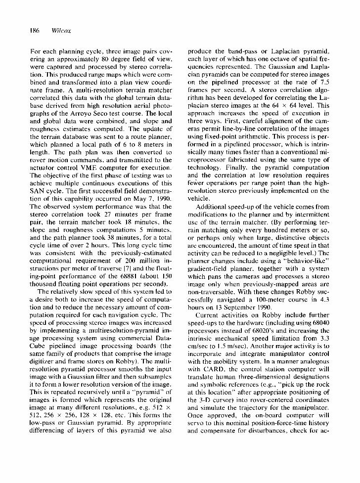
For each planning cycle, three image pairs cov- ering an approximately 80 degree field of view, were captured and processed by stereo correla- tion. This produced range maps which were com- bined and transformed into a plan view coordi- nate frame. A multi-resolution terrain marcher correlated this data with the global terrain data- base derived from high resolution aerial photo- graphs of the Arroyo Seco test course. The local and global data were combined, and slope and roughness estimates computed. The update of the terrain database was sent to a route planner, which planned a local path of 6 to 8 meters in length. The path plan was then converted to rover motion commands, and transmitted to the actuator control VME computer for execution. The objective of the first phase of testing was to achieve multiple continuous executions of this SAN cycle. The first successful field demonstra- tion of this capability occurred on May 7, 1990. The observed system performance was that the stereo correlation took 27 minutes per frame pair, the terrain matcher took 18 minutes, the slope and roughness computations 5 minutes, and the path planner took 38 minutes, for a total cycle time of over 2 hours. This long cycle time was consistent with the previously-estimated computational requirement of 200 million in- structions per meter of traverse [7] and the float- ing-point performance of the 68881 (about 150 thousand floating point operations per second).
The relatively slow speed of this system led to a desire both to increase the speed of computa- tion and to reduce the necessary amount of com- putation required for each navigation cycle. The speed of processing stereo images was increased by implementing a multiresolution-pyramid im- age processing system using commercial Data- Cube pipelined image processing boards (the same family of products that comprise the image digitizer and frame stores on Robby). The multi- resolution pyramid processor smooths the input image with a Gaussian filter and then subsamples it to form a lower resolution version of the image. This is repeated recursively until a "pyramid" of images is formed which represents the original image at many different resolutions, e.g. 512 x 512, 256 x 256, 128 × 128, etc. This forms the low-pass or Gaussian pyramid. By appropriate differencing of layers of this pyramid we also
produce the band-pass or Laplacian pyramid, each layer of which has one octave of spatial fre- quencies represented. The Gaussian and Lapla- cian pyramids can be computed for stereo images on the pipelined processor at the rate of 7.5 frames per second. A stereo correlation algo- rithm has been developed for correlating the La- placian stereo images at the 64 x 64 level. This approach increases the speed of execution in three ways. First, careful alignment of the cam- eras permit line-by-line correlation of the images using fixed-point arithmetic. This process is per- formed in a pipelined processor, which is intrin- sically many times faster than a conventional mi- croprocessor fabricated using the same type of technology. Finally, the pyramid computation and the correlation at low resolution requires fevcer operations per range point than the high- resolution stereo previously implemented on the vehicle.
Additional speed-up of the vehicle comes from modifications to the planner and by intermittent use of the terrain marcher. (By performing ter- rain matching only every hundred meters or so, or perhaps only when large, distinctive objects are encountered, the amount of time spent in that activity can be reduced to a negligible level.) The planner changes include using a "behavior-like" gradient-field planner, together with a system which pans the cameras and processes a stereo image only when previously-mapped areas are non-traversable. With these changes Robby suc- cessfully navigated a 100-meter course in 4.3 hours on 13 September 1990.
Current activities on Robby include further speed-ups to the hardware (including using 68040 processors instead of 68020's and increasing the intrinsic mechanical speed limitation from 3.3 cm/sec to 1.5 m/sec). Another major activity is to incorporate and integrate manipulator control with the mobility system. In a manner analogous with CARD, the control station computer will translate human three-dimensional designations and symbolic references (e.g., "pick up the rock at this location" after appropriate positioning of the 3-D cursor) into rover-centered coordinates and simulate the trajectory for the manipulator. Once approved, the on-board computer will servo to this nominal position-force-time history and compensate for disturbances, check for ac-

Robotic Vehicles for Planetary Exploration 187
ceptable error bounds, and halt or recover upon error conditions, notifying the operator of the problem with as much diagnostic information as possible on the first transmission. The supervi- sory language, together with the control system, will allow the rover to conduct rather complex operations such as complete sampling, coring, or other manipulation operations within each speed-of-light round trip. One of the key issues involved in this research is the three-dimensional spatial calibration between the manipulator, camera system, and mobility system.
2.2. Research Applicable to "Small Missions"
The focus of this research on MRSR-type objec- tives has not entirely tracked the trends in the mission planning community, however. Wide- spread apprehension regarding future NASA budgets has caused an upswell in interest in "small missions." MRSR itself was officially ter- minated as a pre-project activity at the end of fis- cal 1990. Current mission concepts revolve around first forming some kind of "Mars Net- work" which would involve ianders at several of the interesting geologic units, but not involve sample return (until a much later mission). One key element of this mission concept is that it is
no longer desired to execute a nearly pinpoint landing near the junction of several geologic units, so that several can be explored with a sin- gle long-range rover. Rather a number of landers would be placed down as close as possible to the centers of each geologic unit, well away from any ambiguous terrain, and then only very local ex- ploration would be required. Furthermore, since no sample return would be involved, there is no clear need for the landers to be highly massive. (A sample return rocket capable of reaching Earth from Mars that uses conventional propul- sion technology necessarily weighs of the order of 1000 Kg.) Thus, at least for near-term missions currently entertained by the mission planning community, it is of interest to create a very small, lightweight, "local" rover.
The objective of this small local rover research program is to demonstrate a microrover (under 5 Kg mass) performing a realistic Mars science mission (e.g., emplace seismometer, take sam- ple, perform spectrometry) within the vicinity of a lander while controlled in a realistic way from a human control station. We are building such a microrover (Figure 3) called Go-For (since its primary mission would be to Go For samples, images, spectra, etc., as commanded more-or- less explicitly by the human operator on Earth).
Fig. 3. Microrover testbed "Go-For" .

188 Wilcox
The overall sys tem concept is to use the lan- der for all possible resources (as would no doubt be the case on a real mission since the lander is close by and has a much larger power and weight budget). This means that the microrover can be essentially " t e l eopera ted" by the lander com- puter, with cont inuous speed and steering com- mands emanat ing from the lander. We have used Robby as the simulated lander in the first series of exper iments , and construct ion of a stand- alone lander is underway.
The lander has the following essential lander equipment: compute r (VME card cage) with im- age capture hardware, an accurately calibrated pan-tilt head with stereo cameras , inclinometers (or means for leveling the platform), radios for communicat ing with the control station, radios for communicat ing with the microrover, motor- generator power source, and air-conditioning. The functions per formed at the lander are cap- ture of stereo images, t ransmission of the images (with possible data compression) , pan-tilt angles, and incl inometer data to the control station, re- ceipt of commands f rom the control station, ex- pansion of the parameter ized commands into real-time ac tuator sequences, and faithful exe- cution of those sequences. The microrover would be CARD-ed from either the lander stereo images or images obtained f rom the rover itself. Note that the lander cameras would be up fairly high, so that they could com m and a fairly good view of the surrounding terrain. This is something that is hard to arrange in an ultralight vehicle.
The basic mobility sys tem on Go-For is the fork-wheel concept , which has only four degrees of f reedom (compared to 8 active and three pas- sive on Robby). Its objective is to simplify sensor and sampler positioning, as well as offering po- tentially ultra-high mobility, self-righting f rom turnover, very compac t s towage, a very high camera vantage point, and other advantages. The fork-wheel sys tem is a four-wheel skid-steer ve- hicle with the front and rear wheel pairs each on a " fo rk , " or a pair of wheel struts connected by a rigid torque-tube through the body. Each fork is driven by a gea rmotor so that the torque-tube can be rotated continuously around. Thus when both forks are down, the body of Go-For is up high for good camera visibility. When both forks are forward, the vehicle can cross crevasses al-
most as long as its body. When both forks are out horizontal (front and back), the vehicle is ex- t remely stable and low as a sampling platform. Clever use of the forks may allow relatively large obstacles to be surmounted. A somewhat similar concept involving four track belts has been de- veloped in Japan (by Mitsubishi H e a v y Indus- tries) and in France (under that FRASTAR proj- ect) for stair-climbing and other advanced indoor mobility requirements.
Go-For has a fiberglass body/f rame and a small video camera with power zoom, autofocus, autoiris, and a macro close-up feature. The mi- crorover is controlled and actuated via commer- cial radio-controlled model hardware (operated on a government -band f requency assignment). The video is t ransmit ted live from the vehicle, and engineering, science, and sensor data will be modulated on the audio channel of the video downlink (to the lander). A core drill which dou- bles as a soil scoop will be the primary manipula- tor. A releasable hook for a simulated seismometer (with integral tether reel) will be provided. Go-For is controlled via a commercial 8-channel radio con- trol (RC) system. It is thus capable of straight joys t ick control from a hand-held commercial control unit, with a range of over 1 Km. It also has a repackaged camcorder video camera with auto-focus, auto-iris, 6:1 power zoom, and mo- torized macro offering close-up resolutions bet- ter than the naked eye. (The camcorder has been repackaged to eliminate weight and to actuate all essential functions in a way compat ible with the RC control system). The video is broadcast over a video t ransmit ter back to the lander. The hand- held commercia l RC control box is interfaced (via D/A converters) to the compute r in the lan- der, and thus can command the microrover from the control console by way of the lander. CARD control can be achieved either by using the lan- der cameras or the camera on the microrover (which is on a translation stage for stereo). In the relatively near future we plan to integrate a mi- cro-core-drill assembly. This should provide 3.5 mm diameter by 1.5 cm rock samples, or alter- natively could be used as a soil scoop. It will be equipped with a plunger which will allow ejection of the sample upon return to the lander. Again clever use of the forks on the microrover will al- low great flexibility in positioning and using the

Robotic Vehicles for Planetary Explorat ion 189
core drill. The core drill will be horizontal ly mounted, have two binary control signals for RC servo actuators , have a mass of about 300 grams, and require an average power of about 3 watts. Additional items planned for integration include pitch/roll sensors and a turn rate gyro. These ad- ditional sensors, along with data for camera auto- focus range, ba t te ry voltage, and net ba t te ry dis- charge current , will be the only te lemetry re- turned f rom the vehicle. However , note that this data set will give the possibility for an impressive array of capabilities. The focus information f rom the auto-focus camera can be used as a proximity and ranging device to warn of upcoming obsta- cles or depressions, as well as used in terminal guidance to reach a designated sampling location or to pass between two rocks. The pitch and roll sensors are necessary to interpret the focus data and for expecta t ion monitor ing and emergency halt/reflex functions. The bat tery voltage and discharge information are the central indicators of overall sys tem health.
Lastly, there is provision for se i smometer de- ployment . There is a cavi ty molded into the body which will have an actuated latch for releasing the se ismometer . (Positioning the se i smometer some distance from the lander is one of the major lessons of the Viking mission, where wind and ac tuator noise from the lander dominated all the seismological data.)
The opera tor control console is a Silicon Graphics h igh-performance 3-D color graphics workstat ion with spaceball input device. Addi- tional equipment in the control station includes V H F and microwave radio communica t ion with the " l ander" (Robby), as well as a compute r (VME chassis) for reconstruct ion of stereo color images as they are received digitally over the mi- c rowave link. (The microwave link provides a 1 Mbit/sec downlink f rom the lander, or real-time analog NTSC color video when the digital data is not being sent. The V H F link is a bidirectional 9600 baud serial data link.) The functions per- formed at the control station are the receipt, re- construct ion, and display of the stereo images re- turned f rom the lander, the manipulat ion and display of over lay cursors and icons, the com- putation of the resulting path and activity com- mand parameters , and the uplinking of those command parameters to the lander. The dead
reckoning accuracy of CARDed microrovers is a mat ter of some concern, since the ability to ac- curately reach and sample at a location desig- nated by the science team with a minimum num- ber of command cycles is of pr ime importance in the overall success of the mission. So long as the microrover is within view of the lander, it is triv- ial to locate the moving rover f rom the lander very accurately with very small computat ion. This is accompl ished by capturing successive stereo images f rom the lander, differencing them so that all non-moving scene elements disappear, and then correlating only those pixels that re- main, which are exact ly those on the microrover. This will give range and heading from the lander to the microrover with about the same accuracy as the original CARD commands , and thus is suf- ficient for our purposes . Fur thermore , since Go- For will have return te lemetry indicating the fo- cus range of the autofocus camera , this sensor can be used for final approach to the sample rock, or to carefully thread between two rocks, if so desired. The need for additional proximity sensors beyond the autofocus range measure- ment is not clear, since a detailed terrain map can be computed at the control station from the stereo images, an accurate vehicle position can be deduced by the method described above, and the autofocus range should be sufficient for re- flexive protect ion against going into holes or off cliffs, which are the principal hazard for a vehicle which is self-righting. (The self-righting vehicle can presumably recover from accidents which do not involve falling great distances or being cov- ered with debris or being t rapped in a pit.)
2.3. Other Mission Drivers
Thus research in planetary rover navigation has come full-circle, f rom the SLRV and Lunakhod vehicles which had no on-board computat ion to Go-For , which also has no on-board computa- tion. (It is interesting to note here that the U.S. space communi ty has essentially rejected the concept of putting a rover on Venus, since it is so hot that no modern microelectronics could survive there. However , a videotape of a Soviet rover recently circulated in the U.S. which clearly showed the rover powered by a windmill. When quest ioned about it, the Soviets said that

190 Wilcox
was a concept for Venus, which has a dense at- mosphere and considerable power available in the a tmospher ic currents [21]. Since microelec- tronics cannot work for long on Venus, they must be investigating a rover with essentially no com- putation. It seems possible that a CARDed rover with a l l -vacuum-tube cameras and control sys- tems, with commands executed as they are re- ceived, and powered by the wind may be feasible for Venus.)
Of course Go-For is accompanied and con- trolled by a lander with modera te computing ca- pacity. Fur thermore , since we are using Robby as the lander, all the SAN and behavior control software developed for Robby can jus t as easily control Go-For. This suggests an interesting ar- chitectural question regarding the p lacement of key resources. When communica t ion is relatively easy, as be tween Go-For and the lander, it seems reasonable to place the compute r in the low-risk location where power and other resources are more readily available. (Of course there will be a compute r on the lander anyway, and radio com- municat ion with the microrover anyway, so in fact nothing is being traded away when this choice is made so long as communica t ions can- not be interrupted.) Similar arguments may be made for some of the sensors and science instru- ments .
It is fair to ask whether the mission planning communi ty is going to return to a desire for high levels of autonomy. Certainly this au tonomy will be ex t remely valuable when missions beyond Mars are a t tempted. Indeed, it is missions to planetary surfaces in the outer solar sys tem where robotic planetary rovers could have great- est benefit as explorers: small mass , long life, ra- diation tolerance, and the versatili ty to reach the varied terrain glimpsed in the Voyager f lybys. We can sketch out such a mission.
The large outer planets (Jupiter, Saturn, Ura- nus, and Neptune) all have multiple moons, many of which are comparable in size to our own moon. As mentioned in the introduction, the Voyager f lybys indicated that they are an ex- t remely diverse and interesting collection of ob- jects. It is essentially out of the question to send manned missions to these objects using conven- tional propulsion technology, due to the very long round-trip flight t imes, and the very large
launch masses required with chemical rockets. Typically hours are required for round-trip com- municat ion at the speed of light. This means that images will take a long time to be sent, and CARD control of rovers is likely to be inade- quate. The science communi ty has clearly indi- cated that the return of wel l -documented sam- ples, even a few grams, is the highest priority for the study of the solar system. (This is because very large and heavy Ear th-based instruments are able to extract essentially a complete geo- chemical history f rom a s a m p l e - - a n d there is lit- tle prospect of miniaturizing these instruments soon. Those instruments which can be flown are ext remely primitive by compar ison in terms of the actual detailed scientific knowledge which re- suits.)
One can imagine a new type of standardized spacecraf t for this mission. One essential ele- ment is electric (ion) propulsion, which gives the high exhaust velocity needed to get to the outer solar sys tem and back in reasonable time. The electric power source might ei ther be nuclear or solar (with a very light but large concentrat ing mirror). The spacecraf t could carry a microrover with chemical rockets for descent to the surface and another chemical rocket for lifting the few- gram sample into orbit. The microrover could also car ry sufficient instruments to document the sample gathering process: camera , spectrometer , etc. The conceptual mission profile for this spacecraf t could begin with one or a few of these sys tems being placed in low-Earth orbit. They would perhaps weigh one or a few tons each, with some 80% of that being reaction mass for the electric drive. The electric power budget would be one or a few thousand watts. Once the propulsion sys tem were act ivated the spacecraf t would slowly spiral out f rom Earth. Within a few weeks they would emerge from Earth orbit into solar orbit, and spiral away toward Jupiter, arriv- ing a few years later.
Those intended for Jovian moons would match speeds with Jupiter and spiral in to the tar- get moon. (The others would use a gravity assist to "s l ingshot" toward their destination.) As each approached its target body, it would spiral down to a low orbit over the moon. The descent vehicle would be released from the "mo the r ship" (the one having the electric propulsion system), and

Robotic Vehicles for Planetary Explorat ion 191
drop down to the surface and land. The mother ship would spiral back UP to the Lagrange point (a stationary point between the moon and its par- ent body). Since these moons (like our moon) are generally face-locked to the parent body, the mother ship would appear at a fixed point in the sky. There it could act both as a communicat ion relay to Earth as well as be the "bra in" of the rover. The mother ship would have both the mass budget (hundreds of Kg) and power budget (a kilowatt or so) to support high levels of on-board computat ion as well as communicat ion band- width with Earth. The rover, by contrast , might weigh only a few kg. It could rove perhaps l0 meters per day by CARD, or use SAN or behav- ior control to move hundreds of meters or more per day. The relatively high bandwidth to Earth would allow numerous high-resolution images to be transmitted every day. After a year or two roving the moon, the sample return capsule would be launched back into orbit. The rover might carry the sample rocket so it could always be launched if the rover became stuck or dis- abled. Since these moons lack an atmosphere, an extremely small rocket can put an extremely small payload into orbit (so long as the mass ratio of fuel to payload results in the necessary final velocity). The limit on how small the ascent ve- hicle can be would normally be the mass of its control system. However , no control system may be necessary, as even an "unguided" rocket (spun slowly using thrust deflectors and using a pyrotechnic fuse to initiate the appropriate "ap- ogee kick" a half-hour or so after lift-off) can achieve a crudely-specified orbit. There the mother ship would rendezvous with it using its very high-performance propulsion system after locating it by a small radio beacon. After docking with the ascent vehicle, the mother ship would leave for Earth. Upon return, it can slowly park in any desired orbit for retrieval of its samples. The elapsed mission duration might be ten years or a little more.
The first place to try a prototype of such a new form of standard spacecraft would be our own moon. It has very representat ive values of grav- ity, orbital velocity, altitude of Lagrange point, etc. for testing the concept fully before commit- ting to the creation of the dozen or so spacecraft which would be used to explore the solar system.
Of course there are significant technical chal- lenges to creating such systems. Electric propul- sion is a well-demonstrated technology in the small sizes needed for this mission concept , but it is generally agreed that a few hundred million dollars will be needed to qualify a production flight unit for a mission like this [22]. A similar amount would probably need to be spent devel- oping the power system, and perhaps a like amount for the flight computer which could sup- port the needs of high-performance autonomous navigation, image data compression, and other computation-intensive tasks. Much of the other ultra-miniature equipment needed for the system (navigation sensors, descent propulsion, etc.) has already been developed (notably for the Stra- tegic Defense Initiative "Brilliant Pebbles" pro- gram) [23]. Although these costs may seem high in absolute terms (especially to AI/Robotics re- searchers) they are quite moderate in the context of typical missions such as Viking and Voyager. Once developed, the standardized (even identi- cal) nature of the spacecraft should make per- unit costs relatively low. Given the level of public attention which focussed on the brief Voyager flybys, it seems plausible that a network of rov- ers on every major planetary surface in the solar system, with vast high-resolution images return- ing daily, would help to reenergize common in- terest in science and technology in general and in robotics and artificial intelligence in particular. The rovers vcould be the centerpiece of these missions, and endowing them with reasonable levels of autonomy would greatly enhance, per- haps even enable, credible science/exploration missions.
3. Conclusions
Through the development and evaluation of tech- nologies like the CARD and SAN navigation sys- tems, research at JPL has expanded the set of viable planetary rover mission possibilities be- yond the limits of remotely teleoperated systems such as Lunakhod. These are potentially appli- cable to exploration of all the solid planetary sur- faces in the solar system, including Mars, Venus, and the moons of the gas giant planets. This re- search has demonstrated in an initial way a wide

192 Wilcox
range of options for autonomy, scale, computa- tion, and mobility for these planetary rover sys- tems.
Acknowledgments
The research described in this publication was carried out by the Jet Propulsion Laboratory, California Institute of Technology, under con- tract with the National Aeronautics and Space Administration. The algorithms for vision-based ranging and terrain matching on the testbed ve- hicle were developed by Donald B. Gennery. The machine vision subsystem on the rovers were created and integrated by Brian K. Cooper. The communication network system for all rovers de- scribed was developed by Todd Litwin. The ve- hicle control subsystem was developed by Tam Nguyen and Steve Katzmann. The manipulator arm control subsystem was developed by Jono- than Cameron. The multiresolution pyramid im- age processing system was developed by Charles H. Anderson. The real-time stereo vision algo- rithm running on the pyramid processor was de- veloped by Larry H. Matthies. SAN planning and behavior control was developed and imple- mented by Jim Firby, Marc Slack, Eran Gat, Ra- jiv Desai, John Loch, Don Gennery, and David P. Miller. The detailed design and engineering of Go-For was performed by Tim Ohm and George Alahuzos. The video camera system on Go-For was implemented by Shawn Anderson, and the core drill assembly is being designed and imple- mented by Kim Aaron, Miles Baker, and Dave Levitt. Fabrication of most of the vehicle com- ponents was by Greg De Wit, Jim Lloyd, and Jack Frazier. Overall system engineering was performed by the author and Andrew Mishkin.
References
I. M. D. Levine, D. A. O'Handley, and G. M. Yagi, "Computer determination of depth maps," Computer Graphics and Image Processing, vol. 2, pp. 131-150, 1973.
2. D. A. O'Handley, "Scene analysis in support of a Mars rover," Computer Graphics and Image Processing, vol. 2, pp. 281-297, 1973.
3. R. A. Lewis and A. R. Johnston, "A scanning laser rangefinder for a robotic vehicle," Proc. Fifth Inter- national Joint Conference on Artificial Intelligence, Cambridge, MA, 1977, pp. 762-768.
4. A. M. Thompson, "The navigation system of the JPL robot," Proc. Fifth International Joint Conference on ArtiJi'cial Intelligence, Cambridge, MA, 1977, pp. 749- 757.
5. S. W. Yerazunis, "Autonomous control of roving vehi- cles for unmanned exploration of the planets," Tech- nical Report MP-61, Rensselaer Polytechnic Institute, Troy, NY, 1978.
6. K. G. Holmes, B. H. Wilcox, J. M. Cameron, B. K. Cooper, and R. A. Salo, "Robotic vehicle computer aided remote driving," vol. 1, JPL D-3282, Jet Propul- sion Laboratory, Pasadena, CA, 1986.
7. B. H. Wilcox and D. B. Gennery, "A Mars rover for the 1990's," Journal of the British Interplanetary Society, 1987.
8. D. B. Gennery, "Visual terrain matching for a Mars rover," Proc. IEEE Conf. on Computer Vision and Pat- tern Recognition, San Diego, CA, 1989.
9. J. R. Randolph (ed.), "Mars rover 1996 mission con- cept ," JPL D-3922, Jet Propulsion Laboratory, Pasa- dena, CA, 1986.
10. J. C. Mankins (ed.), Proc. Technology Planning Work- shop for the Mars Rover, Jet Propulsion Laboratory, Pasadena, CA, 1987.
11. D. P. Miller, "Navigation in rough terrain: Deliberation versus reaction," Proc. IEEE International Conference on Robotics and Automation, Sacramento, CA, 1991.
12. E. Gat, "ALFA, A language for program reactive ro- botic control systems," Proc. IEEE International Con- JOrence on Robotics and Automation, Sacramento, CA, 1991.
13. D. B. Gennery, "Object detection and measurement us- ing stereo vision," Proc. Sixth International Joint Con- ference on Artificial Intelligence, Tokyo, Japan, 1979, pp. 320-327.
14. D. B. Gennery, "A feature-based scene matcher," Proc. Seventh International Joint Conference on Arti- ftcial Intelligence, Vancouver, British Columbia, 1981, pp. 667-673.
15. B. H. Wilcox, "Vision-based planetary rover naviga- tion," SP1E International Conference on Image Pro- cessing and Visualization, Lausanne, Switzerland. 1990.
16. L. H. Matthies, "Stereo vision for planetary rovers," JPL report D-8131, January 1991.
17. P. DeVries (ed.), "Mars sample return mission, 1984 study report," JPL Document JPL D-1845 p7-19, Sept. 28. 1984.
18. J. R. French (ed.), "Mars sample return mission, 1985 study report," JPL Document JPL D-3114 p7-1, July 31, 1985.
19. G. Klein (ed.), "Planetary spacecraft systems technol- ogy, final report 1986," JPL Document JPL D-3731 p I11-79. Oct. 30, 1986.
20. J. Bares, M. Hebert, T. Kanade, E. Krotkov, T. Mitch-

R o b o t i c V e h i c l e s f o r P l a n e t a r y E x p l o r a t i o n 193
ell, R. Simmons, and W. Whittaker, "Ambler: An au- tonomous rover for planetary exploration," IEEE Com- puter, pp. 18-26, 1989.
21. D. S. Pivirotto, Jet Propulsion Laboratory, Pasadena, CA; private communication, 1989.
22. D. Kerrisk, Jet Propulsion Laboratory, Pasadena, CA; private communication, 1991.
23. R. M. Jones, "Microspacecraft missions and systems," J. British Interplanetary Society, vol. 42, no. 10, p. 448, 1989.
Brian H. Wilcox is Supervisor of the Robotic Vehicles Group and technical manager for the Navigation work ele- ment in the NASA Pathfinder Planetary Rover program. He has a B.S. in Physics and a B.A. in Mathematics from the University of California at Santa Barbara and is cur- rently pursuing an MSEE in signal and image processing at the University of Southern California. He has managed several programs for integration of robotic systems, includ- ing being cognizant engineer of several tasks sponsored by the U.S. Army Tank Automotive Command and Engineer Topographic Laboratories, as well as being principal inves- tigator for several rover-related tasks internal to JPL. He has also been cognizant engineer of the Sensing and Per- ception subsystem of the NASA telerobot program and di- rected the integration of the first phase of that system. He has been with JPL since 1982.