Maximizing miniature aerial vehicles
10
U nmanned aerial vehicles (UAVs) are playing increasingly prominent roles in defense pro- grams and strategy around the world. Technol- ogy advancements have enabled the development of large UAVs (e.g., Global Hawk, Predator) and the creation of smaller, increasingly capable UAVs. The focus of this article is on smaller fixed- wing miniature aerial vehicles (MAVs), which range in size from .25–2 m in wingspan. As recent conflicts have demonstrated, there are numerous military applications for MAVs, including reconnaissance, surveillance, battle dam- age assessment, and communications relays. Civil and commercial applications are not as well developed, although potential applications are extremely broad in scope. Possible applications for MAV technology include environmental monitoring (e.g., pollution, weather, and scientific applications), forest fire monitor- ing, homeland security, border patrol, drug interdiction, aerial surveillance and mapping, traffic monitoring, preci- sion agriculture, disaster relief, ad hoc communications networks, and rural search and rescue. For many of these applications to develop to maturity, the reliability of MAVs will need to increase, their capabilities will need to be extended further, their ease of use will need to be improved, and their cost will have to come down. In addition to these technical and economic challenges, the regulatory challenge of integrating UAVs into the nation- al and international airspace must be overcome. Critical to the more widespread use of MAVs is making them easy to use by nonpilots, such as scientists, forest fire- fighters, law enforcement officers, or military ground troops. One key capability for facilitating ease of use is the ability to sense and avoid obstacles, both natural and man made. Many of the applications cited require MAVs to fly at low altitudes in close proximity to structures or terrain. For example, the ability to fly through city canyons and around high-rise buildings is envisioned for future home- land security operations. For MAVs to be effective tools, the challenge of operating in complex environments must be automated, allowing the operator to concentrate on the task at hand. Performing obstacle and terrain avoidance from a fixed- wing MAV platform is challenging for several reasons. The limited payload and power availability of MAV platforms place significant restrictions on the size, weight, and power requirements of potential sensors. Sensors such as scanning laser detection and ranging (LADAR) and radar are typical- ly too large and heavy for MAVs. Related to limits on sen- sor payload are those on computing resources. For most MAVs, the primary computational resource is the excess capacity in the autopilot microcontroller. Additional com- putational capacity can be added, but computers such as PC104-based systems generally exceed the payload capacity of MAVs; smaller microcontrollers are typically used. Another challenge posed by fixed-wing MAVs is that they move fast: ground speeds are often in the range of 10–20 m/s (22–44 mi/h). Contrary to the computational limits imposed, obstacle avoidance algorithms must execute and act quickly. Unlike ground robots and unmanned rotorcraft, fixed-wing MAVs cannot stop or slow down while avoidance algorithms process sensor information or plan maneuvers. Reactions must be immediate. Obstacle sensing is further compli- cated by the fact that sensor readings are altered by changes in air- craft attitude, especially the Maximizing Miniature Aerial Vehicles Obstacle and Terrain Avoidance for MAVs BACKGROUND IMAGE: © PHOTODISC BY STEPHEN GRIFFITHS, JEFF SAUNDERS, ANDREW CURTIS, BLAKE BARBER, TIM MCLAIN, AND RANDY BEARD 1070-9932/06/$20.00©2006 IEEE IEEE Robotics & Automation Magazine SEPTEMBER 2006 34
-
Upload
independent -
Category
Documents
-
view
4 -
download
0
Transcript of Maximizing miniature aerial vehicles

Unmanned aerial vehicles (UAVs) are playingincreasingly prominent roles in defense pro-grams and strategy around the world. Technol-ogy advancements have enabled thedevelopment of large UAVs (e.g., Global
Hawk, Predator) and the creation of smaller, increasinglycapable UAVs. The focus of this article is on smaller fixed-wing miniature aerial vehicles (MAVs), which range insize from .25–2 m in wingspan. As recent conflicts havedemonstrated, there are numerous military applications forMAVs, including reconnaissance, surveillance, battle dam-age assessment, and communications relays.
Civil and commercial applications are not as welldeveloped, although potential applications are extremelybroad in scope. Possible applications for MAV technologyinclude environmental monitor ing (e.g., pollution,weather, and scientific applications), forest fire monitor-ing, homeland security, border patrol, drug interdiction,aerial surveillance and mapping, traffic monitoring, preci-sion agriculture, disaster relief, ad hoc communicationsnetworks, and rural search and rescue. For many of theseapplications to develop to maturity, the reliability ofMAVs will need to increase, their capabilities will need tobe extended further, their ease of use will need to beimproved, and their cost will have to come down. Inaddition to these technical and economic challenges, theregulatory challenge of integrating UAVs into the nation-al and international airspace must be overcome.
Critical to the more widespread use of MAVs is makingthem easy to use by nonpilots, such as scientists, forest fire-fighters, law enforcement officers, or military groundtroops. One key capability for facilitating ease of use is theability to sense and avoid obstacles, both natural and manmade. Many of the applications cited require MAVs to flyat low altitudes in close proximity to structures or terrain.For example, the ability to fly through city canyons andaround high-rise buildings is envisioned for future home-
land security operations. For MAVs to be effective tools,the challenge of operating in complex environments mustbe automated, allowing the operator to concentrate on thetask at hand.
Performing obstacle and terrain avoidance from a fixed-wing MAV platform is challenging for several reasons. Thelimited payload and power availability of MAV platformsplace significant restrictions on the size, weight, and powerrequirements of potential sensors. Sensors such as scanninglaser detection and ranging (LADAR) and radar are typical-ly too large and heavy for MAVs. Related to limits on sen-sor payload are those on computing resources. For mostMAVs, the primary computational resource is the excesscapacity in the autopilot microcontroller. Additional com-putational capacity can be added, but computers such asPC104-based systems generally exceed the payload capacityof MAVs; smaller microcontrollers are typically used.
Another challenge posed by fixed-wing MAVs is thatthey move fast: ground speeds are often in the range of10–20 m/s (22–44 mi/h). Contrary to the computationallimits imposed, obstacle avoidance algorithms must executeand act quickly. Unlike ground robots and unmannedrotorcraft, fixed-wing MAVs cannot stopor slow down while avoidancealgorithms process sensorinformation or planmaneuvers. Reactionsmust be immediate.Obstacle sensing isfurther compli-cated by the factthat sensorreadings arealtered bychanges in air-craft attitude,especially the
Maximizing MiniatureAerial VehiclesObstacle and Terrain Avoidance for MAVs
BACKGROUND IMAGE: © PHOTODISC
BY STEPHEN GRIFFITHS, JEFF SAUNDERS, ANDREW CURTIS, BLAKE BARBER, TIM MCLAIN, AND RANDY BEARD
1070-9932/06/$20.00©2006 IEEEIEEE Robotics & Automation Magazine SEPTEMBER 200634

rolling motions that occur during turns. Attitude changesaffect not only the pointing direction of the sensor, but alsocause motion of fixed objects in the field of view. For avoid-ance maneuvers to be successful, obstacle and terrain detec-tion must account for the effects of aircraft attitude changes.All of the challenges associated with MAV obstacle and ter-rain avoidance are compounded by the reality that for MAVs,mistakes are costly or even catastrophic; crashes can result indamage to or loss of the MAV and failure to complete theobjectives of the flight.
As evidenced by the recent Defense Advance ResearchProjects Agency (DARPA) Grand Challenge, capable obstacleavoidance and terrain navigation systems have been developedfor ground vehicles. Obstacle avoidance and path planninghave been active areas of research for many years, and theassociated robotics literature is immense. While providing aguiding influence, most of the proposed methods fail to dealwith the sensing and computational challenges imposed bythe limited payload capabilities of MAVs.
As autonomous MAVs and feasible obstacle sensors arerecent technological developments, the body of experimentalresearch directed specifically toward MAV obstacle and terrainavoidance is small. Related to terrain avoidance is workfocused on utilizing vision processing techniques to estimateheight above ground. Chahl et al. demonstrated that mimick-ing the landing behavior of bees, by maintaining constantoptic flow during a landing maneuver, could be used to suc-cessfully control the descent of a MAV [1]. The developmentof lightweight sensors for the measurement of optic flow hasenabled their use in MAVs [2], [3], [4]. Barrows et al. havedemonstrated that these sensors can be used to follow undula-tions in terrain with low-flying MAVs [5].
This article presents MAV obstacle and terrain avoidanceresearch performed at Brigham Young University (BYU).Our work builds on the notion of utilizing useful but imper-fect map information to plan nominal paths through city ormountain terrain. Because maps may be limited in resolution,out of date, or offset in location, MAVs must also utilize sen-sory information to detect and avoid obstacles unknown tothe path planner. In this article, we present research utilizinglaser range finder and optic-flow sensors to detect obstaclesand terrain. Avoidance algorithms using this sensor informa-tion are discussed briefly, and flight test results from ourMAVs are presented.
BYU Miniature Aerial Vehicle PlatformsOver the past five years, BYU has been involved in the devel-opment of MAV airframes, autopilots, user interfaces, sensors,and control algorithms. This section describes the experimen-tal platform developed specifically for the obstacle avoidanceresearch described in this article.
AirframeFigure 1 shows the airframe used for obstacle avoidanceexperiments. The airframe has a 1.5-m wingspan and wasconstructed with an expanded polypropylene (EPP) foam
core covered with Kevlar. This design was selected for itsdurability, usable payload, ease of component installation, andflight characteristics. The airframe can carry a 0.4-kg payloadand can remain in flight for over 45 min at a time. The colli-sion avoidance sensors that are embedded in the airframeinclude three optic-flow sensors, one laser ranger, and twoelectro-optical cameras as shown in Figure 2. Additional pay-load includes the Kestrel autopilot, batteries, a 1-W, 900-MHz radio modem, a 12-channel global positioning system(GPS) receiver, and a video transmitter.
Kestrel AutopilotThe collision avoidance algorithms described in this articlewere implemented on Procerus Technologies’ KestrelAutopilot version 2.2 [6]. The autopilot is equipped with aRabbit 3400 29-MHz processor, three-axis rate gyros,three-axis accelerometers, absolute and differential pressuresensors, and a variety of interface ports. The autopilot
SEPTEMBER 2006 IEEE Robotics & Automation Magazine 35
Figure 1. Airframe used for collision avoidance experiments.
Figure 2. Sensors used for collision avoidance. The round holeon the right and the large hole on the belly are the optic-flowsensors. The square hole in the center is the laser range, andthe other two round holes are for electro-optical cameras.

measures 3.8 cm × 5.1 cm × 1.9 cm and weighs 18 g. Theautopilot also serves as a data acquisition device and is ableto log 175 kB of user-selectable telemetry at rates up to 60Hz. The optic-flow sensors and the laser ranger used in thisarticle are connected directly to the autopilot and the colli-sion avoidance algorithms are executed on board the Rab-bit processor.
Optic-Flow SensorsThe MAV is equipped with three optic-flow sensors. Twoof the optic-flow sensors are forward looking but sweptback from the nose by α = 60◦. The third optic-flow sen-sor points down to determine the height above ground.The optic-flow sensors, shown in Figure 3, are constructedby attaching a lens to an Agilent ADNS-2610 opticalmouse sensor. The ADNS-2610 has a small form factor,measuring only 10 mm by 12.5 mm and runs at 1,500frames/s. It requires a light intensity of at least 80 mW/m2
at a wavelength of 639 nm or 100 mW/m2 at a wavelengthof 875 nm. The ADNS-2610 measures the flow of featuresacross an 18 × 18 pixel complementary metal-oxide semi-conductor (CMOS) imager. It outputs two values,δpx and δpy , representing the total optic flow across thesensor’s field of view in both the x and y directions. Theflow data in the camera y direction correspond to lateral
motion of the MAV and are ignored.Figure 4 indicates how distance is
computed using the optic-flow sensor.The optical mouse chip outputs an optic-flow displacement (δpx, δpy)
T at its inter-nal sample rate (1,500 Hz). Since thecollision-avoidance loop is executed atTs = 20 Hz, the total optical displace-ment is integrated over Ts to produce(�px,�py). The distance to the objectD is related to the measured distance dby the expression
D = d cos φ sin α,
where φ is the roll angle of the MAV.From geometry, the measured distance tothe object is given by
d = VgpsTs
tan( λeff2 )
,
where λeff is the effective field of view.The effective field of view is given by
λeff = λcam�px
Px− χTs,
where λcam is the field of view of the camera, Px is the size ofthe pixel array along the direction of motion, and χ is theyaw rate with respect to the ground. Using similar reasoningfor left-looking and down-looking optic-flow sensors we canderive the following expression:
Dright = VgpsTs
tan(
λcamDright px
2Px− χTs
2
) cos φ sin α
Dleft = VgpsTs
tan(
λcamD left px
2Px+ χTs
2
) cos φ sin α
IEEE Robotics & Automation Magazine SEPTEMBER 200636
Figure 3. Optic-flow sensors with three different lens configurations: 1.2◦, 2.5◦,and 6.5◦ field of view. The optic-flow sensors are constructed by attaching a lensto an optical mouse chip.
LeftFOV: 6.5°Long. Size: 25 mmLat. Size: 30 mmMass: 15 gF-stop: 2.0
RightFOV: 1.2°Long. Size: 50 mmLat. Size: 30 mmMass: 23 gF-stop: 2.5
CenterFOV: 2.5°Long. Size: 35 mmLat. Size: 30 mmMass: 23 gF-stop: 2.0
Figure 4. The optic-flow sensor is used to compute the distance to an obstacle based on the distance traveledbetween samples (VgpsTs ) and the effective field of view λ.
VgpsTs
d
Dright
α
χ
λeff
Given a nominal waypoint path, it is essential for the MAV to havethe ability to track the pathwith precision.

Ddown = VgpsTs
tan(
λcamD down px
2Px− θTs
2
) cos θ cos φ.
Laser RangerFor the experiments discussed in this article, we used the Opti-Logic RS400 Laser range finder. The range finder has a range of400 m with an update rate of 3 Hz. It weighs 170 g and con-sumes 1.8 W of power. Figure 2 shows the laser ranger mountedin the airframe. It is important to note that the RS400 is not ascanning laser range finder. Scanning laser range finders are cur-rently too heavy and consume too much power for MAV appli-cations. The RS400 returns a single distance measurement andmust be steered by maneuvering the airframe.
Path Planning and FollowingThe first step in our approach for navigating through complexenvironments is to plan a nominal path based on knowninformation about the environment, which is usually in theform of a street map or topographic map. The MAV must beable to accurately follow the nominal path to avoid knownobstacles. This section discusses the methods for planning andfollowing the nominal path. Subsequent sections will discussreactive, sensor-based obstacle avoidance strategies for obsta-cles unknown during the planning process.
Planning the Nominal PathWhen planning paths through complex environments, thecomputational requirements for finding an optimal path canbe significant and unrealistic for near-real-time execution [7].Because of this, recent research has focused on randomizedtechniques to quickly find acceptable, though not necessarilyoptimal, paths [8], [9]. Path planning for MAVs is also difficultbecause of the dynamic constraints of flight. Many commonpath planning algorithms are inadequate for fixed-wing MAVsystems because they do not handle turn-radius limitationsand airspeed constraints effectively.
One randomized method that addresses these limitations isthe rapidly exploring random tree (RRT) algorithm [7], [10].RRTs use a dynamic model of the system to build a tree of tra-versable paths. The search space is quickly explored by applyingcontrol inputs to states already in the tree. Working with theprecise control inputs ensures that the dynamic constraints arenot violated; however, it also results in an open-loop solution.This would be adequate if we had a perfect model of the systemand no disturbances, but this method is not satisfactory for anactual MAV because of model inaccuracies and disturbancessuch as wind.
Similar to Frazzoli et al. [11], we have extended some ofthe concepts of RRTs to plan paths in the output space.Through this work, we have developed a useful a priori pathplanner for the MAVs [12]. Our modified RRT algorithmsearches the output states instead of the inputs and produces alist of waypoints to track. This is sufficient if we can boundthe error of the controlled MAV from the waypoint path. Fora given waypoint path, we can determine the expected trajec-
tory of the MAV [13] and ensure that only traversable pathsare built into the search tree. Branches in the tree are checkedto ensure that they pass tests on turn radius and climb rate andare collision-free. Figure 5 depicts the growth of an RRTpath through a simulated urban environment.
Vector Field Path FollowingGiven a nominal waypoint path, it is essential for the MAV tohave the ability to track the path with precision. MAVs musttrack these paths despite dynamic limitations, imprecise sensorsand controls, and wind disturbances, which are often 20–60%of airspeed [14]. Trajectory tracking, which requires the MAVto be at a specific location at a specific time, is difficult in suchwind conditions. As an alternative, we have developed a pathfollowing approach where the focus is simply to be on the path,instead of at a specific point that evolves in time. Similarresearch in [15] describes a maneuvering method focused onconverging to the path then matching a desired speed along thepath. Our path following method is based on the creation ofcourse vector fields that direct the MAV onto the desired path.
The vector field method produces a field of desired coursecommands that drive the MAV toward the current path seg-ment. At any point in space, the desired course can be easilycalculated. This desired course is used to command headingand roll control loops to guide the MAV onto the desired path.
SEPTEMBER 2006 IEEE Robotics & Automation Magazine 37
Figure 5. This figure shows the growth of an RRT path treethrough a simulated urban enviroment. The algorithm is termi-nated once a feasible path to the destination (red X) is found.
RRT
−300−300−200
−200 −100
−100 0
0100
100
x-Axis
y-Axis200
200
300
300
200400
0
Hei
ght
For our preliminary flight tests, weconsidered a simple scenario: a
single unknown obstacle placeddirectly in the flight path.

The vector field method uses only the current path segment tofind the desired course, avoiding possible singularities and sinksresulting from sums of vectors. Many paths planned for MAVscan be approximated by combinations of straight line segmentsand circular arcs [16]. Figure 6 shows examples of vector fieldsfor linear and circular paths.
To account for wind, we use the course and groundspeedinstead of heading and airspeed to control the MAV. Ground-track motion is the vector sum of the MAV motion relative tothe surrounding air mass and the motion of the air mass rela-tive to the ground. Since course direction includes the effectsof wind, control based on course is much more effective atrejecting wind disturbances. In implementing the vector fieldapproach, course measurements from GPS are compared withthe desired course from the vector field to determine theappropriate control inputs to keep the MAV on the path.
For a given path, the vector fieldis divided into a transition regionand an outer region. This is similarin some respects to the belt zonetechnique developed by Loizou etal. [17] Outside the transitionregion, the vector field drives theMAV toward the transition regionalong a constant course. Onceinside, the vector field changes lin-early from the entry course direc-tion to the desired course along thepath. The effect is to smoothly drivethe MAV to follow the path, withlarger effort as the error from thepath increases. In [14] it is shownthat for any initial condition, theMAV will enter the transition regionin finite time then converge to thedesired course asymptotically.
Flight tests have demonstrated the effective-ness of the vector field path following method,even in windy conditions. Figure 7 demonstratespath following for straight line segments withacute angles. Wind speeds were approximately20% of the airspeed during these tests. The vec-tor field method has been shown to be effectivein tracking paths of lines and orbits with windspeeds of up to 50% of the airspeed of the MAV.
Reactive Obstacle and Terrain AvoidanceDespite having an effective a priori path plan-ner, we cannot guarantee that the flight pathwill be free of obstacles. Our path plannerassumes a perfect model of the terrain, but thisassumption is not realistic. If an urban terrainmodel is missing a newly constructed buildingor a large antenna or tree, a path leading to acollision could result. Our canyon models arebased on 10 m United States Geological Sur-
vey (USGS) data. They are fairly accurate but cannot repre-sent small obstacles like trees and power lines. In addition,the GPS sensor used on the MAV has a constant bias thatcan be as large as 10 m. Path planners can produce a nomi-nal path prior to flight, but the MAV must also have theability to sense and reactively avoid unanticipated obstaclesand terrain in real time.
The following sections present reactive planners for pro-ducing deviations from a nominal path to enable obstacle andterrain avoidance. The first section presents a method forsensing and avoiding obstacles directly in the flight path andshows results for reactive avoidance of a building. The secondsection presents an approach for staying centered betweenobstacles as might be required for flying through a corridor.Flight test results are presented that demonstrate autonomousnavigation of a winding canyon.
Reactive Obstacle AvoidanceReactive obstacle avoidance from aMAV platform is challenging because ofthe size and weight limitations for sens-ing and computation hardware imposedby the platform. The speed with whichavoidance decisions must be made andcarried out also causes difficulties. Forobstacle avoidance in urban environ-ments, we have developed a heuristicalgorithm that utilizes a laser ranger todetect and avoid obstacles. The laserranger points directly out the front ofthe MAV and returns range data forobjects directly in front of the MAVwith a 3-Hz update. For our prelimi-nary flight tests, we considered a simplescenario: a single unknown obstacleplaced directly in the flight path.
IEEE Robotics & Automation Magazine SEPTEMBER 200638
Figure 7. This figure shows telemetry data forfour consecutive traversals of a waypoint path.Wind speeds during the flight were 20% ofthe MAV airspeed. Note the repeatability ofthe trajectories even in significant wind.
Figure 6. Path following in wind is accomplished by creating a vector fieldof desired course commands based on the lateral deviation from the path:(a) shows a possible vector field for a straight-line waypoint path segmentand (b) shows a possible vector field for orbit following.
−150 −100 −50 0 50 100 150−150
−100
−50
0
50
100
150
0 50 100 150
−20
0
20
40
60
80
100
120
140
(a) (b)

AlgorithmConsider the scenario shown in Figure 8, where obstacleavoidance is required. The MAV has a forward groundvelocity V and a minimum turn radius R and is assumed tobe tracking the given waypoint path at the time the obstacleis detected by the laser, which has a look-ahead distance L.Figure 8(a) shows the instant when the obstacle is detectedby the laser ranger. The basic idea is to construct an internalmap of obstacles detected by the laser and to modify thewaypoint path to maneuver around the obstacles in theinternal map. We will refer to the internal representation ofobstacles as map obstacles. When the laser detects the locationof an obstacle, we are unsure about the size and height ofthe obstacle. We propose representing map obstacles ascylinders with radius R equal to the minimum turn radius ofthe MAV and height equal to the current altitude of theMAV. As shown in Figure 8(b), there are two alternate way-point paths that maneuver around the map obstacle. Theendpoints of the waypoint paths are selected so that the newwaypoint paths are tangent to the obstacles in the internalmap. As shown in Figure 8(a), the new waypoints are locat-ed a distance dR/
√d2 − R2 from the original waypoint
path, where d is the turn-away distance from the obstacle. Ifboth waypoint paths are collision free, then the algorithmrandomly selects between the two paths as shown in Figure8(c). Since the map obstacle may be smaller than the actualobstacle, the laser may again detect the obstacle as it maneu-vers on the modified path. If that is the case, a new mapobstacle is added to the internal map as shown in Figure8(d). This process is repeated until the MAV maneuversaround the obstacle as shown in Figure 8(e) and (f).
If we assume zero wind, then the two-dimensional (2-D)navigation for the MAV is given by
n = V cos χ
e = V sin χ
χ = gV
tan φ,
where g is the gravitational constant, and φ is the roll angleof the MAV. On most MAVs, the roll angle is limitedbetween −φ ≤ φ ≤ φ. We will assume that the roll dynam-ics of the MAV are sufficiently fast to assume near instanta-neous transitions between ±φ. Therefore, the minimum turnradius is given by R = V 2/g tan φ .
We would like to establish a minimum turn-away distanceD so that we are guaranteed to avoid collision with a singlerectangular obstacle. The first step is to determine the boundson the forward and lateral motion of the MAV when it transi-tions from one waypoint path to the next.
Claim: After the insertion of a map obstacle, the MAV requiresat most a forward distance of (2/
√3)R and a lateral distance of√
2/3R to transition onto the new waypoint path while avoidingthe map obstacle.
Assuming the ability to roll instantaneously between ±φ,the motion of the MAV during the transition can be con-
strained to lie on circles of radius R. As shown in [13], thepath length of the transition increases monotonically with theangle between the old and new waypoint paths. Therefore,the forward and lateral distances are maximized when theangular separation is maximized, which occurs when instanta-neous motion of the MAV follows a circle of radius R thatjust touches the map obstacle, as shown in Figure 9(b). Theclaim follows directly from standard geometrical arguments.Note that the maximum angular separation is therefore givenby θ = tan−1(1/
√2) ≈ 36◦ .
Claim: Avoidance of a collision with a flat wall is guaranteed ifthe the turn-away distance D satisfies
D >
(8 + 2
√6
2√
3
)R. (1)
Consider the worst-case scenario, shown in Figure 9(c), ofa MAV that is initially traveling perpendicularly to a flat wall.The MAV detects an obstacle and inserts a waypoint at maxi-mum angle tan−1(1/
√2). After aligning its heading with the
waypoint path, the wall is again detected, a map obstacle isinserted, and a new waypoint with maximum angletan−1(1/
√2) is planned. This scenario will repeat itself at
most three times since 3 tan−1(1/√
2) > π/2. Therefore, themaximum forward direction is bounded by
SEPTEMBER 2006 IEEE Robotics & Automation Magazine 39
Figure 8. Obstacle avoidance algorithm: (a) the laser detectsthe obstacle; (b) a map obstacle of radius R is inserted into themap, and two candidate waypoint paths are constructed; (c) amodified waypoint path is randomly selected; (d) the obstacleis again detected by the laser and another map obstacle isconstructed; and (e)–(f) the process repeats until the MAV isable to maneuver around the obstacle.
Original Waypoint Path
Obstacle
Modified Waypoint Path
(a) (b)
(c) (d)
(e) (f)
The algorithms we have developedenable the MAV to center itself
within a corridor or canyon or to flynear walls with a specified offset.
√2R
((√2
3
)1
+(√
2
3
)2
+(√
2
3
)3)=
⎛
⎝√
8 + 2√
6
2√
3
⎞
⎠ R.
We note that the algorithm described above requires thatthe laser detect points on the obstacle that are outside of themap obstacles as soon as they become visible. Is this feasiblegiven the update rate of the laser? Let Ts be the time betweenlaser updates.
Claim: The maximum distance between laser updates at a rangeof d ≤ L is given by
f (d) = 2√
R2 + d 2 sin(
VTs
2R
).
Assuming the vehicle is turning at its maximum rate, thechange in heading between updates is VTs/R. Utilizing thegeometry depicted in Figure 9(d), the calculation of f (d) isstraightforward. To ensure overlap of map obstacles betweensamples, we require that f (D) < R, which implies that
Ts <2RV
sin−1(
R
2√
R 2 + D 2
).
For our airframes, typical values are V = 13 m/s,R = 25 m, which implies from (1) that D = 93 m andTs < 0.5 s. The laser ranger sample period of 0.33 s satis-fies this constraint, thus ensuring that map obstacles over-lap between samples.
ResultsFor initial testing of the reactive avoidance algorithm, wechose to deal with a single obstacle only. It was important thatthe obstacle be tall enough to allow the MAV to fly at a safealtitude. Flying at an altitude of 40 m also prevented the laserranger from detecting points on the ground that might bemistakenly interpreted as obstacles and allowed for losses ofaltitude that can occur during aggressive maneuvers.
For our flight tests, we used the tallest building on theBYU campus (the Kimball Tower), which is 50 m high and35 m square. The surrounding buildings are only about 20m in height. The MAV was directed to fly at 40 m altitudefrom the south side of the building to the north along awaypoint path that passed directly through the building. Noinformation about the location or the dimensions of thebuilding was provided to the MAV. A GPS telemetry plotof the results is shown in Figure 10.
As the MAV approached the building, the laser rangerdetected the building and calculated its position. When theMAV came within 93 m of the building, the reactive plan-ner generated a path around the building, and the MAVbegan to track the path. Notice that as the MAV began topass the building, it turned towards the original waypointpath and detected the building a second time. This causedthe MAV to execute a second avoidance maneuver beforerejoining the original waypoint path. The MAV successfully
IEEE Robotics & Automation Magazine SEPTEMBER 200640
Figure 9. (a) The waypoint path is constructed so that it is per-pendicular to the map obstacle. The radius R ensures collisionfree passage around the map obstacle. (b) The maximum head-ing change in waypoint paths is when the MAV must make afull bank to maneuver around the obstacle. (c) An approxima-tion of the minimum distance required to avoid a straight wall ifthe laser is only sampled when the MAV is on the waypointpath. (d) The geometry used to calculate the distance betweentwo consecutive laser updates.
dR
d2−R2
Rd
(a)
3R
3R2
36°
R
R
2R
2R3
R2
(b)
2R
2R
2R
3
3
2
2
32
32
(c)
R2+d2
f (d)1
0
R
d VTsR
VTsR
(d)
d2−R2

avoided the building without human intervention. Figure11 shows images of the MAV and its camera view as it exe-cuted the avoidance maneuver.
Remote Environment Terrain AvoidanceAs small MAVs become more reliable and maneuverable,their missions will involve navigating through complex ter-rain, such as mountainous canyons and urban environments.In this section, we focus on terrain avoidance for flying incorridors and canyons. The algorithms we have developedenable the MAV to center itself within a corridor or canyonor to fly near walls with a specified offset. The algorithms
utilize optic-flow sensors like those shown in Figure 3. Tovalidate our algorithms, canyon navigation flight experi-ments were carried out in a mountain canyon.
Canyon Navigation AlgorithmThe first step in navigating through a canyon or urban cor-ridor is to select a suitable path through the terrain. Thiscan be done using the RRT algorithm discussed earlier, orthe operator can utilize maps to define waypoints for theMAV to follow. Preplanned paths will rarely be perfect,and some paths could lead the MAV near or even intouncharted obstacles. Reasons for this include inaccurate or
SEPTEMBER 2006 IEEE Robotics & Automation Magazine 41
Figure 11. In-flight image of the Kimball Tower on the BYU campus during the collision avoidance maneuver.
Figure 10. Flight results for collision avoidance using a laserranger. The green line indicates the planned waypoint path,and the dotted line indicates the GPS track of the MAV.
200
100
0
−100
−100
−200
−200
−300
0 100m
m
Figure 12. Using the measurements from the optic-flow sen-sors, the planned path (solid blue) is shifted by δ to create anew desired path (dashed green) that is centered between thecanyon walls.
Figure 13. The adjusted path (red) is offset from the preplanned path (blue) by the calculated offset (δ) at eachtime step to center the desired path between the canyonwalls, thus shifting the vector field along with it.
δWP 2WP 1
biased terrain data, GPS error, and the existence of obsta-cles that have been added since the terrain was mapped.Therefore, it is important that the MAV be able to makeadjustments to its path to center itself between walls andother potential hazards.
In our approach, the MAV follows its preplanned pathusing the vector field following method. At each time step
along the path, the MAV computes its lateral distance fromobjects to the left and right using the optic-flow ranging sen-sors. Using this information, the MAV computes an offset δfrom its planned path
δ = 12(D right − D left), (2)
where Dleft and Dright are distances to walls on the left andright measured by the optic-flow sensors. Shifting thedesired path by this offset centers the desired pathbetween the detected walls as shown in Figure 12. As Fig-ure 13 illustrates, shifting the desired path also shifts thevector field accordingly. To improve the performance ofthis method, the optic ranging sensors are pointed forwardat a 30◦ angle. This reduces lag caused by filtering thesensor readings and allows the MAV to detect obstaclesahead of its current position.
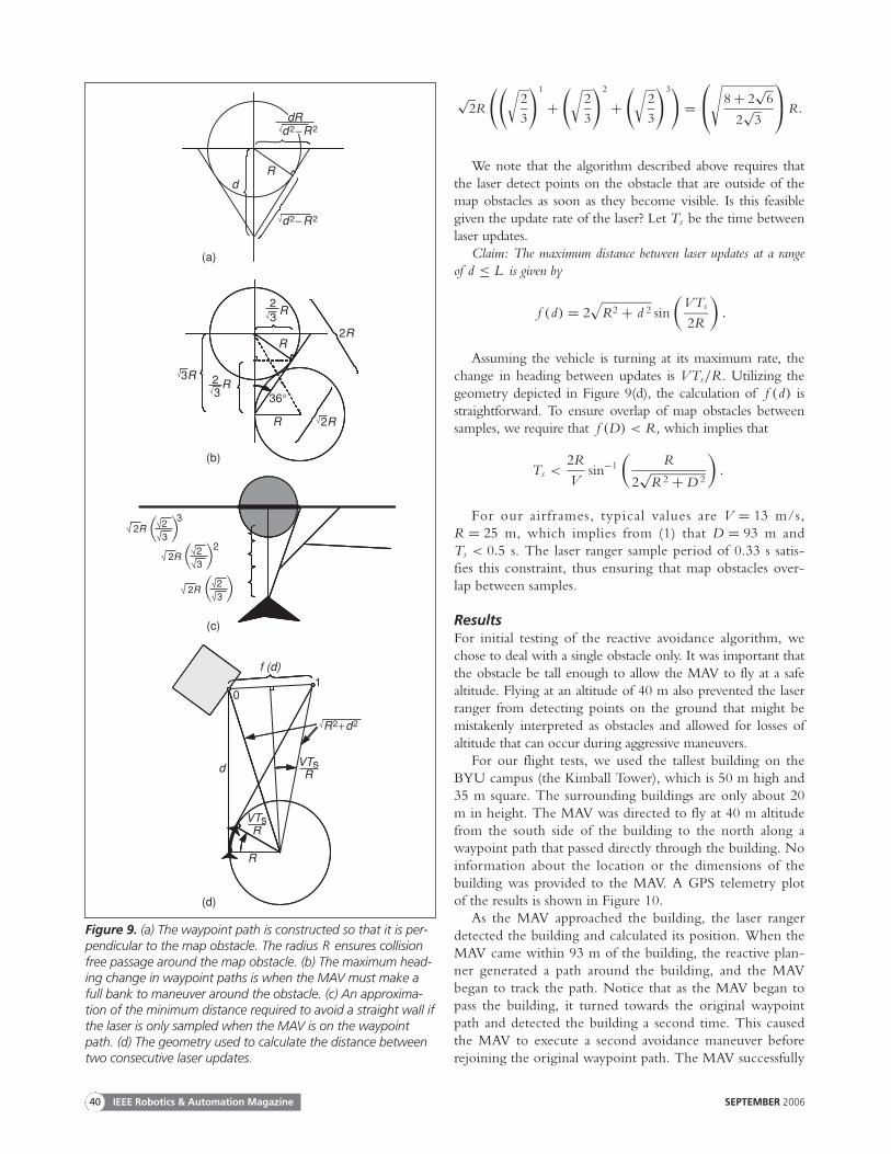
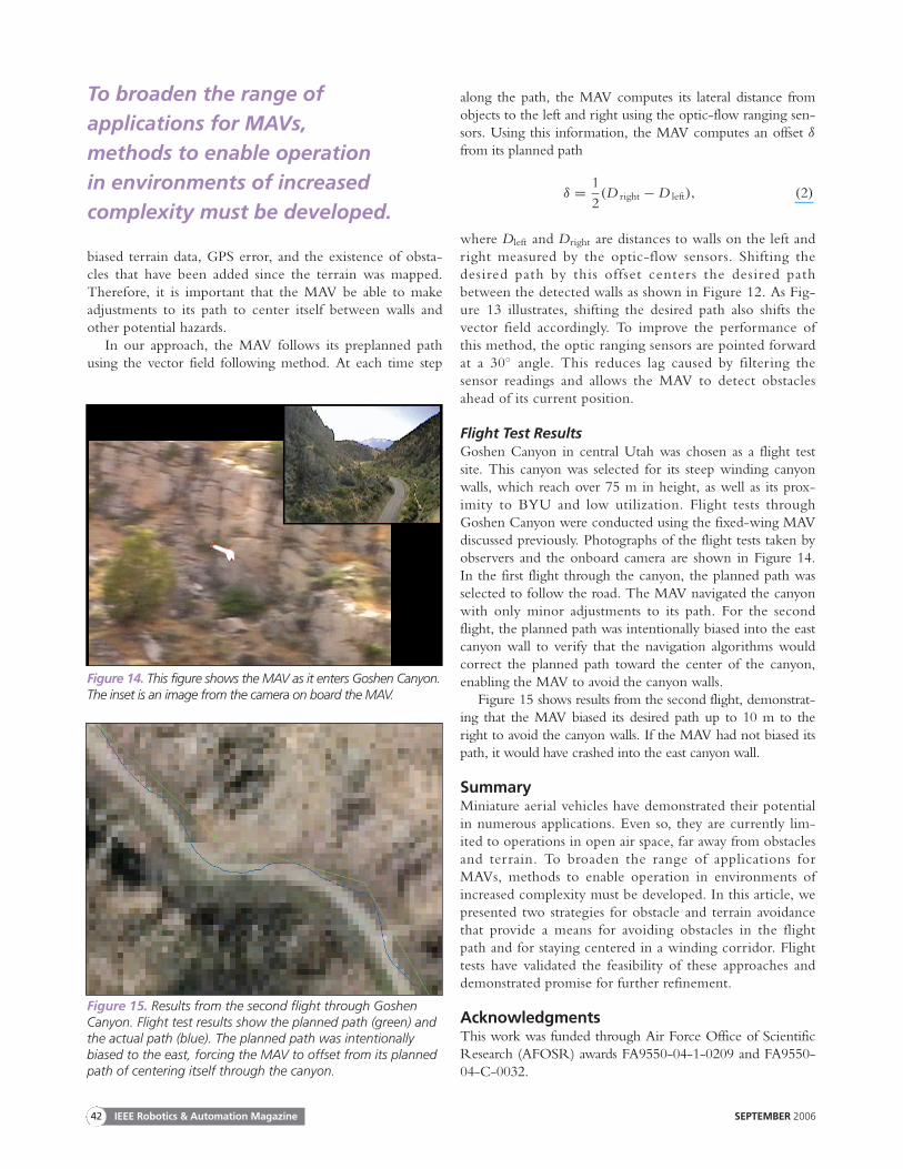
Flight Test Results Goshen Canyon in central Utah was chosen as a flight testsite. This canyon was selected for its steep winding canyonwalls, which reach over 75 m in height, as well as its prox-imity to BYU and low utilization. Flight tests throughGoshen Canyon were conducted using the fixed-wing MAVdiscussed previously. Photographs of the flight tests taken byobservers and the onboard camera are shown in Figure 14.In the first flight through the canyon, the planned path wasselected to follow the road. The MAV navigated the canyonwith only minor adjustments to its path. For the secondflight, the planned path was intentionally biased into the eastcanyon wall to verify that the navigation algorithms wouldcorrect the planned path toward the center of the canyon,enabling the MAV to avoid the canyon walls.
Figure 15 shows results from the second flight, demonstrat-ing that the MAV biased its desired path up to 10 m to theright to avoid the canyon walls. If the MAV had not biased itspath, it would have crashed into the east canyon wall.
SummaryMiniature aerial vehicles have demonstrated their potentialin numerous applications. Even so, they are currently lim-ited to operations in open air space, far away from obstaclesand terrain. To broaden the range of applications forMAVs, methods to enable operation in environments ofincreased complexity must be developed. In this article, wepresented two strategies for obstacle and terrain avoidancethat provide a means for avoiding obstacles in the flightpath and for staying centered in a winding corridor. Flighttests have validated the feasibility of these approaches anddemonstrated promise for further refinement.
Acknowledgments This work was funded through Air Force Office of ScientificResearch (AFOSR) awards FA9550-04-1-0209 and FA9550-04-C-0032.
IEEE Robotics & Automation Magazine SEPTEMBER 200642
Figure 15. Results from the second flight through GoshenCanyon. Flight test results show the planned path (green) andthe actual path (blue). The planned path was intentionallybiased to the east, forcing the MAV to offset from its plannedpath of centering itself through the canyon.
Figure 14. This figure shows the MAV as it enters Goshen Canyon.The inset is an image from the camera on board the MAV.
To broaden the range ofapplications for MAVs, methods to enable operation in environments of increasedcomplexity must be developed.

SEPTEMBER 2006 IEEE Robotics & Automation Magazine 43
KeywordsMiniature aerial vehicle, obstacle avoidance, terrain naviga-tion, autonomous flight.
References[1] J. Chahl, M. Srinivasan, and S. Zhang, “Landing strategies in honeybees
and applications to uninhabited airborne vehicles,” Int. J. Robot. Res.,vol. 23, no. 2, pp. 101–110, 2004.
[2] G. Barrows and C. Neely, “Mixed-mode VLSI optic flow sensors for in-flight control of a micro air vehicle,” in Proc. SPIE, San Diego, Aug.2000, pp. 52–63.
[3] F. Ruffier and N. Franceschini, “Visually guided micro-aerial vehicle:automatic take off, terrain following, landing and wind reaction,” inProc. 2004 IEEE Int. Conf. Robotics Automation, New Orleans, 2004, pp.2339–2346.
[4] J.-C. Zufferey and D. Floreano, “Toward 30-gram autonomous indooraircraft: Vision-based obstacle avoidance and altitude control,” in Proc.2005 IEEE Int. Conf. Robotics Automation, Barcelona, Apr. 2005, pp.2594–2599.
[5] G.L. Barrows, J.S. Chahl, and M.V. Srinivasan, “Biomimetic visual sens-ing and flight control,” Aeronaut. J., London: Royal Aeronaut. Soc., vol.107, no. 1069, pp. 159–168, 2003.
[6] Procerus Technologies [Online]. Available: http://procerusuav.com.[7] S.M. LaValle and J.J. Kuffner, “Randomized kinodynamic planning,”
Int. J. Robot. Res., vol. 20, no. 5, pp. 378–400, May 2001.[8] L.E. Kavraki, P. Svestka, J.-C. Latombe, and M. Overmars, “Probabilis-
tic roadmaps for path planning in high-dimensional configurationspaces,” IEEE Trans. Robot. Automat., vol. 12, no. 4, pp. 66–80, 1996.
[9] N.M. Amato and Y. Wu, “A randomized roadmap method for path andmanipulation planning,” in Proc. IEEE Int. Conf. Robotics Automation,Minneapolis, MN, 1996, pp. 113–120.
[10] S.M. LaValle, “Rapidly-exploring random trees: A new tool for pathplanning,” Computer Science Dept., Iowa State Univ., Tech. Rep. 98-11, Oct. 1998.
[11] E. Frazzoli, M.A. Dahleh, and E. Feron, “Real-time motion planningfor agile autonomous vehicles,” AIAA J. Guid., Contr. Dynam., vol. 25,no. 1, pp. 116–129, 2002.
[12] J.B. Saunders, B. Call, A. Curtis, R.W. Beard, and T.W. McLain, “Sta-tic and dynamic obstacle avoidance in miniature air vehicles,” in Proc.Infotech@Aerospace Conf., Sept. 2005, AIAA-2005-6950.
[13] E.P. Anderson, “Constrained extremal trajectories and unmanned airvehicle trajectory generation,” Master’s thesis, Brigham Young Univ.,Provo, Utah, Apr. 2002.
[14] D.R. Nelson, “Cooperative control of miniature air vehicles,” Master’sthesis, Brigham Young Univ., Provo, Utah, Dec. 2005.
[15] R. Skjetne, T. Fossen, and P. Kokotovic, “Robust output maneuveringfor a class of nonlinear systems,” Automatica, vol. 40, pp. 373–383, 2004.
[16] E.P. Anderson, R.W. Beard, and T.W. McLain, “Real time dynamictrajectory smoothing for uninhabited aerial vehicles,” IEEE Trans. Contr.Syst. Technol., vol. 13, no. 3, pp. 471–477, May 2005.
[17] S. Loizou, H. Tanner, V. Kumar, and K. Kyriakopoulos, “Closed loopmotion planning and control for mobile robots in uncertain environ-ments,” in Proc. 42nd IEEE Conf. Decision Control, 2003, pp.2926–2931.
Stephen Griffiths received his M.S. degree in mechanical engi-neering degree from Brigham Young University in April 2006.His master’s research investigated terrain navigation strategies forsmall unmanned aerial vehicles. He is currently employed in theintelligent and autonomous control systems group at ScientificSystems Company, Inc., Woburn, Massachusetts.
Jeff Saunders is a Ph.D. student in the Electrical andComputer Engineering Department at Brigham Young
University (BYU). He received a B.S. in electrical engi-neering from BYU in 2004. In summer 2006, he spenttime as a visiting researcher at the Air Force Research Lab-oratory Air Vehicles Directorate. He currently pursuesresearch in the area of obstacle and collision avoidance forunmanned aerial vehicles.
Andrew Curtis is a graduate student at Brigham YoungUniversity. He received his B.S. in electrical engineering inApril 2006 and is now pursuing an M.S. in electrical engi-neering. His current research focuses on path planning andtrajectory generation for miniature unmanned aerial vehicles.
Blake Barber is a graduate student in the mechanical engi-neering department at Brigham Young University (BYU). Hereceived a B.S. degree in mechanical engineering from BYUin 2005. He has been actively involved in researching andtesting new flight control algorithms and sensor platforms forminiature unmanned aerial vehicles. His research includes theuse of optic-flow sensors for range measurement, autonomouslanding, path following, and target localization.
Tim McLain is an associate professor in the mechanicalengineering department at Brigham Young University(BYU). He received an M.S. degree in mechanical engi-neering from BYU in 1987 and a Ph.D. in mechanicalengineering from Stanford University in 1995. He hasbeen actively involved in the control of air and underwatervehicles and robotic systems for the past 18 years. Duringthe summers of 1999 and 2000, he was a visiting scientistat the Air Force Research Laboratory. Since that time, hehas pursued research involving the modeling and control ofminiature unmanned aerial vehicles (UAVs), real-time tra-jectory generation for UAVs, and cooperative control ofUAV teams. He is a Senior Member of the IEEE andAIAA and is a member of the AIAA Unmanned SystemsProgram Committee.
Randy Beard is currently an associate professor in theDepartment of Electrical and Computer Engineering atBrigham Young University (BYU). He received his Ph.D.in electrical, computer, and systems engineering fromRensselaer Polytechnic Institute in 1995. He was a researchfellow at the Jet Propulsion Laboratory, California Instituteof Technology in 1997 and 1998. His research interests arein nonlinear control, multiple vehicle coordination, andautonomy for unmanned air vehicles (UAVs) and mobilerobots. He is the cofounder of the BYU MAGICC Lab thatconducts research in miniature UAVs and cooperative con-trol. He is a Senior Member of the IEEE and an associateeditor of IEEE Control Systems Magazine.
Address for Correspondence: Tim McLain, Department ofMechanical Engineering, Brigham Young University, 435 SCTB, Provo, UT 84602 USA. Phone +1 801 422 6537. E-mail: [email protected].