Three Phase Inverter with SetApp Configuration PN
72
Installation Guide Three Phase Inverter with SetApp Configuration PN: SEXXK-XXXXIXXXX For North America Version 1.0
-
Upload
khangminh22 -
Category
Documents
-
view
8 -
download
0
Transcript of Three Phase Inverter with SetApp Configuration PN

Installation Guide
Three Phase Inverter with SetApp ConfigurationPN: SEXXK-XXXXIXXXX
For North AmericaVersion 1.0

DisclaimersImportant NoticeCopyright © SolarEdge Inc. All rights reserved.No part of this document may be reproduced, stored in a retrieval system or transmitted, in any form or by any means, electronic, mechanical, photographic, magnetic or otherwise, without the prior written permission of SolarEdge Inc.The material furnished in this document is believed to be accurate and reliable. However, SolarEdge assumes no responsibility for the use of this material. SolarEdge reserves the right to make changes to the material at any time and without notice. You may refer to the SolarEdge web site (https://www.solaredge.com/us/) for the most updated version.All company and brand products and service names are trademarks or registered trademarks of their respective holders.Patent marking notice: see https://www.solaredge.com/us/patentThe general terms and conditions of delivery of SolarEdge shall apply.The content of these documents is continually reviewed and amended, where necessary. However, discrepancies cannot be excluded. No guarantee is made for the completeness of these documents.The images contained in this document are for illustrative purposes only and may vary depending on product models.
Disclaimers 1
Three Phase Inverter with SetApp Configuration
FCC ComplianceThis equipment has been tested and found to comply with the limits for a Class A digital device, pursuant to part 15 of the FCC Rules.These limits are designed to provide reasonable protection against harmful interference. This equipment generates, uses and can radiate radio frequency energy and, if not installed and used in accordance with the instructions, may cause harmful interference to radio communications. However, there is no guarantee that interference will not occur in a particular installation. If this equipment does cause harmful interference to radio or television reception, which can be determined by turning the equipment off and on, you are encouraged to try to correct the interference by one or more of the following measures:
Reorient or relocate the receiving antenna.
Increase the separation between the equipment and the receiver.
Connect the equipment into an outlet on a circuit different from that to which the receiver is connected.Consult the dealer or an experienced radio/TV technician for help.
Changes or modifications not expressly approved by the party responsible for compliance may void the user’s authority to operate the equipment.
Three Phase Inverter with SetApp Configuration
2 FCC Compliance

Revision History
Version 1.0 (Sep. 2021)Initial release
Revision History 3
Three Phase Inverter with SetApp Configuration

Contents
Disclaimers 1Important Notice 1FCC Compliance 2Revision History 3HANDLING AND SAFETY INSTRUCTIONS 6Safety Symbols Information 6IMPORTANT SAFETY INSTRUCTIONS / CONSIGNES DE SÉCURITÉ IMPORTANTES 7Photovoltaic Rapid Shutdown System Requirements 11Photovoltaic Hazard Control Application 13Chapter 1: Introducing the SolarEdge Power Harvesting System 15Power Optimizer 15Inverter 15Designer 16Monitoring Platform 16SetApp 16Installation Procedures 16Installation Equipment List 16Chapter 2: Installing the Power Optimizers 18Safety 18Package Contents 20Installation Guidelines 20Step 1: Mounting and Grounding the Power Optimizers 23Step 2: Connecting a PV module to a Power Optimizer 26Step 3: Connecting Power Optimizers in Strings 26Step 4: Verifying Proper Power Optimizer Connection 27Chapter 3: Installing the Inverter 29Package Contents 29Identifying the Inverter 29Inverter Interfaces 29Opening the Conduit Drill Guides 34Mounting the Inverter 35Chapter 4: Connecting AC and DC Strings to the Connection Unit 40Grid Connection Guidelines 40Connecting the PV Strings to the Connection Unit of the Inverter 41Connecting the AC Grid to the Connection Unit 43Chapter 5: Setting Up Communication with the Monitoring Platform 46Communication Options 46
Three Phase Inverter with SetApp Configuration
4 Revision History
Communication Connectors 48Removing the Inverter Cover 49Creating an Ethernet (LAN) Connection 49Creating an RS485 Bus Connection 53RS485 Bus Configuration 55Verifying the Connection 56Chapter 6: Activating, Commissioning and Configuring the System 57Step 1: Activating the Installation 57Step 2: Commissioning and Configuring the Installation 58Step 3: Verifying Proper Activation and Commissioning 60Reporting and Monitoring Installation Data 60Appendix A: Errors and Troubleshooting 63Identifying Errors 63Troubleshooting Communication 64Power Optimizer Troubleshooting 65Appendix B: Adding Optional Components 67AC Surge Protection Device (SPD) 67DC Surge Protection Device (SPD) 67Appendix C: Mechanical Specifications 68Dimensions of Inverter Mounting Bracket 69Support Contact Information 70
Revision History 5
Three Phase Inverter with SetApp Configuration

HANDLING AND SAFETY INSTRUCTIONSSafety Symbols InformationThe following safety symbols are used in this document. Familiarize yourself with the symbols and their meaning before installing or operating the system.
WARNING!Denotes a hazard. It calls attention to a procedure that, if not correctly performed or adhered to, could result in injury or loss of life. Do not proceed beyond a warning note until the indicated conditions are fully understood and met. AVERTISSEMENT!Dénote un risque: il attire l'attention sur une opération qui, si elle n'est pas faite ou suivi correctement, pourrait causer des blessures ou un danger de mort. Ne pas dépasser une telle note avant que les conditions requises soient totallement comprises et accomplies.CAUTION!Denotes a hazard. It calls attention to a procedure that, if not correctly performed or adhered to, could result in damage or destruction of the product. Do not proceed beyond a caution sign until the indicated conditions are fully understood and met.ATTENTION! Dénote un risque: il attire l'attention sur une opération qui, si elle n'est pas faite ou suivi correctement, pourrait causer un dommage ou destruction de l'équipement. Ne pas dépasser une telle note avant que les conditions requises soient totallement comprises et accomplies.NOTE
Denotes additional information about the current subject.
IMPORTANT SAFETY FEATUREDenotes information about safety issues.
HANDLING AND SAFETY INSTRUCTIONS 6
Three Phase Inverter with SetApp Configuration

IMPORTANT SAFETY INSTRUCTIONS / CONSIGNES DE SÉCURITÉ IMPORTANTESSAVE THESE INSTRUCTIONS / CONSERVEZ CES INSTRUCTIONS
Warning!To reduce the risk of injury, read all instructions in this document.
AVERTISSEMENT! Pour réduire le risque de blessure, lisez toutes les instructions de ce document.
WARNING! When servicing or replacing SolarEdge equipment, instructions in the SolarEdge Inverter Installation Guide must be followed to maintain the integrity of the PV hazard control system. SolarEdge Power Optimizers and/or inverters may only be replaced with SolarEdge Power Optimizers and/or inverters. Third party equipment is not compatible with SolarEdge equipment.
WARNING!Using this equipment in a manner not specified by SolarEdge in this document may impair the protection provided by this equipment. WARNING!The inverter cover must be opened only after switching the inverter ON/OFF/P switch located at the bottom of the inverter to OFF. This disables the DC voltage inside the inverter. Wait five minutes before opening the cover. Otherwise, there is a risk of electric shock from energy stored in the capacitors.
AVERTISSEMENT!
Ne pas ouvrir le couvercle de l'onduleur avant d'avoir coupé l'interrupteur situé en dessous de l'onduleur. Cela supprime les tensions CC et CA de l'onduleur. Attendre cinq minutes avant d’ouvrir le couvercle. Sinon, il y a un risque de choc électrique provenant de l'énergie stockée dans le condensateur.
WARNING!Before operating the inverter, ensure that the inverter is grounded properly. This product must be connected to a grounded, metal, permanent wiring system, or an equipment-grounding conductor must be run with the circuit conductors and connected to the equipment grounding terminal or lead on the product.
AVERTISSEMENT!
Avant d'utiliser l'onduleur monophasé, assurez-vous que l'onduleur est correctement mis à la terre. Ce produit doit être raccordé à un système de
Three Phase Inverter with SetApp Configuration
7 IMPORTANT SAFETY INSTRUCTIONS / CONSIGNES DE SÉCURITÉIMPORTANTES

câblage fixe, métallique, l'équipement-le conducteur de mise à la terre doit être exécuté avec les conducteurs de circuit et raccordé à l'équipement borne de mise à la terre ou de plomb sur le produit.
WARNING!Opening the inverter and repairing or testing under power must be performed only by qualified service personnel familiar with this inverter.
AVERTISSEMENT!
L’unité ne doit être ouverte que par un technicien qualifié dans le cadre de l'installation et de la maintenance.
WARNING!The Connection Unit meets all requirements for a code-compliant installation of this system. The DC Disconnect Switch disconnects both the positive and negative conductors.
AVERTISSEMENT!
Le sectionneur externe (inclus) repond aux exigences de conformité pour l’installation de ce système . Le coupeur CC ouvre les conducteurs positifs et négatifs.
WARNING!The inverter input and output circuits are isolated from the enclosure. This system does not include an isolation transformer and should be installed with an ungrounded PV array in accordance with the requirements of NEC Articles 690.35 and 690.43 National Electric Code, ANSI/NFPA 70, 2011 (and Canadian Electrical Code, Part I, for installations in Canada). Equipment grounding is the responsibility of the installer and must be performed in accordance with all applicable Local and National Codes.
AVERTISSEMENT!
Les circuits d’entrée et de sortie de l’onduleur sont isolés de l’enveloppe. Ce système n’inclut pas d’isolation galvanique (transformateur) et devra être installé sans mise à la terre du champ PV et en accord avec les articles 690.35 et 690.43 du National Electric Code (NEC), ANSI/NFPA 70, 2011 (et du Code Electrique Canadien, Partie 1, pour les installations faites au Canada). La mise à la terre des équipements est la responsabilité de l’installateur et doit être faite en accord avec les toutes les règles locales et nationales applicables.
IMPORTANT SAFETY INSTRUCTIONS / CONSIGNES DE SÉCURITÉIMPORTANTES 8
Three Phase Inverter with SetApp Configuration
WARNING!SafeDC complies with IEC60947-3 when installing the system with a worst case SafeDC voltage (under fault conditions) < 120V. The worst case voltage is defined as: Voc, max+ (String Length-1)*1V, where: Voc,max = Maximum Voc (at lowest temperature) of the PV modules in the string (for a string with multiple modules, use the max value) String Length = number of Power Optimizers in the string
WARNING!SolarEdge products can expose you to chemicals including antimony trioxide, which is known to the State of California to cause cancer. For more information, go to www.P65Warnings.ca.gov .AVERTISSEMENT!Les produits SolarEdge peut vous exposer à des agents chimiques, y compris trioxyde d'antimoine, identifiés par l'État de Californie comme pouvant causer le cancer. Pour de plus amples informations, prière de consulter www.P65Warnings.ca.gov.
CAUTION!This unit must be operated according to the technical specification datasheet provided with the unit.
ATTENTION!
Cette unité doit être utilisée selon les spécifications de fonctionnement, comme décrit dans la dernière fiche technique des spécifications.
CAUTION!HEAVY OBJECT. To avoid muscle strain or back injury, use proper lifting techniques, and if required - a lifting aid.ATTENTION!Objet lourd. Pour éviter la fatigue musculaire ou des blessures au dos, utilisez des techniques de levage appropriées et, si nécessaire - un auxiliaire de levage lors du retrait.
NOTEThis inverter is provided with an IMI (Isolation Monitor Interrupter) for ground fault protection.
NOTE
The symbol appears at grounding points on the SolarEdge equipment. This symbol is also used in this manual.
Three Phase Inverter with SetApp Configuration
9 IMPORTANT SAFETY INSTRUCTIONS / CONSIGNES DE SÉCURITÉIMPORTANTES

NOTESolarEdge inverters can be installed in sites with an alternative power source such as a generator. SolarEdge requires installing a physical or electronic interlock, which will signal to the inverter when the grid has been disconnected. Interlock procurement, installation, maintenance and support are the responsibility of the installer. Damage to the inverter due to incorrect interlock installation or use of an interlock that is incompatible with the SolarEdge system will render the SolarEdge warranty invalid.For more information on connecting an alternative power source to SolarEdge inverter, refer to https://www.solaredge.com/sites/default/files/se-inverter-support-of-voltage-sources.pdf.
IMPORTANT SAFETY INSTRUCTIONS / CONSIGNES DE SÉCURITÉIMPORTANTES 10
Three Phase Inverter with SetApp Configuration

Photovoltaic Rapid Shutdown System RequirementsWARNING!THIS PHOTOVOLTAIC RAPID SHUTDOWN SYSTEM (PVRSS) INCORPORATES ONE OR MORE PIECES OF EQUIPMENT THAT EXERCISE THE RAPID SHUTDOWN CONTROL OF PV SYSTEM CONDUCTORS REQUIRED BY SECTION 690.12 OF THE NEC (NFPA 70). OTHER EQUIPMENT INSTALLED IN OR ON THIS PV SYSTEM MAY ADVERSELY AFFECT THE OPERATION OF THIS PVRSS. IT IS THE RESPONSIBILITY OF THE INSTALLER TO ENSURE THAT THE COMPLETED PV SYSTEM MEETS THE APPLICABLE RAPID SHUT DOWN FUNCTIONAL REQUIREMENTS. THIS EQUIPMENT MUST BE INSTALLED ACCORDING TO THE MANUFACTURER’S INSTALLATION INSTRUCTIONS.
SolarEdge inverters and power optimizers installed together form a photovoltaic rapid shutdown system (PVRSS). All inputs and outputs of the inverter and power optimizers comply with photovoltaic rapid shutdown requirements for controlled conductors both inside and outside the array boundary. To form a PV rapid shutdown system, no more than 30 power optimizers should be installed in series. Each power optimizer will output around 1 Vdc when rapid shutdown is initiated. Rapid shutdown time limit is 30 Sec. This SolarEdge system is compatible with the Grid support interactive compatible functionality. All DC and AC conductors served by the power optimizers and inverters are controlled by the photovoltaic rapid shutdown system. The AC branch circuit conductors serving the inverter may remain energized until the AC service panel is de-energized. Installers must provide signage complying with Section 690.56(C) of the NEC (NFPA 70).Buildings with rapid shutdown PV systems, complying with NEC 690.56(C), shall have permanent labels as described in 690.56(C)(1) through (C)(2):
(1)(a) For PV systems that shut down the array and conductors leaving the array: The title "SOLAR PV SYSTEM EQUIPPED WITH RAPID SHUTDOWN" shall utilize capitalized characters with a minimum height of 3/8 in. in black on yellow background, and the remaining characters shall be capitalized with a minimum height of 3/16 in. in black on white background.
Three Phase Inverter with SetApp Configuration
11 Photovoltaic Rapid Shutdown System Requirements

(2) A rapid shutdown switch shall have a label located on or no more than 3 ft from the switch that includes this wording. The label shall be reflective, with all letters capitalized and having a minimum height of 3/8 in., in white on red background.
Photovoltaic Rapid Shutdown System Requirements 12
Three Phase Inverter with SetApp Configuration

Photovoltaic Hazard Control ApplicationSolarEdge commercial optimizers and inverters have been evaluated and listed to UL 3741 and may be used to form a PV hazard control system that utilizes SolarEdges PV rapid shutdown system to comply with NEC 690.12. Multiple modules may be connected in series to the optimizer input without exceeding the input voltage rating of the optimizer (125V dc). The diagram below depicts a typical PV hazard control system using multiple PV modules in series connected to optimizers. Installation instructions, warnings and cautions in this installation guide must be followed to comply with Local codes . The PVRSS shall be installed by qualified persons in accordance with the installation instructions and all applicable installation codes and standards.
Power optimizer models P followed by 600-1100 with input voltage up to 125Vdc when used with SolarEdge three phase inverters and DC safety switches listed and marked with PVRSS may be used to form a Listed Photovoltaic Hazard Control System.
Three Phase Inverter with SetApp Configuration
13 Photovoltaic Hazard Control Application

WARNING!Upon servicing replacing equipment, instructions in this installation guide must be followed to maintain the integrity of the PV hazard control system. SolarEdge commercial optimizers and three phase inverters should only be replaced with SolarEdge commercial optimizers and inverters. Third party equipment is not compatible.
Photovoltaic Hazard Control Application 14
Three Phase Inverter with SetApp Configuration

Chapter 1: Introducing the SolarEdge Power Harvesting SystemThe SolarEdge power harvesting solution maximizes the power output from any type of solar photovoltaic (PV) installation while reducing the average cost per watt. The following sections describe each of the system’s components.
Figure 1: The SolarEdge power – harvesting system components
Power OptimizerThe Power Optimizers are DC-DC converters connected to PV modules in order to maximize power harvesting by performing independent Maximum Power Point Tracking (MPPT) at the module level.Each Power Optimizer also transmits module performance data over the DC power line to the inverter.
InverterThe inverter efficiently converts DC power from the modules into AC power that can be fed into the main AC service of the site and from there to the grid. The inverter also receives the monitoring data from each power optimizer and transmits it to a central server (the monitoring platform; requires Internet connection). The Connection Unit has a manually operated switch for disconnecting the DC power of a SolarEdge system. The Connection Unit is located below the inverter and is connected to the inverter with AC and DC wires.
Three Phase Inverter with SetApp Configuration
15 Chapter 1: Introducing the SolarEdge Power Harvesting System

DesignerDesigner recommends inverter and Power Optimizer selection per site size and enables report generation. You can create a project in Designer and export the site design with the string layout to the monitoring platform.
Monitoring PlatformThe monitoring platform enables monitoring the technical and financial performance of one or more SolarEdge sites. It provides past and present information on the system performance both at the system and module levels.
SetAppSetApp is a mobile application that enables activating and configuring the inverter through a smartphone or any mobile device.
Installation ProceduresThe following procedures are used for installing and setting up a new SolarEdge site. Some procedures, may also apply to modify an existing site.
1. Connecting Power Optimizers in Strings, page 1 2. Recording power optimizer serial numbers (optional), page 61 3. Mounting the inverter, page 35 4. Activating, commissioning and configuring the system, page 57
5. Connecting the inverter to the monitoring platform, page 62
Installation Equipment ListStandard tools can be used during the installation of the SolarEdge system. The following is a recommendation of the equipment needed for installation:
4 mm Allen torque screwdriver for the inverter enclosure screws
Standard torque flat-head screwdrivers set
Non-contact voltage detector
Cordless drill (with a torque clutch) or screwdriver and bits suitable for the surface on which the inverter and optimizers will be installed and for opening the Connection Unit drill guides. Use of an impact driver is not allowed.Mounting hardware (stainless bolts, nuts, and washers) for attaching:
Chapter 1: Introducing the SolarEdge Power Harvesting System 16
Three Phase Inverter with SetApp Configuration

the mounting brackets to the mounting surface
the power optimizer to the racking (not required for smart modules)
Tools:Wire cutters
Wire strippers
Voltmeter
Mobile phone with latest SetApp version
For installing the communication options, you may also need the following:For Ethernet:
CAT6 twisted pair Ethernet cable with RJ45 connector
If using a CAT6 cable spool: RJ45 plug and RJ45 crimper
For RS485 / CAN Bus :Four- or six-wire shielded twisted pair cable
Watchmaker precision screwdriver set
Three Phase Inverter with SetApp Configuration
17 Installation Equipment List

Chapter 2: Installing the Power OptimizersSafety
WARNING!The metallic enclosure of the Power Optimizer must be grounded in accordance with the product's listing and local and national codes.
AVERTISSEMENT!
L'enceinte métallique de l’optimiseur de puissance doit être mise à la terre en accord avec les régulations locales et nationales.
WARNING!When modifying an existing installation, turn OFF the inverter ON/OFF/P switch, the DC Disconnect Switch and the AC circuit breaker on the main AC distribution panel.
AVERTISSEMENT!
Avant de faire ces étapes, éteignez l'onduleur monophasé en mettant sur OFF l'interrupteur ON/OFF situé au bas de l'onduleur.
CAUTION!Power Optimizers are IP68/NEMA6P rated. Choose a mounting location where optimizers will not be submerged in water.
ATTENTION!
Les optimiseurs de puissances sont compatibles à la norme IP68/NEMA6P. Choisissez le lieu de montage tel que l’optimiseur ne puisse pas être submergé par l’eau.
CAUTION!This unit must be operated according to the operating specifications provided with the unit.
ATTENTION!
Cette unité doit être opérée suivant les instructions trouvées dans le manuel fourni avec le produit.
CAUTION!Cutting the Power Optimizer input or output cable connector is prohibited and will void the warranty.
ATTENTION!
Sectionner les cables d’entrées ou de sortie de l’optimiseur est interdit et annule sa garantie.
Chapter 2: Installing the Power Optimizers 18
Three Phase Inverter with SetApp Configuration

CAUTION!All PV modules must be connected to a Power Optimizer.ATTENTION!Tous les modules doivent être connectés à un optimiseur de puissance.
CAUTION!If you intend to mount the Power Optimizers directly to the module or moduleframe, first consult the module manufacturer for guidance regarding the mounting location and the impact, if any, on module warranty. Drilling holes inthe module frame should be done according to the module manufacturerinstructions.ATTENTION!Pour installation à même le module ou la monture du module, consultez d'abord le fabricant du module sur la position et son impact sur la garantie du module. Le perçage de trous dans le cadre du module devra se faire suivant lesinstructions du fabricant.IMPORTANT SAFETY FEATUREModules with SolarEdge Power Optimizers are safe. They carry only a low safetyvoltage before the inverter is turned ON. As long as the Power Optimizers arenot connected to the inverter or the inverter is turned OFF, each PowerOptimizer will output a safe voltage of 1V.
CAUTION!Installing a SolarEdge system without ensuring compatibility of the moduleconnectors with the Power Optimizer connectors may be unsafe and could cause functionality problems such as ground faults, resulting in inverter shut down. To ensure mechanical compatibility of the SolarEdge Power Optimizers’connectors with the PV modules’ connectors to which they are connected:
Use identical connectors from the same manufacturer and of the same typeon both the Power Optimizers and on the modules; orVerify that the connectors are compatible in the following way:The module connector manufacturer should explicitly verify compatibilitywith the SolarEdge Power Optimizer connector; and the Inverter DC inputconnectors.A third-party test report by one of the listed external labs (TUV, VDE, BureauVeritas UL, CSA, InterTek) should be obtained, verifying the compatibility ofthe connectors.
ATTENTION!
Three Phase Inverter with SetApp Configuration
19 Safety
Les connecteurs du module doivent être mécaniquement compatibles avec les optimiseurs de puissance. Sinon, le système SolarEdge installé peut être dangereux ou causer des problèmes fonctionnels, tels que les défauts de terre, qui peuvent provoquer un arrêt de l’onduleur. Afin d'assurer la compatibilité mécanique entre les optimiseurs de puissance SolarEdge et les modules auxquels ils sont connectés:.
Utiliser des connecteurs identiques du même fabricant et du même type aussi bien pour les optimiseurs de puissance que pour les modules. Vérifiez que les connecteurs sont compatibles de la manière suivante:Le fabricant du connecteur doit explicitement vérifier la compatibilité avec le connecteur SolarEdge.Un rapport de test de tierce partie doit être effectué par l’un des laboratoires externes indiqués ci-dessous:(TUV, VDE, Bureau Veritas UL, CSA,Intertek), qui vérifiera la compatibilité des connecteurs.
Package ContentsPower Optimizers
Stainless steel grounding lock washers
Installation GuidelinesFor the minimum and maximum number of Power Optimizers in a string (stringlength), see the Power Optimizer datasheets. Refer to the Designer for string lengthverification. The Designer is available on the SolarEdge website at:https://www.solaredge.com/us/products/installer-tools/designer#/.Do not use extension cables between a module and a Power Optimizer, betweentwo modules connected to the same Power Optimizer, or between two PowerOptimizers other than in the following cases:Between a Power Optimizer and a module:
Extension cables of up to 6 ft / 1.8 m are allowed for all Power Optimizers (3 ft /0.9 m for DC+, and 3 ft / 0.9 m for DC -).P-Series Power Optimizers with the 4-type suffix in their part number (Pxxx-4xxxxxx) and the Mxxxx-Series - extension cables of up to 52 ft / 16 m can beinstalled per Power Optimizer (26 ft / 8 m for DC+, and 26 ft / 8 m for DC-).
Chapter 2: Installing the Power Optimizers 20
Three Phase Inverter with SetApp Configuration
ATTENTION!

Between two Power Optimizers or between a Power Optimizer and the inverter:Extension cables can be installed between Power Optimizers only from row to row, around obstacles or pathways within a row and from the end of the string to the inverter. The total length of the extension cables may not exceed the following values:
Single Phase Inverters Three Phase Inverters
All - 1000 ft / 300 mSE9KUS, SE20KUS - 300 m / 1000 ftSE14.4KUS, SE17.3KUS, SE33.3KUS, SE40KUS -700 m / 2300 ft
Frame-mounted Power Optimizers are mounted directly on the module frame, regardless of racking system (rail-less or with rails). For installation of frame-mounted Power Optimizers, refer to http://www.solaredge.com/sites/default/files/installing_frame_mounted_power_optimizers.pdf.The Power Optimizer can be placed in any orientation.
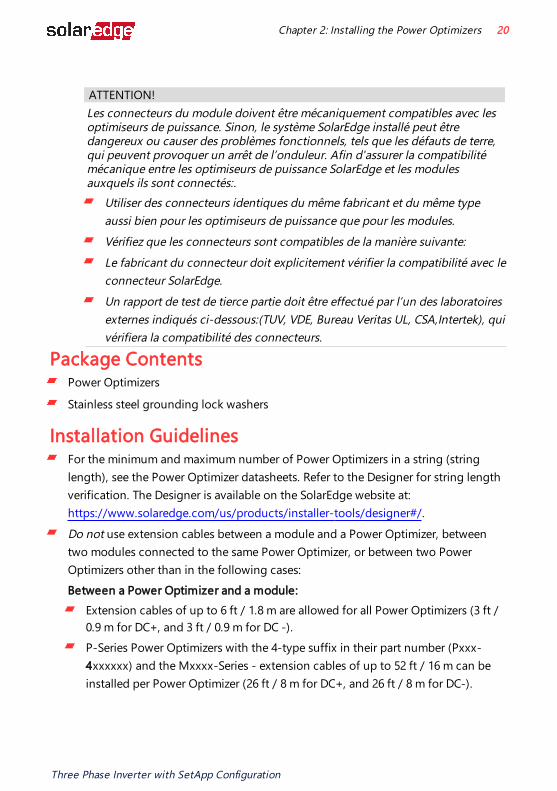
If connecting more modules than Power Optimizer inputs in parallel, use a branch cable. Some commercial Power Optimizer models have a dual input.Position the Power Optimizer close enough to its module so that their cables can be connected.Make sure to use Power Optimizers that have the required output and input conductor length.Completely shaded modules may cause their Power Optimizers to temporarily shut down. This will not affect the performance of the other Power Optimizers in the string, as long as the minimum number of unshaded Power Optimizers connected in a string of modules is met. If under typical conditions fewer than the minimum Power Optimizers are connected to unshaded modules, add more Power Optimizers to the string. To allow for heat dissipation, maintain clearance shown in Equipment grounding tightening torques: 4-6 AWG: 45 lb-in, 8 AWG: 40 lb-in, 10-14 AWG: 35 lb-in.
Three Phase Inverter with SetApp Configuration
21 Installation Guidelines
All Power Optimizers, except for the P860 and P960 Power Optimizers
P860, P960 and M1600 Power Optimizers
Figure 2: Power Optimizers clearance
When installing PV modules in a confined space such as Building-integrated photovoltaic (BIPV) modules, ventilation measures may be required to ensure that the Power Optimizers are not exceeding the maximum temperatures stated in their specifications.
Chapter 2: Installing the Power Optimizers 22
Three Phase Inverter with SetApp Configuration

Step 1: Mounting and Grounding the Power Optimizers For each of the Power Optimizers(1):
1. Determine the Power Optimizer mounting location and use the Power Optimizer mounting brackets to attach the Power Optimizer to the support structure (See Figure 3). It is recommended to mount the Power Optimizer in a location protected from direct sunlight. For frame-mounted Power Optimizers follow the instructions supplied with the optimizers, or refer to https://www.solaredge.com/sites/default/files/installing_frame_mounted_power_optimizers.pdf.
2. If required, mark the mounting hole locations and drill holes.
CAUTION!Drilling vibrations may damage the Power Optimizer and will void the warranty. Use a torque wrench or an electric drill with adjustable clutch that meets the mounting torque requirements. Do not use impact drivers for mounting the Power Optimizer.Do not drill through the Power Optimizer or through the mounting holes.
ATTENTION!Les vibrations résultant du perçage peuvent endommager l’optimiseur de puissance et annulera la garantie. Utilisez une clé dynamométrique ou une perceuse électrique avec embrayage adaptable compatible avec les moments indiqués. Ne pas utiliser des tournevis à percussion pour fixer l’optimiseur. Ne pas percer à travers l’optimiseur de puissance ou ses trous de fixation.
3. Attach each Power Optimizer to the rack using M6 (1/4'')or M8 stainless steel bolts, nuts and washers or other mounting hardware. Apply torque of 6.5-7 lb*ft/9-10 N*m.For 3NA series power optimizes, SolarEdge recommends mounting the Power Optimizer on a rail with the smooth side facing out, so that the Power Optimizer body will prevent its rotation.
(1)Not applicable to smart modules.
Three Phase Inverter with SetApp Configuration
23 Step 1: Mounting and Grounding the Power Optimizers

4. Use the following methods(1) to ground the Power Optimizer:
WARNING!The metallic enclosure of the Power Optimizer must be grounded in accordance with the requirements of the local and national codes.
AVERTISSEMENT!L'enceinte métallique de l’optimiseur de puissance doit être mise à la terre en accord avec les régulations locales et nationales.
For mounting on a grounded metal rail: Use the provided 5/16'' stainless steel grounding star washer between the railing and the flat side of the mounting bracket. The grounding washer should break through the anodize coating of the railing to ensure low resistive connection. Apply a torque of 9.5 N*m / 7 lb*ft.
Figure 3: Power Optimizer installation and grounding using a star washer
(1)These methods have been evaluated by a nationally recognized testing laboratory as part of the Power Optimizer evaluation. The SolarEdge-supplied grounding lug kit has been evaluated only for use with SolarEdge power optimizers. It is not intended or listed to be used as a general purpose grounding lug with other electrical equipment.
Chapter 2: Installing the Power Optimizers 24
Three Phase Inverter with SetApp Configuration
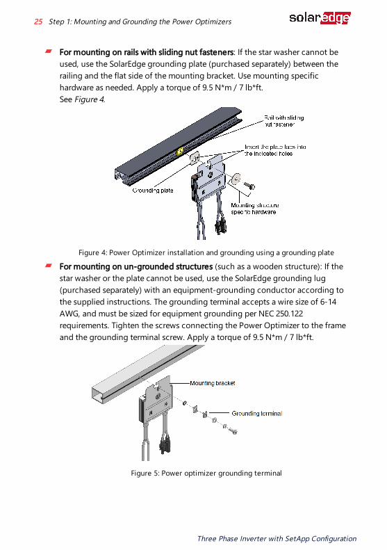
For mounting on rails with sliding nut fasteners: If the star washer cannot be used, use the SolarEdge grounding plate (purchased separately) between the railing and the flat side of the mounting bracket. Use mounting specific hardware as needed. Apply a torque of 9.5 N*m / 7 lb*ft.See Figure 4.
Figure 4: Power Optimizer installation and grounding using a grounding plate
For mounting on un-grounded structures (such as a wooden structure): If the star washer or the plate cannot be used, use the SolarEdge grounding lug (purchased separately) with an equipment-grounding conductor according to the supplied instructions. The grounding terminal accepts a wire size of 6-14 AWG, and must be sized for equipment grounding per NEC 250.122 requirements. Tighten the screws connecting the Power Optimizer to the frame and the grounding terminal screw. Apply a torque of 9.5 N*m / 7 lb*ft.
Figure 5: Power optimizer grounding terminal
Three Phase Inverter with SetApp Configuration
25 Step 1: Mounting and Grounding the Power Optimizers

5. Verify that each Power Optimizer is securely attached to the module support structure.
6. Record Power Optimizer serial numbers and locations, as described in Reporting and Monitoring Installation Data on page 60.
Step 2: Connecting a PV module to a Power OptimizerNOTEImproper wiring may cause electrical faults in a PV system. To avoid electrical faults, verify proper locking of connectors and avoid cable tension and friction. Proper planning, materials and installation reduce the risk of electric arcs, short-circuits and ground faults in the PV system.NOTEImages are for illustration purposes only. Refer to the label on the product to identify the plus and minus input and output connectors.
For each of the Power Optimizers:Connect the Plus (+) output connector of the module to the Plus (+) input connector of the Power Optimizer.Connect the Minus (-) output connector of the module to the Minus (-) input connector of the Power Optimizer.
Figure 6: S-Series (left) and P-Series (right) Power Optimizer connectors
Step 3: Connecting Power Optimizers in StringsYou can construct parallel strings of unequal length, that is, the number of Power Optimizers in each string does not have to be the same. The minimum and maximum string lengths are specified in the power datasheets. Refer to the SolarEdge Site Designer for string length verification.
Chapter 2: Installing the Power Optimizers 26
Three Phase Inverter with SetApp Configuration

IMPORTANT SAFETY FEATUREFor a compliant PV Rapid Shutdown (PVRSS) installation, use no more than 30 Power Optimizers per string. Enabling PVRSS from the inverter menu is only required if the installed Power Optimizers were manufactured before 2015, otherwise it is enabled by default.
NOTE The DC bus of each unit is separate and not shared for all units. Therefore, in addition to following the inverter design rules, each unit should follow the unit design rules as detailed in the Technical Specifications.
1. Connect the Minus (-) output connector of the string’s first Power Optimizer to the Plus (+) output connector of the string’s second Power Optimizer.
2. To minimize electromagnetic interference (EMI), make sure to minimize the distance between the positive and negative DC cables.
For detailed instructions, see: https://www.solaredge.com/sites/default/files/se-emi-performance-application-note.pdf.
3. Connect the rest of the Power Optimizers in the string.
Figure 7: Power Optimizers connected in series
4. If you intend to monitor the installation, using the SolarEdge Monitoring platform, record the physical location of each Power Optimizer, as described in Creating Logical and Physical Layout using Installation Information on page 61.
Step 4: Verifying Proper Power Optimizer ConnectionWhen a module is connected to a Power Optimizer, the Power Optimizer outputs a safe voltage of 1V (±0.1V). Therefore, the total string voltage should equal 1V times the number of Power Optimizers connected in series in the string. For example, if 10 Power
Three Phase Inverter with SetApp Configuration
27 Step 4: Verifying Proper Power Optimizer Connection

Optimizers are connected in a string, then 10V should be produced.Make sure the PV modules are exposed to sunlight during this process. The Power Optimizer will only turn ON if the PV module provides at least 2W. In SolarEdge systems, due to the introduction of Power Optimizers between the PV modules and the inverter, the short circuit current ISC and the open circuit voltage VOC hold different meanings from those in traditional systems. For more information about the SolarEdge system’s string voltage and current, refer to the VOC and ISC in SolarEdge Systems Technical Note, available on the SolarEdge website at: https://www.solaredge.com/sites/default/files/isc_and_voc_in_solaredge_sytems_technical_note.pdf
To verify proper Power Optimizer connection:Measure the voltage of each string individually before connecting it to the other strings or to the inverter. Verify correct polarity by measuring the string polarity with a voltmeter. Use a voltmeter with at least 0.1V measurement accuracy.
NOTESince the inverter is not yet operating, you may measure the string Voltage and verify correct polarity on the DC wires inside the Connection Unit.
For troubleshooting Power Optimizer operation problems, refer to Power Optimizer Troubleshooting on page 65.Proper Power Optimizer connection can also be verified in the Designer application. For more information, refer to https://www.solaredge.com/products/installer-tools/designer#/.
Chapter 2: Installing the Power Optimizers 28
Three Phase Inverter with SetApp Configuration

Chapter 3: Installing the Inverter Package Contents
Mounting bracket kit
Quick installation guide
Warranty card
Safety instructions page
Technical Specifications page
Identifying the InverterRefer to the sticker on the inverter that specifies its Serial Number and its Electrical Ratings. Provide the serial number when contacting SolarEdge support. The serial number is also required when opening a new site in the monitoring platform.
Inverter InterfacesFigure 8 shows an inverter with a Connection Unit, located at the bottom of the inverter.
NOTEThe Connection Unit is applicable based on the inverter model and country of installation.
Figure 8: Inverter front view
Figure 9 shows the inverter connectors and components, located at the bottom of the inverter.
Three Phase Inverter with SetApp Configuration
29 Chapter 3: Installing the Inverter
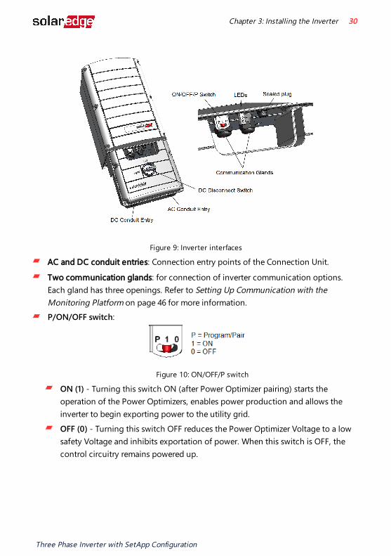
Figure 9: Inverter interfaces
AC and DC conduit entries: Connection entry points of the Connection Unit.
Two communication glands: for connection of inverter communication options. Each gland has three openings. Refer to Setting Up Communication with the Monitoring Platform on page 46 for more information.P/ON/OFF switch:
Figure 10: ON/OFF/P switch
ON (1) - Turning this switch ON (after Power Optimizer pairing) starts the operation of the Power Optimizers, enables power production and allows the inverter to begin exporting power to the utility grid.OFF (0) - Turning this switch OFF reduces the Power Optimizer Voltage to a low safety Voltage and inhibits exportation of power. When this switch is OFF, the control circuitry remains powered up.
Chapter 3: Installing the Inverter 30
Three Phase Inverter with SetApp Configuration
P - Moving and releasing the switch allows viewing system information via the LEDs, and performing the following functions:
P Position Duration
Function Comments
Switch moved to P for 2 seconds, then released.
Displays (via LEDs) production information for 5 seconds, or error type indications (if exist) for 5 seconds.Activates the Wi-Fi access point for connecting to the SetApp
While the switch is in P, all LEDs are ON.When the switch is released all LEDs turn OFF for 0.5 sec and then display the production or error indication.
Switch moved to P for more than 5 seconds, then released.
Starts pairing Pairing is indicated by all 3 LEDs blinking simultaneously.
LEDs
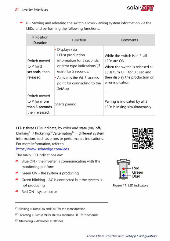
LEDs: three LEDs indicate, by color and state (on/ off/ blinking(1)/ flickering(2)/alternating(3)), different system information, such as errors or performance indications. For more information, refer to https://www.solaredge.com/leds.The main LED indications are:
Blue ON - the inverter is communicating with the monitoring platformGreen ON - the system is producing
Green blinking - AC is connected but the system is not producing Red ON - system error
Figure 11: LED indicators
(1)Blinking = Turns ON and OFF for the same duration
(2)Flickering = Turns ON for 100 ms and turns OFF for 5 seconds
(3)Alternating = Alternate LED flashes
Three Phase Inverter with SetApp Configuration
31 Inverter Interfaces

The following table describes system performance information by LED color and ON/OFF/P switch position.
IndicationON/
OFF/ PSwitch Position
LED ColorComment
Red Green Blue
Power Optimizers not paired
ON (1)
OFF BlinkingS_OK: ONNo S_OK: OFF
S_OK: ONcommunication with the monitoring platform is established.
Pairing Blinking Blinking Blinking Wake-up/ Grid Monitoring
OFF Blinking Blinking
System Producing OFF ON
S_OK: ONNo S_OK: OFF
For detailed percentage of production, refer to the following table.
Night mode (no production)
OFF FlickeringS_OK: ONNo S_OK: OFF
Inverter is OFF (Safe DC)
OFF (0)
OFF BlinkingS_OK: ONNo S_OK: OFF
Inverter is OFF (DC not safe) Blinking Blinking
S_OK: ONNo S_OK: OFF
Inverter configurationor reboot
ON / P ON ON ON
Inverter firmware upgrade
ON / P Alternating Alternating AlternatingThe upgrade process can take up to 5 minutes
Error Any ONON/ OFF/ Blinking/ Flickering
ON/ OFF /Blinking
Refer to Errors and Troubleshooting on page 63
Chapter 3: Installing the Inverter 32
Three Phase Inverter with SetApp Configuration
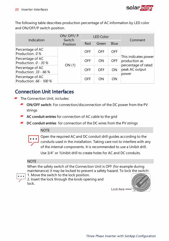
The following table describes production percentage of AC information by LED color and ON/OFF/P switch position.
IndicationON/ OFF/ P
Switch Position
LED ColorComment
Red Green BluePercentage of AC Production: 0 %
ON (1)
OFF OFF OFFThis indicates power production as percentage of rated peak AC output power
Percentage of AC Production: 0 - 33 % OFF ON OFF
Percentage of AC Production: 33 - 66 % OFF OFF ON
Percentage of AC Production: 66 - 100 % OFF ON ON
Connection Unit InterfacesThe Connection Unit, includes:
ON/OFF switch: For connection/disconnection of the DC power from the PV stringsAC conduit entries for connection of AC cable to the grid
DC conduit entries for connection of the DC wires from the PV strings
NOTEOpen the required AC and DC conduit drill guides according to the conduits used in the installation. Taking care not to interfere with any of the internal components. It is recommended to use a Unibit drill.Use 3/4” or 1Unibit drill to create holes for AC and DC conduits.
NOTEWhen the safety switch of the Connection Unit is OFF (for example during maintenance) it may be locked to prevent a safety hazard. To lock the switch: 1. Move the switch to the lock position. 2. Insert the lock through the knob opening and lock.
Three Phase Inverter with SetApp Configuration
33 Inverter Interfaces

Opening the Conduit Drill GuidesThis step may be performed before mounting the inverter.
To open the conduit drill guides: 1. Move the DC Disconnect Switch and the inverter ON/OFF switch to OFF.
2. Loosen the screws on the front cover of the Connection Unit, as shown below:
Figure 12: Opening the Connection Unit cover
3. Remove the Connection Unit cover. 4. Open the required conduit drill guides according to the conduits used in the
installation: The drill guides are located at the bottom, right, left and back sides of the enclosure, each with two sizes: ¾'' and 1''. Open the required drill guides, taking care not to interfere with any of the internal components. It is recommended to use a Unibit drill.
Chapter 3: Installing the Inverter 34
Three Phase Inverter with SetApp Configuration
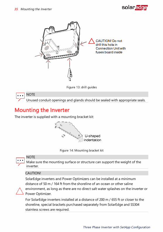
Figure 13: drill guides
NOTEUnused conduit openings and glands should be sealed with appropriate seals.
Mounting the InverterThe inverter is supplied with a mounting bracket kit:
Figure 14: Mounting bracket kit
NOTEMake sure the mounting surface or structure can support the weight of the inverter.
CAUTION!SolarEdge inverters and Power Optimizers can be installed at a minimum distance of 50 m / 164 ft from the shoreline of an ocean or other saline environment, as long as there are no direct salt water splashes on the inverter or Power Optimizer.For SolarEdge inverters installed at a distance of 200 m / 655 ft or closer to the shoreline, special brackets purchased separately from SolarEdge and SS304 stainless screws are required.
Three Phase Inverter with SetApp Configuration
35 Mounting the Inverter

ATTENTION!
Les onduleurs SolarEdge peuvent être installés à une distance minimum de 50m de la ligne d'eau de l'océan ou autre environnement salin, tant qu'il n'y a pas d'éclaboussements d'eau salée directs sur l'onduleur.Pour les onduleurs SolarEdge installés à une distance de 200 m ou moins du rivage, des supports spéciaux achetés séparément auprès de SolarEdge et des vis inox SS304 sont nécessaires.
1. Determine the inverter mounting location, on a wall, rails, stud framing or pole. It is recommended to mount the inverter in a location protected from direct sunlight.
NOTETo avoid wobbly installation of the inverter on rails or stud framing, use a supporting rail on the back of the DC Safety Unit (see Figure 15).
Figure 15: Supporting rail on the back of the DC Safety Unit
2. To allow proper heat dissipation, maintain the following minimum clearance areas between the inverter and other objects as described at: https://www.solaredge.com/sites/default/files/se-clearance-guidelines-for-multiple-inverter-mounting.pdfVerify that the fan, located at the bottom of the inverter, is not blocked and that air can flow freely.
Chapter 3: Installing the Inverter 36
Three Phase Inverter with SetApp Configuration

Figure 16: Inverter fan - airflow
CAUTION!Do not block the airflow from the inverter.
To mount the inverter: 1. Position the mounting bracket against the wall/pole and mark the drilling hole
locations (refer to Mechanical Specifications on page 1 for inverter and mounting bracket dimensions).
2. Drill at least two holes and mount the bracket to the mounting surface. Verify that the bracket is firmly attached to the mounting surface.
3. Hang the inverter on the bracket (See Figure 17): a. Lift the inverter from the sides, or hold it at the top and bottom. Do not lift
holding the Connection Unit as it may be damaged. b. Lower the inverter onto the U-shaped indentations of the mounting bracket. Let
the inverter lay flat against the wall or pole
Three Phase Inverter with SetApp Configuration
37 Mounting the Inverter
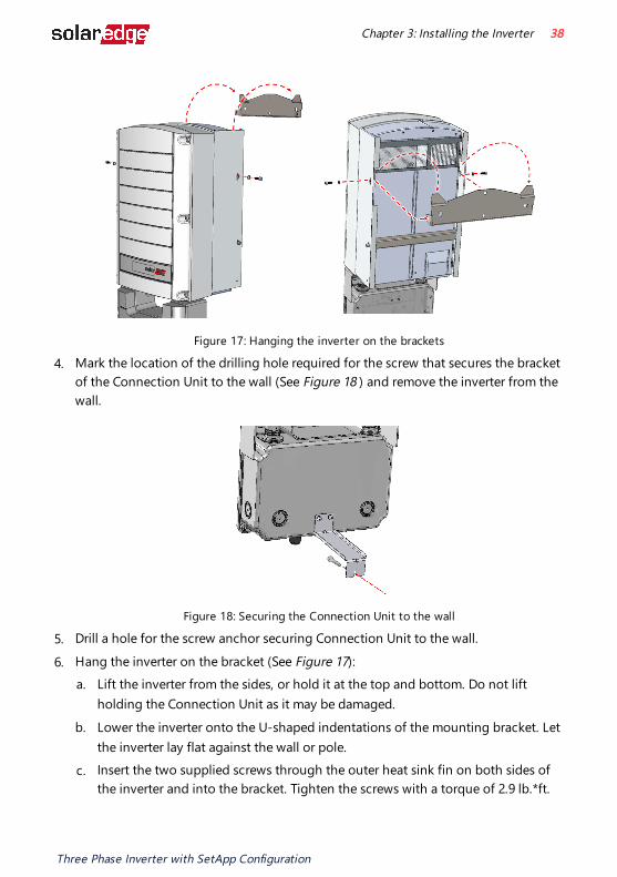
Figure 17: Hanging the inverter on the brackets
4. Mark the location of the drilling hole required for the screw that secures the bracket of the Connection Unit to the wall (See Figure 18 ) and remove the inverter from the wall.
Figure 18: Securing the Connection Unit to the wall
5. Drill a hole for the screw anchor securing Connection Unit to the wall.
6. Hang the inverter on the bracket (See Figure 17): a. Lift the inverter from the sides, or hold it at the top and bottom. Do not lift
holding the Connection Unit as it may be damaged. b. Lower the inverter onto the U-shaped indentations of the mounting bracket. Let
the inverter lay flat against the wall or pole. c. Insert the two supplied screws through the outer heat sink fin on both sides of
the inverter and into the bracket. Tighten the screws with a torque of 2.9 lb.*ft.
Chapter 3: Installing the Inverter 38
Three Phase Inverter with SetApp Configuration

7. Use a screw to secure the bracket that secures Connection Unit to the wall.
8. Verify that the inverter is firmly attached to the mounting surface.
Three Phase Inverter with SetApp Configuration
39 Mounting the Inverter

Chapter 4: Connecting AC and DC Strings to the Connection UnitThe DC Disconnect Switch of the Connection Unit disconnects all ungrounded DC conductors in compliance with the National Electric Code (NEC; Specifically NEC690.35, which addresses ungrounded PV arrays). The Connection Unit is rated to the maximum operating conditions of the inverter.Inverters of different models are equipped with different sizes / types of terminal blocks.Figure 19 shows a Connection Unit with four DC pairs.
Figure 19: Connection Unit with four DC pairs
Grid Connection GuidelinesThe conduits, hubs and fittings must be suited for field wiring systems.
The hubs and other fittings must comply with UL514B.
Use the conduit and wiring appropriate for the installation location per the NEC. Outdoor installations must use components that are rated NEMA 3R or higher. Grids Supported by SolarEdge Inverters application note at: https://www.solaredge.com/sites/default/files/grids_supported_by_se_inverters_europe_and_apac.pdf For recommended circuit breaker size per model refer to Determining the Circuit Breaker Size application note at https://www.solaredge.com/sites/default/files/determining-the-circuit-breaker-size-for-three-phase-inverters.pdf
Chapter 4: Connecting AC and DC Strings to the Connection Unit 40
Three Phase Inverter with SetApp Configuration

For short-circuit currents in SolarEdge Three Phase Inverters refer to Short-Circuit Currents in SolarEdge Three Phase Inverters application note at https://www.solaredge.com/sites/default/files/se-short-circuit-currents-three-phase-inverters-tech-note.pdf
NOTEFor more wiring information refer to the SolarEdge Recommended AC Wiring Application Note, available on the SolarEdge website at https://www.solaredge.com/sites/default/files/application-note-recommended-wiring.pdf
Connecting the PV Strings to the Connection Unit of the InverterUp to four PV strings can be connected to the inverter. When connecting the PV strings to the inverter, use only 6 to 12 AWG wires.
NOTEWhen installing a system with more than 3 strings per a single inverter (whether connected directly or via a combiner box), fuses are required on both the positive and negative conductors. For more information, refer to the “Technical Note – String Fusing Requirements in SolarEdge Systems” technical note at https://www.solaredge.com/sites/default/files/string_fusing_requirements_eu_and_apac_en.pdf
To connect multiple PV strings to the Connection Unit of the inverter:
1. Release the four screws and remove the cover of the Connection Unit.
2. Strip 0.7'' (18 mm) of the DC wire insulation.
NOTEUse only DC wires with a gauge of 6 to 12 AWG. When using a stranded
wire, use of ferrule is at the installer discretion.
3. Insert the DC conduit into the open DC-side drill guide.
4. Tighten the nut that secures the DC conduit to the Connection Unit.
Three Phase Inverter with SetApp Configuration
41 Connecting the PV Strings to the Connection Unit of the Inverter
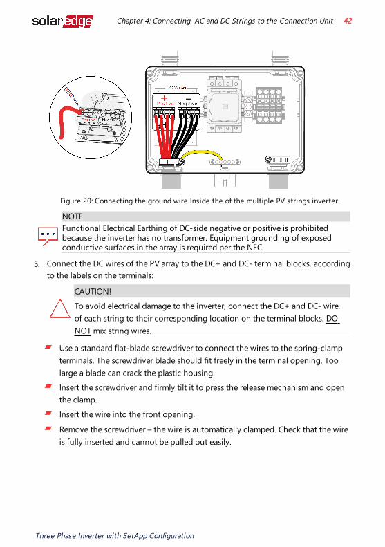
Figure 20: Connecting the ground wire Inside the of the multiple PV strings inverter
NOTEFunctional Electrical Earthing of DC-side negative or positive is prohibited because the inverter has no transformer. Equipment grounding of exposed conductive surfaces in the array is required per the NEC.
5. Connect the DC wires of the PV array to the DC+ and DC- terminal blocks, according to the labels on the terminals:
CAUTION!To avoid electrical damage to the inverter, connect the DC+ and DC- wire, of each string to their corresponding location on the terminal blocks. DO NOT mix string wires.
Use a standard flat-blade screwdriver to connect the wires to the spring-clamp terminals. The screwdriver blade should fit freely in the terminal opening. Too large a blade can crack the plastic housing.Insert the screwdriver and firmly tilt it to press the release mechanism and open the clamp.Insert the wire into the front opening.
Remove the screwdriver – the wire is automatically clamped. Check that the wire is fully inserted and cannot be pulled out easily.
Chapter 4: Connecting AC and DC Strings to the Connection Unit 42
Three Phase Inverter with SetApp Configuration

Connecting the AC Grid to the Connection UnitThe inverter can operate with connection of four wires (N, L1, L2, L3) and Protective Ground (PE) wire or three wires (L1, L2, L3) and PE wire connections. Use 6 to 10 AWG gauge of wires. When using a stranded wire, use of ferrule is at the installer discretion.
WARNINGTurn OFF AC before connecting wires to the Connection Unit of the inverter.
To connect AC grid to the Connection Unit:
1. Insert the AC conduit with the grid wires through the drilled hole in the Connection Unit and secure the conduit with a nut.
2. Strip 0.4 to 0.43" (10 to 11mm) of the PE wire insulation.
Figure 21: Connecting PE Wire to the PE Terminal Block inside the Connection Unit
3. Insert the PE wire into the PE terminal and tighten the screw using a torque of 1.1 lb-in.
Three Phase Inverter with SetApp Configuration
43 Connecting the AC Grid to the Connection Unit

NOTEConnect Protective Ground before connecting the AC wires to the AC terminal blocks.
Veillez à relier le conducteur de PE (la terre) avant de connecter les fils CA au bornier CA.
Figure 22: Connecting the N, L1 ,L2, L3 wires to the Terminal blocks inside the Connection Unit
4. Strip 0.7" (18mm) of the N, L1, L2, L3 wires insulation. 5. Connect the wires to the appropriate terminal blocks according to the labels on the
terminal blocks (N, L1, L2, L3):Use a standard flat-blade screwdriver to connect the wires to the spring-clamp terminals.The screwdriver blade should fit freely in the terminal opening. Too large a blade can crack the plastic housing.Insert the screwdriver, press the release mechanism and open the clamp.
Insert the wire into the square opening and remove the screwdriver – the wire is automatically clamped.
6. Verify that all wires are properly connected and cannot be pulled out from the terminals.
Chapter 4: Connecting AC and DC Strings to the Connection Unit 44
Three Phase Inverter with SetApp Configuration
7. Close the Connection Unit cover: Attach the Connection Unit cover and secure the four screws with a torque of 6.6 ft.*lb (7.6 ft.*lb for plastic screws) in a crossed pattern.
8. Ensure proper conduit sealing; inspect the entire conduit run and use standard conduit sealants to avoid water penetration.
Three Phase Inverter with SetApp Configuration
45 Connecting the AC Grid to the Connection Unit

Chapter 5: Setting Up Communication with the Monitoring PlatformThe inverter sends the following information to the monitoring platform:
Power Optimizer information received via the DC power lines (the PV output circuit)
Inverter information
Information of any other connected devices
This chapter describes how to set up communication between: The inverter and the monitoring platform through the Internet (wired/ wireless)
Multiple inverters for a leader-follower configuration
Communication setup is not required for power harvesting, however it is needed for using the monitoring platform.
CAUTION!When connecting the communication cables, make sure that the ON/OFF/P switch on the inverter is turned OFF, the DC Disconnect Switch on the Connection Unit is turned OFF and the AC is turned OFF.When configuring the communication parameters, make sure that the ON/OFF/P switch on the inverter is OFF, and the AC is turned ON.
ATTENTION!
Lors de la connexion des câbles de communication, assurez-vous que l'interrupteur MARCHE/ARRÊT à la base de l'onduleur soit en position ARRÊT, le sectionneur DC est éteint et le CA est en position ARRÊT. Lors de la configuration des paramètres de communication, assurez-vous que l'interrupteur MARCHE/ARRÊT soit en position ARRÊT, et le CA est en position MARCHE.
Communication OptionsThe following types of communication can be used to transfer the monitored information from the inverter to the monitoring platform.
NOTEThis guide refers to 3rd party communication products, such as internet switches and routers that are not supported by SolarEdge. For detailed information on how to install and use the products, refer to the respective publication provided with each product.
Chapter 5: Setting Up Communication with the Monitoring Platform 46
Three Phase Inverter with SetApp Configuration

EthernetEthernet is used for a LAN connection. For connection instructions refer to "Creating an Local Area Network (LAN) Connection" on page 1Creating an Ethernet (LAN) Connection on page 49Creating an Ethernet (LAN) Connection on page 49
RS485RS485 is used for the connection of multiple SolarEdge devices on the same bus in a leader-follower configuration. RS485 can also be used as an interface to external devices, such as meters and third party data loggers.
RS485-1: Enables the connection of multiple devices (inverters/Commercial Gateway) over the same bus, such that connecting only one device to the internet is sufficient to provide communication services for all the devices on the bus. RS485-2: Enables connection of multiple SolarEdge devices and of non-SolarEdge devices over the same bus.
For connection instructions refer to Creating an RS485 Bus Connection on page 53.
The Wireless Gateway collects inverter data using a dedicated Wi-FiThe inverter connects to the Monitoring platform with via a home router. Wireless Repeater(s) extend the Wi-Fi signal range between the Wireless Gateway and inverter. Wireless Gateway and Wireless Repeaters can be purchased separately from SolarEdge. For more information, refer to https://www.solaredge.com/sites/default/files/se-wirelessgateway-wireless-repeater-installation-guide.pdf.
Cellular Cellular Plug-in (purchased separately) provides cellular communication to connect one or several inverters to the Monitoring platform. Cellular communication depends on the purchased data plan.
Three Phase Inverter with SetApp Configuration
47 Communication Options

Communication ConnectorsTwo communication glands are used for connection of the various communication options. Each gland has three openings. The table below describes the functionality of each opening. Unused openings should remain sealed.
Gland# Opening Functionality Cable size (diameter)
Com 1 (PG16)
One small External antenna cable 2-4 mm
Two large Ethernet connection (CAT6) or Cellular 4.5-7 mm
Com 2 (PG13.5) All three RS485 2.5-5 mm
Figure 23: Communication Glands
The communication board has a standard RJ45 terminal block for Ethernet connection, and a 6-pin terminal block for RS485 connection, as shown below:
Figure 24: Internal communication connectors
Chapter 5: Setting Up Communication with the Monitoring Platform 48
Three Phase Inverter with SetApp Configuration
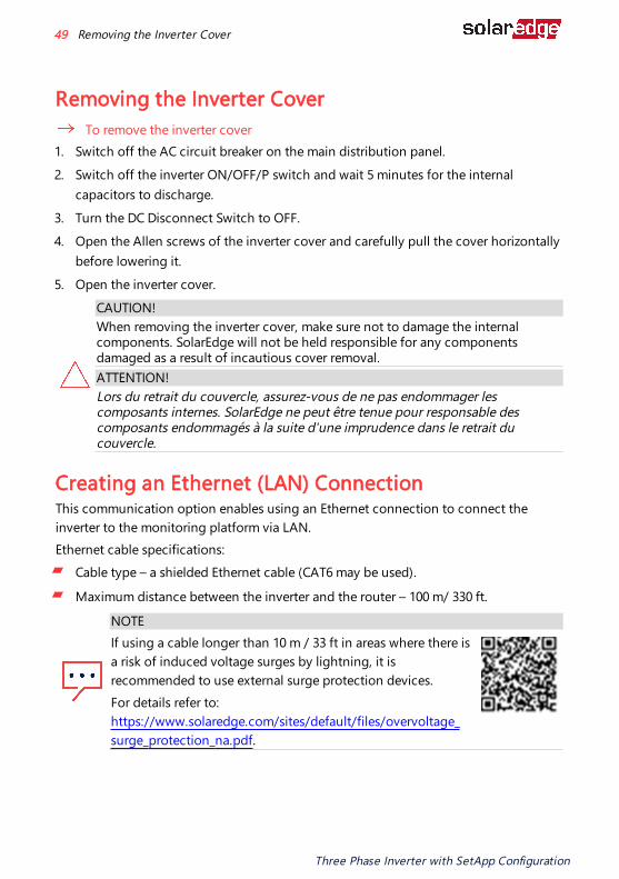
Removing the Inverter CoverTo remove the inverter cover
1. Switch off the AC circuit breaker on the main distribution panel. 2. Switch off the inverter ON/OFF/P switch and wait 5 minutes for the internal
capacitors to discharge. 3. Turn the DC Disconnect Switch to OFF. 4. Open the Allen screws of the inverter cover and carefully pull the cover horizontally
before lowering it. 5. Open the inverter cover.
CAUTION!When removing the inverter cover, make sure not to damage the internal components. SolarEdge will not be held responsible for any components damaged as a result of incautious cover removal.ATTENTION!Lors du retrait du couvercle, assurez-vous de ne pas endommager les composants internes. SolarEdge ne peut être tenue pour responsable des composants endommagés à la suite d'une imprudence dans le retrait du couvercle.
Creating an Ethernet (LAN) ConnectionThis communication option enables using an Ethernet connection to connect the
inverter to the monitoring platform via LAN.Ethernet cable specifications:
Cable type – a shielded Ethernet cable (CAT6 may be used).
Maximum distance between the inverter and the router – 100 m/ 330 ft. NOTE
If using a cable longer than 10 m / 33 ft in areas where there is a risk of induced voltage surges by lightning, it is
recommended to use external surge protection devices.For details refer to:
https://www.solaredge.com/sites/default/files/overvoltage_surge_protection_na.pdf.
Three Phase Inverter with SetApp Configuration
49 Removing the Inverter Cover

Example of Ethernet connection
To connect the Ethernet cable: 1. Remove the inverter cover as described Removing the Inverter Cover on page 49 2. Open the communication gland #1.
CAUTION!The gland includes a rubber waterproof fitting, which should be used to ensure proper sealing.
ATTENTION!
Le cote interne du gland contient une rondelle qui doit être utilisée pour une bonne étancheïté.
3. Remove the plastic seal from one of the large opening. 4. Remove the rubber fitting from the gland and insert the CAT6 cable through the
gland and through the gland opening in the inverter. 5. Push the cable into the cut opening of the rubber fitting.
Figure 25: Rubber fitting
CAT6 standard cables have eight wires (four twisted pairs), as shown in the diagram below. Wire colors may differ from one cable to another. You can use either wiring standard, as long as both sides of the cable have the same pin-out and color-coding.
Chapter 5: Setting Up Communication with the Monitoring Platform 50
Three Phase Inverter with SetApp Configuration

RJ45 Pin #Wire Color(1) 10Base-T Signal
100Base-TX SignalT568B T568A1 White/Orange White/Green Transmit+2 Orange Green Transmit-3 White/Green White/Orange Receive+4 Blue Blue Reserved5 White/Blue White/Blue Reserved6 Green Orange Received-7 White/Brown White/Brown Reserved8 Brown Brown Reserved
Figure 26: Standard cable wiring 6. Use a pre-crimped cable to connect via gland #1 to the RJ45 plug on the inverter's
communication board or, if using a spool of cable, connect as follows: a. Insert the cable through gland #1.
b. Remove the cable’s external insulation using a crimping tool or cable cutter and
expose eight wires. c. Insert the eight wires into an RJ45 connector, as described in Figure 26.
d. Use a crimping tool to crimp the connector. e. Connect the Ethernet connector to the RJ45 port on the communication board.
(1)The connection does not support RX/TX polarity change. Supporting crossover Ethernet cables depends on the switch capabilities.
Three Phase Inverter with SetApp Configuration
51 Creating an Ethernet (LAN) Connection

Figure 27: The RJ45 Ethernet connection
7. For the switch/router side, use a pre-crimped cable or use a crimper to prepare an RJ45 communication connector: Insert the eight wires into the RJ45 connector in the same order as above (Figure 26).
8. Connect the cable RJ45 connector to the RJ45 port of the Ethernet switch or router. You can connect more than one inverter to the same switch/router or to different switches/routers, as needed. Each inverter sends its monitored data independently to the monitoring platform.
9. The inverter is configured by default to LAN. If reconfiguration is required: a. Make sure the ON/OFF/P switch is OFF. b. Turn ON the DC Disconnect Switch
c. Turn ON the AC to the inverter by turning ON the circuit breaker on the main distribution panel.
d. Configure the connection as described in Communication on page 59.
NOTEIf your network has a firewall, you may need to configure it to enable the connection to the following address: Destination Address: prod2.solaredge.comTCP Port: 22222, 22221, or 80 (for incoming and outgoing data)
10. Verify the connection, as described in Verifying the Connection on page 56.
Chapter 5: Setting Up Communication with the Monitoring Platform 52
Three Phase Inverter with SetApp Configuration

Creating an RS485 Bus ConnectionThe RS485 option enables creating a bus of connected inverters, consisting of up to 31 follower inverters and 1 leader inverter. Using this option, inverters are connected to each other in a bus (chain), via their RS485 connectors. The first and last inverters in the chain must be terminated as described on page 54.RS485 wiring specifications:
Cable type: CAT6
Maximum nodes: 32
Maximum distance between first and last devices: 1 km /3300 ft
NOTEIf grounded metal conduits are used for routing the communication wires, a lightning protection device is not required.
The following sections describe how to physically connect the RS485 bus and how to configure the bus.
To connect the RS485 communication bus: 1. Release the six Allen screws and carefully remove the DC Safety Unit cover 2. Remove the seal from one of the openings in communication gland #2 and insert
the wire through the opening. 3. Pull out the 6-pin RS485 terminal block connector, as shown in Figure 28.
Figure 28: RS485 terminal block on the communication board
4. Loosen the screws of pins A(+), B(-), and G on the left of the RS485 terminal block (RS485-1 or RS485-2).
Three Phase Inverter with SetApp Configuration
53 Creating an RS485 Bus Connection
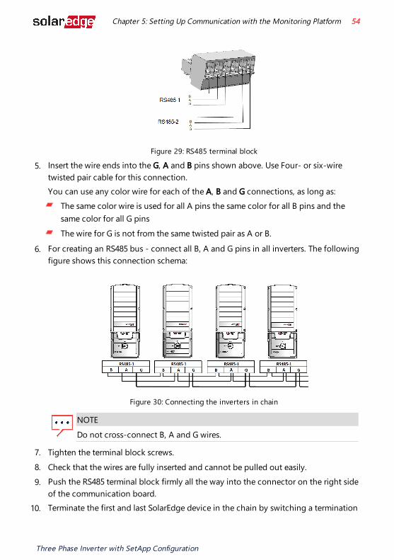
Figure 29: RS485 terminal block
5. Insert the wire ends into the G, A and B pins shown above. Use Four- or six-wire twisted pair cable for this connection. You can use any color wire for each of the A, B and G connections, as long as:
The same color wire is used for all A pins the same color for all B pins and the same color for all G pinsThe wire for G is not from the same twisted pair as A or B.
6. For creating an RS485 bus - connect all B, A and G pins in all inverters. The following figure shows this connection schema:
Figure 30: Connecting the inverters in chain
NOTEDo not cross-connect B, A and G wires.
7. Tighten the terminal block screws. 8. Check that the wires are fully inserted and cannot be pulled out easily. 9. Push the RS485 terminal block firmly all the way into the connector on the right side
of the communication board. 10. Terminate the first and last SolarEdge device in the chain by switching a termination
Chapter 5: Setting Up Communication with the Monitoring Platform 54
Three Phase Inverter with SetApp Configuration

DIP-switch inside the inverter to ON (move the left switch up). The DIP-switch is located on the communication board and is marked SW1.
Figure 31: RS485 termination DIP-switch (SW1)
NOTEOnly the first and last SolarEdge devices in the chain should be terminated. The other inverters in the chain should have the termination switch OFF (down position).
11. Tighten the nut of the COMM2 gland in a torque of 3 lb*ft.
RS485 Bus ConfigurationTo connect to the monitoring platform:
1. Designate a single inverter as the connection point between the RS485 bus and the monitoring platform. This inverter will serve as the leader inverter.
2. Connect the leader to the monitoring platform using Ethernet (refer to Creating an Ethernet (LAN) Connection above).
To configure the RS485 bus: All inverters are configured by default as followers. To configure the leader:
1. Make sure the inverter's ON/OFF/P switch is off. 2. Make sure that the AC circuit breaker on the main distribution panel is on. 3. Turn-on the DC Disconnect Switch on the Connection Unit . 4. Access SetApp, as described in Communication on page 59. 5. From the Commissioning screen, select Site Communication > RS485-1 > Protocol
> SolarEdge > SolarEdge Leader. 6. Return to the RS485-1 screen and select Follower Detect.
Three Phase Inverter with SetApp Configuration
55 RS485 Bus Configuration
The system starts automatic detection of the follower inverters connected to the leader inverter. The inverter should report the correct number of followers. If it does not, verify the connections and terminations in all inverters in the chain.
7. To check the follower IDs and last communication time, select RS485-1 > Follower List.
8. Verify the connection of the leader to the monitoring platform, as described below.
Verifying the Connection After connecting and configuring a communication option, perform the following steps to check that the connection to the Monitoring platform has been successfully established.
1. If the DC Safety Unit cover is not closed, close it: Attach the DC Safety Unit cover and secure it by tightening the screws with a torque of 2.6 lb*ft. For proper sealing, first tighten the corner screws and then the two central screws.
2. Commission the inverter as describe in "Activating, Commissioning and Configuring the System" on page 57.
3. Access SetApp and select Status from the Configuring screen. 4. In the Summary section, under Server Comm., make sure S_OK is displayed
together with the selected communication option. 5. Scroll down to the Communication section and check that the communication
options are as required.
Chapter 5: Setting Up Communication with the Monitoring Platform 56
Three Phase Inverter with SetApp Configuration

Chapter 6: Activating, Commissioning and Configuring the SystemAfter the solar system is installed, it is important to activate and commission the solar system. Activation and commission of the system is performed using the inverter SetApp mobile application.During the activation and commissioning, the inverter discovers and communicates with all connected components in the solar system, such as: optimizers, peripheral communication devices and other linked inverters. When commissioning is performed, the user is required to set the grid parameters and backup Voltage information (if used).Before starting the activation and commissioning, verify the all the communication hardware is properly connect. For communication options, refer to: Setting Up Communication with the Monitoring Platform on page 46. Before arriving at the site, download SolarEdge SetApp application to your mobile device from Apple App Store or Google Play .Before activation and commissioning, download the SetApp application from:
For downloading SetApp, Internet connection, one-time registration and logging are required. No registration is required for using the SetApp.
Step 1: Activating the InstallationDuring system activation, a Wi-Fi connection is created between the mobile device and the inverter and the system firmware is upgraded.Before activation
Download, register (first time only) and login to SetApp on your mobile device. Verify that the application is updated with the latest version.
Three Phase Inverter with SetApp Configuration
57 Chapter 6: Activating, Commissioning and Configuring the System

If applicable, turn on all devices (battery, Energy Meter, Backup Interface) connected to the inverter, so that the devices may be auto-detected.
To activate the inverter: 1. Turn-on the AC circuit breaker on the main distribution panel. 2. Turn-on the DC Disconnect Switch (if applicable).
3. Open SetApp and follow the on-screen instructions (scan the inverter barcode; move the ON/OFF/P switch to P position for 2 seconds and release). SetApp creates a Wi-Fi connection, upgrades the inverter firmware and activates the inverter.
4. When the activation is complete, do one of the following: Select Connect to Another Device to continue activating additional inverters.
Select Start Commissioning for pairing and other system configuration.
Step 2: Commissioning and Configuring the InstallationThis section describes how to use the SetApp menus for commissioning and configuring the inverter settings.Menus may vary in your application depending on your system type.
To access the Commissioning screen:Do one of the following:
During first time installation: Upon activation completion, in the SetApp, tap Start Commissioning. If the inverter has already been activated and commissioned:
If not already ON - turn ON AC to the inverter by turning ON the circuit breaker on the main distribution panel. Open SetApp and follow the on-screen instructions (scan the inverter QR code, move the ON/OFF/P switch to P position for 2 seconds and release). The mobile device creates a Wi-Fi connection with the inverter and displays the main Commissioning screen.
Setting Country, Grid and LanguageThe inverter must be configured to the proper settings in order to ensure that it complies with the country grid code and functions.
Chapter 6: Activating, Commissioning and Configuring the System 58
Three Phase Inverter with SetApp Configuration
1. From the Commissioning screen select Country & Grid.
2. From the Country & Grid drop-down list, select the required option and tap Set Country & Grid.
3. From the Language drop-down list, select your language and tap Set Language.
Pairing 1. From the Commissioning menu, select Pairing.
2. Tap Start Pairing. 3. When Pairing Complete is displayed, the system startup process begins:
Since the inverter is ON, the Power Optimizers start producing power and the inverter starts converting AC.
WARNING!When you turn ON the ON/OFF/P switch, the DC cables carry a high Voltage and the Power Optimizers no longer output a safe output.
AVERTISSEMENT!
Après avoir mis l'interrupteur ON/OFF/P de l'onduleur monophasé sur ON, les câbles DC portent une haute tension et les optimiseurs de puissance ne génèrent plus la tension de sécurité.
When the inverter starts converting power after the initial connection to the AC, the inverter enters Wake up mode until its working voltage is reached. This mode is indicated by the flickering green inverter LED.When working voltage is reached, the inverter enters Production mode and produces power. The steadily lit green inverter LED indicates this mode.
4. Tap OK to return to the Commissioning menu.
CommunicationCommunication settings can be configured only after communication connections are complete. Refer to Setting Up Communication with the Monitoring Platform on page 46.
Select Monitoring Communication to configure communication with the monitoring platform.Select Site Communication to configure communication between multiple SolarEdge devices or external non-SolarEdge devices, such as batteries or loggers.
Three Phase Inverter with SetApp Configuration
59 Step 2: Commissioning and Configuring the Installation

Power ControlFor P(Q) diagram refer to: https://www.solaredge.com/sites/default/files/application_note_p_q_diagram_of_se_inverters_en_and_na.pdf.
NOTESolarEdge inverters with “Grid Support” functionality (as marked on the inverter certification label), are compliant with UL 1741 Supplement A. The functionality is built into the inverter and no additional external device is required.
Step 3: Verifying Proper Activation and Commissioning
1. Select Information and verify that the correct firmware versions are installed on each inverter.
2. Select Status and verify that inverter is operating and producing power. 3. Verify that additional configurations were properly set by viewing the relevant
Status screens. 4. Verify that the green inverter LED is steadily lit.Your SolarEdge power harvesting system is now operational.
Reporting and Monitoring Installation DataMonitoring the site requires connecting the to the monitoring platform, using any of the wired or wireless options available from SolarEdge. Refer to Setting Up Communication with the Monitoring Platform on page 46.
The Monitoring PlatformThe monitoring platform provides enhanced PV performance monitoring and inverter yield assurance through immediate fault detection and alerts at the module, string and system level. Using the platform, you can:
View the latest performance of specific components.
Find under-performing components, such as modules, by comparing their performance to that of other components of the same type.Pinpoint the location of alerted components using the physical layout.
The monitoring platform enables accessing site information, including up-to-date information viewed in a physical or logical view:
Chapter 6: Activating, Commissioning and Configuring the System 60
Three Phase Inverter with SetApp Configuration

Logical Layout: Shows a schematic tree-layout of the components in the system, such as: inverters, Power Optimizers, strings, modules, meters and sensors, as well as their electrical connectivity. This view enables you to see which modules are connected in each string, which strings are connected to each inverter, and so on.Physical Layout: Provides a bird's eye view of the actual placement of modules in the site, and allows pinpoint issues to the exact location of each module on a virtual site map.
If you do not report the mapping of the installed Power Optimizers, the monitoring platform will show the logical layout indicating which Power Optimizers are connected to which , but will not show strings or the physical location of Power Optimizers.The monitoring platform includes a built-in help system that guides you through the monitoring functionality. For more information, refer to https://www.solaredge.com/products/pv-monitoring#/.
Creating Logical and Physical Layout using Installation InformationTo display a logical layout, insert in the new site created in the monitoring platform. When the communication between the and the monitoring server is established, the logical layout is displayed.To display a physical layout, you need to map the locations of the installed power optimizers. To map the locations, use one of the methods described in the next sections.
Designer Designer recommends inverter and Power Optimizer selection per site size and enables report generation. You can create a project in Designer and export the site design with the string layout to the monitoring platform. For more information, refer to https://www.solaredge.com/products/installer-tools/designer#/.
Three Phase Inverter with SetApp Configuration
61 Reporting and Monitoring Installation Data

Physical Layout Editor 1. If you are a registered installer, access the monitoring platform site
creation page at https://monitoring.solaredge.com/solaredge-web/p/home#createSites. If you have not yet signed up, go to https://monitoring.solaredge.com/solaredge-web/p/createSelfNewInstaller.
2. Fill out all required information in the screen, which includes information about your installation, as well as details about its logical and physical mapping.
Chapter 6: Activating, Commissioning and Configuring the System 62
Three Phase Inverter with SetApp Configuration

Appendix A: Errors and TroubleshootingThis chapter describes how to troubleshoot general system problems. For further assistance, contact SolarEdge Support.
Identifying Errors Errors may be indicated in various system interfaces: On the inverter bottom panel, a red LED indicates an error. In the monitoring platform and SetApp, errors are displayed with codes. For more information on the codes displayed for error and warning messages, refer to https://www.solaredge.com/sites/default/files/troubleshooting_for_se_inverter_insallation_guide_addendum_na.pdf. This document describes errors that appear in SetApp, monitoring platform, and LCD (for inverters with LCD). To identify the error types, use the methods described below.
To identify the error type using the inverter LEDs: 1. Move the ON/OFF/P switch to P position for 2 seconds and release it. 2. Observe the LED lights and use the following table to identity the
error type. For more information, refer to https://www.solaredge.com/us/leds.
Error TypeInverter LED Color and State
Red Green BlueArc detected ON OFF OFFIsolation or RCD problem Blinking OFF OFFGrid error OFF ON OFFHigh temperature OFF Blinking OFFPairing failed OFF OFF ONOther issue OFF OFF Blinking
To identify the error type using the monitoring platform: 1. Open the site dashboard and click the Layout icon. 2. Right-click the inverter and select Info from the menu. The inverter details window is
displayed. 3. Click the Errors tab. The list is displayed.
Three Phase Inverter with SetApp Configuration
63 Appendix A: Errors and Troubleshooting

Troubleshooting Communication
Troubleshooting Ethernet (LAN) CommunicationThe possible errors and their troubleshooting are detailed in the following table:
Error Message Possible Cause and Troubleshooting
LAN cable disconnectedPhysical connection fault. Check the cable pin-out assignment and cable connection.
No DHCP IP settings issue. Check the router and configuration. Consult your network IT.Configure Static IP or set to DHCP
Gateway not responding
Ping to router failed. Check the physical connection to the switch/ router. Check that the link LED at the router /switch is lit (indicating phy-link). If OK - contact your network IT, otherwise replace the cable or change it from cross to straight connection.
No Internet connection
Ping to google.com failed. Connect a laptop and check for internet connection. If internet access is unavailable, contact your IT admin or your internet provider.
Troubleshooting RS485 CommunicationIf the message RS485 Leader Not Found appears in the Status screen, check the connections to the leader device and fix if required.
If after follower detection the number of followers displayed for the leader under RS485-1 > Follower Detect is lower than the actual number of followers, refer to the following application note to identify missing followers and troubleshoot connectivity problems: https://www.solaredge.com/sites/default/files/troubleshooting_undetected_RS485_devices.pdf
Appendix A: Errors and Troubleshooting 64
Three Phase Inverter with SetApp Configuration
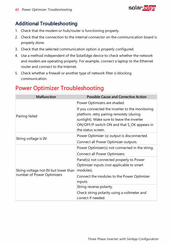
Additional Troubleshooting 1. Check that the modem or hub/router is functioning properly. 2. Check that the connection to the internal connector on the communication board is
properly done. 3. Check that the selected communication option is properly configured. 4. Use a method independent of the SolarEdge device to check whether the network
and modem are operating properly. For example, connect a laptop to the Ethernet router and connect to the Internet.
5. Check whether a firewall or another type of network filter is blocking communication.
Power Optimizer Troubleshooting Malfunction Possible Cause and Corrective Action
Pairing failed
Power Optimizers are shaded.If you connected the inverter to the monitoring platform, retry pairing remotely (during sunlight). Make sure to leave the inverter ON/OFF/P switch ON and that S_OK appears in the status screen.
String voltage is 0VPower Optimizer (s) output is disconnected.Connect all Power Optimizer outputs.
String voltage not 0V but lower than number of Power Optimizers
Power Optimizer(s) not connected in the string.Connect all Power Optimizers.Panel(s) not connected properly to Power Optimizer inputs (not applicable to smart modules).Connect the modules to the Power Optimizer inputs.String reverse polarity.Check string polarity using a voltmeter and correct if needed.
Three Phase Inverter with SetApp Configuration
65 Power Optimizer Troubleshooting

Malfunction Possible Cause and Corrective Action
String Voltage is higher than number of Power Optimizers
WARNING!If the measured voltage is too high, the installation may not have a safe low voltage. PROCEED WITH CARE! A deviation of ±1% per string is reasonable. AVERTISSEMENT!Si la tension mesuree est trop haute, la tension basse de securite pourrait manquer dans l’installation. REDOUBLEZ DE PRECAUTION. Une deviation de ±1% par string est raisonnable.
Extra Power Optimizer(s) connected in the string (not applicable to smart modules). Check if an extra Power Optimizer is connected in the string. If not – proceed to next solution.A module is connected directly to the string, without a Power Optimizer (not applicable to smart modules). Verify that only Power Optimizers are connected in the string and that no module outputs are connected without a Power Optimizer. If the problem persists, proceed to the next step.Power Optimizer(s) malfunction.
1. Disconnect the wires connecting the Power Optimizers in the string.
2. Measure the output voltage of each Power Optimizer to locate the Power Optimizer that does not output 1V safety Voltage. If a malfunctioning Power Optimizers located, check its connections, polarity, module, and voltage.
3. Contact SolarEdge Support. Do not continue before finding the problem and replacing the malfunctioning Power Optimizer. If a malfunction cannot be bypassed or resolved, skip the malfunctioning Power Optimizer, thus connecting a shorter string.
Appendix A: Errors and Troubleshooting 66
Three Phase Inverter with SetApp Configuration
Appendix B: Adding Optional ComponentsAC Surge Protection Device (SPD) The AC SPD is a device designed to protect the inverter from Voltage spikes and surge attempts forming on the AC grid lines. The SPD limits the Voltage supplied to the inverter by either blocking or shorting to ground Voltages above a safe threshold. The SPD is installed inside the inverter and communicates with the SolarEdge Monitoring platform for reporting surge protection events and faults.For installation and configuration of AC SPD, refer to: https://www.solaredge.com/sites/default/files/se-ac-surge-protection-device-installation-guide.pdf
DC Surge Protection Device (SPD) The DC SPD is a device designed to protect the inverter from Voltage spikes and surge attempts, forming on the PV DC lines, mainly induces by lightning. The SPD limits the Voltage supplied to the inverter by either blocking or shorting to ground Voltages above a safe threshold. The SPD is installed inside the inverter and communicates with the SolarEdge Monitoring platform for reporting surge protection events and faults.For installation and configuration of DC SPD, refer to: https://www.solaredge.com/sites/default/files/se-dc-surge-protection-device-installation-guide.pdf
Three Phase Inverter with SetApp Configuration
67 Appendix B: Adding Optional Components

Appendix C: Mechanical Specifications
Figure 32: Dimensions of Three Phase Inverter with Connection Unit
Appendix C: Mechanical Specifications 68
Three Phase Inverter with SetApp Configuration

Dimensions of Inverter Mounting Bracket
Figure 33: Dimensions of Inverter mounting bracket
Three Phase Inverter with SetApp Configuration
69 Dimensions of Inverter Mounting Bracket
Support Contact InformationIf you have technical problems concerning SolarEdge products, please contact us:
https://www.solaredge.com/us/service/supportBefore contact, make sure to have the following information at hand:
Model and serial number of the product in question.
The error indicated on the SetApp mobile application, on the monitoring platform, or by the LEDs, if there is such an indication.System configuration information, including the type and number of modules connected and the number and length of strings.The communication method to the SolarEdge server, if the site is connected.
The product's software version as it appears in the status screen.
Support Contact Information 70
Three Phase Inverter with SetApp Configuration