biofuel, land-use tradeoffs and livelihoods in southern africa
Upload
independentCategory
view
0download
0
IEEE TRANSACTIONS ON COMPONENTS AND PACKAGING TECHNOLOGIES, VOL. 28, NO. 3, SEPTEMBER 2005 457
Thermo-Mechanical Reliability Tradeoffs forDeployment of Area Array Packages
in Harsh EnvironmentsPradeep Lall, Member, IEEE, Naveen Singh, Jeffrey C. Suhling, Member, IEEE, Mark Strickland, and Jim Blanche
Abstract—Fine-pitch ball grid arrays (BGAs) and underfillshave been used in benign office environments and wireless ap-plications for a number of years, however their reliability inharsh environments is not well understood. In this work, thedesign guidelines development effort for deployment of fine-pitchball-grid array packages in the harsh environments have beenpresented. Guidelines are targeted toward government contrac-tors, OEMs, and third party contract manufacturers who intendto select part architectures and board designs based on specifiedmission requirements. The guidelines are intended as an aid forunderstanding the sensitivity of component reliability to geometry,package architecture, material properties and board attributes indifferent thermal environments in order to quantitatively evaluatethe impact of these parameters on the component reliability. Theintent is to develop a tool for doing tradeoffs between geometry,materials and quantitatively evaluating the impact on reliability.Sensitivity relations for geometry, materials, and architecturesbased on statistical models and failure mechanics based closedform models have been developed. Convergence between statisticalmodel sensitivities and failure mechanics based sensitivities hasbeen demonstrated. Predictions of sensitivities have been validatedagainst experimental test data.
Index Terms—Ball grid array (BGA), design guidelines, solderjoint fatigue, statistical model, thermal reliability prediction.
I. NOMENCLATURE
Coefficient of thermal expansion.Shear strain.Shear stress.Area, .
BGA Ball grid array.CTE Coefficient of thermal expansion.DF Degrees of freedom.
Modulus of elasticity, MPa.EMC Encapsulant mold compound.
-ratio (Mean square between groups)/(mean squarewithin groups).Shear force.Shear modulus.Height, mm.
Manuscript received May 4, 2004; revised March 21, 2005. This work wassupported by the NSF Center for Advanced Vehicle Electronics (CAVE) atAuburn University. This work was recommended for publication by AssociateEditor P. McCluskey upon evaluation of the reviewers’ comments.
P. Lall, N. Singh, and J. C. Suhling are with the Department of Mechanical En-gineering and NSF Center for Advanced Vehicle Electronics (CAVE), AuburnUniversity, Auburn, AL 36849 USA (e-mail: [email protected]).
M. Strickland and J. Blanche are with NASA Marshall Space Flight Center,Huntsville, AL 35812 USA.
Digital Object Identifier 10.1109/TCAPT.2005.854162
Cross-sectional moment of inertia.Number of thermal cycles.
NSMD Nonsolder mask defined.-value -value of the coefficient.
Pitch.PCB Printed circuit board.
coefficient of determination, 1 ( Error/Total).
Ramp rate.adjusted for degrees of freedom.
Standard deviation.Standard error of the coefficient.
SMD Solder mask defined.-statistic of the coefficient.
thermal cycling temperature range, C.Sum-of-squares.
Subscripts
1% failure.PCB.
c Component.Solder ball.
II. INTRODUCTION
THE hybrid-modeling methodology presented in this paper,is intended as a tool-set for evaluating “what-if” scenarios
involving selection or substitution of candidate packaging tech-nologies in harsh environments for use by government contrac-tors, OEMs, and third party contract manufacturers. In addition,the mathematical relationships presented in this paper provideguidelines for smart selection of component packaging tech-nologies and perturbing presently-deployed product designs forrisk-informed insertion of new packaging technologies.
Electronic packaging design and analysis are very broad andcomplex areas. The increasing functionality in modern micro-electronics requires more complexity in less space and more re-liability at lower cost. Demands on miniaturization have lead tothe evolution of several types of area array packages like PBGA,Flex-BGA, flip chip CSPs, etc. Area array packages have beenincreasingly targeted for use in harsh environments such as au-tomotive, military and space applications but the thermo-me-chanical reliability of these packages in such environments is aconcern for the electronic industry.
Several efforts [1]–[6] have been made to investigate andunderstand the failure mechanics and thermal reliability ofthese packages under harsh environment. Previous studies have
1521-3331/$20.00 © 2005 IEEE
458 IEEE TRANSACTIONS ON COMPONENTS AND PACKAGING TECHNOLOGIES, VOL. 28, NO. 3, SEPTEMBER 2005
demonstrated that thermal-fatigue reliability of area-array pack-ages depends on design parameters and material properties ofthe package and the environmental conditions such as extremetemperatures, dwell time, and ramp-rates encountered by thepackage during it’s life. Design of robust assemblies that meetproduct-life requirements, is often addressed by acceleratedtesting or by using reliability models. Several approaches areavailable today for reliability prediction including nonlinearfinite element models [1], [7], [8] and first and second-orderclosed form models [9]–[11].
In this paper, a hybrid approach to reliability predictionhas been presented, for achieving turn-key life-estimates withaccuracy comparable to more complex finite-element models.Additional advantages of the proposed approach include theability to address both single and coupled effects in a deci-sion-support framework, in addition to addressing tacit factorssuch as board finish and mask definition, which do not lendthemselves to a mathematical description easily in first-orderformulations. The perturbation approach presented in thispaper, achieves better life-estimates by perturbing knownaccelerated-test data-sets using models, using factors whichquantify the sensitivity of reliability to various design, material,architecture and environmental parameters. The models arebased on a combination of statistics and failure mechanics.In addition, parameter interaction effects, which are oftenignored in closed form modeling, have been incorporated in theproposed hybrid approach. The statistics models are based onaccelerated test data in harsh environments, while failure me-chanics models are based on damage mechanics and materialconstitutive behavior.
Methodology presented in this paper, is intended as atool-set for doing “what-if” studies on COTS (commer-cial-off-the-shelf) components. The trend of the defenseapplications toward usage of COTS components as a costmitigation measure and its impact on component reliability isimmense. COTS components have gained visibility over thepast decade. The COTS philosophy decrees that, when youcan obtain commercial components and subsystems that meetmilitary specifications, you can use them in military systems.
The hybrid approach is intended as an aid for designersdealing with the problem of “component obsolescence” and inidentification of equivalent reliability packaging architectures.Component obsolescence has been deemed a leading problemfor designers of long-living systems. The “mil-spec” parts havespecial status which involves long-term availability, beyondthe point at which a commercial part would be discontinued.If one were to use a commercial part, then commercial rulesapply: no special treatment and there is no guarantee of supplyoutside normal practices. Therefore, it is essential that futurepackaging architectures for advanced military applications beinsensitive to obsolescence. Substitution of components on thefly as they become obsolete to maintaining the highest level ofoperational readiness without extensive experimental testingfor each change will require a fundamental understanding ofthe materials and interfaces in drop and shock impact loadingscenarios.
Methodology presented in this paper, addresses scope be-yond that addressed by published standards [13]–[15]. Thehybrid approach presented in this paper addresses parameters,beyond those addressed by finite-element models and closed
form models. Some parameters, such as board finish do notlend themselves to analysis by closed-form models. In thispaper effort has been made to include a comprehensive list ofthe design parameters to address the thermal reliability.
III. HYBRID APPROACH
A combination of statistics-based and failure-mechanicsbased methodology has been used to identify the critical pa-rameters and their sensitivity on the thermal reliability of theBGA packages. Sensitivities of reliability to design, material,architecture, and environment parameters have been devel-oped from both statistics and failure-mechanics and validatedversus experimental data. Parameters investigated for thermalreliability of the BGAs include: body size, die size, die topackage ratio, solder ball composition, solder ball size (balldia and height), stencil thickness, solder volume, ball pitch,ball count, array configuration (partial or full array), under-fill,EMC filler content, conformal coat, pad size, pad configuration(SMD/NSMD), solder mask diameter, solder mask thickness,local CTE mismatch between mold compound, under-fill andsubstrate, global CTE mismatch between component and PCBboard, PCB thickness, board finish (HASL, OSP, Ni–Au), PCBmaterial, substrate material and temperature cycle conditionssuch as ramp rate, dwell time, and temperature extremities.
The relative influence of these parameters on the thermalreliability has been determined by using multivariate regres-sion and analysis of variance techniques. MINITAB has beenused for statistical analysis. Closed form models have beendeveloped and implemented in MATLAB. Statistics-basedmodels have been developed based on extensive harsh-envi-ronment accelerated test database developed by researchers atthe Center of Advanced Vehicle Electronics (CAVE). Data hasbeen supplemented with accelerated test data from publishedliterature [1]–[23]. Scope of the Accelerated Test Database isshown in Table I. Model library has been developed to addresscommon package architectures. Accelerated life-test data inharsh thermal environments, for various formats of ball-gridpackages has been accumulated and used for analysis. Packagesizes targeted include 8 mm, 12 mm, 15 mm, 16 mm, 17 mm,23 mm, and 27 mm BGAs. Multivariate regression, analysis ofvariance techniques have been used to develop mathematicalequations for parameter sensitivities. The parameters are givena physical basis through correlation with failure mechanics.Candidate Models of following form are proposed for flex-sub-strate BGAs
DietoBodyRatio BallCount BallDiaMM
BoardFinishID (1)
The log coefficient (i.e., Log ) and the indices( ) for the model have been derived for flex-sub-strate BGAs (Table II). The indices indicate the sensitivity ofeach of the parameters. The model in its present form can beused for evaluating relative improvement instead of predictionof absolute value of life. Parameters with “ID” at the endare dummy variables. MasfDefID toggles the mask definitionbetween SMD and NSMD. A value of 1 corresponds to SMDand value of 10 corresponds to NSMD. EMCfillID toggles themold compound filler content between low and high. A value of

LALL et al.: THERMO-MECHANICAL RELIABILITY TRADEOFFS 459
TABLE ISCOPE OF ACCELERATED TEST DATABASE
TABLE IIMULTIVARIATE REGRESSION MODEL OF FLEX-SUBSTRATE
BGA THERMAL FATIGUE DATA
1 corresponds to high filler content and value of 10 correspondsto low filler content. BoardFinishID toggles the board finishbetween OSP, HASL, and Ni-Au finish. 1 corresponds to OSPfinish, 10 corresponds to HASL and 100 corresponds to Ni–Auboard finish. The -value of a parameter indicates the statisticalsignificance of that parameter and the parameter with -valueless than 0.05 is considered to be statistically significant and itshould have significant effect on the reliability of the package,with confidence level of more than 95.0%. All the predictorvariables except the BoardFinishID are statistically significantwith -values of 0.000. BoardFinishID has -value of 0.076which indicates 92.4% confidence level which is little less thanthe 95.0% confidence level but it has still been included in themodel as we know from failure mechanics that the board finishhas significant effect on the thermal reliability of the BGApackages. A negative value of the index indicates a decreasein cycles-to-1% failure with increase in value of the variable.Parameters with “MM” at the end indicate that the parametershave been measured in millimeters. BallDiaMM reperesentssolder ball diameter and PCBthkMM represents PCB thickness.Dimensionless parameters including die-to-body ratio and ballcount have no units. is the thermal cycling temperaturerange measured in C. Several forms of the log-log modelwere considered. The model presented gives the best fit for thereliability data indicated by value of 87.9%, good
-values for all the predictor variables. A high -value indicatesstatistical significance of difference between groups.
Since the regression is based on assumption of normal distri-bution, the nature of distribution of the residuals has been veri-fied. Residual plots of the statistical model are shown in Fig. 1.If we plot the residuals against the normal score of the residualsthen a perfectly normal distribution is represented by a straightline at 45 on the normal plot of the residuals. The normal plot of
Fig. 1. Residual plots for the statistical model.
Fig. 2. Actual versus predicted 1% failure cycles plot.
residuals for this model indicates a fairly normal distribution ofthe residuals as it is quite close to a straight line at 45 (Fig. 1).The histogram plot of residual versus frequency also exhibits anearly symmetrical bell-shape pattern, which is consistent witha sample from a normal distribution. The I-chart of individualobservations reveals that the residuals for all the observationsare within the three sigma limits of (0.2175, 0.2175) whichimplies that all the data points in our analysis are fitted within thecontrol limits of 3 sigma. We can see fairly random distributionof the residuals in the residual versus fits plot, which demon-strates the linear relationship between the predictors and the re-sponse variable in the model. If the relationship is not linear thanthe residuals follow some curved pattern distribution. The plotalso holds the assumption of homoskedasticity (constant vari-ance) in the data as the residuals do not fan out or show anypattern as we go from the lower fits to the higher fitted values.
One-percent failure cycles values predicted by the statisticalmodel has been plotted against the actual values from the exper-imental database to assess the goodness of fit of the model. Thestraight line at 45 in Fig. 2 represents the perfect fit of the pre-dicted values. After comparing the various statistical models forthe fit of the predicted values with that of actual 1% failure cy-cles values form the experimental data, the model with the best
460 IEEE TRANSACTIONS ON COMPONENTS AND PACKAGING TECHNOLOGIES, VOL. 28, NO. 3, SEPTEMBER 2005
fit has been finally selected. The plot in Fig. 2 for the modelshows that the predicted values are consistent with the experi-mental values within close tolerance.
IV. MODEL LIBRARY
Several statistical models have been developed to predictthe thermal reliability of BGAs. These models include linearmodels, log-linear models and log-log models. The valuesof cycles to 1% failure for different configurations of areaarray packages has been used to compare the accuracy of thepredicted values of each model.
A. Linear Models
Maximum number of predictor variables (parameters) havebeen included in the linear model to analyze the effect of eachvariable on the reliability of the package. The statistical modelin the form of mathematical equation is given by
BodyMM DietoBodyRatio
BallCount BallDiaMM PitchMM
PCBthkMM PCBPadDiaMM
EMCFillID MaskDefID MaskDefID
SubstrateID BoardFinishID
(2)
where are generalized degree of freedom inthe problem definition. The various predictors used in thismodel were BodyMM (package body size), DietoBodyRatio(ratio of die size to body size), BallCount, BallDiaMM (solderball diameter), PitchMM (solder ball pitch), PCBthkMM (PCBthickness), PCBPadDiaMM (PCB pad diameter), EMCFillID(EMC filler content), MaskDefID (pad configuration), Sub-strateID (substrate type), BoardFinishID, (thermal cyclingtemperature range) and RampRate. Some variables such asEMCFillID, MaskDefID, SubstrateID and BoardFinishIDdo not have numerical values so they were used as dummyvariables and each dummy variable was assigned a numericalvalue.
MaskDefID toggles the mask definition between SMD andNSMD. A value of 0 corresponds to SMD and value of 1 cor-responds to NSMD. EMCFillID toggles the mold compoundfiller content between low and high. A value of 0 corresponds tolow filler content and value of 1 corresponds to high filler con-tent. SubstrateID toggles the substrate material between poly-imide, 2 layer tape laminate and 3 layer tape laminate. A value0 corresponds to polyimide, value of 1 corresponds to 2 layertape and value 2 corresponds to 3 layer tape laminate. Board-FinishID toggles the board finish between Ni-Au, HASL andOSP. A value of 0 corresponds to Ni-Au, value of 1 correspondsto HASL and the value of 2 corresponds to OSP finish. Theresponse variable used for the regression analysis was(number of cycles for 1% failure). The coefficient of each vari-able in this model defines the sensitivity of that parameter onthe thermal reliability of the package.
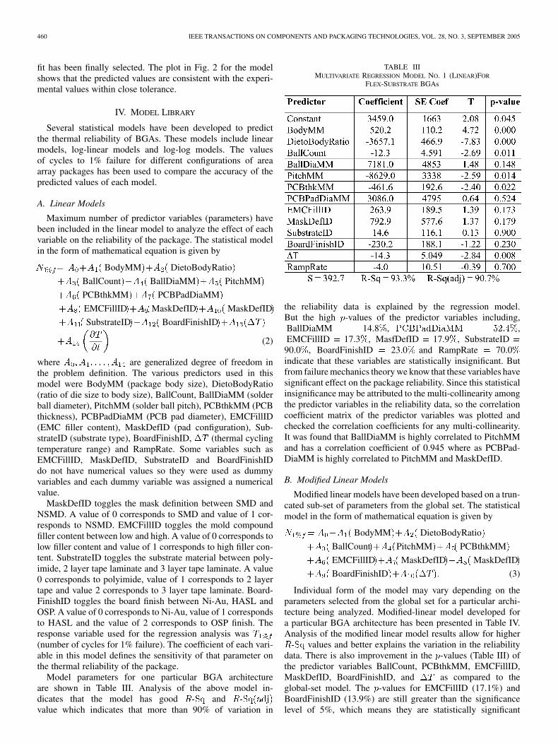
Model parameters for one particular BGA architectureare shown in Table III. Analysis of the above model in-dicates that the model has good andvalue which indicates that more than 90% of variation in
TABLE IIIMULTIVARIATE REGRESSION MODEL NO. 1 (LINEAR)FOR
FLEX-SUBSTRATE BGAs
the reliability data is explained by the regression model.But the high -values of the predictor variables including,BallDiaMM 14.8 , ,EMCFillID 17.3 , MasfDefID 17.9 , SubstrateID90.0 , BoardFinishID 23.0 and RampRate 70.0indicate that these variables are statistically insignificant. Butfrom failure mechanics theory we know that these variables havesignificant effect on the package reliability. Since this statisticalinsignificance may be attributed to the multi-collinearity amongthe predictor variables in the reliability data, so the correlationcoefficient matrix of the predictor variables was plotted andchecked the correlation coefficients for any multi-collinearity.It was found that BallDiaMM is highly correlated to PitchMMand has a correlation coefficient of 0.945 where as PCBPad-DiaMM is highly correlated to PitchMM and MaskDefID.
B. Modified Linear Models
Modified linear models have been developed based on a trun-cated sub-set of parameters from the global set. The statisticalmodel in the form of mathematical equation is given by
BodyMM DietoBodyRatio
BallCount PitchMM PCBthkMM
EMCFillID MaskDefID MaskDefID
BoardFinishID (3)
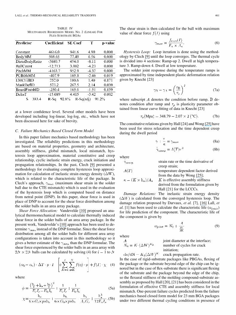
Individual form of the model may vary depending on theparameters selected from the global set for a particular archi-tecture being analyzed. Modified-linear model developed fora particular BGA architecture has been presented in Table IV.Analysis of the modified linear model results allow for higher
values and better explains the variation in the reliabilitydata. There is also improvement in the -values (Table III) ofthe predictor variables BallCount, PCBthkMM, EMCFillID,MaskDefID, BoardFinishID, and as compared to theglobal-set model. The -values for EMCFillID (17.1%) andBoardFinishID (13.9%) are still greater than the significancelevel of 5%, which means they are statistically significant
LALL et al.: THERMO-MECHANICAL RELIABILITY TRADEOFFS 461
TABLE IVMULTIVARIATE REGRESSION MODEL NO. 2 (LINEAR) FOR
FLEX-SUBSTRATE BGAs
at a lower confidence level. Several other models have beendeveloped including log-linear, log-log, etc., which have notbeen discussed here for sake of brevity.
C. Failure Mechanics Based Closed Form Model
In this paper failure mechanics based methodology has beeninvestigated. The reliability predictions in this methodologyare based on material properties, geometry and architecture,assembly stiffness, global mismatch, local mismatch, hys-teresis loop approximation, material constitutive and creeprelationship, cyclic inelastic strain energy, crack initiation andpropagation relationships. In the past, Clech [9] presented amethodology for evaluating complete hysteresis loop approxi-mation for calculation of inelastic strain energy density ( ),which is related to the characteristic life of the package. InClech’s approach, (maximum shear strain in the solderball due to the CTE mismatch) which is used in the evaluationof the hysteresis loop which is computed based on distancefrom netral point (DNP). In this paper, shear force is used inplace of DNP to account for the shear force distribution amongthe solder balls in an area array package.
Shear Force Allocation: Vandevelde [10] proposed an ana-lytical thermomechanical model to calculate thermally inducedshear force in the solder balls of an area array package. In thepresent work, Vandevelde’s [10] approach has been used to de-termine instead of the DNP formulae. Since the shear forcedistribution among all the solder balls for different area arrayconfigurations is taken into account in this methodology so itgives a better estimate of the than the DNP formulae. Theshear force experienced by the solder balls in an area array with
balls can be calculated by solving (4) for 1 to
(4)
where
(5a)
(5b)
The shear strain is then calculated for the ball with maximumvalue of shear force using
(6)
Hysteresis Loop: Loop iteration is done using the method-ology by Clech [9] until the loop converges. The thermal cycleis divided into 4 sections: Ramp-up 2. Dwell at high tempera-ture 3. Ramp-down 4. Dwell at low temperature.
The solder joint response during the temperature ramps isapproximated by time independent plastic deformation relationgiven by Knecht [23]
(7a)
where subscript denotes the condition before ramp, de-notes condition after ramp and is plasticity parameter ob-tained from linear curve fitting of data in Knecht [23]
Mpa 348.79 2.07 C (7b)
The constitutive relations given by Hall [24] and Wong [25] havebeen used for stress relaxation and the time dependent creepduring the dwell period
(8a)
(8b)
wherestrain rate or the time derivative ofcreep strain;temperature dependent factor derivedfrom the data by Wong [25];
is effective assembly stiffnessderived from the formulation given byHall [21] for the LCCCs.
Damage Relations: The inelastic strain energy density( ) is calculated from the converged hysteresis loop. Thedamage relation proposed by Darvaux, et al. [7], [16] Lall, etal. [1] has been used to calculate the characteristic life ( )for life prediction of the component. The characteristic life ofthe component is given by
(9)
wherejoint diameter at the interface;number of cycles for crackinitiation;crack propagation rate.
In the case of rigid-substrate packages like PBGAs, flexing ofthe package or the substrate beyond edge of the chip can be ig-nored but in the case of flex-substrate there is significant flexingof the substrate and the package beyond the edge of the chip,so the flexural stiffness of the molding compound-substrate as-sembly as proposed by Hall [20], [21] has been considered in theformulation of effective CTE and assembly stiffness for localmismatch. One-percent failure cycles predicted from the failuremechanics based closed form model for 23 mm BGA packagesunder two different thermal cycling conditions in presence of

462 IEEE TRANSACTIONS ON COMPONENTS AND PACKAGING TECHNOLOGIES, VOL. 28, NO. 3, SEPTEMBER 2005
Fig. 3. Effect of temperature condition on thermal reliability of 23 mm PBGApackage, in presence of coupled effects of ball array, thermal balls, ball diameter,and die size.
coupled effects of ball array, thermal balls, ball diameter, and diesize, has been plotted in Fig. 3 against the experimental values.
1) 40 C to 125 C with 15 min ramp and 30 min dwell.2) 50 C to 150 C with 15 min ramp and 30 min dwell.
There is a close consistency between the predicted and the ex-perimental values, which validates the model.
V. MODEL VALIDATION
The effect of the various design parameters on the thermal re-liability of the package has been presented. Statistics and failuremechanics based sensitivity factors quantifying the effect ofdesign, material, architecture, and environment parameters onthermal fatigue reliability, have been used to compute life. Thesensitivity factors have been computed by perturbing only thedesired parameter or in conjunction with other geometry andmaterial parameters and evaluating its effect on reliability. Thepredictions from the statistical model has been also comparedwith the experimental data.
A. Die to Package Ratio
The reliability of a ball-grid array package generally de-creases with the increase in the die-to-package ratio. This effecthas been demonstrated in both rigid-substrate and flex-sub-strate packages. The hybrid model has been used to evaluatesensitivity to die-to-body. Packages with compliant elastomericsubstrates (e.g., BGA) may not exhibit this effect. This ratiois often referred to as the packaging ratio in literature.
Experimental data on thermal-fatigue reliability effect ofdie/body ratio on the solder joint thermal fatigue life of differentsizes of BGA packages in thermal cycle of 40 C to 125 Cwith 15 min ramps and 15 min dwells has been correlatedwith the model predictions for 8 mm, 12 mm, 15 mm, 16 mm,17 mm, and 27 mm BGA packages with different die sizes.The cycles for 1% failure from the experimental data and thestatistical model has been plotted against the die to body ratio ofthe various packages. Four layer FR-4 test boards of 0.85 mmand 1.6 mm thickness with OSP finish and SMD pads wereused for the air to air thermal cycling test. The experimental
Fig. 4. Effect of die-to-package ratio on thermal fatigue reliability of BGAsubjected to �40 to 125 C thermal cycle.
Fig. 5. Effect of ball count on thermal fatigue reliability of BGA subjected to�40 to 125 C thermal cycle.
data has been plotted along with the predicted values from thestatistical model. The predicted values from the hybrid modelfollow the experimental values quite accurately and show thesame trend (see Fig. 4).
B. Ball Count
Experimental data indicates that thermal reliability of theBGAs increases with the increase in the ball count of thepackage. The experimental data used correlation includes7.5 mm, 8 mm, 12 mm, 15 mm, and 16 mm BGA packages.Fig. 5 indicates a close agreement between the experimentaldata and the statistical model predictions. The general trendof increase in thermal reliability with the increase in the ballcount can be seen from the plot, which is in agreement withthe failure mechanics theory. Increase in the number of solderballs distributes the thermal deformation over a larger numberof solder joints reducing the stress level in the individual ball.
C. Ball Diameter
The solder joint ball diameter has a pronounced effect on thethermal reliability of the BGA packages. Experimental thermalreliability data has been compared with the statistical model

LALL et al.: THERMO-MECHANICAL RELIABILITY TRADEOFFS 463
Fig. 6. Effect of solder ball diameter on thermal fatigue reliability of BGAsubjected to �40 to 125 C thermal cycle.
predictions. BGA packages evaluated include solder ball diam-eter of 0.30 mm, 0.45 mm, and 0.50 mm. The plot in Fig. 6shows correlation of 1% failure cycles for BGA with variableball diameter. Experimental data indicates that the increase inthe ball diameter leads to overall better thermal reliability of thepackage. This trend is in compliance with the theory of failuremechanics as the increase in the solder ball diameter increasesthe crack area resulting in higher thermal fatigue life.
D. Board Thickness
The decrease in reliability of a ball-grid array package withthe increase in the PCB thickness is evident from the plots inFigs. 7 and 8. This effect is consistent from failure mechanicspoint of view as the increased PCB thickness leads to higherassembly stiffness, which results in higher stresses in the in-terconnect. This effect has been demonstrated in both rigid-substrate and flex-substrate packages. Packages with compliantelastomeric substrates (e.g., BGA) do not exhibit this effect.Sensitivity factor has been computed from the multivariate re-gression model for PCB thickness in the range of 0.85 mm to1.6 mm for BGA packages including 8 mm, 12 mm, 15 mm,and 16 mm BGAs.
E. Mold Compound Filler Content
The thermal reliability of the BGA package decreases withthe increase in the mold compound filler content. The BGA withlower amount of the mold compound filler have better thermalfatigue reliability. This trend is visible in the plots for two dif-ferent 16 mm BGA packages with die-to-body ratio of 0.53 and0.72 (Fig. 9). The value of 0 indicates high filler content andthe value of 1 indicates low filler content for a linear statisticalmodel. Values of 1,10 will be used for log model in place of 0,1.Both the curves have nearly same slope, which implies the cor-rect prediction of the sensitivity of the component’s thermal reli-ability to the mold compound filler content. This trend is consis-tent from the failure mechanics point of view as the higher fillercontent mold compound will have higher elastic modulus anda lower CTE. Higher modulus of elasticity makes the packagestiffer, therefore higher stresses are transmitted to the solder
Fig. 7. Exp. data plot for BGAs (A to H) with die-to-package ratios between0.53 and 0.81, subjected to �40 to 125 C thermal cycle and PCB thickness0.85 and 1.60 mm.
Fig. 8. Statistical model prediction plot for BGAs (A to H) with die-to-packageratios between 0.53 and 0.81, subjected to�40 to 125 C thermal cycle and PCBthickness 0.85 and 1.60 mm.
joints and lower CTE will increase both the local and globalthermal expansion mismatch. Both contributing to poor thermalfatigue reliability of the package.
F. Pad Configuration (SMD/NSMD)
Solder joint reliability in thermal fatigue increases withchange in mask definition from SMD to NSMD. This trendis visible from the 1% failure plot for 15 mm, 160 I/O BGA(Fig. 10). The value of 0 indicates SMD pad configuration andthe value 1 indicates NSMD pad configuration in the plo for alinear statistical model. Values of 1,10 will be used for a logmodel in plane of 0,1. This effect is true for both rigid-substrateand flex-substrate ball grid array packages. Packages with com-pliant elastomeric substrates (e.g., BGA) do not exhibit thiseffect. This trend may vary depending on the mode of failure.The package may show opposite trend in case the failure isdue to the tearing out of the laminate under bending as shownby Mawer et al. [17]. In that case the solder mask of the SMD
464 IEEE TRANSACTIONS ON COMPONENTS AND PACKAGING TECHNOLOGIES, VOL. 28, NO. 3, SEPTEMBER 2005
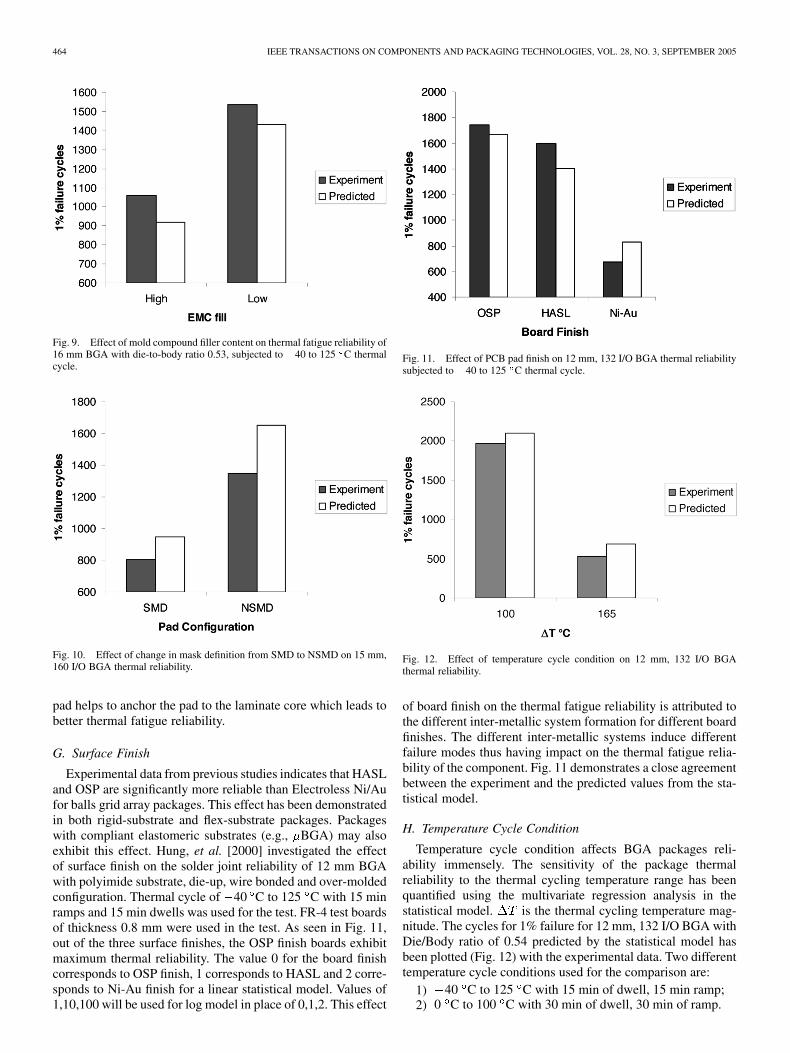
Fig. 9. Effect of mold compound filler content on thermal fatigue reliability of16 mm BGA with die-to-body ratio 0.53, subjected to �40 to 125 C thermalcycle.
Fig. 10. Effect of change in mask definition from SMD to NSMD on 15 mm,160 I/O BGA thermal reliability.
pad helps to anchor the pad to the laminate core which leads tobetter thermal fatigue reliability.
G. Surface Finish
Experimental data from previous studies indicates that HASLand OSP are significantly more reliable than Electroless Ni/Aufor balls grid array packages. This effect has been demonstratedin both rigid-substrate and flex-substrate packages. Packageswith compliant elastomeric substrates (e.g., BGA) may alsoexhibit this effect. Hung, et al. [2000] investigated the effectof surface finish on the solder joint reliability of 12 mm BGAwith polyimide substrate, die-up, wire bonded and over-moldedconfiguration. Thermal cycle of 40 C to 125 C with 15 minramps and 15 min dwells was used for the test. FR-4 test boardsof thickness 0.8 mm were used in the test. As seen in Fig. 11,out of the three surface finishes, the OSP finish boards exhibitmaximum thermal reliability. The value 0 for the board finishcorresponds to OSP finish, 1 corresponds to HASL and 2 corre-sponds to Ni-Au finish for a linear statistical model. Values of1,10,100 will be used for log model in place of 0,1,2. This effect
Fig. 11. Effect of PCB pad finish on 12 mm, 132 I/O BGA thermal reliabilitysubjected to �40 to 125 C thermal cycle.
Fig. 12. Effect of temperature cycle condition on 12 mm, 132 I/O BGAthermal reliability.
of board finish on the thermal fatigue reliability is attributed tothe different inter-metallic system formation for different boardfinishes. The different inter-metallic systems induce differentfailure modes thus having impact on the thermal fatigue relia-bility of the component. Fig. 11 demonstrates a close agreementbetween the experiment and the predicted values from the sta-tistical model.
H. Temperature Cycle Condition
Temperature cycle condition affects BGA packages reli-ability immensely. The sensitivity of the package thermalreliability to the thermal cycling temperature range has beenquantified using the multivariate regression analysis in thestatistical model. is the thermal cycling temperature mag-nitude. The cycles for 1% failure for 12 mm, 132 I/O BGA withDie/Body ratio of 0.54 predicted by the statistical model hasbeen plotted (Fig. 12) with the experimental data. Two differenttemperature cycle conditions used for the comparison are:
1) 40 C to 125 C with 15 min of dwell, 15 min ramp;2) 0 C to 100 C with 30 min of dwell, 30 min of ramp.
LALL et al.: THERMO-MECHANICAL RELIABILITY TRADEOFFS 465
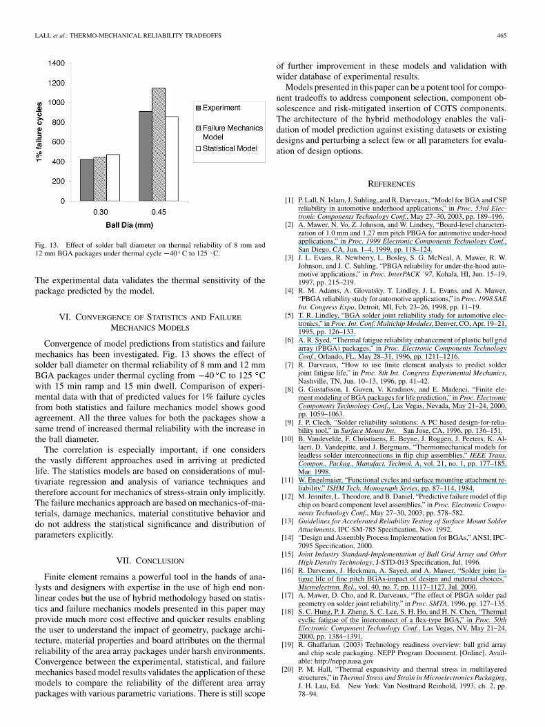
Fig. 13. Effect of solder ball diameter on thermal reliability of 8 mm and12 mm BGA packages under thermal cycle �40 C to 125 C.
The experimental data validates the thermal sensitivity of thepackage predicted by the model.
VI. CONVERGENCE OF STATISTICS AND FAILURE
MECHANICS MODELS
Convergence of model predictions from statistics and failuremechanics has been investigated. Fig. 13 shows the effect ofsolder ball diameter on thermal reliability of 8 mm and 12 mmBGA packages under thermal cycling from 40 C to 125 Cwith 15 min ramp and 15 min dwell. Comparison of experi-mental data with that of predicted values for 1% failure cyclesfrom both statistics and failure mechanics model shows goodagreement. All the three values for both the packages show asame trend of increased thermal reliability with the increase inthe ball diameter.
The correlation is especially important, if one considersthe vastly different approaches used in arriving at predictedlife. The statistics models are based on considerations of mul-tivariate regression and analysis of variance techniques andtherefore account for mechanics of stress-strain only implicitly.The failure mechanics approach are based on mechanics-of-ma-terials, damage mechanics, material constitutive behavior anddo not address the statistical significance and distribution ofparameters explicitly.
VII. CONCLUSION
Finite element remains a powerful tool in the hands of ana-lysts and designers with expertise in the use of high end non-linear codes but the use of hybrid methodology based on statis-tics and failure mechanics models presented in this paper mayprovide much more cost effective and quicker results enablingthe user to understand the impact of geometry, package archi-tecture, material properties and board attributes on the thermalreliability of the area array packages under harsh environments.Convergence between the experimental, statistical, and failuremechanics based model results validates the application of thesemodels to compare the reliability of the different area arraypackages with various parametric variations. There is still scope
of further improvement in these models and validation withwider database of experimental results.
Models presented in this paper can be a potent tool for compo-nent tradeoffs to address component selection, component ob-solescence and risk-mitigated insertion of COTS components.The architecture of the hybrid methodology enables the vali-dation of model prediction against existing datasets or existingdesigns and perturbing a select few or all parameters for evalu-ation of design options.
REFERENCES
[1] P. Lall, N. Islam, J. Suhling, and R. Darveaux, “Model for BGA and CSPreliability in automotive underhood applications,” in Proc. 53rd Elec-tronic Components Technology Conf., May 27–30, 2003, pp. 189–196.
[2] A. Mawer, N. Vo, Z. Johnson, and W. Lindsey, “Board-level characteri-zation of 1.0 mm and 1.27 mm pitch PBGA for automotive under-hoodapplications,” in Proc. 1999 Electronic Components Technology Conf.,San Diego, CA, Jun. 1–4, 1999, pp. 118–124.
[3] J. L. Evans, R. Newberry, L. Bosley, S. G. McNeal, A. Mawer, R. W.Johnson, and J. C. Suhling, “PBGA reliability for under-the-hood auto-motive applications,” in Proc. InterPACK ’97, Kohala, HI, Jun. 15–19,1997, pp. 215–219.
[4] R. M. Adams, A. Glovatsky, T. Lindley, J. L. Evans, and A. Mawer,“PBGA reliability study for automotive applications,” in Proc. 1998 SAEInt. Congress Expo, Detroit, MI, Feb. 23–26, 1998, pp. 11–19.
[5] T. R. Lindley, “BGA solder joint reliability study for automotive elec-tronics,” in Proc. Int. Conf. Multichip Modules, Denver, CO, Apr. 19–21,1995, pp. 126–133.
[6] A. R. Syed, “Thermal fatigue reliability enhancement of plastic ball gridarray (PBGA) packages,” in Proc. Electronic Components TechnologyConf., Orlando, FL, May 28–31, 1996, pp. 1211–1216.
[7] R. Darveaux, “How to use finite element analysis to predict solderjoint fatigue life,” in Proc. 8th Int. Congress Experimental Mechanics,Nashville, TN, Jun. 10–13, 1996, pp. 41–42.
[8] G. Gustafsson, I. Guven, V. Kradinov, and E. Madenci, “Finite ele-ment modeling of BGA packages for life prediction,” in Proc. ElectronicComponents Technology Conf., Las Vegas, Nevada, May 21–24, 2000,pp. 1059–1063.
[9] J. P. Clech, “Solder reliability solutions: A PC based design-for-relia-bility tool,” in Surface Mount Int. San Jose, CA, 1996, pp. 136–151.
[10] B. Vandevelde, F. Christiaens, E. Beyne, J. Roggen, J. Peeters, K. Al-laert, D. Vandepitte, and J. Bergmans, “Thermomechanical models forleadless solder interconnections in flip chip assemblies,” IEEE Trans.Compon., Packag., Manufact. Technol. A, vol. 21, no. 1, pp. 177–185,Mar. 1998.
[11] W. Engelmaier, “Functional cycles and surface mounting attachment re-liability,” ISHM Tech. Monograph Series, pp. 87–114, 1984.
[12] M. Jennifer, L. Theodore, and B. Daniel, “Predictive failure model of flipchip on board component level assemblies,” in Proc. Electronic Compo-nents Technology Conf., May 27–30, 2003, pp. 578–582.
[13] Guidelines for Accelerated Reliability Testing of Surface Mount SolderAttachments, IPC-SM-785 Specification, Nov. 1992.
[14] “Design and Assembly Process Implementation for BGAs,” ANSI, IPC-7095 Specification, 2000.
[15] Joint Industry Standard-Implementation of Ball Grid Array and OtherHigh Density Technology, J-STD-013 Specification, Jul. 1996.
[16] R. Darveaux, J. Heckman, A. Sayed, and A. Mawer, “Solder joint fa-tigue life of fine pitch BGAs-impact of design and material choices,”Microelectron. Rel., vol. 40, no. 7, pp. 1117–1127, Jul. 2000.
[17] A. Mawer, D. Cho, and R. Darveaux, “The effect of PBGA solder padgeometry on solder joint reliability,” in Proc. SMTA, 1996, pp. 127–135.
[18] S. C. Hung, P. J. Zheng, S. C. Lee, S. H. Ho, and H. N. Chen, “Thermalcyclic fatigue of the interconnect of a flex-type BGA,” in Proc. 50thElectronic Component Technology Conf., Las Vegas, NV, May 21–24,2000, pp. 1384–1391.
[19] R. Ghaffarian. (2003) Technology readiness overview: ball grid arrayand chip scale packaging. NEPP Program Document. [Online]. Avail-able: http://nepp.nasa.gov
[20] P. M. Hall, “Thermal expansivity and thermal stress in multilayeredstructures,” in Thermal Stress and Strain in Microelectronics Packaging,J. H. Lau, Ed. New York: Van Nosttrand Reinhold, 1993, ch. 2, pp.78–94.

466 IEEE TRANSACTIONS ON COMPONENTS AND PACKAGING TECHNOLOGIES, VOL. 28, NO. 3, SEPTEMBER 2005
[21] , “Forces, moment, and displacements during thermal chamber cy-cling of leadless ceramic chip carriers soldered to printed boards,” IEEETrans. Compon., Hybrids, Manufact Technol., vol. 7, no. 4, pp. 314–327,Dec. 1994.
[22] P. Lall, M. Pecht, and E. Hakim, Influence of Temperature on Microelec-tronic and System Reliability. Boca Raton, FL: CRC Press, 1997.
[23] S. Knecht and L. Fox, “Integrated matrix creep: Application to acceler-ated testing and lifetime prediction,” in Solder Joint Reliability: Theoryand Applications, J. H. Lau, Ed. New York: Van Nostrand Reinhold,1991, ch. 16, pp. 508–544.
[24] P. M. Hall, “Creep and stress relaxation in solder joints,” in Solder JointReliability: Theory and Applications, J. H. Lau, Ed. New York: VanNostrand Reinhold, 1991, ch. 10, pp. 306–332.
[25] B. Wong, D. E. Helling, and R. W. Clark, “A creep rupture model for twophase eutectic solders,” IEEE Compon., Hybrids, Manufact. Technol.,vol. 11, no. 3, pp. 284–290, Sep. 1988.
Pradeep Lall (M’00) received the B.E. degree in me-chanical engineering from the Delhi College of Engi-neering, Delhi, India, the M.S. and Ph.D. degrees inmechanical engineering from the University of Mary-land, College Park, and the MBA degree from Kel-logg Graduate School of Management, NorthwesternUniversity, Evanston, IL.
He has ten years of industry experience. He waspreviously with Motorola’s Wireless TechnologyCenter. He is currently an Associate Professor withDepartment of Mechanical Engineering and Asso-
ciate Director of the NSF Center for Advanced Vehicle Electronics at AuburnUniversity. He has published extensively in the area of electronic packagingwith emphasis on modeling and predictive techniques. He has authored andco-authored several book chapters and is an Associate Editor for the ASMEJournal of Electronic Packaging. He is lead author of the book Influence ofTemperature on Microelectronic and Device Reliability (Boca Raton, FL: CRC,1997). He holds three U.S. Patents.
Dr. Lall received three Motorola Outstanding Innovation Awards, fiveMotorola Engineering Awards, and four Publication Awards. His publicationshave received nine Best Paper Awards. He is an Associate Editor for the IEEETRANSACTIONS ON ELECTRONICS PACKAGING MANUFACTURING and a memberof Beta Gamma Sigma. He is also a Six-Sigma Black-Belt in Statistics.
Naveen Chandra Singh received the B.S. degreein aerospace engineering from Punjab EngineeringCollege, Punjab University, Chandigarh, India andis currently pursuing the Ph.D. degree in mechanicalengineering at Auburn University, Auburn, AL.
He was Research and Development Engineer withPunjab Tractors, Ltd., India, from 1997 to 2002. Heis now a Research Assistant in the Department ofMechanical Engineering, Auburn University. His re-search areas include electronic packaging reliabilityunder harsh thermo-mechanical environment, with
emphasis on modeling and experimental techniques.
Jeffrey C. Suhling (M’01) received the B.S. degree(with distinction) in applied mathematics, engi-neering, and physics and the M.S. and Ph.D. degreesin engineering mechanics from the University ofWisconsin, Madison, in 1980, 1981, and 1985,respectively.
He joined the Department of Mechanical Engi-neering, Auburn University, Auburn, AL, in 1985,where he currently holds the rank of Quina Dis-tinguished Professor. At Auburn, he serves as theDirector of the NSF Center for Advanced Vehicle
Electronics, which is an Industry University Cooperative Research Center(IUCRC) with 12 member companies. He has authored over 150 technicalpublications, and has advised over 50 graduate students. His research interestsinclude the application of analytical, numerical, and experimental methods ofsolid mechanics to problems in electronic packaging.
Dr. Suhling received the Outstanding Mechanical Engineering FacultyMember Award from the undergraduate students in 1990, the College of Engi-neering Birdsong Superior Teaching Award in 1994, the College of EngineeringSenior Research Award in 2001, and the National Science Foundation GraduateFellowship, from 1980 to 1983. He is a member of Phi Beta Kappa, Phi KappaPhi, and Sigma XI.
Mark Strickland received the B.S. degree in elec-trical and computer engineering from the Universityof Alabama, Huntsville, in 1986.
He has been with the George C. Marshall SpaceFlight Center (MSFC), NASA, Huntsville, since1988 serving in various positions. Previously, hewas the lead of the Quality Engineering and SupportTeam, Safety and Mission Assurance Office. In thisrole, he served as a Technical Consultant on elec-tronics to numerous space flight projects. Currently,he is the technical lead of the Packaging Research
Lab, EEE Design and Fabrication Division, MSFC. In addition to area arraypackaging, his research interests include embedded packaging technology andlead-free solder alloys.
Jim Blanche received the B.S. degree in mechanicalengineering from Louisiana State University, BatonRouge, in 1955.
He was with Convair, Fort Worth, TX, from1955 to 1956, the Ballistics Research Laboratory,Aberdeen Proving Ground, MD, from 1956 to1958, and joined the Army Ballistic Missile Agency(ABMA), Huntsville, AL, in 1958. He was a CharterMember of NASA’s Marshall Space Flight Centerand has 45 years experience in electronic packagingdesign. At the time of his retirement from NASA, he
was the Group Leader of the Electronic Parts and Packaging Group, AvionicsDepartment. Throughout the Saturn Program he was one of three membersof the MSFC ad hoc Solder Committee. During the Shuttle development hehad technical responsibility for the design, development, qualification, andflight evaluation of the Solid Rocket Booster Integrated Electronics Assembly(IEA). He has been a Member of the NASA Workmanship Standards TechnicalCommittee since 1983. He authored or co-authored all of the MSFC and NASAelectrical workmanship standards for soldering, crimping and wirewrap, con-formal coating and staking, cabling and harnessing, printed wiring board designand fabrication, and ESD control, and served as the NASA Volume Leaderfor two of them. He has been working as part of the Joint Group for PollutionPrevention (JG-PP) Lead-Free Solder Task Group since 2002. Currently, he isan Advanced Electronic Packaging Engineer with Allied Aerospace workingwith the EEE Parts and Packaging Group, Marshall Space Flight Center.
Copyright © 2022 FDOKUMEN