Thermally regulated cylinder for adsorption storage of a hydrogenous gas
9
This article appeared in a journal published by Elsevier. The attached copy is furnished to the author for internal non-commercial research and education use, including for instruction at the authors institution and sharing with colleagues. Other uses, including reproduction and distribution, or selling or licensing copies, or posting to personal, institutional or third party websites are prohibited. In most cases authors are permitted to post their version of the article (e.g. in Word or Tex form) to their personal website or institutional repository. Authors requiring further information regarding Elsevier’s archiving and manuscript policies are encouraged to visit: http://www.elsevier.com/authorsrights
-
Upload
independent -
Category
Documents
-
view
3 -
download
0
Transcript of Thermally regulated cylinder for adsorption storage of a hydrogenous gas

This article appeared in a journal published by Elsevier. The attachedcopy is furnished to the author for internal non-commercial researchand education use, including for instruction at the authors institution
and sharing with colleagues.
Other uses, including reproduction and distribution, or selling orlicensing copies, or posting to personal, institutional or third party
websites are prohibited.
In most cases authors are permitted to post their version of thearticle (e.g. in Word or Tex form) to their personal website orinstitutional repository. Authors requiring further information
regarding Elsevier’s archiving and manuscript policies areencouraged to visit:
http://www.elsevier.com/authorsrights

Author's personal copy
Thermally regulated cylinder for adsorption storageof a hydrogenous gas
L.L. Vasiliev, L.E. Kanonchik ⇑, M.I. RabetskyA.V. Luikov Heat and Mass Transfer Institute, National Academy of Sciences of Belarus, 15 P. Brovka Str., Minsk 220072, Belarus
a r t i c l e i n f o
Article history:Received 12 August 2013Received in revised form 4 November 2013Accepted 9 December 2013Available online 3 January 2014
Keywords:HydrogenCylinderSorbentStorageHeat pipeChargingDischargingExperimentModel
a b s t r a c t
A real alternative to a standard cylinder with compressed hydrogen or methane is the adsorption tech-nology of a storing these gases at moderate pressures of 3.5–6 MPa. A thermally regulated heat pipe-based cylinder intended for onboard storage of a hydrogenous gas in an adsorbed form is described. Atwo-dimensional numerical model of heat and mass transfer and sorption processes in such a cylinderis suggested. The fins and heat pipe shell were used as part of the computational domain. Simulationsof gas charging and discharging are performed using the commercial finite volume flow solver Fluenton ANSYS.
An experimental setup has been developed and data on the dynamic behavior of the carbon fibrousmaterial-packed cylinder with hydrogen have been obtained and compared with calculations. The resultsof this work can be used in designing systems for adsorptive storage of hydrogen or methane that are ofinterest for power engineering, transport, and private usage.
� 2013 Elsevier Ltd. All rights reserved.
1. Introduction
Hydrogen and methane are universal heat carriers and energyaccumulators. The main advantages of their application are dueto their high caloric power, flexibility, and efficiency of the pro-cesses of energy transformation and the suitability for thermal en-gines without any substantial changes in their construction.Hydrogen and methane are capable of replacing any one of fuelsin different branches of industry, power engineering, and trans-port. Hydrogen and methane do not contain toxic substances thatare added, for example, to gasoline to raise its octane number. Theunquestionable advantages of using hydrogen and methane is theirecological safety and the possibility of decreasing solid waste andharmful automobile ejections, as well as eliminating the green-house effect. One of the central problems in extensive applicationof a hydrogenous gas (hydrogen, methane, and their mixtures) isthe high cost of their storage and transportation because of theirlow density in a gaseous state and low volumetric heat value. Atatmospheric pressure and conventional temperature, 1 kg ofhydrogen occupies a volume of 11 m3. The high metal content oftraditional vessels with a compressed gas, large energy expendi-tures on liquefaction of gas at cryogenic temperatures or its
compression up to 35–69 MPa, in combination with the negativeeffect on the properties of structural materials put the problemof developing the systems of rational storage of hydrogenous gasin the forefront and require the devising of new promisingmaterials.
According to the standards [1] developed in different countries(Table 1), the present-day mobile system of hydrogen storage musthave a storing capacity of 6–7 wt.% at mean pressures of 2–5 MPaand temperatures of 273–363 K, a holding capacity of 5 kg, and aspecific energy of 7.2 MJ/kg. The Department of Energy of theUSA has set an object of increasing the hydrogen storage capacityup to 9 wt.% by the year 2015 and shorten the time of chargingto 2.5 min [2]. At the present time, there is no universal methodof storing that would satisfy the above-formulated technical–oper-ational requirements. The sorption technology of storing is closestto the practical realization of storage. This is the real alternative tocompression up to high pressures or to gas liquefaction at low tem-peratures. The mass characteristics of such storage systems thatexclude the possibility of explosion on leakage are comparablewith high-pressure vessels and gradually approach on the average6 wt.%. Such hydrogen adsorptive storage systems will find wideapplication in transport, power engineering (autonomous energysources for decentralized use), as small-size power sources/accu-mulators of electronic devices (cellphones, portable computers,etc.).
0017-9310/$ - see front matter � 2013 Elsevier Ltd. All rights reserved.http://dx.doi.org/10.1016/j.ijheatmasstransfer.2013.12.018
⇑ Corresponding author. Tel.: +375 0172842223; fax: +375 0172842133.E-mail address: [email protected] (L.E. Kanonchik).
International Journal of Heat and Mass Transfer 71 (2014) 125–132
Contents lists available at ScienceDirect
International Journal of Heat and Mass Transfer
journal homepage: www.elsevier .com/locate / i jhmt

Author's personal copy
Noticeable advances have been made recently in the develop-ment of the systems of on-board storage of hydrogen, especiallywith the aid of carbon materials and metal hydrides. All the mate-rials capable of storing bound hydrogen can be subdivided ratherconventionally by the energy of binding an atom or a molecule ofhydrogen with this material [2]. An important advantage of carbonsorbents is the decrease in energy expenditures on conductingdesorption of gas molecules (to 2–4 � 10 kJ/mole) as comparedwith metal hydrides (50–100 kJ/mole). The high specific surfaceand density, large volume of micropores, and the low cost areessential positive qualities of carbon sorbent-fillers of transportcylinders. The specific surface and specific capacity per unit vol-ume and unit mass, the heat and kinetics of sorption can be relatedto the basic criteria with the aid of which one can preliminarily se-lect porous materials that would be potentially promising for thesystems of bound storage of gas. They determine such workingparameters as the stock of gas, as well as duration of chargingand discharging. Despite the different mechanisms of gas accumu-lation, the materials used as fillers in storage systems must con-form to the requirements of economy, safety, and reliability; theymust have an optimum mass for specific application; the capabilityfor multiple charging and discharging. Often, as sorbents for gasstorage, preference is given to activated carbons obtained as a re-sult of thermal treatment of raw material (wood, saw dust, cellu-lose, peat, etc.) after impregnating them [3]. In Belarus, thecarbon fibrous material ‘‘Busofit’’ is produced industrially in thisway (the product of pyrolysis of impregnated cellulose). Such fi-bers can rather strongly hold molecules of both hydrogen and
methane because of the complex polymodal structure formed bythe micropores, macropores, and mesopores and of the presenceof a large number of defects.
The thermal effects of the processes of adsorption/desorptionare closely related to the external heat transfer of the storage sys-tem, thermophysical properties of structural materials, and to theorganization of heat transfer in the sorbent bed. The adsorptionoccurring in the course of cylinder charging with a hydrogenousgas is an exothermal process. An increase in the sorbent tempera-ture, caused by release of the latent heat of phase transition and bythe very low thermal conductivity equal to 0.1–0.4 W/(m � K), leadsto a decrease in the quantity of gas stored under dynamic condi-tions as against the expected quantity. During discharging, the sor-bent, on the contrary, is cooled additionally because of theendothermal character of desorption. This results in the formationof a unrecovered gas residue which decreases the efficiency of itsusage. As follows from the investigations performed in [4–6], thetemperature of the storing system is an important factor thatdetermines the kinetics and thermodynamics of the processes offilling and extraction of gas. This causes the necessity of regulatingthe supplied and removed heat fluxes.
To make the sorption method of storing hydrogenous gas com-petitive, it is necessary not only to seek for new sorptive materialswith improved properties, but also to design devices of thermalregulation capable of controlling the distribution and level of tem-perature in the sorbent bed and to influence the quantity of storedgas and the rate of its accumulation. The present paper considersthe problems of development, experimental investigation, and
Nomenclature
a current adsorption [kg/kg]aeq equilibrium adsorption [kg/kg]ag adsorbability [wt.%]C heat capacity [J/(kg � K)]Ds0 phenomenological constantE activation energy [J/kg], sorption characteristic energy
[J/kg]Eg total gas energy [J]Es total energy of a solid sorbent [J]F force vector [N]K permeability [m2]Ks0 ¼ 15Ds0=R2
pP pressure [MPa]qst isosteric heat of adsorption [J/kg]Rl gas constant [J/(kg � K)]Rp mean particle radius [m]S spacing between fins [mm]T temperature [K]u velocity vector [m/s]ma specific volume [m3/kg]W0 maximum specific volume of micropores [m3/kg]e sorbent bed porosity
kef effective thermal conductivity of the sorbent bed [W/(m � K)]
l dynamic viscosity [kg/(m � s)]qs sorbent density [kg/m3]q sorbent bed density [kg/m3]qg gas density [kg/m3]qg gravimetric storage density of gas in sorbent bed [wt.%]qv volumetric storage density of gas in sorbent bed [nm3/
m3]sst stress tensor [Pa]s time [s]
Subscriptsa adsorbatecr criticalend final valueeq equilibrium conditiong gashp heat pipes sorbent0 initial value
Table 1Main requirements places upon the hydrogen storage system [1].
Parameters Dept.of Energy of the USA (DOE) Japan government program (WE-NET) International Energy Agency (IEA)
Quantity of H2, wt.% >6 >3 >5Density, kg/m3 >45–60 – –Cost, US $/kg H2 >40–130 – –Charging time, min 1–10 1–10 1–10Temperature of H2 desorption, K 273–363 374–423 353Specific energy, MJ/kg 7.2 – –Cyclic stability >90% after 5000 cycles
126 L.L. Vasiliev et al. / International Journal of Heat and Mass Transfer 71 (2014) 125–132

Author's personal copy
numerical simulation of a thermally regulated system of on-boardstorage of hydrogenous gas in an adsorbed state. The paperdescribes a setup and analyzes the results of investigation of thefilling up hydrogen into a cylinder packed with activated carbonfibrous material.
2. Description of construction of the cylinder and numericalsimulation
The schematic of the computational 2-D axisymmetrical do-main corresponding to a thermally regulated cylinder is given inFig. 1a. In essence, the cylinder is a pressurized reservoir filled witha microporous sorbent and provided with an inlet valve combiningheat transfer and sorptional unsteady-state processes. In one of itsends there is a hole for supplying/tapping a gas, with the secondend face being blind. The sorbent bed is surrounded by a thin, per-forated tube. There is a small annular gap between the sorbent bedand the cylinder wall. The annular channel acts like a gas collectorthrough which the gas moves along the cylinder to the pressureregulator. The gas flow rate is maintained constant with the helpof a pressure regulator. To decrease the negative influence of sorp-tion heat and temperature gradients, a heat exchanging element ismounted in the sorbent bed. As the heat-exchanging element, usecan be made of a heat pipe, thermosyphon, a single-phase or two-phase heat exchanging loop. Highly conducting metal inserts canbe fastened to the inside wall of the cylinder casing or to theheat-exchanging element built into the sorbent.
The numerical model of the processes of heat and mass transferin a sorption system of storing a hydrogenous gas is based on thesystem of two-dimensional partial differential equations of mass,momentum, and energy transfer for a homogeneous porous med-ium with source terms owing their origin to viscous and inertiallosses and volumetric heat generation [7,8]:
@qg
@sþr � ðqguÞ ¼ �qs
ð1� eÞe
@a@s; ð1Þ
@
@sðqguÞ þ r � ðqguuÞ ¼ �rP þr � sst �
lK
uþ C2juju� �
; ð2Þ
@
@sðeqgEg þ ð1� eÞq�sEsÞ þ r � ðuðqgEg þ PÞÞ
¼ r � ðkefrTÞ þ qstð1� eÞqs@a@s: ð3Þ
In analyzing heat transfer in the adsorption based cylinder, useis made of the one-temperature approximation, since the temper-ature of the gaseous and solid phases coincide because of the highvalue of the coefficient of volumetric heat exchange between them.The viscous dissipation in Eq. (3) may also be neglected. Eq. (3)takes into account that the total heat capacity of the sorbent bed
unit volume includes not only the heat capacity of the gaseousand solid phases, but also the heat capacity of the adsorbedhydrogenous gas [9]:
q�s ¼ qsð1þ aCa=CsÞ: ð4Þ
In the case of the adsorption above the critical temperature thespecific heat of adsorbed hydrogen is considered to be equal to thespecific heat of free gas at a pressure of 80 MPa, occupying theadsorption microporous space [10]. Its temperature dependenceis described by the cubic obtained by fitting with the experimentaldata reported in [11]:
Ca ¼ 0:000344T3 � 0:31646T2 þ 95:1001T þ 5776:8553: ð5Þ
The thermodynamic properties of the gas phase are specified bythe equation of state of an ideal gas (this assumption is valid below20 MPa).
qg ¼P
RlTð6Þ
The isosteric heat of adsorption (which derive from the adsorptionequilibrium isotherms) can be calculated using the Clausius–Cla-peyron equation
qst ¼ RlT @ ln P=@ ln T½ �jaeq¼const: ð7Þ
The effective thermal conductivity of the packed sorbent bed, whichis characterized by an effective (hydrodynamic) porosity e, is deter-mined from the equation
kef ¼ ekg þ ð1� eÞks; ð8Þ
where kg is the thermal conductivity of the gas and ks is the thermalconductivity of the sorbent. Note that Eq. (8) allows one to quicklyand easily assess the value of the effective thermal conductivity ofthe porous medium, despite the lower accuracy. Such an approachdoes not take into account the effect of contact factors, complexpolymodal structure of the sorbent, and considers it as a homoge-neous system of two components: the solid phase and the gasphase.
The numerical model is supplemented with the approximate ki-netic equation and modified Dubinin–Radushevich’s equation ofisothermal sorption, extended to the supercritical regime:
@a@s¼ ðaeq � aÞ � Ks0 exp � E
RlT
� �; ð9Þ
aeq ¼W0
vaexp � RlT
Eln
Pcr
P� T
Tcr
� �2 !" #2
8<:
9=;: ð10Þ
For a free gas in the free space of the cylinder, in the gas channelwhere the porosity is equal to unity, the energy and mass balanceequations are solved together with the Navier–Stokes equations.
Fig. 1. Schematic of the computational cell (a) and mesh (b) for the thermally regulated cylinder with finned heat pipe: ( ) cylinder casing; ( ) annular gas channel; ( )sorbent; ( ) heat pipe shell (outer diameter 0.02 m); ( ) free gas volume located before the sorbent bed; ( ) cylinder flange; (x) monitoring point of temperature andthermopair location.
L.L. Vasiliev et al. / International Journal of Heat and Mass Transfer 71 (2014) 125–132 127

Author's personal copy
In the metal elements of the construction that have zero porosity,we consider the heat conduction equation.
The simulations were performed using the commercial finitevolume flow solver Fluent on ANSYS. We utilized the user-definedscalar (UDS) to simulate the transport equations and adsorptionphenomena into a cylinder with activated carbon fibrous materialand gas. The C programming language has been used to write thecodes in the User’s Defined Functions (UDF) file for customizingthe UDS equation. Evidently from Fig. 1b, mesh boundaries coin-cide with the boundaries of the computational domain The gridconsists of 9065 cells with 9864 nodes. Note that pressure basedsolver and adaptive time stepping method were applied.
The two-dimensional distributions of temperature, sorption,pressure, and velocity in time form a basis for finding such impor-tant characteristics as the gravimetric density of storage (the ratioof the total mass of adsorbed and compressed gas in the cylinder tothe mass of sorbent), the adsorbability (percent content of ad-sorbed gas in the sorbent unit mass), and the dynamic coefficientof cylinder filling m (the ratio of the current gas amount in the cyl-inder to its value at the storage pressure Pst and storage tempera-ture Tst). Other characteristics of the process are the time of gascharging (or discharging) and the average volumetric temperatureand pressure of the sorbent bed.
3. Experimental setup
The schematic diagram of the developed experimental setup isgiven in Fig. 2. The setup is intended for carrying out experimentalinvestigations of steady-state and dynamic regimes of the pro-cesses of sorption of hydrogenous gas in solid sorbents.
The setup consists of the following functional blocks:
(1) a block for storage (holding) of standard pressure vessels(�20 MPa) with the test gases and helium, which are placedon the frame in a metal cabinet;
(2) a block of calibrating cylinders which provides pre-storing apredetermined amount of tested gas; it includes an air sys-tem of thermostatting, valves for manual and automatic fill-ing of cylinders, temperature and pressure sensors;
(3) a block of flow meters which consists of a system of cocksand valves, two Flow-Lo and Flow-Hi devices for differentmeasurement ranges and for controlling the volumetricand mass flow rates of the adsorbed and desorbed gas;
(4) a vacuum pumping block consisting of an oil-free volute andturbomolecular pumps with cocks and an exhaust line (intothe ventilation); it is intended for removing air and othergases from the setup;
(5) a block of sorption that includes a test cylinder with a cut-offcock, a pressure sensor, thermocouples, joints, and a HL85thermostat. The cylinder filled with a sorbent is equippedwith a double-pipe heat exchanger, and a thermostating sys-tem; a separate detachable electric heater is mounted to per-form desorption on its outside wall;
(6) a system of acquisition and analysis of experimental datawith an Agilent HP3497OA multimeter, an Agilent N670Apower source with two 300 W channels, communicationcables, and a computer.
The combination of the positions of the switches of cocks en-sures the pumping out of the setup loop, of the sorbent-filled cyl-inder, performing sorption and desorption that correspond to gascharging into the sorbent-filled cylinder and its discharging. Thevalues of temperature in different zones of the adsorption basedcylinder and of the calibrating volume are controlled by the cop-per-constantan thermocouples, made from a special thermocouplewire. The thermocouples were calibrated preliminarily with the aidof a laboratory thermometer (with a scale spacing of 0.1 �C). Theaccuracy of temperature measurement is ±0.1 �C. The data are re-corded by a universal device, Agilent 34980A, with subsequentprocessing on a computer. The base and additional modules of Agi-lent 34980A controlle the automatic cocks and flow rate regulators.
The setup elements subjected to an elevated pressure are madeof stainless steel. The volumes of pipelines, cocks, and valves, thefree volume of the experimental cylinder (ballast volumes) aredetermined preliminarily and are the characteristics of the setup.
The test cylinder of external volume 2.8 L contains the prelimi-narily determined amount of sorbent. Sorbent formed by pressinglumps (of length not exceeding 50 lm) of carbon fiber ‘‘Busofit’’was additionally activated in a gas medium [3]. The characteristics
Fig. 2. Schematic of experimental setup for investigation of steady-state and dynamic operating conditions of the processes of hydrogenous gas sorption in the cylinder.
128 L.L. Vasiliev et al. / International Journal of Heat and Mass Transfer 71 (2014) 125–132

Author's personal copy
of this sorbent are presented in Table 2. The steel casing of cylinderhad the outside radius equal to 0.051 m and the thickness of thewall of 0.006 m. The aluminum fins (disks of thickness 0.5 mm)are attached to the outer wall of the heat exchanger (the step offinning is about 0.013 m). The height of the fins was in line withthe outer boundary of the annular sorbent bed with radii 0.01 mand 0.0428 m.
4. Results and discussion
Test of the fabricated adsorption-based cylinder was carried outin the course of its two-step filling with hydrogen at the inlet massflow rate of 0.003 g/s. It is maintained constant with the help of themass flow controller. Initially, hydrogen at a temperature of 293 Kentered the cylinder until the pressure in it was 4 MPa. Thereafterthe supply of hydrogen was stopped, and the working fluid havinga constant temperature of 233 K was pumped by the thermostatthrough the double-pipe heat exchanger that is built into the sor-bent bed. As a result, the cylinder is cooled, its pressure was re-duced. When the average temperature of the sorbent bed wasdecreased to 238 K, the hydrogen supply was resumed. After theestablishment of the pressure at 3.5 MPa and the stable tempera-ture the adsorption process is considered complete and the cylin-der was precharged. The amount of stored gas was measuredwith the aid of the calibrating block, pressure sensors, and flowmeters.
To confirm the reliability of numerical simulation, the results ofcalculations were compared with experimental data. Fig. 3 illus-trates satisfactory agreement, with experimental data, of computa-tional dependences of the mean temperature and pressure in asorbent on time; these dependences are related to the character
of the change in the amount of hydrogen stored in the process ofslow charging.
Due to the influence of many factors on the progress of unstea-dy-state processes of heat and mass transfer and sorption, it is dif-ficult to choose an efficient material and construction of thecylinder proceeding only from the results of testing. The suggestedmodel was used to analyze the influence of aluminum inclusions inthe sorbent volume with low effective thermal conductivity on thecharacteristics of charging and discharging cycle of hydrogen sorp-tion storage. Two constructions of the storage cylinder were com-pared: the axially built-in heat pipe without fins (i.e., the sorbentbed without metal radial inserts) and a heat pipe with regularly ar-ranged radial fins having an ideal thermal contact with the heatpipe surface.
The problem of the thermally regulated cylinder modelingamounts to consideration of different charging/discharging scenar-ios and to the choice of the best one. It is assumed that at the firststage of charging (fueling) the gas was admitted with a fixed massflow of 0.01 g/s up to the moment of attainment of a nominal pres-sure of 6 MPa. During the second stage (refueling), the pressure didnot undergo a change and the mass flux at the inlet tended to zeroasymptotically. Mathematically this is expressed by the replace-ment of the boundary condition of a constant mass flow with thecondition of pressure constancy at the inlet. During charging, theintake of hydrogen was accompanied by the sorbent bed coolingof the heat pipe with the internal coefficient of heat transferahp = 103 W/(m2 � K); it is homogeneous over the surface and greatas compared with the sorbent/heat pipe thermal resistance. Thetemperature of the heat sink was 233 K (i.e., the boundary condi-tions of the third kind were considered). The cylinder casing wasthermally insulated from the environment.
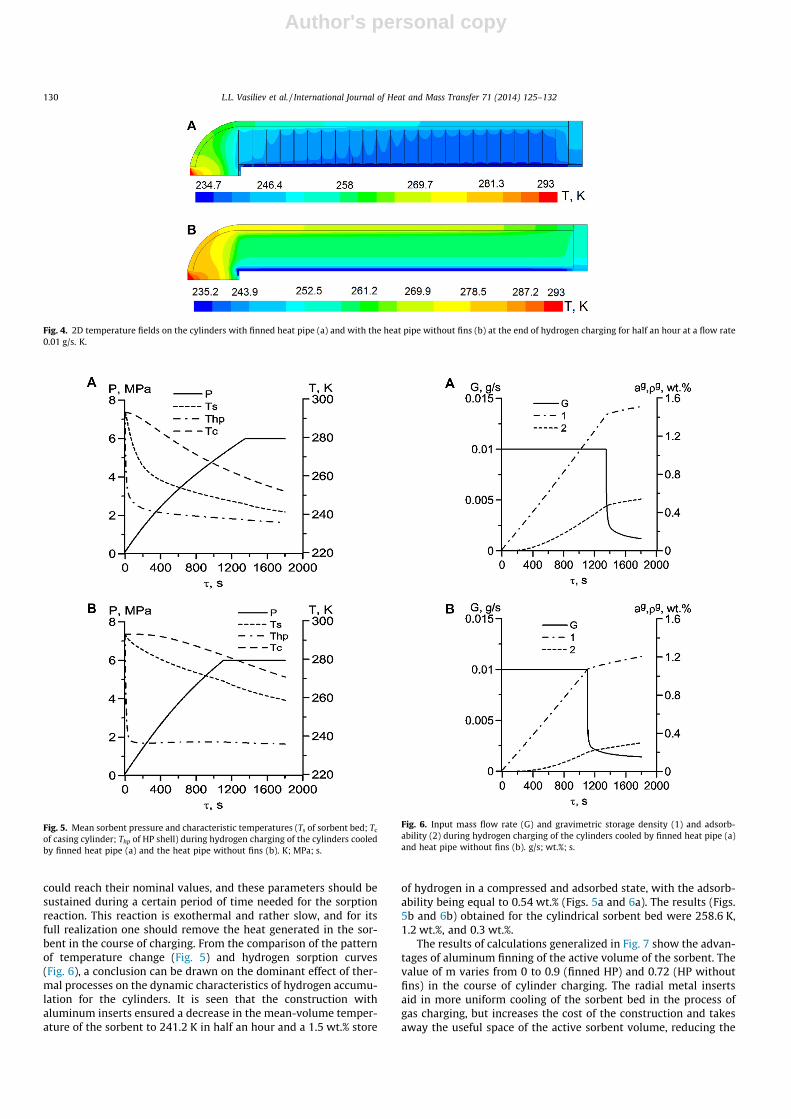
The surface plots in 2D visualized with color scales (Fig. 4) showthe temperature as a function of the cell position after half an hourof hydrogen filling for the constructions considered. The lowertemperature is observed in the finned volume of sorbent and inthe sorbent layer adjacent to the cooled wall when there are nometal inserts. The explicit difference in the color chart betweenthe temperature surface plots prints to the effectiveness of thefinned heat pipe in transferring heat from the sorbent bed to theinner surface of the heat pipe.
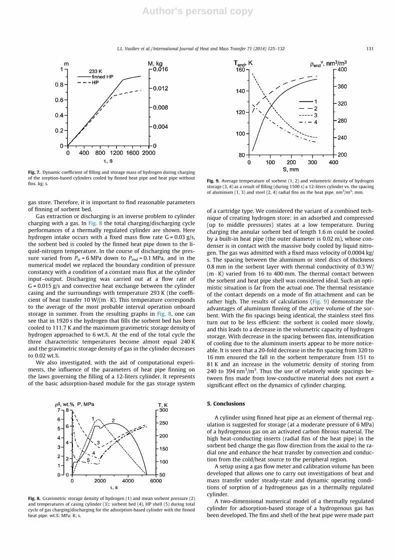
The evolutions of the inlet mass rate of hydrogen flow and vol-ume-average characteristics of various charged processes of identi-cal duration of 1800 s for two constructions are shown in Figs. 5and 6. The behavior of hydrogen charging is determined by thereaction rate of gas adsorption and heat transfer through the sor-bent bed. Unsteady temperature and pressure variations take placein the cylinder during charging. At the beginning of the chargingprocedure, hydrogen and sorbent were in equilibrium state charac-terized by the pressure P0 = 0.1 MPa and temperature T0 = 293 K.The pressure in the sorbent bed of low effective thermal conductiv-ity (without metal inserts) increases rapidly because of the admis-sion of hydrogen, its entry into the macropores, and subsequentcompression, since the sorbent is slowly cooled and gas is adsorbedpoorly. For the variant with metal inserts having an ideal thermalcontact with the heat pipe surface, intense uptake of gas moleculesby the cooled sorbent at the expense of the physical adsorption ledto a decrease in the pressure increase rate. The temperature insidethe sorbent is defined by the heat pipe heat transfer rate, the heatof adsorption and heat capacity of the design. It is obvious that thesorbent temperature decreases, despite sorption heat release, andthe rate of cooling is dependent on the heat output. In this case,as in many other cases, the finned heat pipe serves as an elementof the thermal control system.
The equilibrium adsorption aeq(P, T) increases with increase inpressure and decrease in temperature. To charge the cylinder fully,it is necessary that the pressure and temperature in the sorbent
Table 2Characteristics of the briquetted carbon fibre ‘‘Busofit’’.
Total porosity (porosity used in the model) 0.78Solid density or helium density 2200 kg/m3
BET surface area 1939 m2/gVolume of micropores VDR 1.04 ml/gBed effective thermal conductivity 0.203 W/m/KSorbent bed density 484 kg/m3
Specific heat 840 J/kg/KMaximum microporous specific volume W0 = 0.482 m3/kgSorption characteristic energy E = 1710 kJ/kg
Fig. 3. Comparison of the calculated and experimental mean values of pressure andtemperature of the sorbent bed and mass of stored hydrogen during charging of thethermally regulated cylinder (heat exchange element with fins of thickness 0.5 mm,spacing 13 mm). kg, MPa, K; s.
L.L. Vasiliev et al. / International Journal of Heat and Mass Transfer 71 (2014) 125–132 129
Author's personal copy
could reach their nominal values, and these parameters should besustained during a certain period of time needed for the sorptionreaction. This reaction is exothermal and rather slow, and for itsfull realization one should remove the heat generated in the sor-bent in the course of charging. From the comparison of the patternof temperature change (Fig. 5) and hydrogen sorption curves(Fig. 6), a conclusion can be drawn on the dominant effect of ther-mal processes on the dynamic characteristics of hydrogen accumu-lation for the cylinders. It is seen that the construction withaluminum inserts ensured a decrease in the mean-volume temper-ature of the sorbent to 241.2 K in half an hour and a 1.5 wt.% store
of hydrogen in a compressed and adsorbed state, with the adsorb-ability being equal to 0.54 wt.% (Figs. 5a and 6a). The results (Figs.5b and 6b) obtained for the cylindrical sorbent bed were 258.6 K,1.2 wt.%, and 0.3 wt.%.
The results of calculations generalized in Fig. 7 show the advan-tages of aluminum finning of the active volume of the sorbent. Thevalue of m varies from 0 to 0.9 (finned HP) and 0.72 (HP withoutfins) in the course of cylinder charging. The radial metal insertsaid in more uniform cooling of the sorbent bed in the process ofgas charging, but increases the cost of the construction and takesaway the useful space of the active sorbent volume, reducing the
Fig. 4. 2D temperature fields on the cylinders with finned heat pipe (a) and with the heat pipe without fins (b) at the end of hydrogen charging for half an hour at a flow rate0.01 g/s. K.
Fig. 5. Mean sorbent pressure and characteristic temperatures (Ts of sorbent bed; Tc
of casing cylinder; Thp of HP shell) during hydrogen charging of the cylinders cooledby finned heat pipe (a) and the heat pipe without fins (b). K; MPa; s.
Fig. 6. Input mass flow rate (G) and gravimetric storage density (1) and adsorb-ability (2) during hydrogen charging of the cylinders cooled by finned heat pipe (a)and heat pipe without fins (b). g/s; wt.%; s.
130 L.L. Vasiliev et al. / International Journal of Heat and Mass Transfer 71 (2014) 125–132
Author's personal copy
gas store. Therefore, it is important to find reasonable parametersof finning of sorbent bed.
Gas extraction or discharging is an inverse problem to cylindercharging with a gas. In Fig. 8 the total charging/discharging cycleperformances of a thermally regulated cylinder are shown. Herehydrogen intake occurs with a fixed mass flow rate G = 0.03 g/s,the sorbent bed is cooled by the finned heat pipe down to the li-quid-nitrogen temperature. In the course of discharging the pres-sure varied from Pst = 6 MPa down to Pend = 0.1 MPa, and in thenumerical model we replaced the boundary condition of pressureconstancy with a condition of a constant mass flux at the cylinderinput–output. Discharging was carried out at a flow rate ofG = 0.015 g/s and convective heat exchange between the cylindercasing and the surroundings with temperature 293 K (the coeffi-cient of heat transfer 10 W/(m � K). This temperature correspondsto the average of the most probable interval operation onboardstorage in summer. From the resulting graphs in Fig. 8, one cansee that in 1920 s the hydrogen that fills the sorbent bed has beencooled to 111.7 K and the maximum gravimetric storage density ofhydrogen approached to 6 wt.%. At the end of the total cycle thethree characteristic temperatures become almost equal 240 Kand the gravimetric storage density of gas in the cylinder decreasesto 0.02 wt.%.
We also investigated, with the aid of computational experi-ments, the influence of the parameters of heat pipe finning onthe laws governing the filling of a 12-liters cylinder. It representsof the basic adsorption-based module for the gas storage system
of a cartridge type. We considered the variant of a combined tech-nique of creating hydrogen store: in an adsorbed and compressed(up to middle pressures) states at a low temperature. Duringcharging the annular sorbent bed of length 1.6 m could be cooledby a built-in heat pipe (the outer diameter is 0.02 m), whose con-denser is in contact with the massive body cooled by liquid nitro-gen. The gas was admitted with a fixed mass velocity of 0.0004 kg/s. The spacing between the aluminum or steel discs of thickness0.8 mm in the sorbent layer with thermal conductivity of 0.3 W/(m � K) varied from 16 to 400 mm. The thermal contact betweenthe sorbent and heat pipe shell was considered ideal. Such an opti-mistic situation is far from the actual one. The thermal resistanceof the contact depends on a mode of fin attachment and can berather high. The results of calculations (Fig. 9) demonstrate theadvantages of aluminum finning of the active volume of the sor-bent. With the fin spacings being identical, the stainless steel finsturn out to be less efficient: the sorbent is cooled more slowly,and this leads to a decrease in the volumetric capacity of hydrogenstorage. With decrease in the spacing between fins, intensificationof cooling due to the aluminum inserts appear to be more notice-able. It is seen that a 20-fold decrease in the fin spacing from 320 to16 mm ensured the fall in the sorbent temperature from 151 to81 K and an increase in the volumetric density of storing from240 to 394 nm3/m3. Thus the use of relatively wide spacings be-tween fins made from low-conductive material does not exert asignificant effect on the dynamics of cylinder charging.
5. Conclusions
A cylinder using finned heat pipe as an element of thermal reg-ulation is suggested for storage (at a moderate pressure of 6 MPa)of a hydrogenous gas on an activated carbon fibrous material. Thehigh heat-conducting inserts (radial fins of the heat pipe) in thesorbent bed change the gas flow direction from the axial to the ra-dial one and enhance the heat transfer by convection and conduc-tion from the cold/heat source to the peripheral region.
A setup using a gas flow meter and calibration volume has beendeveloped that allows one to carry out investigations of heat andmass transfer under steady-state and dynamic operating condi-tions of sorption of a hydrogenous gas in a thermally regulatedcylinder.
A two-dimensional numerical model of a thermally regulatedcylinder for adsorption-based storage of a hydrogenous gas hasbeen developed. The fins and shell of the heat pipe were made part
Fig. 7. Dynamic coefficient of filling and storage mass of hydrogen during chargingof the sorption-based cylinders cooled by finned heat pipe and heat pipe withoutfins. kg; s.
Fig. 8. Gravimetric storage density of hydrogen (1) and mean sorbent pressure (2)and temperatures of casing cylinder (3); sorbent bed (4), HP shell (5) during totalcycle of gas charging/discharging for the adsorption-based cylinder with the finnedheat pipe. wt.%; MPa; K; s.
Fig. 9. Average temperature of sorbent (1, 2) and volumetric density of hydrogenstorage (3, 4) as a result of filling (during 1500 s) a 12-liters cylinder vs. the spacingof aluminum (1, 3) and steel (2, 4) radial fins on the heat pipe. nm3/m3; mm.
L.L. Vasiliev et al. / International Journal of Heat and Mass Transfer 71 (2014) 125–132 131
Author's personal copy
of the computational cell. The model takes into account the tem-perature dependence of the heat capacity of the adsorbed hydro-gen and the adsorption heat, which is calculated using theadsorption isotherms at various temperatures.
The simulations of gas charging (including the stages of fuelingand refueling) and discharging are performed using the commer-cial finite volume flow solver Fluent on ANSYS and user-definedsubroutine.
The comparison of the numerical solution with experimentallyobtained data point to the promising application of the proposedmodel to optimize the regimes of charging and discharging of theadsorption-based system of hydrogenous gas storage.
References
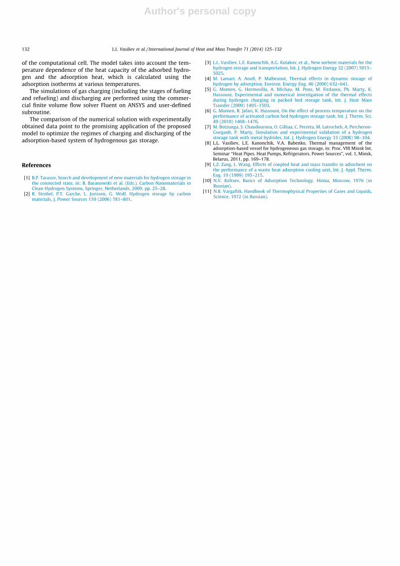
[1] B.P. Tarasov, Search and development of new materials for hydrogen storage inthe connected state, in: B. Baranowski et al. (Eds.), Carbon Nanomaterials inClean Hydrogen Systems, Springer, Netherlands, 2009, pp. 25–28.
[2] R. Strobel, P.T. Garche, L. Jorissen, G. Wolf, Hydrogen storage by carbonmaterials, J. Power Sources 159 (2006) 781–801.
[3] L.L. Vasiliev, L.E. Kanonchik, A.G. Kulakov, et al., New sorbent materials for thehydrogen storage and transportation, Int. J. Hydrogen Energy 32 (2007) 5015–5025.
[4] M. Lamari, A. Aoufi, P. Malbrunot, Thermal effects in dynamic storage ofhydrogen by adsorption, Environ. Energy Eng. 46 (2000) 632–641.
[5] G. Momen, G. Hermosilla, A. Michau, M. Pons, M. Firdaous, Ph. Marty, K.Hassouni, Experimental and numerical investigation of the thermal effectsduring hydrogen charging in packed bed storage tank, Int. J. Heat MassTransfer (2009) 1495–1503.
[6] G. Momen, R. Jafari, K. Hassouni, On the effect of process temperature on theperformance of activated carbon bed hydrogen storage tank, Int. J. Therm. Sci.49 (2010) 1468–1476.
[7] M. Botzunga, S. Chaudournea, O. Gilliaa, C. Perreta, M. Latrocheb, A. Percheron-Gueganb, P. Marty, Simulation and experimental validation of a hydrogenstorage tank with metal hydrides, Int. J. Hydrogen Energy 33 (2008) 98–104.
[8] L.L. Vasiliev, L.E. Kanonchik, V.A. Babenko, Thermal management of theadsorption-based vessel for hydrogeneous gas storage, in: Proc. VIII Minsk Int.Seminar ‘‘Heat Pipes. Heat Pumps, Refrigerators. Power Sources’’, vol. 1, Minsk,Belarus, 2011, pp. 169–178.
[9] L.Z. Zang, L. Wang, Effects of coupled heat and mass transfer in adsorbent onthe performance of a waste heat adsorption cooling unit, Int. J. Appl. Therm.Eng. 19 (1999) 195–215.
[10] N.V. Keltsev, Basics of Adsorption Technology, Himia, Moscow, 1976 (inRussian).
[11] N.B. Vargaftik, Handbook of Thermophysical Properties of Gases and Liquids,Science, 1972 (in Russian).
132 L.L. Vasiliev et al. / International Journal of Heat and Mass Transfer 71 (2014) 125–132