Thermally Conductive Interface Materials for Cooling Electronic Assemblies Sil-Pad
103
Thermally Conductive Interface Materials for Cooling Electronic Assemblies Sil-Pad ® SELECTION GUIDE
-
Upload
independent -
Category
Documents
-
view
1 -
download
0
Transcript of Thermally Conductive Interface Materials for Cooling Electronic Assemblies Sil-Pad

Thermally Conductive
Interface Materials for
Cooling Electronic Assemblies
Sil-Pad®
S E L E C T I O N G U I D E
SPDG_Cover_0511 v7.qxp 6/22/2011 12:25 PM Page 2

All statements, technical information and recommendations herein are based on tests we believe to be reliable, and THEFOLLOWING IS MADE IN LIEU OF ALL WARRANTIES, EXPRESSED OR IMPLIED, INCLUDING THEIMPLIED WARRANTIES OF MARKETABILITY AND FITNESS FOR PURPOSE. Sellers' and manufacturers' onlyobligation shall be to replace such quantity of the product proved to be defective. Before using, user shall determine thesuitability of the product for its intended use, and the user assumes all risks and liability whatsoever in connection there-with. NEITHER SELLER NOR MANUFACTURER SHALL BE LIABLE EITHER IN TORT OR IN CONTRACT FORANY LOSS OR DAMAGE, DIRECT, INCIDENTAL, OR CONSEQUENTIAL, INCLUDING LOSS OF PROFITS ORREVENUE ARISING OUT OF THE USE OR THE INABILITY TO USE A PRODUCT. No statement,purchase order or recommendations by seller or purchaser not contained herein shall have any force or effect unless in anagreement signed by the officers of the seller and manufacturer.
© Copyright 2011, The Bergquist Company. All rights reserved.
June 2011
SPDG_Cover_0511 v7.qxp 6/22/2011 12:25 PM Page 3
Table of Contents
1
Introduction 2Thermal Properties and Testing 4Interface Material Selection Guide 5
Gap Pad® Thermally Conductive Materials 6Gap Pad Comparison Data 7Frequently Asked Questions 8Gap Pad VO 9Gap Pad VO Soft 10Gap Pad VO Ultra Soft 11Gap Pad VO Ultimate 12Gap Pad 1000SF 13Gap Pad HC1000 14Gap Pad 1500 15Gap Pad 1500R 16Gap Pad 1500S30 17Gap Pad A2000 18Gap Pad 2000S40 19Gap Pad 2200SF 20Gap Pad 2500S20 21Gap Pad 2500 22Gap Pad A3000 23Gap Pad 3000S30 24Gap Pad 5000S35 25Gap Filler Comparison Data 26Frequently Asked Questions 27Gap Filler 1000 (Two-Part) 28Gap Filler 1100SF (Two-Part) 29Gap Filler 1500 (Two-Part) 30
Gap Filler 2000 (Two-Part) 31Gap Filler 3500S35 (Two-Part) 32
TIC™ Thermal Interface Compound 33Comparison Data and Frequently Asked Questions 33TIC 1000A 34TIC 4000 35
Hi-Flow ® Phase Change Interface Materials 36Hi-Flow Comparison Data 37Frequently Asked Questions 38Hi-Flow 105 39Hi-Flow 225F-AC 40Hi-Flow 225UT 41Hi-Flow 225U 42Hi-Flow 625 43Hi-Flow 300P 44Hi-Flow 300G 45Hi-Flow 565U 46Hi-Flow 565UT 47Hi-Flow 650P 48
Sil-Pad® Thermally Conductive Insulators 49Frequently Asked Questions 50Choosing Sil-Pad Thermally Conductive Insulators 51Mechanical, Electrical and Thermal Properties 52Sil-Pad Applications 54Sil-Pad Selection Table 54Sil-Pad Comparison Data 56Sil-Pad 400 57Sil-Pad 800 58Sil-Pad 900S 59Sil-Pad 980 60Sil-Pad 1100ST 61Sil-Pad 1200 62Sil-Pad A1500 63Sil-Pad 1500ST 64Sil-Pad 2000 65Sil-Pad A2000 66Sil-Pad K-4 67Sil-Pad K-6 68Sil-Pad K-10 69Q-Pad® II 70Q-Pad 3 71Poly-Pad® 400 72Poly-Pad 1000 73Poly-Pad K-4 74Poly-Pad K-10 75Sil-Pad Tubes 76Sil-Pad Shield 77
Bond-Ply® and Liqui-Bond® Adhesives 78Bond-Ply and Liqui-Bond Comparison Data 79Frequently Asked Questions 79Bond-Ply 100 80Bond-Ply 400 81Bond-Ply 660P 82Liqui-Bond SA 1000 (One-Part) 83Liqui-Bond SA 1800 (One-Part) 84Liqui-Bond SA 2000 (One-Part) 85
Solutions for Surface Mount Applications 86Ordering Information 88
Sil-Pad Configurations - Imperial 90Hi-Flow Configurations - Imperial 93Sil-Pad Configurations - Metric 94Hi-Flow Configurations - Metric 97Sil-Pad Shield Configurations - Imperial 98Notes 99
SEL_SP_0511_Chpt1 v25.qxp 1/10/2012 2:38 PM Page 1

2
INTR
OD
UC
TIO
N
At Bergquist, developing high quality
components for the electronics indus-
try is our first priority. As a world-
leading manufacturer with state-of-
the-art facilities, we serve a multitude
of industries worldwide including
automotive, computer, consumer
electronics, lighting/LED, solar, mili-
tary, motor control, power conver-
sion, telecommunications and more.
We make it our business to know
your business. We understand your
problems. We also know that there
will always be a better way to help
you reach your goals and objectives.
To that end, our company continually
invests considerable time and money
into research and development. The
Bergquist Company is focused on a
single purpose – discovering the
need, then developing and delivering
technologically advanced solutions
backed by superior service.
World Leader inThermal Management ThroughTechnology, Innovation and Service
Bergquist Takesthe Heat
Thermal Management Products
Bergquist's Thermal Products Group is a world-leading developer and manufacturer of thermalmanagement materials which provide productsolutions to control and manage heat inelectronic assemblies and printed circuitboards. Used by many of the world’s largestOEMs in various industries including auto-motive, computer, power supply, military andmotor control, these materials include:
Sil-Pad® – Thermally Conductive Insulators
Bond-Ply® and Liqui-Bond® – ThermallyConductive Adhesives
Gap Filler – Thermally ConductiveLiquid Gap Filling Materials
Gap Pad® – Thermally ConductiveGap Filling Materials
Hi-Flow® – Phase Change Interface Materials
TIC™ – Thermal Interface Compounds
Thermal Clad® – Insulated Metal Substrates
World Class OperationsAround the Globe
Worldwide Locations
In the United States, the Thermal ProductsGroup’s 90,000 square-foot manufacturingfacility is located in Cannon Falls, Minnesota.A 95,000 square-foot facility in Prescott,Wisconsin houses the Thermal Clad printedcircuit board operations. A130,000 square-foot facility in Chanhassen, Minnesota is thelocation for Bergquist’s corporate headquartersand state-of-the-art research and developmentfacilities. A 36,000 square foot facility was builtin Brandon, South Dakota to serve the grow-ing demand for Bergquist thermal manage-ment materials.Worldwide, Bergquist hasfacilities in The Netherlands, Germany,Taiwan,South Korea, Hong Kong and China with salesrepresentatives in 30 countries to supportworldwide growth.
SEL_SP_0511_Chpt1 v25.qxp 1/10/2012 2:38 PM Page 2

3
INTRO
DU
CTIO
NG
AP PA
DTIC
HI--FLO
WSIL-PA
DBO
ND
-PLYO
RDERIN
G
A Legacy of Industry-Leading Technology
New Product Innovation
For over 40 years, outstanding quality,innovation and engineering have been hall-marks of The Bergquist Company.Today,developing innovative products for theelectronics industry remains our first priority.Bergquist has developed over 260 materialswhich provide thermal solutions for a widevariety of electronic applications. Many of ourproducts were originally developed to satisfya customer request for a specific materialdesigned to perform to their particularspecifications.This “can do” attitude andcustomized technology has earned TheBergquist Company its ISO 9001:2000 certification.
Research and Developmentat the Speed of Change
R&D Facilities
Keeping pace in today’s aggressive electronicsindustry demands continual anticipation ofchange and the ability to develop customer-driven solutions quickly and efficiently. OurChanhassen headquarters features astate-of-the-art development laboratory andengineering department staffed with highlyskilled chemical engineers, laboratorytechnicians and manufacturing engineers – all dedicated to researching, developing andtesting new materials. From such dedicationhave come many industry-standard proprietaryproducts including Thermal Clad, Sil-Pad,Gap Pad, Gap Filler, Bond-Ply, Liqui-Bond,TICand Hi-Flow materials.
SEL_SP_0511_Chpt1 v25.qxp 1/10/2012 2:38 PM Page 3
Thermal Properties and Testing
4
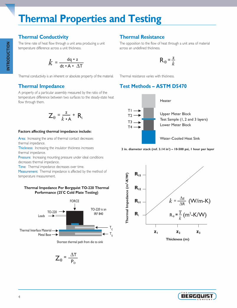
Thermal ConductivityThe time rate of heat flow through a unit area producing a unittemperature difference across a unit thickness.
Thermal conductivity is an inherent or absolute property of the material.
Thermal ImpedanceA property of a particular assembly measured by the ratio of thetemperature difference between two surfaces to the steady-state heatflow through them.
Factors affecting thermal impedance include:
Area: Increasing the area of thermal contact decreasesthermal impedance.Thickness: Increasing the insulator thickness increasesthermal impedance.Pressure: Increasing mounting pressure under ideal conditionsdecreases thermal impedance.Time: Thermal impedance decreases over time.Measurement: Thermal impedance is affected by the method oftemperature measurement.
Thermal Impedance Per Bergquist TO-220 ThermalPerformance (25oC Cold Plate Testing)
Thermal ResistanceThe opposition to the flow of heat through a unit area of materialacross an undefined thickness.
Thermal resistance varies with thickness.
Test Methods – ASTM D5470
2 in. diameter stack (ref. 3.14 in2) – 10-500 psi, 1 hour per layer
i
INTR
OD
UC
TIO
N
SEL_SP_0511_Chpt1 v25.qxp 1/10/2012 2:38 PM Page 4

Interface Material Selection Guide
5
INTRO
DU
CTIO
N
T = Typical; AS = Application-Specific (contact Bergquist Sales); A = Available; * = Roll stock configurations are limited; (1) For applications that could be sensitive to silicone, pleasereference our silicone free materials identified with SF at the end of the naming convention — contact your Bergquist Sales Representative for more information. Note: For Hi-Flow 225UT, 225F-AC and Hi-Flow 565UT, the adhesive is not a pressure sensitive adhesive (PSA).
SEL_SP_0511_Chpt1 v25.qxp 1/10/2012 2:39 PM Page 5

Gap Pad® Thermally Conductive Materials
6
GA
P PA
D
Solution-Driven Thermal Management Products for Electronic Devices
The Bergquist Company, a world leader in thermal interface materials,developed the Gap Pad family to meet the electronic industry’s growing need for interface materials with greater conformability,higher thermal performance and easier application.
The extensive Gap Pad family provides an effective thermal interfacebetween heat sinks and electronic devices where uneven surfacetopography, air gaps and rough surface textures are present. Bergquistapplication specialists work closely with customers to specify the properGap Pad material for each unique thermal management requirement.
A Complete Range of Choices for Filling Air Gaps and Enhancing Thermal Conductivity
FeaturesEach of the many products withinthe Gap Pad family is unique inits construction, properties andperformance. Following is anoverview of the importantfeatures offered by theGap Pad family.
• Low-modulus polymer material
• Available with fiberglass/rubbercarriers or in a non-reinforcedversion
• Special fillers to achieve specificthermal and conformabilitycharacteristics
• Highly conformable to unevenand rough surfaces
• Electrically isolating
• Natural tack on one or bothsides with protective liner
• Variety of thicknesses andhardnesses
• Range of thermal conductivities
• Available in sheets anddie-cut parts
BenefitsGap Pad thermal products aredesigned to improve an assembly’sthermal performance and reliabilitywhile saving time and money.Specifically:
• Eliminates air gaps to reduce thermal resistance
• High conformability reduces interfacial resistance
• Low-stress vibration dampening
• Shock absorbing
• Easy material handling
• Simplified application
• Puncture, shear and tearresistance
• Improved performance for high-heat assemblies
• Compatible with automated dispensing equipment
OptionsSome Gap Pad products havespecial features for particularapplications, including:
• Available with or withoutadhesive
• Rubber-coated fiberglass reinforcement
• Thicknesses from 0.010"to 0.250"
• Available in custom die-cutparts, sheets and rolls(converted or unconverted)
• Custom thicknesses and constructions
• Adhesive or naturalinherent tack
• Silicone-free Gap Pad availablein thicknesses of 0.010" - 0.125"
• Gap Fillers are well suited forautomated dispensing
We produce thousands of specials.Tooling charges vary dependingon tolerance and complexity ofthe part.
ApplicationsGap Pad products are well suitedto a wide variety of electronics,automotive, medical, aerospaceand military applications such as:
• Between an IC and a heat sinkor chassis.Typical packagesinclude BGA’s, QFP, SMT powercomponents and magnetics
• Between a semiconductor andheat sink
• CD-ROM/DVD cooling
• Heat pipe assemblies
• RDRAM memory modules
• DDR SDRAM
• Hard drive cooling
• Power supply
• IGBT modules
• Signal amplifiers
• Between other heat-generatingdevices and chassis
SEL_SP_0511_Chpt1 v25.qxp 1/10/2012 2:39 PM Page 6

Gap Pad® Comparison Data
7
GA
P PAD
Conductivity, Hardness and General Overview
SEL_SP_0511_Chpt1 v25.qxp 1/10/2012 2:39 PM Page 7

8
Frequently Asked Questions
Q: What thermal conductivity test method was used toachieve the values given on the data sheets?
A: A test fixture is utilized that meets the specifications outlined inASTM D5470.
Q: Is Gap Pad offered with an adhesive?A: Currently, Gap Pad VO, Gap Pad VO Soft, and Gap Pad VO Ultra
Soft are offered with or without an adhesive on the Sil-Pad800/900 carrier-side of the material.The remaining surface hasnatural inherent tack. All other Gap Pads have inherent tack.
Q: Is the adhesive repositionable?A: Depending on the surface being applied to, if care is taken, the
pad may be repositioned. Special care should be taken whenremoving the pad from aluminum or anodized surfaces to avoidtearing or delamination.
Q: What is meant by “natural tack”?A: The characteristic of the rubber itself has a natural inherent tack,
with the addition of an adhesive.As with adhesive-backed prod-ucts, the surfaces with natural tack may help in the assemblyprocess to temporarily hold the pad in place while the applicationis being assembled. Unlike adhesive-backed products, inherent tackdoes not have a thermal penalty since the rubber itself has thetack.Tack strength varies from one Gap Pad product to the next.
Q: Can Gap Pad with natural tack be repositioned?A: Depending on the material that the pad is applied to, in most
cases they are repositionable. Care should be taken when remov-ing the pad from aluminum or anodized surfaces to avoid tearingor delaminating the pad.The side with the natural tack is alwayseasier to reposition than an adhesive side.
Q: Is Gap Pad reworkable?A: Depending on the application and the pad being used, Gap Pad
has been reworked in the past. Bergquist has customers that arecurrently using the same pad for reassembling their applicationsafter burn-in processes and after fieldwork repairs. However, thisis left up to the design engineer's judgment as to whether or notthe Gap Pad will withstand reuse.
Q: Will heat make the material softer?A: From -60°C to 200°C, there is no significant variance in hardness
for silicone Gap Pads and Gap Fillers.
Q: What is the shelf life of Gap Pad?A: Shelf life for most Gap Pads is one (1) year after the date of
manufacture. For Gap Pad with adhesive the shelf life is six (6)months from the date of manufacture. After these dates, inherenttack and adhesive properties should be recharacterized.The GapPad material long-term stability is not the limiter on the shelf-life;it is related to the adhesion or "age up" of the Gap Pad to theliner. Or in the case of a Gap Pad with adhesive, the shelf life isdetermined by how the adhesive ages up to the removable liner.
Q: How is extraction testing performed?A: The test method used is the Soxhlet Extraction Method, please
refer to Gap Pad S-Class White Paper.
Q: What is the thickness tolerance of your pads?A: The thickness tolerance is ±10% on materials 10 mil and ±1 mil
on materials 10 mil.
Q: What are the upper processing temperature limitsfor Gap Pad and for how long can Gap Pad be exposedto them?
A: Gap Pad in general can be exposed to temporary processingtemperatures of 250°C for five minutes and 300°C for oneminute.
Q: Is Gap Pad electrically isolating?A: Yes, all Gap Pad materials are electrically isolating. However,
keep in mind that Gap Pad is designed to FILL gaps and it is notrecommended for applications where high mounting pressure isexerted on the Gap Pad.
Q: How much force will the pad place on my device?A: Refer to the Pressure vs. Deflection charts in Bergquist
Application Note #116. In addition, there are other helpfulresources online at www.bergquistcompany.com.
Q: Why are “wet out”, “compliance” or “conformability”characteristics of Gap Pad important?
A: The better a Gap Pad lays smooth "wets out" or conforms to arough or stepped surface, giving less interfacial resistance causedby air voids and air gaps. Gap Pads are conformable or compliantas they adhere very well to the surface.The Gap Pads can actsimilar to a "suction cup" on the surface.This leads to a loweroverall thermal resistance of the pad between the two interfaces.
Q: Is anything given off by the material(e.g. extractables, outgassing)?
A: 1) Silicone Gap Pad and Gap Fillers, like all soft silicone materials,can extract low molecular weight silicone (refer to White Paperon Gap Pad S-Class). Also note that Gap Pad and Gap Filler havesome of the lowest extraction values for silicone-based gap fillingproducts on the market and if your application requires minimalsilicone, see our line of Sil-Free material.
2) Primarily for aerospace applications, outgassing data is testedper ASTM E595.
Q: Why does the data sheet describe the hardness ratingas a bulk rubber hardness?
A: A reinforcement carrier is generally utilized in Bergquist Gap Padsfor ease of handling.When testing hardness, the reinforcementcarrier can alter the test results and incorrectly depict thinnermaterials as being harder.To eliminate this error, a 250 mil rubberpuck is molded with no reinforcement carrier.The puck is thentested for hardness.The Shore hardness is recorded after a 30second delay.
GA
P PA
D
SEL_SP_0511_Chpt1 v25.qxp 1/10/2012 2:39 PM Page 8

9
Gap Pad® VO
Features and Benefits• Thermal conductivity: 0.8 W/m-K
• Enhanced puncture, shear and tear resistance
• Conformable gap filling material
• Electrically isolating
Gap Pad VO is a cost-effective, thermallyconductive interface material.The material is afilled, thermally conductive polymer suppliedon a rubber-coated fiberglass carrier allowingfor easy material handling.The conformablenature of Gap Pad VO allows the pad to fill inair gaps between PC boards and heat sinksor a metal chassis.Note: Resultant thickness is defined as the final gapthickness of the application.
Conformable,Thermally Conductive Material for Filling Air Gaps
Typical Applications Include:• Telecommunications
• Computer and peripherals
• Power conversion
• Between heat-generating semiconductors and a heat sink
• Area where heat needs to be transferred to a frame, chassis, or other type of heat spreader
• Between heat-generating magnetic components and a heat sink
Configurations Available:• Sheet form and die-cut parts
Building a Part Number Standard Options
1 3 5 7 9 11 13
250
200
150
100
50
0
Thickness vs. Thermal Resistance Gap Pad VO
Thermal Resistance (C-in2/W)
Res
ulta
nt T
hick
ness
(m
ils)
Sect
ion
A
Sect
ion
B
Sect
ion
C
Sect
ion
D
Sect
ion
E NA = Selected standard option. If not selecting a standard option, insert company name, drawing number, and revision level.
GPVO = Gap Pad VO Material
GPVO 0.040 AC 0816 NA
Note: To build a part number, visit our website at www.bergquistcompany.com.
Standard thicknesses available: 0.020", 0.040", 0.060", 0.080", 0.100", 0.125", 0.160", 0.200", 0.250"
AC = Adhesive on Sil-Pad® side, natural tack on one side01 = No pressure sensitive adhesive, natural tack on one side
0816 = Standard sheet size 8" x 16" or 00 = custom configuration
– – – –
TYPICAL PROPERTIES OF GAP PAD VOPROPERTY IMPERIAL VALUE METRIC VALUE TEST METHODColor Gold/Pink Gold/Pink Visual
Reinforcement Carrier Sil-Pad Sil-Pad —
Thickness (inch) / (mm) 0.020 to 0.250 0.508 to 6.350 ASTM D374
Inherent Surface Tack (1 sided) 1 1 —
Density (Bulk Rubber) (g/cc) 1.6 1.6 ASTM D792
Heat Capacity (J/g-K) 1.0 1.0 ASTM E1269
Hardness (Bulk Rubber) (Shore 00) (1) 40 40 ASTM D2240
Young's Modulus (psi) / (kPa) (2) 100 689 ASTM D575
Continuous Use Temp (°F) / (°C) -76 to 392 -60 to 200 —
ELECTRICALDielectric Breakdown Voltage (Vac) >6000 >6000 ASTM D149
Dielectric Constant (1000 Hz) 5.5 5.5 ASTM D150
Volume Resistivity (Ohm-meter) 1011 1011 ASTM D257
Flame Rating V-O V-O U.L. 94
THERMALThermal Conductivity (W/m-K) 0.8 0.8 ASTM D5470
THERMAL PERFORMANCE vs. STRAIN
Deflection (% strain) 10 20 30Thermal Impedance (°C-in2/W) 0.040" (3) 2.47 2.37 2.24
1) Thir ty second delay value Shore 00 hardness scale. 2)Young’s Modulus, calculated using 0.01 in/min. step rate of strainwith a sample size of 0.79 inch2. 3) The ASTM D5470 test fixture was used. The recorded value includes interfacial ther-mal resistance. These values are provided for reference only. Actual application performance is directly related to the sur-face roughness, flatness and pressure applied.
GA
P PAD
SEL_SP_0511_Chpt1 v25.qxp 1/10/2012 2:39 PM Page 9

10
Features and Benefits• Thermal conductivity: 0.8 W/m-K
• Conformable, low hardness
• Enhanced puncture, shear and tear resistance
• Electrically isolating
Gap Pad VO Soft is recommended forapplications that require a minimum amountof pressure on components. Gap Pad VOSoft is a highly conformable, low-modulus,filled-silicone polymer on a rubber-coatedfiberglass carrier.The material can be usedas an interface where one side is in contactwith a leaded device.Note: Resultant thickness is defined as the final gapthickness of the application.
Gap Pad® VO SoftHighly Conformable,Thermally Conductive Material for Filling Air Gaps
1 2 3 4 8 7 6 5 9 10
200 180 160 140 120 100 80 60 40 20
Thickness vs. Thermal Resistance Gap Pad VO Soft
Thermal Resistance (C-in2/W)
Res
ulta
nt T
hick
ness
(m
ils)
Typical Applications Include:• Telecommunications
• Computer and peripherals
• Power conversion
• Between heat-generating semiconductors or magnetic components and a heat sink
• Area where heat needs to be transferred to a frame, chassis, or other type of heat spreader
Configurations Available:• Sheet form and die-cut parts
Building a Part Number Standard Options
Sect
ion
A
Sect
ion
B
Sect
ion
C
Sect
ion
D
Sect
ion
E NA = Selected standard option. If not selecting a standard option, insert company name, drawing number, and revision level.
GPVOS = Gap Pad VO Soft Material
GPVOS 0.060 AC 00 ACME10256 Rev. a
Note: To build a part number, visit our website at www.bergquistcompany.com.
Standard thicknesses available: 0.020", 0.040", 0.060", 0.080", 0.100", 0.125", 0.160", 0.200"
AC = Adhesive on Sil-Pad® side, natural tack on one side01 = No pressure sensitive adhesive, natural tack on one side
0816 = Standard sheet size 8" x 16", or 00 = custom configuration
– – – –
TYPICAL PROPERTIES OF GAP PAD VO SOFTPROPERTY IMPERIAL VALUE METRIC VALUE TEST METHODColor Mauve/Pink Mauve/Pink Visual
Reinforcement Carrier Sil-Pad Sil-Pad —
Thickness (inch) / (mm) 0.020 to 0.200 0.508 to 5.080 ASTM D374
Inherent Surface Tack (1 side) 1 1 —
Density (Bulk Rubber) (g/cc) 1.6 1.6 ASTM D792
Heat Capacity (J/g-K) 1.0 1.0 ASTM E1269
Hardness (Bulk Rubber) (Shore 00) (1) 25 25 ASTM D2240
Young's Modulus (psi) / (kPa) (2) 40 275 ASTM D575
Continuous Use Temp (°F) / (°C) -76 to 392 -60 to 200 —
ELECTRICALDielectric Breakdown Voltage (Vac) >6000 >6000 ASTM D149
Dielectric Constant (1000 Hz) 5.5 5.5 ASTM D150
Volume Resistivity (Ohm-meter) 1011 1011 ASTM D257
Flame Rating V-O V-O U.L. 94
THERMALThermal Conductivity (W/m-K) 0.8 0.8 ASTM D5470
THERMAL PERFORMANCE vs. STRAIN
Deflection (% strain) 10 20 30Thermal Impedance (°C-in2/W) 0.040" (3) 2.48 2.29 2.11
1) Thir ty second delay value Shore 00 hardness scale. 2)Young’s Modulus, calculated using 0.01 in/min. step rate of strainwith a sample size of 0.79 inch2. 3) The ASTM D5470 test fixture was used. The recorded value includes interfacial ther-mal resistance. These values are provided for reference only. Actual application performance is directly related to the surface roughness, flatness and pressure applied.
GA
P PA
D
SEL_SP_0511_Chpt1 v25.qxp 1/10/2012 2:39 PM Page 10

11
Gap Pad® VO Ultra SoftUltra Conformable,Thermally Conductive Material for Filling Air Gaps
Features and Benefits• Thermal conductivity: 1.0 W/m-K
• Highly conformable, low hardness
• “Gel-like” modulus
• Decreased strain
• Puncture, shear and tear resistant
• Electrically isolating
Gap Pad VO Ultra Soft is recommended forapplications that require a minimum amountof pressure on components.The viscoelasticnature of the material also gives excellentlow-stress vibration dampening and shockabsorbing characteristics. Gap Pad VO UltraSoft is an electrically isolating material, whichallows its use in applications requiringisolation between heat sinks and high-voltage,bare-leaded devices.Note: Resultant thickness is defined as the final gapthickness of the application.
Typical Applications Include:• Telecommunications
• Computer and peripherals
• Power conversion
• Between heat-generating semiconductors or magnetic components and a heat sink
• Area where heat needs to be transferred to a frame, chassis, or other type of heat spreader
Configurations Available:• Sheet form and die-cut parts
Building a Part Number Standard Options
1 2 3 5 8 4 6 9 7 10
250
200
150
100
50
0
Thickness vs. Thermal Resistance Gap Pad VO Ultra Soft
Thermal Resistance (C-in2/W)
Res
ulta
nt T
hick
ness
(m
ils)
Sect
ion
A
Sect
ion
B
Sect
ion
C
Sect
ion
D
Sect
ion
E NA = Selected standard option. If not selecting a standard option, insert company name, drawing number, and revision level.
GPVOUS = Gap Pad VO Ultra Soft Material
GPVOUS 0.100 AC 0816 NA
Note: To build a part number, visit our website at www.bergquistcompany.com.
Standard thicknesses available: 0.020", 0.040", 0.060", 0.080", 0.100", 0.125", 0.160", 0.200", 0.250"
AC = Adhesive on Sil-Pad® side, natural tack on one side01 = No pressure sensitive adhesive, natural tack on one side
0816 = Standard sheet size 8" x 16", or 00 = custom configuration
– – – –
TYPICAL PROPERTIES OF GAP PAD VO ULTRA SOFTPROPERTY IMPERIAL VALUE METRIC VALUE TEST METHODColor Mauve/Pink Mauve/Pink Visual
Reinforcement Carrier Fiberglass Fiberglass —
Thickness (inch) / (mm) 0.020 to 0.250 0.508 to 6.350 ASTM D374
Inherent Surface Tack (1 sided) 1 1 —
Density (Bulk Rubber) (g/cc) 1.6 1.6 ASTM D792
Heat Capacity (J/g-K) 1.0 1.0 ASTM E1269
Hardness (Bulk Rubber) (Shore 00) (1) 5 5 ASTM D2240
Young's Modulus (psi) / (kPa) (2) 8 55 ASTM D575
Continuous Use Temp (°F) / (°C) -76 to 392 -60 to 200 —
ELECTRICALDielectric Breakdown Voltage (Vac) 6000 6000 ASTM D149
Dielectric Constant (1000 Hz) 5.5 5.5 ASTM D150
Volume Resistivity (Ohm-meter) 1011 1011 ASTM D257
Flame Rating V-0 V-0 U.L. 94
THERMALThermal Conductivity (W/m-K) 1.0 1.0 ASTM D5470
THERMAL PERFORMANCE vs. STRAIN
Deflection (% strain) 10 20 30Thermal Impedance (°C-in2/W) 0.040" (3) 1.97 1.87 1.68
1) Thir ty second delay value Shore 00 hardness scale. 2)Young’s Modulus, calculated using 0.01 in/min. step rate of strainwith a sample size of 0.79 inch2. 3) The ASTM D5470 test fixture was used. The recorded value includes interfacial ther-mal resistance. These values are provided for reference only. Actual application performance is directly related to the sur-face roughness, flatness and pressure applied.
GA
P PAD
SEL_SP_0511_Chpt1 v25.qxp 1/10/2012 2:39 PM Page 11

12
Gap Pad®VO UltimateUltra Conformability, Robust, Improved Thermal Conductivity, Gap Filling Material
Features and Benefits• Thermal conductivity: 1.3 W/m-K
• Ultra conformability
• Gel-like modulus
• Excellent rebound
• Decreased strain
• Remarkable handling
• Electrically isolating
Gap Pad® VO Ultimate is a robust, highlycompliant product that is ideal for both smalland large gap designs.The fiberglass carrier onone side of the material allows ease ofrework, excellent handling characteristics andpuncture resistance. Additionally the fiberglasscarrier has a slight inherent tack, minimizingany shifting during assembly.
The conformable and elastic nature of Gap Pad®
VO Ultimate allows excellent interfacing and wet-out characteristics, even to surfaces with a highdegree of roughness or uneven topography.
The construction of Gap Pad® VO Ultimate;one side has high inherent tack, while theother side has minimal tack.This combinationis useful for manual and automated processes.Note: Resultant thickness is defined as the final gapthickness of the application.
Typical Applications:• Various IC packages
• Thermally enhanced BGA packages
• Between any heat-generating semiconductor and a heat sink
• Computers and peripherals
Configurations Available:• Sheet form and die-cut parts
Building a Part Number Standard OptionsGPVOU
0.020", 0.040", 0.060"
01 0816 0.020
0.61 1.21 1.82 2.42 3.03 3.79
140 120 100 80 60 40 20 0
Thickness vs. Thermal ResistanceGap Pad VO Ultimate
Thermal Resistance (C-in2/W)
Res
ulta
nt T
hick
ness
(m
ils)
TYPICAL PROPERTIES OF GAP PAD VO ULTIMATEPROPERTY IMPERIAL VALUE METRIC VALUE TEST METHODColor Gray/Black Gray/Black Visual
Reinforcement Carrier Fiberglass Fiberglass —
Thickness (inch) / (mm) 0.020 to 0.125 0.508 to 3.175 ASTM D374
Inherent Surface Tack (1 side) 1 1 —
Density (Bulk Rubber) (g/cc) 1.8 1.8 ASTM D792
Heat Capacity (J/g-K) 1.0 1.0 ASTM E1269
Hardness (Bulk Rubber) (Shore 00) (1) 30 30 ASTM D2240
Young's Modulus (psi) / (kPa) (2) 13 90 ASTM D575
Continuous Use Temp (°F) / (°C) -76 to 392 -60 to 200 —
ELECTRICALDielectric Breakdown Voltage (Vac) 6000 6000 ASTM D149
Dielectric Constant (1000 Hz) 5.0 5.0 ASTM D150
Volume Resistivity (Ohm-meter) 109 109 ASTM D257
Flame Rating V-O V-O U.L. 94
THERMALThermal Conductivity (W/m-K) 1.3 1.3 ASTM D5470
THERMAL PERFORMANCE vs. STRAIN
Deflection (% strain) 10 20 30Thermal Impedance (°C-in2/W) 0.040" (3) 1.60 1.55 1.46
1) Thir ty second delay value Shore 00 hardness scale. 2)Young’s Modulus, calculated using 0.01 in/min. step rate of strainwith a sample size of 0.79 inch2. 3) The ASTM D5470 test fixture was used. The recorded value includes interfacial ther-mal resistance. These values are provided for reference only. Actual application performance is directly related to the surface roughness, flatness and pressure applied.
• Telecommunications
• Power conversion
• Automotive
• LED lighting packages
GA
P PA
D
SEL_SP_0511_Chpt1 v25.qxp 1/10/2012 2:39 PM Page 12

13
Gap Pad® 1000SFThermally Conductive, Silicone-Free Gap Filling Material
Features and Benefits• Thermal conductivity: 0.9 W/m-K
• No silicone outgassing
• No silicone extraction
• Reduced tack on one side to aid inapplication assembly
• Electrically isolating
The new Gap Pad 1000SF is a thermallyconductive, electrically insulating, silicone-free polymer specially designed forsilicone-sensitive applications.The materialis ideal for applications with high standoffand flatness tolerances. Gap Pad 1000SF isreinforced for easy material handling andadded durability during assembly.Thematerial is available with a protective lineron both sides of the material.The topside hasreduced tack for ease of handling.Note: Resultant thickness is defined as the final gapthickness of the application.
0 1 2 43 5
125
100
75
50
25
0
Thickness vs. Thermal ResistanceGap Pad 1000SF
Thermal Resistance (C-in2/W)
Res
ulta
nt T
hick
ness
(m
ils)
Typical Applications Include:• Digital disk drives / CD-ROM
• Automotive modules
• Fiber optics modules
Configurations Available:• Sheet form
• Die-cut parts
Building a Part Number Standard Options
Sect
ion
A
Sect
ion
B
Sect
ion
C
Sect
ion
D
Sect
ion
E NA = Selected standard option. If not selecting a standardoption, insert company name, drawing number, andrevision level.
GP1000SF = Gap Pad 1000SF Material
GP1000SF 0.010 02 0816 NA
Note: To build a part number, visit our website at www.bergquistcompany.com.
Standard thicknesses available: 0.010", 0.015", 0.020",0.040", 0.060", 0.080", 0.100", 0.125"
02 = Natural tack, both sides
0806: = Standard sheet size 8" x 16", or00 = custom configuration
– – – –
TYPICAL PROPERTIES OF GAP PAD 1000SFPROPERTY IMPERIAL VALUE METRIC VALUE TEST METHODColor Green Green Visual
Reinforcement Carrier Fiberglass Fiberglass —
Thickness (inch) / (mm) 0.010 to 0.125 0.254 to 3.175 ASTM D374
Inherent Surface Tack (1- or 2-sided) 2 2 —
Density (g/cc) 2.0 2.0 ASTM D792
Heat Capacity (J/g-K) 1.1 1.1 ASTM E1269
Hardness, Bulk Rubber (Shore 00) (1) 40 40 ASTM D2240
Young’s Modulus (psi) / (kPa) (2) 34 234 ASTM D575
Continuous Use Temp (°F) / (°C) -76 to 257 -60 to 125 —
ELECTRICALDielectric Breakdown Voltage (Vac) >6000 >6000 ASTM D149
Dielectric Constant (1000 Hz) 5.0 5.0 ASTM D150
Volume Resistivity (Ohm-meter) 1010 1010 ASTM D257
Flame Rating V-1 V-1 U.L. 94
THERMALThermal Conductivity (W/m-K) 0.9 0.9 ASTM D5470
1) Thirty second delay value Shore 00 hardness scale.2) Young's Modulus, calculated using 0.01 in/min. step rate of strain with a sample size of 0.79 inch2. For more information on Gap Pad
modulus, refer to Bergquist Application Note #116.
GA
P PAD
SEL_SP_0511_Chpt1 v25.qxp 1/10/2012 2:39 PM Page 13

14
Gap Pad® HC1000“Gel-Like” Modulus Gap Filling Material
Features and Benefits• Thermal conductivity: 1.0 W/m-K
• Highly conformable, low hardness
• “Gel-like” modulus
• Fiberglass reinforced for puncture,shear and tear resistance
Gap Pad HC 1000 is an extremely conformable,low-modulus polymer that acts as a thermalinterface and electrical insulator betweenelectronic components and heat sinks.The“gel-like” modulus allows this material to fillair gaps to enhance the thermal performanceof electronic systems. Gap Pad HC1000 isoffered with removable protective liners onboth sides of the material.Note: Resultant thickness is defined as the final gapthickness of the application.
0.25 0.30 0.400.35 0.500.45 0.55
20
18
16
14
12
10
Thickness vs. Thermal ResistanceGap Pad HC1000
Thermal Resistance (C-in2/W)
Res
ulta
nt T
hick
ness
(m
ils)
Typical Applications Include:• Computer and peripherals
• Telecommunications
• Heat interfaces to frames, chassis, or other heat spreading devices
• RDRAM™ memory modules / chip scale packages
• CDROM / DVD cooling
• Areas where irregular surfaces need to make a thermal interface to a heat sink
• DDR SDRAM memory modules
• FBDIMM modules
Configurations Available:• Sheet form, die-cut parts, and roll form (converted or unconverted)
Building a Part Number Standard Options
Sect
ion
A
Sect
ion
B
Sect
ion
C
Sect
ion
D
Sect
ion
E NA = Selected standard option. If not selecting a standard option, insert company name, drawing number, and revision level.
HC1000 = High Compliance 1000 Material
HC1000 0.015 02 0816 NA
Note: To build a part number, visit our website at www.bergquistcompany.com.
Standard thicknesses available: 0.010", 0.015", 0.020"
02 = Natural tack, both sides
0816 = Standard sheet size 8" x 16", or 00 = custom configuration
– – – –
TYPICAL PROPERTIES OF GAP PAD HC1000PROPERTY IMPERIAL VALUE METRIC VALUE TEST METHODColor Gray Gray Visual
Reinforcement Carrier Fiberglass Fiberglass —
Thickness (inch) / (mm) 0.010 to 0.020 0.254 to 0.508 ASTM D374
Inherent Surface Tack (1 side) 2 2 —
Density (Bulk Rubber) (g/cc) 1.6 1.6 ASTM D792
Heat Capacity (J/g-K) 1.0 1.0 ASTM E1269
Hardness (Bulk Rubber) (Shore 00) (1) 25 25 ASTM D2240
Young's Modulus (psi) / (kPa) (2) 40 275 ASTM D575
Continuous Use Temp (°F) / (°C) -76 to 392 -60 to 200 —
ELECTRICALDielectric Breakdown Voltage (Vac) >5000 >5000 ASTM D149
Dielectric Constant (1000 Hz) 5.5 5.5 ASTM D150
Volume Resistivity (Ohm-meter) 1011 1011 ASTM D257
Flame Rating V-O V-O U.L. 94
THERMALThermal Conductivity (W/m-K) 1.0 1.0 ASTM D5470
THERMAL PERFORMANCE vs. STRAIN
Deflection (% strain) 10 20 30Thermal Impedance (°C-in2/W) 0.020" (3) 1.30 1.00 0.96
1) Thir ty second delay value Shore 00 hardness scale. 2)Young’s Modulus, calculated using 0.01 in/min. step rate of strainwith a sample size of 0.79 inch2. 3) The ASTM D5470 test fixture was used. The recorded value includes interfacial ther-mal resistance. These values are provided for reference only. Actual application performance is directly related to the surface roughness, flatness and pressure applied.
GA
P PA
D
SEL_SP_0511_Chpt1 v25.qxp 1/10/2012 2:39 PM Page 14

15
Gap Pad® 1500Thermally Conductive, Un-Reinforced Gap Filling Material
Features and Benefits• Thermal conductivity: 1.5 W/m-K
• Un-reinforced construction for additionalcompliancy
• Conformable, low hardness
• Electrically isolating
Gap Pad 1500 has an ideal filler blend thatgives it a low-modulus characteristic thatmaintains optimal thermal performance yetstill allows for easy handling.The natural tackon both sides of the material allows forgood compliance to adjacent surfaces ofcomponents, minimizing interfacial resistance.Note: Resultant thickness is defined as the final gapthickness of the application.
0 1 3 2 5 4 6
200
150
100
50
0
Thickness vs. Thermal Resistance Gap Pad 1500
Thermal Resistance (C-in2/W)
Res
ulta
nt T
hick
ness
(m
ils)
Typical Applications Include:• Telecommunications
• Computer and peripherals
• Power conversion
• RDRAM™ memory modules / chip scale packages
• Areas where heat needs to be transferred to a frame chassis or other type of heat spreader
Configurations Available:• Sheet form and die-cut parts
Building a Part Number Standard Options
Sect
ion
A
Sect
ion
B
Sect
ion
C
Sect
ion
D
Sect
ion
E NA = Selected standard option. If not selecting a standardoption, insert company name, drawing number, andrevision level.
GP1500 = Gap Pad 1500 Material
GP1500 0.100 02 0816 NA
Note: To build a part number, visit our website at www.bergquistcompany.com.
Standard thicknesses available: 0.020", 0.040", 0.060",0.080", 0.100", 0.125", 0.160", 0.200"
02 = Natural tack, both sides
0816 = Standard sheet size 8" x 16", or00 = custom configuration
– – – –
TYPICAL PROPERTIES OF GAP PAD 1500PROPERTY IMPERIAL VALUE METRIC VALUE TEST METHODColor Black Black Visual
Reinforcement Carrier — — —
Thickness (inch) / (mm) 0.020 to 0.200 0.508 to 5.080 ASTM D374
Inherent Surface Tack (1 sided) 2 2 —
Density (Bulk Rubber) (g/cc) 2.1 2.1 ASTM D792
Heat Capacity (J/g-K) 1.0 1.0 ASTM E1269
Hardness (Bulk Rubber) (Shore 00) (1) 40 40 ASTM D2240
Young's Modulus (psi) / (kPa) (2) 45 310 ASTM D575
Continuous Use Temp (°F) / (°C) -76 to 392 -60 to 200 —
ELECTRICALDielectric Breakdown Voltage (Vac) >6000 >6000 ASTM D149
Dielectric Constant (1000 Hz) 5.5 5.5 ASTM D150
Volume Resistivity (Ohm-meter) 1011 1011 ASTM D257
Flame Rating V-O V-O U.L. 94
THERMALThermal Conductivity (W/m-K) 1.5 1.5 ASTM D5470
THERMAL PERFORMANCE vs. STRAIN
Deflection (% strain) 10 20 30Thermal Impedance (°C-in2/W) 0.040" (3) 1.62 1.50 1.33
1) Thir ty second delay value Shore 00 hardness scale. 2)Young’s Modulus, calculated using 0.01 in/min. step rate of strainwith a sample size of 0.79 inch2. 3) The ASTM D5470 test fixture was used. The recorded value includes interfacial ther-mal resistance. These values are provided for reference only. Actual application performance is directly related to the sur-face roughness, flatness and pressure applied.
GA
P PAD
SEL_SP_0511_Chpt1 v25.qxp 1/10/2012 2:39 PM Page 15

16
Gap Pad® 1500R
Features and Benefits• Thermal conductivity: 1.5 W/m-K
• Fiberglass reinforced for puncture, shearand tear resistance
• Easy release construction
• Electrically isolating
Gap Pad 1500R has the same highlyconformable, low-modulus polymer as thestandard Gap Pad 1500.The fiberglassreinforcement allows for easy material handlingand enhances puncture, shear and tearresistance.The natural tack on both sides ofthe material allows for good compliance tomating surfaces of components, furtherreducing thermal resistance.Note: Resultant thickness is defined as the final gapthickness of the application.
Thermally Conductive, Reinforced Gap Filling Material
0.25 0.30 0.40 0.35 0.50 0.45 0.55
20
18
16
14
12
10
Thickness vs. Thermal Resistance Gap Pad 1500R
Thermal Resistance (C-in2/W)
Res
ulta
nt T
hick
ness
(m
ils)
Typical Applications Include:• Telecommunications
• Computer and peripherals
• Power conversion
• RDRAM™ memory modules / chip scale packages
• Areas where heat needs to be transferred to a frame chassis or other type of heat spreader
Configurations Available:• Sheet form, die-cut parts, and roll form (converted or unconverted)
Building a Part Number Standard Options
Sect
ion
A
Sect
ion
B
Sect
ion
C
Sect
ion
D
Sect
ion
E NA = Selected standard option. If not selecting a standardoption, insert company name, drawing number, andrevision level.
GP1500R = Gap Pad 1500R Material
GP1500R 0.020 02 00 ACME10256 Rev. A
Note: To build a part number, visit our website at www.bergquistcompany.com.
Standard thicknesses available: 0.010", 0.015", 0.020"
02 = Natural tack, both sides
0816 = Standard sheet size 8" x 16", or00 = custom configuration
– – – –
TYPICAL PROPERTIES OF GAP PAD 1500RPROPERTY IMPERIAL VALUE METRIC VALUE TEST METHODColor Black Black Visual
Reinforcement Carrier Fiberglass Fiberglass —
Thickness (inch) / (mm) 0.010 to 0.020 0.254 to 0.508 ASTM D374
Inherent Surface Tack (1 side) 2 2 —
Density (Bulk Rubber) (g/cc) 2.1 2.1 ASTM D792
Heat Capacity (J/g-K) 1.3 1.3 ASTM E1269
Hardness (Bulk Rubber) (Shore 00) (1) 40 40 ASTM D2240
Young's Modulus (psi) / (kPa) (2) 45 310 ASTM D575
Continuous Use Temp (°F) / (°C) -76 to 392 -60 to 200 —
ELECTRICALDielectric Breakdown Voltage (Vac) >6000 >6000 ASTM D149
Dielectric Constant (1000 Hz) 6.0 6.0 ASTM D150
Volume Resistivity (Ohm-meter) 1011 1011 ASTM D257
Flame Rating V-O V-O U.L. 94
THERMALThermal Conductivity (W/m-K) 1.5 1.5 ASTM D5470
THERMAL PERFORMANCE vs. STRAIN
Deflection (% strain) 10 20 30Thermal Impedance (°C-in2/W) 0.020" (3) 1.07 0.88 0.82
1) Thir ty second delay value Shore 00 hardness scale. 2)Young’s Modulus, calculated using 0.01 in/min. step rate of strainwith a sample size of 0.79 inch2. 3) The ASTM D5470 test fixture was used. The recorded value includes interfacial ther-mal resistance. These values are provided for reference only. Actual application performance is directly related to the surface roughness, flatness and pressure applied.
GA
P PA
D
SEL_SP_0511_Chpt1 v25.qxp 1/10/2012 2:39 PM Page 16

17
Gap Pad®1500S30Highly Conformable,Thermally Conductive, Reinforced “S-Class” Gap Filling Material
Features and Benefits• Thermal conductivity: 1.3 W/m-K
• Highly conformable / low hardness
• Decreased strain on fragile components
• Fiberglass reinforced for puncture, shearand tear resistance
• Quick rebound to original shape
Gap Pad 1500S30 is a highly compliant Gap Pad material that is ideal for fragile component leads.The material is fiberglassreinforced for improved puncture resistanceand handling characteristics. Gap Pad1500S30 maintains a conformable, yet elasticnature that provides excellent interfacing andwet-out characteristics, even to surfaces withhigh roughness or uneven topography.
Gap Pad 1500S30 features an inherent tackon both sides of the material, eliminating theneed for thermally impeding adhesive layers.Note: Resultant thickness is defined as the final gapthickness of the application.
Typical Applications:• Any heat-generating component and
a heat sink
• Computers and peripherals
• Telecommunications
Configurations Available:• Sheet form and die-cut parts
Building a Part Number Standard OptionsGP1500S30
GP1500S30 = Gap Pad 1500S30 Material
0.020", 0.040", 0.060"
02 0816
0816 = Standard sheet size 8" x 16", or
02 = Natural tack, both sides
0.020
0.080", 0.100", 0.125", 0.160", 0.200", 0.250"
0.61 1.21 1.82 2.42 3.03 3.79 4.85 6.06 7.57
250200160125100806040200
Thickness vs. Thermal ResistanceGap Pad 1500S30
Thermal Resistance (C-in2/W)
Res
ulta
nt T
hick
ness
(m
ils)
• Between any heat-generating semiconductor and a heat sink
• Shielding devices
TYPICAL PROPERTIES OF GAP PAD 1500S30PROPERTY IMPERIAL VALUE METRIC VALUE TEST METHODColor Light Pink Light Pink Visual
Reinforcement Carrier Fiberglass Fiberglass ASTM D374
Thickness (inch) / (mm) 0.020 to 0.250 0.508 to 6.350 ASTM D374
Inherent Surface Tack (1 side) 2 2 —
Density (Bulk Rubber) (g/cc) 1.8 1.8 ASTM D792
Heat Capacity (J/g-K) 1.0 1.0 ASTM E1269
Hardness (Bulk Rubber) (Shore 00) (1) 30 30 ASTM D2240
Young's Modulus (psi) / (kPa) (2) 16 110 ASTM D575
Continuous Use Temp (°F) / (°C) -76 to 392 -60 to 200 —
ELECTRICALDielectric Breakdown Voltage (Vac) >6000 >6000 ASTM D149
Dielectric Constant (1000 Hz) 5.0 5.0 ASTM D150
Volume Resistivity (Ohm-meter) 1011 1011 ASTM D257
Flame Rating V-O V-O U.L. 94
THERMALThermal Conductivity (W/m-K) 1.3 1.3 ASTM D5470
THERMAL PERFORMANCE vs. STRAIN
Deflection (% strain) 10 20 30Thermal Impedance (°C-in2/W) 0.040" (3) 1.69 1.41 1.26
1) Thir ty second delay value Shore 00 hardness scale. 2)Young’s Modulus, calculated using 0.01 in/min. step rate of strainwith a sample size of 0.79 inch2. 3) The ASTM D5470 test fixture was used. The recorded value includes interfacial ther-mal resistance. These values are provided for reference only. Actual application performance is directly related to the surface roughness, flatness and pressure applied.
GA
P PAD
SEL_SP_0511_Chpt1 v25.qxp 1/10/2012 2:40 PM Page 17

18
Gap Pad® A2000High Performance,Thermally Conductive Gap Filling Material
Features and Benefits• Thermal conductivity: 2.0 W/m-K
• Fiberglass reinforced for puncture, shearand tear resistance
• Electrically isolating
Gap Pad A2000 acts as a thermal interfaceand electrical insulator between electroniccomponents and heat sinks. In the thicknessrange of 10 to 40 mil, Gap Pad A2000 issupplied with natural tack on both sides,allowing for excellent compliance to theadjacent surfaces of components.The 40 milmaterial thickness is supplied with lower tackon one side, allowing for burn-in processesand easy rework.Note: Resultant thickness is defined as the final gapthickness of the application.
Typical Applications Include:• Computer and peripherals; between CPU and heat spreader
• Telecommunications
• Heat pipe assemblies
• RDRAM™ memory modules
• CDROM / DVD cooling
• Areas where heat needs to be transferred to a frame chassis or other type of heat spreader
• DDR SDRAM memory modules
Configurations Available:• Sheet form, die-cut parts and roll form (converted or unconverted)
Building a Part Number Standard Options
0.20 0.30 0.50 0.40 0.70 0.60 0.80
403530252015100
Thickness vs. Thermal Resistance Gap Pad A2000
Thermal Resistance (C-in2/W)
Res
ulta
nt T
hick
ness
(m
ils)
Sect
ion
A
Sect
ion
B
Sect
ion
C
Sect
ion
D
Sect
ion
E NA = Selected standard option. If not selecting a standardoption, insert company name, drawing number, andrevision level.
GPA2000 = Gap Pad A2000 Material
GPA2000 0.010 02 0816 NA
Note: To build a part number, visit our website at www.bergquistcompany.com.
Standard thicknesses available: 0.010", 0.015", 0.020"0.040"
02 = Natural tack, both sides
0816 = Standard sheet size 8" x 16", or00 = custom configuration
– – – –
TYPICAL PROPERTIES OF GAP PAD A2000PROPERTY IMPERIAL VALUE METRIC VALUE TEST METHODColor Gray Gray Visual
Reinforcement Carrier Fiberglass Fiberglass —
Thickness (inch) / (mm) 0.010 to 0.040 0.254 to 1.016 ASTM D374
Inherent Surface Tack (1 side) 2 2 —
Density (Bulk Rubber) (g/cc) 2.9 2.9 ASTM D792
Heat Capacity (J/g-K) 1.0 1.0 ASTM E1269
Hardness (Bulk Rubber) (Shore 00) (1) 80 80 ASTM D2240
Young's Modulus (psi) / (kPa) (2) 55 379 ASTM D575
Continuous Use Temp (°F) / (°C) -76 to 392 -60 to 200 —
ELECTRICALDielectric Breakdown Voltage (Vac) >4000 >4000 ASTM D149
Dielectric Constant (1000 Hz) 6.0 6.0 ASTM D150
Volume Resistivity (Ohm-meter) 1011 1011 ASTM D257
Flame Rating V-O V-O U.L. 94
THERMALThermal Conductivity (W/m-K) 2.0 2.0 ASTM D5470
THERMAL PERFORMANCE vs. STRAIN
Deflection (% strain) 10 20 30Thermal Impedance (°C-in2/W) 0.040" (3) 1.04 1.00 0.95
1) Thir ty second delay value Shore 00 hardness scale. 2)Young’s Modulus, calculated using 0.01 in/min. step rate of strainwith a sample size of 0.79 inch2. 3) The ASTM D5470 test fixture was used. The recorded value includes interfacial ther-mal resistance. These values are provided for reference only. Actual application performance is directly related to the surface roughness, flatness and pressure applied.
GA
P PA
D
SEL_SP_0511_Chpt1 v25.qxp 1/10/2012 2:40 PM Page 18

19
Gap Pad® 2000S40Highly Conformable,Thermally Conductive, Reinforced “S-Class” Gap Filling Material
Features and Benefits• Thermal conductivity: 2.0 W/m-K
• Low “S-Class” thermal resistance at verylow pressures
• Highly conformable, low hardness
• Designed for low-stress applications
• Fiberglass reinforced for puncture, shearand tear resistance
Gap Pad 2000S40 is recommended for low-stress applications that require a mid to highthermally conductive interface material.Thehighly conformable nature of the materialallows the pad to fill in air voids and air gapsbetween PC boards and heat sinks or metalchassis with stepped topography, roughsurfaces and high stack-up tolerances.
Gap Pad 2000S40 is offered with inherentnatural tack on both sides of the materialallowing for stick-in-place characteristics duringapplication assembly.The material is suppliedwith protective liners on both sides.The topside has reduced tack for ease of handling.Note: Resultant thickness is defined as the final gapthickness of the application.
Typical Applications Include:• Power electronics DC/DC; 1/4, 1/2, full bricks, etc.
• Mass storage devices
• Graphics card/processor/ASIC
• Wireline/wireless communications hardware
• Automotive engine/transmission controls
Configurations Available:• Sheet form and die-cut parts
Building a Part Number Standard Options
Sect
ion
A
Sect
ion
B
Sect
ion
C
Sect
ion
D
Sect
ion
E NA = Selected standard option. If not selecting a standardoption, insert company name, drawing number, andrevision level.
GP2000S40 = Gap Pad 2000S40 Material
GP2000S40 0.020 02 0816 NA
Note: To build a part number, visit our website at www.bergquistcompany.com.
Standard thicknesses available: 0.020", 0.040", 0.060",0.080", 0.100", 0.125"
02 = Natural tack, both sides
0816 = Standard sheet size 8" x 16", or00 = custom configuration
– – – –
0.20 0.50 1.50 1.00 2.00 2.50
125
100
75
50
25
0
Thickness vs. Thermal Resistance Gap Pad 2000S40
Thermal Resistance (C-in2/W)
Res
ulta
nt T
hick
ness
(m
ils)
TYPICAL PROPERTIES OF GAP PAD 2000S40PROPERTY IMPERIAL VALUE METRIC VALUE TEST METHODColor Gray Gray Visual
Reinforcement Carrier Fiberglass Fiberglass —
Thickness (inch) / (mm) 0.020 to 0.125 0.508 to 3.175 ASTM D374
Inherent Surface Tack (1 side) 2 2 —
Density (Bulk Rubber) (g/cc) 2.9 2.9 ASTM D792
Heat Capacity (J/g-K) 0.6 0.6 ASTM E1269
Hardness (Bulk Rubber) (Shore 00) (1) 30 30 ASTM D2240
Young's Modulus (psi) / (kPa) (2) 45 310 ASTM D575
Continuous Use Temp (°F) / (°C) -76 to 392 -60 to 200 —
ELECTRICALDielectric Breakdown Voltage (Vac) >5000 >5000 ASTM D149
Dielectric Constant (1000 Hz) 6.0 6.0 ASTM D150
Volume Resistivity (Ohm-meter) 1011 1011 ASTM D257
Flame Rating V-O V-O U.L. 94
THERMALThermal Conductivity (W/m-K) 2.0 2.0 ASTM D5470
THERMAL PERFORMANCE vs. STRAIN
Deflection (% strain) 10 20 30Thermal Impedance (°C-in2/W) 0.040" (3) 0.97 0.89 0.80
1) Thir ty second delay value Shore 00 hardness scale. 2)Young’s Modulus, calculated using 0.01 in/min. step rate of strainwith a sample size of 0.79 inch2. 3) The ASTM D5470 test fixture was used. The recorded value includes interfacial ther-mal resistance. These values are provided for reference only. Actual application performance is directly related to the surface roughness, flatness and pressure applied.
GA
P PAD
SEL_SP_0511_Chpt1 v25.qxp 1/10/2012 2:40 PM Page 19
20
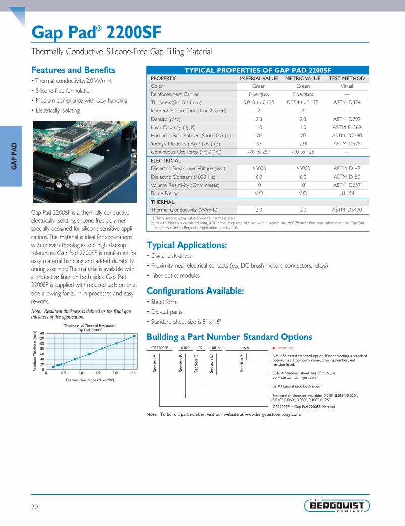
Gap Pad® 2200SFThermally Conductive, Silicone-Free Gap Filling Material
TYPICAL PROPERTIES OF GAP PAD 2200SFPROPERTY IMPERIAL VALUE METRIC VALUE TEST METHODColor Green Green Visual
Reinforcement Carrier Fiberglass Fiberglass —
Thickness (inch) / (mm) 0.010 to 0.125 0.254 to 3.175 ASTM D374
Inherent Surface Tack (1 or 2 sided) 2 2 —
Density (g/cc) 2.8 2.8 ASTM D792
Heat Capacity (J/g-K) 1.0 1.0 ASTM E1269
Hardness, Bulk Rubber (Shore 00) (1) 70 70 ASTM D2240
Young’s Modulus (psi) / (kPa) (2) 33 228 ASTM D575
Continuous Use Temp (°F) / (°C) -76 to 257 -60 to 125 —
ELECTRICALDielectric Breakdown Voltage (Vac) >5000 >5000 ASTM D149
Dielectric Constant (1000 Hz) 6.0 6.0 ASTM D150
Volume Resistivity (Ohm-meter) 108 108 ASTM D257
Flame Rating V-O V-O U.L. 94
THERMALThermal Conductivity (W/m-K) 2.0 2.0 ASTM D5470
1) Thirty second delay value Shore 00 hardness scale.2) Young's Modulus, calculated using 0.01 in/min. step rate of strain with a sample size of 0.79 inch2. For more information on Gap Pad
modulus, refer to Bergquist Application Note #116.
Features and Benefits• Thermal conductivity: 2.0 W/m-K
• Silicone-free formulation
• Medium compliance with easy handling
• Electrically isolating
Gap Pad 2200SF is a thermally conductive,electrically isolating, silicone-free polymerspecially designed for silicone-sensitive appli-cations.The material is ideal for applicationswith uneven topologies and high stackuptolerances. Gap Pad 2200SF is reinforced foreasy material handling and added durabilityduring assembly.The material is available witha protective liner on both sides. Gap Pad2200SF is supplied with reduced tack on oneside allowing for burn-in processes and easyrework.Note: Resultant thickness is defined as the final gapthickness of the application.
Typical Applications:• Digital disk drives
• Proximity near electrical contacts (e.g. DC brush motors, connectors, relays)
• Fiber optics modules
Configurations Available:• Sheet form
• Die-cut parts
• Standard sheet size is 8" x 16"
Building a Part Number Standard Options
Sect
ion
A
Sect
ion
B
Sect
ion
C
Sect
ion
D
Sect
ion
E NA = Selected standard option. If not selecting a standardoption, insert company name, drawing number, andrevision level.
GP2200SF = Gap Pad 2200SF Material
GP2200SF 0.010 02 0816 NA
Note: To build a part number, visit our website at www.bergquistcompany.com.
Standard thicknesses available: 0.010", 0.015", 0.020",0.040", 0.060", 0.080", 0.100", 0.125"
02 = Natural tack, both sides
0816 = Standard sheet size 8" x 16", or00 = custom configuration
– – – –
Gap Pad 2200SF140
0 0.5 1.0 1.5 2.0 2.50
GA
P PA
D
SEL_SP_0511_Chpt1 v25.qxp 1/10/2012 2:40 PM Page 20

21
Gap Pad® 2500S20Highly Conformable,Thermally Conductive, Reinforced “S-Class” Gap Filling Material
Features and Benefits• Thermal conductivity: 2.4 W/m-K
• Low “S-Class” thermal resistance atultra-low pressures
• Ultra conformable, “gel-like” modulus
• Designed for low-stress applications
• Fiberglass reinforced for puncture, shearand tear resistance
Gap Pad 2500S20 is a thermally conductive,reinforced material rated at a thermalconductivity of 2.4 W/m-K.The material is afilled-polymer material yielding extremely soft,elastic characteristics.The material is reinforcedto provide easy handling, converting, addedelectrical isolation and tear resistance. GapPad 2500S20 is well suited for low-pressureapplications that typically use fixed standoff orclip mounting.The material maintains aconformable, yet elastic nature that allows forexcellent interfacing and wet-outcharacteristics, even to surfaces with highroughness and/or topography.
Gap Pad 2500S20 is offered with inherentnatural tack on both sides of the materialallowing for stick-in-place characteristics duringapplication assembly.The material is suppliedwith protective liners on both sides.The topside has reduced tack for ease of handling.Note: Resultant thickness is defined as the final gapthickness of the application.
Typical Applications• Between processors and heat sinks
• Between graphics chips and heat sinks
• DVD and CDROM electronics cooling
• Areas where heat needs to be transferred to a frame, chassis or other type of heat spreader
Configurations Available:• Sheet form and die-cut parts
Building a Part Number Standard Options
Sect
ion
A
Sect
ion
B
Sect
ion
C
Sect
ion
D
Sect
ion
E NA = Selected standard option. If not selecting a standardoption, insert company name, drawing number, andrevision level.
GP2500S20 = Gap Pad 2500S20 Material
GP2500S20 0.100 02 00 ACME 89302 Rev a
Note: To build a part number, visit our website at www.bergquistcompany.com.
Standard thicknesses available: 0.010", 0.015", 0.020",0.040", 0.060", 0.080", 0.100", 0.125", 0.160", 0.200", 0.250"
02 = Natural tack, both sides
0816 = Standard sheet size 8" x 16", or00 = custom configuration
– – – –
.33 .66 .99 1.31 1.64 2.05 2.63 3.28 4.10
250200160125100806040200
Thickness vs. Thermal ResistanceGap Pad 2500S20
Thermal Resistance (C-in2/W)
Res
ulta
nt T
hick
ness
(m
ils)
TYPICAL PROPERTIES OF GAP PAD 2500S20PROPERTY IMPERIAL VALUE METRIC VALUE TEST METHODColor Light Yellow Light Yellow Visual
Reinforcement Carrier Fiberglass Fiberglass —
Thickness (inch) / (mm) 0.010 to 0.250 0.254 to 6.350 ASTM D374
Inherent Surface Tack (1 side) 2 2 —
Density (Bulk Rubber) (g/cc) 3.1 3.1 ASTM D792
Heat Capacity (J/g-K) 1.0 1.0 ASTM E1269
Hardness (Bulk Rubber) (Shore 00) (1) 20 20 ASTM D2240
Young's Modulus (psi) / (kPa) (2) 5 35 ASTM D575
Continuous Use Temp (°F) / (°C) -76 to 392 -60 to 200 —
ELECTRICALDielectric Breakdown Voltage (Vac) >3000 >3000 ASTM D149
Dielectric Constant (1000 Hz) 6.6 6.6 ASTM D150
Volume Resistivity (Ohm-meter) 1011 1011 ASTM D257
Flame Rating V-O V-O U.L. 94
THERMALThermal Conductivity (W/m-K) 2.4 2.4 ASTM D5470
THERMAL PERFORMANCE vs. STRAIN
Deflection (% strain) 10 20 30Thermal Impedance (°C-in2/W) 0.040" (3) 0.75 0.68 0.61
1) Thir ty second delay value Shore 00 hardness scale. 2)Young’s Modulus, calculated using 0.01 in/min. step rate of strainwith a sample size of 0.79 inch2. 3) The ASTM D5470 test fixture was used. The recorded value includes interfacial ther-mal resistance. These values are provided for reference only. Actual application performance is directly related to the surface roughness, flatness and pressure applied.
GA
P PAD
SEL_SP_0511_Chpt1 v25.qxp 1/10/2012 2:40 PM Page 21

22
Gap Pad® 2500Thermally Conductive, Un-Reinforced Gap Filling Material
Features and Benefits• Thermal conductivity: 2.7 W/m-K
• High thermal performance, cost-effectivesolution
• Un-reinforced construction for additionalcompliancy
• Medium compliancy and conformability
Gap Pad 2500 is a thermally conductive,electrically insulating, un-reinforced gap fillingmaterial. Gap Pad 2500 is a filled-polymermaterial yielding an elastic polymer that allowsfor easy handling and converting without theneed for reinforcement.These properties alsoallow for good wet-out and interfacing char-acteristics to surfaces with roughnessand/or topography. All these characteristicsmake this material ideal for applications usingeither clip or screw-mounted assemblies.
Gap Pad 2500 is offered with inherentnatural tack on both sides of the materialallowing for stick-in-place characteristicsduring application assembly.The material issupplied with protective liners on both sides.Note: Resultant thickness is defined as the final gapthickness of the application.
Typical Applications Include:• Multiple heat-generating components to a common heat sink
• Graphics chips to heat sinks
• Processors to heat sinks
• Mass storage drives
• Wireline / wireless communications hardware
Configurations Available:• Sheet form and die-cut parts
Building a Part Number Standard Options
Sect
ion
A
Sect
ion
B
Sect
ion
C
Sect
ion
D
Sect
ion
E NA = Selected standard option. If not selecting a standardoption, insert company name, drawing number, andrevision level.
GP2500 = Gap Pad 2500 Material
GP2500 0.100 02 00 ACME 89302 Rev a
Note: To build a part number, visit our website at www.bergquistcompany.com.
Standard thicknesses available: 0.020", 0.040", 0.060",0.080", 0.100", 0.125"
02 = Natural tack, both sides
0816 = Standard sheet size 8" x 16", or00 = custom configuration
– – – –
0.20 0.60 1.00 1.40 1.80
120100806040200
Thickness vs. Thermal ResistanceGap Pad 2500
Thermal Resistance (C-in2/W)
Res
ulta
nt T
hick
ness
(m
ils)
TYPICAL PROPERTIES OF GAP PAD 2500PROPERTY IMPERIAL VALUE METRIC VALUE TEST METHODColor Light Brown Light Brown Visual
Reinforcement Carrier — — —
Thickness (inch) / (mm) 0.020 to 0.125 0.508 to 3.175 ASTM D374
Inherent Surface Tack (1 side) 2 2 —
Density (Bulk Rubber) (g/cc) 3.1 3.1 ASTM D792
Heat Capacity (J/g-K) 1.0 1.0 ASTM E1269
Hardness (Bulk Rubber) (Shore 00) (1) 80 80 ASTM D2240
Young's Modulus (psi) / (kPa) (2) 113 779 ASTM D575
Continuous Use Temp (°F) / (°C) -76 to 392 -60 to 200 —
ELECTRICALDielectric Breakdown Voltage (Vac) >6000 >6000 ASTM D149
Dielectric Constant (1000 Hz) 6.8 6.8 ASTM D150
Volume Resistivity (Ohm-meter) 1011 1011 ASTM D257
Flame Rating V-O V-O U.L. 94
THERMALThermal Conductivity (W/m-K) 2.7 2.7 ASTM D5470
THERMAL PERFORMANCE vs. STRAIN
Deflection (% strain) 10 20 30Thermal Impedance (°C-in2/W) 0.040" (3) 0.74 0.62 0.61
1) Thir ty second delay value Shore 00 hardness scale. 2)Young’s Modulus, calculated using 0.01 in/min. step rate of strainwith a sample size of 0.79 inch2. 3) The ASTM D5470 test fixture was used. The recorded value includes interfacial ther-mal resistance. These values are provided for reference only. Actual application performance is directly related to the surface roughness, flatness and pressure applied.
GA
P PA
D
SEL_SP_0511_Chpt1 v25.qxp 1/10/2012 2:40 PM Page 22

23
Gap Pad® A3000Thermally Conductive, Reinforced Gap Filling Material
Features and Benefits• Thermal conductivity: 2.6 W/m-K
• Fiberglass reinforced for puncture, shearand tear resistance
• Reduced tack on one side to aid inapplication assembly
• Electrically isolating
Gap Pad A3000 is a thermally conductive,filled-polymer laminate, supplied on areinforcing mesh for added electrical isolation,easy material handling and enhanced puncture,shear and tear resistance. Gap Pad A3000has a reinforcement layer on the dark goldside of the material that assists in burn-inand rework processes while the light goldand soft side of the material allows foradded compliance.Note: Resultant thickness is defined as the final gapthickness of the application.
Typical Applications Include:• Computer and peripherals • Telecommunications
• Heat pipe assemblies • RDRAM™ memory modules
• CDROM / DVD cooling • Between CPU and heat spreader
• Area where heat needs to be transferred to a frame, chassis or other type of heat spreader
Configurations Available:• Sheet form, die-cut parts and roll form (converted or unconverted)
Building a Part Number Standard Options
0.10 0.30 0.50 0.70 1.100.90 1.501.30 1.70
125
115
95
75
55
35
Thickness vs. Thermal ResistanceGap Pad A3000
Thermal Resistance (C-in2/W)
Res
ulta
nt T
hick
ness
(m
ils)
Sect
ion
A
Sect
ion
B
Sect
ion
C
Sect
ion
D
Sect
ion
E NA = Selected standard option. If not selecting a standardoption, insert company name, drawing number, andrevision level.
GPA3000 = Gap Pad A3000 Material
GPA3000 0.015 01 0816 NA
Note: To build a part number, visit our website at www.bergquistcompany.com.
Standard thicknesses available: 0.015", 0.020", 0.040",0.060", 0.080", 0.100", 0.125"
01 = Natural tack, one side
0816 = Standard sheet size 8" x 16", or00 = custom configuration
– – – –
TYPICAL PROPERTIES OF GAP PAD A3000PROPERTY IMPERIAL VALUE METRIC VALUE TEST METHODColor Gold Gold Visual
Reinforcement Carrier Fiberglass Fiberglass —
Thickness (inch) / (mm) 0.015 to 0.125 0.381 to 3.175 ASTM D374
Inherent Surface Tack (1 side) 1 1 —
Density (Bulk Rubber) (g/cc) 3.2 3.2 ASTM D792
Heat Capacity (J/g-K) 1.0 1.0 ASTM E1269
Hardness (Bulk Rubber) (Shore 00) (1) 80 80 ASTM D2240
Young's Modulus (psi) / (kPa) (2) 50 344 ASTM D575
Continuous Use Temp (°F) / (°C) -76 to 392 -60 to 200 —
ELECTRICALDielectric Breakdown Voltage (Vac) >5000 >5000 ASTM D149
Dielectric Constant (1000 Hz) 7.0 7.0 ASTM D150
Volume Resistivity (Ohm-meter) 1010 1010 ASTM D257
Flame Rating V-O V-O U.L. 94
THERMALThermal Conductivity (W/m-K) 2.6 2.6 ASTM D5470
THERMAL PERFORMANCE vs. STRAIN
Deflection (% strain) 10 20 30Thermal Impedance (°C-in2/W) 0.040" (3) 0.78 0.73 0.68
1) Thir ty second delay value Shore 00 hardness scale. 2)Young’s Modulus, calculated using 0.01 in/min. step rate of strainwith a sample size of 0.79 inch2. 3) The ASTM D5470 test fixture was used. The recorded value includes interfacial ther-mal resistance. These values are provided for reference only. Actual application performance is directly related to the surface roughness, flatness and pressure applied.
GA
P PAD
SEL_SP_0511_Chpt1 v25.qxp 1/10/2012 2:40 PM Page 23

24
Gap Pad® 3000S30Thermally Conductive, Reinforced, Soft “S-Class” Gap Filling Material
Features and Benefits• Thermal conductivity: 3.0 W/m-K
• Low “S-Class” thermal resistance at verylow pressures
• Highly conformable, “S-Class” softness
• Designed for low-stress applications
• Fiberglass reinforced for puncture, shearand tear resistance
Gap Pad 3000S30 is a soft gap filling materialrated at a thermal conductivity of 3 W/m-K.The material offers exceptional thermalperformance at low pressures due to an all-new 3 W/m-K filler package and low-modulusresin formulation. It is reinforced to enhancematerial handling, puncture, shear and tearresistance. It is well suited for high perform-ance, low-stress applications that typically usefixed standoff or clip mounting. Gap Pad3000S30 maintains a conformable yet elasticnature that allows for excellent interfacingand wet-out characteristics, even to surfaceswith high roughness and/or topography.
Gap Pad 3000S30 is offered with naturalinherent tack on both sides of the material,eliminating the need for thermally-impedingadhesive layers.The material’s natural inherenttack allows for stick-in-place characteristicsduring assembly. Gap Pad 3000S30 is suppliedwith protective liners on both sides.The topside has reduced tack for ease of handling.
Note: Resultant thickness is defined as the final gapthickness of the application.
Typical Applications:• Processors • Notebook computers
• Server S-RAMs • BGA packages
• Mass storage drives • Power conversion
• Wireline / wireless communications hardware
Configurations Available:• Sheet form and die-cut parts available
Building a Part Number Standard Options
Sect
ion
A
Sect
ion
B
Sect
ion
C
Sect
ion
D
Sect
ion
E NA = Selected standard option. If not selecting a standardoption, insert company name, drawing number, andrevision level.
GP3000S30 = Gap Pad 3000S30 Material
GP3000S30 0.020 02 0816 ACME 89302 Rev a
Note: To build a part number, visit our website at www.bergquistcompany.com.
Standard thicknesses available: 0.010", 0.015", 0.020",0.040", 0.060", 0.080", 0.100", 0.125"
02 = Natural tack, both sides
0816 = Standard sheet size 8" x 16", or00 = custom configuration
– – – –
0.10 1.701.501.301.100.900.700.500.30
130
110
90
70
50
30
10
Thickness vs. Thermal ResistanceGap Pad 3000S30
Thermal Resistance (C-in2/W)
Res
ulta
nt T
hick
ness
(m
ils)
TYPICAL PROPERTIES OF GAP PAD 3000S30PROPERTY IMPERIAL VALUE METRIC VALUE TEST METHODColor Light Blue Light Blue Visual
Reinforcement Carrier Fiberglass Fiberglass —
Thickness (inch) / (mm) 0.010 to 0.125 0.254 to 3.175 ASTM D374
Inherent Surface Tack (1 side) 2 2 —
Density (Bulk Rubber) (g/cc) 3.2 3.2 ASTM D792
Heat Capacity (J/g-K) 1.0 1.0 ASTM E1269
Hardness (Bulk Rubber) (Shore 00) (1) 30 30 ASTM D2240
Young's Modulus (psi) / (kPa) (2) 26 180 ASTM D575
Continuous Use Temp (°F) / (°C) -76 to 392 -60 to 200 —
ELECTRICALDielectric Breakdown Voltage (Vac) >3000 >3000 ASTM D149
Dielectric Constant (1000 Hz) 7.0 7.0 ASTM D150
Volume Resistivity (Ohm-meter) 109 109 ASTM D257
Flame Rating V-O V-O U.L. 94
THERMALThermal Conductivity (W/m-K) 3.0 3.0 ASTM D5470
THERMAL PERFORMANCE vs. STRAIN
Deflection (% strain) 10 20 30Thermal Impedance (°C-in2/W) 0.040" (3) 0.66 0.60 0.54
1) Thir ty second delay value Shore 00 hardness scale. 2)Young’s Modulus, calculated using 0.01 in/min. step rate of strainwith a sample size of 0.79 inch2. 3) The ASTM D5470 test fixture was used. The recorded value includes interfacial ther-mal resistance. These values are provided for reference only. Actual application performance is directly related to the surface roughness, flatness and pressure applied.
GA
P PA
D
SEL_SP_0511_Chpt1 v25.qxp 1/10/2012 2:40 PM Page 24

25
Gap Pad® 5000S35High thermal conductivity plus “S-Class” softness and conformability
Features and Benefits• High thermal conductivity: 5 W/m-K
• Highly conformable, “S-Class” softness
• Natural inherent tack reduces interfacial thermal resistance
• Conforms to demanding contours and maintains structural integrity with little or no stress applied to fragile component leads
• Fiberglass reinforced for puncture, shearand tear resistance
• Excellent thermal performance atlow pressures
Gap Pad 5000S35 is a fiberglass-reinforcedfiller and polymer featuring a high thermalconductivity.The material yields extremely softcharacteristics while maintaining elasticity andconformability.The fiberglass reinforcementprovides easy handling and converting, addedelectrical isolation and tear resistance.Theinherent natural tack on both sides assists inapplication and allows the product to effec-tively fill air gaps, enhancing the overall thermalperformance.The top side has reduced tackfor ease of handling. Gap Pad 5000S35 is idealfor high-performance applications at lowmounting pressures.
Typical Applications• CDROM / DVD ROM
• Voltage Regulator Modules ( VRMs) and POLs
• Thermally-enhanced BGAs
Configurations Available:• Die-cut parts are available in any shape or size, separated or in sheet form
Building a Part Number Standard Options
• Memory packages / modules
• PC Board to chassis
• ASICs and DSPs
Note: Resultant thickness is defined as the final gap thickness ofthe application.
TYPICAL PROPERTIES OF GAP PAD 5000S35PROPERTY IMPERIAL VALUE METRIC VALUE TEST METHODColor Light Green Light Green Visual
Reinforcement Carrier Fiberglass Fiberglass —
Thickness (inch) / (mm) 0.020 to 0.125 0.508 to 3.175 ASTM D374
Inherent Surface Tack (1 side) 2 2 —
Density (Bulk Rubber) (g/cc) 3.6 3.6 ASTM D792
Heat Capacity (J/g-K) 1.0 1.0 ASTM E1269
Hardness (Bulk Rubber) (Shore 00) (1) 35 35 ASTM D2240
Young's Modulus (psi) / (kPa) (2) 17.5 121 ASTM D575
Continuous Use Temp (°F) / (°C) -76 to 392 -60 to 200 —
ELECTRICALDielectric Breakdown Voltage (Vac) >5000 >5000 ASTM D149
Dielectric Constant (1000 Hz) 7.5 7.5 ASTM D150
Volume Resistivity (Ohm-meter) 109 109 ASTM D257
Flame Rating V-O V-O U.L. 94
THERMALThermal Conductivity (W/m-K) 5.0 5.0 ASTM D5470
THERMAL PERFORMANCE vs. STRAIN
Deflection (% strain) 10 20 30Thermal Impedance (°C-in2/W) 0.040" (3) 0.41 0.34 0.30
1) Thir ty second delay value Shore 00 hardness scale. 2)Young’s Modulus, calculated using 0.01 in/min. step rate of strainwith a sample size of 0.79 inch2. 3) The ASTM D5470 test fixture was used. The recorded value includes interfacial ther-mal resistance. These values are provided for reference only. Actual application performance is directly related to the surface roughness, flatness and pressure applied.
GA
P PAD
SEL_SP_0511_Chpt1 v25.qxp 1/10/2012 2:40 PM Page 25

26
Liquid Dispensable Gap Filler Materials
IntroductionEffective thermal management is key to ensuring consistent perform-ance and long term reliability of many electronic devices. With thewide variety of applications requiring thermal management, the needfor alternative thermal material solutions and innovative materialplacement methods continues to grow. In response, Bergquist hasdeveloped a family of dispensable liquid polymer materials withunique characteristics especially designed for ultimate thermal man-agement design and component assembly flexibility.
Two-Part Gap FillersBergquist two-part, cure-in-place materials are dispensed as a liquidonto the target surface.As the components are assembled, the materialwill wet-out to the adjacent surfaces, filling even the smallest gaps andair voids. Once cured, the material remains a flexible and soft elastomer,designed to assist in relieving coefficient of thermal expansion (CTE)mismatch stresses during thermal cycling. Gap Filler is ideally suited forapplications where pads cannot perform adequately, can be used toreplace grease or potting compounds and is currently used in powersupply, telecom, digital, and automotive applications.
Liquid Gap Filler Key Performance BenefitsUltra Low Modulus: Minimal Stress During Assembly
Because Gap Filler is dispensed and wet-out in its liquid state, the mate-rial will create virtually zero stress on components during the assemblyprocess. Gap Filler can be used to interface even the most fragile anddelicate devices.
Excellent Conformability to Intricate Geometries
Liquid Gap Filler materials are able to conform to intricate topogra-phies, including multi-level surfaces. Due to its increased mobility priorto cure, Gap Filler can fill small air voids, crevices, and holes, reducingoverall thermal resistance to the heat generating device.
Single Solution for Multiple Applications
Unlike pre-cured gap filling materials, the liquid approach offers infinitethickness options and eliminates the need for specific pad thicknessesor die-cut shapes for individual applications.
Efficient Material Usage
Manual or semi-automatic dispensing tools can be used to apply mate-rial directly to the target surface resulting in effective use of materialwith minimal waste. Further maximization of material usage can beachieved with implementation of automated dispensing equipment,which allows for precise material placement and reduces the applica-tion time of the material.
Customizable Flow Characteristics
Although Gap Fillers are designed to flow easily under minimal pres-sure, they are thixotropic in nature which helps the material remain inplace after dispensing and prior to cure. Bergquist Gap Filler offeringsinclude a range of rheological characteristics and can be tailored tomeet customer specific flow requirements from self-leveling to highlythixotropic materials that maintain their form as dispensed.
Gap Filler solutions provide easy dispensing and efficient heattransfer in electronic applications
GA
P PA
D
SEL_SP_0511_Chpt1 v25.qxp 1/10/2012 2:40 PM Page 26

27
Frequently Asked Questions
Q: How is viscosity measured?A: Due to the thixotropic characteristics of most Gap Fillers, special
consideration should be given to the test method(s) used todetermine viscosity of these materials. Because the material vis-cosity is dependent on shear rate, different measurement equip-ment testing under varying shear rates will produce varied viscos-ity readings.When comparing apparent viscosities of multiplematerials, it is important to ensure that the data was generatedusing the same test method and test conditions (therefore thesame shear rate). Bergquist test methods and conditions arenoted in the individual product data sheets.
Q: How are Pot Life and Cure Time Defined? A: Two-part Gap Filler systems begin curing once the two compo-
nents are mixed together. Bergquist defines the pot life (workinglife) of a two-part system as the time for the viscosity to doubleafter parts A and B are mixed. Bergquist defines the cure timeof a two-part material as the time to reach 90% cure after mix-ing.Two-part Gap Fillers will cure at room temperature (25°C),or cure time can be accelerated with exposure to elevatedtemperatures.
Q: Can I use my Gap Filler after the shelf life has expired?A: Bergquist does not advocate using Gap Filler beyond the recom-
mended shelf life and is unable to recertify material that hasexpired. In order to ensure timely use of product, Bergquist rec-ommends a first-in-first-out (FIFO) inventory system.
Q: How should I store my Gap Filler?A: Unless otherwise indicated on product data sheets, two-part Gap
Fillers should be stored in the original sealed container in a climatecontrolled environment at or below 25°C and 50% RelativeHumidity. If stored at reduced temperatures, materials should beplaced at room temperature and allowed to stabilize prior to use.Unless otherwise noted, all cartridges and tubes should be storedin Bergquist defined packaging with the nozzle end down.
Q: Do temperature excursions above 25°C affect the shelf life?
A: Short periods of time above the recommended storage temper-ature, such as during shipping, have not been shown to affect thematerial characteristics.
Q: Does Gap Filler have adhesive characteristics?A: Although Gap Fillers are not designed as structural adhesives,
when cured, they have a low level of natural tack, which will allowthe material to adhere mildly to adjacent components.This aids inkeeping the material in the interface throughout repeated tem-perature cycling and eliminates pump-out from the interface.
Q: Is Gap Filler reworkable?A: In many cases, Gap Filler can be reworked. The ease of rework is
highly dependent on the topography of the application as well asthe coverage area.
Q: What container sizes are available for Gap Fillers?A: Two-part materials are available in several standard dual cartridge
sizes including 50cc (25cc each of parts A and B) and 400cc (200cc each of parts A and B). Gap fillers are also available in kits of1200cc (two stand-alone 600cc containers, one of each part) and10-gallon (two 5-gallon pails, one of each part) sizes for highervolume production. Other special and custom container sizes areavailable upon request.
Q: How do I mix the two-part Gap Fillers?A: Disposable plastic static mixing nozzles are used to mix parts A
and B together at the desired ratio. Static mixers can be attachedto the ends of cartridges or mounted on automated dispensingequipment.They are reliable, accurate and inexpensive to replaceafter extended down times. Unless otherwise indicated, mixingnozzles with a minimum of 21 mixing elements are recommend-ed to achieve proper mixing.
Q: What is the tolerance on the mix ratio?A: Two-part materials should be mixed to the stated mix ratio by
volume within a +/-5% tolerance to ensure proper material char-acteristics. If light colored streaks or marbling are present in thematerial, there has been inadequate mixing. Bergquist recom-mends purging newly tapped containers through the static mixeruntil a uniform color is achieved. In order to ensure consistent material characteristics and performance, Bergquisttwo-part systems are to be used with matching part A and B lot numbers.
Q: What options are available for dispensing materialonto my application?
A: Bergquist can provide manual or pneumatic applicator guns forproduct supplied in dual cartridge form. Gap Filler supplied inhigh volume container kits can be dispensed via automated dis-pensing equipment for high-speed in-line manufacturing. Bergquisthas aligned with several experienced automated dispensingequipment vendors to further assist our customers in creating anoptimized dispensing process. For information regarding dispens-ing equipment, contact your local Bergquist representative. Forsome materials, screen or stencil application may be an optionand should be evaluated on a case by case basis.
Q: Should I be concerned about Gap Filler compatibilitywith other materials in my application?
A: Although not common, it is possible to encounter materials thatcan affect the cure of two-part Gap Fillers. A list of general cate-gories of compounds that may inhibit the rate of cure or poisonthe curing catalyst in Gap Filler products is available to help assistwith material compatibility evaluation. Please contact your localBergquist representative for more details.
GA
P PAD
SEL_SP_0511_Chpt1 v25.qxp 1/10/2012 2:40 PM Page 27

28
Thermally Conductive, Liquid Gap Filling Material
Gap Filler 1000 (Two-Part)
Features and Benefits• Thermal conductivity: 1.0 W/m-K
• Ultra-conforming, designed for fragile andlow-stress applications
• Ambient and accelerated cure schedules
• 100% solids – no cure by-products
• Excellent low and high temperaturemechanical and chemical stability
Gap Filler 1000 is a thermally conductive, liquidgap filling material. It is supplied as a two-component, room or elevated temperaturecuring system.The material is formulated toprovide a balance of cured material propertieshighlighted by a low modulus and good com-pression set (memory).The result is a soft,thermally conductive, form-in-place elas-tomer ideal for coupling “hot” electroniccomponents mounted on PC boards with anadjacent metal case or heat sink. Before cure,Gap Filler 1000 flows under pressure like agrease. After cure, it does not pump from theinterface as a result of thermal cycling. Unlikethermal grease, the cured product is dry tothe touch. Unlike cured gap filling materials,the liquid approach offers infinite thicknesswith little or no stress during displacementand eliminates the need for specific pad thick-ness and die-cut shapes for individual applica-tions. Gap Filler 1000 is intended for use inthermal interface applications when a strongstructural bond is not required.
Typical Applications Include:• Automotive electronics • Telecommunications
• Computer and peripherals • Thermally conductive vibration dampening
• Between any heat-generating semiconductor and a heat sink
Configurations Available:• Supplied in cartridge and kit form
Building a Part Number Standard Options
Sect
ion
A
Sect
ion
B
Sect
ion
C
Sect
ion
D
Sect
ion
E NA = Selected standard option. If not selecting a standardoption, insert company name, drawing number, andrevision level.
GF1000 = Gap Filler 1000 Material
GF1000 00 15 50cc NA
Note: To build a part number, visit our website at www.bergquistcompany.com.
00 = No spacer beads07 = 0.007" spacer beads
Pot Life: 15 = 15 minutes
Cartridges: 50cc = 50.0cc, 400cc = 400.0ccKits: 1200cc = 1200.0cc, or 10G = 10 gallon
– – – –
TYPICAL PROPERTIES OF GAP FILLER 1000PROPERTY IMPERIAL VALUE METRIC VALUE TEST METHODColor / Part A Gray Gray Visual
Color / Part B White White Visual
Viscosity as Mixed (cps) (1) 100,000 100,000 ASTM D2196
Density (g/cc) 1.6 1.6 ASTM D792
Mix Ratio 1:1 1:1 —
Shelf Life @ 25°C (months) 6 6 —
PROPERTY AS CUREDColor Gray Gray Visual
Hardness (Shore 00) (2) 30 30 ASTM D2240
Heat Capacity (J/g-K) 1.0 1.0 ASTM E1269
Continuous Use Temp (°F) / (°C) -76 to 347 -60 to 175 —
ELECTRICAL AS CUREDDielectric Strength (V/mil) 500 500 ASTM D149
Dielectric Constant (1000 Hz) 5.0 5.0 ASTM D150
Volume Resistivity (Ohm-meter) 1011 1011 ASTM D257
Flame Rating V-O V-O U.L. 94
THERMAL AS CUREDThermal Conductivity (W/m-K) 1.0 1.0 ASTM D5470
CURE SCHEDULEPot Life @ 25°C (min) (3) 15 15 —
Cure @ 25°C (min) (4) 60 - 120 60 - 120 —
Cure @ 100°C (min) (4) 5 5 —
1) Brookfield RV, Heli-Path, Spindle TF @ 20 rpm, 25°C.2) Thirty second delay value Shore 00 hardness scale.3) Time for viscosity to double.4) Cure schedule (rheometer - time to read 90% cure)
GA
P PA
D
SEL_SP_0511_Chpt1 v25.qxp 1/10/2012 2:40 PM Page 28

29
Gap Filler 1100SF (Two-Part)Thermally Conductive, Silicone-Free, Liquid Gap Filling Material
Features and Benefits• Thermal conductivity: 1.1 W/m-K
• No silicone outgassing or extraction
• Ultra-conforming, designed for fragile andlow-stress applications
• Ambient and accelerated cure schedules
• 100% solids – no cure by-products
Gap Filler 1100SF is the thermal solution forsilicone-sensitive applications.The material issupplied as a two-part component, curing atroom or elevated temperatures.The materialexhibits low modulus properties then curesto a soft, flexible elastomer, helping reducethermal cycling stresses during operation andvirtually eliminating stress during assembly oflow-stress applications.
The two components are colored to assistas a mix indicator (1:1 by volume).The mixedsystem will cure at ambient temperature.Unlike cured thermal pad materials, the liquidapproach offers infinite thickness variations withlittle or no stress during assembly displacement.Gap Filler 1100SF, although exhibiting somenatural tack characteristics, is not intended foruse in thermal interface applications requiringa mechanical structural bond.
ApplicationGap Filler 1100SF can be mixed and dispensedusing dual-tube cartridge packs with staticmixers and manual or pneumatic gun or highvolume mixing and dispensing equipment(application of heat may be used toreduce viscosity).
Typical Applications Include:• Silicone-sensitive optic components • Hard disk assemblies
• Silicone-sensitive electronics • Dielectric for bare-leaded devices
• Filling various gaps between heat-generating devices to heat sinks and housings
• Mechanical switching relay
Configurations Available:• Supplied in cartridge or kit form
Building a Part Number Standard Options
Sect
ion
A
Sect
ion
B
Sect
ion
C
Sect
ion
D
Sect
ion
E NA = Selected standard option. If not selecting a standard option, insert company name, drawing number, and revision level.
GF1100SF = Gap Filler 1100SF Material
GF1100SF 00 240 400cc NA
Note: To build a part number, visit our website at www.bergquistcompany.com.
00 = No spacer beads 07 = 0.007" spacer beads
Pot Life: 240 = 240 minutes
Cartridges: 400cc = 400.0cc Kits: 1200cc = 1200.0cc, or 10G = 10 gallon
– – – –
TYPICAL PROPERTIES OF GAP FILLER 1100SFPROPERTY IMPERIAL VALUE METRIC VALUE TEST METHODColor / Part A Yellow Yellow Visual
Color / Part B Red Red Visual
Viscosity as Mixed (cps) (1) 450,000 450,000 ASTM D2196
Density (g/cc) 2.0 2.0 ASTM D792
Mix Ratio 1:1 1:1 —
Shelf Life @ 25°C (months) 6 6 —
PROPERTY AS CUREDColor Orange Orange Visual
Hardness (Shore 00) (2) 60 60 ASTM D2240
Heat Capacity (J/g-K) 0.9 0.9 ASTM E1269
Continuous Use Temp (°F) / (°C) -76 to 257 -60 to 125 —
ELECTRICAL AS CUREDDielectric Strength (V/mil) 400 400 ASTM D149
Dielectric Constant (1000 Hz) 5.0 5.0 ASTM D150
Volume Resistivity (Ohm-meter) 1010 1010 ASTM D257
Flame Rating V-O V-O U.L. 94
THERMAL AS CUREDThermal Conductivity (W/m-K) 1.1 1.1 ASTM D5470
CURE SCHEDULEPot Life @ 25°C (3) 240 min (4 hr) 240 min (4 hr) —
Cure @ 25°C (hrs) (4) 24 24 —
Cure @ 100°C (min) (4) 10 10 —
1) Brookfield RV, Heli-Path, Spindle TF @ 2 rpm, 25°C.2) Thirty second delay value Shore 00 hardness scale.3) Time for viscosity to double.4) Cure schedule (rheometer - time to read 90% cure)
TEMPERATURE DEPENDENCE OF VISCOSITY
The viscosity of the Gap Filler 1100SF material is tempera-ture dependent.The table below provides the multiplicationfactor to obtain viscosity at various temperatures.To obtainthe viscosity at a given temperature, look up the multiplica-tion factor at that temperature and multiply the correspon-ding viscosity at 25°C.
Temperature Multiplication Factor°C Part A Part B20 1.43 1.5725 1.00 1.0035 0.58 0.5045 0.39 0.3050 0.32 0.24
Example - Viscosity of Part A @ 45°:
Viscosity of Part A at 25°C is 450,000 cp. The multipli-cation factor for part A at 45°C is 0.39. Therefore:
(450,000) x (0.39) = 175,500 cps
GA
P PAD
SEL_SP_0511_Chpt1 v25.qxp 1/10/2012 2:40 PM Page 29

30
Thermally Conductive Liquid Gap Filling Material
Gap Filler 1500 (Two-Part)
Features and Benefits• Thermal conductivity: 1.8 W/mK
• Optimized shear thinning characteristics forease of dispensing
• Excellent slump resistance (stays in place)
• Ultra-conforming with excellent wet-out forlow stress interface applications
•100% solids – no cure by-products
• Excellent low and high temperaturemechanical and chemical stability
Gap Filler 1500 is a two-part, high performance,thermally conductive liquid gap filling material,which features superior slump resistance andhigh shear thinning characteristics for optimizedconsistency and control during dispensing.Themixed system will cure at room temperatureand can be accelerated with the addition ofheat. Unlike cured thermal pad materials, a liquidapproach offers infinite thickness variations withlittle or no stress to the sensitive componentsduring assembly. Gap Filler 1500 exhibits lowlevel natural tack characteristics and is intendedfor use in applications where a strong structuralbond is not required.As cured, Gap Filler 1500provides a soft, thermally conductive, form-in-place elastomer that is ideal for fragile assembliesand filling unique and intricate air voids and gaps.
Typical Applications Include:• Automotive electronics • Telecommunications
• Computer and peripherals • Thermally conductive vibration dampening
• Between any heat generating semiconductor and a heat sink
Configurations Available:• Supplied in cartridge or kit form
• With or without glass beads
• Many other special or custom configurations are available upon request
Building a Part Number Standard Options
Sect
ion
A
Sect
ion
B
Sect
ion
C
Sect
ion
D
Sect
ion
E NA = Selected standard option. If not selecting a standardoption, insert company name, drawing number, andrevision level.
GF1500 = Gap Filler 1500 (Two-Part) Material
GF1500 00 60 10G NA
Note: To build a part number, visit our website at www.bergquistcompany.com.
00 = No spacer beads, 07 = 0.007" spacer beads,10 = 0.010" spacer beads
Pot Life: 60 = 60 min
Cartridges: 50cc = 50.0cc, 400cc = 400.0ccKits: 1200cc = 1200.00cc, 10G = 10 gallon
– – – –
TYPICAL PROPERTIES OF GAP FILLER 1500PROPERTY IMPERIAL VALUE METRIC VALUE TEST METHODColor / Part A Yellow Yellow Visual
Color / Part B White White Visual
Viscosity as Mixed (cps) (1) 250,000 250,000 ASTM D2196
Density (g/cc) 2.7 2.7 ASTM D792
Mix Ratio 1:1 1:1 —
Shelf Life @ 25°C (months) 6 6 —
PROPERTY AS CUREDColor Yellow Yellow Visual
Hardness (Shore 00) (2) 50 50 ASTM D2240
Heat Capacity (J/g-K) 1.0 1.0 ASTM D1269
Continuous Use Temp (°F) / (°C) -76 to 347 -60 to 175 —
ELECTRICAL AS CUREDDielectric Strength (V/mil) 400 400 ASTM D149
Dielectric Constant (1000 Hz) 6.4 6.4 ASTM D150
Volume Resistivity (Ohm-meter) 1010 1010 ASTM D257
Flame Rating V-O V-O U.L. 94
THERMAL AS CUREDThermal Conductivity (W/m-K) 1.8 1.8 ASTM D5470
CURE SCHEDULEPot Life @ 25°C (min) (3) 60 60 -
Cure @ 25°C (hrs) (4) 5 5 -
Cure @ 100°C (min) (4) 2 2 -
1) Brookfield RV, Heli-Path, Spindle TF @ 20 rpm, 25°C.2) Thirty second delay value Shore 00 hardness scale.3) ARES Parallel Plate Rheometer - Working life as liquid, time for viscosity to double.4) ARES Parallel Plate Rheometer - Estimated time to read 90% cure.
GA
P PA
D
SEL_SP_0511_Chpt1 v25.qxp 1/10/2012 2:40 PM Page 30

31
Gap Filler 2000 (Two-Part)Thermally Conductive, Liquid Gap Filling Material
TYPICAL PROPERTIES OF GAP FILLER 2000PROPERTY IMPERIAL VALUE METRIC VALUE TEST METHODColor / Part A Pink Pink Visual
Color / Part B White White —
Viscosity as Mixed (cps)(1) 300,000 300,000 ASTM D2196
Density (g/cc) 2.9 2.9 ASTM D792
Mix Ratio 1:1 1:1 —
Shelf Life @ 25°C (months) 6 6 —
PROPERTY AS CUREDColor Pink Pink Visual
Hardness (Shore 00)(2) 70 70 ASTM D2240
Heat Capacity (J/g-K) 1.0 1.0 ASTM D1269
Continuous Use Temp (°F) / (°C) -76 to 392 -60 to 200 —
ELECTRICAL AS CUREDDielectric Strength (V/mil) 500 500 ASTM D149
Dielectric Constant (1000 Hz) 7 7 ASTM D150
Volume Resistivity (Ohm-meter) 1011 1011 ASTM D257
Flame Rating V-O V-O U.L. 94
THERMAL AS CUREDThermal Conductivity (W/m-K) 2.0 2.0 ASTM D5470
CURE SCHEDULE SCHEDULE 1 SCHEDULE 2 SCHEDULE 3Pot Life @ 25°C (3) 15 min 60 min 600 min (10 hr)
Cure @ 25°C (4) 1-2 hours 3-4 hours 3 days
Cure @ 100°C (4) 5 min 15 min 1 hour
1) Brookfield RV, Heli-Path, Spindle TF @ 20 rpm, 25°C.2) Thirty second delay value Shore 00 hardness scale.3) Time for viscosity to double.4) Cure schedule (rheometer - time to read 90% cure)
Features and Benefits• Thermal conductivity: 2.0 W/m-K
• Ultra-conforming, designed for fragile andlow-stress applications
• Ambient and accelerated cure schedules
• 100% solids – no cure by-products
• Excellent low and high temperaturemechanical and chemical stability
Gap Filler 2000 is a high performance, thermallyconductive, liquid gap filling material suppliedas a two-component, room or elevatedtemperature curing system.The materialprovides a balance of cured material propertiesand good compression set (memory).Theresult is a soft, form-in-place elastomer idealfor coupling “hot” electronic componentsmounted on PC boards with an adjacentmetal case or heat sink. Before cure, it flowsunder pressure like grease.After cure, it won'tpump from the interface as a result of thermalcycling and is dry to the touch.
Unlike cured Gap Filling materials, the liquidapproach offers infinite thickness with little or nostress during displacement and assembly. It alsoeliminates the need for specific pad thicknessand die-cut shapes for individual applications.
Gap Filler 2000 is intended for use in thermalinterface applications when a strong structuralbond is not required.
Typical Applications Include:• Automotive electronics • Telecommunications
• Computer and peripherals • Thermally conductive vibration dampening
• Between any heat-generating semiconductor and a heat sink
Configurations Available:• Supplied in cartridge or kit form
Building a Part Number Standard Options
Sect
ion
A
Sect
ion
B
Sect
ion
C
Sect
ion
D
Sect
ion
E NA = Selected standard option. If not selecting a standardoption, insert company name, drawing number, andrevision level.
GF2000 = Gap Filler 2000 Material
GF2000 00 60 10G NA
Note: To build a part number, visit our website at www.bergquistcompany.com.
00 = No spacer beads07 = 0.007" spacer beads
Pot Life: 15 = 15 minutes, 60 = 60 minutes600 = 600 minutes
Cartridges: 50cc = 50.0cc, 400cc = 400.0ccKits: 1200cc = 1200.0cc, or 10G = 10 gallon
– – – –
GA
P PAD
SEL_SP_0511_Chpt1 v25.qxp 1/10/2012 2:40 PM Page 31

32
Gap Filler 3500S35 (Two-Part)Thermally Conductive Liquid Gap Filling Material
Features and Benefits• Thermal Conductivity: 3.6 W/m-K
• Thixotropic nature makes it easy to dispense
• Two-part formulation for easy storage
• Ultra-conforming - designed for fragile andlow stress applications
• Ambient or accelerated cure schedules
Gap Filler 3500S35 is the technology leaderin thermally conductive, liquid gap filling mate-rials, featuring ultra-high thermal performanceand superior softness.The material is two-component, cured either at room or elevatedtemperature. Prior to curing, the materialmaintains good thixotropic characteristics aswell as low viscosity.The result is a gel-like liquid material designed to fill air gaps andvoids yet flow when acted upon by an external force (e.g. dispensing or assemblyprocess).The material is an excellent solutionfor interfacing fragile components with hightopography and/or stack-up tolerances to auniversal heat sink or housing. Once cured, itremains a low modulus elastomer designedto assist in relieving CTE stresses during ther-mal cycling yet maintain enough modulus toprevent pump-out from the interface. GapFiller 3500S35 will lightly adhere to surfaces,thus improving surface area contact. Gap Filler 3500S35 is not designed to be a structural adhesive.
Typical Applications Include:• Automotive electronics • PCBA to housing
• Discrete components to housing • Fiber optic telecommunications equipment
Configurations Available:• Supplied in cartridge or kit form
Building a Part Number Standard Options
TYPICAL PROPERTIES OF GAP FILLER 3500S35PROPERTY IMPERIAL VALUE METRIC VALUE TEST METHODColor / Part A White White Visual
Color / Part B Blue Blue Visual
Viscosity as Mixed (cps) (1) 150,000 150,000 ASTM D2196
Density (g/cc) 3.0 3.0 ASTM D792
Mix Ratio 1:1 1:1 —
Shelf Life @ 25°C (months) 5 5 —
PROPERTY AS CUREDColor Blue Blue Visual
Hardness (Shore 00) (2) 35 35 ASTM D2240
Continuous Use Temp (°F) / (°C) -76 to 392 -60 to 200 —
ELECTRICAL AS CUREDDielectric Strength (V/mil) 275 275 ASTM D149
Dielectric Constant (1000 Hz) 8.0 8.0 ASTM D150
Volume Resistivity (Ohm-meter) 109 109 ASTM D257
Flame Rating V-O V-O U.L. 94
THERMAL AS CUREDThermal Conductivity (W/m-K) 3.6 3.6 ASTM D5470
CURE SCHEDULEPot Life @ 25°C (min) (3) 60 60 —
Cure @ 25°C (hrs) (4) 15 15 —
Cure @ 100°C (min) (4) 30 30 —
1) Brookfield RV, Heli-Path, Spindle TF @ 20 rpm, 25°C.2) Thirty second delay value Shore 00 hardness scale.3) Time for viscosity to double.4) Cure schedule (rheometer - time to read 90% cure)
GA
P PA
D
SEL_SP_0511_Chpt1 v25.qxp 1/10/2012 2:40 PM Page 32

33
TIC
TIC™- Thermal Interface CompoundThermally Conductive Grease Compounds
Bergquist’s line of thermally conductive thermal interface compoundswill flow under assembly pressure to wet-out the thermal interfacesurfaces and produce very low thermal impedance. TIC products are
designed for use between a high-end computer processor and a heatsink or other high watt density applications.
FeaturesThe TIC portfolio has diversethermal and electricalcharacteristics. Key criteria whenselecting TIC products include:
• Viscosity
• Volume resistivity
• Thermal conductivity
• Thermal performance
• Filler size
BenefitsTIC products are ideal for highwatt density applications. Primarybenefits include:
• Low interfacial resistance
• Low thermal impedance
• Resists dripping
• Ideally suited to screen printingapplications
• No post “cure” conditioningrequired
OptionsTIC products can be obtainedwith application-specific optionssuch as:
• Containers
ApplicationsTIC has a variety of applicationssuch as:
• CPU
• GPU
• IGBT
• High power density applications
Comparison Data and FAQ’sQ: What is the best fastening method for a TIC interface?A: A constant-pressure fastener is preferred when using TIC for high
performance applications.The constant pressure from a clip orspring washer will ensure adequate pressure is being applied withvarying bond line thickness.
Q: How should the TIC be applied?A: Screenprinting the TIC is a fast, low-cost method that delivers
a consistent and accurate amount of material on each application.Alternate methods include stenciling, pin transfer and needledispensing.
Q: Will the grease stay in the interface?A: All the TIC materials were specifically designed to resist pump-out
of the interface, even after many hours of thermal and powercycling.
SEL_SP_0511_Chpt1 v25.qxp 1/10/2012 2:40 PM Page 33

34
TIC
TIC
34
TIC™1000AHigh Performance,Value Compound for High-End Computer Processors
Features and Benefits• High thermal performance:
0.32°C/W (@ 50 psi)
• Good screenability
• Room temperature storage
• No post “cure” required
• Exceptional value
TIC 1000A is a high performance, thermallyconductive compound intended for use as athermal interface material between a high-end computer processor and a heat sink.Other high watt density applications will alsobenefit from the extremely low thermalimpedance of TIC 1000A.
TIC 1000A compound wets-out the thermalinterface surfaces and flows to produce thelowest thermal impedance.The compoundrequires pressure of the assembly to causeflow.The TIC 1000A compound will resistdripping.
For microprocessor applications, traditionalscrew fastening or spring clamping methodswill provide adequate force to optimize thethermal performance of TIC 1000A.
An optimized application would utilize theminimum volume of TIC 1000A materialnecessary to ensure complete wet-out ofboth mechanical interfaces.
Assembly – No Post Screen CureTIC 1000A has good screenability. Nosolvent is used to reduce the viscosity, sono post “cure” conditioning is required.
Application Cleanliness1. Pre-clean heat sink and component interface with isopropyl alcohol prior to assembly or
repair. Ensure heat sink is dry before applying TIC 1000A.
Application Methods1. Dispense and/or screenprint TIC 1000A compound onto the processor or heat sink surface
like thermal grease (see a Bergquist Representative for application information).
2.Assemble the processor and heat sink with spring clips or constant-pressure fasteners.
Typical Applications Include:• High performance CPUs
• High performance GPUs
Building a Part Number Standard Options
Cartridge: 600cc = 600.0cc
TYPICAL PROPERTIES OF TIC 1000APROPERTY IMPERIAL VALUE METRIC VALUE TEST METHODColor Gray Gray Visual
Density (g/cc) 2.1 2.1 ASTM D792
Continuous Use Temp (°F) / (°C) 302 150 —
ELECTRICALElectrical Resistivity (Ohm-meter) (1) N/A N/A ASTM D257
THERMALThermal Conductivity (W/m-K) 1.5 1.5 ASTM D5470
THERMAL PERFORMANCE vs PRESSUREPressure (psi) 10 25 50 100 200
TO-220 Thermal Performance (°C/W) (2) 0.32 0.32 0.32 0.31 0.28
1) The compound contains an electrically conductive filler surrounded by electrically non-conductive resin.2) TO-220 performance data is provided as a reference to compare material thermal performance.
SEL_SP_0511_Chpt1 v25.qxp 1/10/2012 2:40 PM Page 34

35
TIC
TIC™ 4000High Performance Thermal Interface Compound for Copper-Based Heat Sinks
Features and Benefits• Thermal conductivity: 4.0 W/m-K
• Exceptional thermal performance:0.19°C/W @ 50 psi
TIC 4000 is a thermally conductive greasecompound designed for use as a thermal inter-face material between a computer processorand a copper-based heat sink. Other highwatt density applications will benefit from theextremely low thermal impedance of TIC 4000.
TIC 4000 compound wets-out the thermalinterface surfaces and flows to produce lowthermal impedance.The compound requirespressure of the assembly to cause flow.TIC 4000 compound will not drip.
For a typical 0.5" x 0.5" application at 0.005"thick, Bergquist estimates approximately0.02 ml (cc) of TIC 4000.
Although Bergquist estimates a 0.02 ml (cc)volumetric requirement for a 0.5" x 0.5"component interface, dispensed at a thicknessof 0.005", Bergquist also recognizes that anoptimized application would utilize theminimum volume of TIC 4000 materialnecessary to ensure complete wet-out ofboth mechanical interfaces.
Application Methods1. Pre-clean heat sink and component interface with isopropyl alcohol prior to
assembly or repair. Ensure heat sink is dry before applying TIC 4000.
2. Dispense TIC 4000 compound onto the processor or heat sink surface like thermal grease.
3. Assemble the processor and heat sink with clip or constant-pressure fasteners.
Typical Applications Include:• High performance computer processors (traditional screw fastening or clamping methods will
provide adequate force to optimize the thermal performance of TIC 4000)
• High watt density applications where the lowest thermal resistance interface is required
Building a Part Number Standard Options
TYPICAL PROPERTIES OF TIC 4000PROPERTY IMPERIAL VALUE METRIC VALUE TEST METHODColor Gray Gray Visual
Density (g/cc) 4.0 4.0 ASTM D792
Continuous Use Temp (°F) / (°C) 302 150 —
ELECTRICALElectrical Resistivity (Ohm-meter) (1) N/A N/A ASTM D257
THERMALThermal Conductivity (W/m-K) 4.0 4.0 ASTM D5470
THERMAL PERFORMANCE vs PRESSUREPressure (psi) 10 25 50 100 200
TO-220 Thermal Performance (°C/W) (2) 0.21 0.20 0.19 0.19 0.18
1) The compound contains an electrically conductive filler surrounded by electrically non-conductive resin.2) TO-220 performance data is provided as a reference to compare material thermal performance.
SPDG_Chapter2_0511 v16.qxp 1/11/2012 2:25 PM Page 35

36
HI-F
LOW
Hi-Flow® Phase Change Interface MaterialsSolutions-Driven Thermal Management Products for Electronic Devices
Hi-Flow phase change materials are an excellent replacement forgrease as a thermal interface between a CPU or power device and aheat sink.The materials change from a solid at specific phase changetemperatures and flow to assure a total wet-out of the interfacewithout overflow.The result is a thermal interface comparable togrease, without the mess, contamination and hassle.
The Hi-Flow family of phase change thermal interface materials covers awide range of applications.The Bergquist Company is a leader in thermalmanagement solutions and works closely with customers to ensurethat the proper Hi-Flow material is specified.
Use phase change materials for excellent thermal performance without the mess of grease.
FeaturesHi-Flow handles like Bergquist’sfamed Sil-Pad materials at roomtemperature, but flows like greaseat its designed phase changetemperature.The following is anoverview of the important featuresshared by the Hi-Flow family:
• Comparable thermalperformance to grease in most applications
• Thermally conductive phasechange compound
• Aluminum, film or fiberglass carriers and non-reinforcedversions
• Low volatility
• Easy to handle and apply in themanufacturing environment
• Tackified or tack-free at roomtemperature
BenefitsUsing Hi-Flow materials insteadof grease can save time and moneywithout sacrificing thermalperformance. Here are someother benefits:
• No mess – thixotropic charac-teristics of the materials keep itfrom flowing out of the interface
• Easier handling – tackified ortack-free at room temperature
• Does not require protectiveliner
• High thermal performance helps ensure CPU reliability
• Does not attract contaminants
• Easier material handling and shipping
• Simplified application process
OptionsThe broad Hi-Flow family offersa variety of choices to meet thecustomer’s performance, handlingand process needs. Some of thechoices include:
• Some Hi-Flows are availablewith or without adhesive
• Aluminum carrier forapplications not requiringelectrical isolation
• Film or fiberglass carrier forelectrical isolation
• Dry, non-reinforced material
• Tackified or tack-free at roomtemperature
• Tabbed parts, die-cut parts,sheets or bulk rolls
• Adhesive specifically for coldapplication without preheatingheat sink
We produce thousands of specials.Tooling charges vary dependingon the complexity of the part.
ApplicationsHi-Flow materials are suited forconsumer and industrialelectronics, automotive, medical,aerospace and telecommunica-tions applications such as:
• UPS and SMPS AC/DC, DC/DCor linear power supplies
• Between a CPU and heat sink
• Power conversion devices
• Fractional and integral motorcontrol
• Leaded, surface mount andpower module assemblies
SPDG_Chapter2_0511 v16.qxp 1/11/2012 2:25 PM Page 36

Hi-Flow® Comparison Data
37
HI-FLO
W
TO-220 Thermal Performance
Non-Isolating Hi-Flow Series 105 to 300G Grease Replacement Materials
Hi-Flow 565UTHi-Flow 565U
0.10
0
Non-Isolating Hi-Flow 225 and 565 Grease Replacement Materials
SPDG_Chapter2_0511 v16.qxp 1/11/2012 2:25 PM Page 37

38
Frequently Asked Questions
Q: How is the ASTM D5470 test modified to character-ize phase change thermal performance?
A: ASTM classifies a phase change as a Type 1, viscous liquid thatexhibits unlimited deformation when a stress is applied. Bergquistutilizes test equipment that is designed to meet ASTM D5470specifications for Type 1, which requires a shim or mechanicalstop to precisely control the thickness.The phase change materialis conditioned at 5oC over the stated phase change temperature.Understanding that time is also a key variable for material flow,the over-temperature condition is limited to 10 minutes and thenallowed to cool, prior to initiating the actual test at the givenpressure.The 10 minute time has been demonstrated to be anacceptable time period for the thermal mass inherent in the testsetup. Note: Actual application testing may require more orless time to condition, depending upon the heat transfer andassociated thermal mass.The performance values are recordedand published at 10, 25, 50, 100 and 200 psi to give the design-er a broad-based understanding of Hi-Flow’s performance.
Q: What is the minimum pressure required to optimizethe thermal performance of the Hi-Flow material?
A: Upon achieving phase change temperature (e.g. pre-conditioning),Bergquist has demonstrated that 10 psi provides adequatepressure to achieve exceptional thermal performance. Bergquistcontinues to research lower pressure wet-out characteristics inan effort to minimize interfacial losses associated with ultra-thinmaterial interfaces.
Q: Will the Hi-Flow replace a mechanical fastener?A: Mechanical fasteners are required. Bergquist recommends the
use of spring clips to maintain consistent pressure over time.
Q: Can I use screw-mount devices with Hi-Flow material?A: Hi-Flow works best with a clip or spring washer-mounted
assembly.The continuous force applied by these devices allowsthe Hi-Flow material to flow and reduce the cross sectional gap.Bergquist suggests that design engineers evaluate whether ascrew-mount assembly will have acceptable performance. SeeTO-220 Technical Note.
Q: Is the adhesive in Hi-Flow 225F-AC repositionable?A: The adhesive in the current construction does adhere more to
the heat sink aluminum than to the Hi-Flow material.There is thepotential that the adhesive will be removed by the heat sinksurface when it is removed to reposition on the heat sink.Timeand/or pressure will increase the bond to the aluminum increasingthe potential for the adhesive to adhere to the heat sink.
Q: Is there any surface preparation required beforeapplying the adhesive-backed Hi-Flow to the heat sink?
A: Standard electronics industry cleaning procedures apply. Removedirt or other debris. Best results are attained when the Hi-Flowmaterial is applied to a heat sink at a temperature of 25° +/- 10°C.If the heat sink has been surface treated (e.g. anodized orchromated), it is typically ready for assembly. For bare aluminum,mild soap and water wash cleaning processes are typically usedto eliminate machine oils and debris.
Q: Is Hi-Flow material reworkable?A: If the material has not gone through phase change, the material
will readily release from the device surface. For this situation, theHi-Flow material will not likely have to be replaced.
If the material has gone through the phase change, it will adherevery well to both surfaces. In this case, Bergquist suggests warmingthe heat sink to soften the Hi-Flow compound for easier removalfrom the processor. Replace with a new piece of Hi-Flow material.
Q: What is meant by “easy to handle” in manufacturing?A: Insulated Hi-Flow products are manufactured with inner film
support.This film stiffens the material, allowing parts to be morereadily die-cut as well as making the material easier to handle inmanual or automated assembly.
Q: What is meant by “tack free” and why is this impor-tant?
A: Many Hi-Flow materials have no surface tack at room temperature.The softer materials will pick up dirt more readily. Softer resinsare more difficult to clean if any dirt is on the surface. If you tryto rub the dirt away, the dirt is easily pushed into the soft phasechange materials. Hi-Flow coatings are typically hard at roomtemperature rendering them easier to clean off withoutembedding dirt.
Q: What does “more scratch resistance” mean onHi-Flow 625?
A: Hi-Flow 625 does not require a protective film during shipment.There are two issues with competitors’ materials:
1) Melt point of the material is low enough that it can gothrough phase change in shipment and be very tacky.Hi-Flow has a higher phase change temperature andremains hard to a higher temperature.
2) The Hi-Flow material is harder and is not as easy toscratch or dent in shipping and handling.
Q: Why is Hi-Flow phase change temperature 65oC?A: The 65oC phase change temperature was selected for two reasons.
First, it was a low enough temperature for the phase change tooccur in applications. Second, it would not phase change intransport. Bergquist studies show that shipping containers canreach 60oC in domestic and international shipments.The higherphase change temperature eliminates the possibility of a productbeing ruined in shipment.We offer a standard line of Hi-Flow 225and 300 series products with 55oC phase change for thosecustomers wanting the lower phase change temperature.
Q: In which applications should I avoid using Hi-Flow?A: Avoid using Hi-Flow in applications in which the device will
not reach operation at or above phase change temperature.Alsoavoid applications in which the operating temperature exceeds themaximum recommended operating temperature of the com-pound.
HI-F
LOW
SPDG_Chapter2_0511 v16.qxp 1/11/2012 2:25 PM Page 38

39
Hi-Flow® 105Phase Change Coated Aluminum
Features and Benefits• Thermal impedance:
0.37°C-in2/W (@25 psi)
• Used where electrical isolation isnot required
• Low volatility – less than 1%
• Easy to handle in the manufacturingenvironment
• Flows but doesn’t run like grease
Hi-Flow 105 is a phase change material coatedon both sides of an aluminum substrate. It isdesigned specifically to replace grease as athermal interface, eliminating the mess,contamination and difficult handling associatedwith grease. Hi-Flow 105 is tack-free andscratch resistant at room temperature anddoes not require a protective liner in shipmentwhen attached to a heat sink.
At 65°C (phase change temperature),Hi-Flow 105 changes from a solid and flows,thereby assuring total wet-out of the interface.The thixotropic characteristics of Hi-Flow 105reduce the pump-out from the interface.
Hi-Flow 105 has thermal performance equalto grease with 0.10°C-in2/W contact thermalresistance.
Typical Applications Include:• Power semiconductors
• Microprocessors mounted on a heat sink
• Power conversion modules
• Spring or clip mount applications where thermal grease is used
Configurations Available:• Sheet form, die-cut parts and roll form
• With or without pressure sensitive adhesive
Building a Part Number Standard Options
Sect
ion
A
Sect
ion
B
Sect
ion
C
Sect
ion
D
Sect
ion
E NA = Selected standard option. If not selecting a standardoption, insert company name, drawing number, andrevision level.
HF105 = Hi-Flow 105 Phase Change Material
HF105 0.0055 AC 12/250 NA
Note: To build a part number, visit our website at www.bergquistcompany.com.
Standard thicknesses available: 0.0055"
AC = Adhesive, one side00 = No adhesive
_ _ _ = Standard configuration dash number,1212 = 12" x 12" sheets, 12/250 = 12" x 250' rolls, or00 = custom configuration
– – – –
TYPICAL PROPERTIES OF HI-FLOW 105PROPERTY IMPERIAL VALUE METRIC VALUE TEST METHODColor Dark Gray Dark Gray Visual
Reinforcement Carrier Aluminum Aluminum —
Thickness (inch) / (mm) 0.0055 0.139 ASTM D374
Continuous Use Temp (°F) / (°C) 266 130 —
Phase Change Temp (°F) / (°C) 149 65 ASTM D3418
ELECTRICALDielectric Constant (1000 (Hz) 3.2 3.2 ASTM D150
Flame Rating V-O V-O U.L. 94
THERMALThermal Conductivity (W/m-K) (1) 0.9 0.9 ASTM D5470
THERMAL PERFORMANCE vs PRESSUREPressure (psi) 10 25 50 100 200
TO-220 Thermal Performance (°C/W) 0.95 0.80 0.74 0.69 0.64
Thermal Impedance (°C-in2/W) (2) 0.39 0.37 0.36 0.33 0.30
1) This is the measured thermal conductivity of the Hi-Flow coating. It represents one conducting layer in a three-layer laminate.TheHi-Flow coatings are phase change compounds.These layers will respond to heat and pressure induced stresses.The overall conductivityof the material in post-phase change, thin film products is highly dependent upon the heat and pressure applied.This characteristic isnot accounted for in ASTM D5470. Please contact Bergquist Product Management if additional specifications are required.2) The ASTM D5470 test fixture was used and the test sample was conditioned at 70°C prior to test.The recorded value includesinterfacial thermal resistance.These values are provided for reference only. Actual application performance is directly related to thesurface roughness, flatness and pressure applied.
HI-FLO
W
SPDG_Chapter2_0511 v16.qxp 1/11/2012 2:26 PM Page 39

40
Hi-Flow® 225F-ACReinforced, Phase Change Thermal Interface Material
Features and Benefits• Thermal impedance:
0.10°C-in2/W (@25 psi)
• Can be manually or automatically appliedto the surfaces of room-temperatureheat sinks
• Foil reinforced, adhesive-coated
• Soft, thermally conductive 55°C phasechange compound
Hi-Flow 225F-AC is a high performance,thermal interface material for use between acomputer processor and a heat sink. Hi-Flow225F-AC consists of a soft, thermallyconductive 55°C phase change compoundcoated to the top surface of an aluminumcarrier with a soft, thermally conductiveadhesive compound coated to the bottomsurface to improve adhesion to the heat sink.
Above the 55°C phase change temperature,Hi-Flow 225F-AC wets-out the thermalinterface surfaces and flows to produce lowthermal impedance.
Hi-Flow 225F-AC requires pressure from theassembly to cause material flow.The Hi-Flowcoatings resist dripping in vertical orientation.
The material includes a base carrier liner withdifferential release properties to facilitatesimplicity in roll form packaging and applicationassembly. Please contact Bergquist ProductManagement for applications that are less than0.07" square.
Typical Applications Include:• Computer and peripherals
• Power conversion
• High performance computer processors
• Power semiconductors
• Power modules
Configurations Available:• Roll form, kiss-cut parts, and sheet form
Building a Part Number Standard Options
TYPICAL PROPERTIES OF HI-FLOW 225F-ACPROPERTY IMPERIAL VALUE METRIC VALUE TEST METHODColor Black Black Visual
Reinforcement Carrier Aluminum Aluminum —
Thickness (inch) / (mm) 0.004 0.102 ASTM D374
Carrier Thickness (inch) / (mm) 0.0015 0.038 ASTM D374
Continuous Use Temp (°F) / (°C) 248 120 —
Phase Change Temp (°F) / (°C) 131 55 ASTM D3418
ELECTRICALFlame Rating V-O V-O U.L. 94
THERMALThermal Conductivity (W/m-K) (1) 1.0 1.0 ASTM D5470
THERMAL PERFORMANCE vs PRESSUREPressure (psi) 10 25 50 100 200
TO-220 Thermal Performance (°C/W) 0.87 0.68 0.57 0.50 0.45
Thermal Impedance (°C-in2/W) (2) 0.12 0.10 0.09 0.08 0.07
1) This is the measured thermal conductivity of the Hi-Flow coating. It represents one conducting layer in a three-layer laminate.TheHi-Flow coatings are phase change compounds.These layers will respond to heat and pressure induced stresses.The overall conductivityof the material in post-phase change, thin film products is highly dependent upon the heat and pressure applied.This characteristic isnot accounted for in ASTM D5470. Please contact Bergquist Product Management if additional specifications are required.2) The ASTM D5470 test fixture was used and the test sample was conditioned at 70°C prior to test.The recorded value includesinterfacial thermal resistance.These values are provided for reference only. Actual application performance is directly related to thesurface roughness, flatness and pressure applied.
Sect
ion
A
Sect
ion
B
Sect
ion
C
Sect
ion
D
Sect
ion
E NA = Selected standard option. If not selecting a standardoption, insert company name, drawing number, andrevision level.
HF225FAC = Hi-Flow 225F-AC Phase Change Material
HF225FAC 0.004 AC 11/250 NA
Note: To build a part number, visit our website at www.bergquistcompany.com.
Standard thicknesses available: 0.004"
AC = Adhesive, one side
_ _ _ = Standard configuration dash number,1112 = 11" x 12" sheets, 11/250 = 11" x 250' rolls, or00 = custom configuration
– – – –
HI-F
LOW
SPDG_Chapter2_0511 v16.qxp 1/11/2012 2:26 PM Page 40

41
Hi-Flow® 225UTUn-Reinforced, Pressure Sensitive Phase Change Thermal Interface Material
Features and Benefits• Thermal impedance:
0.08°C-in2/W (@25 psi)
• 55°C phase change composite withinherent tack characteristics
• High-visibility protective tabs
• Pressure sensitive phase change thermalinterface material
Hi-Flow 225UT is designed as a pressuresensitive thermal interface material for usebetween a high performance processor and a heat sink. Hi-Flow 225UT is a thermallyconductive 55°C phase change compositewith inherent tack.The material is supplied ona polyester carrier liner and is available withhigh-visibility protective tabs.
Above its phase change temperature, Hi-Flow225UT wets-out the thermal interface surfacesand flows to produce the lowest thermalimpedance.The material requires pressure ofthe assembly to cause flow.
Application Methods:1. Hand-apply Hi-Flow 225UT to a room-
temperature heat sink.The Hi-Flow 225UTpad exhibits inherent tack and can behand-applied similar to an adhesive pad.The tab liner can remain on the heat sinkand pad throughout shipping and handlinguntil is it is ready for final assembly.
Typical Applications Include:• Computer and peripherals
• High performance computer processors
• Graphic cards
• Power modules
Configurations Available:• Roll form with tabs, kiss-cut parts – no holes
Hi-Flow 225UT is limited to a square or rectangular part design. Dimensional tolerance is+/- 0.020 inch (0.5mm).
Building a Part Number Standard Options
Clear PolyesterCarrier Liner
HF 225UTRoll Form,
Kiss-Cut Parts
Clear/ColoredProtective Tab
Adhesive Strip
"Quick-Snap" High VisibilityTab for Removal
TYPICAL PROPERTIES OF HI-FLOW 225UTPROPERTY IMPERIAL VALUE METRIC VALUE TEST METHODColor Black Black Visual
Reinforcement Carrier None None —
Thickness (inch) / (mm) 0.003 0.077 ASTM D374
Continuous Use Temp (°F) / (°C) 248 120 —
Phase Change Temp (°F) / (°C) 131 55 ASTM D3418
ELECTRICALFlame Rating V-O V-O U.L. 94
THERMALThermal Conductivity (W/m-K) (1) 0.7 0.7 ASTM D5470
THERMAL PERFORMANCE vs PRESSUREPressure (psi) 10 25 50 100 200
TO-220 Thermal Performance (°C/W) 0.60 0.53 0.46 0.40 0.35
Thermal Impedance (°C-in2/W) (2) 0.09 0.08 0.07 0.06 0.05
1) This is the measured thermal conductivity of the Hi-Flow coating. It represents one conducting layer in a three-layer laminate.TheHi-Flow coatings are phase change compounds.These layers will respond to heat and pressure induced stresses.The overall conductivityof the material in post-phase change, thin film products is highly dependent upon the heat and pressure applied.This characteristic isnot accounted for in ASTM D5470. Please contact Bergquist Product Management if additional specifications are required.2) The ASTM D5470 test fixture was used and the test sample was conditioned at 70°C prior to test.The recorded value includesinterfacial thermal resistance.These values are provided for reference only. Actual application performance is directly related to thesurface roughness, flatness and pressure applied.
HI-FLO
W
SPDG_Chapter2_0511 v16.qxp 1/11/2012 2:26 PM Page 41

42
Hi-Flow® 225UUn-Reinforced Phase Change Thermal Interface Material
Features and Benefits• Thermal impedance: 0.07°C-in2/W (@25 psi)
• Hi-Flow coating will resist dripping
• Thermally conductive 55°C phase changecompound
• Available in roll form with kiss-cut parts
Hi-Flow 225U is designed for use as a thermalinterface material between a computerprocessor and a heat sink.The productconsists of a thermally conductive 55°Cphase change compound coated on a releaseliner and supplied on a carrier.
Above its phase change temperature, Hi-Flow225U wets-out the thermal interface surfacesand flows to produce low thermal impedance.Hi-Flow 225U requires pressure of theassembly to cause flow.
Application Methods:1. Hand-apply to 35°- 45°C heat sink.The heat
sink is heated in an oven or via heat gun tobetween 35°- 45°C.The Hi-Flow 225U partis then applied like an adhesive pad.The heatsink is cooled to room temperature andpackaged.A protective tab liner remains inplace until the unit is ready for final assembly.The protective tab can be readily removedfrom the applied Hi-Flow 225U pad at amaximum temperature of 28°C.
2.Automated equipment with 30-psi pressure.A pick-and-place automated dispensing unitcan be used to apply the Hi-Flow 225Upad to a room-temperature heat sink.Theplacement head should have a siliconerubber pad, and should apply approximately30-psi pressure to the pad on transfer tothe 25° – 35°C heat sink. Once applied,the protective tab can be readily removedfrom the Hi-Flow 225U pad at a maximumtemperature of 28°C.
Typical Applications Include:• Computer and peripherals
• High performance computer processors
• Graphic cards
• Power modules
Configurations Available:• Roll form with tabs, kiss-cut parts – no holes
Hi-Flow 225U is limited to a square or rectangular part design. Dimensional tolerance is+/- 0.020 inch (0.5mm).
Building a Part Number Standard Options
Sect
ion
A
Sect
ion
B
Sect
ion
C
Sect
ion
D
Sect
ion
E NA = Selected standard option. If not selecting a standardoption, insert company name, drawing number, andrevision level.
HF225U = Hi-Flow 225U Phase Change Material
HF225U 0.0015 00 NA
Note: To build a part number, visit our website at www.bergquistcompany.com.
Standard thicknesses available: 0.0015"
00 = No adhesive
_ _ _ = Standard Hi-Flow 225U configuration,11/500 = 11" x 500' rolls, or 00 = custom configuration
– – – –11/500
TYPICAL PROPERTIES OF HI-FLOW 225UPROPERTY IMPERIAL VALUE METRIC VALUE TEST METHODColor Black Black Visual
Reinforcement Carrier None None —
Thickness (inch) / (mm) 0.0015 0.036 ASTM D374
Continuous Use Temp (°F) / (°C) 302 150 —
Phase Change Temp (°F) / (°C) 131 55 ASTM D3418
ELECTRICALFlame Rating V-O V-O U.L. 94
THERMALThermal Conductivity (W/m-K) (1) 1.0 1.0 ASTM D5470
THERMAL PERFORMANCE vs PRESSUREPressure (psi) 10 25 50 100 200
TO-220 Thermal Performance (°C/W) 0.53 0.47 0.39 0.34 0.32
Thermal Impedance (°C-in2/W) (2) 0.08 0.07 0.06 0.05 0.04
1) This is the measured thermal conductivity of the Hi-Flow coating. It represents one conducting layer in a three-layer laminate.TheHi-Flow coatings are phase change compounds.These layers will respond to heat and pressure induced stresses.The overall conductivityof the material in post-phase change, thin film products is highly dependent upon the heat and pressure applied.This characteristic isnot accounted for in ASTM D5470. Please contact Bergquist Product Management if additional specifications are required.2) The ASTM D5470 test fixture was used and the test sample was conditioned at 70°C prior to test.The recorded value includesinterfacial thermal resistance.These values are provided for reference only. Actual application performance is directly related to thesurface roughness, flatness and pressure applied.
HI-F
LOW
SPDG_Chapter2_0511 v16.qxp 1/11/2012 2:26 PM Page 42

Hi-Flow® 625
43
Electrically Insulating,Thermally Conductive Phase Change Material
Features and Benefits• Thermal impedance:
0.71°C-in2/W (@25 psi)
• Electrically isolating
• 65°C phase change compound coatedon PEN film
• Tack-free and scratch-resistant
Hi-Flow 625 is a film-reinforced phase changematerial.The product consists of a thermallyconductive 65°C phase change compoundcoated on PEN film. Hi-Flow 625 is designedto be used as a thermal interface materialbetween electronic power devices thatrequire electrical isolation and a heat sink.Thereinforcement makes Hi-Flow 625 easy tohandle, and the 65°C phase changetemperature of the coating material eliminatesshipping and handling problems.The PEN filmhas a continuous use temperature of 150°C.
Hi-Flow 625 is tack-free and scratch-resistant atproduction temperature and does not requirea protective liner in most shipping situations.The material has the thermal performance of2-3 mil mica and grease assemblies.
Typical Applications Include:• Spring / clip mounted
• Power semiconductors
• Power modules
Configurations Available:• Sheet form, die-cut parts and roll form
• With or without pressure sensitive adhesive
Building a Part Number Standard Options
Sect
ion
A
Sect
ion
B
Sect
ion
C
Sect
ion
D
Sect
ion
E NA = Selected standard option. If not selecting a standard option, insert company name, drawing number, and revision level.
HF625 = Hi-Flow 625 Phase Change Material
HF625 0.005 AC – – – – 1212 NA
Note: To build a part number, visit our website at www.bergquistcompany.com.
Standard thicknesses available: 0.005"
AC = Adhesive, one side 00 = No adhesive
1212 = 12" x 12" sheets, 12/200 = 12" x 200' rolls, or00 = custom configuration
TYPICAL PROPERTIES OF HI-FLOW 625PROPERTY IMPERIAL VALUE METRIC VALUE TEST METHODColor Green Green Visual
Reinforcement Carrier PEN Film PEN Film —
Thickness (inch) / (mm) 0.005 0.127 ASTM D374
Elongation (%45° to Warp and Fill) 60 60 ASTM D882A
Tensile Strength (psi) / (MPa) 30,000 206 ASTM D882A
Continuous Use Temp (°F) / (°C) 302 150 —
Phase Change Temp (°F) / (°C) 149 65 ASTM D3418
ELECTRICALDielectric Breakdown Voltage (Vac) 4000 4000 ASTM D149
Dielectric Constant (1000 Hz) 3.5 3.5 ASTM D150
Volume Resistivity (Ohm-meter) 1010 1010 ASTM D257
Flame Rating V-O V-O U.L. 94
THERMAL
Thermal Conductivity (W/m-K) (1) 0.5 0.5 ASTM D5470
THERMAL PERFORMANCE vs PRESSUREPressure (psi) 10 25 50 100 200
TO-220 Thermal Performance (°C/W) 2.26 2.10 2.00 1.93 1.87
Thermal Impedance (°C-in2/W) (2) 0.79 0.71 0.70 0.67 0.61
1) This is the measured thermal conductivity of the Hi-Flow coating. It represents one conducting layer in a three-layer laminate.TheHi-Flow coatings are phase change compounds.These layers will respond to heat and pressure induced stresses.The overall conductivityof the material in post-phase change, thin film products is highly dependent upon the heat and pressure applied.This characteristic isnot accounted for in ASTM D5470. Please contact Bergquist Product Management if additional specifications are required.2) The ASTM D5470 test fixture was used and the test sample was conditioned at 70°C prior to test.The recorded value includesinterfacial thermal resistance.These values are provided for reference only. Actual application performance is directly related to thesurface roughness, flatness and pressure applied.
HI-FLO
W
SPDG_Chapter2_0511 v16.qxp 1/11/2012 2:26 PM Page 43

44
Hi-Flow® 300PElectrically Insulating,Thermally Conductive Phase Change Material
Features and Benefits• Thermal impedance:
0.13°C-in2/W (@25 psi)
• Field-proven polyimide film- excellent dielectric performance- excellent cut-through resistance
• Outstanding thermal performance in aninsulated pad
Hi-Flow 300P consists of a thermallyconductive 55°C phase change compoundcoated on a thermally conductive polyimidefilm.The polyimide reinforcement makes thematerial easy to handle and the 55°C phasechange temperature minimizes shipping andhandling problems.
Hi-Flow 300P achieves superior values involtage breakdown and thermal perform-ance when compared to its competition.Theproduct is supplied on an easy release linerfor exceptional handling in high volumemanual assemblies. Hi-Flow 300P is designedfor use as a thermal interface materialbetween electronic power devices requiringelectrical isolation to the heat sink.
Bergquist suggests the use of spring clips toassure constant pressure with the interfaceand power source. Please refer to thermalperformance data to determine nominalspring pressure for your application.
Typical Applications Include:• Spring / clip mounted
• Discrete power semiconductors and modules
Configurations Available:• Roll form, die-cut parts and sheet form, dry both sides
Building a Part Number Standard Options
Sect
ion
A
Sect
ion
B
Sect
ion
C
Sect
ion
D
Sect
ion
E NA = Selected standard option. If not selecting a standard option, insert company name, drawing number, and revision level.
HF300P = Hi-Flow 300P Phase Change Material
HF300P 0.001 00 – – – – 00 ACME10256 Rev a
Note: To build a part number, visit our website at www.bergquistcompany.com.
Standard polyimide thicknesses available: 0.001", 0.0015", 0.002"
00 = No adhesive
1112 = 11" x 12" sheets, 11/250 = 11" x 250' rolls, or00 = custom configuration
We produce thousands of specials.Tooling charges varydepending on tolerances and complexity of the part.
TYPICAL PROPERTIES OF HI-FLOW 300PPROPERTY IMPERIAL VALUE METRIC VALUE TEST METHODColor Green Green Visual
Reinforcement Carrier Polyimide Polyimide —
Thickness (inch) / (mm) 0.004 - 0.005 0.102 - 0.127 ASTM D374
Film Thickness (inch) / (mm) 0.001 - 0.002 0.025 - 0.050 ASTM D374
Elongation (%) 40 40 ASTM D882A
Tensile Strength (psi) / (MPa) 7000 48 ASTM D882A
Continuous Use Temp (°F) / (°C) 302 150 —
Phase Change Temp (°F) / (°C) 131 55 ASTM D3418
ELECTRICALDielectric Breakdown Voltage (Vac) 5000 5000 ASTM D149
Dielectric Constant (1000 Hz) 4.5 4.5 ASTM D150
Volume Resistivity (Ohm-meter) 1012 1012 ASTM D257
Flame Rating V-O V-O U.L. 94
THERMAL
Thermal Conductivity (W/m-K) (1) 1.6 1.6 ASTM D5470
THERMAL PERFORMANCE vs PRESSUREPressure (psi) 10 25 50 100 200
TO-220 Thermal Performance (°C/W) 0.0010" 0.95 0.94 0.92 0.91 0.90
TO-220 Thermal Performance (°C/W) 0.0015" 1.19 1.17 1.16 1.14 1.12
TO-220 Thermal Performance (°C/W) 0.0020" 1.38 1.37 1.35 1.33 1.32
Thermal Impedance (°C-in2/W) 0.0010" (2) 0.13 0.13 0.12 0.12 0.12
Thermal Impedance (°C-in2/W) 0.0015" (2) 0.17 0.16 0.16 0.16 0.15
Thermal Impedance (°C-in2/W) 0.0020" (2) 0.19 0.19 0.19 0.18 0.18
1) This is the measured thermal conductivity of the Hi-Flow coating. It represents one conducting layer in a three-layer laminate.TheHi-Flow coatings are phase change compounds.These layers will respond to heat and pressure induced stresses.The overall conductivityof the material in post-phase change, thin film products is highly dependent upon the heat and pressure applied.This characteristic isnot accounted for in ASTM D5470. Please contact Bergquist Product Management if additional specifications are required.2) The ASTM D5470 test fixture was used and the test sample was conditioned at 70°C prior to test.The recorded value includesinterfacial thermal resistance.These values are provided for reference only. Actual application performance is directly related to thesurface roughness, flatness and pressure applied.
HI-F
LOW
SPDG_Chapter2_0511 v16.qxp 1/11/2012 2:26 PM Page 44

Hi-Flow® 300G
45
Fiberglass-Reinforced, Phase Change Thermal Interface Material
Features and Benefits• Thermal impedance:
0.20°C-in2/W (@25 psi)
• Resists running or dripping
• Phase change compound coated ona fiberglass carrier
Hi-Flow 300G consists of a thermally conductive55°C phase change compound coated on afiberglass web. Hi-Flow 300G is designed as athermal interface material between a computerprocessor and a heat sink.
Above the phase change temperature,Hi-Flow 300G wets-out the thermal interfacesurfaces and flows to produce low thermalimpedance.The material requires pressure ofthe assembly to cause flow. Hi-Flow 300G willresist running or dripping.
Application Methods1. Hand-apply to 40°- 50°C heat sink.The heat
sink is heated in an oven or by a heat gunto between 40°- 50°C allowing the Hi-Flow300G pad to be applied like an adhesivepad.The heat sink is then cooled to roomtemperature and packaged.
2. Hand-apply to 20°- 35°C heat sink.Hi-Flow 300G can be applied to a roomtemperature heat sink with the assistanceof a foam roller.The pad is positioned onthe heat sink and a hand roller is used toapply pressure of 30 psi.
3.Automated equipment with 30 psi pressure.A pick-and-place automated dispensing unitcan be used to apply Hi-Flow 300G to aroom temperature heat sink.The placementhead should have a soft silicone rubberpad, and apply 30 psi pressure to the padon transfer to the 20°- 35°C heat sink.
Typical Applications Include:• Computer and peripherals
• As a thermal interface where bare die is exposed and needs to be heat sinked
Configurations Available:• Sheet form, die-cut parts and roll form
• With or without pressure sensitive adhesive
Building a Part Number Standard Options
Sect
ion
A
Sect
ion
B
Sect
ion
C
Sect
ion
D
Sect
ion
E NA = Selected standard option. If not selecting a standard option, insert company name, drawing number, and revision level.
HF300G = Hi-Flow 300G Phase Change Material
HF300G 0.005 00 – – – – 1012 NA
Note: To build a part number, visit our website at www.bergquistcompany.com.
Standard thicknesses available: 0.005"
AC = Adhesive, one side 00 = No adhesive
1012 = 10" x 12" sheets, 10/250 = 10" x 250' rolls, or00 = custom configuration
TYPICAL PROPERTIES OF HI-FLOW 300GPROPERTY IMPERIAL VALUE METRIC VALUE TEST METHOD
Color Green Green Visual
Reinforcement Carrier Fiberglass Fiberglass —
Thickness (inch) / (mm) 0.005 0.127 ASTM D374
Elongation (%45° to Warp and Fill) 40 40 ASTM D882A
Tensile Strength (psi) / (MPa) 400 3 ASTM D882A
Continuous Use Temp (°F) / (°C) 212 100 —
Phase Change Temp (°F) / (°C) 131 55 ASTM 3418
ELECTRICAL
Dielectric Breakdown Voltage (Vac) 300 300 ASTM D149
Dielectric Constant (1000 Hz) 3.5 3.5 ASTM D150
Volume Resistivity (Ohm-meter) 108 108 ASTM D257
Flame Rating V-O V-O U.L. 94
THERMAL
Thermal Conductivity (W/m-K) (1) 1.6 1.6 ASTM D5470
THERMAL PERFORMANCE vs PRESSURE
Pressure (psi) 10 25 50 100 200
TO-220 Thermal Performance (°C/W) 0.96 0.92 0.88 0.85 0.84
Thermal Impedance (°C-in2/W) (2) 0.27 0.20 0.16 0.15 0.14
1) This is the measured thermal conductivity of the Hi-Flow coating. It represents one conducting layer in a three-layer laminate.TheHi-Flow coatings are phase change compounds.These layers will respond to heat and pressure induced stresses.The overall conductivityof the material in post-phase change, thin film products is highly dependent upon the heat and pressure applied.This characteristic isnot accounted for in ASTM D5470. Please contact Bergquist Product Management if additional specifications are required.2) The ASTM D5470 test fixture was used and the test sample was conditioned at 70°C prior to test.The recorded value includesinterfacial thermal resistance.These values are provided for reference only. Actual application performance is directly related to thesurface roughness, flatness and pressure applied.
HI-FLO
W
SPDG_Chapter2_0511 v16.qxp 1/11/2012 2:26 PM Page 45

46
Hi-Flow® 565UHigh Performance, Un-Reinforced Phase Change Thermal Interface Material
Features and Benefits• Thermal impedance:
0.04°C-in2/W (@25 psi)
• Very high thermal conductivity: 3.5 W/mk
• 52°C phase change temperature
• Unsupported
Hi-Flow 565U is a thermally conductivephase change material which is applied intabulated pad form. In the application theeasy to use material undergoes a phasechange at 52°C. After phase change,Hi-Flow 565U wets out the thermal interfaces producing a very low thermalimpedance.
Hi-Flow 565U displaces easily at low pres-sures to provide a thermal performancecomparable to the best thermal greases.Hi-Flow 565U is provided at a consistentthickness to ensure reliable performance.Hi-Flow 565U is attached to the target surface via pressure from a hard rubberroller or squeegee.
Typical Applications Include:• Processor lid to heat sink • FBDIMM to heat spreader
• Processor die to lid or heat sink
Configurations Available:• Tabulated in roll form, kiss-cut parts - no holes
• Hi-Flow 565U is limited to a square or rectangular part design.Dimensional tolerance is +/- 0.20 inch (0.5mm)
Building a Part Number Standard Options
Sect
ion
A
Sect
ion
B
Sect
ion
C
Sect
ion
D
Sect
ion
E NA = Selected standard option. If not selecting a standard option, insert company name, drawing number, and revision level.
HF565U = Hi-Flow 565U Phase Change Material
HF565U 0.010 00 – – – – 00 ACME10256 Rev a
Note: To build a part number, visit our website at www.bergquistcompany.com.
Standard Thickness Available = 0.010"
00 = No adhesive
_ _ _ = Standard configuration dash number, 11/100 = 11" x 100' rolls, or 00 = custom configuration
TYPICAL PROPERTIES OF HI-FLOW 565UPROPERTY IMPERIAL VALUE METRIC VALUE TEST METHODColor Gray Gray Visual
Reinforcement Carrier None None —
Thickness (inch) / (mm) 0.010 0.254 ASTM D374
Continuous Use Temp (°F) / (°C) 257 125 —
Phase Change Temp (°F) / (°C) 126 52 ASTM D3418
ELECTRICALFlame Rating V-O V-O U.L. 94
THERMAL
Thermal Conductivity (W/m-K) (1) 3.5 3.5 ASTM D5470
THERMAL PERFORMANCE vs PRESSUREPressure (psi) 10 25 50 100 200
TO-220 Thermal Performance (°C/W) 0.29 0.27 0.25 0.24 0.23
Thermal Impedance (°C-in2/W)(2) 0.05 0.04 0.04 0.04 0.03
1) This is the measured thermal conductivity of the Hi-Flow coating. It represents one conducting layer in a three-layer laminate.TheHi-Flow coatings are phase change compounds.These layers will respond to heat and pressure induced stresses.The overall conductivityof the material in post-phase change, thin film products is highly dependent upon the heat and pressure applied.This characteristic isnot accounted for in ASTM D5470. Please contact Bergquist Product Management if additional specifications are required.2) The ASTM D5470 test fixture was used and the test sample was conditioned at 70°C prior to test.The recorded value includesinterfacial thermal resistance.These values are provided for reference only. Actual application performance is directly related to thesurface roughness, flatness and pressure applied.
HI-F
LOW
SPDG_Chapter2_0511 v16.qxp 1/11/2012 2:26 PM Page 46

47
Hi-Flow® 565UTTacky, High Performance, Un-Reinforced Phase Change TIM
TYPICAL PROPERTIES OF HI-FLOW 565UTPROPERTY IMPERIAL VALUE METRIC VALUE TEST METHODColor Blue Blue Visual
Reinforcement Carrier None None —
Thickness (inch) / (mm) 0.005, 0.010 0.127, 0.254 ASTM D374
Continuous Use Temp (°F) / (°C) 257 125 —
Phase Change Softening Temp (°F) / (°C) 126 52 ASTM D3418
ELECTRICALFlame Rating V-O V-O U.L. 94
THERMAL
Thermal Conductivity (W/m-K) (1) 3.0 3.0 ASTM D5470
THERMAL PERFORMANCE vs PRESSUREPressure (psi) 10 25 50 100 200
TO-220 Thermal Performance (°C/W) 0.37 0.35 0.34 0.30 0.26
Thermal Impedance (°C-in2/W)(2) 0.09 0.05 0.03 0.02 0.02
1) This is the measured thermal conductivity of the Hi-Flow coating. It represents one conducting layer in a three-layer laminate.The Hi-Flow coatings are phase change compounds.These layers will respond to heat and pressure induced stresses.The overallconductivity of the material in post-phase change, thin film products is highly dependent upon the heat and pressure applied.This characteristic is not accounted for in ASTM D5470. Please contact Bergquist Product Management if additional specificationsare required.2) The ASTM D5470 test fixture was used and the test sample was conditioned at 70°C prior to test.The recorded value includes inter-facial thermal resistance.These values are provided for reference only. Actual application performance is directly related to the surfaceroughness, flatness and pressure applied.
Features and Benefits• Thermal impedance:
0.05°C-in2/W (@25 psi)
• High thermal conductivity: 3.0 W/mk
• Phase change softening temp 52°C
• Naturally tacky
• Tabulated for ease of assembly
Hi-Flow 565UT is a naturally tacky, thermallyconductive phase change material which issupplied in an easy to use tabulated padform. In the application the material under-goes a phase change softening, starting near52°C.The phase change softening featureimproves handling characteristics prior to afacilitated assembly. At application tempera-tures and pressures, Hi-Flow 565UT wetsout the thermal interfaces producing a verylow thermal impedance.
The thermal performance of Hi-Flow 565UTis comparable to the best thermal greases.Hi-Flow 565UT is provided at a consistentthickness to ensure reliable performance.Hi-Flow 565UT can be applied in high vol-umes to the target surface via low pressurefrom a roller or manual application.
Typical Applications Include:• Processor lid to heat sink • FBDIMM to heat spreader
• Processor die to lid or heat sink
Configurations Available:• Tabulated in roll form, kiss-cut parts - no holes
• Hi-Flow 565UT is limited to a square or rectangular part design.Dimensional tolerance is +/- 0.20 inch (0.5mm)
Building a Part Number Standard Options
HI-FLO
W
SPDG_Chapter2_0511 v16.qxp 1/11/2012 2:26 PM Page 47

48
Hi-Flow® 650PElectrically Insulating, High Performance,Thermally Conductive Phase Change Material
Features and Benefits• Thermal Impedance: 0.20°C-in2/W
(@25 psi)
• 150°C high temperature reliability
• Natural tack one side for ease of assembly
• Exceptional thermal peformance in aninsulated pad
Hi-Flow 650P is a thermally conductivephase change material, reinforced with apolyimide film that is naturally tacky on one side.The polyimide film provides a high dielectric strength and high cut through resistance. Hi-Flow 650P offers high temperature reliability ideal for automotive applications.
Hi-Flow 650P is designed for use between ahigh-power electrical device requiring elec-trical isolation from the heat sink and is idealfor automated dispensing systems.
Bergquist recommends the use of springclips to assure constant pressure with thecomponent interface and the heat sink.Please refer to the TO-220 thermal per-formance data to determine the nominalspring pressure for your application.
Typical Applications• Spring / clip-mounted devices
• Discrete power semiconductors and modules
Configurations Available• Roll form, die-cut parts, sheet form
• Available with 1.0, 1.5 or 2.0 mil Polyimide reinforcement carrier
Building a Part Number Standard Options
TYPICAL PROPERTIES OF HI-FLOW 650PPROPERTY IMPERIAL VALUE METRIC VALUE TEST METHOD
Color Gold Gold Visual
Reinforcement Carrier Polyimide Polyimide —
Thickness (inch) / (mm) 0.0045 - 0.0055 0.114 - 0.140 ASTM D374
Film Thickness (inch) / (mm) 0.001 - 0.002 0.025 - 0.050 ASTM D374
Inherent Surface Tack (1 or 2-Side) 1 1 —
Elongation (%) 40 40 ASTM D882A
Tensile Strength (psi) 7000 7000 ASTM D882A
Continuous Use Temp (°F / °C) -40 to 302 -40 to 150 —
Phase Change Softening Temp (°F / °C) 126 52 ASTM D3418
ELECTRICAL
Dielectric Breakdown Voltage (Vac) 5000 5000 ASTM D149
Dielectric Constant (1000 Hz) 4.5 4.5 ASTM D150
Volume Resistivity (Ohm-meter) 1012 1012 ASTM D257
Flame Rating V-O V-O U.L. 94
THERMAL
Thermal Conductivity (W/m-K)(1) 1.5 1.5 ASTM D5470
THERMAL PERFORMANCE vs PRESSURE
Pressure (psi) 10 25 50 100 200
TO-220 Thermal Performance (°C/W) 0.0010" 1.20 1.15 1.11 1.06 1.00
TO-220 Thermal Performance (°C/W) 0.0015" 1.47 1.41 1.37 1.33 1.29
TO-220 Thermal Performance (°C/W) 0.0020" 1.59 1.48 1.43 1.38 1.35
Thermal Impedance (°C-in2/W)(2) 0.0010" 0.21 0.20 0.19 0.18 0.17
Thermal Impedance (°C-in2/W)(2) 0.0015" 0.23 0.22 0.21 0.20 0.20
Thermal Impedance (°C-in2/W)(2) 0.0020" 0.27 0.27 0.26 0.25 0.24
1) This is the measured thermal conductivity of the Hi-Flow wax coating. It represents one conducting layer in a three-layer laminate.The Hi-Flow coatings are phase change compounds.These layers will respond to heat and pressure induced stresses.The overall conductivity ofthe material in post-phase change, thin film products is highly dependent upon the heat and pressure applied.This characteristic is notaccounted for in ASTM D5470. Please contact Bergquist Product Management if additional specifications are required.2) The ASTM D5470 test fixture was used and the test sample was conditioned at 70°C for 5 minutes prior to test.The recorded valueincludes interfacial thermal resistance.These values are provided for reference only. Actual application performance is directly related tothe surface roughness, flatness and pressure applied.
HI-F
LOW
SPDG_Chapter2_0511 v16.qxp 1/11/2012 2:26 PM Page 48

Sil-Pad® Thermally Conductive Insulators
49
SIL-PAD
Solutions-Driven Thermal Management Products for Electronic Devices
More than 25 years ago, Bergquist set the standard for elastomericthermal interface materials with the introduction of Sil-Pad.Today,Bergquist is a world leader with a complete family of Sil-Pad materialsto meet the critical needs of a rapidly changing electronics industry.
Sil-Pad thermally conductive insulators, in their many forms, continueto be a clean and efficient alternative to mica, ceramics or grease for awide range of electronic applications. Bergquist application specialistswork closely with customers to specify the proper Sil-Pad material foreach unique thermal management requirement.
Comprehensive choices for a cleaner and more efficient thermal interface
FeaturesThe Sil-Pad family encompassesdozens of products, each with itsown unique construction, prop-erties and performance. Here aresome of the important featuresoffered by the Sil-Pad family:
• Proven silicone rubber binders
• Fiberglass, dielectric film or polyester film carriers
• Special fillers to achieve specificperformance characteristics
• Flexible and conformable
• Reinforcements to resist cut-through
• Variety of thicknesses
• Wide range of thermal conductivities and dielectricstrengths
BenefitsChoosing Sil-Pad thermal productssaves time and money while maxi-mizing an assembly’s performanceand reliability. Specifically:
• Excellent thermal performance
• Eliminates the mess of grease
• More durable than mica
• Less costly than ceramic
• Resistant to electrical shorting
• Easier and cleaner to apply
• Under time and pressure,thermal resistance will decrease
• Better performance for today’shigh-heat compacted assemblies
• A specific interfacial performancethat matches the need
• Efficient “total applied cost” thatcompares favorably with otheralternatives
OptionsSome Sil-Pad products have specialfeatures for particular applications.Options include:
• Available with or withoutadhesive
• Some configurations are wellsuited for automateddispensing and/or placement
• Aluminum foil or imbeddedgraphite construction forapplications not requiringelectrical insulation
• Copper shield layer
• Polyester binder material for silicone-sensitive applications
• Polyimide film carrier forincreased voltage breakdown
• Materials with reduced moisturesensitivity
• Available in rolls, sheets, tubes and custom die-cut parts
• Custom thicknesses and constructions
We produce thousands of specials.Tooling charges vary dependingon the complexity of the part.
ApplicationsThe large family of Sil-Padthermally conductive insulators isextremely versatile. In today’smarketplace, Sil-Pads are used invirtually every component of theelectronics industry, including:
• Interface between a power transistor, CPU or other heat-generating component and aheat sink or rail
• Isolate electrical componentsand power sources from heatsink and/or mounting bracket
• Interface for discrete semicon-ductors requiring low-pressure spring-clamp mounting
• Consumer electronics
• Automotive systems
• Telecommunications
• Aerospace
• Military
• Medical devices
• Industrial controls
SPDG_Chapter2_0511 v16.qxp 1/11/2012 2:26 PM Page 49

50
SIL-
PAD
Frequently Asked Questions
Q: What is the primary difference betweenSil-Pad A2000 and Sil-Pad 2000 products?
A: Sil-Pad A2000 utilizes a different filler package than Sil-Pad 2000.This change results in a more compliant Sil-Pad A2000 materialthat inherently lowers interfacial resistance losses.This reductionin interfacial resistance results in improved overall thermalperformance when measured at lower pressures in standardASTM D5470 and TO-220 testing.
Q: When should I choose Sil-Pad A2000versus Sil-Pad 2000 for my application?
A: The answer is based on the assumption that the primary designintent is to increase thermal performance. If your applicationutilizes lower clamping pressures (e.g. 10 to 75 psi) you will findthe Sil-Pad A2000 to provide excellent thermal performance. Incontrast, if you are designing for higher clamping pressures (e.g.100 psi or greater), it is likely that you will require the thermalperformance characteristics of the Sil-Pad 2000.
Q: Are there differences in electrical characteristicsbetween Sil-Pad A2000 and Sil-Pad 2000?
A: Yes. Bergquist evaluates and publishes voltage breakdown,dielectric constant and volume resistivity data per ASTMstandards for these materials. Due to differences betweenASTM lab testing and actual application performance, for bestresults, these characteristics should be evaluated within theactual customer system.
Q: Can I get Sil-Pad A2000 in roll form?A: Yes.With the new environmentally “green” process improve-
ments added with the introduction of Sil-Pad A2000 products,the materials are now available in roll form.The original Sil-Pad2000 material cannot be produced in continuous roll form.
Q: When should I choose Sil-Pad 800versus Sil-Pad 900S for my application?
A: Sil-Pad 800 is specifically formulated to provide excellent thermalperformance for discrete semiconductor applications that utilizelow clamping pressures (e.g. spring clips at 10 to 50 psi). In con-trast, if you are designing for higher clamping pressure applica-tions using discrete semi-conductors (e.g. 50 to 100 psi), it is like-ly that you will prefer the combination of high thermal perform-ance and cut-through resistance inherent in Sil-Pad 900S material.
Q: When should I choose Sil-Pad 980versus Sil-Pad 900S for my application?
A: Sil-Pad 980 is specifically formulated to provide superior cut-through and crush resistance in combination with excellent heattransfer and dielectric properties. Sil-Pad 980 has a proven historyof reliability in high-pressure applications where surfaceimperfections such as burrs and dents are inherently common.These applications often include heavily machined metal surfacesmanufactured from extrusions or castings. Sil-Pad 900S carries ahigh level of crush resistance and is more likely to be used inburr-free or controlled-surface finish applications.
Q: Is there an adhesive available for Sil-Pad 1500ST andSil-Pad 1100ST?
A: Sil-Pad 1500ST and Sil-Pad 1100ST have an inherent tack onboth sides of the material.This inherent tack is used instead ofan adhesive.The tack provides sufficient adhesive for dispensingfrom the carrier liner and placement on the component. Sil-Pad1500ST and Sil-Pad 1100ST can be repositioned after the initialplacement.
Q: Why are the thermal performance curves of Sil-Pad1500ST and Sil-Pad 1100ST so flat when compared toother Sil-Pads?
A: Sil-Pad 1500ST and Sil-Pad 1100ST wet-out the application surfaces at a very low pressures. Optimal thermal performance is achieved at pressures as low as 50 psi.
Q: How do I know which Sil-Pad is right formy specific application?
A: Each application has specific characteristics (e.g. surface finish,flatness tolerances, high pressure requirements, potential burrs,etc.) that determine which Sil-Pad will optimize thermalperformance. Select a minimum of two pads that best fit theapplication, then conduct testing to determine which materialperforms the best.
Q: What is IS09001:2008?A: The ISO certification is the adoption of a quality management
system that is a strategic decision of the organization.ThisInternational Standard specifies requirements for a qualitymanagement system where an organization: a) needs todemonstrate its ability to consistently provide product thatmeets customer and applicable regulatory requirements, andb) aims to enhance customer satisfaction through the effectiveapplication of the system, including processes for continualimprovement of the system and the assurance of conformityto customer and regulatory requirements.
SPDG_Chapter2_0511 v16.qxp 1/11/2012 2:26 PM Page 50

Why Choose Sil-Pad Thermally Conductive Insulators?
51
Binders Most Sil-Pad products use silicone rubber as the binder. Silicone rubberhas a low dielectric constant, high dielectric strength, good chemicalresistance and high thermal stability.
Silicone rubber also exhibits cold flow, which excludes air from theinterface as it conforms to the mating surfaces.This flow eliminates theneed for thermal grease. A rough-surface-textured insulator needs toflow more to exclude air than a smooth one.The smoother pads alsoneed less pressure to wet-out the surfaces and obtain optimum ther-mal contact.
Carriers The carrier provides physical reinforcement and contributes to dielectricstrength. High dielectric and physical strength are obtained by using aheavy, tight mesh, but thermal resistance will suffer. A light, open meshreduces thermal resistance, dielectric strength and cut-through resistance.The carrier materials used in Sil-Pad materials include fiberglass anddielectric film.
Fillers The thermal conductivity of Sil-Pad products is improved by fillingthem with ingredients of high thermal conductivity.The fillers changethe characteristics of the silicone rubber to enhance thermal and/orphysical characteristics.
For instance, some fillers make the silicone rubber hard and toughwhile still retaining the ability to flow under pressure. A harder siliconehelps the material resist cut-through. In other applications a filler isused to make the silicone rubber softer and more conformable torough surfaces.While the range in thermal resistance of greased micais quite large, the average is comparable to elastomeric insulators filledwith a blend of the appropriate ingredients.
Mica and GreaseMica insulators have been in use for over 35 years and are stillcommonly used as an insulator. Mica is inexpensive and has excellentdielectric strength, but it is brittle and is easily cracked or broken.Because mica used by itself has high thermal impedance, thermalgrease is commonly applied to it.The grease flows easily and excludesair from the interface to reduce the interfacial thermal resistance. Ifthe mica is also thin (2-3 mils [50-80 µm]), a low thermal impedancecan be achieved.
However, thermal grease introduces a number of problems to theassembly process. It is time-consuming to apply, messy and difficult toclean. Once thermal grease has been applied to an electronic assem-bly, solder processes must be avoided to prevent contamination of thesolder. Cleaning baths must also be avoided to prevent wash-out ofthe interface grease, causing a dry joint and contamination of thebath. Assembly, soldering and cleaning processes must be performedin one process while the greased insulators are installed off-line in asecondary process. If the grease is silicone-based, migration of siliconemolecules occurs over time, drying out the grease and contaminatingthe assembly.
Polyimide FilmsPolyimide films can also be used as insulators and are often combined with wax or grease to achieve a low thermal impedance.These polyimide films are especially tough and have high dielectricstrength. Sil-Pad K-4, K-6 and K-10 incorporate polyimide film as the carrier material.
Ceramic InsulatorsOther insulation materials include ceramic wafer insulators which havea higher thermal conductivity than mica.They are often used thicker(20-60 mils), (.5 to 1.5 mm) to reduce capacitive coupling whilemaintaining a low thermal impedance.
Drawbacks to ceramic insulators are their high cost and, like mica,they are rigid and crack easily.Also, ceramic beryllia use requirescareful handling since inhalation of beryllia dust can cause lunginflammation (berylliosis).
Sil-Pad MaterialsSil-Pad thermally conductive insulators are designed to be clean,grease-free and flexible.The combination of a tough carrier materialsuch as fiberglass and silicone rubber which is conformable, providesthe engineer with a more versatile material than mica or ceramicsand grease. Sil-Pad products minimize the thermal resistance from thecase of a power semiconductor to the heat sink. Sil-Pad materialselectrically isolate the semiconductor from the heat sink and have suf-fiicient dielectric strength to withstand high voltage.They are alsostrong enough to resist puncture by the facing metal surface.
SIL-PAD
SPDG_Chapter2_0511 v16.qxp 1/11/2012 2:26 PM Page 51

Mechanical and Electrical Properties
52
Devices with larger surface areas need more pressure to get theinsulator to conform to the interface than smaller devices. In mostscrew-mount applications, the torque required to tighten the fasteneris sufficient to generate the pressure needed for optimum thermalresistance.There are exceptions where the specified torque on thefastener does not yield the optimum thermal resistance for the insula-
tor being used and either a different insulator or adifferent mounting scheme should be used.
Interfacial thermal resistance decreases as timeunder pressure increases. In applications wherehigh clamping forces cannot be used, time can besubstituted for pressure to achieve lower thermalresistance.The only way to know precisely what the thermal resistance of an insulator will be in an application is to measure it in that application.
Electrical PropertiesIf your application does not require electrical insulation, Q-Pad II orQ-Pad 3 are ideal grease replacement materials.These materials donot provide electrical isolation but have excellent thermal properties.Hi-Flow phase change materials should also be considered for theseapplications. (Reference pages 36-48 of this guide.)
The most important electrical property in a typical assembly where aSil-Pad insulator is used is dielectric strength. In many cases the dielectricstrength of a Sil-Pad will be the determining factor in the design ofthe apparatus in which it is to be used.
Here are some general guidelines regarding electrical properties toconsider when selecting a Sil-Pad material:
• Q-Pad II and Q-Pad 3 are used when electrical isolation is notrequired.
• Dielectric breakdown voltage is the total voltage that a dielectricmaterial can withstand.When insulating electrical components fromeach other and ground, it is desirable to use an insulator with a highbreakdown voltage.
Mechanical PropertiesWoven fiberglass and films are used in Sil-Pad products to providemechanical reinforcement.The most important mechanical propertyin Sil-Pad applications is resistance to cut-through to avoid electricalshorting from the device to the heat sink.
Cut-Through Resistance - Bergquist introduced its TO-220 cut-through testto help customers better understand typical application performance.
Mounting Techniques and Mounting PressureTypical mounting techniques include:
• A spring clip, which exerts a centralized clamping force on the bodyof the transistor.The greater the mounting force of the spring, thelower the thermal resistance of the insulator.
• A screw in the mounting tab.With a screw-mounted TO-220, theforce on the transistor is determined by the torque applied to thefastener.
In extremely low-pressure applications, an insulator with pressuresensitive adhesive on each side may give the lowest thermal resistancesince the adhesive wets-out the interface easier than the dry rubber.This decreases the interfacial thermal resistance.
SIL-PAD TYPICAL ELECTRICAL PROPERTIESBREAKDOWN VOLTAGE DIELECTRIC STRENGTH DIELECTRIC CONSTANT VOLUME RESISTIVITY
Material (kV) (Volts/mil) (kV/mm) (1000 Hz) (Ohm-Meter)Sil-Pad 400 - 0.007 3.5 500 20 5.5 1011
Sil-Pad 400 - 0.009 4.5 500 20 5.5 1011
Sil-Pad 900S 5.5 600 24 6.0 1010
Sil-Pad 1200 - 0.009 6.0 667 26 7.0 1010
Sil-Pad A1500 6.0 600 24 7.0 1011
Sil-Pad 2000 4.0 400 16 4.0 1011
Sil-Pad K-4 6.0 1000 39 5.0 1012
Sil-Pad K-6 6.0 1000 39 4.0 1012
Sil-Pad K-10 6.0 1000 39 3.7 1012
Test Method ASTM D149** Method A,Type 3 Electrodes
ASTM D149** Method A,Type 3 Electrodes
ASTM D150 ASTM D257
SIL-
PAD
SPDG_Chapter2_0511 v16.qxp 1/11/2012 2:26 PM Page 52

53
SP1200
2.45
2.90
5.14
2.21
(0.010)(0.008)
1.51
2.0
3.132.76
1.86 2.01
1.23
1.76
2.682.41
• Breakdown voltage decreases as the area of the electrodesincreases.This area effect is more pronounced as the thickness of the insulator decreases.
• Breakdown voltage decreases as temperature increases.
• Breakdown voltage decreases as humidity increases.
• Breakdown voltage decreases in the presence of partial discharge.
• Breakdown voltage decreases as the size of the voltage source (kVArating) increases.
• Breakdown voltage can be decreased by excessive mechanical stresson the insulator.
Dielectric strength, dielectric constant and volume resistivity shouldall be taken into consideration when selecting a Sil-Pad material.If your application requires specific electrical performance, pleasecontact a Bergquist Sales Representative for more detailedtesting information.
Thermal Properties The thermal properties of a Sil-Pad material and your requirements forthermal performance probably have more to do with your selection of aSil-Pad than any other factor.
Discrete semiconductors, under normal operating conditions, dissipatewaste power which raises the junction temperature of the device. Unlesssufficient heat is conducted out of the device, its electrical performanceand parameters are changed. A 10°C rise in junction temperature canreduce the mean-time-to-failure of a device by a factor of two. Also,above 25°C, the semiconductor's total power handling capability will bereduced by a derating factor inherent to the device.
The thermal properties of Sil-Pad products are thermal impedance,thermal conductivity and thermal resistance. The thermal resistanceand conductivity of Sil-Pad products are inherent to the material anddo not change.Thermal resistance and thermal conductivity aremeasured per ASTM D5470 and do not include the interfacial thermalresistance effects.Thermal impedance applies to the thermal transfer inan application and includes the effects of interfacial thermal resistance.As the material is applied in different ways, the thermal impedance valueswill vary from application to application.
• The original Sil-Pad material, Sil-Pad 400, continues to be Bergquist'smost popular material for many applications.
• Sil-Pad A1500 is chosen when greater thermal performance isrequired. Sil-Pad A2000 is ideal for high performance, high reliabilityapplications.
Beyond these standard materials, many things can contribute to theselection of the correct material for a particular application. Questionsregarding the amount of torque and clamping pressure are oftenasked when selecting a Sil-Pad material. Here are some guidelines:
• Interfacial thermal resistance decreases as clamping pressure increases.
• The clamping pressure required to minimize interfacial thermalresistance can vary with each type of insulator.
• Sil-Pad products with smooth surface finishes (Sil-Pad A1500, Sil-PadA2000, Sil-Pad K-4, Sil-Pad K-6 and Sil-Pad K-10) are less sensitive toclamping pressure than Sil-Pads with rough surface finishes (Sil-Pad 400)or smooth and tacky finishes (Sil-Pad 1500ST).
Thermal PropertiesSIL-PA
D
SPDG_Chapter2_0511 v16.qxp 1/11/2012 2:26 PM Page 53

54
Sil-Pad 400.007 in.
Sil-Pad 400.009 in.
Sil-Pad800
Sil-Pad900S
Sil-Pad980
Sil-Pad1100ST
Sil-Pad1200
Sil-PadA1500
Color Gray Gray Gold Pink Mauve Yellow Black Green
Thickness (in/mm) .007 ± .001(.18 ± .025)
.009 ± .001(.23 ± .025)
.005 ± .001(.13 ± .025)
.009 ± .001(.23 ± .025)
.009 ± .001(.23 ± .025)
.012 ± .001(.30 ± .025)
.009 ± .001(.23 ± .025)
.010 ± .001(.25 ± .025)
Thermal PerformanceTO-220 Test @ 50 psi °C/W 5.14 6.61 2.45 2.50 4.52 2.68 2.41 2.21
Thermal Impedance (°C-in2/W) 1.13 1.45 0.53 0.61 1.07 0.81 0.53 0.42
Thermal Conductivity (W/m-K nominal) 0.9 0.9 1.6 1.6 1.2 1.1 1.8 2.0
Voltage Breakdown (Vac) 3500 4500 2000 4500 4000 3000 6000 4000
Continuous Use Temperature (°C) -60 to 180 -60 to 180 -60 to 180 -60 to 180 -40 to 150 -60 to 180 -60 to 180 -60 to 180
Construction Silicone/Fiberglass
Silicone/Fiberglass
Silicone/Fiberglass
Silicone/Fiberglass
Silicone/Fiberglass
Silicone/Fiberglass
Silicone/Fiberglass
Silicone/Fiberglass
Sil-Pad Applications
Here, Sil-Pad 900S enhances thethermal transfer from this FR-4circuit board with thermal vias tothe metal base plate.
Sil-Pad is available in over 100standard configurations forcommon JEDEC packageoutlines.
The circuit board above showspunched parts interfacing screw-mounted transistors to a finnedheat sink.
This application uses Sil-Pad toisolate the mounting brackets fromthe assembly frame.
A common Sil-Pad applicationincludes TO-220 transistorsmounted in a row on a heat rail.
These Sil-Pad applications showclip mounting of transistors on theleft and screw mounting to an alu-minum bracket on the right.
Choose a Sil-Pad that optimizesthermal performance for yourmounting method — screw, clip,spring, bar, etc.
Sil-Pad 980 is used extensively inindustrial applications havingexcellent cut-through and abrasionresistance.
SIL-
PAD
Sil-Pad® Thermally Conductive
SPDG_Chapter2_0511 v16.qxp 1/11/2012 2:26 PM Page 54

Insulator Selection Table
55
Sil-Pad1500ST
Sil-Pad2000
Sil-PadA2000
Sil-PadK-4
Sil-PadK-6
Sil-PadK-10
Poly-Pad1000
Poly-PadK-4
Poly-PadK-10
TestMethod
Blue White White Gray Bluegreen Beige Yellow Tan Yellow Visual
.008 ± .001(.20 ± .025)
.010 ± .001(.25 ± .025)
.015 ± .001(.38 ± .025)
.006 ± .001(.15 ± .025)
.006 ± .001(.15 ± .025)
.006 ± .001(.15 ± .025)
.009 ± .001(.23 ± .025)
.006 ± .001(.15 ± .025)
.006 ± .001(.15 ± .025) ASTM D374
1.51 2.02 1.86 3.13 2.76 2.01 3.74 4.34 2.75 ASTM D5470
0.23 0.33 0.32 0.62 0.64 0.41 0.82 0.95 0.60 ASTM D5470
1.8 3.5 3.0 0.9 1.1 1.3 1.2 0.9 1.3 ASTM D5470
3000 4000 4000 6000 6000 6000 1300 5500 6000 ASTM D149
-60 to 180 -60 to 200 -60 to 200 -60 to 180 -60 to 180 -60 to 180 -20 to 150 -20 to 150 -20 to 150 —
Silicone/Fiberglass
Silicone/Fiberglass
Silicone/Fiberglass
Silicone/Film
Silicone/Film
Silicone/Film
Polyester/Fiberglass
Polyester/Film
Polyester/Film —
Sil-Pad Comparison Made Simple!Comparing thermally conductive interfacematerials has never been easier.Simply go to the “Thermal Materials” section of theBergquist website (www.bergquistcompany.com)and select “Compare Material Properties.”Thenselect up to three separate products and this handycomparison tool will automatically chart thermalresistance values and display a material propertiestable of the selected materials.
The materials comparison tool can be used formost Bergquist thermal materials, including Sil-Pad,Hi-Flow, Gap Pad, Q-Pad, Bond-Ply andLiqui-Bond products.
SIL-PAD
SPDG_Chapter2_0511 v16.qxp 1/11/2012 2:26 PM Page 55

56
Sil-Pad® Comparison DataTO-220 Thermal Performance
The
rmal
Per
form
ance
(C
/W)
Interface Pressure (psi)
Sil-Pad High Performance Materials
0 50 100 150 200
3.25
3.05
2.85
2.65
2.45
2.25
2.05
1.85
1.65
1.45
1.25
Sil-Pad A1500, 10 mil Sil-Pad 1200, 9 mil Sil-Pad 2000, 10 mil Sil-Pad A2000, 15 mil Sil-Pad 1500ST, 8 mil
0.00
0.25
0.50
0.75
1.00
1.25
1.50
1.75
2.00
2.25
2.50
2.75
0 50 100 150 200
The
rmal
Per
form
ance
(C
/W)
Interface Pressure (psi)
Q-Pad MaterialsNon-Electrically Isolating
Q-Pad 3Q-Pad II
1.25
2.25
3.25
4.25
5.25
6.25
7.25
8.25
9.25
0 50 100 150 200
The
rmal
Per
form
ance
(C
/W)
Interface Pressure (psi)
Sil-Pad High Value Materials
Sil-Pad 400, 9 milSil-Pad 400, 7 milSil-Pad 980Sil-Pad 900SSil-Pad 800Sil-Pad 1100ST
Sil-Pad Polyimide-Based Materials4.25
4.00
3.75
3.50
3.25
3.00
2.75
2.50
2.25
2.00
1.75
1.50
1.25
The
rmal
Per
form
ance
(C
/W)
Interface Pressure (psi)
0 50 100 150 200
Sil-Pad K-4Sil-Pad K-6Sil-Pad K-10
SIL-
PAD
SPDG_Chapter2_0511 v16.qxp 1/11/2012 2:26 PM Page 56
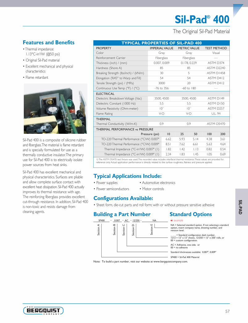
Sil-Pad® 400
57
The Original Sil-Pad Material
Features and Benefits• Thermal impedance:
1.13°C-in2/W (@50 psi)
• Original Sil-Pad material
• Excellent mechanical and physicalcharacteristics
• Flame retardant
Sil-Pad 400 is a composite of silicone rubberand fiberglass.The material is flame retardantand is specially formulated for use as athermally conductive insulator.The primaryuse for Sil-Pad 400 is to electrically isolatepower sources from heat sinks.
Sil-Pad 400 has excellent mechanical andphysical characteristics. Surfaces are pliableand allow complete surface contact withexcellent heat dissipation. Sil-Pad 400 actuallyimproves its thermal resistance with age.The reinforcing fiberglass provides excellentcut-through resistance. In addition, Sil-Pad 400is non-toxic and resists damage fromcleaning agents.
Typical Applications Include:• Power supplies • Automotive electronics
• Power semiconductors • Motor controls
Configurations Available:• Sheet form, die-cut parts and roll form; with or without pressure sensitive adhesive
Building a Part Number Standard Options
Sect
ion
A
Sect
ion
B
Sect
ion
C
Sect
ion
D
Sect
ion
E NA = Selected standard option. If not selecting a standard option, insert company name, drawing number, and revision level.
SP400 = Sil-Pad 400 Material
SP400 0.007 AC 12/250 NA
Note: To build a part number, visit our website at www.bergquistcompany.com.
Standard thicknesses available: 0.007", 0.009"
AC = Adhesive, one side; or00 = no adhesive
_ _ _ = Standard configuration dash number, 1212 = 12" x 12" sheets, 12/250 = 12" x 250' rolls, or 00 = custom configuration
– – – –
TYPICAL PROPERTIES OF SIL-PAD 400PROPERTY IMPERIAL VALUE METRIC VALUE TEST METHODColor Gray Gray Visual
Reinforcement Carrier Fiberglass Fiberglass —
Thickness (inch) / (mm) 0.007, 0.009 0.178, 0.229 ASTM D374
Hardness (Shore A) 85 85 ASTM D2240
Breaking Strength (lbs/inch) / (kN/m) 30 5 ASTM D1458
Elongation (%45° to Warp and Fill) 54 54 ASTM D412
Tensile Strength (psi) / (MPa) 3000 20 ASTM D412
Continuous Use Temp (°F) / (°C) -76 to 356 -60 to 180 —
ELECTRICALDielectric Breakdown Voltage (Vac) 3500, 4500 3500, 4500 ASTM D149
Dielectric Constant (1000 Hz) 5.5 5.5 ASTM D150
Volume Resistivity (Ohm-meter) 1011 1011 ASTM D257
Flame Rating V-O V-O U.L. 94
THERMALThermal Conductivity (W/m-K) 0.9 0.9 ASTM D5470
THERMAL PERFORMANCE vs PRESSUREPressure (psi) 10 25 50 100 200
TO-220 Thermal Performance (°C/W) 0.007" 6.62 5.93 5.14 4.38 3.61
TO-220 Thermal Performance (°C/W) 0.009" 8.51 7.62 6.61 5.63 4.64
Thermal Impedance (°C-in2/W) 0.007" (1) 1.82 1.42 1.13 0.82 0.54
Thermal Impedance (°C-in2/W) 0.009" (1) 2.34 1.83 1.45 1.05 0.69
1) The ASTM D5470 test fixture was used.The recorded value includes interfacial thermal resistance.These values are provided forreference only. Actual application performance is directly related to the surface roughness, flatness and pressure applied.
SIL-PAD
SPDG_Chapter2_0511 v16.qxp 1/11/2012 2:26 PM Page 57

58
Sil-Pad® 800
Features and Benefits• Thermal impedance:
0.45°C-in2/W (@50 psi)
• High value material
• Smooth and highly compliant surface
• Electrically isolating
The Sil-Pad 800 family of thermally conductiveinsulation materials is designed for applicationsrequiring high thermal performance andelectrical isolation.These applications alsotypically have low mounting pressures forcomponent clamping.
Sil-Pad 800 material combines a smooth andhighly compliant surface characteristic with highthermal conductivity.These features optimize thethermal resistance properties at low pressure.
Applications requiring low componentclamping forces include discrete semiconduc-tors (TO-220,TO-247 and TO-218) mountedwith spring clips. Spring clips assist withquick assembly but apply a limited amountof force to the semiconductor.The smoothsurface texture of Sil-Pad 800 minimizesinterfacial thermal resistance and maximizesthermal performance.
High Performance Insulator for Low-Pressure Applications
Typical Applications Include:• Power supplies
• Automotive electronics
• Motor controls
• Power semiconductors
Configurations Available:• Sheet form, die-cut parts and roll form
• With or without pressure sensitive adhesive
Building a Part Number Standard Options
Sect
ion
A
Sect
ion
B
Sect
ion
C
Sect
ion
D
Sect
ion
E NA = Selected standard option. If not selecting a standardoption, insert company name, drawing number, andrevision level.
SP800 = Sil-Pad 800 Material
SP800 0.005 AC 1212 NA
Note: To build a part number, visit our website at www.bergquistcompany.com.
Standard thicknesses available: 0.005"
AC = Adhesive, one side00 = No adhesive
_ _ _ = Standard configuration dash number, 1212 = 12" x 12" sheets, 12/250 = 12" x 250' rolls, or00 = custom configuration
– – – –
TYPICAL PROPERTIES OF SIL-PAD 800PROPERTY IMPERIAL VALUE METRIC VALUE TEST METHODColor Gold Gold Visual
Reinforcement Carrier Fiberglass Fiberglass —
Thickness (inch) / (mm) 0.005 0.127 ASTM D374
Hardness (Shore A) 91 91 ASTM D2240
Elongation (%45° to Warp and Fill) 20 20 ASTM D412
Tensile Strength (psi) / (MPa) 1700 12 ASTM D412
Continuous Use Temp (°F) / (°C) -76 to 356 -60 to 180 —
ELECTRICALDielectric Breakdown Voltage (Vac) 3000 3000 ASTM D149
Dielectric Constant (1000 Hz) 6.0 6.0 ASTM D150
Volume Resistivity (Ohm-meter) 1010 1010 ASTM D257
Flame Rating V-O V-O U.L. 94
THERMALThermal Conductivity (W/m-K) 1.6 1.6 ASTM D5470
THERMAL PERFORMANCE vs PRESSUREPressure (psi) 10 25 50 100 200
TO-220 Thermal Performance (°C/W) 3.56 3.01 2.45 2.05 1.74
Thermal Impedance (°C-in2/W) (1) 0.92 0.60 0.45 0.36 0.29
1) The ASTM D5470 test fixture was used.The recorded value includes interfacial thermal resistance.These values are provided forreference only. Actual application performance is directly related to the surface roughness, flatness and pressure applied.
SIL-
PAD
SPDG_Chapter2_0511 v16.qxp 1/11/2012 2:26 PM Page 58

Sil-Pad® 900S
59
High Performance Insulator for Low-Pressure Applications
Features and Benefits• Thermal impedance:
0.61°C-in2/W (@50 psi)
• Electrically isolating
• Low mounting pressures
• Smooth and highly compliant surface
• General-purpose thermal interfacematerial solution
The true workhorse of the Sil-Pad productfamily, Sil-Pad 900S thermally conductiveinsulation material, is designed for a widevariety of applications requiring high thermalperformance and electrical isolation.Theseapplications also typically have low mountingpressures for component clamping.
Sil-Pad 900S material combines a smoothand highly compliant surface characteristicwith high thermal conductivity.These featuresoptimize the thermal resistance properties atlow pressures.
Applications requiring low component clamp-ing forces include discrete semiconductors(TO-220,TO-247 and TO-218) mounted withspring clips. Spring clips assist with quickassembly and apply a limited amount of forceto the semiconductor.The smooth surfacetexture of Sil-Pad 900S minimizes interfacialthermal resistance and maximizes thermalperformance.
Typical Applications Include:• Power supplies
• Automotive electronics
• Motor controls
• Power semiconductors
Configurations Available:• Sheet form, die-cut parts and roll form
• With or without pressure sensitive adhesive
Building a Part Number Standard Options
Sect
ion
A
Sect
ion
B
Sect
ion
C
Sect
ion
D
Sect
ion
E NA = Selected standard option. If not selecting a standardoption, insert company name, drawing number, andrevision level.
SP900S = Sil-Pad 900S Material
SP900S 0.009 AC 00 ACME 951753 Rev B
Note: To build a part number, visit our website at www.bergquistcompany.com.
Standard thicknesses available: 0.009"
AC = Adhesive, one side00 = No adhesive
_ _ _ = Standard configuration dash number, 1212 = 12" x 12" sheets, 12/250 = 12" x 250' rolls, or00 = custom configuration
– – – –
TYPICAL PROPERTIES OF SIL-PAD 900SPROPERTY IMPERIAL VALUE METRIC VALUE TEST METHODColor Pink Pink Visual
Reinforcement Carrier Fiberglass Fiberglass —
Thickness (inch) / (mm) 0.009 0.229 ASTM D374
Hardness (Shore A) 92 92 ASTM D2240
Elongation (%45° to Warp and Fill) 20 20 ASTM D412
Tensile Strength (psi) / (MPa) 1300 9 ASTM D412
Continuous Use Temp (°F) / (°C) -76 to 356 -60 to 180 —
ELECTRICALDielectric Breakdown Voltage (Vac) 5500 5500 ASTM D149
Dielectric Constant (1000 Hz) 6.0 6.0 ASTM D150
Volume Resistivity (Ohm-meter) 1010 1010 ASTM D257
Flame Rating V-O V-O U.L. 94
THERMALThermal Conductivity (W/m-K) 1.6 1.6 ASTM D5470
THERMAL PERFORMANCE vs PRESSUREPressure (psi) 10 25 50 100 200
TO-220 Thermal Performance (°C/W) 3.96 3.41 2.90 2.53 2.32
Thermal Impedance (°C-in2/W) (1) 0.95 0.75 0.61 0.47 0.41
1) The ASTM D5470 test fixture was used.The recorded value includes interfacial thermal resistance.These values are provided forreference only. Actual application performance is directly related to the surface roughness, flatness and pressure applied.
SIL-PAD
SPDG_Chapter2_0511 v16.qxp 1/11/2012 2:26 PM Page 59

60
Sil-Pad® 980
Features and Benefits• Thermal impedance:
1.07°C-in2/W (@50 psi)
• Excellent cut-through resistance
• Use in screw-mounted applications withcut-through problems
In addition to excellent heat transfer anddielectric properties, Sil-Pad 980 is speciallyformulated for high resistance to crushing andcut-through typically found in high-pressureapplications where surface imperfections suchas burrs and dents are inherently common(e.g. heavily-machined metal surfacesmanufactured from extrusions or castings).
With a field-proven history of reliability,Sil-Pad 980 is Bergquist's best material forcut-through resistance in screw-mounted andother applications with cut-through problems.
High Cut-Through Resistant, Electrically Insulating,Thermally Conductive Material
Typical Applications Include:• Silicone-sensitive assemblies
• Telecommunications
• Automotive electronics
Configurations Available:• Sheet form, die-cut parts and roll form
• With or without pressure sensitive adhesive
Building a Part Number Standard Options
Sect
ion
A
Sect
ion
B
Sect
ion
C
Sect
ion
D
Sect
ion
E NA = Selected standard option. If not selecting a standardoption, insert company name, drawing number, andrevision level.
SP980 = Sil-Pad 980 Material
SP980 0.009 AC 00 ACME 951753 Rev B
Note: To build a part number, visit our website at www.bergquistcompany.com.
Standard thicknesses available: 0.009"
AC = Adhesive, one side00 = No adhesive
_ _ _ = Standard configuration dash number, 1212 = 12" x 12" sheets, 12/250 = 12" x 250' rolls, or00 = custom configuration
– – – –
TYPICAL PROPERTIES OF SIL-PAD 980PROPERTY IMPERIAL VALUE METRIC VALUE TEST METHODColor Mauve Mauve Visual
Reinforcement Carrier Fiberglass Fiberglass —
Thickness (inch) / (mm) 0.009 0.229 ASTM D374
Hardness (Shore A) 95 95 ASTM D2240
Breaking Strength (lbs/inch) / (kN/m) 140 26 ASTM D1458
Elongation (%45° to Warp and Fill) 10 10 ASTM D412
Cut-Through (lbs) / (kg) 750 340 ASTM D412
Continuous Use Temp (°F) / (°C) -40 to 302 -40 to 150 —
ELECTRICALDielectric Breakdown Voltage (Vac) 4000 4000 ASTM D149
Dielectric Constant (1000 Hz) 6.0 6.0 ASTM D150
Volume Resistivity (Ohm-meter) 1010 1010 ASTM D257
Flame Rating V-O V-O U.L. 94
THERMALThermal Conductivity (W/m-K) 1.2 1.2 ASTM D5470
THERMAL PERFORMANCE vs PRESSUREPressure (psi) 10 25 50 100 200
TO-220 Thermal Performance (°C/W) 5.48 5.07 4.52 4.04 3.56
Thermal Impedance (°C-in2/W) (1) 1.51 1.22 1.07 0.89 0.53
1) The ASTM D5470 test fixture was used.The recorded value includes interfacial thermal resistance.These values are provided forreference only. Actual application performance is directly related to the surface roughness, flatness and pressure applied.
SIL-
PAD
SPDG_Chapter2_0511 v16.qxp 1/11/2012 2:26 PM Page 60

61
Sil-Pad® 1100STAffordable, Electrically Insulating,Thermally Conductive, Soft Tack Elastomeric Material
Features and Benefits• Inherent tack on both sides for exceptional
thermal performance and easy placement
• Re-positionable for higher utilization, ease of use and assembly error reduction
• Lined on both sides for ease of handlingprior to placement in high volume assemblies
• Exhibits exceptional thermal performanceeven at a low mounting pressure
• Fiberglass reinforced
• Value alternative to Sil-Pad 1500ST
Sil-Pad 1100ST (Soft Tack) is a fiberglass-reinforced thermal interface material featuringinherent tack on both sides.The materialexhibits excellent thermal performance atlow mounting pressures.The material is sup-plied on two liners for exceptionally easyhandling prior to auto-placement in high-vol-ume assemblies.The material is ideal forplacement between an electronic powerdevice and its heat sink.
Typical Applications Include:• Automotive ECMs • Motor controls
• Power supplies • Between an electronic power device and its heat sink
Configurations Available:• Sheet form, die-cut parts and roll form
• Top and bottom liners
Building a Part Number Standard Options
TYPICAL PROPERTIES OF SIL-PAD 1100STPROPERTY IMPERIAL VALUE METRIC VALUE TEST METHOD
Color Yellow Yellow Visual
Reinforcement Carrier Fiberglass Fiberglass —
Thickness (inch) / (mm) 0.012 0.305 ASTM D374
Inherent Surface Tack (1or 2 sided) 2 2 —
Hardness (Shore 00) (1) 85 85 ASTM D2240
Breaking Strength (lb/inch) / (kN/m) 2.6 0.5 ASTM D1458
Elongation (% - 45º to Warp and Fill) 16 16 ASTM D412
Tensile Strength (psi) / (MPa) 220 1.5 ASTM D412
Continuous Use Temp (°F) / (°C) -76 to 356 -60 to 180 —
ELECTRICAL
Dielectric Breakdown Voltage (Vac) 5000 5000 ASTM D149
Dielectric Constant (1000 Hz) 5.0 5.0 ASTM D150
Volume Resistivity (Ohm-meter) 1010 1010 ASTM D257
Flame Rating V-O V-O U.L. 94
THERMAL
Thermal Conductivity (W/m-K) 1.1 1.1 ASTM D5470
THERMAL PERFORMANCE VS. PRESSURE
Pressure (psi) 10 25 50 100 200
TO-220 Thermal Performance (ºC/W) 2.72 2.71 2.68 2.62 2.23
Thermal Impedance (ºC-in2/W) (2) 0.75 0.71 0.66 0.61 0.57
1) Thirty second delay value Shore 00 hardness scale.2) The ASTM D5470 test fixture was used.The recorded value includes interfacial thermal resistance.These values are provided for reference only. Actual application performance is directly related to the surface roughness, flatness and pressure applied.
SIL-PAD
SPDG_Chapter2_0511 v16.qxp 1/11/2012 2:27 PM Page 61

62
TYPICAL PROPERTIES OF SIL-PAD 1200PROPERTY IMPERIAL VALUE METRIC VALUE TEST METHOD
Color Black Black Visual
Reinforcement Carrier Fiberglass Fiberglass —
Thickness (inch) / (mm) 0.009 to 0.016 0.229 to 0.406 ASTM D374
Hardness Bulk Rubber (Shore 00) 80 80 ASTM D2240
Elongation (% - 45º to warp and fill) 20 20 ASTM D412
Tensile Strength (psi) / (MPa) 1300 9 ASTM D412
Continuous Use Temp (°F) / (°C) -76 to 356 -60 to 180 —
ELECTRICAL
Dielectric Breakdown Voltage (Vac) 6000 6000 ASTM D149
Dielectric Constant (1000 Hz) 8.0 8.0 ASTM D150
Volume Resistivity (Ohm-meter) 109 109 ASTM D257
Flame Rating V-O V-O U.L. 94
THERMAL
Thermal Conductivity (W/m-K) (1) 1.8 1.8 ASTM D5470
THERMAL PERFORMANCE VS PRESSURE
Pressure (psi) 10 25 50 100 200
TO-220 Thermal Performance (ºC/W) 2.82 2.64 2.41 2.13 1.90
Thermal Impedance (ºC-in2/W) (2) 0.71 0.62 0.53 0.47 0.41
1)This is the measured thermal conductivity of the Sil-Pad Compound.2) The ASTM D5470 test fixture was used.The recorded value includes interfacial thermal resistance.These values are provided for reference only. Actual application performance is directly related to the surface roughness, flatness and pressure applied.
Sil-Pad® 1200Exceptional Performance,Thermally Conductive Elastomeric Material
Features and Benefits• Thermal Impedance: 0.53oC-in2/W
(@ 50 psi)
• Exceptional thermal performance at lowerapplication pressures
• Smooth and non-tacky on both sides foreasy re-positioning, ease of use and assem-bly error reduction
• Superior breakdown voltage and surface“wet out” values
• Designed for applications where electricalisolation is critical
• Excellent cut-through resistance, designedfor screw and clip mounted applications
Sil-Pad 1200 is a silicone based, fiberglass-reinforced thermal interface material featuringa smooth, highly compliant surface.The mate-rial features a non-tacky surface for efficientre-positioning and ease of use, as well as anoptional adhesive coating. Sil-Pad 1200exhibits exceptional thermal performance atlow and high application pressures.The mate-rial is ideal for placement between electronicpower devices and a heatsink for screw andclip mounted applications.
Typical Applications Include:• Automotive electronics control modules • Power supplies
• Motor controls • Audio amplifiers
• Discrete devices • Telecommunications
Configurations Available:• Sheet form, slit-to-width roll form
• Die-cut parts
• 9, 12 and 16 mil thicknesses
• Adhesive coating
We produce thousands of specials and customs.Tooling charges vary depending on tolerances and complexity of the part.
Building a Part Number Standard OptionsSP1200
AC = Adhesive, one side00 = No adhesive
SP1200 = Sil-Pad 1200 Material
Standard thicknesses available: 0.009", 0.012", 0.016"
AC
___ = Standard configuration dash number,1212 = 12" x 12" sheets, 12/250 = 12' x 250" rolls or 00 = custom configuration
0.009
SIL-
PAD
SPDG_Chapter2_0511 v16.qxp 1/11/2012 2:27 PM Page 62

63
Sil-Pad® A1500
Features and Benefits• Thermal impedance:
0.42°C-in2/W (@50 psi)
• Elastomeric compound coated onboth sides
Bergquist Sil-Pad A1500 is a silicone-based,thermally conductive and electrically insulatingmaterial. It consists of a cured siliconeelastomeric compound coated on both sidesof a fiberglass reinforcement layer.
Sil-Pad A1500 performs well under clampingpressure up to 200 psi and is an excellentchoice for high performance applicationsrequiring electrical isolation and cut-throughresistance.
Electrically Insulating,Thermally Conductive Elastomeric Material
Typical Applications Include:• Power supplies
• Automotive electronics
• Motor controls
• Power semiconductors
Configurations Available:• Sheet form, die-cut parts, and roll form
• With or without pressure sensitive adhesive
Building a Part Number Standard Options
Sect
ion
A
Sect
ion
B
Sect
ion
C
Sect
ion
D
Sect
ion
E NA = Selected standard option. If not selecting a standardoption, insert company name, drawing number, andrevision level.
SPA1500 = Sil-Pad A1500 Material
SPA1500 0.010 AC 12/250 NA
Note: To build a part number, visit our website at www.bergquistcompany.com.
Standard thicknesses available: 0.010"
AC = Adhesive, one side00 = No adhesive
_ _ _ = Standard configuration dash number, 1212 = 12" x 12" sheets, 12/250 = 12" x 250' rolls, or00 = custom configuration
– – – –
TYPICAL PROPERTIES OF SIL-PAD A1500PROPERTY IMPERIAL VALUE METRIC VALUE TEST METHODColor Green Green Visual
Reinforcement Carrier Fiberglass Fiberglass —
Thickness (inch) / (mm) 0.010 0.254 ASTM D374
Hardness (Shore A) 80 80 ASTM D2240
Breaking Strength (lbs/inch) / (kN/m) 65 12 ASTM D1458
Elongation (% - 45° to Warp and Fill) 40 40 ASTM D412
Continuous Use Temp (°F) / (°C) -76 to 356 -60 to 180 —
ELECTRICALDielectric Breakdown Voltage (Vac) 6000 6000 ASTM D149
Dielectric Constant (1000 Hz) 7.0 7.0 ASTM D150
Volume Resistivity (Ohm-meter) 1011 1011 ASTM D257
Flame Rating V-O V-O U.L. 94
THERMALThermal Conductivity (W/m-K) 2.0 2.0 ASTM D5470
THERMAL PERFORMANCE vs PRESSUREPressure (psi) 10 25 50 100 200
TO-220 Thermal Performance (°C/W) 3.03 2.62 2.21 1.92 1.78
Thermal Impedance (°C-in2/W) (1) 0.59 0.50 0.42 0.34 0.31
1) The ASTM D5470 test fixture was used.The recorded value includes interfacial thermal resistance.Thesevalues are provided for reference only. Actual application performance is directly related to the surface roughness, flatness andpressure applied.
SIL-PAD
SPDG_Chapter2_0511 v16.qxp 1/11/2012 2:27 PM Page 63

64
Features and Benefits• Thermal impedance:
0.23°C-in2/W (@50 psi)
• Naturally tacky on both sides
• Pad is repositionable
• Excellent thermal performance
• Auto-placement and dispensable
Bergquist Sil-Pad 1500ST (Soft Tack) is a fiber-glass reinforced thermal interface materialthat is naturally tacky on both sides.Sil-Pad 1500ST exhibits superior thermalperformance when compared to thecompetitors’ thermal interface materials.Sil-Pad 1500ST is supplied in sheet or rollform for exceptional auto-dispensing andauto-placement in high volume assemblies.Sil-Pad 1500ST is intended for placementbetween an electronic power device and itsheat sink.
Sil-Pad® 1500ST
Typical Applications Include:• Power supplies
• Automotive electronics
• Motor controls
Configurations Available:• Sheet form, die-cut parts and slit-to-width roll form
Building a Part Number Standard Options
Electrically Insulating,Thermally Conductive, Soft Tack Elastomeric Material
Sect
ion
A
Sect
ion
B
Sect
ion
C
Sect
ion
D
Sect
ion
E NA = Selected standard option. If not selecting a standard option, insert company name, drawing number, and revision level.
SP1500ST = Sil-Pad 1500ST Material
SP1500ST 0.008 02 1012 NA
Note: To build a part number, visit our website at www.bergquistcompany.com.
Standard thicknesses available: 0.008"
02 = Natural tack, both sides
_ _ _ = Standard configuration dash number, 1012 = 10" x 12" sheets, 10/250 = 10" x 250' rolls, or 00 = custom configuration
– – – –
TYPICAL PROPERTIES OF SIL-PAD 1500STPROPERTY IMPERIAL VALUE METRIC VALUE TEST METHODColor Blue Blue Visual
Reinforcement Carrier Fiberglass Fiberglass —
Thickness (inch) / (mm) 0.008 0.203 ASTM D374
Hardness (Shore 00) 75 75 ASTM D2240
Breaking Strength (lbs/inch) / (kN/m) 1.9 0.34 ASTM D1458
Elongation (% - 45° to Warp and Fill) 22 22 ASTM D412
Tensile Strength (psi) / (MPa) 238 1.6 ASTM D412
Continuous Use Temp (°F) / (°C) -76 to 356 -60 to 180 —
ELECTRICALDielectric Breakdown Voltage (Vac) 3000 3000 ASTM D149
Dielectric Constant (1000 Hz) 6.1 6.1 ASTM D150
Volume Resistivity (Ohm-meter) 1011 1011 ASTM D257
Flame Rating V-O V-O U.L. 94
THERMALThermal Conductivity (W/m-K) 1.8 1.8 ASTM D5470
THERMAL PERFORMANCE vs PRESSUREPressure (psi) 10 25 50 100 200
TO-220 Thermal Performance (°C/W) 1.54 1.52 1.51 1.49 1.46
Thermal Impedance (°C-in2/W) (1) 0.37 0.28 0.23 0.21 0.20
1) The ASTM D5470 test fixture was used.The recorded value includes interfacial thermal resistance.These values are provided forreference only. Actual application performance is directly related to the surface roughness, flatness and pressure applied.
SIL-
PAD
SPDG_Chapter2_0511 v16.qxp 1/11/2012 2:27 PM Page 64

Sil-Pad® 2000Higher Performance, High Reliability Insulator
Features and Benefits• Thermal impedance:
0.33°C-in2/W (@50 psi)
• Optimal heat transfer
• High thermal conductivity: 3.5 W/m-K
Sil-Pad 2000 is a high performance, thermallyconductive insulator designed for demandingaerospace and commercial applications.
Sil-Pad 2000 is a silicone elastomer formulatedto maximize the thermal and dielectricperformance of the filler/binder matrix.Theresult is a grease-free, conformable materialcapable of meeting or exceeding the thermaland electrical requirements of high-reliabilityelectronic packaging applications.
TYPICAL PROPERTIES OF SIL-PAD 2000PROPERTY IMPERIAL VALUE METRIC VALUE TEST METHODColor White White Visual
Reinforcement Carrier Fiberglass Fiberglass —
Thickness (inch) / (mm) 0.010 to 0.020 0.254 to 0.508 ASTM D374
Hardness (Shore A) 90 90 ASTM D2240
Continuous Use Temp (°F) / (°C) -76 to 392 -60 to 200 —
ELECTRICALDielectric Breakdown Voltage (Vac) 4000 4000 ASTM D149
Dielectric Constant (1000 Hz) 4.0 4.0 ASTM D150
Volume Resistivity (Ohm-meter) 1011 1011 ASTM D257
Flame Rating V-O V-O U.L.94
THERMALThermal Conductivity (W/m-K) 3.5 3.5 ASTM D5470
THERMAL PERFORMANCE vs PRESSUREPressure (psi) 10 25 50 100 200
TO-220 Thermal Performance (°C/W) 2.61 2.32 2.02 1.65 1.37
Thermal Impedance (°C-in2/W) (1) 0.57 0.43 0.33 0.25 0.20
1) The ASTM D5470 test fixture was used.The recorded value includes interfacial thermal resistance.Thesevalues are provided for reference only. Actual application performance is directly related to the surface roughness, flatness andpressure applied.
Typical Applications Include:• Power supplies • Motor controls
• Power semiconductors • Aerospace
• Avionics
Configurations Available:• Sheet form, die-cut parts
• With or without pressure sensitive adhesive
Building a Part Number Standard Options
Sect
ion
A
Sect
ion
B
Sect
ion
C
Sect
ion
D
Sect
ion
E NA = Selected standard option. If not selecting a standardoption, insert company name, drawing number, andrevision level.
SP2000 = Sil-Pad 2000 Material
SP2000 0.010 AC 00 NA
Note: To build a part number, visit our website at www.bergquistcompany.com.
Standard thicknesses available: 0.010", 0.015", 0.020"
AC = Adhesive, one side00 = No adhesive
_ _ _ = Standard configuration dash number, 1212 = 12" x 12" sheets, or 00 = custom configuration
– – – –
65
SIL-PAD
SPDG_Chapter3_0511 v12.qxp 6/8/2011 3:42 PM Page 65

66
Features and Benefits• Thermal impedance:
0.32°C-in2/W (@50 psi)
• Optimal heat transfer
• High thermal conductivity: 3.0 W/m-K
Sil-Pad A2000 is a conformable elastomerwith very high thermal conductivity that actsas a thermal interface between electricalcomponents and heat sinks. Sil-Pad A2000 isfor applications where optimal heat transfer isa requirement.
This thermally conductive silicone elastomer isformulated to maximize the thermal anddielectric performance of the filler/bindermatrix.The result is a grease-free, conforma-ble material capable of meeting or exceedingthe thermal and electrical requirements of highreliability electronic packaging applications.
Sil-Pad® A2000Higher Performance, High Reliability Insulator
Typical Applications Include:• Motor drive controls
• Avionics
• High-voltage power supplies
• Power transistor / heat sink interface
Configurations Available:• Sheet form, die-cut parts and roll form
• With or without pressure sensitive adhesive
Building a Part Number Standard Options
Sect
ion
A
Sect
ion
B
Sect
ion
C
Sect
ion
D
Sect
ion
E NA = Selected standard option. If not selecting a standardoption, insert company name, drawing number, andrevision level.
SPA2000 = Sil-Pad A2000 Material
SPA2000 0.015 00 1012 NA
Note: To build a part number, visit our website at www.bergquistcompany.com.
Standard thicknesses available: 0.015", 0.020"
AC = Adhesive, one side00 = No adhesive
_ _ _ = Standard configuration dash number, 1012 = 10" x 12" sheets, 10/250 = 10" x 250' rolls, or00 = custom configuration
– – – –
TYPICAL PROPERTIES OF SIL-PAD A2000PROPERTY IMPERIAL VALUE METRIC VALUE TEST METHODColor White White Visual
Reinforcement Carrier Fiberglass Fiberglass —
Thickness (inch) / (mm) 0.015 to 0.020 0.381 to 0.508 ASTM D374
Hardness (Shore A) 90 90 ASTM D2240
Heat Capacity (J/g-K) 1.0 1.0 ASTM E1269
Continuous Use Temp (°F) / (°C) -76 to 392 -60 to 200 —
ELECTRICALDielectric Breakdown Voltage (Vac) 4000 4000 ASTM D149
Dielectric Constant (1000 Hz) 7.0 7.0 ASTM D150
Volume Resistivity (Ohm-meter) 1011 1011 ASTM D257
Flame Rating V-O V-O U.L.94
THERMALThermal Conductivity (W/m-K) 3.0 3.0 ASTM D5470
THERMAL PERFORMANCE vs PRESSUREPressure (psi) 10 25 50 100 200
TO-220 Thermal Performance (°C/W) 0.015" 2.05 1.94 1.86 1.79 1.72
Thermal Impedance (°C-in2/W) 0.015" (1) 0.53 0.40 0.32 0.28 0.26
1) The ASTM D5470 test fixture was used.The recorded value includes interfacial thermal resistance.These values are provided forreference only. Actual application performance is directly related to the surface roughness, flatness and pressure applied.
SIL-
PAD
SPDG_Chapter3_0511 v12.qxp 6/8/2011 3:42 PM Page 66
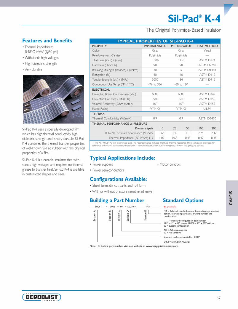
SIL-PAD
Sil-Pad® K-4The Original Polyimide-Based Insulator
Features and Benefits• Thermal impedance:
0.48°C-in2/W (@50 psi)
• Withstands high voltages
• High dielectric strength
• Very durable
Sil-Pad K-4 uses a specially developed filmwhich has high thermal conductivity, highdielectric strength and is very durable. Sil-PadK-4 combines the thermal transfer propertiesof well-known Sil-Pad rubber with the physicalproperties of a film.
Sil-Pad K-4 is a durable insulator that with-stands high voltages and requires no thermalgrease to transfer heat. Sil-Pad K-4 is availablein customized shapes and sizes.
Typical Applications Include:• Power supplies • Motor controls
• Power semiconductors
Configurations Available:• Sheet form, die-cut parts and roll form
• With or without pressure sensitive adhesive
Building a Part Number Standard Options
Sect
ion
A
Sect
ion
B
Sect
ion
C
Sect
ion
D
Sect
ion
E NA = Selected standard option. If not selecting a standardoption, insert company name, drawing number, andrevision level.
SPK4 = Sil-Pad K4 Material
SPK4 0.006 00 12/250 NA
Note: To build a part number, visit our website at www.bergquistcompany.com.
Standard thicknesses available: 0.006"
AC = Adhesive, one side00 = No adhesive
_ _ _ = Standard configuration dash number, 1212 = 12" x 12" sheets, 12/250 = 12" x 250' rolls, or00 = custom configuration
– – – –
TYPICAL PROPERTIES OF SIL-PAD K-4PROPERTY IMPERIAL VALUE METRIC VALUE TEST METHODColor Gray Gray Visual
Reinforcement Carrier Polyimide Polyimide —
Thickness (inch) / (mm) 0.006 0.152 ASTM D374
Hardness (Shore A) 90 90 ASTM D2240
Breaking Strength (lbs/inch) / (kN/m) 30 5 ASTM D1458
Elongation (%) 40 40 ASTM D412
Tensile Strength (psi) / (MPa) 5000 34 ASTM D412
Continuous Use Temp (°F) / (°C) -76 to 356 -60 to 180 —
ELECTRICALDielectric Breakdown Voltage (Vac) 6000 6000 ASTM D149
Dielectric Constant (1000 Hz) 5.0 5.0 ASTM D150
Volume Resistivity (Ohm-meter) 1012 1012 ASTM D257
Flame Rating VTM-O VTM-O U.L.94
THERMALThermal Conductivity (W/m-K) 0.9 0.9 ASTM D5470
THERMAL PERFORMANCE vs PRESSUREPressure (psi) 10 25 50 100 200
TO-220 Thermal Performance (°C/W) 3.66 3.43 3.13 2.74 2.42
Thermal Impedance (°C-in2/W) (1) 1.07 0.68 0.48 0.42 0.38
1) The ASTM D5470 test fixture was used.The recorded value includes interfacial thermal resistance.These values are provided forreference only. Actual application performance is directly related to the surface roughness, flatness and pressure applied.
67
SPDG_Chapter3_0511 v12.qxp 6/8/2011 3:42 PM Page 67

68
Features and Benefits• Thermal impedance:
0.49°C-in2/W (@50 psi)
• Physically strong dielectric barrier againstcut-through
• Medium performance film
Sil-Pad K-6 is a medium performance, film-based thermally conductive insulator.The filmis coated with a silicone elastomer to deliverhigh performance and provide a continuous,physically strong dielectric barrier against“cut-through” and resultant assembly failures.
Sil-Pad® K-6The Medium Performance Polyimide-Based Insulator
Typical Applications Include:• Power supplies • Motor controls
• Power semiconductors
Configurations Available:• Sheet form, die-cut parts and roll form
• With or without pressure sensitive adhesive
Building a Part Number Standard Options
Sect
ion
A
Sect
ion
B
Sect
ion
C
Sect
ion
D
Sect
ion
E NA = Selected standard option. If not selecting a standardoption, insert company name, drawing number, andrevision level.
SPK6 = Sil-Pad K6 Material
SPK6 0.006 AC 12/250 NA
Note: To build a part number, visit our website at www.bergquistcompany.com.
Standard thicknesses available: 0.006"
AC = Adhesive, one side00 = No adhesive
_ _ _ = Standard configuration dash number, 1212 = 12" x 12" sheets, 12/250 = 12" x 250' rolls, or00 = custom configuration
– – – –
TYPICAL PROPERTIES OF SIL-PAD K-6PROPERTY IMPERIAL VALUE METRIC VALUE TEST METHODColor Bluegreen Bluegreen Visual
Reinforcement Carrier Polyimide Polyimide —
Thickness (inch) / (mm) 0.006 0.152 ASTM D374
Hardness (Shore A) 90 90 ASTM D2240
Breaking Strength (lbs/inch) / (kN/m) 30 5 ASTM D1458
Elongation (%) 40 40 ASTM D412
Tensile Strength (psi) / (MPa) 5000 34 ASTM D412
Continuous Use Temp (°F) / (°C) -76 to 356 -60 to 180 —
ELECTRICALDielectric Breakdown Voltage (Vac) 6000 6000 ASTM D149
Dielectric Constant (1000 Hz) 4.0 4.0 ASTM D150
Volume Resistivity (Ohm-meter) 1012 1012 ASTM D257
Flame Rating VTM-O VTM-O U.L.94
THERMALThermal Conductivity (W/m-K) 1.1 1.1 ASTM D5470
THERMAL PERFORMANCE vs PRESSUREPressure (psi) 10 25 50 100 200
TO-220 Thermal Performance (°C/W) 3.24 3.03 2.76 2.45 2.24
Thermal Impedance (°C-in2/W) (1) 0.82 0.62 0.49 0.41 0.36
1) The ASTM D5470 test fixture was used.The recorded value includes interfacial thermal resistance.These values are provided forreference only. Actual application performance is directly related to the surface roughness, flatness and pressure applied.
SIL-
PAD
SPDG_Chapter3_0511 v12.qxp 6/8/2011 3:42 PM Page 68
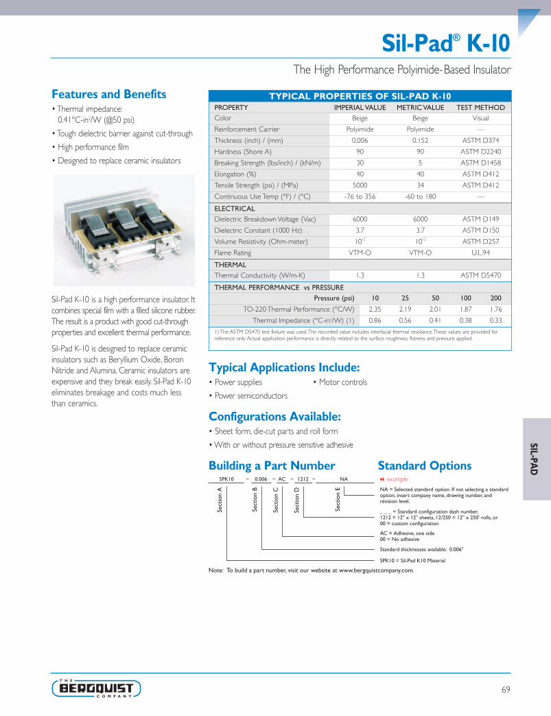
Sil-Pad® K-10The High Performance Polyimide-Based Insulator
Features and Benefits• Thermal impedance:
0.41°C-in2/W (@50 psi)
• Tough dielectric barrier against cut-through
• High performance film
• Designed to replace ceramic insulators
Sil-Pad K-10 is a high performance insulator. Itcombines special film with a filled silicone rubber.The result is a product with good cut-throughproperties and excellent thermal performance.
Sil-Pad K-10 is designed to replace ceramicinsulators such as Beryllium Oxide, BoronNitride and Alumina. Ceramic insulators areexpensive and they break easily. Sil-Pad K-10eliminates breakage and costs much lessthan ceramics.
Typical Applications Include:• Power supplies • Motor controls
• Power semiconductors
Configurations Available:• Sheet form, die-cut parts and roll form
• With or without pressure sensitive adhesive
Building a Part Number Standard Options
Sect
ion
A
Sect
ion
B
Sect
ion
C
Sect
ion
D
Sect
ion
E NA = Selected standard option. If not selecting a standardoption, insert company name, drawing number, andrevision level.
SPK10 = Sil-Pad K10 Material
SPK10 0.006 AC 1212 NA
Note: To build a part number, visit our website at www.bergquistcompany.com.
Standard thicknesses available: 0.006"
AC = Adhesive, one side00 = No adhesive
_ _ _ = Standard configuration dash number, 1212 = 12" x 12" sheets, 12/250 = 12" x 250' rolls, or00 = custom configuration
– – – –
TYPICAL PROPERTIES OF SIL-PAD K-10PROPERTY IMPERIAL VALUE METRIC VALUE TEST METHODColor Beige Beige Visual
Reinforcement Carrier Polyimide Polyimide —
Thickness (inch) / (mm) 0.006 0.152 ASTM D374
Hardness (Shore A) 90 90 ASTM D2240
Breaking Strength (lbs/inch) / (kN/m) 30 5 ASTM D1458
Elongation (%) 40 40 ASTM D412
Tensile Strength (psi) / (MPa) 5000 34 ASTM D412
Continuous Use Temp (°F) / (°C) -76 to 356 -60 to 180 —
ELECTRICALDielectric Breakdown Voltage (Vac) 6000 6000 ASTM D149
Dielectric Constant (1000 Hz) 3.7 3.7 ASTM D150
Volume Resistivity (Ohm-meter) 1012 1012 ASTM D257
Flame Rating VTM-O VTM-O U.L.94
THERMALThermal Conductivity (W/m-K) 1.3 1.3 ASTM D5470
THERMAL PERFORMANCE vs PRESSUREPressure (psi) 10 25 50 100 200
TO-220 Thermal Performance (°C/W) 2.35 2.19 2.01 1.87 1.76
Thermal Impedance (°C-in2/W) (1) 0.86 0.56 0.41 0.38 0.33
1) The ASTM D5470 test fixture was used.The recorded value includes interfacial thermal resistance.These values are provided forreference only. Actual application performance is directly related to the surface roughness, flatness and pressure applied.
69
SIL-PAD
SPDG_Chapter3_0511 v12.qxp 6/8/2011 3:42 PM Page 69

70
Features and Benefits• Thermal impedance:
0.22°C-in2/W (@50 psi)
• Maximum heat transfer
• Aluminum foil coated both sides
• Designed to replace thermal grease
Q-Pad II is a composite of aluminum foil coatedon both sides with thermally / electricallyconductive Sil-Pad rubber.The material isdesigned for those applications in which maxi-mum heat transfer is needed and electricalisolation is not required. Q-Pad II is the idealthermal interface material to replace messythermal grease compounds.
Q-Pad II eliminates problems associated withgrease such as contamination of reflow solderor cleaning operations. Unlike grease, Q-Pad IIcan be used prior to these operations. Q-Pad IIalso eliminates dust collection which can causepossible surface shorting or heat buildup.
Q-Pad® IIFoil-Format Grease Replacement for Maximum Heat Transfer
Typical Applications Include:• Between a transistor and a heat sink
• Between two large surfaces such as an L-bracket and the chassis of an assembly
• Between a heat sink and a chassis
• Under electrically isolated power modules or devices such as resistors,transformers and solid state relays
Configurations Available:• Sheet form, die-cut parts and roll form
• With or without pressure sensitive adhesive
Building a Part Number Standard Options
TYPICAL PROPERTIES OF Q-PAD IIPROPERTY IMPERIAL VALUE METRIC VALUE TEST METHODColor Black Black Visual
Reinforcement Carrier Aluminum Aluminum —
Thickness (inch) / (mm) 0.006 0.152 ASTM D374
Hardness (Shore A) 93 93 ASTM D2240
Continuous Use Temp (°F) / (°C) -76 to 356 -60 to 180 —
ELECTRICALDielectric Breakdown Voltage (Vac) Non-Insulating Non-Insulating ASTM D149
Dielectric Constant (1000 Hz) NA NA ASTM D150
Volume Resistivity (Ohm-meter) 102 102 ASTM D257
Flame Rating V-O V-O U.L.94
THERMALThermal Conductivity (W/m-K) 2.5 2.5 ASTM D5470
THERMAL PERFORMANCE vs PRESSUREPressure (psi) 10 25 50 100 200
TO-220 Thermal Performance (°C/W) 2.44 1.73 1.23 1.05 0.92
Thermal Impedance (°C-in2/W) (1) 0.52 0.30 0.22 0.15 0.12
1) The ASTM D5470 test fixture was used.The recorded value includes interfacial thermal resistance.These values are provided forreference only. Actual application performance is directly related to the surface roughness, flatness and pressure applied.
SIL-
PAD
SPDG_Chapter3_0511 v12.qxp 6/8/2011 3:42 PM Page 70

Q-Pad® 3Glass-Reinforced Grease Replacement Thermal Interface
Features and Benefits• Thermal impedance:
0.35°C-in2/W (@50 psi)
• Eliminates processing constraints typicallyassociated with grease
• Conforms to surface textures
• Easy handling
• May be installed prior to soldering andcleaning without worry
Bergquist Q-Pad 3 eliminates problemsassociated with thermal grease such as con-tamination of electronic assemblies and reflowsolder baths. Q-Pad 3 may be installed priorto soldering and cleaning without worry.Whenclamped between two surfaces, the elastomerconforms to surface textures thereby creatingan air-free interface between heat-generatingcomponents and heat sinks.
Fiberglass reinforcement enables Q-Pad 3 towithstand processing stresses without losingphysical integrity. It also provides ease ofhandling during application.
Typical Applications Include:• Between a transistor and a heat sink
• Between two large surfaces such as an L-bracket and the chassis of an assembly
• Between a heat sink and a chassis
• Under electrically isolated power modules or devices such as resistors,transformers and solid state relays
Configurations Available:• Sheet form, die-cut parts and roll form
• With or without pressure sensitive adhesive
Building a Part Number Standard Options
Sect
ion
A
Sect
ion
B
Sect
ion
C
Sect
ion
D
Sect
ion
E NA = Selected standard option. If not selecting a standardoption, insert company name, drawing number, andrevision level.
Q3 = Q-Pad 3 Material
Q3 0.005 AC 12/250 NA
Note: To build a part number, visit our website at www.bergquistcompany.com.
Standard thicknesses available: 0.005"
AC = Adhesive, one side00 = No adhesive
_ _ _ = Standard configuration dash number, 1212 = 12" x 12" sheets, 12/250 = 12" x 250' rolls, or00 = custom configuration
– – – –
TYPICAL PROPERTIES OF Q-PAD 3PROPERTY IMPERIAL VALUE METRIC VALUE TEST METHODColor Black Black Visual
Reinforcement Carrier Fiberglass Fiberglass —
Thickness (inch) / (mm) 0.005 0.127 ASTM D374
Hardness (Shore A) 86 86 ASTM D2240
Continuous Use Temp (°F) / (°C) -76 to 356 -60 to 180 —
ELECTRICALDielectric Breakdown Voltage (Vac) Non-Insulating Non-Insulating ASTM D149
Dielectric Constant (1000 Hz) NA NA ASTM D150
Volume Resistivity (Ohm-meter) 102 102 ASTM D257
Flame Rating V-O V-O U.L.94
THERMALThermal Conductivity (W/m-K) 2.0 2.0 ASTM D5470
THERMAL PERFORMANCE vs PRESSUREPressure (psi) 10 25 50 100 200
TO-220 Thermal Performance (°C/W) 2.26 1.99 1.76 1.53 1.30
Thermal Impedance (°C-in2/W) (1) 0.65 0.48 0.35 0.24 0.16
1) The ASTM D5470 test fixture was used.The recorded value includes interfacial thermal resistance.These values are provided forreference only. Actual application performance is directly related to the surface roughness, flatness and pressure applied.
71
SIL-PAD
SPDG_Chapter3_0511 v12.qxp 6/8/2011 3:42 PM Page 71

72
Poly-Pad® 400Polyester-Based,Thermally Conductive Insulation Material
Features and Benefits• Thermal impedance:
1.13°C-in2/W (@50 psi)
• Polyester based
• For applications requiring conformal coatings
• Designed for silicone-sensitive standardapplications
Poly-Pad 400 is a fiberglass-reinforcedinsulator coated with a filled polyester resin.Poly-Pad 400 is economical and designed formost standard applications.
Polyester-based, thermally conductive insulatorsfrom Bergquist provide a complete family ofmaterials for silicone-sensitive applications.Poly-Pads are ideally suited for applicationsrequiring conformal coatings or applicationswhere silicone contamination is a concern(telecomm and certain aerospace applications).Poly-Pads are constructed with ceramic-filledpolyester resins coating either side of a fiber-glass carrier or a film carrier.The Poly-Padfamily offers a complete range of performancecharacteristics to match individual applications.
Typical Applications Include:• Power supplies
• Automotive electronics
• Motor controls
• Power semiconductors
Configurations Available:• Sheet form, die-cut parts and roll form
• With or without pressure sensitive adhesive
• We produce thousands of specials.Tooling charges vary depending on tolerances and thecomplexity of the part.
Building a Part Number Standard Options
Sect
ion
A
Sect
ion
B
Sect
ion
C
Sect
ion
D
Sect
ion
E NA = Selected standard option. If not selecting a standardoption, insert company name, drawing number, andrevision level.
PP400 = Poly-Pad 400 Material
PP400 0.009 00 1212 NA
Note: To build a part number, visit our website at www.bergquistcompany.com.
Standard thicknesses available: 0.009"
AC = Adhesive, one side00 = No adhesive
_ _ _ = Standard configuration dash number, 1212 = 12" x 12" sheets, 12/250 = 12" x 250' rolls, or00 = custom configuration
– – – –
TYPICAL PROPERTIES OF POLY-PAD 400PROPERTY IMPERIAL VALUE METRIC VALUE TEST METHODColor Tan Tan Visual
Reinforcement Carrier Fiberglass Fiberglass —
Thickness (inch) / (mm) 0.009 0.229 ASTM D374
Hardness (Shore A) 90 90 ASTM D2240
Breaking Strength (lbs/inch)/(kN/m) 100 18 ASTM D1458
Elongation(% - 45° to Warp andFill) 10 10 ASTM D412
Tensile Strength (psi) / (MPa) 7000 48 ASTM D412
Continuous Use Temp (°F) / (°C) -4 to 302 -20 to 150 —
ELECTRICALDielectric Breakdown Voltage (Vac) 2500 2500 ASTM D149
Dielectric Constant (1000 Hz) 5.5 5.5 ASTM D150
Volume Resistivity (Ohm-meter) 1011 1011 ASTM D257
THERMALThermal Conductivity (W/m-K) 0.9 0.9 ASTM D5470
Flame Rating V-O V-O U.L. 94
THERMAL PERFORMANCE vs PRESSUREPressure (psi) 10 25 50 100 200
TO-220 Thermal Performance (°C/W) 5.85 5.61 5.13 4.59 4.12
Thermal Impedance (°C-in2/W) (1) 1.62 1.35 1.13 0.86 0.61
1) The ASTM D5470 test fixture was used.The recorded value includes interfacial thermal resistance.These values are provided forreference only. Actual application performance is directly related to the surface roughness, flatness and pressure applied.
SIL-
PAD
SPDG_Chapter3_0511 v12.qxp 6/8/2011 3:42 PM Page 72
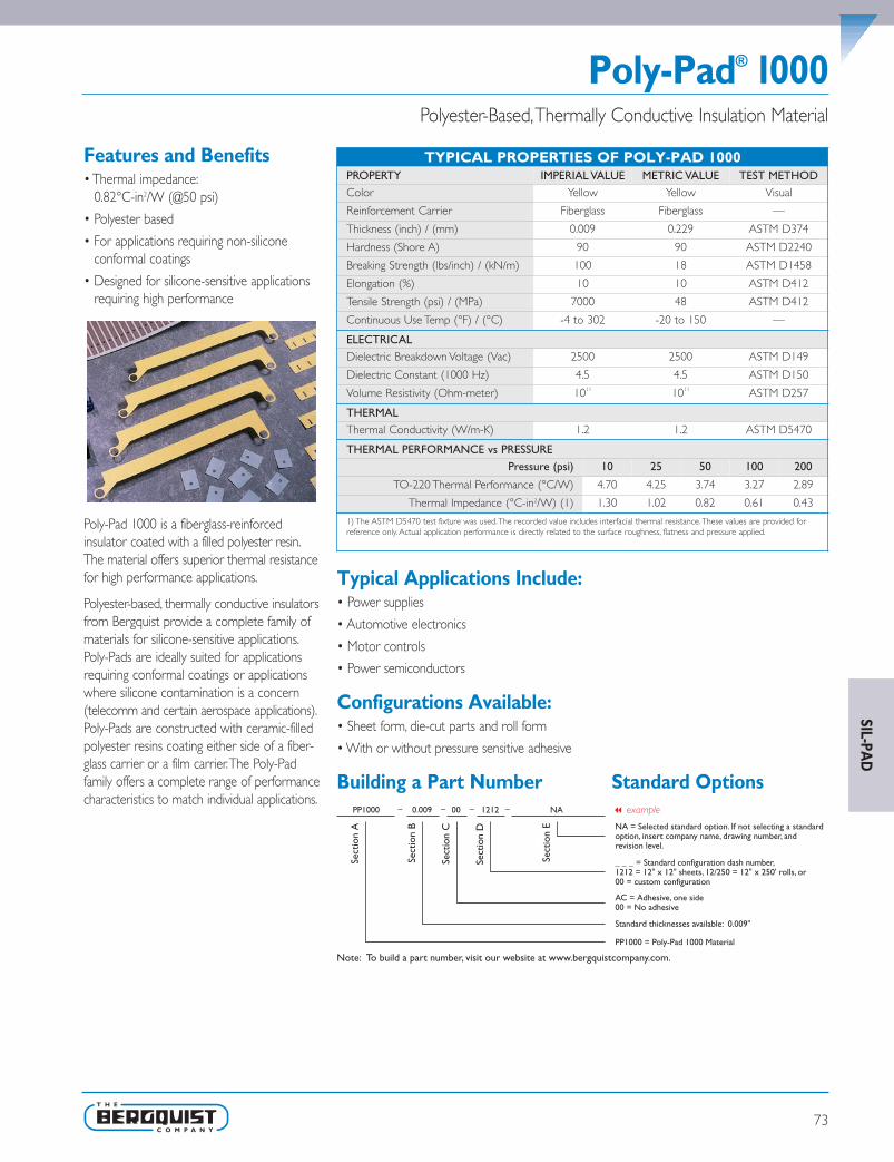
Poly-Pad® 1000Polyester-Based,Thermally Conductive Insulation Material
Features and Benefits• Thermal impedance:
0.82°C-in2/W (@50 psi)
• Polyester based
• For applications requiring non-siliconeconformal coatings
• Designed for silicone-sensitive applicationsrequiring high performance
Poly-Pad 1000 is a fiberglass-reinforcedinsulator coated with a filled polyester resin.The material offers superior thermal resistancefor high performance applications.
Polyester-based, thermally conductive insulatorsfrom Bergquist provide a complete family ofmaterials for silicone-sensitive applications.Poly-Pads are ideally suited for applicationsrequiring conformal coatings or applicationswhere silicone contamination is a concern(telecomm and certain aerospace applications).Poly-Pads are constructed with ceramic-filledpolyester resins coating either side of a fiber-glass carrier or a film carrier.The Poly-Padfamily offers a complete range of performancecharacteristics to match individual applications.
Typical Applications Include:• Power supplies
• Automotive electronics
• Motor controls
• Power semiconductors
Configurations Available:• Sheet form, die-cut parts and roll form
• With or without pressure sensitive adhesive
Building a Part Number Standard Options
Sect
ion
A
Sect
ion
B
Sect
ion
C
Sect
ion
D
Sect
ion
E NA = Selected standard option. If not selecting a standardoption, insert company name, drawing number, andrevision level.
PP1000 = Poly-Pad 1000 Material
PP1000 0.009 00 1212 NA
Note: To build a part number, visit our website at www.bergquistcompany.com.
Standard thicknesses available: 0.009"
AC = Adhesive, one side00 = No adhesive
_ _ _ = Standard configuration dash number, 1212 = 12" x 12" sheets, 12/250 = 12" x 250' rolls, or00 = custom configuration
– – – –
TYPICAL PROPERTIES OF POLY-PAD 1000PROPERTY IMPERIAL VALUE METRIC VALUE TEST METHODColor Yellow Yellow Visual
Reinforcement Carrier Fiberglass Fiberglass —
Thickness (inch) / (mm) 0.009 0.229 ASTM D374
Hardness (Shore A) 90 90 ASTM D2240
Breaking Strength (lbs/inch) / (kN/m) 100 18 ASTM D1458
Elongation (%) 10 10 ASTM D412
Tensile Strength (psi) / (MPa) 7000 48 ASTM D412
Continuous Use Temp (°F) / (°C) -4 to 302 -20 to 150 —
ELECTRICALDielectric Breakdown Voltage (Vac) 2500 2500 ASTM D149
Dielectric Constant (1000 Hz) 4.5 4.5 ASTM D150
Volume Resistivity (Ohm-meter) 1011 1011 ASTM D257
THERMALThermal Conductivity (W/m-K) 1.2 1.2 ASTM D5470
THERMAL PERFORMANCE vs PRESSUREPressure (psi) 10 25 50 100 200
TO-220 Thermal Performance (°C/W) 4.70 4.25 3.74 3.27 2.89
Thermal Impedance (°C-in2/W) (1) 1.30 1.02 0.82 0.61 0.43
1) The ASTM D5470 test fixture was used.The recorded value includes interfacial thermal resistance.These values are provided forreference only. Actual application performance is directly related to the surface roughness, flatness and pressure applied.
73
SIL-PAD
SPDG_Chapter3_0511 v12.qxp 6/8/2011 3:42 PM Page 73

74
Features and Benefits• Thermal impedance:
0.95°C-in2/W (@50 psi)
• Polyester based
• For applications requiring non-siliconeconformal coatings
• Designed for silicone-sensitive applications
• Excellent dielectric and physical strength
Poly-Pad K-4 is a composite of film coated witha polyester resin.The material is an economicalinsulator and the film carrier provides excellentdielectric and physical strength.
Polyester-based, thermally conductive insulatorsfrom Bergquist provide a complete family ofmaterials for silicone-sensitive applications.Poly-Pads are ideally suited for applicationsrequiring conformal coatings or applicationswhere silicone contamination is a concern(telecomm and certain aerospace applications).Poly-Pads are constructed with ceramic-filledpolyester resins coating either side of a fiber-glass carrier or a film carrier.The Poly-Padfamily offers a complete range of performancecharacteristics to match individual applications.
Poly-Pad® K-4Polyester-Based,Thermally Conductive Insulation Material
Typical Applications Include:• Power supplies
• Motor controls
• Power semiconductors
Configurations Available:• Sheet form, die-cut parts and roll form
• With or without pressure sensitive adhesive
Building a Part Number Standard Options
Sect
ion
A
Sect
ion
B
Sect
ion
C
Sect
ion
D
Sect
ion
E NA = Selected standard option. If not selecting a standardoption, insert company name, drawing number, andrevision level.
PPK4 = Poly-Pad K-4 Material
PPK4 0.006 00 12/250 NA
Note: To build a part number, visit our website at www.bergquistcompany.com.
Standard thicknesses available: 0.006"
AC = Adhesive, one side00 = No adhesive
_ _ _ = Standard configuration dash number, 1212 = 12" x 12" sheets, 12/250 = 12" x 250' rolls, or00 = custom configuration
– – – –
TYPICAL PROPERTIES OF POLY-PAD K-4PROPERTY IMPERIAL VALUE METRIC VALUE TEST METHODColor Tan Tan Visual
Reinforcement Carrier Polyimide Polyimide —
Thickness (inch) / (mm) 0.006 0.152 ASTM D374
Hardness (Shore A) 90 90 ASTM D2240
Breaking Strength (lbs/inch) / (kN/m) 30 5 ASTM D1458
Elongation (%) 40 40 ASTM D412
Tensile Strength (psi) / (MPa) 5000 34 ASTM D412
Continuous Use Temp (°F) / (°C) -4 to 302 -20 to 150 —
ELECTRICALDielectric Breakdown Voltage (Vac) 6000 6000 ASTM D149
Dielectric Constant (1000 Hz) 5.0 5.0 ASTM D150
Volume Resistivity (Ohm-meter) 1012 1012 ASTM D257
Flame Rating V-O V-O U.L.94
THERMAL
Thermal Conductivity (W/m-K) 0.9 0.9 ASTM D5470
THERMAL PERFORMANCE vs PRESSUREPressure (psi) 10 25 50 100 200
TO-220 Thermal Performance (°C/W) 5.64 5.04 4.34 3.69 3.12
Thermal Impedance (°C-in2/W) (1) 1.55 1.21 0.95 0.70 0.46
1) The ASTM D5470 test fixture was used.The recorded value includes interfacial thermal resistance.These values are provided forreference only. Actual application performance is directly related to the surface roughness, flatness and pressure applied.
SIL-
PAD
SPDG_Chapter3_0511 v12.qxp 6/8/2011 3:42 PM Page 74

Poly-Pad® K-10Polyester-Based,Thermally Conductive Insulation Material
Features and Benefits• Thermal impedance:
0.60°C-in2/W (@50 psi)
• Polyester based
• For applications requiring non-siliconeconformal coatings
• Designed for silicone-sensitive applications
• Excellent dielectric strength andthermal performance
Poly-Pad K-10 is a composite of film coatedwith a polyester resin.The material offerssuperior thermal performance for your mostcritical applications with a thermal resistanceof 0.2°C-in2/W as well as excellent dielectricstrength.
Polyester-based, thermally conductive insulatorsfrom Bergquist provide a complete family ofmaterials for silicone-sensitive applications.Poly-Pads are ideally suited for applicationsrequiring conformal coatings or applicationswhere silicone contamination is a concern(telecomm and certain aerospace applications).Poly-Pads are constructed with ceramic-filledpolyester resins coating either side of a fiber-glass carrier or a film carrier.The Poly-Padfamily offers a complete range of performancecharacteristics to match individual applications.
Typical Applications Include:• Power supplies
• Motor controls
• Power semiconductors
Configurations Available:• Sheet form, die-cut parts and roll form
• With or without pressure sensitive adhesive
Building a Part Number Standard Options
Sect
ion
A
Sect
ion
B
Sect
ion
C
Sect
ion
D
Sect
ion
E NA = Selected standard option. If not selecting a standardoption, insert company name, drawing number, andrevision level.
PPK10 = Poly-Pad K-10 Material
PPK10 0.006 AC 1212 NA
Note: To build a part number, visit our website at www.bergquistcompany.com.
Standard thicknesses available: 0.006"
AC = Adhesive, one side00 = No adhesive
_ _ _ = Standard configuration dash number, 1212 = 12" x 12" sheets, 12/250 = 12" x 250' rolls, or00 = custom configuration
– – – –
TYPICAL PROPERTIES OF POLY-PAD K-10PROPERTY IMPERIAL VALUE METRIC VALUE TEST METHODColor Yellow Yellow VisualReinforcement Carrier Polyimide Polyimide —Thickness (inch) / (mm) 0.006 0.152 ASTM D374Hardness (Shore A) 90 90 ASTM D2240Breaking Strength (lbs/inch) / (kN/m) 30 5 ASTM D1458Elongation (%) 40 40 ASTM D412Tensile Strength (psi) / (MPa) 5000 34 ASTM D412Continuous Use Temp (°F) / (°C) -4 to 302 -20 to 150 —
ELECTRICALDielectric Breakdown Voltage (Vac) 6000 6000 ASTM D149Dielectric Constant (1000 Hz) 3.7 3.7 ASTM D150Volume Resistivity (Ohm-meter) 1012 1012 ASTM D257Flame Rating V-O V-O U.L.94
THERMALThermal Conductivity (W/m-K) 1.3 1.3 ASTM D5470
THERMAL PERFORMANCE vs PRESSUREPressure (psi) 10 25 50 100 200
TO-220 Thermal Performance (°C/W) 3.76 3.35 2.75 2.30 2.03Thermal Impedance (°C-in2/W) (1) 1.04 0.80 0.60 0.43 0.30
1) The ASTM D5470 test fixture was used.The recorded value includes interfacial thermal resistance.These values are provided for reference only. Actual application performance is directly related to the surface roughness, flatness and pressure applied.
75
SIL-PAD
SPDG_Chapter3_0511 v12.qxp 6/8/2011 3:42 PM Page 75

76
Sil-Pad® Tubes
Features and Benefits• Thermal conductivity:
SPT 400 – 0.9 W/m-KSPT 1000 – 1.2 W/m-K
• For clip-mounted plastic power packages
SPT 400 and SPT 1000 (Sil-Pad Tubes) providethermally conductive insulation for clip-mounted plastic power packages. Sil-PadTubes are made of silicone rubber with highthermal conductivity.
Sil-Pad Tube 1000 is best suited for higherthermal performance. Sil-Pad Tube 400 is idealfor applications requiring average thermalconductivity and economy.
Sil-Pad Tube 400 and Sil-Pad Tube 1000 aredesigned to meet VDE, U.L. and TUV agencyrequirements.
Typical ApplicationsInclude:• Clip-mounted power semiconductors
• TO-220,TO-218,TO-247 and TO-3P
Configurations Available:• TO-220,TO-218,TO-247 and TO-3P
Silicone-Based,Thermally Conductive Tubes
Standard DimensionsA = Wall Thickness: .305 mm (.012") + .10 mm/ -0.0 mm (+.004" / -0.0")B = Inner Diameter: 11 mm (.433") or 13.5 mm (.532") ± 1.0 mm (± .039")C = Length: 25 mm (.985") or 30 mm (1.18") +3.18 mm / -0.0 mm (+ .125" / - 0.0")
Special lengths are available. For more information, contact a Bergquist Sales Representative.
Ordering Procedure:
Sample: SPT 400 ___ - ___ - ___“A” – “B” – “C”
A
B
C
TYPICAL PROPERTIES OF SIL-PAD TUBE 400PROPERTY IMPERIAL VALUE METRIC VALUE TEST METHOD
Color Gray/Green Gray/Green Visual
Thickness / Wall (inch) / (mm) 0.012 0.305 ASTM D374
Hardness (Shore A) 80 80 ASTM D2240
Breaking Strength (lbs/inch) / (kN/m) 6 1 ASTM D1458
Continuous Use Temp (°F) / (°C) -76 to 356 -60 to 180 —
ELECTRICAL
Dielectric Breakdown Voltage (Vac) 5000 5000 ASTM D149
Dielectric Constant (1000 Hz) 5.5 5.5 ASTM D150
Volume Resistivity (Ohm-meter) 1011 1011 ASTM D257
Flame Rating V-O V-O U.L.94
THERMAL
Thermal Conductivity (W/m-K) 0.9 0.9 ASTM D5470
Thermal Impedance (°C-in2/W) (1) 0.6 0.6 ASTM D5470
TYPICAL PROPERTIES OF SIL-PAD TUBE 1000PROPERTY IMPERIAL VALUE METRIC VALUE TEST METHOD
Color Brown Brown Visual
Thickness / Wall (inch) / (mm) 0.012 0.30 ASTM D374
Hardness (Shore A) 80 80 ASTM D2240
Breaking Strength (lbs/inch) / (kN/m) 6 1 ASTM D1458
Continuous Use Temp (°F) / (°C) -76 to 356 -60 to 180 —
ELECTRICAL
Dielectric Breakdown Voltage (Vac) 5000 5000 ASTM D149
Dielectric Constant (1000 Hz) 4.5 4.5 ASTM D150
Volume Resistivity (Ohm-meter) 1011 1011 ASTM D257
Flame Rating V-O V-O U.L.94
THERMAL
Thermal Conductivity (W/m-K) 1.2 1.2 ASTM D5470
Thermal Impedance (°C-in2/W) (1) 0.4 0.4 ASTM D5470
1) The ASTM D5470 test fixture was used.The recorded value includes interfacial thermal resistance.Thesevalues are provided for reference only. Actual application performance is directly related to the surface roughness, flatness andpressure applied.
SIL-
PAD
SPDG_Chapter3_0511 v12.qxp 6/8/2011 3:42 PM Page 76

Sil-Pad® ShieldBonded Laminate of Sil-Pad with a Copper Shield
Features and Benefits• Bonded laminate
• Electrically isolating
• Copper shield between layers of Sil-Pad
• Pre-tinned 60/40 solder point for easygrounding
PROBLEM:Radio Frequency Interference (RFI) is pro-duced by heat sink current.The capacitancebetween a TO-3 encapsulated transistor andits heat sink is typically 100pf when a mica orother insulating washer is used. A powersupply constructed with a standard insulatorand a grounded heat sink can be expected toproduce about 10 times more interferencethan is permitted.
SOLUTION:1.The use of chokes, filters and LC networks
which have to be designed into the circuitry.
OR
2. Constructing a shield between the transistorand its heat sink by replacing the mica insu-lator with a Sil-Pad Shield (see illustration).
Typical Applications Include:• Switch mode power supplies • EMI / RFI shield between PCB’s
Configurations Available:Sil-Pad Shield is available in many custom configurations to meet special requirements.Toolingcharges vary depending on tolerances and complexity of the part.
Sil-Pad Shield is a laminate of copper with Sil-Pad thermally conductive insulators. Sil-Pad Shieldprovides:
• Shielding effectiveness of 50dB or higher
• Good thermal transfer
• Reduced labor costs due to the elimination of having to apply thermal grease
TYPICAL PROPERTIES OF SIL-PAD SHIELDPROPERTY VALUE TEST METHODThickness / Total (inches) 0.019 ***Shield / Copper Thickness (inches) 0.0015 ***Approx.Thermal Resistance (TO-3) (°C/W) 0.85 - 1.0 ***Min. Breakdown Voltage Between Device and Copper (Volts) 4500 ASTM D149Capacitance @ 1000 Hz and 5 Volts (pF) 50 ***Dissipation Factor @ 1000 Hz and 5 Volts (Power Factor) 0.0155 ASTM D150Dielectric Constant @ 1000 Hz and 5 Volts 5.5 ASTM D150Continuous Use Temp. (°C) -60 to 180 ***Recommended Torque (TO-3) (inch-pounds) 6-8 ***
77
SIL-PAD
SPDG_Chapter3_0511 v12.qxp 6/8/2011 3:42 PM Page 77

BON
D-P
LY
78
Bond-Ply® and Liqui-Bond® Adhesives
Bond-Ply Adhesive TapesAvailable in a pressure sensitive adhesive or laminating format, theBond-Ply family of materials are thermally conductive and electricallyisolating. Bond-Ply facilitates the decoupling of bonded materials withmismatched thermal coefficients of expansion.
Typical Bond-Ply Applications
Features• High performance, thermally conductive, pressure sensitive adhesive
• Material immediately bonds to the target surface
• Bond strength increases over time when repeatedly exposed tohigh continuous-use temperatures
Benefits• Provide an excellent dielectric barrier
• Excellent wet-out to most types of component surfacesincluding plastic
• Bond-Ply 400 is unreinforced to increase conformance andwet-out on low surface energy materials
• Eliminates need for screws, clip mounts or fasteners
Options• Supplied in sheet, die-cut, roll and tabulated forms
• Available in thickness range of 3 to 11mil
• Custom coated thickness
Applications• Attach a heat sink to a graphics processing unit
• Attach a heat spreader to a motor control PCB
• Attach a heat sink to a power converter PCB
• Attach a heat sink to a drive processor
Liqui-Bond Liquid AdhesivesBergquist Liqui-Bond liquid adhesives are high performance, thermallyconductive, liquid adhesive materials.These form-in-place elastomersare ideal for coupling “hot” electronic components mounted on PCboards with an adjacent metal case or heat sink.
Typical Liqui-Bond Applications
Features• Excellent low and high temperature mechanical and chemical stability
BenefitsBefore cure, Liqui-Bond flows under pressure like a grease. Aftercure, it bonds the components, eliminating the need for mechanicalfasteners. Additional benefits include:
• Low modulus provides stress-absorbing flexibility
• Supplied as a one-part material with an elevated temperaturecuring system
• Offers infinite thickness with little or no stress during displacement
• Eliminates need for specific pad thickness and die-cut shapesfor individual applications
OptionsThe growing Liqui-Bond family offers a variety of choices to meet thecustomer’s performance, handling and process needs.
ApplicationsLiqui-Bond products are intended for use in thermal interfaceapplications where a structural bond is a requirement.This materialis formulated for high cohesive and adhesive strength and cures toa low modulus.Typical applications include:
• Automotive electronics
• Telecommunications
• Computer and peripherals
• Between any heat-generating semiconductor and a heat sink
SPDG_Chapter3_0511 v12.qxp 6/8/2011 3:42 PM Page 78
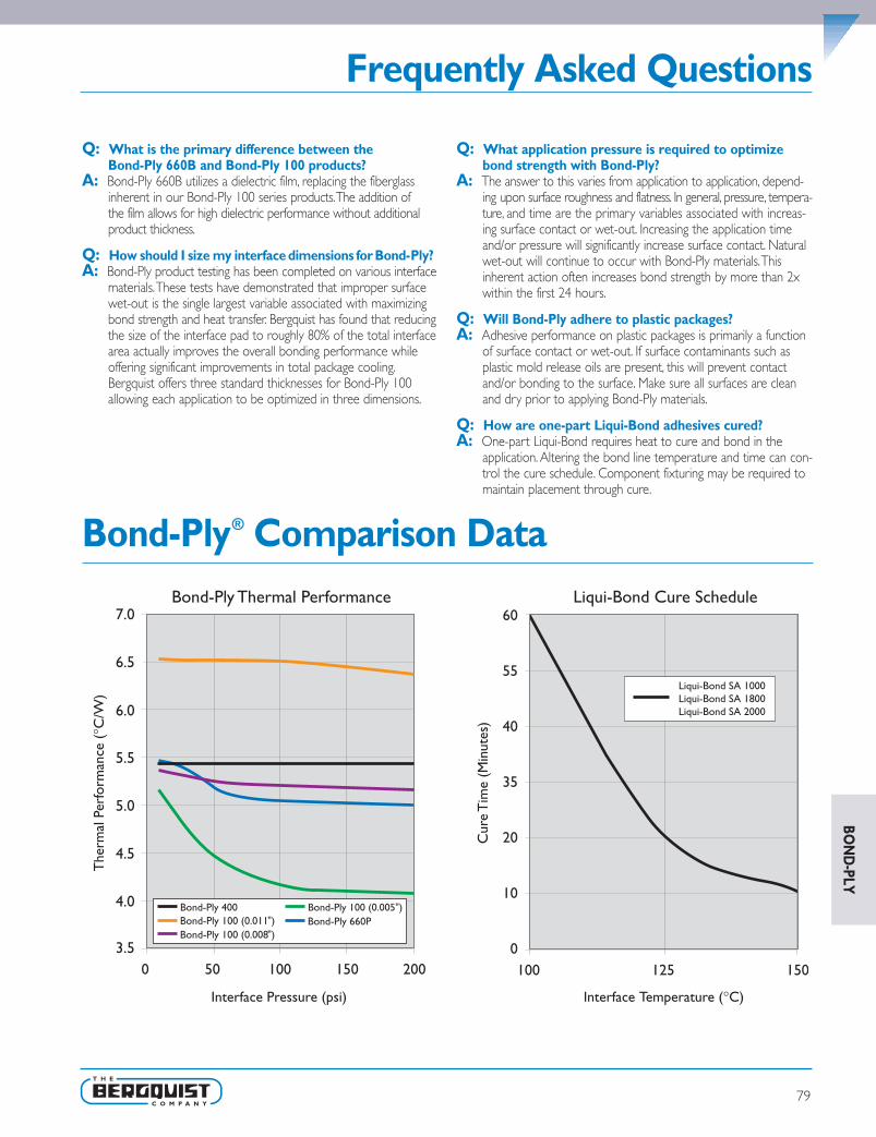
79
BON
D-PLY
Frequently Asked Questions
Q: What is the primary difference between theBond-Ply 660B and Bond-Ply 100 products?
A: Bond-Ply 660B utilizes a dielectric film, replacing the fiberglassinherent in our Bond-Ply 100 series products.The addition ofthe film allows for high dielectric performance without additionalproduct thickness.
Q: How should I size my interface dimensions for Bond-Ply?A: Bond-Ply product testing has been completed on various interface
materials.These tests have demonstrated that improper surfacewet-out is the single largest variable associated with maximizingbond strength and heat transfer. Bergquist has found that reducingthe size of the interface pad to roughly 80% of the total interfacearea actually improves the overall bonding performance whileoffering significant improvements in total package cooling.Bergquist offers three standard thicknesses for Bond-Ply 100allowing each application to be optimized in three dimensions.
Q: What application pressure is required to optimizebond strength with Bond-Ply?
A: The answer to this varies from application to application, depend-ing upon surface roughness and flatness. In general, pressure, tempera-ture, and time are the primary variables associated with increas-ing surface contact or wet-out. Increasing the application timeand/or pressure will significantly increase surface contact. Naturalwet-out will continue to occur with Bond-Ply materials.Thisinherent action often increases bond strength by more than 2xwithin the first 24 hours.
Q: Will Bond-Ply adhere to plastic packages?A: Adhesive performance on plastic packages is primarily a function
of surface contact or wet-out. If surface contaminants such asplastic mold release oils are present, this will prevent contactand/or bonding to the surface. Make sure all surfaces are cleanand dry prior to applying Bond-Ply materials.
Q: How are one-part Liqui-Bond adhesives cured?A: One-part Liqui-Bond requires heat to cure and bond in the
application. Altering the bond line temperature and time can con-trol the cure schedule. Component fixturing may be required tomaintain placement through cure.
Bond-Ply® Comparison Data
3.5
4.0
4.5
5.0
5.5
6.0
6.5
7.0
Liqui-Bond SA 1000 Liqui-Bond SA 1800 Liqui-Bond SA 2000
Bond-Ply 660PBond-Ply 100 (0.011 )Bond-Ply 100 (0.008 )
SPDG_Chapter3_0511 v12.qxp 6/8/2011 3:42 PM Page 79

80
Bond-Ply® 100Thermally Conductive, Fiberglass Reinforced Pressure Sensitive Adhesive Tape
Features and Benefits• Thermal impedance:
0.52°C-in2/W (@50 psi)
• High bond strength to a variety of surfaces
• Double-sided, pressure sensitiveadhesive tape
• High performance, thermally conductiveacrylic adhesive
• Can be used instead of heat-cure adhesive,screw mounting or clip mounting
Typical ApplicationsInclude:• Mount heat sink onto BGA graphic
processor or drive processor
• Mount heat spreader onto powerconverter PCB or onto motor control PCB
Configurations Available:• Sheet form, roll form and die-cut parts
Shelf Life: The double-sided, pressuresensitive adhesive used in Bond-Ply productsrequires the use of dual liners to protectthe surfaces from contaminants. Bergquistrecommends a 6-month shelf life at amaximum continuous storage temperatureof 35°C or 3-month shelf life at a maximumcontinuous storage temperature of 45°C, formaintenance of controlled adhesion to theliner.The shelf life of the Bond-Ply material,without consideration of liner adhesion(which is often not critical for manual assemblyprocessing), is recommended at 12 monthsfrom date of manufacture at a maximumcontinuous storage temperature of 60°C.
Building a Part Number Standard Options
Sect
ion
A
Sect
ion
B
Sect
ion
C
Sect
ion
D
Sect
ion
E NA = Selected standard option. If not selecting a standardoption, insert company name, drawing number, andrevision level.
BP100 = Bond-Ply 100 Material
BP100 0.008 00 1112 NA
Note: To build a part number, visit our website at www.bergquistcompany.com.
Standard thicknesses available: 0.005", 0.008", 0.011"
00 = No adhesive
1112 = 11" x 12" sheets,11250 = 11" x 250' rollsor 00 = custom configuration
– – – –
TYPICAL PROPERTIES OF BOND-PLY 100PROPERTY IMPERIAL VALUE METRIC VALUE TEST METHODColor White White Visual
Reinforcement Carrier Fiberglass Fiberglass —
Thickness (inch) / (mm) 0.005, 0.008, 0.011 0.127, 0.203, 0.279 ASTM D374
Temp. Resistance, 30 sec. (°F) / (°C) 392 200 —
Elongation (%45° to Warp & Fill) 70 70 ASTM D412
Tensile Strength (psi) / (MPa) 900 6 ASTM D412
CTE (ppm) 325 325 ASTM D3386
Glass Transition (°F) / (°C) -22 -30 ASTM D1356
Continuous Use Temp (°F) / (°C) -22 to 248 -30 to 120 —
ADHESIONLap Shear @ RT (psi) / (MPa) 100 0.7 ASTM D1002
Lap Shear after 5 hr @ 100°C 200 1.4 ASTM D1002
Lap Shear after 2 min @ 200°C 200 1.4 ASTM D1002
Static Dead Weight Shear (°F) / (°C) 302 150 PSTC#7
ELECTRICAL VALUE TEST METHODDielectric Breakdown Voltage - 0.005" (Vac) 3000 ASTM D149
Dielectric Breakdown Voltage - 0.008" (Vac) 6000 ASTM D149
Dielectric Breakdown Voltage - 0.011" (Vac) 8500 ASTM D149
Flame Rating V-O U.L.94
THERMALThermal Conductivity (W/m-K) 0.8 ASTM D5470
THERMAL PERFORMANCE vs PRESSUREInitial Assembly Pressure (psi for 5 seconds) 10 25 50 100 200
TO-220 Thermal Performance (°C/W) 0.005" 5.17 4.87 4.49 4.18 4.10
TO-220 Thermal Performance (°C/W) 0.008" 5.40 5.35 5.28 5.22 5.20
TO-220 Thermal Performance (°C/W) 0.011" 6.59 6.51 6.51 6.50 6.40
Thermal Impedance (°C-in2/W) 0.005" (1) 0.56 0.54 0.52 0.50 0.50
Thermal Impedance (°C-in2/W) 0.008" (1) 0.82 0.80 0.78 0.77 0.75
Thermal Impedance (°C-in2/W) 0.011" (1) 1.03 1.02 1.01 1.00 0.99
1) The ASTM D5470 test fixture was used.The recorded value includes interfacial thermal resistance.Thesevalues are provided for reference only. Actual application performance is directly related to the surface roughness, flatness andpressure applied.
BON
D-P
LY
SPDG_Chapt4_0511 v9.qxp 6/8/2011 3:51 PM Page 80

Bond-Ply® 400
Features and Benefits• Thermal impedance:
0.87°C-in2/W (@50 psi)
• Easy application
• Eliminates need for external hardware(screws, clips, etc.)
• Available with easy release tabs
Bergquist Bond-Ply 400 is an un-reinforced,thermally conductive, pressure sensitiveadhesive tape.The tape is supplied withprotective topside tabs and a carrier liner.Bond-Ply 400 is designed to attain high bondstrength to a variety of “low energy” surfaces,including many plastics, while maintaining highbond strength with long term exposure toheat and high humidity.
Typical ApplicationsInclude:Secure:
• Heat sink onto BGA graphic processor
• Heat sink to computer processor
• Heat sink onto drive processor
• Heat spreader onto power converter PCB
• Heat spreader onto motor control PCB
Configurations Available:• Die-cut parts (supplied on rolls with easy
release, protective tabs)
Thermally Conductive, Un-Reinforced, Pressure Sensitive Adhesive Tape
Shelf Life: The double-sided pressure sensitive adhesive used in Bond-Ply products requiresthe use of dual liners to protect the surfaces from contaminants. Bergquist recommends a6-month shelf life at a maximum continuous storage temperature of 35°C, or 3-month shelf life ata maximum continuous storage temperature of 45°C, for maintenance of controlled adhesion tothe liner. The shelf life of the Bond-Ply material, without consideration of liner adhesion (which isoften not critical for manual assembly processing), is recommended at 12 months from date ofmanufacture at a maximum continuous storage temperature of 60°C.
Building a Part Number Standard Options
Sect
ion
A
Sect
ion
B
Sect
ion
C
Sect
ion
D
Sect
ion
E NA = Selected standard option. If not selecting a standard option, insert company name, drawing number, and revision level.
BP400 = Bond-Ply 400 Material
BP400 0.005 00 11/250 NA
Note: To build a part number, visit our website at www.bergquistcompany.com.
Standard thicknesses available: 0.005", 0.010"
00 = No adhesive
11/250 = 11" x 250' rolls or 00 = custom configuration
– – – –
TYPICAL PROPERTIES OF BOND-PLY 400PROPERTY IMPERIAL VALUE METRIC VALUE TEST METHODColor White White Visual
Thickness (inch) / (mm) 0.005 to 0.010 0.127 to 0.254 ASTM D374
Glass Transition (°F) / (°C) -22 -30 ASTM E1356
Continuous Use Temp (°F) / (°C) -22 to 248 -30 to 120 —
ADHESIONLap Shear @ RT (psi) / (MPa) 100 0.7 ASTM D1002
Lap Shear after 5 hr @ 100°C 200 1.4 ASTM D1002
Lap Shear after 2 min @ 200°C 200 1.4 ASTM D1002
ELECTRICAL VALUE TEST METHODDielectric Breakdown Voltage (Vac) 3000 ASTM D149
Flame Rating V-O U.L.94
THERMALThermal Conductivity (W/m-K) 0.4 ASTM D5470
THERMAL PERFORMANCE vs PRESSURE
Initial Assembly Pressure (psi for 5 seconds) 10 25 50 100 200
TO-220 Thermal Performance (°C/W) 0.005" 5.4 5.4 5.4 5.4 5.4
Thermal Impedance (°C-in2/W) (1) 0.87
1) The ASTM D5470 test fixture was used.The recorded value includes interfacial thermal resistance.Thesevalues are provided for reference only. Actual application performance is directly related to the surface roughness, flatness andpressure applied.
81
BON
D-PLY
SPDG_Chapt4_0511 v9.qxp 6/8/2011 3:51 PM Page 81

82
Bond-Ply® 660P
Features and Benefits• Thermal impedance:
0.87°C-in2/W (@50 psi)
• Highly puncture resistant Polyimide reinforcement carrier
• Double-sided pressure sensitiveadhesive tape
• Provides a mechanical bond, eliminating theneed for mechanical fasteners or screws
Bond-Ply 660P is a thermally conductive, electri-cally insulating, double sided pressure sensitiveadhesive tape.The tape consists of a high per-formance, thermally conductive acrylic adhesivecoated on both sides of a Polyimide film. UseBond-Ply 660P in applications to replacemechanical fasteners or screws.
Typical ApplicationsInclude:• Heat sink onto BGA graphic processor
• Heat sink onto drive processor
• Heat spreader onto power converter PCB
• Heat spreader onto motor control PCB
Configurations Available:• Roll form and die-cut parts
The material as delivered will include a continuous base liner with differential releaseproperties to allow for simplicity in roll packaging and application assembly.
Thermally Conductive, Film Reinforced, Pressure Sensitive Adhesive Tape
Shelf Life: The double-sided pressure sensitive adhesive used in Bond-Ply products requiresthe use of dual liners to protect the surfaces from contaminants. Bergquist recommends a6-month shelf life at a maximum continuous storage temperature of 35°C, or 3-month shelf life ata maximum continuous storage temperature of 45°C, for maintenance of controlled adhesion tothe liner. The shelf life of the Bond-Ply material, without consideration of liner adhesion (which isoften not critical for manual assembly processing), is recommended at 12 months from date ofmanufacture at a maximum continuous storage temperature of 60°C.
Building a Part Number Standard Options
Sect
ion
A
Sect
ion
B
Sect
ion
C
Sect
ion
D
Sect
ion
E NA = Selected standard option. If not selecting a standard option, insert company name, drawing number, and revision level.
BP660P = Bond-Ply 660P Material
BP660P 0.008 00 12/250 NA
Note: To build a part number, visit our website at www.bergquistcompany.com.
Standard thicknesses available: 0.008"
00 = No adhesive
1212 = 12" x 12" Sheets, 12/250 = 12" x 250' rolls or 00 = custom configuration
– – – –
TYPICAL PROPERTIES OF BOND-PLY 660PPROPERTY IMPERIAL VALUE METRIC VALUE TEST METHOD
Color Light Brown Light Brown Visual
Reinforcement Carrier Polyimide Film Polyimide Film —
Thickness (inch) / (mm) 0.008 0.203 ASTM D374
Glass Transition (°F) / (°C) -22 -30 ASTM E1356
Continuous Use Temp (°F) / (°C) -22 to 248 -30 to 120 —
ADHESION
Lap Shear @ RT (psi) / (MPa) 100 0.7 ASTM D1002
Lap Shear after 5 hr @ 100°C 200 1.4 ASTM D1002
Lap Shear after 2 min @ 200°C 200 1.4 ASTM D1002
ELECTRICAL VALUE TEST METHOD
Dielectric Breakdown Voltage (kVAC) 6000 ASTM D149
Flame Rating V-O U.L.94
THERMAL
Post-Cured Thermal Conductivity (W/m-K) 0.4 ASTM D5470
THERMAL PERFORMANCE vs PRESSURE
Initial Assembly Pressure (psi for 5 seconds) 10 25 50 100 200
TO-220 Thermal Performance (°C/W) 5.48 5.47 5.15 5.05 5.00
Thermal Impedance (°C-in2/W) (1) 0.83 0.82 0.81 0.80 0.79
1) The ASTM D5470 test fixture was used.The recorded value includes interfacial thermal resistance.These values are provided forreference only. Actual application performance is directly related to the surface roughness, flatness and pressure applied.
BON
D-P
LY
SPDG_Chapt4_0511 v9.qxp 6/8/2011 3:51 PM Page 82

83
Liqui-Bond® SA 1000 (One-Part)
Features and Benefits• High thermal performance
• Eliminates need for mechanical fasteners
• Low viscosity for ease of screening or stenciling
• Can achieve a very thin bond line
• Mechanical and chemical stability
• Maintains structural bond insevere-environment applications
• Heat cure
Liqui-Bond SA 1000 is a thermally conductive,one-part liquid silicone adhesive with a lowviscosity for easy screenability. Liqui-Bond SA1000 features a high thermal performanceand maintains it’s structure even in severe-environment applications.
Liqui-Bond SA 1000 features excellentlow and high-temperature mechanical andchemical stability.The material’s mild elasticproperties assist in relieving CTE stressesduring thermal cycling. Liqui-Bond SA 1000contains no cure by-products, cures at elevat-ed temperatures and requires refrigerationstorage at 10°C.The material is available inboth tube and mid-sized container forms.
Typical Applications Include:• PCBA to housing
• Discrete component to heat spreader
Configurations Available:• With or without glass beads
Building a Part Number Standard Options
Sect
ion
A
Sect
ion
B
Sect
ion
C
Sect
ion
D
Sect
ion
E NA = Selected standard option. If not selecting a standardoption, insert company name, drawing number, andrevision level.
LBSA1000 = Liqui-Bond SA 1000 Liquid Adhesive Material
LBSA1000 00 00 30cc NA
Note: To build a part number, visit our website at www.bergquistcompany.com.
00 = No spacer beads07 = 0.007" spacer beads
00 = No adhesive
Cartridges: 30cc = 30.0cc, 600cc = 600.0cc (ml)Pail: 0.85G = 0.85-gallon, 5G = 5-gallon
– – – –
Thermally Conductive, One-Part, Liquid Silicone Adhesive
TYPICAL PROPERTIES OF LIQUI-BOND SA 1000PROPERTY AS SUPPLIED IMPERIAL VALUE METRIC VALUE TEST METHODColor Black Black Visual
Viscosity (cps) (1) 125,000 125,000 ASTM D2196
Density (g/cc) 2.4 2.4 ASTM D792
Shelf Life @ 10°C (months) 6 6 —
PROPERTY AS CURED - PHYSICALHardness (Shore A) 75 75 ASTM D2240
Continuous Use Temp (°F) / (°C) -76 to 392 -60 to 200 —
Shear Strength (psi) / (MPa) 200 1.4 ASTM D1002
PROPERTY AS CURED - ELECTRICALDielectric Strength (V/mil) / (V/mm) 250 10,000 ASTM D149
Dielectric Constant (1000 Hz) 5.5 5.5 ASTM D150
Volume Resistivity (Ohm-meter) 1010 1010 ASTM D257
Flame Rating V-O V-O U.L.94
PROPERTY AS CURED - THERMALThermal Conductivity (W/m-K) 1.0 1.0 ASTM D5470
CURE SCHEDULEPot Life @ 25°C (hours) (2) 10 10 —
Cure @ 125°C (minutes) (3) 20 20 —
Cure @ 150°C (minutes) (3) 10 10 —
1) Brookfield RV, Heli-path, Spindle TF @ 20 rpm, 25°C.2) Based on 1/8" diameter bead.3) Cure Schedule - time after cure temperature is achieved at the interface. Ramp time is application dependent.
BON
D-PLY
SPDG_Chapt4_0511 v9.qxp 6/8/2011 3:51 PM Page 83

Liqui-Bond® SA 1800 (One-Part)Thermally Conductive, One-Part, Liquid Silicone Adhesive
84
Features and Benefits• High thermal conductivity: 1.8 W/m-K
• Eliminates need for mechanical fasteners
• Low viscosity for ease of screeningor stenciling
• Maintains structural bond in severe-environment applications
• Heat cure
Liqui-Bond SA 1800 is a high performance,liquid silicone adhesive that cures to a solidbonding elastomer.The adhesive is supplied asa one-part liquid component, offered in atube or mid-size container.
Liqui-Bond SA 1800 features a combinationof high thermal conductivity with a low vis-cosity which allows for ease of screen orstencil application.This material is also ideal forhigh volume automated pattern dispensing.Liqui-Bond SA 1800’s low viscosity allows thematerial to achieve a very thin bond line, pro-ducing excellent thermal performance and ahigh shear strength.
Liqui-Bond SA 1800’s mild elastic propertiesassist in relieving CTE stresses during thermalcycling.The material cures at elevated tem-peratures and requires refrigeration storageat 10°C. Liqui-Bond SA 1800 is available withoptional glass beads to provide a consistentstand-off and ensure dielectric integrity.
Typical Applications Include:• PCB assembly to housing
• Discrete component to heat spreader
Configurations Available:• With or without glass beads
Building a Part Number Standard Options
Sect
ion
A
Sect
ion
B
Sect
ion
C
Sect
ion
D
Sect
ion
E NA = Selected standard option. If not selecting a standard option, insert company name, drawing number, and revision level.
LBSA1800 = Liqui-Bond SA 1800 (One-Part) Liquid Adhesive Material
LBSA1800 00 00 30cc NA
Note: To build a part number, visit our website at www.bergquistcompany.com.
00 = No spacer beads 07 = 0.007" spacer beads
00 = No adhesive
Cartridges: 30cc = 30.0cc, 600cc = 600.0cc (ml) Pail: 0.85G = 0.85-gallon, 5G = 5-gallon
– – – –
TYPICAL PROPERTIES OF LIQUI-BOND SA 1800PROPERTY AS SUPPLIED IMPERIAL VALUE METRIC VALUE TEST METHODColor Black Black Visual
Viscosity (cps) (1) 125,000 125,000 ASTM D2196
Density (g/cc) 2.8 2.8 ASTM D792
Shelf Life @ 10°C (months) 6 6 —
PROPERTY AS CURED - PHYSICALHardness (Shore A) 80 80 ASTM D2240
Continuous Use Temp (°F) / (°C) -76 to 392 -60 to 200 —
Shear Strength (psi) / (MPa) 200 1.4 ASTM D1002
PROPERTY AS CURED - ELECTRICALDielectric Strength (V/mil) / (V/mm) 250 10,000 ASTM D149
Dielectric Constant (1000 Hz) 6.0 6.0 ASTM D150
Volume Resistivity (Ohm-meter) 1011 1011 ASTM D257
Flame Rating V-O V-O U.L.94
PROPERTY AS CURED - THERMALThermal Conductivity (W/m-K) 1.8 1.8 ASTM D5470
CURE SCHEDULEPot Life @ 25°C (hours) (2) 10 10 —
Cure @ 125°C (minutes) (3) 20 20 —
Cure @ 150°C (minutes) (3) 10 10 —
1) Brookfield RV, Heli-path, Spindle TF @ 20 rpm, 25°C.2) Based on 1/8" diameter bead.3) Cure Schedule - time after cure temperature is achieved at the interface. Ramp time is application dependent.
BON
D-P
LY
SPDG_Chapt4_0511 v9.qxp 6/8/2011 3:51 PM Page 84

85
Liqui-Bond® SA 2000
Features and Benefits• High thermal conductivity: 2.0 W/m-K
• Eliminates need for mechanical fasteners
• One-part formulation for easy dispensing
• Mechanical and chemical stability
• Maintains structural bond insevere-environment applications
• Heat cure
Liqui-Bond SA 2000 is a high performance,thermally conductive silicone adhesive thatcures to a solid bonding elastomer. Liqui-BondSA 2000 is supplied as a one-part liquidcomponent, in either tube or mid-sizedcontainer form.
Liqui-Bond SA 2000 features excellentlow and high-temperature mechanical andchemical stability.The material’s mild elasticproperties assist in relieving CTE stressesduring thermal cycling. Liqui-Bond SA 2000cures at elevated temperatures and requiresrefrigeration storage at 10°C.
Typical Applications Include:• PCBA to housing
• Discrete component to heat spreader
Configurations Available:• With or without glass beads
Building a Part Number Standard Options
Sect
ion
A
Sect
ion
B
Sect
ion
C
Sect
ion
D
Sect
ion
E NA = Selected standard option. If not selecting a standardoption, insert company name, drawing number, andrevision level.
LBSA2000 = Liqui-Bond SA 2000 Liquid Adhesive Material
LBSA2000 00 00 30cc NA
Note: To build a part number, visit our website at www.bergquistcompany.com.
00 = No spacer beads07 = 0.007" spacer beads
00 = No adhesive
Cartridges: 30cc = 30.0cc, 600cc = 600.0cc (ml)Pail: 0.85G = 0.85-gallon, 5G = 5-gallon
– – – –
Thermally Conductive, One-Part, Liquid Silicone Adhesive
TYPICAL PROPERTIES OF LIQUI-BOND SA 2000PROPERTY AS SUPPLIED IMPERIAL VALUE METRIC VALUE TEST METHODColor Yellow Yellow Visual
Viscosity (cps) (1) 200,000 200,000 ASTM D2196
Density (g/cc) 2.4 2.4 ASTM D792
Shelf Life @ 10°C (months) 6 6 —
PROPERTY AS CURED - PHYSICALHardness (Shore A) 80 80 ASTM D2240
Continuous Use Temp (°F) / (°C) -76 to 392 -60 to 200 —
Shear Strength (psi) / (MPa) 200 1.4 ASTM D1002
PROPERTY AS CURED - ELECTRICALDielectric Strength (V/mil) / (V/mm) 250 10,000 ASTM D149
Dielectric Constant (1000 Hz) 6.0 6.0 ASTM D150
Volume Resistivity (Ohm-meter) 1011 1011 ASTM D257
Flame Rating V-O V-O U.L.94
PROPERTY AS CURED - THERMALThermal Conductivity (W/m-K) 2.0 2.0 ASTM D5470
CURE SCHEDULEPot Life @ 25°C (hours) (2) 24 24 —
Cure @ 125°C (minutes) (3) 20 20 —
Cure @ 150°C (minutes) (3) 10 10 —
1) Brookfield RV, Heli-path, Spindle TF @ 20 rpm, 25°C.2) Based on 1/8" diameter bead.3) Cure Schedule - time after cure temperature is achieved at the interface. Ramp time is application dependent.
BON
D-PLY
SPDG_Chapt4_0511 v9.qxp 6/8/2011 3:51 PM Page 85

Solutions for Surface Mount Applications
86
Sil-PadSil-Pad is the benchmark in thermal interface materials.The Sil-Pad family of materialsare thermally conductive and electrically insulating. Available in custom shapes, sheets,and rolls, Sil-Pad materials come in a variety of thicknesses and are frequently used inSMT applications such as:
• Interface between thermal vias in a PCB, and a heat sink or casting
• Heat sink interface to many surface mount packages
Hi-FlowThe Hi-Flow family of phase change materials offers an easy-to-apply thermal interfacefor many surface mount packages. At the phase change temperature, Hi-Flow materialschange from a solid and flow with minimal applied pressure.This characteristic optimizesheat transfer by maximizing wet-out of the interface. Hi-Flow is commonly used toreplace messy thermal grease.
Bergquist phase change materials are specially compounded to prevent pump-out ofthe interface area, which is often associated with thermal grease. Typical applications forHi-Flow materials include:
• Pentium®, Athlon®, Core 2 Duo and other high performance CPUs
• DC/DC converters
• Power modules
Hi-Flow materials are manufactured with or without film or foil carriers. Custom shapesand sizes for non-standard applications are also available.
Mid Power Application with Bond-Ply or Sil-Pad
Power Device
Sil-Pad orBond-Ply FR-4
High Power Application Hi-Flow without Thermal Clad
High Power Application Hi-Flow with Thermal Clad
Power Device
Processor
Thermal Clad
Hi-Flow
Hi-FlowHeatSpreader
HeatSpreader
FR-4 Board
HeatSpreader
Pentium® is a registered trademark of Intel Corporation.Athlon® is a registered trademark of Advanced Micro Devices, Inc.
ORD
ERIN
G
SPDG_Chapt4_0511 v9.qxp 6/8/2011 3:51 PM Page 86

ORD
ERING
Where Thermal Solutions Come Together
87
Bond-Ply and Liqui-BondThe Bond-Ply family of materials are thermally conductive and electrically isolating.Bond-Ply is available in a pressure sensitive adhesive or laminating format. Bond-Ply pro-vides for the mechanical decoupling of bonded materials with mismatched thermalcoefficients of expansion. Liqui-Bond is a high thermal performance liquid silicone adhe-sive that cures to a solid bonding elastomer.Typical applications include:
• Bonding bus bars in a variety of electronic modules and sub assemblies
• Attaching a metal-based component to a heat sink
• Bonding a heat sink to a variety of ASIC, graphic chip, and CPU packages
• Bonding flexible circuits to a rigid heat spreader or thermal plane
• Assembly tapes for BGA heat spreader
• Attaching PCB assemblies to housings
Gap Pad and Gap FillerGap Pad and Gap Filler product families are highly conformable, thermally conductivematerials in pad or liquid dispensable format.Varying degrees of thermal conductivityand compression deflection characteristics are available.Typical applications include:
• On top of a semiconductor package such as a QFP or BGA. Often times, severalpackages with varying heights can use a common heat sink when utilizing Gap Pad
• Between a PCB or substrate and a chassis, frame, or other heat spreader
• Areas where heat needs to be transferred to any type of heat spreader
• For interfacing pressure sensitive devices
• Filling various gaps between heat-generating devices and heat sinks or housings
Gap Pads are available in thickness of 0.010" to 0.250", and in custom shapes, with orwithout adhesive. Gap Fillers are available in cartridge or kit form.
Top Efficiency InThermal Materials ForToday’s Changing Technology.Contact Bergquist for additional information regardingour Thermal Solutions.We are constantly innovatingto offer you the greatest selection of options andflexibility to meet today’s changing technology.
Lower Power Applicationwith Gap Pad
Gap Pad or Gap FillerPowerDevice
HeatSpreader
FR-4 Board
SPDG_Chapt4_0511 v9.qxp 6/8/2011 3:51 PM Page 87

88
Ordering Information
Typical Configuration Tolerances:• Roll width: ±0.06" (1.6mm) for standard widths (2", 4", 6", etc.)• Sil-Pad sheet: -0.06" / +0.25" (-1.6mm / +6.4mm)• Gap Pad sheet: -0.0" / +0.40" (-0.0mm / +10.0mm)• Typical Sil-Pad roll length: 250' - 300'• Typical number of splices per roll: 3• Typical butt splice: 2-sided colored tape• Material thickness tolerances: Sil-Pad ±0.001" (0.0254mm)
Gap Pad VO ±5%Gap Pad S-Class ±10%
Note: Tighter tolerances are available per factory review.
Sheets:Standard sheet size for most materials is 12" x 12", with or withoutadhesive as specified on the individual data sheet.When orderingsheets, please specify material type, thickness and include alldimensions. Contact Bergquist Sales if other sizes are required.
Note: Sil-Pad A2000 maximum sheet size is 10" x 12". Gap Padstandard sheet size is 8" x 16".
Rolls:Sil-Pad materials are available in roll form, with or without adhesive,with the exception of Sil-Pad 1750 and Sil-Pad 2000. Hi-Flow materialsare available in roll form. Certain Gap Pad materials are available inroll form. Please contact Bergquist Sales for more information.
Color Matching:Bergquist identifies product color as a reference product characteristicand/or specification for Sil-Pad and Gap Pad products. Slight colorvariation is normal across lot-to-lot splicing due to the differentvariations in natural colorants used to achieve the desired hue andshade in these products. Bergquist continues to monitor and controlincoming raw material specifications and production processes toensure the highest possible consistency of quality and productperformance. If you have any questions regarding color matching,please contact Bergquist Product Management.
Ordering Procedure:The last 2 or 3 digits define the part number selected.The “foot print”and dimensions are shown on pages 87-95.
Special Shapes:For applications requiring non-standard or custom Sil-Pad configurations,contact your Bergquist Sales Representative.We produce thousands ofcustom die shapes and designs.
Tolerances:Typical converting tolerances are held on length (L), width (W), holediameter and hole location for most materials as noted below:
TYPICAL SIL-PAD / HI-FLOW TOLERANCESPart (1)
DimensionLength and Width
ToleranceRule DefinedFeatures (2)
Hole Location & Diameter
<6" ± 0.010" (0.25mm) ± 0.010" (0.25mm) ± 0.005" (0.13mm)
6" - 12" ± 0.015" (0.38mm) ± 0.015" (0.38mm) ± 0.010" (0.25mm)
>12" ± 0.020" (0.51mm) ± 0.020" (0.51mm) ± 0.020" (0.51mm)
TYPICAL GAP PAD TOLERANCES (3)
MaterialThickness Length and Width Tolerance Hole Location
& Diameter10 mil ± 0.015" (0.38mm) ± 0.015" (0.38mm)
15 mil ± 0.015" (0.38mm) ± 0.015" (0.38mm)
20 mil ± 0.020" (0.51mm) ± 0.020" (0.51mm)
30 mil ± 0.030" (0.76mm) ± 0.030" (0.76mm)
40 mil ± 0.035" (0.89mm) ± 0.035" (0.89mm)
50 mil ± 0.040" (1.02mm) ± 0.040" (1.02mm)
60 mil ± 0.050" (1.27mm) ± 0.050" (1.27mm)
70 mil ± 0.050" (1.27mm) ± 0.050" (1.27mm)
80 mil ± 0.050" (1.27mm) ± 0.050" (1.27mm)
100 mil ± 0.060" (1.52mm) ± 0.060" (1.52mm)
125 mil ± 0.075" (1.91mm) ± 0.075" (1.91mm)
140 mil ± 0.100" (2.54mm) ± 0.100" (2.54mm)
160 mil ± 0.100" (2.54mm) ± 0.100" (2.54mm)
200 mil ± 0.125" (3.17mm) ± 0.125" (3.17mm)
225 mil ± 0.160" (4.06mm) ± 0.160" (4.06mm)
250 mil ± 0.160" (4.06mm) ± 0.160" (4.06mm)
(1) Material thicknesses: <6" (152.4mm), 6-12" (152.4-304.8mm), >12" (304.8mm).(2) Rule defined by geometry can be notches, internal shapes not created by a punch or cutouts
that are created by a rule and not a punch.(3) Gap Pad VO materials have a Sil-Pad Side / Cutline tolerance of parts on the liner to within
± 0.020" (0.51mm) typically, Gap Pad may deform to the standard tolerances when handled orremoved from the liner.
Note: Dependent upon material and application requirements, tighter tolerances may be feasibleand available. Please contact Bergquist Sales for these requests and additional informationregarding tolerances.
ORD
ERIN
G
SPDG_Chapt4_0511 v9.qxp 6/8/2011 3:51 PM Page 88

89
Ordering Information
PSA Characteristics:
Standard pressure sensitive adhesive (AC) coated on one side of aSil-Pad will increase the thermal resistance (per ASTM D5470) by0.2°C-in2/W. Standard pressure sensitive adhesive on 2 sides increasesthe thermal impedance by 0.4°C-in2/W.
Thermally conductive pressure sensitive adhesive (TAC) on one sideincreases the thermal resistance by 0.05°C-in2/W and on two sides by0.1°C-in2/W.
The effect of AC and TAC on the thermal impedance in an applicationwill vary. In low-pressure applications, the pressure sensitive adhesivewill wet-out the interface easier and eliminate the interfacial thermalresistance.
Note: Bergquist adhesives are designed for ease of application duringassembly. If an automated dispensing method is preferred, Bergquistwill recommend manufacturers of automated dispensing equipmentupon request. Please contact Bergquist Sales for more information onthis subject.
Note: Bergquist cannot be responsible for dispensing equipment selectionand/or performance of specific materials on said equipment. It is thecustomer’s responsibility to determine the suitability and compatibility ofthe specific Bergquist material with the selected equipment.
U.L. Recognition:For information regarding the U.L. (Underwriters Laboratories, Inc.)recognition status of Bergquist Sil-Pad, Gap Pad and Hi-Flow materials,the U.L. web site provides the most current information.
Using the URL: http://www.ul.com, select “Online CertificationDirectory.”You may then enter one of the following file numbers forthe applicable Bergquist file:
QMFZ2.E59150: Plastics – Component. This category includes allSil-Pad, Gap Pad and Hi-Flow materials.
QOQW2.E81718: Polymeric Adhesive Systems, Electrical Equipment– Component. This category includes Bond-Ply adhesive only.
In each group there is a “Guide Information” section which gives adetailed description of the categories listed and all recognized materialswill be listed with supporting data.
Adhesives:Bergquist adhesives include:
SILICONE: (AC) - Unloaded(ACA) - Unloaded, Low Tack(TAC) - Loaded (Thermally Enhanced)
ACRYLIC: (AAC) - Unloaded(TAAC) - Thermally Loaded(EAAC) - Thermally Enhanced
THICKNESS: 0.0005" - 0.001", (12-25µm) (adhesive only)
Note: For non-symmetrical parts, please indicate on print which sidethe adhesive is on.
Peel Strength: See data below.
POL = Peel-Off Liner (force per unit width of the liner tothe adhesive).
QS = Quick Stick (simulated force per unit width of the adhesive tothe heat sink).g/in = Grams per inch.
Note: These values are typical after the material has aged for 2-3weeks and are significantly different immediately after coating. Uponcompletion of coating, QS is 250-500 g/in and POL is 3-20 g/in for allsilicone adhesives.
Shelf Life:
Silicone Adhesives: Six (6) months from date of manufacture whenstored in original packaging at 70°F (21°C) and 50% relative humidity.
Acrylic Adhesives: One (1) year from date of manufacture when storedin original packaging at 70°F (21°C) and 50% relative humidity.
Peel adhesion data is available upon request. Please contact BergquistSales for more information.
TYPICAL ADHESIVE PROPERTIESADHESIVE POL QSSilicone AC 50-150 g/in 50-150 g/in
Silicone ACA 5-70 g/in 5-150 g/inSilicone TAC 50-150 g/in 50-150 g/inAcrylic AAC 5-70 g/in 100-800 g/inAcrylic TAAC 5-70 g/in 100-400 g/inAcrylic EAAC 5-60 g/in 100-200 g/in
ORD
ERING
SPDG_Chapt4_0511 v9.qxp 6/8/2011 3:51 PM Page 89

Sil-Pad® Configurations
90
4 Lead Part NumberTO-66 Suffix "A" "B" "C" "D" "E" "F" "G"
-84 1.312 .762 .140 .062 .960 .200 .100
Plastic Part Number Dimensions Part Number DimensionsPower Suffix "A" "B" "C" "D" Suffix "A" "B" "C" "D"
Various -35 .710 .500 .160 .141 Various -104 1.000 .750 .300 .140(Clip Mount) -43 .750 .500 Various -107 .810 .910 .170 .147TO-126 -50 .437 .312 .140 093 Various -110 .984 .787Various -51 .687 .562 .218 .125 Various -114 .827 .945 .197 .150Various -52 .855 .630 .230 .093 Various -116 .855 .630 .228 .122TO-220 -54 .750 .500 .187 .147 Various -117 .827 .709 .256 .126TO-202 -55 .610 .560 .245 .125 Various -118 .748 .551 .217 .126Various -56 .855 .562 .218 .125 Various -119 .437 .311 .142 .110TO-220 -58 .750 .500 .187 .125 Various -120 .728 .472 .157 .098TO-126 -60 .437 .312 .140 .122 TO-3P -122 1.140 .810 .355 .147Various -61 .750 .410 .225 .156 Various -126 .945 .748 .256 .162TO-220 -62 .750 .600 .240 .150 Various -128 .984 1.654 .315 .157Various -63 .750 .600 .240 .115 Various -131 .709 .512 .177 .122Various -64 .500 .385 .170 .120 Various -132 .472 .315 .157 .126TO-218 -68 1.125 .625 .200 .145 Various -133 .866 .709 .256 .126Various -70 1.410 .810 .355 .147 Various -134 .945 .709 .228 .126Various -90 .860 .740 .200 .160 Various -136 1.250 1.000Various -102 .866 .650 .217 .142 Various -137 1.250 1.000 .258 .127Various -103 .750 .800 .150 .160 Various -138 1.250 1.000 .258 .148
Power Part Number DimensionsModule Suffix "A" "B" "C" "D" "E" "F"
-67 1.500 .900 .150 1.200 .450 .075-101 2.500 2.000 .344 1.812 1.000 .156
Plastic Part Number DimensionsPower Suffix "A" "B" "C" "D" "E" "F" "G"
-57 .910 .500 .200 .125 .580 .046 .265-89 .983 .750 .432 .156 .665 .101 .217
Plastic Part Number DimensionsPower Suffix "A" "B" "C" "D" "E" "F" "G" "H"
-66 1.000 .500 .200 .141 .626 .046 .219 .032
Power Part Number DimensionsResistors Suffix "A" "B" "C" "D" "E" "F" "G" "H" "I"
RH-25 -94 1.187 1.205 .234 .469 .212 .156 .719 .781 .140RH-50 -95 2.093 1.265 .265 .530 .210 .255 1.563 .845 .140RH-5 -96 .725 .771 .140 .280 .140 .156 .445 .491 .093RH-10 -97 .805 .890 .127 .250 .130 .190 .551 .630 .121RH-25 -98 1.150 1.180 .231 .425 .190 .270 .688 .800 .147RH-50 -99 1.965 1.236 .198 .404 .132 .263 1.569 .972 .130
TO-220 Part Number Dimensions # ofMultiples Suffix "A" "B" "C" "D" "E" "F" Holes
2 Parts -34 1.000 .750 .187 .125 .250 .500 23 Parts -36 1.500 .750 .187 .125 .250 .500 3
-37 2.000 .750 .187 .125 .250 .500 4-38 2.500 .750 .187 .125 .250 .500 5-39 3.000 .750 .187 .125 .250 .500 6-40 3.500 .750 .187 .125 .250 .500 7-41 4.000 .750 .187 .125 .250 .500 8
Power Part Number DimensionsModule Suffix "A" "B" "C" "D" "E" "F"
-108 4.600 2.400 2.125 .500 1.800 .125-140 4.598 2.402 2.098 0.500 1.799 0.150-141 2.279 2.402 2.102 0.488 0.650 0.150-142 2.280 1.450 1.270 0.490 0.650 0.130
TO-220
Imperial Measurements
ORD
ERIN
G
SPDG_Chapt4_0511 v9.qxp 6/8/2011 3:51 PM Page 90

Sil-Pad® Configurations
91
Imperial Measurements
Part Number DimensionsMultiwatt Suffix "A" "B" "C" "D" "E"
-124 .872 .790 .160 .148 .118 x 45°-125 .866 .787 .157 .154 .079 x 45°
Multi-Lead Part NumberTO-66 Suffix "A" "B" "C" "D" "E" "F"
-93 1.350 .800 .140 .400 .960 .480
Diode Part Number Dimensions Part Number DimensionsWasher Suffix "A" "B" Suffix "A" "B"
Various -19 .510 .140 Various -75 .360 .260DO-4 -20 .510 .200 Various -76 .750 .125DO-5 -21 .800 .260 Various -77 .800 .190DO-4 (oversized) -22 .625 .200 DO-8 -78 .875 .313DO-5 (oversized) -25 1.000 .260 Various -79 1.180 .515Various -26 .812 .145 Various -80 1.250 .380Various -27 .812 .115 Various -81 1.500 .200Various -28 1.000 .140 Various -82 .512 .161Various -32 1.500 .500 Various -111 .591 .217
Part Number DimensionsTO-36 Suffix "A" "B" "C"
-08 1.063 .690 .190
SmallPower Part Number DimensionsDevices Suffix "A" "B" "C"
TO-5, 3 Holes -09 .360 .200 .040TO-18, 3 Holes -12 .250 .100 .036TO-18, 4 Holes -13 .250 .100 .036TO-5, 4 Holes -33 .360 .200 .040TO-5, 3 Holes -44 .390 .200 .040TO-5, 4 Holes -45 .390 .200 .040
Part Number DimensionsRectifier Suffix "A" "B" "C"
-46 1.250 1.250 .200-47 1.125 1.125 .140-48 1.000 1.000 .187
TIP Part Number DimensionsPackages Suffix "A" "B" "C" "D" "E"
Clip Mount -42 .984 .787 .205TIP-36
Plastic Tip -53 .865 .650 .650 .140 .205TO-3P -65 1.260 .787 .984 .142 .205Plastic Clip -73 .984 .787 .708 .142 .205
Power Part Number Dimensions Module Suffix "A" "B" "C" "D" "E" "F" "G"
-100 2.510 1.260 .630 .305 1.900 .205 .205-123 1.614 1.102 .551 .157 1.220 .118 .118
SIP Part Number DimensionsPackage Suffix "A" "B" "C" "D" "E" "F" "G"
-105 1.450 .838 .612 .245 .960 .170 .120
Part Number DimensionsQuarz Suffix "A" "B" "C" "D"
-115 .472 .197 .193 .031
Power Part Number DimensionsModule Suffix "A" "B" "C" "D" "E" "F" "G"
-109 1.350 .642 .321 .195 .960 .060 .125
B
A
D-DIA EC
A
B
C
D
A
D
CB
(2) G Dia
F RAD(TYP)
E
ORD
ERING
SPDG_Chapt4_0511 v9.qxp 6/8/2011 3:51 PM Page 91

92
Sil-Pad® ConfigurationsImperial Measurements
TO-3 & TO-66Part Number Dimensions
Style Suffix "A" "B" "C" "D" "E" "F" "G"
-02 1.780 1.250 .140 .093 1.187 .430 .072-03 1.563 1.050 .140 .080 1.187 .430 .072-04 1.650 1.140 .122 .062 1.187 .430 .072-05 1.650 1.140 .140 .093 1.187 .430 .072-06 1.650 1.140 .165 .062 1.187 .430 .072-07 1.780 1.250 .165 .094 1.187 .430 .072-10 1.440 1.000 .140 .075 .960 .200 .100-11 1.312 .762 .140 .062 .960 .200 .100-15 1.780 1.250 .140 .046 1.187 .430 .072-16 2.070 1.560 .122 .062 1.187 .430 .072-17 1.650 1.140 .140 .046 1.187 .430 .072-18 1.563 1.050 .140 .140 1.187 .430 .072-23 1.593 1.100 .156 .062 1.187 .430 .072-24 1.700 1.187 .156 .062 1.187 .430 .072-29 1.650 1.065 .140 .046 1.187 .430 .072-30 1.250 .700 .140 .062 .960 .200 .100-31 1.375 .825 .140 .062 .960 .200 .100
-59 Leadless 1.650 1.140 .165 1.187-112 1.780 1.248 .165 .063 1.185 .429 .073-113 1.563 1.051 .165 .079 1.185 .429 .073-127 1.307 .819 .165 .063 .909 .236 .061-129 1.654 1.063 .138 .059 1.181 .433 .071-135 1.650 1.142 .165 .142 1.187 .429 ..072
3 Lead Part Number DimensionsTO-3 Suffix "A" "B" "C" "D" "E" "F" "G" "H" "I"
-92 1.650 1.140 .140 .093 1.187 .430 .400 .155 .718
4 Lead Part Number DimensionsTO-3 Suffix "A" "B" "C" "D" "E" "F" "G"
-86 1.560 1.050 .156 .080 1.170 .470 72°-87 1.563 1.050 .156 .063 1.187 .470 72°
8 Lead Part Number DimensionsTO-3 Suffix "A" "B" "C" "D" "E" "F" "G"
-88 1.655 1.187 .156 .060 1.187 40° .500
10 Lead Part Number DimensionsTO-3 Suffix "A" "B" "C" "D" "E" "F" "G" "H"
-91 1.650 1.140 .165 .040 1.187 .593 .500 32.7°
3 Lead Part Number DimensionsTO-66 Suffix "A" "B" "C" "D" "E" "F" "G" "H"
-85 1.275 .750 .156 .100 .960 .200 .100 .200
9 Lead Part Number DimensionsTO-66 Suffix "A" "B" "C" "D" "E" "F" "G" "H"
-83 1.440 1.000 .140 .055 .960 .480 .325 36°
Power Part Number DimensionsModule Suffix "A" "B" "C" "D" "E"
-130 1.600 .480 .165 1.197 .240
I
AF DIA.
B
E
C DIA. (2)
D DIA. (4)
18¡
G¡
A
B
ED
C - DIA. (2)
ORD
ERIN
G
SPDG_Chapt4_0511 v9.qxp 6/8/2011 3:52 PM Page 92

Hi-Flow® 225 Configurations
93
Imperial Measurements
MATERIAL
("B")
-.500+.030LINER
LINER
PSA STRIP.080+.000
.040
("B")
("C")
("A") ("A")
COLORED PSA TAPE
CLEAR PSA TAPE
PSA STRIPMATERIAL
LINER
LINER
.750+.063
.750+.063
.500+.030
.250+.125
("B")
("B")
("C")
("A") ("A")
Part Number Dimensions (± .015)Suffix “A” “B” “C” Min. Pcs/Roll
-150 1.650 1.650 2.650 3000
-151 1.500 1.500 2.500 5000
-152 1.375 1.375 2.375 5000
-153 1.250 1.250 2.250 5000
-154 1.000 1.000 2.000 7500
-155 .700 .700 1.700 10000
-156 .500 .500 1.500 15000
Part Number Dimensions (± .015)Suffix “A” “B” “C” Min. Pcs/Roll
-143 1.500 1.500 2.500 5000
-144 1.378 1.378 2.378 5000
-145 1.250 1.250 2.250 5000
-146 1.000 1.000 2.000 7500
-147 .700 .700 1.700 10000
-148 .500 .500 1.500 15000
-149 .300 1.000 2.000 22500
Hi-Flow 225U Tab Configurations
Hi-Flow 225UT/565U/565UT Tab Configurations
ORD
ERING
SPDG_Chapt4_0511 v9.qxp 6/8/2011 3:52 PM Page 93

94
Sil-Pad® ConfigurationsMetric Measurements
4 Lead Part Number DimensionsTO-66 Suffix "A" "B" "C" "D" "E" "F" "G"
-84 33.32 19.35 3.56 1.57 24.38 5.08 2.54
Plastic Part Number Dimensions Part Number DimensionsPower Suffix "A" "B" "C" "D" Suffix "A" "B" "C" "D"
Various -35 18.03 12.70 4.06 3.58 Various -104 25.40 19.05 7.62 3.56(Clip Mount) -43 19.05 12.70 Various -107 20.57 23.11 4.32 3.73TO-126 -50 11.10 7.92 3.56 2.36 Various -110 24.99 19.99Various -51 17.45 14.27 5.54 3.18 Various -114 21.01 24.00 5.00 3.81Various -52 21.72 16.00 5.84 2.36 Various -116 21.72 16.00 5.79 3.10TO-220 -54 19.05 12.70 4.75 3.73 Various -117 21.01 18.01 6.50 3.20TO-202 -55 15.49 14.22 6.22 3.18 Various -118 19.00 14.00 5.51 3.20Various -56 21.72 14.27 5.54 3.18 Various -119 11.10 7.90 3.61 2.79TO-220 -58 19.05 12.70 4.75 3.18 Various -120 18.49 11.99 3.99 2.49TO-126 -60 11.10 7.92 3.56 3.10 TO-3P -122 28.96 20.57 9.02 3.73Various -61 19.05 10.41 5.72 3.96 Various -126 24.00 19.00 6.50 4.11TO-220 -62 19.05 15.24 6.10 3.81 Various -128 24.99 42.01 8.00 3.99Various -63 19.05 15.24 6.10 2.92 Various -131 18.01 13.00 4.50 3.10Various -64 12.70 9.78 4.32 3.05 Various -132 11.99 8.00 3.99 3.20TO-218 -68 28.58 15.88 5.08 3.68 Various -133 22.00 18.01 6.50 3.20Various -70 35.81 20.57 9.02 3.73 Various -134 24.00 18.01 5.79 3.20Various -90 21.84 18.80 5.08 4.06 Various -136 31.75 25.40Various -102 22.00 16.51 5.51 3.61 Various -137 31.75 25.40 6.55 3.23Various -103 19.05 20.32 3.81 4.06 Various -138 31.75 25.40 6.55 3.76
Power Number DimensionsModule Suffix "A" "B" "C" "D" "E" "F"
-67 38.10 22.86 3.81 30.48 11.43 1.90-101 63.50 50.80 8.74 46.02 25.40 3.96
Plastic Part Number DimensionsPower Suffix "A" "B" "C" "D" "E" "F" "G"
-57 23.11 12.70 5.08 3.18 14.73 1.17 6.73-89 24.97 19.05 10.97 3.96 16.89 2.57 5.51
Plastic Part Number DimensionsPower Suffix "A" "B" "C" "D" "E" "F" "G" "H"
-66 25.40 12.70 5.08 3.58 15.90 1.17 5.56 0.81
Power Part Number DimensionsResistors Suffix "A" "B" "C" "D" "E" "F" "G" "H" "I"
RH-25 -94 30.15 30.61 5.94 11.91 5.38 3.96 18.26 19.84 3.56RH-50 -95 53.16 32.13 6.73 13.46 5.33 6.48 39.70 21.46 3.56RH-5 -96 18.42 19.58 3.56 7.11 3.56 3.96 11.30 12.47 2.36RH-10 -97 20.45 22.61 3.23 6.35 3.30 4.83 14.00 16.00 3.07RH-25 -98 29.21 29.97 5.87 10.80 4.83 6.86 17.48 20.32 3.73RH-50 -99 49.91 31.39 5.03 10.26 3.35 6.68 39.85 24.69 3.30
TO-220 Part Number Dimensions # ofMultiples Suffix "A" "B" "C" "D" "E" "F" Holes
2 Parts -34 25.40 19.05 4.75 3.18 6.35 12.70 23 Parts -36 38.10 19.05 4.75 3.18 6.35 12.70 3
-37 50.80 19.05 4.75 3.18 6.35 12.70 4-38 63.50 19.05 4.75 3.18 6.35 12.70 5-39 76.20 19.05 4.75 3.18 6.35 12.70 6-40 88.90 19.05 4.75 3.18 6.35 12.70 7-41 101.60 19.05 4.75 3.18 6.35 12.70 8
Power Part Number DimensionsModule Suffix "A" "B" "C" "D" "E" "F"
-108 116.84 60.96 53.97 12.70 45.72 3.18-140 116.8 61.00 53.30 12.70 45.70 3.80-141 57.90 61.00 53.40 12.40 16.50 3.80-142 57.91 36.83 32.26 12.45 16.50 3.30
TO-220
ORD
ERIN
G
SPDG_Chapt4_0511 v9.qxp 6/8/2011 3:52 PM Page 94

95
Sil-Pad® ConfigurationsMetric MeasurementsPart Number Dimensions
Multiwatt Suffix "A" "B" "C" "D" " E"
-124 22.15 20.07 4.06 3.76 3.0 x 45°-125 22.00 19.99 3.99 3.91 2.0 x 45°
Multi-Lead Part Number DimensionsTO-66 Suffix "A" "B" "C" "D" "E" "F"
-93 34.29 20.32 3.56 10.16 24.38 12.19
Diode Part Number Dimensions Part Number DimensionsWasher Suffix "A" "B" Suffix "A" "B"
Various -19 12.95 3.56 Various -75 9.14 6.60DO-4 -20 12.95 5.08 Various -76 19.05 3.18DO-5 -21 20.32 6.60 Various -77 20.32 4.83DO-4 (oversized) -22 15.88 5.08 DO-8 -78 22.23 7.95DO-5 (oversized) -25 25.40 6.60 Various -79 29.97 13.08Various -26 20.62 3.68 Various -80 31.75 9.65Various -27 20.62 2.92 Various -81 38.10 5.08Various -28 25.40 3.56 Various -82 13.00 4.09Various -32 38.10 12.70 -111 15.01 5.51
Part Number DimensionsTO-36 Suffix "A" "B" "C"
-08 27.00 17.53 4.83
SmallPower Part Number DimensionsDevices Suffix "A" "B" "C"
TO-5, 3 Holes -09 9.14 5.08 1.02TO-18, 3 Holes -12 6.35 2.54 0.91TO-18, 4 Holes -13 6.35 2.54 0.91TO-5, 4 Holes -33 9.14 5.08 1.02TO-5, 3 Holes -44 9.91 5.08 1.02TO-5, 4 Holes -45 9.91 5.08 1.02
Part Number DimensionsRectifier Suffix "A" "B" "C"
-46 31.75 31.75 5.08-47 28.58 28.58 3.56-48 25.40 25.40 4.75
TIP Part Number DimensionsPackages Suffix "A" "B" "C" "D" "E"
Clip Mount -42 24.99 19.99 5.21TIP-36 Plastic Tip -53 21.97 16.51 16.51 3.56 5.21TO-3P -65 32.00 19.99 24.99 3.61 5.21Plastic Clip -73 24.99 19.99 17.98 3.61 5.21
Power Part Number Dimensions Module Suffix "A" "B" "C" "D" "E" "F" "G"
-100 63.75 32.00 16.00 7.75 48.26 5.21 5.21-123 41.00 27.99 14.00 3.99 30.99 3.00 3.00
SIP Part Number Dimensions Package Suffix "A" "B" "C" "D" "E" "F" "G"
-105 36.83 21.29 15.54 6.22 24.38 4.32 3.05
Power Part Number Dimensions Module Suffix "A" "B" "C" "D"
-115 11.99 5.00 4.90 0.79
Power Part Number Dimensions Module Suffix "A" "B" "C" "D" "E" "F" "G"
-109 34.29 16.31 8.15 4.95 24.38 1.52 3.18
B
A
D-DIA EC
A
B
C
D
A
D
CB
(2) G Dia
F RAD(TYP)
E
ORD
ERING
SPDG_Chapt4_0511 v9.qxp 6/8/2011 3:52 PM Page 95

96
Sil-Pad® ConfigurationsMetric Measurements TO-3 Part Number Dimensions
Style Suffix "A" "B" "C" "D" "E" "F" "G"
-02 45.21 31.75 3.56 2.36 30.15 10.92 1.83-03 39.70 26.67 3.56 2.03 30.15 10.92 1.83-04 41.91 28.96 3.10 1.57 30.15 10.92 1.83-05 41.91 28.96 3.56 2.36 30.15 10.92 1.83-06 41.91 28.96 4.19 1.57 30.15 10.92 1.83-07 45.21 31.75 4.19 2.39 30.15 10.92 1.83-10 36.58 25.40 3.56 1.90 24.38 5.08 2.54-11 33.32 19.35 3.56 1.57 24.38 5.08 2.54-15 45.21 31.75 3.56 1.17 30.15 10.92 1.83-16 52.58 39.62 3.10 1.57 30.15 10.92 1.83-17 41.91 28.96 3.56 1.17 30.15 10.92 1.83-18 39.70 26.67 3.56 3.56 30.15 10.92 1.83-23 40.46 27.94 3.96 1.57 30.15 10.92 1.83-24 43.18 30.15 3.96 1.57 30.15 10.92 1.83-29 41.91 27.05 3.56 1.17 30.15 10.92 1.83-30 31.75 17.78 3.56 1.57 24.38 5.08 2.54-31 34.92 20.96 3.56 1.57 24.38 5.08 2.54
-59 Leadless 41.91 28.96 4.19 30.15-112 45.21 31.70 4.19 1.60 30.10 10.90 1.85-113 39.70 26.70 4.19 2.01 30.10 10.90 1.85-127 33.20 20.80 4.19 1.60 23.09 5.99 1.55-129 42.01 27.00 3.51 1.50 30.00 11.00 1.80-135 41.91 29.01 4.19 3.61 30.15 10.90 1.83
3 Lead Part Number DimensionsTO-3 Suffix "A" "B" "C" "D" "E" "F" "G" "H" "I"
-92 41.91 28.96 3.56 2.36 30.15 10.92 10.16 3.94 18.24
4 Lead Part Number DimensionsTO-3 Suffix "A" "B" "C" "D" "E" "F" "G"
-86 39.62 26.67 3.96 2.03 29.72 11.94 72°-87 39.70 26.67 3.96 1.60 30.15 11.94 72°
8 Lead Part Number DimensionsTO-3 Suffix "A" "B" "C" "D" "E" "F" "G"
-88 42.04 30.15 3.96 1.52 30.15 40° 12.70
10 Lead Part Number DimensionsTO-3 Suffix "A" "B" "C" "D" "E" "F" "G" "H"
-91 41.91 28.96 4.19 1.02 30.15 15.06 12.70 32.7°
3 Lead Part Number DimensionsTO-66 Suffix "A" "B" "C" "D" "E" "F" "G" "H"
-85 32.38 19.05 3.96 2.54 24.38 5.08 2.54 5.08
9 Lead Part Number DimensionsTO-66 Suffix "A" "B" "C" "D" "E" "F" "G" "H"
-83 36.58 25.40 3.56 1.40 24.38 12.19 8.26 36°
Power Part Number DimensionsModule Suffix "A" "B" "C" "D" "E"
-130 40.64 12.19 4.19 30.40 6.10
I
AF DIA.
B
E
C DIA. (2)
D DIA. (4)
18¡
G¡
A
B
ED
C - DIA. (2)
ORD
ERIN
G
SPDG_Chapt4_0511 v9.qxp 6/8/2011 3:52 PM Page 96

Hi-Flow® 225 ConfigurationsMetric Measurements
97
MATERIAL
("B")
-.500+.030LINER
LINER
PSA STRIP.080+.000
.040
("B")
("C")
("A") ("A")
COLORED PSA TAPE
CLEAR PSA TAPE
PSA STRIPMATERIAL
LINER
LINER
.750+.063
.750+.063
.500+.030
.250+.125
("B")
("B")
("C")
("A") ("A")
Part Number Dimensions (± .015)Suffix “A” “B” “C” Min. Pcs/Roll
-150 41.91 41.91 67.31 3000
-151 38.10 38.10 63.50 5000
-152 34.93 34.93 60.33 5000
-153 31.75 31.75 57.15 5000
-154 25.40 25.40 50.80 7500
-155 17.78 17.78 43.18 10000
-156 12.70 12.70 38.10 15000
Part Number Dimensions (± .015)Suffix “A” “B” “C” Min. Pcs/Roll
-143 38.10 38.10 63.50 5000
-144 35.00 35.00 60.40 5000
-145 31.75 31.75 57.15 5000
-146 25.40 25.40 50.80 7500
-147 17.78 17.78 43.18 10000
-148 12.70 12.70 38.10 15000
-149 7.62 7.62 50.80 22500
Hi-Flow 225U Tab Configurations
Hi-Flow 225UT/565U/565UT Tab Configurations
ORD
ERING
SPDG_Chapt4_0511 v9.qxp 6/8/2011 3:52 PM Page 97

98
Sil-Pad® ShieldStandard Configurations
P/N 09SPS01-002 (TO-220) P/N 09SPS01-001 (TO-3) P/N 09SPS01-009
P/N 09SPS01-011 (TO-5) P/N 09SPS01-016 (TO-3) P/N 09SPS01-017 (TO-66)
P/N 09SPS01-020 (DO-5) P/N 09SPS01-023 (TO-3) P/N 09SPS01-019 (DO-4)
Contact the factory for other configurations.
ORD
ERIN
G
SPDG_Chapt4_0511 v9.qxp 6/8/2011 3:52 PM Page 98

99
NotesO
RDERIN
G
SPDG_Chapt4_0511 v9.qxp 6/8/2011 3:52 PM Page 99

100
NotesO
RDER
ING
SPDG_Chapt4_0511 v9.qxp 6/8/2011 3:52 PM Page 100

June 2011
Corporate Headquarters and Sales Office:18930 West 78th StreetChanhassen, MN 55317
Bergquist Sil-Pad®
SE
LE
CT
ION
GU
IDE
Toll Free: (800)347-4572 • Main: (952) 835-2322 • Fax: (952) 835-0430 • www.bergquistcompany.com
Thermal Products • Membrane Switches • Touch Screens
SEL_SP_0611
DOMESTIC AGENTSFor a complete list of Bergquist sales representatives in the U.S. contact The Bergquist Company: 1-800-347-4572.
INTERNATIONAL SALES OFFICESCHINA
Tel: 86-21-6464-2206Fax: 86-21-6464-2209
GERMANYTel: 49-4101-803-230Fax: 49-4101-803-100
HONG KONGAsian HeadquartersTel: 852-2690-9296Fax: 852-2690-2344
THE NETHERLANDSEuropean HeadquartersTel: 31-35-5380684 Fax: 31-35-5380295
SOUTH KOREATel: 82-31-448-0382 Fax: 82-31-448-0383
AUSTRALIAAUSTRIABELGIUMBRAZILCANADACHINADENMARKFINLANDFRANCE
HOLLANDHONG KONGISRAELITALYJAPANMALAYSIAMEXICONEW ZEALANDNORWAY
PORTUGALRUSSIASINGAPORESPAINSWEDENSWITZERLANDTAIWANTHAILANDTURKEY
INTERNATIONAL AGENTS
SPDG_Cover_0511 v7.qxp 6/22/2011 12:25 PM Page 1