
Basics of Nakshatra Pad hath i (Marriage, Profession & Health ...
Upload
khangminh22Category
view
6download
0
Citation: Mehdi, S.M.; Kim, T.H.
Computational Model Development
for Hybrid Tilting Pad Journal
Bearings Lubricated with
Supercritical Carbon Dioxide. Appl.
Sci. 2022, 12, 1320. https://doi.org/
10.3390/app12031320
Academic Editor: Homer Rahnejat
Received: 19 November 2021
Accepted: 21 January 2022
Published: 26 January 2022
Publisher’s Note: MDPI stays neutral
with regard to jurisdictional claims in
published maps and institutional affil-
iations.
Copyright: © 2022 by the authors.
Licensee MDPI, Basel, Switzerland.
This article is an open access article
distributed under the terms and
conditions of the Creative Commons
Attribution (CC BY) license (https://
creativecommons.org/licenses/by/
4.0/).
applied sciences
Article
Computational Model Development for Hybrid Tilting PadJournal Bearings Lubricated with Supercritical Carbon DioxideSyed Muntazir Mehdi 1 and Tae Ho Kim 2,*
1 Department of Mechanics and Design, Kookmin University, Seoul 02707, Korea; [email protected] School of Mechanical Engineering, Kookmin University, Seoul 02707, Korea* Correspondence: [email protected]
Featured Application: Power generation systems based on supercritical carbon dioxide.
Abstract: Fluid film bearings lubricated with supercritical carbon dioxide (sCO2) eliminate the in-frastructural requirement for oil lubricant supply and sealing in turbomachinery for sCO2 powersystems. However, sCO2’s thermohydrodynamic properties, which depend on pressure and tempera-ture, pose a challenge, particularly with computational model development for such bearings. Thisstudy develops a computational model for analyzing sCO2-lubricated tilting pad journal bearings(TPJBs) with external pressurization. Treating sCO2 as a real gas, the Reynolds equation for com-pressible turbulent flows solves the pressure distribution using the finite element method, and theNewton−Raphson method determines the static equilibrium position by simultaneously calculatingforces, moments, flow rates of externally pressurized sCO2, and pressure drop due to flow inertia.The finite difference method solves the energy equation for temperature distribution. The density andviscosity of sCO2 are converged using the successive substitution method. The obtained predictionsagree with the previous and authors’ computational fluid dynamics predictions, thus validatingthe developed model. Hybrid lubrication increases the minimum film thickness and stiffness upto 80% and 65%, respectively, and decreases the eccentricity ratio by up to 65% compared to thoseof pure hydrodynamic TPJB, indicating significant improvement in the load capacity. The bearingperformance is further improved with increasing sCO2 supply pressure.
Keywords: tilting-pad journal bearing; hybrid lubrication; supercritical carbon dioxide; load capacity
1. Introduction
The supercritical carbon dioxide (sCO2) cycle enables higher thermal efficiency thanthe conventional steam Rankine cycle, resulting in reduced fuel cost and greenhouse gasproduction [1]. Thus, the sCO2 cycle is extensively applied in various power-conversionsystems, including concentrated solar thermal and nuclear power [2–5], waste heat recoveryfrom large engines [6], and geothermal [1].
The high density of sCO2 at high-pressure can cause compact turbomachinery, criticalequipment in circulatory systems for the sCO2 thermodynamic cycle, at low capital costs [2].To achieve commercial viability, various types of bearings have been investigated to supportthe rotors of such high-speed turbomachinery.
Wright et al. [2] replaced angular contact ball bearings initially installed in a turbo-compressor for the sCO2 Brayton cycle with gas-foil bearings (GFBs). The GFBs lubricatedwith sCO2, enabled a simple configuration without the sealing mechanism to prevent oilcontamination and ensured a long bearing life. During preliminary tests, the authors foundthat high-pressure sCO2 in the foil thrust bearing generates significant power loss, whichis attributed to the rotational speed. Cho et al. [7] employed GFBs to support the shaft intheir 10-kWe-class unrecuperated sCO2 Brayton cycle [7]. Preliminary operations weresuccessfully conducted at 30 krpm and at a turbine inlet temperature and pressure of 83 C
Appl. Sci. 2022, 12, 1320. https://doi.org/10.3390/app12031320 https://www.mdpi.com/journal/applsci

Appl. Sci. 2022, 12, 1320 2 of 22
and 8500 kPa, respectively. Cho et al. [8] also reported a 60-kWe-class recuperated Braytoncycle facility with turbomachinery supported on oil-lubricated tilting-pad bearings. Toprevent oil contamination of the process fluid (sCO2), carbon ring-type mechanical seals arefixed between the turbine and the bearing unit, resulting in a long shaft. The above-citedstudies focused on cycle analysis rather than the constituents. Although Ahn et al. [9] andUtamura et al. [10] studied the design of the experimental loop for sCO2 power cycles, theydid not detail the bearings employed for turbomachinery.
To achieve the desired performance of turbomachinery for sCO2 power cycles, theperformance of their bearings is an important design consideration [10]. Thus, researchershave developed computational models to predict the performance of various types of sCO2-lubricated bearings. Conboy [11] used an isothermal and real gas model to investigate thestatic performance of a sCO2-lubricated gas-foil thrust bearing (GFTB). The author used thethermodynamic properties of sCO2 reported in Ref. [12] and showed that GFTB has a largerload capacity and power loss when lubricated with sCO2 than with air. Qin et al. [13,14]investigated the static performance of sCO2-lubricated GFTBs using computational fluiddynamics (CFD). Dousti and Allaire [15] studied a plain sCO2-lubricated journal bearingusing a density model linearized with pressure. The isothermal model considers pressure-dependent density on only the Reynolds equation’s left-hand side (Poiseuille terms). Theoverly simplified compressible model predicted a greater load capacity of the bearing thandid the incompressible model. Heshmat et al. [16] assumed sCO2 as an isothermal idealgas and analyzed a gas-foil journal bearing (GFJB) with the same diameter and lengthas the journal bearing reported in Ref. [15]. The authors predicted a comparable loadcapacity of GFJB for the plain journal bearing. In addition, they reported that the loadcapacity obtained using the compressible model is higher than that obtained using theincompressible model, which is inconsistent with the results reported in Ref. [15]. Dimondand Allaire [17] studied sCO2-lubricated tilting pad journal bearings (TPJBs). The predictivemodel neglects the most crucial parameters associated with sCO2, such as the density andviscosity dependency on pressure and temperature. The authors compared oil- and sCO2-lubricated TPJBs and discovered that using sCO2 as a TPJB lubricant requires increasedbearing size to have dynamic coefficients comparable to those of oil-lubricated TPJBs. Xuand Kim [18] developed a thermoelastohydrodynamic model for CO2-lubricated externallypressurized GFTB. The lubricant, CO2, was treated as a real gas. The authors comparedlaminar and turbulent flow models for CO2- and R245fa-lubricated bearings. Preuss [19]analyzed hybrid journal and thrust bearings lubricated with sCO2 and calculated the loadcapacity using the rule of thumb. To calculate the rotordynamic coefficients, the author useda commercial tool developed by San Andres and Childs [20] for water-lubricated journalbearings and reported that the stiffness coefficient increases with an increase in the bearingdiameter for angled injection hybrid journal bearing. Chunxiao et al. [21] reported a detaileddynamic analysis of sCO2-lubricated plain journal bearings. The turbulent flow modelemploys the look-up table method to extract the thermodynamic properties of sCO2 inRef. [12], similar to that in Ref. [11]. Kim et al. [22] conducted theoretical and experimentalstudies on the rotor dynamic instability of magnetic journal bearings operating in an sCO2ambiance. To understand the unstable shaft levitation at high speeds, sCO2 pressureforces developed between the shaft and the magnetic bearings were calculated using theone-dimensional Reynolds equation.
Herein, we developed a computational model for hybrid (hydrostatic/hydrodynamic)TPJB lubricated with sCO2 and predict its static and dynamic performances. In the hybridTPJB, pressurized sCO2 is supplied through a hole located at the center of the pad’s recessto enhance the load capacity and dynamic characteristics, as reported for water- and air-lubricated bearings [20,23,24]. The Reynolds equation for turbulent compressible fluidflows solves hydrodynamic pressure generation. The mass flow balance between the orificeflow and the Poiseuille and Couette flows at the pad recess boundaries calculates the recesspressure. The fluid inertia effects at the recess boundaries, which cause a pressure drop,

Appl. Sci. 2022, 12, 1320 3 of 22
were modeled using the average velocities of film flows. The real gas model is used forsCO2, whose thermophysical properties are functions of pressure and temperature.
2. Hybrid TPJB Lubricated with sCO2 and Its Computational Model
Figure 1 shows a schematic of TPJB with four pads and an angular extent of θpad in theload-between-pad (LBP) configuration. Each pad has a rectangular recess with a hole atits geometric center to supply pressurized sCO2 through the pivot support. The suppliedsCO2 flows into the gap between the rotating journal and the pads.
Figure 1. Schematic of a four-pad tilting-pad journal bearing (TPJB) in a load-between-pad (LBP)configuration with recesses for high-pressure supercritical carbon dioxide (sCO2) supply.
2.1. Thermohydrodynamic Model for Turbulent Compressible Fluid Flows
The Reynolds equation for turbulent and compressible fluid flows governs pressuredistribution in the film land area. Note that sCO2 is a highly compressible fluid, and itslarge density and low viscosity result in a large Reynolds number:
∂
∂x
(Gxρh3
µ
∂p∂x
)+
∂
∂z
(Gzρh3
µ
∂p∂z
)=
U2
∂(ρh)∂x
+∂(ρh)
∂t(1)
where ρ, h, µ, p, U, t, x, and z denote the lubricant density, film thickness, viscosity, pressure,journal surface speed, time, circumferential coordinate, and axial coordinate, respectively.Gx and Gz are the turbulent coefficients empirically determined using the Hirs bulk flowmodel [25], which considers the inertia effects inherent to the flow turbulence:
Gx =1
2 + m0Gz, Gz =
21+m0
n0Re−(1+m0) (2)
where m0 (=−0.25) and n0 (=0.066) are empirical constants applicable exclusively to smoothsurfaces. Re is the local flow Reynolds number dependent on the local density ρ, viscosityµ, and film thickness h:
Re =ρUh
µ(3)
The flow becomes turbulent when Re is greater than or equal to the critical Reynoldsnumber Rec, which is equal to 1000 [15,26,27]. For Re less than the critical value, Gx and Gzare equal to 1/12 for the laminar flow.
The equation of film thickness is modified from that in Ref. [28] by including the recessdepth Dr to account for the depth of the recess:
h = Cp + e cos(θc − θ)−(rp − ζ
)cos(θ − θp
)− δ(
Rp + tp)
sin(θ − θp
)+ Dr (4)

Appl. Sci. 2022, 12, 1320 4 of 22
where Cp (=Rp − Rj), e, θc, θ, rp (=Rp − Rb), ζ, θp, δ, tp, and Dr are the pad radial clearance,journal eccentricity, angle between the line passing through the bearing and journal centersand the horizontal axis X, circumferential coordinate starting from the axis X, preload, pivotdeflection, pivot circumferential location, pad tilt angle, pad thickness, and depth of therecess, respectively. Rp, Rb, and Rj are the pad, bearing, and journal radii, respectively. Themathematical model for the pivot deflection ζ is detailed in Refs. [28–30]. Note that Dr isnull at the film land region.
In the recess region, externally pressurized sCO2 with pressure ps is provided throughthe orifice restrictor, causing a pressure drop from ps to pre, which then flows over the landarea on each pad’s surface. The gaseous mass flow rate through the orifice restrictor Qo forthe choked and unchoked conditions are derived from the Bernoulli’s equation consideringmechanical energy balance between two arbitrary points on a streamline. The relations forboth choked and unchoked conditions can be given from [18,31] as follows:
Un− choked : preps
>( 2
κ+1)κ/(κ − 1)
Qo = Cd Ao√
RgTs
√2κ
κ−1
[(preps
)2/κ
−(
preps
)(κ + 1)/κ]
Choked : preps≤( 2
κ+1)κ/(κ − 1)
Qo = Cd Ao√
RgTs
√2κ
κ+1( 2
κ+1)1/(κ − 1)
(5)
where Cd, Ao, Rg, and Ts are the discharge coefficient, orifice area, gas constant, and supplytemperature, respectively, and κ is the ratio of the specific heat capacity at constant pressurecp to that at constant volume cv.
The mass flow balance between the orifice mass flow (Mo = ρQo) and Poiseuille andCouette flows at the recess’s circumferential leading (Γi) and trailing (Γi′ ) boundaries andaxial leading (Γj) and trailing (Γj′ ) boundaries gives recess pressure (pre):
∫Γi∪Γi′
(Gxρh3
µ
∂p∂x− ρUh
2
)dz +
∫Γj∪Γj′
(Gzρh3
µ
∂p∂z
)dx = Mo (6)
The pressure drop due to inertia forces at the boundary edges of the recess is modeledbased on Bernoulli type relationships [32,33]. These relationships were derived for stepbearings by assuming inertia effect dependency on average velocity instead of local velocity.The equations for turbulent flows can be given as follows:
Circumferential direction:
pre − pdc =ρ2 Ql
2(
1hl
2 − 1hre2
)+ 0.412ρQl
2(
δlhl
2 − δrehre2
)− 1.725ρV2(βl − βre)
where β = 0.885Re0.367 , δ = 1.95
Re0.43 l: film land, re: recess(7)
Axial direction:
pre − pda =ρ
2Ql
2(
1hl
2 −1
hre2
)(8)
where pdc and pda are the pressures at the entrances of the film land in the circumferentialand axial directions, respectively. Ql, hl, and hre are the flux, film thickness at the land area,and film thickness at the recess area, respectively.
The numerical scheme to find the recess pressure (pre) and pressure drops (pre-pdc,pre-pda) at the entrance boundary of the film land for a given supply pressure (ps) is ex-plained in the next section.
The energy equation calculates the temperature distribution T. In the energy equation,thermal energy transport due to fluid flow advection and heat convection into the bearing

Appl. Sci. 2022, 12, 1320 5 of 22
and journal surfaces balance the compression work and frictional power dissipation asfollows [34]:
cp
[∂(ρhVT)
∂x + ∂(ρhWT)∂z
]+ htb(T − Tb) + htj
(T − Tj
)= βthT
[V ∂p
∂x + W ∂p∂z
]+ hU
2∂p∂x
+ µh
[1
Gx
(V2 + W2 + U
2 V)+ U
Gx
(U4 −V
)] (9)
where V and W are the bulk flow velocities in the circumferential and axial directions,respectively, and htb and htj are the convective heat transfer coefficients for the bearingsurface at temperature Tb and journal at temperature Tj, respectively. βt is the volumetricexpansion coefficient [34], which can be calculated using the following relation:
βt = −(
1ρ
∂ρ
∂T
)ρ
(10)
Notably, βt is 0 for incompressible liquids and 1 for ideal gases. The thermal energymixing model for the inlet flow between adjacent pads follows Ref. [28].
2.2. Real Gas Model for sCO2
CO2 is a real gas whose density and viscosity vary with temperature and pressure,particularly in the supercritical region. Therefore, the current study takes the densityand viscosity models proposed by Wang et al. [35] and Fenghour and Wakeham [36],respectively, to predict the pressure and temperature-dependent density and viscosityof CO2.
The empirical model for calculating the density of CO2 is valid for pressure andtemperature ranging from 3 to 60 MPa and from 303 to 473 K, respectively. The density canbe expressed as follows:
ρ =(a1Tr
3 + a2Tr2 + a3Tr + a4
)pr
6 +(b1Tr
3 + b2Tr2 + b3Tr + b4
)pr
5 +(c1Tr
3 + c2Tr2 + c3Tr + c4
)pr
4
+(d1Tr
3 + d2Tr2 + d3Tr + d4
)pr
3 +(e1Tr
3 + e2Tr2 + e3Tr + e4
)pr
2 +(
f1Tr3 + f2Tr
2 + f3Tr + f4)
pr
+(
g1Tr3 + g2Tr
2 + g3Tr + g4) (11)
where Tr (=T/Tc) and pr (=p/pc) are the ratios of the local temperature and pressure to thetemperature and pressure at the critical point of CO2, respectively. Note that Tc = 304.1 K,and pc = 7.37 MPa. See Ref. [35] for the values of the coefficients (ai, . . . , gi, i = 1, . . . , 4).Note that the value of c4 is mistyped in Ref. [35] and the correct value is −23259.58953 [15].
The viscosity equation is also empirically derived, which models CO2 as a function oftemperature and density:
µ = 1.00697√
TG∗(T∗) + l11ρ + l21ρ2 + l61ρ6
T∗3 + l81ρ8 + l82ρ8
T∗
ln G∗(T∗) =4∑
n=0λn(ln T∗)n, T∗ = κT
ε , εκ = 251.196
(12)
where T* is the reduced temperature. The coefficients l11, l21, l81, l82, and λn = 0 . . . 4 can befound in Ref. [36].
2.3. Boundary Conditions for Pressure and Temperature
The pressure at all the edges of the pad and the pad’s backside is equal to the ambientpressure pa. The recess pressure pre is constant throughout the recess region owing to thelarge recess depth relative to the film thickness in the land area [37]. The bearing andjournal surface temperatures are set equal to the supply lubricant temperature [38]. Thefilm flow temperature at the inlet of each pad is calculated using the thermal energy mixingmodel [28], which considers the mixture of the hot lubricant from the upstream pad withthe cold (supplied) lubricant.

Appl. Sci. 2022, 12, 1320 6 of 22
3. Numerical Procedure
The current computational model and numerical scheme are based on those for hydro-dynamic TPJBs considering pivot stiffness in Ref. [28], which is extended further to considerhydrostatic pressurization at the recess region, flow turbulence, and pressure/temperature-dependent thermochemical properties of the lubricant (sCO2). The finite element methodsolves the Reynolds equation for pressure, the finite difference method solves the energyequation for the temperature distribution, and the Newton–Raphson method determinesthe equilibrium position. Figure 2 shows a flowchart of the numerical procedure.
Figure 2. Flowchart of the numerical procedure.
Each step in Figure 2 is briefly explained as follows:
1. The bearing geometry, lubricant properties at the initial condition, the initial guessesfor the pad tilting angle δ, pivot deflection ζ, eccentricity ratio ε, the angle betweenthe X-axis and the line of the centers θc, and the pressure ratios pratio (pre/ps), pratiod(pdc/ps), pratioa (pda/ps) are provided as the input. For the initial guess for δ, Equation(4) assumes zero film thickness at the trailing edge of a pad, which indicates themaximum δ. Half of the maximum δ is then taken as the initial guess for δ of eachpad. The initial guess for ζ is 0.1% of the bearing clearance. Similarly, the initial guessfor ε, pratio, pratiod, and pratioa must be positive and less than 1, and θc is guessed to be90, indicating that the rotor is displaced only in the vertical direction.
2. The finite element method solves the Reynolds equation to compute the pressuredistribution over each pad. The generated hydrodynamic pressure exerts a force Fpadon the surface of the pad, which deflects the supporting pivot and gives rise to arestoring force Fp in it [28]. As shown in Equation (13), TPJB with the number ofpads Npad in the static equilibrium requires that Fp balance Fpad all the moments andbearing horizontal force FX balance to zero, the bearing vertical force FY balance thestatic load Fp0, and the orifice flow rate Qo balance the summation of the flow rates at
Appl. Sci. 2022, 12, 1320 7 of 22
the recess boundaries Qr. The circumferential and axial pressure drops at the recessedges due to inertia are also calculated iteratively as follows:
[Fpad − Fp
]n=1...Npad
M1...Npad
∑ FX∑ FY−Fp0[Qr + Qo]n=1...Npad[
pdci− pdci−1
]n=1...Npad[
pdai− pdai−1
]n=1...Npad
=
0000000
(13)
where i and i − 1 denote the current and previous iterations, respectively. TheNewton–Raphson method calculates the equilibrium position.
3. Once the static equilibrium position converges, the thermal energy mixing modelcalculates the fluid’s inlet temperature at the pad’s leading edge. The control-volumefinite difference technique with an upwind scheme solves the two-dimensional energyequation (Equation (9)) for the temperature distribution (see Ref. [34] for more details).
4. The converged pressure and temperature are then used to calculate the densityand viscosity.
5. Once the density and viscosity are converged iteratively using the successive substi-tution method, the journal is perturbed to a new position, and static equilibrium isachieved again.
6. The stiffness and damping coefficients are calculated from the ratio of the differencebetween the forces at the new and old equilibrium positions to the difference indistance and velocity, respectively, at both points. Note that the squeeze velocity termgiven on the right-hand side of the Reynolds equation accommodates the calculationof stiffness and damping coefficients.
4. Model Validations
The experimental and theoretical performance of hybrid TPJBs lubricated with SCO2has not yet been reported. Therefore, we performed comprehensive model validations bycomparing the obtained model predictions to the reported predictions or test data availablein the literature for density and viscosity models of SCO2, load-carrying performance ofSCO2-lubricated hydrodynamic journal bearings, and the load-carrying performance of amulti-recess hybrid journal bearing lubricated with low viscosity fluid, including water,operating with significant flow turbulence.
4.1. Density and Viscosity of sCO2
Figure 3 compares (a) density and (b) viscosity predictions plotted against pressure at atemperature of 37°C to the predictions from National Institute of Standards and Technology(NIST) [12]. Note that the predicted data from NIST are the most reliable for bearinglubrication models [11,21]. Both density and viscosity increase nonlinearly with an increasein pressure. The density and viscosity calculated using Equations (11) and (12), respectively,agree well with the predictions in Ref. [12].
4.2. Fixed-Pad Hydrodynamic Journal Bearings
Figure 4 compares the predicted static load versus eccentricity ratio for an sCO2-lubricated plain journal bearing to the predictions in Ref. [16] with incompressible andcompressible fluid flows. The analyzed bearing has an axial length and a diameter of40 mm (L/D = 1) with a radial clearance of 40 µm, and the rotating speed is 60 krpm [16].CFD model predictions using ANSYS FLUENT software are also compared with bothpredictions. In the CFD model, the ANSYS design modeler is used to create the fluid film

Appl. Sci. 2022, 12, 1320 8 of 22
model. The fluid film is meshed with 10 divisions in the radial direction and 900 divisionsin the circumferential direction, and it has an element face size of 0.4 mm in the axialdirection, resulting in 900,000 hexahedron elements. The interfaces attached to the bearingand journal sides are specified as stationary and rotating no-slip walls, respectively. Three-dimensional (3D) compressible Reynolds-averaged Navier–Stokes (RANS) with an SSTk-omega turbulence model is solved using a coupled numerical scheme until the predefinedconvergence criteria are reached. Note that the CFD tool also uses Equations (11) and (12) tomodel the density and viscosity of sCO2, respectively. The static load increases nonlinearlywith the eccentricity ratio for all predictions. Compressible fluid flow models show higherload capacity than the incompressible ones, particularly for high eccentricity ratios, becausethe density and viscosity of compressible fluids (sCO2) increase with an increase in hydro-dynamic pressure under heavy loads (Figure 3). The current bulk flow model predictionsagree well with those obtained using CFD. For the compressible fluid flow model, thediscrepancies between the current model predictions and those reported in Ref. [16] canbe attributed to the difference in the density and viscosity models. Reference [16] treatssCO2 as an isoviscous ideal gas, whereas the proposed model considers it a real gas withtemperature- and density-dependent viscosity. The mean square errors for the currentpredictions and those in Ref. [16] are 0.13% and 0.35% for incompressible and compressiblefluids, respectively.
1200 --NIST
1000 (a) -----Current Predictions
i 800 6 >,
·;; 600 C:
"
0
N
0 400
200
0 6 8 10 12 14 16 18
Pressure (MPa)
120
100 (b)
-;;;-"' 80
·;;; 60 g V>
N
0 40
20
0 6 8 10
--NIST
-----Current Predictions
12 Pressure (MPa)
14 16 18
Figure 3. (a) Density and (b) viscosity of supercritical carbon dioxide (sCO2) vs. pressure at 37 C.Comparison between the developed model and that in NIST [12].
4.3. Fixed-Pad Hydrostatic and Hybrid Journal Bearings
The test data for the water-lubricated, three-recess hybrid fixed-pad journal bearingreported in Ref. [39] validate the proposed bulk flow model for hydrostatic/hydrodynamichybrid operations. The analyzed bearing has an axial length and a diameter of 80 mm(L/D = 1) with a radial clearance of 125 µm. The circumferential angle and width of therecess are 90 and 50 mm, respectively, and the recess depth is 10 mm [39]. The low viscosityof water may lead to flow turbulence at high operating speeds and significant fluid inertiaat recess edges. Figure 5 compares the predicted static load plotted against the eccentricityratio with the test data from Ref. [39] at 0 rpm, i.e., pure hydrostatic operation. In general,the predictions agree well with the test data, with a mean square error of 0.3%.

Appl. Sci. 2022, 12, 1320 9 of 22
Figure 4. Static load vs. eccentricity ratio for compressible and incompressible fluid flows comparedto the predictions in Ref. [16] and those obtained using computational fluid dynamics (CFD). Rotorspeed = 60 krpm.
Figure 5. Static load vs. eccentricity ratio for a fixed-pad three-recess hybrid journal bearing comparedto test data in Ref. [39]. Ps = 0.4 MPa, and rotor speed = 0 rpm (hydrostatic operation).
Figure 6 shows the predicted centerline pressure ratio (P/Ps) compared to the test datafrom Ref. [39] at rotor speeds of 5 and 8 krpm with a static load of 356 N applied at 270.Note that the figure shows one-third of the bearing geometry and film pressure betweentwo externally pressurized flow supply tubes located circumferentially at 210 and 330.The predicted pressure ratios are compared to test data measured at 11 locations from 210
to 310 with an increment of 10. The film pressure ratio is higher at the recess regions. Thesudden pressure drop at the entrance of the film land is attributed to the increase in theflow inertia with an increase in rotor speed. The predictions agree well with test data withmean square errors of 0.04% and 0.05% for 5- and 8-krpm rotor speeds, respectively, thusvalidating the proposed bearing model for hybrid operations.

Appl. Sci. 2022, 12, 1320 10 of 22
Figure 6. Centerline pressure vs. circumferential coordinates (from 220 to 320) for a fixed-padthree-recess hybrid journal bearing compared to the test data reported in Ref. [39]. Ps = 0.4 MPa, andstatic load = 356 N. Rotor speed = 5 and 8 krpm (hybrid operation).
5. Results
Table 1 lists TPJB, pivot, and recess geometries and the properties of sCO2 at the initialcondition. The journal diameter and axial pad length are both equal to 25 mm. The fourpads, each with an angular extent of 70, a pad thickness of 8 mm, a pivot offset of 0.5,and a preload factor of 0.5, constitute the TPJB. The pivot is of the rocker-back shape, acylindrical type whose radius is 18 mm with a housing radius of 21 mm. The rocker-backpivot length is equal to the bearing length (25 mm). Each pad has a rectangular recesswhose geometrical center is concentric with the pad’s pivot. The recess has a circumferentiallength of 5 mm (22.9), an axial length of 5 mm, and a depth of 0.1 mm, thus coveringabout 6.67% of the pad area. The orifice at the center of the recess has a diameter of 0.5 mm,and the orifice discharge coefficient is 0.68 [31]. The bearing is lubricated with sCO2 withan ambient pressure and temperature of 8.0 MPa and 37 C, respectively, at which itsdensity and viscosity are 426.6 kg/m3 and 30.4 µPa·s, respectively. The temperature ofthe high-pressure sCO2 supplied through the orifice is similar to that of the ambiance.Note that sCO2 supplied through the orifice must have a higher pressure than the ambientpressure to pressurize the bearing hydrostatically.

Appl. Sci. 2022, 12, 1320 11 of 22
Table 1. Tilting-pad journal bearing (TPJB), pivot, and recess geometries and lubricant properties.
Parameters Values
Load configuration LBPJournal diameter, D (mm) 25Pad axial length, L (mm) 25Number of pads, Npad (-) 4Pad arc angle, θpad (deg) 70
TPJB Pad thickness, tp (mm) 8.0Pivot offset (-) 0.5
Radial pad clearance, Cp (µm) 67Preload factor, m (-) 0.5
Pivot type Rocker-backPivot’s housing radius, Rh (mm) 21.0
Pivot Pivot radius, Rp (mm) 18.0Rocker-back length, LR (mm) 25.0
Young’s modulus, E (GPa) 200
Recess type RectangularCircumferential length of recess, l (mm) 5.0
Recess Axial length of recess, b (mm) 5.0Depth of recess, Dr (mm) 0.1Orifice diameter, do (mm) 0.5
Orifice discharge coefficient, Cd 0.68
Lubricant type sCO2Pressure, Pa (MPa) 8.0
Lubricant Temperature, Ta (C) 37Density, ρ0 (kg/m3) 426.6Viscosity, µ0 (µPa·s) 30.4
Figure 7 shows plots of the 3D distributions of the (a) pressure, (b) temperature,(c) density, and (d) viscosity of the lubricant (sCO2) over each pad for hybrid TPJB withpressurized recesses. The supply pressure of sCO2 at the orifice is 10 MPa, and the staticload applied at 270 and rotor speed are 100 N and 60 krpm, respectively. Each pad haspeak constant pressure at the recess region. The loaded pads (pads 3 and 4) have the highestrecess pressure, whereas the unloaded pads (pads 1 and 2) have the lowest values. Thetemperature is lowest at the pad leading edge and highest at the trailing edge. For eachpad, the stepped track from the recess toward the trailing edge is attributed to the coolingeffect of the fresh orifice flow. The density and viscosity of sCO2 are maximum at the recessregion. The loaded pads (pads 3 and 4) have the highest values, whereas the unloaded pads(pads 1 and 2) have the lowest values, similar to the case of pressure. Though the densityand viscosity of sCO2 are functions of both pressure and temperature, it mainly follows thetrend of the film pressure, as the temperature rise is relatively insignificant owing to thelarge specific heat of the lubricant.
Figure 8 shows the 3D distributions of (a) pressure, (b) temperature, (c) density, and(d) viscosity of sCO2 over pads for conventional hydrodynamic TPJB without recessesbut with a load and speed similar to those in Figure 7. The loaded pads (pads 3 and4) have the highest hydrodynamic pressure, whereas the unloaded pads (pads 1 and 2)have the lowest pressure. Note the relatively small film pressure on the unloaded padsfor the hydrodynamic TPJB compared to that of hybrid TPJB. The film temperature risesfrom the lowest value at the leading edge of the unloaded pad (pad 1) to the maximumvalue at the trailing edge of the loaded pad (pad 4). Note that hydrodynamic TPJB has ahigher temperature than hybrid TPJB, particularly at the loaded pads; the hydrostaticallypressurized fresh fluid flow from the orifice cools the film for hybrid TPJB. Temperaturechanges in the axial direction are relatively insignificant, as in hybrid TPJBs.

Appl. Sci. 2022, 12, 1320 12 of 22Appl. Sci. 2022, 12, x FOR PEER REVIEW 12 of 22
Figure 7. Three-dimensional plots of (a) pressure, (b) temperature, (c) density, and (d) viscosity for hybrid tilting-pad journal bearing with ps = 10 MPa for each pad. Static load = 100 N, and rotor speed = 60 krpm.
Figure 8 shows the 3D distributions of (a) pressure, (b) temperature, (c) density, and (d) viscosity of sCO2 over pads for conventional hydrodynamic TPJB without recesses but with a load and speed similar to those in Figure 7. The loaded pads (pads 3 and 4) have the highest hydrodynamic pressure, whereas the unloaded pads (pads 1 and 2) have the lowest pressure. Note the relatively small film pressure on the unloaded pads for the
Hybrid operation with pressurized recesses
(c)
(d)
pad 1 pad 2 pad 3 pad 4
Load (a)
(b)
Figure 7. Three-dimensional plots of (a) pressure, (b) temperature, (c) density, and (d) viscosity forhybrid tilting-pad journal bearing with ps = 10 MPa for each pad. Static load = 100 N, and rotorspeed = 60 krpm.

Appl. Sci. 2022, 12, 1320 13 of 22
Appl. Sci. 2022, 12, x FOR PEER REVIEW 13 of 22
hydrodynamic TPJB compared to that of hybrid TPJB. The film temperature rises from the lowest value at the leading edge of the unloaded pad (pad 1) to the maximum value at the trailing edge of the loaded pad (pad 4). Note that hydrodynamic TPJB has a higher temperature than hybrid TPJB, particularly at the loaded pads; the hydrostatically pressurized fresh fluid flow from the orifice cools the film for hybrid TPJB. Temperature changes in the axial direction are relatively insignificant, as in hybrid TPJBs.
(a)
(b)
(c)
(d)
Hydrodynamic operation without recesses
pad 1 pad 2 pad 3 pad 4
Load
Figure 8. Three-dimensional plots of (a) pressure, (b) temperature, (c) density, and (d) viscosityfor hydrodynamic tilting-pad journal bearings without recesses. Static load = 100 N, and rotorspeed = 60 krpm.
Figure 9 shows the centerline (a) film thickness, (b) pressure, and (c) temperatureplotted against the circumferential coordinate for the supply pressures of 10, 15, and20 MPa for the hybrid TPJB with a static load of 100 N and rotor speed of 60 krpm. Thepredictions for the hydrodynamic TPJB without recesses are also presented for comparisonpurposes. Note that the large film thickness at the recess area for hybrid TPJBs is due to

Appl. Sci. 2022, 12, 1320 14 of 22
the recess depth of 0.1 mm. The film thickness for hybrid TPJBs is larger than that for thehydrodynamic TPJB at the loaded pads, and it increases with an increase in supply pressure.The centerline pressure for the hybrid TPJB is also greater than that of the hydrodynamicTPJB and increases with an increase in the supply pressure for both loaded and unloadedpads. The pressure drop is attributed to the inertia effects at the boundary edges of therecess, as experimentally obtained in Ref. [39]. The pad tilting angle, pivot radial deflection,and maximum pivot stress for different supply pressures are provided in Appendix A.The pad tilting angle generally decreases, and the pivot deflection and maximum stressincrease with an increase in the supply pressure. The predicted values for the pivots arenot fatal when considering the pad’s and pivot’s mechanical and material design limits.The predicted centerline temperature for the hybrid TPJB at the unloaded pads is slightlyhigher than that of the hydrodynamic TPJB. At the loaded pads, hybrid TPJB has a highertemperature than the hydrodynamic TPJB until the trailing edge of the recess of pad 3, afterwhich it becomes lower owing to the influence of externally pressurized sCO2. The resultshows that the freshly supplied sCO2 cools the hybrid TPJB effectively, particularly in theloaded region.
Figure 9. Centerline (a) film thickness, (b) pressure, and (c) temperature vs. circumferential coordinatefor increasing supply pressures. Static load = 100 N, and rotor speed = 60 krpm.
Figure 10 shows the centerline (a) density and (b) viscosity of an sCO2 film flowversus the circumferential coordinate for different supply pressures. As expected, thedensity increases significantly with an increase in supply pressure following the trendsof the centerline pressure in Figure 9b. Note that the density at the loaded pads’ trailingedges becomes smaller than the ambient value (426 kg/m3) because of the significanttemperature rise in Figure 9c. The viscosity follows the trends of the density with anincrease in supply pressure.
Figure 10. Centerline (a) density and (b) viscosity vs. circumferential coordinate for increasing supplypressures. Static load = 100 N, and rotor speed = 60 krpm.

Appl. Sci. 2022, 12, 1320 15 of 22
Figure 11 shows the journal eccentricity ratio versus rotor speed for different supplypressures at a static load of 100 N. An increase in the supply pressure dramatically reducesthe eccentricity ratio. The decrease in journal eccentricity with a supply pressure of 20 MPais ~65% compared to that for hydrodynamic TPJB at 60 krpm. The journal eccentricity ratioalso decreases as the rotor speed increases owing to the increased hydrodynamic effect.However, the effect of the rotor speed on the eccentricity is relatively less significant forhybrid TPJBs, as in Refs. [23,24].
Figure 11. Journal eccentricity ratio vs. rotor speed for increasing supply pressures. Static load = 100 N.
Figure 12 displays the minimum film thickness versus rotor speed for increasing sup-ply pressures. In general, the minimum film thickness is greater for the hybrid TPJB than forhydrodynamic TPJB owing to the decreased eccentricity ratio, and it further increases withan increase in the supply pressure. The minimum film thickness for the hybrid TPJB with asupply pressure of 20 MPa increases by ~80% compared with that for the hydrodynamiccase at the lowest rotor speed. The minimum film thickness increases with increasing rotorspeed; however, the degree of increment for the hybrid TPJB is lower than that for thehydrodynamic TPJB. The significant increment in the minimum film thickness indicates aconsiderable improvement in the load capacity due to the external pressurization.
Figure 12. Minimum film thickness vs. rotor speed for increasing supply pressures. Static load = 100 N.
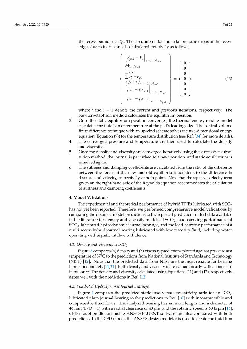
Figure 13 shows the variation of the maximum film pressure with increasing rotorspeed for different supply pressures. The maximum pressure increases with an increase inthe supply pressure and rotor speed. The hydrodynamic TPJB has the lowest maximumpressure. As shown in Figure 14, the predicted bearing drag power loss increases nonlin-early with the rotor speed. The hybrid TPJB has a higher power loss than the hydrodynamicTPJB because of the increase in the viscosity of sCO2. The change in power loss as thesupply pressure increases from 10 to 20 MPa is small.
Appl. Sci. 2022, 12, 1320 16 of 22
Figure 13. Maximum pressure vs. rotor speed for increasing supply pressures. Static load = 100 N.
Figure 14. Power loss vs. rotor speed for increasing supply pressures. Static load = 100 N.
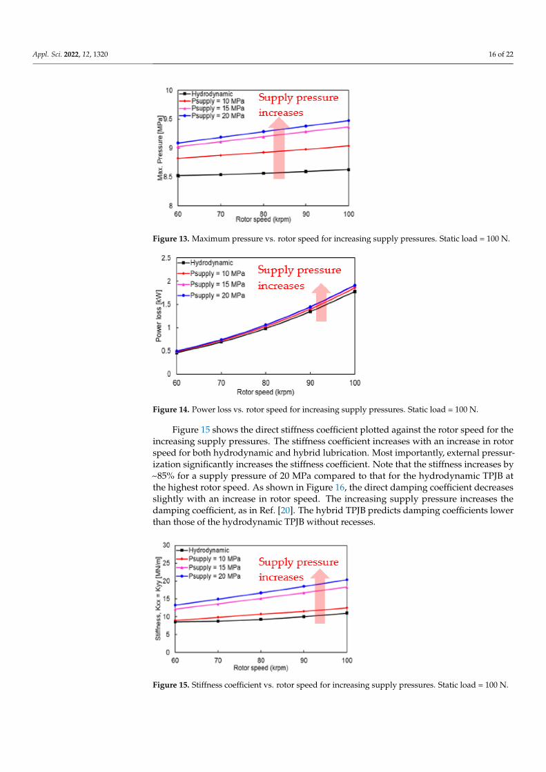
Figure 15 shows the direct stiffness coefficient plotted against the rotor speed for theincreasing supply pressures. The stiffness coefficient increases with an increase in rotorspeed for both hydrodynamic and hybrid lubrication. Most importantly, external pressur-ization significantly increases the stiffness coefficient. Note that the stiffness increases by~85% for a supply pressure of 20 MPa compared to that for the hydrodynamic TPJB atthe highest rotor speed. As shown in Figure 16, the direct damping coefficient decreasesslightly with an increase in rotor speed. The increasing supply pressure increases thedamping coefficient, as in Ref. [20]. The hybrid TPJB predicts damping coefficients lowerthan those of the hydrodynamic TPJB without recesses.
Figure 15. Stiffness coefficient vs. rotor speed for increasing supply pressures. Static load = 100 N.

Appl. Sci. 2022, 12, 1320 17 of 22
Figure 16. Damping coefficient vs. rotor speed for increasing supply pressures. Static load = 100 N.
6. Conclusions
sCO2-lubricated TPJBs enable a simple configuration of turbomachinery for sCO2power cycles by eliminating not only the issue of mixing-up of oil lubricant and sCO2process fluid but also the need for oil pumps and sealing devices for the lubricant.
The present study develops a computational model for sCO2-lubricated TPJB withhydrostatic pressurization at the tilting pad recesses to improve its static and dynamicperformances. The finite element and finite difference methods solve the Reynolds andenergy equations for the pressure and temperature distributions, respectively. The Newton–Raphson method is employed to find the equilibrium position, and the successive substitu-tion method finds the numerical solution for the local density and viscosity of sCO2, whichdepend nonlinearly on pressure and temperature.
The models for the density and viscosity of sCO2, hydrodynamic lubrication withcompressible and incompressible fluid flows, and hydrostatic lubrication with a turbulentflow and high Reynolds numbers are validated by comparing their results with predictionsand test data in the literature. A parametric study of the hybrid TPJB reveals that an increasein supply pressure significantly increases the pad pressure. At a rotor speed of 60 krpm,with an increase in supply pressure, the journal eccentricity decreases by 65%, and theminimum film thickness increases by 80%, thus enhancing the load capacity compared tothat of the hydrodynamic TPJB. Hydrostatic pressurization has the most significant effectson the load capacity at the lowest rotor speed, where hydrodynamic pressure generation isthe lowest. The stiffness coefficients increase, but the damping coefficients decrease owingto external pressurization. For the hybrid TPJB, with an increase in the supply pressure, thestiffness significantly increases, but the damping coefficients change slightly.
Author Contributions: Conceptualization, S.M.M. and T.H.K.; methodology, S.M.M.; model develop-ment, S.M.M.; formal analysis, S.M.M.; writing—original draft preparation, S.M.M.; writing—reviewand editing, T.H.K.; supervision, T.H.K.; project administration, T.H.K.; funding acquisition, T.H.K.All authors have read and agreed to the published version of the manuscript.
Funding: This study was supported by the National Research Foundation of Korea (NRF) grantfunded by the Korea Ministry of Science and ICT (MSIT) (No. NRF2021R1F1A105960211), “Fea-sibility Study on High-Speed, Long-Life Bearing-Seal Units in Turbopumps for Small ReusableLiquid-Propellant Space Launch Vehicles” and the Korea Energy Technology Evaluation and Plan-ning (KETEP) grant funded by the Korea Ministry of Trade, Industry and Energy (MOTIE) (No.2021202080026D), “Development of Infrastructure/Platform Technology and Operation ManagementSystem for AI/ICT-Based Variable Fluid Device Design and Condition Diagnosis.”
Institutional Review Board Statement: Not applicable.
Informed Consent Statement: Not applicable.
Data Availability Statement: Not applicable.

Appl. Sci. 2022, 12, 1320 18 of 22
Acknowledgments: This work was supported by the National Research Foundation of Korea (NRF)grant funded by the Korea Ministry of Science and ICT (MSIT) (Grant No. NRF2021R1F1A105960211)and the Korea Energy Technology Evaluation and Planning (KETEP) grant funded by the KoreaMinistry of Trade, Industry and Energy (MOTIE) (Grant No. 2021202080026D). The first authoracknowledges the support of the Global Scholarship Program for Foreign Graduate Students atKookmin University, South Korea.
Conflicts of Interest: The authors declare that they have no conflicts of interest.
Nomenclature
(a . . . g)1 . . . 4 Empirical coefficientsAo Orifice area [m2]b Recess axial length [m]Cd Orifice discharge coefficient [-]Cb Radial bearing clearance [m]cp Specific heat capacity at constant pressure [J/kg/K]cv Specific heat capacity at constant volume [J/kg/K]Cp Radial pad clearance [m]Cα ,β = X,Y Damping coefficientdo Orifice diameter [m]Dr Recess depth [m]e Eccentricity [m]Fp Pivot restoring force [N]Fpad Force on pad [N]Fpo Bearing static load [N]FX Horizontal direction fluid film force [N]FY Vertical direction fluid film force [N]Gx Turbulent coefficient in circumferential direction [-]Gz Turbulent coefficient in axial direction [-]h Film thickness [m]hl Film thickness at a land area adjacent to recess [m]hre Film thickness at recess area adjacent to film land [m]htj Convective heat transfer coefficient to journal surface [W/m2·K]htb Convective heat transfer coefficient to bearing [W/m2·K]Kα ,β = X,Y Stiffness coefficientL Bearing axial length [m]l Recess circumferential length [m]l11, l21, l81, l82 Empirical coefficientsM Pad moment [N.m]m Preload factor (1 − Cb/Cp) [-]m0, n0 Empirical constants used for calculating turbulent coefficientsMo Orifice mass flow rate [kg/s]Npad Number of pads [-]p Fluid film pressure [Pa]pa Ambient pressure [Pa]pc Critical point pressure of CO2 [Pa]pdc Pressure drop due to inertia at the circumferential trailing edge of the recess [Pa]pda Pressure drop due to inertia at the axial trailing edge of the recess [Pa]ps Supply pressure of the externally pressurized fluid [Pa]pr Ratio of local pressure to critical pressure of sCO2 [-]pratio Ratio of recess pressure to supply pressure [-]pre Recess pressure [Pa]Ql Flow flux at the land adjacent to recess boundary [m2/s]Qo Orifice volumetric flow rate [m3/s]

Appl. Sci. 2022, 12, 1320 19 of 22
Qr Summation of the flow rates at the recess boundaries [m3/s]Re Reynolds number [-]Rec Critical Reynolds number [-]Rh Pivot’s housing radius [m]Rp Pad radius [m]Rg Gas constant [J/kg/K]rp Preload [m]t time [s]tp pad thickness [m]T Fluid film temperature [C]Tb Bearing temperature [C]Tc Critical point temperature of CO2 [C]Tj Journal temperature [C]Tr Ratio of local temperature to the critical temperature of sCO2 [-]Ts Fluid film supply temperature [C]T* Reduced temperature of CO2 [C]U Journal surface speed [m/s]V Bulk flow velocity in the circumferential direction [m/s]W Bulk flow velocity in the axial direction [m/s]X, Y Inertial coordinates [m]x Circumferential coordinate [m]z Axial coordinate [m]δ Pad’s tilting angle [rad]β Fluid’s thermoviscosity coefficient [C−1]βt Fluid’s thermal expansion coefficient [C−1]βl Reynolds number dependent coefficient in the land area used in the
calculation of pressure dropβre Reynolds number dependent coefficient in recess area used in the
calculation of pressure dropρ Fluid’s local density [kg·m−3]ρ0 Fluid density at the initial condition [kg·m−3]ζ Deflection of pivot [m]µ Fluid’s local viscosity [Pa·s]µ0 Fluid’s viscosity at initial condition [Pa·s]θ Circumferential coordinate [rad]θc Angle between a line passing through bearing and journal centers
and horizontal axis [rad]θp Pivot’s angular location [rad]θpad Pad’s angular extent [rad]ν Poisson’s ratioΩ Journal rotational speed [rad·s−1]κ ratio of the specific heat capacity at constant pressure to the specific heat
capacity at constant volume [-](λ)0 . . . 4 Empirical coefficients
Appendix A. Pad Tilting Angle, Pivot Deflection, and Pivot Maximum Stress
Figure A1 shows the pad tilting angle versus supply pressure for each pad. The nullpressure indicates hydrodynamic lubrication. As the supply pressure increases from 10 to20 MPa, the pad tilt angle decreases, except for pad 3.
Appl. Sci. 2022, 12, 1320 20 of 22
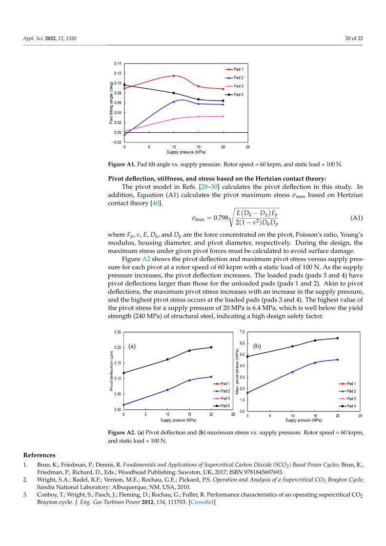
Figure A1. Pad tilt angle vs. supply pressure. Rotor speed = 60 krpm, and static load = 100 N.
Pivot deflection, stiffness, and stress based on the Hertzian contact theory:The pivot model in Refs. [28–30] calculates the pivot deflection in this study. In
addition, Equation (A1) calculates the pivot maximum stress σmax based on Hertziancontact theory [40].
σmax = 0.798
√E(
Dh − Dp)
Fp
2(1− ν2)DhDp(A1)
where Fp, ν, E, Dh, and Dp are the force concentrated on the pivot, Poisson’s ratio, Young’smodulus, housing diameter, and pivot diameter, respectively. During the design, themaximum stress under given pivot forces must be calculated to avoid surface damage.
Figure A2 shows the pivot deflection and maximum pivot stress versus supply pres-sure for each pivot at a rotor speed of 60 krpm with a static load of 100 N. As the supplypressure increases, the pivot deflection increases. The loaded pads (pads 3 and 4) havepivot deflections larger than those for the unloaded pads (pads 1 and 2). Akin to pivotdeflections, the maximum pivot stress increases with an increase in the supply pressure,and the highest pivot stress occurs at the loaded pads (pads 3 and 4). The highest value ofthe pivot stress for a supply pressure of 20 MPa is 6.4 MPa, which is well below the yieldstrength (240 MPa) of structural steel, indicating a high design safety factor.
Figure A2. (a) Pivot deflection and (b) maximum stress vs. supply pressure. Rotor speed = 60 krpm,and static load = 100 N.
References1. Brun, K.; Friedman, P.; Dennis, R. Fundamentals and Applications of Supercritical Carbon Dioxide (SCO2) Based Power Cycles; Brun, K.,
Friedman, P., Richard, D., Eds.; Woodhead Publishing: Sawston, UK, 2017; ISBN 9781845697693.2. Wright, S.A.; Radel, R.F.; Vernon, M.E.; Rochau, G.E.; Pickard, P.S. Operation and Analysis of a Supercritical CO2 Brayton Cycle;
Sandia National Laboratory: Albuquerque, NM, USA, 2010.3. Conboy, T.; Wright, S.; Pasch, J.; Fleming, D.; Rochau, G.; Fuller, R. Performance characteristics of an operating supercritical CO2
Brayton cycle. J. Eng. Gas Turbines Power 2012, 134, 111703. [CrossRef]

Appl. Sci. 2022, 12, 1320 21 of 22
4. Turchi, C.S.; Ma, Z.; Neises, T.W.; Wagner, M.J. Thermodynamic study of advanced supercritical carbon dioxide power cycles forconcentrating solar power systems. J. Sol. Energy Eng. 2013, 135, 041007. [CrossRef]
5. Dostal, V.; Hejzlar, P.; Driscoll, M.J. High-performance supercritical carbon dioxide cycle for next-generation nuclear reactors.Nucl. Technol. 2006, 154, 265–282. [CrossRef]
6. Uusitalo, A.; Ameli, A.; Turunen-Saaresti, T. Thermodynamic and turbomachinery design analysis of supercritical Brayton cyclesfor exhaust gas heat recovery. Energy 2019, 167, 60–79. [CrossRef]
7. Cho, J.; Choi, M.; Baik, Y.-J.; Lee, G.; Ra, H.-S.; Kim, B.; Kim, M. Development of the turbomachinery for the supercritical carbondioxide power cycle. Int. J. Energy Res. 2016, 40, 587–599. [CrossRef]
8. Cho, J.; Shin, H.; Ra, H.S.; Lee, G.; Roh, C.; Lee, B.; Baik, Y.J. Development of the supercritical carbon dioxide power cycleexperimental loop in KIER. In Proceedings of the ASME Turbo Expo 2016: Turbomachinery Technical Conference and Exposition,Seoul, Korea, 13–17 June 2016; Volume 9, pp. 1–8.
9. Ahn, Y.; Lee, J.; Kim, S.G.; Lee, J.I.; Cha, J.E. The design study of supercritical carbon dioxide integral experimental loop. InProceedings of the ASME Turbo Expo 2013: Turbine Technical Conference and Exposition, San Antonio, TX, USA, 3–7 June2013; pp. 1–7.
10. Utamura, M.; Hasuike, H.; Yamamoto, T. Demonstration test plant of closed cycle gas turbine with supercritical CO2 as workingfluid. Strojarstvo 2010, 52, 459–465.
11. Conboy, T.M. Real-gas effects in foil thrust bearings operating in the turbulent regime. J. Tribol. 2013, 135, 031703. [CrossRef]12. Lemmon, E.W.; McLinden, M.O.; Huber, M.L. NIST Reference Fluid Thermodynamic and Transport Properties-REFPROP.
Available online: https://webbook.nist.gov/chemistry/fluid/# (accessed on 1 January 2019).13. Qin, K.; Jahn, I.; Gollan, R.; Jacobs, P. Development of a computational tool to simulate foil bearings for supercritical CO2 cycles. J.
Eng. Gas Turbines Power 2016, 138, 092503. [CrossRef]14. Qin, K.; Jahn, I.H.; Jacobs, P.A. Effect of operating conditions on the elastohydrodynamic performance of foil thrust bearings for
supercritical CO2 cycles. J. Eng. Gas Turbines Power 2017, 139, 042505. [CrossRef]15. Dousti, S.; Allaire, P. A compressible hydrodynamic analysis of journal bearings lubricated with supercritical carbon dioxide.
In Proceedings of the 5th International Supercritical CO2 Power Cycles Symposium, San Antonio, TX, USA, 29–31 March2016; pp. 1–18.
16. Heshmat, H.; Walton II, J.F.; Cordova, J.L. Technology readiness of 5th and 6th generation compliant foil bearing for 10 MWEs-CO2 turbomachinery systems. In Proceedings of the 6th International Supercritical CO2 Power Cycles Symposium, Pittsburgh,PA, USA, 27–29 March 2018; pp. 1–29.
17. Dimond, T.; Younan, A.; Allaire, P. Journal bearing lubrication using sCO2—A theoretical study. In Proceedings of the 2ndInternational Supercritical CO2 Power Cycles Symposium, Troy, NY, USA, 29–30 April 2009.
18. Xu, F.; Kim, D. Three-dimensional turbulent thermo-elastohydrodynamic analyses of hybrid thrust foil bearings using real gasmodel. In Proceedings of the ASME Turbo Expo 2016: Turbomachinery Technical Conference and Exposition, Seoul, Korea, 13–17June 2016; Volume 7B-2016, pp. 1–10.
19. Preuss, J.L. Application of hydrostatic bearings in supercritical CO2 turbomachinery. In Proceedings of the 5th InternationalSupercritical CO2 Power Cycles Symposium, San Antonio, TX, USA; 2016; pp. 1–10.
20. San Andrés, L.; Childs, D.W. Angled Injection—Hydrostatic Bearings Comparison to Test Results. J. Tribol. 1997, 119, 179–187.[CrossRef]
21. Bi, C.; Han, D.; Yang, J. The frequency perturbation method for predicting dynamic coefficients of supercritical carbon dioxidelubricated bearings. Tribol. Int. 2020, 146, 106256. [CrossRef]
22. Kim, D.; Baik, S.; Lee, J.I. Instability Study of Magnetic Journal Bearing under S-CO2 Condition. Appl. Sci. 2021, 11, 3491.[CrossRef]
23. San Andrés, L. Hybrid-flexure pivot-tilting pad gas bearings: Analysis and experimental validation. J. Tribol. 2006, 128, 551–558.[CrossRef]
24. San Andrés, L.; Ryu, K. Flexure pivot tilting pad hybrid gas bearings: Operation with worn clearances and two load-padconfigurations. J. Eng. Gas Turbines Power 2008, 130, 042506. [CrossRef]
25. Hirs, G.G. A Bulk-flow theory for turbulence in lubricant films. J. Lubr. Technol. 1973, 137–145. [CrossRef]26. Okabe, E.P.; Cavalca, K.L. Rotordynamic analysis of systems with a non-linear model of tilting pad bearings including turbulence
effects. Nonlinear Dyn. 2009, 57, 481–495. [CrossRef]27. Orcutt, F.K. The steady-state and dynamic characteristics of the tilting-pad journal bearing in laminar and turbulent flow regimes.
J. Lubr. Technol. 1967, 89, 392–400. [CrossRef]28. Mehdi, S.M.; Jang, K.E.; Kim, T.H. Effects of pivot design on performance of tilting pad journal bearings. Tribol. Int. 2018,
119, 175–189. [CrossRef]29. Lee, T.W.; Kim, T.H. Finite element analysis of pivot stiffness for tilting pad bearings and comparison to Hertzian contact model
calculations. J. Korean Soc. Tribol. Lubr. Eng. 2014, 30, 205–211. [CrossRef]30. Choi, T.G.; Kim, T.H. Analysis of Tilting Pad Journal Bearings Considering Pivot Stiffness. J. Korean Soc. Tribol. Lubr. Eng. 2014,
30, 77–85.31. Brian Rowe, W. FiMeche Hydrostatic, Aerostatic and Hybrid Bearing Design, 1st ed.; Elsevier Inc.: London, UK, 2012; ISBN 9780123969941.32. Constantinescu, V.N.; Galetuse, S. Pressure Drop Due To Inertia Forces in Step Bearings. J. Lubr. Technol. 1975, 167–174. [CrossRef]

Appl. Sci. 2022, 12, 1320 22 of 22
33. Bou-Said, B.; Chaomleffel, J.P. Hybrid Journal Bearings: Theoretical and Experimental Results. J. Tribol. 1989, 111, 265–269.[CrossRef]
34. San Andrés, L. Notes10: Thermohydrodynamic Bulk-Flow Model in Thin Film Lubrication. Available online: http://phn.tamu.edu/me626 (accessed on 20 August 2016).
35. Wang, Z.; Sun, B.; Yan, L. Improved density correlation for supercritical CO2. Chem. Eng. Technol. 2015, 38, 75–84. [CrossRef]36. Fenghour, A.; Wakeham, W.A.; Vesovic, V. The viscosity of carbon dioxide. J. Phys. Chem. Ref. Data 1998, 27, 31–44. [CrossRef]37. Liu, Z.; Wang, Y.; Cai, L.; Zhao, Y.; Cheng, Q.; Dong, X. A review of hydrostatic bearing system: Researches and applications. Adv.
Mech. Eng. 2017, 9, 1687814017730536. [CrossRef]38. Balbahadur, A.C.; Kirk, R. Part I-Theoretical Model for a Synchronous Thermal Instability Operating in Overhung Rotors. Int. J.
Rotating Mach. 2004, 10, 469–475. [CrossRef]39. Chaomleffel, J.P.; Nicolas, D. Experimental investigation of hybrid journal bearings. Tribol. Int. 1986, 19, 253–259. [CrossRef]40. Young, W.C.; Budnyas, R.G. Roark’s Formulas for Stress and Strain, 7th ed.; McGraw-Hill: New York, NY, USA, 2002;
ISBN 0-07-072542-X.
Copyright © 2022 FDOKUMEN