
Instability Threshold of a Rigid Rotor-Tilting Pad Journal Bearings System
16
International Journal of Rotating Machinery 1997, Vol. 3, No. 3, pp. 199-213 Reprints available directly from the publisher Photocopying permitted by license only (C) 1997 OPA (Overseas Publishers Association) Amsterdam B.V. Published in The Netherlands under license by Gordon and Breach Science Publishers Printed in Malaysia Instability Threshold of a Rigid Rotor-Tilting Pad Journal Bearings System STEFANO PAGANOa, ERNESTO ROCCAa, MICHELE RUSSO’* and RICCARDO RUSSO b aDipartimento di Ingegneria Meccanica per l’Energetica--Universitgt di Napoli "Federico H"--Italy; bDipartimento di Ingegneria Meceanica--Universit& di Salerno--Italy (Received 8 July 1996; In final form 8 July 1996) The stability of a rigid rotor supported on radial tilting pad journal bearings is analysed. This study has been tackled both for small unbalance values by linearising the equations of motion, and also in the case where, because of the high unbalance value, the rotor axis describes orbits with an amplitude such that the system’s non-linearity cannot be ignored. In both cases the system’s stable operation maps have been obtained and verified through numerical integration of the differential equations of motion. Keywords." Tilting pad journal bearings, rotor-bearing system, stability INTRODUCTION Tilting-pad journal bearings are widely used for sup- porting the rotors of turbomachines as they help pre- vent the occurrence of oil film instability phenomena that can be induced by high rotation speeds. Never- theless, for the components in question, there are forms of instability that arise if the operating condi- tions, and the rotation speed in particular, exceed cer- tain limits which should thus be regarded as thresh- olds of stable behaviour. In the case of well-balanced rotors, the residual unbalance forces the journal to describe orbits that have a very small amplitude around the stationary equilibrium position and are synchronous with rotor speed. In these conditions, if the pads are arranged symmetrically to the direction of the static load and if the pads have a negligible mass compared to that of the journal, then the rotor bearing system is always stable. If the pads have a mass that is not negligible com- pared to that of the rotor, a form of instability may arise whose threshold can be found by linearising the journal-pads system’s equations of motion around the stationary equilibrium position. The search for the real part of the eigenvalues of the non-conservative system with several degrees of freedom constituted by the journal, the pads and the linearised action of the oil film in the gaps, makes it possible to determine the stability threshold of the *Corresponding author. Tel.: 39-81-7683291. Fax: 39-81-2394165. 199
-
Upload
independent -
Category
Documents
-
view
1 -
download
0
Transcript of Instability Threshold of a Rigid Rotor-Tilting Pad Journal Bearings System
International Journal of Rotating Machinery1997, Vol. 3, No. 3, pp. 199-213
Reprints available directly from the publisherPhotocopying permitted by license only
(C) 1997 OPA (Overseas Publishers Association)Amsterdam B.V. Published in The Netherlands
under license by Gordon and Breach Science Publishers
Printed in Malaysia
Instability Threshold of a Rigid Rotor-Tilting PadJournal Bearings System
STEFANO PAGANOa, ERNESTO ROCCAa, MICHELE RUSSO’* and RICCARDO RUSSOb
aDipartimento di Ingegneria Meccanica per l’Energetica--Universitgt di Napoli "Federico H"--Italy; bDipartimento di IngegneriaMeceanica--Universit& di Salerno--Italy
(Received 8 July 1996; In final form 8 July 1996)
The stability of a rigid rotor supported on radial tilting pad journal bearings is analysed. Thisstudy has been tackled both for small unbalance values by linearising the equations ofmotion, and also in the case where, because of the high unbalance value, the rotor axisdescribes orbits with an amplitude such that the system’s non-linearity cannot be ignored. Inboth cases the system’s stable operation maps have been obtained and verified throughnumerical integration of the differential equations of motion.
Keywords." Tilting pad journal bearings, rotor-bearing system, stability
INTRODUCTION
Tilting-pad journal bearings are widely used for sup-porting the rotors of turbomachines as they help pre-vent the occurrence of oil film instability phenomenathat can be induced by high rotation speeds. Never-theless, for the components in question, there are
forms of instability that arise if the operating condi-
tions, and the rotation speed in particular, exceed cer-
tain limits which should thus be regarded as thresh-olds of stable behaviour.
In the case of well-balanced rotors, the residual
unbalance forces the journal to describe orbits thathave a very small amplitude around the stationaryequilibrium position and are synchronous with rotor
speed. In these conditions, if the pads are arrangedsymmetrically to the direction of the static load and if
the pads have a negligible mass compared to that of
the journal, then the rotor bearing system is alwaysstable.
If the pads have a mass that is not negligible com-
pared to that of the rotor, a form of instability mayarise whose threshold can be found by linearising the
journal-pads system’s equations of motion around the
stationary equilibrium position.The search for the real part of the eigenvalues of
the non-conservative system with several degrees of
freedom constituted by the journal, the pads and the
linearised action of the oil film in the gaps, makes it
possible to determine the stability threshold of the
*Corresponding author. Tel.: 39-81-7683291. Fax: 39-81-2394165.
199
200 S. PAGANO et al.
stationary equilibrium position for given geometricaland operating conditions.
The study is conducted on a linear system and thecorresponding instability is thus indicated as "linear
instability".In the case of unbalanced rotors, the journal and
the pads describe periodic motions with a non-negli-gible amplitude and the non-linearity of the system isthus important. Under these circumstances it will benecessary to investigate the stability, not of the sta-
tionary equilibrium position but of the motion (whichis synchronous with the rotation speed) that the jour-nal and the pads undergo as a result of the unbalance.In this case the instability arises even if the mass ofthe pads is negligible and it assumes the forms typicalof systems with a non linear behaviour.
This instability is therefore indicated as "non linear
instability" and it arises with the onset in the systemmotion of components having a frequency equal to an
integer submultiple of that corresponding to the rota-
tion speed, and with amplitudes that can be so largeas to compromise the very operation of the system.The study of this form of instability is conducted us-
ing the methods of non linear analysis.Hereafter both the linear and the non linear limit
stability curves of the tilting pads-rotor bearing sys-tem are determined in an appropriate operating con-
ditions plane. These curves are validated by verifica-
tions carried out by numerically integrating the non
linear equations of motion.
The analysis is conducted with reference to a four-
pad bearing but the illustrated method has a generalvalidity and can thus be applied to the case of bear-
ings with a different number of pads without encoun-
tering any difficulties of a conceptual nature.
BEARING CIRCLE
(C)
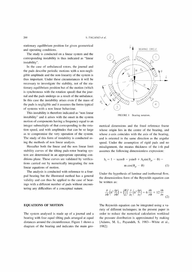
FIGURE Bearing notation.
metrical dimensions and the fixed reference framewhose origin lies in the centre of the bearing, andwhose z-axis coincides with the axis of the bearing,and is oriented in the same direction as the angularspeed. Under the assumption of rigid pads and no
misalignment, the meatus thickness of the i-th padassumes the following dimensionless expression:
h xcosO- ysinO + Aisin(Opi
m cos(0pi 0)
-0)-
(1)
Under the hypothesis of laminar and isothermal flow,the dimensionless form of the Reynolds equation can
be written as:
O0 - + hop
6--+ 12--&.(2)
EQUATIONS OF MOTION
The system analysed is made up of a journal and a
bearing with four equal tilting pads arranged at equaldistances around the circumference. Figure shows a
diagram of the bearing and indicates the main geo-
The Reynolds equation can be integrated using a va-
riety of different techniques; in the present paper inorder to reduce the numerical calculation workloadthe pressure distribution is approximated by making[Adams, M. L., Payandeh, S. 1983--White et al.,1982]:
INSTABILITY THRESHOLD...BEARINGS SYSTEM 201
p(O, z) p(O, 0)[1 (2z)2] (3)
So, it is possible to write eq. (2) in the followingone-dimensional form:
Oh Ohh3p(O, 0) 6-- + 12I)
Eq. (4), numerically integrated with the boundaryconditions corresponding to null pressure values at
the edge of the pad, provides the pressure distributionfor each pad.
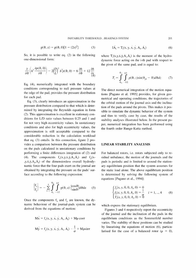
Eq. (3), clearly introduces an approximation in thepressure distribution compared to that which is deter-mined by integrating the Reynolds equation in form
(2). This approximation is excellent in stationary con-
ditions for L/D ratio values between 0.25 and andfor not very high eccentricity values. In unstationaryconditions and also for high eccentricity values, theapproximation is still acceptable compared to theconsiderable reduction in the calculation workloadthat eq. (3) entails. In this connection, figure 2 pro-vides a comparison between the pressure distributionon the pads calculated in unstationary conditions byperforming a finite differences integration of (2) and(4). The components fx(x,y,z,5,,Ai,/i) and fy(X-,y,,5,,Ai,Ai) of the dimensionless overall hydrody-namic force that the four pads exert on the journal are
obtained by integrating the pressure on the pads’ sur-
face according to the following expression:
"1i2 1/2
{fx} 4 ,[cosOd. dzfy f f p(o, tsinOJ o
Oi 1/2
(5)
Once the components fx and fy are known, the dy-namic behaviour of the journal-pads system can bederived from the equations of motion:
M; fx(X, y, x, 3, Ai, Ai) q- Mp cosn"
M fy(X, y, , 3), Ai,/xi) L -k- Mpsim-o"
Ifi. Ti(x, y, , y, Ai, Ai) (6)
where Ti(x,y,X,,Ai,Ai) is the moment of the hydro-dynamic force acting on the i-th pad with respect to
the pivot of the same pad, and is equal to:
0i2 1/2
Ti Y Y P(O, z)sin(Opi0il 1/2
O)dOdz (7)
The direct numerical integration of the motion equa-tions [Pagano et al. 1995] provides, for given geo-metrical and operating conditions, the trajectories ofthe orbital motion of the journal axis and the inclina-
tion of the pads around the pivots. This makes it pos-sible to simulate the dynamic behavior of the systemand thus to verify, case by case, the results of the
stability analyses illustrated below. In the present pa-per, numerical integration has been performed usingthe fourth order Runge-Kutta method.
LINEAR STABILITY ANALYSIS
For balanced rotors, i.e. rotors subjected only to re-
sidual unbalance, the motion of the journals and the
pads is periodic and is limited to around the station-
ary equilibrium position that the system assumes forthe static load alone. The above equilibrium positionis determined by solving the following system of
equations [Pagano et al., 1994]:
y, 0, 0, Ai, O) 0
fy(x, y, O, O, Ai, O)1
Ti(x, y, O, O, Ai, O) --o4 (8)
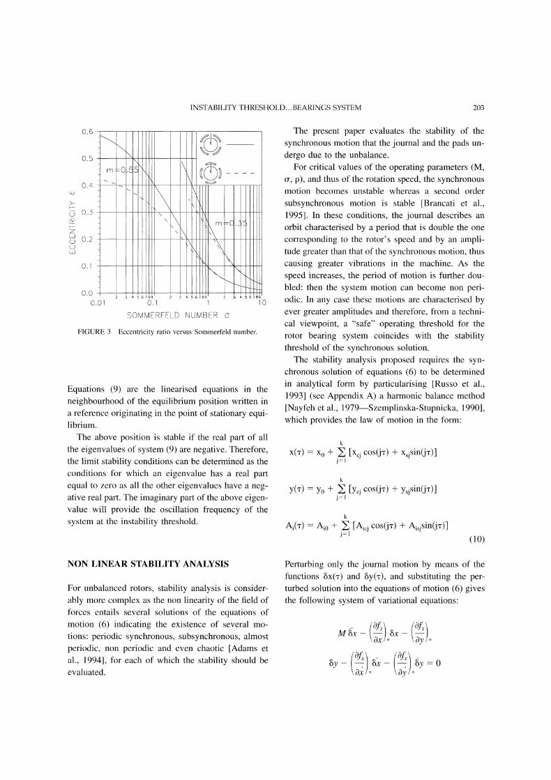
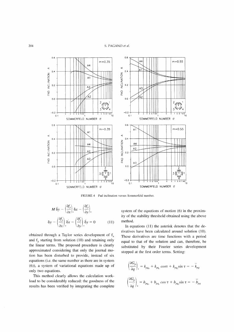
which express the stationary equilibrium.Figures 3 and 4 respectively report the eccentricity
of the journal and the inclination of the pads in the
equilibrium conditions as the Sommerfeld numbervaries. The stability of these positions can be studied
by linearising the equations of motion (6), particu-larised for the case of a balanced rotor (p 0),
202 S. PAGANO et al.
2.5
2.0
1.5
1.0
0.5
0.0
KINEMATIC STATEX=+.0992
A1 =+.7494A3=-.2034’Z=-.1553
,1 =-.0,.590/3=+.875
Y=-.2785A2=+.0787A4=+.49339=-.0738
A’2 =-.2954A’4=+.1876
REYNOLDS EQUATION
APPROXIMATE REYNOLDS EQUATION
PAD PAD
o" 45"
2 PAD
S5 180" 225 ’0
-COORDINATE
4
315 360"
2.0
1.5
1.o
0.5PAD PAD 2 PAD
0 .5 -.5 0 .5 -5
Z-COORDINATE
PAD
FIGURE 2 Circumferential and axial pressure distribution: comparison between the results obtained with the two-dimensional and theone-dimensional methods, for a given kinematic state and for: L/D 0.7" m 0.35; M 20; 0.1, o- 1.0.
through a Taylor series expansion of the hydrody-namic force and maintaining only the first order terms"
M; -[- bxx Jr- bxy --[- kxxx -[- kxyy Jr- (kxAAii--1
--]- bxAAi 0 (9)
IJ -]- kAAAi + kaxiX + kAyiY + b
+ +
after making:
M" q- byA @ byy. -[- kyxx -[- kyyy -Jr- (kyA.i
-F byA.ri) 0
kpq- ,-q/; bpq \--q /with:
G -f,fy, T and p, q x, y,A
INSTABILITY THRESHOLD...BEARINGS SYSTEM 203
0.6
0.5
G o.3
zc9 0.2(D
0.1
m -0.55\\
0.0O.Ol o.
FIGURE 3
lO
SOMMERFELD NUMBER o-
Eccentricity ratio versus Sommerfeld number.
Equations (9) are the linearised equations in theneighbourhood of the equilibrium position written ina reference originating in the point of stationary equi-librium.The above position is stable if the real part of all
the eigenvalues of system (9) are negative. Therefore,the limit stability conditions can be determined as theconditions for which an eigenvalue has a real partequal to zero as all the other eigenvalues have a neg-ative real part. The imaginary part of the above eigen-value will provide the oscillation frequency of the
system at the instability threshold.
The present paper evaluates the stability of thesynchronous motion that the journal and the pads un-
dergo due to the unbalance.For critical values of the operating parameters (M,
o-, p), and thus of the rotation speed, the synchronousmotion becomes unstable whereas a second order
subsynchronous motion is stable [Brancati et al.,1995]. In these conditions, the journal describes an
orbit characterised by a period that is double the one
corresponding to the rotor’s speed and by an ampli-tude greater than that of the synchronous motion, thuscausing greater vibrations in the machine. As thespeed increases, the period of motion is further dou-bled: then the system motion can become non peri-odic. In any case these motions are characterised byever greater amplitudes and therefore, from a techni-cal viewpoint, a "safe" operating threshold for therotor bearing system coincides with the stabilitythreshold of the synchronous solution.The stability analysis proposed requires the syn-
chronous solution of equations (6) to be determined
in analytical form by particularising [Russo et al.,1993] (see Appendix A) a harmonic balance method[Nayfeh et al., 1979--Szemplinska-Stupnicka, 1990],which provides the law of motion in the form:
k
x(’r)- x0 + [Xcj cos(j’r) + XsjSin(j’r)]j=l
k
y(’r) Y0 + [Ycj cos(j’r) + ysjsin(j’r)]j=l
k
Ai(q" Aio + ] [Aic cos(jq’) + Aisjsin(jq’)]j=l
(10)
NON LINEAR STABILITY ANALYSIS
For unbalanced rotors, stability analysis is consider-
ably more complex as the non linearity of the field offorces entails several solutions of the equations ofmotion (6) indicating the existence of several mo-tions: periodic synchronous, subsynchronous, almostperiodic, non periodic and even chaotic [Adams et
al., 1994], for each of which the stability should beevaluated.
Perturbing only the journal motion by means of thefunctions 8x(’r) and 8y(r), and substituting the per-turbed solution into the equations of motion (6) givesthe following system of variational equations:
M xOx Oy
\Oy/*
204 S. PAGANO et al.
0.6
0.4
0.2
0.0
0.6
0.4
0.2
0.0
m =0.,.35
A4
/A21
SOMMERFELD NUMBER Cr
m :0.35A1
\-,.
A4
A3 ,,,/
I0
SOMMERFELD NUMBER O
0.4
0.2
0.0
-0.2
0.1
SOMMERFELD NUMBER O"
m =0.55
0.6
0.4
0.2
0.0
A4
m =0.55
SOMMERFELD NUMBER o"
FIGURE 4 Pad inclination versus Sommerfeld number.
M @ 8x 19f\-Ox/* Oy’*
03,(ll)
obtained through a Taylor series development of fxand fy starting from solution (10) and retaining onlythe linear terms. The proposed procedure is clearlyapproximated considering that only the journal mo-
tion has been disturbed to provide, instead of six
equations (i.e. the same number as there are in system(6)), a system of variational equations made up of
only two equations.This method clearly allows the calculation work-
load to be considerably reduced: the goodness of theresults has been verified by integrating the complete
system of the equations of motion (6) in the proxim-ity of the stability threshold obtained using the abovemethod.
In equations (11) the asterisk denotes that the de-rivatives have been calculated around solution (10).These derivatives are time functions with a periodequal to that of the solution and can, therefore, besubstituted by their Fourier series developmentstopped at the first order terms. Setting:
--q ,, kpq + kpq. cos’r + kpq.,Sin "r kp
Obpq + bp. cos
INSTABILITY THRESHOLD...BEARINGS SYSTEM 205
with: G fx, fy; p, q x, y
Equations (1 l) can be rewritten:
ax + kyy ay + by Jc + byy 0(12)
The variational equations in the form (12) are Hilltype equations and the stability of their trivial solu-tion coincides with the stability of solution (10), i.e.with the stability of the synchronous motion of thejournal-pads system {Szemplinska-Stupnicka W.1990]. Therefore, by searching for the limit condi-tions that make the trivial solution of equation (12)unstable (see Appendix B), it is possible to determinethe stability threshold of the synchronous solution
and, for the above reasons, of "safe" rotor operation.
LINEAR ANALYSIS RESULTS
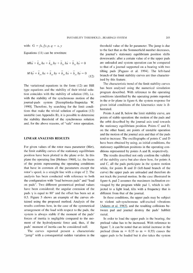
For given values of the rotor mass parameter (Mo-),the limit stability curves of the stationary equilibriumposition have been plotted in the plane o--Io-. In this
plane the operating line [Holmes 1960], i.e. the locusof the points representing the operating conditionsthat have in common all the parameters except therotor’s speed, is a straight line with a slope of 2. Theanalysis has been conducted with reference to boththe configuration with "load between pads" and "loadon pads". Two different geometrical preload valueshave been considered; the angular extension of thepads /is equal to 80 and the offset has been set at
0.5. Figure 5 shows an example of the curves ob-tained using the proposed method. Analysis of theresults confirms how, in the case of the symmetricalarrangement of the load with respect to the pads, thesystem is always stable if the moment of the pads’forces of inertia is negligible compared to the mo-
ment of the hydrodynamic force and, thus, if thepads’ moment of inertia can be considered null.The curves reported present a characteristic
"jump" with a consequential sudden variation in the
threshold value of the Io- parameter. The jump is dueto the fact that as the Sommerfield number decreases,the journal’s stationary equilibrium position shifts
downwards: after a certain value of the upper padsare unloaded and system operation can be comparedto that of a journal supported on a bearing with two
tilting pads [Pagano et al. 1994]. The left-handbranch of the limit stability curves are thus character-ised by this feature.The characteristic trend of the limit stability curves
has been analysed using the numerical simulation
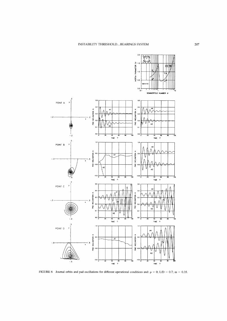
program described. With reference to the operatingconditions identified by the operating points reportedin the o--Io- plane in figure 6, the system response for
given initial conditions of the kinematics state is il-
lustrated.Points A and B, below the limit stability curve, are
points of stable operation: the motion of the pads andthe orbit described by the journal axis tend towardsthe stationary equilibrium position. Points C and D,on the other hand, are points of unstable operationand the motion of the journal axis and that of the padstend to increase. The oscillographs of points C and Dhave been obtained by using, as initial conditions, thestationary equilibrium positions in the operating con-
ditions represented by points A and B, respectively.The results described not only confirm the validity
of the stability curve but also show how, for points Aand C, all the pads participate in the system motion
while, for points B and D (left-hand branch of the
curve) the upper pads are unloaded and therefore donot track the journal motion. In the case illustrated in
figure 6, pad 2 assumes the maximum inclination en-
visaged by the program while pad 1, which is sub-
jected to a light load, tilts with a frequency that is
different from that of the journal.In these conditions, the upper pads may be subject
to violent sub-synchronous self-excited vibrations
[Adams et al. 1983], and the resulting collisions be-tween pad and journal destroy the pads’ babbitt
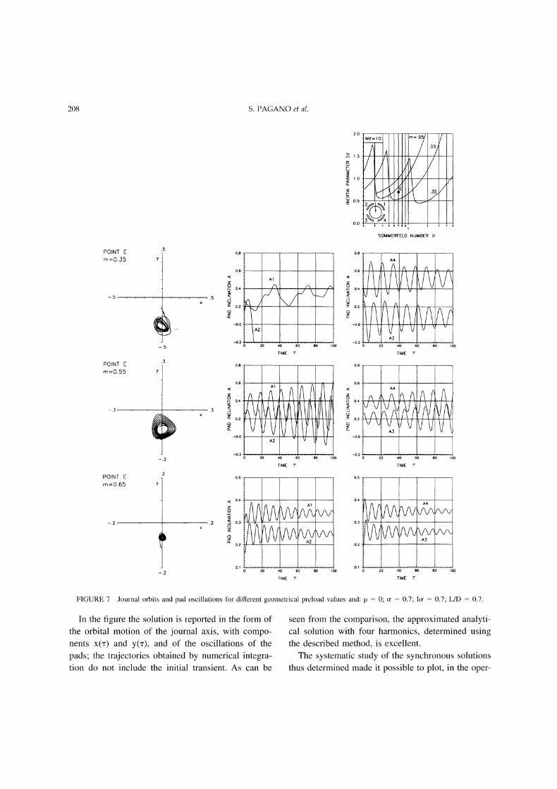
metal.In order to load the upper pads in the bearing, the
preload value has to be increased. With reference to
figure 7, it can be noted that an initial increase in thepreload (from m 0.35 to m 0.55) causes theupper pads to be loaded but it also takes the system
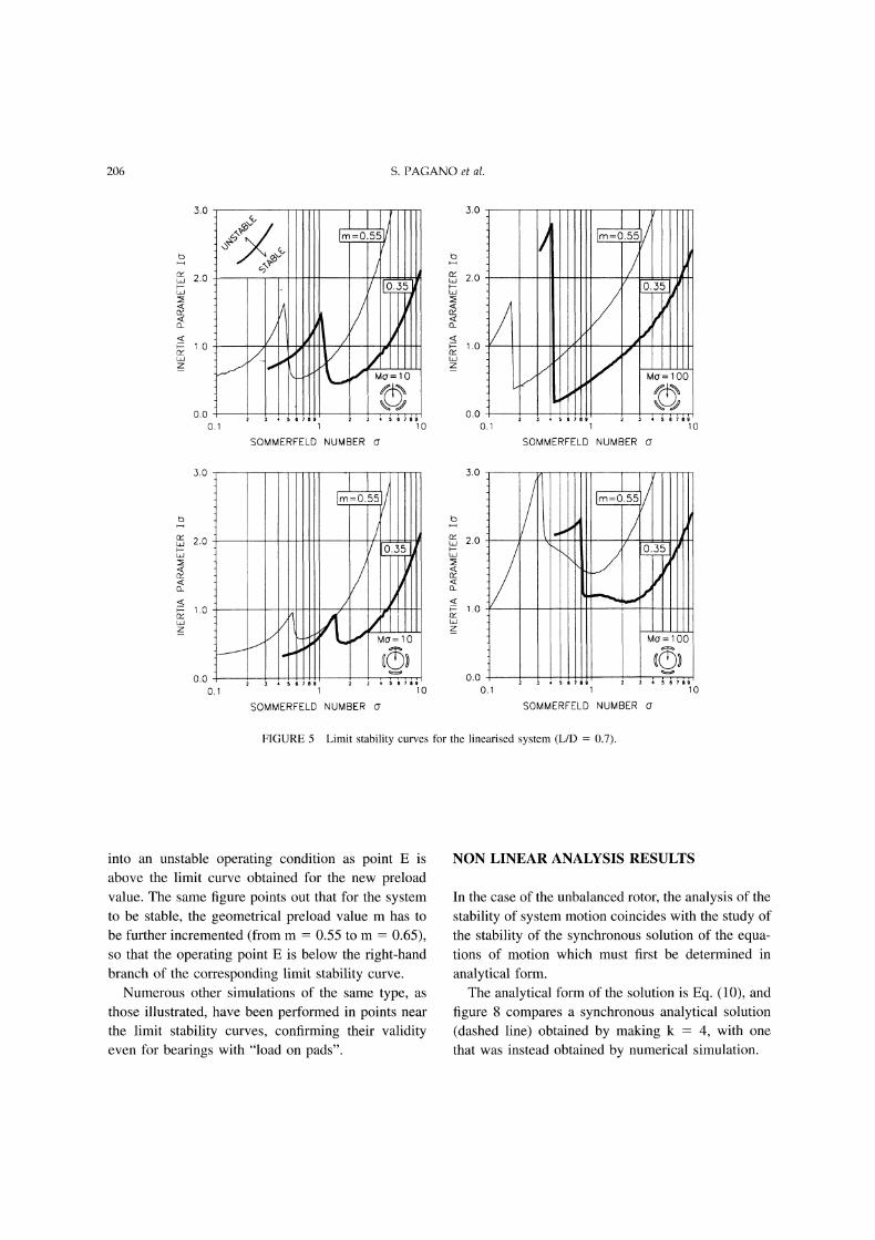
206 S. PAGANO et al.
3.0
I Uo’= 10
SOMMERFELD NUMBER
3.0
1.0
Z
0.0O.
100
SOMMERFELD NUMBER cr
3.0
1.0
Z
SOMMERFELD NUMBER O"
3.0
1.0
0.00.1
m=0.55
Mcr=lO0
SOMMERFELD NUMBER o-
FIGURE 5 Limit stability curves for the linearised system (L/D 0.7).
into an unstable operating condition as point E is
above the limit curve obtained for the new preloadvalue. The same figure points out that for the systemto be stable, the geometrical preload value m has to
be further incremented (from m 0.55 to m 0.65),so that the operating point E is below the right-handbranch of the corresponding limit stability curve.
Numerous other simulations of the same type, as
those illustrated, have been performed in points near
the limit stability curves, confirming their validityeven for bearings with "load on pads".
NON LINEAR ANALYSIS RESULTS
In the case of the unbalanced rotor, the analysis of the
stability of system motion coincides with the study ofthe stability of the synchronous solution of the equa-tions of motion which must first be determined in
analytical form.The analytical form of the solution is Eq. (10), and
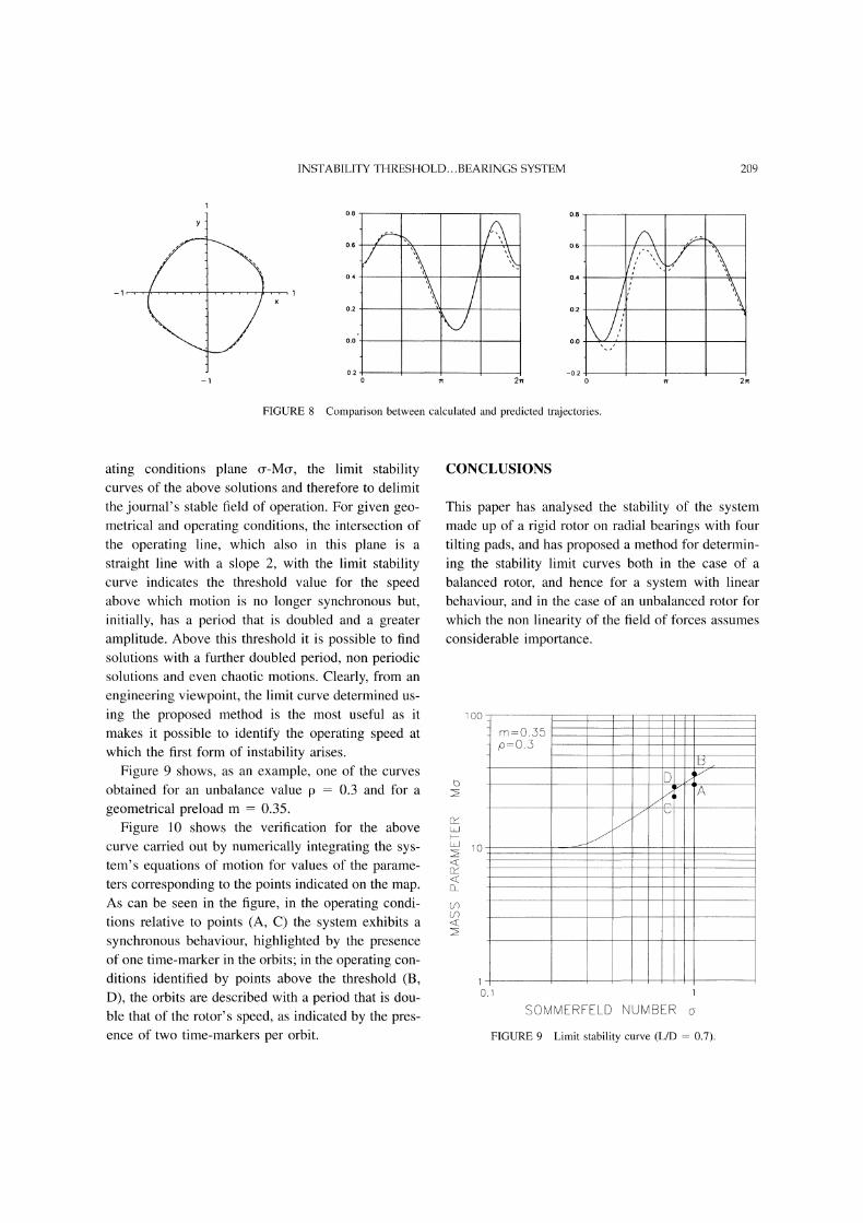
figure 8 compares a synchronous analytical solution
(dashed line) obtained by making k 4, with one
that was instead obtained by numerical simulation.
INSTABILITY THRESHOLD...BEARINGS SYSTEM 207
SOMMERFELD NUMBER
POINT A
POINT B
AAAo. Vtl v.
POINT C
-.2TIME
.5
./ "x .5
TIME
o. \..2
TIME
.5
TIME
IAIIAA .VV\ V
TIME
FIGURE 6 Journal orbits and pad oscillations for different operational conditions and: p 0; L/D 0.7; rn 0.35.
208 S. PAGANO et al.
POINT E=0.35
POINT Em=0.55
-.3
POINT Em=0.65
-.2
-.3
.2
-.2
..5/_z
/A2
A1
TIME
TIME
V A3
A A A
TME
o., A/\A AAA#A
TIME:
i’ooTIME
FIGURE 7 Journal orbits and pad oscillations for different geometrical preload values and: p 0; o- 0.7" Io- 0.7; L/D 0.7.
In the figure the solution is reported in the form ofthe orbital motion of the journal axis, with compo-nents x(T) and y(-), and of the oscillations of thepads; the trajectories obtained by numerical integra-tion do not include the initial transient. As can be
seen from the comparison, the approximated analyti-cal solution with four harmonics, determined usingthe described method, is excellent.The systematic study of the synchronous solutions
thus determined made it possible to plot, in the oper-
INSTABILITY THRESHOLD...BEARINGS SYSTEM 209
FIGURE 8
0.8 0.8
0.2 -0.22 2
Comparison between calculated and predicted trajectories.
ating conditions plane or-Me, the limit stabilitycurves of the above solutions and therefore to delimitthe journal’s stable field of operation. For given geo-metrical and operating conditions, the intersection ofthe operating line, which also in this plane is a
straight line with a slope 2, with the limit stabilitycurve indicates the threshold value for the speedabove which motion is no longer synchronous but,initially, has a period that is doubled and a greateramplitude. Above this threshold it is possible to findsolutions with a further doubled period, non periodicsolutions and even chaotic motions. Clearly, from an
engineering viewpoint, the limit curve determined us-
ing the proposed method is the most useful as itmakes it possible to identify the operating speed at
which the first form of instability arises.
Figure 9 shows, as an example, one of the curvesobtained for an unbalance value p 0.3 and for a
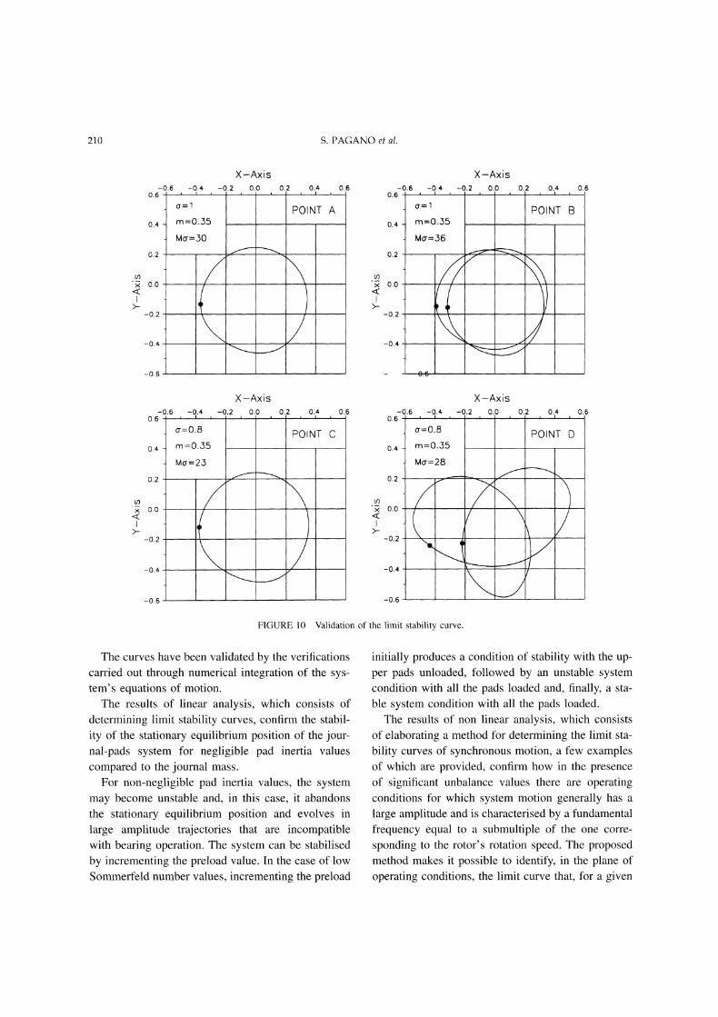
geometrical preload m 0.35.Figure 10 shows the verification for the above
curve carried out by numerically integrating the sys-tem’s equations of motion for values of the parame-ters corresponding to the points indicated on the map.As can be seen in the figure, in the operating condi-tions relative to points (A, C) the system exhibits a
synchronous behaviour, highlighted by the presenceof one time-marker in the orbits; in the operating con-
ditions identified by points above the threshold (B,D), the orbits are described with a period that is dou-ble that of the rotor’s speed, as indicated by the pres-ence of two time-markers per orbit.
CONCLUSIONS
This paper has analysed the stability of the systemmade up of a rigid rotor on radial bearings with four
tilting pads, and has proposed a method for determin-
ing the stability limit curves both in the case of a
balanced rotor, and hence for a system with linear
behaviour, and in the case of an unbalanced rotor forwhich the non linearity of the field of forces assumes
considerable importance.
100
10
m=0.35p=O.3
SOMMERFF-LD NUMBER
FIGURE 9 Limit stability curve (L/D 0.7).
210 S. PAGANO et al.
0.0
-0.2
-0.6
POINT A
-0.6 -0.4 -0.20.6-,
0"=1
o.4 m=0.55
M=36
0.2
o.o
-0.2
-0.4
X-Axis0.0 0.2 0.4 0.6
POINT B
X-Axis-0.6 -0.4 -0.2 0.0
0.6
G=0.8
0.4 m=0.35
Mo’=23
0.2
x 0.0
-0.2
-0.4
-0.6
0.2 0.4 0.6
POI NT C
X-Axis
o.o
-0.:2
-0.4
-0.6 -0.4 -0.2 0.00.6-
=0.8 POINT D0.4. m=0.35
Mo’=28
0.2 -’--"’- -’-"-’"
-0.6
O.2 0.4 0.6
FIGURE 10 Validation of the limit stability curve.
The curves have been validated by the verifications
carried out through numerical integration of the sys-tem’s equations of motion.
The results of linear analysis, which consists ofdetermining limit stability curves, confirm the stabil-
ity of the stationary equilibrium position of the jour-nal-pads system for negligible pad inertia valuescompared to the journal mass.
For non-negligible pad inertia values, the systemmay become unstable and, in this case, it abandonsthe stationary equilibrium position and evolves in
large amplitude trajectories that are incompatiblewith bearing operation. The system can be stabilised
by incrementing the preload value. In the case of lowSommerfeld number values, incrementing the preload
initially produces a condition of stability with the up-per pads unloaded, followed by an unstable systemcondition with all the pads loaded and, finally, a sta-
ble system condition with all the pads loaded.The results of non linear analysis, which consists
of elaborating a method for determining the limit sta-
bility curves of synchronous motion, a few examplesof which are provided, confirm how in the presenceof significant unbalance values there are operatingconditions for which system motion generally has a
large amplitude and is characterised by a fundamentalfrequency equal to a submultiple of the one corre-
sponding to the rotor’s rotation speed. The proposedmethod makes it possible to identify, in the plane of
operating conditions, the limit curve that, for a given

INSTABILITY THRESHOLD...BEARINGS SYSTEM 211
system, marks the passage from synchronous motionto motion with a fundamental frequency equal to halfthat of the synchronous one.
APPENDIX A
The analytical solution of the non linear system (6),which is necessarily approximated, is put in the form(10) in the text:
k
x(’r) x0 + [Xcj cos(j’r) + XsjSin(j’r)]j=l
k
y(’r)- Y0 + E [Ycj cos(jr) + ysjsin(jn-)]j=l
k
Ai(n- Ai0 + [Aic cosOn-) + Aisjsin(jn-)] (10)j=l
The expressions of the functions fx, fy and Tj which
appear in the equations of motion, if the solution is
periodic, are also periodic functions of the same pe-riod; they can thus be developed in Fourier series
stopping the series development at the terms of thesame order as that of the above solutions:
k
f(n-) qo + E [f,c cos(j’r) + fxsSin(jn’)]j=l
k
fy() fyo + E [fy cs0n) + fysin(jq-)]j=l
k
Ti(n’) Tio + [Tic cos0’r) + Tisjsin(j’r)]j=l
with:
(1A)
2qT
f fxd,r;2
0
fxcj27r
=--1 f fx cos(jr)dr;0
27r
f sin(j’r)d’r; etc.
By substituting (10) and (1A) into (6) gives the fol-lowing expressions"
k
M [j2(Xcj cos(j’r) + XsjSinOn-)) + fxo +j=l
k
[fcj cos(j’r) + fxsjSin(j’r)] + Mp cos(n-) 0j=l
k
M E [j2(Ycj cos(j’r) + YsSin(jn-))] + fyo +j=l
k
E [fyc3 cos(j’r) + fys3Sin(.jq)]1 + Mpsin(n-) 0
j=l O"
k
I [j2(Aic cosOn- + Aijsin(j)) + Tio +j=l
k
] [Tic cos0’r + Tisjsin(j’r)] 0j=l
(2A)
For each of Eqs. (2A), by grouping the terms in sine
and cosine of the same argument and making them
separately equal to zero, gives an algebraic system of
equations in the unknowns made up of the coeffi-cients of Eqs. (9). Therefore, by solving the above
system (in the paper the Newton-Raphson methodhas been adopted), the analytical expression of thelaw of motion is obtained.
APPENDIX B
Hill’s system of equations (11), at the instabilitythreshold of the trivial solution allows the periodicsolution:
8x(v) 8xo + l= 8x cos\2 + 8xsin 8x
8y(n-)- 8y0 +; 8ycj cos + 8ysjsin 2 8y
(IB)
Imposing equations (1B) as the approximated solu-tion of equations (11) gives the following expressionsfor the residuals, indicated symbolically with Vx(Saand Vy(Sa):
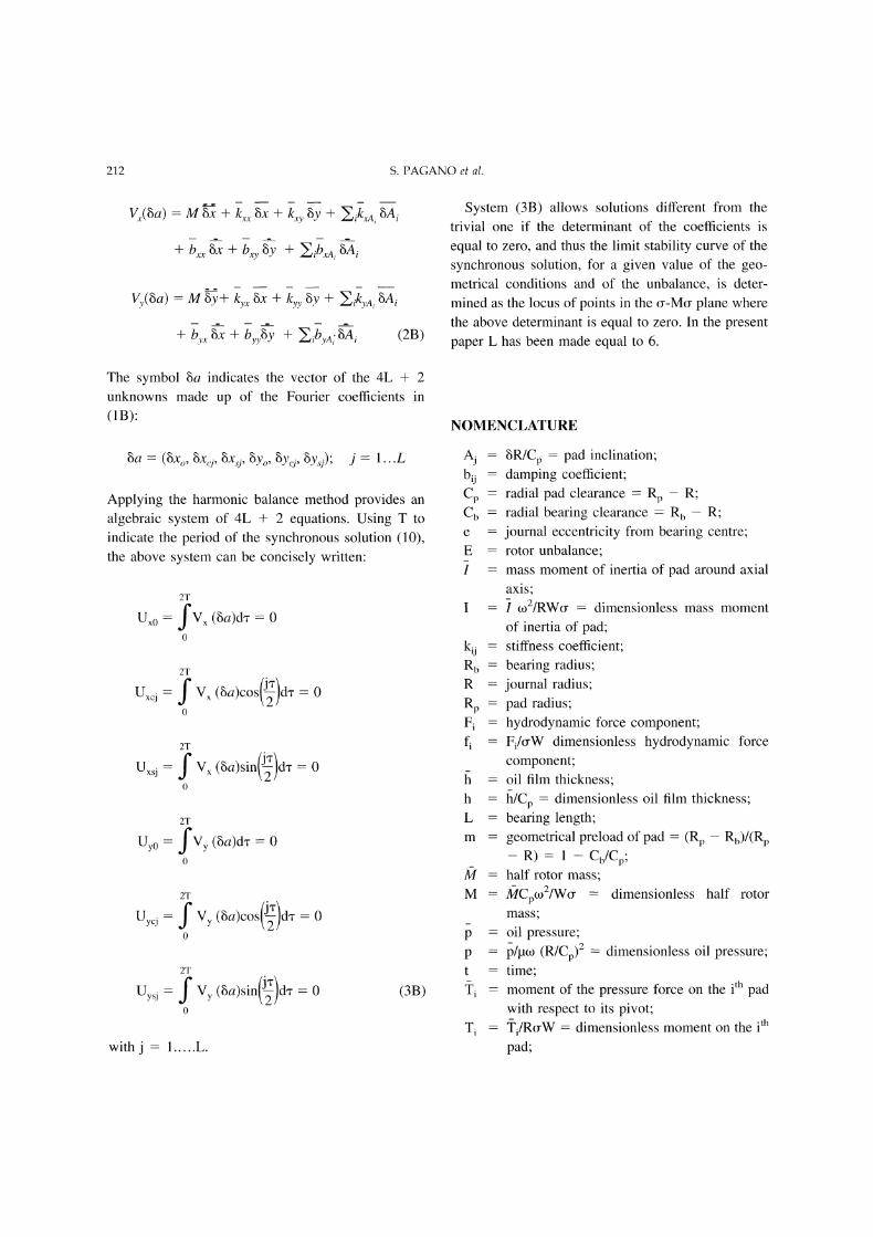
212 S. PAGANO et al.
Vx(a M -- + kxx gx + kxy y + EikxAi Aq- bLx gX q- b-xy -}- Eib--xAi A
Vy(8a)-M+ ky 8x + kyy 8y + ,ikyA, 8A
+ -y -- + -yy8--y + .i--yA;Ai (2B)
The symbol 8a indicates the vector of the 4L + 2unknowns made up of the Fourier coefficients in
(1B):
8a (8xo, 8xj, 8x,q, 8Yo, 8yj, 8Gj); j 1...L
Applying the harmonic balance method provides an
algebraic system of 4L + 2 equations. Using T to
indicate the period of the synchronous solution (10),the above system can be concisely written:
Ux0
Uxcj
Uxsj
Uyo
Uycj
Uysj
2T
fV (8a)dr 00
2T
V (8a)cos()d’r 0
2T
2T
fVy (8a)d’r0
=0
2T
-0
2T
(3B)
with L.
System (3B) allows solutions different from thetrivial one if the determinant of the coefficients is
equal to zero, and thus the limit stability curve of the
synchronous solution, for a given value of the geo-metrical conditions and of the unbalance, is deter-mined as the locus of points in the (r-Mo- plane wherethe above determinant is equal to zero. In the presentpaper L has been made equal to 6.
NOMENCLATURE
bijCpCb
EI
k0RbRRpFifi
8R/Cp pad inclination;damping coefficient;radial pad clearance Rp R;radial bearing clearance Rb R;journal eccentricity from bearing centre;rotor unbalance;mass moment of inertia of pad around axial
axis;to2/RW(r dimensionless mass moment
of inertia of pad;stiffness coefficient;bearing radius;
journal radius;pad radius;hydrodynamic force component;Fi/(rW dimensionless hydrodynamic forcecomponent;oil film thickness;
h/Cp dimensionless oil film thickness;bearing length;geometrical preload of pad (Rp Rb)/(Rp
R) Cb/Cp;half rotor mass;
CpmZ/W(r dimensionless half rotor
mass;oil pressure;/[.lm (R/Cp)2 dimensionless oil pressure;time;moment of the pressure force on the th padwith respect to its pivot;i/RcrW dimensionless moment on the th
pad;
INSTABILITY THRESHOLD...BEARINGS SYSTEM 213
W externally applied load;x,y,z coordinates;x fr/Cp, y f/Cp, z L dimensionless coor-
dinates;
[3 angular amplitude of pads;pad deflection angle;
e e/Cp bearing eccentricity ratio;3 circumferential coordinate;
%rpi circumferential coordinate of the th pivot;
a dynamic oil viscosity;v frequency;v ,2r/o dimensionless frequency;f) E/Cp dimensionless rotor unbalance;"r 0t dimensionless time;eo shaft angular speed;o- (oRL/W)(R/Cp)2 Sommerfeld number;(.) dimensionless time derivative.
Adams, M. L., Abu-Mahfouz, I. A. (1994) Exploratory research onchaos concepts as diagnostic tools for assessing rotating machin-eryvibrations signatures, proc. IFToMM.
Brancati, R., Russo, M., Russo, R. (1995) On the stability of peri-odic motions of an unbalanced rigid rotor on lubricated journalbearings--vol. 10, n.2 (1996) Non Linear Dynamics.
Holmes, R (1960) The vibration of a shaft on short sleeve bearings.Journ. of Mech. Sci, vol. 2, n.4, pp. 337-341.
Nayfeh, A. H., Mook, D. T. (1979) Non linear oscillations, JohnWiley & Sons.
Pagano, S., Rocca, E., Russo, M., Russo, R. (1995) Dynamic be-haviour of tilting-pad journal bearings. Proc. Inst. ofMechanicalEngineers’, vol. 209 pp. 275-285.
Pagano, S., Rocca, E., Russo, M. (1994) Sul comportamento insta-bile dei cuscinetti radiali a pattini oscillanti. Terzo ConvegnoAIMETA di Tribologia.
Russo, M., Russo, R. (1993) Parametric excitation instability of arigid unbalanced rotor in short turbulent journal bearings. Proc.Inst. Mech. Engrs, part C, vol. 207.
Szemplinska-Stupnicka, W. (1990) The Behavior of nonlinear vi-brating systems, Kluwer Academic Publishers, Dordrecht, Neth-erlands, (1990)
White, M. E, Chan, S. H. (1992) The subsynchronous dynamicbehaviour of tilting pad journal bearing. ASME Journal of Tri-bology, vol. 114/167.
ReferencesAdams, M. L., Payandeh, S. (1983) Self-Excited Vibration of Stat-
ically Unloaded Pads in Tilting-Pad Journal Bearings. ASMEJournal of Lubrication Technology, Vol. 105

EENNEERRGGYY MMAATTEERRIIAALLSSMaterials Science & Engineering for Energy Systems
Economic and environmental factors are creating ever greater pressures for theefficient generation, transmission and use of energy. Materials developments arecrucial to progress in all these areas: to innovation in design; to extending lifetimeand maintenance intervals; and to successful operation in more demandingenvironments. Drawing together the broad community with interests in theseareas, Energy Materials addresses materials needs in future energy generation,transmission, utilisation, conservation and storage. The journal covers thermalgeneration and gas turbines; renewable power (wind, wave, tidal, hydro, solar andgeothermal); fuel cells (low and high temperature); materials issues relevant tobiomass and biotechnology; nuclear power generation (fission and fusion);hydrogen generation and storage in the context of the ‘hydrogen economy’; andthe transmission and storage of the energy produced.
As well as publishing high-quality peer-reviewed research, Energy Materialspromotes discussion of issues common to all sectors, through commissionedreviews and commentaries. The journal includes coverage of energy economicsand policy, and broader social issues, since the political and legislative contextinfluence research and investment decisions.
SSUUBBSSCCRRIIPPTTIIOONN IINNFFOORRMMAATTIIOONNVolume 1 (2006), 4 issues per year Print ISSN: 1748-9237 Online ISSN: 1748-9245Individual rate: £76.00/US$141.00Institutional rate: £235.00/US$435.00Online-only institutional rate: £199.00/US$367.00For special IOM3 member rates please emailssuubbssccrriippttiioonnss@@mmaanneeyy..ccoo..uukk
EEDDIITTOORRSSDDrr FFuujjiioo AAbbeeNIMS, Japan
DDrr JJoohhnn HHaalldd, IPL-MPT,Technical University ofDenmark, Denmark
DDrr RR VViisswwaannaatthhaann, EPRI, USA
FFoorr ffuurrtthheerr iinnffoorrmmaattiioonn pplleeaassee ccoonnttaacctt::Maney Publishing UKTel: +44 (0)113 249 7481 Fax: +44 (0)113 248 6983 Email: [email protected] Publishing North AmericaTel (toll free): 866 297 5154 Fax: 617 354 6875 Email: [email protected]
For further information or to subscribe online please visitwwwwww..mmaanneeyy..ccoo..uukk
CCAALLLL FFOORR PPAAPPEERRSSContributions to the journal should be submitted online athttp://ema.edmgr.com
To view the Notes for Contributors please visit:www.maney.co.uk/journals/notes/ema
Upon publication in 2006, this journal will be available via theIngenta Connect journals service. To view free sample contentonline visit: wwwwww..iinnggeennttaaccoonnnneecctt..ccoomm//ccoonntteenntt//mmaanneeyy
NNEEWW
FFOORR 22000066
Maney Publishing on behalf of the Institute of Materials, Minerals and Mining