mitsubishi compact alternators and starter motors replacement ...
Upload
independentCategory
view
0download
0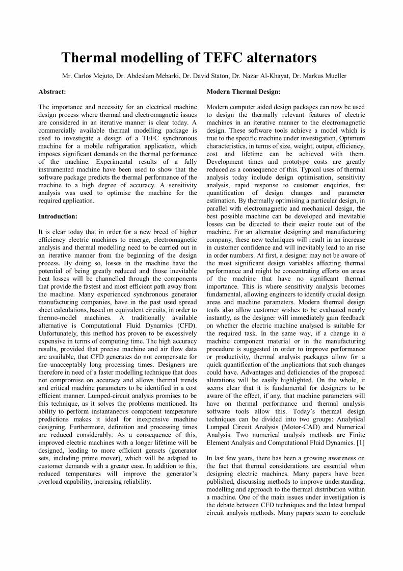
Thermal modelling of TEFC alternators Mr. Carlos Mejuto, Dr. Abdeslam Mebarki, Dr. David Staton, Dr. Nazar Al-Khayat, Dr. Markus Mueller
Abstract:
The importance and necessity for an electrical machine design process where thermal and electromagnetic issues are considered in an iterative manner is clear today. A commercially available thermal modelling package is used to investigate a design of a TEFC synchronous machine for a mobile refrigeration application, which imposes significant demands on the thermal performance of the machine. Experimental results of a fully instrumented machine have been used to show that the software package predicts the thermal performance of the machine to a high degree of accuracy. A sensitivity analysis was used to optimise the machine for the required application.
Introduction:
It is clear today that in order for a new breed of higher efficiency electric machines to emerge, electromagnetic analysis and thermal modelling need to be carried out in an iterative manner from the beginning of the design process. By doing so, losses in the machine have the potential of being greatly reduced and those inevitable heat losses will be channelled through the components that provide the fastest and most efficient path away from the machine. Many experienced synchronous generator manufacturing companies, have in the past used spread sheet calculations, based on equivalent circuits, in order to thermo-model machines. A traditionally available alternative is Computational Fluid Dynamics (CFD). Unfortunately, this method has proven to be excessively expensive in terms of computing time. The high accuracy results, provided that precise machine and air flow data are available, that CFD generates do not compensate for the unacceptably long processing times. Designers are therefore in need of a faster modelling technique that does not compromise on accuracy and allows thermal trends and critical machine parameters to be identified in a cost efficient manner. Lumped-circuit analysis promises to be this technique, as it solves the problems mentioned. Its ability to perform instantaneous component temperature predictions makes it ideal for inexpensive machine designing. Furthermore, definition and processing times are reduced considerably. As a consequence of this, improved electric machines with a longer lifetime will be designed, leading to more efficient gensets (generator sets, including prime mover), which will be adapted to customer demands with a greater ease. In addition to this, reduced temperatures will improve the generator’s overload capability, increasing reliability.
Modern Thermal Design: Modern computer aided design packages can now be used to design the thermally relevant features of electric machines in an iterative manner to the electromagnetic design. These software tools achieve a model which is true to the specific machine under investigation. Optimum characteristics, in terms of size, weight, output, efficiency, cost and lifetime can be achieved with them. Development times and prototype costs are greatly reduced as a consequence of this. Typical uses of thermal analysis today include design optimisation, sensitivity analysis, rapid response to customer enquiries, fast quantification of design changes and parameter estimation. By thermally optimising a particular design, in parallel with electromagnetic and mechanical design, the best possible machine can be developed and inevitable losses can be directed to their easier route out of the machine. For an alternator designing and manufacturing company, these new techniques will result in an increase in customer confidence and will inevitably lead to an rise in order numbers. At first, a designer may not be aware of the most significant design variables affecting thermal performance and might be concentrating efforts on areas of the machine that have no significant thermal importance. This is where sensitivity analysis becomes fundamental, allowing engineers to identify crucial design areas and machine parameters. Modern thermal design tools also allow customer wishes to be evaluated nearly instantly, as the designer will immediately gain feedback on whether the electric machine analysed is suitable for the required task. In the same way, if a change in a machine component material or in the manufacturing procedure is suggested in order to improve performance or productivity, thermal analysis packages allow for a quick quantification of the implications that such changes could have. Advantages and deficiencies of the proposed alterations will be easily highlighted. On the whole, it seems clear that it is fundamental for designers to be aware of the effect, if any, that machine parameters will have on thermal performance and thermal analysis software tools allow this. Today’s thermal design techniques can be divided into two groups: Analytical Lumped Circuit Analysis (Motor-CAD) and Numerical Analysis. Two numerical analysis methods are Finite Element Analysis and Computational Fluid Dynamics. [1] In last few years, there has been a growing awareness on the fact that thermal considerations are essential when designing electric machines. Many papers have been published, discussing methods to improve understanding, modelling and approach to the thermal distribution within a machine. One of the main issues under investigation is the debate between CFD techniques and the latest lumped circuit analysis methods. Many papers seem to conclude
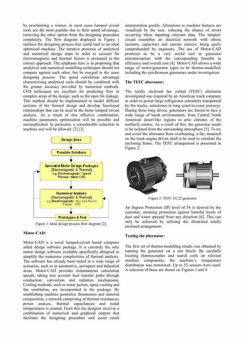
by proclaiming a winner, in most cases lumped circuit tools are the most popular due to their speed advantage, removing the other option from the designing procedure completely. The flow diagram displayed in Figure 1 outlines the designing process that could lead to an ideal optimised machine. The iterative presence of analytical and numerical design steps in order to account for electromagnetic and thermal factors is presented as the correct approach. The emphasis here is in proposing that analytical and numerical modelling techniques should not compete against each other, but be merged in the same designing process. The speed calculation advantage characterising analytical tools should be combined with the greater accuracy provided by numerical methods. CFD techniques are excellent for predicting flow in complex areas of the design, such as the open fin leakage. This method should be implemented to model difficult sections of the thermal design and develop functional relationships that can be used in the faster lumped circuit analysis. As a result of this effective combination, machine parameters optimisation will be possible and uncomplicated. In particular, a considerable reduction in machine size will be allowed. [2] [3]
Figure 1: Ideal design process flow diagram [2].
Motor-CAD: Motor-CAD is a novel lumped-circuit based computer aided design software package. It is currently the only motor design software available specifically designed to simplify the numerous complexities of thermal analysis. The software has already been tested in a wide range of scenarios, such as in automotive, aerospace and industrial areas. Motor-CAD provides instantaneous calculation speeds, taking into account heat transfer paths through conduction, convection and radiation mechanisms. Cooling methods, such as water jackets, spray cooling and fan ventilation, are incorporated in the package. By establishing machine geometric dimensions and material composition, a network comprising of thermal resistances, power sources, thermal capacitances and nodal temperatures is created. From this the designer receives a combination of numerical and graphical outputs that facilitate the designing procedure and assist result
interpretation greatly. Alterations to machine features are visualised by the user, reducing the chance of errors occurring when inputting relevant data. The lumped-circuit resembles an electrical network with ohmic resistors, capacitors and current sources, being easily comprehended by engineers. The use of Motor-CAD promises to be a very useful tool in generator miniaturisation, with the corresponding benefits in efficiency and overall cost [4]. Motor-CAD allows a wide range of motor/generator types to be thermo-modelled, including the synchronous generators under investigation. The TEFC alternator: The totally enclosed fan cooled (TEFC) alternator investigated was required by an American truck company in order to power large refrigerator containers transported by the trucks, sometimes in long coast-to-coast journeys. During these long drives, generators are forced to face a wide range of harsh environments, from Central North American desert-like regions to artic climates of the northerly estates. As a result of this, the generator needs to be isolated from the surrounding atmosphere [5]. To try and avoid the alternator from overheating, a fan, mounted on the truck engine driven shaft is be used to ventilate the enclosing frame. The TEFC arrangement is presented in Figure 2.
Figure 2: TEFC UC22 generator.
An Ingress Protection (IP) level of 54 is desired by the customer, meaning protection against harmful levels of dust and water sprayed from any direction [6]. This can only be achieved by utilising the illustrated totally enclosed arrangement. Testing the alternator:
The first set of thermo-modelling results was obtained by running the generator on a test bench. By carefully locating thermocouples and search coils on relevant machine components, the machine’s temperature distribution was monitored. Up to 52 sensors were used. A selection of these are shown on Figures 3 and 4
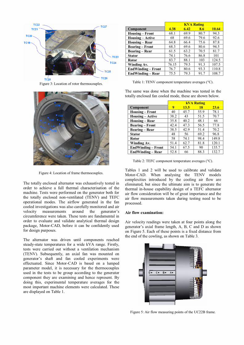
Figure 3: Location of rotor thermocouples.
Figure 4: Location of frame thermocouples.
The totally enclosed alternator was exhaustively tested in order to achieve a full thermal characterisation of the machine. Tests were performed on the generator both for the totally enclosed non-ventilated (TENV) and TEFC operational modes. The airflow generated in the fan cooled investigations was also carefully monitored and air velocity measurements around the generator’s circumference were taken. These tests are fundamental in order to evaluate and validate analytical thermal design package, Motor-CAD, before it can be confidently used for design purposes. The alternator was driven until components reached steady-state temperatures for a wide kVA range. Firstly, tests were carried out without a ventilation mechanism (TENV). Subsequently, an axial fan was mounted on generator’s shaft and fan cooled experiments were effectuated. Since Motor-CAD is based on a lumped parameter model, it is necessary for the thermocouples used in the tests to be group according to the generator component they are examining and hence represent. By doing this, experimental temperature averages for the most important machine elements were calculated. These are displayed on Table 1.
Table 1: TENV component temperature averages (°C).
The same was done when the machine was tested in the totally enclosed fan cooled mode, these are shown below.
Table 2: TEFC component temperature averages (°C).
Tables 1 and 2 will be used to calibrate and validate Motor-CAD. When analysing the TENV models complexities introduced by the cooling air flow are eliminated, but since the ultimate aim is to generate the thermal in-house capability design of a TEFC alternator air flow consideration will be of great importance and the air flow measurements taken during testing need to be processed. Air flow examination: Air velocity readings were taken at four points along the generator’s axial frame length, A, B, C and D as shown on Figure 5. Each of these points is a fixed distance from the end of the cowling, as shown on Table 3.
Figure 5: Air flow measuring points of the UC22B frame.
KVA Rating Component 4.38 6.42 8.6 10.64 Housing – Front 68.1 69.9 80.7 94.3 Housing – Active 68 69.6 79.6 92.6 Housing – Rear 64.8 66.4 75.6 87.8 Bearing – Front 68.3 69.6 80.6 94.5 Bearing – Rear 61.5 63.2 70.5 81.7 Stator 74.1 76.6 86.8 101 Rotor 83.7 88.1 103 124.5 Winding Av. 76.15 79.5 91.3 107.5 EndWinding – Front 76.7 80.6 93.3 110.8 EndWinding – Rear 75.5 79.3 91.7 108.7
kVA Rating Component 9 13.5 18 23.6 Housing – Front 40 45.7 55.9 78.1 Housing – Active 38.2 43 51.5 70.7 Housing – Rear 35.8 40.2 48.1 66 Bearing – Front 42.4 47.3 56.5 77.8 Bearing – Rear 38.5 42.9 51.4 70.2 Stator 48 56 69.2 96.8 Rotor 58 74.1 98.4 149.8 Winding Av. 51.4 62.7 81.8 120.1 EndWinding – Front 54.1 67.5 90 135.7 EndWinding – Rear 52.8 66 88.3 132.7
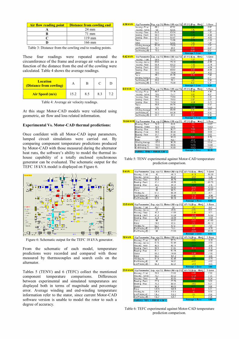
Table 3: Distance from the cowling end to reading points. These four readings were repeated around the circumference of the frame and average air velocities as a function of the distance from the end of the cowling were calculated. Table 4 shows the average readings.
Location (Distance from cowling) A B C D
Air Speed (m/s) 15.2 8.5 8.3 7.2
Table 4: Average air velocity readings. At this stage Motor-CAD models were validated using geometric, air flow and loss related information. Experimental Vs. Motor-CAD thermal predictions: Once confident with all Motor-CAD input parameters, lumped circuit simulations were carried out. By comparing component temperature predictions produced by Motor-CAD with those measured during the alternator heat runs, the software’s ability to model the thermal in-house capability of a totally enclosed synchronous generator can be evaluated. The schematic output for the TEFC 18 kVA model is displayed on Figure 6.
Figure 6: Schematic output for the TEFC 18 kVA generator. From the schematic of each model, temperature predictions were recorded and compared with those measured by thermocouples and search coils on the alternator. Tables 5 (TENV) and 6 (TEFC) collect the mentioned component temperature comparisons. Differences between experimental and simulated temperatures are displayed both in terms of magnitude and percentage error. Average winding and end-winding temperature information refer to the stator, since current Motor-CAD software version is unable to model the rotor to such a degree of accuracy.
Table 5: TENV experimental against Motor-CAD temperature
prediction comparison.
Table 6: TEFC experimental against Motor-CAD temperature prediction comparison.
Air flow reading point Distance from cowling end A 24 mm B 71 mm C 119 mm D 166 mm
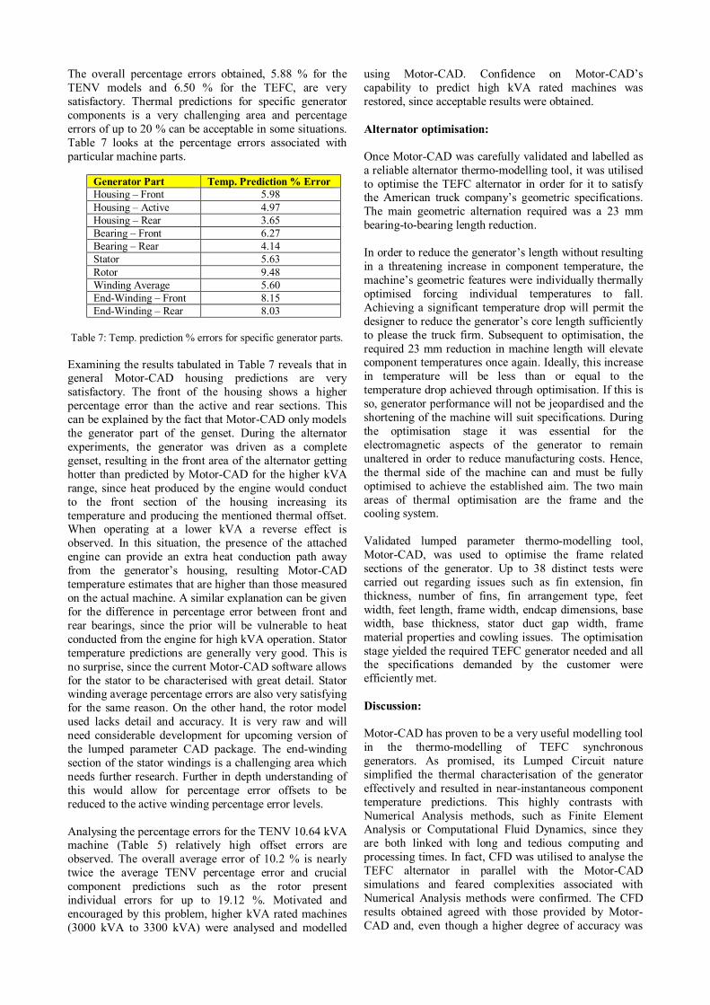
The overall percentage errors obtained, 5.88 % for the TENV models and 6.50 % for the TEFC, are very satisfactory. Thermal predictions for specific generator components is a very challenging area and percentage errors of up to 20 % can be acceptable in some situations. Table 7 looks at the percentage errors associated with particular machine parts.
Table 7: Temp. prediction % errors for specific generator parts.
Examining the results tabulated in Table 7 reveals that in general Motor-CAD housing predictions are very satisfactory. The front of the housing shows a higher percentage error than the active and rear sections. This can be explained by the fact that Motor-CAD only models the generator part of the genset. During the alternator experiments, the generator was driven as a complete genset, resulting in the front area of the alternator getting hotter than predicted by Motor-CAD for the higher kVA range, since heat produced by the engine would conduct to the front section of the housing increasing its temperature and producing the mentioned thermal offset. When operating at a lower kVA a reverse effect is observed. In this situation, the presence of the attached engine can provide an extra heat conduction path away from the generator’s housing, resulting Motor-CAD temperature estimates that are higher than those measured on the actual machine. A similar explanation can be given for the difference in percentage error between front and rear bearings, since the prior will be vulnerable to heat conducted from the engine for high kVA operation. Stator temperature predictions are generally very good. This is no surprise, since the current Motor-CAD software allows for the stator to be characterised with great detail. Stator winding average percentage errors are also very satisfying for the same reason. On the other hand, the rotor model used lacks detail and accuracy. It is very raw and will need considerable development for upcoming version of the lumped parameter CAD package. The end-winding section of the stator windings is a challenging area which needs further research. Further in depth understanding of this would allow for percentage error offsets to be reduced to the active winding percentage error levels. Analysing the percentage errors for the TENV 10.64 kVA machine (Table 5) relatively high offset errors are observed. The overall average error of 10.2 % is nearly twice the average TENV percentage error and crucial component predictions such as the rotor present individual errors for up to 19.12 %. Motivated and encouraged by this problem, higher kVA rated machines (3000 kVA to 3300 kVA) were analysed and modelled
using Motor-CAD. Confidence on Motor-CAD’s capability to predict high kVA rated machines was restored, since acceptable results were obtained. Alternator optimisation: Once Motor-CAD was carefully validated and labelled as a reliable alternator thermo-modelling tool, it was utilised to optimise the TEFC alternator in order for it to satisfy the American truck company’s geometric specifications. The main geometric alternation required was a 23 mm bearing-to-bearing length reduction. In order to reduce the generator’s length without resulting in a threatening increase in component temperature, the machine’s geometric features were individually thermally optimised forcing individual temperatures to fall. Achieving a significant temperature drop will permit the designer to reduce the generator’s core length sufficiently to please the truck firm. Subsequent to optimisation, the required 23 mm reduction in machine length will elevate component temperatures once again. Ideally, this increase in temperature will be less than or equal to the temperature drop achieved through optimisation. If this is so, generator performance will not be jeopardised and the shortening of the machine will suit specifications. During the optimisation stage it was essential for the electromagnetic aspects of the generator to remain unaltered in order to reduce manufacturing costs. Hence, the thermal side of the machine can and must be fully optimised to achieve the established aim. The two main areas of thermal optimisation are the frame and the cooling system. Validated lumped parameter thermo-modelling tool, Motor-CAD, was used to optimise the frame related sections of the generator. Up to 38 distinct tests were carried out regarding issues such as fin extension, fin thickness, number of fins, fin arrangement type, feet width, feet length, frame width, endcap dimensions, base width, base thickness, stator duct gap width, frame material properties and cowling issues. The optimisation stage yielded the required TEFC generator needed and all the specifications demanded by the customer were efficiently met. Discussion: Motor-CAD has proven to be a very useful modelling tool in the thermo-modelling of TEFC synchronous generators. As promised, its Lumped Circuit nature simplified the thermal characterisation of the generator effectively and resulted in near-instantaneous component temperature predictions. This highly contrasts with Numerical Analysis methods, such as Finite Element Analysis or Computational Fluid Dynamics, since they are both linked with long and tedious computing and processing times. In fact, CFD was utilised to analyse the TEFC alternator in parallel with the Motor-CAD simulations and feared complexities associated with Numerical Analysis methods were confirmed. The CFD results obtained agreed with those provided by Motor-CAD and, even though a higher degree of accuracy was
Generator Part Temp. Prediction % Error Housing – Front 5.98 Housing – Active 4.97 Housing – Rear 3.65 Bearing – Front 6.27 Bearing – Rear 4.14 Stator 5.63 Rotor 9.48 Winding Average 5.60 End-Winding – Front 8.15 End-Winding – Rear 8.03
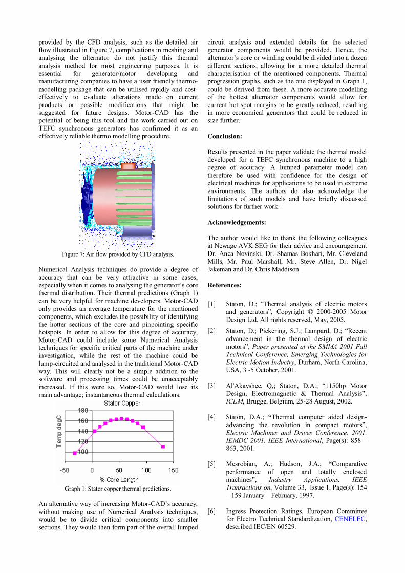
provided by the CFD analysis, such as the detailed air flow illustrated in Figure 7, complications in meshing and analysing the alternator do not justify this thermal analysis method for most engineering purposes. It is essential for generator/motor developing and manufacturing companies to have a user friendly thermo-modelling package that can be utilised rapidly and cost-effectively to evaluate alterations made on current products or possible modifications that might be suggested for future designs. Motor-CAD has the potential of being this tool and the work carried out on TEFC synchronous generators has confirmed it as an effectively reliable thermo modelling procedure.
Figure 7: Air flow provided by CFD analysis.
Numerical Analysis techniques do provide a degree of accuracy that can be very attractive in some cases, especially when it comes to analysing the generator’s core thermal distribution. Their thermal predictions (Graph 1) can be very helpful for machine developers. Motor-CAD only provides an average temperature for the mentioned components, which excludes the possibility of identifying the hotter sections of the core and pinpointing specific hotspots. In order to allow for this degree of accuracy, Motor-CAD could include some Numerical Analysis techniques for specific critical parts of the machine under investigation, while the rest of the machine could be lump-circuited and analysed in the traditional Motor-CAD way. This will clearly not be a simple addition to the software and processing times could be unacceptably increased. If this were so, Motor-CAD would lose its main advantage; instantaneous thermal calculations.
Graph 1: Stator copper thermal predictions.
An alternative way of increasing Motor-CAD’s accuracy, without making use of Numerical Analysis techniques, would be to divide critical components into smaller sections. They would then form part of the overall lumped
circuit analysis and extended details for the selected generator components would be provided. Hence, the alternator’s core or winding could be divided into a dozen different sections, allowing for a more detailed thermal characterisation of the mentioned components. Thermal progression graphs, such as the one displayed in Graph 1, could be derived from these. A more accurate modelling of the hottest alternator components would allow for current hot spot margins to be greatly reduced, resulting in more economical generators that could be reduced in size further. Conclusion: Results presented in the paper validate the thermal model developed for a TEFC synchronous machine to a high degree of accuracy. A lumped parameter model can therefore be used with confidence for the design of electrical machines for applications to be used in extreme environments. The authors do also acknowledge the limitations of such models and have briefly discussed solutions for further work. Acknowledgements: The author would like to thank the following colleagues at Newage AVK SEG for their advice and encouragement Dr. Anca Novinski, Dr. Shamas Bokhari, Mr. Cleveland Mills, Mr. Paul Marshall, Mr. Steve Allen, Dr. Nigel Jakeman and Dr. Chris Maddison. References:
[1] Staton, D.; “Thermal analysis of electric motors and generators”, Copyright © 2000-2005 Motor Design Ltd. All rights reserved, May, 2005.
[2] Staton, D.; Pickering, S.J.; Lampard, D.; “Recent advancement in the thermal design of electric motors”, Paper presented at the SMMA 2001 Fall Technical Conference, Emerging Technologies for Electric Motion Inductry, Durham, North Carolina, USA, 3 -5 October, 2001.
[3] Al'Akayshee, Q,; Staton, D.A.; “1150hp Motor
Design, Electromagnetic & Thermal Analysis”, ICEM, Brugge, Belgium, 25-28 August, 2002.
[4] Staton, D.A.; “Thermal computer aided design-
advancing the revolution in compact motors”, Electric Machines and Drives Conference, 2001. IEMDC 2001. IEEE International, Page(s): 858 – 863, 2001.
[5] Mesrobian, A.; Hudson, J.A.; “Comparative
performance of open and totally enclosed machines”, Industry Applications, IEEE Transactions on, Volume 33, Issue 1, Page(s): 154 – 159 January – February, 1997.
[6] Ingress Protection Ratings, European Committee
for Electro Technical Standardization, CENELEC, described IEC/EN 60529.
Copyright © 2022 FDOKUMEN