Thermal and mechanical properties of phenolic-based composites reinforced by carbon fibres and...
10
Thermal and mechanical properties of phenolic-based composites reinforced by carbon fibres and multiwall carbon nanotubes Zahra Eslami, Farshad Yazdani ⇑ , Mir Aidin Mirzapour Chemistry and Chemical Engineering Research Center of Iran, P.O. Box 14335-186, Tehran, Iran article info Article history: Received 9 July 2014 Received in revised form 7 January 2015 Accepted 10 January 2015 Available online 29 January 2015 Keywords: A. Polymer-matrix composites (PMCs) B. High-temperature properties B. Mechanical properties D. Electron microscopy abstract The thermal, mechanical and ablation properties of carbon fibre/phenolic composites filled with multi- wall carbon nanotubes (MWCNTs) were investigated. Carbon fibre/phenolic/MWCNTs were prepared using different weight percentage of MWCNTs by compression moulding. The samples were character- ized by scanning electron microscopy (SEM), flexural tests, thermal gravimetric analysis and oxy- acetylene torch tests. The thermal stability and flexural properties of the nanocomposites increased by increasing MWCNTs content (wt% 61), but they decreased when the content of MWCNTs was 2 wt%. The linear and mass ablation rates of the nanocomposites after modified with 1 wt% MWCNTs decreased by about 80% and 52%, respectively. To investigate the material post-test microstructure, a morphological characterization was carried out using SEM. It was shown that the presence of MWCNTs in the composite led to the formation of a strong network char layer without any cracks or opening. Ó 2015 Elsevier Ltd. All rights reserved. 1. Introduction In recent years, carbon fibre/phenolic composites modified with nanomaterial have attracted great interest in the field of advanced, high-performance materials and structures. Specifically, they are so used in the aerospace applications where most of the ceramic and metallic materials cannot be used [1–4]. Ablative materials protect the space vehicle from the huge amount of heat produced by the friction of the atmosphere, with adsorbing the heat and avoiding its transfer to the interior parts [5–8]. Phenolic resin, which is the first synthetic thermoset polymer, due to the low flammability, high char yield, remarkable thermal insulation and good thermal stability is an attractive candidate for use as ablative material [9,10]. The char so formed plays a crucial role in the abla- tion behavior because it reduces pyrolysis rate by reemitting large amount of incident radiation into gas phase [9,11,12]. However, even in the presence of fibrous reinforcement, a char layer may be mechanically removed by shear force in high pressure and velo- city condition [13–15]. To resolve these problems, several kinds of nanosized reinforcements have been evaluated on carbon fibre/ phenolic composites. Different kinds of nanoparticles, such as nanosilica, montmorillonite organoclays, carbon nanofibres and carbon nanotubes (CNTs) have been studied to improve the ther- mal behavior of polymer composites [12,13]. Natali et al. have studied synthesis and thermal characteriza- tion of phenolic resin/silica composites prepared with high shear rate-mixing technique. The results of this study showed that all the produced composites exhibit a better thermal stability than the pristine matrix [16]. Mirzapour et al. studied the effect of nano- silica on the ablation and thermal properties of carbon fibre/phe- nolic composites. They observed better thermal stability and ablation response in nano-modified samples [17]. Among the nano-additives, CNTs are increasingly considered to be unique reinforcement fillers for making polymer based compos- ites [10,18]. Due to the excellent thermal, mechanical and electri- cal properties and high aspect ratio of CNTs, only a small amount of them in the polymer matrix can significantly improve the prop- erties of the composites [19]. In order to achieve improvement as elevated as possible, homogeneous dispersion of CNTs and strong interaction between CNT and surrounding matrix are required. Due to the agglomeration tendency of the CNTs, uniform disper- sion of them in the phenolic resin, is a highly challenging task [18–21]. The addition of CNTs in flame retardant polymers has been recently explored by some researchers. They studied the effects of CNTs on the flammability of the polymers such as poly- styrene, epoxy, poly methyl methacrylate and polypropylene [22–25]. However, while various polymers have been comprehen- sively investigated as matrices to prepare the CNT-filled compos- ites, little attention has been paid to the research on phenolic http://dx.doi.org/10.1016/j.compositesa.2015.01.015 1359-835X/Ó 2015 Elsevier Ltd. All rights reserved. ⇑ Corresponding author. Tel.: +98 2144580774. E-mail addresses: [email protected] (F. Yazdani), aidinmirzapour1@gmail. com (M.A. Mirzapour). Composites: Part A 72 (2015) 22–31 Contents lists available at ScienceDirect Composites: Part A journal homepage: www.elsevier.com/locate/compositesa
-
Upload
independent -
Category
Documents
-
view
3 -
download
0
Transcript of Thermal and mechanical properties of phenolic-based composites reinforced by carbon fibres and...

Composites: Part A 72 (2015) 22–31
Contents lists available at ScienceDirect
Composites: Part A
journal homepage: www.elsevier .com/locate /composi tesa
Thermal and mechanical properties of phenolic-based compositesreinforced by carbon fibres and multiwall carbon nanotubes
http://dx.doi.org/10.1016/j.compositesa.2015.01.0151359-835X/� 2015 Elsevier Ltd. All rights reserved.
⇑ Corresponding author. Tel.: +98 2144580774.E-mail addresses: [email protected] (F. Yazdani), aidinmirzapour1@gmail.
com (M.A. Mirzapour).
Zahra Eslami, Farshad Yazdani ⇑, Mir Aidin MirzapourChemistry and Chemical Engineering Research Center of Iran, P.O. Box 14335-186, Tehran, Iran
a r t i c l e i n f o a b s t r a c t
Article history:Received 9 July 2014Received in revised form 7 January 2015Accepted 10 January 2015Available online 29 January 2015
Keywords:A. Polymer-matrix composites (PMCs)B. High-temperature propertiesB. Mechanical propertiesD. Electron microscopy
The thermal, mechanical and ablation properties of carbon fibre/phenolic composites filled with multi-wall carbon nanotubes (MWCNTs) were investigated. Carbon fibre/phenolic/MWCNTs were preparedusing different weight percentage of MWCNTs by compression moulding. The samples were character-ized by scanning electron microscopy (SEM), flexural tests, thermal gravimetric analysis and oxy-acetylene torch tests. The thermal stability and flexural properties of the nanocomposites increased byincreasing MWCNTs content (wt% 61), but they decreased when the content of MWCNTs was 2 wt%.The linear and mass ablation rates of the nanocomposites after modified with 1 wt% MWCNTs decreasedby about 80% and 52%, respectively. To investigate the material post-test microstructure, a morphologicalcharacterization was carried out using SEM. It was shown that the presence of MWCNTs in the compositeled to the formation of a strong network char layer without any cracks or opening.
� 2015 Elsevier Ltd. All rights reserved.
1. Introduction
In recent years, carbon fibre/phenolic composites modified withnanomaterial have attracted great interest in the field of advanced,high-performance materials and structures. Specifically, they areso used in the aerospace applications where most of the ceramicand metallic materials cannot be used [1–4]. Ablative materialsprotect the space vehicle from the huge amount of heat producedby the friction of the atmosphere, with adsorbing the heat andavoiding its transfer to the interior parts [5–8]. Phenolic resin,which is the first synthetic thermoset polymer, due to the lowflammability, high char yield, remarkable thermal insulation andgood thermal stability is an attractive candidate for use as ablativematerial [9,10]. The char so formed plays a crucial role in the abla-tion behavior because it reduces pyrolysis rate by reemitting largeamount of incident radiation into gas phase [9,11,12]. However,even in the presence of fibrous reinforcement, a char layer maybe mechanically removed by shear force in high pressure and velo-city condition [13–15]. To resolve these problems, several kinds ofnanosized reinforcements have been evaluated on carbon fibre/phenolic composites. Different kinds of nanoparticles, such asnanosilica, montmorillonite organoclays, carbon nanofibres and
carbon nanotubes (CNTs) have been studied to improve the ther-mal behavior of polymer composites [12,13].
Natali et al. have studied synthesis and thermal characteriza-tion of phenolic resin/silica composites prepared with high shearrate-mixing technique. The results of this study showed that allthe produced composites exhibit a better thermal stability thanthe pristine matrix [16]. Mirzapour et al. studied the effect of nano-silica on the ablation and thermal properties of carbon fibre/phe-nolic composites. They observed better thermal stability andablation response in nano-modified samples [17].
Among the nano-additives, CNTs are increasingly considered tobe unique reinforcement fillers for making polymer based compos-ites [10,18]. Due to the excellent thermal, mechanical and electri-cal properties and high aspect ratio of CNTs, only a small amountof them in the polymer matrix can significantly improve the prop-erties of the composites [19]. In order to achieve improvement aselevated as possible, homogeneous dispersion of CNTs and stronginteraction between CNT and surrounding matrix are required.Due to the agglomeration tendency of the CNTs, uniform disper-sion of them in the phenolic resin, is a highly challenging task[18–21]. The addition of CNTs in flame retardant polymers hasbeen recently explored by some researchers. They studied theeffects of CNTs on the flammability of the polymers such as poly-styrene, epoxy, poly methyl methacrylate and polypropylene[22–25]. However, while various polymers have been comprehen-sively investigated as matrices to prepare the CNT-filled compos-ites, little attention has been paid to the research on phenolic

Z. Eslami et al. / Composites: Part A 72 (2015) 22–31 23
resin; this is maybe due to the difficulties of processing of this resin[10]. Natali et al. studied the thermal and the ablative properties ofhighly loaded (50 wt%, and in absence of fibre reinforcement) car-bon black (CB) and multiwall carbon nanotubes (MWCNTs) basedphenolic resin (PR) composites. They found the PR–MWCNTsexhibited higher erosion rate as compared to PR–CB [13].
To the best of our knowledge, few works have been conductedon the thermal stability, microstructure and ablation behaviors ofcomposites containing MWCNTs additive. Also, no specific investi-gation on formation mechanism of a char layer during the ablationtest has been done. The major objective of this research is to devel-op advanced composite material that has significant improvementcompared to pure carbon fibre/phenolic composite. This paperinvestigated the effects of different percentages of MWCNTs onthe thermal stability, mechanical and ablation properties of carbonfibre/phenolic composites by thermogravimetric analysis (TGA),bending test and oxyacetylene torch test, respectively. Further-more, the ablation mechanism of composites was studied by scan-ning electron microscopy (SEM) observation of the morphology ofthe char layer.
2. Experimental
2.1. Materials
Resol-type phenolic resin (IL800/2, Resitan, Co) with a solidscontent of about 87% and density 1.2 g/cm3 was used as a matrix.The viscosity of liquid resin at 20 �C was 600–800 MPa s. The car-boxylated MWCNTs consist of more than 95% carbon basis andwith a length of 10–20 lm and a diameter of 10–15 nm was usedas additive. They were produced by chemical vapor depositionmethod (CVD) and were supplied by Arkema. The chopped strandssupplied by UVICOM, was used as the reinforcing material, andconsisted of rayon-based carbon filaments with a nominal lengthof 5 mm, diameter 7 lm. For dispersion of the MWCNTs in water,sodium dodecyl sulfate (SDS) was used as an anionic surfactant,which was supplied by Sigma–Aldrich.
2.2. Preparation of nanocomposites
2.2.1. Dispersion of MWCNTs into phenolic resinThe selected amount of MWCNTs was weighted and dispersed
into water by a high-intensity ultrasonic horn (20 kHz, 50 watts)in 0.5 h. In order to obtain uniform dispersion of MWCNTs in phe-nolic resin, surfactant was added with SDS/MWCNTs ratio of 1/1 bymass fraction and sonicated for 0.5 h. To avoid overheating of themixture caused by the sonication, a water cooling system wasused. In the next step, the phenolic resin was blended with theMWCNTs and stirred in 500 rpm for 1 h. The MWCNTs/phenolicmixture was heated to 70 �C to remove the solvent.
2.2.2. Moulding compound preparationThe next step of preparation process was the production of Bulk
Moulding Compound (BMC). In all samples, the fibre amount waskept constant at a value equal to 50 wt%. Therefore, the final
Table 1Composition, density and porosity of the samples.
Samples Content of CNT (wt%) Resin (wt%) Ca
C-0 0 50 50C-0.25 0.25 49.75 50C-0.5 0.5 49.5 50C-1 1 49 50C-2 2 48 50
MWCNTs load on the whole weight was 2 wt% (C-2) when adding50 wt% of the highest filled composite. In order to further investi-gate the effects of MWCNTs, three other composite recipes con-taining a MWCNTs percentage equal to 0.25 wt% (C-0.25),0.5 wt% (C-0.5) and 1 wt% (C-1) of the whole amount were studied.Finally, a BMC recipe prepared without MWCNTs was used as acontrol material (C-0). A summary of the compositions of all theevaluated recipes are shown in Table 1. The preparation of theBMC pastes was as follows. First, a theoretical amount of choppedcarbon fibres was weighed and then the fibres were mixed withthe resin or the produced nanocomposites. Mixing operations werecarried out manually in order to completely open the chopped fibrebundles.
2.2.3. Compression mouldingThe BMC paste was moulded by compression moulding using
an automatic hydraulic compression press. Each paste was placedin a cylindrical shaped mould and in the first step, the pasteswas compression moulded at a pressure of about 1 bar, tem-perature of the mould was 100 �C and remained at this tem-perature for half an hour. Then the mould was opened up to exitgenerated vapors. In the second step, the BMC paste was compres-sion moulded at a pressure of about 10 bar, at the same time, a cur-ing cycle of 5 h at 170 �C was applied. To achieve a good cross-linked composite, all samples were post-cured at 200 �C for 2 h[17,26]. The diameter and thickness of obtaining composites were250 and 6.5 mm, respectively. The apparent density (overall mass-to-volume ratio) and porosity of the samples are listed in Table 1.Nanocomposite has not shown significant variation in density andporosity as compared to blank composite, indicating good com-pressibility of the nanocomposites. All the composites were cutinto require size for the experimental purpose.
2.3. Measurement and characterization
2.3.1. Thermal stability testThe thermal stability of the composite was evaluated by the
weight loss in a NETZSCH TG 209 F1 Iris thermogravimetric analyz-er with a heating rate of 10 �C/min in air environment. Before theTGA analysis, the temperature was held constant at 100 �C for30 min, to remove any moisture trapped in the sample. The TGAwas performed using specimens with weight approximately 6–7 mg, from ambient temperature up to 900 �C.
2.3.2. Ablation testTo study the ablation behavior of the composites, the severe
hyperthermia environment was simulated by the oxyacetylenetorch test according to ASTM E285-80 standard. Plate test sampleswere about 90 � 90 mm in size and 6.5 mm in thickness. The dis-tance and the angle between the torch tip and the sample surfacewere 20 mm and 90�, respectively. This device is able to producehigh temperature flame approximately 3000 �C and also high heatflux about 850 W/cm2.
For this experiment, all samples were tested until the speci-mens were burnt through. Although pure composite was burntthrough after 190s, nanocomposites were not burnt through even
rbon fibre (wt%) Sample density (g/cm3) Porosity (%)
1.345 2.561.339 2.711.336 2.661.319 2.591.306 2.62

Fig. 1. Schematic for calculating linear ablation rate.
24 Z. Eslami et al. / Composites: Part A 72 (2015) 22–31
after 300s. In order to measure the linear and mass ablation rates,thickness and mass changes of all samples during the test weredivided into the exposure time. To calculate the linear ablationrate, only the thickness of virgin material, excluding char thicknesswas measured. The linear ablation rate (Rl) was calculated by fol-lowing equation,
Rl ¼ðh0 � hÞ
tð1Þ
where h0 and h are the original height of the sample and the dis-tance from the bottom to the lowest point on the surface, respec-tively, and t is the ablation time. The schematic illustration forcalculating linear ablation rate is presented in Fig. 1. The final abla-tion rates of each specimen were the average ablation rates of fivespecimens.
2.3.3. Mechanical testTo study the mechanical properties of the composites, 3-points
bending test was conducted on the composite specimens by ahydraulic testing machine (Instron 6025, England) according toASTM D7264 standard. The ultimate bending results of compositeswere average data of six individual tests.
Fig. 2. SEM image of the fracture surface of the composite without MWCNTs.
2.3.4. CharacterizationThe observation of the composite microstructure both on the
pristine and on the burnt samples was accomplished by scanningelectron microscopy (SEM) in a Vega2/Tescan. To prepare the
Fig. 3. SEM image of the fracture surface of the composites: (a) C-0.25
SEM samples, the fracture surface of samples was sputter coatedwith gold.
3. Result and discussion
3.1. Morphological characterization
The dispersion behavior of the carbon nanotubes was investi-gated by means of SEM analysis. Figs. 2 and 3 show the SEMmicrophotographs of the fractured surface of the pure compositesand nanocomposites, respectively.
, (b) C-0.5, (c) C-1 and (d) C-2 (MWCNTs are shown with arrows).
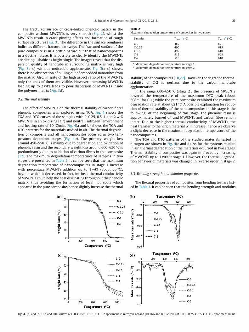
Table 2Maximum degradation temperature of composites in two stages.
Samples Tmax,1a (�C) Tmax,2
b (�C)
C-0 480 621C-0.25 490 615C-0.5 495 610C-1 515 608C-2 510 610
a Maximum degradation temperature in stage 1.b Maximum degradation temperature in stage 2.
Z. Eslami et al. / Composites: Part A 72 (2015) 22–31 25
The fractured surface of cross-linked phenolic matrix in thecomposite without MWCNTs is very smooth (Fig. 2), whilst theMWCNTs result in crack pinning effects and formation of roughsurface structures (Fig. 3). The difference in the surface roughnessindicates different fracture pathways. The fractured surface of thepure composite is in a brittle nature but that of nanocompositesin a ductile nature. It is possible to clearly identify the MWCNTsare distinguishable as bright single. The images reveal that the dis-persion quality of nanotube in surrounding matrix is very high(Fig. 3a–c) without noticeable agglomerate. Fig. 3(a–c) shows,there is no observation of pulling out of embedded nanotubes fromthe matrix. Also, in spite of the high aspect ratio of the MWCNTs,only the ends of them are visible. However, increasing MWCNTsloading up to 2 wt% leads to poor dispersion of MWCNTs insidethe polymer matrix (Fig. 3d).
3.2. Thermal stability
The effect of MWCNTs on the thermal stability of carbon fibre/phenolic composites was explored using TGA. Fig. 4 shows theTGA and DTG curves of the samples with 0, 0.25, 0.5, 1 and 2 wt%MWCNTs in an oxidizing (air) and neutral (nitrogen) environmentand heating rate of 10 �C/min. Fig. 4(a and b) shows the TGA andDTG patterns for the materials studied in air. The thermal degrada-tion of composite and all nanocomposites occurred in two tem-perature-dependent stages (Fig. 4b). The primary weight lossaround 450–550 �C is mainly due to degradation and oxidation ofphenolic resin and the secondary weight loss around 600–650 �C ispredominantly due to oxidation of carbon fibres in the composite[17]. The maximum degradation temperatures of samples in twostages are presented in Table 2. It can be seen that the maximumdegradation temperature of nanocomposites in stage 1 increasewith percentage MWCNTs addition up to 1 wt% (about 35 �C),beyond which it decreased. In fact, intrinsic thermal conductivityof MWCNTs could help the heat dissipating throughout the phenolicmatrix, thus avoiding the formation of local hot spots whichappeared in the pure composite, hence slightly increase the thermal
Fig. 4. (a) and (b) TGA and DTG curves of C-0, C-0.25, C-0.5, C-1, C-2 specimens in nitrog
stability of nanocomposites [10,27]. However, the degraded thermalstability of C-2 is perhaps due to the carbon nanotubeagglomeration.
In the range 600–650 �C (stage 2), the presence of MWCNTslowered the temperature of the maximum DTG peak (about608 �C for C-1) while the pure composite exhibited the maximumdegradation rate at about 621 �C. A possible explanation for reduc-tion of thermal stability of the nanocomposites in this stage is thefollowing. At the beginning of this stage, the phenolic resin isapproximately burned off and MWCNTs and carbon fibre remainintact. Due to the higher thermal conductivity of MWCNTs, theheat transfer to the virgin material will increase; hence we observea slight decrease in the maximum degradation temperature of thenanocomposites.
The TGA and DTG patterns of the studied materials tested innitrogen are shown in Fig. 4(c and d). As for the systems studiedin air, thermal degradation of the materials occurred in two stages.Thermal stability of composites was again improved by increasingof MWCNTs up to 1 wt% in stage 1. However, the thermal degrada-tion behavior of materials was changed in reverse order in stage 2.
3.3. Bending strength and ablation properties
The flexural properties of composites from bending test are list-ed in Table 3. It can be seen that the bending strength and modulus
en, (c) and (d) TGA and DTG curves of C-0, C-0.25, C-0.5, C-1, C-2 specimens in air.

Table 3Mechanical and ablation properties of carbon fibre/carbon nanotube/phenolic composites (standard deviation in bracket).
Samples Bending strength (MPa) Modulus of bending (MPa) Linear ablation rate (mm/s) Mass ablation rate (g/s) Exposure time to the flame (s)
C-0 41.3 (1.5) 7748 (107) 0.0340 (0.005) 0.126 (0.03) 190C-0.25 43.7 (0.7) 7984 (85) 0.0127 (0.003) 0.080 (0.01) 300C-0.5 49.3 (2.2) 8158 (94) 0.0115 (0.002) 0.068 (0.04) 300C-1 68.7 (3.2) 8425 (101) 0.0071 (0.007) 0.061 (0.009) 300C-2 54.9 (3.5) 7805 (115) 0.0123 (0.006) 0.072 (0.02) 300
Fig. 6. Digital images of the front surface of (a) C-0, (b) C-1 and (c) C-2 afteroxyacetylene test.
26 Z. Eslami et al. / Composites: Part A 72 (2015) 22–31
of the as-received composites increase with percentage MWCNTsaddition up to 1%. While, they decrease when the content ofMWCNTs is 2 wt% for the C-2. The enhancements are because ofthe reinforcing effects of the well dispersed carbon nanotubes,which strengthen the fibre–matrix interface by bridging the inter-face micro cracks. The reason for the drop in bending properties ofthe C-2 could be due to the fact that MWNTs act as inclusions ordefect centers rather than as reinforcement.
The fracture behavior of the pure composite and C-1 nanocom-posite after bending test is shown in Fig. 5. In the case of pure com-posite (Fig. 5a), the carbon fibre pull out appears to be more thannanocomposite (Fig. 5b). Consequently, it confirms that the addi-tion of nanotubes helped in creating interlocking between thefibres and the matrix. Similar strengthening mechanisms for theinterface improvement of the fibre–matrix systems due to CNTswere reported previously by some other research groups [28–30].
The ablative properties of the as-received composites contain-ing different weight percentages of MWCNTs are listed in Table 3.It was observed that the linear and mass ablation rates of the com-posites after addition of MWCNTs decreased significantly. Allnano-modified samples showed better performance than that ofthe control sample. The linear and mass ablation rates of the con-trol sample (C-0) are 0.0340 and 0.126, respectively. Whereas, thelinear and mass ablation rates of the C-1 are 0.0071 and 0.061. Thelinear and mass ablation rates of the pure composites aredecreased by about 80% and 52% respectively after adding of1 wt% MWCNTs. That means the nanocomposite (C-1) shows bet-ter ablation resistance under exposure of an oxy-acetylene torch.The higher ablation rate of the C-2 sample is perhaps due to anincrease in thermal conductivity of the sample at high MWCNTsloading. MWCNTs have very high thermal conductivity and withincrease in the amount of MWCNTs, the thermal conductivity ofthe composite increases. Because of the higher thermal conduc-tivity of the nanocomposite (C-2), the heat transfer to the interiorof the specimen will increase; hence we observe a slight increase inthe ablation rate.
Fig. 5. Fracture behavior of the (a) C-0 and (b) C-1 samples after bending test.
Z. Eslami et al. / Composites: Part A 72 (2015) 22–31 27
3.4. Structure and surface morphology of char layers
The difference in ablative properties of different composites islikely caused by the diversity of the char layers formed in the abla-tion. To elucidate the reason for the ablation results summarized inTable 3, the post-test specimen surface was studied by optical ana-lysis and SEM. For exact examination of specimens after ablationtesting, test samples were cut into two halves and digital imageson flame front were obtained. Fig. 6 shows the surfaces of the com-posites after the exposure to the flame.
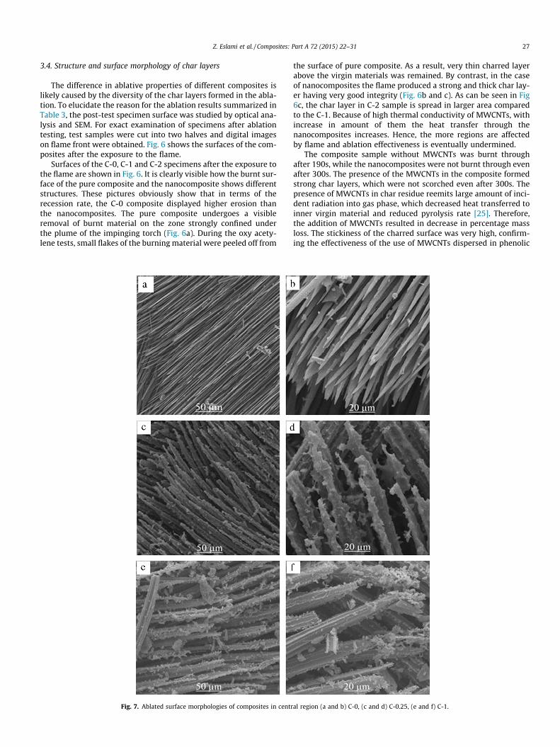
Surfaces of the C-0, C-1 and C-2 specimens after the exposure tothe flame are shown in Fig. 6. It is clearly visible how the burnt sur-face of the pure composite and the nanocomposite shows differentstructures. These pictures obviously show that in terms of therecession rate, the C-0 composite displayed higher erosion thanthe nanocomposites. The pure composite undergoes a visibleremoval of burnt material on the zone strongly confined underthe plume of the impinging torch (Fig. 6a). During the oxy acety-lene tests, small flakes of the burning material were peeled off from
Fig. 7. Ablated surface morphologies of composites in centr
the surface of pure composite. As a result, very thin charred layerabove the virgin materials was remained. By contrast, in the caseof nanocomposites the flame produced a strong and thick char lay-er having very good integrity (Fig. 6b and c). As can be seen in Fig6c, the char layer in C-2 sample is spread in larger area comparedto the C-1. Because of high thermal conductivity of MWCNTs, withincrease in amount of them the heat transfer through thenanocomposites increases. Hence, the more regions are affectedby flame and ablation effectiveness is eventually undermined.
The composite sample without MWCNTs was burnt throughafter 190s, while the nanocomposites were not burnt through evenafter 300s. The presence of the MWCNTs in the composite formedstrong char layers, which were not scorched even after 300s. Thepresence of MWCNTs in char residue reemits large amount of inci-dent radiation into gas phase, which decreased heat transferred toinner virgin material and reduced pyrolysis rate [25]. Therefore,the addition of MWCNTs resulted in decrease in percentage massloss. The stickiness of the charred surface was very high, confirm-ing the effectiveness of the use of MWCNTs dispersed in phenolic
al region (a and b) C-0, (c and d) C-0.25, (e and f) C-1.

28 Z. Eslami et al. / Composites: Part A 72 (2015) 22–31
resin. The MWCNTs have large aspect ratios, which may enablethem to form a network protective layer on the surface of compos-ite even at very low loadings [23]. This layer has strong adhesion tothe composite and it is difficult to be blown away by the gas flow.Thus prevent the composite from further oxidation.
To explore the ablation behavior of samples in the centralregion (see Fig. 6), the morphology of the burnt surfaces of thecomposite and nanocomposites was also investigated by SEM ana-lysis (Fig. 7).
0It was found that the ablation pattern of composite withoutMWCNTs (Fig. 7a and b) shows a needle-shape structure formedby thermomechanical and thermochemical erosion simultaneous-ly. The surface morphology of the nano-modified sample afterthe ablation test was completely different from that of C-0 com-posite. Fig. 7(c and d) shows the ablation surface of C-0.25, asseen, damage to the carbon fibre in this nanocomposite is lowercompared to the damage occurring in pure composite. It is con-sidered that the diameter of carbon fibres in C-0.25 is significant-ly larger than that of the C-0 sample and the matrix regionremains between carbon fibres. Furthermore, the ablated surfaceof the carbon fibre in pure composites is very smooth and glossy,while for nanocomposite that is rough and covered by char resi-due. Ablation surface of C-1 (Fig. 7(e and f)) shows damage to thecarbon fibre is considerably lower compared to the damageoccurring in C-0 and even C-0.25. The diameter of carbon fibrein C-1 is larger than the other composites and there is a muchmore matrix and char residue. With the ablation going on, thephenolic matrix is oxidized and carbon fibres are surroundedby residue containing MWCNTs, prevent them to contact withoxygen, to some extent, and consequently, contribute to protectthe fibres from oxidation. This condition improved the preserva-
Fig. 8. SEM images of surface of char layer for (a) C-0.25, (b) C-0
tion of the surface considerably, leading to a significantly lowererosion rate.
3.5. Ablation mechanism
When a heat flux was applied on the specimens, the ablatorundergoes a series of complex reactions, which produce decom-posed gases and solid carbonaceous char residues [31,32]. Forma-tion of a protective char layer on the composite surface is criticalfor reducing the transfer of heat into the interior of material[23,33,34]. The char layer formed by traditional composites is usu-ally weak and brittle, making the material susceptible to rapidremoval by mechanical shear and spoliation. It is essential to resistthe mechanical erosion due to high-velocity aerodynamic shearingexerted by the harsh environments [26,35,36].
In the case of the nanocomposites a compact and hard charredsubstrate is produced on top of the burnt samples during the oxy-acetylene test. The structure of the char layers for differentnanocomposites observed by SEM is shown in Fig. 8. This figureshows that intensity of the produced char layer increased withincrease in the MWCNTs wt%, so that the formation of a protectivenetwork layer covering the surface is clearly visible.
Fig. 8 also shows the morphology of the char layer is similar to abubble-like structure. With increasing the magnification (Fig. 9), itis seen there are rarely open bubbles when the amount ofMWCNTs6 1, while for C-2 both the open and closed bubble areeasily visible. The formation of the bubble-like structures in thechar layer is due to the accumulation of pyrolysis gas in the interiorof the materials. The bubble and pore size of the char layer mightbe related to the gas permeability of material during the oxy-acetylene test [13]. Gas permeability of material decreases by
.5, (c) C-1 and (d) C-2 nanocomposites (low magnification).

Fig. 9. SEM images of surface of char layer for (a, b) C-1 and (c, d) C-2 nanocomposites.
Z. Eslami et al. / Composites: Part A 72 (2015) 22–31 29
increasing char layer thickness that is present on the pyrolysiszone.
From the large size pores in Fig. 9c and d, it can be inferred thatthe pressure of the gas might be high when the pyrolysis gasbreaks through the char surface. This phenomenon might takeplace because of increasing the MWCNTs content up to 2 wt%.The thermal conductivity of the C-2 nanocomposite is high enoughto increase the heat transfer to the interior of nanocomposite [25],therefore it increases the decomposition of materials and the vol-ume of the pyrolysis gas.
It is important to understand the behavior of the sample duringthe oxyacetylene test. In the pure composite, the carbon fibres andloose carbon matrix will be severely decomposed and produced
Fig. 10. Proposed ablation mechanisms for the ablation process: (a) pure comp
decomposed gases and solid carbonaceous char residues. Since achar is relatively weak, it is removed mechanically by high shearforces associated with the stream of gases during the oxyacetylenetest [17]. As a result, a new ablation interface is formed (Fig. 10a).Nevertheless, the ablation behavior of the nanocomposites con-taining MWCNTs is completely different. When the solid carbona-ceous char residues produce, the structured layer consisted of thehigh aspect ratios of the MWCNTs could yield a physically stronglayer.
The MWCNTs can act as interlocking pins within the interphaseand create a higher friction, on the one hand, between the pro-duced char layers and, on the other hand, between the carbona-ceous char residues and the inner virgin material. This proposed
osite and (b) nanocomposite with a definite mass fraction of the MWCNTs.
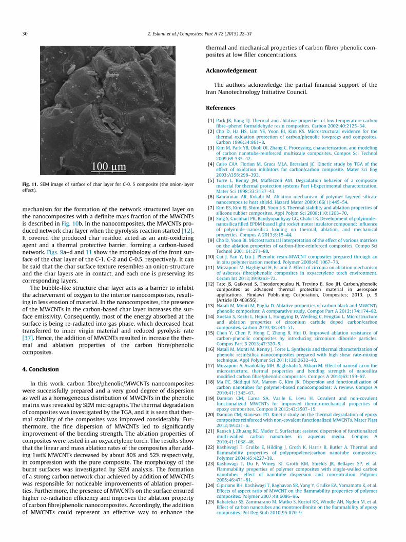
Fig. 11. SEM image of surface of char layer for C-0. 5 composite (the onion-layereffect).
30 Z. Eslami et al. / Composites: Part A 72 (2015) 22–31
mechanism for the formation of the network structured layer onthe nanocomposites with a definite mass fraction of the MWCNTsis described in Fig. 10b. In the nanocomposites, the MWCNTs pro-duced network char layer when the pyrolysis reaction started [12].It covered the produced char residue, acted as an anti-oxidizingagent and a thermal protective barrier, forming a carbon-basednetwork. Figs. 9a–d and 11 show the morphology of the front sur-face of the char layer of the C-1, C-2 and C-0.5, respectively. It canbe said that the char surface texture resembles an onion-structureand the char layers are in contact, and each one is preserving itscorresponding layers.
The bubble-like structure char layer acts as a barrier to inhibitthe achievement of oxygen to the interior nanocomposites, result-ing in less erosion of material. In the nanocomposites, the presenceof the MWCNTs in the carbon-based char layer increases the sur-face emissivity. Consequently, most of the energy absorbed at thesurface is being re-radiated into gas phase, which decreased heattransferred to inner virgin material and reduced pyrolysis rate[37]. Hence, the addition of MWCNTs resulted in increase the ther-mal and ablation properties of the carbon fibre/phenoliccomposites.
4. Conclusion
In this work, carbon fibre/phenolic/MWCNTs nanocompositeswere successfully prepared and a very good degree of dispersionas well as a homogeneous distribution of MWCNTs in the phenolicmatrix was revealed by SEM micrographs. The thermal degradationof composites was investigated by the TGA, and it is seen that ther-mal stability of the composites was improved considerably. Fur-thermore, the fine dispersion of MWCNTs led to significantlyimprovement of the bending strength. The ablation properties ofcomposites were tested in an oxyacetylene torch. The results showthat the linear and mass ablation rates of the composites after add-ing 1wt% MWCNTs decreased by about 80% and 52% respectively,in compression with the pure composite. The morphology of theburnt surfaces was investigated by SEM analysis. The formationof a strong carbon network char achieved by addition of MWCNTswas responsible for noticeable improvements of ablation proper-ties. Furthermore, the presence of MWCNTs on the surface ensuredhigher re-radiation efficiency and improves the ablation propertyof carbon fibre/phenolic nanocomposites. Accordingly, the additionof MWCNTs could represent an effective way to enhance the
thermal and mechanical properties of carbon fibre/ phenolic com-posites at low filler concentrations.
Acknowledgement
The authors acknowledge the partial financial support of theIran Nanotechnology Initiative Council.
References
[1] Park JK, Kang TJ. Thermal and ablative properties of low temperature carbonfibre–phenol formaldehyde resin composites. Carbon 2002;40:2125–34.
[2] Cho D, Ha HS, Lim YS, Yoon BI, Kim KS. Microstructural evidence for thethermal oxidation protection of carbon/phenolic towpregs and composites.Carbon 1996;34:861–8.
[3] Kim M, Park YB, Okoli OI, Zhang C. Processing, characterization, and modelingof carbon nanotube-reinforced multiscale composites. Compos Sci Technol2009;69:335–42.
[4] Cairo CAA, Florian M, Graca MLA, Bressiani JC. Kinetic study by TGA of theeffect of oxidation inhibitors for carbon/carbon composite. Mater Sci Eng2003;A358:298–393.
[5] Torre L, Kenny JM, Maffezzoli AM. Degradation behavior of a compositematerial for thermal protection systems Part I-Experimental characterization.Mater Sci 1998;33:3137–43.
[6] Bahramian AR, Kokabi M. Ablation mechanism of polymer layered silicatenanocomposite heat shield. Hazard Mater 2009;166(1):445–54.
[7] Kim ES, Kim EJ, Shim JH, Yoon J-S. Thermal stability and ablation properties ofsilicone rubber composites. Appl Polym Sci 2008;110:1263–70.
[8] Sing S, Guchhait PK, Bandyopadhyay GG, Chaki TK. Development of polyimide–nanosilica filled EPDM based light rocket motor insulator compound: influenceof polyimide–nanosilica loading on thermal, ablation, and mechanicalproperties. Compos A 2013;8:15–44.
[9] Cho D, Yoon BI. Microstructural interpretation of the effect of various matriceson the ablation properties of carbon-fibre-reinforced composites. Compo SciTechnol 2001;61:271–80.
[10] Cui J, Yan Y, Liu J. Phenolic resin-MWCNT composites prepared through anin situ polymerization method. Polymer 2008;40:1067–73.
[11] Mirzapour M, Haghighat H, Eslami Z. Effect of zirconia on ablation mechanismof asbestos fibre/phenolic composites in oxyacetylene torch environment.Ceram Int 2013;39:9263–72.
[12] Tate JS, Gaikwad S, Theodoropoulou N, Trevino E, Koo JH. Carbon/phenoliccomposites as advanced thermal protection material in aerospaceapplications. Hindawi Publishing Corporation, Composites; 2013. p. 9[Article ID 403656].
[13] Natali M, Monti M, Puglia D. Ablative properties of carbon black and MWCNT/phenolic composites: A comparative study. Compos Part A 2012;174:174–82.
[14] Xuetao S, Kezhi L, Hejun L, Hongying D, Weifeng C, Fengtao L. Microstructureand ablation properties of zirconium carbide doped carbon/carboncomposites. Carbon 2010;48:344–51.
[15] Chen Y, Chen P, Hong C, Zhong B, Hui D. Improved ablation resistance ofcarbon-phenolic composites by introducing zirconium diboride particles.Compos Part B 2013;47:320–5.
[16] Natali M, Monti M, Kenny J, Torre L. Synthesis and thermal characterization ofphenolic resin/silica nanocomposites prepared with high shear rate-mixingtechnique. Appl Polymer Sci 2011;120:2632–40.
[17] Mirzapour A, Asadolahy MH, Baghshahi S, Akbari M. Effect of nanosilica on themicrostructure, thermal properties and bending strength of nanosilicamodified carbon fibre/phenolic composites. Compos A 2014;63:159–67.
[18] Ma PC, Siddiqui NA, Marom G, Kim JK. Dispersion and functionalization ofcarbon nanotubes for polymer-based nanocomposites: A review. Compos A2010;41:1345–67.
[19] Damian CM, Garea SA, Vasile E, Lovu H. Covalent and non-covalentfunctionalized MWCNTs for improved thermo-mechanical properties ofepoxy composites. Compos B 2012;43:3507–15.
[20] Damian CM, Stanescu PO. Kinetic study on the thermal degradation of epoxycomposites reinforced with non-covalent functionalized MWCNTs. Mater Plast2012;49:231–6.
[21] Rausch J, Zhuang RC, Mader E. Surfactant assisted dispersion of functionalizedmulti-walled carbon nanotubes in aqueous media. Compos A2010;41:1038–46.
[22] Kashiwagi T, Grulke E, Hilding J, Groth K, Harris R, Butler A. Thermal andflammability properties of polypropylene/carbon nanotube composites.Polymer 2004;45:4227–39.
[23] Kashiwagi T, Du F, Winey KI, Groth KM, Shields JR, Bellayer SP, et al.Flammability properties of polymer composites with single-walled carbonnanotubes: effect of nanotube dispersion and concentration. Polymer2005;46:471–81.
[24] Cipiriano BH, Kashiwagi T, Raghavan SR, Yang Y, Grulke EA, Yamamoto K, et al.Effects of aspect ratio of MWCNT on the flammability properties of polymercomposites. Polymer 2007;48:6086–96.
[25] Rahatekar SS, Zammarano M, Matko S, Koziol KK, Windle AH, Nyden M, et al.Effect of carbon nanotubes and montmorillonite on the flammability of epoxycomposites. Pol Deg Stab 2010;95:870–9.

Z. Eslami et al. / Composites: Part A 72 (2015) 22–31 31
[26] Yeh MK, Tai NH, Lin YJ. Mechanical properties of phenolic-based compositesreinforced by multi-walled carbon nanotubes and carbon fibres. Compos A2008;39:677–84.
[27] Park JM, Kwon DJ, Wang ZJ, Roh JU, Lee W, Park JK, et al. Effects of nanotubesand carbon fibre reinforcements on thermal conductivity and ablationproperties of carbon/phenolic composites. Compos B 2014;22:29–67.
[28] Srikanth I, Padmavathi N, Kumar S, Ghosal P, Kumar A, Subrahmanyam Ch.Mechanical, thermal and ablative properties of zirconia, CNT modified carbon/phenolic composites. Compos Sci Technol 2013;1:7–80.
[29] Mathur RB, Chatterjee S, Singh BP. Growth of carbon nanotubes on carbon fibresubstrates to produce hybrid/phenolic composites with improved mechanicalproperties. Compos Sci Technol 2008;68:1608–15.
[30] Yu B, Jiang Z, Tang XZ, Yue CY, Yang J. Enhanced interphase between epoxymatrix and carbon fiber with carbon nanotube-modified silane coating.Compos Sci Technol 2014;99:131–40.
[31] Allcorn EK, Natali M, Koo JH. Ablation performance and characterization ofthermoplastic polyurethane elastomer nanocomposites. Compos Part A. http://dx.doi.org/10.1016/j.compositesa.2012.08.017.
[32] Natali M, Rallini M, Puglia D, Kenny JM, Torre L. EPDM based Heat ShieldingMaterials for Solid Rocket Motors a comparative study of different fibrousreinforcements. Compos Part A 2013;98:2131–9.
[33] Natali M, Monti M, Kenny JM, Torre L. A nanostructured ablative bulkmoulding compound: Development and characterization. Compos A2011;42:1197–204.
[34] Guan Y, Zhang LX, Zhang LQ, Lu YL. Study on ablative properties andmechanisms of hydrogenated nitrile butadiene rubber (HNBR) compositescontaining different fillers. Polymer Deg Stab 2011;96:808–17.
[35] Yang D, Zhang W, Jiang B, Guo Y. Silicon rubber ablative composites improvedwith zirconium carbide or zirconia. Compos A 2013;44:70–7.
[36] Lee YJ, Joo HJ. Investigation on ablation behavior of CFRC composites preparedat different pressure. Compos A 2004;35:1285–90.
[37] Hong Ch, Han J, Zhang X, David H, Li W, Chen Y, et al. Novel phenolicimpregnated 3-D fine-woven pierced carbon fabric composites;microstructure and ablation behavior. Compos Part B 2012;43:2389–94.