Thermal Analysis of a Raft Concrete Foundation - MDPI
17
Citation: Wattanapanich, C.; Imjai, T.; Aosai, P.; Hansapinyo, C.; Figueiredo, F.P.; Garcia, R. Thermal Analysis of a Raft Concrete Foundation: A Case Study of a Leaking Ethane Tank. Buildings 2022, 12, 889. https:// doi.org/10.3390/buildings12070889 Academic Editor: Elena Ferretti Received: 14 May 2022 Accepted: 21 June 2022 Published: 23 June 2022 Publisher’s Note: MDPI stays neutral with regard to jurisdictional claims in published maps and institutional affil- iations. Copyright: © 2022 by the authors. Licensee MDPI, Basel, Switzerland. This article is an open access article distributed under the terms and conditions of the Creative Commons Attribution (CC BY) license (https:// creativecommons.org/licenses/by/ 4.0/). buildings Article Thermal Analysis of a Raft Concrete Foundation: A Case Study of a Leaking Ethane Tank Chirawat Wattanapanich 1 , Thanongsak Imjai 1, * , Pakjira Aosai 1 , Chayanon Hansapinyo 2 , Fabio P. Figueiredo 3 and Reyes Garcia 4 1 School of Engineering and Technology, Walailak University, Nakhonsithammarat 80161, Thailand; [email protected] (C.W.); [email protected] (P.A.) 2 Center of Excellence in Natural Disaster Management, Department of Civil Engineering, Chiang Mai University, Chiang Mai 50200, Thailand; [email protected] 3 School of Engineering, University of Minho, 4800-058 Guimarães, Portugal; f.fi[email protected] 4 Civil Engineering Stream, School of Engineering, The University of Warwick, Coventry CV4 7AL, UK; [email protected] * Correspondence: [email protected]; Tel.: +66-(0)-7567-2378 Abstract: This article presents a case study on the thermal assessment of a reinforced concrete (RC) foundation exposed to low temperatures. The foundation supports a 19,500 m 3 -capacity tank with low-temperature (-89 ◦ C) ethane. Icing and bubbling were observed on the tank’s surface soon after it started operations. Condensation was also observed at the bottom of the 0.8-m-depth RC slab, which raised concerns about the structural condition of the concrete. This study provides details of the field and analytical investigations conducted to assess the structural condition of the foundation. Heat transfer finite element (FE) analyses were performed to examine the concrete sections subjected to low temperatures. It was found that the ethane leakage produced a low temperature on the top side of the concrete foundation of +9.7 ◦ C. Overall, the temperatures calculated by the FE analyses were in good agreement with actual field measurements, within a ±5% accuracy. The simplified heat transfer equation for porous media used in this study was sufficiently accurate to model the effects of the ethane leakage in the concrete foundation, provided that the ambient temperature at the site is taken into account in the analysis. The results also confirm that reinforcing bars can be neglected in the thermal analysis of massive concrete slabs. The results from the field measurements and FE analyses confirmed that the structural integrity of the RC foundation was never compromised. The approaches, methods and techniques discussed in this article are deemed suitable to solve the practical and scientific challenges involved in the thermal assessment and repairs of large special structures. Accordingly, they can serve as useful reference and guidance for engineers and practitioners working in the field of forensic engineering. Keywords: reinforced concrete; raft foundation; temperature effects; finite element modelling 1. Introduction Storage tanks in industrial facilities often store liquids and/or gases at extreme low (or high) temperatures at very high pressures. Many of such tanks are made of materials susceptible to corrosion (and erosion) at the contact zone where the phase of materials changes from liquid to gas, and vice versa. As a result of these drastic changes, serious incidents (or ‘accidents’) have been reported in tanks in the past [1]. Most of the storage tanks at petrochemical plants in Thailand are built on thick reinforced concrete (RC) founda- tions. Traditionally, these cast-in-place foundations are supported on piles and are therefore commonly referred to as ‘raft foundations’ [2]. The raft foundations then support the storage tanks. Raft RC foundations have proven to be a cost-effective and reliable structural solution to support storage tanks in the petrochemical industry. However, the construction of such raft foundations requires strict quality control and quality assurance, as well as Buildings 2022, 12, 889. https://doi.org/10.3390/buildings12070889 https://www.mdpi.com/journal/buildings
-
Upload
khangminh22 -
Category
Documents
-
view
0 -
download
0
Transcript of Thermal Analysis of a Raft Concrete Foundation - MDPI

Citation: Wattanapanich, C.; Imjai, T.;
Aosai, P.; Hansapinyo, C.; Figueiredo,
F.P.; Garcia, R. Thermal Analysis of a
Raft Concrete Foundation: A Case
Study of a Leaking Ethane Tank.
Buildings 2022, 12, 889. https://
doi.org/10.3390/buildings12070889
Academic Editor: Elena Ferretti
Received: 14 May 2022
Accepted: 21 June 2022
Published: 23 June 2022
Publisher’s Note: MDPI stays neutral
with regard to jurisdictional claims in
published maps and institutional affil-
iations.
Copyright: © 2022 by the authors.
Licensee MDPI, Basel, Switzerland.
This article is an open access article
distributed under the terms and
conditions of the Creative Commons
Attribution (CC BY) license (https://
creativecommons.org/licenses/by/
4.0/).
buildings
Article
Thermal Analysis of a Raft Concrete Foundation: A Case Studyof a Leaking Ethane TankChirawat Wattanapanich 1 , Thanongsak Imjai 1,* , Pakjira Aosai 1 , Chayanon Hansapinyo 2 ,Fabio P. Figueiredo 3 and Reyes Garcia 4
1 School of Engineering and Technology, Walailak University, Nakhonsithammarat 80161, Thailand;[email protected] (C.W.); [email protected] (P.A.)
2 Center of Excellence in Natural Disaster Management, Department of Civil Engineering,Chiang Mai University, Chiang Mai 50200, Thailand; [email protected]
3 School of Engineering, University of Minho, 4800-058 Guimarães, Portugal; [email protected] Civil Engineering Stream, School of Engineering, The University of Warwick, Coventry CV4 7AL, UK;
[email protected]* Correspondence: [email protected]; Tel.: +66-(0)-7567-2378
Abstract: This article presents a case study on the thermal assessment of a reinforced concrete (RC)foundation exposed to low temperatures. The foundation supports a 19,500 m3-capacity tank withlow-temperature (−89 ◦C) ethane. Icing and bubbling were observed on the tank’s surface soon afterit started operations. Condensation was also observed at the bottom of the 0.8-m-depth RC slab,which raised concerns about the structural condition of the concrete. This study provides details ofthe field and analytical investigations conducted to assess the structural condition of the foundation.Heat transfer finite element (FE) analyses were performed to examine the concrete sections subjectedto low temperatures. It was found that the ethane leakage produced a low temperature on the topside of the concrete foundation of +9.7 ◦C. Overall, the temperatures calculated by the FE analyseswere in good agreement with actual field measurements, within a ±5% accuracy. The simplified heattransfer equation for porous media used in this study was sufficiently accurate to model the effectsof the ethane leakage in the concrete foundation, provided that the ambient temperature at the siteis taken into account in the analysis. The results also confirm that reinforcing bars can be neglectedin the thermal analysis of massive concrete slabs. The results from the field measurements and FEanalyses confirmed that the structural integrity of the RC foundation was never compromised. Theapproaches, methods and techniques discussed in this article are deemed suitable to solve the practicaland scientific challenges involved in the thermal assessment and repairs of large special structures.Accordingly, they can serve as useful reference and guidance for engineers and practitioners workingin the field of forensic engineering.
Keywords: reinforced concrete; raft foundation; temperature effects; finite element modelling
1. Introduction
Storage tanks in industrial facilities often store liquids and/or gases at extreme low(or high) temperatures at very high pressures. Many of such tanks are made of materialssusceptible to corrosion (and erosion) at the contact zone where the phase of materialschanges from liquid to gas, and vice versa. As a result of these drastic changes, seriousincidents (or ‘accidents’) have been reported in tanks in the past [1]. Most of the storagetanks at petrochemical plants in Thailand are built on thick reinforced concrete (RC) founda-tions. Traditionally, these cast-in-place foundations are supported on piles and are thereforecommonly referred to as ‘raft foundations’ [2]. The raft foundations then support thestorage tanks. Raft RC foundations have proven to be a cost-effective and reliable structuralsolution to support storage tanks in the petrochemical industry. However, the constructionof such raft foundations requires strict quality control and quality assurance, as well as
Buildings 2022, 12, 889. https://doi.org/10.3390/buildings12070889 https://www.mdpi.com/journal/buildings

Buildings 2022, 12, 889 2 of 17
periodic inspection and maintenance to guarantee the integrity of the foundations overthe service life of the tanks [3–5]. This is important from a structural engineering pointof view because the changes in temperature in the tank can in turn lead to changes in themechanical properties of concrete, such as its compressive and tensile strengths [6,7].
Ethane storage tanks are very common in petrochemical plants. Liquid ethane hasa very low boiling point and turns into gas at ambient temperature. However, liquidethane can reach extremely low temperatures well below 0 ◦C. In the case of unexpectedleakages, part of the concrete surface in the foundation can be subjected to extremely lowtemperatures (up to −20 ◦C), which in turn can also lead to damage [8–11]. Previousresearch has shown that the strength of both concrete and reinforcement tends to increasewhen the temperature reduces within a particular range (e.g., 20 ◦C to−40 ◦C) [11–15]. Thiseffect is particularly evident in moist concrete, where the increase in compressive strengthhas been attributed to the formation of ice which increases progressively as the temperaturereduces [16]. For steel reinforcement subjected to low temperature, experiments have shownthat reinforced bars tend to become brittle when exposed to extremely low-temperatureenvironments (less than −20 ◦C) [11–15]. Other studies have also investigated fatigueand thermal effects on concrete [17]. On the other hand, test results indicate that steelreinforcement subjected to extreme low temperature (below −20 ◦C) tends to becomebrittle. While unlikely, the potential leakage of ethane is possible even if quality controland quality assurance procedures were followed during construction of the foundationand the tank. However, to date there are limited guidelines [18,19] on how to assess theeffect of unexpected leakage of extreme low-temperature liquids on the overall structuralintegrity of concrete foundations, especially for practical case studies. Moreover, only a fewstudies have investigated numerically the changes in temperature of structural elementsunder specific, realistic temperature profiles [20–22].
The structural inspection of raft foundations of storage tanks has significant challengesdue to the peculiarities of these special structures. For instance, excavations around thefoundation and in situ load testing are often required to identify damage. Concrete coresampling/testing can also provide some relevant information on the concrete properties.However, coring can be very challenging (due to the limited working space under thefoundation slab) and time consuming and can sometimes produce damage to the founda-tions. Limitations always exist as potential defects between the foundation and the tankcannot be easily detected by simple visual inspections. To bypass some of these limitations,nondestructive tests (NDTs) can be used to assess the condition of concrete foundationsfor tanks. Whilst it has been claimed that NDTs can help assess the structural integrityof structures without the need for excessive concrete coring or load testing [23–25], it isalways preferred to validate NDT test results with core test results, whenever possible.
Another challenge arises when concrete is exposed to very low temperatures. Underthis condition, the capillary water changes phase from liquid to solid, which increasesthe water’s volume, and chemically bound water is released due to hydration. Thisresults in an increase in pore pressure, which is believed to be one of the mechanismsleading to concrete spalling in structures exposed to extremely low temperatures of lessthan −20 ◦C [11,12]. Several mathematical models to simulate the thermal behaviourof concrete exist in the literature. Most of these models are based on the theory of heatand mass transfer in porous media and have been implemented in finite element (FE)software [14,26]. Vapour diffusion, liquid water flow due to pressure gradients, capillaryeffects, and evaporation/condensation are the main characteristics observed in porousmedia such as concrete [27–29]. Due to the complexity of the nonlinear phenomena involvedin porous media at extremely high or low temperature, a fully coupled mathematical modelis necessary to predict the evolution of temperature and pore pressure.

Buildings 2022, 12, 889 3 of 17
This article presents a case study on the thermal assessment of a circular RC foundationexposed to low temperatures. The foundation supports one of the largest storage tanks inThailand, and it is part of a large petrochemical plant. Because most of the informationin the subject is limited and/or scattered, this study aims to summarise the approaches,methods and techniques used to solve the practical and scientific challenges involved inthe structural assessment and repairs of this large special structure that presented issuessoon after it started operating. Indeed, the storage tank leaked ethane that spilled to the RCfoundation, which raised structural safety concerns to the stakeholders. A numerical finiteelement (FE) model is developed to simulate the temperature changes of the RC foundationsubjected to temperature profiles of the ethane leakage. Issues related to the computationalstrategy for heat transfer problems are then reported and commented upon. The FE resultsare compared with field temperatures measured at the bottom of the foundation. Finally,the results from the FE simulation are analysed and discussed. This article is an additionto the very few studies that have investigated numerically the changes in temperature ofstructural elements. The approaches, methods and techniques adopted in this study canserve as useful reference and guidance for engineers and practitioners working in the fieldof forensic engineering.
2. Case Study: Ethane Storage Tank2.1. General Characteristics
The storage tank is part of a petrochemical plant at the Ta Phut Industrial Estate,Rayong Province, Thailand. Figure 1a shows the location of the plant. The constructionof the plant was completed in late 2010 [30], after which it started operations. The plantincludes the T-4801 ethane storage tank shown in Figure 1b. This is a single containmenttank with an internal diameter of 28.5 m, a height of 30.6 m, and a total capacity of 19,500 m3.The 35 mm thick walls of the tank are made of stainless/carbon steel Grade 304 accordingto ASTM A240 [31]. The tank stores liquid ethane (C2H6) for gas processing and thereforeoperates at an extremely low temperature of −89 ◦C and at a pressure of 500 mH2O.The tank is not insulated but only protected with a fireproof coating, according to localregulations. A raft RC slab of depth 0.8 m supports the tank. The slab sits on 122 square(0.4 × 0.4 m) concrete piles of 7.0 m height typically spaced at 2.0 m at the central zone ofthe slab, and at 1.5 m at its circumferential zone (see typical distance TYP. in Figure 2b).The bottom of the slab itself is at only 0.5 m above the ground level (Figures 1c and 2c).Such small gap provides just enough headroom to perform periodic inspections of thefoundation. It should be noted that this gap was not part of the original constructionproject and that the slab was originally touching the ground. However, partial settlementgradually developed and a 0.5 m gap was observed at the time of inspection.

Buildings 2022, 12, 889 4 of 17Buildings 2022, 12, x FOR PEER REVIEW 4 of 18
Figure 1. (a) Location of T-4801 ethane tank within the Ta Phut Industrial Estate, and (b) T-4801 ethane tank [30].
Figure 1. (a) Location of T-4801 ethane tank within the Ta Phut Industrial Estate, and (b) T-4801ethane tank [30].

Buildings 2022, 12, 889 5 of 17
Figure 2. (a) Elevation of T-4801 tank, (b) plan view of foundation and location dew at the outer shellwall plate and bottom plate, and (c) lateral view of foundation and location of dew fall.
2.2. Inspections and Repairs
Icing and bubbling were reported to occur on the tank’s wall and base plate in early2011, at the location shown schematically in Figure 2a. A visual inspection performed atthe bottom of the RC foundation revealed the presence of dew at the periphery aroundthe annular space. In particular, dew condensation was observed at an orientation ofabout 310◦, as shown in Figure 2b. The icing disappeared after three weeks, but the dewremained on the tank’s wall and base plate. In addition, the dew condensation was alsoobserved at some parts of the welded joints between the outer shell wall plate and bottomplate. Visual testing (VT) and ultrasonic testing (UT) methods were performed accordingto ASTM [32] to assess the integrity and defects of the welded joints of the tank. Thetest results confirmed a small defect in the welding. From the inspection results, it wasconcluded that a more detailed engineering assessment (DEA) and more thorough periodicinspections were necessary to discard further structural issues.
A preliminary inspection detected dew condensation at some parts of the welded jointbetween the outer shell wall plate and bottom plate of the steel tank, with the evidenceof ethane leakage in an area of approximately 5 × 2 m2. Therefore, it was concluded thaturgent repairs were needed at the welded joints to maintain the functionality of the tank.However, as the stakeholders decided to keep the tank fully operational during the repairs,the preliminary inspection was limited to the outer part of the tank. Accordingly, it was not

Buildings 2022, 12, 889 6 of 17
possible to determine other potential damage inside the tank. The repairs were completedin March 2011. No cracks and/or spall of concrete were observed at the bottom side of theRC foundation, and this was confirmed by UPV tests.
A follow-up inspection was carried out after three months of the repairs on the weldedjoints. Despite the repairs, dew was still observed at the tank’s bottom, at the same locationwhere the leak was initially observed. As a result, it was decided to empty the tank toinspect the leakage in more detail. The dew was present at the bottom of the RC foundation(Figure 2c) as the liquid ethane leaked from the welded joint inside the container andremained at the bottom of the tank, thus producing the dew observed at the bottom of thefoundation (due to thermal conduction through the concrete). After emptying the tank,access was possible to the outer shell wall and bottom plates from the inside of the tank,which allowed the repair of the affected area (about 5 × 2 m2, as shown in Figure 2b) thatcaused the ethane leaks. The good quality of the welding repairs was verified using UPVtechniques [18].
The work on the tank was divided into two phases. Figure 3 shows the flowchart ofthe inspections performed in Phase 1. In Phase 1 and following the preliminary inspections(items 1 and 2 in Figure 3), a DEA was carried out to assess more thoroughly the structuralcondition of the foundation and to obtain the thermal properties of the concrete via NDTs(item 6 and 7 in Figure 3). The results from Phase 1 were subsequently used in Phase 2 toperform thermal integrity analyses to diIt scard potential damage in the RC foundation asa consequence of the leakage. Detailed results from the NDTs in Phase 1 were presented bythe authors previously [33,34]. Further details on Phase 1 and all Phase 2 are described inthe following sections.
Figure 3. Flowchart of work in Phase 1 (adapted from Imjai and Tungsanga [33]).

Buildings 2022, 12, 889 7 of 17
3. Phase 1: Inspection of the T-4801 Tank
The main aims in Phase 1 were to identify structural deterioration and to determinethe preliminary serviceability condition of all the structural components of the tank. The in-spection was performed according to the ACI 364 [35] standard, whereas the damage ratingcondition complied with the RILEM TC 104 guidelines [18]. The steel tank structure wasalso inspected in accordance with the manual and guidelines of the American PetroleumInstitute (API) [18]. Special attention was paid to assessing the condition of the weldedjoints of the steel tank, which was performed according to the API specifications [18,36].The visual inspection was limited to accessible areas of the tank, as well as to the accessibleparts of the bottom of the RC foundation (see Figure 1b). Accordingly, there may havebeen inaccessible areas or parts of the tank/foundation with some damage that was notvisible because they were covered and/or blocked by staircases, fire hoses, etc. To examinethe structural integrity of the tank, design checks on load-bearing capacity with the actualmaterial properties at the time of construction were also performed.
3.1. Field Temperature Measurements
Two datasets of temperature (shown in Appendix A) were obtained using thermalsensors. Dataset 1 was obtained by the staff of the petrochemical plant, who measured thetemperatures at the bottom side of the concrete foundation soon after the ethane leakagewas observed. The authors obtained Dataset 2 one week after the repairs of the weldedjoints were completed. To achieve this, a thermal resistance temperature detector (RTD)sensor (Figure 4) with a measurement range of −100 ◦C to +330 ◦C was used to measurethe temperature at the bottom of the RC foundation. The thermal sensor was calibrated bythe manufacturer before use. Moreover, just before the field measurements, the thermalsensor readings were compared with laser temperature readings in hot and cold water.The temperature readings in both cases were the same. The measurements were limited toaccessible locations where condensation was observed. Temperature data were collectedat three different locations (0, 50 and 100 mm) measured from the bottom of the concreteslab. To fix the sensor to the concrete, a 4 mm hole was first drilled. Then the dust insidethe hole was removed using an air blower, after which the hole was filled in with a thermalgrease of extremely high thermal conductivity. The field temperature was monitored for24 h and transmitted to a data acquisition system in real time. The relative humidity andwind speed were also recorded on the day of the field inspection.
Figure 4. High precision thermal RTD sensor (RTD-1PT100K2515-36-T) and data acquisition system.
3.2. Material Properties and Design Checks on Load Bearing Capacity
The physical and thermal properties of the concrete exposed to low temperatureswere obtained to provide data for FE modeling. Only twelve cores were extracted ascoring was very challenging due to the limited working space under the foundation slab(0.5 m only). The testing points were selected based on the original construction drawingsfollowed by a walk-through around the foundation. The concrete compressive strength wasobtained from NDT rebound hammer tests and from compression tests on six core samples(diameter = 100 mm). The average concrete compressive strength was 24.0 MPa, the drydensity was 2355 kg/m3, and the calculated elastic modulus was 23,025 MPa based on theACI-318 equation [37]. Comparatively, the original (cylinder) design compressive strengthwas 21.0 MPa. These initial results suggested that the concrete under the slab was unlikely

Buildings 2022, 12, 889 8 of 17
to be exposed to very low temperatures. Additionally, the other six concrete cores weresliced into 10-mm-thick samples to examine the thermal properties of the concrete accordingto ASTM C177-19 [38]. The average conductivity and specific heat of the concrete werefound to be 2.56 W/m ◦C and 0.88 kJ/kg ◦C, respectively. The results from these sampleswere later fed into the numerical analysis. The original drawings of the RC foundationspecified a yield strength of the reinforcing bars equal to 392 MPa for the flexural (Ø25 mm)and shear (Ø16 mm) bars. The concrete cover (75 mm) and location/size of reinforcing barswere verified using ferro scanning techniques.
The structural assessment and DEA of the ethane tank structure was performedaccording to Eurocode 3 and AISC specifications [39], as well as ACI 318 [37]. The ultimatecapacity of the RC members and applied factored loads were considered. The calculationsconfirmed that, as expected from a relatively new structure, the capacity of the existingsteel tank and concrete foundation were adequate to resist the original design loads.
4. Phase 2: Thermal Integrity Analysis
An inverse numerical analysis was carried out to investigate the effect of the lowtemperature on the concrete slab. It should be noted that whilst an inverse numericalanalysis was adopted in this study, such analysis may not be the best approach to dothermal analysis of other structures. This study employed an inverse analysis to assessthe slab mainly because it was impossible to measure the temperature at the top face ofthe slab (i.e., just under the ethane tank at the tank-foundation interface), and therefore,only temperature data measured at the bottom of the slab (Section 3.1) was availablefor comparisons.
4.1. Heat Transfer in Concrete Slab
In this study, the concrete of the foundation was modeled as a porous media materialwhere the voids of the solid skeleton were filled with liquid and gas. The heat transferin the foundation was examined using the computational fluid dynamics (CFD) moduleof the FE software COMSOL Multiphysics [40]. This software was chosen because (i) ithas a stable solver for both linear and nonlinear problems, and (ii) it has an extensivelibrary of elements which can be used to model concrete subjected to thermal loading.In COMSOL, one of the most important steps was choosing the appropriate physics for themodel, adding physics conditions and constraints, and assigning the physics to foundationgeometric entities. In this study, the “Heat Transfer” physics was used by choosing theheat transfer in porous media library added into the model. The time-dependent heattransfer in the solid interface was numerically computed by solving the heat equation andthe momentum balance equation [40,41], as shown in Equation (1).
ρCp
(∂T∂t
+ utrans·∇T)+∇·(q + qr) = −αT :
dSdt
+ q (1)
where ρ is the density of the material (SI units: kg/m3), Cp is the specific heat capacityat constant stress (J/kg·K), T is the absolute temperature (K), utrans is the velocity vectorof translational motion (m/s), q is the heat flux by conduction (W/m2), qr is the heatflux by radiation (W/m2), α is the coefficient of thermal expansion (1/K), S is the secondPiola-Kirchhoff stress tensor (Pa), and q contains the additional heat sources (W/m3).
For a steady-state problem, the temperature does not change with time, and the termswith time derivatives disappear. The heat transfer equation for porous media can be derivedfrom the mixture rule on energies appearing in solid and fluid heat transfer equations [42].Accordingly, Equation (1) can be simplified to
ρsCp,s∂Ts
∂t+∇·qs = Qs (2)

Buildings 2022, 12, 889 9 of 17
where ρs is the solid and fluid densities (kg/m3), Cp,s is the solid heat capacity at constantpressure (J/kg·K), qs is the solid conductive heat flux (W/m2), and Qs is the solid heatsource (W/m3).
Previous studies have shown that the heat transfer through porous materials suchas concrete was successfully simulated using Equations (1) and (2) and COMSOL Multi-physics [26,43,44].
4.2. FE Modelling, Boundary Conditions and Thermal Effects
Figure 5a shows the plan view and cross section of the model of the concrete founda-tion. 3D-solid hexahedron elements with eight-noded elements (global mesh size = 200 mm)with three degrees of freedom at each node (three translations in x, y and z directions) wereused to model both the slab (diameter = 31.4 m; overall thickness = 0.8 m) and the concretepiles (square section = 0.4 × 0.4 m). This element type is less sensitive to distortion, andhence it was preferred over brick element to better model the circular geometry of the slab.The hexahedron elements (see Figure 5b for close up view of mesh for quarter of slab)also have higher coarse mesh accuracy over 3D tetra or wedge elements. This elementis based on the displacement mode separation method. The element passes the constantstress patch tests, shows a low mesh distortion sensitivity and high accuracy in shell appli-cations. Moreover, the element maintains an adequate element size along the whole sectionof the foundation to minimise potential issues with numerical instabilities. It should bementioned that COMSOL optimises the mesh size, which in this case led to a total cellnumber of 77,535 elements. At the time of the field inspection, the tank was empty due tothe repair works in the welded joints, and therefore, the steel tank and gas loading werenot included in the analysis. The default penalty method for contact characteristics (usedto simulate the contact between the deformable and rigid objects defined by COMSOL)were used to simulate the contact between slab and piles. Because the mass and volume ofthe concrete slab are massive compared to those of the reinforcing bars (volume of bars wasonly 3.75% of total), the bars were not included in the modeling as these were expectedto have a negligible effect in the results, as reported in previous studies [43,44]. Figure 5cillustrates a quarter of slab showing the thermal boundary conditions.
Figure 5. (a) Plan view and cross section of 3D FE mesh of the slab; (b) Close-up view of mesh forquarter of slab, and (c) quarter of slab showing the thermal boundary conditions.

Buildings 2022, 12, 889 10 of 17
A default penalty method available in COMSOL contact library was adopted andused in the analysis. The penalty method offers a more stability from the convergence, ismore robust, and requires less computational time. In this case, a sliding between concretepile and foundation can be considered as small, but no separation was left between thecontacting pairs. Table 1 summarises the linear elastic material properties and thermalcharacteristics of the concrete used in the analyses.
Table 1. Concrete parameters used in the FE analyses.
Parameter Value Unit
Concrete density, ρ 2300 kg/m3
Thermal conductivity, k 2.56 W/m·CSpecific heat capacity, Cp 0.88 J/Kg·C
Coefficient of thermal expansion, α 10 × 10−6 1/CYoung modulus, Ec 23,025 MPa
Poisson’s ratio, v 0.31 -
The boundary temperature assumed in Step 1 of the numerical analysis (Figure 5b)was applied to the top side of the slab on an area of 5 × 2 m2 (see Figure 2b), which wasthe approximate area of ethane leakage under the tank. To reduce computational time, onlya quarter of the concrete foundation was modeled, as shown in Figure 5b.
To determine the top temperature distribution of the foundation (which had un-known boundary conditions), an iterative inverse numerical FE analysis was implemented.In Step 1, a temperature distribution was assumed at the top of the slab (at the location ofinterest). Next, heat transfer numerical analyses were implemented (in Step 2) by solvingthe heat transfer equations for porous media. Subsequently, the temperature distributionat the bottom of the slab calculated by the FE models was compared to the field tempera-ture data (Step 3). The FE analyses were repeated by changing the assumed temperaturedistribution (in Step 1) until the analytical results matched the measured temperatures(Datasets 1 and 2) within a 5% accuracy.
5. Results and Discussion5.1. Temperature Distribution along the Concrete Foundation
Figure 6a shows the temperature distributions at the top of the slab calculated by the FEsimulations. The results indicate that maximum temperatures of +9.7 ◦C were distributedover the possible leakage location. Figure 6b,c shows the temperature profile at differentcross sections along the 0◦ and 270◦ orientations of the foundation. The results show thatthe temperature at the bottom of the foundation was +17.8 ◦C when the temperature at thetop of the slab was +9.7 ◦C.

Buildings 2022, 12, 889 11 of 17
Figure 6. Temperature profile across concrete foundation; (a) temperatures at the top of the slab,(b) along orientation 0◦, and (c) along orientation 270◦ orientation.

Buildings 2022, 12, 889 12 of 17
5.2. Effect of Ambient Temperature
Figure 7 shows the effect of the ambient temperature on the temperature profile acrossthe slab. The ambient temperature at the site was recorded from 14:00 h onwards, and itwas found to vary between +18.4 and +23.9 ◦C during the field temperature measurementsin Phase 1. The average relative humidity (RH) measured at the site was 82%, with asunny environment. Figure 7 also shows the temperature gradient over the cross sectionsof the slab at 130◦ orientation subjected to a temperature of +9.7 ◦C applied to the topof the foundation, which increases to +15.8 ◦C at the bottom of the slab without ambienttemperature introduced in the model.
Figure 7. Temperature profile along the cross section of concrete foundation at 310◦ orientation withthe effect of ambient temperature.
The effect of the ambient temperature (Ta) was taken into account by inputting dif-ferent values of Ta into the FE model. Parametric studies on the effect of Ta (by settingTa = +16 ◦C) showed that the predicted temperature at the bottom of the slab was 30% lowerthan the measurements, although such difference reduced to 13% by setting Ta = +20 ◦C.A value Ta = +23 ◦C (i.e., the temperature recorded during the field inspection) led to agood match with the temperatures from the field measurements. Indeed, the ratio betweenthe measured and calculated temperatures (Exp/FE) and standard deviation (SD) were1.03 and 0.03 for Dataset 1, respectively. Such values were Exp/FE = 1.05 and SD = 0.04for Dataset 2 (see Appendix A). Figure 7 also shows that the temperature progressivelyincreases towards the bottom of the concrete slab. This means that the reinforcing barsand the inner temperature of the slab was higher than +9.7 ◦C, and it reached +23 ◦C atthe bottom of the slab once the influence of environmental conditions were considered. Itshould be noted that, in Figure 7, the variation of the ambient temperature did not changethe temperature on top of the slab because such concrete surface is directly under the ethanetank and not exposed to the air.
Figure 8 compares the FE results against the measured temperature of the two Datasets(32 locations shown in Appendix A). It is shown that the results from the FE model matchwell the field data within a good degree of accuracy (SD < 5%). It should be noted that the
Buildings 2022, 12, 889 13 of 17
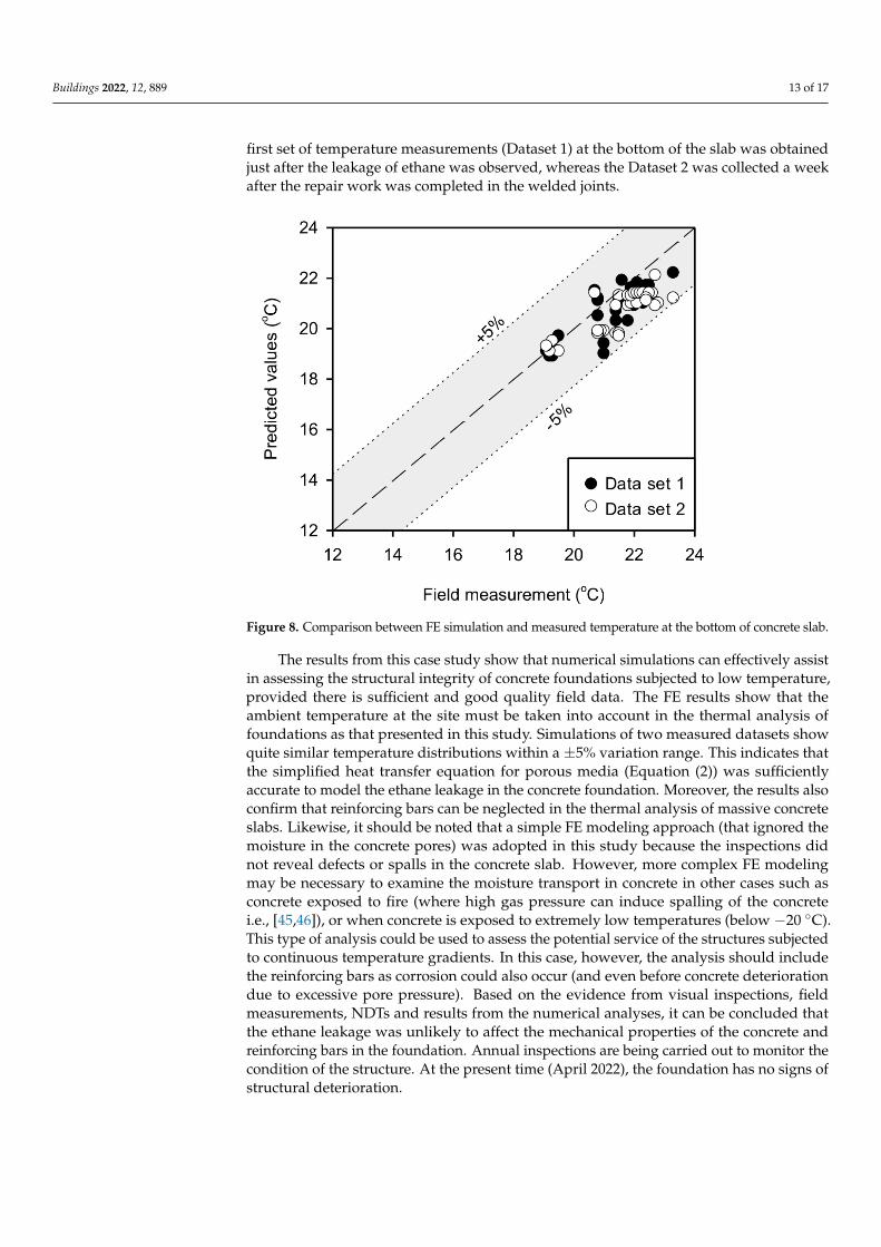
first set of temperature measurements (Dataset 1) at the bottom of the slab was obtainedjust after the leakage of ethane was observed, whereas the Dataset 2 was collected a weekafter the repair work was completed in the welded joints.
Figure 8. Comparison between FE simulation and measured temperature at the bottom of concrete slab.
The results from this case study show that numerical simulations can effectively assistin assessing the structural integrity of concrete foundations subjected to low temperature,provided there is sufficient and good quality field data. The FE results show that theambient temperature at the site must be taken into account in the thermal analysis offoundations as that presented in this study. Simulations of two measured datasets showquite similar temperature distributions within a ±5% variation range. This indicates thatthe simplified heat transfer equation for porous media (Equation (2)) was sufficientlyaccurate to model the ethane leakage in the concrete foundation. Moreover, the results alsoconfirm that reinforcing bars can be neglected in the thermal analysis of massive concreteslabs. Likewise, it should be noted that a simple FE modeling approach (that ignored themoisture in the concrete pores) was adopted in this study because the inspections didnot reveal defects or spalls in the concrete slab. However, more complex FE modelingmay be necessary to examine the moisture transport in concrete in other cases such asconcrete exposed to fire (where high gas pressure can induce spalling of the concretei.e., [45,46]), or when concrete is exposed to extremely low temperatures (below −20 ◦C).This type of analysis could be used to assess the potential service of the structures subjectedto continuous temperature gradients. In this case, however, the analysis should includethe reinforcing bars as corrosion could also occur (and even before concrete deteriorationdue to excessive pore pressure). Based on the evidence from visual inspections, fieldmeasurements, NDTs and results from the numerical analyses, it can be concluded thatthe ethane leakage was unlikely to affect the mechanical properties of the concrete andreinforcing bars in the foundation. Annual inspections are being carried out to monitor thecondition of the structure. At the present time (April 2022), the foundation has no signs ofstructural deterioration.

Buildings 2022, 12, 889 14 of 17
6. Conclusions
This article presents a case study on the thermal assessment of an RC foundationexposed to low temperatures. The foundation supports a large tank of a petrochemicalplant and stores low-temperature ethane (−89 ◦C). The ethane leaked to the RC foundationshortly after the tank started operations, which in turn produced condensation in theconcrete slab of the foundation and raised structural safety concerns. An FE model of theconcrete foundation was developed, and this proved to be an effective tool that providedfurther insight into the thermal behaviour of the slab. Based on the field inspections andnumerical analysis presented in this study, the following conclusions can be drawn:
• The FE results show that the ambient temperature at the site must be taken into accountin the thermal analysis of foundations, as presented in this study. When the ambienttemperature recorded during the field temperature measurements was consideredin the analysis, the temperatures calculated by the FE model agreed well with themeasured values. The average of the ratios of measured temperatures to FE results wasExp/FE = 1.03, with a standard deviation SD = 0.03 for Dataset 1. The correspondingvalues were Exp/FE = 1.05 and SD = 0.04 for Dataset 2.
• The FE results also showed that the temperature progressively increases towardsthe bottom of the concrete slab. This means that the reinforcing bars and the innertemperature of the slab was higher than +9.7 ◦C, and it reached +23 ◦C at the bottomof the slab once the influence of environmental conditions were considered. Thisindicates that the simplified heat transfer equation for porous media (Equation (2))was sufficiently accurate to model the ethane leakage in the concrete foundation.Moreover, the results also confirm that reinforcing bars can be neglected in the thermalanalysis of massive concrete slabs.
• Based on the evidence from visual inspections, field measurements, nondestructivetesting and results from the FE analyses, it can be concluded that the ethane leakagewas unlikely to affect the mechanical properties of the concrete and reinforcing barsin the foundation. Annual inspections are being carried out to monitor the conditionof the structure. The approaches, methods and techniques presented in this articleproved suitable to solve the practical and scientific challenges involved in the structuralassessment and repairs of this large special structure. Accordingly, they can serve asuseful reference and guidance for engineers and practitioners working in the field offorensic engineering.
Author Contributions: Conceptualization, T.I. and C.W.; methodology, T.I.; software, C.W.; valida-tion, T.I. and P.A.; formal analysis, T.I.; investigation, P.A.; writing—original draft preparation, T.I.;writing—review and editing, C.W. and F.P.F.; visualization, C.H.; supervision, R.G. All authors haveread and agreed to the published version of the manuscript.
Funding: This research was funded by a Walailak University research grant (contract no. WU 64252).
Institutional Review Board Statement: Not applicable.
Data Availability Statement: Not applicable.
Acknowledgments: This research was financially supported by the new strategic research project(P2P), Walailak University, Thailand. The authors are also thankful to International EngineeringConsultants Co., Ltd., (IEC-Thailand) and PTT Global Chemical Public Company Limited, forproviding access to the results from the field temperature measurements.
Conflicts of Interest: The authors declare no conflict of interest.
Buildings 2022, 12, 889 15 of 17
Appendix A
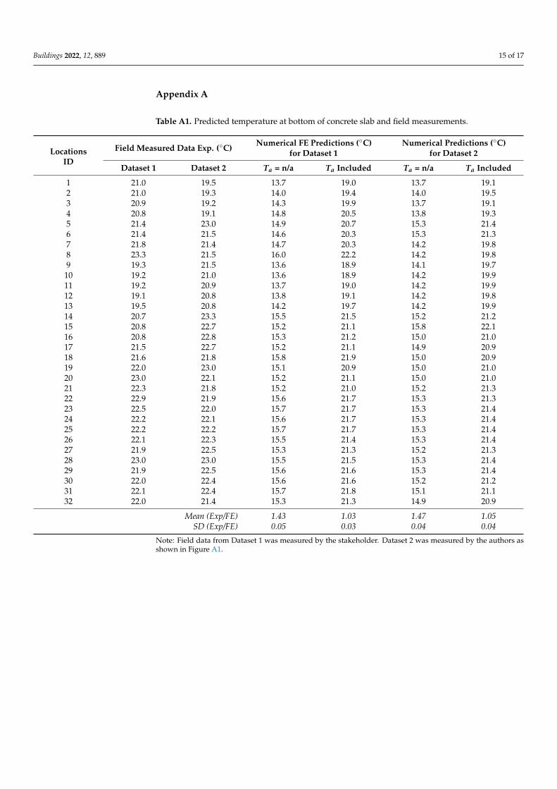
Table A1. Predicted temperature at bottom of concrete slab and field measurements.
LocationsID
Field Measured Data Exp. (◦C) Numerical FE Predictions (◦C)for Dataset 1
Numerical Predictions (◦C)for Dataset 2
Dataset 1 Dataset 2 Ta = n/a Ta Included Ta = n/a Ta Included
1 21.0 19.5 13.7 19.0 13.7 19.12 21.0 19.3 14.0 19.4 14.0 19.53 20.9 19.2 14.3 19.9 13.7 19.14 20.8 19.1 14.8 20.5 13.8 19.35 21.4 23.0 14.9 20.7 15.3 21.46 21.4 21.5 14.6 20.3 15.3 21.37 21.8 21.4 14.7 20.3 14.2 19.88 23.3 21.5 16.0 22.2 14.2 19.89 19.3 21.5 13.6 18.9 14.1 19.7
10 19.2 21.0 13.6 18.9 14.2 19.911 19.2 20.9 13.7 19.0 14.2 19.912 19.1 20.8 13.8 19.1 14.2 19.813 19.5 20.8 14.2 19.7 14.2 19.914 20.7 23.3 15.5 21.5 15.2 21.215 20.8 22.7 15.2 21.1 15.8 22.116 20.8 22.8 15.3 21.2 15.0 21.017 21.5 22.7 15.2 21.1 14.9 20.918 21.6 21.8 15.8 21.9 15.0 20.919 22.0 23.0 15.1 20.9 15.0 21.020 23.0 22.1 15.2 21.1 15.0 21.021 22.3 21.8 15.2 21.0 15.2 21.322 22.9 21.9 15.6 21.7 15.3 21.323 22.5 22.0 15.7 21.7 15.3 21.424 22.2 22.1 15.6 21.7 15.3 21.425 22.2 22.2 15.7 21.7 15.3 21.426 22.1 22.3 15.5 21.4 15.3 21.427 21.9 22.5 15.3 21.3 15.2 21.328 23.0 23.0 15.5 21.5 15.3 21.429 21.9 22.5 15.6 21.6 15.3 21.430 22.0 22.4 15.6 21.6 15.2 21.231 22.1 22.4 15.7 21.8 15.1 21.132 22.0 21.4 15.3 21.3 14.9 20.9
Mean (Exp/FE) 1.43 1.03 1.47 1.05SD (Exp/FE) 0.05 0.03 0.04 0.04
Note: Field data from Dataset 1 was measured by the stakeholder. Dataset 2 was measured by the authors asshown in Figure A1.

Buildings 2022, 12, 889 16 of 17
Figure A1. Locations of field temperature measurements and typical pile spacing (in meters).
References1. Le May, I. Structural integrity and petrochemical industry. Energy Mater. 2008, 3, 208–219. [CrossRef]2. Mieno, F. The Eastern Seaboard Development Plan and Industrial Cluster in Thailand: A Quantitative Overview. In Aid as
Handmaiden for the Development of Institutions: A New Comparative Perspective; Nissanke, M., Shimomura, Y., Eds.; PalgraveMacmillan: London, UK, 2013; pp. 81–105.
3. Azadeh, A.; Salehi, V.; Arvan, M.; Dolatkhah, M. Assessment of resilience engineering factors in high-risk environments by fuzzycognitive maps: A petrochemical plant. Saf. Sci. 2014, 68, 99–107. [CrossRef]
4. Moradi, B. Risk-Based Inspection Technique and the Benefits of Its Implementation in Improving the Process Management Systemof Oil, Gas and Petrochemical Industries: A Review Study. J. Saf. Promot. Inj. Prev. 2020, 8, 158–171. [CrossRef]
5. Si, H.; Ji, H.; Zeng, X. Quantitative risk assessment model of hazardous chemicals leakage and application. Saf. Sci. 2012, 50,1452–1461. [CrossRef]
6. Ghani, U.; Shabbir, F.; Khan, K. Effect of temperature on different properties of concrete. In Proceedings of the 31st ConferenceOur World in Concrete and Structures, Singapore, 16–17 August 2006.
7. Lee, G.C.; Shih, T.S.; Chang, K.C. Mechanical Properties of Concrete at Low Temperature. J. Cold Reg. Eng. 1988, 2, 13–24.[CrossRef]
8. Collins, A.R. The Destruction of Concrete by Frost. J. Inst. Civ. Eng. 1944, 23, 29–41. [CrossRef]9. Rostásy, F.S.; Schneider, U.; Wiedemann, G. Behaviour of mortar and concrete at extremely low temperatures. Cem. Concr. Res.
1979, 9, 365–376. [CrossRef]10. Filiatrault, A.; Holleran, M. Stress-strain behavior of reinforcing steel and concrete under seismic strain rates and low temperatures.
Mater. Struct. 2001, 34, 235–239. [CrossRef]11. Liu, S.; Gu, X.L.; Huang, Q.H.; Zhang, W.P. Experimental Study on the Bending Behavior of Reinforced Concrete Beams under
Super-Low Temperature. In Earth and Space 2021: Engineering, Science, Construction, and Operations in Challenging Environments;ASCE: Reston, VA, USA, 2021; pp. 3537–3544.
12. DeRosa, D.; Hoult, N.A.; Green, M.F. Effects of varying temperature on the performance of reinforced concrete. Mater. Struct.2015, 48, 1109–1123. [CrossRef]
13. Montejo, L.; Asce, S.; Sloan, J.; Asce, A.; Kowalsky, M.; Kowalsky, J.; Hassan, T. Cyclic Response of Reinforced Concrete Membersat Low Temperatures. J. Cold Reg. Eng. 2008, 22, 79–102. [CrossRef]
14. Sargam, Y.; Faytarouni, M.; Riding, K.; Wang, K.; Jahren, C.; Shen, J. Predicting thermal performance of a mass concretefoundation—A field monitoring case study. Case Stud. Constr. Mater. 2019, 11, e00289. [CrossRef]
15. Yan, J.-B.; Xie, J. Behaviours of reinforced concrete beams under low temperatures. Constr. Build. Mater. 2017, 141, 410–425.[CrossRef]
16. Monfore, G.E.; Lentz, A.E. Physical Properties of Concrete at Very Low Temperatures; Portland Cement Association, Research andDevelopment Laboratories: Washington, DC, USA, 1962.
17. Li, W.; Sun, W.; Jiang, J. Damage of concrete subjected to simultaneous fatigue load and thermal effect. Mag. Concr. Res. 2012, 64,35–42. [CrossRef]
Buildings 2022, 12, 889 17 of 17
18. API 653; Tank Inspection, Repair, Alteration, and Reconstruction. The American Petroleum Institute: Washington DC, USA, 2014.19. BS EN 14620-3:2006; Design and Manufacture of Site Built, Vertical, Cylindrical, Flat-Bottomed Steel Tanks for the Storage of
Refrigerated, Liquefied Gases with Operating Temperatures between 0 ◦C and −165 ◦C—Part 3: Concrete Components. BritishStandards Institution: London, UK, 2006.
20. Kong, L.-P.; Qiao, L.; Xiao, Y.-Y.; Li, Q.-W. A study on heat transfer characteristics and pile group influence of enhanced heattransfer energy piles. J. Build. Eng. 2019, 24, 100768. [CrossRef]
21. Sharifi, N.P.; Freeman, G.E.; Sakulich, A.R. Using COMSOL modeling to investigate the efficiency of PCMs at modifyingtemperature changes in cementitious materials—Case study. Constr. Build. Mater. 2015, 101, 965–974. [CrossRef]
22. Yang, W.; Zhang, L.; Zhang, H.; Wang, F.; Li, X. Numerical investigations of the effects of different factors on the displacement ofenergy pile under the thermo-mechanical loads. Case Stud. Therm. Eng. 2020, 21, 100711. [CrossRef]
23. Cawley, P. Non-destructive testing—Current capabilities and future directions. Proc. Inst. Mech. Eng. Part L J. Mater. Des. Appl.2001, 215, 213–223. [CrossRef]
24. Dwivedi, S.K.; Vishwakarma, M.; Soni, P.A. Advances and Researches on Non Destructive Testing: A Review. Mater. Today Proc.2018, 5, 3690–3698. [CrossRef]
25. Sinclair, T.; Malkin, R. Sensors for Ultrasonic Nondestructive Testing (NDT) in Harsh Environments. Sensors 2020, 20, 456.[CrossRef]
26. Weber, B.; Dauti, D.; Dal Pont, S. COMSOL Implementation of a porous media model for simulating pressure development inheated concrete. In Proceedings of the COMSOL Conference 2016, Munich, Germany, 12–14 October 2016; p. 6.
27. Žmindák, M.; Novák, P.; Dekýš, V.; Pelagic, Z. Finite Element Thermo-mechanical Transient Analysis of Concrete Structure.Procedia Eng. 2013, 65, 224–229. [CrossRef]
28. Huang, H.; Garcia, R.; Guadagnini, M.; Pilakoutas, K. Effect of section geometry on development of shrinkage-induceddeformations in box girder bridges. Mater. Struct. 2017, 50, 222. [CrossRef]
29. Jana, D. Cracking of residential concrete foundations in eastern Connecticut, USA from oxidation of pyrrhotite. Case Stud. Constr.Mater. 2022, 16, e00909. [CrossRef]
30. Toyo Engineering Corporation. The Thermal (Low Temperature) Effect to T-4801 Ethane Tank Foundation Due to the Leakage of Ethane;Technical Report R0 20110207; Toyo Engineering Corporation: Bangkok, Thailand, 2011.
31. ASTM A240; Standard Specification for Chromium and Chromium-Nickel Stainless Steel Plate, Sheet, and Strip for PressureVessels and for General Applications. ASTM International: West Conshohocken, PA, USA, 2020. [CrossRef]
32. ASTM E1002-11; Standard Practice for Leaks Using Utrasonics. ASTM International: West Conshohocken, PA, USA, 2018.[CrossRef]
33. Imjai, T.; Tungsanga, K. Finite Element Analysis on Temperature Distribution of Ethane Storage Tank Concrete Foundation—A Case Study. In Proceedings of the International Conference on Advances in Computational Mechanics (ACOME), Ho Chi MinhCity, Vietnam, 14–16 August 2012.
34. International Engineering Consultants Co.Ltd. Engineering Verification of T-4801 Ethane Tank Foundation Strength; Technical ReportNo. IEC-T4801-01; International Engineering Consultants Co., Ltd.: Bangkok, Thailand, 2011; p. 32.
35. ACI 364. 1; Guide for Evaluation of Concrete Structures Prior to Rehabilitation. American Concrete Institute: Farmington Hills,MI, USA, 1999.
36. API 12C; Specification for Welded Oil Storage Tanks. The American Petroleum Institute: Washington, DC, USA, 1962.37. ACI 318-14; Building Code Requirements for Structural Concrete. American Concrete Institute: Farmington Hills, MI, USA, 2014.38. ASTM C177-19; Standard Test Method for Steady-State Heat Flux Measurements and Thermal Transmission Properties by Means
of the Guarded-Hot-Plate Apparatus. ASTM International: West Conshohocken, PA, USA, 2019. [CrossRef]39. Bernuzzi, C.; Cordova, B. Structural Steel Design to Eurocode 3 and AISC Specifications: Bernuzzi/Structural Steel Design to Eurocode 3
and AISC Specifications; John Wiley & Sons: Hoboken, NJ, USA, 2016.40. Comsol Multiphysics. Comsol v. 5.4 Heat Transfer Module User’s Guide; Comsol Multiphysics: Burlington, MA, USA, 2008.41. Nield, D.A. Effects of local thermal nonequilibrium in steady convective processes in a saturated porous medium: Forced
convection in a channel. J. Porous Media 1998, 1, 181–186.42. Nield, D.A.; Bejan, A. Convection in Porous Media, 4th ed.; Springer: New York, NY, USA, 2013.43. Gasch, T.; Ericsson, D. Thermally-induced cracking of a concrete arch dam using COMSOL Multiphysics. In Proceedings of the
14th ICOLD International Benchmark Workshop on Numerical Analysis of Dams, Stockholm, Sweden, 6–8 September 2017.44. Johnson, K.R. Thermal Integrity Analysis of Concrete Bridge Foundations Using COMSOL Multiphysics® Software; Comsol Multiphysics:
Burlington, MA, USA, 2017.45. da Amorim Coelho, N.; Pedroso, L.J.; da Silva Rêgo, J.H.; Nepomuceno, A.A. Use of ANSYS for thermal analysis in mass concrete.
J. Civ. Eng. Archit. 2014, 8, 860–868. [CrossRef]46. Isgor, O.B.; Razaqpur, A.G. Finite element modeling of coupled heat transfer, moisture transport and carbonation processes in
concrete structures. Cem. Concr. Compos. 2004, 26, 57–73. [CrossRef]