Effect of foundation flexibility on seismic response of reinforced concrete TV-towers
17
Effect of foundation flexibility on seismic response of reinforced concrete TV-towers Amir M. Halabian and M. Hesham El Naggar Abstract: The analysis of tall reinforced concrete TV-towers is commonly simplified by assuming a fixed base and ig- noring the effect of soil–structure interaction. However, the foundation flexibility affects the dynamic characteristics of tall structures and influences their dynamic behaviour. To design these towers for dynamic loading, the fundamental natural periods, base bending moment, and base shear force as the most important parameters are needed and must be evaluated properly. In the current study, a finite element formulation for the response analysis of TV-towers subjected to earthquake ground motion accounting for soil–structure interaction is presented. The effects of foundation flexibility on the dynamic behaviour of TV-towers were evaluated for two different types of foundation, shallow footing and deep foundation, and various soil profiles. A typical example for these towers is analysed and the results for a range of soil dynamic parameters are presented. It was found that the foundation flexibility increases the natural periods, alters the natural mode shapes, and decreases the base bending moment. It was also concluded that the effect of soil–structure in- teraction may have a large effect on the base shear of the tower and should be considered in the analysis, especially for the design of horizontal reinforcement. Key words: soil–structure interaction, TV-towers, natural period, base forces, foundation flexibility. Résumé : L’analyse de grande tours de télévision en béton armé est souvent simplifiée en assumant une base fixe et en ignorant l’effet de l’interaction sol–structure. Cependant, la flexibilité de la fondation affecte les caractéristiques dyna- miques des grandes structures et influence leur réponse dynamique. Pour la conception de ces tours pour des charges dynamiques, les périodes fondamentales naturelles, le moment à la base et la force de cisaillement, en tant que paramè- tres les plus importants, sont requis et doivent être évalués correctement. Dans la présente étude, un modèle d’éléments finis pour l’analyse du comportement des tours de télévision soumises à la vibration du sol causée par un tremblement de terre, tenant compte de l’interaction sol–structure, est présenté. Les effets de la flexibilité de la fondation sur la ré- ponse dynamique des tours de télévision ont été évaluées pour deux types de fondation, peu profonde et profonde, et pour différents profils de sol. Un exemple typique de ces tours est analysé et les résultats pour un éventail de paramè- tres dynamiques de sol sont présentés. Il a été trouvé que la flexibilité de la fondation augmente les périodes naturel- les, change les formes des modes naturels et diminue le moment à la base. Il a aussi été conclu que l’effet de l’interaction sol–structure peut avoir un grand effet sur le cisaillement à la base de la tour et devrait être considéré dans l’analyse, spécialement pour la conception de l’armature horizontale. Mots clés : interaction sol–structure, tours de télévision, période naturelle, forces à la base, flexibilité de la fondation. [Traduit par la Rédaction] 481 Halabian and El Naggar Introduction Reinforced concrete TV-towers are generally supported on soils unless rock is very near the ground surface. The soil and supporting foundations have a significant effect on the response of these structures to dynamic loads from wind and earthquakes, due to the phenomenon commonly referred to as soil–structure interaction (SSI). The evaluation of SSI is needed for proper analysis of the tower’s response to wind and earthquake forces. Because different tall shell structures such as chimneys, cooling towers, and TV-towers behave differently in dy- namic loading conditions, extension of the results from SSI discussion on dynamic characteristics of one type of tall shell structures to another is generally rare and difficult. Johns et al. (1980) and Ogendo et al. (1983) considered foundation flexibility when exploring the effect of an added damping mat on the behaviour of steel chimneys. Novak (1974a, 1977) and Novak and El Hifnawy (1988) examined the response of tall reinforced concrete chimneys to gusting wind. Recently, Galsworthy and El Naggar (1997, 2000) considered the behaviour of reinforced concrete chimneys accounting for SSI. For reinforced concrete TV-towers, the conventional method of analysis, in which the tower is assumed to behave as a Can. J. Civ. Eng. 28: 465–481 (2001) © 2001 NRC Canada 465 DOI: 10.1139/cjce-28-3-465 Received July 5, 2000. Revised manuscript accepted February 21, 2001. Published on the NRC Research Press Web site at http://cjce.nrc.ca on June 5, 2001. A.M. Halabian and M.H. El Naggar. 1 Geotechnical Research Centre, Department of Civil and Environmental Engineering, Faculty of Engineering Science, The University of Western Ontario, London, ON N6A 5B9, Canada. Written discussion of this article is welcomed and will be received by the Editor until October 31, 2001. 1 Author to whom all correspondence should be addressed (e-mail: [email protected]).
-
Upload
independent -
Category
Documents
-
view
2 -
download
0
Transcript of Effect of foundation flexibility on seismic response of reinforced concrete TV-towers

Effect of foundation flexibility on seismic responseof reinforced concrete TV-towers
Amir M. Halabian and M. Hesham El Naggar
Abstract: The analysis of tall reinforced concrete TV-towers is commonly simplified by assuming a fixed base and ig-noring the effect of soil–structure interaction. However, the foundation flexibility affects the dynamic characteristics oftall structures and influences their dynamic behaviour. To design these towers for dynamic loading, the fundamentalnatural periods, base bending moment, and base shear force as the most important parameters are needed and must beevaluated properly. In the current study, a finite element formulation for the response analysis of TV-towers subjectedto earthquake ground motion accounting for soil–structure interaction is presented. The effects of foundation flexibilityon the dynamic behaviour of TV-towers were evaluated for two different types of foundation, shallow footing and deepfoundation, and various soil profiles. A typical example for these towers is analysed and the results for a range of soildynamic parameters are presented. It was found that the foundation flexibility increases the natural periods, alters thenatural mode shapes, and decreases the base bending moment. It was also concluded that the effect of soil–structure in-teraction may have a large effect on the base shear of the tower and should be considered in the analysis, especiallyfor the design of horizontal reinforcement.
Key words: soil–structure interaction, TV-towers, natural period, base forces, foundation flexibility.
Résumé: L’analyse de grande tours de télévision en béton armé est souvent simplifiée en assumant une base fixe et enignorant l’effet de l’interaction sol–structure. Cependant, la flexibilité de la fondation affecte les caractéristiques dyna-miques des grandes structures et influence leur réponse dynamique. Pour la conception de ces tours pour des chargesdynamiques, les périodes fondamentales naturelles, le moment à la base et la force de cisaillement, en tant que paramè-tres les plus importants, sont requis et doivent être évalués correctement. Dans la présente étude, un modèle d’élémentsfinis pour l’analyse du comportement des tours de télévision soumises à la vibration du sol causée par un tremblementde terre, tenant compte de l’interaction sol–structure, est présenté. Les effets de la flexibilité de la fondation sur la ré-ponse dynamique des tours de télévision ont été évaluées pour deux types de fondation, peu profonde et profonde, etpour différents profils de sol. Un exemple typique de ces tours est analysé et les résultats pour un éventail de paramè-tres dynamiques de sol sont présentés. Il a été trouvé que la flexibilité de la fondation augmente les périodes naturel-les, change les formes des modes naturels et diminue le moment à la base. Il a aussi été conclu que l’effet del’interaction sol–structure peut avoir un grand effet sur le cisaillement à la base de la tour et devrait être considérédans l’analyse, spécialement pour la conception de l’armature horizontale.
Mots clés: interaction sol–structure, tours de télévision, période naturelle, forces à la base, flexibilité de la fondation.
[Traduit par la Rédaction] 481
Halabian and El NaggarIntroduction
Reinforced concrete TV-towers are generally supported onsoils unless rock is very near the ground surface. The soiland supporting foundations have a significant effect on theresponse of these structures to dynamic loads from wind and
earthquakes, due to the phenomenon commonly referred toas soil–structure interaction (SSI). The evaluation of SSI isneeded for proper analysis of the tower’s response to windand earthquake forces.
Because different tall shell structures such as chimneys,cooling towers, and TV-towers behave differently in dy-namic loading conditions, extension of the results from SSIdiscussion on dynamic characteristics of one type of tallshell structures to another is generally rare and difficult.Johns et al. (1980) and Ogendo et al. (1983) consideredfoundation flexibility when exploring the effect of an addeddamping mat on the behaviour of steel chimneys. Novak(1974a, 1977) and Novak and El Hifnawy (1988) examinedthe response of tall reinforced concrete chimneys to gustingwind. Recently, Galsworthy and El Naggar (1997, 2000)considered the behaviour of reinforced concrete chimneysaccounting for SSI.
For reinforced concrete TV-towers, the conventional methodof analysis, in which the tower is assumed to behave as a
Can. J. Civ. Eng.28: 465–481 (2001) © 2001 NRC Canada
465
DOI: 10.1139/cjce-28-3-465
Received July 5, 2000. Revised manuscript acceptedFebruary 21, 2001. Published on the NRC Research PressWeb site at http://cjce.nrc.ca on June 5, 2001.
A.M. Halabian and M.H. El Naggar.1 GeotechnicalResearch Centre, Department of Civil and EnvironmentalEngineering, Faculty of Engineering Science, The Universityof Western Ontario, London, ON N6A 5B9, Canada.
Written discussion of this article is welcomed and will bereceived by the Editor until October 31, 2001.
1Author to whom all correspondence should be addressed(e-mail: [email protected]).

lumped mass cantilever (stick model) with fixed base, un-derestimates the natural periods and overestimates the basebending moment of the shaft. In some cases, this methodfails to predict correctly the behaviour of the tower as a re-sult of ignoring some three-dimensional effects (especiallytorsional modes). Therefore, the correct prediction of naturalperiods and base forces depends on the accuracy of descrip-tion of the foundation and its structural properties. For thistype of structures, SSI may remarkably alter the mode shapesand reduce structural damping which significantly affectsthe across wind response. Depending on the underlying soil,the structural damping may or may not be compensated by in-creased foundation damping (Novak and El Hifnawy 1983).
Conceptionally, the easiest way to account for SSI in seis-mic analysis is to model a significant part of the soil aroundthe embedded structure and to apply the free-field motion atthe fictitious soil–structure interface. This direct procedurewould even allow certain nonlinear material laws of the soilto be considered. Furthermore, the effect of the spatial vari-ability of the ground motion and the properties of the soilsinvolved are taken into consideration in this approach. How-ever, the number of dynamic degrees of freedom in the soilregion is high, resulting in a large computer storage require-ment and a significant running time.
Assuming that the principle of the superposition is validin a SSI analysis, it is computationally more efficient to usean alternative method called substructure approach. Thismethod divides the entire system into two parts, superstruc-ture and substructure, and performs the dynamic analysis forsuperstructure using the impedance functions of the sub-structure. The SSI analysis for seismic excitation consists oftwo distinct parts. First, the force response of the site is cal-culated. Second, the modification of the seismic motion,which results from the actual interaction when superstruc-ture is inserted into seismic environment of the free field, isevaluated. Because the principle of superposition is assumedin the analysis, the substructure approach is limited to linearor equivalent linear problems.
In the current study, the substructuring approach has beenused to incorporate the effects of SSI. Using this approach,the fundamental natural periods and base forces for TV-towers with flexible foundations have been examined. Fur-thermore, the effect of element used to model the towercomponents on the results was investigated.
Modeling dynamic soil–structure interaction
TV-towers could be supported by different types of foun-dations. In most cases, they are supported by shallow or matfoundations. This type of foundation usually includes a tran-sition structure between the mat foundation and the shaft todistribute the internal forces coming from the shaft to amuch larger area of a mat foundation. The supporting soilunderneath the foundation could be considered as elastic orviscoelastic half space (Fig. 1a), a homogenous layer under-lain by a rigid medium (Fig. 1b), or a shallow layer under-lain by a half space (Fig. 1c). Alternatively, but lessfrequently encountered, deep foundations can be used. Deepfoundations comprise groups of piles in a deep homoge-neous soil deposit (floating piles) or penetrating a soil de-posit and resting on the bedrock (end bearing piles) as
shown in Fig. 1d. In all cases, the tower foundation may beburied to some extent beneath the surface of the ground.This embedment may have a considerable effect on the dy-namic response of the structure, in terms of the relative fre-quency content and amplitude of the resulting motions. In allcases, the flexibility of the foundation influences the dy-namic characteristics of the tower and SSI should be ac-counted for.
The basic substructure methodUsing the direct stiffness approach in structural analysis,
the three-dimensional dynamic equilibrium equations for thecomplete soil–structure system with damping added can begiven in terms of the absolute displacements,U, as follows:
[1] [ ]{ &&} [ ]{ &} [ ]{ } { }M U C U K U+ + = 0
where [M], [C], [K] are the mass, damping, and stiffness ma-trices, respectively, of the soil–structure model. To facilitatethe SSI analysis, eq. [1] can be reformulated in terms ofthree sets of nodal points (see Fig. 2) and the equilibriumequation can be rewritten as
[2]
[ ]
[ ]
[ ]
{ && }
{ && }
{ && }
M
M
M
U
U
U
SS
II
FF
S
I
F
0 0
0 0
0 0
é
ë
êêê
ù
û
úúú
ì
íï
îï
ü
ýï
þï
+
é
ë
êêê
ù
û
úúú
[ ] [ ]
[ ] [ ] [ ]
[ ] [ ]
{ &C C
C C C
C C
SS SI
IS II IF
FI FF
0
0
U
U
U
S
I
F
}
{ & }
{ & }
ì
íï
îï
ü
ýï
þï
+
é
ë
êêê
ù
û
úúú
[ ] [ ]
[ ] [ ] [ ]
[ ] [ ]
{K K
K K K
K K
USS SI
IS II IF
FI FF
0
0
S
I
F
}
{ }
{ }
{ }U
U
ì
íï
îï
ü
ýï
þï= 0
in which the common nodes at the interface of the structureand foundation are defined with I; the nodes within thestructure and the nodes within the foundation are definedwith S and F, respectively. The mass, the stiffness, and thedamping at the interface nodes are the sum of the contribu-tion from the structure (S) and the foundation (F) and aregiven by
[ ] [ ] [ ]M M MII II(S)
II(F)= +
[3] [ ] [ ] [ ]C C CII II(S)
II(F)= +
[ ] [ ] [ ]K K KII II(S)
II(F)= +
In terms of absolute motion, there are no external forcesacting on the system in the case of seismic excitation. How-ever, the displacement at the boundary of the foundationmust be known. If the absolute displacementsU are ex-pressed in terms of inertial displacements,u, relative to thefree-field displacements,v, which are called kinematic dis-placements, in absence of the structure mass, then
[4] { U} = { u} + { v}
Substituting eq. [4] into eq. [2] and assuming the free-field displacement is constant over the base of the super-
© 2001 NRC Canada
466 Can. J. Civ. Eng. Vol. 28, 2001
structure and considering the requirements for the dynamicfree-field motion (Gutierrez and Chopra 1978), the govern-ing equilibrium equations for dynamic response of a soil–structure system can be rewritten as
[5] [ ]{ &&} [ ]{ &} [ ]{ }[ ]
[ ]{&&M u C u K u
M
Mv+ + = -
é
ëê
ù
ûú
SS
II(S)
0
0}
It is worth noting that eq. [5] does not contain the mass ofthe foundation, which is accounted for in the calculation ofthe foundation dynamic stiffnesses.
The solution of the free-field displacements or kinematicdisplacements in the case of very rigid foundation–structuresystem is completely defined by the rotations and transla-tions of the massless structure, which moves as a rigid body.Hence, in calculating the free-field displacements one canreplace the massless structure by a rigid massless founda-tion, subjected to the same ground excitation as the originalsystem.
For computational convenience, the analysis of SSI underseismic excitation can be performed in three consecutive in-dependent analysis steps (Fig. 3) as follows:
1. Determination of the motion of the massless rigid foun-dation, when subjected to the same input motion as the totalsystem.
2. Determination of the dynamic impedance functions(springs and dashpot constants) associated with horizontalswaying, rocking, and cross rocking vibration modes of the
foundation. Due to the symmetry of the TV-tower, the othercomponents are usually not significant.
3. Computation of the seismic response of the superstruc-ture supported on springs and dashpots obtained in step 2,subjected to the free-field motion of the foundation obtainedin step 1.
The estimation of earthquake motions at the site of astructure is important for its design or retrofit measures. Inthe current study, it is assumed that the free-field motions atthe location of the structure, without the structure present,
© 2001 NRC Canada
Halabian and El Naggar 467
Fig. 1. Type of foundation: (a) shallow foundation on half space; (b) layer underlain by a rigid medium; (c) shallow layer underlain bya rigid medium; and (d) deep foundation.
Fig. 2. Soil–structure interaction system.

can be estimated and are specified in the form of an earth-quake design spectrum.
Substructure model
The determination of proper values for the dynamic stiff-ness and damping of foundation plays an important role inobtaining an accurate seismic response of towers. The varia-tion of these values with dynamic soil properties is usuallyremarkable and consequently their effect on the superstruc-ture behaviour is important. In this study, the variation of thetower response with the shear wave velocity of the support-ing soil was investigated for both shallow and deep founda-tions.
A number of analytical and numerical approaches areavailable to calculate the impedance functions for both shal-low and deep foundation systems that are mostly based on
the assumption of elastic or viscoelastic soil continuum. Inthese solutions the impedance functions of a foundation sys-tem are described in terms of complex functions, which havea real part,K1, representing the stiffness and an imaginary(out-of-phase) component,K2, representing the damping.The impedance functions of the foundation in each vibrationmode can be written as
[6] K = K1 + iK2
The impedance function can also be expressed using thestiffness constant,k (k = K1), and the constant of equivalentviscous damping,c = Im(K/w) = K2/w.
Shallow foundation on a half spaceFor sites where supporting soils extend to large depths
and there is no obvious rigid boundary such as a soil–rockinterface at shallow depths, it is appropriate to idealize the
© 2001 NRC Canada
468 Can. J. Civ. Eng. Vol. 28, 2001
Fig. 3. Decomposition of seismic soil–structure response into kinematic and inertial responses: (a) total system; (b) kinematic interac-tion; (c) subgrade impedance; and (d) inertial response.

soil domain as a viscoelastic half space. Based on this ideal-ization and assuming that the structure has a rigid base plateand sits on the surface of the viscoelastic half space, a num-ber of approaches are available to determine the equivalent dy-namic stiffness for the soil region. The dynamic stiffnesses fora circular foundation on the surface of a viscoelastichalf spacehave been tabulated by Luco and Westmann (1971),Veletsos and Wei (1971), Verbic and Veletsos (1972), andVeletsos and Verbic (1973) as a function of frequency. Inthese solutions the complex stiffness,Ki, associated with di-rection i is obtained from the determination of the relation-ship between harmonic force acting on a massless disc andthe resulting displacement of the disc. This complex stiff-ness can be expressed as
[7] K K iK k k ia cii i i
i i= + = +l st2 0( )
in which kist is the static stiffness and dimensionless parame-
terski andci are stiffness and damping frequency dependentconstants which are normalized as follows:k K ki
i i= l st/ ,c V k r Ki s
i i= ( / )w st 2. In eq. [7], a0 = wr/Vs is a dimensionlessfrequency, wherew is the excitation frequency,r is the ra-dius of the foundation, andVs is the soil shear wave velocity.
For the case of an embedded shallow foundation, it isknown that the embedment increases both stiffness anddamping components, but the increase in the damping pa-rameters is more significant. Approximate expressions forthe motion of a rigid cylindrical body completely embeddedin an elastic stratum were presented by Tajimi (1969). Solu-tions for embedded circular and rectangular foundationshave been obtained (e.g., Novak and Beredugo 1971;Beredugo and Novak 1972; Novak and Sachs 1973; Kausel1974; Elsabee 1975; Kausel and Ushijima 1979). To accountfor the embedment effect, the method developed by Novaket al. (1978) has been used in this study. In this method theformulas for a surface foundation are used to reproduce thebase stiffness, and the side soil (the backfill) reactions arecalculated from Baranov’s (1967) equations assuming planestrain conditions. Novak et al. (1978) also indicated that, asa simplification, these coefficients may be assumed to beconstant, in which case the surrounding soil can be repre-sented by a set of springs and dashpots.
In the case shown in Fig. 1a, a stratum whose depth isgreater than about five equivalent footing radii may betreated as a half space using this option. In the case of abackfill existing around the foundation, the properties of thesoil layer overlying half space may differ from those of thehalf space.
Footing on a homogeneous layer (stratum)For the option shown in Fig. 1b, the footing resting on the
surface of or being embedded in a shallow, homogeneouslayer underlain by a rigid medium (bed rock), the impedancefunction may be remarkably different from those of the halfspace. The most prominent feature of a shallow layer case isthat the geometric damping of the foundation can be consid-erably reduced or even vanished if the dominant frequencyof the response is lower than the first lateral frequency of thelayer. The layer stiffness and damping constants may be ob-tained from the method suggested by Kausel and Ushijima(1979). Kausel and Ushijima derived the static stiffnesses ofa footing embedded in a layer of limited thickness in the ro-
tational and translational modes as a function of the thick-ness of the soil layer. They recommendedk and c valuesequal to those of the half space except forc in the low fre-quency range.
Footing on a layer overlying half spaceIn this case, shown in Fig. 1c, in which the footing base
rests on the surface of a shallow layer underlain by a halfspace, the base soil reaction may be obtained using the re-sults in Wong and Luco (1985). The solution is exact forsquare footings, but for other shapes, the impedances can beevaluated approximately using equivalent dimensions ob-tained by equating the geometric properties of the base ofthe actual footing with those of a square base. In this solu-tion the layers may be uniform or non-uniform with linearlyvarying shear wave velocity and the half space is homoge-neous.
Deep foundationThe calculation of the stiffness and damping for a deep
foundation may be carried out in two steps: calculation of
© 2001 NRC Canada
Halabian and El Naggar 469
Fig. 4. Stick model of the soil–structure system.

the complex stiffness of the single pile and evaluation of thegroup effect. Several approaches are developed to calculatethe single pile impedance functions that are mostly based onWinkler foundation assumption. Novak (1974b) developed asolution for single piles based on the Winkler assumptionand assuming plane strain conditions. This solution was ex-tended by Novak and Aboul-Ella (1978) to the case of a lay-ered medium. In this approach the dynamic soil reactions tothe displacements of a pile are calculated assuming that thesoil consists of infinitely thin layers extending horizontallyto infinity.
The calculation of pile group dynamic stiffnesses shouldaccount for the interaction of piles with soil and the otherpiles in the group. This effect, dynamic group effect, is quitecomplex and there is no simple way to alleviate this com-plexity. A simplified approximate analysis for the dynamicgroup effects can be formulated on the basis of dynamic in-teraction factors,a, introduced by Kaynia and Kausel(1982), who presented charts for dynamic interaction factorsof pile groups based on the boundary element method.
Soil–structure model for TV-towers
Lumped mass (stick) modelIn practice, the response analysis of TV-towers is com-
monly simplified by using the lumped mass (stick) finite ele-ment model, usually referred to as the stick model. Theaccuracy of the simplified stick model in calculating the dy-namic response of TV-towers will be evaluated using boththe stick model and a more accurate finite element modelthat incorporates shell elements to analyze the response of aTV-tower. The results are compared in terms of the naturalperiod of the tower for the fixed base case. The descriptionof the stick model is given in this section and will be fol-lowed by the description of the finite element (shell) model.
In the stick model, shown in Fig. 4, the superstructure in-cluding the tower shaft, antenna, and tower head building isrepresented by a series of beam elements and some lumpedmasses. To account for SSI, the substructure system could beassumed resting on a sway-rocking foundation system withmass and mass moment of inertia equal tomb andIb, respec-tively. This representation leads to a system ofn + 2 degreesof freedom (n is the number of lumped masses of the super-structure): one horizontal translation (relative to the founda-tion) for each mass,ui, where i = 1, …, n; the horizontaltranslation of the foundation,ub; and the rotation of the sys-tem,y. Assuming small displacements, the matrices in thegoverning equations (eq. [5]) of the system can be defined as
[ ]
[ ] { } { }
{ }
{ }
M
m m mh
m m m m h
mh m
ii
n
ii
n
i= += =å å
M
L M L L
M
M
Tb
T
1 1
ii
n
i ii
n
ih I m h= -å å+
é
ë
êêêêêêê
ù
û
úúúúúúú
1 1
2b
[8] [ ]
[ ] { } { }
{ }
{ }
K
k
k k
k kuu u
u
=
é
ë
êêêêê
ù
û
úM
L M L L
M
M
0 0
0
0
T
Ty
y yy
úúúú
[ ]
[ ] { } { }
{ }
{ }
C
c
c c
c cuu u
u
=
é
ë
êêêêê
ù
û
úM
L M L L
M
M
0 0
0
0
T
Ty
y yy
úúúú
and in eq. [5] the displacement vector {u} = [ u1 u2 … un uby]T is the vector of structural and foundation displacementsrelative to the foundation, and the excitation force (neglect-ing the kinematic effect interaction) is given by
- +é
ëêê
ù
ûúú= =
å å{ } &&m m m m h uii
n
ii
n
ib
T
g1 1
where &&ug he free-field earthquake acceleration. In eq. [8],[m] is a diagonal mass matrix listing lumped massesmi ateach foundation-to-mass heights,hi; [k] is the stiffness ma-trix; [c] is the viscous damping matrix of the superstructure;{ m} = { m1 m2 … mn}
T; { mh} = { m1h1 m2h2 … mnhn}. Also,
© 2001 NRC Canada
470 Can. J. Civ. Eng. Vol. 28, 2001
Fig. 5. Finite element model.
I m hi
n
i ib +=S
1
2 is the total moment of inertia of the structure
and foundation with respect to the central axis of the foun-dation. The foundation properties are incorporated as stiff-ness, damping, and mass submatrices as shown in eq. [8]. Inthese matrices,kuu, kuy, kyu, and kyy are stiffness coeffi-cients of the foundation andcuu, cuy, cyu, and cyy are itsdamping coefficients.
Finite element (shell) modelUsing beam elements and lumped masses instead of distrib-
uted mass in the preceding model overestimates the stiffnessof the superstructure, underestimates the natural periods, andalters the natural modes of the system. To address the draw-backs of the stick model, a three-dimensional finite elementformulation was used to model the superstructure. The finiteelement model was used to study the damped fundamentalnatural periods and induced base forces (at the interface ofthe shaft and foundation of the tower) due to earthquakeloading. In this model, shell elements (quadrilateral ele-ments) with linear shape functions and five principal degreesof freedom at each node were used to represent the shaft.The tower head building was modelled as a series of floors
whose masses have been lumped at corresponding dia-phragms at each floor. The antenna is modelled using shellelements, to account for its torsional modes of vibration. Totake into account foundation flexibility, a three-dimensionalone-node spring-dashpot element has been used to representthe foundation stiffness and damping constants. A masslessrigid plate was used to distribute the foundation stiffness tothe shaft walls (Fig. 5). The thickness and modulus of elas-ticity of this plate, which is located between the spring-dashpot element and the tower shaft, are chosen so that nosingularity occurs in the stiffness matrix of the tower.
Therefore, using the method described by Clough andPenzien (1993), the governing differential equations of iner-tial motion for the proposed model can be written in theform:
[9][ ]
[ ]
{&& }
{&& }
[ ]
[ ]
[M
M
u
u
c
c
cSS
II
s
I
SS
IS
S0
0
é
ëê
ù
ûúìíî
üýþ+ I
II FF
s
I
]
[ ] [ ]
{& }
{& }c c
u
u+é
ëê
ù
ûúìíî
üýþ
++
é
ëê
ù
ûúìíî
üýþ= -
[ ] [ ]
[ ] [ ] [ ]
{ }
{ }
[k k
k k k
u
uSS SI
IS II FF
s
I
M
MvSS
II(S)
]
[ ]{&&}
0
0
é
ëê
ù
ûú
© 2001 NRC Canada
Halabian and El Naggar 471
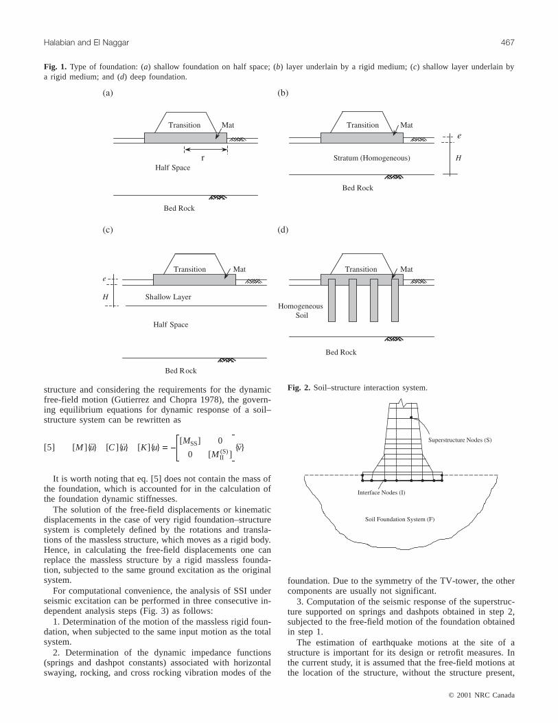
Fig. 6. Design earthquake spectra.
Period (s) Mass participation factor* (%) Mode shape type
Mode shapes Shell Stick Shell Stick Shell Stick†
1 5.66 5.275 46 47 Translation —x Translation —x2 5.66 5.275 46 47 Translation —y Translation —y3 1.495 2.01 6.5 1.62 Translation —x Translation —x4 1.495 2.01 6.5 1.62 Translation —y Translation —y5 1.117 1.027 17.2 21 Translation —x Translation —x6 1.117 1.027 17.2 21 Translation —y Translation —y7 0.959 0.591 0 1 Torsion (antenna) Translation —x8 0.935 0.591 0 1 Torsion (shaft) Translation —y9 0.422 0.383 0 8.8 Torsion (shaft) Translation —x
10 0.391 0.383 0 8.8 Torsion (shaft) Translation —y
*In lateral translation.†Mode shapes iny-direction are taken identical to those inx-direction because of the 2-D assumption of the stick model and the symmetry of the tower.
Table 1. Fundamental natural periods of the fixed base case.

where [kFF] and [cFF] are the spring-dashpot element stiff-ness and damping matrices which express the foundation im-pedance and each is represented in the form of a 6 × 6matrix corresponding to the foundation rigid motions:
[ ]
( ) ( )
( ) ( )
( )
(k
k k
k k
k
k
uu x ur x
uu y ur y
ww z
rrFF =
0 0 0 0
0 0 0
0 0 0
)
( )
( )
x
rr y
rr z
k
k
0 0
0sym.
é
ë
êêêêêêêê
ù
û
úúúúúúúú
[10]
[ ]
( ) ( )
( ) ( )
( )
(c
c c
c c
c
c
uu x ur x
uu y ur y
ww z
rrFF =
0 0 0 0
0 0 0
0 0 0
)
( )
( )
x
rr y
rr z
c
c
0 0
0sym.
é
ë
êêêêêêêê
ù
û
úúúúúúúú
where those parameters subscribed byu, r, and ur corre-spond to the horizontal translation, rotation, and couplingterms of translational and rotational displacements, respec-tively, andw is the vertical translation.
To solve eq. [9], the mode-superposition analysis method(modal analysis) was used. An improved Ritz-vector proce-dure is used to perform mode-superposition analysis ofstructure subjected to design earthquake spectra, which areobtained from free-field motion. It has been demonstrated(Wilson et al. 1982) that dynamic analyses based on a spe-
cial set of load-dependent Ritz vectors yield more accurateresults than the use of the same number of natural modeshapes. In this method the spatial distribution of the dynamicload vector serves as a starting load vector to initiate theprocedure. The first Ritz vector is the static displacementvector corresponding to the starting load vector. The remain-ing vectors are generated from a recurrence relationship inwhich the mass matrix is multiplied by the previously ob-tained Ritz vector and used as the load vector for the nextstatic solution, called generation cycle. When the dynamicload is made up of several independent spatial distributions,each of these may serve as a starting load vector to generatea set of Ritz vectors, each generation cycle creates as manyRitz vectors as there are starting load vectors. When a suffi-cient number of Ritz vectors have been found, some of themmay be closely approximate natural mode shapes and fre-quencies. The detailed algorithm may be found in Wilson(1985). In this study, three starting load vectors were used inthe analysis to obtain 50 Ritz-vector modes.
Seismic response of a TV-tower
To demonstrate the effect of foundation flexibility on theseismic response of TV-towers, an actual TV-tower was ana-lysed using the proposed methodology. The geometric dataof the Milad tower were made available to the authors to beexamined in this study. The Milad tower is located in north-west of Tehran, Iran, in a seismically active area. The toweris 435 m in height and consists of about 240 m reinforcedconcrete shaft, a twelve-storey heavy observation buildinglocated at a height of 240 m, and a 120 m tube antenna. Theactual foundation system consisted of a concrete slab sup-porting a heavy transition structure that is located betweenthe mat and the shaft. In this study, for purposes of compari-son, two different foundation systems, shallow footing and
© 2001 NRC Canada
472 Can. J. Civ. Eng. Vol. 28, 2001
First natural period ratio
Type of foundation Vs* = 100 Vs* = 200 Vs* = 300 Vs* = 400 Vs* = 500
Shallow foundation on half spaceNo embedment 1.545 1.147 1.072 1.057 1.044Embedded,e/r = 0.1 1.432 1.131 1.069 1.048 1.038Embedded,e/r = 0.2 1.412 1.125 1.066 1.046 1.037Whole model, no embedment 1.616 1.178 1.089 1.058 1.049
Shallow footing on a layerH = 2r, no embedment 1.429 1.127 1.069 1.047 1.037H = 2r, e/r = 0.1 1.358 1.109 1.06 1.043 1.034H = 3r, no embedment 1.452 1.135 1.071 1.049 1.038H = 3r, e/r = 0.1 1.374 1.114 1.062 1.044 1.035H = 4r, no embedment 1.473 1.136 1.072 1.049 1.039H = 4r, e/r = 0.1 1.382 1.116 1.063 1.044 1.035
Shallow footing on layer overlying half spaceH = r 1.379 1.116 1.063 1.044 1.035H = 0.5r 1.341 1.106 1.058 1.042 1.033
Deep foundationFloating piles 1.181 1.065 1.039 1.028 1.022End-bearing piles 1.104 1.072 1.054 1.044 1.039
*In metres per second.
Table 2. Variation of fundamental natural period with shear wave velocity.

deep foundation, are considered. Three different soil modelswere considered for the shallow foundation option: shallowfooting resting on a half space, shallow footing on a homo-geneous layer, and footing on a layer overlying a half space.In the deep foundation system, both end-bearing and floatingpiles were considered. The shear modulus of the soil was as-sumed to be constant with the depth. The soil shear velocitywas varied from 100 to 500 m/s to represent possible valuesof real soils. In all cases, the following soil parameters wereused: The unit weight of soilg = 17.5 kN/m3, Poisson’s ratiov = 0.3, and the material damping ratio = 0.05. The seismicexcitation is given by a horizontal free-field accelerationwith a peak value of 0.35g. The design spectrum used in thisstudy, shown in Fig. 6, is identical to the artificial spectrumobtained for the site of the real structure (Yadman Sazeh Co.1996).
The natural periods of the tower for the fixed base casewere calculated using both the stick model and the finite ele-ment shell model to examine the effect of the model used inthe analysis on the tower’s response and the results werecompared. The results for the fixed base finite element shellmodel were then used to normalize the results from the flex-ible foundation cases. The whole structure model (i.e., theshaft with the foundation structure including the transitionstructure and mat) was analyzed using the finite elementshell model to examine the effect of structural flexibility ofthe foundation on the response.
Table 1 shows the dynamic properties of the first ten modeshapes of the structure in the fixed base finite element shellmodel case. As it can be seen, the structure has several tor-sional mode shapes that cannot be extracted from the stickmodel analysis.
Shallow footingThe actual foundation system for the Milad TV-tower was
used in the analyses. Its foundation includes a relativelythick slab and a transition structure, similar to the foundationshown in Fig. 1a. The transition structure comprises someconcrete solid blocks and 16 thick concrete walls and sits ona circular mat with radiusr = 33 m. The natural periods (T),base bending moment, and shear forces of the structure dueto earthquake spectra assumed for the Tehran area were ob-tained for different soil models using corresponding imped-ance functions outlined above. The foundation stiffnesseswere calculated at the frequency equal to the weighted aver-age of the first three fundamental frequencies of the struc-ture obtained from the fixed base case analysis. In the caseof high-rise buildings with a period of more than about 4 s,the first natural mode of the structure usually occurs at a fre-quency much lower than the predominant frequency of the ap-plied earthquake spectra. Therefore, in this study, the weightedaverage method has been used over the first three fundamen-tal natural frequencies in which 70% of the total cumulativemass participation may be anticipated, as shown in Table 1.
Shallow footing on a half spaceThree different cases for a shallow footing on a half space
were considered: footing with no embedment and embeddedfoundation with an embedment ratio (e/r) equal to 0.1 and0.2. Table 2 shows the variation of the ratio of the first fun-damental natural period of the system to that for the fixed
base case (T/Tf) with shear wave velocity for the three cases.The fixed base case was examined using both the stickmodel and the finite element model. Because of the stifferbehaviour of the beam elements compared with shell ele-ments, the first natural period computed from the finite ele-ment (shell) model is approximately 8% greater than thatobtained from the stick model. However, this effect is less
© 2001 NRC Canada
Halabian and El Naggar 473
Fig. 7. First two normalized natural mode shapes for fixed baseand shallow foundation on half space based tower: (a) first modeand (b) second mode.

significant in the higher vibration modes. The results shownin the following sections were normalized by the fixed basefinite element (shell) model results.
It can be noted from Table 2 that the period shifts arewithin 55% ofTf, for the lower values ofVs. Table 2 also in-dicates that theT values associated with the embedded foun-dation options are smaller than those associated with the no-embedment cases. Furthermore, Table 2 shows a significantdifference between theT values obtained from the model inwhich the foundation structure flexibility was not considered
in the superstructure and the correspondingT values ob-tained from the whole model. This was more significant forlower values ofVs.
The SSI alters the mode shapes of the structure and accel-erates the convergence of the superposition method in themodal analysis approach. Besides, it changes the basic dy-namic characteristics of the tower, which may be manifestedin creation of a new set of modal shapes in the system. Forinstance, in the current analysis, the 8th and 15th modeshapes for the fixed base case (i.e., the first torsional and
© 2001 NRC Canada
474 Can. J. Civ. Eng. Vol. 28, 2001
Fig. 8. Variation of base shear with shear wave velocity for shallow foundation on a half space.
Fig. 9. Variation of base bending moment with shear wave velocity for shallow foundation on a half space.
Base shear ratio
Model Vs* = 100 Vs* = 200 Vs* = 300 Vs* = 400 Vs* = 500
Finite element model not including the foundation structure 1.0615 1.2526 1.2123 1.1482 1.1028Finite element model including the foundation structure 3.3214 3.8231 3.7543 3.6232 3.4814
*In metres per second.
Table 3. Variation of base shear ratio with shear wave velocity for shallow foundation.

vertical mode shapes) became the 7th and 10th mode shapeswith SSI accounted for. These modes, which would have im-portant influence on the behaviour of the observation build-ing, will contribute in the torsional and vertical behaviour ofthe tower by the mass participation factors about 83% and92%, respectively. The first two mode shapes (lateral trans-lation) scaled for the translational displacements of thetower axis along the height are shown in Fig. 7 for the fixedand flexible foundation cases. As it can be observed, for theflexible foundation case the curvature of the tower is re-duced as a result of the rotation of the foundation. It can alsobe noted from Fig. 7 that the effect of foundation flexibilityon the first mode amplitudes is more pronounced than its ef-fect on the higher modes. The changes in the first mode aremore significant because it involves the deformations of thetower itself, whereas the second mode involves, in the mostpart, changes in the deformations of the antenna. It was alsofound that the number of mode shapes required to achieve a95% cumulative mass participation factor in modal analysisusing the Ritz vector method decreased asVs decreased.
Figures 8 and 9 show the variation of the base shear andbending moment of the shaft at the interface between theshaft and foundation structure, as a ratio of the values fromthe fixed base finite element shell model, withVs. There aredifferences between the base shear and bending moment ob-tained from the fixed base stick model and the fixed baseshell model. For the present model, this difference was up to5% and 7% for base shear and base bending moment, re-spectively, which is important because the base forces forthis type of structures are usually high. Figure 8 shows thatthe base shear increased by as much as 32% due to the foun-dation flexibility. This shows that the base shear of the flexi-ble base structure can be higher than that for the fixed basestructure depending on the type of structure, the distributionof mass of structure along the height, the soil shear modulus,and the base motion frequency content. Similar results wereobtained by Kumar (1996) for the case of low-rise buildingsand by Gan (1996) for high-rise buildings. The AppliedTechnology Council’s (ATC 3-06) recommendations (ATC1978) suggest that neglecting the SSI effects err on the con-servative side but that may not be the case for some struc-tures. As pointed out by Mylonakis and Gazetas (2000) andGazetas and Mylonakis (2001), this perception apparentlystems from oversimplifications in the nature of seismic de-mands and modeling of the structures adopted in code provi-sions. For example, the ATC recommendation was based onthe work of Veletsos and Nair (1975) considering SDOF sys-tems, which may not apply for MDOF systems.
The results from the finite element shell model (wholemodel) including the foundation structure showed that theshear force induced at the soil–foundation interface was upto three times the base shear from the fixed base case, as canbe noted from Table 3. This must be taken into account inthe structural and geotechnical design of the foundation, es-pecially for pile foundation. It can also be noted from Ta-ble 3 that the variation of this contact shear force with theshear wave velocity is similar to the variation of the baseshear withVs. In addition, the comparison between the baseshear results at the shaft–foundation interface obtained fromthe finite element shell model including the foundationstructure flexibility and from the model neglecting it showed
that there is a good agreement between these two sets of val-ues (up to 1.8%). Therefore, the large difference between theshear force induced at the soil–foundation interface and thebase shear may be attributed to the substantial mass of theembedded portion of the foundation. Figure 9 indicates thatthe base bending for the flexible case was as low as 50% ofthe fixed base case.
The lateral displacement of the tower, which is importantfor consideringP–D effect, is shown in Fig. 10. It should benoted that the displacement amplitudes shown are the maxi-mum elastic displacements and not the working displace-ments.
Shallow footing on a soil layerThree cases were considered to examine the effect of the
deposit (stratum) depth on the behaviour of the tower. Threedepths for layer deposits are considered in this study:H = 2r,3r, and 4r. For each model, two embedment ratios,e/r = 0 and0.1, were considered to examine the effect of embedment onthe response. Table 2 shows the variation of the first naturalperiod of the tower withVs. Table 2 indicates that for similarshear wave velocities, the natural period of the structure islarger for the deeper soil deposits. It can also be noted fromTable 2 that the natural period decreases asVs and theembedment ratio increase. Figures 11 and 12 show the varia-tion of the base shear and bending moment withVs for theshallow layer option. The effect of the foundation flexibilityis to decrease the base bending moment by up to 45% and toincrease the base shear by up to 20%.
Shallow footing on a layer overlying a half spaceFor this soil model, two different practical depth values
for the upper layer, 0.5r andr, are considered in the analyses
© 2001 NRC Canada
Halabian and El Naggar 475
Fig. 10. Horizontal displacement of the tower with height due todesign spectra.

© 2001 NRC Canada
476 Can. J. Civ. Eng. Vol. 28, 2001
Fig. 11. Variation of base shear with shear wave velocity for shallow footing on layer.
Fig. 12. Variation of base bending moment with shear wave velocity for shallow footing on layer.
Fig. 13. Variation of base shear with shear wave velocity for shallow footing on a layer overlying a half space.
© 2001 NRC Canada
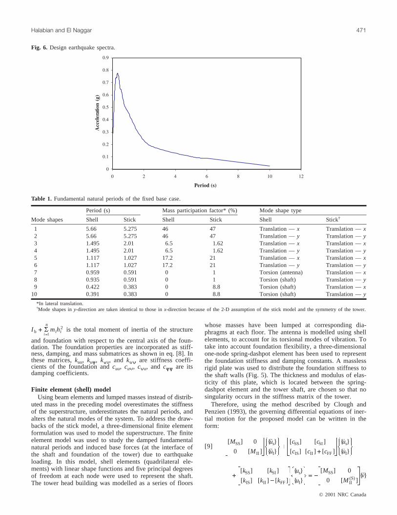
Halabian and El Naggar 477
Fig. 14. Variation of base bending moment with shear wave velocity for shallow footing on a layer overlying a half space.
Fig. 15. Variation of base shear with shear wave velocity for deep foundations.
Fig. 16. Variation of base bending moment with shear wave velocity for deep foundations.
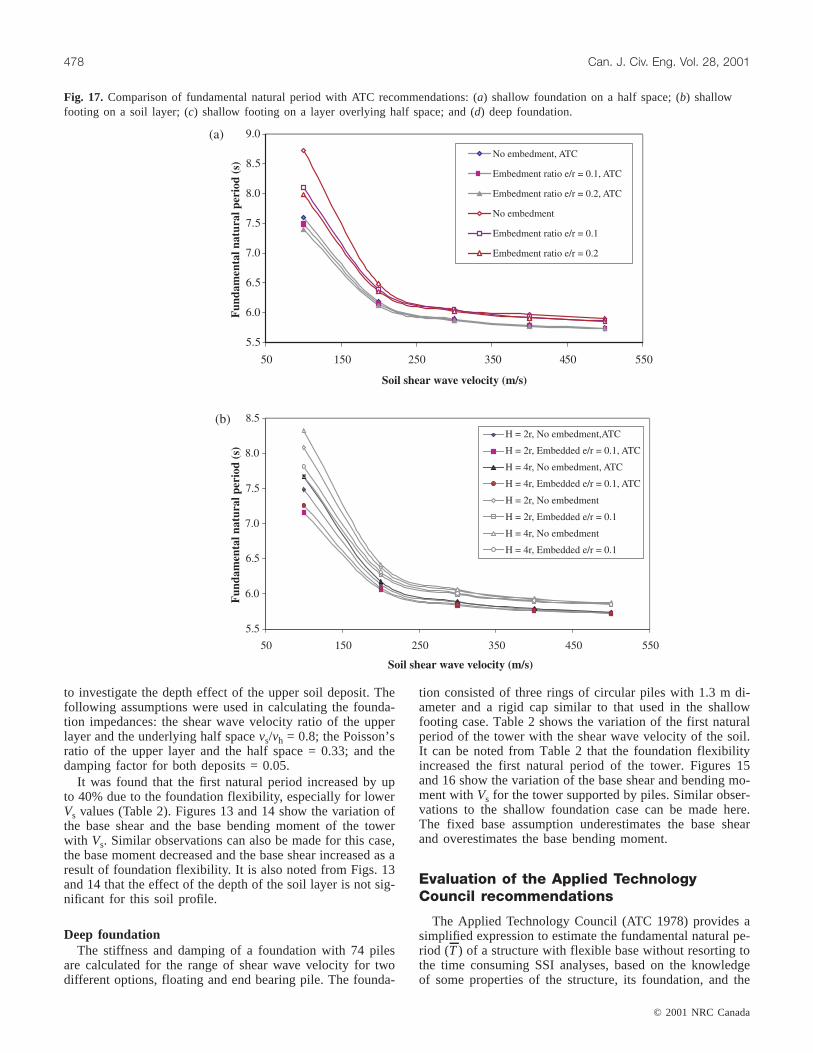
to investigate the depth effect of the upper soil deposit. Thefollowing assumptions were used in calculating the founda-tion impedances: the shear wave velocity ratio of the upperlayer and the underlying half spacevs/vh = 0.8; the Poisson’sratio of the upper layer and the half space = 0.33; and thedamping factor for both deposits = 0.05.
It was found that the first natural period increased by upto 40% due to the foundation flexibility, especially for lowerVs values (Table 2). Figures 13 and 14 show the variation ofthe base shear and the base bending moment of the towerwith Vs. Similar observations can also be made for this case,the base moment decreased and the base shear increased as aresult of foundation flexibility. It is also noted from Figs. 13and 14 that the effect of the depth of the soil layer is not sig-nificant for this soil profile.
Deep foundationThe stiffness and damping of a foundation with 74 piles
are calculated for the range of shear wave velocity for twodifferent options, floating and end bearing pile. The founda-
tion consisted of three rings of circular piles with 1.3 m di-ameter and a rigid cap similar to that used in the shallowfooting case. Table 2 shows the variation of the first naturalperiod of the tower with the shear wave velocity of the soil.It can be noted from Table 2 that the foundation flexibilityincreased the first natural period of the tower. Figures 15and 16 show the variation of the base shear and bending mo-ment withVs for the tower supported by piles. Similar obser-vations to the shallow foundation case can be made here.The fixed base assumption underestimates the base shearand overestimates the base bending moment.
Evaluation of the Applied TechnologyCouncil recommendations
The Applied Technology Council (ATC 1978) provides asimplified expression to estimate the fundamental natural pe-riod (T) of a structure with flexible base without resorting tothe time consuming SSI analyses, based on the knowledgeof some properties of the structure, its foundation, and the
© 2001 NRC Canada
478 Can. J. Civ. Eng. Vol. 28, 2001
Fig. 17. Comparison of fundamental natural period with ATC recommendations: (a) shallow foundation on a half space; (b) shallowfooting on a soil layer; (c) shallow footing on a layer overlying half space; and (d) deep foundation.

underlying soil deposit. This expression, which is based onthe work of Veletsos and Nair (1975) for providing an esti-mate ofT, takes the form
[11] T TKK
K hKx
x= + +ö
ø÷
æ
èçç1 1
2
q
whereT is the period of the fixed base structure,K is the lat-eral stiffness of the structure model when fixed at the base(kN/m), Kx is the lateral stiffness of the foundation (kN/m),Kq is the rocking stiffness of the foundation (kN·m/m), andhis the effective height of the structure model (m).
Using the foundation impedance functions calculated fordifferent soil profiles, the periods are computed from eq. [11]for both shallow and deep foundation options. These periodsare compared with the periods based on soil–structure inter-action analyses. The comparisons between the natural peri-ods computed from eq. [11] and those obtained previouslyfrom SSI analyses are given in Fig. 17. It can be noted fromFig. 17 that for all cases considered, the ATC recommenda-tions predicted periods close to those obtained from the SSI
analysis forVs ³ 250 m/s (within 5% range). However, forlow values ofVs, 100£ Vs £ 200 m/s, the fundamental natu-ral periods predicted using the ATC recommendations areunderestimated by up to 15%. Kumar and Prakash (1997)made similar observations for the case of low-rise buildings.
Conclusions
The analysis of the seismic response of reinforced con-crete TV-towers supported by two types of foundation anddifferent soil profiles was evaluated accounting for soil–structure interaction. The results show that irrespective ofthe type of foundation and soil models, the soil–structure in-teraction increased the natural period of the structure. Thefoundation flexibility alters the first natural mode of thetower, which involves close to 45% of the seismic responseof the structure, while there is almost acceptable agreementbetween the higher mode shapes obtained from fixed andflexible base structures. The SSI may result in a new set ofmode shapes and move some torsional and vertical modes tohigher modes.
© 2001 NRC Canada
Halabian and El Naggar 479
Fig. 17 (concluded).

It was also found that the first natural period computedfrom the finite element model is greater than that obtainedfrom the stick model. Furthermore, it was found that theATC recommendations predict the natural period for towerssupported by stiffer foundation systems reasonably well.However, they underestimate the natural period for towerssupported by relatively flexible foundations. The ATC rec-ommendations suggest that ignoring the SSI effects willyield lower base shear force, which may not be the case forthis type of structure.
The foundation flexibility, for the range of foundationproperties considered in this study, reduced the base bendingmoment and increased the base shear. The increase in thebase shear for this type of structure may be attributed to thesignificant mass of the embedded part of the foundation(represented about 40% of the total mass of the structure).This increase in the base shear should be considered in thedesign of the reinforcement of the structure, and the struc-tural and geotechnical design of the foundation. It is impor-tant to allow for a plastic hinge to develop in the structurebefore the foundation fails. The effect of foundation flexibil-ity on the base moment was of a similar order for both shal-low and deep foundation; however, its effect was less for thedeep foundation case than it was for the shallow foundationcase.
Acknowledgments
This research was supported by a scholarship from theNational Research Centre of Iran to the first author and agrant from the Natural Sciences and Engineering ResearchCouncil of Canada to the second author. The contribution ofdata and advice from Yadman Sazeh Co. and N.C.K. Ltd.(the management Consultant and the structural consultant ofMilad TV-tower) is gratefully acknowledged.
References
ATC. 1978. Tentative provisions for the development of seismic reg-ulations for buildings: ATC 3-06. Applied Technology Council,Washington, D.C.
Baranov, V.A. 1967. On the calculation of excited vibrations of anembedded foundation. Polytechnical Institute of Riga. No.14.(In Russian).
Beredugo, Y.O., and Novak, M. 1972. Coupled horizontal androcking vibration of embedded footings. Canadian GeotechnicalJournal,9(4): 477–497.
Clough, R.W., and Penzien, J. 1993. Dynamics of structures.McGraw-Hill, New York.
Elsabee, F. 1975. Dynamic behaviour of embedded foundations.M.Sc. thesis, Massachusetts Institute of Technology, Cambridge,Mass.
Galsworthy, J.K., and El Naggar, M.H. 1997. Analysis of R/Cchimneys with soil–structure interaction. ASCE GeotechnicalSpecial Publication, No. 70, pp. 23–35.
Galsworthy, J.K., and El Naggar, M.H. 2000. Effect of foundationflexibility on across-wind response of reinforced concrete chim-neys with free-standing liners. Canadian Geotechnical Journal,37(3): 676–688.
Gan, G. 1996. 3-D dynamic high-rise structure–foundation–soil in-teraction. Ph.D. thesis, Zhejiang University, China.
Gazetas, G., and Mylonakis, G. 2001. Soil–structure interaction ef-fects on elastic and inelastic structures. Proceedings of theFourth International Conference on Recent Advances inGeotechnical Earthquake Engineering, San Diego, Calif.
Gutierrez, J.A., and Chopra, A.K. 1978. A substructure method forearthquake analysis of structure including structure–soil interac-tion. Earthquake Engineering and Structural Dynamics,6: 51–69.
Johns, D.J., Milsted, M.G., Bradshaw, P.M., and Ogendo, J.E.W.1980. Vibration models of steel chimneys with added damping.Proceedings of the Conference On Recent Advances in Struc-tural Dynamics, Southampton, pp. 305–314.
Kausel, E. 1974. Forced vibrations of circular foundations on lay-ered media. Department of Civil Engineering, Massachusetts In-stitute of Technology, Cambridge, Mass., Research Report R74-11, January.
Kausel, E., and Ushijima, R. 1979. Vertical and torsional stiffness ofcylindrical footings. Department of Civil Engineering, Massachu-setts Institute of Technology, Cambridge, Mass., Report R79-6.
Kaynia, A.M., and Kasuel, E. 1982. Dynamic behaviour of pilegroups. Proceedings of the 2nd International Conference on Nu-merical Methods in Offshore Pilling, The University of Texas,Austin, Tex., pp. 509–532.
Kumar, S. 1996. Dynamic response of low-rise buildings subjectedto ground motion considering non-linear soil properties and fre-quency-dependent foundation parameters. Ph.D. thesis, Univer-sity of Missouri-Rolla, Mo.
Kumar, S., and Prakash, S. 1997. Effect of type of foundation onperiod and base shear response of structures. ASCEGeotechnical Special Publication, No. 70, pp. 52–68.
Luco, J.E., and Westmann, R.A. 1971. Dynamic response of circu-lar footings. ASCE Journal of the Engineering Mechanics Divi-sion, 97(EM6): 1381–1395.
Mylonakis G., and Gazetas, G. 2000. Seismic soil–structure inter-action: beneficial or detrimental? Journal of Earthquake Engi-neering,4(3): 377–401.
Novak, M. 1974a. Effect of soil on structural response to wind andearthquake. International Journal of Earthquake Engineering andStructural Dynamics,3(1): 79–96.
Novak, M. 1974b. Dynamic stiffness and damping of piles. Cana-dian Geotechnical Journal,11(4): 574–598.
Novak, M. 1977. Soil–structure interaction under wind loading. Pro-ceedings of the 14th Annual Meeting of the Society of EngineeringScience, Lehigh University, Bethlehem, Pa., pp. 1099–1110.
Novak, M., and Aboul-Ella, F. 1978. Impedance functions of pilesin layered media. ASCE Journal of the Engineering MechanicsDivision, 104(EMS): 643–661.
Novak, M., and Beredugo, Y.O. 1971. The effect of embedment onfooting vibrations. Proceedings of the First Canadian Confer-ence on Earthquake Engineering Research, Vancouver, B.C.
Novak, M., and El Hifnawy, L. 1983. Damping of structures due tosoil–structure interaction. Journal of Wind Engineering and In-dustrial Aerodynamics,11: 295–306.
Novak, M., and El Hifnawy, L. 1988. Structural response to windwith soil–structure interaction. Journal of Wind Engineering andIndustrial Aerodynamics,28: 329–338.
Novak, M., and Sachs, K. 1973. Torsional and coupled vibrationsof embedded footings. Journal of Earthquake Engineering andStructural Dynamics,2(1).
Novak, M., Nogami, T., and Aboul-Ella, F. 1978. Dynamic soil re-actions for plain strain case. ASCE Journal of the EngineeringMechanics Division,104(EM4): 953–959.
Ogendo J.E.W., Milsted, M.G., and Johns, D.J. 1983. Response ofsteel chimneys with added damping. Journal of Wind Engi-neering and Industrial Aerodynamics,14: 141–152.
© 2001 NRC Canada
480 Can. J. Civ. Eng. Vol. 28, 2001

© 2001 NRC Canada
Halabian and El Naggar 481
Tajimi, H. 1969. Dynamic analysis of a structure embedded in anelastic stratum. Proceedings of the 4th World Conference onEarthquake Engineering, Santiago, Chile.
Veletsos, A.S., and Nair, V.V. 1975. Seismic interaction of struc-ture on hysteretic foundations. ASCE Journal of the StructuralDivision, 101(ST1): 109–129.
Veletsos, A.S., and Verbic, B. 1973. Vibration of viscoelastic foun-dations. Earthquake Engineering and Structural Dynamics,2:87–102.
Veletsos, A.S., and Wei, Y.T. 1971. Lateral and rocking vibrationof footings. ASCE Journal of the Soil Mechanics and Founda-tion Division, 97(SM9): 1227–1248.
Verbic, B., and Veletsos, A.S. 1972. Impulse response functions for
elastic foundations. Rice University, Houston, Tex., ResearchReport No. 15.
Wilson, E.L. 1985. A new method of dynamic analysis for linearand non-linear systems. Finite Elements in Analysis and Design,1: 21–23.
Wilson, E.L., Yuan, M., and Dickens, J. 1982. Dynamic analysisby direct superposition of Ritz vector. Earthquake Engineeringand Structural Dynamics,10: 813–823.
Wong, H.L., and Luco, J.E. 1985. Tables of impedance functionsfor square foundations on layered media. International Journalof Soil Dynamics and Earthquake Engineering,4(2): 64–81.
Yadman Sazeh Co. 1996. Technical documents of Milad TV-towerproject. Tehran, Iran.