Theoretical and experimental studies for spherical free-conducting particle behavior between...
14
404 S a k i et al.: Theoretical and Experimental Studies with ac Voltages in Air Theoretical and Experimental Studies for Spherical Free-Conducting Particle Behavior Between Non-parallel Plane gectrodes with ac Voltages in Air Koh-ichi Sakai, Dan Labrado Abella, Yasin Khan, Junya Suehiro and Masanori Hara Department of Electrical and Electronic Systems Engineering Graduate School of Information Science and Electrical Engineering (ISEE) Kpshu University, Higashi-ku, Fukuoka, 812-8581 Japan ABSTRACT This paper deals with free-conducting particle motion and particle-triggered breakdown in ac electric fields between non-parallel plane electrodes in atmo- spheric air. Spherical particle motion was investigated theoretically and experi- mentally under ac voltages with various frequencies, considering the effect of the electrical gradient force and the dependence of the Coulomb force magnitude on the distance between a particle and an electrode. The result shows that when the Coulomb force acting on a bouncing particle changes its direction periodically un- der ac voltage whose frequency is around commercial power frequency, the electri- cal gradient force can become effective in initiating particle motion toward de- creasing electrode gap regions, causing the particle to trigger breakdown. More- over, it was found that the direction in which a particle advances horizontally is greatly influenced by microdischarge occurrence when the particle bounces very near to the grounded electrode under high-frequency ac voltage, and that when a particle bounces on an electrode, particle-triggered breakdown voltage is decreased by the effect of microdischarge. Index Terms - Electrical gradient force, free-conducting spherical particle, particle motion, particle-triggered breakdown, microdischarge. 1 INTRODUCTION HE application of a gas insulated system (GIs) in electric power transmission systems has been increas- ing especially in the cities because of compactness and non-flammability as well as the high degree of insulation reliability. However, there is a limit to the degree of com- pactness of the GIS due to the problems caused by thc increase in working field stress. One of the most impor- tant problems is conducting particles, which might acci- dentally contaminate the GIS gaps [l-81. With the aim of further increasing the reliability of a GIs, many investigations concerning particle motion and particle-triggered breakdown characteristics have been conducted [l-81. However, the percentage of insulation failures caused by foreign particles is still high, and this tendency will become greater when working field stress increases due to reduction in the electrode gap length in GIs. Therefore, reassessment of the role of various phe- T." . Manrrrc+ receiued on 25 April 2001, in final form 20 December 2002. nomena which are possibly overlooked in the mechanism of particle-triggered breakdown should be made. In this respect, the authors have been investigating par- ticle motion and particle-triggered breakdown mechanism in the presence of electrical gradient force/dielectro- phoretic force which has not been adequately considered in the study of particle motion in GIs. We have pointed out the importance of taking into account the effect of electrical gradient force on particle motion and particle- triggered breakdown mechanism under non-uniform elec- tric field distribution along the electrode surface [9,101. However, when a particle keeps bouncing in the proximity of an electrode under ac voltages, the influences of the dependence of the Coulomb force on the distance be- tween a particle and an electrode [31 and microdischarge occurrence on .particle motion, which may affect particle behavior especially, have not been adequately considered yet. In the present comprehensive study, for the particle motion and particle- triggered breakdown mechanism un- der non-uniform electric field distribution along the elec-
-
Upload
independent -
Category
Documents
-
view
0 -
download
0
Transcript of Theoretical and experimental studies for spherical free-conducting particle behavior between...

404 S a k i et al.: Theoretical and Experimental Studies with ac Voltages in Air
Theoretical and Experimental Studies for Spherical Free-Conducting Particle Behavior Between
Non-parallel Plane gectrodes with ac Voltages in Air
Koh-ichi Sakai, Dan Labrado Abella, Yasin Khan, Junya Suehiro and Masanori Hara
Department of Electrical and Electronic Systems Engineering Graduate School of Information Science and Electrical Engineering (ISEE)
K p s h u University, Higashi-ku, Fukuoka, 812-8581 Japan
ABSTRACT This paper deals with free-conducting particle motion and particle-triggered breakdown in ac electric fields between non-parallel plane electrodes in atmo- spheric air. Spherical particle motion was investigated theoretically and experi- mentally under a c voltages with various frequencies, considering the effect of the electrical gradient force and the dependence of the Coulomb force magnitude on the distance between a particle and a n electrode. The result shows that when the Coulomb force acting on a bouncing particle changes its direction periodically un- der ac voltage whose frequency is around commercial power frequency, the electri- cal gradient force can become effective in initiating particle motion toward de- creasing electrode gap regions, causing the particle to trigger breakdown. More- over, it was found that the direction in which a particle advances horizontally is greatly influenced by microdischarge occurrence when the particle bounces very near to the grounded electrode under high-frequency ac voltage, and that when a particle bounces on an electrode, particle-triggered breakdown voltage is decreased by the effect of microdischarge.
Index Terms - Electrical gradient force, free-conducting spherical particle, particle motion, particle-triggered breakdown, microdischarge.
1 INTRODUCTION HE application of a gas insulated system (GIs) in
electric power transmission systems has been increas- ing especially in the cities because of compactness and non-flammability as well as the high degree of insulation reliability. However, there is a limit to the degree of com- pactness of the GIS due to the problems caused by thc increase in working field stress. One of the most impor- tant problems is conducting particles, which might acci- dentally contaminate the GIS gaps [l-81.
With the aim of further increasing the reliability of a GIs, many investigations concerning particle motion and particle-triggered breakdown characteristics have been conducted [l-81. However, the percentage of insulation failures caused by foreign particles is still high, and this tendency will become greater when working field stress increases due to reduction in the electrode gap length in GIs. Therefore, reassessment of the role of various phe-
T . " .
Manrrrc+ receiued on 25 April 2001, in final form 20 December 2002.
nomena which are possibly overlooked in the mechanism of particle-triggered breakdown should be made.
In this respect, the authors have been investigating par- ticle motion and particle-triggered breakdown mechanism in the presence of electrical gradient force/dielectro- phoretic force which has not been adequately considered in the study of particle motion in GIs. We have pointed out the importance of taking into account the effect of electrical gradient force on particle motion and particle- triggered breakdown mechanism under non-uniform elec- tric field distribution along the electrode surface [9,101. However, when a particle keeps bouncing in the proximity of an electrode under ac voltages, the influences of the dependence of the Coulomb force on the distance be- tween a particle and an electrode [31 and microdischarge occurrence on .particle motion, which may affect particle behavior especially, have not been adequately considered yet.
In the present comprehensive study, for the particle motion and particle- triggered breakdown mechanism un- der non-uniform electric field distribution along the elec-
IEEE Transactions on Dielectrics and Electrical Insulation Vol. 10, No. 3; June 2003 405
Groundei electrode (G.E.') . Figure 1. Coordinate systems used for analysis.
trode surface, particle motion between non-parallel pla- nar electrodes with ac voltages of various frequencies is investigated theoretically and experimentally in atmo- spheric air. Also, the effects of microdischarge occurrence on spherical particle motion and particle-triggered break- down voltage are discussed on the basis of the experimen- tal and theoretical results.
2 EXPERIMENTAL SETUP AND METHOD
2.1 ELECTRODE SYSTEM A pair of non-parallel stainless-steel plates as shown in
Figure 1 was used as an electrode system [lo]. The field strength at point (r, 8 ) within the gap as shown in Figure 1 is given by equation (11, where V is the applied voltage and 8, is the angle between the plates, and the electric lines of force within the diverging gap has only a 8 com- ponent if fringing effects are neglected,
E,, = V/r8, (1)
In practical GIS equipment, non-uniform field distribu- tion appears along the electrode surface around the spacer or when the inner conductor has an inclination relative to outer conductor. This typical angle of inclination in GIS is reported in the range between 2" to 5" [SI. Therefore, on average 8, = 3.5" was selected throughout this presenta- tion in order to simulate the gap configuration commonly found in GIs.
2.2 EXPERIMENTAL SETUP The schematic diagram of the experimental setup is
shown in Figure 2. The applied voltage is a dc or an ac voltage, which is generated by a waveform generator (SG1200, Yokogawa) and amplified by a factor of 2.0X lo3 by a HV amplifier (Model 20/20A, Trek). In the measure- ment of particle motion onset fields and the voltage at which breakdown is triggered by a particle fixed to an electrode, ramped dc or ac voltage was applied, increasing at a rate of 0.5 kV/s. On the other hand, in the observa- tion of particle motion and the position at which free-con- ducting particle triggers breakdown, the voltage was ap- plied as a step input in order to make the observation
A.W.
1 - I (A.W.G. : /Mitray waveform generator)
Figure 2. Schematic diagram of experimental sctup.
easy and to simulate the practical voltage application. Since not only the frequency f hut also the initial phase angle &, is an important parameter in the analysis of par- ticle motion, the applied voltage is expressed as
v(t) = vpeai, sin[2~rft + &] (2)
where f is the time from voltage application and Ceni, is the peak value of the applied voltage. When f = 0 and 4, = 90" is used in equation (21, it is a dc voltage.
Tested foreign particles are stainless-steel spheres of radius a = 0.25, 0.5, and 1.0 mm. The x-coordinate of the center of the particle at the initial position on the grounded electrode shown in Figure 1 is indicated by the subscript 0, i.e., xo.
The measurement system of particle motion behavior and microdischarge is the same as described in the previ- ous paper [lo]. In order to make experiments easy, every experiment was conducted in laboratory air controlled at O.lMPa, - 50% relative humidity and 20°C.
3 ANALYSIS AND OBSERVATION OF SPHERICAL PARTICLE MOTION
3.1 FORCE ANALYSIS ON CONDUCTING PARTICLES
PARTICLE 3.1.1 FORCES ACTING ON A SPHERICAL
When a charged particle is in the electric field between two diverging plates, the particle is acted upon by the Coulomb force F,, the electrical gradient force FE,.., the viscous force F,, the gravitational force Fp, and the repul- sive force at the instant of particle collision with an elec- trode [9,101. Occasionally, forces caused by externally in- duced vibration due to the opening or closing action of switching devices, earthquake, etc. act on a particle rest- ing on the grounded electrode [SI, and the consideration of their effects can he made by using acceleration p due to externally induced vibration in the + z direction [lo].
If it is assumed that the particle is small enough to he negligible compared with gap length and that corona dis- charge from the particle suspended in space does not oc- cur, F, can he calculated by assuming that the particle is

406 S a k i et al.: Theoretical and Experimental Studies with ac Voltages in Air
I I I I I 2 4 6 8 10
dla Figure 3. Dependence of the Coulomb force magnitude on the dis- tance between a particle and an electrode [31.
in a uniform electric field E,, and the magnitude of F, changes with the distance d between the particle and the nearest electrode as shown in Figure 3 [3]. In Figure 3, k is the ratio of F, and q 1 E,, and q+ and 4- are the induced charge on the particle upon touching the elec- trode of positive or negative polarity, respectively. They are given by [3,111
q + = +2.rr3~,~,E,a2/3 ( 3 ) where q, and e, are the permittivity of v a c u u m and the relative permittivity of medium gas, respectively.
It can be seen from Figure 3 that the magnitude of F, changes greatly in the-region of d < a, and that the mag- nitude of F, in the case of q * E , > 0 where the charge on the particle is in the opposite polarity to the electrode is greater than that of Fq in the case of q + E , < 0 where the charge on the particle is of the same polarity as the near- est electrode. Although it is considered that the influence of the dependence of F, magnitude on d is small enough to be negligible when a particle moves under dc voltages [lo], particle motion under ac voltages may he influenced, by the difference in F, magnitudes between F,(q * E, > 0) and F,(q E, < 0) since a particle suspended in the prox- imity of the electrode may experience polarity changes in the electric field many times. In the present study, there- fore, in order to consider this proxity effect of a particle near an electrode, Fq is expressed as
.Fq = kq* E, (4)
where k is the ratio of Fq and q+ E, shown in Figure 3. As far as the forces acting on a particle in the present
electrode system are concerned, E, in equations (3) and (4) must be rewritten into E,8. The forces acting on a spherical conducting particle within the diverging gap can
Table 1. Forces acting on a spherical particle. F O K C Direction Magnitude Coulomb force - B(q,V> 0) Fq= k l q , €,,I F, + O(q*V< 0) Electrical gradient - r F~~~~ = Z~~C,~,IVEE:,I force F8,acj Gravitational force - I F8 = (4/3)?iu3g( pp ~ p,)
FP Viscous resistancc Opposite to F, = 6aqau F,, motion
be summarized as shown in Table 1 191. In this table, q is gas viscosity, pp and p, are the particle and medium gas densities, respectively. Moreover, the information of the repulsive force on impact of a particle with an electrode is expressed as [lo]
U: = h,u,
ha% (5) = -
where h is the effective coefficient of restitution, U and U’ are the particle velocities before and after impact, and the subscripts f and n indicate tangential and normal compo- nents to the electrode surface, respectively. From the pre- liminary studies h , and h, , under 60 Hz ac voltage condi- tions were set as follows: h , = 0.8 for any impaction, h , = 1 for the case where a particle bounces only on the ground electrode (GE) and h, = 0.8 for the case where a particle has kinetic energy enough to oscillate between the HV and GE.
3.1.2 FORCE ANALYSIS
When the magnitudes of F,, FRrnd and Fg are com- pared, the magnitude of Fprod is small enough to be negli- gible compared with that of F, or F, [9,101. Therefore, it seems that FRrod does not affect on particle motion. How- ever, when the hovering condition, i.e., F, = Fg is satis- fied, Fg,ad becomes an effective force in initiating particle’s lateral motion because the vertical force components can- cel and the horizontal force components then become ef- fective [9,201. Under ACvoltages, the condition of F, = F, can appear in every half cycle of the applied voltage; and besides, a particle may remain suspended in space for sev- eral cycles of the applied voltage. Therefore, the horizon- tal force components will be more effective on particle motion under ac voltages than under dc voltages.
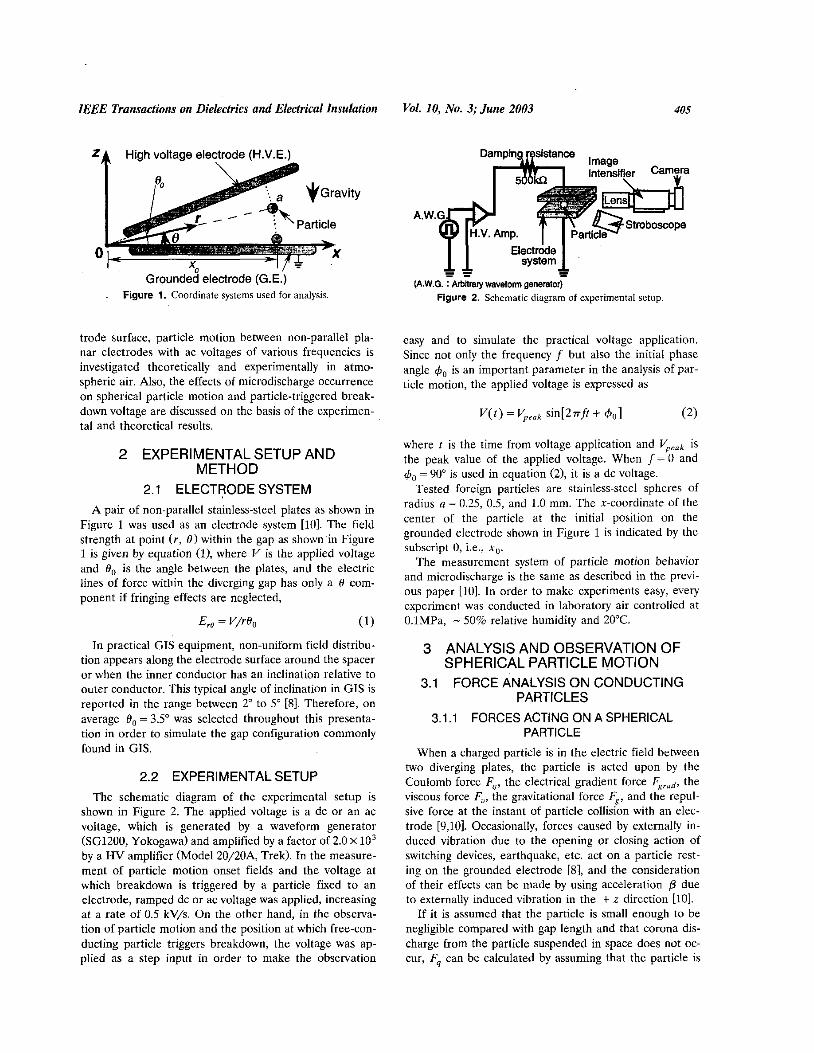
In order to consider which force acting on a particle in the horizontal direction is effective on particle motion, the x component of the electrical gradient force Fgrndr and the x component of the Coulomb force Fqx are compared as a function of d. As a result, it was found that the mag- nitude of Fg,ad, is smaller than that of FqX as shown in Figure 4. However, when a particle is suspended in space under ac voltage, Fqx changes its direction periodically while FRrodr always acts in the direction of higher field regions. Therefore, if the direction of FqI and FRrudx is

IEEE Transactions on Dielectrics and Electrical Insuhtian Vol. IO, No. 3; June 2003 407
Figure nents.
- assuming G= %Ea ---.....- }assuming F,= k%€d{ %Em’0
0.8 %Em < 0 -
d [mm]- 4. Comparison of the magnitude of horizontal farce compo-
considered, the direction in which the particle advances horizontally under ac voltage will be as follows.
When a particle is in contact with the grounded elec- trode, the particle will move toward decreasing electrode gap regions, i.e., in the - x direction because both of Fqx and Fgrodx act in the - x direction as shown in Figure Sa. On the other hand, when a particle is suspended in space under ac voltage, Fqx changes its direction periodically while Fgradx always acts in the - x direction as shown in Figure Sb. Therefore, if the particle suspended in the re- gion of d > a where F,(q * E,, > 0) and FqCq f E,, < 0) are almost of the same magnitude experiences periodic polar- ity changes in the electric field, the impulse of FqI upon the particle becomes nearly equal to zero, and then the particle will move toward decreasing electrode gap re- gions, i.e., in the - x direction by the action of FR,,,,x. On the other hand, if the particle suspended in the proximity of an electrode, i.e., d < a experiences polarity changes in the electric field many times, the particle may be driven toward increasing electrode gap regions, i.e., in the + x direction because the effect of F,,(q, E,, > 0) which acts
(4 (b) (c) Figure 5. Direction of horizontal force components acting on a par- ticle. a, in contact with the grounded electrode; b, on a particle sus- pended in space; c. on a particle whose micro-gap is bridged by a microdischarge.
in the + x direction may become greater than that of F,,(q+ E,, < 0) and Fgrodx which act in the -x direction.
When a particle lifted during one half cycle of the ap- plied voltage returns to the electrode in an opposite- polarity half cycle, microdischarge will occur between the particle and the electrode [2,12,13]. In this case, the parti- cle will be recharged into the same polarity with the bridged electrode immediately through microdischarge channel [2,5]. Therefore, the effect of F,,(q, Er, > 0) will disappear just after the occurrence of microdischarge, and F,,(q, E,, < 0) will act on the particle instead, as shown in Figure Sc. As a result, the particle will move toward -x direction.
3.2 MOTION ONSET FIELDS In the analysis of particle motion, it is necessaty to know
the condition when a particle begins to move. The condi- tion can he estimated by considering the balance of the forces acting on the particle. When forces acting on a par- ticle in the horizontal direction are considered, a particle resting on the GE begins to move laterally when the sum of Fqx and Fg,,,,, is of sufficient magnitude to overcome the static friction F,,, [9,lOl. Therefore, the field strength needed for a particle to begin to move laterally, which we call “hovering onset field E,”, can be calculated as in equation (61,
where p is the coefficient of static friction, p is the accel- eration in the + z direction due to externally induced vi- bration, and r,, = [ x i + a21”.
On the other hand, a particle levitates when the z com- ponent of the Coulomb force Fqz exceeds Fg [9,101. Therefore, lifting onset field E, is as shown in equation (7)
When E, and E, for a particle at x , = 160 mm are calculated as a function of particle radius using equations (6) and (71, the estimated values of E, and E, agree well with the values of E , and E , measured under dc voltage, respectively, as shown in Figure 6. As for ac voltages, the measured values of E , and E, tend to be higher than those measured under dc voltage, and the effective values of the measured E, and EH tend to correspond to the values estimated by using equations (6) and (7) as f in- creases.
If Figure 6 is divided into three conditions according to the combination of particle radius and field strength at the particle position, initial particle motion under each condition will be as follows: under the condition I where
408 S a k i et al.: Theoretical and Experimental Studies with ac Voltages in Air
I Estimation Experiment 1
- - - - - E U -
T 30 P s 3 20
'i - a [mm1
0.25 0.5 0.75 1 OO
Figure 6. Particle motion onset fields as a function of particle ra- dius.
the external field which a particle experiences E,, ex- ceeds E, (Er , > EL), the particle is lifted from its initial position after voltage application: under the condition I1 ( E , E,, z E H ) , the particle is not lifted from its initial position, hut begins to move laterally on the grounded electrode toward decreasing electrode gap regions; and under the condition I11 (E,# < E H ) , the particle does not move at all.
3.3 SIMULATION OF PARTICLE MOTION In general, if there is no polarity change in the electric
field, a particle once lifted crosses the full-gap immedi- ately, collides with the HV electrode, and then bounces back and forth between the HV and grounded electrodes. However, if there exists polarity changes in the electric field and the voltage varies at a rate comparable to or faster than the transit time of a particle under dc condi- tion, a particle once lifted may not cross the entire gap, but bounce on the lower electrode because the driving force, i.e., Fq changes its direction periodically [41. In this case, since the particle can experience polarity changes in the electric field in the region d < a where the magnitude of Fq greatly varies with d, particle motion may be af- fected by the dependence of F, magnitude on d shown in Figure 3.
In this section, in order to investigate the influence of the dependence of F, magnitude on d, particle motion is analyzed considering the dependence of Fq magnitude on d.
3.3.1 METHOD OF SIMULATION In order to simplify the calculation, the following as-
sumptions were made: (i) the magnitude of Fq depends on d, i.e., k in equation (4) varies with d as shown in Figure
3; (ii) effect of microdischarge occurrence on particle mo- tion is small enough to be negligible; and (iii) charge on a particle changes only through contact with the HV or grounded electrode.
The particle motion was simulated by solving the mo- tion equations of a conducting particle, i.e., equations (8) and (9) numerically under the above assumptions (i)-(iii)
= k q , E,,sin@ - F,,,,cosB - F,, (8)
=-kq*E,,cosB-F,,,,sinB-F,,-F, (9)
where m is the mass of the particle, and k is the ratio of F, and q , E , shown in Figure 3. The first terms on the right side of equations (8) and (9) are the x and z compo- nents of Fq, respectively, the second terms are the compo- nents of Fgrod and the third terms are the components of F" .
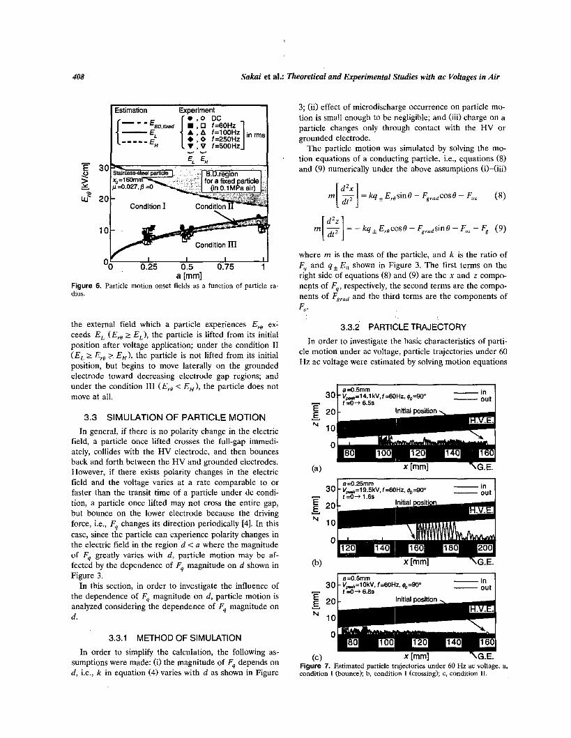
3.3.2 PARTICLE TRAJECTORY In order to investigate the hasic characteristics of parti-
cle motion under ac voltage, particle trajectories under 60 Hz ac voltage were estimated by solving motion equations
-in a=O.lmm 30 Vw=14.1 kV,f=BOHz, - t t =O+ 6.5s
-in - out a=0.255"
30 v,=l9.5kV.f=8OHz. ,&=sa' f d + l ~ 6 s
- in a =0.5mm - out I 30 Vm=lOkV, f=GOHz, ,&=WO
c t t =O+ 6.88
. . Figure 7. Estimated particle trajectories under 60 Hz ac voltage. a, condition I (bounce); b, condition I (crossing); c, condition 11.

IEEE Transactions on Dielecm'cs and Electrical Insulation Vol. IO, No. 3; June 2003 409
(8) and (9) under the assumptions (i)-(iii) described in 3.3.1. The typical examples of the estimated particle tra- jectories are shown in Figure 7.
3.3.2.1 UNDER CONDITION I
When the field strength around a particle satisfies E, in equations (7) at the particle's initial position, the parti- cle lifts. In this case, if the polarity of the applied voltage changes faster than the transit time of the particle, the particle will not cross the entire gap but begins bouncing on the grounded electrode. On the other hand, if the field strength around a particle is sufficiently high, the particle once lifted will he able to cross the entire gap immedi- ately.
When the 60 H z ac voltage of V,,,,=14.1 kV is ap- plied with & = 90", the particle of a = 0.5 mm placed at x , = 160 mm is estimated to behave as shown in Figure 7a. Although the particle lifts since the field strength at the particle position is just above E, for the particle, the par- ticle does not cross the fulllgap just after levitation, hut keeps bouncing on the grounded electrode. Eventually, F8,,d acting in the -r direction becomes an effective force, and the particle advances toward decreasing electrode gap regions. When the 'particle comes around x = 97 mm where the field strength is sufficiently high, the particle crosses the gap, reaches the HV electrode and then oscil- lates between the two electrodes and reverses its direction of advance, i.e., toward increasing electrode gap regions by the effect of the reflection angle on impact with the upper electrode 19,101. In this case, the position beyond which the particle does not proceed toward higher field regions any further, i.e., rmrn [lo] is estimated to be r,,,,, = 97 mm.
When the 60 Hz ac voltage of ccak = 19.5 kV which is much higher than E, is applied with 6, = 90", the parti- cle of a = 0.25 mm placed at x , = 160 mm is estimated to behave as shown in Figure 7b. As shown in the figure, the particle lifts from its initial position and crosses the gap immediately. Thereafter, it oscillates between the elec- trodes, advancing toward + x direction. In this case, since the particle does not progress toward - x direction any further, rmin is represented as rmin = xo = 160 mm.
3.3.2.2 UNDER CONDITION II Under condition 11, since a particle is accelerated to-
ward - x direction by FqX and Fgrodr until the condition I is satisfied, the particle can easily advance toward - x di- rection when it begins bouncing motion at higher field po- sitions.
When the 60 Hz ac voltage of Vpeak = 10 kV is applied with '3, = 90", the particle of a = O S mm placed at xo =
160 mm is estimated to behave as shown in Figure 7c. That is, the particle is not levitated from its initial posi- tion, hut begins to move laterally on the grounded elec- trode toward decreasing electrode gap regions. When the
c
particle reaches the position where the lifting condition for the particle is satisfied, the particle lifts off and begins bouncing motion on the grounded electrode, advancing toward decreasing electrode gap regions. When the parti- cle comes around x = 73 mm, it crosses the full-gap, oscil- lates between the two electrodes, and reverses its direc- tion of advance, i.e., toward the increasing electrode gap regions. In this case, rmin is estimated to he rmin = 73 mm.
The above results indicates that when a particle bounces on the grounded electrode under non-uniform field distri- bution along the electrode surface, the particle can enter higher field regions more easily than it does under dc volt- age. Therefore, the effect of Fgrod on particle motion un- der non-unifom electric field distribution along the elec- trode surface should be taken into account in the design of particle-traps in GIs.
3.3.3 INFLUENCE OF f Although f = 50 or 60 Hz is generally used as a com-
mercial power frequency in the electric power systems, ac voltages of various frequencies of f = 500Hz can acciden- tally occur due to system transients. If the frequency f of the applied ac voltage is changed, the particle's bounce height in the I direction will change greatly because of the change in the F, direction due to polarity change in the electric field. That is, when f is changed, the position where a particle crosses the entire gap with enough en- ergy to oscillate between the HV and GE changes. Even- tually, rmi,, is greatly influenced by f.
Since rmin is an important parameter in evaluating the insulation strength of a diverging gap, characteristics of I,,,,,, were investigated by simulating particle motion for the voltages of different f from 0 to 500 Hz under the condition of a = 0.5 mm, xo = 160 mm, V,eak = 14.1 kV and +,, = 90" where the particle levitates from its initial position. The result is shown in Figure 8. In Figure 8, the
Estimation Experiment
L E P 2 100
I
L
L
J
50
0 100 200 300 400 500 f [Hzl
Figure 8. Dependence of rmin and rso,,,rr On f. The plots are the estimated or experimental points.

41 0
solid and dotted lines indicate the estimated rmin with and without the consideration of the dependence of F, magni- tude on d, respectively, and the plots along the lines are the estimated points of r,,,;,,. The two boundaries of hatch- ing regions rBD,fjrrd and rBD,,,<< shown in Figure 8 are the estimated regions of breakdown triggered by a particle fixed to an electrode and by a particle suspended in space, respectively, whose estimation method will be described in the next section.
It can be seen from Figure 8 that the dependence of F, magnitude on d does not affect the characteristics of rmin for the voltage of 0 < f s 180 Hz under the present condi- tion. That is, when the voltage of 0 5 f 5 40 Hz is applied, the particle lifted from xo crosses the full-gap, and oscil- lates between the two electrodes, advancing toward + x direction, i.e., rmi, = xu, and when the voltage of 40 < f < 180 Hz is applied, rmin decreases with increase in f, that is, the particle bouncing on the GE can progress toward - x direction easily as f increases. On the other hand,
under the voltage of f > 180 Hz, rmin characteristics are quite different between the cases with and without consid- eration of the dependence of F, magnitude on d. That is, when the dependence of Fq magnitude on d is taken into account, it is estimated that the particle bouncing on the GE does not proceed toward - x direction any further from xo, rather adeances toward + x direction without oscillating between the two electrodes, i.e., rmCn = x o , while rmin is estimated to decrease with increase in f in the absence of the dependence of F, magnitude on d.
In order to find the reason why the direction in which a bouncing particle advances horizontally changes when f is increased in the presence of the dependence of Fq magni- tude on d, impulses of FErndr and Fqx upon the bouncing particle in the presence/absence of the dependence of F, magnitude on d were calculated for the period of f = 0- 0.5 s, within which the particle bouncing on the grounded electrode begins to move horizontally under the condition shown in Figure 8. As a result, it was found that when a bouncing particle progresses toward - x direction under the ac voltage whose frequency is around commercial power frequency, the impulse of FErodx which is in the - x direction (i.e. < 0) is greater than that of Fqx as shown in Table 2. On the other hand, when a bouncing particle advances toward + x direction under ac voltages of f > 180 Hz in the presence of the dependence of F, magni-
Sakai et al.: Theoretical and Experimental Studies with ac Vokages in Air
..
tude on d, the impulse of Fqx is in the + x direction (i.e. > 0) and is greater than that of FE,,,,, whereas the im- pulse of Fqx is smaller than that of FE,adx in the absence of the dependence of F, magnitude on d.
From the above results, it can be said that when a parti- cle bounces very near to the grounded electrode under high frequency ac voltage, the proximity effect of the par- ticle to an electrode becomes greater. Therefore, the par- ticle bouncing under high-frequency ac voltage will be driven toward lower field regions by the action of F,Jq * E,, > 0). In the experiment, however, the action of F,,(q * E,, > 0) may be suppressed by the occurrence of microdischarge between a particle and an electrode as de- scribed in 3.1.2. In this case, the particle may progress toward a higher field region by the action of FE,,, and F& * E,, < 0).
3.3.4 INFLUENCE OF+, In order to investigate the influence of & on r,,, char-
acteristics, rmin for various combinations of & and f were estimated. As a result, it was found that the effect of 4o on the characteristics of rmjn is small enough to be negli- gible under the ac voltages with f 2 10 Hz since the ap- plied ac voltage varies faster than the transit time of a particle, and rmi, rather depends on the particle's bounce height in the z direction. However, when an ac voltage of f 1 Hz under which particle motion is almost the same as that under dc voltage 1101 is applied, comes to affect rmrn directly as shown in Figure 9.
When the particle of a = 1 mm is placed at x o = 155 mm and the voltage of V,,.., = 14.1 kV is applied with 76"s s 104' so that the condition I is satisfied at the instant of voltage application, rmin is estimated to be rmin = xo because the particle levitates from its initial posi- tion, crosses the gap, and oscillates between the two elec- trodes, advancing toward + x direction.
Estimation
-0 - .. F=O.OI Hz L r
Table 2. Calculated results of the impulse upon a bouncing particle during t = 0 - 0.5s.
0.5 0.5
Fxr#dxAr F,,At[X10-8NsI
[ X 1 0 ~ 8 N s ] Fq = kq, E,, Fq = q + E,, 4 , = u 4 c - 0
60Hz -4.56 4.38 2.98 18OHz -4.55 4.48 1.03 2ooHz -4.55 5.14 0.98 SOOHZ -4.54 8.31 0.79
I
Figure 9. Dependence of rm;" and r8D,,,.. on +o. The plots are the estimated 01 experimental points.

IEEE Transactions on Dielectrics and Electrical Insulation
On the other hand, when the voltage is applied with 55's &, s 75" or 105"s &, s 125" so that condition I1 is satisfied at the instant of voltage application, the particle is estimated to move laterally on the grounded electrode first until the condition I is satisfied. In this case, external field strength which the particle experiences increases due to particle movement toward higher field regions even if the applied voltage is kept constant. Therefore, if the volt- age is applied with 55"s & s 75" where the magnitude of the applied voltage increases with f, the lower the fre- quency of the applied ac voltage is, the deeper the parti- cle can invade high field regions, i.e., rmi, decreases with decrease in f as shown in Figure 9 because it takes longer until the condition I is satisfied if the magnitude of the applied voltage increases with f slowly.
If the voltage is applied with 105'5 & s 125" where the magnitude of the applied voltage decreases with f, the particle can enter higher field regions easily because it can experience condition I1 two times, i.e., in the first and the next half cycle~of the applied ac voltage before it lifts off. In this case, if the decreasing rate of the applied volt- age synchronizes with the increasing rate of the external field strength which the laterally moving particle experi- ences such as the case where 0.1 Hz ac voltage is applied with & = 105-12So, a particle continues to proceed deeply into the shorter gap regions until the condition I in the next half cycle of the applied ac voltage is satisfied.
When the voltage of beah = 14.1 kV is applied with 0 s Co s 54" or 126"s +,, s 180" where condition I11 is satis- fied initially, the particle does not move at all just after voltage application, hut when the magnitude of the ap- plied voltage increases with f and condition I1 is satisfied,
1lO 140 160 180 . 2 (b) x [mm] 1G.E.
(C) Figure 10. Examples of observed particle trajectories under~60 Hz ac voltage. a, condition I (bounce); b, condition I (crossing); c, wndi- r i m 11.
Vol. 10, No. 3; June 2003 411
the particle behaves as it does under the voltage with 55" s & s 75".
3.4 OBSERVATION OF PARTICLE MOTION
3.4.1 TYPICAL PARTICLE BEHAVIOR
In order to confirm the results obtained in the simula- tion, particle motion was observed under the same condi- tions as the simulation, Firstly, typical particle behavior under 60Hz AC voltage was observed.
When 60 Hz ac voltage of teak = 14.1kV was applied with &, = 90" the particle of a = 0.5 mm placed at xo = 160 mm behaved as shown in Figure 10a. Since condition I was satisfied at the instant of voltage application, the par- ticle lifted from its initial position, began bouncing on the grounded electrode, and progressed toward the decreas- ing electrode gap region. When it reached around x = 118 mm, breakdown was triggered by the particle. In this case, the position where the particle triggered breakdown is represented as raD,f,ae = 118 mm.
When the 60 Hz ac voltage of = 19.5 kV was ap- plied with &, = 90", the particle of a = 0.25 mm placed at x , = 160 mm lifted from its initial position and crossed the entire gap immediately. Then, the particle advanced to- ward lower field regions, oscillating between the HV and grounded electrodes as shown in Figure 10h, i.e., r,,,,, = x,, = 160 mm.
Whereas, when the 60 Hz ac voltage of VP,,* = 10 kV was applied with & =90", the particle of a=OS mm placed at xo = 160 mm behaved as shown in Figure 1Oc. In this case, the particle firstly exhibited lateral motion on the grounded electrode, and was lifted at around x = 153 mm. Thereafter, the particle began bouncing motion, ad- vancing toward decreasing gap regions. When the particle came around x = 85 mm, it triggered breakdown, i.e.,
The estimated particle trajectories under 60 Hz ac volt- ages agree fairly well with the experimental ones. As far as the velocity at which a particle bouncing on the GE advances in the horizontal direction is concerned, there was scatter in the time from voltage application to parti- cle-triggered breakdown in the experiment. For example, under the condition shown in Figure loa, the time to par- ticle-triggered breakdown at around x = 118 mm after voltage application scattered between I = 2.5-5 s in the experiment, while it is estimated to be f = 5.1 s for the particle to pass through x=118 mm in the simulation. This scatter in the experiment would be caused by mi- crodischarge occurrence between the particle and the electrode which will suppress the action of Fqz (q* E,, >
'BD,free = ss ".
0).
3.4.2 MEASUREMENTOF r,,, AND r,,,,,,, If a particle progresses toward higher field regions, it is
important to determine whether the particle triggers

412 Sakai et al.: Theoretical and Experimental Shrdies with ac Voltages in Air
3 .
. . Figure 11. Obseked particle motion under 500 Hz ac voltage. a, towaid higher field regions; b, toward lower tield regions.
breakdown or not. In order to investigate it, characteris- tics of r,,, and rBD,f,es were experimentally observed un- der the same conditions as the estimation described in 3.3.3 and 3.3.4, respectively.
The experimental values of r,,, and rBD,f,.r for differ- ent f a r e shown in Figure 8 together with the estimated ones described in 3.3.3. If the characteristics of particle movement toward - x direction are compared between the experiment and the estimation, it can he seen that estimated characteristics of particle movement toward - x direction agree well with the experimental ones under the voltages of f < 200 Hz, that is, if f is increased around commercial power frequency, the particle progresses to- ward higher field regions easily, and triggers breakdown when it enters the estimated region of rBD,f,ee. However, under the ac voltages of f 2 200 Hz, although the bounc- ing particle is estimated to advance toward + x direction in the presence of the dependence of F, magnitude on d, there were roughly two cases where a bouncing particle advances either in the - x or + x direction as shown in Figures l l a and l l b in the experiment, and almost all of the cases (SO-YO%), the particle eventually advanced to- ward - x direction and triggered breakdown when it en- tered the estimated region of rBD,,, ... If it is considered that particle movement toward t x direction does not oc- cur without the consideration of the dependence of Fq on d, it can be said that the dependence of F, magnitude on d does affect particle motion under high-frequency ac voltages. In this case, therefore, there would be an under- lying mechanism which causes the particle bouncing un- der high-frequency ac voltage to move toward - x direc- tion, and it would he the effect of microdischarge occur- rence which will suppress the action of F,,(q, E,, > 0). The consideration of the effect of microdischarge occur- rence on particle motion will he discussed in the next sec- tion.
As far as the influence of 4o on r,,, and rBD,,,p. is concerned, there could be seen negligible effect of r$o on
. . Figure 12. Lateral motion of a spherical particle under 0.1 Hz ac voltage.
particle motion under ac voltages of f 2 10 Hz in the ex- periment as estimated in 3.3.4. However, when a very- low-frequency ac voltage o f f s 1 Hz was applied, r,,, and rBD,free were obviously affected by +o. Especially, when a very-low-frequency ac voltage was applied so that condi- tion I1 would be satisfied at the instant of voltage applica- tion and the decreasing rate of the applied voltage would synchronize with the increasing rate of the extemal field strength which a particle exhibiting lateral motion toward - x direction experiences, the spherical'particle kept en- tering higher field regions, exhibiting lateral motion or rolling over on the grounded electrode, and triggered breakdown as shown in Figure 12.
The obtained result suggests that when a very-low- frequency ac voltage is used in the field-test of GIS equip- ment etc., q50 should he adequately considered so that particles accidentally contaminating GIS gaps may not trigger breakdown.
4 DISCUSSION
MICRODISCHARGE 4.1 OBSERVATION OF
When a particle approaches an oppositely charged elec- trode and the streamer criterion which is expressed as equation (10) is satisfied in the small gap between the par- ticle and oppositely charged electrode, a microdischarge can occur in the micro-gap side of a particle [1-3,Y,10,12,131
b d z 2 K (10)
where E is the effective ionization coefficient, and K is a constant of K = 10 for air and K = 10.5 for SF, [141.
In order to confirm the occurrence of microdischarges under ac voltage, observation of light emissions from mi- crodischarge was conducted for the case where a particle bounces on an electrode, using an image-intensifier in nightvision.
As a result, when a particle bounces on the grounded electrode under 60 Hz ac voltage as shown in Figure loa, light emissions from microdischarge were often observed just before particle impact on the grounded electrode as shown in Figure 13a. On the other hand, when a particle bounces under a high-frequency ac voltage, microdis- charge occurred more frequently than it did under 60 Hz

ZEEE Transactions on Dielectrics and Elechical Insuhtion Vol. 10, No. 3; June 2003 41 3
Figure 13. Photo of light emissions from micradischargesr a, 60 Hz; b, 500Hz.
ac voltage as shown in Figure 13b. This would be because polarity of the applied voltage changes before a particle leaves a critical distance from the electrode and the field strength in the microgap between the particle and the electrode increases rapidly under high-frequency ac volt- ages.
As far as the relationship between microdischarge oc- currence and the direction in which a bouncing particle advances horizontally under high-frequency ac voltages is concerned, the particle tends to move toward - x direc- tion when microdischarge occurs steadily. On the other hand, when microdischarge does not occur so frequently as the case where the bouncing particle advances toward - x direction, the particle occasionally moved toward + x direction.
This result shows that the direction in which a bouncing particle advances horizontally under high-frequency ac voltage is greatly affected by microdischarge occurrence,
30 I Estimation Ex oe r i m e nt I
a=O.lmm xo =lea"
(in 0.lMPaair)
B O 100 120 140 x [mm1
Figure 14. Breakdown voltage and particle position at breakdown.
and that when microdischarge occurs steadily, the particle can progress toward higher field regions easily.
4.2 EFFECT OF MICRODISCHARGE OCCURRENCE
It is generally considered that a microdischarge has the following effects: (a) to bridge the microgap between a particle and an electrode; (b) to increase the field strength around the particle rapidly by instantaneous charge flow onto the particle through the discharge-channel; (c) to provide an initial electron for the subsequent discharge around the particle; (d) to emit light; and so on. There- fore, in the breakdown voltage calculations, the delay time of initiatory electrons supplied was ignored. In this sec- tion, on the basis of the above effects (a-d), the voltage and position at which a particle triggers breakdown are discussed. Also, the effect of microdischarge occurrence on particle motion is discussed.
4.2.1 EFFECT ON BREAKDOWN VOLTAGE AND PARTICLE POSITION AT BREAKDOWN
When a microdischarge occurs between a particle and an electrode, particle-triggered breakdown voltage is de- creased mainly by the effects (a-d) mentioned above. In this case, the dc voltage at breakdown triggered by a par- ticle suspended in space can be estimated by using equa- tion (10) in the main-gap side of the particle whose micro- gap side is bridged by a microdischarge [9,101.
Under ac voltage, similarly, if it is assumed that a parti- cle charged at of the applied voltage is approaching an oppositely charged electrode at V,,,,, the minimum value of the voltage at breakdown triggered by a particle suspended in space will be estimated by using equation (10) in the main-gap side of the particle whose micro-gap is bridged by a microdischarge.
In order to investigate the effect of microdischarge oc- currence on particle-triggered breakdown under ac volt- age, the minimum value of the ac voltage at breakdown triggered by a particle suspended in space and the break- down voltage triggered by a particle fixed to an electrode were estimated as a function of particle position, and the results are.shown in Figure 14 as the solid line VBD,frer and the dash-dotted line VBD,Jixed, respectively.
If the experimental values of the voltage and position at breakdown triggered by a particle of a = 0.5 mm which begins to move'from xo = 160 mm under 60 Hz ac voltage are plotted in Figure 14, the experimental values of V,D,,r,, is lower than the estimated and experimental val- ues of VBD,rjxed, and the minimum value of the experi- mental V,,,,,, corresponds to the.minimum value of the estimated
Moreover, if the region where V,D,J,ee(minimum) s < VBD,Jiled is satisfied under the condition shown in
Figure 8 are considered, the region where a bouncing par- ticle can trigger breakdown is estimated as the hatching

41 4 Saki et al.: Theoretical and Experimental Studies with ac Voltages in Air
region rnr,,,,re shown in Figure 8, and it can be seen that rBD,f,ea obtained in the experiment scattered within the estimated region of rBD,f,re for the voltage of different f.
Therefore, it can be concluded that particle-triggered breakdown voltage is decreased by microdischarge occur- rence under ac voltage too, and that the bouncing particle '
can trigger breakdown in the region where V,D,f,,,(min.) s Vpeak s VBD,,ixed is satisfied. The main reason for the scatter in the experimental rBD,f,se would be because the relationship between the charge on the particle and the external field strength at the instant of a microdischarge varies in a complex manner under ac voltage, and so the energy and the distance of microdischarge development differ.
4.2.2 EFFECT ON PARTICLE MOTION As described in section 4.1, it can be said that particle's
bouncing motion is influenced by microdischarge occur- rence especially under high-frequency ac voltages, and that when microdischarge occurs frequently between a particle and an electrode, the particle tends to move toward - x direction. This result would be explained as follows.
When the micro-gap between a particle and an elec- trode is bridged hy a microdischarge, the particle can he immediately charged in the same polarity with the bridged electrode by the instantaneous charge flow onto the parti- cle through the microdischarge-channel. Consequently, the action of F,J9 + E,@ > 0) is suppressed, and so the parti- cle can advance toward - x direction by the action of Fg,,,, and F,J9 f E,, < 0).
In order to confirm this consideration, particle motion was simulated, taking into account the effect of microdis- charge occurrence. That is, particle motion was simulated by solving motion equations (8) and (9) numerically under the following updated assumptions: (i) k in equation (4) varies with d as shown in Figure 3; (ii) microdischarge occurs when the field strength in the microgap side of a particle satisfies the field strength given by the Paschen's curve [12,13]; (iii) charge on a particle changes when the particle touches an electrode'or at the instant of microdis- charge occurrence; and (iv) when equation (10) is satisfied in the main-gap side of a particle whose micro-gap is bridged by a microdischarge, breakdown is triggered by the particle. Although it is difficult to estimate the charge quantity on a particle just after microdischarge occur- rence, it is assumed to be given by equation (3) in order to simplify the calculation.
Firstly, in order to compare typical particle motion with/without microdischarge occurrence, particle motion was estimated under the same condition with Figure 7a in the presence of the effect of microdischarge occurrence. The result is shown in Figure 15a. If particle trajectories with/without microdischarge occurrence are compared, the effect of microdischarge occurrence on particle trajec- tory seems to be small enough to be negligible under 60 Hz ac voltage although particle's bounce height tends to
lnitlal 1
&tion
Figure 15. Estimated particle trajectories with the consideration of microdischarge occurrence. a, under 60 Hz voltage; b, under 500 Hz; c, macrogragh of Fig.15b.
slightly decrease in the presence of microdischarge occor- rence since the particle's velocity in the - z direction just before particle's impact on an electrode is decreased by F,,(q, E,, < 0) at the instant of microdischarge occur- rence. However, when the velocity at which the particle advances in the - x direction is concerned, there is a large difference between them. That is, it is estimated to take 2.3 s for the particle to trigger breakdown at x = 119 mm after voltage application in the presence of microdis- charge occurrence, while it is estimated to take 5.1 s for the particle to pass through x = 119 mm without a mi- crodischarge. If it is considered that the time at which the particle triggers breakdown in the experiment under the same condition scattered between t = 2.5-5 s, the esti- mated results with/without consideration of microdis- charge occurrence agree well with the experimental ones.
On the other hand, under 500 Hz ac voltage, particle trajectories are completely different between the cases with/without microdischarge occurrence as shown in Fig- ures 15b and 15c. That is, the particle bouncing around x,, is estimated to progress toward ~ x direction in the pres- ence of microdischarge occurrence, whereas the particle is estimated to advance toward + x direction in the absence of a microdischarge. In this case, if the characteristics of

IEEE Transactions on Dielectrics and Ekchical Insulation Vol. 10, No. 3; June 2003 415
rmin and rBD,,,,, are estimated for different f by consid- ering the effect of microdischarge occurrence under the condition shown in Figure 8, rmin and rsD,f,e. estimated with the consideration of microdischarge occnrrence agree well with the case where the bouncing particle advances toward higher field regions in the experiment. On the other hand, rmim and rBD,r,ee estimated without the con- sideration of microdischarge occurrence agree fairly well with the case where the particle does not proceed toward - x direction in the experiment as shown in Figure 16. The reason why the particle's advancing direction or the particle's velocity in the horizon!al direction differs every time in the experiment would be because microdischarge occurrence actually depends on the presence of an initial electron.
From the above results, it can he concluded that parti- cle's bouncing motion under non-uniform' electric field distribution along the electrode surface is greatly influ- enced by microdischarge occurrence especially under high-frequency ac voltages, and that when microdischarge occurs frequently between a particle and an electrode, the particle can progress toward decreasing electrode gap re- gions easily, causing breakdown at high field positions.
,
4.3 EFFECT OF GAS ATMOSPHERE Although it was found from the above results obtained
in 0.1 MPa air that the characteristics of particle move- ment toward higher field regions are greatly influenced by microdischarge occurrence, the condition that microdis- charge occurs depends on gas-atmosphere, and this may affect the characteristics of rmin and raD,,ree versus f.
In order to consider the effect of gas atmosphere on particle motion, the characteristics of rmi, and rBD,f,er versus f are estimated for the cases in 0.1 MPa and 0.4 MPa SF, under the same condition shown in Figure 8, considering the effect of microdischarge occurrence. The result is shown in Figure 16.
It can he seen from Figure 16 that when the ac voltage whose frequency is around commercial power frequency is applied, the influence of gas-atmosphere on the charac- teristics of rmin, rBD,fr,.e - f is small enough to he negligi- ble, that is, particles tend to enter higher field regions easily as f increases. Also, it can be seen that when the high-frequency ac voltage under which F,,(q E,, > 0) af- fect particle motion is applied, the characteristics of rmin, rBD,/"<< - f is changed by gas-atmosphere. That is, it is estimated that particle movement toward higher field re- gions under the ac voltage of f > 300 Hz and f > 240 Hz can he suppressed by using 0.1 MPa and 0.4 MPa SF, as a medium gas under the present condition, respectively.
The above results suggest that the use of gases which have high dielectric strength suppresses the movement of a bouncing particle from low to high field regions under high-frequency ac voltages. However, even if the gas which has high dielectric strength is used, particle movement to-
--
0 100 200 300 400 500 f [Hzl
Figure 16. Estimated results of the Characteristics of rmjn, rsD,,,ie YS f in different gases. The opened and closed symbols are the esti- mated points of r,njm and rBD,,,ee, respectively.
ward higher field regions should he adequately considered in the design of GIS since a particle may progress toward higher field regions depending on the combination of par- ticle size, shape, and external field strength such as parti- cle's lateral motion under the condition 11.
5 CONCLUSIONS (a) In a horizontally mounted GIs, when the Coulomb
force acting on a particle balances the gravitational force under non-uniform electric field distribution along the electrode surface, the particle moves laterally on the grounded electrode toward decreasing electrode gap re- gions by the action of the electrical gradient force and the horizontal component of the Coulomb force, and lifts at the position where the lifting field for the particle is satis- fied.
(b) When the Coulomb force changes its direction peri- odically under ac voltage whose frequency is around com- mercial po;er frequency, the electrical gradient force can become effective in initiating particle motion toward de- creasing electrode gap regions, causing the particle to trigger breakdown at relatively low voltages.
(c)- When a particle bounces in the proximity of the grounded electrode under high-frequency ac voltage, the direction in which the particle advances horizontally to the grounded electrode is greatly influenced by microdis- charge occurrence. In this case, when microdischarge oc- curs frequently between the particle and the electrode, the particle can progress deeply into high field regions easily, causing breakdown. Therefore, when an abnormal ac volt- age whose frequency is higher than commercial power fre- quency appears in actual GIs, much attention should he paid for particle movement toward higher field regions.

41 6 Sakai et al.: Theoretical and Experimental Studies with ac Voltages in Air
(d) The influence of the initial phase angle of the ap- plied ac voltage on particle motion is small enough to he negligible under ac voltages whose frequency is around or higher than commercial power frequency, hut great under ac voltages with very-low frequency.
the effect of microdischarge occurrence hetween a parti- cle and an electrode.
The present work is a hasic research, which mainly dis- cusses the effects of electrical gradient force and mi- crodischarge on particle motion using a modeled elec- trode arrangement. Therefore the experiments on full scale model may he important for the design of actual equipment focusing the effects of electrical gradient force and microdischarge. The obtained results indicate that the use of the gases which have high dielectric strength can suppress not only the development or occurrence of dis- charges around a particle but also particle movement to- ward higher field regions under high-frequency ac volt- ages. Then, even if the gas which has high dielectric strength is used in GIS, particle movement toward higher field regions should he definitely considered in the design of GIS since a particle can progress toward higher field regions.
(e) Particle-triggered breakdown voltage is decreased by ,
REFERENCES [I1 A. Diessner and J.G. Trump: “Free Conducting Particles in a
Coaxial Compressed-Gas-Insulated System’, IEEE Trans. PAS, Vol. 89, pp. 1970-1978, 1970.
[21 A. H. Caakson, 0. Farish and G. M. L. Sommerman: “Effect of Conducting Panicles an AC Corona and Breakdown in Com- pressed SF6’, IEEE Trans. PAS, Vol. 91, pp. 1329-1338; 1972.
[31 M. Hara and M. Akiizaki: “A Method fur Prediction of Gaseous Discharge Threshold Voltage in the Presence of a Conducting Panicle’, I. Electrostatics, Vol. 2, pp. 223-239, 1976/1977.
141 C. M. Cooke, R. E. Wootton and A. H. Caakson: “lnfiuence of Particles on AC and DC Electrical Performance of Gas Insu- lated Systems at Eara-HV’, IEEE Trans. PAS, Vol. 96, pp. 768-777, 1977.
[SI F. A. M. Rizk, C. Masetti and R. P. Comsa: “Particle-Initiated Breakdoun in SF, Insulated Systems under High Direct Volt- age’, IEEE Trans. PAS, Vol. 98, pp. 825-836, 1979.
[61 S . I. Dale, R. E. Wootton and A. H. Cookson: “Effects of Parti- cle Contamination in SF6 CGIT Systems and Methods of Parti- cle Control and Elimination”, Gaseous Dielectrics 11, Knoxville, USA., No. 33, pp. 256-265, 1980.
[71 M. M. Morcns and K. D. Srivastava: “On Electrostatic Trapping of Particle Contamination in G I n Systems”, IEEE Trans. PWRD, Vol. 7, pp. 1698-1705, 1992.
181 T. Hasegawa, K. Yamaji, M. Hatano, F. Endo, T. Rokunohe and T. Yamagiwa: “Development of Insulation S t ~ c t u r e and Enhancement of Insulation Reliability of 500kV DC GIS“,IEEE Trans. PWRD, Vol. 12, No.1, pp. 194-202, 1997.
191 M. Hara, K. Sakai, S. TSUN and D. L. Abella: “Particle-Tri- ggered Breakdown Mechanism in the Presence of DC and AC Electrical Gradient Forces in Atmospheric Air”,Prac. 11th ISH, London, U.K., Vol. 3, pp. 47-50, 1999.
[lo] K. Sakai, S. TSUN, D. L. Abella and M. Hara: “Conducting Par- ticle Motion and Particle-initiated Breakdown in dc Electric Field between Diverging Conducting Plates in Atmospheric Air”, IEEE Trans. DEI, Vol. 6, pp. 122-130, 1999.
[ l l ] N. N. Lebedev and 1. P. Skal‘skaya: “Force Acting on a Con- ducting Sphere in the Field of a Parallel Plane Condenser”,Sov. Phys. Tech. Phys., Vol. 7, pp. 268-270, 1962.
[I21 M. Ham and M. Akazaki: “Analysis of Microdischarge Thresh- old Conditions between a Conducting Sphere and Plane”, J. Electrostatics, Vol. 13, pp. 1055118, 1982.
[13] M. Hara, T. Yamashita and M. Akazaki: “Microdischarge Char- acteristics in Air Gap behvcen Spherical Particle and Plane”, Prac. IEE, Vol. 130, Pt.A, No. 6, pp. 329-335,1983.
[141 S . Berger, “Onset or Breakdown Voltage Reduction by Elec- trode Surface Roughness in Air and SF6”, IEEE Trans. PAS, Vol. 95, pp. 1073-1079,1976,
Electric Power Co. I the Insthtute of Elect
Koh-ichi Sakai was born in Nagasaki Prefec- ture, Japan, in February, 1976. He received his M.S. and the Dr. Eng. degrees from Kyushu University, Fukuoka, Japan, in 1999 and 2032, respectively. Dr. Sakai was a Re. search Fellow of the Japan Society for the Promotion of Science (JSPS) from 1999 to 2002. Now he is working in the Kyushu Elec- tric Power Co., Japan. He is a member of the Institute of Electrical Engineers, Japan (IEEJ).
Dan Labrada Abella was born in Naga, Cebu, Philpines on August 2, 1971. He received his B.S. and M.S. degrees in Electrical Engi- neering from Cebu Tnstitute of Technology. Cebu City, Philpines and Kyushu University. Fukuoka, Japan in 1992 and 2W0, respec- tively. From 1993 to 1997, he worked at the Davao Light & Power Co.Inc. as Systems Design Engineer. Presently, he is working at the Staff, Corporate Planning Office. Kpshu
nc. Japan since May, 20W. He is a member of r i a l Engineen, Japan (IEEJ).
Yasin Khan was born in Peshawar, Pakistan, in February, 1971. He received the BSc. and MSc. degrees in Electrical Engineering from thc N.W.F.P. University of Engineer- ing and Technology. Peshawar in 1993 and 1997, respectively. From 1995 to 2000, he was working in the Energy Wing, Planning Commission, Govt. of Pakistan, Islamabad as a Research Officer (Power). Since 2000, he is enrolled in the doctoral pmgram in
Kyushu University, Fukuoka, Japan. Mr. Khan is a member of the Pakistan Engineering Council (PEC) and the Institute of Electrical Engineers, Japan (IEEJ)
Junya Suehiro was born in Fukuokn Prefec- ture. Japan, in 1961. He received his B.S.. M.S., and Dr. Eng. degrees from Kyushu University in 1983, 1985, and 1991, respec- tively. He was with the Nippon Steel Co., Japan. from 1985 to 1988. Since 1988, he has been at Kyushu University. He is now an Associate Professor and is involved in re- search on the applied electrostatics, HV en- gineering and superconductivity. Dr. Sue-
hiro is a member of the IEU. the Institute of Electrostatics Japan. the Cryogenic Association of Japan and the IEEDJ.

IEEE Transactions on Dielectrics and Electrical Insulntion Val. 10, No. 3; June 2003
sity as an Associate neering. Since 19x6
Masanori Hara (M79-SM89 was born in Kagawa Prefecture, Japan. in 1942. He re- ceived the B.S. degree from Kyushu Insti- tute of Technology, Japan, in 1967 and the M.S. and Dr. Eng. degrees from Kyushu University, Japan, in 1969, and 1972, respec- tively. He served at Kyushu Institute of Tcechnalogy, as a Lecturer from 1972 to 1973 and as an Associate Professor from 1973 to 1975, In 1975. he moved to Kyushu Uniuer-
Professor in the Department of Electrical Engi- , he is a Professor of the Department of Electri-
’
cal and Electronic Systems Engineering in the same univenity, and has been engaged in research on electric power engineering, HV pulsed power engineering, superconductivity and applied electro- statics. He was an invited researcher at the University of Quebec at Chicoutimi. Quebec, Canada, from 1976 to 1977.Dr. Hara is a member of the Institute of Electrical Engineers of Japan (IEEJ), the Institute of Electrostatics Japan, the Clyogenic Association of Japan and the Institute of Engineers on Electrical Dischargges in Japan (IEEDJ). Now he is a Vice-President of the IEEJ and a President of the IEEDJ.
41 7