
BMT Module -2 BIOELECTRIC SIGNALS AND ELECTRODES
34
BMT Module -2 BIOELECTRIC SIGNALS AND ELECTRODES Hemanth kumar G , Asst Prof, Dept. of BME, ACSCE Page 1 MODULE -2 BIOELECTRIC SIGNALS AND ELECTRODES 2.1 Sources of Biomedical Signals 2.2 Origin of Bioelectric Signals 2.3 Electrocardiogram (ECG) 2.4 Electroencephalogram (EEG) 2.5 Electromyogram (EMG) 2.6 Electrooculogram (EOG) 2.7 Electroretinogram (ERG) 2.8 Recording Electrodes– Electrode-tissue interface, Electrolyte-Skin interface, Polarization, skin contact impedance, Motion artifacts. 2.9 Silver-Silver Chloride electrodes, 2.10 Electrodes for ECG, 2.11 Electrodes for EEG, 2.12 Electrodes of EMG, 2.13 Electrical conductivity of electrode jellies and creamS 2.14 Microelectrodes.
-
Upload
khangminh22 -
Category
Documents
-
view
0 -
download
0
Transcript of BMT Module -2 BIOELECTRIC SIGNALS AND ELECTRODES

BMT Module -2 BIOELECTRIC SIGNALS AND ELECTRODES
Hemanth kumar G , Asst Prof, Dept. of BME, ACSCE Page 1
MODULE -2
BIOELECTRIC SIGNALS AND ELECTRODES
2.1 Sources of Biomedical Signals
2.2 Origin of Bioelectric Signals
2.3 Electrocardiogram (ECG)
2.4 Electroencephalogram (EEG)
2.5 Electromyogram (EMG)
2.6 Electrooculogram (EOG)
2.7 Electroretinogram (ERG)
2.8 Recording Electrodes–
Electrode-tissue interface, Electrolyte-Skin interface, Polarization, skin
contact impedance, Motion artifacts.
2.9 Silver-Silver Chloride electrodes,
2.10 Electrodes for ECG,
2.11 Electrodes for EEG,
2.12 Electrodes of EMG,
2.13 Electrical conductivity of electrode jellies and creamS
2.14 Microelectrodes.

BMT Module -2 BIOELECTRIC SIGNALS AND ELECTRODES
Hemanth kumar G , Asst Prof, Dept. of BME, ACSCE Page 2
2.1: Sources of Biomedical Signals
Biomedical signals are those signals (phenomenon that conveys information) which are used
primarily for extracting information on a biological system under investigation.
Fig. 1.8 Sources of biomedical signals
The process of extracting information could be as simple as feeling the pulse of a person on
the wrist or as complex as analyzing the structure of internal soft tissues by an ultrasound
scanner. Biomedical signals originate from a variety of sources (Fig. 1.8) such as:
Bioelectric Signals: These are unique to the biomedical systems. They are generated by
nerve cells and muscle cells. Their basic source is the cell membrane potential which under
certain conditions may be excited to generate an action potential. The electric field generated
by the action of many cells constitutes the bio-electric signal. The most common examples of
bioelectric signals are the ECG (electrocardiographic) and EEG (electroencephalographic)
signals.

BMT Module -2 BIOELECTRIC SIGNALS AND ELECTRODES
Hemanth kumar G , Asst Prof, Dept. of BME, ACSCE Page 3
Bioacoustic Signals: The measurement of acoustic signals created by many biomedical
phenomena provides information about the underlying phenomena. The examples of such
signals are: flow of blood in the heart, through the heart’s valves and flow of air through the
upper and lower airways and in the lungs which generate typical acoustic signal.
Biomechanical Signals: These signals originate from some mechanical function of the
biological system. They include all types of motion and displacement signals, pressure and
flow signals etc. The movement of the chest wall in accordance with the respiratory activity
is an example of this type of signal.
Biochemical Signals: The signals which are obtained as a result of chemical measurements
from the living tissue or from samples analyzed in the laboratory. The examples are
measurement of partial pressure of carbon-dioxide (pCO2), partial pressure of oxygen (pO2)
and concentration of various ions in the blood.
Biomagnetic Signals: Extremely weak magnetic fields are produced by various organs such
as the brain, heart and lungs. The measurement of these signals provides information which is
not available in other types of bio-signals such bio-electric signals. A typical example is that
of magneto-encephalograph signal from the brain.
Bio-optical Signals: These signals are generated as result of optical functions of the
biological systems, occurring either naturally or induced by the measurement process. For
example, blood oxygenation may be estimated by measuring the transmitted/back scattered
light from a tissue at different wavelengths.
Bio-impedance Signals: The impedance of the tissue is a source of important information
concerning its composition, blood distribution and blood volume etc. The measurement of
galvanic skin resistance is a typical example of this type of signal. The bio-impedance signal
is also obtained by injecting sinusoidal current in the tissue and measuring the voltage drop
generated by the tissue impedance. The measurement of respiration rate based on bio-
impedance technique is an example of this type of signals.
2.2: Origin of Bioelectric Signals
The association of electricity with medical science dates back to the 18th century when
Galvani demonstrated that most of the physiological processes were accompanied with
electrical changes. This discovery formed the basis of the explanation of the action of living

BMT Module -2 BIOELECTRIC SIGNALS AND ELECTRODES
Hemanth kumar G , Asst Prof, Dept. of BME, ACSCE Page 4
tissues in terms of bioelectric potentials. It is now well established that the human body,
which is composed of living tissues, can be considered as a power station generating multiple
electrical signals with two internal sources, namely muscles and nerves.
Normal muscular contraction is associated with the migration of ions which generates
potential differences measurable with suitably placed electrodes. For example, the heart and
the brain produce characteristic patterns of voltage variations which when recorded and
analyzed are useful in both clinical practice and research. Potential differences are also
generated by the electrochemical changes accompanied with the conduction of signals along
the nerves to or from the brain. These signals are of the order of a few microvolts and give
rise to a complicated pattern of electrical activity when recorded. The fact that the activity of
the living tissues is due to the potential changes in them suggested the use of external
electricity for the diagnosis of certain diseases affecting muscles and nerves, for the
augmentation or replacement of a deficient natural activity or for the restoration of a palsied
muscle.
Bioelectric potentials are generated at a cellular level and the source of these potentials is
ionic in nature. A cell consists of an ionic conductor separated from the outside environment
by a semipermeable membrane which acts as a selective ionic filter to the ions. This means
that some ions can pass through the membrane freely where as others cannot do so. All living
matter is composed of cells of different types. Human cells may vary from 1 micron to 100
microns in diameter, from 1 mm to 1 m in length, and have a typical membrane thickness of
0.01 micron (Peter Strong, 1973). Surrounding the cells of the body are body fluids, which
are ionic and which provide a conducting medium for electric potentials. The principal ions
involved with the phenomena of producing cell potentials are sodium (Na+), potassium (K+)
and chloride (Cl–). The membrane of excitable cells readily permits the entry of K+ and Cl–
but impedes the flow of Na+ even though there may be a very high concentration gradiant of
sodium across the cell membrane. This results in the concentration of the sodium ion more on
the outside of the cell membrane than on the inside. Since sodium is a positive ion, in its
resting state, a cell has a negative charge along the inner surface of its membrane and a
positive charge along the outer portion.
The unequal charge distribution is a result of certain electrochemical reactions and processes
occurring within the living cell and the potential measured is called the resting potential. The

BMT Module -2 BIOELECTRIC SIGNALS AND ELECTRODES
Hemanth kumar G , Asst Prof, Dept. of BME, ACSCE Page 5
cell in such a condition is said to be polarized. A decrease in this resting membrane potential
difference is called depolarization..
Fig. 2.1 A typical cell potential waveform
The distribution of positively charged ions on the outer surface and negatively charged
ionsinside the cell membrane results in the difference of potential across it and the cell
becomes,in effect, a tiny biological battery. Experiments have shown that the internal resting
potentialwithin a cell is approximately –90 mV with reference to the outside of the cell.
When the cellis excited or stimulated, the outer side of the cell membrane becomes
momentarily negativewith respect to the interior. This process is called depolarization and the
cell potential changes to approximately +20 mV. Repolarization then takes place a short time
later when the cell regains its normal state in which the inside of the membrane is again
negative with respect to the outside. Repolarization is necessary in order to re-establish the
resting potential. This discharging and recharging of the cell produces the voltage waveforms
BMT Module -2 BIOELECTRIC SIGNALS AND ELECTRODES
Hemanth kumar G , Asst Prof, Dept. of BME, ACSCE Page 6
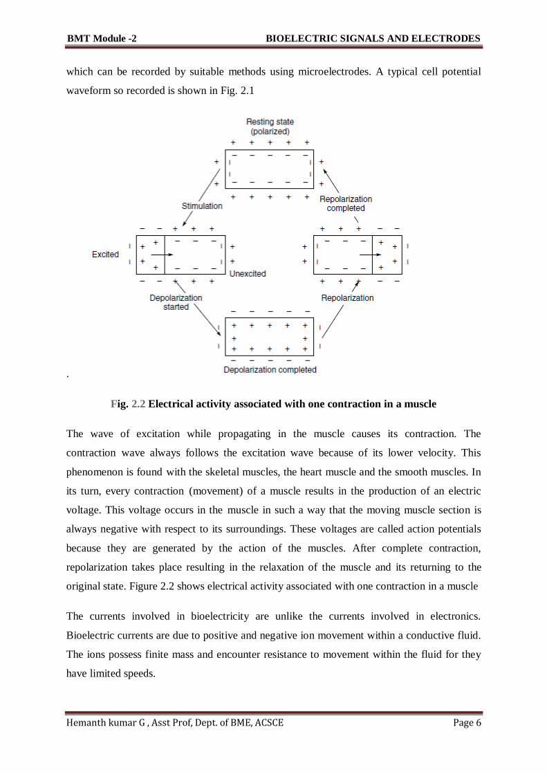
which can be recorded by suitable methods using microelectrodes. A typical cell potential
waveform so recorded is shown in Fig. 2.1
.
Fig. 2.2 Electrical activity associated with one contraction in a muscle
The wave of excitation while propagating in the muscle causes its contraction. The
contraction wave always follows the excitation wave because of its lower velocity. This
phenomenon is found with the skeletal muscles, the heart muscle and the smooth muscles. In
its turn, every contraction (movement) of a muscle results in the production of an electric
voltage. This voltage occurs in the muscle in such a way that the moving muscle section is
always negative with respect to its surroundings. These voltages are called action potentials
because they are generated by the action of the muscles. After complete contraction,
repolarization takes place resulting in the relaxation of the muscle and its returning to the
original state. Figure 2.2 shows electrical activity associated with one contraction in a muscle
The currents involved in bioelectricity are unlike the currents involved in electronics.
Bioelectric currents are due to positive and negative ion movement within a conductive fluid.
The ions possess finite mass and encounter resistance to movement within the fluid for they
have limited speeds.

BMT Module -2 BIOELECTRIC SIGNALS AND ELECTRODES
Hemanth kumar G , Asst Prof, Dept. of BME, ACSCE Page 7
The cell action potential, therefore, shows a finite rise time and fall time. It may be noted that
a cell may be caused to depolarize and then repolarize by subjecting the cell membrane to an
ionic current. However, unless a stimulus above a certain minimum value is applied, the cell
will not be depolarized and no action potential is generated. This value is known as the
stimulus threshold. After a cell is stimulated, a finite period of time is required for the cell to
return to its pre-stimulus state. This is because the energy associated with the action potential
is developed from metabolic processes within the cell which take time for completion. This
period is known as refractory period.
The bioelectric signals of clinical interest, which are often recorded, are produced by the
coordinated activity of large groups of cells. In this type of synchronized excitation of many
cells, the charges tend to migrate through the body fluids towards the still unexcited cell
areas. Such charge migration constitutes an electric current and hence sets up potential
differences between various portions of the body, including its outer surface. Such potential
differences can be conveniently picked up by placing conducting plates (electrodes) at any
two points on the surface of the body and measured with the help of a sensitive instrument.
These potentials are highly significant for diagnosis and therapy. The primary characteristics
of typical bioelectric signals are given in Table 2.1.
2.3 : Electrocardiogram (ECG)
The recording of the electrical activity associated with the functioning of the heart is known
as electrocardiogram. ECG is a quasi-periodical, rhythmically repeating signal synchronized

BMT Module -2 BIOELECTRIC SIGNALS AND ELECTRODES
Hemanth kumar G , Asst Prof, Dept. of BME, ACSCE Page 8
by the function of the heart, which acts as a generator of bioelectric events. This generated
signal can be described by means of a simple electric dipole (pole consisting of a positive and
negative pair of charge). The dipole generates a field vector, changing nearly periodically in
time and space and its effects are measured on the surface. The waveforms thus recorded
have been standardized in terms of amplitude and phase relationships and any deviation from
this would reflect the presence of an abnormality. Therefore, it is important to understand the
electrical activity and the associated mechanical sequences performed by the heart in
providing the driving force for the circulation of blood. The heart has its own system for
generating and conducting action potentials through a complex change of ionic concentration
across the cell membrane. Located in the top right atrium near the entry of the vena cava, are
a group of cells known as the sino-atrial node (SA node) that initiate the heart activity and act
as the primary pace maker of the heart (Fig. 2.3). The SA node is 25 to 30 mm in length and 2
to 5 mm thick. It generates impulses at the normal rate of the heart,
Fig. 2.3 The position of the sino-atrial node in the heart from where the impulse
responsible for the electrical activity of the heart originates. The arrow shows the path of
the impulse.
Note: The numbers like 0.18, 0.145, 0.15, 0.2 ... etc. indicate the time taken for
the impulse to travel from the S-A node to various parts of the heart about 72 beats per minute at rest. Because the body acts as a purely resistive medium, the
potential field generated by the SA node extends to the other parts of the heart. The wave
propagates through the right and left atria at a velocity of about 1 m/s. About 0.1 s are
required for the excitation of the atria to be completed. The action potential contracts the

BMT Module -2 BIOELECTRIC SIGNALS AND ELECTRODES
Hemanth kumar G , Asst Prof, Dept. of BME, ACSCE Page 9
atrial muscle and the impulse spreads through the atrial wall about 0.04s to the AV (atrio-
ventricular) node. This node is located in the lower part of the wall between the two atria.
The AV node delays the spread of excitation for about 0.12 s, due to the presence of a fibrous
barrier of non-excitable cells that effectively prevent its propagation from continuing beyond
the limits of the atria. Then, a special conduction system, known as the bundle of His
(pronounced as hiss) carries the action potential to the ventricles. The atria and ventricles are
thus functionally linked only by the AV node and the conduction system. The AV node delay
ensures that the atria complete their contraction before there is any ventricular contraction.
The impulse leaves the AV node via the bundle of His. The fibres in this bundle, known as
Purkinje fibres, after a short distance split into two branches to initiate action potentials
simultaneously in the two ventricles.
Conduction velocity in the Purkinje fibres is about 1.5 to 2.5 m/s. Since the direction of the
impulse propagating in the bundle of His is from the apex of the heart, ventricular contraction
begins at the apex and proceeds upward through the ventricular walls. This results in the
contraction of the ventricles producing a squeezing action which forces the blood out of the
ventricles into the arterial system. Figure 2.3 shows the time for action potential to propagate
to various areas of the heart.
The normal wave pattern of the electrocardiogram is shown in Fig. 2.4. The PR and PQ
interval, measured from the beginning of the P wave to the onset of the R or Q wave
respectively, marks the time which an impulse leaving the SA node takes to reach the
ventricles. The PRinterval normally lies between 0.12 to 0.2 s. The QRSinterval, which
represents the time taken by the heart impulse to travel first through the interventricular
system and then through the free walls of the ventricles, normally varies from 0.05 to 0.10s.

BMT Module -2 BIOELECTRIC SIGNALS AND ELECTRODES
Hemanth kumar G , Asst Prof, Dept. of BME, ACSCE Page 10
Fig. 2.4 Normal wave pattern of an ECG waveform recorded in the standard
lead position
TheT wave represents repolarization of both ventricles. The QT interval, therefore, is the
period for one complete ventricular contraction (systole). Ventricular diastole, starting from
the end of the T wave extends to the beginning of the next Qwave. Typical amplitude of
QRSis 1 mV for a normal human heart, when recorded in lead 1 position.
2.4 : Electroencephalogram (EEG)
The brain generates rhythmical potentials which originate in the individual neurons of the
brain. These potentials get summated as millions of cell discharge synchronously and appear
as a surface waveform, the recording of which is known as the electroencephalogram (Fig.
2.5). The neurons, like the other cells of the body, are electrically polarized at rest. The
interior of the neuron is at a potential of about –70 mV relative to the exterior. When a
neuron is exposed to a stimulus above a certain threshold, a nerve impulse, seen as a change
in membrane potential, is generated which spreads in the cell resulting in the depolarization
of the cell. Shortly afterwards, repolarization occurs.

BMT Module -2 BIOELECTRIC SIGNALS AND ELECTRODES
Hemanth kumar G , Asst Prof, Dept. of BME, ACSCE Page 11
Fig. 2.5 Typical EEG signal waveform
The EEG signal can be picked up with electrodes either from the scalp or directly from the
cerebral cortex. The peak-to-peak amplitude of the waves that can be picked up from the
scalp is normally 100 µV or less while that on the exposed brain, is about 1 mV. The
frequency varies greatly with different behavioural states. The normal EEG frequency content
ranges from 0.5 to 50 Hz. The nature of the wave varies over the different parts of the scalp.
The variations in EEG signals both in terms of amplitude and frequency are of diagnostic
value. Frequency information is particularly significant since the basic frequency of the EEG
range is classified into the following five bands for purposes of EEG analysis:
Delta (d) 0.5–4 Hz
Theta (q) 4–8 Hz
Alpha (a) 8–13 Hz
Beta (b) 13–22 Hz
Gamma (g) 22–30 Hz
The alpha rhythm is one of the principal components of the EEG and is an indicator of the
state of ‘alertness’ of the brain. It serves as an indicator of the depth of anaesthesia in the
operating room. The frequency of the EEG seems to be affected by the mental activity of a
person. The wide variation among individuals and the lack of repeatability in a given person
from one occasion to another makes the analysis a difficult proposition. However, certain
characteristic EEG waveforms can be conveniently related to gross abnormalities like
epileptic seizures and sleep disorders. Besides the importance of the frequency content of the
EEG pattern, phase relationships between similar EEG patterns from different parts of the
brain are also being studied with great interest in order to obtain additional knowledge
regarding the functioning of the brain. Another important measurement is the recording of
‘evoked response’ , which indicates the disturbance in the EEG pattern resulting from

BMT Module -2 BIOELECTRIC SIGNALS AND ELECTRODES
Hemanth kumar G , Asst Prof, Dept. of BME, ACSCE Page 12
external stimuli. The stimuli could be a flash of light or a click of sound. Since the responses
to the stimuli are repeatable, the evoked response can be distinguished from the rest of the
EEG activity by averaging techniques to obtain useful information about the functioning of
particular parts of the brain.
2.5: Electromyogram (EMG)
The contraction of the skeletal muscle results in the generation of action potentials in the
individual muscle fibres, a record of which is known as electromyogram.
The activity is similar to that observed in the cardiac muscle, but in the skeletal muscle,
repolarization takes place much more rapidly, the action potential lasting only a few
milliseconds.
Since most EMG measurements are made to obtain an indication of the amount of activity of
a given muscle, or a group of muscles, rather than of an individual muscle fibre, the EMG
pattern is usually a summation of the individual action potentials from the fibres constituting
the muscle or muscles being studied.
The electrical activity of the underlying muscle mass can be observed by means of surface
electrodes on the skin.
However, it is usually preferred to record the action potentials from individual motor units for
better diagnostic information using needle electrodes. In voluntary contraction of the skeletal
muscle, the muscle potentials range from 50 mV to 5 mV and the duration from 2 to 15 ms.
The values vary with the anatomic position of the muscle and the size and location of the
electrode. In a relaxed muscle, there are normally no action potentials. A
typical EMG signal is shown in Fig. 2.6.

BMT Module -2 BIOELECTRIC SIGNALS AND ELECTRODES
Hemanth kumar G , Asst Prof, Dept. of BME, ACSCE Page 13
2.6: Electrooculogram (EOG)
Electro-oculography is the recording of the bio-potentials generated by the movement of the
eye ball. The EOG potentials are picked up by small surface electrodes placed on the skin
near the eye.
One pair of electrodes is placed above and below the eye to pick up voltages corresponding to
vertical movements of the eye ball. Another pair of electrodes is positioned to the left and
right of the eye to measure horizontal movement.
The recording pen is centred on the recording paper, corresponding to the voltage changes
accompanying it. EOG has applications mostly for research and is not widely used for
clinical purposes.
2.7: Electroretinogram (ERG)
It is found that an electrical potential exists between the cornea and the back of the eye. This
potential changes when the eye is illuminated.

BMT Module -2 BIOELECTRIC SIGNALS AND ELECTRODES
Hemanth kumar G , Asst Prof, Dept. of BME, ACSCE Page 14
The process of recording the change in potential when light falls on the eye is called
electroretinography.
ERG potentials can be recorded with a pair of electrodes. One of the electrodes is mounted on
a contact lens and is in direct contact with the cornea.
The other electrode is placed on the skin adjacent to the outer corner of the eye. A reference
electrode may be placed on the forehead.
A general purpose direct writing recorder may be used for recording electroretinograms.
The magnitude of the ERG voltage depends upon the intensity and duration of the light
falling on the eye. It may be typically about 500 mV.
2.8: Recording Electrodes–Electrode-tissue interface,
Bioelectric events have to be picked up from the surface of the body before they
can be put into the amplifier for subsequent record or display. This is done by
using electrodes.
Electrodes make a transfer from the ionic conduction in the tissue to the
electronic conduction which is necessary for making measurements.
Two types of electrodes are used in practice-surface electrodes and the deep-
seated electrodes. The surface electrodes pick up the potential difference from
the tissue surface when placed over it without damaging the live tissue.
2.8.1 ELECTRODE TISSUE INTERFACE
The most commonly used electrodes in patient monitoring and related studies are surface
electrodes. The notable examples are when they are used for recording ECG, EEG and
respiratory activity by impedance pneumography.
In order to avoid movement artefacts and to obtain a clearly established contact (low contact
impedance) an electrolyte or electrode paste is usually employed as an interface between the

BMT Module -2 BIOELECTRIC SIGNALS AND ELECTRODES
Hemanth kumar G , Asst Prof, Dept. of BME, ACSCE Page 15
electrode and the surface of the source of the event. Figure 2.7 (a, b) represent the electrode-
tissue interface.
The characteristic of a surface electrode composed of a metal electrode and attached to the
surface of the body through an electrolyte (electrode jelly) are dependent upon the conditions
at the metal-electrolyte interface, the electrolyte-skin interface and the quality of the
electrolyte.
Metal-Electrolyte Interface:
At the metal-electrolyte transition, there is a tendency for each electrode to discharge ions
into the solution and for ions in the electrolyte to combine with each electrode. The net result
is the creation of a charge gradient (difference of potential) at each electrode, the spatial
arrangement of which is called the electrical double layer (Fig. 2.7(c)). The double layer is
known to be present in the region immediately adjacent to the electrode and can be
represented, in its simplest form, as two parallel sheets of charge of opposite sign separated
by a thin film of dielectric. Therefore, the metal-electrolyte interface appears to consist of a
voltage source in series with a parallel combination of a capacitance and reaction resistance.
The voltage developed is called the half-cell potential.

BMT Module -2 BIOELECTRIC SIGNALS AND ELECTRODES
Hemanth kumar G , Asst Prof, Dept. of BME, ACSCE Page 16
Electrolyte-Skin Interface:
An approximation of the electrolyte-skin interface can be had by assuming that the skin acts
as a diaphragm arranged between two solutions (electrolyte and body fluids) of different
concentrations containing the same ions, which is bound to give potential differences.
The simplest equivalent representation could then be described as a voltage source in series
with a parallel combination of a capacitance and resistance. The capacitance represents the
charge developed at the phase boundary whereas the resistance depends upon the conditions
associated with ion-migration along the phase boundaries and inside the diaphragm.
The above discussion shows that there is a possibility of the presence of voltages of
Non�physiological origin. These voltages are called contact potentials.

BMT Module -2 BIOELECTRIC SIGNALS AND ELECTRODES
Hemanth kumar G , Asst Prof, Dept. of BME, ACSCE Page 17
The electrical equivalent circuit of the surface electrode suggests that the voltage presented to
the measuring instrument from the electrode consists of two main components. One is the
contact potential and the other is the biological signal of interest.
The contact potential depends upon several factors and may produce an interference signal
which exceeds several times the useful signal. The contact potential is found to be a function
of the type of skin, skin preparation and composition of the electrolyte.
The electrodes are used to measure a bioelectric event and are connected to a differential
amplifier. Three potentials are found to exist in this circuit (Fig. 2.9), one is due to the
bioelectric event (Eb) and the other two are non-physiologicand represent the half-cell
potentials (E1 and E2) of the electrodes. Z1 and Z2 are the skin contact impedances of these
electrodes and R is the tissue resistance or resistance of the bioelectric generator.
This circuit shows that the impedance of the electrodes would be high in the low�frequency
region and it would decrease with increasing frequency. It is further clear that in the
measurement of a bioelectric signal, it is essential to minimize potential drops across the
electrode impedance. This is achieved by making the skin-contact impedance as low as
possible and making the input impedance of the measuring device as high as possible.

BMT Module -2 BIOELECTRIC SIGNALS AND ELECTRODES
Hemanth kumar G , Asst Prof, Dept. of BME, ACSCE Page 18
POLARISATION
If a low voltage is applied to two electrodes placed in a solution, the electrical double layers
are disturbed. Depending on the metals constituting the electrodes, a steady flow of current
may or may not take place.

BMT Module -2 BIOELECTRIC SIGNALS AND ELECTRODES
Hemanth kumar G , Asst Prof, Dept. of BME, ACSCE Page 19
In some metal/liquid interfaces, the electrical double layer gets temporarily disturbed by the
externally applied voltage, and therefore, a very small current flows after the first surge, thus
indicating a high resistance. This type of electrode will not permit the measurement of steady
or slowly varying potentials in the tissues.
They are said to, be polarized or nonreversible. Thus, the phenomenon of polarization affects
the electro-chemical double layer on the electrode surface and manifests itself in changing the
value of the impedance and voltage source representing the transition layer.
Parsons (1964) stated that electrodes in which no net transfer of charge takes place across the
metal-electrolyte interface can be termed as perfectly polarized. Those in which unhindered
exchange of charge is possible are called non-polarizable or reversible electrodes. The ionic
double layer in metals of these electrodes is such that they allow considerable current to flow
when a small voltage is applied, thus offering a low resistance.
SKIN CONTACT IMPEDANCE :
Measurement of Skin Contact Impedance: A convenient method to measure the contact
impedance at any individual electrode is shown in Fig. 2.11.
The three electrodes, A, B and C, have contact impedance respectively of Za, Zb andZc. An
oscillator provides a constant current in the frequency range of 0.1–100 Hz through the 47
kW series resistor.
By suitably positioning the switch, a sensitive oscilloscope can be used to monitor either the
voltage dropped across the 1 kW resistor or the voltage dropped across Zb.
The voltage drop across Zb can be neglected since the input impedance of the oscilloscope
used with an input probe is usually high. From the voltage dropped across the 1 kW resistor
it is possible to calculate the circuit current and thus to obtain a value for Zc.
Using this technique, the skin contact impedance of the following types of electrodes were
measured by Hill and Khandpur (1969).

BMT Module -2 BIOELECTRIC SIGNALS AND ELECTRODES
Hemanth kumar G , Asst Prof, Dept. of BME, ACSCE Page 20
• Plastic cup self-adhesive electrodes (Boter et al, 1966)
• Metal plate limb electrodes used with conducting jelly
• Metal plate electrodes used with conducting plastic (Jenkner, 1967)
• Dry multi-point limb electrodes (Lewes, 1966)
• Dry multi-point suction chest electrodes
• Self-adhesive multi-point chest electrodes used with conducting jelly
• Self-adhesive gauze electrodes
• Self-adhesive dry multi-point chest electrodes (Lewes and Hill, 1967)
Motion Artifacts
Motion artefact is a problem in biopotential measurements. The problem is greatest in cardiac
stress laboratories where the exercise ECG is recorded. The problem is also serious in
coronary care units where patients are monitored for relatively long periods.
Motion of the subject under measurement creates artefacts which may even mask the desired
signal or cause an abrupt shift in the baseline. These artefacts may result in a display being

BMT Module -2 BIOELECTRIC SIGNALS AND ELECTRODES
Hemanth kumar G , Asst Prof, Dept. of BME, ACSCE Page 21
unreadable, a recording instrument exceeding its range, a computer yielding incorrect output
or a false alarm being triggered by the monitoring device.
Tam and Webster (1977) concluded that the skin-electrolytic paste interface is the major
source of motion artefact. When a metal electrode contacts an electrolytic paste, a half�cell
potential is generated at the electrode-paste interface. Kahn (1965) demonstrated that when
polarizable metal-plate electrodes are used, the electrode-paste interface can be a source of
motion artefact.
When the paste is agitated, the half-cell potential varies because of the altered metallic ion
gradient at the interface. He recorded a 1 mV offset potential change from a silver-silver
chloride electrode exposed to a flowing stream of saline solution, as contrasted to 30 mV
change for some silver electrodes.
Motion artefact is reduced to a negligible magnitude by skin abrasion. However, when the
skin is abraided, it is more susceptible to irritants. The possible sources for skin irritation
include the electrode, the paste and the adhesive. When large currents flow through metallic
electrodes, migration of some ions into the skin can cause irritation.
2.9 Silver-Silver Chloride electrodes
Production of Silver-Silver Chloride Electrodes: Silver-silver chloride electrodes are
normally prepared by electrolysis. Two silver discs are suspended in a saline solution. The
positive pole of a dc supply is connected to the disc to be chlorided and the negative pole
goes to the other disc. A current at the rate of 1 mA/cm2 of surface area is passed through the
electrode for several minutes. A layer of silver chloride is thus deposited on the surface of the
anode. The chemical changes that take place at the anode and cathode respectively are:
To prepare silver-silver chloride electrodes of good quality, only pure silver should be used
and the saline solution should be made from analar grade sodium chloride. Before
chloriding, silver must be cleaned—preferably by the electrolytic method.

BMT Module -2 BIOELECTRIC SIGNALS AND ELECTRODES
Hemanth kumar G , Asst Prof, Dept. of BME, ACSCE Page 22
2.10 ELECTRODES FOR ECG LIMB ELECTRODE:
The most common type of electrodes routinely used for recording ECG are rectangular or
circular surface electrodes (Fig. 2.13).
The material used is german silver, nickel silver or nickel plated steel. They are applied to the
surface of the body with electrode jelly.
The typical value of the contact impedance of these electrodes, which are of normal size, is
nearly 2 to 5 kW when measured at 10 Hz.
The electrodes are held in position by elastic straps. They are also called limb electrodes as
they are most suitable for application on the four limbs of the body.
The size of the limb electrodes is usually 3 \ 5 cm and they are generally made of german
silver, an alloy of zinc, copper and nickel. They are reusuable and last several years.
Limb electrodes are generally preferred for use during surgery because the patient’s limbs
are relatively immobile. Moreover, chest electrodes cannot be used as they would interfere
with the surgery.
Limb electrodes are not suitable for use in long-term patient monitoring because the long
flowing leads are inconvenient to the patient. Also, the electromyographic voltages generated
by the activity of the limb muscles makes them unsuitable for use when monitoring conscious
and semi-conscious patients.
Suction-cup electrode is commonly used to record the unipolar chest leads. It has a high
contact impedance as only the rim of the electrode is in contact with the skin. The electrode is

BMT Module -2 BIOELECTRIC SIGNALS AND ELECTRODES
Hemanth kumar G , Asst Prof, Dept. of BME, ACSCE Page 23
popular for its practicality, being easily attachable to fleshy parts of the body. Electrode jelly
forms the vacuum seal.
FLOATING ELECTRODES:
Limb electrodes generally suffer from what is known as motion artefacts caused due to the
relative motion at the interface between the metal electrode and the adjacent layer of
electrode jelly.
The interface can be stabilized by the use of floating electrodes in which the metal electrode
does not make direct contact with the skin. The electrode (Fig. 2.14) consists of a light-
weight metalled screen or plate held away from the subject by a flat washer which is
connected to the skin. Floating electrodes can be recharged, i.e. the jelly in the electrodes can
be replenished if desired.
Connection with the instrument is established with silver-plated copper wires fixed in the
conducting adhesive. The type of electrodes are extremely light-weight and do not make use
of electrode jelly.
This makes them ideal for use in monitoring the ECG of exercising subjects and aeroplane
pilots as they give rise to minimal motion artefacts. The contact impedance shown by these
electrodes is of the order of 50 kW.
PREGELLED DISPOSABLE ELECTRODE
Electrodes which are employed in stress testing or long term monitoring, present additional
problems because of the severe stresses, perspiration and major body movement encountered
in such studies.

BMT Module -2 BIOELECTRIC SIGNALS AND ELECTRODES
Hemanth kumar G , Asst Prof, Dept. of BME, ACSCE Page 24
Both design considerations and application techniques of electrodes used in
electrocardiography are necessary to prevent random noise on the baseline, baseline
wandering and skin contact over extended periods causing a loss of signal.
To overcome problems due to prolonged application, special disposable electrodes have been
developed.
Figure 2.15(a) illustrates the principle of a pregelled electrode while Fig. 2.15(b) shows a
cross-section of such an electrode. The main design feature of these electrodes which helps in
reducing the possibility of artefacts, drift and baseline wandering is the provision of a high-
absorbancy buffer layer with isotonic electrolyte.
This layer absorbs the effects of movement of the electrode in relationship to the skin, and
attempts to maintain the polarization associated with the half-cell potential constant.
Since perspiration is the most common cause of electrode displacement, the use of an
additional porous overlay disc resists perspiration and ensures secure placement of the
electrode on the skin even under stress conditions. Figure 2.16 show a typical pregelled
electrode.

BMT Module -2 BIOELECTRIC SIGNALS AND ELECTRODES
Hemanth kumar G , Asst Prof, Dept. of BME, ACSCE Page 25
PASTELESS ELECTRODES
ECG monitoring electrodes, in a majority of the cases, are metal plates applied to the skin
after cleaning and application of a coupling-electrolyte in the form of an electrode paste or
jelly.
Such preliminary preparation can be sometimes irritating and time consuming. Also, it is
often not done satisfactorily, resulting in problems like poor quality signals and baseline drift,
etc. Another disadvantage of using electrode jelly is that during long-term monitoring there is
likely to be patient-skin reactions as the electrode-skin interface dries out in a matter of a few
hours.
The electrodes need to be periodically removed for jelly replenishments, thus causing further
discomfort due to repetitive skin preparation. In addition, bacterial and fungal growth can
take place under electrodes worn over long periods. Also, in conductive electrodes, shifts in
electrode position at the electrode-skin interface appear as baseline drift, particularly when
the subject moves.
Therefore, any attempt of using a dry electrode that may dispense with the practice of skin
preparation would look attractive.
Capacitive Electrodes: A metal plate electrode in direct contact with the skin though makes
a very high resistive contact and has a considerable capacitive contact too with the skin.
By using a very high input impedance amplifier, it is possible to record a signal through the
tissue electrode capacitance. Lopez and Richardson (1969) describe the construction of
electrodes which can be capacitively coupled to the subject.
The electrode consists of an aluminium plate which is anodized on the surface to be placed in
contact with the skin. The ohmic resistance of the anodized electrode is about 1 to 30 GW
(1000–30,000 MW). Two such electrodes are applied to the subject.
Luca et al (1979) designed an electrode and amplifier as an integrated unit, so that the
assembly could be used in the front end of the commonly used biomedical recorders. The

BMT Module -2 BIOELECTRIC SIGNALS AND ELECTRODES
Hemanth kumar G , Asst Prof, Dept. of BME, ACSCE Page 26
arrangement (Fig. 2.18) basically comprises a metal shell which performs a dual function as a
housing for the electrode and as the ground contact.
The shell is made of highly pure titanium metal measuring 30 \ 1 5 \ 7 mm. Two FETs are
cemented with epoxy glue in the middle of the shell, their centers spaced 10 mm apart. The
recording surfaces are formed by the cases of the two FETs.
The cans have a diameter of 4.5 mm and are made of stainless steel. The rectangular border
of the shell acts as the ground contact and the remainder of the shell forms a shield against
interfering radiation.
The source leads of the two FETs are connected to the differential inputs of instrumentation
Amplifier. The amplifier (Analog Devices 521) has a high ac input impedance (> 100 MW).
Air-Jet ECG Electrodes: Wohnhas (1991) describes a novel air-jet electrode which employs
Bernoulli technology to achieve constant and secure electrode contact resulting in quality
tracings while minimizing artefact and maximizing baseline stability.
Air-jet electrodes (Fig. 2.19) are Ag-AgCl electrodes encased within a contoured medical
silicon Cup bounded by a skin-engaging rim. The contact area (pill) is anchored to a layer of
synthetic, sintered carbon by a titanium screw. The miniature silver venturi air-jet bisects the
sintered layer of synthetic carbon.

BMT Module -2 BIOELECTRIC SIGNALS AND ELECTRODES
Hemanth kumar G , Asst Prof, Dept. of BME, ACSCE Page 27

BMT Module -2 BIOELECTRIC SIGNALS AND ELECTRODES
Hemanth kumar G , Asst Prof, Dept. of BME, ACSCE Page 28
2.11 ELECTRODES FOR EEG
Among the most commonly used electrodes for EEG (electroencephalogram) recording are
the chlorided silver discs (Fig. 2.20) having approximately 6–8 mm diameters. Contact with
the scalp is made via an electrolytic paste through a washer of soft felt.
They have ac resistance varying from 3–20 kW. Small needle electrodes are sometimes used
for carrying out special EEG studies when they are inserted subcutaneously. Silver ball or
pellet electrodes covered with a small cloth pad are useful when electrical activity is to be
recorded from the exposed cortex, but they have high dc resistances.
Hector (1968) describes a pad electrode (Fig. 2.21(a)) which is made from a silver rod belled
out at the end and padded with a sponge, or a similar material, contained in gauze. It is
screwed into an insulated mount and held in place on the head with a rubber cap.
To hold three such electrodes, an adjustable tripod mount is employed. Another type of EEG
electrode consists of multiple fine chlorided silver wires (Fig. 2.21(b)) fixed in a rigid plastic
cup.
The plastic cup is fixed to the scalp with an adhesive. It is filled with jelly through a hole in
the top. In this electrode, contact with the tissue is made via an electrolyte bridge so that jelly
in contact with the electrode metal is not disturbed by scalp movement.
To avoid metal junctions which may get corroded with electrolyte, the silver wires are used
as the output lead. The large surface area and excess of silver chloride favour stability.

BMT Module -2 BIOELECTRIC SIGNALS AND ELECTRODES
Hemanth kumar G , Asst Prof, Dept. of BME, ACSCE Page 29
2.12 ELECTRODES OF EMG
Electrodes for electromyographic work are usually of the needle type (Fig. 2.22(a)). Needle
electrodes are used in clinical electromyography, neurography and other electrophysiological
investigations of the muscle tissues underneath the skin and in the deeper tissues.
The material of the needle electrode is generally stainless steel. In spite of the fact that
stainless steel is unfavorable electrode material from the point of view of noise, it is preferred
in EMG work due to its mechanical solidity and low price.
Needle electrodes are designed to be fully autoclavable and in any case they should be
thoroughly sterilized before use. Needle electrodes come in various forms. The monopolar
needle electrode usually consists of a Teflon coated stainless steel wire which is bare only at
the tip. It is found that after the needle has been used a number of times, the Teflon coating
will recede, increasing the tip area.
The needle must be discarded when this occurs. Bipolar (double coaxial) needle electrodes
contain two insulated wires within a metal cannula. The two wires are bared at the tip and
provide the contacts to the patient.
BMT Module -2 BIOELECTRIC SIGNALS AND ELECTRODES
Hemanth kumar G , Asst Prof, Dept. of BME, ACSCE Page 30
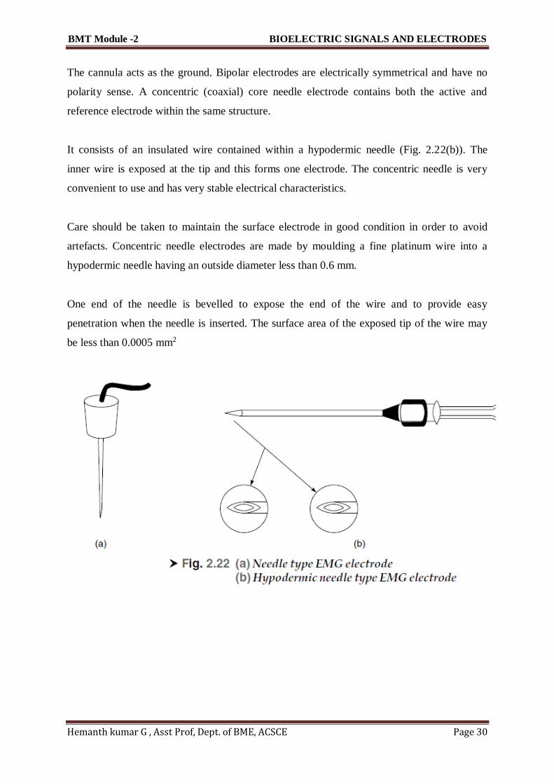
The cannula acts as the ground. Bipolar electrodes are electrically symmetrical and have no
polarity sense. A concentric (coaxial) core needle electrode contains both the active and
reference electrode within the same structure.
It consists of an insulated wire contained within a hypodermic needle (Fig. 2.22(b)). The
inner wire is exposed at the tip and this forms one electrode. The concentric needle is very
convenient to use and has very stable electrical characteristics.
Care should be taken to maintain the surface electrode in good condition in order to avoid
artefacts. Concentric needle electrodes are made by moulding a fine platinum wire into a
hypodermic needle having an outside diameter less than 0.6 mm.
One end of the needle is bevelled to expose the end of the wire and to provide easy
penetration when the needle is inserted. The surface area of the exposed tip of the wire may
be less than 0.0005 mm2

BMT Module -2 BIOELECTRIC SIGNALS AND ELECTRODES
Hemanth kumar G , Asst Prof, Dept. of BME, ACSCE Page 31
2.13 ELECTRICAL CONDUCTIVITY OF ELECTRODE JELLIES AND
CREAMS
Conducting creams and jellies have for long been used to facilitate a more intimate contact
between the subject’s skin and the recording electrodes. The outer horny layer of the skin is
responsible for the bulk of the skin contact impedance, and for this reason careful skin
preparation is essential in order to obtain the best results. The recording site should first be
cleaned with an ether-meth mixture.
In addition to having good electrical conductivity, the electrode jelly must have a particular
chloride ion concentration (about 1%) close to the physiological chloride concentration.
This is primarily important for long-term monitoring because it should not produce a harmful
diffusion between the jelly and the body. It is to be particularly ensured that the jelly chosen
is of a bland nature and does not contain soap or phenol which can produce a marked
irritation of the skin after a few hours.
The electrical conductivity of different makes of electrode cream can be measured (Hill and
Khandpur, 1969) by means of the Schering ac bridge circuit. The cream is placed in a
Perspex conductivity cell of known dimensions and the resistive component of the cell
impedance is measured at 10 Hz, the conductivity being calculated from the cell dimensions.
The contact impedance of the skin depends upon the type of electrolyte used and the time
(Trimby, 1976). Figure 2.24 shows the effect of these parameters. A low concentration
sodium chloride electrolyte has 0.5% NaCI and a high concentration electrolyte has a

BMT Module -2 BIOELECTRIC SIGNALS AND ELECTRODES
Hemanth kumar G , Asst Prof, Dept. of BME, ACSCE Page 32
concentration in the range of 5 to 10% NaCI. The impedance is found to fall rapidly to 40%
between 7 to 30 min.
Stabilization occurs at about 30 to 45 min. An interesting observation from this figure is that
while pre-rubbing the skin will lower the initial impedance value, the final value after using a
high concentration electrolyte becomes nearly the same.
Electrode jelly can be replaced in certain cases by using a conducting plastic as an interface
between the electrode and the surface of the body.
2.14 MICROELECTRODES
To study the electrical activity of individual cells, microelectrodes are employed. This type of
electrode is small enough with respect to the size of the cell in which it is inserted so that
penetration by the electrode does not damage the cell.
The size of an intracellular microelectrode is dictated by the size of the cell and the ability of
its enveloping membrane to tolerate penetration by the microelectrode tip. Single-living cells
are rarely larger than 0.5 mm (500 microns) and are usually less than one-tenth of this size.
Typical microelectrodes have tip dimensions ranging from 0.5 to 5 microns. The tips of these
electrodes have to be sufficiently strong to be introduced through layers of tissues without
breaking.
Two types of microelectrodes are generally used: metallic (Fig. 2.25(a)) and glass
microcapillaries (Fig. 2.25(b)). Metallic electrodes are formed from a fine needle of a suitable
metal drawn to a fine tip. On the other hand, glass electrodes are drawn from Pyrex glass of
special grade.
These microcapillaries are usually filled with an electrolyte. The metal microelectrodes are
used in direct contact with the biological tissue and, therefore, have a lower resistance.
However, they polarize with smaller amplifier input currents.
Hence, they tend to develop unstable electrode offset potentials and are therefore not
preferred for steady state potential measurements. On the other hand, in case of glass
microelectrodes, improved stability can be obtained by properly choosing the metal and the
electrolyte so that the small current passing through their junction may not be able to modify
the electrical properties of the electrodes.

BMT Module -2 BIOELECTRIC SIGNALS AND ELECTRODES
Hemanth kumar G , Asst Prof, Dept. of BME, ACSCE Page 33
Also, the glass microelectrode has a substantial current carrying capacity because of the large
surface contact area between the metal and the electrolyte.
The microelectrodes have a very high impedance as compared to conventional electrodes
used for recording ECG, EEG, etc. The high impedance of a metal microelectrode is due to
the characteristics of the small area metal-electrolyte interface.
Similarly, a micropipet tip is filled with an electrolyte which substitutes an electrolytic
conductor of small cross-sectional area, which gives a micropipet its high resistance. Because
of high impedance of microelectrodes, amplifiers with extremely high input impedances are
required to avoid loading the circuit and to minimize the effects of small changes in interface
impedance.
Glass Capillary Electrode
Several methods exist for producing microelectrodes of wide variety and shapes. For drawing
electrodes of uniform and accurate diameter, it is essential to maintain constant timing,
temperature, strength and direction of pull. These factors are difficult to control when the
electrodes are drawn manually.
The mechanical method employs gravitational force for extension and the electrodes which
are drawn in one or more stages can readily produce capillary tubes between 3–30 mm
diameter, but great difficulty is encountered in producing electrodes of less than 1 mm.
The most commonly used method for making small tip micropipet consists of the
circumferential application of heat to a small area of glass tubing which is placed under some

BMT Module -2 BIOELECTRIC SIGNALS AND ELECTRODES
Hemanth kumar G , Asst Prof, Dept. of BME, ACSCE Page 34
initial tension. When the glass softens, the tension is increased very rapidly and the heat is
turned off.
Proper timing, controlled adjustment of the amount of heat as well as the initial and final
tensions and cooling result in the production of microcapillaries with controlled dimensions.
Metal Microelectrode
Metal electrodes with very fine tips used for recording from single cells have the advantage
over glass micropipetes of being relatively robust. Steel microelectrodes can be made from
ordinary darning needles but preferably they should be of good stainless steel wire.
They can be easily made up to 10 mm diameter but great care has to be taken for diameters as
small as 1 µm. Thesevery small tips are not very satisfactory as they are extremely brittle and
have very high input impedance.
Hubel (1957) described a method to make tungsten microelectrodes with a tip diameter of 0.4
µm. He used electropointing technique which consists in etching a metal rod while the metal
rod is slowly withdrawn from the etching solution, thus forming a tapered tip on the end of
the rod. The etched metal is then dipped into an insulating solution for placing insulation on
all but the tip.
Figure 2.26 shows the cross-section of a metal microelectrode. In this electrode, a thin film of
Precious metal is bonded to the outside of a drawn glass microelectrode. This arrangement
offers lower impedance than the microcapillary electrode, infinite shelf life and reproduciable
performance, with ease of cleaning and maintenance. The metal—electrolyte interface is
between the metal film and the electrolyte of the cell.