
A unified approach to the perception of motion, stereo, and static-flow patterns

Perception & Psychophysics1998, 60 (3), 377-388
The perception of surface curvaturefrom optical motion
VICTOR J. PEROTTIand JAMEST.TODDOhio State University, Columbus, Ohio
JOE S. LAPPINVanderbilt University, Nashville, Tennessee
and
FLIP PHILIlPSOhio State University, Columbus, Ohio
Observers viewed the optical flow field of a rotating quadric surface patch and were required tomatch its perceived structure by adjusting the shape of a stereoscopically presented surface. In Experiment 1, the flow fields included rigid object rotations and constant flow fields with patterns ofimage acceleration that had no possible rigid interpretation. In performing their matches, observers hadindependent control of two parameters that determined the surface shape. One of these, called theshape characteristic, is defined as the ratio of the two principle curvatures and is independent of object size. The other, called curvedness, is defined as the sum of the squared principle curvatures anddepends on the size of the object. Adjustments of shape characteristic were almost perfectly accuratefor both motion conditions. Adjustments of curvedness, on the other hand, were systematically overestimated and were not highly correlated with the simulated curvedness of the depicted surface patch.In Experiment 2, the same flow fields were masked with a global pattern of curl, divergence, or shear,which disrupted the first-order spatial derivatives of the image velocity field, while leaving the secondorder spatial derivatives invariant. The addition of these masks had only negligibleeffects on observers'performance. These findings suggest that observers' judgments of three-dimensional surface shapefrom motion are primarily determined by the second-order spatial derivatives of the instantaneous fieldof image displacements.
Human observers make use of many different sourcesof information to perceive the three-dimensional (3-D)structure of their environment. One of the most important of these sources is the changing pattern of retinalstimulation created by the movements of the observerand environmental objects. Wallach and Q'Connell (1953)showed that motion information could by itself create animpression of 3-D structure. In their demonstration, anapparently two-dimensional (2-D) form created by the projected shadows ofa wireframe figure suddenly appearedto have a compelling 3-D structure when the wireframewas rotated in depth.
Early theoretical analyses of this phenomenon definedthe minimal information that would permit an observerto determine the 3-D structure ofa configuration ofpoints.To simplify the analysis, these models typically assumethat the input is a set of image points moving across discrete frames. For general configurations under orthographic projection, a minimum ofthree distinct views of
This research was supported in part by AFOSR Grant F49620-93-1oI 16. Correspondence should be addressed to V. 1. Perotti, RochesterInstitute of Technology, College of Business, 107 Lomb MemorialDrive, Rochester, NY 14623 (e-mail: [email protected]).
four noncoplanar points are needed to compute the 3-Dstructure ofan object up to a reflection in depth (e.g., seeBennett & Hoffman, 1986; Hoffman & Bennett, 1985,1986; Hoffman & Flinchbaugh, 1982; Ullman, 1979).For objects observed under polar projection, only twoviews of five points are needed to specify 3-D structure(Longuet-Higgens & Prazdny, 1980), although, in thiscase, without additional information to specify an object's distance from the point of observation, the analysis isambiguous as to the object's exact size.
A large number ofpsychophysical tests have been performed to determine how well these computational theories apply to human observers. Many of the results haveindicated that observers have no trouble perceiving 3-Dshapes when presented with only two frames under orthographic projection (see Braunstein, Hoffman, & Pollick, 1990; Braunstein, Hoffman, Shapiro, Andersen, &Bennett, 1987; Lappin, Doner, & Kottas, 1980; Norman& Todd, 1993; Todd, Akerstrom, Reichel, & Hayes,1988). Moreover, for many different perceptual tasks,there is no significant difference between observers' performance when shown two views and their performancewhen shown more than two views (see Liter, Braunstein,& Hoffman, 1993; Todd & Bressan, 1990; Todd & Norman, 1991). These results demonstrate that observers are
377 Copyright 1998 Psychonomic Society, Inc.
378 PEROTTI, TODD, LAPPIN, AND PHILLIPS
These two functions are related by a constant scale factor,OJ, which is the rate of the surface's angular rotation:
The image velocity field, V, formed by the orthographicprojection of this surface as it rotates about a verticalaxis, can be expressed as a function ofthe horizontal andvertical positions:
The scale factor, OJ, is a specific quantity that must bedetermined in order to get an unambiguous measurementof surface structure from the velocity field. The constantrelationship between the image-velocity field and the surface structure holds also for the first and second partialderivatives across space. To simplify the notation, a subscripted letter is used to identify a partial (spatial) derivative in a given direction. Two subscripted letters indi-
(6)
(7)
cate a second partial derivative in the directions specified.For example, the first partial derivatives of the velocityfield are given by
v" = oil, and Jj = OJly. (4)
The second partial derivatives are
v"x = OJIxx> v"y = OJlxy, and Jjy = OJlyy- (5)
Although it is desirable to obtain an unambiguousmeasure of an object's structure from its projected motion, the existence of an unknown scale factor OJ meansthat the structure is only specified up to a one-parameterfamily of possible interpretations. However, if we consider instead the ratios of these measures, the scale factor OJ would drop out. Ratios of the partial derivatives areunambiguous measures and thus represent invariant properties for rotating objects under orthographic projection.
The distinction between ratio and nonratio quantitiesis a powerful one. This idea allows us to predict whichproperties in the environment can be unambiguously determined from the velocity field and which cannot. Forexample, consider the well-known descriptions of surface attitude-slant (a) and tilt (r):
I Vtan r=...L =..L.
Iy Jj
The difference between these two quantities is evident:slant has an inherent ambiguity, as it is reflected in thevelocity field, but tilt does not. This means that any estimate of slant is only as good as the observer's estimatefor the angular rotation velocity, whereas tilt is specifieduniquely by the first spatial derivatives of the velocityfield (see Cornilleau-Peres & Droulez, 1989; Koenderink& van Doorn, 1975, 1977; Te Pas, Kappers, & Koenderink, 1996).
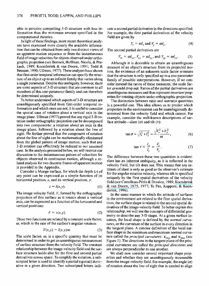
In the same manner in which the attitude of surfacesin the environment are related to the first spatial derivatives, the surface shape is related to the second spatial derivatives ofthe image-velocity field. To better explain thisrelationship, we will use the concepts ofdifferential geometry to describe any 3-D shape. At a given surface location, the local shape is defined by the normal curvatures, or the curvature of the surface in every direction inthe tangent plane. A concise definition of the local surface shape is the minimum and maximum normal curvature called the principal curvatures: /(min and /(max (seeFigure 1). The directions in the tangent plane of the principal curvatures are called the principal directions andare always perpendicular to one another.
We shall now consider several important shape properties and whether they are unambiguously measurablefrom the image-velocity field. For example, the angle (a)of rotation about the line of sight that is needed to align
(I)
(2)
(3)
z = I(x,y).
V = v(x,y).
V(x,y) = I(x,y)OJ.
able to perceive compelling 3-D structure with less information than the minimum amount specified in thecomputational theories.
In light ofthese findings, more recent theoretical analyses have examined more closely the available information that can be obtained from only two distinct views ofan apparent motion sequence or from the instantaneousfield of image velocities for objects observed under orthographic projection (see Bennett, Hoffman, Nicola, & Prakash, 1989; Koenderink & van Doorn, 1991; Todd &Bressan, 1990; Ullman, 1977). These analyses have shownthat first-order temporal information can specify the structure ofan object up to an infinite family that varies alonga single parameter. Despite this ambiguity, however, thereare some aspects of3-D structure that are common to allmembers of this one-parameter family and can thereforebe determined uniquely.
To better understand which aspects of3-D structure areunambiguously specified from first-order temporal information and which ones are not, it is useful to considerthe special case of rotation about a vertical axis in theimage plane. Ullman (1977) proved that any rigid 3-D rotation under orthographic projection can be decomposedinto two components: a rotation about an axis in theimage plane, followed by a rotation about the line ofsight. He further proved that the component of rotationabout the line of sight can be mathematically eliminatedfrom the global pattern of image motion, such that any3-D rotation can effectively be reduced to our assumedcase. In the analysis presented below, we will restrict ourdiscussion to the instantaneous pattern of velocities forobjects observed in continuous motion, although a related analysis for two discrete frames ofapparent motionis provided in the Appendix.
Consider a Monge surface, for which the depth (z) ofany point can be expressed as a simple function of itshorizontal position, x, and its vertical position, y:

p
c,
p
PERCEPTION OF 3-D SHAPE FROM MOTION 379
Figure 1. The principal directions, C\ and Cz, and principal curvature, K 1 are shown ata surface point p. From "Perception of Local Three-Dimensional Shape," by F. Phillipsand J. T. Todd, 1996, Journal ofExperimental Psychology: Human Perception & Performance, 22, p. 931. Copyright 1996 by the American Psychological Association. Adaptedwith permission.
(8)
the principal curvatures with the horizontal and verticalaxes can be unambiguously determined:
I (I -I J V -Vcot (2a) =_ xx .w = xx .w .2 Ixy 2Vxy
The magnitudes of these realigned principal curvaturesare defined by the following equations:
I (Ixx ) oivxx
K:x
= F+I;+l~ ll+l; =Uoi+v;+v} )(oi+vn'
Note that these equations both contain the scale factor ro,so that the principal curvatures are not uniquely specified by the instantaneous velocity field. There are, however, some invariant relationships between the principalcurvatures that can be determined under appropriateconditions.
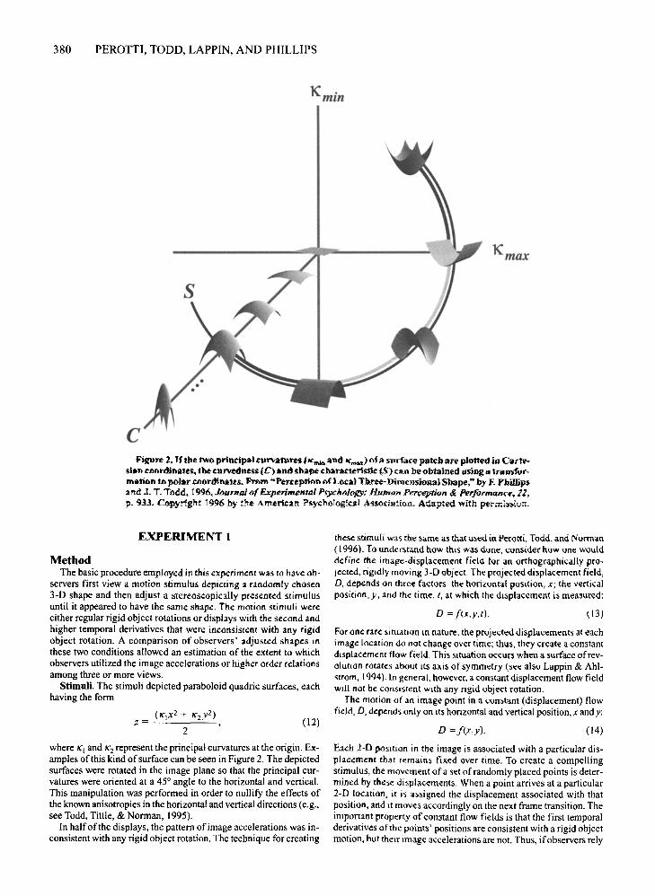
Consider, for example, the ratio of the two principalcurvatures, which is sometimes referred to as the shapecharacteristic (Mamassian, 1993; see Figure 2):
/(x = Ixx (1+1;] = Vxx (ro2
+v/]. (II)/(y l.w 1+/; V.w ro2 +Vx2
For cases where the first spatial derivatives of the velocityfield are zero (i.e., where the tangent plane to the surfaceis frontoparallel) or where they are equal to one another,the shape characteristic is unambiguously measurable.This is not strictly the case for points outside these regions, though the resulting error is negligible over a relatively broad range of surface slants (see Dijkstra, Snoeren, & Gielen, 1994).
Another commonly used relationship among the twoprincipal curvatures is called curvedness and is definedas the square root of their sum of squares (Koenderink,
1990). Because this is a sum rather than a ratio, the scalefactor to is not removed, so that the curvedness portionof3-D shape cannot be uniquely specified by the instantaneous velocity field. It could, however, be perceptuallyspecified if the visual system were sensitive to higherorder temporal derivatives, such as image accelerations.
It is especially interesting to note, in this context, thata similar distinction between the shape characteristic andcurvedness is also applicable to the perceptual analysisof structure from motion for objects that are observedunder polar projection. It is important to keep in mind thatan instantaneous velocity field under polar projection allows a one-parameter family of possible interpretationsthat are related to one another by a homogeneous scalingtransformation. Thus, it is similar to orthographic projection, in that the shape characteristic ofa surface patch isuniquely specified but not its curvedness.
Although the analysis presented above requires somepreliminary transformations in order to achieve a specificcoordinate system and a specific rotation axis, a moregeneral formulation without these requirements can befound in Koenderink and van Doorn (1992) or Dijkstraet aI., (1994). In the latter paper, several simulations arealso presented to show that estimations of the shapecharacteristic are only minimally perturbed ifthe tangentplane of a surface patch is slanted in depth or if it isviewed under polar perspective (see also Lappin, Ahlstrom, Craft, & Tschantz, 1995).
The research described in the present article was designed to compare the predictions of this analysis withthe perceptual performance of human observers. In Experiment I, we examined the importance of higher ordertemporal derivatives for the visual perception of surfacecurvature by comparing performance for two differenttypes ofdisplays-rigid object rotations and constant flowfields for which the pattern of image accelerations weremathematically inconsistent with any rigid object rotation. In Experiment 2, we investigated the importanceof higher order spatial derivatives in the image velocityfield by comparing performance for moving surfacespresented both with and without a first-order maskingfield.
380 PEROTTI, TODD, LAPPIN, AND PHILLIPS
K min
c
Kmax
Figure 2. lithe two principal curvafUrell (Ie",,,,, and lema.) ofa snrtace patch are plotted in Carl\"sian coordinates, the cDJ"Vedness (C) and sbape cbaracteristic ($) can be obtained using IItr8"51"1"mation to polar coordinates. From '"Perception of Local Three-Dnnensienal Shape," by F. Ybillij»2nd J. T. Todd, 1996, .Jt;UTnmofExperimental P5Y£hbJbGY: Human PerceptiQfI & Performance, 11,p, 'H3. Copyright 1996 hy the Americ2n Psychologicl1! AssOCiation. Adapted with permission.
these stimuli was the same as thacused in Perotti, Todd, and Norman(1996). To understand how this was done, consider how one woulddefine the image-displacement field for an orthographically projeered, rigidly moving 3-D object. The projected displacement field,0, depends On three factors: the horizontal position, x; the verticalposinon, y; and the time, t, at which the displacement is measured:
For Me rare situation lIT nature, the projected displacements at eachimage location do not change over time; thus, they create a constantdisplacement flow field. This SItuation occurs when a surface ofrevolurion rotates about ItSaxis of symmetry (see a150 Lappin & Ahlstrom, 1994). In general, however, a constant displacement flow fieldwJ11 not be consistent with any rigid object rotation.
The motion of an image point in a constant (displacement) flowfield, D, depends only on ItS horizontal and vertical position,x andy:
EXPERIMENT 1
MethodThe basic procedure employed in this experiment was to have ob
servers first view a motion stimulus depicting a randomly chosen3-D shape and then adjust a stereoscopically presented stimulusuntil it appeared to have the same shape. The motion stimuli wereeither regular rigid object rotations or displays with the second andhigher temporal derivatives that were inconsistent with any rigidobject rotation. A comparison of observers' adjusted shapes inthese two conditions allowed an estimation of the extent to whichobservers utilized the image accelerations or higher order relationsamong three or more views.
Stimuli. The stimuli depicted paraboloid quadric surfaces, eachhaving the form
(12)
o = !(x,y,t).
0= !(x,y).
( 13)
(14)
where /(\ and /(2 represent the principal curvatures at the origin. Examples ofthis kind ofsurface can be seen in Figure 2. The depictedsurfaces were rotated in the image plane so that the principal curvatures were oriented at a 45° angle to the horizontal and vertical.This manipulation was performed in order to nullify the effects ofthe known anisotropies in the horizontal and vertical directions (e.g.,see Todd, Tittle, & Norman, 1995).
In half of the displays, the pattern of image accelerations was inconsistent with any rigid object rotation. The technique for creating
Each 2-D posinon in the image is associated with a particular displacement that remains fixed over time. To create a compellingstimulus, the movement ofa set of randomly placed points is determined by these displacements. When a point arrives at a particular2-D location, it is assigned the displacement associated with thatposition, and it moves accordingly on the next frame transition. Theimportant property ofconstant flow fields is that the first temporalderivatives of the points' positions are consistent with a rigid objectmotion, but their image accelerations are not. Thus, ifobservers rely
PERCEPTION OF 3-D SHAPE FROM MOTION 381
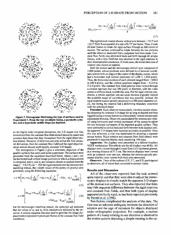
Figure 3. Stereograms illustrating the type of surfaces used inExperiment 1. From the top: an elliptic bump, a parabolic cylinder, and a hyperbolic saddle shape are depicted.
(15)
z = 30 [(r,adj H lOOj)C;;,)' +(r'wi H 100i >( 1~~' j. (16)
+2(1('2 d -I(' ad)--aU .1 U 10,000
For the stereoscopic matching stimuli, the subscript adj indicatesthat the values of 1('1 and 1('2 were interactively adjusted by the observer. A similar equation was also used to generate the image displacements (expressed in pixels per frame) in the constant flow fieldconditions:
on the higher order temporal derivatives, the 3-D shapes that theyreconstruct from the constant flow field stimuli should be much lessaccurate than those that they reconstruct from the rigid object motion stimuli. However, if observers can only utilize the first temporal derivatives, then the constant flow field and the rigid object rotation stimuli should yield equally accurate 3-D shapes.
The stereograms in Figure 3 give a schematic depiction of thequadric surfaces that were used in the experiment. The surfaces weregenerated from the equations described below, where x and yarethe horizontal and vertical image positions at which a displacementis computed, and 1('1 and 1('2 are constants chosen at random from therange [- 3.0,3.0] em -I. For the rigid rotations and the stereoscopicmatching stimuli, the z depth values of the points (in pixels) weregenerated, using the following equations:
Z=30[(1('1 +1('2)(~)2 +(1('1 +1('2)(L)2 +2(1('2 -I('I)~]100 100 10,000 '
Results and DiscussionAll of the observers reported that the task seemed
quite natural and that they were able to adjust the stereoscopic displays to closely match the apparent 3-D shapesof the motion test surfaces. They also reported that therewas little apparent difference between the rigid rotationsand constant flow fields, and that both types of displayappeared perfectly rigid, as has been reported previouslyby Perotti et al. (1996).
Two factors complicated the analysis of the data. Thefirst was an inherent ambiguity between the direction ofrotation and the sign of curvature for objects displayedunder orthographic projection. For example, a motionpattern ofa bump rotating in one direction is identical tothe motion pattern depicting a dimple rotating in the op-
(17)
The rigid stimuli rotated about a vertical axis between - 22.5° and+22.5° from frontoparallel at a rate of0.75° per frame. Thus, it took60 total frames to rotate the rigid surface through its full extent ofmotion. The surface continued to rotate between the two extremauntil the observer indicated that a judgment had been made. Constant flow fields also alternated back and forth through 60 uniqueframes, with a flow field that was identical to the rigid rotations intheir frontoparallel orientation. In both cases, the initial direction ofrotation was chosen at random.
Both the motion and the stereoscopic stimuli were composed of2,000 points, whose positions were defined in a Cartesian coordinate system with an origin at the center of the display screen, whichhad a horizontal and vertical resolution of 1,280 X 1,024 pixels.Thus, the horizontal position of each element ranged from -640.0to 640.0 pixels, and the vertical positions ranged from -512.0 to51~.O pixels. The constant flow field patterns were viewed througha circular aperture that was 380 pixels in diameter, with the videoscreen a uniform black outside this area. For the rigid rotation conditions, a similar aperture was not used, because it greatly limitedthe available range of curvedness that was possible. Instead, therigid rotation stimuli initially projected to a 380-pixel-diameter circle, but during the rotation had a deforming boundary consistentwith the simulated shape.
Procedure. Each observer monocularly viewed a motion stimulus depicting the selected 3-D shape for as long as desired and thento~gled (usin~ a mouse button) to a binocularly viewed stereoscopicadjustment stimulus. Observers manipulated the stereoscopic stimuli using horizontal and vertical movement of the mouse to adjustthe two principal curvatures of the depicted quadric surface. Theywere instructed to switch back and forth between both displays untilthe apparent 3-D shapes were matched as closely as possible. Oncethis was achieved, a trial was terminated by pressing a separatemouse button. Rigid rotation and constant flow field stimuli werepresented in separate blocks, each containing 100 trials.
Apparatus. The displays were presented on a Silicon GraphicsVGXT workstation. The refresh rate for all displays was 60 Hz. Alldisplays were viewed through Crystal Eyes LCD shuttered glasses,at a viewing distance of57.3 ern, The motion displays were viewedwith an eyepatch over one eye, whereas the stereoscopically presented displays were viewed with both eyes uncovered.
Observers. Three of the authors (Y.P., J.T., and EP.)participatedas observers, all of whom had corrected-to-normal vision.
.;.:" ..• -I. .. •• _.,,1 . I,
I • • 'If1J.... A • .... •
.... :~.~ ....:.'.J.....""-w:' . . • :~,. ..~.,::: ;:.:.; I' . ~ 'L
~ -.' '.,. S' "J..."'. ••••••1.'. I· .. • • • .....,... ., .,~.,
if',' • "\" •..'i I_. .1
• '.~ I'r:: '. r#J ..__~ '"j. ;0.
I .-. ::. -•• ~. .: 'r-·-.- I,,·. ~ ..:::: .• '':... : ..... "'. . If:·.l .
• .,' I ... : ••••,.: .::.,.,:-:.- .~r& •• "...~'•• : •
•• • lIlIl. \.
.:::.- ...
.~';.,., ~• .. , 01.
• ',I,' ... ~ '. .. ..: .:~. • .1 .::.: I.:., •
. .'1.: ; .., .....1. II: "i .: I· "'~' . ":" :..,.:1.: :.f. ;.... ~... ,.•. I..,- :.~ ,.,:... .. / :.,.
'i-:" ...... , .. --I ".
.,1 z : .1.. .:... ~ .. ': l s»,' , .....;,., "
• :.'-:: _•• ,I ~.
..' ' ...... ," .1' '.1 ...•1 -.1 '.1 S '", ..:; I'::':' :I : : ••'· ..I, . ... ., .., ,:':: ', -"I:.:" •
• '.,,; I'I.' 'I ~
..-.: ....~ ~ 1 •
,_, ':. I.' : ..: .....". • ". " • .." II••
. .., ''\ 1.':- I. ~•.. . . . -:. I.- .', '."I"': »:1': .::·t~·: ~ .~.. '#~~'" : ... . ". ',.
"" .'.... .
• : • i. \"". ~. I:,'" .,,~ ... II ~ .LI..:'::••• 1 :':': II. ~'I •
• • ":.: • ~ .., ••~ I •• '.
.... I.) •• ..,··..: ...~ I, r-. :'., _.1.. .'. ~:...;.... :' . ~'.
, .. :.; ~.~ :.01.• -I :., .

382 PEROTTI, TODD, LAPPIN, AND PHILLIPS
CurvednessShape Characteristic
3
2
Simulated-3 -2
-2
-3 Adjusted
2
••
3
Adjusted2.5
2
1.5
0.5
... ..a. , •
".'. :.•.. .
• •.. .-...• •.... ,-.. ,, .
0.5 0.75
Simulated
1.25 1.5
Figure 4. Simulated versus adjusted shape characteristic and curvedness for observer J.T. in the constant flow field condition ofExperiment 1. The diagonal lines indicate perfect reconstruction performance. Note the superior performance for judgments of shapecharacteristic in comparison with those of curvedness,
posite direction. In order to resolve this ambiguity, theone alternative that was closest to the adjusted shape wasconsidered to be the test stimulus.
A second potential problem involved scaling the shapecharacteristic. As suggested by Koenderink (1990), wetransformed this to a circular measure by computing thearctangent of the ratio of the adjusted values for 1(1 andI(z. These angular data were then analyzed by performing a linear regression between the adjusted and simulated shapes along the circumference of a circle. A separate linear regression was performed for the curvednesscomponent of the observers' adjustments, which wascalculated on each trial as the square root of the sum ofsquares of 1(1 and /(z.
To provide a typical example of the overall pattern ofperformance, Figure 4 shows a scatter plot ofthe data forobserver 1.T. in the constant flow field condition. The datafor the other observers are summarized in Table I, whichgives the RZ values for adjusted versus simulated shapecharacteristic and curvedness in all conditions. It is clearfrom these results that the observers were remarkably accurate in their judgments of the shape characteristic. Indeed, the adjusted values of this component in the stereo-
Table IThe R2 Values for the Linear Correlations BetweenSimulated and Adjusted Shape Characteristic and
Curvedness for All Observers and Conditions in Experiment 1
R2 for Shape R2 forObserver Motion Stimulus Characteristic Curvedness
F.P. constant flow field .9927 .1886rigid rotation .9901 .3741
J.T.T. constant flow field .9964 .4398rigid rotation .9972 .7246
Y.J.P. constant flow field .9972 .2083rigid rotation .9975 .5521
Average constant flow field .9954 .2789rigid rotation .9949 .5503
scopic displays were almost perfectly correlated withtheir simulated values in the motion displays. Across allobservers and conditions, the average R2 for the shapecharacteristic correlations was .994, the average slope ofthe best fitting regression line was 1.00, and the averageintercept was 0.03. It is important to keep in mind thatthe shape characteristic is unambiguously specified inboth the constant flow fields and rigid rotations, so it isnot theoretically surprising that the observers producedequivalent performance in both conditions.
It is interesting to note in Figure 4 that there is a noticeable gap in the central region of the shape characteristic scatter plot. This phenomenon arises because thesign of relief is mathematically ambiguous for movingsurfaces under orthographic projection. For hyperbolic(i.e., saddle-shaped) surface patches in the present experiment, both possible interpretations of surface reliefwere perceived with equal frequency, but for the ellipticpatches, the observers were strongly biased to see thesurfaces as convex, relative to the point of observation.
Curvedness adjustments were much less accurate thanthose for shape characteristic, which is consistent withthe hypothesis that the perception of3-D structure frommotion is primarily determined by the first-order patternof projected image velocities. In contrast to the shapecharacteristic, curvedness requires an analysis of higherorder relations among three or more views and cannot beuniquely specified by a pattern of image velocities or displacements. To the extent that observers are able to makeuse of this information, we would expect to see differences between the rigid rotations and constant flow fields,because their patterns of image acceleration are quitedifferent. To compute a correlation for the constant flowfields, the simulated curvedness was calculated using thevalues of 1(1 and /(2 from Equation 17 that were used togenerate the field of image displacements. Because thepatterns of image acceleration in that condition are in-

PERCEPTION OF 3-D SHAPE FROM MOTION 383
compatible with any rigid body motion, it is perhaps notsurprising that the correlations between simulated andadjusted curvedness produced a mean R2 of only .27.
An interesting question to consider is how the observers perceived any curvedness at all from the constantflow field stimuli, since the information to specify curvedness was not reliable in those displays. One possibility is that the observers used some sort of heuristic analysis to estimate a unique structure. For example, Liter et al.(1993) and Todd and Norman (1991) have suggested thatperceived depth may be scaled by the overall range ofprojected displacements in a moving display. If that werethe case, perceived depth should increase proportionallywith the angular velocity of an object's rotation. However, Todd and Norman and Perotti, Todd, Tittle, andNorman (1994) have found little difference in observers'performance when angular velocity is systematicallyvaried.
Although there was potential information about curvedness in the higher order temporal relations of the rigidrotation displays, there was not much improvement inthe observers' performance. In order to compare the reliability of adjusted curvedness for the rigid rotation andconstant flow field conditions, an F test was performedfor each observer on the ratio of residual variance fromthe linear correlations. For one observer, Y.P., the R2 values that were obtained in the two conditions were significantly different [F(99,99) = 2.05568,p < .05], but for theother two observers they were not. Wealso performed a Fischer's protected least significant difference test (PLSD)to compare the average signed error in the different conditions (see Figure 5). For two of the observers, Y.P. andF.P., the magnitude of adjusted curvedness was signifi-
cantly greater in the constant flow field displays (p <.001), though this effect did not occur for observer IT.These small differences in performance between therigid rotation and constant flow field conditions couldbe due to observers' limited sensitivity to the pattern ofimage accelerations (see also Norman & Todd, 1993; Perotti et aI., 1996), or alternatively, they could be due to thefact that the constant flow field displays had fixed circular boundaries, whereas those for the rigid rotations deformed over time.
Although it may seem theoretically reasonable to attribute errors of adjusted curvedness to distortions thatoccur in the perceptual analysis of structure from motion, that is not necessarily the case. It is also possiblethat the errors were due to observers' perceptions of thestereoscopic matching stimuli. With appropriate information about interocular distance and the state of convergence, it would be theoretically possible to accuratelycompute 3-D structure from binocular disparity, but theavailable evidence does not suggest that human observersare capable of that (e.g., see Norman, Todd, Perotti, &Tittle, 1996; Tittle, Todd, Perotti, & Norman, 1995).Several studies have shown that either motion or stereoprovides sufficient information to accurately discriminatethe shape characteristics of quadric surfaces (de Vries,Kappers, & Koenderink, 1994; Phillips & Todd, 1996;van Damme, Oosterhoff, & van de Grind, 1994), but thisdoes not appear to be true for the scale-dependent property of curvedness, as indicated by the low R2 valuesshown in Table 1. This also suggests, moreover, that theerrors occurring in these two modalities are not linearlyrelated to one another.
EXPERIMENT 22.0
Experiment 2 was designed to evaluate how the spatialrelationships among image velocities are used to determine 3-D structure. Recall that our analysis specifiesthat the second spatial derivatives of the velocity fieldallow an unambiguous measurement ofthe surface shapecharacteristic. To test this claim, the observers in Experiment 2 adjusted 3-D shapes after viewing displays withthe first spatial derivatives ofthe motion stimulus masked.Figure 6 schematically illustrates the three maskingfields that were used to perturb the motion patterns.These masking fields alter the first spatial derivatives ofthe velocity field, but they leave the higher spatial derivatives intact. Thus, if the perception of 3-D shape isbased primarily on the second-order spatial derivatives,adjusted shape should not be affected by the masks at all.
MethodThe apparatus and procedure were identical to those used in Ex
periment I. Each motion stimulus depicted a constant flow field ora rigid object rotation identical to those used in Experiment I, whichwas additively combined with a first-order motion mask. A maskeddisplay was created by adding curl, divergence, or shear to the projected motions of each dot, as described by Equations 15 and 17.
VJPFP
~
~ rXffi ~
-3:-
0.0
Eu;- 1.5
!~8 1.0
~:::l
~c:: 0.5IIIII~
....~
JTTObserver
Figure 5. The average error of observers' curvedness adjustments for the different conditions of Experiment 1. The shaded barsindicate the mean difference between adjusted and simulatedcurvedness for the constant flow field condition; the light barsrepresent the same measurement for the rigid rotation condition.Error bars indicate the 95% confidence intervals for each condition.

384 PEROTTI, TODD, LAPPIN, AND PHILLIPS
\\,'", ........
..... --__ ,,,.1,_-
__ '1''''--
//11///1
...... --. ..., ...... , \. '''''''''''"'\11///
"\\11///\\,'\\\,
'" ................
, , ""111/11//
...... ...... ... .. .,\\\,,\\
""~I I
//11/111
Figure 6. The three motion patterns used to mask the first spatial derivatives of the velocity field in Experiment 2.
The mask displacement for a given point was a function of its horizontal position, x, and its vertical position, y. For curl,
x' = x cos 6 + Y sin 6, y' = y cos 6 - x sin 6; (18)
for divergence,
Results and DiscussionIn describing their impressions of the phenomena,
both observers noted that each masking pattern had adistinct effect on the apparent 3-D motion of the depictedsurfaces. For the curl displays, the objects appeared to berotating in depth about a moving axis that was precess-
x' = xa,y' = 2::.. (20)a
The orientation of the shear component was determined at randomfor each trial. The image rotation angle, 6, was set to 0.18° perframe, and the scale factor, a, was set to 1.00325. These valueswere chosen using a set of Monte Carlo simulations. For each masking condition, the total motion energy was determined by summingthe squared magnitude of all points' image displacements. Different values of 6 and a were tried until this total motion energy wasroughly equal for all three masking conditions and the total motionenergy in each mask was equivalent to the unmasked motion energy. The rigid rotations and constant flow fields were presented inseparate sessions, each containing three blocks of 100 trials for thedifferent mask conditions. Two of the authors, Y.P. and IT., againparticipated as observers.
and for shear,
x' = xa,y' = ya; (19)
ing in the image plane. For the divergence displays, theobjects appeared to be rotating back and forth about avertical axis, while simultaneously translating back andforth in depth. For the shear displays, the objects appeared to be rotating in depth about a fixed axis in theimage plane that varied at random across trials.
Table 2 shows the R2 values that were obtained, foreach observer in each condition, from the linear correlations between adjusted and simulated shape characteristic and curvedness. As in Experiment I, the observers'judgments of the shape characteristic were almost perfectly accurate. Averaged over conditions and observers,the mean (R2) for the shape characteristic was .995; theaverage slope of the best fitting regression line was .99;and the average intercept was .04. For judgments ofcurvedness, in contrast, the values ofR2 were much lower.
Additional analyses were performed to compare theR2 values and mean adjusted errors among the differentconditions. The ratio ofresidual variances from the linearcorrelation revealed that the R2values for both observerswere significantly different for the rigid rotation andconstant flow field displays [J.T., F(299,299) = 1.5869,P < .05; V:P., F(299,299) = 1.61591,p < .05]. They alsodiffered significantly in their mean adjusted errors as revealed by a Fischer's PLSD test (p < .000 I). A comparison of the R2 values among the various types of motionmasks and the unmasked displays of Experiment I re-
Table 2The R2 Values for the Linear Correlations Between Simulated and Adjusted
Shape Characteristic and Curvedness for All Observers and Conditions in Experiment 2
Image Rotation Shear Divergence
Motion Shape Shape ShapeObserver Stimulus Characteristic Curvedness Characteristic Curvedness Characteristic Curvedness
Y.1P. Constantflow field .9954 .2506 .9898 .3303 .9947 .1595
Rigid rotation .9970 .5466 .9906 .3802 .9983 .4941
IT.T. Constantflow field .9970 .5276 .9955 .5063 .9972 .4098
Rigid rotation .9969 .6619 .9955 .5608 .9970 .6340
Average Constantflow field .9962 .3891 .9926 .4183 .9960 .2846
Rigid rotation .9970 .6043 .9930 .4705 .9976 .5640

PERCEPTION OF 3-D SHAPE FROM MOTION 385
Figure 7. The average error of observers' curvedness adjustments for the different motion masks of Experiment 2 and theunmasked displays of Experiment 1. Error bars indicate the 95%confidence intervals for each condition.
vealed no systematic effects, though several of the pairwise comparisons were statistically significant. There was,however, a clear pattern of results for the mean signederrors ofthe observers' curvedness adjustments (see Figure 7). For both observers, the addition ofa motion masksignificantly lowered the magnitude ofperceived curvedness (PLSD, p < .000 I), and the effect of shear was significantly larger than the effects ofrotation or divergence(PLSD,p < .0001).
It is important to keep in mind that these particularmasking patterns were designed to disrupt the first-orderspatial derivatives of the image velocity field while leaving the second-order spatial derivatives invariant. Thus,the fact that these masks had virtually no effect at all onobservers' judgments ofthe shape characteristic (see alsoLappin & Craft, 1997) provides strong empirical supportfor the theoretical proposals ofDijkstra et a1. (1994) andKoenderink and van Doom (1992) that second-orderspatial derivatives of the instantaneous velocity field area primary source of visual information for the scaleindependent aspects of3-D shape. It is also interesting tonote, in this regard, that the addition ofmasking fields inthe present experiment produced patterns of motionwhose overall range ofimage velocity were roughly twiceas large as those in the unmasked displays of Experiment 1. Because this change significantly reduced themagnitude ofobservers' curvedness adjustments, it seems
When an object rotates in depth under orthographicprojection, there is sufficient information within the pattern of optical flow to compute its 3-D structure up to areflection in depth. In order to actually perform thiscomputation, however, it is necessary to measure the instantaneous acceleration of each point or the higherorder relations among three or more discrete views forobjects observed in apparent motion. In the case ofcontinuous rotation about a vertical axis, the depth z ofanygiven point, relative to the rotation axis, is specified by
z=-V~, (21)
reasonable to conclude that they could not have beenbased on a heuristic analysis in which perceived depth isdetermined by the magnitude of relative image motion(see Liter, et aI., 1993; Todd & Norman, 1991).
GENERAL DISCUSSION
where x is its horizontal position relative to the axis ofrotation, and V and A are its projected velocity and acceleration. It is interesting to note, in this case, that theratio x/A specifies the frequency of rotation, which mustbe the same for all points on a rigidly moving object.
If a visual system were incapable of measuring howthe velocities (or displacements) of points change overtime, a projected pattern of motion would only be sufficient to determine an object's structure up to a oneparameter affine transformation (see Koenderink, 1990;Todd & Bressan, 1990). The best that could be accomplished in that case would be to somehow guess the valueof the unknown parameter, perhaps by assuming someecological constraints on the overall range of possibleobject depths or rates of rotation. Any inaccuracies inthis estimate would cause the perceived structure of anobject to be systematically distorted by an affine stretching transformation.
There is a growing amount ofevidence to suggest thatthis type ofdistortion is a typical characteristic ofour visual perceptions of structure from motion. There havebeen numerous investigations reported in the literature,in which observers have judged the perceived depths ofrotating objects, such as cylinders, ellipsoids, dihedralangles, or random configurations of points in a volume(e.g., see Liter & Braunstein, 1997; Liter et al., 1993; Tittle et aI., 1995; Todd, 1984; Todd & Norman, 1991). Invirtually all of these studies, there have been large constant errors in the magnitude ofperceived depth scaling,though the size and direction ofthis effect can vary considerably over different viewing conditions.
Such findings suggest that human observers have relatively poor sensitivity to optical accelerations, so thatthe visual perception of structure from motion must bedetermined primarily by the pattern of image velocities(or displacements). Additional evidence to support thisconclusion has been obtained by comparing the accuracyof observers' judgments for apparent motion sequences
VJP
JTT
No Image Shear Dlve~
Mask Rotation
-0.2
0.4
No Image Shear Divergence-0.3 ....k Rotation
0.3
~i 0.2
~8 0.0~__...IOOo;...L._...I.o....L_-.&.....L__"""'_
gw:I 0.1
!
Io -0.1

386 PEROTTI, TODD, LAPPIN, AND PHILLIPS
with varying numbers ofdiscrete frames. In general, thereare few or no improvements in the accuracy ofperceivedstructure as the number ofdistinct frames in a motion sequence is increased beyond two-provided that all otherparameters are optimized at each sequence length to produce the best possible performance (e.g., see Liter et al.,1993; Todd & Bressan, 1990; Todd & Norman, 1991).
Another useful procedure for addressing this issue involves motion patterns with higher order structural deformations that are inherently undetectable from the firstorder relations between individual pairs of views. Thisincludes any pattern with parallel image trajectories forwhich all moving elements do not have the same ratiox/A (see Equation 21). Previous research has shown thatdifferent types ofhigher order structural deformations arenot all perceptually equivalent. Although some such displays appear perfectly rigid, there are others that are easily identified as nonrigid, thus indicating that observerscan obtain at least some useful information from changesover time in the pattern of image velocities or displacements (Liter & Braunstein, 1997; Norman & Todd, 1993;Perotti et al., 1996).
One important goal ofthe present research was to examine the effects ofhigher order structural deformationson observers' judgments 00-0 structure. In order to address this issue, rigid rotations ofquadric surface patcheswere compared with constant flow field displays whosepatterns of optical acceleration had no possible rigid interpretation. The results revealed that the rigid rotationsproduced slightly higher correlations between simulatedand judged curvedness than did the constant flow fielddisplays, but that observers were equally accurate in bothconditions for their judgments of the shape characteristic. These findings are similar to those obtained by Literand Braunstein (1997) for higher order structural deformations of a rotating dihedral angle. Observers' judgments ofrigidity for these displays were significantly reduced relative to rigid rotations, but both types ofmotionproduced comparable results for judgments of the magnitude of the depicted dihedral angle or of the extent ofits rotation.
Although observers may be relatively poor at extracting information about 3-D structure from changes inimage velocity over time, this does not appear to generalize to changes in image velocity over space. It has longbeen recognized that first-order spatial changes in velocity (i.e., curl, divergence, and shear) provide importantinformation for the control of locomotion and the detection ofimpending collisions (see, e.g., Gibson, 1950; Koenderink & van Doorn, 1975, 1977; Todd, 1981). More recent analyses have demonstrated that second-orderspatial changes in velocity can provide potentially usefulinformation about certain aspects of surface curvature(Dijkstra et al., 1994; Droulez & Cornilleau-Peres, 1990;Koenderink & van Doorn, 1992). Under appropriate conditions, these changes can specify the ratio ofthe two prin-
cipal curvatures (i.e., the shape characteristic) and theirdirections, though it cannot specify other properties, suchas curvedness.
There have been a number of empirical studies reported in the literature that have examined observers'sensitivity to the 3-D curvature of moving surfaces (seeCornilleau-Peres & Droulez, 1989; Lappin et al., 1995;Norman & Lappin, 1992; van Damme et al., 1994). Thepresent experiments were designed to extend this research by employing a response task with two degrees offreedom, so that we could separate the distinct components of shape characteristic and curvedness, and by including displays with first-order motion masks in an effort to restrict the relevant information to second-orderspatial changes in velocity. The results obtained werehighly consistent with the mathematical analyses proposed by Dijkstra et al. (1994) and by Koenderink andvan Doorn (1992). Observers were almost perfectly accurate in their judgments of the shape characteristic,which is unambiguously specified by the instantaneousvelocity field, but they produced large constant errors intheir judgments of curvedness, which is not. Moreover,this performance was only minimally affected by altering the displays with a first-order motion mask, whichsuggests that the relevant information for performingthese judgments involves second-order spatial changes inthe pattern of image velocities or displacements.
An interesting question that arises from this researchis why changes in image velocity over time should be moredifficult to process than are changes in velocity over space.One possible explanation for this distinction is that mechanisms for measuring the accelerations of individualmoving points would be highly sensitive to noise. Becausevisually sensitive neurons can only respond to fixed locations in space (i.e., their receptive fields), they are notwell suited for tracking individual elements over multiple locations. The detection of spatial changes, in contrast, involves relationships among different moving elements. Thus, they can be measured by comparing thesimultaneous outputs ofdifferent motion detectors, without having to worry about whether they were stimulatedby the same identifiable feature.
REFERENCES
BENNETT, B., & HOFFMAN, D. (1986). The computation of structurefrom fixed axis motion: Nonrigid structures. Biological Cybernc.ics,51,293-300.
BENNETT, B., HOFFMAN, D., NICOLA, J., & PRAKASH, C. (1989). Structure from two orthographic views of rigid motion. Journal ofthe Optical Society ofAmerica, 6,1052-1069.
BRAUNSTEIN, M. L., HOFFMAN, D. D., & POLLICK, F. E. (1990). Discriminating rigid from nonrigid motion: Minimum points and views.Perception & Psychophysics, 47, 205-214.
BRAUNSTEIN, M. L., HOFFMAN, D. D., SHAPIRO, L. R., ANDERSEN, G. J.,& BENNETT, B. M. (1987). Minimum points and views for the recovery of three-dimensional structure. Journal ofExperimental Psychology: Human Perception & Performance, 13,335-343.
CORNILLEAU-PERES, v., & DROULEZ, J. (1989). Visual perception of

surface curvature: Psychophysics of curvature detection induced bymotion parallax. Perception & Psychophysics, 46, 351-364.
DE VRIES, S. C, KAPPERS, A. M. L., & KOENDERlNK, J. J. (I994).lnfluence of surface attitude and curvaturescaling on discrimination ofbinocularlypresentedcurved surfaces. Vision Research, 34, 2409-2423.
DUKSTRA, T M. H., SNOEREN, P.R., & GIELEN, C C A. M. (1994). Extraction of three-dimensional shape from optic flow: A geometric approach. Journal ofthe Optical Society ofAmerica A, 11,2184-2196.
DROULEZ, J., & CORNILLEAU-PERES, V. (1990). Visual perception ofsurface curvature: The spin variation and its psychological implications. Biological Cybernetics, 62, 211-224.
GIBSON, J. J. (1950). The perception of the visual world. Boston:Houghton Mifflin.
HOFFMAN, D., & BENNETT, B. (1985). Inferring the relative three-dimensional positions of two movingpoints. Journal ofthe Optical Society ofAmerica A, 2, 242-249.
HOFFMAN, D.,& BENNETT, B. (1986).The computationof structure fromfixedaxis motion: Rigidstructures.Biological Cybernetics, 54, 71-83.
HOFFMAN, D. D., & FLINCHBAUGH, B. E. (1982). The interpretation ofbiological motion. Biological Cybernetics, 42, 195-204.
KOENDERINK, J. J. (1990). Solid shape. Cambridge, MA: MIT Press.KOENDERINK, J. J., & VAN DooRN, A. J. (1975). Invariant properties of
the motion parallax field due to the movement of rigid bodies relative to an observer. Opt. Acta, 22, 773-791.
KOENDERINK, J. J., & VAN DoORN, A. 1. (1977). How an ambulant observer can construct a model of the environment from the geometrical structure of the visual inflow.In G. Hauske& F. Butenandt (Eds.),Kybemetik (pp. 224-247). Munich: Oldenburg.
KOENDERINK, 1. 1., & VAN DOORN, A. 1. (1991). Affine structure frommotion. Journal of the Optical Society of America A, 8, 377-385.
KOENDERINK, J. J., & VAN DOORN, A. J. (1992). Second-order opticflow. Journal ofthe Optical Society ofAmerica A, 9, 530-538.
LAPPIN,1. S., & AHLSTROM, U. B. (1994). On the scaling of visual spacefrom motion-in response to Pizlo and Salach-Golyska. Perception& Psychophysics, 55, 235-242.
LAPPIN, J. S., AHLSTROM, U. B., CRAFT, W. D., & TSCHANTZ, S. T(1995). Spatial primitives for seeing three-dimensional shape frommotion. In T. Papathomas (Ed.), Early vision and beyond (pp. 145153).Cambridge, MA: MIT Press.
LAPPIN, J. S., & CRAFT, W.D. (1997). Definition and detection ofbinocular disparity. Vision Research, 37, 2953-2974.
LAPPIN, J. S., DONER, J. E, & KOTTAS, B. L. (1980). Minimal conditions for the visual detection of structure and motion in three dimensions. Science, 209, 717-719.
LITER, J. C; & BRAUNSTEIN, M. L. (1997). The relationship ofverticaland horizontal velocity gradients in the perception ofshape. rotationand rigidity. Manuscript submitted for publication.
LITER, J. C, BRAUNSTEIN, M. L., & HOFFMAN, D. D. (1993). Inferringstructure from motion in two-view and multiview displays. Perception, 22, 1441-1465.
LONGUET-HIGGINS, H. C, & PRAZDNY, K. (1980). The interpretationof a moving retinal image. Proceedings ofthe Royal Society ofLondon: Series B, 208, 385-387.
MAMASSIAN, P. (1993). Illuminance critical points on generic smoothsurfaces. In B. C Vemuri(Ed.), Geometric methods in computer vision 1/: Proceedings ofSPlE (Vol.2031, pp. 124-133). Bellingham:International Society for Optical Engineering.
NORMAN, 1.E, & LAPPIN, J. S. (1992).Thedetectionof surfacecurvaturesdefined by optical motion. Perception & Psychophysics, 51, 386-396.
NORMAN, J. E, & TODD, 1. T. (1993). The perceptual analysis ofstructure from motion for rotating objects undergoing affine stretchingtransformations. Perception & Psychophysics, 53, 279-291.
NORMAN, J. E, TODD, J. T. , PEROTTI, V.J., & nTTLE,1. S. (1996). Thevisual perception of three-dimensional length. Journal of Experimental Psychology: Human Perception & Performance, 22, 173-186.
PEROTTI, V.J., TODD, J. T., & NORMAN, J. E (1996). The visual perception ofrigid motion from constant flow fields. Perception & Psychophysics, 58, 666-679.
PEROTTI, V.J., TODD, J. T, nTTLE,J. S., & NORMAN, J. F. (1994). Theperception of 3D form from instantaneous flow components. Investigative Ophthalmology & Visual Science, 35, 1317.
PERCEPTION OF 3-D SHAPE FROM MOTION 387
PHILLIPS, E, & TODD, J. T. (1996). Perceptionoflocal three-dimensionalshape. Journal of Experimental Psychology: Human Perception &Performance, 22, 930-944.
TEPAS, S., KAPPERS, A. M. L., & KOENDERlNK, J. J. (1996). Detectionof first-order structure in optic flow fields. Vision Research, 36,259-270.
nTTLE,J. S., TODD, J. T, PEROTTI, V.J., & NORMAN, J. E (1995). Systematic distortion of perceivedthree-dimensional structure frommotion and binocular stereopsis. Journal ofExperimental Psychology:Human Perception & Performance, 21, 663-678.
TODD, J. T (1981). Visual information about movingobjects.Journal ofExperimental Psychology: Human Perception & Performance, 7,795-810.
TODD, J. T. (1984). The perception of three-dimensional length.JournalofExperimental Psychology: Human Perception & Performance, 22,173-186.
TODD, 1. T, AKERSTROM, R. A., REICHEL, ED., & HAYES, W. (1988).Apparentrotationin three-dimensional space:Effectsof temporal,spatial, and structural factors. Perception & Psychophysics, 43, 179-188.
TODD, J. T., & BRESSAN, P. (1990). The perception of 3-dimensionalaffine structure from minimal apparent motion sequences. Perception & Psychophysics, 48, 419-430.
TODD, J. T., & NORMAN, 1. E (1991). The visual perception of smoothlycurved surfaces from minimal apparent motion sequences. Perception & Psychophysics, 50, 509-523.
TODD, J. T, nTTLE,J. S., & NORMAN, J. E (1995). Distortions of threedimensional space in the perceptual analysis of motion and stereo.Perception, 24, 75-86.
ULLMAN, S. (1977). The interpretation ofvisual motion. Unpublisheddoctoral dissertation, Massachusetts Institute of Technology.
ULLMAN, S. (1979). The interpretation of visual motion. Cambridge,MA: MIT Press.
VAN DAMME, W. J. M., OoSTERHOFF, F. H., & VAN DE GRIND, W. A.(1994). Discrimination of3-D shape and 3-D curvature from motion'in active vision. Perception & Psychophysics, 55, 340-349.
WALLACH, H., & O'CONNELL, D. N. (1953). The kinetic depth effect.Journal ofExperimental Psychology, 45,205-217.
APPENDIXDisplacement Field for Discrete Rotations
Under ParaDel Projection
For the traditional Cartesian space 91 3 (with the z-axis denoting depth), the horizontal position (x) ofa point rotating about avertical axis by some angle (e) is
x' = x cos e+ z sin e. (AI)
This new position (x') can be expressed as the old position (x)plus some displacement in x (~x):
x +~x = x cos e+ z sin e. (A2)
The displacement field, D, can thus be specified as
D = ~x = x(cos e- 1) + z sin e. (A3)
Substituting the surface equation, z = I(x,y):
D = x(cos e- I) + I(x,y) sin e. (A4)
Adopting the notation that subscripts indicate spatial derivatives in the specified direction, the first spatial derivatives ofthe displacement field are
D, = (cos e - 1) + l, sin eandDy = Iy sin e. (AS)
And the second spatial derivatives ofthe displacement field are
Dxx = Ixx sin e,Dxy = Ixy sin e, and Dyv = Iyysin e. (A6)
The tilt component of the surface attitude is unambiguouslyspecified for small rotations:

388 PEROTTI, TODD, LAPPIN, AND PHILLIPS
(A9)
(All)
(AIO)
(Manuscript received August 29, 1996;revision accepted for publication February 13, 1997.)
However, the ratio of these is an unambiguous measure of surface shape for the case where the first spatial derivatives ofzeroare equal to one another:
(A7)Dx - (cos e- I)
Dy
But the slant component of the surface attitude is not
tana=~l;+l; =csce-!D;+(l-Dx+cose. (A8)
The magnitude of the surface curvatures in the horizontal andvertical directions cannot be unambiguously determined fromthe velocity field:
I (Ixx ) (sin0)2Vxx
K"x= ~I+I;+I; 1+1; =[(SinO)2+vn~(SinO)2+V;+V;'
Copyright © 2022 FDOKUMEN