
Dual scattering approximation for fast multiple scattering in hair

PIMS-Director [email protected] (604) 822-3922
SFU-site [email protected] (604) 268-6655 UCalgary-site [email protected] (403) 220-3951
UAlberta-site [email protected] (780) 492-4308 UVic-site [email protected] (250) 472-4271
UBC-site [email protected] (604) 822-3922 UWashington-site [email protected] (206) 543-1173
The no response test - a sampling method for
for inverse scattering problems
D. Russell Luke Roland PotthastPIMS Institut for Numerical and Applied MathematicsSimon Fraser University University of GottingenBurnaby BC V5A 1S6, CANADA Germany
Preprint number: PIMS-03-5
Received on March 11, 2003


The no response test - a sampling method for
inverse scattering problems
D. Russell Luke1 and Roland Potthast 2
Abstract. We describe a novel technique, which we call the no response test, to locate the support of ascatterer from knowledge of a far-field pattern of a scattered acoustic wave. The method uses a set of samplingsurfaces and a special test response to detect the support of a scatterer without a priori knowledge of the physicalproperties of the scatterer. Specifically, the method does not depend on information about whether the scatterer ispenetrable or impenetrable nor does it depend on any knowledge of the nature of the scatterer (absorbing, reflecting,etc). In contrast to previous sampling algorithms, the techniques described here enable one to locate obstacles orinhomogeneities from the far field pattern of only one incident field – the no response test is a one-wave-method.We investigate the theoretical basis for the no response test and derive a one-wave uniqueness proof for a regioncontaining the scatterer. We show how to find the object within this region. We demonstrate the applicabilityof the method by reconstructing sound-soft, sound-hard, impedance and inhomogeneous medium scatterers in twodimensions from one wave with full and limited aperture far-field data.
Key words. inverse problems, scattering theory, image processing
AMS subject classifications. 35R30, 35P25, 68U10, 94A08
1. Introduction. Inverse scattering is concerned with recovering information about a mediumand its embedded objects by exciting or illuminating the medium with acoustic or electromagneticfields and measuring the resulting field. One of the fundamental problems is to determine thelocation and shape of scatterers that are either buried or located in some inaccessible region of amedium. Applications range from geoscience to medical imaging.
Over the past decade, several innovative and successful methods have been introduced intothe area of inverse scattering. Here, we add to the list a methodology that we call the no responsetest and demonstrate its applicability. The idea of the method is to test the hypothesis that ascatterer lies within a given test domain given the far-field data. We sample by construction theset of incident fields that are small on the test domain and large outside. The far-field patternscorresponding to these incident fields are then calculated using the given far-field data. We call thecalculated far field patterns responses. If all the responses are small, then the unknown scattereris shown to be a subset of the test domain, that is the hypothesis is true. The unknown scattereris located within the union of all test domains for which the hypothesis is true. Since small, ratherthan large, responses indicate the location of the scatterer, the methodology is called the ”noresponse” method.
To place this methodology relative to other reconstruction techniques we give a brief review ofthe different reconstruction approaches. The evolutionary tree of inverse scattering algorithms isdiverse enough that some taxonomy is in order. We separate reconstruction algorithms into threeclasses: iterative, decomposition, and sampling/probe methods.
1Simon Fraser University, Burnaby, British Columbia V5A 1S6, CANADA ([email protected]). This author isa Postdoctoral Fellow of the Pacific Institute for the Mathematical Sciences. His work was supported while at theUniversity of Gottingen.
2Institut for Numerical and Applied Mathematics, University of Gottingen, Germany;http://www.scienceatlas.de/nfg

2 THE NO RESPONSE TEST
Category MethodsI Iterative techniques
Newton MethodLandweber SchemeLeast Squares Fits (depending on the setup)Conjugate Gradient Method
II Decomposition techniquesColton-Monk Method / Dual Space MethodKirsch-Kress MethodPotthast / Point Source Method
III Probe- and sampling techniquesColton-Kirsch Method / Linear Sampling MethodKirsch / Factorization MethodPotthast / Singular Sources MethodIkehata / Probe MethodIkehata / Enclosure MethodLuke-Potthast / No Response Test
Iterative methods (Category I in [16]) use the model of the full forward problem, or an ap-propriate approximation thereof, for the solution of the inverse problem. These techniques havethe advantage that they use all information about the forward problem for the solution of theinverse problem and they usually deliver quite good reconstructions. However, due to the needto solve the forward problem many times, they can be computationally intensive. Also, obtaininga localized reconstruction in a limited data setting is problematic since full data for solving theforward problem is presumed. Indeed, at the very least it is presumed that one knows which modelthe data should satisfy. Well-known examples of iterative techniques are the Newton method, theLandweber method and various versions of least-squares fits.
Decomposition algorithms (Category II in [16]) consist of methods that split the inverse prob-lem into an ill-posed part to reconstruct the scattered field and a well-posed part to find theunknown scatterer due to some boundary condition. Representatives of this type of method arethe dual-space method proposed by Colton-Monk [3] [4] and the technique of Kirsch-Kress [2], butalso newer strategies like the point source method of Potthast [16, 14, 15], which turns out to be atype of adjoint method to the Kirsch-Kress technique.
Sampling and probe methods comprise the third and most recent class of algorithms (CategoryIII in [16]). These involve testing a given region with a model mapping the data to a point inthe test region and locating the boundary of the unknown scatterer as the points where someunusual or characteristic behavior (usually some resolvable type of blow-up) occurs in the modelfunctions. Where these techniques differ is in the construction of the model functions, whichleads to fundamentally different algorithms. These methods share the advantage that they can beapplied without knowing whether the scatterer is impenetrable (sound-soft or sound-hard), or aninhomogeneous medium. The no response test belongs to this class. We discuss in more detail thedifferent strategies within this class that have been proposed since 1995.
A scatterer is denoted by its support Ω ⊂ Rm (m = 2, or 3) where Ω is bounded. For ourpurposes we need only assume that the boundary of the scatterer ∂Ω is Lipschitz, however thisintroduces mathematical technicalities that cloud the central ideas here. We therefore limit ourdiscussion to twice continuously differentiable (C2) boundaries. Readers interested in the detailsof boundaries with corners, or more generally Lipschitz boundaries, are referred to [11, 12]. Wedenote by ν(x0) the unit outward normal to Ω at the point x0 ∈ ∂Ω, that is, |ν(x0)| = 1 and thevector product (y − x0, ν(x0)) ≤ 0 for every y ∈ Ω.

D. RUSSELL LUKE AND ROLAND POTTHAST 3
Let u, us : Rm → C and u∞ : S → C , denote the total, scattered, and far fields respectivelydue to excitation from an incident plane wave ui at a fixed wavenumber κ > 0. Here S :=x ∈ Rm | |x| = 1. We parameterize these fields by the direction of incidence y of the incidentplane wave ui(x, y) := eiκx·y, x ∈ Rm y ∈ S, where i =
√−1 in the exponential. Similarly we
write the dependence on the direction of incidence explicitly in the argument of the other fields asu(x, y), us(x, y), and u∞(x, y) respectively. Here and elsewhere, the hat indicates a unit vector,x := x
|x| . When the far field data is known only on an open subset Γ of S, we call the data limitedaperture data.
AssumptionsMethod Amount of on the physical
far field data needed nature of thescatterer
Colton-Kirsch /Linear Sampling Method u∞(x, y), ∀x, y ∈ Γ ⊂ S noneKirsch / Factorization Method u∞(x, y), ∀x, y ∈ S nonePotthast /Singular Sources Method u∞(x, y), ∀x, y ∈ Γ ⊂ S noneIkehata / Probe Method u∞(x, y), ∀x, y ∈ S noneIkehata / Enclosure Method u∞(x, y), ∀x ∈ S one y ∈ S noneLuke-Potthast / u∞(x, y), ∀x ∈ Γ ⊂ S,No Response Test one y ∈ S none
The linear sampling method of Colton and Kirsch [1] characterizes the domain of an unknownscatterer by the behavior of the solution to the integral equation of the first kind∫
S
u∞(x, y)g(y)ds(y) = eiκx·z, x ∈ S.(1.1)
Here a regularized solution g is calculated for all points z on a sampling grid G. The unknownboundary is found where ||g(z)|| becomes unbounded.
Kirsch [10] proposed a modified version of this method by constructing a spectral decompositionof the operator
(Fg)(x) :=∫S
u∞(x, y)g(y)ds(y), x ∈ S,
used in (1.1). He proposed to solve the equation
(F ∗F )1/4g(x) = eiκx·z, x ∈ S
for all z ∈ G and showed that the equation is solvable if and only if z is in the interior of theunknown scatterer. This technique of Kirsch is known as modified linear sampling or factorizationmethod.
Ikehata and Potthast have independently proposed two related algorithms, the probe method[6] and the method of singular sources [16] respectively. These techniques are distinct from the(modified) linear sampling methods above in that they use different quantities that blow up whenapproaching the boundary of some scatterer.
The probe method of Ikehata uses Green’s formula to define an indicator function that blowsup when the virtual source touches the unknown obstacle. Let Λ be the Dirichlet-to-Neumannmap for the boundary value problem in a domain B with the unknown domain Ω ⊂ B and Λ0 be

4 THE NO RESPONSE TEST
the Dirichlet-to-Neumann map for B without the existence of Ω. Ikehata proposed to consider
I(z, f) :=∫∂B
(Λ− Λ0)f · fds
for specially constructed functions f . It can be shown that I(z, f) tends to infinity if z tends tothe boundary of the unknown domain. The Dirichlet-to-Neumann map can be calculated from thefar field patterns u∞(x, y) for all x, y ∈ S, i.e. from the far field pattern for scattering of all planewaves of one fixed frequency.
The singular sources method of Potthast uses a different functional which also blows up at theboundary of the obstacle. This functional is defined as the magnitude of the scattered field Ψs(z, z)of singular sources Ψ(·, z) and is calculated by backprojection of the form
Ψs(y, z) ≈∫S
∫S
u∞(x, y)g(x, y)g(−y, z)ds(y)ds(x), y, z ∈ Rm \ Ω,
for explicitly constructed kernels g(·, ·).All of the linear sampling and probe methods share the advantage that no knowledge about
the boundary condition of the unknown scatterer is needed. With the exception of the Kirschfactorization method, these methods are valid in the limited aperture case, where the far field datais not known on the full sphere, but only on an open subset Γ ⊂ S. The principle disadvantage ofsampling and probe techniques, however, is that they all require the knowledge of far field patternsfor a large number of incident plane waves. The current challenge facing these algorithms is toreduce the amount of data needed for reliable reconstructions.
Recent work by Ikehata has made significant progress toward the development of reconstructionalgorithms using very limited data. His enclosure method [7, 8] enables one to find the supportof convex polygons from the knowledge of one measured field. Ikehata uses a special harmonicincident field
v = eτx·(ω+iω⊥),
to construct the following indicator function
Iω(τ, t) = e−τt⟨
∂u
∂ν
∣∣∣∣∂G
, v|∂G⟩−⟨∂v
∂ν
∣∣∣∣∂G
, u|∂G⟩
, τ > 0, t ∈ R,(1.2)
where ω ∈ S is a direction vetor, u is the unknown, weak solution to the scattering problem andG is some domain containing the unknown scatterer, Ω ⊂ intG the interior of G. Ikehata showsthat at the corners of polygonal scatterers this indicator function becomes unbounded. He thenexploits this property to uniquely reconstruct the scatterer. For details on implementation see [9].While for the purposes of analysis the presentation of the enclosure method is limited to specificsettings, it appears that in practice the method is independent of the material properties of thescatterer.
In this work we propose another technique for locating a scatterer from a single incident wavethat also exploits the behavior of a special indicator function in the neighborhood of a scatterer.Since we look, rather, for where the indicator function does not become unbounded, we call themethod the no response test. Like the enclosure method, the no response test can be used tolocate scatterers from only one incident wave. Moreover, neither the enclosure method nor the noresponse test require a priori knowledge of the material properties of the scatterer. However, theindicator function in the no response test is a different functional on the measured data than thatof Ikehata. Also, we do not make use of, nor place any particular constraints on, the goemetricproperties of the scatterer.

D. RUSSELL LUKE AND ROLAND POTTHAST 5
It is often the case that numerical algorithms preceed by many years their mathematicaljustification. The absence of analytical results for a particular application does not preclude thesuccessful implementation and numerical study of algorithms. At the expense of mathematicalanalysis limited to narrow settings, we have chosen to highlight the robustness of the no responsetest in a variety of settings by focusing on numerical results. We leave many unanswered questions,however the demonstration of the applicability of the techniques discussed here helps to motivateand formulate the analysis that must follow. In Section 3 we provide preliminary theoretical resultsto motivate the method. A convergence proof for one-wave reconstructions would include a one-wave uniqueness result. These results are not yet available. However, we can show that a set(depending on some test domain Ω0
t ) surrounding the unknown scatterer, which we call its corona,is uniquely determined by the one-wave far field pattern independent of the boundary condition.
The no response algorithm is given in Section 4. In the same section we show reconstructionsfor scattering from scatterers with Dirichlet, Neumann, or impedance boundary condition, or forscattering from an inhomogeneous medium. We show results from each of these scatterers withfull and limited aperture data. Preparatory to this, we briefly review in Section 2 the fundamentalscattering models for sound-soft, sound-hard, and mixed obstacles as well as inhomogeneous media.
2. Dirichlet, Neumann, impedance and medium scattering problems. This sectionserves to briefly review the key elements of scattering by bounded objects or media, and to providesome tools for the inversion method described in Section 3. We also describe how we solved theforward problems to produce the data used for the demonstration of the no response test.
Scattering review. Let vi be an incident field that satisfies the Helmholtz equation,
4v + κ2v = 0,
with wave number κ > 0 on Rm. The incident field produces a scattered field vs that solvesthe Helmholtz equation on the exterior of the scatterer Ω and satisfies the Sommerfeld radiationcondition
rm−1
2
( ∂∂r− iκ
)v(x)→ 0, r = |x| → ∞
uniformly in all directions. For impenetrable scatterers we consider cases where the scatterer iseither sound-soft (a perfect conductor), sound-hard (a perfect reflector) or some mixture of these.Each of these types of scatterers is modeled by a total field,
v = vi + vs,
that satisfies either Dirichlet, Neumann or impedance boundary conditions. These boundary con-ditions are given respectively as
v|∂Ω = 0,∂v
∂ν|∂Ω = 0,
∂v
∂ν|∂Ω + λv|∂Ω = 0,
with the impedance function λ ∈ C(∂Ω). We also treat penetrable scatterers, where the inho-mogeneity is modeled by a nonegative refractive index n : Rm → R+ and where n(x) := 1 forx ∈ Rm \ Ω. Then the total field v ∈ H2
loc(Rm) solves the inhomogeneous Helmholtz equation,
4v + κ2nv = 0,
in Rm, and vs = v − vi satisfies the Sommerfeld radiation condition.

6 THE NO RESPONSE TEST
The following result enables us to calculate the scattered and far fields of any reasonableincident field as the weighted superposition of the corresponding fields generated by scatteringfrom incident plane waves. This result is fundamental to the no response test.
Theorem 2.1. Let Γ be an open subset of S, the unit sphere on Rm (m = 2, 3), and let Ω ⊂ Rmdenote the bounded support of a scattering body with C2 boundary. Denote by us : Rm → C andu∞ : S→ C , the scattered and far fields respectively due to excitation from an incident plane waveui at a fixed wavenumber κ > 0 with direction −y, ui(x,−y) := eiκx·(−y), x ∈ Rm, y ∈ S.Consider the superposition of plane waves
vi(x) =∫
Γ
eiκx·(−y)g(−y)ds(y), x ∈ Rm,(2.1)
where g ∈ L2(−Γ). The corresponding solution to the scattering problem with Dirichlet, Neumannor impedance boundary conditions or scattering by an inhomogeneous medium is given by v = vi+vs
where
vs(x) =∫
Γ
us(x,−y)g(−y)ds(y), x ∈ Rm \ Ω.
The corresponding far field pattern is given by
v∞(x) =∫
Γ
u∞(x,−y)g(−y)ds(y), x ∈ S.(2.2)
Proof. The proof relies only on the linearity and boundedness of the particular scatteringproblem. Linearity implies that the sum of two incident fields is scattered onto the sum of thesingle scattered fields. By boundedness of the scattering operator from C(Ω) into Cloc(Rm \Ω) thelimit for the integration can be performed and we obtain the stated results.
The signs in the expressions for vi, vs, and v∞ above have been chosen so that the backprojectionmapping between the far field measurments and the scattered field which we derive below has anatural interpretation in terms of a physical aperture in the far field. Note that the function gis defined on −Γ where −Γ is the mirror image of the interval Γ: y ∈ Γ ⇐⇒ −y ∈ −Γ. Usingthe standard far field reciprocity relation u∞(x,−y) = u∞(y,−x), (x, y ∈ S), we see that the farfield is defined on Γ with any incident wave direction −x. When Γ = S this virtual aperture isnot as apparent. The incident field vi given by Eq.(2.1) is called a Herglotz wave function. Sincethis function depends on the density g we write this explicitly as vi[g](x). We denote the scatteredfield for scattering of a Herglotz wave function vi[g](x) by vs[g](x). Similarly the correspondingfar field pattern is given by v∞[g](x).
Numerical considerations. As a basis both for the theoretical discussion and the implemen-tations (that is, the generation of the simulated data) we briefly sketch the solution of the abovescattering problems. For all proofs and a detailed discussion we refer to [2] and [16].
For the solution of the Dirichlet problem we represent the scattered field as a combined single-and double layer potential
vs(x) =∫∂Ω
∂Φ(x, y)∂ν(y)
− iΦ(x, y)ϕ(y)ds(y), x ∈ Rm \ ∂Ω.
For this representation of the scattered field and the boundary condition, the density ϕ must satisfythe integral equation
ϕ+Kϕ− iSϕ = −2vi,(2.3)

D. RUSSELL LUKE AND ROLAND POTTHAST 7
where S is the single-layer operator,
(Sϕ)(x) := 2∫∂Ω
Φ(x, y)ϕ(y)ds(y), x ∈ ∂Ω
and K is the double-layer operator,
(Kϕ)(x) := 2∫∂Ω
∂Φ(x, y)∂ν(y)
ϕ(y)ds(y), x ∈ ∂Ω.
The equation has a unique solution that depends continuously on the right-hand side in C(∂Ω).For the Neumann problem we use the modified approach due to Panich [13]
vs(x) =∫∂Ω
Φ(x, y)ϕ(y) + i
∂Φ(x, y)∂ν(y)
(S20ϕ)(y)
ds(y), x ∈ Rm \ ∂Ω,(2.4)
where S0 denotes the single layer operator in the case κ = 0. For this representation of the scatteredfield, the density ϕ can be shown to satisfy the boundary integral equation
ϕ−K ′ϕ− iTS20ϕ = 2
∂vi
∂ν(2.5)
where
(K ′ϕ)(x) := 2∫∂Ω
∂Φ(x, y)∂ν(x)
ϕ(y)ds(y), x ∈ ∂Ω,
and
(Tϕ)(x) := 2∂
∂ν(x)
∫∂Ω
∂Φ(x, y)∂ν(y)
ϕ(y)ds(y), x ∈ ∂Ω.
Both Eq.(2.3) and Eq.(2.5) have unique solutions that depend continuously on the incident fieldin C(∂Ω).
For the impedance boundary value problem we follow the same approach using the represen-tation (2.4). An application of the jump relations leads to the equation
[I −K ′ − iTS2
0 − λS − iλ(I +K)S20
]ϕ = 2
∂vi
∂ν+ 2λvi.(2.6)
Under suitable assumptions on the impedance λ (basically ensuring uniqueness of the impedancescattering problem) the integral equation Eq.(2.6) has a unique solution which depends continu-ously on the incident field in C(∂Ω).
For the penetrable inhomogeneous medium we use Green’s formula applied to the total field torecast the solution to the scattering problem as the solution to the Lippmann-Schwinger equation
v(x) = vi − κ2
∫Rm
Φ(x, y)m(y)v(y), x ∈ Rm,
where m(y) := 1 − n(y) for the index of refraction n : Rm → R+ . The Lippmann-Schwingerequation has a unique solution in C(Ω) that depends continuously on the incident field vi.

8 THE NO RESPONSE TEST
3. The inverse problem and the no response test. The inverse problem we consideris to locate the scatterer Ω given an incident plane wave ui and the far field data restricted tothe aperture u∞|Γ, where Γ ⊂ S is some open set. The solution to the inverse problem is oftencalled the reconstruction of the scatterer. The no response method is a reconstruction algorithmthat uses only one incident wave, and does not use any a priori information about the physicalcharacteristics of the scatterer.
We consider the hypothesis that a scatterer lies within a given domain. The no response testis a way to determine whether or not this hypothesis is true. We begin with a heuristic descriptionof the reconstruction method based on this test. An explicit formulation of the full algorithm isgiven in the next section.
The scattering test response. Let Ωt ⊂ Rm be a bounded test domain with a C2 boundary.Sample by construction (see Eq.(2.1)) the set of incident fields that are small on the test domain Ωtand large outside. The far-field patterns corresponding to these incident fields are then calculatedvia Eq.(2.2). We call the magnitude of the calculated far field patterns responses. If the maximumof the sampled responses is small, we show that this is an indication that the unknown scattereris a subset of the test domain Ωt. While general goemetric properties of the test domain are notimportant (e.g. convexity, symmetry, and so forth), it is critical that the test domain be largeenough that by translation the scatterer is containted in the interior. The no response algorithmmakes use of a template test domain Ω0
t that is rotated and translated around the computationaldomain. The location and shape of the scatterer is then recovered by the behavior, with respect tothese test domains, of the sampled scattering test response, that is, the supremum over all responsesfor a fixed test domain. This is defined below.
Definition 3.1 (scattering test response). Given the far field pattern u∞ due to an incidentplane wave ui with direction −x and a scatterer Ω as in Theorem 2.1, let vi[g] denote a Herglotzwave function defined by Eq.(2.1), and v∞[g] the corresponding far field pattern given by Eq.(2.2).We define the scattering test response for the test domain Ωt by
µε(Ωt,Ω, x) := sup|v∞[g](x)| : g ∈ L2(−Γ)(3.1)
such that ||vi[g]||C(Ωt) ≤ ε.
We keep the direction x fixed in the sequel, so to reduce notational clutter we drop the argumentand use the notation µε(Ωt,Ω) whenever there is no chance for confusion.
To calculate µε from the far field pattern u∞|Γ for scattering of a plane wave ui with direction−x, we use the reciprocity relation u∞(x,−y) = u∞(y,−x), (x, y ∈ S) and Theorem 2.1 to obtain
v∞(x) =∫
Γ
u∞(x,−y)g(−y)ds(y)
=∫
Γ
u∞(y,−x)g(−y)ds(y).(3.2)
Thus, from knowledge of the far field pattern u∞(y,−x), y ∈ Γ for one wave with direction of inci-dence −x, we can reconstruct µε(Ωt,Ω) for any domain Ωt by construction of appropriate kernelsg of the (limited aperture) Herglotz wave functions. Before discussing in detail the constructionof the densities g and the test domains Ωt, we prove some basic results about the behavior of thescattering test response that motivate our numerical methods.
The no response test is built upon two observations. First, when the scatterer Ω is containedin interior of the test domain Ωt, the value µε(Ωt,Ω) is small or bounded. Second, if the scattereris in the exterior of the test domain then µε(Ωt,Ω) large or unbounded. These facts are used tolocate the support Ω of the scatterer as a region contained in the union of test domains where

D. RUSSELL LUKE AND ROLAND POTTHAST 9
the scattering test response µε is bounded. We summarize this critical behavior in the followingtheorem.
Theorem 3.2 (behavior of the scattering test response). If Ω ⊂ Ωt then there is a constantc ∈ R such that
µε(Ωt,Ω) ≤ cε.
On the other hand, if Ω ∩ Ωt = ∅, and Rm \ (Ω ∪ Ωt) is connected, then we have
µε(Ωt,Ω) =∞.
Proof. When Ω ⊂ Ωt the boundedness of the scattering map vi 7→ v∞ implies the existence ofa constant c such that for all vi satisfying
||vi||C(Ωt) ≤ ε,
we have
||v∞||C(S) ≤ cε.
This completes the proof of the first statement.To prove the second statement, we consider two disjoint domains, Ω′t and Ω′ satisfying Ωt ⊂ Ω′t,
Ω ⊂ Ω′ and Ω′t ∩ Ω′ = ∅. We further require that the interior homogeneous Dirichlet problemsfor Ω′t and Ω′ have only the trivial solution. Then the Herglotz wave operator H : L2(−Γ) →L2(∂(Ω′t ∪ Ω′)
), defined by
(Hg)(x) := vi[g](x)∣∣∣∂(Ω′t∪Ω′)
,
has dense range. This can be shown in a similar fashion to the proof of Lemma 3.1.2 of [16]. Choosey 6∈ Ω′t ∪Ω′ such that the far field pattern w∞(x, y) for scattering of Φ(·, y) by Ω is not zero. Thisis always possible since, by the mixed reciprocity relation ([16, Theorem 2.1.4]), we have
w∞(x, y) = γus(y,−x)
and us(·,−x) cannot vanish on an open subset of Rm. Next, construct vi[g](x) satisfying
||vi[g](x)||C(Ω′t)≤ ε, ||vi[g](x)− βΦ(·, y)||C(Ω′) ≤ ε.
Then since Ωt ⊂ Ω′t, we have
µε(Ωt,Ω) ≥ |v∞[g](x)|.
By definition Ω ⊂ Ω′, thus ∣∣∣v∞[g](x)− βw∞(x, y)∣∣∣ ≤ cε,
with some constant c, which, by the triangle inequality, yields
|v∞[g](x)| ≥ β|w∞(x, y)| − cε.
Thus we have
µε(Ωt,Ω) ≥ β|w∞(x, y)| − cε,
10 THE NO RESPONSE TEST
for all β ∈ R. This completes the proof.
Remark 3.3. In general we would like to know if the implication
Ω 6⊂ Ωt =⇒ µε(Ωt,Ω) =∞
is true. It would immediately yield a convergence proof of the no response test to find the support ofunknown scatterers. This implication is strongly linked to the uniqueness question for the inversescattering problem under consideration, for which to date there is no proof. Colton and Sleeman[5] have proven uniqueness for the problem with Dirichlet boundary data given a finite number ofincident fields and a priori information about the size of the scatterer. The number of incident fieldsrequired depends on the size of the scatterer and the wavelength of the incident field. Alternatively,we could try to prove
Ω 6⊂ Ωt =⇒ µε(Ωt,Ω) > C
for the smallest constant C = cε for which Theorem 3.2 is true. This would also lead to a con-vergence proof for the no response test under the condition that the right constant C is chosenappropriately for the judgment about a test domain. Both problems will be part of future research.
In the following corollary to Theorem 3.2, we use Eq.(3.2) to show that the far field patternon a limited aperture Γ resulting from excitation by a single incident field uniquely determines theunion of all translations of a fixed test domain Ω0
t for which µε is finite. This is stated preciselybelow.
Definition 3.4 (corona of Ω corresponding to Ω0t ). Let Ω0
t denote a fixed, bounded testdomain with C2 boundary. Denote translations of Ω0
t by Ω0t (z) := Ω0
t + z for z ∈ Rm. Define thecorona of the scatterer Ω by
M(Ω0t ,Ω, x) :=
⋃Ω0t (z) : z ∈ Rm, µε(Ω0
t (z),Ω, x) <∞.(3.3)
Corollary 3.5 (uniqueness and bounds for the corona). Let Ω0t ⊂ Rm with Rm\Ω0
t connectedbe a bounded domain large enough that there is some z ∈ Rm for which Ω ⊂ Ω0
t (z), where Ω denotesthe support of the scatterer. Then we have
M(Ω0t ,Ω, x) ⊂
⋃Ω0t (z) : z ∈ Rm,Ω0
t (z) ∩ Ω 6= ∅
(3.4)
and the scatterer Ω is a subset of its corona, M(Ω0t ,Ω, x). Moreover, the corona is uniquely
determined by the far field pattern for scattering of one plane wave with direction of incidence−x.
Proof. For points z with µε(Ω0t (z)) <∞,, we apply Theorem 3.2 to conclude that Ω0
t (z)∩Ω 6= ∅,from which we immediately obtain the relation (3.4). For Ω ⊂ Ω0
t (z) we have µε(Ω0t (z)) <∞ and
thus the support of the scatterer is a subset of its corona: Ω ⊂M .Using Eq.(3.2) the values of µε(Ω0
t (z),Ω, x) can be calculated directly from the limited aperturefar field pattern u∞(y,−x), y ∈ Γ, that is, for fixed test domain Ω0
t and direction x, the scatteringtest response µε(Ω0
t (z),Ω, x) is a scalar-valued mapping of x. Since the direction of incidence ofa plane wave uniquely determines the far field pattern u∞(·,−x), then the corona is uniquelydetermined by the far field pattern u∞.
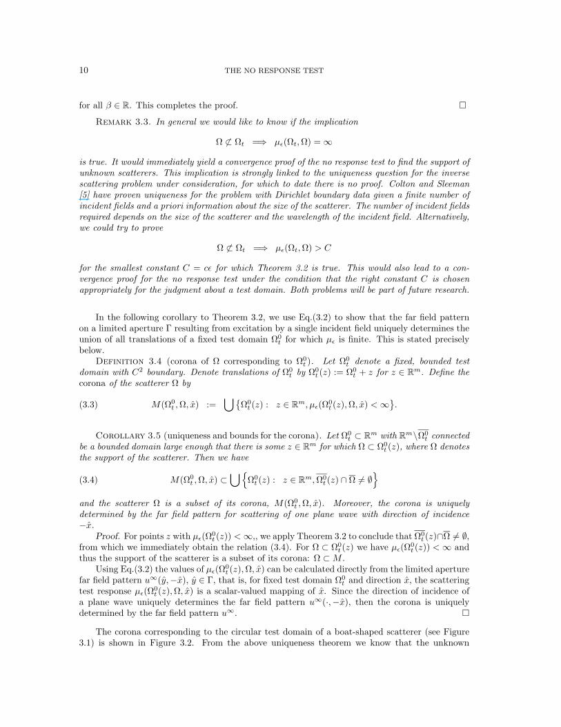
The corona corresponding to the circular test domain of a boat-shaped scatterer (see Figure3.1) is shown in Figure 3.2. From the above uniqueness theorem we know that the unknown

D. RUSSELL LUKE AND ROLAND POTTHAST 11
scatterer – whatever its physical nature might be – is located in the corona. Note that, at the veryleast, we can use the center of the corona for a single incident wave as an estimate for the centerof the obstacle. In our experiments here, however, we are able to extract even more informationabout the scatterer from the corona. Recall from Remark 3.3 that we cannot say anything specificabout the behavior of µε for Ω ∩ Ω0
t (z) 6= ∅ when Ω 6⊂ Ω0t (z). We observe numerically that the
value of the scattering test response increases as the intersection Ω ∩ Ω0t (z) 6= ∅ becomes smaller.
We therefore propose a technique that allows us to detect these increases, and thereby detect thelocation and shape of the scatterer within the corona. We begin by describing the choice of thetest domain and the calculation of the scttering test response. Details for efficient implementationtogether with the algorithm are given in the following section.
The test domain Ω0t . For fixed scatterers Ω and incident wave directions x, the scattering test
response µε takes as input the test domains Ω0t (z) and returns a scalar value as output. We would
like to know which test domains Ω0t (z) yield small values for µε without having to work with the
unwieldy domains themselves. For this, we construct a mapping from the domain Ω0t (z) to the
point z′ ∈ Ω0t (z) and assign to that point the corresponding value of µε. It is how we choose the
point z′ that allows us to get much more information about the obstacle than we would expect.The key property that we exploit is the observation that µε grows as the intersection Ω∩Ω0
t (z)becomes smaller. We emphasize that this observation is empirical, since at this time we cannotprove anything about the behavior of µε in this situation. In order to detect this growth, assignthe domain Ω0
t (z) to a point z′ on the boundary ∂Ω0t (z). To avoid keeping track of more points
than necessary, we construct the generating domain Ω0t such that 0 ∈ ∂Ω0
t and map the translateddomain ∂Ω0
t (z) to the point z′ = z. When z ∈ Ω then the the scatterer will not to fall entirelywithin the domain Ω0
t (z). In this case we observe that the scattering test response µε is significantlyhigher than when z is in the parts of the corona that do not intersect with the scatterer, representingthe situation where Ω ⊂ Ω0
t (z).We now describe a special realization of the no response test. We assign to the point z the
value of the scattering test response
f∗(z; Ω0t ) := µε(Ω0
t (z),Ω).(3.5)
However, by restriction to the point z from the full set Ω0t (z) we loose information: we obtain
small values for f∗(z; Ω0t ) only on one side of the unknown object as shown in Figure 3.3, where
f∗(z; Ω0t ) is plotted. The full information is recovered by rotating the generating domain Ω0
t aroundthe origin and repeating the above procedure. This is described in detail next.
Rotations or other variations of the test domain are necessary because of our choice of themapping from Ω0
t (z) to the point z′ ∈ Ω0t (z). Had we chosen a radially symmetric generating
domain Ω0t and mapped this domain to its center, rotations would not be necessary. However,
in this case the image does not directly reflect the behavior of the test response that we use toreconstruct the obstacle, not just its corona, that is, the behavior of the test response when theboundary of the test domain intersects the scatterer. Note that the idea of monitoring the behaviorat the boundary of the test domain also appears in the enclosure method, where the test domainis a half-space and the behavior of the indicator function Eq.(1.2) indicates which half-space theobstacle belongs to [6, 9]. Alternatively, we could use an arbitrary set of generating domains Ω0
t
with 0 ∈ ∂Ω0t , however it is much more convenient to work with a single generating domain rotated
about the origin.The value f∗(z; Ω0
t ) assigned to the point z via Eq.(3.5) at one rotation of the domain Ω0t
does not necessarily correspond to the value of the same point at a different rotation. To seethis, suppose that the scatterer Ω is contained in a small circle of radius 1 centered at the point(−1, 0). Suppose further that Ω0
t is a circle of radius 2 with center (−2, 0). In this case Ω ⊂ Ω0t
and f∗(0; Ω0t ) will therefore be small. If we rotate Ω0
t about the origin by 180 and denote the

12 THE NO RESPONSE TEST
(a) −10 −8 −6 −4 −2 0 2−5
−4
−3
−2
−1
0
1
2
3
4
5
Ωt0
Ω
(b)−10 −8 −6 −4 −2 0 2
−5
−4
−3
−2
−1
0
1
2
3
4
5
Ωt0
Ω
Fig. 3.1. Scatterer Ω, and test domain Ω0t used in reconstruction simulations. The obstacle Ω in (a) is
used for Dirichlet, Neumann and impedance obstacle reconstructions. The scatterer shown in (b) is usedfor inhomogeneous media reconstructions.
resulting domain by Ωt0, then Ω ∩ Ωt
0= 0. In this case we observe that the corresponding
value for f∗(0; Ωt0) will be large. In each case we assign a value to the point z = 0, but clearly
the values do not correspond to the same situation. In order to prevent the large values of oneorientation from drowning out the information contained in the small values from other rotations,we take the minimum of the values assigned to the points z over all rotations.
Let Rθ denote the rotation operator mapping the domain Ω0t onto the rotated domain RθΩ0
t .If at a point z the value F (z; Ω0
t ),
F (z; Ω0t ) := inf
θ∈[0,2π]f∗(z;RθΩ0
t ),(3.6)

D. RUSSELL LUKE AND ROLAND POTTHAST 13
(a)
(b)
Fig. 3.2. The figure demonstrates the calculated corona and the corresponding bound for the locationof the unknown obstacle when Ω0
t is a circle with radius rt = 4 as shown in Figure 3.1(a). For this boundwe do not need to know the physical nature of the scatterer and only one scattered wave is necessary. Herewe used the wave number κ = 5, aperture opening θ = 0.9π;, regularization parameter α = 10−11 for anincident wave with direction (−1, 0). The far field pattern contains 1-2% errors. The figure demonstratesthe change in the corona for different choices of the approximation domain: (a) shows the corona foran approximation domain of radius rt = 4, (b) shows the corona for an approximation domain of radiusrt = 1.3.
Fig. 3.3. The figure shows a plot of the function f∗(z; Ω0t ) given by Eq.(3.5) on a grid containing
the unknown scatterer. The scatterer is indicated by the black curve. Here, we used a Dirichlet boundarycondition.

14 THE NO RESPONSE TEST
is large, then we suppose that the unknown obstacle lies partly outside all rotations of the testdomain about this point. In this way, by sampling all points z in and around the unknown scattererΩ we are able to reconstruct aspects of the shape, location and size of Ω. Details about how weimplement this are given next.
4. Implementation and Numerical demonstrations.
Calculating the densities g. As prescribed in Eq.(3.1), we construct incident fields that aresmall on the test domain Ω0
t (z). For this we approximate the fundamental solution to the Helmholtzequation Φ(x, y) where the singularity is located at a point y ∈ Rm sufficiently far away from Ω0
t (z).To construct the densities g corresponding to these incident fields we use Tikhonov regularizationto approximately solve the ill-posed equation(
Hzg(·, y))
(x) = Φ(x, y), for x ∈ ∂Ω0t (z),
where Hz : L2(Γ)→ L2(∂Ω0t (z)) is a (limited angle) Herglotz wave operator defined by
(Hzg)(x) :=∫
Γ
eiκx·(−y)g(−y)ds(y), x ∈ ∂Ω0t (z).(4.1)
Specifically, for the regularization parameter α > 0, we define
gz,α(·, y) := (αI +H∗zHz)−1H∗zΦ(·, y),(4.2)
where the argument y of the density gz,α denotes the dependence of the density on the locationof the singularity in Φ. The subscripts z and α on g denote the dependence of the density on theregularization parameter α and the test domain Ω0
t (z). This yields
vi[gz,α(·, y)](·) ≈ Φ(·, y) on ∂Ω0t (z).
On Ω0t (z), for d(y,Ω0
t (z)) ≥ ρ we have, for all α ∈ [0, α0] for fixed α0 sufficiently small,
|vi[gz,α(x, y)]| ≤
c√ρ m = 2
cρ m = 3
, x ∈ Ω0t (z),(4.3)
with some constant c that is typically of size smaller than 101. Thus by knowing the value ofvi[gz,α] at the point closest to the source point we obtain upper bounds on the size of the incidentfield on all of Ω0
t (z). This is used in the calculation of the scattering test response µε. On theexterior region Rm\Ωt the magnitude of vi[gz,α] is in the range of c/2α. For example |vi[gz,α]| isof size 50 if c = 1 and α = 10−2. This corresponds to a data error of one percent.
Translations of the test domain. We describe a quick method to calculate lower estimates forthe test response µε for a large number of translated test domains Ω0
t (z) with generating domainΩ0t . In the moving reference frame of the test domain, spatial translations look like translations
of the incident field. We use this and the fact that phase shifts in the far field correspond tospatial translations in the near field in order to translate the generating domain Ω0
t around thecomputational domain.
Let Ω0t be a generating test domain and define Ω0
t (z) = Ω0t + z to be the corresponding
translated test domain. Translations of the Herglotz wave function vi[g] can be easily performedby the multiplication of the density g by the complex factor e−iκz·d. At points z ∈ Q coveringthe area where the unknown scatterer is supposed to be (that is, Q is the computational domain

D. RUSSELL LUKE AND ROLAND POTTHAST 15
and satisfies Ω ⊂ Q) we calculate translations Ω0t (z) of the test domain Ω0
t by the correspondingtranslation of the Herglotz wave function vi[g]:
vi[g](x− z) = vi[e−iκz·(·)g(·)](x), x ∈ Rm.(4.4)
We define the function |v∞[g](x, z)| to be the far field pattern at the point x ∈ S for scattering ofthe shifted incident field vi[g](x− z). Then from Theorem 2.1 and Eq.(3.2) we obtain
|v∞[g](x, z)| =∣∣∣ ∫
Γ
u∞(y,−x)eiκz·yg(−y)ds(y)∣∣∣.(4.5)
In words, the magnitude of the far field v∞ at the point x ∈ S with test domain Ω0t (z) is given
by the magnitude of the weighted superposition of the measured far field pattern due to a singleincident plane wave excitation; the weight g(−y) is determined by the generating domain Ω0
t andthe phase shift is determined by the translation of Ω0
t .
Sampling the scattering test response. The scattering test response µε(Ω0t (z),Ω) is the
supremum over |v∞[g](x, z)| where g ∈ L2(Γ) is chosen such that
||vi[g]||C(Ω0t (z))
≤ ε.(4.6)
We choose a finite subsetg1, . . . , gny
of densities g such that (4.6) is satisfied and calculate the
maximum of the values |v∞[gj ](x, z)| for j = 1, . . . , ny via Eq.(4.5). To obtain different densitiesg we solve Eq.(4.2) at the points yj , j = 1, . . . , ny in the exterior of Ω0
t (z). In our experiments wechose ny ≈ 20. Using the efficient translations in Eq.(4.4), we need only solve Eq.(4.2) for g withΩ0t for each j = 1, . . . , ny, rather than solving for g for every translated domain Ω0
t (z). Also, fromthe discussion following Eq.(4.3) if we choose the points yj appropriately, there is no need to checkexplicitly if condition Eq.(4.6) is satisfied.
The no response algorithm We finish this section with a detailed prescription for using the noresponse test to locate an unknown obstacle.
Algorithm 4.1 (no response test).• Choose an appropriate test domain Ω0
t with 0 ∈ ∂Ω0t , that is large enough such that trans-
lations of Ω0t and its rotated versions may contain the unknown scatterer (see Figure 3.1).
• For the angles θl := 2πl/nr with l = 1, . . . , nr let RθlΩ0t be the domain that is obtained
from Ω0t by rotation around the origin by angle θl as described in Section 3. For each
l = 1, . . . , nr do:– Choose points yj, j = 1, . . . , ny in the exterior of RθlΩ
0t and calculate the density gl,j
by
gl,j := (αI +H∗θlHθl)−1H∗θlΦ(·, yj)
where Hθl is the Heglotz wave operator (see Eq.(4.1)) corresponding to the rotateddomain RθlΩ
0t .
– For each j = 1, . . . , ny calculate
fj(z;RθlΩ0t ) :=
∣∣∣ ∫Γ
u∞(y,−x)eiκz·ygl,j(−y)ds(y)∣∣∣,
for all z ∈ G, the computational grid, from the one-wave far field pattern u∞(y,−x),y ∈ Γ.

16 THE NO RESPONSE TEST
– Calculate the maximum with respect to the densities gl,j , that is calculate the sampledversion of Eq.(3.5)
f∗(z;RθlΩ0t ) := max
j=1,...,nyfj(z;RθlΩ
0t ), z ∈ G.
• Calculate the minimum with respect to the rotations θl, that is the sampled version ofEq.(3.6):
F (z; Ω0t ) := min
l=1,...,nrf∗(z;RθlΩ
0t ), z ∈ G.
• Choose a threshold C and calculate
Ωrec :=z ∈ G : F (z; Ω0
t ) ≥ C.
Now, an approximation for the support Ω of the unknown scatterer is given by the compo-nents of Ωrec that are not connected with infinity.
For the choice of the constant C we propose dynamical thresholding on the image F (z) thatis informed by a priori knowledge about the approximate size of the object.
Numerical results. All the following numerical reconstruction procedures are based on thesame algorithm independent of the boundary condition or physical nature of the scatterer. Allreconstructions use the far field data for one wave only. We show results for full and limitedaperture data.
To compare different reconstructions for obstacles with different boundary condition for all thefollowing pictures we used the far field pattern for one wave with direction of incidence (−1, 0).We first show results for full aperture and demonstrate the influence of the cut-off parameter.
In a second part, we restrict our measurements to a limited aperture. Here, we would like toshow that even with limited aperture the method yields reasonable results. Figures 4.7 to 4.10 showlimited aperture reconstructions for the Dirichlet, Neumann and impedance boundary conditionand for the inhomogeneous medium. We used κ = 5 and an aperture of 0.6π, or 108.
5. Concluding remarks. The no response test is a novel sampling technique for reconstruct-ing the support of unknown scatterers. The method does not require a priori knowledge about thephysical or geometric properties of the unknown scatterer. Reconstructions can be obtained fromthe far field pattern for scattering of a single incident wave. The method appears to be robust andcan be used in limited aperture settings. The results and open questions discussed in this workoffer a new perspective on some old questions (for example the uniqueness question for one wave)and provide new directions for future research, both in numerical techniques and analysis.
REFERENCES
[1] Colton, D. and Kirsch, A.: ”A simple method for solving inverse scattering problems in the resonance region.”Inverse problems 12(4), 383-93 (1996).
[2] Colton, D. and Kress, R.: Inverse Acoustic and Electromagnetic Scattering Theory. 2nd Ed., Springer-Verlag(1998).
[3] Colton, D. and Monk, P.: “A novel method for solving the inverse scattering problem for time-harmonic wavesin the resonance region.” SIAM J. Appl. Math. 45, 1039-1053 (1985).
[4] Colton, D. and Monk, P.: “A novel method for solving the inverse scattering problem for time-harmonic wavesin the resonance region II.” SIAM J. Appl. Math. 46, 506-523 (1986).
[5] Colton, D. and Sleeman, B. D.: ”Uniqueness theorems for the inverse problem of acoustic scattering.” IMA J.Appl. Math. 31, 253-259 (1983).
[6] Ikehata, M.: ”Reconstruction of an obstacle from the scattering amplitude at a fixed frequency.” InverseProblems 14 (1998), no. 4, 949–954.

D. RUSSELL LUKE AND ROLAND POTTHAST 17
(a)
(b)
(c)
Fig. 4.1. (a) Original total field for scattering by a Dirichlet obstacle. (b) A plot of the function F (z)defined by (3.6) for z ∈ G, the computational grid. (c) Thresholded version of the function F with C = 1.4(see Alg. 4.1). Here we used the wave number κ = 5, aperture opening θ = 1.8π;, regularization parameterα = 10−11 for an incident wave with direction (−1, 0). The far field pattern contains 1-2% errors.

18 THE NO RESPONSE TEST
[7] Ikehata, M.: ”Enclosing a polygonal cavity in a two-dimensional bounded domain from Cauchy data”, InverseProblems 15 (October 1999) 1231-1241.
[8] Ikehata, M.: ”On reconstruction in the inverse conductivity problem with one measurement”, Inverse Problems16 (2000) 785-793.
[9] Ikehata, M. and Ohe, T.: ”A numerical method for finding the convex hull of polygonal cavities using theenclosure method”, Inverse Problems 18 (2002) 111-124.
[10] Kirsch, A: ”Characterization of the shape of a scattering obstacle using the spectral data of the far fieldoperator.” Inverse problems 14(6), 1489-1512 (1998).
[11] Lies, R.: Initial Boundary Value Problems in Mathematical Physics, B.G. Teubner, Stuttgart (1985).[12] Mitrea, D., Mitrea, M., Taylor, M.: ” Layer potentials, the Hodge Laplacian, and global boundary problems
in nonsmooth Riemannian manifolds”, Mem. Amer. Math. Soc. 150(2001).[13] Panich, O.I.:, “On the question of the solvability of the exterior boundary-value problems for the wave equation
and Maxwell’s equations. Usp. Mat Nauk 20A, 221-226 (1965) (Russian).[14] Potthast, R.: ”A fast new method to solve inverse scattering problems.” Inverse Problems 12, 731-742 (1996).[15] Potthast, R.: ”A point-source method method for inverse acoustic and electromagnetic obstacle scattering
problems.” IMA Jour. Appl. Math. 61, 119-140 (1998).[16] Potthast, R.: Point sources and multipoles in inverse scattering theory. Chapman & Hall (2001).

D. RUSSELL LUKE AND ROLAND POTTHAST 19
(a) (b)
Fig. 4.2. (a) Original total field for scattering by an impedance obstacle with λ = i. (b) A plot of thefunction F (z) defined by (3.6) for z ∈ G, the computational grid. Here we used the wave number κ = 5,aperture opening θ = 1.8π;, regularization parameter α = 10−11 for an incident wave with direction (−1, 0).The far field pattern contains 1-2% errors.
(a) (b)
(c) (d)
(e)
Fig. 4.3. We show different thresholded versions of the reconstruction to demonstrate the influence ofthe cut-off parameter C. The wave number is κ = 5, aperture opening θ = 1.8π;, regularization parameterα = 10−11 for an incident wave with direction (−1, 0), that is the incident wave is coming from the right-hand side. The far field pattern contains 1-2% errors.

20 THE NO RESPONSE TEST
(a) (b)
(c) (d)
Fig. 4.4. (a)-(b) Original total field for scattering by an obstacle with Neumann boundary condition,we show a surface and a contour plot of the field. (c) A plot of the function F (z) defined by (3.6) forz ∈ G and (d) a thresholded version of the reconstruction with C = 2.0. Here we used the wave numberκ = 5, aperture opening θ = 1.8π;, regularization parameter α = 10−11 for an incident wave with direction(−1, 0). The far field pattern contains 1-2% errors.
(a) (b)
Fig. 4.5. (a) Original total field for scattering by a homogeneous penetrable medium with n := 4 in Ωwhere the inhomogeneity is shown in Figure 3.1. (b) A plot of the function F (z) defined by (3.6) for z ∈ G.Here we used the wave number κ = 5, aperture opening θ = 1.8π;, regularization parameter α = 10−11 foran incident wave with direction (−1, 0). The far field pattern contains 1-2% errors.

D. RUSSELL LUKE AND ROLAND POTTHAST 21
(a)
(b)
(c)
(d)
Fig. 4.6. (a)-(d) We show several thresholded versions of the function F for the reconstruction of aninhomogeneous medium, where we used the thresholds C = 0.1, C = 0.06 C = 0.05 and C = 0.045.

22 THE NO RESPONSE TEST
(a) (b)
Fig. 4.7. Limited aperture reconstruction of a Dirichlet obstacle. (a) A plot of the function F (z) definedby (3.6) for z ∈ G, the computational grid. (b) Thresholded version of the function F . Here we used thewave number κ = 5, aperture opening θ = 0.6π;, regularization parameter α = 10−11 for an incident wavewith direction (−1, 0). The far field pattern contains 1-2% errors.
(a) (b)
Fig. 4.8. Limited aperture reconstruction of a Neumann obstacle. (a) A plot of the function F (z)defined by (3.6) for z ∈ G. (b) Thresholded version of the function F . Here we used the wave numberκ = 5, aperture opening θ = 0.6π;, regularization parameter α = 10−11 for an incident wave with direction(−1, 0). The far field pattern contains 1-2% errors.

D. RUSSELL LUKE AND ROLAND POTTHAST 23
(a) (b)
Fig. 4.9. Limited aperture reconstruction of an impedance obstacle with λ = i. (b) A plot of thefunction F (z) defined by (3.6) for z ∈ G, the computational grid. (c) Thresholded version of the functionF . Here we used the wave number κ = 5, aperture opening θ = 0.6π;, regularization parameter α = 10−11
for an incident wave with direction (−1, 0). The far field pattern contains 1-2% errors.
(a) (b)
Fig. 4.10. Limited aperture reconstruction of the support of an inhomogeneous medium. (a) A plot ofthe function F (z) defined by (3.6) for z ∈ G. (b) Thresholded version of the function F . Here we used thewave number κ = 5, aperture opening θ = 0.6π;, regularization parameter α = 10−11 for an incident wavewith direction (−1, 0). The far field pattern contains 1-2% errors.
Copyright © 2022 FDOKUMEN