The MC9S12 Pulse Width Modulation - Course Overview
30
EE 308 Spring 2014 • The MC9S12 Pulse Width Modulation System o Introduction to PWM o Review of the Output Compare Function o Using Output Compare to generate a PWM signal o Registers used to enable the Output Capture Function o The MC9S12 PWM system
-
Upload
khangminh22 -
Category
Documents
-
view
3 -
download
0
Transcript of The MC9S12 Pulse Width Modulation - Course Overview

EE 308 Spring 2014
• The MC9S12 Pulse Width Modulation System o Introduction to PWMo Review of the Output Compare Functiono Using Output Compare to generate a PWM signalo Registers used to enable the Output Capture Functiono The MC9S12 PWM system

EE 308 Spring 2014
Pulse Width Modulation
• Often want to control something by adjusting the percentage of time the object is turned on
• For example,
- A heater- A light- A DC motor
• Can use Output Compare to generate a PWM signal
• What frequency should you use for PWM?
- A heater - ?- A light - ?-A DC motor - ?- A heater -period of seconds- A light - > 100 Hz- A DC motor
* Big motor { 10 Hz* Small motor { kHz
• Suppose you are controlling four motors, each at 10 kHz
- Need to handle 40,000 interrupts/second- Each interrupt takes about 1 μs- 4% of time spent servicing interrupts

EE 308 Spring 2014
Close loop motor control of DC motors
Simplified H-Bridge diagram

EE 308 Spring 2014
Using the MC9S12 Output Compare Function to generate a PWM signal
Want a Pulse Width Modulated signal
Want to produce pulse with width dT, period T
Applications of PWM systems
-Illumination control
EE 308 Spring 2014
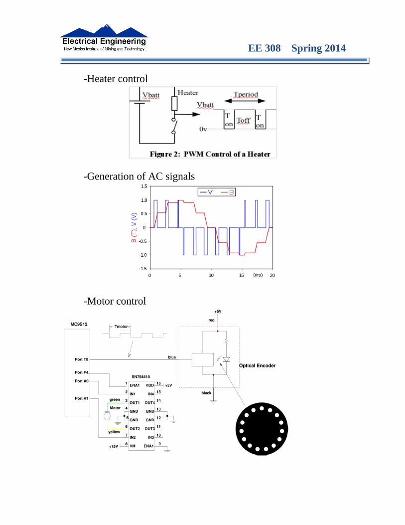
-Heater control
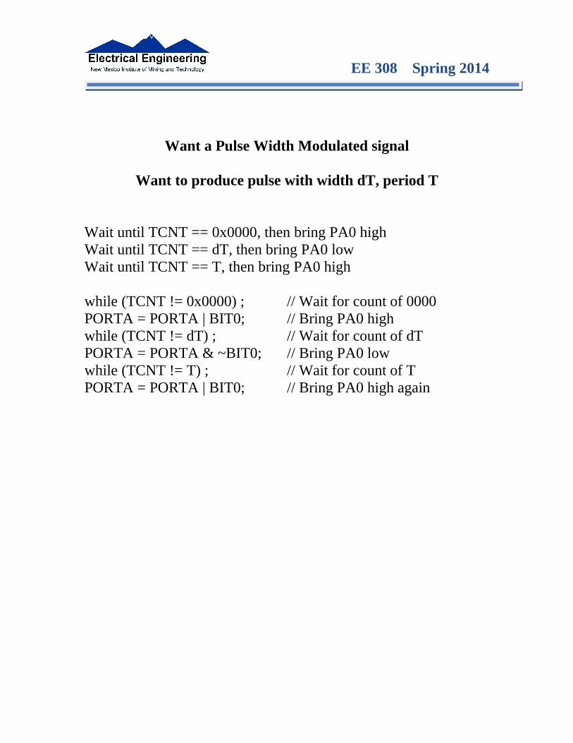
-Generation of AC signals
-Motor control
EE 308 Spring 2014
Want a Pulse Width Modulated signal
Want to produce pulse with width dT, period T
Wait until TCNT == 0x0000, then bring PA0 highWait until TCNT == dT, then bring PA0 lowWait until TCNT == T, then bring PA0 high
while (TCNT != 0x0000) ; // Wait for count of 0000PORTA = PORTA | BIT0; // Bring PA0 highwhile (TCNT != dT) ; // Wait for count of dTPORTA = PORTA & ~BIT0; // Bring PA0 lowwhile (TCNT != T) ; // Wait for count of TPORTA = PORTA | BIT0; // Bring PA0 high again

EE 308 Spring 2014
Output Compare PORT T 0−7
To use Output Compare, you must set IOSx to 1 in TIOS

EE 308 Spring 2014
How to use Output Compare Function to generate a PWM signal
• The MC9S12 allows you to force an event to happen on any of the eight PORTT pins
• An external event is a rising edge, a falling edge, or a toggle
• To use the Output Compare Function:
– Enable the timer subsystem (set TEN bit of TSCR1)
– Set the prescaler
– Tell the MC9S12 that you want to use Bit x of PTT for output compare
– Tell the MC9S12 what you want to do on Bit x of PTT (generate rising edge, falling edge, or toggle)
– Tell the MC9S12 what time you want the event to occur
– Tell the MC9S12 if you want an interrupt to be generated when the event is forced to occur

EE 308 Spring 2014
Using Output Compare on the MC9S12
1. In the main program:
(a) Turn on timer subsystem (TSCR1 reg)
(b) Set prescaler (TSCR2 reg)
(c) Set up PTx as OC (TIOS reg)
(d) Set action on compare (TCTL 1-2 regs, OMx OLx bits)
(d) Clear Flag (TFLG1 reg)
(f) Enable int (TIE reg)
2. In interrupt service routine
(a) Set time for next action to occur (write TCx reg)• For periodic events add time to TCx register
(b) Clear flag (TFLG1 reg)
EE 308 Spring 2014
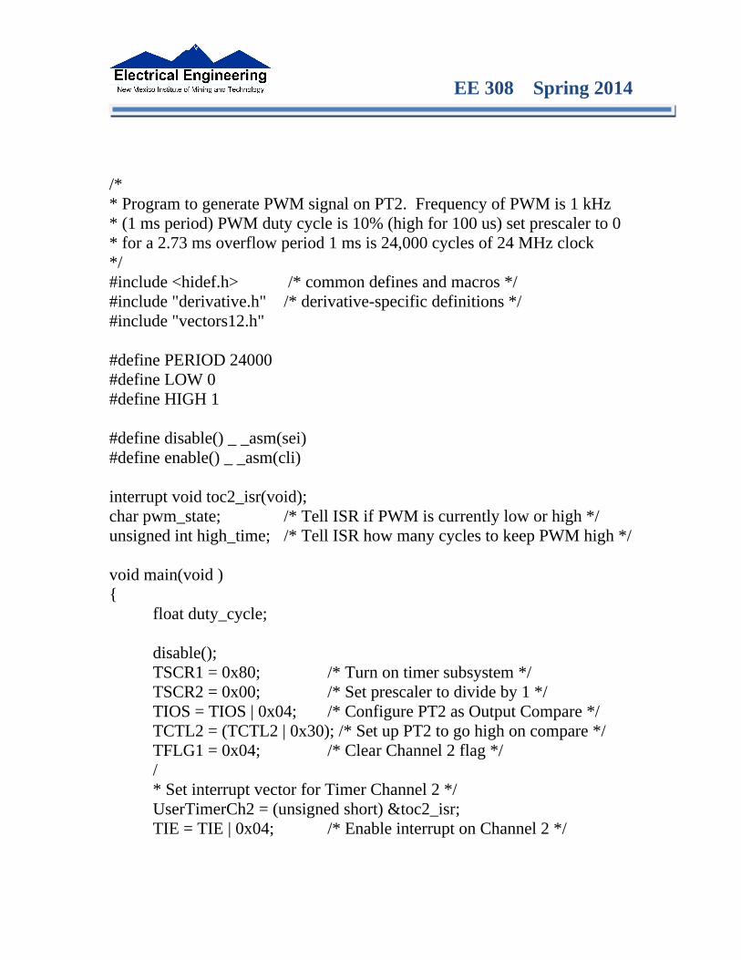
/** Program to generate PWM signal on PT2. Frequency of PWM is 1 kHz* (1 ms period) PWM duty cycle is 10% (high for 100 us) set prescaler to 0 * for a 2.73 ms overflow period 1 ms is 24,000 cycles of 24 MHz clock*/#include <hidef.h> /* common defines and macros */#include "derivative.h" /* derivative-specific definitions */#include "vectors12.h"
#define PERIOD 24000#define LOW 0#define HIGH 1
#define disable() _ _asm(sei)#define enable() _ _asm(cli)
interrupt void toc2_isr(void);char pwm_state; /* Tell ISR if PWM is currently low or high */unsigned int high_time; /* Tell ISR how many cycles to keep PWM high */
void main(void ){
float duty_cycle;
disable();TSCR1 = 0x80; /* Turn on timer subsystem */TSCR2 = 0x00; /* Set prescaler to divide by 1 */TIOS = TIOS | 0x04; /* Configure PT2 as Output Compare */TCTL2 = (TCTL2 | 0x30); /* Set up PT2 to go high on compare */TFLG1 = 0x04; /* Clear Channel 2 flag *//* Set interrupt vector for Timer Channel 2 */UserTimerCh2 = (unsigned short) &toc2_isr;TIE = TIE | 0x04; /* Enable interrupt on Channel 2 */

EE 308 Spring 2014
pwm_state = LOW; /* Start with PWM low */duty_cycle = 0.10; /* Initial duty cycle */high_time = duty_cycle*PERIOD; /* Cycles PWM should be high */
enable();
while (1){
/* Code to adjust duty cycle to set speed to desired value */}
}
interrupt void toc2_isr(void){
if (pwm_state == LOW) {TC2 = TC2 + high_time; /* Stay high for duty cycle */TCTL2 = (TCTL2 & ~0x10); /* Set up PT2 to go low on */
/* next compare */pwm_state = HIGH;
}else {
TC2 = TC2 + (PERIOD - high_time); /* Stay low until *//* period over */
TCTL2 = (TCTL2 | 0x30); / * Set up PT2 to go high on *//* next compare */
pwm_state = LOW;}TFLG1 = 0x04;
}
• Question: What are restrictions on minimum and maximum duty cycles?• Can you have 0% duty cycle?• Can you have 100% duty cycle?

EE 308 Spring 2014
Pulse Width Modulation on the MC9S12
• Because PWM is used so often the MC9S12 has a built-in PWM system
•The MC9S12 PWM does not use interrupts
• The PWM system on the MC9S12 is very flexible
- It allows you to set a wide range of PWM frequencies
- It allows you to generate up to 8 separate PWM signals, each with a different frequency
- It allows you to generate eight 8-bit PWM signals (with 0.5% accuracy) or four 16-bit PWM signals (with 0.002% accuracy)
- It allows you to select high polarity or low polarity for the PWM signal
- It allows you to use left-aligned or center-aligned PWM signals
• Because the MC9S12 PWM systems is so flexible, it is fairly complicated to program
• To simplify the discussion we will only discuss 8-bit, left-aligned, high-polarity PWM signals.
EE 308 Spring 2014
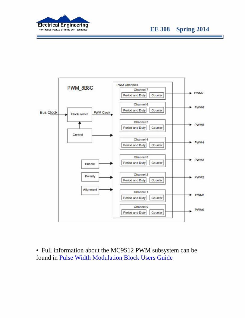
• Full information about the MC9S12 PWM subsystem can be found in Pulse Width Modulation Block Users Guide
EE 308 Spring 2014
Pulse Width Modulation
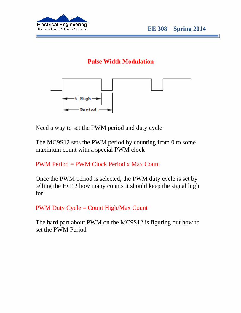
Need a way to set the PWM period and duty cycle
The MC9S12 sets the PWM period by counting from 0 to some maximum count with a special PWM clock
PWM Period = PWM Clock Period x Max Count
Once the PWM period is selected, the PWM duty cycle is set by telling the HC12 how many counts it should keep the signal high for
PWM Duty Cycle = Count High/Max Count
The hard part about PWM on the MC9S12 is figuring out how to set the PWM Period

EE 308 Spring 2014
The MC9S12 Pulse Width Modulation System
• The PWM outputs are on pins 0 through 7 of Port P
– On the Dragon12-Plus board, pins 0 through 3 of Port P control the seven-segment LEDs.
– If you want to use the seven-segment LEDs in addition to PWM, you will need to use PWM channels 4 through 7
• There are 33 registers used by the PWM subsystem
• You don’t need to work with all 33 registers to activate PWM
• To select 8-bit mode, write a 0 to Bits 7, 6, 5 and 4 of PWMCTL register.
• To select left-aligned mode, write 0x00 to PWMCAE.
• To select high polarity mode, write a 0xFF to PWMPOL register.

EE 308 Spring 2014
• To set the period for a PWM channel you need to program bits in the following PWM registers:
– For Channel 0 the registers are PWMCLK, PWMPRCLK, PWMSCLA and PWMPER0– For Channel 1 the registers are PWMCLK, PWMPRCLK, PWMSCLA and PWMPER1– For Channel 2 the registers are PWMCLK, PWMPRCLK, PWMSCLB and PWMPER2– For Channel 3 the registers are PWMCLK, PWMPRCLK, PWMSCLB and PWMPER3– For Channel 4 the registers are PWMCLK, PWMPRCLK, PWMSCLA and PWMPER4– For Channel 5 the registers are PWMCLK, PWMPRCLK, PWMSCLA and PWMPER5– For Channel 6 the registers are PWMCLK, PWMPRCLK, PWMSCLB and PWMPER6– For Channel 7 the registers are PWMCLK, PWMPRCLK, PWMSCLB and PWMPER7
• To set the duty cycle for a PWM channel you need to write to the PWDTYn register for Channel n.
• To enable the PWM output on one of the pins of Port P, write a 1 to the appropriate bit of PWME
Set PWMEn = 1 to enable PWM on Channel nIf PWMEn = 0, Port P bit n can be used for general purpose I/O
PWMPOLn − Choose polarity 1 => high polarity 0 => low polarity
We will use high polarity only. PWMPOL = 0xFF;
With high polarity, duty cycle is amount of time output is high

EE 308 Spring 2014
PWMCLKn − Choose clock source for Channel n
CH5, CH4, CH1, CH0 can use either A (0) or SA (1)CH7, CH6, CH3, CH2 can use either B (0) or SB (1)
This register selects the prescale clock source for clocks A and B independently
PCKA[2−0] − Prescaler for Clock A A = 24 MHz / 2(PCKA[2−0])
PCKB[2−0] − Prescaler for Clock B B = 24 MHz / 2(PCKB[2−0])
Select center aligned outputs (1) or left aligned outputs (0)
Choose PWMCAE = 0x00 to choose left aligned mode
EE 308 Spring 2014
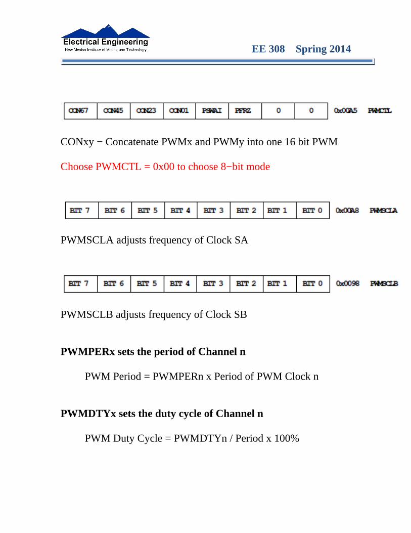
CONxy − Concatenate PWMx and PWMy into one 16 bit PWM
Choose PWMCTL = 0x00 to choose 8−bit mode
PWMSCLA adjusts frequency of Clock SA
PWMSCLB adjusts frequency of Clock SB
PWMPERx sets the period of Channel n
PWM Period = PWMPERn x Period of PWM Clock n
PWMDTYx sets the duty cycle of Channel n
PWM Duty Cycle = PWMDTYn / Period x 100%
EE 308 Spring 2014
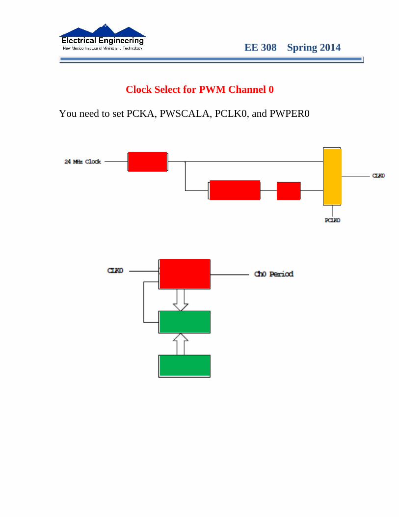
Clock Select for PWM Channel 0
You need to set PCKA, PWSCALA, PCLK0, and PWPER0
EE 308 Spring 2014
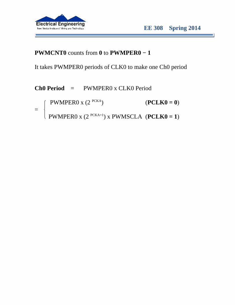
PWMCNT0 counts from 0 to PWMPER0 − 1
It takes PWMPER0 periods of CLK0 to make one Ch0 period
Ch0 Period = PWMPER0 x CLK0 Period
PWMPER0 x (2 PCKA) (PCLK0 = 0)= PWMPER0 x (2 PCKA+1) x PWMSCLA (PCLK0 = 1)

EE 308 Spring 2014
How to set the Period for PWM Channel 0
• To set the period for PWM Channel 0:– Set the PWM Period register for Channel 0, PWMPER0
– CLK0, the clock for Channel 0, drives a counter (PWCNT0)
– PWCNT0 counts from 0 to PWMPER0 – 1
– The period for PWM Channel 0 is PWMPER0 × Period of CLK0
• There are two modes for the clock for PWM Channel 0
– You select the mode by the PCLK0 bit:
– If PCLK0 == 0, CLK0 is generated by dividing the 24 MHz clock by 2PCKA, where PCKA is between 0 and 7
– If PCLK0 == 1, CLK0 is generated by dividing the 24 MHz clock by 2PCKA+1× PWSCLA, where PCKA is between 0 and 7 and PWSCALA is between 0 and 255 (a value of 0 gives a divider of 256)
• The Period for PWM Channel 0 (in number of 41.67 ns cycles) is calculated by
PWMPER0 × 2PCKA if PCLK0 == 0Period =
PWMPER0 × 2PCKA+1 × PWMSCLA if PCLK0 == 1
EE 308 Spring 2014
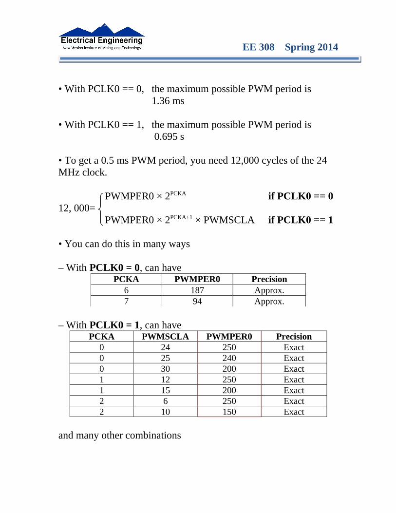
• With PCLK0 == 0, the maximum possible PWM period is 1.36 ms
• With PCLK0 == 1, the maximum possible PWM period is 0.695 s
• To get a 0.5 ms PWM period, you need 12,000 cycles of the 24 MHz clock.
PWMPER0 × 2PCKA if PCLK0 == 012, 000=
PWMPER0 × 2PCKA+1 × PWMSCLA if PCLK0 == 1
• You can do this in many ways
– With PCLK0 = 0, can havePCKA PWMPER0 Precision
6 187 Approx.7 94 Approx.
– With PCLK0 = 1, can have
PCKA PWMSCLA PWMPER0 Precision0 24 250 Exact0 25 240 Exact0 30 200 Exact1 12 250 Exact1 15 200 Exact2 6 250 Exact2 10 150 Exact
and many other combinations

EE 308 Spring 2014
• You want PWMPER0 to be large (say, 100 or larger)
– If PWMPER0 is small, you don’t have much control over the duty cycle
– For example, if PWMPER0 = 4, you can only have 0%, 25%, 50%, 75% or 100% duty cycles
• Once you choose a way to set the PWM period, you can program the PWM registers
• For example, to get a 0.5 ms period, let’s use PCLK0 = 1, PCKA = 0, PWMSCLA = 30, and PWMPER0 = 200
• We need to do the following:
– Write 0x00 to PWMCTL (to set up 8-bit mode)– Write 0xFF to PWMPOL (to select high polarity mode)– Write 0x00 to PWMCAE (to select left aligned mode)
– Write 0 to Bits 2,1,0 of PWMPRCLK (to set PCKA to 0)– Write 1 to Bit 0 of PWMCLK (to set PCLK0 = 1)– Write 30 to PWMSCLA– Write 200 to PWMPER0– Write 1 to Bit 0 of PWME (to enable PWM on Channel 0)– Write the appropriate value to PWDTY0 to get the desired duty cycle (e.g., PWMDTY0 = 120 will give 60% duty cycle)
Do not Change

EE 308 Spring 2014
C code to set up PWM Channel 0 for 0.5 ms period (2 kHzfrequency) PWM with 60% duty cycle
PWMCTL = 0x00; /* 8-bit Mode */PWMPOL = 0xFF; /* High polarity mode */PWMCAE = 0x00; /* Left-Aligned */
PWMPRCLK = PWMPRCLK & ~0x07; /* PCKA = 0 */PWMCLK = PWMCLK | 0x01; /* PCLK0 = 1 */PWMSCLA = 30;PWMPER0 = 200;PWME = PWME | 0x01; /* Enable PWM Channel 0 */PWMDTY0 = 120; /* 60% duty cycle on Channel 0 */
EE 308 Spring 2014
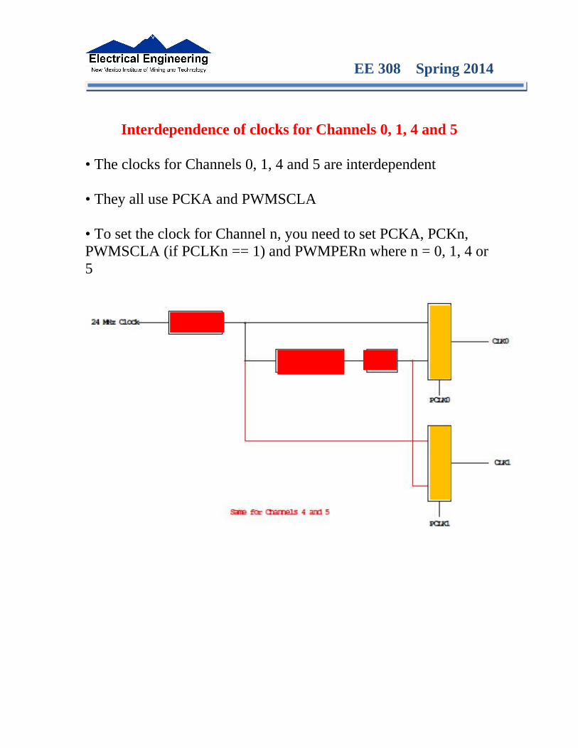
Interdependence of clocks for Channels 0, 1, 4 and 5
• The clocks for Channels 0, 1, 4 and 5 are interdependent
• They all use PCKA and PWMSCLA
• To set the clock for Channel n, you need to set PCKA, PCKn, PWMSCLA (if PCLKn == 1) and PWMPERn where n = 0, 1, 4 or 5

EE 308 Spring 2014
PWM Channels 2, 3, 6 and 7
• PWM channels 2, 3, 6 and 7 are similar to PWM channels 0, 1, 4 and 5
• To set the clock for Channel n, you need to set PCKB, PCLKn, PWMSCLB (if PCLKn == 1) and PWMPERn where n = 2, 3, 6 or 7
EE 308 Spring 2014
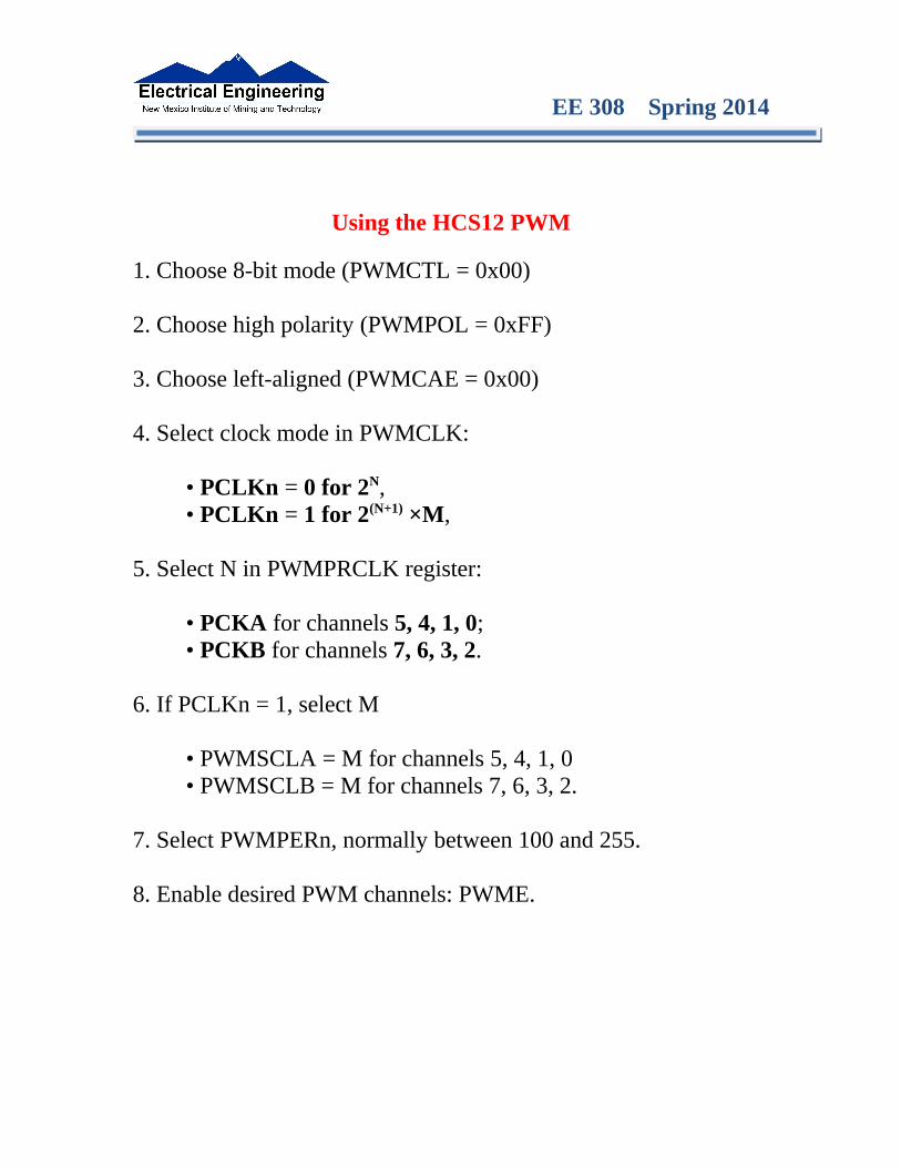
Using the HCS12 PWM
1. Choose 8-bit mode (PWMCTL = 0x00)
2. Choose high polarity (PWMPOL = 0xFF)
3. Choose left-aligned (PWMCAE = 0x00)
4. Select clock mode in PWMCLK:
• PCLKn = 0 for 2N,• PCLKn = 1 for 2(N+1) ×M,
5. Select N in PWMPRCLK register:
• PCKA for channels 5, 4, 1, 0;• PCKB for channels 7, 6, 3, 2.
6. If PCLKn = 1, select M
• PWMSCLA = M for channels 5, 4, 1, 0• PWMSCLB = M for channels 7, 6, 3, 2.
7. Select PWMPERn, normally between 100 and 255.
8. Enable desired PWM channels: PWME.

EE 308 Spring 2014
9. Select PWMDTYn, normally between 0 and PWMPERn. Then
Duty Cycle n = (PWMDTYn / PWMPERn) × 100%
Change duty cycle to control speed of motor or intensity of light, etc.
10. For 0% duty cycle, choose PWMDTYn = 0x00.
EE 308 Spring 2014
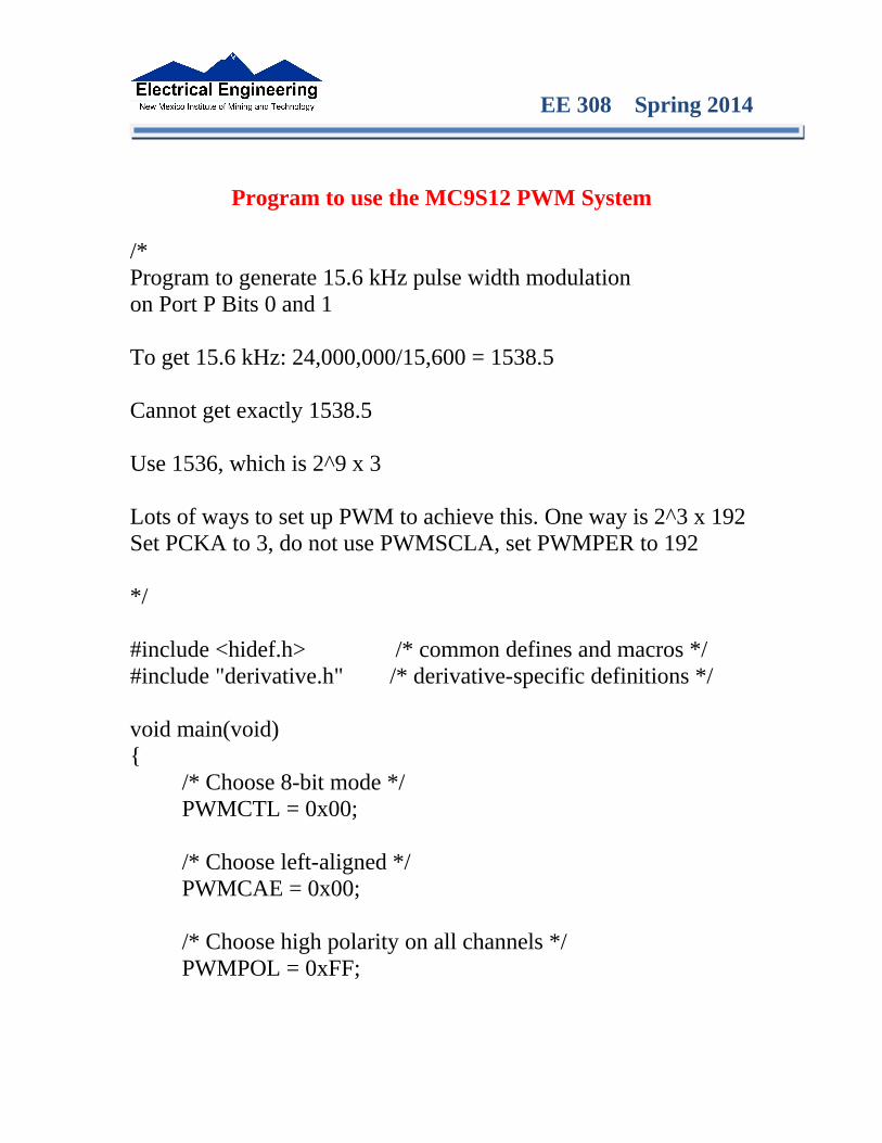
Program to use the MC9S12 PWM System
/*Program to generate 15.6 kHz pulse width modulationon Port P Bits 0 and 1
To get 15.6 kHz: 24,000,000/15,600 = 1538.5
Cannot get exactly 1538.5
Use 1536, which is 2^9 x 3
Lots of ways to set up PWM to achieve this. One way is 2^3 x 192Set PCKA to 3, do not use PWMSCLA, set PWMPER to 192
*/
#include <hidef.h> /* common defines and macros */#include "derivative.h" /* derivative-specific definitions */
void main(void){
/* Choose 8-bit mode */PWMCTL = 0x00;
/* Choose left-aligned */PWMCAE = 0x00;
/* Choose high polarity on all channels */PWMPOL = 0xFF;
EE 308 Spring 2014
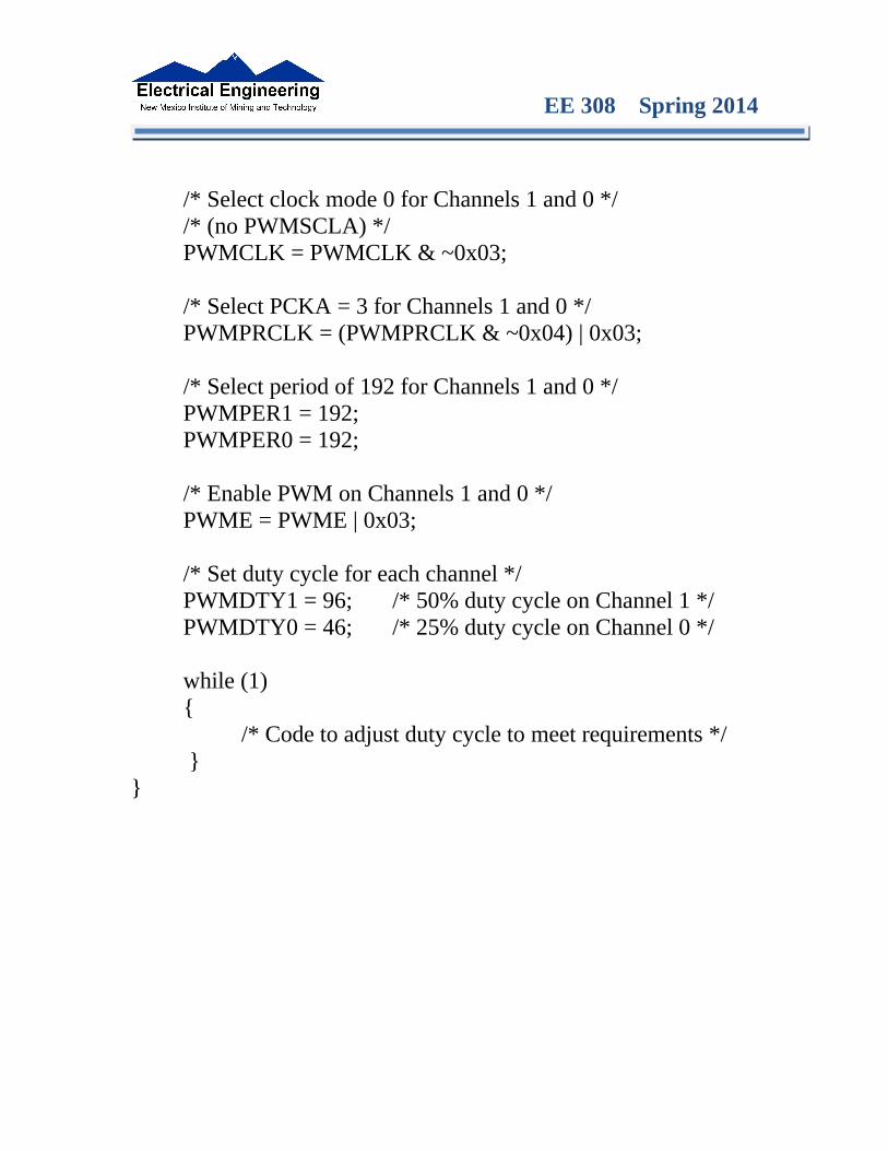
/* Select clock mode 0 for Channels 1 and 0 *//* (no PWMSCLA) */PWMCLK = PWMCLK & ~0x03;
/* Select PCKA = 3 for Channels 1 and 0 */PWMPRCLK = (PWMPRCLK & ~0x04) | 0x03;
/* Select period of 192 for Channels 1 and 0 */PWMPER1 = 192;PWMPER0 = 192;
/* Enable PWM on Channels 1 and 0 */PWME = PWME | 0x03;
/* Set duty cycle for each channel */PWMDTY1 = 96; /* 50% duty cycle on Channel 1 */PWMDTY0 = 46; /* 25% duty cycle on Channel 0 */
while (1){
/* Code to adjust duty cycle to meet requirements */ }
}