
The MASC/BGMP Architecture for Inter-Domain Multicast Routing
12
-
Upload
nagarjunauniversity -
Category
Documents
-
view
1 -
download
0
Transcript of The MASC/BGMP Architecture for Inter-Domain Multicast Routing

The MASC/BGMP Architecture for Inter-domain Multicast Routing�
Satish Kumary, Pavlin Radoslavov
Information Sciences Institute
University of Southern California
fkkumar,[email protected]
David Thaler
Electrical Engineering and Computer Science Dept
University of Michigan
Cengiz Alaettino�glu, Deborah Estrinz, Mark Handley
Information Sciences Institute
University of Southern California
fcengiz,estrin,[email protected]
Abstract
Multicast routing enables e�cient data distribution to mul-tiple recipients. However, existing work has concentrated onextending single-domain techniques to wide-area networks,rather than providing mechanisms to realize inter-domainmulticast on a global scale in the Internet.
We describe an architecture for inter-domain multicastrouting that consists of two complementary protocols. TheMulticast Address-Set Claim (MASC) protocol forms thebasis for a hierarchical address allocation architecture. Itdynamically allocates to domains multicast address rangesfrom which groups initiated in the domain get their mul-ticast addresses. The Border-Gateway Multicast Protocol(BGMP), run by the border routers of a domain, constructsinter-domain bidirectional shared trees, while allowing anyexisting multicast routing protocol to be used within in-dividual domains. The resulting shared tree for a group isrooted at the domain whose address range covers the group'saddress; this domain is typically the group initiator's do-main. We demonstrate the feasibility and performance ofthese complementary protocols through simulation.
�This work was supported by NSF under grant NCR-9321043,DARPA under contract number DABT63-96-C-0054 and a Pre-doctoral Merit Fellowship from the University of Southern California.
yKumar was the primary author of the paper, Radoslavov collab-orated in the design of MASC and conducted all the simulations inthis paper. Alaettinoglu, Estrin, Handley, and Thaler collaboratedon the design of the overall architecture and protocol details. Thiswork built upon earlier work by Handley et. al. on HPIM, Ballardieet. al. on CBT, and many of the key ideas came from discussionswith Steve Deering, Dino Farinacci, Van Jacobson, and David Meyer.
zAlso with the Computer Science Department at the University ofSouthern California.
This architecture, together with existing protocols op-erating within each domain, is intended as a framework inwhich to solve the problems facing the current multicast ad-dressing and routing infrastructure.
1 Introduction
IP Multicast provides e�cient one-to-many data distribu-tion in an Internet environment, and also provides the func-tionality to logically group (and hence identify) a set ofhosts/routers in a distributed fashion. Hence, it is an im-portant mechanism to support many applications such asmultimedia teleconferencing, distance learning, data repli-cation and network games. The current infrastructure forglobal, Internet-wide multicast routing however faces somekey problems.
Firstly, the existing multicast routing mechanisms broad-cast some information and therefore do not scale well togroups that span the Internet. Multicast routing protocolslike DVMRP[1, 2, 3] and PIM-DM[4] periodically ood datapackets throughout the network. MOSPF[5] oods groupmembership information to all the routers so that they canbuild multicast distribution trees. Protocols like CBT[6, 7]and PIM-SM[8, 9] scale better by having the members ex-plicitly join a multicast distribution tree rooted at a corerouter. However, the mechanism for distributing the map-ping of a group to its corresponding core router requires ooding of the set of all routers that are willing to be cores.
Secondly, the current scheme used to assign multicastaddresses to groups does not scale well. An IP multicastgroup is identi�ed by a single IP address. Senders to thegroup use this address as the destination of packets to reachall the members of the group. The multicast addresses donot have any structure to them. A multicast group initiatortypically contacts an address allocation application (e.g., thesession directory tool, sdr[10]) and an address is randomlyassigned from those not known to be in use. The assignedaddress is unique with high probability when the numberof addresses in use is small, but the probability of addresscollisions increases steeply when the percentage of addresses
in use crosses a certain threshold and as the time to notifyother allocators grows. Hence, a need has been recognizedfor a hierarchical multicast address allocation scheme[10] forthe Internet.
The Internet today is an interconnection of networks ad-ministered by di�erent organizations. The set of networksunder administrative control of a single organization is re-ferred to as an Autonomous System or domain. In thispaper we describe an architecture for inter-domain multi-cast routing comprising two complementary protocols: theMulticast Address-Set Claim (MASC)[11] protocol and theBorder Gateway Multicast Protocol (BGMP)[12]. Togetherwith existing protocols operating within each domain, thisis intended as a framework in which to solve the problemsfacing multicast addressing and routing.
MASC forms the basis for a hierarchical address alloca-tion architecture. The domains running MASC form a hi-erarchy based on the structure of the existing inter-domaintopology (e.g., campus area networks have a regional net-work as their parent, regionals have backbone networks asparent). MASC then dynamically allocates address rangesto domains using a listen and claim with collision detection
approach. In this approach, child domains listen to mul-ticast address ranges selected by their parent, select sub-ranges from their parent's range and propagate the claimsto their siblings. The claimers wait for a suitably long pe-riod to detect any collision, before communicating the ac-quired range to the domain's Multicast Address Allocation
Servers (MAAS's)[13] and to other domains through theinter-domain routing protocol, BGP[14, 15] as group routes.MAAS's can then allocate individual multicast addresses togroups initiated in their domain.
BGMP (run by the border routers of a domain) uses theBGP group routes to construct multicast distribution treesfor active multicast groups. These are known as bidirec-
tional shared trees, and consist of the BGMP border routersof domains that lie on the path between the sender/receiverdomains and the group's root domain. Each shared tree isrooted at the domain whose address allocation includes thegroup's address. Thus, the domain that injected a multicastaddress range into BGP is the root domain for those groups.Since an initiator of a group normally gets a multicast ad-dress from the range allocated to its local domain, the sharedtree is rooted there. Intra-domain routing protocols such asPIM and DVMRP are used to forward data between the do-main's group members and its BGMP border routers. Theseborder routers in turn forward the data along the group'sshared tree to reach members in other domains. Data can ow in either direction along this bidirectional tree1.
Since inter-domain routing involves the use of resourcesin autonomously administered domains, the routing policyconstraints of such domains need to be accommodated. Inour architecture, polices for multicast tra�c can be realizedthrough selective propagation of group routes in BGP. Thismechanism should be of operational bene�t as it is the sameas that used for unicast routing policy expression. In ad-dition, bidirectional trees minimize third-party dependency
policy issues. In other words, the communication betweengroup members in two domains along the bidirectional treedoes not depend, as much as possible, on the quality of pathsto a third domain that does not lie on the path between thetwo domains.
In section 2, we describe the current inter-domain unicast
1This is in contrast to unidirectional trees built by protocols likePIM-SM where data can ow only in a speci�ed direction on eachbranch of the tree.
routing infrastructure and how it relates to our proposedarchitecture for inter-domain multicast routing. We thenenumerate the design requirements for e�cient inter-domainmulticast routing in Section 3. In section 4, we describeMASC, with simulations of its performance, and describehow the allocations from MASC are distributed using BGP.We describe BGMP in section 5 with simulations comparingthe quality of bidirectional shared trees built by BGMP todistribution trees built by other multicast routing protocols.
2 Background and Motivation
Inter-domain unicast routing To enable communication be-tween domains in the Internet, border routers run an inter-domain unicast routing protocol. The one used in the Inter-net today is BGP. BGP border routers of neighboring do-mains establish TCP peerings with each other to exchangerouting information in update messages. Update messagescontain a set of routes, each comprising an address pre�xof a destination network that is reachable from the borderrouter together with attributes of the path to that destina-tion network. When a router X advertises a route for R toa router Y, it means that the router Y can use X to reachthe destination network R.
All the border routers of a domain peer with each otherto exchange the routes received by them from external peers(i.e., peers in other domains). They then locally select thebest route to each destination. The chosen route is thenadvertised by the border routers to the external peers.
BGP is currently being extended[16] to carry multipletypes of routes for destinations and consequently allow mul-tiple logical views of the routing table corresponding to eachroute type. This helps in supporting other network layerprotocols like QoS and multicast routing protocols. For ex-ample, the multicast routing information in the logical viewof the routing table called the Multicast Routing Informa-tion Base (M-RIB) would be used for RPF checks 2 so thatthe multicast routing protocols perform correctly even if themulticast topology is not congruent to the unicast topology.
The architecture presented in this paper uses a type ofroute in BGP that we call a group route. Group routes,injected into BGP by a MASC speaker, contain the mul-ticast address ranges allocated to the domain by MASC,and hence implicitly bind each group address to its root do-main. We refer to the portion of the routing table holdinggroup routes as the Group Routing Information Base (G-RIB). BGMP uses the G-RIB information to construct ashared multicast distribution tree for a group rooted at theroot domain for that group address. Hence BGP serves asa glue between MASC and BGMP by distributing the ad-dress allocation information from MASC to border routersof domains so as to enable BGMP to construct inter-domainmulticast distribution trees for groups.
Address Allocation and Aggregation The number of net-works in the Internet is growing at an exponential rate.Since the BGP unicast routing tables had entries on theorder of the number of networks (address pre�xes) in the In-ternet, it too was growing at an exponential rate. The abovescaling problem was reduced by the deployment of ClasslessInter-Domain Routing (CIDR)[17], which allows consecutiveaddress pre�xes to be combined into a single pre�x thereby
2An RPF (Reverse Path Forwarding) check refers to the checkmade by some multicast routing protocols that a packet received froma source S came from the neighboring router that is the shortest pathback to S.
reducing the number of routing table entries. For example,the address pre�xes 128.8.0.0/163 and 128.9.0.0/16 can beaggregated to 128.8.0.0/15 as they di�er only in their last(i.e. 16th) bit. When a border router X advertises an ag-gregate to border router Y, Y can reach hosts in all thecomponent address pre�xes of the aggregate via X. CIDRonly achieves e�cient aggregation to the extent that theunicast address pre�xes are assigned to domains in a struc-tured manner. With unicast address pre�xes, this is cur-rently achieved by static address assignments with limitedsuccess.
Unlike unicast addresses where an address represents ahost or router, the number of multicast group addresses re-quired in a domain is far more volatile (due to their logicalnature). Hence, MASC dynamically allocates multicast ad-dress ranges to domains based on the usage patterns so asto achieve e�cient address space utilization. In addition,dynamic allocation of address ranges makes it possible toachieve better aggregation (compared to the unicast case)of the group routes that MASC injects into BGP.
Routing policies The Internet is composed of a number ofprovider domains that o�er as a service to facilitate dataexchange between other domains. Provider domains vary insize; some operate in a single metropolitan area while othersspan continents. Larger provider domains o�ering nationalor inter-continental transit are typically known as backbonedomains. Smaller provider domains are often customers oflarger provider domains.
Provider-customer relationships in the Internet de�nepolicy constraints of domains to limit tra�c that they arewilling to carry. Typically, a provider domain allows tran-sit tra�c to or from its customer domains to pass throughits networks. These policies are realized by BGP throughselective propagation of the unicast routes. For example,if an unicast route R is not propagated by a border routerX to its peer Y, then Y will not be aware that it can useX to reach the destinations represented by R. The borderrouters of a provider domain would typically advertise onlyroutes corresponding to networks in its own domain and itscustomer domains. This ensures that only tra�c destinedeither to a host in its own networks or in the networks ofone of its customer domains will transit through it (apartfrom the tra�c originated by hosts in these networks).
We propose to realize multicast policies through selec-tive propagation of the group routes in BGP so that use ofthe provider's networks can be suitably restricted (similarto the unicast case). However, there is a limit to how manyheterogeneous policies can be supported in the constructionof a single multicast distribution tree for a group across do-mains. Multicast gains its e�ciency by distributing packetsover a common tree. The fragmentation of the tree by policymight at some point lead to the communication between thegroup members essentially devolving to unicast. Providersspecifying multicast policy should be aware of the impact ofbaroque policies.
We next enumerate the requirements for e�cient inter-domain multicast.
3 Requirements for inter-domain multicast
The key requirements for inter-domain multicast routingconcern scaling, stability, policy, conformance to the IP Ser-
3128.8.0.0/16 refers to the set of addresses whose �rst 16 bits are10000000 00001000 (128.8)
vice Model [18, 19] and intra-domain multicast routing pro-tocol independence.
Scaling:
Multicast forwarding state: The amount of statewhich must be distributed to permit global multi-cast forwarding should be minimal and scale wellas the Internet expands. Where there are no re-ceivers or senders, state for the group should beminimized.
Address allocation: The address allocation schemeshould scale well as the number of groups in-creases. The probability of address collision, aswell as the delay in obtaining an address to assignto a group, should be small, consistent with best-e�ort architectural principles. An application- orsession-level protocol should be able to detect anddrop packets that it receives due to infrequent col-lisions to the extent required by that application.
Stability: Distribution trees should not be reshaped fre-quently, since this causes both additional control tra�cas well as potential packet loss on sessions in progress.We believe that reducing protocol overhead is more im-portant than maintaining optimal distribution trees.
Policy:
Policy model: It is important for an inter-domainmulticast routing protocol to have a policy modelto control the ow of multicast tra�c if it is tobe widely deployed in the Internet.
Third-party dependency issues: As much as pos-sible, the communication between two domainsshould not rely on the quality of paths to a thirddomain if that third domain does not lie on thepath between the two domains. Such dependen-cies are possible in protocols that build sharedtrees when the root of the shared tree lies in athird-party domain and the protocol requires thatall packets go via the root before reaching groupmembers along the shared tree. In addition, foradministrative reasons it is desirable that the rootof the shared tree not be in a domain that has nei-ther group members nor senders.
Incongruent multicast and unicast topologies:The multicast routing protocol should work evenif the unicast and multicast topologies are notcongruent. This can be achieved by using the M-RIB information in BGP.
Conformance to IP service model: In the IP Multicastservice model, senders need not be members of a groupto send data. This accommodates a wide range of ap-plications; for example many small sensors reportingdata to a set of servers without facing the overhead ofreceiving each other's tra�c. Moreover, IP does notrequire signaling in advance of sending data. This hascontributed to its applicability to bursty-source appli-cations that expect to send whenever data is availablebut for which long-term per-source state is ine�cient.The combination of the above requirements impliesthat any router must be able to forward a data packettowards group members if there is a multicast group inexistence. It is therefore important that any requiredcomputation at the router to forward data packets to
groups be fast enough so that data is not lost due tobu�er over ows. This cannot be addressed by cachingthe information obtained from a remote lookup sincedata packets can be lost deterministically if the packetinter-arrival time is greater than the router state time-out period [20].
Intra-domain multicast routing independence: Intra-domain multicast routing protocol independence al-lows each domain the choice of which multicast routingprotocol to run inside the domain. This allows eachdomain the autonomy to run a protocol that is bestsuited for its needs. It also allows a domain to upgradeto a newer version of a protocol while minimizing thee�ects on other domains.
In the context of these requirements, we will describe theMASC protocol for address allocation. In section 4.2 we de-scribe the distribution of MASC address allocations throughBGP, followed by a description of how BGMP uses this in-formation to build multicast distribution trees in Section 5.
4 Multicast address allocation to domains using MASC
One or more nodes (typically border routers) in a domainuse MASC to acquire address ranges for use by MulticastAddress Allocation Servers (MAAS's) in that domain. Theseservers coordinate with each other using intra-domain mech-anisms [13] to assign unique multicast addresses to clientsin their domain from address ranges provided, and to moni-tor the domain's address space utilization. When necessary,they communicate to the MASC nodes the need for moreaddress space or to relinquish some of the acquired space.
We term a domain that has at least one node runningMASC a MASC domain. MASC domains form a hierarchythat re ects the structure of the inter-domain topology. Adomain that is a customer of other domains will choose oneor more of those provider domains to be its MASC parent.Backbone MASC domains that are not customers of otherdomains typically do not have a parent MASC domain. Werefer to a MASC domain that does not have a parent asa top-level domain. The hierarchy can be con�gured, orheuristics can be used to select the parent. For example,the MASC node could look up the routing table on one ofits border routers to determine who its provider domain is(typically indicated by the default routing entry, if any, inthe unicast routing table)
4.1 MASC address allocation overview
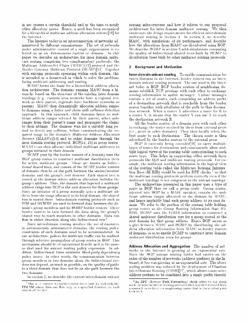
Consider a hierarchy of MASC domains as shown in �gure 1.Domains A, D, and E are backbone providers. Domains Band C are regional providers and are customers of A. Theregional providers, B and C have F and G as their customersrespectively. We will show how B acquires an address rangefor use by its domain. We assume that backbone domain Ahas already acquired the address range 224.0.0.0/16 usingMASC. Backbone domains acquire address ranges by a pro-cess similar to that of any other domain, which is explainedat the end of this subsection.
MASC domains B and C have A as their parent. A adver-tises its address range, 224.0.0.0/16, to all its children. Childdomain B claims an address range, say 224.0.1.0/24, fromits parent domain's (A's) address space and informs its par-ent, as well as any directly-connected siblings, of the claim.
224.0.128.0/24Domain B
224.0.0.0/16Domain A
Domain C224.0.1.1/25
Domain G
Domain D Domain E
Domain F
Border Routers
B1
A3 A2
C1
C2
G1F1
B2
A4 A1
E1D1
Figure 1: Address Allocation using MASC
A then propagates this claim information to its other chil-dren (the algorithm used by B to decide the address rangeit should claim is discussed in section 4.3.3).
In case any of B's siblings are using the address rangethat B chose, they send back collision announcements. Forexample, if C is already using the address range, 224.0.1.1/25it sends a collision announcement to B. In general, if two do-mains make a claim for the same address range, one of themwill \win" the claim4 . When B hears a collision announce-ment, it gives up its current claim and makes a claim for adi�erent address range, say 224.0.128.0/24, from its parent'sspace. Domain B listens for collision announcements for awaiting period long enough to span network partitions thatmight prevent B's claim from reaching all its siblings. Basedon feedback from network service providers, we believe 48hours to be a realistic period of time to wait. If no colli-sions occur, B communicates the acquired address range tothe local MAASes and to other domains through BGP asgroup routes. We refer to the proposed mechanism used toobtain address ranges as the claim-collide mechanism. Themotivation for the claim-collide mechanism is elucidated insection 4.3.4.
This decoupling of inter- and intra-domain address allo-cation mechanisms allows multicast addresses to be inter-nally allocated very quickly, just as a local unicast addresscan be acquired quickly relative to acquiring a new unicastsubnet pre�x for the domain. It is expected that MASC willkeep ahead of the demand for multicast addresses in its do-main, but if there is a sudden increase in demand, addressescould be obtained from the parent's address space. If thisis done, the root of the shared tree for these groups wouldsimply be the parent's domain, which might be sub-optimalfor the group if no senders or receivers were outside the childdomain.
The parent domain, A, keeps track of how much of itscurrent space has been allocated to itself and to its chil-dren. It claims more address space when the utilizationexceeds a given threshold. Since A is a backbone providerdomain, it does not have any parent MASC domain fromwhich it can claim address ranges. However, domain A stilluses the claim-collide mechanism to acquire address rangesby making claims from the global multicast address space,
4The winner may be based on domain IDs or IP addresses of theclaimant MASC nodes or timestamps on the requests.
224.0.0.0/4. Its sibling domains correspond to the other top-level (backbone) domains that do not have a parent domain.
4.2 Distribution of MASC address allocation informationthrough BGP
Once a MASC router5 in B successfully obtains an uniqueaddress range, it is sent to the other border routers of thedomain, which then inject the address range into BGP asa group route. When a border router X advertises a grouproute R to a border router Y, it means that the border routerY can use X as the next hop to forward data packets (aswell as control messages) towards the root domain for theaddress range represented by R. For example, the borderrouter B1 advertises the group route corresponding to theaddress pre�x 224.0.128.0/24 to A3 in domain A. Since allBGP border routers of a domain peer with each other toexchange routes received by them from external peers, theborder routers A1, A2, A3, and A4 learn of the group routereceived from B1. As only one route is received by A forthis address pre�x, it is chosen for use. If multiple routesare received, a preference function based on the attributesof the group route is used to pick one route among them,according to normal BGP behavior.
The chosen group route is stored by A3 in its G-RIBas (224.0.128.0/24, B1), indicating that B1 is the next hopfrom A3 to reach the root domain for range 224.0.128.0/24.The other border routers of A (i.e., A1, A2 and A4) store(224.0.128.0/24, A3) in their G-RIBs, as they use A3 as thenext hop to reach the root domain for 224.0.128.0/24.
BGP group route aggregation then functions the same asfor unicast routes. Since the address range allocated to A,224.0.0.0/16, subsumes B's address range, 224.0.128.0/24,A's border routers need not propagate 224.0.128.0/24 toother domains. The border routers in these other domainsthat need to reach the root domain for 224.0.128.0/24 canforward their packets following the group route correspond-ing to 224.0.0.0/16 that A is already advertising. Such pack-ets reach a border router in A that then uses its more speci�cG-RIB entry for 224.0.128.0/24 to direct packets to the rootdomain, B.
In the above fashion, the routing information to reachthe root domain for the address ranges allocated by MASCis distributed to the border routers of other domains. Multi-cast policies are realized by the selective propagation of thegroup routes in BGP. For example, if border router X doesnot advertise group route R to neighbor Y then Y will notbe aware that it can use X to reach the root domain for theaddress range represented by R. Thus, a provider domaincould restrict the use of its resources by advertising only thegroup routes pertaining to its claimed address ranges andpropagating only those group routes received from its cus-tomer domains (whose address ranges are not subsumed bythe provider's address range) to other domains.
4.3 MASC design choices
The design choices we made for the MASC address allo-cation mechanism are intended to achieve e�cient addressspace utilization, aggregation of the injected group routes,and robustness. In addition, we wanted to make use of exist-ing Internet mechanisms as much as possible. In this section,
5Typically the MASC nodes are border routers of the domain, butthis is not a requirement. If this is not the case, a BGP peeringsession has to be set up between the MASC node and one of theBorder Routers of the domain to inject the address range.
we will examine details of the protocol within the context ofthese goals.
4.3.1 Address space utilization
To achieve good address utilization, the multicast addressrange claims made by a MASC domain are driven by itsown and its children's usage patterns in a bottom-up fash-ion. In addition, each claimed address range is associatedwith a lifetime. The address range claimed by the domainbecomes invalid once the lifetime expires unless the requestis renewed before expiration. Once the lifetime expires, theaddress range is treated as unallocated by the parent do-main and can be claimed by the children or by itself for itsown use. A domain should claim address ranges with ap-propriate lifetimes according to its needs, but it may onlyclaim a range for a lifetime less than or equal to the lifetimeof the parent's range. If an appropriate lifetime range isnot available, a domain should pick the address range withthe longest lifetime that meets its needs. Consequently, itis possible that some applications within the domain mayobtain a multicast address that has a shorter lifetime thanneeded for their sessions. Applications should be preparedto cope with this hopefully infrequent event by either ex-plicitly renewing the address before it expires, or getting anew address once the old one expires.
We expect to have at least two pools of multicast ad-dresses with di�erent lifetimes - one associated with lifetimeson the order of months and the other with lifetimes on theorder of days. The former would be useful for a domainto meet the \steady-state" demand for multicast addresseswhile the latter could take care of short-term increases indemand. As we gain more experience with multicast usagepatterns, heuristics for lifetime selection should be re�ned.
The above restrictions posed by the address lifetimes al-low address allocations of domains to organize themselvesbased on the usage patterns. This enables us to achievee�cient address space utilization as well as aggregation ofgroup routes so that the G-RIB size scales well.
4.3.2 Aggregation of group routes
A MASC domain claims addresses by picking an addressrange out of its parent's address space. If no collisions oc-cur, the claimed address pre�xes are then injected by thedomain as group routes into BGP. The group routes injectedby the parent would hence cover the pre�xes claimed by itschildren. For this reason, the border routers of the parentdomain need not propagate their children's group routes ex-plicitly to the rest of the world. This helps in reducing thenumber of routes in the G-RIB at the border routers of do-mains.
In addition, the address pre�xes claimed by a domainshould be aggregatable so that the number of group routesinjected by the domain into BGP is minimal, thus furtherimproving the scaling of the G-RIB sizes. It is challengingto design the MASC claim algorithm to achieve both aggre-
gation and e�cient utilization of the address space given thedynamic nature of the demand patterns for multicast ad-
dresses. We now present a MASC address claim algorithmand evaluate its performance in terms of address space uti-lization and the size of the G-RIB routing tables that result.
4.3.3 MASC claim algorithm
We have considered and simulated a number of claim algo-rithms for MASC. The algorithm described below is rela-
0
10
20
30
40
50
60
70
0 100 200 300 400 500 600 700 800
Util
izat
ion
(%)
Time (in days)
50 top-level domains, 50x50 children
(a) Address space utilization
0
50
100
150
200
250
300
0 100 200 300 400 500 600 700 800
G-R
IB s
ize
Time (in days)
50 top-level domains, 50x50 children
Average sizeMax. size
(b) G-RIB size
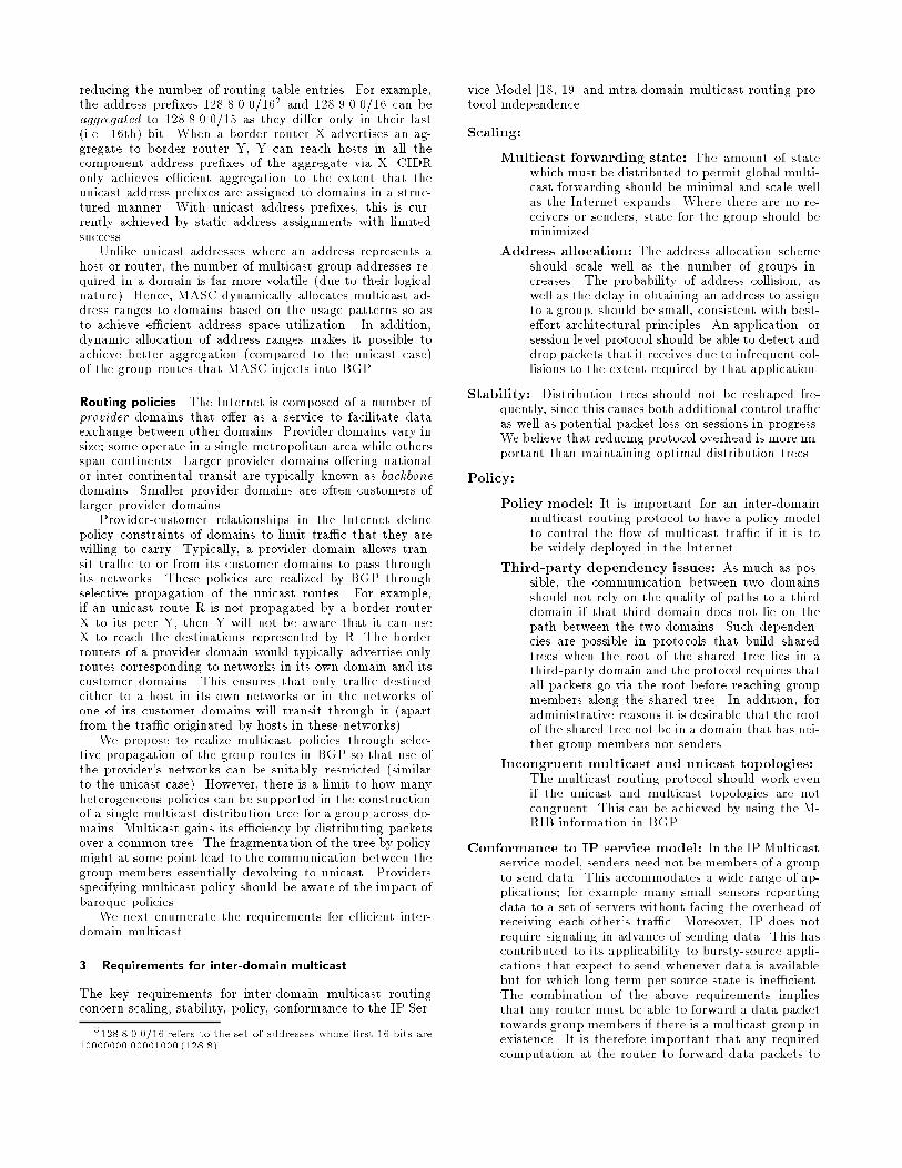
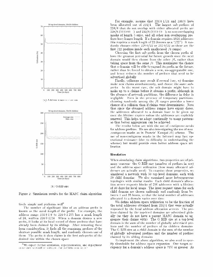
Figure 2: Simulation results for the MASC claim algorithm
tively simple and performs well6.The number of signi�cant bits of an address pre�x is
known as the mask length of the pre�x. For example, theaddress range 224.0.1.0 to 224.0.1.255 has a mask lengthof 24, written 224.0.1/24. When a domain desires a newpre�x, it looks at its local record of those pre�xes that havealready been claimed by its siblings. After removing thesefrom consideration, it �nds all the remaining pre�xes of theshortest possible mask length, and randomly chooses one ofthem. The pre�x it then claims is the �rst sub-pre�x of thedesired size within the chosen space.
6We expect further simulation, experimentation, and deploymentexperience to result in versions that perform even better.
For example, assume that 224.0.1/24 and 239/8 havebeen allocated out of 224/4. The largest sub-pre�xes of224/4 that do not overlap with either allocated pre�x are228/6 (1110 01...) and 232/6 (1110 10...); no non-overlappingmasks of length 5 exist, and all other non-overlapping pre-�xes have longer length. If a domain requires 1024 addressesthis requires a mask length of 22 (known as a \/22"). It ran-domly chooses either 228.0/22 or 232.0/22 as these are the�rst /22 pre�xes inside each unallocated /6 range).
Choosing the �rst sub-pre�x from the chosen pre�x al-lows the greatest potential for future growth since the nextdomain would then choose from the other /6, rather thantaking space from the same /6. This maximizes the chancethat a domain will be able to expand its pre�x in the future,rather than be forced to obtain a new, un-aggregatable one,and hence reduces the number of pre�xes that need to beadvertised globally.
Finally, collisions may result if several (say, n) domainsmake new claims simultaneously, and choose the same sub-pre�x. In the worst case, the nth domain might have tomake up to n claims before it obtains a pre�x, although inthe absence of network partitions, the di�erence in delay isnegligible. Even in the presence of temporary partitions,choosing randomly among the /6 ranges provides a lowerchance of a collision than if claims were deterministic. Notethat since the obtained address ranges have expiry dates,the addresses allocated to a domain have to be given uponce the lifetime expires unless the addresses are explicitlyrenewed. This helps us adapt continually to usage patternsso that better aggregation can be achieved.
The results below are with the use of contiguous masksfor address pre�xes. We are also investigating the use of non-contiguous masks as in Francis' Kampai[21] scheme. Theuse of non-contiguous masks in the Internet may face op-erational resistance (due to di�culty in understanding thescheme) but would provide even better address space uti-lization.
Simulation
When simulating claim algorithms, two properties are of pri-mary concern: the G-RIB size (number of pre�xes in use)and the address space utilization (how many allocated ad-dresses are actually used). To examine these properties, wesimulated a network with 50 top-level domains, each with50 child domains. We also examined more heterogeneoustopologies with similar results. Each child domain's alloca-tion server requests blocks of 256 addresses with a lifetimeof 30 days for local usage. The inter-request times for eachchild domain are chosen uniformly and randomly from be-tween 1 and 95 hours, so that the total number of addressesallocated to a domain varies over time.
We de�ne address space utilization to be the fraction ofthe total addresses obtained from 224/4 that were actuallyrequested by the local address allocation servers. The pre-�xes claimed by the top-level domains are advertised glob-ally (as they do not have a parent MASC domain to ag-gregate their claims with). The G-RIB size at a top-leveldomain is the sum of the number of globally advertised pre-�xes and the number of pre�xes of its children domains.The G-RIB size at a child domain is the sum of the numberof globally advertised pre�xes and the number of pre�xesclaimed by its sibling domains.
To implement the above algorithm, we also need to spec-ify thresholds for address space expansion. Our target oc-cupancy for a domain's address space is 75% or greater. At
the same time, we attempt to keep the number of pre�xesper domain to no more than two. We term a domain's pre-�x to be active if addresses from the pre�x's range will beassigned to new groups in the domain. Otherwise the pre�xis termed inactive. When a domain receives a demand formore addresses that it cannot satisfy, we allow it to eitherdouble one of its active pre�xes, or to claim an additionalsmall pre�x that is just su�cient to satisfy the demand. Wedouble an active pre�x if the total demand for addresses issuch that after doubling this pre�x, utilization of the do-main's entire address space will be at least 75%. Typicallythis means that when we have more than one active pre�x,we double the smallest one. If a domain has two or moreactive pre�xes and none of them can be expanded, a singlenew pre�x large enough to accommodate the current usageis claimed, if possible. If the domain succeeds in claimingthis new pre�x, the old pre�xes are made inactive and willtimeout when the currently allocated addresses timeout.
The results of this simulation are shown in �gure 2(a).They indicate the utilization and G-RIB size over time fromthe start of the simulation. At the left hand side of bothgraphs a startup transient is observed caused by the veryrapid increase in demand for addresses. After 30 days, thetotal demand for addresses has stabilized, and the G-RIBsize then reduces rapidly as pre�xes are recycled and aggre-gation can take place. Utilization rapidly converges to 50%,and the G-RIB size reaches a mean of 175 group routes,and does not exceed 180 group routes. It should be notedthat the total number of child domains is 2500, and in thesteady state there are 37500 requests for address blocks be-ing satis�ed, so this indicates extremely good aggregation.The 50% utilization is due in part to the choice of a 75%threshold at each level in this two level hierarchy. Results inthis range should be acceptable for wide-scale deploymentin the Internet.
4.3.4 Robustness
We have avoided centralized control in the MASC protocol.We believe this decentralization contributes to the overallrobustness of the scheme, just as it does to the robustnessof the Internet. The MASC hierarchy con�guration rules aresimple and are decided locally by bilateral agreements be-tween domains, just as in BGP. For example, a domain canchoose any of its provider domains to be its parent. Withinthis context, there were two options for the claim mecha-nism. One was the claim-collide mechanism we described insection 4.1, and the other was a query-response mechanismwhere a domain would acquire an unique address pre�x byquerying its parent domain.
We chose the claim-collide mechanism for reasons of pol-icy, simplicity, and robustness. The top-level domains inthe MASC hierarchy are typically backbone domains thatare not customers of other domains. For policy reasons, thearchitecture should not require that any one of the top-leveldomains be speci�ed as the root of the hierarchy. At thetop-most level, there is no clear reason for a domain to bethe parent of all the other top-level domains or for the top-level domains to accept someone as their parent. Using aquery-response mechanism would however require a singleroot and introduce a third-party dependency at the top-level. Therefore, we chose to make the top-level domainsclaim from the entire multicast address space, 224/4. Lowerin the hierarchy, parent-child relationships do exist, and fol-low the provider-customer relationships where there are pay-ment agreements to enable the customer domain access the
Internet. Given the use of a claim-collide mechanism amongthe top-level domains, and given the uid nature of networktopologies, it appears simpler and more robust to have acommon mechanism at all levels.
A query-response mechanism would also require redun-dant servers within a domain for robustness, introducing ad-ditional problems of synchronization. Besides, this mecha-nism would still need to handle address collisions that mightoccur due to network partitions. Hence, our proposed claim-collide mechanism appears simpler and more robust than aquery-response mechanism.
4.4 Start-up phase behavior
Start-up behavior is based on the same rules as those used insteady state. The entire multicast address space is initiallypartitioned among one or more Internet exchange points 7
(say, one per continent). MASC nodes at each exchange arebootstrapped to advertise its portion of the address space.All the MASC domains hear these advertisements and pickan address subrange, the size of which depends on their cur-rent address requirements. Backbone providers with no par-ent then pick the pre�x of a nearby exchange (either one towhich they connect, or one which they are con�gured to use)as their \parent's" pre�x. Since this involves no parent-childMASC peerings at the top level, this approach minimizesthird-party dependencies.
Top-level providers can then claim a small amount ofspace, which then grows as their children issue claims as de-scribed earlier. Alternatively, a top-level provider could ini-tially wait for some period of time before claiming space, andjust propagate its parent's group route to its own children.After listening to children's claims, it could then estimatethe amount of address space needed to satisfy its children'srequirements and then claim address ranges su�ciently largeto satisfy their needs. However, to achieve aggregatability,the parent domains would then need to send back collisionannouncements to any children whose claims fall outside theparent's newly acquired space, forcing the children to pickup new address ranges.
We next describe how BGMP uses the G-RIB informa-tion to build inter-domain multicast distribution trees for agroup.
5 Inter-domain distribution tree construction using BGMP
BGMP is run by domain border routers to construct aninter-domain shared tree for a group. The border routersalso participate in protocols such as DVMRP and PIM run-ning within each domain. Such intra-domain multicast rout-ing protocols are also known as Multicast Interior GatewayProtocols (MIGPs). The portion of the border router run-ning an MIGP is referred to as the MIGP component andthe portion running BGMP as the BGMP component.
As in the example in section 4.2, we assume that BGP'sroute selection algorithm ensures that one border router ischosen as the best exit router for each group route. Thisrouter has an external peer as its next hop towards a group'sroot domain, while all other border routers have the best exitrouter as their BGP next hop. When a host in the domainjoins a new group whose root domain is elsewhere in theInternet, the BGMP component of the best exit router is in-formed by the domain's MIGP. The rules to achieve this are
7The Internet exchange points are neutral locations where thelarger providers such as backbones interconnect with each other (e.g.,MAE-East in Washington, D.C. and LINX in London).
MIGP-speci�c. For example, in DVMRP, a Domain WideReport [22] is sent to the MIGP components of the domain'sborder routers, including the exit border router, when a hostjoins a new group. The MIGP component of the best exitrouter passes a join request to the BGMP component, whichsends a BGMP group join message to the next hop towardsthe root domain. These join messages set up multicast for-warding state in the intermediate border routers as theypropagate across various domains towards the root domain,establishing the shared tree for the group.
When a group's root domain is external, multicast datapackets reach the group's best exit router using MIGP spe-ci�c rules. In DVMRP, for example, data packets are ini-tially ooded throughout the domain and so reach all theborder routers. The border routers that are not the group'sexit router send DVMRP prune messages back towards thesource, ensuring that only the exit border router continuesto get data packets for that group. The best exit routerforwards the packets along the inter-domain shared tree toreach group members in other domains. Since in IP Mul-ticast, senders need not be members of the group, the bestexit router might receive data packets destined to a groupeven though it has not previously received a group join re-quest. In this case, the border router simply forwards thedata packets towards the root domain, and when they reacha router that is on the group's shared tree, they are dis-tributed to the members.
In the following sections, we discuss the key design choicesmade for BGMP, and present some protocol details. Thedesign choices made in BGMP address the requirements forinter-domain multicast which are typically di�erent from theintra-domain case. Protocols like CBT and PIM-SM buildshared trees among their group members, but the mech-anisms used to build these trees are better suited for theintra-domain case, and do not apply as well when used forinter-domain multicast. We explain in the following sec-tions why some of the corresponding choices made for intra-domain multicast routing do not apply well to inter-domainmulticast. We also present simulation results to comparethe quality of the distribution trees built by the di�erentmulticast routing protocols.
5.1 Location of the root of the shared-tree
The choice of a group's shared-tree root has important pol-icy and performance implications in the inter-domain case.In the intra-domain case, all routers that are willing to bethe root are treated the same, and one is chosen, typicallyby hashing the group address over the set of routers. Thisis well suited to the intra-domain case where the empha-sis is more on load sharing, and where the penalty of non-optimally rooted trees is not signi�cant. In the inter-domaincase, however, all potential roots cannot be treated as equiv-alent, since there are administrative issues concerning theownership of the root, and there is also a much greaterchance of poor locality.
We therefore adopt an approach where the root of theshared tree is selected based on administrative and per-formance constraints. The shared tree built by BGMP isrooted at the root domain for the group, which is the do-main whose multicast address allocation includes the groupaddress. Since a group initiator typically gets a group ad-dress from its domain's address range, the group initiator'sdomain is normally also the group's root domain.
The root's location a�ects performance since a root thatis located poorly with respect to the senders and group mem-
bers can lead to long paths between them. If the group's ini-tiator sources a signi�cant portion of the data, the root do-main in BGMP is located reasonably optimally because theshortest-path tree from the receivers to the most signi�cantsender now coincides with the shared tree for the group8 .For example, the multicast session for a NASA space shut-tle broadcast would have the shared tree rooted in NASA'sdomain. The root would be reasonably optimal for all re-ceivers as they would receive packets from NASA along theshortest path from them to the sender.
A disincentive for a domain to claim an excessive amountof addresses in MASC is that it would then be the root do-main for all the covered groups. There is also an incen-tive for domains to claim su�ciently large address ranges,which is that groups initiated locally can get multicast ad-dresses from the domain's range, thereby making them lo-cally rooted. We believe that these two competing factorswill lead to some equilibrium for the size of the addressranges claimed by a domain; however, this is an area thatrequires further investigation.
We do not try to have BGMP form optimally rooteddistribution trees as the multicast group memberships arefairly dynamic. Frequent reshaping of the distribution treesas members join and leave can cause data loss and highcontrol tra�c overhead.
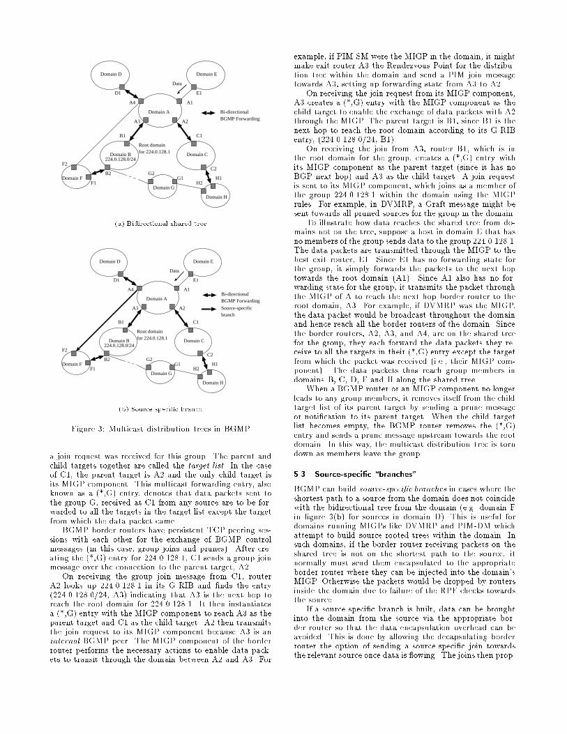
5.2 Bidirectional trees
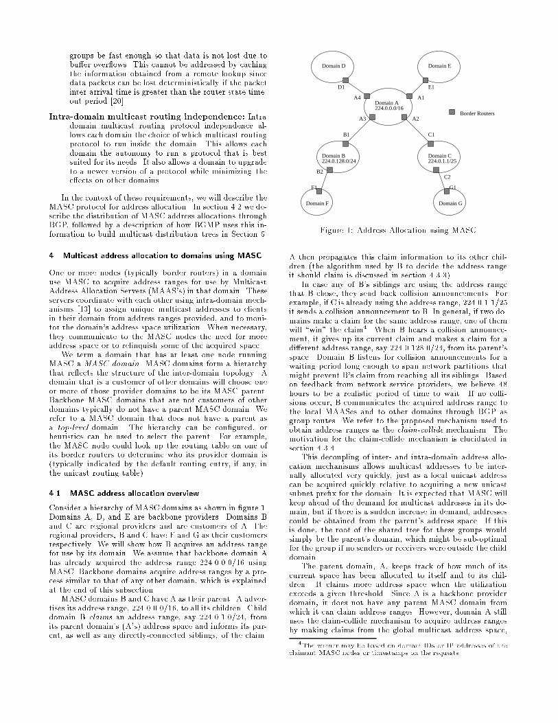
BGMP, like CBT[6, 7], builds bidirectional group-sharedtrees to minimize third-party dependencies and improve per-formance. For example, in �gure 3(a), members in domainsC and D can communicate with each other along the bidi-rectional tree without depending on the quality of their con-nectivity to the root domain, B. This is also more e�cientbecause of the shorter paths taken. In contrast, PIM-SMbuilds unidirectional shared trees for a group, where datafrom senders has to travel up to the root and then down theshared tree to all the members. This approach would intro-duce third-party dependencies and potentially poor perfor-mance if applied at the inter-domain level.
In section 5.4, we present simulation results to comparethe path lengths from senders to receivers in unidirectionaltrees built by PIM-SM to the bidirectional trees built byBGMP. We next illustrate BGMP bidirectional tree con-struction through an example.
Establishing the bidirectional shared treeConsider a multicast group created by a host in do-
main B in �gure 3(a). Since the host acquires the address224.0.128.1 from B's address range, B will be the group'sroot domain. When a host in domain C now joins this group,a join request is received from the MIGP by the BGMP com-ponent of the best exit router for 224.0.128.1, namely C1.
C1 looks up 224.0.128.1 in its G-RIB, �nds (224.0.0.0/16,A2), and creates a multicast-group forwarding entry consist-ing of a parent target and a list of child targets. The parenttarget identi�es the BGMP peer that is the next hop to-wards the group's root domain9 . A child target identi�eseither a BGMP peer or an MIGP component from which
8Note that the shortest-path trees built by multicast routing pro-tocols are actually reverse shortest-path trees; i.e., data from thesenders ows along the shortest path from the receivers to the senders.If unicast routing is symmetric, this would be the shortest path fromthe senders to the receivers. Using reverse paths avoids the need toenumerate all the receivers.
9In case the BGMP peer is internal to the domain, the parenttarget is the MIGP component of the border router.
Domain A
Domain D Domain E
A3 A2
A4 A1
E1D1
Bi-directionalBGMP Forwarding
Data
224.0.128.0/24Domain B Domain C
Domain H
Domain F
B1 C1
C2
H1F1
B2
Root domainfor 224.0.128.1
F2
Domain GH2
G1G2
(a) Bidirectional shared tree
Domain A
Domain D Domain E
A3 A2
A4 A1
E1D1
Data
224.0.128.0/24Domain B Domain C
Domain H
Domain F
B1 C1
C2
H1F1
B2
Root domainfor 224.0.128.1
F2
Domain GH2
G1G2
Bi-directionalBGMP Forwarding
Source-specificbranch
(b) Source-speci�c branch
Figure 3: Multicast distribution trees in BGMP
a join request was received for this group. The parent andchild targets together are called the target list. In the caseof C1, the parent target is A2 and the only child target isits MIGP component. This multicast forwarding entry, alsoknown as a (*,G) entry, denotes that data packets sent tothe group G, received at C1 from any source are to be for-warded to all the targets in the target list except the targetfrom which the data packet came.
BGMP border routers have persistent TCP peering ses-sions with each other for the exchange of BGMP controlmessages (in this case, group joins and prunes). After cre-ating the (*,G) entry for 224.0.128.1, C1 sends a group joinmessage over the connection to the parent target, A2.
On receiving the group join message from C1, routerA2 looks up 224.0.128.1 in its G-RIB and �nds the entry(224.0.128.0/24, A3) indicating that A3 is the next hop toreach the root domain for 224.0.128.1. It then instantiatesa (*,G) entry with the MIGP component to reach A3 as theparent target and C1 as the child target. A2 then transmitsthe join request to its MIGP component because A3 is aninternal BGMP peer. The MIGP component of the borderrouter performs the necessary actions to enable data pack-ets to transit through the domain between A2 and A3. For
example, if PIM-SM were the MIGP in the domain, it mightmake exit router A3 the Rendezvous-Point for the distribu-tion tree within the domain and send a PIM join messagetowards A3, setting up forwarding state from A3 to A2.
On receiving the join request from its MIGP component,A3 creates a (*,G) entry with the MIGP component as thechild target to enable the exchange of data packets with A2through the MIGP. The parent target is B1, since B1 is thenext hop to reach the root domain according to its G-RIBentry, (224.0.128.0/24, B1).
On receiving the join from A3, router B1, which is inthe root domain for the group, creates a (*,G) entry withits MIGP component as the parent target (since it has noBGP next hop) and A3 as the child target. A join requestis sent to its MIGP component, which joins as a member ofthe group 224.0.128.1 within the domain using the MIGPrules. For example, in DVMRP, a Graft message might besent towards all pruned sources for the group in the domain.
To illustrate how data reaches the shared tree from do-mains not on the tree, suppose a host in domain E that hasno members of the group sends data to the group 224.0.128.1.The data packets are transmitted through the MIGP to thebest exit router, E1. Since E1 has no forwarding state forthe group, it simply forwards the packets to the next hoptowards the root domain (A1). Since A1 also has no for-warding state for the group, it transmits the packet throughthe MIGP of A to reach the next hop border router to theroot domain, A3. For example, if DVMRP was the MIGP,the data packet would be broadcast throughout the domainand hence reach all the border routers of the domain. Sincethe border routers, A2, A3, and A4, are on the shared treefor the group, they each forward the data packets they re-ceive to all the targets in their (*,G) entry except the targetfrom which the packet was received (i.e., their MIGP com-ponent). The data packets thus reach group members indomains B, C, D, F and H along the shared tree.
When a BGMP router or an MIGP component no longerleads to any group members, it removes itself from the childtarget list of its parent target by sending a prune messageor noti�cation to its parent target. When the child targetlist becomes empty, the BGMP router removes the (*,G)entry and sends a prune message upstream towards the rootdomain. In this way, the multicast distribution tree is torndown as members leave the group.
5.3 Source-speci�c \branches"
BGMP can build source-speci�c branches in cases where theshortest path to a source from the domain does not coincidewith the bidirectional tree from the domain (e.g. domain Fin �gure 3(b) for sources in domain D). This is useful fordomains running MIGPs like DVMRP and PIM-DM whichattempt to build source-rooted trees within the domain. Insuch domains, if the border router receiving packets on theshared tree is not on the shortest path to the source, itnormally must send them encapsulated to the appropriateborder router where they can be injected into the domain'sMIGP. Otherwise the packets would be dropped by routersinside the domain due to failure of the RPF checks towardsthe source.
If a source-speci�c branch is built, data can be broughtinto the domain from the source via the appropriate bor-der router so that the data encapsulation overhead can beavoided. This is done by allowing the decapsulating borderrouter the option of sending a source-speci�c join towardsthe relevant source once data is owing. The joins then prop-
agate until they hit either a branch of the bidirectional treeor the source domain. A source-speci�c prune is sent backto the encapsulating border router, which can then propa-gate it up the shared tree to prevent unnecessary copies ofthe packet arriving.
Source-speci�c branches di�er from source-speci�c short-est path trees built by some MIGPs in that the source-speci�c branch stops where it reaches either a BGMP routeron the bidirectional tree or the source domain. In shortest-path trees, the source-speci�c state is set up all the way backto the source. BGMP does not support source-speci�c treesbecause of their incompatibility with bidirectional sharedtrees. There are some scenarios in which persistent dupli-cation of data packets can occur when both source-speci�ctrees and bidirectional shared trees intersect 10. Fortunately,the di�erence in path lengths between source-speci�c dis-tribution trees and bidirectional trees is less signi�cant forthe inter-domain case. The inter-domain topology is sparserthan the intra-domain topologies, so that the path lengthsand tra�c concentration properties of the bidirectional sharedtree are more acceptable (see Section 5.4). Source-speci�cbranches are thus used primarily to stop data encapsulation.
We next illustrate the establishment of a source-speci�cbranch through an example (see �gure 3(b)).
Establishing a source-speci�c branch from FSuppose there are members of a group 224.0.128.1 in
domains B, C, D, F, and H, and B is the root domain forthe group (see �gure 3(b)). The bidirectional shared tree isset up as shown in the �gure. Domain F has an inter-domainlink to domain A via border router F2. Hence, the shortestpath from domain F to hosts in D is through F2. F runsDVMRP as its MIGP, which implies that internal routerswill only accept packets from a source which they receivefrom their neighbor towards that source. Since only F1 ison the bidirectional shared tree, data from a source S indomain D will be received by F1. F1 must then encapsulatethe data packets to F211 in order to avoid internal RPFcheck failures. F2 then injects the data into the DVMRP
10Duplication or loss of data packets may occur depending on therules used in forming the outgoing interface (oif) list for a source-speci�c (S,G) entry when a shared tree (*,G) entry also exists at therouter for the group. When both (S,G) and (*,G) entries exist ata router, the router will forward packets from source S that arriveon the RPF interface to S only to the oifs listed in the (S,G) entry.Hence if the oif list from a (*,G) entry is not copied to a (S,G) entrythen data packets from S will consistently not be delivered to somereceivers. Let us consider the case where the oif list of the (*,G)entry is copied to the (S,G) entry. Suppose domain D (in �gure 3(a))establishes source-speci�c state to domain H so that receivers in D canreceive packets along the shortest path (according to unicast routing)from a source, S in domain H. The shortest path between domainsH and D happens to be via domains A, B and G (note that inter-domain unicast routing is policy based and hence the shortest pathbetween domains according to unicast routing may not be the sameas the path with the smallest number of inter-domain hops). Thisaction will cause receivers in some domains like C to get duplicatepackets from the source in H - one copy from source in H on thebidirectional tree and another copy while the packet travels along thesource-speci�c tree via G and B to A and then down the bidirectionaltree to C. The rules required for an appropriate border router ofdomain C to generate prunes to stop getting such duplicates seemtoo complex or have high state or forwarding overhead in the moregeneral case. Hence BGMP allows only source-speci�c branches whenthe source-speci�c trees intersect with the bidirectional shared treefor a group. In BGMP, the source-speci�c join received at D1 frominternal receivers is not propagated further by D1 since it is alreadyon the shared tree for the group.11F1 knows that the path through F2 is the shortest path to reach
the source in D from its BGP routing tables, since F2 is the best exitrouter for the route to S.
1
2
3
4
5
6
0 200 400 600 800 1000
Rat
io
Number of receivers
Path length overhead (SPT = 1.0)
Unidirectional Tree (max)Bidirectional Tree (max)
Hybrid Tree (max)Unidirectional Tree (ave)Bidirirectional Tree (ave)
Hybrid Tree (ave)
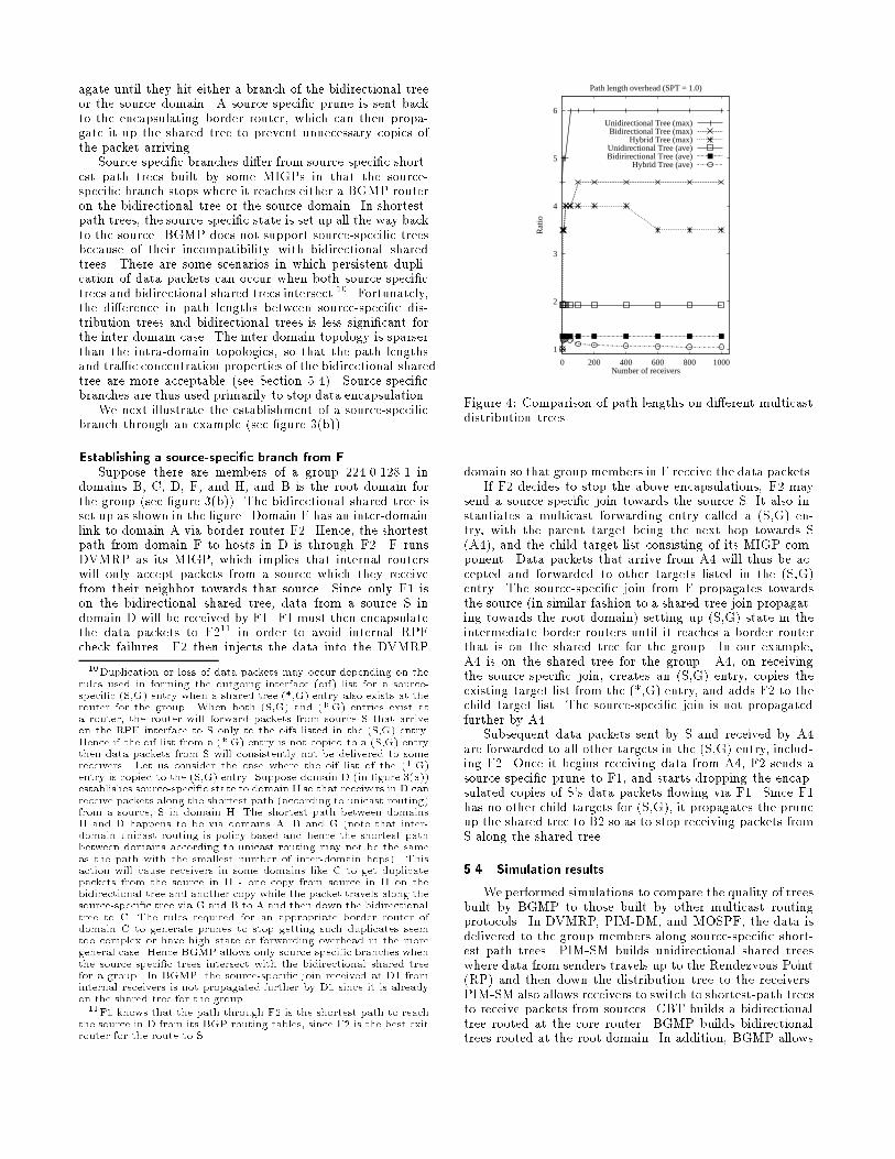
Figure 4: Comparison of path lengths on di�erent multicastdistribution trees
domain so that group members in F receive the data packets.If F2 decides to stop the above encapsulations, F2 may
send a source-speci�c join towards the source S. It also in-stantiates a multicast forwarding entry called a (S,G) en-try, with the parent target being the next hop towards S(A4), and the child target list consisting of its MIGP com-ponent. Data packets that arrive from A4 will thus be ac-cepted and forwarded to other targets listed in the (S,G)entry. The source-speci�c join from F propagates towardsthe source (in similar fashion to a shared-tree join propagat-ing towards the root domain) setting up (S,G) state in theintermediate border routers until it reaches a border routerthat is on the shared tree for the group. In our example,A4 is on the shared tree for the group. A4, on receivingthe source-speci�c join, creates an (S,G) entry, copies theexisting target list from the (*,G) entry, and adds F2 to thechild target list. The source-speci�c join is not propagatedfurther by A4.
Subsequent data packets sent by S and received by A4are forwarded to all other targets in the (S,G) entry, includ-ing F2. Once it begins receiving data from A4, F2 sends asource-speci�c prune to F1, and starts dropping the encap-sulated copies of S's data packets owing via F1. Since F1has no other child targets for (S,G), it propagates the pruneup the shared tree to B2 so as to stop receiving packets fromS along the shared tree.
5.4 Simulation results
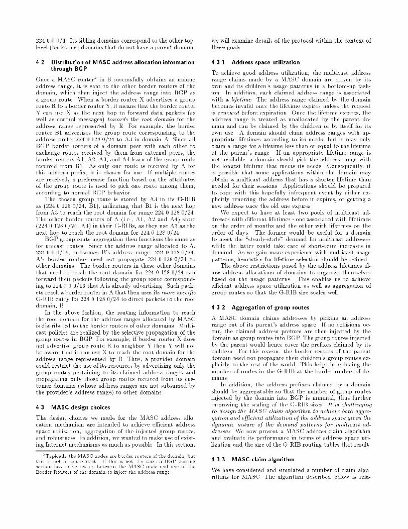
We performed simulations to compare the quality of treesbuilt by BGMP to those built by other multicast routingprotocols. In DVMRP, PIM-DM, and MOSPF, the data isdelivered to the group members along source-speci�c short-est path trees. PIM-SM builds unidirectional shared treeswhere data from senders travels up to the Rendezvous Point(RP) and then down the distribution tree to the receivers.PIM-SM also allows receivers to switch to shortest-path treesto receive packets from sources. CBT builds a bidirectionaltree rooted at the core router. BGMP builds bidirectionaltrees rooted at the root domain. In addition, BGMP allows
source-speci�c branches to be built by the domains. We re-fer to the tree built by BGMP consisting of the bidirectionaltree and the source-speci�c branches as a hybrid tree.
We compare the path lengths on the di�erent types ofinter-domain multicast distribution trees constructed by theabove protocols (i.e., shortest path, unidirectional shared,bidirectional shared and hybrid trees). The path length be-tween a source and a receiver of a group in the simulations isthe number of inter-domain hops in the path between them.
Our topology12 of 3326 nodes was derived from a dump13
of the BGP routing tables at 15 routers located at the majorbackbones and network exchange points in the Internet. Westudied the variation in path length from a source selectedrandomly to all the receivers of the group as the group sizewas increased from 1 to 1000 (see �gure 5.4). The averagepath lengths from the source to the receivers were less than20% longer (with a maximum di�erence of 4 times in theworst case) on a hybrid tree where source-speci�c brancheswere established from the receivers to the source, comparedto that on the shortest-path tree. The bidirectional treeswithout the source-speci�c branches had path lengths thatwere less than 30% longer (maximum di�erence of 4.5 times)to that on the shortest-path trees. The unidirectional treesperformed much worse compared to the bidirectional trees,with their average path lengths being about twice that ofthe shortest-path trees (maximum worst case path lengthsup to 6 times that of the shortest-path trees).
6 Related work
HPIM[23] builds on PIM-SM by using a hierarchy of RPsfor a group. A receiver would send joins to the lowest levelRP, which in turn would join a RP at the next level, and soon. The number of levels in the hierarchy depends on thescope of the multicast group. Data from senders ows alongthe branches of this tree in a bidirectional manner to reachreceivers. However, as HPIM uses hash functions to choosethe next RP at each level, the trees can be very bad in theworst case, especially for global groups.
OCBT[24] is a proposed extension to CBT where a hier-archy of cores is used for a group on the lines of HPIM. BothHPIM and OCBT do not allow MIGP independence; i.e., itis not possible to run an arbitrary MIGP inside the domain,and run HPIM or OCBT only for inter-domain multicast.HPIM and OCBT also do not explicitly address policy con-straints of domains.
HDVMRP[25] has been proposed as an inter-region (ordomain) routing protocol that interconnects regions run-ning any of the existing multicast protocols. HDVMRP oods data packets to the boundary routers of all regionsand boundary routers that are not part of the group sendprunes towards the source region to stop getting packets.Like DVMRP, HDVMRP still su�ers from the overhead ofbroadcasting packets to parts of the network where thereare no members. In addition, the memory requirements arehigh, as each boundary router must maintain state for eachsource sending to each group. HDVMRP also requires en-capsulating data packets for them to transit a domain, whichadds additional undesirable overhead.
In the area of multicast addressing, Sassan et al.[26] haveproposed assigning group addresses based on the IP address
12We have performed simulations with other generated topologiesas well. The simulation results for these topologies are available athttp://netweb.usc.edu/bgmp/sim-results.13The routing table dumps were obtained from the Oregon Ex-
change BGP Route Viewer, route-views.oregon.ix.net
of the host and the port number of the application on thathost initiating the group. The resulting group address is 6bytes long. In order to perform multicast routing, all themulticast routers would have to be changed to recognizethese extended addresses.
Braudes and Zabele have outlined an hierarchical ad-dress allocation scheme in [27]. However they use the query-response mechanism with a single root for the hierarchy thatwe believe is not well suited for the Internet.
7 Open Issues and Conclusions
The primary open issues in our architecture that requirefurther investigation involve incentives in MASC, the MASCclaim algorithm, address allocation interface, scaling BGMPforwarding state and authentication mechanisms.
Incentives in MASC:
Restricting number of top-level domains: Thereare many open issues with respect to who be-comes a top-level domain, and the incentives tobe provided for appropriate self-selection. Poorbehaviour can lead to poor scaling.
\Fair" address space utilization: We would likeMASC to provide disincentives to domains to pre-vent them from claiming too large an addressrange, as this may starve other domains of ad-dresses. A possible enforcement mechanism is fora parent domain to send back explicit collisionswhen a child claims too large a range. At thetop-level, collisions could be sent by the siblingdomains whenever a top-level domain claims toolarge a range. However, we lack an appropriatede�nition for \too large". We similarly need in-centives for top-level domains to choose addressranges with reasonable lifetimes.
MASC claim algorithm: The algorithm used by domainsto claim address ranges, while achieving good addressspace utilization and aggregation of group routes, needsto be studied more. The performance of the algorithmcould be improved by the use of non-contiguous masksas in Tsuchiya's Kampai[21] scheme.
Address allocation interface: It may be desirable to al-low a group initiator to pick a group address such thatthe resulting tree is rooted in another domain. Thismight be the case if, for example, the initiator knewthat either the dominant sources would be located else-where, or that the initiator would be moving to an-other domain by the time the session begins. If thereis su�cient demand for this capability, the interface bywhich a group initiator could obtain an address fromanother domain would need to be designed.
Scaling forwarding entries: We need mechanisms to en-able the size of the multicast forwarding tables scalewell to large numbers of groups. BGMP has provi-sions for this by allowing (*,G-pre�x) and (S-pre�x,G-pre�x) state to be stored at the routers wherever thelist of targets are the same. Its e�ectiveness will de-pend on the location of the group members and sourcesto those groups.
Authentication mechanisms: In general, authenticationmechanisms are needed in our architecture. These
mechanisms are especially important in the enforce-ment of disincentives in MASC.
We have presented an architecture for global Internetmulticast addressing and routing. The MASC protocol dy-namically allocates address ranges to domains with set life-times. These are distributed as group routes by BGP to allthe domains, where they are used by BGMP to determinethe root of the inter-domain multicast distribution tree foreach group. By default, these shared trees are rooted at thegroup initiator's domain.
Our architecture allows MIGP independence; within eachdomain, any multicast routing protocol can be used. In ad-dition, mechanisms are provided to realize policies to controlthe multicast tra�c owing through a domain. There is nocentralized control in our architecture. The peerings be-tween domains required by MASC and BGMP are decidedlocally by a domain through bilateral or payment agree-ments with other domains, and hence conform to the currentInternet administrative model.
8 Acknowledgements
Many people have contributed to the basic ideas and haveprovided detailed comments on the design of this architec-ture. We particularly appreciate the valuable comments andsuggestions from Steve Deering, George Eddy, Dino Fari-nacci, Bill Fenner, Ramesh Govindan, Jeremy Hall, Van Ja-cobson, David Meyer and the anonymous SIGCOMM re-viewers.
References
[1] S. Deering. Multicast Routing in a Datagram Internet-work. PhD thesis, Stanford University, 1991.
[2] S. Deering and D. Cheriton. Multicast routing in data-gram internetworks and extended lans. ACM Transac-
tions on Computer Systems, pages 85{111, May 1990.
[3] D. Waitzman, S. Deering, C. Partridge. Distance Vec-tor Multicast Routing Protocol. RFC-1075, November1988.
[4] S. Deering, D. Estrin, D. Farinacci, V. Jacobson, A.Helmy, L. Wei. Protocol Independent Multicast Version2, Dense Mode Speci�cation. Internet Draft, May 1997.Work in progress.
[5] J. Moy. Multicast Extensions to OSPF. RFC-1584,March 1994.
[6] A. Ballardie, P. Francis, J. Crowcroft. Core BasedTrees. In Proc. of the ACM SIGCOMM, San Francisco,September 1993.
[7] A. Ballardie. Core Based Trees (CBT Version 2) Mul-ticast Routing - Protocol Speci�cation. RFC-2189,September 1997.
[8] S. Deering, D. Estrin, D, Farinacci, V. Jacobson, C.Liu, L. Wei. An architecture for wide-area multicastrouting. In Proc. of the ACM SIGCOMM, London,UK, September 1994.
[9] D. Estrin, D. Farinacci, A. Helmy, D. Thaler, S. Deer-ing, M. Handley, V. Jacobson, C. Liu, P. Sharma, L.Wei. Protocol Independent Multicast - Sparse Mode(PIM-SM): Protocol Speci�cation. RFC-2117, June1997.
[10] M. Handley. On Scalable Internet Multimedia Con-ferencing Systems. PhD thesis, University of London,1997.
[11] D. Estrin, M. Handley, S. Kumar, D. Thaler. The Mul-ticast Address Set Claim (MASC) Protocol. InternetDraft, November 1997. Work in progress.
[12] D. Thaler, D. Estrin, D. Meyer. Border Gateway Multi-cast Protocol (BGMP): Protocol Speci�cation. InternetDraft, March 1998. Work in progress.
[13] M. Handley, D. Thaler, D. Estrin. The Internet Mul-ticast Address Allocation Architecture. Internet Draft,December 1997. Work in progress.
[14] Christian Huitema. Routing in the Internet. PrenticeHall, 1995.
[15] Y. Rekhter and T. Li. A border gateway protocol 4(bgp-4). RFC-1771, March 1995.
[16] T. Bates, R. Chandra, D. Katz, Y. Rekhter. Multipro-tocol Extensions for BGP-4. Internet Draft, January1998. Work in progress.
[17] V. Fuller, T. Li, J. Yu, K. Varadhan. Classless Inter-Domain Routing (CIDR): an Address Assignment andAggregation Strategy. RFC-1519, September 1993.
[18] J. Postel. Internet Protocol. RFC-791, September 1981.
[19] S. Deering. Host extensions for IP Multicasting. RFC-1112, August 1989.
[20] D. Estrin, M. Handley, A. Helmy, P. Huang, D. Thaler.A Dynamic Bootstrap Mechanism for Rendezvous-based Multicast Routing. Technical Report USC CSTR97-644, University of Southern California, 1997.
[21] Paul Tsuchiya. E�cient and Flexible Hierarchical Ad-dress Assignment. INET92, pages 441{450, June 1992.
[22] W. Fenner. Domain Wide Multicast Group Member-ship Reports. Internet Draft, November 1997. Work inprogress.
[23] M. Handley, J. Crowcroft, I. Wakeman. HierarchicalProtocol Independent Multicast.ftp://cs.ucl.ac.uk/darpa/hpim.ps.
[24] C. Shields and J. J. Garcia-Luna-Aceves. The OrderedCore Based Tree Protocol. In Proc. of IEEE INFO-COM, Kobe, Japan, April 1997.
[25] A. Thyagarajan and S. Deering. Hierarchical Distance-Vector Multicast Routing for the Mbone. In Proc. of theACM SIGCOMM, Cambridge, Massachusetts, August1995.
[26] S. Pejhan, A. Eleftheriadis, D. Anastassiou. DistributedMulticast Address Management in the Global Internet.IEEE Journal on Selected Areas in Communications,pages 1445{1456, October 1995.
[27] R. Braudes and S. Zabele. Requirements for MulticastProtocols. RFC-1458, May 1993.