
A survey of application-layer multicast protocols
21
> REPLACE THIS LINE WITH YOUR PAPER IDENTIFICATION NUMBER (DOUBLE-CLICK HERE TO EDIT) < 1 Abstract—In light of the slow deployment of IP Multicast technology on the global Internet and the explosive popularity of peer-to-peer file-sharing applications, there has been a flurry of research activities investigating the feasibility of implementing multicasting capability at the application layer, referred to as Application Layer Multicasting (ALM), and numerous algorithms and protocols have been proposed. This article aims to provide researchers in the field with an understanding of ALM protocols by identifying significant characteristics, from both application requirements and networking points of view, and by using those characteristics as a basis for organizing the protocols into an integrated and well-structured format. Current trends and directions for further research are also presented. This article surveys the literature over the period 1995-2005 on different application layer multicasting approaches. Index Terms—Application layer multicast, IP multicast, multicast routing, peer-to-peer communication I. INTRODUCTION HE Internet was designed for and grew primarily due to the success of one-to-one applications such as reliable file transfer and electronic mail. Its growth however has fostered the emergence of new applications that are inherently one-to- many, such as video-on-demand and live media streaming; or many-to-many, such as video conferencing and multiplayer games. These applications put a strain on the available resources and make inefficient use of a one-to-one or in other words unicast-only infrastructure. The need for efficient support of one-to-many and many-to-many applications led to the proposal for the implementation of multicasting on the global inter-network called IP Multicast [1]. In essence, an IP Multicast capable network allows one or more sources to efficiently send data to a group of recipients [1] whereby the source transmits only one copy of the data and the appropriate network nodes efficiently make duplicate copies for each receiver. After a decade of research into the various issues of IP Multicasting such as routing, group management, address allocation, authorization and security, Quality of Service (QoS) and scalability, the widespread deployment of IP Multicast on the global inter-network has been dogged by technical, administrative and business related issues [2]. This is especially true with respect to Internet connections to homes provided by local Internet Service Providers (ISP) that very rarely allow home users the ability to be a part of an IP Multicast session. Therefore, there have been recent proposals to alternative group communication services that either grow out of the IP Multicast model and still support IP Multicasting or offer a competing model. El-Sayed et al give a survey of such proposals [3] where they present a survey of multicasting approaches alternative to classic IP Multicasting. These include using reflectors, permanent tunneling (e.g. MBONE), relying on specific routing services such as IPv6, and Application Layer Multicasting or automatic tunneling. In contrast to the general overview of all IP multicast alternatives presented in [3], our paper’s contribution is its survey on Application Layer Multicasting specifically and providing much greater details about existing trends and a much deeper discussion of ALM protocols. The motivation behind studying ALM, as opposed to the other proposed alternatives to IP Multicasting, is ALM’s practical success and deployability on today’s Internet, especially for home users, as demonstrated by file sharing applications such as Napster and Kazaa. Our approach here is to identify properties that are significant across the board for all applications and characterize the protocol architecture accordingly. These properties include application domain, group configuration, routing protocols, and other characteristics that typically lead to trade-offs in design decisions such as mesh-first approach versus tree-first approach (group management), minimum spanning tree or clustering structure (routing), multi-source versus single source (application domain), and many other characteristics. Our paper further contributes to the field by using the above- mention properties for categorizing ALM protocols based on these properties. As such, we define two sets of categorization. In one set, we first classify routing algorithms and their properties and then categorize the protocols based on the type of routing algorithm used. In the second set, we categorize the protocols based primarily on their application domain and group configuration, also taking into account other important characteristics. We begin our discussion with a background about multicasting. A. Multicasting Background In one-to-many or many-to-many communications, often a A Survey of Application-Layer Multicast Protocols Mojtaba Hosseini, Dewan Tanvir Ahmed, Shervin Shirmohammadi, and Nicolas D. Georganas Distributed & Collaborative Virtual Environments Research Laboratory (DISCOVER Lab), School of Information Technology and Engineering, University of Ottawa, Canada T
Transcript of A survey of application-layer multicast protocols
> REPLACE THIS LINE WITH YOUR PAPER IDENTIFICATION NUMBER (DOUBLE-CLICK HERE TO EDIT) <
1
Abstract—In light of the slow deployment of IP Multicast
technology on the global Internet and the explosive popularity of
peer-to-peer file-sharing applications, there has been a flurry of
research activities investigating the feasibility of implementing
multicasting capability at the application layer, referred to as
Application Layer Multicasting (ALM), and numerous
algorithms and protocols have been proposed. This article aims to
provide researchers in the field with an understanding of ALM
protocols by identifying significant characteristics, from both
application requirements and networking points of view, and by
using those characteristics as a basis for organizing the protocols
into an integrated and well-structured format. Current trends
and directions for further research are also presented. This
article surveys the literature over the period 1995-2005 on
different application layer multicasting approaches.
Index Terms—Application layer multicast, IP multicast,
multicast routing, peer-to-peer communication
I. INTRODUCTION
HE Internet was designed for and grew primarily due to
the success of one-to-one applications such as reliable file
transfer and electronic mail. Its growth however has fostered
the emergence of new applications that are inherently one-to-
many, such as video-on-demand and live media streaming; or
many-to-many, such as video conferencing and multiplayer
games. These applications put a strain on the available
resources and make inefficient use of a one-to-one or in other
words unicast-only infrastructure. The need for efficient
support of one-to-many and many-to-many applications led to
the proposal for the implementation of multicasting on the
global inter-network called IP Multicast [1]. In essence, an IP
Multicast capable network allows one or more sources to
efficiently send data to a group of recipients [1] whereby the
source transmits only one copy of the data and the appropriate
network nodes efficiently make duplicate copies for each
receiver. After a decade of research into the various issues of
IP Multicasting such as routing, group management, address
allocation, authorization and security, Quality of Service
(QoS) and scalability, the widespread deployment of IP
Multicast on the global inter-network has been dogged by
technical, administrative and business related issues [2]. This
is especially true with respect to Internet connections to homes
provided by local Internet Service Providers (ISP) that very
rarely allow home users the ability to be a part of an IP
Multicast session. Therefore, there have been recent proposals
to alternative group communication services that either grow
out of the IP Multicast model and still support IP Multicasting
or offer a competing model. El-Sayed et al give a survey of
such proposals [3] where they present a survey of multicasting
approaches alternative to classic IP Multicasting. These
include using reflectors, permanent tunneling (e.g. MBONE),
relying on specific routing services such as IPv6, and
Application Layer Multicasting or automatic tunneling. In
contrast to the general overview of all IP multicast alternatives
presented in [3], our paper’s contribution is its survey on
Application Layer Multicasting specifically and providing
much greater details about existing trends and a much deeper
discussion of ALM protocols. The motivation behind studying
ALM, as opposed to the other proposed alternatives to IP
Multicasting, is ALM’s practical success and deployability on
today’s Internet, especially for home users, as demonstrated by
file sharing applications such as Napster and Kazaa. Our
approach here is to identify properties that are significant
across the board for all applications and characterize the
protocol architecture accordingly. These properties include
application domain, group configuration, routing protocols,
and other characteristics that typically lead to trade-offs in
design decisions such as mesh-first approach versus tree-first
approach (group management), minimum spanning tree or
clustering structure (routing), multi-source versus single source
(application domain), and many other characteristics. Our
paper further contributes to the field by using the above-
mention properties for categorizing ALM protocols based on
these properties. As such, we define two sets of categorization.
In one set, we first classify routing algorithms and their
properties and then categorize the protocols based on the type
of routing algorithm used. In the second set, we categorize the
protocols based primarily on their application domain and
group configuration, also taking into account other important
characteristics. We begin our discussion with a background
about multicasting.
A. Multicasting Background
In one-to-many or many-to-many communications, often a
A Survey of Application-Layer Multicast
Protocols
Mojtaba Hosseini, Dewan Tanvir Ahmed, Shervin Shirmohammadi, and Nicolas D. Georganas
Distributed & Collaborative Virtual Environments Research Laboratory (DISCOVER Lab), School of
Information Technology and Engineering, University of Ottawa, Canada
T
> REPLACE THIS LINE WITH YOUR PAPER IDENTIFICATION NUMBER (DOUBLE-CLICK HERE TO EDIT) <
2
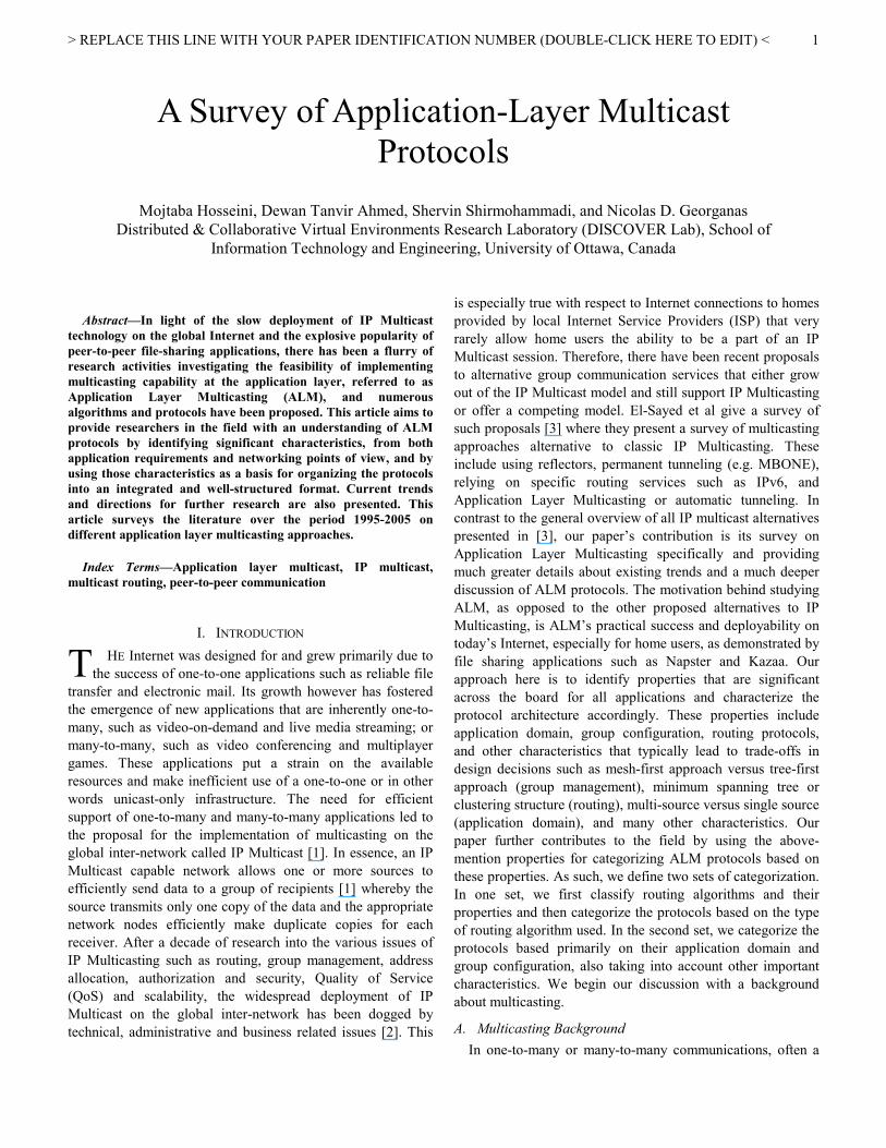
Figure 1. (a) A multicast scenario (b) receiver r1 joins (c) receiver r2 joins (d) receiver r3 joins (e) receiver r4 joins
sender may need to send the same message to many receivers.
Examples include audio webcasting, where the same audio
stream is sent to many receivers and video conferencing or
online gaming where any participant can generate data (audio,
video, update messages) that need to be sent to all other
participants. Traditional approaches such as using multiple
one-to-one unicast connections or using a client-server
approach are not scalable and will become bottlenecks and
eventually collapse with increasing number of users in the
system. Multicasting, on the other hand, allows a sender to
send the message only once; the network would then deliver
the message to all receivers in the group. The source sends a
packet to the network, and the network copies the packet at the
routers such that each destination will receive a copy of the
packet. This approach, which is the main component of IP
Multicast [1] will make the most efficient use of network
resources compared to one-to-one or client-server approaches,
where the packet has to be sent more than once either by the
source or by a server. However, this also implies that the
network has to be intelligent, in the sense that it has to know
how to route the packet such that each destination receives a
copy. In other words, the routers in the network must be
capable of setting up and tearing down of IP Multicast sessions
as well as processing and routing IP Multicast packets. It is
this intelligence required from the network that can present a
major hurdle in the way of the deployment of IP Multicast in a
global inter-network that was originally conceived based on
unicasting principals.
Hence, Multicasting requires route establishment since data
is forwarded to a group of receivers rather than to individual
receivers. Multicast routing protocols come up with solutions
to setup routes within the network. A good understanding of
this concept is essential to the fundamentals presented in this
paper; hence we present an example here to illustrate a typical
multicast routing technique: Distance Vector Multicast
Routing Protocol (DVMRP) [4]. DVMRP is a multicast
extension to the unicast routing concepts used in RIP (Routing
Information Protocol) [5]. It is a source-based routing protocol
where the receiver initiates the calculation of routing
information. Therefore, a spanning tree, optimal with respect
to delay, is created for each source. Multicast data units are
then routed using reverse path multicasting (RPM). It applies
techniques like poison-reverse and graft data units for dynamic
control of the multicast tree. Figure 1(a) represents a network
consisting of a set of routers A to E. A cost is associated with
each link interconnecting two routers. The number associated
with the cost is an indication of the value of parameters such as
end to end delay, maximum outgoing bandwidth, or any other
parameter pertinent to the application (actual $ cost, out
degree, …), and should be considered as a normalized number
that is relative across all links. For instance, in Figure 1(a), the
link from A to C is more “costly” than the link from C to D. A
number of multicast group members (r1, r2, r3, r4) are
attached to some of the routers. In a real application, these
could be home users participating in an online game, for
example. DVMRP builds a separate shortest path for each
sender. For example, in Figure 1(a), there is more than one
path from Router A to Router D: A-D and A-C-D. The cost of
the first path (18) is higher than that of the second path
(8+5=13). Figure 1(b) shows the shortest path from source S,
attached at Router A, to receiver r1. Similarly, when receiver
r2, r3 and r4 join the system in that order, the tree is further
extended as shown in Figure 1(c), 1(d) and Figure 1(e),
respectively. Figure 1(e) clearly shows the data distribution
tree among the multicast members from the source attached at
Router A. It should be noted that this tree is only for the single
source S. When dealing with multiple sources, the tree
construction becomes more complicated, as we shall see later
in the article.
In addition to the approach shown in the above example,
(e)
A
C
D
B
E
r1
8
5 5
2
r3
r2
r4
s
(d)
A
C
D
B
E
r1
8
5 5
2
r3
r2
s
(c)
A
C
D E
r1
8
5 2
r2
s
(b)
A
C
D
r1
8
5
s
1
(a)
A
C
D
B
E
r1
8 2
5 5
2
r3
r2
r4
s

> REPLACE THIS LINE WITH YOUR PAPER IDENTIFICATION NUMBER (DOUBLE-CLICK HERE TO EDIT) <
3
there are other approaches for multicast routing. Multicast
extension to the unicast OSPF, called MOSPF, is another
routing protocol for IP multicasting [6]. It is based on OSPF
(Open Shortest Path First) [7] and can be categorized as a
source based algorithm. In contrast to DVMRP, it is not a
reverse path algorithm, and is based on link state algorithm.
Core-based trees (CBT), another approach, use the concept of
shared trees with rendezvous points [8]. CBTs generate a
shared bidirectional multicast tree that take into account the
current group membership when it is being established. The
main objective of CBT is to minimize the amount of status
information and to reduce the control overhead. But it has the
disadvantages of traffic concentration and non-optimal paths.
Protocol Independent Multicasting (PIM) is yet another
approach. PIM has two variants: PIM-sparse mode [10] and
PIM-dense mode [11]. These modes are inherently two
different multicast routing protocols. They operate efficiently
for sparse and dense groups respectively. In PIM-sparse mode,
it assumes that nodes are likely to be located far away from
each other. The available bandwidth tends to be small. For
PIM-dense mode, the distances between members must be
short and their availability is judged to be high.
B. Deployment Issues with Multicasting
Although IP Multicasting seems to hold great promise, its
practical deployment issues have prevented it from becoming
available on a global Internet level. Here we briefly describe
some of these issues and refer the readers to [2] for a
comprehensive list of deployment issues and their detailed
discussion.
IP Multicast-capable routers need to be installed at all levels
of the network (from backbone to edge routers) for the
multicasting service to work and be widely available,
presenting a substantial cost to ISPs. In addition, there is a
tendency to install simple and unintelligent (therefore very
fast) routers at the backbone level since they can more
efficiently handle high capacity traffic instead of routers that
can handle complex services such as IP Multicasting. There
also exist management and security issues related to the
deployment of IP Multicast: the ease of flooding attacks via
multicasting, unauthorized reception of data from a multicast
session, preventing allocation of same multicast address for
two sessions, the difficulty of setting up firewalls while
allowing multicasting, etc. Billing and service charge is
another problem: a standard model to charge for the delivery
of packets duplicated by routers does not yet exist. Note that
most of the problems discussed above are easier to solve in an
Intranet environment controlled by a single entity due to the
level of control that exists in an Intranet. However, when it
comes to the Internet, these issues become problematic to the
extent that they make the deployment of IP Multicast at all
levels of the Internet next to impractical. In fact other
approaches, such as the Multicast Backbone (MBONE) [12]
project of the mid 90’s bring multicasting closer to reality. In
essence, MBONE uses unicast connections between two or
more subnetworks which are capable of IP Multicast, referred
to as Multicast Capable Islands, by encapsulating the multicast
packet in a regular unicast IP packet and sending it from one
subnetwork to others. This technique is also known as IP
tunneling. But, inherent to the MBONE are the general
problems of IP Multicasting such as receiver authentication,
group management and possibility of flooding. In addition, the
static setting up of unicast tunnels stymies the natural growth
of such a network and assumes responsible use of the available
resources. Consequently, the MBONE is not made available to
typical home Internet users through their ISPs, restricting its
use among education and research institutions.
The lack of network-level support for multicasting has thus
led researchers and commercial entities to seek alternative
ways of multicasting at the application layer. In this article we
present the rational and design concepts behind ALM. We will
compare it against IP multicasting and discuss its pros and
cons. A novel classification of various ALM protocols for the
past 10 years is also presented. This classification, structured
in 2 sets of categorization based on application configuration
and routing algorithm type, gives a unique perspective of the
plethora of ALM protocols that have emerged, helping
practitioners in the field select suitable protocols for their
given multi-user networked applications. We will also take a
closer look at three popular ALM protocols (ZIGZAG [13],
NICE [13], and OMNI [15]) and present their inner working as
a tutorial for those researchers who are interested in
developing their own ALM protocol for a specific application.
The rest of this article is organized as follows: Section II gives
an introduction to ALM and compares it to IP Multicasting,
while Section III discusses design of ALM protocols. In
Section IV, we present the classification of various ALM
protocols. Some classical ALM protocols are explained in
Section V. Section VI portrays open issues and future work.
Finally, Section VII concludes the paper with closing remarks.
II. APPLICATION LAYER MULTICASTING
The concept of ALM is simply the implementation of
multicasting functionality as an application service instead of a
network service. Figure 2(b) represents the ALM configuration
for the same group of sender and receivers in the IP
multicasting scenario shown in Figure 2(a). Here, the
multicasting tree has been built at the application layer. Using
only the unicasting capability of the network, the source sends
two packets, one to D1 and one to D2, each of which in turn
send the packet to D4 and D3, respectively.
While IP Multicast is implemented by network nodes (i.e.
routers) and avoids multiple copies of the same packet on the
same link as well as possibly constructing optimal trees, ALM
is implemented by application nodes (either end systems or
proxies) and results in multiple copies of the same packet on
the same link as well as typically constructing non-optimal
trees. In exchange for its inefficiency, as compared to IP
Multicast (by resulting in higher stress links and larger
diameter trees), ALM remedies the key shortcoming of the IP
Multicast model: easier and possibly immediate deployment

> REPLACE THIS LINE WITH YOUR PAPER IDENTIFICATION NUMBER (DOUBLE-CLICK HERE TO EDIT) <
4
(a) (b)
Figure 2. (a) IP multicasting scenario (b) Application layer multicast
Figure 3. (a) Sample overlay topology (b) an overlay multicast tree
over the Wide Area Network. For example, End System
Multicast (ESM) [16][17], one of the current implementation
of ALM, has been already deployed successfully on the
Internet in various applications. In ESM, when a user tunes
into the system, this end-host is both downloading the data and
uploading it to other end-host.
In what can be regarded as one of the key efforts advocating
ALM, Chu et al. illustrated using both simulation and Internet
experiments that ALM systems can form overlay multicast
trees that incur low performance penalties (in terms of link
stress and tree stretch) compared to IP Multicast [17]. ALM
disadvantages such as longer delays and less efficient network
usage compared to IP multicasting are balanced by its
advantages such as immediate deployability on the Internet,
easier maintenance and update of the algorithm, and last but
certainly not least the ability to adapt to a specific application.
A common approach to Application Layer Multicasting is for
the multicast participants to establish an overlay topology of
unicast links to serve as a virtual network (overlay network) on
top of which multicast trees can be constructed. Figure 3
below shows an example of 7 peers forming a topology
(Figure 3(a)) and a multicast tree being constructed with node
D as the source (Figure 3b).
To better illustrate the performance penalties mentioned
above, let us have a closer look at one scenario comparing IP
Multicast and ALM. Consider Figure 4(a) that shows a
physical topology. There are four routers (A-D), and four end-
systems (a-d). Link delays are as indicated. Assume ‘a’ wishes
to send data to all other end-systems. Figure 4 (b) depicts the
IP Multicast tree constructed by DV MRP. Routers A and C
receive a single copy of the packet and forward it along
multiple interfaces. At most one copy of a packet is sent over
any physical link. Each recipient receives data with the same
delay as though End-system ‘a’ were sending to it directly by
unicast. ALM on the other hand does not rely on router
support for multicast. Here, data replication and forwarding
are handled by the end-systems as shown in Figure 4(c). Figure
4(d) shows how end-system overlay network maps onto the
underlying physical network. The resource usage for IP
multicast and ALM for this particular case are 37 and 39
respectively. ALM is therefore more “costly” in this example,
again balanced with the benefit of being immediately
deployable.
Multicast routing protocols build multicast trees to deliver
data and to exchange necessary routing information. In IP
multicast, each host informs to its designated multicast router
in its subnetwork when it joins or leaves the group. Then the
multicast routers exchange group membership information
over the multicast tree. All of this control overhead about
members joining, members leaving, and updating the multicast
tree is carried by the Internet Group Membership Protocol
(IGMP) [18]. As there is no redundant path in the tree delivery
structure, IP multicast improves network efficiency and scales
to a large group size. Despite its bandwidth efficiency, it
suffers from the deployment issues mentioned earlier.
Application layer multicast, although less efficient than IP
Multicast as demonstrated in the above comparison, is
receiving increasing popularity in the multicast community
primarily due to its ease of deployment. In ALM, multicast
architecture, group membership, multicast delivery structure
construction, and data forwarding are exclusively controlled
by participating end hosts, thus it does not require the support
of intermediate nodes such as routers. On the negative side, an
end-host in ALM has little or no knowledge about the
underlying network topology, thus resulting in performance
penalty in term of longer end-to-end latency and lower
A
B
G
D
E
F C
A
B
G
D
E
F C
(a) (b)

> REPLACE THIS LINE WITH YOUR PAPER IDENTIFICATION NUMBER (DOUBLE-CLICK HERE TO EDIT) <
5
(a) (b)
(c) (d)
Figure 4. (a) A physical topology (b) IP multicast tree constructed by DVMRP (c) ALM concept
(d) End-system overlay network
TABLE I. Conceptual Comparison of IP multicast and ALM
Issues IP multicast Application Layer Multicast
Multicast efficiency in terms
of delay/bandwidth High Low - Medium
Complexity or Overhead Low Medium - High
Ease of deployment Low Medium – High
The OSI layer where the
multicast protocol works Network layer Application layer
efficiency compared to IP multicast. Group membership and
multicast delivery structures and monitoring of network
conditions are also done at end hosts, causing additional
overhead for end hosts compared to IP multicasting. Table I
below is a conceptual comparison of typical IP multicast with
ALM.
In ALM, new members find out about the topology from a
common bootstrap point called a Rendezvous Point (RP) and
join the topology by exchanging control messages with a
subset of members already part of the topology. Unlike the
IGMP protocol used in IP Multicasting, the control messages
in ALM are exchanged in an application-specific manner and
are completely up to the designers of the protocol. A ‘good’
topology consists of a rich connected graph, such that a peer is
connected to other peers through multiple paths, and in an
efficient and cost-aware manner, such that the distance or
delay between peers is minimized while the number of
connections is bounded. Other metrics such as robustness
(ability to deal with members leaving the topology), scalability
(ability to efficiently increase the size of the topologies for
very large number of peers) and low control overhead
(minimizing the exchange of control messages) also determine
the quality of an overlay topology. Creating and maintaining
‘good’ topologies thus becomes one of the core responsibilities
of an ALM protocol. Once a topology is constructed and
maintained, a multicast tree can be constructed on top of the
graph according to a routing strategy that would commonly
strive to minimize the cost of the multicast tree in terms of the
delay (or other important parameters, depending on the
application) experienced by each peer as well as the amount of
data duplication each peer is required to perform. Revisiting
Figure 3, we can say that Figure 3b shows an example of
overlay tree over the sample topology of Figure 3a. In the next
section, we will take a closer look at these design issues
pertaining to the ALM topology and multicast tree.
Receiver Sourc
a
b
c
d
1+15+1
1+10+1 1+8+1
A
B D
C
1
1
2
Receiver Sourc Router
1
8
1 1
1 a
b
c
d
A
B D
C
1
1
Receiver Sourc Router
1
8
1 1
1 a
b
c
d
A
B D
C
1
1
2
Receiver Sourc Router
1
8
1 1
1 a
b
c
d
> REPLACE THIS LINE WITH YOUR PAPER IDENTIFICATION NUMBER (DOUBLE-CLICK HERE TO EDIT) <
6
III. APPLICATION LAYER MULTICAST PROTOCOL DESIGN
Since its introduction, there have been a myriad of ALM
protocols with a wide variety of approaches and
characteristics. Designing a protocol typically involves making
design decisions based on a given set of requirement,
constraints under certain circumstances and given set of
resources whose availability is assumed. The aim of this
section is to highlight some of the more important categories
and general approaches of the different protocols based on
these requirements, constraints and assumed resources and
discuss how they affect the service each protocol provides as
well as how its overall characteristics.
A. Application Domain
Perhaps the most crucial feature of an ALM protocol and
one that affects most of its resulting characteristics is its
targeting application. The application domain determines the
number of users that a protocol must support, the data types a
protocol’s delivery tree must accommodate and the metrics
that such a tree attempts to optimize. We follow the same
categorization of application domains driving multicast
deployment as those according to Diot et al. [2]:
1) Audio/video streaming: usually involves a single source
distributing media to a large number of receivers.
Examples include live streaming of a sporting event, or
streaming of pre-recorded news. The primary metric is
bandwidth and latency to a lesser extent
2) Audio/video conferencing: these involve small to
medium size groups interacting in a multi-party
conferencing session. The difference with the previous
category is the smaller group size, higher degree of
interactivity and the existence of multiple sources. Both
bandwidth and latency are important metrics
3) Generic multicast service: protocols falling into this
application domain category try to create a generic
multicast service based on specific metrics that can affect
a variety of applications
4) Reliable data broadcast and file transfer: reliable
transfer and distribution of (usually large) files (e.g.
distributed databases and file sharing). Bandwidth is the
only metric
As can be seen, the different classes of applications have
different sets of requirements regarding reliability, latency,
bandwidth, and scaling. Such requirements in turn determine
the design choices of ALM protocol regarding the group
management mechanism it deploys. The application domain
therefore influences the ALM protocol. In a tree based
multicast system, for example, a node is either an interior node
(has children) or a leaf node (has no children). This design
choice initiates two problems. First, it is an unfair system.
Only the interior nodes are responsible to forward the data.
The system becomes unbalanced as leaf nodes increase more
rapidly than the interior nodes. Second, due to network
capacity, interior nodes may not handle high bandwidth
applications – sacrificing the quality. In an application level
streaming system, usually audio/video streams are split into
several smaller streams. Each stream is stamped with a
numerical sequence number to put it at the correct sequence
for playback. Usually FEC (forward error correction) code is
used to ensure guaranteed stream delivery. For example, split
stream [19] ensures that the majority of nodes are interior
nodes in one tree, and they will be leaf nodes in all other trees.
Hence the system distributes forwarding workloads among all
nodes and solves the unfair and unbalanced problem in the
conventional streaming system. In split stream, nodes choose
to join a subset of the stripes to control their inbound
bandwidths and also opt to limit the number of children nodes
they accept to control their outbound bandwidths. Thus, it
accommodates nodes with different bandwidths and solves the
second problem. Similarly, other application domains have
different objectives and different constraints. Typically, an
ALM protocol focuses on optimizing its tree for a single and
very specific application domain.
B. Deployment Level
A key factor determining the set of assumptions an ALM
protocol operates based on, is at what level the protocol is
expected to be deployed: at the infrastructure level or end
system level. Infrastructure-level, also known as proxy-based
ALM protocols, requires the deployment of dedicated
servers/proxies on the Internet where they self-organize into an
overlay network and provides a transparent multicast service
to the end-user (Figure 5(a)). End system level ALM protocols
on the other hand, assume only a unicast service from the
infrastructure and expect end-system hosts to participate in
providing the multicasting functionality by taking on some of
the forwarding responsibility (Figure 5(b)). Figure 5 highlights
the difference between the two approaches to ALM.
The choice between developing an infrastructure level or an
end system level ALM protocol is perhaps driven as much by
business and marketing issues as purely technological ones.
End systems sharing the forwarding load of a multicast session
use the existing Internet infrastructure available to them and
may not be expected to pay more for participating in the
multicast session (as illustrated by the free nature of peer-to-
peer file-transfer applications). An infrastructure of dedicated
proxies deployed over the Internet that offer multicasting
services however are more likely to expect a service charge.
There are however technological consequences of a choice
between a proxy-based or an end system level approach to
ALM.
Proxy-based ALM protocols can take advantage of existing
IP Multicast ‘islands’ by including a representative of an
island as an overlay node (and therefore increase their
efficiency), can assume greater bandwidth availability to the
proxy nodes (compared to the bandwidth available to end-
systems), can assume longer life cycle of overlay nodes
(compared to transient nature of end systems), relieve end-
systems from any forwarding responsibility and therefore

> REPLACE THIS LINE WITH YOUR PAPER IDENTIFICATION NUMBER (DOUBLE-CLICK HERE TO EDIT) <
7
Figure 5. (a) Proxy-based deployment of ALM (b) End-system ALM
reduce application complexity since multicast is transparently
made available to end-systems. The major disadvantage of this
approach is the need for the deployment of dedicated proxies
over the inter-network and so incurring the cost associated
with acquiring and deploying them. Proxy-based ALM may
also be less adaptable to and less optimized for specific
applications since it would typically provide a generic
multicast service rather than a service specific to a particular
class of applications.
End system ALM protocols enjoy more flexibility,
adaptability to specific application domains and immediate
deployment over the Internet but may not scale well (to large
number of users or large number of simultaneous sessions),
must deal with limited bandwidth of end systems and require
end systems to take on some of the forwarding responsibility
(and therefore increase application software development
complexity).
C. Group Management
Once application domain and deployment level has been
decided, a protocol designer must make some key decisions
regarding how to manage a group of nodes in a multicast
session. This includes
1. Basic group management: how users find out about
multicast sessions, how they join a session (through a
Rendezvous Point, or if p2p substrate is required and some
form of flooding is used to find the appropriate source), how
they leave (depending on how permanent and cooperative
the users are assumed to be), can the users still contribute to
existing multicast session even if they are not a part of
them? Are they assumed to be very transient and anonymous
or more permanent and known users?
2. Whether the management of the group is done in a
centralized or distributed way and how this affects the
design and service provided.
3. Whether a mesh-first approach or a tree-first approach is
taken? What are the advantages and disadvantages of each?
If a mesh-first approach is chosen, whether a peer to peer
substrate is assumed to exist and if so, what type of substrate
with what requirements and services does it provide?
4. Whether the protocol will take advantage of existing IP
Multicast islands in order to alleviate part of the
multicasting load? If so, how they will interface to these
islands?
5. Depending on the assumed life-time of the multicast
sessions, whether it is necessary to refine the multicast tree
to improve performance as well as deal with fluctuations in
the network resources available and deal with congestion? If
so, how aggressive these refinement methodologies can be
with its effects on the stability of the system and the service
provided to users
The basic group management services that an ALM protocol
provides consists of a mechanism for the new nodes to
discover a multicast session (typically through rendezvous
point(s)), a distributed or a centralized administration, the
mesh-first or the tree-first approach for constructing source-
specific or shared trees based on some metrics. Such
characteristics of the group management mechanism are
primarily driven by the application domain. For instance,
single-source video streaming with large number of receivers
usually involves a distributed group management and
construction of a source-specific tree based on bandwidth and
delay metrics, whereas medium-sized conferencing
applications may involve the mesh-first construction of a
shared tree based on bandwidth and delay and can afford a
centralized approach to the group management. These
characteristics are described next.
1) Mesh First versus Tree First
There are two basic approaches to configure the data
distribution pathways: mesh-first, and tree-first. In the mesh-
first approach, members keep a connected mesh topology
(Figure 6(a)) among themselves. Usually the source is chosen
as a root and a routing algorithm is run over the mesh relative
to the root to build the tree. This mesh topology is explicitly
created at the beginning, hence it is known. On the other hand,
the resulting tree topology is unknown. So the quality of the
tree depends on the quality of the mesh chosen. By contrast, in
the tree-first approach, the tree is built directly without any
mesh. The members explicitly select their parent from the
known members in the tree. This may require running an
algorithm to detect and avoid loops, and to ensure that the
structure is indeed a tree. There is no intervening mesh
R
R
R
R
R
R
R
R
Proxy Proxy
(a) (b)

> REPLACE THIS LINE WITH YOUR PAPER IDENTIFICATION NUMBER (DOUBLE-CLICK HERE TO EDIT) <
8
topology here. The reason for using the tree-first approach
Figure 6. (a) A mesh: a network topology with many redundant interconnections between network nodes (b) Initial tree (c)
Lopsided Tree
over the mesh-first approach is that the tree-first approach
gives direct control over the tree. This control is valuable for
different aspects such as maintaining strict control over the
fan-out, selecting a best parent neighbor that has enough
resources, or responding to the failed members with a
minimum impact to the tree. Another advantage of the tree first
approach is independent actions from each member. It makes
the protocol simple as it has a lower communication overhead.
But when a member changes a parent, it drags all of its
descendents with it (Figure 6(c)). This is desirable in the sense
that the descendents do not need to change their neighbors; in
fact, they are indeed unaware of the incident. However, this
can also result in lopsided trees, which are “uneven: and less
efficient than correctly formed trees. The advantage of the
mesh-first approach becomes apparent here as it gives more
freedom to refine the tree. It is possible to manipulate the tree
topology to a significant extent by selecting mesh neighbors
and changing the metrics. A mesh-first approach is therefore
more robust and responsive to tree partitions and is more
suitable for multi-source applications, at the cost of higher
control overhead.
2) Source Specific Tree versus Shared Tree
In multicasting two conflicting design goals are (a)
minimizing the length of the path (usually in terms hops/end-
to-end delay) to a specific individual destination and (b)
minimizing the total number of hops or the cumulative end-to-
end delay to forward the packet to all the destinations. To the
best of our knowledge, there is yet no good heuristic to
balance these two conflicting goals. The choice between a
source-specific tree (case a) and shared tree (case b) usually
depends on whether the multiple sources use the same overlay
for data distribution or not. Shared trees are preferred when
there is a multiparty communication; i.e. multiple sources such
as online games. It is better than source specific tree in terms
of the maintenance cost. Source specific tree, on the other
hand, allows for optimization of the tree for a given source, but
cannot support efficiently multiple sources on that tree.
3) Distributed versus Centralized
Although intuitively one might think that a distributed
routing approach better fits large-scale applications to
efficiently manage group communication, there are still
incentives for a centralized approach [20]. In a distributed
approach, the workload of maintaining the tree is evenly
distributed among the root nodes. But the synchronous
communication among the members for real-time applications
like media streaming is hard to ensure due to the inherent
decision-making delay in distributed techniques. The
centralized management of multicast groups is a fair choice for
small-scale applications. It is simple and easy to deploy.
Naturally there is always a risk of single point of failure in
centralized system. Designers must balance simplicity and
practicality versus robustness when choosing one of these
approaches in designing an ALM protocol.
4) IP Multicast Compatibility
It would be beneficial if an ALM protocol exploits IP
multicasting where it is available. This is advantageous for
applications where the existing infrastructure of IP
Multicasting (typically in a large organization or company) can
be further enhanced to support Internet users. An example is
the Hybrid Distributed Simulation Protocol (HDSP), which
allows military simulations, traditionally performed on
expensive networking infrastructure, to be extended to home
users and/or between multiple multicast sites [21]. Another
example is Island Multicast (IM), which integrates IP multicast
with ALM [22]. It has a two level architecture, with the top
level concerned with packet delivery between “islands” using
unicast mechanism and the bottom level concerned with packet
delivery among the members in an island using IP multicast.
5) Refinement
Depending upon the order of joining requests for the same
set of nodes, constructed trees might be different and have
different perception quality. The quality of an ALM path
between any pair of members is comparable to the quality of
the unicast path between that pair of members. This implies
requirement of a minimum diameter tree. But, as the protocol
R
A
B
C N
R
A
B
C
N
(b) (c) (a)

> REPLACE THIS LINE WITH YOUR PAPER IDENTIFICATION NUMBER (DOUBLE-CLICK HERE TO EDIT) <
9
constructs the tree in real time and has no a-priori knowledge
of node arrivals, it is hard to construct this optimum tree.
Refinement is a solution to this problem. It moves the overlay
structure from the local optimum to the global optimum and
Figure 7. (a) A graph with link costs (b) Shortest Path Tree (b) Minimum Spanning Tree
improves the system’s performance. But excessive refinement
makes the structure unstable due to the ad hoc natures of node
behavior. Moreover, the effectiveness of the refinement to
real-time applications is questionable due to interrupted data
distributions among the members. A designer must thus
carefully choose the depth and frequency of tree refinement for
a given application.
D. Routing Mechanism
Once the overall group management has been designed and
the various choices are decided on, the most important part of
the design is how the tree (or a different structure) is formed
that provides the multicast service. This greatly depends on the
previous choices such as application domain (mainly
determining the quality metric and constraints), the
deployment level (mainly determining the resources available
to each node in terms of permanency as well as bandwidth)
and group management. Design of the routing mechanism
typically involves a (heuristic) solution to a graph theory
problem. That is, given a certain graph (i.e. a certain existing
structure of nodes) and certain constraints on each node (e.g.
inbound and outbound bandwidth constraints), the problem
involves the construction of a structure connecting the group
of users (or in case of a tree, connecting a source to all its
recipients) that satisfies a given requirement; e.g. minimum
overlay delay or minimum worst case delay. The solution to
the problem largely comprises the routing mechanisms; the
routing mechanism must then be augmented with stipulations
about nodes leaving the multicast structure, as well as possibly
periodic or event-based refinement strategies for the
improvement of the structure. In this section we provide a
survey of common approaches to the routing mechanism.
1) Group 1: Shortest Path
The aim of this group is to construct degree constraint
minimum diameter spanning tree. Here they use RTT
measurement to determine the shortest path tree from the
source to the end hosts and minimize the time delay for each
application while considering the degree constraint and QoS.
A Shortest Path Tree (SPT) constructs a minimum cost path
from a source node to all its receivers (see chapter 25 of [23]
for Dijkstra’s algorithm for building SPTs). An SPT or one of
its variants is commonly used by ALM protocols (such as Yoid
[24], SpreadIt [25], TAG [26], RITA [27]) in order to
construct a source-specific multicast tree or in graph theoretic
terms a rooted tree. Figure 7(b) shows the SPT rooted at the
filled-in node. It is important to note that both MST and SPT
can be modified to respect degree constraints of each node
[28].
2) Group 2: Minimum Spanning Tree
This group does not worry about degree constraint of nodes
and just tries to construct a ‘low cost’ tree or in other words a
Minimum Spanning Tree. Given a graph with a cost associated
with each edge (usually delay), a Minimum Spanning Tree
(MST) is a tree with minimum total cost spanning all the
members (see Chapter 24 of [23] for Kruskal and Prim’s
algorithms for building MSTs). Given the graph with edge
costs shown in Figure 7(a), an MST is constructed to have the
minimum total cost as shown in Figure 7(c) (total cost is 11 in
this example). A MST is commonly used by a centralized
ALM protocol such as ALMI [29] and HBM [30] in order to
construct a low cost shared tree that is not rooted at any
particular source (a shared tree implies that all nodes use the
same tree to distribute their data).
Figure 8. A hierarchical cluster of nodes with cluster size 4
3) Group 3: Clustering Structure
This group constructs a cluster of nodes that can be used to
construct trees. In order to better organize the overlay tree and
reduce control message overhead, some ALM protocols such
as ZIGZAG [13] and NICE [13] construct a hierarchical
cluster of nodes with each cluster having a ‘head’ representing
it in the higher layer (Figure 8). The advantage of a
hierarchical clustering approach to multicast tree routing is the
reduction in control overhead (nodes keep states only about a
subset of other nodes) and faster joining and management of
the tree at the cost of a sub-optimal tree and a lack of hard
guarantees on the degree limitation of each node.
4) Group 4: Peer-to-Peer Structure
In P2P structure, the routing is simply done through reverse-
path forwarding or forward-path forwarding or in some cases a
combination of both types. From Table II, we observe that
many ALM protocols (such as RMX [31], Gossamer [32],
Bayeux [33], Borg [34], Scribe [35]) operate based on an
4 3 4
2 2
2 2
4 3
2
2 2
3
2
2 2
(a) (b) (c)

> REPLACE THIS LINE WITH YOUR PAPER IDENTIFICATION NUMBER (DOUBLE-CLICK HERE TO EDIT) <
10
existing peer-to-peer substrate that serves as a mesh on top of
which an overlay multicast tree can be constructed using either
a reverse-path forwarding scheme (Gossamer [32], RMX [31],
Scribe [35]), a forward-path forwarding scheme (Bayeux [33])
or both (Borg [34]). The advantage of these approaches
includes low control overhead and distributed management of
the multicast tree but they do not restrict the degree of each
node and are sub-optimal.
It should be noted that Peer to Peer technology is a research
area of its own, and a big one at that. In general, a P2P system
is a system where peers communicate directly with one
another. As such, there is not necessarily a multicasting
component, and therefore outside the scope of this paper. For
example, Kazaa is a well-known P2P file sharing system that
does not use multicasting. The P2P aspect mentioned here
applies only to ALM systems that happen to also have a P2P
component, such as TVUPlayer [37], Sopcast [38], and
PPLive [39], to name a few.
E. Degree-constraint routing
The feasibility of carrying multicast data over the ALM
depends on whether or not there is available bandwidth (out
degree) at the end hosts. Usually end hosts have asymmetric
downloading and uploading speeds. Moreover, heterogeneity
of outgoing bandwidth of end hosts forces protocols to
consider realistic degree assignment. It may happen that a user
has zero out degree, i.e. pure receiver. In the real world,
around 50% of hosts have zero out degree to support
streaming bit rate [40]. From a practical perspective, the
asymmetric bandwidth fact cannot be ignored and should be
taken into consideration to assign out degrees to nodes during
implementation. It reflects the maximum bandwidth a node can
provide. For example, if a node has an out degree of 4, it
means it can support at most 4 children. There are two types of
degree constrains. In some cases there is only a bound for the
maximum number of edges that a node can have that is usually
flexible and can be changed according to different
applications. In other cases there is a fixed bound that is
restrict and predetermined. Minimum Spanning Tree (MST)
and Shortest Path Tree (SPT) routing algorithms can be
modified to respect the degree constraints of each node. The
problem of finding minimum-cost degree-constrained
multicast trees or degree-constrained Steiner trees is NP-
complete [41]. There exists several heuristic approximation
algorithms addressing this problem [23][42][43][44][45].
Some of these algorithms (such as [43][44]) do not provide
exact guarantees on the degree of each node in the tree and
instead provide a bound on the worst-case degree. Others
focus on constructing a single tree and do not consider
multiple trees over the same graph ([23][45][46]). Though
there has been some research with regards to constructing
multiple trees on a shared graph [47], they still only provide a
bound on the worst case (maximum) degree of any node as
opposed to guarantees on the individual maximum degree for
every node as is required for a protocol supporting multi-
source collaboration applications.
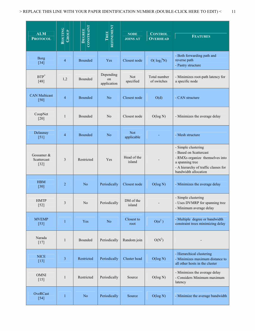
IV. SURVEY AND CLASSIFICATION OF ALM PROTOCOLS
As mentioned previously, a plethora of ALM protocols has
emerged from both the research and practice arenas. This
section lists a number of such protocols that were published
between 1995 and 2005. To simply list these protocols would
not serve much purpose to the reader. As such, we have
tabulated the surveyed protocols based on their “class”, in
order to provide practitioners in the field with a comparative
perceptive of these protocols. We have used the design,
routing, application, and group characteristics described in
section III in order to create a classification of the protocols.
The ALM protocol are categorized here based on their routing
characteristics described in Section III D and E (Table II), and
application/group configurations as described in Section III A,
B, and C (Table III).
TABLE II. Classification of ALM protocols based on routing algorithm
ALM
PROTOCOL
RO
UT
ING
GR
OU
P
DE
GR
EE
CO
NST
RA
INT
TR
EE
RE
FIN
EM
EN
T
NODE
JOINS AT
CONTROL
OVERHEAD FEATURES
ALMI
[29] 2 No Periodically Closest node O(N)
- Minimizes average cost of
shortest path trees rooted at group
members
Amcast
[48] 2 Restricted No
Not
specified O(log N)
- Minimize diameter while
respecting the degree constraints
Bayeux
[33] 4 Bounded Yes Closest node O(log N)
- Forwarding path
- Tapestry structure
> REPLACE THIS LINE WITH YOUR PAPER IDENTIFICATION NUMBER (DOUBLE-CLICK HERE TO EDIT) <
11
ALM
PROTOCOL
RO
UT
ING
GR
OU
P
DE
GR
EE
CO
NST
RA
INT
TR
EE
RE
FIN
EM
EN
T
NODE
JOINS AT
CONTROL
OVERHEAD FEATURES
Borg
[34] 4 Bounded Yes Closest node O( log2
bN)
- Both forwarding path and
reverse path
- Pastry structure
BTP*
[48] 1,2 Bounded
Depending
on
application
Not
specified
Total number
of switches
- Minimizes root-path latency for
a specific node
CAN Multicast
[50] 4 Bounded No Closest node O(d) - CAN structure
CoopNet
[20] 1 Bounded No Closest node O(log N) - Minimizes the average delay
Delaunay
[51] 4 Bounded No
Not
applicable - - Mesh structure
Gossamer &
Scattercast
[32]
3 Restricted Yes Head of the
island -
- Simple clustering
- Based on Scattercast
- RMXs organize themselves into
a spanning tree
- A hierarchy of traffic classes for
bandwidth allocation
HBM
[30] 2 No Periodically Closest node O(log N) - Minimizes the average delay
HMTP
[52] 3 No Periodically
DM of the
island -
- Simple clustering
- Uses DVMRP for spanning tree
- Minimum average delay
MVEMP
[53] 1 Yes No
Closest to
root O(n2 )
- Multiple degree or bandwidth
constraint trees minimizing delay
Narada
[17] 1 Bounded Periodically Random join O(N2) -
NICE
[13] 3 Restricted Periodically Cluster head O(log N)
- Hierarchical clustering
- Minimizes maximum distance to
all other hosts in the cluster
OMNI
[15] 1 Restricted Periodically Source O(log N)
- Minimizes the average delay
- Considers Minimum maximum
latency
OveRCast
[54] 1 No Periodically Source O(log N) - Minimize the average bandwidth

> REPLACE THIS LINE WITH YOUR PAPER IDENTIFICATION NUMBER (DOUBLE-CLICK HERE TO EDIT) <
12
ALM
PROTOCOL
RO
UT
ING
GR
OU
P
DE
GR
EE
CO
NST
RA
INT
TR
EE
RE
FIN
EM
EN
T
NODE
JOINS AT
CONTROL
OVERHEAD FEATURES
ProBaSS
[55] 1 Yes No Closest node -
- Proxy-based single-source ALM
protocol
PST*
[56] 1,2 Yes Yes
Not
specified
Total number
of switches
- Incorporate application specified
priority for the packet
RITA
[27] 1 Restricted
When
application
quality is
violated
Closest node O(log N) - Minimizes average delay
RMX
[31] 3 Bounded
Yes
Cluster head -
- Simple clustering
- Based on Scattercast
- RMXs organize themselves into
a spanning tree
- A hierarchy of traffic classes for
bandwidth allocation.
Scribe
[35] 4 Bounded Yes Closest node O( log2
b N) - Reverse path
- Pastry
SpreadIt
[25] 1 Restricted No Source O(dL) - Minimizes the average delay
TAG
[26] 1 Bounded No Source O(k(log N)) - Minimizes the average delay
TBCP
[57] 2 Yes No Root -
- End-system multicast with
dynamic group join and leave
Yoid
[24] 1 Restricted Periodically Closest node O(log N) - Minimizes the average delay
ZIGZAG
[13] 3 Restricted Periodically Cluster head
O (K*log N) or
O (k)
- Hierarchical clustering
- Minimum average delay
*BTP and PST belong to both group one and two since they use SPF when minimizing delay and MST when lower cost is desired
> REPLACE THIS LINE WITH YOUR PAPER IDENTIFICATION NUMBER (DOUBLE-CLICK HERE TO EDIT) <
13
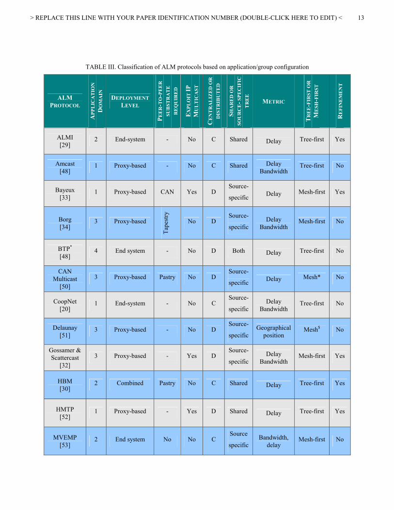
TABLE III. Classification of ALM protocols based on application/group configuration
ALM
PROTOCOL
APPL
ICA
TIO
N
DO
MA
IN
DEPLOYMENT
LEVEL
PE
ER-T
O-P
EE
R
SU
BST
RA
TE
RE
QU
IRE
D
EX
PL
OIT
IP
MU
LT
ICA
ST
CE
NT
RA
LIZ
ED
OR
DIS
TR
IBU
TE
D
SH
AR
ED
OR
SO
UR
CE-
SPE
CIF
IC
TR
EE
METRIC
TR
EE-F
IRST
OR
ME
SH-F
IRST
RE
FIN
EM
EN
T
ALMI
[29] 2 End-system - No C Shared Delay Tree-first Yes
Amcast
[48] 1 Proxy-based - No C Shared Delay
Bandwidth Tree-first No
Bayeux
[33] 1 Proxy-based CAN Yes D
Source-
specific Delay Mesh-first Yes
Borg
[34] 3 Proxy-based
Tap
estry
No D Source-
specific
Delay
Bandwidth Mesh-first No
BTP*
[48] 4 End system - No D Both Delay Tree-first No
CAN
Multicast
[50]
3 Proxy-based Pastry No D Source-
specific Delay Mesh* No
CoopNet
[20] 1 End-system - No C
Source-
specific
Delay
Bandwidth Tree-first No
Delaunay
[51] 3 Proxy-based - No D
Source-
specific
Geographical
position Mesh$ No
Gossamer &
Scattercast
[32]
3 Proxy-based - Yes D Source-
specific
Delay
Bandwidth Mesh-first Yes
HBM
[30] 2 Combined Pastry No C Shared Delay Tree-first Yes
HMTP
[52] 1 Proxy-based - Yes D Shared Delay Tree-first Yes
MVEMP
[53] 2 End system No No C
Source
specific
Bandwidth,
delay Mesh-first No

> REPLACE THIS LINE WITH YOUR PAPER IDENTIFICATION NUMBER (DOUBLE-CLICK HERE TO EDIT) <
14
ALM
PROTOCOL
APPL
ICA
TIO
N
DO
MA
IN
DEPLOYMENT
LEVEL
PE
ER-T
O-P
EE
R
SU
BST
RA
TE
RE
QU
IRE
D
EX
PL
OIT
IP
MU
LT
ICA
ST
CE
NT
RA
LIZ
ED
OR
DIS
TR
IBU
TE
D
SH
AR
ED
OR
SO
UR
CE-
SPE
CIF
IC
TR
EE
METRIC
TR
EE-F
IRST
OR
ME
SH-F
IRST
RE
FIN
EM
EN
T
Narada
[17] 2 End-system - No D
Source-
specific
Delay
Bandwidth Mesh-first Yes
NICE
[13] 1 End-system - No D
Source-
specific
Delay
Bandwidth
Mesh-
first~ Yes
OMNI
[15] 1 Proxy-based - Yes D
Source-
specific
Delay
Bandwidth Tree-first Yes
OveRCast
[54] 4 Proxy-based - No D
Source-
specific Bandwidth Tree-first No
ProBaSS
[55] 1 Proxy-based Yes No C
Source-
specific Delay Tree-first No
PST*
[56] 2 End system No No D
Source
Specific
Priority,
Delay Tree-first Yes
RITA
[27] 1 Proxy-based - No D
Source-
specific
Delay
Bandwidth Mesh-first Yes
RMX
[31] 4 Proxy-based
Sca
tter
Cas
t
Yes D Shared Delay
Bandwidth Mesh-first Yes
Scribe
[35] 3 Proxy-based
Sca
tter
Cas
t
No D Source-
specific
Delay
Bandwidth Mesh-first Yes
SpreadIt
[25] 1 End-system - No D
Source-
specific
Bandwidth
Delay Tree-first No
TAG
[26] 1 End-system - No D
Source-
specific
Topology
Bandwidth Tree-first No
TBCP
[57] 3 End-system - No D
Source-
specific
Delay
Bandwidth Tree-first No
Yoid
[24] 3 End-system - Yes D Shared Bandwidth
Delay Tree-first! Yes
ZIGZAG
[13] 1 End-system - No D
Source-
specific
Delay
Bandwidth
Mesh-
First~ Yes
* CAN-Multicast doesn’t make a tree (duplicate copies)
> REPLACE THIS LINE WITH YOUR PAPER IDENTIFICATION NUMBER (DOUBLE-CLICK HERE TO EDIT) <
15
$ Using Delaunay triangulation, an explicit tree constructing algorithm is not actually needed
~ A hierarchical cluster of nodes is constructed and a tree is built on top of this hierarchy
& since the out degree of a node is potentially unbounded, they see if a node is overwhelmed and try to offload
! A mesh also exists but is constructed after the tree
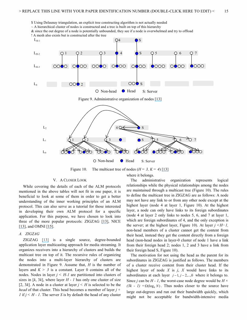
Figure 9. Administrative organization of nodes [13]
Figure 10. The multicast tree of nodes (H = 3, K = 4) [13]
V. A CLOSER LOOK
While covering the details of each of the ALM protocols
mentioned in the above tables will not fit in one paper, it is
beneficial to look at some of them in order to get a better
understanding of the inner working principles of an ALM
protocol. This can also serve as a tutorial for those interested
in developing their own ALM protocol for a specific
application. For this purpose, we have chosen to look into
three of the more popular protocols: ZIGZAG [13], NICE
[13], and OMNI [15].
A. ZIGZAG
ZIGZAG [13] is a single source, degree-bounded
application layer multicasting approach for media streaming. It
organizes receivers into a hierarchy of clusters and builds the
multicast tree on top of it. The recursive rules of organizing
the nodes into a multi-layer hierarchy of clusters are
demonstrated in Figure 9. Assume that, H is the number of
layers and K > 3 is a constant. Layer 0 contains all of the
nodes. Nodes in layer j < H-1 are partitioned into clusters of
sizes in [k, 3k], where layer H - 1 has only one cluster of size
[2, 3k]. A node in a cluster at layer j < H is selected to be the
head of that cluster. This head becomes a member of layer j +
1 if j < H - 1. The server S is by default the head of any cluster
where it belongs.
The administrative organization represents logical
relationships while the physical relationships among the nodes
are maintained through a multicast tree (Figure 10). The rules
to define the multicast tree in ZIGZAG are as follows: A node
may not have any link to or from any other node except at the
highest layer (node 4 at layer 1, Figure 10). At the highest
layer, a node can only have links to its foreign subordinates
(node 4 at layer 2 only links to nodes 5, 6, and 7 at layer 1,
which are foreign subordinates of 4, and the only exception is
the server; at the highest layer, Figure 10). At layer j <H−1,
non-head members of a cluster cannot get the content from
their head, instead they get the content directly from a foreign
head (non-head nodes in layer-0 cluster of node 1 have a link
from their foreign head 2; nodes 1, 2 and 3 have a link from
their foreign head S, Figure 10).
The motivation for not using the head as the parent for its
subordinates in ZIGZAG is justified as follows. The members
of a cluster receive content from their cluster head. If the
highest layer of node X is j, X would have links to its
subordinates at each layer 0,...,2,1 −− jj where it belongs to.
Since j can be H - 1, the worst-case node degree would be H ×
(3k - 1) = )(log NkΩ . Thus nodes closer to the source have
large out-degrees and run out their bandwidth quickly, which
might not be acceptable for bandwidth-intensive media
1 2 3 4 S 5 6 7
4 S
2 S
LH-1
LH-2
LH-3
L0
Non-head Head S: Server
Non-head Head S: Server
1 2 3
4
S 5 6 7
4 S L2
L1
L0

> REPLACE THIS LINE WITH YOUR PAPER IDENTIFICATION NUMBER (DOUBLE-CLICK HERE TO EDIT) <
16
streaming applications. Moreover when the parent node fails,
the head of its children is still working and helps to reconnect
the children to the new parent immediately. It is proven that
the worst case degree of a node and the height of the multicast
tree are )( 2kO and )(log NO k respectively [13]. The join
request is propagated down the multicast tree until a suitable
parent is found while keeping the structure defined by the
Figure 11. Hierarchical arrangement of hosts in NICE [13]
Figure 12. Control and data delivery paths for a two layer hierarchy in NICE [13]
rules. It finds a node that it is closest to the lowest layer.
ZIGZAG periodically runs optimization algorithms to improve
the quality of service to clients. Degree-based and capacity-
based switching approaches are taken to balance the degree
and the load of the nodes respectively.
B. NICE
NICE [13] is a recursive acronym which stands for the
NICE Internet Cooperative Environment. This scalable
application layer multicast protocol uses a hierarchical
clustering approach to support a larger number of receivers.
NICE was designed to provide architecture for low bandwidth
soft real-time data stream applications such as real-time stock
quotes and updates and Internet radio.
It organizes hosts in a hierarchy of layers and each layer has
several clusters of hosts. The lowest layer in the hierarchy is
denoted by L0. The size of the cluster is between K to 3K -1,
where K is a constant. Each cluster has a leader to
communicate with higher layers. It is chosen at the center of
the cluster; i.e., the leader has the minimum maximum distance
to all other hosts in the cluster. Hierarchical arrangement of
hosts in NICE is presented in Figure 11.
This hierarchical structure ensures following properties for
the distribution of hosts in different layers,
• A host only belongs to a single cluster at any layer
• A host is a member of all layers 110 ,..., −jLLL , in fact a
leader, if it stays in layer jL
• A host is in layer jL if it is a leader 1−jL
• Cluster size is bounded between K and 3K -1 except the
highest layer that has only a single member.
• There are at most Nklog layers
On top of the hierarchy, NICE can build source-specific
trees of different kind. Figure 12 is an example of control and
data delivery paths for a two layer hierarchy. All Ai hosts are in
layer L0 and distributed in different clusters at that layer. All B0
hosts are members of both layers, namely L0 and L1. The layer
L1 has only one cluster consisting of all the Bi hosts and Co,
where it is the leader at this cluster and layer. For example,
member A0 only belongs to layer L0 and thus has control paths
to A1, A2 and B0 whereas member B0 stays in both layers L0 and
L1 and therefore its control paths extends to both member of L0
cluster (i.e. A0, A1, A2) and L1 cluster (i.e. B1, B2, C0). NICE
assumes that there is a special node named Rendezvous Point
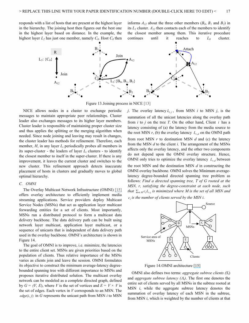
(RP) which is known to all members. Figure 13 is an example
of the join procedure. Let us assume that host A12 wants to join
the multicast group. It sends a join query to the RP. The RP
A1
B0
A0 A2
A7
B2
A6 A8
A4
B1
A3 A5
C0
A1
B0
A0 A2
C0
A7 A8
B2
A6
A4 A5
B1
A3
L1
L0
L2
B C
A D
E F
G
H
J
M K
L
C F M
F Cluster-leaders of
layer 1 from layer 2
Cluster-leaders of
layer 0 from layer 1
> REPLACE THIS LINE WITH YOUR PAPER IDENTIFICATION NUMBER (DOUBLE-CLICK HERE TO EDIT) <
17
responds with a list of hosts that are present at the highest layer
in the hierarchy. The joining host then figures out the best one
in the highest layer based on distance. In the example, the
highest layer L2 has just one member, namely C0. Host C0 then
informs A12 about the three other members (B0, B1 and B2) in
its L1 cluster. A12 then contacts each of the members to identify
the closest member among them. This iterative procedure
continues until it reaches to L0 cluster.
Figure 13. Joining process in NICE [13]
NICE allows nodes in a cluster to exchange periodic
messages to maintain appropriate peer relationships. Cluster
leader also exchanges messages to its higher layer members.
Cluster leader is responsible of maintaining proper cluster size
and thus applies the splitting or the merging algorithm when
needed. Since node joining and leaving may result in changes,
the cluster leader has methods for refinement. Therefore, each
member, H, in any layer Li periodically probes all members in
its super-cluster - the leaders of layer Li clusters - to identify
the closest member to itself in the super-cluster. If there is any
improvement, it leaves the current cluster and switches to the
new cluster. This refinement approach detects inaccurate
placement of hosts in clusters and gradually moves to global
optimal hierarchy.
C. OMNI
The Overlay Multicast Network Infrastructure (OMNI) [15]
offers overlay architecture to efficiently implement media
streaming applications. Service providers deploy Multicast
Service Nodes (MSNs) that act as application layer multicast
forwarding entities for a set of clients. Most importantly,
MSNs run a distributed protocol to form a multicast data
delivery backbone. The data delivery path can be built using
network layer multicast, application layer multicast, or a
sequence of unicasts that is independent of data delivery path
used in the overlay backbone. OMNI’s architecture is shown in
Figure 14.
The goal of OMNI is to improve, i.e. minimize, the latencies
to the entire client set. MSNs are given priorities based on the
population of clients. Thus relative importance of the MSNs
varies as clients join and leave the session. OMNI formulates
its objective to construct the minimum average-latency degree-
bounded spanning tree with different importance to MSNs and
proposes iterative distributed solution. The multicast overlay
network can be modeled as a complete directed graph, defined
by G = (V, E), where V is the set of vertices and E = V × V is
the set of edges. Each vertex in V corresponds to an MSN. The
),( jiedge in G represents the unicast path from MSN i to MSN
j. The overlay latency jiL , , from MSN i to MSN j, is the
summation of all the unicast latencies along the overlay path
from i to j on the tree T. On the other hand, Client i has a
latency consisting of (a) the latency from the media source to
the root MSN r, (b) the overlay latency drL , on the OMNI path
from root MSN r to destination MSN d and (c) the latency
from the MSN d to the client i. The arrangement of the MSNs
affects only the overlay latency, and the other two components
do not depend upon the OMNI overlay structure. Hence,
OMNI only tries to optimize the overlay latency drL , between
the root MSN and the destination MSN d in constructing the
OMNI overlay backbone. OMNI solves the Minimum average-
latency degree-bounded directed spanning tree problem as
follows: Find a directed spanning tree, T of G rooted at the
MSN, r, satisfying the degree-constraint at each node, such
that ∑ ∈Mi iriLc , is minimized where M is the set of all MSN and
ic is the number of clients served by the MSN i.
Figure 14. OMNI architecture [15]
OMNI also defines two terms: aggregate subtree clients (Si)
and aggregate subtree latency (Λi). The first one denotes the
entire set of clients served by all MSNs in the subtree rooted at
MSN i, while the aggregate subtree latency denotes the
summation of overlay latency of each MSN in the subtree,
from MSN i, which is weighted by the number of clients at that
B C
D E F
Source
MSNs
Clients
Service area of
MSNs
L1:B0, B1, B2
B0 B2
B1
C0
R
Join
L2: C0
A12
A12
Join
B0 B2
C0
A12
Attach
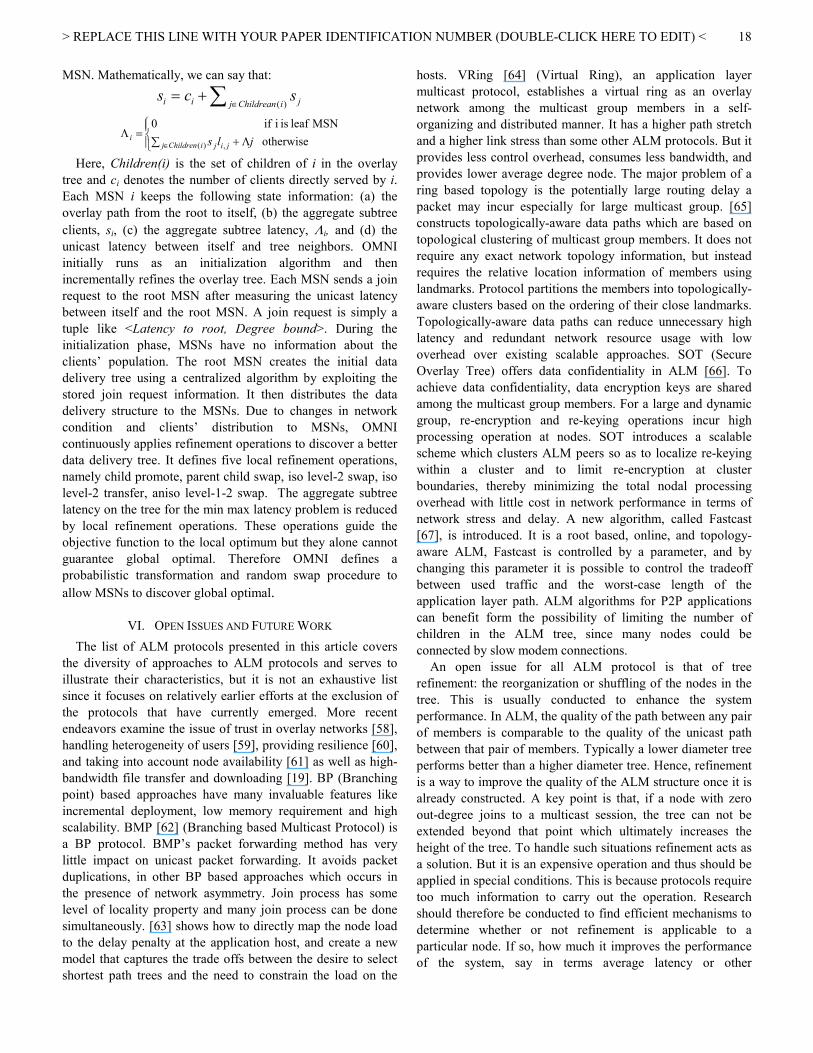
> REPLACE THIS LINE WITH YOUR PAPER IDENTIFICATION NUMBER (DOUBLE-CLICK HERE TO EDIT) <
18
MSN. Mathematically, we can say that:
∑ ∈+=
)(iChildreanj jii scs
Λ+∑=Λ
∈ otherwise
MSN leaf is i if 0
)( , jlsiChildrenj jiji
Here, Children(i) is the set of children of i in the overlay
tree and ci denotes the number of clients directly served by i.
Each MSN i keeps the following state information: (a) the
overlay path from the root to itself, (b) the aggregate subtree
clients, si, (c) the aggregate subtree latency, Λi, and (d) the
unicast latency between itself and tree neighbors. OMNI
initially runs as an initialization algorithm and then
incrementally refines the overlay tree. Each MSN sends a join
request to the root MSN after measuring the unicast latency
between itself and the root MSN. A join request is simply a
tuple like <Latency to root, Degree bound>. During the
initialization phase, MSNs have no information about the
clients’ population. The root MSN creates the initial data
delivery tree using a centralized algorithm by exploiting the
stored join request information. It then distributes the data
delivery structure to the MSNs. Due to changes in network
condition and clients’ distribution to MSNs, OMNI
continuously applies refinement operations to discover a better
data delivery tree. It defines five local refinement operations,
namely child promote, parent child swap, iso level-2 swap, iso
level-2 transfer, aniso level-1-2 swap. The aggregate subtree
latency on the tree for the min max latency problem is reduced
by local refinement operations. These operations guide the
objective function to the local optimum but they alone cannot
guarantee global optimal. Therefore OMNI defines a
probabilistic transformation and random swap procedure to
allow MSNs to discover global optimal.
VI. OPEN ISSUES AND FUTURE WORK
The list of ALM protocols presented in this article covers
the diversity of approaches to ALM protocols and serves to
illustrate their characteristics, but it is not an exhaustive list
since it focuses on relatively earlier efforts at the exclusion of
the protocols that have currently emerged. More recent
endeavors examine the issue of trust in overlay networks [58],
handling heterogeneity of users [59], providing resilience [60],
and taking into account node availability [61] as well as high-
bandwidth file transfer and downloading [19]. BP (Branching
point) based approaches have many invaluable features like
incremental deployment, low memory requirement and high
scalability. BMP [62] (Branching based Multicast Protocol) is
a BP protocol. BMP’s packet forwarding method has very
little impact on unicast packet forwarding. It avoids packet
duplications, in other BP based approaches which occurs in
the presence of network asymmetry. Join process has some
level of locality property and many join process can be done
simultaneously. [63] shows how to directly map the node load
to the delay penalty at the application host, and create a new
model that captures the trade offs between the desire to select
shortest path trees and the need to constrain the load on the
hosts. VRing [64] (Virtual Ring), an application layer
multicast protocol, establishes a virtual ring as an overlay
network among the multicast group members in a self-
organizing and distributed manner. It has a higher path stretch
and a higher link stress than some other ALM protocols. But it
provides less control overhead, consumes less bandwidth, and
provides lower average degree node. The major problem of a
ring based topology is the potentially large routing delay a
packet may incur especially for large multicast group. [65]
constructs topologically-aware data paths which are based on
topological clustering of multicast group members. It does not
require any exact network topology information, but instead
requires the relative location information of members using
landmarks. Protocol partitions the members into topologically-
aware clusters based on the ordering of their close landmarks.
Topologically-aware data paths can reduce unnecessary high
latency and redundant network resource usage with low
overhead over existing scalable approaches. SOT (Secure
Overlay Tree) offers data confidentiality in ALM [66]. To
achieve data confidentiality, data encryption keys are shared
among the multicast group members. For a large and dynamic
group, re-encryption and re-keying operations incur high
processing operation at nodes. SOT introduces a scalable
scheme which clusters ALM peers so as to localize re-keying
within a cluster and to limit re-encryption at cluster
boundaries, thereby minimizing the total nodal processing
overhead with little cost in network performance in terms of
network stress and delay. A new algorithm, called Fastcast
[67], is introduced. It is a root based, online, and topology-
aware ALM, Fastcast is controlled by a parameter, and by
changing this parameter it is possible to control the tradeoff
between used traffic and the worst-case length of the
application layer path. ALM algorithms for P2P applications
can benefit form the possibility of limiting the number of
children in the ALM tree, since many nodes could be
connected by slow modem connections.
An open issue for all ALM protocol is that of tree
refinement: the reorganization or shuffling of the nodes in the
tree. This is usually conducted to enhance the system
performance. In ALM, the quality of the path between any pair
of members is comparable to the quality of the unicast path
between that pair of members. Typically a lower diameter tree
performs better than a higher diameter tree. Hence, refinement
is a way to improve the quality of the ALM structure once it is
already constructed. A key point is that, if a node with zero
out-degree joins to a multicast session, the tree can not be
extended beyond that point which ultimately increases the
height of the tree. To handle such situations refinement acts as
a solution. But it is an expensive operation and thus should be
applied in special conditions. This is because protocols require
too much information to carry out the operation. Research
should therefore be conducted to find efficient mechanisms to
determine whether or not refinement is applicable to a
particular node. If so, how much it improves the performance
of the system, say in terms average latency or other

> REPLACE THIS LINE WITH YOUR PAPER IDENTIFICATION NUMBER (DOUBLE-CLICK HERE TO EDIT) <
19
parameters. The protocol should also be aware of the transient
period of the refinement when it actually takes place – does it
affects its dependent nodes, if so by how much. Furthermore,
the protocol must consider its side effects like churn that may
lead to inconsistent systems. As an example, OMNI uses local
transformations (child promote, parent-child swap, iso-level-2
transfer, aniso+level-1-2 swap) and probabilistic
transformations (simulated annealing) to refine its structure.
As it is an expensive operation and requires extra care,
frequent refinement may adversely affects the system
performance. Most of the ALM protocols strategically and
infrequently apply refinement operation.
Another open issue is balancing the two conflicting design
goals mentioned in Section III: (a) minimizing the length of
the paths (usually in terms hops) to the individual destinations
and (b) minimizing the total number of hops to forward the
packet to all the destinations. The minimum spanning tree
(MST) and the shortest path tree (SPT) are two well-known
data distribution methods in ALM. The MST optimizes the
resource usage of the multicast tree but the pair-wise paths
may not be optimal and can cause large end-to-end delays.
Hence it is suitable for non-interactive data dissemination
when end-to-end delays are not an issue. In SPT, the
distribution tree will consist of separate unicast connections
from the sender to each receiver. It is optimal from the source
to the receiver in terms of end-to-end delay but it causes high
consumption of network resources. Moreover, it is not
practical when the sender’s bandwidth is not sufficient to serve
all receivers simultaneously. Scaleable ALM systems usually
require clustering of the nodes. The advantage of a hierarchical
clustering is the reduction in control overhead as nodes keep
states only about a subset of other nodes. Furthermore, faster
joining and group management is possible at the cost of a sub-
optimal tree.
VII. CONCLUSION
In this article, we looked at the roots and rationale behind
Application Layer Multicasting. Compared to IP multicasting,
ALM has certain disadvantages such as longer delays and less
efficient traffic generation. However, due to its overwhelming
advantages for certain applications, such as immediate deploy-
ability and application-specific adaptation, it can be a practical
solution to many of the existing problems in multi-user
communications. The fact that an ALM protocol can be
developed and deployed on the Internet without the need to
make any changes to the existing network infrastructure, and
the ability to evolve and apply modifications to the protocol
quickly and easily at the application layer has helped the ALM
approach to have a quicker start compared to other multi-user
communications solutions. These advantages have caused the
serious consideration and development of ALM protocols
which in turn would lead to the creation of new applications
and communications paradigms on the Internet.
The popularity of application layer multicasting continues to
grow in different fields as an alternative to native IP
multicasting. These include news group, video conferencing,
internet games, internet jukebox, interactive chat-lines, distant
learning, and video on demand just to name a few. Although
ALM is considered as an active research topic over the last
decade, still there are many open issues to continue research
for creating efficient and robust ALM protocols in terms of
application domain requirements and the quality of service.
This survey paper functions as a reference guide for new
researchers in this field to use as a starting point.
ACKNOWLEDGMENT
The authors acknowledge the research contributions of Sara
Alavi, as well the financial support of the Natural Sciences and
Engineering Research Council (NSERC) of Canada.
REFERENCES
[1] S. Deering and D. Cheriton, “Multicast Routing in Datagram
Internetworks and Extended LANS,” ACM Trans. on Comput. Syst.,
vol. 8, no. 2, pp. 85-111, 1990.
[2] C. Diot, B.N. Levine, B. Lyles, H. Kassem, and D. Balensiefen,
“Deployment issues for the IP multicast service and architecture," IEEE
Network Mag., vol. 14, no. 1, pp. 78-88, 2000.
[3] A. El-Sayed, and V. Roca, “A Survey of Proposals for an Alternative
Group Communication Service,” IEEE Network, vol. 17, no. 1, pp. 46-
51, Jan./Feb. 2003.
[4] D. Waitzman, C. Partridge, and S.E. Deering, “Distance Vector
Multicast Routing Protocol,” RFC 1075, Internet Engineering Task
Force, Nov. 1988.
[5] C. Hedric, “Routing Information Protocol,” IETF RFC 1058, 1988.
[6] J. Moy, “Multicast extensions for OSPF,” IETF Internet Draft, Aug.
1998.
[7] J. Moy, “OSPF version 2,” IETF RFC 2328, 1998.
[8] A. Ballardie, "Core based Trees (CBT version 2) Multicast Routing,"
RFC 2189, Sept. 1997.
[9] T. Ballardie, P. Francis, and J. Crowcroft, "Core Based Trees (CBT): An
Architecture for Scalable Inter-Domain Multicast Routing," ACM
SIGCOMM, pp. 85-95, San Francisco, CA, Sept. 1993.
[10] D. Estrin, D. Farinacci, A. Helmy, D. Thaler, S. Deering, M. Handley,
V. Jacobson, C. Liu, P. Sharma, and L. Wei, “Protocol Independent
Multicast Sparse Mode (PIM-SM): Protocol Speciation,” IETF RFC
2117, Jun. 1997.
[11] D. Estrin, A. Farinacci, V. Helmy, et al., “Protocol Independent
Multicast - Dense Mode (PIMDM): Protocol Specification,” IETF RFC
3973.
[12] H. Ericksson, “MBONE: The Multicast Backbone,” ACM Commun.,
vol. 37, no. 8, pp. 54-60, 1994.
[13] D. A. Tran, K. A. Hua, and T. T. Do, "A peer-to-peer architecture for
media streaming," IEEE J. Sel. Areas Commun., vol. 22, no. 1, pp. 121-
133, Jan. 2004.
[14] S. Banerjee, B. Bhattacharjee, and C. Kommareddy, “Scalable
application layer multicast,” ACM SIGCOMM, pp. 205-217, Pittsburgh,
PA, Aug. 2002.
[15] S. Banerjee, C. Kommareddy, K. Kar, B. Bhattacharjee, and S. Khuller,
“Construction of an efficient overlay multicast infrastructure for real-
time applications,” IEEE INFOCOM, vol. 2, pp. 1521-1531, San
Francisco, CA, Apr. 2003.
[16] Link to http://esm.cs.cmu.edu/technology
[17] Y. Chu, S. G. Rao, and H. Zhang, “A Case for End System Multicast,”
IEEE J. Sel. Areas Commun., vol. 20, no. 8, pp. 1456-1471, Oct. 2002.
[18] W. Fenner, “Internet Group Management Protocol, version 2”, IETF
RFC 2236, 1997.
[19] M. Castro, P. Druschel, A.-M. Kermarrec, A. Nandi, A. Rowstron and
A. Singh, "SplitStream: high-bandwidth multicast in cooperative
environments," ACM Symp. Oper. Sys. Princ., pp. 298-313, New York,
USA, Oct. 2003.

> REPLACE THIS LINE WITH YOUR PAPER IDENTIFICATION NUMBER (DOUBLE-CLICK HERE TO EDIT) <
20
[20] V. Padmanabhan, H. Wang, P. Chou, and K. Sripanidkulchai,
"Distributing streaming media content using cooperative networking, "
12th ACM NOSSDAV, pp. 177-186, Miami, FL, May 2002.
[21] A. Diabi, S. Shirmohammadi, A. Gillmore, P. Lacombe, and J. C. de
Oliveira, “Internet-based Collaborative Virtual Simulations with Area of
Interest Management,” Int’l Symp. Collaborative Technol. and Syst.,
pp. 200- 207, Las Vegas, USA, May 2006.
[22] J. Liu, B. Li, H. Shao; W.Zhu, and Y. Zhang, "A proxy-assisted
adaptation framework for object video multicasting," IEEE Trans.
Circuits Syst. Video Technol., vol. 15, pp. 402-411, Mar. 2005.
[23] T.H. Cormen, C.E. Leiserson, R.L. Rivest, Introduction to Algorithms,
MIT Press, McGraw-Hill Book Company, 1993.
[24] P. Francis, “Yoid: Extending the Multicast Internet Architecture,” 1999,
available: http://www.aciri.org/yoid
[25] H. Deshpande, M. Bawa, and H. Garcia-Molina, “Streaming Live Media
over a Peer-to-Peer Network,” Tech. Rep. version 2001-31, available:
http://dbpubs.stanford.edu/pub/2001-30.
[26] M. Kwon, S. Fahmy, “Topology-Aware Overlay Networks for Group
Communication,” ACM NOSSDAV, pp. 127-136, Maimi, FL, May
2002.
[27] Z. Xu, C. Tang, S. Banerjee, S.J. Lee, “RITA: Receiver Initiated Just-in-
Time Tree Adaptation for Rich Media Distribution”, ACM NOSSDAV,
pp. 50-59, Monterey, CA, 2003.
[28] F. Bauer, A. Varma, “Degree-Constrained Multicasting in Point-to-
Point Networks,” IEEE INFOCOM, vol. 1, pp. 369-376, Boston, MA,
Mar. 1995.
[29] D. Pendarakis, S. Shi, D. Verma, and M. Waldvogel, "ALMI: An
application level multicast infrastructure," 3rd Usenix Symp. Int’l
Technol. and Syst., pp. 49-60, Mar. 2001.
[30] V. Roca and A. El-Sayed, "A host-based multicast (hbm) solution for
group communications," IEEE Int’l Conf. Net., pp. 610-619, Jul. 2001.
[31] Y. Chawathe, S. McCanne, and E. Brewer, “RMX: Reliable Multicast
for Heterogeneous Networks,” IEEE INFOCOM, vol. 2, pp. 795-804,
Tel Aviv, Israel, Mar. 2000.
[32] Y. Chawathe, “Scattercast: An Architecture for Internet Broadcast
Distribution as an Infrastructure Service,” Ph.D. Thesis, University of
California, Berkeley, Dec. 2000.
[33] S. Q. Zhuang, B. Y. Zhao, A. D. Joseph, R. H. Katz, and J. D.
Kubiatowicz, "Bayeux: An Architecture for Scalable and Fault-tolerant
Wide-area Data Dissemination," ACM NOSSDAV, pp. 11-20. Port
Jefferson, NY, Jun. 2001.
[34] R. Zhang, Y.C. Hu, “Borg: A Hybrid Protocol for Scalable Application-
Level Multicast in Peer-to-Peer Networks,” ACM NOSSDAV, pp. 172-
179, Monterey, CA, 2003.
[35] M. Castro, P. Druschel, A.M. Kermarrec, A. Rowstron, “Scribe: A
large-scale and decentralized application-level multicast infrastructure,”
IEEE J. Sel. Areas Commun., vol. 20, no. 8, pp. 1489-1499, 2002.
[36] Available: http://en.wikipedia.org/wiki/Skype
[37] Available: http://en.wikipedia.org/wiki/TVUPlayer
[38] Available: http://www.sopcast.org/
[39] Available: http://en.wikipedia.org/wiki/PPLive
[40] K. Sripanidkulchai, A. Ganjam, B. Maggs, and H. Zhang, "The
Feasibility of Supporting Large-Scale Live Streaming Applications with
Dynamic Application End-Points," ACM SIGCOMM, pp. 107-120,
Sept. 2004.
[41] R. Douglas, “NP-completeness and degree restricted spanning trees,”
Discrete Mathematics, vol. 105, pp. 41-47, 1992.
[42] N. Malouch, Z. Liu, D. Rubenstein, and S. Sahu, "A Graph Theoretic
Approach to Bounding Delay in Proxy-Assisted, End-System
Multicast," Int’l. Workshop QoS, pp. 106-115, May 2002.
[43] J. Konemann and R. Ravi, “A matter of degree: Improved
approximation algorithms for degree-bounded minimum spanning
trees,” SIAM journal of computing, vol. 3, no. 6, pp. 1783-1793, 2002.
[44] J. Konemann, R. Ravi, “Primal-dual meets local search: Approximating
MST’s with non-uniform degree bounds,” ACM Symp. Theory of
Computing, pp. 389-395, 2003.
[45] R. Ravi, M.V. Marathe, S.S. Ravi, D.J. Rosenkrantz, H.B. Hunt,
“Approximation Algorithms for Degree-Constrained Minimum Cost
Network Design Problems,” Algorithmica, vol. 31 no. 1, pp. 58-78,
2001.
[46] S. Y. Shi, J. S. Turner, "Routing in Overlay Multicast Networks," IEEE
INFOCOM, vol. 3, pp. 1200-1208, New York, NY, USA, Jun. 2002.
[47] S. Chen, O. Gunluk, and B. Yener, "The Multicast Packing Problem,"
IEEE/ACM Trans. Net., vol. 8, no. 3, pp. 311-318, 2000.
[48] S. Shi, J. Turner, and M. Waldvogel, "Dimensioning server access
bandwidth and multicast routing in overlay networks," ACM NOSSDAV,
pp. 83-91, Port Jefferson, NY, Jun. 2001.
[49] D. Helder and S. Jamin. "End-host multicast communication using
switch trees protocols," IEEE/ACM Int’l Symp. Cluster Comp. and the
Grid, pp. 419, 2002.
[50] S. Ratnasamy, M. Handley, R. Karp, and S. Shenker, "Application-level
multicast using content-addressable networks," 3rd Int’l Workshop Net.
Gr. Commun., pp. 14-29, London, UK, Nov. 2001.
[51] J. Liebeherr, M. Nahas, W. Si, “Application-layer Multicasting with
Delaunay Triangulation Overlays,” IEEE J. Sel. Areas Commun. vol.
20, no. 8, pp. 1472-1488, 2002.
[52] B. Zhang, S. Jamin, L. Zhang, “Host Multicast: A Framework for
Delivering Multicast to End Users,” IEEE INFOCOM, vol.3, pp. 1366-
1375, New York, USA, Jun. 2002.
[53] M. Hosseini and N.D. Georganas, “End System Multicast Protocol for
Collaborative Virtual Environments”, J. PRESENCE: Teleoperators
and Virtual Environments, MIT Press, vol. 13, no. 3, Jun. 2004.
[54] J. Jannotti, D. K. Gifford, K. L. Johnson, M. F. Kaashoek, J. W. O'Toole
Jr, "Overcast: Reliable Multicasting with an Overlay Network," USENIX
OSDI, pp. 197-212, San Diego, CA, USA Oct. 2000.
[55] Y. Zhong, S. Shirmohammadi, and A. El Saddik, “Measurement of the
Effectiveness of Application-Layer Multicasting” IEEE IMTC, vol. 3,
pp. 2334-2339, Ottawa, Canada, May 2005.
[56] J. Vogel, J. Widmer, D. Farin, M. Mauve, W. Effelsberg, “Priority-
Based Distribution Trees for Application-Level Multicast,” ACM
NetGames, pp. 148-157, Redwood City, CA, 2003.
[57] L. Mathy, R. Canonico, and D. Hutchison, "An Overlay Tree Building
Control Protocol," 3rd Int'l. Workshop Net.Gr. Commun., pp. 78-87,
London, UK, Nov. 2001.
[58] S. Lee, R. Sherwood, and B. Bhattacharjee, “Cooperative Peer Groups
in NICE,” IEEE INFOCOM, vol. 2, pp. 1272-1282, San Francisco, CA,
Apr. 2003.
[59] Z. Xu, M. Mahalingam, M. Karlsson, “Turning Heterogeneity into an
Advantage in Overlay Routing,” IEEE INFOCOM, vol. 2, pp. 1499-
1509, San Francisco, CA, 2003.
[60] D. Andersen, H. Balakrishnan, F. Kaashoek, R. Morris, “Resilient
Overlay Networks,” ACM Symp. Operating Syst. Principles, pp. 131-
145, Chateau Lake Louise, Banff, Canada, Oct. 2001.
[61] M. Hefeeda, A. Habib, B. Botev, D. Xu, B. Bhargava, “PROMISE:
Peer-to-Peer Media Streaming Using CollectCast,” ACM Conf. MM.,
pp. 45-54, Berkeley, California, Nov. 2003.
[62] S. Samadian-Barzoki, M. Bag-Mohammadi, N. Yazdani, “BMP: an
efficient and scalable multicast protocol,” Canadian Conf. on Elec. and
Comp. Eng., vol. 4, pp. 1993-1996, May 2004.
[63] E. Brosh, Y. Shavitt, "Approximation and Heuristic Algorithms for
Minimum Delay Application-Layer Multicast Trees," IEEE INFOCOM,
vol. 4, pp. 2697-2707, Mar. 2004.
[64] A. Sobeih, W. Yurcik, J.C. Hou, “VRing: A Case for Building
Application-Layer Multicast Rings (Rather Than Tress),” IEEE Symp.
MASCOTS, pp. 437-446, Oct. 2004.
[65] K. Yusung, C. Kilnam, “Scalable and Topologically-aware Application-
layer Multicast,” IEEE GLOBECOM, Vol. 2, pp. 1266 – 1270, 2004.
[66] W.-P.K. Yiu, S.-H.G. Chan, “SOT: Secure overlay Tree for Application
Layer Multicast”, IEEE Conf. on Commun., vol. 3, pp. 1451-1455, Jun.
2004.
[67] A. Wierzbicki, R. Szczepaniak, M. Buszka, “Application Layer
Multicast for Efficient Peer-to-Peer Application,” IEEE Workshop on
Int’l App., pp. 126-130, 2003.
Mojtaba Hosseini ([email protected]) received his M.A.Sc. and
Ph.D. in 2001 and 2004, respectively, from the University of Ottawa, where
he is currently an adjunct professor at the School of Information Technology
and Engineering. Dr. Hosseini is also a Senior Software Designer at mTech
Vision Canada, working on video technology for wireless environments. His
research interests include Application Layer Multicasting, Multi-source video
conferencing, and collaborative virtual environments.
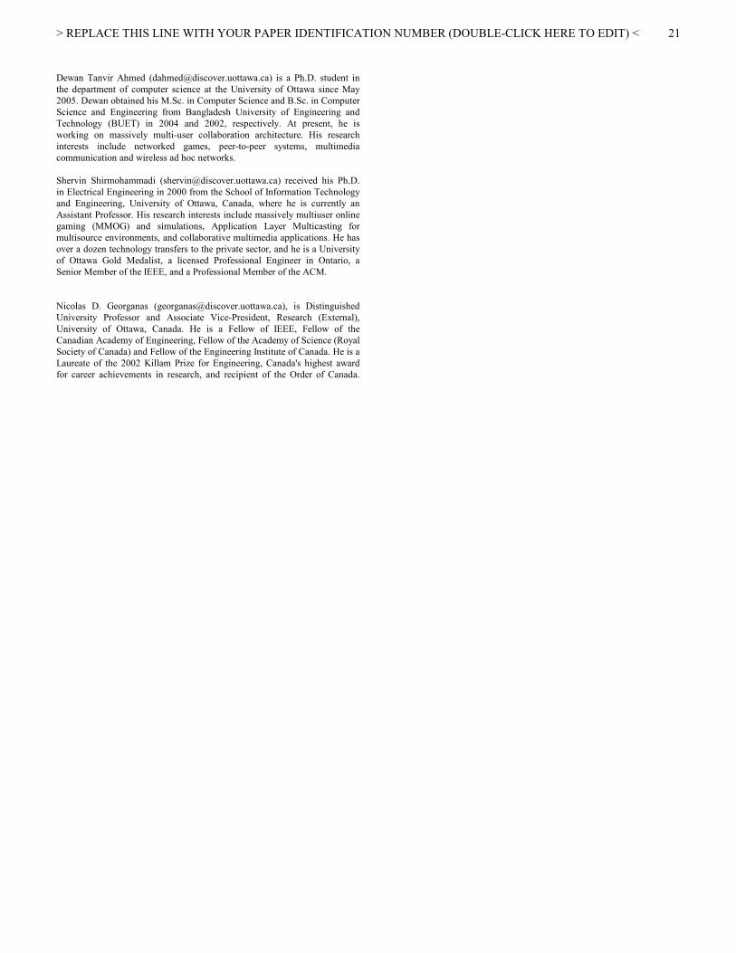
> REPLACE THIS LINE WITH YOUR PAPER IDENTIFICATION NUMBER (DOUBLE-CLICK HERE TO EDIT) <
21
Dewan Tanvir Ahmed ([email protected]) is a Ph.D. student in
the department of computer science at the University of Ottawa since May
2005. Dewan obtained his M.Sc. in Computer Science and B.Sc. in Computer
Science and Engineering from Bangladesh University of Engineering and
Technology (BUET) in 2004 and 2002, respectively. At present, he is
working on massively multi-user collaboration architecture. His research
interests include networked games, peer-to-peer systems, multimedia
communication and wireless ad hoc networks.
Shervin Shirmohammadi ([email protected]) received his Ph.D.
in Electrical Engineering in 2000 from the School of Information Technology
and Engineering, University of Ottawa, Canada, where he is currently an
Assistant Professor. His research interests include massively multiuser online
gaming (MMOG) and simulations, Application Layer Multicasting for
multisource environments, and collaborative multimedia applications. He has
over a dozen technology transfers to the private sector, and he is a University
of Ottawa Gold Medalist, a licensed Professional Engineer in Ontario, a
Senior Member of the IEEE, and a Professional Member of the ACM.
Nicolas D. Georganas ([email protected]), is Distinguished
University Professor and Associate Vice-President, Research (External),
University of Ottawa, Canada. He is a Fellow of IEEE, Fellow of the
Canadian Academy of Engineering, Fellow of the Academy of Science (Royal
Society of Canada) and Fellow of the Engineering Institute of Canada. He is a
Laureate of the 2002 Killam Prize for Engineering, Canada's highest award
for career achievements in research, and recipient of the Order of Canada.