
The Marco Polo Mission: - ESA Science & Technology
12
Marco Polo MP.ASU.ES Issue 1 Page 1 of 12 Company Registration No. 2449259 Registered Office: Gunnels Wood Road, Stevenage, Hertfordshire, SG1 2AS, UK Executive Summary_Issue 1.doc The Marco Polo Mission: Executive Summary Report DTI EXPORT CONTROL RATING: 9E001 – 9A004 Rated by: Paolo D’Arrigo © Astrium Limited 2009 EADS Astrium Limited owns the copyright of this document which is supplied in confidence and which shall not be used for any purpose other than that for which it is supplied and shall not in whole or in part be reproduced, copied, or communicated to any person without written permission from the owner. Astrium Limited Gunnels Wood Road, Stevenage, Hertfordshire, SG1 2AS, England
-
Upload
khangminh22 -
Category
Documents
-
view
0 -
download
0
Transcript of The Marco Polo Mission: - ESA Science & Technology

Marco Polo
MP.ASU.ESIssue 1
Page 1 of 12
Company Registration No. 2449259 Registered Office: Gunnels Wood Road, Stevenage, Hertfordshire, SG1 2AS, UK
Executive Summary_Issue 1.doc
The Marco Polo Mission:
Executive Summary Report
DTI EXPORT CONTROL RATING: 9E001 – 9A004 Rated by: Paolo D’Arrigo
© Astrium Limited 2009
EADS Astrium Limited owns the copyright of this document which is supplied in confidence and which shall not be used for any purpose other than that for which it is supplied and shall not in whole or in part be reproduced,
copied, or communicated to any person without written permission from the owner.
Astrium Limited Gunnels Wood Road, Stevenage, Hertfordshire, SG1 2AS, England

MP.ASU.ES Issue 1 Page 2 of 12
Marco Polo
Astrium Limited owns the copyright of this document which is supplied in confidence and which shall not be used for any purpose other than that for which it is supplied and shall not in whole or in part be reproduced, copied, or communicated to any person without written permission from the owner.
Executive Summary_Issue 1.doc
1 STUDY OVERVIEW AND BACKGROUND Marco Polo has been proposed as an M-class joint mission by the European Space Agency within the Cosmic Vision programme and by the Japanese Space Exploration Agency. The primary goal of this mission is to return a sample from a Near Earth Object belonging to a primitive class to the Earth, allowing a significant step in our understanding of the origin of the solar system. Additional investigations should: enable safe operation and manoeuvring in close proximity to the Asteroid; provide complementary science; and place the collected sample in context.
Various collaboration options are being contemplated. The Marco Polo Assessment Study under ESA contract led by Astrium Ltd has focused on an ESA-defined scenario, defining a feasible mission architecture for the mission and providing preliminary designs for the spacecraft and Earth Re-entry Capsule. Trade-offs have been carried out to determine the optimum launch and transfer strategy, proximity operations, and return strategy. In parallel the key-technologies for the mission have been assessed and the development requirements identified.
In order to present a robust design for M class mission selection the following programmatic requirements must be met:
Nominal and back-up launches to be identified from 2017 - 2019
Asteroid stay time 8-24 months, total mission operations <8years
Technologies shall be at Technology Readiness Level (TRL) 5 in 2009, or plans must be in place to raise the TRL to 5 by 2011
The early phases of the study involved a thorough analysis of the Science, Mission and Programmatic Requirements. This was necessary in order to evaluate the driving requirements for the mission architecture trade-off. A total of 52 different mission architectures were identified, 16 of which were down selected for preliminary assessment, with 5 architectures selected for detailed review.
Architecture No. Configuration
1 PRM
2 PRM/ORB
3 PRM/ORB/ERV
4 PRM/DM/SM
5
DM/SM
ORB/ERV
PRM/ORB/DM/SM/ERV
S/C elements
ORB/DM/SM/ERV
DM/SM/ERV
AB
AB
A
AB
A
PRM Propulsion ModuleORB OrbiterDM Descent ModuleSM Sampling ModuleERV Earth Return Vehicle
Figure 1-1 Marco Polo potential mission architectures
Marco Polo
MP.ASU.ESIssue 1
Page 3 of 12
Astrium Limited owns the copyright of this document which is supplied in confidence and which shall not be used for any purpose other than that for which it is supplied and shall not in whole or in part be reproduced, copied, or communicated to any person without written permission from the owner.
Executive Summary_Issue 1.doc
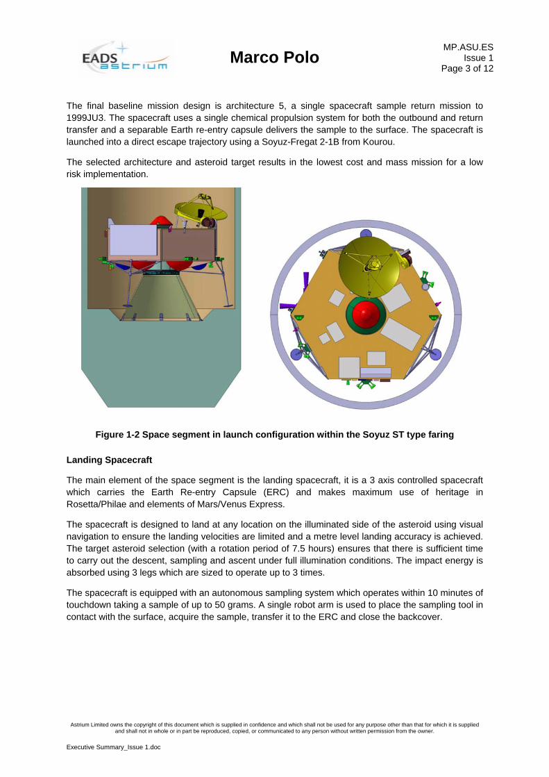
The final baseline mission design is architecture 5, a single spacecraft sample return mission to 1999JU3. The spacecraft uses a single chemical propulsion system for both the outbound and return transfer and a separable Earth re-entry capsule delivers the sample to the surface. The spacecraft is launched into a direct escape trajectory using a Soyuz-Fregat 2-1B from Kourou.
The selected architecture and asteroid target results in the lowest cost and mass mission for a low risk implementation.
Figure 1-2 Space segment in launch configuration within the Soyuz ST type faring
Landing Spacecraft
The main element of the space segment is the landing spacecraft, it is a 3 axis controlled spacecraft which carries the Earth Re-entry Capsule (ERC) and makes maximum use of heritage in Rosetta/Philae and elements of Mars/Venus Express.
The spacecraft is designed to land at any location on the illuminated side of the asteroid using visual navigation to ensure the landing velocities are limited and a metre level landing accuracy is achieved. The target asteroid selection (with a rotation period of 7.5 hours) ensures that there is sufficient time to carry out the descent, sampling and ascent under full illumination conditions. The impact energy is absorbed using 3 legs which are sized to operate up to 3 times.
The spacecraft is equipped with an autonomous sampling system which operates within 10 minutes of touchdown taking a sample of up to 50 grams. A single robot arm is used to place the sampling tool in contact with the surface, acquire the sample, transfer it to the ERC and close the backcover.
MP.ASU.ES Issue 1 Page 4 of 12
Marco Polo
Astrium Limited owns the copyright of this document which is supplied in confidence and which shall not be used for any purpose other than that for which it is supplied and shall not in whole or in part be reproduced, copied, or communicated to any person without written permission from the owner.
Executive Summary_Issue 1.doc
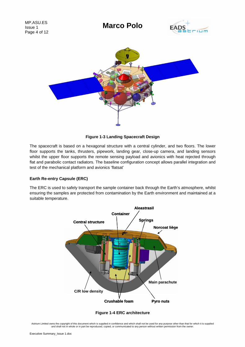
Figure 1-3 Landing Spacecraft Design
The spacecraft is based on a hexagonal structure with a central cylinder, and two floors. The lower floor supports the tanks, thrusters, pipework, landing gear, close-up camera, and landing sensors whilst the upper floor supports the remote sensing payload and avionics with heat rejected through flat and parabolic contact radiators. The baseline configuration concept allows parallel integration and test of the mechanical platform and avionics ‘flatsat’
Earth Re-entry Capsule (ERC)
The ERC is used to safely transport the sample container back through the Earth’s atmosphere, whilst ensuring the samples are protected from contamination by the Earth environment and maintained at a suitable temperature.
C/R low density
Central structure
Main parachute
Crushable foam
Norcoat liège
Container
Pyro nuts
Springs
Aleastrasil
C/R low density
Central structure
Main parachute
Crushable foam
Norcoat liège
Container
Pyro nuts
Springs
Aleastrasil
Figure 1-4 ERC architecture

Marco Polo
MP.ASU.ESIssue 1
Page 5 of 12
Astrium Limited owns the copyright of this document which is supplied in confidence and which shall not be used for any purpose other than that for which it is supplied and shall not in whole or in part be reproduced, copied, or communicated to any person without written permission from the owner.
Executive Summary_Issue 1.doc
The ERC entry strategy is based on a descent under parachute instead of a hard impact strategy (based on a crushable capsule). This allows a significant reduction of the mass and size of the capsule.
The Earth atmospheric entry is performed on a hyperbolic trajectory from 1999 JU3 with an entry velocity of ~11.9km/s. The capsule and entry phase are designed to limit the maximum heat fluxes to 18MW/m2. This results in a capsule design of ~25kg including margins with a front shield diameter of 600mm and a flight path angle requirement of 8.2 degrees ±0.5 degrees. The landing ellipse is similar to Stardust (~8km x 38km).
The descent phase uses both a drogue and main chute. The drogue chute is deployed during supersonic phase by using a mortar, the main chute is deployed by ejection of the back cover once the dynamic pressure and Mach number are compliant with the parachute capabilities.
Biprop Best estimate
Mean maturity margin
Spacecraft 595.9AOCS 39.8 8% 43.1Communications 24.8 16% 28.7Data handling 21.0 11% 23.3Harness 50.0 0% 50.0Mechanisms 44.0 12% 49.3In-Situ Payload 1.0 20% 1.2Remote Sensing Payload 17.8 22% 21.7Power 77.2 14% 87.9Propulsion 112.1 7% 119.7Structure 119.8 20% 143.7Thermal 23.7 15% 27.3
System margin 20% 119.2 119.2Total Spacecraft Dry Mass 715.0ERC 22.14 19% 26.3System Margin 20.0% 3.9 3.9Total ERC Mass 30.2Composite Dry Mass 745.2BaselineWET MASS 1408.1Margin (kg) 196Margin (%) 13%BackupWET MASS 1390.9Margin (kg) 181Margin (%) 13%
Predicted mass
Table 1-1 Summary Mass Budget
The assessment study has shown that the science and mission requirements can be met with a 13% launch margin in addition to the standard margins and an industrial cost of the correct order for an M-class mission implementation. The technology development horizon ‘TRL5 by 2011’ is challenging but this requirement was set for compatibility with 2017 launch. The earliest identified launch date for Marco Polo is November 2018 making the envisaged technology development schedules compatible with Marco Polo mission programmatics.

MP.ASU.ES Issue 1 Page 6 of 12
Marco Polo
Astrium Limited owns the copyright of this document which is supplied in confidence and which shall not be used for any purpose other than that for which it is supplied and shall not in whole or in part be reproduced, copied, or communicated to any person without written permission from the owner.
Executive Summary_Issue 1.doc
2 NEAR ASTEROID OPERATIONS
2.1 SCIENCE OPERATIONS
The main goal of the Marco Polo mission is to return a sample from a near Earth asteroid. In addition, several science instruments shall be used to globally and locally investigate the target body by extensive remote sensing campaigns while in-situ instruments will be used for detailed context studies of the sampling area. The sampling operations represent the most critical and most complex part of the mission operations. This is also reflected in the definition of the spacecraft modes and the mission operations scheme.
The operations phases for the Marco Polo mission to the primary target 1999 JU3 have been assessed with the main emphasis placed on the most important science phases during the proximity operations.
Figure 2-1 Proximity operations plan
The far and global remote sensing and the radio science campaign will be performed from different orbits before the potential sampling sites can be identified based on the collected data. This is followed by the detailed local characterisation of up to 5 sites from close fly-bys or by close hovering. In principle, these can also be used for the first landing rehearsal attempts.
Once the local investigation is finished up to three potential landing sites will be selected for final approaches. The current descent baseline considers starting the descent from a waiting orbit at around 1.5 to 2 km to the gate position at 250 to 500 m above the asteroid surface. At this gate position communication with the Earth will take place for final approval of the current attitude and surface position of the spacecraft and the authorisation for the autonomous final descent phase. The final landing phase ends with free vertical descent and the touch down of the spacecraft.
Before and after the sampling procedure itself, the context of the sample shall be investigated by means of the close up camera.
After the sampling, the spacecraft ascends and acquires a safe position in orbit before a possible repetition of the landing and sampling sequence at a different landing site. Up to three different sampling sites are possible.
Finally, the spacecraft will enter the return cruise phase to the Earth. In Earth vicinity the ERC is separated from the spacecraft and enters the atmosphere. A recovery beacon is switched on to aid fast recovery of the capsule for transfer to a laboratory with suitable equipment to analyse and investigate the samples in detail.

Marco Polo
MP.ASU.ESIssue 1
Page 7 of 12
Astrium Limited owns the copyright of this document which is supplied in confidence and which shall not be used for any purpose other than that for which it is supplied and shall not in whole or in part be reproduced, copied, or communicated to any person without written permission from the owner.
Executive Summary_Issue 1.doc
2.2 GUIDANCE NAVIGATION AND CONTROL (GNC)
The driving GNC requirements for the Marco Polo proximity operations are those associated with the descent phase. For the characterisation phases the requirements are not very stringent when compared with the latest Earth observation or scientific missions. Classical star trackers will provide sufficient attitude measurement performances to meet the pointing requirement, and the stability requirement is met with classical reaction wheels.
The reference scenario for the descent phase proposed by the Astrium team as a first iteration is the following:
• Waiting phase at the home position (9 o’clock 2km orbit). The spacecraft waits here for the optimal time at which the deorbit boost will be performed. The science pointing mode ensures that the spacecraft gets power from the solar arrays.
• Deorbit boost to leave the home position for the gate position which is a hovering point 500m above the landing site. The attitude law is chosen so that the transfer can be solar powered.
• Second boost to stabilize the spacecraft at the gate position. The spacecraft waits at gate position for 1 hour (continuously controlling its velocity to zero relatively to the terrain) to communicate with Earth and allow ground monitoring (and ground guidance & navigation if selected).
• Start of controlled vertical descent. The vertical speed is set to 20 cm/s, the lateral velocities are controlled to zero. If the latitude of the landing site is higher than 45 degrees then no further power is provided by the solar arrays: this is the beginning of the battery-powered phase.
Figure 2-2 Landing strategy

MP.ASU.ES Issue 1 Page 8 of 12
Marco Polo
Astrium Limited owns the copyright of this document which is supplied in confidence and which shall not be used for any purpose other than that for which it is supplied and shall not in whole or in part be reproduced, copied, or communicated to any person without written permission from the owner.
Executive Summary_Issue 1.doc
• At 50m, the vertical control is inhibited. The spacecraft is in free fall. The lateral velocities are still controlled to zero.
• At 15m, all control is inhibited until touchdown.
• Touchdown. Expected horizontal and vertical velocities at touchdown are respectively below 1cm/s and 22cm/s
The position and velocity of the spacecraft need to be sensed in an absolute way to ensure an accurate landing with respect to the selected landing site, and in a relative way once the landing site has been designated to ensure a soft and safe landing.
For the absolute navigation the feature extraction and matching method (MAGELLAN) is selected as the baseline, for the following reasons:
- It is autonomous, thus allowing a short descent sequence (the duration of the landing sequence is one of the key drivers for this phase),
- It is based on visual information, thus allowing a performant and robust solution compared to a blind technique based only on knowledge from inertial measurements and rotation / shape models,
The relative navigation function will be based on an adaptation of the Navigation for Planetary Approach and Landing system (NPAL) for Marco Polo, hybridised with a Doppler velocimeter in order to solve accurately the V/d ambiguity and enhance the robustness of the system.
Both these functions require a navigation camera. It is proposed to use the same camera for these two different needs.
The position / velocity control is performed by 10N hydrazine thrusters arranged in an 8-thrusters configuration. The attitude is estimated by a classical gyro-stellar estimator. It is controlled with reaction wheels in order to avoid firing thrusters for attitude control in the last meters of the descent, and ensure the stability of the platform during characterization phase. The star trackers can also be used to detect the target in the acquisition / insertion phase.
The measurement of the relative attitude of the spacecraft with respect to the terrain is required for the last part of the descent. The vision-based relative navigation could be used for that purpose, a back-up option could be to use multiple beams such as the Laser Range Finder that has been used successfully in the Hayabusa mission.

Marco Polo
MP.ASU.ESIssue 1
Page 9 of 12
Astrium Limited owns the copyright of this document which is supplied in confidence and which shall not be used for any purpose other than that for which it is supplied and shall not in whole or in part be reproduced, copied, or communicated to any person without written permission from the owner.
Executive Summary_Issue 1.doc
3 SURFACE OPERATIONS
3.1 ASTEROID LANDING
The landing simulations carried out have proven that with a simple crushable damper integrated into the legs a stable landing can be achieved within all the envisaged landing scenarios. Based on this assessment it is recommended to implement a simple leg design consisting of two elements:
• Leg framework consisting of struts and brackets
• Damping system consisting of crash dampers for horizontal energy absorption
• Optionally a horizontal crash damper within the foot could be implemented but it is not currently considered
Figure 3-1 Landing gear design accommodated to the Lander
The landing gear consists of 3 independent legs. Each leg is linked to the spacecraft by 6 diagonal struts which are attached at two points to the leg. The leg itself consists of the leg tube which includes the crush material at its top and the piston tube that penetrates into the crush material while landing.
MP.ASU.ES Issue 1 Page 10 of 12
Marco Polo
Astrium Limited owns the copyright of this document which is supplied in confidence and which shall not be used for any purpose other than that for which it is supplied and shall not in whole or in part be reproduced, copied, or communicated to any person without written permission from the owner.
Executive Summary_Issue 1.doc
3.2 SAMPLE COLLECTION AND TRANSFER
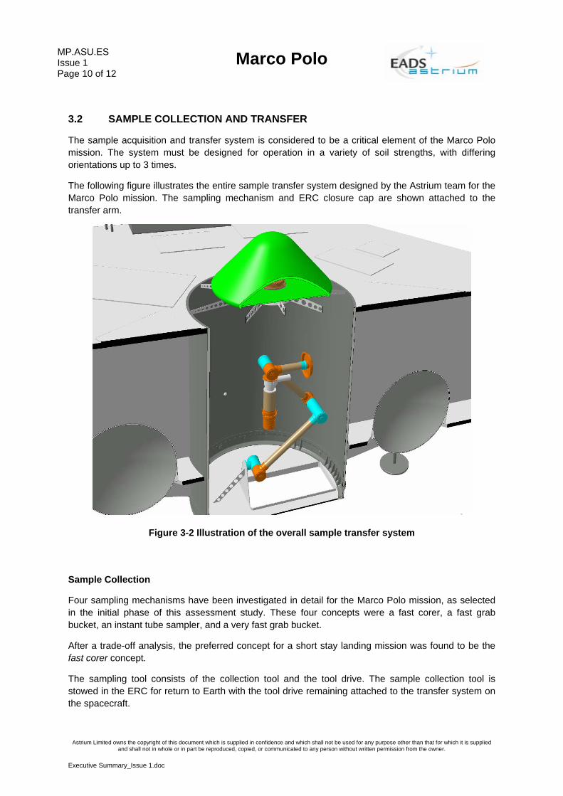
The sample acquisition and transfer system is considered to be a critical element of the Marco Polo mission. The system must be designed for operation in a variety of soil strengths, with differing orientations up to 3 times.
The following figure illustrates the entire sample transfer system designed by the Astrium team for the Marco Polo mission. The sampling mechanism and ERC closure cap are shown attached to the transfer arm.
Figure 3-2 Illustration of the overall sample transfer system
Sample Collection
Four sampling mechanisms have been investigated in detail for the Marco Polo mission, as selected in the initial phase of this assessment study. These four concepts were a fast corer, a fast grab bucket, an instant tube sampler, and a very fast grab bucket.
After a trade-off analysis, the preferred concept for a short stay landing mission was found to be the fast corer concept.
The sampling tool consists of the collection tool and the tool drive. The sample collection tool is stowed in the ERC for return to Earth with the tool drive remaining attached to the transfer system on the spacecraft.

Marco Polo
MP.ASU.ESIssue 1
Page 11 of 12
Astrium Limited owns the copyright of this document which is supplied in confidence and which shall not be used for any purpose other than that for which it is supplied and shall not in whole or in part be reproduced, copied, or communicated to any person without written permission from the owner.
Executive Summary_Issue 1.doc
Seal land with clips (#5)
TripodInterface(female)
Electrical contacts(four)
Interface for motiontransmission to shutters
Nut forhold interface
Clips (#5)
Figure 3-3 Tool illustrations – side, top and bottom views
Sample Transfer
A number of different transfer arm concepts were investigated, involving traversing platforms, multiple arms, single arms, and various degrees of freedom with either rotating or translating joints. The final conclusion was that a single 3 Degree of Freedom (DOF) robot arm with rotational joints is the optimal solution for Marco Polo.
The single 3 DOF robot arm solution comprises three similar joints, with motion in the same axis. The design of the robot arm joints is based on Beagle 2 heritage, with motors and bevel gears at the joint areas, which link to the output of the planetary gearbox to the harmonic drive at the correct orientation. The arm will be stowed at launch, and attached to the spacecraft via its support structure at the bottom, and a non explosive actuator at the top to ensure the launch environment and shocks do not compromise the arm joints. The sampling mechanism will be already attached to the end of the arm from launch.

MP.ASU.ES Issue 1 Page 12 of 12
Marco Polo
Astrium Limited owns the copyright of this document which is supplied in confidence and which shall not be used for any purpose other than that for which it is supplied and shall not in whole or in part be reproduced, copied, or communicated to any person without written permission from the owner.
Executive Summary_Issue 1.doc
4 PROGRAMMATICS
4.1 MISSION DEVELOPMENT PLANNING
The model philosophy for Marco Polo is driven by reducing the risk of the mission while ensuring the industrial cost is kept low. For the Near Earth Asteroid mission the model philosophy has to be defined for the landing spacecraft and Earth re-entry capsule. These spacecraft elements are not independent and for most of the mission operations are combined in the same vehicle. Therefore some tests performed on the stand alone elements need to be carried out again at the launch composite level.
The proposed model philosophy is a single spacecraft model programme – the protoflight model spacecraft – used for system level development and flight acceptance testing. The spacecraft structural model will be composed of a platform structural model, that will be refurbished to be used as a protoflight model, the mass dummies used for the Structure Model test campaign will be replaced with flight hardware.
A Landing Simulation Model (LSM) consisting of a dummy structure representing the inertia of the spacecraft and the stiffness between the attachment points of the landing gear as well as 3 landing legs with dampers. This model shall be used for development and verification tests of the landing gear in parallel with the Structure Model (SM) campaign. This model is assumed to be developed as part of the technology development activity for Marco Polo.
For the ERC both an Engineering Qualification Model (EQM) and Flight Model are required. The drop test will be carried out on the EQM to validate the flight sequence, the parachute deployments and functioning, flight stability and to measure the landing impact shock of the capsule.
4.2 TECHNOLOGY DEVELOPMENT
One of the goals of the assessment studies is to identify the technologies which require development activities in the coming years to bring the TRL to 5 by 2011. The 4 critical technologies identified for Marco Polo are:
• GNC for proximity operations • Landing Gear • Sampling and Transfer System • Earth Re-entry Capsule
Additional technologies which require pre-development or characterisation to increase confidence in the mission design are:
• Directional radiators to achieve the required detector temperatures • Propulsion system contamination assessment
For each of the identified critical technologies, pre-development activities have been planned and costed. These activities typically finish during 2011 or 2012. The identified critical technologies should therefore be available in time for the Marco Polo mission planning where the earliest launch date is November 2018.
The Marco Polo Assessment Study has resulted in an innovative and efficient mission design which results in a 13% launch margin. The mission programmatics and technology development schedules are compatible with the baseline Marco Polo Launch date in November 2018 making the mission a strong candidate for selection.