ESA ACHIEVEMENTS - European Space Agency
202
BR-250 more than thirty years of pioneering space activity
-
Upload
khangminh22 -
Category
Documents
-
view
0 -
download
0
Transcript of ESA ACHIEVEMENTS - European Space Agency

BR-250
more than thirty years of pioneering space activity
ESA ACHIEVEM
EN
TS
BR-25
0
ESA-AchieveCOVER 8/1/05 1:58 PM Page 1

BR-250
June 2005
more than thirty years of pioneering space activity
Andrew Wilson
ESA-Achieve 8/1/05 1:56 PM Page 1
2 3
Foreword 4
Introduction 8
Europa 46
ESRO-2 50
ESRO-1 52
HEOS 54
TD-1 58
ESRO-4 60
Cos-B 62
Geos 66
OTS 70
ISEE-2 74
Meteosat 76
IUE 82
Ariane-1/2/3/4 86
Marecs 94
Sirio-2 98
Exosat 100
ECS 104
Spacelab 108
Giotto 114
Olympus 120
Hipparcos 124
FOC/HST 128
Ulysses 134
ERS 144
Eureca 152
ISO 156
SOHO 160
Ariane-5 168
Cluster 182
Huygens 188
TeamSat 200
ARD 202
XMM-Newton 206
Artemis 210
Proba-1 216
Envisat 220
MSG 230
Integral 236
Mars Express 244
SMART-1 254
Rosetta 260
Sloshsat 272
Coming Launches
CryoSat 274
Venus Express 278
Galileo 284
Metop 292
ATV 298
GOCE 304
Columbus 310
SMOS 324
Proba-2 330
Planck 332
Herschel 338
Vega 344
ERA 348
ADM-Aeolus 352
LISA Pathfinder 356
Swarm 358
JWST 362
Gaia 366
BepiColombo 372
EarthCARE 378
LISA 380
Solar Orbiter 384
Chronologies 388
Acronyms & 398Abbreviations
Index 400
BR-250 “ESA Achievements (3rd edition)”
ISBN 92-9092-493-4 ISSN 0250-1589
Compiled/ Andrew Wilson,written by: ESA Publications Division
Published by: ESA Publications Division,ESTEC, Noordwijk, The Netherlands
Design by: Leigh Edwards &Andrew Wilson
Price: €30
© European Space Agency 2005
Contents
ESA-Achieve 8/1/05 1:56 PM Page 2

It is a privilege to be part of an organisation with such a rich heritage and exciting
potential as the European Space Agency (ESA). The Agency is at a turning point in
its history, so it is an appropriate moment to document and reflect on the many
successes of the past and those still under way, while preparing to head in
new directions for the future.
The remarkable record stretches from humble beginnings in the
1960s to ESA’s leading position today among the front rank of
space organisations, generating enormous benefits for its Member
States and their citizens. The Agency has been responsible for
developing systems that are now accepted as everyday – and
profitable – parts of our lives, leading to the creation of new
entities and companies responding to our needs.
The Ariane rocket alone has provided an impressive return
on investment. It has long dominated the world’s
commercial launch market, operated by the Arianespace
company. The new heavy-lift Ariane-5 is already building
a significant reputation as the latest addition to the
Ariane family. The Meteosat weather satellite system
developed by ESA similarly led to the creation of
Eumetsat. The ECS communications satellites led to
Eutelsat, and the Marecs maritime satellites were vitally
important to Inmarsat. These are all now enterprises of
global importance. Likewise, ESA’s science programme is
second-to-none, and our Earth-observation satellites
continue to return torrents of data. Our expertise is such
that we are welcomed as a major Partner in the
International Space Station. These missions are all included
in this volume. Individual entries cover past, current and
approved future missions beyond this decade.
Despite this superb record, the Agency cannot afford to stand
still. We have thus set three main priorities for the future. The first
is Global Monitoring for Environment and Security, or GMES. The
environment and security are two of the biggest concerns of Europe’s
citizens, and ESA has been working with the European Commission over
the past few years to build a plan for future activities. The time has now
come to implement that plan, based on the concrete results that we have
already achieved in Earth observation, especially with ERS and Envisat.
5
The second priority is Exploration. It is a very important priority for our future,
creating the basis for increasing scientific benefits and for robust European
participation in future large international cooperative space programmes
beyond the lifetime of the International Space Station. Europe has always been
highly successful in this domain, as our scientific missions have proved time
and again, and it now has a new momentum created in part by the Vision for
Space Exploration of President George W. Bush. European spacecraft are now
orbiting the Moon and Mars and one recently made the first-ever landing on
Titan, so we are building our future on concrete results.
The third priority groups together market technologies, essentially
telecommunications, technologies preparing for the long-term, and dual-use
technologies. Technology programmes are a key element of an industrial policy
that serve to consolidate the capabilities and competitiveness of European
industry.
Together, the GMES and technology initiatives provide the foundation for
responding to the demands of European security policies.
The three new initiatives build on the priorities defined by the Space Council, a
joint meeting of the ESA Council and the European Union Council. ESA’s
relationship with the European Union has been strengthened substantially by a
Framework Agreement essential for joint activities. The joint Space Council set
up by this Framework Agreement held its inaugural meeting in November 2004,
the first time that the EU and ESA Councils have met to discuss space policy
and the future of space in Europe. Close cooperation between our two
organisations lies at the heart of European space policy. The pioneering Galileo
satellite navigation system is but the first joint venture that will put space at the
service of European citizens.
The Agency is preparing programme proposals on the basis of this strategy and
will submit them to the ESA Ministerial meeting scheduled for December 2005.
With these new directions, we can expect that the Agency has an equally
productive future and a crucial role in the success of Europe.
Jean-Jacques Dordain
Director-General, European Space Agency
4
Foreword
ESA-Achieve 8/1/05 1:56 PM Page 4

7
Launch date Mission
Proba-1 22 Oct 2001 Technology/Earth observationEnvisat 1 Mar 2002 Earth observation
Meteosat-8 28 Aug 2002 Meteorology: Meteosat Second GenerationIntegral 17 Oct 2002 Science: gamma-ray astronomy
Ariane-5ECA* 11 Dec 2002 Launcher: 9 t GTO-capacity, A5ECA debutMars Express 2 Jun 2003 Science: Mars orbiter & lander
SMART-1 27 Sep 2003 Technology/science: lunar orbiterRosetta 2 Mar 2004 Science: Comet rendezvous (2014-2015)
Sloshsat 12 Feb 2005 Technology
*launch failure Only the debut launches of Ariane-1/2/3/4/5/5ECA, Europa, Vega, Spacelab and ATV are shown.
PLANNED Launch date Mission
MSG-2 Aug 2005 Meteorology: Meteosat Second GenerationCryoSat Sep 2005 Earth observation: polar ice thicknessVenus Express Oct 2005 Science: Venus orbiterGSTB-V2 Dec 2005 Navigation: Galileo System Test BedMetop-2 Apr 2006 Meteorology: polar meteorological servicesATV 2006 Space station: Automated Transfer Vehicle debutGOCE Sep 2006 Earth observation: Earth’s gravity field and geoidColumbus 2006 Space station: research laboratorySMOS Mar 2007 Earth observation: soil moisture and ocean salinityProba-2 Mar 2007 Technology/solar observation
Planck Aug 2007 Science: map Cosmic Microwave BackgroundHerschel Aug 2007 Science: far-IR/sub-mm astronomyVega Nov 2007 Launcher: debut of small solid-propellant launcherERA Nov 2007 Space station: European Robotic ArmADM-Aeolus Sep 2008 Earth observation: global wind measurementsGalileo IOV 2008 Navigation: Galileo in-orbit validationLISA Pathfinder 2008 Technology/science: demonstration for LISAProba-31 2008 TechnologyMSG-3 2008-2009 Meteorology: Meteosat Second GenerationSwarm 2009 Earth observation: Earth’s magnetic field
Metop-1 2010 Meteorology: polar meteorological servicesMSG-4 2010-2011 Meteorology: Meteosat Second GenerationJWST Aug 2011 Science: James Webb Space TelescopeGaia 2011 Science: astrometryBepiColombo May 2012 Science: two Mercury orbiters
EarthCARE 2012 Earth observation: clouds and aerosolsLISA 2012 Science: gravitational wave detection
Solar Orbiter1 Oct 2013 Science: solar observations
Metop-3 2014 Meteorology: polar meteorological servicesMTG1 2015 Meteorology: Meteosat Third Generation
1awaiting full approval
Launch date Mission
Europa-I F1 5 Jun 1964 Launcher: test of stage-1ESRO-2A* 29 May 1967 Science: cosmic rays, solar X-rays
ESRO-2B 17 May 1968 Science: cosmic rays, solar X-raysESRO-1A 3 Oct 1968 Science: Earth auroral and polar-cap phenomena, ionosphere
Europa-I F7* 30 Nov 1968 Launcher: first orbital attemptHEOS-1 5 Dec 1968 Science: interplanetary medium, bow shock
ESRO-1B 1 Oct 1969 Science: as ESRO-1AEuropa-II F11* 5 Nov 1971 Launcher: orbital demonstration
HEOS-2 31 Jan 1972 Science: Earth polar magnetosphere, interplanetary mediumTD-1 12 Mar 1972 Science: UV, X-ray and gamma-ray astronomy
ESRO-4 26 Nov 1972 Science: Earth neutral atmosphere, ionosphere, auroral particles
Cos-B 9 Aug 1975 Science: gamma-ray astronomyGeos-1 20 Apr 1977 Science: dynamics of Earth magnetosphereOTS-1* 14 Sep 1977 Telecommunications: demonstrate European technologiesISEE-2 22 Oct 1977 Science: Sun/Earth relations and magnetosphereMeteosat-1 23 Nov 1977 Meteorology: pre-operational meteorological servicesIUE 26 Jan 1978 Science: ultraviolet astronomyOTS-2 12 May 1978 Telecommunications: demonstrated European technologiesGeos-2 24 July 1978 Science: Earth magnetospheric fields, waves and particlesAriane-1 24 Dec 1979 Commercial launcher: first of 11 Ariane-1 launches
Meteosat-2 19 Jun 1981 Meteorology: pre-operational meteorological servicesMarecs-A 20 Dec 1981 Telecommunications: maritime communicationsMarecs-B* 10 Sep 1982 Telecommunications: maritime communicationsSirio-2* 10 Sep 1982 Meteorological data distribution & clock synchronisation Exosat 26 May 1983 Science: X-ray astronomyECS-1 16 Jun 1983 Telecommunications: operational European
Communications SatelliteSpacelab-1 28 Nov 1983 First of 22 manned Spacelab missions, plus
multi-disciplinary First Spacelab Payload (FSLP)Ariane-2/3 4 Aug 1984 Commercial launcher: first of 17 Ariane-2/3 launchesECS-2 4 Aug 1984 Telecommunications: operational European
Communications SatelliteMarecs-B2 10 Nov 1984 Telecommunications: maritime communications
Giotto 2 Jul 1985 Science: Comet Halley and Comet Grigg- Skjellerup encounters
ECS-3* 12 Sep 1985 Telecommunications: operational European Communications Satellite
ECS-4 16 Sep 1987 Telecommunications: operational European Communications Satellite
Ariane-4 15 Jun 1988 Commercial launcher: first of 116 Ariane-4 launchesMeteosat-3 15 Jun 1988 Meteorology: pre-operational meteorological servicesECS-5 21 Jul 1988 Telecommunications: operational European
Communications SatelliteMeteosat-4 6 Mar 1989 Meteorology: operational meteorological servicesOlympus 12 Jul 1989 Telecommunications: technology demonstrationHipparcos 8 Aug 1989 Science: astrometryHST/FOC 24 Apr 1990 Science: astronomy (Hubble Space Telescope/Faint
Object Camera)
Ulysses 6 Oct 1990 Science: probing heliosphere above/below ecliptic up to solar poles
Meteosat-5 2 Mar 1991 Meteorology: operational meteorological servicesERS-1 17 Jul 1991 Earth observation: pre-operational radar
Eureca 31 Jul 1992 Science: multi-disciplinary, reusable platformMeteosat-6 20 Nov 1993 Meteorology: operational meteorological services
ERS-2 21 Apr 1995 Earth observation: pre-operational radarISO 17 Nov 1995 Science: infrared astronomy
SOHO 2 Dec 1995 Science: Sun, from core to beyond Earth orbitAriane-5* 4 Jun 1996 Commercial launcher: new generation of heavy launchers
Cluster* 4 Jun 1996 Science: space plasma physics in 3D (FM1-FM4)
Meteosat-7 2 Sep 1997 Meteorology: operational meteorological servicesHuygens 15 Oct 1997 Science: Titan atmosphere/surface probe
TeamSat 30 Oct 1997 Science/technology: experiments on Ariane-502 demonstration launch
ARD 21 Oct 1998 Technology: demonstration of Earth-return technologiesXMM-Newton 10 Dec 1999 Science: X-ray astronomy
Cluster 16 Jul 2000 Science: space plasma physics in 3D (first pair: FM6 & FM7)Cluster 9 Aug 2000 Science: space plasma physics in 3D (second pair: FM5 & FM8)
Artemis 12 Jul 2001 Telecommunications: demonstration
/continued next page
6
Planned
launches of
ESA and
related
missions
Launches of
ESA, ESRO,
ELDO and
related
missions
ESA-Achieve 8/1/05 1:56 PM Page 6

98
mandatory, so that long-termplanning was possible for the firsttime. Three more optionalprogrammes were added in 1973:Spacelab, Europe’s contribution tothe US Space Shuttle programme; theAriane launcher; and the Marots(later Marecs) maritimecommunications satellite.
All of these programmes wereunderway in May 1975 when ESAassumed de facto responsibility.
ESA and ScienceThe Science Programme is one of theAgency’s mandatory activities, inwhich all Member States participate.Much of the advanced technologyused today stems from the scientificprogramme: over the years it hasbeen the driving force behind manyother ESA activities.
The origins of the ScienceProgramme, the oldest in the Agency,hark back to the days of ESRO.ESRO’s seven successful scientificsatellites paved the way for ESA’sremarkable series of pioneeringmissions that have placed Europe atthe vanguard of disciplines such asX-ray, gamma-ray and infraredastronomy; astrometry; Solar Systemsciences (especially cometary), solarand heliospheric physics, as well asspace plasma physics. Driven by thelimited available means, ESA’sScience Programme has consistentlyfocused on missions with stronginnovative contents. All of themissions launched or approved so farare covered in separate entries in thisvolume.
1985 was an important milestone inthe history of ESA’s ScienceProgramme. It saw the approval of
the long-term Horizon 2000programme of scientific research inspace, designed to ensure thatEurope would play a key andbalanced role beyond the end of thecentury. Executing Horizon 2000required a special financial effortfrom the Member States, amountingto a progressive budgetary increase of5% per year from 1985 to a steadyplateau in 1994 of about €470 millionin 2004 terms. Horizon 2000encompassed the missions alreadyapproved (Hubble Space Telescope,Ulysses, Hipparcos and ISO) andadded four Cornerstone missions,plus Medium-size (‘M’) missions
Ulysses completed itsoriginal mission ofprobing the heliosphereat all latitudes and isnow swinging aroundon a third passage
The impetus for creating anindependent space power in Europebegan in the early 1960s. Belgium,France, Germany, Italy, theNetherlands and the United Kingdom(associated with Australia) signed theConvention in March 1962 to createthe European Launcher DevelopmentOrganisation (ELDO), with the goal ofdeveloping a satellite launch vehicleindependent of the two great spacepowers, the USA and USSR.
Similarly, Belgium, Denmark, France,Germany, Italy, the Netherlands,Spain, Sweden, Switzerland and theUK in June 1962 signed theConvention to create the EuropeanSpace Research Organisation (ESRO),for undertaking scientific satelliteprogrammes.
These partners subsequently decidedto merge the activities of ELDO andESRO into a single body, and in July1973 a ministerial conference of the10 European countries met inBrussels and laid down the principlesfor creating the European SpaceAgency (ESA). The Agency beganoperating on 31 May 1975, and on30 October 1980 the final signatureratifying the Convention gave legalexistence to ESA.
While ELDO had dramatic difficultiesdeveloping the Europa launcher,ESRO was becoming a matureorganisation. Seven scientificsatellites reached orbit by the end of
1972, proving that ESRO couldcompete with the major space powersand could manage importantindustrial contracts. By this time,there had been a fundamental changein ESRO’s aims. Its Council resolvedin December 1971 to includeapplications satellites, namely theOrbital Test Satellite fortelecommunications, Meteosat formeteorology and Aerosat foraeronautical communications. Whilethese would dominate the scienceelement financially, they wereoptional, allowing Member States thechoice of participating or not. TheScience Programme became
From humblebeginnings: the ESRO
scientific satellites(ESRO-4 is shown here)
were small bycomparison with today’s
sophisticated spacecraft,but they laid a firm
foundation for the future.
ESA
Achievements
http://sci.esa.int/http://www.esa.int
sec1 8/1/05 2:33 PM Page 8

1110
selected competitively. Cornerstone-1combined two missions into the Solar-Terrestrial Science Programme:Cluster and SOHO. The CS-2 High-Throughput X-ray SpectroscopyCornerstone is XMM-Newton; theCS-3 Cometary Cornerstone isRosetta; the CS-4 Far-Infrared andSubmillimetre SpectroscopyCornerstone is Herschel. The selectedMedium missions are: M-1 HuygensProbe; M-2 Integral; M-3 Planck.
Preparatory work began in 1993 onthe follow-up Horizon 2000 Plusprogramme to cover new missions for2007-2016, including three newCornerstones. The Ministerial Meetingin September 1995 approved the long-term programme but imposed a 3%annual reduction in purchasing poweron the Scientific Directorate. Then,when the four Cluster satellites weredestroyed by the Ariane-501 failure inJune 1996, it became inevitable thatthe Science Programme had to berevised.
The Cornerstones were maintained,but the medium M-missions werereplaced by smaller missions in orderto regain programme flexibility. Thesewere ‘F’ (Flexible) missions with purelyscientific goals, and ‘SMART’ (SmallMissions for Advanced Research inTechnology), which can provide in-orbit proof of technologies,particularly for Cornerstones, andcarry, as a secondary goal, scientificexperiments. Mars Express wasconditionally approved in November1998 as the first Flexi mission (F1)and confirmed following the May 1999Ministerial Council meeting. SMART-1(2002) is demonstrating technologiesfor the Mercury Cornerstone, andSMART-2 (now called LISA Pathfinder;2008) for LISA. On 1 October 1999,ESA requested proposals for F2 and
F3, selecting five of the 50 forassessment studies March-May 2000:Eddington, Hyper, MASTER, SolarOrbiter and Storms; the James WebbSpace Telescope was already part ofthe process.
In October 2000, the ScienceProgramme Committee (SPC)approved a package of missions for2008-2013. BepiColombo becameCS-5 (2012, Mercury Cornerstone)and Gaia CS-6 (2012). LISA is also aCornerstone (Fundamental Physics)but to fly in collaboration with NASAat a cost to ESA of a Flexi mission.F2 and F3 are JWST and SolarOrbiter, respectively. A reserve Fleximission, Eddington (to map stellarevolution and find habitable planets),was also selected in case the JWSTand LISA schedules of NASA slippedbeyond 2013 (see later forEddington’s fate).
The Cornerstone Darwin InfraredSpace Interferometer, to search forEarth-like planets around other stars,falls beyond the horizon but work onit continues towards future funding.
Following the Ministerial Council ofNovember 2001 (Edinburgh, UK),where there was no increase in realterms of the level of resourcesallocated to science, ESA undertook acomplete reassessment of the scienceprogramme in close collaborationwith the science community. Theresulting ‘Cosmic Vision’ wasapproved by the SPC on 23 May2002. It not only maintained themissions approved in October 2000,but added the Eddington mission:
AstrophysicsGroup 1: XMM-Newton, IntegralGroup 2: Herschel, Planck, Eddington Group 3: Gaia.
Solar SystemGroup 1: Rosetta, Mars Express Group 2: SMART-1, BepiColombo,
Solar Orbiter
Fundamental PhysicsSTEP (Satellite Test of the Equivalence
Principle, cancelled by NASA in2002)
SMART-2 (became LISA Pathfinder)LISA (joint mission with NASA).
In addition, the Agency was committedto cooperation with NASA on JWST.
The ‘production groups’ are more thanscientific groupings. Missions withineach are sharing technologies andengineering teams wherever possible.For example, Herschel, Planck andEddington were to use not only thesame bus but also the sameengineering team. BepiColombo and
Solar Orbiter were teamed, andinternational collaboration sought.The philosophy saw Venus Expressadded in November 2002 to reuse theMars Express bus, expertise andmost of the instruments. At the sametime, major technical changesreduced the cost of Gaia with no lossof science.
The high ambitions combined withthe slow decline in funding meantthere was little flexibility left to copewith adverse events. A major blowwas dealt when the failure of the newAriane-5 design in December 2002grounded the whole fleet and forcedmajor delays on Rosetta (13 months)and SMART-1 (6 months) costingabout €100 million. Faced with thisand other financial demands, the SPCon 6 November 2003 was forced forthe first time ever to cancel a
SOHO observes a Coronal Mass Ejection – billionsof tonnes of magnetised plasma erupting from the
Sun’s corona at up to 2000 km/s.
sec1 8/1/05 2:33 PM Page 10

1312
The Grand Canyon of Mars: Valles Marinerisimaged by the High Resolution Stereo Camera ofMars Express on 14 January 2004.(ESA/DLR/FU Berlin, G. Neukum)
sec1 8/1/05 2:33 PM Page 12

1514
ISO’s infrared view of the HelixNebula, showing the shells of
gas and dust ejected as a Sun-like star collapsed. The
resulting central white dwarfstar is too hot to show up in
the infrared.(ESA/ISOCAM/P. Cox et al)
ESA’s Huygens Probeparachuted through theatmosphere of Saturn’smoon Titan in January2005. Inset: the firstcolour image from thesurface of themysterious moon.
Phobos: the martianmoon imaged by Mars
Express at a resolutionof about 7 m per pixel
on 22 August 2004.(ESA/DLR/FU Berlin,
G. Neukum)
XMM-Newton is helpingto solve a number of
cosmic mysteries,ranging from the enigma
of black holes to theorigin of the Universeitself. Inset: soft X-ray
image of CometMcNaught-Hartley,
January 2001.
The first four Clustersatellites were
destroyed in 1996, but areplacement set was
launched successfully inpairs in 2000.
Ultraviolet image ofgalaxy M81 obtained by
the Optical Monitor ofXMM-Newton in April 2001.
sec1 8/1/05 2:33 PM Page 14
17
The Agency then focused ondeveloping mission scenarios andtechnology requirements to satisfythese themes within the envisagedtimescale. Following endorsement bythe SPC in May 2005, the ‘CosmicVision 2015-2025’ document will beproduced, laying out the targets forEuropean space science for thatdecade. Subsequently, once thefinancial framework is known, theEuropean scientific community willbe called upon to produce a plan,including concrete missions andmission scenarios, to capture therange of scientific themes targeted.
Past, current and approved sciencemissions are:
ESRO-2 (1968): studied cosmic raysand solar X-rays.
ESRO-1A/B (1968/69): aurora andionosphere.
HEOS-1/2 (1968/72): first Europeansatellites beyond near-Earth space,to study magnetosphere andinterplanetary medium.
TD-1 (1972): UV, X-ray and gamma-ray astronomy.
ESRO-4 (1972): upper atmosphereand ionosphere.
Cos-B (1975): ESA’s first satellitemapped the little-explored gamma-ray sky.
Geos (1977/78): two satellitesstudied the particles, fields andplasma of Earth’s magnetosphere.
ISEE-2 (1977): worked in tandemwith NASA’s ISEE-1 studyingEarth’s magnetosphere.
IUE (1978): the InternationalUltraviolet Explorer was the world’slongest serving and most prolificastronomy satellite, returning UVspectra on celestial objects rangingfrom comets to quasars until 1996.
Exosat (1983): studied the X-rayemissions and their variations over
time of most classes ofastronomical objects in 1780observing sessions.
Giotto (1985): first close flyby of acomet (Comet Halley, March 1986),followed by a bonus encounter withComet Grigg-Skjellerup in July1992.
Hipparcos (1989): produced the mostaccurate positional survey of morethan 100 000 stars, fundamentallyaffecting every branch ofastronomy.
Hubble Space Telescope (1990): 15%contribution, including the FaintObject Camera, to this premierinternational space telescope.
Ulysses (1990): continuing the fieldsand particles investigation of theinner heliosphere at all solarlatitudes, including the solar poles.
ISO (1995): world’s first infraredastronomical observatory provideda fresh perspective on the Universe.
SOHO (1995): first Horizon 2000Cornerstone, studying the Sun’sinterior, as well as the corona andits expansion into the solar wind.
Cluster (1996): part of the firstHorizon 2000 Cornerstone, toinvestigate plasma processes inEarth’s magnetosphere using foursatellites. Lost in first Ariane-5launch failure; replacementssuccessful in mid-2000.
Huygens (1997): the first probedesigned to descend through theatmosphere of Saturn’s moonTitan, January 2005.
XMM-Newton (1999): the X-ray Multi-Mirror mission is the mostsensitive X-ray astronomy satelliteyet, finding millions of new objects.
Cluster (2000): duplicatereplacements of the four Clustersatellites, observing plasmaprocesses in Earth’smagnetosphere.
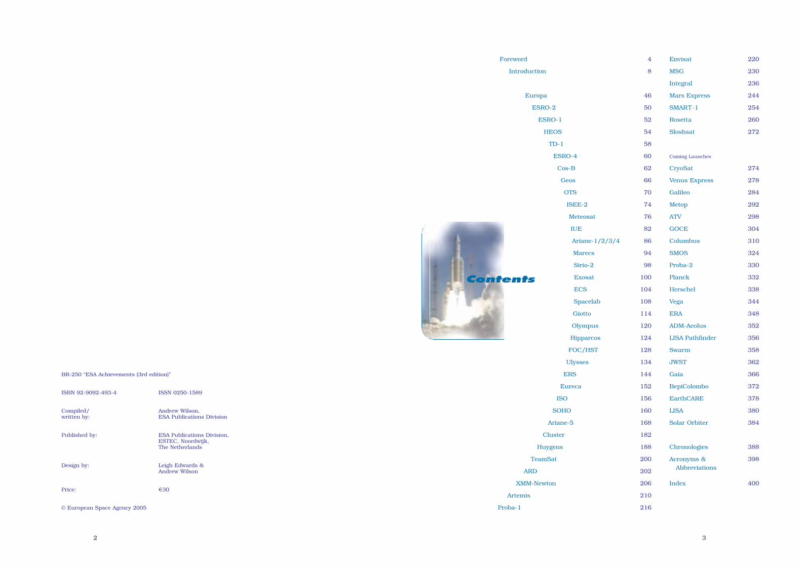
Integral (2002): the International
16
mission. The choice came down toEddington and LISA Pathfinder.Eddington was riding on the coat-tails of Herschel/Planck and couldnot be delayed without major costincrease, whereas LISA Pathfinderwas already agreed with NASA on astrict schedule. Eddington wascancelled. In addition, the Mercurylander of BepiColombo was cancelled.
Cosmic Vision is a living programme,having to adapt to the availablefunding at the same time asresponding to the expectations of thescientific community. The goal of theSPC is to maximise the outcome ofCosmic Vision across disciplines,keeping it challenging but affordable.
The current Cosmic Visionruns until 2015 but the
Agency, supported byits advisory
structure, developed a new planduring 2004 for approval in 2005.This will be the culmination of thethird major planning exercises thathave framed European space scienceover the past two decades since theHorizon 2000 exercise of 1983-1984.
ESA issued a call for themes inspring 2004. Nine major themes werecondensed from the 151 proposals:
– Other worlds and life in theUniverse;
– The early Universe;– The evolving violent Universe;– Towards quantum gravity;– Beyond the standard model;– The gravitational-wave Universe;– From the Sun to the Earth and
beyond;– Tracing the origin of the Solar
System;– Life and habitability in the Solar
System and beyond.
Integral is observing themost energetic events in
the Universe.(ESA/D. Ducros)
Inset: a gamma-rayburst like this, Integral’s
first, may signal the birthof a black hole.
sec1 8/1/05 2:33 PM Page 16

1918
Gamma-Ray Astrophysics Lab isobserving gamma-ray sourceswithin our Galaxy and beyond,including exploding stars, blackholes, gamma-ray bursts andpulsars.
SMART-1 (2002): demonstrating keytechnologies, including primarypropulsion by a solar electricthruster, critical for BepiColombo.
Mars Express (2003): this orbiter isintensively studying Mars.
Rosetta (2004): arriving at CometChuryumov-Gerasimenko in 2014,Rosetta will orbit the nucleus for2 years of intensive studies,depositing a lander.
Venus Express (2005): reuse of MarsExpress bus and instruments.
Planck (2007): the mission to mapthe structure of the CosmicMicrowave Background, inunprecedented detail. Launch intandem with Herschel.
Herschel (2007): using one of theleast explored windows on theUniverse, it will observe the births
of stars and galaxies throughoutthe history of the Universe. Launchin tandem with Planck.
LISA Pathfinder (2008): todemonstrate key technologies forLISA.
JWST (2011): 15% contribution toNASA’s infrared observatory forprobing back to the time of the veryfirst stars.
Gaia (2011): building on Hipparcos tocreate a high-precision 3-D map of1000 million stars in our Galaxyand beyond.
BepiColombo (2012): two Mercuryorbiters, arriving 2017, incollaboration with Japan.
Solar Orbiter (2013): SOHOsuccessor to study the Sun towithin 45 solar radii.
LISA (2013): three satellites information to detect gravitationalwaves for the first time, incollaboration with NASA.
The Cosmic Vision space scienceplan as of October 2004.
ESA Science Programme funding is currently about €370 million annually. The annual budgets have been converted into 2004 €,highlighting the gradual reduction in real terms. (Status November 2004.)
Above: the Horizon 2000 space science plan was formulated in 1985. Right: it was extended byHorizon 2000 Plus 10 years later, and jointly termedHorizons 2000. Financial constraints and theCluster launch failure led to the later Medium (blue)missions being replaced by Flexi and SMARTmissions.
sec1 8/1/05 2:33 PM Page 18

20
ESA and Earth ObservationIt has become increasinglyrecognised over the past threedecades that many key aspects ofmonitoring and managing our planetcan be adequately addressed only byobserving the Earth from space. Inthis respect, ESA’s role has beencritically important.
The Earth’s environment and climateare determined not only by complexinteractions between the atmosphere,oceans, land and ice regions, butalso by mankind’s ability to affectthem. Our future depends on thecareful management of resources andon an improved understanding of theinteractions creating our ecosphere.
The first of seven first-generationMeteosat meteorological satellites,originating under ESA’s auspices,appeared in 1977 to monitor theweather of Europe and Africa from avantage point over the Equator. Thesuccess of that first satellite led tothe formation of the EuropeanOrganisation for the Exploitation ofMeteorological Satellites (Eumetsat)in 1986, which took over directoperational control in December1995.
It has been estimated that the totalbenefits from improved weatherforecasts due to Meteosat aloneequate to about €125 millionannually in cost savings for allindustries and €137 million in savingof life and reduction inenvironmental damage. Agriculturealone saves €30 million and civilaviation €11 million each year. Inaddition, the capacity of weathersatellites to gather long-termmeasurements from space in supportof climate-change studies is ofgrowing importance.
The Meteosat Second Generation(MSG) entered service in 2004.Jointly funded by ESA MemberStates and Eumetsat, the programmebegan in 1994 to enhance theperformance of today’s satellites,incorporating a much-improvedimager and the first instrumentcapable of observing the Earth’sradiation balance from geostationaryorbit. MSG provides the mostadvanced capabilities available fromgeostationary orbit. It is not only amajor advance in monitoringchanging weather patterns over anentire hemisphere, but it is alsoimproving storm warnings and long-term forecasts, while contributingsignificantly to global climateresearch. MSG sees much moreclearly and frequently than itspredecessors, revealing features likethunderstorms, encroaching stormfronts, fog banks and otherhazardous weather conditions. Bymonitoring ozone in the upperatmosphere, MSG is improvingforecasts of harmful ultraviolet lightlevels and thereby reducing thethreat of skin cancer.
The Meteosat Third Generation (MTG)is already under study, with the aimof entering service in 2015.
Polar-orbiting meteorologicalsatellites will be added in 2006 withthe first of three Metop(Meteorological Operational)spacecraft developed by ESA andEumetsat. This will not only continueand improve meteorologicalobservations previously provided byUS NOAA satellites in the ‘morning’polar orbit, but it will also endowEurope with an enhanced capabilityfor routine climate monitoring.Notable improvements includeroutine observations of sea-surface
http://earth.esa.int
The Meteosat Second Generationentered service in 2004 to extend
services to Europe’s meteorologicalagencies. MSG-1/Meteosat-8 final
inspection. (Alcatel Space Industries)
The series of eight Meteosats has returnedhundreds of thousands of Earth imagesfrom geostationary orbit. (Meteosat-8image, 19 May 2003; Eumetsat)
sec1 8/1/05 2:33 PM Page 20

2322
wind fields, ozone levels and muchhigher-resolution temperature andhumidity profiles.
ESA’s first remote-sensing satelliteseries, ERS, continues to make majorcontributions in areas as diverse asglobal and regional ocean andatmospheric science, sea ice,glaciological and snow coverinvestigations, land surface studiesand the dynamics of the Earth’scrust. For example, global maps ofsea-surface winds are routinelyprovided as inputs to numericalweather forecasting. The 1991 launchof ERS-1 was followed in 1995 by
ERS-2, which added the GlobalOzone Monitoring Experiment toaddress an area of growing concern,namely atmospheric chemistry, andin particular to generate global ozonemaps every 3 days.
ESA’s large Envisat secondgeneration remote-sensing satelliteappeared in orbit in 2002. It not onlyensures continuity of many ERSobservations but adds important newcapabilities for understanding andmonitoring our environment,particularly in the areas ofatmospheric chemistry and oceanbiological processes.
The global reach of the Envisat environmentalsatellite is revealed by this portrait of PlanetEarth in 2004. Envisat’s MERIS imagingspectrometer reveals a wide variety of landcovering, from ice to forest, grassland todesert. For this true-colour mosaic, a total of1561 orbits during May, July, October andNovember 2004 were used to screen out theclouds.
Inset: ASAR interferogram of the Bam (Iran)earthquake of 26 December 2003. Combiningimages taken shortly before and after thelevel-6.3 quake shows the 5-30 cm groundmovement, revealing a fault previouslyunsuspected.
Envisat is carrying the three mostadvanced instruments to date tostudy atmospheric chemistry: MIPAS,GOMOS and SCIAMACHY. They arehelping us to understand the complexprocesses behind the growinggreenhouse effect.
The MERIS instrument is recognisedas providing unprecedented spectralresolution for land and oceanresearch and applications. Inaddition, the ATSR instrument onERS and Envisat is the most accuratesource of sea-surface temperaturemeasurements from space, and theonly one able to study long-term
sec1 8/1/05 2:33 PM Page 22

24
climate change by virtue of itsaccuracy and continuity over up to18 years in orbit.
The Agency’s strategy for Earthobservation beyond 2000 wasendorsed by ESA’s Council in March1998 after being approved inprinciple by the Ministerial Council ofOctober 1995 in Toulouse. ESA’s‘Living Planet’ programme follows onfrom Envisat, and is designed tocover the whole spectrum of userinterests ranging from scientificresearch to applications. Research-driven Earth Explorer missions areparalleled by Earth Watch missions,designed to focus on specificapplications and service provision tosatisfy operational user needs.
Member States subscribe to theoverall Explorer financial envelope, sothat each project no longer has to beapproved separately. As has longbeen the case in ESA’s ScienceProgramme, this allows a coherent,long-term set of missions to bedeveloped.
The Earth’s environment is a highlycomplex system coupling theatmosphere, oceans, biosphere andcryosphere. Despite its importance,many aspects of this Earth systemare still poorly understood and weare struggling to assess globalthreats such as climate change,stratospheric ozone depletion andtropospheric pollution, as well asmore localised events such as the1998 El Niño event, fires in SouthEast Asia and devastatingearthquakes in Turkey. Observationsfrom space can provide the requiredglobally coherent data.
Explorer offers two mission types:Core and Opportunity. The larger
Core missions are selected through atraditional process involvingextensive consultation with the usercommunity. Opportunity missionsare intended to respond quickly toflight opportunities or to userrequirements, and are not necessarilyESA-led. In this way, the programmecombines stability with flexibility,notably the ability to respond quicklyto an evolving situation. Coremissions cost the Agency no morethan €425 million (2004 conditions),while Opportunity missions cost anaverage €110 million (€170 millionmaximum in 2004 terms). The goal isto fly a Core mission about every2 years, interspersed withOpportunity missions.
Explorer Core MissionsAn Earth Observation UserConsultation Meeting at ESTEC inOctober 1994, followed by otherconsultations, identified ninecandidate Core missions. These wereassessed by ESA working groups andfour were selected in November 1996for June 1998 to June 1999 Phase-Astudies: Earth Radiation Mission(ERM), Gravity Field and Steady-State Ocean Circulation Mission(GOCE), Land Surface Processes andInteractions Mission (LSPIM) and
25
Atmospheric Dynamics Mission(ADM-Aeolus). GOCE and ADM wereselected in order of priority inNovember 1999. GOCE immediatelybegan Phase-B for launch in 2006,while ADM-Aeolus began Phase-B in2002 for launch in 2007.
GOCE will measure the Earth’sgravity field and geoid withunprecedented accuracy andresolution using a 3-axis gradiometer.This will improve our understandingof the Earth’s internal structure andprovide a much better reference forocean and climate studies.
ADM-Aeolus will make the first directobservations on a global scale of windprofiles over the depth of theatmosphere, a notable deficiency incurrent observing methods. This isimportant for understandingatmospheric processes – particularlyin the tropics – as well as improvingthe numerical modelling used inweather forecasting.
The second Call for Ideas for Coremissions was issued on 1 June 2000,receiving ten proposals by the1 September 2000 closing date. On20 November 2000, ESA selected fivefor assessment studies:
ACECHEM: Atmospheric CompositionExplorer for Chemistry and ClimateInteraction to study climate-chemistry interactions and man-made effects;
EarthCARE: Earth Clouds Aerosoland Radiation Explorer(encompassing ERM) to measurethe physical properties of cloudsand aerosols to improve climatemodelling and our understandingof Earth’s radiation balance; jointmission with JAXA;
SPECTRA: Surface Processes andEcosystems Changes ThroughResponse Analysis to measurevegetation parameters for studyingthe carbon cycle and the effects ofclimate variability on ecosystems(builds on LSPIM);
WALES: Water Vapour LidarExperiment in Space to measurewater vapour and aerosoldistribution in the troposphere;
WATS: Water Vapour and Wind inAtmospheric Troposphere andStratosphere to monitor waterdistribution for assessing climatechange (encompassing the ACE hotstandby from the Opportunitymissions).
Three were selected on 29 November2001 for 12-month Phase-A studies:EarthCARE, SPECTRA and WALES.On 28 May 2004, the ProgrammeBoard announced the choice wouldbe between EarthCARE andSPECTRA, although EarthCARE wasranked first. The Board of24 November 2004 voted forEarthCARE, with launch in 2012.
Explorer Opportunity MissionsThe AO for Opportunity missions wasreleased on 30 June 1998 and 27proposals were received by closure on2 December 1998. On 27 May 1999,ESA approved CryoSat as the first for
The Earth’s environment is a highlycomplex, coupled system. Understandingit requires observations from space.
sec1 8/1/05 2:33 PM Page 24

2726
ADM-AeolusEarthCARE
SMOSCryoSat SwarmGOCE
Phase-A/B, with an extendedPhase-A for SMOS. CryoSat willmeasure the variations in thethickness of the polar ice sheets andthe thickness of floating sea ice.SMOS will measure soil moisture andocean salinity – two key variables inthe Earth system. Launches areexpected in 2005 and 2007,respectively.
Work continued on ACE (AtmosphericClimate Explorer) as a hot backupshould the first two suffer problems.It would monitor GPS signalsrefracted through the upperatmosphere to measure temperatureand humidity. ACE+ competed againfor the third Opportunity slot in2004. Swarm and SWIFT were heldin reserve. Multiple Swarm satelliteswould measure the geomagnetic fieldat high resolution, providing newinsights into the Earth’s structure.SWIFT (Stratospheric WindInterferometer for Transport studies)would map winds and ozone in thestratosphere.
In fact, SWIFT (largely funded byCanada) was approved in October2000 by Japan’s NASDA (now JAXA)space agency to fly on Gosat(Greenhouse Gas Observing Satellite)in 2007. It remains part of EarthExplorer but flying cooperativelyleaves the funding intact for furtherfull ESA missions.
The next Opportunity AO was madeon 1 June 2001 and 25 full proposalswere received by closure in January
2002. The Programme Board selectedthree on 16 May 2002 for Phase-Astudies: Swarm, ACE+ and EGPM(European contribution to the GlobalPrecipitation Mission). Swarm wasselected by the Programme Board on28 May 2004 for launch in 2009.EGPM was recommended forconsideration as part of Earth Watch.
GOCE, ADM-Aeolus, Cryosat, SMOS,Swarm and EarthCARE are coveredin separate entries.
The next Call for Ideas for EarthExplorer Core missions was issuedon 15 March 2005, with a deadline of15 July 2005. Up to six candidatemissions will be announced on30 December 2005 for furtherstudies.
Further information on EarthExplorer can be found athttp://www.esa.int/livingplanet
Earth WatchEarth Watch missions are theprototypes for future operationalsystems, focusing on specificapplications and service provision tosatisfy user needs in partnershipwith industry and operationalentities. Driven by the operationaluser communities, Earth Watchmissions are being implemented withpartners who will eventually takeresponsibility for service continuity.The long-term guaranteed provisionof services is essential, which meansthey must be sustained outside ofESA’s research budgets. The
collaboration with Eumetsat onmeteorological satellites is the firstexample of Earth Watch missionimplementation.
Central to Earth Watch is theinitiative for Global Monitoring forEnvironment and Security (GMES).Institutional needs include theemerging requirements of GMES,defined as part of the Europeanstrategy for space jointly establishedwith the European Commission.GMES centres on three majorenvironmental themes: globalchanges, including management oftreaty commitments; natural andmanmade hazards; andenvironmental stress. In addition,peacekeeping and security requireall-weather high-resolution imagery.GMES itself is not a satelliteprogramme, but is the link betweenEurope’s political requirements andthe capabilities provided byobservation satellites, ensuring thatthe integrated information required atthe political level is available. It isexpected to be a major new arena forESA; full implementation of GMESwill be decided at the next MinisterialCouncil in December 2005. FollowingGalileo, it will be the second majorjoint activity with the EC.
GMES means optimising the use ofcurrent and future Earth observationsystems, whose unique perspectivesprovide a whole new dimension ofinformation about the Earth. As afirst step, ESA is supporting a pilotsuite of operational observation-
based services. This 5-year€84 million first GMES programme,known as the GMES ServicesElement (GSE), was approved at theMinisterial Council of November2001 for 2002-2006. For example,‘Coastwatch’ is providinginformation in support of coastalmanagement. Data from GSEsupports the work of scientists,policymakers and implementerswithin government agencies, non-governmental organisations and keyinternational scientific bodies. Theneeds of GSE users are alsoinfluencing the design of futureEuropean satellite systems. Already,initial studies are under way on thefive ‘Sentinel’ satellites that wouldform the backbone of the Europeansystem to monitor the environment:
Sentinel-1 A SAR family, continuingestablished applications,especially interferometry. Beginoperating end-2008.
Sentinel-2 Superspectral terrestrialimaging, continuing Landsat andSpot. Begin operating 2009.
Sentinel-3 Ocean monitoring. Beginoperating 2010-2011.
Sentinel-4 A GEO family foratmospheric composition andtrans-border pollution monitoring.Begin operating end-2012.
Sentinel-5 A LEO family foratmospheric compositionmonitoring. Begin operating end-2012.
Further information GMES can befound at http://earth.esa.int/gmes
sec1 8/1/05 2:33 PM Page 26

2928
ESA and TelecommunicationsESA has played the lead role indeveloping space communications forEurope, with the Orbital Test Satellite(OTS), European CommunicationsSatellite (ECS), Maritime ECS (Marecs)and the direct-broadcasting Olympus.Public telecommunications serviceshave made full use of ESA satellites,through Eutelsat and Inmarsat; somesatellites served for more than15 years. Artemis, launched in 2001,is demonstrating further innovativetechniques.
After a relatively late start, Europeanspace industry has achieved a highlevel of technical competence. In 2000,its provision of commercialtelecommunications satellitesexceeded that of US industry for thefirst time. ESA’s long-termtelecommunications plan is to helpEuropean industry maintain andimprove its competitiveness. TheAgency’s programme accounts for acumulative expenditure in excess of€1 billion, but it is estimated thatmore than €2.7 billion has beengenerated in service revenues andabout €3 billion in industry turnover.
OTS was the first-ever Ku-bandsatellite with 3-axis stabilisation, aconcept that has since become thestandard for telecommunicationssatellites worldwide. Some 30satellites built in Europe were derivedfrom the original OTS design. ESA’ssecond technology demonstrationmission, Olympus, began in 1989. Itsfour advanced payloads helped to
push back the frontiers of newtelecommunications services such asdirect-to-home TV, business networks,narrowcasting and videoconferencing.ESA continues to help Europeanindustry gain a foothold in the marketfor second-generation satellite systemsfor personal and mobilecommunications. Artemis isdemonstrating the next generation ofEuropean services: voice and datalinks between mobile terminals,mainly on cars, trucks, trains andboats; accurate navigation informationbroadcast as part of the EuropeanGeostationary Navigation OverlayService (EGNOS), to augment the USGlobal Positioning System (GPS) andRussia’s similar Glonass system; andhigh-rate data links directly betweensatellites are helping Europe to reapthe benefits of its investment in Earthobservation from space by bringingdata directly to the user where it isneeded most. The combined use ofGPS positioning data and the pan-European mobile communicationscapabilities of Artemis promiseimproved transport management.
Commercial satellites are growinginexorably larger and more powerful,and Europe cannot afford to be leftbehind. Around 100 in-orbit satelliteswill need replacement during 2006-2011, so the commercial potential ishuge. European satellites are so farlimited to 10 kW payload power, whichmeant that the €4 billion market of1998-2003 for larger satellites was leftentirely to US manufacturers. Inresponse, ESA and CNES are working
with EADS Astrium and Alcatel Spaceto develop the 12-18 kW AlphaBusplatform. It will accommodate 100-250transponders, and antennas up to7.5 m diameter will handle high-powermobile missions such as future 3G-type handsets. The payload will bepowered by the 15-25 kW solar array.Launch mass will be 5.5-8 t, sized tofit in the 5 m-dia fairing of Ariane-5.Technology developments includeelectric propulsion, deployable radiatorpanels, active fluid loops and heatpipes for heat dissipation, new solar-array technology, a 500 N apogeeboost motor, Li-ion batteries, fibre-optic gyroscopes, accelerometers and anew generation of star trackers. Thesedevelopments will give AlphaBusgrowth potential up to 25 kW payloadpower.
ESA and NavigationFor the first time, the Agency hastaken a lead role in the navigationsegment. ESA and the EuropeanCommission have joined forces todesign and develop Europe’s ownsatellite navigation system, Galileo.Whereas GPS and Glonass weredeveloped for military purposes, thecivil Galileo will offer a guaranteedservice. It will be interoperable withGPS and Glonass, so that a receivercan use any satellite in any system.However, Galileo will deliverpositioning accuracy down to 5 m,which is unprecedented for a publicsystem.
The European Commission, ESA andprivate industry are meeting the€3.55 billion cost (2001 conditions)through a public/private partnership.Studies suggest that Galileo will repayits investment handsomely – at a ratioof 4.6 – estimating that equipmentsales and value-added services willearn €90 billion over 20 years.
http://telecom.esa.int http://www.esa.int/navigation
Far left: Artemis is successfully demonstrating newtechnologies such as mobile communications andinter-satellite laser links. Left: AlphaBus will provideEurope with a competitive powerful commercialsatellite.
The fully-fledged service will beoperating from about 2010 when 30Galileo satellites are in position incircular orbits 23 222 km above theEarth. The first will be launched in2008 and by 2009 sufficient shouldbe in place to begin an initial service.
This is the Agency’s first major jointventure with the EuropeanCommission, laying the foundationsfor expanding together into globalmonitoring and communications.
Europe’s first venture into satellitenavigation is EGNOS, a system toimprove the reliability of GPS andGlonass to the point where they canbe used for safety-criticalapplications, such as landing aircraft.Working in close cooperation with theEC and the European Organisationfor the Safety of Air Navigation(Eurocontrol), ESA will begin EGNOSoperations in 2005 using payloads onArtemis and two Inmarsat satellitesworking with a network of groundstations to increase navigationreceiver accuracy (2 m instead of20 m) and reliability.
The first Galileonavigation satellite isexpected to belaunched in 2008.
sec1 8/1/05 2:34 PM Page 28

30
ESA and LaunchersThrough the Ariane launcherprogramme, ESA has providedEurope with autonomous access tospace – the strategic key to thedevelopment of all space applications.Moreover, having been developedinitially for the sake of Europeanindependence, the Ariane launcherhas become Europe’s mostspectacular commercial spacesuccess by virtue of the volume ofbusiness and the share of the worldmarket it has achieved. It is one ofthe most important factors inEurope’s credibility as a space power.
The space ministers of 10 countriesdecided in Brussels in July 1973 todevelop a competitive satellite launchvehicle that would capture asignificant share of the expectedmarket for launching applicationssatellites. Arianespace wasestablished in 1980 to contract,manage production, finance, marketand conduct the launches.
Ariane proved to be a resoundingtechnical and commercial success. In1998 alone, the profit reported byArianespace was €12.6 million onrevenues of €1.07 billion from 11launches involving 14 satellites.Taxpayers’ investment of €6 billionbetween 1974-2000 was handsomelyrewarded by the more than€18 billion generated by launchcontracts.
Beginning with the maiden Ariane inDecember 1979, there was a total of144 launches, successfully delivering196 main satellites and 25 auxiliarypayloads into orbit. The 1.85 tcapacity into geostationary transferorbit (GTO) by the initial Ariane-1model grew into more than 4.95 t forthe Ariane-4.
First launched in 1996, the radicallynew Ariane-5 completely assumedthe mantle of Europe’s mainlauncher in 2003. The ESAMinisterial Council meeting inNovember 1987 endorsed thedevelopment of this first Europeanheavy-lift launch vehicle. AlthoughAriane-1 to -4 were outstandinglysuccessful, it was clear that a largervehicle would be required to handlethe ever-growing telecommunicationssatellites dominating the payloadmarket. Ariane-5’s goal is to reducethe payload cost/kg by more than40%.
The maiden launch, in June 1996,was unsuccessful, but two furtherlaunches by the end of 1998 proved
Ariane-1 scored a remarkable success on its firstlaunch (shown). Ariane-4 then more than doubled
the original capacity and was long the world’s mostsuccessful commercial launch vehicle.
(ESA/CNES/CSG)
Ariane-5 entered commercial service in 1999as Europe’s new heavy-lift launcher.
(ESA/CNES/CSG)
http://www.esa.int/launchers/
sec1 8/1/05 2:34 PM Page 30

32
the vehicle’s capabilities. Ariane-5 isnow in the hands of Arianespace forcommercial exploitation. But themarket does not stand still and theinitial target capacity of 5.95 t intoGTO is now unable to handle manypaired satellites – essential forprofitability. The October 1995 ESAMinisterial Council meeting thereforeapproved the Ariane-5 Evolutionprogramme to expand capacity to7.4 t. But even that is nowinsufficient to satisfy the market.ESA’s Council in June 1998approved the Ariane-5 Plusprogramme to offer 9 t into GTOusing a cryogenic upper stage. The
maiden launch proved to be afailure, on 11 December 2002, butthe second flight, on 12 February2005, was a resounding success.Earlier that year, Arianespace hadalready placed an order wortharound €3 billion for 30 vehicles tosatisfy demand into 2009. By then, alarger cryogenic upper stagedelivering 12 t into GTO may becomea necessity.
At the end of 2000, ESA approvedthe development of the Vega solid-propellant launcher for smallerpayloads – up to 1.5 t into a 700 kmpolar orbit from the Ariane launchsite at Kourou, French Guiana. Thecost to users will be held to€18.5 million by synergy withAriane-5 production and operations.The qualification first launch, beingoffered to potential customers at areduced price, is planned forNovember 2007.
In 2008, the payload capabilities ofAriane-5 and Vega will be extendedby a pioneering collaboration withRussia. ESA on 4 February 2004approved €223 million funding, inaddition to €121 million fromArianespace, to build a complex atthe Guiana Space Centre forcommercial Soyuz launches.
This Soyuz version is based on theupgraded Soyuz-2 vehicle that firstflew on 8 November 2004. Its GTOcapacity will be 3 t, in contrast to the1.7 t from Baikonur.
The new ELS (Ensemble deLancement Soyouz) site is being builtin freshly-cleared jungle 10 kmnorthwest of the Ariane site andincludes the launch pad and, 700 maway, the satellite preparationbuilding. A rail track will take Soyuz
Soyuz launches areplanned from the
Guiana Space Centrebeginning in 2008.
(ESA/D. Ducros)
The Vega small launcherwill make its debut in late
2007.
sec1 8/1/05 2:34 PM Page 32

3534
to the pad horizontally, as atBaikonur. The site has been designedso that it can be adapted for mannedmissions.
To prepare for the next launchergeneration after Ariane-5, and aimingat drastically reducing the cost ofaccess to space, ESA is carrying out atechnology programme to prepare thebest options for decisions on majordevelopments around 2010. TheFESTIP Future European SpaceTransportation InvestigationProgramme studied several conceptsfrom 1994 to 2000, with more than30 companies pooling their effortstowards the goal of a ReusableLaunch Vehicle (RLV) capable ofplacing 7 t into a low equatorial orbitand 2 t into polar. This wasequivalent to 4 t in geostationarytransfer orbit – now clearly well shortof today’s market needs as satellitesgrow larger, showing how difficultmarket prediction can be. So theFLTP Future Launchers TechnologiesProgramme, approved at the May1999 Ministerial Council, increasedthe target to 7.5 t into GEO.
Meanwhile, ESA gathered valuabledata from the 1998 flight of theAtmospheric Reentry Demonstratorand collaborated with Germany toassist NASA in developing the X-38prototype of the Crew Return Vehiclefor the International Space Station.The Hermes spaceplane project in theearly 1990s added considerableexpertise.
Building on that FESTIP experienceand on results from nationalprogrammes, ESA began preliminarywork on its new Future LauncherPreparatory Programme (FLPP) in2004 following approval of €37 millionfunding from the Ministerial Council
meeting in May 2003. The next periodof FLPP will be put forward forapproval at the next Ministerialmeeting, in Berlin in late 2005.
Under FLPP, Europe will look atdifferent launcher concepts, developkey technologies and test-flyexperimental vehicles. Particularemphasis in the early stages is onreusable propulsion and advancedstructures. Progress in these areaswill allow ESA to select the preferredreusable launch vehicle systemconcept by 2007 and to completecomparative system studies ofexpendable and reusable concepts forthe next-generation launcher by2010.
Two-stage and multi-stage semi-reusable vehicles are already withinour grasp, and they may be a step onthe road to building fully reusablesuccessors. A Two-Stage-To-Orbitdesign would typically involve areusable, large spaceplane releasing asecond, smaller reusable vehicle athigh altitude to make its own way toorbit. The first stage would return tobase for a fast turnaround, like anaircraft, before its next trip.
After further detailed studies of themost promising concepts anddemonstration flights of experimentalvehicles by the FLPP, a decision toproceed with the full development ofthe next-generation launcher could betaken around 2012. However, majoradvances will have to be made inmany areas, including engines,guidance and navigation, andlightweight reusable structures,before this becomes a reality. Thegoal is to have a new-generationvehicle operational by 2020 thatreduces today’s €15 000/kg cost intoorbit by around two-thirds.
ES
A/D
.Duc
ros
sec1 8/1/05 2:34 PM Page 34

36
ESA and Manned SpaceflightEuropean involvement in mannedspaceflight stretches back to 1969,when NASA issued an invitation toparticipate in the post-Apolloprogramme. Europe opted inDecember 1972 to develop themodular Spacelab as an integralelement of the Space Shuttle.Spacelab’s 22 missions betweenNovember 1983 and April 1998 madeoutstanding contributions toastronomy, life sciences, atmosphericphysics, Earth observation andmaterials science.
Spacelab’s debut also saw the firstESA astronaut, Ulf Merbold,venturing into space. By the end of2004, ESA astronauts had made atotal of 22 flights, comprising 14aboard the Space Shuttle, three long-duration stays aboard Russia’s Mirspace station, and five Soyuz visits tothe International Space Station. TheAgency’s first three astronauts wereselected in 1977, six were added in1992 and in 1998 a Single EuropeanAstronaut Corps was formed, creatinga cadre of 16 astronauts by 2000.
ESA astronaut missions for theforeseeable future will, of course,centre on the International SpaceStation. This is the largest project ofinternational cooperation everundertaken. For the first time, almosthalf a century after the dawn of theSpace Age, scientists and engineershave a permanent internationalpresence in space. While orbiting atan average altitude of 400 km, theyare performing scientific andtechnological tests using laboratoriescomparable with the best on Earth.The Station will be a research baselike those built in the Antarctic or onthe ocean floor, but it uniquelyinvolves five international Partners
(USA, Europe, Japan, Russia andCanada) and embraces almost allfields of science and technology.
Physicists, engineers, technicians,physicians and biologists are workingtogether to pursue fundamentalresearch and to seek commercially-oriented applications. Research willextend far beyond basic goals such aspuzzling over the mysteries of life: theStation is a test centre for developinginnovative technologies andprocesses, speeding their introductioninto all areas of our lives.
Despite significant budget reductionsin space activities, Europe in March1995 committed itself to fullpartnership in the InternationalSpace Station and to providingelements on a strict schedule. Thismajor multi-year investmentimmediately boosted Europe’saerospace industry, hard hit sincethe late 1980s by budget cuts indefence and aviation. Opting for thisnew space policy ensured thatestablished teams of engineers andscientists could remain intact,assuring the future of European hightechnology.
Fully assembled, the InternationalSpace Station will total about 450 t inorbit and offer 1200 m3 of habitablevolume – equivalent to the passengercabins of two Airbus aircraft. With alength of 108 m, span of 80 m andvast solar panels, it is sheltering apermanent crew of two during theassembly phase – expanding to sixfrom 2007 – as it builds towardscompletion in 2010. There will be sixlaboratories, including Europe’sColumbus. The Russian Zvezdamodule provides the crew’s livingquarters. There will be European,Japanese and Russian research
Claude Nicollier workson servicing the Hubble
Space Telescope,December 1999.
http://www.esa.int/spaceflight
sec1 8/1/05 2:34 PM Page 36

3938
modules, all maintained with Earth-like atmospheres. Additional researchfacilities will be available in theconnecting Nodes. The central 90 m‘truss’ girder connecting the modulesand the main solar power arrays willalso carry Canada’s 17 m-long roboticarm on a mobile base to performassembly and maintenance work. Alifeboat Soyuz descent vehicle hasalways been attached sincepermanent occupation began inOctober 2000.
ESA’s major contribution to theStation is the Columbus laboratory.Columbus provides Europe with thepossibility for continuous exploitationof an orbital facility. In thispressurised laboratory, Europeanastronauts and their internationalcounterparts can work in acomfortable shirtsleeve environment.This state-of-the-art workplace,launched in late 2006, will supportthe most sophisticated research inweightlessness for at least 10 years.Columbus is a general-purposelaboratory, accommodating astronautsand experiments studying lifesciences, materials science,technology development, fluidsciences, fundamental physics,biology and other disciplines.
In combination with the Ariane-5launcher, the Automated TransferVehicle (ATV) will enable Europe totransport supplies to the InternationalSpace Station. Its 7.4 t payload willinclude scientific equipment, generalsupplies, water, oxygen andpropellant. Up to 4.6 t can bepropellant for ATV’s own engines toreboost the Station at regularintervals to combat the atmosphericdrag that pulls the Station towardsEarth at around 200 m each day. Upto 860 kg of refuelling propellant can
be transferred for Station attitudeand orbit control. Up to 5.5 t of drycargo can be carried in thepressurised compartment.
ATV offers about four times thepayload capability of Russia’sProgress ferry. Without ATV, onlyProgress can significantly reboost theStation. Both technically andpolitically, it is essential that theStation can call on at least twoindependent systems.
An ATV will be launched on averageevery 15 months, beginning in early2006, paying Europe’s 8.3%contribution in kind towards theStation’s common operating costs. Itcan remain docked for up to6 months, during which time it willbe loaded with waste beforeundocking and flying into Earth’satmosphere to burn up.
Another major ESA contribution tothe Station is the European RoboticArm (ERA). Mounted on the RussianMultipurpose Laboratory Module, the11.3 m-long ERA manipulator armwill be launched in 2007. Byreplacing or supporting spacewalkingastronauts, it reduces the risks andtime spent on dangerous work in theharsh conditions of space. ERA has areach of 10 m and strength to movearound 8 t. While one ‘hand’ graspsone of the many base points on theRussian modules, the other is free tocarry astronauts or large pieces ofhardware. It can travel around theRussian part of the Station bymoving hand-over-hand from onebase point to the next.
Unusually, the main computer ismounted on ERA itself so that theversatile arm can be operated frominside or outside the Station.
ESA’s Automated Transfer Vehicle will deliver7.4 t of supplies to the International SpaceStation on each mission. (ESA/D. Ducros)
ESA’s principal contributions to the International Space Station.
/continued on p.44
sec1 8/1/05 2:34 PM Page 38
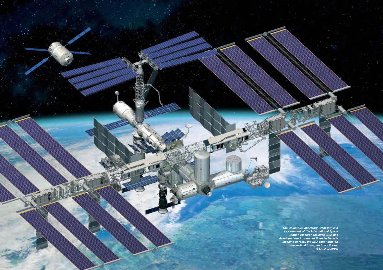
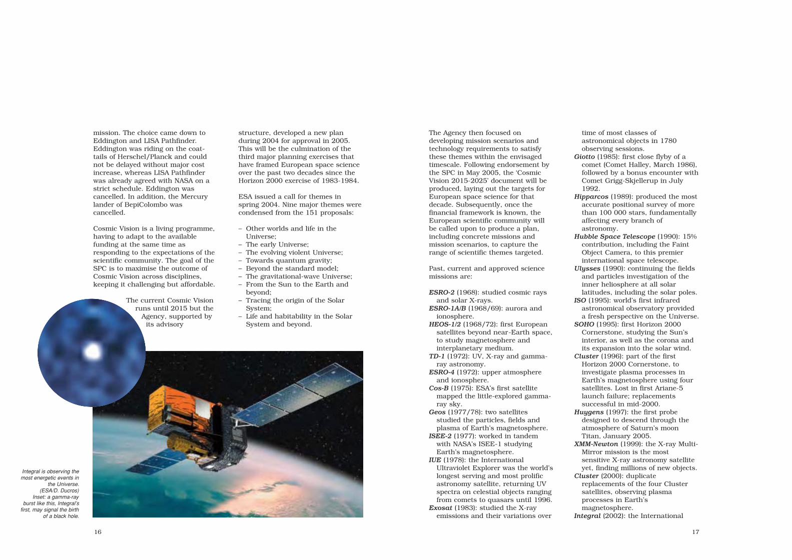
The Columbus laboratory (front left) is akey element of the International Space
Station research facilities. ESA hasdeveloped the Automated Transfer Vehicle
(docking at rear), the ERA robot arm (onthe vertical tower) and two Nodes.
(ESA/D. Ducros)
sec1 8/1/05 2:34 PM Page 40

4342
The European Astronaut CorpsESA began its manned flight programmewith Spacelab, providing the opportunity forthe selection of the first ESA astronauts in1978: Ulf Merbold (D), Wubbo Ockels (NL)and Claude Nicollier (CH). Merbold was thefirst to fly in 1983 (STS-9) and Ockels flew2 years later. Nicollier had to wait 14 yearsfor his first flight (STS-46, 1992), but nowleads the pack with four flights.
The second selection came in 1992 toprepare for the major Hermes and Columbusprojects. More than 22 000 Europeansexpressed interest in becoming astronauts,including 5500 serious candidates. Six wereselected, including an existing nationalastronaut: Jean-Francois Clervoy (F). Alsoselected were Thomas Reiter (D), MaurizioCheli (I; left in 1996), Pedro Duque (E),Christer Fuglesang (S) and the first woman,Marianne Merchez (B), who left before flying.
On 25 March 1998, the ESA Council agreedto build the single European AstronautCorps of 16 astronauts (four for Germany,France and Italy, and four for all the otherMember States). Member States could stillcall on their astronauts for missions
organised at the national level. The firstgroup of seven joined the Corps in 1998:Gerhard Thiele (D), Hans Schlegel (D),Umberto Guidoni (I), Paolo Nespoli (I),Roberto Vittori (I), Léopold Eyharts (F) andJean-Pierre Haigneré (F). Haignere left theCorps in November 1999, after his secondflight, to become Head of the AstronautDivision at the European Astronaut Centre(Cologne, D). Since 2004, he has been incharge of studying manned Soyuz flightsfrom Kourou. A second group of four joinedin 1999: Reinhold Ewald (D), André Kuipers(NL), Claudie Haigneré (F; formerly André-Deshays) and Michel Tognini (F). FrankDe Winne (B) joined at the beginning of2000. In June 2002, Claudie Haigneré tookup the post of Minister for Research andNew Technologies in the Frenchgovernment. In May 2003, Tognini left tohead the Astronaut Division; he becamehead of EAC in January 2005.
Philippe Perrin (F) joined in December 2002(after flying on the Shuttle in June 2002 asa CNES astronaut) and left in May 2004 tobecome a test pilot with Airbus Industrie inToulouse. Guidoni left the Corps in June2004, leaving a total of 13.
The ESA AstronautCorps, May 2003. Fromleft, front: Duque,Thiele, Clervoy, Guidoni,Eyharts, Ewald, Vittori,Nicollier; back: Nespoli,Reiter, Fugelsang,De Winne, Tognini,Schlegel, Perrin,Kuipers.
Pedro Duque floatsthrough the Zvezdamodule of the ISS.
ESA astronaut missions
Astronaut Launch Mission
Ulf Merbold November 1983 STS-9/Spacelab-1Wubbo Ockels October 1985 STS-22/Spacelab-D1Ulf Merbold January 1992 STS-42/Spacelab IML-1Claude Nicollier July 1992 STS-46/TSS-1 + Eureca-1Claude Nicollier December 1993 STS-61/Hubble servicingUlf Merbold October 1994 Euromir-94J.-F. Clervoy November 1994 STS-66/Atlas-3Thomas Reiter September 1995 Euromir-95Maurizio Cheli February 1996 STS-75/TSS-1RClaude Nicollier February 1996 STS-75/TSS-1RJ.-F. Clervoy May 1997 STS-84/MirPedro Duque October 1998 STS-95J.-P. Haigneré* February 1999 Soyuz-TM27/MirClaude Nicollier December 1999 STS-103/Hubble servicingJ.-F. Clervoy December 1999 STS-103/Hubble servicingGerhard Thiele* February 2000 STS-99/SRTMUmberto Guidoni* April 2001 STS-100/ISS + MPLMClaudie Haigneré* October 2001 Soyuz-TM33/ISSRoberto Vittori April 2002 Soyuz-TMA1/ISSFrank De Winne October 2002 Soyuz-TMA2/ISSPedro Duque October 2003 Soyuz-TMA3/ISSAndré Kuipers April 2004 Soyuz-TMA4/ISSRoberto Vittori April 2005 Soyuz-TMA6/ISS
PlannedThomas Reiter September 2005 STS-121/ISSChrister Fugelesang April 2006 STS-116/ISS
*mission flown under national agency while member of ESA Corps
sec1 8/1/05 2:34 PM Page 42
4544
Astronauts may assume control fromthe safety of Russia’s Zvezda module,working via a laptop computer anddetailed video images from ERA.Alternatively, ERA can be operated bya spacewalker via a sturdy externalcontrol panel.
As part of the barter agreement withNASA for launching Columbusaboard the Space Shuttle, ESA isproviding two of the Station’s threeNodes, the connecting elementsbetween various laboratory andhabitation modules. These Nodes-2
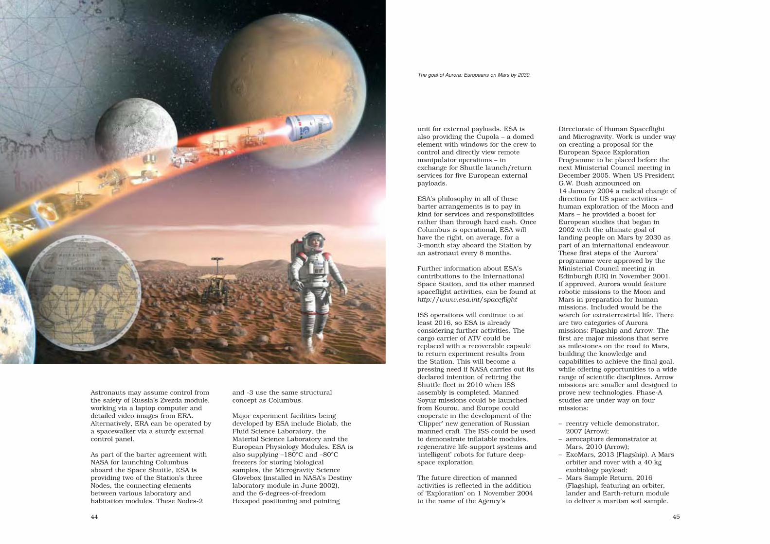
Directorate of Human Spaceflightand Microgravity. Work is under wayon creating a proposal for theEuropean Space ExplorationProgramme to be placed before thenext Ministerial Council meeting inDecember 2005. When US PresidentG.W. Bush announced on14 January 2004 a radical change ofdirection for US space actvities –human exploration of the Moon andMars – he provided a boost forEuropean studies that began in2002 with the ultimate goal oflanding people on Mars by 2030 aspart of an international endeavour.These first steps of the ‘Aurora’programme were approved by theMinisterial Council meeting inEdinburgh (UK) in November 2001.If approved, Aurora would featurerobotic missions to the Moon andMars in preparation for humanmissions. Included would be thesearch for extraterrestrial life. Thereare two categories of Auroramissions: Flagship and Arrow. Thefirst are major missions that serveas milestones on the road to Mars,building the knowledge andcapabilities to achieve the final goal,while offering opportunities to a widerange of scientific disciplines. Arrowmissions are smaller and designed toprove new technologies. Phase-Astudies are under way on fourmissions:
– reentry vehicle demonstrator,2007 (Arrow);
– aerocapture demonstrator atMars, 2010 (Arrow);
– ExoMars, 2013 (Flagship). A Marsorbiter and rover with a 40 kgexobiology payload;
– Mars Sample Return, 2016(Flagship), featuring an orbiter,lander and Earth-return moduleto deliver a martian soil sample.
unit for external payloads. ESA isalso providing the Cupola – a domedelement with windows for the crew tocontrol and directly view remotemanipulator operations – inexchange for Shuttle launch/returnservices for five European externalpayloads.
ESA’s philosophy in all of thesebarter arrangements is to pay inkind for services and responsibilitiesrather than through hard cash. OnceColumbus is operational, ESA willhave the right, on average, for a3-month stay aboard the Station byan astronaut every 8 months.
Further information about ESA’scontributions to the InternationalSpace Station, and its other mannedspaceflight activities, can be found athttp://www.esa.int/spaceflight
ISS operations will continue to atleast 2016, so ESA is alreadyconsidering further activities. Thecargo carrier of ATV could bereplaced with a recoverable capsuleto return experiment results fromthe Station. This will become apressing need if NASA carries out itsdeclared intention of retiring theShuttle fleet in 2010 when ISSassembly is completed. MannedSoyuz missions could be launchedfrom Kourou, and Europe couldcooperate in the development of the‘Clipper’ new generation of Russianmanned craft. The ISS could be usedto demonstrate inflatable modules,regenerative life-support systems and‘intelligent’ robots for future deep-space exploration.
The future direction of mannedactivities is reflected in the additionof ‘Exploration’ on 1 November 2004to the name of the Agency’s
and -3 use the same structuralconcept as Columbus.
Major experiment facilities beingdeveloped by ESA include Biolab, theFluid Science Laboratory, theMaterial Science Laboratory and theEuropean Physiology Modules. ESA isalso supplying –180°C and –80°Cfreezers for storing biologicalsamples, the Microgravity ScienceGlovebox (installed in NASA’s Destinylaboratory module in June 2002),and the 6-degrees-of-freedomHexapod positioning and pointing
The goal of Aurora: Europeans on Mars by 2030.
sec1 8/1/05 2:34 PM Page 44

4746
Europa
Achievements: first European satellite launcher development programmeLaunch dates: 11 launches 1964-1971Launch site: Woomera (Australia) and Kourou (French Guiana)Launch mass: 104 t Europa 1; 112 t Europa 2Performance: 1150 kg LEO, 170 kg GEO from Kourou
The impetus for creatingan independent spacepower in Europe began inthe early 1960s. Belgium,France, Germany, Italy,the Netherlands and theUnited Kingdom(associated with Australia)signed the Convention in1962 to create theEuropean LauncherDevelopment Organisation(ELDO), with the goal ofdeveloping a satellitelaunch vehicle independently of thetwo great space powers. The UKbegan development of the medium-range Blue Streak nuclear missile in1955 under prime contractorde Havilland. The 2500 km range wasincreased to 4000 km in 1958 but theconcept was overtaken by changes inthe political and military landscapes –Blue Streak was cancelled as amissile on 13 April 1960. Rather thancancel it altogether, the UKgovernment took up the idea ofrecycling it as a satellite launcher,using the UK Black Knight researchrocket as stage 2. A 3-day conferencein Strasbourg beginning 30 January1961 produced an Anglo-Frenchmemorandum declaring that anorganisation should be set up todevelop a launcher using a BlueStreak first stage and a Frenchsecond. Germany declared itsintention in June 1961 to provide thethird stage. The Lancaster House,
London meeting of 30October - 3 November1961 agreed on theguiding principles of theELDO Convention, whichwas signed on 30 April1962 and came intoforce on 29 February1964. Italy was toprovide the fairing andtest satellites, Belgiumthe downrange guidancestation and TheNetherlands the long-
range telemetry links. Australia’scontribution was the Woomeralaunch site.
ELDO A (later renamed Europa 1)was to be capable of delivering 500-1000 kg satellites into LEO orbits.The first three tests (see table) werepromising but by now it was clearthat Europe would need a vehiclecapable of deliveringtelecommunications satellites intoGEO by the early 1970s. In July1966, the participants agreed todevelop the ELDO PAS (Europa 2)version. The Perigee-Apogee Systemwould use a solid-propellant motorat perigee and the satellite’s ownapogee motor to deliver 170 kg intoGEO. The UK replaced the radioguidance system with inertialguidance, Italy provided the perigeemotor and STV and France theoperational launches from its Kouroubase. There were also proposals to
replace the second and third stagessuccessively with hydrogen-oxygenstages, to deliver 1 t into GEO.
Spiralling costs and disappointingtests of the upper stages increasinglythreatened the whole organisation.With hindsight, there were two majorproblems: ELDO did not havegenuine technical and managementauthority (which belonged to theMember States) and there was nooverall prime contractor. The UK,under a different government since1964, became lukewarm towards aEuropean heavy launcher. In April1969, the UK and Italy withdrew fromEuropa 2, while the other ELDOstates resolved to begin studies of aEuropa 3 to deliver 400-700 kg intoGEO, indicative of Frenchdetermination in particular to developa heavy launcher that did not dependon Blue Streak.
The 5th European Space Conference(ESC) in December 1972 agreed toEuropeanise the French L3S project(which became Ariane) and cancelEuropa 3. ELDO’s Council on27 April 1973 decided to close theEuropa 2 programme and to winddown the organisation. The 6th ESCin July 1973 paved the way for ESA’screation to merge the activities ofELDO and ESRO.
Europa 1 CharacteristicsLaunch mass: 104 tLength: 31.7 mPrincipal diameter: 3.05 mGuidance: radioPerformance: 850 kg into 500 km
circular orbit launched northwardsfrom Woomera, 1150 kg launchedeastwards from equatorial site.800 km: 700 kg & 950 kg;400x5000 km: 350 kg & 550 kg
Stage 1 (Blue Streak)Principal contractor: Hawker Siddeley
DynamicsPropulsion: 2x Rolls-Royce RZ-2 (US
Rocketdyne S3 under licence), total1334.4 kN sea-level thrust
Propellants: 84950 kg LOX/keroseneLength: 18.7 mPrincipal diameter: 3.05 mMass: 95025 kg (dry 6168 kg)Burn duration: 160 s
Europa 2 on theELA-1 pad at
Kourou. Facingpage: the F11
launch. The samepad was later
used for Arianeand is being
rebuilt for Vega.
sec2 7/20/05 2:39 PM Page 46

4948
Stage 2 (Coralie)Principal contractors: SNIAS, Lab de
Recherches Balistiques etAérodyanmiques (engines)
Propulsion: 4 engines providing total265 kN vac; SI 280 s
Propellants: NTO/UDMHLength: 5.50 mPrincipal diameter: 2.00 mMass: 12186 kg (dry 2263 kg)Burn duration: 96.5 s
Stage 3 (Astris)Principal contractors: Bölkow, ERNOPropulsion: 22.5 kN vac + 2x0.4 kN
verniers
Propellants: NTO/Aerozine 50Length: 3.82 mPrincipal diameter: 2.00 mMass: 4007 kg (dry 885 kg)Burn duration: 36 s
FairingLength: 4.00 mDiameter: 2.00 mMass: 300 kg
Europa 2 Characteristics (wheredifferent from Europa 1)
Launch mass: 111.6 tGuidance: inertial (Marconi Space &
Defence Systems)Performance: 400/170 kg into
GTO/GEO from Kourou
Stage 4Principal contractors: AERFER
Pomigliano d’Arco Napoli, MatraPropulsion: 41.2 kN vac, solid
propellant. Spun-up to 120 rpm by4x1250 N solids
Length: 2.02 mPrincipal diameter: 73 cmMass: 790 kg (dry 105 kg)Burn duration: 45 s
Europa Launch Record
Date Vehicle Comments
F1 5 Jun 1964 Europa 1 Blue Streak-only. Success. Altitude 177 km, downrange 965 km. Engines shut down 6 s early (147 s) because of lateral oscillations induced by propellant sloshing (planned downrange 1500 km)
F2 20 Oct 1964 Europa 1 Blue Streak-only. Success. Altitude 241 km, downrange 1609 km
F3 22 Mar 1965 Europa 1 Blue Streak-only. Success
F4 24 May 1966 Europa 1 BS/inert upper stages/STV. Success
F5 15 Nov 1966 Europa 1 BS/inert upper stages/STV. Success
F6-1 4 Aug 1967 Europa 1 BS/stage 2/inert stage 3/STV. Success. Stage 2 failed to ignite
F6-2 6 Dec 1967 Europa 1 BS/stage 2/inert stage 3/STV. Stage 2 sequencer did not start;
stage did not separate
F7 30 Nov 1968 Europa 1 All live + STV. Stage 3 burned 6 s. First orbital attempt
F8 3 Jul 1969 Europa 1 All live + STV. Stage 3 failed to ignite. Second orbital attempt
F9 12 Jun 1970 Europa 1 All live + 260 kg STV. Fairing failed to separate and stage 3
under-performed. Third orbital attempt
F11 5 Nov 1971 Europa 2 Europa 1/stage 4/360 kg STV. Inertial guidance failed at 105 s,
vehicle broke up at 150 s. Fourth orbital attempt (GTO)
All launches from Woomera, except F11 (Kourou). BS = Blue Streak; STV = Satellite Test Vehicle. F12 was ready atKourou when the programme was cancelled (before F11 failure, F12 launch was scheduled for Apr 1972). F13 is atthe Deutsches Museum, Munich (D); F14 at East Fortune Field, Edinburgh Science Museum (UK); F15 at Redu (B).F13/F14 were earmarked for the Franco-German Symphonie telecommunications satellites, launched instead byUS Deltas in Dec 1974/Aug 1975; F15 was planned for Cos-B.
Europa 1 at Woomera.
Stage 2 of Europa 2 F11 at Kourou.
Left: principal characteristics of Europa 1 (Europa 2 was identical but the satellite perched on a perigeekick stage). 1: fairing. 2: Satellite Test Vehicle.3: payload adapter. 4: Aerozine tank (NTO tank islower half). 5: support ring. 6: He tank (x2). 7: vernier(x2). 8: main engine. 9: pressurant tanks. 10: NTOtank. 11: interbay ducting. 12: UDMH tank. 13: mainengines (x4). 14: telemetry antenna. 15: equipmentbay. 16: access door. 17: LOX tank pressurisationpipe. 18: LOX tank. 19: kerosene tank. 20: low-pressure feed pipes. 21: turbopumps. 22: GN2.23: turbine exhaust. 24: LN2-GN2 heat exchanger.25: LOX-GOX heat exchanger. 26: expansion bell.
sec2 7/20/05 2:39 PM Page 48

5150
ESRO-2
ESRO-2 Scientific Instruments
S25 Two Geiger-Müller counters measured time variations in Van Allen belt population. Imperial College London (UK)
S27 Four solid-state detectors measured solar and Van Allen protons (1-100 MeV) and α-particles. Imperial College London (UK)
S28 Scintillator, proportional counters and Cerenkov detectors measured 0.4-0.8 GeV solar protons/α-particles. Imperial College London (UK)
S29 Scintillator/Cerenkov detector for flux/energy spectrum of 1-13 GeV electrons. Univ of Leeds (UK)
S36 Proportional counters measured 1-20 Å solar X-rays. University College London/Leicester Univ (UK)
S37 Proportional counters measured 44-60 Å solar X-rays. Lab voor Ruimteonderzoek, Utrecht (NL)
S72 Two solid-state detectors measured solar and galactic protons (0.035-1 GeV) and α-particles (140-1200 MeV). Centre d’Etudes Nucleaires de Saclay (F)
Satellite configuration: 12-sidedcylinder, 86 cm long, 78 cm diameter.Six aluminium panels (carrying thesolar array) were attached to sixmagnesium alloy longerons, bolted totwo honeycomb floors and stabilisedby end frames. Central thrust tube.
Attitude/orbit control: spin stabilisedat 40 rpm along main axis, 90º toSun direction. Spin-up by gas jets;spin axis controlled by magnetorquer.
Power system: 3456 20.5 mm2 Si cellson body panels. Supported by 3 Ahnickel cadmium battery.
Communications: 128 bit/s realtimetelemetry on 137 MHz. Tape recorderstored 128 bit/s for 110 min;playback at 4096 bit/s on 136 MHz.TC at 148 MHz. Controlled fromESOC.
ESRO-2 thermal-vacuum testing at ESTEC.
Right: ESRO-2 andits Scout stage 4undergoing spin-balancing at the
Western TestRange.
ESRO-2 attached to the final stage of its Scoutlauncher at the Western Test Range in California.
Achievements: first ESRO satellite; significant contributions to understandingnear-Earth space
Launch dates: ESRO-2A 29 May 1967 (launch failure); ESRO-2B (Iris) 17 May1968
Mission end: ESRO-2A 29 May 1967 (launch failure); ESRO-2B 9 May 1971 (reentry; 12-month design life)
Launch vehicle/site: NASA Scout from Western Test Range, CaliforniaLaunch mass: 74 kg (21.3 kg scientific payload)Orbit: 334x1085 km, 98.9° Sun-synchronousPrincipal contractor: Hawker Siddeley Dynamics (UK)
ESRO’s first satellites concentratedon solar and cosmic radiation and itsinteraction with the Earth. ESRO-2looked at solar X-rays, cosmicradiation and Earth’s radiation belts,while ESRO-1A simultaneouslyexamined how the auroral zonesresponded to geomagnetic and solaractivity. Direct measurements weremade as high-energy chargedparticles plunged from the outermagnetosphere into the atmosphere.
ESRO’s HEOS-1 also played its partthrough simultaneous measurementsof the interplanetary magnetic fieldand the particles en route to Earth.This meant the particles could beused to trace out themagnetosphere’s structure and how itconnected with the interplanetaryfield. ESRO-2 and -1 contributedsignificant pieces to this puzzle.ESRO-2 was particularly fruitful onthe arrival of solar particles over thepolar caps, highlighting strikingintensity variations between the tworegions, when uniformity had beenexpected.
ESRO-2A was lost when the fourthstage of its Scout launcher failed toignite, leaving the satellite to burn upon reentry. The prototype wasrefurbished as a replacement,carrying the same seven experiments(see table) and renamed ‘Iris’ once inorbit. Although its design life wasonly 1 year, most of the subsystems
worked well throughout and fourexperiments were still returning databy the time atmospheric dragprecipitated reentry after 16 282orbits. The tape recorder failed after6.5 months, reducing average datarecovery from more than 90% toaround 20%.
sec2 7/20/05 2:39 PM Page 50

5352
ESRO-1
Achievements: significant contributions to understanding near-Earth spaceLaunch dates: ESRO-1A (Aurora) 3 October 1968; ESRO-1B (Boreas) 1 October
1969Mission end: ESRO-1A 26 June 1970; ESRO-1B 23 November 1969 (reentry;
6-month design lives)Launch vehicle/site: NASA Scout from Western Test Range, CaliforniaLaunch mass: 74 kg (22 kg scientific payload)Orbit: ESRO-1A 258x1538 km, 93.7° Sun-synchronous;
ESRO-1B 291x389 km, 86.0°Principal contractors: Laboratoire Central de Telecommunications (Paris), with
Contraves (CH) and Bell Telephone Manufacturing (B) as main associates
ESRO’s first satellites concentratedon solar and cosmic radiation and itsinteraction with the Earth. ESRO-2looked at solar X-rays, cosmicradiation and Earth’s radiation belts,while ESRO-1A simultaneouslyexamined how the auroral zonesresponded to geomagnetic and solaractivity. Direct measurements were
made as high-energy chargedparticles plunged from the outermagnetosphere into the atmosphere.
ESRO’s HEOS-1 also played its partthrough simultaneous measurementsof the interplanetary magnetic fieldand the particles en route to Earth.This meant the particles could beused to trace out themagnetosphere’s structure and how itconnected with the interplanetaryfield. ESRO-2 and -1 contributedsignificant pieces to this puzzle.ESRO-1B aimed at a lower circularorbit to provide complementarymeasurements, but it was lower thanplanned and reentry was inevitableafter a few weeks.
The satellites were stabilised so that,over the North Pole, the particleexperiments looked up or across themagnetic field, while two photometerslooked down to measure absoluteauroral luminosity. This was one ofthe first dual-satellite arrangementstried in the magnetosphere, precedingthe more sophisticated ISEE missionby 8 years. Two satellites made itpossible to distinguish spatial fromtemporal variations.
Both satellites continued transmittingdata until reentry. ESRO-1A’s taperecorder failed on 29 April 1969,reducing the data take from 80% to20%, but those data (over the NorthPole) were the most important.
Installation of ESRO-1Bon its Scout launcher atthe Western TestRange, California.
ESRO-1 solarsimulation testingat ESTEC.
ESRO-1 was built, unusually, around a conicalthrust tube and four vertical walls.
sec2 7/20/05 2:39 PM Page 52

55
Achievements: first European probe into cislunar space; first magnetically cleanEuropean satellite; first highly-eccentric polar orbit
Launch dates: HEOS-1 5 December 1968; HEOS-2 31 January 1972Mission end: HEOS-1 reentered 18 October 1975; HEOS-2 reentered 2 August
1974Launch vehicle/sites: HEOS-1 Delta from Cape Canaveral, Florida; HEOS-2 Delta
from Western Test Range, CaliforniaLaunch mass: HEOS-1 108 kg; HEOS-2 117 kgOrbits: HEOS-1 injected into 424x223 428 km, 28.3°; HEOS-2 injected
into 405x240 164 km, 89.9°Principal contractors: Junkers Flugzeug- und Motorenwerke GmbH (prime)
HEOS-1 (Highly Eccentric OrbitSatellite-1) was the first Europeanspacecraft to venture beyond near-Earth space, in order to study themagnetic fields, radiation and thesolar wind outside of the Earth’smagnetosphere. This required anorbit stretching two-thirds of the wayto the Moon and launch during aperiod of high solar activity. Thescientific experiments also demandeda magnetically clean vehicle, anotherfirst for Europe and requiring a newfacility at ESTEC for testing theintegrated satellite.
HEOS-1 performed admirably for7 years, for the first time providingscientists with continuousobservations of interplanetaryconditions over most of a solar cycle.Precise calibration of themagnetometer meant that these datahave been used ever since as afundamental reference. Anotherfeature – novel at the time – was themagnetometer’s memory, whichallowed measurements with very hightime resolution. HEOS-1 also releaseda canister of barium and copper oxideon 18 March 1969 some 75 000 kmout from Earth – igniting it 40 kmfrom HEOS – in order to trace distantmagnetic field lines.
HEOS-2 was equally successful, thistime investigating northern polarregions by climbing into a high-inclination orbit. It discovered a layer
of plasma flow (‘plasma mantle’)inside the tail magnetosphere. Inaddition, it observed interplanetaryconditions during most of its orbit. InAugust 1972 it was ideally placed tostudy some of the most dramaticinterplanetary and magnetosphericevents ever recorded following majorsolar activity.
54
ESRO-1 Scientific Instruments
S32 Two photometers registered northern auroral brightness. Norwegian Institute of Cosmic Physics (N)
S44 Two boom-mounted Langmuir probes for ionosphere electron temperature/density. University College London (UK)
S45 Boom-mounted Langmuir probe for ionosphere ion composition/temperature. University College London (UK)
S71A Scintillator for electron flux/energy spectra (50-400 keV). Radio & Space Research Station (UK)
S71B Electrostatic analysers + channeltrons for electrons and protons (1-13 keV) with high time resolution. Kiruna Geophysical Observatory (S)
S71C Three solid-state detectors for 0.01-6 MeV protons. Univ of Bergen/Danish Space Research Institute (N/DK)
S71D Four Geiger counters for pitch angles of electrons (>40 keV) and protons (>500 keV) with high time resolution. Norwegian Defence Research Establishment/Danish Space Research Institute (N/DK)
Ratemeter Geiger counter for trapped electrons (>40 keV) and protons (>500 keV). ESLAB (Space Science Dept) of ESRO
S71E Solid-state detector and scintillator telescope for flux/energy spectra of 1-30 MeV solar protons. Radio & Space Research Station (UK)
Satellite configuration: 90 cm-high,76 cm-diameter cylindrical bus.Conical magnesium thrust tubesupported four vertical aluminiumhoneycomb walls for attachingexperiments and subsystems. Totalheight 153 cm. Forward axial boomextended to 50 cm in orbit; two 99 cmbooms released from base.
Attitude/orbit control: injection spin of150 rpm removed by yo-yo masses,for satellite to stabilise itself to within5° along the magnetic field linesusing two 25.2 Am2 bar magnets.
Power system: 6990 2 cm2 Si cells onbody panels provided 23 W orbitaverage. Supported by 3 Ah nickelcadmium battery.
Communications: 5120 bit/s realtimetelemetry on 1.2 W/137 MHz, or320 bit/s on 0.2 W/136 MHz. Taperecorder stored 320 bit/s forplayback at 10.24 kbit/s on137 MHz. Telecommand at 148 MHz.Controlled from ESOC.
ESRO-1 principal features.
HEOS’ 1.7 m boom held the magnetometer away from thebody’s magnetic influence. HEOS-2 (seen here) was similar toits predecessor but notably carried a loop antenna just above itsmain body for solar radio observations.
HEOS
sec2 7/20/05 2:39 PM Page 54

5756
HEOS-1 Scientific Instruments
S24A Triaxial fluxgate magnetometer on 1.70 m tripod boom. Measured ±64-gamma magnetic fields with 0.5-gamma accuracy. 3.8 kg.Imperial College London (UK)
S24B Cerenkov and scintillation counters detected high-energy cosmic ray protons of >350 MeV and their anisotropies. 2.9 kg. Imperial College London (UK)
S24C Solid-state detector telescopes detected 0.9-20 MeV solar protons and their anisotropies. 2.1 kg. Imperial College London (UK)
S58/ Measured the energy and angular distributions of solar wind S73 protons. 0.7/2.2 kg. Universities of Rome, Florence and Brussels
S72 Solid-state telescope measured electrons, protons and α-particles over wide energy ranges. 1.8 kg. Centre d’Etudes Nucleaires de Saclay (F)
S79 Measured 50-600 MeV cosmic ray electrons. 5.0 kg. Centre d’Etudes Nucleaires de Saclay (F) & University of Milan (F/I)
S16 Released barium canister to highlight magnetic field lines. 8.2 kg (capsule 7.7 kg). Max-Planck-Institut für Extraterrestrische Physik, Garching (D)
HEOS-2 Scientific Instruments
S201 As S24A on HEOS-1 but range/accuracy improved to ±144-gamma with 0.25-gamma accuracy in lower range
S202 Measurement of 20 eV-50 keV electrons and protons. Univ of Rome (I)
S203 Solar VLF observations at 20-236 Hz by a 1.4 m2 loop antenna and two spherical wire-cage antennas. Danish Space Research Institute
S204 Particle telescopes to measure 0.5-3 MeV electrons, 9-36 MeV protons and 36-142 MeV α-particles. Space Science Dept of ESRO/ESTEC
S209 As S79 on HEOS-1
S210 Solar wind’s velocity and angular distributions. Max-Planck-Institut für Extraterrestrische Physik, Garching (D)
S215 Mass/velocity determination of 10-17-10-9 g micrometeoroids. Max-Planck-Institut für Kernphysik, Heidelberg (D)
Satellite configuration: 16-sided bus,75 cm high, 130 cm diameter acrossfaces. 1.70 m-high fixed boom alongspin axis for magnetometer andantennas. Equatorial belt reserved forexperiments, attitude sensors andspin nozzles. Central aluminiumhoneycomb octagonal thrust tube,with outrigger structures onalternating panels supporting foursolar array panels. Electronic boxesbolted on thrust tube, with sensorson cantilever supports. HEOS-1’s S16experiment and its ejectionmechanism was on lower adapter (onHEOS-2, this space housed the S215micrometeoroid impact detector); theupper part housed the nitrogen bottlenear the centre of gravity.
Attitude/orbit control: spin-stabilisedat 10 rpm around axis perpendicularto Sun direction. Spin axisdetermined to ±2° by Sun/Earthsensors. Spin axis adjusted bypulsing single 0.2 N thruster onbottom skirt; spin-up/down by paired0.2 N equatorial belt thrusters; 1.9 kgof nitrogen stored at 250 bar in singlecentral titanium sphere.
Power system: four solar panelsformed HEOS outer surface. 8576 Sicells provided 60 W BOL (42 W after1 year) at 16 V. Supported by 5 Ahsilver cadmium battery.
Communications payload: 12 bit/sdata (32 bit/s on HEOS-2) returnedat 136 MHz by 6 W transmitter inrealtime (no onboard storage).Primary stations Redu (Belgium) andFairbanks (Alaska, US), controlledfrom ESOC. Telecommand at145.25/148.25 MHz HEOS-1/2.
The prototype and two flight models of HEOS-1 inthe integration hall at ESTEC.
HEOS-2 was the first to probe the Earth’snorthern polar region from a highly-eccentric
orbit. Right: HEOS-1 released a bariumcanister to create an artificial ion cloud tracing
the Earth’s magnetic field lines.
The orbits of both HEOS were designed to slicethrough Earth’s magnetosphere and penetrate deepinto interplanetary space. The high inclination ofHEOS-2 made it the first spacecraft to explore theouter polar cusp, searching for a neutral point.
sec2 7/20/05 2:40 PM Page 56

59
TD-1 Scientific Instruments
S2/68 Telescope/spectrometer: whole-sky scan at 1350-3000 Å. Inst d’Astrophysique, Liège (B)/Royal Obs Edinburgh (UK)
S59 Telescope/spectrometer gimballed for star-tracking: UV stellar spectroscopy 2000-3000 Å (1.8 Å resolution). Space Research Lab, Utrecht (NL)
S67 Two solid-state detectors/Cerenkov detector: spectrometry of primary charged particles. Centre d’Etudes Nucléaires, Saclay (F)
S77 Proportional counter: spectrometry of 2-30 keV celestial X-rays. Centre d’Etudes Nucleaires de Saclay (F)
S88 Solar gamma-rays (50-500 MeV). Univ of Milan (I)
S100 CsI scintillation crystal: solar X-rays (20-700 keV). Space Research Lab, Utrecht (NL)
S133 Spark chamber, vidicon camera, particle counters and Cerenkov counter: celestial gamma-rays (70-300 MeV). CENS/Univ of Milan/MPI Garching (F/I/D)
array face) Sun-pointing with1 arcmin accuracy, while TD rotatedat 1 rev/orbit about X-axis for thefour instruments pointing along the+Z-axis (anti-Earth) to scan the wholesky in 6 months. Sun/Earth sensors,momentum wheels and cold-gas jets(11 kg gas supply).
Power system: two deployed solarwings continuously faced Sun (Sun-synchronous orbit) to provide powerfrom 9360 2x2 cm Si cells; supportedby nickel cadmium battery.
Communications: 1700 bit/s realtimeon 0.3 W transmitter, withsimultaneous recording on taperecorders for playback at 30.6 kbit/son 3 W transmitter. Both recordersfailed by 23 May 1972, but oneresumed working in October 1973.
achieved in the second scan period ofMarch-October 1973, the mostproductive phase of the mission. Onetape recorder even began workingagain, in October 1973.
Hibernation was successful againOctober 1973-March 1974. All of theinstruments were still working in May1974 when attitude control was lostfollowing exhaustion of the onboardgas supply, and the mission ended.By that time, TD-1 had achieved 2.5celestial scans and the mission wasdeclared a total success.
Satellite configuration: box-shapedbus, 0.9x1 m, 2.2 m high.Experiments housed in upper box;subsystems in lower box.
Attitude/orbit control: X-axis (solar
TD-1 in the integrationhall at ESTEC, July1971. The attitudecontrol system heldthis side square on tothe Sun.
This internal viewhighlights the complexityof TD-1. Compare it withthe photographs of itsESRO contemporaries onother pages.
58
TD-1
Achievements: ESRO’s first astronomy satellite; important advances in UVastronomy (all-sky UV survey not superseded until US GALEX mission of 2003)
Launch date: 12 March 1972Mission end: 4 May 1974 (design life 6 months; reentered 9 January 1980)Launch vehicle/site: Thor Delta (hence name of satellite) from Western Test Range,
CaliforniaLaunch mass: 473 kg (scientific payload 120 kg)Orbit: 531x539 km, 95.3° (Sun-synchronous)Principal contractors: Engins Matra (prime), ERNO (structure, thermal control,
housekeeping subsystems), Saab (communications), HSD (power supply, gyros)
TD-1 was ESRO’s most ambitioussatellite project of that era, carrying alarge and complex scientific payloadto survey the whole sky in ultraviolet,X-rays and gamma-rays, monitorheavy cosmic ray nuclei and measureX/gamma-rays from the Sun.
It was the organisation’s first satelliteto carry astronomical telescopes, withheavy emphasis on UV observationsof stars. One telescope used a wideaperture for scanning the whole skyin this little-studied section of thespectrum, while another made high-resolution measurements of UVspectral lines from individual stars.The resolution of 1.8 Å was a majoradvance over anything flownpreviously.
The mission was seriouslyjeopardised soon after launch, whenboth onboard tape recorders failedafter only 2 months. A dramaticrescue operation by ESRO set up 40ground stations around the world incollaboration with other spaceagencies to capture most of therealtime data.
As a result of the rescue, 95% of thecelestial sphere was scanned, andspectral measurements on more than30 000 stars were catalogued andpublished. The measurement of UVspectral line shapes and positionsrevealed, for example, that some starsare rapidly shedding theiratmospheres. Significant advanceswere also made in identifyinginterstellar dust and plotting itsdistribution throughout the Galaxy.
The mission had been planned to endin October 1972 when the orbit hadshifted such that the Earth beganeclipsing the attitude system’s Sunsensors. In view of the data lost fromthe recorder failures and TD-1’sotherwise good health, it was decidedto try a manoeuvre for which thesatellite had not been designed. Asthe eclipses began, TD-1 was spunfaster around its Sun-pointing axisfor stability and placed inhibernation. The reverse operationwas successful in February 1973, tothe delight of its controllers andscientists. 70% data coverage was
sec2 7/20/05 2:40 PM Page 58

6160
ESRO-4
Achievements: significant contributions to upper atmosphere, ionosphere andmagnetosphere research
Launch date: 22 November 1972Mission end: 15 April 1974 (reentry; 18-month design life)Launch vehicle/site: NASA Scout from Western Test Range, CaliforniaLaunch mass: 114 kg Orbit: 245x1087 km, 99.2°Principal contractor: Hawker Siddeley Dynamics (UK)
ESRO-4 was based on the provenESRO-2 design and carried fiveexperiments concentrating on theEarth’s ionosphere, atmosphere,radiation belts and penetration ofsolar particle radiation into themagnetosphere. Achievementsincluded unique high-qualitymeasurements of the atmosphere’sconstituents between 240 km and320 km altitude. Detailed globalmaps were produced for theconcentrations of nitrogen, oxygen,helium and argon and their seasonalvariations. Their movement followingionosphere and geomagnetic
ESRO-4 Scientific Instruments
S45 Boom-mounted spherical probes: density, temperature and composition of positive ions. University College London (UK)
S80 Monopole mass spectrometer: density and composition of 1-44 amu atmosphere constituents. University of Bonn (D)
S94 Electrostatic analysers, Geiger counters and solid-state detectors: angle/energy spectra of 0.5-150 keV electrons and protons. Geophysical Observatory Kiruna (S)
S99 Two solid-state detector telescopes: solar protons (2-100 MeV) and α-particles (4-240 MeV) over poles. Space Research Lab, Utrecht (NL)
S103 Solid-state detectors: solar protons (0.2-90 MeV) and α-particles (2.5-360 MeV), mainly over poles. MPI Garching (D)
disturbances was plotted, and theirvariations with longitude wereestablished.
ESRO-4’s results feature prominentlyin the world’s scientific literature onthe upper atmosphere. This smallsatellite significantly advanced ourbasic understanding of therelationships between solar radiationand the Earth’s atmosphere andmagnetic environment.
A total of 3x10¹⁰ data bits werereturned before reentry in 1974, andeven the tape recorder was still
running – a European record. NASA’slauncher placed ESRO-4 in a loworbit (perigee 245 km instead of280 km), which reduced its orbital lifefrom the planned 3 years to17 months but which also allowed itto sample a deeper slice ofatmosphere.
Satellite configuration: 90 cm-high,76 cm-diameter cylindrical bus.Central thrust tube supported twoequipment floors, enclosed by outershell of solar array. Four boomsdeployed for experiment S45: oneaxial and three 130 cm-long radial.
Attitude/orbit control: magnetorquerscould precess the spin axis todifferent geomagnetic attitudes.
Power system: Si cells on body panelsprovided 60 W orbit average.
Communications: 640 bit/s or10.24 kbit/s realtime data or20.48 kbit/s tape recorder playback,at 137.2 MHz using 0.3 W or 2.8 Wtransmitters. Controlled from ESOC.
ESRO-4 flew some of the experiments planned forTD-2, cancelled in 1968 on cost grounds. It used
the ESRO-2 bus, whereas the alternative ESRO-3proposal would have been derived from ESRO-1.
sec2 7/20/05 2:40 PM Page 60

6362
Cos-B
Achievements: first complete galactic survey in high-energy gamma-raysLaunch date: 9 August 1975 (1-year design life; 2-years’ consumables)Science operations began/ended: first data returned 12 August 1975, routine
science operations began 17 August 1975, Cos-B deactivated 25 April 1982Launch vehicle/site: Delta 2913 from Western Test Range, CaliforniaLaunch mass: 278 kg (including 118 kg scientific payload)Orbit: initially 337x99 067 km, 90.2°; evolved to 12 155x87 265 km, 98.4° by
mission-end. Orbit maximised time above interfering radiation belts, on averageallowing observations for 25 h on each 37 h orbit
Principal contractors: MBB (prime, spacecraft), Aerospatiale (structure, thermal),BAC (AOCS, solar array), ETCA/TERMA (power supply), Selenia (data handling,telecommunications)
Cos-B was the first ESA/ESROsatellite devoted to a single payload: agamma-ray telescope designed toperform an extensive, pioneeringsurvey of the Galaxy at energies of50 MeV to 5 GeV. Before Cos-B, thishigh-energy range had been onlypartially explored. Majorachievements included observationsof the Crab and Vela pulsars,discovery of numerous point sourcesin the galactic disc, pinpointing themysterious Geminga object to within0.5°, and the first observation ofgamma-rays from an extragalacticsource (quasar 3C273).
The satellite operated in a pointingmode with its spin axis directedtowards fixed points in the sky forperiods of 4-5 weeks early in themission and up to 3 months in laterobservations. In total, 64 pointingswere carried out: a broad band alongthe galactic equator was studieddeeply by repeated and overlappingobservations. About 50% of thecelestial sphere was covered. Thedatabase was formally released to thescientific community on 27 September 1985.
The telescope performed wellthroughout the mission, the onlycomplication being occasional erraticperformance of the spark chamberand the inevitable reduction in
performance as the chamber gasaged. This ageing was minimised byemptying and refilling the neon, and,as the rate of gas deteriorationslowed, the intervals betweenflushings rose from the initial6 weeks to about 36 weeks before thelast in November 1981. The payloadwas still working when the attitudecontrol gas was exhausted in April1982.
Cos-B (and, simultaneously, Geos)was formally approved by the ESROCouncil in July 1969 in competitionwith other science missions becauseit placed Europe at the forefront of anew field. The proposed Cos-Aincluded an X-ray detector, but it wasfelt that Europe should leapfrog tothe next generation in order tocompete with NASA; this led directlyto Exosat.
Cos-B prototype vibration testing atESTEC.
Artist’s impression of Cos-B inoperational configuration.
The Galaxy’s gamma-ray emission asobserved by Cos-B.
http://astro.estec.esa.nl/Cosb/
sec2 7/20/05 2:40 PM Page 62

64 65
Satellite configuration: 1200 mm-high,1488 mm-diameter cylinder withscience payload in centre. 1712 mmtotal height, including antennas.Aluminium central cone, platform,struts and outer cylinder.
Attitude/orbit control: spin-stabilisedat 10 rpm about main axis,maintained and pointed by simplecold gas attitude control system: 2 spin-up/down + 2 precession jets;9.9 kg nitrogen at initial 250 bar.Sun/Earth sensors provided attitudedetermination to 0.5°.
Power system: 12 solar panels oncylindrical surface designed toprovide 83 W at 16 V after 2 years;9480 Si cells. Supported by 6 Ahnickel cadmium battery. Experimentrequired 25 W.
Communications/data: 6.5 W137 MHz transmitter provided80/160/320 bit/s, 8 Kbit buffer(typical gamma event 1100 bit).Telecommand at 148 MHz. Primaryground stations Redu (B) &Fairbanks (Alaska, USA).
Science payload: the gamma-raydetector’s effective sensitive areapeaked at 50 cm2 at 400 MeV.Angular resolution 2° at highenergies; energy resolution peaked(~40% FWHM) at 150 MeV, and was
>100% up to at least 3 GeV. Itfeatured a 24x24x24 cm sparkchamber (SC, see labelled diagram)with 16 paired wire grids. Tungstensheets between the grids convertedsome gamma-rays into electronpairs. The particles’ ionisation trailthrough the 2-bar neon gas waslocated and timed by applying ahigh voltage across the grids. Thefield of view was defined by theTriggering Telescope, whichtriggered the voltage when itsscintillation (B1/B2) and Cerenkov(C) counters, with theirphotomultiplier tubes (PMTs),generated simultaneous signals.Cosmic rays (~1000/s) were rejectedwhen the surrounding anti-coincidence scintillation counter (A)and its nine PMTs produced a signalsimultaneous with the TriggeringTelescope. Below, the caesiumiodide scintillator EnergyCalorimeter (E/D) absorbed theelectron pairs, PMTs recording thelight pulse strength as a directmeasure of the original energy. A 2-12 keV 1° FOV ‘Pulsar Synchroniser’argon proportional countermonitored X-rays for correlationwith gamma variations. For the SC,1.1 kg of neon was stored at 13 barto flush/refill the chamber at 2 barup to 13 times.
Cos-B principal features. 1: Anti-coincidence Counter. 2: Spark Chamber.3: Triggering Telescope. 4: Energy Calorimeter. 5: Pulsar Synchroniser.6: structure. 7: super-insulation. 8: Sun/Earth attitude sensors. 9: spinthruster. 10: precession thruster. 11: nitrogen tank. 12: neon tank.13: solar array. 14: electronics. (MBB)
Bottom right: schematic of Cos-B’s gamma-ray detector package. Seethe text for a description.
Integration of the Cos-Bdetector package and
spacecraft prototypes atMBB.
sec2 7/20/05 2:40 PM Page 64

6766
Geos
Achievements: major contributions to magnetospheric researchLaunch dates: Geos-1 20 April 1977; Geos-2 14 July 1978Mission end: Geos-1 April 1980; Geos-2 October 1985 (24-month goal)Launch vehicle/sites: Geos-1 Delta from Cape Canaveral, Florida; Geos-2 Delta
from Cape CanaveralLaunch mass: Geos-1 573 kg; Geos-2 573 kgOrbits: Geos-1 injected into 2682x38 475 km, 26.6°; Geos-2 initial science
operations over 37°E geostationaryPrincipal contractors: British Aircraft Corp heading Star consortium of Dornier,
Sener, Ericsson, Thomson-CSF, Contraves, CGE-FIAR, Montedel
Geos was designed for geostationary(GEO) orbit to study the particles,fields and plasmas of the Earth’smagnetosphere using seveninstruments provided by tenEuropean laboratories. Because of itsunique orbit and the sophistication ofits payload, Geos was selected as thereference spacecraft for the worldwide‘International Magnetospheric Study’.Unfortunately, Geos-1 was left in alow transfer orbit because of astage-2/3 separation problem on itsUS Delta launcher. As a result, theQualification Model was launchedwith an identical payload andsuccessfully reached GEO.
In spite of its orbit, Geos-1 made asignificant contribution to IMS,
ending its mission formally on 23June 1978, when the ground systemhad to be handed over to prepare forGeos-2. That second craft was highlysuccessful, creating a huge databasefor magnetospheric studies andplasma research in general.
Geos was the first ever spacecraft tocarry a totally conductive coating –even over its solar cells. An electronbeam experiment and a pair of probes40 m apart provided independentmeasurements of the electric field atGEO altitude, yielding not onlyexcellent science but also confirmingthe surface-treatment technology. Thelessons proved extremely valuable fordesigning commercial satellitesoperating in this regime.
Geos in the IntegrationHall at ESTEC. In frontof Geos-1 is the ApogeeBoost Motor. In thebackground is the GeosQualification Model,later modified asGeos-2.
The Geos QualificationModel (which becameGeos-2) on the moment-of-inertia measurementmachine in the DynamicTest Chamber atESTEC.
Geos-1/2 Scientific Instruments
S300 AC-magnetic fields to 30 kHz; DC/AC electric fields & plasma resonances to 80 kHz; mutual/self-impedance. CRPE (F)
S302 Thermal plasma to 500 eV by 2 electrostatic analysers. Mullard Space Science Laboratory (UK)
S303 Ion composition (1-140 amu) and energy spectra to 16 keV by combined electrostatic and magnetic analyser. University of Bern/MPI Garching (CH/D)
S310 Pitch-angles of 0.2-20 keV electrons/protons by 10 electrostatic analysers. Kiruna Geophysical Observatory (S)
S321 Pitch-angles for 20-300 keV electrons & 0.020-3 MeV protons by magnetic deflection system followed by solid-state detectors. Max-Planck-Institut Lindau (D)
S329 DC electric field by tracing electron beam over one or more gyrations. Max-Planck-Institut Garching (D)
S331 DC & ULF magnetic field by fluxgate magnetometer. CNR/NASA Goddard Space Flight Center (I/US)
sec2 7/20/05 2:40 PM Page 66

6968
Satellite configuration: cylindrical bus,132 cm high, 164.5 cm diameter.Maximum dimensions 477 cm fromUHF antenna tip to S300 long axialboom tip; 42.6 m tip-to-tip of longradial booms.
Attitude/orbit control: apogee kickmotor (269 kg solid propellant) forinjection into GEO. Six 15 Nthrusters provided reaction control(30.6 kg hydrazine): 2 axial thrusters(tilt/precess), 2 radial (orbit adjust)+ spinup/down; 2 fluid nutation
dampers. Attitude measurement bySun and Earth sensors plusaccelerometer.
Power system: >110 W BOL providedfrom 7200 solar cells on cylindricalbus.
Communications payload: data100 kbit/s continuous at 2299.5 MHz(no onboard storage). Telecommandat 149.48 MHz.
Geos-1 being prepared for boom deployment testsin the Dynamic Test Chamber at ESTEC.
sec2 7/20/05 2:40 PM Page 68

7170
OTS
Achievements: first ESA telecommunications satellite; first European 3-axisKu-band satellite; far exceeded design life
Launch dates: OTS-1 14 September 1977 (launch failure); OTS-2 12 May 1978Mission end: OTS-2 retired operationally end-1983; deactivated January 1991Launch vehicle/site: Delta 3914 from Cape CanaveralLaunch mass: 865 kg (444 kg on-station BOL); including 432 kg apogee boost
motorOrbit: geostationary, over 10°EPrincipal contractors: British Aerospace, heading MESH consortium (Matra AIT,
EGSE, AOCS; ERNO structure, RCS; Saab-Scania TT&C; AEG-Telefunkenrepeater payload)
The Orbital Test Satellite (OTS) wasESA’s first communications satelliteprogramme, and was crucial indemonstrating the technology for theEuropean Communications Satellite(ECS) and Marecs maritimederivatives. It was instrumental in thecreation of the EuropeanTelecommunications Organization(Eutelsat). Although the programmesuffered the worst of all beginnings –its US Delta launcher exploded only54 s after launch from CapeCanaveral – OTS ultimately went onto become one of the world’s mostsuccessful telecommunicationsprojects. Eight months later, thesecond flight model was launchedsuccessfully and placed in ageostationary orbit over 10°E, itsthree transmit antennas coveringWestern Europe, the Middle East,North Africa and Iceland.
OTS was the first satellite under 3-axis control to demonstrate use ofthe Ku-band (11-14 GHz) for the nextgeneration of satellites, seeking toease the growing congestion at C-band (4-6 GHz). It offered fourwideband channels with a totalcapacity of 7200 telephone circuits oreight TV transmissions. OTSdemonstrated the commercialpotential of the Ku-band within itsfirst year of operations, includingtelephone, data transmission and TVexchanges between Europe and NorthAfrica. An important element of the
utilisation programme was thedevelopment and testing of the TimeDivision Multiple Access (TDMA)system for use later in theoperational ECS telephony network.The first videoconferencingexperiments using small groundantennas between Germany and theUK were successful by 1980, andusing small terminals suitable forcommunity TV reception aroused theinterest of cable distributioncompanies. OTS’ TV distribution
OTS-2 in the anechoictest chamber at BritishAerospace,Stevenage, UK.
OTS-2 final tests.
OTS-2 is installed on itsDelta launcher at
complex 17, CapeCanaveral.
sec2 7/20/05 2:40 PM Page 70

7372
ECS and Marecsadopted the generaldesign proved by OTS.
ESA’s firsttelecommunicationssatellite, OTS-1, waslost in September 1977when its US launchvehicle exploded.
experiments were so successful thatECS-1 was almost entirelydedicated to this function. Therapid response of satellite systemsfor coping with emergencies wasdemonstrated in November 1981when the French PTT system atLyons was destroyed by fire. Withinhours, OTS and a transportablestation had been brought into useto handle priority telephone traffic.
OTS more than doubled its targetoperational life of 3 years and wasused by Eutelsat for commercialoperations until the end of 1983.Before it was retired, ESAexperimented with some riskymanoeuvres, including recoveryfrom a flat spin, a first for a 3-axisgeostationary satellite. ESA alsopioneered a new method of ‘solarsailing’ that tightenedstationkeeping without consumingsignificantly more propellant. Solarsailing was also used operationallyfor more than 2 years for attitudecontrol during normal modecontrol. OTS was placed inhibernation from late 1984 for finalstudies of long-term subsystemdegradation, but in May 1988 itwas reactivated to broadcastcelebrations marking its 10thanniversary. The last of its channelsfailed in late 1990, so ESOC inJanuary 1991 boosted it above thegeostationary arc and into a well-earned retirement.
Satellite configuration: hexagonal-prism bus, 2.39 m high and 2.13 mwide; span 9.26 m across solararray. Service module (43 kg
structure) based around centralconical tube housing ABM; themodule carried the propellant tanks,momentum wheels, gyros, most of theelectronic units and the solar wingmounts. The communications module(20 kg structure) housed the repeaterpackage and, on a separate panel, thesix Ku-band antennas and Earthsensors.
Attitude/orbit control: fixedmomentum wheel in conjunction withhydrazine thrusters provided normalEarth-pointing, using 2-axis Earthsensor (pitch/roll); rate gyro providedyaw error. Antenna Earth accuracy±0.2°. Aerojet SVM-7 solid-propellantABM provided transfer from GTO intoGEO.
Power system: twin 2-panel Si-cellsolar wings powered the 50 V bus.Nickel cadmium battery sized tocontinue operating two channelsthrough 72-min eclipse.
Communications payload: two11.5 GHz 20 W 40 MHz-bandwidthwith 4.25x7.5° Eurobeam-A coverage;two 11.6 GHz 20 W 120 MHz-bandwidth with 2.5° Spotbeamcoverage; two 11.8 GHz 20 W 5 MHz-bandwidth with 3.5x5° Eurobeam-Bcoverage.
OTS was instrumental in ushering Europe intoregional satellite telecommunications.
OTS pioneered the coverage ofEurope planned for ECS.
sec2 7/20/05 2:40 PM Page 72

7574
ISEE-2
Achievements: unprecedented observations, with ISEE-1, of Earth’smagnetosphere
Launch date: 22 October 1977Mission end: reentered 26 September 1987 (design life 3 years)Launch vehicle/site: US Delta from Cape Canaveral complex 17Launch mass: 165 kg (27.7 kg science payload)Orbit: operational 2400x135 830 km, 23.0°Principal contractors: Dornier-System GmbH, heading the STAR consortium
The International Sun-Earth Explorer(ISEE) was a joint ESA/NASA3-spacecraft mission designed tostudy the dynamic properties of theEarth’s magnetosphere and the solarwind in front of the magnetosphere.ESA’s ‘daughter’ ISEE-2 waslaunched in tandem with NASA’s‘mother’ ISEE-1 and released intoalmost the same highly-elliptical orbitthat provided good coverage of all themagnetosphere features over theperiod of a year. The separationbetween the spacecraft could bevaried between 50 km and 5000 km,according to the scale of the featurebeing studied. The pairing allowed
differentiation between spatial andtemporal phenomena.
NASA’s ISEE-3 was launched inAugust 1978 to monitor the solarwind, fields and cosmic rays beforethey arrived at Earth. More than 100investigators, representing most ofthe magnetospheric community, from33 institutes were involved in theISEE mission and its 28 instruments.The satellites were planned with 3-year lives but the ISEE-1/2 pair bothoperated for almost 10 years untiltheir reentries in 1987. It isremarkable that no ISEE-2 unitsfailed, apart from the expected loss ofits battery.
Mission objectives includedquantifying the picture of themagnetosphere known at the time,identifying how the solar wind affectsthe near-Earth environment,exploiting the plasmasphere and bowshock magnetosheath for plasma andparticle physics studies, andmeasuring the isotopic composition ofsolar and galactic cosmic rays. Forexample, the satellites provided thefirst reliable measurement of thethickness of the magnetopause, theboundary between the Earth’smagnetic field and the solar wind.
Satellite configuration: spin-stabilisedcylindrical bus with three deployedinstrument booms. Strict measureswere followed to eliminateinterference from the spacecraft tosome of the experiments: the entire
Mating ESA's ISEE-2 (top) withNASA’s ISEE-1 at Cape Canaveral in
preparation for launch.
ISEE-2 installation in the HBF 3 facilityat ESTEC for thermal-vacuum testing.
ISEE-2 in the DynamicTest Chamber at
ESTEC.
exterior was made conductive toreduce potential difference to 1 V, theuse of non-magnetic materialsrestricted ISEE’s DC field to<0.25-gamma at the magnetometer,and stringent limits were imposed onthe electromagnetic radiation emittedby ISEE’s interior.
Attitude/orbit control: 20 rpm spin-stabilised about longitudinal axis,perpendicular to ecliptic plane; 4 spinnozzles, 2 precession nozzles, alsoused for separation manoeuvres fromISEE-1. Cold gas propellant: 10.7 kgFreon-14. Attitude determined by twoEarth albedo and solar aspectsensors.
Power system: Si cells on cylindricalpanels generated >100 W (65 W after10 years; 27 W required by sciencepayload), supported by nickelcadmium battery (failed, as predicted,after 2 years).
ISEE-2 Scientific Instruments
AND 8-380 keV protons & 8-200 keV electrons at high time resolution. K.A. Anderson, Univ. California at Berkeley (US)
EGD 0.001-10 keV/N solar wind ions. G. Moreno, CNR Frascati (I)
FRD 0.001-50 keV protons & 0.001-250 keV electrons at high angular resolution. L. Frank, Iowa Univ. (US)
GUD 10 Hz-2 MHz electric waves & 10 Hz-10 kHz magnetic waves. D. Gurnett, Iowa Univ. (US)
HAD Total electron density between ISEE-1/2. C.C. Harvey, Meudon (F)
KED 0.025-2 MeV protons & 20-250 keV electrons at high angular resolution. D. Williams, NOAA Boulder (US)
PAD 0.005-40 keV protons & 0.005-20 keV electrons at high time resolution. G. Paschmann, MPI Garching (D)
RUD Magnetometer, range 8192-gamma sensitivity 0.008-gamma. C. Russell, Univ. California at Los Angeles (US)
Communications payload: S-banddata returned at 8192 bit/s (high) or2048 bit/s (low). Controlled fromNASA Goddard.
Only two ISEE-2 models were built: the vibration-testversion (later converted to engineering/prototype
standard) and the flight model.
sec2 7/20/05 2:40 PM Page 74

7776
Meteosat
Achievements: first European meteorological satellite; firstEuropean geostationary satellite; creation of Eumetsat
Launch dates: Meteosat-1 23 November 1977; Meteosat-219 June 1981; Meteosat-3 15 June 1988; Meteosat-46 March 1989; Meteosat-5 2 March 1991; Meteosat-620 November 1993; Meteosat-7 2 September 1997
Mission end: Meteosat-1 end-1984; Meteosat-2 end-1991;Meteosat-3 end-1995; Meteosat-4 end-1995; Meteosat-5end-2005; Meteosat-6/7 still in service (5-year design lives)
Launch vehicles/sites: Meteosat-1 Delta from CapeCanaveral; Meteosat-2/3/4/5/6/7 Ariane from Kourou,French Guiana
Launch mass: about 680 kg (320 kg on-station BOL)Orbit: geostationary over 0°Principal contractors: Aerospatiale (prime), Matra (radiometer)
ESRO approved development ofEurope’s first applications-satelliteproject in 1972, creating the systemthat is now an integral andindispensable part of the world’snetwork of meteorological satellites.The success of the first threepre-operational satellites paved theway for the Meteosat OperationalProgramme in 1983 (Meteosat-4/5/6)and the current Meteosat TransitionProgramme (Meteosat-7).
ESA was responsible for developingand operating the system on behalf ofthe newly-created EuropeanMeteorological Satellite Organisation(Eumetsat), which took directoperational control on 1 December1995 as MTP began. Eumetsat’sConvention was ratified in June 1986and the organisation assumed overalland financial responsibility for MOPin January 1987. MOP began life asan ESA ‘optional programme’ – as didthe original programme – butEumetsat then took over allobligations from the Agency and itbecame a ‘third party-financedprogramme’ (as is MTP). For the onenew satellite of MTP – identical to itsthree predecessors – ESA managedsatellite procurement but Eumetsatwas responsible for the groundsegment, launch and operations.
The Meteosat Second Generation wasintroduced in 2002, althoughMeteosat-7 will remain at the prime0º location until end-2005. ESAcontinues responsibility fordeveloping and procuring these newsatellites.
Meteosat-1 was on-station over theprime meridian from 7 December1977 – as Europe’s first geostationarysatellite – and returned its first imagesoon after. Its planned 3-year life wascut short on 24 November 1979 whena design fault in an under-voltageprotection unit knocked the imagingand data-dissemination systems outof action. Nevertheless, Meteosat-1had returned more than 40 000images and admirably fulfilled itspromise. It continued in its data-collection role until the end of 1984,when its hydrazine nearedexhaustion.
Meteosat-2 arrived on station 20 July1981 and began routine operations12 August 1981. It performed theprimary role far beyond its design life,until Meteosat-3 took over on11 August 1988. The original
Merged images fromMeteosats-3/4 on16 May 1993. At thetime, Meteosat-4 was atEurope’s primelongitude of 0°, whileMeteosat-3 was at50°W on loan to the USweather service.(ESA/Eumetsat)
Meteosats 1-7 lookidentical. The secondgeneration is a similar
configuration, but larger.
programme called for two satellites,but the P2 prototype was upgraded toensure continuity until the MOP wasready. Meteosat-2 was boosted aboveGEO in December 1991 and shutdown after returning 284 000 Earthimages. Meteosat-3 also proved to bea great success. Once it was replacedas the prime satellite by Meteosat-4,it spent several spells covering theeastern United States from 50°W onloan to the US because of problemsin the GOES system. It was removedfrom GEO and retired in November1995.
Meteosat-4 entered service as theprime satellite over 0° on 19 June1989. Although interference betweenpower supplies caused striping insome images, it served as prime fromApril 1990 to February 1994, when itwas replaced by Meteosat-5. It wasremoved from GEO and deactivatedin November 1995. Its two successorstook over the prime roles in February1994 and February 1997,respectively. Meteosat-5 beganmoving from storage at 10°W inJanuary 1998 and halted at 63°E on19 May 1998 to begin 18 months
http://www.eumetsat.de
sec3 7/20/05 2:52 PM Page 76
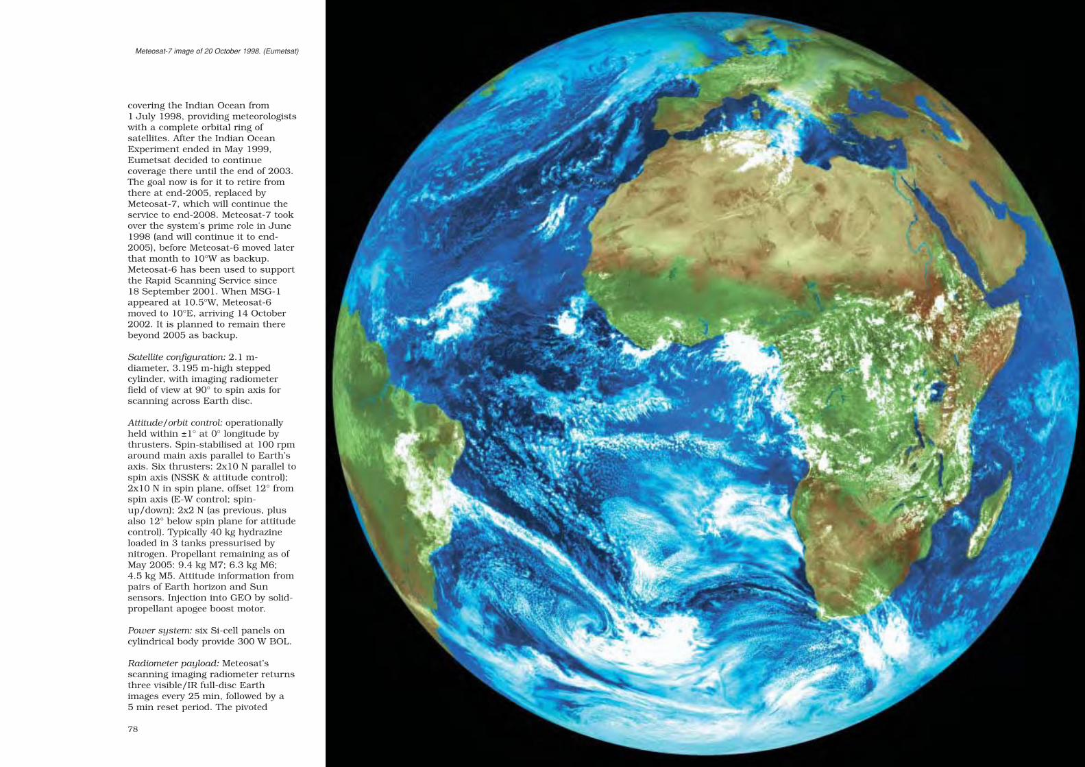
78
covering the Indian Ocean from1 July 1998, providing meteorologistswith a complete orbital ring ofsatellites. After the Indian OceanExperiment ended in May 1999,Eumetsat decided to continuecoverage there until the end of 2003.The goal now is for it to retire fromthere at end-2005, replaced byMeteosat-7, which will continue theservice to end-2008. Meteosat-7 tookover the system’s prime role in June1998 (and will continue it to end-2005), before Meteosat-6 moved laterthat month to 10°W as backup.Meteosat-6 has been used to supportthe Rapid Scanning Service since18 September 2001. When MSG-1appeared at 10.5°W, Meteosat-6moved to 10°E, arriving 14 October2002. It is planned to remain therebeyond 2005 as backup.
Satellite configuration: 2.1 m-diameter, 3.195 m-high steppedcylinder, with imaging radiometerfield of view at 90° to spin axis forscanning across Earth disc.
Attitude/orbit control: operationallyheld within ±1° at 0° longitude bythrusters. Spin-stabilised at 100 rpmaround main axis parallel to Earth’saxis. Six thrusters: 2x10 N parallel tospin axis (NSSK & attitude control);2x10 N in spin plane, offset 12° fromspin axis (E-W control; spin-up/down); 2x2 N (as previous, plusalso 12° below spin plane for attitudecontrol). Typically 40 kg hydrazineloaded in 3 tanks pressurised bynitrogen. Propellant remaining as ofMay 2005: 9.4 kg M7; 6.3 kg M6;4.5 kg M5. Attitude information frompairs of Earth horizon and Sunsensors. Injection into GEO by solid-propellant apogee boost motor.
Power system: six Si-cell panels oncylindrical body provide 300 W BOL.
Radiometer payload: Meteosat’sscanning imaging radiometer returnsthree visible/IR full-disc Earthimages every 25 min, followed by a5 min reset period. The pivoted
Meteosat-7 image of 20 October 1998. (Eumetsat)
sec3 7/20/05 2:52 PM Page 78

8180
Ritchey-Chrétien 40 cm-aperture,365 cm-focal length telescope, isstepped 0.125 mrad by a motor every100 rpm Meteosat rotation to scanEarth’s disc at 5 km intervals southto north. The two visible (0.4-0.9 µm)Si photodiode detectors return imagesof 5000 scan lines, for 2.5 kmresolution. The thermal-IR (10.5-12.5 µm) and the water vapour-IR(5.7-7.1 µm) mercury-cadmium-telluride detectors assemble images of2500 lines (each 2500 pixels),yielding 5 km resolution. The watervapour channel was experimental onthe first three satellites, but wasincluded operationally beginning withMeteosat-4.
Meteosat-3 added the LaserSynchronisation from Stationary
Orbit (LASSO) package of laserreflectors to demonstrate timestandard synchronisation over largedistances with 10-9 s accuracy. Thelaser pulses could also measureMeteosat’s distance to within 10 cm.
Communications payload: top cylindercarries radiating dipole antennaelements activated sequentially(electronically despun) for 333 kbit/sS-band image transmissions andTT&C operations. The imagery werereceived and processed at ESOC (byEumetsat in Darmstadt from1 December 1995) and disseminatedto users at L-band through Meteosatitself. The satellite also relays datafrom international Data CollectionPlatforms (to transfer to MSG-1end-2005).
Far right: Meteosat-5 view from 63°E, 4 September 2001. (Eumetsat).
Examples of Meteosat imagery from Meteosat-3.Top left: visible full-disc; top right: visible-light
Europe; bottom left: thermal-IR; bottom right: watervapour-IR. The colouring has been added. During
the Meteosat Operational Programme (1983-1995),ESA’s European Space Operations Centre (ESOC)
in Germany processed more than 1.1 millionMeteosat images. (ESA/Eumetsat)
Meteosat-2 (top) isprepared for launch byAriane in 1981.(CSG/Arianespace)
Meteosat Radiometer Payload
Meteosat’s scanning imaging radiometer returnsthree visible/IR full-disc Earth images every 25 min,followed by a 5 min reset period. The pivoted Ritchey-Chrétien 40 cm-aperture, 365 cm-focal lengthtelescope, is stepped 0.125 mrad by a motor every100 rpm Meteosat rotation to scan Earth’s disc at5 km intervals south to north. The two visible (0.4-0.9 µm) Si photodiode detectors return images of5000 scan lines, for 2.5 km resolution. The thermal-IR (10.5-12.5 µm) and the water vapour-IR (5.7-7.1 µm) ) mercury-cadmium-telluride detectorsassemble images of 2500 lines (each 2500 pixels),yielding 5 km resolution. The water vapour channelwas experimental on the first three satellites, but wasincluded operationally beginning with Meteosat-4.
Meteosat-3 added the Laser Synchronisation fromStationary Orbit (LASSO) package of laser reflectorsto demonstrate time standard synchronisation overlarge distances with 10-9 s accuracy. The laser pulsescould also measure Meteosat’s distance to within10 cm.
sec3 7/20/05 2:52 PM Page 80

82 83
IUE
Achievements: longest spaceborne astronomy mission (18.7 years); firstastronomical satellite at geostationary altitude
Launch date: 17:36 UT 26 January 1978Mission end: 30 September 1996, terminated 18:44 UT on ground command
(design life 3 years; consumables sized for 5 years)Launch vehicle/site: Delta 2914, from Cape Canaveral, FloridaLaunch mass: 671 kg (122 kg science, 237 kg apogee boost motor)Orbit: geosynchronous over Atlantic: initially 32050x52254 km, 28.6º, 23.93 h,
mission-end 36360x48003 km, 35.9º; Jan 2004 29191x42490 km, 40º
The International Ultraviolet Explorer(IUE) remains the longest-serving andmost prolific astronomical satellite yetlaunched: its 18.7 years of operationsreturned 104 468 high- (~0.1 Å) andlow-resolution (~6 Å) spectra from9600 celestial sources in the 1150-3200 Å UV band. IUE providedastronomers with a unique tool, andrequests for observing time eventowards the end of its careerremained two-three times greaterthan could be satisfied. Despite theappearance of the Hubble SpaceTelescope in 1990, IUE continued toprosper because it covered an entirespectral region not accessible in onesweep to HST’s high-resolutionspectrographs. It was the first
scientific satellite that allowed‘visiting’ astronomers to makerealtime observations of UV spectra:the impressive response time of <1 hprovided an unparalleled flexibility inscheduling targets of opportunity.
IUE was a trilateral project, based onthe 1974 Memorandum ofUnderstanding specifying that NASAwould provide the spacecraft,telescope, spectrographs and oneground observatory, ESA the solarpanels and the second observatory,and the UK the four spectrographdetectors. In addition to controllingthe satellite, the ground sites actedas typical astronomical observatories,except that their telescope hoveredfar out in space. ESA’s ‘IUEObservatory’ was established in 1977at the Villafranca Satellite TrackingStation, Madrid, Spain. During IUE’slife, >1000 European observingprogrammes were conducted fromVillafranca, returning >30 000spectra from about 9000 targets.
IUE identified the star that exploded into SN 1987A – the first supernovavisible to the naked eye in 383 years. The diagram below shows howthe brightness at each UV wavelength changed, beginning a few hoursafter the supernova’s discovery. The emission shifts towards longerwavelengths as the supernova rapidly cools from 13 500 K on25 February 1987 to 5200 K by 14 March 1987.
IUE carried two startrackers (Fine ErrorSensors) viewingthrough the maintelescope to provideprecise positioninginformation. This FESimage shows Halley’sComet during itsclosest approach toEarth in 1985.
IUE was the first astronomical observatory basedaround geostationary altitude, hovering over the Atlantic
Ocean in constant view of its users at Villafranca andNASA Goddard. Below: a section of IUE’s high-
resolution spectrum of supernova SN 1987A. Thenarrow lines are caused by the gas in our Galaxy, the
Large Magellanic Cloud and in between.
http://sci.esa.int/iue
These spectra were processed anddeposited in a public domain archivetogether with the data collected by theIUE Observatory at NASA’s GoddardSpace Flight Center. The IUE DataArchive remains the most heavily usedastronomical archive in existence: eachIUE spectrum had been used almostnine times by 2004. During 2000-2003,15% of papers using HST data referredto IUE data in the abstract.
IUE’s only serious problems stemmedfrom the failures (1979, 2x1982, 1985,1991) of five of the six gyros in itsattitude control system, although onlyone succumbed within the 3-yeardesign life. When the fourth failed in1985, IUE continued operations thanksto an innovative reworking of itsattitude control system by using thefine Sun sensor as a substitute. Evenwith another lost in the last year, IUEcould still be stabilised in 3-axes byadding star tracker measurements.
Until October 1995, IUE was incontinuous operation, run 16 h dailyfrom Goddard and 8 h from Villafranca.After that, as the two agency’s budgetstightened, observations were made onlyduring the 16 h low-radiation part ofthe orbit, controlled from Villafranca
In March 2000, ESA delivered the IUE Archive to thescientific community. Spain’s Laboratory for SpaceAstrophysics and Theoretical Physics (LAEFF, part ofthe National Institute for Aerospace Technology,INTA) assumed responsibility for the Archive andINES (IUE Newly Extracted Spectra), a system forrapid and simple global access. This principal centreis mirrored by the Canadian Astronomical DataCentre and supported through 18 National Hosts thatoffer local access to the data. From 2000 to 2003,the INES system had 30 000 queries from 1400nodes in 30 countries, resulting in the download of227 000 files (29 Gbytes).
2500 Å 3200 Åwavelength
dat
e (1
987)
23 M
ar
25 F
eb
sec3 7/20/05 2:52 PM Page 82

8584
while NASA concentrated on creatingthe IUE Final Archive. IUE remainedoperational until its hydrazine wasdeliberately vented, its batteriesdrained and its transmitter turned off.
Satellite configuration: 1.45 m-diaoctagonal-prism bus with telescopeassembly along main axis, and fixedsolar wings extending from opposingfaces. Most of the higher-powerelectronics were mounted on the mainequipment panel at the base, near thethermal louvres, while the experimentelectronics and attitude controlelements were on the upper equipmentplatform.
Attitude/orbit control: 3-axis control byfour reaction wheels, Fine ErrorSensors (2-axis star trackers using thetelescope optics for 0.27 arcsecangular resolution in 16 arcmin FOV),fine/coarse Sun sensors and 8x9 N +4x22 N hydrazine thrusters (27.3 kghydrazine in 6 tanks) for momentumdumping and orbit adjust. The controlsystem had to hold a 1 arcsec-dia starimage within a 3 arcsec-diaspectrograph entrance for a 1 hintegration by the camera.
Power system: 424 W BOL/28 Vdc(170 W after 18 yr; 210 W required)provided by two fixed 3-panel wingscarrying 4980 2x2 cm Si cells; 2x6 Ahnickel cadmium batteries.
Communications/data: 1.25-40 kbit/s2.25 GHz 6 W S-band downlink withfixed + reprogrammable formats.139 MHz VHF for telecommand.
Science payload: 45 cm-diameter f/15Ritchey-Chrétien telescope with twoFine Error Sensors, echellespectrographs (1150-1980 Å; 1800-3200 Å), resolutions 270 at 1500 Å &400 at 2700 Å. Redundant 1150-1970 Å and 1750-3300 Å vidiconcameras, 768x768 pixels.
Right: The IUE Flight Model beingprepared for a fine-pointing test.
Below: IUE ready for launch.(NASA)
The Goals and Highlights of IUE
IUE’s original scientific objectives were to:
– obtain high-resolution spectra of stars of all spectraltypes to determine their physical characteristics
– study gas streams in and around binary star systems– observe faint stars, galaxies and quasars at low
resolution, interpreting these spectra by reference tohigh-resolution spectra
– observe the spectra of planets and comets– make repeated observations of objects with variable
spectra– study the modification of starlight caused by
interstellar dust and gas.
Scientific highlights were the:
– first detection of aurorae on Jupiter– first detection of sulphur in a comet – first measurement of water loss in a comet (10 t/s)– first evidence for strong magnetic fields in chemically
peculiar stars– first orbital radial velocity curve for a Wolf-Rayet star,
allowing its mass determination– first detection of hot dwarf companions to Cepheid
variables– first observational evidence for semi-periodic mass-
loss in high-mass stars– discovery of high-velocity winds in stars other than
the Sun– first identification of a supernova progenitor
(SN 1987A)– discovery of starspots on late-type stars through
Doppler mapping– discovery of large-scale motions in the transition
regions of low-gravity stars– discovery of high-temperature effects in stars in the
early stages of formation– discovery of high-velocity winds in cataclysmic
variables– discovery of the effect of chemical abundance on the
mass-loss rate of stars– first determination of a temperature and density
gradient in a stellar corona beyond the Sun– first detection of gas streams within and outflowing
from close binary stars.– determination that no nova ejects material with solar
abundance– discovery of ‘O-Ne-Mg’ novae, where the excess of
these elements can be directly traced to the chemicalcomposition of the most massive white dwarfs
– discovery of a ring around SN 1987A, a leftover fromprevious evolutionary stages
– first direct detection of galactic haloes– first observations of extragalactic symbiotic stars– first uninterrupted lightcurves of stars for more than
24 h continuously– first detection of photons below 50 nm from any
astronomical source other than the Sun– first direct determination of the size of the active
regions in the nuclei of Seyfert galaxies (mini-quasars)– first detection of a transparent sightline to a quasar at
high redshift, allowing the first abundancedetermination of the intergalactic medium in the earlyUniverse
– first astronomical and satellite facility to deliver fullyreduced data within 48 h to scientists
sec3 7/20/05 2:52 PM Page 84

8786
Achievements: first successful European satellitelauncher; launched half of world’s commercialsatellites into GTO; 144 flights (116 Ar-4); 100thlaunch 23 Sep 1997; 100th Ar-4 launch 29 Oct2000 (Ar-4 total 337 t orbited in 163 payloads);Ariane carried its 100th telecommunicationssatellite (Astra 1E) on 19 Oct 1995; heaviestpayload is Anik-F1 (4711 kg, 21 Nov 2000); worldrecord 74 consecutive successes Mar 1995 to Feb2003 (programme end; Ar-4 overall success rate97.4%, orbiting 182 satellites totalling 404.1 t)
Launch dates: 24 Dec 1979 for first of 11 Ar-1;4 Aug 1984 for first of 17 Ar-2/3; 15 Jun 1988for first of 116 Ar-4
Launch site: Ar-1/2/3 from ELA-1 pad, Ar-2/3/4from ELA-2 pad; Kourou, French Guiana
Launch mass: 484 t for heaviest Ariane-4 version(Ar-44L), 245 t for lightest Ariane-4 version(Ar-40)
Performance: optimised for GTO. Up to 4950 kg into7°-inclined GTO for Ar-44L from Kourou; Ar-11850 kg; Ar-2 2175 kg; Ar-3 2700 kg
Principal contractor: EADS Launch Vehicles(industrial architect)
The Ministers responsible for spaceaffairs in 10 European countriesdecided in Brussels on 31 July 1973to develop a competitive vehicle thatwould win a significant share of thelaunch market for applicationssatellites. All the signs were that1980-90 would see the setting up of amyriad of operational and commercialspace systems for telecommunica-tions, direct TV broadcasting,meteorology and Earth observation.Several contemporary studiesestimated that 180 satellites wouldrequire launches intogeosynchronous orbits.
The highly successful and profitableAriane programme more thanvindicated that original agreement ofthe 10 countries: France (63.9%),Germany (20.1%), Belgium (5.0%),
Ariane-1Ariane-2
Ariane-3
Ariane-4
UK (2.5%), The Netherlands (2.0%),Spain (2.0%), Italy (1.7%),Switzerland (1.2%), Sweden (1.1%)and Denmark (0.5%). The vehiclecaptured half of the world’scommercial launch contractsannually. In 1998 alone, the profitreported by Arianespace – established by CNES in 1980 tocontract, manage production, finance,market and conduct the launches –was €12.6 million on sales of€1.07 billion from 11 launchesinvolving 14 satellites.
A study of the direct economic effectsof the Ariane-1 to -4 programmesshowed a financial return of slightlymore than a factor of 3. In otherwords, the revenues generated forArianespace and European industrywere more than three times the initial
ascent into GTO, beginning withAriane-1’s capacity of 1850 kg. The47.4 m-high, 210 t Ariane-1 waspowered by four Viking 5 engines onstage-1, a single Viking 4 on stage-2and the cryogenic liquidoxygen/liquid hydrogen HM-7 engineof stage-3. The Ariane-1 vehicle flew11 times during 1979-86, with itsnine successes a remarkableachievement for a new design.
public investment in Ariane, takinginto account the €6 billion investedby ESA and national institutionsbetween 1974 and 2000 and themore than €18 billion generated bylaunch contracts. These figures alsocovered the public expenditurerelated to the Kourou launch site.
ESA was responsible (as designauthority) for Ariane developmentwork, owning all the assets produced.It entrusted technical direction andfinancial management to CNES,which wrote the programmespecifications and placed theindustrial contracts on its behalf.EADS Launch Vehicles (the formerAerospatiale) acted as industrialarchitect. ESA/CNES were directlyresponsible for the L01-L04development launches and the L5-L8promotional launches, beforeArianespace assumed responsibilitybeginning with flight 9. The 3-stagelauncher was optimised for direct
Launch of the firstAriane-4 (V22), in
August 1984. Note thetwo liquid-propellant and
two solid-propellantstrapons.
(ESA/CNES/CSG)
Overpage: preparing forAriane-44P V144,
launched 25 September2001 carrying Atlantic
Bird-2 for Eutelsat (left);Ariane-44L V156 with
NSS-6 on 17 December2002. (ESA/CNES/CSG)
Ariane-4 Variants
Launch Launch 7° GTO thrust mass capacity
Ar-40 no strapons 2720 kN 245 t 2130 kg
Ar-42P 2 solids 3945 kN 324 t 2970 kg
Ar-44P 4 solids 5140 kN 356 t 3530 kg
Ar-42L 2 liquids 4060 kN 363 t 3560 kg
Ar-44LP 2 solids/2 liquids 5270 kN 421 t 4310 kg
Ar-44L 4 liquids 5400 kN 484 t 4950 kg
Arianespace
sec3 7/20/05 2:52 PM Page 86

sec3 7/20/05 2:52 PM Page 88

9190
Ariane-4 V34 included fourliquid-propellant strapons to
help deliver the Intelsat 6telecommunications satellite
into GTO. Forty of theseAr-44L versions had been
launched when theprogramme ended in February
2003. (ESA/CNES/CSG)
Ariane’s first launch, on24 December 1979, was a
complete success.(ESA/CNES/CSG)
Ariane V10 in August 1984 saw the first use of solid-propellant strapons to increase performance. On thisoccasion, the boosters carried recoverable cameras
to film the separation sequence 4.8 km high. Theother booster can be seen as Ariane accelerates
away with its four Viking engine bells glowing redhot. (ESA/MAN)
Ariane-4 Principal Characteristics
Stage-1
Principal contractor: EADS-LV (Aerospatiale)
Size: 28.39 m (including 3.31 m interstage)long; 3.80 m diameter, 17.5 t dry mass
Powered by: four Snecma Moteurs Viking 5engines providing total of 2720 kN at launchfor up to 205 s (qualified to 300 s), gimballedfor attitude control, drawing on up to 227 t ofnitrogen tetroxide (NTO) and UH25(unsymmetrical dimethyl hydrazine + 25%hydrazine hydrate)
Design: propellants were carried in twoidentical 10.1 m-long, 3.80 m-diameter steeltanks, separated by a 2.69 m-long interstage.An 8200-litre toroidal water tank sat on topof the lower tank, used for engine cooling
Solid-propellant strapons: 0, 2 or 4 carried,ignited at launch, 4.2 s after main engines.Each 650 kN thrust, 33 s burn (ejected>1 min after launch), 1205 cm long, 107 cmdiameter, 12 660 kg (9500 kg propellant).EADS-LV prime contractor
Liquid-propellant strapons: 0, 2 or 4 carried,ignited with stage-1 engines. Each 670 kNthrust, 142 s burn (ejected 149 s afterlaunch), 1860 cm long, 222 cm diameter,43 550 kg (39 000 kg propellant). Powered bysingle, fixed Viking 6; design similar tostage-2. Astrium GmbH prime contractor
Stage-2
Principal contractor: Astrium GmbH
Size: 11.61 m long; 2.60 m diameter, 3.4 t drymass
Powered by: Snecma Moteurs Viking 4 engineproviding 798 kN for 125 s, drawing on up to35 t of NTO/UH25
Design: propellants were carried inaluminium cylinder, 652 cm long, dividedinto two vessels by an internal bulkhead.Rear conical skirt, 157 cm long, connectedwith stage-1 interstage and housed Viking’storoidal water coolant tank. 125 cm-longfront skirt connected with stage-3’s interstage
But each Ariane-1 could carry onlytwo GTO satellites of up to 700 kgeach, when it was clear that themarket would soon demand greatercapacities. The Ariane-3 design thusmade its debut in 1984, capable ofdelivering two 1195 kg satellites (orone of 2700 kg) into GTO. This wasachieved mainly by uprating theengines, stretching stage-3 by 1.3 m,adding two solid-propellant strapons
to stage-1 and enlarging the payloadfairing. Ariane-2, capable of placing2175 kg in GTO, was identical butflew without the strapons. Ten of the11 Ariane-3s were successful 1984-89 and 5 out of 6 Ariane-2s during1986-89.
The development of a more powerfulvariant to become the standardvehicle through the 1990s was
Stage-3
Principal contractor: EADS-LV (Aerospatiale)
Size: 11.05 m long; 2.60 m diameter, 1.24 t dry mass
Powered by: gimballed Snecma MoteursHM-7B cryogenic engine providing 64.8 kN for780 s, drawing on 11.9 t of liquidoxygen/liquid hydrogen
Design: propellants are housed in analuminium cylinder, with tanks separated byan internal bulkhead. 45 cm-long front skirtconnects to Ariane’s equipment bay; 273 cm-long rear skirt connects with stage-2.
Vehicle Equipment Bay (VEB)
Principal contractor: Astrium SA
Purpose: carried equipment for vehicleguidance, data processing, sequencing,telemetry and tracking
Size: 104 cm high; 4.0 m diameter, 520 kg
Design: internal cone provided 1920 mm-diameter attachment to payload; external coneconnected with payload fairing/carrier;annular platform carried the electronics
Payload Fairing and Carriers
Payloads were protected by a 2-piecealuminium fairing until it was jettisoned afterabout 285 s during the stage-2 burn. Primecontractor was Oerlikon Contraves. Threebasic lengths are available: 8.6 m, 9.6 m and 11.1 m; diameter was 4 m. The mainpayload carrier was the Spelda, which satbetween the fairing and stage-3, housing onesatellite internally and a second on its topface, under the fairing. A range of sizes formatching payload requirements was available.Some missions could also carry up to six50 kg satellites as passengers.
sec3 7/20/05 2:52 PM Page 90

9392
Stage-2 was powered by a single Viking engine. (ESA/CNES/CSG)
The night launch of Ariane-4 V48 in December 1991 carried the Inmarsat-2 F3 andTelecom-2A telecommunications satellites. (ESA/CNES/CSG)
formally approved by ESA’s Councilin January 1982 and managementresponsibility assigned to CNES. Atotal of 116 vehicles was launched(the last in February 2003) before thenew-generation Ariane-5 completelyreplaced it. Its 113 successes (97.4%)delivered 182 satellites into orbit (139telecommunications, 9 Earthobservation, 5 meteorological, 2scientific, 27 auxiliary), totalling404.1 t. Six Ariane-4 variants werecreated by mixing pairs of solidand/or liquid strapon boosters; inorder of increasing performance, theyare shown in the earlier table.
Ariane-4 was not merely anupgrading but a significant redesignto meet the increasing needs of thecommercial market. From Ariane-3,stage-1 was stretched by 6.7 m toincrease propellant capacity from144 t to 227 t, and the Viking 5engines increased their burn timesfrom 138 s to 205 s. Stage-1 couldalso carry up to four liquid-propellantstrapons comparable in size andperformance with stage-2; a stretchedversion of Ariane-3’s solid-propellantstrapons was also available. Initially,stage-3 was similar to that onAriane-3, but it was stretched by
The engine bay of Ariane’sfirst stage carried four Viking 5
engines. (Snecma Moteurs)
The Giotto Halley’s Cometprobe installed on top of its
Ariane-1 launcher. The VehicleEquipment Bay carried therocket’s control electronics.
Behind, to the left, is one halfof the fairing.
(ESA/CNES/CSG)
32 cm in April 1992 to add another340 kg of cryogenic propellants, andthen another redesign was introducedin December 1994 that increasedcapacity from 4460 kg to 4720 kginto GTO. In January 1996, otheradjustments produced 4820 kg. Therecord is 4947 kg, for the launch of28 October 1998; 5000 kg wasattainable. In addition, Ariane-4offered a range of payload fairingsand carriers to handle mixes of up totwo major satellites and six 50 kgpayloads on each launch.
sec3 7/20/05 2:52 PM Page 92

9594
Marecs
Achievements: first European maritime communications satellites; inauguratedInmarsat; greatly exceeded 7-year design lives
Launch dates: Marecs-A 20 December 1981; Marecs-B 10 September 1982(launch failure); Marecs-B2 10 November 1984
Mission end: Marecs-A retired from Inmarsat service in 1991, ESA deactivated itin August 1996; Marecs-B2 retired from Inmarsat service in December 1996,ESA deactivated it in January 2002
Launch vehicle/site: Ariane from Kourou, French GuianaLaunch mass: 1060 kg (562 kg on-station BOL; communications payload 96 kg)Orbit: geostationary, Marecs-A initially 26°W (retired from 22.5°E), Marecs-B2
initially 177.5°W (retired from 26°W)Principal contractors: British Aerospace (prime); Marconi Space Systems (payload)ESA cost-to-completion (MAU): Marecs-A 161 (1982 e.c.), Marecs-B/B2 107 (1984 e.c.)
Conceived as an experimental project,Marecs evolved to provide Europewith a major breakthrough in mobiletelecommunications expertise. SeveralESA Member States undertook in 1973to fund a satellite programme thatwould demonstrate communicationsbetween ships and land stationslinking into the public networks, at atime when vessels could call only viaunpredictable short-wave radio. Infact, Marecs (so named because itadapted ESA’s ECS design for amaritime application) became theagency’s first venture into thecommercial satellite business. Thetwo successfully-launched satelliteswere leased initially for 10 satellite-years to the Inmarsat (InternationalMaritime Satellite Organisation),which formally inaugurated itsservice on 1 February 1982. Marecswas designed to provide high-qualityvoice, data and telex services formaritime users. This included about60 telephone channels linked into thepublic system (including fax and datatransmissions), 1200 telex channelsworking through the internationaltelex system, priority relay of distresssignals, and the broadcasting ofmaterial such as weather forecasts towhole groups of userssimultaneously.
With Marecs-A and -B2 providingcoverage over the Atlantic and Pacific
Oceans, 130 ships carried Inmarsattransceivers on inauguration day.More than 100 000 terminals havebeen commissioned, today includingsystems on aircraft and land vehicles,and even briefcase sets for businesstravellers. Inmarsat has now changedthe ‘Maritime’ in its name to ‘Mobile’to better reflect its growing business.
Developing Marecs placed Europe atthe forefront of mobilecommunications technology, so thatwhen Inmarsat requested bids for
One of the two L-bandSolid State Power
Amplifier (SSPA)clusters for transmitting
to maritime users. Threeof the five SSPAs in
both clusters weregrouped to generate a
75 W output.
Marecs-A in orbitalconfiguration.
Marecs-A assembly atBritish Aerospace inStevenage, UK.
building its first generation ofdedicated satellites a consortiumheaded by British Aerospace won theprime contract, drawing on theMarecs heritage. These four satelliteswere launched 1990-1992, and arenow augmented by third-generationsatellites carrying payloads providedby Astrium.
Despite the advent of the newsatellites, the two Marecs continuedin service with Inmarsat far beyondtheir 7-year design lives. Marecs-Awas removed from service in 1991because of its ageing solar arrays, butESA continued to use it forexperiments at 22.5°E until it wasboosted above GEO in August 1996and deactivated. Inmarsat’s Marecs-B2 lease expired at the end of 1996and the veteran satellite was movedto 26°W, where it was leased byNuovo Telespazio (Italy) from August1997 to January 2000. A NuovoTelespazio customer, Fugro,disseminated GPS navigation systemupdates to users primarily in SouthAmerica. It was expected to be leasedto Comsat General Corp to providelinks with the US National ScienceFoundation at the South Pole, fromwhere its 10º orbital inclination madeit visible for 2 h each day, but the
opportunity was lost in the aftermathof 11 September 2001. It was raisedinto an elliptical orbit 752-1778 kmabove GEO and deactivated on25 January 2002.
sec3 7/20/05 2:52 PM Page 94

9796
Marecs-A undergoes asolar array deploymenttest at BritishAerospace.
Marecs pioneered maritime satellite communications,providing reliable links with the land-based publicnetworks.
Marecs principal features. The service module wasdirectly derived from the ECS satellite.
Marecs-A is prepared for launch from Kourou on anAriane vehicle.
Satellite configuration: maritimeversion of ECS satellite,2.2x3.1x1.8 m at launch, solar arraydeployed span 13.8 m.
Attitude/orbit control: 3-axisstabilisation and maintained in GEOby momentum wheels and redundant0.5 N and 2 N hydrazine thrusters(90 kg hydrazine in four tanks; 26 kgremained in B2 as of Feb 2001).Earth and Sun sensors provide Earthpointing with 0.04° accuracy.Transfer from GTO to GEO by solid-propellant apogee boost motor.
Power system: two 3-panel Si solarwings generated 1050 W; 425 Wrequired by communications payload.Powered by 2x21 Ah nickel cadmiumbatteries during eclipse.
Communications payload: up to sixL-band SSPAs (out of 10) with total75 W output (EIRP 33.1 dBWhemispherical beam edge) relayed>35 voice channels at 1.54 GHz toships, and could receive >50 at1.64 GHz. One C-band 1 W 6.4 GHzTWTA provides link to land station.Flight Control Centre at ESOC (Redufrom March 1997), working viaC-band station at Villafranca.
sec3 7/20/05 2:52 PM Page 96

9998
Sirio
Launch date: 10 September 1982 (launch failure)Mission end: launch failure; 2-year nominal mission plannedLaunch vehicle/site: Ariane from Kourou, French GuianaLaunch mass: 420 kg (on-station BOL 237 kg; payload 50.0 kg, apogee motor
203 kg, hydrazine/nitrogen 34 kg)Orbit: orbit not achieved, planned to be geostationary over 25°WPrincipal contractor: Compagnia Nazionale Satelliti per Telecommunicaziono SpA
Italy expressed an interest in 1977 inusing the spare flight model of itssuccessful domestic Sirio-1telecommunications satellite forapplications on a broader Europeanbasis. ESA’s proposal, afterconsulting national meteorologicalservices and the World MeteorologicalOrganisation, was accepted by theAgency’s Council in December 1978and spacecraft development (Phase-C/D) began in January 1979.
One payload was for theMeteorological Data Distribution(MDD) mission. Sirio-2 was to bepositioned in geostationary orbit overAfrica, so that its MDD transponderwould allow meteorological centres on
that continent to relay weather datausing simple receive/transmitstations. Sirio provided 24x100 bit/sand 12x2.4 kbit/s 2105/1695 MHzup/down channels working to<40 dBw EIRP stations. On Sirio, thedespun 70x99 cm 45° planar reflectordirected incoming signals to the fixed70 cm parabolic reflector and itsantenna feed.
The other payload was LaserSynchronisation from StationaryOrbit (Lasso) for synchronising high-precision clocks at widely-separatedlocations with 1 ns accuracy at lowcost. Lasso consisted of a155x340 mm panel of 98 20 mm-diameter laser retro-reflectorsmounted on the Ariane interfaceadapter, photodetectors for sensingruby and neodyme laser pulses, andan ultrastable oscillator/counter totime-tag the pulse arrivals. Differentground stations could thus observethe reflected pulses and use the time-tagging to compare their clocks.
Satellite configuration: total height2.400 m, diameter 1.438 m, based oncylindrical body 9.954 m high,1.438 m diameter. Four principalelements: main structure; solar arraystructure; payload platform; interfaceadapter. Main structure wasaluminium honeycomb thrust conesupporting apogee motor at one end,the main load platform on its mid-section, and payload platform on topend. The main load platformaccommodated the four propellant
Sirio-2 ready at Kourou for encapsulation in theAriane payload fairing. The despun antenna iscovered by a protective cylinder (top).(ESA/CNES/CSG)
Sirio-2 complete, with the solar arraypanels removed.
Facing page: Sirio’s main platform carriedmost of the spacecraft systems. Prominentat top is the launcher interface adapter,carrying the panel of 98 laser reflectors.
tanks, thrusters, attitude detectionunits and main services such aspower, telemetry & command. Solararray cylindrical structure of four 90°sections attached to main loadplatform at mid-height and to thrustcone by struts at both ends.
Attitude/orbit control: AuxiliaryPropulsion Subsystem of two radialand two axial 22 N hydrazinethrusters; spin-stabilised at 90 rpm.Attitude determination by four 2 kgEarth/Sun IR sensor packages.
Insertion into GEO by solid-propellant apogee motor.
Power system: 8496 2x2 cm Si cellson cylindrical body main array,supported by 300 2x2 cm Si cells forbattery charging. Total output 133 WBOL at summer solstice.
Communications payload: telemetry &command at 148/136 MHz up/downVHF using redundant 8 Wtransponders; 512 bit/s telemetry.Controlled from Fucino, Italy.
sec3 7/20/05 2:52 PM Page 98

100
Exosat
Achievements: detailed observations of celestial X-ray sourcesLaunch date: 26 May 1983Mission end: reentered 6 May 1986 (designed for 2-year life, science operations
began August 1983)Launch vehicle/site: Delta from Vandenberg Air Force Base, California Launch mass: 510 kg (science instruments 120 kg)Orbit: 2919x189 000 km, 71.4°Principal contractors: MBB headed the Cosmos consortium: SNIAS-Cannes (F)/
CASA (E)/Contraves (CH)/BADG (UK) (structure/thermal/mechanisms/solararray mechanical); MBB (D)/SNIAS-LM (F)/MSDS (UK)/Sodern (F)/Ferranti(UK)/SEP(F)/TPD-TNO (NL)/NLR (NL) (AOCS); Selenia (I)/Laben (I)/Saab(S)/Crouzet (F)/LM-Ericsson (S) (data handling/RF); ETCA (B)/Terma (DK)/Saft(F)/AEG (D) (power/solar array electrical)
ESA’s X-ray Observatory Satellite(Exosat) studied the X-ray emissionfrom most classes of astronomicalobjects, including active galacticnuclei, white dwarfs, stars,supernova remnants, clusters ofgalaxies, cataclysmic variables andX-ray binaries. In 1780 observations,it measured the locations of cosmicX-ray sources, their structuralfeatures and spectral, as well astemporal, characteristics in thewavelength range from extreme-UVto hard X-rays. Its primary missionwas to study sources alreadydetected by earlier satellites,although it did discover many newones serendipitously as it slewedfrom one target to the next orfocused on specific areas.
Exosat was the first ESA/ESROscience satellite totally funded by theAgency. Its observations and datawere not restricted to the groups thathad built the three instruments, butwere made available to a widercommunity. The satellite wasoperated as a true astronomicalobservatory. A unique feature wasthe highly eccentric orbit which,although it subjected Exosat tohigher background radiationdependent on solar activity, providedup to several days at a time foruninterrupted viewing of a source.More than 450 publications of
Exosat in operatingconfiguration. On thefront, from left to right,are two startrackers, thetwo low-energy imagingtelescopes and the fourquadrants of themedium-energyinstrument. The gasscintillation proportionalcounter is visible to theright of the mediumenergy instrument.
Inside Exosat. The twolow-energy imagingtelescopes areprominent, with theirapertures at left andtheir detectors at right.
Exosat Mission Objectives
Precise location of sources: within 10 arcsec at0.04-2 keV, 2 arcmin for 1.5-50 keV.
Mapping diffuse extended objects: at lowenergies using imaging telescopes.
Broadband spectroscopy of sources: with allinstruments between 0.04 keV & 80 keV.
Dispersive spectroscopy: of point sourcesusing gratings with imaging telescopes.
Time variability of sources: from days to sub-millisec.
New sources: detection.
http://astro.estec.esa.nl/exosat
Exosat results in leading scientificjournals have been made. Notablediscoveries include:
— ‘quasi-periodic oscillations’(QPOs). Exosat searched for thespin rates of neutron stars inlow-mass X-ray binaries but,instead, discovered periodswandering back and forth. QPOsare thought to be caused byinstabilities in the accretiondiscs surroundings the neutronstars.
— Exosat discovered two starsorbiting each other every 11 min– the shortest period known atthe time. XB 1820-30 emitsX-rays 1011 more intense thanfrom the Sun as material fallsonto its neutron star.
— The X-ray binary SS433 isprobably a massive star feeding ablack hole 10 times the mass ofthe Sun. Two giant jets near theblack hole are ejecting materialat a quarter the speed of light.The X-ray jets wave back andforth every 167 days, whichExosat discovered is the sameperiod as variations in theoptical lines. This is helping toexplain the enigmatic nature ofjets from black holes – still oneof the hot topics in astrophysics.
— Exosat surveyed 48 Seyfertgalaxies, which have giant black
holes at their centres and arestrong X-ray emitters. Exosatdiscovered a soft X-raycomponent, now thought to beemission from matter swirling intoan accretion disc beforedisappearing into a black hole.
— observations of the pulsing X-raynova EXO 2030+375 provided newinsights into how material from acompanion is captured by theintense magnetic field of a pulsingneutron star.
Exosat was approved in 1973, whenthe intention was to take simplereadings of X-ray sources – only asmall number of positions wereknown at that time. This HELOS(Highly Eccentric Lunar OccultationSatellite) would map the positions
101
and shapes of X-ray sources byobserving as they were covered by theMoon. By 1977, when Exosat wasfunded, missions such as Uhuru,Copernicus, Ariel-5, ANS, SAS-3 andHEAO-1 had changed the priority,because positions were now beingdetermined much more accurately. Itwas therefore decided to includeX-ray imaging, making Exosat aforerunner of XMM-Newton andChandra.
Exosat was ESA’s first satellite tocarry an onboard computer (OBC), a16-bit parallel machine forexperiment control and dataprocessing. It was reprogrammed inflight in response to lessons-learnedto allow, for example, better study ofthe newly-discovered QPOs.
sec3 7/20/05 2:52 PM Page 100
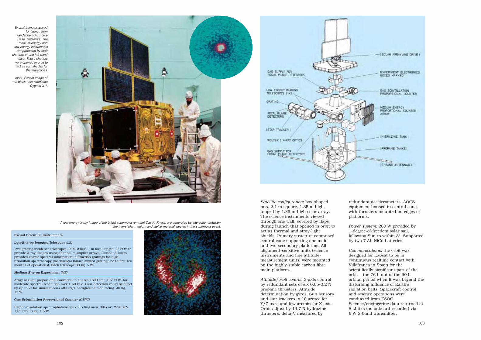
103102
Satellite configuration: box-shapedbus, 2.1 m square, 1.35 m high,topped by 1.85 m-high solar array.The science instruments viewedthrough one wall, covered by flapsduring launch that opened in orbit toact as thermal and stray-lightshields. Primary structure comprisedcentral cone supporting one mainand two secondary platforms. Allalignment-sensitive units (scienceinstruments and fine attitude-measurement units) were mountedon the highly-stable carbon fibremain platform.
Attitude/orbit control: 3-axis controlby redundant sets of six 0.05-0.2 Npropane thrusters. Attitudedetermination by gyros, Sun sensorsand star trackers to 10 arcsec forY/Z-axes and few arcmin for X-axis.Orbit adjust by 14.7 N hydrazinethrusters; delta-V measured by
Exosat being preparedfor launch from
Vandenberg Air ForceBase, California. Themedium-energy and
low-energy instrumentsare protected by their
shutters on the left-handface. These shutters
were opened in orbit toact as sun shades for
the telescopes.
Inset: Exosat image ofthe black hole candidate
Cygnus X-1.
redundant accelerometers. AOCSequipment housed in central cone,with thrusters mounted on edges ofplatforms.
Power system: 260 W provided by1-degree-of-freedom solar sail,following Sun to within 3°. Supportedby two 7 Ah NiCd batteries.
Communications: the orbit wasdesigned for Exosat to be incontinuous realtime contact withVillafranca in Spain for thescientifically significant part of theorbit – the 76 h out of the 90 horbital period when it was beyond thedisturbing influence of Earth’sradiation belts. Spacecraft controland science operations wereconducted from ESOC.Science/engineering data returned at8 kbit/s (no onboard recorder) via6 W S-band transmitter.
A low-energy X-ray image of the bright supernova remnant Cas-A. X-rays are generated by interaction betweenthe interstellar medium and stellar material ejected in the supernova event.
Exosat Scientific Instruments
Low-Energy Imaging Telescope (LE)
Two grazing incidence telescopes, 0.04-2 keV, 1 m focal length, 1° FOV toprovide X-ray images using channel-multiplier arrays. Passband filtersprovided coarse spectral information; diffraction gratings for high-resolution spectroscopy (mechanical failure limited grating use to first fewmonths of operations). Each telescope 30 kg, 5 W.
Medium Energy Experiment (ME)
Array of eight proportional counters, total area 1600 cm2, 1.5° FOV, formoderate spectral resolution over 1-50 keV. Four detectors could be offsetby up to 2° for simultaneous off-target background monitoring. 48 kg,17 W.
Gas Scintillation Proportional Counter (GSPC)
Higher-resolution spectrophotometry, collecting area 100 cm2, 2-20 keV,1.5° FOV. 8 kg, 1.5 W.
sec3 7/20/05 2:52 PM Page 102

105104
ECS
Achievements: first European regional satellite communications system; farexceeded design lives; 348 channel-years of communications service
Launch dates: ECS-1 16 June 1983; ECS-2 4 August 1984; ECS-3 12 September1985 (launch failure); ECS-4 16 September 1987; ECS-5 21 July 1988
Mission end: ECS-1 December 1996; ECS-2 November 1993; ECS-3 launchfailure; ECS-4 December 2002; ECS-5 May 2000 (7-year design lives)
Launch vehicle/site: Ariane, from Kourou, French GuianaLaunch mass: about 1185 kg (about 700 kg on-station BOL)Orbit: geostationary; initially ECS-1 10°E, ECS-2 10°E, ECS-4 10°E, ECS-5 16°EPrincipal contractors: Hawker Siddeley Dynamics (UK, prime) heading MESH
consortium of Matra (F), ERNO (D), Saab (S), AEG (D), Selenia (I), Aeritalia (I)ESA cost-to-completion: ECS-1/2 154.3 MAU; ECS-3/4/5 115.1 MAU (1977 rates)
The success of ESA’s firstcommunications satellite programme,OTS, led directly to the developmentof the European CommunicationsSatellite (ECS) and the creation of theEuropean TelecommunicationsSatellite Organization (Eutelsat) in1977 as an inter-governmental entityto operate Europe’s first regionalsatellite system on behalf of, at thetime of privatisation in July 2001, 48member states. Under a 10-yearagreement, ESA provided the first-generation space segment forEutelsat, which became the owner ofeach satellite after in-orbit testing.The last was handed over in 1988,and operated for almost 12 years.ESA controlled the satellites from itsRedu (B) site.
Apart from the Ariane launch loss ofECS-3, the satellites provedremarkably successful and servedwell beyond their 7-year design goals.Each operated up to nine Ku-bandtransponders working simultaneouslythrough five beams around Europe,with an equivalent capacity of 12 000telephone circuits or 10 TV channels.They provided all types oftelecommunications and audiovisualservices, such as telephony,European Broadcasting Union TV andradio distribution, business TV andcommunications, satellitenewsgathering and, from 1991, the
Euteltracs two-way messaging andposition-reporting service for smallmobile terminals. The antennamodule generated three adjacent spotbeams for the telecommunicationsservices, a lower-intensity broad‘Eurobeam’ and (after ECS-3) theSatellite Multiservice System (SMS)beam dedicated to business datatransmissions.
ECS-1 was handed over to Eutelsatby ESA on 12 October 1983 to begin
ECS-1 undergoing solararray deployment testsat Matra.
Inset: The end of an era.Benoit Demelenne atESA’s Redu groundstation sends the finalcommand to shut downECS-4 at 17:22 UT1 December 2002. Thesatellite’s last 4.6 kg ofpropellant had raised it414 km above GEO in aseries of burns starting26 November 2002.
Europe’s new phase of satellite-basedcommunications. It served at anumber of GEO positions and, afterthe Eutelsat-procured secondgeneration was well established, itwas moved to 48°E in December 1993to provide services to the newly-independent ex-Soviet countries. Itretired in December 1996 at 36°E,almost doubling its design life and
having accumulated 710 562channel-hours of communicationsservice.
Successor satellites added SMS toprovide companies with a Europeannetwork of dedicated links for 2.4-2000 kbit/s data transmission, videoconferencing, facsimile and remoteprinting. ECS-2 retired from serviceat 1°E on 13 September 1993 andwas boosted by its hydrazinethrusters 400 km above GEO inNovember 1993, the first Eutelsatretirement. It had provided 634 576channel-hours. ECS-5 was last usedat 12°W (arriving March 1999) forInternet traffic between Canada andTurkey, with two transpondersavailable. In March 2000, it arrived at4°E, from where it was retired in May2000, after 779 727 channel-hours.
Despite Eutelsat completing itssecond-generation network of sixsatellites and beginning its third,ECS-4 remained in service with fouroperational transponders, held at33°E with its four usabletransponders leased until mid-2002to a state communications agency inGeorgia for Internet links. Until 2000,it was at 25.5°E for Euteltracs, TVand news gathering. It was last usedfor ad hoc data links between Europeand the Middle East, bringing it to932 400 channel-hours.
“...the ECS satellites were remarkablysuccessful and reliable from thetechnical point of view, and enabledEutelsat to establish itself as anincreasingly profitable organisation.”A History of the European SpaceAgency, ESA SP-1235 (2000)
sec3 7/20/05 2:52 PM Page 104

107106
Satellite configuration: 1.91 m-length,1.46 m-width, 1.42 m-height (1.95 mwith antennas) hexagonal bus,derived from OTS, using service andcommunications modules ofaluminium construction. Builtaround central cylindrical thrust conehousing apogee boost motor. Spanacross solar array 13.8 m.
Attitude/orbit control: 3-axis controlby two momentum wheels + onereaction wheel, and 8x2 N + 12x0.5 Nthrusters (4 yaw backup on latermodels) drawing on 117-122 kghydrazine in four spheres. Injectioninto GEO by solid-propellant apogeeboost motor.
Power system: two 1.3x5.2 m 3-panelwings of Si cells generated 1.26 kWBOL. 2x24 Ah NiCd batteriesprovided power during eclipses.
Communications payload: 9 of 14(ECS-1 9 of 12) 20 W Ku-band(10.95-11.2/11.45-11.7 GHz) TWTAsactive simultaneously providing threespot beams (EIRP 46 dBw), oneEurobeam (41 dBw) and (after ECS-1)SMS 12.5-12.75 GHz beam(43.5 dBw).
ECS-2 and subsequentsatellites reconfiguredthe antenna platform,adding the SatelliteMultiservice System forbusiness datatransmissions.
ECS-1 ready for launch.The black Syldacanister carried asecond satellite.(CSG/Arianespace)
ECS-1 provided services toEurope and north Africa via threespot beams and a singleEurobeam. Its successors addedthe Satellite Multiservice Systemfor business users.
sec3 7/20/05 2:53 PM Page 106

Inserting Spacelab-1into the Shuttle Orbiter’scargo bay. The tunnelfrom the Orbiter’s cabinhas yet to be connected(top left).
Spacelab was anintegral part of the
Space TransportationSystem. Shown is the
Spacelab-1configuration, flown in
1983.
109108
Spacelab
Achievements: principal scientific manned module for US Space Shuttle; majorcontributions to space sciences research and applications; first Europeanmanned space project; 22 missions
Launch dates: see tableLaunch vehicle/site: US Space Shuttle, Kennedy Space Center, FloridaLaunch mass: typically 10 t (Spacelab-1 totalled 8145 kg Pressure Module and
3386 kg Pallet; including experiments totalling 1392 kg)Orbits: typically 300 km altitude, inclinations 28-57°Principal contractors: VFW-Fokker/ERNO (later MBB/ERNO; prime), Aeritalia (PM
structure, Igloo, thermal control), Matra (command/data management), Dornier(IPS, ECLSS), British Aerospace (Pallet)
Spacelab was an integral element ofNASA’s Space Shuttle programmeand provided ESA/ESRO with aunique opportunity for developing amanned space capability. The 22missions made outstandingcontributions to astronomy, lifesciences, atmospheric physics, Earthobservation and materials scienceunder microgravity – advances thatstemmed from this crucial Europeancontribution. Spacelab essentiallycomprised two types of payloadcarrier: a pressurised mannedlaboratory module and unpressurisedexternal pallets. Its flexibility allowedit to accommodate both multi-disciplinary experiments andcomplements devoted to a singlescientific or applications theme. ThePressure Module (PM) hosted theexperiments equipment, dataprocessing and electrical powerequipment, an environmental controlsystem and crew control stations. Thecrew of up to six researchers reliedon the Shuttle Orbiter for livingquarters, communications and datatransmissions.
Europe was invited in 1969 toparticipate in the post-Apolloprogramme, ultimately deciding atthe Ministerial Meeting of theEuropean Space Conference inBrussels on 20 December 1972 toentrust ESRO with developing amodular, general-purpose laboratory.
The Memorandum of Understandingwas signed with NASA on 24September 1973, giving Europe theresponsibility for funding, designingand building Spacelab. Europe agreedto deliver free of charge theEngineering Model and the first FlightUnit, plus ground support equipment,in return for a shared first mission.NASA would purchase any furtherequipment. The consortium headed byVFW-Fokker/ERNO (later MBB/ERNO)was awarded the 6-year ECU180million Phase C/D contract in June1974. Spacelab Flight Unit I, inSpacelab-1 configuration, was formallyaccepted by NASA in February 1982,comprising a Pressure Module, fivePallets, an Igloo, an Instrument
Pointing System, plus supportequipment. NASA bought a secondset from ESA for aboutECU200 million.
The maiden mission was designed toprove Spacelab’s capabilities acrossnumerous disciplines. Half thepayload was allocated to ESA’s FirstSpacelab Payload (FSLP). Therepresentative configuration was thePM plus one Pallet with a total of 70experiments. The mission requirednot only more experiment hardwarethan any previous ESA flight, butalso more experimenters: 100investigators interested inatmospheric physics, Earthobservation, space plasma physics,
sec4 7/20/05 2:58 PM Page 108

111110
ESA astronaut WubboOckels at work during
the Spacelab-D1mission.
Spacelab-1 in orbit: thedebut of Europe’s
manned spacelaboratory. (NASA)
life sciences, materials science,astronomy, solar physics andtechnology. It also included the firstEuropean astronaut, Ulf Merbold,selected by ESA in 1977 along withWubbo Ockels and Claude Nicollieras the agency’s first astronaut corps.The mission was a resoundingsuccess, demonstrating Spacelab’sfar-reaching capabilities. Spacelab
went on to prove itself as anunsurpassed asset. In the first eightPM missions alone, 387 experimentsinvolved 323 Principal Investigatorsfrom 148 institutes in 26 countries.Spacelab flew its last mission in 1998– a quarter of a century after Europebegan the project – as scientistsprepared for the advent of theInternational Space Station.
Spacelab Missions
STS Launch Orbit Inc Mission Configuration Discipline EuropeanOrbiter Duration Altitude Astronaut
STS-9 28 Nov 83 57° SL-01 LM + 1P Multi- U. MerboldColumbia 10 d 250 km FSLP discipline
STS-51B 29 Apr 85 57° SL-03 LM MaterialsChallenger 7 d 360 km + MPESS Science
STS-51F 29 Jul 85 50° SL-02 IG + 3P SolarChallenger 8 d 320 km + IPS Astronomy
STS-61A 30 Oct 85 57° SL-D1 LM Materials/ W. OckelsChallenger 7 d 330 km + MPESS Life Sciences E. Messerschmid
R. Furrer
STS-35 2 Dec 90 28° Astro-1 IG + 2P AstronomyColumbia 9 d 350 km + IPS
STS-40 5 Jun 91 39° SLS-01 LM LifeColumbia 9 d 300 km Sciences
STS-42 22 Jan 92 57° IML-01 LM Materials/ U. MerboldDiscovery 8 d 300 km Life Sciences
STS-45 24 Mar 92 57° Atlas-1 IG + 2P Atmos. Physics D. FrimoutAtlantis 9 d 300 km Solar Astron.
STS-50 25 Jun 92 28° USML-01 LM/EDO MaterialsColumbia 14 d 300 km Science
STS-47 12 Sep 92 57° SL-J LM Materials/Endeavour 8 d 300 km Life Sciences
STS-56 8 Apr 93 57° Atlas-2 IG + 1P AtmosphericDiscovery 9 d 300 km Physics
STS-55 26 Apr 93 28° SL-D2 LM + USS Multi- M. SchlegelColumbia 10 d 300 km discipline U. Walter
STS-58 18 Oct 93 39° SLS-02 LM/EDO LifeColumbia 14 d 280 km Sciences
STS-65 8 Jul 94 28° IML-02 LM/EDO Materials/Columbia 15 d 300 km Life Sciences
STS-66 3 Nov 94 57° Atlas-3 IG + 1P Atmospheric J-F. ClervoyAtlantis 11 d 300 km Physics
STS-67 2 Mar 95 28° Astro-2 IG + 2P AstronomyEndeavour 17 d 350 km EDO
STS-71 27 Jun 95 52° SL-Mir LMAtlantis 10 d 300 km
STS-73 20 Oct 95 39° USML-02 LM/EDO MaterialsColumbia 16 d 300 km Science
STS-78 20 Jun 96 39° LMS LM/EDO Materials/ J-J. FavierColumbia 17 d 280 km Life Sciences
STS-83 4 Apr 97 28° MSL-01 LM/EDO MaterialsColumbia 4 d 300 km Science
STS-94 1 Jul 97 28° MSL-01R LM/EDO MaterialsColumbia 16 d 300 km Science
STS-90 17 Apr 98 39° Neurolab LM/EDO LifeColumbia 16 d 280 km Sciences
Atlas: Atmospheric Laboratory for Applications and Science. EDO: Extended Duration Orbiter. IG: Igloo. IML: International Microgravity Laboratory. LM: Long Module. LMS: Life and MicrogravitySpacelab. MPESS: Mission Peculiar Experiment Support Structure. MSL: Microgravity SciencesLaboratory. P: Pallet. SL: Spacelab. SLS: Spacelab Life Sciences. USML: US Microgravity Laboratory.
sec4 7/20/05 2:58 PM Page 110

113112
Configuration: Spacelab comprisedseveral elements that could be mixed-and-matched according to missionrequirements. The Pressure Moduleaccommodated experiments in ashirtsleeve environment, externalexperiments were mounted on Pallets,the Instrument Pointing Systemprovided precision pointing for largetelescopes, and the Igloo housedavionics when the PM was absent (6out of 22 missions). See the separatesections for descriptions of each.
Attitude/orbit control: provided bySpace Shuttle Orbiter.
Life support: a joint effort with theOrbiter to maintain a 1-baratmosphere at 18-27°C and 30-70%humidity. Orbiter cabin air wasdrawn in through the linking tunnel,cleaned with lithium hydroxide andcharcoal, cooled by heat exchangersand blown into the module throughroof diffusers.
The Atlas Spacelab missions did not include a Pressure Module,but instead housed the avionics in an Igloo (foreground) forcontrolling the payloads on the two Pallets. (NASA)
The Astro-1 mission was the first to employ the InstrumentPointing System, using the high-precision pointing capabilities
for detailed observations of the Sun.
Transferring theassembled Spacelab-1to Space ShuttleColumbia. Thisassembly has beendisplayed in the Udvar-Hazy Center annex ofthe National Air & SpaceMuseum at DullesInternational Airport,Washington DC, sinceDecember 2003(http://www.nasm.si.edu/udvarhazy/). Thesecond set, flown on thefinal mission, can beseen at Bremen Airport(D).
Pressure Module (PM)The 75 m3 PM was Spacelab’s principalelement, providing scientist-astronautswith a comfortable workingenvironment. The 4.1 m-diameter, 7 m-long module was basically a 1.6-3.5 mm-thick aluminium cylinder withconical end pieces. The main segmentscould be unbolted for groundprocessing. The experiment racks wereintegrated outside the PM and thenrolled with the floor into place alongthe PM side support beams. The racksheld standard 48.3 cm-wide laboratorytrays; the Double Rack had a1.75 m3/580 kg capacity. The PMcould carry the equivalent of 20 SingleRacks, although two DRs werereserved each mission for avionics andequipment storage. The roof and flooroffered storage space. The roofincluded two 1.3 m-diameterapertures: a window in the forward oneand a scientific airlock aft for exposingexperiments to space.
Pallets and IglooExperiments requiring direct exposureto space were carried on U-shaped
Pallets that could be fully integratedbefore being inserted into theShuttle’s cargo bay. These proved tobe so useful that non-Spacelabmissions also used the Pallets;indeed, they continued in service forthe International Space Station. Each725 kg, 3 m-long 4 m-widealuminium Pallet could hold a 3 tpayload. Experiments were normallycontrolled via the PM, but on non-PMmissions the pressurised 640 kg,2.4 m-high 1.1 m-diameter cylindricalIgloo accommodated the avionics.
Instrument Pointing System (IPS)Three Spacelab missions carried IPSto provide precision control andpointing of astronomical telescopes:the arcsec accuracy for a 2 t payloadwas 0.4 lateral/11.2 roll under startracker control, and 0.5/41.0 in Sunmode. The 1.18 t IPS carried allinertial sensors, data and powerelectronics and the dedicatedsoftware for control via the Spacelabcomputers. It could route 1.25 kW tothe payload and provided a 16 Mbit/sdata rate.
Power/thermal system: Spacelab waspowered by the Space Shuttle’s fuelcells at 28 Vdc, limited to 8 kW bythe thermal control system.Experiments and avionics weremounted on cold plates linked to theOrbiter’s cooling system. Cooling airwas also forced up inside theexperiment racks and drawn off. Thewhole module carried an externaljacket of 39 layers of Dacron andgoldised Kapton completed by anouter layer of Teflon-coated betacloth.
Communications/data: data wereusually transmitted in realtimethrough NASA’s relay satellite systemat up to 50 Mbit/s via the Orbiter’sKu-band system. When the realtimelink was unavailable, a High DataRate Recorder provided 32 Mbit/sstorage. Spacelab’s systems andexperiments were controlled by threeIBM AP-101SL computers (originallyMatra 125/MS 64 kbit).
sec4 7/20/05 2:58 PM Page 112

115114
Giotto
Achievements: first cometary close flyby; first dual-cometmission; first European deep space mission; firstEuropean gravity-assist mission; first reactivation of anESA spacecraft
Launch date: 2 July 1985Mission end: 2 April 1986 (Halley flyby); 23 July 1992
Giotto Extended MissionLaunch vehicle/site: Ariane-1 from Kourou, French GuianaLaunch mass: 960 kg (574 kg at time of Halley flyby)Orbit: injected into 199x36 000 km, 7° GTO; Mage boosted
Giotto on 3 July 1985 into heliocentric orbit with120 000 km Halley miss-distance
Principal contractors: British Aerospace (prime), AlcatelThomson Espace (telecommunications), SEP (antennadespin, kick motor), FIAR (power), Fokker (thermal),TPD (starmapper), Dornier (structure)
Giotto’s flyby of Comet Halley inMarch 1986 was the culmination ofthe international effort to investigatethe most famous of all comets. Halleywas selected because, of all the>1000 comets then known, it wasunique in being young, active andwith a well-defined path – essentialfor an intercept mission. ESA’s probewas also unique: of all the worldwidescientific instrumentation focused onthe comet, Giotto was the onlyplatform that could take a payloadclose in to the nucleus. It was thefirst (and until Stardust in 2004, theonly) spacecraft to do this.
Observations from the two SovietVega probes were crucial for pin-pointing Halley’s nucleus, reducingthe Earth-based error from 1500 kmto 75 km. At 21:00 UT on 12 March1986, the JPA instrument signalledthe beginning of the encounter,detecting the first Halley hydrogenions 7.8 million km from the nucleus.At 19:40 UT on 13 March, and still1 064 000 km out, Giotto crossed thebowshock in the solar wind. Theformal 4 h encounter began 35 minlater. The first of 12 000 dust impactscame 122 min before closestapproach. At 23:58 UT, at a distanceof 20 100 km, Giotto passed throughthe contact surface where the solar
wind was turned away by cometarymaterial. The closest approach of596 km occurred at 00:03:02 UT on14 March over the sunlit hemisphere.
The best of Giotto’s 2112 images,from 18 270 km, showed a lumpynucleus 15 km long and 7-10 kmwide, the full width being obscuredby two large jets of dust and gas onthe active sunward side. The dark
Giotto with the cylindrical solar cell array removed. Shown onthe payload platform are (from left to right) the Halley
Multicolour Camera (HMC), the electronics box of the DustImpact Detection System (DIDS), the Rème Plasma Analyser(RPA) with its red cover on, and the dust mass spectrometer
(PIA). Seen on the upper platform are two of the fourhydrazine fuel tanks for attitude and orbit control.
Giotto depicted a few days before closestapproach to Halley’s Comet. The diameter ofHalley's visible dust coma at the time ofencounter was about 100 000 km.
Giotto during the solarsimulation test at
Intespace in Toulouse,France. Visible are the
Halley MulticolourCamera (white baffle,
two horns for balancingduring camera rotation)
and the starmapper(red cover).
side, with an unexpectedly low albedoof 2-4%, was quiescent but imageenhancement revealed circularstructures, valleys and hills over theentire surface. The jets broke throughthe dark crust that insulated theunderlying ice from solar radiation.
Images continued to within 1372 km,18 s before closest approach. The rateof dust impacts rose sharply in thefinal few minutes, and in the lastseconds there were 230 strikes asGiotto apparently penetrated one ofthe jets. Only 7.6 s before closestapproach, it was hit by a particlelarge enough to break Earth lock,although data for the following30 min were later recovered from thedegraded signal.
Giotto confirmed that Halley hadformed 4500 million years ago fromices condensing onto grains ofinterstellar dust, and had thenremained almost unaltered in thecold, outer regions of the SolarSystem. Analysis of the dust particlesprovided some surprises. Comets arenot dirty snowballs, as previouslybelieved, but largely dust withembedded ice. Tiny grains the size ofsmoke particles were much moreabundant than expected, and – unlike most space dust – they were
htttp://sci.esa.int/giotto
sec4 7/20/05 2:58 PM Page 114

117116
Giotto’s principal elements. Mostof the experiments were housed
on the bottom section, behindthe dual bumper shield. At the
very bottom is the closuremechanism that sealed the
shield after the firing of the solid-propellant motor.
Locations of Giotto’s scientificinstruments. The abbreviationsare explained in the table.
Installation of Giotto on its Ariane launcher atKourou. The dome cover of Ariane’s thirdstage liquid hydrogen tank can be seenprotruding through the centre of the VehicleEquipment Bay. (CSG/CNES/Arianespace)
The Giotto mission begins.(CSG/CNES/Arianespace)
not stony but organic. Giottodiscovered particles rich in carbon,hydrogen, oxygen and nitrogen –elements essential for life. Dust fromcomets could have fertilised Earth,supplying the raw materials fornucleic acids and proteins to form.
Giotto’s encounter with Halley provedto be a magnificent success,providing unprecedented informationon the solar system’s most active butleast known class of object. Althoughits primary mission was successfullycompleted, Giotto was placed in
hibernation on 2 April 1986 in thehope that another mission could beattempted.
ESOC reactivated Giotto in 1990 after1419 days in hibernation to assessits condition for the Giotto Extended
Mission (GEM). This time, a flyby ofComet Grigg-Skjellerupcomplemented the Halleyobservations by studying a far lessactive comet. The camera proved tobe unusable because it was blockedby its Halley-damaged baffle, but
sec4 7/20/05 2:58 PM Page 116

Giotto returned more than 2000 images during its closeflyby of Comet Halley. The six shown here range from
#3416 375 s before closest approach to #3496 only 55 sbefore closest approach. (MPAE, courtesy Dr. H.U. Keller)
This composite of seven Halley images highlightsdetails on the nucleus and the dust jets emanatingfrom the sunlit side. (MPAE, courtesy Dr. H.U. Keller)
119118
eight scientific instruments were stillactive. JPA detected the first cometary ions440 000 km from the nucleus, and MAGfound exciting wave phenomena notpreviously seen in a natural plasma. EPAsaw surprising differences in the structurescompared with Halley. OPE provided thefirst indication of entering the dust coma at17 000 km; combined with MAG data, itshowed that Giotto passed by on the darktail side. Closest approach was about100 km at 15:30:43 UT on 10 July 1992.
Spacecraft configuration: 1.867 m diameter,2.848 m high, cylindrical bus (derived fromGeos design). Central aluminium thrusttube supported three aluminium sandwichplatforms: the top one carried the despunantenna and telecommunicationsequipment; the central one housed the fourpropellant tanks; the bottom one carriedmost of the experiments behind thebumper shield. Because of the 68 km/sHalley encounter speed, Giotto venturedinto the coma protected by a dual bumpershield capable of stopping of a 1 g particle:a 1 mm-thick aluminium alloy outer shield23 cm in front of a 13.5 mm-thick Kevlarsandwich.
Attitude/orbit control: spin-stabilised at15 rpm about main axis. Redundant sets offour 2 N thrusters (69 kg hydrazine loaded)provided spin control and orbit adjust.Mage 1SB solid-propellant motor provided1.4 km/s boost from GTO into Halleyintercept orbit. Mage was housed in thethrust tube, firing through a central hole inthe bumper shield, which was then closedby two quadrispherical aluminium shells.Attitude reference by Earth and Sunsensors for near-Earth, then Sun and starmapper.
Power system: 5032 Si cells on thecylindrical body were sized to provide190 W at Halley encounter, supported byfour 16 Ah silver cadmium batteries forpeak demands.
Communications: the 1.47 m-diameter 20 WS/X-band antenna was canted 44.3° to thespin axis to point at Earth during theHalley flyby. The 8.4 GHz X-band provided40 kbit/s realtime data to ESOC – therewas no onboard storage as Giotto mightnot have survived encounter. Two low-gain antennas were used for near-Earth operations.
Giotto Science Instruments
Halley Multicolour Camera (HMC)
CCD camera with f/7.68 Ritchey-Chretientelescope, 22 m resolution from1000 km.13.5 kg, 11.5 W. PI: H.U. Keller, MPI für Aeronomie (D)
Neutral Mass Spectrometer (NMS)
Energy/mass of neutral atomic particles: 1-36 amu, 20-2110 eV. 12.7 kg, 11.3 W. PI: D. Krankowsky, MPI für Kernphysik (D)
Ion Mass Spectrometer (IMS)
Energy/mass of ions. 9.0 kg, 6.3 W. PI: H. Balsiger, Univ. of Bern (CH)
Dust Mass Spectrometer (PIA)
Mass (3x10–16-5x10⁻¹⁰ g) and composition (1-110 amu) of dust particles. 9.9 kg, 9.1 W. PI: J. Kissel, MPI für Kernphysik (D)
Dust Impact Detector (DID)
Mass spectrum of dust particles: 10–17-10–3 g.2.3 kg, 1.9 W. PI: J.A.M. McDonnell, Univ of Kent (UK)
Johnstone Plasma Analyser (JPA)
Solar wind and cometary ions 10 eV-20 keV,cometary ions 100 eV-70 keV/1-40 amu.4.7 kg, 4.4 W. PI: A. Johnstone, MullardSpace Science Laboratory (UK)
Rème Plasma Analyser (RPA)
Solar wind and cometary ions 10 eV-30 keV,cometary ions 1-200 amu. 3.2 kg, 3.4 W. PI: H. Rème, Centre d’Etude Spatiale desRayonnements (F)
Energetic Particles Analyser (EPA)
3-D measurements of protons (15 keV-20 MeV), electrons (15-140 keV), α-particles(140 keV-12.5 MeV). 1.0 kg, 0.7 W. PI: S. McKenna-Lawlor, St Patrick’s College (IRL)
Magnetometer (MAG)
0.004-65 536 nT. 1.4 kg, 0.8 W. PI: F.M. Neubauer, Institut für Geophysikund Meteorolgie (D)
Optical Probe Experiment (OPE)
Coma brightness in dust and gas bands. PI: A.C. Levasseur-Regourd, Serviced’Aeronomie du CNRS (F)
Radio Science (GRE)
Cometary electron content and mass fluence.PI: P. Edenhofer, Institut für Hoch- undHöchstfrequenztechnik (D)Principal features
identified on Giotto’simages of Comet Halley.
sec4 7/20/05 2:58 PM Page 118

121120
Olympus
Achievements: demonstrated new communicationsservices; largest civil telecommunications satellite
Launch date: 12 July 1989Mission end: 30 August 1993 (5-year target)Launch vehicle/site: Ariane from Kourou, French
GuianaLaunch mass: 2612 kg (359 kg communications
payload; 1328 kg propellant)Orbit: geostationary, at 19°WPrincipal contractors: British Aerospace (prime),
Alenia Spazio, Marconi Space and Alcatel-Bell(payloads)
ESA’s Olympus telecommunicationsproject was aimed at demonstratingnew market applications using state-of-the-art payloads and a new-generation satellite platform. It alsohelped to establish the requirementsfor future Data Relay Satellites. Thedemonstrations covered TV and radiobroadcasting direct to users’ dishes,inter-city telephone routing, businesscommunications and ground-breakingmm-wave links. For example, the In-Orbit Communications (IOC)experiment tested the first Ka-banddata relay between two spacecraft,working with ESA’s Eureca satelliteduring August 1992 to June 1993.Users of the direct-broadcast beamincluded Eurostep, an association ofinstitutions interested in exploitingsatellites for education, training anddistance-learning projects. More than100 organisations in 12 countriesemployed the facility. Technicalinstitutes across Europe tookmeasurements of the Ku/Ka-bandpropagation beacons and coordinatedtheir results on how these frequenciesbehaved under different conditions tohelp plan for future satellite systems.Phase-C/D cost was 465.3 MAU (1980e.c.; 119.8% envelope). Phase-A/Benvelope ~35 MAU.
Olympus achieved most of itsobjectives but control was lost in1991 and it drifted from itsoperational position at 19°W. A
complex recovery programme that initself broke new ground brought itback after 77 days, on 13 August1991. The rescue drew heavily on thepropellant reserves, but it was stillhoped that Olympus would completeits nominal 5-year mission. However,control was lost again 2 years laterand the remaining propellant wasalmost exhausted; Olympus was thuslowered from GEO and deactivated.
Satellite configuration: 257 cm-high,210x175 cm cross-section box-shapedbus centred on cylindrical propulsionunit, with base service module.
Attitude/orbit control: 3-axis controlin GTO/GEO by reaction wheels and16x22 N N2O4/MMH thrusters (firstESA satellite under 3-axis control inGTO). GEO insertion by MarquardtR-4D 490 N liquid apogee engine.
Power system: two solar wingsspanning 27.5 m delivered 3.6 kW(payload required 2.3 kW). Batteries:24 Ah nickel cadmium + 35 Ah nickelhydrogen.
Olympus deployed in itsorbital configuration.Inset: launch byAriane-4 V32.
Olympus launchpreparations at Kourou.
sec4 7/20/05 2:58 PM Page 120

123122
Communications payload:• two 230 W 12.2 GHz TWTAs for
delivering TV/radio direct to userswith 45 cm and 90 cm dishes: onefor Italy (1.0x2.4° elliptical beam),one Europe-wide (1.5° circularbeam). Both antennas fullysteerable.
• four 30 W 12.5 GHz TWTAsSpecialised Services Payloadworking through steerable beamsfor high-speed data transmission,video conferencing and TV delivery.
• two 30 W 19 GHz TWTAs providingtwo steerable 0.6°-diameter spotbeams for experimental videoconferencing, businessapplications, VSAT and SNG.
• 20 GHz and 30 GHz beacons forpropagation research.
Integration of Olympus with its Arianecarrier at the Kourou launch site.(CSG/Arianespace)
Olympus undergoingelectromagneticcompatibility testing atthe David FloridaLaboratory in Canada.
sec4 7/20/05 2:58 PM Page 122

124 125
Hipparcos
Achievements: first space-based astrometric surveyLaunch date: 8 August 1989 (design life 30 months)Science operations began/ended: November 1989/March 1993. Communications
ended 15 August 1993Launch vehicle/site: Ariane-44LP from ELA-2, Kourou, French GuianaLaunch mass: 1140 kg (including 215 kg science payload)Orbit: boost motor failure left Hipparcos in 200x35 896 km, 6.9° instead of
placing it in geostationary orbit at 12°W. Thrusters raised it to 526x35 900 kmfor revised science operations
Principal contractors: Matra Marconi Space (satellite prime, payload development),Alenia Spazio (co-prime: spacecraft procurement & AIT)
Hipparcos (‘High Precision ParallaxCollecting Satellite’) had the singlegoal of producing the most accuratepositional survey of more than100 000 stars, in the processdetermining their distances, theirmotions and other characteristicssuch as their variability and binarynature. Improving on ground-basedaccuracies by a factor of 10-100,Hipparcos is fundamentally affectingevery branch of astronomy, from theSolar System to the history of theUniverse, and especially theories ofstars and their evolution.
The mission was a major technicalchallenge for European industry inbuilding the satellite, and theEuropean astronomical community ingenerating the resulting starcatalogues. The satellite designrequired extreme thermal stability tomaintain optical precision, smoothjitter-free motion, realtime attitudedetermination to within 1 arcsec, andfast realtime data downlinking tohandle the information generated bythe scanning. 1000 Gbit werereturned during the 4 years ofoperations, making the production ofthe catalogues the largest dataanalysis problem ever undertaken inastronomy. The approach was simple:measure the angles between selectedpairs of stars as Hipparcos’ rotationscanned its telescope across the sky.Covering the whole celestial sphere
allowed these 118 000 target stars tobe precisely located to within about0.001 arcsec. Simultaneously,redundant star mappers of thesatellite’s attitude determinationsystem performed the less accurate‘Tycho’ survey of 1 million stars. TheHipparcos Catalogue (118 218entries) and the Tycho Catalogue(1 058 332 entries) were bothdeclared final on 8 August 1996, andthe 17-volume set was published byESA in 1997.
Astronomers continue to analyse thedata: the Tycho-2 catalogue covering2 539 913 stars (99% of all starsdown to 11th magnitude) was issuedin 2000. Hipparcos pioneeredtechniques that will be used by ESA’sGaia mission (see separate entry) toanalyse the composition, formationand evolution of our Galaxy bymapping 1000 million stars.
The resounding success of Hipparcosis even more remarkable consideringits dramatic problems soon after
Accuracy of Hipparcos stellar distances. The dataobtained by Hipparcos is of unprecendentedaccuracy and is being used to tackle many issues inastronomy, such as the structure of the Galaxy, theevolution of stars, and the age the Universe. Themap is in equatorial coordinates; mas =milliarcsecond. (From the Hipparcos and TychoCatalogues, ESA SP-1200, Vol. 1.)
Hipparcos finalqualification testing inthe Large SpaceSimulator at ESTEC.One of the telescope’stwo semi-circularapertures is seenclosed; the other isside-on at far right.
http://sci.esa.int/hipparcos/ http://astro.estec.esa.nl/hipparcos/
sec4 7/20/05 2:58 PM Page 124

127
central thrust tube. Payload module mounted on top;CFRP structure required for thermal stability. Toppedby sunshield. Total height 3 m; body diameter 1.8 m.
Attitude/orbit control: 6x20 mN nitrogen thrusters(9.3 kg supply in two tanks, 285 bar) maintainedsmooth spin stabilisation at 11.25 revolutions dailyfor scanning. Supported by 4x5 N hydrazine thrusters(32 kg supply in two tanks, 22-5.5 bar blowdown).Mage-2 Apogee Boost Motor to circularise GTO intoGEO (failed).
Power system: three 119x169 cm deployed Si solarpanels generated 380 W at 50 Vdc (payloadrequirement 110 W); 2x10 Ah nickel cadmiumbatteries.
Communications/data: 2.5 W 2.24 GHz S-band omnitransmitter provided 24 kbit/s realtime science datadownlink.
Hipparcos Scientific Payload
1.400 m-focal length 29.0 cm-diameter Schmidt telescope simultaneouslyobserved two 0.9° star fields separated by 58°. Combining mirror focusedthe two fields on a 2.5x2.5 cm detector carrying 2688 3.2 mm-wideparallel slits 8.2 mm apart for the modulated light over a 38 arcsec fieldto be sampled by a redundant image dissector tube at 1200 Hz. AsHipparcos’ spin axis changed by 4.415° daily, the whole sky was scannedseveral times. An average star crossed the detector in 20 s and wasobserved 80 times during the mission. This allowed the positions, propermotions and parallaxes of 118 000 programmed stars to be measuredwith 0.001 arcsec accuracy. Also, two star mappers used primarily forattitude determination produced the Tycho catalogue of position (0.015arcsec) and photometric (0.01m) data on 1 million other stars, followed bythe Tycho-2 catalogue of 2.54 million stars.
The Hipparcos Engineering Model is displayed at the Noordwijk Space Expo, ESTEC.
Hipparcos’ optical system measured theangular separations of stars by timing their
passages over a modulating grid, combiningfields of view 58° apart on the sky.
Processing the voluminous data required avery accurate knowledge of the satellite'sorientation at all times. These data, along
with data for the million-star TychoCatalogue, came from separate detectorsand a star-mapper grid on one side of the
main grating.
The Hipparcos flight model being preparedfor testing in the Large Space Simulator atESTEC, April 1988. The payload module ismounted on the bus before installation ofthe sunshield. The two telescopeaperatures are covered at top.
launch. The satellite was destined forgeostationary orbit, but it wasstranded in the transfer orbit whenits solid-propellant boost motor failedto fire. Using 26 kg of its 32 kghydrazine supply allowed its smallthrusters to lift the 200 km perigeeaway from atmospheric drag, but thatstill left severe operational problems.The solar panels and spacecraftelectronics were not designed forrepeated passage through the harshVan Allen radiation belts, andunexpected periods in Earth’s shadowthreatened battery breakdown. Also,the torrent of realtime data could nolonger be collected by the singleOdenwald station in Germany asHipparcos swung around the Earth– stations in Kourou, Perth andGoldstone had to be added,increasing costs. Despite theseproblems, the goal of 30 months’observations was comfortablyachieved before the electronicssuccumbed to the bombardingradiation in 1993.
The mission’s scientific aspects wereconducted by four consortia,altogether comprising some 200scientists, responsible forconstructing, documenting andpublishing the final catalogues.
Satellite configuration: bus was anirregular hexagonal prism ofconventional aluminium design with
sec4 7/20/05 2:58 PM Page 126

129128
Achievements: first photon-counting high-resolution camera for Hubble SpaceTelescope
Launch date: 24 April 1990 Mission end: returned to Earth 12 March 2002 by Space Shuttle mission STS-109Launch vehicle/site: NASA Space Shuttle mission STS-31, Kennedy Space Center,
Florida Launch mass: 320 kg (Hubble Space Telescope 10 843 kg) Orbit: about 600 km, 28.5°Principal contractors: Dornier/Matra Espace (co-contractors), British Aerospace
(photon-counting assembly)
The objective of the Hubble SpaceTelescope (HST) mission is to operatea 2 m-class astronomical telescope inorbit for at least 15 years as aninternational observatory. HST’sadvantages over a ground-basedobservatory include the diffraction-limited angular resolution and accessto the UV and near-IR ranges. ESA’s15% contribution consists of threemain elements:
• the Faint Object Camera (FOC), aprime focal plane instruments;
• two pairs of solar wings (theoriginal pair was replaced by thesecond, improved, pair during thefirst Servicing Mission in December1993);
• scientific and technical personnelseconded to the Space TelescopeScience Institute (STScI) inBaltimore, Maryland, US.
In return, European astronomersfrom ESA Member States areguaranteed a minimum of 15% ofHST observing time. However, in opencompetition, Europe averages about20%. European astronomers are alsosupported by the ESA/ESO SpaceTelescope - European CoordinatingFacility (ST-ECF), located within theEuropean Southern Observatory atGarching (D). ST-ECF’s mainfunctions are to provide a regionalsource of information on instrumentstatus, analysis software and accessto the HST data archives.
The most important change in HST’sstatus after SM1 was correction ofthe spherical aberration discovered inthe primary mirror after launch. Thatmission substituted the least-usedHigh Speed Photometer with theCOSTAR device to deploy pairs ofcorrective mirrors in front of theremaining axial instruments. TheFOC optics performed flawlessly,showing text-book diffraction-limitedimages of stars.
Almost 7000 images were recordedwith the FOC and archived, providingunique close-up views of almost everytype of astronomical object known –from the asteroids and planets of oursolar system to the most remotequasars and galaxies. FOC’s firstimage, of NGC 188, came on 17 June
Above: ESA provided HST’s solar array and one ofthe five original scientific instruments. The FaintObject Camera is one of the four box-like units inthe base section.
Above left: the first surface maps of Plutoconstructed from a long series of FOC images takenin 1994. The two smaller inset pictures give samplesof the actual raw FOC images. Pluto is only two-thirds the size of the Moon and is 12000 timesfarther away.
1990. It was last used scientifically3 July 1999 to image quasarQ1157+317, but it continued to beoperated for calibration purposesuntil shortly before it was removed.FOC’s major achievements include:
• first direct image of the surface ofthe red giant star Betelgeuse;
• first high-resolution image of thecircumstellar ring and ejecta ofSupernova 1987A;
• first detection of white dwarfs andstellar mass segregation in aglobular cluster;
• first image of an ‘exposed’ blackhole;
• first detection of intergalactichelium in the early Universe.
SM3A in December 1999 renewedHubble’s gyros. SM3B in March 2002replaced FOC with NASA’s ownAdvanced Camera for Surveys (ACS),and ESA’s flexible solar wings withrigid US versions. The FOC wasremoved on 7 March 2002 andreturned for storage at ESTEC. TheSM4 fifth servicing mission wasplanned to replace COSTAR with theCosmic Origins Spectrograph (COS)and WFPC2 by Wide Field Camera 3(WFC3) in 2005. Lacking a propulsionsystem, Hubble would then havebeen deorbited robotically in about2010.
Faint Object CameraHubble Space Telescope
However, following the loss of ShuttleColumbia, NASA on 16 January 2004announced cancellation of SM4because of the risks. The tworemaining gyros are expected to fail2007-2008 and the batteries by 2010.The Space Telescope ImagingSpectrometer (STIS, installed duringSM2 in February 1997) failed on3 August 2004, leaving astronomerswithout a UV-spectrometer. COS isdesigned to replace it. Scientific andpolitical support has resulted instudies of a robotic servicing missionin late 2007 or 2008. HST could thencontinue operations possibly beyond2011 when its successor, the JamesWebb Space Telescope (JWST), isscheduled for launch. The ESA/NASAHST MoU of October 1977 expired inApril 2001 but has been extended by5 years.
Bottom left: FOC is removed from HST by JimNewman and Mike Massimino.
http://hubble.esa.int
sec4 7/20/05 2:58 PM Page 128
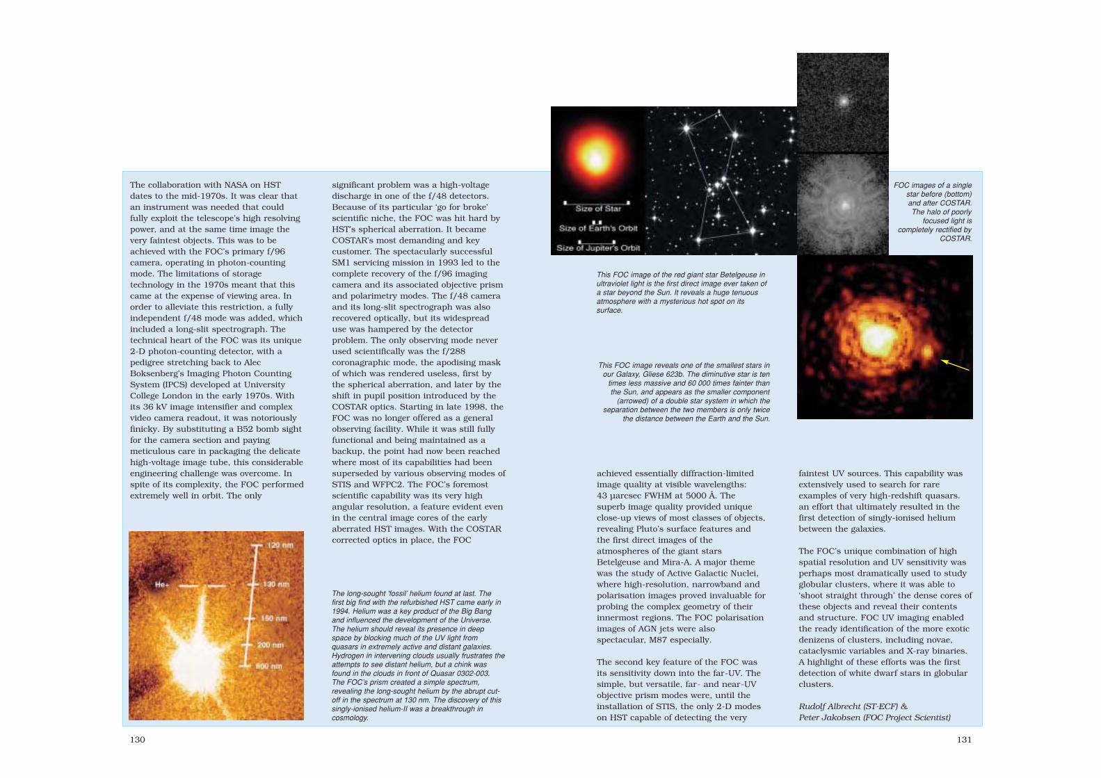
130
The collaboration with NASA on HSTdates to the mid-1970s. It was clear thatan instrument was needed that couldfully exploit the telescope’s high resolvingpower, and at the same time image thevery faintest objects. This was to beachieved with the FOC’s primary f/96camera, operating in photon-countingmode. The limitations of storagetechnology in the 1970s meant that thiscame at the expense of viewing area. Inorder to alleviate this restriction, a fullyindependent f/48 mode was added, whichincluded a long-slit spectrograph. Thetechnical heart of the FOC was its unique2-D photon-counting detector, with apedigree stretching back to AlecBoksenberg’s Imaging Photon CountingSystem (IPCS) developed at UniversityCollege London in the early 1970s. Withits 36 kV image intensifier and complexvideo camera readout, it was notoriouslyfinicky. By substituting a B52 bomb sightfor the camera section and payingmeticulous care in packaging the delicatehigh-voltage image tube, this considerableengineering challenge was overcome. Inspite of its complexity, the FOC performedextremely well in orbit. The only
significant problem was a high-voltagedischarge in one of the f/48 detectors.Because of its particular ‘go for broke’scientific niche, the FOC was hit hard byHST’s spherical aberration. It becameCOSTAR’s most demanding and keycustomer. The spectacularly successfulSM1 servicing mission in 1993 led to thecomplete recovery of the f/96 imagingcamera and its associated objective prismand polarimetry modes. The f/48 cameraand its long-slit spectrograph was alsorecovered optically, but its widespreaduse was hampered by the detectorproblem. The only observing mode neverused scientifically was the f/288coronagraphic mode, the apodising maskof which was rendered useless, first bythe spherical aberration, and later by theshift in pupil position introduced by theCOSTAR optics. Starting in late 1998, theFOC was no longer offered as a generalobserving facility. While it was still fullyfunctional and being maintained as abackup, the point had now been reachedwhere most of its capabilities had beensuperseded by various observing modes ofSTIS and WFPC2. The FOC’s foremostscientific capability was its very highangular resolution, a feature evident evenin the central image cores of the earlyaberrated HST images. With the COSTARcorrected optics in place, the FOC
The long-sought 'fossil’ helium found at last. Thefirst big find with the refurbished HST came early in1994. Helium was a key product of the Big Bangand influenced the development of the Universe.The helium should reveal its presence in deepspace by blocking much of the UV light fromquasars in extremely active and distant galaxies.Hydrogen in intervening clouds usually frustrates theattempts to see distant helium, but a chink wasfound in the clouds in front of Quasar 0302-003.The FOC’s prism created a simple spectrum,revealing the long-sought helium by the abrupt cut-off in the spectrum at 130 nm. The discovery of thissingly-ionised helium-II was a breakthrough incosmology.
131
achieved essentially diffraction-limitedimage quality at visible wavelengths:43 µarcsec FWHM at 5000 Å. Thesuperb image quality provided uniqueclose-up views of most classes of objects,revealing Pluto’s surface features andthe first direct images of theatmospheres of the giant starsBetelgeuse and Mira-A. A major themewas the study of Active Galactic Nuclei,where high-resolution, narrowband andpolarisation images proved invaluable forprobing the complex geometry of theirinnermost regions. The FOC polarisationimages of AGN jets were alsospectacular, M87 especially.
The second key feature of the FOC wasits sensitivity down into the far-UV. Thesimple, but versatile, far- and near-UVobjective prism modes were, until theinstallation of STIS, the only 2-D modeson HST capable of detecting the very
faintest UV sources. This capability wasextensively used to search for rareexamples of very high-redshift quasars.an effort that ultimately resulted in thefirst detection of singly-ionised heliumbetween the galaxies.
The FOC’s unique combination of highspatial resolution and UV sensitivity wasperhaps most dramatically used to studyglobular clusters, where it was able to‘shoot straight through’ the dense cores ofthese objects and reveal their contentsand structure. FOC UV imaging enabledthe ready identification of the more exoticdenizens of clusters, including novae,cataclysmic variables and X-ray binaries.A highlight of these efforts was the firstdetection of white dwarf stars in globularclusters.
Rudolf Albrecht (ST-ECF) &Peter Jakobsen (FOC Project Scientist)
FOC images of a singlestar before (bottom)and after COSTAR.The halo of poorly
focused light iscompletely rectified by
COSTAR.
This FOC image of the red giant star Betelgeuse inultraviolet light is the first direct image ever taken ofa star beyond the Sun. It reveals a huge tenuousatmosphere with a mysterious hot spot on itssurface.
This FOC image reveals one of the smallest stars inour Galaxy, Gliese 623b. The diminutive star is ten
times less massive and 60 000 times fainter thanthe Sun, and appears as the smaller component
(arrowed) of a double star system in which theseparation between the two members is only twice
the distance between the Earth and the Sun.
sec4 7/20/05 2:58 PM Page 130

133132
HST configuration: HST,13.1 m longand 4.27-4.7 m diameter, employs a2.40 m-diameter primary mirror andoptical relaying light to five (four afterSM1) aft-mounted focal planeinstruments. The f/24 Ritchey-Chrétien Cassegrain optical systemcomprises an 830 kg primary mirrorof ultra-low expansion titaniumsilicate glass and a 30 cm-diameterZerodur secondary. Effective focallength is 57.6 m. The 5 m-distantsecondary directs the light conethrough the primary’s 60 cm-diameter central aperture to a focus1.5 m behind the face plate fordispersion to the scientificinstruments.
Power system: FOC requires 150 Wwhen operating, 75 W in standby.HST was powered by twinESA/British Aerospace solar wingsproviding 5.0 kW BOL and 4.3 kWafter 5-year design life. Each 150 kg,2.83x11.8 m wing carried 24 380 Si
Principal features of theFaint Object Camera.
The Faint ObjectCamera is installed in
the base of Hubble,behind the main mirror.
The camera wasreturned to Earth
aboard the SpaceShuttle in March 2002.
cells. First pair replaced by SM1 inDecember 1993; inspection found> 80 000 micrometeoroid impacts.Second pair replaced by SM3B inMarch 2002.
FOC: 2 m long, 1x1 m cross section,optimised to exploit HST’s fullresolution capabilities for faintobjects of magnitude +24 to +29using long exposures. Covering 1150-6500 Å, it operated in four principalmodes: direct imaging at f/48 (22x22arcsec FOV, 2x magnification), f/96(11x11 arcsec, 4x) and f/288 (4x4arcsec, 12x), and as a 20x0.1 arcsecR=1000 long-slit spectrograph. Fourwheels provided banks of filters,polarisers and objective prisms. Twophoton-counting intensified camerasacted as detectors. Following SM1,FOC’s optical chains were fedcorrected but magnified images: f/96became f/150 (7 arcsec FOV), f/48became f/75 (14 arcsec) and f/288became f/450.
FOC awaits installation in the HubbleSpace Telescope.
sec4 7/20/05 2:58 PM Page 132

135134
Ulysses
Achievements: first in situ investigation of the inner heliosphere from the solarequator to the poles; first exploration of the dusk sector of Jupiter’smagnetosphere; fastest spacecraft at launch (15.4 km/s)
Launch date: 6 October 1990Mission end: planned March 2008Launch vehicle/site: NASA Space Shuttle Discovery from Kennedy Space Center,
USALaunch mass: 370 kg (including 55 kg scientific payload)Orbit: heliocentric, 1.34x5.4 AU, inclined 79.1° to ecliptic, 6.2 year periodPrincipal contractors: Dornier (prime), British Aerospace (AOCS, HGA), Fokker
(thermal, nutation damper), FIAR (power), Officine Galileo (Sun sensors), Laben(data handling), Thomson-CSF (telecommand), MBB (thrusters)]
Ulysses is making the first-ever studyof the particles and fields in the innerheliosphere at all solar latitudes,including the polar regions. A Jupiterflyby in February 1992 deflectedUlysses out of the ecliptic plane intoa high-inclination solar orbit,bringing it over the Sun’s south polefor the first time in September 1994and its north pole 10.5 months later.Ulysses spent a total of 234 days atlatitudes >70°, reaching a maximum80.2° in both hemispheres. Themission was originally to end inSeptember 1995, but Ulysses’excellent health and the prospect ofimportant new science resulted inoperations being extended for twomore solar orbits. Ulysses passedover the south pole for a second timein November 2000, and the northpole in October 2001. In contrast tothe passes in 1994/95, which tookplace near solar minimum, the returnto high latitudes was under muchmore active conditions. In 2007/08,Ulysses will return to the polesduring quiet conditions again, butthis time with the Sun’s magneticpolarity reversed.
The unique data from Ulysses haveadded a new dimension to ourknowledge of the Sun’s environment– the heliosphere. Importantaccomplishments include thecharacterisation of two distinctlydifferent solar-wind states (fast wind
from the poles filling a large fractionof the heliosphere, and slow windconfined to the equatorial regions),the discovery that high- and low-latitude regions of the heliosphere areconnected in a much more systematicway than previously thought, the firstdirect measurement of interstellar gas(both in neutral and ionised states)and dust particles, and the precisemeasurement of cosmic-ray isotopes.These, together with numerous otherimportant findings, have resulted inmore than 1100 publications to datein the scientific literature.
ESA and NASA signed the MoU29 March 1978 for the InternationalSolar Polar Mission (ISPM) as a 2-craft mission launched by a single
Shuttle and 3-stage Inertial UpperStage (IUS) in February 1983. Jupitergravity assists would have thrownthem into opposing solar orbits.NASA awarded TRW the contract forthe US spacecraft in July 1979;Dornier was selected in September1979 as leader of the STARconsortium for ESA’s spacecraft. USbudget cuts in February 1981 sawNASA unilaterally cancelling itsspacecraft to save $250-300 million.NASA would still provide launch,tracking and the RTG. Shuttle andother problems delayed the launch toMay 1986 – now using a cryogenicCentaur upper stage – but theChallenger accident of January 1986postponed all flights. Safety concernsprompted the final switch to an all-solid 3-tier IUS/Payload AssistModule (PAM) upper stage.
Ulysses’ record 15.4 km/s speed tookit across the Moon’s orbit in only 8 h.The deployment of the 5.55 m radialboom on 7 October 1990 reduced thespin to 4.7 rpm. Beginning with
EPAC, the science instruments wereturned on starting 19 October andchecked out over several weeks. The7.5 m axial boom was deployed on4 November.
After travelling 993 million km andalready collecting importantinformation on the interplanetarymedium, Ulysses began the Jupiterencounter by detecting the bowshockcrossing at 17.33 GMT 2 February
Ulysses’ high-gainantenna points
continuously towardsEarth, returning 8 h of
realtime and 16 h ofrecorded data every
day on the Sun’sdomain
Preparing Ulysses forlaunch, in Hangar AO at
Cape Canaveral.
sec5 7/20/05 3:09 PM Page 134

137136
At the end of February 1992, the Sun,Earth and Ulysses were in directopposition, the best time to detectgravitational waves by observing anarcmin shift in the craft’s position.Although they were not positivelyidentified by this radio scienceexperiment, new upper limits were setwith a factor of 20 improvement insensitivity. Important observationsinclude the first direct detection ofionised O, N and He (and neutral He)atoms arriving from interstellar space,and the measurement of micron-sizeddust grains from interstellar space.This first-ever measurement of theinterstellar 3He/4He ratio sugests thatthe amount of dark matter created inthe Big Bang was greater thanpreviously believed.
By mid-1993, Ulysses waspermanently immersed in the region ofspace dominated by the Sun’ssouthern pole. This could be seen inthe consistently negative polaritymeasured by the magnetometer fromApril 1993. Increasing latitude alsoreduced the intensity of chargedparticles.
Passage over the Sun’s south poleprovided the first long-term in situobservations of high-speed solar windflowing from the large coronal hole thatcovers that polar cap at solarminimum. Measurements of ionisedinterstellar neutral gas (‘interstellarpickup ions’) led to a major advance inunderstanding the processes affectingthis component of the heliosphericparticle population.
Unexpectedly, the magnetometersdetected a wide variety of fluctuationsat many spatial scales in the Sun’shigh-latitude field. They are believed torepresent relatively unevolvedturbulence originating at the southern
Ulysses is sampling the Sun’s sphere ofinfluence in 3-D for the first time.
Ulysses was launched on an IUS topped by aPAM final kick stage. (Boeing)
1992, some 113 RJ out, more distantthan Pioneer (100 RJ) and Voyager(60 RJ). It approached through thelate morning region of themagnetosphere at about 30ºN, camewithin 378 400 km of the cloudtops(5.3 RJ) at 12.02 GMT 8 February1992, and then exited unscathed onthe previously unexplored eveningside, at high southern latitudes,having spent more than a week in themagnetosphere. Just before closestapproach, Ulysses entered themagnetosphere’s polar cap. The close13.5 km/s flyby produced the highecliptic inclination – IUS/PAM couldhave reached only 23º without theassist. A major finding was that thesolar wind affects the magnetospheremuch more than expected. Themagnetic field in the dusk sector isnot rotating with the planet and isswept down into the magnetotail.Also, Jupiter’s intense radiation beltsreach only to 40º latitude, whereasEarth’s extend to 70º. Ulysses passeddirectly through the Io plasma torus(only Voyager 1 preceded it), whichplays a key role in refuelling themagnetosphere with plasma.
sec5 7/20/05 3:09 PM Page 136

139138
Measurements made by Ulysses during one complete orbit of the Sun, in theform of a polar diagram. The traces show (from the inside moving out) thesolar wind speed increasing from 400 km/s near the equator to 750 km/s atlatitudes >20-30°, the magnetic field polarity, the intensity of acceleratedinterplanetary particles, and the intensity of incoming cosmic rays.
Installed on its kick stages at Cape Canaveral,Ulysses is ready for installation aboard the
Space Shuttle. (NASA)
Further information on the Ulysses mission can be found at http://sci.esa.int/ulysses/The Ulysses Qualification Model is displayed at the Noordwijk Space Expo at ESTEC
1999 to be cometary in origin. Withthis result. Ulysses set a record forthe observation of the longest(3.8 AU) comet tail.
In June 2000, ESA’s ScienceProgramme Committee approvedadditional funding to continueoperations until September 2004.A key argument for the extension wasto observe the effects of the Sun’smagnetic polarity reversal on theheliosphere’s structure. From May2002, however, the RTG has not beenable to power the full payload. Thepower-sharing strategy guarantees aset of core measurements coveringfundamental solar wind and magneticfield parameters, as well as a number
polar coronal hole. Another importantfinding was that the magnetic fieldradial component varies relatively littlewith latitude. This is contrary to theexpectation that the imprint of theunderlying dipole-like magnetic fieldat the Sun’s surface, showing anincrease in the radial field at thepoles, would be detected at Ulysses’position. Simply, there was no southmagnetic pole at high latitudes.Undoubtedly related to the large-scalefluctuations in the polar magneticfield was the detection of anunexpectedly small increase in theinflux of cosmic rays over the poles. Itwas hoped that the much-reducedeffects of solar rotation over the polewould result in a smooth near-radialmagnetic field, providing easy accessto low-energy cosmic rays.
Moving back towards the equator,Ulysses left the fast solar wind(750 km/s) in which it had beenimmersed for more than 18 months,crossed briefly into the equatorialregion dominated by slow wind(400 km/s) and once again becameimmersed in the fast wind, this timefrom the north pole. The boundarieswere strikingly symmetric: 22ºS/21ºN.The magnetic field changed fromnegative (directed inwards) to positive(outwards), reflecting the configurationof the Sun’s dipole-like surface field.The radial component’s strengthcontinued to show no change withlatitude. With the exception of the N-Ssolar wind asymmetry and cosmic-rayintensity, the north pass was generallysimilar to the south pass.
An unexpected result was the findingthat Ulysses crossed the distant tail ofComet Hyakutake in 1996. Not wellunderstood at the time, the signaturein the magnetic field, solar wind andlow-energy ion data was recognised in
sec5 7/20/05 3:09 PM Page 138

141140
of energetic particle and cosmic raychannels.
After crossing the ecliptic at a distanceof 5.4 AU in April 1998 (thuscompleting the first out-of-the-eclipticorbit), Ulysses headed back towardsthe increasingly active Sun, passingover the south pole for a second timein November 2000, and the north polein October 2001. The solar windstructure was fundamentally different;the speed measured during 1998-2000was persistently variable. There wereno signs of the stable stream structureseen earlier, and the wind speed rarelyexceeded 600 km/s. Althoughmagnetic field compressions related tostream interactions were seen, theseshowed no persistent recurrence andextended to the highest latitudescovered.
The spacecraft spent the last 3 monthsof 2001 fully immersed in the fast(~750 km/s) solar wind from thenewly-formed north polar coronal hole,followed by regular excursions backinto the slow wind, skimming theboundary of the hole. Observationsfrom SWOOPS and SWICS werecombined for the first-ever study ofsolar wind flows from high-latitudecoronal holes near solar maximum. By
2004, Ulysses was sampling the edgesof coronal holes in detail as it returnedslowly to lower latitudes. From October2002, there were no more excursionsinto the high-speed wind from thenorthern polar coronal hole, andUlysses spent most of the time since inmore variable, lower-speed flows.
In line with the decreasing level ofsolar activity, the Sun’s magneticdipole began to dominate the globalmagnetic field configuration again. Theangle between the dipole androtational axes, nearly 90º at solarmaximum, also decreased. As aconsequence, the heliospheric currentsheet that separates inward (negative)magnetic fields from outward (positive)magnetic fields became less inclined tothe solar equator. These large-scalechanges had a significant effect on theenergetic particles measured atUlysses. For most of the period, onlymodest increases in particle fluxeswere observed, with very few transient-related events.
Starting at the end of October 2003,however, the Sun underwent a majorsurge in activity. Strong outbursts inthe form of solar flares and coronalmass ejections are often seen duringthe declining phase of a solar cycle
(sunspot maximum of cycle 23 was inmid-2000), but that surge wasunusual in its intensity and lateness.The largest flare of the series, rated atX28, came on 4 November 2003.Although 5.3 AU from the Sun, Ulysseswas well-placed to observe the effectsof this violent outburst. A fast CMEfrom the same region swept overUlysses, driving a significantinterplanetary shock wave. Impressiveenhancements in the flux of energeticparticles, modulated by the passage ofCME-related solar wind transients –and the passage of high-speed solarwind streams originating in a large,persistent, trans-equatorial coronalhole – were seen at Ulysses throughoutthis increased activity. The study ofthe precise mechanisms whereby solarenergetic particles are distributedthroughout large volumes of theheliosphere, and under whichconditions efficient re-acceleration ofthese particles occurs, remains animportant area of research by Ulysses.This unusual activity period appears tohave been the Sun’s final outburstbefore settling into a more stableconfiguration leading to the next solarminimum.
Ulysses ‘encountered’ Jupiter for thesecond time in February 2004,although only to within 0.8 AU. Thistime, though, it observed previouslyunexplored regions of the jovianmagnetosphere. A bonus was theavailability of 24 h/day real-timecoverage for a 50-day period thatallowed the tape recorders to beswitched off, freeing sufficient power torun the full payload suite instead ofpower-sharing. As it approached fromhigh northern latitudes, the differencefrom 1992’s encounter was apparentin the URAP radio data as far back asFebruary 2003. URAP detected intenseradio emission, at levels well above
those seen in 1993 when Ulysses wasat a comparable 2.8 AU. The unusualapproach geometry was well-suited tostudying periodic auroral phenomenathat produce both radio and X-raybursts. For example, URAP detectednumerous quasi-periodic (averaging40-min period) radio bursts. Alsoseen in 1992/93, they are thought tobe triggered by solar wind transientsimpacting Jupiter’s magnetosphere.The encounter brought moreinformation on jovian dust streams.Thought to originate in the volcanosof moon Io, they were discovered byUlysses, and have also been observedby Galileo and Cassini. This time, thestreams recurred about every28 days, and showed a fine structure.
On 1 October 2004, Ulysses beganwhat is likely to be the final phase ofits unique mission of exploration.This third extension, to March 2008,was approved by the SPC in February2004, and allows Ulysses to cover amajor part of the Sun’s 22-yearmagnetic cycle.
Key Dates in the Ulysses Mission.
Events Date
Launch 1990 10 06Jupiter flyby 1992 02 08
start 1994 06 26maximum latitude (80.2°, 2.3 AU) 1994 09 13end 1994 11 05
1st Perihelion (1.34 AU) 1995 03 122nd Polar Pass (north)
start 1995 06 19maximum latitude (80.2°, 2.0 AU) 1995 07 31end 1995 09 29
Start of Solar Maximum Mission 1995 10 01
Aphelion (5.40 AU) 1998 04 173rd Polar Pass (south)
start 2000 09 06maximum latitude (80.2°, 2.3 AU) 2000 11 27end 2001 01 16
2nd Perihelion (1.34 AU) 2001 05 234th Polar Pass (north)
start 2001 08 31maximum latitude (80.2°, 2.0 AU) 2001 10 13end 2001 12 12
Jupiter approach (0.8 AU) 2004 02 04Aphelion 2004 06 305th Polar Pass (south)
start 2006 11 17maximum latitude 2007 02 07end 2007 04 03
3rd Perihelion 2007 08 186th Polar Pass (north)
start 2007 11 30maximum latitude 2008 01 11end 2008 03 15
End of Mission 2008 03 31
A comparison of solarwind observations fromthe solar minimum (leftpanel) and around solarmaximum (right panel)phases of the mission.(D.J. McComas)
sec5 7/20/05 3:09 PM Page 140

143142
Ulysses Scientific Instruments
Instrument Measurements Instrumentation Mass Power Data(kg) (W) (bit/s)
SWOOPS Solar Wind Plasma ions 0.257-35 keV/Q; 2 electrostatic analysers 6.7 5.5 160electrons 1-903 eV + channel electron multipliers
SWICS Solar Wind elemental & ion charge electrostatic analyser 5.6 4.0 88Ion Composition composition, T & speed of time-of-flight/
145 km/s (H+)-1352 km/s (Fe+8) energy measurementsolar wind ions
DUST Cosmic Dust 2x10⁻⁹-2x10-15g multi-coincidence impact 3.8 2.2 8detector with channeltron
MAG Magnetic Field ±0.01-44 000 nT triaxial vector helium and 4.8 5.1 80fluxgate magnetometers
GRB Solar X-rays/ 5-150 keV 2 Si solid-state 2.0 2.6 40Cosmic Gamma Bursts + 2 CsI scintillation detectors
EPAC/ Energetic Particle 0.080-15 MeV/nucleon composition 4 solid-state detectors 4.3 4.0 160GAS Composition/ Interstellar Neutral Helium LiF-coated conversion plates
Interstellar Gas with channel electron multipliers
HISCALE Low-Energy Ions 0.050-5 MeV ions; 2 sensor heads with 5.8 4.0 160& Electrons 30-300 keV electrons 5 solid-state detectors
COSPIN Cosmic Rays/ 0.3-600 MeV/nucleon; 5 solid-state detectors 14.8 14.8 160Solar Particles 4-2000 MeV electrons + double Cerenkov and
semiconductor telescopefor electrons
URAP Radio & Plasma Waves 0-60 kHz plasma waves 72.5 m radial dipole antenna 7.4 10.0 2321-940 kHz 7.5 m axial monopole antenna10-500 Hz magnetic fields 2-axis search coil
Radio Science investigations (Coronal Sounding and Gravitational Wave Experiments) were conducted during the primary missionphase.
Satellite configuration: box-shapedaluminium bus supports body-mounted aluminium/CFRP HGA, RTGboom and several science booms:5.55 m radial boom carries foursensors for VHM/FGM (MAG), URAP &GRB experiments (see table), 7.5 maxial boom acts as monopole for URAPand two wire booms 72.5 m tip-to-tipas dipole for URAP.
Attitude/orbit control: spin-stabilised at5 rpm, with fixed HGA pointingcontinuously at Earth. Two sets of4x2 N catalytic thrusters (33.5 kghydrazine in single sphere pressurisedby nitrogen at 22 bar; 7.9 kg hydrazineremained June 2004) provide spincontrol and trajectory corrections.Attitude determined by Sun sensorsand HGA X-band signal angle.
Power system: RTG provided 284 Winitially, decreasing to 221 W by 2001and 206 W by October 2004; power-saving measures since May 2002.
Communications/data: Ulysses istracked 10 h/day by the 34 mantennas of NASA’s Deep SpaceNetwork. Operations are controlled bya joint ESA/NASA team at NASA’s JetPropulsion Lab in California. 1.65 m-diameter HGA downlinks realtimedata at 1024 kbit/s interleaved withplayback of stored data at 20 W8.4 GHz X-band (primary TWTA failedFebruary 2003). 5 W S-band2112/2293 MHz up/down is used fordual-frequency radio scienceinvestigations. Two redundant taperecorders each store 45.8 Mbit at128/256/512 bit/s.
ESA named the project after Homer’s mythological hero and in reference to Dante’sdescription in the Inferno of Ulysses’ urge to explore ‘an uninhabited world behind the Sun’.
Locations of Ulysses’scientific instruments.See the table forexplanation of theacronyms.
Ulysses principalfeatures.
sec5 7/20/05 3:09 PM Page 142
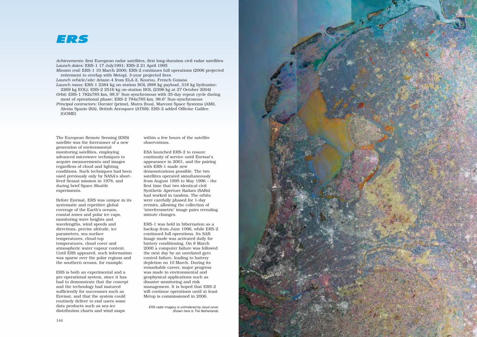
144
ERS
Achievements: first European radar satellites, first long-duration civil radar satellitesLaunch dates: ERS-1 17 July1991; ERS-2 21 April 1995Mission end: ERS-1 10 March 2000; ERS-2 continues full operations (2006 projected
retirement to overlap with Metop). 3-year projected livesLaunch vehicle/site: Ariane-4 from ELA-2, Kourou, French GuianaLaunch mass: ERS-1 2384 kg on-station BOL (888 kg payload, 318 kg hydrazine;
2269 kg EOL); ERS-2 2516 kg on-station BOL (2398 kg at 27 October 2004)Orbit: ERS-1 782x785 km, 98.5° Sun-synchronous with 35-day repeat cycle during
most of operational phase; ERS-2 784x785 km, 98.6° Sun-synchronousPrincipal contractors: Dornier (prime), Matra (bus), Marconi Space Systems (AMI),
Alenia Spazio (RA), British Aerospace (ATSR); ERS-2 added Officine Galileo(GOME)
within a few hours of the satelliteobservations.
ESA launched ERS-2 to ensurecontinuity of service until Envisat’sappearance in 2001, and the pairingwith ERS-1 made newdemonstrations possible. The twosatellites operated simultaneouslyfrom August 1995 to May 1996 – thefirst time that two identical civilSynthetic Aperture Radars (SARs)had worked in tandem. The orbitswere carefully phased for 1-dayrevisits, allowing the collection of‘interferometric’ image pairs revealingminute changes.
ERS-1 was held in hibernation as abackup from June 1996, while ERS-2continued full operations. Its SARImage mode was activated daily forbattery conditioning. On 8 March2000 a computer failure was followedthe next day by an unrelated gyrocontrol failure, leading to batterydepletion on 10 March. During itsremarkable career, major progresswas made in environmental andgeophysical applications such asdisaster monitoring and riskmanagement. It is hoped that ERS-2will continue operations until at leastMetop is commissioned in 2006.
The European Remote Sensing (ERS)satellite was the forerunner of a newgeneration of environmentalmonitoring satellites, employingadvanced microwave techniques toacquire measurements and imagesregardless of cloud and lightingconditions. Such techniques had beenused previously only by NASA’s short-lived Seasat mission in 1978, andduring brief Space Shuttleexperiments.
Before Envisat, ERS was unique in itssystematic and repetitive globalcoverage of the Earth’s oceans,coastal zones and polar ice caps,monitoring wave heights andwavelengths, wind speeds anddirections, precise altitude, iceparameters, sea-surfacetemperatures, cloud-toptemperatures, cloud cover andatmospheric water vapour content.Until ERS appeared, such informationwas sparse over the polar regions andthe southern oceans, for example.
ERS is both an experimental and apre-operational system, since it hashad to demonstrate that the conceptand the technology had maturedsufficiently for successors such asEnvisat, and that the system couldroutinely deliver to end users somedata products such as sea-icedistribution charts and wind maps
ERS radar imagery is unhindered by cloud cover.Shown here is The Netherlands.
sec5 7/20/05 3:09 PM Page 144
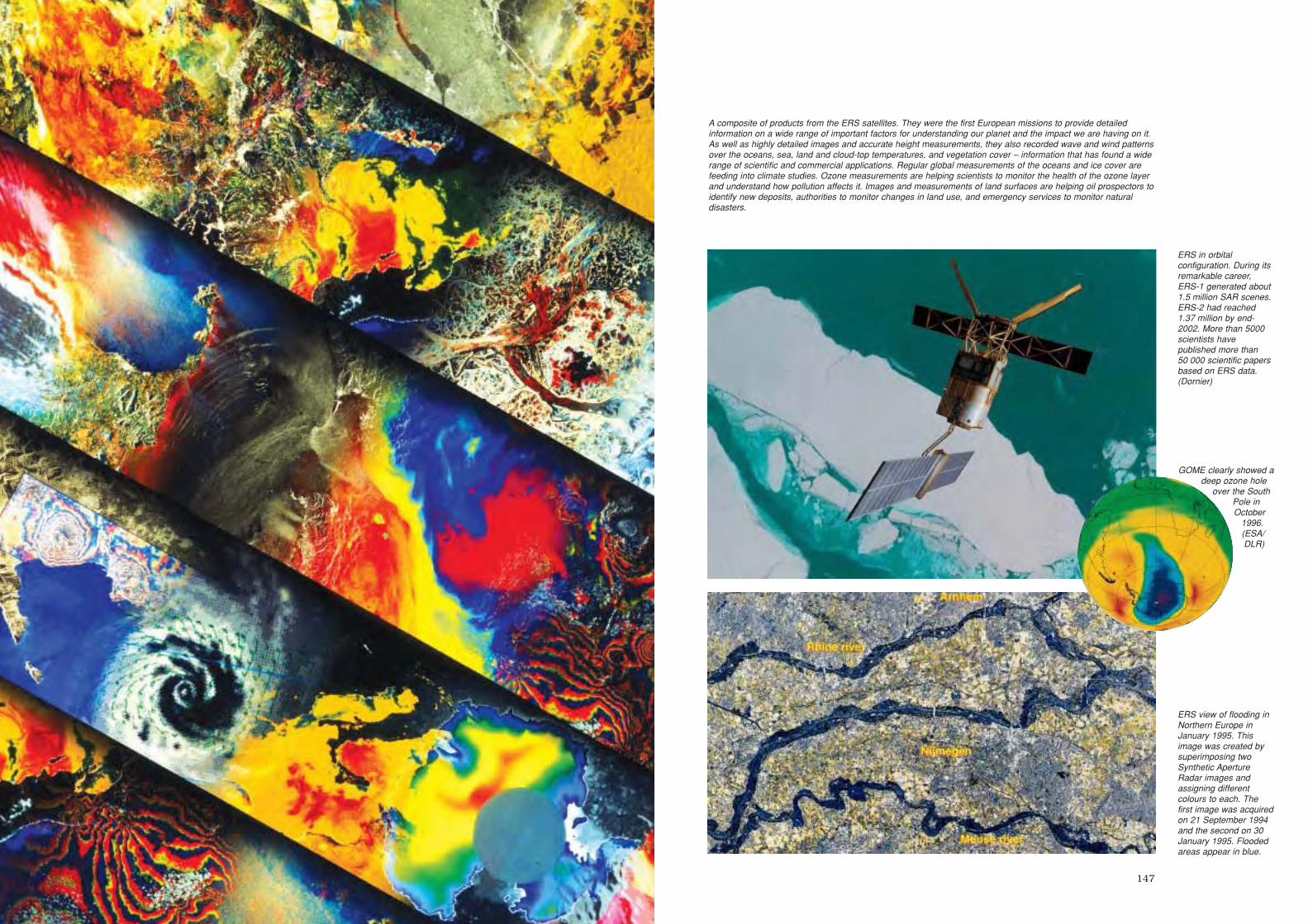
147
A composite of products from the ERS satellites. They were the first European missions to provide detailedinformation on a wide range of important factors for understanding our planet and the impact we are having on it.As well as highly detailed images and accurate height measurements, they also recorded wave and wind patternsover the oceans, sea, land and cloud-top temperatures, and vegetation cover – information that has found a widerange of scientific and commercial applications. Regular global measurements of the oceans and ice cover arefeeding into climate studies. Ozone measurements are helping scientists to monitor the health of the ozone layerand understand how pollution affects it. Images and measurements of land surfaces are helping oil prospectors toidentify new deposits, authorities to monitor changes in land use, and emergency services to monitor naturaldisasters.
GOME clearly showed adeep ozone hole
over the SouthPole inOctober
1996.(ESA/DLR)
ERS view of flooding inNorthern Europe inJanuary 1995. Thisimage was created bysuperimposing twoSynthetic ApertureRadar images andassigning differentcolours to each. Thefirst image was acquiredon 21 September 1994and the second on 30January 1995. Floodedareas appear in blue.
ERS in orbitalconfiguration. During itsremarkable career,ERS-1 generated about1.5 million SAR scenes.ERS-2 had reached1.37 million by end-2002. More than 5000scientists havepublished more than50 000 scientific papersbased on ERS data.(Dornier)
sec5 7/20/05 3:10 PM Page 146
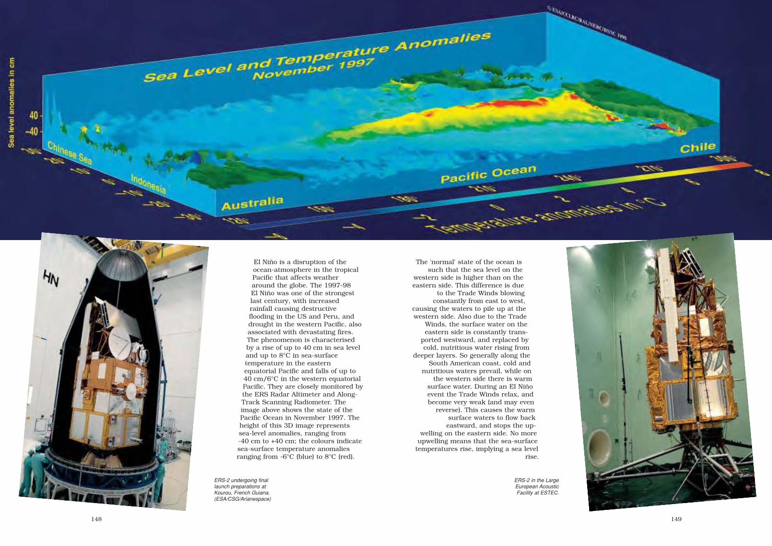
149148
ERS-2 in the LargeEuropean AcousticFacility at ESTEC.
ERS-2 undergoing finallaunch preparations atKourou, French Guiana.(ESA/CSG/Arianespace)
El Niño is a disruption of theocean-atmosphere in the tropicalPacific that affects weatheraround the globe. The 1997-98El Niño was one of the strongestlast century, with increasedrainfall causing destructiveflooding in the US and Peru, anddrought in the western Pacific, alsoassociated with devastating fires.The phenomenon is characterisedby a rise of up to 40 cm in sea leveland up to 8°C in sea-surfacetemperature in the easternequatorial Pacific and falls of up to40 cm/6°C in the western equatorialPacific. They are closely monitored bythe ERS Radar Altimeter and Along-Track Scanning Radiometer. Theimage above shows the state of thePacific Ocean in November 1997. Theheight of this 3D image representssea-level anomalies, ranging from-40 cm to +40 cm; the colours indicatesea-surface temperature anomaliesranging from -6°C (blue) to 8°C (red).
The 'normal' state of the ocean issuch that the sea level on the
western side is higher than on theeastern side. This difference is due
to the Trade Winds blowingconstantly from east to west,
causing the waters to pile up at thewestern side. Also due to the Trade
Winds, the surface water on theeastern side is constantly trans-
ported westward, and replaced bycold, nutritious water rising from
deeper layers. So generally along theSouth American coast, cold and
nutritious waters prevail, while onthe western side there is warm
surface water. During an El Niñoevent the Trade Winds relax, andbecome very weak (and may even
reverse). This causes the warmsurface waters to flow back eastward, and stops the up-
welling on the eastern side. No moreupwelling means that the sea-surface
temperatures rise, implying a sea levelrise.
sec5 7/20/05 3:10 PM Page 148

151150
ERS Earth Observation Payload
Active Microwave Instrument (AMI)
Incorporates two separate 5.3 GHz C-band 4.8 kW-peak power radars:a Synthetic Aperture Radar using a 1x10 m antenna for the image andwave modes; a 3-beam scatterometer for the wind mode. SAR imaging:30 m resolution, linear-vertical polarisation, 37.1 µs transmit pulsewidth, 105 Mbit/s data rate, 100 km swath width, with 23° incidentangle at mid-swath (up to 35° using experimental roll-tilt attitudecontrol system mode). SAR wave mode: operates at 200 km intervalsalong-track for 5x5 km images to provide ocean wave speed anddirections. AMI Wind Scatterometer: three antennas (fore/aft360x25 cm, mid 230x35 cm) providing fore/mid/aft beams sweep500 km swath in 50 km cells for surface wind vectors: 4-24 m/s,0-360±20°.
Radar Altimeter (RA)
The 120 cm-diameter nadir-viewing, 13.8 GHz, 1.3°-beamwidthaltimeter measures, in Ocean Mode, wind speed (2 m/s accuracy),1-20 m wave heights (50 cm accuracy, 2 km footprint), and altitude to5 cm. Ice Mode operates with a coarser resolution to determine icesheet topography, ice type and sea/ice boundaries.
Along-Track Scanning Radiometer and Microwave Sounder (ATSR-M)
An experimental 4-channel IR radiometer for temperaturemeasurements and a 2-channel nadir-viewing microwave sounder forwater vapour measurements. IR Radiometer: scanning at1.6/3.7/10.8/12 µm, 0.5 K resolution over 50x50 km, 1 km spatialresolution; 500 km swath. ERS-2 added 0.55/0.67/0.78 µm visiblechannels to improve monitoring of land applications, such asvegetation moisture. Microwave Sounder: 23.8/36.5 GHz channelsmeasuring the vertical column water vapour content within a 20 kmfootprint, providing corrective data for ATSR sea-surface temperatureand RA measurements.
Global Ozone Monitoring Experiment (GOME, ERS-2 only)
Near-UV/visible scanning spectrometer measuring backscatteredEarth radiance in 3584 pixels over four channels, 240-316/311-405/405-611/595-793 nm, to determine ozone and trace gases introposphere and stratosphere.
Precise Range/Range Rate Experiment (PRARE)
For precise orbit determination with ranging accuracy of 3-7 cm using8.5 GHz signals transmitted to a network of mobile groundtransponders. ERS-1 PRARE failed within 3 weeks because ofradiation damage, but ERS-2’s improved design remains operational.
Laser Retroreflector
Also permits precise range/orbit determination, but less frequentlythan PRARE, and RA calibration.
Satellite configuration: payload supportmodule, 2x2 m, 3 m high, above aplatform derived from Matra’s 3-axisSpot platform providing power, AOCSand overall operational management.Total 11.8 m high, 11.7 m deployedspan.
Attitude/orbit control: primary attitudecontrol by reaction wheels, unloadedby magnetorquers. Hydrazinethrusters provide orbit adjust andfurther attitude control. Pitch/rollinformation from Digital Earth Sensor,yaw reference from Sun sensor;supported by 6 gyros. ERS-2 began 1-gyro control in Feb 2000, and switchedto gyroless control (using DES and X-axis RW) after last gyro failed13 January 2001.
Power system: twin 2.4x5.8 m Si-cellsolar wings sized for 2.2 kW after2 years, supported by four 24 Ahnickel cadmium batteries.
Communications: controlled fromESOC at Darmstadt, Germany withESA ground receiving stations atSalmijärvi, near Kiruna (Sweden,primary station, also for TT&C), Fucino(I), Gatineau (CDN), Maspalomas (E),Prince Albert (CDN), plus national &foreign stations e.g. at Fairbanks(Alaska, US), Neustrelitz (D), WestFreugh (UK), Alice Springs (Australia).SAR’s 105 Mbit/s image data returnedin realtime only, available only whenthe wave/wind modes are inactive. Allother data (LBR: Low Bit Rate)recorded onboard for global coverage,but all data realtime-only since mid-2003, after tape recorder B failed20 Dec 2002 & A 22 Jun 2003. SoLBR station network is being expanded(Miami, McMurdo, Beijing & Hobartadded by end-2004); this new LBRscenario provides data within 15-45 min of sensing. ESRIN ERS CentralFacility (EECF) facility at Frascati (I) isthe user service and data managementcentre and prepares the missionoperation plan for ESOC, with
ERS principal features (ESA). Inset far left: ERS-1imaged from 41 km above by France’s Spot-4 Earthobservation satellite on 6 May 1998 over the TenereDesert of Niger, Africa (CNES). Inset near-left: the firstrecorded SAR image (at Kiruna) from ERS-1, taken at11:50:32 UT 27 July 1991 and centred on79.99°N/15.01°E (ESA).
processing/archiving facilities atBrest (F), Farnborough (UK), DLROberpfaffenhofen (D) and Matera (I).Some products, such as from thewind scatterometer, are availablewithin 3 h of observation.
Further information on ERS and otherESA Earth observation projects can be
found at http://earth.esa.int
sec5 7/20/05 3:10 PM Page 150

153152
Eureca
Achievements: world’s first dedicated microgravity free-flyer; Europe’s firstreusable satellite
Launch date: 31 July 1992Mission end: 24 June 1993Launch vehicle/site: NASA Space Shuttle from Kennedy Space Center, FloridaLaunch mass: 4490 kg (payload capacity up to 1000 kg)Orbit: released from Shuttle into 425 km, 28.5°, raised to 508 km for experiment
operations, lowered to 476 km for retrieval by ShuttlePrincipal contractors: MBB-ERNO (prime)
ESA began studying the EuropeanRetreivable Carrier (Eureca) in 1978as a follow-on to the mannedSpacelab programme; the ESACouncil approved it in December1981. Eureca was designed to carry amix of experiments totalling up to 1 tfor 6-9 months in orbit, released andretrieved by NASA’s Space Shuttle. Itwas the world’s first free-flyerdesigned specifically to satisfymicrogravity experiments, providing10-5 g conditions for long periods.Although Eureca was controlled fromESOC in Germany, it could operateautonomously for up to 48 h. Animportant feature was reusability:Eureca was capable of making fiveflights over a 10-year period.
Eureca-1 and its 15 experiments (seeseparate box) were launched aboardShuttle mission STS-46 in July 1992and released from the Shuttle’s robotarm by ESA Mission SpecialistClaude Nicollier on 2 August.Eureca’s thrusters raised its orbit by83 km within a week and the6 months of operations began on 18August. Most of the microgravityexperiments were completed byJanuary 1993, but others continuedeven as it Eureca waited for recoveryduring Shuttle mission STS-57 inJune 1993. By that time, its orbithad decayed through atmosphericdrag to 490 km and its thrusterslowered it further to 476 km for NASAastronaut George Low to capture itduring 24 June.
The Eureca-1 mission was rated ashighly successful, and a 1995Eureca-2 mission was planned beforeESA Ministerial meetings rejectedfurther funding. The carrier wasstored at DASA (ex-MBB/ERNO) inBremen, where it was hoped that aDASA-led consortium could providecommercial flights.
Eureca’s solar wingswere safely deployedbefore the free-flyer wasreleased. (NASA)
Integration of Eureca atDASA in Bremen.(DASA)
Eureca-1 Payload
ESA’s five microgravity core multi-userfacilities:
– Automatic Mono-ellipsoid Mirror Furnace(AMF)
– Solution Growth Facility (SGF)– Protein Crystallisation Facility (PCF)– Multi Furnace Assembly (MFA)– Exobiological Radiation Assembly (ERA).
Two further microgravity elements were:
– High Precision Thermostat (HPT, Germany)– Surface Forces Adhesion Experiment (SFA,
Italy).
The five space science experiments were:
– Solar Spectrum Experiment (SOSP)– Solar Variation Experiment (SOVA)– Occultation Radiometer (ORA)– Wide Angle Telescope for Cosmic and
X-ray Transients (WATCH)– Timeband Capture Cell Experiment (TICC).
The three technology demonstrations were:
– Radio Frequency Ionization ThrusterAssembly (RITA)
– Advanced Solar Gallium Arsenide Array(ASGA)
– Inter Orbit Communication Experiment(IOC, working with Olympus).
sec5 7/20/05 3:10 PM Page 152

155154
Satellite configuration: total width4.6 m, total height about 2.6 m. Busstructure consisted of carbon fibrestruts connected by titanium nodaljoints. The nodes carried largerhardware loads, while smallerassemblies were fastened to standardEquipment Support Panels.Supported in Shuttle cargo bay bytwo longeron and one keel fitting.Grapple fixture alloweddeployment/retrieval by ShuttleRemote Manipulator System.
Attitude/orbit control: 3-axis control(normally Sun-pointing) bymagnetorquers, supported byReaction Control Assembly of6x21 mN nitrogen thrusters. Orbittransfers between about 400-500 kmby Orbit Transfer Assembly ofredundant 4x21 N hydrazinethrusters (supply sized for twotransfers plus 9-month on-orbit stay).Attitude/rate determination byaccelerometer package, gyros and IREarth and Sun sensors.
Power system: twin deployable/retractable 5-panel Si-cell wings
Processing Eureca atthe Kennedy SpaceCenter for insertion intothe Space Shuttle cargobay. (NASA)
Eureca has been displayed since November 2000 at the Swiss Museum of Transport and Communication in Lucerne. (Courtesy of the Museum)
Eureca – with its solarwings already folded
against its sides – wasrecaptured in June 1993
after almost a year inorbit. ESA cost-at-completion for the
project was€296.3 million (1983conditions). (NASA)
generated 5 kW at 28 Vdc, providing1 kW average for payload operations(1.5 kW peak). Supported by 4x40 Ahnickel cadmium batteries.
Communications: controlled fromESOC in Darmstadt, Germany.S-band link provided up to256 kbit/s downlink for payloads,with 128 Mbit onboard memory.
sec5 7/20/05 3:10 PM Page 154

157156
ISO
Achievements: world’s first space infrared observatory; fundamental discoveries onthe nature of the Universe; far-exceeded design life
Launch date: 19 November 1995 (routine science operations began 4 February1996)
Mission end: deactivated 12:00 UT 16 May 1998; last science observation 10 May1998; cryogen exhausted 8 April 1998
Launch vehicle/site: Ariane-44P from ELA-2, Kourou, French GuianaLaunch mass: 2498 kg (2418 kg BOL)Orbit: initially 500x71 850 km, 5.25°; raised to operational 1038x70 578 km, 5.2°,
24 h; by 10 January 2004 521x70 202 km, 3.0°Cost to ESA: €977 million (2004 conditions; €503 million 1987)Principal contractors: Aerospatiale (prime), DASA (cryostat payload module)
The spectacular success of theInfrared Space Observatory (ISO) asthe world’s first spaceborneobservatory working in the cool lightof the infrared has provided anentirely fresh perspective on theUniverse. It has proved a major boostto most areas of astrophysics,reaching from the nearby planets tothe most distant quasars, taking instar formation, dark matter andsuperluminous galaxies. Even now,6 years after it was shut down, itsdata continue to deliver ground-breaking results.
The cryogenically-cooled ISO studiedthe Universe’s 2.5-240 µm IRradiation as a follow-up to the all-skysurvey undertaken by IRAS(8-120 µm) in 1983. However, ISO’ssensitivity at 12 µm was about 1000times greater and spatial resolution100 times higher, and it was operatedfrom ESA’s station in Villafranca,Spain as an observatory, studyingspecific targets for up to 10 h at atime, with more than half of itsobserving time available to thegeneral astronomical community.
Very deep camera and photometerimages were recorded to study theearly evolution of galaxies and to helpdetermine the history of starformation. All the instrumentsobserved many star-forming regionsto study how clouds of dust and gascollapse to form young stars. Manyobservations looked at stars withdiscs of matter to unravel themysteries of planet formation. Thespectrometers found abundant waterin many different places: Comet Hale-Bopp, Mars, Titan and the giantplanets in our own Solar System,around young and old stars and evenin external galaxies. ISO looked hardat the mysterious ‘ULIRGs’ (ultra-
luminous IR galaxies) and shed newlight on whether their prodigiouspower comes mainly from bursts ofstar formation (the ‘baby’ theory) orfrom stars being swallowed by blackholes (the ‘monster’ theory). ISOfound the characteristic chemicalsignatures of starbursts.
ISO found clear links between stars,comets and Earth’s origin. It foundthe spectral signature of the mineralolivine – a major constituent ofEarth’s interior – in Comet Hale-Boppand in dusty discs encircling youngstars where planetary systems areforming. Many molecular specieswere detected in interstellar space forthe first time, including carbon-bearing molecules such as the methylradical and benzene, providing
insight into thecomplex organicchemistrynecessary toproduce themolecules of life.
ISO made morethan 26 000separateobservations and,by the time orbital
operations ended, the work ofdetailed analysis was only juststarting. The flood of results showsno sign of abating: 1200 refereedpapers were published between late1996 and end-2004, and about 50astronomers every month retrievedata from the ISO archive inVillafranca (E). The ISO LegacyArchive was released in February2002. The Active Archive Phase ofJanuary 2002 - December 2006 willbequeath an enriched archive forfuture astronomers.
Working at these thermalwavelengths meant that ISO’s
telescope and detectors had to beencased in a cryostat filled with>2100 litres of superfluid heliumchilled to only 1.8 K above absolutezero. A pre-mission life of about18 months was required before thehelium completely boiled away,leaving the instruments to warm up,but the supply lasted for 10 monthslonger, until 8 April 1998. Thisallowed, for example, two series ofobservations of the Taurus-Orionregion, an important cradle of starbirth. Even after the cryogen wasexhausted, a few of the short-wavelength detectors in aspectrometer could be used for aspecial scientific programmeinterleaved with final calibrations andtechnology tests. Some extra 150 hwere used to measure almost 300stars at 2.4-4 µm. ISO’s ‘last light’observation, late on 10 May 1998,was of the Canis Majoris hotsupergiant star. The remainingpropellant was then used to lower theperigee in order to speed up theorbit’s decay: ISO is expected toreenter within 20-30 years.
http://sci.esa.int/isohttp://www.iso.vilspa.esa.es
The Antennae: thecollision of two galaxieshas triggered starformation within denseIR-bright dust clouds.
ES
A/IS
OP
HO
T
Seen in the far-IR, theAndromeda Galaxy(M31) sports multiplerings rather than theclassical spiral formseen in visible light.
ES
A/IS
OC
AM
ISO’s payload modulewas supported by theservice module below.
(Aerospatiale)
Newborn stars in the Rho Ophiuchi cloud. In 2001,continuing analysis discovered 30 rare brown dwarf'failed' stars in the cloud. At 50 Jupiter-masses, theyfall short of the 80 MJ lower limit to ignite as stars.The bright fuzzy object at top is a new star muchlarger than the Sun, still wrapped in its birth cloud.(ESA/ISO, CEA Saclay, ISOCAM)
sec5 7/20/05 3:10 PM Page 156

159158
Satellite configuration: cylindrical payload module with conical sunshade and twostar trackers, supported by servicemodule providing basic spacecraftfunctions. Overall size: 5.3 m high, 2.3 mwide. The payload module was a cryostatenveloping the telescope and detectors,cooled by a toroidal tank holding 2250litres of 1.8 K superfluid helium for atleast 18 months’ observations. Somedetectors were cooled to 2 K by copperlinks to the tank; other elements werecooled to 3-4 K by the boiloff gas. Atoroidal tank with 60 litres of normalliquid helium provided cooling on the padfor the last 100 h before launch.
Attitude/orbit control: 3-axis arcsec-control for stable observations of up to10 h incorporated Earth/Sun sensors,star trackers, four rate integrating gyros,four skewed reaction wheels andredundant sets of 8x2 N hydrazinethrusters.
Power system: 600 W provided from twofixed Si-cell body panels (which also actedas thermal shields).
Communications: realtime downlink (noonboard recorders) at 33 kbit/s (24 kbit/sfor science data) to ISO Control Centre atVillafranca, Spain, allowing about 13 h ofcontact daily. NASA’s Goldstone station inCalifornia extended coverage to almost24 h daily. ISO was used scientificallywhile outside the radiation belts, i.e.about 16.75 h per day.
ISO Scientific Instruments
The 60 cm-diameter Ritchey-Chrétien tele-scope fed four focal-plane instrumentsbehind the main mirror for photometry andimaging at 2.5-240 µm and medium/high-resolution spectroscopy at 2.5-196 µm.
ISOCAM
2.5-17 µm camera/polarimeter,1.5/3/6/12 arcsec resolutions, two channelseach with 32x32-element arrays. PI: Catherine Cesarsky, CEN-Saclay, France.
ISOPHOT
2.5-240 µm imaging photopolarimeter,operating in three separate modes as30-240 µm far-IR camera, 2.5-12 µm spectro-photometer, and 3-110 µm multi-band multi-aperture photopolarimeter. PI: Dietrich Lemke, MPI für Astronomie,Germany.
SWS
2.5-45 µm Short Wavelength Spectrometer(two gratings and two Fabry-Perot inter-ferometers), 7.5x20 and 12x30 arcsecresolutions, 1000 and 20 000 spectralresolution. PI: Thijs de Graauw, SRON, Netherlands.
LWS
45-196 µm Long Wavelength Spectrometer(grating and two Fabry-Perot interferometers),1.65 arcmin resolution, 200 & 10 000spectral resolution. PI: Peter Clegg, Queen Mary & WestfieldCollege, UK.
TheWhirlpool Galaxy
was ISO’s ‘first light’ targeton 28 November 1995, when the
telescope was opened to the sky. TheISOCAM image shows regions of star formations
along the spiral arms and on either side of the nucleus.
ISOCAM image of Comet Hale-Bopp inOctober 1996, revealing the comet’sdust coma 100 000 km across. Inset: ISOCAM.
ISO’s orbit took it above the worst of Earth’sradiation belts for almost 17 h per day.
ISO found water throughout theUniverse, increasing expectationsof life beyond Earth. Particularlyexciting was finding water on Titan– Saturn’s largest moon and thetarget of ESA’s Huygens probe.Titan will help us to understandthe organic chemistry of the youngEarth, with its mix of elaborateorganic molecules resembling thechemical soup out of which lifeemerged. Thanks to ISO, thecosmic history of water was tracedfor the first time. During theviolent early stages of starbirth, ayoung star spews out high-speedgas, generating a shock wave thatheats and compresses thesurrounding hydrogen and oxygen,creating the right conditions forwater to form. ISO saw the processat work in the Orion andSagittarius nebulae. ISO alsounexpectedly found large amountsof water in the higher atmospheresof the Solar System’s giant planets.The water must be coming fromcometary grains. (ESA/ISO SWS)
The Birth of StarsISO peered into clouds of dust andgas where stars are being born, seeingfor the first time the earliest steps ofstar formation. It discovered that starsbegin to form at temperatures of–250ºC or even lower. Astronomerswere able to follow the evolution ofdust from its creation in massive oldstars, to the regions where it formsnew planetary systems. ISO analysedthe chemical composition of the dust,thereby opening up a new field ofresearch: astromineralogy. It alsofound that most young stars havedust discs that could harbour planets.
Left: ISO’s telescope and detectors wereencased in a cryostat filled with superfluidhelium at 1.8 K. Incoming infrared radiationwas fed to the four science instrumentsbelow the main mirror.
sec5 7/20/05 3:10 PM Page 158

160
SOHO
Achievements: unique studies of Sun’s interior; the heating and dynamics of thecorona and transition region; the acceleration and composition of the solar windand coronal mass ejections; comets, the heliosphere and the interstellar wind
Launch date: 08:08 UT 2 December 1995Mission end: operations approved to March 2007 (2-year design life)Launch vehicle/site: Atlas 2AS from Complex 36, Cape Canaveral Air StationLaunch mass: 1864 kg (655 kg payload, 251 kg hydrazine)Orbit: halo orbit around Sun-Earth L1 libration point (1.5 million km from Earth);
arrived 14 February 1996Principal contractors: Matra Marconi Space (prime, payload module, propulsion
subsystem), British Aerospace (AOCS), Alenia (structure, harness), CASA(thermal control), Saab Ericsson (communications, data handling)
The Solar and HeliosphericObservatory (SOHO) is a cooperativeproject between ESA and NASAstudying the Sun, from its deep core,through its outer atmosphere and thesolar wind, into the heliosphere. Ithas revolutionised our understandingof the Sun, particularly the ‘big three’questions: what are the structure anddynamics of the interior, how is thecorona heated, and how is the solarwind accelerated? SOHO is providingsolar physicists with their first long-term, uninterrupted view of the Sun,helping us to understand theinteractions between the Sun and theEarth’s environment withunprecedented clarity.
Three helioseismology instrumentsare providing unique data on thestructure and dynamics of the Sun’sinterior, from the very deep core tothe outermost layers of theconvection zone. Five complementaryimagers, spectrographs andcoronagraphs observing in EUV, UVand visible-light are providing ourfirst comprehensive view of the outersolar atmosphere and corona, helpingto solve some of the Sun’s mostperplexing riddles, including theheating of the corona and theacceleration of the solar wind.
Three particle instruments explorethe detailed composition, state and
variability of the Earth’s environmentin space, as influenced by the solarwind, coronal mass ejections andextragalactic sources. The outward-looking SWAN scans the sky for cluesto the changing large-scale structureof the solar wind and its interactionwith the intergalactic medium, as wellas giving unique measurements ofcomet properties.
SOHO recorded its first solar imageon 19 December 1995, en route to itsorbit around the L1 Lagrangian point.Halo-orbit insertion occurred on14 February 1996, 6 weeks ahead ofschedule following a launch so preciseit retained enough hydrazine for 100years of operations. Routine scienceoperations began after commissioningwas formally completed on 16 April1996. Since then, SOHO hasgenerated a torrent of data that placeit centre stage in solar physics.Scientific highlights include:
– unprecedented accuracy inmodelling the solar interior, and inmeasuring solar irradiancevariations;
– detecting plasma rivers beneath thesurface;
http://sci.esa.int/soho/
EIT extreme-UV image of a huge eruption. Theprominence is 60 000-80 000K, much cooler than
the 1 million K and more of the surrounding corona.(He II line at 304 Å; 14 September 1997)
sec5 7/20/05 3:10 PM Page 160

163162
– discovering a quasi-periodicoscillation in the rotational shearnear the base of the solarconvection zone;
– discovering a magnetic surface‘carpet’, subducted and replacedevery 1.5-3 days, that may be theenergy source for coronal heating;
– the first detection of a flare-induced‘Sunquake’;
– holographic imaging of the Sun’sfar side – the Sun madetransparent;
– identifying the source regions of thefast solar wind;
– revealing the highly dynamic natureof the transition region even in‘quiet Sun’ areas;
– detecting polar plume oscillations of11-25 min indicative of compressivewaves;
– discovering ‘EIT waves’ and theirrelation to CMEs, dramaticallyimproving space weatherforecasting reliability;
– possibly the first directobservations of a post-CME currentsheet;
– providing invaluable statistics on,
and spectacular images and moviesof coronal mass ejections;
– measuring ion temperatures incoronal holes up to 200 million K;
– significantly contributing tounderstanding the acceleration ofthe solar wind;
– discovering large differences betweenthe heating and accelerationmechanisms at play in polar versusequatorial coronal holes;
– discovering falling coronalstructures;
– initial acceleration of >10 MeVparticles seem to occur when an ‘EITwave’ propagates to the Earth-connected field lines;
– measuring ion freeze-intemperatures and their variationswith element and time;
– discovering >850 Sun-grazingcomets (nearly half of all cometdiscoveries since 1761!), about 70%by amateurs via the Web;
– uniquely measuring cometaryoutgassing rates and nucleus sizes;
– detecting active regions on the Sun’sfar side through their ‘lighthouse’effect;
– the first 3-D view of CMEs;– discovery of oscillations in hot loops,
opening a new area of ‘coronalseismology’.
SOHO had returned about 2 millionimages when, on 25 June 1998,control was lost during routinemaintenance operations. Contact wasre-established on 3 August, allowingthe batteries to be charged, and thepropulsion system and its hydrazine tobe thawed. Sun-pointing was restoredon 16 September and SOHO wasfinally returned to normal mode on 25September. The first instrument(SUMER) was switched on 5 Octoberand all 12 science instruments wereback to normal on 4 November.SOHO’s mission continued.
SOHO's Payload Moduleat Matra Marconi Space.
During 2 weeks in October-November 2003, the Sun featured three unusually largesunspot groups (including the largest one of this solar cycle), 11 X-class flares (includingthe strongest ever recorded), numerous halo coronal mass ejections (two with near-recordspeeds) and two proton storms. Satellites, power grids, radio communications andnavigation systems were affected. The events, among the best observed ever, with datafrom multiple spacecraft and ground observatories, will be analysed for years to come.They generated unprecedented attention from the media and the public; SOHO imagesappeared in most major news outlets. All existing SOHO web traffic records were rewritten,including monthly (31 million requests, 4.3 TB data), weekly (16 million/2.6 TB) and daily.The daily and hourly volumes were bandwidth-limited.
From top left: giant sunspot regions 10484, 10486 and 10488 seen by MDI in white light;the X 17.2 flare as seen by EIT at 195 Å; the 2200 km/s CME in the LASCO C2coronagraph; then in the LASCO C3 coronagraph (with particle shower becoming visible as‘snow’ in the image). The cloud impacted Earth’s magnetosphere a mere 19 h later, almosta record speed.
sec5 7/20/05 3:10 PM Page 162

164
The Origins of SOHO
SOHO was first proposed in 1982 but itsroots were laid in the earlier studies ofGRIST (Grazing Incidence SolarTelescope) and DISCO (Dual SpectralIrradiance and Solar Constant Orbited).The combined objectives of these twomissions formed the core of SOHO'smission.
In June 1976, GRIST competed withSolar Probe and proposals from otherdisciplines for further study. Solar Probeenvisaged a set of instruments on a craftclose to the Sun, but it was GRIST thatproceeded to the feasibility stagebecause its wavelength range wasparticularly useful for studying the hotouter solar atmosphere. GRIST wasintended for flights on the mannedSpacelab. As a collaboration with NASA,GRIST fell victim in 1981 to theunilateral cancellation of the US twinprobe for what became Ulysses. GRISTwas ‘parked’, but restricted studies onits main spectrometers were supportedby ESA.
In 1980, a group of French andAmerican physicists observed the Sun
continuously from Antarctica for 6 days.These historic global velocity oscillationmeasurements led to the decision toinclude the same sort of experiments onthe proposed DISCO mission. DISCOwould sit at the L1 Lagrange pointbetween the Sun and the Earth, an idealobserving site. The Antarctic experimentcould be used as part of DISCO’spayload, provided its weight could bereduced. DISCO was conceived as afairly small and cheap spin-stabilisedspacecraft of no more than 520 kg,similar to Cluster. A first assessmentwas made in 1981. ESA’s Solar SystemWorking Group preferred DISCO to thecompeting Kepler Mars mission, but itlost out to ISO in 1983.
SOHO itself developed as a mission in1983, combining many aspects of theearlier proposals. It became importantbecause it developed momentum,together with Cluster, as part of theInternational Solar-Terrestrial PhysicsProgramme. In May 1984, ESA identifiedSOHO as part of a Cornerstone of theHorizon 2000 science programme.
SOHO is providing anunprecedented view of the
Sun and its interior
The range of SOHO’s scientific research. Theinterior image from MDI illustrates the rivers of
plasma discovered flowing under the surface. Thesurface image is from EIT at 304 Å. They are
superimposed on a LASCO C2 image of the corona.
sec5 7/20/05 3:10 PM Page 164

167166
SOHO Scientific Payload
Principal CollaboratingInvestigation Investigator Countries Measurements Technique
HelioseismologyGlobal Oscillations at A. Gabriel, F, ESA, DK, Global Sun velocity Na-vapour resonant scattering cell, Low Frequencies IAS, Orsay, F D, CH, UK, oscillations (l = 0-3) Doppler shift and circular polarisation(GOLF) NL, E, USA
Variability of solar C. Fröhlich, CH, N, F, B, Low-degree (l = 0-7) irradiance Global Sun and low-resolution (12-pixel)IRradiance and Gravity PMOD/WRC, ESA, E oscillations and solar constant imaging and active cavity radiometers Oscillations (VIRGO) Davos, CH
Michelson Doppler P.H. Scherrer, Stanford USA, DK, UK Velocity oscillations high-degree Doppler shift with Fourier tachometer, Imager (MDI) Univ, California, USA modes (up to l = 4500) 4 and 1.3 arcsec resolution
Solar Atmosphere Remote Sensing Solar UV Measurements W. Curdt, D, F, CH, Plasma flow characteristics Normal-incidence spectrometer,of Emitted Radiation MPAe, Lindau, D USA (temperature, density, velocity); 50-160 nm, spectral resolution 20000-40000,(SUMER) chromosphere through corona angular resolution 1.2-1.5 arcsec
Coronal Diagnostic A. Fludra, UK, CH, D, Temperature and density: Normal and grazing-incidence spectrometers,Spectrometer (CDS) RAL, Chilton, UK USA, N, I transition region and corona 15-80 nm, spectral resolution 1000-10000,
angular resolution 3 arcsec
Extreme-ultraviolet J-P Delaboudinière, F, USA, B Evolution of chromospheric and Full-disc images (1024×1024 pixels in Imaging Telescope IAS, Orsay, F coronal structures 42×42 arcmin) at lines of HeII, FeIX, (EIT) FeXII, FeXV
Ultraviolet Coronagraph J.L. Kohl, SAO, USA, I, CH, D Electron and ion temperature Profiles and/or intensity of selected Spectrometer (UVCS) Cambridge, MA, USA densities, velocities in EUV lines 1.3-10 R
corona (1.3-10 R)
Large Angle and R. Howard USA, D, F Structures’ evolution, mass, One (C1) internally and two (C2 & C3) Spectrometric NRL, Washington DC, UK momentum and energy transport externally occulted coronagraphs.COronagraph (LASCO) USA in corona (1.1-30 R) Spectrometer for 1.1-3 R
Solar Wind ANisotropies J.L. Bertaux, SA F, FIN, USA Solar wind mass flux Scanning telescopes with hydrogen (SWAN) Verrières-le-Buisson, F anisotropies. Temporal variations absorption cell for Lyman-alpha
Solar Wind ‘in situ’Charge, ELement and P. Bochsler, CH, D, USA, Energy distribution and composition. Electrostatic deflection, time-of-flight Isotope Analysis System Univ. Bern, CH Russia (mass, charge, charge state) measurements and solid-state detectors (CELIAS) (0.1-1000 keV/e)
Comprehensive H. Kunow D, USA, J, F, Energy distribution of ions (p, He) Solid-state detector telescopes and SupraThermal Univ. Kiel, D E, ESA, IRL 0.04-53 MeV/n and electrons electrostatic analysers Energetic Particle 0.04-5 MeVanalyser (COSTEP)
Energetic and Relativistic J. Torsti, FIN, UK Energy distribution and isotopic, Solid-state and plastic scintillationNuclei and Electron Univ. Turku, FIN composition of ions (p-Ni) detectors experiment (ERNE) 1.4-540 MeV/n and electrons
5-60 MeV
IAS: Institut d’Astrophysique. PMOD: Physikalisch-Meteorologisches Observatorium Davos. MPAe: Max-Planck-Institut für Aeronomie. RAL:Rutherford Appleton Laboratory. SAO: Smithsonian Astrophysical Observatory. NRL: Naval Research Laboratory. SA: Service d’Aeronomie
Although the freezing had not seriouslyaffected the instruments, two of SOHO’sthree gyros were damaged by the cold.Then, on 21 December 1998, thesurviving gyro failed and SOHO beganfiring its thrusters to maintain Sun-pointing. To halt the rapid depletion ofhydrazine, engineers devised software toignore faulty gyro data, making SOHOthe first 3-axis spacecraft to operatewithout gyros. Science operationsresumed 2 February 1999.
In order to fulfil its high promise, SOHO observations were planned tocontinue at least through the period ofmaximum sunspot activity in 2000. The two agencies then agreed to extendthe mission to 2003, operating SOHOas the flagship of a multi-national fleetof solar spacecraft that includes Ulysses and Cluster. In February 2002,ESA approved an extension to March2007, allowing SOHO to cover a fullsolar cycle.
The satellite’s age began to show when,in May 2003, the drive mechanism ofthe high-gain antenna began missingsteps. It was prudently parked andSOHO is instead rotated every6 months to minimise the data loss.The mission continues to deliver itsunique results; by the end of 2004, ithad returned 25 million images andspectra: EIT 450 000; MDI 9 million;UVCS 1.35 million; LASCO 450 000;CDS 7.91 million; SUMER 5.23 million.
Satellite configuration: 2.5x2.9 m, totalheight 3.9 m, 9.5 m span across solararray. Instruments accommodated inPayload Module, highly decoupled fromService Module, which forms the lowerportion of the spacecraft and providespower, thermal control, AOCS, pointingand telecommunications for the wholespacecraft and support for the solarpanels.
Attitude/orbit control: 3-axisstabilisation, Sun-pointing withnominal 10 arcsec accuracy, pointingstability 1 arcsec per 15 min(10 arcsec per 6 months), using 4reaction wheels and two sets(redundant) of eight (2xpitch, 2xyaw,4xroll) thrusters: 4.2 N (blowdownBOL, 22.4 bar; 2.2 N @ 6.6 bar; 3 N@ Dec 1998, 15.8 bar), 251 kghydrazine loaded (122 kg @ Feb 2002)in single He-pressurised tank. Totaldelta-V 318 m/s (43 m/s reserved forattitude control). Attitude data fromtwo fine-pointing Sun sensors, twostar trackers and three gyros (no-gyrooperations since February 1999).
Power system: 1400 W from twin2.3x3.66 m Si-cell solar wings(payload requires 440 W); two 20 AhNiCd batteries used soon after launchand in recovery operations (1 dead).
Communications: science instrumentsnormally return 40 kbit/s(+160 kbit/s when MDI in high-ratemode) at 2.245 GHz S-band toNASA’s Deep Space Network for 12 hdaily; supported by 1 Gbit taperecorder and 2 Gbit solid-staterecorder. Instrument operations arecontrolled from the ExperimentOperations Facility at NASA’sGoddard Space Flight Center.
Most SOHO instruments are operational, but:SUMER: both detectors are near the end of their calibratedlifetimes, so the instrument is used only during selectedcampaigns. LASCO: C1 has not operated since 1998'srecovery. CELIAS: one of 4 sensors is impaired. COSTEP:one of 2 sensors is impaired.
SOHO ready for mounting onthe launch vehicle.
sec5 7/20/05 3:10 PM Page 166

168
Ariane-5
Achievements: first European heavy-lift satellite launcher; 20 launches by end-2004; planned launches 6 in 2005
Launch dates: debut A501 4 Jun 1996 (failed), first success A502 30 Oct 1997,first operational flight A504 10 Dec 1999; debut A5ECA 11 December 2002(failed), first success 12 February 2005; debut A5ES planned 2006
Launch site: ELA-3 complex, KourouLaunch mass: 747 t (A5G), 746 t (A5GS), 767 t (A5ES), 780 t (A5ECA)Length: depending on fairing configuration 46.27-53.93 m (A5G/GS), 46.27-
53.43 m (A5ES), 50.56-57.72 m (A5ECA)Performance: optimised for geostationary transfer orbit (GTO); see separate tablePrincipal contractor: EADS Space Transportation (industrial architect)
The ESA Ministerial Council meetingin The Hague, The Netherlands inNovember 1987 approved developmentof the first European heavy-lift launchvehicle. Although Ariane-1 to -4proved to be remarkably successful, itwas clear that a new, larger vehiclewas required to handle the ever-growing sizes of commercialtelecommunications satellites. Thegoal was to offer 60% additional GTOcapacity for only 90% the cost of anAriane-44L, equivalent to reducing thecost/kg by 44%. From 2005, the costis expected to be €13 000/kg for eightlaunches annually.
At the time of approval, it wasintended that Ariane-5 would also betailored to carry the Hermes mannedspaceplane. Although Hermes waslater shelved, the design can still beman-rated if required. The standard‘lower composite’ of stage-1 plusboosters is aiming for a reliability of99%. Ariane-5’s overall reliabilitytarget is 98.5%. Like Ariane-4, it isoptimised for dual-satellite launchesinto GTO.
ESA is responsible (as designauthority) for Ariane developmentwork, owning all the assets produced.Until 2003, it entrusted technicaldirection and financial management tothe French space agency, CNES,which wrote the programmespecifications and placed the
industrial contracts on its behalf.EADS Launch Vehicles (the mergedAerospatiale and DASA) acted asindustrial architect. As part of areorganisation of Europe’s launcherindustry, ESA in 2003 took overmanagement of the programme andEADS Space Transporation becameprime contractor, responsible fordelivering the integrated vehicle toArianespace. ESA/CNES weredirectly responsible for the firstthree Ariane-5 launches, beforeArianespace assumed responsibilityfor commercial operations. The newvehicle completely replaced Ariane-4in 2003.
Kourou’s ELA-3 and associatedprocessing areas were constructedas dedicated Ariane-5 facilities topermit up to 10 launches annually(8 is the current target). UnlikeAriane-4, the payload assembly isintegrated with the vehicle beforethey are transported to the padonly 8 h before launch, in order tominimise pad operations. A launchcampaign covers 21 days; thepayload is mated 6 days beforelaunch. The simplified pad conceptallows filling of the cryogenicpropellants for the core stage frombelow the mobile launch table; italso reduces vulnerability tolaunch accidents. There are fourprincipal buildings in thepreparation zone:
http://www.esa.int/launchers/
The launch ofA516/V162, with the
triple payload thatincluded ESA’s
SMART-1 lunar orbiter.(ESA/Arianespace/CSG)
sec6 8/1/05 1:14 PM Page 168
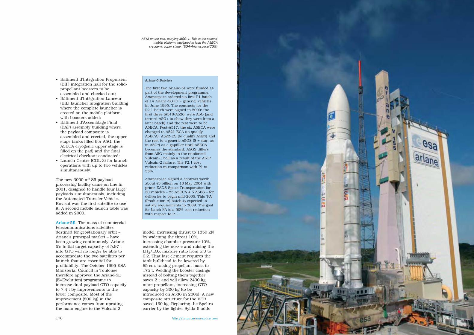
170
Ariane-5 Batches
The first two Ariane-5s were funded aspart of the development programme.Arianespace ordered its first P1 batchof 14 Ariane-5G (G = generic) vehiclesin June 1995. The contracts for theP2.1 batch were signed in 2000: thefirst three (A518-A520) were A5G (andtermed A5G+ to show they were from alater batch) and the rest were to beA5ECA. Post-A517, the six A5ECA werechanged to A521-ECA (to qualifyA5ECA), A522-ES (to qualify A5ES) andthe rest to a generic A5GS (S = star, asin A5G*) as a gapfiller until A5ECAbecomes the standard. A5GS differsfrom A5G mainly in the reinforcedVulcain-1 bell as a result of the A517Vulcain-2 failure. The P2.1 costreduction in comparison with P1 is35%.
Arianespace signed a contract worthabout €3 billion on 10 May 2004 withprime EADS Space Transporation for30 vehicles – 25 A5ECA + 5 A5ES – fordeliveries to begin mid-2005. This ‘PA’(Production-A) batch is expected tosatisfy requirements to 2009. The goalfor batch PA is a 50% cost reductionwith respect to P1.
• Bâtiment d’Intégration Propulseur(BIP) integration hall for the solid-propellant boosters to beassembled and checked out;
• Bâtiment d’Intégration Lanceur(BIL) launcher integration buildingwhere the complete launcher iserected on the mobile platform,with boosters added;
• Bâtiment d’Assemblage Final(BAF) assembly building wherethe payload composite isassembled and erected, the upperstage tanks filled (for A5G; theA5ECA cryogenic upper stage isfilled on the pad) and the finalelectrical checkout conducted;
• Launch Centre (CDL-3) for launchoperations with up to two vehiclessimultaneously.
The new 3000 m2 S5 payloadprocessing facility came on line in2001, designed to handle four largepayloads simultaneously, includingthe Automated Transfer Vehicle.Envisat was the first satellite to useit. A second mobile launch table wasadded in 2000.
Ariane-5E The mass of commercialtelecommunications satellitesdestined for geostationary orbit –Ariane’s principal market – havebeen growing continuously. Ariane-5’s initial target capacity of 5.97 tinto GTO will no longer be able toaccommodate the two satellites perlaunch that are essential forprofitability. The October 1995 ESAMinisterial Council in Toulousetherefore approved the Ariane-5E(E=Evolution) programme toincrease dual-payload GTO capacityto 7.4 t by improvements to thelower composite. Most of theimprovement (800 kg) in theperformance comes from upratingthe main engine to the Vulcain-2
model: increasing thrust to 1350 kNby widening the throat 10%,increasing chamber pressure 10%,extending the nozzle and raising theLH2/LOX mixture ratio from 5.3 to6.2. That last element requires thetank bulkhead to be lowered by65 cm, raising propellant mass to175 t. Welding the booster casingsinstead of bolting them togethersaves 2 t and will allow 2430 kgmore propellant, increasing GTOcapacity by 300 kg (to beintroduced on A536 in 2006). A newcomposite structure for the VEBsaved 160 kg. Replacing the Speltracarrier by the lighter Sylda-5 adds
http://www.arianespace.com
A513 on the pad, carrying MSG-1. This is the secondmobile platform, equipped to load the A5ECA
cryogenic upper stage. (ESA/Arianespace/CSG)
sec6 8/1/05 1:14 PM Page 170
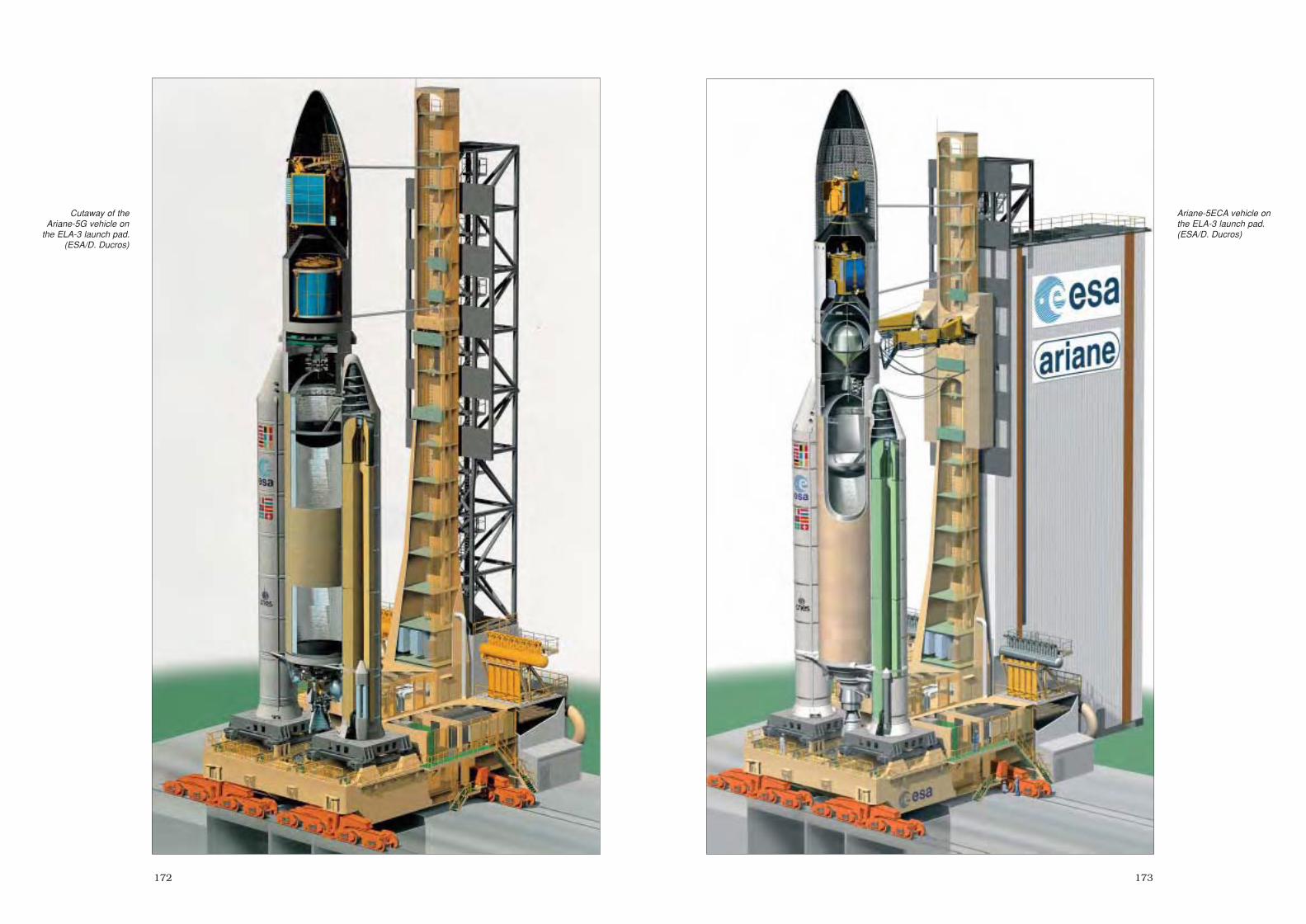
173172
Cutaway of theAriane-5G vehicle on
the ELA-3 launch pad.(ESA/D. Ducros)
Ariane-5ECA vehicle onthe ELA-3 launch pad.(ESA/D. Ducros)
sec6 8/1/05 1:14 PM Page 172

175174
380 kg capacity. Roll control duringburns is provided by a thrusterpackage on the EPC core,simplifying the control system.
But even these improvements arenot enough to remain competitive,as market projections predictlaunches of paired 6 t satellites willbe required by 2006. ESA’s Councilin June 1998 therefore approved the Ariane-5 Plus programme tomeet this challenge by adding upper-stage improvements toAriane-5E.
Ariane-5ECA (EvolutionCryogénique A) provides 9 t intoGTO using the ESC-A cryogenicupper stage (Etage SupérieureCryogénique) powered by the64.8 kN HM7B engine fromAriane-4. Propellant mass is 14.5 t,diameter 5.4 m; single ignition.It uses the Ariane-4 LOX tank andthrust frame, plus the Ariane-5EPC tank bulkhead. The first flight(A517) on 11 December 2002(which was also the maidenAriane-5E) ended with failure of theVulcain-2 nozzle extension, nowreinforced. ESC-A did not have the opportunity to ignite. Thesecond test flight, of A521, on12 February 2005, was fullysuccessful, and A5ECA enteredservice in 2005 as the standardmodel.
Ariane-5ES (Evolution Stockables)will allow multiple EPS Aestusengine reignitions to accommodatea wider range of missions.Stretched EPS tanks add 250 kg ofpropellant. Coasting between burns requires a longer life,provided by improving thermalprotection and larger batteries. Thefirst customer is ATV, which
requires three ignitions, includingthe deorbit burn of the spent upperstage.
Ariane-5ECB (EvolutionCryogénique B) was approved bythe Ministerial Council inNovember 2001 as the final phaseof Ariane-5 Plus. However, effortswere reduced to a minimum post-A517 in order to focus on bringingthe A5ECA back to flight. Theintention was to offer 12 t GTOcapacity by 2006 (now 2010 at theearliest) by using the ESC-B stage,derived from ESC-A. TheAriane-5 Plus programme wouldhave achieved 11.6 t, with furthereffort required for the full 12 t. Thenew 178 kN Snecma Moteurs Vinciengine offers multiple ignitions.Vinci uses the expander cycle, inwhich the turbines are driven byhydrogen heated through the wallsof the combustion chamber beforebeing injected. SI 464 s,combustion pressure 61 bar,expansion ratio 240, mixture ratio5.8 (LOX/LH2), flow rates 39 kg/s,burn time 610 s, mass 510 kg,height 5.6 m, exit diameter 2.10 m.A5ECB launch mass would beabout 790 t, length (depending onfairing) 51.51-58.67 m; ESC-B drymass 6 t.
The successful first hot-firing test,lasting 1 s, of the Vinci engine tookplace on 20 May 2005 at the DLRLampoldshausen P4.1 test stand inGermany.
Current and future versions of Ariane-5. Left: A5G.Right: Ariane-5E lower composite (note the
Vulcain-2) supporting ESC-A (left), ES (centre, withATV payload) and ESC-B. (ESA/D. Ducros)
sec6 8/1/05 1:14 PM Page 174

177176
Ariane-5’s VehicleEquipment Bay (VEB)
carries the controlsystems. The EPS
upper stage sits on theinner truncated cone.
Preparing to install the Vulcain-1 main engine onAriane-5. (ESA/CNES/CSG)
The EPS upper stage is designed forcompactness, nestling the engine among
clustered propellant tanks. (ESA/CNES/CSG)
Ariane-5G/G+/GS
Boosters(EAP: Etage d’Accélération à Poudre)Principal contractors: EADS Space
Transportation (stage integrator),Europropulsion (motors)
Size: 31.2 m long, 3.05 m diameter, 40 tempty mass
Powered by: 238 t of solid propellantgenerates 5250 kN each at launch;132 s burn time
Design: motor is assembled in Kouroufrom three sections, each of 8 mm-thick steel. The two lower sections eachcomprise three 3.35 m-long cylinders.HTPB solid propellant of 68%ammonium perchlorate, 18%aluminium and 14% liner producedand cast in casings in Kourou; 3.4 m-long forward section shipped alreadyloaded by Avio from Italy. Nozzleexpansion ratio 11; steering by twohydraulic actuators using flexbearingfor 6° deflection. Recovery option forinspection of two booster sets every2 years using parachutes carried innosecone.
Core Stage(EPC: Etage Principal Cryotechnique)Principal contractors: EADS Space
Transportation (stage integrator),Snecma-Safran Moteurs (main engine),Cryospace (tanks)
Size: 30.7 m long; 5.40 m diameter, 12.6 tdry mass
Powered by: one Snecma Moteurs Vulcaincryogenic engine providing 900 kN atlaunch, increasing to 1145 kN (vacuumthrust) for 580 s, gimballed for attitudecontrol, drawing on 157 t LOX/LH2
Design: the aluminium tank is dividedinto two sections by a commonbulkhead, creating a 120 m3 LOXforward tank (pressurised to 3.5 bar byhelium) and a 390 m3 LH2 aft tank(pressurised to 2.5 bar by gaseous H2).The tank’s external surface carries a
2 cm-thick insulation layer to helpmaintain the cryogenic temperatures
Upper Stage(EPS: Etage à Propergols Stockables)Principal contractor: EADS Space
TransportationSize: 3.3 m long; 3.94 m diameter, 1.2 t
dry massPowered by: Astrium Aestus gimballed
engine with delayed or reignitioncapability providing 27.5 kN for 1100 s,drawing on up to 9.7 t of NTO/MMH
Design: this orbit injection stage alsoensures payload orientation andseparation. Required to nestle insidethe VEB under the payload fairing, it isdesigned for compactness: the engine isembedded within the four propellantspheres (each 1.41 m-diameter,pressurised to 18.8 bar by helium).Main structural element is frustumcontinuing VEB’s frustum at 3936 mm-diameter lower face and supportingpayload adapters on 1920 mm-diameterforward face
Vehicle Equipment Bay (VEB)Principal contractor: EADS Space
TransportationPurpose: carries equipment for vehicle
guidance, data processing, sequencing,telemetry and tracking
Size: 104 cm high; 4.0 m diameter, 520 kg
Design: internal frustum of a CFRPsandwich supports upper stage at its
Ariane-5 Performance (kg)
A5G A5GS A5ES A5ECA A5ECB
GTO1 59502 61302 – 83002,5 12 0002
SSO3 9216 9940 – – 13 300
LEO – – 19 6704 – –
1: dual payloads, 600x36 000 km, 7º, short fairing. 2: Sylda-5. 3: Sun-synchronous800x800 km, 98.6º, long fairing. 4: 260x260 km, 51.6º for ATV, long fairing;increase to 20 700 kg in 300x300 km for ATV-2 in 2006 when welded jointsintroduced on boosters. 5: increase to 9400 kg with introduction of boosters usingwelded joints.
sec6 8/1/05 1:14 PM Page 176

179178
3936 mm-dia forward end; external aluminiumcylinder supports payload fairing/carrier; annularplatform carries the electronics. Hydrazinethrusters provide roll control during stage-1/2burns, and 3-axis control after stage firings
Payload Fairing and CarriersPayloads are protected by a 2-piece aluminiumfairing until it is jettisoned after about 278 s duringthe core stage burn. Prime contractor is Contraves.Three basic lengths are available: 12.7, 13.8 and17 m; dia 5.4 m. The initial main payload carrierwas the Speltra, which sits between the fairing andupper stage/VEB, housing one satellite internallyand a second on its top face, under the fairing. Twomodels: 5.5 m (704 kg) & 7 m (820 kg) heights.Sylda-5 added in 2002, sitting inside standardfairings: 6 versions, 420 kg smallest, 4.9-6.4 mheights (extension rings 30 cm high), 4.6 m innerdia. Four extension rings available for fairing,increase heights by 0.50-2.0 m. Some missions canalso carry up to six 50 kg satellites as passengerson ASAP-5 adapter.
Ariane-5ECA Characteristics
Boosters(EAP: Etage d’Accélération à Poudre)Principal contractors: EADS Space Transportation
(stage integrator), Europropulsion (motors)Size: 31.2 m long, 3.05 m diameter, 38 t empty massPowered by: 241 t of solid propellant generates
5250 kN each at launch; 132 s burn timeDesign: as A5G/G+/GS
Core Stage(EPC: Etage Principal Cryotechnique)Principal contractors: EADS Space Transportation
(stage integrator), Snecma Moteurs (main engine),Cryospace (tanks)
Size: 30.7 m long; 5.40 m diameter, 12.6 t dry massPowered by: one Snecma Moteurs Vulcain-2
cryogenic engine providing 960 kN at sea level,increasing to 1355 kN (vacuum), 590 s, SI 434 s,expansion ratio 60, 2040 kg, 115 bar chamberpressure, gimballed for attitude control, drawingon 175 t LOX/LH2
Design: as A5G/G+/GS but tank bulkhead lowered65 cm
Ariane-5 Launch Log
Flight Date Type Mission Capacity* Carriers** Payload
V881 A501 04 Jun 1996 – GTO 5759 kg 02001 Cluster
V1012 A502 30 Oct 1997 – GTO 5728 kg 02001 dummy/Teamsat
V112 A503 21 Oct 1998 A5G sub/GTO 6543 kg 02001 ARD/dummy
V119 A504 10 Dec 1999 A5G HEO 3954 kg 00001 XMM
V128 A505 21 Mar 2000 A5G GTO 5811 kg 00101 AsiaStar/Insat-3B
V130 A506 14 Sep 2000 A5G GTO 5963 kg 00101 Astra-2B/GE-7
V135 A507 16 Nov 2000 A5G GTO+ 6317 kg 00001 PAS-1R3
V138 A508 20 Dec 2000 A5G GTO 4803 kg 00411 Astra-2D/GE-8/LDREX
V140 A509 08 Mar 2001 A5G GTO 5304 kg 00421 Eurobird/BSat-2a
V1424 A510 12 Jul 2001 A5G GTO 5317 kg 00421 Artemis/BSat-2b
V145 A5115 01 Mar 2002 A5G SSO 8605 kg 00003 Envisat
V153 A512 05 Jul 2002 A5G GTO 6632 kg 00121 Stellat-5/NStar-c
V155 A513 28 Aug 2002 A5G GTO 6586 kg 00422 MSG-1/Atlantic Bird
V1576 A517 11 Dec 2002 A5ECA GTO 8353 kg 00603 Hot Bird-7/Stentor
V160 A514 09 Apr 2003 A5G GTO 5443 kg 00402 Insat-3A/Galaxy-12
V161 A515 11 Jun 2003 A5G GTO 6883 kg 00212 Optus-C1/BSat-2c
V162 A516 27 Sep 2003 A5G GTO 6137 kg 00641 Insat-3E/eBird/SMART-1
V158 A518 02 Mar 2004 A5G+7 escape 3188 kg 00001 Rosetta
V163 A519 18 Jul 2004 A5G+ GTO 6246 kg 00002 Anik-F28
V165 A520 18 Dec 2004 A5G+ SSO 6038 kg 00021 Helios-2A9
V164 A521 12 Feb 2005 A5ECA GTO 8312 kg 00442 XTAR/Sloshsat/dummy
V166 A523 Aug 2005 A5GS10 GTO iPSTAR
V167 A522 Aug 2005 A5ECA GTO Spaceway-2/Telkom-2
1: failure; guidance system software error. 2: partial success; unpredicted roll torque from Vulcainled to early shut down of stg-1, lowering final orbit; allowed for on future flights. 3: + auxiliarypayloads Amsat-P3D & STRV-1c/1D; first ASAP-5. 4: Aestus combustion instability ended stg-3burn 90 s early, leaving payloads in sub-GTO. 5: A5G upgraded beginning A511 – Vulcain couldchange mix ratio inflight (added 150 kg GTO) and EAP nozzle lengthened/exit ratio increased from10.3 to 11 (adding 70 kg GTO). EPC forward skirt strengthened. 6: failure; Vulcain-2 nozzleextension required strengthening; first A5ECA. 7: EPS further upgraded for the three A5G+: carried300 kg more propellant and ignition optimised by delay. 8: heaviest-ever telecom satellite (5965 kg).9: + auxiliary payloads Essaim (x4), Parasol & Nanosat on ASAP-5. 10: A5GS introduced by A523 asgapfiller until A5ECA qualified. Reinforced Vulcain-1 bell.
Welded booster joints will be introduced on A536 in late 2006, adding 300 kg GTO.
* total vehicle performance into orbit indicated (thus greater than payload carried).** identifies type of fairing & carrier used in ‘abcde’ code. ‘a’: ACY 5400 extension ring beneathSpeltra/Sylda (0 = none; 1 = 0.5 m; 2 = 1 m; 3 = 1.5 m; 4 = 2 m). ‘b’: Speltra (0 = none;1 = short/5.5 m; 2 = long/7 m). ‘c’: Sylda-5 (0 = none; 1 = short/4.9 m; 2 = 5.2 m; 3 = 5.5 m;4 = 5.8 m; 5 = 6.1 m; 6 = long/6.4 m; 7 = ultra-short/4.3 m). ‘d’: as ‘a’, but beneath fairing.‘e’: fairing (1 = short/12.7 m; 2 = medium/13.8 m; 3 = long/17 m).
The first three launches employed a Speltra carrier.(ESA/D. Ducros)
sec6 8/1/05 1:14 PM Page 178

180
Upper Stage(ESC-A: Etage Supérieure Cryogenique)Principal contractor: EADS Space
TransportationSize: 4.750 m long; 5.435 m diameter,
3.450 t dry massPowered by: Ariane-4 HM7B engine
providing 64.8 kN for 950 s. SI 445.6 s,162 kg, mix ratio 5.04, expansion ratio62.5, chamber pressure 36 bar,drawing on 11952/2582 kg LOX/LH2at 14.8 kg/s
Design: adapts the Ariane-4 third stageHM7B engine, thrust frame and LOXtank to 5.435 m dia. Tank volumes39.41/11.36 m3 LOX/LH2. Attitudecontrol during burn: pitch/yaw bygimballed nozzle; roll by 4 GH2thrusters. Control during coast: 3-axisby 4 clusters of 3 GH2 thrusters.
Vehicle Equipment Bay (VEB)Principal contractor: Astrium SASPurpose: carries equipment for vehicle
guidance, data processing, sequencing,telemetry and tracking
Size: 104 cm high; 4.0 m dia, 950 kgDesign: internal frustum of a CFRP
sandwich supports upper stage at its3936 mm-dia forward end; externalaluminium cylinder supports payloadfairing/carrier; annular platform carriesthe electronics.
Payload Fairing and CarriersPayloads are protected by a 2-piecealuminium fairing until it is jettisonedafter about 180 s during the stage-2 burn.Prime contractor is Contraves. Three basiclengths are available: 12.7, 13.8 and17 m; dia 5.4 m. The main payload carrieris Sylda-5, sitting inside standard fairings:6 versions, 420 kg smallest, 4.9-6.4 mheights (extension rings 30 cm high),4.6 m inner dia. Four extension ringsavailable for fairing, increase heights by0.50-2.0 m. Some missions can also carryup to six 50 kg satellites as passengers onASAP-5 adapter.
Typical launch sequence (GTO, dualpayload)
Event (min:s) alt. (km)Vulcain ignition –0.65 0Booster ignition –0.25 0Lift-off 0 0Begin pitch 5.03 0.08Begin roll 9.75 0.35End pitch 24.75 2.5Mach 1 41.3 6.8Max. dyn. pressure 57.7 12.6Boosters sep 2:15.7 68.9Fairing sep 3:0.7 113.3Natal acquire 6:45.7 211Vulcain shutdown 8:40.7 215EPC sep 8:46.7 215ESC-A ignite 9:50.7 215Ascension acquire 13:2.7 201Libreville acquire 18:4.7 229ESC-A shotdown 24:24.7 646Sat-1 sep 27:17.7 1089Sylda-5 sep 31:18.7 1887Sat-2 sep 35:34.7 2879ESC-A passivation 48:53.7 6275
The baseline ESC-Bcryogenic stage.
A515/V161 carried two commercialtelecommunication satellites.
(ESA/Arianespace/CSG)
sec6 8/1/05 1:14 PM Page 180

183182
Cluster
Achievements: most comprehensive and detailed observations of Earth’smagnetosphere and its environment
Launch dates: FM1-FM4 4 June 1996 (launch failure); FM6/FM7 16 July 2000;FM5/FM8 9 August 2000
Mission end: planned December 2009Launch vehicle/site: FM1-FM4 Ariane-501 from ELA-3, Kourou, French Guiana;
FM5-FM8 in pairs on Soyuz-Fregats from Baikonur Cosmodrome, KazakhstanLaunch masses: FM1 1183 kg; FM2 1169 kg; FM3 1171 kg; FM4 1184 kg; FM5
1183 kg; FM6 1193 kg; FM7 1181 kg; FM8 1195 kg. 650 kg propellant, 72 kgscience payload
Orbits: FM1-FM4 planned 25 500x125 000 km, 90° (via 10° GTO); FM5-FM8delivered into 250x18 050 km, 64.8°, used onboard propulsion in 5 burns toattain 23 600x127 000 km, 90.5°, formation-flying began 16 August 2000
Principal contractors: Dornier (prime), MBB (solar array, thrusters), BritishAerospace (AOCS, RCS), FIAR (power), Contraves (structure), Alcatel (TT&C),Laben (OBDH), Sener (booms)
The Cluster mission was proposed tothe Agency in late 1982 and selected,with SOHO, as the Solar TerrestrialScience Programme, the firstCornerstone of ESA’s Horizon 2000Programme. The mission isinvestigating plasma processes in theEarth’s magnetosphere using fouridentical spacecraft simultaneously. Itis accurately measuring 3-D andtime-variable phenomena, making itpossible to distinguish clearlybetween spatial and temporalvariations for the first time.
The four Cluster spacecraft are inalmost identical, highly eccentricpolar orbits, essentially fixedinertially so that in the course of thenominal 2-year mission a detailedexamination was made of all thesignificant regions of the magneto-sphere. With summer launches, theplane of this orbit bisects thegeomagnetic tail at apogee during thesummer, and passes through thenorthern cusp region of themagnetosphere 6 months later.Thrusters are being used to changethe in-orbit constellation of thesatellites periodically by modifyingtheir separations to between 200 kmand 18 000 km to match the scalelengths of the plasma phenomena
under investigation. For example,600 km was established for theFebruary 2001 cusp crossings. As theoriginal Cluster mission tookadvantage of a cheap Ariane-5 GTOdemonstration launch, the satellitescarried high propellant loads to attaintheir required orbits. Unfortunately,the spacecraft were lost in the launchfailure. ESA’s Science ProgrammeCommittee on 3 April 1997 approvedthe replacement mission. Only threenew satellites required ordering fromDornier in November 1997; the first
(FM5) was quickly assembled fromspares. The spacecraft are essentiallyidentical to their predecessors, butsome electronic components were nolonger available. The solid-staterecorders are new designs, withincreased capacities. The high-poweramplifiers, previously provided byNASA, were procured in Europe.Minor modifications shortened theexperiment-carrying radial booms tofit the spacecraft inside the Soyuzpayload fairing. Also, the mainground antenna at Odenwald (D) wasreplaced by Villafranca (E).
Cluster commissioning began16 August 2000 when they hadrendezvoused in the planned orbit.First, the ASPOC and CIS covers wereopened and all rigid booms weredeployed. The magnetometers on allfour craft were then commissioned.The instruments were split into twogroups: the wave instruments werecommissioned on two spacecraftwhile the particle instruments werecommissioned on the other pair. Thisavoided conflict between deployingthe 44 m-long wire booms (four oneach craft) and commissioning theparticle instruments. This took about1.5 months; work then began on theother half. During commissioning,
ASPOC failed on FM5 (high-voltagecontrol) and CIS on FM6 (powersupply). Formally, science operationsbegan 1 February 2001.
The first glimpse of the fluctuatingmagnetic battleground came on9 November 2000 when the quartetmade their first crossings of themagnetopause. Data clearly showedthat gusts in the solar wind werecausing the magnetosphere to balloonin and out, meaning the satelliteswere alternately inside and outsideEarth’s magnetic field. For the firsttime, simultaneous measurementswere made on both sides of themagnetopause. An early achievementwas the first observational proof bySTAFF and FGM of waves along thisshifting boundary. Cluster foundwaves rippling along it like waves ona lake – but at 145 km/s.
By late December 2000, the quartetmoved close to the bow shock –100 000 km on Earth’s sunward side– where solar wind particles areslowed to subsonic speeds afterslamming into Earth’s magneticshield at more than 1 million km/h.Cluster’s instruments began to recordin great detail what happens at thisturbulent barrier. Again, the buffeting
http://sci.esa.int/cluster/
In orbit, the satellites werenamed Rumba (FM5), Salsa
(FM6), Samba (FM7) andTango (FM8)
sec6 8/1/05 1:14 PM Page 182

185184
solar wind shifted the bow shock backand forth across the spacecraft atirregular intervals. The bow shock hadnever been seen before in such detail.
The first observations of the northpolar cusp were made on 14 January2001, when shifts in the solar windcaused the spacecraft to pass rightthrough this narrow ‘window’ in themagnetic envelope at an altitude ofabout 64 000 km. The EISCAT ground-based radar in Svalbard, which laybeneath the Cluster spacecraft at thattime, confirmed the abrupt change inthe cusp’s position.
The different data sets are providingvaluable new insights into the physicalprocesses in these key regions abovethe Earth’s magnetic poles. This verydynamic region had been studiedpreviously only by single satellites.
During 10 May - 3 June 2001, 28burns (consuming 2.7 kg propellant)increased the satellite separations to2000 km for 6 months of magnetotailobservations. By August, the apogeewas centred in the tail.
In January 2002, the separation wasreduced to 100 km (consuming 3.1 kgpropellant) to study the cusp and bowshock in great detail. This will be thesmallest separation of the wholemission. On 18 March 2002, Clustermade a breakthrough inunderstanding a puzzling type ofaurora. It observed protons leakingthrough the magnetosheath during amagnetic reconnection event, just asNASA’s IMAGE satellite witnessed a‘dayside proton auroral spot’ in theionosphere. This first direct linkbetween the two has opened a newarea of research: these aurorae showwhere and for how long cracks appearin the magnetic shield.
The mating of the ring-shaped main equipmentplatform of FM6 with its
cylindrical centralsection took place on2 November 1998 at
prime contractor DornierSatellitensysteme in
Friedrichshafen,Germany. A team of
about 30 spent the next2 months attaching the
11 scientific experimentsto the aluminium
structure andcompleting assembly.
Several more months oftesting followed before
the spacecraft wasdelivered to IABG in
Munich for further trials.Facing page: at
Baikonur preparing forlaunch.
In February 2002, the SPC approvedextension of the mission from January2003 to December 2005, plus a secondground station (Maspalomas, CanaryIslands, began 15 September 2002) todouble the data return, along thewhole orbit. In February 2005, themission was extended to December2009.
In June-July 2002 separation wasincreased (6 kg propellant) to 4000 kmfor tail measurements. During 4 June- 7 July 2003, each satellite madeabout 10 burns (7.3 kg propellant) toachieve 250 km in order to study thetail in the greatest detail of themission, followed 6 months later byfurther cusp measurements. DuringJune-July 2004, the line of apsideswas changed and separation increased(10.1 kg propellant) to 1100 km formore tail measurements. By 14 July2005, C3 & C4 were paired at1000 km while the others remained at10 000 km for the first-ever multi-scale measurements. In later 2005, a10 000 km separation for all will allow
Double Star: Two More Cluster-type Satellites
Cluster has been joined by China’s twoDouble Star (DSP) satellites carrying someCluster flight spare instruments to providecomplementary observations from equatorialand polar orbits, respectively. The eightEuropean instruments are ASPOC, FGM,PEACE, STAFF-DWP, Hot Ion Analyser andNeutral Atom Imager. The 350 kg Tan Ce 1(‘Explorer’) was launched 29 December 2003on a CZ-2C vehicle from Xichang into555x78 051 km, 28.5º. Science operationsbegan February 2004; planned life was18 months but extended in May 2005 toDecember 2006. The STAFF boom failed todeploy but data are still being returned. The343 kg TC 2 was launched 25 July 2004 ona CZ-2C from Taiyuan into 666x38 566 km,90.1º. Science operations began October2004; planned life is 12 months (bothattitude-control computers failed within2 weeks of launch; 1-yr life can be achieveddespite slow drift of spin axis).
The agreement with the Chinese NationalSpace Administration was signed at ESA HQon 9 July 2001; the ESA cost of €8 millionincludes 4 h/day data reception.
large-scale observations in thedayside magnetosphere and solarwind. The apogee will be allowed todrift naturally to the southernhemisphere to probe regions for thefirst time with multiple satellites. For
example, Cluster will cross the low-altitude auroral zone where electronsare accelerated to high energiesbefore pouring into the atmosphere,causing intense auroras andtransmitting strong radio waves.
sec6 8/1/05 1:15 PM Page 184

187186
Satellite configuration: spin-stabilised2.9 m-dia cylinder, 1.3 m high, withconductive surfaces, solar arraymounted on body, two 5 m-longradial booms carry magnetic fieldinstruments, two pairs of 100 m tip-to-tip wire antennas for electric fieldmeasurements. The structure isbased around a central CFRP cylindersupporting the main equipmentplatform (MEP), an aluminium-skinned honeycomb panel reinforcedby an outer aluminium ring,supported by CFRP struts connectedto the cylinder. Six cylindricaltitanium propellant tanks withhemispherical ends are each mountedto the central cylinder via four CRFPstruts and a boss. Six curved solar-array panels together form the outercylindrical shape of the spacecraftbody and are attached to the MEP.The MEP provides the mounting areafor most of the spacecraft units, thepayload units being accommodatedon the upper surface and thesubystems, in general, on the lowersurface. The five batteries and theirregulator units that power thespacecraft during eclipse aremounted directly on the centralcylinder.
Attitude/orbit control: spin-stabilisedat 15 rpm in orbit; attitude
Cluster Scientific Instruments (identical on each satellite)
FGM Fluxgate Magnetometer (2 on 5 m boom; DC to ~10 Hz). PI: A. Balogh, Imperial College, UK
STAFF Spatio-Temporal Analysis of Field Fluctuations (3-axis search coil on 5 m boom; wave form to 10 Hz). PI: N. Cornilleau-Wehrlin, CETP, F
EFW Electric Fields & Waves (paired 88 m wire booms; wave form to 10 Hz). PI: M. Andre, IRFU, S
WHISPER Waves of High Frequency and Sounder for Probing of Density by Relaxation (total electron density, natural plasma waves to 400 kHz). PI: P.M.E. Décréau, LPCE, F
WBD Wide Band Data (high frequency electric fields of several 100 kHz). PI: D.A. Gurnett, Iowa Univ., USA
DWP Digital Wave Processor (controls STAFF, EFW, WHISPER, WBD wave consortium experiments). PI: H. Alleyne, Sheffield Univ., UK
EDI Electron Drift Instrument (measurement of electric field by firing electron beam in circular path for many tens of km around satellite, detector on other side picks up return beam; 0.1-10 mV/m, 5-1000 nT). PI: G. Paschmann, MPE, D
CIS Cluster Ion Spectrometry (composition/dynamics of slowest ions, 0-40 keV/q). PI: H. Rème, CESR, F
PEACE Plasma Electron/Current Analyser (distribution, direction, flow and energy distribution of low/medium-energy electrons; 0-30 keV). PI: A. Fazakerley, MSSL, UK
RAPID Research with Active Particle Imaging Detectors (energy distribution of 20-400 keV electrons & 2-1500 keV/nucleon ions). PI: P. Daly, MPAe, D
ASPOC Active Spacecraft Potential Control (removal of satellite excess charge by emitting indium ions, current up to 50 mA). PI: K. Torkar, IWF, A
Cluster FM3 at primecontractor Dornier. (DASA)
The five Wave Experiment Consortium instruments onCluster-II. 1: Spatio-Temporal Analysis of FieldFluctuations (STAFF). 2: Electrical Field & Wave(EFW). 3: Digital Wave Processing (DWP). 4: Wavesof High Frequency and Sounder for Probing of Densityby Relaxation (WHISPER). 5: Wideband Data (WBD).(ESA/VisuLab)
determination better than 0.25° bystar mapper and Sun sensor. RCS ofeight 10 N MON/MMH thrusters.Single 400 N MON/MMH motorraised parking orbit into operationalorbit in five firings consuming 500 kgpropellant (~63 kg left forconstellation and other manoeuvres).
Power system: silicon-cell solar arrayon cylindrical body sized to provide224 W (payload requires 47 W); fivesilver-cadmium batteries totalling80 Ah provide eclipse power
Communications: science data ratetransmitted at 16.9 kbit/s realtime(105 kbit/s burst mode) or stored ontwo 3.7 Gbit (2.25 Gbit FM1-FM4)SSRs for later replay. Telemetrydownlink 2-262 kbit/s at S-band(2025-2110/2200-2290 MHzup/down) at 10 W. Data from foursatellites synchronised via highlystable onboard clock and timestamping at ground stations.Operated from ESOC via Villafranca& Maspalomas (E). Science operationscoordinated through a Joint ScienceOperations Centre in the UK; datadistributed via Cluster Science DataSystem (CSDS), using internet totransfer to centres in Austria, France,Germany, Hungary, Scandanavia,Netherlands, UK, China and US.
FM1-FM4 at IABG inOttobrun, Germany.(DASA)
sec6 8/1/05 1:15 PM Page 186

188
Huygens
Achievements: most distant lander, first probe to Titan, first ESA lander andplanetary mission
Launch: 08.43 UT 15 October 1997 by Titan-4B from Cape Canaveral Air ForceStation, Florida
Mission end: 14 January 2005 (Titan entry/descent/landing); Cassini 1 July 2008Launch mass: 348.3 kg total (318.3 kg entry Probe; 30.0 kg Orbiter attachment).
Cassini/Huygens total launch mass 5548 kgOrbit: interplanetary, using gravity assists at Venus (26 April 1998; 24 June
1999), Earth (18 August 1999) and Jupiter (30 December 2000)Principal contractors: Aerospatiale (prime, thermal protection,
aerothermodynamics); DASA (system integration & test; thermal control)
The Huygens Probe was ESA’selement of the joint Cassini/Huygensmission with NASA/ASI to theSaturnian system. Huygens wascarried by NASA’s Orbiter to Saturn,where it was released to enter theatmosphere of Titan, the planet’slargest satellite and the only moon inthe Solar System with a thickatmosphere. The Probe’s primaryscientific phase came during the148 min parachute descent, when thesix sophisticated instruments studiedthe complex atmosphere's chemicaland physical properties. AlthoughTitan is too cold (–180°C at thesurface) for life to have evolved, itoffers the unique opportunity forstudying pre-biotic chemistry on aplanetary scale in a cold environmentwith no liquid water.
ESA cost-at-completion was€363.8 million (2004 conditions).
The Cassini/Huygens spacecraftarrived at Saturn in late June 2004,and fired its main engine as itcrossed the ring plane on 1 July2004, setting up an initial 117-dayorbit. A second burn, on 23 August,shifted the trajectory towards Titan; afinal correction on 17 Decemberduring the third orbit around Saturnset up the entry trajectory. On25 December 2004, Cassini turned toorient Huygens to its entry attitude,spun it up to 7.5 rpm (confirmed byCassini’s magnetometer detecting
Huygens’ rotating weak magneticfield) and released it at 0.35 m/s.Huygens hit the atmosphere at6 km/s at an entry angle of –65.2°,aiming for a dayside landing at10.2°S/190.7ºW.
The entry configuration consisted ofthe 2.75 m-diameter 79 kg 60° half-angle coni-spherical front heatshieldand the aluminium back cover,providing thermal protection asHuygens decelerated to 400 m/s(Mach 1.5) within 4.7 min as itreached 155 km altitude. At thispoint, the parachute deploymentsequence began as a mortar extractedthe 2.59 m-diameter pilot ’chutewhich, in turn, pulled away the backcover. After inflation of the 8.30 m-diameter main parachute todecelerate and stabilise Huygensthrough the transonic region, thefront shield was released at Mach 0.6to fall from the Descent Module (DM).Then, after a 30 s delay to ensurethat the shield was sufficiently farbelow the DM to avoid instrumentcontamination, the GCMS and ACPinlet ports were opened and the HASIbooms deployed. The main ’chute wassized to pull the DM safely from thefront shield; it was jettisoned after15 min to avoid a lengthy descentand a smaller 3.03 m-diameterparachute was deployed. Resourceswere sized, with a comfortablemargin, for a maximum descent of150 min and at least 3 min on the
captions overpage
sec6 8/1/05 1:15 PM Page 188
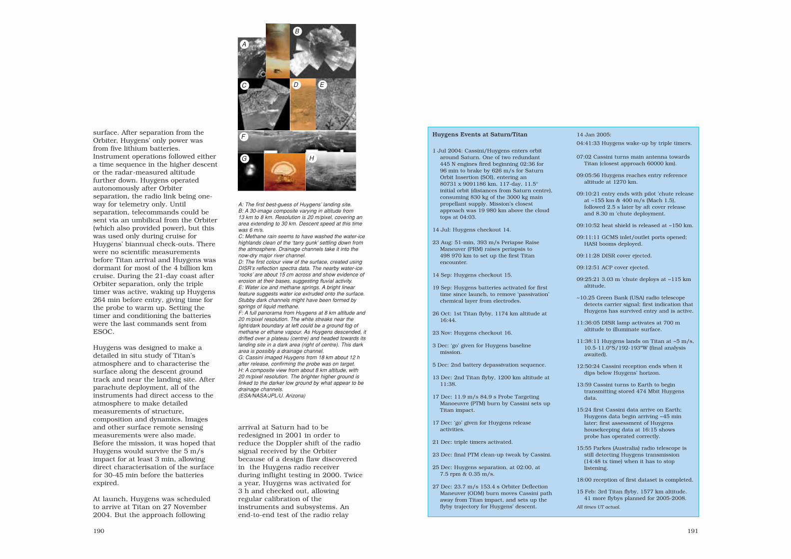
191190
surface. After separation from theOrbiter, Huygens’ only power wasfrom five lithium batteries.Instrument operations followed eithera time sequence in the higher descentor the radar-measured altitudefurther down. Huygens operatedautonomously after Orbiterseparation, the radio link being one-way for telemetry only. Untilseparation, telecommands could besent via an umbilical from the Orbiter(which also provided power), but thiswas used only during cruise forHuygens’ biannual check-outs. Therewere no scientific measurementsbefore Titan arrival and Huygens wasdormant for most of the 4 billion kmcruise. During the 21-day coast afterOrbiter separation, only the tripletimer was active, waking up Huygens264 min before entry, giving time forthe probe to warm up. Setting thetimer and conditioning the batterieswere the last commands sent fromESOC.
Huygens was designed to make adetailed in situ study of Titan’satmosphere and to characterise thesurface along the descent groundtrack and near the landing site. Afterparachute deployment, all of theinstruments had direct access to theatmosphere to make detailedmeasurements of structure,composition and dynamics. Imagesand other surface remote sensingmeasurements were also made.Before the mission, it was hoped thatHuygens would survive the 5 m/simpact for at least 3 min, allowingdirect characterisation of the surfacefor 30-45 min before the batteriesexpired.
At launch, Huygens was scheduledto arrive at Titan on 27 November2004. But the approach following
arrival at Saturn had to beredesigned in 2001 in order toreduce the Doppler shift of the radiosignal received by the Orbiterbecause of a design flaw discoveredin the Huygens radio receiverduring inflight testing in 2000. Twicea year, Huygens was activated for3 h and checked out, allowingregular calibration of theinstruments and subsystems. Anend-to-end test of the radio relay
Huygens Events at Saturn/Titan
1 Jul 2004: Cassini/Huygens enters orbitaround Saturn. One of two redundant445 N engines fired beginning 02:36 for96 min to brake by 626 m/s for SaturnOrbit Insertion (SOI), entering an80731 x 9091186 km, 117-day, 11.5°initial orbit (distances from Saturn centre),consuming 830 kg of the 3000 kg mainpropellant supply. Mission’s closestapproach was 19 980 km above the cloudtops at 04:03.
14 Jul: Huygens checkout 14.
23 Aug: 51-min, 393 m/s Periapse RaiseManeuver (PRM) raises periapsis to498 970 km to set up the first Titanencounter.
14 Sep: Huygens checkout 15.
19 Sep: Huygens batteries activated for firsttime since launch, to remove ‘passivation’chemical layer from electrodes.
26 Oct: 1st Titan flyby, 1174 km altitude at16:44.
23 Nov: Huygens checkout 16.
3 Dec: ‘go’ given for Huygens baselinemission.
5 Dec: 2nd battery depassivation sequence.
13 Dec: 2nd Titan flyby, 1200 km altitude at11:38.
17 Dec: 11.9 m/s 84.9 s Probe TargetingManoeuvre (PTM) burn by Cassini sets upTitan impact.
17 Dec: ‘go’ given for Huygens releaseactivities.
21 Dec: triple timers activated.
23 Dec: final PTM clean-up tweak by Cassini.
25 Dec: Huygens separation, at 02:00, at7.5 rpm & 0.35 m/s.
27 Dec: 23.7 m/s 153.4 s Orbiter DeflectionManeuver (ODM) burn moves Cassini pathaway from Titan impact, and sets up theflyby trajectory for Huygens’ descent.
14 Jan 2005:
04:41:33 Huygens wake-up by triple timers.
07:02 Cassini turns main antenna towardsTitan (closest approach 60000 km).
09:05:56 Huygens reaches entry referencealtitude at 1270 km.
09:10:21 entry ends with pilot ’chute releaseat ~155 km & 400 m/s (Mach 1.5),followed 2.5 s later by aft cover release and 8.30 m ’chute deployment.
09:10:52 heat shield is released at ~150 km.
09:11:11 GCMS inlet/outlet ports opened;HASI booms deployed.
09:11:28 DISR cover ejected.
09:12:51 ACP cover ejected.
09:25:21 3.03 m ’chute deploys at ~115 kmaltitude.
~10.25 Green Bank (USA) radio telescopedetects carrier signal; first indication thatHuygens has survived entry and is active.
11:36:05 DISR lamp activates at 700 maltitude to illuminate surface.
11:38:11 Huygens lands on Titan at ~5 m/s,10.5-11.0ºS/192-193ºW (final analysisawaited).
12:50:24 Cassini reception ends when it dips below Huygens’ horizon.
13:59 Cassini turns to Earth to begintransmitting stored 474 Mbit Huygensdata.
15:24 first Cassini data arrive on Earth;Huygens data begin arriving ~45 min later; first assessment of Huygenshousekeeping data at 16:15 shows probe has operated correctly.
15:55 Parkes (Australia) radio telescope is still detecting Huygens transmission (14:48 tx time) when it has to stoplistening.
18:00 reception of first dataset is completed.
15 Feb: 3rd Titan flyby, 1577 km altitude. 41 more flybys planned for 2005-2008.
All times UT actual.
A: The first best-guess of Huygens’ landing site.B: A 30-image composite varying in altitude from13 km to 8 km. Resolution is 20 m/pixel, covering anarea extending to 30 km. Descent speed at this timewas 6 m/s. C: Methane rain seems to have washed the water-icehighlands clean of the ‘tarry gunk’ settling down fromthe atmosphere. Drainage channels take it into thenow-dry major river channel. D: The first colour view of the surface, created usingDISR’s reflection spectra data. The nearby water-ice‘rocks’ are about 15 cm across and show evidence oferosion at their bases, suggesting fluvial activity.E: Water ice and methane springs. A bright linearfeature suggests water ice extruded onto the surface.Stubby dark channels might have been formed bysprings of liquid methane. F: A full panorama from Huygens at 8 km altitude and20 m/pixel resolution. The white streaks near thelight/dark boundary at left could be a ground fog ofmethane or ethane vapour. As Huygens descended, itdrifted over a plateau (centre) and headed towards itslanding site in a dark area (right of centre). This darkarea is possibly a drainage channel. G: Cassini imaged Huygens from 18 km about 12 hafter release, confirming the probe was on target.H: A composite view from about 8 km altitude, with20 m/pixel resolution. The brighter higher ground islinked to the darker low ground by what appear to bedrainage channels. (ESA/NASA/JPL/U. Arizona)
A
B
C D E
F
G H
sec6 8/1/05 1:15 PM Page 190

Huygens’ Descent Module is attached to the rear ofthe front shield, which protected it from the intenseheat of entry. The central canister contained themortar that began the 148-min parachute descentphase by firing a small deployment parachutethrough a membrane in the centre of the back cover(at left), which then itself was detached by theparachute’s drag. The main and stabiliser ’chuteswere stored in the large box. Also visible on theDM’s top face are the two redundant (black conical)antennas that transmitted the data back to theCassini Orbiter. At top left is the CD carrying morethan 100 000 signatures and messages.
sec6 8/1/05 1:15 PM Page 192

195194
link during the 5th checkout, inFebruary 2000 (supported by furthertests using the Probe EngineeringModel at ESOC in September-December 2000) revealed that thebandwidth of the Huygens receiveron Cassini was too narrow to copewith the expected Doppler shiftduring descent. As a result,Cassini’s flyby was moved muchfurther out from Titan to reduce theDoppler shift. Huygens’ onboardsoftware and that of severalinstruments was also modified inDecember 2003 to optimise thesignal.
More than 474 Mbit were receivedfrom Huygens, including some 350images collected during the descentand on the surface, which revealed alandscape apparently modelled byerosion, with drainage channels,shoreline-like features and evenpebble-shaped objects.
The descent proved to be bumpierthan expected, with Huygensswinging up to 20º before stabilising;there may have been an unexpectedchange in wind profile at about25 km. After 10 min under the mainparachute, Huygens’ spin reversed forreasons yet to be explained. Theatmosphere was probed and sampledall the way from 145 km altitude toground level, revealing a uniform mixof methane with nitrogen in thestratosphere. The methaneconcentration increased steadily inthe troposphere and down to thesurface. A cloud layer was found atabout 20 km, and perhaps fog nearthe surface. Unexpectedly, GCMSfound only argon of the inert gases,perhaps implying that Titan wentthrough a hot phase that drove suchgases from the atmosphere. Duringthe descent, HASI’s microphoneprovided the sound backdrop. Itlistened for thunder in a search for
Cassini/Huygensrequired several
planetary swingbys togain sufficient speed to
reach Saturn within7 years.
Bottom view ofHuygens’ Experiment
Platform. The redcylinder is part of the
SSP; the black cylinderis the GCMS; the black
box is the ACP. Thesilver boxes are the
batteries, connected tothe power distribution
unit (green box).
Cassini/Huygens pathafter Saturn OrbitInsertion (SOI).ODM: Orbiter DeflectionManeuver;PRM: Perigee RaiseManeuver; PTM: ProbeTarget Maneuver.
sec6 8/1/05 1:15 PM Page 194

197196
lightning; although none wasimmediately apparent, the analysiscontinues.
Spectacular images from DISR revealthat Titan has extraordinarily Earth-like meteorology and geology.A complex network of narrow drainagechannels run from brighter highlandsto lower, flatter, dark regions. Thesechannels merge into river systemsrunning into lakebeds featuringoffshore ‘islands’ and ‘shoals’remarkably similar to those on Earth.We now have the key to understandingwhat shapes Titan’s landscape;geological evidence for precipitation,erosion, mechanical abrasion andother fluvial activity says that thephysical processes shaping Titan aremuch the same as those on Earth.Huygens’ data show strong evidencefor liquids flowing on Titan. However,the fluid is methane, a simple organiccompound that can exist as a liquid orgas at Titan’s very low temperatures,rather than water as on Earth. Titan’srivers and lakes appear to be dry atthe moment, although the landing sitewas wet with methane, so it may haverained not long ago.
As Huygens touched down, SSPprovided a large amount ofdeceleration and penetration data onthe texture of the surface, whichresembles wet sand or clay with a thinsolid crust. DISR measurementsshowed mainly a mix of dirty water iceand hydrocarbon ice, producing adarker ‘soil’ than expected. Thetemperature measured at ground levelwas 94K. Huygens settled 10-15 cminto the surface.
Heat generated by Huygens warmedthe soil beneath the probe and bothGCMS and SSP detected bursts ofmethane gas boiled out of surface
material. DISR surface images showsmall rounded pebbles in a dryriverbed. DISR colour spectrameasurements are consistent with dirtywater ice rather than silicate rocks.However, water-ice is rock-like inTitan’s climate. The soil consists atleast in part of precipitated deposits ofthe organic haze that shrouds theplanet. This dark tarry gunk’ settlesout of the atmosphere. When washedoff high elevations by methane rain, itconcentrates at the bottom of thedrainage channels and riverbeds,contributing to the dark areas seen inDISR images.
Thus, while many of Earth's familiargeophysical processes occur on Titan,the chemistry involved is quitedifferent. Instead of liquid water, Titanhas liquid methane. Instead of silicaterocks, Titan has hard water-ice.Instead of dirt, Titan has hydrocarbonparticles settling out of the atmosphere,and instead of lava, perhaps there areTitanian volcanoes spewing very coldice. Titan is therefore an extraordinaryworld, having Earth-like geophysicalprocesses operating on exotic materialsin very alien conditions.
Generation of the wind profilesaccurate to 1 m/s took longer becausehuman error meant that datachannel A, the only one with the ultra-stable receiver required by DWE, wasnever activated aboard Cassini. It wasexpected, though, that DWE’sobjectives would be fully satisfied bythe Earth network of 17 radiotelescopes using VLBI (Very LongBaseline Interferometry) on Huygens’carrier signal. A bonus set of 350 DISRimages interpolated between thereceived images was also lost, as wassome HASI data; the other instrumentsduplicated their data on the twochannels.
The Principal Characteristics of the Huygens Payload.
Instrument/ Science objectives Sensors/measurements Mass Power ParticipatingPrincipal Investigator (kg) (typical/ countries
peak, W)
Huygens Atmospheric Atmospheric temperature T: 50-300K, P: 0-2000 mbar 6.3 15/85 I, A, D, E, Structure Instrument and pressure profile, winds γ: 1 µg-20 mg F, N, (HASI) and turbulence AC E-field: 0-10 kHz , SF, USA,
Atmospheric conductivity. 80 dB at 2 µV/m Hz UK, M. Fulchignoni, Search for lightning. DC E-field: 50 dB at 40 mV/m ESA/RSSD, University Paris 7/ Surface permittivity and Conductivity 10-15 Ω/m to ∞ ISObs. Paris-Meudon radar reflectivity. Relative permittivity: 1 to ∞(France) Acoustic: 0-5 kHz, 90 dB at 5 mPa
Gas Chromatograph Atmospheric composition Mass range: 2-146 dalton 17.3 28/79 USA, A, FMass Spectrometer profile. Aerosol pyrolysis Dynamic range: >108
(GCMS) products analysis. Sensitivity: 10-10 mixing ratioMass resolution: 10-6 at 60 dalton
H.B. Niemann, GC: 3 parallel columns, H2 carrier gasNASA/GSFC, Quadropole mass filterGreenbelt (USA) 5 electron impact sources
Enrichment cells (×100-×1000)
Aerosol Collector and Aerosol sampling in two 2 samples: 150-40 km; 23-17 km 6.3 3/85 F, A, USAPyrolyser (ACP) layers – pyrolysis and 3-step pyrolysis: 20°C, 250°C, 600°C
injection to GCMSG.M. Israel, SA/CNRS Verriéres-le-Buisson (France)
Descent Atmospheric composition Upward and downward 8.1 13/70 USA, D, FImager/Spectral and cloud structure. (480-960 nm) and IR (0.87-1.64 µm) Radiometer Aerosol properties. spectrometers, res. 2.4/6.3 nm.(DISR) Atmospheric energy Downward and side imagers.
budget. (0.660-1 µm), res. 0.06-0.20°M.G. Tomasko, Surface imaging. Solar Aureole measurements: University of Arizona, 550±5 nm, 939±6 nm.Tucson (USA) Surface spectral reflectance with
25 W surface lamp.
Doppler Wind Probe Doppler tracking (Allan Variance) : 10-11 (1 s); 1.9 10/18 D, I, USAExperiment (DWE) from the Orbiter for zonal 5×10-12 (10 s); 10-12 (100 s)
wind profile measurement. Wind measurements 2-200 m/sM.K. Bird, University Probe spin, signal attenuationof Bonn (Germany)
Surface Science Titan surface state and γ: 0-100 g; tilt ±60°; T: 65-110K; 3.9 10/11 UK, F, Package (SSP) composition at landing Tth: 0-400 mW m-1 K-1 USA,
site. Atmospheric Speed of sound: 150-2000 m s-1, ESA/RSSD,J.C. Zarnecki, measurements. Liquid density: 400-700 kg m-3 PLOpen University, Refractive index: 1.25-1.45Milton Keynes (UK) Acoustic sounding, liquid relative
permittivity
Further information can be found athttp://sci.esa.int/huygens and in Huygens: Science, Payload and Mission, ESA SP-1177, August 1997.
sec6 8/1/05 1:15 PM Page 196

199198
Huygens configuration: the Probeconsisted of the Entry Assembly(ENA) cocooning the Descent Module(DM). ENA provided Orbiterattachment, umbilical separation andejection, cruise and entry thermalprotection, and entry decelerationcontrol. It was jettisoned after entry,releasing the DM. The DM comprisedan aluminium shell and innerstructure containing all theexperiments and support equipment,including the parachutes. The DMwas sealed except for a 6 cm2 venthole on the top, and comprised:73 mm-thick aluminium honeycombsandwich Experiment Platform(supporting most experiments andsubsystems); 25 mm-thick aluminiumhoneycomb sandwich Top Platform,forming the DM’s top surface (descentsystem and RF antennas); After Coneand Fore Dome aluminium shells,linked by a central ring.
Attitude/orbit control: provided byCassini orbiter; spun up to 7.5 rpm
for release. 36 peripheral DM vanesensured slow spin (1-2 rpm < 20 kmaltitude) during descent for azimuthalcoverage of some instruments.
Power system: five LiSO2 batteries toprovide total of 2060 Wh, beginningshortly before release: 0.3 W for 21-day coast (to power wake-up timers),90 W for pre-heating, 210-330 W fordescent and ~260 W after landing.
Thermal protection/control: tiles ofAQ60 ablative material, a felt of silicafibres reinforced by phenolic resin,glued to the front shield’s CFRPhoneycomb shell to protect againstthe 1 MW/m2 entry flux. Prosial, asuspension of hollow silica spheres insilicon elastomer, was sprayeddirectly on to the shield’s rearaluminium structure, where fluxeswere ten times lower. The back coverwas protected by 5 kg of Prosial. Inspace, Huygens was insulated fromthe Orbiter and protected againstvariations in solar heating(3800 W/m2 near Venus, reducing to17 W/m2 near Titan) by: multi-layerinsulation on all external areas(except for a 0.17 m2 white-paintedthin aluminium sheet on the frontshield’s outer face as a controlledheat leak – about 8 W during cruise);35 radioisotope heaters on theExperiment and Top Platformsprovided continuous 1 W each.
Communications payload: two hot-redundant S-band 10 W transmittersand two circular-polarisationantennas (LHCP 2040 MHz; RHCP2098 MHz) on Huygens broadcastdata at 8 kbit/s 41.7 dBm EIRPbeginning shortly before entry. Noonboard storage. Received by CassiniHGA, recorded and later relayed toEarth (command error failed toactivate LHCP receiver).
Cassini/Huygensinstalled on their launchvehicle.
Cassini, with Huygens mounted on the side, is lowered on to itslaunch vehicle adapter in the Payload Hazardous Servicing
Facility at the Kennedy Space Center. The HuygensEngineering Model is in the Huygens Probe Operations Centre
(HPOC) at ESOC, used as a testbed during the cruise toSaturn. (NASA)
The Descent Module underits parachute. The HASIbooms are deployed and theDISR sensor head can beseen. At right, the GCMS,ACP and SSP view throughthe fore dome.
separation/ejection device
after cone
experiment platform
front shield
fore dome
descentmodule
entryassembly
top platform
back cover
sec6 8/1/05 1:15 PM Page 198

Unique images werereturned to Earth by TeamSatas it separated with Ariane’s Maqsat-Hupper payload. Shown is the Speltra/upperstage composite falling behind, 64 s after separation600 km over Africa. TeamSat’s Visual Telemetry System wasdesigned to acquire image sequences of critical operations. (ESA)
Preparing Maqsat-H, with TeamSat attached at bottom,in the Batiment d’Assemblage Final building at Kourou,
French Guiana ready for the Ariane-502 launch.(ESA/CNES/CSG)
200
TeamSat
Achievements: developed in record time and cost; demonstrated new technologiesLaunch date: 30 October 1997Mission end: 2 November 1997 (after 3 days when battery expired)Launch vehicle/site: Ariane-502 from ELA-3, Kourou, French GuianaLaunch mass: 350 kgOrbit: 540x26 635 km, 8°Principal contractor: ESTEC
TeamSat (Technology, Science andEducation Experiments Added toMaqsat) was an initiative of ESTEC’sAutomation and InformaticsDepartment in response to aninvitation from ESA’s LaunchersDirectorate to add experiments to oneof the Maqsat instrumented mockupson the Ariane-502 test flight. Aprincipal objective was hands-oninvolvement of young traineeengineers at ESTEC. The payload was produced in the unprecedentedshort time of only 7 months fromstart (December 1996) to readiness(July 1997). Furthermore, costs werekept to a bare minimum(<ECU1 million) through the use ofin-house equipment and spares,support from ESTEC staff and thefree launch.
TeamSat was not an independentsatellite – most of it remainedattached to Ariane’s Maqsat-Hmonitoring payload. The fiveexperiments were (in order ofincreasing complexity):
Orbiting Debris Device (ODD):Maqsat-H was painted 75%white/25% black for optical trackingof the spinning object to helpcalibrate ground-based telescopesand radars for space debris tracking.Other studies included paintdegradation;
Autonomous Vision System (AVS): acamera that automatically recogniseda non-stellar object and could beused to determine attitude
accurately; it could thus be used fornavigation and imaging purposes(Technical University of Denmark);
Visual Telemetry System (VTS): asystem of three cameras with animage compression and storage unitthat recorded images of the fairingand satellite separation after launch(Catholic University of Leuven);
Flux Probe Experiment (FIPEX):measured the concentration of atomicoxygen up to altitudes of 1000 km.Atomic oxygen is known for itserosion of optical surfaces andlenses;
TeamSat’s first fit-checkin the High Bay ofESTEC’s Erasmus
building of the Team(top) and YES (Young
Engineers’ Satellite,bottom) systems with theejection springs in place.
(ESA/Andy Bradford)
Young Engineers’ Satellite (YES):designed, assembled and integratedin record time by young graduates atESTEC, YES was planned as atethered subsatellite to be deployedon a 35 km tether. It also containedsome additional small experiments,to measure radiation, the solar angleand acceleration in autonomousmode after separation fromMaqsat-H. A GPS receiver was alsoinstalled, demonstrating the firstreception from above the GPSsatellite constellation. Unfortunately,the tether was not used because thelaunch window requirements werechanged, resulting in the tetherposing a high collision and debrisrisk. Nevertheless, YES wasseparated from Maqsat-H (withoutany tether), and a rehearsal of thetether operations was performed inpreparation for a possible futureflight.
The whole project, particularly YES,evolved for Young Graduate Traineesand Spanish Trainees to gainvaluable experience in designing,
building and integrating a satelliteand its payload. Some 43 youngengineers from these schemes, aswell as from the Technical Universityof Delft, were involved at differentstages during the satelliteproduction.
From the technology point of view,TeamSat’s achievements included:
• use of a quadrifilar helix antennafor 100 MHz to 3 GHz links (to beflown on the Metop weathersatellite);
• first fully asynchronous ESACCSDS-standard packet telemetrysystem, using new chips fortelemetry transfer framegeneration;
• provision of telemetry dynamicbandwidth allocation without theuse of an onboard computer;
• first ESA spacecraft to use thestandard packet-telecommandprotocols;
• first demonstration of GPSreception from above the GPSsatellite constellation.
201
sec6 8/1/05 1:15 PM Page 200

203202
ARD
Achievements: ESA’s first Earth-return craft, first complete spacemission (launch to landing) byEurope
Launch date: 16:37 UT, 21 October1998
Mission end: flight duration 101 min,splashing down at 19:28 UT,21 October 1998
Launch vehicle/site: Ariane-503 fromELA-3 complex, Kourou, FrenchGuiana
Launch mass: 2716 kgOrbit: suborbital, apogee 830 km
above Indian Ocean(5.40ºS/78.5ºE)
Principal contractors: Aerospatiale(prime; contract signed30 September 1994), Alenia(descent & landing system), DASA(RCS), MMS-France (electronics),SABCA & SONACA (structure)
ESA’s Atmospheric ReentryDemonstrator (ARD) was a major steptowards developing and operatingspace transportation vehicles capableof returning to Earth, whethercarrying payloads or people. For thefirst time, Europe flew a completespace mission – launching a vehicleinto space and recovering it safely.
ARD was an unmanned, 3-axisstabilised automatic capsulelaunched by an Ariane-5 into asuborbital ballistic path that took itto a height of 830 km before bringingit back into the atmosphere at27 000 km/h. Atmospheric frictionand a series of parachutes slowed itdown for a relatively soft landing inthe Pacific Ocean, 101 min afterlaunch and three-quarters of the wayaround the world from its startingpoint.
ARD’s recorded and transmittedtelemetry allowed Europe to study thephysical environment to which futurespace transportation systems will be
exposed when they reenter theEarth’s atmosphere. It tested andqualified reentry technologies andflight control algorithms under actualflight conditions. In particular, it:validated theoreticalaerothermodynamic predictions;qualified the design of the thermalprotection system and of thermalprotection materials; assessednavigation, guidance and controlsystem performances; assessed theparachute and recovery system; andstudied radio communications duringreentry. ARD provided Europe withkey expertise in developing futurespace transportation and launchvehicles.
One objective was to validate theflight control algorithms developed aspart of the former Hermes spaceplaneprogramme. The guidance algorithmwas similar to that used by NASA’sSpace Shuttle, based on a reference
Principal stages in themission of ARD.(ESA/D. Ducros)
deceleration profile and also used byApollo. This approach provided goodfinal guidance accuracy (5 km;achieved 4.9 km) with limited real-time calculation complexity. In orderto reach the target and to holddeceleration levels to 3.7 g andthermal flux within acceptable limits,ARD snaked left and right of thedirect flight path with the help of thereaction control system (RCS)thrusters.
Another objective was to studycommunications possibilities duringreentry and, in particular, to analyseblackout phenomena and their effectson radio links. Radio blackout wasexpected between 90 km and 42 kmaltitude (actual: 90-43 km) asionisation of the super-heatedatmosphere interfered with signals.As soon as ARD reached 200 km, itwas in telemetry contact with two USAir Force KC-135 aircraft.
ARD vehiclearchitecture.(ESA/D. Ducros)
sec6 8/1/05 1:15 PM Page 202

205204
allowed the capsule’s location to bedetermined within 1500 m. TheFrench naval recovery shipapproached within 100 m and thenstood off for 6 h so that the capsule’sinterior could cool below 47ºC, theexplosive temperature for theremaining RCS hydrazine. The shipdelivered ARD to Papeete in Tahiti,from where it was transported by acommercial ship to Europe andreturned to Aerospatiale in Bordeauxfor inspection and testing.
Vehicle configuration: conical capsule(70%-scale of Apollo CommandModule), height 2.04 m, basediameter 2.80 m. Four main elementscreating air- and water-tightpressurised structure: bulkheadstructure with heatshield; conicalsection carrying RCS and internalsecondary structure; secondarystructure holding electricalequipment; back cover protectingdescent & recovery systems. Allstructural elements made ofmechanical-fastened aluminium alloyparts.
Thermal protection: heatshieldexposed to 2000ºC/1000 kW/m2,conical surface to 1000ºC/90-125 kW/m2. Internal temperaturewithin 40ºC. 600 kg heatshieldcomposed of 93 Aleastrasil tiles(randomly-oriented silica fibresimpregnated with phenolic resin)arranged as one central tile and sixcircumferential rings. Conical surfacecoated with Norcoat 622-50FI (corkpowder and phenolic resin). Samplesof new materials tested: four CeramicMatrix Composite heatshield tiles andtwo Flexible External Insulationpanels on conical surface.
Control: automatic navigation,guidance and control system
The automatic parachute deploymentsequence began at 87 min 56 s at13.89 km above the Pacific Ocean. Inorder to avoid tearing the parachutes,the deployment sequence did notbegin until the speed fell below Mach0.7; maximum allowable dynamicpressure was 5000 Pa. The 91 cm-diameter extraction parachute wasejected by a mortar from under theback cover; this then extracted a5.80 m drogue. That was jettisoned78 s later at 6.7 km altitude, and aset of three 22.9 m-diameter mainparachutes was released. They werereefed and opened in three steps inorder to avoid over-stressing thesystem. They slowed the descent rateto 20 km/h at impact (7.3 g) at134.0ºE/3.90ºN, south-east of Hawaiiand north-east of the FrenchMarquesa Islands. After landing,these parachutes were separated andtwo balloons inflated to ensureupright flotation.
Analysis of the telemetry received atthe ARD Control Centre in Toulouse
Main image: ARD integrated atAerospatiale, Bordeaux.The heatshield includedsamples of newmaterials. Inset: post-flight measurementsshowed that the mainshield was eroded byonly 0.1-0.3 mm.
Installation of ARD on its Ariane adapterin the final assembly building at thelaunch site. The combination was thenhoisted on to the launch vehicle.(ESA/CNES/CSG)
ARD recovery from thePacific Ocean.
consisted of Global PositioningSystem (GPS) receiver, inertialnavigation system, computer, databus and power supply & distributionsystem, and RCS. RCS was derivedfrom Ariane-5’s attitude controlsystem, using seven 400 N thrusters(3 pitch, 2 roll, 2 yaw) drawing onhydrazine carried in two 58-litretanks pressurised by nitrogen.
Power system: two 40 Ah NiCdSpot-4-type batteries.
Communications: >200 parametersrecorded during flight andtransmitted to TDRS and USAFaircraft at up to 250 kbit/s duringdescent below 200 km: 121temperature channels, 38 pressure,14 accelerometer and gyro,8 reflectometer, 5 forcemeasurement, 1 acoustic andfunctional parameters such asmission sequences.
ARD has been displayed since June 2002at the Cité de l’Espace space park inToulouse: www.cite-espace.com
sec6 8/1/05 1:15 PM Page 204

207206
XMM-Newton
Achievements: high-throughput, broadband (0.1-10 keV), medium resolution (20-30 arcsec) X-ray spectrophotometry and imaging of sources, ranging fromnearby stars to quasars
Launch date: 10 December 1999, routine science operations began 1 July 2000Mission end: 31 March 2008 (nominally 2 yr); 10-yr extended mission possibleLaunch vehicle/site: Ariane-504 from ELA-3, Kourou, French GuianaLaunch mass: 3764 kg Orbit: Ariane delivered it into 838x112 473 km, 40.0°; six apogee burns
10-16 December produced 7365x113 774 km, 38.9°, 48 hPrincipal contractors: Dornier Satellitensysteme (prime), Carl Zeiss (mirror
mandrels), Media Lario (mirror manufacture/assembly), MMS Bristol (AOCS),BPD Difesa e Spazio (RCS), Fokker Space BV (solar array)
The X-ray Multi-Mirror (XMM)observatory (renamed XMM-Newtonin February 2000) forms the second,High-Throughput X-ray Spectroscopy,cornerstone mission of ESA’sHorizons 2000 space science plan,concentrating on the soft X-rayportion of the electromagneticspectrum (100 eV to 12 keV). Byvirtue of its large collecting area andhighly eccentric orbit, it is makinglong observations of X-ray sourceswith unprecedented sensitivity. Mostof the 50-200 sources in every imageare being seen for the first time.Whereas the German/US/UK Rosatmission, launched in 1990, pushedthe number of known X-ray sourcesto 120 000, XMM-Newton is seeingmillions.
The heart of the mission is the X-raytelescope. It consists of three largemirror modules and associated focalplane instruments held together bythe telescope’s central tube. Eachmodule carries 58 nested gold-coatednickel mirrors using their shallowincidence angles to guide theincoming X-rays to a common focusfor imaging by the scientificinstruments.
One module uses an advanced PN-CCD camera (EPIC) capable ofdetecting rapid intensity variationsdown to a thousand of a second orless – important for tracking down
black holes. All three EPIC camerasmeasure the proportions of differentX-ray wavelengths to give a broadimpression of each source’sspectrum. For a more thoroughanalysis, two telescopes divert about40% of their beams with gratingstacks to diffract the X-rays, fanningout the various wavelengths on to aCCD strip (RGS). Spikes stand out atspecific wavelengths, correspondingto individual chemical elements.
Besides its X-ray telescopes, XMMcarries a sensitive conventionaltelescope (OM) to observe the samesections of sky by UV and visible lightso that astronomers know exactlywhat the satellite is observing.
Far left: combined 30 hexposures from theEPIC-PN and EPIC-MOS cameras of theLockman Hole, where a‘window’ in our Galaxyprovides a view into thedistant Universe. Red(low-energy) objectswere previouslyobserved by Rosat, butgreen and blue objectsare much moreenergetic and are beingseen clearly for the firsttime. It is evident thatXMM is detecting vastnumber of previouslyunknown X-ray sources.
EPIC shows theexpanding ring of X-raysfrom a powerful gamma-
burster (GRB 031203)on 3 December 2003.
The slowly fadingafterglow of the gamma
burst is at the centre.(ESA/S. Vaughn, Univ.
Leicester)
XMM confirms Europe’s position atthe forefront of X-ray astronomy byproviding unprecedented observationsof, for example, star coronas;accretion-driven binary systemscontaining compact objects;supernova remnants (SNRs); normalgalaxies containing hot interstellarmedium as well as point-likeaccretion-driven sources and SNRs;Active Galactic Nuclei, which maywell be accretion-driven; clusters ofgalaxies with hot inter-clustermedium.
Activation of the science instrumentsbegan on 4 January 2000, after themirror module and OM doors hadbeen opened on 17/18 December1999. After engineering images werereturned, the first science imagesfrom all three EPIC cameras and OMwere taken 19-24 January 2000. Thefirst RGS spectrum was produced25 January. The Calibration &Performance Validation phase began3 March 2000; routine scienceoperations began 1 July 2000.
An exciting result is that XMM cantrack simultaneously the X-ray andoptical afterglows of gamma-raybursts. It has identified the chemicalelements thrown out and confirmed itas the death of a massive star in asupernova explosion. In anotherdiscovery, XMM has found more ironthan expected in an early galaxy on
the edge of the Universe. As ironlevels build with age, is the Universeolder than we thought?
Highlights from the first 5 years ofthe mission include:
– the first detection of an X-ray cyclein a Sun-like star;
– observations of several gamma-raybursters and supernovas, and thefirst detection of their expandinghaloes of X-rays;
– observations of supernovaeremnants, and the movement ofthe neutron star Geminga in one;
– the detection of four regularlyspaced absorption features in thespectrum of the neutron star
http://sci.esa.int/xmm/
One of the first scienceimages: an EPIC-PNview of the 30 Doradusregion of the LargeMagellanic Cloud. In thisregion, supernovae areseeding the creation ofnew stars. At rightcentre is the blue-whitearc of a supernovashockwave heating theinterstellar gas. At lowerright is the remains ofthe star that explodedas Supernova 1987A –the first naked-eyesupernova since 1604.The brightest object (leftcentre) is also asupernova remnant star.(EPIC Consortium)
sec7 8/1/05 1:23 PM Page 206

209208
XMM-Newton Scientific Instruments
Three Wolter 1-type mirror modules provide the photon-collecting area(1475 cm2 at 1.5 keV; 580 cm2 at 8 keV EOL) for three CCD imaging arraycameras and two reflection grating spectrometers; complemented by aseparate optical monitor. Each 420 kg mirror module contains 58paraboloid/hyperboloid mirrors 60 cm-long with a gold coating providingthe reflective surface at 0.5° grazing incidence. Outermost mirror 70.0 cmdiameter, innermost 30.6 cm; mirror thickness reduces from 1.07 mm to0.47 mm and separation from 4 mm to 1.5 mm. Focal length 7500 mm.
European Photon Imaging Camera (EPIC)
A CCD camera at the prime focus of each mirror module performsbroadband (0.1-10 keV) imaging/spectrophotometry. Two cameras basedon MOS-CCD technology share the mirrors with the RGS; one camerausing PN-CCD has its own dedicated mirror module. EPIC consortium ledby University of Leicester, UK (PI: M. Turner)
Reflection Grating Spectrometer (RGS)
Half of the exit beams from two mirror modules are intercepted by a20 cm-deep gold-coated reflection grating stack for dispersion to a CCDstrip at the secondary focus. E/∆E of 300-700 (1st order) for 0.35-2.5 keV; resolving power >500 at 0.5 keV. RGS consortium led by SRON,The Netherlands (PI: A.C. Brinkman)
Optical Monitor (OM)
A separate 30 cm-aperture Cassegrain telescope provides simultaneouscoverage at 160-550 nm for coordination with X-ray observations andpointing calibration. Photon-counting detectors provide 17x17 arcminFOV at 1 arcsec resolution down to magnitude +24.5. A 10-positionfilter/prism wheel permits spectroscopy. The OM group is led by theMullard Space Science Laboratory, UK (PI: K.O. Mason)
Right: each of XMM’s mirror modules houses 58nested mirrors to reflect the incoming X-rays at
grazing angles to a focus. Two modules also have agrating stack for spectroscopy.
of centre-of-mass considerations.Subsystems are positioned around theexternal circumference at this end inthe separate Service Module (SVM),including solar arrays, data handlingand AOCS. ESA’s Integral gamma-rayobservatory uses the same SVM toreduce cost. The FPA is protected by aSun shield incorporating passiveradiators for instruments’ detectorcooling.
Attitude/orbit control: four ReactionWheels, two Star Trackers, four InertialMeasurements Units, three Fine SunSensors and three Sun AcquisitionSensors provide 3-axis control. Pointingaccuracy better than 1 arcmin, with adrift of 5 arcsec/h and 45 arcsec/16 h.Hydrazine thrusters provide orbitmaintenance, attitude control andwheel desaturation: four sets of twothrusters (primary + redundant) 20 Nblowdown (24-5.5 bar) thrusters sit oneach of four inter-connected 177 litretitanium propellant tanks. Hydrazineloading 530 kg.
Power system: two fixed solar wings,each of three 1.81x1.94 m rigid panelswith Si cells totalling 21 m2, sized toprovide 1600 W after 10 years. 28 Vmain bus. Eclipse power from two24 Ah 41 kg NiCd batteries.
Communications: data rate 70 kbit/s inrealtime (no onboard storage) tostations at Perth (Australia), Kourou
(French Guiana) and – added in Feb2001 – Santiago (Chile). Controlledfrom ESOC; science data returned toVillafranca, Spain. Observationspossible for up to 40 h out of each48 h orbit, when above Earth’sradiation belts.
MirrorModule 3
ApertureStops
EPICCamera 3
(MOS)
EPICCamera 2
(MOS)
EPICCamera 1
(p-n)
RGSCamera 2
RGSCamera 1
MirrorModule 2
Optical MonitorTelescope
TelescopeTube
MirrorModule 4
GratingAssembly 2
GratingAssembly 1
Left: the gold-plated mandrel for one of XMM’s mirrors. Mirrormanufacturing was based on a replication process, which transferreda gold layer deposited on the highly polished master mandrel to theelectrolytic nickel shell that was electroformed on to the gold.
1E1207.4-5209, caused by resonantcyclotron absorption;
– the detection of a hot spot only 60 macross on the surface of the neutronstar Geminga;
– iron lines distorted and broadenedby the strong gravitational fields ofnearby black holes;
– the final emission from stars fallinginto a supermassive black hole;
– collisions between clusters of galaxy– objects containing thousand ofgalaxies;
– spectra of the oldest objects in theUniverse, from 12.7 billion yearsago, when the Universe was only1 billion years old.
Satellite configuration: 10.05 m totallength in launch configuration;10.80 m deployed in orbit, 16.16 mspan across solar wings. XMM’s shapeis dominated by the telescope’s 7.5 mfocal length and the need to fit insideAriane-5’s fairing. The mirror modulesare grouped at one end in the MirrorSupport Platform (MSP) and connectedrigidly by the 6.7 m-long CFRPtelescope tube to the scientificinstruments in the Focal Plane Array(FPA). Launch was with the mirror endattached to Ariane’s adapter because
The lower module Flight Model in the Large SpaceSimulator at ESTEC. ESA still has a spare mirrorassembly, which in 2001 was part of two proposalsfor NASA Explorer missions.
Left: this supernovae exploded in 1006 and wasobserved in Europe, Egypt, Iraq, China and Japan.The two images of the supernova remnant in twoenergy bands indicate different radiationmechanisms. (CEA/DSM/DAPNIA/SAp & ESA)
Right: clusters of galaxies can contain thousands ofgalaxies. They are favourite targets of X-ray
astronomers because the hot gas between thegalaxies can be seen only in the X-ray energy band.This temperature map of Abell 754 shows, at left, a
shock wave from a collision with smaller clusters300 million years ago. (ESA/P. Henry et al.)
sec7 8/1/05 1:23 PM Page 208

210
ESA’s Advanced Relay andTechnology Mission Satellite isdemonstrating newtelecommunications techniques,principally for data relay and mobileservices. Before Artemis, users ofEarth observation satellites such asERS in low orbit relied on globalnetworks of ground stations toreceive their vital data. But, asinformation requirements and thenumber of missions grow, thisapproach is becoming too slow andexpensive and sometimes technicallyunfeasible.
Two Artemis payloads are exploringdata relay directly between satellites,receiving data from low Earth-orbitingsatellites and relaying them toEurope: the SILEX laser terminal andthe SKDR S/Ka-band terminal.Spot-4 and Envisat are already majorusers.
The ‘L-band Land Mobile’ (LLM)provides 2-way links between fixedEarth stations and land mobiles inEurope, North Africa and the NearEast. LLM is fully compatible with theEuropean Mobile System (EMS)payload already developed by ESAand flying aboard Italsat-2.
Artemis also carries a transponderproviding part of the EuropeanGeostationary Navigation OverlayService (EGNOS) for enhancing the
GPS/Glonass navigation satelliteconstellations.
Artemis is the first ESA satellite to flyelectric propulsion technologyoperationally: UK and German xenonion thrusters were included to controlthe north-south drift in geostationaryorbit (NSSK: north-southstationkeeping). The attractions ofthis technology are its high specificimpulse (3000 s) and low thrust(about 20 mN) in contrast withchemical propulsion. For Artemis, theresult was a mass saving of about400 kg.
Artemis also differs from thetraditional approach by combiningonboard data handling and AOCSinto a centralised processingarchitecture.
The programme cost-to-completion is€827 million (2004 conditions).
Artemis was released into a lowtransfer orbit because of amalfunction in Ariane-5’s upperstage: instead of the planned858x35 853 km, 2° GTO, the under-burn resulted in 590x17 487 km,2.94°. As scheduled, the solar wingswere partially deployed some 2 h afterlaunch and began delivering powerwhile controllers formulated arecovery strategy. The Liquid ApogeeEngine (LAE) was fired during five
Artemis
Achievements: first European data relay mission, including first opticalintersatellite link; first European operational use of ion propulsion
Launch: 21:58 UT 12 July 2001Mission end: design life 10 yearsLaunch vehicle/site: Ariane-510 from ELA-3, Kourou, French GuianaLaunch mass: 3105 kg (550 kg payload, 1559 kg propellant)Orbit: geostationary, above 21.5ºEPrincipal contractors: Alenia Spazio (prime, thermal control, RF data relay
payload), FiatAvio (propulsion), CASA (structure), Fiar (power), Fokker (solararray), Bosch/Alcatel (RD data relay payload elements), Astrium SAS (SILEX),Astrium UK (Portsmouth; Electro-bombardment Thruster), Astrium GmbH(Ottobrun; RF Ion Thruster), Telespazio (ground segment)
http://telecom.esa.int
Artemis is dominated bythe two 2.85 m-diameter
reflectors for inter-orbitlinks and the LLM
payload.
sec7 8/1/05 1:23 PM Page 210

213212
perigee passes on 18-20 July to raiseapogee to about 31 000 km. The LAEraised perigee in three burns on 22-24 July to produce a circular orbit atabout 31 000 km, 0.8°, 20 h. Thesolar arrays were then fully deployed,as were the two antenna reflectors. Inescaping the deadly Van Allen belts,Artemis had used 1449 kg(1885 m/s) of the available 1519 kgchemical propellant.
Artemis could then use its ionthrusters to climb slowly tooperational altitude. They wereoriginally designed only to controlorbit inclination by thrusting at 90ºto the orbital plane, now Artemis hadto turn through 90º for them to pushalong the orbit. Steering the enginesincluded entirely new control modesnever before used on a telecomsatellite, as well as new telecommandand telemetry and other data-handling functions. In all, some 20%of the original onboard controlsoftware had to be modified byuplinking patches totalling 15 000words, the largest reprogramming offlight software ever done on a telecomsatellite. By the end of December2001, the new software wascompleted and on 19 February 2002the orbit-raising began. The 15 mN
thrust produced a climb of 15 km perday. In all, the thrusters operated forabout 6000 h, equivalent to 4 yr ofconventional GEO NSSK. Almost allof the work was done by RITA-2 onthe north side because of operatingdifficulties with the other three.
The final adjustments were madeusing the 10 N chemical thrusters,activated for the first time. A burn inDecember 2002 and two more inJanuary 2003 slowed the drift rate toa few degrees/day. The last burn on31 January halted Artemis at theplanned 21.5°E. Despite the extensivemanoeuvres, the remaining 40±10 kgof MMH/N2O4 and 25 kg of Xe aresufficient for 7-10 years of operations.To conserve propellant, no NSSK isbeing performed. Artemis arrived inGEO with 1.6° inclination, which will
satellite were transmitted by laser toa quasi-GEO satellite, and fromthere to the data processing centrein Toulouse. All 26 attempts weresuccessful. Link quality was almostperfect: a bit error rate of better than1 in 109 was measured. Since 1 April2003, Artemis has been routinelyproviding the SILEX link for Spot-4;by 30 January 2005, the total linktime was 140 h (765 links).
In 2005, a SILEX test programme isplanned with Japan’s OICETSsatellite and with an aircraft opticalterminal. SILEX can also point atneighbouring GEO satellites, so ademonstration might be made.
Since 1 April 2003, Artemis hasprovided routine links for ESA’sEnvisat using Ka-band SKDR.Envisat is using up to 14 links perday on two channels for ASAR andMERIS data, which Artemistransmits directly to the EnvisatProcessing Centre at ESRIN. By30 January 2005, the total link timereached 2400 h (5025 links).
In the future, ATV will use theS-band SKDR service, andColumbus plans to use the S/Ka-bands.
be allowed to grow to 4° after 3 yrand 10° after 10 yr. The ion thrusterwill be used to remove Artemis fromGEO at the end of its life.
The gap of several months beforeorbit-raising began in February 2002was used to commission thecommunications payload. Payloadtests during November/December2001 could be done only every 5thday, when the Artemis feeder linkantenna beam illuminated ESA’sRedu station. All payloads metspecifications. The most spectacularevent came with SILEX. Followinginitial commissioning via ESA’soptical ground station on Tenerife,the optical link was establishedbetween Artemis and Spot-4. On30 November 2001, for the first timeever, image data collected by a LEO
Above: unpacking theFlight Model after itsarrival at ESTEC tobegin systems-level
testing in July 1998. TheSILEX terminal is at
bottom right; thetelescope is pointingdown. Above it is the
Ku-band feeder link forthe LLM land mobile
package. At top left isthe Ka-band feeder forthe SKDR and SILEX
packages. Bottom left isthe L-band horn for the
EGNOS navigationpackage.
Artemis ready to beinstalled on its launcher.Note the south-face ionthruster package belowthe solar wing.
sec7 8/1/05 1:23 PM Page 212

215214
Since March 2003, the LLM L-bandpayload has been providingoperational 2-way links between fixedEarth stations and land mobiles inEurope, North Africa and the NearEast. LLM is fully compatible with theEuropean Mobile System (EMS)payload developed by ESA andinitiated aboard Italsat-2. LLM ishighly reconfigurable, with spotbeams allowing traffic to be directedstraight to the area of interest. Mobileservice operators, including Telespazioand Eutelsat are leasing capacity tocomplement their existing systems.
The NAV payload was commissionedin February 2003 and demonstratedwith the EGNOS testbed in November2003. The EGNOS system will becomeoperational in 2005.
Satellite configuration: classical box-shaped 3-axis bus derived from Italsat
System: conventional bipropellant(MMH/N2O4; 1519 kg at launch)system of a single 400 N LiquidApogee Engine (LAE, for insertion intoGEO) and two redundant branches ofeight 10 N RCS thrusters each.Propellants in two Cassini-type 700-litre tanks; helium pressurant inthree spheres. LAE operates atregulated 15.7 bar, then isolated oncein GEO for RCS to operate inblowdown mode. E/W positioningmaintained by RCS; N/S by ionthrusters (planned). Ion PropulsionSubsystem (IPS) comprises twothruster assemblies, one each on N/Sfaces: a 15 mN RF Ion ThrusterAssembly (RITA) and an 18 mN
Electro-bombardment ThrusterAssembly (EITA). Each is poweredand monitored separately, but withcommon propellant supply (40 kg Xe).600 W required in operation.
Power: twin 4-panel solar wingsprovide 2.8 kW at equinox after10 years to 42.5 Vdc bus; eclipseprotection by two 60 Ah nickel-hydrogen batteries.
Communications: satellite controlfrom Control Centre and TT&Cstation in Fucino Mission Control;In-Orbit Testing from ESA Redu. Seeseparate box for Artemiscommunications payload.
and other European predecessors.25 m span across solar wings.Primary structure of central cylinder(aluminium honeycomb skinned bycarbon fibre), main platform,propulsion platform and four shearpanels. The secondary structure isprincipally the N/S radiators, E/Wpanels and Earth-facing panel. Thecentral propulsion module housesthe propellant tanks, LAE,pressurant tanks and RCS pipes.E panel: L-band antenna/feed.W panel: IOL antenna. N/S panels:host most of the electroniccomponents requiring heatdissipation. Earth panel: otherantennas and AOCS sensors.
Attitude/orbit control: Earth/Sunsensors & gyros for attitudedetermination, reaction wheels forattitude control (RCS thrusters forwheel offloading). Unified Propulsion
Artemis Communication and Navigation Payload
Semiconductor Laser Intersatellite Link Experiment (SILEX)
SILEX is the world’s first civil laser-based intersatellite data relay system. The transmitter terminalon Spot-4 in LEO beams data at 50 Mbit/s (bit error rate <10-6) to the receiver on Artemis for relayvia the feeder link to Spot’s Earth station near Toulouse (F). Japan’s OICETS satellite will also beused in experiments (including 2 Mbit/s from ground via Artemis to OICETS). Each terminal has a25 cm-diameter telescope mounted on a coarse pointing mechanism; pointing accuracy 0.8 mrad.Optical power source: 830 nm GaAlAs semiconductor laser diode, peak output 160 mW (60 mWcontinuous), beamwidth 0.0004º (400 m-diameter circle at the distance of receiver). Receiver: siliconavalanche photodiode (SI-APD), followed by a low-noise trans-impedance amplifier; 1.5 nW usefulreceived power. CCD acquisition/tracking sensors direct fine-pointing mechanism of orthogonalmirrors. A 1 m telescope at the Teide Observatory on Tenerife acts as a test station.
S/Ka-band Data Relay (SKDR)
The 2.85 m antenna tracks a LEO user satellite via either loaded pointing table values and/or errorsignals to receive up to 450 Mbit/s Ka-band or up to 3 Mbit/s S-band for relay via the feeder link toEarth. Up to 10 Mbit/s Ka-band and 300 kbit/s S-band can be transmitted by Artemis to LEOsatellite. Single Ka-band transponder (plus one backup) 25.25-27.5/23.2-23.5 GHz rx/tx, adjustableEIRP 45-61 dBW, G/T 22.3 dB/K, up to 150 Mbit/s each of three channels LEO to Artemis and upto 10 Mbit/s Artemis to LEO. RH/LHCP on command. One S-band transponder (plus one backup)2.200-2.290/2.025-2.110 GHz rx/tx, adjustable EIRP 25-45 dBW, G/T 6.8 dB/K, 15 MHzbandwidth, up to 3 Mbit/s single channel LEO to Artemis and up to 300 kbit/s Artemis to LEO.RH/LHCP on command. Artemis broadcasts 23.540 GHz beacon to help the LEO satellite track it.
SILEX and SKDR feeder link
Three transponders (plus one backup, 4-for-3) act as Artemis-ground links for SILEX and SKDR.27.5-30/18.1-20.2 GHz rx/tx, EIRP 43 dBW, G/T 0 dB/K, 234 MHz bandwidth, linear verticalpolarisation.
L-band Land Mobile (LLM)
Designed principally for mobile users such as trains and trucks. Artemis carries 2.85 m antenna andmultiple element feed for pan-European coverage and three European spot beams. Three 1 MHz plusthree 4 MHz SSPA channels, providing up to 650 2-way circuits with EIRP >19 dBW 1550 MHzL-band transmitting to terminals (1650 MHz receiving) and 14.2/12.75 GHz Ku-band rx/tx for thefeeder links to the home stations. All channels fully tunable and most commandable LH/RHCP. LLMprovides an operational service in conjunction with Italsat-2’s European Mobile System package (alsofunded through ESA).
Navigation Payload (NAV)
As part of the European Geostationary Navigation Overlay System (EGNOS), NAV broadcasts L-bandnavigation signals from the EGNOS Master Control Centre, adding accuracy and integrity forGPS/Glonass users. Tx 1575.42 MHz, 4 MHz bandwidth, EIRP > 27 dBW (1 of 3 SSPAs has failed),45 cm-dia horn. Uses LLM Ku-band package for feeder: 13.875/12.748 GHz rx/tx. 25 kg, 110 W.
1 coarse pointing assembly supportbracket
2 satellite interface structure3 launch locking device4 coarse pointing mechanism5 mobile part carrier structure6 fine pointing drive electronics
(nominal)7 fine pointing drive electronics
(redundant)8 telescope baffle9 telescope assembly10 point ahead drive electronics11 mobile telecom electronics
12 fine pointing sensors & control electronics13 mechanism & thermal control electronics14 acquisition detector proximity electronics module
(nominal)15 acquisition detector proximity electronics module
(redundant)16 optical head bench attachment devices17 optical head bench 18 optical head thermal hood19 field separator module20 folding mirror21 beam combiner module22 point ahead mechanism23 fine pointing mechanism24 flip flop mechanism25 optical head harness26 retroreflecting corner cube27 folding mirror28 acquisition detector module (redundant)29 acquisition detector module (nominal)30 acquisition lens module 31 tracking filter32 fixed beam translator33 tracking sensor detection unit (nominal)34 tracking sensor detection unit (redudant)35 anamorphoser36 transmitter redundancy module37 laser diode transmitter package38 laser diode transmitter package39 laser diode transmitter package40 receiver front end (redundant), GEO only41 receiver front end (nominal), GEO only42 receiver redundancy module, GEO only43 beacon head, GEO only44 return link, GEO only45 folding mirror, GEO only46 flip-flop mechanism, GEO only
sec7 8/1/05 1:23 PM Page 214

217216
Proba-1
Achievements: ESA’s first small satellite for technology demonstration, highest-performance computing system flown by ESA, first flight of new type of Earth-observation instrument
Launch date: 04:53 UT 22 October 2001Mission end: 2-year nominal mission; extension to end-2005 (funded since 1 Jan
2005 as Earth Observation third-party mission; ESA cost-at-completion€13.5 million)
Launch vehicle/site: auxiliary passenger on PSLV-C3 from Sriharikota, IndiaLaunch mass: 94 kg (payload 25 kg)Orbit: 561x681 km, 97.9° Sun-synchronousPrincipal contractors: Verhaert Design & Development (B; prime), Spacebel (B;
software), Verhaert/SIL/Netronics (B/UK/NL; RF, power & avionics), SAS (B;ground segment), Université de Sherbrooke/NGC Aerospace (Canada; attitudecontrol and navigation), Space Systems Finland (FIN; software validation tool),Officine Galileo (I; solar array). Ph-A June 1997 - February 1998; Ph-B June-October 1998; Ph-C/D October 1998 - October 2001
ESA’s small, low-cost Proba (Project forOn-Board Autonomy) satellite validatednew spacecraft autonomy and 3-axiscontrol and data system technology aspart of the Agency’s In-orbitTechnology Demonstration Programme.Provided as an ESA Announcement ofOpportunity instrument, Proba’s mainpayload is the novel CHRIS imagingspectrometer.
First contact with Proba-1 was madeat 06:16 UT 22 October 2001 viaKiruna, ready to complete platformcommissioning in May 2002. The firstyear was allocated to technologydemonstrations; since then, Proba-1has operated as an Earth observationmission. Proba’s autonomy requiresonly the coordinates of a target to beprovided and its onboard computernavigates to the correct location, tilts,shoots and delivers the image. Thenominal mission was completed withfull success; Verhaert & Spacebel nowoffer the platform as a commercialturnkey satellite system. Proba-2 isplanned for early 2007.
Proba is ESA’s first fully autonomousspacecraft, specifically aimed atreducing the cost of space-missionoperations and including some of themost advanced technology yet flown. Itcarries the highest-performance
computing system yet flown by ESA,with 50 times the processing power ofSoho. It relies on radiation-hardSPARC (ERC-32) and DSP processors,the latter resulting from an ESA-European Union co-fundedtechnology development effort.
Proba’s high-performance attitudecontrol and pointing system supportsthe complex multispectralmeasurements of CHRIS. The GPS-based position and attitudedetermination and autonomous starsensor technology make it one of thebest-performing small satellites inproduction.
Proba offers the opportunity for rapidflight-testing of technologies such asminiature digital cameras anddistributed sensing, all of which areof strategic importance for future ESA missions and Europeanindustrial competitivity. In particular,the following functions areautonomous:
– commanding for management ofonboard resource andhousekeeping functions;
– scheduling, preparation andexecution of scientific observations(eg slew, attitude pointing,instrument settings);
– scientific data collection, storage,processing and distribution;
– data communications managementbetween Proba, scientific users andthe ground station;
– performance evaluation andestimation of drifts, trends;
– failure detection, reconfigurationsand software exchanges.
A core of technologies to demonstrateautonomy was accommodated in theattitude control and avionicssubsystems:
– autonomous double-head startracker, all-sky coverage, high-accuracy for Earth observation andastronomy. Can autonomouslyreconstruct inertial attitude from‘lost in space’ attitude (SpaceInstrumentation Group, TechnicalUniv. Denmark);
– GPS L1 C/A receiver and fourantennas for position and medium-accuracy attitude determination. Itprovides all essential AOCSmeasurements without groundintervention, plus all onboardtiming for autonomous operations(Surrey Satellite Technology Ltd,UK);
– ERC-32 onboard computerperforms guidance, navigation,control, housekeeping, onboardscheduling and resourcemanagement. It supports allprocessing normally performed onground. It is a space version of astandard commercial processor,intended by ESA to validate acomputing core for futurespacecraft such as SMART-1 andATV. >80 Krad SPARC V7processor, 10 MIPS & 2 MFLOPSwith floating-point unit;
Proba’s view of theMauna Kea volcano,Hawaii. Inset: first imagefrom Proba, taken oversnowy Brugge (B) on4 January 2002 byCHRIS. In its first3 years, Proba hasreturned more than10 000 CHRIS & HRCimages, adding 300every month.
http://www.esa.int/proba
sec7 8/1/05 1:23 PM Page 216

218
S-band patch antenna (x4)
Earth-viewing:CHRIS, HRC, WACA: Astrium/Sira star tracker
B: DTU star tracker
velocity
Sun
B
B
A
DEBIE
DEBIE
GPS antenna (x4)
SREM
219
Proba Scientific Payload
Compact High Resolution Imaging Spectrometer (CHRIS)
Targeted at directional spectral reflectance of land areas; Proba slewingallows multiple imaging (typically 6) of same Earth scene under differentviewing & illumination geometries. This permits new land surfacebiophysical & biochemical information to be derived. For example, it isnow possible for the first time to distinguish between variations in leafbiochemistry and leaf/canopy structure (such as wilting due to waterstress), which both affect the spectral reflectance of vegetation canopies.Range 415-1050 nm, spectral resolution 5-12 nm, spatial resolution 25 m at nadir, swath width 19 km, area CCD. The spectral bands arefully programmable over whole range; up to 19 can be acquiredsimultaneously at full resolution. Contractor: Sira Electro-optics (UK).
Standard Radiation Environment Monitoring (SREM)
Measures electron (0.3-6 MeV) & proton (8-300 MeV) fluxes using threeSi-diode detectors (two stacked) and total dose (RadFET). Box10x12x22 cm; 2.5 kg; 2.5 W. Contractor: Contraves (CH). 10 SREMS builtto provide radiation-environment data to satellite operators; also carriedby Integral, Rosetta, Herschel, Planck, Galileo GSTP-V2 & Gaia. Proba-1is also testing a trial version of a second-generation, miniaturised, SREMusing crystal scintillation: 3x10x10 cm; 0.325 kg; 0.5 W.
Debris In-orbit Evaluator (DEBIE)
Measures mass (>10-14 g), speed and penetration power using impactionisation, momentum & foil penetration detection of Proba’s sub-mmmeteoroid & debris environment. Two 10x10 cm impact detectors, on ram side and deep space face, plus processing unit. Standard detectordesigned for different missions with little modification; seehttp://gate.etamax.de/edid. DEBIE-2 planned for International SpaceStation EuTEF in 2007. Contractor: Patria Finnavitec (FIN).
Cameras
High-level imaging requests handled by Proba’s planning capability topredict ground target visibility. High Resolution Camera (HRC) is a black& white camera to demonstrate high-res (10 m) imaging using aminiaturised telescope (Cassegrain, 115 mm aperture dia, focal length2296 mm) and steerable spacecraft; also complements CHRISmultispectral imaging. 1024x1024 CCD detector using 3D packagingtechnology. FOV 0.504º across diagonal. Wide Angle Camera (WAC) is aminiaturised (7x7x6 cm) black & white camera using a 640x480 CMOSActive Panel Sensor. FOV 40x31º. WAC (already carried by XMM-Newtonand Cluster) is for public relations and educational purposes; 40 Belgianschools in the EduProba project perform WAC & HRC experiments via the Internet. Contractor: OIP (B).
Smart Instrumentation Point (SIP)
SIP sensors provide measurements of total radiation dose andtemperature around the spacecraft, using smart sensor and 3Dtechnology. Contractors: Xensor (NL), 3D plus (F).
Top right and centre right: the flight model at prime contractorVerhaert D&D. Centre left: ready for launch. Bottom left: the smokingEtna, viewed 30 October 2002 by CHRIS. Bottom right: the flightmodel during integration.
– Digital Signal Processor (DSP),TCS21020, for payload dataprocessing;
– Memory Management Unit, 1 Gbit,as part of Payload Processor Unit,to support autonomous datatransmissions (Astrium UK).
Satellite configuration:600x600x800 mm box-shapedstructure of conventional aluminiumhoneycomb design. Load-carryingstructure is of three panels in ‘H’configuration. Top panel: 4 GPSantennas, 2 S-band patch antennas,solar cells. Ram panel: DEBIEsensor, solar cells. Anti-ram panel:SREM sensor hole, solar cells. Deep-space panel: star sensor (2 holes),solar cells. Earth panel: CHRISaperture, 3 S-band patch antennas,launcher interface.
Attitude/orbit control: 3-axisstabilisation by four 5 mN-m Teldixreaction wheels (unloaded by three5 Am2 Fokker magnetotorquers);attitude determination byautonomous high-accuracy(<10 arcsec) 2-head star tracker(7.5 W, 2.7 kg), GPS sensor & 3-axismagnetometer. Nadir pointing to150 arcsec accuracy; off-nadirinertial pointing to 100 arcsec.A second star tracker (AstriumUK/Sira) validated a new star-pattern recognition algorithm.Autonomous navigation via GPS andorbit propagation. No onboardpropulsion.
Power/thermal system: 4x4 cm200 µm-thick GaAs cells on a Gesubstrate body-mounted on fivefaces provide 90 W peak (72 W max.required; 17 W in safe mode),supported by 9 Ah 1.9 kg Li-ionbattery (AEA Technology, UK).28 Vdc bus. Passive thermal control.
Communications: S-band link to ESARedu (B) control centre (2.4 m dish);4 kbit/s packet TC uplink, 1 Mbit/spacket TM down (2 W redundanttransmitter). (Kiruna for LEOP.)1 Gbit Memory Management Unit,orbit allows complete dump at leastevery 12 h if required.
Operations: controlled from adedicated ground station at ESARedu (B; 2.4 m dish). Scientific datadistributed from Redu via awebserver. Contractors: SAS (B),Enertec (F), Gigacomp (CH).
sec7 8/1/05 1:23 PM Page 218
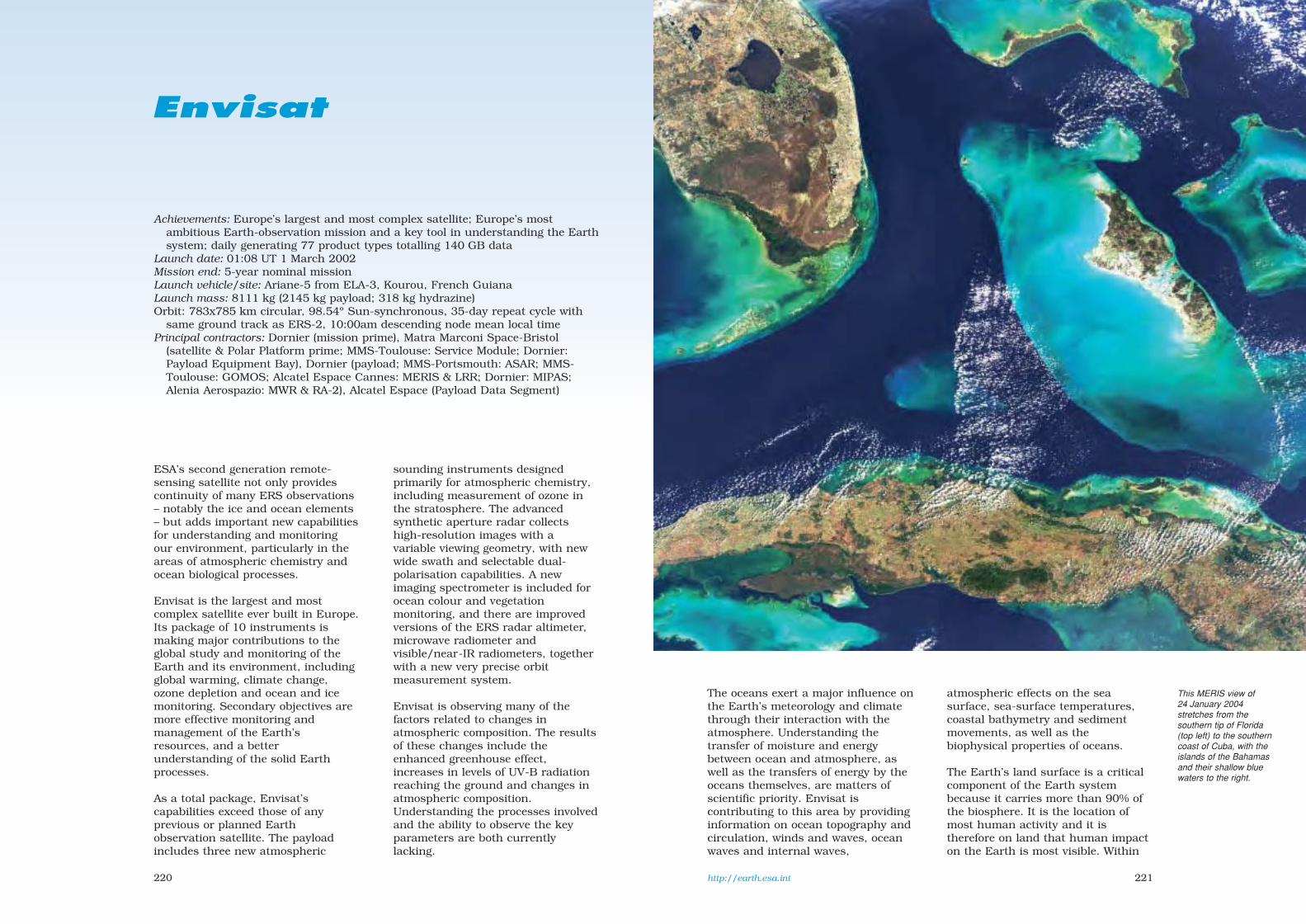
221220
Envisat
Achievements: Europe’s largest and most complex satellite; Europe’s mostambitious Earth-observation mission and a key tool in understanding the Earthsystem; daily generating 77 product types totalling 140 GB data
Launch date: 01:08 UT 1 March 2002Mission end: 5-year nominal missionLaunch vehicle/site: Ariane-5 from ELA-3, Kourou, French GuianaLaunch mass: 8111 kg (2145 kg payload; 318 kg hydrazine)Orbit: 783x785 km circular, 98.54º Sun-synchronous, 35-day repeat cycle with
same ground track as ERS-2, 10:00am descending node mean local timePrincipal contractors: Dornier (mission prime), Matra Marconi Space-Bristol
(satellite & Polar Platform prime; MMS-Toulouse: Service Module; Dornier:Payload Equipment Bay), Dornier (payload; MMS-Portsmouth: ASAR; MMS-Toulouse: GOMOS; Alcatel Espace Cannes: MERIS & LRR; Dornier: MIPAS;Alenia Aerospazio: MWR & RA-2), Alcatel Espace (Payload Data Segment)
The oceans exert a major influence onthe Earth’s meteorology and climatethrough their interaction with theatmosphere. Understanding thetransfer of moisture and energybetween ocean and atmosphere, aswell as the transfers of energy by theoceans themselves, are matters ofscientific priority. Envisat iscontributing to this area by providinginformation on ocean topography andcirculation, winds and waves, oceanwaves and internal waves,
atmospheric effects on the seasurface, sea-surface temperatures,coastal bathymetry and sedimentmovements, as well as thebiophysical properties of oceans.
The Earth’s land surface is a criticalcomponent of the Earth systembecause it carries more than 90% ofthe biosphere. It is the location ofmost human activity and it istherefore on land that human impacton the Earth is most visible. Within
http://earth.esa.int
ESA’s second generation remote-sensing satellite not only providescontinuity of many ERS observations– notably the ice and ocean elements– but adds important new capabilitiesfor understanding and monitoringour environment, particularly in theareas of atmospheric chemistry andocean biological processes.
Envisat is the largest and mostcomplex satellite ever built in Europe.Its package of 10 instruments ismaking major contributions to theglobal study and monitoring of theEarth and its environment, includingglobal warming, climate change,ozone depletion and ocean and icemonitoring. Secondary objectives aremore effective monitoring andmanagement of the Earth’sresources, and a betterunderstanding of the solid Earthprocesses.
As a total package, Envisat’scapabilities exceed those of anyprevious or planned Earthobservation satellite. The payloadincludes three new atmospheric
sounding instruments designedprimarily for atmospheric chemistry,including measurement of ozone inthe stratosphere. The advancedsynthetic aperture radar collectshigh-resolution images with avariable viewing geometry, with newwide swath and selectable dual-polarisation capabilities. A newimaging spectrometer is included forocean colour and vegetationmonitoring, and there are improvedversions of the ERS radar altimeter,microwave radiometer andvisible/near-IR radiometers, togetherwith a new very precise orbitmeasurement system.
Envisat is observing many of thefactors related to changes inatmospheric composition. The resultsof these changes include theenhanced greenhouse effect,increases in levels of UV-B radiationreaching the ground and changes inatmospheric composition.Understanding the processes involvedand the ability to observe the keyparameters are both currentlylacking.
This MERIS view of24 January 2004stretches from thesouthern tip of Florida(top left) to the southerncoast of Cuba, with theislands of the Bahamasand their shallow bluewaters to the right.
sec7 8/1/05 1:23 PM Page 220
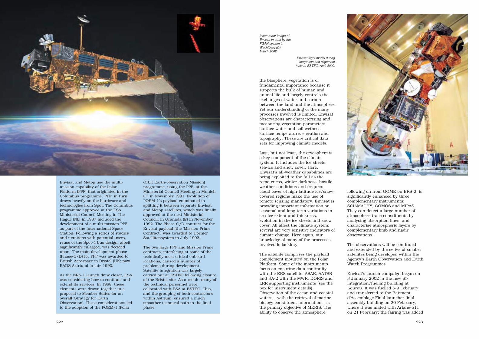
223222
the biosphere, vegetation is offundamental importance because itsupports the bulk of human andanimal life and largely controls theexchanges of water and carbonbetween the land and the atmosphere.Yet our understanding of the manyprocesses involved is limited. Envisatobservations are characterising andmeasuring vegetation parameters,surface water and soil wetness,surface temperature, elevation andtopography. These are critical datasets for improving climate models.
Last, but not least, the cryosphere isa key component of the climatesystem. It includes the ice sheets,sea-ice and snow cover. Here,Envisat’s all-weather capabilities arebeing exploited to the full as theremoteness, winter darkness, hostileweather conditions and frequentcloud cover of high-latitude ice/snow-covered regions make the use ofremote sensing mandatory. Envisat isproviding important information onseasonal and long-term variations insea-ice extent and thickness,evolution in the ice sheets and snowcover. All affect the climate system;several are very sensitive indicators ofclimate change. Here again, ourknowledge of many of the processesinvolved is lacking.
The satellite comprises the payloadcomplement mounted on the PolarPlatform. Some of the instrumentsfocus on ensuring data continuitywith the ERS satellite: ASAR, AATSRand RA-2 with the MWR, DORIS andLRR supporting instruments (see thebox for instrument details).Observation of the ocean and coastalwaters – with the retrieval of marinebiology constituent information – isthe primary objective of MERIS. Theability to observe the atmosphere,
following on from GOME on ERS-2, issignificantly enhanced by threecomplementary instruments:SCIAMACHY, GOMOS and MIPAS.They can detect a large number ofatmosphere trace constituents byanalysing absorption lines, andcharacterise atmospheric layers bycomplementary limb and nadirobservations.
The observations will be continuedand extended by the series of smallersatellites being developed within theAgency’s Earth Observation and EarthWatch Programmes.
Envisat’s launch campaign began on3 January 2002 in the new S5integration/fuelling building atKourou. It was fuelled 6-9 Februaryand transferred to the Batimentd’Assemblage Final launcher finalassembly building on 20 February,where it was mated with Ariane-511on 21 February; the fairing was added
Envisat flight model duringintegration and alignment
tests at ESTEC, April 2000.
Inset: radar image ofEnvisat in orbit by theFGAN system inWachtberg (D),March 2002.
Envisat and Metop use the multi-mission capability of the PolarPlatform (PPF) that originated in theColumbus programme. PPF, in turn,draws heavily on the hardware andtechnologies from Spot. The Columbusprogramme approved at the ESAMinisterial Council Meeting in TheHague (NL) in 1987 included thedevelopment of a multi-mission PPFas part of the International SpaceStation. Following a series of studiesand iterations with potential users,reuse of the Spot-4 bus design, albeitsignificantly enlarged, was decidedupon. The main development phase(Phase-C/D) for PPF was awarded toBritish Aerospace in Bristol (UK; nowEADS Astrium) in late 1990.
As the ERS-1 launch drew closer, ESAwas considering how to continue andextend its services. In 1988, theseelements were drawn together in aproposal to Member States for anoverall ‘Strategy for EarthObservation’. These considerations ledto the adoption of the POEM-1 (Polar
Orbit Earth-observation Mission)programme, using the PPF, at theMinisterial Council Meeting in Munich(D) in November 1991. Evolution ofPOEM-1’s payload culminated insplitting it between separate Envisatand Metop satellites, which was finallyapproved at the next MinisterialCouncil, in Granada (E) in November1992. The Phase-C/D contract for theEnvisat payload (the ‘Mission PrimeContract’) was awarded to DornierSatellitensystem in July 1992.
The two large PPF and Mission Primecontracts, interfacing at some of thetechnically most critical onboardlocations, caused a number ofproblems during development.Satellite integration was largelycarried out at ESTEC following closureof the Bristol site. As a result, many ofthe technical personnel werecollocated with ESA at ESTEC. This,and the grouping of both contractorswithin Astrium, ensured a muchsmoother technical path in the finalphase.
sec7 8/1/05 1:23 PM Page 222

225224
Earth’s newest desert. Once the fourth largest lake in the world, the Aral Sea has lost three-quartersof its volume over the last 40 years, leaving 40 000 km 2 of dry white salt terrain now called theAralkum Desert. The Sea began shrinking in the 1960s when the USSR diverted the Amu Darya andSyr Darya rivers to irrigate the cotton crops of Kazakhstan and Uzbekistan. During the 1980s, littlewater reached the Sea, and evaporation eventually split it into two sections. MERIS, 9 July 2003,300 m full resolution; orbit 7088.
China’s longest river and its second largest lake feature in this 230 km-wide ASAR image of16 August 2003. Dongting Lake is the large L-shaped body of water at lower right. Its size variesconsiderably as flood waters pour from the famous Yangtze River (from top left and exiting at right)into the lake between July and September. The Yangtze is the longest river in Asia and the third inthe world, snaking for 6300 km across China and draining 1.8 million km 2 of territory. Note the oxbowlakes formed on its right bank. Also feeding into Dongting Lake are the Yuan (from left) and theYiang (from bottom). The heart-shaped water body above the Yangtze to the right is Lake Hong,known for its beauty and significant as a site for fishing and crab breeding.
sec7 8/1/05 1:23 PM Page 224

227226
The range of ASARoperating modes.
The wavelength rangesof Envisat’s suite of
instruments.
22 February. The stack wastransported to the pad on 27 February,but two ventilation hoses becamedisconnected in windy conditions andthe assembly returned to BAF forreconnection; it returned to the pad28 February. Envisat separated fromAriane 26 min after launch. The solararray was deployed and stable attitudeachieved within 90 min of leavingKourou. Within 2 days, orbitaladjustments using 29 kg of hydrazinemoved it towards the same groundtrack as ERS-2, although 30 minahead, by 3 April. The ASAR antennawas deployed in stages 2-4 March; theArtemis Ka-band antenna 7 March.ASAR was activated 8 March; the firstimage (of the Amazonian forest) wasreceived 13 March. The Wide Swath
Mode (405 km) was successfully tested14 March. RA2 was commanded intoits main measurement mode12 March. MWR measurements began15 March; MERIS 21 March; AATSR14 March (visible channels only; IRchannel 11 April); GOMOS observed itsfirst occultation 20 March; the firstMIPAS interferogram was acquired24 March after cooling down;SCIAMACHY was activated andhealthy but the first atmosphericspectra were not returned until Aprilbecause the optical covers remainedclosed to avoid pollution from satelliteoutgassing. The Commissioning Phaseended in December 2002; the officialtransition from ‘initial operations’ to‘routine operations’ came on1 September 2003.
Above: 18 months ofSCIAMACHY data onnitrogen dioxide makesclear just how muchhuman activities polluteair quality. NO2 ismainly man-made, frompower plants, heavyindustry and roadtransport, along withbiomass burning.SCIAMACHY’s30x60 km resolutionshows individual cities inN. America and Europe,a very highconcentration above NEChina, and biomassburning across SE Asiaand Africa. Even shiptracks are visible in theRed Sea and from thetip of India to Indonesia.
Envisat installed on itslauncher.(ESA/CSG/Arianespace)
sec7 8/1/05 1:23 PM Page 226

229228
Envisat Payload
Advanced Synthetic Aperture Radar (ASAR) ESA
Improved version of ERS SAR. 5.331 GHz, 1.3x10 m array of twenty 66.4x99.5 cm radiating panels(each 16 rows of 24 microstrip patches). Imaging mode: HH or VV polarisation, 29x30 m/2.5 dBresolution, 7 selectable swaths 100-56 km wide at 15-45º incidence angles, 96.3 Mbit/s, 1365 Wpower consumption. Alternating polarisation mode: HH + VV, 29x30 m/3.5 dB, 7 selectable swaths100-56 km at 15-45º, 96.3 Mbit/s, 1395 W. Wide swath mode: HH or VV, 150x150 m/2.5 dB,405 km swath width in 5 subswaths at 17-42º, 96.8 Mbit/s, 1200 W. Global monitoring mode: HH orVV, 1000x1000 m/1.5 dB, 405 km swath width in 5 subswaths at 17-42º, 0.9 Mbit/s (allowingonboard storage), 713 W. Wave mode: HH or VV, 30 m/2.0 dB, two vignettes of 5x5 km every100 km in any swath at 20-45º, 0.9 Mbit/s, 647 W. Up to 30 min of high-resolution imagery can bereturned on each orbit. 830 kg.
Radar Altimeter (RA-2) ESA
Fully-redundant nadir-pointing pulse-limited radar using 1.2 m-diameter dish at 13.575 & 3.3 GHz.Derived from ERS RA; 3.3 GHz channel added to correct for ionosphere propagation effects. Fixedpulse repetition frequencies of 1800/450 Hz are used respectively by the two channels. Onboardautonomous selection of transmitted bandwidth (20, 80 or 320 MHz) makes possible continuousoperation over ocean, ice and land. Altitude accuracy after ionospheric correction improved to< 4.5 cm for Significant Wave Height up to 8 m. 110 kg, 100 kbit/s, 161 W.
Advanced Along-Track Scanning Radiometer (AATSR) UK/Australia
Continues data from ERS-1/2 ATSR on sea-surface temperatures (accurate to 0.5 K) for climateresearch and operational users. AATSR adds land and cloud measurements for vegetation biomass,moisture, health and growth stage, and cloud parameters such as water/ice discrimination andparticle size distribution. Seven channels: 0.555, 0.67, 0.865, 1.6, 3.7, 10.85 & 12 µm, spatialresolution 1x1 km, swath width 500 km. 101 kg, 625 kbit/s, 100 W.
Scanning Imaging Absorption Spectrometer for Atmospheric Chartography (SCIAMACHY) D/NL
240-2380 nm grating spectrometer (limb/nadir viewing) for detrimental trace gas measurement introposphere/stratosphere. Resolution 2.4 Å UV and 2.2-14.8 Å visible/IR. Swath 1000 km wide innadir mode. 198 kg, 400 kbit/s (1867 kbit/s realtime), 122 W.
Medium Resolution Imaging Spectrometer (MERIS) ESA
MERIS is the first programmable imaging spectrometer. 400-1050 nm, 250 m spatial/12.5 nmspectral resolution (adjustable as required), swath width 1130 km. Water quality measurements,such as phytoplankton content, depth and bottom-type classification and monitoring of extendedpollution. Secondary goals: atmospheric monitoring and land surfaces processes. 207 kg,24/1.6 Mbit/s (full/reduced resolution), 148 W average.
Michelson Interferometer for Passive Atmospheric Sounding (MIPAS) ESA
A Fourier transform spectrometer observing mid-IR 4.15-14.6 µm limb emissions with high spectralresolution (< 0.03 cm-1), allowing day/night measurement of trace gases (including the completenitrogen-oxygen family and several chlorofluorocarbons) in stratosphere and cloud-free troposphere.Global coverage, including poles. 320 kg, 533 kbit/s (8 Mbit/s raw), 195 W.
Global Ozone Monitor by Occultation of Stars (GOMOS) ESA
Two UV to near-IR spectrometers observe setting stars through the atmosphere for 50 m verticalresolution and 0.1% annual variation sensitivity of ozone/related gases. Occultation method is self-calibrating and avoids the long-term instrumental drift problems of previous sensors.Spectrometer A: 2500-6750 Å, resolution 0.3 nm/pixel; B: 9260-9520 Å (H2O) and 7560-7730 Å(O2), resolution 0.05 nm/pixel. The Fast Photometer Detection Module provides 1 kHz 2-bandscintillation monitoring of the star image. 163 kg, 222 kbit/s, 146 W. Switched to redundant side15 July 2003 because of reduction in FOV.
Microwave Radiometer (MWR) ESA
A nadir-viewing 23.8/36.5 GHz Dicke radiometer with 600 MHz bandwidth. ERS MWR designmodified mainly in the mechanical layout and antenna configuration. Radiometric stability < 0.5 Kover 1 year. Periodic onboard calibration by switching receiver input between two references: a hornpointing at the cold sky and a hot radiator at ambient. MWR determines tropospheric column watervapour content by measuring the radiation received from Earth’s surface to correct RA-2 altitudemeasurements. 25 kg, 16.7 kbit/s, 23 W.
Doppler Orbitography & Radio-positioning Integrated by Satellite (DORIS) France
DORIS determines orbit with cm-accuracy. It receives 2.03625 GHz & 401.25 MHz signals fromground beacons and measures the Doppler shift every 7-10 s. 91 kg, 16.7 kbit/s, 42 W. Switched tobackup June 2004.
Laser Retroreflector (LRR) ESA
Precise orbit determination using cluster of laser reflectors mounted close to RA-2.
Dornier
Satellite configuration: 10.5 m long,4.57 m diameter envelope in launchconfiguration; 26x10x5 m deployed inorbit. The satellite comprises the bus(Polar Platform; PPF) and the payload.The PPF is divided into the ServiceModule (derived from Spot-4’s SMand providing power, AOCS andS-band communications) and thePayload Module providing datahandling, power and communicationsfor the payload.
Attitude/orbit control: primary 3-axisattitude control by five 40 Nmsreaction wheels, magnetorquers forfine control (0.1º 3σ). Hydrazinethrusters provide orbit adjust andattitude control. Attitudedetermination by Earth, Sun and starsensors, with gyros. 289 kg hydrazineremained on reaching the operationalorbit; 257 kg @ October 2003; 226 kg@ September 2004.
Power system: single 5x14 m14-panel Si solar wing generates6.5 kW after 5 years (1.9/4.1 kWaverage/peak to payload); eclipsepower provided by eight 40 Ah NiCdbatteries.
Communications: Flight OperationsSegment including Flight OperationsControl Centre at ESOC working viathe primary S-band TT&C station(2/4 kbit/s up/down) at Kiruna-Salmijärvi (S). Payload Data Segmentincluding Payload Data ControlCentre at ESRIN, Payload DataHandling Stations at Kiruna-Salmijärvi (X-band data) and ESRIN(Ka-band data via Artemis), PayloadData Acquisition Station at Matera(I, X-band data) and 6 ProcessingArchiving Centres in F, UK, D, I, E &S. Data transmission by 100 Mbit/schannel for ASAR and one0-32 Mbit/s and nine 0-10 Mbit/schannels for others. Two 70 GB SSRsfor Low Bit Rate (LBR) recording at4.6 Mbit/s, dump 50 Mbit/s; plusHigh Bit Rate (HBR) 100 Mbit/srecord/dump for ASAR high-rate &MERIS full-resolution. Backup taperecorder for LBR. Realtime/recordeddata via three 8.1-8.3 GHz X-bandTWTA direct links and three 26-27 GHz Ka-band via Artemis(steerable 90 cm-diameter antenna on2 m-long mast) at 50 & 100 Mbit/s.Artemis link increases coverage bymore than 30 min per orbit.
sec7 8/1/05 1:23 PM Page 228

231230
ESRO approved development ofEurope’s first applications-satelliteproject in 1972, creating the Meteosatsystem that is now an integral andindispensable part of the world’snetwork of meteorological satellites.The success of the first three pre-operational satellites paved the wayfor the Meteosat OperationalProgramme in 1983 (Meteosat-4/5/6)and the current Meteosat TransitionProgramme (Meteosat-7).
ESA was responsible for developingand operating the system on behalf ofthe newly-created EuropeanOrganisation for the Exploitation ofMeteorological Satellites (Eumetsat),which took direct operational controlon 1 December 1995. The MeteosatSecond Generation (MSG) wasintroduced in 2002 to provideservices until at least 2018. ESAcontinues responsibility fordeveloping and procuring thesesatellites; MSG-1/Meteosat-8 fundingwas shared by ESA (two-thirds) andEumetsat, while MSG-2/3/4 arefunded solely by Eumetsat.
MSG is a significantly enhancedfollow-on system, designed inresponse to user needs for‘nowcasting’ applications andNumerical Weather Prediction (NWP),in addition to providing importantdata for climate monitoring andresearch.
MSG carries the new SpinningEnhanced Visible and Infrared Imager(SEVIRI), improving on its predecessors:
• 12 spectral channels, instead ofthree, to provide more precise dataabout the atmosphere, improving thequality of the starting conditions forNWP models,
• 15-min imaging cycle, instead of 30-min, to provide more timely data fornowcasting, helping in theforecasting of severe weather such as thunderstorms, snow and fog,
• better horizontal image resolution:3 km (vs 5 km) for 11 channels and1 km (vs 2.5 km) for high-resolutionvisible, the latter to help forecastersin detecting small-scale weatherphenomena,
• the all-digital data transmissionincreases performance and datarates.
The Global Earth Radiation Budget(GERB) instrument was selected by ESAas an Announcement of Opportunitypayload for MSG-1. Eumetsat decidedto fund further instruments forMSG-2/3/4. GERB is providing criticaldata on the Earth’s reflected solar andthermal radiation for climate research.
ESA/ESOC delivered MSG-1 to 10.5°W,where it was formally handed over toEumetsat on 25 September 2002 tobegin commissioning. On 17 October2002, SSPA-C in the communication
MSG
Achievements: continues and extends Europe’s geostationary meteorologicalsatellite system
Launch dates: Meteosat-8/MSG-1 22.45 UT 28 August 2002; planned MSG-2 August 2005; MSG-3 2008-2009; MSG-4 2010-2011
Mission end: 2018 (7-year design lives)Launch vehicle/site: Ariane-5 from Kourou, French Guiana Launch mass: MSG-1 2032 kg (dry 1063 kg; 1220 kg BOL GEO)Orbit: geostationary over 0° (MSG-1 3.4°W)Principal contractors: Alcatel Space Industries (Cannes, prime), Astrium SAS
(radiometer), Astrium GmbH (power system, AOCS, propulsion system), AleniaSpazio (Mission Communication Package), Saab-Ericsson Space (Data HandlingSubsystem)
system failed. Although there is aspare SSPA, it was deemed prudent todisseminate processed images to usersinstead through commercial satellites(EUMETCast); MSG-1 continuesdownlinking raw images and its search& rescue and data platform functions.As a result, Meteosat-7 will remain at0° until replaced by MSG-2 at end-2005. The full dissemination servicewill not be implemented until about2009 via MSG-3, with MSG-2 asbackup. EUMETCast will be availablefor the whole mission.
MSG-1 commissioning resumed on26 November 2002, and the firstSEVIRI image was returned on28 November. Commissioning wascompleted 19 Dec 2003. MSG-1 beganmoving from 10.5°W on 14 January2004, and arrived at its newoperational slot over 3.4°W 13 days
http://www.eumetsat.de http://weathertoday.esa.inthttp://www.esa.int/msg/
Right: the first image from MSG-1/Meteosat-8:recorded in the visible channel at 12.15 UT on
28 November 2002. (Eumetsat)
Right below: GERB images on 1 February 2003. Theleft view shows radiances in the shortwave channel,
at right in the total channel.
Below: MSG-1/Meteosat-8 in final configuration atAlcatel Space Industries.
later. It was declared operational on29 January 2004 and renamedMeteosat-8. It will continue to workin parallel with Meteosat-7 untilMSG-2 arrives to assume the primerole at end-2005.
The original design – but nowbeginning with MSG-3 – was fordigital image data and meteorologicalproducts to be disseminated via twodistinct channels: High-Rate ImageTransmission for the full volume ofprocessed image data in compressedform; Low-Rate Image Transmissionfor a reduced set of processed imagedata and other data in compressedform. Different levels of access toHRIT and LRIT data are providedthrough encryption. The Eumetsatcentral processing facility inDarmstadt generates a range ofmeteorological products, including:
sec7 8/1/05 1:23 PM Page 230

The Applications of Meteosat Second Generation
These channels are essential for cloud detection, cloud tracking, sceneidentification and the monitoring of land surfaces and aerosols. Together
with channel 3, they can be used to generate vegetation indices.
Helps to discriminate betweensnow and cloud, and between iceand water clouds. Also provides
aerosol information.
Used mainly to provide quantitativeinformation on thin cirrus cloudsand to support the discrimination
between ice and water clouds.
Responsive to ozone concentrationin the lower stratosphere. It is usedto monitor total ozone and diurnal
variability. Potential for trackingozone patterns as an indicator of
wind fields at that level.
CO2 absorption channel, used forestimating atmospheric instability,
as well as contributing temperatureinformation on the lower
troposphere.
Broadband visible channel, as theprevious Meteosat VIS channel, butwith an improved sampling interval
of 1 km (Meteosat-7: 2.5 km).
Primarily for detection of low cloudand fog at night, but also useful for
measurement of land and seatemperatures at night and the
detection of forest fires.
Provides continuity of the Meteosat first-generation broadband watervapour channel to measure mid-atmospheric water vapour and to producetracers for atmospheric winds. Also supports height assignment for semi-
transparent clouds. Two separate channels representing differentatmospheric layers instead of the single channel on Meteosat-7.
The 'split-window' thermal-IR channels.They have slightly different responsesto the temperatures of clouds and the
surface. Together, they reduce
atmospheric effects when measuringsurface and cloud-top temperatures. Alsocloud tracking for atmospheric winds andestimates of atmospheric instability.
CHANNEL 1: VISIBLE 0.6(0.56-0.71 µm)
CHANNEL 2: VISIBLE 0.8(0.74-0.88 µm)
CHANNEL 7: INFRARED 8.7(8.3-9.1 µm)
CHANNEL 8: INFRARED 9.7(9.38-9.94 µm)
CHANNEL 9: INFRARED 10.8(9.8-11.8 µm)
CHANNEL 10: INFRARED 12.1(11-13 µm)
CHANNEL 11: INFRARED 13.4(12.4-14.4 µm)
CHANNEL 12: HIGH-RES VISIBLE(0.6-0.9 µm)
CHANNEL 3: NEAR-INFRARED 1.6(1.50-1.78 µm)
CHANNEL 4: INFRARED 3.9(3.48-4.36 µm)
CHANNEL 5: WATER VAPOUR 6.2(5.35-7.15 µm)
CHANNEL 6: WATER VAPOUR 7.3(6.85-7.85 µm)
sec7 8/1/05 1:23 PM Page 232

235234
MSG-1 minus its solar array.
Integration of the SEVIRI Engineering Model at AstriumSAS. The telescope stands 1.3 m high, plus the 1.2 m-
high passive cooler for the infrared detectors.
• atmospheric wind vectors atvarious altitudes,
• cloud analysis providingidentification of cloud layers withcoverage, height and type,
• tropospheric humidity at mediumand upper levels,
• high-resolution precipitation index,• cloud-top height images for
aviation meteorology,• clear-sky radiances• global airmass instability,• total ozone product.
In addition to these instruments,MSG receives 100 bit/s DataCollection Platform information fordistribution in near-realtime, and theGEOSAR Search & Rescuetransponder relays 406 MHz distresssignals from ships, aircraft and othervehicles to the COSPAS-SARSATsystem.
Satellite configuration: 3.218 m-dia,3.742 m-high (2.4 m body) steppedcylinder, with SEVIRI field of view at90° to axis for scanning Earth disc.
Attitude/orbit control: operationallyheld within ±1° at 0° longitude (3.4°WMSG-1) by thrusters. Spin-stabilised(by thrusters) at 100 rpm anti-clockwise around main axis parallelto Earth’s axis. Attitude informationfrom Earth horizon and Sun sensors.Bipropellant (MMH/MON-1) UnifiedPropulsion System (94 kg dry) of two400 N apogee engines for 3-burninsertion into GEO and six 10 Nthrusters. Four 75 cm-dia sphereshold up to 976 kg propellant (MSG-1:61.9 kg MMH, 100.4 kg MON-1remained as of May 2005).
Power system: eight panels 2.4 mhigh, 1.25 m wide on cylindrical bodycarry 7854 32x60 mm high-ε Si cells,supported by two 29 Ah 27.5 kg
MSG Earth Observation Payload
Spinning Enhanced Visible and Infrared Imager (SEVIRI)
SEVIRI returns 12 visible/IR full-disc Earth images every 12 min,followed by a 3 min reset period. The 5367 mm-focal length telescopeuses three lightweight Zerodur mirrors. The 51 cm diameter circularmain mirror is combined with a 512x812 mm elliptical scanning mirror,stepped with MSG’s rotation to scan Earth’s disc at 9 km intervals southto north. There are 42 detector elements: 9 for High-Resolution Visible(HRV, 0.5-0.9 µm) and 3 each for the other 11 channels: 0.56-0.71, 0.74-0.88, 1.50-1.78, 3.48-4.36, 8.30-9.10, 9.80-11.80 & 11.00-13.00 µm(enhanced imaging); 5.35-7.15, 6.85-7.85, 9.38-9.94 & 12.40-14.40 µm(air-mass, pseudo-sounding). Data sampling intervals 3 km, except 1 kmfor HRV. 270 kg, 153 W nominal power consumption. First image 28 Nov2003.
Global Earth Radiation Budget (GERB)
Together with SEVIRI, GERB enables study of water vapour and cloudforcing feedback, two of the most important (and poorly understood)processes in climate prediction. It measures Earth’s long- and shortwaveradiation to within 1%; a full scan takes 5 min. Bands: 0.35-4.0 and0.35-30 µm (4.0-30 µm by subtraction). 45x50 km nadir pixel size.Instrument 26 kg, 36 W power consumption, 55 kbit/s data rate.Cooperative project by UK, Italy & Belgium; developed by consortium ledby Rutherford Appleton Laboratory, UK. Data sent from Darmstadt toRAL in near-realtime, processed and forwarded 20 min later to RoyalMeteorological Inst. Belgium for further processing and release to scienceteam in 2 h. Activated 9 Dec 2002; first image 12 Dec 2002.
NiCd batteries, deliver 700 W atequinox after 7 years. Solar arraymass 76 kg.
Communications payload: raw datadownlinked at 3.27 Mbit/s1686.8 MHz L-band using one ofthree (4:3 redundancy) 10 W SSPAsolid-state power amplifiers, togetherwith relayed Data Collection Platformdata, to Eumetsat in Darmstadt,Germany. L-band retransmitsprocessed imagery received at S-bandand other data to users in high/lowrate data streams (up to 1 Mbit/swithout compression). Data volume isa magnitude greater than previousgeneration. (Service not available viaMSG-1.) Telecommand/telemetry atS-band.
Meteosat Third Generation (MTG)
Even as MSG-1 was being prepared for launch, preliminary work wasalready under way on the mission requirements and observationconcepts for the third generation, projected to enter service in 2015.MTG will significantly improve Europe's short-range weatherforecasting, including extreme events, and the monitoring of air qualityand pollution. Consultations with users, beginning with a workshop inNovember 2001, have yielded five candidate observation goals for MTG:high-resolution fast imagery; full-disc spectral imagery; IR sounding;lightning imagery; UV-visible sounding. Pre-Phase-A studies have beenconducted 2002-2005; parallel ESA & Eumetsat Ph-A studies areplanned 2005-2007; Ph-B 2007-2009; Ph-C/D 2009-2014.
sec7 8/1/05 1:23 PM Page 234
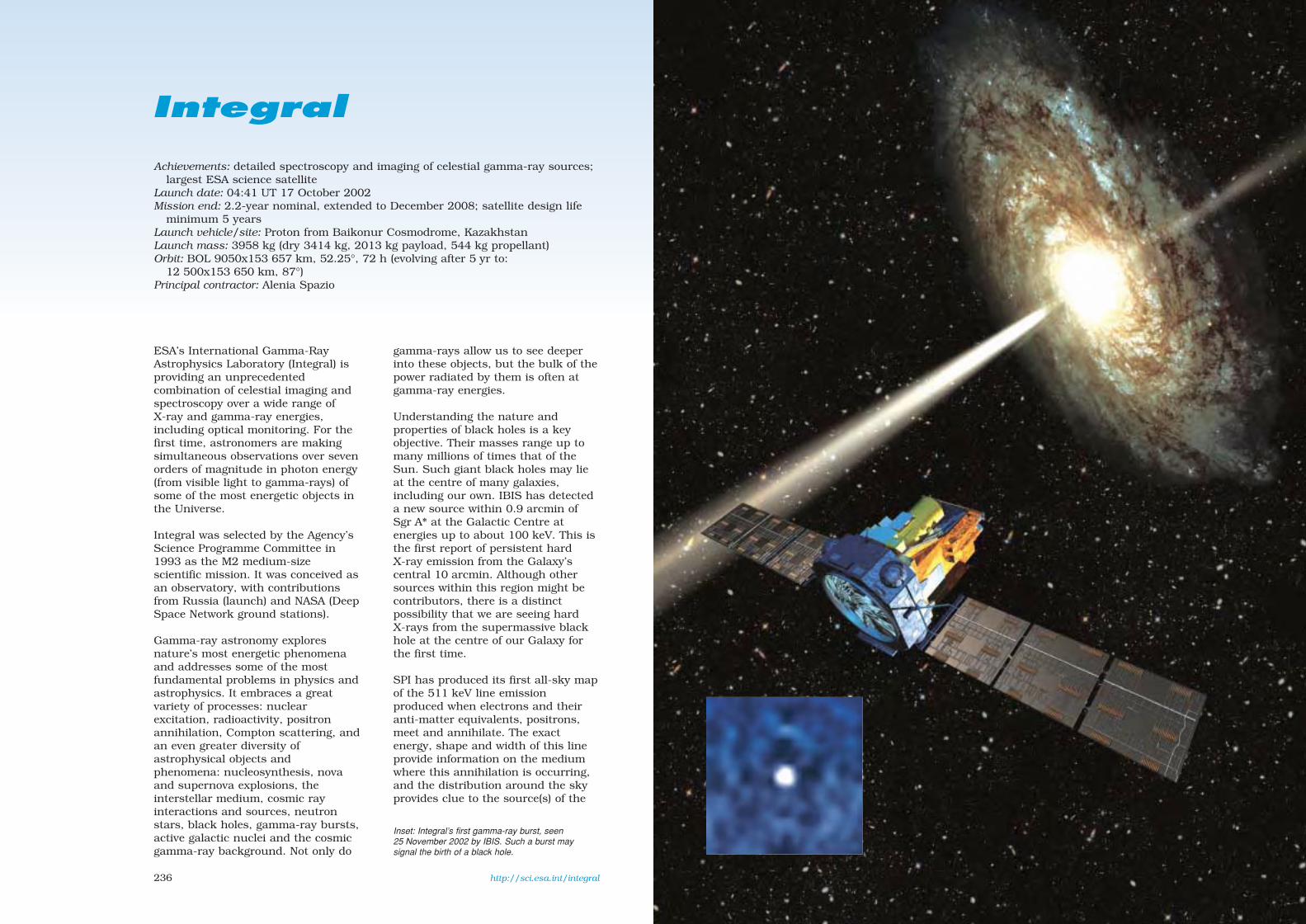
236
ESA’s International Gamma-RayAstrophysics Laboratory (Integral) isproviding an unprecedentedcombination of celestial imaging andspectroscopy over a wide range ofX-ray and gamma-ray energies,including optical monitoring. For thefirst time, astronomers are makingsimultaneous observations over sevenorders of magnitude in photon energy(from visible light to gamma-rays) ofsome of the most energetic objects inthe Universe.
Integral was selected by the Agency’sScience Programme Committee in1993 as the M2 medium-sizescientific mission. It was conceived asan observatory, with contributionsfrom Russia (launch) and NASA (DeepSpace Network ground stations).
Gamma-ray astronomy exploresnature’s most energetic phenomenaand addresses some of the mostfundamental problems in physics andastrophysics. It embraces a greatvariety of processes: nuclearexcitation, radioactivity, positronannihilation, Compton scattering, andan even greater diversity ofastrophysical objects andphenomena: nucleosynthesis, novaand supernova explosions, theinterstellar medium, cosmic rayinteractions and sources, neutronstars, black holes, gamma-ray bursts,active galactic nuclei and the cosmicgamma-ray background. Not only do
gamma-rays allow us to see deeperinto these objects, but the bulk of thepower radiated by them is often atgamma-ray energies.
Understanding the nature andproperties of black holes is a keyobjective. Their masses range up tomany millions of times that of theSun. Such giant black holes may lieat the centre of many galaxies,including our own. IBIS has detecteda new source within 0.9 arcmin ofSgr A* at the Galactic Centre atenergies up to about 100 keV. This isthe first report of persistent hardX-ray emission from the Galaxy’scentral 10 arcmin. Although othersources within this region might becontributors, there is a distinctpossibility that we are seeing hardX-rays from the supermassive blackhole at the centre of our Galaxy forthe first time.
SPI has produced its first all-sky mapof the 511 keV line emissionproduced when electrons and theiranti-matter equivalents, positrons,meet and annihilate. The exactenergy, shape and width of this lineprovide information on the mediumwhere this annihilation is occurring,and the distribution around the skyprovides clue to the source(s) of the
Integral
Achievements: detailed spectroscopy and imaging of celestial gamma-ray sources;largest ESA science satellite
Launch date: 04:41 UT 17 October 2002Mission end: 2.2-year nominal, extended to December 2008; satellite design life
minimum 5 yearsLaunch vehicle/site: Proton from Baikonur Cosmodrome, KazakhstanLaunch mass: 3958 kg (dry 3414 kg, 2013 kg payload, 544 kg propellant)Orbit: BOL 9050x153 657 km, 52.25°, 72 h (evolving after 5 yr to:
12 500x153 650 km, 87°)Principal contractor: Alenia Spazio
Inset: Integral’s first gamma-ray burst, seen25 November 2002 by IBIS. Such a burst maysignal the birth of a black hole.
http://sci.esa.int/integral
sec7 8/1/05 1:23 PM Page 236

239238
anti-matter – one of the mysteriesthat Integral is hoping to solve. Whatis producing the positrons is beinghotly debated. SPI shows theemission is so far seen only towardsthe Galactic Centre, with a spreadthat could be from a galactic bulge orhalo, a bulge and disc, or acombination of point sources. Suchdistributions are expected if the anti-matter is created in X-ray binarystars, novae, Type-Ia supernovae or,more excitingly, by light Dark Matter.Integral has measured the shape ofthe 511 keV line with unprecedentedprecision; it suggests the annihilationis happening in a region with atemperature of at least 7000 K.
Another new high-energy sourcerecently discovered by Integralconcides with the giant molecularcloud Sgr B2 towards the GalacticCentre. Integral and other
observatories strongly support the ideathat the hard X-ray emission of Sgr B2is Compton scattered and reprocessedradiation emitted 300 years ago bySgr A*, the supermassive black holecandidate in the centre of our Galaxy.
A key puzzle solved by Integral is thecontribution of point sources to thediffuse soft gamma-ray background.With its superior ability to see faintand fine details, Integral reveals theindividual sources that comprise thefoggy, soft gamma-ray backgroundseen by previous observatories. Thebrightest 91 objects mapped byIntegral as individual sources almostentirely account for that diffuseemission.
A surprise was the unexpecteddiscovery by Integral of a new type ofhighly absorbed X-ray binary starsthat had escaped detection by other
missions. These objects have hardspectra at high energies and strongphotoelectric absorption, most likelycaused by the stellar wind andaccreting material of the companionstars below a few keV. Fromspectroscopic observations, theseobjects are likely to be high-massX-ray binaries, many of them in thespiral arms Scutum and Norma.
The high-energy sky is highly variableand many objects appear only briefly.Integral has observed many of theseunusual ‘Targets of Opportunity’. Themassive X-ray binary V0332+53(discovered in 1973 by Vela-5B) wasobserved by Integral during anoutburst in early 2005. The binarysystem X0115+63 was observedduring an outburst in September2004. Again, it is a transient pulsarand Integral provided the highestresolution observation ever ofcyclotron lines – radiation fromcharged particles oscillating in astar’s strong magnetic field. The lineenergy varies during the pulse phase,suggesting that the magnetic field ischanging. Another surprise was thedetection by Integral of very hardemission from anomalous X-raypulsars. These systems were knownuntil Integral as young pulsars, withsoft spectra and very strong magneticfields. Integral showed for the firsttime that the spectra are very hardabove 10-20 keV.
Observation of gamma-ray linesproduced during nucleosynthesis isthe main objective for SPI. The511 keV observations of the GalacticCentre revealed a weak disc emissionfrom the positrons produced duringthe radioactive decay of 26Al and 44Ti,two radioactive species producedduring explosive nucleosynthesis insupernova explosions. 26Al is thereby
a key tracer of star formation. Theline has been detected in the Cygnusregion of active star formation. 44Tiemission has been detected from thesupernova remnant Cas A; work isunder way to measure the line widthto help explain the explosionmechanism. Recently, an importantdiscovery was the line emission fromthe decay of 60Fe, another product ofnucleosynthesis at the end of a star’slife. Future mapping should separatethe different stars responsible forcreating 26Al and 60Fe, believed tooccur at different stages of a star’slife cycle.
Active galactic nuclei are importanttargets for Integral. At the centres ofeach AGN is an accretingsupermassive black hole. Dependingon the angle of the surroundingtorus, it can hide the black hole andhot accretion disc from us. Suchgalaxies are known as ‘Seyfert 2’types and are usually faint to opticaltelescopes. Another theory is thatthey are faint because the black holeis not actively accreting gas and thedisc is therefore weak. But Integraland XMM-Newton have found moreevidence that massive black holes aresurrounded by a toroidal gas cloudthat sometimes blocks our view.Looking edge-on into this doughnutfor NGC 4388, features were revealedin unprecedented clarity. Some of thegamma-rays produced close to theblack hole are absorbed by ironatoms in the torus and re-emitted ata lower energy.
One of Integral’s most important objectives is tostudy compact objects such as neutron stars and
black holes. IBIS is imaging them in unprecedenteddetail and SPI is allowing the first detailed physical
analysis at gamma-ray energies. Early observationsincluded simultaneous views by all four instruments
of Cygnus X-1, believed to be a black holeconsuming its giant star companion.
The 511 keV gamma-rays from the Galactic Centreare created by the annihilation of electrons with theiranti-matter twins (J. Knoedlseder/CESR Toulouse).The inset spectrum, the best ever obtained,provides information on the conditions where thegamma-rays are generated. (E. Churazov/IKI/MPI)
Are we seeing the supermassive black hole at thecentre of our Galaxy for the first time? IBIS has
found a new source (arrowed cross) close to theSgr A* galactic nucleus. (G. Belanger/CEA-Saclay
et al.)
sec7 8/1/05 1:23 PM Page 238

241240
Integral’s two main instruments are SPI and IBIS. The fine spectroscopy by SPI permits spectralfeatures to be uniquely identified and line profiles to be determined. The fine imaging capabilityof IBIS within a large field of view accurately locates the gamma-emitting objects withcounterparts seen at other wavelengths, enabling extended regions to be distinguished frompoint sources. These instruments are complemented by two monitors in the X-ray (JEM-X) andoptical (OMC) bands. SPI, IBIS and JEM-X have a common principle of operation: they are allcoded-aperture mask telescopes. This is the key that allows imaging at these high energies,which is all-important in separating and locating sources. The instruments were activated inorder and made their first-light observations: IBIS 20 Oct 2002 (fully operational 7 Nov), OMC21 October, JEM-X & SPI 27 Oct (first JEM-X image 29 Oct). Integral’s early observationsincluded Cygnus X-1, one of the brightest gamma emitters, and thought to be a black holeripping apart a blue-supergiant star. The operational science programme began 30 Dec 2002.
sec7 8/1/05 1:23 PM Page 240

243242
Integral Scientific Instruments
SPI IBIS JEM-X OMCSpectrometer Imager X-ray Monitor Optical Monitor
Energy range 0.018-8 MeV 0.015-10 MeV 3-35 keV 500-850 nm
Detector 19 6x7 cm Ge 16384 CdTe Microstrip CCDcooled to 85 K (4x4x2 mm) Xe-gas (1.5 bar) + V-filter
4096 CsI(9x9x30 mm)
Detector area (cm2) 500 2600 CdTe; 3100 CsI 2x500 2048x1024 pixel
Spectral resolution 2.2 keV 8 keV 1.3 keV –at 1.33 MeV at100 keV at 10 keV
Field of View 16 8x8 4.8 5x5(fully coded, degrees)
Angular res. (FWHM) 2.5º 12 arcmin 3 arcmin 23 arcsec/pixel
10σ source location < 60 arcmin < 1 arcmin < 20 arcsec 6 arcsec
Continuum sensitivity* 8x10⁻⁷ at 1 MeV 7x10⁻⁷ at 100 keV 1.2x10⁻⁴ at 6 keV 18.1m (2000 s)
Line sensitivity* 2x10⁻⁵ at 1 MeV 2x10⁻⁵ at 100 keV 1.6x10⁻⁴ at 6 keV –
Timing accuracy (3σ) 129 µs 61 µs - 1 h 122 µs >3 s
Mass (kg) 1273 731 76 23
Power (W) 384 234 68 26
*sensitivities are 3σ in 106 s, units photons/(cm2 s keV) continuum, photons/(cm2 s) line
SPI
The spectrometer performs spectral analysis of gamma-ray sources and regions with unprecedentedenergy resolution using 19 hexagonal high-purity germanium detectors (2 now failed) cooled byactive Stirling coolers to 85 K. A hexagonal coded-aperture mask 1.7 m above the detection planeimages large regions of the sky. To reduce background radiation, the detector assembly is shieldedby an active scintillator veto system around the bottom and side of the detectors almost up to thecoded mask. Co-PIs J.-P. Roques (CESR Toulouse, France) & R. Diehl (MPE Garching, Germany).
IBIS
The imager provides fine imaging and spectral sensitivity to continuum and broad lines over a wideenergy range, achieved by two layers of detector elements: a front layer of CdTe backed by CsIelements. A tungsten coded-aperture mask 3.2 m above the detection plane is optimised for highangular resolution. The two layers of detectors allow the photons to be tracked in 3D as they scatterand interact with elements. The aperture is restricted by a lead tube system and shielded in all otherdirections by an active scintillator veto system. PI: P. Ubertini (IASF Rome, Italy).
JEM-X
The X-ray monitor is crucial for identifying gamma sources by making observations simultaneouslywith the main gamma-ray instruments. Two identical imaging microstrip gas chambers each viewthe sky through a coded-aperture mask positioned 3.2 m above the detection plane. PI: N. Lund (Danish Space Research Institute, Denmark).
OMC
The optical monitor consists of a passively cooled CCD in the focal plane of a 50 mm lens. It offersthe first opportunity for making long-duration V-band optical observations simultaneously withthose at X/gamma-rays. Variability patterns from tens of seconds up to years are monitored.PI: M. Mas-Hesse (INTA Madrid, Spain).
IREM (Integral Radiation Environment Monitor): provides electron (> 0.5 MeV) & proton (> 20 MeV)counts to instruments so they can turn off their detectors to avoid damage from particle radiation.
Integral regularly sees Gamma-rayBursts (GRBs) as serendipitoussources in its large field of view. Anautomatic ground system detects theGRBs and instantly alertsastronomers worldwide to performcrucial follow-up observations atother wavelengths. Thanks to thisservice, a GRB seen on 3 December2003 was thoroughly studied byIntegral and an armada of space andground observatories. GRB 031203proved to be the closest gamma-rayburst on record, and the faintest. Itsuggests that an entirely new familyof weaker bursts was going unnoticeduntil Integral.
Satellite configuration: 5 m high, bodydiameter 3.7 m, 16 m span acrosssolar wings. The Service Module(SVM) design, including power, datahandling and attitude/RCS, is reusedfrom the XMM mission, with minormodifications. The scienceinstruments are accommodated inthe Payload Module (PLM), designedto be tested separately and thenattached to the SVM via simpleinterfaces.
Attitude/orbit control: four ReactionWheels, two Star Trackers, four InertialMeasurements Units, a RateMeasurement Unit, three Fine SunSensors and three Sun AcquisitionSensors provide 3-axis control. Pointingaccuracy better than 15 arcmin, with a
Left: the Integral FlightModel ready for payloadintegration at AleniaSpazio. Right: Integral’sStructural and ThermalModel (STM) at ESTECin 1998. The patternedcoded-aperture mask forIBIS is visible at topright. SPI is thecylindrical unit at left.
drift of 4 arcsec/h. Hydrazine thrustersprovide orbit adjust, attitude controland wheel desaturation: four pairs(primary + redundant) of 20 Nblowdown (24-5.5 bar) thrusters sit onthe SVM base, supplied by four inter-connected 177-litre titaniumpropellant tanks. Hydrazine loading543.7 kg (+4.2 kg pressurant);reached operational orbit with182.7 kg, sufficient for >15 yr.Released by Proton into643.3x152 094 km, 51.71º, Raisedperigee at 3-5th apogees + 5th perigeepasses to attain final9050x153 657 km, 52.25º (target:9000x153 600 km, 51.6º) by 1 Nov.
Power system: two fixed solar wings,each of three 1.81x1.94 m rigidpanels of Si cells totalling 21 m2,sized to provide 1600 W after10 years. 28 V main bus; provided2380 W BOL. Eclipse power from two24 Ah 41 kg NiCd batteries.
Communications: science data rate112 kbit/s in realtime (no onboardstorage) to ESA Redu & NASAGoldstone ground stations. Controlledfrom ESOC; science data routed byESOC to the Integral Science DataCentre (provided by the usercommunity) in Geneva, Switzerland.The Integral Science OperationsCentre (initially at ESTEC but movedto ESAC in February 2005) plans theobservations for uplinking by ESOC.
sec7 8/1/05 1:23 PM Page 242
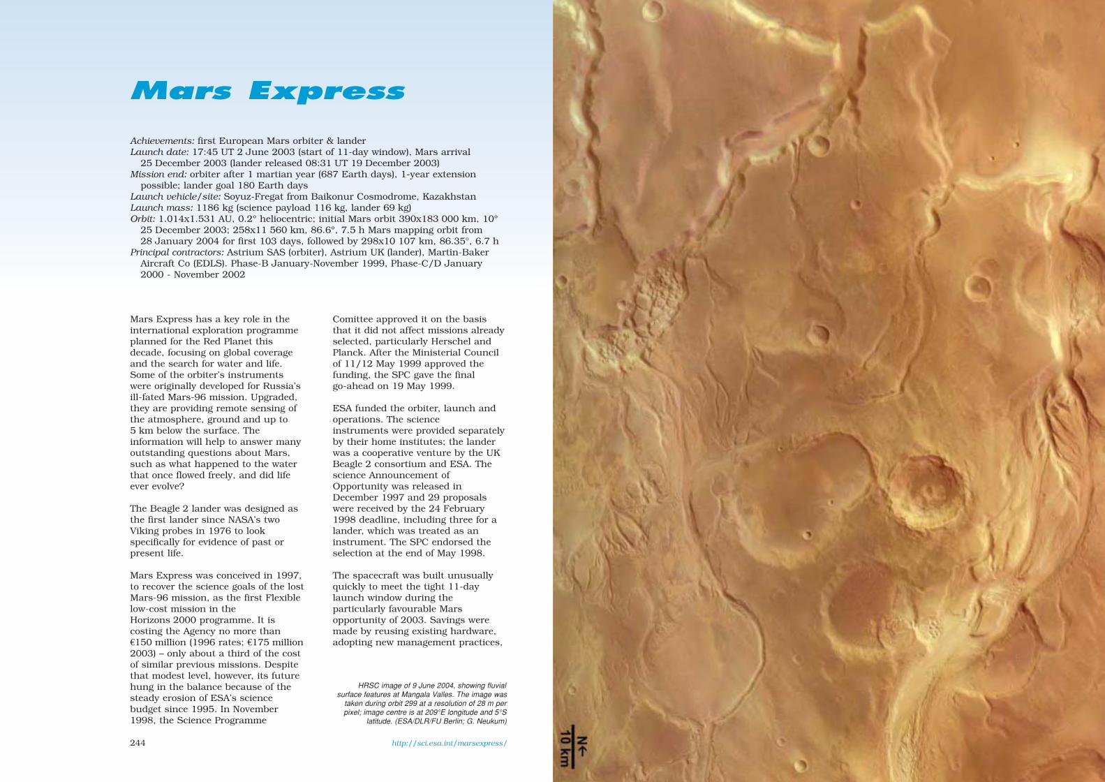
244
Mars Express
Achievements: first European Mars orbiter & landerLaunch date: 17:45 UT 2 June 2003 (start of 11-day window), Mars arrival
25 December 2003 (lander released 08:31 UT 19 December 2003)Mission end: orbiter after 1 martian year (687 Earth days), 1-year extension
possible; lander goal 180 Earth days Launch vehicle/site: Soyuz-Fregat from Baikonur Cosmodrome, KazakhstanLaunch mass: 1186 kg (science payload 116 kg, lander 69 kg)Orbit: 1.014x1.531 AU, 0.2º heliocentric; initial Mars orbit 390x183 000 km, 10º
25 December 2003; 258x11 560 km, 86.6º, 7.5 h Mars mapping orbit from28 January 2004 for first 103 days, followed by 298x10 107 km, 86.35°, 6.7 h
Principal contractors: Astrium SAS (orbiter), Astrium UK (lander), Martin-BakerAircraft Co (EDLS). Phase-B January-November 1999, Phase-C/D January2000 - November 2002
Mars Express has a key role in theinternational exploration programmeplanned for the Red Planet thisdecade, focusing on global coverageand the search for water and life.Some of the orbiter’s instrumentswere originally developed for Russia’sill-fated Mars-96 mission. Upgraded,they are providing remote sensing ofthe atmosphere, ground and up to5 km below the surface. Theinformation will help to answer manyoutstanding questions about Mars,such as what happened to the waterthat once flowed freely, and did lifeever evolve?
The Beagle 2 lander was designed asthe first lander since NASA’s twoViking probes in 1976 to lookspecifically for evidence of past orpresent life.
Mars Express was conceived in 1997,to recover the science goals of the lostMars-96 mission, as the first Flexiblelow-cost mission in theHorizons 2000 programme. It iscosting the Agency no more than€150 million (1996 rates; €175 million2003) – only about a third of the costof similar previous missions. Despitethat modest level, however, its futurehung in the balance because of thesteady erosion of ESA’s sciencebudget since 1995. In November1998, the Science Programme
Comittee approved it on the basisthat it did not affect missions alreadyselected, particularly Herschel andPlanck. After the Ministerial Councilof 11/12 May 1999 approved thefunding, the SPC gave the finalgo-ahead on 19 May 1999.
ESA funded the orbiter, launch andoperations. The science instruments were provided separatelyby their home institutes; the landerwas a cooperative venture by the UKBeagle 2 consortium and ESA. Thescience Announcement ofOpportunity was released inDecember 1997 and 29 proposalswere received by the 24 February1998 deadline, including three for alander, which was treated as aninstrument. The SPC endorsed theselection at the end of May 1998.
The spacecraft was built unusuallyquickly to meet the tight 11-daylaunch window during theparticularly favourable Marsopportunity of 2003. Savings weremade by reusing existing hardware,adopting new management practices,
http://sci.esa.int/marsexpress/
HRSC image of 9 June 2004, showing fluvialsurface features at Mangala Valles. The image was
taken during orbit 299 at a resolution of 28 m perpixel; image centre is at 209°E longitude and 5°S
latitude. (ESA/DLR/FU Berlin; G. Neukum)
sec7 8/1/05 1:23 PM Page 244

246
shortening the time from originalconcept to launch, and procuring themost cost-effective launcher available.Maximum use was made of off-the-shelf and Rosetta technology – 65% ofthe hardware was at least partiallyderived from the Rosetta cometarymission. ESA delegated tasks toAstrium SAS in Toulouse (F) thatpreviously would have beenperformed by the project team atESTEC. In particular, Astriummanaged the orbiter/payload andorbiter/launcher technical interfaces.The period from concept to awardingthe design and development contractwas cut from about 5 years to littlemore than 1 year. Astrium SAS wonthe €60 million fixed-price primecontract in December 1998 in
competition with consortia led byAlenia/Aerospatiale and Dornier. ThePhase-B/C/D design anddevelopment phase took less than4 years, compared with up to 6 yearsfor previous similar missions.
Previous missions raised manyquestions about Mars. What forcescreated the spectacular landscapefeatures? When did they stop – or arethey still active? Was early Marsreally warm and wet? If so, where didthe water and atmosphere go? Did lifeevolve there? And is primitive life stillthriving, perhaps in undergroundaquifers? Mars Express is helping toprovide answers by mapping thesubsurface, surface, atmosphere andionosphere from orbit, and planned to
Mars Express Science Goals
– image the entire surface at highresolution (10 m/pixel) and selected areasat super-high resolution (2.3 m/pixelfrom 250 km)
– map the mineral composition of thesurface at 100 m resolution
– map the composition of the atmosphereand determine its global circulation
– determine the structure of the subsurfacedown to a few kilometres
– determine the effect of the atmosphere onthe surface
– determine the interaction of theatmosphere with the solar wind
Beagle 2 lander:– determine the geology and mineral
composition of the landing site– search for life signatures (exobiology)– study the weather and climate
OMEGA was activated on 18 January 2004 andobserved the southern polar cap of Mars. At right isthe visible image; in the middle is carbon dioxideice; at left is water ice. The two types of ice aremixed in some areas but distinct in others.(ESA/IAS, Orsay; J-P. Bibring)
This HRSC vertical view shows the complex calderaat the summit of Olympus Mons, the highest
volcano in the Solar System. The average elevationis 22 km; the caldera has a depth of about 3 km.
This is the first high-resolution colour image of thecomplete caldera, taken from a height of 273 km
during revolution 37 on 21 January 2004. Centred at18.3°N/227°E, the image is 102 km across with a
resolution of 12 m/pixel; south is at the top.(ESA/DLR/FU Berlin; G. Neukum)
sec7 8/1/05 1:24 PM Page 246

249
Express entered an initial orbit of390x183 000 km, 10º. An apogeeburn on 30 December made theinclination the final 86.6º. The firstpericentre was reached at 13:05 UT4 January. The mapping orbit of258x11 560 km, 86.6º was reachedon 28 January 2004 after a series ofapogee-reduction manoeuvres.
Following completion of orbitercommissioning in mid-January 2004,most instruments began their owncalibration and testing, in the processacquiring scientific data. PFS was thefirst to make observations, on4 January, even before the first peri-centre. OMEGA followed on 8 January,HRSC & SPICAM on 9 January andASPERA on 14 January. MaRSperformed its first bistatic radarexperiment on 21 January using the70 m DSN dish in Australia; the firstdirect tracking was performed21 January.
will look for underground water andice. This will be the first time that aground-penetrating radar has beenused in space.
A precise inventory of existing wateron the planet (ice or liquid, mostlybelow ground) is important given itsimplications for the potentialevolution of life on Mars; the3.8 billion-year age is precisely whenlife appeared on Earth, whichharboured similar conditions to Marsat that time. Thus, it is notunreasonable to imagine that life mayalso have emerged on Mars andpossibly survived the intense UVsolar radiation by remainingunderground. The confirmation ofmethane in the atmosphere by PFSindicates just that or the presence ofactive volcanism.
Following a 34 min burn ending at03:21 UT 25 December 2003, Mars
248
conduct observations andexperiments on the surface.Investigations are also providingclues as to why the north is sosmooth while the south is so rugged,how the Tharsis and Elysium bulgeswere raised and whether there arestill active volcanoes. Not only doesMars have the largest volcanoes anddeepest canyons in the Solar System,it also shows evidence for the mostcatastrophic floods. Large channelscarved by these floods drain into thenorthern plains, lending support forthe existence of an ancient ocean overmost of the northern hemisphere.Valley networks that criss-cross thesouthern highlands were alsoprobably formed by water. And manycraters, especially at high latitudes,are surrounded by fluidised ejecta.This suggests there was undergroundwater or ice at the time of impact,and possibly more recently. Water isthe unifying theme of the mission.
If water was largely responsible forthese features, however, it has longsince disappeared: most of theevidence is more than 3.8 billionyears old. Today, atmosphericpressure at ground level is onlyabout 1% that on Earth. So wheredid the gases and water go and why?Each of the orbiter’s seveninstruments will contribute towardsthe answer.
The water could have been lost tospace and/or trapped underground.Four orbiter experiments (ASPERA,SPICAM, PFS, MaRS) are observingthe atmosphere and revealingprocesses by which water vapour andother atmospheric gases could haveescaped into space. Two (HRSC,OMEGA) are examining the surfaceand in the process adding toknowledge about where water mayonce have existed and where it couldstill lie underground. One (MARSIS)
Inset: Beagle 2 driftsslowly from MarsExpress. This image,taken at 08:33 UT19 December 2003 by asmall engineeringcamera aboard theorbiter, shows the entrycapsule when it wasabout 20 m away.
Water ice in a 35 km-diameter crater on theVastitas Borealis plain,which covers much of
Mars’ far northernlatitudes. HRSC
obtained thisperspective view on
2 February 2005 at aresolution of 15 m per
pixel. (ESA/DLR/FUBerlin; G. Neukum)
sec7 8/1/05 1:24 PM Page 248

251
1 MARSIS2 HRSC
3 OMEGA4 SPICAM
5 PFS6 ASPERAMaRS (no
additionalhardware)
6
1
23
5
4
HRSC
thrusters (4x2)
UHF antennas
ASPERAOMEGA
PFS
low-gain antenna (x2)
reaction wheels (x4)
250
Commissioning lasted until 3 June2004, when all the instrumentsexcept MARSIS began routineoperations. The deployment of theMARSIS radar antennas, however,was postponed. It was initiallyplanned to begin after 20 April toallow the other instruments to takeadvantage of the good lightingconditions before the pericentrenaturally drifted to southernlatitudes, which coincides with thenightime conditions required forsubsurface sounding by MARSIS.However, new studies by JPL of theUS-supplied MARSIS booms showedthe potential for the two 20 m-longbooms to strike the orbiter during the10 min deployment; the decision wastaken 25 April to postpone releaseuntil later in the mission when theother instruments had achieved theirprimary objectives. The ESA reviewboard gave its approval 25 January2005, and deployment was successfulin May-June 2005.
HRSC is providing breathtaking viewsof the planet, particularly in regionsnear the Valles Marineris canyon(pointing to liquid water asresponsible for modifying tectonic andimpact features in the area) and ofseveral large volcanoes (the OlympusMons caldera and glaciation featuressurrounding Hecates Tholus).OMEGA has provided unprecedentedmaps of water-ice and carbondioxide-ice at the south pole. PFS hasconfirmed the presence of methanefor the first time, which wouldindicate current volcanic activityand/or biological processes. SPICAMhas provided the first completevertical profile of carbon dioxidedensity and temperature, and hassimultaneously measured thedistribution of water vapour andozone. ASPERA has identified the
solar wind interaction with the upperatmosphere, and has measured theproperties of the planetary wind inMars’ magnetic tail. MaRS hasmeasured surface roughness for thefirst time by pointing the high-gainantenna towards the planet andreflecting the signal to Earth. Also,the martian interior is being probedby studying the gravity anomaliesaffecting the orbit owing to massvariations of the crust.
Beagle 2 was released at 08:31 UT19 December 2003 to enter theatmosphere at more than20 000 km/h on its way to landing at02:52 UT 25 December. Contact wasattempted by the NASA Mars Odysseyorbiter, several Earth-based radiotelescopes and later by the MarsExpress orbiter itself, but no signalwas ever received. It was declared lost6 February 2004; it is unknown ifBeagle 2 arrived on the surfaceintact. An ESA investigation wasunable to pinpoint a single cause forthe failure.
Orbiter configuration: box-shaped bus1.5x1.8x1.4 m of conventionalaluminium construction. Dry mass637 kg.
Attitude/orbit control: orbit correction& Mars insertion by single 400 NNTO/MMH thruster, attitude controlby 8x10 N hydrazine thrusters(457 kg in 2 tanks totalling 580 litres)and 4x12 Nms reaction wheels.Pointing accuracy 0.15º supported by2 star trackers, 6 laser gyros,2 coarse Sun sensors.
Power system: twin 4-panel Si solarwings derived from Globalstartotalling 11.42 m2 to provide 650 W atMars (500 W required). Post-launchtesting showed up to 30% lost owing
Mars Express ready forinstallation on its
launcher at Baikonur.
sec7 8/1/05 1:24 PM Page 250

253
drive mass. Collects sample in tipcavity, wound back in from up to 3 mby power cable for sample delivery toinstruments. Grinder/corer to exposefresh rock surfaces and could drill1 cm deep for 2 mm-dia 60 mgsample.
Power provided by GaAs arraytotalling 1 m2 on 5 panels, supportedby 200 Wh Li-ion battery. 128 Kbit/sdata link by 400 MHz UHF 5 Wtransmitter via patch antennas toorbiter. Goal for surface operationswas 180 Earth days.
252
to faulty connection between solararray and power conditioning unit.Supported by 3x22.5 Ah Li-ionbatteries.
Thermal control: aluminium/tin alloyblankets keep interior at 10-20ºC.
Communications: via 1.6 m-dia 65 WX-band HGA to 34 m New Norcia,Perth ground station and NASA DSNat up to 230 kbit/s from 12 GbitSSR. Daily download 0.5-6 Gbit,depending on Earth-Mars geometry.UHF antenna to receive Beagle 2data (commands were relayed toNASA’s Spirit Mars rover for the firsttime 6 February 2004, and imagesreceived from it). Processed data areplaced in public archive at ESTECafter 6 months. Controlled fromMission Operations Centre, ESOC.
Beagle 2 configuration: lander66 cm-dia, 22 cm-high, primarystructure carbon-fibre skin onaluminium honeycomb; 69 kg (33 kg
on surface, 8.90 kg scienceinstruments). Powered up shortlybefore ejection from orbiter.Comprised lander and Entry, Descent& Landing System (EDLS), drawingheavily on Huygens heritage. EDLSprovided a front shield/aeroshell andback cover/bioshield. Mortar firedthrough patch in back shield todeploy 3.2 m-dia drogue ’chute andthen 7.5 m-dia main ’chute; frontshield released pyrotechnically. Three2 m-dia gas-bags inflated. Oncontact, ’chute released for lander tobounce away. Coming to rest, thelacing was cut for the bags to open.Beagle’s clam-shell lid opened tobegin the science phase. Most scienceinstruments mounted on arm with75 cm reach: stereo camera,microscope, two spectrometers(Mössbauer and X-ray), lamp, moleand corer/grinder.
DLR’s Pluto (planetary undersurfacetool) mole could crawl 1 cm in 6 s byusing spring compression to propel a
Mars Express Scientific Instruments
HRSC Super/High-Resolution Stereo Colour Imager. Push-broom scanning camera, 9 CCDs. 10 m global res, 2 m res selected areas. 20 kg, 40 W, 25 Mbit/s. PI: Gerhard Neukum, Freie Universität Berlin (D). Participating countries: D, F, RU, US, FIN, I, UK
OMEGA Visible/IR Mineralogical Mapping Spectrometer. Mineral mapping at 100 m res,Specific surface mineral and molecular phases, mapping photometric units, atmospheric particles. 0.5-5.2 µm. 30 kg, 42 W, 500 kbit/s.PI: Jean-Pierre Bibring, Institut d’Astrophysique Spatiale (Orsay, F). Participating countries: F, I, RU
PFS Planetary Fourier Spectrometer. Atmospheric composition & circulation, surface mineralogy, surface-atmosphere interactions. 1.2-45 µm. 32 kg, 35 W, 33 kbit/s.PI: Vittorio Formisano, Istituto Fisica Spazio Interplanetario (Frascati, I). Participating countries: I, RU, PL, D, F, E, US
MARSIS Subsurface Sounding Radar/Altimeter. Subsurface structure from 200 m to few km, distribution of water in upper crust, surface roughness and topography, ionosphere. 40 m-long antenna, l1.3-5.5 MHz RF waves, 17 kg, 60 W, 30 kbit/s.PI: Giovanni Picardi, Universita di Roma La Sapienza (Rome, I). Participating countries: I, US, D, CH, UK, DK
ASPERA Energetic Neutral Atoms Analyser. Upper atmosphere interaction with interplanetary medium & solar wind (lack of a magnetic field is believed to have allowed the solar windto sweep away most of Mars’ atmosphere); near-Mars plasma and neutral gas environment. 9 kg, 12 W, 6 kbit/s. PI: Rickard Lundin, Swedish Institute of Space Physics (Kiruna, S). Participating countries: S, D, UK, F, FIN, I, US, RU
SPICAM UV and IR Atmospheric Spectrometer. Water (1.30 µm), ozone (250 nm UV) & dust profiles of atmosphere by stellar occultation. 6 kg, 12 W, 6 kbit/s. PI: Jean-Loup Bertaux, Service d’Aeronomie du CNRS (Verrieres-le-Buisson, F). Participating countries: F, B, RU, US
MaRS Radio Science Experiment. Atmospheric density, P & T profiles, ionospheric electrondensity profiles (passage of radio waves through atmosphere), surface dielectric and scattering properties (reflection of radio waves) and gravity anomalies (orbital tracking). PI: Martin Paetzold, Köln University (D). Participating countries: D, F, US, A
Beagle 2 360º panoramic stereo camera & microscope (surface textures, 4 µm res; Mullard Space Science Lab.), X-ray spectrometer (in situ chemical composition; Leicester Univ.), Mössbauer spectrometer (Fe minerals, inc. carbonates, sulphates, nitrates; MPI fürChemie), Gas Analyser Package (GAP; carbon, gas isotopes, trace constituents; Open Univ.), Environmental Sensor Suite (T, P, wind speed/direction, 200-400 nm UV flux, solar protons/cosmic rays, dust impacts; 0.180 kg; Leicester Univ./Open Univ.), mole & corer/grinder (DLR Inst. Space Simulation & Polytechnic Univ. of Hong Kong). Lander surface mass 33 kg (instruments 9 kg, 40 W, 128 Kbit/s). PI: Colin Pillinger, Open Univ. (Milton Keynes, UK). Participating countries: UK, D, F, HK, CH
Beagle 2 as it wouldhave appeared on the
surface of Mars.
sec7 8/1/05 1:24 PM Page 252

http://sci.esa.int/smart/254
SMART-1
Achievements: first European lunar orbiter, first global map of lunar elements,new technologies tested, first electric thruster-powered gravity assist
Launch date: 23:14 UT 27 September 2003 Mission end: nominally August 2006 Launch vehicle/site: Ariane-5 from Kourou, French GuianaLaunch mass: 367 kg (19 kg science payload)Orbit: initial 656x35 881 km, 7.0º GTO; operational lunar orbit 471x2880 km,
90.1°, 4.97 h from 28 February 2005, with perilune over South Pole Principal contractors: Swedish Space Corp (prime), SNECMA (plasma thruster),
APCO (bus structure), Saab Ericsson Space (integration, test, thermal, RTUs,harness), Fokker Space (solar array), CRISA (battery management electronics),Primex (hydrazine system); Phase-A May – September 1997, Phase-B April 1998– June 1999, Phase-C/D October 1999 – September 2003
SMART-1 is the first of the SmallMissions for Advanced Research inTechnology of ESA’s Horizons 2000science plan. Its principal missionis to demonstrate innovative andkey technologies for deep-spacescience missions. Its primaryobjective is to flight test SolarElectric Primary Propulsion (SEPP)for future large missions; theBepiColombo Mercury mission willbe the first to benefit, followed bySolar Orbiter and LISA.
ESA’s Science ProgrammeCommittee (SPC) in November 1998approved a lunar-orbiting missionas the baseline, with the possibilityof extending it to a flyby of a near-Earth asteroid. The SPC approvedthe €84 million (1999 rates) sciencefunding in September 1999; theprime and launch contracts weresigned in November 1999. Totalcost to ESA is €110 million (2004rate). The low budget meant that alow-cost launch and a new procure-ment and management approachhad to be adopted. SMART-1 wastherefore launched as an auxiliarypayload on a commercial Ariane-5launch into GTO. The SEPP used its70 mN Hall-effect xenon plasmathruster to spiral out from GTOover 10 months for lunar capturebefore spiralling down to a polarlunar orbit.
The SPC confirmed the selectedscience payload in November 1999following AOs in March 1998(science) and April 1998 (technology).It includes a 5° field-of-viewmulticolour micro-camera (AMIE)with high resolution and sensitivityeven for lunar polar areas. Thecompact IR spectrometer (SIR) ismapping lunar minerals and lookingfor water ice in eternally shadowedcraters. The X-ray mappingspectrometer (D-CIXS) is generatingthe first global map of the majorrock-forming elements, following itsX-ray monitoring of very brightcosmic sources during the cruise. Theabsence so far of global maps of
SMART-1 in the finalassembly building at
Kourou, 18 September2003, ready for
encapsulation on itslauncher. (ESA/CSG)
sec7 8/1/05 1:24 PM Page 254

257256
magnesium, aluminium and siliconabundances is a serious hurdle tounderstanding the Moon. The XSMsolar X-ray monitor also performedspectrometric observations of the Sunduring the cruise. The lightweightSPEDE characterised the natural andinduced plasma environment aroundthe spacecraft. The complementaryEPDP technology package monitoredthe plasma and contaminationcreated by the SEPP thruster. TheRSIS radio science investigation isusing the KATE X-Ka radiotransponder technology payload toperform several experiments. One, inconjunction with AMIE, is measuringlunar libration as a demonstration ofthe crucial BepiColombo investigationof Mercury’s internal structure.
AMIE has helped to validate deep-space optical communications(LaserLink Experiment) using ESA’sOptical Ground Station at the TeideObservatory in Tenerife. The cameraalso validated the OBAN autonomousnavigation experiment based onimage processing. For the spacecraftbus, a combination of off-the-shelfhardware and innovative applicationwere used. For example, thecommunications bus was inheritedfrom the automotive industry.
In synergy with its technologyobjectives, SMART-1 provides anopportunity for lunar scienceinvestigations. These include studiesof the chemical composition andevolution of the Moon, of geophysicalprocesses (volcanism, tectonics,cratering, erosion, deposition of icesand volatiles) for comparativeplanetology, and high-resolutionstudies in preparation for futuresteps in lunar exploration. Themission is also addressing severaltopics such as the accretional
processes that led to the formation ofplanets, and the origin of the Earth-Moon system. SMART-1 is alsopreparing the scientific community forthe BepiColombo mission.
SMART-1 was released by its Ariane-542 min after liftoff, into a656x35 881 km, 7.0º GTO. The electricthruster was fired for the first time foran hour beginning 12:25 UT on30 September. By the end of January2004, SMART-1 had completed morethan 200 orbits of Earth, with allfunctions normal. It had accumulatedmore than 1700 h of thrusting, using27.1 kg of Xe for a delta-V of1.22 km/s to reach a highly ellipticorbit of 14 312x59 491 km, period of24 h 53 min, optimised to limit thelength of the eclipses in March 2004.After 4 months of repeated passagesthrough the near-Earth radiation beltsand suffering heavily from energeticparticle events, SMART-1 reached amuch gentler environment on7 January when perigee rose above20 000 km. With the ion engineswitched off on 30 January 2004, thenext 3 weeks were used to commissionthe payload. A first test image of theMoon was obtained by AMIE on
18 January. The efficiency of theelectric propulsion system and thehigher level of electric power available(resulting from low solar celldegradation and lower powerconsumption) meant that SMART-1was expected to arrive at the Moonearlier than the Spring 2005anticipated at launch, and would notrequire lunar swingbys. The fuelefficiency meant that operators couldaim for an operational orbit of only300 km altitude over the South Poleand 3000 km over the North Pole (pre-launch goal of 300-2000 x 10 000 km),and then raise the orbit to a morestable altitude after 6 months ofscience investigations.
Instead, three ‘lunar resonantapproaches’, on 19 August,15 September & 12 October 2004,used the Moon’s gravity to raise theperigee and change the inclination.After the third, SMART-1’s orbit was ageocentric 173 339x298 835 km,20.6º. SMART-1 passed through theweak stability boundary region at theEarth-Moon L1 point on 11 Novemberand passed into the Moon’s sphere ofinfluence. The ion thruster wasreignited at 05:24 UT on 15 November
as SMART-1 headed towards captureby the Moon and its first perilune at17:48 UT over the South Pole,establishing a stable lunar orbit of4962 x 51 477 km, 81º, 89 h. To reachthe Moon, it had orbited the Earth 332times, travelling 84 million km, whilefiring its ion thruster 289 times for atotal of 3700 h, consuming 59 kg ofthe 82 kg of xenon.
By the 9th apolune passage on4 December 2004, the orbit had beenreduced to 5455 x 20 713 km, 83.0º,37.30 h. By the 12th perilune passageon 9 December, the 20 periods ofthrusting totalling 333 h beginning15 November had reduced the periodto 29 h. The science operational orbitof 471 x 2880 km, 90.06º, 4.97 h wasreached on 28 February 2005, allowing6 months of science observations tobegin at the end of March. By the endof this phase, Earth-gravityperturbations will threaten to crashSMART-1 into the Moon, so 4 kg of Xeare reserved to raise the orbit. TheSPC on 10 February 2005 approved a1-year mission extension to August2006 to complete measurements incontribution to future internationalmissions.
SMART-1 Technology and Science Goals
– test SEPP and characterise the inducedenvironment
– test new spacecraft and payloadtechnology for Cornerstone missions(Li-ion modular battery package, X-Kadeep-space transponder with turbo-codes,deep-space laser link, Swept ChargeDevice X-ray detector, onboard softwareauto-code generation & autonomy)
– Moon elemental geochemistry andmineralogy
– Moon geology, morphology & topographyat medium- & high-resolution
– Moon exospheric and polar environment– cruise observations of X-ray cosmic
sources
SMART-1 is hoisted towards installation on itsAriane-5 launch vehicle. (ESA/CSG)
SMART-1 approaches the Moon over the north pole(north is to right). AMIE recorded this view on
12 November 2004 at a distance of 60 000 km,shortly before SMART-1 was captured into lunar
orbit. (ESA/Space-X)
sec7 8/1/05 1:24 PM Page 256

259
Satellite configuration: box-shaped115x115x94.5 cm 45 kg bus ofconventional aluminiumconstruction, with twin solar wingsspanning 14 m. Thin-walled rivetedthrust cone carries main loads (top,equipment and bottom platforms) andhouses Xe tank.
Primary propulsion: PPS-1350 Hall-effect Stationary Plasma Thruster,70 mN at 1350 W inlet power, 10 cm-dia chamber, SI 1500 s, 82 kg Xepropellant, mounted in 2-degree-of-freedom gimbals, pointing accuracy0.02º.
Attitude/orbit control: 3-axis zeromomentum by 4x2.5 Nms Teldixreaction wheels, 10 arcsec accuracyfor 10 s required; 8x1 N hydrazinethrusters (4 kg hydrazine) for RWunloading and high-rate recovery.Attitude determination to 4 arcsec bytwo autonomous star trackers.
Power system: twin 3-panel (each800x1778 mm) solar wings, adaptedfrom Globalstar design, GaAs/InPmulti-junction cells, 1850 W at 1 AUBOL. Supported by 5 Li-ion batteriestotalling 600 Wh capacity.
Communications: no realtime science oroperations, planned ground contact of< 8 h every 4 d via 15 m ESA stationnetwork, but thruster, startracker andthermal anomalies required continuouscoverage. Experimental mobile XKaTlaboratory based at ESTEC as backup(S-band 62 kbit/s, X-band 2 kbit/sfrom lunar orbit, Ka-band 120 kbit/s).Redundant 4 Gbit solid-state massmemory. S1MOC Mission OperationsCentre at ESOC, STOC Science &Technology Operations Centre atESTEC.
The glow of ionised Xefrom the PPS-1350thruster.
258
SMART-1 payload experiments.
Expt. Investigation Main TeamCode Type Investigator Co-Is Description of Experiment
AMIE Principal J.L. Josset F, NL, Asteroid Moon Imaging Experiment. Investigator (Space-X, CH) FIN. miniaturised CCD (1024x1024-pixel) camera,
I, ESA 27 m res from 300 km, 4 fixed filters (750, 847, 900, 950 nm), 5.3° FOV, 16.5 mm-dia aperture, 154 mm f.l., micro-Data Processing Unit. Also supports LaserLink, OBAN & RSIS. 1.8 kg (camera 0.45 kg), 9 W
LaserLink Guest Z. Sodnik Demonstration of a deep-space laser Technology (ESA) link with ESA Optical Ground Station:Investigator OGS aims 6 W 847 nm laser with
< 10 µrad accuracy for detection by AMIE.
OBAN Guest F. Ankersen Validation of On-Board Autonomous Technology (ESA) Navigation algorithm. AMIE stares at planet/Investigator asteroid, ground software uses star tracker
data to remove spacecraft attitude motions to reveal relative velocity vector. Ground demonstration only.
SPEDE Principal A. Malkki FIN, S, Spacecraft Potential, Electron & Dust Investigator (FMI, FIN) ESA, Experiment. 2 Langmuir Probes on 60 cm-
USA long CFRP booms measure spacecraft potential and plasma environment created by EP. 0-40 eV, 0.7 kg,2 W
EPDP Technology G. Noci I, ESA, Electric Propulsion Diagnostics Package Investigator (Laben FIN, A for monitoring the EP; plasma environment
Proel, I) characterisation. Plasma (0-400 eV):Langmuir Probe and Retarding Potential Analyser. Quartz-Crystal Microbalance measures mass of deposited contamination; dedicated solar cell monitors neutral ion deposition. 2.3 kg, 18 W
RSIS Guest L. Iess USA, D, Radio-Science Investigation System monitors Science (Univ. Rome, UK, F, the Electric Propulsion, using KATE and Investigator I) ESA, S AMIE.
SIR Technology U. Keller D, UK, SMART-1 IR Spectrometer. Miniaturised Investigator (MPAe, D) CH, I, 256-channel near-IR (0.9-2.4 µm) grating
IRL spectrometer for lunar surface mineralogy studies. 1.1 mrad FOV, 6 nm spectral res, 330 m spot size at 300 km. Passively cooled InGaAs array. Good discrimination between pyroxenes, olivines & feldspar; possible detection of H2O, CO2 & CO ices/frosts. 1.7 kg, 2.0 W
D-CIXS/ Technology M. Grande S, E, Demonstration Compact Imaging X-ray XSM Investigator (RAL, UK) I, F, Spectrometer for mapping main lunar rock-
J. Huovelin ESA, forming minerals (Si, Mg, Fe, Na, O, C; (Univ. USA 30 km res) via X-ray fluorescence. 24 Swept Helsinki, FIN) Charge Detectors plus micro-collimators.
0.5-10 keV. X-ray Solar Monitor using Peltier-cooled Si diode measures the solar X-rays that excite the Moon’s fluorescence. 0.8-20 keV. Total D-CIXS/XSM: 3.3 kg, 10 W
KATE Technology R. Kohl ESA, Ka-band TT&C Experiment, demonstrates Investigator (Dornier, D) UK, I X-band (8 GHz) + Ka-band (32-34 GHz)
P. McManamon telecommunications (up to 500 kbit/s from (ESA) lunar orbit) & tracking (X/Ka-band Doppler
improves accuracy) and tests turbo-codes (2-3 dB increase) and VLBI operation. 5.2 kg, 18 W
sec7 8/1/05 1:24 PM Page 258

http://sci.esa.int/rosetta/260
Rosetta
Planned achievements: first comet orbiter, first comet lander, first solar-powereddeep space probe, first European probe beyond Mars
Launch date: 07:17:51 UT 2 March 2004 (window 26 February - 17 March)Mission end: December 2015 Launch vehicle/site: Ariane-5G+ from ELA-3 Kourou, French GuianaLaunch mass: 3064.8 kg (dry 1335 kg, propellant 1719 kg, 165 kg Orbiter science
payload, 108 kg Lander)Orbit: heliocentric (initially 0.885x1.094 AU, 0.4º, target 1.29x5.72 AU, 7.1º);
cometocentricPrincipal contractors: Astrium GmbH (prime), Astrium UK (bus), Astrium SAS
(avionics), Alenia Spazio (AIV), DLR (Lander). Mission Definition 1993-1996,Phase-B March 1997 - September 1998, Phase-C/D 12 April 1999 - May 2002
Rosetta’s main goal is mankind’sfirst rendezvous with a comet:67P/Churyumov-Gerasimenko.Comets are the most primitiveobjects in the Solar System so theyhold many clues to the evolution ofthe Sun and planets. On its way to67P/C-G, Rosetta will inspect twoasteroids, Steins and Lutetia, atclose quarters.
Launch came more than a year laterthan scheduled. In January 2003,Rosetta was ready to depart toComet 46P/Wirtanen when thefailure of the new Ariane-5ECA onits maiden flight on 11 December2002 grounded the vehicle familyand Wirtanen moved out of range.The Project Team, in closecooperation with the FlightDynamics Team at ESOC, studiedpossible options for a new mission.67P/C-G was the only target thatcould be reached using the originalAriane-5G+, did not requiremodifications to the spacecraft orpayload, and did not extend themission duration by more than2 years.
Intensive observations of the newtarget began immediately. HubbleSpace Telescope observationsshowed a nucleus radius of 2 km. Amajor concern was whether theLander could cope with the higher
touchdown speed of about 1 m/s, incontrast to the 0.5 m/s for the600 m radius of Wirtanen. Studiesand tests demonstrated that only aminor modification was required tostiffen the landing gear. In April2003, the Rosetta Science WorkingTeam approved the new missionscenario, which provides the samepotential scientific return as theoriginal baseline.
The mission faces a number ofunique features and challenges,including a flight of 10 years indeep space while relying onelectrical power from solar arrays.The considerable variations in thedistances from the Sun (0.9-5.7 AU) and the Earth have majoreffects on thermal control, solararray design andtelecommunications. Onboardautonomous operations areparticularly important because theround-trip light time for radiosignals exceeds 90 min for asignificant part of the mission.
Orbiting the comet for more than ayear, Rosetta will observe changes insurface activity as the nucleus iswarmed by the Sun. Instrumentswill analyse the effusions of dustand gas and determine thechemical, mineralogical and isotopiccomposition of the volatiles. The
sec7 8/1/05 1:24 PM Page 260

263
asteroid yet encountered by aspacecraft, while Steins will be one ofthe smallest. Both are scientificallyimportant. The spectrum of 100 km-diameter Lutetia resembles that ofcarbonaceous chondrites in the near-IR but is closer to that of an ironmeteorite at shorter wavelengths.Steins, with a diameter of a few km,does not fit any known type – it has afeatureless spectrum with a verysteep UV slope – but it might be aprimitive C-type asteroid. Rosetta willapproach to within 1700 km of Steinson 5 September 2008, and to3000 km of Lutetia on 10 July 2010.
Rosetta will rendezvous with 67P onthe inward leg to the Sun so that itcan study the nucleus and itsenvironment as solar radiationincreases. When Rosetta closes in toabout 100 000 km, the navigationcameras will image the comet tooptimise the approach trajectory. Onarrival, Rosetta will manoeuvre intoan orbit at an altitude of about25 km, depending on the comet’sactual size, shape and mass. Thecomet’s radius is 3-5 km, while theOrbiter’s relative velocity will be< 1 km/h much of the time. A
and VIRTIS were then used the sameday to observe the comet, from adistance of 95 million km.
The propulsion system waspressurised to 17 bar on 6 May 2004by firing the 12 pyro valves, inpreparation for the first trajectoryadjustment, Deep Space Manoeuvre 1(DSM-1), made on 10 May(152.8 m/s, 3.5 h burn by 4 axialthrusters) and the touch-up burn on16 May (5.0 m/s, 17 min), before thefirst phase of commissioning endedon 7 June 2004. Rosetta then wentinto quiet cruise mode until6 September 2004, when it began thefinal commissioning phase, completed15 October.
Four planetary gravity-assists will setup the rendezvous (see box). Rosettawill twice fly through the mainasteroid belt, fulfilling the secondarymission objective, and fly close toasteroids Steins and Lutetia. Theseflybys were baselined only afterlaunch, when the propellant situationbecame clear.
These primordial rocks are verydissimilar. Lutetia will be the largest
262
The MissionAriane’s main stage provided anEarth ‘orbit’ of 45x3849 km, 5.7º; theEPS upper stage began a 17 minburn at 09:14 UT to inject Rosettainto a hyperbolic Earth escape orbitwith a perigee of 392 km, departingat a relative 3.4 km/s; they separatedat 09:32 UT. Rosetta entered aheliocentric orbit of 0.885x1.094 AU,0.4º with perihelion on 25 May.
COSIMA was the first instrument tobegin commisioning, on 8 Mar,followed by CONSERT (includingantenna deployment) 11 Mar, OSIRIS11-12 Mar & 25 Apr - 1 May, Lander12-17 Mar, 9-15 Apr & 13-21 May,RPC 17-19 Mar (including MIP/LAPboom deployment) & 7-10 May,ROSINA 19-21 Mar & 21-27 May,ALICE 22-24 Mar & 15-23 Apr,VIRTIS 24-26 Mar, RSI 26-29 Mar,MIRO 30 Mar - 3 Apr, GIADA 4 Apr,MIDAS 4-9 Apr, and SREM 11-13 May. OSIRIS, duringcommissioning, on 30 April 2004returned the mission’s first scientificresults by observing CometC/2002 T7 (LINEAR). Althoughparallel operation was not planneduntil later in the year, ALICE, MIRO
Lander will provide ground truth databy analysing in situ samples. Thematerial has changed little since itwas part oi the early solar nebula4600 million years ago.
The comet was discovered on20 September 1969 by KlimChuryumov on plates of32P/Comas Solá taken by SvetlanaGerasimenko. The comet has anunusual history. Up to 1840, itsperihelion was 4.0 AU, so it wasinvisible from Earth. That year, anencounter with Jupiter reduced theperihelion to 3.0 AU. Over the nextcentury, perihelion graduallydecreased to 2.77 AU. Then, in 1959,a Jupiter encounter reduced it to only1.29 AU. 67P/C-G has now beenobserved from Earth on sixapproaches to the Sun: 1969, 1976,1982, 1989, 1996 and 2002. It isunusually active for a short-periodobject and has a coma and often atail at perihelion. Although it isclassed as a dusty comet, its peakdust production rate (60 kg/s) issome 40 times lower than for1P/Halley (although up to 220 kg/swas reported in 1982/83). Twice asmuch gas is emitted.
67P/Churyumov-Gerasimenkophotographed by theEuropean SouthernObservatory.
Inset: Comet LINEARimaged by OSIRIS inblue light, 30 April 2004.(ESA/MPG/H.U. Keller)
sec7 8/1/05 1:24 PM Page 262

265
MIRO
LGAMIDAS
RPC-MIP
RPC-LAP
RPC-LAP2RPC-MAG(boom notdeployed)
RPC-ICA
RPC-IES
navigationcameras
louvred radiator
Sunsensor
CONSERT
Sunsensor
ALICE
Lander leg (x3)
Berenice (deleted)
Lander
VIRTIS radiatorVIRTIS-M
VIRTIS-HROSINA COPS
ROSINADFMS
star tracker
star tracker
OSIRIS-WAC
OSIRIS-NAC
GIADA
COSIMA
SREM
264
Launch (2 Mar 2004): injected intoEarth-escape trajectory.
Earth flybys (4 Mar 2005, 13 Nov2007 & 13 Nov 2009): Rosettaremains active during the cruise toEarth. Flyby distance is 300-14 000 km (2005 = 1955 km).Operations mainly involve tracking,orbit determination and payloadcheckout. Orbit corrections beforeand after each.
Mars flyby (25 Feb 2007): Rosettaflies past Mars at 200 km,obtaining some science. Earth iseclipsed by Mars for 37 min,causing a communicationsblackout.
Steins flyby (5 Sep 2008): Rosettahibernates on the way to theasteroid belt. Flypast at 1700 km,9 km/s; science data downlinkedafter flyby.
Lutetia flyby (10 Jul 2010): Rosettahibernates during the cruise to
Lutetia. Flypast at 3000 km,15 km/s; science data downlinkedafter flyby.
Deep-space hibernation (Jul 2011 -Jan 2014): after a 526 m/s deep-space manoeuvre, Rosetta entershibernation. During this phase, itrecords its maximum distancesfrom the Sun (800 million km) andEarth (930 million km).
Comet approach (Jan-May 2014):Rosetta is reactivated for the777 m/s rendezvous manoeuvre,during which the thrusters fire forseveral hours to slow the relativedrift rate with the comet to 25 m/s.As Rosetta drifts towards thenucleus, the mission team willavoid dust and aim for goodillumination. The first images willdramatically improve calculationsof the nucleus position, orbit, size,shape and rotation. The relativespeed will gradually be reduced to2 m/s after 90 days.
Comet mapping/characterisation(Aug-Oct 2014): within 200 km ofthe nucleus, images show thespin-axis orientation, angularvelocity, major landmarks andother basic characteristics.Eventually, Rosetta is inserted intoorbit at a height of 25 km; relativespeed is a few cm/s. The orbiterbegins mapping in great detail.Five potential landing sites areselected for closer observation.
Landing (Nov 2014): Philae isreleased from 1 km for touchdownat < 1.5 m/s. Once anchored,Philae transmits high-resolutionimages and other data on the icesand organic crust. The orbiterdownlinks them to Earth during thenext ground station contact.
Escorting the nucleus (Nov 2014 -Dec 2015): Rosetta observesevents as perihelion (Aug 2014)approaches. The mission ends inDec 2015 after 4000 days.
The Rosetta Structural &Thermal Model duringthermal balance tests inthe Large SpaceSimulator at ESTEC.
1: launch 2: Earthflyby 1. 3: Mars flyby.
4: Earth flyby 2.5: Asteroid Belt
passage. 6: Earthflyby 3. 7: Asteroid Belt
passage. 8: exithibernation. 9: landing.
(Green: Earth. Red:Mars. Yellow: Rosetta.
White: comet.)
Rosetta Scientific GoalsThe primary scientific objectivesare to study the origin of comets,the relationship between cometaryand interstellar material, and theimplications for theories on theorigin of the Solar System. Themeasurements will provide:
– global characterisation of thenucleus, determination ofdynamic properties, surfacemorphology and composition;
– determination of the chemical,mineralogical and isotopiccompositions of volatiles andrefractories in a cometarynucleus;
– determination of the physicalproperties and interrelation ofvolatiles and refractories in acometary nucleus;
– study of the development ofcometary activity and theprocesses in the surface layerof the nucleus and the innercoma (dust/gas interaction);
– global characterisation of anasteroid, includingdetermination of dynamicproperties, surface morphologyand composition.
Comet 67P/Churyumov-Gerasimenko
Nucleus diameter (km) 3x5Rotation period (h) ~12Orbital period (yr) 6.57Aphelion (million km/AU) 858/5.74Perihelion (million km/AU) 194/1.29Orbital eccentricity 0.632Orbital inclination (deg) 7.12
Asteroids 2867 Steins & 21 Lutetia
Steins LutetiaPerihelion (AU) 2.019 2.036Aphelion (AU) 2.709 2.834Orbital period (yr) 3.7 3.8Size (km) ~10 ~96Rotation period (min) ? 490Orbital inc (deg) 9.9 3.06Orbital eccentricity 0.146 0.168Asteroid type C CVDiscovered Nov 1969 Nov 1852
The Names: Rosetta and Philae
The Rosetta Stone was the key tounderstanding ancient Egypt, so it isappropriate to adopt the name for a missionthat will unlock the mysteries of the SolarSystem’s oldest building blocks. The Stone’shieroglyphics were duplicated in Greek, sohistorians were able to begin deciphering themysterious carved figures.
Three weeks before launch, the Lander wasnamed ‘Philae’ after the Nile island where anobelisk was found with a bilingualinscription that included the names ofCleopatra and Ptolemy in hieroglyphs. Thisprovided French scholar Jean-FrançoisChampollion with the final clues thatenabled him to decipher the Rosetta Stone.The main contributors to the Lander heldnational competitions to select anappropriate name; Philae was proposed by15-year-old Serena Olga Vismara fromArluno (I).
sec7 8/1/05 1:24 PM Page 264

267266
dedicated 1-month global mappingprogramme will help to select alanding site, while otherinstruments simultaneouslymeasure the comet’s environment.
The Lander ejection, descent andlanding operation is a complexautonomous sequence of events.The Orbiter navigation must beprecise to within 10 cm and 1 mm/sat the time of ejection, at an altitudeof 1 km for a touchdown speed of upto 1.5 m/s (10º slope). For thiscomet, a bracket was added tostiffen the legs, allowing only up to5º flex. Local gravity is only30x10–4 g, so the Lander will anchoritself to the dusty snowball by firingtwo harpoons from under the bodyon contact. The minimum goal forsurface operations is a week, but itis hoped that several months will beachieved.
As the Lander carries out itsexperiments, the data will be relayedto Earth via the Orbiter. Thereafter,the Orbiter will follow the comet foranother year. Throughout thecometary phase, there are severetechnical, operational andnavigational challenges becauseRosetta will fly at low altitudearound an irregular celestial bodywith a weak, asymmetric androtating gravity field, enveloped bydust and gas jets.
The Orbiter payload comprises 11investigations. Four instruments(ALICE, OSIRIS, VIRTIS, MIRO)provide remote sensing of thenucleus, covering the wavelengthrange from UV to sub-mm. Three(ROSINA, COSIMA, MIDAS) providecompositional and morphologicalanalysis of the volatile andrefractory components of the
nucleus. They are complemented bya suite of instruments that describethe near-nucleus gas and dustenvironments and the comainteraction with the solar wind(GIADA, RPC). CONSERT, on bothcraft, investigates the large-scalestructure of the nucleus. RSI usesthe telecommunications system tostudy the mass distribution in thenucleus. The Lander focuses on thein situ composition and physicalproperties of nucleus material. Itcarries cameras (CIVA and ROLIS)and instruments for compositionalanalysis (APXS, COSAC, Ptolemy)and for the study of physicalproperties (SESAME, MUPUS,ROMAP, CONSERT).
Spacecraft configuration:2.0x2.1x2.8 m box-shaped bus ofconventional aluminiumconstruction, with solar arrayspanning 32 m. Central thrustcylinder of corrugated Al honeycombwith shear panels connecting theside panels. Solar wings on Y panels,HGA +X, Lander –X, scienceinstruments +Z.
Control: up to 90-min round-triplight-time means that realtimecontrol is not possible, soautonomous management systemexecutes pre-loaded sequences andensures immediate corrective actionsin case of anomalies. Implementedon 4 MA31750 processors (any 2 fordata management & AOCS).
Attitude/orbit control: 2 sets of12x10 N Mars Express thrustersusing 1060 kg NTO / 659.6 kgMON1 in 2x1108-litre Spacebustanks, 310 bar MEOP. 4 axialthrusters only for delta-V; Rosettacapacity 2300 m/s, 2114 m/srequired to complete rendezvous.
The Rosetta FlightModel at ESTEC, 2002.
sec7 8/1/05 1:24 PM Page 266

269
Communications: 2.2 m-dia 2-axisHGA S/X-band up/down (28 WX-band), 1º beam, up to 64 kbit/sdown (5 kbit/s min during mainscience phases). Coding &modulation optimised for power-limited system (Turbo Codedemonstrated by SMART-1). Fixed80 cm-dia MGA, 9º X-band, 30ºS-band. 2 LGAs for emergency
hot redundant, so autonomous fault-management system not requiredactive).
Thermal control: to cope with x25variation in solar heating. 132 W ofheaters for cold operations. MLI of 2sets of 10-layers; external foil is 1-milcarbon-filled black Kapton. Coolingby 14x0.17 m2 louvre radiators.
268
Blowdown mode (22 bar max), can bepressurised twice (4x35-litre Hetanks): first on 6 May 2004 to 17 bar.Attitude determination to 40 arcsecby 2 star trackers (16.8x16.8º FOV),3 laser gyros, Sun sensors.
Power system: twin 5-panel steerablesolar wings provide 850/395 W at3.4/5.25 AU. 249 W required during
hibernation, 401 W active cruise,660 W at comet. 62 m2 of Si LILTcells optimised for low-intensity(40 W/m2) & low-T (–130ºC). 4x10 AhNiCd batteries. In hibernation,totalling 2.5 yr, almost all electricalsystems are off: Rosetta spins at Sun-pointing 1 rpm, with only radioreceivers, command decoders andpower supply active (these units are
Navigation cameras
Low-gain antenna
Solid-statemass memory
Propellant tanks
Pressurant tank
Power supplyunits behindthe panel
Thrusters
Louvres
Computers
Medium-gainS-bandantenna
High-gainantenna
ROSINA DFMS
MIRO
ROSINA RTOF
CONSERT antenna
Sun sensor
Medium-gainX-bandantenna
DLR
Rosetta: a History
ESA’s Horizon 2000 long-term programme wasestablished in 1984 with ‘A Mission toPrimordial Bodies including Return of PristineMaterials’ as one of the four Cornerstones. Areturned drill core from a comet was of thehighest scientific interest. The Rosetta CometNucleus Sample Return mission was studiedin partnership with NASA for launch in 2002to deliver 10 kg of samples in 2010 to Earth.The main craft was based on NASA’s Cassinidesign, with ESA providing the lander andreturn capsule. NASA decided in 1991 that theproject could not begin until about 2000,departing in 2005 at the earliest. ESA’s newbaseline thus became a Europe-only missionfocusing on comet rendezvous and asteroidflyby. The International Rosetta Mission wasapproved in November 1993 by the SPC as thePlanetary Cornerstone Mission ofHorizon 2000. The reference mission wasoriginally Comet Schwassmann-Wachmann 3and asteroid Brita but studies showed there tobe insufficient margins. Comet 46P/Wirtanenand asteroids 3840 Mimistrobell &2530 Shipka were adopted in 1994.2703 Rodari replaced Shipka in 1996;Otawara and Siwa were baselined in 1998after further studies showed them to be moreinteresting objects.
The AO for Orbiter investigations andInterdisciplinary Scientists was issued inMarch 1995, and the selection was endorsedby the SPC in February 1996. It included twoSurface Science Packages: Champollion byNASA/JPL/CNES and RoLand by DLR/MPAe.During the 1-year science verification phase,the payload was consolidated and, forprogrammatic and budget reasons, NASA
withdrew from Champollion in September1996. CNES and the RoLand team thenmerged their efforts into the Rosetta Lander.The prime contract was awarded to what wasthen Dornier Satellitensysteme in February1997.
The launch contract with Arianespace wassigned 19 June 2001. Launch was scheduledfor 13 January 2003, but the failure of a newAriane-5 version (ECA) on 11 December 2003led to cancellation on 14 January 2003 of theWirtanen mission. Of the eight alternativemission scenarios studied by the RosettaScience Working Team, three were presentedto the SPC on 25/26 February 2003. TheFebruary 2004 (Ar-5G+) and February 2005(Ariane-5ECA or Proton) proposals would takeRosetta to 67P/C-G, while that of January2004 (Proton) returned to Wirtanen. The SPCon 14 May 2003 approved selection of67P/C-G, with launch on 26 February 2004.The delay cost about €80 million.
The proposed Comet Nucelus Sample Return mission.
sec7 8/1/05 1:24 PM Page 268

271270
S-band. 25 Gbit mass memory. Up to12 h/day coverage by 35 m-diaground station at New Norcia, Perth,Australia. Mission Control Centre atESOC, Science Operations Centre atESTEC & ESOC; Lander ControlCentre at DLR Cologne, supported byLander Science Centre at CNESToulouse.
Lander: carbon-fibre structureconsists of a baseplate and a 5-panel
instrument platform under apolygonal hood covered by solarcells. The ‘balcony’ area is exposed,with SD2 sampling system andMUPUS & APX deployable sensors.Nine experiments total 21 kg, plusSD2. On command, Lander self-ejects 1 km above surface by 3rotating lead screws, providingejection speed selectable 0.05-0.5 m/s (±1%). Descent stabilised by5 Nms flywheel. Single 17.5 N GN2
thruster provides up to 1 m/sincrease to reduce 1 h descent timeand minimise atmospheric effects.Tripod legs deploy and damp outimpact energy. Microswitches onfootpads trigger two harpoons fromunder body to anchor Lander tosurface (GN2 thruster also fires).Orbiter provides power before release;at release, 700 Wh primary non-rechargeable battery +68 Whrechargeable. At 3 AU, Si LILT cells
covering 1.4 m2 provide 9-10 Wduring comet’s ‘day’; average 5 Wprojected. Primary battery allowscomplete measurement cycle in60 h irrespective of solar power.16 kbit/s data rate to Orbiter,allowing 13 Mbit in 15 min aftertouchdown. At 3-2 AU, electronicsare kept warm inside two 20-layerMLI tents aided by two absorberson hood. At 2 AU, overheatingbecomes the problem.
Rosetta Lander Scientific Instruments
APXS (Alpha Proton X-ray Spectrometer). Surface elemental composition (C-Ni) by α-particlebackscattering and X-ray fluorescence. PI: R. Rieder, MPI für Chemie, D. 1.2 kg, 1.5 W.
ÇIVA (Comet IR & Visible Analyser). 6 identical ÇIVA-P micro-cameras return panoramic surfaceimages (1 mm res under Lander); 7th camera adds stereo. ÇIVA-M 1-4 µm spectrometer studiescomposition, texture & albedo of samples collected by SD2. 40 µm res. ÇIVA-M microscope 7 µm res,3-colour images. PI: J.P. Bibring, IAS, F. 4.4 kg (with ROLIS). Participating: D. Imaging MainElectronics shared with ROLIS.
ROLIS (Rosetta Lander Imaging System). CCD camera obtains high-res images during descent andstereo panoramic images of areas sampled by SD2. PI: S. Mottola, DLR Berlin, D. 0.94 kg, 4 W.Participating: F.
CONSERT See Orbiter entry. 1.9 kg, 2 W, 1.5 Mbit/orbit.
COSAC (Cometary Sampling & Composition Expt). Evolved gas analyser identifies complex organicmolecules from their elemental & molecular composition. PI: H. Rosenbauer, MPI für Aeronomie, D.4.85 kg, 8 W, typically 3 Mbyte from 1 sample. Participating: F.
MUPUS (Multi-Purpose Sensors for Surface & Subsurface Science). Sensors on anchor, probe &exterior measure density, thermal & mechanical properties of upper 32 cm of surface. PI: T. Spohn Univ. Münster, D. 2.0 kg, 1.3 W, 3 Mbit/first science sequence. Participating: A, F, POL,UK, USA.
Ptolemy. Evolved gas analyser focuses on isotopic ratios of light elements. Gas chromatograph &mass spectrometer. PI: I. Wright, Open Univ., UK. 4.3 kg.
ROMAP (Rosetta Lander Magnetometer & Plasma Monitor). Local magnetic field (fluxgatemagnetometer) and comet/solar wind interaction (Simple Plasma Monitor). Ions to 8 MeV, electronsto 4.2 MeV. PI: U. Auster, TU Braunschweig, D. 0.7 kg, 0.9 W, 4.4 kbit/s. Participating: A, HUN, RU,USA.
SD2 (Sampling & Distribution Device). Drills up to 23 cm deep, collects samples and delivers toÇIVA-M microscope and COSAC/Ptolemy ovens. PI: A. Finzi, Politecnico di Milano, I. 4.6 kg, 6 W.
SESAME (Surface Electrical, Seismic & Acoustic Monitoring Expts). 3 instruments measureproperties of nucleus outer layers to 2 m depth: Cometary Acoustic Sounding Surface Expt (CASSE,propagation of sound); Permittivity Probe (PP, electrical properties); Dust Impact Monitor (DIM, dustfalling back to surface). PI: D. Möhlmann, DLR Köln, D; W. Schmidt, FMI, FIN; I. Apathy, KFKI, HUN.1.9 kg. Participating: F, NL.
Rosetta Orbiter Scientific Instruments
ALICE. UV (70-205 nm) imaging spectrometer. Coma/tail gas composition, production rates of H2O& CO2/CO, nucleus surface composition. Spectral res 3-13 Å; spatial res 0.05x0.6º. PI: S.A. Stern,SouthWest Research Inst., USA. 3.1 kg, 2.9 W, Participating: F.
CONSERT (Comet Nucleus Sounding Expt by Radiowave Transmission). Nucleus deep structure.Lander transponds 90 MHz radio waves back to Orbiter after propagation through nucleus.PI: W. Kofman, CEPHAG, F. 3.1 kg, 2.5 W, 24 Mbit/orbit. Participating: D, I, NL, UK, USA.
COSIMA (Cometary Secondary Ion Mass Analyser). Characteristics of dust grains. Time-of-flightmass spectrometer, m/∆m 2000. PI: J. Kissel, MPI für Sonnensystemforschung, D. 19.1 kg, 19.5 W. Participating: A, CH, F, FIN, I, NL, USA.
GIADA (Grain Impact Analyser & Dust Accumulator). Number, mass, momentum & speeddistribution of dust grains. PI: L. Colangeli, Obs. di Capodimonte, I. 6.2 kg, 3.9 W. Participating: D,E, F, UK, USA.
MIDAS (Micro-Imaging Dust Analysis System). Dust environment: particle population, size, volume &shape. Atomic Force Microscope with nm-res. PI: W. Riedler, Space Research Inst., A. 8.0 kg, 7.4 W.Participating: D, F, N, NL, UK, USA.
MIRO (Microwave Instrument for the Rosetta Orbiter). Abundances of major gases, surfaceoutgassing rate, nucleus subsurface T. 30 cm-dia dish radiometer & spectrometer, 1.6 & 0.5 mmwavelengths. Spatial res 15 m & 5 m at 2 km, respectively. PI: S. Gulkis, JPL, USA. 19.5 kg, 43 W,2.53 kbit/s. Participating: D, F.
OSIRIS (Optical, Spectroscopic & IR Remote Imaging System). High-resolution imaging. WAC wide-angle camera (10.1 m res at 100 km, 12x12º, 245-800 nm, f.l. 767 mm) & NAC narrow-angle camera(1.9 m res at 100 km, 2.18x2.18º, 250-1000 nm, f.l. 132 mm). PI: H.U. Keller, MPI für Aeronomie, D.30.9 kg, 22 W. Participating: E, F, I, NL, S, TWN, UK, USA.
ROSINA (Rosetta Orbiter Spectrometer for Ion & Neutral Analysis). Atmosphere/ionospherecomposition, velocities of electrified gas particles and their reactions. Double-focusing spectrometer:12-200 amu, m/∆m 3000; time-of-flight spectrometer 12-350 amu, m/∆m 2900. PI: H. Balsiger,Univ. Bern, CH. 34.8 kg, 27.5 W. Participating: B, D, F, USA.
RPC (Rosetta Plasma Consortium). Nucleus physical properties, inner coma structure, cometaryactivity, cometary interaction with solar wind. Five particle/field sensors: Langmuir probe, ion &electron sensor, fluxgate magnetometer, ion composition analyser, mutual impedance probe.PI: A. Eriksen & R. Lundin, Swedish Inst. Space Physics, S; J. Burch, Southwest Research Inst.,USA; K-H. Glassmeier, TU Braunschweig, D; J.G. Trotignon, LPCE/CNRS, F. 8.0 kg, 10.6 W.Participating: HUN, S, UK.
RSI (Radio Science Investigation). Nucleus mass, density, gravity, orbit, inner coma by Dopplertracking of X-band signal. PI: M. Pätzold, Univ. Köln, D. Uses spacecraft telemetry. Participating:CHL, F, N, S, UK, USA.
VIRTIS (Visible/IR Thermal Imaging Spectrometer). Maps nature & T of nucleus solids, identifiesgases, characterises coma conditions, identifies landing sites. 0.25-5 µm. PI: A. Coradini, IFSI-CNR,I. 30.0 kg, 28 W, 3 Mbit/s. Participating: F, G.
Rosetta also carries an ESA Standard Radiation Environment Monitor (SREM). See the Proba-1 entry for furtherinformation.
sec7 8/1/05 1:24 PM Page 270

273272
The data are being used to validate anew generation of fluid-motionsimulation models. These models willbetter predict sloshing behaviour inmicrogravity, yielding more accuratecontrol of satellites carrying largequantitites of fluids. For example,docking supply vessels to theInternational Space Station,controlling launch vehicles andaccurately pointing astronomicalsatellites will all benefit from the newmodels.
The mission’s main objectives wereto:• design and develop Sloshsat and
perform the experiment;• obtain experiment data to
verify/validate existing fluiddynamic models;
• develop and qualify a low-cost,small spacecraft bus that complied
Achievements: first satellite dedicated to studying fluid behaviour in weightlessnessLaunch date: 21.03 UT 12 February 2005 Mission end: last contact 18:30 UT 19 February 2005; reentry projected after about
20 yearsLaunch vehicle/site: Ariane-5ECA A521 from Kourou, French Guiana Launch mass: satellite 128.5 kgOrbit: geostationary transfer orbit of 250x35 821 km, 6.98°Contractors: National Aerospace Laboratory (NL; prime), Dutch Space (NL; structure,
power), Verhaert (B; ejection system, ground support equipment), Newtec (B;Hitchhiker Communication System, Sloshsat radio subsystem), Rafael (IS;reaction control system), Kvant (RU; solar cells). Phase-A/B September 1993 -September 1995, Phase-C/D September 1995 - August 2000
Above: completion of Sloshsat. The ‘spots’ on thetank are some of the 270 platinum capacitors formeasuring the thickness of water on the wall. Right:Sloshsat being prepared for thermal-vacuum testing.
Installing Sloshsat ontop of the Maqsat-B2
dummy payload onAriane-5 in the BAF final
assembly building inKourou.
with Ariane-5 and Shuttle safetyrequirements.
The data obtained are being used forseveral main scientific objectives:• to verify the adequacy of existing
analytical fluid dynamics models;• to verify the existing Computational
Fluid Dynamics (CFD) software;• to allow the development of new
CFD numerical models;• to provide information for designing
microgravity liquid managementsystems.
The effect of sloshing on spacecraftcontrol has so far been difficult topredict for real situations.
Sloshsat was designed to be releasedfrom the Space Shuttle into an orbitof about 225 km, 51.6°. However, theloss of Shuttle Columbia in February2003 postponed it indefinitely, andmade it available for the second testflight of Ariane-5 ECA. Additionalefforts required to fly on Ariane-5were:• structural qualification tests at
Ariane-5 levels; • separation shock test;• communications via ESA’s Diane
station in Kourou.
Configuration: box-shaped bus,91.6x74.8x96.5 cm. 86.9-litre experimenttank, cylindrical with hemispherical ends,contained 33.5-litres of deionised water
Sloshsat-FLEVO was a small satellitedesigned to investigate the dynamicsof fluids in microgravity. Thebehaviour of water in aninstrumented tank was monitored tohelp understand how sloshingaffects the control of launchers andspace vehicles. As a joint programmebetween ESA and the NetherlandsAgency for Aerospace Programmes(NIVR), satellite development wasperformed within ESA’s TechnologyDevelopment Programme Phase 2and NIVR’s Research & Technologyprogramme. FLEVO is the acronymFacility for Liquid Experimentationand Verification in Orbit; it is alsothe region of The Netherlands whereNLR is located. Indeed, the wordmeans ‘water’. Total cost was about€9 million, including the €7 millionDutch contribution.
For 7 days, Sloshsat transmitteddata on the behaviour of the water inits experiment tank. The thickness ofthe water near the tank wall wasmeasured at 270 locations, as wellas the temperature, pressure andfluid velocity at 17 locations. Theinfluence of the sloshing water onthe spacecraft’s dynamics wasmeasured by gyroscopes andaccelerometers. Total experimenttime was 55 h 36 min; quiescentperiods between experiment runsallowed the water to settle and thebattery to charge.
and nitrogen at 1 bar. The aluminiumouter tank, 736 mm long, 498 mmdiameter, protected the inner tank of anaramid fibre reinforced epoxy and 2.3 mm-thick polyethylene liner. Sensors: 270capacitors (coarse water thickness onwall); fine liquid thickness (3 locations);liquid velocity (10); liquid pressure (1);liquid temperature (3). The tank wasmounted on the equipment platform,which hosts power, data handling, control,etc systems. Sloshsat’s structure wasaluminium. Released from Ariane byESAEJECT mechanism, designed for 50-150 kg satellites.
Power/thermal control: body-mounted Sisolar cells on five sides provided 35-55 W,supported by 5.1 Ah/143 Wh NiCd batteryfor eclipses. Internal 0-70ºC maintained bymulti-layers insulation blankets, heaters &coatings.
Motion control: 12x1.1 N blowdownthrusters fed by four nitrogen tanks(1.6 kg N2 at 600 bar) providedlinear/rotational movement to excite fluidmotion. (Corresponds to maximum linearacceleration capability of 0.0186 m/s2 for432 s.) Three Litton-Litef fibre-optic gyros(±98º/s) and six AlliedSignal QA-3000-10accelerometers (±0.030 & ±1.5 g)monitored Sloshsat movements. Noattitude or orbit control.
Communications: when available,2205 MHz used for realtime data downlinkand 2075 MHz for TC uplink. Sloshsat wascontrolled by operators at the Dianeground station in Kourou, using real-timeorbit predictions provided by ESOC fromtracking of Sloshsat using the NORADradar system (US Space Command).
Sloshsat-FLEVO
sec7 8/1/05 1:24 PM Page 272
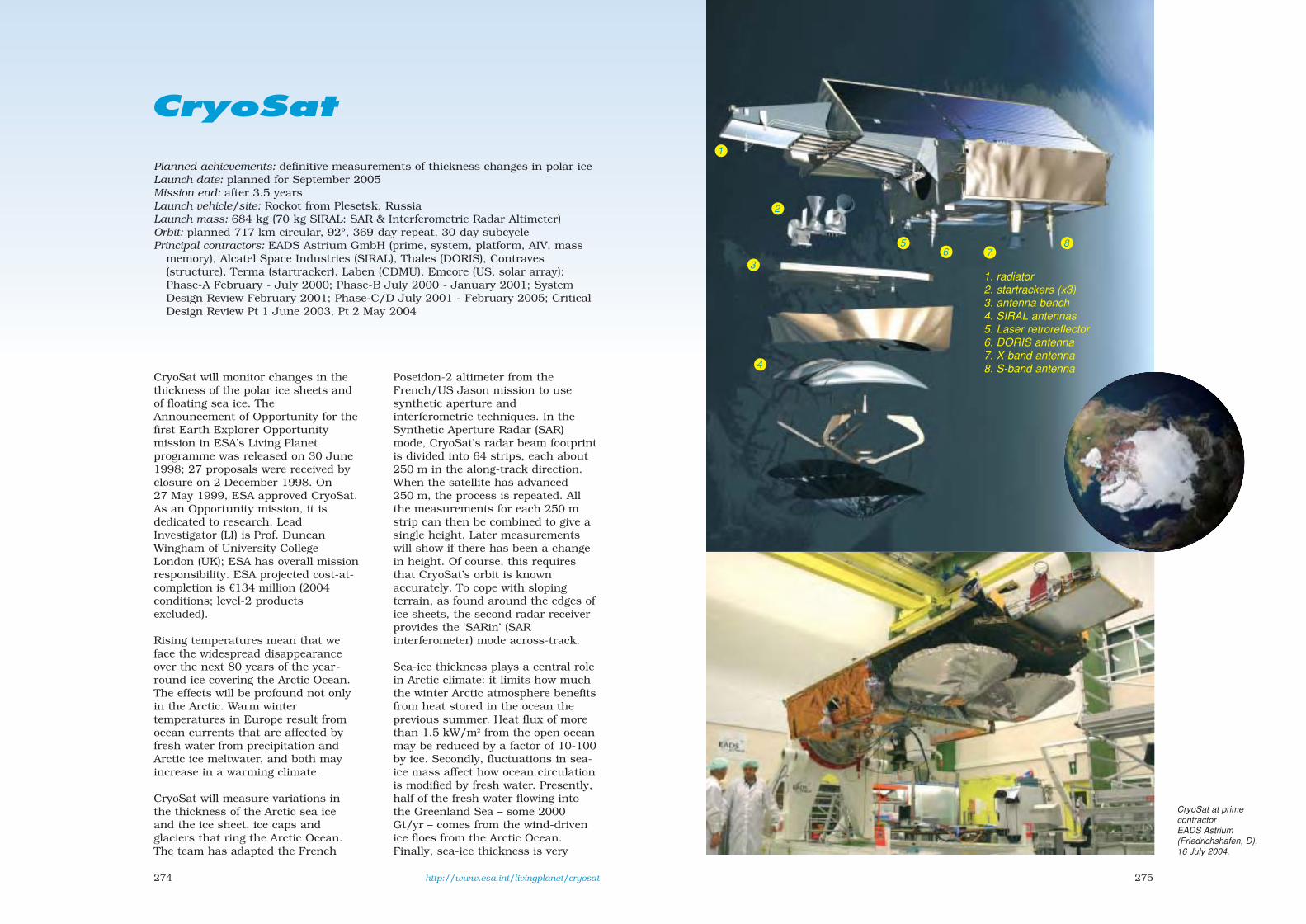
275274
CryoSat
Planned achievements: definitive measurements of thickness changes in polar iceLaunch date: planned for September 2005Mission end: after 3.5 years Launch vehicle/site: Rockot from Plesetsk, RussiaLaunch mass: 684 kg (70 kg SIRAL: SAR & Interferometric Radar Altimeter)Orbit: planned 717 km circular, 92º, 369-day repeat, 30-day subcyclePrincipal contractors: EADS Astrium GmbH (prime, system, platform, AIV, mass
memory), Alcatel Space Industries (SIRAL), Thales (DORIS), Contraves(structure), Terma (startracker), Laben (CDMU), Emcore (US, solar array);Phase-A February - July 2000; Phase-B July 2000 - January 2001; SystemDesign Review February 2001; Phase-C/D July 2001 - February 2005; CriticalDesign Review Pt 1 June 2003, Pt 2 May 2004
CryoSat will monitor changes in thethickness of the polar ice sheets andof floating sea ice. TheAnnouncement of Opportunity for thefirst Earth Explorer Opportunitymission in ESA’s Living Planetprogramme was released on 30 June1998; 27 proposals were received byclosure on 2 December 1998. On27 May 1999, ESA approved CryoSat.As an Opportunity mission, it isdedicated to research. LeadInvestigator (LI) is Prof. DuncanWingham of University CollegeLondon (UK); ESA has overall missionresponsibility. ESA projected cost-at-completion is €134 million (2004conditions; level-2 productsexcluded).
Rising temperatures mean that weface the widespread disappearanceover the next 80 years of the year-round ice covering the Arctic Ocean.The effects will be profound not onlyin the Arctic. Warm wintertemperatures in Europe result fromocean currents that are affected byfresh water from precipitation andArctic ice meltwater, and both mayincrease in a warming climate.
CryoSat will measure variations inthe thickness of the Arctic sea iceand the ice sheet, ice caps andglaciers that ring the Arctic Ocean.The team has adapted the French
Poseidon-2 altimeter from theFrench/US Jason mission to usesynthetic aperture andinterferometric techniques. In theSynthetic Aperture Radar (SAR)mode, CryoSat’s radar beam footprintis divided into 64 strips, each about250 m in the along-track direction.When the satellite has advanced250 m, the process is repeated. Allthe measurements for each 250 mstrip can then be combined to give asingle height. Later measurementswill show if there has been a changein height. Of course, this requiresthat CryoSat’s orbit is knownaccurately. To cope with slopingterrain, as found around the edges ofice sheets, the second radar receiverprovides the ‘SARin’ (SARinterferometer) mode across-track.
Sea-ice thickness plays a central rolein Arctic climate: it limits how muchthe winter Arctic atmosphere benefitsfrom heat stored in the ocean theprevious summer. Heat flux of morethan 1.5 kW/m2 from the open oceanmay be reduced by a factor of 10-100by ice. Secondly, fluctuations in sea-ice mass affect how ocean circulationis modified by fresh water. Presently,half of the fresh water flowing intothe Greenland Sea – some 2000Gt/yr – comes from the wind-drivenice floes from the Arctic Ocean.Finally, sea-ice thickness is very
http://www.esa.int/livingplanet/cryosat
1
2
3
4
56
87
1. radiator2. startrackers (x3)3. antenna bench4. SIRAL antennas5. Laser retroreflector6. DORIS antenna7. X-band antenna8. S-band antenna
CryoSat at primecontractorEADS Astrium(Friedrichshafen, D),16 July 2004.
sec8 8/1/05 1:37 PM Page 274

277276
CryoSat measures thefreeboard (heightabove thewater) of floating ice. Fromthat, the ice thickness canbe estimated if the densityis known.
The first radar echo comesfrom the nearest point to
the satellite. CryoSatmeasures the angle from
which this echo originates,so that the source point can
be located on the ground.This allows the height of
that point to be determined.
sensitive to ice thermodynamics, howice deforms under stress, and heatfrom the air and ocean – 10 W/m2 willmelt around 1 m of ice in a year.
It is possible that an irreversiblechange in Arctic sea-ice mass isalready underway. Existing thicknessmeasurements already suggest animportant trend in Arctic climate –but it is equally possible that this ismerely an unremarkable local change.The measurements are still scatteredtoo thinly in space and time to tell.Sea-ice thickness has previously beenmeasured by drilling, by sonarobservations of ice draught fromsubmarines operating beneath thepack ice, or in one case, from amoored sonar array across the FramStrait. Measurements haveaccumulated over the years, but arerarely of the same locations. CryoSat,by repeatedly sampling 70% of icefloes, will provide an authoritativeview of the fluctuations.
CryoSat will do more than observe thefloating ice of the Arctic Ocean.Obvious sources for the water causingthe 18 cm rise in sea level lastcentury are the ice sheets and glacierson land. Observations from ERS,Seasat and Geosat indicate that thegreat central plateaus of the Antarcticand Greenland ice sheets are stableso, if these ice sheets are contributingto the rising sea level, the changesmust be happening at their edges. Theimprovement in resolution fromCryoSat’s radar, coupled with itsinterferometric capability, will makecontinuous measurements of the icesheet margins and smaller ice capspossible for the first time.
These measurements translate intothe need to measure thicknesschanges in Arctic sea ice of 105 km2
with an accuracy of 3.5 cm/yr(1.2 cm/yr will be achieved); in icesheets covering 104 km2 of 8.3 cm/yr(3.3 cm/yr will be achieved); and inice sheets the size of Antarctica(13.8x10⁶ km2) of 0.76 cm/yr(equivalent to a loss of 92 Gt of watereach year; 0.12 cm/yr will beachieved).
Satellite configuration: total length4.6 m, width 2.34 m. Box-shapedaluminium bus with extended nosefor SIRAL. End/side plates completemain body and support solar array;nadir face as radiator. Controlled byERC-32 single-chip processor viaMIL-1553B bus.
Attitude/orbit control: 3-axis nadirpointing to 0.2/0.2/0.25ºroll/pitch/yaw by three 30 Am2
magnetorquers supported byredundant sets of eight 10 mN cold-gas nitrogen blowdown thrusters(plus four 40 mN for orbit adjust);37 kg nitrogen at 250 bar in singlecentral sphere. Attitudedetermination by 3 star trackers, 3fluxgate magnetometers, andEarth/Sun sensors. Precise orbitdetermination by DORIS (5 cm radialaccuracy; 30 cm realtime), LaserRetroreflectors (cm accuracy) andS-band transponder.
Power system: two GaAs panelstotalling 9.4 m2 on upper bus provide525 Wh (SIRAL requires 132 W; 99 Win low-res mode). Supported by 60 AhLi-ion battery.
Communications: controlled fromESOC via Kiruna (S). 320 Gbitdownlink each day from 2x128 Gbitsolid-state mass recorder at100 Mbit/s QSPK 25 W 8.100 GHz.2 kbit/s TC at 2026.7542 MHz.4 kbit/s TM at 2201 MHz.
CryoSat Payload
SIRAL
Cassegrain antenna emits 44.8 µs Ku-bandpulses, bandwidth 320 MHz. Three operatingmodes: Low-Resolution Mode (LRM) 1 pulse in44.8 µs burst, 51 kbit/s; SAR mode 64pulses in 3.8 ms burst, 12 Mbit/s, for icefloes & ice sheet interiors at < 1 km res;SARin mode 64 pulses in 3.8 ms burst,received by both antennas, 2x12 Mbit/s, forice sheet edges at 250-300 m res.
DORIS
Doppler Orbitography & Radio-positioningIntegrated by Satellite determines the orbitwith 5 cm accuracy. It receives 2.03625 GHz& 401.25 MHz signals from ground beaconsand measures the Doppler shift every 7-10 s.91 kg, 16.7 kbit/s, 42 W.
LRR
Cluster of 7 laser reflectors provides orbitdetermination with cm-accuracy using laserground stations. Backup to DORIS.
The UK Hadley Centre predicts a thinning of
Arctic ice from 5 m (left)to 1 m (right) if the
carbon dioxide levelquadruples.
sec8 8/1/05 1:38 PM Page 276

278
Venus Express
Although it comes closer to Earththan any other planet, Venus remainsa mystery. After more than threedecades of intense scrutiny bynumerous Russian and US spaceprobes, the cloud-shrouded worldrefuses to unveil many of its secrets.Remarkably similar in size to Earth,Venus could hardly be more differentin other respects – and we do notreally know why. We still do notunderstand the details of thegreenhouse effect on Venus, whichkeeps the surface at a sizzling 460°C,hot enough to melt lead. Thecrushing atmosphere is 90 timesthicker than Earth’s.
Venus and Earth have evolved quitedifferently. In the absence ofcontinents, Venus is covered in vast,smooth volcanic plains. Planet-widevolcanism is believed to feed thesulphur-rich cloud layers andsulphuric acid rain. Instead of crustalplates that slide past each other togenerate earthquakes and volcanoes,Venus seems to have one all-embracing slab of crust perforated byhot spots where molten magmaerupts onto the surface.
Most puzzling of all is how theatmosphere circulates – high-level,hurricane-force winds sweep aroundVenus in just four days at 360 km/h,remarkably rapid for a planet that
rotates only once every 243 Earthdays. Yet the surface atmosphere is astagnant syrup. By explaining thesestartling differences between sisterworlds, we will gain a betterunderstanding of Earth’s weather andchanging climate.
Despite its impressive goals, VenusExpress is a low-cost spacecraft builtand launched in only three years.This is made possible by basing it onESA’s Mars Express, withmodifications to cope with the hotterenvironment at Venus, and the seveninstruments including five developedfor previous missions. Suchinstruments have never flown toVenus before, so the planet will beviewed through new eyes.
Some instruments, directly derivedfrom Mars Express and Rosetta, willlook at the composition, temperatureand density of the atmosphere to analtitude of 200 km. One innovativeinstrument will picture the energeticatoms escaping from the atmosphere.Unlike Earth, Venus has no protectivemagnetic field so the powerful wind ofelectrified atomic particles streamingin from the Sun is continuouslystripping away the top of theatmosphere. A wide-angle camera willmonitor the whole planet. From itsoperational polar orbit, it will studythe atmosphere, surface and
Planned achievements: first European Venus orbiter Launch date: planned for 26 October 2005 (window to 25 November), Venus
arrival mid-April 2006 Mission end: after 2 Venus sidereal days (486 Earth days), 2-day extension
possibleLaunch vehicle/site: Soyuz-Fregat from Baikonur Cosmodrome, KazakhstanLaunch mass: 1270 kg (science payload 88 kg, 570 kg propellant)Orbit: 250x350 000 km, ~90º, 10 d Venus capture orbit; 250x66 000 km, 90º,
24 h operational Venus orbitPrincipal contractors: Astrium-EADS (prime, Toulouse, F), Alenia Spazio (AIV,
Turin, I). Phase-B August 2002 - January 2003, Phase-C/D February 2003- June 2005; PDR January 2003, CDR March 2004, Flight Acceptance ReviewJuly 2005
sec8 8/1/05 1:38 PM Page 278

281280
electrified particles for at least2 Venus ‘days’ of 243 Earth dayseach.
Venus Express was proposed to ESAin response to the March 2001 Callfor Ideas for reuse of the MarsExpress platform. A strict schedulewas imposed, aiming at a launch datein 2005, with a strongrecommendation to includeinstruments already available, inparticular as flight-spare units fromMars Express and Rosetta. Threemissions were studied by EADSAstrium in parallel from mid-July tomid-October 2001: Venus Express,Cosmic Dune (interplanetary &interstellar dust) and Sport Express(polarisation of cosmic microwavebackground). Venus Express wasunanimously recommended by ESA’sSolar System Working Group andthen by the Space Science AdvisoryCommittee in November 2001. Afterthe Science Programme Committeemeeting in December 2001, VenusExpress was included in the list ofmissions to be considered in thereplanning exercise of ESA’s ScienceProgramme that was conducted inearly 2002. In order to maintain the2005 launch schedule, pre-Phase-Bactivities were carried out inFebruary-May 2002. Venus Express,originally included in the ‘CosmicVision 2020’ programme put forwardfor SPC approval in May 2002, waswithdrawn from the programme byESA’s executive because the payloadfunding was not secured. Followingthe recommendation formulated byESA’s Council of 16-17 June, furthernegotiations on payload funding weresuccessfully concluded in late Junewith the funding authorities of theinstruments’ home countries. On11 July 2002, although the payloadfunding was still not fully in place,
the SPC unanimously approved thestart of work. On 5 November 2002,ESA made its final decision on thepayload complement and therefore toproceed with the mission. Industrialand payload activities started in mid-July.
Venus Express will be by far thefastest developed scientific projectimplemented by ESA.The Phase-C/Dcontract for €82.4 million was signedwith EADS Astrium on 28 January
2003. The projected ESA cost-at-completion is €220 million (2004conditions).
Venus Express will provide abreakthrough by fully exploiting thenear-IR atmospheric windows overthe planets night side, discovered inthe 1980s, through which radiationfrom the lower atmosphere and eventhe surface escapes to space.
As there were strict requirements onthe instruments – they had to beavailable to match the challengingschedule of the mission – the list ofcandidates was restricted. Theobvious candidates were the sparemodels from the Mars Express andRosetta projects. After detailedassessment, three Mars Express andtwo Rosetta instruments werechosen, enhanced with a newminiaturised 4-band camera and anew magnetometer (with heritagefrom the Rosetta lander). In addition,
a very high-resolution solaroccultation spectrometer was addedto the SPICAM Mars Expressinstrument. This resulted in aninstrument complement able tosound the entire atmosphere from thesurface to 200 km altitude bycombining different spectrometers, animaging spectrometer and a camera,covering the UV to thermal-IR range,along with a plasma analyser and amagnetometer. Radio science will usethe communication link to Earthenhanced with an ultra-stableoscillator, for high-resolution verticalinvestigations. As it turns out,despite the limitations in choice, thepayload is close to optimised for themission.
The spacecraft is derived from MarsExpress, using most subsystemswithout modification. The majordifferences are in the thermal controlsystem, which was redesigned to copewith the much higher heat input from
Venus Express Science Goals
Scientific observations are divided betweenthe pericentre region, where high-resolutionstudies of small-scale features will be carriedout, and near-apocentre and intermediateobservations, where global features will bestudied. The main goal is a comprehensivestudy of the atmosphere and to study insome detail the plasma environment and theinteraction between the upper atmosphereand the solar wind. Surface and surface-atmosphere interactions will also be studied.Seven Science Themes have been defined,each with its own detailed set of objectives:
– atmospheric dynamics;– atmospheric structure;– atmospheric composition and chemistry;– cloud layers and hazes;– radiative balance;– surface properties and geology;– plasma environment and escape
processes.
The fundamental questions to be answeredinclude: – what is the mechanism of the global
atmospheric circulation?– what are the mechanisms and the driving
force behind the atmospheric super-rotation?
– what are the chemical composition andits spatial and temporal variations at theshort- and long-term?
– what is the role of the cloud layers andthe trace gases in the thermal balance ofthe planet?
– what is the importance of the greenhouseeffect?
– how can the origin and the evolution ofthe atmosphere be described?
– what has been and what is the role ofatmospheric escape for the present stateof the atmosphere?
– what role does the solar wind play in theevolution of the atmosphere?
– is there still active volcanism and seismicactivity on Venus?
Resolving these issues is of crucialimportance for understanding the long-termevolution of climatic processes on the sisterplanets of Venus, Earth and Mars, and willsignificantly contribute to generalcomparative planetology.
sec8 8/1/05 1:38 PM Page 280

283282
the Sun (2600 W/m2 at Venus vs600 W/m2 at Mars) and the higheralbedo of the planet itself. For thesame reason, the solar panels havebeen completely redesigned: they arebased on high-temperature GaAscells and cover about half the area ofthe Mars Express panels.
Configuration: box-shaped bus1.5x1.8x1.4 m of conventionalaluminium honeycomb construction.Dry mass 680 kg.
Attitude/orbit control: orbit correction& Venus insertion by single 400 NMON-3/MMH thruster, attitude
control by 8x10 N hydrazinethrusters (570 kg in 2 267-litre tanks)and 4x12 Nms reaction wheels.Pointing accuracy 0.15º supported by2 star trackers, 2 inertialmeasurement units (each 3 ring lasergyros + 3 accelerometers) , 2 coarseSun sensors.
Power system: twin 2-panel GaAssolar wings totalling 5.8 m2 to provide1450 W at Venus (160 W for science).Supported by 3x24 Ah Li-ionbatteries.
Thermal control: 24-layer MLI derivedfrom Rosetta on the 2 hot walls
(+X/+Z) keep interior at 10-20ºC.Radiators on –X wall (opposite HGA)for PFS & VIRTIS. ASPERA moved(from Mars Express) to side wall toavoid Sun illumination; VIRTISoccupies OMEGA/HRSC locations ofMars Express.
Communications: transmitted from12 Gbit SSR to ground during the 8 hfollowing the pericentre pass eachorbit via 1.3 m-dia X/S-band HGA to35 m Cebreros (E). Plus 30 cm-diaX-band HGA2 on top (+Z) derivedfrom Rosetta MGA. Rate will varyaccording to Earth distance, with 26-228 kbit/s giving at least 500 Mbit
(2 Gbit average) of science data perorbit via the 65 W X-band link. ESA’sother 35 m station, at New Norcia,Australia, will be used duringmission-critical operations and forradio science support duringdedicated campaigns. The 5 WS-band channel is included for near-Earth communications and radioscience. Processed data will be placedin ESA’s publicly accessible PlanetaryScience Archive (PSA) after 6 months.Mission control is handled by theMission Operations Centre at ESOC;the science planning andcoordination is handled by theScience Operations Centre at ESTEC.
Venus Express Scientific Instruments
PFS Planetary Fourier Spectrometer (from Mars Express). Atmospheric composition &circulation, surface mineralogy, surface-atmosphere interactions. 1.2-45 µm. 32 kg,35 W, up to 300 Mbit/orbit. PI: V. Formisano, Istituto Fisica Spazio Interplanetario(Rome, I). Participating countries: I, RU, PL, D, F, E, US
ASPERA Energetic Neutral Atoms Analyser (from Mars Express). Upper atmosphere interactionwith interplanetary medium & solar wind; near-Venus plasma and neutral gasenvironment. 9 kg, 12 W, up to 400 Mbit/orbit. PI: S. Barabash, Swedish Institute ofSpace Physics (Kiruna, S). Participating countries: S, D, UK, F, FIN, I, US, RU, CH, IRL
SPICAV UV and IR Atmospheric Spectrometer (from Mars Express with added SOIR high-res IRsolar occultation channel). O3 content of atmosphere and vertical profiles of CO2, O3and dust. SOIR channel will detect chemical species such as H2O, CO, H2S and tracegases such as methane & ethane. 9 kg, 21 W, up to 250 Mbit/orbit. PI: J.-L. Bertaux,Service d’Aeronomie du CNRS (Verrieres-le-Buisson, F). Participating countries: F, B,RU, US
VeRa Radio Science Experiment (from Rosetta). Atmospheric density, P & T profiles,ionospheric electron density profiles (passage of radio waves through atmosphere),surface dielectric and scattering properties (reflection of radio waves) and gravityanomalies (orbital tracking). 1.5 kg, 5 W. PI: B. Häusler (Universität der Bundeswehr,München, D). Participating countries: D, F, US, B, JPN
MAG Magnetometer (partly from Rosetta Lander). Identify boundaries between plasmaregions, interaction of solar wind with atmosphere, support data for other instruments.Two tri-axial fluxgate magnetometers, one body-mounted and one on a 1 m deployedboom. Default range ±262.1 nT (res 8 pT); range commandable to between ±32.8nT (res1 pT) and ±8388.6 nT (res 128 pT). 2.2 kg, 4.25 W, up to 50 Mbit/orbitPI: T. Zhang (IFW, Graz, A). Participating countries: A, D, UK, S, ESA, US
VIRTIS Visible/IR Imaging Spectrometer (from Rosetta). Composition of atmosphere belowclouds, cloud structure & composition, cloud tracking, T/wind speed at 60-100 kmaltitude, T of surface (volcanoes?), lightning. Spectral res 0.25-5 µm. R~200 at 0.25-1 &1-5 µm, and R~1200 at 2-5 µm. PI: P. Drossart (Obs. de Paris, Meudon, F) & G. Piccioni(IASF, Rome, I). 31 kg, 66 W, up to 5 Gbit/orbit. Participating countries: F, D, I, US, PL,NL, UK
VMC Wide-angle Venus Monitoring Camera. 1032 x 1024-pixel CCD with four 13 mm f.l. F/5optics for imaging in UV (0.365 µm), visible (0.513 µm) & near-IR (1.01 & 0.915 µm),17.5º FOV for global spatial & temporal coverage of Venus disc. 1.1 kg, 4 W, up to1.5 Gbit/orbit. PI: W. Markiewicz (MPAe, Katlenburg-Lindau, D). Participating countries:D, F, US, JPN, RU
The Venus Expressflight model beingprepared for vibrationat Intespace.
sec8 8/1/05 1:38 PM Page 282

284
Galileo
Planned achievements: first European global navigation satellite system; civilposition accuracy to 5 m
Launch date: experimental satellite planned December 2005, demonstrationsatellites 2008, operational satellites 2008-2010
Mission end: no mission end; each operational satellite nominal lifetime of 15 yearsLaunch vehicle/site: operationally in clusters of 6 on Ariane-5 from Kourou, and
Soyuz-Fregat, replacements by vehicles such as Soyuz-Fregat Launch mass: GSTB-V2/A 600 kg; GSTB-V2/B 525 kg; IOV/operational satellites
650 kgOrbit: 23 222 km circular, 56°, 14.4 h, in 3 orbital planesPrincipal contractors: Galileo Industries (GSTB-V2/B; IOV), SSTL (GSTB-V2/A),
contractor for operational satellites to be selected. Development & ValidationPhase 2001-2007; Deployment Phase 2008-2010; Operations Phase from 2010
For the first time, the Agency hastaken a lead role in the navigationsegment. ESA and the EuropeanCommission have joined forces todesign and develop Europe’s ownsatellite navigation system, Galileo.Whereas the US GPS and RussianGlonass systems were developed formilitary purposes, Galileo is a civilsystem that will offer ,inter alia, aguaranteed service, allowing Europe todevelop an integrated transportsystem. It will also allow the Europeaneconomy to benefit from the enormousgrowth expected in value-addedservices and equipment for navigationsystems.
Europe’s first venture into satellitenavigation is EGNOS (EuropeanGeostationary Navigation OverlayService), a system to improve thereliability and accuracy (2 m) of GPSand Glonass to the point where theycan be used for safety-criticalapplications, such as landing aircraftand navigating ships through narrowchannels. ESA engineers firstdeveloped plans for a GPS and Glonassaugmentation system in the late1980s. Working in close cooperationwith the EC and the EuropeanOrganisation for the Safety of AirNavigation (Eurocontrol), the Agencylater adopted the plans as the EGNOSprogramme. When EGNOS becomes
operational in 2005, using payloadson Artemis and Inmarsat satellites, itwill be Europe’s contribution to thefirst stage of the Global NavigationSatellite System (GNSS-1),complementing similar enhancementsin the US and Japan.
In addition, the European Unionrecognised the need for its ownindependent global satellitenavigation system. Consultationsbegan in 1994 and 4 years later plansfor a fully European system weredrawn up. Early in 1999, the EC
http://www.esa.int/navigation 285
announced Galileo. It will beinteroperable with GPS and Glonass,so that a user can take a positionwith the same receiver from any ofthe satellites in any system. Byoffering dual frequencies as standard,however, Galileo will deliverpositioning accuracy down to 5 m,which is unprecedented for a civilsystem. It will also guaranteeavailability of the service under allbut the most extreme circumstancesand will inform users within 6 s ofthe failure of any satellite. This willmake it suitable for safety-criticalapplications.
The fully-fledged service will beoperating by about 2010 when 30Galileo satellites are in position incircular orbits 23 222 km above theEarth. The first will be launched in2008 and by 2009 sufficient shouldbe in place to begin an initial service.The orbits will be inclined at 56º tothe equator, giving good coverage atall latitudes. A total of 27 satelliteswill be operational and three will beactive spares, ensuring that the lossof one has no discernible effect onthe user. Ground stations spreadaround the globe will monitor thesatellites’ positions and theaccuracies of their onboard clocks.The stations will be connected tocentral control facilities in Europe via
a dedicated network. The controlfacilities will monitor and control theconstellation and compute navigationmessages to transmit to the satellitesvia the ground stations. The controlfacilities will also keep serviceproviders, such as providers of trafficmanagement services, informed aboutthe operating status of the satellites.
ESA approved the initial studies inMay 1999 at its Ministerial Council inBrussels; the EC decided on its owngo-ahead in June 1999. The EC isresponsible for the politicaldimension: undertaking studies intothe overall system architecture, theeconomic benefits and the needs ofusers. ESA defined the Galileo spaceand ground segments under itsGalileoSat programme. ESA placedcontracts with European industry todevelop critical technologies, such asnavigation signal generators, poweramplifiers, antennas and highlyaccurate atomic clocks, and toprovide tools to simulate theperformance of the wholeconstellation.
Europe’s traditional space industryundertook Galileo definition studiesfrom November 1999 to February2001 under two contracts financedseparately by the EC and ESA.Industries not usually associated
http://www.GalileoJU.com
sec8 8/1/05 1:38 PM Page 284

286
with space, such as mobile phonemanufacturers and serviceproviders, are, in addition to theirinvolvement in the EC-fundeddefinition study, undertaking theirown studies of services andapplications.
The European Commission, ESAand the eventual commercialoperator will meet the €3550 million(2001 conditions) estimated cost ofGalileo through a public/privatepartnership. Public money will fundthe project through to the end of thevalidation phase, followed bymajority private funding from theconcession-winner for launchingand operating the final system.
Studies suggest that Galileo willrepay its investment handsomely,estimating that equipment sales andvalue-added services will earn anextra €90 billion over 20 years. Morerecent studies yielded higherestimates by considering potentialearnings from value-added servicesthat combine Galileo positioningwith other services provided by thenew generation of mobile phones,such as internet services. Around140 000 jobs are expected to becreated, with a return ratio on thesystem cost of 4.6.
Initial funding on the EC side camefrom the European Union’s 5thFramework programme of researchand development and on the ESAside from the Agency’s GalileoSatdefinition programme (November1999 to 2002, costing €97.6 million,including technology development).
The development and in-orbitvalidation (IOV) phase was projectedin 2000 to cost €1.1 billion, financedequally by ESA and the EU from
public money. It aims to have in orbitby 2008 a handful of satellites forvalidating the Galileo system.
At its meeting on 30 January 2001,ESA’s Navigation Programme Boardapproved the release of €53 millionfor funding critical technologydevelopment, the Galileo Phase-B2study, the mission consolidationstudies and the support studies onthe Galileo services to begin. ESAreleased the second and maintranche of €547 million at its CouncilMeeting of May 2003.
On the EU side, the TransportMinisters on 5 April 2001 approvedthe release of €100 million to startdevelopment. The ministers approvedthe release of a further €450 millionon 26 March 2002, when they alsoapproved the setting up of an entityto manage the programme. TheEC/ESA Galileo Joint Undertaking(GJU) formally assumedresponsibility on 1 September 2003for the development, validation andcommercial phases. ESA’s approval toset up GJU came at its May 2003Council Meeting; the GJU foundingact was signed by the EC and ESA on25 May 2003.
287
The€2.1 billioncost of thedeployment phasewill be met from amixture of public (one-third)and private funding (two-thirds).ESA and the EU will share the publicslice equally (i.e. €350 million each).The EC on 10 December 2004approved the move to the deploymentand operational phases. During thedeployment phase, which will endaround 2010 when all the satellitesare launched, industry and serviceproviders will be able to developcommercial opportunities. Onceoperational, the system will costaround €220 million annually tomaintain, including satellitereplacements. The Public sectorintends to provide financial supportfor the first years of the operationalphase; €500 million is earmarked forthat purpose. After that initial period,
the cost should be borne entirely bythe concessionaire. By this time, thesystem will be fully operational andavailable for a wide variety ofcommercial and public service users.
The total cost for the design,development, in-orbit validation anddeployment of the first fullconstellation, including the groundsegment, is €3550 million (2001conditions).
On 17 October 2003, the GJU beganthe process to find a concessionaire,the commercial operator for thesystem. Two bids were submitted by
sec8 8/1/05 1:38 PM Page 286

288
the deadline of 1 September 2004 (andthe final bids on 25 January 2005):from the iNavsat consortium led byEADS Space, Thales and Inmarsat,and the Eurely consortium headed byVinci Concessions, Alcatel Space andFinmeccanica. The selection is due tobe made in March 2005, and the 20-year concession contract to be signedin December 2005. The concessionairewill be responsible for awarding thecontract for the 26-27 satellites tocome after IOV.
Navigation payload: the navigationsignals are modulated with 500-1000 bit/s data messages receivedfrom ground stations through theTT&C subsystem and stored,formatted and encoded onboard.Galileo will use up to four 50 Wcarriers at 1164-1215, 1260-1300 &1559-1591 MHz. A highly stableonboard reference frequency of10.23 MHz is generated fromrubidium atomic frequency standardsand passive hydrogen masers
The Galileo navigationand S&R payload,
carried by the IOV andoperational satellites.
289
operating in hot redundant, parallelconfiguration. Solid-state amplifiersgenerate some 50 W output per signalcarrier. The navigation antenna usestwin beam-forming networks (one foreach band) and an array of radiatingelements to provide global coveragewith a single beam. High data rates
maximise the potential for value-added services such as weatheralerts, accident warnings, trafficinformation and map updates.
Two Galileo Control Centres (GCCs)will be built in Europe to control thesatellites and manage the navigationmission. The data provided by aglobal network of some 30 GalileoSensor Stations (GSSs) will be usedby the GCCs to compute the integrityinformation and to synchronise thetime signal of all satellites and of theground station clocks. The exchangeof data between the GCCs and thesatellites will be via five S-band and10 C-band stations around the globe.
Search & Rescue (SAR) payload: theSAR payload, being defined incooperation with COSPAS-SARSAT,
Galileo Services
Galileo will provide five levels of service:
The Open Service (OS) is for mass-marketapplications, free of direct user charge. Up tothree separate frequencies are available, butcheap single-frequency receivers can providereduced accuracy. In general, OSapplications will use a combination ofGalileo and GPS signals, which will improveperformance in severe environments such asurban areas. OS does not offer integrityinformation, and determining the quality ofsignals will be left entirely to the users.
The certified Safety-of-Life Service (SoL) willprovide the same position and timingaccuracy as OS, but it offers a worldwidehigh level of integrity for safety-criticalapplications, such as maritime, aviation andrail, where guaranteed accuracy is essential.EGNOS will be integrated with it for GPSintegrity information.
The Commercial Service (CS) aims at marketapplications requiring higher performancethan from OS. It provides added valueservices on payment of a fee. CS is based onadding two signals to the open accesssignals, protected via commercial encryption.
The encrypted Public Regulated Service(PRS) will be used by groups such as thepolice, coastguard and customs. It will beoperational at all times and under allcircumstances, including periods of crisis.A major feature is the signal robustness,protected against jamming and spoofing.
The Search & Rescue Service (SAR) isEurope’s contribution to the internationalsearch and rescue. Improvements on theexisting system include near real-timereception of distress messages fromanywhere on Earth (the average waiting timeis currently an hour) and the preciselocation of alerts (a few metres, instead ofthe current 5 km).
sec8 8/1/05 1:38 PM Page 288

290
receives signals from standard406 MHz distress beacons through adedicated antenna. The signals areamplified and transmitted at1544 MHz to SAR Control Centresusing the navigation antenna.Acknowledgement messages arerelayed back to the beacon byintegrating them in the navigationdata stream.
IOV & GSTB-V2The Galileo Development andValidation phase began in December2003, aiming for 3-4 satellites toprove the system concept before fulldeployment begins. On 14 June2004, ESA released the Request forQuotation for Phase-C/D/E1 to theGalileo Industries consortium ofAlcatel Space Industries (F), AleniaSpazio (I), Astrium GmbH (D),Astrium Ltd (UK), Galileo Sistemas yServicios (E) and Thales (F), formed inMay 2000, with the response duemid-October; a €150 million initialcontract was signed 21 December2004 with Galileo Industries. The firstIOV launch is planned for mid-2008.The whole phase was projected inDecember 2000 to cost €1.1 billion,with €645 million for thespace/ground segment, but theoverall costs have risen to€1.5 billion, largely because a secondexperimental satellite has beenadded, the total now includes thecost of security elements, and thechange in economic conditions from2000 to 2005.
The Galileo System Test Bed iscomposed of an experimental satellite‘GSTB-V2’ and a network of GPSstations and processing facilities toverify the Galileo algorithms(GSTB-V1). A purpose of GSTB-V2 isto ensure that the International
Telecommunications Union legalrequirement of representative Galileosignals being received from arepresentative Galileo orbit was metbefore the deadline of June 2006.GSTB-V2 is also designed to measurethe radiation environment in thisorbit (instruments include the ESAStandard Radiation EnvironmentMonitor; see Proba-1 entry),demonstrate key technologies andprovide test signals for coordinationwith other systems. Which of the twoGSTB-V2 satellites will be launchedfirst, in late 2005 aboard a Soyuzfrom Baikonur Cosmodrome, will bedecided in mid-2005.
Contracts for both satellites weresigned 11 July 2003: €27.9 millionwith Surrey Satellite Technology Ltd(UK) for GSTB-V2/A; and€72.3 million with Galileo Industriesfor GSTB-V2/B. The smaller V2/Acarries a rubidium clock and twodifferent signal generators to covervarious signal options, while V2/Badds a passive hydrogen maser andwill allow the contemporarytransmission of signals over threenavigation bands. The maser stabilityof better than 1 ns per day will makeit the best clock ever flown in space.
GSTB-V2/ASchedule: PDR December 2003; CDR
February 2005Principal contractors: SSTLDesign life: 27 monthsKey technologies: rubidium clock,
dual signal generators, 70 WTWTA, navigation antenna
Launch mass: 600 kgSatellite configuration: bus
1.3x1.8x1.65 m; space acrossdeployed solar array 9.6 m
Attitude/orbit control: 3-axis nadir-pointing by 4 reaction wheels; 3-axis magnetorquers for wheel
291
offloading; attitude determinationby Earth/Sun sensors. 8 thrusters,75 kg butane in 2 tanks
Power system: 700 W required, 2-panel wings (each panel0.98x1.74 m) of Si cells, Li-ionbattery.
Communications: 9.6 kbit/s S-bandwith control centre at SSTL(Guildford), ground stations in UK(Guildford & RAL-Oxfordshire) &Malaysia; in-orbit testing facility atChilbolton (UK).
GSTB-V2/BSchedule: PDR December 2003;
CDR-1 July 2004, CDR-2December 2004
Principal contractors: GalileoIndustries
Design life: 27 monthsKey technologies: rubidium clock,
passive hydrogen maser, 50 WSSPA, navigation antenna
Launch mass: 525 kgSatellite configuration: bus
1.6x1.8x2.7 mAttitude/orbit control: 3-axis nadir-
pointing by 4 12 Nms reactionwheels; 3 one-axis magnetorquersfor wheel offloading; attitudedetermination by Earth sensor + 3fine Sun sensors; 2 3-axis gyrosused when no Earth reference.18 N thrusters, 28 kg hydrazine in1 tank
Power system: 940 W required, 4-panel Si wings (each panel0.8x1.49 m), 78 Ah Li-ion battery
Communications: S-band (TC
2 kbit/s, TM 31.25 kbit/s) withcontrol centre in Fucino (I). groundstations in Fucino (I) & Kiruna (S)(LEOP adds Santiago/Chile &Dongara/Australia); in-orbit testingfacility in Redu (B).
IOV SatellitesSchedule: PDR June 2005; CDR
September 2007Principal contractors: Galileo
IndustriesDesign life: 12 years (reliability 0.832
over 12 years)Launch mass: 690 kgSatellite configuration: bus
1.10x1.20x2.50 m, aluminiumpanels; span across deployed solararray 13 m
Attitude/orbit control: 3-axis nadir-pointing by 4 reaction wheels; 3-axis magnetorquers for wheeloffloading; attitude determinationby Earth sensor + 3 fine Sunsensors; 2 3-axis gyros used whenno Earth reference. 8 N thrusters,75 kg hydrazine in 1 tank
Power system: 1700 W EOL required,24-panel GaAs wings, Li-ionbattery
Communications: S-band, with controlcentre and ground stations to bedecided
Navigation and S&R payload: 146 kg,940 W, 2 paired rubidium &hydrogen maser clocks,1.32x1.48 m L-band navigationantenna, 35.2 cm C-band rxantenna; L-band S&R 1544 MHz tx& 406 MHz rx antennas.
GSTB-V2/A
GSTB-V2/B
sec8 8/1/05 1:38 PM Page 290

292
Metop
Planned achievements: first European meteorological satellite in polar orbitLaunch dates: Metop-2 planned for April 2006, Metop-1 2010, Metop-3 2014Mission end: nominally after 5 yearsLaunch vehicle/site: Soyuz-ST from Baikonur Cosmodrome, Kazakhstan (also
compatible with Ariane-5 from Kourou, French Guiana)Launch mass: 4093 kg (2128 kg payload module, 1397 kg service module, 252 kg
solar array, 316 kg propellant)Orbit: planned 817 km circular, 98.7° Sun-synchronous (09:30 local time
descending node), 29-day/412-rev repeat cyclePrincipal contractors: Astrium SAS (prime, service module), Astrium GmbH (payload
module, ASCAT, GRAS with Saab-Ericsson Space), Galileo Avionica (GOME-2),Dutch Space (solar generator); all other instruments are customer-provided
Metop will provide Europe’s firstmeteorological satellites in polar orbit.They were originally part of a muchlarger satellite concept, called POEM,which was to have been the successorto ERS, based on the Columbus PolarPlatform. This very large satellitewould have carried the payloads ofboth Envisat and Metop and wouldhave been serviceable in-orbit. At theESA Ministerial Council in Granada,Spain in 1992, this approach wasabandoned and Envisat and Metopwere born. Metop is a jointundertaking by ESA and Eumetsat aspart of the Eumetsat Polar System(EPS). In addition to the satellites, EPScomprises the ground segmentdevelopment and operations, thelaunches and various infrastructureelements. ESA is funding 64%(€480 million in 2004 terms) ofMetop-1, while Eumetsat covers therest (€264.2 million) and the twofollow-on satellites. The cooperativeagreement between the two agencieswas signed on 9 December 1999, atthe same time as the industrialcontract with Matra Marconi Space(now EADS Astrium). EPS will providean operational service for 14 years,which requires three satellites withnominal lifetimes of 5 years.
The US National Oceanic &Atmospheric Administration (NOAA)currently operates polar meteorologicalsatellites for civil use in two Sun-
synchronous planes: mid-morning andafternoon. Following launch of the firstMetop, the mid-morning service will beprovided by EPS as part of the ‘InterimJoint Polar System’. During thetransitional phase, the oldergeneration of instruments willcontinue to fly as the newerinstruments are introduced; Metop willcarry older instruments from NOAA aswell as more advanced, European,ones. The present NOAA satellites andthe military DMSP satellites will bereplaced by the end of the decade by anew integrated system (NPOESS)operating in three planes: early
http://earth.esa.int
The engineeringmodel of Metop’s
payload module beingprepared for testing in
ESTEC’s LargeSpace Simulator,
June 2001.
sec8 8/1/05 1:38 PM Page 292

294 295
morning, mid-morning and afternoon.Under the Joint Polar Systemagreement, EPS/Metop will continue toprovide the main sounding mission forthe mid-morning service.
Metop stores its data for downlinkingeach orbit, but it also providescontinuous direct data-broadcastservices to users. The channels can beselectively encrypted for decoding bycommercial customers. The High-Resolution Picture Transmission(HRPT) broadcasts the full data set atL-band for regional meteorologicalorganisations to receive relevant datain realtime. The Low-Resolution PictureTransmission (LRPT) service at VHFprovides a subset of the HRPT data. Itis comparable to the existing NOAAautomatic picture transmission (APT)service, with the objective of providinginexpensive access to low-resolutionAVHRR images by local users.
Notable improvements for Metop are:
– new instruments: ASCAT, IASI,GOME-2 and GRAS;
– an innovative onboard compressionscheme that is a considerableimprovement over the existing APTservice and provides LRPT useraccess to three channels of AVHRRdata at full instrument spatial andradiometric resolution;
– continuous onboard recording of the
global data set for dumping everyorbit to a high-latitude groundstation, with the global processeddata available to users within 2.25 hof the measurements;
– high pointing and orbital stability toensure that data may be geo-locatedwithout reference to ground-controlpoints in imagery;
– a selective encryption system toensure the commercial and data-denial needs of Eumetsat and theUS Government, respectively.
The three Metops will carry heritageinstruments from the current NOAAsatellites:
– Advanced Very High ResolutionRadiometer (AVHRR), anoptical/infrared imager for globalcoverage of clouds, ocean and land;
– High-resolution Infra-Red Sounder(HIRS), a spectrometer with arelatively coarse spatial resolutionand a mechanical scan over a wideswath, from which height profiles ofatmospheric pressure andtemperature may be derived (not onMetop-3 because IASI by then willbe a proven instrument);
– Advanced Microwave SoundingUnit-A (AMSU-A), a mechanicallyscanned multi-channel microwaveradiometer for pressure andtemperature profiles;
Right: radio-frequency compatibility tests wereconducted on the engineering model payloadmodule at ESTEC in mid-2001.
Facing page, bottom right: the Metop-2 payloadmodule in ESTEC’s Large Space Simulator,February 2004.
Facing page, top: principal Metop features.acronyms (in addition to instruments):CRA: Combined Receive Antenna (ADCS, SARR,SARP-2); DTA: DCS-2 Transmit Antenna;GAVA: GRAS Anti-Velocity Antenna; GVA: GRASVelocity Antenna; GZA: GRAS Zenith Antenna;HRPT: High-Resolution Picture Transmission; LRPT:Low-Resolution Picture Transmission;MEPED: Medium-Energy Proton & ElectronDetector; SARP: S&R Processor; SARR: S&RReceiver; SLA: S&R L-band transmit Antenna(SARR); SVM: service vehicle module; TED: TotalEnergy Detector
sec8 8/1/05 1:38 PM Page 294

296
Metop payload
Advanced Very High Resolution Radiometer (AVHRR/3) NOAA
6-channel visible/IR (0.6-12µm) imager, 2000 km swath, 1x1 km resolution. Global imagery ofclouds, ocean and land. 35 kg, 622/39.9 kbit/s (high/low rate), 27 W.
High-resolution Infra-Red Sounder (HIRS/4) NOAA
20-channel optical/IR filter-wheel radiometer, 2000 km swath, IFOV 17.4 km (nadir). 35 kg,2.9 kbit/s, 21 W. Not on Metop-3.
Advanced Microwave Sounding Unit (AMSU-A1/A2) NOAA
Step-scan 15-channel microwave radiometers for 50 GHz oxygen absorption line, 2000 km swath,IFOV 30 km (nadir). A1/A2: 54/50 kg, 2.1/1.1 kbit/s, 79/37 W.
Microwave Humidity Sounder (MHS) Eumetsat
5-channel quasi-optical heterodyne radiometer, 190 GHz (water vapour absorption line), 89 GHz(surface emissivity), 2000 km swath, IFOV 30 km (nadir). 63 kg, 3.9 kbit/s, 95 W.
Infrared Atmospheric Sounding Interferometer (IASI) CNES/Eumetsat
Fourier-transform spectrometer, 3.62-15.5 µm in 3 bands. 4 IFOVs of 20 km at nadir in a square50x50 km, step-scanned across track (30 steps), synchronised with AMSU-A. 2000 km swath.Resolution 0.35 cm-1. Radiometric accuracy 0.25-0.58 K. Integrated near-IR imager for clouddiscrimination. Water vapour sounding, NO2 & CO2, temperature sounding, surface & cloudproperties. 251 kg, 1.5 Mbit/s, 240 W.
Advanced Scatterometer (ASCAT) ESA
5.255 GHz C-band radar scatterometer with 3 dual-swath (2x500 km width, offset 384 km left/rightof groundtrack) antennas (fore/mid/aft) for measurement of radar backscatter at three azimuthangles to provide surface wind vectors of 4-24 m/s with accuracy ±2 m/s & ±20°, spatial resolution50 km (25 km experimental), 0.57 dB radiometric accuracy. Incidence angle range 25-65°, 10 mspulses of 120 W peak power. Additional products such as sea-ice cover, snow cover and vegetationdensity. 263 kg, 60 kbit/s, 251 W.
Global Ozone Monitoring Experiment (GOME-2) ESA/Eumetsat
Scanning spectrometer, 250-790 nm, resolution 0.2-0.4 nm, 960 km or 1920 km swath, resolution80x40 km or 160x40 km. Double monochromator design: first stage of quartz prism with physicalseparation of 4 channels (240-315, 311-403, 401-600, 590-790 nm); second stage of blazed gratingin each channel. Detector: 1024-pixel random-access Si-diode arrays. Ozone total column & profilesin stratosphere & troposphere; NO2 BrO OClO ClO. Albedo and aerosol; cloud fraction, cloud-topaltitude, cloud phase. 67 kg, 400 kbit/s, 45 W.
GNSS Receiver for Atmospheric Sounding (GRAS) ESA/Eumetsat
GPS satellite occultation (up to 500/day) receiver for bending angle measurement better than1 µrad, fitting data to stratospheric model for temperature profile (vertical sounding of ±1 K withvertical resolution of 150 m in troposphere (5-30 km altitude) and 1.5 km in stratosphere), retrievalof refractive index vs. altitude profile. 27 kg, 60 kbit/s, 42 W.
Advanced Data Collection System (ADCS) CNES
Collection of oceanographic, atmospheric and/or meteorological 400 bit/s or 4800 bit/s data on401.65 MHz from platform transmitters (PTT) on buoys, ships, land sites and balloons worlwide forlater relay to ground via X-band and HRPT. Determines PTT location by Doppler. Can transmit toPTTs on 466 MHz at 200 bit/s or 400 bit/s. 22 kg, 7.5 kbit/s, 60 W.
Space Environment Monitor (SEM-2) NOAA
Multi-channel charged particle spectrometer as part of NOAA’s ‘Space Weather’ activities. Totalenergy of electron & proton fluxes 0.05-1 keV and 1-20 keV; directional & omni measurements in 6bands 30-6900 keV for protons and three bands 30-300 keV for electrons. 16 kg, 166 bit/s, 9 W.
Search & Rescue (S&R; SARP, SARR) CNES/NOAA
Relay of distress beacon signals; 121.5/243.0/406.05 MHz uplink from EPIRB (Emergency PositionIndicating Rescue Beacon), 1544.5 GHz 2.4 kbit/s downlink. 33 kg, 75 W. Not on Metop-3.
297
– Microwave Humidity Sounder(MHS), a new instrument on thelast of the NOAA satellites: globalsounding, cloud and Earthradiation budget, sea ice;
– Space Environment Monitor (SEM),to measure the charged-particleradiation environment;
– Data Collection System (DCS/Argos), which receives brieftelemetry signals from a globalnetwork of remote stations. As wellas delivering these messages to acentral processing site, this newversion can also send messages tothe terminals;
– Search & Rescue (S&R), forreception and rebroadcast ofsignals from emergencytransmitters typically carried onships and aircraft. Not on Metop-3.
The new generation of instrumentsoffers improved sensing capabilities:
– Infrared Atmospheric SoundingInterferometer (IASI), an importantdevelopment providing asignificant improvement indetermining the verticaltemperature and humidity profilesin the atmosphere;
– Advanced Scatterometer (ASCAT),developed within the Metop-1contract, uses multiple radarbeams to measure the small-scaleroughness of the ocean surfacefrom three directions, over a wideswath on each side of the satellite,to determine the wind speed anddirection;
– Global Ozone MeasurementExperiment-2 (GOME-2), animproved successor to GOME-1 ofERS-2, is a high-resolutionvisible/UV spectrometer formeasurements over a wide swathand wide spectral range todetermine ozone profiles and total
column amounts of many othertrace gases;
– GNSS Receiver for AtmosphericSounding (GRAS), developed withinthe Metop-1 contract, is a geodetic-quality GPS receiver equipped withthree antennas to measure thesignals from GPS satellites inoccultation by Earth’s atmosphere,revealing temperature and humidityprofiles.
Satellite configuration: payload modulesupported by box-shaped servicemodule derived from Envisat andSpot-5 service modules. Launchconfiguration 3.4x3.4x16.5 m; in-orbit 5x5.2x17.6 m.
Attitude/orbit control: 3-axis (pointingknowledge 0.07º X /0.11º Y/0.15º Z) by 3x0.45 Nm/40 Nms (atmax 2400 rpm) reaction wheels;orbit adjust by redundant 8x22.7 Nthrusters in blowdown mode (22 barBOL), max. 316 kg hydrazine in 4tanks.
Power system: single 8-panel flatpacksolar array provides 1835 W orbitaverage EOL (1398 W for payload).Each panel 1x5 m. Total area 40 m2
carrying 32.4x73.7 mm Si BSR cells,supported by five 40 Ah batteries.
Communications: data downlinked at70 Mbit/s 7750-7900 MHz X-bandfrom 24 Gbit solid-state recorder to2 ground stations within one orbit ofrecording. Realtime broadcasting ofdata for HRPT (3.5 Mbit/s1701.3 MHz L-band) and LRPT(72 kbit/s 137.1 MHz VHF).Spacecraft controlled by Eumetsatvia Kiruna (S) S-band2053/2230 MHz up/down groundstation at 2.0/4.096 kbit/sup/down. Metop autonomy for 36 hwithout ground contact.
sec8 8/1/05 1:38 PM Page 296

298
ATV
Planned achievements: ISS resupply/reboostLaunch date: ATV-1 planned for early 2006, ATV-2 July 2007, ATV-3 mid-2009;
then annuallyMission end: nominally after 6 monthsLaunch vehicle/site: Ariane-5ES from ELA-3, Kourou, French GuianaLaunch mass: 20 750 kg (7667 kg payload)Orbit: as ISS (typically 400 km, 51.6°)Principal contractors: EADS-Space Transportation (Les Mureaux, F; prime
contractor, software), EADS Astrium GmbH (Bremen, D; integration, Propulsion& Reboost Subsystem), Alenia Spazio (Torino, I; Cargo Carrier), EADS Astrium(avionics), Oerlikon Contraves (structure), Alcatel Bell Telephon (EGSE), DutchSpace) solar array)
In combination with the Ariane-5launcher, the Automated TransferVehicle (ATV) will enable Europe totransport supplies to theInternational Space Station. It willdock with Russia’s Zvezda moduleafter a 2-day autonomous flightusing its own guidance, propulsionand docking systems. Its 7.4 tpayload will include scientificequipment, general supplies, water,oxygen and propellant. Up to 4.6 tcan be propellant for ATV’s ownengines to provide propulsivesupport including reboost of theStation at regular intervals tocombat atmospheric drag. Up to860 kg of refuelling propellant canbe transferred via Zvezda to Zaryafor Station attitude and orbitcontrol. Up to 5.5 t of dry cargo canbe carried in the pressurisedcompartment.
ATV offers about four times thepayload capability of Russia’sProgress ferry. Without ATV, onlyProgress could reboost the Station.Both technically and politically, it isessential that the Station can call onat least two independent systems.
An ATV will be launched on averageevery 15 months, paying Europe’s8.3% contribution in kind to theStation’s common operating costs. Itcan remain docked for up to6 months, during which time it willbe loaded with Station waste before
undocking and flying into Earth’satmosphere to burn up.
Following launch from the Ariane-5complex, the mission will becontrolled from the ATV ControlCentre in Toulouse (F). Dockingmanoeuvres will be coordinated withNASA’s Space Station Control Center
299
in Houston and with Russia’scontrol centre near Moscow, whichoversees all the Station’s Russianmodules.
ATV’s docking mechanism is beingprovided by Russia in exchange forESA’s Data Management System(DMS-R) for Zvezda (ESA will buythem after the first two). A similarDMS is being used in ATV. Thedocking system has long been usedon Russia’s stations and Soyuz andProgress craft. A probe engages thereceptacle on Zvezda and is slowlyretracted until the 1.3 m-dia facesand their electrical and hydraulicconnectors mate. Eight hooks oneach face are closed to completehard docking. Zvezda’s 80 cm-diahatch is opened by the crew and along tool is used to unlock ATV’shatch. Finally, 16 clamps areinstalled for rigidity across thedocking collars.
ATV development was confirmed at theOctober 1995 ESA Ministerial Councilmeeting in Toulouse. Phase-B2 beganin July 1996. The €408.3 million (1997conditions) Phase-C/D fixed-pricecontract was signed with EADSLaunch Vehicles (now EADS SpaceTransportation) on 25 November 1998.PDR was completed in December 2000and CDR in June 2003. The SystemQualification Review starting in May2005 is the final hurdle before flight.ESA and Arianespace in June 2000signed a €1 billion contract to launchnine ATVs over a period of 10 years.With design changes and costincreases, revised contracts weresigned in 2004: €925 million on12 May for the Phase-C/D and deliveryof ATV-1, and a stepped €835 millioncontract on 13 July to build ATV-2 to-7.
Ariane-5 injects ATV into a260x260 km, 51.6° circular orbit.
ATV’s four 490 N mainengines fire to boost theStation’s altitude.(ESA/D. Ducros)
sec8 8/1/05 1:38 PM Page 298

300
The Station crew willclosely monitor the ATVapproach and can abort
it at any time.Inset above: the laserreflectors installed on
Zvezda.
To ensure proper capture and acceptabledocking loads, ATV’s docking probe has tomeet Zvezda’s docking cone within 10 cmand a lateral velocity of less than 2 cm/s. Tomeet these conditions, the relativenavigation during final approach from3.5 km is based on ATV’s optical sensors,with corresponding passive target patternsclose to Zvezda’s port. Whilemeasurements from the Videometer primarysensor are used in the active GNC loops tocontrol ATV’s motion, the informationprovided by the Telegoniometer secondarysensor is provided to the Flight ControlMonitoring (FCM) system that supervisesthe performance of the active loop.
The Videometer delivers range and line-of-sight angles to the GNC system, and, fromwithin 30 m, relative attitude angles, basedon triangulation. A diverging laser beamemitted by diodes on the ATV front conetowards Zvezda is returned by a pattern ofreflectors, imaged by a CCD. The patternsize provides the range, its position on theCCD yields the line-of-sight angles, and itsapparent shape gives information about therelative attitude angles.
The Telegoniometer delivers range and line-of-sight angles to the FCM. Collimated laserpulses from a diode scan the ISS vicinityand are returned by three reflectors onZvezda. The light-pulse travel time providesthe distance, and the positions of two beamsteering mirrors give the two line-of-sightangles.
The crew closely monitors this last part ofthe approach using information independentof ATV’s onboard systems: Zvezda videocamera visual image, and range and range-rate readings from the Russian Kursrendezvous system on Zvezda.
301
A series of reconfiguration andcheck-out operations is thenperformed, notably deployment ofthe solar array. Altitude raisingand phasing with the Station thentake about 50 h. All ATVoperations are monitored fromToulouse via NASA’s Tracking &Data Relay Satellite (TDRS) systemand Europe’s own Artemissatellite.
About 90 min before it enters theapproach ellipsoid, integratedoperations begin and missionauthority is transferred to theMission Control Center in Moscow.Beginning at about 30 km, ATVperforms final approach anddocking manoeuvres automaticallyover a period of 5 h, with eitherautomatic or manual capability
from the Station crew to trigger acollision avoidance manoeuvre. Onfirst contact, ATV thrusts to ensurecapture and to trigger the automaticdocking sequence.
After docking, the hatch remainsopen unless it is closed to minimise the power required fromthe Station. The crew manuallyunloads cargo from the pressurisedcompartment while ATV is dormant.Dry cargo is carried in a shirtsleeveenvironment.
Station refuelling is powered andcontrolled (integrity checks, lineventing, fluid transfer and linepurging) by the Station throughconnectors in the docking face. ATVis reactivated during the attitudecontrol and reboost.
Right/top: the Integrated Cargo Carrier of ATV-1‘Jules Verne’ in the ESTEC Test Centre, September
2004. The red covers protect the Russian dockingsystem. The Videometers can be seen in the
8 & 10 o’clock positions. Right/bottom: the spacecraftsection ready for mating with the cargo carrier. Below: the ATV Structural & Thermal Model in
ESTEC’s acoustic test chamber.
sec8 8/1/05 1:38 PM Page 300

302
ATTITUDE CONTROL THRUSTERS
MDPS CCMDPS CC
Ø 4482 MAXI MDPS WITHOUT MLI
MAIN THRUSTERS
PROPELLANT TANKS
SEPARATION ANDDISTANCING MODULE (SDM)
EQUIPPEDPROPULSION BAY (EPB)
EQUIPPED AVIONICS BAY (EAB)
EQUIPPED EXT. BAY (EEB)
EQUIPPEDPRESSURIZEDMODULE (EPM)
RUSSIAN DOCKINGSYSTEM (RDS)
GAS, WATER AND RFS
AVIONICS EQUIPMENTCHAINS (AEC)
RADIATORS EAB
MDPS EPB
SEPARATION PLANE
SOLAR GENERATIONSYSTEM (SGS)
ATTITUDE CONTROL ANDBRAKING THRUSTERSSPACECRAFT
SUBASSEMBLY
INTEGRATEDCARGO CARRIER
1077
3
4916
3330
2000
ATV Capacities
Launch mass: 20750 kg (ATV-1: 19670 kg)Cargo: 7667 kg
dry cargo: 1500-5500 kgwater: 0-840 kggas (O2, N2, air): 0-100 kgRefuelling propellant: 0-860 kg
(306/554 kg MMH/MONReboost propellant: 0-4600 kg
Dry mass: 10470 kg Spacecraft dry: 5320 kgCargo Carrier dry: 5150 kg (cargo
hardware 1437 kg)Consumables (propellant/He): 2613 kgDownload: 6340 kg (5500 dry + 840 wet)
Rendezvous SensorHead (Videometer)
303
After undocking, ATV automaticallymanoeuvres for deorbiting andcontrolled reentry in the Earth'satmosphere. Carrying up to 5.5 t ofdry waste (plus 840 kg wet) from theStation, ATV will be safely consumedduring reentry.
Configuration: flared cylinder, 10.27 mlong, max 4.48 m dia, 22.281 m acrosssolar wings. Propulsion Module,Avionics Module and Separation andDistancing Module, all of Al-2219aluminium alloy, with a Meteoroid andDebris Protection System (Al-6061-T6covered by Nextel/Kevlar blankets)mounted on the primary structure.
Attitude/orbit control: Propulsion &Reboost Subsystem uses four 490 Nmain engines (SI >310 s) and 28 220 Nattitude thrusters (minimum impulsebit < 5 Ns). Mixed oxides of nitrogen(MON, oxidiser) and monomethylhydrazine (MMH, fuel) stored in eightidentical 1 m-dia titanium tanks,pressurised with helium stored in two
high-pressure tanks regulated to20 bar. Tanks can hold up to 6760 kgof propellant for main navigation andISS propulsive support. GNCcalculations are based on two GPSreceivers for position, four gyros andtwo Earth sensors for attitude, andtwo rendezvous sensors for finalapproach and docking.
Power system: four wings (each offour 1.158x1.820 m panels) in X-configuration, using mix of GaAs andhigh-efficiency Si cells. 3860 W BOLin Sun-pointing mode; 3800 W EOL(6 months). Supported by 40 Ah NiCdbatteries during eclipse periods; non-rechargeable batteries are usedduring some flight phases. Attachedto ISS, ATV in dormant moderequires up to 400 W (900 W active)from the Station.
Communications: via two redundantS-band systems – a TDRS link toground control and a proximity linkto the Station.
sec8 8/1/05 1:38 PM Page 302

304
GOCE
Planned achievements: major improvement in measurement of Earth’s gravity fieldand geoid; first use of gradiometry in space
Launch date: planned for 31 August 2006Mission end: nominal 20 months, extended 30 monthsLaunch vehicle/site: Rockot from Plesetsk, RussiaLaunch mass: 1100 kg (200 kg payload)Orbit: planned operational 250 km circular, 96.5° Sun-synchronous; initial
285 km for 1.5 month commissioning, then 250 km for 1.5 month payloadcommissioning, 6 months measurements; 240 km 6 months measurements
Principal contractors: Alenia Spazio (prime), EADS Astrium (platform), EADS Casa(structure), Alcatel Space Industries (gradiometer), ONERA (gradiometeraccelerometers); Phase-A June 1998 - June 1999; Phase-B December 2000 -9 April 2002; Phase-C/D April 2003 - June 2006
The Gravity Field and Steady-StateOcean Circulation Mission (GOCE)will measure the Earth’s gravity fieldand geoid with unprecedentedaccuracy and resolution using a3-axis gradiometer. This will improveour understanding of the Earth’sinternal structure and provide amuch better reference for ocean andclimate studies, including sea-levelchanges and ice-sheet dynamics.
GOCE was selected in 1999 as thefirst Earth Explorer Core mission inthe Living Planet programme. Fourcandidate Core missions wereselected in November 1996 for12-month Phase-A studies, completedin June 1999. GOCE and ADM wereselected in November 1999 in order ofpriority. Alenia Spazio was selected asGOCE prime contractor in January2001; the €149 million Ph-B/C/D/E1contract was signed 23 November2001. The launch contract wasawarded in December 2003 toEurockot. The GOCE cost-at-completion to ESA is €289 million(2004 conditions).
The Earth’s gravity field is thefundamental physical force for everydynamic process on the surface andbelow. Since the beginning of thespace age, mapping the global gravityfield has been a high-priority task.The first era lasted for about 40
years, with Europe playing a leadingrole. The research was characterisedby a combination of satellite geodetic(optical, laser, Doppler) and terrestrialgravity methods. It producedsignificantly improved measurementsat the scale of several thousand km.The new era is using dedicatedsatellite missions to determinine theglobal gravity field with consistentaccuracy and higher resolution.GOCE puts European science andtechnology in a leading position. TheGOCE-derived gravity field and
Why Measure the Gravity Field?
The gravity field plays a dual role inEarth sciences. Gravity anomaliesreflect mass variations inside the Earth,offering a rare window on the interior.The geoid is the shape of an ideal globalocean at rest, and it is used as thereference surface for mapping alltopographic features, whether they areon land, ice or ocean. The geoid’s shapedepends solely on Earth’s gravity field,so its accuracy benefits from improvedgravity mapping. Measuring sea-levelchanges, ocean circulation and icemovements, for example, need anaccurate geoid as a starting point. Heatand mass transport by oceans areimportant elements of climate change,but they are still poorly known andawait measurement of ocean surfacecirculation.
305http://www.esa.int/livingplanet/goce
1
2
34
5
6
7
7
1. solar wing2. body solar panel3. stabiliser tailfin4. gradiometer5. ion-thruster assembly6. S-band antenna7. GPS antenna
sec8 8/1/05 1:38 PM Page 304

GeodesyGeodesy is concerned with mapping the Earth’s shape, to the benefit of allbranches of the Earth sciences. Whereas positions on the Earth’s surfacecan be measured purely geometrically, height determination requiresknowledge of the gravity field. Geodetic levelling provides mm-precision overshort distances, but has systematic distortions on a continental scale thatseverely limit the comparison and linking of height systems used inneighbouring countries or, for example, of tide gauges on distant coasts.Separation of land areas by sea inevitably leads to large discontinuitiesbetween height systems. GOCE data will serve to control or even replacetraditional levelling methods, making feasible levelling with a globalspaceborne reference system such as GPS and Galileo. This will helptowards worldwide unification of height systems, allowing, for example,comparison of the sea-level and its changes in the North Sea with those inthe Mediterranean.
Absolute Ocean Circulation With ocean topography measured by altimeter satellites using GOCE’s geoidas the reference surface, almost all ocean current systems from thestrongest (Gulf Stream, Kuroshio, Antarctic Circumpolar Current) through toweaker deep-ocean and coastal current systems will be determined in termsof location and amplitude. Uncertainties in mass and heat transport will behalved in the upper layers, with significant reductions throughout the oceandepths. Clear benefits are expected in high-resolution ocean forecasting.
Solid Earth Detailed 3-D mapping of density variations in the lithosphere and uppermantle, derived from a combination of gravity, seismic tomography,lithospheric magnetic-anomaly information and topographic models, willallow accurate modelling of sedimentary basins, rifts, tectonic movementand sea/land vertical changes. It will contribute significantly to understandingsub-crustal earthquakes – a long-standing objective.
Ice SheetsGOCE will improve our knowledge of the bedrock landscape under theGreenland and Antarctic ice sheets, especially undulations at scales of 50-100 km. A precise geoid will be a major benefit to modern geodetic surveysof the ice sheets, while improved gravity maps in polar regions will helpsatellites to measure their orbits using altimeters.
The accuracies necessary to resolvethe noted phenomena and processes.The curves show current accuraciesand what can be expected fromGOCE. (INS: Inertial NavigationSystem, uncertainties in the geoidintroduce errors in inertial navigation.)
The Benefits from GOCE
ESA’s Quiet MissionGOCE's goal is to map Earth’s gravity field with
unprecedented precision, so it is crucial that themeasurements are of true gravity and not influenced by
movements of the satellite itself. There are strictrequirements on the structure's dimensional stability andany micro disturbances caused by moving parts, sudden
stress releases from differential thermal expansions,inductive electromagnetic forces, gas and liquid flows,etc. are eliminated or minimised. A comprehensive test
programme covering structural items, electronic units andthe multi-layer insulation blankets will verify potential
noise sources that could affect the gradiometricmeasurements.
The 3 axes of the GOCE gradiometersimultaneously measure six independentbut complementary components of thegravity field. Shown here are global mapsof residual gradients referring to anellipsoidal model. 1 E (Eötvös) = 10–9 s–2
sec8 8/1/05 1:39 PM Page 306

308
associated geoid will be the dominantreference for the following decades ofgeophysical research.
GOCE’s gradiometer will for the firsttime measure gravity gradients in alldirections. It is specifically designedfor the stationary gravity field –measuring the geoid and gravityanomalies with high accuracy (1-2 cmand 1 mgal, respectively) and highspatial resolution (100 km). Inparticular, it will provide:
– new understanding of the physicsof the Earth’s interior such asgeodynamics associated with thelithosphere, mantle compositionand flow, uplifting and subductionprocesses,
– a precise estimate of the marinegeoid for the first time, which isneeded in combination withsatellite altimetry for measuringocean circulation and transport ofmass,
– estimates of the thickness of thepolar ice sheets through thecombination of bedrock topographyderived from space gravity and icesurface height measured byaltimeter satellites.
– a high-accuracy global heightreference system for datum pointlinking, which can serve as areference surface for studyingtopographic processes, includingthe evolution of ice sheets and landtopography.
Space gradiometry is themeasurement of accelerationdifferences, ideally in all three
dimensions, between separated proofmasses inside a satellite. Thedifferences reflect the variousattracting masses of the Earth,ranging from mountains and valleys,via ocean ridges, subduction zonesand mantle inhomogeneities down tothe topography of the core-mantle-boundary. The technique can resolveall these features imprinted in thegravity field. Non-gravitational forceson the satellite, such as air drag,affect all the accelerometers in thesame manner and so are cancelledout by looking at the differences inaccelerations. The satellite’s rotationdoes affect the measured differences,but can be separated from thegravitational signal in the analysis.The gravitational signal is strongercloser to Earth, so an orbit as low aspossible is chosen, although thatthen requires thrusters to combat theair drag. GOCE’s cross-section is assmall as possible in order to minimisethat drag.
The gradiometer measurements aresupplemented by a GPS receiver thatcan ‘see’ up to 12 satellitessimultaneously. The gravity field’slong-wavelength effects on the orbit
GOCE Payload
Gradiometer
The Electrostatic Gravity Gradiometer (EGG)is a set of six 3-axis capacitiveaccelerometers mounted in a diamondconfiguration in an ultra-stable carbon/carbon structure. Each accelerometer pairforms a ‘gradiometer arm’ 50 cm long, withthe difference in gravitational pull measuredbetween the two ends. Each accelerometermeasures the voltage needed to hold theproof mass (4x4x1 cm, 320 g platinum-rhodium) centred between electrodes,controlled by monitoring the capacitancebetween the mass and the cage. Three armsare mounted orthogonally: along-track,cross-track and vertically.
Laser Retroreflector (LRR)
As used on ERS and Envisat: 9 corner cubesin hemispherical configuration, Earth-facingfor orbit determination by laser ranging.
Satellite-to-Satellite Tracking (SST)
Real-time position (100 m), speed (30 cm/s)and time data using GPS C/A signal. 1-2 cmeach axis post-processing position accuracy.
309
will be detected by this technique.Laser-ranging will independentlymonitor GOCE’s orbit to cm-precisionto validate the GPS-based orbit.
Satellite configuration: CFRP bus is anoctagonal prism of 5.02 m totallength, 90 cm dia, of sandwich sidepanels connected by longerons. Span2.20 m across fixed solar wings.Small cross-section of 0.8 m2 andsymmetry minimises atmosphericperturbations. Seven transverseplatforms (two for gradiometer).
Attitude/orbit control: paired Xe ionthrusters operate continuously alongthe main axis to counteractatmospheric drag. Thrust controllable1-20 mN; 40 kg Xe. Magnetorquersfor attitude control. GPS receiver,gradiometer and star trackers provideattitude/orbit data. Nitrogen cold-gasthrusters selectable 0-1 mN forgradiometer calibration.
Thermal: MLI, paint pattern, OSRs,heaters, thermistors. GOCE flies inSun-synchronous orbit with one sidealways facing the Sun. High-dissipation units such as the batteryand transponders are mounted onthe ‘cold’ side.
Power system: >1.3 kW EOL (950 Wrequired) from two fixed wings + fourbody panels of GaAs cells, supportedby 78 Ah Li-ion battery.
Communications: controlled fromESOC via Kiruna 4 kbit/s uplink.14 kbit/s data stored on 4 Gbit SSRfor S-band downlinking to Kiruna orSvalbard at maximum 1 Mbit/s.
GOCE's gradiometer uses six pairedproof masses to measure variations inthe gravitational field to within 10–13 g.
The accelerometers are 100 times moresensitive than any previously flown.
1
11
2
2
2
3
4
5
6
1. accelerometer pair2. ultra-stable carbon-carbon
structure3. isostatic X-frame
4. heater panel5. intermediate tray6. S-band antenna7. electronics panel
sec8 8/1/05 1:39 PM Page 308

311
Columbus will be attached to Node-2 onthe Station’s starboardforward position.(ESA/D. Ducros)
May 1999, where the overallprogramme approach and the initialphase of activities were approved. Theprogramme is being carried out in5-year phases, each with a 3-yearfirm commitment and a 2-yearprovisional commitment. Theprogramme covers the SystemOperations costs in Europe, the ESAshare (8.3%) of the overall StationCommon Operations costs and theEuropean Utilisation-related costs.The average yearly cost over thewhole period will be about€300 million (2004 rates).
Under an agreement with the ItalianSpace Agency (ASI), ESA provided theColumbus-derived ECLS for ASI’sthree Multi-Purpose LogisticsModules (MPLMs, first flown March2001) in exchange for the Columbusprimary structure, derived from thatof MPLM. The estimated saving toeach partner was €25 million.
Although it is the Station’s smallestlaboratory module, Columbus offersthe same payload volume, power,
data retrieval etc. as the others. Thisis achieved by careful use of theavailable volume and sometimes bycompromising crew access andmaintainability in favour of payloadaccommodation. A significant benefitof this cost-saving design is thatColumbus can be launched alreadyoutfitted with 2500 kg of payloadracks, together with two externalpayloads. Once Columbus isoperational, an ESA astronaut willwork on average aboard the Stationfor 3 months every 8 months.
Columbus will be delivered to the ISSby the Space Shuttle Orbiter, carriedin the spaceplane’s cargo bay via itstrunnions and keel fitting. A Station-common grapple fixture will allow theSpace Station Remote ManipulatorSystem (SSRMS) to lift it out of theOrbiter and transport it to its finaldestination on Node-2.
In exchange for NASA launchingColumbus aboard the Space Shuttle,ESA is providing two of the Station’sthree Nodes, the Cryosystem freezer
http://spaceflight.esa.int/310
Planned achievements: key Space Station laboratoryLaunch date: planned for late 2006Mission end: nominally after 10 yearsLaunch vehicle/site: NASA Space Shuttle from Kennedy Space Center, FloridaLaunch mass: 12 800 kg (including 2500 kg payload)Orbit: as ISS (about 400 km, 51.6°)Principal contractors: EADS Space Transportation (Bremen, D; prime; ECLS,
MDPS), Alenia Spazio (Torino, I; structure, ECLS, thermal control,pre-integration), EADS Astrium SAS (Toulouse, F; DMS). Phase-C/D beganJanuary 1996; PDR December 1997; CDR October-December 2000
The Columbus laboratory is thecornerstone of Europe’s participationin the International Space Station(ISS). Columbus will provide Europewith experience of continuousexploitation of an orbital facility,operated from its own ground controlfacility in Oberpfaffenhofen (D). Inthis pressurised laboratory, Europeanastronauts and their internationalcounterparts will work in acomfortable shirtsleeve environment.This state-of-the-art workplace willsupport the most sophisticatedresearch in weightlessness for10 years or more. Columbus is ageneral-purpose laboratory,accommodating astronauts andexperiments studying life sciences,materials processes, technologydevelopment, fluid sciences,fundamental physics and otherdisciplines.
In October 1995, the ESA MinisterialCouncil meeting in Toulouseapproved the programme ‘EuropeanParticipation in the InternationalSpace Station Alpha’ – 10 years afterthe authorisation of studies andPhase-B work by the MinisterialCouncil in Rome in 1985. During thatperiod, a variety of space elementswas studied in parallel with theAriane-5 launcher and Hermesshuttle programmes, which all led tointegrated European scenarios thatwere clearly unaffordable. In late1994, a series of dramatic cutbacks
began, which underwent frequentiterations with ESA Member Statesand the ISS Partners. The processculminated in a package worth some€2.6 billion being approved inToulouse, including what was thencalled the Columbus Orbital Facility.
Soon after that Toulouse conference,a contract was signed with primecontractor Daimler Benz Aerospace(which then became DaimlerChryslerAerospace or DASA, thenAstrium GmbH), in March 1996, at afixed price of €658 million, the largestsingle contract ever awarded by theAgency at the time. The cost ofmodule development has notincreased since then.
ESA’s ISS Exploitation Programme for2000-2013 was presented at theMinisterial Council in Brussels in
Columbus
When the programme was approved in 1994,the launch target for Columbus was 2002.Before the loss of Shuttle Columbia inFebruary 2003, the goal was October 2004.Columbus development formally ended on4 November 2004 with QualificationReview-2; it then remained in hibernation atprime contractor EADS Space Transportationin Bremen (D). The final integration will begin 13 months before launch, followed6 months later by shipping to the KennedySpace Center ready for launch.
ESA is entitled to an astronaut on theColumbus launch and then a member of theresident crew for 3 months every 8 months.
sec8 8/1/05 1:39 PM Page 310

313312
and other miscellaneous elements(the Crew Refrigerator/Freezer wascancelled by NASA). ESA entrustedresponsibility for developing Nodes-2and -3, which use the samestructural concept as Columbus, toASI, but then assumed control of theNodes programme in 2004.
Inside Columbus, the InternationalStandard Payload Racks (ISPRs) arearranged around the circumferenceof the cylindrical section, in a 1 gconfiguration, to provide a workingenvironment for up to threeastronauts. A total of 16 racks canbe carried in four segments of fourracks each. Three in the floorcontain systems; D1 containsenvironmental equipment (waterpumps, condensing heat exchanger,water separator, sensors); D2/D3are devoted to avionics. Ten racksare fully outfitted with resources forpayloads and three are for stowage.NASA has the rights to five of thepayload racks. ISPRs havestandardised interfaces that allowoperation in any non-Russian ISSmodule.
Columbus will be launched with aninternal payload of up to 2500 kg infive racks: ESA’s Biolab, FluidScience Lab (FSL), EuropeanPhysiology Modules (EPM), EuropeanDrawer Rack (EDR) and theEuropean Transport Container (ETC)stowage rack. The other five are beingdelivered by MPLM, the only carrierthat can deliver and return wholeracks.
European rack payloads areconnected to dedicated busses fordata to be routed, via the ISS datatransfer system, directly to theColumbus Control Centre inOberpfaffenhofen (D) and thence tothe individual users. For NASA rackpayloads, interfaces to the NASA DataManagement System are provided.
Columbus also offers an ExternalPayload Facility (EPF), added in 1997when it became clear that leasing USlocations would be too expensive andthat Japan’s sites were full. Externalpayloads will be installed on the fourpositions on-orbit by EVA (the firsttwo during the 1E mission). EPF
The External Payload Facility isinstalled on Columbus. Note the
bolted cover over the moduleopening used during assembly.
The Columbus assembly arrivesin Bremen, September 2001.
The layers of Columbus. Fromtop: complete with Meteoroid &Debris Protection System; theprimary pressure vessel; thesecondary structure; the payloadracks. (ESA/D. Ducros)
The External Payload Facility,featuring (from bottom) ACES,
Export, EuTEF and Solar.(ESA/D. Ducros)
Bottom image: the Columbusinterior after delivery from Alenia
Spazio, before outfitting.
sec8 8/1/05 1:39 PM Page 312

315
will be activated shortly afterreaching orbit, and during thetransfer from the Shuttle bay,drawing on the SSRMS power supply.
Atmosphere: the cabin is ventilated bya continuous airflow entering viaadjustable air diffusers on the upperstand-offs, sucked in from Node-2 bya fan centred below the hatch in theport cone. The air returns to the Nodefor refreshing and carbon dioxideremoval. The crew can controltemperature (16-30ºC) and humidity,and air content is monitored forcontamination.
Communications: data rate up to43 Mbit/s available (ESA has accessright of 8.3%) through NASA Ku-bandTDRS/White Sands system; alsopossible via Japan’s JEM to Artemis
to Redu ground station. System/payload control by Data ManagementSystem (DMS) using MIL-STD-1553bus and Ethernet LAN; crew accessvia laptops. Columbus Control Centreis at DLR Oberpfaffenhofen (D;inaugurated 19 October 2004).
MDPS: Columbus is protected by the2 t Meteoroid and Debris ProtectionSystem of bumper panels. There aretwo general panel types: single(1.6 mm-thick Al 6061-T6), double(2.5 mm-thick Al 6061-T6 with aseparate internal bumper of Nextel &Kevlar). The cylinder carries 48panels: double on the side along thevelocity vector (+Y), and single on theanti-velocity face (–Y). The port conehas 16 singles; the starboard conehas 16 doubles plus a single on thecentral disc.
314
provides the same mechanicalinterfaces as NASA’s standardExpress Pallets for external payloadson the ISS Truss.
The central area of the starboardcone carries system equipment thatrequires direct crew viewing andhandling access, such as videomonitors and cameras, switchingpanels, audio terminals and fireextinguishers.
Although Columbus is notautonomous – it has no powergeneration or attitude control, forexample – it is a manned laboratoryand as such carries its ownEnvironmental Control and LifeSupport Subsystem (ECLSS), largelyin system rack D1.
Configuration: 10.3 t without researchequipment, 12.8 t at launch, 20.1 tfully outfitted. 4.2 m-dia cylinderclosed with welded endcones. 3004 kgprimary structure is 2219-aluminiumalloy, 3.8 mm thick, increasing to7 mm for the endcones. Length6.2 m. Total volume 75 m3, reducingto 50 m3 with full rack load. Passive
NASA-designed Common BerthingMechanism (CBM) attaches it to activeCBM of Node-2. Other endcone has2.5 m-dia opening used on ground toinstall large items such as systemracks. On completion, the hole waspermanently closed off by a boltedplate.
Power: Columbus is sized to receive20 kW total (13.5 kW for payloads).The Station’s 120 Vdc system goesthrough the Columbus PowerDistribution Unit and then, as120 Vdc, to all payload racks, EPFlocations, centre aisle standard utilitypanels and subsystems.
Thermal control: 22 kW-capacity activecontrol via a water loop serving allpayload rack locations. Connected tothe ISS centralised heat rejectionsystem via interloop heat exchangers.In addition, there is an air/water heatexchanger to remove condensationfrom cabin air. The module is wrappedin goldised Kapton Multi LayerInsulation to minimise overall heatleaks. A system of electrical heaterscombats the extreme cold possible atsome Station attitudes. These heaters
The communications infrastructure for Columbus and ATV. ATV-CC: Automated Transfer Vehicle Control Centre(Toulouse, F), EAC: European Astronaut Centre (ESA), EET: ESA Earth Terminal, ESC: Engineering SupportCentre, FRC: Facility-Responsible Centre, GS: ground station, GSC: Guiana Space Centre, G/W: ground network,IGS: Interconnected Ground Subnet, JSC: Johnson Space Center (NASA), MCC-H: Mission Control Center-Houston, MSFC: Marshall Space Flight Center (NASA), NISN: NASA Integrated Services Network, N/W: network,PDSS: Payload Data Service System, POIC: Payload Operations Integration Center (NASA), SSCC: SpaceStation Control Center, TsUP: Russian Flight Control Centre, USOC: User Support Operations Centre,WSGT: White Sands Ground Terminal.
The layout of Columbus racks atlaunch (left) and fully outfitted inorbit (right).
sec8 8/1/05 1:39 PM Page 314

317316
Schedule of European Hardware and Research Facility Contributions to the ISS
Launch Mission Comments
DMS-R 12 Jul 00 Proton Data Management System-Russian, Zvezda and initial ISS controlMPLM 08 Mar 01 STS-102/5A.2 Debut of 3 reusable MultiPurpose Logistics ModulesMSG 05 Jun 02 STS-111/UF-2 Microgravity Science Glovebox. Installed in Destiny; transfer to
Columbus plannedMatroshka 29 Jan 04 Progress-13P Measurement of EVA radiation dose using ‘human phantom’,
installed outside Zvezda 26 Feb 2004 by EVAMELFI Sep 2005 STS-121/ULF-1.1 Debut of ‘Minus-Eighty degrees Lab for the ISS’ to deliver/return
cold/frozen cargo in MPLM (MPLM not configured for active coolingon first ascent). To be installed in Destiny. MELFI-2 for JAXA;MELFI-3 NASA
EMCS Sep 2005 STS-121/ULF-1.1 European Modular Cultivation System, to be installed in Destiny for plant research
PFS Sep 2005 STS-121/ULF-1.1 Pulmonary Function System, part of NASA HRF-2 Human ResearchFacility in Destiny
ATV-1 early 2006 Ariane-5ES Debut of cargo ferryNode-2 Oct 2006 STS-120/10AColumbus late 2006 STS-122/1E Launched with Biolab, FSL, EPM, EDR (carrying PCDF Protein
Crystallisation Diagnostics Facility), ETC and external EuTEF &Solar
MSL-USLab May 2007 STS-123/ULF-2 Half of US Materials Science Research Rack (MSSR-1) in DestinyATV-2 mid-2007 Ariane-5ES Cargo ferryERA Nov 2007 Proton Attached to Russian Multipurpose Laboratory ModulePEMS Jan 2008 STS-127/UF-3 Percutaneous Electrical Muscle Stimulator for muscle research,
with HRF-1/2 & EPM in ColumbusMARES Jan 2008 STS-127/UF-3 Muscle Atrophy Research & Exercise System, with HRF-1/2 & EPM
in ColumbusHexapod Mar 2008 STS-128/UF-4 Pointing unit carrying NASA SAGE-III atmosphere instrumentMSL-EML Jul 2008 STS-130/UF-5 To be installed in ColumbusNode-3 Oct 2008 STS-131/20ACupola Mar 2009 STS-133/14A To be installed on Node-3ACES Mar 2009 STS-133/14A Atomic Clock Ensemble in Space;
installation on Columbus EPFExport Mar 2009 STS-133/14A Expose exobiology and Sport
astronomy payloads; installationon Columbus EPF
ATV-3 mid-2009 Ariane-5ES Cargo ferryCryosystem Jul 2009 STS-134/UF-7 Launched with CAM Centrifuge
Accommodation Module to storebiological samples and proteincrystals at –180ºC
ATV-4 mid-2010 Ariane-5ES Cargo ferryATV-5 mid-2011 Ariane-5ES Cargo ferryATV-6 mid-2012 Ariane-5ES Cargo ferryATV-7 mid-2013 Ariane-5ES Cargo ferry
UF: Utilization Flight; ULF: Utilization & Logistics Flight
Columbus will be launchedwith four ESA researchfacilities, and a fifth (MSL-EML) will be added later.
Biolab: biological experimentson micro-organisms, animalcells, tissue cultures, smallplants and small invertebratesin zero gravity. This is anextension – as for so manyother payloads – of pioneeringwork conducted on theSpacelab missions.
European Physiology Modules(EPM): body functions such asbone loss, circulation, respir-ation, organ and immunesystem behaviour, and theircomparison with 1 gperformance to determinehow the results can beapplied to Earth-boundatrophy and age-relatedproblems.
Fluid Science Laboratory (FSL):the complex behaviour of
fluids, the coupling betweenheat and mass transfer influids, along with researchinto combustion phenomenathat should lead toimprovements in energyproduction, propulsionefficiency and environmentalissues.
Material Science Laboratory-Electromagnetic Levitator(MSL-EML): solidificationphysics, crystal growth withsemiconductors,measurement ofthermophysical propertiesand the physics of liquidstates. For example, crystalgrowth processes aimed atimproving ground-basedproduction methods can bestudied. In metal physics, theinfluences of magnetic fieldson microstructure can bedetermined. Microstructurecontrol during solidificationcould lead to new materialswith industrial applications.
EML allows containerlessprocess, which avoidscontamination of the samples.
The first pair of externalpayloads will be installed viaEVA on the Columbusmission: Solar (on CoarsePointing Device), to measurethe Sun’s total and spectralirradiance; EuropeanTechnology Exposure Facility(EuTEF), a wide range ofon-orbit technologyinvestigations. Two others will be added later: AtomicClock Ensemble in Space(ACES), providing an ultra-accurate global time-scale,supporting preciseevaluations of relativity;Export, comprising Expose, ona CPD, for long-term studiesof microbes in artificialmeteorites and differentecosystems, and Sport, tomeasure polarisation of thesky’s diffuse background at20-90 GHz.
Inset: NASA astronaut PeggyWhitson working with the
Microgravity Science Glovebox.
EDR
EuTEF ExportACES
SolarMatroshka
MSL MELFIMSG
Biolab
ETC
FSLEPM
sec8 8/1/05 1:39 PM Page 316

319318
Columbus internal payloadaccommodation: payloads carried in10 ISPRs supplied with services viaColumbus. ISPR (2013 mm ht,1046 mm width, 858 mm max depth,empty mass 99 kg) supports 704 kgin 1.2 m3. 3 kW & 6 kW versions,located in six 6 kW & four 3 kW slots,with water cooling loop sized tomatch. 13.5 kW total to payloads.GN2 supply, vacuum (except rackpositions O2/O1), 32 Mbit/s(Columbus max 43 Mbit/s), videosystem (A4 only), MIL-STD-1553Columbus & Destiny payload bus &LAN. Payloads also carried in centreaisle, which provides only data &power (500 W) links.
EPF Accommodation: 4 positions eachoffer payload envelope of981x1194 mm, 1393 mm ht, 227 kg,2x1.25 kW @ 120 Vdc, 32 Mbit/s,interface to Columbus/Destinypayload bus & LAN. No thermalcontrol GN2, venting. Payload carriesintegrated standard Express PalletAdapter (EPA) on active FlightReleasable Attachment Mechanism(FRAM). SSRMS positions payload onEPF’s passive FRAM.
Nodes-2 & 3 will provide importanton-orbit resources for operating otherISS elements. In particular, Node-3will provide water processing andoxygen generation for the USsegment, avoiding dependence on theRussian segment. Node-2 wasdelivered to the Kennedy SpaceCenter in June 2002, and will belaunched in October 2006. Node-3delivery is scheduled for December2006, and its launch October 2008.The Nodes have the same basicgeometry of a cylindrical pressureshell capped by two end-cones withaxial ports. The cylinder is a 2-baysection for housing eight racks plus asection with four radial ports.
The initial NASA concept design forNodes-2/3 was the same as that ofNode-1. However, NASA wantedlonger Nodes from Europe. Stretchingprovided additional locations forstowage. Node-3 was a Node-2 copyfor future Station use. NASA thendecided to make the stowage areaconfigurable for Crew Quarters, sothat Node-2 could provide earlyStation habitation, and most of theformer US Habitation modulefunctions such as air revitalisationand water processing were movedinto Node-3. Eventually, Node-3 wasconfigured with resources for otherattached elements: Cupola, CrewReturn Vehicle and a futureHabitation module, in addition toproviding redundant ports withgrowth utilities for docking of MPLMs,Shuttle or another laboratory module.
Each Node is 7.19 m long overall and4.48 m in diameter. Node-2 carriesfour avionics racks and four racklocations for either stowage or crewquarters. Node-3 has two avionicsracks, four for environmental controland one Waste & Hygiene
The Space Shuttledelivers an MPLM.
Top: the locations ofNodes-2/3. (CRV wasthe Crew ReturnVehicle, cancelled byNASA in 2001.)Bottom: Node-2 arrivesin the Space StationIntegration Facility atKSC, June 2002.
Nodes
sec8 8/1/05 1:39 PM Page 318

321320
Compartment packaged in two racklocations. Externally, the layoutincludes 98 MDPS panels withthermal blankets underneath, tominimise heat flux across the shelland to protect against meteoroids anddebris. Heat exchangers between theexternal panels and the pressureshell reject heat from Node internalequipment and attached modules.
Node-2 will be attached in front ofDestiny, with its longitudinal axisalong the Station’s velocity vector.The forward port supports Shuttledocking, via a Pressurized MatingAdapter (PMA). The starboard sideprovides resources for Columbus, andthe port side for JEM. At the zenithposition, Node-2 will initiallyaccommodate Japan’s ExperimentalLogistics Module-Pressurized Section(ELM-PS), before JEM appears, andlater the Centrifuge Accommodation
Module (CAM). Finally, the nadir portwill allow temporary docking of MPLMor Japan’s HII Transfer Vehicle (HTV).
When Node-2 is delivered to theStation, its aft port will be docked firstto Node-1’s port side. After the Shuttledeparts, the SSRMS will move thedocking adapter to Node-2’s forwardport, and then move the whole moduleto Destiny’s forward port.
Node-3 will be attached to Node-1’snadir, with its radial ports closer toEarth. To starboard, Node-3 canaccommodate a lifeboat, while the portside is outfitted for a future Habitationmodule. The forward position includesutilities for berthing the Cupola and isalso a backup location for the MPLM.The aft port can be used for temporaryparking of Cupola. Nadir offers aredundant location for Shuttledocking, via a PMA.
Node-2 internalconfiguration.
(Alenia Spazio)
Node-2 views (from top):aft, forward, starboard
and zenith.(ESA/D. Ducros)
Node-3 internalconfiguration. (Alenia Spazio)
Node-2 Major Capabilities– regulation and distribution of power to elements
and Node equipment (sized for 56 kW);– active thermal control of coolant water for heat
rejection from internal Node equipment andfrom attached elements;
– temperature, humidity and revitalisation controlof cabin air and air exchanged with attachedelements;
– distribution lines for cabin air sampling,oxygen, nitrogen, waste water and fuel cellwater;
– data acquisition and processing to supportpower distribution, thermal control andenvironmental control functions inside theNode, as well as data exchange between the USLab and Node-attached elements;
– audio and video links.
Node-3 Major CapabilitiesFeaturing the same basic Node-2 capabilities,
Node-3 manages less power (23 kW) but adds:– on-orbit air pressure and composition control,
including carbon dioxide removal;– oxygen generation, a dedicated rack also
scarred for future water generation;– waste and hygiene compartment;– urine and water processing;– controlled venting of byproducts from
environmental control;– drinking water distribution;– audio and video recording;– on-orbit reconfiguration of utilities provided to
Cupola, MPLM and Habitation Module.
Node-3 views (from topleft): forward, zenith, portand starboard.(ESA/D. Ducros)
sec8 8/1/05 1:39 PM Page 320

323322
Initially being developed by Boeing aspart of the US segment of the SpaceStation, the Cupola was cancelled byNASA in 1993 as a financialmeasure. NASA and ESA in 1997began discussing a barter, in whichESA would deliver the Cupola inexchange for the Shuttle launch andreturn of five external payloads and70 kg of Columbus internalpayloads. The signature of theagreement in October 1998 broughtthe Cupola back into the ISSconfiguration. Following the€20 million contract award inDecember 1998, Alenia improvedand matured the Boeing design.
Cupola will be installed on Node-3’sradial forward port to provideexternal views for controlling therobotic operations of the SSRMS,and monitoring crew spacewalks andthe berthings of Japan’s HTV. Inaddition, it will allow scientificobservations of the Earth andcelestial bodies, and offer a primelocation for the crew to relax. Its rolein maintaining the psychologicalhealth of astronauts on long missionwill be priceless.
The Cupola is a truncated hexagonalpyramid – the closest shape to aspherical dome given the technicalconstraint of flat window panes. Theone circular and six trapezoidalwindows (totalling 15 m2) offer a fullhemispherical view on the Station,Earth and Universe. At 80 cmdiameter, the circular window will bethe largest ever flown in space. Thewindow design is highlysophisticated, incorporating two2.5 cm-thick glass pressure panes tomaintain the cabin pressure andresist the internal pressure load.Normally, only the inner pane takesthe pressure load, with the outer
pane redundant. A glass scratch paneprotects the inner pressure pane fromdamage by crew activities, while aglass debris pane protects the outerpressure pane from EVA activitiesand micrometeoroid and orbitaldebris impacts. When not in use, thewindows are further protected frommeteoroids and orbital debris byexternal shutters, manually operatedfrom inside the Cupola.
Internally, the Cupola provides all themechanical, electrical, video andaudio interfaces for the Robotic WorkStation and Audio Terminal Unit thatcontrols the SSRMS arm andcommunications with the rest of theStation, the ground, the Shuttle and
Size: 1500 mm height, 2955 mmdia
Construction: dome forged Al 2219-T851, machined to 50 mmthickness; Al 2219-T851 skirt.Windows (provided by NASA)fused silica & borosilicate glass
Environmental control: via Node-3,manual T adjustment (water loopfrom Node-3), passive MLI,window heaters
Power: 120 Vdc from Node-3Communications: Audio Terminal
Unit; 1553B bus to Node-3Outfitting: Robotic Work Station,
Portable Computer System,portable light system
spacewalkers. It provides ashirtsleeve environment for up to twoastronauts, using water cooling andair circulation from Node-3.
The Cupola’s stringent leak limit is3.6 g of air per day; testing showedthe actual level was 10 times better.
Cupola arrived at KSC on 8 October2004 and ownership was formallytransferred to NASA on 7 July 2005.By the end of the year, Cupola was instorage, with a launch goal of 2009.
Mass: 1805 kg launch, 1880 kgoutfitted in orbit
Cupola
sec8 8/1/05 1:39 PM Page 322

324
SMOS
Planned achievements: the first global measurements of soil moisture and oceansalinity; first passive L-band interferometer in space
Launch date: planned for February/March 2007Mission end: after minimum 3 years (2-year extension expected)Launch vehicle/site: Rockot from Plesetsk, RussiaLaunch mass: 670 kg (370 kg payload; 282 kg dry platform; 28 kg propellant)Orbit: planned 756 km circular, 98.42º Sun-synchronous (06:00 local time
ascending node), revisit time 3 days at the equator Principal contractors (Phase-A): Alcatel Space Industries platform prime, EADS-
CASA Espacio payload prime; Payload Extended Phase-A September 2000 -December 2001; Bridging Phase April-December 2002, Phase-B December 2002- December 2003, Phase-C/D December 2003 - May 2006
The Soil Moisture and Ocean Salinity(SMOS) mission will use an L-bandpassive interferometer to measuretwo crucial elements of Earth’sclimate: soil moisture and oceansalinity. It will also monitor thevegetation water content, snow coverand ice structure. SMOS wasselected as the second EarthExplorer Opportunity mission inESA’s Living Planet programme. TheAO was released on 30 June 1998and 27 proposals were received byclosure on 2 December 1998. On 27May 1999, ESA approved CryoSat asthe first for Phase-A/B, with anextended Phase-A for SMOS as thesecond. The projected ESA cost-at-completion is about €158 million(2003 conditions, including 7%contingency). Total cost to ESA,CNES and CDTI (Centro para elDesarrollo Tecnológico Industrial, E)is projected at about €222 million.The €62 million payload Phase-C/Dcontract was signed with EADS-CASA on 11 June 2004; it is Spain’sfirst major satellite payload for ESA.
Human activities appear to beinfluencing our climate. The mostpressing questions are: is the climateactually changing and, if so, how fastand what are the consequences,particularly for the frequency ofextreme events? Answering thesequestions requires reliable models to
predict the climate’s evolution and toforecast extreme events. Significantprogress has been made in weatherforecasting, climate monitoring andextreme-event forecasting in recentyears, using sophisticated models fedwith data from operational satellitessuch as Meteosat. However, furtherimprovements now depend to a largeextent on the global observation of anumber of key variables, includingsoil moisture and sea-surfacesalinity. No such long-duration spacemission has yet been attempted.
The RAMSES mission (RadiométrieAppliquée à la Mesure de la Salinitéet de l’Eau dans le Sol) was proposedin 1997 to CNES as a Frenchnational mission and studied toPhase-A. Further work produced theSMOS proposal to ESA by a team ofscientists from 10 Europeancountries and the USA, bringingtogether most of the availableexpertise in the related fields. As anExplorer Opportunity mission, it isdedicated to research and headed byLead Investigators (LIs): Yann H. Kerrof the Centre d’Etudes Spatiales de laBiosphère (CESBIO, F); and JordiFont, Institut de Ciències del Mar (E).ESA has overall missionresponsibility, CNES is managing thesatellite bus, and CDTI the PayloadMission and Data Centre atVillafranca (E). A joint team is in
sec8 8/1/05 1:39 PM Page 324

327326
Water is the source of all life on Earth. The total amount isfixed and does not change but, powered by the Sun, wateris continuously circulated between the oceans, atmosphereand land. This ‘water cycle’ is a crucial component of ourweather and climate. More than 96% of the water is storedin the oceans. Evaporation from the oceans is thus theprimary driver of the surface-to-atmosphere portion of thecycle. The atmosphere holds less than 0.001% of theEarth’s water, which seems remarkably low since waterplays such an important role in the weather. While around90% of this atmospheric water vapour comes from theoceans, the remaining 10% is provided by planttranspiration and evaporation from soil.
Simulated seasonal sea-surface salinity maps,highlighting how theAtlantic is saltier than thePacific. In-situ samplingis difficult, so the onlycurrent way of estimatingglobal ocean salinity is tosimulate the data usingcomplex computermodels. (psu = practicalsalinity unit, equivalent to1 g of salt in 1 litre ofwater.)
Simulated seasonal soilmoisture maps (startingwith winter at the top).The units are ‘cubicmetre of water per cubicmetre of soil’.
The roughly hexagonalfield of view 1000 kmwide will cover the globein 3 days.
charge of technical definition anddevelopment of the missioncomponents.
The microwave emission of soildepends on its moisture content to adepth of a few cm. At 1.4 GHz, thesignal is strong and has minimalcontributions from vegetation and theatmosphere. Water and energyexchange between land and theatmosphere strongly depend on soilmoisture. Evaporation, infiltrationand runoff are driven by it. Itregulates the rate of water uptake byvegetation in the unsaturated zoneabove the water table. Soil moistureis thus critical for understanding thewater cycle, weather, climate andvegetation.
At sea, the 1.4 GHz microwaveemission depends on salinity, but isaffected by temperature and sea-state. Those factors must beaccounted for.
The global distribution of salt in theoceans and its variability are crucialfactors in the oceans’ role in theclimate system. Ocean circulation isdriven mainly by the momentum andheat exchanges with the atmosphere,which can be traced by observingsea-surface salinity. In high-latitudeocean regions such as the Arctic,salinity is the most importantvariable because it controls processessuch as deep water formation bycontrolling the density. This is a keyprocess in the ocean thermohalinecirculation ‘conveyor belt’. Salinity isalso important for the carbon cycle inoceans, as it determines oceancirculation and plays a part inestablishing the chemical equilibriumthat, in turn, regulates the carbondioxide uptake and release –important for global warming.
Monitoring sea-surface salinity couldalso improve the quality of theEl Niño-Southern Oscillationprediction by computer models. Thelack of salinity measurements createsmajor discrepancies with theobserved near-surface currents.
Satellite configuration: CNES Proteusplatform (first launched as Jason,December 2001), 1 m cube, hardwareon four side walls. Flight software in
http://www.cesbio.ups-tlse.fr/us/indexsmos.htmhttp://www.esa.int/livingplanet
sec8 8/1/05 1:40 PM Page 326

1 1
8
2
2
7
3
4
5
6
ab
g
cd
e
f
1
2
3
3
4
5
6
1. solar panel2. S-band antennas3. hydrazine thrusters4. GPS antenna
5. Sun sensor (x8)6. launcher adapter7. star trackers8. X-band antenna
1. LICEF (x69)2. root hinge3. segment hinge4. cable pulleys5. X-band antenna6. star trackers
LICEF receivera. carbon fibre structureb. patch antennac. feeding discsd. cavity floore. aluminium spacerf. feed circuits (multilayer
microstrips)g. aluminium spacer
Unable to carry a single large antenna, SMOSachieves the required resolution bysynthesising together a multitude of smallantennas. It employs the ‘Microwave ImagingRadiometer using Aperture Synthesis’ (MIRAS)instrument, developed since 1993 withinESA’s Technology Research Programme andGeneral Support & Technology Programme.MIRAS has a hub and three 3-paneldeployable arms carrying 66 LightweightCost-Effective Front-end (LICEF) receiversseparated by 18.4 cm (0.875 times the L-bandwavelength of 21 cm). A central correlatorunit then performs interferometry cross-correlations of the signals between allpossible combinations of receiver pairs,dramatically reducing the amount of datathat has to be transmitted to the ground.
MIRAS can operate in two measurementmodes: dual-polarisation or polarimetry. The
baseline is dual-polarisation, where allthe LICEF antennas are switchedbetween horizontal and verticalmeasurements. The polarimetric modeacquires both polarisationssimultaneously, adding scientific valuebut doubling the data requiringtransmission. Only flight experience willshow if the baseline mode alone satisfiesthe mission’s objectives.
The receivers are sensitive to temperatureand ageing, so they will be calibratedseveral times per orbit by injecting aknown signal into them. In addition, anabsolute calibration every 14 days willrequire attitude manoeuvres to view deepspace or a celestial target. To avoidelectromagnetic disturbance, the LICEFmeasurements are routed via fibre opticsto the control and correlator unit.
329
MA-31750 microprocessor; dualredundant MIL-STD-1553B bus.Payload module 130 cm-diahexagonal prism, 124 cm high. Spanacross antenna array 8.03 m; spanacross solar array 9.64 m.
Attitude/orbit control: 3-axis control to32.5º in pitch by 4 reaction wheelsdesaturated by magnetotorquers,measured to 0.05º using 2 startrackers, 8 coarse Sun sensors,3 gyros and 2 magnetometers. Orbitcontrol by four 1 N thrusters (28 kghydrazine in 40-litre tank; includingsafe mode and SMOS disposal EOL).GPS provides 100 m positionaccuracy.
Power system: up to 900 W (619 WEOL orbit average) from two solarwings of four 80x150 cm Si panelseach; 375/300 W required forpayload/bus. Supported by 78 Ah Li-ion battery.
Communications: controlled fromSpacecraft Operations Control Centreat Toulouse (F) via generic Proteus
system, commands uplinked typicallyweekly at 4 kbit/s S-band via Kiruna.Science data downlink by 8.2 GHzX-band at 16.8 Mbit/s to 15 m dishat Payload Mission and Data Centre,Villafranca (E). Onboard storage at180 kbit/s on redundant 20 GBitsolid-state recorders.
SMOS Payload
The accuracies required are: soil moisture4% every 3 days (to track land drying afterrainfall) at 50x50 km resolution; salinity0.1 psu every 10-30 days at 200x200 kmresolution (psu = practical salinity unit,equates to 0.1% mass; oceans typically 32-37 psu); vegetation moisture 0.3 kg/m2 every7 days at 50x50 km resolution.
MIRAS Interferometric Radiometer
A passive interferometer using three 4 m-long CFRP arms in Y-shaped configuration.69 receiver elements, including 18 on eacharm, 19 cm-dia, 1 kg each. 1404-1423 MHzL-band, H/V polarisation. Records emissionevery 1.2 s within irregular-hexagonal FOVinstantaneously and at several incidences (0-50º) as SMOS moves along orbit. Swathwidth ~1000 km, spatial resolution < 35 kmin centre FOV, radiometric resolution 0.8-2.2 K.
sec8 8/1/05 1:40 PM Page 328

330
Proba-2
Achievements: ESA’s second small satellite for technology demonstrationLaunch date: planned for February/March 2007Mission end: 2-year nominal mission; 3-month in-orbit commissioningLaunch vehicle/site: auxiliary passenger on Rockot (with SMOS) Launch mass: 120 kg (85 kg platform, 35 kg payload)Orbit: planned polar LEOPrincipal contractors: Verhaert Design & Development (B; prime), Spacebel (B;
software). Ph-A/B November 2003 - May 2004, Ph-C/D May 2004 - July 2006
http://www.esa.int/proba
ESA’s series of small, low-cost Proba(Project for On-Board Autonomy)satellites is being used to validate newspacecraft autonomy and 3-axiscontrol and data system technologiesas part of the Agency’s In-orbitTechnology Demonstration Programmefunded through the General SupportTechnology Programme. Proba-1 (q.v.)continues to operate after more than3 years.
Proba-2 will use the same platform todemonstrate yet more advanced bustechnologies:
– miniaturised and highly integratedavionics bus (computer, telemetry &telecommand, power) based on thenew LEON processor;
– all-startracker attitude controlsystem;
– agility using advanced startrackers(Active Pixel Sensor, high slew rate);
– high pointing accuracy suitable forEarth observation and scientificmissions;
– atonomous orbit control;– advanced software development and
tools using automated softwaregeneration, and simulation-baseddevelopment and testing;
– commercial-off-the-shelf productsand commercial parts.
A Call for Ideas for platform elementswas issued in March 2002 and 84were submitted by the deadline in July2002. A total of 23 were announced inNovember 2002. Of these, 12 remainedat the end of Ph-B in May 2004 for
firm inclusion. Two (PALAMGI &X-CAM) were transferred to thepayload element (see box).
– onboard software (Spacebel, B);– payload software (Spacebel, B);– Software Validation Facility
(Spacebel, B);– advanced stellar compass: new
miniaturised and high tracking-rateautonomous star sensor (DTU, DK);
– AOCS design & software (NGC,CAN);
– reaction wheels (Dynacon, CAN);– solar array assembly (Galileo
Avionica, I);– Li-ion battery (SAFT, F);– resistojet propulsion system (SSTL,
UK);– solid gas-generator: new technology
for tank repressurisation (BradfordEngineering, NL).
In addition, ESA is providing otherplatform elements:
– dual-frequency GPS sensor (Alcatel,F);
– miniaturised commercial GPS sensor(DLR, D);
– new digital Sun sensor (TNO, NL);– BepiColombo startracker: APS-based
(Galileo Avionica, I);– solar panel concentrator (CSL, B);– Fibre Sensor technology
Demonstrator (FSD): (MPB, CAN).
For the payload, the Announcment ofOpportunity was issued on 3 June2002 and 14 proposals were submittedby the deadline of 26 July 2002. Five
331
Proba-2 Payload
Sun Watcher using APS (SWAP)
EUV telescope for coronal imaging using APS detector with scintillatorcoating (1024x1024-pixel phosphor-coated CMOS detector). Off-axisRitchey-Chrétien telescope, FOV 45x45 arcmin, 14Å spectral rangecentred on 195Å, exposure 1-15 s. Investigator: Centre Spatial de Liège(B).
Lyman α-Radiometer (LYRA)
Solar irradiance in 4 channels: 121.6 (Lyman alpha), 120-200, 200-220,1-200 nm using new (diamond) detector. Investigator: Royal Observatoryof Belgium.
Dual Segmented Langmuir Probe (DSLP)
To measure plasma properties (electron density & T; ion density) in Probaorbit and the satellite’s interaction with it (Proba potential; low-frequencyE-field & Proba potential fluctuations) using two 4 cm-dia electrodes(already flying on CNES Demeter). Investigator: Inst. Atmospheric Physics(CZ).
Thermal Plasma Measurement Unit (TPMU)
To measure total ion density (2x10⁷-8x10¹² m3), electron T (800-20000K), ion composition & T (800-10000K) and floating potential(±12 V). Investigator: Inst. Atmospheric Physics (CZ).
Science Grade Vector Magnetometer (SGVM)
To measure Earth 3-axis magnetic field 20 times/s; sensor noise < 15 pTrms, vector accuracy ~2 arcsec. Derived from instrument flown onChamp. Investigator: Danish Technical Univ. (DK).
PALAMGI & X-CAM
Miniature camera provides 360º annular view for attitude sensing. Therefraction & reflection optics (PALAMGI = Panoramic Annular LensAttitude Measurement sensor combined with Ground Imager) is combinedwith 3D camera (X-CAM), which includes CCD detector, analogue-digitalconverter & mass memory. PALAMGI Investigator: OPTOPAL (HUN);X-CAM Investigator: Space-X (CH).
substrate body-mounted on2 deployed/fixed panels provide 90 Wpeak (88 W max. required; 17 W insafe mode), supported by 16.5 Ah Li-ion SAFT battery. 28 Vdc bus. Passivethermal control.
Communications: S-band link to ESARedu (B) control centre (2.4 m dish);16 kbit/s packet TC uplink, 1 Mbit/spacket TM down (2 W redundanttransmitter). (Kiruna for LEOP.) SPARCV8 processor (100 MHz, 100 MIPS,2 MFLOPS). 3 Gbit MemoryManagement Unit, orbit allowscomplete dump at least every 12 h ifrequired.
Operations: controlled from a dedicatedground station at ESA Redu (B; 2.4 mdish). Scientific data distributed fromRedu via a webserver. Contractors:SAS (B), Enertec (F), Gigacomp (CH).
were announced in October 2002, inorder of priority: SWAP, LYRA, DSLP,TPMU and SGVM (see box for details).This package of two solar (SWAP &LYRA) and plasma instruments willexercise the platform’s full capabilities,demonstrate payload technologies (e.g.the APS detectors) for future missionsand deliver valuable scientific data.
The €13.5 million Proba-2 primecontract was signed with VerhaertD&D on 15 July 2004. The ESA cost-at-completion is projected to be€20 million (€13.84 million from theGeneral Support TechnologyProgramme).
Satellite configuration:600x600x800 mm box-shapedstructure of conventional aluminiumhoneycomb design. Load-carryingstructure is of three panels in ‘H’configuration.
Attitude/orbit control: 3-axisstabilisation by four 30 mN-mDynacon reaction wheels (unloaded bymagnetorquers); attitude determinationby autonomous high-accuracy(5 arcsec over 10 s) 2-head startracker, GPS sensors & 3-axismagnetometer. Sun pointing to100 arcsec accuracy. Autonomousnavigation via GPS and orbitpropagation. Single 20 mN resistojetfor orbit adjust, using xenon ornitrogen (nitrogen from solid cartridge).
Power/thermal system: 4x4 cm200 µm-thick GaAs cells on a Ge
sec8 8/1/05 1:40 PM Page 330

http://sci.esa.int/planck/332
Planck
Planned achievements: most detailed observations to date of Cosmic MicrowaveBackground
Launch date: planned for February 2007 (with Herschel)Mission end: after 15 months of observationsLaunch vehicle/site: Ariane-5 from Kourou, French GuianaLaunch mass: about 1430 kg (445 kg science payload)Orbit: planned Lissajous orbit around L2 Lagrangian point, 1.5 million km from
Earth in anti-Sun direction. 4-month transfer from EarthPrincipal contractors: Alcatel Space Industries (Cannes, F; prime, Payload Module,
AIV), Alenia Spazio (Torino, I; Service Module). Phase-B April 2001 - June 2002;Phase-C/D July 2002 - September 2006, PDR September 2002, CDR October2004
Planck is designed to help answerkey questions: how did the Universecome to be and how will it evolve? Todo this, it will map with the highestaccuracy yet the first light that filledthe Universe after the Big Bang. Itstelescope will focus radiation fromthe sky onto two arrays of highlysensitive radio detectors. Together,they will measure the temperature ofthe Cosmic Microwave Background(CMB) radiation over the whole sky,searching for regions slightly warmeror colder than the average 2.73 K.
300 000 years after the Big Bang, theUniverse was 1000 times smallerthan now and had cooled to 3000 K.This was cold enough for hydrogenatoms to form, so light and matternow existed independently and lightcould travel freely for the first time.CMB radiation is that ‘first light’, afossil light carrying information bothabout the past and the future of theUniverse. This background glow wasdiscovered in 1964. A thousandmillion years after the Big Bang, theUniverse was a fifth of its presentsize and stars and galaxies alreadyexisted. They formed as matteraccreted around primaeval dense‘clots’ that were present in the earlyUniverse and that left their imprint inthe radiation, at the period whenlight and matter were still closelycoupled. Today, the fingerprints ofthese clots are detected as very slight
differences – sometimes as small asone in a million – in the apparenttemperature of the CMB. All of thevaluable information lies in theprecise shape and intensity of thesetemperature variations. In 1992,NASA’s COBE satellite made the firstblurry maps of these anisotropies inthe CMB. Planck will map thesefeatures as fully and accurately aspossible.
The anisotropies hold the answers tomany key questions in cosmology.Some refer to the past of theUniverse, such as what triggered theBig Bang, and how long ago ithappened. Others look deep into thefuture. What is the density of matterin the Universe and what is the truenature of this matter? Theseparameters will tell us if the Universewill continue its expansion forever orif it will eventually collapse on itself.
Another question is the existence of a‘dark energy’ that might exist in largequantities in our Universe, asindicated by recent experiments. Is itreally there? If so, what are itseffects? Planck will shed light onthese issues, because it will be themost powerful tool yet for analysingthe CMB anisotropies.
Planck’s instruments will focus onmicrowaves with wavelengths of0.3 mm to 1 cm. This wide coverage
Planck will provide awindow back to the
early Universe.
sec8 8/1/05 1:40 PM Page 332

335
solves a major challenge: todistinguish between the actual CMBand the many other undesired signalsthat introduce spurious noise. Manyother objects, such as our ownGalaxy, radiate at the samewavelengths as the CMB itself. Theseconfusing signals have to be mappedand finally removed from themeasurements. This means thatmany of Planck’s wavelengthchannels are dedicated to measuringsignals other than the CMB. Thesemeasurements in turn will generate awealth of information on the dust andgas in our Galaxy and the propertiesof other galaxies. The Sunyaev-Zeldovich effect (a distortion of theCMB by the hot gas in galacticclusters) will be measured forthousands of clusters.
The detectors must be very cold sothat their own emissions do notswamp the signal from the sky. Somewill be cooled to about 20 K andsome to 0.1 K. Planck will rotateslowly and sweep a large swath of thesky each minute. In about 15months, it will have covered the skyfully, twice over. It will operatecompletely autonomously and dumpthe stored data each day to Earth.
A call for ideas for ESA’s M3 thirdMedium-class science mission forlaunch in 2003 was issued to thescientific community in November1992. Assessment studies began inOctober 1993 on six, including whatwas then called COBRAS/SAMBA(Cosmic Background RadiationAnisotropy Satellite/Satellite forMeasurement of BackgroundAnisotropies, originally two separateproposals). The studies werecompleted in April 1994 for four tocontinue with Phase-A studies untilApril 1996. COBRAS/SAMBA was
selected as M3 by ESA’s ScienceProgramme Committee in June 1996.However, the SPC in February 1996had already ordered a reduction inthe cost of new missions, so startingin 1997 several studies looked at howM3 could be implemented morecheaply. Three scenarios wereconsidered: a dedicated satellite; amerged mission with Herschel,operating the instruments in turn; adedicated satellite launched intandem with Herschel. The last,
Simulations of observations of the CMB show thedramatic improvement that can be achieved byincreasing the angular resolution from the level ofthe COBE satellite (bottom) to the 5-10 arcmin ofPlanck (top). On scales of larger than 10°, the CMBtemperature varies by about one part in 100 000from the average 2.73 K.
sec8 8/1/05 1:40 PM Page 334

337
Attitude/orbit control: spin-stabilised at 1 rpm aboutlongitudinal axis to scan telescopeacross sky. Pointing error16.9 arcsec. ERC 32-based attitudecontrol computer; star mapper,3x2-axis Sun sensors, 2x3-axisquartz rate sensors. Redundantsets of 6x10 N + 2x1 N thrusters;3x135 kg hydrazine tanks.
Power system: solar array mountedon Earth/Sun-facing thermalshield, GaAs cells provide 1664 WEOL, supported by 2x36 Ah Li-ionbatteries.
Communications: data rate100 kbit/s 30 W X-band from single25 Gbit solid-state recorder toESA’s Perth (Australia) station; 3-hour data dump daily. Controlledfrom Mission Operations Centre(MOC) at ESOC; science dataprovided to the two PI DataProcessing Centres.
‘carrier’, option was selected by theSPC in May 1998 for a 2007 launch.
The Announcement of Opportunityfor the instruments was made inOctober 1997; the flight models aredue to be delivered in mid-2005. InSeptember 2000, ESA issued a jointHerschel-Planck Invitation to Tenderto industry for building bothspacecraft. The responses weresubmitted by early December 2000and Alcatel Space Industries wasselected 14 March 2001 as the primecontractor for the largest spacescience contract yet awarded by ESA:€369 million, signed in June 2001.Phase-B began early April 2001.
Satellite configuration: octagonalservice module with a sunshieldcarrying solar array. CFRP centralcone, 8 CFRP shear webs, CFRPupper/lower platforms. Payloadmodule houses telescope, two scienceinstruments and their coolers.
336
Planck’s scientific payload
Low Frequency Instrument (LFI)
LFI’s 56 High Electron Mobility Detectors (HEMTs), fed by a ring of corrugated horns, are cooled to20 K by H2 sorption cooler. PI: Reno Mandolesi, Istituto di Tecnologie e Studio delle RadiazioniExtraterrestri (CNR), Bologna (I).
High Frequency Instrument (HFI)
HFI’s 50 bolometers, fed by corrugated horns and filters, are cooled to 0.1 K by a combination of a20 K sorption cooler, a 4 K Joule-Thompson mechanical cooler and an open-cycle dilutionrefrigerator. PI: Jean-Loup Puget, Institut d’Astrophysique Spatiale (CNRS), Orsay (F).
Telescope
1.5 m-diameter telescope, 8°-FOV, 1.8 m focal length, is offset by 85° from Planck’s spin axis toscan the sky. Both reflectors are CFRP. LFI/HFI occupy the focal plane, with HFI’s detectors in thecentre surrounded by LFI’s in a ring. PI: Hans Ulrik Nørgaard-Nielsen, Danish Space ResearchInstitute. Copenhagen (DK).
Centre Frequency (GHz) 100 143 217 353 545 857Number of Detectors 8 12 12 12 4 4Bandwidth (∆ν/ν) 0.25 0.25 0.25 0.25 0.25 0.25Angular Resolution (arcmin) 9.5 7.1 5.0 5.0 5.0 5.0Average ∆T/T per pixel 2.5 2.2 4.8 14.7 147.0 6700(14 months, 1σ, 10–6 units)Average ∆T/T polarisation 4.0 4.2 9.8 29.8 – –per pixel (14 months, 1σ, 10–6 units)
Centre Frequency (GHz) 30 44 70Number of Detectors 4 6 12Bandwidth (∆ν/ν) 0.2 0.2 0.2Angular Resolution (arcmin) 33 23 14Average ∆T/T per pixel 2.0 2.7 4.7(14 months, 1σ, 10–6 units)Average ∆T/T polarisation per pixel 2.8 3.9 6.7(14 months, 1σ, 10–6 units)
LFI is an array of 56 tuned radio receivers usingHigh Electron Mobility Transistors (HEMTs) cooledto 20 K to map at three wavelengths of 4 mm to1 cm. HFI is also visible, inserted in the centre ofthe LFI ring of horns.
HFI is an array of 48 bolometers cooled to 0.1 K tomap at six wavelengths of 0.3-3 mm.
sec8 8/1/05 1:40 PM Page 336

http://sci.esa.int/herschel/338
Herschel
Planned achievements: first spaceborne observatory for 100-600 µm; largestimaging telescope ever launched (3.5 m diameter mirror)
Launch date: planned for August 2007 (with Planck)Mission end: minimum of 3 years of routine science operations Launch vehicle/site: Ariane-5ECA from ELA-3, Kourou, French GuianaLaunch mass: about 3200 kg (science payload 415 kg)Orbit: planned halo orbit around L2 Lagrangian point, 1.2-1.8 million km satellite
distance from Earth in anti-Sun direction. 4-month transfer from EarthPrincipal contractors: Alcatel Space Industries (Cannes, F; prime), EADS Astrium
(Friedrichshafen, D; AIV, cryostat), Alenia Spazio (Torino, I; Service Module),EADS Astrium (Toulouse, F; mirror). Phase-B April 2001 - June 2002;Phase-C/D July 2002 - September 2006, satellite PDR October 2002, satelliteCDR October 2004
ESA’s Herschel Space Observatorywill be the first astronomical satelliteto study the cold Universe at far-infrared and submillimetrewavelengths. Its main goal is to lookat the origins of stars and galaxies,reaching back to when the Universewas only a third of its present age.When and how did galaxies form? Didthey all form at about the same time?Were the first galaxies like those wesee now? Did the stars form first andthen congregate as galaxies? As wellas peering at the distant past,Herschel will also see into the heartsof today’s dust clouds as theycollapse to create stars and planets.
Objects at 5-50 K radiate mostly inHerschel’s wavelength range of 60-670 µm, and gases between 10 K anda few hundred K have their brightestmolecular and emission lines there.Broadband thermal radiation fromsmall dust grains is the commonestcontinuum emission process accrossthis band.
The Universe was probably alreadydusty as the first galaxies formed andother telescopes cannot penetrate theveil. That epoch has therefore so farremained a ‘dark age' forastronomers, although pioneeringinfrared satellites, such as ESA’sInfrared Space Observatory (ISO),
have helped to outline a generalscenario. Sometime after the BigBang, the first stars formed,possibly in small clusters. Withtime, they merged and grew, and theaccumulation of matter triggered theformation of more stars. These starsproduced dust, which was recycledto make more stars. By then, thefirst galaxies were already in place,and they also merged to form largersystems. These galactic collisionstriggered an intense formation ofstars in the Universe. Herschel willsee the emission from dustilluminated by the first big star-bursts in the history of the Universe.
Herschel will also show us new starsforming within their thick cocoons ofdust. Gravity squeezes gas and dusttowards the centre, while coolingmechanisms keep the system at verylow temperatures to avoid a quickcollapse and a premature death ofthe embryonic star. The dustcocoons and the 13 K temperaturesmake the pre-star cores invisible toall but radio and infrared telescopes.The earliest stages of star-birth arethus poorly known, even though ISOunveiled more than a dozencocoons.
After starbirth, leftover gas and dustremain swirling around the young
sec8 8/1/05 1:40 PM Page 338
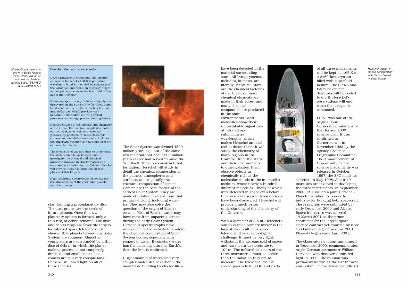
341
have been detected in thematerial surroundingstars. All living systems,including humans, areliterally ‘stardust’. Starsare the chemical factoriesof the Universe: mostchemical elements aremade in their cores, andmany chemicalcompounds are producedin the stars’environments. Mostmolecules show theirunmistakable signaturesat infrared andsubmillimetrewavelengths, whichmakes Herschel an idealtool to detect them. It willstudy the chemistry ofmany regions in theUniverse, from the starsand their environmentsto other galaxies. It willobserve objects aschemically rich as themolecular clouds in the interstellarmedium, where nearly a hundreddifferent molecules – many of whichwere detected in space even beforethey were ever seen in laboratories –have been discovered. Herschel willprovide a much betterunderstanding of the chemistry ofthe Universe.
With a diameter of 3.5 m, Herschel’ssilicon carbide primary mirror is thelargest ever built for a spacetelescope. It is a technologicalchallenge: it must be very light,withstand the extreme cold of spaceand have a surface accurate to10-6 m. The infrared detectors of thethree instruments must be coolerthan the radiation they are tomeasure. The telescope itself iscooled passively to 80 K, and parts
of all three instrumentswill be kept at 1.65 K ina 2160-litre cryostatfilled with superfluidhelium. The SPIRE andPACS bolometerdetectors will be cooledto 0.3 K. Herschel’sobservations will endwhen the cryogen isexhausted.
FIRST was one of theoriginal fourCornerstone missions ofthe Horizon 2000science plan; it wasconfirmed asCornerstone 4 inNovember 1993 by theAgency’s ScienceProgramme Committee.The Announcement ofOpportunity for thescience instruments wasreleased in October1997; the SPC made its
selection in May 1998. About 40institutes are involved in developingthe three instruments. In September2000, ESA issued a joint Herschel-Planck Invitation to Tender toindustry for building both spacecraft.The responses were submitted byearly December 2000 and AlcatelSpace Industries was selected14 March 2001 as the primecontractor for the largest spacescience contract yet awarded by ESA:€369 million, signed in June 2001.Phase-B began early April 2001.
The observatory’s name, announcedin December 2000, commemmoratesAnglo-German astronomer WilliamHerschel, who discovered infraredlight in 1800. The mission waspreviously known as the Far Infraredand Submillimetre Telescope (FIRST).
Herschel (upper) inlaunch configurationwith Planck (lower).(Alcatel Space)
340
star, forming a protoplanetary disc.The dust grains are the seeds offuture planets. Once the newplanetary system is formed, only athin ring of debris remains. The discsand debris rings are favourite targetsfor infrared space telescopes. ISOshowed that planets beyond our SolarSystem are common. Almost allyoung stars are surrounded by a thindisc of debris, in which the planet-making process is not completelyfinished, and small bodies likecomets are still very conspicuous.Herschel will shed light on all ofthese theories.
The Solar System was formed 4500million years ago, out of the sameraw material that about 500 millionyears earlier had served to build theSun itself. To help reconstruct thatformation, Herschel will study indetail the chemical composition ofthe planets’ atmospheres andsurfaces, and especially thechemical composition of comets.Comets are the best ‘fossils’ of theearliest Solar System. They aremade of pristine material from thatprimaeval cloud, including water-ice. They may also solve thequestion of the origin of Earth’soceans. Most of Earth’s water mayhave come from impacting cometsduring the early Solar System.Herschel’s spectrographs haveunprecedented sensitivity to analysethe chemical composition of SolarSystem bodies, especially withrespect to water. If cometary waterhas the same signature as Earth’s,then the link is confirmed.
Huge amounts of water, and verycomplex molecules of carbon – themost basic building blocks for life –
Herschel: the main science goals
Deep extragalactic broadband photometricsurveys in Herschel’s 100-600 µm primewavelength band for detailed investigation ofthe formation and evolution of galaxy bulgesand elliptical galaxies in the first third of theage of the Universe
Follow-up spectroscopy of interesting objectsdiscovered in the survey. The far-IR/sub-mmband contains the brightest cooling lines ofinterstellar gas, which provides veryimportant information on the physicalprocesses and energy production in galaxies
Detailed studies of the physics and chemistryof the interstellar medium in galaxies, both inour own Galaxy as well as in externalgalaxies, by photometric & spectroscopicsurveys and detailed observations. Includesthe important question of how stars form outof molecular clouds
The chemistry of gas and dust to understandthe stellar/interstellar lifecycle and toinvestigate the physical and chemicalprocesses involved in star formation andearly stellar evolution in our Galaxy. Herschelwill provide unique information on mostphases of this lifecycle
High-resolution spectroscopy of comets andthe atmospheres of the cold outer planetsand their moons
Infrared-bright regions inthe M16 Eagle Nebulareveal dense clouds ofcool dust that harbour
forming stars. (ESA/ISO& G. Pilbratt et al.)
sec8 8/1/05 1:40 PM Page 340

2x2-axis Sun sensors, 2x3-axisquartz rate sensors, 4 skewed RWs.Redundant sets of 6x10 N thrusters;2x135 kg hydrazine tanks.
Power system: solar array mountedon thermal shield, GaAs cells provide1450 W EOL, supported by 2x36 AhLi-ion batteries.
Communications: downlink data ratemax. 1.5 Mbit/s (25 Gbit solid-statememory) to Perth (Australia).Controlled from Mission OperationsCentre (MOC) at ESOC; science datareturned to Herschel Science Centre(HSC) at Villafranca (Spain) fordistribution to users. The NASAHerschel Science Center at theInfrared Processing & Analysis Center(IPAC/Caltech) serves USastronomers. The L2 orbit allowscontinuous observations andoperations (3 h daily downlink).
343
Satellite configuration: 7.5 m high,4.0 m wide. Payload module (PLM),based on ISO’s superfluid heliumcryostat technology, houses theoptical bench with the instrumentfocal plane units (SPIRE and PACSeach carry an internal 3He sorptioncooler for 0.3 K bolometer operatingtemperature) and supports thetelescope and some payload-associated equipment. The servicemodule (SVM; partial commonalitywith Planck) below provides theinfrastructure and houses the ‘warm’payload equipment. Cassegraintelescope with 3.5 m-diameter SiC12-segment primary mirror withwavefront error of 6 µm, feeding SiCsecondary. Sunshade allows mirror tocool to 80 K.
Attitude/orbit control: 3-axis pointingto 2.12 arcsec. ERC 32-based attitudecontrol; 2 star trackers, 4-axis gyro,
Herschel’s scientific payload
Photodetector Array Camera & Spectrometer (PACS)
PACS is a camera and low- to medium-resolution spectrometer for 60-210 µm. Two 16×25 Ge:Gaand two bolometer detector arrays cover: 60-90 & 90-130 µm (‘blue’; 3.4 arcsec pixels) and 130-210 µm (‘red’; 6.8 arcsec pixels). As a photometer, images a 1.75×3.5 arcmin FOV simultaneously in‘red’ and one ‘blue’ band. As a spectrometer, covers all three bands with 50×50 arcsec FOV, with150-200 km-1 velocity resolution and instantaneous coverage of 1500 km–1. PI: Albrecht Poglitsch, MPE Garching (D).
Spectral & Photometric Imaging Receiver (SPIRE)
SPIRE is an imaging photometer and low- to medium-resolution imaging Fourier TransformSpectrometer (FTS) for 200-610 µm. Both use bolometer detector arrays: three dedicated tophotometry and two for spectroscopy. As a photometer, it covers a large 4×8 arcmin field of view thatis imaged in three bands (centred on 250, 350, 500 µm) simultaneously. PI: M. Griffin, Queen Mary & Westfield College, London (UK).
Heterodyne Instrument for the Far-Infrared
HIFI is a heterodyne spectrometer offering very high velocity-resolution (0.3-300 km-1), combinedwith low-noise detection using superconductor-insulator-superconductor (SIS; bands 1-5 500-1250 GHz) and hot electron bolometer (HEB; bands 6-7, 1410-1910 & 2400-2700 GHz) mixers, for asingle pixel on the sky (imaging by raster mapping or continuous slow scanning). PI: Th. de Graauw, Space Research Organisation Netherlands, Groningen (NL).
Herschel’s 3.5 m-diameter SiC primary mirror isthe largest ever made for a space observatory,but weighs only 300 kg. Top: assembling the 12petals. Centre: before machining the stiffenersoff the inner face and reducing the shellthickness to 2.5 mm (February 2004). Bottom:after machining, ultrasonic inspection of thepetals‘ brazed joints (May 2004). (EADS Astrium)
sec8 8/1/05 1:40 PM Page 342

http://www.esa.int/launchers344
Vega
Achievements: cost-effective small launcherLaunch dates: planned debut November 2007Launch site: Kourou, French Guiana (Vega pad 5º14'9"N/52º46'29"W)Launch mass: 138 tPerformance: optimised for LEO. 1500 kg into 700 km 90º polar, 1200 kg into
1200 km Sun-synchronousPrincipal contractors: vehicle: ELV, Avio, EADS-ST, EADS Espacio, Dutch Space,
TNO-Stork, Contraves, CRISA, Sabca, SES, Officine Galileo, Vitrociset, OCI,Arianespace, Pyroalliance; P80: Avio, Europropulsion, Snecma (nozzle), TNO-Stork (igniter), Sabca; ground segment: Vitrociset, Carlo Gavazzi, Nofrayane,Peyrani, OCI, Cegelec, Dataspazio, GTD, Laben
Vega’s primary role is to fill a gap inEurope’s line of launchers. While themarket segment initially targeted wasscience satellites of 1000-1200 kg intoLEO, later forecasts prompted a focuson polar-orbiting Earth observationsatellites of 400-2500 kg. In addition,the need for microsatellite (50-200 kg)services increased significantly inrecent market assessments. Thelaunch service price will be€18.5 million, assisted by synergy withAriane-5 production and operationsand based on only 2-4 governmentand 1-2 commercial missionsannually. Once operational, the servicewill be offered by Arianespace.
Vega began as a national Italianconcept in the 1980s. BPD Difesa eSpazio in 1988 proposed a vehicle tothe Italian space agency (ASI) toreplace the retired US Scout launcherbased around the Zefiro (Zephyr)motor developed from the company’sAriane expertise. The design wassignificantly reworked in 1994 towardsthe current configuration. Over thesame period, CNES was studying aEuropean Small Launcher drawing onAriane-5 technology and facilities.Spain was also studying its ownsmaller Capricornio to operate fromthe Canary Islands.
In February 1998, ASI proposed Vegaas a European project. In April 1998,ESA’s Council approved a Resolutionauthorising programme start in June;
but this was only a limited declaration,approving the first step of pre-development activities, notably onsolid-booster design. Step-1, runningfrom June 1998 to September 1999,studied a Vega using a P85 first stagederived from Ariane-5’s existing strap-on. At the October 1999 Council,France declined to support thatapproach. In November 2000, after afurther trade-off between differentvehicle configurations and options forthe first and third stages, it wasagreed to proceed with two strands: anadvanced booster that could serve asboth an improved Ariane-5 strap-onand as Vega’s first stage, and the Vegaprogramme itself.
The Vega Programme was approved byESA’s Ariane Programme Board on 27-28 November 2000, and the projectofficially started on 15 December 2000when seven countries subscribed tothe Declaration. ESA signed the€221 million development contractwith ELV (Euopean Launch Vehicle:70/30% Avio/ASI) on 25 February2003, at the same time as CNES onESA's behalf signed the €40.7 millionP80 development contract with Avio(then FiatAvio). Industry's owninvestment of P80 is €63 million. ELVis funding the qualification firstlaunch, worth about €30 million.
The ESA cost-to-completion for Vega is€335 million (1997 conditions; 2004:€367 million), including the €44 million
sec8 8/1/05 1:40 PM Page 344

346
Vega is sized for 1500 kg into 700 km polar orbits. (Vertical axis: payload in kg; horizontal axis: orbit inclination.)
of Step-1. The national contributionsare: Belgium 5.63%, France 15%, Italy65%, Netherlands 3.5%, Spain 6%,Sweden 0.8%, Switzerland 1.34%.
The separate P80 Solid PropulsionStage Demonstrator programme willcost a total of €123 million (2000conditions), with €54 million fromESA, €63 million from Italy via theprime contractor and €6.6 million fromBelgium via ESA’s General Support &Technology Programme. The overallcontributions are therefore (€ million):Belgium 6.6, France 45.1, Italy 68.6,Netherlands 2.7.
Vega’s PDR was held Jun-Jul 2001,and the System Design Review Apr-May 2004. The System CDR isplanned for Sep 2006 and theQualification Flight in Nov 2007. P80’s
PDR was held in Mar 2001; the CDRis planned for May 2006 after thedevelopment firing test of Jan 2006.P80’s QM1 qualification firing test isplanned for Jul 2006.
Vega will make maximum use of theexisting Ariane infrastructure atKourou. It was decided in Nov 2001that it would reuse the old ELA-1Ariane-1 pad. Launcher assemblyand integration will be performed onthe pad within the new Mobile Gantry(MG). Launch will be conducted froma dedicated room in the Ariane-5CDL-3 control centre. Satellites willbe processed in Kourou’s existingEPCU payload facilities. The€48.7 million (2004 conditions)ground segment contract will besigned in 2005 with prime contractorVitrociset (I).
Vega CharacteristicsTotal length: 30.22 mPrincipal diameter: 3.005 mLaunch mass: 136.7 t (excluding payload)Launch thrust: 2700 kN sea levelCapability: reference mission is 1500 kginto 700 km 90º orbit from Kourou.Injection accuracy: ±10 km altitude,±0.1º inclination
Reliability goal: 0.98Guidance: avionics mounted on AVUM
Stage-1Principal contractor: Avio/EuropropulsionLength: 11.713 m (aft skirt 70 cm;interstage 2138 mm, 14.5º slope)
Principal diameter: 3.005 m Motor: P80, filament-wound graphite-epoxy casing, 88.4 t HTPB 1912, SI279.5 s vac, 95 bar operating pressure,nozzle (carbon phenolic) expansion ratio16 (3D carbon-carbon throat 468 mmdia), length 10.555 m, mass fraction0.92
Thrust: 2260/3050 kN avg/max vacuumBurn time: 106.7 sSteering: TVC by ±6.58º deflection offlexible nozzle joint by electromechanicalactuators provides vehicle pitch/yawcontrol
Stage-2Principal contractor: AvioLength: 5.790 m Principal diameter: 1.905 m Motor: Zefiro 23, filament-wound carbon-epoxy casing, 23.9 t HTPB 1912, finocylgrain, SI 288.6 s vac, 106 bar maximumoperating pressure, nozzle expansionratio 25 (throat 294 mm dia), massfraction 0.92, EPDM insulation. Scaledup from Zefiro 16 (length 7.3 m); tested18 Jun 1998, 17 Jun 1999, 15 Dec 2000(QM1); planned: Dec 2005 & Dec 2006
Thrust: 900/1200 kN avg/max vacuumBurn time: 72 sSteering: TVC by ±6.5º deflection ofsubmerged flexible nozzle joint byelectromechanical actuators providesvehicle pitch/yaw control, 3D carbon-carbon throat
Stage-3Principal contractor: AvioLength: 3.767 m (aft interstage 163 mm,aluminium)
Principal diameter: 1.905 m Motor: Z9 derived from Zefiro 16, filament-wound carbon-epoxy casing, 10 t HTPB1912, finocyl grain, SI 294 s vac, 83 barmaximum operating pressure. nozzleexpansion ratio 56 (throat 164 mm dia),mass fraction 0.925, EPDM insulation
Thrust: 235/330 kN avg/max vacuumBurn time: 110 sSteering: as stage-2 except TVC ±6º
AVUM Attitude & Vernier Upper ModuleAVUM provides the final injectionaccuracy, orbit circularisation, deorbit,roll control during stage-3 burn and3-axis control during all coasts. Lowersection is APM (AVUM PropulsionModule), upper is AAM (AVUM AvionicsModule).Principal contractor: Avio (engine:Yuzhnoye, Ukraine)
Length: 1.285 m (820 mm aft interstage)Principal diameter: 1.90 m Dry mass: 440 kgPropulsion: single 2450 N NTO/UDMHRD-869 engine for delta-V, SI 315.5 s,nozzle expansion ratio 102.5, chamberpressure 20 bar; 5-ignition capability;up to 550 kg propellant depending onmission: up to 367/183 kg NTO/UDMHin 4x142-litre tanks, pressurised to max36 bar by He in 87-litre tank (310 bar).Two sets 3x50 N GN2 (310 bar in 87-litre tank) thrusters for attitude control
Burn time: typically 400 s #1 + 143 s #2
Payload Fairing and AccommodationCan carry a main payload and up to 6microsats, or two payloads of 300-1000 kg each. Protected by Contraves2-piece 500 kg fairing until it is jettisonedafter about 223 s after stage-2 separationwhen heating <1135 w/m2. Carbon skinon aluminium honeycomb. Total length7.88 m, diameter 2.6 m; payload envelope5.5 m high, 2.38 m diameter. Payloadadaptor Ariane ACU 937B. Acceleration load (static): 5.5 g maxlongitudinal, 1 g lateralAcoustic: max 142 dB overal
347
Stg 1 ignition/launchT (mission time) = 0 sz (altitude) = 0 kmV (relative speed) = 0 m/sR (downrange) = 0 km
Stg 1 burnout/sep,Stg 2 ignitionT = 107 sz = 44 kmV = 1825 m/sR = 64 km
Stg 2 burnoutT = 179 sz = 95 kmV = 4120 m/sR = 271 km
Stg 2 separation/Stg 3 ignitionT = 217 sz = 116 kmV = 4072 m/sR = 423 km
Fairing separationT = 223 sz = 118 kmV = 4162 m/sR = 445 km
Stg 3 burnout/sepAVUM ignition 1T = 329 sz = 146 kmV = 7645 m/sR = 1205 km
AVUM cut-off,circularisationT = 3013 sz = 700 kmV = 7522 m/s
AVUM cut-off(transfer orbit)T = 725 sz = 216 kmV = 7912 m/sR = 4031 km
AVUM ignition 2T = 2870 sz = 698 kmV = 7376 m/sR = 18553 km
AVUM carries Vega’scontrol system and
provides the finalinjection.
sec8 8/1/05 1:40 PM Page 346

348
ERA
Planned achievements: first European robot arm in spaceLaunch date: about November 2007Mission end: 10 yearsLaunch vehicle/site: Proton from Baikonur Cosmodrome, KazakhstanLaunch mass: 630 kg Orbit: attached to International Space Station (altitude about 400 km)Principal contractors: Dutch Space (prime), SABCA (MJS), NLR (MPTE),
Spacebel/Trasys (IMMI, MPTE), EADS Astrium (EES, MJS, OBC), OG (CLU),Fiar (EMMI), HTS (MLS), Saab (OBC), Technospacio/Terma (software)
ESA’s European Robotic Arm (ERA)will play an important role inassembling and servicing theInternational Space Station (ISS). It isa cooperative venture between ESAand Roskosmos, the Russian spaceagency. The project began as theHermes Robot Arm (HERA) for ESA’sHermes mini-shuttle. When Hermeswas discontinued, studies for the armto fly on Russia’s proposed Mir-2second generation space station wereconducted between Fokker (nowDutch Space) and RSC-Energia.These studies highlighted the value ofa robotic manipulator in reducing thetime needed for expensive mannedactivities in a hazardousenvironment.
Following Russia joining the ISSprogramme in 1993, the arm wasformally incorporated into thestation’s Russian Segment in July1996. It was to be mounted onRussia’s Science and Power Platform(SPP), launched together on the USShuttle in 1999. Among its first tasks
was installing the SPP’s solar arrays.Russian funding problems indefinitelypostponing work on the SPP andShuttle difficulties stretching out theISS assembly sequence pushed ERA’slaunch beyond 2005 even thoughESA could have had it flight-ready in2002. The goal now is to launch it in2007 as part of Russia’sMultipurpose Laboratory Module(MLM), built using the Zarya backupvehicle. ERA passed its Qualification& Acceptance Review in October2003, certifying it flightworthy. Costto ESA by end-2003 was €188 million(2003 conditions).
ERA is functionally symmetrical, witheach end sporting an ‘End-Effector’that works either as a hand or as abase from which the arm can operate.There are seven joints (in order: roll,yaw, pitch, pitch, pitch, yaw, roll), ofwhich six can operate at any onetime. This configuration allows ERAto relocate itself on to differentbasepoints, using a camera on theEnd-Effector to locate a basepointaccurately.
Each End-Effector includes a specialfixture to grapple and carry payloadsof up to 8 t. Through this fixture, thearm can supply power and exchangedata and video signals. In addition, itfeatures a built-in Integrated ServiceTool that can activate smallmechanisms in the grappled payload.Equipped with a foot restraint, ERAcan carry spacewalking cosmonauts,
ERA Characteristics
Total length: 11.30 mReach: 9.70 mMass: 630kgPayload positioning accuracy: 5 mmPayload capability: 8000 kgMaximum tip speed: 20 cm/sStiffness (fully stretched): >0.4 N/mmOperating power: 475/800 W avg/peakArm booms: carbon fibre, 25 cm dia
Preparing for thermal-vacuum testing of the
EngineeringQualification Model at
ESTEC, November1999.
sec8 8/1/05 1:40 PM Page 348

350
prepared mission plans), semi-automatic mode (standardautosequences) and manual mode(controlling the individual joints).
Cosmonauts train on the MissionPlanning and Training Equipment(MPTE), a realistic simulator of thearm and its environment. At its coreis a fully flight-representative ERAonboard computer using the fullflight software. The MPTE, includingfully functional models of IMMI andEMMI and using their flight software,is located in Russia at RSC-Energiaand the Gagarin Cosmonaut TrainingCentre, and at ESTEC in the ERASupport Centre. The ESTEC MPTEadditionally includes the ERASoftware Maintenance Facility (SMF).The Russian MPTEs are used to trainERA’s cosmonaut operators andgenerate ERA flight procedures for
providing them with a platform asthey work in weightlessness.
Unusually, ERA’s main computer ismounted on the arm itself, providinga simpler control interface. It can becontrolled from inside the Station,using the Internal Man-MachineInterface (IMMI) at the Zvezdamodule’s central control post. IMMI’ssynoptic display provides computer-generated detailed and overviewpictures of ERA and its surroundings.In addition, monitors display videoimages from ERA and the Station’sexternal cameras. ERA can also beoperated by a spacewalker via theExternal Man-Machine Interface(EMMI) control panel. Commands areentered via toggle switches, whileLEDs display arm status andoperations progress. Both approachesoffer an automatic mode (using
transmission to the Space Station.The MPTE can also provide on-linesupport during ERA operations, andplay back and analyse actualoperations. ESTEC’s MPTE supportthese activities.
Crews aboard the Station willmaintain their expertise via a special‘Refresher Trainer’. This is a reducedERA simulation built into astandalone laptop. They can practisean entire ERA operation before it isdone for real.
There are three main developmentmodels. The Engineering/Qualification Model (EQM) was testedin November 1999 in the Large SpaceSimulator at ESTEC to check itsthermal balance. The Flight Modelunderwent EMC and vibration testingat ESTEC at the end of 2000. The
351
The EMMI control panel (upper left) is used by aspacewalking cosmonaut (upper far left). Cosmonauts insidethe Space Station control ERA via IMMI’s computer-generated views (lower far left). Lower left: the End-Effector.The hardware shown in both cases is the Flight Model atDutch Space, February 2002.
ERA will be launched onthe MultipurposeLaboratory Module in2007.
ERA principal features. CLU: Camera &Lighting Unit; ECC: ERA Control
Computer; EES: End-Effector System; GF:Grapple Fixture; MJS: Manipulator Joint
System; MLS: Manipulator Limb System.Should there be a serious failure, it is
divided at the ends of the limbs into threeERA (Orbit) Replaceable Units (ERUs).
There are spares of the elbow section andone wrist section, making two-thirds of a
flightworthy arm.
Flight Spare consists of a wrist andelbow ERUs, making two-thirds of aflightworthy arm.
Under the July 1996 agreement,Russia takes ownership of the flighthardware once it is launched, inexchange for which ESA willparticipate in robotics activitiesaboard the Station and Agencyastronauts will train at the Gagarincentre.
sec8 8/1/05 1:40 PM Page 350
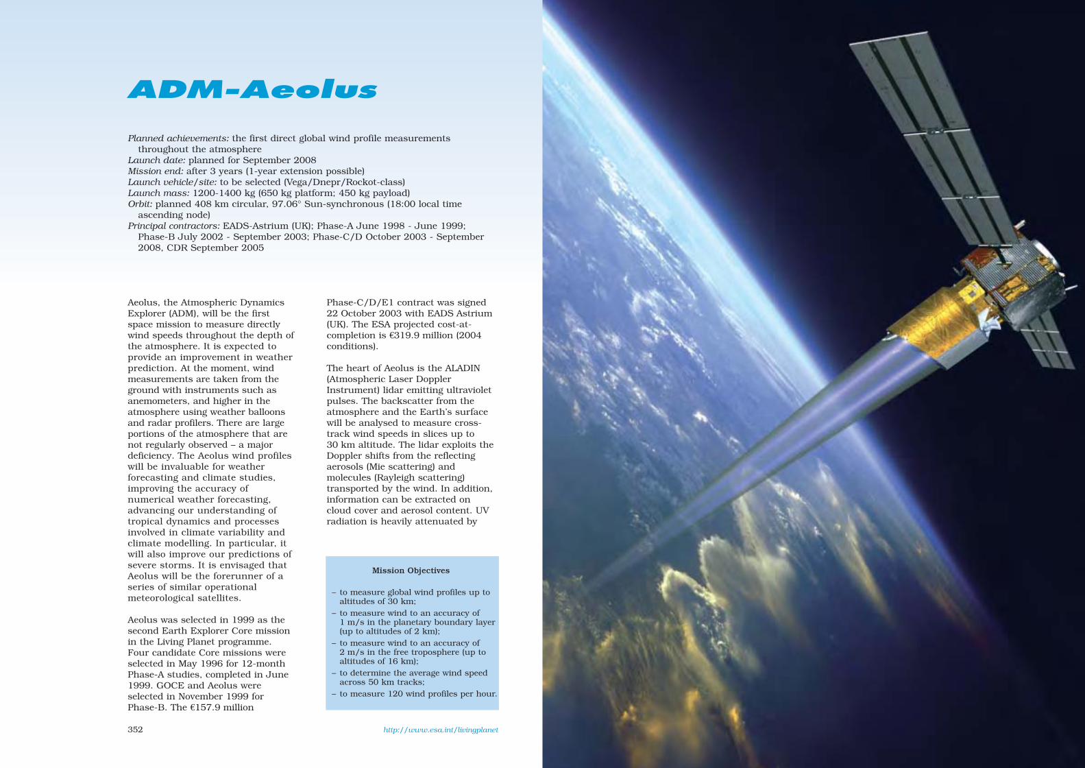
http://www.esa.int/livingplanet352
ADM-Aeolus
Planned achievements: the first direct global wind profile measurementsthroughout the atmosphere
Launch date: planned for September 2008Mission end: after 3 years (1-year extension possible)Launch vehicle/site: to be selected (Vega/Dnepr/Rockot-class)Launch mass: 1200-1400 kg (650 kg platform; 450 kg payload)Orbit: planned 408 km circular, 97.06° Sun-synchronous (18:00 local time
ascending node)Principal contractors: EADS-Astrium (UK); Phase-A June 1998 - June 1999;
Phase-B July 2002 - September 2003; Phase-C/D October 2003 - September2008, CDR September 2005
Aeolus, the Atmospheric DynamicsExplorer (ADM), will be the firstspace mission to measure directlywind speeds throughout the depth ofthe atmosphere. It is expected toprovide an improvement in weatherprediction. At the moment, windmeasurements are taken from theground with instruments such asanemometers, and higher in theatmosphere using weather balloonsand radar profilers. There are largeportions of the atmosphere that arenot regularly observed – a majordeficiency. The Aeolus wind profileswill be invaluable for weatherforecasting and climate studies,improving the accuracy ofnumerical weather forecasting,advancing our understanding oftropical dynamics and processesinvolved in climate variability andclimate modelling. In particular, itwill also improve our predictions ofsevere storms. It is envisaged thatAeolus will be the forerunner of aseries of similar operationalmeteorological satellites.
Aeolus was selected in 1999 as thesecond Earth Explorer Core missionin the Living Planet programme.Four candidate Core missions wereselected in May 1996 for 12-monthPhase-A studies, completed in June1999. GOCE and Aeolus wereselected in November 1999 forPhase-B. The €157.9 million
Phase-C/D/E1 contract was signed22 October 2003 with EADS Astrium(UK). The ESA projected cost-at-completion is €319.9 million (2004conditions).
The heart of Aeolus is the ALADIN(Atmospheric Laser DopplerInstrument) lidar emitting ultravioletpulses. The backscatter from theatmosphere and the Earth’s surfacewill be analysed to measure cross-track wind speeds in slices up to30 km altitude. The lidar exploits theDoppler shifts from the reflectingaerosols (Mie scattering) andmolecules (Rayleigh scattering)transported by the wind. In addition,information can be extracted oncloud cover and aerosol content. UVradiation is heavily attenuated by
Mission Objectives
– to measure global wind profiles up toaltitudes of 30 km;
– to measure wind to an accuracy of1 m/s in the planetary boundary layer(up to altitudes of 2 km);
– to measure wind to an accuracy of2 m/s in the free troposphere (up toaltitudes of 16 km);
– to determine the average wind speedacross 50 km tracks;
– to measure 120 wind profiles per hour.
sec8 8/1/05 1:40 PM Page 352

355354
cloud, so a complete wind profilecan be derived only in a clear orpartly cloud-free atmospherethrough cloud gaps. In an overcastsky, wind profiles can be derived forthe layers above the clouds.
Satellite configuration: conventionalbox-shaped bus with four side wallsattached to central thrust cone byflat shear walls. Electronicsmounted on ±X walls (acting asradiators) that also carry the solarwings. Lidar mounted on cone bythree bipods.
Attitude/orbit control: the dawn-duskorbit means that the +Y axis alwaysfaces away from the Sun, and thesolar wings can be fixed ±Xaft/forward along the line of flight.Attitude control to 50 µrad by four40 Nms reaction wheels & three400 Am2 magnetorquers. Pointingknowledge 30 µrad from two startrackers, gyros, GPS receiver, two3-axis magnetometers & coarseEarth/Sun sensors. Four 5 Nhydrazine thrusters for orbit adjust;116-266 kg propellant in two tanks.
Thermal: instrument dissipation of500 W via heat pipes to +Y face todeep space. 215 W from electronicsboxes mounted on ±X walls.
Power system: two 3-panel wings(total 13.4 m2) of GaAs cellsproviding 2200 W EOL (1.4 kWrequired), supported by 84 Ah Li-ion battery. System design drivenby laser pulse power.
Communications: raw datadownlinked at 10 Mbit/s on 5.6 WSSPA 8.040 GHz X-band toSvalbard (N) ground station.2 kbit/s TC & 8 kbit/s TM S-band.X-band antenna mounted on lidarbaffle. Aeolus controlled from ESOCvia Kiruna. ESRIN will process &calibrate the data before sending itto the European Centre forMedium-Range Weather Forecasts(UK), which will be responsible forquality control and disseminationwithin 3 h of observation tometeorological centres and otherusers.
ADM-Aeolus Payload
ALADIN
The Atmospheric Laser Doppler Instrument(ALADIN) uses a 1.5 m-dia main CassegrainSiC mirror. Diode-pumped Nd:YAG lasergenerates 355 nm 150 mJ 100 Hz pulses for7 s (+1 s warm-up) every 28 s. ALADIN aims35° off-nadir and at 90° to the flightdirection to avoid Doppler shift from its ownvelocity. A measurement is made every200 km over a length of 50 km (integratedfrom 3.5 km steps; 1 km steps possible) in7 s. A wind accuracy of 2-3 m/s is required,for vertical steps selectable 0.5-2 km. Twooptical analysers measure respectively theDoppler shift of the molecular scattering(Rayleigh) and scattering from aerosols andwater droplets (Mie).
The centre frequency of the backscattered light isshifted by the wind speed in the measurementdirection, and the random motion of the airmolecules broadens the frequency width of thebackscattered Rayleigh signal. Time corresponds toaltitude.
1
2
3
45
66
7
8
9
10
11
12
1. X-band antenna2. coarse Earth/Sun
sensor3. orbit-adjust thruster4. startracker5. inertial measurement
unit6. hydrazine tanks7. reaction wheels (x4)8. laser cooling radiator9. S-band antenna
10. power control &distribution unit
11. Li-ion battery12. ALADIN control & data
management
sec8 8/1/05 1:40 PM Page 354
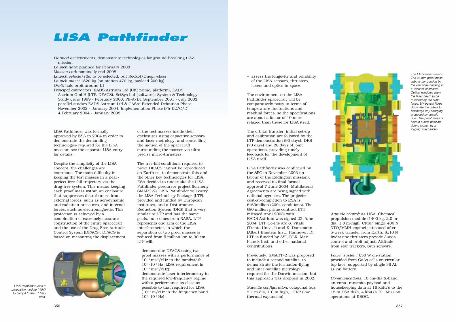
357356
The LTP inertial sensor.The 46 mm proof masscube is surrounded bythe electrode housing ina vacuum enclosure.Optical windows allowthe laser beam to bereflected by the cubefaces. UV optical fibresilluminate the cubes todischarge any chargingproduced by cosmicrays. The proof mass isheld in a safe positionduring launch by a‘caging’ mechanism.
Planned achievements: demonstrate technologies for ground-breaking LISAmission
Launch date: planned for February 2008 Mission end: nominally end-2008Launch vehicle/site: to be selected, but Rockot/Dnepr-classLaunch mass: 1820 kg (on-station 470 kg, payload 200 kg)Orbit: halo orbit around L1Principal contractors: EADS Astrium Ltd (UK; prime, platform), EADS
Astrium GmbH (LTP, DFACS), SciSys Ltd (software); System & TechnologyStudy June 1999 - February 2000; Ph-A/B1 September 2001 - July 2002,parallel studies EADS Astrium Ltd & CASA; Extended Definition PhaseNovember 2002 - January 2004; Implementation Phase (Ph-B2/C/D)4 February 2004 - January 2008
LISA Pathfinder
LISA Pathfinder was formallyapproved by ESA in 2004 in order todemonstrate the demandingtechnologies required for the LISAmission; see the separate LISA entryfor details.
Despite the simplicity of the LISAconcept, the challenges areenormous. The main difficulty iskeeping the test masses in a near-perfect free-fall trajectory via thedrag-free system. This means keepingeach proof mass within an enclosurethat suppresses disturbances fromexternal forces, such as aerodynamicand radiation pressures, and internalforces, such as electromagnetic. Thisprotection is achieved by acombination of extremely accurateconstruction of the entire spacecraftand the use of the Drag-Free AttitudeControl System (DFACS). DFACS isbased on measuring the displacement
of the test masses inside theirenclosures using capacitive sensorsand laser metrology, and controllingthe motion of the spacecraftsurrounding the masses via ultra-precise micro-thrusters.
The free-fall conditions required toprove DFACS cannot be reproducedon Earth so, to demonstrate this andthe other key technologies for LISA,ESA decided to undertake the LISAPathfinder precursor project (formerlySMART-2). LISA Pathfinder will carrythe LISA Technology Package (LTP),provided and funded by Europeaninstitutes, and a DisturbanceReduction System (DRS) that is verysimilar to LTP and has the samegoals, but comes from NASA. LTPrepresents one arm of the LISAinterferometer, in which theseparation of two proof masses isreduced from 5 million km to 30 cm.LTP will:
– demonstrate DFACS using twoproof masses with a performance of10–14 ms–2/√Hz in the bandwidth10–3-10–1 Hz (LISA requirement is10–15 ms–2/√Hz);
– demonstrate laser interferometry inthe required low-frequency regimewith a performance as close aspossible to that required for LISA(10–11 m/√Hz in the frequency band10–3-10–1 Hz)
Attitude control: as LISA. Chemicalpropulsion module (1400 kg, 2.0 m-dia, 1.8 m-high, CFRP, single 400 NNTO/MMH engine) jettisoned after5-week transfer from Earth; 8x10 Nhydrazine thrusters provide 3-axiscontrol and orbit adjust. Attitudefrom star trackers, Sun sensors.
Power system: 650 W on-station,provided from GaAs cells on circulartop face, supported by single 36 AhLi-ion battery.
Communications: 10 cm-dia X-bandantenna transmits payload andhousekeeping data at 16 kbit/s to the15 m ESA dish, 4 kbit/s TC. Missionoperations at ESOC.
– assess the longevity and reliabilityof the LISA sensors, thrusters,lasers and optics in space.
The environment on the LISAPathfinder spacecraft will becomparatively noisy in terms oftemperature fluctuations andresidual forces, so the specificationsare about a factor of 10 morerelaxed than those for LISA itself.
The orbital transfer, initial set-upand calibration are followed by theLTP demonstration (90 days), DRS(70 days) and 20 days of jointoperations, providing timelyfeedback for the development ofLISA itself.
LISA Pathfinder was confirmed bythe SPC in November 2003 (infavour of the Eddington mission),and received its final formalapproval 7 June 2004; MultilateralAgreements are being signed withnational agencies. The projectedcost-at-completion to ESA is€160million (2004 conditions). The€80 million prime contract (ITTreleased April 2003) withEADS Astrium was signed 23 June2004. LTP Co-PIs are S. Vitale(Trento Univ., I) and K. Danzmann(Albert Einstein Inst., Hannover, D);LTP is funded by ASI, DLR, MaxPlanck Inst. and other nationalcontributions.
Previously, SMART-2 was proposedto include a second satellite, todemonstrate the formation-flyingand inter-satellite metrologyrequired for the Darwin mission, butthis approach was dropped in 2002.
Satellite configuration: octagonal bus2.1 m dia, 1.0 m high, CFRP (lowthermal expansion).
LISA Pathfinder uses apropulsion module (right)to carry it to the L1 halo
orbit.
sec9 8/1/05 1:51 PM Page 356

359
Understanding how this thinningshield will change in the future is soimportant that new and uniquesatellite measurements are required.
Swarm will use a constellation ofthree satellites in polar orbits atinitial altitudes of 450 km and530 km for high-precision and high-resolution measurements of thestrength and direction of themagnetic field. Swarm will take fulladvantage of a new generation ofmagnetometers for measurementsover different regions of the Earthsimultaneously. GPS receivers, anaccelerometer and an electric fieldinstrument will providesupplementary information forstudying the interaction of themagnetic field with other terrestrialfeatures; for example, Swarm could
provide independent data on oceancirculation.
In parallel, other issues could also beaddressed:
– in conjunction with recentadvances in numerical andexperimental dynamos, bettermapping of the geomagnetic fieldwith time will provide new insightsinto field generation and diffusion,and mass and wave motions inEarth’s fluid core. Progress ingeomagnetic research calls formoving beyond simpleextrapolation of the field with timeto forecasting that field via a betterunderstanding of the underlyingphysics.
– the magnetism of the lithosphere,which tells us about the history of
The magnetic field strength at the Earth’s surface. The South Atlantic Anomaly is evident from the weak field. Thewhite dots show where the Topex/Poseidon satellite suffered radiation upsets. The change in field strength over20 years (from Magsat to Ørsted) is shown in percentage terms. (right).
358
Swarm
Planned achievements: most detailed measurements ever of Earth’s magnetic fieldand its environment
Launch date: planned for 2009Mission end: after about 4.5 years Launch vehicle/site: Dnepr/Vega/Rockot-classLaunch mass: each identical Swarm satellite 300-400 kgOrbit: planned Swarm-A/B 450 km (separated east-west by 150 km at equator);
Swarm-C 530 km; inclinations between 86-88º. Swarm-C drifts relative toSwarm-A/B with time
Principal contractors: Phase-A Astrium GmbH and OHB System, Phase-A May2003 - March 2004; Phase-B (prime to be selected) 2005, Phase-C/D 2006 -2009
Swarm will provide the most detailedsurvey of the Earth’s magnetic fieldand its changes over time, providingnew insights into our planet’s interiorand climate. Swarm was selected asthe third Earth Explorer Opportunitymission in ESA’s Living Planetprogramme. Like its predecessors, itis being developed quickly inresponse to a pressing environmentalconcern. The AO was released on1 June 2001 and 25 full proposalswere received by closure in January2002. The ESA Programme Board forEarth Observation selected three on16 May 2002 for Phase-A studies:Swarm, ACE+ (Atmospheric ClimateExplorer) and EGPM (EuropeanGlobal Precipitation Mission). Theparallel 10-month studies on Swarmwere completed by Astrium GmbHand OHB System in March 2004.Swarm was selected by theProgramme Board on 28 May 2004for full development. As anOpportunity mission, it is dedicatedto research. Drs Eigil Friis-Christensen (Danish National SpaceCentre), Hermann Lühr(GeoForschungsZentrum, Potsdam,D) and Gauthier Hulot (Inst. Physiquedu Globe de Paris, F) led the scienceteam that proposed the mission toESA; the Agency has overall missionresponsibility. ESA projected cost-at-
completion is €170 million (2004conditions).
The powerful and complicatedmagnetic field created deep inside theEarth protects us from thecontinuous flow of charged particles,the solar wind, before it reaches theatmosphere. The field is generated bythe turbulent motions of molten ironin the planet’s outer core acting like adynamo. The dominant axial dipolecomponent, however, is weakeningten times faster than it wouldnaturally decay if the dynamo wereswitched off. It has fallen by almost8% over the last 150 years, a ratecomparable to that seen at times ofmagnetic reversals. However, inregions like the South AtlanticAnomaly the field has weakened byup to 10% in the last 20 years alone.
Swarm, with the closest satellite in a higher orbit.The booms trail behind the satellites.
http://www.esa.int/livingplanet
sec9 8/1/05 1:51 PM Page 358

361
and time on global and regionalscales.
The geomagnetic field is not onlyimportant for learning about theorigin and the evolution of our planet.While it is well-known that the airdensity in the thermosphere isstatistically related to geomagneticactivity, recent results suggest that itis also locally affected by geomagneticactivity in a way that is still poorlyunderstood. Furthermore, themagnetic field is a shield againsthigh-energy particles from the Sunand deeper space. It controls thelocation of the radiation belts, andalso the paths of incoming cosmic rayparticles, which reflect the physicalstate of the heliosphere. Theinterplanetary medium controls theenergy input into the Earth’smagnetosphere and the developmentof magnetic storms, in short: SpaceWeather. Numerously reported, butstill poorly understood, correlationsbetween solar activity and climatevariations have recently been relatedto the flux of high-energy cosmic rayparticles from space and the Sun.
No other single physical quantity canbe used for such a variety of studiesrelated to our planet. Highly accurateand frequent measurements of themagnetic field will provide newinsights into the Earth’s formation,dynamics and environment,stretching all the way from theEarth’s core to the Sun.
Satellite configuration: magneticallyclean, with VFM & ASM ondeployed boom (~4-6 m). Size: 6-8 m long (boom deployed behind),1.5-2 m wide, 0.8-1.1 m high.
Attitude/orbit control: attitudedetermination by startracker,magnetometer, coarse Sun/Earthsensors; 3-axis control by 1 N cold-gas thrusters & magnetorquers.Propellant about 50 kg in 2 tanks.
Power system: two panels (4.4-4.7 m2) of GaAs cells provide 105-160 W, supported by 36 Ah Li-ionbattery.
Communications: Mission Controlat ESOC, via Kiruna. Dataprocessing & archiving at ESRIN.Science data downlink 1-5 Mbit/sS- or X-band; 125 Mbyte/day;onboard storage S-band forsatellite TM/TC.
Swarm Payload
Absolute Scalar Magnetometer (ASM)
To measure magnetic field strength and tocalibrate VFM to maintain the absoluteaccuracy during the multi-year mission. Onthe boom.
Vector Field Magnetometer (VFM)
To measure the magnetic field vector, on theboom, together with startracker for preciseattitude measurement.
Electrical Field Instrument (EFI)
To measure local ion density, drift velocityand electric field. Also for plasma densitymapping in conjunction with GPS.
Accelerometer (ACC)
To measure non-gravity accelerations, suchas air drag and solar radiation.
GPS Receiver (GPS)
To determine precise position, speed andtime.
Laser Retroreflector (LRR)
Orbit determination to cm-accuracy by laserranging.
360
the global field and geologicalactivity, could be determined withmuch higher resolution. This will bea bridge between knowledge of thelower crust from previous satellitemissions, and knowledge of theupper crust from aeromagneticsurveys. The changing field mightalso have affected the climate overhistory by affecting the escape tospace of atmospheric gases.
– global 3-D images of the mantle’selectrical conductivity would bepossible for the first time. Thesewould provide clues to the chemicalcomposition and temperature,fundamentally important forunderstanding mantle propertiesand dynamics.
– the magnetic field is of primaryimportance for the Earth’s externalenvironment, providing informationabout the connected Sun-Earthsystem.
Magnetic sensors on or near theEarth’s surface measure acombination of the core field tangledwith others from magnetised rocks inthe crust, electrical currents flowing inthe ionosphere, magnetosphere andoceans, and currents induced in theEarth by external fields. The challengeis to separate the magnetic field fromall these other sources, each with itsown spatial and time characteristics.
The core field and, in particular, how itchanges with time are among the veryfew means available for probing the
On 25 October 2003, Japan’s Midori-2ceased operation above the Pacific, a littlewestward of Peru, possibly as a result of thehuge geomagnetic storm under way at thattime. This region in the southernhemisphere is known to be the place ofmany spacecraft failures owing to thereduced magnetic field intensity allowingdamaging particle radiation to leak throughthe Earth’s magnetic shield. This was thelatest in a series of radiation-inducedsatellite failures in recent years, mainly inthe South Atlantic Anomaly, where the fieldis particularly weak.
Simulated results from Swarm at 400 km altitude. After progressive elimination of each dominant field effect,weaker sources are revealed. From left: core; magnetosphere; ionosphere; crust; ocean currents.
Earth’s liquid core. Variations withtime directly reflect the fluid flows inthe outermost core and provide aunique experimental constraint ongeodynamo theory. But a seriouslimitation on investigating internalprocesses over months to years is theeffect of external magnetic sourcesthat contribute on time-scales up tothe 11-year solar cycle. All thisclearly shows the need for acomprehensive separation andunderstanding of external andinternal processes.
Recent studies have greatly improvedour global and regional knowledge ofthe magnetisation of the crust anduppermost mantle. However,fundamental unresolved questionsremain about the magnetic field ofthe lithosphere and the electricalconductivity of the mantle. The key toanswering these questions is high-resolution measurements in space
sec9 8/1/05 1:51 PM Page 360
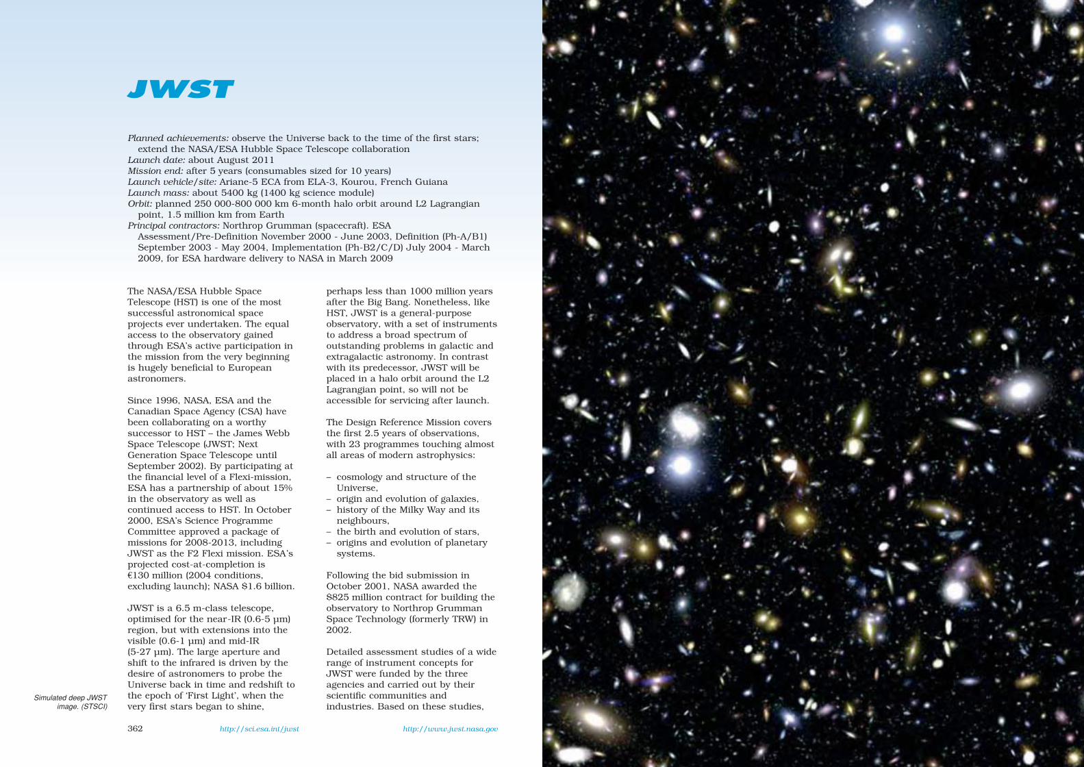
362
JWST
Planned achievements: observe the Universe back to the time of the first stars;extend the NASA/ESA Hubble Space Telescope collaboration
Launch date: about August 2011Mission end: after 5 years (consumables sized for 10 years)Launch vehicle/site: Ariane-5 ECA from ELA-3, Kourou, French GuianaLaunch mass: about 5400 kg (1400 kg science module)Orbit: planned 250 000-800 000 km 6-month halo orbit around L2 Lagrangian
point, 1.5 million km from EarthPrincipal contractors: Northrop Grumman (spacecraft). ESA
Assessment/Pre-Definition November 2000 - June 2003, Definition (Ph-A/B1)September 2003 - May 2004, Implementation (Ph-B2/C/D) July 2004 - March2009, for ESA hardware delivery to NASA in March 2009
The NASA/ESA Hubble SpaceTelescope (HST) is one of the mostsuccessful astronomical spaceprojects ever undertaken. The equalaccess to the observatory gainedthrough ESA’s active participation inthe mission from the very beginningis hugely beneficial to Europeanastronomers.
Since 1996, NASA, ESA and theCanadian Space Agency (CSA) havebeen collaborating on a worthysuccessor to HST – the James WebbSpace Telescope (JWST; NextGeneration Space Telescope untilSeptember 2002). By participating atthe financial level of a Flexi-mission,ESA has a partnership of about 15%in the observatory as well ascontinued access to HST. In October2000, ESA’s Science ProgrammeCommittee approved a package ofmissions for 2008-2013, includingJWST as the F2 Flexi mission. ESA’sprojected cost-at-completion is€130 million (2004 conditions,excluding launch); NASA $1.6 billion.
JWST is a 6.5 m-class telescope,optimised for the near-IR (0.6-5 µm)region, but with extensions into thevisible (0.6-1 µm) and mid-IR(5-27 µm). The large aperture andshift to the infrared is driven by thedesire of astronomers to probe theUniverse back in time and redshift tothe epoch of ‘First Light’, when thevery first stars began to shine,
perhaps less than 1000 million yearsafter the Big Bang. Nonetheless, likeHST, JWST is a general-purposeobservatory, with a set of instrumentsto address a broad spectrum ofoutstanding problems in galactic andextragalactic astronomy. In contrastwith its predecessor, JWST will beplaced in a halo orbit around the L2Lagrangian point, so will not beaccessible for servicing after launch.
The Design Reference Mission coversthe first 2.5 years of observations,with 23 programmes touching almostall areas of modern astrophysics:
– cosmology and structure of theUniverse,
– origin and evolution of galaxies,– history of the Milky Way and its
neighbours,– the birth and evolution of stars,– origins and evolution of planetary
systems.
Following the bid submission inOctober 2001, NASA awarded the$825 million contract for building theobservatory to Northrop GrummanSpace Technology (formerly TRW) in2002.
Detailed assessment studies of a widerange of instrument concepts forJWST were funded by the threeagencies and carried out by theirscientific communities andindustries. Based on these studies,
http://sci.esa.int/jwst http://www.jwst.nasa.gov
Simulated deep JWSTimage. (STSCI)
sec9 8/1/05 1:51 PM Page 362
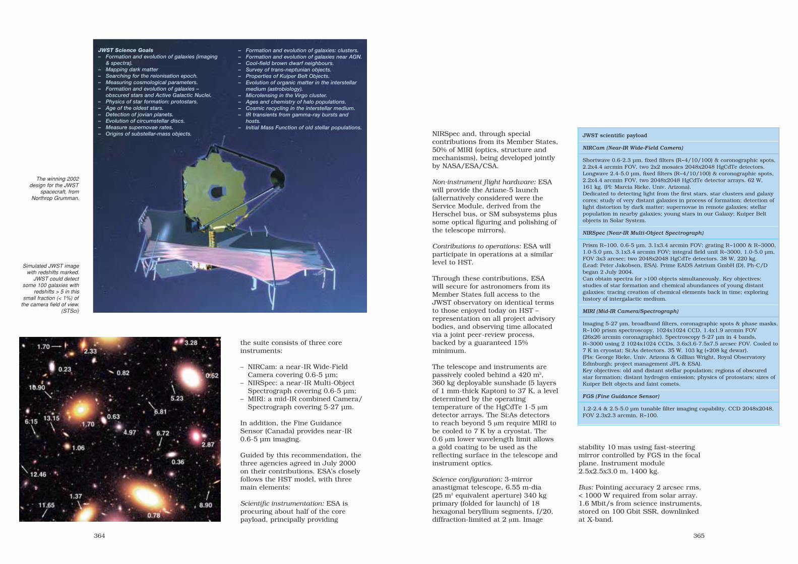
364
the suite consists of three coreinstruments:
– NIRCam: a near-IR Wide-FieldCamera covering 0.6-5 µm;
– NIRSpec: a near-IR Multi-ObjectSpectrograph covering 0.6-5 µm;
– MIRI: a mid-IR combined Camera/Spectrograph covering 5-27 µm.
In addition, the Fine GuidanceSensor (Canada) provides near-IR0.6-5 µm imaging.
Guided by this recommendation, thethree agencies agreed in July 2000on their contributions. ESA’s closelyfollows the HST model, with threemain elements:
Scientific instrumentation: ESA isprocuring about half of the corepayload, principally providing
Simulated JWST imagewith redshifts marked.
JWST could detectsome 100 galaxies with
redshifts > 5 in thissmall fraction (< 1%) of
the camera field of view.(STSci)
The winning 2002design for the JWST
spacecraft, fromNorthrop Grumman.
JWST Science Goals– Formation and evolution of galaxies (imaging
& spectra).– Mapping dark matter– Searching for the reionisation epoch.– Measuring cosmological parameters.– Formation and evolution of galaxies –
obscured stars and Active Galactic Nuclei.– Physics of star formation: protostars.– Age of the oldest stars.– Detection of jovian planets.– Evolution of circumstellar discs.– Measure supernovae rates.– Origins of substellar-mass objects.
– Formation and evolution of galaxies: clusters.– Formation and evolution of galaxies near AGN.– Cool-field brown dwarf neighbours.– Survey of trans-neptunian objects.– Properties of Kuiper Belt Objects.– Evolution of organic matter in the interstellar
medium (astrobiology).– Microlensing in the Virgo cluster.– Ages and chemistry of halo populations.– Cosmic recycling in the interstellar medium.– IR transients from gamma-ray bursts and
hosts.– Initial Mass Function of old stellar populations.
365
NIRSpec and, through specialcontributions from its Member States,50% of MIRI (optics, structure andmechanisms), being developed jointlyby NASA/ESA/CSA.
Non-instrument flight hardware: ESAwill provide the Ariane-5 launch(alternatively considered were theService Module, derived from theHerschel bus, or SM subsystems plussome optical figuring and polishing ofthe telescope mirrors).
Contributions to operations: ESA willparticipate in operations at a similarlevel to HST.
Through these contributions, ESAwill secure for astronomers from itsMember States full access to theJWST observatory on identical termsto those enjoyed today on HST –representation on all project advisorybodies, and observing time allocatedvia a joint peer-review process,backed by a guaranteed 15%minimum.
The telescope and instruments arepassively cooled behind a 420 m2,360 kg deployable sunshade (5 layersof 1 mm-thick Kapton) to 37 K, a leveldetermined by the operatingtemperature of the HgCdTe 1-5 µmdetector arrays. The Si:As detectorsto reach beyond 5 µm require MIRI tobe cooled to 7 K by a cryostat. The0.6 µm lower wavelength limit allowsa gold coating to be used as thereflecting surface in the telescope andinstrument optics.
Science configuration: 3-mirroranastigmat telescope, 6.55 m-dia(25 m2 equivalent aperture) 340 kgprimary (folded for launch) of 18hexagonal beryllium segments, f/20,diffraction-limited at 2 µm. Image
JWST scientific payload
NIRCam (Near-IR Wide-Field Camera)
Shortwave 0.6-2.3 µm, fixed filters (R~4/10/100) & coronographic spots,2.2x4.4 arcmin FOV, two 2x2 mosaics 2048x2048 HgCdTe detectors.Longwave 2.4-5.0 µm, fixed filters (R~4/10/100) & coronographic spots,2.2x4.4 arcmin FOV, two 2048x2048 HgCdTe detector arrays. 62 W,161 kg. (PI: Marcia Rieke, Univ. Arizona).Dedicated to detecting light from the first stars, star clusters and galaxycores; study of very distant galaxies in process of formation; detection oflight distortion by dark matter; supernovae in remote galaxies; stellarpopulation in nearby galaxies; young stars in our Galaxy; Kuiper Beltobjects in Solar System.
NIRSpec (Near-IR Multi-Object Spectrograph)
Prism R~100, 0.6-5 µm, 3.1x3.4 arcmin FOV; grating R~1000 & R~3000,1.0-5.0 µm, 3.1x3.4 arcmin FOV; integral field unit R~3000, 1.0-5.0 µm,FOV 3x3 arcsec; two 2048x2048 HgCdTe detectors. 38 W, 220 kg.(Lead: Peter Jakobsen, ESA). Prime EADS Astrium GmbH (D), Ph-C/Dbegan 2 July 2004.Can obtain spectra for >100 objects simultaneously. Key objectives:studies of star formation and chemical abundances of young distantgalaxies; tracing creation of chemical elements back in time; exploringhistory of intergalactic medium.
MIRI (Mid-IR Camera/Spectrograph)
Imaging 5-27 µm, broadband filters, coronagraphic spots & phase masks,R~100 prism spectroscopy, 1024x1024 CCD, 1.4x1.9 arcmin FOV(26x26 arcmin coronagraphic). Spectroscopy 5-27 µm in 4 bands,R~3000 using 2 1024x1024 CCDs, 3.6x3.6-7.5x7.5 arcsec FOV. Cooled to7 K in cryostat; Si:As detectors. 35 W, 103 kg (+208 kg dewar).(PIs: George Rieke, Univ. Arizona & Gillian Wright, Royal ObservatoryEdinburgh; project management JPL & ESA).Key objectives: old and distant stellar population; regions of obscuredstar formation; distant hydrogen emission; physics of protostars; sizes ofKuiper Belt objects and faint comets.
FGS (Fine Guidance Sensor)
1.2-2.4 & 2.5-5.0 µm tunable filter imaging capability, CCD 2048x2048,FOV 2.3x2.3 arcmin, R~100.
stability 10 mas using fast-steeringmirror controlled by FGS in the focalplane. Instrument module2.5x2.5x3.0 m, 1400 kg.
Bus: Pointing accuracy 2 arcsec rms.< 1000 W required from solar array.1.6 Mbit/s from science instruments,stored on 100 Gbit SSR, downlinkedat X-band.
sec9 8/1/05 1:51 PM Page 364

366
Gaia
Planned achievements: map 1000 million stars at 10-200 microarcsec accuracy todiscover how and when our Galaxy formed, how it evolved and its currentdistribution of dark matter; fundamental importance for all branches ofastronomy; maintain Europe’s lead in astrometry
Launch date: planned for 2011Mission end: 5-year mission planned (5-year observation period); 1-year extension
possibleLaunch vehicle/site: Soyuz-Fregat from Kourou, French GuianaLaunch mass: 2000 kg (900 kg payload)Orbit: planned Lissajous orbit around L2 point 1.5 million km from EarthPrincipal contractors: Alcatel (Cannes, F: definition studies), Alenia (I: definition
studies), EADS-Astrium (F: definition studies, focal plane assembly, opticalbench, SiC mirror), e2v (UK: CCD). Ph-B1 April 2004 - April 2005, Ph-B2begins mid-2005; Phase-C/D 2006-2011
Gaia aims to solve one of the mostdifficult but fundamental challengesin modern astronomy: to determinethe composition, creation andevolution of our Galaxy, in theprocess creating an extraordinarilyprecise 3-D map of more than 1000million stars throughout the Galaxyand beyond.
When ESA’s Horizon 2000 scienceprogramme was extended in 1994with Horizon 2000 Plus, the threenew Cornerstones included aninterferometry mission. Two optionswere proposed. Gaia aimed at10 microarcsec-level astrometry,while Darwin would look for life onplanets discovered around otherstars. Following studies, Gaia’sinterferometric approach wasreplaced in 1997 by measurementsusing simpler monolithic mirrors (andGaia became a name instead of anacronym for Global AstrometricInteferometer for Astrophysics). Gaiacompeted in 2000 with BepiColombofor the fifth Cornerstone slot. InOctober 2000, the ScienceProgramme Committee approved apackage of missions for 2008-2013:BepiColombo was selected as CS-5(2009) and Gaia as CS-6. Followingthe Ministerial Council of November2001, the revised science programmefunding indicated that the costs of
new Cornerstone missions(€586 million for Gaia in 2002 terms)could not be supported, so a majorreview of the overall ESA scienceprogramme was undertaken by theAgency’s advisory bodies. The Gaiaproject began a 6-month technicalreassessment study in December2001. The constraint to use a sharedAriane-5 was relaxed, and thepayload was resized for the smallerand cheaper Soyuz vehicle, whilemaintaining all of the primaryscientific goals. The accuracy goal of10 µarcsec at 15 mag, was relaxed to15–20 µarcsec, primarily because theprimary mirror was reduced from1.7x0.7 m2 to 1.4x0.5 m2 for Soyuz.The service module is now adaptedfrom Herschel/Planck. Gaia wasconfirmed by the SPC in June 2002,and reconfirmed following anotherreevaluation of the programme inNovember 2003. The expected cost-at-completion for the revised missionis about €460 million (2004conditions).
By combining positions with radialvelocities, Gaia will map the stellarmotions that encode the origin andevolution of the Galaxy. It will identifythe detailed physical properties ofeach observed star: brightness,temperature, gravity and elementalcomposition.
http://rssd.esa.int/Gaia
sec9 8/1/05 1:51 PM Page 366

369368
studies will receive a massive impetusthrough the discovery of many tens ofthousands of minor planets; innerTrojans and even new trans-Neptunian objects, includingPlutinos, will be discovered.
Gaia will also contribute tofundamental physics. It will quantifythe bending of starlight by the Sunand major planets over the entirecelestial sphere, and thereforedirectly observe the structure ofspace-time. Gaia’s accuracy will allowthe long-sought scalar correction tothe tensor form to be determined. TheParameterised Post-Newtonian (PPN)parameters γ and ß, and the solarquadrupole moment J2 will bedetermined with unprecedentedprecision. New constraints on the rateof change of the gravitationalconstant, G
., and possibly on
gravitational wave energy over acertain frequency range will beobtained.
Like Hipparcos, Gaia will measure theangles between targets as its rotationscans two telescopes (separated by99º) around the sky. Processing onthe ground will link these targets in agrid with 10 microarcsec accuracy.Distances and proper motions will‘fall out’ of the processing, as willinformation on double and multiplestar systems, photometry, variabilityand planetary systems.
The two moderate-size telescopes uselarge CCD focal plane assemblies,with passive thermal control. ALissajous orbit around Lagrangepoint L2 is preferred, from where anaverage of 1 Mbit/s will return to thesingle ground station throughout the5-year mission (totalling 20 Tbytes ofraw data). Every one of the 109
targets will be observed typically 100times, each time in a complementaryset of photometric filters, and a largefraction also with the radial velocityspectrograph.
current orbits are the result of theirdynamical histories, so Gaia willidentify where they formed and probethe distribution of dark matter. Gaiawill establish the luminosity functionfor pre-main sequence stars, detectand categorise rapid evolutionarystellar phases, place unprecedentedconstraints on the age, internalstructure and evolution of all startypes, establish a rigorous distancescale framework throughout theGalaxy and beyond, and classify starformation and movements across theLocal Group of galaxies.
Gaia will pinpoint exotic objects incolossal numbers: many thousands ofextrasolar planets will be discovered,and their detailed orbits and massesdetermined; brown dwarfs and whitedwarfs will be identified in their tensof thousands; some 100 000extragalactic supernovae will bediscovered in time for ground-basedfollow-up observations; Solar System
Gaia will achieve all this byrepeatedly measuring the positionsand multi-colour brightnesses of allobjects down to magnitude +20.Variable stars, supernovae, transientsources, micro-lensed events andasteroids will be catalogued to thisfaint limit. Final accuracies of10 microarcsec (the diameter of ahuman hair viewed from a distance of1000 km) at magnitude +15, willprovide distances accurate to 10% asfar as the Galactic Centre, 30 000light-years away. Stellar motions willbe measured even in the AndromedaGalaxy.
Gaia will provide the raw data to testour theories of how galaxies and starsform and evolve. This is possiblebecause low-mass stars live for muchlonger than the present age of theUniverse, and retain in theiratmospheres a fossil record of thechemical elements in the interstellarmedium when they formed. Their
Overview of Gaia’sperformance,superimposed on theLund Observatory mapof the sky.
sec9 8/1/05 1:51 PM Page 368

371370
Many analyses will be possible evenduring operations, while some willrequire the whole missioncalibration information or even thefinal data reduction. Gaia willprovide exciting scientific data to avery wide community, beginningwith the first photometricobservations, and rapidly increasinguntil the fully reduced data becomeavailable 2-3 years after mission-end. The resulting analyses willprovide a vast scientific legacy,generating a wealth of quantitativedata on which all of astrophysicswill build.
Satellite configuration: payloadmodule (PLM) 3.8 m diameter,2.1 m high; service module (SVM)3.8/9.0 m diameter(stowed/deployed), PLM/SVMmechanically- and thermally-decoupled, separated by 9.0 m-diameter solar array/sunshield (theonly deployable element), SVMinterfaces with Soyuz adapter;structure is aluminium with CFRPshear walls. Lateral panels used asradiators and covered with opticalsolar reflectors. SVM is at 200ºC,PLM at 200K (stability tens of µK).6 solar wings stowed during launch;insulated from PLM with MLI onrear face. Additional insulationsheets, reinforced with kevlarcables, are spread between thewings.
Attitude/orbit control: FEEP electricor cold-gas thrusters maintain60 arcsec/s spin; 3-axis control by10 N thrusters during 220-240 daytransfer orbit to L2 point. Lissajouseclipse-free orbit around L2provides stable thermalenvironment and high observingefficiency (Sun and Earth alwaysout of fields of view).
Power system: 2200 W required,including 1100 W payload, 700 WSVM. Two panels of GaAs cells oneach of 6 CFRP solar wings, totalling20 m2.
Communications: 17 W X-band high-gain, electronically-steered phased-array antenna provides 3 Mbit/s(minimum 1 Mbit/s) to ESA’s 35 m-diameter Cebreros ground station 8 hdaily. SSR ≥200 Gbit, sized to holdfull day’s data. Controlled fromESOC. Low-gain omni antenna for TCand housekeeping TM.
Gaia MeasurementCapabilities
Median parallax errors4 µas at +10 mag 11 µas at +15 mag 160 µas at +20 mag
Distance accuracies2 million better than 1% 50 million better than 2%110 million better than 5%220 million better than 10%
Radial velocity accuracies1-10 km/s to V = +16-17 mag,
depending on spectral type
Catalogue~1000 million stars 26 million to V = +15 mag250 million to V = +18 mag1000 million to V = +20 magcompleteness to about +20 mag
Photometryto V = +20 mag in 4 broad and 11
medium bands
Gaia Science Goals
Galaxyorigin and history of Galaxytests of hierarchical structure
formation theoriesstar-formation historychemical evolutioninner bulge/bar dynamicsdisc/halo interactionsdynamical evolution
nature of the warpstar cluster disruptiondynamics of spiral structuredistribution of dustdistribution of invisible massdetection of tidally-disrupted
debrisGalaxy rotation curvedisc mass profile
Star formation and evolutionin situ luminosity functiondynamics of star-forming regionsluminosity function for pre-main
sequence starsdetection/categorisation of rapid
evolutionary phasescomplete local census to single
brown dwarfsidentification/dating of oldest halo
white dwarfsage censuscensus of binaries/multiple stars
Distance scale and referenceframe
parallax calibration of all distancescale indicators
absolute luminosities of Cepheidsdistance to the Magellanic Cloudsdefinition of the local,
kinematically non-rotating metric
Local Group and beyondrotational parallaxes for Local
Group galaxieskinematical separation of stellar
populationsgalaxy orbits and cosmological
historyzero proper motion quasar survey
cosmological acceleration of SolarSystem
photometry of galaxiesdetection of supernovae
Solar Systemdeep and uniform detection of
minor planetstaxonomy and evolutioninner TrojansKuiper Belt Objectsdisruption of Oort Cloudnear-Earth objects
Extrasolar planetary systemscomplete census of large planets to
200-500 pcorbital characteristics of several
thousand systems
Fundamental physicsγ to ~5x10⁻⁷
ß to 3x10⁻⁴ - 3x10⁻⁵
solar J2 to 10-7 - 10-8
G./G to 10-12 - 10-13 yr-1
constraints on gravitational waveenergy for 10-12 < f < 4x10⁻⁹ Hz
constraints on ΩM and ΩΛ fromquasar microlensing
Specific objects106 - 107 resolved galaxies 105 extragalactic supernovae500 000 quasars105 - 106 (new) Solar System
objects50 000 brown dwarfs30 000 extrasolar planets200 000 disc white dwarfs200 microlensed events 107 resolved binaries within 250 pc
The payload is mounted on a silicon carbide optical bench. Twotelescopes separated by 99º are scanned by Gaia’s 1 rev/6 hspin rate, for the simultaneous measurement of the angularseparations of thousands of star images as they pass throughthe 1º FOV. The precise angular separation (‘basic angle’) of theprimary 1.4x0.5 m rectangular mirrors (50 m f.l.), iscontinuously measured. Secondary mirrors are adjustable towithin 1 µm. The focal plane has an array of 170 CCDs (each4500x1966 pixels) forming a 45x58 mm detector. FOV dividedinto: Astrometric Sky Mapper of 2 CCD strips to identifyentering objects; Astrometric Field (0.5x0.66º) for the actualposition measurements; 4-band photometer. The third telescope(entrance pupil 50x50 cm) is a spectrometer, for radial velocity(from Doppler shift) measurements using 20 CCDs andmedium-band photometry using 20 CCDs with 11 filters.
Progress in astrometricaccuracy. Two periods ofdramatic increase inastrometric accuracy areevident between theHipparchus and Hipparcoscatalogues: Tycho Brahe inthe early 17th Century andESA’s Hipparcos astrometrymission. Gaia pushesspace-based astrometricmeasurements to the limits;its catalogue will beavailable 3 years after themission is completed.(E. Høg)
sec9 8/1/05 1:51 PM Page 370
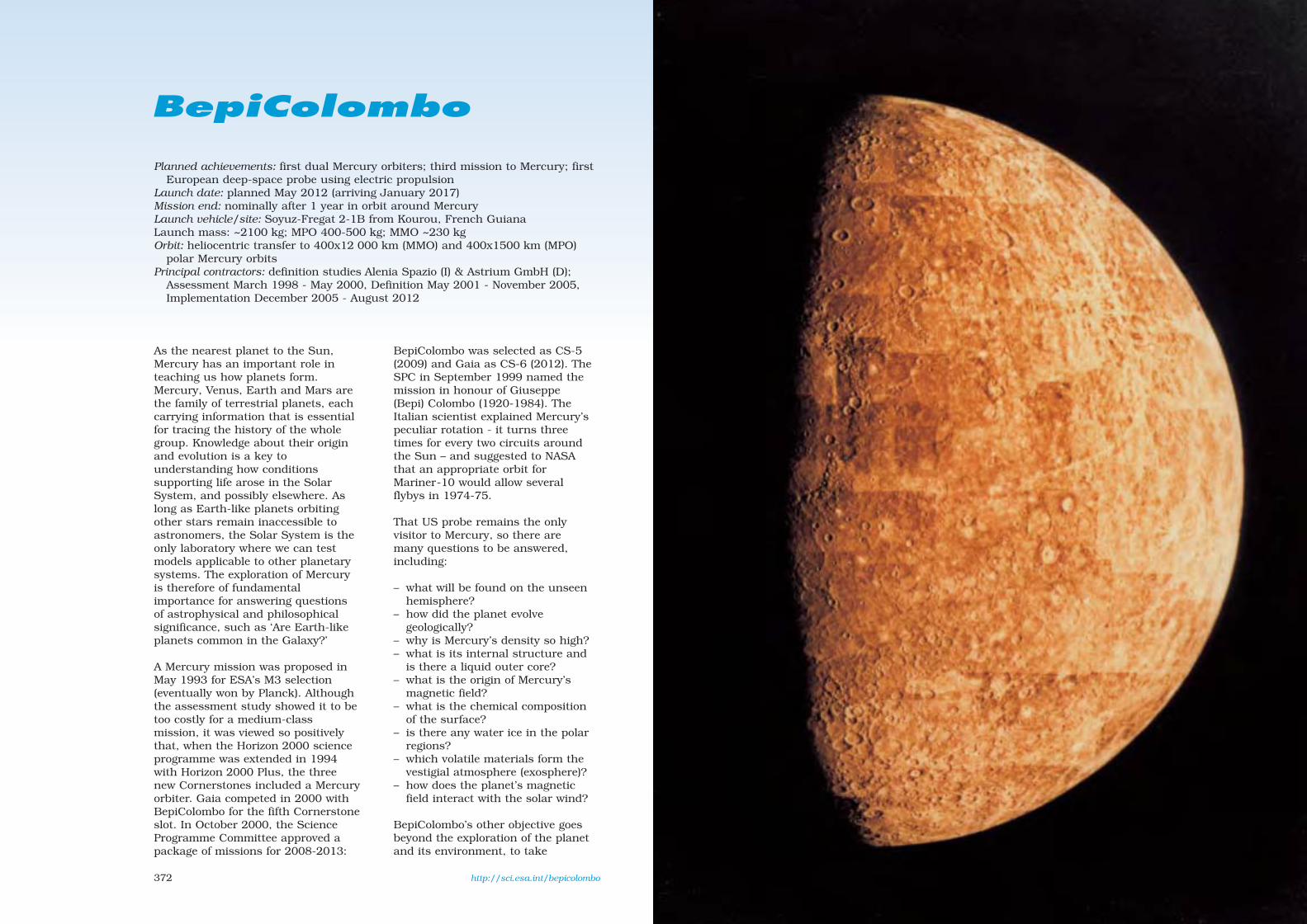
372
BepiColombo
Planned achievements: first dual Mercury orbiters; third mission to Mercury; firstEuropean deep-space probe using electric propulsion
Launch date: planned May 2012 (arriving January 2017)Mission end: nominally after 1 year in orbit around Mercury Launch vehicle/site: Soyuz-Fregat 2-1B from Kourou, French GuianaLaunch mass: ~2100 kg; MPO 400-500 kg; MMO ~230 kgOrbit: heliocentric transfer to 400x12 000 km (MMO) and 400x1500 km (MPO)
polar Mercury orbitsPrincipal contractors: definition studies Alenia Spazio (I) & Astrium GmbH (D);
Assessment March 1998 - May 2000, Definition May 2001 - November 2005,Implementation December 2005 - August 2012
As the nearest planet to the Sun,Mercury has an important role inteaching us how planets form.Mercury, Venus, Earth and Mars arethe family of terrestrial planets, eachcarrying information that is essentialfor tracing the history of the wholegroup. Knowledge about their originand evolution is a key tounderstanding how conditionssupporting life arose in the SolarSystem, and possibly elsewhere. Aslong as Earth-like planets orbitingother stars remain inaccessible toastronomers, the Solar System is theonly laboratory where we can testmodels applicable to other planetarysystems. The exploration of Mercuryis therefore of fundamentalimportance for answering questionsof astrophysical and philosophicalsignificance, such as ‘Are Earth-likeplanets common in the Galaxy?’
A Mercury mission was proposed inMay 1993 for ESA’s M3 selection(eventually won by Planck). Althoughthe assessment study showed it to betoo costly for a medium-classmission, it was viewed so positivelythat, when the Horizon 2000 scienceprogramme was extended in 1994with Horizon 2000 Plus, the threenew Cornerstones included a Mercuryorbiter. Gaia competed in 2000 withBepiColombo for the fifth Cornerstoneslot. In October 2000, the ScienceProgramme Committee approved apackage of missions for 2008-2013:
BepiColombo was selected as CS-5(2009) and Gaia as CS-6 (2012). TheSPC in September 1999 named themission in honour of Giuseppe(Bepi) Colombo (1920-1984). TheItalian scientist explained Mercury’speculiar rotation - it turns threetimes for every two circuits aroundthe Sun – and suggested to NASAthat an appropriate orbit forMariner-10 would allow severalflybys in 1974-75.
That US probe remains the onlyvisitor to Mercury, so there aremany questions to be answered,including:
– what will be found on the unseenhemisphere?
– how did the planet evolvegeologically?
– why is Mercury’s density so high?– what is its internal structure and
is there a liquid outer core?– what is the origin of Mercury’s
magnetic field?– what is the chemical composition
of the surface?– is there any water ice in the polar
regions?– which volatile materials form the
vestigial atmosphere (exosphere)?– how does the planet’s magnetic
field interact with the solar wind?
BepiColombo’s other objective goesbeyond the exploration of the planetand its environment, to take
http://sci.esa.int/bepicolombo
sec9 8/1/05 1:51 PM Page 372

375374
A two-launchscenario, withthe spacecraft
elements dividedinto two composites using
near-identical propulsion elements,was considered as the baseline: theMPO and MMO-MSE composites werelaunched by two Soyuz-Fregats. Twocompeting industrial definitionstudies began in May 2001 to run tolate 2002 to prepare for the 1-yearPhase-B to begin by mid-2003 andPhase-C/D in 2004. However, thisstudy showed that a third launcherwas required for MSE. The severereduction in the science budget afterthe Ministerial Council of November2001 ultimately meant that MSE hadto be dropped from the missionbaseline. From 1 October 2002 to30 June 2003, BepiColombo wentthrough a reassessment with the aimof maximising the scientificperformance by optimising the
payload, whilereducing cost andrisk. Thescenario thatemerged was to launchMPO/MMO together on a singlelauncher (a Soyuz-Fregat 2-1B,offering higher capacity) in mid-2012.To achieve this ambitious goal withadequate resource margins, the MPOpayload resources, particularly mass,had to be significantly reduced (to~50 kg) while ensuring the mission’sscientific competitiveness wasimproved. This was achieved bydefining, from analysis of the scienceobjectives, the corresponding payloadcomplement and resulting instrumentrequirements (these normally resultfrom scientists’ proposals forexperiments). An optimised referencepayload suite was defined in whichinstruments share common functionsand resources, producing improvedscience performance at significantlylower cost.
On 6 November 2003 the SPCapproved the BepiColombo missionwith MPO/MMO but cancelled MSEas part of the reconstructed CosmicVision programme. The cost isprojected at €456 million (mixed 2004conditions), having saved€275 million on the lander.
ESA issued its MPO payload requestfor proposals on 26 February 2004,with a closing date of 15 May. Theselection was made by the SPC on10 November 2004. Japan’s SpaceActivities Commission approvedparticipation in BepiColombo in July2003. JAXA issued its own MMO AOon 15 April 2004, with a closing dateof 15 July 2004.
Key technologies are being developed2001-2004: high-temperature
MPO (left) and MMO(right) in operationalconfiguration.
MMO will emphasisefields & particlesmeasurements. (JAXA)
advantage of Mercury’s proximity tothe Sun:
– fundamental science: isEinstein’s theory of gravitycorrect?
A 1-year System and TechnologyStudy completed in April 1999revealed that the best way to fulfilthe scientific goals was to fly twoOrbiters and a Lander:
– the Mercury Planetary Orbiter(MPO), a 3-axis stabilised andnadir-pointing module in a loworbit for planet-wide remotesensing and radio science;
– the Mercury MagnetosphericOrbiter (MMO), a spinner in aneccentric orbit, accommodatingmostly the field, wave and
particle instruments. Provided byJapan’s JAXA space agency;
– the Mercury Surface Element(MSE) lander, for in situ physical,optical, chemical and mineralogicalobservations that would alsoprovide ground-truth for theremote-sensing measurements.
How to deliver these elements to theirdestinations emerged from a trade-offbetween mission cost and launchflexibility. It combined electricalpropulsion, chemical propulsion andplanetary gravity assists.Interplanetary transfer is performedby a Solar Electric Propulsion Module(SEPM), jettisoned upon arrival. Theorbit injection manoeuvres then use aChemical Propulsion Module (CPM),which is also jettisoned once thesatellites are deployed.
Caloris Basin
Craters
Ray Crater2439 km
Inter-crater Plains
Scarps or Cliffs
sec9 8/1/05 1:51 PM Page 374

377376
thermal control (materials, louvres,heat pipes embedded in structuralpanels); high-temperature solararrays (GaAs cells, arrays, drivemechanisms); high-temperaturehigh-gain antennas (reflectormaterials, feed and pointing/despinmechanisms); miniaturisedintegrated avionics. SMART-1 hasalready demonstrate the use of anelectric thruster for primarypropulsion.
Mission profile: the composite islaunched into Earth orbit with ahigh apogee (312 500 km), leadingto a lunar swingby to set up oneEarth, 2 Venus and 2 Mercurygravity assists during the 4.2-yearcruise. At Mercury, the CPM’s 4 kNengine burns to enter a400x12 000 km polar orbit, whereMMO can be released. For MPO,CPM reignites to set up a400x1500 km orbit and is thenjettisoned. MPO/MMO are bothdesigned for 1 year of observations(4 Mercury years).
MPO: configuration driven bythermal constraints, requiring high-efficiency insulation and 1.5 m2
(200 W rejection) radiator. Bus is aflat prism with 3 sides slanting 20ºas solar arrays, providing 420 W atperihelion (30% cells, 70% opticalsolar reflectors). 1.5 m dia Ka-bandHGA delivers 1550 Gbit in 1 year. 3-axis control, nadir-pointing. Mass400-500 kg (including ~50 kgscience payload).
MMO: cylindrical bus (1.80 m-dia,90 cm-high) spinning at 15 rpm(axis perpendicular to Mercuryequator). CFRP thrust cone housestanks for cold-gas nitrogenthrusters. Hardware mounted onwalls and 2 platforms; top/bottom
faces are radiators. Despun X-band20 W HGA delivers 160 Gbit in1 year; 2 MGAs. Mass ~230 kg(including 30 kg science payload).
Solar Electric Propulsion Module:provides cruise propulsion and isjettisoned before Mercury insertion.150-200 mN-class Xe ion thrusterspowered by 2 wings of GaAs cellsdelivering ~5.5 kW at 1 AU. Wings tiltto maintain T < 150ºC.
Chemical Propulsion Module: providesMercury capture and orbitmanoeuvres. Classical bipropellantengine with redundant attitudethrusters.
BepiColombo Scientific Instruments
Instrument Measurements Mass Power(kg) (W)
MPOBepiColombo Laser Altimeter BELA* topographic mapping 10 50
Italian Spring Accelerometer ISA non-gravity acceleration of spacecraft 5.0 6.2
Magnetic Field Investigation MERMAG magnetic field, interaction with solar wind 1.9 4.7
Mercury Radiometer & MERTIS global mineral mapping (7-14 µm), surface T 2.8 7.0Thermal Imaging Spectrometer
Mercury Gamma-ray & MGNS** elemental surface/subsurface composition, volatile 5.2 3.5Neutron Spectrometer or MANGA** deposits in polar areas
Mercury Imaging X-ray MIXS elemental surface composition, global mapping & 4.6 12.4Spectrometer composition of surface features
Mercury Orbiter Radio MORE core & mantle structure, orbit, gravity field, fundamental 3.5 15Science Experiment science
Probing of Hermean Exosphere PHEBUS UV spectral mapping of the exosphere 4.5 4.1by UV Spectroscopy
Search for Exospheric SERENA in situ study of composition, vertical structure and source 4.1 20.8Refilling & Emitted Natural & sink processes of the exosphereSubstances
Solar Intensity X-ray & SIXS monitor solar X-ray intensity & particles to support MIXS 1.4 1.8Particle Spectrometer
Spectrometers & Imagers for SIMBIO-SYS: optical high-res & stereo imaging, near-IR (<2.0 µm) 7.1 31.6MPO BepiColombo Integrated HIRC, STC, imaging spectroscopy for global mineralogical mappingObservatory VIHI
MMOMercury Magnetometer MERMAG magnetosphere, interaction with solar wind 1.7 2.8
Mercury Plasma Particle Expt MPPE low/high-energy particles in magnetosphere 15.1 19.5
Plasma Wave Instrument PWI structure & dynamics of magnetosphere 8.2 9.7
Mercury Sodium Atmosphere MSASI abundance, distribution & dynamics of sodium 4.2 7.1Spectral Imager in exosphere
Mercury Dust Monitor MDM distribution of interplanetary dust in Mercury orbit 0.5 2.7
*feasibility still to be demonstrated; **feasibility still to be demonstrated, MGNS is preferred solution
The pre-definition study design forBepiColombo. In the foreground isMPO, with the Solar ElectricPropulsion Module still attachedvia the conical interface thathouses the Chemical PropulsionModule. In the background is theMMO/MSE composite.
BepiColombo Science Goals
— exploration of Mercury’s unknownhemisphere;
— investigation of the geological evolution ofthe planet;
— understanding the origin of Mercury’shigh density;
— analysis of the planet’s internal structureand search for the possible liquid outercore;
— investigation of the origin of Mercury’smagnetic field;
— study of the planet’s magnetic fieldinteraction with the solar wind;
— characterisation of the surfacecomposition;
— identification of the composition of theradar bright spots in the polar regions;
— determination of the global surfacetemperature;
— determination of the composition ofMercury’s vestigial atmosphere(exosphere);
— determination of the source/sinkprocesses of the exosphere;
— determination of the exosphere andmagnetosphere structures;
— study of particle energisationmechanisms in Mercury’s environment;
— fundamental physics: verification ofEinstein’s theory of gravity.
sec9 8/1/05 1:51 PM Page 376

378
EarthCARE
Planned achievements: global cloud & aerosol measurements Launch date: planned for 2012 Mission end: nominally after 2 years (potential 1-year extension)Launch vehicle/site: to be selected, but Soyuz/Rockot/Dnepr-classLaunch mass: ~1300 kg Orbit: 451 km or 444 km, Sun-synchronous polarPrincipal contractors: to be selected (Phase-A EADS Astrium GmbH & Alcatel
Space Industries). Phase-A November 2002 - April 2004, Phase-B 2006-2007,Phase-C/D 2007-2012
EarthCARE (Earth Clouds, Aerosols& Radiation Explorer), a jointESA/Japan mission, was selected in2004 as the third Earth ExplorerCore mission in the Living Planetprogramme. It is designed tomeasure the physical properties ofclouds and aerosols to improveclimate modelling and ourunderstanding of Earth’s radiationbalance.
The second Call for Ideas forExplorer Core missions was issuedon 1 June 2000, receiving tenproposals by the 1 September 2000closing date. On 20 November 2000,ESA selected five for assessmentstudies: ACECHEM, EarthCARE,SPECTRA, WALES & WATS.
EarthCARE, SPECTRA and WALESwere selected on 29 November 2001for 12-month Phase-A studies, forlaunch in about 2008. On 28 May2004, the Earth ObservationProgramme Board announced thechoice would be between EarthCAREand SPECTRA, although EarthCAREwas ranked first. The Board of24 November 2004 voted in favour ofEarthCARE as the next EarthExplorer Core mission.
Aerosols, clouds and convection arenot easily included in numericalmodels of the atmosphere, seriouslylimiting our ability to forecast theweather accurately and to predictthe future climate reliably. Theygovern the radiation balance (hence
the Earth’s temperature) and aredirectly responsible for precipitation(thus controlling the water cycle).
Aerosols reflect solar radiation backto space, which leads to cooling.Absorbing aerosols, such as man-made carbon, can produce localheating. Aerosols also control theradiative properties of clouds andtheir precipitation. The lowconcentration of aerosols in marineair creates water clouds with a smallnumber of relatively large droplets.In contrast, the high concentration ofaerosols in continental and pollutedair creates a much higherconcentration of smaller droplets.Continental clouds therefore not onlyreflect more sunlight back to space,but also are much more stable andlong-lived and less likely to produceprecipitation. Aerosols also controlglaciation, yet their effect on iceclouds is essentially unknown. Weneed to measure how much aerosolsare responsible for the rapid drop inthe albedo of fresh snow. Today’sobservations of global aerosolproperties are limited to opticaldepth and a crude estimate ofparticle size. This is veryunsatisfactory, because we need toknow their chemical composition,whether they scatter or absorb, andtheir vertical and geographicaldistribution.
Clouds are the principal modulatorsof the Earth’s radiation balance.Currently, there are global estimates
379
of cloud cover, but little informationon their vertical extent or thecondensed mass of ice or liquid cloudwater. Low clouds cool the climate byreflecting short-wave solar radiationback to space, whereas high cloudswarm the climate because they arecold and emit less IR radiation tospace. In the present climate, thesetwo effects are large and opposite.Any changes in the verticaldistribution of clouds in a futurewarmer climate could lead to largechanges in the net radiation. Climatemodels disagree whether this wouldattenuate or amplify the effect of theoriginal direct greenhouse gaswarming. Uncertainties in the verticalprofiles of clouds strongly affectpredictions of future global warming,and also limit the accuracy ofnumerical weather prediction. Modelscan reproduce the observed top-of-the-atmosphere radiation but withvery different vertical profiles ofclouds and water content.Observations of cloud profiles areurgently required, so that the abilityof models to provide reliable weatherforecasts and predictions of futureglobal warming can be improved.
Clouds are the source of allprecipitation, but the process ispoorly understood. Major difficultiesinclude the large spread in model
predictions of cloud condensate, theefficiency with which this is convertedto precipitation, and the convectivemotions. The extent to whichvigorous tropical convectionintroduces moisture into thestratosphere is uncertain. It is alsoknown that the modelled daily cycleof convection is wrong.Understanding these processes iscrucial for accurate precipitationforecasting. For example, we couldpredict flash flooding with far greatercertainty.
EarthCARE Payload
Cloud Profiling Radar (CPR) JAXA
Vertical profiles of cloud structures,penetrating deeply into lower cloud layersunseen by MSI or ATLID. Sensitivity detectsalmost all ice clouds. Doppler shiftmeasurements of vertical motion of cloud &rain particles overlaid on vertical wind toidentify cloud types, drizzle & cloud dropletfall speed. 2.5 m-dia main reflector with highsurface accuracy & pointing. 94.05 GHz,pulse repetition >6 Hz, footprint 750 m dianadir. 216 kg, 300 W, 120 kbit/s.
Backscatter Lidar (ATLID) ESA
Vertical profiles of thin cloud & aerosollayers, particle shapes and altitude of cloudboundaries. 355 nm Nd-YAG laser, ~20 mJpulses at 70-100 Hz. Res 100 m vertical fromground to 20 km. Three channels: Mieco-polar & cross-polar; Rayleigh co-polar.Footprint 5-12 m, 2º forward along-track.
Multispectral Imager (MSI) ESA
Complementary data for other instruments,to determine cloud type, texture & top T.7 channels 0.659-12.0 µm, swath 150 km,500x500 m pixels.
Broadband Radiometer (BBR) ESA
Reflected 0.2-4 µm & emitted 4-50 µmradiation at top of atmosphere. 10x10 kmFOV. 3 simultaneous views: nadir, ±50ºalong-track.
One of the satelliteconcepts emerging fromthe two Phase-A studies.EarthCARE is dominatedby the 2.5 m-dia radardish.
sec9 8/1/05 1:51 PM Page 378

381380
Planned achievements: first detection of gravitational waves, first directmeasurements of massive black holes at centres of galaxies
Launch date: planned for 2012-2013 Mission end: nominally after 5 years in operational orbitLaunch vehicle/site: Delta-IV from Cape Canaveral, FloridaLaunch mass: total 1380 kg (on-station 274 kg each, science payload 70 kg each)Orbit: heliocentric, trailing Earth by 20ºPrincipal contractors: to be selected; System & Technology Study June 1999 -
February 2000; Phase-A January 2005 - January 2007, Phase-B 2007 - 2008,Phase-C/D 2008 - 2012
The ambitious Laser InterferometerSpace Antenna (LISA) aims to makethe first detection of gravitationalwaves – ripples in space-time.According to Einstein’s Theory ofGeneral Relativity, these waves aregenerated by exotic objects such asbinary black holes, which distortspace and time as they orbit closely.To detect the elusive gravitationalwaves, the three LISA satellites willcarry state-of-the-art inertial sensors,a laser-interferometry telescopesystem and highly sensitive ionthrusters.
In October 2000, the ScienceProgramme Committee approved apackage of missions for 2008-2013.LISA will fly as Cornerstone 7(Fundamental Physics), but incollaboration with NASA at a cost toESA of a Flexi mission. Thedemanding technologies will be testedby the dedicated LISA Pathfinder in2008; see the separate entry.
Massive bodies produce indentationsin the elastic fabric of spacetime, likebilliard balls on a springy surface. Ifa mass distribution movesaspherically, then the spacetimeripples spread outwards asgravitational waves. A perfectlysymmetrical collapse of a supernovawill produce no waves, while a non-spherical one will emit gravitationalradiation. A binary system alwaysradiates.
As gravitational waves distortspacetime, they change the distancesbetween free bodies. Gravitationalwaves passing through the SolarSystem changes the distancesbetween all bodies in it. This could bethe distance between a spacecraftand Earth, as in the cases of Ulyssesand Cassini (attempts continue tomeasure these distance fluctuations),or the distances between shieldedproof masses inside well-spacedsatellites, as in LISA. The mainproblem is that the distance changesare exceedingly small. For example,the periodic change between twoproof masses owing to a typical whitedwarf binary at a distance of 50 pc isonly 10-10 m. Gravitational waves arenot weak (a supernova in a not too-distant galaxy drenches every squaremetre on Earth with kilowatts ofgravitational radiation), but theresulting length changes are smallbecause spacetime is so stiff that ittakes huge energies to produce evenminute distortions.
If LISA does not detect thegravitational waves from knownbinaries with the intensity andfrequency predicted by Einstein’sGeneral Relativity, it will shake thevery foundations of gravitationalphysics.
LISA’s main objective is to learnabout the formation, growth, spacedensity and surroundings of massive
LISA will fly a troika of identical satellites in anequilateral triangle formation to detect
distance changes as they surf gravitationalwaves passing through the Solar System.
black holes (MBHs). There is nowcompelling indirect evidence for theexistence of MBHs with masses of106-108 Suns in the centres of mostgalaxies, including our own. The mostpowerful sources are the mergers ofMBHs in distant galaxies.Observations of these waves wouldtest General Relativity and,particularly, black-hole theory tounprecedented accuracy. Not much isknown about black holes of masses102-106 Suns. LISA can provideunique new information throughoutthis mass range.
LISA uses identical satellites5 million km apart in an equilateraltriangle. It is a giant Michelsoninterferometer, with a third armadded for redundancy andindependent information on the
waves’ two polarisations. Theirseparations (the interferometer armlength) determine LISA’s wavefrequency range (10–4-10–1 Hz),carefully chosen to cover the mostinteresting sources of gravitationalradiation.
http://sci.esa.int/lisa/
LISA PathfinderLISA
ESA-studied LISA satellite configuration. TheY-shaped twin-telescope assembly is supported bya carbon-epoxy ring. The top solar array is notshown, nor the bottom propulsion module.
LISA is a NASA/ESA collaboration: NASAprovides the satellites, launch, X-bandcommunications, mission and scienceoperations, and about 50% of the payload;Europe provides the other 50% of thepayload (funded nationally), with ESAresponsible for payload integration & testing.The formal agreement with NASA was signedin 2004. ESA projected cost-at-completion is€204 million (2004 conditions).
A 4-satellite version of LISA was proposed toESA in May 1993 for the M3 competition(won by Planck), but that version clearlyexceeded the cost limit for a medium-classmission. A 6-spacecraft version wasproposed in December 1993 as aCornerstone for the Horizon 2000 Plusprogramme, and selected, earmarked forlaunch after 2017. By early 1997, the costhad been drastically reduced by halving thenumber of satellites and throughcollaboration with NASA (until August 2004,it was expected that ESA would provide thesatellites).
sec9 8/1/05 1:51 PM Page 380

383382
The centre of the triangularformation is in the ecliptic plane1 AU from the Sun and 20º behindthe Earth. The plane of the triangleis inclined 60º to the ecliptic. Thisconfiguration means that theformation is maintained throughoutthe year, and appears to rotatearound its centre annually.
Each satellite contains two opticalassemblies, each pointing to anidentical assembly on each of theother satellites. A 1 W 1.064 µm IRNd:YAG laser beam is transmittedvia a 30 cm-aperture f/1 Cassegraintelescope. The other satellite’s ownlaser is phase-locked to theincoming light, providing a returnbeam with full intensity. The firsttelescope focuses the very weakbeam (a few pW) from the distantspacecraft and directs it to asensitive photodetector, where it issuperimposed with a fraction of theoriginal local light, serving as a localoscillator in a heterodyne detection.The distance fluctuations are
measured to 40 pm (4x10–11 m)precision which, combined with the5 million km separations, allowsLISA to detect gravitational-wavestrains down to one part in 10-23 in ayear of observation with a signal-to-noise ratio of 5.
At the heart of each assembly is avacuum enclosure housing a free-flying polished platinum-gold 46 mmcubic proof mass, which serves asthe optical reference mirror for thelasers. The spacecraft serve mainlyto shield the proof masses fromsolar radiation pressure, and thespacecraft’s actual position does notdirectly enter into the measurement.It is nevertheless necessary to keepthem moderately centred(10–8 m/√Hz in the measurementband) on their proof masses toreduce spurious local noise forces.This is done by a drag-free controlsystem consisting of anaccelerometer (or inertial sensor)and a system of µN thrusters. 3-Dcapacitive sensing measures thedisplacements of the proof massesrelative to the spacecraft. Theseposition signals are used tocommand Field-Emission ElectricPropulsion (FEEP) thrusters toenable the spacecraft to follow itsproof masses precisely. Thethrusters also control the attitude ofthe spacecraft relative to theincoming optical wave fronts usingsignals derived from quadrantphotodiodes. As the constellationorbits the Sun in the course of ayear, the observed gravitationalwaves are Doppler-shifted by theorbital motion. For periodic waveswith sufficient signal-to-noise ratio,this allows the direction of thesource to be determined toarcminute or degree precision,depending on source strength.
Satellite configuration (ESA study):total diameter 2.2 m across solararray. Main structure is a 1.80 m-dia,48 cm-height ring of graphite-epoxy(low thermal expansion). Eachsatellite houses two identicaltelescopes and optical benches in aY-shaped configuration.
Attitude control: drag-free attitudecontrol system (DFACS) of 6 clustersof four FEEP thrusters (to be decidedif caesium or indium), controlled byfeedback loop using capacitiveposition sensing of proof masses.Performance: 3x10–15 m/s2 in theband 10–4-10–3 Hz. Solar-electricpropulsion module (142 kg, 1.80 m-dia, 40 cm-high, CFRP, redundant20 mN Xe ion thrusters) jettisonedafter 13-month transfer from Earth;4x4.45 N + 4x0.9 N hydrazinethrusters provide 3-axis control andorbit adjust. Attitude from 4 startrackers, Sun sensors.
Power system: 315 W on-station(72 W science), provided from GaAscells on circular top face, supported
by Li-ion batteries. 940 W requiredduring ion-powered cruise, fromsimilar propulsion module array.
Communications: two 30 cm-dia 5 WX-band steerable antennas transmitscience and engineering data (storedonboard for 2 days in 1 GB solid-state memory) 8 h/day at 7 kbit/s tothe 34 m network of NASA’s DeepSpace Network. Total science rate672 bit/s.
Each satellite hastwo identicaltelescopespointing 60º apart.The 46 mmpolished cubes(yellow) are thezero points formeasuringdistance changesbetween thesatellites.
LISA’s sensitivity to binary stars in our Galaxy and black holes in distant galaxies. The heavyblack curve shows LISA’s detection thresholdafter a year’s observations. The vertical scale isthe distance change detected (one part in 1023 isthe goal). At frequencies below 10-3 Hz, binarystars in the Galaxy are so numerous that LISAwill not resolve them (marked ‘Binary confusionnoise’). In lighter green is the region where LISAshould resolve thousands of binaries closer tothe Sun or radiating at higher frequencies. Thesignals expected from two known binaries areindicated by the green triangles. The blue areacovers waves expected from massive blackholes merging in other in galaxies (redshiftz = 1). The red spots mark the mergings of twomillion-solar-mass black holes, and two 10 000-solar-mass black holes. The bottom red spotshows the expected wave from a 10-solar-massblack hole falling into one of a million solarmasses, at a distance of z = 1.
LISA consists of a constellation of three spacecraftflying in formation at the corners of an equilateraltriangle, inclined at 60° with respect to the eclipticplane, in a heliocentric orbit. The equilateral triangleperforms a complete rotation around its centreduring one year, while rotating around the Sun.
sec9 8/1/05 1:51 PM Page 382
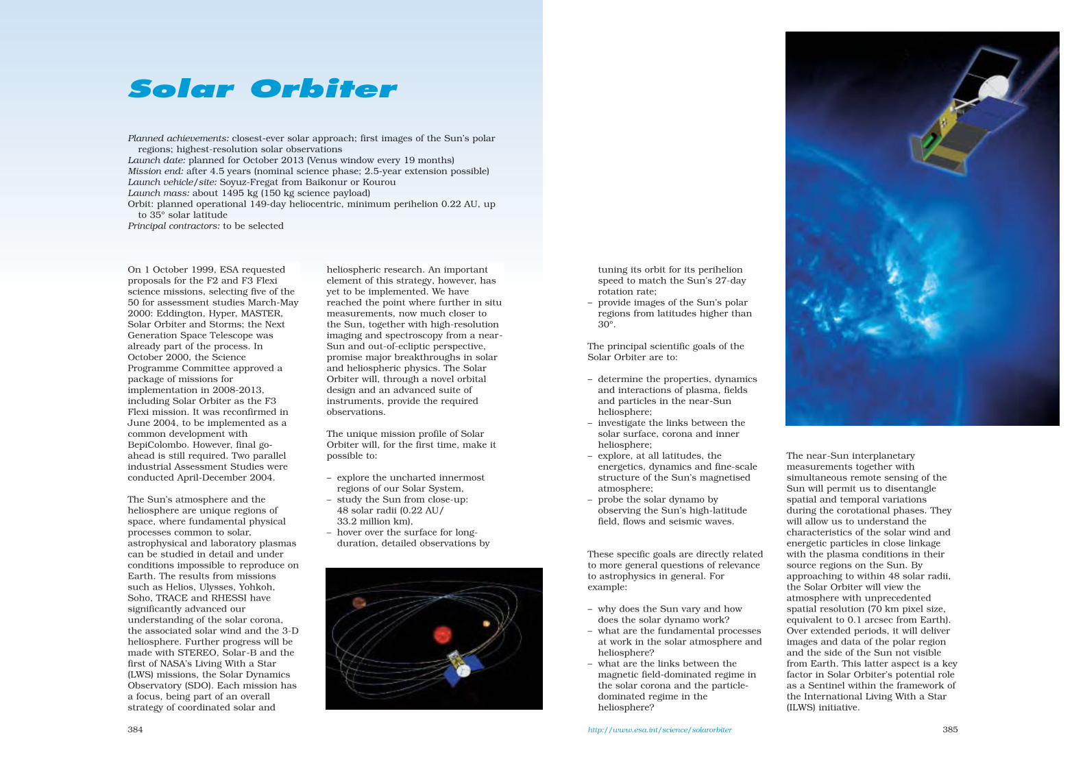
385384
Solar Orbiter
Planned achievements: closest-ever solar approach; first images of the Sun’s polarregions; highest-resolution solar observations
Launch date: planned for October 2013 (Venus window every 19 months)Mission end: after 4.5 years (nominal science phase; 2.5-year extension possible)Launch vehicle/site: Soyuz-Fregat from Baikonur or KourouLaunch mass: about 1495 kg (150 kg science payload)Orbit: planned operational 149-day heliocentric, minimum perihelion 0.22 AU, up
to 35º solar latitudePrincipal contractors: to be selected
On 1 October 1999, ESA requestedproposals for the F2 and F3 Flexiscience missions, selecting five of the50 for assessment studies March-May2000: Eddington, Hyper, MASTER,Solar Orbiter and Storms; the NextGeneration Space Telescope wasalready part of the process. InOctober 2000, the ScienceProgramme Committee approved apackage of missions forimplementation in 2008-2013,including Solar Orbiter as the F3Flexi mission. It was reconfirmed inJune 2004, to be implemented as acommon development withBepiColombo. However, final go-ahead is still required. Two parallelindustrial Assessment Studies wereconducted April-December 2004.
The Sun’s atmosphere and theheliosphere are unique regions ofspace, where fundamental physicalprocesses common to solar,astrophysical and laboratory plasmascan be studied in detail and underconditions impossible to reproduce onEarth. The results from missionssuch as Helios, Ulysses, Yohkoh,Soho, TRACE and RHESSI havesignificantly advanced ourunderstanding of the solar corona,the associated solar wind and the 3-Dheliosphere. Further progress will bemade with STEREO, Solar-B and thefirst of NASA’s Living With a Star(LWS) missions, the Solar DynamicsObservatory (SDO). Each mission hasa focus, being part of an overallstrategy of coordinated solar and
heliospheric research. An importantelement of this strategy, however, hasyet to be implemented. We havereached the point where further in situmeasurements, now much closer tothe Sun, together with high-resolutionimaging and spectroscopy from a near-Sun and out-of-ecliptic perspective,promise major breakthroughs in solarand heliospheric physics. The SolarOrbiter will, through a novel orbitaldesign and an advanced suite ofinstruments, provide the requiredobservations.
The unique mission profile of SolarOrbiter will, for the first time, make itpossible to:
– explore the uncharted innermostregions of our Solar System,
– study the Sun from close-up:48 solar radii (0.22 AU/33.2 million km),
– hover over the surface for long-duration, detailed observations by
tuning its orbit for its perihelionspeed to match the Sun’s 27-dayrotation rate;
– provide images of the Sun’s polarregions from latitudes higher than30º.
The principal scientific goals of theSolar Orbiter are to:
– determine the properties, dynamicsand interactions of plasma, fieldsand particles in the near-Sunheliosphere;
– investigate the links between thesolar surface, corona and innerheliosphere;
– explore, at all latitudes, theenergetics, dynamics and fine-scalestructure of the Sun’s magnetisedatmosphere;
– probe the solar dynamo byobserving the Sun’s high-latitudefield, flows and seismic waves.
These specific goals are directly relatedto more general questions of relevanceto astrophysics in general. Forexample:
– why does the Sun vary and howdoes the solar dynamo work?
– what are the fundamental processesat work in the solar atmosphere andheliosphere?
– what are the links between themagnetic field-dominated regime inthe solar corona and the particle-dominated regime in theheliosphere?
The near-Sun interplanetarymeasurements together withsimultaneous remote sensing of theSun will permit us to disentanglespatial and temporal variationsduring the corotational phases. Theywill allow us to understand thecharacteristics of the solar wind andenergetic particles in close linkagewith the plasma conditions in theirsource regions on the Sun. Byapproaching to within 48 solar radii,the Solar Orbiter will view theatmosphere with unprecedentedspatial resolution (70 km pixel size,equivalent to 0.1 arcsec from Earth).Over extended periods, it will deliverimages and data of the polar regionand the side of the Sun not visiblefrom Earth. This latter aspect is a keyfactor in Solar Orbiter’s potential roleas a Sentinel within the framework ofthe International Living With a Star(ILWS) initiative.
http://www.esa.int/science/solarorbiter
sec9 8/1/05 1:51 PM Page 384

387
Representative trajectory of SolarOrbiter. The 22-month cruise phaseuses Venus flybys and SEP thrustersfirings to establish the initial0.22x0.88 AU operational orbit. Duringthe 7-orbit prime operational phase,Venus encounters increase theinclination to achieve a maximumsolar latitude of 30.8°. In the extendedphase, two further Venus swingbysincrease the maximum latitude to 35°.
Soho observations of the regionswhere the solar wind is createdillustrate the need for high-latitudeobservations and the potential forlinking remote-sensing and in situmeasurements of the surface andsolar wind. The green image showsthe extreme-UV Sun (Soho/EIT) withthe polar coronal holes clearly visible.The inset Soho/SUMER Dopplerimages (Ne VIII) show blue- and red-shifted plasma flows; black lanesmark the supergranular networkboundaries. The outflowing solar wind(blue-shifts) clearly originate in thenetwork cell boundaries and junctions.This is an intriguing result, but asDoppler shifts can be measured onlyclose to the line-of-sight, instrumentsneed to fly well above the eclipticplane to obtain a thoroughunderstanding of the polar outflow ofthe high-speed solar wind. In addition,the distribution of the solar-windoutflow regions should be imprintedon the higher solar wind, which canbe confirmed only by in situmeasurements.
386
Solar Orbiter will achieve its wide-ranging aims with a suite ofsophisticated instruments thatperform remote sensing of the Sunwith high spatial and temporalresolution, and also measure theproperties of the particles and fieldsat the location of the spacecraft.
In order to reduce costs, thespacecraft design will benefit fromtechnology developed forBepiColombo (such as Solar ElectricPropulsion). SEP in conjunction withmultiple planetary swingbys at Earthand Venus will deliver Solar Orbiterinto a solar orbit with a period of149 days, exactly two-thirds that of
Venus. The initial operational orbitwill have a perihelion of 0.22 AU(48 solar radii) and an aphelion of0.88 AU. Subsequent Venus swingbyswill increase the inclination of theorbit, allowing Solar Orbiter to reachlatitudes in excess of 30º, whileincreasing the perihelion distance. Amission extension of about 2 yearswould allow a maximum latitude of35º to be reached.
The spacecraft will be 3-axisstabilised and Sun-pointed. Given theextreme thermal conditions – up to20 times harsher than at Earth’sdistance – the craft’s thermal designis the subject of detailed study.
Solar Orbiter Model Payload
Instrument Science Goals
SWA Solar Wind Plasma Kinetic properties and composition (mass & charge states) of solar Analyser wind plasma
RPW Radio & Plasma Radio and plasma waves, including coronal and interplanetaryAnalyser emissions
MAG Magnetometer Solar wind magnetic field
EPD Energetic Particle The origin, acceleration and propagation of solar energeticDetector particles
DPD Dust Detector The flux, mass and major elemental composition of near-Sun dust
NGD Neutron Gamma- The characteristics of low-energy solar neutrons, and solarray Detector flare processes
VIM Visible Imager & Magnetic and velocity fields in the photosphereMagnetograph
EUS EUV Spectrometer Properties of the solar atmosphere
EUI EUV Imager High-res UV imaging of the solar atmosphere
COR VIS-EUV Polarised brightness measurements in EUV of coronal structuresCoronagraph
STIX Spectrometer Energetic electrons near the Sun, and solar X-ray emissionTelescope ImagingX-ray
sec9 8/1/05 1:51 PM Page 386

388 389
ESA Milestones (1997-2005)
19975 Mar: ESA and NASA sign an
agreement in principle for theColumbus module to belaunched by the Shuttle inexchange for two Nodes andother hardware.
20 Mar: Council appointsAntonio Rodotà as the nextDirector General, Hans Kappleras Director of IndustrialMatters and TechnologyProgrammes, Daniel Sacotte asDirector of Administration,and David Dale as Director ofTechnology and OperationalSupport.
3 Apr: the SPC approves thereflight of Cluster.
18 Apr: ESA and NASDA sign anMoU on the launch and use ofArtemis.
15-24 May: ESA astronaut Jean-Francois Clervoy flies Shuttlemission STS-84.
1 Jul: Mr Rodotà takes over fromhis predecessor, Jean-MarieLuton (F).
3 Sep: launch of Meteosat-7, lastof the first-generationmeteorological satellites.
23 Sep: 100th flight of Ariane,carrying Intelsat 803.
15 Oct: launch of the NASA/ESACassini/Huygens mission byTitan-4B/Centaur from CapeCanaveral.
30 Oct: second test flight ofAriane-5 (502).
24 Nov: Meteosat celebrates 20years.
12 Dec: signature of the ESA/ASIArrangement for Node-2/Node-3.
199829 Jan: signature of the
Intergovernmental Agreement(IGA) on Space StationCooperation by 15 countriesand of the MoU between ESAand NASA in Washington DC.
2 Feb: Matra Marconi Spacereceives the green light fromESA and Eumetsat to beginthe development andproduction of three Metopmeteorological satellites.
25 Mar: Council approves theproposal to set up a singleEuropean Astronaut Corps bymerging existing national
astronaut programmes withthe ESA programme.
16 May: completion of the ISOmission, which made morethan 26 000 observationssince launch in 1995.
22 Jun: ceremony in Brussels tomark the 25th anniversary ofthe 1973 European SpaceConference that laid thefoundation for ESA.
23-24 Jun: 136th ESA Councilmeets in Brussels andapproves funding for the: firststep of the Global NavigationSatellite System (GNSS-2);definition and start-up ofactivities for the ‘Living PlanetProgramme’ of EarthObservation; first step in thedevelopment of a morepowerful version of Ariane-5(Ariane-5 Plus); preliminarywork to develop the Vegasmall launcher. In addition,Council adopts a Resolutionon the Reinforcement of theSynergy between ESA and theEuropean Union. Thisdocument was adopted inparallel by the EU ResearchMinisters on 22 Jun.
20 Oct: successful launch ofAriane-503 allows the vehicleto be declared operational.Atmospheric ReentryDemonstrator was carried andsuccessfully recovered.
21 Oct: Council appoints ClaudioMastracci (I) as Director ofApplication Programmes. Hetakes up duties in Dec.
29 Oct: ESA Astronaut PedroDuque is launched on 9-dayShuttle mission STS-95.
2-3 Nov: the SPC approves theMars Express mission.
20 Nov: launch of Zarya, the firstelement of the InternationalSpace Station, by Protonrocket from Baikonur.
25 Nov: signature with
Aerospatiale of the ATVdevelopment contract.
4 Dec: launch of Node-1 (Unity),the second ISS element,aboard the Shuttle.
16 Dec: Council decides to locateColumbus control centre atDLR Oberpfaffenhofen (D) andATV control centre at CNESToulouse (F).
20 Dec: celebration of the 20thanniversary of the ESA/CanadaCooperation Agreement.
199921 Jan: ESA signs eight bilateral
Agreements with Air TrafficService Providers for EuropeanGeostationary NavigationOverlay Service (EGNOS).
8 Feb: Alenia Aerospazio and ESAsign Cupola contract for ISS;see 6 Sep 2004.
20 Feb: Jean-Pierre Haignerédeparts for his 188-day flightto the Mir space station (until28 Aug); it is the longest stayin space for a non-Russian.
30 Mar: signature of MarsExpress contract with MatraMarconi Space.
7-9 Apr: the 139th Councilmeeting is held inLongyearbyen, Spitzbergen (N).
May 1999: Jean-Jacques Dordainis appointed Director of thenew Directorate of Strategyand Technical Assessment.
11-12 May: Council meeting atministerial level in Brusselsapproves investments inmajor new programmes intelecommunications,navigation (including theGalileo definition phase) andEarth observation.
17 May: creation of Astrium byAerospatiale Matra, DASA andMarconi.
23-24 Jun: Council elects AlainBensoussan (F) as new
Chairman from 1 Jul, takingover from Hugo Parr (N).
28 Jun: the ISS User Centreformally opens at ESTEC.
9 Sep: launch of Foton-12 fromPlesetsk carrying 240 kg ofEuropean experiments.
14 Oct: creation of the EuropeanAeronautic, Defense andSpace Co. (EADS).
7 Dec: ESA and the EuropeanCommission sign the contractfor the GalileoSat study, theESA contribution to thedefinition phase of the Galileoprogramme.
10 Dec: first operational flight ofAriane-5 (504) carrying ESA’sXMM-Newton X-rayobservatory.
15 Dec: signature of accessionagreement of Portugal, whichbecomes 15th ESA memberstate.
19-27 Dec: ESA AstronautsClaude Nicollier and Jean-François Clervoy fly on theSTS-103 third servicingmission to the Hubble SpaceTelescope.
200011-22 Feb: ESA Astronaut
Gerhard Thiele flies the STS-99Shuttle Radar TopographyMission (SRTM).
13 Mar: the ERS-1 mission endsafter 9 years of service.
4 May: inauguration of the jointESA/EC Galileo ProgrammeOffice in Brussels.
17 May: 10th anniversary of theEuropean Astronaut Centre(EAC).
7 Jun: ESA contract award toArianespace for nine Ariane-5launchers for ATV. The totalvalue of more than €1 billionis the largest contract everplaced by ESA.
20 Jun: signature of InternationalCharter on disastermanagement between ESAand CNES.
21 Jun: CNES/ESA Agreement onconstitution of EAC team.
21 Jun: ESA and Canada renewcooperation agreement inParis in the presence of theCanadian Prime Minister, JeanChrétien.
10 Jul: ESA and UNESCO presenttheir joint report on the socialand ethical implications ofspace activities.
12 Jul: launch of the Zvezdamodule to the ISS. ESAprovided the module’s DataManagement System.
15 Jul: the first pair of Cluster-IIsatellites is launched by Soyuzfrom Baikonur.
9 Aug: the second pair ofCluster-II satellites is launchedby Soyuz from Baikonur.
12 Sep: signature of Agreementbetween Luxembourg andESA on participation in ARTES.
14 Sep: third commercial flightof Ariane-5 (506).
30 Oct: 100th Ariane-4 flight.ESTEC: the principaltechnical site of ESA.
The main control roomin ESOC.
sec9 8/1/05 1:51 PM Page 388

31 Oct: launch of first ISShabitation crew, aboard Soyuzfrom Baikonur.
16 Nov: adoption of a commonResolution on a Europeanstrategy for space by the ESAand EU Research Councils, afirst in the ESA/EUrelationship.
19 Nov: the three Wise Men(C. Bildt, J. Peyrelevade,L. Späth) present their reporton the evolution of ESA.
19 Dec: Council appoints Jean-Jacques Dordain to the post ofDirector of Launchers; he takesup duties on 15 Feb 2001.
200117 Jan: signature of framework
cooperation agreement withGreece.
8 Mar: ‘Leonardo’ makes the firstflight of Europe’s MPLM multipurpose logistics module tothe ISS, aboard STS-102.
21 Mar: Council nominates PieterGaele Winters as Director ofTechnical and OperationalSupport; he takes up duties on1 Jun 2001.
19 Apr: ESA Astronaut UmbertoGuidoni is launched onShuttle STS-100 and becomesthe first European aboard theISS.
1 May: the new Director ofScience, David Southwood,takes up office. He succeedsRoger Bonnet, who managedthe Science Programme for 17years.
17 May: inauguration of the newbuilding for INTA-Spasolab,ESA’s external laboratory forsolar-cell qualification andtesting in Madrid (E).
21 Jun: Council appoints Jean-Pol Poncelet as Director ofStrategy and ExternalRelations; he takes up dutieson 16 Aug 2001.
22 Jun: ESA announces theaward of its largest contract todate, totalling about€370 million to a consortiumled by Alcatel Space to buildboth Herschel and Planck.
9 Jul: ESA and the ChineseNational Space Administration(CNSA) sign an agreement tofly Cluster instruments onChina’s Double Star satellites.See 29 Dec 2003.
12 Jul: Ariane-5 (V142) placesArtemis and Japan’s BSAT-2bin lower-than-planned orbits.ESOC controllers rescueArtemis using its ownchemical and ion thrusters,delivering it to its final GEOposition 31 Jan 2003.
21 Oct: ESA Astronaut ClaudieHaigneré is launched aboardSoyuz-TM33 to the ISS on an8-day visit.
22 Oct: ESA’s first microsatellite,Proba-1, is launched by PSLV.
26 Oct: ISS receives Prince ofAsturias Award ofInternational Cooperation.
14-15 Nov: Council meeting atministerial level in Edinburgh(UK) approves investments innew programmes amountingto almost €8 billion, includingabout €500 million for Galileo.
21 Nov: Artemis and Spot-4become the first satellites tocommunicate with each othervia laser.
18 Dec: CNES celebrates its 40thanniversary.
20 Dec: Council appoints JoséAchache (F) as the Director ofEarth ObservationProgrammes; he takes upduties on 1 Jan 2002.
200225 Jan: Marecs-B2, launched in
1984, is retired..
28 Feb: launch of Envisat fromKourou by Ariane-5.
26 Mar: the EU Transport Councilapproves the Galileodevelopment phase andreleases €450 million for itsfunding.
25 Apr: ESA Astronaut RobertoVittori is launched aboardSoyuz-TMA1 for an 8-daymission aboard the ISS.
2 May: ESA and CNES sign acontract on funding the fixedcosts of CNES/CSG facilities2002-2006.
27 May: the Director of Sciencepresents the ‘Cosmic Vision2020’ restructured long-termplan for space science to theSPC.
12 Jun: Council elects Per Tegnéras its new Chairman as from1 Jul 2002. He takes over fromAlain Bensoussan (F).
17 Jun: Claudie Haigneré isappointed as Minister forResearch and NewTechnologies in the Frenchgovernment.
28 Aug: MSG-1 is by Ariane-5(V155) and returns its firstimage 28 Nov.
6 Sep: 35th anniversary of ESOC.
8 Oct: signature of agreement onAmerHis project (onboardswitchingtelecommunications) betweenCDTI, Hispasat and ESA.
15 Oct: Foton-M1, carrying 44ESA experiments, is destroyedsoon after launch fromPlesetsk.
17 Oct: Integral is launched byProton from Baikonur. Scienceoperations begin 30 Dec.
30 Oct: ESA Astronaut FrankDe Winne is launched aboardSoyuz-TMA2 for an 8-daymission aboard the ISS.
5 Nov: the SPC approves theVenus Express for launch in2005.
12 Nov: EIROforum is formally
established with the signatureof a common Charter by theDGs of seven Europeanintergovernmental researchorganisations (CERN, EMBL,ESA, ESO, ESRF, ILL, EFDA).
1 Dec: the ECS programme endswith deactivation of the lastsatellite.
11 Dec: failure of the first flight ofthe new Ariane-5 ECA model(V157). See 12 Feb 2005.
11-12 Dec: Council appointsJean-Jacques Dordain as newDirector General as from 1 Jul2003. It approves a Resolutionon introducing 3-year budgetplanning and the creation ofthe European Space PolicyInstitute (ESPI), in Vienna (A).
200315 Jan: presentation of the
Bonnet report on Frenchspace policy.
21 Jan: the EuropeanCommission publishes theGreen Paper on Europeanspace policy.
28 Jan: signature of contractwith EADS Astrium for thedesign & development(Phase-C/D) of Venus Express.
31 Jan: Artemis reaches its finalorbital position after the 18-month recovery operations,becoming operational on 1 Apr.
1 Feb: loss of Space ShuttleColumbia.
6 Feb: EU Convention: thePresidium presents drafts ofArticles 1 to 16 of theConstitutional Treaty.Reference to space is made inArt. 3 (the Union’s objectives)and in Art. 12.2 (Sharedcompetences).
11 Feb: signature of theAgreement between ESA andRussia on Cooperation andPartnership in the Explorationand Use of Outer Space for
Peaceful Purposes in Paris inthe presence of the RussianForeign Minister, Igor Ivanov.
15 Feb: 116th and last flight of aAriane-4. The 73rd consecutivesuccess.
25 Feb: signature of contracts forfull development of Vega andP80.
5 Mar: ESA’s first deep-spaceground station opens, in NewNorcia, West Australia.
31 Mar: signature with DLR ofcontract for the ColumbusControl Centre.
1 Apr: Maxus-5 is launched fromKiruna (S), providing 740 s ofµg to five experiments.
7 Apr: signature of EuropeanCooperating State Agreementbetween ESA and Hungary(see 5 Nov 2003).
9 Apr: Ariane-5 (514/V160) islaunched carrying Insat-3Aand Galaxy-12. It is the firstAriane-5 since the ECA failureof 11 Dec 2002.
17 Apr: signature with CNES ofthe contract for the ATVControl Centre.
12 May: 25th anniversary ofVILSPA.
25 Apr: Council appoints AntonioFabrizi (I) as Director ofLaunchers.
27 May: Council at delegate level
in Paris takes importantdecisions on the Europeanlauncher sector, ISS and ESA-EU relations.
May: the 1000th refereed paperbased on ISO data ispublished.
1 Jun: ISS Node-2 arrives at theKennedy Space Center fromAlenia in Turin (I). Ownership isformally transferred from ESAto NASA 18 Jun.
2 Jun: launch of Mars Express bySoyuz from Baikonur.
11 Jun: ESTEC celebrates its 35thanniversary.
11 Jun: Ariane-5 (V161) islaunched carrying Optus-C1and BSAT-2c.
17 Jun: the contract to launchVenus Express on Soyuz fromBaikonur is signed withStarsem.
1 Jul: Jean-Jacques Dordaintakes up duties as DirectorGeneral.
10 Jul: ESA and the NetherlandsGovernment sign the bilateralagreement for the DELTADutch Soyuz Mission. The ISSFlight Order Contract is signedwith Rosaviakosmos/RSC Energia 23 Jul.
11 Jul: contracts for the firstGalileo satellites are signed atESTEC:€27.9 million with SSTL
390 391
ESA’s Villafrancatracking station nearMadrid, Spain.
sec9 8/1/05 1:51 PM Page 390

Ltd (UK) and €72.3 millionwith Galileo Industries.
11 Jul: the Phase-C/D contractfor ACES (Atomic ClockAssembly in Space) is signedwith EADS.
15 Jul: ESA signs the Transfer ofOwnership for theMicrogravity ScienceGlovebox to NASA; the USagency signs 14 Aug.
22 Jul: ESA and Spain sign anagreement for a new high-performance deep-spacetracking station in Cebreros(E), to become operational Sep2005.
27 Sep: SMART-1, Europe’s firstlunar mission, is launched byAriane-5 V162 from Kourou,French Guiana, at 23:14 UT.See 30 Sep.
29 Sep: three industrial teamsare announced to carry outPhase-A mission designs forAurora ExoMars under10-month €600k contracts,headed by Alenia Spazio (I),Alcatel Space (F) and EADSAstrium (F). See Feb 2004. Twoteams were selected for theEntry Vehicle Demonstratormission pre-Phase-A 5-month€150k studies, led by EADSLaunch Vehicles (F) and SSTL(UK).
30 Sep: SMART-1's ion thruster isfired for the first time at12:25 UT for 1 h. This is the firstEuropean mission to useelectric primary propulsionand the first European Hall-effect thruster.
17 Oct: the Galileo JointUndertaking issues theinvitation to tender for theGalileo Concession. The JointUndertaking will shortlistbidders to become theConcession-holder for Galileo’sdeployment and operationsphases.
18 Oct: ESA Astronaut PedroDuque is launched to the ISSaboard Soyuz-TMA3/7S,returning 28 Oct.
21 Oct: ESA and Rosaviakosmossign the agreement for Fotonflights M2 (2005) & M3 (2006).to carry 660 kg of ESApayloads.
22 Oct: the €157.9 millionPhase-C/D/E1 contract tobuild Aeolus is signed withEADS Astrium (UK).
Oct: two €600k Phase-A studywinners for Aurora’s MarsSample Return Mission wereannounced: Astrium Ltd (UK)and Alenia (I).
5 Nov: signature of the PECSdocument (Plan of spacecollaboration activities forEuropean Cooperating State)between ESA and Hungary(see 7 Apr 2003).
6 Nov: the Science ProgrammeCommittee approves the LISAPathfinder mission, butcancels Eddington and theBepiColombo lander becauseof financial constraints.
11 Nov: the EuropeanCommission adopts the WhitePaper on European SpacePolicy. It presents an actionplan for implementing anenlarged European spacepolicy, including proposals forjoint ESA-EU spaceprogrammes.
20 Nov: 5th anniversary oflaunch of the first ISS element,Zarya.
24 Nov: signature of EuropeanCooperating State Agreementbetween ESA and CzechRepublic (see 24 Nov 2004).
25 Nov: signature of the ESA-EUFramework Agreement tofacilitate new joint projects.
25 Dec: Mars Express enters Marsorbit. Beagle-2 (released19 Dec) fails in landingattempt.
29 Dec: Double Star-1 islaunched by China, includingeight ESA instruments tostudy the interaction betweenthe solar wind and Earth’smagnetic field in conjunction
with Cluster. DS-2 followed25 Jul 2004.
20044 Feb: Council approves funding
for European GuaranteedAccess to Space (EGAS; see9 Mar), Soyuz launches fromKourou and the FutureLauncher PreparatoryProgramme (FLPP).
Feb: two industrial teams areannounced to carry outPhase-A designs for Aurora’sExoMars rover and Pasteurpayload under 12-month€900k contracts, headed byEADS Astrium (UK) &MD Robotics (CDN). See29 Sep 2003.
2 Mar: launch of Rosetta byAriane-5 from Kourou.
5 Mar: Soyuz launch contract issigned for the two GalileoSystem Test Bed satellites.
9 Mar: ESA and Arianespace signthe €950 million EuropeanGuaranteed Access to Space(EGAS) contract.
25 Mar: Council approves theaccession of Greece andLuxembourg (see 6 May &19 Jul) to the ESA Convention.
19 Apr: ESA Astronaut AndréKuipers is launched to the ISSaboard Soyuz-TMA4/8S,returning 30 Apr.
Apr: Gaele Winters takes up dutyas Director of Operations andInfrastructure (D/OPS).
1 May: Michel Courtois isappointed Director ofTechnical & QualityManagement, and head ofESTEC.
6 May: Mrs Erna Hennicot-Schoepges, Minister forCulture, Higher Education andResearch of the Grand Duchyof Luxembourg, and Jean-Jacques Dordain sign theAgreement on Luxembourg’saccession to the ESAConvention. Under thisagreement, Luxembourgbecomes a full Member State
of ESA by Dec 2005 at thelatest, after a transition period.
28 May: the Swarm geomagneticsurvey mission is selected bythe Earth ObservationProgramme Board as the nextEarth Explorer Opportunitymission, for launch in 2009.
23 Jun: signature of €80 millioncontract with EADS AstriumLtd (Stevenage, UK) for LISAPathfinder Phase-B2/C/D.Launch is planned for 2008.
Jun: Giuseppe Viriglio isappointed Director ofEuropean Union andIndustrial Programmes(D/EUI).
1 Jul: Cassini/Huygens entersorbit around Saturn.
13 Jul: signature of €1.046 billioncontract with EADS SpaceTransportation (Bremen, D) forISS exploitation activities,including six ATVs(€835 million) and Columbus.
15 Jul: signature of theFramework CooperationAgreement between ESA andTurkey on Cooperation in theExploration and Use of OuterSpace for Peaceful Purposes.
15 Jul: signature of the€13.5 million prime contractwith Verhaert D&D forProba-2.
19 Jul: signature of Agreementon Greece’s accession to theESA Convention. See 9 Mar2005.
25 Jul: Double Star-2 is launchedby China; see 29 Dec 2003.
6 Sep: ceremony at AleniaSpazio, Torino (I) marks end ofCupola development.Delivered to Kennedy SpaceCenter 8 Oct; launch isplanned for Jan 2009.
19 Oct: inauguration of theColumbus Control Centre,Oberpfaffenhofen (D).
22 Oct: Proba-1 marks 3 years ofoperations.
26 Oct: Cassini/Huygens makes
its first close approach toTitan (1200 km).
1 Nov: Daniel Sacotte takes upduty as Director of HumanSpaceflight, Microgravity &Exploration (D/HME). VolkerLiebig takes up duty asDirector of Earth Observation(D/EOP).
2 Nov: signature of €135 millioncontract with Alcatel Space forMSG-4.
15 Nov: SMART-1 enters orbitaround the Moon.
22 Nov: Maxus-6 is launchedfrom Kiruna (S), providing12 min of µg to 8experiments.
24 Nov: signature of the PECSdocument (Plan of spacecollaboration activities forEuropean Cooperating State)between ESA and the CzechRepublic (see 24 Nov 2003).
25 Nov: the first Space Council isheld, in Brussels, the first jointmeeting of the EU Counciland of the ESA Council atministerial level.
10 Dec: EC approves Galileodeployment and operationphases.
21 Dec: ESA signs a €150 millioncontract with GalileoIndustries for the Galileo In-Orbit Validation phase as astep towards a €950 millioncontract covering the overallIOV phase.
25 Dec: Huygens is released at02:00 UT by Cassini; see 14 Jan2005.
200514 Jan: Huygens successfully
probes the atmosphere andsurface of Titan.
19 Jan: signature in Moscow byJean-Jacques Dordain and theHead of the Russian FederalSpace Agency, AnatolyPerminov, of an agreement forlong-term cooperation andpartnership in thedevelopment, implementationand use of launchers.
10 Feb: the Science ProgrammeCommittee approves a 4-yearextension of the Clustermission, to Dec 2009.
12 Feb: success of the secondflight of the new Ariane-5 ECAmodel (V164).
4 Mar: Rosetta flies past Earth,closing to 1900 km at 22:10 UT.
9 Mar: Greece formally becomesthe 16th member state of ESA.
17 Mar: the Council approves acooperation agreementbetween ESA and ISRO forIndia’s first Moon mission,Chandrayaan-1, planned forlaunch 2007/2008.
15 Apr: ESA Astronaut RobertoVittori is launched to the ISSaboard Soyuz-TMA6/10S,returning 25 Apr.
21 Apr: ERS-2 and all itsinstruments continueoperations 10 yr and 52 289orbits after launch.
2 May: Maser-10 is launchedfrom Kiruna (S), providing6 min of µg to 5 experimentsand reaching 252 km altitude.
31 May: ESA marks its 30thbirthday.
31 May: launch of Foton-M2from Baikonur carrying 385 kgof European experiments,landing 16 Jun.
31 May: ESA and the EuropeanCentre for Medium-RangeWeather Forecasts (ECMWF)sign a long-term agreementto exchange information andexpertise.
1 Jun: René Oosterlinck takes upduties as Director of ExternalRelations (D/EXR).
7 Jun: the second Space Councilis held in Luxembourg.
16 Jun: the contract forAlphaBus development issigned by ESA, CNES, EADSAstrium & Alcatel Space.
22 Jun: Council elects SigmarWittig as its new Chairman asfrom 1 Jul 2005. He takes overfrom Per Tegnér (S).
393392
sec9 8/1/05 1:51 PM Page 392

394
ISS Mission Milestones
199820 Nov 1998: Zarya launch, first
ISS element.
4 Dec 1998: STS-88/2A launch,docks Unity Node-1 withZarya 7 Dec. First crew aboardISS 10 Dec. 3 Shuttle EVAsmake external connections.
199927 May 1999: STS-96/2A.1
launch, docks with Unity/PMA-2 29 May carryinglogistics in Spacehab module.Shuttle EVA installs 2 externalcranes. Undocks 3 Jun.
200019 May: STS-101/2A.2a Atlantis
launch, docks with Unity/PMA-2 21 May carryingsupplies and to performmaintenance (including EVA22 May from Shuttle). Undocks26 May.
12 Jul: Zvezda launch,incorporating ESA DMS-R;Zarya/Unity docks 26 Jul.
6 Aug: Progress-M1-3/1P launch,docks with Zvezda aft port8 Aug carrying cargo/propellant. Undocks 1 Nov.
8 Sep: STS-106/2A.2b Atlantislaunch, docks withUnity/PMA-2 10 Sep carryinglogistics in Spacehab module.Shuttle EVA makes Zvezda/Zarya external connections.Undocks 17 Sep.
11 Oct: STS-92/3A Discoverylaunch, docks withUnity/PMA-2 13 Oct. Attachesfirst Truss section (Z1, withCMGs and Ku-band commssystem) to Unity zenith port14 Oct. 4 Shuttle EVAs makeZ1/Unity connections, attachPMA-3 to Unity nadir, andprepare for futureattachments. Undocks 20 Oct.
31 Oct: Soyuz-TM31 launch,Expedition-1 crew (Gidzenko,Shepherd, Krikalev) docks withZvezda aft port 2 Nov.Beginning of ISS continuousoccupation.
16 Nov: Progress-M1-4/2Plaunch, docks with Zarya nadirport 18 Nov carryingcargo/propellant. Undocks1 Dec; redocks 26 Dec;undocks 8 Feb 2001.
30 Nov: STS-97/4A Endeavour
launch, docks with UnityPMA-3 2 Dec. P6 Trusssegment with solar arraysinstalled in 3 EVAs. Undocks9 Dec.
20017 Feb 2001: STS-98/5A Atlantis
launch, docks with UnityPMA-3 9 Feb. US Destiny labattached 10 Feb; PMA-2moved from Unity nadir toDestiny forward. ISS attitudecontrol transferred fromZvezda to Destiny. Undocks16 Feb.
24 Feb: Soyuz-TM31 moves fromZvezda aft port to Zarya nadirport.
26 Feb: Progress-M44/3P launch,docks with Zvezda aft port28 Feb carrying cargo/propellant. Undocks 16 Apr.
8 Mar: STS-102/5A.1 Discoverylaunch, docks with Destiny/PMA-2 10 Mar. First MPLM(Leonardo) attached/detachedUnity/PMA-3 nadir.Expedition-2 crew swaps with#1 crew. Undocks 19 Mar.
18 Apr: Soyuz-TM31 moves fromZarya nadir port to Zvezda aftport.
19 Apr: STS-100/6A Endeavourlaunch, docks 21 Apr withDestiny/PMA-2. Crew includesESA astronaut UmbertoGuidoni, first Europeanaboard the ISS. Second MPLM(Raffaello) attached/detachedUnity/PMA-3 nadir, withracks/equipment for Destinyoutfitting. UHF antenna andCanadarm2 SSRMS Stationrobot arm installed in 2 EVAs.Undocks 29 Apr.
28 Apr: Soyuz-TM32/2S taxi flightlaunch, docks 30 Apr withZarya nadir port. Crew returnsin TM31 5 May from Zvezda aftport, leaving TM32 as freshreturn craft.
20 May: Progress-M1-6/4Plaunch, docks with Zvezda aft
port 23 May carrying cargo/propellant. Undocks 22 Aug.
8 Jun: Usachev & Voss make19 min internal ‘spacewalk’ inZvezda’s node, replacing nadirhatch with docking cone. DC-1docking compartment will beattached to this third Russiandocking port.
12 Jul: STS-104/7A Atlantislaunch, docks withDestiny/PMA-2 03:08 UT14 Jul. Berths ‘Quest’ JointAirlock 07:34 UT 15 Jul toUnity’s starboard positionassisted by 359 minGernhardt/Reilly EVA. 389 minEVA-2 by Gernhardt/Reilly on18 Jul adds O2/N2 tanks.242 min EVA-3 byGernhardt/Reilly on 21 Jul isfirst to use Quest. Undocks04:54 UT 22 Jul.
10 Aug: STS-105/7A.1 Discoverylaunch, docks withDestiny/PMA-2 18:42 UT12 Aug. MPLM (Leonardo)attached/detachedUnity/PMA-3 nadir 13/19 Aug,with racks/equipment forDestiny outfitting(3300/1700 kg up/down).Barry/Forrester 376 min EVA-116 Aug adds ammonia coolantsupply; 329 min EVA-2 18 Auginstalls handrails and heatercables on Destiny to preparefor S0 truss. Expedition-3 crew(Culbertson, Dezhurov, Tyurin)swaps with Expedition-2.Undocks 14:52 UT 20 Aug.
22 Aug: Progress-M45/5Plaunch, docks with Zvezda aftport 23 Aug carrying cargo/propellant. Undocks 22 Nov.
14 Sep: Russian Pirs modulelaunch, docks with Zvezdanadir port 01:05 UT 17 Sep forEVAs and Soyuz dockings.
8 Oct: Dezhurov & Tyurin make298 min first EVA from Pirs,installing equipment forfuture EVAs and dockings.
15 Oct: Dezhurov & Tyurin make352 min second EVA from Pirs,installing experiments onZvezda.
19 Oct: Soyuz-TM32 moves fromZarya nadir port to Pirs (firstuse).
21 Oct: Soyuz-TM33/3S taxi flightlaunch with Afanasyev, Kozeev& ESA astronaut ClaudieHaigneré, docks 23 Oct withZarya nadir port. Crew returnsin TM32 31 Oct from Pirs,leaving TM33 as fresh returncraft.
12 Nov: Dezhurov & Culbertsonmake 304 min EVA from Pirs,completing module’s externaloutfitting.
26 Nov: Progress-M1-7/6Plaunch, soft docks with Zvezdaaft port 28 Nov carryingcargo/propellant (see 3 Dec).Undocks 19 Mar 2002.
3 Dec: Dezhurov & Tyurin make166 min EVA from Pirs,clearing debris from Zvezdaaft port, allowingProgress-M1-7/6P to harddock.
5 Dec: STS-108/UF-1 Endeavourlaunch, docks withDestiny/PMA-2 20.03 UT
7 Dec. MPLM (Raffaello)attached/detachedUnity/PMA-3 nadir 8/14 Dec,with supplies. Godwin/Tani252 min EVA 10 Dec addsthermal blankets to P6bearing assembly.Expedition-4 crew(Onufrienko, Walz, Bursch)swaps 8 Dec with #3. Undocks17:28 UT 15 Dec.
200214 Jan: Onufrienko & Walz make
363 min EVA from Pirs, usingits Strela arm to install secondStrela, previously stored onPMA-1.
25 Jan: Onufrienko & Burschmake 359 min EVA from Pirs,installing thruster deflectorson Zvezda and replacingmaterials experiments.
20 Feb: Walz & Bursch make347 min EVA from Quest toprepare for arrival of S0 Trusssegment.
21 Mar: Progress-M1-8/7Plaunch, docks with Zvezda aftport 24 Mar carryingcargo/propellant. Undocks25 Jun.
8 Apr: STS-110/8A Atlantislaunch, docks with
Umberto Guidoni wasthe first European
aboard the ISS. (NASA)
395
STS-100 approachescarrying MPLMRaffaello, April 2001.(NASA)
Blue text indicates European participation
sec9 8/1/05 1:51 PM Page 394

Destiny/PMA-2 16:04 UT10 Apr. 12 t S0 truss attachedto Destiny 11 Apr,accompanied by 468-minSmith/Walheim EVA toconnect struts and cabling.Ross/Morin 450-min EVA13 Apr completes strutinstallation. Smith/Walheim387-min EVA 14 Apr reroutesCanadarm2 power/controllinks via S0 and unclampsMobile Transporter, whichmoves for first time 15 Apr.Ross/Morin 397-min EVA16 Apr completes S0installation. All EVAs fromQuest. Undocks 18:31 UT17 Apr.
20 Apr: Soyuz-TM33 moves fromZarya nadir port to Pirs.
25 Apr: Soyuz-TM34/4S taxi flightlaunch with Gidzenko,Shuttleworth & ESA astronautRoberto Vittori, docks 27 Aprwith Zarya nadir port. Crewreturns in TM33 5 May fromPirs, leaving TM34 as freshreturn craft.
5 Jun: STS-111/UF-2 Endeavourlaunch, docks with Destiny/PMA-2 16:25 UT 7 Jun. MPLMLeonardo attached/detached
Unity/PMA-3 nadir 8/14 Jun,with supplies (2540/2110 kgup/down); MicrogravityScience Glovebox, first ESAfacility aboard, transferred toDestiny 9 Jun. 434-min EVA-19 Jun adds Power & DataGrapple Fixture to P6 truss.Mobile Remote Servicer BaseSystem added to MobileTransporter 10 Jun. 300-minEVA-2 11 Jun makesBase/Transporter connections.437-min EVA-3 13 Jun replacesCanadarm2 wrist roll joint. AllEVAs by Chang-Díaz/Perrinfrom Quest. Expedition-5 crew(Korzun, Treschev, Whitson)swaps with #4. Undocks14:32 UT 15 Jun.
26 Jun: Progress-M46/8P launch,docks with Zvezda aft port29 Jun carrying cargo/propellant. Undocks 24 Sep.
16 Aug: Korzun & Whitson make265 min EVA from Pirs,installing 6 debris protectionshields on Zvezda.
26 Aug: Korzun & Treschev make321 min EVA from Pirs,swapping NASDA exposureexperiments on Zvezda andinstalling Russian sensor tomeasure thruster pollution.
25 Sep: Progress-M1-9/9Plaunch, docks with Zvezda aftport 29 Sep carrying cargo/propellant. Undocks 1 Feb2003.
7 Oct: STS-112/9A Atlantislaunch, docks withDestiny/PMA-2 15:17 UT 9 Oct.S1 truss attached to S0 byCanadarm2. 3 EVAs totalling19:41 by Wolf/Sellers fromQuest completes installation.Undocks 13:13 UT 16 Oct.
30 Oct: Soyuz-TMA1/5S taxiflight launch with Zalyotin,Lonchakov & ESA astronautFrank De Winne, docks 1 Novwith Pirs. Crew returns in TM349 Nov from Zarya nadir port,leaving TMA1 as fresh returncraft. TMA1 undocks 3 May2003 with Expedition-6 crew.
24 Nov: STS-113/11A Endeavourlaunch, docks withDestiny/PMA-2 21:59 UT25 Nov. P1 truss attached to S026 Nov. 3 EVAs by Lopez-Alegria/Herrington from Questfinalised P1: 405 min 26-27Nov; 370 min 28-29 Nov;420 min 30 Nov-1 Dec.Expedition-6 crew (Bowersox,Budarin, Pettit) swaps with #5.Undocks 20:05 UT 2 Dec.
2003
15 Jan: 411 min EVA by Bowersox& Pettit from Quest to deployP1’s radiator.
2 Feb: Progress-M47/10P launch,docks with Zvezda aft port4 Feb carrying cargo/propellant. Undocks 27 Aug.
8 Apr: 386 min EVA by Bowersox& Pettit from Quest to performmultiple small tasks.
26 Apr: Soyuz-TMA2/6S launchwith Expedition-7 crewMalenchenko & Lu, docks28 Apr with Zarya nadir port.Undocks 28 Oct withMalenchenko, Lu & Duque.
8 Jun: Progress-M1-10/11Plaunch, makes first unmanned
docking with Pirs 11 Juncarrying cargo/propellant.Undocks 4 Sep.
29 Jul: 1000th day of continuoushabitation (Expedition-1 crewboarded 2 Nov 2000).
29 Aug: Progress-M48/12Plaunch, docks with Zvezda aftport 31 Aug carryingcargo/propellant. Undocks28 Jan 2004.
18 Oct: Soyuz-TMA3/7S launchwith Expedition-8 crew Foale& Kaleri and ESA astronautPedro Duque, docks 20 Octwith Pirs. Undocks 30 Apr 2004with Foale, Kaleri & Kuipers.
2004
29 Jan: Progress-M1-11/13Plaunch, docks with Zvezda aftport 31 Jan carryingcargo/propellant, includingMatroshka. Undocks 24 May.
26 Feb: 235 min EVA by Foale &Kaleri from Pirs mountsMatroshka outside Zvezda.ATV laser targets leftuntouched because planned5.5 h EVA curtailed byhumidity problem in Kaleri’ssuit.
19 Apr: Soyuz-TMA4/8S launchwith Expedition-9 crewPadalka & Fincke and ESAastronaut André Kuipers,docks 21 Apr with Zarya nadirport. Undocks 23 Oct withPadalka, Fincke & Shargin.
25 May: Progress-M49/14Plaunch, docks with Zvezda aftport 27 May carrying cargo/propellant. Undocks 30 Jul.
24 Jun: Padalka & Fincke EVAcancelled after a few minbecause of oxygen controlproblem on Fincke’s suit. EVAsuccessful 30 Jun.
30 Jun: Padalka & Fincke make340 min EVA from Pirs toreplace a power controller onControl Moment Gyro 2.
3 Aug: Padalka & Fincke make
270 min EVA from Pirs toinstall ATV hardware onZvezda.
11 Aug: Progress-M50/15Plaunch, docks with Zvezda aftport 14 Aug carrying cargo/propellant. Undocks 22 Dec.
3 Sep: Padalka & Fincke make321 min EVA from Pirs toinstall ATV hardware onZvezda.
14 Oct: Soyuz-TMA5/9S launchwith Expedition-10 crew Chiao& Sharipov and testcosmonaut Yuri Shargin, docks16 Oct with Pirs. Transfers29 Nov to Zarya nadir;undocks 24 Apr 2005 withChiao, Sharipov & Vittori.
23 Dec: Progress-M51/16Plaunch, docks with Zvezda aftport 25 Dec carryingcargo/propellant. Undocks27 Feb 2005.
200526 Jan: Chiao & Sharipov make
328 min EVA from Pirs tomount experiments onZvezda, including DLR’sRokviss test robotic arm.
28 Feb: Progress-M52/17Plaunch, docks with Zvezda aft
port 2 Mar carryingcargo/propellant, includingexperiments for Vittori missionand ProximityCommunications Equipment(see 28 Mar) for ATV. Undocks15 Jun.
28 Mar: Chiao & Sharipov make270 min EVA from Pirs toinstall remaining ATVhardware (3 S-band antennas& GPS antenna) on Zvezda.
15 Apr: Soyuz-TMA6/10S launchwith Expedition-11 crewKrikalev & Phillips and ESAastronaut Roberto Vittori,docks 17 Apr with Pirs. Vittorireturns to Earth 25 Apr withExpedition-10 crew Chiao &Sharipov in Soyuz-TMA5.
16 Jun: Progress-M53/18Plaunch, docks with Zvezda aftport 19 Jun carryingcargo/propellant.
19 Jul: Krikalev & Phillips moveSoyuz-TMA6 from Pirs to Zaryanadir port to clear Pirs forEVAs.
26 Jul: STS-114/LF-1 Discoverylaunch, docks with Destiny/PMA-2 11:18 UT 28 Jul. MPLMRaffaello attached Unity/PMA-3 nadir 29 Jul.
The Soyuz carryingFrank De Winne
approaches dockingwith the ISS. (NASA)
The ISS configuration asSTS-112 departed inOctober 2002. (NASA)
396 397
sec9 8/1/05 1:51 PM Page 396

398
Acronyms & Abbreviations
ACE: AtmosphericComposition Explorer
ACES: Atomic ClockEnsemble in Space
ADM; Atmospheric DynamicsMission
Ah: amp-hourAIT: assembly, integration &
testAOCS: attitude and orbit
control systemAPS: Advanced Pixel SensorARD: Atmospheric Reentry
DemonstratorASI: Agenzia Spaziale
ItalianaATV: Automated Transfer
VehicleAU: Astronomical Unit
(149.5 million km)
BOL/EOL: beginning oflife/end of life
BSR: back scatter reflector
CCD: charge coupled deviceCCSDS: Consultative
Committee on Space DataSystems
CEA: Commissariat àl'Energie Atomique (F)
CEN: Centre d’EtudesNucleaires (F)
CESR: Centre d’EtudeSpatiale desRayonnements (F)
CETP: Centre d'étude desEnvironnements Terrestreet Planétaires (F)
CFD: computational fluiddynamics
CFRP: carbon-fibrereinforced plastic
CMG: control moment gyroCNES: Centre National
d’Etudes Spatiales (F)CNRS: Centre National de la
Recherche Scientifique (F)COROT: COnvection,
ROtation and planetaryTransits (CNES)
CPD: Coarse Pointing DeviceCRPE: Centre de Recherche
en Physique del’Environnement terrestreet planetaire (F)
CSG: Centre SpatialGuyanais
DLR: Deutsches Zentrum fürLuft- und Raumfahrt (D)
DMS-R: Data ManagementSystem-Russian
DSP: digital signal processor
EAC: European AstronautCentre (ESA)
ECLSS: environmentalcontrol and life supportsystem
ECS: EuropeanCommunications Satellite
ECU: European CurrencyUnit
EDR: European Drawer Rack
EGNOS: EuropeanGeostationary NavigationOverlay Service
EGPM: Europeancontribution to the GlobalPrecipitation Mission
EGSE: electrical groundsupport equipment
EIRP: equivalent isotropicallyradiated power
ELDO: European LauncherDevelopment Organisation
EMCS: European ModularCultivation System
EOL/BOL: end/beginning oflife
EPM: European PhysiologyModules
ERA: European Robotic ArmERS: European Remote
Sensing satelliteESA: European Space
AgencyESOC: European Space
Operations Centre (ESA)ESRO: European Space
Research OrganisationESTEC: European Space
Research and TechnologyCentre (ESA)
ETC: European TransportContainer
EuTEF: EuropeanTechnology ExposureFacility
EUV: extreme ultraviolet
FESTIP: Future EuropeanSpace TransportationInvestigation Programme
FIR: far-infraredf.l.: focal lengthFLPP: Future Launcher
Preparatory ProgrammeFM: flight modelFOV: field of viewFSL: Fluid Science
LaboratoryFWHM: full width at half
maximum
GaAs: gallium arsenideGEO: geostationaryGMES: Global Monitoring for
Environment and SecurityGN2: gaseous nitrogenGOCE: Gravity Field and
Steady-State OceanCirculation Mission
GOX: gaseous oxygenGPS: Global Positioning
SystemGSOC: German Space
Operations CentreGSTP: General Support &
Technology ProgrammeGTO: geostationary transfer
orbit
HEOS: Highly EccentricOrbit Satellite
HGA: high-gain antennaHRF: Human Research
Facility
IABG: Industrieanlagen-betriebsgesellschaft GmbH
IAS: Institut d’AstrophysiqueSpatiale (F)
IAS: Istituto di AstrofisicaSpaziale (I)
IFOV: instantaneous FOVINTA: Instituto Nacional de
Tecnica Aeroespacial (E)IR: infraredIRFU: Swedish Institute of
Space PhysicsISEE: International Sun-
Earth ExplorerISO: Infrared Space
ObservatoryISS: International Space
Station
IUE: International UltravioletObservatory
IWF: Institut fürWeltraumforschung (A)
JAXA: Japan Aerospace &Exploration Agency
JEM: Japanese ExperimentModule (ISS)
JWST: James Webb SpaceTelescope
LEO: low Earth orbitLHCP: left-hand circular
polarisationLISA: Laser Interferometer
Space AntennaLN2: liquid nitrogenLOX: liquid oxygenLPCE: Laboratoire de
Physique et Chimie, del’Environnement (F)
Marecs: Maritime EuropeanCommunications Satellite
MARES: Muscle AtrophyResearch & ExerciseSystem
mas: milliarcsecMDM: multiplexer-
demultiplexerMELFI: Minus-Eighty
degrees Laboratory for theISS
MGSE: mechanical groundsupport equipment
MMH: monomethylhydrazine
MON: mixed oxides ofnitrogen
MOS: metal oxidesemiconductor
MPAe: Max-Planck-Institutfür Aeronomie (Germany)
MPE: Max-Planck-Institut fürExtraterrestrische Physik(D)
MPI: Max-Planck-Institut (D)MPK: Max-Planck-Institut
für Kernphysik (D)MPLM: MultiPurpose
Logistics Modulemrad: milliradianMSG: Meteosat Second
Generation; MicrogravityScience Glovebox
MSL: Material ScienceLaboratory
MSSL: Mullard SpaceScience Laboratory (UK)
MW: momentum wheel
N2O4: nitrogen tetroxideNASA: National Aeronautics
and Space Administration(USA)
NASDA: National SpaceDevelopment Agency ofJapan (now JAXA)
NIR: near-infraredNOAA: National
Oceanographic &AtmosphericAdministration (USA)
NRL: Naval Research Lab(USA)
NTO: nitrogen tetroxide
OBDH: onboard datahandling
OSR: optical solar reflectorOTS: Orbital Test Satellite
PCDF: Protein CrystallisationDiagnostics Facility
PEMS: PercutaneousElectrical MuscleStimulator
PFS: Pulmonary FunctionSystem
PI: Principal InvestigatorPMOD: Physikalisch-
MeteorologischesObservatorium Davos (CH)
PMT: photomultiplier tubePN: positive-negativePOEM: Polar Orbit Earth-
observation MissionProdex: PROgramme de
DÉveloppementd’EXpériencesscientifiques
RAL: Rutherford AppletonLaboratory (UK)
RCS: reaction control systemRHCP: right-hand circular
polarisationRLV: Reusable Launch
VehicleRTG: radioisotope
thermoelectric generator
RW: reaction wheelRx: receive
SA/CNRS: Serviced’Aeronomie du CentreNational de la RechercheScientifique (F)
SAO: Smithsonian Astro-physical Observatory(USA)
Si: siliconSILEX: Semiconductor Laser
Intersatellite LinkExperiment
SMART: Small Missions forAdvanced Research inTechnology
SMOS: Soil Moisture andOcean Salinity
SNG: satellite news gatheringSOHO: Solar and
Heliospheric ObservatorySPC: Science Programme
Committee (ESA)SRON: Space Research
Organisation NetherlandsSSPA: solid-state power
amplifierSSR: solid-state recorderSTEP: Satellite Test of the
Equivalence PrincipleSTM: structural and thermal
modelSWIFT: Stratospheric Wind
Interferometer forTransport Studies
TC: telecommandTD: Thor-DeltaTDP: Technology
Development ProgrammeTT&C: telemetry, tracking
and controlTWTA: travelling wave tube
ampliferTx: transmit
UV: ultraviolet
VSAT: very small apertureterminal
XMM: X-ray Multi-Mirror
399
sec9 8/1/05 1:51 PM Page 398

400
Index
ACE: 25, 26ACES: 316, 317Alphabus/Alphasat: 28-29ADM-Aeolus: 25, 352-355ARD: 202-205Ariane: 30-32, 35, 86-93,
168-181, 202-205, 272-273, 298
Arrow: 45Artemis: 210-215Astro-F: 19Astronauts: 36-37, 42-43ATV: 298-303, 317Aurora: 44, 45
Beagle-2: 244-253BepiColombo: 10, 16, 18,
19, 372-377Biolab: 314, 316, 317Blue Streak: 46-49
Cassini: 19, 188-199Clipper: 45Cluster: 10, 14, 17, 19,
182-187Columbus: 36, 39, 310-318Comet: 114-119, 260-271Cornerstone: 10COROT: 19Cos-B: 17, 62-65Cosmic Vision: 10-11, 16-17CryoSat: 25-26, 274-277Cryosystem: 311, 317Cupola: 39, 317-323
Darwin: 10DMS-R: 319Double Star: 19, 185
Earth Explorer: 24-26Earth Watch: 26-27EarthCARE: 25, 378-379ECS: 28, 104-107Eddington: 16EDR: 314, 316, 317EGNOS: 29, 284EGPM: 26, 27ELDO: 8, 46-49EMCS: 317Envisat: 22-24, 220-229EPM: 316, 317ERA: 38, 39, 348-351ERS: 22, 144-151, 220ESRO-1: 17, 52-54ESRO-2: 17, 50-51ESRO-4: 8, 17, 60-61ETC: 316Eureca: 152-155Europa: 46-49
European Astronaut Corps:36-37
EuTEF: 316, 317ExoMars: 45Exosat: 17, 62, 100-103Export: 316, 317
Faint Object Camera: 128-133
FESTIP: 34Flagship: 45Flexi missions: 10FLPP: 34-35FSL: 312, 316, 317
Gaia: 10, 18, 19, 366-371Galileo: 5, 29, 284-291Geos: 17, 66-69Giotto: 17, 114-119GMES: 4, 5, 27GOCE: 25, 304-309
HEOS: 17, 55-57Herschel: 9, 18, 19, 338-343Hexapod: 44, 317Hipparcos: 17, 124-127Hubble Space Telescope: 17,
19, 37, 128-133, 362Huygens: 9, 14-15, 17, 19,
188-199
Integral: 17-18, 19, 236-243International Space Station:
36-45, 298-303, 310-323,348-351
ISEE-2: 17, 74-75ISO: 15, 17, 19, 156-159IUE: 17, 82-85
JWST: 10, 18, 362-365
LISA/LISA Pathfinder: 10,18, 19, 356-357, 380-381
Marecs: 28, 94-97MARES: 317Mars Express: 10, 12-13,
15, 18, 19, 244-253, 278Matroshka: 316, 317MELFI: 317Metop: 144, 292-297Meteosat: 20,21, 76-81,
230-235Meteosat Second
Generation: 20, 21, 230-235
Microgravity ScienceGlovebox: 316, 317
MPLM: 311, 312, 316, 317
MSG: see Meteosat SecondGeneration; MicrogravityScience Glovebox
MSL: 316, 317
Newton: see XMM-NewtonNode: 38, 39, 317-321
Olympus: 28, 120-123OTS: 28, 70-73
PEMS: 317PFS: 317Philae: see RosettaPlanck: 9, 18, 19, 332-337POEM: 222Proba: 216-219, 330-331
Rosetta: 11, 18, 19, 260-271
Sentinel: 27SILEX: 210-215Sirio: 98-99Sloshsat: 272-273SMART-1: 10, 11, 18, 19,
254-259SMART-2: see LISA
PathfinderSMOS: 26, 324-329SOHO: 10, 11, 17, 19, 160-
167Solar: 316, 317Solar-B: 19Solar Orbiter: 384-385Soyuz: 32, 35, 45Spacelab: 108-113STEP: 11Sun: 134-143, 160-167,
384-385Swarm: 358-361SWIFT: 25, 26
TD-1: 17, 58-59Teamsat: 200-201Titan: 188-189
Ulysses: 9, 17, 19, 134-143
Vega: 32-33, 35, 344-347Venus Express: 11, 18, 19,
278-283
XMM-Newton: 10, 14, 15,17, 19, 206-209
sec9 8/1/05 1:51 PM Page 400