The LICCON computer system for telescopic and lattice boom ...
10
The LICCON computer system for telescopic and lattice boom cranes. A system with comprehensive informative, monitoring and control functions. The better crane. CD-
-
Upload
khangminh22 -
Category
Documents
-
view
1 -
download
0
Transcript of The LICCON computer system for telescopic and lattice boom ...
The LICCON computer systemfor telescopic and lattice boomcranes.A system with comprehensiveinformative, monitoring andcontrol functions.
The better crane.
CD-

13 14 15 16
1
8 9 9 92
3 4 5
67
10
1211
17
2
17
18
1
8
916
14153
4
5
6
7
1310
11
11
12
The LICCON computer system. The LICCON safe load indicator (SLI).The LICCON safe load indicator (SLI) essentiallydiffers from other SLIs on the market by the internalcomputing process. Liebherr developed a calculatingmethod not only taking into account the deflectionof given telescoping boom lengths but any deflectionat any extended boom length. This method offersentirely new possibilities. Formerly, a telescopiccrane could only handle the loads stipulated in therespective load charts. The safe load indicatordeveloped by Liebherr allows the handling of theoptimal load at any boom length. The systemreceives the measured data from the sensor inputsand its operating parameters by the “configurationprogram”. The computer system informs the craneoperator by means of the “operating picture” inrespect to all parameters required for craneoperation.
The LICCON components:
1 Electronic basic unit2 Display screen with keyboard3 Pressure sensor4 Length sensor (tele ram)5 Angle sensor (base section)6 Cable drum7 Angle sensor (boom head)8 Power pack9 Microprocessor (central unit)
10 Hoist limit switch (main boom)11 Hoist limit switch (swing-away jib)12 Wind sensor13 Limit switch: boom interlocked14 Limit switch: superstructure locked15 Sensor: Working area limitation (optional)16 Supporting pressure sensor 4x (optional)17 Key-operated switch18 Crane control
In 1989 Liebherr already developed a modular,programmable control system for hydraulicfunctional units in Liebherr mobile cranes andbriefly called it LICCON (Liebherr ComputedControlling). In essence, the LICCON computersystem consists of the following components:� the hardware system components with power
pack, up to 6 central units, the monitor withoperator keyboard, the insertion rack and thewiring and adaptor board
� the multi-tasking real-time operating system� the application software� the load charts, the geometry files and some
other files with stored constants� the software of the data base management system� and the development programs for the software
development
The LICCON computer system accomplishes allessential requirements in respect to craneoperation, such as:� insensivity against environmental influence,
e.g. differences in temperature from minus 40°Cup to plus 85°C, vibrations, humidity andaggressive air, dust and dirt, electromagneticand electrostatic exposure
� a limited number of plug-in cards (max. 2modules), thus a constant high quality standarddue to the production of large series, guaranteedspare parts supply, intensive and coordinateddevelopment possibilities
� highest safety standard in conformance to therelevant regulations
� cost-optimized coordination of the control systemwith the crane and its hydraulic system; cranecontrol and safe load indicator (SLI) are combinedinto a unit; comfortable setting and diagnosticfacilities, large flexibility due to free pro-grammability, minor assembling and cablingexpenditure
� the entire know how of the soft- and hardwareis developed by Liebhherr exclusively
The crane control is subject to additionalrequirements which are entirely taken into accountby the LICCON computer system, such as maximumavailability, reliability and quality, sensitiveresponse of the crane motions, safe and simpleoperation as well as an individually adjustablecontrol behaviour of the crane to the requirementsof the crane operator.At present, the LICCON computer system comprisesthe following application programs:� Safe load indicator (SLI)� Configuration program with configuration picture� Operating program with operating picture and
with additional displays� Telescoping program with telescoping picture� Supporting forces control program (optional)� Working area limitation program (optional)� Control parameter program� Test system� Work planning (optional)
The LICCON computers system features top-classengineering for functional and safe craneoperation.
CD-

13 14 15 16
1
8 9 9 92
3 4 5
67
10
1211
17
2
17
18
1
8
916
14153
4
5
6
7
1310
11
11
12
The LICCON computer system. The LICCON safe load indicator (SLI).The LICCON safe load indicator (SLI) essentiallydiffers from other SLIs on the market by the internalcomputing process. Liebherr developed a calculatingmethod not only taking into account the deflectionof given telescoping boom lengths but any deflectionat any extended boom length. This method offersentirely new possibilities. Formerly, a telescopiccrane could only handle the loads stipulated in therespective load charts. The safe load indicatordeveloped by Liebherr allows the handling of theoptimal load at any boom length. The systemreceives the measured data from the sensor inputsand its operating parameters by the “configurationprogram”. The computer system informs the craneoperator by means of the “operating picture” inrespect to all parameters required for craneoperation.
The LICCON components:
1 Electronic basic unit2 Display screen with keyboard3 Pressure sensor4 Length sensor (tele ram)5 Angle sensor (base section)6 Cable drum7 Angle sensor (boom head)8 Power pack9 Microprocessor (central unit)
10 Hoist limit switch (main boom)11 Hoist limit switch (swing-away jib)12 Wind sensor13 Limit switch: boom interlocked14 Limit switch: superstructure locked15 Sensor: Working area limitation (optional)16 Supporting pressure sensor 4x (optional)17 Key-operated switch18 Crane control
In 1989 Liebherr already developed a modular,programmable control system for hydraulicfunctional units in Liebherr mobile cranes andbriefly called it LICCON (Liebherr ComputedControlling). In essence, the LICCON computersystem consists of the following components:� the hardware system components with power
pack, up to 6 central units, the monitor withoperator keyboard, the insertion rack and thewiring and adaptor board
� the multi-tasking real-time operating system� the application software� the load charts, the geometry files and some
other files with stored constants� the software of the data base management system� and the development programs for the software
development
The LICCON computer system accomplishes allessential requirements in respect to craneoperation, such as:� insensivity against environmental influence,
e.g. differences in temperature from minus 40°Cup to plus 85°C, vibrations, humidity andaggressive air, dust and dirt, electromagneticand electrostatic exposure
� a limited number of plug-in cards (max. 2modules), thus a constant high quality standarddue to the production of large series, guaranteedspare parts supply, intensive and coordinateddevelopment possibilities
� highest safety standard in conformance to therelevant regulations
� cost-optimized coordination of the control systemwith the crane and its hydraulic system; cranecontrol and safe load indicator (SLI) are combinedinto a unit; comfortable setting and diagnosticfacilities, large flexibility due to free pro-grammability, minor assembling and cablingexpenditure
� the entire know how of the soft- and hardwareis developed by Liebhherr exclusively
The crane control is subject to additionalrequirements which are entirely taken into accountby the LICCON computer system, such as maximumavailability, reliability and quality, sensitiveresponse of the crane motions, safe and simpleoperation as well as an individually adjustablecontrol behaviour of the crane to the requirementsof the crane operator.At present, the LICCON computer system comprisesthe following application programs:� Safe load indicator (SLI)� Configuration program with configuration picture� Operating program with operating picture and
with additional displays� Telescoping program with telescoping picture� Supporting forces control program (optional)� Working area limitation program (optional)� Control parameter program� Test system� Work planning (optional)
CD-

The LICCON configuration picture. The LICCON operating picture.
By means of the LICCON configuration picture onthe monitor, the crane operator transmits to thesafe load indicator the desired configuration andthus receives the respective load charts.Comfortable interactive functions enable the settingof the desired crane configuration. The operatingmode is preselected by means of function keys “F4”for the main boom and “F3” for the auxiliary jib.Function keys “F4” to “F6” set the configurationwithin the operating mode in respect to counter-weight, supporting basis and operating areadesired. An assigned code to each load chart selectedaccording to this setting procedure also enablesquick selection of a load chart. A load chart availableaccording to the preselected operating mode andconfiguration is displayed on the monitor upon
Graphic symbols in the LICCON operating picturedisplay continuous information in respect to allessential data of the crane’s geometry. Displayedare for instance:� the maximum lifting capacity� the actual load suspended on the hook including
weight of the load hook and the taring possibility� the radius and the angle of the main boom� the total length of the telescopic boom in [m] and
the extended lengths of the individual telescopesin [%]
� the height of the pulley head and, in case of amounted luffing lattice jib, the angle of the latticejib
� the rate of utilization by means of a baton displaywith a prewarning at 90 % of the crane’s rate ofutilization and with a STOP symbol whenexceeding 100 % of the rate of utilization
pressing the key “ENTER”. The “F7”-key allowsto set the hoist rope reeving. A load chart compris-ing more than 9 columns is displayed on severalpages. The safe load indicator adopts the new setvalues upon pressing the key “O.K” which resultsin the automatic display of the operating picture.
� depending on the crane’s equipment, the motionof winch 1 and, if existing, of winch 2 is displayedby flashing arrows; the actual hook path iscontinously displayed with the correct signaccording to the zero point adjustable accordingto requirement
� the contact of the hoist limit switch results inthe display of a flashing symbol
All displays for critical conditions are accompaniedby an audible signal. Due to safety reasons, anotherprogram may only be selected upon the operator’sacknowledgement of the warning signal byswitching off the horn. Any subsequent criticalcondition will again be audible.
The development of the entire soft- and hardwareof the LICCON computer system is the result ofLiebherr’s know-how.
CD-

Depending on crane type and equipment, a seriesof other symbols can be displayed, either accordingto the requirement of the crane operator or auto-matically in case of a failure. The advantage ofthis feature is that the operating picture is notovercharged with information but that the operatoralways gets a warning signal in case of a failure.The following symbols are assigned to the monitor-ing function:� indication of inclination� wind sensor� monitoring of supporting pressure� interlocking of superstructure with horizontal
slewing angle display and set slewing speedreduction
� tension of batteries
The overlay of these symbols is accompanied by anaudible warning signal. The following symbols, ofan informative character only and which do notsignalize a failure, are displayed in another areaof the operating picture:� high-speed switched off� LICCON safe load indicator bridged by means of
the setting switch� lower/upper limit angle of the load utilization
attained� fuel indication
The LICCON telescoping picture is only availableon mobile cranes with interlockable telescopicboom. It demonstrates the crane operator theinterlocking condition of the telescopic boom bymeans of a dynamic full graphics display, theposition of the individual telescopes to one anotherand the extended condition of the telescoping ram.Due to the automated telescoping procedure, it isvery easy for the crane operator to performtelescoping since he does not need any more to takecare of the interlocking/unlocking of the telescopicram or of the telescopes. The computer systemselects the operating sequence of the individualtelescopes in attaining the final position desired.Upon preselection of the boom position required,all telescoping motions as well as the interlock-ing/unlocking functions are performed fullyautomatically. The telescoping control “Telematik”
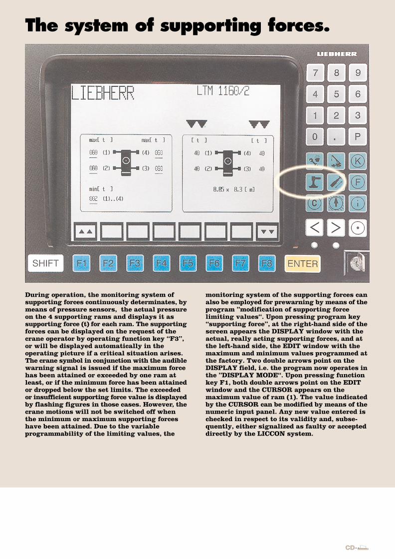
During operation, the monitoring system ofsupporting forces continuously determinates, bymeans of pressure sensors, the actual pressureon the 4 supporting rams and displays it assupporting force (t) for each ram. The supportingforces can be displayed on the request of thecrane operator by operating function key “F3”,or will be displayed automatically in theoperating picture if a critical situation arises.The crane symbol in conjunction with the audiblewarning signal is issued if the maximum forcehas been attained or exceeded by one ram atleast, or if the minimum force has been attainedor dropped below the set limits. The exceededor insufficient supporting force value is displayedby flashing figures in those cases. However, thecrane motions will not be switched off whenthe minimum or maximum supporting forceshave been attained. Due to the variableprogrammability of the limiting values, the
enables manual as well as automatic telescoping.In the telescoping picture of the LTM 1160/2for instance, the following display elements arerepresented:� the stylised telescopic boom with base section
and piston rod, the ram with interlocking device,and telescopes 1- 5 with their interlocking points
� the function keys F3-F7 for selecting the positionof telescopes 1- 5
� the selected telescoping position of telescopes1-5
� the actual telescoped condition of telescopes1-5 and, divided by a hyphen, the condition ofthe telescoping ram
� the display symbols for the automatic and manualtelescoping procedure
� the telescopable load
monitoring system of the supporting forces canalso be employed for prewarning by means of theprogram ”modification of supporting forcelimiting values“. Upon pressing program key“supporting force”, at the right-hand side of thescreen appears the DISPLAY window with theactual, really acting supporting forces, and atthe left-hand side, the EDIT window with themaximum and minimum values programmed atthe factory. Two double arrows point on theDISPLAY field, i.e. the program now operates inthe ”DISPLAY MODE“. Upon pressing functionkey F1, both double arrows point on the EDITwindow and the CURSOR appears on themaximum value of ram (1). The value indicatedby the CURSOR can be modified by means of thenumeric input panel. Any new value entered ischecked in respect to its validity and, subse-quently, either signalized as faulty or accepteddirectly by the LICCON system.
The additional displays. The LICCON telescoping picture. The system of supporting forces.
The LICCON computer system displays systemerrors and application errors on the monitor.Application errors caused by operation or externalinfluence, e.g. on the sensors, are displayed in theoperating picture by ERROR with an error number.
The LICCON computers system is the most moderncomputer system world-wide with comprehensiveinformative, monitoring and control functions.
CD-

Depending on crane type and equipment, a seriesof other symbols can be displayed, either accordingto the requirement of the crane operator or auto-matically in case of a failure. The advantage ofthis feature is that the operating picture is notovercharged with information but that the operatoralways gets a warning signal in case of a failure.The following symbols are assigned to the monitor-ing function:� indication of inclination� wind sensor� monitoring of supporting pressure� interlocking of superstructure with horizontal
slewing angle display and set slewing speedreduction
� tension of batteries
The overlay of these symbols is accompanied by anaudible warning signal. The following symbols, ofan informative character only and which do notsignalize a failure, are displayed in another areaof the operating picture:� high-speed switched off� LICCON safe load indicator bridged by means of
the setting switch� lower/upper limit angle of the load utilization
attained� fuel indication
The LICCON telescoping picture is only availableon mobile cranes with interlockable telescopicboom. It demonstrates the crane operator theinterlocking condition of the telescopic boom bymeans of a dynamic full graphics display, theposition of the individual telescopes to one anotherand the extended condition of the telescoping ram.Due to the automated telescoping procedure, it isvery easy for the crane operator to performtelescoping since he does not need any more to takecare of the interlocking/unlocking of the telescopicram or of the telescopes. The computer systemselects the operating sequence of the individualtelescopes in attaining the final position desired.Upon preselection of the boom position required,all telescoping motions as well as the interlock-ing/unlocking functions are performed fullyautomatically. The telescoping control “Telematik”
During operation, the monitoring system ofsupporting forces continuously determinates, bymeans of pressure sensors, the actual pressureon the 4 supporting rams and displays it assupporting force (t) for each ram. The supportingforces can be displayed on the request of thecrane operator by operating function key “F3”,or will be displayed automatically in theoperating picture if a critical situation arises.The crane symbol in conjunction with the audiblewarning signal is issued if the maximum forcehas been attained or exceeded by one ram atleast, or if the minimum force has been attainedor dropped below the set limits. The exceededor insufficient supporting force value is displayedby flashing figures in those cases. However, thecrane motions will not be switched off whenthe minimum or maximum supporting forceshave been attained. Due to the variableprogrammability of the limiting values, the
enables manual as well as automatic telescoping.In the telescoping picture of the LTM 1160/2for instance, the following display elements arerepresented:� the stylised telescopic boom with base section
and piston rod, the ram with interlocking device,and telescopes 1- 5 with their interlocking points
� the function keys F3-F7 for selecting the positionof telescopes 1- 5
� the selected telescoping position of telescopes1-5
� the actual telescoped condition of telescopes1-5 and, divided by a hyphen, the condition ofthe telescoping ram
� the display symbols for the automatic and manualtelescoping procedure
� the telescopable load
monitoring system of the supporting forces canalso be employed for prewarning by means of theprogram ”modification of supporting forcelimiting values“. Upon pressing program key“supporting force”, at the right-hand side of thescreen appears the DISPLAY window with theactual, really acting supporting forces, and atthe left-hand side, the EDIT window with themaximum and minimum values programmed atthe factory. Two double arrows point on theDISPLAY field, i.e. the program now operates inthe ”DISPLAY MODE“. Upon pressing functionkey F1, both double arrows point on the EDITwindow and the CURSOR appears on themaximum value of ram (1). The value indicatedby the CURSOR can be modified by means of thenumeric input panel. Any new value entered ischecked in respect to its validity and, subse-quently, either signalized as faulty or accepteddirectly by the LICCON system.
The additional displays. The LICCON telescoping picture. The system of supporting forces.
The LICCON computer system displays systemerrors and application errors on the monitor.Application errors caused by operation or externalinfluence, e.g. on the sensors, are displayed in theoperating picture by ERROR with an error number.
The LICCON computers system is the most moderncomputer system world-wide with comprehensiveinformative, monitoring and control functions.
CD-

The working area limitation.
The LICCON working area limitation systemfor Liebherr mobile and crawler cranescontributes to the unburdening of the craneoperator by controlling the working area limits,especially in situations where the handlingof loads requires his full attention. Workingareas may be restricted by buildings, bridges,roofs, high-voltage overhead lines, pipe linesor adjacent cranes. The automatic arealimitation system can be programmed conven-iently and its functions are easily understand-able. Four different limitation functions areprovided:� The pulley head height limitation restricts
the boom head pulley to a predeterminedmeasure. The boom luffing and telescopingmotions are cut off when the forbiddenworking areas are attained.
� The radius limitation prevents the load hookfrom exceeding a predetermined ”maximum“radius. The boom lowering and telescopingmotions are cut off when the forbidden work-ing areas are attained.
� The slewing area limitation consists of a rightside and left side angle limit which cannot beoverrun during activated limitation.
� The edge limitation allows a working arealimitation between two edges - A and B - which,however, should not intersect the slewing rimcentre. The edge limitation enables slewing at360° but it may be necessary to reduce the radiusin certain cases.
By means of a simple but convenient editor program,the crane operator can enter the various area limitsinto the LICCON system and activate or inactivatethem. Every limitation function can be activatedindividually but also in conjunction with others sothat even a complex of working area limitationsare programmable.
CD-
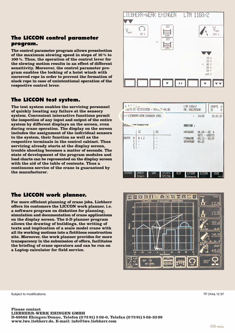
The LICCON control parameterprogram.The control parameter program allows preselectionof the maximum slewing speed in steps of 10 % to100 %. Thus, the operation of the control lever forthe slewing motion results in an effect of differentsensitivity. Moreover, the control parameter pro-gram enables the locking of a hoist winch withunreeved rope in order to prevent the formation ofslack rope in case of unintentional operation of therespective control lever.
The LICCON test system.The test system enables the servicing personnelof quickly locating any failure at the sensorysystem. Convenient interactive functions permitthe inspection of any input and output of the entiresystem by different displays on the screen, evenduring crane operation. The display on the screenincludes the assignment of the individual sensorsto the system, their function as well as therespective terminals in the control cabinet. Thusservicing already starts at the display screen,trouble shooting becomes a matter of seconds. Thestate of development of the program modules andload charts can be represented on the display screenwith the aid of the table of contents. Thus acontinuous service of the crane is guaranteed bythe manufacturer.
The LICCON work planner.For more efficient planning of crane jobs, Liebherroffers its customers the LICCON work planner, i.e.a software program on diskettes for planning,simulation and documentation of crane applicationson the display screen. The 2-D planner programallows the drawing of buildings, the writing oftexts and implication of a scale model crane withall its working motions into a fictitious constructionsite. Moreover, the work planner provides for moretransparency in the submission of offers, facilitatesthe briefing of crane operators and can be run ona Laptop calculator for field service.
Subject to modifications. TP 244a. 12.97
CD-
Please contactLIEBHERR-WERK EHINGEN GMBHD-89582 Ehingen/Donau, Telefon (07391) 5 02-0, Telefax (07391) 5 02-3399www.lwe.liebherr.de, E-mail: [email protected]


![“BOOM, BOOM, BOOOOOM! Notes on a Giant [neoliberal] Implosion” in Ibraaz Magazine. Issue 8th. January 2015](https://static.fdokumen.com/doc/165x107/63459845596bdb97a909007a/boomboom-booooom-notes-on-a-giant-neoliberal-implosion-in-ibraaz-magazine.jpg)