THE FELT, ITS PROPERTIES AND MODE OF ACTION ... - iibcc
16
202 THE FELT, ITS PROPERTIES AND MODE OF ACTION IN FIBRE CEMENT MANUFACTURE Tony Cooke Affiliation: Building Materials and Technology Pty Ltd, 169 Elms Road, Lade Vale, NSW 2581, Australia [email protected] KEYWORDS: felts, Hatschek Machine, dewatering, sheet formation, specifications ABSTRACT. The felt is a critical component in the smooth operation of the Hatschek Machine whose operation and performance is not so well understood. Thus this paper examines the mechanisms whereby felts x are dewatered, x effect the transfer of films from the sieve cylinders x carry the first and subsequent films hanging on their inverted face x assist in the transfer of multiple films onto the forming roll and x promote the formation of well-formed fibre cement sheets. The paper also considers the properties of the felt and the changes in the felt properties that result in the deterioration of the formation of the fibre cement during their time of use on the machine.
-
Upload
khangminh22 -
Category
Documents
-
view
0 -
download
0
Transcript of THE FELT, ITS PROPERTIES AND MODE OF ACTION ... - iibcc
202
THE FELT, ITS PROPERTIES AND MODE OF ACTION IN FIBRE CEMENT
MANUFACTURE
Tony Cooke
Affiliation: Building Materials and Technology Pty Ltd,
169 Elms Road,
Lade Vale, NSW 2581, Australia
KEYWORDS: felts, Hatschek Machine, dewatering, sheet formation, specifications
ABSTRACT.
The felt is a critical component in the smooth operation of the Hatschek Machine whose operation and
performance is not so well understood.
Thus this paper examines the mechanisms whereby felts
are dewatered,
effect the transfer of films from the sieve cylinders
carry the first and subsequent films hanging on their inverted face
assist in the transfer of multiple films onto the forming roll and
promote the formation of well-formed fibre cement sheets.
The paper also considers the properties of the felt and the changes in the felt properties that result in
the deterioration of the formation of the fibre cement during their time of use on the machine.
203
INTRODUCTION
During formation of fibre cement sheets in the Hatschek machine a film of fibre cement is formed on
each sieve cylinder (Cooke 20022). The films are collected by a continuous porous felt passing over
each cylinder in the Hatschek machine that is the primary agent on which films are transferred to the
forming roll for final dewatering and compaction into the sheet of fibre cement. The felt performs the
following actions
1. collects each film from the sieve cylinders,
2. melds the first film with second and later films,
3. films are progressively dewatered without disruption by means of compression and
application of suction by vacuum boxes
4. multiple films are transferred to the forming roll and
5. films are released from the felt during final dewatering and compaction.
We will now consider the mechanisms by which the felt performs or assists in the accomplishment of
these actions.
ACTION OF THE FELT
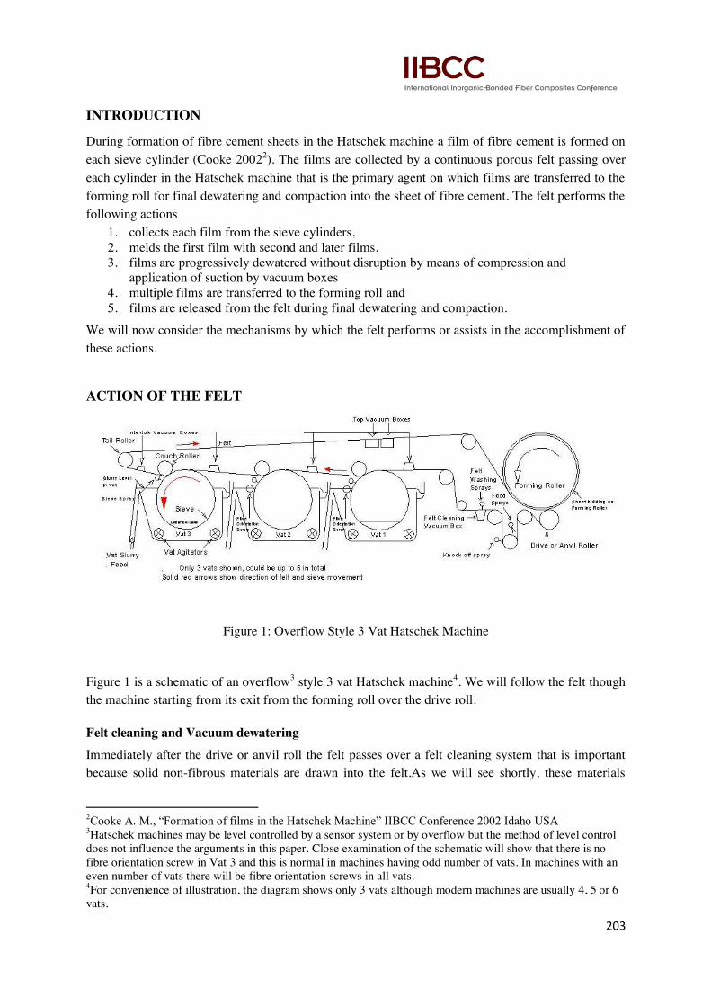
Figure 1: Overflow Style 3 Vat Hatschek Machine
Figure 1 is a schematic of an overflow3 style 3 vat Hatschek machine
4. We will follow the felt though
the machine starting from its exit from the forming roll over the drive roll.
Felt cleaning and Vacuum dewatering
Immediately after the drive or anvil roll the felt passes over a felt cleaning system that is important
because solid non-fibrous materials are drawn into the felt.As we will see shortly, these materials
2Cooke A. M., ―Formation of films in the Hatschek Machine‖ IIBCC Conference 2002 Idaho USA 3Hatschek machines may be level controlled by a sensor system or by overflow but the method of level control
does not influence the arguments in this paper. Close examination of the schematic will show that there is no
fibre orientation screw in Vat 3 and this is normal in machines having odd number of vats. In machines with an
even number of vats there will be fibre orientation screws in all vats. 4For convenience of illustration, the diagram shows only 3 vats although modern machines are usually 4, 5 or 6
vats.
204
must be removed as completely as possible to ensure that the felt continues to work properly. Felt
washing usually consists of a low pressure flood spray that forces water through the felt from back to
front as the felt passes around the bottom roller. The dirty water emerging from the back of the felt is
washed off with more clean water by the knock-off spray. This is followed by a high pressure
oscillating spray over a vacuum box that forces water through the felt from its back to its front further
flushing out more of the embedded solids. This ensures that the felt is as clean as possible but still
contains some water.
Vacuum dewatering – vacuum dewatering of the felt is essential to facilitate the transfer of the film
from the sieve cylinder. Dewatering is accomplished by a vacuum box connected to a high volume
liquid ring vacuum pump that may develop up to 500KPa pressure drop between the interior of the
box and atmosphere. Dewatering of the felt occurs principally by two mechanisms.
Application of the pressure compresses the felt and squeezes water into the vacuum box onto the
backside of the felt. Since the felt has an open structure air is pushed through the felt displacing water
from within the felt pore space. Ultimately, air breaks through the felt to establish continuous flow.
Once air-flow through the felthas occurred, water is atomized into small droplets and carried away in
the air flow through the vacuum pump.
Finally there is a very short additional compression of the felt as it passes over the lip of the vacuum
box slot that scrapes off more water.5
Dewatering takes place in a very short period of time. For example, a typical Hatschek machine runs
at 80 m/minute and a typical slotted vacuum box has 2 slots about 25mm wide.Thus the passage of the
felt from one side of the box to the other over both slots will therefore take 37.5 milliseconds.
5The paper industry takes advantage of this phenomenon by the use of so-called ―foils‖ that present a backward
sloping blade to the surface of the incoming felt that amplifies this effect.
205
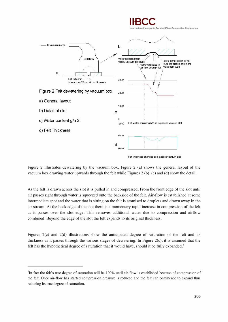
Figure 2 illustrates dewatering by the vacuum box. Figure 2 (a) shows the general layout of the
vacuum box drawing water upwards through the felt while Figures 2 (b), (c) and (d) show the detail.
As the felt is drawn across the slot it is pulled in and compressed. From the front edge of the slot until
air passes right through water is squeezed onto the backside of the felt. Air-flow is established at some
intermediate spot and the water that is sitting on the felt is atomised to droplets and drawn away in the
air stream. At the back edge of the slot there is a momentary rapid increase in compression of the felt
as it passes over the slot edge. This removes additional water due to compression and airflow
combined. Beyond the edge of the slot the felt expands to its original thickness.
Figures 2(c) and 2(d) illustrations show the anticipated degree of saturation of the felt and its
thickness as it passes through the various stages of dewatering. In Figure 2(c), it is assumed that the
felt has the hypothetical degree of saturation that it would have, should it be fully expanded.6
6In fact the felt‘s true degree of saturation will be 100% until air-flow is established because of compression of
the felt. Once air-flow has started compression pressure is reduced and the felt can commence to expand thus
reducing its true degree of saturation.
206
The thickness of the felt can be better estimated and it is expected that the felt will initially compress
and then expand as the air-flow relieves the pressure. The felt momentarily is heavily compressed as it
passes over the edge of the slot. Beyond the slot is relaxes back to its original thickness.
Some calculations are illustrative of the work that the vacuum system does. Assume the following
Weight of felt = 1600g/m2 Felt = 4mm thick Density of fibre = 1.3g/m
3
Therefore volume of 1m2 of felt = 100*100*4/10 = 4,000 cm
3
Volume of fibre in 1m2 of felt = 1600/1.3 = 1230 cm
3
Therefore porosity of felt = (4000-1230)/4000*100 = 69.25%
We can then draw up table1 assuming that the presence of water in the pores of the felt does not cause
it to contract in thickness due to surface tension.
Table 1 Felt Water content
Felt weight g/m2 Water Content g/m
2 Degree of Saturation %
1600 0 0%
2293 693 25%
2985 1385 50%
3678 2078 75%
4370 2770 100%
We can also use this information to estimate the quantity of water that the vacuum system must
extract to reduce the water content of the felt to say 50% for example.
Typical felt width = 1.65m
From the above table volume of water to be removed from each lineal metre of felt is 1.65
*(2.77-1.385) = 2.28 litres
Speed of felt = 80m/min therefore removal rate =80*2.28 = 183 litres/min.
We can also calculate the compression of the felt required to remove 25% of the water assuming that
it is all removed by compression neglecting that removed by air-flow through the felt.
Water to be removed from the felt is 2770 – 2078 = 692 cm3/m
2
Area of felt = 100*100 = 10,000 cm2
Therefore thickness of water volume = 692/10000 cm = 0.692 mm
Felt is 4mm thick therefore compression of felt = 0.692/4*100 = 17.3%
207
Some properties of actual felts are given in Appendix 1. The Shore Hardness of the felt can be used to
estimate its Elastic Modulus (E)using the formula7
where S = Shore Hardness A and
E is in units of MPa
Using the typical values of Shore Hardness of around 75 for a fibre cement felt gives an elastic
modulus of approximately 3000 KPa. Using the figure of 17.3% compression to dewater this felt to
75% void volume means that we will need a pressure drop across the felt of 3000 *0.173 = 519 KPa
with our assumptions above. In other words the pressure in the vacuum box will have to be 519 KPa
below atmospheric pressure.
The last set of vacuum boxes of the felt cleaning section ensure that the felt has dewatered sufficiently
to assist the pick up of film from the first sieve. The principles of dewatering described here are
relevant to the dewatering elsewhere in the Hatschek machine and will appear later in this paper.
Couch Rollers and their operation
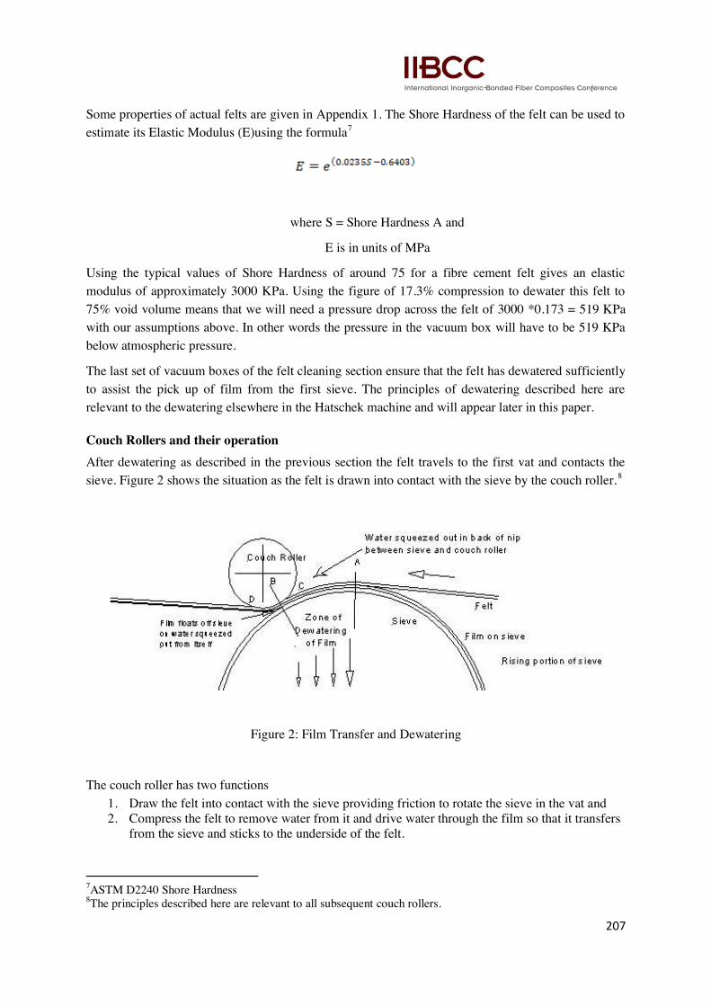
After dewatering as described in the previous section the felt travels to the first vat and contacts the
sieve. Figure 2 shows the situation as the felt is drawn into contact with the sieve by the couch roller.8
Figure 2: Film Transfer and Dewatering
The couch roller has two functions
1. Draw the felt into contact with the sieve providing friction to rotate the sieve in the vat and
2. Compress the felt to remove water from it and drive water through the film so that it transfers
from the sieve and sticks to the underside of the felt.
7ASTM D2240 Shore Hardness
8The principles described here are relevant to all subsequent couch rollers.
208
We now consider the detailed mechanisms.
The rising portion of the sieve carries with it a film of solids that is not homogenous through its
thickness. The film contains cellulose filter fibres (and where used synthetic fibres) predominantly on
its surface in contact with the sieve surface and non-fibrous or matrix particles (cement and other
minerals) on its top surface. It also contains a large amount of water so the solids content is probably
no more than 20% of the total weight of the film.9
As the felt comes in contact with the sieve (position A) water flows from the film into the felt because
the felt is porous and is not saturated. Since the felt comes into contact with the matrix portion of the
film a small amount of matrix solids are drawn into the felt with this water. It is this material that
needs to be removed from the felt during cleaning before the felt is once again returned to the pick up
fresh films of material.
The felt also applies pressure to the film perpendicular to the sieve and this pressure depends on the
difference in tension between points A and B. The difference in tension between points A and B is
determined by the drag of the sieve in the vat, that in turn depends on the size of the sieve, the friction
of the sieve seals and bearings and the viscous drag between the sieve and the contents of the vat. The
pressure applied perpendicular to the surface of the sieve results in a zone of dewatering of both the
film and the felt.10
The pressure between the felt and the sieve can be calculated from the theory applying to band
brakes11
.
The total force T applied by the felt on the sieve is given by
where p = vertical pressure applied by the felt
w = width of the felt and
r = radius of the sieve
Normally we can measure the felt tension (F) directly on the felt using the Huyck Tensometer whose
values are read directly as force per unit width in KgF/cm
hence we can write
As the tension varies between points A and B from a low to a high value, so does the pressure driving
water from the film into the sieve and compressing the felt to push some water to its back surface. We
will also see that the felt tension varies from the front to the back of the machine at sieve level
9The determination of the water content of the film on the sieve is difficult for two reasons. Collection of the
specimen is highly dangerous and requires special sampling equipment. Sampling is likely to cause changes to
the water content of the film because it is relatively easy to displace water from it. So the estimate of 20% is
based on extrapolation from measurements taken elsewhere in the system. 10
This can easily be seen in the sieve interior using a strobe light to illuminate and to visually stop motion,
where it can be seen that there is a cascade of clean water from the top portion of the sieve between points A and
B. 11
Useful Tables – Band brakes, Roymech Co
209
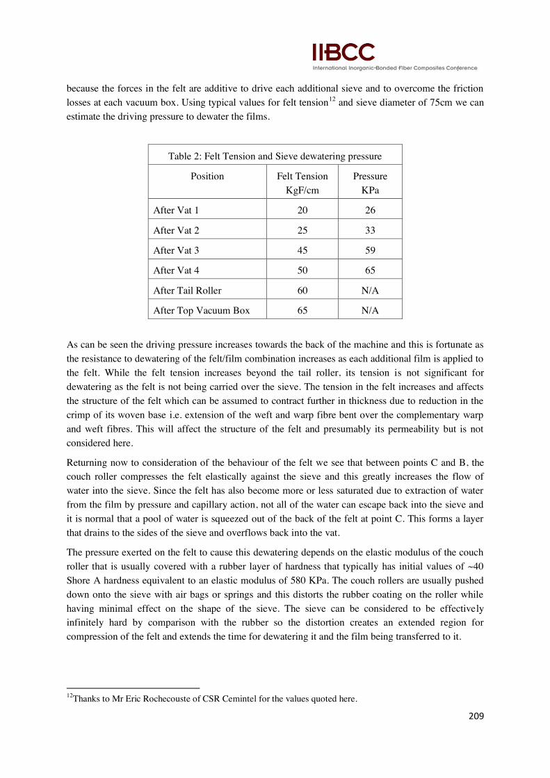
because the forces in the felt are additive to drive each additional sieve and to overcome the friction
losses at each vacuum box. Using typical values for felt tension12
and sieve diameter of 75cm we can
estimate the driving pressure to dewater the films.
As can be seen the driving pressure increases towards the back of the machine and this is fortunate as
the resistance to dewatering of the felt/film combination increases as each additional film is applied to
the felt. While the felt tension increases beyond the tail roller, its tension is not significant for
dewatering as the felt is not being carried over the sieve. The tension in the felt increases and affects
the structure of the felt which can be assumed to contract further in thickness due to reduction in the
crimp of its woven base i.e. extension of the weft and warp fibre bent over the complementary warp
and weft fibres. This will affect the structure of the felt and presumably its permeability but is not
considered here.
Returning now to consideration of the behaviour of the felt we see that between points C and B, the
couch roller compresses the felt elastically against the sieve and this greatly increases the flow of
water into the sieve. Since the felt has also become more or less saturated due to extraction of water
from the film by pressure and capillary action, not all of the water can escape back into the sieve and
it is normal that a pool of water is squeezed out of the back of the felt at point C. This forms a layer
that drains to the sides of the sieve and overflows back into the vat.
The pressure exerted on the felt to cause this dewatering depends on the elastic modulus of the couch
roller that is usually covered with a rubber layer of hardness that typically has initial values of ~40
Shore A hardness equivalent to an elastic modulus of 580 KPa. The couch rollers are usually pushed
down onto the sieve with air bags or springs and this distorts the rubber coating on the roller while
having minimal effect on the shape of the sieve. The sieve can be considered to be effectively
infinitely hard by comparison with the rubber so the distortion creates an extended region for
compression of the felt and extends the time for dewatering it and the film being transferred to it.
12
Thanks to Mr Eric Rochecouste of CSR Cemintel for the values quoted here.
Table 2: Felt Tension and Sieve dewatering pressure
Position Felt Tension
KgF/cm
Pressure
KPa
After Vat 1 20 26
After Vat 2 25 33
After Vat 3 45 59
After Vat 4 50 65
After Tail Roller 60 N/A
After Top Vacuum Box 65 N/A
210
However, the water that is squeezed through the felt into the sieve, lifts the film off the sieve and
causes it to transfer to the felt at point B. Beyond point B up to point D where the felt leaves contact
with the couch roller, the pressure compressing the felt is relieved and the felt expands elastically
drawing some water into it from the film.Expansion creates air space within the film and the felt and
thereby generates surface tension in the interstitial water.
Relaxation of the felt is likely not complete as the felt leaves contact with couch roller and this will
continue until an equilibrium is reached or some other factor intervenes such as contact with the next
vacuum box. Since the surface tension is inversely proportional to the pore size and the felt is relaxing
then there will be a change in the surface tension within the internal films of water due to the change
in the porosity of the felt. Therefore beyond point B and probablycontinuing until the felt reaches the
next inter-tub vacuum box, there will be a redistribution of water between the film and the felt
depending on their respective pore distributions and the dynamics of the situation.
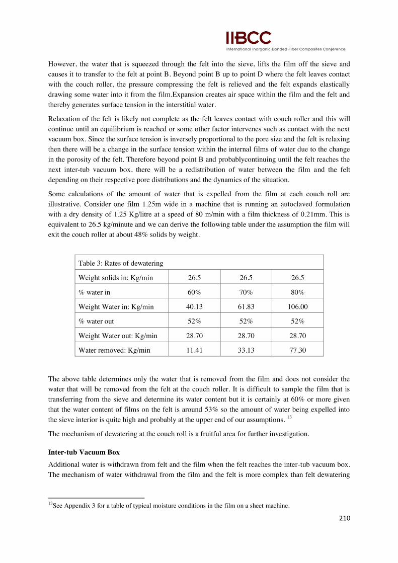
Some calculations of the amount of water that is expelled from the film at each couch roll are
illustrative. Consider one film 1.25m wide in a machine that is running an autoclaved formulation
with a dry density of 1.25 Kg/litre at a speed of 80 m/min with a film thickness of 0.21mm. This is
equivalent to 26.5 kg/minute and we can derive the following table under the assumption the film will
exit the couch roller at about 48% solids by weight.
Table 3: Rates of dewatering
Weight solids in: Kg/min 26.5 26.5 26.5
% water in 60% 70% 80%
Weight Water in: Kg/min 40.13 61.83 106.00
% water out 52% 52% 52%
Weight Water out: Kg/min 28.70 28.70 28.70
Water removed: Kg/min 11.41 33.13 77.30
The above table determines only the water that is removed from the film and does not consider the
water that will be removed from the felt at the couch roller. It is difficult to sample the film that is
transferring from the sieve and determine its water content but it is certainly at 60% or more given
that the water content of films on the felt is around 53% so the amount of water being expelled into
the sieve interior is quite high and probably at the upper end of our assumptions. 13
The mechanism of dewatering at the couch roll is a fruitful area for further investigation.
Inter-tub Vacuum Box
Additional water is withdrawn from felt and the film when the felt reaches the inter-tub vacuum box.
The mechanism of water withdrawal from the film and the felt is more complex than felt dewatering
13
See Appendix 3 for a table of typical moisture conditions in the film on a sheet machine.
211
and similar to that described above for the couch roller. Aslund14
has identified three mechanisms
whereby paper webs are dewatered on a vacuum box. The web is firstly compressed along with the
felt (or the forming fabric as it is described in the paper industry) and water is expressed from the
felt/web combination into the vacuum box. If the vacuum pulse is prolonged for a sufficient time air is
drawn through the web removing additional water. After the felt moves past the vacuum box, the
pressure on the felt/web combination relaxes and the web rewets as water redistributes between the
web and the felt. The degree of water removal from the web depends on the vacuum pulse defined as
the product of vacuum pressure and its duration of application. Rewetting of the web after the vacuum
was also found to be equivalent to a reduction in dry solids content from 3 to 6% dependent on the
vacuum pulse.A longer vacuum pulse resulted in a decrease in rewetting due to there being less water
in the felt because of removal of more water from the web into the vacuum box.15
Asplund‘s description can be directly translated into the situation of fibre cement films on the felt in the Hatschek machine. His paper web may be replaced by the film on the felt in the Hatschek machine
with the exception that the film is hanging on the underside of the felt rather than on top of the
forming fabric as in the paper machine. Because the film is underneath the felt, slightly more pressure
is required to draw water through the felt and the film combination. Also more pressure is required to
break through the film/felt combination because of the additional resistance of the film compared to
the felt alone.
It is important that the film and the felt are sufficiently dewatered at the couch roll and the following
inter-tub vacuum box to create free voids in both. This allows the water to enter the voids from the
film transferring from the sieve in the next vat and helps to bind the overlying and the incoming films
14Aslund P., ―On suction box dewatering mechanisms‖, Doctoral Thesis, Royal Institute of Technology, School of Chemical Science and Engineering, Department of Fibre and Polymer Technology, SE-100 44 Stockholm,
Sweden
Felt cleaning and Vacuum dewatering
Immediately after the drive or anvil roll the felt passes over a felt cleaning system that is important
because solid non-fibrous materials are drawn into the felt.As we will see shortly, these materials
must be removed as completely as possible to ensure that the felt continues to work properly. Felt
washing usually consists of a low pressure flood spray that forces water through the felt from back to
front as the felt passes around the bottom roller. The dirty water emerging from the back of the felt is
washed off with more clean water by the knock-off spray. This is followed by a high pressure
oscillating spray over a vacuum box that forces water through the felt from its back to its front further
flushing out more of the embedded solids. This ensures that the felt is as clean as possible but still
contains some water.
15
This is slightly different from the situation described above where we considered only the dewatering of the
felt by the vacuum box
212
together. As the film transfers to the felt from the sieve the processes described above repeat for each
successive vat and the felt now containing several (usually 4 or more) films reaches the forming roll.
We can also calculate the amount of water that is expelled at the inter-tub vacuum box using the data
from Appendix 3 of the film at the tail drum and the film after the vacuum box. Using that data and
the assumptions above, we estimate that water reduction from an individual film is just over 3
litre/minute. This is probably an underestimate as the data in appendix 3 is for two films and can be
regarded as a minimum amount but is equivalent to an increase in the void content of the film of about
15% by volume and this is significant for the adhesion of the next film.
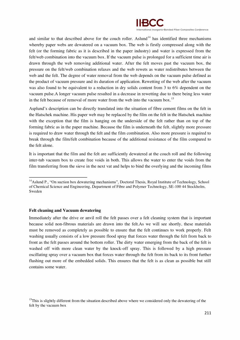
Forming Roll
At the forming roll, the films are transferred from the felt to the sheet that is building up on the
forming roll. This occurs in a similar fashion to the transfer of individual films from the sieve to the
felt in that water is expelled from the back of the group of films to lift them from the felt. There are
however several significant differences between the transfer at this point.
1. Water leaves the film from front to back.
2. Water leaves several films simultaneously
3. At least an equal amount of water is expelled at this point as at each sieve but through a
greater thickness and with a great deal more resistance due to the greater compaction of the
forming sheet.
We can also estimate the amount of water that is removed from the films as they are formed onto the
forming roll using the same data as above and assuming that 4 films are compacted onto the forming
roll at the same time. In this case films are delivered to the forming roll at the rate of 105 kg/min and
the water coming in is 100.8 kg/min, the water going out in the sheet is 52.3 kg/min. Therefore the
water removed from the films at the forming roll will be 48.7 Kg/min.
213
In addition a considerable amount of water is expelled from the felt. We can estimate the amount of
water that is expelled from the felt assuming that it is 75% saturated and is compressed by the drive
roll against the forming roll with a force of 120Kn (6 tonnes per side) over 1.65 m wide that
effectively compresses the felt over a width of 10mm.
As we have seen the modulus of elasticity of the felt is approximately 3000 KPa and is 4mm thick.
The compression pressure is 120,000N and we assume that the area where the force is applied is 1650
by 10 = 16500 mm2. Therefore pressure on the felt is 120000/16500= 7.27 N/mm
2.
Assuming E = 3 N/mm2 the compression is 3/7 = 57% as the solid volume of the felt fabric is 30.7%
the free volume is now 26.5%. Assuming that the felt is now saturated from table 1 we can see that it
contains approximately 700 g/m2 and at 75% saturation it previously contained 2078 g/m
2 when it
entered the forming roll nip. So the water expelled from the felt is 1378 g/m2.
The felt is running at 80m/minute and is 1.65m wide so the total amount of water expelled per minute
will be 80 *1.65 *1.378 = 182 litre/minute. Thus the total amount of water expelled at the forming roll
will be around 230 litre/minute.
Changes in the Felt Performance with Use
How Felts Change
Felts normally last for around 2-3 weeks with continuous use and adequate cleaning. However as the
felt ages its performance changes and various phenomena are observed usually in the following time
order.
1. The felt becomes stiffer and heavier.
2. Dewatering of the felt becomes more difficult and greater vacuum pressures are needed to
remove water from the felt.
3. Initially the films may become drier and more likely to debond at the couch rolls and the
forming roll.
4. When the films become drier they also tend to fall off the forming roll failing to pick up at
sheet change over and producing drier and poorly bonded final product.
5. Eventually the films on the felt become wetter and dewatering at the forming roll becomes
difficult resulting in the forming sheet becoming so soft that it calendars i.e. extruding
sideways and longitudinally on the forming roll, sometimes decoupling from the forming roll
and falling off.
6. Extremely wet films are found that make more difficult holding the second and subsequent
films on the felt. Thus the later films may fall off the felt before reaching the inter-tub
vacuum box, falling back into the vat or between adjacent vats and often pulling off the
earlier films as well. It is common for films to fall off at the tail drum due to centrifugal force.
Explanation
The explanation for all of these phenomena is the progressive blocking of the felt that prevents it from
adequately dewatering the films and dewatering itself. Specifically
214
1. The increase in stiffness and weight of the felt is due to non-fibrous materials being drawn
into the felt and their remaining in the felt despite washing. The nature of the cement is such
that it is not possible to completely remove it from the felt and this and the other fine
materials slowly build up in the felt blocking its pores.
2. Build up of solids in the felt increases the resistance of the felt to air-flow and thereby
decreases the flow and the ability of the felt dewater itself and the films.
3. Build up of solids also increases the stiffness of the felt meaning that progressively greater
forces are needed to compress it and thereby dewater it.
4. During the time when a felt passes the vacuum box, a stage is reached when air-flow is
established. As the felt stiffens and blocks there are significantly fewer continuous pores are
available to allow air-flow. However, because air is compressible the velocity of air through
the felt significantly increases and this removes more water from the felt and the films. So
paradoxically the films tend to dry out at this stage.
5. Dry films tend not to bond so readily to adjoining films because bonding requires that water
passes between the films either at the couch roller for the between film bonds or at the
forming roll for the interlayer bonding. Transfer of water also carries solid particles between
films and bonds them together.
6. Once the build up of solids within the felt reaches a particular stage the pores within the felt
become so blocked that no airflow can be established through the felt and it effectively
becomes incompressible and dewatering of the film and felt becomes practically impossible.
7. Saturated films not only fail to bond to each other because they are saturated, the fibre
reinforcement which exists when they are porous after dewatering, ceases to exist and these
films tend to fall apart under light stress. Should they reach the forming roll, they are likely to
calendar under the pressure of the forming roll.
Compensation
Adjustment for these problems is possible for most of the life of the felt and it is normal to start a felt
run with low vacuum pressures, reduced couch roller loads and low loading of the drive roll against
the forming roll. As the felt blocks these loads and pressures are progressively increased until further
increases are impossible and the felt is blocked to the stage where saturated films, film drop off and
calendaring occurs. At this point it is necessary to change the felt.
Conclusions
Understanding the behaviour of felts is critical to the understanding of the operation of the Hatschek
machine and is not understood in detail. Systematic investigation of the behaviour of felts will result
in the better design of felts for the manufacture of fibre cement that will last longer and assist
operators to maintain the optimum performance during their lifetime.
Some evidence has been presented that simple measurement of the hardness of the felt is indicative of
the changes that occur during its life. This deserves more investigation and could show the way to
make adjustments to operating machine parameters.
Appendix 1: Some properties of Felts
215
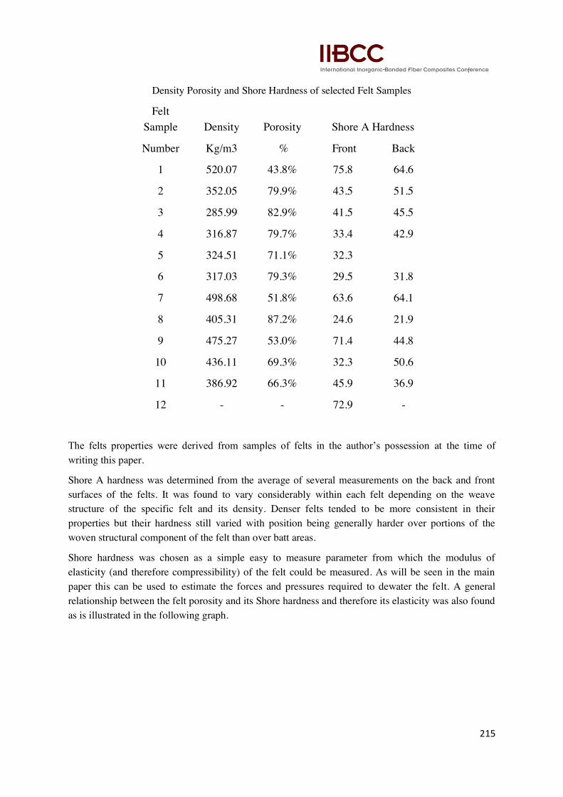
Density Porosity and Shore Hardness of selected Felt Samples
Felt
Sample Density Porosity Shore A Hardness
Number Kg/m3 % Front Back
1 520.07 43.8% 75.8 64.6
2 352.05 79.9% 43.5 51.5
3 285.99 82.9% 41.5 45.5
4 316.87 79.7% 33.4 42.9
5 324.51 71.1% 32.3
6 317.03 79.3% 29.5 31.8
7 498.68 51.8% 63.6 64.1
8 405.31 87.2% 24.6 21.9
9 475.27 53.0% 71.4 44.8
10 436.11 69.3% 32.3 50.6
11 386.92 66.3% 45.9 36.9
12 - - 72.9 -
The felts properties were derived from samples of felts in the author‘s possession at the time of
writing this paper.
Shore A hardness was determined from the average of several measurements on the back and front
surfaces of the felts. It was found to vary considerably within each felt depending on the weave
structure of the specific felt and its density. Denser felts tended to be more consistent in their
properties but their hardness still varied with position being generally harder over portions of the
woven structural component of the felt than over batt areas.
Shore hardness was chosen as a simple easy to measure parameter from which the modulus of
elasticity (and therefore compressibility) of the felt could be measured. As will be seen in the main
paper this can be used to estimate the forces and pressures required to dewater the felt. A general
relationship between the felt porosity and its Shore hardness and therefore its elasticity was also found
as is illustrated in the following graph.

216
Appendix 2: Changes in Shore A Hardness of a Sample Felt No 12 during use
Felt 12: Changes in Shore Hardness
New ~2hrs ~24 hrs operation ~40 hrs operation
Clean Clean Clean Dirty Clean Dirty
77.5 77 77.5 82.5 73.5 84.0
68.5 71 83.5 76.0 88.0
78.5 81 88.0 80.0 79.0
71.5 71 74.5 79.0
68.5
72.9 75.0 77.5 84.7 76.0 82.5
Sample felt No 12 was tested for Shore hardness from start up. All measurements were taken with the
felt positioned over the top vacuum box faced with a HDPE cover of hardness 110 SA. The felt was
measured here because Shore Hardness is not accurate for materials of less than 6mm when placed
over a hard surface such as steel.
Because operation of the felt was quite intermittent with frequent stops and starts, the result may not
be typical of normal performance and as may be seen from the table there is considerable variation in
the hardness at all stages of measurement. It can be seen however that there was a progressive
increase in the Hardness of the felt with use.
217
After the equivalent of about 24 hours of continuous operation the felt had become dirty in places and
was streaked. Advantage was taken of the fact that it was possible to measure the hardness in places
that were obviously clean and obviously dirty. It can be seen that the dirty streaks were somewhat
harder than the clean portions of the felt indicating that this may be a useful method to assess the
performance of the felt (apart from the usual indications of felt blocking such as water marking etc)
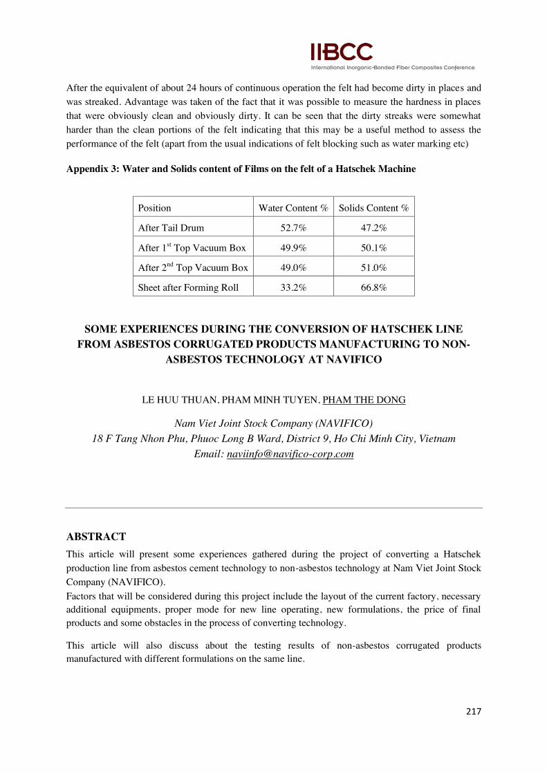
Appendix 3: Water and Solids content of Films on the felt of a Hatschek Machine
Position Water Content % Solids Content %
After Tail Drum 52.7% 47.2%
After 1st Top Vacuum Box 49.9% 50.1%
After 2nd
Top Vacuum Box 49.0% 51.0%
Sheet after Forming Roll 33.2% 66.8%
SOME EXPERIENCES DURING THE CONVERSION OF HATSCHEK LINE
FROM ASBESTOS CORRUGATED PRODUCTS MANUFACTURING TO NON-
ASBESTOS TECHNOLOGY AT NAVIFICO
LE HUU THUAN, PHAM MINH TUYEN, PHAM THE DONG
Nam Viet Joint Stock Company (NAVIFICO)
18 F Tang Nhon Phu, Phuoc Long B Ward, District 9, Ho Chi Minh City, Vietnam
Email: [email protected]
ABSTRACT
This article will present some experiences gathered during the project of converting a Hatschek
production line from asbestos cement technology to non-asbestos technology at Nam Viet Joint Stock
Company (NAVIFICO).
Factors that will be considered during this project include the layout of the current factory, necessary
additional equipments, proper mode for new line operating, new formulations, the price of final
products and some obstacles in the process of converting technology.
This article will also discuss about the testing results of non-asbestos corrugated products
manufactured with different formulations on the same line.


![kkt_6_dan_7_pemupukan_2014 [Compatibility Mode]](https://static.fdokumen.com/doc/165x107/6322b43c28c445989105e2db/kkt6dan7pemupukan2014-compatibility-mode.jpg)