The Effect of Waves on Rubble-Mound Structures - Caltech ...
31
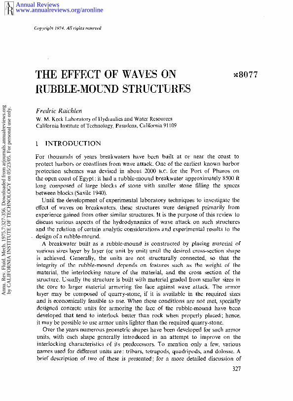
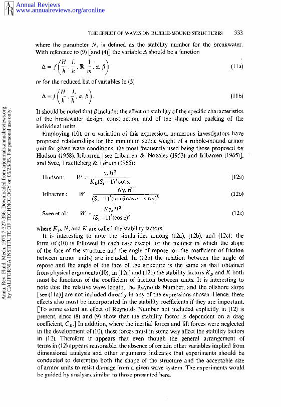
CopyrifJht 1974. All rights reserved THE EFFECT OF WAVES ON RUBBLE-MOUND STRUCTURES x8077 Fredric Raichlen w. M. KeckLaboratory of Hydraulics and WaterResources California Institute of Technology, Pasadena, California 91109 1 INTRODUCTION For thousands of years breakwaters have been built at or near the coast to protect harbors or coastlines from waveattack. One of the earliest known harbor protection schemes was devised in about 2000 B.C. for the Port of Pharos on the open coast of Egypt; it had a rubble-moundbreakwater approximately 8500 ft long composed of large blocks of stone with smaller stone filling the spaces betweenblocks (Savile 1940). Until the development of experimental laboratory techniques to investigate the effect of waves on breakwaters, these structures were designed primarily from experience gained from other similar structures. It is the purpose of this review to discuss various aspects of the hydrodynamics of waveattack on such structures and the relation of certain analytic considerations and experimental results to the ¯ design of a rubble-mound. A breakwater built as a rubble-mound is constructed by placing material of various sizes layer by layer (or unit by unit) until the desired cross-section shape is achieved. Generally, the units are not structurally connected, so that the integrity of the rubble-mound depends on features such as the weight of the material, the interlocking nature of the material, and the cross section of the structure. Usually the structure is built with material graded from smaller sizes in the core to larger material armoring the face against wave attack. The armor layer may be composed of quarry-stone, if it is available in the required sizes and is economically feasible to use. When these conditions are not met, specially designed concrete units for armoring the face of the rubble-mound have been developed that tend to interlock better than rock when properly placed; hence, it may be possible to use armor units lighter than the required quarry-stone. Over the years numerous geometric shapes have been developed for such armor units, with each shape generally introduced in an attempt to improve on the interlocking characteristics of its predecessors. To mention only a few, various namesused for different units are: tribars, tetrapods, quadripods, and dolosse. A brief description of two of these is presented; for a more detailed discussion of 327 www.annualreviews.org/aronline Annual Reviews Annu. Rev. Fluid. Mech. 1975.7:327-356. Downloaded from arjournals.annualreviews.org by CALIFORNIA INSTITUTE OF TECHNOLOGY on 05/23/05. For personal use only.
-
Upload
khangminh22 -
Category
Documents
-
view
2 -
download
0
Transcript of The Effect of Waves on Rubble-Mound Structures - Caltech ...
CopyrifJht 1974. All rights reserved
THE EFFECT OF WAVES ONRUBBLE-MOUND STRUCTURES
x8077
Fredric Raichlenw. M. Keck Laboratory of Hydraulics and Water ResourcesCalifornia Institute of Technology, Pasadena, California 91109
1 INTRODUCTION
For thousands of years breakwaters have been built at or near the coast toprotect harbors or coastlines from wave attack. One of the earliest known harborprotection schemes was devised in about 2000 B.C. for the Port of Pharos onthe open coast of Egypt; it had a rubble-mound breakwater approximately 8500 ftlong composed of large blocks of stone with smaller stone filling the spacesbetween blocks (Savile 1940).
Until the development of experimental laboratory techniques to investigate theeffect of waves on breakwaters, these structures were designed primarily fromexperience gained from other similar structures. It is the purpose of this review todiscuss various aspects of the hydrodynamics of wave attack on such structuresand the relation of certain analytic considerations and experimental results to the
¯ design of a rubble-mound.A breakwater built as a rubble-mound is constructed by placing material of
various sizes layer by layer (or unit by unit) until the desired cross-section shapeis achieved. Generally, the units are not structurally connected, so that theintegrity of the rubble-mound depends on features such as the weight of thematerial, the interlocking nature of the material, and the cross section of thestructure. Usually the structure is built with material graded from smaller sizes inthe core to larger material armoring the face against wave attack. The armorlayer may be composed of quarry-stone, if it is available in the required sizesand is economically feasible to use. When these conditions are not met, speciallydesigned concrete units for armoring the face of the rubble-mound have beendeveloped that tend to interlock better than rock when properly placed; hence,it may be possible to use armor units lighter than the required quarry-stone.
Over the years numerous geometric shapes have been developed for such armorunits, with each shape generally introduced in an attempt to improve on theinterlocking characteristics of its predecessors. To mention only a few, variousnames used for different units are: tribars, tetrapods, quadripods, and dolosse. Abrief description of two of these is presented; for a more detailed discussion of
327
www.annualreviews.org/aronlineAnnual Reviews
Ann
u. R
ev. F
luid
. Mec
h. 1
975.
7:32
7-35
6. D
ownl
oade
d fr
om a
rjou
rnal
s.an
nual
revi
ews.
org
by C
AL
IFO
RN
IA I
NST
ITU
TE
OF
TE
CH
NO
LO
GY
on
05/2
3/05
. For
per
sona
l use
onl
y.
328 RAICHLEN
shape along with drawings of the units the interested reader is directed to CERC(1966) and Hudson (1974). Tribars, which consist basically of three circular cylindersconnected by a yoke of three cylinders, are usually placed in a uniformgeometric pattern on the face of the rubble-mound. Dolosse are shaped like theletter "H" with the vertical legs rotated 90° to each other, and are generally placedrandomly on a rubble-mound face. It is the effective interlocking of dolosse thatleads to the use of random placement techniques.
Obviously an important aspect in the design of a rubble-mound is its stabilityunder wave attack. This subject is discussed in detail, along with descriptions ofthe basis for certain design approaches currently used. The support of these designcriteria as well as their limitations are discussed with reference to availableexperimental data.
Three other aspects of the effect of waves on rubble-mounds are treated in thisreview: wave run-up, transmission, and overtopping. Runrup is defined as thevertical height above still water level to which waves incident upon a structurecan be expected to travel up the face of the structure. Wave run-up isimportant in defining both the amount of wave energy transmitted over andthrough permeable rubble-mounds and also the quantity of water that may beexpected to overtop the structure.
In each of the following sections the discussion is directed toward understandingthe fluid-mechanic aspects of the various problems and the features and the short-comings of analytical and experimental models used in connection with the design ofbreakwaters constructed as rubble-mounds.
~ STABILITY
2.1 Analytical Considerations
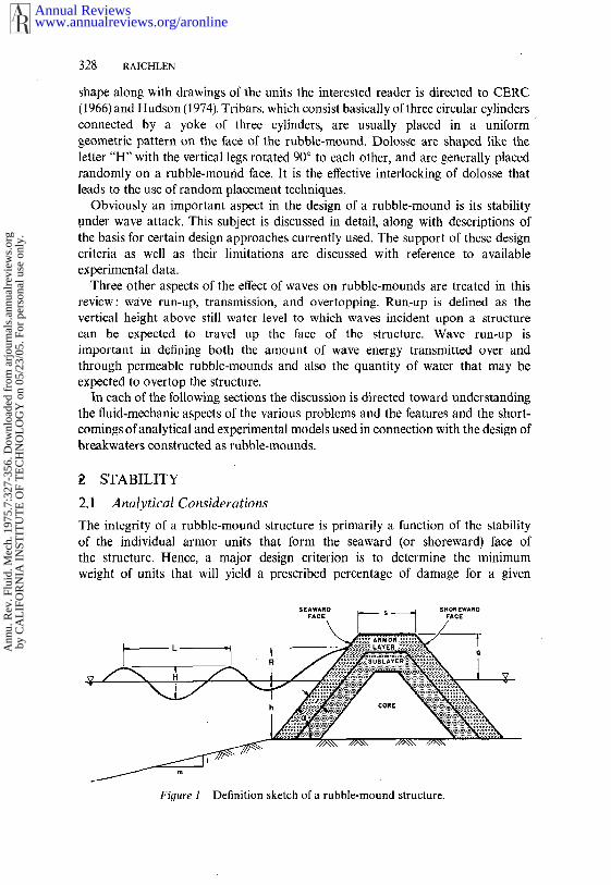
The integrity of a rubble-mound structure is primarily a function of the stabilityof the individual armor units that form the seaward (or shoreward) face the structure. Hence, a major design criterion is to determine the minimumweight of units that will yield a prescribed percentage of damage for a given
Figure I Definition sketch of a rubble-mound structure.
www.annualreviews.org/aronlineAnnual Reviews
Ann
u. R
ev. F
luid
. Mec
h. 1
975.
7:32
7-35
6. D
ownl
oade
d fr
om a
rjou
rnal
s.an
nual
revi
ews.
org
by C
AL
IFO
RN
IA I
NST
ITU
TE
OF
TE
CH
NO
LO
GY
on
05/2
3/05
. For
per
sona
l use
onl
y.
THE EFFECT OF WAVES ON RUBBLE-MOUND STRUCTURES 329
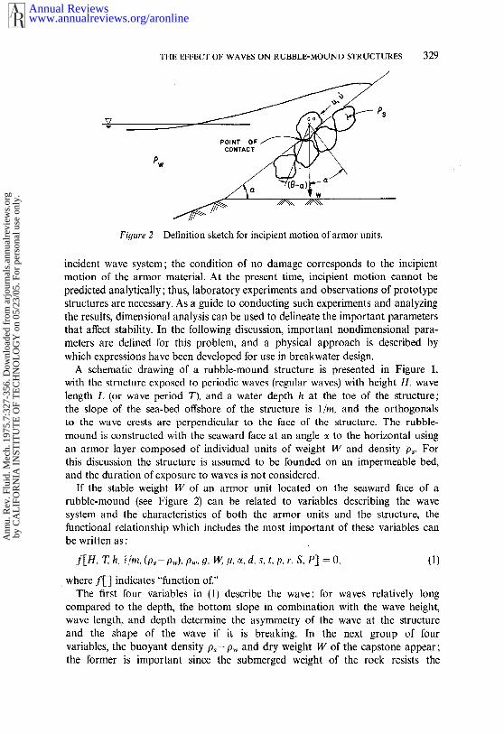
Fiyure 2 Definition sketch for incipient motion of armor units.
incident wave system; the condition of no damage corresponds to the incipientmotion of the armor material. At the present time, incipient motion cannot bepredicted analytically; thus, laboratory experiments and observations of prototypestructures are necessary. As a guide to conducting such experiments and analyzingthe results, dimensional analysis can be used to delineate the important parametersthat affect stability. In the following discussion, important nondimensional para-meters are defined for this problem, and a physical approach is described bywhich expressions have been developed for use in breakwater design.
A schematic drawing of a rubble-mound structure is presented in Figure 1,with the structure exposed to periodic waves (regular waves) with height H, wavelength L (or wave period T), and a water depth h at the toe of the structure;the slope of the sea-bed offshore of the structure is l/m, and the orthogonalsto the wave crests are perpendicular to the face of the structure. The rubble-mound is constructed with the seaward face at an angle ~ to the horizontal usingan armor layer composed of individual units of weight W and density p~. Forthis discussion the structure is assumed to be founded on an impermeable bed,and the duration of exposure to waves is not considered.
If the stable weight W of an armor unit located on the seaward face of arubble-mound (see Figure 2) can be related to variables describing the wavesystem and the characteristics of both the armor units and the structure, thefunctional relationship which includes the most important of these variables canbe written as :
f[H, T, h, ~/m, (p,- pw), pw, g, W, #, ~, d, s, t, p, r, S, P] = O, (1)
¯ where f[] indicates "function of."The first four variables in (1) describe the wave: for waves relatively long
compared to the depth, the bottom slope in combination with the wave height,wave length, and depth determine the asymmetry of the wave at the structureand the shape of the wave if it is breaking. In the next group of fourvariables, the buoyant density p~- p,~ and dry weight W of the capstone appear ;the former is important since the submerged weight of the rock resists the
www.annualreviews.org/aronlineAnnual Reviews
Ann
u. R
ev. F
luid
. Mec
h. 1
975.
7:32
7-35
6. D
ownl
oade
d fr
om a
rjou
rnal
s.an
nual
revi
ews.
org
by C
AL
IFO
RN
IA I
NST
ITU
TE
OF
TE
CH
NO
LO
GY
on
05/2
3/05
. For
per
sona
l use
onl
y.
330 RAICHLEN
action of the hydrodynamic forces imposed by the incident waves. The accelerationof gravity g and the fluid density pw also are in this group. The variable/~ is thedynamic fluid viscosity, which provides for viscous effects in the problem. Thenext group of terms describes the geometric characteristics of the rubble-moundand the armor units: the slope of the face of the structure, ~; the height of thecrest of the breakwater above the mean level, d; the width of the crown of thestructure, s; the thickness of the cover-layer, t; the porosity of the cover-layer, p;a measure of the roughness’ of the cover-layer, r; a measure of the shape ofthe armor units, S; and the packing and construction characteristics, P. Thereare probably other parameters that could be included in (1) to describe theface and the underlayers, but it is assumed that the variable P includes all otherefl~cts.
The variables in (1) can be reduced in number by incorporating certaindescriptors of the structure and the detailed characteristics of the breakwaterunits, e.g., t, p, r, S, and P, into one nondimensional parameter /?. (It shouldbe noted that (1) is being used to describe the incipient motion of armor unitson a structure, so that no consideration is given at this point in the discussionto the percentage of damage suffered by the structure.) Therefore, the variable/3describes the shape and the interlocking features of the individual breakwaterarmor units as well as the overall geometric characteristics of the constructedbreakwater. If it is assumed that the breakwater is not overtopped by waves,the vertical distance from the water surface to the crest of the structure, d, andwidth of the crest, s, are no longer ~’important variables. Hence, (1) can reduced to the following :
f[H, T, h, l/m, (p~- pw), Pw, g, W, p, ~z, fl] -- O. (2)
In (2) there are eleven variables and, as there are three independent dimensions,eight dimensionless parameters should exist that characterize the problem. Choosingthe depth, fluid density, and acceleration of gravity as repeating variables, one setof dimensionless parameters that can be constructcd is:
¢(I~ T2g p~-p,~, ’ h. ’ p,~, ’ h3pwg’ (gh)l/2h’ m’ ~’ fl = 0, (3)
where ¢() indicates "function of."The second dimensionless variable in (3) is proportional to the ratio of the
wave length to the depth, and the fifth parameter is the inverse of a ReynoldsNumber; the velocity used is the shallow-water wave celerity. By a suitablecombination of terms in (3) it can be shown that the length in the ReynoldsNumber can be expressed as a characteristic dimension of an armor unit andthe velocity can be expressed as the water-particle velocity. Thus, (3) can rewritten as:
- ~,/~ =0, (4)’ h’ p~. ’h3pwg’ m’
where R is the Reynolds Number. Since in general the surface of a rubble-
www.annualreviews.org/aronlineAnnual Reviews
Ann
u. R
ev. F
luid
. Mec
h. 1
975.
7:32
7-35
6. D
ownl
oade
d fr
om a
rjou
rnal
s.an
nual
revi
ews.
org
by C
AL
IFO
RN
IA I
NST
ITU
TE
OF
TE
CH
NO
LO
GY
on
05/2
3/05
. For
per
sona
l use
onl
y.
THE EFFECT OF WAVES ON RUBBLE-MOUND STRUCTURES 331
mound is composed of large-scale roughnesses, during the run-up of waves on thestructure the influence of the Reynolds Number in the region of maximum potentialdamage should be small and under certain conditions may be neglected. Ifwaves that break offshore of the structure are not considered, then the offshoreslope 1/m is not significant; the primary effect of the offshore slope is to definethe type of breaking wave, i.e. surging, plunging, collapsing, to which the seawardface of the structure is exposed. [Ahrens (1970) has shown that the form of thebreaking wave on the structure may be an important aspect of stability, an effectdiscussed in Sect. 2.2.] For purposes of this discussion both the Reynolds Numberand the offshore slope are eliminated from (4) yielding
- , ~,/~ . (5)h3pwy 49 ’ h’ Pw
Equation (5) states that, under the assumptions made, the weight of an armorunit that is marginally stable is a function of the relative wave height, relativewave length, submerged specific gravity of the armor material, angle of the break-water with the horizontal, and a factor that pertains to the type of armor,breakwater configuration, and method of construction. [By combining the firstand second terms on the right-hand side of (5), the nondimensional weightbecomes a function of the wave steepness and the relative wave length alongwith the other variables.]
Numerous investigators, e.g. lribarren & Nogales (1953), Beaudevin (1955), Svee,Traetteberg & T~rum (1965), and Hudson (1958), to mention only a few, developed, through analysis, experiments, and field observations, expressions fordesign purposes to describe the stability of breakwaters under wave attack.Selected experimental results from these and similar studies are described in detailin Sect. 2.2.
A development is presented to demonstrate how certain variables in (5) can combined using physical arguments to provide an expression that describes theminimum weight of stable armor units for given wave conditions and rubble-moundconfigurations. Certain features of this development are based on an approachproposed by Hudson (1958). Figure 2 shows schematically an armor unit restingon a matrix of units on the face of an idealized breakwater ; for convenience, thecondition is considered where the wave has run up the face of the breakwaterand the velocities and accelerations are now directed downslope. It is assumedthat the forces acting on the unit are independent and consist of a drag force Fo,an inertial force F~, and a lift force FL similar to the approach of Morison et al(1950) for wave forces on structures. The first two forces are assumed to actparallel to the breakwater face and the third perpendicular to the face. Forsimplicity, the forces are assumed to act at the center of gravity of the unit,although the following treatment would be modified only slightly by includingadditional variables for the points of application and the directions of theapplied forces. Moments are taken about the point of contact (support) shownin Figure 2, resulting in
(Fo + F1)cl cos 0 + FLcl I sin0 = (p~-- p~,)gcl c31nsin (0 = ~),(6
www.annualreviews.org/aronlineAnnual Reviews
Ann
u. R
ev. F
luid
. Mec
h. 1
975.
7:32
7-35
6. D
ownl
oade
d fr
om a
rjou
rnal
s.an
nual
revi
ews.
org
by C
AL
IFO
RN
IA I
NST
ITU
TE
OF
TE
CH
NO
LO
GY
on
05/2
3/05
. For
per
sona
l use
onl
y.
332 RAICHLEN
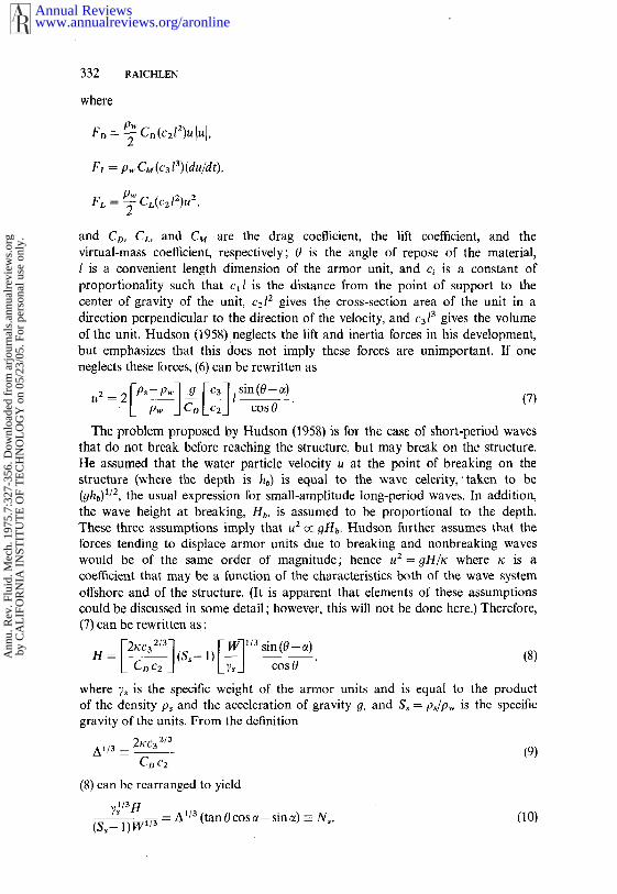
where
F, = p., CM(c3 ?)(du/ch).
FL = ~ C~(c~l~)u~,
and C~, C~, and C~ are the drag coeNcient, the lift coe~cient, and thevirtual-mass coeNcient, respectively; 0 is the angle of repose of the material,I is a convenient length dimension of the armor unit, and c~ is a constant ofproportionality such that c~l is the distance from the point of support to thecenter of gravity of the unit, c~l~ gives the cross-section area of the unit in adirection perpendicular to the direction of ~e velocity, and cal~ gives the volumeof the unit. Hudson (1958).neglects the lift and inertia forces in his development,but emphasizes that this does not imply these forces are unimpor~nt. If oneneglects these forces, (6) can be rewritten
~CP~-Pw] .g ~c3] sin(0-~) os0
The problem proposed by Hudson (1958) is for the case of short-period wavesthat do not break before reaching the structure, but may break on the structure.He assumed that the water particle velocity u at the point of breaking on thestructure (where the depth is hb) is equal to the wave celerity,’ taken to (ghb)~/~, the usual expression for small-amplitude long-period waves. In addition,the wave height at breaking, Hb, is assumed to be proportional to the depth.These three assumptions imply that u~ OHb. Hudson further assumes that theforces tending to displace armor units due to breaking and nonbreaking waveswould be of the same order of magnitude; hence u2= gH/~ where x is a~effident that may be a function of the characteristics both of the wave systemoffshore and of the structure. (It is apparent that elements of these assumptionscould be discussed in some detail ; however, this will not be done here.) Therefore,(7) can be rewritten as:
2xc3 ~/~ S cos 0 (8)
where 7~ is the specific weight of the armor units and is equal to the productof the density p~ and the acceleration of gravity ~, and S~ = p~/p~ is the spec~cgravity of the units. From the definition
A~/~ ~ 2~c~ (9)C~ c~
(8) can be rearranged to yield
~aH - A~/a (tan0cose- sin~) N~,(10)
(S~- I)W~
www.annualreviews.org/aronlineAnnual Reviews
Ann
u. R
ev. F
luid
. Mec
h. 1
975.
7:32
7-35
6. D
ownl
oade
d fr
om a
rjou
rnal
s.an
nual
revi
ews.
org
by C
AL
IFO
RN
IA I
NST
ITU
TE
OF
TE
CH
NO
LO
GY
on
05/2
3/05
. For
per
sona
l use
onl
y.
THE EFFECT OF WAVES ON RUBBLE-MOUND STRUCTURES333
where the parameter Ns is defined as the stability number for the breakwater.With reference to (9) [and (4)] the variable A shou;d be a function
A=f ~-,~,R,- ~,fl (lla)
or for the reduced list of variables in (5)
¯ A =f ,~, c~, [t . (llb)
It should be noted that fl includes the effect on stability of the specific characteristicsof the breakwater design, construction, and of the shape and packing of theindividual units.
Employing (10), or a variation of this expression, numerous investigators haveproposed relationships for the minimum stable weight of a rubble-mound armorunit for given wave conditions, the most frequently used being those proposed byHudson (1958), Iribarren [see Iribarren & Nogales (1953) and Iribarren (1965)],and Svee, Traetteberg & Terum (1965):
Hudson : W = )~s H3(12a)
KD(Ss- 1)3 cot c~N?s H3
Iribarren :
W --- ($, _ 1)3(tan 0 cos c~- sin c03
(12b)
Svee et al : W = K~ H3
(S~- l)a(cos (12c)
where KD, N, and K are called the stability factors.It is interesting to note the similarities among (12a), (12b), and (12c):
form of (10) is followed in each case except for the manner in which the slopeof the face of the structure and the angle of repose (or the coefficient of frictionbetween armor units) are included. In (12b) the relation between the angle repose and the angle of the face of the structure is the same as that obtainedfrom physical arguments (10); in (12a) and (12c) the stability factors KD and must be functions of the coefficient of friction between units. It is interesting tonote that the relative wave length, the Reynolds Number, and the offshore slope[see (1 la)] are not included directly in any of the expressions shown. Hence, theseeffects also must be incorporated in the stability coefficients if they are important..[-To some extent an effect of Reynolds Number not included explicitly in (12) present, since (8) and (9) show that the stability factor is dependent on a coefficient, Co.] In addition, where the inertial forces and lift forces were neglectedin the development of (10), these forces must in some way affect the stability factorsin (12). Therefore it appears that even though the general arrangement terms in (12) appears reasonable, the absence of certain other variables implied fromdimensional analysis and other arguments indicates that experiments should beconducted to determine both the shape of the structure and the acceptable sizeof armor units to resist damage from a given wave system. The experiments wouldbe guided by analyses similar to those presented here.
www.annualreviews.org/aronlineAnnual Reviews
Ann
u. R
ev. F
luid
. Mec
h. 1
975.
7:32
7-35
6. D
ownl
oade
d fr
om a
rjou
rnal
s.an
nual
revi
ews.
org
by C
AL
IFO
RN
IA I
NST
ITU
TE
OF
TE
CH
NO
LO
GY
on
05/2
3/05
. For
per
sona
l use
onl
y.
334 RAICHLEN
2.2 Experimental Considerations
The experimental results presented in this section were selected from a numberof sources and are used to demonstrate certain features of the analyses describedin Sect. 2.1. In some cases these data were obtained in the process of designingparticular structures; however, an attempt also has been made to use the resultsof experiments that were more general.
Hudson (1958) presents the results of an extensive series of experiments conductedto obtain basic inform~ition on thc stability of rubble-mound breakwaters [see alsoHudson & Jackson (1953), Hudson (1959), and Hudson & Jackson (1959)]. Certaininitial studies were conducted to determine the angle of repose of modeled break-water armor to permit evaluation of the stability coefficient N in Iribarren’sexpression (12b). Three different weights of quarry-stone were used along withconcrete cubes and concrete tetrapods. The angle of r~pose was determined foreases where the material had been dumped in water, dumped in air, stacked inwater, and stacked in air. For the quarry-stone the value of tan 0 varied froma minimum of 0.78 to a maximum of 1.28 with an average value of approximately0.98. Considering all of the material, the angle of repose varied with both theshape of the armor units and method of placement; in addition, there was aconsiderable scatter from experiment to experiment. Subsequently, Iribarren (1965)carefully measured the angle of repose for quarry-stone of three different sizes,cubes, and tetrapods (each of two different sizes) and found that the angle repose for each material was a function of the number of units and wasindependent of the absolute size of the particular armor. For all materials tested,
2.
ROCK ,~. ROCK ~NxUpM~B~E,R.~.OFT~(o.. °
¯
COT e
23
5. 6. 7. 8. 9. lO.
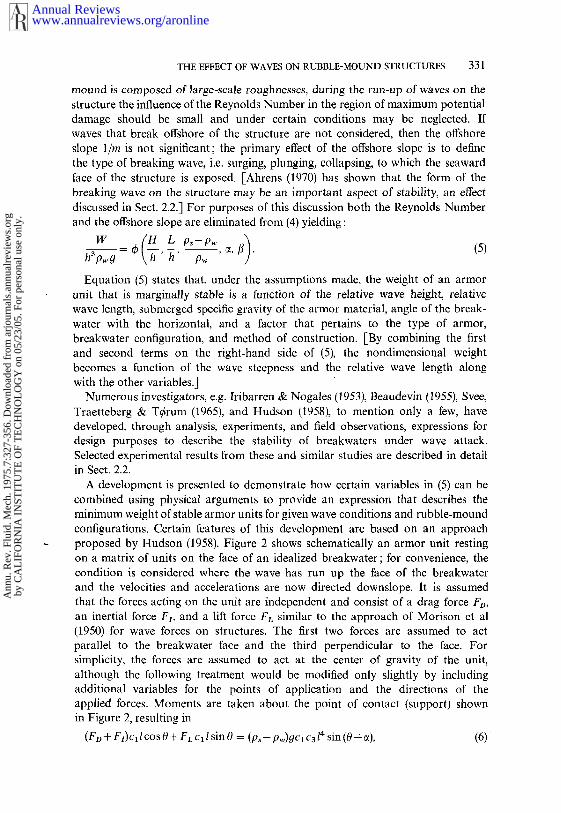
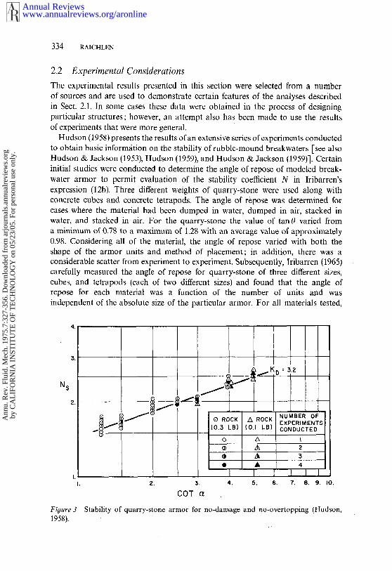
Stability of quarry-stone armor for no-damage and no-overtopping (Hudson,Figure 31958).
www.annualreviews.org/aronlineAnnual Reviews
Ann
u. R
ev. F
luid
. Mec
h. 1
975.
7:32
7-35
6. D
ownl
oade
d fr
om a
rjou
rnal
s.an
nual
revi
ews.
org
by C
AL
IFO
RN
IA I
NST
ITU
TE
OF
TE
CH
NO
LO
GY
on
05/2
3/05
. For
per
sona
l use
onl
y.
THE EFFECT OF WAVES ON RUBBLE-MOUND STRUCTURES 335
the tangent of the angle of repose varied from about 3.0 for 5 units to between1.0 and 1.5 for 50 units.
Primarily because of problems associated with determining the angle of reposeof the rubble-mound material, Hudson (1958) experimentally defined the stabilitynumber N~ in (10) in terms of the angle of the slope, e, and the characteristicsof the structure and the armor material,//. Laboratory experiments were conductedin a wave tank using regular waves, with the model breakwater exposed to a burstof waves for a period of time such that waves incident upon the structure were notreinforced by waves reflected from the wave generator. Thus the height of thewaves to which the structure was exposed could be determined from a calibrationof the wave tank without the structure in place; the wave height used in (12a) defined in this way. [Others have shown that the presence of the structureaffects the height of the maximum incident wave at a structure, for example, seeDanel (1952), so attention must be given to its definition.]
For a rubble-mound composed of quarry-stone a basic breakwater cross sectionwas tested under the condition of no overtopping by waves with various heights.The slope of the seaward face of the structure was varied and experiments wererepeated for reproducibility of results; in this way for a given structure thewave height which gave a specified percentage of damage was determined. Therefore,referring to (10), the value of the stability number Ns was evaluated as a functionof the breakwater slope, ~, for a given armor-layer material. The results of theseexperiments using quarry-stone are presented in Figure 3 for the condition of nodamage where the abscissa is the cotangent of the angle of the seaward faceto the horizontal and the ordinate is the stability number Ns. The data aresomewhat scattered, but the trend is obvious: the stability coefficient N~ appearsproportional to (cotc~)1/3. The constant of proportionality is the parameter KDthat appears in (12a); and for this quarry-stone KD = 3.2. Within the reproducibilityof the experiments, the same relationship was obtained with stone of a differentnominal size.
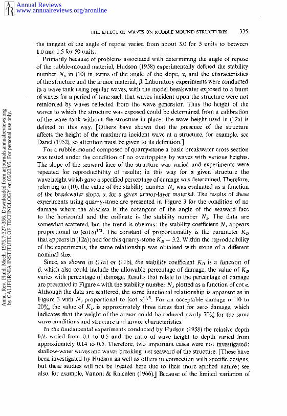
Since, as shown in (1 la) or (llb), the stability coefficient KD is a function of[L which also could include the allowable percentage of damage, the value of Kovaries with percentage of damage. Results that relate to the percentage of damageare presented in Figure 4 with the stability number N, plotted as a function of cotAlthough the data are scattered, the same functional relationship is apparent as inFigure 3 with N~ proportional to (cot c01/3. For an acceptable damage of 10 to20~, the value of K~ is approximately three times that for zero damage, whichindicates that the weight of the armor could bc reduced nearly 70~ for the samewave conditions and structure and armor characteristics.
In the fundamental experiments conducted by Hudson (1958) the relative depthh/L varied from 0.1 to 0.5 and the ratio of wave height to depth varied fromapproximately 0.14 to 0.5. Therefore, two important cases were not investigated:shallow-water waves and waves breaking just seaward of the structure. [These havebeen investigated by Hudson as well as others in connection with specific designs,but these studies will not be treated here due to their more applied nature; seealso, for example, Vanoni & Raichlen (1966).] Because of the limited variation
www.annualreviews.org/aronlineAnnual Reviews
Ann
u. R
ev. F
luid
. Mec
h. 1
975.
7:32
7-35
6. D
ownl
oade
d fr
om a
rjou
rnal
s.an
nual
revi
ews.
org
by C
AL
IFO
RN
IA I
NST
ITU
TE
OF
TE
CH
NO
LO
GY
on
05/2
3/05
. For
per
sona
l use
onl
y.
336 RAICHLF~N
6.
Figure 41958).
Oal ~ ~IS ~ 06 ~O ~.~ I
N~~01 NOTE: NUMERALS NEXT TO¯ ~1 DATA POINTS ARE --
EXPERIMENTALLY
DETERMINED PERCENT
DAMAGE.
2. 3. 4. 5. 6. 7: 8. 9. I0.
COT a
Stability of quarry-stone armog as a function of percentage of damage (Hudson,
the ratio of depth to wave length in these experiments it is difficult to draw con-clusions about the importance of this variable. However, Brandtzaeg (1965), summarizing the work of several authors [Svee, Traetteberg & T~rum (1965),Iribarren (1965), Saville, Garcia & Lee (1965)], comments that the effect of ratio of depth to wave length on the stability of a rubble-mound structure appearssmall. Certain problems associated with breaking waves will be discussed later. Itappears that extensions of this fundamental work by Hudson (1958) to investigatein detail the effect of long waves and breaking waves on the stability of a structureare indicated.
The ability of armor units on the face of a breakwater to interlock is quiteimportant with respect to stability, and essentially this interlocking is describedby the importance of the parameter/3 in (1 la,b). Quarry-stone has a limited abilityto interlock; generally interlocking improves as the material becomes more angular.However, specially shaped concrete armor units, some of which were mentioned inSect. 1, are designed to interlock and thus reduce the required weight of thestable units. Over the years many different shapes of concrete armor units havebeen developed, and experiments similar to those of Hudson (1958) have beenperformed to evaluate the stability of such units. (It should be realized that the
www.annualreviews.org/aronlineAnnual Reviews
Ann
u. R
ev. F
luid
. Mec
h. 1
975.
7:32
7-35
6. D
ownl
oade
d fr
om a
rjou
rnal
s.an
nual
revi
ews.
org
by C
AL
IFO
RN
IA I
NST
ITU
TE
OF
TE
CH
NO
LO
GY
on
05/2
3/05
. For
per
sona
l use
onl
y.
THE EFFECT OF WAVES ON RUBBLE-MOUND STRUCTURES 337
stability of the structure is also a function of specific features of the structure suchas the cross section, so care must be taken in applying the results of oneexperiment to another design.)
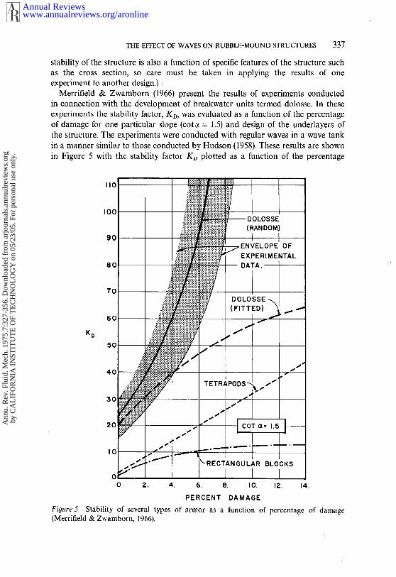
Merrifield & Zwamborn (1966) present the results of experiments conductedin connection with the development of breakwater units termed dolosse. In theseexperiments the stability factor, KD, was evaluated as a function of the percentageof damage for one particular slope (cot ~ = 1.5) and design of the underlayers the structure. The experiments were conducted with regular waves in a wave tankin a manner similar to those conducted by Hudson (1958). These results are shownin Figure 5 with the stability factor KD plotted as a function of the percentage
~ L___ o’o,oss~’(RANDOM)
ENVELOPE OFy EXPERIMEI~ TAL
(FITTED) ~ ~
~’ ~’~’ ’ ~"-" "t~- I
00 2. 4. 6. 8. I0. 12. 14.
PERCENT DAMAGE
Figure 5 Stability of several types of armor as a function of percentage of damage(Merrifield & Zwamborn, 1966).
www.annualreviews.org/aronlineAnnual Reviews
Ann
u. R
ev. F
luid
. Mec
h. 1
975.
7:32
7-35
6. D
ownl
oade
d fr
om a
rjou
rnal
s.an
nual
revi
ews.
org
by C
AL
IFO
RN
IA I
NST
ITU
TE
OF
TE
CH
NO
LO
GY
on
05/2
3/05
. For
per
sona
l use
onl
y.

338 RAICHLEN
of damage, which was assessed in terms of movement of a unit over a specificdistance as well as of excessive rocking of the unit that in the prototype could causedestruction of that unit. These experiments are particularly interesting because theyshow a comparison of different types of armor units with similar underlayersunder comparable test conditions. For damage less than 5~o the stability factorincreases by a factor of about five for randomly placed dolosse compared to tetrapodsor rectangular blocks. From (12a) this increase in the stability factor correspondsto a comparable decrease in the weight of the unit required, for other variables keptconstant. A significant difference in stability is noted in Figure 5 for randomlyplaced dolosse compared to the units packed (or fitted). For the former thestructure appears to become more stable with increasing damage, which indicatesthat the dolosse become more interlocked as damage increases, but for the packeddolosse the opposite is true. At zero damage the stability factor for the dolosse(either randomly placed or packed) is approximately six times that determined Hudson (1958) for quarry-stone (see Figure 3), which means dolosse with sixth the weight of quarry-stone afford the same protection for the same wave
SYMBOL MATERIAL PLACEMEN~- ~-- ROCK RANDOM~ ROCK FITTED-~-- TETRAPODS RANDOM~ TETRAPODS FITTED
~ INDICATES FILTER-=- LAYER UNCOVERED
Figure 6 Stability of quarry-stone and tetrapod armor as a function ofpcrcentage of damagefor two techniques of placement (Font. ! 970).
www.annualreviews.org/aronlineAnnual Reviews
Ann
u. R
ev. F
luid
. Mec
h. 1
975.
7:32
7-35
6. D
ownl
oade
d fr
om a
rjou
rnal
s.an
nual
revi
ews.
org
by C
AL
IFO
RN
IA I
NST
ITU
TE
OF
TE
CH
NO
LO
GY
on
05/2
3/05
. For
per
sona
l use
onl
y.
THE EFFECT OF WAVES ON RUBBLE-MOUND STRUCTURES 339
conditions, structure shape, and density of units. (These results are meant toindicate only the effect of shape of armor units on stability and do not constitutedesign criteria.)
It is evident from certain of the results discussed that the packing and methodof construction [-included in the parameter ~¢ in (lla, b)] have an important effecton stability. Recent work by Font (1970) demonstrates this aspect of the stabilityproblem quite well. Some results relative to this are shown in Figure 6, wherethe stability of a breakwater (cot ~ = 1.5) armored with two different types material was studied. For each of these materials, quarry-stone and tetrapods, twodifferent methods of placement were used : randomly placed without attempting tointerlock units, and carefully fitted units forming a well interlocked layer. InFigure 6 the stability number N~ is shown as a function of damage observed : asthe percentage of damage increases the stability number increases for each of thefour cases investigated. The structure was built with an impermeable core andtwo or three layers of filter material with the armor units above. Therefore, asdamage increased to about 15~o the filter layer was uncovered in some experiments.With both rock and tetrapods it was found, for a given percentage of damage, thathigher waves were necessary to cause this damage, that is, a larger value of Ns,when the material was carefully fitted compared to random placement. Hence, theseresults indicate for given wave conditions that a smaller armor unit is acceptablewhen careful placement techniques are used. [-Note for dolosse shown in Figure 5the opposite was found, which may be a peculiarity of the dolos shape. Forquarry-stone Kidby, Powell & Roberts (1964) found that careful fitting of angularrock above the mean water level with the long axis placed perpendicular to theface of the structure yielded a significantly more stable structure than that composedof the same material randomly placed,] In addition, Font (1970) found that themaximum observed damage occurred near the intersection of the mean water levelwith the breakwater face and generally was concentrated in a region approximatelytwo wave heights above and below that point.
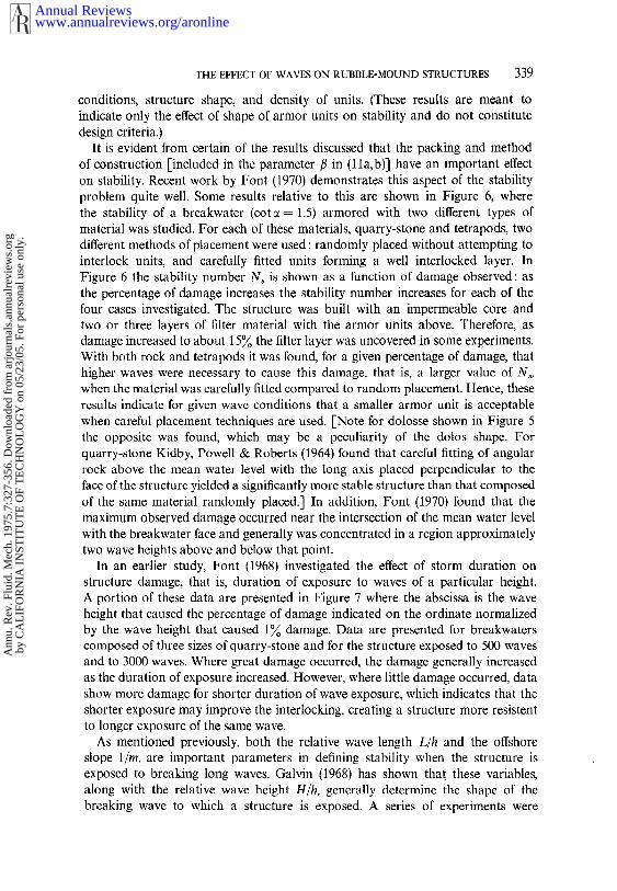
In an earlier study, Font (1968) investigated the effect of storm duration structure damage, that is, duration of exposure to waves of a particular height.A portion of these data are presented in Figure 7 where the abscissa is the waveheight that caused the percentage of damage indicated on the ordinate normalizedby the wave height that caused 1~ damage. Data are presented for breakwaterscomposed of three sizes of quarry-stone and for the structure exposed to 500 wavesand to 3000 waves. Where great damage occurred, the damage generally increasedas the duration of exposure increased. However, where little damage occurred, datashow more damage for shorter duration of wave exposure, which indicates that theshorter exposure may improve the interlocking, creating a structure more resistentto longer exposure of the same wave.
As mentioned previously, both the relative wave length L/h and the offshoreslope l/m, are important parameters in defining stability when the structure isexposed to breaking long waves. Galvin (1968) has shown that these variables,along with the relative wave height H/h, generally determine the shape of thebreaking wave to which a structure is exposed. A series of experiments were
www.annualreviews.org/aronlineAnnual Reviews
Ann
u. R
ev. F
luid
. Mec
h. 1
975.
7:32
7-35
6. D
ownl
oade
d fr
om a
rjou
rnal
s.an
nual
revi
ews.
org
by C
AL
IFO
RN
IA I
NST
ITU
TE
OF
TE
CH
NO
LO
GY
on
05/2
3/05
. For
per
sona
l use
onl
y.
340 RAICHLEN
I-Z~J
uJ
Figure 7
50.
30.
20.
I0.
0.5
¯1
w n(gin) 500
255 o
190 []
102 ~x
3000--
¯
O.i0.5 I. 1.5 2.0
H/H~%
Percentage of damage for various storm durations (Font 1968).
conducted by Ahrens (1970) to investigate this effect on the stability of a structure.In these experiments the rubble-mound was built of quarry-stone to a large scalewith a slope of 1 : 1.25 (cot c~ = 1.25) in a wave tank with a horizontal bottom.This structure was exposed to waves with a maximum ratio of wave height todepth of 0.23 so that these waves broke on the face of the structure and notbefore reaching the structure. The types of breakers on the structure ranged fromsurging breakers to plunging breakers, with a portion of tl~e experiments producingthe collapsing breaker defined by Galvin 0968). It was found that the stabilitynumber Ns decreased by about 40~o for the case of the collapsing breakers compared
www.annualreviews.org/aronlineAnnual Reviews
Ann
u. R
ev. F
luid
. Mec
h. 1
975.
7:32
7-35
6. D
ownl
oade
d fr
om a
rjou
rnal
s.an
nual
revi
ews.
org
by C
AL
IFO
RN
IA I
NST
ITU
TE
OF
TE
CH
NO
LO
GY
on
05/2
3/05
. For
per
sona
l use
onl
y.
THE EFFECT OF WAVES ON RUBBLE-MOUND STRUCTURES341
to either surging or plunging breakers for the condition of no damage. It shouldbe emphasized that in these experiments the breaker shape was defined by thestructure, not by Offshore conditions. Nevertheless, since breaker shape appearsimportant in defining stability, the relative wave length, L/h, and the offshoreslope, l/m, may be important for breaking waves. Certainly additional fundamentalinvestigations are warranted to investigate this feature of stability.
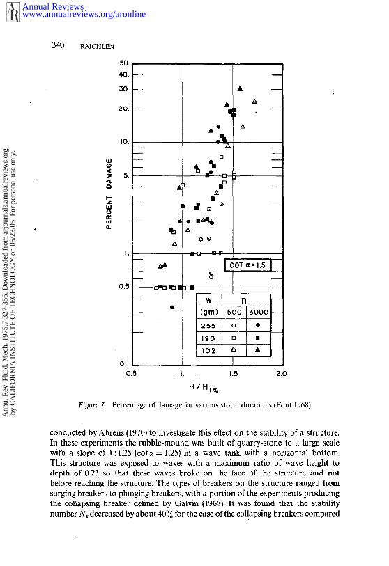
Limited experiments have been conducted in the laboratory by Dai & Kamel(1969) to investigate the effect of Reynolds Number on the stability number. Rubble-mound structures composed of quarry-stone and of quadripods were constructedat three different model scales: Lr = 1/2, 1, and 7.5, where Lr is the ratio of alength in the model to the corresponding length in the prototype. In all casesan attempt was made to build the structure the same way for each of the threescales. To some extent surface texture was also considered. For example, therough surface texture of the structure for quarry-stone was due to the use ofangular rock, whereas a smoother surface resulted when the rock was rounded;two different methods of casting were used for the quadripods to produce a smoothand a rough unit. Selected data are presented in Figure 8 where the stability numberN, is plotted as a function of the model scale for each of four cases; thecorresponding ratio of the depth to wave length is also indicated for the data. TheReynolds Number is defined in terms of a characteristic length of an armor unitand a theoretical velocity parallel to the slope near the still-water-level; theReynolds Number varied from 104 for the smallest scale to 10s to 106 for thelargest scale for these experiments. Although the data are scattered the stabilitynumber appears to decrease with decreasing model size or Reynolds Number, andthere is an apparent effect of the ratio of depth to wave length on the stabilitynumber for a given model scale. Although these tests are not conclusive, and moreeffort should be directed to this aspect of the problem, the data demonstrate thatthe choice of scale for an experiment in this type of investigation is as importantas it is in other experiments where gravity forces are dominant.
Only limited data are available from stability investigations using irregular (non-periodic) waves. It has been generally assumed that stability experiments conductedin the laboratory with regular wave systems, where the wave height was set equalto the significant wave height of an irregular wave train, would yield conservativeresults compared to testing with the actual irregular wave train, although fromthe results available this assumption may not be completely valid. (The significantwave is defined as the average of the highest one-third of the wave train.)
Studies have been conducted using wind-generated waves in the laboratory [see,for example, Nagai (1962), Plate & Nath (1969)], but the reproduction of a scaledocean-wave spectrum in a laboratory wave tank using wind alone is difficult.Significant advances are being made in irregular wave studies using mechanicalwave generators in the laboratory that are hydraulically driven and controlled by aprogrammed servomechanism. Carstens, Tqlrum, & Traetteberg (1966) presentresults of a stability study of a rubble-mound armored with quarry-stone in awave tank equipped with a mechanical irregular-wave generator. Two differentstructure slopes were examined (cot ~ = 1.25 and 1.5), but only selected results are
www.annualreviews.org/aronlineAnnual Reviews
Ann
u. R
ev. F
luid
. Mec
h. 1
975.
7:32
7-35
6. D
ownl
oade
d fr
om a
rjou
rnal
s.an
nual
revi
ews.
org
by C
AL
IFO
RN
IA I
NST
ITU
TE
OF
TE
CH
NO
LO
GY
on
05/2
3/05
. For
per
sona
l use
onl
y.

342 RAICHLEN
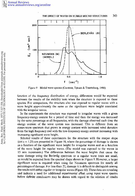
presented here. The structure was exposed to two wave spectra in separateexperiments: the Berlev~g (B) spectrum and the model Neumann (N) spectrum,These spectra are shown in Figure 9, and it is apparent that the B spectrumhas energy concentrated in a frequency band narrower than the N spectrum,although for the same significant wave height the frequency distribution of waveheights for these two spectra were similar. Hence, if indeed the stability is a
Ns
Ns
I
0.I
Fioure 81969).
MATERIAL ~QUARRY-STONE .45
.23
" " .14
" " .09
ROUGH
SMOOTH,o.
MATERIALQUADRIPODS
ROUGH
SMOOTH
T
0.5 I. 5. I0.
Lr
Effect of model scale on stability; quarry-stone and quadripods (Dai & Kamel,
www.annualreviews.org/aronlineAnnual Reviews
Ann
u. R
ev. F
luid
. Mec
h. 1
975.
7:32
7-35
6. D
ownl
oade
d fr
om a
rjou
rnal
s.an
nual
revi
ews.
org
by C
AL
IFO
RN
IA I
NST
ITU
TE
OF
TE
CH
NO
LO
GY
on
05/2
3/05
. For
per
sona
l use
onl
y.
THE EFFECT OF WAVES ON RUBBLE-MOUND STRUCTURES343
Figure 9
!
NEUMANN (N) /
¯ ( MODe//
I I I I
~- BERLEVAG
0.5 1,0
f (sec-I )
Model wave spectra (Carstens, T~rum & Traetteberg, 1966).
function of the frequency distribution of energy, differences would be expectedbetween the results of the stability tests when the structure is exposed to thesespectra. For comparison, the structure also was exposed to regular waves with awave height approximately the same as the significant wave height associatedwith the irregular waves.
In the experiments the structure was exposed to irregular waves with a givenfrequency-energy content for a period of time and then the energy was increasedby the same percentage at all frequencies, with the damage observed each time theenergy content of the wave system was increased. This is different from anocean-wave spectrum that grows in energy content with increased wind durationfrom the high frequency end with the low-frequency energy content increasing withincreasing significant wave height.
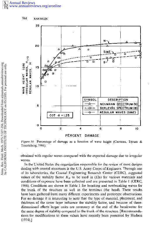
Selected results of these experiments for the structure with the steeper slope(cot ~ = 1.25) are presented in Figure 10, where the percentage of damage is shownas a function of the significant wave height for irregular waves and as a functionof the wave height for regular waves. (The model was exposed to the waves in15 min increments.) The differences between the wave heights that cause thesame damage using the Berlev~g spectrum or a regular wave train are small,as would be expected from the spectral shape shown in Figure 9. However, a largersignificant wave is required when using the Neumann spectrum for nearly allpercentages of damage. For less than 2~o damage it is difficult to distinguish amongthe results with either regular or irregular waves (Figure 10). These data are revealingand indicate a need for additional experimental effort using input wave spectrabefore definite conclusions may be drawn with regard to the relation of r6sults
www.annualreviews.org/aronlineAnnual Reviews
Ann
u. R
ev. F
luid
. Mec
h. 1
975.
7:32
7-35
6. D
ownl
oade
d fr
om a
rjou
rnal
s.an
nual
revi
ews.
org
by C
AL
IFO
RN
IA I
NST
ITU
TE
OF
TE
CH
NO
LO
GY
on
05/2
3/05
. For
per
sona
l use
onl
y.
3214 RAICHLEN
25
20
15
10
0 2 4 6 8 I0
PERCENT DAMAGE
Fiyure 10 Percentage of damage as a function of wave height (Carstens, Tqrum Traetteberg, 1966).
obtained with regular waves compared with the expected damage due to irregularwaves.
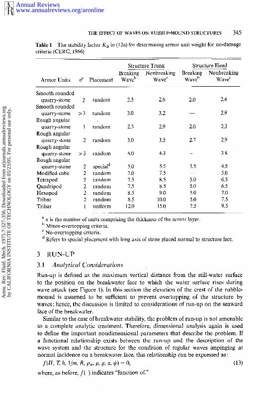
In the United States the organization responsible for the review of most designsdealing with coastal structures is the U.S. Army Corps of Engineers. Through oneof its laboratories, the Coastal Engineering Research Center (CERC), suggestedvalues of the stability factor KD to be used in (12a) for various materials andconditions of exposure have been collected and are presented in Table 1 (CERC,1966). Conditions are shown in Table 1 for breaking and nonbreaking waves forthe trunk of the structure as well as the terminus (the head). These resultshave been gathered from many different experiments and prototype observations.For no damage it is interesting to note that the type of material, placement, andthickness of the cover layer influence the stability factor, and because of three-dimensional effects larger units are necessary at the end of the breakwater forthe same degree of stability compared to the trunk of the structure. [Recommenda-tions for modifications to these values have recently been presented by Hudson(1974).]
www.annualreviews.org/aronlineAnnual Reviews
Ann
u. R
ev. F
luid
. Mec
h. 1
975.
7:32
7-35
6. D
ownl
oade
d fr
om a
rjou
rnal
s.an
nual
revi
ews.
org
by C
AL
IFO
RN
IA I
NST
ITU
TE
OF
TE
CH
NO
LO
GY
on
05/2
3/05
. For
per
sona
l use
onl
y.
THE EFFECT OF WAVES ON RUBBLE-MOUND STRUCTURES345
Table 1 The stability factor Ko in (12a) for determining armor unit weight for no-damagecriteria (CERC, 1966)
Armor Units na Placement
Structure Trunk Structure HeadBreaking Nonbreaking Breaking NonbreakingWaveb Wavec Waveb Wavec
Smooth roundedquarry-stone 2 random 2.5 2.6 2.0 2.4
Smooth roundedquarry-stone > 3 random 3.0 3.2 -- 2.9
Rough angularquarry-stone 1 random 2.3 2.9 2.0 2.3
Rough angularquarry-stone 2 random 3.0 3.5 2.7 2.9
Rough angularquarry-stone > 3 random 4.0 4.3 -- 3.8
Rough angularquarry-stone 2 speciald 5.0 5.5 3.5 4.5
Modified cube 2 random 7.0 7.5 -- 5.0Tetrapod 2 random 7.5 8.5 5.0 6.5Quadripod 2 random 7.5 8.5 5.0 6.5Hexapod 2 random 8.5 9.0 5.0 7.0Tribar 2 random 8.5 10.0 5.0 7.5Tribar 1 uniform 12.0 15.0 7.5 9.5
n is the number of units comprising the thickness of the armor layer.Minor-overtopping criteria.No-overtopping criteria.Refers to special placement with long axis of stone placed normal to structure face.
3 RUN-UP
3.1 Analytical Considerations
Run-up is defined as the maximum vertical distance from the still-water surfaceto the position on the breakwater face to which the water surface rises duringwave attack (see Figure 1). In this section the elevation of the crest of the rubble-mound is assumed to be sufficient to prevent overtopping of the structure bywaves; hence, the discussion is limited to considerations of run-up on the seawardface of the breakwater.
Similar to the case of breakwater stability, the problem of run-up is not amenableto a complete analytic treatment. Therefore, dimensional analysis again is usedto define the important nondimensional parameters that describe the problem. Ifa functional relationship exists between the run-up and the description of thewave system and the structure for the condition of regular waves impinging atnormal incidence on a breakwater face, this relationship can be expressed as :
f(H, T, h, l/m, R, p,~, kt, g, ~, ~p) = 0, (13)
where, as before, f( ) indicates "function of."
www.annualreviews.org/aronlineAnnual Reviews
Ann
u. R
ev. F
luid
. Mec
h. 1
975.
7:32
7-35
6. D
ownl
oade
d fr
om a
rjou
rnal
s.an
nual
revi
ews.
org
by C
AL
IFO
RN
IA I
NST
ITU
TE
OF
TE
CH
NO
LO
GY
on
05/2
3/05
. For
per
sona
l use
onl
y.
346 RAICHLEN
The first four variables of (13) define the incident-wave characteristics; the nextterm, R, is the run-up on the structure face measured vertically from the still-water level; the next two terms define the fluid density pw and the dynamic fluidviscosity #; g is the acceleration of gravity; and c~ is the slope of the face ofthe structure with respect to horizontal. The last variable, @, describes the physicalcharacteristics of the breakwater face which affect run-up, and would be a functionof such factors as shape of the armor units, roughness of the face, permeabilityof the armor layer, characteristics of the underlying material, and method andtype of construction. Hence, @ essentially describes various particular features ofthe breakwater and demonstrates the difficulty of developing universal run-upcharacteristics for rubble-mounds. The variables pw, g, and h are used in non-dimensionalizing (13), resulting in the following:
f(.~ T2g 1 R ~/p~ ~’ h ’~’~’(~’’ ]=0.(14)
Equation 14 basically has the same type of terms as (3) did for stabilityconsiderations. By suitable combination of nondimensional variables, (14) can rewritten :
~=~ ’h’m’
where the Reynolds Number, R, is a Nnction of the water-particle velocity and alinear dimension of the armor.
In (15) the relative run-up (expressed as the run-up elevation divided by wave height) is a function of the wave characteristics as embodied in the ratio ofwave height to depth and the ratio of the wave length to the depth as well as theoffshore slope, 1/m. ffhese three parameters define the characteristics of long wavesand the latter becomes most impotent at breaking in defining the shape of thebreaking waves. As beNre, for short waves, the first two terms can be combinedto give a wave steepness and wave-length to depth ratio.)
The breakwater Nee, composed of rock or armor units, represents an hydro-dynamically rough surNce, and, for a su~ciently large Reynolds Number, theeffect of the Reynolds Number on run-up as shown in (15) is minimal. Therefore,the list of variables shown in (15) can be reduced to:
--= 7, O ̄ (~6)H ~ ’h’m’
In conducting laboratory experiments to Nvestigate run-up, if the scale of theexperiments is not large enough, corrections for the effect of Reynolds Numbermust be applied to the results. Such corrections will be discussed briefly later.
3.2 Experimental Considerations ~
The variable O in (16) embodies numerous characteristics of the rubble-mound thatmay in part be peculiar to a particular design, and for this reason laboratoryexperiments are conducted to evaluate run-up in the design of important structures.
www.annualreviews.org/aronlineAnnual Reviews
Ann
u. R
ev. F
luid
. Mec
h. 1
975.
7:32
7-35
6. D
ownl
oade
d fr
om a
rjou
rnal
s.an
nual
revi
ews.
org
by C
AL
IFO
RN
IA I
NST
ITU
TE
OF
TE
CH
NO
LO
GY
on
05/2
3/05
. For
per
sona
l use
onl
y.

THE EFFECT OF WAVES ON RUBBLE-MOUND STRUCTURES 347
In this section selected experimental results from different investigations are usedto describe the important features of run-up.
Figure 11 shows run-up data (CERC, 1966) for smooth and rubble-mound slopes;from Saville (1956) and Hudson (1958), respectively, and in both cases only experi-mental curves are shown without the corresponding data. The run-up isnormalized with respect to the deep water wave height, H0, and is plotted as afunction of the ratio of the deep water wave height to the wave period squared,HolT~ ; hence, the abscissa is proportional to the deep-water wave steepness. (Thedeep-water wave height is determined from small amplitude wave theory forshoaling from the measured wave height, depth, and wave period.) Attention is firstdirected toward the data for run-up on smooth slopes where the experiments wereconducted with a 1 : 10 bottom slope leading seaward from the toe of the structure.The results are shown for various structure slopes with 1.25 < cot c~ < 5, and inall cases the ratio of the deep-water wave height to the depth at the toe of thestructure was-less than 0.33. [With reference to (16), this method of datapresentation assumes that the ratio of wave length to depth is relatively un-important and the wave steepness, obtained by dividing the first variable by thesecond variable in (16), is the most important parameter,] For a given structureslope Figure 11 shows that as the wave steepness decreases, the relative run-up
R/Ho
4.0
hO
0.8
0.6
0.4
0.2
I I I I I I } Io.o~ o.oz 0.04 o.o6 o.oe o.~ o.z 0.4 o.e o.e LO
Ho/T = (ft/sec~)
Wave rnn-up on smooth slopes and rubble-mound slopes (h/Ho > 3) (CERC,
www.annualreviews.org/aronlineAnnual Reviews
Ann
u. R
ev. F
luid
. Mec
h. 1
975.
7:32
7-35
6. D
ownl
oade
d fr
om a
rjou
rnal
s.an
nual
revi
ews.
org
by C
AL
IFO
RN
IA I
NST
ITU
TE
OF
TE
CH
NO
LO
GY
on
05/2
3/05
. For
per
sona
l use
onl
y.
348 RAICHLEN
increases. In the region where Holt2 < 0.03 ft/sec 2 the relative run-up generallyincreases with decreasing structure slope ; the reverse is true for Holt2 > O. 1 ft/sec2.
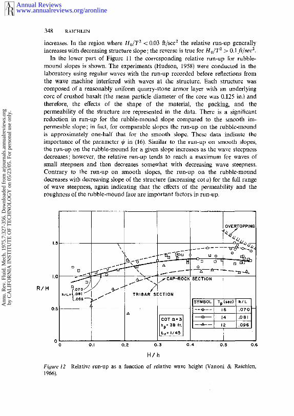
In the lower part of Figure 11 the corresponding relative run-up for rubble-mound slopes is shown. The experiments (Hudson, 1958) were conducted in thelaboratory using regular waves with the run-up recorded before reflections fromthe wave machine interfered with waves at the structure. Each structure wascomposed of a reasonably uniform quarry-stone armor layer with an underlyingcore of crushed basalt (the mean particle diameter of the core was 0.125 in.) andtherefore, the effects of the shape of the material, the packing, and thepermeability of the structure are represented in the data. There is a significantreduction in run-up for the rubble-mound slope compared to the smooth im-permeable slope; in fact, for comparable slopes the run-up on the rubble-moundis approximately one-half that for the smooth slope. These data indicate theimportance of the parameter ~b in (16). Similar to the run-up on smooth slopes,the run-up on the rubble-mound for a given slope increases as the wave steepnessdecreases; however, the relative run-up tends to reach a maximum for waves ofsmall steepness and then decreases somewhat with decreasing wave steepness.Contrary to the run-up on smooth slopes, the run-up on the rubble-mounddecreases with decreasing slope of the structure (increasing cot ct) for the full rangeof wave steepness, again indicating that the effects of the permeability and theroughness of the rubble-mound face are important factors in run-up.
R/H
1.5
TRIBAR SECTIONh/L,’~.O81k.OgS --
SECTION
ISYMBOL I Tp
OVERTOPPING
o
(,sec) I b/L
i .o7olI.o~, II.o~ I
Figure 121966).
0.1 0.2 0.3 0.4 0.5 0.6
H/h
Relative run-up as a function of relative wave height (Vanoni & Raichlen,
www.annualreviews.org/aronlineAnnual Reviews
Ann
u. R
ev. F
luid
. Mec
h. 1
975.
7:32
7-35
6. D
ownl
oade
d fr
om a
rjou
rnal
s.an
nual
revi
ews.
org
by C
AL
IFO
RN
IA I
NST
ITU
TE
OF
TE
CH
NO
LO
GY
on
05/2
3/05
. For
per
sona
l use
onl
y.
THE EFFECT OF WAVES ON RUBBLE-MOUND STRUCTURES349
For a structure face composed of a well-graded quarry-stone both the permeabilityand the roughness are reduced. The results of experiments with such a primarylayer over an impermeable base (CERC, 1966) show an increase in relative run-upfrom 35 to 70Voo compared to the comparable case shown in Figure 11. These resultsagain demonstrate the effect on run-up of the roughness and permeability of thestructure and indicate the importance of properly modeling the structure to betested in the laboratory.
Detailed experiments were conducted by Vanoni & Raichlen (1966) to determinethe stability and the run-up characteristics of a structure exposed to periodicwaves. The primary armor layer of the structure was composed in part of tribarsand in part of quarry-stone. An attempt was made in this study to view the run-upas described by (16) for a horizontal bottom offshore, that is, the variable 1/m wasneglected in the formulation of the problem. In these experiments the wavesbetween the wave machine and the structure were allowed to reach a steady state,and the incident and reflected wave heights were determined from measurementsof the partial standing-wave envelope. The slope of the structure face was 1 : 3(cot c~ = 3) and the structure modeled in the laboratory was composed of theprimary armor layer, an underlayer of quarry-stone, and a portion of the coreof the proposed structure.
Selected data are presented in Figure 12 for one model scale (Lr = 1/45) wherethe graph shows run-up over wave height/-/against H over depth h. The structurewas exposed to regular waves with three different wave periods; hence, curvesare shown on Figure 12 for constant ratios of depth to wave length, h/L. Sincethe structure face was armored with tribars from the bottom up to a particularelevation and then with quarry-stone, one curve on Figure 12 shows the line ofdemarcation between these two materials; an additional curve indicates overtoppingof the structure. Figure 12 shows that the relative run-up is a function of bothH/h and h/L over the full range of the experiments; in fact, even for small valuesof the ratio of wave height to depth, the relative run-up is a function of h/L.General conclusions cannot be drawn from these limited data regarding therelative importance of the ratios of either depth to wave length or height todepth in affecting run-up, but both parameters appear important. It is difficult tocompare the data in Figure 12 to the relative run-up for a rubble-moundstructure of the same slope shown in Figure 11, since the effect of the ratio ofdepth to wave length is not shown in the latter. However, the smallest value ofdepth to wave length investigated by Hudson (1958) for a rubble-mound structureof the same slope was 0.10 and the relative run-up was about unity, which isapproximately that shown in Figure 12 for a depth to wave length of 0.096.Particular attention was given in this study to large wave height to depth ratiosin contrast to the other studies mentioned, e.g., in the experiments for h/L = 0.07the ratio of the maximum wave height to the depth of water beneath the troughwas approximately 0.65.
Additional attention has been given in recent years to the run-up due toirregular waves. Since ’(16) has been derived for the case of regular waves,additional parameters are necessary to describe irregular waves. Basic differences
www.annualreviews.org/aronlineAnnual Reviews
Ann
u. R
ev. F
luid
. Mec
h. 1
975.
7:32
7-35
6. D
ownl
oade
d fr
om a
rjou
rnal
s.an
nual
revi
ews.
org
by C
AL
IFO
RN
IA I
NST
ITU
TE
OF
TE
CH
NO
LO
GY
on
05/2
3/05
. For
per
sona
l use
onl
y.
350 RAICHLEN
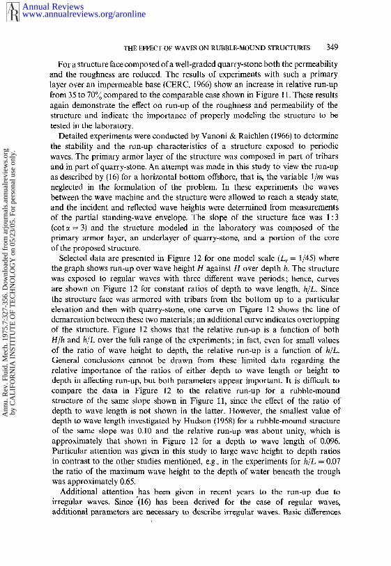
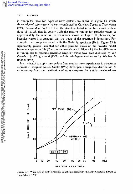
in run-up for these two types of wave systems are shown in Figure 13, whichshows selected results from the study conducted by Carstens, T~rum & Traetteberg(1966) discussed in Sect. 2.2. For the structure tested (a rubble-mound with slope of 1 : 1.25, that is, cot ~ = 1.25) the relative run-up for periodic waves isapproximately the same as the maximum shown in Figure 11; however, forirregular waves it is apparent that the shape of the spectrum is important. Forexample, the run-up associated with the Berlevag spectrum (B) in Figure 13 significantly greater than that for either periodic waves or the broader modelNeumann spectrum (N). (The spectra were shown in Figure 9.) Similar differencesin run-up due to machine-generated irregular waves have been discussed by vanOorschot & d’Angremond (1968) and for wind-generated waves by Webber Bullock (1968).
In an attempt to apply run-up data from regular wave experiments to structuresexposed to irregular waves, Saville (1962) developed a frequency distribution wave run-up from the distribution of wave steepness for a fully developed sea
40
o5
(N)
I0 20 40 60 80 90 95 99 99.9
PERCENT LESS THAN
Fioure 13 Wave run-up distribution for equal significant wave heights (Carstens, T~rum Traetteberg, 1966).
www.annualreviews.org/aronlineAnnual Reviews
Ann
u. R
ev. F
luid
. Mec
h. 1
975.
7:32
7-35
6. D
ownl
oade
d fr
om a
rjou
rnal
s.an
nual
revi
ews.
org
by C
AL
IFO
RN
IA I
NST
ITU
TE
OF
TE
CH
NO
LO
GY
on
05/2
3/05
. For
per
sona
l use
onl
y.
THE EFFECT OF WAVES ON RUBBLE-MOUND STRUCTURES 351
obtained from the joint distribution of wave height and wave period. In this waythe approximate percentage of the wave train that could exceed the run-up asdetermined from periodic wave tests was defined. For rubble-mounds with slopesvarying from 1:1.5 to 1:6 (1.5 < cot~ < 6) it was found that approximately 20700of the time the run-up would.be from one to two times that experienced with a wavewith the height of the significant wave. These results are comparable to thoseshown in Figure 13.
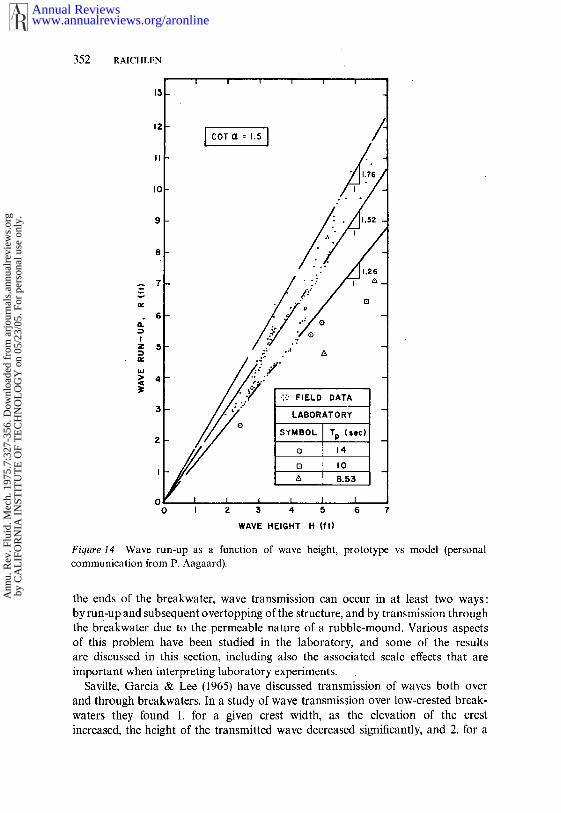
A major problem associated with interpreting experimental run-up results in thedesign of coastal structures is the effect of model scale. Most research in thisarea has dealt with models of various scales, for example, see Saville (1958) described in CERC (1966). In one investigation field measurements of run-up the rubble-mound slope of an artificial island off the coast of Southern Californiawere obtained. These measurements were made using a wave-staff gage mountedparallel to the slope of the structure and were compared to the results of laboratorytests of run-up using periodic incident waves (personal communication fromP. Aagaard); the length scale of the laboratory experiments was 1/50. Selecteddata obtained in the field and in the laboratory are shown in Figure 14 wherethe ordinate is the run-up measured in feet and the abscissais the wave height infeet. For the field measurements, the run-up was ranked in order of descendingmagnitude and plotted as a function of the wave height measured off thestructure ranked in the same way; thus the maximum run-up corresponds to themaximum wave height for a given record. For the laboratory data, the run-up isplotted as a function of the causitive wave, with both scaled up to the prototype,and the wave period indicated corresponds to the prototype period. Figure 14shows that the run-up obtained from field measurements was considerably largerthan that determined in the laboratory: the relative run-up, R/H, varied from1.26 to 1.76 for the field data compared with slightly less than 1.26 for thelaboratory results. There are at least two possible reasons for this difference: thescale effect (or Reynolds-Number effect) mentioned previously and the effect the irregular waves for the field measurements. Due to viscous effects, CERC(1966) recommends that run-up measured in the laboratory for small-scale experi-ments be increased by 15 to 20~0 in applying the data to the full-size structure.If a similar factor is applied to the laboratory data shown in Figure 14, mostexperimental results would fall between a relative run-up of 1.26 and 1.52. If, inaddition, the effect of frequency distribution of wave run-up wer,e included, thelaboratory data would agree more closely with the field data. These are a verylimited sample of the data needed to more accurately relate laboratory run-upexperiments to field conditions.
4 WAVE TRANSMISSION
Usually the function of a breakwater is to protect a harbor or section of thecoastline from wave attack with the breakwater acting as a wave attenuator.Therefore, in the overall design of a breakwater the magnitude of energy transmittedpast the structure must be considered. Excluding the transmission of energy around
www.annualreviews.org/aronlineAnnual Reviews
Ann
u. R
ev. F
luid
. Mec
h. 1
975.
7:32
7-35
6. D
ownl
oade
d fr
om a
rjou
rnal
s.an
nual
revi
ews.
org
by C
AL
IFO
RN
IA I
NST
ITU
TE
OF
TE
CH
NO
LO
GY
on
05/2
3/05
. For
per
sona
l use
onl
y.
352 RAICHLEN
15
12
II
I0
9
WAVE HEIGHT H (fl)
Figure 14 Wave run-up as a function of wave height, prototype vs model (personalcommunication from P. Aagaard).
the ends of the breakwater, wave transmission can occur in at least two ways:by run:up and subsequent overtopping of the structure, and by transmission throughthe breakwater due to the permeable nature of a rubble-mound. Various aspectsof this problem have been studied in the laboratory, and some of the resultsare discussed in this section, including also the associated scale effects that areimportant when interpreting laboratory experiments.
Saville, Garcia & Lee (1965) have discussed transmission of waves both overand through breakwaters. In a study of wave transmission over low-crested break-waters they found 1. for a given crest width, as the elevation of the crestincreased, the height of the transmitted wave decreased significantly, and 2. for a
www.annualreviews.org/aronlineAnnual Reviews
Ann
u. R
ev. F
luid
. Mec
h. 1
975.
7:32
7-35
6. D
ownl
oade
d fr
om a
rjou
rnal
s.an
nual
revi
ews.
org
by C
AL
IFO
RN
IA I
NST
ITU
TE
OF
TE
CH
NO
LO
GY
on
05/2
3/05
. For
per
sona
l use
onl
y.
THE EFFECT OF WAVES ON RUBBLE-MOUND STRUCTURES 353
given crest elevation, as the width of the breakwater crest increased, the transmittedwave height also decreased. Both results are expected and are determinations thatmust be made in connection with a particular design.
In two papers Cross & Sollitt (1972) and Sollitt & Cross (1972) discuss trans-mission of regular waves due to overtopping and to transmission through apermeable structure. Cross & Sollitt (1972) developed a method to predict trans-mission by relating the estimated energy flux past a Structure due to overtoppingto the flux of energy associated with the transmitted wave. An analysis is presentedfor nonbreaking waves arriving at normal incidence to a breakwater that is afunction of certain parameters that must be experimentally evaluated. The wavetransmission correlates with the ratio of the crest elevation above the still waterlevel to the run-up that would be experienced if the breakwater were of unlimitedheight. The transmission coefficient, defined as the ratio of transmitted to incidentwave heights, decreases as the ratio of the crest elevation to this hypothetical t;un-upincreases. Sollitt & Cross (1972) investigate analytically and experimentally thetransmission of wave energy through a rectangular permeable homogeneous break-water and through an idealized trapezoidal breakwater of layered construction.With a rectangular structure the transmission through the breakwater decreases withincreasing incident wave steepness and with increasing depth-to-wavelength ratio.The transmission coefficient varies in a similar fashion for the trapezoidal structure.This is in agreement with observations in nature where rubble-mounds may berelatively transparent to very long-period waves of small steepness but opaque toshorter-period waves.
Kondo & Toma (1972) investigated the wave reflection and transmission througha porous structure composed of a lattice of circular cylinders. If this structureis considered as an idealized breakwater, some interesting effects are observed.Similar to the work of Sollitt & Cross (1972), the transmission coefficient decreasedwith increasing depth-to-wavelength ratio and also with increasing wave steepness.In addition, the ratio of structure length to wavelength had an important effect onthe transmission coefficient: as this ratio increased the transmission coefficientdecreased significantly. Also, the reflection coefficient was a periodic function of theratio of structure length to wave length.
Wave transmission through an idealized rectangular breakwater composed ofspheres or cubes was investigated by Kamel (1969). As the ratio of depth to wavelength decreased, the transmission coefficient increased, and as the wave steepnessincreased, the transmission through the idealized breakwater decreased, similar tothe observations of others. The ratio of structure length to wave length also had aneffect on the transmission coefficient.
Since the transmission of wave energy through a rubble-mound is a function ofthe structure permeability, the scale of laboratory experiments becomes importantin applying the measured transmission coefficient to real structures. Severalinvestigators have studied the problem of scale effects: Johnson, Kondo &Wallihan (1966), Delmonte (1972), and Wilson & Cross (1972). In all cases effect of Reynolds Number was found to exist.
Three models of a rectangular breakwater consisting of crushed stone were
www.annualreviews.org/aronlineAnnual Reviews
Ann
u. R
ev. F
luid
. Mec
h. 1
975.
7:32
7-35
6. D
ownl
oade
d fr
om a
rjou
rnal
s.an
nual
revi
ews.
org
by C
AL
IFO
RN
IA I
NST
ITU
TE
OF
TE
CH
NO
LO
GY
on
05/2
3/05
. For
per
sona
l use
onl
y.

354 RAICHLEN
investigated by Johnson, Kondo & Wallihan (1966); the Froude Law was usedfor scaling, with the structure composed of the largest rock considered the"prototype." The structure composed of the smallest rock exhibited a reducedtransmission coefficient over the full range of wave steepness tested compared to thestructures composed of larger material. For small wave steepness l~he transmissioncoefficient was approximately one-half that for the "prototype."
Clearly these results indicate a need for additional investigations of both theproblem of the transmission of wave energy through and over rubble-mounds aswell as the effect of the model scale on interpreting experimentally determinedtransmission coefficients.
5 OVERTOPPING
Overtopping of a rubble-mound by waves affects the stability of the structureand the waves transmitted past the structure. In Sect. 4 attention was given to thelatter; in this section, the effect of overtopping on the stability of the structureand the quantity of overflow for shore structures is discussed.
Since an important economic consideration in breakwater design is the maximumelevation of the crest, to reduce costs the crest elevation may be lowered topermit significant overtopping by waves during an extreme storm. Hence, the waterjet associated with the overtopping wave can impinge directly on the shorewardface of the breakwater, which during normal wave conditions is protected from this.This may lead to instability of the armor on the shoreward face of the rubble-mound for the same waves for which the seaward face was stable; only limiteddata are available on this aspect of stability.
Lording & Scott (1971) present useful information in this regard from experimentsconducted to investigate the stability of a rubble-mound constructed of quarry-stoneunder the condition of overtopping. It was found that the stability of the shorewardface may be a more reliable index than the seaward face for the estimation ofarmor size in an expression such as (12a). In a scnsc these observations are agreement with those of Raichlen (1972), where a study was conducted in thelaboratory specifically to investigate stability of the shoreward face of a breakwaterunder the condition of overtopping where the armor-layer was composed oftribars. Raichlen (1972) found that the necessary w~ight of stable armor units on theshoreward face was nearly twice that which would be required on the seawardface, due to the violent jet action associated with overtopping. However, it wasapparent that (12a) could not be applied to the shoreward face of the structure forthis case, since decreasing the slope of the shoreward face of the breakwaterdid not improve the stability of the armor for a given wave height but actuallymade it less stable. The reason is that the stability of armor on the shorewardface of an overtopped rubble-mound is affected primarily by impingement ofthe overtopping jet on the structure and the ensuing flow down the face. Whenthe shoreward face is relatively steep the jet impinges on the still-water surfaceon the shoreward face and the sti’ucture face is exposed to smaller velocities atthe same distance from the cres~t than for the case of less steep shoreward slope.
www.annualreviews.org/aronlineAnnual Reviews
Ann
u. R
ev. F
luid
. Mec
h. 1
975.
7:32
7-35
6. D
ownl
oade
d fr
om a
rjou
rnal
s.an
nual
revi
ews.
org
by C
AL
IFO
RN
IA I
NST
ITU
TE
OF
TE
CH
NO
LO
GY
on
05/2
3/05
. For
per
sona
l use
onl
y.

THE EFFECT OF WAVES ON RUBBLE-MOUND STRUCTURES 355
It is apparent that this problem is important in understanding the effect of over-
topping on a structure and needs additional attention. This is especially truebecause of the economic considerations which seldom pcrmit design for no-overtopping.
Detailed consideration of the question of the quantity of overtopping forstructures located at the coast is beyond the intended scope of this review;however, because of its importance in understanding the problems associated withovertopping, it will be mentioned briefly. Several investigators have treated thisproblem: Tsuruta & Goda (1968), Shiraishi & Numata (1968), Paape (1960),Sibul & Tickner (1956), Saville (1955), and Nagai & Takada (1972). Only first of this group are discussed in this section.
Tsuruta & Goda (1968) present interesting results comparing the dischargeexpected due to overtopping of two seawalls by regular and irregular waves.One structure was composed of a vertical wall and the other of a vertical wallwith a rubble-mound constructed seaward of the wall. An approach is presentedby which regular wave data can be used to predict the overtopping effect ofirregular waves. For a given crest elevation above the still-water level the dischargeincreases to a maximum and then decreases as a function of increasing significantwave height for a given depth. This effect is most striking for the case of a rubble-mound seaward of the wall, indicating that wave breaking on the structure hasan effect in reducing overtopping discharge. A comparison of the two differentstructures indicates that, for a given incident wave height and seawall height,the vertical-wall type of seawall has a significantly greater incidence of over-
topping compared with a rubble-mound just seaward of the structure.
Literature Cited
Ahrens, J. P. 1970. Proc. Cot¢ Coastal End4.12th, 1557~56
Beaudevin, C. 1955. La Houille Blanche I0:332-39
Brandtzaeg, A. 1965. XXI Perm. Int. Assoc.Navi¢t. Conor. Sect. II, Subj. 1 : Gen. Rep.20 pp.
’ Carstens, T.,Tqrum, A., Traetteberg, A. 1966.Proc. Conf Coastal Eng. lOth, 958-71
CERC (U.S. Army Coastal Eng. Res. Cen.)1966. Tech. Rep. 4
Cross, R. H., Sollitt, C. K. 1972. J. Water-ways Harbors Div. Proc. ASCE 98:295-309
Dai, Y. B., Kamel, A. M. 1969. U.S. ArmyEn#. Waterways Exp. Sta. Res. Rep.H-69-2
Danel, P. 1952. Nat. Bur. Stand. Circ. 521 :35 38
Delmonte, R. C. 1972. Proc. Conf CoastalEnf~. 13th, 1867-72
Font, J. B. 1970. Proc. Conf Coastal En9.12th, 1567-85
Font, J. B. 1968. Proc. Conf Coastal Eng.11 th, 779-86
Galv[n, C. J. 1968. d. Geophys. Res. 73(12):3651-59
Hudson, R. Y. 1974. U.S. Army En9. Water-ways Exp. Sta. Misc. Pap. H-74-2
Hudson, R. Y. 1959. J. Waterways HarborsDiv. Proc. ASCE 85, no. WW3:93-121
Hudson, R. Y. 1958. U.S. Army Eng. Water-ways Exp. Sta. Rep. 2-2
Hudson, R. Y., Jackson, R. A. 1959. U.S.Army En.q. Waterways Exp. Sta. Misc. Pap.2-296
Hudson, R. Y., Jackson, R. A. 1953. U.S.Army Eng. Waterways Exp. Sta. Tech.Mere. 2-365
Iribarren-C., R. 1965. XXI Perm. Int. Assoc.Navig. Congr. Sect. 11, Subj. 1:15-46(1 fold-out)
Iribarren-C., R., Nogales-O., C. 1953, X VIIIPerm. Int. Assoc. Navig. Congr. Sect. II,Subj. 3:119-39
Johnson, J. W., Kondo, H., Wallihan, R.1966. Proc. Conf Coastal En9. lOth, 1022-
24Kamel, A. M. 1969. U.S. Army En9. Water-
ways Exp. Sta. Res. Rep. H-69-1
www.annualreviews.org/aronlineAnnual Reviews
Ann
u. R
ev. F
luid
. Mec
h. 1
975.
7:32
7-35
6. D
ownl
oade
d fr
om a
rjou
rnal
s.an
nual
revi
ews.
org
by C
AL
IFO
RN
IA I
NST
ITU
TE
OF
TE
CH
NO
LO
GY
on
05/2
3/05
. For
per
sona
l use
onl
y.
356 RAICHLEN
Kidby, H. A., Powell, S. B., Roberts, A. L.1964. J. Wd~erways Harbor Div. Proc.ASCE 90, no. WW4 : 77-85
Kondo, H., Toma, S. 1972. Proc. ConfCoastal En9. 13th, 1847-66
Lording, P. T., Scott, J. R. 1971. J. WaterwaysHarbors Div. Proc. ASCE 97:341-54
Merrifield, E. M., Zwamborn, J. A. 1966.Proc. Conf Coastal Eng. lOth, 885-912
Morison, J. R., O’Brien, M. P., Johnson, J.W., Schaaf, S. A. 1950. Am. Inst. Minin9,Metall. Pert. Eng., Pert. Trans. 189(TP2846): 149
Nagai, S. 1962. J. Waterways Harbor Div.Proc. ASCE 88, no. WW3 : 85-115
Nagai, S., Takada, A. 1972. Proc. ConfCoastal Eng. 13th, 1975-91
Paape, A. 1960. Proc. Conf Coastal Eng. 7th,674-81
Plate, E. J., Nath, J. H. 1969. J. WaterwaysHarbors Div. Proe. ASCE 95 : 491-511
Raichlen, F. 1972. J. Waterways HarborDiv. Proc. ASCE 98 : 273-79
Savile, L. H. 1940. J. Inst. Cir. Eng. 15:1-26
Saville, T. Jr. 1962. Proc. Conf Coastal En,q:8th, 48-59
Saville, T. Jr. 1958. U.S. Army Eng. Beach
Erosion Bd. UnpublishedSaville, T. Jr. 1956. J. Waterways Harbor
Div. Proc. ASCE 82, 925(1 )-925(14)Savi!le, T. Jr. 1955. U.S. Army Eng. Beach
Erosion Bd. Tech. Mere. 64Saville, T. Jr., Garcia, W. J., Lee, C. E.
1965. X X I P erm. Int. Assoc. N avig. C ongr.Sect. II, Subj. 1 : 229 53
Shiraishi, N., Numata, A., Endo, T. 1968.Proc. Conf Coastal Eng. l lth, 853-69
Sibul, O. J., Tickner, E. G. 1956. U.S. ArmyEng. Beach Erosion Bd. Tech. Mem. 80
Sollitt, C. K., Cross, R. H. 1972. Proc. ConfCoastal Eng. 13th, 182746
Svee, R., Traetteberg, A., Tqrum, A. 1965.X X I Perm. Int. Assoc. N avi.q. Con,qr. II( 1 ) 133-62
Tsuruta, S., Goda, Y. 1968. Proc. ConfCoastal Eng. llth, 833 52
Vanoni, V. A., Raichlen, F. 1966. W. M. KeckLab. Hydraul. Water Resoarces Cal. Inst.Technol. Rep. KH-R-14
van Oorschot, J. H., d’Angremond, K. 1968.Proc. Conf Coastal Eng. 1 lth, 888-900
Webber, N. B., Bullock, G. N. 1968. Proc.Conf Coastal Eng. 11th, 870-87
Wilson, K. W., Cross, R. H. 1972. Proc.Conf Coastal Eng. 13th, 1873-84
www.annualreviews.org/aronlineAnnual Reviews
Ann
u. R
ev. F
luid
. Mec
h. 1
975.
7:32
7-35
6. D
ownl
oade
d fr
om a
rjou
rnal
s.an
nual
revi
ews.
org
by C
AL
IFO
RN
IA I
NST
ITU
TE
OF
TE
CH
NO
LO
GY
on
05/2
3/05
. For
per
sona
l use
onl
y.
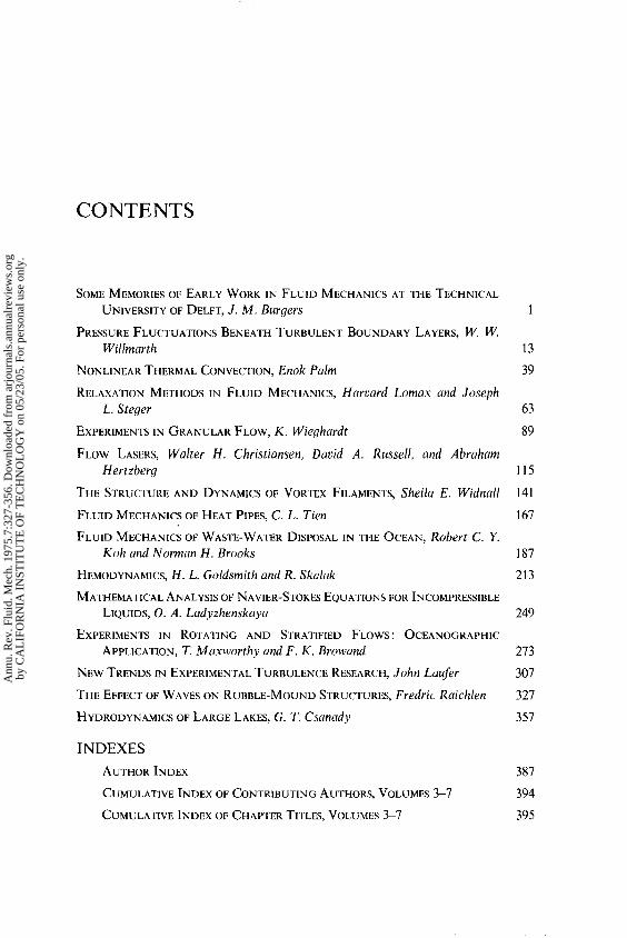
Ann
u. R
ev. F
luid
. Mec
h. 1
975.
7:32
7-35
6. D
ownl
oade
d fr
om a
rjou
rnal
s.an
nual
revi
ews.
org
by C
AL
IFO
RN
IA I
NST
ITU
TE
OF
TE
CH
NO
LO
GY
on
05/2
3/05
. For
per
sona
l use
onl
y.