The effect of the addition of alloying elements on carbide precipitation and mechanical properties...
13
The effect of the addition of alloying elements on carbide precipitation and mechanical properties in 5% chromium martensitic steels P. Michaud a,b,d , D. Delagnes a,b, * , P. Lamesle a , M.H. Mathon c , C. Levaillant a a Ecole des Mines d’Albi-Carmaux, CROMeP, Campus Jarlard, Route de Teillet, F-81 013 Albi Cedex 09, France b Centre d’Elaboration des Mate ´riaux et d’Etudes Structurales, CNRS, 29 rue Jeanne Marvig, BP 94347, F-31055 Toulouse Cedex 4, France c Laboratoire Le ´on Brillouin (CEA-CNRS), CEA Saclay, F-91191 Gif-sur-Yvette, France d Aubert & Duval, BP1 F-63770 Les Ancizes, France Received 21 March 2007; received in revised form 4 May 2007; accepted 7 May 2007 Available online 5 July 2007 Abstract Carbide-forming elements (W, Mo, Nb, V), as well as elements that influence only the tempering kinetics (Co, Ni), were added to a 5% Cr tempered martensitic steel in order to modify its precipitation. The main goal was to shift the secondary hardening peak towards higher tempering temperatures. Small angle neutron scattering and X-ray diffraction experiments, as well as transmission electron microscopy, were performed to characterize the precipitation of nanometric carbides. A significant modification of the volume fraction and/or chemistry of the very fine secondary precipitation was observed only for Mo, V and Ni additions. Moreover, the mechanical properties showed that the volume fraction of small precipitates (VC, Fe 3 Mo 3 C) directly influences the mechanical resistance at high temperature but has a detrimental effect on Charpy impact energy. Ó 2007 Acta Materialia Inc. Published by Elsevier Ltd. All rights reserved. Keywords: Martensitic steels; Precipitation; Secondary carbides; Yield strength; Impact test 1. Introduction For low-temperature applications (<450 °C), the differ- ent possible time–temperature conditions for tempering a martensitic steel lead to a large variety of mechanical prop- erties. Frequently, the tempering conditions can be success- fully adapted to the application. Conversely, tempered martensitic steels used for high-pressure die casting or forg- ing tools show a limited lifetime owing to the severe thermo-mechanical working conditions. As the tempera- ture of the tool surface may exceed the tempering temper- ature, the microstructure after heat treatment rapidly evolves and a sharp decrease in mechanical strength is observed. Moreover, this temperature effect is enhanced by the cyclic plasticity, which also results in a strong soft- ening of the material [1–5]. The flow stress at high temperature of martensitic steels is linked both to the extremely high dislocation density introduced during the martensitic transformation and to the alloyed carbides precipitating above 450 °C during tem- pering [6–8]. These main microstructural features theoreti- cally offer several routes to improve high temperature mechanical properties by modifying heat treatment condi- tions. However, the dislocation density is fixed by the quench conditions, which strongly depend on the tool geometry. Consequently, a slight modification in quench conditions may lead to a disastrous result. A second route consisting in adjusting the tempering conditions is also limited, as a small variation in tempering 1359-6454/$30.00 Ó 2007 Acta Materialia Inc. Published by Elsevier Ltd. All rights reserved. doi:10.1016/j.actamat.2007.05.004 * Corresponding author. Address: Ecole des Mines d’Albi-Carmaux, CROMeP, Campus Jarlard, Route de Teillet, F-81 013 Albi Cedex 09, France. Tel.: +33 (0)5 63 49 32 48; fax: +33 (0)5 63 49 32 42. E-mail address: [email protected] (D. Delagnes). www.elsevier.com/locate/actamat Acta Materialia 55 (2007) 4877–4889
-
Upload
independent -
Category
Documents
-
view
1 -
download
0
Transcript of The effect of the addition of alloying elements on carbide precipitation and mechanical properties...
www.elsevier.com/locate/actamat
Acta Materialia 55 (2007) 4877–4889
The effect of the addition of alloying elements on carbideprecipitation and mechanical properties in 5%
chromium martensitic steels
P. Michaud a,b,d, D. Delagnes a,b,*, P. Lamesle a, M.H. Mathon c, C. Levaillant a
a Ecole des Mines d’Albi-Carmaux, CROMeP, Campus Jarlard, Route de Teillet, F-81 013 Albi Cedex 09, Franceb Centre d’Elaboration des Materiaux et d’Etudes Structurales, CNRS, 29 rue Jeanne Marvig, BP 94347, F-31055 Toulouse Cedex 4, France
c Laboratoire Leon Brillouin (CEA-CNRS), CEA Saclay, F-91191 Gif-sur-Yvette, Franced Aubert & Duval, BP1 F-63770 Les Ancizes, France
Received 21 March 2007; received in revised form 4 May 2007; accepted 7 May 2007Available online 5 July 2007
Abstract
Carbide-forming elements (W, Mo, Nb, V), as well as elements that influence only the tempering kinetics (Co, Ni), were added to a 5%Cr tempered martensitic steel in order to modify its precipitation. The main goal was to shift the secondary hardening peak towardshigher tempering temperatures. Small angle neutron scattering and X-ray diffraction experiments, as well as transmission electronmicroscopy, were performed to characterize the precipitation of nanometric carbides. A significant modification of the volume fractionand/or chemistry of the very fine secondary precipitation was observed only for Mo, V and Ni additions. Moreover, the mechanicalproperties showed that the volume fraction of small precipitates (VC, Fe3Mo3C) directly influences the mechanical resistance at hightemperature but has a detrimental effect on Charpy impact energy.� 2007 Acta Materialia Inc. Published by Elsevier Ltd. All rights reserved.
Keywords: Martensitic steels; Precipitation; Secondary carbides; Yield strength; Impact test
1. Introduction
For low-temperature applications (<450 �C), the differ-ent possible time–temperature conditions for tempering amartensitic steel lead to a large variety of mechanical prop-erties. Frequently, the tempering conditions can be success-fully adapted to the application. Conversely, temperedmartensitic steels used for high-pressure die casting or forg-ing tools show a limited lifetime owing to the severethermo-mechanical working conditions. As the tempera-ture of the tool surface may exceed the tempering temper-ature, the microstructure after heat treatment rapidly
1359-6454/$30.00 � 2007 Acta Materialia Inc. Published by Elsevier Ltd. All
doi:10.1016/j.actamat.2007.05.004
* Corresponding author. Address: Ecole des Mines d’Albi-Carmaux,CROMeP, Campus Jarlard, Route de Teillet, F-81 013 Albi Cedex 09,France. Tel.: +33 (0)5 63 49 32 48; fax: +33 (0)5 63 49 32 42.
E-mail address: [email protected] (D. Delagnes).
evolves and a sharp decrease in mechanical strength isobserved. Moreover, this temperature effect is enhancedby the cyclic plasticity, which also results in a strong soft-ening of the material [1–5].
The flow stress at high temperature of martensitic steelsis linked both to the extremely high dislocation densityintroduced during the martensitic transformation and tothe alloyed carbides precipitating above 450 �C during tem-pering [6–8]. These main microstructural features theoreti-cally offer several routes to improve high temperaturemechanical properties by modifying heat treatment condi-tions. However, the dislocation density is fixed by thequench conditions, which strongly depend on the toolgeometry. Consequently, a slight modification in quenchconditions may lead to a disastrous result.
A second route consisting in adjusting the temperingconditions is also limited, as a small variation in tempering
rights reserved.
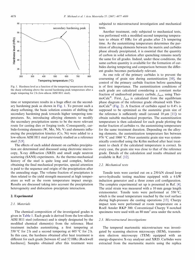
Fig. 1. Hardness level as a function of the tempering temperature showingthe sharp softening above the second hardening peak temperature after asingle tempering for 2 h (low-silicon AISI H11 steel).
4878 P. Michaud et al. / Acta Materialia 55 (2007) 4877–4889
time or temperature results in a huge effect on the second-ary hardening peak as shown in Fig. 1. To prevent such asharp softening, the basic solution consists of shifting thesecondary hardening peak towards higher tempering tem-peratures. So, introducing alloying elements to modifythe secondary precipitation seems to be the more relevantroute for casting dies or forging tools. Consequently, car-bide-forming elements (W, Mo, Nb, V) and elements influ-encing the precipitation kinetics (Co, Ni) were added to alow-silicon AISI H11 steel previously studied as a referencesteel [5,9].
The effects of each added element on carbides precipita-tion are determined and discussed using electronic micros-copy, X-ray diffraction (XRD) and small angle neutronscattering (SANS) experiments. As the thermo-mechanicalhistory of the steel is quite long and complex, beforeobtaining the final mechanical properties, special attentionis paid to the sequence and origin of the precipitation afterthe annealing stage. The volume fraction of precipitates isthen related to the yield strength measured at high temper-ature as well as the room temperature impact energy.Results are discussed taking into account the precipitationheterogeneity and dislocation–precipitate interaction.
2. Experimental
2.1. Materials
The chemical composition of the investigated grades isgiven in Table 1. Each grade is derived from the low-siliconAISI H11 steel (reference) and is simply designated by themodified chemical element(s) from the reference. Heattreatment includes austenitizing, a first tempering at550 �C for 2 h and a second tempering at 605 �C for 2 h.In this case, the hardness obtained after heat treatment isdifferent for each grade [between 42 and 52 HRc (Rockwellhardness)]. Samples obtained after this treatment were
subjected to microstructural investigation and mechanicaltests.
Another treatment, only subjected to mechanical tests,was performed with a modified second tempering tempera-ture to obtain 47 HRc for all grades after 2 h temperingtime. As the austenitizing temperature determines the par-tition of alloying elements between the matrix and carbidesphase already precipitated, it is essential that the quantityof carbon in solid solution after quenching remains nearlythe same for all grades. Indeed, under these conditions, thesame carbon quantity is available for the formation of car-bides during tempering and comparison between the differ-ent grades becomes particularly relevant.
As one role of the primary carbides is to prevent thecoarsening of grain size during austenitization [10], thecontrol of the primary carbide fraction before quenchingis of first importance. The austenitization conditions ofeach grade are calculated considering a constant molarfraction of undissolved primary carbide, fmol, using Ther-moCalc�. First, fmol is calculated from the equilibriumphase diagram of the reference grade obtained with Ther-moCalc� (Fig. 2). A fraction of carbides equal to 0.4% issupposed to be optimized as the austenitic grain size ofthe reference is sufficiently small (around 10 lm [11]) toobtain suitable mechanical properties. The austenitizationtemperature is then calculated for each grade plotting themolar fraction of carbides vs. the austenitizing temperaturefor the same treatment duration. Depending on the alloy-ing elements, the austenitization temperature lies between976 �C and 1060 �C. Prior austenitic grain size was system-atically controlled using the Kohn method after heat treat-ment to check if the calculated temperature is correct. Inevery case, the grain size was close to that of the referencegrade. Details of the calculation and results obtained areavailable in Ref. [12].
2.2. Mechanical tests
Tensile tests were carried out on a 250 kN closed loopservo-hydraulic testing machine equipped with a 6 kWinduction generator and a three zones coil configuration.The complete experimental set up is presented in Ref. [4].The axial strain was measured with a 10 mm gauge lengthextensometer. Tensile tests were performed at 550 �C,which is the usual temperature reached by the tool surfaceduring high-pressure die casting operations [13]. Charpyimpact tests were performed at room temperature on aRoell Amsler RKP 300. Conventional Charpy V-notchedspecimens were used with an 80 mm2 area under the notch.
2.3. Microstructural investigations
The tempered martensitic microstructure was investi-gated by scanning electron microscopy (SEM), transmis-sion electron microscopy (TEM) equipped with anenergy-dispersive X-ray analyser and XRD. Carbides wereextracted from the martensitic matrix using the replica
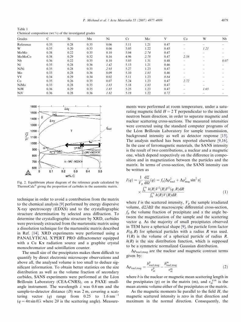
Table 1Chemical composition (wt.%) of the investigated grades
Grades C Si Mn Ni Cr Mo V Co W Nb
Reference 0.35 0.28 0.35 0.06 5.11 1.21 0.47 – – –W 0.35 0.20 0.33 0.06 5.05 1.22 0.45 – 1.21 –MoMo 0.38 0.22 0.35 0.10 5.04 2.74 0.47 – – –MoMoCo 0.38 0.29 0.32 0.16 4.96 2.78 0.47 2.58 – –Nb 0.36 0.22 0.35 0.10 5.03 1.31 0.48 – – 0.07
Ni 0.35 0.28 0.36 1.42 5.13 1.21 0.46 – – –NiNi 0.35 0.28 0.35 2.93 5.27 1.23 0.47 – – –Mo 0.33 0.28 0.36 0.09 5.10 1.83 0.46 – – –VV 0.34 0.29 0.34 0.02 5.11 1.23 0.84 – – –Co 0.35 0.26 0.35 0.07 5.24 1.23 0.47 2.72 – –NiMo 0.33 0.28 0.35 1.83 5.18 1.83 0.47 – – –NiW 0.36 0.29 0.35 1.85 5.25 1.23 0.47 – 1.65 –NiV 0.36 0.28 0.36 1.82 5.19 1.22 0.72 – – –
Fig. 2. Equilibrium phase diagram of the reference grade calculated byThermoCalc� giving the proportion of carbides in the austenitic matrix.
P. Michaud et al. / Acta Materialia 55 (2007) 4877–4889 4879
technique in order to avoid a contribution from the matrixto the chemical analysis [9] performed by energy dispersiveX-ray spectroscopy (EDXS) and to the crystallographicstructure determination by selected area diffraction. Todetermine the crystallographic structure by XRD, carbideswere previously extracted from the martensitic matrix usinga dissolution technique for the martensitic matrix describedin Ref. [14]. XRD experiments were performed using aPANALYTICAL X’PERT PRO diffractometer equippedwith a Cu Ka radiation source and a graphite crystalmonochromator and scintillation counter.
The small size of the precipitates makes them difficult toquantify by direct electronic microscope observations andabove all, the analysed volume is too small to deduce sig-nificant information. To obtain better statistics on the sizedistribution as well as the volume fraction of secondarycarbides, SANS experiments were performed at the LeonBrillouin Laboratory (CEA-CNRS), on a PAXE small-angle instrument. The wavelength k was 0.6 nm and thesample-to-detector distance (D) was 2 m, covering a scat-tering vector (q) range from 0.25 to 1.6 nm�1
(q = 4p sinh/k where 2h is the scattering angle). Measure-
ments were performed at room temperature, under a satu-rating magnetic field H = 2 T perpendicular to the incidentneutron beam direction, in order to separate magnetic andnuclear scattering cross-sections. The measured intensitieswere corrected using the standard computer programs ofthe Leon Brillouin Laboratory for sample transmission,background intensity as well as detector response [15].The analysis method has been reported elsewhere [9,16].In the case of ferromagnetic materials, the SANS intensityis the result of two contributions, a nuclear and a magneticone, which depend respectively on the difference in compo-sition and in magnetization between the particles and thematrix. In terms of cross-section, the SANS intensity canbe written as
IðqÞ ¼ 1
V p
dRdXðqÞ ¼ fp½Dq2
nucl þ Dq2mag sin2 a�
�R1
0hðRÞV 2ðRÞF 2ðq;RÞdRR1
0hðRÞV ðRÞdR
ð1Þ
where I is the scattered intensity, Vp the sample irradiatedvolume, dR/dX the macroscopic differential cross-section,fp the volume fraction of precipitate and a the angle be-tween the magnetization of the sample and the scatteringvector q. As the majority of small precipitates observedin TEM have a spherical shape [9], the particle form factorF(q,R) for spherical particles with a radius R was used.V(R) is the volume of a spherical particle of radius R.h(R) is the size distribution function, which is supposedto be a symmetric normalized Gaussian distribution.
Dqnucl,mag are the nuclear and magnetic contrast termsgiven by:
Dqnucl;mag ¼bp
nucl;mag
vpat
�bm
nucl;mag
vmat
ð2Þ
where b is the nuclear or magnetic mean scattering length inthe precipitates (p) or in the matrix (m), and v p;m
at is themean atomic volume either of the precipitates or the matrix.
As the magnetic moments lie parallel to the field H, themagnetic scattered intensity is zero in that direction andmaximum in the normal direction. Consequently, the

4880 P. Michaud et al. / Acta Materialia 55 (2007) 4877–4889
nuclear cross-section can be measured at a = 0, while thesum of the nuclear and the maximum magnetic cross-sec-tion is measured at a = p/2. Subsequently, the magneticcontrast can be calculated by a simple subtraction. Someinformation about chemical composition can be deducedfrom the ratio between those two quantities, called A-ratio.
For chemically and magnetically homogeneous parti-cles, the A-ratio depends on the chemical composition,magnetization and atomic density variations between pre-cipitates and the matrix, and is given by:
A ¼ ðdR=dXÞ?~HðdR=dXÞk~H
¼Dq2
nucl þ Dq2mag
Dq2nucl
¼ 1þDq2
mag
Dq2nucl
ð3Þ
Eq. (1) was used to fit the experimental data. The proce-dure is precisely described in [9,16]. The factor C ¼ fp
½Dq2nucl þ Dq2
mag sin2 a�, which contains the volume fractionof particles, is independent of the size distribution and isconsidered to be a fitting parameter. The mean size of theparticles (radius R) as well as the full width at the half max-imum of the Gaussian distribution were also obtained.
3. Results
3.1. Influence of alloying addition on carbides precipitation
3.1.1. Chemical compositionTwo populations of secondary carbides were identified
by TEM (cf. Fig. 3a and b) and SANS on the referencegrade (low-silicon AISI H11 steel) [5,9]:
� small carbides (radius around 1.5 nm, standard devia-tion @ 0.2 nm): this first population includes mainlyvanadium carbides (MC type) and a smaller quantityof chromium carbides (M7C3type).
Fig. 3. (a and b) Bright field TEM images of the two different p
� carbides with a radius between 15 nm and 20 nm esti-mated by both SANS and TEM (standard [email protected] nm by SANS and @5 nm by TEM): this secondpopulation includes mainly chromium carbides (M7C3)and a significant quantity of vanadium carbides (MC).
The identification of these populations is performedusing three complementary experiments: XRD after disso-lution of the matrix, electronic diffraction and comparisonbetween experimental and theoretical A-ratios [9,16] usingscattered intensity obtained by SANS. With the SANSexperimental configuration previously described, the quan-tification is only possible for the first population of car-bides [17].
In addition, a third population of bigger iron carbides(M3C), chromium carbides (M23C6) and vanadium car-bides (MC) in the range 50–300 nm was observed. How-ever, the density of these carbides is very low comparedto the number of carbides belonging to the populationsdescribed above. Moreover, large M23C6 and MC carbideswere identified in the as-quenched sample showing thatthese two types of carbide were only partially dissolvedduring the austenitization. The four types of carbides iden-tified on the reference grade are shown in Fig. 4.
For all the investigated grades, a first and second popu-lation of carbides (respectively radius around 1.5 nm and15 nm) were observed. Modification of the chemical com-position has not significantly influenced the average sizeof both populations observed by SANS. Conversely, thepopulation of larger carbides was modified in some cases.The different types of identified carbides are given in Table2. As Nb, Mo and W are strong carbide formers, the chem-ical composition of precipitates is modified. Niobium car-bides (Type MC � NbC), molybdenum carbides (type
opulations of secondary carbides (reference grade, replica).

Fig. 4. Carbides morphology observed by TEM (bright field image, replica) (i), EDXS analysis (ii), electronic diffraction pattern (iii) for the four types ofidentified carbides: (a) MC, (b) M7C3, (c) M3C and (d) M23C6 in the reference grade.
Table 2Identified carbides for each grade of modified AISI H11 steels
Grades Carbides
Reference MC (�VC), M3C (�(Fe,Cr)3C),M23C6(�(Cr,Fe)23C6), M7C3(�(Cr,Fe)7C3)
W, NiW Reference+M6C (�Fe3W3C)Mo, MoMo, MoMoCo Reference+M6C (�Fe3Mo3C)Nb Reference+MC (�NbC)Ni, NiNi, VV, Co, NiV,
NiMo=Reference
P. Michaud et al. / Acta Materialia 55 (2007) 4877–4889 4881
M6C � Fe3Mo3C) as well as tungsten carbides (typeM6C � Fe3W3C) were identified using XRD, electronic dif-fraction, EDXS and SANS. Ni and Co are not carbide-forming elements and as expected, no modification of thetype of precipitates from the reference grade was observed.Addition of vanadium results in a higher quantity of vana-dium carbides observed in the VV grade.
3.1.2. Distribution of carbides among the different
populations
For the Nb grade, the added niobium precipitatestotally into large niobium carbides which were not dis-
solved during the austenitization. Conversely, the second-ary precipitation was not modified by the niobiumaddition for the adopted condition of austenitization. Con-sequently, the main goal of offering numerous pinningobstacles for dislocations is not reached with niobium addi-tion. This conclusion is also true for tungsten for the inves-tigated composition. Indeed, large ‘‘undissolved’’ tungstencarbides were also observed (Fig. 5). On the contrary, addi-tions of vanadium and molybdenum modify the secondaryprecipitation, as indicated in Table 3.
3.1.3. Volume fraction of small carbides
The volume fraction of the first population concerningthe smallest size precipitates is calculated from SANSexperiments. An estimation can be obtained from the fac-tor C provided that nuclear and/or magnetic contrastscan be evaluated [9,16]. In this case, the chemical composi-tion of carbides should be previously determined. UsingTEM observations associated with electronic diffractionand EDXS, XRD, as well as the calculated A-ratio forlarge values of q, the hypothesis of a first populationincluding only vanadium carbides is relevant [9] exceptfor high molybdenum content grades (Mo, MoMo,
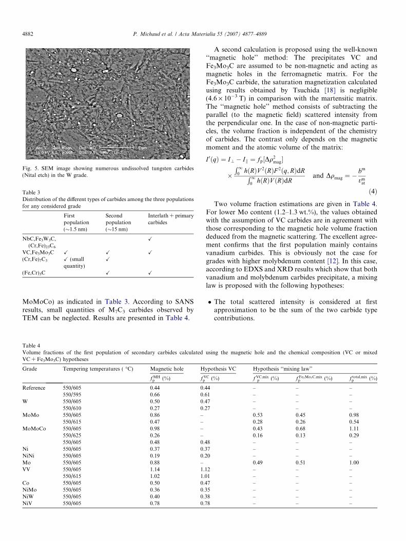
Fig. 5. SEM image showing numerous undissolved tungsten carbides(Nital etch) in the W grade.
Table 3Distribution of the different types of carbides among the three populationsfor any considered grade
Firstpopulation(�1.5 nm)
Secondpopulation(�15 nm)
Interlath + primarycarbides
NbC,Fe3W3C,(Cr,Fe)23C6
X
VC,Fe3Mo3C X X X
(Cr,Fe)7C3 X (smallquantity)
X
(Fe,Cr)3C X X
4882 P. Michaud et al. / Acta Materialia 55 (2007) 4877–4889
MoMoCo) as indicated in Table 3. According to SANSresults, small quantities of M7C3 carbides observed byTEM can be neglected. Results are presented in Table 4.
Table 4Volume fractions of the first population of secondary carbides calculatedVC + Fe3Mo3C) hypotheses
Grade Tempering temperatures ( �C) Magnetic hole H
f MHp (%) f V
p
Reference 550/605 0.44 0.550/595 0.66 0.
W 550/605 0.50 0.550/610 0.27 0.
MoMo 550/605 0.86 –550/615 0.47 –
MoMoCo 550/605 0.98 –550/625 0.26 –550/605 0.48 0.
Ni 550/605 0.37 0.NiNi 550/605 0.19 0.Mo 550/605 0.88 –VV 550/605 1.14 1.
550/615 1.02 1.Co 550/605 0.50 0.NiMo 550/605 0.36 0.NiW 550/605 0.40 0.NiV 550/605 0.78 0.
A second calculation is proposed using the well-known‘‘magnetic hole’’ method: The precipitates VC andFe3Mo3C are assumed to be non-magnetic and acting asmagnetic holes in the ferromagnetic matrix. For theFe3Mo3C carbide, the saturation magnetization calculatedusing results obtained by Tsuchida [18] is negligible(4.6 · 10�3 T) in comparison with the martensitic matrix.The ‘‘magnetic hole’’ method consists of subtracting theparallel (to the magnetic field) scattered intensity fromthe perpendicular one. In the case of non-magnetic parti-cles, the volume fraction is independent of the chemistryof carbides. The contrast only depends on the magneticmoment and the atomic volume of the matrix:
I 0ðqÞ ¼ I? � Ik ¼ fp½Dq2mag�
�R1
0hðRÞV 2ðRÞF 2ðq;RÞdRR1
0hðRÞV ðRÞdR
and Dqmag ¼ �bm
vmat
ð4Þ
Two volume fraction estimations are given in Table 4.For lower Mo content (1.2–1.3 wt.%), the values obtainedwith the assumption of VC carbides are in agreement withthose corresponding to the magnetic hole volume fractiondeduced from the magnetic scattering. The excellent agree-ment confirms that the first population mainly containsvanadium carbides. This is obviously not the case forgrades with higher molybdenum content [12]. In this case,according to EDXS and XRD results which show that bothvanadium and molybdenum carbides precipitate, a mixinglaw is proposed with the following hypotheses:
� The total scattered intensity is considered at firstapproximation to be the sum of the two carbide typecontributions.
using the magnetic hole and the chemical composition (VC or mixed
ypothesis VC Hypothesis ‘‘mixing law’’
C (%) f VC;mixp (%) f Fe3Mo3C;mix
p (%) f total;mixp (%)
44 – – –61 – – –47 – – –27 – – –
0.53 0.45 0.980.28 0.26 0.540.43 0.68 1.110.16 0.13 0.29
48 – – –37 – – –20 – – –
0.49 0.51 1.0012 – – –01 – – –47 – – –35 – – –38 – – –78 – – –

P. Michaud et al. / Acta Materialia 55 (2007) 4877–4889 4883
� The smallest precipitates can only include VC orFe3 Mo3C carbides.� Both types of precipitate can be described by the same
form factor (spherical shape) and the precipitates sizesfollow the same distribution.� The differentiation of carbides is carried out in the calcu-
lations of the contrast and the volume fractions.
Considering the above-mentioned hypothesis, factor C
for the scattered intensity, respectively perpendicular andparallel to the magnetic field can be approximated by thefollowing expressions:
Ctotal? ¼ CVC
? þ CFe3Mo3C? ¼ f VC
p ½Dq2nucl;VC þ Dq2
mag;VC�þ f Fe3Mo3C
p ½Dq2nucl;Fe3Mo3C þ Dq2
mag;Fe3Mo3C�ð5aÞ
Ctotalk ¼ CVC
k þ CFe3Mo3Ck ¼ f VC
p ½Dq2nucl;VC�
þ f Fe3Mo3Cp ½Dq2
nucl;Fe3Mo3C� ð5bÞ
From Eq. (5) and introducing the A-ratio (Eq. (3)), the vol-ume fraction of each type of carbide is given by:
f Fe3Mo3Cp ¼
Ctotal? � Ctotal
k AVC
Dq2nucl;Fe3Mo3CðAFe3Mo3C � AVCÞ
ð6aÞ
f VCp ¼
Ctotalk AFe3Mo3C � Ctotal
?
Dq2nucl;VCðA
Fe3Mo3C �AVCÞð6bÞ
Results are given in Table 4. For the magnetic holemethod, the estimated error obtained for the volume frac-tion is linked to the counting statistics and the selectedadjustment model (particle shape and size distribution).Despite the extreme experimental conditions, the estimatederror is less than 10%. When the chemical composition ofthe particles is involved in the calculation (contrasts shouldbe determined), an additional error caused by deviations
Fig. 6. Influence of alloying elements on the volume fraction of the fir
from the stoichiometry and from the ideal composition(substitution) should be evaluated. Considering theextreme experimental values of the chemical composition(EDXS) and the crystallographic structures (XRD), theerror still remains below 10% for the vanadium carbidebut reaches 20% for the Fe3Mo3C carbide.
The values found by supposing a mixing law are compa-rable to those obtained by considering only magnetic holes.They are nevertheless systematically slightly higher thanthe magnetic hole volume fraction (15%) but this variationcan be justified by imprecise evaluations of the variousparameters necessary for the contrasts calculation (varia-tion of the stoichiometry of carbides, atomic volume vari-ation according to chemical composition, etc.). Theseresults clearly show that the volume fraction of vanadiumcarbides in Mo, MoMo and MoMoCo grades is quite closeto the value obtained in the reference grade showing thatmolybdenum addition does not interfere with vanadiumcarbide precipitation during tempering. Therefore, in spiteof the assumptions made concerning the particle distribu-tion, the adopted method gives reliable results.
Fig. 6 shows that only molybdenum and vanadium addi-tions strongly increase the volume fraction of the nano-sizepopulation. Cobalt addition has no effect on the three pop-ulations in the reference grade. However, a significantincrease in the volume fraction of molybdenum carbidesis observed when cobalt is associated with molybdenum:0.68% compared with 0.45% for the MoMo grade (Table4). The complex effect of cobalt on the dislocations struc-ture and consequently on the density and nature of nucle-ation sites of precipitation has already been investigatedand reported in the literature [6,8,19–21] and will not bediscussed further on in this paper. Nickel addition signifi-cantly decreases the volume fraction of the first population.Conversely, a slight increase in the volume fraction of thesecond population is observed. As nickel remains in solid
st population calculated using the magnetic hole (fMH) hypothesis.
4884 P. Michaud et al. / Acta Materialia 55 (2007) 4877–4889
solution during tempering, several hypotheses concerningthe modification of tempering kinetics can be formulated.The best-known explanation is that nickel decreases thesolubility of carbon in the martensitic matrix leading to agreater supersaturation effect. The higher carbon supersat-uration promotes the formation of alloyed carbides andthen accelerates the secondary hardening process [22,23].
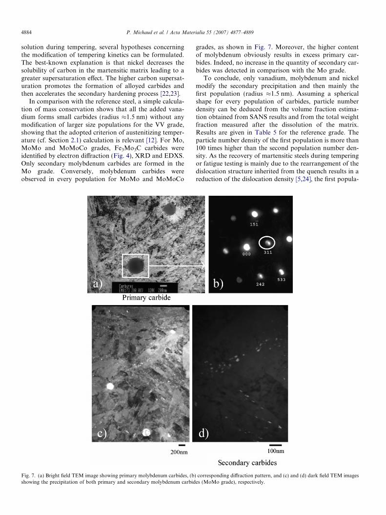
In comparison with the reference steel, a simple calcula-tion of mass conservation shows that all the added vana-dium forms small carbides (radius �1.5 nm) without anymodification of larger size populations for the VV grade,showing that the adopted criterion of austenitizing temper-ature (cf. Section 2.1) calculation is relevant [12]. For Mo,MoMo and MoMoCo grades, Fe3Mo3C carbides wereidentified by electron diffraction (Fig. 4), XRD and EDXS.Only secondary molybdenum carbides are formed in theMo grade. Conversely, molybdenum carbides wereobserved in every population for MoMo and MoMoCo
Fig. 7. (a) Bright field TEM image showing primary molybdenum carbides, (bshowing the precipitation of both primary and secondary molybdenum carbid
grades, as shown in Fig. 7. Moreover, the higher contentof molybdenum obviously results in excess primary car-bides. Indeed, no increase in the quantity of secondary car-bides was detected in comparison with the Mo grade.
To conclude, only vanadium, molybdenum and nickelmodify the secondary precipitation and then mainly thefirst population (radius �1.5 nm). Assuming a sphericalshape for every population of carbides, particle numberdensity can be deduced from the volume fraction estima-tion obtained from SANS results and from the total weightfraction measured after the dissolution of the matrix.Results are given in Table 5 for the reference grade. Theparticle number density of the first population is more than100 times higher than the second population number den-sity. As the recovery of martensitic steels during temperingor fatigue testing is mainly due to the rearrangement of thedislocation structure inherited from the quench results in areduction of the dislocation density [5,24], the first popula-
) corresponding diffraction pattern, and (c) and (d) dark field TEM imageses (MoMo grade), respectively.

Table 5Estimation of particle number density (N) and mean inter-particle distance between a particle and its two or three neighbours (d) for each population ofthe reference grade
First population Second population Interlath + primary carbides
Average radius (nm) �1.5 �15 r > 80fp(%) 0.4 < fp < 0.5 1.5 < fp < 2.5 2 < fp < 3
N ¼ fp
ð4=3Þpr3 ðm�3Þ 2 · 1023 < N < 4 · 1023 1021 < N < 2.1021 N < 1019
d ¼ 1:18rffiffiffiffiffiffiffiffiffiffiffiffiffiffiffi2p=3f p
qðnmÞ, see Refs.
[25,26]36 < d < 41 160 < d < 210 Above the mean width of martensitic
laths
P. Michaud et al. / Acta Materialia 55 (2007) 4877–4889 4885
tion seems to be the relevant microstructural parameter toimprove the material. Indeed, small carbides offer numer-ous obstacles to the dislocation motion thereby preventingthe quick recovery observed for plain carbon steels. Thenext section aims to show how the first population influ-ences mechanical properties.
3.2. Relationship between volume fraction of small carbidesand mechanical properties
The influence of secondary carbides on the mechanicalproperties of martensitic steels has been widely investigatedin the literature [6,8,27,28] (essentially tensile properties,creep and more rarely fatigue). The role of carbides in dis-location rearrangement during tempering has also beendescribed in steels with high chromium content for hightemperature applications [7,29]. However, work was per-formed on over-aged steels and only little informationexists on the effect of small carbides in early stage of theprecipitation sequence for tempering conditions very closeto the second hardening peak. Above all, crossing mecha-nisms of secondary carbides by dislocations are still uncleareven if the first in situ TEM experiments [30] (tensile testperformed inside the microscope at room temperature)have shown a clear planar bypassing mechanism on the ref-erence grade. Conversely, as shown in Fig. 8, the pinning ofdislocations on small carbides has been clearly observed onthe reference grade by TEM observations. However, aspreviously mentioned, the first population is partially seenby TEM and the major area of the observations concernsthe right side of the Gaussian distribution.
Fig. 8. (a) Bright field TEM image of a martensitic lath showing the pinning oTEM image of the same area obtained under the crystallographic orientation
3.2.1. Yield strength
In Fig. 9, the yield strength measured at 550 �C isshown as a function of the volume fraction of precipitatescalculated by SANS, using the magnetic hole method.Stress measurements were obtained within a scatter bandless than ±10 MPa taking into account the load sensoraccuracy as well as the temperature gradient along thespecimen. The curve can be divided into two differentparts. For volume fraction values lower than 0.6%, astrong correlation is observed with a large increase in theyield strength from 650 MPa to 950 MPa. Above 0.6%, asaturation of the yield strength is observed particularlyfor grades containing a first population which include onlyvanadium carbides. Increasing the number density of smallcarbides becomes inefficient. Conversely, for grades con-taining 2.7 wt.% Mo (MoMo, MoMoCo), a slight increasein the yield strength is measured above fMH = 0.6%(Fig. 9).
3.2.2. Charpy impact energy
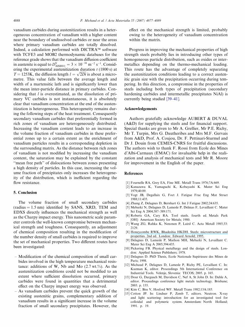
Scanning electron microscope analysis of the surfacerupture shows a ductile transgranular rupture for everygrade (Fig. 10). Moreover, scarce zones of interlath andintergranular rupture are observed but this conclusion isalso valid for all grades. So, no modification of the crackpropagation mechanism was detected at the microscopicscale for the measured range of Charpy impact energy(20–50 J). Fig. 11 presents the relationship between theCharpy impact energy measured at room temperatureand the volume fraction of the first population. Two majorcomments can be deduced from this figure:
f dislocations on small vanadium carbides (reference grade). (b) Dark fieldcondition ~g ¼ ½011� showing the distribution of small vanadium carbides.
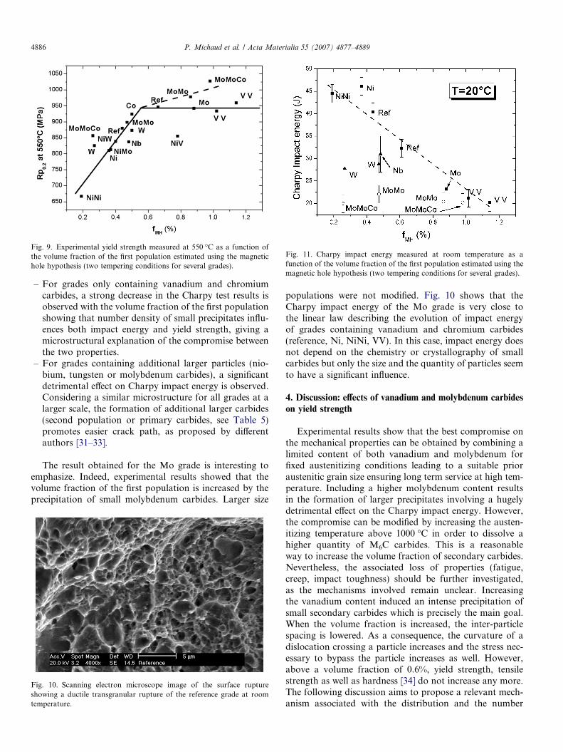
Fig. 11. Charpy impact energy measured at room temperature as afunction of the volume fraction of the first population estimated using themagnetic hole hypothesis (two tempering conditions for several grades).
Fig. 9. Experimental yield strength measured at 550 �C as a function ofthe volume fraction of the first population estimated using the magnetichole hypothesis (two tempering conditions for several grades).
4886 P. Michaud et al. / Acta Materialia 55 (2007) 4877–4889
– For grades only containing vanadium and chromiumcarbides, a strong decrease in the Charpy test results isobserved with the volume fraction of the first populationshowing that number density of small precipitates influ-ences both impact energy and yield strength, giving amicrostructural explanation of the compromise betweenthe two properties.
– For grades containing additional larger particles (nio-bium, tungsten or molybdenum carbides), a significantdetrimental effect on Charpy impact energy is observed.Considering a similar microstructure for all grades at alarger scale, the formation of additional larger carbides(second population or primary carbides, see Table 5)promotes easier crack path, as proposed by differentauthors [31–33].
The result obtained for the Mo grade is interesting toemphasize. Indeed, experimental results showed that thevolume fraction of the first population is increased by theprecipitation of small molybdenum carbides. Larger size
Fig. 10. Scanning electron microscope image of the surface ruptureshowing a ductile transgranular rupture of the reference grade at roomtemperature.
populations were not modified. Fig. 10 shows that theCharpy impact energy of the Mo grade is very close tothe linear law describing the evolution of impact energyof grades containing vanadium and chromium carbides(reference, Ni, NiNi, VV). In this case, impact energy doesnot depend on the chemistry or crystallography of smallcarbides but only the size and the quantity of particles seemto have a significant influence.
4. Discussion: effects of vanadium and molybdenum carbides
on yield strength
Experimental results show that the best compromise onthe mechanical properties can be obtained by combining alimited content of both vanadium and molybdenum forfixed austenitizing conditions leading to a suitable prioraustenitic grain size ensuring long term service at high tem-perature. Including a higher molybdenum content resultsin the formation of larger precipitates involving a hugelydetrimental effect on the Charpy impact energy. However,the compromise can be modified by increasing the austen-itizing temperature above 1000 �C in order to dissolve ahigher quantity of M6C carbides. This is a reasonableway to increase the volume fraction of secondary carbides.Nevertheless, the associated loss of properties (fatigue,creep, impact toughness) should be further investigated,as the mechanisms involved remain unclear. Increasingthe vanadium content induced an intense precipitation ofsmall secondary carbides which is precisely the main goal.When the volume fraction is increased, the inter-particlespacing is lowered. As a consequence, the curvature of adislocation crossing a particle increases and the stress nec-essary to bypass the particle increases as well. However,above a volume fraction of 0.6%, yield strength, tensilestrength as well as hardness [34] do not increase any more.The following discussion aims to propose a relevant mech-anism associated with the distribution and the number

P. Michaud et al. / Acta Materialia 55 (2007) 4877–4889 4887
density of particles in order to explain the saturationphenomenon.
First, further investigations requiring complex in situTEM observations need to be performed to analyse the dis-location arrangement in grades containing a high volumefraction of small secondary carbides. Indeed, even thoughthe Orowan mechanism was clearly identified by Mebarki[30], results concerning the possible shearing mechanismof small vanadium carbides presenting a well-defined orien-tation relationship with the matrix [8,35], are not availablein the literature. As all the vanadium carbides belonging tothe first population have nearly the same shape and size, allthe particles could be sheared with the same stress explain-ing the saturation.
Conversely, the considerable work of Mohles et al. [36–38] on the computer simulations of dislocation glide inover-aged spherical particle strengthened materials hasshown the different configurations taken by the disloca-tions in relation to the following parameters: the volumefraction of particles, the mean particle radius and thedegree of randomness of the distribution. Orowan processcontrolled dislocation glide in a single crystal (no climb, nocross-slip) containing spherical precipitates is computersimulated.
One main conclusion obtained by Mohles et al. dealswith the tendency to create more Orowan islands in obsta-cle field with high volume fraction. Even if the simulatedconditions considered by these authors are different fromour investigated cases (larger radius and volume fractionof particles), our grades obviously contain a larger numberof obstacles (�3 · 1023 m�3) than the simulated cases con-sidered by Mohles et al. (less than 3 · 1021 m�3) leading tothe hypothesis of Orowan island formation. Indeed, the rel-evant microstructural parameter is definitively the numberdensity of obstacles to the dislocation glide. The volume
Fig. 12. Bright field TEM images showing the heterogeneous distribution of se(a) 5 s and (b) 15 s during the replica preparation. High number density zones
fraction of precipitates has a scientific sense if every singleparticle influences the dislocation motion and consequentlyparticipates in strengthening. This is not the case whenOrowan islands are formed, as several particles areenclosed in a common dislocation loop. In this case, Figs.9 and 11 should be modified considering the number den-sity of particles really contributing to the pinning of dislo-cations, which may progressively saturate when the volumefraction increases.
The heterogeneity of the particle distribution is anotherimportant factor increasing the tendency to Orowan islandformation [37]. Carbides embedded in the martensiticmatrix, as well as carbides extracted from the bulk, wereobserved by TEM. From both kinds of preparation, anon-uniform arrangement is qualitatively observed. Fromobservation of thin foils, the heterogeneity may be partiallyassociated with crystallographic aspects as vanadium car-bides present a defined coherency with the martensiticmatrix [8,35] (Baker-Nutting). The relevant informationis obtained with orientation conditions corresponding toobservation of the glide plane of dislocations. However,the high dislocation density (�1016 m�2 [5]) impedes anyreliable statistics.
Easier TEM observations can be performed using repli-cas, but the crystallographic information is lost. Assumingthat chemical etch and the subsequent preparation givesidentical results on the whole surface of the replica, it canbe concluded that the distribution of small precipitates isheterogeneous, as shown in Figs. 12 and 3a. The proposedmechanism inducing the yield strength saturation dealswith the heterogeneity of vanadium distribution withinthe martensitic lath. Indeed, it has been shown that vana-dium carbides form by separate nucleation within the mar-tensitic lath on dislocations inherited from the martensitictransformation [8]. The incomplete dissolution of primary
condary vanadium carbides in the reference grade for a Nital etch time ofare marked.
4888 P. Michaud et al. / Acta Materialia 55 (2007) 4877–4889
vanadium carbides during austenitization results in a heter-ogeneous concentration of vanadium with a higher contentnear the boundary of undissolved carbides or near the areaswhere primary vanadium carbides are totally dissolved.Indeed, a calculation performed with DICTRA� softwarewith TCFE3 and MOB2 thermodynamic databases for thereference grade shows that the vanadium diffusion coefficientin austenite is equal to DV
AISIH11 ¼ 3� 10�16 m�2 s�1. Consid-ering the experimental austenitization duration t (1800 s) atT = 1253K, the diffusion length l ¼
ffiffiffiffiffiffiffiffi2Dtp
is about a micro-metre. This value falls between the average length andwidth of a martensitic lath and is significantly lower thanthe mean inter-particle distance in primary carbides. Con-sidering that l is overestimated, as the dissolution of pri-mary VC carbides is not instantaneous, it is absolutelyclear that vanadium concentration at the end of the austen-itization is heterogeneous. This heterogeneity remains dur-ing the following steps of the heat treatment. Consequentlysecondary vanadium carbides that preferentially formed inrich zones of vanadium are heterogeneously distributed.Increasing the vanadium content leads to an increase inthe volume fraction of vanadium carbides in these prefer-ential zones up to a certain extent as the enrichment ofvanadium particles results in a corresponding depletion inthe surrounding matrix. As the distance between rich zonesof vanadium is not modified by increasing the vanadiumcontent, the saturation may be explained by the constant‘‘mean free path’’ of dislocations between zones presentinga high density of particles. In this case, increasing the vol-ume fraction of precipitates only increases the heterogene-ity of the distribution, which is inefficient regarding theflow resistance.
5. Conclusion
The volume fraction of small secondary carbides(radius = 1.5 nm) identified by SANS, XRD, TEM andEDXS directly influences the mechanical strength as wellas the Charpy impact energy. This nanometric scale param-eter controls the well-known compromise between mechan-ical strength and toughness. Consequently, an adjustmentof chemical composition resulting in the modification ofthe number density of small carbides is required to improvethe set of mechanical properties. Two different routes havebeen investigated:
– Modification of the chemical composition of small car-bides involved in the high temperature mechanical resis-tance: additions of W, Nb and Mo (2.7 wt.%). As theaustenitization conditions could not be modified to anextent where sufficient dissolution occurred, primarycarbides were found in quantities that a detrimentaleffect on the Charpy impact energy was observed.
– As vanadium carbides prevent the quick growth of theexisting austenitic grains, complementary addition ofvanadium results in a significant increase in the volumefraction of small secondary precipitates. However, the
effect on the mechanical strength is limited, probablyowing to the heterogeneity of vanadium concentrationwithin the matrix.
Progress in improving the mechanical properties of highstrength steels probably lies in introducing other types ofhomogeneous particle distribution, such as oxides or inter-metallics depending on the thermo-mechanical loading.This route has the advantage of completely separatingthe austenitization conditions leading to a correct austen-itic grain size with the precipitation occurring during tem-pering. In this direction, a compromise in the properties ofsteels including both types of precipitation (secondaryhardening carbides and intermetallic precipitates NiAl) iscurrently being studied [39–41].
Acknowledgements
Authors gratefully acknowledge AUBERT & DUVAL(A&D) for supplying the steels and for financial support.Special thanks are given to Mr A. Grellier, Mr P.E. Richy,Mr T. Turpin, Mrs G. Dautheribes and Mrs M.F. Gervaisfrom A&D, Prof. A. Coujou, Dr. F. Pettinari-Sturmel andDr J. Douin from CEMES-CNRS for fruitful discussions.The authors wish to thank F. Rossi from Ecole des Minesd’Albi-Carmaux (EMAC) for invaluable help in the reali-zation and analysis of mechanical tests and Mr R. Moorefor improvement in the English of the paper.
References
[1] Fournelle RA, Grey EA, Fine ME. Metall Trans 1976;7A:669.[2] Kanazawa K, Yamaguchi K, Kobayashi K. Mater Sci Eng
1979;40:89.[3] Vogt JB, Degallaix G, Foct J. Fatigue Frac Eng Mat Struct
1988;11:435.[4] Zhang Z, Delagnes D, Bernhart G. Int J Fatigue 2002;24:635.[5] Mebarki N, Delagnes D, Lamesle P, Delmas F, Levaillant C. Mater
Sci Eng A 2004;387–389:171.[6] Roberts GA, Cary RA. Tool steels. fourth ed. Metals Park
[OH]: American Society for Metals; 1980.[7] Wang ZG, Rahka K, Nenonen P, Laird C. Acta Metall 1985;33:
2129.[8] Honeycombe RWK, Bhadeshia HKDH. Steels: microstructure and
properties. 2nd ed. London: Edward Arnold; 1995.[9] Delagnes D, Lamesle P, Mathon MH, Mebarki N, Levaillant C.
Mater Sci Eng A 2005;394:435.[10] Pickering FB. Physical metallurgy and the design of steels. Lon-
don: Applied Science Publishers; 1978.[11] Delagnes D. PhD Thesis, Ecole Nationale Superieure des Mines de
Paris; 1998.[12] Michaud P, Delagnes D, Lamesle P, Richy PE, Levaillant C. In:
Kuzman K, editor. Proceedings 5th International Conference onIndustrial Tools. Velenje, Slovenia: TECOS; 2005. p. 165.
[13] Dour G, Dargusch M, Davidson C, Nef A, St John D. In: Dahle A,editor. Proceedings conference light metals technology. Brisbane;2003. p. 155.
[14] Kim C, Biss V, Hosford WF. Metall Trans 1982;13A:185.[15] Cotton JP. In: Lindner P, Zemb T, editors. Neutron. X-ray
and light scattering: introduction for an investigated tool forcolloidal and polymeric system. Amsterdam: North Holland;1991. p. 19.
P. Michaud et al. / Acta Materialia 55 (2007) 4877–4889 4889
[16] Mathon MH, Barbu A, Dunstetter F, Maury F, Lorenzelli N, DeNovion CH. J Nucl Mater 1997;245:224.
[17] Leitner H, Staron H, Clemens H, Marsoner S, Warbichler P. MaterSci Eng A 2005;398:323.
[18] Tsuchida T. J Mater Sci 2001;36:1735.[19] Dyson DJ, Keown SR. Acta Metall 1969;17:1095.[20] Chandhok VK, Hirth JP, Dulis EJ. Trans TMS-AIME 1962;224:858.[21] Gorynin IV, Rybin VV, Malyshevskiy VA, Semicheva TG, Sherok-
hina LG. Metal Sci Heat Treat 1999;41:377.[22] Irvine KJ, Crowe DJ, Pickering FB. JISI 1960;195:386.[23] Lee KB, Yang HR, Kwon H. Metall Mater Trans 2001;32A:1659.[24] Pesicka J, Kuzel R, Dronhofer A, Eggeler G. Acta Mater
2003;51:4847.[25] Kocks UF. Acta Metall 1966;14:1629.[26] Daigne J, Guttmann M, Naylor JP. Mater Sci Eng 1982;56:1.[27] Nutting J. JISI 1969;207:872.[28] Maropoulos S, Paul JDH, Ridley N. Mater Sci Tech 1993;9:1014.
[29] Chang HJ, Tsai CH, Kai JJ. Int J Pres Ves Piping 1994;59:31.[30] Mebarki N. PhD Thesis. Ecole Nationale Superieure des Mines de
Paris; 2003.[31] Tomita Y. Mater Sci Tech 1990;6:349.[32] Neri MA, Colas R. Mater Charact 2001;47:283.[33] Briant CL. Mater Sci Tech 1989;5:138.[34] Michaud P. PhD Thesis. Ecole Nationale Superieure des Mines de
Paris; 2006.[35] Yamasaki S, Bhadeshia HKDH. Mater Sci Tech 2003;19:1335.[36] Mohles V, Ronnpagel D, Nembach E. Comput Mater Sci
1999;16:144.[37] Mohles V, Fruhstorfer B. Acta Mater 2002;50:2503.[38] Mohles V. Mater Sci Eng A 2001;309–310:265.[39] Garrison WM, Strychor R. Metall Trans 1988;19A:3103.[40] Hamano R. Metall Trans 1993;24A:127.[41] Erlach SD, Leitner H, Bischof M, Clemens H, Danoix F, Lemarc-
hand D, et al. Mater Sci Eng A 2006;429:96.