The Effect of Power Frequency High Intensity Electric Fields on Implanted Cardiac Pacemakers
12
The Effect of Power Frequency High Intensity Electric Fields on Implanted Cardiac Pacemakers GHAZWAN S. BUTROUS. JOHN C. MALE,* ROBERT S. WEBBER,t DAVID G. BARTON.* STUART J. MELDRUM.t JOHN A. BONNELL.* and A. JOHN CAMM From the Uepartmenls of Cardiology and Medical Electronics,! SI. Bartholomew's Hospital. London and Health and Safety Department^ and Central Electricity Research Laboratories.* Central Electricity Generating Board. U.K. BUTROUS, G.S., ETAL.: The effect of power frequency high intensity electric fields on implanted cardiac pacemakers. 'J'hjrly-/7ve palit-'iils fitted with 16 (/if/'eren( pacemaker models (irom 6 manuf'ac- turersj were exposed Io50 Hz electric fields up to a maximum of 20 kV/m. Four different response pat- terns were encountered: (1( normal sensing and pacing in all Medtronic and some Vitatron units; (2) reversion to the fixed {interference} rate in all Teiectronics. all Pacesetter, some Vitatron and Q^^Pl units; (3) slow and irregular pacing in one CPI and in all Cordis units; (4) mixed behavior over a critical range of field strengths in which slow and irregu/ar pacing preceded reversion (o fixed-rate, in some Teiectronics and Pacesetter units. The field strengths required lo induce such behavior varied from unit to unit and from model to model, with Telecfronics being the most sensitive. In general, the interference threshold depended on the magnitude and distribution of induced body current relative to the pacemakeras we/las field strength and thus varied with patienI height, build and posture. While only a small proportion of pacemaker patients are likely lo encounter electric fields strong enough (o interfere wilh pacemaker behavior, this possible hazard should be recognized. (PACE. Vol. 6. November-December. 1983} eiectromagnetic inlerference. power frequency, electric fields, cardiac pacemakers Introduction Since the early days of cardiac pacing, elec- tromagnetic interference has been recognized as a potential hazard. Apart from the risk of dan- gerous arrhythmias caused by direct curreni leak- age via the pacemaker to the heart,'""^ there is the possibility that strong alternating electric fields may induce abnormal pacemaker responses.*"^ High-voltage power transmission lines (operat- ing at 50 Hz in Europe and 60 Hz in the USA) are an important source of such electric fields. Bench studies and experiments with implants in animals have shown that strong power fre- quency electric fields may cause some demand pacemakers to revert to the asynchronous mode.'"'° Published clinical cases had shown a variety of behaviors in different pacemakers.® Address for reprints: Dr. G.S. Butrous. Department of Car- diology. SI. Barlhotomew's Hospital. I^ondon. Ei'.i 7BE. United Kingdom. Received January 25. 1983; revision received March 11. t983: accepted May 13,1983. The increasing use of very high-voltage for power transmission, together with the growing numbers of pacemakers implanted, theirincreas- ing sensitivity, complexity and versatility and the common use of unipolar electrode configuration makes it important to be fully aware of possible problems. In this report we demonstrate a num- ber of different patterns of pacemaker response to power frequency electric fields. Method Patients The clinical and pacing details of thirty five palients who volunteered for this study ore shown in Table 1. Their mean age was 63 (range 32-80 years). They were fitted with sixteen mod- els of pacemakers from six manufacturers Table I. Thirty-two patients were ventricuiarly paced. Twenty-three of these pacemakers were implant- ed in the left pre-pectoral region, seven in the right pre-pectoral region and two were implanted 1282 November-December 1983 PACE. Vol. 6
Transcript of The Effect of Power Frequency High Intensity Electric Fields on Implanted Cardiac Pacemakers

The Effect of Power Frequency High Intensity ElectricFields on Implanted Cardiac Pacemakers
GHAZWAN S. BUTROUS. JOHN C. MALE,* ROBERT S. WEBBER,t DAVID G.BARTON.* STUART J. MELDRUM.t JOHN A. BONNELL.* and A. JOHN CAMMFrom the Uepartmenls of Cardiology and Medical Electronics,! SI. Bartholomew's Hospital. London andHealth and Safety Department^ and Central Electricity Research Laboratories.* Central Electricity GeneratingBoard. U.K.
BUTROUS, G.S., ETAL.: The effect of power frequency high intensity electric fields on implantedcardiac pacemakers. 'J'hjrly-/7ve palit-'iils fitted with 16 (/if/'eren( pacemaker models (irom 6 manuf'ac-turersj were exposed Io50 Hz electric fields up to a maximum of 20 kV/m. Four different response pat-terns were encountered: (1( normal sensing and pacing in all Medtronic and some Vitatron units; (2)reversion to the fixed {interference} rate in all Teiectronics. all Pacesetter, some Vitatron and Q^^Pl units;(3) slow and irregular pacing in one CPI and in all Cordis units; (4) mixed behavior over a critical range offield strengths in which slow and irregu/ar pacing preceded reversion (o fixed-rate, in some Teiectronicsand Pacesetter units. The field strengths required lo induce such behavior varied from unit to unit andfrom model to model, with Telecfronics being the most sensitive. In general, the interference thresholddepended on the magnitude and distribution of induced body current relative to the pacemakeras we/lasfield strength and thus varied with patienI height, build and posture. While only a small proportion ofpacemaker patients are likely lo encounter electric fields strong enough (o interfere wilh pacemakerbehavior, this possible hazard should be recognized. (PACE. Vol. 6. November-December. 1983}
eiectromagnetic inlerference. power frequency, electric fields, cardiac pacemakers
Introduction
Since the early days of cardiac pacing, elec-tromagnetic interference has been recognized asa potential hazard. Apart from the risk of dan-gerous arrhythmias caused by direct curreni leak-age via the pacemaker to the heart,'""^ there is thepossibility that strong alternating electric fieldsmay induce abnormal pacemaker responses.*"^High-voltage power transmission lines (operat-ing at 50 Hz in Europe and 60 Hz in the USA) arean important source of such electric fields.
Bench studies and experiments with implantsin animals have shown that strong power fre-quency electric fields may cause some demandpacemakers to revert to the asynchronousmode.'"'° Published clinical cases had shown avariety of behaviors in different pacemakers.®
Address for reprints: Dr. G.S. Butrous. Department of Car-diology. SI. Barlhotomew's Hospital. I^ondon. Ei'.i 7BE.United Kingdom.
Received January 25. 1983; revision received March 11.t983: accepted May 13,1983.
The increasing use of very high-voltage forpower transmission, together with the growingnumbers of pacemakers implanted, theirincreas-ing sensitivity, complexity and versatility and thecommon use of unipolar electrode configurationmakes it important to be fully aware of possibleproblems. In this report we demonstrate a num-ber of different patterns of pacemaker responseto power frequency electric fields.
Method
Patients
The clinical and pacing details of thirty fivepalients who volunteered for this study oreshown in Table 1. Their mean age was 63 (range32-80 years). They were fitted with sixteen mod-els of pacemakers from six manufacturers TableI. Thirty-two patients were ventricuiarly paced.Twenty-three of these pacemakers were implant-ed in the left pre-pectoral region, seven in theright pre-pectoral region and two were implanted
1282 November-December 1983 PACE. Vol. 6

HIGH INTENSITY ELECTRIC FIELDS AND PACEMAKERS
in the abdomen. Three patients were fitted withatrial pacemakersflwo implanted in the right pre-pectoral and one in the left prepectoral region).All pacemaker systems were of unipolar con-figuration and, except for two, were transve-nous.
The aim and the procedure of the study wasfully explained to each patient and informed con-sent was obtained.
Study Protocol
Pre-exposure Evaluation
Each patient had a formal pacemaker evalua-tion before the study. This involved measure-ments of stimulus-to-stimulus interval, stimuluspulse width, magnet function and lead vectors,using a Vitatron** MBAI analyzer. The program-mability of each pacemaker was tested using theappropriate programmer. The effect of any com-petitive rhylhm induced by the induction offixed-rate pacing by magnet application wastested.
Exposure Protocol
Exposure to the electric field was performed inthe high-voltage test bay (Fig. 1) at the centralElectricity Research Laboratories. Leatherhead.Surrey. England.
The vertical 50 Hz electric field was producedbeneath a high voltage electrode comprising twoco-axial aluminium-coated glass fiber toroids(1.28 m in diameter, 330 mm diameter section)separated by 330 mm and suspended at a height of5.5 meters above ground level (Fig. 1). This heightwas sufficient to ensure no risk of flashover andgave a substantially uniform electric fieldstrength over a horizontal radius of 1.5 m. Theelectrode voltage was continuously variable overthe range of 0-320 kV rms, giving a range of un-perturbed electric field strengths of 0-20 kV/m ata height of 1.8 m above the ground.
Each patient stood with stockinged feet on a457 mm square earthed aluminium plate placeddirectly beneath the high-voltage electrode. Theplate was insulated from the ground and sur-
rounded by an insulating carpet. Current collect-ed by the plate was measured by means of a mi-croammeter connected via a shielded cable toground. The minimum clearance to the wall ofthe laboratory and to the other earthed objectsaround the patient was 6 meters, with the excep-tion of two persons in attendance (a doctor andengineer) who were standing 2.5 m away from thepatient. This influenced the field and the patient'sbody current by less than 5 per cent.
The electrocardiogram of each patient wasmonitored during the exposure using a Hewlett-Packard*! 78100A telemetry transmitter. Thetransmitter was connected via very short leads to3 skin electrodes arranged horizontally with theshortest distance possible between them. Thewhole system was wrapped with aluminium foilattached to the skin to minimize the pickup of 50Hz interference.'^
The electrocardiogram was continuously mon-itored on an oscilloscope and recorded intermit-tently using a hot-pen writer. This equipmentwas situated in a shielded cabinet 10 meters awayfrom the patient.
Each patient was standing on the aluminiumplate and under electrocardiographic sur-veillance while the electric field was switchedon and increased gradually from 1 kV/m up to 20kV/m. The patient was asked to perform differentmaneuvers (Fig. 2) at each field strength. In eachmaneuver the patient was monitored or 10-30seconds. These maneuvers were arranged to pro-duce different distributions of body current. Ex-posure was interrupted between maneuvers torest the patient.
The behavior of pacemakers was tested withdifferent programmable settings, adjusting rate,sensitivity, hysteresis and mode.
Post-exposure Pacemaker Evaluation
Pacemaker function was tested in a similarway to the pre-exposure evaluation.
Statistical Analysis
The data were analyzed with the paired Stu-
"Vitatron Medical BV, P.O. Box 76. 6950AB. Dieren. TheNetherlands.
•tHewIett-Packard, Medical Products Group, 175 WymanStreet, Waltham, Massachusetts02154, U.S.A.
PACE, Vol. 6 November-December 1983 1283
BUTROUS. ET AL.
Figure 1. Thu experimentai sel-up at CERL. Thi.s photograph shows the high-voIta^e elec-trode {A} and (he aiuminium plale (B) on which (he p/j(ien(s s(ood during Ihe exposure.
dent's t test, correlation and group regression
Results
Body Curreni
Electric fields ranging between 1-20 kV/m in-duced body currents between 10-337 fxA in thisstudy. The body current magnitude was well cor-related with the intensity of the electric fieldstrength (r = 0.99) (Fig. 3). There is a significantincrease (P < 0.005] in the slope of the regression
line with increasing body beight (during maneu-ver 1) [P < 0.005).
Raising the arm [eg., maneuvers 2 and 3) in-creased the patient's effective height (i.e., de-creased the distance between the patient and thefield source). This increased the body current pro-duced by a given field strength.
Behavior of (he Pacemakers
During exposure, four patterns of pacemakerbehavior were observed (Table II),
1284 November-December 1983 PACE, Vol. 6

HIGH INTENSITY ELECTRIC FIELDS AND PACEMAKERS
Name
J.D.T.J.G.M.G.B.W.D,J.C.R.M.J.G.S.K.E.B.H.O.H.C.E.G.LA.
E.B.H.F,M.LD.K.D.B.J.H.J.D.W.S.H.R.S.J.R.J.H.F.
G.M.J.K.A.L.E.G.E.R.AC.C.G.E.V.D A
Sex
MMMMMMMFMFMFFM
FMMFFMMMMMMM
MMMMMMMFM
HeartAge Disease
6860525461513275526364667667
807068727262506762745260
767671707160575755
CHBCHBSSSSSSSSSCHBSSSRBBB + syncopeSSSLBBB + syncopeRBBB+LAHBRBBB+syncopeSSS2nd degree AVblock -f syncopeSSSCHBSSSSSSSSSSSSCHBSSSCHBRBBB+syncopeSSS2nd degree AVblock + syncopeSSSRBBB + LAHBRBBB+LAHBSSSCHBCHBSSSSSSSSS
Table 1.
Clinical and Pacing Data
Durationof Pacing
1 year4 years1 month6 months3 months5 years4 months3 years2 months1 year4 months11 months14 months2 months
7 months10 months4 years4 years9 years5 years2 years4 years4 years3 years6 years6 years
4 years4 years3 years9 months14 months1 year2 months4 years4 years
Pacemaker &Pacing Site
LPP/VRPP/VLPP/VRPP/ALPP/VLPP/VRPP/VL PP/VLPP/VAb /ALPP/VLPP/VRPP/VLPP/V
LPP/VLPP/VLPP/VLPP/VLPP/ARPP/ALPP/VLPP/VLPP/VLPP/VLPP/VAb /V
RPP/VL PP/VRPP/VR PP/VLPP/VLPP/VL PP/VRPP/VLPP/V
Model ofPacemaker
T182T120BT Optima MPT Optima MPT Optima MPT Optima MPT174T174T161T161T OptimaT OptimaP221A-0P221A-1
P221A-0P221A-0M5985M5965M 5985M5985M6985M5985M5985iM 5985M5985M5985
VtC2121VtC2121VtS6221C221A-7C 242A-7C 190FC334ACPI 0503CPI 0503
Abbreviations: SSS = sick sinus syndrome; CHB = complete heart block; RBBB = right bundle branchblock; LBBB = left bundle branch block; LAHB = left anterior hemiblock; L PP = left pre-pectoral; R PP =right pre-pectoral; Ab = abdominal; T = Teiectronics; P = Pacesetter; M = Medtronic; Vt= Vitatron; C =Cordis; CPI = Cardiac Pacemakers Inc.; A = atriai pacing site; V = ventricular pacing site.
Norma/ pacing and sensing. One Vitatron unit(C2121) and all ten Medtronic 5985 (Spectrax-SX)units paced and sensed normally even in the pres-ence of fields sufficient to induce body currentsup to 320 juA. When the pacemakers were set to arate less than the natural rhythm, exposure to theelectric field did not activate the pacemaker.When the Medtronic 5985 models were pro-
grammed to a hysteresis of 40 bpm and the high-est sensitivity, i.e. 1.25 mV, a slight increase inthe heart rate above the programmed rate (1 pa-tient) or the occurrence of ventricular prematurecomplexes (1 patient) appropriately inactivatedthe pacemaker [Fig. 4). This indicated adequatesensing function of the pacemaker.
Reversion to interference mode. Reversion to
PACE. Vol. 6 November-December 1983 1285

BUTROUS, ET AL.
Man. 1
Metal pidtet
Man. 2 Man. 3
@
Man. 4
@
Man. 6
Man. 5
@
Man. 7
Figure 2. Diagrammatic represenlalion of maneu-vers used in this study.
an interference mode was observed in all Teiec-tronics and Pacesetter units, in two Vitatron units(S6221 and C2121) and in one of the two CPI 0503units. The minimum body current needed to re-vert the pacemaker (reversion current) differedaccording to the pacemaker unit and model. AllTeiectronics units needed less than 120 fxA [in
ZSO
200
ISO
182cm
BodycuffenM
Electric field (kV.T
Figure 3. Body current as a funclion of electric fieldintensity for patienis of various heights.
maneuver 1, Fig. 2) to revert the pacemaker tointerference mode. Pacesetter units needed 75-200 juA. The two Vitatron pacemakers needed areversion current of more than 203 [xA (Fig. 5).
Individual units of the same model needed dif-ferent reversion currents in different patientsduring the same maneuvers. For example, thereversion currents for four patients with Teiec-tronics Optima MP [in maneuver 1, Fig. 2) were70, 37, 46 and 55 ju.A; reversion currents for twopatients with Teiectronics 174 were 26 and 91/^A;for two patients with Teiectronics 161 were 45.3and 89.8 fxA and for two patients with Pacesetterwere 87 and 158 ;uA.
The reversion current decreased as the pace-maker sensitivity was increased. When threeunits [all Teiectronics Optima MP] were re-pro-grammed to a higher sensitivity level (from anominal 1.66 up to 1.29 mV). The reversion cur-rent was significantly reduced (70, 37 and 56 fxAto 50, 27 and 46 {lA, respectively) [P < 0.05). In afourth patient with a Teiectronics Optima MP,the sensitivity was decreased from 1.66 mV to 2.9mV and the reversion current then increased from55 to 113 iiA.
The reversion current was also affected bychanging the distribution of body current by per-forming different maneuvers during the expo-sure. Raising tbe arm [maneuvers 2-4, 6, 7] de-creased the amount of current needed to revertthe pacemaker for a particular field intensity.When the pacemaker was in the left pre-pectoralregion, raising the left arm (maneuver 2] signifi-
1286 November-December 1983 PACE, Vol. 6
HIGH INTENSITY ELECTRIC FIELDS AND PACEMAKERS
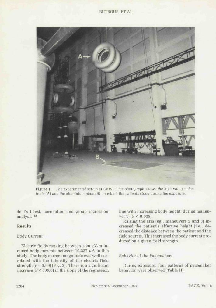
Table II.
Summary of the Effect of High Intensity Power FrequencyElectric Fields on Implanted Cardiac Pacemakers
Pattern of Effect
1. Normal sensing andpacing
2. Reversion tointerference mode
3. Abnormal pacingbehavior
4. Mixed pattern
Pacemaker
All Medtronic 5985Vitatron C2121
TeiectronicsMost PacesetterCPI 0503(1 Of 2)Vitatron S6221Vitatron C2121 {1 of 2)
AH CordisCPI 0503 {1 of 2)
Teiectronics Optima MPPacesetter 221 A-1
Comments
The current needed torevert the pacemakerdepends on model andunit (see Fig. 5)
Field strength needed> 5 kV/m
Abnormal slow pacing ata critical currentlevel, followed byreversion tointerference mode
cantly (P < 0,02) decreased the minimum rever-sion current compared to raising the right arm(maneuver 3), although the same body currentwas induced for each particular field intensity inthe two maneuvers. Similar results were obtainedfor pacemakers implanted in the righl pre-pec-toral region. Raising ofthe right arm (maneuver 3)needed less current to induce reversion to theinterference mode than maneuver 2 (P < 0.1).This is not statistically significant because of thesmall number of patients [Fig. 6).
Opposite findings were observed (Fig. 7) whencomparing maneuvers 6 and 7 (standing on aninsulated carpet raising one arm, and touchingthe earthed aluminium plate with a conductingstick held in the contralateral hand). Raising theleft arm (maneuver 6) significantly (P < 0.001)increased the amount of the reversion current incomparison to raising the right arm (maneuver 7)in patients with the pacemaker in the left pre-pectorai region. Similar observations were madein patients with right pre-pectoral pacemakers,where maneuver 7 needed higher reversion cur-rent than maneuver 6 (P < 0.1).
In patients with left pre-pectoral pacemakers,more reversion current was needed in maneuver6than in maneuver2 (where in both maneuvers theleft arm was raised) (P < 0.01] and more in ma-neuver 3 than maneuver 7 (P < 0.05) (where theright arm was raised in both maneuvers). For
right pre-pectoral pacemakers, more reversioncurrent was needed for maneuver 7 than ma-neuver 3 and more in maneuver 2 than maneuver6. These differences were not significant statis-tically, probably because of the small numberof patients.
With some units, intermittent reversion to theinterference mode was noted at field strengthssufficient to induce body currents of approx-imately 10-20 fiA less than that needed to achievecomplete reversion. In one Vitatron unit (S6221)only intermittent reversion took place, despiteinduced body currents of up to 337 jxA.
Abnormal pacing. In five patients (with fourCordis: 334A, 190F. 242A-7 and 221A-7 units;and one CPI 0503 unit) the pacemakers revertedto abnormally irregular and slow pacing duringthe exposure.
In one patient with Cordis 334A (implanted inthe right pre-pectoral region) the pacemaker re-verted to slow irregular pacing for a few secondsand then changed to fixed rate pacing at 42 bpm(Fig. 8). These changes occurred with an electricfield of 13 kV/m and body current of 140 uA inmaneuverl: with maneuver7 these changes wereobserved with a field intensity of 11 kV/m and abody current of 136 juA. Periods of slow and ir-regular pacing were occasionally observed whenthere was a change in total body current causedby increasing or decreasing the electric field in-
PACE, Vol. 6 November-December 1983 1287

BUTROUS, ET AL.
VPC
OK Mvdtronk 5
pacing ma•«Mitivttvhynrnmn
12 kV/m
120 PPM1.25 mV
40 Bf>M
GM Vitatron C2121 20 kV/n9G0nii
Figure 4. Klecfrocardiographic tracing showing normal sensing and pacing of Medlronic(5985) and Vilalron (02121) units during exposure Io high infensily eieclric fields.
tensity or when there were changes in the dis-tribution of body current associated with differ-ent maneuvers. In another patient with a Cordis(190F] unit, the pacemaker was inhibited formore than 4 seconds during exposure at 5 kV/mwith a body current of 58 /AA (Fig. 9). The patient
300
240
Bodycurrent
180
120
60 i
tron
• »
1a. o
coro
Figure 5. Body curreni needed to revert differentpacemakers to the interference mode.
was presyncopal and the electric field was im-mediately switched off. The pacemaker then re-sumed normal function. The other two Cordisunits (242A-7 and 221A-7) reverted to a slow andirregular pacing at 20 kV/m(body current of 213juA) and 13 kV/m (body current of 178 juA). re-spectively.
During maneuver 1 in the patient with a rightpre-pectoral CPI 0503 unit, the pacemaker start-ed to slow down and pace irregularly at an av-erage rate of 50 bpm when the electric field in-tensity reached 10 kV/m and the body current 80
P<0.1
30Q
3A0
ClIIFBnl 1B0
130
300
240
1B0
120
PBcema»(«f-lhe rigHI nrepKtoril region
Figure 6. The effect of d/sfribution of body currenton ihe amount of reversion curreni in pa(ien(s wilhpacemakers impJanled in righl pre-pec(oral region.
1288 November-December 1983 PACE, Vol. 6

HIGH INTENSITY ELECTRIC FIELDS AND PACEMAKERS
Body
p<0.001
3D0
PKiinili»f-tht Iclt priDcctortl rtgion
Figure 7. The eifecl of dislribulion of body currenton reversion curreni in palienis wilh pacemakers in Iheleft pre-pecloral region.
juA. During maneuver 3 this irregular slow-ing was observed at an electric field intensity of 3kV/m and body current of 30 ^A.
Mixed paltern. In two patients (with Teiec-tronics Optima MP and Pacesetter 221A-1) thepacemakers, programmed to rates higher thanthe patients' spontaneous heart rates [to achieveconlinous pacing), started to pace slowly andirregularly at a critical body current before revert-ing to the interference rate at a higher body cur-rent. These changes were observed at body cur-
rents of 55 /iA and 113 juA in the patient withTeiectronics Optima MP (Fig. 10] and at 104juA and 121 fiA in the patient with a Pacesetter221A-1.
Pacemaker EvaJuation After the Exposure
None of the induced pacing abnormalities per-sisted after the electric field was switched off.Pacing rate, pulse width, lead vectors, magnetfunction and programmability were identicalwith their pre-exposure evaluation.
Clinical Observations
Seven patients [38%] of the eighteen whosepacemakers reverted to the interference modeduring exposure were aware of competitive pac-ing. This sensation was very uncomfortable intwo patients, one of whom is an electronics en-gineer working in a high-voltage substation. Noserious cardiac arrhythmias were caused by com-petitive pacing. In one patient, dizziness and pre-syncope was noticed when the pacemaker failedto pace during the exposure.
In eight patients occasional ventricular ectopicbeats were observed during the exposure but thedesignof this experiment does not allow any con-clusion from this isolated observation. A slightincrease in heart rate (usually less than 10 bpm]was sometimes observed during the exposure.
CORDIS 334A
U KV/m
S/
Figure 8. EJeclrocardiographictracingofapatient with a Cordis 334 A during exposure to 14-15 kV/m.
PACE. Vol. 6 November-Decemher 1983 1289

BUTROUS, ET AL.
AC Cordi* 190FField Strength &KV/m Body current 62;iA
Figure 9. Electrocardiographic recording of a patient wilh a Cordis 190F during exposure lo 5kV/m.
Discussion
An external alternating electric fieid inducesan internal body current, which generates a po-tential gradient when it passes through resistivetissues. Since the input impedance of a pace-maker is normally higher than the tissue impe-dance between its electrodes, the pacemakerwill, in the presence of an external electric field,sense an interference voltage superimposed onthe natural QRS activity. The response of a de-mand pacemaker depends on how well it is able todiscriminate between the two signals. The fre-quency distribution of the QRS complex is about10-30 Hz,^-' and it is therefore possible tbat somepacemakers could misinterpret power frequency
potentials as genuine QRS signals and be falselyinhibited by them. Most new models thereforeincorporate an operational mode in whicb thepacemaker switches off its sensing mechanism inthe presence of interference and begins to func-tion as an asynchronous (fixed-rate) unit. ** Re-version to this interference mode was the mostcommon pacemaker response observed in thisstudy. Asynchronous competitive pacing cancause discomfort and there is a small possibilityof dangerous arrhythmias,'^-'^ although nonewas observed during tbe present investigation.
Bench studies^' ° have shown that some pace-makers perform erratically at certain critical lev-els of interference voltage (lower for 50 Hz tban60 Hz).^° In clinical terms these observations
SkVAn55pA
• \
Figure 10. The mixed pattern of a Teiectronics Optima MP. The upper two e/ectrocar-diographic traces show sJow and irreguiar pacing during exposure lo 5 kV/m. The pacemakerreverted lo the interference mode wilh furlher increase of the field intensily (boKom Irace).
1290 Novemher-December 1983 PACE, Vol. 6

HIGH INTENSITY ELECTRIC FIELDS AND PACEMAKERS
were considered insignificant^^ because of thevery small and narrow range over which the phe-nomenon occurred. In this study, however, er-ratic behavior was very easily demonstrated inmany models and is therefore of potential clinicalimportance for patients who happen to encounterelectric fields of the critical strength.
The different interference sensitivities wehave observed in this study, even for units of thesame model, may be due partly to differences inthe relative configurations of pacemaker caseand active electrode and partly to differences inthe current distribution in patients exposed to thesame electric field. The body can, as a first ap-proximation, be considered a combination of re-sistors arranged in series^^ and thus, for a givendistribution of body current, the potential dif-ference between the active electrode and thepacemaker case (or indifferent electrode) will de-pend on their relative positions. Conversely, forgiven relative positions, the potential differencewill depend on the current distributions, as dem-onstrated by the observed differences in rever-sion current required with different maneuvers inthis study (Figs. 6 and 7).
The differences in behavior between differentpacemaker models must be due to differences inthe design of their sensing and filtration circuitry.It is encouraging that some models appear to becompletely immune to interference by electricfields as high as 20 kV/m.
Despite the abnormal behavior seen with somepacemaker models it should be stressed thatpower transmission lines, even those operating atthe highest voltages (400 kV in the U.K.). shouldnot be considered potentially hazardous to mem-bers of the general public who are fitted with
pacemakers, Electric fields to which the generalpublic may be exposed rarely exceed 5 kV/m. Itwas observed from this study that all pacemakerstested (with the exception of two Teiectronicsunits) needed more than 5 kV/m to change theirbehavior. It is important to note that the electricfield did not affect the programmability of pace-makers and all pacing abnormalities ceased whenthe electric fieid was switched off. However, thehazard cannot be neglected in patients at risk ofexposure to higher field intensities, such as work-ers in electric substations.'^
The preferred remedy is to design future pace-makers such that they are immune to this kind ofinterference. Many previous suggestions, suchas the development of an interference mode andthe enclosure of pacemaker circuitry within astainless steel or titanium case to improve elec-tromagnetic shielding.'"*'^ are now used routine-ly in modern pacemaker models. However, theincorporation of an efficient noise-rejection cir-cuit, already available in some models, appearsto be a feasible and ideal solution.
Finally, this study has emphasized the need forfurther clinical and bench studies to characterizethe interference response of increasingly sophis-ticated modern pacemaker devices such as trig-gered systems, dual chamber and antitachycardiapacemakers.
Acknowledgment: We would Uke to express our thanks toDr. W.T. Norris, Head of Electrical Engineering Branch,CERL. for his encouragement and support and to Mr. R.C.Hughes and his staff in Ihe high-voltage test bay. CERL. fortheir technical help.
This work was partly supported by the Central ElectricityGenerating Board. Dr. Camm is a Wellcome Senior Lec-turer.
References
1. Whalen, R.E.. Starmer, F. and Mclntosh. H.D,:Etectric hazards associated with cardiac pacing.Ann, N.Y. Acad. Sci., 11:922. 1964.
2. Furman, S., Schwedel. J.B., Robinson, G.. et al.;Use of an intracardiac pacemaker in the control ofheart block. Surgery. 49:98, 1961.
3. Noordjik. ).A., Oey. F,T.L, and Tebra, W.: Myo-cardial electrodes and the danger of ventricularfibrillation. Lancet. 1:975. 1961.
4. Carleton. R.A., Sessions, R.W., andGraettinger,
J.S.: Environmental influence on implantable car-diac pacemakers. }AMA. 190:160. 1964.
5. Mansfield. P.B.; On interference signals andpacemakers. Am. }. EJectronics, First Quarter; 61,1961.
6. Furman. S.. Parker, B., Krauthamer, M., et al.:The influence of electromagnetic environment onthe performance of artificial cardiac pacemakers.Ann. Thorac. Surg.. 6:90. 1968.
7. Zalewski, R.A.: Effecl of EHV Lines on Heart
PACE, Vol. 6 November-December 1983 1291

BUTROUS. ET AL.
Pacemakers. UT Research Institute, Chicago,E8128, 1975. 14.
8. Bridges, J.E., Frazier. M.J., and Hauser, R.G.:The effect of 60 Hertz electric fields and currentson implanted cardiac pacemakers. IEEE Inter-national Symposium on Elecfroniagnetic Com- 15.patibility. Published by the Institute of Electricaland Electronics Engineers. Inc.. 1978. p. 258.
9. Bridges. J.E., andErazier, M.J.. The effects of 60- 16.Hertz electric and magnetic fields on implantedcardiac pacemakers. EPRI EA-1174 Project 679-1Einal Report, Chicago, 1979. 17.
10. Jenkins, B.M.. and Woody, J.A.: Cardiac pace-maker responses to power frequency signals.IEEE Jnternafionai Symposium on Elec-tromagnetic Compa(ibi/i(y. Published by The In-stitute of Electricai and Electronics Engineers.Inc., 1978, p. 273.
11. Meldrum, S., Butrous, G.S.. and Camm, A.].: 18.Electrocardiographic recording in high intensityelectric fields. /. Med. Eng. Tech.. 7:66, 1983.
12. Armitage. P.: Sfah'stical Methods in Medicai Re-search. Blackwell Scientific Publications, 1971, 19.
13. Kleinert. M., Elmqvist, H.. and Strandberg. H.:Spectral properties of atrial and ventricular en-
docardial signals. PACE. 2:11, 1979.Smyth. N.P.D.. Parsonnet, V., Escher. D.J.W., etal.: The pacemaker patient and the elec-tromagnetic environment. JAMA. 227:1412.1974.Tavel, M.E., and Fisch. C : Repetitive ventriculararrhythmia resulting from artificial internal pace-maker. Circtj/alion, 30:493, 1964.Bilitch. M.. Cosby. R.S.. andCafferky, E.A.: Ven-tricular fihrillation and competitive pacing. N.Enfil. J, Med.. 276:598, 1967.Frazier, M.J., Bridges, J.E.. and Hauser. R.G.:Internal body potentials and currents from ELFelectric fields and household appliances. JEEEInternational Sympo.siijnj on ElectromagneticCoiTipalibilily. Published by the Institute of Elec-trical and Electronics Engineers. Inc.. 1976. p.266.Butrous, G.S.. Bexton. R.S,, Barton. D,C.. et al.:Interference with pacemakers in two workers atelectricity substations. Br. /. Indust. Med.. (Inpress).Sowton, E., Gray, R.. and Preston. T.: Electricalinterference in non-competitive pacemakers. Br.Hearr J,. 32:626, 1970.
". . . the heart muscle was unaffected by any degeneration or sclerotic changeexcepting in the very limited area of the middle portion of the auriculoventricularbundle... (wherein) was a patch of atheromatous character, sclerotic and white,and it extended to the endocardium exactly over the bundle of His where this bandpasses from the ventricle to the auricle."
Alfred Stengel: Fatal case of Stokes-Adams disease with autopsy showing involve-ment of auriculoventricular bundle of His. Am. J. Med. Sa. 130:1083. 1905
Excerpt provided by David C. Schechter, M.D.. New York, New York
1292 November-Decemher 1983 PACE, Vol. 8