Effect of microstructure on abrasive wear behavior of thermally sprayed WC–10Co–4Cr coatings
Upload
independentCategory
view
0download
0
JOURNAL OF MATERIALS SCIENCE 33 (1998) 3095 — 3100
The effect of high-velocity oxygen fuel, thermallysprayed WC–Co coatings on the high-cycle fatigueof aluminium alloy and steel
A. IBRAHIM, C. C. BERNDTDepartment of Materials Science and Engineering, State University of New York at StonyBrook, Stony Brook, NY 11794, USAE-mail: [email protected]
Thermally sprayed WC—Co coatings are currently used in numerous contact wearapplications in the aircraft, automotive and paper industries. High-cycle fatigue tests wereperformed at room temperature and 370 °C on SAE 12L14 low-carbon steel and aluminiumalloy 2024-T4 thermally sprayed with WC—17 wt % Co using the high-velocity oxygen fuelprocess. The fatigue life distributions of specimens in the polished, grit-blasted, peened andcoated conditions are presented as a function of the probability of failure. Composite beamtheory was applied to the coated beam to evaluate the stresses and elastic modulus.The stress—strain curves for the coated and uncoated specimens were used to evaluatethe stiffness factor for the aluminium alloy and steel. It is concluded that (i) the coatedspecimens exhibited significantly high fatigue lives compared with the uncoated specimens,(ii) the mechanisms of deformation for the coated and uncoated aluminium alloy specimensare quite different and (iii) the elastic modulus of the coating plays a significant role indetermining the fatigue strength of the coated component. 1998 Kluwer Academic Publishers
1. IntroductionHigh-velocity oxygen fuel (HVOF) thermally sprayedWC—Co coatings on metallic substrates, particularlyaluminium, have found wide use as wear- and cor-rosion-resistant coatings in many industrial applica-tions. The HVOF process, which combines a relativelylow thermal energy with a high kinetic energy, pro-duces coatings with a high hardness, a low porosityand a high bond strength. The influence of the coatingon the fatigue life of the base material has been thesubject of several investigators; for instance thermallysprayed WC—Co exhibits favourable fatigue-resistantproperties [1—5]. While most of these data have beendevoted to establishing the S—N curve, less effort wasgiven to understanding the deformation mechanism ofthe coating and the base material.
In order to evaluate the fatigue strength of a givenmaterial from a reliability viewpoint, the value of thestress versus life relation for prescribed failure prob-abilities (P—S—N relations) must be available [6]. Forcoated beams under applied bending moments or dy-namic vibrations, the stiffness of the coated beam[6, 7] is an important factor in determining thestrength of the component.
In this investigation, rotating bending high-cyclefatigue (HCF) of SAE 12L14 low-carbon steel andaluminium alloy 2024-T4 in the polished, grit-blastedand peened conditions, as well as coated with WC—Co,are investigated. The fatigue life distributions are pre-sented as a function of the probability of failure.
The fracture mechanisms of the coated and uncoatedspecimens are also discussed on the basis of detailedmacroscopic and metallographic analysis. Strain gaugeswere bonded to the test specimen to measure the elasticstrain of the coated beam. Composite beam theory deter-mined the stresses and elastic modulus of the coating.Finally, the stiffness factor was introduced to assess theresistance of the coated beam to bending stress.
2. Experimental procedureThe base materials used in this study were SAE12L14 low-carbon steel and aluminium alloy 2024-T4.The mechanical properties of these materials areshown in Table I. The fatigue test specimen shown inFig. 1 was prepared according to ASTM standardE466-82 [9].
The fatigue experiments were conducted at roomtemperature and 370 °C under rotating bending(R"!1) at a loading frequency of 50 Hz. The surfaceof the specimen was prepared for coating by gritblasting with grade 24 alumina particles using a blast-ing pressure of 500 kPa. The specimens were coatedwith a WC—Co coating 0.200 mm thick using a HVOFsystem (DJ gun, Sulzer-Metco Inc., Westbury, NY).The elastic strains of coated and uncoated specimenswere measured with strain gauges glued at the centreof the specimen surface. The fracture surfaces werecharacterized using optical and scanning electronmicroscopy (SEM).
0022—2461 ( 1998 Kluwer Academic Publishers 3095
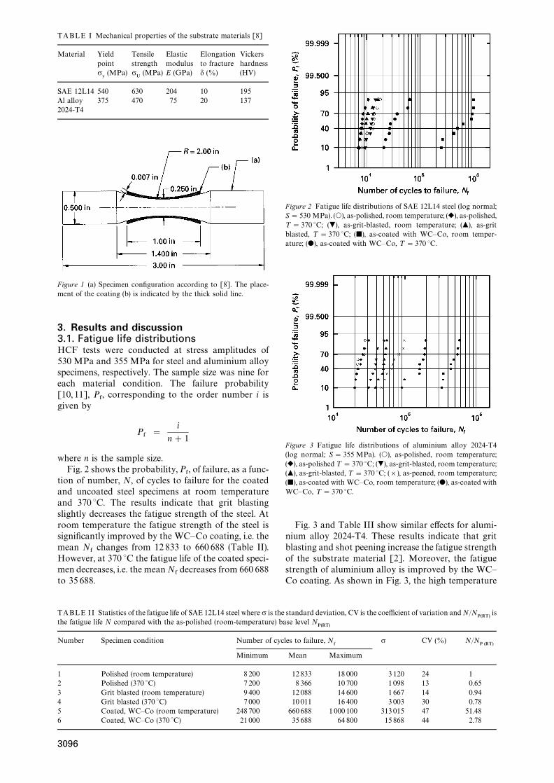
TABLE II Statistics of the fatigue life of SAE 12L14 steel where r is the standard deviation, CV is the coefficient of variation and N/NP(RT)
isthe fatigue life N compared with the as-polished (room-temperature) base level N
P(RT)
Number Specimen condition Number of cycles to failure, N&
r CV (%) N/NP (RT)
Minimum Mean Maximum
1 Polished (room temperature) 8 200 12 833 18 000 3120 24 12 Polished (370 °C) 7200 8 366 10 700 1098 13 0.653 Grit blasted (room temperature) 9 400 12 088 14 600 1667 14 0.944 Grit blasted (370 °C) 7000 10 011 16 400 3003 30 0.785 Coated, WC—Co (room temperature) 248700 660688 1 000 100 313015 47 51.486 Coated, WC—Co (370 °C) 21 000 35 688 64 800 15 868 44 2.78
TABLE I Mechanical properties of the substrate materials [8]
Material Yield Tensile Elastic Elongation Vickerspoint strength modulus to fracture hardnessr:
(MPa) rU
(MPa) E (GPa) d (%) (HV)
SAE 12L14 540 630 204 10 195Al alloy2024-T4
375 470 75 20 137
Figure 1 (a) Specimen configuration according to [8]. The place-ment of the coating (b) is indicated by the thick solid line.
3. Results and discussion3.1. Fatigue life distributionsHCF tests were conducted at stress amplitudes of530 MPa and 355 MPa for steel and aluminium alloyspecimens, respectively. The sample size was nine foreach material condition. The failure probability[10, 11], P
&, corresponding to the order number i is
given by
P&"
i
n#1
where n is the sample size.Fig. 2 shows the probability, P
&, of failure, as a func-
tion of number, N, of cycles to failure for the coatedand uncoated steel specimens at room temperatureand 370 °C. The results indicate that grit blastingslightly decreases the fatigue strength of the steel. Atroom temperature the fatigue strength of the steel issignificantly improved by the WC—Co coating, i.e. themean N
&changes from 12 833 to 660 688 (Table II).
However, at 370 °C the fatigue life of the coated speci-men decreases, i.e. the mean N
&decreases from 660 688
to 35 688.
Figure 2 Fatigue life distributions of SAE 12L14 steel (log normal;S"530 MPa). (s), as-polished, room temperature; (r), as-polished,¹"370 °C; (.), as-grit-blasted, room temperature; (m), as-gritblasted, ¹"370 °C; (j), as-coated with WC—Co, room temper-ature; (d), as-coated with WC—Co, ¹"370 °C.
Figure 3 Fatigue life distributions of aluminium alloy 2024-T4(log normal; S"355 MPa). (s), as-polished, room temperature;(r), as-polished ¹"370 °C; (.), as-grit-blasted, room temperature;(m), as-grit-blasted, ¹"370 °C; (]), as-peened, room temperature;(j), as-coated with WC—Co, room temperature; (d), as-coated withWC—Co, ¹"370 °C.
Fig. 3 and Table III show similar effects for alumi-nium alloy 2024-T4. These results indicate that gritblasting and shot peening increase the fatigue strengthof the substrate material [2]. Moreover, the fatiguestrength of aluminium alloy is improved by the WC—Co coating. As shown in Fig. 3, the high temperature
3096

TABLE III Statistics of the fatigue life of aluminium alloy 2024-T4 where r is the standard deviation, CV is the coefficient of variation andN/N
P (RT)is the fatigue life N compared with the as-polished (room temperature) base level N
P (RT)
Number Specimen condition Number of cycles to failure, N&
r CV (%) N/NP (RT)
Minimum Mean Maximum
1 Polished (room temperature) 19 700 22 977 27 600 3 119 14 12 Polished (370 °C) 19 800 23 822 31 000 3 624 15 1.043 Grit blasted (room temperature) 30 600 38 422 50 500 5 706 15 1.674 Grit blasted (370 °C) 38 200 49 055 55 600 5 632 11 2.135 As-peened (room temperature) 46 700 70 088 98 300 18 213 26 3.056 Coated, WC—Co (room temperature) 327300 448466 581 900 97 546 22 19.527 Coated, WC—Co (370 °C) 90 400 158445 195 600 38 683 24 6.90
Figure 4 (a) Fractograph of the fracture surface of an SAE 12L14specimen coated with WC—Co that failed at r"530 MPa,N"1 000 100 cycles and ¹"23 °C. (b) A SEM fractograph show-ing the transition zone between ductile and brittle fracture for thespecimen in (a).
diminishes the fatigue strength of the WC—Co-coatedspecimen.
3.2. FractographyThe fracture surface of a coated steel specimen isshown in Fig. 4a. The fracture surface indicates that
fatigue originated at the centre of the dark area [12]indicated by the arrow. Fig. 4b shows a progressivecrack separating the dark area (fatigue origin) fromthe rest of the substrate material. Examination of thisarea revealed that microvoids and dimples havegrown and joined to form cracks that grew radiallyoutwards [13, 14]. At 370 °C the dark area (fatigueorigin) was larger, thereby indicating higher deforma-tion.
Visual and macroscopic examination of the coatedaluminium alloy fracture surface indicate that the frac-ture surface in Fig. 5a consists of two distinct zones,indicated by A and B. Fig. 5b shows the transitionbetween the two zones. Zone A shows cracks andsignificant plastic deformation, both characteristicsof ductile fracture that started at the periphery ofthe substrate and propagated towards the centre ofthe material. Zone B exhibits cleavage features thatare characteristics of brittle fracture. Continuousmonitoring of the specimen during the test revealedthat no coating peeled from the specimen in the earlystage of the loading. However, at the final stage ofloading of each test, a small section of the coatingdelaminated from the surface prior to complete failure.In a typical test the experiment was interrupted toexamine the failure location (Fig. 6a) and revealed thatthe substrate material was extensively deformed(Fig. 6b). Therefore, the mechanism of coating failureis extensive deformation followed by progressivecracking at the surface of the aluminium alloy substra-te, giving rise to a segment of the coating which wasessentially standing free without support. At 370 °Cthe number of such cracks increased and formed anarray along the upper half of the specimen.
Fracture surfaces of the polished and grit-blastedaluminium alloy specimens are shown in Figs 7 and 8.The polished specimen plastically deformed extensive-ly compared with the as-coated specimen (Fig 5).Thus, the coating has significantly reduced the rate ofdeformation and consequently the fatigue life is in-creased. As shown in Fig. 8, the grit-blasting proced-ure lead to the formation of a protective layer on theperiphery of the specimen. This layer is the outermostlayer that was work hardened due to the compressiveresidual stress during grit blasting. Therefore, fatiguenucleation was initiated just below the hardened layer;consequently, the rate of the fatigue process decreasedand the fatigue life increased.
3097

Figure 5 (a) Fractograph of the fracture surface of an aluminiumalloy of 2024-T4 specimen coated with WC—Co that failed atr"355 MPa, N"327 300 cycles and ¹"23 °C. (b) A SEM frac-tograph showing the transition zone between ductile and brittlefracture for the specimen in (a).
3.3. Bending stresses of coated beamsHVOF WC—Co coatings sprayed onto cylindricalspecimens exhibit high adhesion strength and highdensity. In addition the thickness of the coating isusually small compared with the substrate. Therefore,the coated specimen behaves like a homogeneouscomposite material and may be analysed by the samebending theory used for ordinary beams, providedthat the assumption that plane cross-sections beforebending remain plane after bending. The normalstress, r
9, acting on the cross-section as a result of
bending moment, M, can be obtained from the strains,e9, using the stress—strain relationships for the mater-
ials. Denoting the modulus of elasticity for the sub-strate as E
Sand of the elasticity modulus of the
coating as EC
and also assuming that EC'E
S, we
obtain the stress diagram in Fig. 9.The normal stresses, r
9, at distance y from the x axis
in the coating and substrate, are given by the followingequations
rC
" !ECjy r
S" !E
Sjy (1)
Where j is the curvature and y is the distance from theneutral axis.
Figure 6 Fractograph of an aluminium alloy 2024-T4 specimencoated with WC—Co. (a) The dark area is the origin of failure andthe white area is the location, where the coating is peeled off asa result of substrate damage. (b) A close-up picture for the dark areain (a). The test stopped at r"355 MPa and N"534800 cycles.
The relationship between the bending moment, M,and the stress in the beam is as follows
M " Pr9y dA
Applying this formula for coated beams gives
M " PrSy dA#Pr
Cy dA
M " !jESP y2 dA!jE
C P y2 dA (2)
M " !j (ESIS#E
CIC)
Equation 2 can be solved for the curvature, j
i " !
M
ESIS#E
CIC
(3)
The stresses in the coated beams are obtained bysubstituting the expressions for curvature into theexpressions for r
Cand r
S(Equation 1)
rS"
MyES
ESIS#E
CIC
, rC
"
MyEC
ESIS#E
CIC
(4)
These expressions are the flexure formulae for coatedbeams. The relationship between the longitudinal
3098
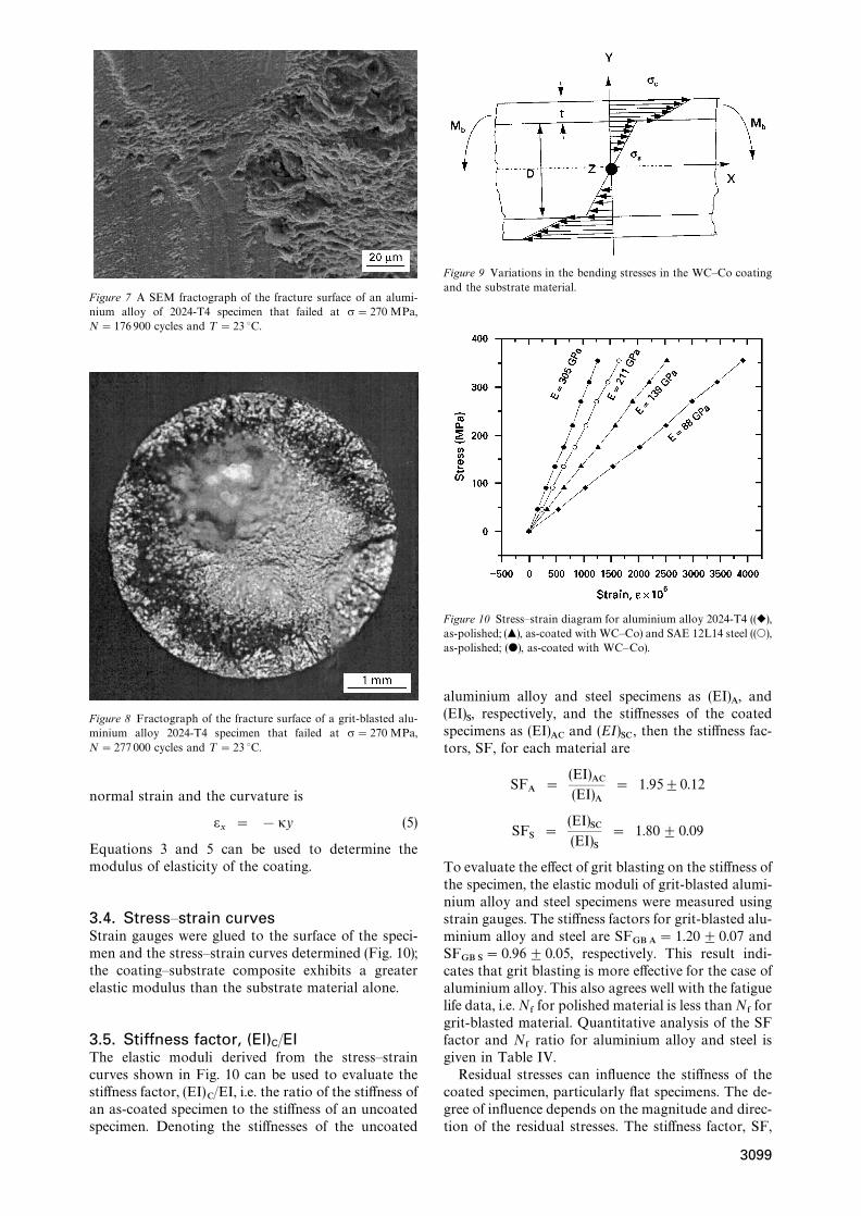
Figure 7 A SEM fractograph of the fracture surface of an alumi-nium alloy of 2024-T4 specimen that failed at r"270 MPa,N"176 900 cycles and ¹"23 °C.
Figure 8 Fractograph of the fracture surface of a grit-blasted alu-minium alloy 2024-T4 specimen that failed at r"270 MPa,N"277 000 cycles and ¹"23 °C.
normal strain and the curvature is
ex
" !jy (5)
Equations 3 and 5 can be used to determine themodulus of elasticity of the coating.
3.4. Stress—strain curvesStrain gauges were glued to the surface of the speci-men and the stress—strain curves determined (Fig. 10);the coating—substrate composite exhibits a greaterelastic modulus than the substrate material alone.
3.5. Stiffness factor, (EI)C/EIThe elastic moduli derived from the stress—straincurves shown in Fig. 10 can be used to evaluate thestiffness factor, (EI)
C/EI, i.e. the ratio of the stiffness of
an as-coated specimen to the stiffness of an uncoatedspecimen. Denoting the stiffnesses of the uncoated
Figure 9 Variations in the bending stresses in the WC—Co coatingand the substrate material.
Figure 10 Stress—strain diagram for aluminium alloy 2024-T4 ((r),as-polished; (m), as-coated with WC—Co) and SAE 12L14 steel ((s),as-polished; (d), as-coated with WC—Co).
aluminium alloy and steel specimens as (EI)A, and
(EI)S, respectively, and the stiffnesses of the coated
specimens as (EI)AC
and (EI)SC
, then the stiffness fac-tors, SF, for each material are
SFA
"
(EI)AC
(EI)A
" 1.95$0.12
SFS"
(EI)SC
(EI)S
" 1.80$0.09
To evaluate the effect of grit blasting on the stiffness ofthe specimen, the elastic moduli of grit-blasted alumi-nium alloy and steel specimens were measured usingstrain gauges. The stiffness factors for grit-blasted alu-minium alloy and steel are SF
GB A"1.20$0.07 and
SFGB S
"0.96$0.05, respectively. This result indi-cates that grit blasting is more effective for the case ofaluminium alloy. This also agrees well with the fatiguelife data, i.e. N
&for polished material is less than N
&for
grit-blasted material. Quantitative analysis of the SFfactor and N
&ratio for aluminium alloy and steel is
given in Table IV.Residual stresses can influence the stiffness of the
coated specimen, particularly flat specimens. The de-gree of influence depends on the magnitude and direc-tion of the residual stresses. The stiffness factor, SF,
3099
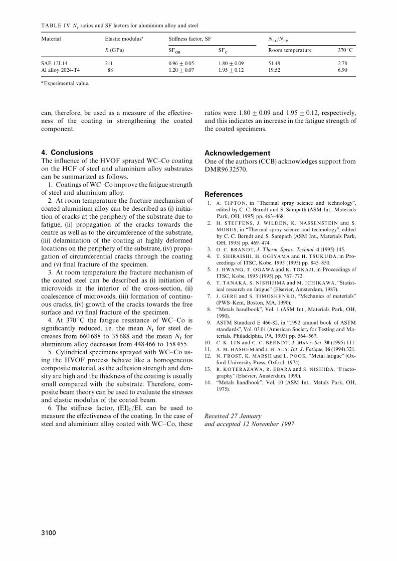
TABLE IV N&ratios and SF factors for aluminium alloy and steel
Material Elastic modulus! Stiffness factor, SF N& C
/N& P
E (GPa) SFGB
SFC
Room temperature 370 °C
SAE 12L14 211 0.96$0.05 1.80$0.09 51.48 2.78Al alloy 2024-T4 88 1.20$0.07 1.95$0.12 19.52 6.90
! Experimental value.
can, therefore, be used as a measure of the effective-ness of the coating in strengthening the coatedcomponent.
4. ConclusionsThe influence of the HVOF sprayed WC—Co coatingon the HCF of steel and aluminium alloy substratescan be summarized as follows.
1. Coatings of WC—Co improve the fatigue strengthof steel and aluminium alloy.
2. At room temperature the fracture mechanism ofcoated aluminium alloy can be described as (i) initia-tion of cracks at the periphery of the substrate due tofatigue, (ii) propagation of the cracks towards thecentre as well as to the circumference of the substrate,(iii) delamination of the coating at highly deformedlocations on the periphery of the substrate, (iv) propa-gation of circumferential cracks through the coatingand (v) final fracture of the specimen.
3. At room temperature the fracture mechanism ofthe coated steel can be described as (i) initiation ofmicrovoids in the interior of the cross-section, (ii)coalescence of microvoids, (iii) formation of continu-ous cracks, (iv) growth of the cracks towards the freesurface and (v) final fracture of the specimen.
4. At 370 °C the fatigue resistance of WC—Co issignificantly reduced, i.e. the mean N
&for steel de-
creases from 660 688 to 35 688 and the mean N&for
aluminium alloy decreases from 448 466 to 158 455.5. Cylindrical specimens sprayed with WC—Co us-
ing the HVOF process behave like a homogeneouscomposite material, as the adhesion strength and den-sity are high and the thickness of the coating is usuallysmall compared with the substrate. Therefore, com-posite beam theory can be used to evaluate the stressesand elastic modulus of the coated beam.
6. The stiffness factor, (EI)C/EI, can be used to
measure the effectiveness of the coating. In the case ofsteel and aluminium alloy coated with WC—Co, these
ratios were 1.80$0.09 and 1.95$0.12, respectively,and this indicates an increase in the fatigue strength ofthe coated specimens.
AcknowledgementOne of the authors (CCB) acknowledges support fromDMR9632570.
References1. A. TIPTON, in ‘‘Thermal spray science and technology’’,
edited by C. C. Berndt and S. Sampath (ASM Int., MaterialsPark, OH, 1995) pp. 463—468.
2. H. STEFFENS, J. WILDEN, K. NASSENSTEIN and S.
MOBUS, in ‘‘Thermal spray science and technology’’, editedby C. C. Berndt and S. Sampath (ASM Int., Materials Park,OH, 1995) pp. 469—474.
3. O. C. BRANDT, J. ¹herm. Spray. ¹echnol. 4 (1995) 145.4. T. SHIRAISHI , H. OGIYAMA and H. TSUKUDA, in Pro-
ceedings of ITSC, Kobe, 1995 (1995) pp. 845—850.5. J . HWANG, T. OGAWA and K. TOKAJI , in Proceedings of
ITSC, Kobe, 1995 (1995) pp. 767—772.6. T. TANAKA, S. NISHIJIMA and M. ICHIKAWA, ‘‘Statist-
ical research on fatigue’’ (Elsevier, Amsterdam, 1987).7. J . GERE and S. TIMOSHENKO, ‘‘Mechanics of materials’’
(PWS—Kent, Boston, MA, 1990).8. ‘‘Metals handbook’’, Vol. 1 (ASM Int., Materials Park, OH,
1990).9. ASTM Standard E 466-82, in ‘‘1992 annual book of ASTM
standards’’, Vol. 03.01 (American Society for Testing and Ma-terials, Philadelphia, PA, 1993) pp. 564—567.
10. C. K. LIN and C. C. BERNDT, J. Mater. Sci. 30 (1995) 111.11. A. M. HASHEM and I. H. ALY, Int. J. Fatigue, 16 (1994) 321.12. N. FROST, K. MARSH and L. POOK, ‘‘Metal fatigue’’ (Ox-
ford University Press, Oxford, 1974).13. R. KOTERAZAWA, R. EBARA and S. NISHIDA, ‘‘Fracto-
graphy’’ (Elsevier, Amsterdam, 1990).14. ‘‘Metals handbook’’, Vol. 10 (ASM Int., Metals Park, OH,
1975).
Received 27 Januaryand accepted 12 November 1997
3100
Copyright © 2022 FDOKUMEN


![:_UZR ]ZWed TfcSd `_ W]ZXYed Wc`^ F\cRZ_V - Daily Pioneer](https://static.fdokumen.com/doc/165x107/6325e8105c2c3bbfa8036c00/uzr-zwed-tfcsd-wzxyed-wc-fcrzv-daily-pioneer.jpg)
![DV_R cVSV]d XVe "% URj cVacZVgV Wc`^ D4 ` - Daily Pioneer](https://static.fdokumen.com/doc/165x107/6332d26f3108fad7760eca6b/dvr-cvsvd-xve-urj-cvaczvgv-wc-d4-daily-pioneer.jpg)


![% aYRdV ; < TZgZT a`]]d Wc`^ @Te ) - Daily Pioneer](https://static.fdokumen.com/doc/165x107/631c483976d2a44505037853/-ayrdv-tzgzt-ad-wc-te-daily-pioneer.jpg)