the effect of deoxidation practice on non- metallic inclusions ...
262
THE EFFECT OF DEOXIDATION PRACTICE ON NON- METALLIC INCLUSIONS AND THEIR EFFECT ON MECHANICAL PROPERTIES OF A LOW ALLOY STEEL. Jose Manuel Naranjo Espinosa February 2018 Thesis submitted in partial fulfilment for the degree of Doctor of Philosophy
-
Upload
khangminh22 -
Category
Documents
-
view
2 -
download
0
Transcript of the effect of deoxidation practice on non- metallic inclusions ...

1
THE EFFECT OF DEOXIDATION PRACTICE ON NON-METALLIC INCLUSIONS AND THEIR EFFECT ON
MECHANICAL PROPERTIES OF A LOW ALLOY
STEEL.
Jose Manuel Naranjo Espinosa
February 2018
Thesis submitted in partial fulfilment for the
degree of Doctor of Philosophy

2
Abstract
In the present work, the characterisation of a low alloy steel produced for structural applications
is presented. The steel was fabricated via two different deoxidation practices; conventional Al
killing and a proposed Si-Al killing technique. The casting method employed was continuous
casting and material from different heats was analysed. Their respective inclusion contents were
assessed in the as-cast and as-deformed conditions. The imaging methods included manual and
automated imaging by optical microscopy and Scanning Electron Microscopy. Steel fabricated
via the aluminium killing practice, contained less inclusions per mm2 but more alumina and
calcium aluminates compared to the Si-Al killing practice, which contained more inclusions per
mm2 but exhibited a higher percentage of manganese sulphide type inclusions. The mechanical
properties of material in the as-deformed condition were assessed, according to standard
specification requirements.

3
Table of Contents
ABSTRACT .................................................................................................................................... 2
TABLE OF CONTENTS ................................................................................................................. 3
TABLE OF FIGURES ..................................................................................................................... 8
INDEX OF TABLES ..................................................................................................................... 17
ACKNOWLEDGEMENTS ............................................................................................................ 18
ABBREVIATIONS ........................................................................................................................ 19
CHAPTER 1 INTRODUCTION .................................................................................................... 20
1.1 INDUSTRIAL JUSTIFICATION .......................................................................................................................... 20
1.2 INDUSTRIAL PARTNER ................................................................................................................................. 20
1.3 THESIS STRUCTURE ..................................................................................................................................... 21
CHAPTER 2 LITERATURE REVIEW .......................................................................................... 22
2.1 INTRODUCTION TO STEELMAKING ................................................................................................................. 22
2.1.1 Introduction .............................................................................................................................. 22
2.1.2 High Strength Low Alloy (HSLA) steels ...................................................................................... 22
2.1.3 Steelmaking .............................................................................................................................. 23
2.2 WHAT ARE INCLUSIONS? ............................................................................................................................. 25
2.3 ORIGIN OF INCLUSIONS ............................................................................................................................... 26
2.3.1 Origin ........................................................................................................................................ 26
2.3.2 Composition .............................................................................................................................. 26
2.3.3 Size ............................................................................................................................................ 27
2.3.4 Deoxidation ............................................................................................................................... 28
2.3.5 Deoxidation with aluminium .................................................................................................... 29
2.3.6 Deoxidation with silicon ........................................................................................................... 30
2.3.7 Combined deoxidation using Si-Al ............................................................................................ 31
2.4 BEHAVIOUR OF INCLUSIONS ......................................................................................................................... 32
2.4.1 Behaviour in the liquid state ..................................................................................................... 32
2.4.2 Behaviour in the solid state ...................................................................................................... 34

4
2.5 EFFECT OF INCLUSIONS ON MECHANICAL PROPERTIES ........................................................................................ 38
2.5.1 Effect on Tensile strength ......................................................................................................... 39
2.5.2 Effect on Toughness .................................................................................................................. 39
2.5.3 Effect on Fatigue ....................................................................................................................... 43
2.5.4 Effect on Machinability ............................................................................................................. 45
2.6 CHARACTERISATION TECHNIQUES .................................................................................................................. 46
2.6.1 Introduction .............................................................................................................................. 46
2.6.2 Optical Microscopy ................................................................................................................... 47
2.6.3 Scanning Electron Microscopy .................................................................................................. 47
2.6.4 Oxygen content ......................................................................................................................... 48
2.6.5 Ultrasonic Testing ..................................................................................................................... 49
2.6.6 Extreme Value Statistical Analysis ............................................................................................ 50
CHAPTER 3 EXPERIMENTAL PROCEDURE ............................................................................ 53
3.1 MATERIALS .............................................................................................................................................. 53
3.1.1 Steel grade ................................................................................................................................ 53
3.1.2 Deoxidation Practices ............................................................................................................... 53
3.1.3 Forging and rolling .................................................................................................................... 54
3.2 SAMPLE SELECTION .................................................................................................................................... 55
3.2.1 Introduction .............................................................................................................................. 55
3.2.2 As cast bloom – effect of location on inclusion population ...................................................... 55
3.2.3 As cast bloom – effect of deoxidation practice on inclusion population .................................. 56
3.2.4 Effect of forging and rolling on inclusion population ............................................................... 56
3.3 METALLOGRAPHIC PREPARATION OF SAMPLES ................................................................................................. 56
3.4 INCLUSION CHARACTERISATION .................................................................................................................... 57
3.4.1 Optical Microscopy ................................................................................................................... 57
3.4.2 Scanning Electron Microscope (SEM) ....................................................................................... 59
3.4.3 Ultrasonic Testing ..................................................................................................................... 60
3.4.4 Extreme Values Statistical Analysis ........................................................................................... 61
3.5 MECHANICAL PROPERTIES ........................................................................................................................... 61

5
3.5.1 Hardness testing ....................................................................................................................... 62
3.5.2 Tensile Testing .......................................................................................................................... 62
3.5.3 Impact testing ........................................................................................................................... 63
3.5.4 Crack Tip Opening Displacement (CTOD) testing ...................................................................... 64
CHAPTER 4 EFFECT OF AS CAST BLOOM LOCATION ON INCLUSION POPULATION ...... 66
4.1 INTRODUCTION ......................................................................................................................................... 66
4.2 DETAILED ANALYSIS OF AL KILLED SAMPLE (HEAT 1320) ................................................................................... 66
4.2.1 Optical Microscopy Results ....................................................................................................... 67
4.3 ANALYSIS OF AL KILLED AND SI-AL KILLED SAMPLES (HEATS 1319 AND 2456 RESPECTIVELY) ................................... 69
4.3.1 Automated Optical Microscopy ................................................................................................ 71
4.3.2 Automated Feature Analysis – Scanning Electron Microscope (SEM-AFA) .............................. 76
4.3.3 Joint Ternary diagrams ............................................................................................................. 93
4.3.4 Extreme Value Analysis ............................................................................................................. 97
4.3.5 Grain size measurements ....................................................................................................... 102
CHAPTER 5 EFFECT OF DEOXIDATION PRACTICE ON INCLUSION POPULATION ......... 104
5.1 INTRODUCTION ....................................................................................................................................... 104
5.2 CHARACTERISATION OF AS CAST AL HEATS (1319, 1320, 1332) AND SI-AL DEOXIDISED HEATS (2456, 2457,
2458) ........................................................................................................................................................ 104
5.2.1 Optical Microscopy ................................................................................................................. 104
5.2.2 Automated OM ....................................................................................................................... 105
5.2.3 Scanning Electron Microscopy- Automated Feature Analysis ................................................ 110
5.2.4 Joint Ternary Diagrams ........................................................................................................... 115
5.2.5 Extreme Value Analysis ........................................................................................................... 119
5.2.6 Discussion Summary ............................................................................................................... 123
CHAPTER 6 EFFECT OF PLASTIC DEFORMATION ON INCLUSION POPULATION ........... 124
6.1 INTRODUCTION ....................................................................................................................................... 124
6.2 CHARACTERISATION OF AS DEFORMED AL HEATS (1319, 1320, 1330 AND 1332) AND SI-AL DEOXIDISED HEATS (2455,
2456, 2457 AND 2458) ............................................................................................................................... 124

6
6.2.1 Optical Microscopy ................................................................................................................. 124
6.2.2 Automated Optical Microscopy .............................................................................................. 125
6.2.3 Scanning Electron Microscopy-Automated Feature Analysis ................................................. 126
6.2.4 Joint Ternary Diagrams ........................................................................................................... 137
6.2.5 Extreme Value Analysis ........................................................................................................... 141
6.3 COMPARISON BETWEEN AS CAST AND AS DEFORMED SAMPLES ......................................................................... 146
6.3.1 Optical Microscopy ................................................................................................................. 146
6.3.2 Automated Optical Microscopy .............................................................................................. 149
6.3.3 Scanning Electron Microscopy-Automated Feature Analysis results ..................................... 152
6.3.4 Joint Ternary Diagrams ........................................................................................................... 158
6.4 GRAIN SIZE MEASUREMENTS ...................................................................................................................... 162
CHAPTER 7 MECHANICAL TESTING RESULTS .................................................................... 164
7.1 INTRODUCTION ....................................................................................................................................... 164
7.2 HARDNESS TESTING RESULTS ...................................................................................................................... 164
7.3 TENSILE TESTING RESULTS .......................................................................................................................... 165
7.4 TOUGHNESS TESTING RESULTS .................................................................................................................... 166
7.4.1 Charpy Impact testing ............................................................................................................. 166
7.4.2 Crack Tip Opening Displacement testing ................................................................................ 170
CHAPTER 8 CONCLUSIONS AND SUGGESTIONS FOR FURTHER WORK ........................ 176
8.1 CONCLUSIONS ......................................................................................................................................... 176
8.2 FURTHER WORK ...................................................................................................................................... 178
CHAPTER 9 REFERENCES ..................................................................................................... 179
APPENDIX A. CHEMICAL EVOLUTION OF INCLUSIONS AT DIFFERENT STAGES OF
STEELMAKING PROCESS. ...................................................................................................... 188
APPENDIX B. SEM-AFA REPORTS (GATEWAY ANALYTICAL & FEI) .............................. 191
APPENDIX C. TENSILE TEST RESULTS ............................................................................ 232
APPENDIX D. MICROGRAPHS OF GRAIN SIZE MEASUREMENT ................................... 241
APPENDIX E. CTOD REPORTS ........................................................................................... 243

7

8
Table of Figures
Figure 1 Critical metallurgical reactors (Ladle, Tundish and Mould) for inclusion control in
continuous casting of steel (12). ................................................................................................. 24
Figure 2 Phenomena occurring in steel continuous casting (14). ............................................... 25
Figure 3 Oxygen content reduction at various stages of the steel production process(24). ....... 28
Figure 4 Deoxidation performance of the most common deoxidisers (25). ................................ 29
Figure 5 Dissolved and total oxygen content in ladle processing (26). ...................................... 29
Figure 6 Phase relations at liquidus temperatures of the system MnO-Al2O3-SiO2.................. 31
Figure 7 Deoxidation equilibria of Si/Mn compared to Si/Mn/Al for two levels of Si content (36).
.................................................................................................................................................... 32
Figure 8 Inclusion evolution mechanisms in liquid steel (40). ..................................................... 33
Figure 9 Stages and times for inclusion nucleation and growth.(41) .......................................... 33
Figure 10 Effect of oxygen and deoxidant activities on inclusion morphology (42). ................... 34
Figure 11 Various research fields of non-metallic inclusions in steel (48). ................................. 35
Figure 12 Stress raising properties of inclusions based on their mean expansion coefficient (16).
.................................................................................................................................................... 36
Figure 13 Effect of hot plastic deformation on inclusions (22,51). .............................................. 37
Figure 14 Nucleation of voids at small strains (a), large strains (b) and fracture of steel (c) from
(60) . ............................................................................................................................................ 40
Figure 15 Schematic showing the relationship between static and dynamic fracture toughness.
.................................................................................................................................................... 41
Figure 16 Anisotropy of a conventional steel and a steel with inclusion control (61). ................ 42
Figure 17 Effect of sulphur content and specimen orientation on the upper shelf impact energy of
rolled carbon steels (62). ............................................................................................................. 42
Figure 18 Mechanical equivalence of (a) crack emanating from the inclusion-matrix interface, (b)
a crack emanating from a defect, (c) a narrow crack with the same projected area. (59) .......... 43
Figure 19 Classification of inclusion by location (59). ................................................................. 44
Figure 20 Harmfulness index vs inclusion diameter (53). ........................................................... 45
Figure 21 Detection techniques and resolution range versus inclusion frequency..................... 48
Figure 22 Oxygen content improvement in the last 40 years of a bearing steel producer (61). . 49

9
Figure 23 Evolution of total and dissolved oxygen content at different stages of the steelmaking
process (75). ............................................................................................................................... 49
Figure 24 Detection limit in accordance with the mass of the material to be analysed using
different methods including different ultrasound frequencies (23). ............................................. 50
Figure 25 Steps to produce a typical rolled ring: 1.-Upsetting, 2.-Piercing 3.-Rough rolling 4.-
Precision rolling. .......................................................................................................................... 54
Figure 26 Samples taken from as cast round bloom. ................................................................. 55
Figure 27 As-cast samples obtained from mid-radius position of blooms from different heats .. 56
Figure 28 Metallic sample mounted on a round polymer resin and the location of fields surveyed
per sample with manual optical microscopy. .............................................................................. 57
Figure 29 Procedure for inclusion characterisation with manual optical microscope and Image J.
.................................................................................................................................................... 58
Figure 30 SEM micrographs showing inclusions in an un-etched sample (left) and in an etched
sample (right). ............................................................................................................................. 60
Figure 31 Measurement of the diagonal of an indentation seen through the magnifying lens of the
hardness testing machine. .......................................................................................................... 62
Figure 32 Representation of the direction of evaluation of the tensile (left) and SENB toughness
(right) specimens. ........................................................................................................................ 63
Figure 33 Schematic illustration of the extraction of specimens for Charpy V notch testing from
the forged and rolled ring. ........................................................................................................... 64
Figure 34 SENB specimen inside the cooling chamber after CTOD testing has been performed.
.................................................................................................................................................... 65
Figure 35 Location of samples in each of the four quadrants, the dotted lines indicate the cutting
lines. ............................................................................................................................................ 66
Figure 36 Average number of inclusions at different depths of the bloom. ................................ 67
Figure 37 Count of inclusions at each of the quadrants surveyed. ............................................. 67
Figure 38 Total area of inclusions at different depths of the bloom. ........................................... 68
Figure 39 Total area of inclusions at each of the quadrants surveyed. ...................................... 68
Figure 40 Average sizes of inclusions at different depths of the bloom. .................................... 69
Figure 41 Average size at each of the quadrants surveyed. ...................................................... 69
10
Figure 42 Basic concept of transformation from a perfect circle. Narrow solid lines denote perfect
circles before transformation. a) Only the perimeter increases; the area does not change. b) Only
the area decreases; the perimeter does not change (91). .......................................................... 70
Figure 43 Test circle/ellipse images with aspect ratios of 10/10 to 10/1 and diameters/widths from
1448 pixels down to 1 pixel (91). ................................................................................................ 71
Figure 44 Number of inclusions per mm2 at each position for the six heats analysed with an
automated Optical Microscope. .................................................................................................. 72
Figure 45 Average inclusion area at each position for the six heats analysed with an automated
Optical Microscope. ..................................................................................................................... 72
Figure 46 Inclusion index at each position for the six heats analysed with an automated Optical
Microscope. ................................................................................................................................. 73
Figure 47 Average diameter of inclusions at each position for the six heats analysed with an
automated Optical Microscope. .................................................................................................. 73
Figure 48 Maximum diameter of inclusions at each position for the six heats analysed with an
automated Optical Microscope. .................................................................................................. 74
Figure 49 Size distribution of inclusions at each position for the six heats analysed with an
automated Optical Microscope. .................................................................................................. 74
Figure 50 Average circularity of inclusions at each position for the six heats analysed with an
automated Optical Microscope. .................................................................................................. 75
Figure 51 Distribution of circularity values of inclusions at each position for the six heats analysed
with an automated Optical Microscope. ...................................................................................... 76
Figure 52 SEM-AFA results showing the number of inclusions per mm2 at the core position for
each deoxidation practice. .......................................................................................................... 77
Figure 53 SEM-AFA results showing the number of Inclusions at the middle position of each
deoxidation practice. ................................................................................................................... 77
Figure 54 SEM-AFA results showing the number of Inclusions at the surface position for each
deoxidation practice. ................................................................................................................... 78
Figure 55 SEM-AFA results showing the area covered by inclusion type at the core position for
each deoxidation practice. .......................................................................................................... 79
Figure 56 SEM-AFA results showing the area percent of each inclusion category at the core
position. ....................................................................................................................................... 80
11
Figure 57 SEM-AFA results showing the area covered by inclusion type at the mid radius position
for each deoxidation practice. ..................................................................................................... 80
Figure 58 SEM-AFA results showing the area percent of each inclusion category at the mid radius
position. ....................................................................................................................................... 81
Figure 59 SEM-AFA results showing the area covered by inclusion type at the surface position
for each deoxidation practice. ..................................................................................................... 82
Figure 60 SEM-AFA results showing the area percent of each inclusion category at the surface
position. ....................................................................................................................................... 82
Figure 61 SEM-AFA results showing the Inclusion index at each position for both practices. ... 83
Figure 62 SEM-AFA results showing the average diameter sizes at the core position. ............. 84
Figure 63 SEM-AFA results showing the average diameter sizes at the mid radius position. ... 85
Figure 64 SEM-AFA results showing the average diameter sizes at the surface position. ........ 85
Figure 65 SEM-AFA results showing the maximum diameter sizes at the core position. .......... 86
Figure 66 SEM-AFA results showing the maximum diameter sizes at the mid radius position. . 87
Figure 67 SEM-AFA results showing the maximum diameter sizes at the surface position. ..... 87
Figure 68 SEM-AFA results showing the size distribution at the core position of heats 1319 and
2456 ............................................................................................................................................ 88
Figure 69 SEM-AFA results showing the size distribution at mid radius position of heats 1319 and
2456. ........................................................................................................................................... 89
Figure 70 SEM-AFA results showing the size distribution at the surface position of heats 1319
and 2456. .................................................................................................................................... 89
Figure 71 SEM-AFA results showing the average aspect ratio at the core position................... 90
Figure 72 SEM-AFA results showing the average aspect ratio at the mid radius position. ........ 90
Figure 73 SEM-AFA results showing the average aspect ratio at the surface position. ............. 91
Figure 74 Joint ternary diagram for the core position of the Al deoxidised steel. ....................... 94
Figure 75 Joint ternary diagram for the middle position of the Al deoxidised steel. ................... 95
Figure 76 Joint ternary diagram for the surface position of the Al deoxidised steel. .................. 95
Figure 77 Joint ternary diagram for the centre position of the Si-Al deoxidised steel. ............... 96
Figure 78 Joint ternary diagram for the middle position of the Si-Al deoxidised steel. ............... 96
Figure 79 Joint ternary diagram for the surface position of the Si-Al deoxidised steel. .............. 97
Figure 80 Screenshot of the Extreme Value Statistical Analysis spreadsheet following the ASTM
E2283 standard procedure.......................................................................................................... 98

12
Figure 81 Extreme Value Distribution at the centre position for optical microscopy results. ...... 98
Figure 82 Extreme Value Distribution at the middle position for optical microscopy results. ..... 99
Figure 83 Extreme Value Distribution at the surface position for optical microscopy results. .... 99
Figure 84 Extreme Value Distribution at the centre position of SEM-AFA results. ................... 100
Figure 85 Extreme Value Distribution at the middle position of SEM-AFA results. .................. 100
Figure 86 Extreme Value Distribution at the surface position of SEM-AFA results. ................. 101
Figure 87 Summary of the average grain size measurements of all heats at different positions of
the as cast bloom. ..................................................................................................................... 103
Figure 88 Number of inclusions per mm2 from automated OM of the as cast middle position. 106
Figure 89 Total area of inclusions from automated OM of the as cast middle position. ........... 106
Figure 90 Average Size from automated OM of the as cast middle position. ........................... 107
Figure 91 Maximum diameter from automated OM of the as cast middle position. ................. 107
Figure 92 Size distribution of inclusions from automated OM of the as cast middle position. .. 108
Figure 93 Circularity and frequencies from automated OM of the as cast middle position. ..... 109
Figure 94 Inclusions per mm2 of each heat from SEM-AFA as cast results. ............................ 110
Figure 95 Inclusion index of each heat from SEM-AFA as cast results. ................................... 110
Figure 96 Percentage of area by inclusion category of each heat from SEM-AFA as cast results.
.................................................................................................................................................. 111
Figure 97 Top 6 average inclusion sizes of each heat from SEM-AFA as cast results. ........... 111
Figure 98 Top 6 Largest inclusions of each heat from SEM-AFA as cast results. ................... 112
Figure 99 Size frequency distributions of inclusions of each heat from SEM-AFA as cast results.
.................................................................................................................................................. 112
Figure 100 Maximum aspect ratio, showing the top 4 categories of each heat from SEM-AFA as
cast results. ............................................................................................................................... 113
Figure 101 Average aspect ratio of the most irregular inclusions of each heat from SEM-AFA as
cast results. ............................................................................................................................... 113
Figure 102 As-Cast joint ternary diagram of heat 1319. ........................................................... 115
Figure 103 As-Cast joint ternary diagram of heat 1320. ........................................................... 116
Figure 104 As-Cast joint ternary diagram of heat 1332. ........................................................... 116
Figure 105 As-Cast joint ternary diagram of heat 2456. ........................................................... 117
Figure 106 As-Cast joint ternary diagram of heat 2457. ........................................................... 118
Figure 107 As-Cast joint ternary diagram of heat 2458. ........................................................... 118

13
Figure 108 Extreme value distribution of as-cast Al heats from automated OM. ..................... 119
Figure 109 Extreme value distribution of as-cast Si-Al heats from automated OM. ................. 120
Figure 110 Extreme value distributions summarising 3 heats of each deoxidation practice from
automated OM results. .............................................................................................................. 120
Figure 111 Extreme value distribution of as-cast Al heats from AFA-SEM results. .................. 121
Figure 112 Extreme value distribution of as-cast Si-Al heats from AFA-SEM results. ............. 121
Figure 113 Extreme value distributions summarising Al heats vs Si-Al as-cast heats from SEM-
AFA. .......................................................................................................................................... 122
Figure 114 SEM-AFA results showing the number of inclusions per mm2 of as deformed heats
1330 and 2455. ......................................................................................................................... 126
Figure 115 SEM-AFA results showing inclusion index per inclusion category of as deformed heats
1330 and 2455. ......................................................................................................................... 127
Figure 116 SEM-AFA results showing the average diameter of inclusions per inclusion category
of as deformed heats 1330 and 2455. ...................................................................................... 128
Figure 117 SEM-AFA results showing the maximum inclusion diameter per inclusion category of
as deformed heats 1330 and 2455. .......................................................................................... 128
Figure 118 SEM-AFA results showing the size distribution of as deformed heats 1330 and 2455.
.................................................................................................................................................. 129
Figure 119 SEM-AFA results showing the average aspect ratio per inclusion category of as
deformed heats 1330 and 2455. ............................................................................................... 129
Figure 120 SEM-AFA results showing the maximum aspect ratio per inclusion category of as
deformed heats 1330 and 2455. ............................................................................................... 130
Figure 121 SEM-AFA results showing the number of inclusions per mm2 of as-deformed heats.
.................................................................................................................................................. 131
Figure 122 SEM-AFA results showing the inclusion indexes per inclusion category of as-deformed
heats. ......................................................................................................................................... 131
Figure 123 SEM-AFA results showing the average inclusion diameter per inclusion category of
as-deformed heats. ................................................................................................................... 132
Figure 124 SEM-AFA results showing the maximum inclusion diameter per inclusion category of
as-deformed heats. ................................................................................................................... 132
Figure 125 SEM-AFA results showing the inclusion size frequency distribution of as deformed
heats. ......................................................................................................................................... 133

14
Figure 126 SEM-AFA results showing the average aspect ratio per inclusion category of as
deformed heats. ........................................................................................................................ 133
Figure 127 SEM-AFA results showing the maximum aspect ratio per inclusion category of as-
deformed heats. ........................................................................................................................ 134
Figure 128 SEM-AFA summary of inclusions per mm2 of as deformed heats. ........................ 134
Figure 129 SEM- AFA summary of inclusion index of as-deformed heats. .............................. 135
Figure 130 SEM-AFA summary results of area percentage of inclusions in as-deformed heats.
.................................................................................................................................................. 135
Figure 131 Joint ternary diagram of as-deformed heat 1319 (Al deoxidised). .......................... 137
Figure 132 Joint ternary diagram of as-deformed heat 1320 (Al deoxidised). .......................... 138
Figure 133 Joint ternary diagram of as-deformed heat 1330 (Al deoxidised). .......................... 138
Figure 134 Joint ternary diagram of as-deformed heat 1332 (Al deoxidised). .......................... 139
Figure 135 Joint ternary diagram of as-deformed heat 2455 (Si-Al deoxidised). ..................... 139
Figure 136 Joint ternary diagram of as-deformed heat 2456 (Si-Al deoxidised). ..................... 140
Figure 137 Joint ternary diagram of as-deformed heat 2457 (Si-Al deoxidised). .................... 140
Figure 138 Joint ternary diagram of as-deformed heat 2458 (Si-Al deoxidised). ..................... 141
Figure 139 Extreme value distribution of as deformed Al heats obtained with automated OM. 142
Figure 140 Extreme value distribution of as deformed Si-Al heats obtained with automated OM.
.................................................................................................................................................. 142
Figure 141 Summary of extreme value distribution of as-deformed Al vs Si-Al deoxidised heats
obtained with automated OM. ................................................................................................... 143
Figure 142 Extreme value distribution of as-deformed Al deoxidised heats obtained with SEM-
AFA. .......................................................................................................................................... 144
Figure 143 Extreme value distribution of as-deformed Si-Al deoxidised heats obtained with SEM-
AFA. .......................................................................................................................................... 144
Figure 144 Summary of extreme value distribution of as-deformed Al vs Si-Al deoxidised heats
obtained with SEM-AFA. ........................................................................................................... 145
Figure 145 Comparison of number of inclusions between as-cast and deformed material with
manual OM. ............................................................................................................................... 146
Figure 146 Comparison of total area of inclusions between as-cast and deformed material with
manual OM. ............................................................................................................................... 147

15
Figure 147 Comparison of average size of inclusions between as-cast and deformed material with
manual OM. ............................................................................................................................... 147
Figure 148 Comparison of maximum diameter of inclusions between as-cast and deformed
material with manual OM. ......................................................................................................... 148
Figure 149 Comparison of circularity between as cast and deformed material with manual OM.
.................................................................................................................................................. 148
Figure 150 Comparison of number of inclusions between as-cast and deformed material from
automated OM results. .............................................................................................................. 150
Figure 151 Comparison of inclusion indexes between as-cast and deformed material from
automated OM results. .............................................................................................................. 150
Figure 152 Comparison of average size of inclusions between as-cast and deformed material
from automated OM results....................................................................................................... 151
Figure 153 Comparison of size distribution of inclusions between as-cast and deformed material
from automated OM results....................................................................................................... 151
Figure 154 Comparison of circularity of inclusions between as-cast and deformed material from
automated OM. ......................................................................................................................... 152
Figure 155 SEM-AFA results showing the number of inclusions per millimetre squared of each
heat in as-cast and as-deformed material. ................................................................................ 153
Figure 156 SEM-AFA results showing the inclusion indexes per heat in as-cast and as-deformed
material...................................................................................................................................... 153
Figure 157 SEM-AFA results showing average diameter per heat in as-cast and as-deformed
material...................................................................................................................................... 154
Figure 158 SEM-AFA results showing the maximum diameter detected per heat in as-cast and
as-deformed material. ............................................................................................................... 154
Figure 159 SEM-AFA results showing the size distribution in as-cast and as-deformed material of
Al deoxidised heats. .................................................................................................................. 155
Figure 160 SEM-AFA results showing the size distribution in as cast and as deformed material of
Si-Al deoxidised heats. .............................................................................................................. 155
Figure 161 SEM-AFA results showing the average aspect ratio per heat in as-cast and as-
deformed material. .................................................................................................................... 156
Figure 162 SEM-AFA results showing the maximum aspect ratio per heat in as-cast and as-
deformed material. .................................................................................................................... 156

16
Figure 163 SEM-AFA results showing the inclusion per mm2 comparison between as cast and as
deformed material of heats from both deoxidation practices. ................................................... 157
Figure 164 SEM-AFA results showing the inclusion index comparison between as cast and as
deformed material of heats from both deoxidation practices. ................................................... 158
Figure 165 Joint ternary diagrams of heat 1319 (Al deoxidised). ............................................. 159
Figure 166 Joint ternary diagrams of heat 1320 (Al deoxidised). ............................................. 159
Figure 167 Joint ternary diagrams of heat 1332 (Al deoxidised). ............................................. 160
Figure 168 Joint ternary diagrams of heat 2456 (Si-Al deoxidised). ......................................... 160
Figure 169 Joint ternary diagrams of heat 2457 (Si-Al deoxidised). ......................................... 161
Figure 170 Joint ternary diagrams of heat 2458 (Si-Al deoxidised). ......................................... 161
Figure 171 Average grain size measurements in as cast and as deformed samples .............. 163
Figure 172 Average impact energy values at half and quarter thickness of Al and Si-Al heats.
.................................................................................................................................................. 170
Figure 173 Fracture surface of heat 1319. ................................................................................ 174
Figure 174 Fracture surface of heat 2455. ................................................................................ 174
Figure 175 Fracture surface of heat 1320. ................................................................................ 174
Figure 176 Fracture surface of heat 2456. ................................................................................ 174
Figure 177 Fracture surface of heat 1330 ................................................................................. 174
Figure 178 Fracture surface of heat 2457. ................................................................................ 174
Figure 179 Fracture surface of heat 1332 ................................................................................. 174
Figure 180 Fracture surface of heat 2458 ................................................................................. 174
Figure 181 Composition of inclusions at each stage of the process for an Al killed steel ........ 188
Figure 182 Inclusion composition change between VTD and CCM ......................................... 189
Figure 183 Composition diagrams of two Al killed steels ......................................................... 189
Figure 184 Composition diagrams of two Al-Si killed steels. .................................................... 189
Figure 185 Comparison between Al killed (2459) vs Si-Al killed (2456) deoxidation practices. 190
17
Index of Tables
Table 1 Nominal composition of steel grade produced. (ASTM A694) ....................................... 53
Table 2 Heat identification number, Deoxidation practice and condition in which materials has
been ............................................................................................................................................ 53
Table 3 Summary of position analysis of SEM-AFA results. ...................................................... 92
Table 4 Predicted maximum inclusion sizes from extreme value analysis. .............................. 102
Table 5 Micrographs showing the as-cast microstructure of 1319 Al killed steel. .................... 102
Table 6 Micrographs showing the as-cast microstructure of2456 Si-Al killed steel. ................ 103
Table 7 Manual Optical Microscopy summary of as cast heats results. ................................... 104
Table 8 ASTM As-Cast results Method A ................................................................................. 105
Table 9 Automated Optical Microscopy summary of as-cast heats results .............................. 109
Table 10 SEM-AFA summary of different as-cast heats results. .............................................. 114
Table 11 Maximum predicted inclusion size from extreme value analysis of as-cast heats from
automated OM and SEM analysis. ........................................................................................... 122
Table 12 Manual Optical Microscopy as-deformed summary results. ...................................... 124
Table 13 Automated Optical Microscopy as-deformed summary results. ................................ 125
Table 14 SEM-AFA summary of results of as-deformed heats. ............................................... 136
Table 15 Maximum predicted inclusion size from extreme value analysis of as deformed heats
from automated OM and SEM. ................................................................................................. 145
Table 16 ASTM As deformed results according to method A ................................................... 149
Table 17 Micrographs of microstructure after deformation. ...................................................... 162
Table 18 Hardness Testing results. .......................................................................................... 164
Table 19 Tensile Testing results of material. ............................................................................ 165
Table 20 Charpy impact values of the first ring at half and quarter thickness of each heat. .... 167
Table 21 Charpy impact values of the second ring at half and quarter thickness of each heat.
.................................................................................................................................................. 168
Table 22 Average of Charpy values at half and quarter thickness, of Al vs Si-Al deoxidised heats.
.................................................................................................................................................. 169
Table 23 Crack tip opening displacement test values of each heat.......................................... 172
Table 24 Fracture surfaces of SENB specimens showing differences in the fracture appearance.
.................................................................................................................................................. 174

18
Acknowledgements
I would like to thank CONACYT and FRISA, for providing the economic and material support for
the realisation of this work, especially to Drs Edgar Saldaña and Florentino Fernandez.
I would also like to express my gratitude to my supervisor Dr Richard Thackray and the University
staff that has helped me to develop my characterisation skills in particular to Michael Bell.
I would also like to acknowledge Dr. Tu Tran from the Materials Processing Institute, for the helpful
discussions and his patience while explaining the automated SEM results.
I am also grateful with FEI and Gateway Analytical Laboratory for providing results from
automated SEM. Also I am grateful to Missouri University of Science and Technology, for
providing the macro file for plotting the inclusions in joint ternary diagrams.
To alumni colleagues from Morelia Institute of Technology: Edgar Castro for allowing me to use
his Python script to perform Extreme Value Statistical Analysis and to Eduardo Pineda for his
encouragement and valuable advice given for the evaluation of inclusions particularly with optical
methods and standards.
To Roberto Rocca Education Program particularly to Marcelo Ramos for allowing me to visit
Tenaris-Tamsa to perform CTOD testing and Israel Marines and Benjamin Soriano for their help
and discussions.
I would like to thank my family and friends and last but not least I would like to express immense
gratitude to my ever supporting dear wife Laura Requena.
Finally, I would like to thank God, the ultimate reason of our being, (in which we move, we live
and have our being).

19
Abbreviations
Abbreviation Meaning
A Area
AA Area fraction
AFA Automated Feature Analysis
Al2O3 Alumina
Aref Area of reference
ASTM American Society of Testing Materials
BS British Standard
BSE Back Scattered Electrons
C Carbon
Ca Calcium
CA Calcium Aluminate
CTOD Crack Tip Opening Displacement
CVN Charpy V Notch
D mean diagonal length
EDS Energy Dispersive Spectroscopy
F Force
Fe Iron
H2 Hydrogen
HSLA High Strength Low Alloy
HV Vickers Hardness
Kg Kilogram
KIC Material Toughness
Kq Apparent Toughness
L Length
L-C Longitudinal-Circumferential
Lmax Maximum Length
M Meter
MnS Manganese Sulphide
MPa Mega Pascals
N2 Nitrogen
NMI Non-Metallic Inclusion
P Phosphorous
ppm Parts per million
S Sulphur
SEN Submerged Entry Nozzle
Si Silicon
SiO2 Silica
T, B Thickness
T tonne
UTS Ultimate Tensile Strength
YS Yield Strength
Vv Volume fraction
W Width

20
Chapter 1 Introduction
1.1 Industrial Justification
Steel is the material of choice for many industrial components employed in critical applications. A
subsea component for the oil and gas industry in Arctic areas, the structure that supports a giant
wind turbine offshore or a modern diesel engine are examples of such demanding critical
applications involving very stringent requirements in terms of the steel properties. Such
requirements vary in terms of their specific needs ranging from light weight, high strength, high
toughness, ability to withstand high pressures, ability to withstand sub-zero temperatures,
excellent weldability and good corrosion resistance, and more often than not a combination of
such properties is required. The versatility of steel allows the engineer to tailor the properties by
modifying the chemistry and/or the microstructure. Despite the fact that many developments have
been made with regard to these two variables, another crucial aspect that determines
performance in service of a steel component is how free of impurities it is (sometimes called
cleanliness). To understand how performance can be improved in this sense, defects such as
Non-Metallic Inclusions (NMI) must be analysed. NMI are inevitable chemical compounds
embedded in the steel matrix, consisting of at least one non-metallic component, such as oxygen,
nitrogen or sulphur. NMI compounds can originate at various stages in the steel production route
and are detrimental in the way that they break the homogeneity of the structure when it has
solidified. Some of the harmful effects that inclusions cause in the as cast condition can be
reduced with hot working as this process can induce orientation changes and a break up of
inclusions. Therefore, the exploration of the different factors that affect the steel quality in terms
of its fabrication and further processing together will help to better understand their relationship
to ensure consistent quality to comply with the evermore stringent mechanical property
requirements of steel components for demanding applications.
1.2 Industrial Partner
This project was sponsored by FRISA, a leading forging company which is striving to provide
better solutions to its customers. FRISA manufactures seamless rolled rings and open die
forgings serving several industries. The company has four facilities in Mexico and one in the US,
with the ability to handle big volumes as well as one-piece jobs and to provide a worldwide delivery
service, exporting their products to the most demanding industries and markets on five continents.

21
In recent years FRISA has collaborated closely with its customer base to find areas of opportunity
for product improvement such as increased service life, improved performance in service and
reduction of costs. One of the strategies for product improvement involves modifications of
chemical composition and steelmaking parameters. In this regard, the present modification of
deoxidation practice was presented and evaluated as an option for improvement.
1.3 Thesis structure
This thesis set out to study the effect of inclusions from two different deoxidation practices in steel
prior to, and after forging, and to assess the effect of the different inclusion populations on some
mechanical properties. In order to achieve this a coherent sequence has been followed to present
the context of the research and its implications.

22
Chapter 2 Literature Review
2.1 Introduction to Steelmaking
2.1.1 Introduction
Steel is a material employed for many industrial components for many industries, including the
energy sector. It consists of an alloy of iron and iron-carbide containing up to 2.14% of carbon.
Steels are generally classified according to their carbon content. The most widely used steels are
carbon steels and can be categorized as low-carbon steels (up to 0.3% C), medium-carbon steels
(between 0.3 to 0.6% C), high-carbon steels (between 0.6 to 1.0% C), and ultrahigh-carbon steels
(between 1.00 to 2.0% C). Variations in the carbon content affect the mechanical properties,
increasing the carbon content leads to an increase in hardness and strength, while decreasing
carbon content makes the steel more malleable and ductile.
Steel is of interest for many applications for its advantages such as: high strength to weight ratio,
durability, versatility, recyclability and most importantly its economic viability in comparison to
other engineering metals.
2.1.2 High Strength Low Alloy (HSLA) steels
In recent years there has been an increasing interest in the use of high strength steels for the
energy industry in certain applications(1), especially in terms of the benefits of an increase in the
strength to weight ratio, the savings in the cost of the materials and their long term sustainability
compared to other materials.
HSLA steels have low carbon content 0.05 to −0.25% C, in order to have good formability and
weldability, and a manganese content of up to 2.0% and various other alloying elements to
increase performance depending on the different intended application. They are not considered
to be alloy steels, which require at least between 4-8% of an alloying element, and rather are
known as micro-alloyed steels in the sense that they are designed to meet specific mechanical
properties with low additions of alloying elements.
Some offshore structures, such as jack up rigs for oil extraction and wind towers for energy
production have traditionally been produced with moderate strength steels which have yield

23
strengths up to 350MPa (2). These components have mainly been produced by a normalising
route. However, more recently, demand for higher strength steels has been driven by an effort to
save money and increase performance(3). A survey indicated that the proportion of high strength
steel (with >350MPa yield strength) used in offshore structures increased from less than 10% to
over 40% from 1995 to 2012 (4). Such steels are generally produced by alternative processing
routes such as quenching and tempering.
In order to improve the performance of HSLA steels, defects such as Non-Metallic Inclusions
(NMI) must be considered and controlled. The non-metallic inclusions are a critical problem for
steels for structural applications since depending on their size, shape and distribution, they can
be very detrimental to the mechanical properties(5). The metallurgical fundamentals of the
steelmaking process, their relation to the formation of non-metallic inclusions and the effect of
these inclusions on mechanical properties are reviewed in the following sections.
2.1.3 Steelmaking
The steelmaking process is the first and most important stage in the manufacturing chain of any
steel component. The role of the steelmaking process in terms of inclusion control is very
important because the inclusions originate and can be modified at various stages along the
process route (6–9).
Modern steelmaking processes can be split into two categories: primary and secondary
steelmaking. Primary steelmaking consists of a number of operations and techniques designed
to adjust chemical composition to produce steel and can include basic oxygen steelmaking as
well as electric arc furnace steelmaking. Secondary steelmaking involves operations carried out
in the ladle in order to refine the steel, and improve quality before casting. The stages of
secondary steelmaking that play an important role for inclusion control include: deoxidation,
desulphurisation, vacuum degassing and argon stirring. During these operations alloying agents
are added, dissolved gases in the steel are reduced, and inclusions are removed and/or altered
chemically to ensure high-quality steel is obtained (6,7,10,11).
The operations carried out in the ladle, often called ‘Ladle Metallurgy (LM)’, have the following
main objectives:
24
To reduce the primary refining operations in the furnace, in order to simplify the operation,
and minimize tap to tap times.
To control the temperature required for desulphurisation and for teeming or casting.
To provide conditions for stirring, injection and slag modification that are difficult to
achieve with conventional primary practices.
Inclusion morphology modification through calcium treatment.
Removal of inclusions, by argon bubbling, via the use of synthetic slags and/or stirring.
Vacuum treatments to eliminate hydrogen, and nitrogen.
Depending on the particular steel requirements further operations can be performed to the steel
in the ladle, usually a desulphurisation process and removal of gases (N2, H2) is performed in a
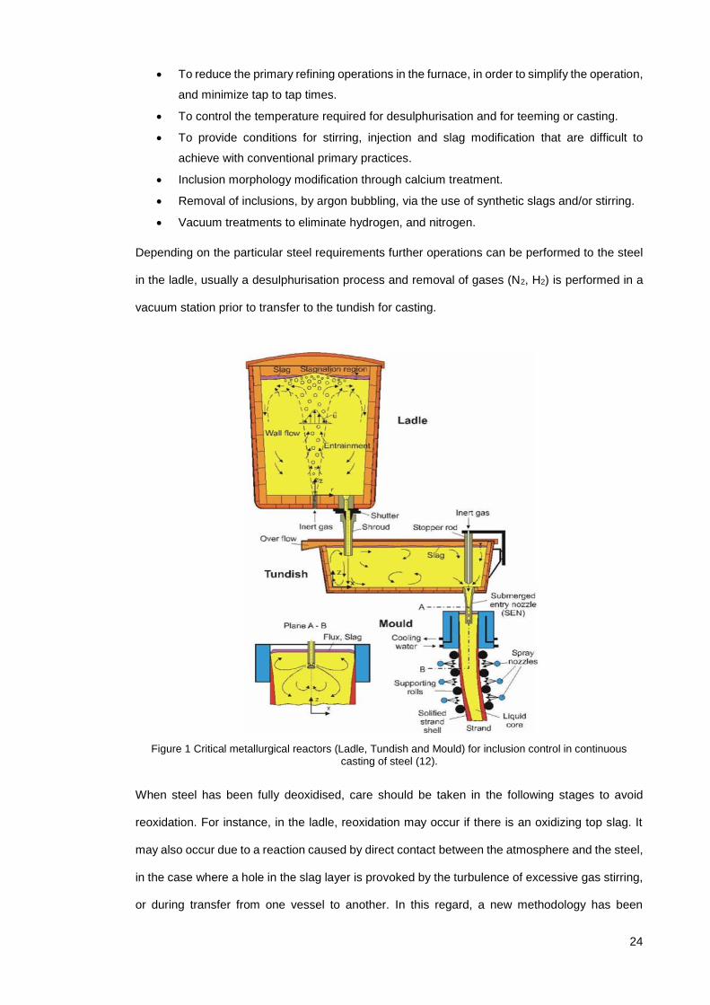
vacuum station prior to transfer to the tundish for casting.
Figure 1 Critical metallurgical reactors (Ladle, Tundish and Mould) for inclusion control in continuous casting of steel (12).
When steel has been fully deoxidised, care should be taken in the following stages to avoid
reoxidation. For instance, in the ladle, reoxidation may occur if there is an oxidizing top slag. It
may also occur due to a reaction caused by direct contact between the atmosphere and the steel,
in the case where a hole in the slag layer is provoked by the turbulence of excessive gas stirring,
or during transfer from one vessel to another. In this regard, a new methodology has been

25
established for tracking reoxidation in the tundish (13). Refractories and some alloying additions
may also contribute oxygen in the form of small but varying amounts of oxides.
Figure 2 Phenomena occurring in steel continuous casting (14).
After performing the operations of secondary steelmaking, the refined steel is then transferred
into the continuous casting machine in order to cast slabs or blooms. During casting, many
different interactions between steel and inclusions can occur as illustrated in Figure 2. Reactions
between the casting powder and the liquid steel may happen(15), and entrapment of casting
powder can occur. Submerged entry nozzle (SEN) design and fluid flow, electromagnetic stirring
and the use of a vertical or curved caster are some of the main phenomena having an impact on
the final inclusion content of the steel.
2.2 What are inclusions?
Non-Metallic Inclusions are chemical compounds consisting of a combination of a metallic
element (Fe, Mn, Si, Al, Ca, etc.) and a non-metallic one (O, S, N, C, etc.). The most common
inclusions include oxides, sulphides, oxy-sulphides, phosphates, nitrides, carbides and carbo-
nitrides. Depending on their nature and cooling conditions during the solidification stage they can
present a crystalline or a glassy state. NMI form phases different to the steel although some

26
represent a higher mismatch than others depending on their crystalline structure and atomic sizes
(16). Inclusions containing more than one compound are called complex inclusions (spinels, oxy-
sulphides, carbo-nitrides).
2.3 Origin of inclusions
Inclusions are inevitable by products of the refining treatment in the production of steel, and they
can be classified in terms of their origin, composition and size, as follows:
2.3.1 Origin
In terms of origin they can be endogenous inclusions, arising from natural internal processes, or
exogenous inclusions, arising from foreign material or external sources. Indigenous inclusions
can be formed in the melt as a result of the addition of the deoxidants which react with the
remaining dissolved oxygen or as a result of sulphide precipitation (17). The formation of these
inclusions occurs due to the limited solid solubility for oxygen and sulphur in the solidified steel
product. The composition and quantity of the indigenous inclusions can be largely controlled.
Controlling inclusions during these processes is a challenging task, requiring knowledge and
practice in order to be perfected. Exogenous inclusions originate from external sources such as
refractories, or the reoxidation of steel. Exogenous inclusions generally have greater dimensions,
are irregularly distributed and therefore can have a more detrimental effect. Inclusions of this type
are primarily detected by ultrasonic inspection.
2.3.2 Composition
Regarding their composition they can be classified according to their reaction of formation, and
in this case they can be considered as follows:
Oxides, which are formed as a result of deoxidation reactions (Al2O3, CaO, SiO2 etc), nitrides
(TiN, NiN, AlN, etc) and sulphides (eg. MnS, FeS). These are formed as a result of precipitation.
Precipitation is a thermodynamic condition where one phase becomes unstable and tends to
decompose to other phases of differing compositions. This condition of instability can be caused
by a change of pressure, temperature or composition in the thermodynamic system. In the case
of steels precipitation usually occurs during cooling, as temperature drops and the steel solidifies,
fractions of solid phase with a different composition from the liquid with which it is in contact are

27
created. The result of precipitation is the generation of an additional crystalline phase distributed
throughout the unstable matrix. This liquid is undercooled (i.e. the temperature drops below the
freezing point without it becoming solid) due to the accumulation of solute and heat ahead of the
interface front. The interface then becomes unstable and dendritic solidification occurs. The rate
of nucleation of particles by precipitation depends upon the degree of supersaturation of the
excess component (18). In steel there are two types of segregation: micro and macro segregation,
characterised by the extent to which each is dispersed along the material. Micro segregation is
widely discussed for both hypo-eutectoid (below 0.77% C) and hyper-eutectoid (above 0.77% C)
steels in a paper by J.D. Verhoeven (19) in which the author cites the description of pre-
segregation and trans-segregation from Kirkaldy et al.(20) The former relates to the
microsegregation that occurred in the dendritic solidification process plus any reduction in the
amplitude of this dendritic microsegregation during the cooldown to the start of ferrite precipitation.
Transegregation refers to any segregation that occurs during the solid state transformation from
austenite to ferrite + pearlite. For a more detailed description of solidification and segregation and
their effect on banding the reader may be refered to the 2003 Houwe Memorial Lecture publication
by G. Krauss (21) in which also the effect segregation on banding and mechanical properties is
discussed.
Complex inclusions, can be formed by a mixture of deoxidation and precipitation reactions,
examples of these include: Spinels, Oxy-sulphides, Carbo-nitrides.
2.3.3 Size
In terms of size inclusions can be classified as micro and macro inclusions. The threshold value
that has been employed to distinguish between micro and macro inclusions is generally assumed
to be 100 micrometres. However, more recently with the advancement of steelmaking procedures
to control the sizes of inclusions, another way to refer to micro inclusions has been proposed (22)
namely, the diameter sizes below their floatability limit which is in the dozens of micrometres for
modern steel processes(23). Micro inclusions are the most abundant due to their small size and
tend to be more uniformly distributed in the steel, and are therefore seen to be less harmful. Macro
inclusions due to their larger size are responsible for the failure initiation in final components or
defects on semi-finished products.

28
2.3.4 Deoxidation
Deoxidation is the removal of oxygen from the melt. There is a need to reduce the oxygen content
from the steel because the solubility in liquid steel (0.16%) is higher than that of solid steel
(0.003%) and this can cause defects such as porosity and pinhole formation during solidification.
There are several sources of oxygen in the ladle including the atmosphere, the top slag and any
refractory lining. The deoxidation procedure requires the addition of elements with a high affinity
for oxygen in order to form oxides which are either gaseous or can readily be floated to the top of
the ladle or to the slag where they can be removed. In Figure 3 the reduction of oxygen at different
stages of the production process is illustrated.
Figure 3 Oxygen content reduction at various stages of the steel production process(24).
The effect of different deoxidisers is illustrated in Figure 4. In terms of their economic availability
and performance, the most widely used deoxidisers are Mn, Si and Al.

29
Figure 4 Deoxidation performance of the most common deoxidisers (25).
The hashed areas in the above diagram are present to distinguish the effect of different Si
containing deoxidants.
2.3.5 Deoxidation with aluminium
Aluminium is a strong deoxidiser due to its high affinity for oxygen. The addition of aluminium
rapidly decreases the dissolved oxygen content to a few parts per million (ppm). The total oxygen
decreases more slowly as the formed alumina inclusions are separated as shown in Figure 5.
Figure 5 Dissolved and total oxygen content in ladle processing (26).

30
When the steel solidifies, the solubility of oxygen approaches zero. The remaining oxygen in the
melt will end up as oxide inclusions, therefore the total oxygen content can be used as an indicator
of the inclusion amount in the solidified steel. Deoxidation with Al produces solid particles of Al2O3,
and these particles agglomerate in irregular shapes called ‘clusters’. Alumina inclusions easily
form three dimensional clusters via collision and aggregation due to their high interfacial energy.
Alumina clusters are undesirable because they cause nozzle blocking during casting.
2.3.6 Deoxidation with silicon
Silicon is a weaker deoxidation element when compared to aluminium, but it still has the potential
to lower the oxygen content up to 50 ppm. But it offers other benefits compared to aluminium. It
forms liquid inclusions at steelmaking temperatures and hence improves the castability by
reducing the risk of nozzle clogging. In Figure 6, the different phase fields of some silicate systems
over different liquidus temperatures are shown, the regions where the inclusions are liquid at
steelmaking temperatures can be appreciated. Aiming to obtain these types of inclusions is
especially beneficial for wire drawing steel and spring grades (27–29). Deoxidation with Si also
has the benefit that is less expensive compared to other widely used deoxidants like Al or Ti. In
the solid state, silicate inclusions are deformable over a certain range of temperatures until they
crystallise and become harder and not deformable. Faraji et al. studied the effect of
thermomechanical processing on inclusions of a steel containing a mixture of complex inclusions,
consisting of silicates, sulphides and oxides. They have reported changes in the distribution of
inclusions in different areas of the hot deformed material. In addition they found that the thermal
cycle alone altered the chemical composition of inclusions in particular SiO2. (30)

31
Figure 6 Phase relations at liquidus temperatures of the system MnO-Al2O3-SiO2.
2.3.7 Combined deoxidation using Si-Al
Turkdogan (31) discusses how a small addition of Al (about 35 kg for a 220 to 240 t heat)
combined with a Si/Mn deoxidation can produce low oxygen levels in the steel. In Figure 7, the
top solid line indicates the deoxidation potential of Si/Mn with low Si, the second solid line shows
how the deoxidation of Si/Mn with low Si and Al has an increased potential to deoxidise the steel,
the third and fourth lines show the potential of deoxidation with a higher Si content. The effect of
a higher Si content has not only been reported to be beneficial to deoxidation but more recently,
Debdutta et al. have studied the beneficial effects on desulphurisation. In their paper they tested
the idea that Si suppresses the reduction of SiO2 at the slag/metal interface (which can consume
Al) with thermodynamic model calculations and they found that Si indeed affects the kinetics and
the equilibrium of desulphurisation (32). In a second publication, they contrasted their model
results with experimental results obtained at an industrial scale. In this second paper they found
that incorporating Si early into the ladle desulphurisation process leads to considerable savings
in Al consumption (33). Kang et al. utilised modern thermodynamic computation which take into
account the relationship between liquid steel, slag and inclusions, to predict the composition of
inclusion chemistries based on MnO/SiO2 ratio and Al203 content(34). Their results were verified
with experimental results of plant casts and results from other reseachers (35) to produce low
liquidus temperature and soft primary inclusion phases, which would be beneficial not only in the
liquid state but also during the rolling and plastic deformation stage.

32
Figure 7 Deoxidation equilibria of Si/Mn compared to Si/Mn/Al for two levels of Si content (36).
More recently, Holappa et al. have reported the beneficial effects of an intensified Si deoxidation
and more specifically how slag modifications aid in the process of inclusion modification (29,37–
39), because the inclusion composition gradually changes towards the top slag composition. The
extent of the influence of the top slag chemistry depends on the time of the refining operation.
2.4 Behaviour of inclusions
2.4.1 Behaviour in the liquid state
The whole process of inclusion removal in the liquid state consists of a “nucleation-growth-
removal” cycle. The formation of inclusions can be divided in different stages depending on
phenomena that occur at each one of them. Nucleation occurs as a result of supersaturation of
the liquid steel with the solutes due to a change in temperature or chemical composition of the
system. The growth of inclusions continues until there is no supersaturation or chemical
equilibrium is achieved. The motion of liquid steel due to thermal convection or magnetic stirring
forces cause the coalescence or agglomeration of (liquid or solid respectively) inclusions. In
Figure 8 the processes, phenomena and evolution mechanisms of inclusions at different stages
of the manufacturing of steel are described in more detail.

33
Figure 8 Inclusion evolution mechanisms in liquid steel (40).
Inclusions with higher surface energy, tend to merge more easily than inclusions with lower
surface energy. The larger the inclusions becomes the easier it is to float them to the slag where
they are absorbed, but this removal process depends on the particle radius, The particle radius
and estimated times of nucleation and growth mechanisms of inclusions are illustrated in Figure
9.
Figure 9 Stages and times for inclusion nucleation and growth.(41)
From the schematic diagram illustrated in Figure 10, certain types of inclusion can be
distinguished: Globular, Platelet shape, Dendrite shaped and polyhedral inclusions. In terms of
their shape the most desirable is the globular shape because of their isotropic nature with regard
to their effect on the mechanical properties. Platelet shaped or thin films are located at grain

34
boundaries due to the eutectic transformation during solidification. These are the most harmful to
mechanical properties because they weaken the bonds at grain boundaries. Dendrite shaped,
are cause by an excess of amount of aluminium, these inclusions have high melting point and
can cause clogging in liquid stage and ins solidified steel the sharp edges and corners of the
dendrite may cause concentration of internal stresses and negatively impact the mechanical
properties. The Polyhedral inclusions have a lower effect on mechanical properties than dendrite
or platelet shaped due to their more globular shape. The morphology of dendrite shaped
inclusions can be modified to polyhedral shape by small addition of rare earth (Ce,La) or alkaline
earth elements (Ca, Mg). The evolution of an inclusion, from a small nucleus, to a large dendrite
and a faceted crystal is shown in Figure 10.
Figure 10 Effect of oxygen and deoxidant activities on inclusion morphology (42).
There have been different studies to control the precipitation of inclusions during solidification in
order to obtain cleaner steels and to effectively produce fine particles in steel (38,43–45).
2.4.2 Behaviour in the solid state
To understand better the behaviour of inclusions, it is necessary to understand the transition from
the liquid to solid state for both the steel matrix and the inclusions (43,46). The physical properties
of the surrounding matrix and the inclusion at solidification temperature are of importance,
because they can present different scenarios. If the inclusion is liquid (i.e with a lower melting
point) at steel solidification temperatures a compressive residual stress system will develop
ensuring coherency between the inclusion and the matrix. On the other hand, if the inclusion is
solid when the steel is solidifying, the stress development will depend on the different thermal

35
expansion coefficients of both species. When an inclusion contracts to a lesser extent than the
matrix a compressive residual stress develops within the inclusion and a resultant tensile stress
develops in the matrix around the inclusion. On the contrary, if the inclusion contracts faster than
the matrix then tensile residual stresses will be generated in the inclusion and decohesion of it
and the matrix will occur in the form of a void (16).
Non-metallic inclusions constitute a very small part of the solidified steel and are usually finely
dispersed (47). They are detrimental in the way that they break the homogeneity of the structure.
The following figure presented by Kitamura (48) , illustrates the various areas of research on
inclusions, investigated at different stages of production, highlighting the importance of the new
field of study focusing on the later stages of the production route.
Figure 11 Various research fields of non-metallic inclusions in steel (48).
The deformation behaviour of inclusions during the hot working of steel is of great importance for
the properties of the final product. Both the steel matrix and the inclusions are usually multiphase
structures, but for the sake of comparison, steel may be regarded as a homogenous phase
because the structures of the inclusion are coarser when compared to steel microstructures.

36
Figure 12 Stress raising properties of inclusions based on their mean expansion coefficient (16).
The plasticity of inclusions compared to the plasticity of the steel at different temperatures has
been studied by several authors. Scheil and Schnell developed a simple method to compare the
deformability of inclusions with the deformability of steels. Malkiewicz and Rudnik (49) defined an
index of deformability for the inclusions and studied the bond strength between the matrix and the
inclusion. Brooksbank and Andrews have shown that internal stresses may generate due to
inclusion and matrix thermal expansion differences. Based on these coefficients Figure 12, shows
the types of inclusions that are more detrimental to fatigue properties (16).
Segal and Charles studied the influence of particle size on deformation of inclusions in the steel
and they have found that larger inclusions are more readily deformed than smaller ones (50).
Figure 13, obtained from a review by Birat (22), shows a schematic diagram of the effect of
deformation on different types of inclusions originally published by Hilty et al. (51) but it includes
at the top a compositional ternary diagram of the CaO-Al2O3-SiO2 system, indicating the
compositional region of inclusions that exhibit those changes in morphology illustrated in the
bottom part.

37
Figure 13 Effect of hot plastic deformation on inclusions (22,51).
Baker et al, proposed that the effect of the steel matrix flowing over and around the inclusions
generated the deformation of the inclusions and that the degree of deformation decreased with
elongation of the inclusions as a result of the friction at the interface in the direction of rolling (52).
In line with his observations if an inclusion has a strong interfacial bond, the inclusion will lengthen
and remain unbroken during hot working. On the other hand, if an inclusion has a weak interfacial
bond it will not interact with the flow of steel and discontinuities could be produced, as can be
seen in Figure 13.
From this point of view inclusions may be categorised as:
- inherently plastic inclusions (such as MnS)
- non-crystalline glassy inclusions which behave rigidly but become plastic at some characteristic
temperature (such as some glassy silicates)
- crystalline ionic solids (such as calcium aluminates, aluminate oxides and some crystalline
silicates) which show no plasticity and behave in a brittle manner.

38
2.5 Effect of inclusions on mechanical properties
The effect of inclusions on the mechanical properties of metals has long been studied. But the
first study of the effect of inclusions on mechanical properties and which related those with
variables from the melting practice was by Monnot et al (53). Inclusions can be tailored from the
steelmaking process for as cast products to improve mechanical properties (54). Also by knowing
the required performance of wrought products, the inclusions of a certain grade of steel can be
“engineered”. In order to properly address the improvement of mechanical properties by means
of inclusion engineering, it is important to have knowledge of phenomena and behaviour of
inclusions along the entire processing route, from the liquid stage through to the post casting
operations and their effects in wrought products (55). In 2009 the European Commission
published a research review comprising studies carried out at 4 major steel producers, the aim
was the optimisation and evaluation of different secondary metallurgy routes to achieve high-
quality strip steel by controlling non-metallic inclusions, where for the production of bulk materials
it is a matter of reproducibility, whereas for special steels is individually tailored (56). Therefore is
is important to understand the effects of the route on inclusions populations and the effect that
inclusions have on mechanical properties. In this particular research review, the advanced
implementation of automated inclusion analysis as a tool for rapid characterisation of inclusion
engineering for different steel grades and applications is highlighted.
More recent studies on the effect of inclusions on the mechanical properties have been made by
Kaushik et al. on the critical measurements in modern steelmaking to assess the influence of
process conditions on product properties of carbon aluminium killed steels, medium carbon
aluminium killed steels, advanced high strength steels and free machining steels (57) all these
taking into account the stringent requirements of mechanical properties for automotive
applications, which include low inclusion content and calcium modification to ensure higher
formability and improved mechanical performance of automotive parts.
The requirements for cleanliness with respect to Non-metallic inclusions vary from product to
product. There can be no universal definition of cleanness with respect to inclusions. The
requirements must be considered with respect to the demands of the specific application that the

39
steel will be used for and also for many other aspects like their location, shape and distribution in
the steel component.
2.5.1 Effect on Tensile strength
The tensile strength of steel can be affected by the final volume fraction of inclusions, and also
the morphology and orientation of inclusions with respect to the direction of loading is of
importance due to the fact that certain inclusions levels affect the ductility of the material (8). In
the case of smaller cross-sectional sections, the effect of inclusions is greater due to the role of
inclusion sizes acting as nucleation sites of micro voids either by decohesion with the matrix or
by fracture of the inclusion, which negatively affect material ductility. The inclusion volume fraction
levels in current steelmaking practices have been significantly reduced, to the point that their
effect on the tensile strength is practically negligible in standard testing sizes. Tervo el al. have
investigated steels with various impurity levels to determine the tolerance levels to inclusions in
ultrahigh strength steels. They found that while elongated MnS impaired ductility and bendability,
however they did not have any notable effect on the strength (58). This is consistent with the
observations pointed out by Murakami in (59).
2.5.2 Effect on Toughness
Fracture toughness is the property of a material to resist the propagation of a crack, and is a
crucial property employed in the design of many engineering components. Most NMI are
considered as stress raisers (9) in the solidified structure and can cause failure by means of
fracture. The distribution of void nucleating particles is considered as involving two size scales;
larger inclusions that nucleate voids at relatively small strains and smaller particles that nucleate
voids at much larger strains. The nucleation of a small crack usually happens at larger sizes of
inclusions and the propagation of the crack happens through linkage of micro voids created at
smaller inclusions (17). The size of the void nucleating particles is typically between 0.1 μm and
100 μm, with volume fractions of no more than a few percent although this small percentages
play a major role in the crack growth resistance of structural alloys.
The fracture modes in steels consists of three main different mechanisms:

40
a) Cleavage is a trans-granular fracture mode in which fracture propagates through
crystallographic planes inside grains and the fracture surface appears as a series of flat
planes. In this fracture mode, the main way to improve toughness is by controlling the
microstructural unit that produces the propagation planes, which in ferritic steels it is the
ferrite gain size and in pearlite and bainite it is the prior austenite grain size.
b) Low-temperature intergranular fracture, is a mode of fracture that occurs along grain
boundaries due to micro-segregation or precipitation of second phases along grain
boundaries. In low alloy steels manganese sulphide precipitation is often found as a result
of high temperature treatments usually above recrystallization temperature of steels
(around 1250ºC). These particles act as void nucleation sites for intergranular dimpled
fracture.
c) Dimple rupture is a type of fracture where voids nucleate at inclusions and fracture occurs
when these voids grow and coalesce under straining conditions (often referred as “void
coalescence”). MnS are known to decohese from the matrix even before straining, while
most oxide inclusions decohese at small strains this is related to the cohesion bonding by
thermal expansion coefficient presented in Figure 12. The resulting surface is a relatively
equiaxed dimple fracture surface.
The first two modes generally occur below the ductile to brittle transition temperature, whereas
the third occurs above the transition temperature.
Figure 14 Nucleation of voids at small strains (a), large strains (b) and fracture of steel (c) from (60) .

41
Ductile and brittle fracture are the two main types of failure in low alloy steels. Ductile fracture
occurs when the material is exposed to high temperatures while brittle fracture occurs usually at
low temperatures. Figure 15 shows the difference between static and dynamic fracture mode
curves, characterised by the differences in the strain rate applied. There are two tests to evaluate
static and dynamic fracture modes. The Charpy V notch test is employed to assess dynamic
fracture and the Crack Tip Opening Displacement (CTOD) test to assess quasi-static fracture
toughness. CTOD testing is applied to materials that can present some plastic deformation before
failure of a component. The measurement of this displacement is very important for engineering
purposes and the importance of this test relies on the accurate measurement of this parameter.
Figure 15 Schematic showing the relationship between static and dynamic fracture toughness.
Another important factor that affects toughness is the anisotropy in fracture behavior of hot rolled
products. This is associated with the orientation of elongated inclusions or inclusion clusters. The
highest energy absorbed occurs in specimens where the crack plane is normal to the elongated
inclusions, and the crack may be deflected along the interfaces of the inclusions. Lower energies
are absorbed when a crack propagates along the interfaces of the elongated inclusions. In Figure
16 two steels are compared, to the left a conventional rolled steel can be seen, the anisotropy is
greater due to the elongation of inclusions parallel to the rolling direction. If the material was
loaded in this direction (red arrows) the strength would be higher than if the material was loaded
in the transverse direction (yellow arrows). In the steel on the right, the anisotropy is less due to
better inclusion control which produces fewer, isolated and smaller inclusions. If the material was

42
loaded in this case there would not be much difference between the most and least favorable
loading conditions.
Figure 16 Anisotropy of a conventional steel and a steel with inclusion control (61).
MnS inclusions are a major cause of fracture anisotropy. As can be seen in Figure 17 transverse
and through thickness orientations are the most affected by inclusion anisotropy. This can be
improved by modifying sulphur containing inclusions to form hard inclusions that remain spherical
during working or if the added cost is justified, the sulphur content can be reduced by further
desulfurization or vacuum stirring.
Figure 17 Effect of sulphur content and specimen orientation on the upper shelf impact energy of rolled carbon steels (62).
Oxide inclusions are associated with ductile fracture which is characterised by linking of dimples.
Void formation around oxide inclusions plays a dominant role in shear fracture. With increasing
strength levels of the steel, the effect of inclusions especially at low temperatures is highly noticed.

43
As noted from the work of Tervo H. et al. (63) low inclusion levels are enough to guarantee
acceptable ductility and toughness criteria in ultra-high strength steels. However, if in the future
the demand to develop these properties, the need to avoid elongated MnS and minimize the
number of coarse TiN should be pursued, as these were the most deteriorating inclusion types
for ductility of relatively low impurity levels in ultrahigh strength steels.
2.5.3 Effect on Fatigue
When the failure of a component has been due to a repeated number of load applications (cycles)
below the yield stress of the material it is considered a fatigue failure. In this regard, there are
very important aspects in which inclusions play a major role. One of the first studies to establish
a relationship between hardness and fatigue limit was the one carried out by Garwood et al.(64).
Since then, the relevance that non-metallic inclusions have with regard especially to high strength
steels has been studied by several authors (5,53,65,66). Most of these studies have pointed out
several factors that relate to stress concentration, namely inclusion shape, adhesion of inclusion
to the matrix, elastic constants of inclusions and matrix and inclusion size.
Murakami and Endo (59,67,68) developed the area model for evaluating the effect of small
defects (holes) in metallic materials. In their study, they demonstrated that the problem of a small
defect is essentially a small crack problem and therefore this problem should be solved with stress
intensity factors instead of stress concentration. They found that there is a strong correlation of
the maximum stress intensity factor with the projected area of the defect in a plane perpendicular
to the maximum principal stress. Non-metallic inclusions in fact can be treated as mechanically
equivalent to small defects having the same value of the projected area (square root of crack
area, √area) as illustrated in Figure 18.
Figure 18 Mechanical equivalence of (a) crack emanating from the inclusion-matrix interface, (b) a crack emanating from a defect, (c) a narrow crack with the same projected area. (59)

44
It is not only those factors that influence the fatigue life of a component, but also the location of
the inclusion or defect inside the component. An inclusion of a certain size found close to the
surface has a greater impact on the fatigue life than an inclusion of the same size in a location
more distant to the surface. Murakami published quantitative equations for the prediction of the
fatigue strength of a material with a surface defect, near the surface and an internal defect.
Figure 19 Classification of inclusion by location (59).
a) Surface inclusion:
𝜎𝑤 =1.43(𝐻𝑣 + 120)
(√𝑎𝑟𝑒𝑎)1/6
b) Inclusion in touch with surface:
𝜎𝑤 =1.41(𝐻𝑣 + 120)
(√𝑎𝑟𝑒𝑎)1/6
c) Internal inclusions:
𝜎𝑤 =1.56(𝐻𝑣 + 120)
(√𝑎𝑟𝑒𝑎)1/6
where: 𝜎𝑤 = fatigue limit [in MPa], 𝐻𝑣 = Hardness Vickers [in kgf/mm2] and √𝑎𝑟𝑒𝑎 [in µm].
The relationship between the harmful effects of inclusions on fatigue life versus inclusion size is
presented in Figure 20.

45
Figure 20 Harmfulness index vs inclusion diameter (53).
This figure can help to illustrate that large globular inclusions are most harmful because of their
size, not of their shape. Also, that calcium sulphides, compared with oxides of an equal size are
less harmful. Finally, that titanium nitrides are the most harmful type of inclusions over an equal
size range compared to other oxides or sulphides.
2.5.4 Effect on Machinability
Machinability comprises a wide range of parameters, including chip formation, cutting tool wear,
surface properties of the machined work piece and environmental factors. Machining can be
mainly described as consisting of two processes, metal fracture and metal removal to produce a
certain shape or drilled holes at specific locations on the work piece.
Some oxide inclusions may have a positive effect on the process of chip formation (which is
dependent on the ability to create a fracture along the structure) but may have a negative effect
on the cutting tool wear that may overcome the initial positive effect on chip formation. MnS
inclusions also have a beneficial effect on chip formation, and the beneficial effect of high sulphur
content on free machining steels have long been reported, because manganese sulphide
inclusions don’t cause cutting tool wear to the same extent as oxides do. A thorough investigation
of the effect of different inclusion types on different steel grades for different applications has been
published in 2015 by Anmark et al. (69) In it they discuss that different steel grades have various
non-metallic inclusions with very different characteristics. Therefore, these characteristics should
be optimised for each group of steel grades in order to make improvements to the machinability
of steel without significantly producing a reduction in their mechanical properties.
46
2.6 Characterisation techniques
2.6.1 Introduction
Zhang and Thomas in reference (70), have reviewed nearly 30 methods of inclusion evaluation
and control. The same authors in reference (71), increased the review to include more recent
methods and established a classification for the characterisation of inclusions which is divided
into direct and indirect methods. The main distinction is based on accuracy, cost and turnaround
time. Some common direct methods include: optical microscope observation, automated image
analysis, sulphur print, scanning electron microscope, optical emission spectrometry with pulse
discrimination analysis OES-PDA, ultrasonic scanning testing, Mannesmann Inclusion Detection
by Analysis of Surfboards MIDAS, X-ray detection, and chemical dissolution. The indirect
methods consist of: total oxygen measurement, nitrogen pickup, slag composition measurements,
lining refractory observation (absorption or erosion), and final product tests.
Faraji et al.(72,73) published a review of the existing standards to classify inclusions based on
size, morphology and chemistry. In their work they analysed a high carbon steel deoxidised with
a mix of manganese-silicon, employing different characterisation techniques they found that most
of the inclusions were complex oxy-sulphides which were difficult to characterise with the existing
standards. They used the number density distribution technique to study the distributions of
particles in the area studied.
As it can be inferred, a single characterisation technique is not sufficient to provide all the
information about inclusions and their relationship with the processing route. Thus, a combination
of various techniques is often employed to obtain information to measure inclusions. Kaushik et
al. in 2012, reviewed a combination of faster and more reliable offline techniques with online
methods to facilitate refining and casting of clean steelmaking processes at ArcelorMittal (74).
Bartosiaki et al. in 2015, have reviewed the assessment via manual and automated SEM methods
and oxygen content of steel, with their own advantages and disadvantages. They have concluded
that by relating these techniques a comprehensive characterisation of micro inclusion populations
can be performed (75).The methods that have been employed in the present study are discussed
in the following sections.

47
2.6.2 Optical Microscopy
The most common oldest method to analyse inclusions involves Optical Microscopy observations.
This microscope uses light to illuminate the surface of a steel sample and lenses to magnify the
vision of the field of view under analysis on the sample surface. The Optical Microscopy technique
relies on the distinction of shape and contrast of inclusions for classification. This technique
assists in obtaining the total amount of inclusions in a specific area, but as inclusions are very
small, the magnification has to be high, and as a result usually smaller areas are surveyed. Other
variables that can be determined using this technique in a section of a steel sample are the
average inclusion size and some individual shape differences and distributions as demonstrated
in several studies (15,75–77).
2.6.2.1 Automated OM
Automated optical microscopy consists of an automated stage system that works with relevant
software to automatically acquire images of different fields of view within the sample surface. This
technique offers the advantage of analysing a greater area in a shorter time than manual optical
microscopy, but still relies on the grayscale colour of inclusions and morphology to classify
different inclusion types.
2.6.3 Scanning Electron Microscopy
Scanning Electron Microscopy (SEM) is a technique that can obtain information on the three-
dimensional morphology and the composition of inclusions in steel. By means of backscattered
diffraction of electrons it is relatively easy to locate inclusions via the differences in densities of
inclusions and the steel matrix. One of the main reasons why this technique is so popular is
because it offers the opportunity to perform a local chemical analysis (Energy Dispersive
Spectroscopy). The disadvantage of these approaches are that they are labor intensive and take
time, also that the SEM operator must manually adjust for imaging of the individual inclusions.
2.6.3.1 Automated SEM
Recent advances in two different fields - namely the automation method for classifying inclusions
in less than seconds and the sophistication of detectors for increased measurement accuracy
have allowed the development of automated SEM analysis (13,78). The development of

48
automated SEM systems has allowed increased response time to modify and control
manufacturing variables in steelmaking practices to produce cleaner steel for more suitable
applications (61,79,80). One of the main advantages of utilizing an automated method is the
possibility of obtaining data for all the inclusions scanned in a sample. Automated SEM allows
scanning of a larger area and records all the identifiable inclusions. Analysis time depends on
SEM characteristics, the extent of automation, analysis parameters, sample area assessed and
the cleanliness of the sample.
Figure 21 Detection techniques and resolution range versus inclusion frequency.
Figure 21 shows the detection limits of various techniques and the resolution in terms of inclusions
size. Automated electron inclusion analysis performed by an automated SEM system offers the
advantage of being able to analyse a wide range of inclusion sizes and a much larger number of
inclusions compared to other techniques.
2.6.4 Oxygen content
The total oxygen content of steel is a measurement that indicates how much oxygen is available
in the steel and this can be correlated to inclusion content. Total oxygen is the sum of the soluble
oxygen in liquid steel and oxygen present as oxide inclusions.(75) The total oxygen measurement
offers the advantage of rapidity and simplicity compared with other techniques. In Figure 22 the
record of total oxygen content of steel during the past 40 years is reported and the improvements
seem to have reached a steady level over the last 20 years which is related to thermodynamic
limits (39).

49
Figure 22 Oxygen content improvement in the last 40 years of a bearing steel producer (61).
The total oxygen content and dissolved oxygen content of steel at different stages of the
steelmaking process are reported in Figure 23.
Figure 23 Evolution of total and dissolved oxygen content at different stages of the steelmaking process (75).
Although total oxygen content is a quick and easy technique for evaluation of cleanliness during
production, it is only applied to oxide inclusions and does not provide the chemical composition
and morphology of inclusions. The main advantage of total oxygen measurement is the efficient
correlation with steelmaking processing data, because it is directly correlated to the micro-
inclusion population of the deoxidation practice (70,74,75) .
2.6.5 Ultrasonic Testing
The analysis of inclusions through ultrasonic testing has been employed to analyse larger
volumes of steel. The most common and studied technique to assess the inclusion content with

50
the use of Ultrasonic testing is the Mannesmann Inclusion Detection through Analysis of
Surfboards or MIDAS technique in which a piece of cast steel is rolled under certain parameters
and then analysed. The non-destructive nature of this technique, has fostered the development
of ultrasonic detection methods of defects down to micrometric sizes (81).
Figure 24 Detection limit in accordance with the mass of the material to be analysed using different methods including different ultrasound frequencies (23).
A more recently developed technique is a coupled computer tomography scanning system with
an ultrasonic probe for detection of inclusion in round shaped goods such as bearing or tubes
(61,82).
2.6.6 Extreme Value Statistical Analysis
This is a relatively novel technique to assess the distribution of large inclusions in steels. This
analytical method consist of measuring extremes and utilizing these to predict further extremes.
This methodology was first developed by Gumbel (83) when he used this approach to predict the
magnitude of river flooding that could be expected to occur in a certain number of years, based
on the maximum levels recorded for previous years. This approach has recently been applied to
predict the presence of a large non-metallic inclusion in a given area or volume of steel. There
have been several studies for the validity of Extreme Value Statistical Analysis applied to
inclusions (23,84–87). However the first to describe a recognised standard methodology for
assessing inclusions and other microstructural features was Hetzner in 2006 (88). He redacted

51
ASTM standard E2283 relying on the previous sampling procedure of ASTM E45 for assessing a
certain lot of steel (usually a heat of steel) (89).
The importance that has driven increased interest for this type of analysis compared to
conventional methods is: that it offers the possibility to discriminate between different lots of steel
with low inclusion contents (stemming from ultraclean steel practices) (84), and that a prediction
of a large inclusion in a given volume can be made, this is useful for the quality control of steels
and for improvement of the steelmaking processes for critical applications like components
subject to fatigue failure.
Anderson et al. contrasted the precision of two methods utilizing the statistics of extremes for the
estimation of the maximum size of inclusions in clean steels. They pointed out that the precision
of the estimation of the characteristic size of the maximum inclusion increases linearly with the
increase of the logarithm of volume of steel used for the extrapolation. Also that the characteristic
maximum size is poorly sensitive to the number of sample areas, but the width of the confidence
intervals decreases with the increase of the number of areas used for the measurement. They
also reported that the method of statistics of extremes has a narrower confidence interval for a
given number of samples compared to other methods (86).
Another advantage of Extreme Value Analysis is the higher accuracy that can be achieved with
automated detection methods which allow for an increased area of analysis without compromising
turnaround times. The fact that automated detection methods can be coupled with precise
chemical analyses in the Scanning Electron Microscope, increased the scope of analysis possible
with this technique, for example the prediction of sizes of different types of inclusions
(sulphides/oxides), the dispersion of carbides in tool steels and graphite nodules in ductile iron;
different areas that affect integrity of materials. Barbosa et al. made a quantitative study on the
differences of the classical student approach and the extreme values method. Their results show
significant differences between the inclusion populations found for different products and also
differences in the values obtained from the same sample with different methods. Their results
indicate that the classical student approach presented higher inclusions levels concerning the
area fraction and average size. They concluded that the extreme values method is the faster and
more reliable method.

52
The discussed reasons of a recognised standard methodology and advantages over more
conventional methods are the reasons why this method was chosen for analysis of inclusions in
the present study.
In the presented literature review, it has been highlighted that one of the critical variables that can
be modified to influence inclusion population is the deoxidation practice. Also that different
inclusion populations have different effects on the mechanical properties in as cast products
depending on the inclusion species formed and their distribution throughout the material.
Furthermore, it has been discussed that these different inclusions populations have different
effects on the mechanical properties depending on the processing that they have been subjected
to. A revision of the initial school of thought and its development up to present on the effect of
inclusions on relevant mechanical properties has been carried out for different industrial
applications. The different methods for characterisation of inclusions have also been reviewed
and their advantages and disadvantages have been presented. Based on this review, the present
work has been designed to characterise and evaluate the material performance from two
deoxidation practices, namely a conventional deoxidation practice (Al deoxidation) and a newly
proposed Si-Al deoxidation practice. The question that is being posed after this proposal is if the
Si-Al deoxidised steel is a viable option to be employed for steel components fabricated with
identical process route and variability, producing the same or improved rate of acceptance criteria
by customers for the current application.

53
Chapter 3 Experimental Procedure
3.1 Materials
3.1.1 Steel grade
The steel for this investigation is a common low alloy steel used for structural applications, the
European Structural Steel Standard that includes this grade is EN10025:2004 (BSEN S355 or
ASTM A572GR50) the nominal yield strength of this grade is 355 N/mm2 (MPa) and the tensile
strength is between 470-630 MPa, with the nominal chemical composition shown in the following
Table 1:
Table 1 Nominal composition of steel grade produced. (ASTM A694)
Spec. C Si Mn P S Ni Cr Mo V Nb Al N H2
Min 0.14 0.15 1.25 0.01 0.02
Max 0.18 0.35 1.4 0.025 0.02 0.1 0.12 0.1 0.12 0.02 0.045 0.015 0.0002
This steel was fabricated via the following route, Electric Arc Furnace (EAF), Ladle Metallurgy
Furnace (LMF), Vacuum Tank Degasser (VTD) and finally continuous casting.
3.1.2 Deoxidation Practices
Eight heats of steel were fabricated to assess two different deoxidation practices namely Al
deoxidation with calcium treatment (conventional) and a new method which principally employs
silicon with a small addition of aluminium for deoxidation and no calcium treatment. The
identification number of each heat, their respective deoxidation practice and the conditions in
which they were provided can be seen in Table 2:
Table 2 Heat identification number, Deoxidation practice and condition in which materials has been provided.
Heat ID Deoxidation practice Calcium treated Condition provided
1319 Al Killing Yes As cast & as deformed
1320 Al Killing Yes As cast & as deformed
1330 Al Killing Yes As deformed only
1332 Al Killing Yes As cast & as deformed

54
2455 Si-Al Killing No As deformed only
2456 Si-Al Killing No As cast & as deformed
2457 Si-Al Killing No As cast & as deformed
2458 Si-Al Killing No As cast & as deformed
The proposed Si-Al method utilises Si as the main deoxidant along with some slag modifications
to lower the oxygen content of the melt to its lowest (Si potential) and at the end of the process a
small amount of Al is added in order to meet specification requirements. In this proposed practice
the small addition of Al is projected to produce far less alumina inclusions and therefore reduces
the need to treat the steel with calcium. Another operative advantage is the improved castability
of the Si-Al practice, by reducing the risk of clogging. Several continuously cast strands of the
same heat were cast into 511.18 mm (20.13 inches) diameter round blooms of several meters in
length.
3.1.3 Forging and rolling
The blooms produced by the steel supplier were sent to FRISA for further sectioning into suitable
lengths to produce rings by forging and rolling as shown schematically in Figure 25 below:
Figure 25 Steps to produce a typical rolled ring: 1.-Upsetting, 2.-Piercing 3.-Rough rolling 4.-Precision rolling.
The standard procedure consists of an upsetting step followed by a rolling step with a forging ratio
of 3:1, the forging temperature used was 1280°C. The rings produced were subjected to a
normalising heat treatment in order to reduce residual stresses and increase ductility and
toughness, and were then cooled down in air from 900°C to ambient temperature, for
approximately 5-6 hours.

55
3.2 Sample selection
3.2.1 Introduction
Samples were taken in both the as cast condition and the as deformed condition. Samples in the
as cast condition were analysed to assess the inclusion distribution as a function of position in
the bloom, and also to assess the effect of deoxidation practice on inclusion population. The
samples were obtained from the sections closer to the middle of the cast bloom rather than at the
top or the bottom in order to avoid the contamination that can occur at the beginning or the end
of a casting sequence. Finally, samples were analysed in the as deformed condition in order to
quantify the effect of forging and rolling on the inclusion population.
3.2.2 As cast bloom – effect of location on inclusion population
Samples were taken from the as cast bloom - the positions selected for the analysis are shown
in Figure 26 below, namely at the core, mid-radius and close to the surface of the continuously
cast round bloom.
Figure 26 Samples taken from as cast round bloom.
In the first instance a detailed analysis of one slice of conventional (Al deoxidised) continuously
cast steel bar was characterised in two cross sectional directions (vertical and horizontal) with
manual optical microscopy. Then in a second analysis, one heat of each deoxidation condition
was characterised with SEM-AFA mainly to analyse chemical composition and compare accuracy
with results previously obtained using manual optical analysis. In a third analysis an automated
optical microscope was employed to characterise material from three different heats of each
deoxidation practice. The reason for this is because automated OM is faster and a more reliable

56
manner to obtain results than manual OM (a greater area of analysis and greater resolution and
contrast to identify defects is possible) also it represents a cheaper alternative to the SEM-AFA
analysis.
3.2.3 As cast bloom – effect of deoxidation practice on inclusion population
Samples were taken as shown below in Figure 27. For this analysis, the mid radius position of
three heats per deoxidation practice were analysed as illustrated in Figure 27.
Figure 27 As-cast samples obtained from mid-radius position of blooms from different heats
3.2.4 Effect of forging and rolling on inclusion population
Samples from four different heats of rolled material per each deoxidation practice were
characterised in order to examine the effect of processing and the final distribution of the
inclusions in the rings produced. The techniques employed for characterisation include optical
microscopy and SEM with automated systems.
3.3 Metallographic preparation of samples
The steel specimens were sectioned using a Buehler Isomet 5000 Precision Saw Machine. The
samples were cut using the set parameters for cutting steel with the aid of a coolant during the
process to avoid modification of the microstructure. After cutting, the samples were hot mounted
using a Struers SimpliMet 1000 Automatic Mounting Press. The mounting cycle employed
consisted of a load of 40KN and a curing heat of 180oC, with a preheating ramp of 3 minutes,

57
then 6 minutes of holding time and 2 minutes for cooling. The resin employed was Condumet,
which is a conductive resin for further characterisation and analysis in the SEM.
Once the samples were mounted, grinding and polishing steps followed using a Buehler EcoMet
250pro Automatic machine, capable of processing six samples simultaneously. Grinding was
carried out utilising a silicon carbide circular sheet of granulometric grades 240, 320, 400, 800
and 1200. The samples were then subject to a polishing stage consisting of 3 steps of using
diamond solution of 9, 6 and 1 µm respectively. After polishing the samples were washed with
water to remove any residues of polishing solution and then rinsed with ethanol solvent and dried
by air flow from a hair drier. For etching to reveal the microstructure, a solution of Nital between
0.5-5% was employed and the etching method was by submerging the steel sample for 10-15
seconds into a laboratory glass beaker containing the Nital solution and then clearing away any
solution by submerging it in another beaker containing water and finally following the drying
procedure with ethanol and the hair drier.
3.4 Inclusion Characterisation
3.4.1 Optical Microscopy
The optical microscope used was a Nikon Eclipse LV 150 for manual characterisation of
inclusions and a Clemex Vision PE with a motorised stage for automated analysis for Extreme
Value Statistics.
3.4.1.1 Manual Optical Microscopy
From the manual microscope, images were taken at 10x magnification surveying and an area of
1,057,163 µm2 per field of view, in total 5 images (or fields) were taken per sample as shown in
the following diagram:
Figure 28 Metallic sample mounted on a round polymer resin and the location of fields surveyed per sample with manual optical microscopy.

58
For this manual optical method, inclusions have been quantified employing ImageJ software
analysis [1] (Version 1.48v). The procedure to obtain data from the inclusions was the following:
Open the image to be analysed, configure the scale using the scale on the image to
calibrate the distance in pixels with the distance in µm,
Convert the image to 8 bit which will convert the image to a grayscale image,
Adjust the threshold to ensure inclusions are distinguishable from the matrix (as shown
in Figure 29), when adjusting the threshold for different pictures the same parameters
where used when possible for optimum resolution of the inclusions, and when the
resolution was significantly affected (i.e. images where taken on a different session, with
different microscope adjustments or conditions) an observed optimum was employed.
This certainly increases error or uncertainty of manually recorded values as opposed as
automated methods which automatically refocus at set image intervals or at every image
taken.
Run the “Analyse particles” function from the “Analysis” tab menu in Image J and finally
Export the results to a spreadsheet for further analysis.
Figure 29 Procedure for inclusion characterisation with manual optical microscope and Image J.
The total area analysed per sample by this method was 5,285,815 µm2 (5.29 mm2) and for each
heat at least 3 samples were analysed in the as cast and forged and rolled condition except for
the analysis of heat 1320 where a more detailed analysis was performed, analysing not only 3
but 5 positions instead as shown in Figure 35.
3.4.1.2 Automated Optical Microscopy
For the Clemex Vision PE microscope with motorised stage, images were taken at 50x
magnification to increase resolution and accuracy. Taking advantage of the motorised stage, 28
fields of view with an area of 3,417,051 µm2 were obtained. The total area analysed per sample
was 95,677,437 µm2 (95.68 mm2). For the as cast condition samples at 3 different positions per

59
heat were analysed and for the forged and rolled condition 1 sample per heat was analysed. Both
procedures employed were adapted from the set standards of ASTM E45 and ASTM E1245 even
though these test methods are employed to assess wrought steel (89). This means that they use
the distinction between shape and contrast for classification of the inclusion types. However, the
analyses carried out serve as an indicator for the total amount of inclusions, average size and
shape differences and distributions between the two conditions as reported in other studies
(15,90).
These traditional inclusion detection standards, do not adequately measure or screen steel quality
to predict the component life or reduce the risk of failure. That is why the use of extreme value
statistical approach becomes of importance.
3.4.2 Scanning Electron Microscope (SEM)
3.4.2.1 Manual SEM Analysis
The analysis of inclusions at higher resolution was carried out in a field emission gun Scanning
Electron Microscope equipped with Secondary Electron (SE), Back Scattered Electron (BSE) and
Energy Dispersive X-ray Spectroscopy (EDS) detectors. The following parameters were
employed for the analysis, 30 KeV, and a spot size of 3. In order to distinguish between inclusions
from voids or external artefacts, the back scattered electron imaging mode was employed. Once
inclusions were detected, the EDS technique was utilized for chemical composition identification
of inclusions. Although SEM identification of inclusions is a more accurate method of
characterising inclusions than optical methods, its operation by manually identifying the inclusions
is very time consuming. For this reason automated systems have been developed to characterise
inclusions of larger areas, in shorter times with sufficient accuracy.

60
Figure 30 SEM micrographs showing inclusions in an un-etched sample (left) and in an etched sample (right).
3.4.2.2 Automated SEM Analysis
An Automated Feature Analysis (AFA) has been performed using an SEM equipped with an
energy-dispersive spectrometer (EDS) detector. The automated system scans a specified area
of the sample and records every single inclusion larger than one micron. The location, size, area,
composition and classification of each inclusion are recorded and later employed to build a report
or to be exported to spreadsheets for further analysis (13,78,80).
The area of analysis with the AFA for the as cast samples was 51.47 mm2 and for the forged and
rolled samples the area of analysis was 13.90 mm2.
3.4.3 Ultrasonic Testing
Ultrasonic Testing (UT) is a non-destructive method usually employed to identify flaws and defects
such as cracking in the steel. The flaws are larger in size than most of the micro inclusions but
this technique can be used to help to spot macro inclusions which are greater in size and are
stochastic events. Ultrasonic Testing was carried out on the forged and rolled material (rings).
There are contact and non-contact ultrasound techniques, the one employed was contact
technique with a dual European transducer of 3.5x10 MHz in order to find macro inclusions
greater than 0.5 mm in length.
61
3.4.4 Extreme Values Statistical Analysis
The extreme value statistical analysis was carried out on the automated metallographic results
from both Optical and Scanning Electron Microscopes. The analysis was performed for the “as
cast” distribution and “as deformed” distributions.
The standard procedure for this analysis is outlined in ASTM E2283, but it has been adjusted
according to the areas analysed in this investigation for an equivalent comparison of deoxidation
practice for each condition.
A brief summary of the procedure is as follows:
1.-For each specimen, record the largest inclusions in different polishing planes and sort them in
ascending order.
2.-The 24 largest measurements are then used to estimate the values of the scale (δ) and
location (λ) of the extreme value distribution for that particular material.
3.-Then the largest inclusion “Lmax” expected to be in a constant reference area “Aref” is calculated,
and a graphical representation of the data is reported.
Using the methodology described, a comparison can be made to find the difference in sizes of
large non-metallic inclusions in two different batches of steel, in this case one deoxidised with Al
and another with Si-Al.
3.5 Mechanical Properties
Material from the rolled rings was extracted to obtain specimens for hardness, tensile, toughness
and crack tip opening displacement (CTOD) testing. The determination of the tensile properties
was carried out in accordance to ASTM E8, in the longitudinal direction. The determination of
fracture toughness properties were evaluated using Crack Tip Opening Displacement and Charpy
V Notch Impact tests. These tests were carried out at -40ºC because steel is more sensitive to
the effect of inclusions at lower temperatures and also because it is the most common
temperature employed in standards to qualify material for low temperature applications.

62
3.5.1 Hardness testing
Hardness testing was carried out on a ZHV30 low-load Vickers hardness testing machine. It was
fitted with a square based pyramidal diamond indenter that creates a square indent when it is
loaded against a flat surface on the specimen. The load employed was 1kgF and the dwell time
was 15 seconds. After the test has been performed, the distance between the corners of the
indentation was measured, then an average of both diagonals is calculated, and the Vickers
hardness (HV) calculated using the following equation:
𝐻𝑉 =𝐹
𝐴 ≈
1.8544 ∙ 𝐹
𝑑2
where F is the force applied to the diamond indenter in kilograms-force (kgF) and d is the mean
diagonal length in mm.
An image of an indentation being measured can be observed in Figure 31.
Figure 31 Measurement of the diagonal of an indentation seen through the magnifying lens of the hardness testing machine.
Four indents were made per specimen and they were spaced at distances of more than 2.5d from
each other to avoid any influence from plastic deformation created around a previous indent
according to ASTM standard E384.
3.5.2 Tensile Testing
Tensile testing was carried out at FRISA laboratories, testing was performed at room temperature
using a 300 kN Tinius Olsen hydraulic universal testing machine. Round tension specimens were
machined with the following dimensions: gauge length (G) of 50 mm, diameter (D) of 12.5 mm,
radius of 10 mm and length of reduced section (A) of 56 mm. Figure 32, shows the orientation
and extraction zone of tensile specimen from the forged ring.

63
Figure 32 Representation of the direction of evaluation of the tensile (left) and SENB toughness (right) specimens.
3.5.3 Impact testing
Impact testing was carried out at FRISA laboratories on a universal pendulum impact testing
machine model IT406 Tinius Olsen, equipped with a low temperature chamber cooled by
propylene glycol and dry ice to maintain the required temperature for testing. The specimens were
machined according to following dimensions, length (L) of 55 mm, width (W) of 10 mm, thickness
(T) of 10 mm, notch radius of 0.25 mm and notch angle of 45°. The notch was orientated along
the transverse rolling direction of the forged and rolled ring. The values reported are the averages
of three tests as stated in standard ASTM E23. The extraction of specimens is shown in Figure
33:
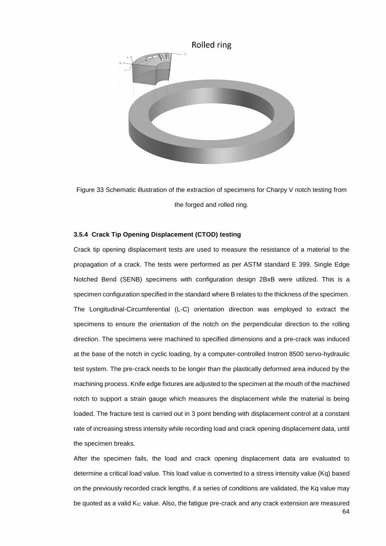
64
Figure 33 Schematic illustration of the extraction of specimens for Charpy V notch testing from
the forged and rolled ring.
3.5.4 Crack Tip Opening Displacement (CTOD) testing
Crack tip opening displacement tests are used to measure the resistance of a material to the
propagation of a crack. The tests were performed as per ASTM standard E 399. Single Edge
Notched Bend (SENB) specimens with configuration design 2BxB were utilized. This is a
specimen configuration specified in the standard where B relates to the thickness of the specimen.
The Longitudinal-Circumferential (L-C) orientation direction was employed to extract the
specimens to ensure the orientation of the notch on the perpendicular direction to the rolling
direction. The specimens were machined to specified dimensions and a pre-crack was induced
at the base of the notch in cyclic loading, by a computer-controlled Instron 8500 servo-hydraulic
test system. The pre-crack needs to be longer than the plastically deformed area induced by the
machining process. Knife edge fixtures are adjusted to the specimen at the mouth of the machined
notch to support a strain gauge which measures the displacement while the material is being
loaded. The fracture test is carried out in 3 point bending with displacement control at a constant
rate of increasing stress intensity while recording load and crack opening displacement data, until
the specimen breaks.
After the specimen fails, the load and crack opening displacement data are evaluated to
determine a critical load value. This load value is converted to a stress intensity value (Kq) based
on the previously recorded crack lengths, if a series of conditions are validated, the Kq value may
be quoted as a valid KIC value. Also, the fatigue pre-crack and any crack extension are measured

65
accurately at intervals along the crack front and then recorded as can be seen in the reports
attached in the Appendix E.
The tests were carried out at a temperature of -40ºC. Conditional fracture toughness (Kq) values
were calculated from the load–crack opening displacement data. Figure 34 shows a specimen
inside the cooling chamber after a CTOD test was concluded.
Figure 34 SENB specimen inside the cooling chamber after CTOD testing has been performed.

66
Chapter 4 Effect of as cast bloom location on inclusion
population
4.1 Introduction
In this section the results of three analyses carried out to determine the distribution of inclusions
are presented. The first one employed manual Optical Microscopy to characterise a cross-
sectional slice of a bloom produced by the conventional Al deoxidation practice. The second and
third parts consist of results obtained from automated Optical Microscopy and SEM-AFA results
at three different positions (core, mid radius and surface) of each deoxidation practice as
illustrated in the experimental procedure section in Figure 26.
4.2 Detailed analysis of Al killed sample (Heat 1320)
There are many factors influencing the distribution of inclusions in as cast products. In continuous
casting, electromagnetic stirring, or the use of a vertical or curved caster can have an effect on
the distribution of inclusions. Therefore a cross-sectional slice of a continuous cast bar of the
conventional Al practice was analysed. The piece was cut along a vertical and a horizontal lines
sectioning the piece into four quadrants A, B, C and D as shown in Figure 35. At the edge of each
quadrant five samples were extracted from the core to the surface of the bloom and have been
identified as 0, 1, 2, 3 and 4, with the position 0 corresponding to the core and position 4 to the
surface.
Figure 35 Location of samples in each of the four quadrants, the dotted lines indicate the cutting lines.

67
4.2.1 Optical Microscopy Results
4.2.1.1 Number descriptor
In Figure 36, the average number of inclusions are presented, there is a sinusoidal shape
tendency from the core towards the surface with a minimum valley at position 1 and a maximum
peak at position 3.
Figure 36 Average number of inclusions at different depths of the bloom.
The same parameter for each of the quadrants is shown in Figure 37. The positions A and C
corresponding to the vertical cutting line in Figure 35, present a higher number of inclusions than
the other two positions B and D corresponding to the horizontal dotted cutting lines for the
sectioning of the quadrants, shown in Figure 35.
Figure 37 Count of inclusions at each of the quadrants surveyed.
4.2.1.2 Area descriptor
In Figure 38, the total area of inclusions found at different depths of the bloom are presented. It
can be seen that the total area of inclusions is the largest at position 3 and smallest at position 1.
Again there is a sinusoidal tendency shown in regard to total area of inclusions.

68
Figure 38 Total area of inclusions at different depths of the bloom.
The total area of inclusions per quadrant analysed are shown in Figure 39. Piece B presented the
largest area followed by A, C and D. Interesting to note that B and D correspond to opposite parts
of the horizontal cutting line and also that A and C correspond to the vertical line(Figure 35) with
a fairly similar area content.
Figure 39 Total area of inclusions at each of the quadrants surveyed.
4.2.1.3 Size descriptor
The results of the average inclusion size are presented in Figure 40. Position 0 at the core of the
bloom has the highest average size of inclusion measured, which is consistent with the previous
results of having a relatively large area and a small number at that same position. The average
size seems to decrease from the core towards the surface with the exception of position 1. The
smallest average size is at the surface position (number 4) which exhibited a relatively high
number of inclusions with an average area of inclusions compared to other positions.

69
Figure 40 Average sizes of inclusions at different depths of the bloom.
Figure 41 shows the average size of inclusion at each of the quadrants surveyed. As it can be
seen position B and D have a larger size than A and D, with B having a slightly larger average
size than quadrant D.
Figure 41 Average size at each of the quadrants surveyed.
4.3 Analysis of Al killed and Si-Al killed samples (Heats 1319 and 2456
respectively)
Automated Optical Microscopy and automated SEM techniques were used to analyse the
distribution of inclusions. In the case of automated OM the shape descriptor parameter employed
was circularity and in the SEM-AFA the shape descriptor parameter utilised was aspect ratio.
Circularity is the measure of how close the contour of a particle is to the shape of a circle, this is
expressed by the following formula (defined by Cox 1927):
𝐶𝑖𝑟𝑐𝑢𝑙𝑎𝑟𝑖𝑡𝑦 = 4𝜋 ∙𝐴𝑟𝑒𝑎
𝑃𝑒𝑟𝑖𝑚𝑒𝑛𝑡𝑒𝑟2

70
The value of circularity can vary in two different ways, one is by varying the perimeter and the
other is by varying the area, as shown in Figure 42. As it can be seen, in both cases the circularity
decreases but only in the case of scenario “b”, with an increase of the aspect ratio the difference
represents an elongation of the particle in a particular direction. In the case of scenario “a” there
is also a decrease in circularity but a significant elongation is not observed.
Figure 42 Basic concept of transformation from a perfect circle. Narrow solid lines denote perfect circles before transformation. a) Only the perimeter increases; the area does not change. b) Only the area
decreases; the perimeter does not change (91).
Scenario “a” would be useful to analyse the shape of alumina and galaxite(a mineral member of
the Al spinels belonging to the spinel group of oxides formed with Mn, with chemical formula
Mn2+Al2O4) oxides, which tend to be angular in nature, and scenario “b” is more useful to analyse
the degree of elongation of deformable inclusions.
The aspect ratio is defined as the ratio of the maximum diameter over the diameter perpendicular
to it. The aspect ratio analysis, catalogues particles according to their elongation as in the charts
shown in Figure 43, ranging from 10/10 for a perfect circle and 10/1 for very elongated particles.
As it can be seen the circles are only present when the aspect ratio is 10/10, these circles have
diameters of 1448 pixels (the largest circle) and successively reducing the diameter down to 1
pixel (the smallest circle). The aspect ratio changes but the width of the ellipsoids that are created
are maintained constant in order to compare with those of the circles (aspect ratio=1).

71
Figure 43 Test circle/ellipse images with aspect ratios of 10/10 to 10/1 and diameters/widths from 1448 pixels down to 1 pixel (91).
When the value of a particular type of inclusion is closer to 1 the particle is closer to being round
and when the value of this ratio deviates more from the value of 1 it means the particle has a
greater elongation in one particular dimension as demonstrated in (92) and (91). Only those
inclusions with a high deformability index will exhibit elongation after hot working and this will
depend on the degree of deformation.
4.3.1 Automated Optical Microscopy
A summary of the results from material analysed at the three positions of interest of all the as cast
heats with automated Optical Microscopy are presented in the following section.
4.3.1.1 Number Descriptor
In Figure 44, the number of inclusions at each position can be observed. It can be seen that at
the core and mid radius position the number of inclusions is greater for the Al practice and the
opposite is observed at the surface position.

72
Figure 44 Number of inclusions per mm2 at each position for the six heats analysed with an automated Optical Microscope.
4.3.1.2 Area Descriptor
In Figure 45 the average area of inclusions found at each position for the three heats is shown. It
can be observed that the average area for the Al practice tends to be larger from the core towards
the surface, and the opposite trend is observed for the Si-Al practice.
Figure 45 Average inclusion area at each position for the six heats analysed with an automated Optical Microscope.
In Figure 46, the Inclusion index at each position is presented. The inclusion index is defined as
the ratio of the area of inclusions over the total area scanned. It can be seen that in the core the
total area of inclusions is greater for the Si-Al practice, whereas for the middle and surface
positions the total area is greater for the Al practice.
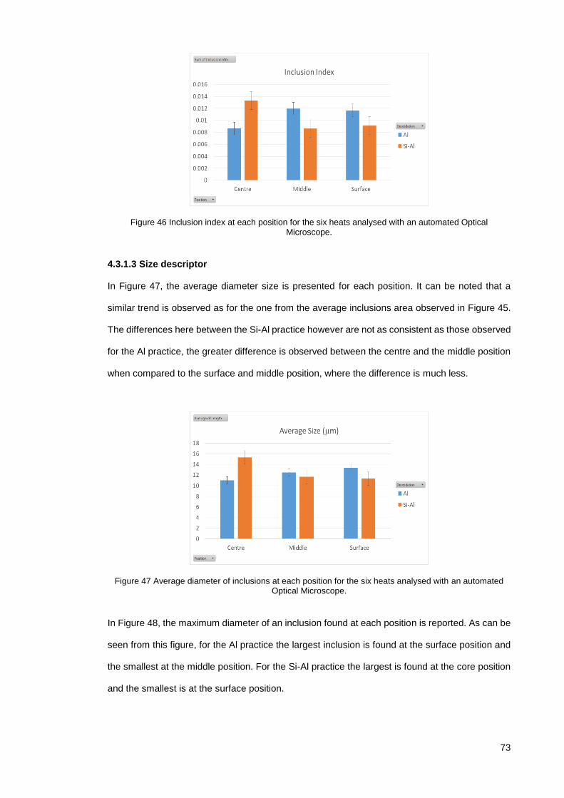
73
Figure 46 Inclusion index at each position for the six heats analysed with an automated Optical Microscope.
4.3.1.3 Size descriptor
In Figure 47, the average diameter size is presented for each position. It can be noted that a
similar trend is observed as for the one from the average inclusions area observed in Figure 45.
The differences here between the Si-Al practice however are not as consistent as those observed
for the Al practice, the greater difference is observed between the centre and the middle position
when compared to the surface and middle position, where the difference is much less.
Figure 47 Average diameter of inclusions at each position for the six heats analysed with an automated Optical Microscope.
In Figure 48, the maximum diameter of an inclusion found at each position is reported. As can be
seen from this figure, for the Al practice the largest inclusion is found at the surface position and
the smallest at the middle position. For the Si-Al practice the largest is found at the core position
and the smallest is at the surface position.

74
Figure 48 Maximum diameter of inclusions at each position for the six heats analysed with an automated Optical Microscope.
The size distribution of inclusions detected with the automated optical microscope are shown in
Figure 49. It is interesting to note from this figure that for the smaller size bin (5-9 µm) the trends
are opposite. Al practice exhibits less small inclusions in the surface position, with frequency of
these sizes increasing in the middle and the central position respectively. The Si-Al practice to
the contrary, exhibits more small inclusions in the surface position, with frequency of these sizes
decreasing towards the centre. When observing the bins of larger inclusion sizes (over 21 µm),
at the centre position, the Si-Al practice has a higher frequency than the Al practice. In the middle
position, the Al practice shows higher a frequency of inclusions than the Si-Al practice. At the
surface position there is negligible difference detected with this technique.
Figure 49 Size distribution of inclusions at each position for the six heats analysed with an automated Optical Microscope.

75
4.3.1.4 Shape descriptor
In Figure 50, the summary of the average circularity of particles at each position can be
appreciated. The values of circularity are near the value of 0.6, which indicates that not many of
the particles analysed have a circular shape.
Figure 50 Average circularity of inclusions at each position for the six heats analysed with an automated Optical Microscope.
The greatest disparity observed between the two deoxidation practices is at the core position,
with the Si-Al practice showing particles that are less circular. This small tendency is of importance
because it can also be observed for the maximum diameter, the average size and the area results.
Only for the average number of particles at this position, does the Si-Al deoxidation practice
present a smaller number than the Al practice, which seems to indicate that the anisotropy of
inclusions at this position is greater for the Si-Al practice.

76
Figure 51 Distribution of circularity values of inclusions at each position for the six heats analysed with an automated Optical Microscope.
In Figure 51, the distribution of circularity values of inclusions are presented and it can be seen
that the majority of the inclusions are concentrated between the ranges 0.4-0.8 for all positions.
Another observation is that the greatest disparity between the two deoxidation practices is at the
surface position, where the Si-Al practice presents the higher number of inclusions near the higher
end of the circularity values and the Al practice shows the lowest number, confirming the
tendencies that are barely noticeable in the previous figure of average values of circularities
(Figure 50).
4.3.2 Automated Feature Analysis – Scanning Electron Microscope (SEM-AFA)
The inclusions were analysed using the SEM-AFA system as mentioned previously.
4.3.2.1 Number descriptor
The number of inclusions per mm2 and their respective inclusion types are reported in Figure 52,
Figure 53 and Figure 54 for the core, mid radius and surface positions respectively.

77
Figure 52 SEM-AFA results showing the number of inclusions per mm2 at the core position for each deoxidation practice.
At the core of the continuously cast bloom, the predominant type of inclusion for the Si-Al
deoxidation practice is MnS, whereas for the Al deoxidation practice the predominant type of
inclusion is the duplex CaS-MnS with the presence of some other calcium aluminates
(xCaO·yAl2O3 ) and spinel (Al2O3·xMgO) inclusions.
Figure 53 SEM-AFA results showing the number of Inclusions at the middle position of each deoxidation practice.

78
In the mid radius position of the bloom as shown in Figure 53, the predominant type of inclusion
is MnS for both deoxidation practices. Note also the presence of calcium aluminates and spinels,
in the Al deoxidation practice.
Figure 54 SEM-AFA results showing the number of Inclusions at the surface position for each deoxidation practice.
At the surface position (Figure 54), the most numerous inclusion is MnS for both practices, but
the amount of MnS is much greater compared to other types of inclusions for the Si-Al practice.
Calculating ratios of MnS inclusions (total MnS inclusions over the total number of inclusions), it
is found that the lowest fraction is at the core position, namely 0.276 for the Al practice, and the
highest fraction is at the surface position for the Si-Al practice with 0.915. In the Al practice the
majority of MnS inclusions are detected in the mid radius position with a ratio of 0.703 followed
by the surface position with a ratio of 0.458. In the Si-Al practice the smaller ratio is found at the
core with a ratio of 0.705 and then the mid radius position with a ratio of 0.879. Note that for all
positions the ratio of MnS is greater for the Si-Al practice. An opposite trend to the one observed
with the MnS inclusions can be then inferred for the other types of inclusions, mainly calcium
aluminates and calcium sulphides (CaS) for the Si-Al practice. In the Al practice we observe that
for the core position the predominant inclusion type is the duplex CaS-MnS with the presence of
some calcium aluminates and spinel inclusions. For the mid radius position, the predominance of
the CA2 type (CaO·2Al2O3) and the spinel rich type of inclusion over CaS containing inclusions
seems to indicate that CaS mainly tends to agglomerate in the core due to the segregation of
sulphur to the centre region of the bar during cooling(11,93,94). In the surface position the

79
presence of many different types of inclusions seem to be a result of the rapid solidification that
happens within this region (71).
4.3.2.2 Area Descriptor
While the number of inclusions is an indicator of the inclusion population, the area covered by
each type of inclusion can be used as a better representation of the inclusion volume fraction per
each category, especially if this analysis is carried out over a large area or over different planes
of the same specimen for increased accuracy.
Figure 55 SEM-AFA results showing the area covered by inclusion type at the core position for each deoxidation practice.
In Figure 55, the area of each inclusion category at the core position is shown. In Table 3 the total
area covered by inclusions for each practice is reported, with the smallest value for the three
positions analysed belonging to the Al practice (6019 µm²) and the largest (20924 µm²) to the Si-
Al practice. Also in Table 3, the average inclusion area at the core position is reported, 6.32 µm²
for the Al practice and 15.04 µm² (largest) for the Si-Al practice. Figure 55 shows that for the Si-
Al practice the area of inclusions is much larger due to the area occupied by the MnS type in that
practice compared with the Al practice which exhibits a more varied distribution of different types
of inclusions.

80
Figure 56 SEM-AFA results showing the area percent of each inclusion category at the core position.
In Figure 56, the percentage of area of each inclusion type is shown. From this figure it is easier
to determine that the predominant inclusion type for the Al killing practice is the “CaS Other”
category. This category includes all the inclusions that contain the CaS type but don’t contain
enough Mn and S to be considered as a Cas-MnS type. By taking into account both the “CaS
other” and the “CaS MnS” inclusions it can be said that the inclusion type with the largest area for
the Al deoxidation practice at this position are inclusions containing CaS.
Figure 57 SEM-AFA results showing the area covered by inclusion type at the mid radius position for each deoxidation practice.

81
In Figure 57, the area covered by inclusions at the mid radius position is shown. The area of the
inclusions in the Si-Al practice at this position is the largest (28071 µm²), and as it can be seen,
again the largest area per category corresponds to the MnS inclusion type. The area for the Al
practice is the second largest (7425µm²) of the three positions analysed. Al practice exhibits the
smallest average area of inclusions 2.47 µm², and Si-Al practice exhibits the second largest with
11.41 µm².
Figure 58 SEM-AFA results showing the area percent of each inclusion category at the mid radius position.
The percentage of area at the mid radius position can be seen in Figure 58. As it can be seen,
the MnS category of inclusion occupies the largest percentage of area for both practices at this
position. Interestingly at this position for the Al practice, there are very few inclusions containing
CaS as opposed to the previous position (core), where this type of inclusion is the most abundant.
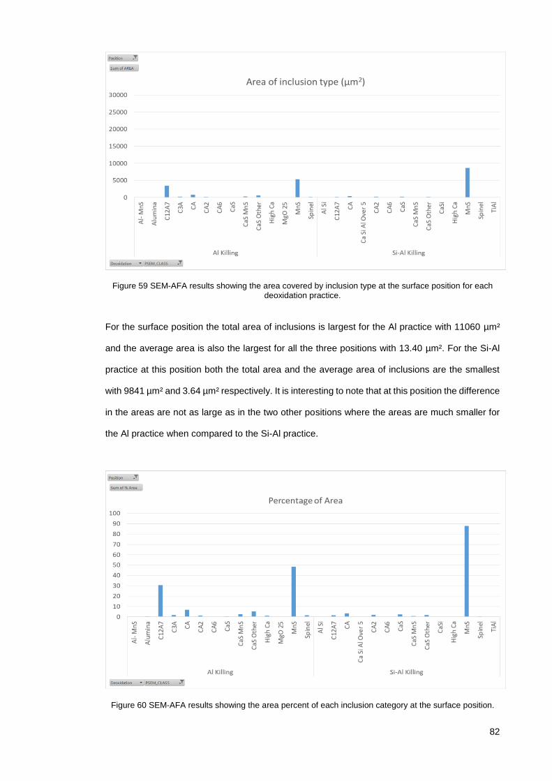
82
Figure 59 SEM-AFA results showing the area covered by inclusion type at the surface position for each deoxidation practice.
For the surface position the total area of inclusions is largest for the Al practice with 11060 µm²
and the average area is also the largest for all the three positions with 13.40 µm². For the Si-Al
practice at this position both the total area and the average area of inclusions are the smallest
with 9841 µm² and 3.64 µm² respectively. It is interesting to note that at this position the difference
in the areas are not as large as in the two other positions where the areas are much smaller for
the Al practice when compared to the Si-Al practice.
Figure 60 SEM-AFA results showing the area percent of each inclusion category at the surface position.
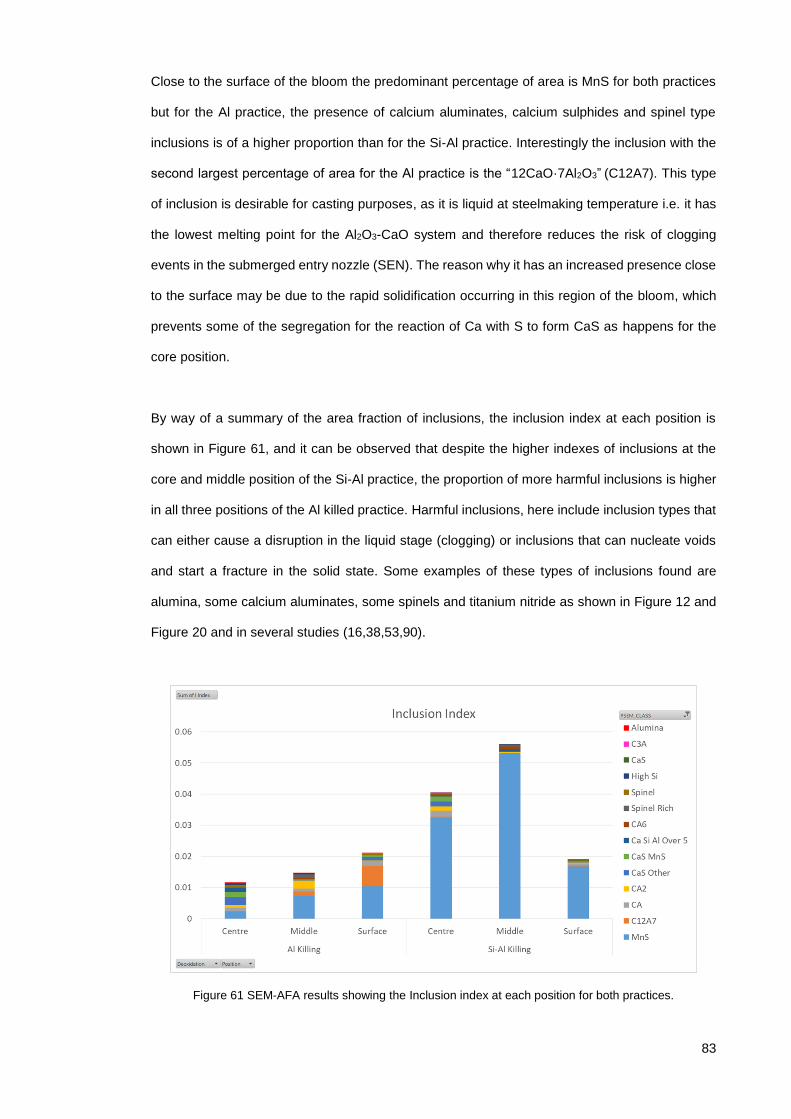
83
Close to the surface of the bloom the predominant percentage of area is MnS for both practices
but for the Al practice, the presence of calcium aluminates, calcium sulphides and spinel type
inclusions is of a higher proportion than for the Si-Al practice. Interestingly the inclusion with the
second largest percentage of area for the Al practice is the “12CaO·7Al2O3” (C12A7). This type
of inclusion is desirable for casting purposes, as it is liquid at steelmaking temperature i.e. it has
the lowest melting point for the Al2O3-CaO system and therefore reduces the risk of clogging
events in the submerged entry nozzle (SEN). The reason why it has an increased presence close
to the surface may be due to the rapid solidification occurring in this region of the bloom, which
prevents some of the segregation for the reaction of Ca with S to form CaS as happens for the
core position.
By way of a summary of the area fraction of inclusions, the inclusion index at each position is
shown in Figure 61, and it can be observed that despite the higher indexes of inclusions at the
core and middle position of the Si-Al practice, the proportion of more harmful inclusions is higher
in all three positions of the Al killed practice. Harmful inclusions, here include inclusion types that
can either cause a disruption in the liquid stage (clogging) or inclusions that can nucleate voids
and start a fracture in the solid state. Some examples of these types of inclusions found are
alumina, some calcium aluminates, some spinels and titanium nitride as shown in Figure 12 and
Figure 20 and in several studies (16,38,53,90).
Figure 61 SEM-AFA results showing the Inclusion index at each position for both practices.

84
4.3.2.3 Size descriptors
Another crucial variable when analysing inclusions populations is the size of the inclusion. The
average sizes per category are shown in Figure 62, Figure 63 and Figure 64 for the core, mid
radius and surface positions respectively.
Figure 62 SEM-AFA results showing the average diameter sizes at the core position.
At the core position, from Table 3 it can be seen that the average diameter for the Al practice
(2.58 µm) is smaller than for the Si-Al practice (3.38 µm) but this does not give us the full picture
with regard to the different categories of inclusions, for example the greater average sizes are
present in the Al deoxidation practice. The classification shows that “Ca Si Al over 5”, “Alumina”,
“High Si” and “C12A7” categories have an average inclusion diameter of 20, 11 and 7 µm
respectively. The “Ca Si Al over 5” type of inclusion consists of the calcium aluminate type of
inclusions that contain Ca, Al, and Si over 5% and didn’t fit in any of the classification rules for the
most common categories of calcium aluminates. The “High Si” category type refers to inclusions
with a Si content of more than 75% weight. For the Si-Al deoxidation practice the largest average
inclusion diameters are 6 µm for the “C12A7” type and “Spinel” and 5 µm for the “C3A” and ”CA”
type.

85
Figure 63 SEM-AFA results showing the average diameter sizes at the mid radius position.
At the mid radius position, the general average diameters are 1.60 µm for the Al practice and 2.76
µm for the Si-Al practice. The largest average diameter is found in the Si-Al practice with 8 µm for
“Ca Si Al over 5” inclusions. For the Al practice at this position, the largest average diameter is 7
µm for the “C12A7” type.
Figure 64 SEM-AFA results showing the average diameter sizes at the surface position.

86
For the surface position, the average diameter value for the Al practice (3.19 µm) is larger than
the value for the Si-Al practice (2 µm). The largest average diameters are found in the Al practice
for the “Alumina”, “C12A7” and “High Ca” types of inclusion with 8, 7 and 6.5 µm respectively. For
the Si-Al practice the largest is “CaS” with 7 µm.
The average size of an inclusion is a helpful parameter to determine the distribution of inclusion
sizes among different types of inclusions, but in order to determine the largest and therefore the
most potentially deleterious inclusion, the analysis of the largest inclusion per category was
carried out and the results are show in Figure 65, Figure 66 and Figure 67.
Figure 65 SEM-AFA results showing the maximum diameter sizes at the core position.
The maximum diameter for the core position is found in the Si-Al practice and corresponds to a
MnS of a diameter of 59 µm.

87
Figure 66 SEM-AFA results showing the maximum diameter sizes at the mid radius position.
The maximum diameter at the mid radius position is also found in the Si-Al practice for an inclusion
of 55 µm corresponding to a category of “Ca Si Al over 5”.
Figure 67 SEM-AFA results showing the maximum diameter sizes at the surface position.
For the surface position, the maximum inclusion diameter is 52 µm for a “MnS” type of inclusion,
followed by 44 µm for a “C12A7”. For the Si-Al practice the largest are “MnS” and “CaS” with 18
and 17 µm respectively. The maximum diameters of inclusions in the Al practice are found at the
surface position, whereas for the Si-Al practice the maximum diameter sizes are found in the
middle and core positions.

88
The size distribution at each position is contrasted in the following figures. Figure 68 shows the
distribution of inclusions at the centre. At this position both practices show a relativly small number
of inclusions compared to the population at the other two positions, the population of Si-Al
includes more inclusions larger than 6µm compared to the Al practice.
Figure 68 SEM-AFA results showing the size distribution at the core position of heats 1319 and 2456
Figure 69 shows the size distribution at the mid radius position. In this figure, the inclusion
population is the greatest for both practices, notice the sharp decrease to smaller distribution
sizes of the Al practice compared to the Si-Al practice.

89
Figure 69 SEM-AFA results showing the size distribution at mid radius position of heats 1319 and 2456.
Figure 70 , shows the distribution of sizes at the surface position. In this position, the Al practice
exhibits a larger proportion of inclusion sizes greater than 6µm compared to the Si-Al practice.
Figure 70 SEM-AFA results showing the size distribution at the surface position of heats 1319 and 2456.
4.3.2.4 Shape descriptors
The average inclusion aspect ratio at different positions is compared in Figure 71, Figure 72 and
Figure 73.

90
Figure 71 SEM-AFA results showing the average aspect ratio at the core position.
In Figure 71, the average aspect ratio at the core position is shown. At this position, for the Al
practice the inclusion with the greatest aspect ratio is the alumina type with a value of 4. For the
Si-Al practice the most irregular particle types are the duplex “Al-MnS” and “MnS” categories with
3.9 and 3.3 aspect ratio values respectively.
Figure 72 SEM-AFA results showing the average aspect ratio at the mid radius position.
For the mid radius position shown in Figure 72, the inclusion type with the highest aspect ratio is
the “Ca Si Al over 5” category for the Si-Al practice with 3.9 and the “Alumina” category for the Al
practice with a value of 2.6.

91
Figure 73 SEM-AFA results showing the average aspect ratio at the surface position.
In Figure 73, the average aspect ratios at the surface position are shown. In this case the highest
values belong to the Si-Al practice for the “Al Si” and the “Ti Al” categories with values of 6.8 and
6 respectively. The “Al Si” type of inclusion corresponds to a classification rule which contains
Al>=10 and Si>=10 and (Al+Si)>=70 and Ca<10 from the EDS chemical analysis. To better
understand this rule this type of inclusion can be seen as a complex mixture of oxide types (Al
and Si) with a calcium content not high enough to be considered as a calcium aluminate. The “Ti
Al” category of inclusion corresponds to the classification rule Ti>=10 and Al>=10, which is
intended to capture inclusions containing mainly Ti and Al oxides without any significant amount
of other elements.

92
4.3.2.5 Summary table
Table 3 summarises the information obtained for the three different positions analysed with the
SEM-AFA technique and can be seen below:
Table 3 Summary of position analysis of SEM-AFA results.
Deoxidation Al Killed Si-Al Killed
Position Core Middle Surface Avg. Core Middle Surface Avg.
Scan Area (mm²) 51.468 50.122 51.468 51.02 51.468 50.122 51.468 51.02
Total Number 952 3369 827 1716.00 1392 3044 2705 2380.33
Inclusion Index % 0.012 0.015 0.022 0.016 0.041 0.057 0.019 0.039
Area Incl. (µm²) 6019 7425 11060 8168 20924 28071 9841 19612
Avg. Area (µm²) 6.32 2.47 13.40 7.40 15.04 11.41 3.64 10.03
Avg. Diameter
(µm)
2.58 1.61 3.20 2.46 3.38 2.76 2.00 2.72
Number per mm² 18 67 16 34 27 61 53 47
Average NND
(µm)
106.66 59.80 114.04 93.50 80.28 58.65 58.84 65.92
Calculated Total
Oxygen (ppm)
15.84 23.72 27.88 22.48 46.01 82.19 21.04 49.74
Minimum Size
(µm)
2 1 2 NA 2 1 2 NA
EDS time (s) 0.5-1 1-2 0.5-1 NA 0.5-1 1-2 0.5-1 NA
Analysis time
(hr:min)
0:31 1:44 0:30 NA 0:32 1:27 0:54 NA
It can be appreciated that from this technique it is possible to obtain lots of very valuable
information in a relatively short time. In this regard, despite the area of analysis being roughly the
same for all the samples (50mm2), the analysis performed for the middle radius position, was a
more precise analysis, which detected smaller inclusion sizes (down to 1 µm) and with increased
EDS analysis time (1-2 seconds). This resulted in an increase in the total analysis time, but it is
still a very advantageous turnaround time. This also explains that the number of inclusions

93
reported in the table are much higher for the mid radius position for both practices compared to
the core and the surface positions. For a more accurate analysis of the inclusion population the
area of inclusions and the inclusion index (area of Inclusions / scan area) should be used. From
these results, a different trend in the distribution of inclusions is clearly observed for each practice.
The area fraction (AA) can be related to the volume fraction (VV) of inclusions as demonstrated by
Underwood (92). Therefore it can be said that the volume fraction of inclusions for the Al killed
practice is higher close to the surface and decreases towards the core of the bloom. The trend
observed with the Si-Al killing practice indicates that the highest volume fraction is at the mid
radius position followed by the core position and the lowest volume fraction is located at the
surface position. Another important observation is that the total area of inclusions in the Si-Al
samples is in general larger than the area of inclusions for the Al killing practice. This observation
seems to be related to the calculated oxygen content which is also higher in average for the Si-
Al practice. In addition, the nearest neighbour distance (NND) was obtained for each sample. The
results showed a larger spacing (93.5 µm) between inclusions in the Al killing practice than the
spacing for the Si-Al killing practice (65.9 µm). This distance was obtained by employing an
algorithm which calculates the centroid of each inclusion based on the measurement of 8
diameters of the particle at different angles. Based on the coordinates of these points it
determines the average Nearest Neighbour Distance (8,95). Finally the total number of inclusions
and the number of inclusions per mm2 are larger for the Si-Al practice than for the Al practice.
4.3.3 Joint Ternary diagrams
As described in the previous section the different inclusions were categorised according to certain
defined rules relating to the percentages of each element detected by the EDS analysis. This
chemical composition data can also be employed to build ternary diagrams for representation of
inclusion chemical composition.
Researchers from the Peaslee Steel Manufacturing Research Center (PSMRC) at Missouri
University of Science and Technology, have developed a system to represent inclusion
populations in a Joint Ternary Diagram, the purpose of this type of representation is to increase
accuracy by avoiding errors in interpretation that may arise from the normalisation of the elements
of the chemical analysis. Harris et al (96) explains how this system works: “Each ternary
represents a distinct inclusion population with each individual inclusion counted only once and
shown in the respective ternary section it belongs. The technique considers the three most

94
abundant elements of a particular inclusion in assigning ternary sections and these elements
typically account for more than 80% of the inclusion composition, thus errors associated with
normalization are greatly reduced.” Another benefit of this type of interpretation is the size markers
which can help to distinguish large exogenous inclusions of differing composition. This system
was employed to represent the inclusion populations at the three positions of the study and are
presented in the following Figure 74-48.
4.3.3.1 Al deoxidised samples
Figure 74 Joint ternary diagram for the core position of the Al deoxidised steel.
The joint ternary diagram in Figure 74, represents 81.86% of the total inclusion population. As it
can be appreciated most of the inclusions are MnS, CaS and CaS with Al content varying between
20 and 80 wt%. This confirms the result of the previous classification at this position with the
largest area corresponding to the category “CaS Other”. From this diagram we can see that a
large proportion of these inclusions are with diameters above 5µm.

95
Figure 75 Joint ternary diagram for the middle position of the Al deoxidised steel.
In Figure 75 the inclusions identified at the mid radius position in the Al deoxidised steel are
represented, in total 53.25% of all the inclusions are represented. The majority of these inclusions
have very small sizes below 2 µm and are localised in regions of the ternary diagram
corresponding to MnS with varied contents of Ca and Al. Another observation is that in these
regions there are very few large (red) inclusions in the region of Ca-S-Al when compared to the
the results from the core position.
Figure 76 Joint ternary diagram for the surface position of the Al deoxidised steel.
Figure 76 shows the surface position of the Al deoxidised steel. In this representation 58.04% of
the inclusions are included. The percentage of the inclusions within the larger size range
(represented in red), is the greatest for all three positions at 32.75%. An increased presence of
large MnS and calcium aluminates with high Ca content above 40% can also be observed.
The tendencies observed in the Al deoxidised steel show that there is a concentration of larger
inclusions present in the core and surface position compared to the mid radius. Also that these
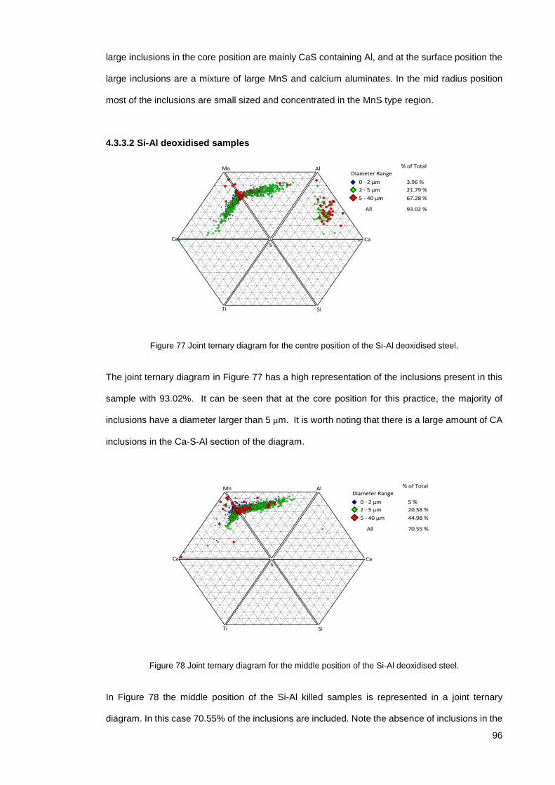
96
large inclusions in the core position are mainly CaS containing Al, and at the surface position the
large inclusions are a mixture of large MnS and calcium aluminates. In the mid radius position
most of the inclusions are small sized and concentrated in the MnS type region.
4.3.3.2 Si-Al deoxidised samples
Figure 77 Joint ternary diagram for the centre position of the Si-Al deoxidised steel.
The joint ternary diagram in Figure 77 has a high representation of the inclusions present in this
sample with 93.02%. It can be seen that at the core position for this practice, the majority of
inclusions have a diameter larger than 5 µm. It is worth noting that there is a large amount of CA
inclusions in the Ca-S-Al section of the diagram.
Figure 78 Joint ternary diagram for the middle position of the Si-Al deoxidised steel.
In Figure 78 the middle position of the Si-Al killed samples is represented in a joint ternary
diagram. In this case 70.55% of the inclusions are included. Note the absence of inclusions in the

97
Ca-S-Al section of this diagram. Also there is a reduction in the amount of CaS types of inclusion
and although there is a large percentage of large particles (red), they are in the region of the MnS
type with a few of them shifting towards higher Al contents.
Figure 79 Joint ternary diagram for the surface position of the Si-Al deoxidised steel.
Figure 79 shows the inclusion population at the surface position of the Si-Al killed steel. In this
diagram 86.96% of the total number of inclusions is represented. Note that most of the inclusions
are below 5 µm in diameter and also that that the inclusion content is localised in the MnS region
with very few calcium aluminates.
The tendencies observed in the Si-Al deoxidised steels, show that inclusions in this practice, tend
to accumulate in the mid radius and central position, and that this seem to be in accordance with
Zhang’s explanation of sulphur segregation and secondary arm spacing entrapping MnS
inclusions interdendritically (71).
4.3.4 Extreme Value Analysis
The extreme value statistical analysis was performed on the results of the automated Optical
Microscope and the SEM-AFA analysis.
The analysis is based on the stereographic measurements obtained from the total area analysed
per sample. Information about defects detected is collected in a spreadsheet and ordered
according to their largest Feret diameter starting from the largest to the smallest. Then the 24
largest were employed to perform the analysis according to the procedure stated in standard
ASTM E2283 as shown in Figure 80 below.

98
Figure 80 Screenshot of the Extreme Value Statistical Analysis spreadsheet following the ASTM E2283 standard procedure.
4.3.4.1 Automated OM
The graphic representation of extreme value distribution for the Al practice is represented in black
and for the Si-Al practice is represented in red. The distributions at each position are contrasted
in the following figures:
Figure 81 Extreme Value Distribution at the centre position for optical microscopy results.
From Figure 81, it can be seen that the probability of finding an inclusion with a larger size at the
core position, belongs to the extreme value distribution of the Si-Al practice.

99
Figure 82 Extreme Value Distribution at the middle position for optical microscopy results.
From Figure 82, it can be appreciated that there is a shift around 63 µm, where the probability of
finding a large inclusion of a size above 63 µm is higher for the Al deoxidised steel and the
probability of finding an inclusion below that value is greater in the Si-Al deoxidised steel.
Figure 83 Extreme Value Distribution at the surface position for optical microscopy results.
In Figure 83, it is shown that the probability of finding an inclusion with a larger size at the surface
position, belongs to the extreme value distribution of Al practice (black line) and the range of large
sizes at this position for the Si-Al practice (red line) is very narrow when compared to that of Al
practice.
4.3.4.2 SEM-AFA
The graphic representation of the extreme value distributions obtained with results from the SEM-
AFA analysis is presented in the following figures.

100
In Figure 84, the extreme value distributions at the centre position are presented. It can be seen
that the distribution in red for the Si-Al practice has a larger span towards higher sizes compared
to the Al practice.
Figure 84 Extreme Value Distribution at the centre position of SEM-AFA results.
Figure 85 Extreme Value Distribution at the middle position of SEM-AFA results.
For the extreme value distribution of the middle position in Figure 85, the probability of finding an
inclusion of larger size is greater for the Si-Al practice with a wider range of sizes, compared to
the Al distribution.

101
Figure 86 Extreme Value Distribution at the surface position of SEM-AFA results.
The extreme value distributions at the surface position are shown in Figure 86. It can clearly be
seen the wider range and greater probability of finding a larger inclusion in the Al practice than in
the Si-Al practice, which has a very narrow range of sizes.
4.3.4.3 Summary
When comparing the inclusion size ranges from both techniques, it can be seen that the sizes are
smaller for the SEM-AFA than for the OM. There could be two factors having an influence on this,
one is that the resolution of SEM-AFA is higher and also it has the ability to discriminate artefacts
that are not related to the inclusion population. On the other hand OM relies only on the threshold
parameter and it is not always constant throughout the different samples analysed as it has to be
set manually every time a new sample is loaded into the stage. The other reason is the difference
in the areas of analysis, the area surveyed with Optical Microscopy was 95.68 mm2 and for SEM-
AFA was 51.47 mm2.
A noticeable trend between different positions for results obtained from both techniques (OM and
SEM-AFA) and then subjected to Extreme Value Statistical Analysis, confirms that the probability
of finding a large inclusion at the core and mid radius positions is higher for the Si-Al practice and
at the surface position is higher for the Al practice.
The maximum inclusion size expected to be found in an area 1000 times larger than the area of
analysis are reported in Table 4 for each position.
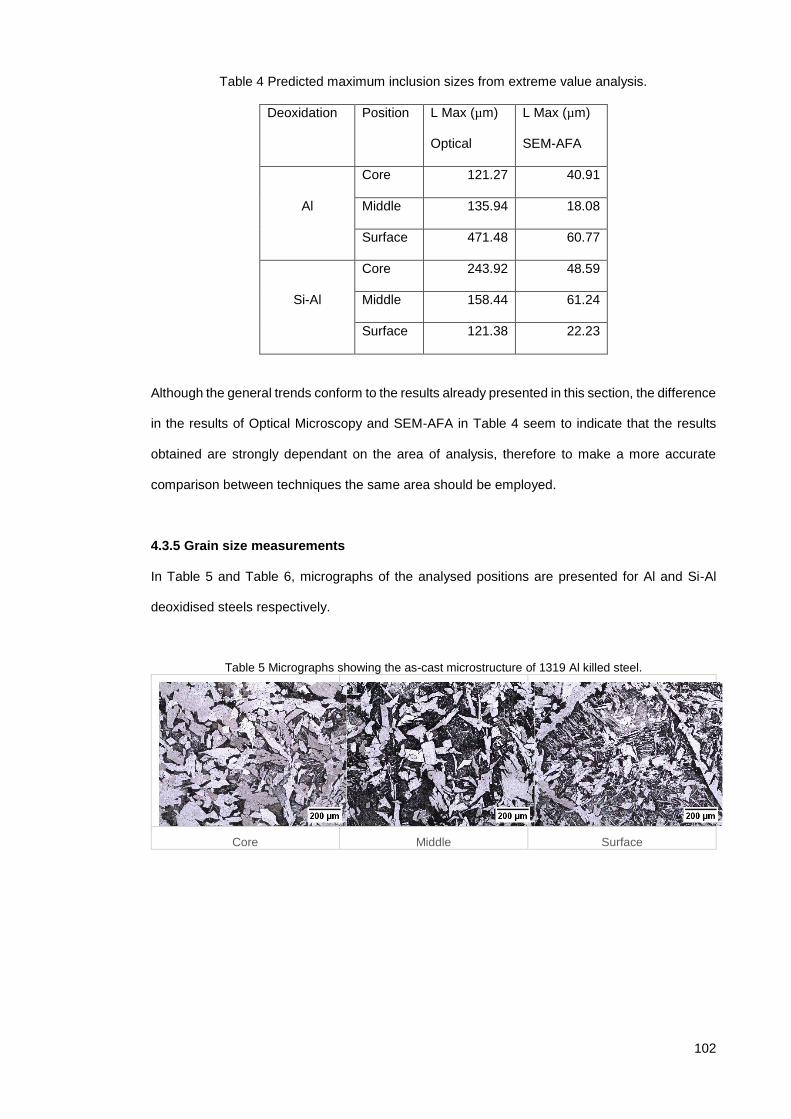
102
Table 4 Predicted maximum inclusion sizes from extreme value analysis.
Deoxidation Position L Max (µm)
Optical
L Max (µm)
SEM-AFA
Al
Core 121.27 40.91
Middle 135.94 18.08
Surface 471.48 60.77
Si-Al
Core 243.92 48.59
Middle 158.44 61.24
Surface 121.38 22.23
Although the general trends conform to the results already presented in this section, the difference
in the results of Optical Microscopy and SEM-AFA in Table 4 seem to indicate that the results
obtained are strongly dependant on the area of analysis, therefore to make a more accurate
comparison between techniques the same area should be employed.
4.3.5 Grain size measurements
In Table 5 and Table 6, micrographs of the analysed positions are presented for Al and Si-Al
deoxidised steels respectively.
Table 5 Micrographs showing the as-cast microstructure of 1319 Al killed steel.
Core Middle Surface

103
Table 6 Micrographs showing the as-cast microstructure of2456 Si-Al killed steel.
Core Middle Surface
From the micrographs presented in the tables above, it can be seen that there are smaller grains
in the positions close to the surface which corresponds to the chill zone. In the middle position it
can be appreciated that the grains are larger than at the surface position, these grains correspond
to the columnar zone and in the case of Al deoxidised steel they are observed to be the largest
from all three positions surveyed. Finally the core position corresponds to the equiaxed zone and
in the case of Si-Al deoxidised steels this position contains the largest grain sizes reported. In
Figure 87 the averages of grain sizes of all the heats analysed at the three positions surveyed
are summarised and presented.
Figure 87 Summary of the average grain size measurements of all heats at different positions of the as cast bloom.

104
Chapter 5 Effect of deoxidation practice on inclusion
population
5.1 Introduction
In this chapter as part of the as-cast characterisation, the distribution of inclusions in samples
from 3 different heats of each deoxidation practice were analysed.
In the case of the manual OM three samples per heat were analysed due to the small area of
analysis compared to the other techniques. In the case of automated OM and SEM-AFA, the
selected position to make a comparison between heats was selected to be the middle radius
position. The reasons for selecting the mid radius position were that the distribution of inclusions
in this region of the continuous cast bloom is the one that will be more representative for the
subsequent comparison with the deformed material (forged and rolled rings), because a section
of the core is pierced out (to obtain the preform for rolling) as shown in Figure 25, and also
because some surface material may be lost due to the forming and scraping of scale throughout
the hot forming processes.
5.2 Characterisation of as cast Al heats (1319, 1320, 1332) and Si-Al
deoxidised heats (2456, 2457, 2458)
5.2.1 Optical Microscopy
The manual OM results are summarised in Table 7, in this analysis three samples per heat were
analysed, and the total surveyed area per heat was 15.85 mm2.
Table 7 Manual Optical Microscopy summary of as cast heats results.
Deoxidation Al deoxidised Si-Al deoxidised
Heat 1319 1320 1332 2456 2457 2458
Total Number 2422 2289 2609 2779 3095 4658
Total Area (µm²) 17638 35261 20345 34984 29450 34015
Average Area (µm²) 7.28 15.40 7.80 12.59 9.52 7.30
Average Diameter (µm) 3.65 4.10 3.63 3.90 3.24 3.63
Inclusion Index 0.11 0.22 0.13 0.22 0.19 0.22
Number per mm² 152.74 144.35 164.53 175.25 195.18 293.75

105
From Table 7, the main differences that can be seen between Al and Si-Al deoxidation practices
are: the number of inclusions is higher for the Si-Al practice, the total area of inclusions is higher
except for heat number 1320 which has an area of 35261 µm² and an average area of inclusions
of 15.40 µm².
5.2.1.1 ASTM E45
The results of ASTM E45 standard with method “A” are reported in Table 8, only results of Al
heats were obtained, the presence of sulphides and globular inclusion types is confirmed.
The method A is also known as the worst fields method, it requires an area analysis of 160mm2
at 100x magnification, the field sizes are approximately 0.50mm2 and each of these fields is
compared to the squared fields on a reference template in search for the worst field, that is the
severity rating of each type of inclusion (A, B, C and D) specified in the template for both a thin a
heavy series. The result of this analysis is reported in a table with the severity level of the worst
fields matching the inclusions content on the sample.
Table 8 ASTM As-Cast results Method A Sulfide A Alumina B Silicate C Globular D
Heat Thin Heavy Thin Heavy Thin Heavy Thin Heavy
1319 0.5 0.5 0 0 0 0 0.5 0.5
1320 0.5 0.5 0 0 0 0 0.4 0.5
1330 0.5 0.5 0 0 0 0 0.5 0.3
1332 0.5 0.5 0 0 0 0 0.5 0.5
5.2.2 Automated OM
The automated OM results, were all obtained from a constant survey area of 95.68 mm2. The
particular differences between practices and different heats are discussed in the following figures.
5.2.2.1 Number descriptor
The number of inclusions per mm2 of each heat is presented in Figure 88, it shows that the greater
number is found in heat 1319 and the lowest is found in heat 1320. This shows a greater disparity
between heats of the Al practice than there is for the Si-Al practice.

106
Figure 88 Number of inclusions per mm2 from automated OM of the as cast middle position.
5.2.2.2 Area Descriptor
The Inclusions index per heat is presented in Figure 89, heat 1332 presents the largest area index
and heat 2457 presents the smallest. Again there is greater disparity in the results for the Al
practice that there is for the Si-Al practice.
Figure 89 Total area of inclusions from automated OM of the as cast middle position.
5.2.2.3 Size Descriptor
Figure 90 shows the average inclusion diameter per heat, the largest corresponds to heat 1332
of the Al practice and the smallest to heat 2457 of the Si-Al practice. From these results it can be
seen that there is not much variation with regard to the average diameter between the different
heats.

107
Figure 90 Average Size from automated OM of the as cast middle position.
In Figure 91, the maximum diameter detected per heat is presented, the largest is found in heat
2458 of the Si-Al practice and the smallest is found in heat 2456. There is a large range between
the two Si-Al deoxidised heats, but also there is large range between Al deoxidised heats where
the largest is found in heat 1332 and the smallest in heat 1319.
Figure 91 Maximum diameter from automated OM of the as cast middle position.
The size distribution of the different heats is summarised in Figure 92, it can be seen that the
majority of inclusions fall on the smaller particle size side of the spectrum, with varying
proportions. Heat 1319 has the largest population of small inclusions (5-9 µm) when compared
with 1332 and 1320, this last one having the smallest population of inclusions between 5-9 µm.

108
Figure 92 Size distribution of inclusions from automated OM of the as cast middle position.
At the other side of the spectrum, i.e. inclusions with sizes greater than 21 µm, it can be seen that
the largest population of all the heats is 1332 which is coherent with the maximum diameter found
for the Al practice, but for the Si-Al practice, even though the maximum inclusion diameter was
found in heat 2458, the population above the range of 21 µm is not as large as that for heat 1332.
5.2.2.4 Shape Descriptor
In Figure 93 the frequency distribution of the circularity of the inclusions is shown. It is interesting
to note from this figure that the highest frequency range of all the heats is 0.6-0.8 followed by the
range of 0.4-0.6 except for heat 1332 of the Al practice which is the only heat with the second
largest number of features in the range of 0.8-1 indicating that inclusions in this heat have high
circularity.

109
Figure 93 Circularity and frequencies from automated OM of the as cast middle position.
5.2.2.5 Summary
The automated OM results, were all obtained from a constant survey area of 95.68 mm2. In
summary the results from the automated OM and the differences from heat to heat are shown in
Table 9.
Table 9 Automated Optical Microscopy summary of as-cast heats results
Deoxidation Al deoxidised Si-Al deoxidised
Heat 1319 1320 1332 2456 2457 2458
Total Number 4585 1759 4230 3309 2984 2810
Total Area (µm²) 312003.6 235342.8 596921.7 238578.5 228126.3 356743.3
Average Area (µm²) 68.05 133.79 141.12 72.10 76.45 126.95
Number per mm2 47.92 18.38 44.21 34.58 31.19 29.37
Average of Length
(µm)
10.69 13.39 14.05 11.34 10.58 13.20
Max of Length (µm) 105.79 133.92 301.59 104.28 135.43 372.67
Average of
Circularity
0.605 0.619 0.637 0.593 0.611 0.652
Inclusion Index 0.326 0.246 0.624 0.249 0.238 0.373

110
5.2.3 Scanning Electron Microscopy- Automated Feature Analysis
5.2.3.1 Number descriptor
The results of SEM-AFA analysis are presented. For these analyses, an area of 50.12 mm2 was
employed for all samples and all other parameters (minimum size, EDS time, etc.) were kept
constant to make an accurate comparison between inclusion populations from different heats.
The number of inclusions per millimetre squared (mm2) for each as cast heat is presented in
Figure 94. Al heats have more variability in terms of inclusions per mm2 compared to Si-Al heats.
Figure 94 Inclusions per mm2 of each heat from SEM-AFA as cast results.
5.2.3.2 Area descriptors
The inclusion indexes in Figure 95 have been filtered for the most representative inclusions and
also exclude the unclassified inclusions.
Figure 95 Inclusion index of each heat from SEM-AFA as cast results.

111
Inclusions indexes of heats 2457 & 2458 of Al-Si practice are similar to those of Al heats, only
heat 2456 exhibits a higher inclusion index. Another observation is that the proportion of MnS
type of inclusions in heats of the Si-Al practice is higher compared to the proportion of the other
types of inclusions. This means that despite Al heats having on average less inclusions, their
proportion of more harmful inclusion types is higher.
The percentage of area (or area fraction) occupied by each inclusion type is shown in Figure 96,
the colour blue at the base of the bar chart for all heats corresponds to the MnS type of inclusion,
and it can be clearly appreciated from this figure that Si-Al heats have a higher proportion
compared to the other types of inclusions.
Figure 96 Percentage of area by inclusion category of each heat from SEM-AFA as cast results.
5.2.3.3 Size descriptors
Figure 97 presents the top 6 average inclusion sizes, showing that the largest average sizes are
found in heat 2458 corresponding to the “C12A7” and “High Si” category of inclusion type.
Figure 97 Top 6 average inclusion sizes of each heat from SEM-AFA as cast results.

112
Figure 98 Top 6 Largest inclusions of each heat from SEM-AFA as cast results.
In Figure 98, the largest inclusion diameters for the top 6 categories of each heat are reported.
The largest diameter for the Si-Al heats was found in heat 2457 for a “MnSi” type which is a
compound formed of MnS-SiO2. For the Al heats the largest inclusion was found in heat 1332 and
corresponds to the ‘High Si” category.
The size distributions of each heat are shown in Figure 99, it can be seen that heat 1319 which
has the most numerous inclusion population nevertheless has most of its inclusions in the range
of 1-2 µm diameter. It can also be seen that heat 2456 which has the highest inclusion index due
to the large area of inclusions also has the greater number of inclusions above 5 µm in diameter.
Figure 99 Size frequency distributions of inclusions of each heat from SEM-AFA as cast results.
5.2.3.4 Shape Descriptors
Figure 100 presents the maximum aspect ratio of the top 4 categories of inclusions per heat. The
majority of inclusions with high aspect ratios are MnS or a combination of CaS-MnS. The
maximum aspect ratio of all the heats was found in heat 2457.

113
Figure 100 Maximum aspect ratio, showing the top 4 categories of each heat from SEM-AFA as cast results.
The average aspect ratio for the most relevant categories is shown in Figure 101, “TiAl” and
“Alumina” type are two common categories for the Al heats and “Spinel Pure” and “Mn Si Al” are
common for the Si-Al practice. Inclusions classified as “Spinel Pure” are inclusions that contain
element contents that fulfil the following rules: ‘Al>=35 and Mg/(Al+Mg+Ca)>=0.15 and
(Al+Mg)>=70 AND (100*S/(Ca+Al+S))<10 and Mn<10 and Si<8 and Ca<5’. The following rule is
for “Mn Si Al” type: ‘Mn>=20 and Si>=10 and Al>=10’.
Figure 101 Average aspect ratio of the most irregular inclusions of each heat from SEM-AFA as cast results.

114
5.2.3.5 Summary
A summary of the SEM-AFA results of the as cast material from each deoxidation practice is
presented in Table 10.
Table 10 SEM-AFA summary of different as-cast heats results.
Deoxidation Al deoxidised Si-Al deoxidised
Heat 1319 1320 1332 2456 2457 2458
Total Number 3369 1795 1927 3044 2625 2487
Total Area (µm²) 8314.18 5919.18 13155.37 34727.81 12128.67 11438.93
Average Area (µm²) 2.47 3.30 6.83 11.41 4.62 4.60
Average Diameter
(µm) 1.61 1.67 2.12 2.76 1.85 1.82
Number per mm² 67.22 35.81 38.45 60.73 52.37 49.62
Average NND (µm) 59.80 80.56 76.40 58.65 66.33 66.61
Calculated Total
Oxygen (ppm) 23.72 15.11 33.50 82.19 30.86 30.45
Clusters 27 30 30 101 43 35
Inclusion Index % 0.015 0.008 0.018 0.057 0.018 0.015
Analysis time (h:m) 1:44 1:07 1:15 1:27 1:19 1:20
From results in Table 10, it can be noticed that there are substantial differences from one heat to
another among the same deoxidation practice. For example, the total number of inclusions is
seen to be larger for heats deoxidised with Si-Al except for heat 1319 which has the highest
number of inclusions. This indicates that despite the large number of inclusions of this heat the
average area of inclusions of this particular heat is the smallest of all the heats with a value of
2.47 µm².
The total area of inclusions in the Si-Al heats is larger than for Al deoxidised heats except for heat
1332 which exceeds the values of heats 2457 and 2458 in spite of having a smaller number of
inclusions. The reason for this is that the average area of inclusions for this particular practice is
higher than for the other two.
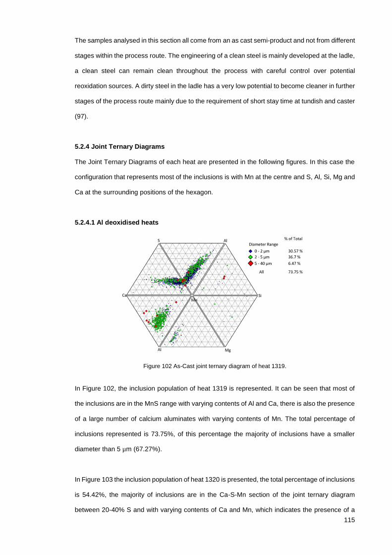
115
The samples analysed in this section all come from an as cast semi-product and not from different
stages within the process route. The engineering of a clean steel is mainly developed at the ladle,
a clean steel can remain clean throughout the process with careful control over potential
reoxidation sources. A dirty steel in the ladle has a very low potential to become cleaner in further
stages of the process route mainly due to the requirement of short stay time at tundish and caster
(97).
5.2.4 Joint Ternary Diagrams
The Joint Ternary Diagrams of each heat are presented in the following figures. In this case the
configuration that represents most of the inclusions is with Mn at the centre and S, Al, Si, Mg and
Ca at the surrounding positions of the hexagon.
5.2.4.1 Al deoxidised heats
Figure 102 As-Cast joint ternary diagram of heat 1319.
In Figure 102, the inclusion population of heat 1319 is represented. It can be seen that most of
the inclusions are in the MnS range with varying contents of Al and Ca, there is also the presence
of a large number of calcium aluminates with varying contents of Mn. The total percentage of
inclusions represented is 73.75%, of this percentage the majority of inclusions have a smaller
diameter than 5 µm (67.27%).
In Figure 103 the inclusion population of heat 1320 is presented, the total percentage of inclusions
is 54.42%, the majority of inclusions are in the Ca-S-Mn section of the joint ternary diagram
between 20-40% S and with varying contents of Ca and Mn, which indicates the presence of a

116
mixture of CaS and MnS inclusion. Also notice that the calcium aluminates population is reduced
compared to heat 1319. There is a higher percentage of inclusions higher than 5 µm in diameter
and most of them are in the Ca-S-Mn section.
Figure 103 As-Cast joint ternary diagram of heat 1320.
Figure 104 As-Cast joint ternary diagram of heat 1332.
In Figure 104, the inclusion population of heat 1332 is presented, the percentage of inclusions
represented is 64.59% of the total. It can be seen that there is a high percentage of inclusions
with diameter higher than 5 µm (30.65%) and from the diagram it can be seen that most of these
large inclusions are concentrated close to the Mn-S axis of the diagram. The amount of calcium
aluminates is less than in heat 1319 but higher than in heat 1320.

117
5.2.4.2 Si-Al deoxidised heats
Figure 105 As-Cast joint ternary diagram of heat 2456.
In Figure 105 the inclusion population of heat 2456 is presented, the percentage of inclusions is
72.12 of the total. The majority of inclusions are in the Mn-S-Al section of the diagram, indicating
that most of the inclusions are MnS with varying contents of Al. Note also the reduced Ca content
of inclusions (<20%) indicating very few CaS and CA types of inclusions are present. This heat
has the highest percentage of inclusions higher than 5 µm (46.01%), with the majority of these
being MnS and few of them being CA.
The inclusion population of heat 2457 is presented in Figure 106, the percentage of inclusions
represented is 67.43% of the total. The majority of inclusions are MnS with varying percentage of
Al, and there are also very few CaS and CA inclusions. It can also be seen that the inclusions
with diameters greater than 5 µm are 24.09% of the population and that they consist mainly of
MnS.

118
Figure 106 As-Cast joint ternary diagram of heat 2457.
The inclusion population of heat 2458 can be seen in Figure 107, it can be seen that the majority
of these inclusions are MnS with varying amounts of Al (up to 60%) and Ca (up to 30%). Most of
these inclusions account for the larger sizes with 21.1% of the total. Note also the few CA
inclusions with only one exceeding 5 µm.
Figure 107 As-Cast joint ternary diagram of heat 2458.
5.2.4.3 Summary
To summarise, it can be seen that the main categories of inclusion present are MnS, CaS-MnS
and some calcium aluminates. There is a higher presence of calcium aluminates in the Al practice
than for the Si-Al practice. With regard to the sizes, the Al practice has a lower percentage of
large inclusions compared to the Si-Al practice, and most of the inclusions with larger sizes in the
Si-Al practice are MnS whereas for the Al practice most of the larger size inclusions are a mixture

119
of MnS and calcium aluminates. The heats with the highest percentage of large inclusions were
1332 and 2456 for the Al and Si-Al practices respectively.
5.2.5 Extreme Value Analysis
5.2.5.1 Extreme Value Analysis of Automated Optical Microscopy:
The extreme value statistical distributions of each heat of the Al deoxidation practice are
presented in Figure 108, and it can be observed that the heat with the highest probability of having
a large inclusion is heat 1332, followed by 1320 and 1319 with smaller large inclusion sizes. This
is demonstrated by the slope of the line created based on the data points (see blue line
corresponding to heat 1332) that spans towards greater sizes, whereas the other lines (heats
1319 and 1320) show a larger slope that spans only over a limited range of sizes.
Figure 108 Extreme value distribution of as-cast Al heats from automated OM.
The extreme value distributions of the Si-Al heats are presented in Figure 109, it can be
appreciated that the distribution with the highest probability of finding and inclusion with the
maximum largest size is heat 2458 followed by 2456 and 2456 with the probability distribution
within smaller inclusion sizes.

120
Figure 109 Extreme value distribution of as-cast Si-Al heats from automated OM.
Figure 110 represents the extreme value distribution summarising the 3 heats analysed for each
deoxidation practice. It can be observed that when grouped together these particular heats to
assess deoxidation practice, the probability of finding a larger inclusion is found in the Al practice
and the size ranges are not very distant from that of the Si-Al practice. In Figure 108, it can be
observed that the dispersion between heats is much greater in the Al practice than the Si-Al
practice. This demonstrates that the distributions of large inclusions is an important variable when
assessing cleanliness on a heat to heat basis.
Figure 110 Extreme value distributions summarising 3 heats of each deoxidation practice from automated OM results.

121
5.2.5.2 Extreme Value Analysis of Scanning Electron Microscopy- Automated Feature
Analysis:
The extreme value distribution of Al heats obtained with SEM-AFA is shown in Figure 111. The
heat with the highest probability of having a large inclusion is 1332 followed by heat 1319 and
1320 respectively although the size ranges of these last two heats are narrower than the size
range of heat 1332.
Figure 111 Extreme value distribution of as-cast Al heats from AFA-SEM results.
The extreme value distribution of Si-Al heats is presented in Figure 112, it can be appreciated
that the heat with the highest probability of having a large inclusion is heat 2456 followed by heats
2458 and 2457 respectively. Heat 2456 has a wider size range than the other two heats.
Figure 112 Extreme value distribution of as-cast Si-Al heats from AFA-SEM results.

122
In Figure 113, the extreme value distributions summarising Al heats and Si-Al heats can be
observed. It can be seen that the probability of finding a large inclusion is higher for the Si-Al
practice and also that the size range is greater for the Si-Al practice.
Figure 113 Extreme value distributions summarising Al heats vs Si-Al as-cast heats from SEM-AFA.
5.2.5.3 Summary
In Table 11, the maximum predicted inclusion size of each heat in an area 1000 times larger than
the area of analysis used in this investigation is shown. Although the trend of the largest inclusions
is consistent for both techniques (i.e the largest predicted inclusion is found in the Al deoxidised
heat 1332), it can also be noted that the results differ between techniques, the possible reasons
were explained in the previous section.
Table 11 Maximum predicted inclusion size from extreme value analysis of as-cast heats from automated OM and SEM analysis.
Deoxidation Heat L Max (µm)
Automated OM
L Max (µm)
AFA-SEM
Al 1319 135.94 18.08
1320 169.79 15.10
1332 383.69 62.97
Si-Al 2456 158.44 61.24
2457 180.52 27.66
2458 210.44 28.11

123
5.2.6 Discussion Summary
In this section the results of inclusion characterisation of heats produced using different
deoxidation practices have been presented. The results show variations from heat to heat even
within the same deoxidation practice. As it has been noted there are many different factors that
can influence the final inclusion content of a heat, and it has been shown that depending on the
technique and the area analysed, the results can vary significantly.

124
Chapter 6 Effect of Plastic Deformation on Inclusion
Population
6.1 Introduction
In this chapter the distribution and characteristics of inclusions in deformed material is presented
and discussed. The first part presents results from 4 different heats of each deoxidation practice
that have been analysed. In the second part, a comparison of as cast and as deformed material
was made to assess the effect of deformation on the inclusion population.
6.2 Characterisation of as deformed Al heats (1319, 1320, 1330 and
1332) and Si-Al deoxidised heats (2455, 2456, 2457 and 2458)
6.2.1 Optical Microscopy
In Table 12, the summary of results from manual optical characterisation is presented. It can be
seen that the number of inclusions varies greatly from one heat to another without a clear trend
between deoxidation practice. The largest number is found in heat 1320 and the lowest in heat
2456. The area of inclusions in general seems to be higher for the Al practice with only heat 1330
showing a lower area than the Si-Al deoxidised heats. The rest of the variables reported vary
greatly among heats.
Table 12 Manual Optical Microscopy as-deformed summary results.
Deoxidation Al deoxidised Si-Al deoxidised
Heat 1319 1320 1330 1332 2455 2456 2457 2458
Total Number 1951 4795 2194 3118 3267 1389 2343 2018
Total Area (µm²) 23272 25896 8360 20572 14695 9657 15814 8186
Average Area
(µm²)
11.93 5.40 3.81 6.60 4.50 6.95 6.75 4.06
Average Diameter
(µm)
4.19 3.03 2.54 3.13 2.81 3.51 3.37 2.58
Inclusion Index 0.15 0.16 0.05 0.13 0.09 0.06 0.10 0.05
Number per mm² 123.04 302.39 138.36 196.63 206.03 87.60 147.76 127.26

125
6.2.2 Automated Optical Microscopy
In Table 13, the results from automated optical microscopy are summarised. It can be seen that
the total number of inclusions is higher for the Si-Al heats. The heat with the highest number was
heat 2455 and the heat with the lowest number was heat 1330. The total area of inclusions was
also higher for all Si-Al deoxidised heats compared to the Al heats, the largest area corresponded
to heat 2455 and the smallest area was found in heat 1330. The average area was largest in heat
1330 and smallest for heat 2455. The number of inclusions per millimetre squared were in general
larger for the Si-Al heats than for the Al heats, the largest number being heat 2455 and the
smallest value was found in heat 1330. The average of length of inclusion was largest in heat
1330 and smallest in heat 2458. The maximum particle length was found in heat 2455 and the
smallest value of maximum particle length was found in heat 1320. It can be noted that in general
the Si-Al heats exhibited larger maximum particle sizes than the Al heats, nevertheless heats
1330 and 1332 presented larger maximum sizes than Si-Al heat 2457. The average circularity of
features varied more in the Si-Al heats as both the largest and smallest values were found in
heats 2455 and 2458 respectively.
Table 13 Automated Optical Microscopy as-deformed summary results.
Deoxidation Al deoxidised Si-Al deoxidised
Heat 1319 1320 1330 1332 2455 2456 2457 2458
Total Number 4982 4033 1949 4170 20726 7262 7943 13534
Total Area 26702
4
19396
7
12630
1
19872
0
80692
8
37051
9
42209
3
63495
6
Average Area 53.60 48.10 64.80 47.65 38.93 51.02 53.14 46.92
Number per
mm2
52.07 42.15 20.37 43.58 216.62 75.90 83.02 141.45
Average of
Length
10.37 10.40 11.45 10.26 10.18 10.32 10.56 9.60
Max of Length 95.5 76.02 154.09 176.73 266.77 254.53 105.1 187.98
Average of
Circularity
0.576 0.526 0.523 0.532 0.461 0.581 0.553 0.601
Inclusion Index 0.279 0.203 0.132 0.208 0.843 0.387 0.441 0.664
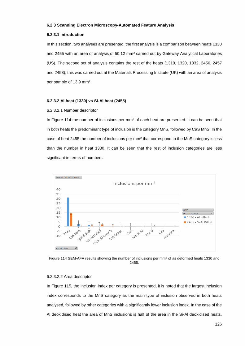
126
6.2.3 Scanning Electron Microscopy-Automated Feature Analysis
6.2.3.1 Introduction
In this section, two analyses are presented, the first analysis is a comparison between heats 1330
and 2455 with an area of analysis of 50.12 mm2 carried out by Gateway Analytical Laboratories
(US). The second set of analysis contains the rest of the heats (1319, 1320, 1332, 2456, 2457
and 2458), this was carried out at the Materials Processing Institute (UK) with an area of analysis
per sample of 13.9 mm2.
6.2.3.2 Al heat (1330) vs Si-Al heat (2455)
6.2.3.2.1 Number descriptor
In Figure 114 the number of inclusions per mm2 of each heat are presented. It can be seen that
in both heats the predominant type of inclusion is the category MnS, followed by CaS MnS. In the
case of heat 2455 the number of inclusions per mm2 that correspond to the MnS category is less
than the number in heat 1330. It can be seen that the rest of inclusion categories are less
significant in terms of numbers.
Figure 114 SEM-AFA results showing the number of inclusions per mm2 of as deformed heats 1330 and 2455.
6.2.3.2.2 Area descriptor
In Figure 115, the inclusion index per category is presented, it is noted that the largest inclusion
index corresponds to the MnS category as the main type of inclusion observed in both heats
analysed, followed by other categories with a significantly lower inclusion index. In the case of the
Al deoxidised heat the area of MnS inclusions is half of the area in the Si-Al deoxidised heats.

127
The second largest area category corresponds to CaS MnS inclusions. In the case of heat 2455
the inclusion index of MnS is the largest despite being less in number per mm2 compared to heat
1330. The second largest category in the Si-Al deoxidised heat is the Spinel Rich category.
Figure 115 SEM-AFA results showing inclusion index per inclusion category of as deformed heats 1330 and 2455.
6.2.3.2.3 Size descriptors
In Figure 116, the average diameter size is presented. In the case of Si-Al deoxidised heats the
presence of CA6 and CA2 categories with the largest average diameter is of interest because
these types are too small or insignificant in terms of numbers and percentage area. The number
of CA6 inclusions and the area they represent are 7 and 1.47% respectively, and in the case of
CA2 the numbers are even lower at 2 and 0.51%. In the case of the Al deoxidised heat the CA2
category represents 2 inclusions with a percentage area of 0.62%. Note also that the MnS
average size corroborates the previous observations about the numbers and areas of inclusions
in this category, the average size is larger for the Si-Al heat and smaller in the Al heat.

128
Figure 116 SEM-AFA results showing the average diameter of inclusions per inclusion category of as deformed heats 1330 and 2455.
The maximum inclusion diameter detected per category is shown in Figure 117, almost in all
categories Si-Al heats show a larger maximum inclusion diameter than Al deoxidised heats. For
both heats the largest inclusion diameter detected is MnS, being larger in the Si-Al deoxidised
heat.
Figure 117 SEM-AFA results showing the maximum inclusion diameter per inclusion category of as deformed heats 1330 and 2455.
In Figure 118, the size distribution of the inclusion population of each heat is shown. The majority
of inclusions are in the range 1-2 µm diameter in both cases, but the amount of inclusions larger
than 5 µm in diameter is higher in the Si-Al deoxidised steel.

129
Figure 118 SEM-AFA results showing the size distribution of as deformed heats 1330 and 2455.
6.2.3.2.4 Shape descriptors
The average aspect ratio is presented in Figure 119. The average aspect ratios show that the
inclusions with higher average aspect ratios in the Al deoxidised steel are “Spinel Pure” and “CA”
category types, whereas for the Si-Al deoxidised steel the higher average aspect ratios
correspond to the “MnS”, “Spinel Rich” and “alumina” categories.
Figure 119 SEM-AFA results showing the average aspect ratio per inclusion category of as deformed heats 1330 and 2455.
In Figure 120, the maximum aspect ratio of inclusion categories are presented. The highest
aspect ratios are found in Si-Al deoxidised steel, with the “MnS”, “unclassified”, and “Spinel Rich”
categories standing out. The top three categories of the Al deoxidised steel are “MnS”, “CaS MnS”
and “unclassified” categories. The MnS inclusion population is the one that has the greatest
variability after deformation.

130
Figure 120 SEM-AFA results showing the maximum aspect ratio per inclusion category of as deformed heats 1330 and 2455.
6.2.3.3 As deformed heats (1319, 1320, 1332, 2456, 2457and 2458)
The previous section highlighted the differences between two particular heats (1330 and 2455)
carried out by Gateway Analytical Laboratories. The area of the analysis was greater and the
instrument employed for the analysis was different than the one employed in this section. The
purpose of this section is to address the results obtained from the rest of the heats as it has been
carried out with material in the as cast condition. In this section the results of remaining heats
(1319, 1320, 1332, 2455, 2456 and 2458) of the as deformed material are addressed in the
following figures. These results were obtained from the Materials Processing Institute in the UK.
6.2.3.3.1 Number descriptor
Figure 121 shows the number of inclusions per mm2 of each heat represented. It can be seen
that the most numerous category in all heats is the MnS. The heat with the highest number of
inclusions is 1319 and the heat with lowest number is 1320 with 41 and 21 inclusions per mm2
respectively, both from the Al deoxidation practice.

131
Figure 121 SEM-AFA results showing the number of inclusions per mm2 of as-deformed heats.
6.2.3.3.2 Area Descriptor
In Figure 122, the inclusion indexes of each heat are represented. As can be seen, the category
with the greatest inclusion index is MnS for all the heats and the heat with the largest inclusion
index is heat 2456 and the heat with the smallest inclusion index is heat 1332.
Figure 122 SEM-AFA results showing the inclusion indexes per inclusion category of as-deformed heats.
6.2.3.3.3 Size Descriptors
In Figure 123 the average inclusion diameters of all the heats can be seen. It can be observed
that in all the Al deoxidised heats most of the inclusion categories have an average inclusion
diameter of less than 5 µm. In the Si-Al deoxidised heats some inclusion types show a higher
average inclusion size (SiO2, CaO- SiO2-MnO and MnS with Al2O3-CaO-MgO). The heat with the
highest average inclusion sizes is heat 2458 and the heat with the lowest is heat 1332.

132
Figure 123 SEM-AFA results showing the average inclusion diameter per inclusion category of as-deformed heats.
The maximum inclusion diameters per category are represented in Figure 124. The largest
inclusion in all the heats investigated was MnS except for heat 1332 in which case the largest
inclusion found was Al2O3 with a size of 9 µm. It is interesting to note that for the case of heat
1332 the most numerous inclusion type is MnS but this heat also shows the lowest average
diameter (Figure 123) which is in accordance with the study made by A. Segal and J.A. Charles,
which indicates that MnS with smaller diameters deform less than larger MnS type inclusions (50).
Figure 124 SEM-AFA results showing the maximum inclusion diameter per inclusion category of as-deformed heats.
In Figure 125, the size frequency distribution of each as deformed heat is presented. In general
Si-Al heats tend to have more inclusions larger than 5 µm than Al heats but in the case of heat
1319, the number of inclusions larger than 5 µm is larger than the number in heat 2458.

133
Figure 125 SEM-AFA results showing the inclusion size frequency distribution of as deformed heats.
6.2.3.3.4 Shape descriptors
The average aspect ratio of inclusions is shown in Figure 126. The average aspect ratio is greater
for the MnS type in almost all heats apart from in heat 1332 where the largest average aspect
ratio corresponds to the category MnS with Al2O3 CaO. As explained earlier this might be as a
result of the presence of larger sizes of the MnS with Al2O3 CaO type of inclusions in the as cast
condition.
Figure 126 SEM-AFA results showing the average aspect ratio per inclusion category of as deformed heats.
In Figure 127, the maximum aspect ratio of each category is presented. The maximum aspect
ratio in all heats was the MnS type, with the highest in heat 1319 and the lowest in heat 1332,
both from Al deoxidation practice.

134
Figure 127 SEM-AFA results showing the maximum aspect ratio per inclusion category of as-deformed heats.
6.2.3.3.5 Summary
The number of inclusions per mm2 of as deformed heats is summarised in Figure 128. Heat 2456
has the highest number of inclusions per mm2 and heat 2455 has the lowest number of inclusions
per mm2. Both of these heats were produced with the Si-Al deoxidation route. As this figure
demonstrates there is also a high variability between heats.
Figure 128 SEM-AFA summary of inclusions per mm2 of as deformed heats.
The inclusion index of as deformed heats is represented as a bar chart with their respective
cumulative categories in Figure 129. It can be seen that in general most of the Al heats show
lower inclusion indexes, only heat 1319 has a higher index than heats 2455 and 2458 from the
Si-Al deoxidation route.

135
Figure 129 SEM- AFA summary of inclusion index of as-deformed heats.
In Figure 130, the percentage of inclusion categories detected in deformed material of each heat
are represented. It can be seen that the predominant type of inclusion is MnS for all the heats
with varying contents of the other inclusion category types.
Figure 130 SEM-AFA summary results of area percentage of inclusions in as-deformed heats.
A summary table of as deformed samples analysed with SEM-AFA is presented in Table 14.

136
Table 14 SEM-AFA summary of results of as-deformed heats.
Deoxidation Al Si-Al
Heat ID 1319 1320 1330 1332 2455 2456 2457 2458
Scan Area
(mm²)
13.9 13.9 50.122 13.9 50.122 13.9 13.9 13.9
Total Number 720 511 1852 593 1100 878 608 460
Total Area
(µm²)
6315 2941 6902 1446 13169 10260 7838 3576
Avg Area (µm²) 9 6 4 2 12 12 13 8
Avg Diameter
(µm)
3 2 2 1 3 3 3 2
Number per
mm²
52 37 37 43 22 63 44 33
Average NND
(µm)
52 56 77 60 103 50 73 74
Inclusion Index 0.045 0.021 0.014 0.010 0.026 0.074 0.056 0.026
The results shown in Table 14, were obtained with different systems and as a result some
differences in the parameters employed were found. An initial attempt was made to include all
heats together for analysis but only some of the parameters were found to be suitable for accurate
comparison of the inclusion populations of the rest of the heats with those of heats 1330 and 2455
(section 6.2.3.3 and section 6.2.3.2). These parameters are discussed below. The number per
mm2 varies from heat to heat and there does not seem to be a clear tendency between
deoxidation practices. For example, the largest number of inclusions per mm2 is in heat 2456 and
the smallest is in heat 2455 both of which are from the Si-Al practice. The average nearest
neighbour distance also varies from heat to heat without any clear tendency. The heat with the
largest inclusion index is found in the Si-Al practice (heat 2456) and the heat with the smallest
inclusion index is found in the Al practice (heat 1332).
In order to avoid the problems associated with different inclusion categories employed by the
different systems (or their classifying rule files), the chemical classification of inclusions was

137
performed employing the joint ternary diagrams. This tool allows us to make a clearer chemical
composition comparison across all heats because this representation takes into account the
normalised raw elemental composition of each individual inclusions and not the categories in the
bar charts as shown previously.
6.2.4 Joint Ternary Diagrams
6.2.4.1 Al heats
The joint ternary diagrams of as deformed Al heats are presented in the following section. In
Figure 131 the inclusion population of heat 1319 is presented. It can be seen that MnS inclusions
with varying Al content is the predominant type with approximately 15.76% of these inclusions
having sizes greater than 5 µm. There is also the presence of MnS inclusions with less than10%
Ca. There is also a small presence of Al, Mg and Si containing inclusions.
Figure 131 Joint ternary diagram of as-deformed heat 1319 (Al deoxidised).
In Figure 132 the inclusion population of heat 1320 is shown. It can be observed that the main
inclusion category is again MnS with varying contents of Al and Ca. It can be seen that Ca
containing inclusions contain a greater percentage of Ca (up to 50%) than heat 1319. There is
also a greater presence of Al and Mg containing inclusions.

138
Figure 132 Joint ternary diagram of as-deformed heat 1320 (Al deoxidised).
In Figure 133 the inclusion population of heat 1330 is presented. The presence of MnS with
varying content of Al and Ca up to 50% can be seen. Also seen is the presence of calcium
aluminates with varying contents of Mn. In the Mn – Al - Mg section of the diagram there are also
some inclusions with higher Al content which could be related to spinel type inclusions.
Figure 133 Joint ternary diagram of as-deformed heat 1330 (Al deoxidised).
The inclusion populations of heat 1332 is presented in Figure 134. It can be seen that there is a
depletion of MnS inclusions on the Mn-S axis region compared to previous heats analysed. The
predominant type is a concentration of MnS inclusions with varying Ca from approximately 5% up
to 33%. There is also a concentration of MnS inclusions with varying Al content from 10% up to
70%.

139
Figure 134 Joint ternary diagram of as-deformed heat 1332 (Al deoxidised).
6.2.4.2 Si-Al heats
The joint ternary diagrams of as deformed Si-Al heats are presented in the following section. In
Figure 135, the inclusion population of heat 2455 is presented. This particular heat presents a
high percentage of inclusions greater than 5 µm in diameter and also a variety of inclusion
compositions. It can be seen that most of the large size (red) inclusions are MnS containing Al.
There is also the presence of Ca containing inclusions but less than Al deoxidised heats. It can
also be seen that there is an increased presence of Si containing inclusions, which is to be
expected given the deoxidation route.
Figure 135 Joint ternary diagram of as-deformed heat 2455 (Si-Al deoxidised).
In Figure 136 the inclusion population of heat 2456 is shown. There is a smaller amount of Ca
containing inclusions compared to heat 2455, but there is an increase in the number of Si
containing inclusions. It can also be observed that the majority of the inclusions are concentrated

140
in the MnS axis with some increase towards higher Al contents. There are just a few inclusions
containing Al and Mg.
Figure 136 Joint ternary diagram of as-deformed heat 2456 (Si-Al deoxidised).
In Figure 137 the inclusion population of heat 2457 is represented. The majority of the large red
inclusions in this diagram are in the MnS axis with up to 40% Al in the Mn-Al-S section and to the
opposite axis up to 10% Ca in the Mn-Ca-S section. There is also a pair of large inclusions
containing 40% Ca, 40% S and 20% Mn. There is a small cluster of inclusions in the Al, Si, Mn
section of the diagram, indicating the presence of Si containing inclusions, which will be as a
result of the deoxidation with Si.
Figure 137 Joint ternary diagram of as-deformed heat 2457 (Si-Al deoxidised).
The inclusion population of heat 2458 is presented in Figure 138. In this heat there are few
inclusions larger than 5 µm. The majority of inclusions are in the MnS area region, some of these

141
inclusions have a Ca content up to 10% and others have Al contents of up to 50%. This heat has
the lowest number of Si containing inclusions. Also there is a small presence of Al and Mg
containing inclusions in the Mn, Al, Mg section of the diagram.
Figure 138 Joint ternary diagram of as-deformed heat 2458 (Si-Al deoxidised).
6.2.4.3 Summary
From the joint ternary diagrams of the Al deoxidised heats it can be seen that the most populated
diagram was from heat 1330, where most of the inclusions were MnS inclusions containing
varying amounts of Al and Ca. The least populated diagram was from heat 1319. Al deoxidised
heats exhibited a higher amount of inclusions containing Al and Mg which can be associated with
spinel formation. Finally a very small proportion of inclusions analysed were larger than 5 µm in
diameter.
In the case of the Si-Al deoxidised heats the most populated diagram was from heat 2455 with a
high percentage of inclusions larger than 5 µm in diameter. The least populated diagram was
from heat 2458. In Si-Al deoxidised heats there is an increased presence of Si and Al which is
associated of course with the residual elements from the deoxidation practice. The percentage of
inclusions larger than 5 µm in diameter is higher for Si-Al deoxidised heats.
6.2.5 Extreme Value Analysis
In the following section, the Extreme Value distribution of the inclusion populations detected with
automated OM of each heat are shown.

142
6.2.5.1 Extreme Value Analysis of Automated Optical Microscopy:
In Figure 139, the extreme value distribution of the Al deoxidised heats is presented. In this
representation it can be seen that the probability of finding a large inclusion is the highest for heat
1330, followed by heats 1332, 1320 and the lowest probability is seen in heat 1319.
Figure 139 Extreme value distribution of as deformed Al heats obtained with automated OM.
In Figure 140, the extreme value distribution of Si-Al heats can be observed. It can be seen that
the probability of finding a large inclusion is highest for heat 2457, followed by heats 2455, 2458
and the lowest probability is for heat 2456.
Figure 140 Extreme value distribution of as deformed Si-Al heats obtained with automated OM.

143
In Figure 141, a summary taking into account the extreme value distribution of all heats of each
deoxidation practice is presented. According to this figure, the probability of finding an inclusion
with a larger size is highest for the Si-Al deoxidation practice.
Figure 141 Summary of extreme value distribution of as-deformed Al vs Si-Al deoxidised heats obtained with automated OM.
6.2.5.2 Extreme Value Analysis of Scanning Electron Microscopy-Automated Feature
Analysis:
The Extreme Value distribution of the inclusion populations detected with SEM-AFA of each heat
after deformation are presented in the following section.
In Figure 142, the extreme value distribution of Al deoxidised heats is presented. It can be seen
that the heat with highest probability of containing a large inclusion is heat 1319, followed by heats
1320, 1330 and the lowest probability is for heat 1332.

144
Figure 142 Extreme value distribution of as-deformed Al deoxidised heats obtained with SEM-AFA.
In Figure 143, the extreme value distribution of Si-Al heats can be observed. It can be observed
that the highest probability of finding a large inclusion in this case corresponds to heat 2458,
followed by heats 2457, 2456 and the lowest probability is seen in heat 2455.
Figure 143 Extreme value distribution of as-deformed Si-Al deoxidised heats obtained with SEM-AFA.
In Figure 144, a summary of extreme value distributions of all heats of each deoxidation practice
in as-deformed material is presented. As it can be seen the probability of finding a large inclusion
is higher for the Si-Al deoxidation practice than for the Al deoxidation practice.

145
Figure 144 Summary of extreme value distribution of as-deformed Al vs Si-Al deoxidised heats obtained with SEM-AFA.
6.2.5.3 Summary
When comparing as deformed results (Figure 144) with those of as-cast values presented in
Figure 113, it can clearly be seen that the probability of finding a larger inclusion in both
deoxidation practices increases after deformation. This is due to the plastic deformation of
inclusions during hot working due to the compressive and shear forces and the friction of the
metal flowing around inclusions as explained in the literature review section (49,52,98–101).
In Table 15, the maximum inclusion size predicted to be found in an area 1000 times larger than
the area of analysis is presented. The largest inclusion of the automated OM results is found for
the Al practice in heat 1330 and for the AFA-SEM results is found for the Si-Al practice in heat
2458.
Table 15 Maximum predicted inclusion size from extreme value analysis of as deformed heats from automated OM and SEM.
Deoxidation Heat L Max (µm)
Automated
OM
L Max (µm)
AFA-SEM
Al 1319 84.92 103.53
1320 105.45 69.29
1330 128.19 19.01
1332 114.13 14.77
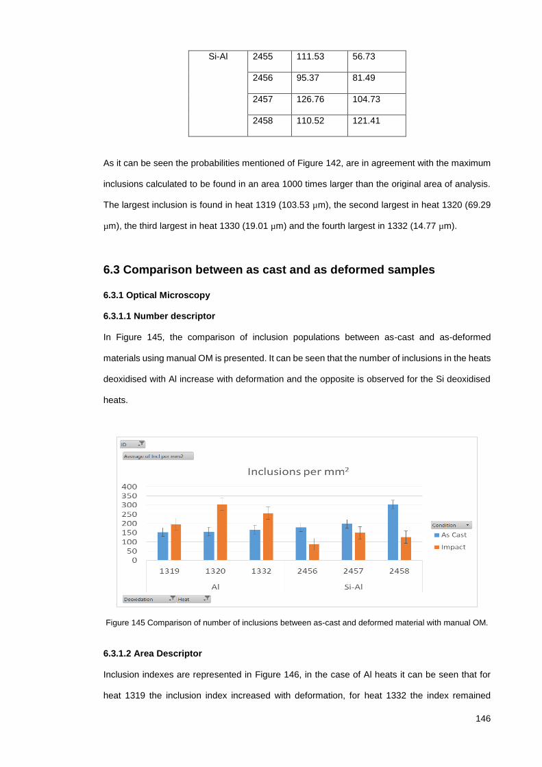
146
Si-Al 2455 111.53 56.73
2456 95.37 81.49
2457 126.76 104.73
2458 110.52 121.41
As it can be seen the probabilities mentioned of Figure 142, are in agreement with the maximum
inclusions calculated to be found in an area 1000 times larger than the original area of analysis.
The largest inclusion is found in heat 1319 (103.53 µm), the second largest in heat 1320 (69.29
µm), the third largest in heat 1330 (19.01 µm) and the fourth largest in 1332 (14.77 µm).
6.3 Comparison between as cast and as deformed samples
6.3.1 Optical Microscopy
6.3.1.1 Number descriptor
In Figure 145, the comparison of inclusion populations between as-cast and as-deformed
materials using manual OM is presented. It can be seen that the number of inclusions in the heats
deoxidised with Al increase with deformation and the opposite is observed for the Si deoxidised
heats.
Figure 145 Comparison of number of inclusions between as-cast and deformed material with manual OM.
6.3.1.2 Area Descriptor
Inclusion indexes are represented in Figure 146, in the case of Al heats it can be seen that for
heat 1319 the inclusion index increased with deformation, for heat 1332 the index remained

147
similar and for 1320 the inclusion index decreased slightly. In the case of the Si-Al heats it can be
seen that there is a decrease in the inclusion indexes for all heats after deformation.
Figure 146 Comparison of total area of inclusions between as-cast and deformed material with manual OM.
6.3.1.3 Size descriptor
In the case of the average inclusion size, represented in Figure 147, the average sizes of
inclusions in all heats decreased as a result of deformation.
Figure 147 Comparison of average size of inclusions between as-cast and deformed material with manual OM.

148
Figure 148 Comparison of maximum diameter of inclusions between as-cast and deformed material with manual OM.
In Figure 148, the maximum diameter size per heat is compared. It can be seen that Al heats had
a greater maximum size in the as cast condition and after deformation all maximum inclusion
sizes were reduced. In the case of Si-Al heats there is a reduction of sizes with respect to heats
2457 and 2458 but no significant decrease with heat 2456.
6.3.1.4 Shape descriptor
In Figure 149, the comparison of average inclusion circularity is presented. There are no
significant changes with respect to inclusion average circularity as the values are near to 1 which
is the value of a perfect circle, although there seems to be a slight increase after deformation
except for heats 1319 and 1332.
Figure 149 Comparison of circularity between as cast and deformed material with manual OM.

149
6.3.1.5 ASTM E45
In Table 16, the results of analysis of as deformed material from each heat according to ASTM
E45 standard method “A” are shown. In comparison with the as-cast values obtained from Al
heats reported in Table 8, it can be seen that there is an increase in the values of category A
(sulphides) and the appearance of category B (alumina) in heats 1320 and 1330. In the case of
category D (globular type) in heat 1319 there is an increase in the thin category from 0.5 to 2.00,
in heat 1320 there is a change in both thin and heavy categories from 0.4 and 0.5 to 1.5 and 0.0
respectively. With regard to heat 1332 the only noticeable change is the small increase from 0.5
to 1.0 in the thin type of category A (sulphide).
Table 16 ASTM As deformed results according to method A
Sulfide A Alumina B Silicate C Globular D
Heat Thin Heavy Thin Heavy Thin Heavy Thin Heavy
1319 0.50 1.00 0.00 0.00 0.00 0.00 2.00 0.50
1320 0.00 0.00 0.50 0.00 0.00 0.00 1.50 0.00
1330 0.50 1.00 0.50 0.00 0.00 0.00 0.50 0.00
1332 1.00 0.50 0.00 0.00 0.00 0.00 0.50 0.50
2455 1.00 1.00 0.00 0.00 0.00 0.00 0.50 0.50
2456 1.50 1.00 0.00 0.00 0.00 0.00 0.50 0.50
2457 1.00 1.50 0.00 0.00 0.00 0.00 0.50 0.00
2458 0.50 1.00 0.00 0.00 0.00 0.00 0.00 0.50
There is no evidence provided from the Si-Al as-cast heats but from processed results in Table
16, it can be seen that on average there are higher values for Category A (sulphides), there is no
evidence of Category B (alumina) detected and the values of category D are lower in general than
Al deoxidised heats after deformation.
6.3.2 Automated Optical Microscopy
6.3.2.1 Number descriptor
In Figure 150, the number of inclusions per mm2 of as-cast and as-deformed heats are compared.
The number of inclusions in general increases as a result of deformation and the increase is larger
for the Si-Al heats. The greatest increase is observed in heat 2458 and the smallest in heat 1332.

150
Figure 150 Comparison of number of inclusions between as-cast and deformed material from automated OM results.
6.3.2.2 Area descriptor
The comparison of the inclusion indexes per heat is shown in Figure 151, the indexes in the Al
heats decrease with deformation whereas the indexes in the Si-Al heats increase. The heats with
the most drastic changes are 1332 and 2458.
Figure 151 Comparison of inclusion indexes between as-cast and deformed material from automated OM results.
6.3.2.3 Size Descriptor
In Figure 152, the comparison of average inclusion size is presented. The average sizes of
inclusions in all heats decreased and the reduction was greater for the Al deoxidised heats.

151
Figure 152 Comparison of average size of inclusions between as-cast and deformed material from automated OM results.
Figure 153 shows a summary of all heats of each practice comparing the size distribution before
and after deformation. The size bin ranges that registered the largest increase as a result of
deformation were 6-8 and 8-10 µm. The size distribution that varied the most with deformation is
the inclusion populations of the Si-Al heats, all the size ranges showed an increase in frequency
as a result of deformation. In the case of the Al heats, there was an increase in the first size
ranges (smaller sizes) and there was a decrease in the latter size ranges (larger sizes).
Figure 153 Comparison of size distribution of inclusions between as-cast and deformed material from automated OM results.
6.3.2.4 Shape descriptor
Finally in Figure 154, the comparison of the circularity parameter with between as cast and as
deformed material is presented. In all cases circularity decreased as a result of deformation, the

152
material not only was deformed axially but also longitudinally as a result of forging and rolling
respectively.
Figure 154 Comparison of circularity of inclusions between as-cast and deformed material from automated OM.
6.3.3 Scanning Electron Microscopy-Automated Feature Analysis results
6.3.3.1 Number descriptor
In Figure 155 the number of inclusions per mm2 are represented, this parameter allows us to
make a comparison with regard to the number of inclusions in as cast and as deformed material.
As it can be seen, the number of inclusions per mm2 decreases for heats 1319, 2457 and 2458.
An increase in the number of inclusions per mm2 is observed for heats 1320, 1332 and 2456. As
noted, there is no clear difference with regard to deoxidation practice as both increasing and
decreasing tendencies were observed in different heats of each deoxidation practice.

153
Figure 155 SEM-AFA results showing the number of inclusions per millimetre squared of each heat in as-cast and as-deformed material.
6.3.3.2 Area descriptor
In Figure 156 the inclusion indexes of each heat before and after deformation are shown. This
parameter is the ratio of area of inclusions found over area analysed. As it can be seen the area
of inclusions increases for all heats as a result of deformation, except for heat 1332 which is Al
deoxidised.
Figure 156 SEM-AFA results showing the inclusion indexes per heat in as-cast and as-deformed material.
6.3.3.3 Size descriptors
In Figure 157 the average diameter is compared. It can be seen that for heats 1319, 1320, 2457
and 2458 the average diameter increases with deformation. For heat 2456 the average diameter
doesn’t change and for heat 1332 the average diameter decreases with deformation. From this

154
we can conclude that the effect of deformation with regard to inclusion average diameter varies
from one heat to another.
Figure 157 SEM-AFA results showing average diameter per heat in as-cast and as-deformed material.
The maximum diameter detected in each heat, prior to and after deformation, is shown in Figure
158. There is an increase in the maximum inclusion diameter of the Si-Al deoxidised heats after
deformation with the largest being in heat 2457. In the case of the Al deoxidised heats the
maxiumum inclusion diameter also increases for heats 1319 and 1320 but decreases for heat
1332.
Figure 158 SEM-AFA results showing the maximum diameter detected per heat in as-cast and as-deformed material.

155
In Figure 159, the inclusion size distributions of as-cast and as-deformed material for the Al
deoxidised heats 1319, 1320 and 1332 are presented, the results indicate a reduction in the
number of inclusions after deformation.
Figure 159 SEM-AFA results showing the size distribution in as-cast and as-deformed material of Al deoxidised heats.
In Figure 160, the size distribution of the Si-Al deoxidised heats 2456, 2457 and 2458 is illustrated.
Figure 160 SEM-AFA results showing the size distribution in as cast and as deformed material of Si-Al deoxidised heats.
There is a reduction in the inclusion size distributions for heats of both deoxidation practices
although this might not be entirely associated with the deformation because there is also an
influence of the area analysed in each case (the as-cast condition had a greater analysis area
and therefore the number of inclusions detected is greater), the same area should be employed
to determine more accurately the effect of deformation on inclusion size distribution.

156
6.3.3.4 Shape Descriptors
In Figure 161, the average aspect ratio is presented, it has increased with deformation for all
heats although in heat 1332 the slight increase is less noticeable compared to other heats. It can
be seen that the extent of the increase varies from heat to heat, the greatest increase is found in
heat 1319 and heat 2456 for the Al and Si-Al deoxidation practices respectively.
Figure 161 SEM-AFA results showing the average aspect ratio per heat in as-cast and as-deformed material.
In Figure 162 the maximum aspect ratio of an inclusion detected is presented. The maximum
aspect ratio for heats 1319 and 2458 was found in deformed material whereas for the rest the
heats the maximum aspect ratio was found in the as-cast material.
Figure 162 SEM-AFA results showing the maximum aspect ratio per heat in as-cast and as-deformed material.

157
6.3.3.5 Summary
As part of the summary of the SEM-AFA results in Figure 163 and Figure 164 the chemical
categories were included. Not all the chemical categories directly compare from the as cast to as
deformed classifications, and the MnS category is a critical inclusion type that will be discussed
further.
Figure 163 SEM-AFA results showing the inclusion per mm2 comparison between as cast and as deformed material of heats from both deoxidation practices.
In heat 1319 it can be seen that the number of MnS inclusions per mm2 decreased with
deformation but the inclusion index of these MnS inclusions was drastically increased. In heat
1320 the number of MnS per mm2 increased and the inclusion index was also increased. In heat
1332 the total number of inclusions per mm2 increased but the number of MnS inclusions
remained at the same level, but the inclusion indexes for this heat decreased both in total and for
the MnS category.

158
Figure 164 SEM-AFA results showing the inclusion index comparison between as cast and as deformed material of heats from both deoxidation practices.
In heat 2456, the total number of inclusions per mm2 increased but the number of MnS inclusions
decreased significantly as a result of deformation. The total inclusion index also increased with
deformation but the inclusion index of MnS decreased. In heat 2457 the total number of inclusions
and of MnS inclusions per mm2 decreased. The total inclusion index and the MnS index both
increased with deformation in heat 2457. In heat 2458 the total number of inclusions and the
number of MnS inclusions per mm2 decreased with deformation. The total inclusion index
increased but the MnS index seemed to remain quite constant.
The only clear tendency from the above results is that the number of MnS per mm2 decreases as
a result of deformation in all the Si-Al deoxidised heats.
6.3.4 Joint Ternary Diagrams
Comparison of the joint ternary diagrams of each heat in the as cast and as deformed conditions
are presented in the following figures.
6.3.4.1 Al deoxidised heats
In Figure 165, the joint ternary diagrams of heat 1319 are presented. The predominant large types
of inclusions in as deformed material were MnS containing Al. In the as cast material there were
fewer MnS containing Al inclusions of larger size. Most of the calcium aluminate inclusions in the
as cast material were not detected in the as deformed material.

159
Figure 165 Joint ternary diagrams of heat 1319 (Al deoxidised).
In Figure 166, the joint ternary diagrams of heat 1320 are presented. In the as cast material the
presence of various type of inclusions (CaS, MnS, Spinel rich and CA) were detected but in the
as deformed material the inclusions found were mainly MnS and Al2O3. Note also the shift in the
larger sizes from scattered inclusion compositions in as cast materials to only large MnS in the
as deformed material.
Figure 166 Joint ternary diagrams of heat 1320 (Al deoxidised).
In Figure 167, the joint ternary diagrams of heat 1332 are shown. The main inclusions detected
in as cast material include MnS, CaS-MnS, and spinel rich inclusions. In the as deformed material
there were fewer Ca containing inclusions, and most of the inclusions present were Mns, MnS-
Al2O3 and MnS with Al2O3 MgO. In this case the larger inclusions were reduced in number from
as cast to as deformed material.

160
Figure 167 Joint ternary diagrams of heat 1332 (Al deoxidised).
6.3.4.2 Si-Al deoxidised heats
In Figure 168 the joint ternary diagrams of heat 2456 are represented. There is a reduction in
larger sizes of inclusions and also a reduction in the number of MnS inclusions from the as cast
to the as deformed material. In the as deformed material there were large Al2O3 and SiO2
containing inclusions detected.
Figure 168 Joint ternary diagrams of heat 2456 (Si-Al deoxidised).
In Figure 169, the joint ternary diagrams of heat 2457 are presented. The total number of
inclusions decreased with deformation but the total number of larger inclusions was larger in the
as deformed condition. In the as cast condition there were some Al and Mg containing inclusions
(spinel rich category) which were not detected in the as deformed material.

161
Figure 169 Joint ternary diagrams of heat 2457 (Si-Al deoxidised).
In Figure 170, the joint ternary diagrams of heat 2458 are illustrated. There was a reduction in the
number of inclusions as a result of deformation and it can be seen that most of the MnS and
spinel rich inclusions were not detected in the as deformed analysis. The larger inclusion types
are randomly distributed in the as deformed material diagram with some showing on the Mn-Si
axis of the diagram.
Figure 170 Joint ternary diagrams of heat 2458 (Si-Al deoxidised).
The main identifiable trend from these compositional ternary diagrams is the reduction in MnS
and Ca containing inclusions as a result of deformation. In the case of the Al deoxidised heats
the same phenomenon was observed with calcium aluminate inclusions.
6.3.4.3 Extreme Value Analysis
Table 15 contains the predicted maximum sizes found in as deformed material in comparison with
the as-cast results from Table 11 it can be seen that the predicted inclusion sizes obtained with
automated OM decrease with deformation in all heats. The AFA-SEM predicted inclusion sizes

162
tend to increase with deformation except heat 1332 of the Al practice which shows a decrease in
the maximum predicted inclusion size after deformation. Interesting that the inclusion index of
heat 1332 was the lowest of all heats. It also has the lowest percentage of MnS inclusions, this
indicates that the probability of finding larger inclusions is related to the percentage of MnS type
of inclusions present in the as cast material.
6.4 Grain size measurements
In Table 17 two micrographs are shown of the microstructure after deformation, it can clearly be
seen that the grain sizes are smaller and it can also be noted the presence of some segregation
bands. The microstructure consists of ferrite grains (bright) and pearlite grains (dark). These
microstructural bands are created due to the interdendritic chemical segregation which occurs
during solidification of the as cast semi product. This segregation is further aligned longitudinally
in rolled products and often appears in hot rolled products as reported in studies (19,102).
Table 17 Micrographs of microstructure after deformation.
Micrograph showing the as-deformed microstructure of Al killed steel from OM.
Micrograph showing the as-deformed microstructure of Si-Al deoxidised steel from
OM.
The results of the average grain size measurements obtained from micrographs of etched
samples are presented in Figure 171. It can be seen that regardless of the as cast average grain
size which is dependent on cooling rate, the effect of plastic deformation reduces the grain size
uniformly to a value between 11 and 12 µm. This is confirmed by the fact that error bars of as
deformed material are barely noticeable in Figure 171.

163
Figure 171 Average grain size measurements in as cast and as deformed samples

164
Chapter 7 Mechanical Testing Results
7.1 Introduction
Various mechanical properties of material from different heats produced with the different
deoxidation practice are reported in this section.
7.2 Hardness testing results
In Table 18 the results of Vickers hardness testing on as deformed (normalised) material are
presented:
Table 18 Hardness Testing results.
Heat Average HV
Al 153.55
1319 149.58
1320 165.16
1330 147.60
1332 156.30
Al-Si 155.03
2455 154.44
2456 167.60
2457 152.20
2458 145.52
Grand Total 154.097
Based on the results of Table 18, there is not a significant variation with regard to deoxidation
practice on the hardness values on the as deformed samples. As explained by Murakami in (59),
if Hardness Vickers is higher than 400, steels are sensitive to fatigue strength and depending on
the hardness of the steel a critical size can be determined above which any type of inclusion
influences fatigue life. In which case the statistics of extremes is the best method to quantify the
effect of inclusions on fatigue strength. According to Murakami empirical rule and the reported
results of Table 18, it can be concluded that there are no significant differences with regard to the
deoxidation practice and that the effect of inclusions on the relatively soft material (below the

165
400HV threshold) will be negligible, other microstructural features will have a higher effect on the
mechanical performance.
7.3 Tensile testing results
In Table 19 the results of tensile testing in the longitudinal direction are shown:
Table 19 Tensile Testing results of material.
Heat Refining
Practice
UTS in
MPa
UTS
(psi)
YS in
MPa
YS
(psi)
Elongation
%
Reduction of
Area %
1319 Al Killing 496.42 72000 330.26 47900 38 73
1320 Al Killing 508.14 73700 337.15 48900 39 75
1330 Al Killing 508.83 73800 344.05 49900 38 73
1332 Al Killing 517.11 75000 355.08 51500 38 72
2455 Si-Al Killing 536.91 77872 352.96 51193 42 72
2456 Si-Al Killing 507.45 73600 333.02 48300 40 75
2457 Si-Al Killing 505.39 73300 339.22 49200 40 73
2458 Si-Al Killing 507.45 73600 331.64 48100 40 74
The specification requirement of the tensile strength for this material is in the range of 450 – 600
MPa. The minimum requirement for yield strength is 295 MPa and a minimum of 21% of
elongation. The reported results in Table 19 shows that all materials evaluated from different
heats were all complying with specification requirements. The yield strength was calculated as
0.02 proof strength as indicated by the blue line in the testing curves presented in appendix C
(page 232). No significant difference with regard to tensile strength is noticed, this is consistent
with the results of Tomita Y. who found a slight anisotropy regarding the strength and percent
elongation of a 0.4C-Cr-Mo-Ni steel, despite the difference in the morphology of the non- metallic
inclusions (17). Tervo and Murakami also reported no significant effect of current inclusion levels
on the tensile strength (63,68). The aforementioned studies considered high strength steels
where the effect of inclusions is more noticeable as compared with low or medium strength steels
where the effect of inclusions is less likely to negatively affect the tensile strength unless at low
temperatures or with high inclusion volume fractions, which do not seem to be the case in the
present study. There is a slight difference noticeable in the percentage of elongation which seems
to suggest an increase in the ductility of the Si-Al deoxidised material which can be attributed to
166
the inclusion population that has a higher deformability index sulphides and silicates, as opposed
to oxides and calcium aluminates in Al deoxidised steel.
7.4 Toughness testing results
7.4.1 Charpy Impact testing
Two rings were produced from material of each heat. The tests were carried out at -40 degrees
Celsius. In Table 20 the results from Charpy impact testing of the first ring at half thickness and a
quarter thickness (towards the outer wall) are reported:

167
Table 20 Charpy impact values of the first ring at half and quarter thickness of each heat.
Deoxidation Heat ID Specimen
1 (Joules)
Specimen
2 (Joules)
Specimen
3 (Joules)
Average
(Joules)
1/2.
Al 1319 21.69 55.59 127.45 68.24
Al 1320 44.74 130.16 97.62 90.84
Al 1330 128.80 54.23 131.51 104.85
Al 1332 63.72 58.30 119.31 80.45
Si-Al 2455 132.87 105.75 86.77 108.47
Si-Al 2456 96.26 42.03 117.96 85.42
Si-Al 2457 81.35 70.50 50.17 67.34
Si-Al 2458 131.51 139.65 150.50 140.55
1/4.
Al 1319 88.13 168.12 37.96 98.07
Al 1320 120.67 77.28 108.47 102.14
Al 1330 117.96 162.70 153.21 144.62
Al 1332 159.99 131.51 153.21 148.24
Si-Al 2455 141.01 127.45 122.02 130.16
Si-Al 2456 111.18 116.60 66.44 98.07
Si-Al 2457 109.82 135.58 116.60 120.67
Si-Al 2458 59.66 107.11 131.51 99.43
In Table 21, the values of Charpy impact testing of the second ring at half thickness and a quarter
thickness (towards the outer wall) can be seen:

168
Table 21 Charpy impact values of the second ring at half and quarter thickness of each heat.
Deoxidation Heat ID Specimen
1 (Joules)
Specimen
2 (Joules)
Specimen
3 (Joules)
Average
(Joules)
1/2.
Al 1319 177.61 162.70 112.53 150.95
Al 1320 47.45 90.84 47.45 61.92
Al 1330 90.84 92.20 88.13 90.39
Al 1332 85.42 131.51 62.37 93.10
Si-Al 2455 98.97 46.10 20.34 55.14
Si-Al 2456 17.63 117.96 23.05 52.88
Si-Al 2458 84.06 107.11 75.93 89.03
1/4.
Al 1319 132.87 112.53 31.18 92.20
Al 1320 29.83 94.91 93.55 72.76
Al 1330 100.33 127.45 74.57 100.78
Al 1332 84.06 90.84 86.77 87.22
Si-Al 2455 14.91 115.24 135.58 88.58
Si-Al 2456 93.55 127.45 23.05 81.35
Si-Al 2458 188.46 172.19 134.23 164.96
The minimum individual impact value that a specimen should exhibit is 35.25 Joules (Nm) and in
average the minimum value should be 50.17 Joules. As it can be noted from tables 18 and 19
some individual values were reported to be below the minimum (highlighted), but on average all
tests comply with the relevant specification requirement.

169
Impact testing is widely used in the industry due to its low cost, its relatively easy set up and
facility to be conducted. The disadvantage of this test is that is not a very scientific approach for
modern applications. The uncertainty limits were originally developed in the 1950’s for the ASTM
organisation, and they were designed to utilize the distribution of the average of five
measurements from “good” machines and a large proportion of the good machines tested.
A review to the limits and uncertainty of the Charpy Machine from the National Institute of
Standards and Technology of the US Department of Commerce(103), highlights the many
sources of variation in results such as between-machine variation, within-machine variation,
material homogeneity, and operator error, variation in room temperature at testing, the type of
notch and the size of the sample, since the dimensions determine whether or not the material is
in plane strain.
In Table 22, the average values of the heats deoxidised with Al and heats deoxidised with Si-Al
are compared. It is noted that the effect of position has a great impact on the value of energy
absorption in both deoxidation conditions (i.e. the effect of cooling rate has an effect on grain size
and this has an effect on toughness).
Table 22 Average of Charpy values at half and quarter thickness, of Al vs Si-Al deoxidised heats.
Heat ID Average of
1 (Joules)
Average of
2 (Joules)
Average of
3 (Joules)
Average of
Average (Joules)
Al
1/2. 78.21 83.28 85.56 82.35
1/4. 109.75 106.75 105.90 107.47
Si-Al
1/2. 91.81 89.87 74.96 85.55
1/4. 102.65 128.80 104.20 111.89

170
Figure 172 Average impact energy values at half and quarter thickness of Al and Si-Al heats.
In Figure 172 the average impact values at different testing positions are presented. As it can be
seen these results demonstrate the importance of sample position selection, because the effect
of cooling rate, the alloying elements and the deformation regime, have an effect on the final grain
size and impact toughness is strongly related to grain size.
7.4.2 Crack Tip Opening Displacement testing
The significance of the CTOD test compared to the impact testing is that this test method
accurately characterises the resistance of any given material to fracture. It is believed that the KIC
value represent the lower limiting value of fracture toughness.
In

171
Table 23, the results of the crack tip opening displacement test at -40 degrees Celsius are shown.
It can be seen that there is no significant difference with regard to deoxidation practice in terms
of the values obtained from the test.

172
Table 23 Crack tip opening displacement test values of each heat.
Deoxidation Heat Kq [MPa sqrt(m)] CTOD[mm]
Al 1319 103.80 2.07
Al 1320 102.33 1.81
Al 1330 102.04 1.97
Al 1332 102.77 1.8
Si-Al 2455 102.41 1.79
Si-Al 2456 100.91 2.01
Si-Al 2457 98.55 1.85
Si-Al 2458 101.73 2.12
The values were obtained following the procedure stated in ASTM E1820 (104). To check for
qualification of Kq as KIC it must meet the certain requirements as stated in Section 9.1 of
1820 (104). The results in

173
Table 23 are shown as Kq because they do not meet the criteria for KIC qualification indicating
that the fracture toughness parameter developed is sensitive to in-plane dimensions.
With regard to deoxidation practice no significant difference seem to affect the results of Al vs Si-
Al deoxidised materials nor does the total CTOD vary significantly. Nonetheless, there is an
appreciable difference with regard to the fracture mode as can be seen in the fracture surfaces
presented in Table 24
In Table 24 the fracture surfaces of the SENB test specimens are presented:

174
Table 24 Fracture surfaces of SENB specimens showing differences in the fracture appearance.
Al deoxidised heats Si-Al deoxidised heats
Figure 173 Fracture surface of heat 1319.
Figure 174 Fracture surface of heat 2455.
Figure 175 Fracture surface of heat 1320.
Figure 176 Fracture surface of heat 2456.
Figure 177 Fracture surface of heat 1330
Figure 178 Fracture surface of heat 2457.
Figure 179 Fracture surface of heat 1332
Figure 180 Fracture surface of heat 2458
There is an appreciable difference in the fracture surface of Al killed heats and Si-Al killed heats.
In the Al deoxidised heats there is a portion of the surface that looks dark as opposed to the Si-
Al deoxidised heats where all the surface is bright. This was because of thermal tinting where the

175
specimens after being tested were heated up (to between 300-400º C in an oxidant atmosphere)
to react with oxygen so that all the surface of the component was “tinted” including the surface of
the crack internally. This was different to the behaviour of the Si-Al deoxidised heats which did
not present any “thermal tinting” or “heat tinting” demonstrating a difference between the two
materials evaluated. This event seems to indicate that the Si-Al deoxidised material has a higher
ductility which relates to the slight increase in the percentage of elongation observed in the tensile
tests of the Si-Al material.

176
Chapter 8 Conclusions and suggestions for further work
8.1 Conclusions
The main objective of this study was to determine the main differences in terms of inclusion
population of a steel grade fabricated via two different deoxidation practices, the effect of
deformation on the final distribution of the inclusions and assessment of the mechanical properties
of deformed material.
The following conclusions have been drawn from the results presented:
I. There were significant differences in the population of inclusions in the as-cast material
at different positions of the bloom for each deoxidation practice. At all positions analysed
Si-Al deoxidised steel had a greater number of inclusions per mm squared and a higher
proportion of MnS type inclusions than Al deoxidised steel. Differences in the inclusion
index were found at different locations within the bloom. Al deoxidised steel had inclusion
indexes decreasing from the surface to the core of the bloom - surface 0.022%, middle
radius 0.015% and core 0.012% respectively. Si-Al deoxidised material had the highest
inclusion index at the mid-radius position 0.057%, followed by the core position 0.041%
and the lowest at the surface position 0.019%. The size distributions showed that most
of the inclusions in the Al deoxidised material were smaller inclusions compared with the
Si-Al deoxidised material which produced larger sizes. The largest inclusion sizes were
reported to be inclusions with a higher deformability index in Si-Al deoxidised steel
(manganese sulphide, duplex manganese sulphide – calcium sulphide) as opposed to
the Al deoxidised steel where the largest inclusion sizes corresponded to inclusions with
a lower deformability index (alumina, calcium aluminates, silica).
II. From analysis of material from different heats in the as cast condition (at the mid radius
position) the amount of inclusions per mm squared of the Si-Al heats (2456, 2457 and
2458) demonstrated a smaller variability range when compared to the Al deoxidised heats
(1319, 1320 and 1332). The number of inclusions per mm squared of all three Si-Al heats
were lower than heat 1319 but higher than heats 1320 and 1332 of the Al deoxidised
process. With regard to inclusion index, Si-Al heats had the greater variability range
(0.057-0.015%) compared to Al heats (0.018-0.008%). The percentages of MnS

177
inclusions in Si-Al heats were all higher than 80% as opposed to Al heats where all were
below 60%, indicating higher percentages of other inclusion types (CaS-MnS, spinel rich,
and calcium aluminates) in Al deoxidised heats.
III. From analysis of material in the as deformed condition, the variability of Al heats with
regard to the number of inclusions per mm squared was larger when comparing heats
1330 and 2455 (Al and Si-Al deoxidised respectively). The inclusion index of Si-Al heats
had the largest range when comparing inclusion indexes. This indicates that Al
deoxidised heats present a higher variability in terms of inclusions per mm squared and
the Si-Al deoxidise heats present a higher variability in terms of the inclusion index. This
is consistent with the fact that Al heats had a higher proportion of hard and brittle
inclusions and the Si-Al heats had a higher proportion of deformable inclusions. The
former are more likely to be broken down into more and more smaller inclusions and the
latter are more likely to change area as a result of deformation.
IV. The results of mechanical properties from material produced with both deoxidation
practices showed no substantial difference at the macroscopic level (complying with
specification requirements). Yield strength and tensile strength are insensitive to the
inclusion populations found in material from both deoxidation practices. In a few single
results of impact testing the value of impact energy absorbed fell below the minimum
value required but when averaged it complied with the specification requirement. There
is no difference with regard to CTOD testing values but when comparing fracture surfaces
of CTOD tests at low temperature (-40º C), there is a clear difference in the fracture
surfaces of Al killed heats when compared to Si-Al heats.
V. The most accurate and descriptive method to analyse inclusions out of all the methods
employed to assess inclusions in this work (Manual Optical, Automated OM, and SEM-
AFA), was SEM-AFA although care should be taken when comparing results obtained
from different instruments to ensure that measurement conditions are the same.

178
8.2 Further Work
There are different areas in which this research can be further developed.
It would be very interesting to obtain samples from different stages of the steelmaking process for
each deoxidation practice to relate to the inclusion populations found in the as cast material, and
to track the evolution of different inclusion populations throughout secondary steelmaking.
Also the number of heats analysed could be increased in order to increase the statistical
significance of the results reported in this work.
The use of thermodynamic modelling to predict inclusion formation and chemistry has been
recently employed with much higher accuracy as many different updates have been made to the
databases and to the models. A study of the two deoxidation practices could be made to compare
with the experimental results data obtained as part of this thesis.
Further analysis of the fracture surfaces and mechanisms of fracture growth and coalescence
with respect to the second phase particles of material from both deoxidation practices should be
further studied.

179
Chapter 9 References
1. Welsch MT, Bruch D, Østby E. Forgings for Low Temperature Applications – Influences
of the Alloying Concept and Advanced Forging Procedures on Impact Strength and
Fracture Toughness. Twenty first International Offshore and Polar Engineering
Conference. 2011. p. 377–83.
2. BILLINGHAM J. Steel: a versatile advanced material in marine environments. Ironmak
Steelmak [Internet]. Maney; [cited 2014 Sep 15];21(6):452–8. Available from:
http://cat.inist.fr/?aModele=afficheN&cpsidt=3377890
3. Professor J Billingham, Professor J V Sharp, Dr J Kilgallon and DPJS. Review of the
performance of high strenght steels for offshore. Heal Saf Exec. 2003;
4. Producers G. Reliability of offshore structures Workshop proceedings. OGP Rep No 486
[Internet]. (486). Available from: http://www.ogp.org.uk/pubs/486.pdf
5. Thornton PA. The influence of Nonmetallic Inclusions on the Mechanical Properties of
Steel: A review. J Mater Sci. 1971;6:347–56.
6. Steneholm, K., Andersson, M. A. T., Nzotta M& J. Effect of top slag composition on
inclusion characteristics during vacuum degassing of tool steel. Steel Res Int.
2007;78((7)):522–530.
7. Riyahimalayeri K, Ölund P. Development of oxide inclusions during vacuum degassing
process. Ironmak Steelmak [Internet]. 2013 May [cited 2014 Sep 16];40(4):290–7.
Available from: http://www.maneyonline.com/doi/abs/10.1179/1743281212Y.0000000049
8. Garrison WM, Wojcieszynski AL. A discussion of the effect of inclusion volume fraction on
the toughness of steel. Mater Sci Eng A [Internet]. 2007 Aug [cited 2014 Sep 16];464(1–
2):321–9. Available from: http://linkinghub.elsevier.com/retrieve/pii/S0921509307003292
9. Maropoulos S, Ridley N. Inclusions and fracture characteristics of HSLA steel forgings.
Mater Sci Eng A [Internet]. 2004 Oct [cited 2014 Sep 16];384(1–2):64–9. Available from:
http://linkinghub.elsevier.com/retrieve/pii/S0921509304005787
10. Li-feng Z. Inclusion and Bubble in Steel- A review. JOURNAI, IRON STEEL Res Int.
2006;3:1–8.
11. Lesoult G. Macrosegregation in steel strands and ingots: Characterisation, formation and
consequences. Mater Sci Eng A [Internet]. 2005 Dec [cited 2014 Sep 16];413–414:19–29.
Available from: http://linkinghub.elsevier.com/retrieve/pii/S0921509305010063

180
12. Pfeifer H, Odenthal H-J. Measurement of flow in metallurgical reactors [Internet]. Available
from: https://www.dantecdynamics.com/flow-in-metallurgical-reactors
13. Maddalena R. Advanced SEM Methodology for Tracking Reoxidation in the Tundish.
AISTech 2013 Proc. 2013;2113–21.
14. Zhang L. Nucleation, growth, transport, and entrapment of inclusions during steel casting.
Jom. 2013;65(9):1138–44.
15. Skobir DA, Godec M, Balcar M, Jenko M. The determination of steel cleanliness in the as-
cast steel ingot 26NiCrMoV145. Vacuum [Internet]. 2009 Aug [cited 2014 Sep
16];84(1):205–8. Available from:
http://linkinghub.elsevier.com/retrieve/pii/S0042207X09002577
16. Kiessling R, Lange N. Nonmetallic Inclusions in Steel I-IV. Society M, editor. London: The
Metals Society; 1978. Section IV, page 46 p.
17. Tomita Y. Effect of Morphology of Nonmetallic Inclusions on Tensile Properties of
Quenched and Tempered. Mater Charact. 1995;5803(4):121–8.
18. Anderson WA, Paxton HW, LENA AJ. Precipitation from Solid Solution. Cleveland, Ohio:
American Society for Metals; 1959. 492 p.
19. Verhoeven JD. A Review of Microsegregation Induced Banding Phenomena in Steels. J
Mater Eng Perform. 2000;9(June):286–96.
20. Kirkaldy JS, von Destinon-Forstmann J, Brigham RJ. Simulation of Banding in Steels. Can
Metall Q [Internet]. Taylor & Francis; 1962 Jul 1;1(1):59–81. Available from:
https://doi.org/10.1179/cmq.1962.1.1.59
21. Bobadilla M, Jolivet JM, Lamant JY, Larrecq M. Continuous casting of steel: a close
connection between solidification studies and industrial process development. Mater Sci
Eng A. 1993;173(1–2):275–85.
22. Birat J. Steel cleanliness and environmental metallurgy. 9th Int Conf Clean Steel.
2015;201(September).
23. Henault E. A Statistical Method to Assess the Reliability of Cleanness Measurements for
High Quality Bearing Steels. ASTM Int. 2006;3(4):1–10.
24. Björklund J. Thermodynamic Aspects on Inclusion Composition and Oxygen Activity
during Ladle Treatment. 2008. 1-68 p.
25. Bodor M and. Steel deoxidation practice: Special emphasis on heavy section steel
castings. AFS Trans. 1985;93:99–114.

181
26. Malley RJO. Inclusion Evolution and Removal in Ladle Refining. AISTech 2017 Proc.
2017;(January):1567–86.
27. Kirihara K. Production technology of wire rod for high tensile strength steel cord.
KOBELCO Technol Rev. 2011;30:62–5.
28. Prasad AD, Sankaranarayanan SR. Thermodynamic modeling of deoxidation products
and inclusion chemistry in Mn/Si killed tire-cord steel. J Min Metall Sect B Metall.
2012;48(1):37–43.
29. Lind M, Holappa L, Prasad AD, Sankaranarayanan SR, Choudhary SK, Ghosh A, et al.
Optimization of intensified silicon deoxidation. ISIJ Int [Internet]. Springer US;
2015;22(1):1735–45. Available from: http://www.mdpi.com/2075-4701/7/11/460
30. Faraji M, Wilcox DP, Thackray RP, Todd I, Howe AA, Tsakiropoulos P. Effect of early
stages of thermomechanical processing on inclusions in high carbon steel. Mater Sci
Technol. 2014;
31. Turkdogan ET. Fundamentals of steelmaking. Materials Characterization. 1996.
32. Roy D, Pistorius PC, Fruehan RJ. Effect of silicon on the desulfurization of Al-killed steels:
Part I. Mathematical model. Metall Mater Trans B Process Metall Mater Process Sci.
2013;44(5):1086–94.
33. Roy D, Pistorius PC, Fruehan RJ. Effect of silicon on the desulfurization of Al-killed steels:
Part II. Experimental results and plant trials. Metall Mater Trans B Process Metall Mater
Process Sci. 2013;44(5):1095–104.
34. Kang Y-B, Lee H-G. Inclusions Chemistry for Mn/Si Deoxidized Steels: Thermodynamic
Predictions and Experimental Confirmations. ISIJ Int [Internet]. 2004;44(6):1006–15.
Available from:
http://joi.jlc.jst.go.jp/JST.Journalarchive/isijinternational1989/44.1006?from=CrossRef
35. Tomioka K, Ogawa K, Matsumoto H. Thermodynamics of Reaction between Trace
Amound of Al and Inclusion in Mn-Si Killed Steel. ISIJ Int. 1996;36(1996):S101–4.
36. Turkdogan ET. Fundumentals of Steelmaking. 2010th ed. 1996.
37. Holappa L, Nurmi S, Louhenkilpi S. Role of slags in steel refining: is ir really understood
and fully exploited? Steelmak Conf Proc. (2):12.
38. Holappa L, Hämäläinen M, Liukkonen M, Lind M. Thermodynamic examination of inclusion
modification and precipitation from calcium treatment to solidified steel. Ironmak Steelmak
[Internet]. 2003;30(2):111–5. Available from:

182
http://www.tandfonline.com/doi/full/10.1179/030192303225001748
39. Holappa L. On physic-chemical and technical limits in clean steel production. Steel Res
Int 2010. 2010;81:869–74.
40. Zhang, Lifeng; Pluschkell WBGT. Nucleation and Growth of Alumina Inclusions During
Steel Deoxidation. Steelmak Conf Proc. 2002;669–79.
41. Lindborg U. A collision model for the growth and separation of deoxidation products. Trans
Met Soc AIME. 1968;242:94.
42. Ende M Van. Formation and Morphology of non-Metallic Inclusions in Aluminium Killed
Steels. 2010. 1-261 p.
43. Kang YB, Kim HS, Zhang J, Lee HG. Practical application of thermodynamics to inclusions
engineering in steel. J Phys Chem Solids. 2005;66(2–4):219–25.
44. Xu G, Jiang Z, Li Y. Formation Mechanism of CaS-Bearing Inclusions and the Rolling
Deformation in Al-Killed, Low-Alloy Steel with Ca Treatment. Metall Mater Trans B Process
Metall Mater Process Sci. Springer US; 2016;47(4):2411–20.
45. Yang W, Zhang L, Wang X, Ren Y, Liu X, Shan Q. Characteristics of Inclusions in Low
Carbon Al-Killed Steel during Ladle Furnace Refining and Calcium Treatment. ISIJ Int.
2013;53(8):1401–10.
46. Choudhary SK. Thermodynamic evaluation of inclusion formation during cooling and
solidification of low carbon Si-Mn killed steel. Mater Manuf Process. 2012;27(9):925–9.
47. Capurro C, Cerrutti G, Cicutti C. Influence of Vacuum Degassing on steel cleanliness. 9th
Int Conf Clean Steel. 2015;(September):6–7.
48. Kitamura S. Preface to the Special Issue on “Fundamentals and Applications of Non-
metallic Inclusions in Solid Steel.” ISIJ Int. 2011;51(12):1943.
49. T. Malkiewicz ; S. Rudnik. Deformation of non-metallic inclusions during rolling of steel. J
Iron Steel Inst. 1963;201:33–8.
50. Segal A, Charles JA. Influence of particle size on deformation characteristics of
manganese sulphide inclusions in steel. Met Technol. 1977;4(November):177–82.
51. Hilty DARK and DC. Inclusions in steel. Electric furnace steelmaking conference
proceedings. 1985. p. 237.
52. Baker TJ, Gave KB, Charles JA. Inclusion deformation and toughness anisotropy in hot-
rolled steels. Met Technol. 1976;3(1):183–93.
53. Monnot, Jaques; Heritier, Monnot and Cogne JY. Relationship pf Melting Practice,

183
Inclusion Type, and Size with Fatigue Resistance of Bearing Steels. Eff steel Manuf
Process Qual Bear steels. 1988;149–65.
54. Pickering F. B. Inclusions. F. B. Pickering, editor. Sheffiled: The institution of metallurgists;
1979. 216 p.
55. Seetharaman S. Treatise on process metallurgy Volume 3: Industrial Processes, Part A.
London: Elsevier; 2014. 1727 p.
56. Pissenberger E. Optimisation and evaluation of different secondary metallurgy routes to
achieve high-quality strip steel [Internet]. EUR Technical steel research. 2009. IV, 171 S.
TS-WorldCat T4-Contract no 7210-P p. Available from:
http://www.worldcat.org/oclc/551856462%5Cnfile:///Z:/Bibliothek/Literaturdatenbank/M2
CC_citavi/Citavi_v5/M2CC/Citavi Attachments/Pissenberger 2009 - Optimisation and
evaluation of different.pdf
57. Kaushik P, Lowry M, Yin H, Pielet H. Inclusion Characterisation for Clean Steelmaking
and Quality Control. Ironmak Steelmak [Internet]. 2012;39(4):284–300. Available from:
http://www.maneyonline.com/doi/abs/10.1179/1743281211Y.0000000069
58. Tervo H, Kaijalainen A, Kömi J. Investigation on Inclusions and Their Effect on the
Mechanical Properties and Bendability of Ultra-High-Strength Steel. MultiScience - XXXI
microCAD Int Multidiscip Sci Conf. 2017;(April):20–1.
59. Murakami Y. Metal fatigue: effects of small defects and non metallic inclusions. Oxford:
Elsevier; 2002.
60. Holappa LEK, Helle AS. Inclusion Control in High-Performance Steels. J Mater Process
Tech. 1995;53(1–2):177–86.
61. Olund P. Developing a lighter, stronger and cleaner air-melt steel for critical applications
[Internet]. Available from: http://www.ovako.com/en/Products/IQ-Steel-isotropic-quality-
steel/
62. Krauss G. Steels: Processing, Structure and Performance. 2005.
63. Tervo H, Kaijalainen A, Pikkarainen T, Mehtonen S, Porter D. Effect of impurity level and
inclusions on the ductility and toughness of an ultra-high-strength steel. Mater Sci Eng A
[Internet]. Elsevier B.V.; 2017;697(January):184–93. Available from:
http://dx.doi.org/10.1016/j.msea.2017.05.013
64. M.F. Garwood HHZ and MAE. Correlation of Laboratory Tests and Service Performance,
Interpretation of Tests and Correlation with Service. ASM, Philadelphia,PA. 1951;1–77.

184
65. Nishikawa, T., Nagayama, H., Nishimon, S., Asai, K, Fujii, I., Sugimoto T. Study of
Evaluating Method for Non-Metallic Inclusions and Development of Slag Refining for
Bearing Steel. Bear Steel Technol ASTM STP 1419. 2002;148–63.
66. Maya-Johnson S, Ramirez AJ, Toro A. Fatigue crack growth rate of two pearlitic rail steels.
Eng Fract Mech [Internet]. Elsevier Ltd; 2015;138:63–72. Available from:
http://dx.doi.org/10.1016/j.engfracmech.2015.03.023
67. Murakami Y, Endo T. Effects of small defects on fatigue strength of metals. Int J Fatigue.
1980;2(1):23–30.
68. Murakami Y, Kodama S, Konuma S. Quantitative evaluation of effects of non-metallic
inclusions on fatigue strength of high strength steels. I: Basic fatigue mechanism and
evaluation of correlation between the fatigue fracture stress and the size and location of
non-metallic inclusions. Int J Fatigue. 1989;11(5):291–8.
69. Ånmark N, Karasev A, Jönsson P. The Effect of Different Non-Metallic Inclusions on the
Machinability of Steels. Materials (Basel) [Internet]. 2015;8(2):751–83. Available from:
http://www.mdpi.com/1996-1944/8/2/751/
70. Zhang LF, Thomas BG. State of the Art in Evaluation and Control of Steel Cleanliness.
ISIJ Int. 2003;43(3):271–91.
71. Zhang L, Thomas BG. Inclusions in continuous casting of steel. Proc XXIV Natl Steelmak
Symp. 2003;138–83.
72. Faraji M, Thackray R, Todd I, Tsakiropoulos PP. Rating Inclusions in an As-cast Carbon
Steel AISTech 2010 Proceedings-Volume II AISTech 2010 Proceedings-Volume II.
2010;II:841–8.
73. Faraji M, Wilcox DP, Thackray R, Howe AA, Todd I, Tsakiropoulos P. Quantitative
Characterization of Inclusions in Continuously Cast High-Carbon Steel. Metall Mater Trans
B Process Metall Mater Process Sci. 2015;
74. Kaushik P, Lehmann J, Nadif M. State of the art in control of inclusions, their
characterization, and future requirements. Metall Mater Trans B Process Metall Mater
Process Sci. 2012;43(4):710–25.
75. Bartosiaki BG, Pereira JAM, Bielefeldt WV, Vilela ACF. Assessment of inclusion analysis
via manual and automated SEM and total oxygen content of steel. J Mater Res Technol
[Internet]. Korea Institute of Oriental Medicine; 2013;4(3):235–40. Available from:
http://dx.doi.org/10.1016/j.jmrt.2015.01.008

185
76. Makino T. The effect of inclusion geometry according to forging ratio and metal flow
direction on very high-cycle fatigue properties of steel bars. International Journal of
Fatigue. 2008. p. 1409–18.
77. Pandey JC, Raj M. Evaluation of internal and subsurface quality of continuously cast billets
and slabs by ultrasonic techniques. Ironmak Steelmak [Internet]. 2007;34(6):482–90.
Available from: http://www.maneyonline.com/doi/abs/10.1179/174328107X155204
78. Singh V, Lekakh S, Peaslee KD, Drake TJ. Process Design of Inclusion Modification in
Cast Steel using Automated Inclusion Analysis. AISTech 2009 Proceedings. 2009.
79. Pretorius EB, Oltmann HG, Cash T. The effective modification of spinel inclusions by Ca
treatment in LCAK steel. Iron Steel Technol. 2010;7(7):31–44.
80. Kaushik P, Pielet H, Yin H. Inclusion characterization: A tool for measurement of steel
cleanliness and process control. Iron Steel Technol. 2009;6(11):82–99.
81. Pandey JC, Raj M, Roy TK, Venugopalan T. A Novel Method to Measure Cleanliness in
Steel Using Ultrasonic C-Scan Image Analysis. Metall Mater Trans B. 2008;39(3):439–46.
82. Alexis J, Andersson M, Björkvall J, Sichen D, Sandberg A. Optimization of Secondary
Metallurgy With Respect To Non- Metallic Inclusions. Jernkontorets Forsk.
2011;D(836):1–50.
83. Gumbel EJ. Statistics of Extremes [Internet]. Dover Publications; 2004. Available from:
https://books.google.co.uk/books?id=kXCg8B5xSUwC
84. Anderson CW, De Maré J, Rootzén H. Methods for estimating the sizes of large inclusions
in clean steels. Acta Mater. 2005;53(8):2295–304.
85. Atkinson H V., Shi G. Characterization of inclusions in clean steels: a review including the
statistics of extremes methods. Prog Mater Sci. 2003;48:457–520.
86. Anderson CW, Shi G, Atkinson H V, Sellars CM. The precision of methods using the
statistics of extremes for the estimation of the maximum size of inclusions in clean steels.
2000;48:4235–46.
87. Anderson C., Shi G, Atkinson H., Sellars C., Yates J. Interrelationship between statistical
methods for estimating the size of the maximum inclusion in clean steels. Acta Mater.
2003;51(8):2331–43.
88. Hetzner D, Dean S. Developing ASTM E 2283: Standard Practice for Extreme Value
Analysis of Nonmetallic Inclusions in Steel and Other Microstructural Features. J ASTM
Int. 2006;3(8):100418.

186
89. Astm-E45-13. Standard Test Methods for Determining the Inclusion Content of Steel. Am
Soc Test Mater. 2013;1–19.
90. Barbosa C, de Campos JB, do Nascimento JL, Caminha IM V. Quantitative Study on
Nonmetallic Inclusion Particles in Steels by Automatic Image Analysis With Extreme
Values Method. J Iron Steel Res Int. 2009;16(4):18–21.
91. Takashimizu, Y.; Iiyoshi M. New parameter of roundness R:circularity corrected by aspect
ratio. Prog Earth Planet Sci [Internet]. Progress in Earth and Planetary Science; 2016;16.
Available from: http://www.progearthplanetsci.com/content/pdf/s40645-015-0078-x.pdf
92. Underwood EE. Stereology, or the quantitative evaluation of microstructures. J Microsc.
1969;89(2):161–80.
93. Ghosh a. Segregation in cast products. Sadhana. 2001;26(1–2):5–24.
94. Hutny AM, Warzecha M, Derda W, Wieczorek P. Segregation of Elements in Continuous
Cast Carbon Steel Billets Designated for Long Products. Arch Metall Mater [Internet].
2016;61(4):2037–42. Available from:
https://www.degruyter.com/view/j/amm.2016.61.issue-4/amm-2016-0328/amm-2016-
0328.xml
95. Choudhary P, Garrison WM. The Effect of Inclusion Type on the Toughness of 4340 Steel.
Mater Manuf Process [Internet]. 2010;25(1–3):180–4. Available from:
http://www.tandfonline.com/doi/abs/10.1080/10426910903221138
96. Harris M, Abada O, Lekakh S, O’Malley R, Richards VL. Improved Methodology for
Automated SEM / EDS Non-Metallic Inclusion Analysis of Mini-Mill and Foundry Steels.
AISTech. 2015;3315–25.
97. Pretorius EB, Oltmann HG, Schart BT. An Overview of Steel Cleanliness From an Industry
Perspective. AISTech 2013 Proc. 2013;993–1026.
98. Yamamoto K-I, Yamamura H, Suwa Y. Behavior of Non-metallic Inclusions in Steel during
Hot Deformation and the Effects of Deformed Inclusions on Local Ductility. ISIJ Int.
2011;51(12):1987–94.
99. Gove KB, Charles J a. Further aspects of inclusion deformation. Met Technol [Internet].
1974;1(1):425–31. Available from:
http://openurl.ingenta.com/content/xref?genre=article&issn=0307-
1693&volume=1&issue=1&spage=425
100. Luo C, Ståhlberg U. Deformation of inclusions during hot rolling of steels. J Mater Process

187
Technol. 2001;114(1):87–97.
101. Luo C, Ståhlberg U. An alternative way for evaluating the deformation of MnS inclusions
in hot rolling of steel. Scand J Metall. 2002;31(3):184–90.
102. Krauss G, Introduction I. Solidification , Segregation , and Banding in Carbon and Alloy
Steels. 2003;34(December):781–92.
103. Wang C. Charpy Machine Verification : Limits and Uncertainty.
104. Testing FM. Measurement of Fracture Toughness 1. Current. 2001;03(August):8–9.

188
Appendix A. Chemical evolution of inclusions at different
stages of steelmaking process.
Slag reports at different stages of the fabrication process have been analysed for the Al killed
steels. This provide useful information about the processing conditions of each individual heat as
can be seen in the following examples:
Evolution of the composition of inclusions during the steelmaking process is shown below:
Figure 181 Composition of inclusions at each stage of the process for an Al killed steel
It is worth noting from this diagram the decrease of the number of inclusions in the Vacuum Tank
Degasser (VTD) as a result of oxygen removal and the reappearance of some inclusions in the
Continuous Casting Machine (CCM) possibly due to deoxidation reaction or interaction with
casting powders.
Another example that shows the increase in the amount and possibly in the size of inclusions as
well is presented:

189
Figure 182 Inclusion composition change between VTD and CCM
The composition diagrams for two Al killed steels and then two Al-Si killed steels are shown below:
Figure 183 Composition diagrams of two Al killed steels
Figure 184 Composition diagrams of two Al-Si killed steels.
As we can appreciate there are differences between these two killing practices. In the two
following diagrams we can appreciate the shift of the inclusion population from one region to
another due to the compositional changes.

190
Figure 185 Comparison between Al killed (2459) vs Si-Al killed (2456) deoxidation practices.

191
Appendix B. SEM-AFA REPORTS (GATEWAY ANALYTICAL &
FEI)

192

193

194

195

196

197

198

199

200

201

202

203

204

205

206

207

208

209

210

211

212

213

214

215
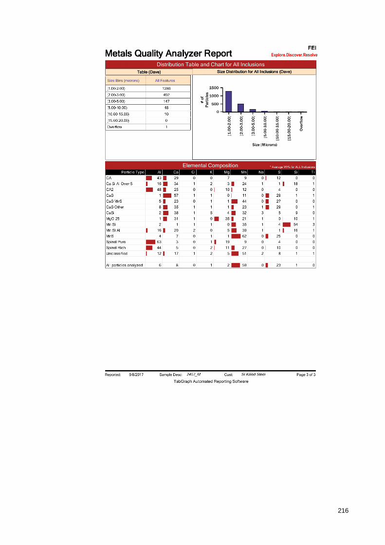
216

217

218

219

220

221

222

223

224

225

226

227

228

229

230

231

232
Appendix C. Tensile test results

233

234

235

236

237

238

239
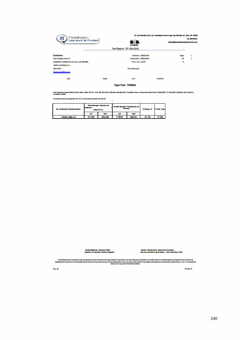
240
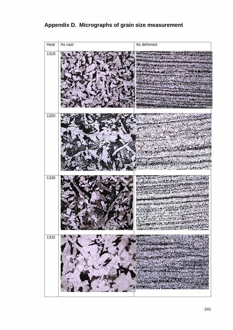
241
Appendix D. Micrographs of grain size measurement
Heat As cast As defomed
1319
1320
1330
1332

242
2455
2456
2457
2458

243
Appendix E. CTOD reports

244

245

246

247

248

249

250

251

252
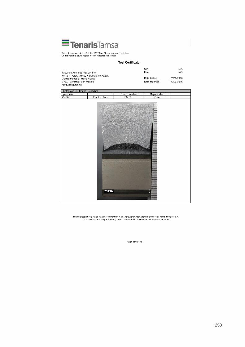
253

254

255

256

257

258

259

260

261
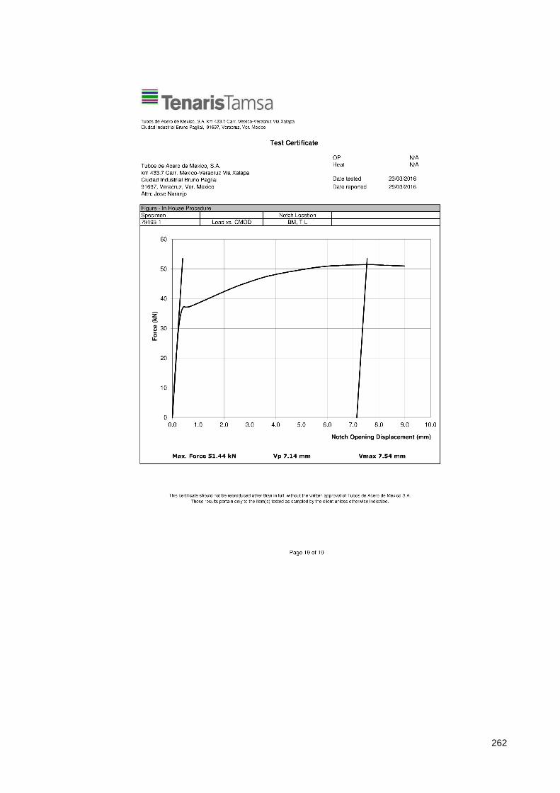
262