The common aspect proof environment
20
The Common Aspect Proof Environment Eyal Dror, Emilia Katz, and Shmuel Katz The Technion—Israel Institute of Technology Haifa, Israel Abstract. The architecture, design considerations, and implementation issues of the Common Aspect Proof Environment (CAPE) are described. The CAPE is an extensible framework integrating formal methods and analysis tools for as- pect-oriented programs. The general principles of the CAPE are first explained, and the components and their high-level organization are given. The steps needed to extend the CAPE by adding new tools or other components are de- scribed, as are the graphical user interface (GUI) and its parts, and the inner ge- neric representation of aspects that the CAPE uses to mediate between source- code and tools. A list of tools being integrated into the CAPE is given, and the steps needed for integration of the SECRET static analysis tool and the CNVA model checking tool are described. 1. Introduction The Common Aspect Proof Environment (CAPE) is an extensible environment for verification and analysis tools and modules to treat aspects as they are used in a vari- ety of aspect languages. It is being developed as one of the primary tasks of the For- mal Methods Laboratory of AOSD-Europe, an EU Network of Excellence. The col- laboration of the different tools is achieved via generic inner structures, including various models, transition systems, and syntactic information. The CAPE is intended to facilitate practical tool integration for the relatively new area of formal methods for aspect-oriented programming and software development. As- pects are modular units that treat concerns of object-oriented systems that otherwise would crosscut the inheritance hierarchy of an object-oriented system. These language constructs are intended to reduce scattering of code to treat a concern throughout a system, and tangling of that code with the code of the rest of the system [TOHS]. There are many languages that include aspects, but all somehow describe what new actions are to be taken as additions or changes to code (called advice), and also under what circumstances each action is applicable (called pointcut descriptions). Aspects are declared, and then connected to an existing system by weaving (binding) the as- pect and its parameters into the system. Many researchers have been working on un- derstanding the implications of Aspect-Oriented Programming (AOP) [FECA], in- cluding the development of design techniques and programming languages such as
-
Upload
independent -
Category
Documents
-
view
0 -
download
0
Transcript of The common aspect proof environment

The Common Aspect Proof Environment
Eyal Dror, Emilia Katz, and Shmuel Katz
The Technion—Israel Institute of Technology
Haifa, Israel
Abstract. The architecture, design considerations, and implementation issues of
the Common Aspect Proof Environment (CAPE) are described. The CAPE is
an extensible framework integrating formal methods and analysis tools for as-
pect-oriented programs. The general principles of the CAPE are first explained,
and the components and their high-level organization are given. The steps
needed to extend the CAPE by adding new tools or other components are de-
scribed, as are the graphical user interface (GUI) and its parts, and the inner ge-
neric representation of aspects that the CAPE uses to mediate between source-
code and tools. A list of tools being integrated into the CAPE is given, and the
steps needed for integration of the SECRET static analysis tool and the CNVA
model checking tool are described.
1. Introduction
The Common Aspect Proof Environment (CAPE) is an extensible environment for
verification and analysis tools and modules to treat aspects as they are used in a vari-
ety of aspect languages. It is being developed as one of the primary tasks of the For-
mal Methods Laboratory of AOSD-Europe, an EU Network of Excellence. The col-
laboration of the different tools is achieved via generic inner structures, including
various models, transition systems, and syntactic information.
The CAPE is intended to facilitate practical tool integration for the relatively new area
of formal methods for aspect-oriented programming and software development. As-
pects are modular units that treat concerns of object-oriented systems that otherwise
would crosscut the inheritance hierarchy of an object-oriented system. These language
constructs are intended to reduce scattering of code to treat a concern throughout a
system, and tangling of that code with the code of the rest of the system [TOHS].
There are many languages that include aspects, but all somehow describe what new
actions are to be taken as additions or changes to code (called advice), and also under
what circumstances each action is applicable (called pointcut descriptions). Aspects
are declared, and then connected to an existing system by weaving (binding) the as-
pect and its parameters into the system. Many researchers have been working on un-
derstanding the implications of Aspect-Oriented Programming (AOP) [FECA], in-
cluding the development of design techniques and programming languages such as
2
AspectJ [Kic] or Compose* [BA]. Most aspect languages extend Java with capabili-
ties for defining and applying aspects although there is some work on aspects for
other underlying languages.
Aspects have been shown useful in a wide variety of tasks including debugging or
logging, adding security or privacy, treating overflow, and adding caching to avoid
recomputing complex results. However, their use raises many questions of reliability
and correctness. It is necessary to establish that an aspect adds properties to the sys-
tem as indicated by its specification, that it does not invalidate desired properties of
the system that were true before the aspect was added, and that multiple aspects do
not interfere with each other, even if each one individually is correct when woven into
existing systems.
In the approach to integration seen here, modules of existing (or proposed) tools, of-
ten developed for particular languages, are generalized and made into robust reusable
modules. These become the basis of the integration framework, and are used to reim-
plement (and often improve) existing tools, and to develop new ones. In CAPE a ge-
neric collection of static analysis and verification modules is developed and used to
construct specific verification tools for a variety of programming and design lan-
guages. The generic collection includes dataflow and parsing components, as well as
type checkers and other modules used by many of the full-fledged analysis tools. Syn-
tactic and semantic issues specific to a tool are treated by writing translators that con-
nect to the generic modules. Individual modules are also intended to be accessible and
separately included in the CAPE, so that they can be individually activated, and also
so they can serve as building blocks for developing new tools. Besides standard code
analysis modules, e.g., to build abstract syntax trees, facilities are provided to con-
struct finite-state models that are then input to model checkers. The CAPE proof envi-
ronment is intended both for those who wish to apply the tools to aspect programs
written in a variety of languages, and for those developing new verification or analy-
sis tools for aspects.
In Section 2 we present a general overview of the CAPE's architecture. Section 3 dis-
cusses in depth the Generic Aspect Representation (GAR), which is used as a media-
tor between the languages' source-code and the tools in the CAPE. Section 4 describes
the user interface of the CAPE and the way functionality is presented to the user. Sec-
tion 5 presents tools that have been selected for incorporation into the CAPE. Section
6 presents a first example of tool incorporation into the CAPE for a static analysis tool
called SECRET. Section 7 discusses the steps needed to integrate the CNVA tool – a
tool that verifies scenario-based specifications of aspects using model checking. Fi-
nally, Section 8 summarizes the present state and immediate plans for the CAPE.
2. Architecture
The CAPE's architecture uses Eclipse's plug-in mechanism to achieve a flexible infra-
structure of its various modules. The CAPE provides a framework in which the dif-
ferent modules can communicate, sharing resources and complementing each other's
functionality. This is achieved through the Generic Aspect Representation (GAR): a
collection of common internal representations of aspect-oriented source code and

3
other properties. This internal representation, expressed mainly through a meta-model
notation, is closely related to the Common Aspect Semantic Base (CASB) [DDFB]
and the meta-model [HSRBB] also developed within AOSD-Europe.
For the CAPE to support an AO (aspect-oriented) language, a translator from that lan-
guage to the internal representations should be created and plugged into the CAPE.
Each verification tool is also plugged into the CAPE. If that tool is not generalized to
work with the internal representations, an adaptor from the appropriate internal repre-
sentation to the tool's input format should be created and plugged in. Tools in the
CAPE can depend on and use other modules in order to avoid re-implementation of
functionality already found in those modules. In Figure 1, the overall data-flow view
of the modules in the CAPE is presented, identifying the major modules. Below we
briefly explain each module, with further details given in later sections.
2.1 Language Translators
The language translators are compilers that translate from the language-specific con-
structs of code and properties into their inner representations as modeled by the GAR.
Creating language translators for a specific language is the first and most important
step in extending the CAPE to support that language.
The language translators use the code processors and the properties expression ana-
lyzers (described below) in order to compile aspect source-code and specification
properties into specific constructs and then translate those into their generic counter-
parts in GAR. An example of this is given in Section 6 for Compose*.
2.2 Code Processors
Code processors are tools or modules that create various syntactic and semantic struc-
tures from source-code. Some of these modules can be a part of a compiler for a spe-
cific language, such as abstract syntax tree builders, while others can be tools for
translating the code's semantics into graph-based models and abstracting them, for use
with various model checkers, examples of which are the Bandera tool [HD] for
model-checking Java programs and its SuperJ extension for model-checking AspectJ
programs [KS].
2.3 Property Expression Analyzers
Property expression analyzers are tools that analyze specification and verification
properties written in a specification language and create internal versions in standard
notations that have a connection to the structures of the program being specified and
reasoned about. This is needed in order for verification tools to verify that a program
fulfills its given properties, since the tools work with the program's various structures
that were built by code processors. Examples of standard notations are temporal lo-
gics, either in LTL or CTL forms, or scenarios that describe valid computation se-
quences [WA].

4
Figure 1 – Data flow diagram of the CAPE
5
2.4 GAR – Generic Aspect Representation
The Generic Aspect Representation is a modeling format for a collection of common
internal representations of aspect-oriented programs and their corresponding specifi-
cation and verification properties, where the original data is language-specific and
was translated to the GAR by language translators. It functions as the mediator be-
tween the source-code being verified and the various tools that verify it. Its function
and structure are described in detail in Section 3.
2.5 Verification Tools
Verification tools perform the actual verification of aspect-oriented programs. In or-
der to work with them in the CAPE, the tools need to be generalized to work directly
on the models of the GAR. When infeasible, a model adaptor needs to be built in or-
der to bridge the gap between the GAR's model and the tool's own internal representa-
tion or input format. Verification tools can then be operated individually, or combined
with other verification tools in a proving strategy (see Section 2.7).
2.6 Model Adaptors
When incorporating a verification tool into the CAPE, it is not always possible to
generalize it to work directly with the GAR's models, either because it is too compli-
cated or because it is not available as open source. When this happens, an adaptor can
be built to translate the desired model from the GAR to the input format of the tool.
2.7 Proof Strategies
Proof strategies are a tool-chaining mechanism for combining the operation of several
verification tools in order to produce a more sophisticated verification process. Some
of the expected functionality of the proof strategy module is wiring outputs of tools as
input of others, iterating operation of tools on a series of inputs and more. Predefined
proof strategies help to share tool resources and outputs, and to divide proof responsi-
bilities among the different tools, according to the strengths of each one.
2.8 Adding Modules to the CAPE
The CAPE framework, in its current form, takes advantage of Eclipse's unique plug-
in-based architecture in order to implement an easy to use mechanism for adding tools
and other modules. The CAPE defines an extension point for every tool or module
type to be incorporated into it. An extension point is an XML schema that defines an
interface for a plug-in of a certain type. It presents the plug-in developer with a form
that asks for all the properties and implementations needed for the plug-in to work
correctly with the system that defined the extension point. Thus, every tool to be in-
corporated into the CAPE is a plug-in for the CAPE. An extension point has been de-
fined for verification tools, denoted CAPE.VerificationTools (actually, a longer name
is used to uniquely identify the extension point, using Eclipse conventions). A similar
extension point is defined for translation tools that connect specific aspect languages
to the internal representations, and for specification properties that are to be verified.
6
The required documentations of an extension point include the identifier string to be
used in an extension, a textual description of the extension point and its uses and DTD
schema (called Configuration Markup) that defines the structure of the possible XML-
based extensions, accompanied by an explanation of each of the elements' attributes
(such as "id", "name" etc.), their meaning and legal values. Below that, an example is
given of a legal XML-based extension for the extension point, as well as information
on API specific issues, and supplied implementations of working extensions for com-
parison and help.
A developer of a module for the CAPE has to: 1) Create a new plug-in project, which
is a special type of Java project in Eclipse that supports the plug-in development
process, 2) Declare a dependency in the CAPE plug-in 3) Create extensions to one or
more of the extension points mentioned above.
3 The Generic Aspect Representation (GAR)
The GAR is used to store the core structure and semantics of aspect-oriented pro-
grams and their properties in a generic way, and thus bridge between different AO
Languages and the verification tools in the CAPE. It is designed as a meta-model for
a collection of different representations of AO source-code, intended for use by dif-
ferent verification tools.
The forms of representation in the GAR and the details of their design have been de-
cided according to the needs of the tools that were selected to be incorporated into the
CAPE. One of the criteria for the selection of these tools was the variety of input
types that they cover, such as static aspectual information in the form of an AST,
separate transition systems of the underlying program and different aspects, or a tran-
sition system of the entire woven program, and more. Because of the differences in
the input needed by various tools, a single model is insufficient, and a collection of
representations is needed.
3.1 The GAR's Representations
The central representation of the GAR is a structured AST-like meta-model of the
aspectual code, which is based on a meta-model for aspects being developed by the
Languages Lab of AOSD-Europe [HSRBB]. The development of the GAR called for
a more complex and full meta-model beyond the object-oriented-style modeling of the
various parts of the aspect code. Such a structural view can be used for running the
meta-model instances in a sand-box environment built in the Smalltalk language, for
the purpose of play-testing aspectual features of different languages. The GAR's
meta-model, however, is used for mediating between language-specific aspect code
and verification tools. For that purpose it was designed to allow easy translation from
aspect source-code, and especially advice code, to the meta-model form, and then
from that form to other forms of aspect representation, as dictated by the required in-
puts of various analysis and verification tools.
The root of the structure is a class representing the system itself, containing several
underlying systems which encapsulate the non-aspectual code, and several aspects.
An aspect, other than having a state and behavior of its own, is basically a list of bind-
7
ings. Bindings connect a pointcut with a list of advices, where the semantics of this
connection is that the advices are activated at the joinpoints that match the pointcut.
Precedence among advices is treated by the method "getAdvices" that returns the ad-
vices for a binding in a sorted list, according to a precedence decided by the imple-
menter who can override it.
A pointcut can be composed of other pointcuts by means of composition operators,
such as AND, OR, NOT. A primitive pointcut is a predicate over the joinpoint do-
main, although there is a possibility to define other kinds of primitive pointcuts.
Structural Predicates are predicates that are computed statically from the source-code;
we focused on the dynamic Behavioral Predicates, which are computed at runtime and
are more common in AO languages. Of the behavioral predicates we focus on the
Current State Predicates, which are computable with the information available at any
runtime state including, among other things, the call stack. There is a possibility to
define a History Predicate, which needs information about previous runtime states.
Some of the current state predicates have properties, such as a method name filter for
a Call Predicate, or a pointcut, under which a CFlow Predicate is defined to imple-
ment a popular primitive seen in AspectJ and other languages. Figure 2 presents the
meta-model representation of the GAR with a Call Predicate as an example of an im-
plemented current state predicate.
The purpose of the GAR is to store generic aspectual information without needlessly
dealing with the structural complexity of the underlying system. Yet in most AO lan-
guages advices are composed of the same language as the underlying system, or some
other Turing-complete language. This is why in contrast to the pointcut description
there is no definition of the advice structure, or of the underlying system for that mat-
ter. Instead, there is a definition of a Code Element, which defines the language each
of these parts is based on, which in the current version of the CAPE is Java by default.
The Code Element can then be used in order to create and store various types of rep-
resentations for the advices, the underlying system and even the woven system.
3.2 The Transition System Representation
Using the Code Element class organization described above, by attaching a type of
representation to the Turing-complete parts of the code, a transition system represen-
tation will also be available for use by verification tools in the CAPE, as seen in Fig-
ure 2.
This representation is based on the Bogor Input Representation – BIR. Bogor [B] is
a very extensible software model checking framework with the capability to be ex-
tended with anything from new primitive types, expressions and special commands to
algorithms and whole levels of abstraction. One of its main features is its internal lan-
guage, the BIR. It is used to represent transition systems at different levels of abstrac-
tion and is general enough to allow description of most base languages, both object-

8
Figure 2 – The GAR meta-model representation
9
oriented and others. The Bogor model checker basically passes over the states of the
transition system and operates according to semantic modules that tell it how to be-
have when encountering states with specific characteristics. For representing the vari-
ous actions that are advice-specific, dummy methods with specific names are used.
This is an easier and more extensible way to treat these actions than to add new syn-
tax constructs to the BIR language. A developer of a translator for this representation
can base it on Bogor by adding a module to it where these methods are being recog-
nized and treated appropriately. This way a translation to a finite state machine or a
different format of transition system is easily achieved.
4 User Interface
Eclipse's GUI structure consists of different views, which are areas in the workbench
that present certain information or functionality to the user. They can be opened,
closed or moved to different locations in the main workbench window. A default ar-
rangement of views can be defined and saved as a perspective. It is therefore natural
that the top level of the CAPE graphical user interface is defined as a new perspective
including some views from the basic Java programming environment, and several
new views specifically designed for the CAPE perspective. As with all perspectives
and views, these are defined using the plug-in mechanism of Eclipse.
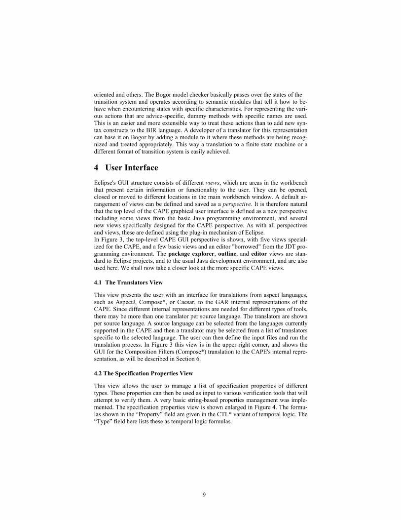
In Figure 3, the top-level CAPE GUI perspective is shown, with five views special-
ized for the CAPE, and a few basic views and an editor "borrowed" from the JDT pro-
gramming environment. The package explorer, outline, and editor views are stan-
dard to Eclipse projects, and to the usual Java development environment, and are also
used here. We shall now take a closer look at the more specific CAPE views.
4.1 The Translators View
This view presents the user with an interface for translations from aspect languages,
such as AspectJ, Compose*, or Caesar, to the GAR internal representations of the
CAPE. Since different internal representations are needed for different types of tools,
there may be more than one translator per source language. The translators are shown
per source language. A source language can be selected from the languages currently
supported in the CAPE and then a translator may be selected from a list of translators
specific to the selected language. The user can then define the input files and run the
translation process. In Figure 3 this view is in the upper right corner, and shows the
GUI for the Composition Filters (Compose*) translation to the CAPE's internal repre-
sentation, as will be described in Section 6.
4.2 The Specification Properties View
This view allows the user to manage a list of specification properties of different
types. These properties can then be used as input to various verification tools that will
attempt to verify them. A very basic string-based properties management was imple-
mented. The specification properties view is shown enlarged in Figure 4. The formu-
las shown in the “Property” field are given in the CTL* variant of temporal logic. The
“Type” field here lists these as temporal logic formulas.

10
Figure 3 – The CAPE perspective
Each property can also be given a name, and its status with respect to the system be-
ing verified is shown in the “Status” field (where the possibilities are Passed, Failed,
or Not verified). It is also possible to define other forms of specifications, such as sce-
nario-based properties (that indicate that every computation is equivalent to one exe-
cuted scenario-by-scenario) [WA], or an invariant in regular logic.
4.3 The Code Processors View
This view presents the different code processor tools that are plugged into the CAPE.
Such a tool processes source code into various types of data that are used as internal
representations, such as finite state machine models, or abstract syntax trees, or

11
Figure 4 – The Specification Properties View
provides a facility such as dataflow analysis. These constructs can then be used as in-
put to verification or analysis tools. The intention is that these modules, like the veri-
fication tools themselves, will be generic versions of modules that have already been
developed as part of a specific tool for one of the numerous aspect languages, or that
are part of the translators seen in Section 4.1. Such modules will probably be of inter-
est mainly to tool developers, as building blocks to ease the implementation of new
verification and analysis approaches. However, they may also be of value to other us-
ers as part of a testing or debugging methodology.
4.4 The Verification Tools View
This view presents the different verification and analysis tools that are plugged into
the CAPE. A verification tool automatically shows that certain specification proper-
ties are either true or not true for some representation of source code. In the CAPE, of
course, the tools relate to systems with aspects, and work with the GAR internal rep-
resentations of the CAPE as input. The tools in the CAPE are intended to be generali-
zations of tools already developed for specific languages. They are divided into dif-
ferent categories according to the type of proof or analysis they supply. Among the
categories are tools based on static analysis of code using dataflow techniques, tools
based on software model checking, and tools based on correctness-preserving pro-
gram transformations for aspects.
Each tool plug-in developer needs to create a GUI component for the tool, plug the
GUI in with the tool itself, and specify the designated category to which the tool be-
longs, using the appropriate extension point of the CAPE GUI. The CAPE verifica-
tion tools view will then present the GUI for that tool within the designated category.

12
4.5 The Proof Strategies View
This view allows the user to use pre-defined proof strategies and to add his/her own.
A proof strategy is a work-plan for verifying projects, when the verification cannot be
done with only one tool. In it, the user defines how to use the different tools available
in the CAPE environment in stages, where every stage contributes to the proof of the
desired properties and verification of the program, either by producing an output that
will be used by another tool, or by proving (or disproving) some of the properties. Al-
though some basic strategies have been considered, a general notation for expressing
strategies still has not been developed for this view of the CAPE. At a minimum it
should allow chaining tools, and e.g., combining a static analysis to determine catego-
ries of aspects, followed by specialized model checking methods that apply only to
specific aspect categories, as seen in [Ka].
5 Tool Selection
5.1 Desired Attributes of Tools for the CAPE
The architecture of the CAPE assumes certain desirable attributes of the tools that are
to be integrated within the framework. The most important attribute of a candidate for
inclusion is its modularity. The main goal of integration with the CAPE is to provide
users and developers alike with functionality that can be utilized in a flexible manner,
when using a module of the tool either as a part of a verification tool-chain strategy,
or as a part of a new tool being developed in the CAPE. Furthermore, a modular tool
will most likely be relatively easy to generalize so that it can work directly on the in-
ternal GAR representation of the CAPE, e.g., by changing the tool’s input analysis.
Another desired attribute is a general domain of applicability for the tool, as op-
posed to tools that are very domain, or language, specific. The function of a candidate
tool should be meaningful for a variety of source languages, regardless of the lan-
guage native to the tool's input.
Another key criterion, of course, is that the aspect analysis tool needs to be at least
partially functional and available for use. Besides an implementation of the tool
functionality itself, this means that subsystems or general verification tools used by
the aspect analysis tool must be open source or publicly available for use in a research
framework.
Finally, in the selected list of tools below we have attempted to select a variety of as-
pect analysis tools, in the sense that they have widely differing types of properties
which can be handled, and use widely diverging analysis techniques..
5.2 Tools for the CAPE
5.2.1 SECRET
SECRET [DSBA] is a static analysis tool which finds user-defined conflicts in the
execution order of several advice actions that are bound to the same joinpoint. It is a
module of the Compose* project and was generalized and extracted from the Com-

13
pose*.NET implementation as a stand-alone tool by Tom Staijen and Eyal Dror. This
tool and its conversion to a preliminary CAPE representation were used as a case
study in the development of the CAPE, and the integration to the full CAPE is de-
scribed in Section 6. The tool analyzes annotated source code and an optional order
specification file, along with a conflict specification file, in which the user specifies
ordering conflicts using regular expressions.
5.2.2 GROOVE Graph Manipulation
The GROOVE tool for aspects [SR] is based on the fact that the semantics of an as-
pect language can be captured in graph transformation rules. The tool first creates a
graph that contains the structural information of a program with aspects. The trans-
formation rules, also known as a production system, can then be used to generate a
transition system of the execution of the program. Every state in the transition system
is again a graph that captures that state of the (running) program.
The transition system can be used to perform different sorts of verification, including
both model checking and static analysis based on the graph structure. Clearly, the pre-
cise verification to be incorporated will depend on the progress in implementing this
tool for its native Compose* environment.
5.2.3 CNVA
An unusual specification method for aspects, based on scenarios, is used in the CNVA
[KK] tool. This tool checks that an augmented system that is the result of weaving an
aspect conforms to a view where the aspect code is executed exactly at the pointcuts,
with no intervening operations, even from independent components. Both the aspects
and the usual computations are specified using scenarios of operations and the tool
proves that every computation in an implemented woven program is equivalent to one
where the operations occur scenario-by-scenario and operations from different scenar-
ios are not mixed together. It can be used for verification that a weaver is operating
correctly, or when a separate aspect language is not used in the final implementation
stage.
The tool automatically builds several models and temporal logic properties to be
checked using the publicly available Cadence SMV model checker. It works directly
on a state machine model of a system that presumably could itself be generated from
input code as part of the GAR. For this purpose, a separate module that translates Java
code to a state machine would be needed, for example by using an existing tool like
Bandera [HD]. A more detailed description of this tool is given in Section 7, as an ex-
ample of the design process of integrating a verification tool into the CAPE.
5.2.4 MAVEN
The MAVEN (Modular Aspect VErificatioN) tool [GK] provides a way to model
check a generic specification of an aspect. A single state machine is built from the ad-
vice of the aspect woven into a state machine that represents any base machine that
satisfies the assumptions of the aspect. The base state machine is constructed directly
from the temporal logic assumptions using a tableaux construction. If the aspect result
specification holds on this constructed machine, it will hold for every possible weav-
14
ing of the aspect with a base machine that satisfies the assumptions of the aspect.
MAVEN works directly on the state machine representations of models, and thus, as
above, is proving relatively easy to integrate into the CAPE.
5.2.5 CompAr
CompAr (Composing Around advice) is a language that has been created [PDS] to
automatically detect and solve Aspect-Composition Issues (ACIs) of around advice,
i.e., advice that adds code both before and after a method call joinpoint. An ACI can
arise when several around pieces of advice apply to the same advised element (it is
then an advice chain). Indeed, each around advice code holds some implicit execution
constraints; when they are composed together in a chain, they can conflict in such a
way that the global system does not fulfill some of the implicit constraints anymore.
With CompAr, one can specify the execution constraints of the advice as well as an
abstract representation of its code. For a given advice chain order, the CompAr com-
piler then checks that all the execution constraints are fulfilled by evaluating the ab-
stract specification for all the possible contexts. In the case an execution constraint is
not fulfilled, the compiler reports an error and some diagnostic information to the
user.
5.2.6 VPA
Support for interaction analysis of aspects over Visibly Pushdown Languages on the
basis of a tool for aspects which is currently under development [NS] as an extension
of an earlier approach [DFS] is also to be included in the CAPE. This approach is es-
pecially appropriate for languages like AspectJ which can relate to the contents of the
call stack in pointcut definitions. The tool under development already has a manipula-
tion package for VPA’s, which is being provided at this stage as a CAPE module for
other tool developers, independently of a specific notation for aspects with VPA’s.
5.2.7 Aspect Dataflow
A dataflow tool for aspects [WTR] is under development, and will be included in the
CAPE when it becomes available. This tool is based on dataflow techniques usually
used for program optimizations in compilers, but here applied to analysis of interac-
tions among aspects and underlying systems. Preliminary results show promise of ef-
fective analysis that can often avoid expensive model checking. Because the tool is
based on syntactic analysis of language constructs, it may be more sensitive to par-
ticular AOP languages than other approaches.
5.3 Tool status
The aspect analysis tools above are in different stages of development, and provide a
variety of approaches and types of properties. The main division is to tools based on
static code analysis or dataflow (SECRET, CompAr, and the Aspect dataflow tool),
those that use model checking (GROOVE, CNVA, MAVEN, VPA), and one using
structural graph analysis (GROOVE). Four of the tools (SECRET, CompAr, CNVA,
and MAVEN) and the VPA library are already implemented in stable preliminary
15
versions, and thus can already be incorporated. The remaining tools will be integrated
to the generic framework as the native implementation becomes sufficiently stable.
Several of the tools have specific specification and descriptive notations of their own,
that will have to be presented in the CAPE GUI, and their generalizations considered.
It is not clear whether all of these tools are appropriate for use with a variety of AOP
languages, beyond the native language for which it was developed. This question is
the subject of ongoing research.
In the following two sections, we describe the generalization of the SECRET static
analysis tool so that it can be applied to the GAR, and the integration to the CAPE of
a more complex tool based on model checking, CNVA. In each case, the parts of the
tool that deal directly with input have to be adjusted, and separated from the main
functionality of the tool.
6 Adapting SECRET to the CAPE
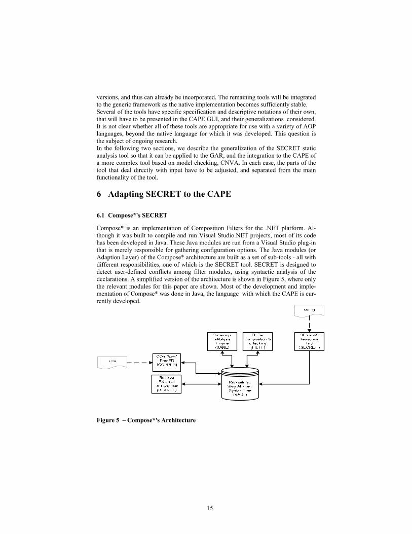
6.1 Compose*'s SECRET
Compose* is an implementation of Composition Filters for the .NET platform. Al-
though it was built to compile and run Visual Studio.NET projects, most of its code
has been developed in Java. These Java modules are run from a Visual Studio plug-in
that is merely responsible for gathering configuration options. The Java modules (or
Adaption Layer) of the Compose* architecture are built as a set of sub-tools - all with
different responsibilities, one of which is the SECRET tool. SECRET is designed to
detect user-defined conflicts among filter modules, using syntactic analysis of the
declarations. A simplified version of the architecture is shown in Figure 5, where only
the relevant modules for this paper are shown. Most of the development and imple-
mentation of Compose* was done in Java, the language with which the CAPE is cur-
rently developed.
Figure 5 – Compose*'s Architecture
16
In order to prepare SECRET for the CAPE, we need to separate out the modules that
deal with preparing Compose* code for analysis, as opposed to those that actually de-
tect conflicts. The COPPER module (COmPose* ParsER) parses composition-filters
source-files and creates a corresponding abstract syntax tree in the central repository.
Then, the REXREF module fixes references between elements of the abstract syntax
tree, e.g. the label of an internal used in a filter should be linked to the actual internal.
The SANE module (Superimposition ANalysis Engine) then takes the superimposition
elements from the repository, analyses them and adds filtermodules to the concerns
they were superimposed upon. The FILTH module analyses the filtermodules super-
imposed on a concern and a filtermodule ordering specification to generate the al-
lowed orders and select one. The result of applying the modules mentioned above in
the described method on a composition-filters source code is a correct AST represen-
tation of that source code in the repository, along with ordering information. Now the
main analysis module can be considered. The SECRET module (SEmantiC REason-
ing Tool) performs a semantic analysis of an ordering of several filtermodules that are
superimposed on the same concern to warn of possible semantic conflicts.
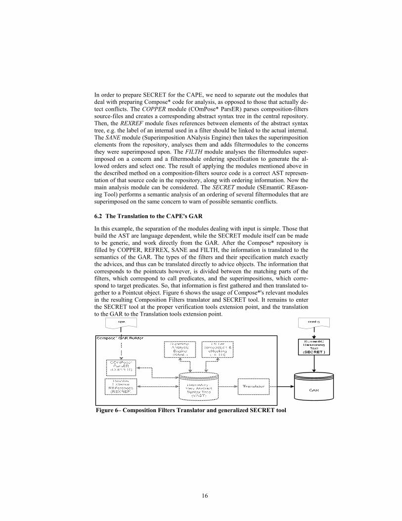
6.2 The Translation to the CAPE's GAR
In this example, the separation of the modules dealing with input is simple. Those that
build the AST are language dependent, while the SECRET module itself can be made
to be generic, and work directly from the GAR. After the Compose* repository is
filled by COPPER, REFREX, SANE and FILTH, the information is translated to the
semantics of the GAR. The types of the filters and their specification match exactly
the advices, and thus can be translated directly to advice objects. The information that
corresponds to the pointcuts however, is divided between the matching parts of the
filters, which correspond to call predicates, and the superimpositions, which corre-
spond to target predicates. So, that information is first gathered and then translated to-
gether to a Pointcut object. Figure 6 shows the usage of Compose*'s relevant modules
in the resulting Composition Filters translator and SECRET tool. It remains to enter
the SECRET tool at the proper verification tools extension point, and the translation
to the GAR to the Translation tools extension point.
Figure 6– Composition Filters Translator and generalized SECRET tool

17
7 Integrating CNVA to the CAPE
CNVA [KK] is a very different verification tool to be plugged into the CAPE frame-
work. This tool is used for verification of conformance of a (woven) system to sce-
nario-based (aspect) specifications, using model checking. The desired behavior of
the base system (the system without aspects) is described by a collection of finite se-
quences of events, called scenarios. Each aspect advice is also described as a sce-
nario. Aspect descriptions are independent of the description of the non-aspectual
scenarios, but the crosscutting relationship between them has to be specified, so for
each aspect a description of its join-points is provided. The verification is performed
on the woven system. Such a system conforms to a collection of aspect and other sce-
narios if every system execution is equivalent to one in which the aspectual scenarios
occur as blocks of operations immediately at their join-points, and all the other opera-
tions form a sequence of non-aspectual scenarios, interrupted only by the aspectual
scenarios (these computations are called convenient).
7.1 Verification in CNVA
The CNVA tool assumes that the join-points of the aspectual scenarios have already
been marked. One of the known techniques for marking joinpoints can be used for
this purpose, perhaps splitting states to guarantee that each state either always is a
joinpoint, or always is not. Then we prove separately that each execution is equivalent
to one where the aspectual scenarios are applied correctly, and that the non-aspectual
scenarios can indeed be formed into blocks interrupted only by aspect advices.
The second and the third part of the verification task - arranging the aspectual and the
non-aspectual scenarios - do not have to be separated, theoretically, but this separa-
tion proves to be a considerable optimization of the verification process, both in its
time and place consumption. For those parts of verification, CNVA creates a new sys-
tem, automatically augmenting the given woven system by additional constructions
and temporal logic assertions. The new system is in the input format of Cadence SMV
[M]. It is then model-checked, and when all the properties are verified by the model-
checking, it follows that every computation of the original woven system is equivalent
to some convenient one, and thus the original system conforms to the specification.
CNVA is not a stand-alone verification tool, because it only creates input files for the
model-checker and does not run the model-checker by itself. Thus it is a verification
tool that should be chained with a model checker such as Cadence SMV.
In order to plug a tool like CNVA into the CAPE, we need to analyze what informa-
tion is needed, both from the GAR of the CAPE and from the user. We also need to
consider how the tool can be launched and how its results are provided.
7.2 Passing Information to CNVA
As our tool is used for verification, it should be provided the following information:
The System to Be Verified: Usually we should be able to construct the system de-
scription automatically from one or more of the internal representations provided by

18
the CAPE. For CNVA we need the description of the woven system as a transition
system consisting of a list of transitions and a list of state variables. This information
is then used to construct the description of the original woven system, in the .cnv for-
mat. It should be taken directly from the GAR transition system of the woven system,
and can also be entered by the user via the tool launching interface.
The Specification: The specification cannot be derived from the information previ-
ously stored by the CAPE, and has to be entered interactively by the user, via an ap-
propriate GUI. In case of CNVA, the specification is given by scenarios - aspectual
and non-aspectual - and by the conditional independence relation (the word "condi-
tional" here means that two operations might be independent in some states and not
independent in others and a predicate is given in order to describe the set of states in
which the independence holds). In most cases only a subset of state variables is
needed to calculate the value of the independence relation predicate at a state. The list
of those variables is also given by the user. Some helpful macros and typedefs are
usually defined to simplify the specification description, and they are also entered by
the user as a part of a specification.
7.3 Run Parameters and Launching
Supplying the run parameters, if needed, and launching the tool is, of course, per-
formed interactively. For CNVA, several parameters should be specified for each run
of the tool, in addition to the system and the specification. These can define specific
subtasks that can be used to divide the entire CVNA verification into stages, omit
tasks that have already been done for related proofs, or change the order of subtasks.
After defining all the parameters above, the user launches the CNVA tool. As a result,
an appropriate augmented system in Cadence SMV format, with the appropriate tem-
poral logic assertions to be verified on it, is created for each of the verification tasks.
7.4 Getting the Results
The CNVA tool should be chained with the Cadence SMV model-checker using the
files built by CNVA. The model checker then returns the verification results to the
user. Presently, the user must run the model checker manually and analyze its output.
Later, when the CadenceSMV model-checker is integrated to the CAPE, this respon-
sibility will be removed from the user through a proof strategy that does the chaining
automatically and the answers will be returned through the GUI after analyzing the
output semi-automatically.
7.5 Performing the Plug-In Process
From the programmer's point of view, the following steps need to be performed:
1. Extend the extension point CAPE.SpecProperties of the CAPE:
(a)Create a class representing the specification as a verifiable property. This represen-
tation provides a connection between the specification and the Properties table of the

19
CAPE, so that the user will be able to create a new property, containing the specifica-
tion of the desired type, or access the defined property from the Properties table, for
either viewing or updating. This class should inherit from the VerifiableProperty class
defined in the CAPE. (b)Develop a user-friendly interface for entering the specifica-
tion. (c)Provide a means for storing and accessing the specification. In CNVA, the
data is stored in several appropriate data structures, serialized in an XML file, and
loaded from the file to the data structures when needed. (d) Connect the above class to
the user interface for entering the specification.
2. Extend the tools extension point CAPE.VerificationTools of the CAPE.
Create a class representing the tool as a verification tool recognized by the CAPE.
This class should inherit from the VerificationTool class defined in CAPE. Create a
user interface for launching the tool. In some cases (as in CNVA ) run parameters are
needed. They should also be entered via the launching interface.
3. If needed, perform preprocessing of the run parameters when launching the tool.
For CNVA, a class responsible for storing all the input data (original system, specifi-
cation and run parameters) was created, and it is responsible for construction of the
appropriate .smv files. The tool-launching interface then is connected to the above
tool class and thus is accessible from the appropriate tool view.
8. Conclusions
This paper has summarized the high level design and status of the CAPE. The system
architecture was described, and the capabilities of the system were illustrated through
a description of the graphic user interface (GUI) that has been implemented as a per-
spective and set of views in the Eclipse development environment. A list of the tools
that were selected for generalization and inclusion in the CAPE was also described.
The tool selection has helped in determining the needed input information on a system
with aspects and thus in the GAR internal representations. The robustness of the de-
sign has so far been confirmed as several very different tools have been or are pres-
ently being integrated into the CAPE. To make the Generic Aspect Representations
useful and easy to use, XML format storage of the meta-model representation is being
considered for the next version of the GAR for better mobility.
The development of richer language translators, treating additional features of the lan-
guages involved, are also scheduled. The first translators are for AspectJ and Com-
pose*, with others to follow later. By March 2007, the first implementation of the
CAPE will be publicly available, although significant work remains to achieve the full
potential of a generic extensible verification environment for systems with aspects.
The difficulties in generalizing formal methods tools developed for a particular con-
text to a framework where they are applied to a variety of input languages are nontriv-
ial, but crucial to tool integration. Practical software engineering issues of connections
among tools, differences in tool maturity, and missing links in a verification chain
also must be considered if integrated formal methods are to become a reality. By deal-
ing with such issues, besides providing tools for verifying and analyzing aspects, the
CAPE is an important step in developing techniques for incorporating isolated tools
into integrated extensible proof environments.
20
References
[BA] L. Bergmans and M. Aksit, Principles and design rationale of Composition Fil-
ters, in [FECA], pp. 63-95.
[B] Bogor website: http://bogor.projects.cis.ksu.edu/.
[DDFB] S. Djoko Djoko, R. Douence, P. Fradet, D. Le Botlan, Revised and Ex-
tended Common Aspect Semantic Base (CASB), AOSD-Europe-INRIA-7, 2006.
[DFS] R. Douence, P. Fradet, and M. Sudholt, A framework for the detection and
resolution of aspect interactions, Proc. Conference on Generative Programming and
Component Engineering (GPCE'02), LNCS 2487, 2002, pp. 173-188.
[DSBA] P. Durr, T. Stajen, L. Bergmans, and M. Aksit, Reasoning about semantic
conflicts between aspects, Eur. Int. Wkshp. on Aspects in Software (EIWAS), 2005.
[FECA] R. Filman, T. Elrad, S. Clarke, and M. Aksit (editors), Aspect-Oriented
Software Design, Addison-Wesley, 2004.
[GK] M. Goldman and S. Katz, MAVIN: Modular Aspect Verification, Proc. Intl.
Conf. on Tools and Algorithms for Constr. And Analysis of Systems (TACAS), to
appear, March 2007. (Note: early version in FOAL 2006).
[HD] J. Hatcliff and M. Dwyer, Using the Bandera tool set to model check properties
of concurrent Java software, CONCUR2001, LNCS 2154, 2001, pp. 39-58.
[HSRBB]Wilke Havinga, Tom Staijen, Arend Rensink, Lodewijk Bergmans, and
Klaas van den Berg, An abstract metamodel for aspect languages, Open and Dynamic
Aspect Languages Workshop, Bonn, 2006.
[KK] E. Katz and S. Katz, Verifying scenario-based aspect specifications, Proc. For-
mal Methods(FM2005), LNCS 3582, pp. 432-447, 2005.
[Ka] S. Katz, Aspect categories and classes of temporal properties, Transactions on
Aspect-Oriented Software Development (TAOSD), Springer-Verlag, vol. 1, LNCS
3880, pp. 106-124, 2006.
[KS] S. Katz and M. Sihman, Aspect validation using model checking , Intl. Sympo-
sium on Verification, Springer-Verlag, LNCS 2772, pp. 389-411, 2003.
[Kic] G. Kiczales, E. Hilsdale, J. Hugunin, M. Kirstin, J. Palm, W. Griswold, An
Overview of AsdpectJ, Proc. ECOOP, LNCS 3880, 2001, pp. 327-353.
[M] K. L. McMillan, Getting started with SMV, Cadence Labs, March 1999.
[NS] D.H. Nguyen and M. Sudholt, Aspects over VPA-based protocols, Intl. Conf.
Software Engineering and Formal Methods (SEFM). 2006
[PDS] R. Pawlak, L. Duchien, and L. Seinturier, CompAr: ensuring safe around ad-
vice composition, Intl. Conf. Open Object-Based Dist. Systems (FMOODS), 2005.
[SR] T. Stajen and A. Rensink, A graph-transformation-based semantics for analyzing
aspect interferences, Brazil Wksp. on Graph Transformation Models, 2006.
[TOHS] P. Tarr, H. Ossher, W. Harrison, and S.M. Sutton, N degrees of separation:
multi-dimensional separation of concerns, ACM Intl. Conf. on Software Engineering
(ICSE), 1999, pp. 107-119. Also in [FECA].
[WTR] N. Weston, F. Taiani, A. Rashid (2005) Modular Aspect Verification for Safer
Aspect-Based Evolution. Workshop on Reflection, AOP and Meta-Data for Software
Evolution RAM-SE (held with ECCOP), 2005.
[WA] J. Whittle and J. Araujo, Scenario modeling with aspects, ISS Proceedings—
Software, vol. 151, no. 4, 2004, pp. 157-172.


![[Revised] Revisiting Verb Aspect in T'boli](https://static.fdokumen.com/doc/165x107/631ef9e50ff042c6110c9f71/revised-revisiting-verb-aspect-in-tboli.jpg)