The biocomposite tube of a chaetopterid marine worm constructed with highly-controlled orientation...
8
The biocomposite tube of a chaetopterid marine worm constructed with highly-controlled orientation of nanofilaments Darshil U. Shah a, ⁎, Fritz Vollrath a , John Stires b , Dimitri D. Deheyn b, ⁎ a Oxford Silk Group, Department of Zoology, University of Oxford, South Parks Road, Oxford OX1 3PS, UK b Marine Biology Research Division, Scripps Institution of Oceanography, University of California San Diego, La California 92093-0202, USA abstract article info Article history: Received 2 June 2014 Received in revised form 30 October 2014 Accepted 5 December 2014 Available online 9 December 2014 Keywords: Biological composites Parchment biomaterial Ultrastructural organisation Chaetopterus Marine polychaete Tube housing Composite pipes and tanks The ultrastructure of the self-constructed tube housing of the bioluminescent marine worm, Chaetopterus sp. re- veals that the bio-nanocomposite tube comprises of multiple non-woven plies of multi-axially oriented organic nanofilaments (ø 50–1100 nm) cemented together by an unstructured organic matrix binder. The thin-walled, impermeable tubes are bio-inspirational for conventional pipe technology. Orientation distribution analyses re- vealed that the dominant orientation angles of nanofilaments in the tube were 0°, ± 45° and ± 65°, which corre- late well with optimal winding angles for ‘man-made’ fibre reinforced composite pipes subjected to specific loading conditions. Such a use of high aspect ratio nanofilaments in multi-axial laminates would impart tough- ness and flexibility to the tube structure, and facilitate rapid tube growth. While the tube production mechanism is not entirely known at this stage, our time-lapse studies show that, contrary to generic assumptions in litera- ture, the worm actively, rapidly and sporadically produces and expands the tube. © 2014 Elsevier B.V. All rights reserved. 1. Introduction Unlike errant polychaetes, the majority of sedentary marine polychaetes spend their entire post-larval existence within self- constructed tubes that are partially burrowed beneath the seabed (as in chaetopterids), if not cemented to hard substrates (as in serpulids). The external tubular structure not only facilitates protection and hiding as antipredator adaptations [1], but also provides a microenvironment that the annelids totally depend upon [2–6]. 1.1. The tubiculous polychaete, Chaetopterus variopedatus Chaetopterus variopedatus animals typically live in un-branched U-shaped tubes, where both inhalant and exhalant openings pro- trude above the seafloor sediment (Fig. 1a). In its tube habitat, C. variopedatus functions as an industrious ‘transfer pump’ [7]. By ac- tively pumping a directional current of water through their tube, they obtain both oxygen and food, and remove excrements and con- taminants (Fig. 1a) [2–4,6]. In fact, C. variopedatus lack appropriate respiratory and feeding structures, such as respiratory pigments and protrusible tentacular apparatus, to support out-of-tube living [2–6], and it has been shown that their filter-feeding mechanism using a mucous bag (Fig. 1a) is entirely dependent upon their water-pumping activities [4]. Consequently, the chaetopterid C. variopedatus, like other sedentary polychaetes, expends over half of its total production energy in tube production, rationing the rest between somatic growth and gamete production [8,9]. Of course, the design and construction of the tube have evolved to support the worm. While chaetopterid tubes have attracted some inter- est since the study of Enders [10], research has principally focussed on the tube building and cleaning behaviour of the worms [2,3,10] and the function of the tube itself [4] with only limited notes and anecdotal observations on the tube ultrastructure [11–13]. Here, we examine the complex oriented ultrastructure of Chaetopterus tubes from both a bio- logical, evolutionary perspective and from a materials science perspec- tive. The discussion is complementary to our recent analysis of the thermo-mechanical properties of the sturdy tube wall biomaterial, which exhibits remarkable stability over a broad temperature range, both in the dry and wet states [14]. Specifically, this article reveals that Chaetopterus tubes share many parallels with, if not inspire, the de- sign and fabrication process of conventional, man-made composite pipes and tubes. In terms of general design, Chaetopterus tubes vary greatly in size, and both the diameter and the length are enlarged during growth [10]. In length, tubes can be up to 50 cm long from orifice to orifice, with vertical arms protruding above the seafloor up to 22 cm long [10]. Notably, the tube ends are tapered (Fig. 1a, b) so that the diam- eter of the two openings (ranging from 0.1 to 0.5 cm) is smaller than Materials Science and Engineering C 48 (2015) 408–415 ⁎ Corresponding authors. E-mail addresses: [email protected], [email protected] (D.U. Shah), [email protected] (D.D. Deheyn). http://dx.doi.org/10.1016/j.msec.2014.12.015 0928-4931/© 2014 Elsevier B.V. All rights reserved. Contents lists available at ScienceDirect Materials Science and Engineering C journal homepage: www.elsevier.com/locate/msec
-
Upload
independent -
Category
Documents
-
view
1 -
download
0
Transcript of The biocomposite tube of a chaetopterid marine worm constructed with highly-controlled orientation...
Materials Science and Engineering C 48 (2015) 408–415
Contents lists available at ScienceDirect
Materials Science and Engineering C
j ourna l homepage: www.e lsev ie r .com/ locate /msec
The biocomposite tube of a chaetopterid marine worm constructed withhighly-controlled orientation of nanofilaments
Darshil U. Shah a,⁎, Fritz Vollrath a, John Stires b, Dimitri D. Deheyn b,⁎a Oxford Silk Group, Department of Zoology, University of Oxford, South Parks Road, Oxford OX1 3PS, UKb Marine Biology Research Division, Scripps Institution of Oceanography, University of California San Diego, La California 92093-0202, USA
⁎ Corresponding authors.E-mail addresses: [email protected], darshil.sh
[email protected] (D.D. Deheyn).
http://dx.doi.org/10.1016/j.msec.2014.12.0150928-4931/© 2014 Elsevier B.V. All rights reserved.
a b s t r a c t
a r t i c l e i n f oArticle history:Received 2 June 2014Received in revised form 30 October 2014Accepted 5 December 2014Available online 9 December 2014
Keywords:Biological compositesParchment biomaterialUltrastructural organisationChaetopterusMarine polychaeteTube housingComposite pipes and tanks
The ultrastructure of the self-constructed tube housing of the bioluminescent marine worm, Chaetopterus sp. re-veals that the bio-nanocomposite tube comprises of multiple non-woven plies of multi-axially oriented organicnanofilaments (ø 50–1100 nm) cemented together by an unstructured organic matrix binder. The thin-walled,impermeable tubes are bio-inspirational for conventional pipe technology. Orientation distribution analyses re-vealed that the dominant orientation angles of nanofilaments in the tubewere 0°, ±45° and±65°, which corre-late well with optimal winding angles for ‘man-made’ fibre reinforced composite pipes subjected to specificloading conditions. Such a use of high aspect ratio nanofilaments in multi-axial laminates would impart tough-ness and flexibility to the tube structure, and facilitate rapid tube growth.While the tube productionmechanismis not entirely known at this stage, our time-lapse studies show that, contrary to generic assumptions in litera-ture, the worm actively, rapidly and sporadically produces and expands the tube.
© 2014 Elsevier B.V. All rights reserved.
1. Introduction
Unlike errant polychaetes, the majority of sedentary marinepolychaetes spend their entire post-larval existence within self-constructed tubes that are partially burrowed beneath the seabed (asin chaetopterids), if not cemented to hard substrates (as in serpulids).The external tubular structure not only facilitates protection and hidingas antipredator adaptations [1], but also provides a microenvironmentthat the annelids totally depend upon [2–6].
1.1. The tubiculous polychaete, Chaetopterus variopedatus
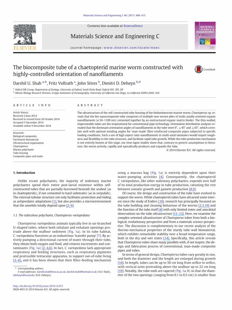
Chaetopterus variopedatus animals typically live in un-branchedU-shaped tubes, where both inhalant and exhalant openings pro-trude above the seafloor sediment (Fig. 1a). In its tube habitat,C. variopedatus functions as an industrious ‘transfer pump’ [7]. By ac-tively pumping a directional current of water through their tube,they obtain both oxygen and food, and remove excrements and con-taminants (Fig. 1a) [2–4,6]. In fact, C. variopedatus lack appropriaterespiratory and feeding structures, such as respiratory pigmentsand protrusible tentacular apparatus, to support out-of-tube living[2–6], and it has been shown that their filter-feeding mechanism
[email protected] (D.U. Shah),
using a mucous bag (Fig. 1a) is entirely dependent upon theirwater-pumping activities [4]. Consequently, the chaetopteridC. variopedatus, like other sedentary polychaetes, expends over halfof its total production energy in tube production, rationing the restbetween somatic growth and gamete production [8,9].
Of course, the design and construction of the tube have evolved tosupport theworm.While chaetopterid tubes have attracted some inter-est since the study of Enders [10], research has principally focussed onthe tube building and cleaning behaviour of the worms [2,3,10] andthe function of the tube itself [4] with only limited notes and anecdotalobservations on the tube ultrastructure [11–13]. Here, we examine thecomplex oriented ultrastructure of Chaetopterus tubes from both a bio-logical, evolutionary perspective and from a materials science perspec-tive. The discussion is complementary to our recent analysis of thethermo-mechanical properties of the sturdy tube wall biomaterial,which exhibits remarkable stability over a broad temperature range,both in the dry and wet states [14]. Specifically, this article revealsthat Chaetopterus tubes share many parallels with, if not inspire, the de-sign and fabrication process of conventional, man-made compositepipes and tubes.
In terms of general design, Chaetopterus tubes vary greatly in size,and both the diameter and the length are enlarged during growth[10]. In length, tubes can be up to 50 cm long from orifice to orifice,with vertical arms protruding above the seafloor up to 22 cm long[10]. Notably, the tube ends are tapered (Fig. 1a, b) so that the diam-eter of the two openings (ranging from 0.1 to 0.5 cm) is smaller than
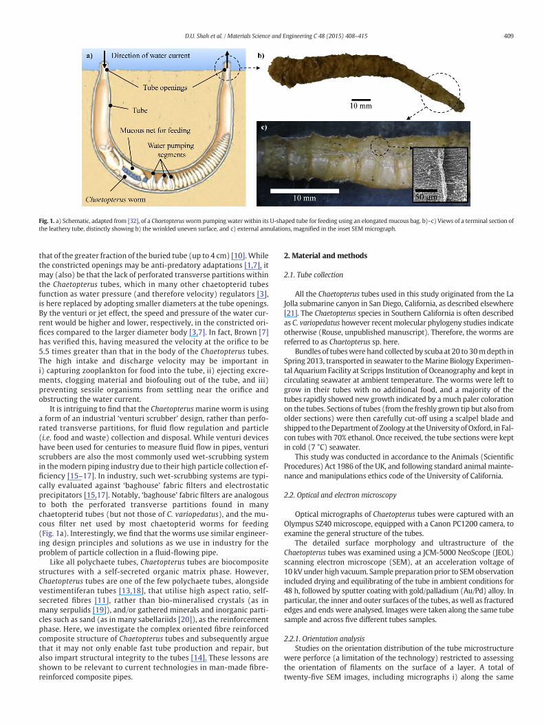
Fig. 1. a) Schematic, adapted from [32], of a Chaetopterusworm pumping water within its U-shaped tube for feeding using an elongatedmucous bag. b)–c) Views of a terminal section ofthe leathery tube, distinctly showing b) the wrinkled uneven surface, and c) external annulations, magnified in the inset SEM micrograph.
409D.U. Shah et al. / Materials Science and Engineering C 48 (2015) 408–415
that of the greater fraction of the buried tube (up to 4 cm) [10].Whilethe constricted openings may be anti-predatory adaptations [1,7], itmay (also) be that the lack of perforated transverse partitions withinthe Chaetopterus tubes, which in many other chaetopterid tubesfunction as water pressure (and therefore velocity) regulators [3],is here replaced by adopting smaller diameters at the tube openings.By the venturi or jet effect, the speed and pressure of the water cur-rent would be higher and lower, respectively, in the constricted ori-fices compared to the larger diameter body [3,7]. In fact, Brown [7]has verified this, having measured the velocity at the orifice to be5.5 times greater than that in the body of the Chaetopterus tubes.The high intake and discharge velocity may be important ini) capturing zooplankton for food into the tube, ii) ejecting excre-ments, clogging material and biofouling out of the tube, and iii)preventing sessile organisms from settling near the orifice andobstructing the water current.
It is intriguing to find that the Chaetopterusmarine worm is usinga form of an industrial ‘venturi scrubber’ design, rather than perfo-rated transverse partitions, for fluid flow regulation and particle(i.e. food and waste) collection and disposal. While venturi deviceshave been used for centuries to measure fluid flow in pipes, venturiscrubbers are also the most commonly used wet-scrubbing systemin themodern piping industry due to their high particle collection ef-ficiency [15–17]. In industry, such wet-scrubbing systems are typi-cally evaluated against ‘baghouse’ fabric filters and electrostaticprecipitators [15,17]. Notably, ‘baghouse’ fabric filters are analogousto both the perforated transverse partitions found in manychaetopterid tubes (but not those of C. variopedatus), and the mu-cous filter net used by most chaetopterid worms for feeding(Fig. 1a). Interestingly, we find that the worms use similar engineer-ing design principles and solutions as we use in industry for theproblem of particle collection in a fluid-flowing pipe.
Like all polychaete tubes, Chaetopterus tubes are biocompositestructures with a self-secreted organic matrix phase. However,Chaetopterus tubes are one of the few polychaete tubes, alongsidevestimentiferan tubes [13,18], that utilise high aspect ratio, self-secreted fibres [11], rather than bio-mineralised crystals (as inmany serpulids [19]), and/or gathered minerals and inorganic parti-cles such as sand (as in many sabellariids [20]), as the reinforcementphase. Here, we investigate the complex oriented fibre reinforcedcomposite structure of Chaetopterus tubes and subsequently arguethat it may not only enable fast tube production and repair, butalso impart structural integrity to the tubes [14]. These lessons areshown to be relevant to current technologies in man-made fibre-reinforced composite pipes.
2. Material and methods
2.1. Tube collection
All the Chaetopterus tubes used in this study originated from the LaJolla submarine canyon in San Diego, California, as described elsewhere[21]. The Chaetopterus species in Southern California is often describedas C. variopedatus however recentmolecular phylogeny studies indicateotherwise (Rouse, unpublished manuscript). Therefore, the worms arereferred to as Chaetopterus sp. here.
Bundles of tubeswere hand collected by scuba at 20 to 30mdepth inSpring 2013, transported in seawater to theMarine Biology Experimen-tal Aquarium Facility at Scripps Institution of Oceanography and kept incirculating seawater at ambient temperature. The worms were left togrow in their tubes with no additional food, and a majority of thetubes rapidly showed new growth indicated by amuch paler colorationon the tubes. Sections of tubes (from the freshly grown tip but also fromolder sections) were then carefully cut-off using a scalpel blade andshipped to theDepartment of Zoology at theUniversity of Oxford, in Fal-con tubes with 70% ethanol. Once received, the tube sections were keptin cold (7 °C) seawater.
This study was conducted in accordance to the Animals (ScientificProcedures) Act 1986 of the UK, and following standard animal mainte-nance and manipulations ethics code of the University of California.
2.2. Optical and electron microscopy
Optical micrographs of Chaetopterus tubes were captured with anOlympus SZ40 microscope, equipped with a Canon PC1200 camera, toexamine the general structure of the tubes.
The detailed surface morphology and ultrastructure of theChaetopterus tubes was examined using a JCM-5000 NeoScope (JEOL)scanning electron microscope (SEM), at an acceleration voltage of10 kV under high vacuum. Sample preparation prior to SEMobservationincluded drying and equilibrating of the tube in ambient conditions for48 h, followed by sputter coating with gold/palladium (Au/Pd) alloy. Inparticular, the inner and outer surfaces of the tubes, as well as fracturededges and ends were analysed. Images were taken along the same tubesample and across five different tubes samples.
2.2.1. Orientation analysisStudies on the orientation distribution of the tube microstructure
were perforce (a limitation of the technology) restricted to assessingthe orientation of filaments on the surface of a layer. A total oftwenty-five SEM images, including micrographs i) along the same
410 D.U. Shah et al. / Materials Science and Engineering C 48 (2015) 408–415
tube of inner, outer, and intermediate surfaces, and ii) across five differ-ent tubes, were considered for detailed images analysis. The grey-scaleSEM images were analysed through the OrientationJ plug-in (EPFL,Switzerland) available in ImageJ software (NIH, Maryland, USA).
Reference [22] discusses the principles behind the orientation anal-ysis used in the software in detail. Fig. 2 illustrates the orientation anal-ysis process. Briefly, for every image (Fig. 2a), the software evaluatedthe structure tensor of every Gaussian-shaped window (defined as 0.5pixels) by computing the continuous spatial derivatives in the x and ydimensions using Gaussian interpolation. From the structure tensor ofevery window, the local predominant orientation (corresponding tothe orientation of the largest eigenvector of the structure tensor), theenergy (defined as the trace of the structure tensor matrix) and the co-herency (defined as the ratio between the difference and the sum of themaximumandminimum tensor eigenvalues)were computed. For qual-itative visual representation of the orientation, the tube surface in Fig. 2acould be converted into a colour coded image (Fig. 2b) of the surface. Forquantitative assessment, the orientation distribution of filaments on thesurface was presented in a histogram (Fig. 2c), using energy and coher-ency values to separate between significantly and not-significantly ori-ented areas. Firstly, the histogram only included orientations of pixelswith both energy and coherency values above a threshold value of 2%(normalised to the maximum values). Secondly, the histogram wasweighted to the coherency values to give more importance to orienta-tions which correspond to elongated structures (i.e. filaments).
The histograms were used to study the general distribution in fibreorientation and to identify any dominant orientation angles (at maxi-mum intensity/frequency). Nanofilaments oriented along the length ofthe tubewere defined to be at a 0° orientation,while nanofilaments ori-ented along the circumference were at a ±90° orientation.
3. Results and discussion
Fromvisual observations, the tubes are typically opaque (Fig. 1b), al-though the ends of the tubes (i.e. near the opening) are more translu-cent, possibly due to fewer layers of secreted material. The latterconjecture is supported by measurements of tube wall thickness;while tube openings were 0.09 ± 0.02 mm (n = 15) thick, the sectionof the tubes embedded in sediment were 0.33 ± 0.08 mm (n = 75)thick.
The outer surface of Chaetopterus tubes has a parchment-like tex-ture. The presence of external annulations, spaced 2 to 5 mm apart, isoften obscured by the wrinkled surface, but clearly visible in the termi-nal portions (Fig. 1c). Each ring represents the successive height of theorifice, and the length of each ring represents successive steps in the for-mation and enlargement of the tubes [10]. Thewrinkles and folds on thesurface are possibly edges of individual layers that were sporadicallyadded during tube growth or repair [13]. In addition, sand particles,
Fig. 2. Image analysis, using OrientationJ plug-in in ImageJ, to determine the distribution of orieimage of a tube surface of interest, b) colour coded image of the surface for visual representationthe surface. Both b) and c) clearly indicate that the nanofilaments are principally oriented in onetube length.
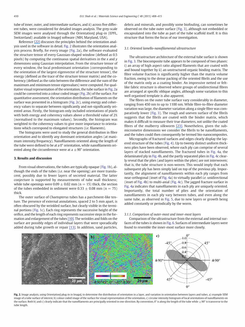
debris and minerals, and possibly some biofouling, can sometimes beobserved on the tube outer surface (Fig. 3), although not embedded orencapsulated into the tube as part of the tube scaffold itself. It is thisstructure that forms the focus of our investigation.
3.1. Oriented lamello-nanofilamental ultrastructure
The ultrastructure architecture of the external tube surface is shownin Fig. 3. The biocomposite tube appears to be composed of two phases:i) an array of high aspect ratio aligned filaments that are coated withand bound together by ii) an unstructured organic binding matrix. Thefibre volume fraction is significantly higher than the matrix volumefraction, owing to the dense packing of the oriented fibrils and the useof the matrix only as a coating binder. An impressive netted or felt-like fabric structure is observed where groups of unidirectional fibresare arranged at specific oblique angles, although some variation to thiswell organised template is also apparent.
The fibres on the outer tube surface vary considerably in diameter,ranging from 450 nm to up to 1100 nm. While fibre-to-fibre diametervariationwas large, the diameter variation along a single fibrewas com-paratively lower (Fig. 3). The rough and uneven surface of the fibrilssuggests that the fibrils are coated with the binder matrix, whichmakes it difficult to measure their true diameters, not unlike the coatedfibres of the mulberry silkworm [23]. Nonetheless, given the sub-micrometre dimensions we consider the fibrils to be nanofilaments,and the tubes could then consequently be termed bio-nanocomposites.
Micrographs of fractured surfaces and edges clearly display the lay-ered structure of the tubes (Fig. 4). Up to twenty distinct uniform thick-ness plies have been observed, where each ply can comprise of severallayers of stacked nanofilaments. The fractured tubes in Fig. 4a, thedelaminated ply in Fig. 4b, and the partly separated plies in Fig. 4c clear-ly reveal that the plies (and layers within the plies) are not interwoven;that is, the tube structure is non-woven. This would imply that eachsubsequent ply has been simply laid on top of the previous ply. Impor-tantly, the alignment of nanofilaments within each ply ranges fromnear-orthogonal (inset of Fig. 4a) to virtually parallel i.e. unidirectional(inset of Fig. 4b) to multi-axial (Fig. 4c). The jagged fracture surface inFig. 4a indicates that nanofilaments in each ply are uniquely oriented.Importantly, the total number of plies and the orientation ofnanofilaments in each ply vary between tubes, and even along thesame tube, as observed in Fig. 5, due to new layers or growth beingadded constantly or periodically by the worm.
3.1.1. Comparison of outer-most and inner-most layersComparison of the ultrastructure from the external and internal sur-
faces of the tubes is shown in Fig. 6. Surfaces of intermediate layerswerefound to resemble the inner-most surface more closely.
ntation in a layer, and variation in orientation between layers and tubes. a) example SEMof the orientation, c) circular intensity histogram of local orientations of nanofilaments on-direction. By convention, 0° is along the length of the tubewhile±90° is transverse to the
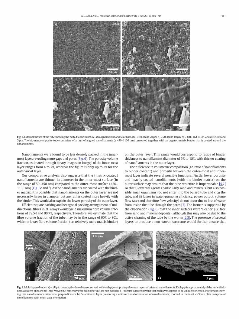
Fig. 3.External surface of the tube showing thenetted fabric structure, atmagnifications and scale bars of a)×1000 and20 μm,b)×2000 and10 μm, c)×3000 and 10 μm,andd)×5000 and5 μm. The bio-nanocomposite tube comprises of arrays of aligned nanofilaments (ø 450–1100 nm) cemented together with an organic matrix binder that is coated around thenanofilaments.
411D.U. Shah et al. / Materials Science and Engineering C 48 (2015) 408–415
Nanofilaments were found to be less densely packed in the inner-most layer, revealingmore gaps and pores (Fig. 6). The porosity volumefraction, estimated through binary images on ImageJ, of the inner-mostlayer ranges from 4 to 7%, whereas the figure is only up to 3% for theouter-most layer.
Our comparative analysis also suggests that the (matrix-coated)nanofilaments are thinner in diameter in the inner-most surface (inthe range of 50–350 nm) compared to the outer-most surface (450–1100nm) (Fig. 6e and f). As the nanofilaments are coatedwith the bind-er matrix, it is possible that nanofilaments on the outer layer are notnecessarily larger in diameter but are rather coated more heavily withthe binder. This would also explain the lower porosity of the outer layer.
Efficient square packing and hexagonal packing arrangement of uni-directional fibres in 2D arrays would yield maximum fibre volume frac-tions of 78.5% and 90.7%, respectively. Therefore, we estimate that thefibre volume fraction of the tube may be in the range of 60% to 80%,with the lower fibre volume fraction (i.e. relativelymorematrix binder)
Fig. 4.Multi-layered tubes. a)–c)Up to twenty plies have been observed, with each ply comprisiness. Adjacent plies are not inter-woven but rather lay over each other (i.e. are non-woven). a) Fing that nanofilaments oriented at perpendiculars. b) Delaminated layer presenting a unidinanofilaments with multi-axial orientation.
on the outer layer. This range would correspond to ratios of binderthickness to nanofilament diameter of 5% to 15%, with thicker coatingof nanofilaments in the outer layer.
The difference in volumetric composition (i.e. ratio of nanofilamentsto binder content) and porosity between the outer-most and inner-most layer indicate several possible functions. Firstly, lower porosityand heavily coated nanofilaments (with the binder matrix) on theouter surface may ensure that the tube structure is impermeable [5,7]so that i) external agents (particularly sand and minerals, but also pos-sibly small organisms) do not enter into the buried tube and clog thetube, and ii) losses in water-pumping efficiency, power output, volumeflow rate (and therefore flow velocity) do not occur due to loss of waterfrom inside the tube through the pores [7]. The former is supported bythe observation (Fig. 6) that the inner surfaces were ‘cleaner’ (i.e. freefrom sand and mineral deposits), although this may also be due to theactive cleaning of the tube by the worm [2,3]. The presence of severallayers to produce a non-woven structure would further ensure that
ng of several layers of oriented nanofilaments. Each ply is approximately of the same thick-racture surface showing that each layer appears to be uniquely oriented. Inset image show-rectional orientation of nanofilaments; zoomed in the inset. c) Some plies comprise of
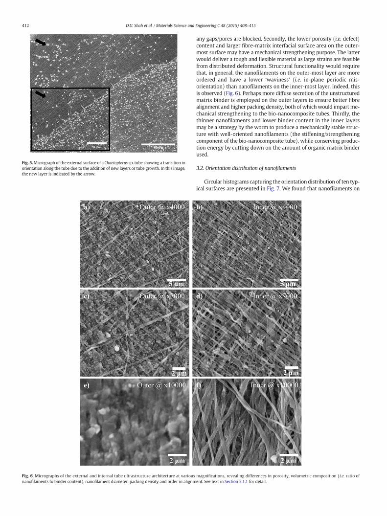
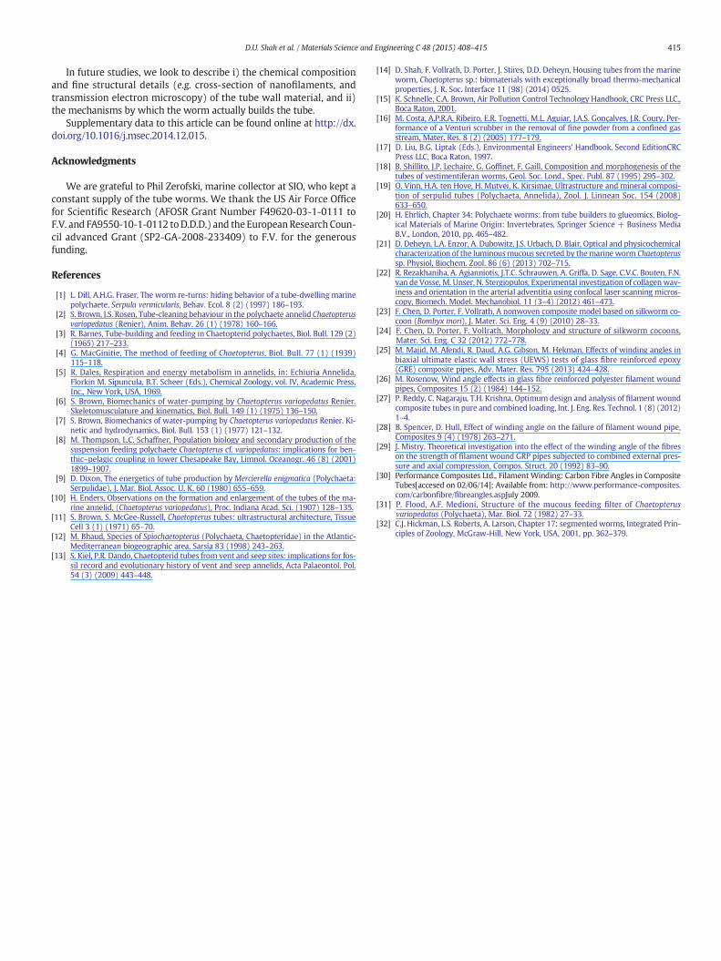
Fig. 5.Micrograph of the external surface of a Chaetopterus sp. tube showing a transition inorientation along the tube due to the addition of new layers or tube growth. In this image,the new layer is indicated by the arrow.
Fig. 6. Micrographs of the external and internal tube ultrastructure architecture at variousnanofilaments to binder content), nanofilament diameter, packing density and order in alignm
412 D.U. Shah et al. / Materials Science and Engineering C 48 (2015) 408–415
any gaps/pores are blocked. Secondly, the lower porosity (i.e. defect)content and larger fibre-matrix interfacial surface area on the outer-most surface may have a mechanical strengthening purpose. The latterwould deliver a tough and flexible material as large strains are feasiblefrom distributed deformation. Structural functionality would requirethat, in general, the nanofilaments on the outer-most layer are moreordered and have a lower ‘waviness’ (i.e. in-plane periodic mis-orientation) than nanofilaments on the inner-most layer. Indeed, thisis observed (Fig. 6). Perhaps more diffuse secretion of the unstructuredmatrix binder is employed on the outer layers to ensure better fibrealignment and higher packing density, both of whichwould impart me-chanical strengthening to the bio-nanocomposite tubes. Thirdly, thethinner nanofilaments and lower binder content in the inner layersmay be a strategy by the worm to produce a mechanically stable struc-ture with well-oriented nanofilaments (the stiffening/strengtheningcomponent of the bio-nanocomposite tube), while conserving produc-tion energy by cutting down on the amount of organic matrix binderused.
3.2. Orientation distribution of nanofilaments
Circular histograms capturing the orientation distribution of ten typ-ical surfaces are presented in Fig. 7. We found that nanofilaments on
magnifications, revealing differences in porosity, volumetric composition (i.e. ratio ofent. See text in Section 3.1.1 for detail.

Fig. 7. Superimposed circular intensity histograms of ten typical tube surfaces (differentcolours) showing the orientation distribution of nanofilaments on the surfaces. By conven-tion, 0° is along the length of the tubewhile±90° is transverse to the tube length. On eachsurface, nanofilaments were principally oriented in one direction only, with no preferredsecond-best orientation. The principal or dominant orientation angles, within a range of±5°, were 0°, ±45° and ±65°. (For interpretation of the references to color in this figurelegend, the reader is referred to the web version of this article.)
Table 1Optimal fibre orientations used in fibre reinforced plastic pipes and tanks for resistanceagainst specific loads [25–30]. A combination of angles, using different plies at ±θ°, maybe incorporated to endure combined loading conditions.
Fibre orientation oncompositetube
Applications
0° (axial) Optimal resistance against longitudinal bending andaxial tension/compression
±90° (hoop) Resistance against internal/external pressure tomaintain cross-section dimension
±45° Optimal resistance to pure torsion (shear) loads±55° Optimal resistance against internal pressure (with
closed-ends)±65° Optimal resistance against external pressure and
buckling±5° to ±25° Optimal for resistance against combined bending and
torsion loadsAlternate layers of±22.5° and ±67.5°
Typical quasi-isotropic structure
413D.U. Shah et al. / Materials Science and Engineering C 48 (2015) 408–415
each surface were principally oriented in one direction only, with thedominant orientation angle unsystematically varying between differentlayers and tubes, and even along the same layer/tube (Fig. 5) due to newlayers or growth being added constantly or periodically by the worm.Generally, for each surface, besides the dominant orientation angle,there was no preferred second-best orientation; that is, all other orien-tations received uniform representation (appearing as uniform intensi-ty on the histograms in Fig. 7).Moreover, for each surface, the dominantorientation angle was spread over a range of ±15° (Fig. 7); this indi-cates the margin of error with which the worm lays the nanofilaments.Most interestingly, it emerged that the principal or dominant orienta-tion angles, within a range of ±5°, were 0° (i.e. along the length of thetube), ±45° and ±65° (Fig. 7).
The production of tubes layers with nanofilaments in such well-defined overlapping orientations suggests a mechanical function for in-creased integrity and toughness (as demonstrated recently through ourmechanical studies [14]), but may possibly be a result of constraintsfrom the mode of tube construction, which may impose particular ori-entations. Analogous to the latter are silkwormswho spin silk protein fi-bres (coated with an organic binder, namely sericin) into a cocoonstructure around themselves by repeatedly moving their head in afigure-of-eight (or an S) motion, and simultaneously cyclically bendingand stretching their body [24]. The construction technique results in auniform thickness, symmetrical cocoon that is non-woven and multi-layered, and the virtually random orientation of the fibres impliesquasi-isotropic in-plane mechanical properties [23,24].
3.2.1. Relating nanofilament arrangement to tube mechanical functionFibre reinforced polymer composites are widely used in the global
pipe and tank industry for a range of applications, including the trans-portation and storage of fluids (such as oil and water), where they canbe subjected to high internal or external pressures. It is well known tothe makers of ‘thin-walled’ composite tubes and vessels, through nu-merical analysis and empirical evidence [25–30], that fibre orientationaffects the mechanical behaviour and structural integrity, and that spe-cific fibre orientations are optimal for specific loading conditions(Table 1).
As the thickness to diameter ratio of Chaetopterus tubes is less than0.1, the tubes can be defined as thin-walled structures. We observedthat the three dominant orientation angles found in the nanofilamentsin the Chaetopterus tube, namely i) 0°, ii) ±45°, and iii) ±65°, areknown as optimal angles for tubular integrity (Table 1) in terms ofi) bending and axial loads, ii) torsion/shear loads, and iii) combined ex-ternal pressure and buckling loads, respectively. In essence, it appearsthat the Chaetopterus tubes naturally (are made to) have a multi-axiallaminate structure for endurance against a large range of loading condi-tions. It is interesting that theworms have naturally evolved to producetubes with complex and optimised nanofilament orientations thatmatch engineering design solutions for man-made composite pipes.
It should be noted that the actual fraction of nanofilaments or layersin each orientation is not known (and difficult to measure given thesub-micrometre diameter of the filaments), and therefore it is not pos-sible, at this stage, to conclusively say which loading conditions aremore critical. Nonetheless, our recent investigation [14] on themechan-ical properties of the tubes has demonstrated dissimilarities betweenthe longitudinal and transverse tensile properties, which consequentlyestablishes a lack of quasi-isotropic structure in the tube walls. In fact,a higher stiffness and strength of the tube wall material in the trans-verse direction (compared to the longitudinal direction) is indicativeof more nanofilaments oriented at±45° and±65° than at 0° (i.e. longi-tudinal) to the tube axis [14]. In this case, the tubes would be more re-sistant to torsion/shear loads (from ±45° oriented fibrils) andcombined external pressure and buckling loads (from±65° oriented fi-brils), than from bending and axial tension/compression loads (from 0°oriented fibrils).
C. variopedatus have been long regarded as one of themost structur-ally specialised of all annelids [6]. The observed complex-orientedlamello-fibrillar ultrastructure of the bio-nanocomposite tubes supportsthis assertion. Chaetopterus tubes are one of the few polychaete tubes,alongside vestimentiferan tubes [13,18], that utilise high aspect rationanofilaments as reinforcements. There are many advantages to pro-ducing tubes with long fibrils. Particle reinforcements (e.g. bio-mineralised crystals or gathered inorganic materials and minerals) arenot only more difficult to align, but due to their short aspect ratio theresulting tubes are more brittle as cracks may propagate through fastfracture across the entire structure. Long fibres, particularly if they arethin (e.g.nano-scale as in Chaetopterus tubes), are efficient in preventingcrack propagation and in transferring/spreading load over adjacent fi-bres through the fibre/matrix interface. The resulting tube would betough and flexible, rather than brittle and hard. A flexible tube materialwould also enable a tube-dwelling worm to expand the tube in lengthand diameter as it grows [7,10]. High aspect ratio fibres also tend to beanisotropic, whereas particles tend to be isotropic. Using high aspect

414 D.U. Shah et al. / Materials Science and Engineering C 48 (2015) 408–415
ratio fibres, thewormwould be able to produce a tubewith fibre anisot-ropy aligned in the principal loading directions to optimally endure theloads over its life. It is proposed, that polymer fibre reinforced tubesmayhave evolved in chaetopterids to capitalise on these factors, in produc-ing a tough, durable housing.
In terms of producing complex oriented structures, the ultrastruc-ture of various serpulid tubes has been studied in great detail over thepast years, and it has been found that most (52%) of the studied 44serpulid species produce tubes that lack an oriented ultrastructure[19]; only 25% of the studied serpulid species can mineralise orientedstructures [19]. Moreover, only 34% of the studied serpulid species pro-duce tubes with more than one layer (i.e. two to four layers) [19].Chaetopterus tubes have evolved to be highly oriented in well-definedangles, and include up to 18 layers. We were able to show that the se-lected orientations clearly matched optimal orientations used in indus-trial fibre reinforced plastic pipes tubes to resist a large range of specificloading conditions. Moreover, amulti-layered structure, with each layerconsisting of differently, but well-aligned nanofilaments, would also bemore effective in preventing crack propagation (through delamination),resulting in a tough structure, as demonstrated for theChaetopterus tubewall material in [14].
3.3. Tube production and assembly
It is often suggested that the tube structures of Chaetopterus reflectthe behaviour and peculiarities of the worm [3,12], which poses an in-teresting evolutionary framework to discuss the relationship betweenthe tube ultrastructure and the tube production.
While it is obvious that successive layers would be added to theinner surface of the tube-wall, at this stage, it can only be hypothesisedhow the worm produces a layer. It may be that the worm lays up a uni-directional group of nanofilaments over previously deposited unidirec-tional groups of nanofilaments, to form a complex-oriented layer.However, such structured layeringmay imply the presence of a mecha-nism by which the worm is capable of detecting or memorising the ori-entation of previously deposited nanofilament groups or layers.Alternatively, it may be that the groups of nanofilaments of a regularset of orientations (e.g. [0°, ±45°, ±65°]) are added in one interlinkedsets of action patterns to form a layer. This would ensure that a pre-ferred orientation (or lack of) is always maintained from layer tolayer, since driven by the most recently deposited layer that serveshere as a template array relative to which the new layer will beorganised.
In producing nanofilaments of a given orientation, the worm maymove in certain directions to align the nanofilaments [3,12], similar tohow in industrial filament winding for composite pipe manufacturethe carriage traverses to lay resin impregnated ‘tows’ (i.e. bundle of fil-aments) over a rotating mandrel. Alternatively, the wormmay producea pre-formed self-assembled orientedfibrillarmeshwork [11], similar tothe use of ‘prepreg’ tapes, either as individual plies (e.g. [θ°]) or stackedplies (e.g. [±θ°, ±α°]), in an automated tape laying process for compos-ite pipe manufacture. Notably, the mucous film net that theChaetopterus worm uses to filter food is hypothesised to be producedusing the latter process [10,31].
Noting that Chaetopterus animals are known to use mucous for a va-riety of functions including, i) serving as a net or bag to filter and trapfood [3,4,31], ii) using bright bluish bioluminescence to attract matesor prey, or for defence against predation [21], it is of interest to ascertainwhether the worm uses mucous films/tunnels for tube building as well(as suggested in [10,21]). At this stage it is not clear whether a differentbody part of theworm secretes a different type ofmucous for a differentfunction, or the same mucous (with possibly different abilities/proper-ties over time)may be responsible for the variety of roles. Investigationson the optical andphysiochemical properties of the bioluminescentmu-cous from Chaetopterus sp. are being carried out [21] to provide insighton the biochemical reactions responsible for light production, and
subsequent changes in physical and material properties of the mucous,leading to its possible use for tube building.
To measure the incremental growth of the tubes over time, prelimi-nary time-lapse studies were undertaken (Supplementary video,Fig. S1). Our observations revealed that the worm ‘actively’ builds thevery first layer of the tube in a matter of few minutes (see Supplemen-tary video, Fig. S1). This is in contrast to the generic assumption in liter-ature [3,10] that the tube is built by ‘passive’ deposition of mucoussecreted by theworm, gradually over time. Indeed, the fine organisationof the nanofilaments observed in the tubes strengthens the case for ‘ac-tive’ rather than ‘passive’ tube building. We hypothesise that the veryfirst layer is a template that coordinates all the successive layers. Thegrowth (in thickness i.e. number of layers, diameter and length) is rath-er rapid and sporadic, occurring in spurs rather than being continuous.The presence of numerous folds and wrinkles on the surface, whichhave been described to be the edges of individual layers [13], also sug-gest sporadic growth. The actualmechanismbywhich thewormactual-ly builds the tube and layers, and the chemical composition of thematerial (both the nanofilaments and the matrix) will be studied in alater publication.
Rapid tube production or repair is important for the worm as bothtime and energy can then be spent on somatic growth and reproduction.The combination of high aspect ratio nanofilaments, well-defined orien-tations and a layered structure is not only a winning strategy in produc-ing tubes with structural integrity, but also to produce, expand andrepair them rapidly [19]. The latter is observed explicitly in the time-lapse video (Supplementary video, Fig. S1). Tube growth, expansionand repair ismore time (and therefore energy) consuming, if not impos-sible, when minerals have been glued together to produce a single-layered brittle housing (as in serpulids) [19].
One of the current disadvantages ofman-made fibre reinforced plas-tic pipes is the difficulty in maintenance and repair, particularly duringoperation (e.g.when fluid is flowing through the pipe, or when a pipe-line is submerged influid (e.g. sub-sea pipes)).While laying-up orientedreinforcements over a region that requires repair is fairly straight-forward, the complexity lies in the controlled setting of a suitablematrixresin system that can cure under-water without heat-activation. Fur-ther investigating the ability of the worm to both build and repair thetube under-water is therefore of interest to the development of bio-based or bio-inspired adhesive glues (or resins) and pipe repair.
4. Conclusions
The self-constructed, biocomposite tube housing of the biolumines-cent worm, Chaetopterus sp. has a remarkable complex-orientedlamello-nanofilamental ultrastructure. While the matrix is in the formof an amorphous organic binder sparingly coated onto high-aspectratio organic nanofilaments, orientation distribution analyses revealedthat the tube comprised of multiple non-woven plies of nanofilamentswith highly-controlled orientation of 0° (i.e. longitudinal), ±45° and±65°. Most interestingly, these dominant orientation angles correlatewith optimal winding angles for fibre reinforced composite pipes sub-jected to specific loading conditions.
The thin-walled Chaetopterus tubes are bioinspirational for conven-tional pipe technology. The worm uses a venturi tube design with re-stricted orifices to regulate flow, and facilitate collection of foodparticles (for feeding) and disposal of waste particles (for tube-cleaning). Removal of pollutants and contaminants from man-madetubes is an important topic in pipe design, and it is interesting to notethat the marine worms employ two of the commonly used designs/de-vices, namely venturi scrubber and fabric filters.
While the tube production mechanism is not entirely known at thisstage, the ability of the worm to rapidly produce, repair and expand thetube under-water may provide useful lessons to mimic; particularly, asthe organic tube material is multi-functional, including fluorescent, andremarkably sturdy.
415D.U. Shah et al. / Materials Science and Engineering C 48 (2015) 408–415
In future studies, we look to describe i) the chemical compositionand fine structural details (e.g. cross-section of nanofilaments, andtransmission electron microscopy) of the tube wall material, and ii)the mechanisms by which the worm actually builds the tube.
Supplementary data to this article can be found online at http://dx.doi.org/10.1016/j.msec.2014.12.015.
Acknowledgments
We are grateful to Phil Zerofski, marine collector at SIO, who kept aconstant supply of the tube worms. We thank the US Air Force Officefor Scientific Research (AFOSR Grant Number F49620-03-1-0111 toF.V. and FA9550-10-1-0112 toD.D.D.) and theEuropeanResearchCoun-cil advanced Grant (SP2-GA-2008-233409) to F.V. for the generousfunding.
References
[1] L. Dill, A.H.G. Fraser, The worm re-turns: hiding behavior of a tube-dwelling marinepolychaete, Serpula vermicularis, Behav. Ecol. 8 (2) (1997) 186–193.
[2] S. Brown, J.S. Rosen, Tube-cleaning behaviour in the polychaete annelid Chaetopterusvariopedatus (Renier), Anim. Behav. 26 (1) (1978) 160–166.
[3] R. Barnes, Tube-building and feeding in Chaetopterid polychaetes, Biol. Bull. 129 (2)(1965) 217–233.
[4] G. MacGinitie, The method of feeding of Chaetopterus, Biol. Bull. 77 (1) (1939)115–118.
[5] R. Dales, Respiration and energy metabolism in annelids, in: Echiuria Annelida,Florkin M. Sipuncula, B.T. Scheer (Eds.), Chemical Zoology, vol. IV, Academic Press,Inc., New York, USA, 1969.
[6] S. Brown, Biomechanics of water-pumping by Chaetopterus variopedatus Renier.Skeletomusculature and kinematics, Biol. Bull. 149 (1) (1975) 136–150.
[7] S. Brown, Biomechanics of water-pumping by Chaetopterus variopedatus Renier. Ki-netic and hydrodynamics, Biol. Bull. 153 (1) (1977) 121–132.
[8] M. Thompson, L.C. Schaffner, Population biology and secondary production of thesuspension feeding polychaete Chaetopterus cf. variopedatus: implications for ben-thic–pelagic coupling in lower Chesapeake Bay, Limnol. Oceanogr. 46 (8) (2001)1899–1907.
[9] D. Dixon, The energetics of tube production by Mercierella enigmatica (Polychaeta:Serpulidae), J. Mar. Biol. Assoc. U. K. 60 (1980) 655–659.
[10] H. Enders, Observations on the formation and enlargement of the tubes of the ma-rine annelid, (Chaetopterus variopedatus), Proc. Indiana Acad. Sci. (1907) 128–135.
[11] S. Brown, S. McGee-Russell, Chaetopterus tubes: ultrastructural architecture, TissueCell 3 (1) (1971) 65–70.
[12] M. Bhaud, Species of Spiochaetopterus (Polychaeta, Chaetopteridae) in the Atlantic-Mediterranean biogeographic area, Sarsia 83 (1998) 243–263.
[13] S. Kiel, P.R. Dando, Chaetopterid tubes from vent and seep sites: implications for fos-sil record and evolutionary history of vent and seep annelids, Acta Palaeontol. Pol.54 (3) (2009) 443–448.
[14] D. Shah, F. Vollrath, D. Porter, J. Stires, D.D. Deheyn, Housing tubes from the marineworm, Chaetopterus sp.: biomaterials with exceptionally broad thermo-mechanicalproperties, J. R. Soc. Interface 11 (98) (2014) 0525.
[15] K. Schnelle, C.A. Brown, Air Pollution Control Technology Handbook, CRC Press LLC.,Boca Raton, 2001.
[16] M. Costa, A.P.R.A. Ribeiro, E.R. Tognetti, M.L. Aguiar, J.A.S. Gonçalves, J.R. Coury, Per-formance of a Venturi scrubber in the removal of fine powder from a confined gasstream, Mater. Res. 8 (2) (2005) 177–179.
[17] D. Liu, B.G. Liptak (Eds.), Environmental Engineers' Handbook, Second EditionCRCPress LLC, Boca Raton, 1997.
[18] B. Shillito, J.P. Lechaire, G. Goffinet, F. Gaill, Composition and morphogenesis of thetubes of vestimentiferan worms, Geol. Soc. Lond., Spec. Publ. 87 (1995) 295–302.
[19] O. Vinn, H.A. ten Hove, H. Mutvei, K. Kirsimae, Ultrastructure and mineral composi-tion of serpulid tubes (Polychaeta, Annelida), Zool. J. Linnean Soc. 154 (2008)633–650.
[20] H. Ehrlich, Chapter 34: Polychaete worms: from tube builders to glueomics, Biolog-ical Materials of Marine Origin: Invertebrates, Springer Science + Business MediaB.V., London, 2010, pp. 465–482.
[21] D. Deheyn, L.A. Enzor, A. Dubowitz, J.S. Urbach, D. Blair, Optical and physicochemicalcharacterization of the luminousmucous secreted by themarine worm Chaetopterussp. Physiol. Biochem. Zool. 86 (6) (2013) 702–715.
[22] R. Rezakhaniha, A. Agianniotis, J.T.C. Schrauwen, A. Griffa, D. Sage, C.V.C. Bouten, F.N.van de Vosse, M. Unser, N. Stergiopulos, Experimental investigation of collagenwav-iness and orientation in the arterial adventitia using confocal laser scanning micros-copy, Biomech. Model. Mechanobiol. 11 (3–4) (2012) 461–473.
[23] F. Chen, D. Porter, F. Vollrath, A nonwoven composite model based on silkworm co-coon (Bombyx mori), J. Mater. Sci. Eng. 4 (9) (2010) 28–33.
[24] F. Chen, D. Porter, F. Vollrath, Morphology and structure of silkworm cocoons,Mater. Sci. Eng. C 32 (2012) 772–778.
[25] M. Majid, M. Afendi, R. Daud, A.G. Gibson, M. Hekman, Effects of winding angles inbiaxial ultimate elastic wall stress (UEWS) tests of glass fibre reinforced epoxy(GRE) composite pipes, Adv. Mater. Res. 795 (2013) 424–428.
[26] M. Rosenow, Wind angle effects in glass fibre reinforced polyester filament woundpipes, Composites 15 (2) (1984) 144–152.
[27] P. Reddy, C. Nagaraju, T.H. Krishna, Optimum design and analysis of filament woundcomposite tubes in pure and combined loading, Int. J. Eng. Res. Technol. 1 (8) (2012)1–4.
[28] B. Spencer, D. Hull, Effect of winding angle on the failure of filament wound pipe,Composites 9 (4) (1978) 263–271.
[29] J. Mistry, Theoretical investigation into the effect of the winding angle of the fibreson the strength of filament wound GRP pipes subjected to combined external pres-sure and axial compression, Compos. Struct. 20 (1992) 83–90.
[30] Performance Composites Ltd., Filament Winding: Carbon Fibre Angles in CompositeTubes[accesed on 02/06/14]; Available from: http://www.performance-composites.com/carbonfibre/fibreangles.aspJuly 2009.
[31] P. Flood, A.F. Medioni, Structure of the mucous feeding filter of Chaetopterusvariopedatus (Polychaeta), Mar. Biol. 72 (1982) 27–33.
[32] C.J. Hickman, L.S. Roberts, A. Larson, Chapter 17: segmentedworms, Integrated Prin-ciples of Zoology, McGraw-Hill, New York, USA, 2001, pp. 362–379.