
double reduction worm gear units - Shrirang Sales Corporation
20
Catalogue No. : 131/G/09/12/R2 DOUBLE REDUCTION WORM GEAR UNITS
-
Upload
khangminh22 -
Category
Documents
-
view
1 -
download
0
Transcript of double reduction worm gear units - Shrirang Sales Corporation

Catalogue No. : 131/G/09/12/R2
DOUBLE REDUCTION WORM GEAR UNITS

ELECON Double Reduction Worm Gear Units are constructed using two single reduction worm gear units. The primary worm gear unit is specially designed to mount integrally on a standard single worm gear unit which forms the secondary stage.
The complete gear unit becomes compact and rigid in arrangement for slow moving machinery. A wide range of ratio from 75:1 to 4900:1 is available.
These gear units are particularly suitable for high torque slow-speed drives. Worm gearing conforms to BS-721.
2
Explanation and use of ratings and service factors.
Gear unit selection is made by comparing actual loads with catalogue ratings. Catalogue ratings
are based on a standard set of loading conditions whereas actual load conditions vary according
to type of application. Service factors are therefore used to calculate an equivalent load to
compare with catalogue ratings.
íMechanical ratings and service factor (F )M
Mechanical ratings measure capacity in terms of life and/or strength assuming 12 hr/day
continuous running under uniform load conditions.
Catalogue ratings allow 100% overload at starting, breaking or momentarily during
operations up to 12 hours per day.
TABLE NO.1 Mechanical service factor (F )M
- For Units subject to frequent starts/stops andoverloads, also applications where high inertialoads are involved e.g. crane travel drives,slewing motion etc. refer to Elecon.
Load classification - driven machineModerate Heavy
Uniform Shock Shock
0.80 1.00 1.501.00 1.25 1.751.25 1.50 2.00
1.00 1.25 1.751.25 1.50 2.001.50 1.75 2.25
1.25 1.50 2.001.50 1.75 2.251.75 2.00 2.50
Prime mover
Electinc motor,steam lurbineorhydraulic motor
Multi-cylinderinternal,combustionengine
Single cylinderinternalcombustionengine
Duration ofservice
hrs per day
Under : 33 to 10Over 10 to 24
Under : 33 to 10Over 10 to 24
Under : 33 to 10Over 10 to 24

3
Driven Machine Type of Load
Agitators & mixersPure Liquids, semi-liquids ULiquids and solids variable density MLiquids with variable density MBlowersCentrifugal, vane ULobe MBrewing & distillingBottle machinery UBrew kettle continuous duty UCookers, scale hopper M(frequent starts)Cane filling Machinery UCane knives MClarifiers• UClassifiers UClay-working machinerybrick press, briquette machine HPug mill, clay-working machinery MCompressorsCentrifugal ULobe MReciprocating multi-cylinder MReciprocating single-cylinder HConveyors - Uniformly loaded or fedApron, Belt, Bucket, Screw UConveyors - Heavy Duty - Not Uniformly fedApron, Belt, Bucket, Screw MReciprocating and shaker MCranesMain Hoist MBridge Travel *CrushersOre, Stone HSugar MElevatorsBucket-uniform load UBucket-heavy load MBucket-continuous load UCentrifugal discharge UGravity discharge UPassenger lifts *FansCentrifugal UInduced draft MLarge (mine, industrial, etc.) MLight (small diameter) UCooling Towers H
Induced draft *forced draft *
FeedersApron MBelt MDisc. U
TABLE NO. 2 LOAD CLASSIFICATION BY APPLICATIONS Driven Machine Type of Load
Reciprocating HScrew MFood IndustryBeef slicer MCereal cooker ULaundry machinesWashers, tumblers MLine shaft MMillsHammers HBall kilns, pebbles MRod tumbling barrels HCement kilns MDryers and coolers MMixersConcrete mixers MSugar industryCane knives M *Crushers M *Mills H *Oil industryChillers MRotary kilns MPaper millBleacher conveyor press, winderCalendars, agitators, beater and pulper MPumpsCentrifugal UReciprocating (three or more cylinders) MGear, lobe type URubber & plastic industryCrackers H *Fixing mills H *Laboratory equipment MRefiners M *Sheeters M *Tubers and strainers M *Warming mills M *Tyre and Tube press M *Sand Mullers MScreensAir washing URotary-stone / gravel MTextile industryBatches MCalendars MDyeing machinery MSpinners MWashers MWinders MWire-drawing, Flattening machine MWire Winding machine M
* Refer to Elecon

- The Rating are based on service factor of 1, continuously transmitted for 12 hours/day with normal overload of 100% momentarily for 15 seconds, 40% for 30 minutes, 25% for 2 hours.
4
CAPACITYRATIO
SPEEDOUTPUT
NOMINAL
SIZE OF UNIT
INPUT POWER (kW)
OUTPUT TORQUE (Nm)20
INPUT POWER (kW)
10OUTPUT TORQUE (Nm)
INPUT POWER (kW)
6OUTPUT TORQUE (Nm)
INPUT POWER (kW)
3OUTPUT TORQUE (Nm)
INPUT POWER (kW)
2OUTPUT TORQUE (Nm)
INPUT POWER (kW)
1.50OUTPUT TORQUE (Nm)
INPUT POWER (kW)
1OUTPUT TORQUE (Nm)
INPUT POWER (kW)
0.75OUTPUT TORQUE (Nm)
INPUT POWER (kW)
0.60OUTPUT TORQUE (Nm)
INPUT POWER (kW)
0.50OUTPUT TORQUE (Nm)
INPUT POWER (kW)
0.36OUTPUT TORQUE (Nm)
INPUT POWER (kW)
0.30OUTPUT TORQUE (Nm)
2.25/40
2.55
962
1.68
1169
1.30
1676
0.98
1747
0.75
1934
0.51
1656
0.36
1822
0.41
2610
0.21
1404
0.26
1837
0.14
1374
0.10
1114
2.25/50
3.00
1146
2.76
2003
1.80
2063
1.55
3158
0.86
2341
0.80
2649
0.65
3166
0.52
2980
0.40
2547
0.35
2540
0.28
2823
0.18
1719
3/60
7.10
2746
4.84
3374
3.10
3553
2.18
4511
1.80
4727
1.46
4834
0.92
4569
0.84
4706
0.68
4762
0.58
4431
0.45
4178
0.30
3152
3/70
8.00
3171
6.34
4541
4.20
4880
3.30
6933
2.17
6217
2.20
7984
1.16
5317
1.06
6614
0.88
6023
0.80
6112
0.76
7661
0.50
5093
4/80
13.40
5311
8.01
6043
6.00
6972
4.20
9359
3.00
9455
2.35
8977
2.12
10933
1.43
9286
1.18
9391
0.93
8171
0.68
7396
0.58
7201
4/90
14.60
5717
9.86
7251
8.30
9512
5.36
10579
4.12
10820
3.10
10658
2.70
11861
1.80
10314
1.32
9455
1.16
8641
0.81
8810
0.70
8691
5/105
21.00
8624
14.40
10452
13.60
15586
7.30
15570
4.60
13838
4.21
14206
2.83
14054
2.00
12224
1.87
12799
1.72
13798
1.12
11290
0.73
9295
5/120
22.20
9116
15.80
11769
14.20
16951
8.11
17814
6.60
17964
5.87
19434
4.00
19100
3.40
20348
2.80
20055
2.50
19100
1.75
18569
1.07
13625
6/140
38.00
15605
31.40
24289
21.00
25737
12.44
27720
10.00
30560
9.20
34558
6.06
31830
5.64
35908
4.25
32470
3.72
32684
2.91
33194
2.00
25467
7/170
51.00
21187
43.00
34905
30.02
37270
18.00
41256
15.00
46556
11.00
45522
8.50
45458
7.80
51646
6.25
51729
5.20
48667
4.00
47750
3.00
42020
75/1
150/1
250/1
500/1
750/1
1000/1
1500/1
2000/1
2500/1
3000/1
4200/1
4900/1
RATING CHART
INPUT SPEED 1500 RPM

5
RATING CHART
INPUT SPEED 1000 RPM
- The Rating are based on service factor of 1, continuously transmitted for 12 hours/day with normal overload of 100% momentarily for 15 seconds, 40% for 30 minutes, 25% for 2 hours.
CAPACITYRATIO
SPEEDOUTPUT
NOMINAL
SIZE OF UNIT
INPUT POWER (kW)
OUTPUT TORQUE (Nm)
INPUT POWER (kW)
OUTPUT TORQUE (Nm)
INPUT POWER (kW)
OUTPUT TORQUE (Nm)
INPUT POWER (kW)
OUTPUT TORQUE (Nm)
INPUT POWER (kW)
OUTPUT TORQUE (Nm)
INPUT POWER (kW)
OUTPUT TORQUE (Nm)
INPUT POWER (kW)
OUTPUT TORQUE (Nm)
INPUT POWER (kW)
OUTPUT TORQUE (Nm)
INPUT POWER (kW)
OUTPUT TORQUE (Nm)
INPUT POWER (kW)
OUTPUT TORQUE (Nm)
INPUT POWER (kW)
OUTPUT TORQUE (Nm)
INPUT POWER (kW)
OUTPUT TORQUE (Nm)
2.25/40 2.25/50 3/60 3/70 4/80 4/90 5/105 5/120 6/140 7/170
75/1
150/1
250/1
500/1
750/1
1000/1
1500/1
2000/1
2500/1
3000/1
4200/1
4900/1
13.30
6.67
4
2
1.33
1
0.66
0.50
0.40
0.33
0.24
0.20
2.00 2.80 5.00 6.12 10.60 11.30 16.10 20.00 31.70
1.50 2.00 3.80 5.10 6.43 7.31 11.20 15.00 22.00
1.10 1.60 2.40 3.20 4.40 5.64 7.73 10.00 16.00
0.76 1.10 1.80 2.50 3.46 4.10 4.80 5.60 10.70
0.50 0.76 1.34 1.80 2.14 3.00 4.00 5.00 6.60
0.43 0.70 0.88 1.32 1.44 2.15 3.52 4.12 6.00
0.30 0.48 0.72 0.82 1.10 1.34 2.24 3.23 4.00
0.25 0.43 0.66 0.80 0.92 1.20 2.00 2.60 3.70
0.18 0.38 0.48 0.67 0.87 0.95 1.57 2.20 3.16
0.12 0.22 0.37 0.55 0.66 0.81 1.36 1.94 2.80
0.10 0.18 0.28 0.44 0.50 0.60 0.95 1.32 2.04
0.08 0.15 0.21 0.35 0.46 0.50 0.80 1.14 1.73
41.50
32.62
23.10
12.50
8.28
7.20
5.44
4.30
3.82
3.30
2.41
2.05
1106 1548 2836 3516 6317 6653 9480 12207 19348 25627
1589 1976 3809 5404 6993 7846 11867 16537 23939 39232
1812 2598 3954 5424 7461 10104 12917 17668 28650 40812
1996 2941 5415 7521 10574 12725 13752 17916 34743 41781
1903 2892 5388 6984 9527 11848 16946 21182 30340 39240
2012 3276 4456 6431 7426 10256 17486 22034 33234 43319
1997 3056 5001 5458 8595 9293 15266 21971 31255 44104
1910 3285 5547 6579 7907 10976 17572 23340 34602 41886
1681 3448 4813 6549 8932 9306 15338 22061 33952 43743
1250 2292 3745 6318 8595 9375 15300 22418 34024 43930
1194 2149 3788 6130 8953 9766 13241 18390 30881 42193
1107 2006 3109 6557 8347 8386 12988 17486 29810 41039

- The Rating are based on service factor of 1, continuously transmitted for 12 hours/day with normal overload of 100% momentarily for 15 seconds, 40% for 30 minutes, 25% for 2 hours.
6
INPUT SPEED 750 RPM
RATING CHART
CAPACITYRATIO
SPEEDOUTPUT
NOMINAL
SIZE OF UNIT
INPUT POWER (kW)
OUTPUT TORQUE (Nm)
INPUT POWER (kW)
OUTPUT TORQUE (Nm)
INPUT POWER (kW)
OUTPUT TORQUE (Nm)
INPUT POWER (kW)
OUTPUT TORQUE (Nm)
INPUT POWER (kW)
OUTPUT TORQUE (Nm)
INPUT POWER (kW)
OUTPUT TORQUE (Nm)
INPUT POWER (kW)
OUTPUT TORQUE (Nm)
INPUT POWER (kW)
OUTPUT TORQUE (Nm)
INPUT POWER (kW)
OUTPUT TORQUE (Nm)
INPUT POWER (kW)
OUTPUT TORQUE (Nm)
INPUT POWER (kW)
OUTPUT TORQUE (Nm)
INPUT POWER (kW)
OUTPUT TORQUE (Nm)
2.25/40 2.25/50 3/60 3/70 4/80 4/90 5/105 5/120 6/140 7/170
75/1
150/1
250/1
500/1
750/1
1000/1
1500/1
2000/1
2500/1
3000/1
4200/1
4900/1
10
5
3
1.5
1
0.75
0.5
0.37
0.3
0.25
0.17
0.15
1.85 2.64 4.14 5.12 9.20 10.50 14.70 16.40 26.00
1.30 1.86 3.25 3.52 5.10 6.00 8.85 12.30 15.80
0.80 1.40 2.10 3.00 3.45 4.60 6.30 8.20 12.76
0.55 0.92 1.40 2.10 3.00 3.85 4.10 5.55 9.00
0.40 0.62 1.10 1.45 1.86 2.40 3.20 4.00 5.10
0.35 0.60 0.80 1.20 1.60 2.00 2.80 3.20 4.60
0.24 0.44 0.60 0.80 0.97 1.25 1.75 2.40 3.30
0.20 0.31 0.53 0.68 0.93 1.00 1.58 2.25 2.80
0.16 0.28 0.40 0.56 0.75 0.78 1.21 1.72 2.43
0.14 0.20 0.31 0.48 0.65 0.73 1.06 1.50 2.23
0.12 0.18 0.27 0.35 0.56 0.62 0.70 0.97 1.60
0.10 0.12 0.17 0.23 0.42 0.46 0.62 0.80 1.38
31.60
22.50
18.80
10.10
7.00
6.20
4.00
3.40
3.00
2.80
2.00
1.70
1325 1967 3082 3912 7556 8022 11231 12843 20609
1738 2483 4345 4909 7695 8595 12678 17620 22634
1655 2941 4479 6494 7578 10104 14045 18794 29246
1821 3264 5615 7888 10887 13481 16445 22968 37818
1872 3079 5883 8309 9770 13752 17725 22920 29223
2050 3811 5297 7793 10798 12733 19609 22411 32801
1879 3531 4928 6876 8323 10983 15545 22003 32776
1910 3201 5609 7723 10597 11357 18302 26174 33244
1783 3209 4792 6774 9528 10475 15356 22449 34036
1765 2598 4237 6601 9435 10712 15387 22920 34030
1592 2275 3195 4393 8070 8786 11842 15789 27277
25651
34810
46680
43726
42784
43421
42020
45634
44885
48132
1685 2769 4599 5899 9495 10385 12977 19072 32358 43818
44376

Key & keyways as per IS 2048, Shaft limits: up to Ø58 – k6 and above Ø58 – m6.
SNU-UD
7
SIZE A AU B BU CU S HU H EU P K K1 K2 K3 D1 L1 M1 T1 W1 D2 L2 M2 T2 W2
2 1/4/40 250 180 200 160 25 18 165.15 108 209.6 325 215.5 142 425 215 22 50 - 18.5 6 45 90 M16 39.5 14
2 1/4/50 300 220 252 200 30 18 175.15 118 245 385 242.5 142 480 235 22 50 - 18.5 6 50 100 M16 44.5 14
3/60 354 266 300 241 32 23 203.2 127 279.4 450 270 155 540 274 25 50 M8 21 8 58 114 M20 52 16
3/70 400 306 340 266 36 23 222.2 146 323.8 524 273 155 560 287 25 50 M8 21 8 65 130 M20 58 18
4/80 440 343 340 266 40 27 247.6 146 349.2 574 294 230 626 312 32 65 M12 27 10 70 140 M20 62.5 20
4/90 490 390 344 282 40 27 255.6 154 382.6 635 320 230 683 325 32 65 M12 27 10 75 145 M20 67.5 20
5/105 590 432 430 330 50 33 299 172 438.7 720 380 260 792 352 35 70 M12 30 10 80 150 M20 71 22
INDICATOROIL LEVEL
DRAIN PLUG
DRAIN PLUG
OIL LEVEL
BREATHER PLUG
BREATHER PLUG
M2
M1
B
BU
ØD
1 k
6
L1
ØD
2 m
6
L2
K1K3
P
EU
HU
CU
K2
K
A
AUØS
W1
INPUT SHAFT
KEYWAY DETAIL
T1
KEYWAY DETAIL
OUTPUT SHAFT
W2
T2
CBA FED
SHAFT
ARRANGEMENT
H
INDICATOR
Elecon
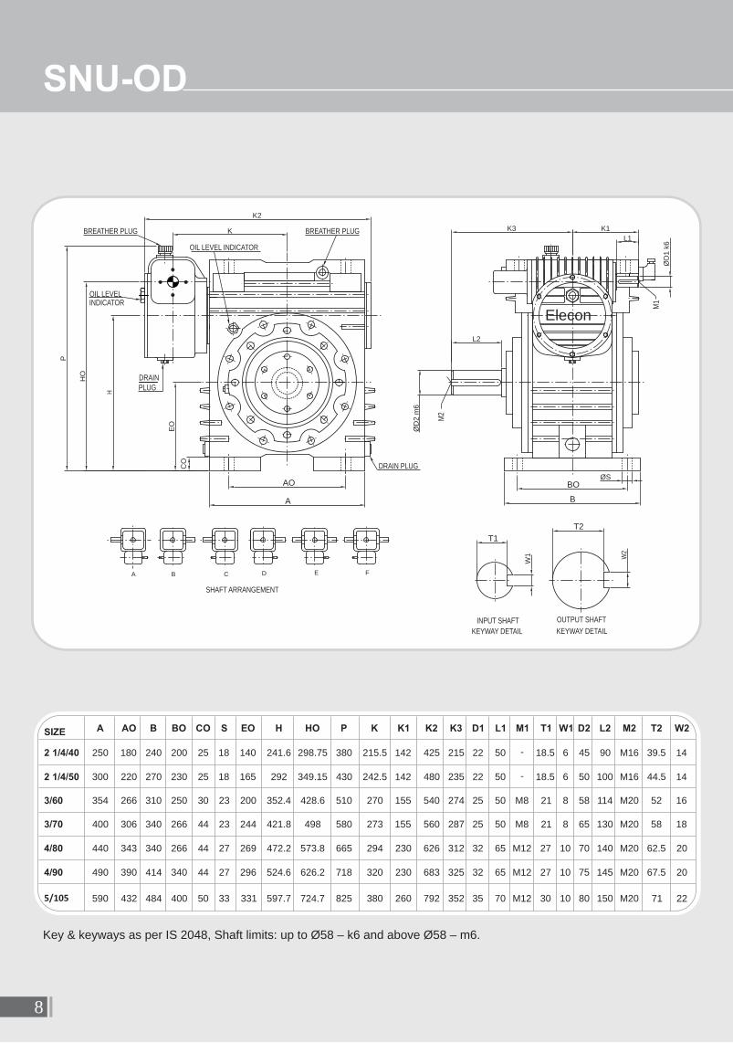
Key & keyways as per IS 2048, Shaft limits: up to Ø58 – k6 and above Ø58 – m6.
SNU-OD
8
BREATHER PLUG
INDICATOROIL LEVEL
DRAIN PLUG
PLUGDRAIN
BREATHER PLUG
OIL LEVEL INDICATOR
M2
M1
ØS
B
BO
ØD
2 m
6
L2
ØD
1 k
6
L1
K1K3
K2
K
P
HO
EO
CO
A
AO
W1
INPUT SHAFT
KEYWAY DETAIL
T1
KEYWAY DETAIL
OUTPUT SHAFTW
2
CBA FED
SHAFT ARRANGEMENT
H
Elecon
T2
SIZE A AO B BO CO S EO H HO P K K1 K2 K3 D1 L1 M1 T1 W1 D2 L2 M2 T2 W2
2 1/4/40 250 180 240 200 25 18 140 241.6 298.75 380 215.5 142 425 215 22 50 - 18.5 6 45 90 M16 39.5 14
2 1/4/50 300 220 270 230 25 18 165 292 349.15 430 242.5 142 480 235 22 50 - 18.5 6 50 100 M16 44.5 14
3/60 354 266 310 250 30 23 200 352.4 428.6 510 270 155 540 274 25 50 M8 21 8 58 114 M20 52 16
3/70 400 306 340 266 44 23 244 421.8 498 580 273 155 560 287 25 50 M8 21 8 65 130 M20 58 18
4/80 440 343 340 266 44 27 269 472.2 573.8 665 294 230 626 312 32 65 M12 27 10 70 140 M20 62.5 20
4/90 490 390 414 340 44 27 296 524.6 626.2 718 320 230 683 325 32 65 M12 27 10 75 145 M20 67.5 20
5/105 590 432 484 400 50 33 331 597.7 724.7 825 380 260 792 352 35 70 M12 30 10 80 150 M20 71 22

SIZE A AV HV CV S K K1 K2 K3 K4 K5 D1 L1 M1 T1 W1 D2 L2 M2 T2 W2
2 1/4/40 280 235 197.15 20 18 215.5 243.6 425 215 140 142 22 50 - 18.5 6 45 90 M16 39.5 14
2 1/4/50 320 260 222.15 22 18 242.5 269 480 235 185 142 22 50 - 18.5 6 50 100 M16 44.5 14
3/60 340 270 256.20 25 23 270 302.4 540 274 180 155 25 50 M8 21 8 58 114 M20 52 16
3/70 400 320 276.2 40 27 273 307.4 560 287 200 155 25 50 M8 21 8 65 130 M20 58 18
4/80 400 360 312.6 40 27 294 432.2 626 312 220 230 32 65 M12 27 10 70 140 M20 62.5 20
4/90 490 410 341.6 40 27 320 457.6 683 325 240 230 32 65 M12 27 10 75 145 M20 67.5 20
5/105 560 460 387 40 33 380 526.7 792 352 260 260 35 70 M12 30 10 80 150 M20 71 22
Key & keyways as per IS 2048, Shaft limits: up to Ø58 – k6 and above Ø58 – m6.
SNU-VD
9
INDICATOROIL LEVEL
DRAIN PLUG
BREATHER PLUG
M1
M2
K1
L1
K3
HV Ø
D1
k6
L2
AAV
ØD2 m6W
1
INPUT SHAFTKEYWAY DETAIL KEYWAY DETAIL
OUTPUT SHAFT
W2
K3
L2
P
BA
SHAFT ARRANGEMENT
K5
Elecon
T1T2
DRAIN PLUG
OIL LEVEL INDICATOR
BREATHER PLUG
ØS
CV
A
AV
K2
K
K4

SNU-SMD
Key & keyways as per IS 2048, Shaft limits: up to Ø58 – k6 and above Ø58 – m6.
SIZE A AU B BU CU S HU H EU P K K1 K2 G J N D1 L1 M1 T1 W1 D2 T2 W2 D3 D4 D5 R T
2 1/4/40 250 180 200 160 25 18 165.15 108 209.6 325 215.5 142 425 115 95 6 22 50 - 18.5 6 65 69.4 18 95 146 222 165 20
2 1/4/50 300 220 252 200 30 18 175.15 118 245 385 242.5 142 480 145 115 15 22 50 - 18.5 6 70 75.1 20 105 195 272 210 20
3/60 354 266 300 241 32 23 203.2 127 279.4 450 270 155 540 165 132 15 25 50 M8 21 8 75 80.1 20 105 205 330 250 20
3/70 400 306 340 266 36 23 222.2 146 323.8 524 273 155 560 160 132 8 25 50 M8 21 8 80 85.6 22 120 224 390 280 20
4/80 440 343 340 266 40 27 247.6 146 349.2 574 294 230 626 180 148 8 32 65 M12 27 10 90 95.6 25 130 263 445 318 20
4/90 490 390 344 282 40 27 255.6 154 382.6 635 320 230 683 190 157 8 32 65 M12 27 10 95 100.6 25 140 266 492 330 20
5/105 590 432 430 330 50 33 299 172 438.7 720 380 260 792 205 180 8 35 70 M12 30 10 100 106.6 28 152 292 540 380 20
10
Elecon
T1
T2
INDICATOR
PLUG
DRAIN PLUG
BREATHER
DRILLING DEPTH MUST NOT EXCEED 'T' mmTAP AND DOWELL TO SUIT OWN REQUIREMENT'R' P.C.D. ON WHICH CUSTOMER CAN DRILL
DRAIN PLUG
BREATHER &
FILLER PLUG
OIL LEVEL
GREASE NIPPLE
M1
G G
N J NJ
K2
B
BU
K1
L1
ØD
5
ØD
4 h
8
ØD
1 k
6
ØD
3 h
11
ØD
2 H
7
EU
P
HU
CU
K
A
AU
ØS
W1
INPUT SHAFT
KEYWAY DETAIL KEYWAY DETAIL
OUTPUT SHAFT
W2
B/LHA/LHA/RH B/RH
SHAFT ARRANGEMENT
D
L
B
B
L
G
D
L
B
B
L
G
D DRAIN PLUGG GREASE NIPPLEL OIL LEVEL INDICATORB BREATHER PLUG
MOUNTING METHOD
A B
H
INDICATOR
OIL LEVEL

SFUD
SIZE A AU B BU CU S HU H1 EU P K K1 K2 K3 D1 L1 M1 T1 W1 D2 L2 M2 T2 W2
5/120 690 521 540 368 55 33 317.5 190.5 495.3 860 405 260 855 381 35 70 M12 30 10 85 165 M20 76 22
6/140 820 597 560 432 65 33 367.4 216 571.6 988 480 279 1002 420 38 76 M12 33 10 110 200 M24 100 28
7/170 920 762 600 508 75 33 431.8 254 685.8 1181 670 311 1351 525 40 82 M16 35 12 135 215 M30 123 36
Key & keyways as per IS 2048, Shaft limits: up to Ø58 – k6 and above Ø58 – m6.
FOR SIZE 7/170 - 6 HOLE DIA.'S'
11
Elecon
T1T2
INDICATOR
FILLER PLUG
DRAIN PLUG
M2
M1
OIL LEVEL
FILER PLUG
DRAIN PLUG
EU
ØD
1 k6L1
HU
P
L2
ØD
2 m
6
K
K2
ØS
A
AU
CU
B
K3
BU
W1
INPUT SHAFTKEYWAY DETAIL KEYWAY DETAIL
OUTPUT SHAFTW
2C FBA ED
SHAFT ARRANGEMENT
K1
H1

SFOD
Key & keyways as per IS 2048, Shaft limits: up to Ø58 – k6 and above Ø58 – m6.
FOR SIZE 7/170 - 6 HOLE DIA.'S'
12
SIZE A AO B BO CO S EO HO P K K1 K2 K3 D1 L1 M1 T1 W1 D2 L2 M2 T2 W2
5/120 630 530 540 440 55 33 330 761.8 863 405 260 855 381 35 70 M12 30 10 85 165 M20 76 22
6/140 770 620 560 470 65 33 395 903 1011 480 279 1002 480 38 76 M12 33 10 110 200 M24 100 28
7/170 920 750 600 510 75 33 460 1069.6 1200 670 311 1351 525 40 82 M16 35 12 135 215 M30 123 36
Elecon
T1T2
OIL LEVEL
INDICATOR
INDICATOR
DRAIN PLUG
OIL LEVEL
BREATHER PLUG
DRAIN PLUG
M1
M2
P
K2
ØD
1 k
6
L1
K1K3
L2
HO
EO
ØD
2 m
6
CO
B
BOØS
AAO
W1
INPUT SHAFTKEYWAY DETAIL KEYWAY DETAIL
OUTPUT SHAFTW
2
CBA FED
SHAFT ARRANGEMENT
K

SFVD
SIZE A AV HV CV S P G H K K1 K2 K3 D1 L1 M1 T1 W1 D2 L2 M2 T2 W2
5/120 620 500 407.00 60 33 661 101 280 405 260 855 381 35 70 M12 30 10 85 165 M20 76 22
6/140 700 580 452.40 65 33 720 120 300 480 279 1002 420 38 76 M12 33 10 110 200 M24 100 28
7/170 1000 800 522.80 75 40 870 180 345 670 311 1351 525 40 82 M16 35 12 135 215 M30 123 36
Key & keyways as per IS 2048, Shaft limits: up to Ø58 – k6 and above Ø58 – m6.
13
M2
DRAIN PLUG
INDICATOROIL LEVEL
DRAIN PLUG
BREATHERPLUG
GREASE
M1
K2K
L1
ØD2 m6
AAV
HV
ØD
1 k
6
CV
AAV
ØS
L2
W1
INPUT SHAFTKEYWAY DETAIL KEYWAY DETAIL
OUTPUT SHAFT
W2
K1
P
L2
K3
K3
BA
SHAFT
ARRANGEMENT
GH
NIPPLE
Elecon
T1T2

14
SSMD
Key & keyways as per IS 2048, Shaft limits: up to Ø58 – k6 and above Ø58 – m6.
SIZE EU H K K1 K2 G J N D1 L1 M1 T1 W1 D2 T2 W2 D3 D4 D5 R T O M Q
5/120 380 304.8 405 260 855 220 190 10 35 70 M12 30 10 110 116.6 28 180 360 640 450 25 12 M12 605
6/140 450 355.6 480 279 1002 240 215 10 38 76 M12 33 10 140 148.7 36 185 400 770 530 21 12 M16 720
SHAFT ARRANGEMENT
Elecon
BREATHERPLUG
DRAIN PLUG
BREATHER PLUG
DRAIN PLUG
M1
NOT EXCEED 'T'
'R' PCD ON WHICH CUSTOMERCAN DRILL TAP AND DOWELTO SUIT OWN REQUIREMENTDRILLING DEPTH MUST
BOTH SIDES.
'O' EXISTING HOLES OF 'M'EQUI SPACED ON 'Q' PCD
ØD
4 h8
ØD
3 h
11G G
N
ØD
5
ØD
2 H
7
ØD
1 k
6
K1
L1
EU
H
K2
K
W1
INPUT SHAFT
KEYWAY DETAIL KEYWAY DETAIL
OUTPUT SHAFT
W2
N J J
OIL LEVEL
INDICATOR
B/LHA/LHA/RH B/RH
G
D DRAIN PLUGG GREASE NIPPLEL OIL LEVEL INDICATORB BREATHER PLUG
D
B B
B
DD L
B
A B
L
T1
T2

ACTUAL RATIO
SHIPING SPECIFICATION & OIL CAPACITY.
SNU-UD
SNU-OD
SNU-VD
SNU-SMD
SFUD
SFOD
SFVD
SSMD
15

I MINERAL OIL :
Brand Grade
International Brands
British Petroleum CS 320 or GR-XP320
Castrol Alpha Zn 320 or Alpha Sp-320 or Tribol 1100/320 TGQA
Caltex Meropa 320
Esso Petroleum Teresso 320 or Spartan 320
Fuchs Renolin CKC 320
Mobil Oil Co. Mobil DTE Oil AA or Mobilgear 632
Shell Co. Vitera Oil 320 or Omela 320
Indian Brands
Bharat Petroleum Cabol 320
Balmer Lawrie Fuchs Renolin CKC 320
Castrol Alpha Zn 320 or Alpha Sp-320 or Tribol 1100/320 TGQA
Gulf Gulf harmony 320 or Gulf EP 320
Hindustan Petroleum Enklo 320 or Parthan EP 320
Indian Oil Servomesh SP 320 or Servosystem 320
Veedol Avalon 320
II POLYGLYCOL BASED SYNTHETIC LUBRICANT
í USE OF POLYGLYCOL BASED SYNTHETIC LUBRICANT IS ALSO ADVISABLE TO IMPROVETHE TRANSMITTING CAPACITY (RATING) OF GEAR UNITS MIN. 20% AS COMPARED WITHUSE OF MINERAL OIL AT SAME WORKING TEMPERATURE. THIS GEAR OIL SHOWSEXCELLENT NON-AGEING STABILITY WITH FAVOURABLE INFLUENCE ON EFFICIENCY.
Approved Synthetic Lubricants
Special Note : Synthetic Lubricants must not be mixed with any other type of oil. The gear unit must be flushedwhile changing to or from this lubricant.
Recommended Grease : For low speed of operations.
Brand Grade
Castrol EPL 2
Indian Oil SERVOGEM EP 2
Brand Grade
Castrol Tribol 800-220
Fuchs Renolin PG 220
RECOMMENDED LUBRICANTS
16
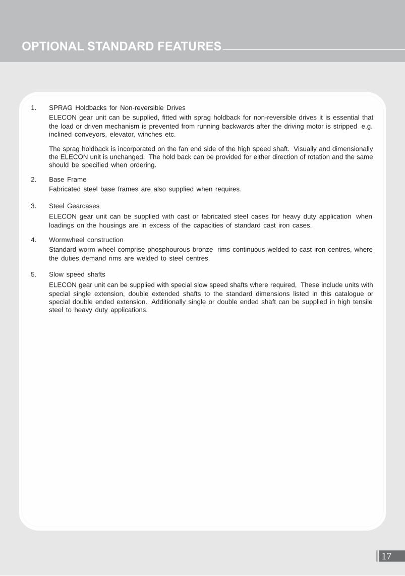
1. SPRAG Holdbacks for Non-reversible Drives
ELECON gear unit can be supplied, fitted with sprag holdback for non-reversible drives it is essential that
the load or driven mechanism is prevented from running backwards after the driving motor is stripped e.g.inclined conveyors, elevator, winches etc.
The sprag holdback is incorporated on the fan end side of the high speed shaft. Visually and dimensionallythe ELECON unit is unchanged. The hold back can be provided for either direction of rotation and the sameshould be specified when ordering.
2. Base Frame
Fabricated steel base frames are also supplied when requires.
3. Steel Gearcases
ELECON gear unit can be supplied with cast or fabricated steel cases for heavy duty application when
loadings on the housings are in excess of the capacities of standard cast iron cases.
4. Wormwheel construction
Standard worm wheel comprise phosphourous bronze rims continuous welded to cast iron centres, where
the duties demand rims are welded to steel centres.
5. Slow speed shafts
ELECON gear unit can be supplied with special slow speed shafts where required, These include units with
special single extension, double extended shafts to the standard dimensions listed in this catalogue orspecial double ended extension. Additionally single or double ended shaft can be supplied in high tensilesteel to heavy duty applications.
OPTIONAL STANDARD FEATURES
17

General ELECON gear units will operate safety provided that they are selected, installed, used
and maintained property. As with any equipment consists of rotating swhafts andtransmitting power, adequate guarding is necessary to elimiate the possibility of physi-cal contact with rotating shafts or coupling.
Potential Hazards The following points should be noted and brought to attention to the persons involved
in the installation, use and maintenance of equipment.
1. For lifting of gearunit eye-bolts or lifting points (on larger units) should be used.
2. Check the grade and quantity of lubrication before commissioning. Read and carry out all instructions onlubricant plate and in the installation and maintenance manual literature.
3. Installation must be performed in accordance with the manufacturer’s instruction and be undertaken bysuitably qualified personnel.
4. Ensure the proper maintenance of gearboxes in operation. USE ONLY ELECON SPARES FOR GEAR-BOXES.
5. The oil level should be examined periodically, if required the oil should be filled again.
6. The operating speeds, transmitting powers, generated torques or the external loads must not exceed thedesign values.
7. The driving and the driven equipment must be correctly selected to ensure that the complete installation ofthe machinery will perform satisfactorily e.g. avoiding system critical speeds, system torsional vibration etc.
As improvement in designing are continuously being made, the details and dimensions are subject to alterationwithout notice.
ELECON ENGINEERING CO. LTD.POST BOX # 6, VALLABH VIDYANAGAR 388 120, GUJARAT, INDIATEL.: +91-2692-236513, 236520, 232890 FAX : +91-2692-236527
E-MAIL : [email protected] Site : http://www.elecon.com
Any other required information or clarification can be obtained by writing to :
18
PRODUCT SAFETY INFORMATION

NOTE

International Branches :
Manufactured by:
ELECON ENGINEERING CO. LTD.
MARKETING & SERVICING COMPANY
EMTICI ENGINEERING LIMITED
National Branches :Ahmedabad :Phone : +91 79 26406683, 26406684 Fax : +91 79 26401363E-mail:[email protected]
Asansol :Phones : +91 341 2305901, 2311726 Fax : +91 341 2302038E-mail : [email protected]
Bilaspur : Phones : +91 7752 247723, 247625 Fax : +91 7752 247720E-mail : [email protected]
Bangalore :Phones : +91 80 22260219, 22281834 Fax : +91 80 22281834E-mail : [email protected]
Chennai :Phones : +91 44 24349237, 24349497Fax : +91 44 24349643E-mail : [email protected]
Dhanbad :Phones : +91 326 2230404 Fax : +91 326 2230490E-mail : [email protected]
MIDDLE EAST :ELECON MIDDLE EAST FZCOPhone : +97 146 091 424, +97 146 091 425 Fax : +97 146 091 426E-mail : [email protected] [email protected] [email protected]
UNITED KINGDOMRadicon Transmission UK Ltd.Park Road, LockwoodHuddersfeld-HD4 5DD Tel: +44 (0)1484 465800Fax: +44 (0)1484 [email protected]
FINLANDOy Benzler AbTel: +358 9 340 1716Fax: +358 10 296 [email protected]
GERMANYBenzler Antriebstechnik GmbHTel: +49 0800 350 4000Fax: +49 0800 350 [email protected]
SWEDENAB BenzlersTel: + 46 42 18 68 00Fax: + 46 42 21 88 [email protected]
NETHERLANDSBenzler-TBA bvTel : +31 077 324 5900Fax: +31 077 324 [email protected]
THAILANDRadicon Transmission Thailand Ltd.Tel : +66 38 459 044Fax: +66 38 213 [email protected]
RADICON USA1599 Lunt Ave, Elk Grove Village, Illinois - 60007 Tel.: 1-847-593-9910Mo.: 1-847-910-5090skype : glenn_pedersen5Fax. : 1-847-593-9950Email : [email protected] www.radicon.com
DENMARKBenzler Transmission A/STel: +45 212 800 [email protected]
FAR EAST :ELECON SINGAPORE PTE. LTD. Phone : +65 622 782 58Fax : +65 622 789 42E-mail : [email protected] [email protected]
Indore :Phone / Telefax : +91 731 2558077
Jamshedpur :Phones : +91 657 2361837, 2362376 Fax : +91 657 2464241E-mail : [email protected]
Kolkata :Phones : +91 33 24761861, 24760876Fax : +91 33 24761831E-mail : [email protected]
Madurai : Phone : +91 4549 293488 Fax : +91 4549 293468
Mumbai : Phones : +91 22 22821315, 22820725 Fax : +91 22 22870791E-mail : [email protected]
Nagpur : Phones : +91 712 6642600, 6642601Fax : +91 712 6642622E-mail : [email protected]
New Delhi : Phones : +91 11 23414340, 23414341Fax : +91 11 23709046E-mail : [email protected]
Pune :Phones : +91 20 40191400Fax : +91 20 40191420E-mail : [email protected]
Raipur : Phone : +91 771 408 1541Fax : +91 771 408 1541E-mail : [email protected]
Secunderabad :Phones : +91 40 27844748, 27845250Fax : +91 40 27848317E-mail : [email protected]
Vadodara : Phone : +91 265 2312972, 23136701Fax : +91 265 2312982E-mail : [email protected]
Anand - Sojitra Road, Vallabh Vidyanagar - 388 120, Gujarat, INDIA Phones : +91 269 223 0168, +91 269 223 1125, Fax : +91 269 223 6508, Website : www.emtici.co.in
REGISTERED OFFICE :
Post Box # 6, Vallabh Vidyanagar - 388 120, Gujarat, INDIAMHE DIVN. : Tel. : +91 269 223 7016, +91 269 223 6521, +91 269 223 6590, Fax : +91 269 222 7020 E-mail : [email protected]
GEAR DIVN. : Tel. : +91 269 223 6469, +91 269 223 6513, +91 269 223 6516, Fax : +91 269 222 7484 E-mail : [email protected] : www.elecon.com