Development of titanium based biocomposite by powder metallurgy processing with in situ forming of...
8
Materials Science and Engineering A 447 (2007) 19–26 Development of titanium based biocomposite by powder metallurgy processing with in situ forming of Ca–P phases Malobika Karanjai a,∗ , Ranganathan Sundaresan a , Gummididala Venkata Narasimha Rao a , Tallapragada Raja Rama Mohan b , Bhagwati Prasad Kashyap b a International Advanced Research Centre for Powder Metallurgy and New Materials, Balapur P.O., Hyderabad 500005, Andhra Pradesh, India b Metallurgical Engineering and Materials Science Department, Indian Institute of Technology, Powai, Mumbai 400076, Maharashtra, India Received 24 May 2006; received in revised form 21 July 2006; accepted 26 October 2006 Abstract Composites of titanium and calcium–phosphorus phases were developed by powder metallurgy processing and evaluated for bioactivity. Titanium hydride powder and precursors of calcium and phosphorus in the form of calcium carbonate and di-ammonium hydrogen orthophosphate were mixed in different proportions, compacted and calcined in different atmospheres. The calcined compacts were subsequently crushed, recompacted and sintered in vacuum. In situ formation of bioactive phases like hydroxylapatite, tricalcium phosphate and calcium titanate during the calcination and sintering steps was studied using X-ray diffraction. The effect of calcination atmosphere on density, interconnected porosity, phase composition and modulus of rupture of sintered composites was examined. The sintered composites were immersed in simulated body fluid for 7 days to observe their in vitro behaviour with XRD and FTIR spectroscopic identification of deposits. Composites with 10 wt% precursors sintered from vacuum calcined powder gave the best results in terms of bioactive phases, density and strength. © 2006 Elsevier B.V. All rights reserved. Keywords: Titanium; Calcium; Phosphorus; Hydroxylapatite; Biocomposite; Load bearing implants 1. Introduction The metallic materials most commonly used for biomedical applications are stainless steels, cobalt based alloys, titanium and titanium based alloys. Among these, titanium and its alloys are of considerable interest in both medical and dental fields because of their biocompatibility and low density coupled with good balance of mechanical properties and corrosion resistance. These alloys are suitable for implant devices replacing hard tissue, such as artificial hip joints, artificial knee joints, bone plates, dental implants, etc. [1], as well as for repairing some soft tissues [2]. However, almost all metallic implants, including tita- nium, are bioinert: while not rejected by the human body, these implants cannot actively interact with the surrounding tissues and thus cannot prevent the implant from being loosened [3,4]. One of the established ways of making metallic implants bioac- tive is to coat with hydroxylapatite, Ca 10 (PO 4 ) 6 (OH) 2 , which constitutes about 70% of natural bone [5,6]. More commonly, ∗ Corresponding author. Tel.: +91 40 24457104; fax: +91 40 24442699. E-mail address: [email protected] (M. Karanjai). synthetic hydroxylapatite (HA) has been plasma spray coated on Ti substrates before implantation [7]. There are also other Ca–P compounds such as amorphous calcium phosphate (ACP), octa-calcium phosphate (OCP), tricalcium phosphate (TCP) and biphasic calcium phosphate (BCP) that can also impart bioac- tivity to implant materials [7]. Thus, coated implants offer the possibility of combining the strength of metals with bioactivity of the ceramics [8]. Coated implants have inherent weaknesses of mismatch of thermal expansion coefficient and delamination at the metal–ceramic interface [9]. In order to overcome the limitations of coated implants, the present study was undertaken to develop a biocomposite from powders containing titanium, calcium and phosphorus. Composites with varying contents of titanium, calcium and phosphorous were synthesized through powder metallurgy under different processing conditions and their in vitro bioactivity was studied. Powder metallurgy processed composites having in situ formed bioactive calcium–phosphatic phases in titanium matrix are expected to be better in anchoring to the host environment as tissues grow not only on to the surface of the implant but also into the pores present in the implant. The resultant composite combining the superior mechanical 0921-5093/$ – see front matter © 2006 Elsevier B.V. All rights reserved. doi:10.1016/j.msea.2006.10.154
Transcript of Development of titanium based biocomposite by powder metallurgy processing with in situ forming of...

A
hmaaatc©
K
1
aaabgTtptniaOtc
0d
Materials Science and Engineering A 447 (2007) 19–26
Development of titanium based biocomposite by powder metallurgyprocessing with in situ forming of Ca–P phases
Malobika Karanjai a,∗, Ranganathan Sundaresan a, Gummididala Venkata Narasimha Rao a,Tallapragada Raja Rama Mohan b, Bhagwati Prasad Kashyap b
a International Advanced Research Centre for Powder Metallurgy and New Materials, Balapur P.O., Hyderabad 500005, Andhra Pradesh, Indiab Metallurgical Engineering and Materials Science Department, Indian Institute of Technology, Powai, Mumbai 400076, Maharashtra, India
Received 24 May 2006; received in revised form 21 July 2006; accepted 26 October 2006
bstract
Composites of titanium and calcium–phosphorus phases were developed by powder metallurgy processing and evaluated for bioactivity. Titaniumydride powder and precursors of calcium and phosphorus in the form of calcium carbonate and di-ammonium hydrogen orthophosphate wereixed in different proportions, compacted and calcined in different atmospheres. The calcined compacts were subsequently crushed, recompacted
nd sintered in vacuum. In situ formation of bioactive phases like hydroxylapatite, tricalcium phosphate and calcium titanate during the calcinationnd sintering steps was studied using X-ray diffraction. The effect of calcination atmosphere on density, interconnected porosity, phase composition
nd modulus of rupture of sintered composites was examined. The sintered composites were immersed in simulated body fluid for 7 days to observeheir in vitro behaviour with XRD and FTIR spectroscopic identification of deposits. Composites with 10 wt% precursors sintered from vacuumalcined powder gave the best results in terms of bioactive phases, density and strength. 2006 Elsevier B.V. All rights reserved.oad b
soCobtpo
omoapc
eywords: Titanium; Calcium; Phosphorus; Hydroxylapatite; Biocomposite; L
. Introduction
The metallic materials most commonly used for biomedicalpplications are stainless steels, cobalt based alloys, titaniumnd titanium based alloys. Among these, titanium and its alloysre of considerable interest in both medical and dental fieldsecause of their biocompatibility and low density coupled withood balance of mechanical properties and corrosion resistance.hese alloys are suitable for implant devices replacing hard
issue, such as artificial hip joints, artificial knee joints, bonelates, dental implants, etc. [1], as well as for repairing some softissues [2]. However, almost all metallic implants, including tita-ium, are bioinert: while not rejected by the human body, thesemplants cannot actively interact with the surrounding tissuesnd thus cannot prevent the implant from being loosened [3,4].
ne of the established ways of making metallic implants bioac-ive is to coat with hydroxylapatite, Ca10(PO4)6(OH)2, whichonstitutes about 70% of natural bone [5,6]. More commonly,
∗ Corresponding author. Tel.: +91 40 24457104; fax: +91 40 24442699.E-mail address: [email protected] (M. Karanjai).
mvcptoT
921-5093/$ – see front matter © 2006 Elsevier B.V. All rights reserved.oi:10.1016/j.msea.2006.10.154
earing implants
ynthetic hydroxylapatite (HA) has been plasma spray coatedn Ti substrates before implantation [7]. There are also othera–P compounds such as amorphous calcium phosphate (ACP),cta-calcium phosphate (OCP), tricalcium phosphate (TCP) andiphasic calcium phosphate (BCP) that can also impart bioac-ivity to implant materials [7]. Thus, coated implants offer theossibility of combining the strength of metals with bioactivityf the ceramics [8].
Coated implants have inherent weaknesses of mismatchf thermal expansion coefficient and delamination at theetal–ceramic interface [9]. In order to overcome the limitations
f coated implants, the present study was undertaken to developbiocomposite from powders containing titanium, calcium andhosphorus. Composites with varying contents of titanium,alcium and phosphorous were synthesized through powderetallurgy under different processing conditions and their in
itro bioactivity was studied. Powder metallurgy processedomposites having in situ formed bioactive calcium–phosphatic
hases in titanium matrix are expected to be better in anchoringo the host environment as tissues grow not only on to the surfacef the implant but also into the pores present in the implant.he resultant composite combining the superior mechanical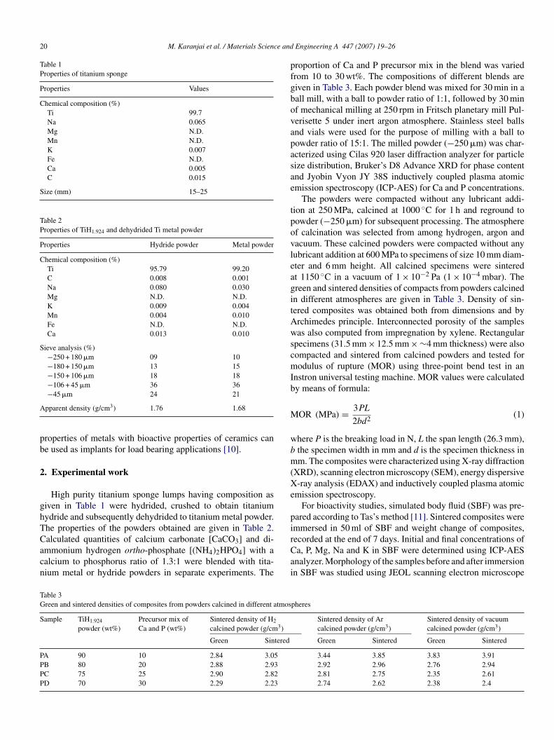
20 M. Karanjai et al. / Materials Science and
Table 1Properties of titanium sponge
Properties Values
Chemical composition (%)Ti 99.7Na 0.065Mg N.D.Mn N.D.K 0.007Fe N.D.Ca 0.005C 0.015
Size (mm) 15–25
Table 2Properties of TiH1.924 and dehydrided Ti metal powder
Properties Hydride powder Metal powder
Chemical composition (%)Ti 95.79 99.20C 0.008 0.001Na 0.080 0.030Mg N.D. N.D.K 0.009 0.004Mn 0.004 0.010Fe N.D. N.D.Ca 0.013 0.010
Sieve analysis (%)−250 + 180 �m 09 10−180 + 150 �m 13 15−150 + 106 �m 18 18−106 + 45 �m 36 36
A
pb
2
ghTCacn
pfgbovapasae
tpovleagitAwscmIb
M
wbm(Xe
pi
TG
S
PPPP
−45 �m 24 21
pparent density (g/cm3) 1.76 1.68
roperties of metals with bioactive properties of ceramics cane used as implants for load bearing applications [10].
. Experimental work
High purity titanium sponge lumps having composition asiven in Table 1 were hydrided, crushed to obtain titaniumydride and subsequently dehydrided to titanium metal powder.he properties of the powders obtained are given in Table 2.
alculated quantities of calcium carbonate [CaCO3] and di-mmonium hydrogen ortho-phosphate [(NH4)2HPO4] with aalcium to phosphorus ratio of 1.3:1 were blended with tita-ium metal or hydride powders in separate experiments. TherCai
able 3reen and sintered densities of composites from powders calcined in different atmos
ample TiH1.924
powder (wt%)Precursor mix ofCa and P (wt%)
Sintered density of H2
calcined powder (g/cm3)
Green Sintered
A 90 10 2.84 3.05B 80 20 2.88 2.93C 75 25 2.90 2.82D 70 30 2.29 2.23
Engineering A 447 (2007) 19–26
roportion of Ca and P precursor mix in the blend was variedrom 10 to 30 wt%. The compositions of different blends areiven in Table 3. Each powder blend was mixed for 30 min in aall mill, with a ball to powder ratio of 1:1, followed by 30 minf mechanical milling at 250 rpm in Fritsch planetary mill Pul-erisette 5 under inert argon atmosphere. Stainless steel ballsnd vials were used for the purpose of milling with a ball toowder ratio of 15:1. The milled powder (−250 �m) was char-cterized using Cilas 920 laser diffraction analyzer for particleize distribution, Bruker’s D8 Advance XRD for phase contentnd Jyobin Vyon JY 38S inductively coupled plasma atomicmission spectroscopy (ICP-AES) for Ca and P concentrations.
The powders were compacted without any lubricant addi-ion at 250 MPa, calcined at 1000 ◦C for 1 h and reground toowder (−250 �m) for subsequent processing. The atmospheref calcination was selected from among hydrogen, argon andacuum. These calcined powders were compacted without anyubricant addition at 600 MPa to specimens of size 10 mm diam-ter and 6 mm height. All calcined specimens were sinteredt 1150 ◦C in a vacuum of 1 × 10⁻² Pa (1 × 10⁻⁴ mbar). Thereen and sintered densities of compacts from powders calcinedn different atmospheres are given in Table 3. Density of sin-ered composites was obtained both from dimensions and byrchimedes principle. Interconnected porosity of the samplesas also computed from impregnation by xylene. Rectangular
pecimens (31.5 mm × 12.5 mm × ∼4 mm thickness) were alsoompacted and sintered from calcined powders and tested forodulus of rupture (MOR) using three-point bend test in an
nstron universal testing machine. MOR values were calculatedy means of formula:
OR (MPa) = 3PL
2bd2 (1)
here P is the breaking load in N, L the span length (26.3 mm),the specimen width in mm and d is the specimen thickness inm. The composites were characterized using X-ray diffraction
XRD), scanning electron microscopy (SEM), energy dispersive-ray analysis (EDAX) and inductively coupled plasma atomic
mission spectroscopy.For bioactivity studies, simulated body fluid (SBF) was pre-
ared according to Tas’s method [11]. Sintered composites weremmersed in 50 ml of SBF and weight change of composites,
ecorded at the end of 7 days. Initial and final concentrations ofa, P, Mg, Na and K in SBF were determined using ICP-AESnalyzer. Morphology of the samples before and after immersionn SBF was studied using JEOL scanning electron microscopepheres
Sintered density of Arcalcined powder (g/cm3)
Sintered density of vacuumcalcined powder (g/cm3)
Green Sintered Green Sintered
3.44 3.85 3.83 3.912.92 2.96 2.76 2.942.81 2.75 2.35 2.612.74 2.62 2.38 2.4
nce and Engineering A 447 (2007) 19–26 21
JddF
3
3
drdphcriuphvi
M. Karanjai et al. / Materials Scie
SM 4410. Multi-point spot and selective area analyses wereone with EDAX, Noran (KEVEX) attached to the SEM. Theeposits on the biocomposite were collected and analyzed byourier transform infrared spectroscopy (FTIR).
. Results and discussions
.1. Composite formation
The XRD and morphology of the titanium hydride and dehy-rided titanium metal powders are shown in Figs. 1 and 2,espectively. Titanium metal being very soft and ductile, dehy-rided powder could not be milled easily, and resulted in flakyowders that were not amenable to subsequent compaction. Theydride powder, on the other hand, was highly friable and therushed powder could be compacted. Further studies were car-ied out using only titanium hydride powder. Density valuesn Table 3 show that densification in sintering did not occurniformly, and in some cases (from hydrogen/argon calcined
owders) sintered density was lower than the green density. Theighest density was found in composite PAv (10 wt% precursors,acuum calcined), which could be a result of various factorsncluding the phase composition of the material.Fig. 1. XRD of titanium: (a) hydride powder and (b) dehydrided powder.
F
sihfstsoc
F
ig. 2. SEM of titanium: (a) hydride powder and (b) dehydrided powder.
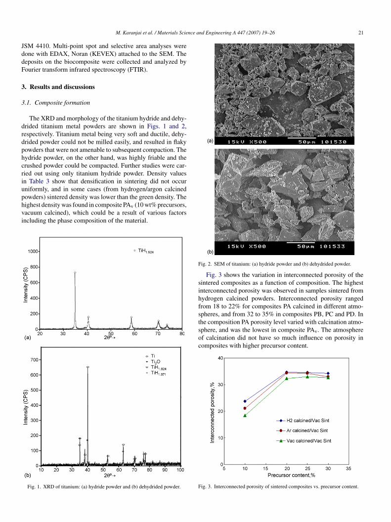
Fig. 3 shows the variation in interconnected porosity of theintered composites as a function of composition. The highestnterconnected porosity was observed in samples sintered fromydrogen calcined powders. Interconnected porosity rangedrom 18 to 22% for composites PA calcined in different atmo-pheres, and from 32 to 35% in composites PB, PC and PD. In
he composition PA porosity level varied with calcination atmo-phere, and was the lowest in composite PAv. The atmospheref calcination did not have so much influence on porosity inomposites with higher precursor content.ig. 3. Interconnected porosity of sintered composites vs. precursor content.
22 M. Karanjai et al. / Materials Science and
Fs
pFiocp
•
•
•
o
agdcwncIpI(HtptFc
iaittnpodpttp
3
iacccts
TM
S
PPPP
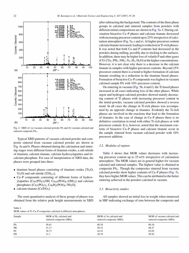
ig. 4. XRD of: (a) vacuum calcined powder PA and (b) vacuum calcined andintered composite PAv.
Typical XRD patterns of vacuum calcined powder and com-osite sintered from vacuum calcined powder are shown inig. 4a and b. Phases obtained during the calcination and sinter-
ng stages were different forms of titanium oxides, a sub nitridef titanium, calcium titanate, calcium hydroxylapatites and tri-alcium phosphate. For ease of interpretation of XRD data, thehases were grouped into three:
titanium based phases consisting of titanium oxides [Ti2O,Ti3O] and sub nitride [TiN0.3],Ca–P compounds consisting of different forms of hydrox-ylapatites [Ca5(PO4)3OH, Ca10(PO4)6·(OH)2] and calciumphosphates [Ca3(PO4)2, Ca8H2(PO4)6·5H2O],
calcium titanate [CaTiO3].The semi-quantitative analysis of these groups of phases wasbtained from the relative peak height measurements in XRD
3
i
able 4OR values of Ti–Ca–P composites calcined in different atmospheres
ample MOR of H2 calcined andsintered composite (MPa)
Msin
A 56.61 60B 51.17 50C 38.73 42D 31.1 30
Engineering A 447 (2007) 19–26
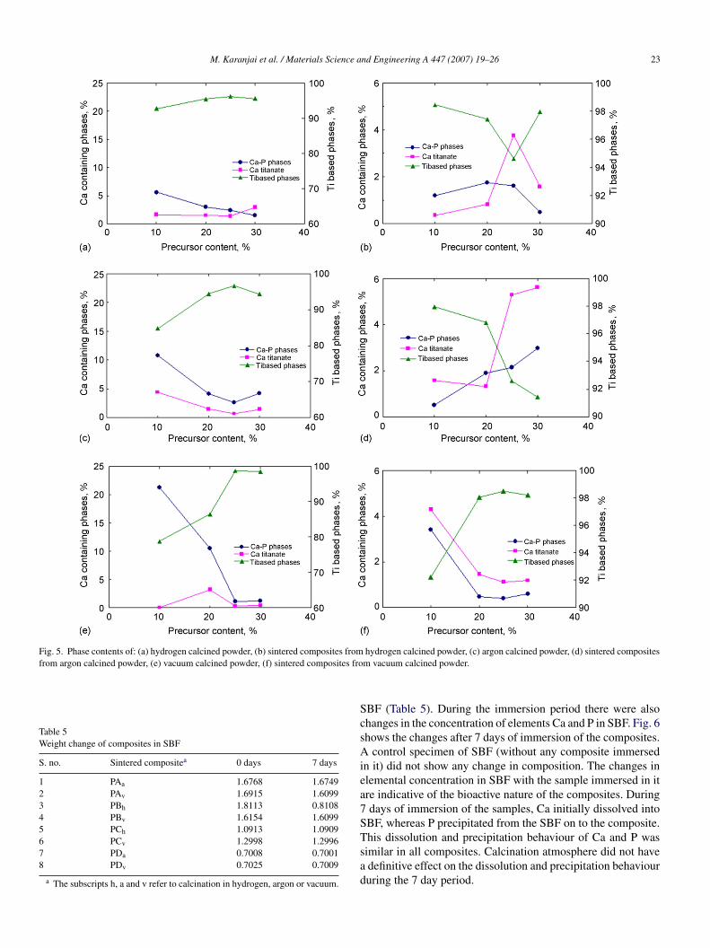
fter subtracting the background. The contents of the three phaseroups in calcined and sintered samples from powders withifferent initial compositions are shown in Fig. 5a–f. During cal-ination bioactive Ca–P phases and calcium titanate decreasedith increasing precursor content up to 25% irrespective of calci-ation atmosphere (Fig. 5a, c and e). At higher precursor contentalcium titanate increased, leading to reduction in Ti-rich phases.t was noted that both Ca and P contents had decreased in theowders during milling, possibly due to sticking to the surfaces.n addition, there may be higher loss of volatile P and other gasesCO, CO2, PH3, NH3, N2, H2, H2O) at the higher concentrations.owever, it is not clear why there is a decrease in the calcium
itanate in samples with higher precursor contents. Beyond 25%recursor content there is a trend to higher formation of calciumitanate resulting in a reduction in the titanium based phases.ormation of bioactive Ca–P compounds was highest in vacuumalcined sample PA with 10% precursor content.
On sintering in vacuum (Fig. 5b, d and f), the Ti based phasesncreased in all cases indicating loss of the other phases. Whilergon and hydrogen calcined powders showed mainly decreas-ng content of Ti phases with increasing precursor content inhe initial powder, vacuum calcined powders showed a reverserend. In all cases the change in Ti-rich phases was accompa-ied by an opposite change in titanates. Evidently the Ti-richhases are involved in the reactions that lead to the formationf titanates. In the case of change in Ca–P phases there is noefinitive correlation in trend with either Ti-rich phases or withrecursor content. It is, however, noted that the maximum con-ents of bioactive Ca–P phases and calcium titanate occur inhe sample sintered from vacuum calcined powder with 10%recursor addition.
.2. Modulus of rupture
Table 4 shows that MOR values decreases with increas-ng precursor content up to 25 wt% irrespective of calcinationtmosphere. The MOR values are in general higher for vacuumalcined and sintered samples. The highest value is obtained inomposite PAv. Though the composites sintered from vacuumalcined powder show higher contents of Ca–P phases (Fig. 5),hey have higher MOR values. This can be attributed to the betterintering achieved in the powders calcined in vacuum.
.3. Bioactivity studies
All samples showed an initial loss in weight when immersedn SBF indicating exchange of ions between the composite and
OR of Ar calcined andtered composite (MPa)
MOR of vacuum calcined andsintered composite (MPa)
.38 80.16
.32 68.27
.43 62.05
.79 59.92
M. Karanjai et al. / Materials Science and Engineering A 447 (2007) 19–26 23
Fig. 5. Phase contents of: (a) hydrogen calcined powder, (b) sintered composites fromfrom argon calcined powder, (e) vacuum calcined powder, (f) sintered composites fro
Table 5Weight change of composites in SBF
S. no. Sintered compositea 0 days 7 days
1 PAa 1.6768 1.67492 PAv 1.6915 1.60993 PBh 1.8113 0.81084 PBv 1.6154 1.60995 PCh 1.0913 1.09096 PCv 1.2998 1.29967 PDa 0.7008 0.70018 PDv 0.7025 0.7009
a The subscripts h, a and v refer to calcination in hydrogen, argon or vacuum.
ScsAiea7STsad
hydrogen calcined powder, (c) argon calcined powder, (d) sintered compositesm vacuum calcined powder.
BF (Table 5). During the immersion period there were alsohanges in the concentration of elements Ca and P in SBF. Fig. 6hows the changes after 7 days of immersion of the composites.
control specimen of SBF (without any composite immersedn it) did not show any change in composition. The changes inlemental concentration in SBF with the sample immersed in itre indicative of the bioactive nature of the composites. Duringdays of immersion of the samples, Ca initially dissolved intoBF, whereas P precipitated from the SBF on to the composite.
his dissolution and precipitation behaviour of Ca and P wasimilar in all composites. Calcination atmosphere did not havedefinitive effect on the dissolution and precipitation behavioururing the 7 day period.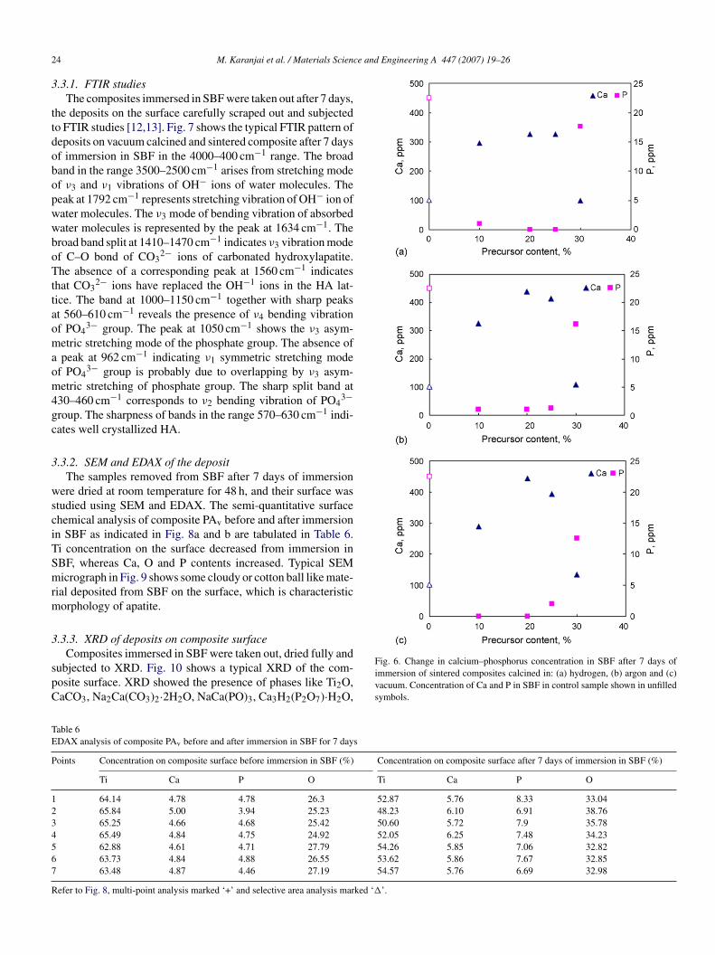
2 ce and Engineering A 447 (2007) 19–26
3
ttdobopwwboTttaomaom4gc
3
wsciTSmrm
3
spC
TE
P
1234567
R
4 M. Karanjai et al. / Materials Scien
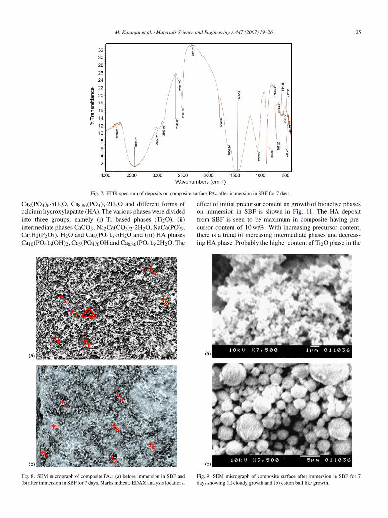
.3.1. FTIR studiesThe composites immersed in SBF were taken out after 7 days,
he deposits on the surface carefully scraped out and subjectedo FTIR studies [12,13]. Fig. 7 shows the typical FTIR pattern ofeposits on vacuum calcined and sintered composite after 7 daysf immersion in SBF in the 4000–400 cm−1 range. The broadand in the range 3500–2500 cm−1 arises from stretching modef ν3 and ν1 vibrations of OH− ions of water molecules. Theeak at 1792 cm−1 represents stretching vibration of OH− ion ofater molecules. The ν3 mode of bending vibration of absorbedater molecules is represented by the peak at 1634 cm−1. Theroad band split at 1410–1470 cm−1 indicates ν3 vibration modef C–O bond of CO3
2− ions of carbonated hydroxylapatite.he absence of a corresponding peak at 1560 cm−1 indicates
hat CO32− ions have replaced the OH−1 ions in the HA lat-
ice. The band at 1000–1150 cm−1 together with sharp peakst 560–610 cm−1 reveals the presence of ν4 bending vibrationf PO4
3− group. The peak at 1050 cm−1 shows the ν3 asym-etric stretching mode of the phosphate group. The absence ofpeak at 962 cm−1 indicating ν1 symmetric stretching mode
f PO43− group is probably due to overlapping by ν3 asym-
etric stretching of phosphate group. The sharp split band at30–460 cm−1 corresponds to ν2 bending vibration of PO4
3−roup. The sharpness of bands in the range 570–630 cm−1 indi-ates well crystallized HA.
.3.2. SEM and EDAX of the depositThe samples removed from SBF after 7 days of immersion
ere dried at room temperature for 48 h, and their surface wastudied using SEM and EDAX. The semi-quantitative surfacehemical analysis of composite PAv before and after immersionn SBF as indicated in Fig. 8a and b are tabulated in Table 6.i concentration on the surface decreased from immersion inBF, whereas Ca, O and P contents increased. Typical SEMicrograph in Fig. 9 shows some cloudy or cotton ball like mate-
ial deposited from SBF on the surface, which is characteristicorphology of apatite.
.3.3. XRD of deposits on composite surface
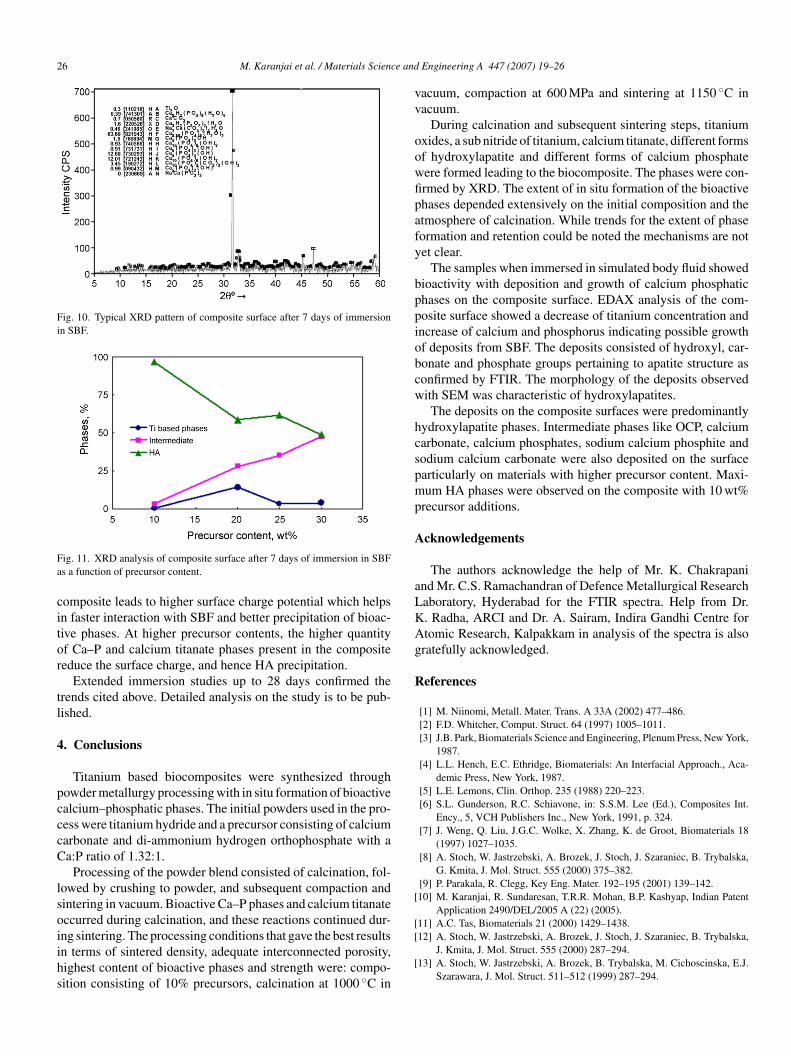
Composites immersed in SBF were taken out, dried fully andubjected to XRD. Fig. 10 shows a typical XRD of the com-osite surface. XRD showed the presence of phases like Ti2O,aCO3, Na2Ca(CO3)2·2H2O, NaCa(PO)3, Ca3H2(P2O7)·H2O,
Fig. 6. Change in calcium–phosphorus concentration in SBF after 7 days ofimmersion of sintered composites calcined in: (a) hydrogen, (b) argon and (c)vacuum. Concentration of Ca and P in SBF in control sample shown in unfilledsymbols.
able 6DAX analysis of composite PAv before and after immersion in SBF for 7 days
oints Concentration on composite surface before immersion in SBF (%) Concentration on composite surface after 7 days of immersion in SBF (%)
Ti Ca P O Ti Ca P O
64.14 4.78 4.78 26.3 52.87 5.76 8.33 33.0465.84 5.00 3.94 25.23 48.23 6.10 6.91 38.7665.25 4.66 4.68 25.42 50.60 5.72 7.9 35.7865.49 4.84 4.75 24.92 52.05 6.25 7.48 34.2362.88 4.61 4.71 27.79 54.26 5.85 7.06 32.8263.73 4.84 4.88 26.55 53.62 5.86 7.67 32.8563.48 4.87 4.46 27.19 54.57 5.76 6.69 32.98
efer to Fig. 8, multi-point analysis marked ‘+’ and selective area analysis marked ‘�’.
M. Karanjai et al. / Materials Science and Engineering A 447 (2007) 19–26 25
ite su
CciiCC
F(
eo
Fig. 7. FTIR spectrum of deposits on compos
a8(PO4)6·5H2O, Ca8.86(PO4)6·2H2O and different forms ofalcium hydroxylapatite (HA). The various phases were divided
nto three groups, namely (i) Ti based phases (Ti2O), (ii)ntermediate phases CaCO3, Na2Ca(CO3)2·2H2O, NaCa(PO)3,a3H2(P2O7). H2O and Ca8(PO4)6·5H2O and (iii) HA phasesa10(PO4)6(OH)2, Ca5(PO4)6OH and Ca8.86(PO4)6·2H2O. Theig. 8. SEM micrograph of composite PAv: (a) before immersion in SBF andb) after immersion in SBF for 7 days. Marks indicate EDAX analysis locations.
fcti
Fd
rface PAv after immersion in SBF for 7 days.
ffect of initial precursor content on growth of bioactive phasesn immersion in SBF is shown in Fig. 11. The HA deposit
rom SBF is seen to be maximum in composite having pre-ursor content of 10 wt%. With increasing precursor content,here is a trend of increasing intermediate phases and decreas-ng HA phase. Probably the higher content of Ti2O phase in theig. 9. SEM micrograph of composite surface after immersion in SBF for 7ays showing (a) cloudy growth and (b) cotton ball like growth.
26 M. Karanjai et al. / Materials Science and
Fig. 10. Typical XRD pattern of composite surface after 7 days of immersionin SBF.
Fa
citor
tl
4
pcccC
lsoiihs
vv
oowfipafy
bppiobcw
hcspmp
A
aLKAg
R
[
[11] A.C. Tas, Biomaterials 21 (2000) 1429–1438.
ig. 11. XRD analysis of composite surface after 7 days of immersion in SBFs a function of precursor content.
omposite leads to higher surface charge potential which helpsn faster interaction with SBF and better precipitation of bioac-ive phases. At higher precursor contents, the higher quantityf Ca–P and calcium titanate phases present in the compositeeduce the surface charge, and hence HA precipitation.
Extended immersion studies up to 28 days confirmed therends cited above. Detailed analysis on the study is to be pub-ished.
. Conclusions
Titanium based biocomposites were synthesized throughowder metallurgy processing with in situ formation of bioactivealcium–phosphatic phases. The initial powders used in the pro-ess were titanium hydride and a precursor consisting of calciumarbonate and di-ammonium hydrogen orthophosphate with aa:P ratio of 1.32:1.
Processing of the powder blend consisted of calcination, fol-owed by crushing to powder, and subsequent compaction andintering in vacuum. Bioactive Ca–P phases and calcium titanateccurred during calcination, and these reactions continued dur-
ng sintering. The processing conditions that gave the best resultsn terms of sintered density, adequate interconnected porosity,ighest content of bioactive phases and strength were: compo-ition consisting of 10% precursors, calcination at 1000 ◦C in[
[
Engineering A 447 (2007) 19–26
acuum, compaction at 600 MPa and sintering at 1150 ◦C inacuum.
During calcination and subsequent sintering steps, titaniumxides, a sub nitride of titanium, calcium titanate, different formsf hydroxylapatite and different forms of calcium phosphateere formed leading to the biocomposite. The phases were con-rmed by XRD. The extent of in situ formation of the bioactivehases depended extensively on the initial composition and thetmosphere of calcination. While trends for the extent of phaseormation and retention could be noted the mechanisms are notet clear.
The samples when immersed in simulated body fluid showedioactivity with deposition and growth of calcium phosphatichases on the composite surface. EDAX analysis of the com-osite surface showed a decrease of titanium concentration andncrease of calcium and phosphorus indicating possible growthf deposits from SBF. The deposits consisted of hydroxyl, car-onate and phosphate groups pertaining to apatite structure asonfirmed by FTIR. The morphology of the deposits observedith SEM was characteristic of hydroxylapatites.The deposits on the composite surfaces were predominantly
ydroxylapatite phases. Intermediate phases like OCP, calciumarbonate, calcium phosphates, sodium calcium phosphite andodium calcium carbonate were also deposited on the surfacearticularly on materials with higher precursor content. Maxi-um HA phases were observed on the composite with 10 wt%
recursor additions.
cknowledgements
The authors acknowledge the help of Mr. K. Chakrapanind Mr. C.S. Ramachandran of Defence Metallurgical Researchaboratory, Hyderabad for the FTIR spectra. Help from Dr.. Radha, ARCI and Dr. A. Sairam, Indira Gandhi Centre fortomic Research, Kalpakkam in analysis of the spectra is alsoratefully acknowledged.
eferences
[1] M. Niinomi, Metall. Mater. Trans. A 33A (2002) 477–486.[2] F.D. Whitcher, Comput. Struct. 64 (1997) 1005–1011.[3] J.B. Park, Biomaterials Science and Engineering, Plenum Press, New York,
1987.[4] L.L. Hench, E.C. Ethridge, Biomaterials: An Interfacial Approach., Aca-
demic Press, New York, 1987.[5] L.E. Lemons, Clin. Orthop. 235 (1988) 220–223.[6] S.L. Gunderson, R.C. Schiavone, in: S.S.M. Lee (Ed.), Composites Int.
Ency., 5, VCH Publishers Inc., New York, 1991, p. 324.[7] J. Weng, Q. Liu, J.G.C. Wolke, X. Zhang, K. de Groot, Biomaterials 18
(1997) 1027–1035.[8] A. Stoch, W. Jastrzebski, A. Brozek, J. Stoch, J. Szaraniec, B. Trybalska,
G. Kmita, J. Mol. Struct. 555 (2000) 375–382.[9] P. Parakala, R. Clegg, Key Eng. Mater. 192–195 (2001) 139–142.10] M. Karanjai, R. Sundaresan, T.R.R. Mohan, B.P. Kashyap, Indian Patent
Application 2490/DEL/2005 A (22) (2005).
12] A. Stoch, W. Jastrzebski, A. Brozek, J. Stoch, J. Szaraniec, B. Trybalska,J. Kmita, J. Mol. Struct. 555 (2000) 287–294.
13] A. Stoch, W. Jastrzebski, A. Brozek, B. Trybalska, M. Cichoscinska, E.J.Szarawara, J. Mol. Struct. 511–512 (1999) 287–294.