The Application of Gage R&R Analysis in s Six Sigma Case of ...
83
Western Kentucky University TopSCHOLAR® Masters eses & Specialist Projects Graduate School Fall 2015 e Application of Gage R&R Analysis in s Six Sigma Case of Improving and Optimizing an Automotive Die Casting Product’s Measurement System Qizheng Ren Western Kentucky University, [email protected] Follow this and additional works at: hp://digitalcommons.wku.edu/theses Part of the Architectural Technology Commons , Industrial Technology Commons , and the Other Operations Research, Systems Engineering and Industrial Engineering Commons is esis is brought to you for free and open access by TopSCHOLAR®. It has been accepted for inclusion in Masters eses & Specialist Projects by an authorized administrator of TopSCHOLAR®. For more information, please contact [email protected]. Recommended Citation Ren, Qizheng, "e Application of Gage R&R Analysis in s Six Sigma Case of Improving and Optimizing an Automotive Die Casting Product’s Measurement System" (2015). Masters eses & Specialist Projects. Paper 1536. hp://digitalcommons.wku.edu/theses/1536
-
Upload
khangminh22 -
Category
Documents
-
view
3 -
download
0
Transcript of The Application of Gage R&R Analysis in s Six Sigma Case of ...
Western Kentucky UniversityTopSCHOLAR®
Masters Theses & Specialist Projects Graduate School
Fall 2015
The Application of Gage R&R Analysis in s SixSigma Case of Improving and Optimizing anAutomotive Die Casting Product’s MeasurementSystemQizheng RenWestern Kentucky University, [email protected]
Follow this and additional works at: http://digitalcommons.wku.edu/theses
Part of the Architectural Technology Commons, Industrial Technology Commons, and theOther Operations Research, Systems Engineering and Industrial Engineering Commons
This Thesis is brought to you for free and open access by TopSCHOLAR®. It has been accepted for inclusion in Masters Theses & Specialist Projects byan authorized administrator of TopSCHOLAR®. For more information, please contact [email protected].
Recommended CitationRen, Qizheng, "The Application of Gage R&R Analysis in s Six Sigma Case of Improving and Optimizing an Automotive Die CastingProduct’s Measurement System" (2015). Masters Theses & Specialist Projects. Paper 1536.http://digitalcommons.wku.edu/theses/1536
THE APPLICATION OF GAGE R&R ANALYSIS IN A SIX SIGMA CASE OF
IMPROVING AND OPTIMIZING AN AUTOMOTIVE DIE CASTING PRODUCT’S
MEASUREMENT SYSTEM
A Thesis
Presented to
The Faculty of the Department of Architectural and Manufacturing Sciences
Western Kentucky University
Bowling Green, Kentucky
In Partial Fulfillment
Of the Requirements for the Degree
Master of Science
By
Qizheng Ren
December 2015


I dedicate this thesis to my parents, Rubin Ren and Catherine Tseng, who have given me
this great chance to continue my graduate study. I also dedicate this work to my
sweetheart, Sophia Wu, who has always given me the support I need. Finally, I dedicate
this work to Company T and the Architecture and Manufacturing Sciences department of
Western Kentucky University, as well as all the faculty, staff, and students who have
helped me to finish this research.
iv
ACKNOWLEDGMENTS
I would like to thank several professors that helped me successfully complete this
research: Dr. Mark Doggett, Dr. Daniel Jackson, and Dr. John Khouryieh. I would also
like to thank the CEO of Company T, Mr. Lowell Guthrie and Mr. Luis Rodrigo, the Vice
President of Quality Department of Company T, for allowing me to utilize the employees
and equipment to conduct this research. Finally, I would like to thank my colleagues of
Company T who have given me suggestions and support in conducting research.

v
CONTENTS
Introduction ......................................................................................................................... 1
Background .................................................................................................................................. 1
Problem Statement ....................................................................................................................... 6
Purpose of the Research Study .................................................................................................... 6
Significance for the Research Study ............................................................................................ 7
Hypothesis ................................................................................................................................... 8
Assumptions ................................................................................................................................. 9
Limitations ................................................................................................................................. 10
Delimitations .............................................................................................................................. 10
Definition of Terms.................................................................................................................... 11
Review of Literature ......................................................................................................... 14
Measurement System Variations ............................................................................................... 14
Measurement System Improvement .......................................................................................... 15
Gage R&R Study and Measurement System Analysis .............................................................. 17
Gage R&R Method .................................................................................................................... 17
Average and Range Gage R&R Study ....................................................................................... 19
Methodology ..................................................................................................................... 26
Define ......................................................................................................................................... 27
Measure ...................................................................................................................................... 33
Analysis ..................................................................................................................................... 36
Improve ...................................................................................................................................... 37
Control ....................................................................................................................................... 38
Findings and Results ......................................................................................................... 39
Numerical Analysis Findings ..................................................................................................... 39
vi
Graphical Analysis Findings ...................................................................................................... 39
Root Cause Analysis .................................................................................................................. 45
Improve the Problematic Gage System ...................................................................................... 49
Management and Quality System Control ................................................................................. 51
Results ........................................................................................................................................ 52
Conclusion ........................................................................................................................ 55
Hypothesis Conclusions ............................................................................................................. 55
Suggestions for Future Research ............................................................................................... 56
Appendix A: Gage R&R Data Collection Sheets ............................................................. 60
Appendix B: Gage Repeatability and Reproducibility Reports ........................................ 64
Appendix C: Gage R&R Data Collection Sheet and Report of the Repaired Air Gage
System B ........................................................................................................................... 68
References ......................................................................................................................... 70
vii
LIST OF FIGURES
Figure 1. Customer A’s Assembled Transmission Product Drawing............................... 29
Figure 2. A Type of the Rear Cover Product of the Customer A. .................................... 30
Figure 3. One Mahr Millimar S 1840 PE Air Gage System Product Example ................ 30
Figure 4. Mahr Millimar S 1840 PE Air Gage System Display/Control Set ................... 31
Figure 5. Air Probe with Handle ...................................................................................... 31
Figure 6. Jet Probe Assembly ........................................................................................... 32
Figure 7. The Probe Detects the Back Pressure Impacted by the Inner Bore Surface ..... 32
Figure 8. The Measurement Process of the Air Gage System. ......................................... 33
Figure 9. Average Chart of the First Experiment. ............................................................ 40
Figure 10. Range Control Chart of the First Experiment.. ............................................... 40
Figure 11. Average Chart of the Second Experiment. ...................................................... 41
Figure 12. Range Control Chart of the Second Experiment.. ........................................... 41
Figure 13. Average Chart of the Third Experiment. ........................................................ 42
Figure 14. Range Control Chart of the Third Experiment. ............................................... 42
Figure 15. Average Chart of the Forth Experiment. ......................................................... 43
Figure 16. Range Control Chart of the Forth Experiment.. .............................................. 43
Figure 17. Air Gage System Block Diagram.................................................................... 47
Figure 18. Average Chart of the Repaired Air Gage System B ....................................... 50
Figure 19. Range control chart of the repaired air gage system B ................................... 51

viii
LIST OF TABLES Table 1. The DMAIC Process Route & Content of the Research .....................................26
Table 2. Comparison of Quality, Cost, and Time Before and After Gage Analysis ........53
ix
THE APPLICATION OF GAGE R&R ANALYSIS IN A SIX SIGMA CASE OF
IMPROVING AND OPTIMIZING AN AUTOMOTIVE DIE CASTING PRODUCT’S
MEASUREMENT SYSTEM
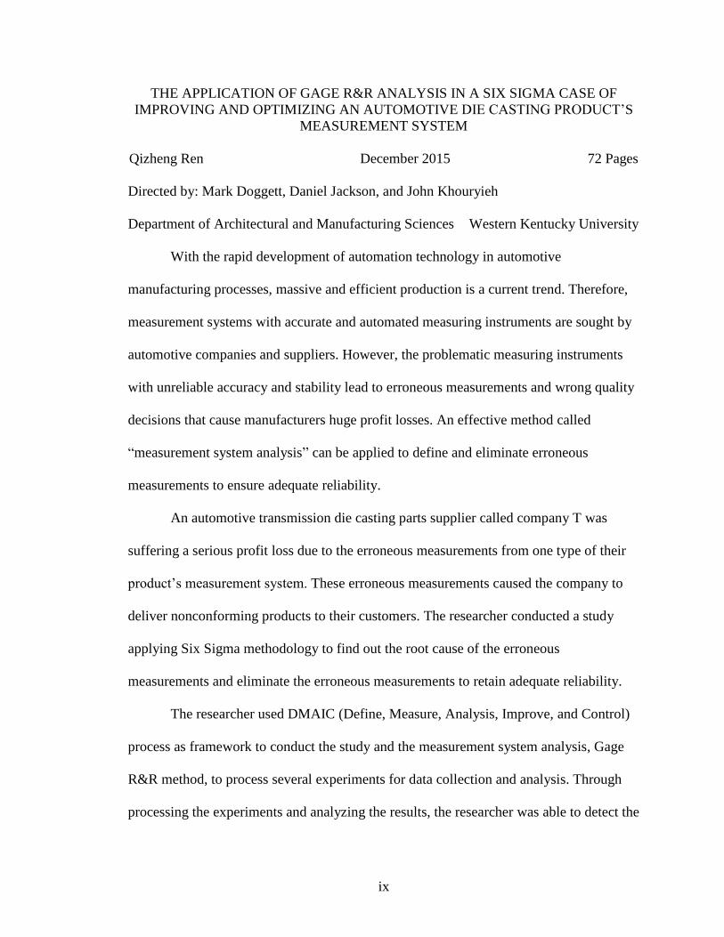
Qizheng Ren December 2015 72 Pages
Directed by: Mark Doggett, Daniel Jackson, and John Khouryieh
Department of Architectural and Manufacturing Sciences Western Kentucky University
With the rapid development of automation technology in automotive
manufacturing processes, massive and efficient production is a current trend. Therefore,
measurement systems with accurate and automated measuring instruments are sought by
automotive companies and suppliers. However, the problematic measuring instruments
with unreliable accuracy and stability lead to erroneous measurements and wrong quality
decisions that cause manufacturers huge profit losses. An effective method called
“measurement system analysis” can be applied to define and eliminate erroneous
measurements to ensure adequate reliability.
An automotive transmission die casting parts supplier called company T was
suffering a serious profit loss due to the erroneous measurements from one type of their
product’s measurement system. These erroneous measurements caused the company to
deliver nonconforming products to their customers. The researcher conducted a study
applying Six Sigma methodology to find out the root cause of the erroneous
measurements and eliminate the erroneous measurements to retain adequate reliability.
The researcher used DMAIC (Define, Measure, Analysis, Improve, and Control)
process as framework to conduct the study and the measurement system analysis, Gage
R&R method, to process several experiments for data collection and analysis. Through
processing the experiments and analyzing the results, the researcher was able to detect the

x
source of variation and find the root cause that caused the erroneous measurements.
Based on the findings, the researcher then corrected the erroneous measurements and
improved the problematic measurement system’s performance.
1
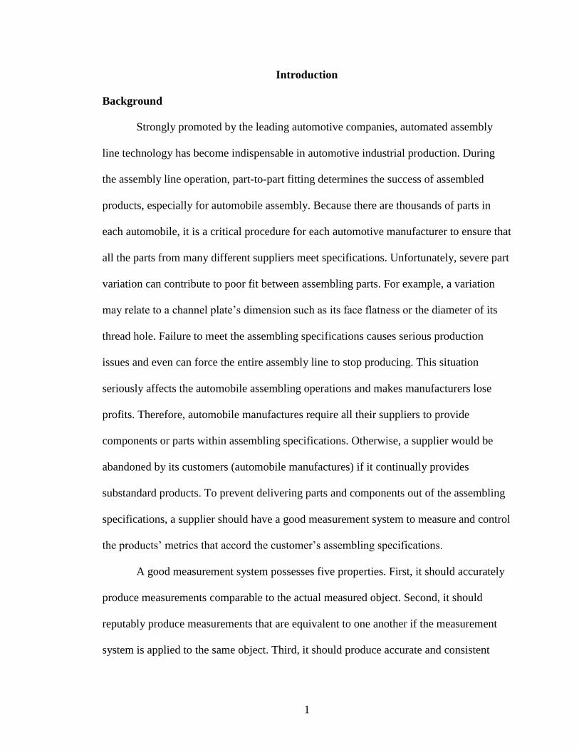
Introduction
Background
Strongly promoted by the leading automotive companies, automated assembly
line technology has become indispensable in automotive industrial production. During
the assembly line operation, part-to-part fitting determines the success of assembled
products, especially for automobile assembly. Because there are thousands of parts in
each automobile, it is a critical procedure for each automotive manufacturer to ensure that
all the parts from many different suppliers meet specifications. Unfortunately, severe part
variation can contribute to poor fit between assembling parts. For example, a variation
may relate to a channel plate’s dimension such as its face flatness or the diameter of its
thread hole. Failure to meet the assembling specifications causes serious production
issues and even can force the entire assembly line to stop producing. This situation
seriously affects the automobile assembling operations and makes manufacturers lose
profits. Therefore, automobile manufactures require all their suppliers to provide
components or parts within assembling specifications. Otherwise, a supplier would be
abandoned by its customers (automobile manufactures) if it continually provides
substandard products. To prevent delivering parts and components out of the assembling
specifications, a supplier should have a good measurement system to measure and control
the products’ metrics that accord the customer’s assembling specifications.
A good measurement system possesses five properties. First, it should accurately
produce measurements comparable to the actual measured object. Second, it should
reputably produce measurements that are equivalent to one another if the measurement
system is applied to the same object. Third, it should produce accurate and consistent
2
measurements. Fourth, it should reproduce the same measurements when used by any
properly trained individual (Pyzdek & Keller, 2009). Finally, it should be stable in order
to produce the same measurements in the future that it has in the past. Those five
properties are the main standards for the measurement system evaluation.
In the automotive component and part manufacturing scope, gage is the most
common measurement instrument. Generally, in order to ensure that parts and
components fit during assembly process, quality controllers use gages to measure
automotive parts so that all the dimensions of their deliveries within the customer’s
specifications. The measurement gages are used often and in many ways to analyze the
automotive products and improve the product’s quality performance (Measurement
Systems Analysis Work Group [MSA], 2010). However, similar to all processes, a
measurement system (gage) is impacted by both random and systematic sources of
variation (MSA, 2010). These sources of variation are due to common and special causes
such as instrumentations, human error or environmental changes. The measurement
results are used to make important decisions about the product and the production
process. Variations of the measurements may cause wrong decisions. For example, a
good part will sometimes be called bad or a bad part will sometimes be called good.
Therefore, a special analysis methodology is called measurement systems analysis
(MSA) is applied to evaluate measurement systems and analyze the variations of the
measurement processes, measurement method, or measurement instruments. This
analysis methodology can effectively ensure the data’s integrity during the quality
analysis, and properly detect and control the measurement variations for production or
process’ decisions.
3
MSA is an important tool of Six Sigma methodology (Pyzdek & Keller, 2009).
Six Sigma is “a rigorous, focused, and highly effective implementation of proven quality
principles and techniques” (Pyzdek & Keller, 2009, p.3). This methodology is used for
improving the quality of the process outputs by identifying and eliminating the causes of
nonconformities and variability during business and manufacturing processes. Six Sigma
is generally constructed as the framework of Define-Measure-Analysis-Improve-Control
(DMAIC) for improving the performance of an existing process, product, or service. Six
Sigma aims to achieve the goal of “free of defects” that is statistically expected to
achieve the standard of 3.4 or less defects per million opportunities (Summers, 2009).
Because of high practical applicability and effectiveness in continuous
improvement for quality control, Six Sigma is widely used in many manufacturing
companies, especially in automotive manufacturing companies and related suppliers.
Company T is a prime example of an automotive parts manufacturer and supplier that has
implemented Six Sigma methodology to improve their quality performance. This
company is located in the east south-central region of the United States and has more
than twenty years of production history. Company T mainly produces automotive
transmission die castings.
In summer 2012, company T’s quality department began to implement Six Sigma
methodology for controlling and optimizing the quality performance of their products and
production processes. As can be seen from the previous description, in order to guarantee
all the dimensions of products shipping to the customer are within the customer’s
specification, automotive part and component manufacturers generally use gages to
measure their products. This holds true for company T. The company has two types of
4
gage systems: an attribute gage system and a variable gage system. For the attribute gage
system, the company uses primarily go/no go gages to test the product’s hole size and
depth of thread. For the variable gage system, the company has more than five types of
variable gages such as air gages or thickness gages, which are used for measuring
different product’s features to get actual numerical results. Company T uses these gage
systems as the essential part of their quality control system.
In order to prevent the substandard products from being shipped to the customer,
the company strictly formulates and applies their product inspection systems and rules
throughout the entire production process. Company T’s product inspection systems
include a visual inspection system, photoelectric inspection system, and coordinate
measuring machine (CMM) inspection system. The visual inspection system is the
company’s most widely used inspection system, which uses humans equipped with a
gage system to inspect products. Also, the visual inspection inspects every product
(100%) at the end of each producing process.
According to company T’s 2014 annual production report there were six out of
fourteen quality complaints related to the product’s dimensions being out of the
customer’s specification. These complaints accounted for the greatest of all company
losses throughout the entire 2014 production year. All of the six complaints were related
to the same product category called transmission rear cover that contains four different
product types supplying two customers. Moreover, the six complaints indicated the same
quality problem and were issued within two months. The customers complained that they
had received a large number of rear cover products in which the diameter of sealed inner
bore was out of the specification. If the rear cover’s sealed inner bore diameter was out of

5
the specification, the customers could not conduct further assembly processes and
suffered serious losses. Based on the contract, company T had to pay for all the
customers’ losses including product replacements, transportation costs, and labor costs.
Consequently, the customers required company T to hire a customer specified third party
company to re-inspect the product before shipping the next delivery to the customer. In
addition, the company was required to retain the sorting company until they found out the
root cause and solved the product problem. As the result, a significant investment was
spent on solving the customers’ quality complaints.
In these six complaint cases, the company shipped a number of nonconforming
products in each of six different batches that belonged to all four rear cover product
types. Two product types were complained twice. After receiving the nonconforming
products returned from the customers, company T found that these nonconforming
products were not detected by the inspectors before shipping. The customers asserted that
erroneous measurements had been made by company T, since the measurement results of
the nonconforming products from company T were different from the customers’
measurement results. Therefore, company T’s inspectors could not detect nonconforming
products. Furthermore, erroneous measurements were caused by the visual inspection
measurement system. Company T’s visual inspection measurement system includes the
gage system, inspector, and other equipment and resources such as the inspection station,
instructions, etc. For measuring and inspecting the rear cover’s sealed inner bore
diameter, the inspector used an air gage system to get the actual diameter results and
compared the results with the customer’s specification. Apparently, even though the
nonconforming rear cover products were measured and inspected, variation existed in the

6
rear cover’s inner sealed bore measurement system. Thus, nonconforming rear cover
products were not detected and shipped to the customers.
Problem Statement
Company T’s rear cover’s inner sealed bore measurement system was not reliable.
The measurement system had four air gage units, and each unit was used to inspect all
four rear cover product types at four inspection stations. This measurement system
appears to be allowing defective product to be shipped to the customer.
Purpose of the Research Study
The purpose of the study was to find out the root cause of the erroneous
measurements of the rear cover’s sealed inner bore diameter, to eliminate the erroneous
measurements, and to correct the measurement system to obtain the measurement results
within the customer’s specification. Another purpose was to use the gage R&R technique
to evaluate and improve the rear cover’s sealed inner bore measurement system. The
researcher applied the Six Sigma methodology to conduct this research study.
In this research study, variables were the measurement instruments and the
inspectors. The measurement systems consisted of the usage amount and the calibration
frequency. The inspectors were defined by the level of their training. The researcher
conducted several experiments to let the inspectors use the air gage system and measure
the four rear cover product types. All the experiments were taken in the testing room at
room temperature. For each experiment, the inspectors used all four air gage systems to
measure ten rear cover product samples. The product samples contained five good
products and five defects returned from the customers. After each experiment, the
researcher applied the gage R&R technique to calculate and analyze the measured data.
7
The data analysis included numerical analysis and graphical analysis. The numerical
analysis would analyze the calculated parameter results such as gage repeatability, gage
reproducibility, or number of distinct categories (ndc). The graphical analysis would
analyze the average and range control chart of each air gage system based on the
measured data.
By comparing the gage R&R results among these four different air gage systems,
the researcher could determine whether the erroneous measurements came from the air
gage instruments or from the inspectors or both. If the erroneous measurements came
from the air gage systems, the researcher could detect the unreliable gage system(s). If
the erroneous measurements came from the operators, the researcher could assess the
reasons for the improper inspections and find out which inspector(s) needed further
training. Once the researcher knew the sources of the variations, the root cause of the
erroneous measurements could be addressed.
Significance for the Research Study
To ensure the reliability of the rear cover’s inner sealed bore measurement system,
the researcher was required to verify the precision and accuracy of the measurement
system. A measurement system analysis called gage repeatability and reproducibility
study, also known as gage R&R, can be used to ensure the reliability of the measurement
system. Such a study can be applied when a measurement system has questionable results
in measurements on a continuous scale (Mast & Trip, 2005). In the rear cover’s inner
bore measurement and inspection procedure, the operator and the air gage are the two key
elements. According to MSA, a measurement system is normally impacted by sources of
variation (2010). For example, the inspector’s training level and the air gage’s usage
8
amount are the sources of variation. Therefore, in order to control the measurement
system’s variations, the researcher needed to:
1. Identify the sources of variation.
2. Eliminate (whenever possible) or monitor these sources of variation (MSA, 2010).
To do these two steps, the researcher would apply the gage R&R technique not
only to detect the sources of variation, but also to eliminate or monitor these sources.
Generally, measurement variations come from these three items: instruments, human
error, and procedures. In this research study, since the complaint problem was directly
related to the erroneous measurements, the corresponding measurement instruments (air
gage systems) and inspectors would have considerable possibility to cause erroneous
measurements.
By identifying the root cause and correcting the erroneous measurements,
company T would have the potential to improve the performance of rear cover’s inner
sealed bore measurement system, and to prevent shipping defective products to the
customers. As a result, delivery time could be saved by preventing extra work from re-
inspecting products by a sorting company. In addition, company T could save the cost by
preventing the cost to compensate for customers’ losses. Additionally, by implementing
the gage R&R study and Six Sigma methodology in this research, the researcher and
company T’s quality department would have a practical opportunity for the continuous
improvement of the company’s quality control system.
Hypothesis
This research study addressed these hypotheses:
9
1. The inspectors were fully trained in how to use and read the air gage instruments
but the air gage systems were unreliable. The gage repeatability value was larger
than the gage reproducibility value. The gage R&R would not be capable of
meeting the customer’s specification.
2. The inspectors were less trained in how to use and read the air gage instruments
and the air gage systems were reliable. The gage reproducibility value was larger
than the gage repeatability value. The gage R&R would not be capable of meeting
the customer’s specification.
3. The air gage systems were reliable and the inspectors were fully trained in how to
use and read the air gage instruments. The gage R&R would be capable of
meeting the customer’s specification.
4. The air gage systems were not reliable and the inspectors were not fully trained in
how to use and read the air gage instruments. The gage R&R would not be
capable of meeting the customer’s specification.
Assumptions
In this research study, the researcher made several assumptions in order to make
the research study more objective. The customers indicated the nonconforming rear cover
products were out of the specification, and their assembly lines could accurately detect
the nonconforming rear cover products. Therefore, the research study assumed that the
diameter of sealed inner bore of nonconforming rear cover product samples used in this
study were out of specification. Similarly, the research study assumed that the diameter
of sealed inner bore of returned rear cover product samples used in this study were within

10
the customer’s specification. The researcher assumed that the experimental results in the
products laboratory were accurate and the experiment was safe.
Limitations
The limitations in this research study were:
1. The materials of the rear cover product samples were made of aluminum alloys.
2. The customer’s specification of the rear cover’s sealed inner bore diameter was
84.9525 ± 0.0125mm. All the company T’s four rear cover product types used this
same specification for the sealed inner bore diameter.
3. The research study used “Mahr Millimar S 1840 PE” air gage systems in company
T to measure the product samples in the experiments.
4. All the experiments were conducted in the company’s products laboratory in this
research study. The products laboratory was designed to be suitable for products
testing and research.
Delimitations
The delimitations in this research study were:
1. The air gage’s level of sensitivity. The researcher could use the sensor regulator to
control the air gage’s level of sensitivity in order to make sure the air gage can
measure the sealed inner bore diameter to the customer’s specification .
2. The sample size was set at 10, per the MSA gage R&R manual.
3. All four product types were used in each experiment.
4. Each product was tested three times in each experiment, per the MSA manual.
5. Three inspectors tested the product samples in each experiment per the MSA
manual. Each inspector operated each testing trial independently.

11
6. During the experiment, the inspectors wrote the measurement results on the data
collection sheets after each measurement. After each experiment, the researcher
gathered all the test results from data collection sheets and recorded on Excel
spreadsheets. The researcher also used Excel for plotting charts and Minitab for
data analysis.
Definition of Terms
Air gage – A type of gage instrument with a measuring probe to release airflow
by inducing the back pressure from the part’s inner bore surface to measure the
inner bore diameter of the part.
Automotive die casting products – The aluminum cases of the automobile parts
such as rear covers, channel plates or gear boxes.
Attribute gage – Is a type of gage that compares part characteristics to
specification limits and either accepts or rejects the part based on whether the
limits are satisfied. Attribute gages often are referred to as go/no-go. The gages
indicate only whether a part is good or bad, not how good or bad it is (Stewart,
1998).
CMM – Coordinate Measuring Machine is a device to measure coordinates of
spatial points on surfaces of a work piece with sub-micrometer accuracy and to
obtain and evaluate the work piece’s three-dimensional metrological shape
information (Park, Kwon, & Cho, 2006).
DMAIC – Define, Measure, Analyze, Improve, and Control is a problem solving
strategy used in Six Sigma methodology. DMAIC is used to define the problem,

12
measure the problem’s process, analyze the root cause, improve the process, and
control the improved process (Summers, 2009).
Gage R&R – Gage Repeatability and Reproducibility is a statistical approach to
evaluate and determine if a gage or gage system is reliable in a process (Smith,
McCray, & Callahan, 2007).
Gage repeatability – The variation in measurements taken by a single person or
instrument on the same item and under the same conditions (William, 2006).
Gage reproducibility – The ability of an entire experiment or study to be
reproduced, either by the researcher or by someone else working independently
(Elizabeth, 2012).
Minitab – A statistical analysis software that is widely used for doing statistical
analysis in different subjects (Rowell & Duffey, 2004).
MSA – Measurement System Analysis, an analysis methodology to be used for
assessing, maintaining, and improving measurement systems.
Number of distinct categories (ndc) – “A metric that is used in gage R&R studies
to identify a measurement system's ability to detect a difference in the measured
characteristic (resolution)” (Minitab, 2015).
Transmission rear cover – The front part of the automotive transmission system,
to protect and install output speed sensors and main transmission shaft.
Six Sigma – Is a statistical terminology in quality management that uses statistical
method to control the quality to achieve the goal of producing 3.4 defects or less
per million opportunities (Pyzdek & Keller, 2010).

13
Variable gage – Is a type of gage provides a quantitative value for the checked
part characteristics, giving numerical measurements that can be used to compare
with the specification limits (Stewart, 1998).
14
Review of Literature
Measurement System Variations
According to the Measurement System Analysis Work Group (MSA) (2010), “the
measurement system is impacted by both random and systematic sources of variation” (p.
15), implying that the variations of the measurement system can be detected directly or
indirectly. The MSA manual listed five essential elements that cause the variations in a
measurement system: Standard, Work Piece, Instrument, Person, and Environment
(MSA, 2010). Under this research circumstance, since the standard was the customer’s
specification and the condition of the work piece was known, the variations in this
research study might have come from three sources: air gage, inspectors, and
environment.
The variations of gages relate to several different causes. Design and maintenance
are the two most important factors that affect the gage’s accuracies (Hoffa & Laux,
2007). For design, there are many different minor factors that belong to it such as use
assumptions or amplifications (Hoffa & Laux, 2007). For maintenance, the gage’s
calibration can affect the gage’s performance. The variations of inspectors relate to the
training, their attitude, or their education (MSA, 2010). During each experiment, different
inspectors use the same air gage to test the same sample parts. Different inspector’s
unique characters affect the measurement results (Dolezal, Burdick, & Birch, 1998). The
variations of environment relate to the temperature, the ergonomics, or the humidity
(MSA, 2010). Environmental factors also affect the measurement system, including the
air gage and the inspectors. Because company T’s products laboratory has appropriate
experimental conditions, the variations of environment in this research were negligible.
15
Therefore, the researcher mainly focused on finding and analyzing the variations of air
gages and inspectors, as one or both of them might cause the erroneous measurements of
the rear cover’s sealed inner bore diameter.
Measurement System Improvement
The researcher used Six Sigma methodology – define, measure, analyze, improve,
and control (DMAIC) as the framework of the research study to define the root cause of
the erroneous measurements of the rear cover’s sealed inner bore diameter, and to correct
the erroneous measurements to improve the measurement system. As previously
mentioned, in this research study the erroneous measurements were related to the air gage
or the inspector or both. By analyzing both of the two sources of variations, the
researcher expected to eliminate the erroneous measurements and to formulate
continuous improvement on the rear cover’s sealed inner bore diameter’s measurement
system.
When the measurement instrument was scrutinized as the source of variations, a
Six Sigma case study showed the use of DMAIC to improve and optimize the electronic
signal measurement instruments at an automotive original equipment company. Wesff’s
article (2012) discussed the implementation of the Six Sigma methodology. The company
used Six Sigma methodology by applying DMAIC to improve the company’s electronic
component measurement systems for one of their products. The company defined the root
cause as a failure to identify the electronic pulse, which was a key step in the process of
measuring the product’s electronic component’s signal peaks. It caused the signal
measurement system to inaccurately and incorrectly distinguish the good or defective
16
products within a certain frequency range. As the result, the company’s defective rate
was out of control.
According to Weff’s findings, the company replaced the signal detection device in
the measurement system and reprogrammed the equipment’s software language. After
comparing the defective rate at the end of the Six Sigma project with the rate before the
project, the defective rate had a significant decline and the company saved $130,000 per
year.
On the other hand, the inspector also impacted the measurement system and it was
another source of variation in this research study. Another case study showed how an
energy enterprise applied DMAIC to improve the company’s vendor inspector’s
capability of inspecting the quality of procured material. In Bubshait and Al-Hamdan’s
article (2013), the authors focused on discussing the implementation of Six Sigma
methodology for improving the vendor inspector’s accuracy and efficiency of qualifying
and testing the procured material. The goal of the project was to reduce the cycle time of
the qualification and test, and also to improve the correct rate. The company applied the
DMAIC and successfully defined the problems and the root cause. By measuring the
process and calculating the data from the customer’s feedback and defects, the company
created a fish bone diagram to summarize five factors that caused the long cycle time and
low correct rate. The company then processed the root cause analysis to investigate and
determine the reasons of the problems.
According to the analysis, improper planning of the qualification and test process
delayed the inspection time. The inspector also did not realize the qualification and test
process was a priority. Therefore, the company then revised the qualification and test
17
process and training plan for the inspector. When the project was completed, the
company achieved a 73% reduction of the cycle time and a 59% promotion of the correct
rate. This resulted in a reduction of customer complaints to an acceptable range.
Based on the two case studies, the Six Sigma methodology had positive effect on
finding and solving the variations of measurement instruments and inspectors to improve
the measurement system. It also supported the researcher’s assertion of this methodology
as appropriate for this research study.
Gage R&R Study and Measurement System Analysis
As mentioned previously, measurement system analysis is an important tool of
Six Sigma methodology. This research study applied the Six Sigma methodology as the
framework to determine the root cause of the erroneous measurements from company T’s
air gage systems, and eliminate any erroneous measurements to improve the air gage
systems to be more reliable. According to Mast and Trip (2005), to reduce the variations
of the measurement system, a gage R&R study could be applied to assess the precision of
the measurement system when it was questionable. Smith, McCray, and Callahan (2007)
stated that a gage R&R study could be used as a significant practice for promoting the
reliability of a measurement system. For a general variable gage R&R study, there are
two to three appraisers with five to ten samples that need to be measured at two to three
processes. Each sample needs to be measured two to three times by the same appraiser at
each process (Six Sigma Material, 2013).
Gage R&R Method
There were several gage R&R methods that could be used in different industries
for variable gage systems. In Pan Jeh-Nan’s article (2006) enumerated three different

18
gage R&R methods commonly used in manufacturing, and evaluated these methods by
statistical technique. Pan first used the three gage R&R methods – ANOVA (Analysis of
Variance), Classical Gage R&R (Average and Range Method), and Long Form
respectively to process the gage R&R study three times to evaluate a measurement
system example. The purpose of Pan’s first research study was to ensure that all the three
gage R&R methods were reliable to detect the variability of a measurement system. Pan
then ensured the adequate effectiveness of the three methods by using a set of data from
the normal distribution to compare the accuracy of the three gage R&R methods. In
comparing the biases for three GR&R methods with various total measurement numbers
of each method, the result of the accuracy of the three gage R&R methods in descending
order was: ANOVA > Classical R&R > Long Form. At the end, Dr. Pan recommended
that “ANOVA method is the most accurate one since it includes the variation of
interaction between product and inspector and it can be done with the existing statistical
software packages such as Minitab and Statistica” (Pan, 2006, p.516). On the other hand,
the Classical Gage R&R method could “provide the estimate of both repeatability and
reproducibility for a measurement, and will allow the measurement system’s variation to
be decomposed into two separate components, repeatability and reproducibility” (MSA,
2010, p.103), which implied the researcher could infer an interaction between the
appraisers and measurement instruments, and the interaction in either the appraisers or
the measurements from the experimental data. Compared with the Classical Gage R&R,
the ANOVA method has advantages that: “estimate the variances more accurately, and
extract more information from the experimental data” (MSA, 2010, p.124). The
ANOVA’s disadvantages are still restricted the experiment’s maneuverability since this
19
method’s computation was more complex and would be difficult to arrange the
experiment.
For this study, the researcher desired to define the variances of the measurement
instruments and inspectors. The Classical Gage R&R method was capable of analyzing
the variations of both air gage instruments and inspectors. On the other hand, the
ANOVA method could identify the variation of appraiser-part interaction while the
Classical Gage R&R could not (MSA, 2010). For this study, the interaction was
determined to be zero because the air gage could measure the rear cover’s sealed inner
bore diameter automatically and the inspector’s duty was simply to determine whether
the measured diameter was in the customer’s specification. Therefore, the researcher
chose to use Classical Gage R&R (Average and Range) method to process the gage R&R
study.
Average and Range Gage R&R Study
As mentioned previously, the purpose of Average and Range (Classical) Gage
R&R study was to estimate the repeatability and reproducibility for a measurement
system. The MSA manual provided a comprehensive and detailed information for the
study, so it was selected as the main reference to conduct the gage R&R study (MSA,
2010, p.103-123). For a study arrangement, the manual suggested ten part samples, three
appraisers, and three test trials per each appraiser in the study. During the test, once
appraiser A completed the first trial, appraiser B and C needed to process their first trials
respectively. For each time of measurement, the appraiser had to write the result on the
data collection sheet. Each appraiser had to process the test independently and could not
see the other inspector’s readings. For analysis of results, the researcher needed to do
20
graphical analysis and numerical analysis. The purpose of the graphical analysis was to
screen the data results by using the average and range control charts to find out apparent
special causes of variations. The average chart could detect the variations from appraiser-
to-appraiser differences and insufficient discrimination of the measurement instrument.
The range control chart could determine if the process was in control. The purpose of
numerical analysis was to “estimate the variation and percent of process variation for the
total measurement system and its components repeatability, reproducibility, and part
variation” (MSA, 2010, p.120).
When the data collection sheet was completed, these values should be calculated
first:
�̿� = average value of all appraisers
XDIFF = difference of average values of all appraisers
Rp = range of part averages
“Gage Repeatability and Reproducibility Report” was then needed for numerical
analysis. The numerical analysis included gage repeatability (equipment variation), gage
reproducibility (appraiser variation), gage repeatability and reproducibility (GRR), part
variation, and total variation:
To calculate the gage repeatability (equipment variation) – EV, the following
equation is used:
EV = �̿� × K1 (1)
Where K1 is a constant and depends on the number of trials used in the gage study. In this
study, K1 = 0.5908 since the trials number was 3.
21
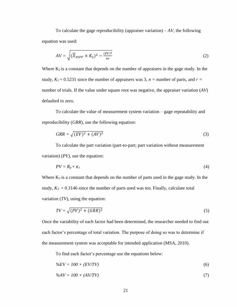
To calculate the gage reproducibility (appraiser variation) – AV, the following
equation was used:
AV = √(𝑋𝐷𝐼𝐹𝐹 × 𝐾2)2 −(𝐸𝑉)2
𝑛𝑟 (2)
Where K2 is a constant that depends on the number of appraisers in the gage study. In the
study, K2 = 0.5231 since the number of appraisers was 3, n = number of parts, and r =
number of trials. If the value under square root was negative, the appraiser variation (AV)
defaulted to zero.
To calculate the value of measurement system variation – gage repeatability and
reproducibility (GRR), use the following equation:
GRR = √(𝐸𝑉)2 + (𝐴𝑉)2 (3)
To calculate the part variation (part-to-part; part variation without measurement
variation) (PV), use the equation:
PV = Rp × K3 (4)
Where K3 is a constant that depends on the number of parts used in the gage study. In the
study, K3 = 0.3146 since the number of parts used was ten. Finally, calculate total
variation (TV), using the equation:
TV = √(𝑃𝑉)2 + (𝐺𝑅𝑅)2 (5)
Once the variability of each factor had been determined, the researcher needed to find out
each factor’s percentage of total variation. The purpose of doing so was to determine if
the measurement system was acceptable for intended application (MSA, 2010).
To find each factor’s percentage use the equations below:
%EV = 100 × (EV/TV) (6)
%AV = 100 × (AV/TV) (7)
22
%GRR = 100 × (GRR/TV) (8)
%PV = 100× (PV/TV) (9)
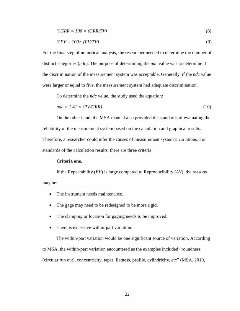
For the final step of numerical analysis, the researcher needed to determine the number of
distinct categories (ndc). The purpose of determining the ndc value was to determine if
the discrimination of the measurement system was acceptable. Generally, if the ndc value
were larger or equal to five, the measurement system had adequate discrimination.
To determine the ndc value, the study used the equation:
ndc = 1.41 × (PV/GRR) (10)
On the other hand, the MSA manual also provided the standards of evaluating the
reliability of the measurement system based on the calculation and graphical results.
Therefore, a researcher could infer the causes of measurement system’s variations. For
standards of the calculation results, there are three criteria:
Criteria one.
If the Repeatability (EV) is large compared to Reproducibility (AV), the reasons
may be:
The instrument needs maintenance.
The gage may need to be redesigned to be more rigid.
The clamping or location for gaging needs to be improved.
There is excessive within-part variation.
The within-part variation would be one significant source of variation. According
to MSA, the within-part variation encountered as the examples included “roundness
(circular run out), concentricity, taper, flatness, profile, cylindricity, etc” (MSA, 2010,

23
p.167). However, the dimension’s property in this research did not conform to the above
examples. Therefore, the within-part variation was omitted.
If the Reproducibility (AV) is large compared to Repeatability (EV), the reasons
may be:
Appraiser needs to be better trained in how to use and read the gage instrument.
Calibration on the gage dial is not clear.
Criteria two.
Ranges of gage repeatability and reproducibility (GRR) percentage for
measurement system acceptability:
If the %GRR < 10%, the measurement system is acceptable.
If the 10% < %GRR < 30%, the measurement system is acceptable depending on
the importance of application, cost of measurement device, cost of repair, and
other factors.
If the %GRR > 30%, the measurement system is considered unacceptable that
should be improved.
Criteria three.
The number of distinct categories (ndc) value should be greater than or equal to 5.
If not, the measurement system has inadequate discrimination.
For graphical results, according to the MSA manual (MSA, 2010, p.106-109), the
standards of average chart and range control chart are shown below:
Average chart. The average chart helped to determine the gage repeatability of
the appraisers on the same part sample. If the measurement system had adequate effective
resolution and could provide useful information for analyzing and controlling the process,
24
more than half of the averages had to fall outside of the control limits. Otherwise, the
measurement system was considered to have inadequate usability to detect part-to-part
variation. (MSA, 2010, p.107). The control limits were based on the average range that
was based on the repeatability error. Therefore, if too many averages were in the control
limits, the repeatability of the measurement system was unacceptable.
Range control chart. The range control chart helped determine statistical control
with respect to reproducibility and consistency of the measurement process between
appraisers for each part (MSA, 2010, p.109). If there were too many ranges out of the
control limit, it could be inferred that the process was out of control and all appraisers did
not have agreement with each other. If all appraisers had some of the ranges out of
control, it could be inferred that the measurement system was sensitive to appraisers’
technique and should be improved. If one appraiser’s ranges were out of control, it could
be inferred that this appraiser’s method was different with the others. If all the ranges
were in control, it could be inferred that the process was in control and the appraisers
were fully trained and had excellent agreement with each other.
The purpose of the review of literature was to gather appropriate information from
different topics as the base of knowledge for this research study. According to the review,
different companies with unique backgrounds have successfully achieved desired goals
by implementing the Six Sigma methodology of DMAIC as a continuous improvement
method. The review showed that Six Sigma methodology was an effective and practical
tool for this research study and that it defines root causes. Through knowing the sources
of variations from reviewing the measurement system analysis, this study could
underscore the importance and effectiveness of using gage R&R method. Through the

25
review of different gage R&R methods, a decision was made to choose Classical Gage
R&R (Average and Range) method for the gage R&R study in this research. Finally, the
researcher reviewed the guidelines for processing a gage R&R study. The various topics
in the literature review contained the necessary information needed to conduct the
research study properly.
26
Methodology
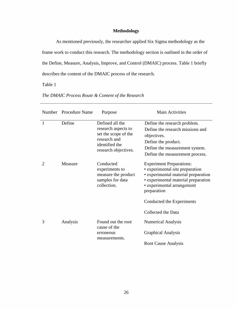
As mentioned previously, the researcher applied Six Sigma methodology as the
frame work to conduct this research. The methodology section is outlined in the order of
the Define, Measure, Analysis, Improve, and Control (DMAIC) process. Table 1 briefly
describes the content of the DMAIC process of the research.
Table 1
The DMAIC Process Route & Content of the Research
Number Procedure Name Purpose Main Activities
1 Define Defined all the
research aspects to
set the scope of the
research and
identified the
research objectives.
Define the research problem.
Define the research missions and
objectives.
Define the product.
Define the measurement system.
Define the measurement process.
2 Measure Conducted
experiments to
measure the product
samples for data
collection.
Experiment Preparations:
• experimental site preparation
• experimental material preparation
• experimental material preparation
• experimental arrangement
preparation
Conducted the Experiments
Collected the Data
3 Analysis Found out the root
cause of the
erroneous
measurements.
Numerical Analysis
Graphical Analysis
Root Cause Analysis
27
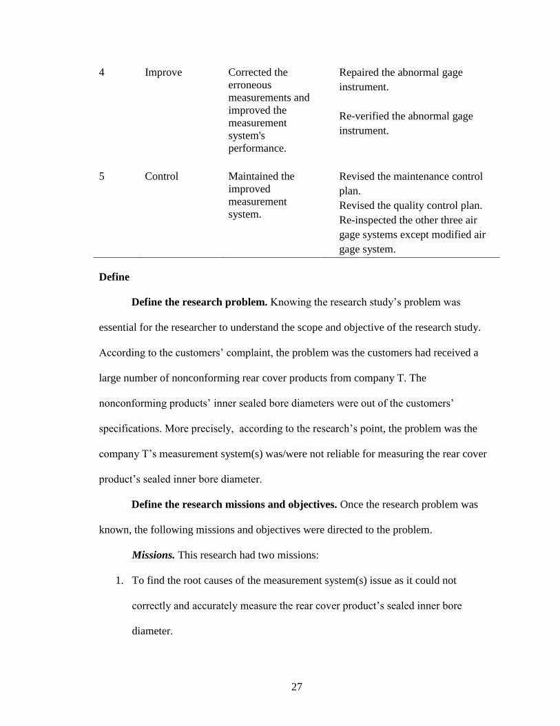
4 Improve Corrected the
erroneous
measurements and
improved the
measurement
system's
performance.
Repaired the abnormal gage
instrument.
Re-verified the abnormal gage
instrument.
5 Control Maintained the
improved
measurement
system.
Revised the maintenance control
plan.
Revised the quality control plan.
Re-inspected the other three air
gage systems except modified air
gage system.
Define
Define the research problem. Knowing the research study’s problem was
essential for the researcher to understand the scope and objective of the research study.
According to the customers’ complaint, the problem was the customers had received a
large number of nonconforming rear cover products from company T. The
nonconforming products’ inner sealed bore diameters were out of the customers’
specifications. More precisely, according to the research’s point, the problem was the
company T’s measurement system(s) was/were not reliable for measuring the rear cover
product’s sealed inner bore diameter.
Define the research missions and objectives. Once the research problem was
known, the following missions and objectives were directed to the problem.
Missions. This research had two missions:
1. To find the root causes of the measurement system(s) issue as it could not
correctly and accurately measure the rear cover product’s sealed inner bore
diameter.
28
2. Correct the measurement system(s) issue to eliminate the erroneous
measurements and to stop shipping the nonconforming rear covers products to the
customers.
Objectives. In order to successfully conduct this research, defining the objectives
was an effective method to reference every aspect of the research. The objectives in this
research included:
1. Experimental objectives. There were a series of necessary experiments conducted
in this research. Essential experiment environmental conditions had to be set
properly to ensure the accuracy of the experiments. All the rear cover product
samples and air gage systems must be available and properly set up as the
experimental requirements. In addition, the researcher needed to properly
organize and arrange the experiments in order to achieve the experimental
expectations.
2. Organizational objectives. The researcher was the experiments’ conductor and
each inspector was responsible for the assigned experiment missions delivered by
the researcher. Meanwhile, all the inspectors had to obey the researcher’s
experimental arrangement and honestly record measurement results so that the
experimental results reflected the actual situation.
3. Technical objectives. The researcher needed to ensure the software tools for data
collection and data analysis were suitable and reliable.
Define the product. The analyzed product in the research was called the
transmission rear cover. Company T supplied this product to two different customers:
customer A and customer G. Company T’s rear cover product had four different types
29
that were supplied for customer A and G in two different types, respectively. The
diameter of the sealed inner bore of all the four rear cover product types had the same
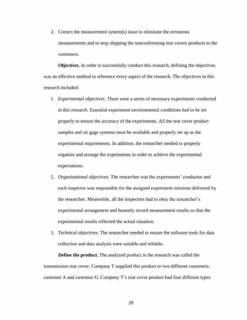
customer specification: 84.9525 ± 0.0125mm. Figure 1 shows customer A’s type of
completed assembled transmission product line drawing:
Figure 1. Customer A’s assembled transmission product drawing.
From Figure 1, the rear cover is the front part shown with the output speed sensor hole
and the transmission’s main shaft through the sealed inner bore. Figure 2 shows the
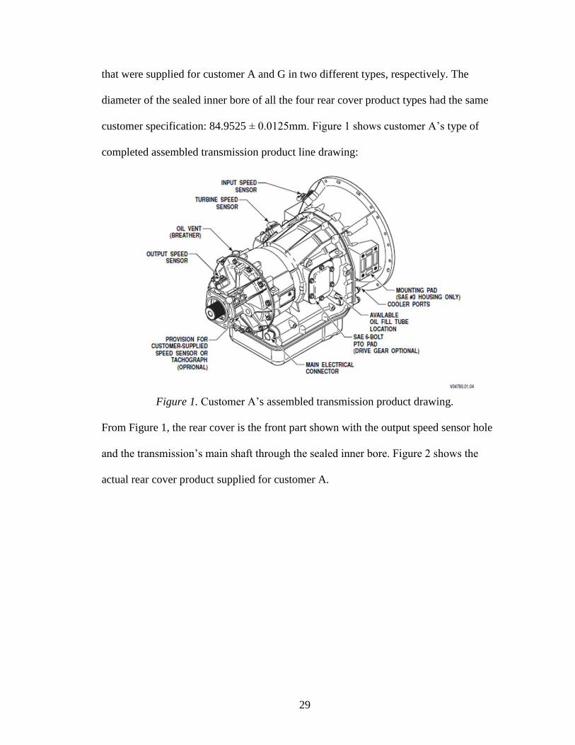
actual rear cover product supplied for customer A.
30
Figure 2. A type of the rear cover product of the customer A.
The sealed inner bore can be seen as the sealed smooth surface at the deepest position of
the part in Figure 2.
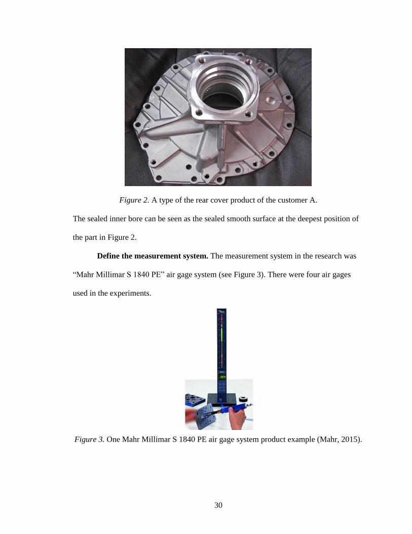
Define the measurement system. The measurement system in the research was
“Mahr Millimar S 1840 PE” air gage system (see Figure 3). There were four air gages
used in the experiments.
Figure 3. One Mahr Millimar S 1840 PE air gage system product example (Mahr, 2015).
31
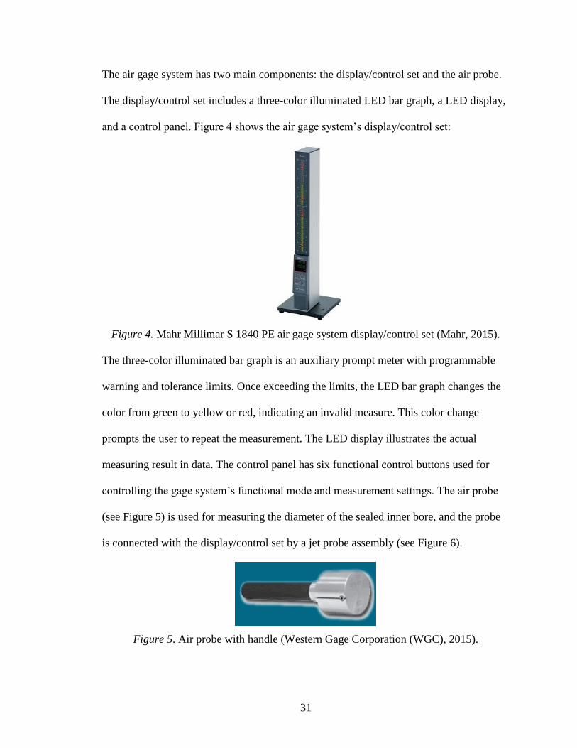
The air gage system has two main components: the display/control set and the air probe.
The display/control set includes a three-color illuminated LED bar graph, a LED display,
and a control panel. Figure 4 shows the air gage system’s display/control set:
Figure 4. Mahr Millimar S 1840 PE air gage system display/control set (Mahr, 2015).
The three-color illuminated bar graph is an auxiliary prompt meter with programmable
warning and tolerance limits. Once exceeding the limits, the LED bar graph changes the
color from green to yellow or red, indicating an invalid measure. This color change
prompts the user to repeat the measurement. The LED display illustrates the actual
measuring result in data. The control panel has six functional control buttons used for
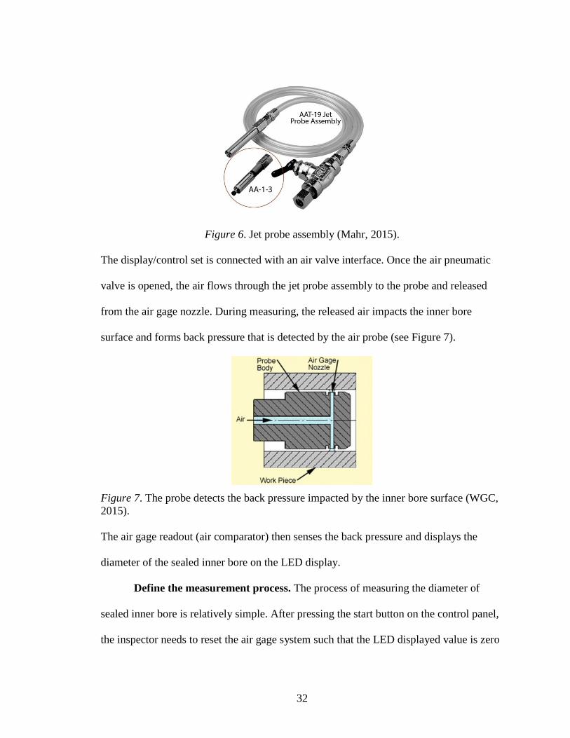
controlling the gage system’s functional mode and measurement settings. The air probe
(see Figure 5) is used for measuring the diameter of the sealed inner bore, and the probe
is connected with the display/control set by a jet probe assembly (see Figure 6).
Figure 5. Air probe with handle (Western Gage Corporation (WGC), 2015).
32
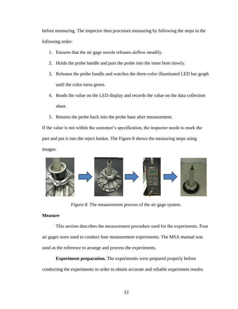
Figure 6. Jet probe assembly (Mahr, 2015).
The display/control set is connected with an air valve interface. Once the air pneumatic
valve is opened, the air flows through the jet probe assembly to the probe and released
from the air gage nozzle. During measuring, the released air impacts the inner bore
surface and forms back pressure that is detected by the air probe (see Figure 7).
Figure 7. The probe detects the back pressure impacted by the inner bore surface (WGC,
2015).
The air gage readout (air comparator) then senses the back pressure and displays the
diameter of the sealed inner bore on the LED display.
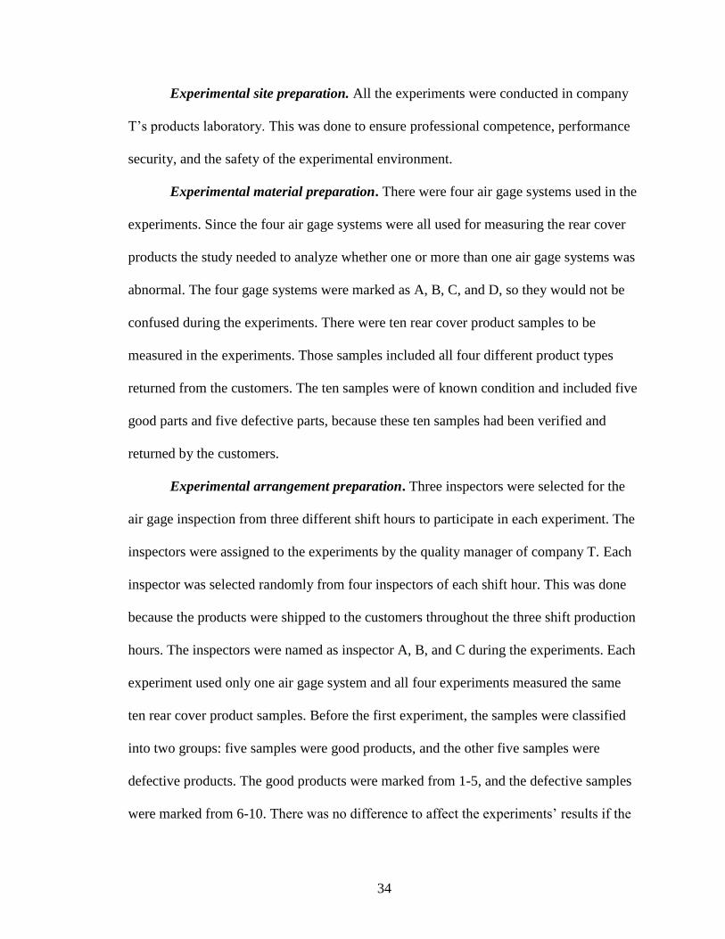
Define the measurement process. The process of measuring the diameter of
sealed inner bore is relatively simple. After pressing the start button on the control panel,
the inspector needs to reset the air gage system such that the LED displayed value is zero
33
before measuring. The inspector then processes measuring by following the steps in the
following order:
1. Ensures that the air gage nozzle releases airflow steadily.
2. Holds the probe handle and puts the probe into the inner bore slowly.
3. Releases the probe handle and watches the three-color illuminated LED bar graph
until the color turns green.
4. Reads the value on the LED display and records the value on the data collection
sheet.
5. Returns the probe back into the probe base after measurement.
If the value is not within the customer’s specification, the inspector needs to mark the
part and put it into the reject basket. The Figure 8 shows the measuring steps using
images:
Figure 8. The measurement process of the air gage system.
Measure
This section describes the measurement procedure used for the experiments. Four
air gages were used to conduct four measurement experiments. The MSA manual was
used as the reference to arrange and process the experiments.
Experiment preparation. The experiments were prepared properly before
conducting the experiments in order to obtain accurate and reliable experiment results.
34
Experimental site preparation. All the experiments were conducted in company
T’s products laboratory. This was done to ensure professional competence, performance
security, and the safety of the experimental environment.
Experimental material preparation. There were four air gage systems used in the
experiments. Since the four air gage systems were all used for measuring the rear cover
products the study needed to analyze whether one or more than one air gage systems was
abnormal. The four gage systems were marked as A, B, C, and D, so they would not be
confused during the experiments. There were ten rear cover product samples to be
measured in the experiments. Those samples included all four different product types
returned from the customers. The ten samples were of known condition and included five
good parts and five defective parts, because these ten samples had been verified and
returned by the customers.
Experimental arrangement preparation. Three inspectors were selected for the
air gage inspection from three different shift hours to participate in each experiment. The
inspectors were assigned to the experiments by the quality manager of company T. Each
inspector was selected randomly from four inspectors of each shift hour. This was done
because the products were shipped to the customers throughout the three shift production
hours. The inspectors were named as inspector A, B, and C during the experiments. Each
experiment used only one air gage system and all four experiments measured the same
ten rear cover product samples. Before the first experiment, the samples were classified
into two groups: five samples were good products, and the other five samples were
defective products. The good products were marked from 1-5, and the defective samples
were marked from 6-10. There was no difference to affect the experiments’ results if the
35
samples were randomly arranged. The researcher by doing this was to distinguish the
good and defective products easily.
Experiment procedures. Following the procedures as recommended by the
literature, the researcher applied the Average and Range Gage R&R method to conduct
the experiments, and all the experiments were conducted on signal shift. The detailed
experimental procedures follow:
1. Inspector A was the first appraiser to measure the rear cover product samples by
following the air gage measurement procedures. Each inspector needed to clearly
record the measurement result every time on the data collection sheet after each
measurement.
2. Each inspector had three trials in each experiment, and all ten samples needed to
be measured in each trial. Once inspector A completed the first trial, inspector B
began to process the first trial, then inspector C when inspector B completed.
3. When the three inspectors completed the first trial, the inspector A started the
second trial. When all the inspectors completed the second trial, the inspector A
started the third trial. In order to reflect the objectivity of experiment, the samples
were presented in a different order for each trial.
The first experiment used air gage system A to measure the product samples, then air
gage B, C, and D were used respectively in the next three experiments. During each
experiment, each inspector had to process the measurement independently and could not
see each other’s readings. When the inspectors completed all four experiments, the
researcher then collected and recorded the data to make four different Excel sheets (see
Appendix A) for the experiments.
36
Analysis
The analysis phase was the key section in the research. The purpose of the
analysis phase was to find out the root cause of the research problem. After data
collection, the data was analyzed using two approaches: numerical analysis and graphical
analysis.
Numerical analysis. The purpose of the numerical analysis was to estimate the
variation and percent of process variation for the measurement system and its
components of repeatability, reproducibility, and part variation. First, values were
calculated as shown below:
�̿� = average value of all appraisers
XDIFF = difference of average values of all appraisers
Rp = range of part averages
Next, the following were calculated: gage repeatability (equipment variation) (EV), gage
reproducibility (appraiser variation) (AV), gage repeatability and reproducibility (GRR),
part variation (PV), total variation (TV), number of distinct categories (ndc), and the
percentage of each factor. A summary of all the formulas used are listed below and match
the equation numbers listed in the review of literature.
EV = �̿� × K1 (1)
AV = √(𝑋𝐷𝐼𝐹𝐹 × 𝐾2)2 −(𝐸𝑉)2
𝑛𝑟 (2)
GRR = √(𝐸𝑉)2 + (𝐴𝑉)2 (3)
PV = Rp × K3 (4)
TV = √(𝑃𝑉)2 + (𝐺𝑅𝑅)2 (5)
37
%EV = 100 × (EV/TV) (6)
%AV = 100 × (AV/TV) (7)
%GRR = 100 × (GRR/TV) (8)
%PV = 100 × (PV/TV) (9)
ndc = 1.41 × (PV/GRR) (10)
Based on the results of the experiments, the researcher made a “Gage Repeatability and
Reproducibility Report” for each experiment (see Appendix B).
Graphical analysis. The researcher also made the graphical analysis by plotting
the average and range control charts for all the air gage systems based on the measured
results. The average chart helps determine if a gage system was repeatable to produce
consistent results by the same inspector for each part. The range control chart helps
determine a gage system’s capability of statistical control with respect to reproducibility
and consistency of the measurement process between appraisers for each part.
Root cause analysis. Once completing the numerical and graphical analysis, the
researcher then processed the root cause analysis based on the findings from the
numerical and graphical analysis. During the root cause analysis, the researcher
determined the suspect gage system(s) and sources of variations that caused the erroneous
measurements. Therefore, the researcher could find the root cause.
Improve
Once the root cause had been found, the researcher could correct the erroneous
measurements and improve the suspect gage system(s)’s reliability. The researcher then
needed to re-verify the reliability of the modified gage system(s).
38
Control
If the modified gage system(s) successfully fulfilled expectations, the researcher
would process the actions on the air gage system’s quality and management control
system.
The detailed procedures, findings, and results of the analysis, improve and control
phases are presented in the next chapter.
39
Findings and Results
Numerical Analysis Findings
According to the data collection sheets, the researcher found that the air gage
system B’s measured results were inconsistent with the known samples’ results. The
other three air gage systems’ measured results were consistent with the known samples’
results. For gage system B, three out of five good samples were defined as defective, and
two out of the five defective samples were defined as good. By reviewing the GRR
reports of the four gage systems, the researcher found the air gage system B’s GRR report
results were abnormal compared with the other three reports results. The GRR value of
the gage system B was 81.4%, which was unacceptable according to the AIAG standards.
The other three gage systems’ GRR reports results showed their GRR values were
acceptable, being smaller than 10%. Moreover, air gage system B’s repeatability was far
greater than its reproducibility. For the other three air gage systems, their repeatability
values were all greater than their reproducibility values, but both of the values were
smaller than 10%, which indicated their impacts were negligible. In addition, air gage
system B’s ndc value was smaller than five. As having been mentioned in the literature
review, the purpose of determining the ndc value was to determine if the discrimination
of the measurement system was acceptable. Based on the AIAG standard, if the ndc value
were larger or equal to five, the measurement system had adequate discrimination.
Therefore, air gage system B had inadequate discrimination.
Graphical Analysis Findings
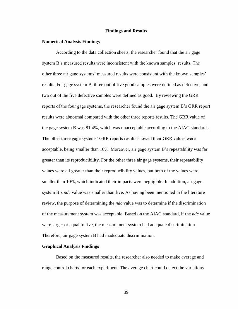
Based on the measured results, the researcher also needed to make average and
range control charts for each experiment. The average chart could detect the variations
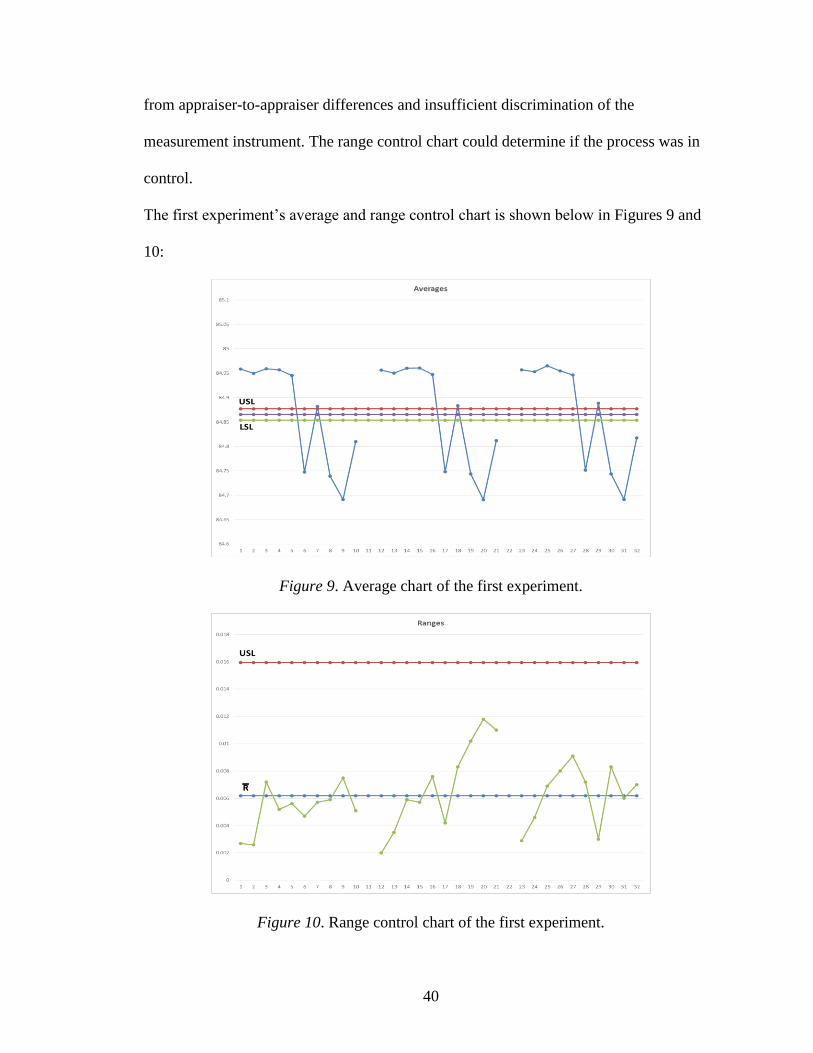
40
from appraiser-to-appraiser differences and insufficient discrimination of the
measurement instrument. The range control chart could determine if the process was in
control.
The first experiment’s average and range control chart is shown below in Figures 9 and
10:
Figure 9. Average chart of the first experiment.
Figure 10. Range control chart of the first experiment.
41
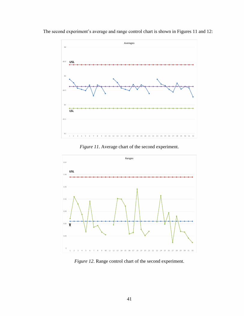
The second experiment’s average and range control chart is shown in Figures 11 and 12:
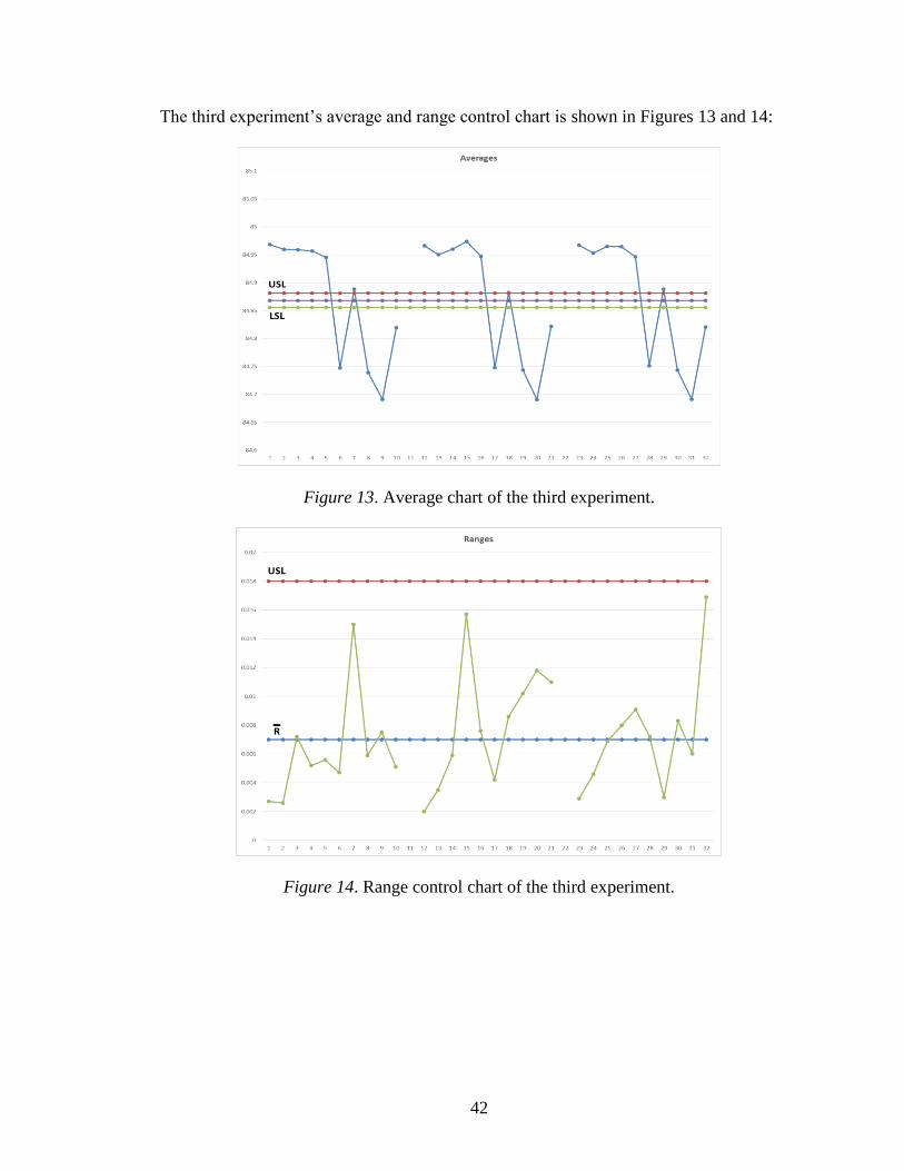
Figure 11. Average chart of the second experiment.
Figure 12. Range control chart of the second experiment.
42
The third experiment’s average and range control chart is shown in Figures 13 and 14:
Figure 13. Average chart of the third experiment.
Figure 14. Range control chart of the third experiment.
43
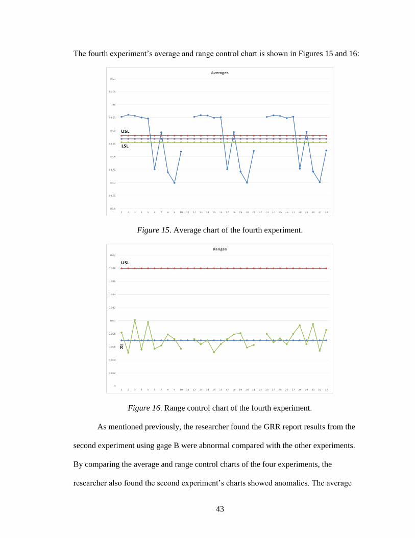
The fourth experiment’s average and range control chart is shown in Figures 15 and 16:
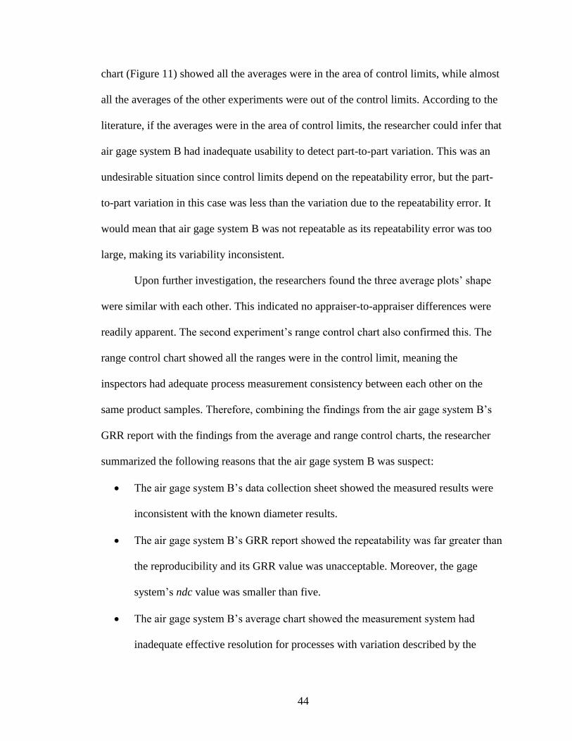
Figure 15. Average chart of the fourth experiment.
Figure 16. Range control chart of the fourth experiment.
As mentioned previously, the researcher found the GRR report results from the
second experiment using gage B were abnormal compared with the other experiments.
By comparing the average and range control charts of the four experiments, the
researcher also found the second experiment’s charts showed anomalies. The average
44
chart (Figure 11) showed all the averages were in the area of control limits, while almost
all the averages of the other experiments were out of the control limits. According to the
literature, if the averages were in the area of control limits, the researcher could infer that
air gage system B had inadequate usability to detect part-to-part variation. This was an
undesirable situation since control limits depend on the repeatability error, but the part-
to-part variation in this case was less than the variation due to the repeatability error. It
would mean that air gage system B was not repeatable as its repeatability error was too
large, making its variability inconsistent.
Upon further investigation, the researchers found the three average plots’ shape
were similar with each other. This indicated no appraiser-to-appraiser differences were
readily apparent. The second experiment’s range control chart also confirmed this. The
range control chart showed all the ranges were in the control limit, meaning the
inspectors had adequate process measurement consistency between each other on the
same product samples. Therefore, combining the findings from the air gage system B’s
GRR report with the findings from the average and range control charts, the researcher
summarized the following reasons that the air gage system B was suspect:
The air gage system B’s data collection sheet showed the measured results were
inconsistent with the known diameter results.
The air gage system B’s GRR report showed the repeatability was far greater than
the reproducibility and its GRR value was unacceptable. Moreover, the gage
system’s ndc value was smaller than five.
The air gage system B’s average chart showed the measurement system had
inadequate effective resolution for processes with variation described by the
45
product samples. The range control chart showed the process was in control, and
inspectors had consistent measurement process. The air gage system B had
inadequate repeatability.
Except for air gage system B, the other air gage systems did not exhibit any
abnormal results from the data collection sheets and GRR reports. The average
and range control charts also confirmed that these air gage systems had adequate
reliabilities.
Additionally, according to the findings from the GRR reports and charts, all the air gage
systems’ reproducibility (appraiser variation) was excellent, making the inspectors a
negligible source of variation. Even though air gage system B was marked as suspect, it
still reported insignificant appraiser-to-appraiser differences in the range control chart
with appropriate reproducibility in the GRR report. The researcher then could determine
that the inspectors were not a significant source of variation that impacted the
measurement system’s variability. They were fully trained in how to measure the product
samples and record the results correctly. Therefore, the researcher would ascertain that
the causes of the erroneous measurements from the air gage system B were related to the
gage instrument.
Root Cause Analysis
Based on the numerical and graphical analysis results, the researcher focused on
analyzing the air gage system B. Because of the unacceptable GRR value and
reproducibility, according to the AIAG standard, the reasons might include:
The instrument needed maintenance.
The gage may need to be redesigned to be more rigid.
46
The clamping or location for gauging needed to be improved.
There was excessive within-part variation.
In order to find out the air gage system B’s causes of unreliability, the researcher
conducted detailed inspection for the air gage instrument based on the reasons listed
above successively.
The instrument needed maintenance. This would be a possible reason why the
gage instrument could not accurately and correctly measure the part’s actual dimension.
In fact, the company T had an appropriate maintenance schedule for the air gage
instruments. The schedule was made based on the instrument producer’s technical
guidance. Except the problematic gage system B, the other three gage systems were in the
proper conditions. Moreover, since the company T purchased the air gage instruments, all
the systems had been performing properly until the complaints made by the customers
this time. Therefore, it was possible that gage system B needed detailed inspection not at
the maintenance level, but at the theoretical and physical level. The theoretical inspection
was to understand and review the air gage’s working principles that could help the
researcher define the root cause based on the air gage’s original design concepts. The
physical inspection was to inspect the abnormal air gage’s internal components so that to
determine whether the root cause from any damaged parts.
The gage may need to be redesigned to be more rigid. This reason could be
disregarded because the instrument itself was particularly designed to the customers’
specifications. Moreover, the instrument was rigidly designed with adequate tolerance to
possess sufficient capability for measuring the sealed inner bore diameter precisely and
accurately.

47
The clamping or location for gaging needed to be improved. Based on the
research’s circumstance, this reason could be also disregarded. The air gage system did
not need clamping for measurement and company T designed the gaging location as an
independent inspection station that was sufficient to meet the gaging inspection needs.
There was excessive within-part variation. According to the literature, the
researcher omitted within-part variation based on the dimension’s property. On the other
hand, the results from the other gage systems also showed no excessive within-part
variation based on the same product samples. Therefore, the researcher excluded this
reason.
By screening the above possible reasons, the researcher determined that the gage
instrument B needed maintenance, and conducted a detailed inspection for air gage
system B at the theoretical and physical level. An understanding of the air gage
instrument’s work principle and internal structure was needed. The Figure 17 shows the
air gage system’s block diagram and details its work principle and process.
Figure 17. Air gage system block diagram (WGC, 2015).
The block diagram shows the instrument construction and work procedure. The air passes
through the air filter and the pressure is adjusted by the pressure regulator to the
48
operating pressure. The flow restrictor is a component to control the input air flow from
the pressure regulator and output air flow to the air gage probe. There is one pressure
transducer unit on both sides of the flow restrictor. The unit before the flow restrictor
detects the input air flow pressure and transmits the electric signal to the microprocessor.
The unit after the flow restrictor measures the back pressure formed by the air gage
nozzle and transmits the electric signal to the microprocessor. The microprocessor is the
core component of the gage system. It can process the pressure signals from the actual
sealed inner bore diameter and shows the data result on the LCD display. Moreover, in
order to best accurately measure the inner sealed bore diameter, the microprocessor also
compares and calculates the pressure signals from both sides of the flow restrictor and
regulates the flow restrictor to control the input and output air flow rate based on the
designed setting.
Through a detailed inspection for the suspected air gage instrument, a root cause
was found for the erroneous measurements. There was unbalanced pressure between the
input and output airflow due to a leak on the jet probe assembly (see Figure 6). The air
flow in the jet probe assembly is the air flow after the flow restrictor as shown in Figure
17. The leak was located on the joint between the top of the probe assembly (AA-1-3 in
Figure 6) and the rubber tube. Because of the leak, the air pressure after the restrictor was
less than the pressure before the restrictor. In this case, the flow restrictor was regulated
by the microprocessor to increase the output flow rate to balance the input flow rate. As
mentioned previously, the air flowed through the probe assembly and released from the
air probe nozzle. The air flow then impacted the inner bore surface and formed back
pressure that was detected by the pressure transducer on the right. However, since the
49
output air flow rate was increased by the restrictor, the back pressure’s fluctuate range
exceeded the designed range. This excessive pressure fluctuate range interfered with the
pressure transducer located after the flow restrictor and transmitted an improper pressure
signal to the microprocessor. Because of the improper pressure signal from the
transducer, the microprocessor had to readjust the default system tolerance to meet the
designed program setting. As the result, the product’s sealed inner bore’s specification
measured by the air gage system was out of the range of the customer’s specification.
More precisely, the air gage probe had undesirable accuracy to form the back pressure
and made the microprocessor incorrectly process the improper pressure signal to the
actual data. Therefore, the air gage system B could not accurately and correctly measure
the rear cover’s sealed inner bore diameter. If a diameter was out of the customer’s
specification, the diameter result measured by the problematic gage might be in the
customer’s specification. Similarly, if a diameter was in the customer’s specification, the
diameter result measured by the problematic gage might be out of the customer’s
specification. This also could be seen in the air gage system B’s measuring results.
Consequently, the erroneous measurements occurred and company T shipped the
defective rear cover products to the customers.
Improve the Problematic Gage System
Once the researcher defined the root cause, correction of the problematic air gage
system would improve the measurement system’s performance. The researcher also
needed to conduct the same gage R&R study experiment as the previous procedure to
determine whether the measurement system achieved the expected results after
modifying.

50
Based on the root cause findings, a new AA-1-3 probe assembly was installed and
reconnected with the rubber tube. The researcher then used a pressure checking
instrument to check whether the pressures in the two sides of the restrictor were balanced.
Once balance pressures was ensured in the two sides, the researcher then conducted the
same gage R&R study on the repaired air gage system. The gage R&R data collection
sheet and report results are shown in Appendix, and the average and range control chart
of the repaired air gage system B are shown in Figures 18 and 19.
Figure 18. Average chart of the repaired air gage system B.
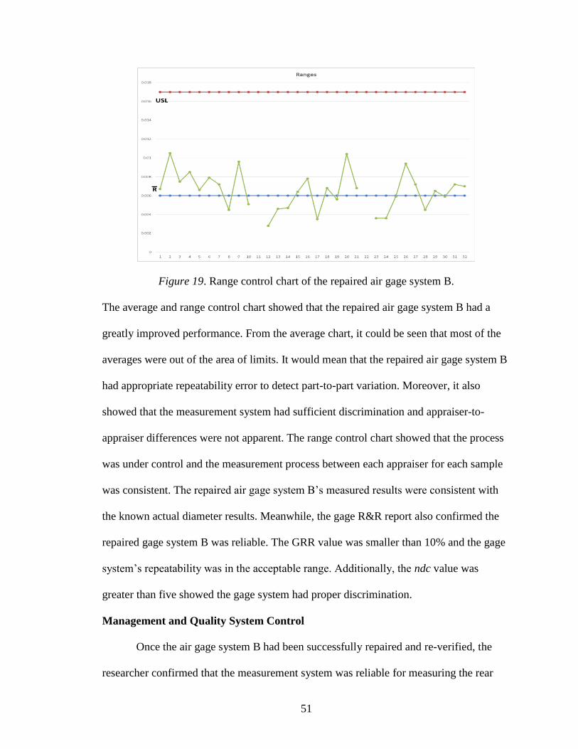
51
Figure 19. Range control chart of the repaired air gage system B.
The average and range control chart showed that the repaired air gage system B had a
greatly improved performance. From the average chart, it could be seen that most of the
averages were out of the area of limits. It would mean that the repaired air gage system B
had appropriate repeatability error to detect part-to-part variation. Moreover, it also
showed that the measurement system had sufficient discrimination and appraiser-to-
appraiser differences were not apparent. The range control chart showed that the process
was under control and the measurement process between each appraiser for each sample
was consistent. The repaired air gage system B’s measured results were consistent with
the known actual diameter results. Meanwhile, the gage R&R report also confirmed the
repaired gage system B was reliable. The GRR value was smaller than 10% and the gage
system’s repeatability was in the acceptable range. Additionally, the ndc value was
greater than five showed the gage system had proper discrimination.
Management and Quality System Control
Once the air gage system B had been successfully repaired and re-verified, the
researcher confirmed that the measurement system was reliable for measuring the rear
52
cover’s sealed inner bore diameter correctly and accurately. By reviewing the procedures
of defining and correcting the erroneous measurements the following actions were taken
related to the air gage system.
Revised the maintenance control plan. The maintenance control plan introduced
when and how to maintain the air gage instrument based on the user’s manual. However,
this research study indicated maintenance based on the user manual was unpredictable.
Therefore, content was added to the maintenance schedule instruction about how to
verify and ensure the air gage system’s pressure balance. In addition, the researcher
added the research study to the rear cover’s Failure Mode and Effects Analysis (FMEA)
quality control section. By implementing these actions, the risk of the similar incidents
was reduced for the future.
Revised the quality control plan. During the research, the abnormality of the air
gage system was unknown. The products measured did not specifically indicate problem
with the air gage system. Therefore, researcher revised the rear cover product’s quality
control plan to emphasize the importance and necessity of noting the air gage system’s
identification number after each measurement.
Re-inspected the other three air gage systems. Except for gage system B, the
other three air gage systems were certified reliable and in good condition by the
experiments results. This was determined through detailed inspections of the other gage
systems.
Results
After completing the Six Sigma procedure, the performance of the rear cover
sealed inner bore’s measurement system improved. Customer feedback two months after
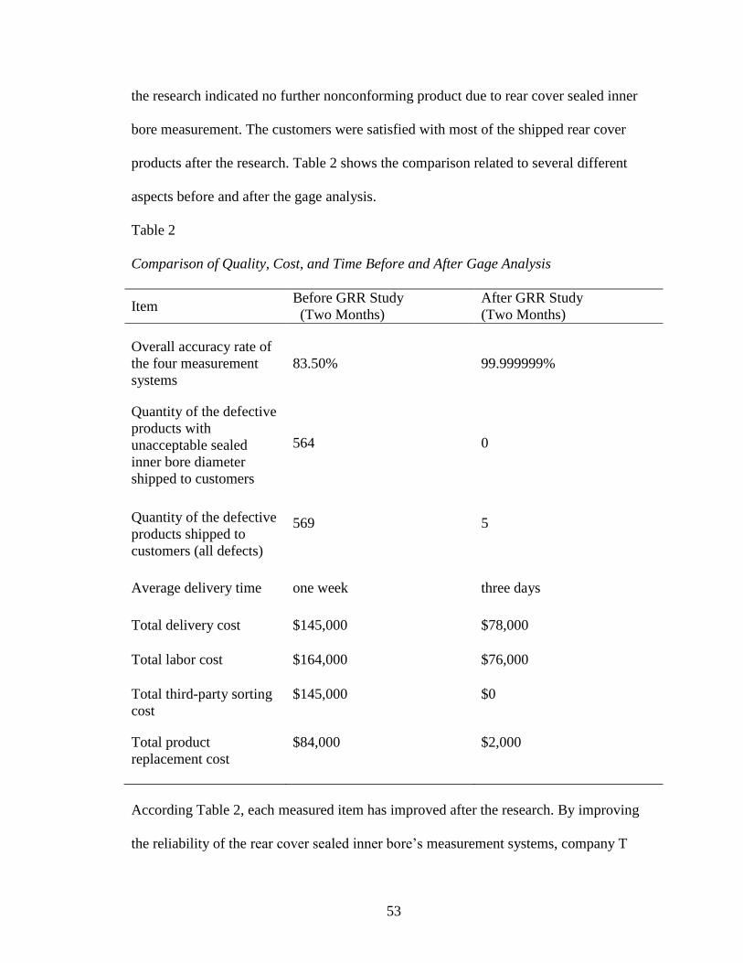
53
the research indicated no further nonconforming product due to rear cover sealed inner
bore measurement. The customers were satisfied with most of the shipped rear cover
products after the research. Table 2 shows the comparison related to several different
aspects before and after the gage analysis.
Table 2
Comparison of Quality, Cost, and Time Before and After Gage Analysis
Item Before GRR Study
(Two Months)
After GRR Study
(Two Months)
Overall accuracy rate of
the four measurement
systems
Quantity of the defective
products with
unacceptable sealed
inner bore diameter
shipped to customers
83.50%
564
99.999999%
0
Quantity of the defective
products shipped to
customers (all defects)
569 5
Average delivery time one week three days
Total delivery cost $145,000 $78,000
Total labor cost $164,000 $76,000
Total third-party sorting
cost
$145,000 $0
Total product
replacement cost
$84,000
$2,000
According Table 2, each measured item has improved after the research. By improving
the reliability of the rear cover sealed inner bore’s measurement systems, company T
54
saved time and costs. In addition, the measurement systems were capable to guarantee no
defective product with unacceptable sealed inner bore diameter shipped to the customers.
In addition, according to the company T’s financial report, the company spent
approximately $597,000 over two months before the study dealing with the customers’
complaints, but spent approximately $215,000 in two months after the study for
necessary expenses. Therefore, the company saved approximately $382,000 after the
study. This also can be calculated by using all the costs before the study subtract all the
costs after the study shown in Table 2.
55
Conclusion
According to the results of the study, the researcher successfully achieved the
purposes of the study. Through applying the Six Sigma methodology and gage R&R
technique, the researcher found out the root cause of the erroneous measurements of the
rear cover’s sealed inner bore diameter: due to a leak on the jet probe assembly of an air
gage instrument caused the erroneous measurements. The researcher also repaired the
problematic air gage instrument to correct and eliminate the erroneous measurements to
obtain the measurement results within the customer’s specification. In addition, the
success of the study illustrated the adequate effectiveness and practicability of Six Sigma
methodology in improving measurement systems, and illustrated that gage R&R
technique is fulfilling for evaluating and verifying measurement systems.
Hypothesis Conclusions
From the research, the following conclusion can be made regarding the stated
hypotheses.
Hypothesis 1. The inspectors were fully trained in how to use and read the air
gage instruments, but the air gage systems were unreliable. The gage repeatability value
was larger than the gage reproducibility value. The gage R&R would not capable of
meeting the customer’s specification.
The circumstance of air gage system B before repair confirmed the hypothesis 1.
Therefore, the research accepted hypothesis 1 as true.
Hypothesis 2. The inspectors were less trained in how to use and read the air gage
instruments and the air gage systems were reliable. The gage reproducibility value was
56
larger than the gage repeatability value. The gage R&R would not be capable of meeting
the customer’s specification.
There was no circumstance that confirmed the hypothesis 2 in the research since
there was no appraiser-to-appraiser difference based on the experimental results that
illustrated no evidence that the inspectors were less trained. Therefore, the researcher
rejected hypothesis 2.
Hypothesis 3. The air gage systems were reliable and the inspectors were fully
trained in how to use and read the air gage instruments. The gage R&R would be capable
of meeting the customer’s specification.
There was no circumstance that confirmed the hypothesis 3 in the research. The
study found that the air gage system was unreliable. It was fixed after the DMAIC but the
hypothesis was regarding the measurement system before the DMAIC. Therefore, the
researcher rejected hypothesis 3.
Hypothesis 4. The air gage systems were not reliable and the inspectors were not
fully trained in how to use and read the air gage instruments. The gage R&R would not
be capable of meeting the customer’s specification.
There was no evidence that confirmed both conditions of the hypothesis 4 in the
research. Therefore, the researcher rejected hypothesis 4.
Therefore, according to the research results, Hypothesis 1 was defined as true and
the other hypothesis were rejected.
Suggestions for Future Research
According to the results of study, utilizing the proper quality methodology and
technique legitimately can help a manufacture improve and optimize a product’s
57
measurement system effectively. The results also shows that a gage instrument’s
accuracy is essential in determining whether a product’s dimension within the customer’s
specification. A gage instrument’s accurate determination guarantees the manufacturer
delivers eligible products to the customers. In addition, massive production is the
common trend in current automotive manufacturing, which emphasizes the significance
of the gage instrument’s accuracy. As shown in the study, inadequate gage accuracy
caused severe consequences to the manufacturer. Therefore, how to maintain a gage
instrument’s accuracy is a top priority for a manufacturer’s quality control system.
In order to achieve high yield and efficient approaches in modern automated
production, traditional measurement methods, such as manual measurements, are
gradually becoming obsolete. Rapid and accurate measurement methods are more
effective and a measurement system with accurate and automated measuring instruments
is preferred. These types of measuring instruments can shorten the measurement time and
improve the measurement accuracy rate. In this case, the role of human is no longer to be
crucial in the actual measurement process, which human influence in such measurement
system is less than the measuring instruments. Therefore, measurement results more
depend on the measuring instruments in current measurement systems. It can be seen
from the study that measurement results were produced by the gage instrument, and the
inspectors verified products based on the results.
Future research should consider measurement methods and measuring instruments
to be suitable for a specific product and production mode. As the industrial technology
continues to improve, the future manufacturing development will trend toward the
direction of intelligent and personalized. Traditional automated production mode for
58
mass producing a signal type of product will be replaced by diversity and flexible
production mode for fulfilling product customization needs (Pye, 2014). It is an
unprecedented challenge for manufacturers to seek effective measurement strategies and
instruments to ensure the quality of future products. Therefore, further research should
search for measurement strategies and instruments base on the standards and
requirements of intelligent and personalized products. Moreover, the researcher needs to
strengthen the knowledge related to future products and producing methods.
According to company T’s production plan, the rear cover products supplied to
the customers will become more diverse within the next three years. Along with the
increase in rear cover product types, different customers’ specifications of the rear cover
sealed inner bore sizes will be also changed based on requirements. Further research
should be conducted based on the current air gage systems and measurement strategy to
satisfy new customers’ requirements in the future.
From the research, it can be seen that the measuring instrument progressively
occupies the significant position of a measurement system in current manufacturing field.
The measuring instrument can become a major source of variation in the measurement
system. Consequently, automating the measuring instrument may cause serious
consequences and huge losses. As shown in the research, due to the inadequate reliability
of company T’s air gage measurement system, the company suffered losses in time and
profit. It also negatively impacted the customers’ confidence and expectations of
company T’s products.
Based on the reasons described above, the second suggestion for future research is
how to maintain the reliability of a measurement system to ensure the accuracy of a
59
measuring instrument. The innovative and advanced measuring instruments have greatly
improved the measurement speed and simplified the measurement procedure, but have
also increased the maintenance difficulty and cost. Future research should consider
formulating a control plan for the operative maintenance and effective failure analysis of
the measurement instruments. This future research should focus not only on the rear
cover products of company T, but for all the other product types. The researcher needs to
consider the systematic control and analysis for company T’s future products’
measurement systems.
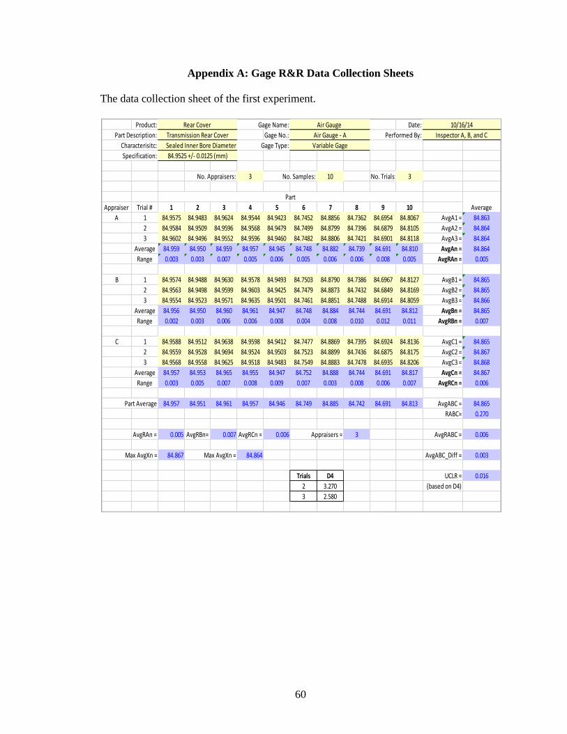
60
Appendix A: Gage R&R Data Collection Sheets
The data collection sheet of the first experiment.
Product: Gage Name: Date:
Part Description: Gage No.: Performed By:
Characterisitc: Gage Type:
Specification:
No. Appraisers: 3 No. Samples: 10 No. Trials: 3
Appraiser Trial # 1 2 3 4 5 6 7 8 9 10
A 1 84.9575 84.9483 84.9624 84.9544 84.9423 84.7452 84.8856 84.7362 84.6954 84.8067 AvgA1 = 84.863
2 84.9584 84.9509 84.9596 84.9568 84.9479 84.7499 84.8799 84.7396 84.6879 84.8105 AvgA2 = 84.864
3 84.9602 84.9496 84.9552 84.9596 84.9460 84.7482 84.8806 84.7421 84.6901 84.8118 AvgA3 = 84.864
Average 84.959 84.950 84.959 84.957 84.945 84.748 84.882 84.739 84.691 84.810 AvgAn = 84.864
Range 0.003 0.003 0.007 0.005 0.006 0.005 0.006 0.006 0.008 0.005 AvgRAn = 0.005
B 1 84.9574 84.9488 84.9630 84.9578 84.9493 84.7503 84.8790 84.7386 84.6967 84.8127 AvgB1 = 84.865
2 84.9563 84.9498 84.9599 84.9603 84.9425 84.7479 84.8873 84.7432 84.6849 84.8169 AvgB2 = 84.865
3 84.9554 84.9523 84.9571 84.9635 84.9501 84.7461 84.8851 84.7488 84.6914 84.8059 AvgB3 = 84.866
Average 84.956 84.950 84.960 84.961 84.947 84.748 84.884 84.744 84.691 84.812 AvgBn = 84.865
Range 0.002 0.003 0.006 0.006 0.008 0.004 0.008 0.010 0.012 0.011 AvgRBn = 0.007
C 1 84.9588 84.9512 84.9638 84.9598 84.9412 84.7477 84.8869 84.7395 84.6924 84.8136 AvgC1 = 84.865
2 84.9559 84.9528 84.9694 84.9524 84.9503 84.7523 84.8899 84.7436 84.6875 84.8175 AvgC2 = 84.867
3 84.9568 84.9558 84.9625 84.9518 84.9483 84.7549 84.8883 84.7478 84.6935 84.8206 AvgC3 = 84.868
Average 84.957 84.953 84.965 84.955 84.947 84.752 84.888 84.744 84.691 84.817 AvgCn = 84.867
Range 0.003 0.005 0.007 0.008 0.009 0.007 0.003 0.008 0.006 0.007 AvgRCn = 0.006
Part Average 84.957 84.951 84.961 84.957 84.946 84.749 84.885 84.742 84.691 84.813 AvgABC = 84.865
RABC= 0.270
AvgRAn = 0.005 AvgRBn= 0.007 AvgRCn = 0.006 Appraisers = 3 AvgRABC = 0.006
Max AvgXn = 84.867 Max AvgXn = 84.864 AvgABC_Diff = 0.003
Trials D4 UCLR = 0.016
2 3.270 (based on D4)
3 2.580
Part
Average
84.9525 +/- 0.0125 (mm)
Sealed Inner Bore Diameter Variable Gage
Rear Cover Air Gauge 10/16/14
Transmission Rear Cover Air Gauge - A Inspector A, B, and C

61
The data collection sheet of the second experiment.
Product: Gage Name: Date:
Part Description: Gage No.: Performed By:
Characterisitc: Gage Type:
Specification:
No. Appraisers: 3 No. Samples: 10 No. Trials: 3
Appraiser Trial # 1 2 3 4 5 6 7 8 9 10
A 1 84.9856 84.9432 84.9624 84.9544 84.9423 84.9452 84.9856 84.9362 84.9454 84.9367 AvgA1 = 84.954
2 84.9767 84.9698 84.9263 84.9269 84.9465 84.9697 84.9896 84.9387 84.9387 84.9378 AvgA2 = 84.952
3 84.9615 84.9852 84.9569 84.9325 84.9556 84.9314 84.9725 84.9202 84.9323 84.9269 AvgA3 = 84.948
Average 84.975 84.966 84.949 84.938 84.948 84.949 84.313 84.932 84.939 84.934 AvgAn = 84.884
Range 0.024 0.042 0.036 0.028 0.013 0.038 0.017 0.019 0.013 0.011 AvgRAn = 0.024
B 1 84.9902 84.9502 84.9701 84.9548 84.9498 84.9501 84.9887 84.9205 84.9323 84.9363 AvgB1 = 84.954
2 84.9785 84.9758 84.9301 84.9205 84.9499 84.9559 84.9405 84.9325 84.9425 84.9225 AvgB2 = 84.945
3 84.9712 84.9906 84.9518 84.9298 84.9615 84.9432 84.9715 84.9358 84.9401 84.9312 AvgB3 = 84.953
Average 84.980 84.972 84.951 84.935 84.954 84.950 84.967 84.930 84.938 84.930 AvgBn = 84.951
Range 0.019 0.040 0.040 0.034 0.012 0.013 0.048 0.015 0.010 0.014 AvgRBn = 0.025
C 1 84.9867 84.9325 84.9623 84.9336 84.9554 84.9426 84.9852 84.9201 84.9487 84.9315 AvgC1 = 84.950
2 84.9974 84.9478 84.9785 84.9626 84.9506 84.9587 84.9715 84.9333 84.9505 84.9269 AvgC2 = 84.958
3 84.9758 84.9754 84.9589 84.9336 84.9498 84.9506 84.9736 84.9321 84.9569 84.9274 AvgC3 = 84.953
Average 84.987 84.952 84.967 84.943 84.952 84.951 84.977 84.929 84.952 84.929 AvgCn = 84.954
Range 0.022 0.043 0.020 0.029 0.006 0.016 0.014 0.013 0.008 0.005 AvgRCn = 0.017
Part Average 84.980 84.963 84.955 84.939 84.951 84.950 84.752 84.930 84.943 84.931 AvgABC = 84.929
RABC= 0.228
AvgRAn = 0.024 AvgRBn= 0.025 AvgRCn = 0.017 Appraisers = 3 AvgRABC = 0.022
Max AvgXn = 84.954 Max AvgXn = 84.884 AvgABC_Diff = 0.070
Trials D4 UCLR = 0.057
2 3.270 (based on D4)
3 2.580
Part
Average
84.9525 +/- 0.0125 (mm)
Sealed Inner Bore Diameter Variable Gage
Rear Cover Air Gauge 10/16/14
Transmission Rear Cover Air Gauge - B Inspector A, B, and C
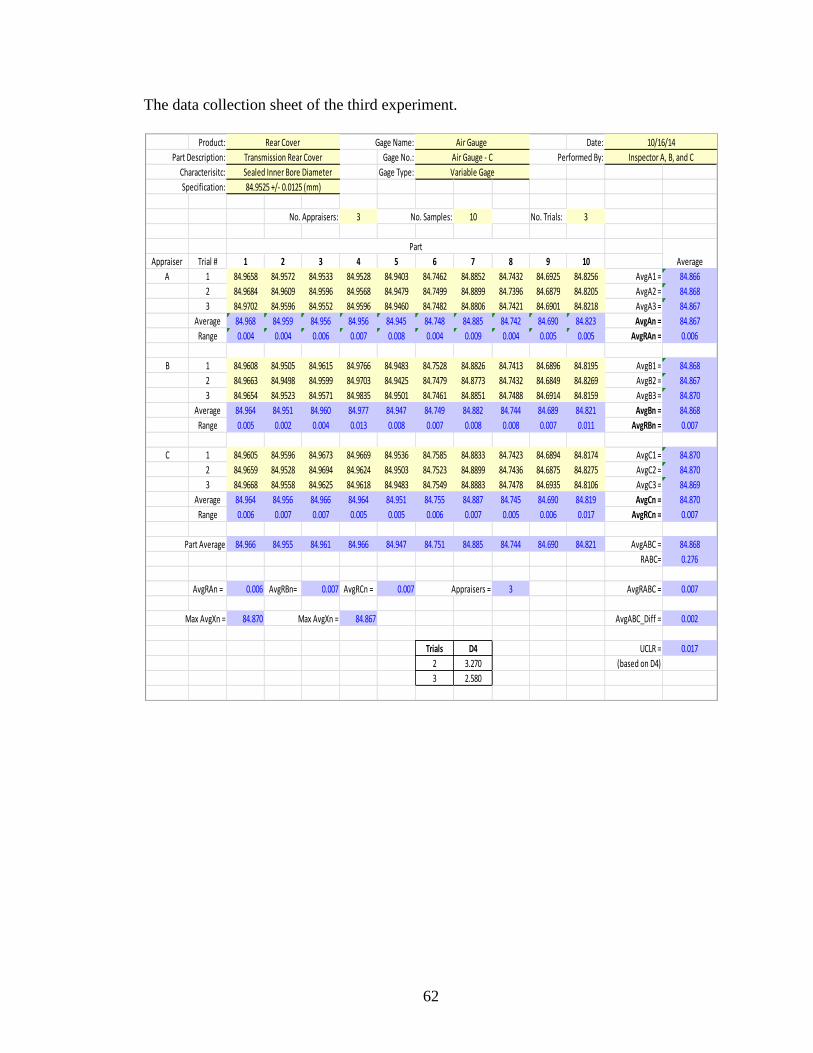
62
The data collection sheet of the third experiment.
Product: Gage Name: Date:
Part Description: Gage No.: Performed By:
Characterisitc: Gage Type:
Specification:
No. Appraisers: 3 No. Samples: 10 No. Trials: 3
Appraiser Trial # 1 2 3 4 5 6 7 8 9 10
A 1 84.9658 84.9572 84.9533 84.9528 84.9403 84.7462 84.8852 84.7432 84.6925 84.8256 AvgA1 = 84.866
2 84.9684 84.9609 84.9596 84.9568 84.9479 84.7499 84.8899 84.7396 84.6879 84.8205 AvgA2 = 84.868
3 84.9702 84.9596 84.9552 84.9596 84.9460 84.7482 84.8806 84.7421 84.6901 84.8218 AvgA3 = 84.867
Average 84.968 84.959 84.956 84.956 84.945 84.748 84.885 84.742 84.690 84.823 AvgAn = 84.867
Range 0.004 0.004 0.006 0.007 0.008 0.004 0.009 0.004 0.005 0.005 AvgRAn = 0.006
B 1 84.9608 84.9505 84.9615 84.9766 84.9483 84.7528 84.8826 84.7413 84.6896 84.8195 AvgB1 = 84.868
2 84.9663 84.9498 84.9599 84.9703 84.9425 84.7479 84.8773 84.7432 84.6849 84.8269 AvgB2 = 84.867
3 84.9654 84.9523 84.9571 84.9835 84.9501 84.7461 84.8851 84.7488 84.6914 84.8159 AvgB3 = 84.870
Average 84.964 84.951 84.960 84.977 84.947 84.749 84.882 84.744 84.689 84.821 AvgBn = 84.868
Range 0.005 0.002 0.004 0.013 0.008 0.007 0.008 0.008 0.007 0.011 AvgRBn = 0.007
C 1 84.9605 84.9596 84.9673 84.9669 84.9536 84.7585 84.8833 84.7423 84.6894 84.8174 AvgC1 = 84.870
2 84.9659 84.9528 84.9694 84.9624 84.9503 84.7523 84.8899 84.7436 84.6875 84.8275 AvgC2 = 84.870
3 84.9668 84.9558 84.9625 84.9618 84.9483 84.7549 84.8883 84.7478 84.6935 84.8106 AvgC3 = 84.869
Average 84.964 84.956 84.966 84.964 84.951 84.755 84.887 84.745 84.690 84.819 AvgCn = 84.870
Range 0.006 0.007 0.007 0.005 0.005 0.006 0.007 0.005 0.006 0.017 AvgRCn = 0.007
Part Average 84.966 84.955 84.961 84.966 84.947 84.751 84.885 84.744 84.690 84.821 AvgABC = 84.868
RABC= 0.276
AvgRAn = 0.006 AvgRBn= 0.007 AvgRCn = 0.007 Appraisers = 3 AvgRABC = 0.007
Max AvgXn = 84.870 Max AvgXn = 84.867 AvgABC_Diff = 0.002
Trials D4 UCLR = 0.017
2 3.270 (based on D4)
3 2.580
Part
Average
84.9525 +/- 0.0125 (mm)
Sealed Inner Bore Diameter Variable Gage
Rear Cover Air Gauge 10/16/14
Transmission Rear Cover Air Gauge - C Inspector A, B, and C

63
The data collection sheet of the fourth experiment.
Product: Gage Name: Date:
Part Description: Gage No.: Performed By:
Characterisitc: Gage Type:
Specification:
No. Appraisers: 3 No. Samples: 10 No. Trials: 3
Appraiser Trial # 1 2 3 4 5 6 7 8 9 10
A 1 84.9561 84.9688 84.9590 84.9542 84.9493 84.7552 84.8967 84.7487 84.7069 84.8254 AvgA1 = 84.872
2 84.9493 84.9623 84.9571 84.9488 84.9468 84.7526 84.8914 84.7441 84.7015 84.8199 AvgA2 = 84.867
3 84.9538 84.9634 84.9523 84.9491 84.9521 84.7485 84.8939 84.7429 84.7026 84.8224 AvgA3 = 84.868
Average 84.953 84.965 84.956 84.951 84.949 84.752 84.894 84.745 84.704 84.823 AvgAn = 84.869
Range 0.007 0.007 0.007 0.005 0.005 0.007 0.005 0.006 0.005 0.005 AvgRAn = 0.006
B 1 84.9462 84.9695 84.9654 84.9406 84.9588 84.7526 84.8954 84.7496 84.6956 84.8179 AvgB1 = 84.869
2 84.9497 84.9621 84.9597 84.9491 84.9535 84.7568 84.8987 84.7439 84.6969 84.8238 AvgB2 = 84.869
3 84.9536 84.9605 84.9618 84.9476 84.9541 84.7496 84.8908 84.7460 84.7014 84.8246 AvgB3 = 84.869
Average 84.950 84.964 84.962 84.946 84.955 84.753 84.895 84.747 84.698 84.822 AvgBn = 84.869
Range 0.007 0.009 0.006 0.008 0.005 0.007 0.008 0.006 0.006 0.007 AvgRBn = 0.007
C 1 84.9477 84.9562 84.9589 84.9526 84.9436 84.7529 84.9026 84.7452 84.7029 84.8290 AvgC1 = 84.869
2 84.9521 84.9584 84.9536 84.9487 84.9498 84.7582 84.8969 84.7382 84.6987 84.8249 AvgC2 = 84.868
3 84.9498 84.9558 84.9566 84.9458 84.9578 84.7561 84.8989 84.7428 84.7041 84.8278 AvgC3 = 84.870
Average 84.950 84.957 84.956 84.949 84.950 84.756 84.899 84.742 84.702 84.827 AvgCn = 84.869
Range 0.004 0.003 0.005 0.007 0.014 0.005 0.006 0.007 0.005 0.004 AvgRCn = 0.006
Part Average 84.951 84.962 84.958 84.949 84.952 84.754 84.896 84.745 84.701 84.824 AvgABC = 84.869
RABC= 0.261
AvgRAn = 0.006 AvgRBn= 0.007 AvgRCn = 0.006 Appraisers = 3 AvgRABC = 0.006
Max AvgXn = 84.869 Max AvgXn = 84.869 AvgABC_Diff = 0.000
Trials D4 UCLR = 0.016
2 3.270 (based on D4)
3 2.580
Part
Average
84.9525 +/- 0.0125 (mm)
Sealed Inner Bore Diameter Variable Gage
Rear Cover Air Gauge 10/16/14
Transmission Rear Cover Air Gauge - D Inspector A, B, and C
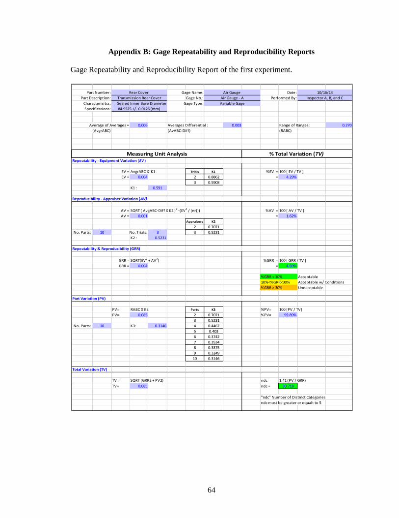
64
Appendix B: Gage Repeatability and Reproducibility Reports
Gage Repeatability and Reproducibility Report of the first experiment.
Part Number: Gage Name: Date:
Part Description: Gage No.: Performed By:
Characterisitcs: Gage Type:
Specifications:
Average of Averages = 0.006 Averages Differential : 0.003 Range of Ranges: 0.270
(AvgrABC) (AvABC-Diff) (RABC)
Repeatability - Equipment Variation (EV )
EV = AvgrABC X K1 Trials K1 %EV = 100 [ EV / TV ]
EV = 0.004 2 0.8862 = 4.29%
3 0.5908
K1 : 0.591
Reproducibility - Appraiser Variation (AV)
AV = SQRT ( AvgABC-Diff X K2 )2 -(EV2 / (nr))) %AV = 100 [ AV / TV ]
AV = 0.001 = 1.62%
Appraisers K2
2 0.7071
No. Parts: 10 No. Trials: 3 3 0.5231
K2 : 0.5231
Repeatability & Reproducibility (GRR)
GRR = SQRT(EV2 + AV2) %GRR = 100 [ GRR / TV ]
GRR = 0.004 = 4.59%
%GRR < 10% Acceptable
10%<%GRR<30% Acceptable w/ Conditions
%GRR > 30% Unnaceptable
Part Variation (PV)
PV= RABC X K3 Parts K3 %PV= 100 [PV / TV]
PV= 0.085 2 0.7071 %PV= 99.89%
3 0.5231
No. Parts: 10 K3: 0.3146 4 0.4467
5 0.403
6 0.3742
7 0.3534
8 0.3375
9 0.3249
10 0.3146
Total Variation (TV)
TV= SQRT (GRR2 + PV2) ndc = 1.41 (PV / GRR)
TV= 0.085 ndc = 30.718
"ndc" Number of Distinct Categories
ndc must be greater or equalt to 5
Rear Cover Air Gauge 10/16/14
Air Gauge - A Inspector A, B, and C
Sealed Inner Bore Diameter Variable Gage
Measuring Unit Analysis % Total Variation (TV)
84.9525 +/- 0.0125 (mm)
Transmission Rear Cover
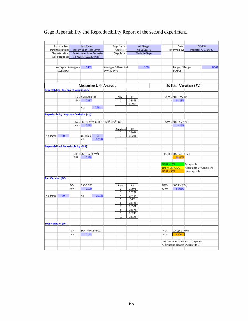
65
Gage Repeatability and Reproducibility Report of the second experiment.
Part Number: Gage Name: Date:
Part Description: Gage No.: Performed By:
Characterisitcs: Gage Type:
Specifications:
Average of Averages = 0.402 Averages Differential : 0.088 Range of Ranges: 0.540
(AvgrABC) (AvABC-Diff) (RABC)
Repeatability - Equipment Variation (EV )
EV = AvgrABC X K1 Trials K1 %EV = 100 [ EV / TV ]
EV = 0.237 2 0.8862 = 81.23%
3 0.5908
K1 : 0.591
Reproducibility - Appraiser Variation (AV)
AV = SQRT ( AvgABC-Diff X K2 )2 -(EV2 / (nr))) %AV = 100 [ AV / TV ]
AV = 0.015 = 5.26%
Appraisers K2
2 0.7071
No. Parts: 10 No. Trials: 3 3 0.5231
K2 : 0.5231
Repeatability & Reproducibility (GRR)
GRR = SQRT(EV2 + AV2) %GRR = 100 [ GRR / TV ]
GRR = 0.238 = 81.40%
%GRR < 10% Acceptable
10%<%GRR<30% Acceptable w/ Conditions
%GRR > 30% Unnaceptable
Part Variation (PV)
PV= RABC X K3 Parts K3 %PV= 100 [PV / TV]
PV= 0.170 2 0.7071 %PV= 58.08%
3 0.5231
No. Parts: 10 K3: 0.3146 4 0.4467
5 0.403
6 0.3742
7 0.3534
8 0.3375
9 0.3249
10 0.3146
Total Variation (TV)
TV= SQRT (GRR2 + PV2) ndc = 1.41 (PV / GRR)
TV= 0.292 ndc = 1.006
"ndc" Number of Distinct Categories
ndc must be greater or equalt to 5
Air Gauge - B Inspector A, B, and C
Sealed Inner Bore Diameter Variable Gage
Measuring Unit Analysis % Total Variation (TV)
84.9525 +/- 0.0125 (mm)
Transmission Rear Cover
Rear Cover Air Gauge 10/16/14

66
Gage Repeatability and Reproducibility Report of the third experiment.
Part Number: Gage Name: Date:
Part Description: Gage No.: Performed By:
Characterisitcs: Gage Type:
Specifications:
Average of Averages = 0.007 Averages Differential : 0.002 Range of Ranges: 0.276
(AvgrABC) (AvABC-Diff) (RABC)
Repeatability - Equipment Variation (EV )
EV = AvgrABC X K1 Trials K1 %EV = 100 [ EV / TV ]
EV = 0.004 2 0.8862 = 4.86%
3 0.5908
K1 : 0.591
Reproducibility - Appraiser Variation (AV)
AV = SQRT ( AvgABC-Diff X K2 )2 -(EV2 / (nr))) %AV = 100 [ AV / TV ]
AV = 0.000 = 0.37%
Appraisers K2
2 0.7071
No. Parts: 10 No. Trials: 3 3 0.5231
K2 : 0.5231
Repeatability & Reproducibility (GRR)
GRR = SQRT(EV2 + AV2) %GRR = 100 [ GRR / TV ]
GRR = 0.004 = 4.88%
%GRR < 10% Acceptable
10%<%GRR<30% Acceptable w/ Conditions
%GRR > 30% Unnaceptable
Part Variation (PV)
PV= RABC X K3 Parts K3 %PV= 100 [PV / TV]
PV= 0.087 2 0.7071 %PV= 99.88%
3 0.5231
No. Parts: 10 K3: 0.3146 4 0.4467
5 0.403
6 0.3742
7 0.3534
8 0.3375
9 0.3249
10 0.3146
Total Variation (TV)
TV= SQRT (GRR2 + PV2) ndc = 1.41 (PV / GRR)
TV= 0.087 ndc = 28.879
"ndc" Number of Distinct Categories
ndc must be greater or equalt to 5
Rear Cover Air Gauge 10/16/14
Air Gauge - C Inspector A, B, and C
Sealed Inner Bore Diameter Variable Gage
Measuring Unit Analysis % Total Variation (TV)
84.9525 +/- 0.0125 (mm)
Transmission Rear Cover
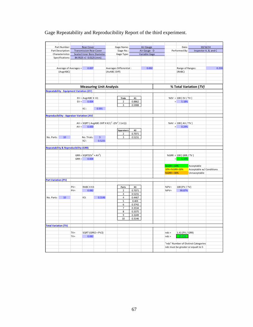
67
Gage Repeatability and Reproducibility Report of the third experiment.
Part Number: Gage Name: Date:
Part Description: Gage No.: Performed By:
Characterisitcs: Gage Type:
Specifications:
Average of Averages = 0.007 Averages Differential : 0.002 Range of Ranges: 0.259
(AvgrABC) (AvABC-Diff) (RABC)
Repeatability - Equipment Variation (EV )
EV = AvgrABC X K1 Trials K1 %EV = 100 [ EV / TV ]
EV = 0.004 2 0.8862 = 5.18%
3 0.5908
K1 : 0.591
Reproducibility - Appraiser Variation (AV)
AV = SQRT ( AvgABC-Diff X K2 )2 -(EV2 / (nr))) %AV = 100 [ AV / TV ]
AV = 0.000 = 0.24%
Appraisers K2
2 0.7071
No. Parts: 10 No. Trials: 3 3 0.5231
K2 : 0.5231
Repeatability & Reproducibility (GRR)
GRR = SQRT(EV2 + AV2) %GRR = 100 [ GRR / TV ]
GRR = 0.004 = 5.19%
%GRR < 10% Acceptable
10%<%GRR<30% Acceptable w/ Conditions
%GRR > 30% Unnaceptable
Part Variation (PV)
PV= RABC X K3 Parts K3 %PV= 100 [PV / TV]
PV= 0.082 2 0.7071 %PV= 99.87%
3 0.5231
No. Parts: 10 K3: 0.3146 4 0.4467
5 0.403
6 0.3742
7 0.3534
8 0.3375
9 0.3249
10 0.3146
Total Variation (TV)
TV= SQRT (GRR2 + PV2) ndc = 1.41 (PV / GRR)
TV= 0.082 ndc = 27.151
"ndc" Number of Distinct Categories
ndc must be greater or equalt to 5
Rear Cover Air Gauge 10/16/14
Air Gauge - D Inspector A, B, and C
Sealed Inner Bore Diameter Variable Gage
Measuring Unit Analysis % Total Variation (TV)
84.9525 +/- 0.0125 (mm)
Transmission Rear Cover
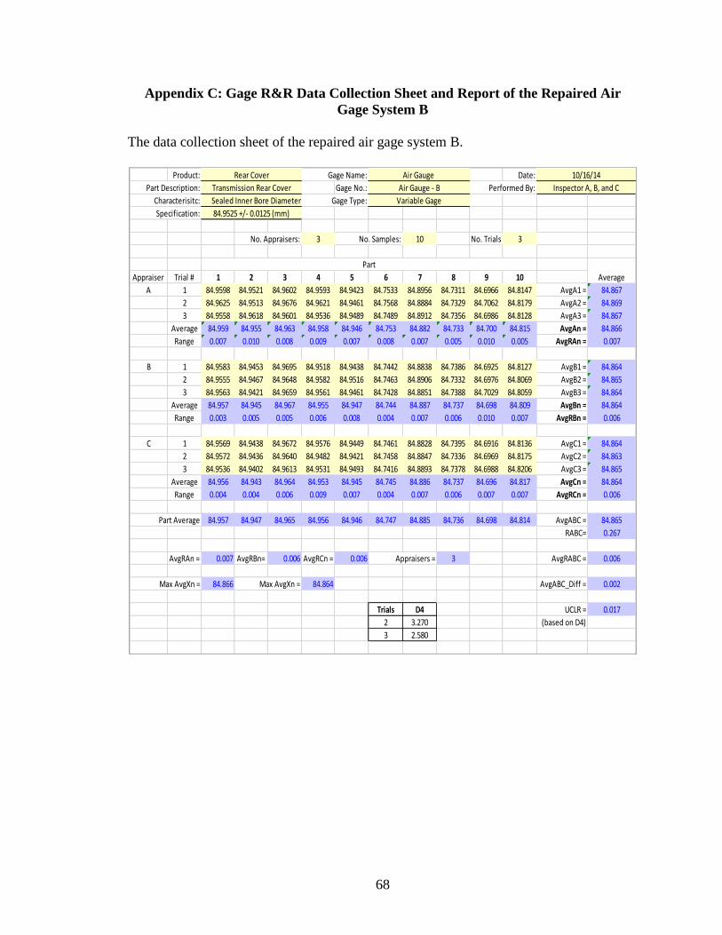
68
Appendix C: Gage R&R Data Collection Sheet and Report of the Repaired Air
Gage System B
The data collection sheet of the repaired air gage system B.
Product: Gage Name: Date:
Part Description: Gage No.: Performed By:
Characterisitc: Gage Type:
Specification:
No. Appraisers: 3 No. Samples: 10 No. Trials: 3
Appraiser Trial # 1 2 3 4 5 6 7 8 9 10
A 1 84.9598 84.9521 84.9602 84.9593 84.9423 84.7533 84.8956 84.7311 84.6966 84.8147 AvgA1 = 84.867
2 84.9625 84.9513 84.9676 84.9621 84.9461 84.7568 84.8884 84.7329 84.7062 84.8179 AvgA2 = 84.869
3 84.9558 84.9618 84.9601 84.9536 84.9489 84.7489 84.8912 84.7356 84.6986 84.8128 AvgA3 = 84.867
Average 84.959 84.955 84.963 84.958 84.946 84.753 84.882 84.733 84.700 84.815 AvgAn = 84.866
Range 0.007 0.010 0.008 0.009 0.007 0.008 0.007 0.005 0.010 0.005 AvgRAn = 0.007
B 1 84.9583 84.9453 84.9695 84.9518 84.9438 84.7442 84.8838 84.7386 84.6925 84.8127 AvgB1 = 84.864
2 84.9555 84.9467 84.9648 84.9582 84.9516 84.7463 84.8906 84.7332 84.6976 84.8069 AvgB2 = 84.865
3 84.9563 84.9421 84.9659 84.9561 84.9461 84.7428 84.8851 84.7388 84.7029 84.8059 AvgB3 = 84.864
Average 84.957 84.945 84.967 84.955 84.947 84.744 84.887 84.737 84.698 84.809 AvgBn = 84.864
Range 0.003 0.005 0.005 0.006 0.008 0.004 0.007 0.006 0.010 0.007 AvgRBn = 0.006
C 1 84.9569 84.9438 84.9672 84.9576 84.9449 84.7461 84.8828 84.7395 84.6916 84.8136 AvgC1 = 84.864
2 84.9572 84.9436 84.9640 84.9482 84.9421 84.7458 84.8847 84.7336 84.6969 84.8175 AvgC2 = 84.863
3 84.9536 84.9402 84.9613 84.9531 84.9493 84.7416 84.8893 84.7378 84.6988 84.8206 AvgC3 = 84.865
Average 84.956 84.943 84.964 84.953 84.945 84.745 84.886 84.737 84.696 84.817 AvgCn = 84.864
Range 0.004 0.004 0.006 0.009 0.007 0.004 0.007 0.006 0.007 0.007 AvgRCn = 0.006
Part Average 84.957 84.947 84.965 84.956 84.946 84.747 84.885 84.736 84.698 84.814 AvgABC = 84.865
RABC= 0.267
AvgRAn = 0.007 AvgRBn= 0.006 AvgRCn = 0.006 Appraisers = 3 AvgRABC = 0.006
Max AvgXn = 84.866 Max AvgXn = 84.864 AvgABC_Diff = 0.002
Trials D4 UCLR = 0.017
2 3.270 (based on D4)
3 2.580
Part
Average
84.9525 +/- 0.0125 (mm)
Sealed Inner Bore Diameter Variable Gage
Rear Cover Air Gauge 10/16/14
Transmission Rear Cover Air Gauge - B Inspector A, B, and C
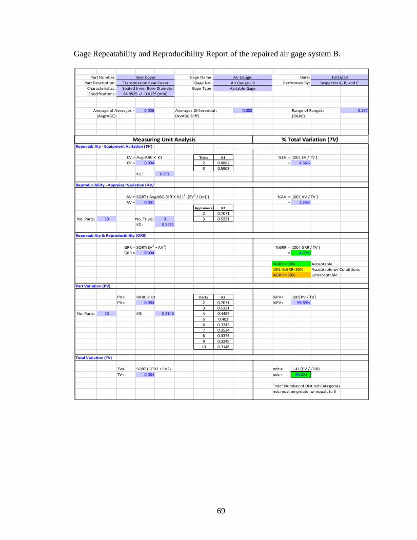
69
Gage Repeatability and Reproducibility Report of the repaired air gage system B.
Part Number: Gage Name: Date:
Part Description: Gage No.: Performed By:
Characterisitcs: Gage Type:
Specifications:
Average of Averages = 0.006 Averages Differential : 0.002 Range of Ranges: 0.267
(AvgrABC) (AvABC-Diff) (RABC)
Repeatability - Equipment Variation (EV )
EV = AvgrABC X K1 Trials K1 %EV = 100 [ EV / TV ]
EV = 0.004 2 0.8862 = 4.56%
3 0.5908
K1 : 0.591
Reproducibility - Appraiser Variation (AV)
AV = SQRT ( AvgABC-Diff X K2 )2 -(EV2 / (nr))) %AV = 100 [ AV / TV ]
AV = 0.001 = 1.24%
Appraisers K2
2 0.7071
No. Parts: 10 No. Trials: 3 3 0.5231
K2 : 0.5231
Repeatability & Reproducibility (GRR)
GRR = SQRT(EV2 + AV2) %GRR = 100 [ GRR / TV ]
GRR = 0.004 = 4.72%
%GRR < 10% Acceptable
10%<%GRR<30% Acceptable w/ Conditions
%GRR > 30% Unnaceptable
Part Variation (PV)
PV= RABC X K3 Parts K3 %PV= 100 [PV / TV]
PV= 0.084 2 0.7071 %PV= 99.89%
3 0.5231
No. Parts: 10 K3: 0.3146 4 0.4467
5 0.403
6 0.3742
7 0.3534
8 0.3375
9 0.3249
10 0.3146
Total Variation (TV)
TV= SQRT (GRR2 + PV2) ndc = 1.41 (PV / GRR)
TV= 0.084 ndc = 29.824
"ndc" Number of Distinct Categories
ndc must be greater or equalt to 5
Rear Cover Air Gauge 10/16/14
Air Gauge - B Inspector A, B, and C
Sealed Inner Bore Diameter Variable Gage
Measuring Unit Analysis % Total Variation (TV)
84.9525 +/- 0.0125 (mm)
Transmission Rear Cover

70
References
Bubshait, A., & Al-Hamdan, H. A. (2013, October). Optimizing vender inspectors’
qualification process using lean six sigma. World Congress on Engineering and
Computer Science, 2(3), 23-25.
Dolezal, K. K., Burdick, R. K. & Birch, N. J. (1998). Analysis of a two-factor R&R study
with fixed operators. Journal of Quality Technology, 30 (2), 163-170.
Elizabeth, I. (2012, June 12). Reproducibility: An important altmetric. Retrieved from:
http://altmetrics.org/altmetrics12/iorns
Hoffa, W. D., & Laux, C. (2006, October). Gage R&R: An effective methodology for
determining the adequacy of a new measurement system for micron-level metrology.
Journal of Industrial Technology, 23 (4), 11-19.
Mahr. (2015). Mahr Millimar S 1840 PE Air Gage System Introduction. Retrieved from:
http://www.mahr.com/es/Products/Metrology/By-Mahr-Product
Group/Millimar/Gages-and-Systems/Air-Gages/S-1840-PE/
Mast, D. J., & Trip, R. (2005, January). Gage R&R studies for destructive measurements.
Journal of Quality Technology, 37 (1), 40-49.
Measurement Systems Analysis (MSA) Work Group. (2010). Measurement systems
analysis reference manual (4th ed.). Chrysler Group LLC, Ford Motor Company, and
General Motors Corporation.
Minitab. (2015). Number of Distinct Categories. Retrieved from:
http://support.minitab.com/en-us/minitab/17/topic-library/quality-
tools/measurement-system-analysis/gage-r-r-analyses/number-of-distinct-categories/
71
Pan, J. N. (2006). Evaluating the gage repeatability and reproducibility for different
industries. Quality & Quantity, 40 (20), 499-518.
Park, J. J., Kwon, K., & Cho, N. (2006, July). Development of a coordinate measuring
machine (CMM) touch probe using a multi-axis force sensor. Measurement Science
and Technology, 17 (6), 2380-2386.
Pye, A. (2014, December). The internet of things: Connecting the unconnected.
Engineering & Technology, 9(11), 64-70.
Pyzdek, T., & Keller, A. P. (2009). The six sigma handbook, a complete guide for green
belts, black belts, and managers at all levels (3rd ed.). The McGraw-Hill Companies,
Inc.
Rowell, G. H., & Duffey, M. (2004). Introduction to Minitab (student version 12 and
professional version 13) [PDF document]. Retrieved from:
https://www.causeweb.org/repository/Minitab/Minitab.pdf
Smith, R., McCary, S. W., & Callahan, N. R. (2007). Gage repeatability and
reproducibility studies and measurement system analysis: A multimethod
exploration of the state of practice. Journal of Industrial Technology, 23(1).
Stewart, T. (1998, April). Selecting the right gage. Retrieved from:
http://www.qualitydigest.com/april98/html/rightgag.html
Six Sigma Material. (2013). Measurement system analysis. Retrieved from:
http://www.six-sigma-material.com/MSA.html
Summers, C., S. (2009). Quality management: Creating and sustaining organizational
effectiveness. Upper Saddle River, NJ: Pearson Education, Inc.
72
Wesff, E. (2012, December). Chinese OEM reduces returns with improved product
testing. The Global Voice of Quality, 4(2), 1-6.
Western Gage Corporation. (2015). Air Probes For Precise Measurement of Internal
Diameters. Retrieved from:
http://www.westerngage.com/air-probes-for-precise-measurement-of-internal-
diameters/
William, M.K. (2006). Types of Reliability. Research methods knowledge base.
Retrieved from:
http://www.socialresearchmethods.net/kb/reltypes.php