Textile wastewater treatment using a UF hollow‐fibre submerged membrane bioreactor (SMBR
12
This article was downloaded by: [Jigisha Parikh] On: 12 July 2011, At: 11:49 Publisher: Taylor & Francis Informa Ltd Registered in England and Wales Registered Number: 1072954 Registered office: Mortimer House, 37-41 Mortimer Street, London W1T 3JH, UK Environmental Technology Publication details, including instructions for authors and subscription information: http://www.tandfonline.com/loi/tent20 Textile wastewater treatment using a UF hollow‐fibre submerged membrane bioreactor (SMBR) P. Niren a & P. Jigisha b a Chemical Engineering Department, Sarvajanik College of Engineering and Technology, Surat, Gujarat, India b Chemical Engineering Department, Sardar Vallabhbhai National Institute of Technology, Surat, Gujarat, India Available online: 30 Jun 2011 To cite this article: P. Niren & P. Jigisha (2011): Textile wastewater treatment using a UF hollow‐fibre submerged membrane bioreactor (SMBR), Environmental Technology, 32:11, 1247-1257 To link to this article: http://dx.doi.org/10.1080/09593330.2010.534821 PLEASE SCROLL DOWN FOR ARTICLE Full terms and conditions of use: http://www.tandfonline.com/page/terms-and-conditions This article may be used for research, teaching and private study purposes. Any substantial or systematic reproduction, re-distribution, re-selling, loan, sub-licensing, systematic supply or distribution in any form to anyone is expressly forbidden. The publisher does not give any warranty express or implied or make any representation that the contents will be complete or accurate or up to date. The accuracy of any instructions, formulae and drug doses should be independently verified with primary sources. The publisher shall not be liable for any loss, actions, claims, proceedings, demand or costs or damages whatsoever or howsoever caused arising directly or indirectly in connection with or arising out of the use of this material.
Transcript of Textile wastewater treatment using a UF hollow‐fibre submerged membrane bioreactor (SMBR
This article was downloaded by: [Jigisha Parikh]On: 12 July 2011, At: 11:49Publisher: Taylor & FrancisInforma Ltd Registered in England and Wales Registered Number: 1072954 Registered office: Mortimer House,37-41 Mortimer Street, London W1T 3JH, UK
Environmental TechnologyPublication details, including instructions for authors and subscription information:http://www.tandfonline.com/loi/tent20
Textile wastewater treatment using a UF hollow‐fibresubmerged membrane bioreactor (SMBR)P. Niren a & P. Jigisha ba Chemical Engineering Department, Sarvajanik College of Engineering and Technology,Surat, Gujarat, Indiab Chemical Engineering Department, Sardar Vallabhbhai National Institute of Technology,Surat, Gujarat, India
Available online: 30 Jun 2011
To cite this article: P. Niren & P. Jigisha (2011): Textile wastewater treatment using a UF hollow‐fibre submerged membranebioreactor (SMBR), Environmental Technology, 32:11, 1247-1257
To link to this article: http://dx.doi.org/10.1080/09593330.2010.534821
PLEASE SCROLL DOWN FOR ARTICLE
Full terms and conditions of use: http://www.tandfonline.com/page/terms-and-conditions
This article may be used for research, teaching and private study purposes. Any substantial or systematicreproduction, re-distribution, re-selling, loan, sub-licensing, systematic supply or distribution in any form toanyone is expressly forbidden.
The publisher does not give any warranty express or implied or make any representation that the contentswill be complete or accurate or up to date. The accuracy of any instructions, formulae and drug doses shouldbe independently verified with primary sources. The publisher shall not be liable for any loss, actions, claims,proceedings, demand or costs or damages whatsoever or howsoever caused arising directly or indirectly inconnection with or arising out of the use of this material.
Environmental Technology
Vol. 32, No. 11, August 2011, 1247–1257
ISSN 0959-3330 print/ISSN 1479-487X online© 2011 Taylor & FrancisDOI: 10.1080/09593330.2010.534821http://www.informaworld.com
Textile wastewater treatment using a UF hollow-fibre submerged membrane bioreactor (SMBR)
P. Niren
a
and P. Jigisha
b
*
a
Chemical Engineering Department, Sarvajanik College of Engineering and Technology, Surat, Gujarat, India;
b
Chemical Engineering Department, Sardar Vallabhbhai National Institute of Technology, Surat, Gujarat, India
Taylor and Francis
(
Received 1 February 2010; Accepted 17 October 2010
)
10.1080/09593330.2010.534821
The objective of this study was to investigate the performance of a laboratory-scale submerged membrane bioreactor(SMBR) system for the treatment of synthetic textile wastewater containing disperse red dye. The SMBR system wasrun aerobically in a continuous flow mode at five different hydraulic retention times (HRTs) of 24,18,14.4,11.28 and8.4 h respectively, with an average permeate flux of 20 L/(m
2
·h). The performance of the system was not adverselyaffected by decreased HRT and the consequent rise in the food/microorganism ratio (0.07 to 0.14 g BOD/(g SS·d))and organic loading rate (OLR: 0.4 to 1.24 BOD kg/(m
3
·d)). The average removal rate for COD, BOD and colourwere 92.33%, 93.69% and 91.36%, respectively. To maintain a stable flux and prevent fouling, the membrane wascovered with a cylindrical wire-mesh cage, and routine chemical backwashing and chemical cleaning procedureswere adapted. Transmembrane pressure increased from 29.47 to 58.42 kPa (0.29 to 0.58 bar) during each run of HRT.The results indicated that synthetic textile wastewater could be treated very effectively by the SMBR system.
Keywords:
submerged membrane bioreactor; disperse red dye; ultrafiltration membrane; fouling; hydraulic retention time
Introduction
The textile industry covers a wide range of activitiesfrom preparation of the raw material to ennoblementtreatment. It includes preliminary treatments (bleach-ing, desizing, mercerization), textile ennobling treat-ments (from dyeing to post-dyeing treatments, such asthose required to increase colourant fastness, in wet anddry conditions) and finishing, including operations suchas fulling or impregnation, which provide special char-acteristics to fibres. These activities use variable quan-tities of water, from 5 to 40 times the fibre weight, andconsequently generate large volumes of wastewater [1].For each ton of produced fabric, approximately 20–350m
3
of water is consumed [2]. In India, around 2100textile units (SSI – small-scale industries) are underoperation. The average water consumption is approxi-mately 200 m
3
/d. About 1.5 million litres of effluent per600 km of fabric per day is generated by an average sizemill [3,4].
The major pollutants present in textile effluent areorganics, colour, toxicants and inhibitory compounds,surfactants, chlorinated compounds (AOX), heavymetals and salts, amongst which coloured dyes are themost troublesome constituents of the wastewater [5–9,10]. Also, there is variation in the composition of
textile wastewater depending on the season and thefashion. Invariably the generated wastewater is drainedinto natural water bodies without proper treatment[2,11,12], posing a major threat to the environment.About 8000 different colour-producing constituents and6900 additives are known and lead to contamination inwater bodies [13]. Sample analysis of influent comingto the effluent treatment plant at CETP-Sachin, Surat,from various surrounding textile industries gave thefollowing results: pH 5.9–6.5, TSS 385–631 mg/L,COD 900–1150 mg/L, BOD 390–455 mg/L, colour2060–3040 apparent (pt-co units) [14].
For the treatment of textile wastewater, commonprocesses applied are coagulation, flotation, chemicalprecipitation, adsorption, electrochemical destruction,biological treatment, etc. [2,7,10,15]. These treatmentprocesses might be effective but they consume highamounts of energy and chemical agents. Chemicalwaste is also generated from these processes, whichrequire further treatment [16]. Because of low biode-gradability, toxicity and colour issues, advanced treat-ment options are of major interest for the treatment oftextile wastewater [7,17,18]. In the near future, manytextile industries will have to improve wastewater qual-ity to the fresh (ground) water standards to allow reuse
*Corresponding author. Email: [email protected]
Dow
nloa
ded
by [
Jigi
sha
Pari
kh]
at 1
1:49
12
July
201
1
1248
P. Niren and P. Jigisha
of the water, to compensate for rising water prices, aswell as because of stringent environment regulations[13,19].
To meet the stricter effluent standards, a more effec-tive and efficient system to remove organic pollutantsand colour has to be established. One of the most prom-ising technologies for providing this is the membranebioreactor (MBR) [6]. An MBR can be defined as anintegrated biological degradation system for wasteproducts using membrane filtration [7,12,20].
Compared with conventional activated sludgeprocesses, which suffer from solid–liquid separationproblems such as bulking and foaming [21], submergedMBR (SMBR) technology seems a promising optionconsidering its smaller footprint, less sludge produc-tion, high biomass concentration, high quality of efflu-ent, long contact time between activated sludge andorganic pollutants, and complete separation of thehydraulic retention time (HRT) and sludge retentiontime (SRT). Moreover, effluent from an SMBR is freefrom bacteria and has the potential for reuse [22–26].The use of a submerged membrane has resulted in asignificant reduction in the energy consumption of theMBR and hence has increased the potential for theapplication of MBR technology in wastewater treat-ment [21–23].
However, a major drawback of membrane processesis their tendency to foul during operation. This reducesthe permeate flow through the membrane as pores getsblocked as a result of fouling, thereby increasing themembrane cleaning frequency, which reduces the planttreatment capacity and shortening the membranemodule lifespan [27,28]. To sustain daily operation,membrane maintenance by periodic chemical cleaningor membrane replacement has to be carried out and thiswill inevitably accrue higher costs. Current methods forcontrolling membrane fouling in an MBR include: (1)operating with a flux lower than its critical flux, (2)increasing the cross-flow velocity by controlling theaeration rate , (3) operating with an intermediate perme-ate suction, (4) backflushing the membrane periodicallywith permeate [23].
Considering the drawback of fouling, an attempt ismade here to reduce the fouling by using a cylindricalcage of wire mesh combined with routine backwashing.The main objective of this study was to find the opti-mum conditions for process performance, to investigateeffluent quality (simultaneous removal of organic
carbon and colour) under different organic loading rates(OLRs) and HRTs using an ultrafiltration hollow-fibre(UF-HF: polyethersulphone) membrane in the SMBR.This may help to provide preliminary studies for theimplementation of MBR under Indian conditions, asthis has not been studied in detail so far. Also, as Suratis a textile industrial hub, wastewater generation is amajor environmental issue, so this study may providesome insight towards the treatment of textile industrywastewater in this area.
Methodology
Disperse dye
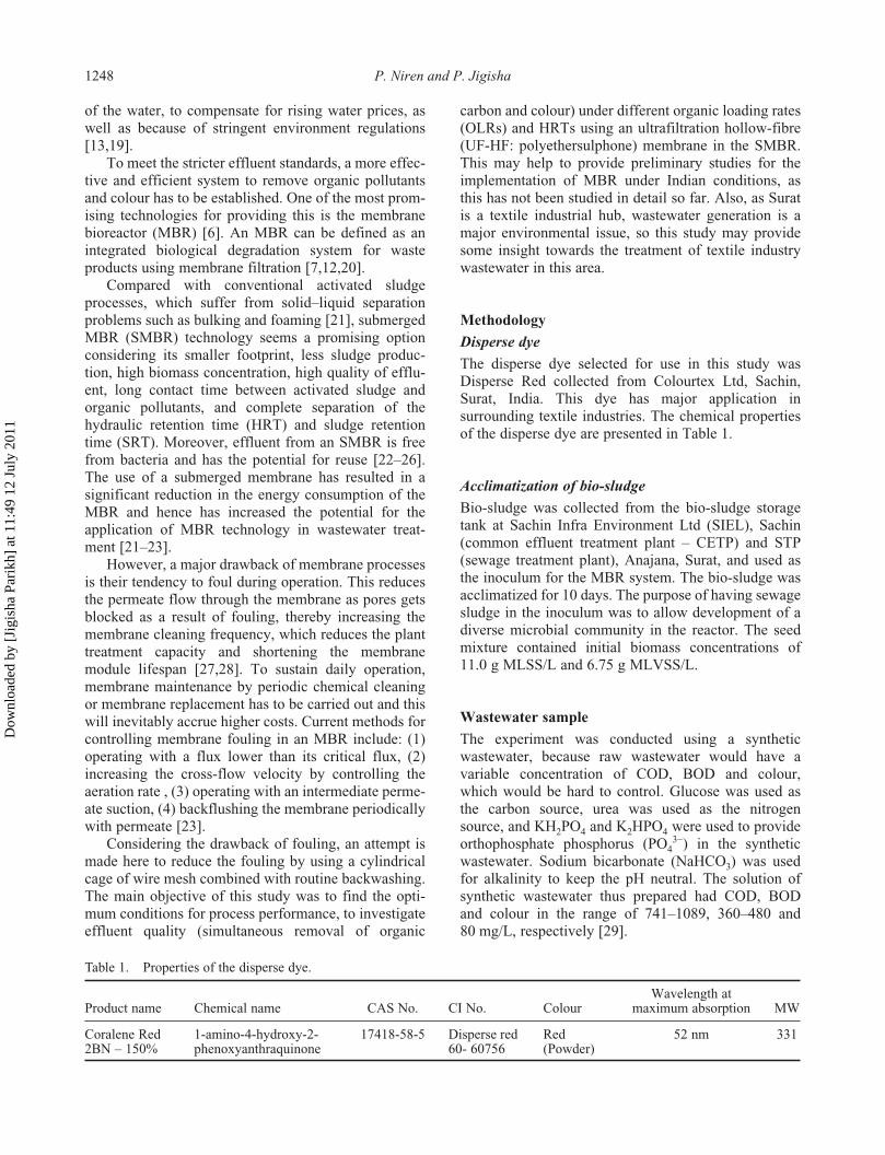
The disperse dye selected for use in this study wasDisperse Red collected from Colourtex Ltd, Sachin,Surat, India. This dye has major application insurrounding textile industries. The chemical propertiesof the disperse dye are presented in Table 1.
Acclimatization of bio-sludge
Bio-sludge was collected from the bio-sludge storagetank at Sachin Infra Environment Ltd (SIEL), Sachin(common effluent treatment plant – CETP) and STP(sewage treatment plant), Anajana, Surat, and used asthe inoculum for the MBR system. The bio-sludge wasacclimatized for 10 days. The purpose of having sewagesludge in the inoculum was to allow development of adiverse microbial community in the reactor. The seedmixture contained initial biomass concentrations of11.0 g MLSS/L and 6.75 g MLVSS/L.
Wastewater sample
The experiment was conducted using a syntheticwastewater, because raw wastewater would have avariable concentration of COD, BOD and colour,which would be hard to control. Glucose was used asthe carbon source, urea was used as the nitrogensource, and KH
2
PO
4
and K
2
HPO
4
were used to provideorthophosphate phosphorus (PO
43
−
) in the syntheticwastewater. Sodium bicarbonate (NaHCO
3
) was usedfor alkalinity to keep the pH neutral. The solution ofsynthetic wastewater thus prepared had COD, BODand colour in the range of 741–1089, 360–480 and80 mg/L, respectively [29].
Table 1. Properties of the disperse dye.
Product name Chemical name CAS No. CI No. ColourWavelength at
maximum absorption MW
Coralene Red 2BN – 150%
1-amino-4-hydroxy-2-phenoxyanthraquinone
17418-58-5 Disperse red 60- 60756
Red (Powder)
52 nm 331
Dow
nloa
ded
by [
Jigi
sha
Pari
kh]
at 1
1:49
12
July
201
1
Environmental Technology
1249
Analytical methods
Standard methods were used to measure the mixedliquor suspended solids (MLSS), mixed liquor volatilesuspended solids (MLVSS), chemical oxygen demand(COD), biochemical oxygen demand (BOD
5
) andcolour [30]. Dissolved oxygen (DO) was measuredusing a DO meter (Lutron DO 5509). A pH meter (AquaScientific 225) was used for measuring the pH. TheCOD and colour were measured using a DR 5000 spec-trophotometer (HACH). The absorbance of the sampleat the peak wavelength (520 nm) of the dye wasmeasured. The concentration of dyestuff was calculatedfrom the ‘absorbance vs concentration’ calibrationcurve, and concentration values were used for calcula-tions of decolorization efficiency.
UF-HF membrane characteristics
In microfiltration (MF) and UF, porous membraneswith approximate pore sizes of 0.05–10.00
µ
m and0.002–0.050
µ
m, respectively, have been used (Table 2)[9,31–34]. Membranes for nanofiltration (NF) andreverse osmosis (RO) can be considered as an interme-diate between porous membranes and densemembranes. As the membrane pores or structurebecomes more open, the necessary applied hydrostaticpressure decreases. Therefore, only relatively smallpressure levels are used in MF, whereas relatively highpressures are used in reverse RO [35]. Like NF, RO isvery sensitive to fouling, and the influent stream mustbe carefully pretreated [9].
The use of UF membranes to remove colour andbinder present in textile industry wastewater has beenstudied. It has been shown that the clean permeate fromUF has a 90% reduction in BOD and 100% reduction incolour [34]. The long-term effect of UF membrane poresize on hydraulic performances has been assessed for 20,
30, 50 and 70 kDa membranes [36]. The smallestMWCO (molecular weight cut-off) that was tested (20kDa) lost the largest permeability within the first 15 minof filtration, when compared with the 30, 50 and 70 kDamembranes. However, when operated for an extendedtime (over 100 days) with regular hydraulic and chemicalcleaning, the largest MWCO membrane (70 kDa) expe-rienced the greatest fouling rate, as 94% of its originalpermeability was lost, compared with only 70% perfor-mance decrease for the other three membranes. Theresults reported show that the 30 and 50 kDa membranesprovided the best overall hydraulic performances.Considering these reported results it was decided to usea UF-HF membrane module for textile wastewater treat-ment. The characteristics of the UF membrane moduleused in the present study are presented in Table 3.
Submerged membrane bioreactor
A schematic diagram of the SMBR, in which themembrane module was directly submerged, is shown in
Table 2. Different membrane processes with typical applications [9,29–32].
MembranePore size
(
µ
m)Applied
pressure (bar) Typical application
Microfiltration 10–0.05 0.1–2 Separation of colloids (colloidal dye from dye bath) and particles, >90% reductions in turbidity or silt density index, clarification of juices and sugar solution.
Ultrafiltration 0.05–0.002 1–10 Separation of macromolecules, separation of polymers from salt, low MW materials (pores of 0.001 to 0.100 micron), 99% turbidity reduction, TOD (total oxygen demand), BOD, COD, removal of metal hydroxides, reducing the heavy metal content to 1 ppm or less, recovery of indigo, azo dyes, MWCO of 1000 to 500,000 Daltons.
Nanofiltration 0.002–0.001 5–20 Separation of low MW solutes, separation of sugars and divalent salts from water, for water softening, decolorization of solutions.
Reverse osmosis < 0.001 10–100 Separation of low MW solutes.
Table 3. Characteristics of UF-HF membrane.
Module specification Value
Filtration UltrafiltrationGeometry Hollow fibreMembrane material PES (modified)Test on BSA proteinOuter diameter 1.2 mmInner diameter 0.9 mmModule working length 12 inPore size 50 kDa (0.01
µ
m)Fiber no. of membrane 50Total surface area, m
2
0.043Manufacturer Aquaplus Water Purifiers
Pvt. Ltd, Pune, India
Dow
nloa
ded
by [
Jigi
sha
Pari
kh]
at 1
1:49
12
July
201
1
1250
P. Niren and P. Jigisha
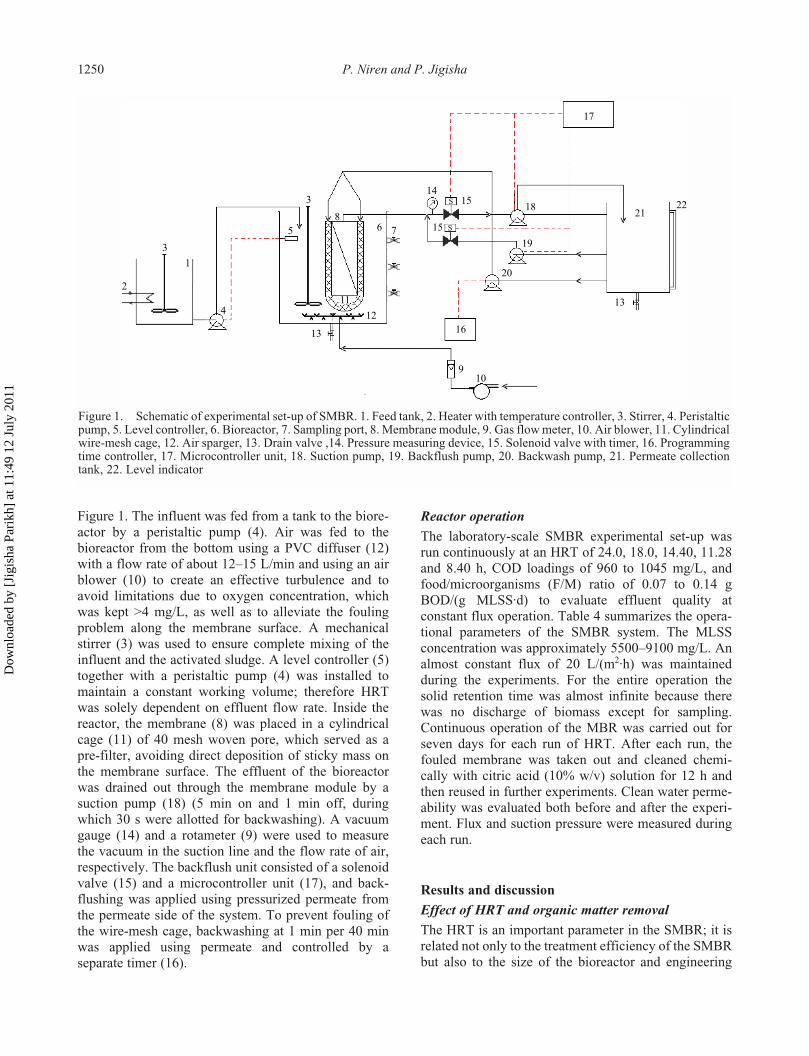
Figure 1. The influent was fed from a tank to the biore-actor by a peristaltic pump (4). Air was fed to thebioreactor from the bottom using a PVC diffuser (12)with a flow rate of about 12–15 L/min and using an airblower (10) to create an effective turbulence and toavoid limitations due to oxygen concentration, whichwas kept >4 mg/L, as well as to alleviate the foulingproblem along the membrane surface. A mechanicalstirrer (3) was used to ensure complete mixing of theinfluent and the activated sludge. A level controller (5)together with a peristaltic pump (4) was installed tomaintain a constant working volume; therefore HRTwas solely dependent on effluent flow rate. Inside thereactor, the membrane (8) was placed in a cylindricalcage (11) of 40 mesh woven pore, which served as apre-filter, avoiding direct deposition of sticky mass onthe membrane surface. The effluent of the bioreactorwas drained out through the membrane module by asuction pump (18) (5 min on and 1 min off, duringwhich 30 s were allotted for backwashing). A vacuumgauge (14) and a rotameter (9) were used to measurethe vacuum in the suction line and the flow rate of air,respectively. The backflush unit consisted of a solenoidvalve (15) and a microcontroller unit (17), and back-flushing was applied using pressurized permeate fromthe permeate side of the system. To prevent fouling ofthe wire-mesh cage, backwashing at 1 min per 40 minwas applied using permeate and controlled by aseparate timer (16).
Figure 1. Schematic of experimental set-up of SMBR. 1. Feed tank, 2. Heater with temperature controller, 3. Stirrer, 4. Peristaltic pump, 5. Level controller, 6. Bioreactor, 7. Sampling port, 8. Membrane module, 9. Gas flow meter, 10. Air blower, 11. Cylindrical wire-mesh cage, 12. Airsparger, 13. Drain valve ,14. Pressure measuring device, 15. Solenoid valve with timer, 16. Programming time controller, 17. Microcontroller unit, 18. Suction pump, 19. Backflush pump, 20. Backwash pump, 21. Permeate collection tank, 22. Level indicator
Reactor operation
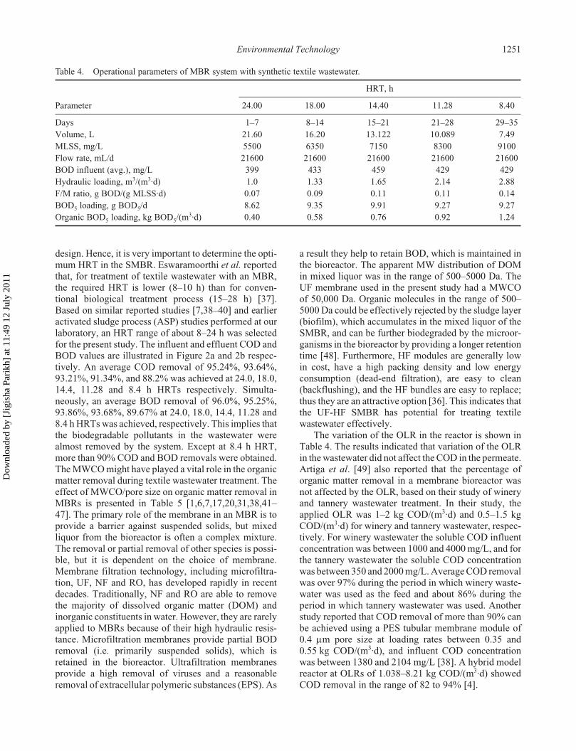
The laboratory-scale SMBR experimental set-up wasrun continuously at an HRT of 24.0, 18.0, 14.40, 11.28and 8.40 h, COD loadings of 960 to 1045 mg/L, andfood/microorganisms (F/M) ratio of 0.07 to 0.14 gBOD/(g MLSS·d) to evaluate effluent quality atconstant flux operation. Table 4 summarizes the opera-tional parameters of the SMBR system. The MLSSconcentration was approximately 5500–9100 mg/L. Analmost constant flux of 20 L/(m
2
·h) was maintainedduring the experiments. For the entire operation thesolid retention time was almost infinite because therewas no discharge of biomass except for sampling.Continuous operation of the MBR was carried out forseven days for each run of HRT. After each run, thefouled membrane was taken out and cleaned chemi-cally with citric acid (10% w/v) solution for 12 h andthen reused in further experiments. Clean water perme-ability was evaluated both before and after the experi-ment. Flux and suction pressure were measured duringeach run.
Results and discussion
Effect of HRT and organic matter removal
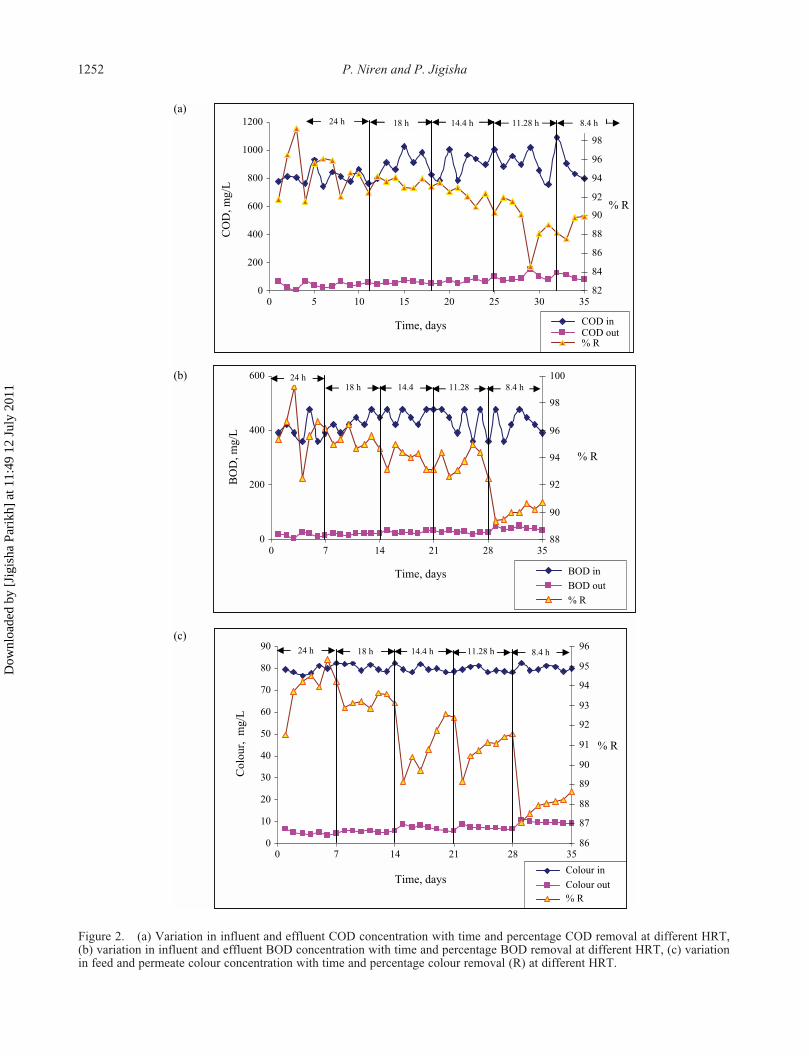
The HRT is an important parameter in the SMBR; it isrelated not only to the treatment efficiency of the SMBRbut also to the size of the bioreactor and engineering
Figure 1. Schematic of experimental set-up of SMBR. 1. Feed tank, 2. Heater with temperature controller, 3. Stirrer, 4. Peristalticpump, 5. Level controller, 6. Bioreactor, 7. Sampling port, 8. Membrane module, 9. Gas flow meter, 10. Air blower, 11. Cylindricalwire-mesh cage, 12. Air sparger, 13. Drain valve ,14. Pressure measuring device, 15. Solenoid valve with timer, 16. Programmingtime controller, 17. Microcontroller unit, 18. Suction pump, 19. Backflush pump, 20. Backwash pump, 21. Permeate collectiontank, 22. Level indicator
Dow
nloa
ded
by [
Jigi
sha
Pari
kh]
at 1
1:49
12
July
201
1
Environmental Technology
1251
design. Hence, it is very important to determine the opti-mum HRT in the SMBR. Eswaramoorthi
et al.
reportedthat, for treatment of textile wastewater with an MBR,the required HRT is lower (8–10 h) than for conven-tional biological treatment process (15–28 h) [37].Based on similar reported studies [7,38–40] and earlieractivated sludge process (ASP) studies performed at ourlaboratory, an HRT range of about 8–24 h was selectedfor the present study. The influent and effluent COD andBOD values are illustrated in Figure 2a and 2b respec-tively. An average COD removal of 95.24%, 93.64%,93.21%, 91.34%, and 88.2% was achieved at 24.0, 18.0,14.4, 11.28 and 8.4 h HRTs respectively. Simulta-neously, an average BOD removal of 96.0%, 95.25%,93.86%, 93.68%, 89.67% at 24.0, 18.0, 14.4, 11.28 and8.4 h HRTs was achieved, respectively. This implies thatthe biodegradable pollutants in the wastewater werealmost removed by the system. Except at 8.4 h HRT,more than 90% COD and BOD removals were obtained.The MWCO might have played a vital role in the organicmatter removal during textile wastewater treatment. Theeffect of MWCO/pore size on organic matter removal inMBRs is presented in Table 5 [1,6,7,17,20,31,38,41–47]. The primary role of the membrane in an MBR is toprovide a barrier against suspended solids, but mixedliquor from the bioreactor is often a complex mixture.The removal or partial removal of other species is possi-ble, but it is dependent on the choice of membrane.Membrane filtration technology, including microfiltra-tion, UF, NF and RO, has developed rapidly in recentdecades. Traditionally, NF and RO are able to removethe majority of dissolved organic matter (DOM) andinorganic constituents in water. However, they are rarelyapplied to MBRs because of their high hydraulic resis-tance. Microfiltration membranes provide partial BODremoval (i.e. primarily suspended solids), which isretained in the bioreactor. Ultrafiltration membranesprovide a high removal of viruses and a reasonableremoval of extracellular polymeric substances (EPS). As
a result they help to retain BOD, which is maintained inthe bioreactor. The apparent MW distribution of DOMin mixed liquor was in the range of 500–5000 Da. TheUF membrane used in the present study had a MWCOof 50,000 Da. Organic molecules in the range of 500–5000 Da could be effectively rejected by the sludge layer(biofilm), which accumulates in the mixed liquor of theSMBR, and can be further biodegraded by the microor-ganisms in the bioreactor by providing a longer retentiontime [48]. Furthermore, HF modules are generally lowin cost, have a high packing density and low energyconsumption (dead-end filtration), are easy to clean(backflushing), and the HF bundles are easy to replace;thus they are an attractive option [36]. This indicates thatthe UF-HF SMBR has potential for treating textilewastewater effectively.
Figure 2. (a) Variation in influent and effluent COD concentration with time and percentage COD removal at different HRT, (b) variation in influent and effluent BOD concentration with time and percentage BOD removal at different HRT, (c) variation in feed and permeate colour concen-tration with time and percentage colour removal (R) at different HRT.
The variation of the OLR in the reactor is shown inTable 4. The results indicated that variation of the OLRin the wastewater did not affect the COD in the permeate.Artiga
et al
. [49] also reported that the percentage oforganic matter removal in a membrane bioreactor wasnot affected by the OLR, based on their study of wineryand tannery wastewater treatment. In their study, theapplied OLR was 1–2 kg COD/(m
3
·d) and 0.5–1.5 kgCOD/(m
3
·d) for winery and tannery wastewater, respec-tively. For winery wastewater the soluble COD influentconcentration was between 1000 and 4000 mg/L, and forthe tannery wastewater the soluble COD concentrationwas between 350 and 2000 mg/L. Average COD removalwas over 97% during the period in which winery waste-water was used as the feed and about 86% during theperiod in which tannery wastewater was used. Anotherstudy reported that COD removal of more than 90% canbe achieved using a PES tubular membrane module of0.4
µ
m pore size at loading rates between 0.35 and0.55 kg COD/(m
3
·d), and influent COD concentrationwas between 1380 and 2104 mg/L [38]. A hybrid modelreactor at OLRs of 1.038–8.21 kg COD/(m
3
·d) showedCOD removal in the range of 82 to 94% [4].
Table 4. Operational parameters of MBR system with synthetic textile wastewater.
HRT, h
Parameter 24.00 18.00 14.40 11.28 8.40
Days 1–7 8–14 15–21 21–28 29–35Volume, L 21.60 16.20 13.122 10.089 7.49MLSS, mg/L 5500 6350 7150 8300 9100Flow rate, mL/d 21600 21600 21600 21600 21600BOD influent (avg.), mg/L 399 433 459 429 429Hydraulic loading, m
3
/(m
3
·d) 1.0 1.33 1.65 2.14 2.88F/M ratio, g BOD/(g MLSS·d) 0.07 0.09 0.11 0.11 0.14BOD
5
loading, g BOD
5
/d 8.62 9.35 9.91 9.27 9.27Organic BOD
5
loading, kg BOD
5
/(m
3
·d) 0.40 0.58 0.76 0.92 1.24
Dow
nloa
ded
by [
Jigi
sha
Pari
kh]
at 1
1:49
12
July
201
1
1252
P. Niren and P. Jigisha
Figure 2. (a) Variation in influent and effluent COD concentration with time and percentage COD removal at different HRT,(b) variation in influent and effluent BOD concentration with time and percentage BOD removal at different HRT, (c) variationin feed and permeate colour concentration with time and percentage colour removal (R) at different HRT.
Dow
nloa
ded
by [
Jigi
sha
Pari
kh]
at 1
1:49
12
July
201
1
Environmental Technology
1253
The F/M ratio falls in the range of 0.05–1.5/d for aconventional system, but is usually <0.1/d for an MBR[7]. In an SMBR, microbial activity remains high as aresult of their retention by the membrane, and a lowfood/biomass ratio is maintained, leading to higherBOD removal and good sludge settleability. Even if thesludge fails to settle down, the MBR membrane blocksthe suspended flocs (biomass) from leaving the digester.However, in the case of conventional biological treat-ment, sludge retention is mainly dependent on its settle-ability in the clarifier [37,50]. Our system operated inthe F/M range of 0.07–0.14 g BOD/(g MLSS·d) (Table4). The low F/M of 0.07–0.14/d occurs because of thehigh MLSS in the bioreactor, which typically rangedfrom 5500 to 9100 mg/L in the present work, ascompared with 2000 mg/L in conventional processes[7]. Availability of food for the microorganisms grow-ing in the MBR is another important aspect to beconsidered. Food limitation is mainly dependent on theamount of food available (which is given by flow
×
BOD = organic loading) and the amount of biomassavailable in the digestion chamber. Thus, for a givenBOD level in the effluent, if the number of micro-organisms per unit volume is kept high by providing alow F/M ratio, higher reduction in BOD could beachieved [37]. The F/M ratio, which ultimately controlsbiomass characteristics, is probably the most importantoperating parameter affecting fouling propensity inMBRs [51]. Membrane fouling rate increases withincrease in the F/M ratio [43]. Fouling derives fromcolloidal/macromolecular species derived from thebiomass, with the free and bound materials respectively
referred to as soluble microbial products (SMP) (freematerial) and extracellular polymeric substances (EPS)(bound material) [52,53]. The soluble fractions could bequantified in terms of COD. In submerged MBRs,membrane modules are exposed directly to soluble EPSin the bulk phase, and thus soluble substances,measured as soluble COD concentration, in mixedliquor would have great influence on membrane fouling[53,54]. It has been reported that SMP, as major organicfoulants for the commonly used microfiltration or ultra-filtration membranes in MBRs, are responsible for 26–52% of membrane fouling, depending on the experi-mental conditions [55]. Ng and Hermanowicz [56]operated an SMBR for synthetic wastewater at F/Mvalues of 1–11 g COD/(g MLVSS·d). The F/M testedby Trussell
et al.
[43] was in the range 0.34–1.41 gCOD/(g VSS·d) and achieved 95–99% COD removal.Irrespective of the high variations in F/M (0.03–0.07 gBOD
5
/(g MLSS·d)) and OLR (0.37–1.01 kg BOD
5
/(m
3
·d)) values, almost complete and continuous oxida-tion of organic compounds was achieved treating denimtextile wastewater [17]. This indicates that the perfor-mance of an SMBR, for organic matter removal, isindependent of OLR and F/M ratio.
Colour removal
A physicochemical parameter related to the aestheticaspect is colour, which is easy to determine analyticallyand provides important information regarding the qual-ity of the water. Figure 2c shows dye concentration inthe influent and permeate; the same chart also shows the
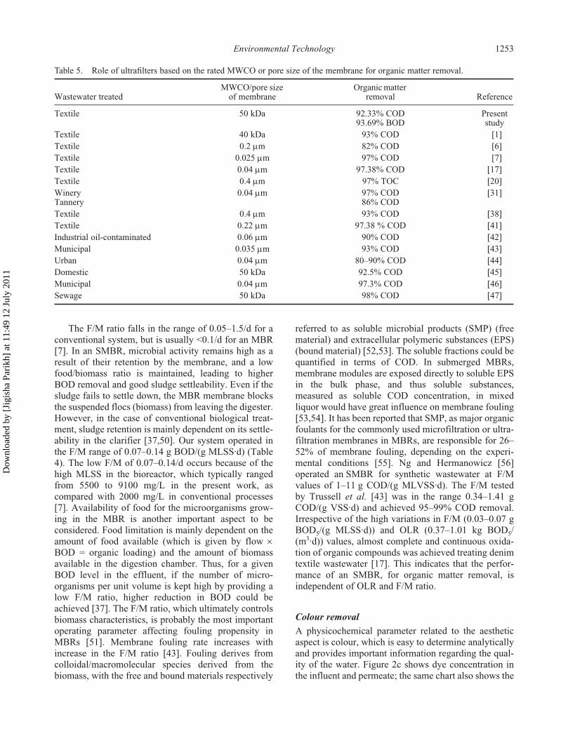
Table 5. Role of ultrafilters based on the rated MWCO or pore size of the membrane for organic matter removal.
Wastewater treatedMWCO/pore size
of membraneOrganic matter
removal Reference
Textile 50 kDa 92.33% COD93.69% BOD
Present study
Textile 40 kDa 93% COD [1]Textile 0.2
µ
m 82% COD [6]Textile 0.025
µ
m 97% COD [7]Textile 0.04
µ
m 97.38% COD [17]Textile 0.4
µ
m 97% TOC [20]WineryTannery
0.04
µ
m 97% COD86% COD
[31]
Textile 0.4
µ
m 93% COD [38]Textile 0.22
µ
m 97.38 % COD [41]Industrial oil-contaminated 0.06
µ
m 90% COD [42]Municipal 0.035
µ
m 93% COD [43]Urban 0.04
µ
m 80–90% COD [44]Domestic 50 kDa 92.5% COD [45]Municipal 0.04
µ
m 97.3% COD [46]Sewage 50 kDa 98% COD [47]
Dow
nloa
ded
by [
Jigi
sha
Pari
kh]
at 1
1:49
12
July
201
1
1254
P. Niren and P. Jigisha
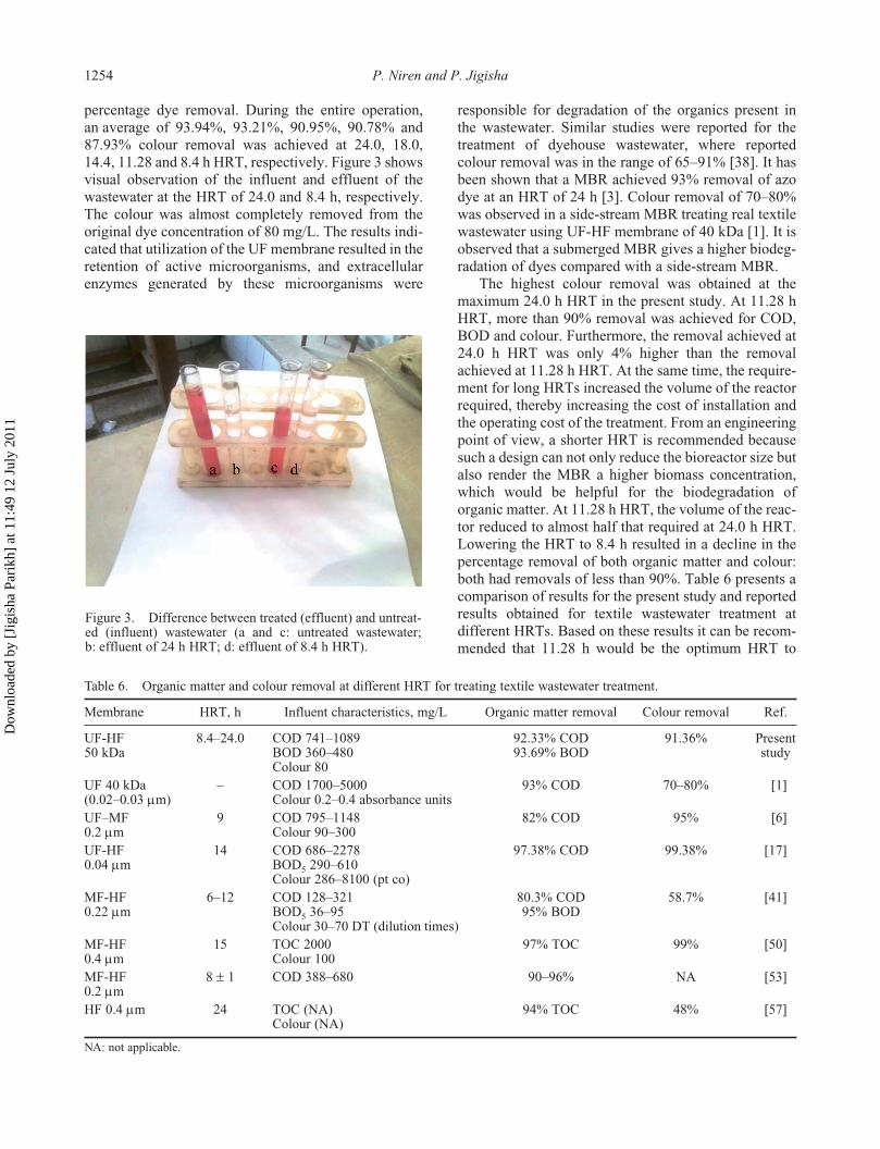
percentage dye removal. During the entire operation,an average of 93.94%, 93.21%, 90.95%, 90.78% and87.93% colour removal was achieved at 24.0, 18.0,14.4, 11.28 and 8.4 h HRT, respectively. Figure 3 showsvisual observation of the influent and effluent of thewastewater at the HRT of 24.0 and 8.4 h, respectively.The colour was almost completely removed from theoriginal dye concentration of 80 mg/L. The results indi-cated that utilization of the UF membrane resulted in theretention of active microorganisms, and extracellularenzymes generated by these microorganisms were
responsible for degradation of the organics present inthe wastewater. Similar studies were reported for thetreatment of dyehouse wastewater, where reportedcolour removal was in the range of 65–91% [38]. It hasbeen shown that a MBR achieved 93% removal of azodye at an HRT of 24 h [3]. Colour removal of 70–80%was observed in a side-stream MBR treating real textilewastewater using UF-HF membrane of 40 kDa [1]. It isobserved that a submerged MBR gives a higher biodeg-radation of dyes compared with a side-stream MBR.
Figure 3. Difference between treated (effluent) and untreated (influent) wastewater (a and c: untreated wastewater; b: effluent of 24 h HRT; d: effluent of 8.4 h HRT).
The highest colour removal was obtained at themaximum 24.0 h HRT in the present study. At 11.28 hHRT, more than 90% removal was achieved for COD,BOD and colour. Furthermore, the removal achieved at24.0 h HRT was only 4% higher than the removalachieved at 11.28 h HRT. At the same time, the require-ment for long HRTs increased the volume of the reactorrequired, thereby increasing the cost of installation andthe operating cost of the treatment. From an engineeringpoint of view, a shorter HRT is recommended becausesuch a design can not only reduce the bioreactor size butalso render the MBR a higher biomass concentration,which would be helpful for the biodegradation oforganic matter. At 11.28 h HRT, the volume of the reac-tor reduced to almost half that required at 24.0 h HRT.Lowering the HRT to 8.4 h resulted in a decline in thepercentage removal of both organic matter and colour:both had removals of less than 90%. Table 6 presents acomparison of results for the present study and reportedresults obtained for textile wastewater treatment atdifferent HRTs. Based on these results it can be recom-mended that 11.28 h would be the optimum HRT to
Figure 3. Difference between treated (effluent) and untreat-ed (influent) wastewater (a and c: untreated wastewater;b: effluent of 24 h HRT; d: effluent of 8.4 h HRT).
Table 6. Organic matter and colour removal at different HRT for treating textile wastewater treatment.
Membrane HRT, h Influent characteristics, mg/L Organic matter removal Colour removal Ref.
UF-HF50 kDa
8.4–24.0 COD 741–1089BOD 360–480Colour 80
92.33% COD93.69% BOD
91.36% Present study
UF 40 kDa(0.02–0.03
µ
m)– COD 1700–5000
Colour 0.2–0.4 absorbance units93% COD 70–80% [1]
UF–MF0.2
µ
m9 COD 795–1148
Colour 90–30082% COD 95% [6]
UF-HF0.04
µ
m14 COD 686–2278
BOD
5
290–610Colour 286–8100 (pt co)
97.38% COD 99.38% [17]
MF-HF0.22
µ
m6–12 COD 128–321
BOD
5
36–95Colour 30–70 DT (dilution times)
80.3% COD95% BOD
58.7% [41]
MF-HF0.4
µ
m15 TOC 2000
Colour 10097% TOC 99% [50]
MF-HF0.2
µ
m8
±
1 COD 388–680 90–96% NA [53]
HF 0.4
µ
m 24 TOC (NA)Colour (NA)
94% TOC 48% [57]
NA: not applicable.
Dow
nloa
ded
by [
Jigi
sha
Pari
kh]
at 1
1:49
12
July
201
1
Environmental Technology
1255
treat synthetic textile wastewater containing COD,BOD and disperse red dye in the range of 741–1089,360–480 and 80 mg/L respectively.
Permeate flux, transmembrane pressure and membrane washing
During the experiment without wire mesh, a transmem-brane pressure (TMP) of 65 kPa was observed within16 hours and the membrane was found to be severelyfouled. This has been confirmed with repeated experi-ments. So, a wire-mesh cage was installed in order tooperate the SMBR at constant flux for a long time. Theresults showed that fouling had reduced considerablyafter installation. An average permeate flux of 20 L/(m
2
·h) was achieved during the filtration with varyingHRTs. Considering the tendency of a decreasing fluxwith time, the membrane flux was stable for all HRTs.This was due to the membrane being covered with wiremesh, which prevented deposition of sticky material onthe membrane surface, as well as routine backwashingbeing applied for 30 s using 100 mL of permeate. TheTMP varied in the range of 29.47–58.42 kPa (0.29–0.58bar). Every seven days, at the end of each run, mainte-nance cleaning with a citric acid solution (10% w/v) wascarried out for 12 h. The objective was to recover thepermeability of the membrane. After
ex situ
chemicalcleaning, the flux recovered to almost its original valueand TMP decreased. This indicated that the prolongedchemical cleaning was effective for recovering perme-ability. Based on the present study it can be concludedthat covering the membrane with a wire-mesh cage andundertaking intermittent backwashing and occasionalcleaning of the membrane could efficiently retardmembrane fouling and retain membrane flux.
Effect of biomass concentration
The MLSS concentration in the reactor increased from5.5 g/L to 9.1 g/L during the entire operation. In thepresent study, the objective was to operate the system atconstant flux throughout the operational period withoutfouling. The maintenance of too high a biomass concen-tration in the reactor negatively affects the obtainedpermeability in the membrane module and demandsmore frequent cleaning of the reactor. Also, a highMLSS concentration impedes oxygen transfer owing toa higher non-Newtonian fluid viscosity. Hence, theSMBR was operated with a moderate MLSS concentra-tion throughout the test run. At the prevailing values ofbiomass concentration in the present work, excellentorganic and colour removals were achieved, as shownin Figure 2. Other studies have also shown that too higha biomass concentration did not enhance water qualityin terms of effluent COD [23]. To maintain membrane
permeability, the SMBR process is limited to a maxi-mum MLSS concentration of 10 to 20 g/L. Currentpractice is to operate the SMBR process at constantMLSS levels of approximately 10 g/L (typically 8 gVSS/L) [31]. Literature review indicated that sludgeviscosity increased with biomass concentration, result-ing in a rapid increase in the TMP, resulting therefore ina decrease in the permeability [45,49].
Conclusions
Treating synthetic textile wastewater with an SMBR atdifferent HRTs, an excellent organic removal and dyeremoval efficiency, independent of the F/M ratio andOLR, was obtained. Except for the 8.40 h HRT, COD,BOD and colour removals of more than 90% wereachieved at all HRTs. Employing the dual technique ofa cylindrical cage of wire mesh and routine backwash-ing for prevention of membrane fouling, an average fluxvalue of 20 L/(h·m
2
) was achieved during the entire testrun. The results indicated that 11.4 h HRT wouldbe optimum to treat synthetic wastewater containingdisperse red dye. This will allow the design of anSMBR system for textile industries wastewater treat-ment, as a strategically placed membrane system canplay an important role in producing a high quality oftreated wastewater. Because very few studies are avail-able on the use of the MBR for Indian conditions, it isalways desirable to conduct pilot-scale studies forindustrial wastewater treatment. The SMBR can berecommended for application in real textile wastewatertreatment plants that are subjected to variable concen-trations of COD, BOD and colour.
Nomenclature
BOD biochemical oxygen demand, mg/LBSA Bovine Serum AlbuminCAS No. Chemical Abstract Service numberCETP common effluent treatment plantCI No. colour index numberCOD chemical oxygen demand, mg/LDO dissolved oxygen, mg/LDOM dissolved organic matterEPS extracellular polymeric substancesF/M food/microorganism ratio, per dayHRT hydraulic retention time, hMF microfiltrationMW molecular weightMWCO molecular weight cut-offMBR membrane bioreactorMLSS mixed liquor suspended solids, mg/LMLVSS mixed liquor volatile suspended solids, mg/LNF nanofiltrationOLR organic loading ratePES polyethersulphonePVC polyvinyl chloride
Dow
nloa
ded
by [
Jigi
sha
Pari
kh]
at 1
1:49
12
July
201
1
1256
P. Niren and P. Jigisha
RO reverse osmosisSIEL Sachin Infra Environment Ltd.SMBR submerged membrane bioreactorSMP soluble microbial productsSRT sludge retention time, dSSI small scale industriesSTP sewage treatment plantTMP transmembrane pressure, kPaUF ultrafiltrationUF-HF ultrafiltration hollow-fibre
References
[1]
[1] C. Lubello and R. Gori,
Membrane bio-reactor foradvanced textile wastewater treatment and reuse,
Water Sci. Technol. 50 (2004), pp. 113–119.
[2]
[2] J.M. Gozálvez-Zafrilla, D. Sanz-Escribano, J. Lora-García, and M.C. León Hidalgo,
Nanofiltration ofsecondary effluent for wastewater reuse in the textileindustry,
Desalination 222 (2008), pp. 272–279.
[3]
[3] N. Tapas, M. Pravin, P.D. Rita, P. Girish, and D. Sukumar,
Water conservation through implementation of ultrafil-tration and reverse osmosis system with recourse to recy-cling of effluent in textile industry – a case study,
Resour.Conserv. Recycl. 51 (2007), pp. 64–77.
[4]
[4] S. Sandhya, K. Sarayu, and K. Swaminathan,
Determi-nation of kinetic constants of hybrid textile wastewatertreatment system,
Bioresour. Technol. 99 (2008), pp.5793–5797.
[5]
[5] M. Karthik, P. Aswale, A. Padhi, P. Manekar, and T.Nandy,
Recent trends in wastewater management intextile sector,
Recent Advances in Waste Management(RAWM) Conference, Varanasi, India, organised bythe Centre of Advanced study, Dept. of ChemicalEngineering & Technology, Institute of Technology,Banaras Hindu University, 2009, pp. 222–230.
[6]
[6] T. Setiadi, Suwardiyono, and I.G. Wenten,
Treatmentof textile wastewater by a coupling of activated sludgeprocess with membrane separation,
J. Water Environ.Technol. 3 (2005), pp. 125–132.
[7]
[7] Z. Badani, H. Ait-Amar, A. Si-Salah, M. Brik, and W.Fuchs,
Treatment of textile wastewater by membranebioreactor and reuse,
Desalination 185 (2005), pp.411–417.
[8]
[8] C. Xuejun, S. Zhemin, Z. Xiaolong, F. Yaobo, and W.Wenhua,
Advanced treatment of textile wastewater forreuse using electrochemical oxidation and membranefiltration,
Water SA 31 (2005), pp. 127–132.
[9]
[9] F. Cheïma and D. Mahmoud,
Treatment of textile planteffluent by ultrafiltration and/or nanofiltration forwater reuse,
Desalination 222 (2008), pp. 263–271.
[10]
[10] S. Majhi, Y.C. Sharma, and S.N. Upadhyay,
Reversemicelles for the removal of dyes from aqueous solu-tions,
Environ. Technol. 30 (2009), pp. 879–884.
[11]
[11] D. Ramesh, B. Goutam, and D.R. Saini,
Activatedcarbon from an agricultural by-product for the treat-ment of dyeing industry wastewater,
Recent Advancesin Waste Management (RAWM) conference, Varanasi,India, organised by the Centre of Advanced study,Dept. of Chemical Engineering & Technology, Insti-tute of Technology, Banaras Hindu University, 2009,pp. 274–278.
[12]
[12] K. Tak-Hyun, L. Yuri, Y. Jeongmok, L. Byunghwan,P. Chulhwan, and K. Sangyong,
Decolourization of dye
solutions by a membrane bioreactor (MBR) usingwhite-rot fungi,
Desalination 168 (2004), pp. 287–293.
[13]
[13] M. Brik, P. Schoerberl, B. Chamam, R. Braun, and W.Fuchs,
Advanced treatment of textile wastewatertowards reuse using a membrane bioreactor, ProcessBiochem. 41 (2006), pp. 1751–1757.
[14][14] M. Patel and S. Mansuri, Environmental application ofhydrogen peroxide, Man-Made Textiles Research Asso-ciation (MANTRA) Bulletin, 3(1), (2008), p. 10.
[15][15] N.M.H. Eidefrawy and H.F. Shaalan, Integratedmembrane solutions for textile industries, Desalination204 (2007), pp. 241–254.
[16][16] S. Suntud and S. Jutarat, Treatability studies with gran-ular activated carbon (GAC) and sequencing batchreactor (SBR) system for textile wastewater containingdirect dyes, J. Hazard. Mater. 159 (2008), pp. 404–411.
[17][17] N.O. Yigit, N. Uzal, H. Koseoglu, I. Harman, H.Yukseler, U. Yetis, G. Civelekoglu, and M. Kitis, Treat-ment of a denim producing textile industry wastewaterusing pilot-scale membrane bioreactor, Desalination240 (2009), pp. 143–150.
[18][18] A.R. Khataee, Optimization of UV-promoted peroxydis-ulphate oxidation of C.I. Basic Blue 3 using responsesurface methodology, Environ. Technol. 31 (2010),pp. 73–86.
[19][19] S. Malekar and N. Tantak, Membrane biobeactor:Technology for wastewater reclamation,, Available athttp://www.ionxchng.com/kms/TechPaper/MBR%20Writeup.pdf. Viewed January 2008
[20][20] T. Mohammed, Evaluation of using membrane biore-actor for treating municipal wastewater at differentoperating conditions, Desalination 221 (2008), pp.502–510.
[21][21] M. Gander, B. Jefferson, and S. Judd, Aerobic MBRsfor domestic wastewater treatment: A review with costconsiderations, Sep. Purif. Technol. 18 (2000), pp.119–130.
[22][22] A.G. Fane and C. Sheng, Membrane bioreactors:Design & operational options, Filtr. Sep. 39 (2002),pp. 26–29.
[23][23] Y.N. How, T.W. Tan, and S.L. Ong, Membrane foul-ing of submerged membrane bioreactors: Impact ofmean cell residence time and the contributing factors,Environ. Sci. Technol. 40 (2006), pp. 2706–2713.
[24][24] F. Fan, H. Zhou, and H. Husain, Identification ofwastewater sludge characteristics to predict criticalflux for membrane bioreactor process, Water Res. 40(2006), pp. 205–212.
[25][25] A. Masse, M. Sperandio, and C. Cabassud, Compari-son of sludge characteristics and performance of asubmerged membrane bioreactor and an activatedsludge process at high solids retention time, Water Res.40 (2006), pp. 2405–2415.
[26][26] C. In-Soung, C. Le Pierre, J. Bruce, and J. Simon,Membrane fouling in membrane bioreactors for waste-water treatment, J. Environ. Eng. 128 (2002), pp.1018–1029.
[27][27] B. Jefferson, A.L. Laine, S.J. Judd, and T. Stephenson,Membrane bioreactors and their role in wastewaterreuse, Water Sci. Technol. 41 (2000), pp. 197–204.
[28][28] F. Fengshen and Z. Hongde, Interrelated effects ofaeration and mixed liquor fractions on membranefouling for submerged membrane bioreactor processesin wastewater treatment, Environ. Sci. Technol. 41(2007), pp. 2523–2528.
[29]
Dow
nloa
ded
by [
Jigi
sha
Pari
kh]
at 1
1:49
12
July
201
1
Environmental Technology 1257
[29] S. Suntud and S. Parawee, Removal of disperse dyesfrom textile wastewater using bio-sludge, Bioresour.Technol. 98 (2007), pp. 1057–1066.
[30][30] APHA, AWWA, and WEF, Standard Methods for theExamination of Water and Wastewater, 20th ed., Ameri-can Public Health Association, Washington, DC, 1998.
[31][31] C. Fersi, L. Gzara, and M. Dhahbi, Treatment of textileeffluents by membrane technologies, Desalination 185(2005), pp. 399–409.
[32][32] A. Bes-Piá, J.A. Mendoza-Roca, M.I. Alcaina-Miranda, and A. Iborra-Clar, Reuse of wastewater ofthe textile industry after its treatment with a combina-tion of physico-chemical treatment and membrane tech-nologies, Desalination 149 (2002), pp. 169–174.
[33][33] P. Schoeberl, M. Brik, R. Braun, and W. Fuchs, Treat-ment and recycling of textile wastewater—case studyand development of a recycling concept, Desalination171 (2004), pp. 173–183.
[34][34] S. Naveed, I. Bhatti, and K. Ali, Membrane technologyand its suitability for treatment of textile waste water inPakistan, J. Res. (Sci.) 17 (2006), pp. 155–164.
[35][35] S.P. Beier, Dynamic microfiltration critical flux andmacromolecular transmission, Ph.D. thesis, Depart-ment of Chemical and Biochemical Engineering, Tech-nical University of Denmark, 2008, pp. 9–10.
[36][36] P. Le-Clech, V. Chen, and T.A.G Fane, Fouling inmembrane bioreactors used in wastewater treatment, J.Membr. Sci. 284 (2006), pp. 17–53.
[37][37] S. Eswaramoorthi, K. Dhanapal, and D.S. Chauhan,Textile wastewater treatment with membrane bioreac-tor, Environment with People’s Involvement and Co-ordination in India, Coimbatore. Available at http://www.epicin.org/documents/Textile_waste_water_treatment-MBR.pdf. Viewed May 2008
[38][38] S. Paul, B. Mounir, B. Marina, B. Rudolf, and F.Werner, Optimization of operational parameters for asubmerged membrane bioreactor treating dyehousewastewater, Sep. Purif. Technol. 44 (2005), pp. 61–68.
[39][39] J.-H. Tay, J.-L. Zeng, and D.-D. Sun, Effects of hydrau-lic retention time on system performance of asubmerged membrane bioreactor, Sep. Purif. Technol.38 (2003), pp. 851–868.
[40][40] A. Ünlü, H. Hasar, C. Kınacı, M. Çakmakcı, and N.-N.Koçer, Real role of an ultrafiltration hollow-fibremembrane module in a submerged membrane bioreac-tor, Desalination 181 (2005), pp. 185–191.
[41][41] X. Zheng and J. Liu, Dyeing and printing wastewatertreatment using a membrane bioreactor with a gravitydrain, Desalination 190 (2006), pp. 277–286,
[42][42] B. Bienati, A. Bottino, G. Capannelli, and A. Comite,Characterization and performance of different types ofhollow fibre membranes in a laboratory-scale MBR forthe treatment of industrial wastewater, Desalination231 (2008), pp. 133–140.
[43][43] R.S. Trussell, R.P. Merlo, S.W. Hermanowicz, and D.Jenkins, The effect of organic loading on processperformance and membrane fouling in a submergedmembrane bioreactor treating municipal wastewater,Water Res. 40 (2006), pp. 2675–2683.
[44][44] J. Arévaloa, G. Garralón, F. Plaza, B. Moreno, J. Pérez,and M-Á. Gómez, Wastewater reuse after treatment bytertiary ultrafiltration and a membrane bioreactor(MBR): A comparative study, Desalination 243 (2009),pp. 32–41.
[45][45] C. Visvanathan, R.B. Aim, and K. Parameshwaran,Membrane separation bioreactors for wastewater treat-ment, Crit. Rev. Environ. Sci. Technol. 30 (2000), pp.1–48.
[46][46] E. Dialynas and E. Diamadopoulos, Integration of amembrane bioreactor coupled with reverse osmosisfor advanced treatment of municipal wastewater,Desalination 238 (2009), pp. 302–311.
[47][47] K.H. Ahn, H.Y. Cha, and K.G. Song, Retrofittingmunicipal sewage treatment plants using an innovativemembrane-bioreactor system, Desalination 124 (1999),pp. 279–286.
[48][48] J-Y. Tian, H. Liang, J. Nan, Y.-L. Yang, S.-J. You, andG-B. Li, Submerged membrane bioreactor (sMBR) forthe treatment of contaminated raw water, Chem. Eng.J. 148 (2009), pp. 296–305.
[49][49] P. Artiga, E. Ficara, F. Malpei, J.M. Garrido, and R.Mendez, Treatment of two industrial wastewaters in asubmerged membrane bioreactor, Desalination 179(2005), pp. 161–169.
[50][50] H.F. Ibney, Y. Kazuo, and F. Kensuke, Developmentof submerged membrane fungi reactor for textilewastewater treatment, Desalination 192 (2006), pp.315–322.
[51][51] J.S. Zhang, C.H. Chuan, J.T. Zhou, and A.G. Fane,Effect of sludge retention time on membrane bio-fouling intensity in a submerged membrane bioreactor,Sep. Sci. Technol. 41 (2006), pp. 1313–1329.
[52][52] E. Reid, X. Liu, and S.J. Judd, Sludge characteristicsand membrane fouling in full-scale submergedmembrane bioreactors, Desalination 219 (2008),pp. 240–249.
[53][53] X-F. Li, L.-N. Zhang, and G.-C. Du, Influence ofsludge discharge on sludge settleability and membraneflux in a membrane bioreactor, Environ. Technol. 31(2010), pp. 1289–1294.
[54][54] Z. Wu, Z. Wang, Z. Zhou, G. Yu, and G. Gu, Sludgerheological and physiological characteristics in a pilot-scale submerged membrane bioreactor, Desalination212 (2007), pp. 152–164.
[55][55] S. Liang, C. Liu, and L. Song, Soluble microbial prod-ucts in membrane bioreactor operation: Behaviors,characteristics, and fouling potential, Water Res. 41(2007), pp. 95–101.
[56][56] H.Y. Ng and S.W. Hermanowicz, Membrane bioreac-tor operation at short solids retention times: Perfor-mance and biomass characteristics, Water Res. 39(2005), pp. 981–992.
[57][57] F.I. Hai, K. Yamamoto, F. Nakajima, and K. Fulkushi,Factors governing performance of continuous fungalreactor during non-sterile operation: The case of amembrane bioreactor treating textile wastewater,Chemosphere 74 (2008), pp. 810–817.
Dow
nloa
ded
by [
Jigi
sha
Pari
kh]
at 1
1:49
12
July
201
1