User requirements and preparedness for User requirements and ...
Upload
khangminh22Category
view
0download
0
NASAlTM-2010-216293R
Testing Requirements for Refractory Materials
Luz Marina Calle NASA Kennedy Space Center
Paul E. Hintze NASA Kennedy Space Center
Christopher R. Parlier NASA Kennedy Space Center
Jerome P. Curran ASRC Aerospace Corporation
Mark R. Kolody ASRC Aerospace Corporation
Jeffrey W. Sampson NASA Kennedy Space Center
Eliza M. Montgomery NASA Postdoctoral Program
February 2011
NASAffM-2010-216293R
The NASA STI Program Office .. .in Profile
Since its founding, NASA has been dedicated to the advancement of aeronautics and space science. The NASA Scientific and Technical Information (ST!) Program Office plays a key part in helping NASA maintain this important role.
The NASA STI Program Office is operated by Langley Research Center, the lead center for NASA's scientific and technical information. The NASA STI Program Office provides access to the NASA STI Database, the largest collection of aeronautical and space science STI in the world. The Program Office is also NASA's institutional mechanism for disseminating the results of its research and development activities. These results are published by NASA in the NASA STI Report Series, which includes the following report types:
• TECHNICAL PUBLICATION. Reports of completed research or a major significant phase of research that present the results of NASA programs and include extensive data or theoretical analysis. Includes compilations of significant scientific and technical data and information deemed to be of continuing reference value. NASA counterpart of peer-reviewed formal professional papers, but having less stringent limitations on manuscript length and extent of graphic presentations.
• TECHNICAL MEMORANDUM. Scientific and technical findings that are preliminary or of specialized interest, e.g., quick release reports, working papers, and bibliographies that contain minimal annotations. Does not contain extensive analysis.
• CONTRACTOR REPORT. Scientific and technical fIDdings by NASA-sponsored contractors and grantees.
• CONFERENCE PUBLICATION. Collected papers from scientific and technical conferences, symposia, seminars, or other meetings sponsored or co-sponsored by NASA.
• SPECIAL PUBLICATIONS. Scientific, technical, or historical information from NASA programs, projects, and missions, often concerned with subjects having substantial public interest.
• TECHNICAL TRANSLATION. Englishlanguage translations of foreign scientific and technical material pertinent to NASA's mission.
Specialized services to complement the STI Program Office's diverse offerings include creating custom thesauri, building customized . databases, organizing and publishing research results . .. even providing videos.
For more information about the NASA STI Program Office, see the following:
• Access the NASA STI Program Home Page at http://www.sti.nasa.gov
• E-mail your question via the internet to [email protected]
• Fax your question to the NASA STI Help Desk at (301) 621-0134
• Phone the NASA STI Help Desk at (30 I) 621-0390
• Write to: NASA STI Help Desk NASA Center for Aerospace Information 1721 Standard Drive Hanover, MD 21076-1320
NASA/TM—2010–216293R
Testing Requirements for Refractory Materials Luz Marina Calle NASA Kennedy Space Center Paul E. Hintze NASA Kennedy Space Center Christopher R. Parlier NASA Kennedy Space Center Jerome P. Curran ASRC Aerospace Corporation Mark R. Kolody ASRC Aerospace Corporation Jeffrey W. Sampson NASA Kennedy Space Center Eliza M. Montgomery NASA Postdoctoral Program
National Aeronautics and Space Administration Kennedy Space Center February 2011

NASA/TM-2010-216293R
ii
Acknowledgments
The research team gratefully acknowledges the contributions made by the following individuals:
a. Nancy P. Zeitlin, Technology Integration Manager, NASA/John F. Kennedy Space Center
b. Karen Thompson, Chief Technologist, NASA/John F. Kennedy Space Center c. Frank Peri, Exploration Technology Development Program Manager,
NASA/Langley Research Center d. Karen Whitley, Structures Materials and Mechanisms Project Manager,
NASA/Langley Research Center e. Judith J. Watson, Structures Materials and Mechanisms Project Manager,
NASA/Langley Research Center f. Scott Kenner, NASA/Langley Research Center g. Phil Weber, Constellation Ground Operations Project, NASA/John F. Kennedy Space
Center h. Jose Perez Morales, Pad Senior Project Manager, NASA/John F. Kennedy Space Center i. Dr. David Trejo, Professor, Oregon State University j. Cori Bucherl, NASA Co-op, University of Washington k. Stephen Perusich, ASRC Aerospace Corp. l. Teddy Back, ASRC Aerospace Corp. m. Jolet Larracas, Structures, United Space Alliance n. Kevin Decker, Instrumentation Engineer, NASA/John F. Kennedy Space Center o. Keith Laufenberg, Project Manager, United Space Alliance p. Ken Page, Ground Systems Instrumentation, United Space Alliance q. Kevin Taylor, Ground Systems Instrumentation, United Space Alliance r. Wulf Eckroth, Launch Site Design Manager, United Space Alliance s. Armand Gosselin, Launch Site Design Manager, United Space Alliance t. Sathish Sounderrajan, Launch Site Design United Space Alliance u. Gabor Tanacs, Launch Site Design Engineer, United Space Alliance
Available from: NASA Center for AeroSpace Information (CASI) 7121 Standard Drive Hanover, MD 21076-1320 (301) 621-0390
National Technical Information Service (NTIS) 5285 Port Royal Road Springfield, VA 22161-2171 (703) 605-6000
This report is also available in electronic form at URL http://www.sti.nasa.gov/ and
http://ntrs.nasa.gov/search.jsp.

NASA/TM-2010-216293R
iii
Contents
1 INTRODUCTION .............................................................................................1 1.1 Background ........................................................................................................1 1.2 Flame Deflector System .....................................................................................2 1.3 Launch Environment ..........................................................................................6 1.4 History of Refractory Material Testing at KSC .................................................8
2 CURRENT REQUIREMENTS .......................................................................11 2.1 KSC-GP-1059, KSC-DD-818-TR, and KSC-DM-3649 ..................................12 2.2 KSC-STD-Z-0004 Section 3.3.9 ......................................................................12 2.3 KSC-STD-164, Section 3.3.16.........................................................................12 2.4 KSC-STD-G-0003 ...........................................................................................13 2.5 KSC-SPEC-P-0012 ..........................................................................................13 2.5.1 Current Specification .......................................................................................13 2.5.2 Revised Specification .......................................................................................14 2.6 NASA-STD-5005 ............................................................................................16 2.7 Product Testing ................................................................................................16 2.8 Summary ..........................................................................................................16
3 LABORATORY TESTING.............................................................................17 3.1 Sample Preparation ..........................................................................................19 3.1.1 Sample Preparation – Shotcreting or Gunning ................................................19 3.1.2 Sample Preparation - Casting ...........................................................................22 3.2 Laboratory Testing and Standards ...................................................................23 3.2.1 Sieve Analysis ..................................................................................................23 3.2.2 Specific Heat Analysis .....................................................................................24 3.2.3 Cold Compressive Strength .............................................................................24 3.2.4 Abrasion Resistance .........................................................................................25 3.2.5 Cold Modulus of Rupture ................................................................................26 3.2.6 Thermal Expansion and Creep of Refractories ................................................28 3.2.7 Thermal Shock .................................................................................................28 3.2.8 Thermal Conductivity ......................................................................................28 3.2.9 Acid Resistance Tests ......................................................................................29 3.2.10 Density, Porosity, Water Absorption, and Apparent Specific Gravity ............29 3.2.11 Petrographic Analysis of Refractory Materials ................................................31
4 ROCKET ENGINE EXHAUST TESTING ....................................................31 4.1 LC-39 Full-Scale Testing .................................................................................31 4.1.1 Installation and Prelaunch Analysis .................................................................34 4.1.2 Postlaunch Analysis .........................................................................................34 4.2 Subscale Rocket Engine Exhaust Test Stands and Material Dimensions ........35
5 SUBSCALE PARAMETERS ..........................................................................39 5.1 Launch Environment Assessment ....................................................................39 5.2 Parameters for Subscale Testing ......................................................................43

NASA/TM-2010-216293R
iv
5.2.1 Temperature .....................................................................................................44 5.2.2 Pressure ............................................................................................................45 5.2.3 Calorimeter and Radiometer ............................................................................46 5.3 Limitations of Subscale Testing.......................................................................48
6 ENGINE TEST STAND FACILITIES ...........................................................49 6.1 John C. Stennis Space Center ..........................................................................49 6.1.1 A-1 and A-2 Test Stands ..................................................................................49 6.1.2 B-1 and B-2 Test Stands ..................................................................................51 6.1.3 E-1 Test Facility ...............................................................................................53 6.1.4 E-2 Test Facility ...............................................................................................54 6.1.5 E-3 Test Facility ...............................................................................................55 6.1.6 Building 3300 at Stennis Space Center ............................................................57 6.2 George C. Marshall Space Flight Center (MSFC) ...........................................59 6.2.1 Dynamic Test Stand .........................................................................................59 6.2.2 Load Test Annex Facility.................................................................................60 6.2.3 Advanced Engine Test Facility ........................................................................61 6.3 ATK Aerospace Systems .................................................................................62
7 LIST OF REFERENCES .................................................................................64
8 ENDNOTES ....................................................................................................66
APPENDIX A. MMA-1918-80, STS-1 .....................................................................................69
APPENDIX B. MTS-505-81, STS-2 ......................................................................................135
APPENDIX C. MTS-142-82, STS-3 ......................................................................................169
APPENDIX D. MTS-340-82, STS-1, -2, AND 3 ...................................................................177
APPENDIX E. MTS-425-82, STS-4 ......................................................................................193
APPENDIX F. MTB-503-83, STS-5, -6, AND -7 ..................................................................199
APPENDIX G. MTB-250-84, STS-8 AND -9 ........................................................................215
APPENDIX H. 93-4436, STS-55 ............................................................................................229

NASA/TM-2010-216293R
v
Figures
Figure 1. Launch of Apollo 11 on July 16, 1969 ..............................................................3 Figure 2. Cross Section of Flame Deflector at Launch Complex 39A ..............................4 Figure 3. Openings for Flames From the Main Engine and SRBs ....................................4 Figure 4. Magnified View of LC-39A Flame Deflector ...................................................5 Figure 5. SSME Flame Trench and Deflector ...................................................................5 Figure 6. SRB Main Flame Deflector ...............................................................................7 Figure 7. Side Flame Deflector .........................................................................................7 Figure 8. History of Shuttle Launches, 1981 – 2010.........................................................9 Figure 9. Flow Chart Highlighting the Developmental Path From Engineering
Design Requirements to NASA/KSC Standards .............................................11 Figure 10. Forms Designed To Hold the Wet Refractory Concrete (Units in Inches) ......20 Figure 11. Position of the Forms During Spray Application ............................................21 Figure 12. Sample Preparation (Zampell Refractories in Tampa, Florida) .......................21 Figure 13. Example of Cut Pattern for Each Sprayed Sample (Units in Inches) ..............22 Figure 14. Paddle Mixer Used at KSC To Prepare Refractory Samples ...........................23 Figure 15. Instron in the Material Testing Laboratories, O&C Building, KSC ................25 Figure 16. Cylindrical Sample Prior To and After Crushing ............................................25 Figure 17. Modulus of Rupture Testing – Fondu Fyre (Pad Sprayed), Sample 81,
Control, MOR = 837 psia (Before Compression) ............................................27 Figure 18. Modulus of Rupture Testing – Fondu Fyre (Pad Sprayed), Sample 81,
Control, MOR = 837 psia (After Compression) ..............................................27 Figure 19. Typical Three Sample Test Stand ....................................................................32 Figure 20. Test Stand Locations ........................................................................................32 Figure 21. Typical Sample Size From KSC-SPEC-P-0012 ..............................................33 Figure 22. Preliminary Test Stand Design, Top View ......................................................36 Figure 23. Cross-Section Details From Top View ............................................................37 Figure 24. Test Stand Side View .......................................................................................37 Figure 25. Refractory ........................................................................................................38 Figure 26. Refractory Material Sample Cross-Sections ....................................................38 Figure 27. Sensor Locations on the East Wall of the SRB Flame Trench ........................40 Figure 28. Sensor Locations on the West Wall of the SRB Flame Trench .......................41 Figure 29. Location of Pressure Sensor 9W Underneath the MLP ...................................41 Figure 30. Sensor Locations on the SRB and SSME Flame Deflectors ............................42 Figure 31. Location 4E Is Highlighted in the Circle .........................................................43 Figure 32. Selected Temperature Measurements During the Launch of STS-125 ...........45 Figure 33. Selected Pressure Measurements During STS-126 ..........................................46 Figure 34. Selected Calorimeter Measurements During STS-119 ....................................47 Figure 35. Selected Radiometer Measurements During STS-126 ....................................48 Figure 36. Exterior View of the A-2 Test Stand ...............................................................50 Figure 37. View of the A-2 Flame Duct and Diffuser .......................................................51 Figure 38. Rocket Motor Test at Stennis B-1 Complex ....................................................52 Figure 39. Stennis B-2 Flame Deflector ............................................................................53 Figure 40. Stennis E-1 Flame Deflector ............................................................................53 Figure 41. E-2 Cell 1 Test Stand at Stennis Space Center ................................................54

NASA/TM-2010-216293R
vi
Figure 42. Stennis Space Center E-2 2 Vertical Test Flame Duct ....................................55 Figure 43. E-3 Vertical Configuration Test Cell Flame Duct ...........................................56 Figure 44. E-3 horizontal Test Configuration ...................................................................57 Figure 45. Test Duct at Stennis Space Center ...................................................................57 Figure 46. Refractory Concrete Apron at Stennis Space Center .......................................58 Figure 47. Stennis Plume Deflector Test Rig ....................................................................59 Figure 48. MSFC Dynamic Test Stand .............................................................................60 Figure 49. MSFC Test Stand 116, Solid Fuel Torch Test .................................................61 Figure 50. MSFC Test Stand 115, Solid Fuel Torch Test .................................................61 Figure 51. A Scaled-Down 24-Inch Version of the Space Shuttle’s Reusable Solid
Rocket Motor Fired at a MSFC Test Stand .....................................................62 Figure 52. Horizontal Testing of an ASAS 21-120 Motor ................................................63 Figure 53. Space Shuttle RSRM........................................................................................63 Figure 54. Space Shuttle RSRM Test Firing at the ATK, Promontory, Utah Facility ......64
Tables
Table 1. Overview of Test Program Since 1981 ............................................................10 Table 2. Laboratory Evaluation Requirements for Refractory Concrete, Suggested
New Revision to KSC-SPEC-P-0012 ..............................................................15 Table 3. Summary of Testing and Qualification Requirements for Refractory
Materials in Launch Environments ..................................................................17 Table 4. Sensors Used During Launch Environment Assessment .................................40 Table 5. Maximum Temperature, Pressure, and Heat Flux Measured During the
Launch of STS-126, STS-119, STS-125, and STS-127...................................44 Table 6. Maximum Temperatures (F) Measured During Three Launches ...................44 Table 7. Maximum and Minimum Pressures (psig) Measured During Three
Launches ..........................................................................................................46 Table 8. Maximum Calorimeter Measurements (btu/ft2 sec) Obtained During Two
Launches ..........................................................................................................47

NASA/TM-2010-216293R
vii
ABBREVIATIONS AND ACRONYMS
ACI American Concrete Institute
AIAA American Institute of Aeronautics and Astronautics
AISC American Institute of Steel Construction
Al2O3 aluminum oxide
ANSI American National Standards Institute
ASCE American Society of Civil Engineers
ASRB Advanced Solid Rocket Booster
ASRM Advanced Solid Rocket Motor
ASTM American Society for Testing and Materials
Btu British thermal unit
CAC calcium aluminate cement
COTS commercial off the shelf
CP center perforated
CxP Constellation program
DSC differential scanning calorimetry
DTS Diagnostic Test Facility
EAR Export Administration Regulation
ECO Export Control Office
EDS energy dispersive x-ray spectroscopy
ETDP Exploration Technology Development Program
FF Fondu Fyre
FOD foreign-object-debris
g gram
GH2 gaseous hydrogen
GHe gaseous helium
GN2 gaseous nitrogen
GO ground operations
gpm gallon per minute
GSE ground support equipment
HB NASA Handbook
HCl hydrochloric acid

NASA/TM-2010-216293R
viii
IBC International Building Code
ITAR International Traffic in Arms Regulations
KSC Kennedy Space Center
LC Launch Complex
LH2 liquid hydrogen
LO2 liquid oxygen
LOX liquid oxygen
MFD main flame deflector
MIL-STD military standard
MLP Mobile Launcher Platform
MOR modulus of rupture
MPa megapascal
MSFC George C. Marshall Space Flight Center
MSL Materials Sciences Laboratory
NASA National Aeronautics and Space Administration
NLS National Launch System
OSHA Occupational Safety and Health Administration
psi pound per square inch
psia pound per square inch absolute
RSRM reusable solid rocket motor
s second
SEM scanning electron microscopy
SFD side flame deflector
SLC Space Launch Complex
SMM Structures, Mechanisms, and Materials
SPEC specification
SPREE solid propellant rocket exhaust effects
SRB solid rocket booster
SRM solid rocket motor
SSc Stennis Space Center
SSME Space Shuttle Main Engine
STD standard
STI Scientific and Technical Information

NASA/TM-2010-216293R
ix
STS Space Transportation System
TBD to be determined
TM Technical Memorandum
TPP Technology Prioritization Panel
USA United Space Alliance

NASA/TM-2010-216293R
x
This page intentionally left blank.

NASA/TM-2010-216293R
xi
ABSTRACT
Launch Pads 39A and 39B currently use refractory material (Fondu Fyre) in the flame trenches. This material was initially approved for the Saturn program, had a lifetime of 10 years according to the manufacturer, and has been used for over 40 years. As a consequence, the Fondu Fyre at Launch Complex 39 requires repair subsequent to almost every launch.
With the recent severe damage to the flame trenches, a new refractory material is sought to replace Fondu Fyre. In order to replace Fondu Fyre, a methodology to test and evaluate refractory products was developed. This paper outlines this methodology and discusses current testing requirements, as well as the laboratory testing that might be required. Furthermore, this report points out the necessity for subscale testing, the locations where this testing can be performed, and the parameters that will be necessary to qualify a product. The goal is to identify a more durable refractory material that has physical, chemical, and thermal properties suitable to withstand the harsh environment of the launch pads at KSC.

NASA/TM-2010-216293R
xii
This page intentionally left blank.
NASA/TM-2010-216293R
1
TESTING REQUIREMENTS FOR REFRACTORY MATERIALS
1 INTRODUCTION
1.1 Background
Corrosion is the environmentally-induced degradation of materials. The natural marine environment at the Kennedy Space Center (KSC) has been documented by the American Society for Metals (ASM) as having the highest corrosion rate of any site in the continental United States. See Endnote 1 in Section 8. As a result, launch structures and ground support equipment (GSE) at KSC degrade faster than similar assets at other locations. With the introduction of the Space Shuttle in 1981, the already highly corrosive natural conditions at the launch pads were rendered even more severe by the acidic exhaust from the solid rocket boosters (SRBs). As a consequence, corrosion-related costs are significant for all launch structures. These costs were estimated in January 2009 to be approximately $336M over the previous 20 years of the Space Shuttle Program. The estimate included the costs associated with inspection and maintenance of the launch pads, medium-scale and large-scale blasting and repainting activities, the repair and replacement of failed refractory materials, and the replacement of badly corroded structural metal elements. Technologies for the prevention, detection, and mitigation of materials degradation in launch facilities and ground support equipment were identified by the Constellation Program Ground Operations (CxP GO) as a critical need for the safety, efficiency, affordability, and sustainability of future launch operations at KSC. Subsequently, CxP GO established an agreement with the Exploration Technology Development Program (ETDP) Structures, Mechanisms, and Materials (SMM) project to identify alternate refractory material for the protection of the launch pad flame deflectors at KSC. This report, prepared as one of the deliverables for the project, provides testing requirements for refractory materials to be used in launch pad applications as well as the available information from all previous testing of refractory materials for launch pad flame trench protection that was gathered in the process of identifying the testing requirements
Materials development, characterization, testing, and optimization would be based on identification of key refractory material performance properties that can improve the durability, performance, and safety of the launch complexes. A small-scale prototype flame deflector system would be developed (or acquired) for component-level materials testing. Material requirements; maintenance and inspection requirements; application, repair, and rehabilitation requirements; system specifications; and qualification requirements/procedures would be developed for the replacement refractory material. These refractory material technologies were to be integrated into a scaled, simulated flame deflector system and demonstrated under simulated launch conditions.
The above project plan had to be revised because of the unavailability of funding to carry out the project as it was originally planned. This report constitutes the last deliverable for the scaled-down project, and it is intended to provide the testing requirements for refractory materials to be used in launch pad applications, as well as provide the available information on all previous testing of refractory materials for launch pad flame trench protection that was gathered in the process of identifying the testing requirements.

NASA/TM-2010-216293R
2
1.2 Flame Deflector System
The launch complexes at the KSC are critical support facilities required for the safe and successful launch of vehicles into space. Most of these facilities are over 30 years old and are experiencing deterioration. See Figure 1. With constant heat/blast effects and environmental exposure, the refractory materials currently used in the NASA launch pad flame deflectors have become very susceptible to failure, resulting in large pieces of refractory materials breaking away from the steel base structure and being projected at high speeds during launch. Repair of these failures is a costly and time-consuming process. Improved materials and systems for use in launch pad flame deflectors will improve supportability in KSC launch facilities by reducing operational life-cycle costs.
The flame deflector systems at Launch Complex (LC) 39A and LC-39B are critical to protect NASA’s assets, including the Space Shuttle, GSE, and personnel. As the name implies, the system diverts rocket exhaust away from critical structures through its geometric design. Further benefits are provided by a water deluge system that dampens acoustic vibrations and the high temperatures associated with launch.
Flame deflectors are typically covered with a heat-resistant material that protects the flame deflector from erosion, ablation, and extreme temperatures that are produced by the rocket propulsion systems. If this refractory layer is compromised, deterioration to the flame deflector and other load-bearing structures may result. Once compromised, the refractory material and flame deflector substructures can turn into unwanted projectiles known as foreign-object-debris (FOD) that can cause consequent damage.
LC-39A and 39B were originally designed to support the Apollo Program and the Saturn V rocket. With the advent of the Shuttle Program, the Saturn-era flame deflectors were replaced. Figure 2 shows a schematic cross section of the current flame deflector at launch complex 39A. The flame deflector system consists of a flame trench, a main flame deflector (MFD), and a pair of side flame deflectors (SFDs). The main flame deflector is designed in an in inverted, V-shaped configuration, is constructed from structural steel, and is covered with refractory concrete material. One side of the inverted "V" deflects the flames and exhaust from the Space Shuttle Main Engine (SSME), and the opposite side deflects the flames and exhaust from the SRBs. Additional protection is provided by the two movable side deflectors at the top of the trench (not shown in the figure). The SFDs direct the SRB exhaust and are needed because the SRBs are very close to the sidewalls of the flame trench. The orbiter side of the flame deflector is 38-feet high, 72-feet long and 57-feet wide. The SRB side of the flame deflector is 42-feet high, 42-feet long and 57-feet wide. The total mass of the asset is over 1 million pounds. See Endnote 2 in Section 8.

NASA/TM-2010-216293R
3
Figure 1. Launch of Apollo 11 on July 16, 1969
The flames from the SSMEs and the SRBs are channeled down opposite sides of the flame deflector. See Endnote 3 in Section 8. The deflector is constructed of steel on a structural steel I-beam framework. To protect the structure from serious degradation during launch, the faces of the flame deflector are lined with refractory concrete. This product is known as Fondu Fyre WA-1G (supplied by the Pryor Giggey Co.). The thickness of the refractory concrete is approximately 6 inches on the SRB side, 4.5 inches on the SSME side, and 4 inches on the side deflectors.

NASA/TM-2010-216293R
4
Figure 2. Cross Section of Flame Deflector at Launch Complex 39A
Figure 3 shows the configuration of the Space Shuttle viewed upward from the flame trench. The openings for the SSME exhaust and the flame deflector used to divert the rocket plume from the SRBs are labeled. The other side of the flame deflector, which is not visible in the picture, diverts the exhaust from the main engines. The SRBs burn at a much higher temperature and create a harsher loading environment than the SSME. Consequently, the SRB exhaust leads to more severe exposure conditions and results in damage that is more significant to the deflector.
Figure 3. Openings for Flames From the Main Engine and SRBs
Figure 4 shows a view of the flame deflector underneath the SRBs. The image shows the structural steel at the bottom of the deflector, which is protected with Fondu Fyre. Figure 5 shows the SSME flame trench and deflector.

NASA/TM-2010-216293R
5
Figure 4. Magnified View of LC-39A Flame Deflector
Figure 5. SSME Flame Trench and Deflector

NASA/TM-2010-216293R
6
Safely meeting the flame deflector requirements of diverting the flame, exhaust, and small items that are dislodged during launch is dependent on the integrity and performance of the materials used to construct the flame deflectors. The use of refractory products that have superior material characteristics (under launch conditions) is necessary to protect the flame deflector, Space Shuttle, GSE, and launch personnel.
1.3 Launch Environment
The launch environment is different in the SRB and SSME flame trenches. The SRB side has historically seen more damage than the SSME side because of the harsher conditions found there. This section gives a general overview of the launch environment.
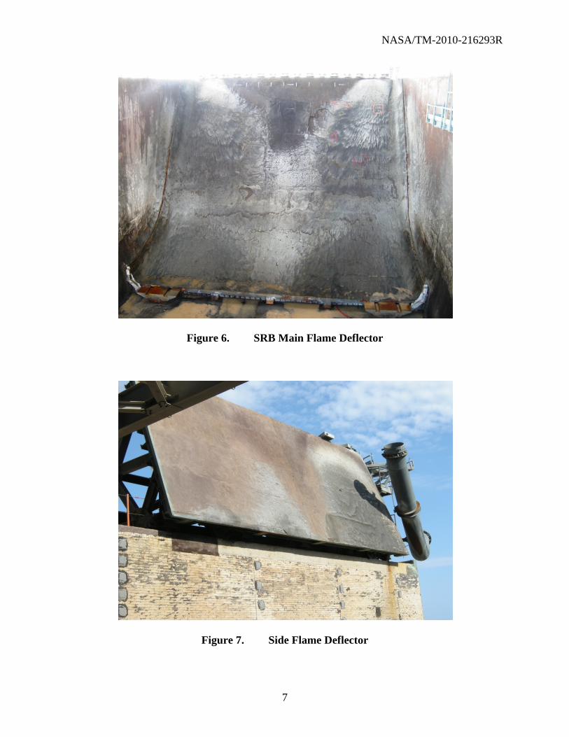
The Space Shuttle has two SRBs, which exhaust in the north flame trench, and three SSMEs, which exhaust towards the south. The SRBs have considerably more thrust, 3,300,000 pounds each, compared to the thrust of the SSMEs, 375,000 pounds each. The SRBs also burn hotter than the SSMEs and produce aluminum oxide particles that can act as abrasives or, if they are near or above melting point, may react with the refractory material. The SRBs impinge in two locations on the top of the flame deflector, underneath the MLP exhaust holes as seen in Figure 6. The light areas at the top left and right are the direct impingement areas. The areas that receive direct impingement appear lighter because of the presence of aluminum oxide particles in these locations. There are two side flame deflectors above the flame trench, shown in Figure 7. The SRBs impinge on the side deflectors before entering the main flame deflector. Examination of the impingement area shows that the material sees very different conditions than outside the impingement area. These differing conditions may cause different failure mechanisms for the refractory material. For example, the bottom lip of the deflector appears to undergo more erosion than those areas farther up the deflector towards its apex.
The launch sequence itself affects the environment. Prior to launch, water is continuously flowed onto the refractory material. This procedural requirement ensures that the sound suppression system is operational and results in the refractory material being thoroughly saturated with water during launch. This process releases approximately 300,000 gallons of water during launch, with a peak flow rate of 900,000 gallons per minute 9 seconds after launch. See Endnote 4 in Section 8. The launch timeline is as follows:
a. The sound suppression water flow starts just before SSME ignition at T – 6.6 seconds (s).
b. SSME ignition occurs at T - 6.6 s.
c. SRB ignition occurs at T – 0 s.
d. The Shuttle clears the tower approximately 6 seconds after launch. See Endnote 5 in Section 8.
NASA/TM-2010-216293R
7
Figure 6. SRB Main Flame Deflector
Figure 7. Side Flame Deflector

NASA/TM-2010-216293R
8
1.4 History of Refractory Material Testing at KSC
Investigations on refractory materials for protection from heat and blast on launch complexes using solid rocket motors (SRMs) started in the mid 60’s. A Solid-Propellant Rocket Exhaust Effects (SPREE) program (see Endnote 6 in Section 8) was established to evaluate materials for the protection of launch facilities from potentially damaging environments created by solid rocket motor exhaust gases.
The program consisted of performing scale-model test firings of both cold and hot jet streams with single nozzle configurations to derive models. Subscale test modeling was refined and correlated with full-scale launches of the Titan IIIC rocket using 120-inch SRMs. Unfortunately, this program’s goal was to develop a design handbook for properly configuring a deflector system for launching with SRMs and did not concentrate on qualifying refractory materials.
Out of the 27 test firings performed, only five refractory materials from two manufacturers were used. Consequently, Fondu Fyre WA-1 was recommended for use because of its superior performance in mechanical, physical, and chemical properties over the other products. Furthermore, it was already approved and in use on Complex 34 for the Apollo Program.
Since then, investigations on thirteen different refractory materials have been performed at KSC during the launches of STS-1 through STS-9 (1981 – 1983) and again on STS-55 (1993). Over the past 30 years (Figure 8), only 10 launches out of 131 (less than 8%) were utilized for testing new refractory materials. Some of the new products showed promise, but further investigations were not performed. These investigations mostly consisted of exposing test panels from different refractory concrete manufacturers to actual launch environments (i.e., panels were placed in the flame deflector during a launch) at LC-39 with the objective of qualifying the materials for use in the flame deflectors. There is no evidence that the material used today, WA-1G (gunnable) was ever tested.

NASA/TM-2010-216293R
9
Figure 8. History of Shuttle Launches, 1981 – 2010
The main issue with qualifying a new material was the uncertainty of a product’s compatibility with the existing installed system from different manufacturers. Refractory concrete panels were evaluated for average depth of erosion and pitting, where pitting is defined as the maximum depth of abrasion. Table 1 shows an overview of the test program including the number of samples tested and the products used for each test. Copies of each test report are provided in Appendix A, MMA-1918-80, STS-1; Appendix B, MTS-505-80, STS-2; Appendix C, MTS-142-82, STS-3; Appendix D, MTS-340-82, STS-1, -2, and -3; Appendix E, MTS-425-82, STS-4; Appendix F, MTB-503-83, STS-5, -6, and -7; Appendix G, MTB-250-84, STS-8 and -9; and Appendix H, 93-4436, STS-55 of this document.
0
1
2
3
4
5
6
7
8N
um
ber
of
Lau
nch
es
Year
LC 39A LC 39B
ChallengerTragedy
ColumbiaTragedy

NASA/TM-2010-216293R
10
Table 1. Overview of Test Program Since 1981
Report No. Launch Report Date Materials Tested (# of samples)
MMA-1918-80 (Appendix A)
STS-1 July 29, 1981
Fondu Fyre WA1 (1)1
Fondu Fyre WA1 w/wire (1) 1
WRP 1 (1) 2
WRP 3 (1) 2
Tufshot (1) 3
Tufshot w/ wire (1) 3
MTS-505-81 (Appendix B)
STS-2 March 1, 1982
Fondu Fyre WA1 (1) 1
Fondu Fyre WA1 w/wire (1) 1
WRP 2 (1) 2
WRP 3 (1) 2
Tufshot w/ wire (1) 3
MTS-142-82 (Appendix C)
STS-3 May 6, 1982
Fondu Fyre FSC-5 (1) 1
Fondu Fyre WA-11
Fondu Fyre WA-1 w/wire (1) 1
WRP 1 w/wire (1) 2
WRP 3 w/wire (1) 2
Tufshot w/wire (1) 3
MTS-340-82 (Appendix D)
STS-1, 2, and 3 June 7, 1982
Fondu Fyre WA-1 Panel 2
Fondu Fyre WA-1 w/wire Panel 3
WRP-1 Panel 1
WRP-2, Panel 7
WRP-3 Panel 4
Tufshot Panel 6 Tufshot with fibers, Panel 5
MTS-425-82 (Appendix E)
STS-4 August 27, 1982 Fondu Fyre WA-1 (3) 1
WRP (3) 2
MTB-503-83 (Appendix F)
STS-5, -6, and -7 September 1, 1983
Fondu Fyre WA-1 (3) 1
WRP 1 (1) 2
WRP 2 (1) 2
WRP 3 w/wire (10) 2
LI (1) 3
17-67 (2) 3
MTB-250-84 (Appendix G)
STS-8 and -9 May 22, 1984
Fondu Fyre HT-1 (1) 1
Fondu Fyre FSC-5 (1) 1
WRP 3 w/wire (2) 2
17-67 (1) 3
No. 75 (2) 4
93-4436 (Appendix H)
STS-55 July 19, 1993 Fondu Fyre WA-1 (3) 1
Mitec (3) 5
1Originally Designed Concretes, now Pryor Giggey Co, 2Wahl Refractory Products, 3Harbison Walker Refractories, 4Sauereisen Cement Co, 5Mitec, Inc

NASA/TM-2010-216293R
11
2 CURRENT REQUIREMENTS
NASA KSC design requirements dictate specific standards for selecting and qualifying refractory materials for use in the launch environment. A flow chart was developed to visually display the NASA/KSC standards that must be met under KSC-DE-512-SM, Facility, System, and Equipment General Design Requirements (Figure 9). This shows the design requirement pathway that leads to understanding and predicting the launch-induced environment and eventually to the standards used to meet those environment and design requirements. A description of the launch-induced environment and corresponding requirements, as listed in the documents and standards below and specifically related to refractory materials, follows.
Figure 9. Flow Chart Highlighting the Developmental Path From Engineering
Design Requirements to NASA/KSC Standards
KSC‐DE‐512‐SMFacility, Systems, and HardwareGeneral Design Requirements
Facilities
EnvironmentalConditions
Launch‐Induced EnvironmentKSC‐GP‐1059, KSC‐DD‐818‐TR
KSC‐DM‐3649
KSC/NASAStandards
Industry Standards
NSTS 07700 Volume
GSE
Natural EnvironmentTM‐82473
Wind Operational
SW ‐E‐0002 for GSE NHB 7320 for Facility
Government (OSHA) Standards
MilitaryStandards
AISC ACI IBC ANSI
KSC‐STD‐Z‐0004KSC‐STD‐164B KSC‐STD‐G‐0003BKSC‐SPEC‐P‐0012
*MIL‐STD‐….. Air Force, Navy
OSHA SafetyStandards
LOADS/ENVIRONMENT
SAFETY FACTORS / ALLOWABLES
ASCE 7 OSHA
*Applicable Army
NASA-STD-5005

NASA/TM-2010-216293R
12
2.1 KSC-GP-1059, KSC-DD-818-TR, and KSC-DM-3649
The documents KSC-GP-1059, KSC-DD-818-TR, and KSC-DM-3649 all describe the launch-induced environment. No testing and qualification requirements are listed in these documents but rather they are the supporting documents that describe launch-induced environment conditions for which the refractory concrete-related specifications are based.
KSC-GP-1059, Environment and Test Specification Levels Ground Support Equipment for Space Shuttle System Launch Complex 39 (Acoustic and Vibration, Volume I of II; Thermal and Pressure, Volume II of II, Part 1 of 2, Heating Rates, Pressure Loads, and Plume Flow Fields, and Part 2 of 2, Specific Temperatures of Selected Parts of LC-39; Acoustics, Volume III; and Thermal and Pressure, Volume IV) encompasses the thermal, pressure, acoustic, and vibration environments induced by launch of Space Shuttle vehicles from LC-39 Pads A and B. Volumes I and II predict the environments from Saturn V launches and anticipated environments for Space Shuttle launches. Volumes III and IV predict the launch-induced environments of Space Shuttle launches after the replacement of Redesigned Solid Rocket Motors (RSRM) and Solid Rocket Boosters (SRB) with Advanced Solid Rocket Boosters (ASRB). Volumes III and IV used launches from STS-1 to STS-30R to predict the new launch environments.
KSC-DD-818-TR, Summary of Measurements of KSC Launch-Induced Environmental Effects (STS-1 through STS-11), summarizes the Shuttle launch-induced environment data acquired at Kennedy Space Center during the STS launches. The measurements included using sensors to record pressure, acoustic, strain, load, temperature, heat rate, and vibration parameters.
KSC-DM-3649, Lift-off Response Spectra to Space Shuttle Launch-Induced Acoustic Pressures, summarizes computations of lift-off response spectra obtained from the acoustic pressure created and correspondingly measured during Shuttle launches. This document uses the acoustic data from STS-2 through STS-31 to derive static and dynamic loads imposed on exposed GSE during launching.
2.2 KSC-STD-Z-0004 Section 3.3.9
KSC-STD-20004, Structural Design, Standard for, defines requirements for framing of structures, ground support equipment, and temporary structures and enclosures. In section 3.3.9, the standard refers to KSC-SPEC-P-0012, Refractory Concrete, Specification for, qualification of materials used in structures that are subject to direct rocket engine exhaust impingement.
2.3 KSC-STD-164, Section 3.3.16
KSC-STD-164, Environmental Test Methods for Ground Support Equipment, Standard for, focuses on test methods for ground support equipment, with section 3.3.16 specifically related to Lift-Off Blast. Refractory materials at the launch pad must meet this standard. According to this standard, the refractory materials can only be qualified by meeting lift-off blast test conditions. No other qualification methods, such as laboratory or test chamber methods, can be substituted. The lift-off blast test can only be performed during an actual launch or on a rocket engine test stand during a test firing.
NASA/TM-2010-216293R
13
2.4 KSC-STD-G-0003
KSC-STD-G-0003, Launch Support and Facility Components, Qualification of, Standard for, establishes methods for the qualification of launch support and facility components. Section 4.0 describes five methods for qualifying a material: (1) qualification by testing, (2) qualification by similarity, (3) prior qualification, (4) qualification by usage and analysis, and (5) qualification by higher level assembly testing. Refractory materials must meet this standard (KSC-STD-G-0003).
Qualification by testing includes demonstration of operational suitability for a specific application when no qualification date is available. Three types of tests (functional, acceptance, and verification) are used in the design and development of new equipment. This testing includes using structural, dynamic, component compatibility and life cycle criteria that is similar to the launch environment but on a laboratory scale. The testing allows the use of subscale accelerated conditions of environment, functions (such as pressure, voltage, flow, etc.), tolerances, life cycles, and time. This testing includes using all natural environmental factors, including humidity, salt fog, rain, sand and dust, fungus, and solar radiation, and then inducing launch environments, including acoustics, shock, vibration, high and low temperatures, liftoff blast, electromagnetic field, and explosive gas/vapor atmosphere. The environmental testing must be in accordance to KSC-STD-164, which is testing during an actual launch or rocket engine test firing.
Qualification by similarity refers to materials that are comparable in use or rating to already-qualified materials.
Prior qualification refers to materials that were formerly qualified to the necessary environment and testing levels.
Qualification by usage and analysis refers to acceptance without a formal qualification test and based on evaluations of usage on previous programs, postlaunch data and inspection, and considering all static and dynamic operating conditions.
Qualification by higher level assembly testing refers to qualification of a component that is part of a higher assembly that has already been qualified by testing in the same application.
2.5 KSC-SPEC-P-0012
KSC-SPEC-P-0012, Refractory Concrete, Specification for, covers requirements for refractory concrete used for the heat and blast protection of the flame deflectors and other areas of a launch or test facility. The material must resist degradation of thermal protection characteristics due to the unprotected seacoast atmosphere exposure at the launch facilities. The KSC specification currently active for refractory concrete is KSC-SPEC-P-0012; however, it is currently being revised.
2.5.1 Current Specification
The current requirements for KSC-SPEC-P-0012 include a qualification process, required material characteristics, minimum fresh and hardened material requirements, as well as quality assurance provisions and packing requirements. The quality assurance section provides

NASA/TM-2010-216293R
14
information on the material qualification process for use at KSC. This process includes making test specimens, as required by the specification, and exposing these specimens to an actual launch environment. Requirements listed in the specification for the acceptance of refractory concrete materials used at KSC include the following:
a. Materials: Aggregate shall be hard, dense, durable, clean, sharp, and well graded.
b. Fineness modulus: The fineness modulus shall be between 3.75 and 2.75.
c. Strength: The refractory concrete shall develop a compressive strength of 4500 psi at 7 days and 90 percent of the 7-day strength within 24 hours.
d. Rocket engine exhaust resistance: Test samples installed at designate areas of the launch facility shall not crack, spall, or erode more that 1/8 inch when subject to rocket exhaust test. Heat flux shall be up to 3300 Btu/ft2-sec with an exposure time of approximately 10 seconds.
e. Workability: The refractory concrete shall be able to be applied pneumatically of manually to a smooth finish
f. Weathering: The refractory concrete shall resist degradation of thermal protection characteristics due to seacoast atmosphere exposure
Some of the limitations that have been identified for the existing KSC-SPEC-P-0012 specifications include the following:
a. Key performance parameters, such as the material shrinkage, are not required in the current specification.
b. No requirements on material storage are provided. Calcium aluminate cement (CAC) can hydrate with time under storage conditions that can significantly change the performance of the material.
c. No requirements are provided on placement procedures, curing, or other key construction practices. Procedures for placement of the entire refractory lining are dependent on the material being used for the refractory lining.
d. No methodology is provided for qualifying materials. Specific requirements, based on existing or newly developed standardized tests, should be included.
This specification is currently being revised to include the newly-identified requirements for refractory concrete.
2.5.2 Revised Specification
The revised specification will include many of the previous requirements, as well as new requirements based on the above noted limitations.

NASA/TM-2010-216293R
15
Table 2 lists the laboratory evaluation parameters that each material must meet in order to be considered for the second stage evaluation, a rocket engine exhaust exposure. The same laboratory evaluation requirements must then be met for the materials after exposure to the rocket engine exhaust.
Table 2. Laboratory Evaluation Requirements for Refractory Concrete, Suggested New Revision to KSC-SPEC-P-0012
Material Characteristic
Test Standard Test Requirement
Sieve analysis ASTM C92, using particle size distribution method
Reportable
Compressive strength
ASTM C133, using cold crushing strength method
4500 psi at 7 days, with 90 percent of 7-day strength developed within 24 hours
Thermal shock ASTM C1171 or C24 No explosive spall in less than 6 thermal cycles when shocked to a temperature determined by the Government
Abrasion resistance ASTM C704 Erosion not more than 3.2 mm per cycle
Shrinkage/thermal expansion
ASTM C 832-00 TBD
Modulus of rupture ASTM C133, using modulus of rupture method
TBD
Acid resistance test Internal Government test*
TBD
Thermal conductivity
ASTM C1113 Reportable
Specific Heat
ASTM E1269 from room temperature to maximum use temperature
Reportable
Bulk Density ASTM C20, section 1.1.4
Reportable
*The acid resistance test was developed by the Government. Details of the test will be given in the specification and are included in this document.
NASA/TM-2010-216293R
16
Rocket Engine Exhaust Exposure:
a. The test sample must be installed at a designated test or launch site and be exposed to engine exhaust. The test will be performed by the Government.
b. The test sample must meet the same testing requirements as above after the rocket engine exposure period.
Additional Requirements:
a. The material may not contain asbestos.
b. The refractory shall be capable of meeting the requirements for a number of thermal cycles or number of year’s exposure to the seacoast environment.
c. The installation, curing process, and temperatures for each phase of testing and final installation at the launch or test site shall be the same.
The reader is urged to consult with the most current version of KSC-SPEC-P-0012 for a complete list of the current and revised requirements.
2.6 NASA-STD-5005
NASA-STD-5005, Standard of the Design and Support of Ground Equipment, defines top-level requirements and provides guidance for the design and fabrication of ground support equipment. In section 5.11.3.1.5.3, the standard refers to KSC-SPEC-P-0012 for qualification of refractory materials used in structures that are subject to heat and blast protection of flame deflectors.
2.7 Product Testing
In order for a product to be considered for rocket engine exhaust testing, the product needs to meet the above referenced requirements. The product must be prepared, installed, and cured using the same methodology as intended for installation at the launch pad.
2.8 Summary
All of the standards and specifications regarded the exposure to launch environments as a critical step for the qualification of refractory materials. A summary of testing requirements referenced in different standards and specifications for refractory materials used in launch environments is shown in Table 3. This information is based on the requirements included in KSC-STD-Z-0004F, KSC-STD-164, KSC-STD-G-0003, and KSC-SPEC-P-0012.

NASA/TM-2010-216293R
17
Table 3. Summary of Testing and Qualification Requirements for Refractory Materials in Launch Environments
NASA Specification
Qualification Requirements Similar
Industry Laboratory
Scale Subscale Launch
KSC-STD-Z-0004F Refers to KSC-SPEC-P-0012 for requirements.
KSC-STD-164 No No Yes Yes
KSC-STD-G-0003 Yes
Yes, along with KSC-STD-164 requirements
Yes Yes
KSC-SPEC-P-0012 No Yes No Yes
Revised KSC-SPEC-P-0012
No Yes Optional Yes
NASA-STD-5005 Refers to KSC-SPEC-P-0012 for requirements.
3 LABORATORY TESTING
Standardized testing of refractory materials is required to assess the characteristics of refractory products and to identify products that can be used in KSC launch environments. For refractory materials, the following standards are applicable. It should be noted that some standards are not specific to refractory products, and modifications to the testing procedures may be required. In most cases, and when possible, the standard that specifically pertains to refractory products should be used.
The following standards are applicable to the testing of refractory materials for NASA. It should be stressed that the list is not all inclusive of the standards that might be required for future needs and requirements.
a. Preparation of Refractory Samples
(1) ASTM C1140, Standard Practice for Preparing and Testing Specimens From Shotcrete Test Panels
(2) ASTM C862, Standard Practice for Preparing Refractory Concrete Specimens by Casting
b. Compressive Strength
(1) ASTM C133 (Reapproved 2003), Standard Test Methods for Cold Crushing Strength and Modulus of Rupture of Refractories

NASA/TM-2010-216293R
18
c. Abrasion/Erosion Resistance
(1) ASTM C704, Standard Test Method for Abrasion Resistance of Refractory Materials at Room Temperature
d. Shrinkage and Thermal Expansion
(1) ASTM C179, Standard Test Method for Drying and Firing Linear Change of Refractory Plastic and Ramming Mix Specimens
(2) ASTM C832 (2005), Standard Test Method of Measuring the Thermal Expansion and Creep of Refractories Under Load
(3) ASTM C1148 (2002) , Standard Test Method for Measuring the Drying Shrinkage of Masonry Mortar (Not specifically for refractory concrete - modified)
(4) ASTM E228, Standard Test Method for Linear Thermal Expansion of Solid Materials With a Push-Rod Dilatometer
(5) ASTM C 1171, Standard Test Method for Quantitatively Measuring the Effect of Thermal Shock and Thermal Cycling on Refractories
e. Modulus of Rupture
(1) ASTM C 133 (Reapproved 2008), Standard Test Methods for Cold Crushing Strength and Modulus of Rupture of Refractories
f. Thermal Conductivity
(1) ASTM C 1113/C 1113M, Standard Test Method for Thermal Conductivity of Refractories by Hot Wire (Platinum Resistance Thermometer Technique)
g. Other Physical Properties
(1) ASTM C 20 (Reapproved 2010), Standard Test Methods for Apparent Porosity, Water Absorption, Apparent Specific Gravity, and Bulk Density of Burned Refractory Brick and Shapes by Boiling Water
(2) ASTM C 830 (Reapproved 2006), Standard Test Methods for Apparent Porosity, Liquid Absorption, Apparent Specific Gravity, and Bulk Density of Refractory Shapes by Vacuum Pressure
(3) ASTM C 1419 (Reapproved 2009), Standard Test Method for Sonic Velocity in Refractory Materials at Room Temperature and Its Use in Obtaining an Approximate Young’s Modulus

NASA/TM-2010-216293R
19
(4) ASTM E 1269, Standard Test Method for Determining Specific Heat Capacity by Differential Scanning Calorimetry
3.1 Sample Preparation
Prior to use or test, refractory materials shall be stored in dry, protected, and weatherproof structures. In general, appropriate care should be exercised to protect the raw materials from weather and ensure that the manufacturer’s recommendations are followed during mixing and installation. Raw material expiration dates should be checked prior to use to ensure that the final material has the properties advertised by the manufacturer and meets the requirements of NASA. Care should be exercised to ensure that the correct product is used for a particular application. Refractory products are often formulated to cast or gun the refractory product. Refractory materials for laboratory testing should be prepared with the same method that would be used to install the material at the pad.
In general, concrete samples can be prepared in three different ways: shotcreting, gunning, or casting. Casting involves mixing the components and pouring the cementitious product in place to cure. Shotcreting is an automatic delivery method that pumps a wet (already mixed) concrete to the nozzle where air is added to deliver the concrete to the target. Gunning is a process in which the cement and sand are injected into an air stream to deliver it to the nozzle. At the nozzle, the dry mix and water are combined, and the materials are pneumatically expelled to the target.
3.1.1 Sample Preparation – Shotcreting or Gunning
Forms for the production of refractory samples by the gunning process can be fabricated using ASTM C1140-03 (Appendix E). Bulk samples utilizing this specification have been prepared at KSC. See Endnote 7 in Section 8. In accordance with the requirements of ASTM C1140, samples cannot be taken from the bulk sample in the space equal to the depth plus 1 inch from the outside edges. The form should be constructed from rigid materials, so that dislodging of the refractory product through vibration or deformation is prevented. The walls and bottom of the forms fabricated at KSC used a 0.5-inch wire fabric mesh to contain the product. See Figure 10.

NASA/TM-2010-216293R
20
24.0
TOP VIEW
FABRIC FORM(1/2" MESH)
24"x24" WIRE
2"x4" FRAME
TOP
24.0
CROSS SECTION VIEW
6.03.5
BOTTOM
Figure 10. Forms Designed To Hold the Wet Refractory Concrete (Units in Inches)
To prepare samples, refractory materials shall be gunned or shotcreted into forms at an angle as shown in Figure 11. In the prior referenced testing, two forms were used for each sample in the study. Sample size or quantity should be sufficient to produce the amount of replicate samples needed for laboratory testing. After material placement, the samples shall cure under ambient conditions in accordance with manufacturers’ recommendations. ASTM C1140 recommends the samples be tightly wrapped to prevent water from evaporating during the curing process.
NASA/TM-2010-216293R
21
HORIZONTAL SURFACE
BACKING MATERIAL
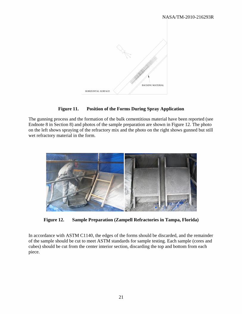
Figure 11. Position of the Forms During Spray Application
The gunning process and the formation of the bulk cementitious material have been reported (see Endnote 8 in Section 8) and photos of the sample preparation are shown in Figure 12. The photo on the left shows spraying of the refractory mix and the photo on the right shows gunned but still wet refractory material in the form.
Figure 12. Sample Preparation (Zampell Refractories in Tampa, Florida)
In accordance with ASTM C1140, the edges of the forms should be discarded, and the remainder of the sample should be cut to meet ASTM standards for sample testing. Each sample (cores and cubes) should be cut from the center interior section, discarding the top and bottom from each piece.

NASA/TM-2010-216293R
22
To prepare individual samples for testing, the ambient-cured bulk refractory material is removed from the form and cut using both a diamond saw and a core drill. Figure 13 shows an example cut pattern that has been used to produce cylindrical, cube, and bar shaped samples that were required for laboratory testing as a part of a prior project. See Endnote 9 in Section 8. The dark areas on the side are discarded.
MOR C133
MOR C133
C1171 C1171
MOR C133
MOR C133
MOR C133
C1171C1171
C11
71C
1171
C11
71C
1171
C11
71C
1171
Compression Cores- 20 SAMPLES (2" round x 2" tall, from center)C1171- 10 SAMPLES (1"x1"x6", from center)MOR C133- 5 SAMPLES (2"x2"x9", from center)
24"
24"
SCRAP AREA SCRAP AREA
SCRAP AREASCRAP AREA
Figure 13. Example of Cut Pattern for Each Sprayed Sample (Units in Inches)
3.1.2 Sample Preparation - Casting
Cast specimens should be produced following the guidance of ASTM C862. According to this procedure, a paddle mixer (Figure 14) is used to prepare the wet cementitious mixture. ASTM C862 gives details on water addition and mixing procedures.
As quickly as possible following the mixing phase, the wet cementitious material should be packed into appropriate molds for the tests to be conducted. The product is then consolidated using a vibration table until the top surfaces appear smooth. The filled molds are then placed in a humidity chamber (greater than 95% humidity) at ambient temperature for a curing period of 24 hours. The specimens are then removed from the molds and are allowed to continue curing under ambient conditions for at least 7 days.

NASA/TM-2010-216293R
23
Figure 14. Paddle Mixer Used at KSC To Prepare Refractory Samples
3.2 Laboratory Testing and Standards
This section describes the tests that can be used to evaluate the performance of a refractory material in a controlled laboratory environment. These tests are suggested to be part of the new qualifying process of a refractory material, though they cannot be used to qualify a refractory product without physical launch pad (or simulated launch pad) testing. The official qualification procedure is found in Section 2.
3.2.1 Sieve Analysis
Particle size distribution of a refractory concrete can be explained using ASTM C92 (Note 13). This test method utilizes a set of calibrated sieves for the analysis prewetted and wetted cementitious material. According to this standard, the concrete is weighed prior to analysis and placed through a series of sieves, starting with the one with the coarsest opening. Results from this standard are based (and reported) upon the material retained in each sieve, as well as the dust loss of the material passing through the final sieve.

NASA/TM-2010-216293R
24
3.2.2 Specific Heat Analysis
Specific heat capacity, or simply specific heat, can be defined as the quantity of heat required to raise the temperature of 1 gram of substance by 1 degree Celsius at constant pressure. ASTM E1269 is used to determine specific heat using differential scanning calorimetry (DSC). DSC measures the specific heat of materials by measuring differences in the heat flow into the test material and a reference material or blank.
The specific heat of the sample (as a function of temperature) is a reportable quantity that may be used by engineers to help select refractory products to satisfy launch pad requirements.
3.2.3 Cold Compressive Strength
The compressive strength of a refractory material can be determined in accordance with ASTM C133. In brief, the cold crushing strength or compression strength (CS in lbf/in
2 or psia) is defined by:
where, Fmax = maximum force or load applied at the yield point of the material (lbf) A = average (between top and bottom) cross-sectional area to which the load is applied (in2) A complete description of the process used to measure cold crushing strength is in ASTM C133. Samples are usually 2-inch cubes or 2-inch-diameter cylinders. Prior to testing, the samples should be dried in a 110°C oven for 18 hours. The compressive strength can then be measured using standard mechanical or hydraulic compression testing machines conforming to the requirements of ASTM E4, Practices for Force Verification of Testing Machines. A photo of the Instron Universal Test Machine (Model 5889) that meet these requirements is shown in Figure 15. Figure 16 shows samples before and after crushing.

NASA/TM-2010-216293R
25
Figure 15. Instron in the Material Testing Laboratories, O&C Building, KSC
When tested according to ASTM C133 and according to the requirements of KSC-SPEC-P-0012, the refractory material shall develop a minimum compressive strength of 31.0 megapascal (MPa) (4500 psi) at 7 days, with 90 percent of the 7-day strength developed within 24 hours.
Figure 16. Cylindrical Sample Prior To and After Crushing
3.2.4 Abrasion Resistance
Solid rocket motors (SRMs) produce aluminum oxide (Al2O3) and hydrochloric acid as a by-product. When the SRMs are operational, the particulates are expelled from the motors at considerable velocities. As a consequence, it is desirable to investigate the refractory materials
NASA/TM-2010-216293R
26
resistance to abrasion. ASTM C704 is used to investigate this phenomenon under ambient laboratory conditions.
Samples used for ASTM C704 are cut from bulk refractory materials and should measure between (4” by 4” by 1”) to (4½” by 4½” by 2½” or 3”). Prior to testing, the samples are dried in an oven at 110ºC until a constant weight is achieved. The sample’s resistance to abrasion is then investigated by propelling 1000g silicon carbide media in air at a pressure of 65 psi. The abrasive media is impinged upon the sample at a 90-degree incident angle.
An important point to note is that ASTM C704 investigates the abrasion resistance of refractory materials under ambient conditions. The abrasion resistance under elevated temperature launch pad conditions may differ greatly.
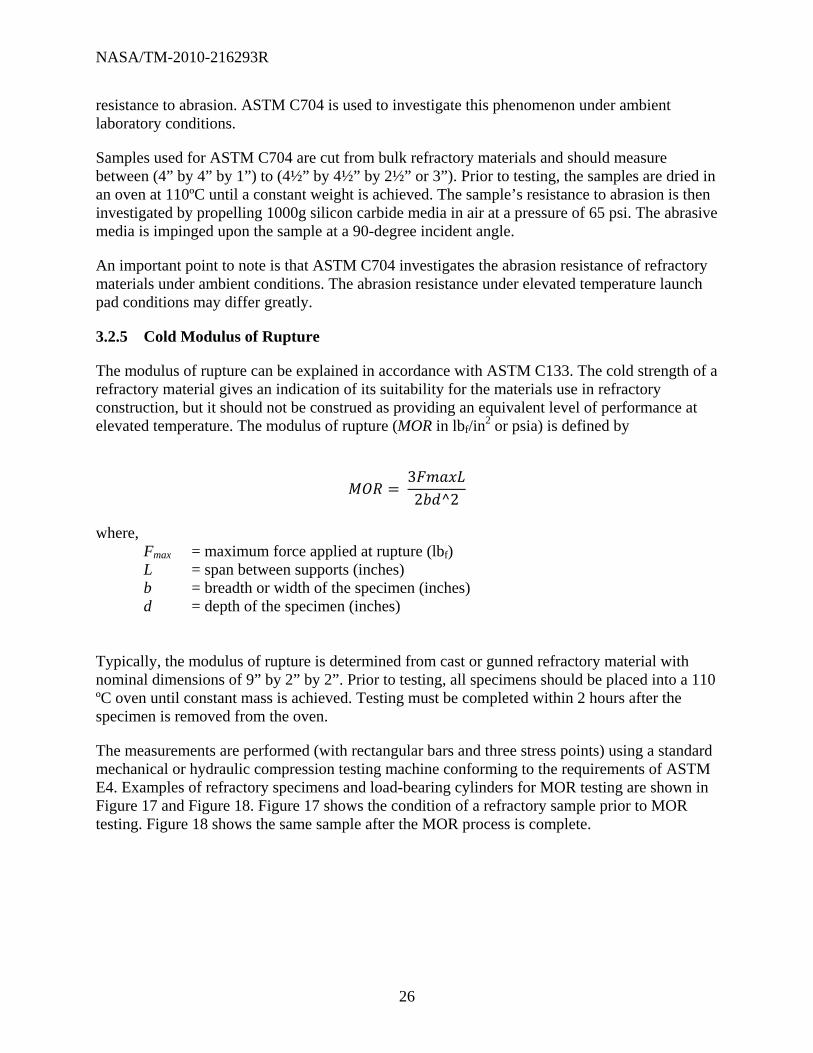
3.2.5 Cold Modulus of Rupture
The modulus of rupture can be explained in accordance with ASTM C133. The cold strength of a refractory material gives an indication of its suitability for the materials use in refractory construction, but it should not be construed as providing an equivalent level of performance at elevated temperature. The modulus of rupture (MOR in lbf/in
2 or psia) is defined by
32 ^2
where, Fmax = maximum force applied at rupture (lbf) L = span between supports (inches) b = breadth or width of the specimen (inches) d = depth of the specimen (inches) Typically, the modulus of rupture is determined from cast or gunned refractory material with nominal dimensions of 9” by 2” by 2”. Prior to testing, all specimens should be placed into a 110 ºC oven until constant mass is achieved. Testing must be completed within 2 hours after the specimen is removed from the oven.
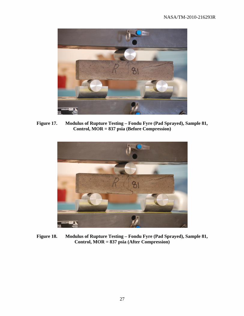
The measurements are performed (with rectangular bars and three stress points) using a standard mechanical or hydraulic compression testing machine conforming to the requirements of ASTM E4. Examples of refractory specimens and load-bearing cylinders for MOR testing are shown in Figure 17 and Figure 18. Figure 17 shows the condition of a refractory sample prior to MOR testing. Figure 18 shows the same sample after the MOR process is complete.
NASA/TM-2010-216293R
27
Figure 17. Modulus of Rupture Testing – Fondu Fyre (Pad Sprayed), Sample 81, Control, MOR = 837 psia (Before Compression)
Figure 18. Modulus of Rupture Testing – Fondu Fyre (Pad Sprayed), Sample 81, Control, MOR = 837 psia (After Compression)

NASA/TM-2010-216293R
28
3.2.6 Thermal Expansion and Creep of Refractories
The shrinkage\thermal expansion shall be tested in accordance with ASTM C832. In summary, this test method subjects refractory materials to elevated temperatures under a 25-psi compressive stress for 50 hours. During the process, sensors continuously measure the linear change of the specimens parallel to the direction of the compressive stress.
A review of prior sensor data indicates that the maximum temperature achieved on the launch pads is 2165 ºF at the time of this writing. It is suggested that the thermal expansion and creep of the refractory product be measured to a temperature equivalent to the maximum temperature that the refractory concrete is subject to at the launch pad. Sensor data for the final Shuttle flights may necessitate that the refractory product is evaluated at higher temperatures. The thermal expansion under load shall be reported. The reader is encouraged to refer to the latest revision of KSC-SPEC-P-0012 for thermal expansion requirements.
3.2.7 Thermal Shock
The thermal shock properties of a refractory material can be explained in accordance with ASTM C1171, ASTM C1419, and ASTM C133. These test methods are used to indicate the extent to which a refractory material can withstand stresses generated by sudden changes in temperature.
ASTM C1171 relies on sudden changes in temperature to generate stress within the refractory materials. Crack and flaw-free samples with the nominal dimensions of 1” x 1” x 6” are cut from the bulk material and are subsequently dried to a constant weight in a 110 ºC oven. The sonic velocity is determined according to ASTM C1419, and the samples are then divided into two separate groups. Modulus of rupture testing (ASTM C133) on the first group (prior to heating) is used to make comparison to the post cyclic sonic velocity and modulus of rupture evaluations after the heating cycles.
One heating cycle results from the exposure of the sample to an elevated temperature of 1200 ± 15ºC (2190 ± 25ºF) for a 10-to-15 minute duration. The samples are then removed from the furnace for 10 to 15 minutes. This procedure is considered a single cycle. According to ASTM C1171, this procedure (or cycle) is repeated five times, the sonic velocity is again determined, and MOR testing is performed to evaluate the post cyclic strength of the sample.
A direct comparison of velocity and strength loss measurements is then used to help delineate the performance of different refractory materials. Furthermore, any spalling of the specimens during the cyclic heating and cooling process should be noted and can be used as a metric to disqualify the use of the product.
3.2.8 Thermal Conductivity
The thermal conductivity of the refractory samples may be determined in accordance with ASTM C1113. In summary, ASTM C1113 uses a constant electric current that is applied to a pure platinum wire between two bricks of the refractory material. The heat that is generated from the electric current is conducted away from the wire at a rate that is dependent upon the thermal

NASA/TM-2010-216293R
29
conductivity of the refractory material. Using a minimum of four test temperatures, the k-Value (thermal conductivity) can be ascertained from this standard.
3.2.9 Acid Resistance Tests
Because of the presence of some amount of acid in the launch environment, or the potential thereof, the acid resistance should be determined/compared for different candidate flame trench refractory materials.
The acid soak test is used to determine a refractory material’s resistance to degradation when placed in a bath of 0.1M hydrochloric acid (HCl). This procedure has been performed in the NASA Corrosion Technology Laboratory at the Kennedy Space Center.
The test compares the cold compression strength before and after acid exposure to evaluate acid resistance. The test is performed as follows. Specimens consisting of 2-inch cubes or 2-inch tall, 2-inch-diameter cylinders are dried overnight in a 110 °C oven. Each sample is individually submerged in a 200-ml volume of the 0.1M HCl acid in a plastic cup for 14 days. Midway through the exposure, the HCl is drained and a new solution is added. After 14 days, the specimens are rinsed and dried in an oven, and the compression strength is measured according to ASTM C133. The percent loss of strength after acid exposure is used to compare the relative acid resistance of different materials.
3.2.10 Density, Porosity, Water Absorption, and Apparent Specific Gravity
Porosity is the ratio of the volume of the open pores to the bulk volume of a material. Bulk density is defined as the mass of a material divided by the total volume it occupies. The total volume includes particle volume, interparticle void volume and internal pore volume. As with crushing strength, both water content and heat treatments factor significantly into apparent porosity and bulk density of the refractory material. See Endnote 10 in Section 8.
Apparent porosity, water absorption, apparent specific gravity, and bulk density are primary properties of refractory materials that can be measured using ASTM C20 or ASTM C830. These properties are widely used in the evaluation and comparison of product quality and as part of the criteria for selection and use of refractory products in a variety of industrial applications.
According to ASTM C20, refractory samples are dried prior to testing in a 110 ºC oven until a constant mass is achieved. This mass is recorded. Specimens are then submerged in boiling water for a 2-hour duration and are allowed to cool. The weight of each sample is then measured while the samples are suspended in the water (to calculate the specific gravity). Finally, the samples are blotted dry with a moistened linen to remove all water from the surface, and then they are subsequently weighed.

NASA/TM-2010-216293R
30
The bulk density of the samples is calculated as follows
Where, B= bulk density D = dry weight V= volume The porosity of the samples is calculated as follows
, % 100
Where, P = porosity W = saturated weight D = dry weight V= volume The water absorption of the samples is calculated as follows
, % 100
Where, A = water absorption W = saturated weight D = dry weight The apparent specific gravity is calculated as follows
Where, T = apparent specific gravity D = dry weight S = suspended weight

NASA/TM-2010-216293R
31
3.2.11 Petrographic Analysis of Refractory Materials
Concrete petrography is the study of hardened concrete microstructure using microscopic techniques. The study of concrete microstructure can be used to investigate properties and issues related to mix design, water/cement ratios, composition, degradation, chemical attack, corrosion of steel reinforcement, microcracking, porosity, and grain size. To investigate these issues, cross-sectioned samples of (cured) refractory materials can be analyzed prior to and immediately after being exposed to rocket blast.
In addition to optical microscopy, scanning electron microscopy (SEM) with energy dispersive x-ray spectroscopy (EDS) can provide information that is beneficial to the analysis of the cementitious materials. SEM/EDS is particularly useful in determining mineralogical composition and in visually documenting significant pores, pore throats, clays, framework grains, and cements. The NASA Corrosion Technology Laboratory and the NASA Materials Sciences Laboratory at the Kennedy Space Center have the equipment necessary to perform a suitable analysis.
X-ray diffraction is an established technique that provides semi-quantitative determination of sample mineralogy and can be used to estimate and elucidate hydrated and nonhydrated phases of refractory materials. The NASA Corrosion Technology Laboratory and the NASA Materials Sciences Laboratory at the Kennedy Space Center have the equipment necessary to perform a suitable analysis.
4 ROCKET ENGINE EXHAUST TESTING
4.1 LC-39 Full-Scale Testing
To meet the requirements of the standards in Section 2, a new refractory concrete product must be exposed to an actual launch environment. To assist in this requirement, two test stands were constructed and installed at the bottom east and west sides of the main flame deflector, SRB side (Figure 19). The east and west test stands are capable of holding three samples each (Figure 20).

NASA/TM-2010-216293R
32
Figure 19. Typical Three Sample Test Stand
Figure 20. Test Stand Locations
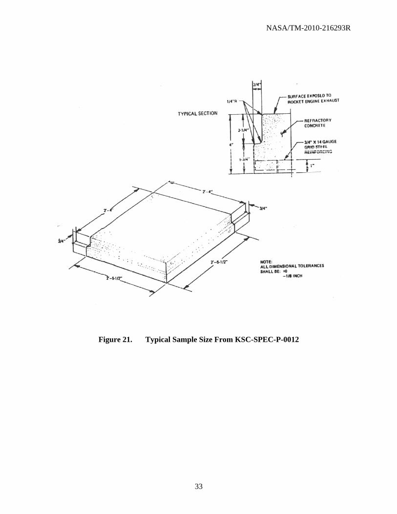
Samples for this testing must be prepared in the same manner as they are intended to be used. The finished dimension of the test samples must be in accordance with sketch in Figure 21, taken from KSC-SPEC-P-0012.
Main Flame Deflector, SRB Side
Test Stand Locations
East West
NASA/TM-2010-216293R
33
Figure 21. Typical Sample Size From KSC-SPEC-P-0012

NASA/TM-2010-216293R
34
4.1.1 Installation and Prelaunch Analysis
Based on the current effort to qualify additional refractory materials for the use on the LC-39 main flame deflector, test samples shall be installed at designated areas of the facility and then subjected to rocket engine exhaust. The intended procedure is outlined below and is based on the historical testing completed at KSC. Specific instances of work will be coordinated by NE-M9 and data transferred to NE-L for documentation by a KSC Materials Sciences Laboratory (MSL) report.
The specimen shall conform to the dimensions outlined in the latest revision of KSC-SPEC-P-0012, and installed in a manner similar to the test frames required in Ground Support Equipment Engineering Order EO3-79K09546, Refractory Test Frames.
Panels shall be installed with GE SCM 3404 on the bottom of the refractory concrete test panels to ensure levelness and adequate structural support of the integrated test panel.
Tap test stall be performed by NE-M9 and United Space Alliance (USA) engineering to determine the soundness of the samples.
Ablative coating, such as Dow Corning 3-6077 Silicone Ablative RTV (white colored) NSN 10753-0012-801 or other approved equal per KSC-SPEC-F-0006, shall be applied to the areas surrounding the panels to protect the fixtures used to secure the samples.
The installation shall be documented with photographs by NE-M9/NE-L or a designee.
The dimensions of the test specimens shall be measured after installation to a tolerance of 1.5 mm (1/16 in) using an optical scanner with a higher resolution performed by USA Optics.
4.1.2 Postlaunch Analysis
The postlaunch condition shall be documented with photographs by NE-M9/NE-L or a designee.
A postlaunch survey of any liberated debris may be performed by base operations contractor based on a consensus within NE.
The dimensions of the test specimens shall be measured after installation on the deflector to a tolerance of 1.5 mm (1/16 in) using an optical scanner with a higher resolution performed by USA Optics.
The test samples will not be removed unless the sample loses pieces of a 2 in x 2 in x 2 in or greater, or other structural detect is denoted by NE-M9/NE-L and USA engineering when determining the soundness of the samples.
For multiple launches, the test stands will be swapped, with intact samples remaining installed between launches.

NASA/TM-2010-216293R
35
The dimensions of the test specimens shall be measured after installation on the deflector to a tolerance of 1.5 mm (1/16 in) using an optical scanner with a higher resolution performed by USA Optics.
An additional sample coupon may be installed at the direction of NE-M9 to avoid the possibility of generating FOD during launch. Sample installation will proceed in accordance with previous installation section.
Installation shall be documented with photographs by NE-M9/NE-L or a designee.
The sample may remain in test indefinitely at the direction of NE-M9.
4.2 Subscale Rocket Engine Exhaust Test Stands and Material Dimensions
Subscale refractory testing has been performed at various locations. This section presents preliminary designs for refractory material sample size and test stand configurations using a standard 5-inch center perforated (CP) solid rocket motor. The basic designs are a modification of 80K60515 drawings used for full-scale live launches at LC-39A. The subscale samples are designed (smaller) for easier handling; 26.5-inch square at the base instead of 29.5-inch square, resulting in a 20 percent reduction in volume. Figures 22 through Figure 26 depict the new test stand designs and material dimensions for subscale testing.

NASA/TM-2010-216293R
36
31.5
6.0
6.0
29.5
6.0
6.0
6.0
6.0 6.0
B-
A-
Figure 22. Preliminary Test Stand Design, Top View

NASA/TM-2010-216293R
37
B
3/4" x 14 GA GRIDSTEEL REINFORCING
3/4" x 14 GA GRIDSTEEL REINFORCING
29.5
31.5
25.75
25.0
1/2"-13x2" BOLTW/ WASHER
DRILL & TAP FOR1/2"-13 BOLT
1/2"-13x3" BOLTW/ WASHER
1.5
1.5
SCALE: TBD
DETAIL-
DETAIL
SCALE: TBD
DRILL & TAP FOR1/2"-13 BOLT
1.0R0.250.5
2.25
1.0
2.875
1/2"-13x3" BOLTW/WASHER
1/2" PLATE
A-
1.0
DRILL & TAP FOR1/2"-13 BOLT
1.53.25
Figure 23. Cross-Section Details From Top View
5" C PT R O C K E T M O TO R
24.0
SCA L E: T BD
STA N D - SID E V IE W
30°
10.0
Figure 24. Test Stand Side View

NASA/TM-2010-216293R
38
REFRACTORY CONCRETE TEST SAMPLE
25.0
26.5
SCALE: TBD
26.525.8
C-
D-
Figure 25. Refractory
3/4" x 14 GA GRIDSTEEL REINFORCING
3/4" x 14 GA GRIDSTEEL REINFORCING
26.5
26.5
25.8
25.0
4.0
4.0
SCALE: TBD
DETAIL D-
SCALE: TBD
DETAIL C-
0.75
R0.25
0.75
R0.25
Figure 26. Refractory Material Sample Cross-Sections

NASA/TM-2010-216293R
39
5 SUBSCALE PARAMETERS
Qualification testing for new refractory materials must take place in either an actual rocket launch or a rocket engine test (KSC-STD-164). This section provides environmental data taken during the launches of STS-126, STS-119, STS-125, and STS-127, which can be used to provide guidance on the test parameters of a particular subscale test. Temperature, pressure, acoustic pressure, acceleration, strain, total heat flux (calorimeter), and radiative heat flux (radiometer) were measured during those launches. In addition, environmental data found in KSC-GP-1059, KSC-DD-818-TR, and KSC-DM-3649 should be consulted when finalizing subscale test parameters. Temperature, pressure, and heat flux values are thought to be directly comparable between the Shuttle launch and subscale testing. Maximum values of these parameters, as well as graphs that show the parameters over time, are reported. Strain and acceleration are impacted by the overall structural design and cannot be simulated in subscale testing. There are limitations to subscale testing, which will be discussed as well.
5.1 Launch Environment Assessment
The launch environment was measured in the flame trench during the launches of STS-126 (Endeavour, November 14, 2008), STS-119 (Discovery, March 15, 2009), STS-125 (Atlantis, May 11, 2009), and STS-127 (Endeavour, July 15, 2009). Complete results are reported in NASA-TM-2010-216294, KSC Launch Pad Flame Trench Environment Assessment.
Temperature, pressure, acoustic pressure, acceleration, total heat flux (calorimeter), and radiative heat flux (radiometer) were measured. The sensors used for each measurement and their locations are given in Table 4. The locations of the sensors are shown in Figure 27 thru Figure 30. Sensors were located on both the east and west flame trench walls for locations 1 – 7. The specific location was labeled with an “E” or “W” after the number to denote the east or west wall as shown in the figures. Sensors at locations 1 – 4 were exposed to the exhaust environment. Locations 4E and 4W were at the bottom of the deflector near the walls and adjacent to the test stands and will be used to test materials during the last Shuttle launches, as shown in Figure 31. The sensors for accelerometer measurements at locations 5 – 7 were placed in the catacombs on the cold face of the flame trench wall. These sensors were not directly exposed to the heat of the launch but were used to analyze the acoustical response of the reinforced concrete structure. Locations 8W and 9W were located on the west side flame deflector, underneath the MLP (Figure 29). These locations did not have equivalent measurements on the east side. Accelerometer and strain gauge measurements were made on the SRB and SSME flame deflectors, with locations as shown in Figure 30. These locations are the only ones where measurements were taken on the deflector structure at the time of this writing.
There are plans to have sensors mounted directly on the hot face of the SRB side of the main flame deflector during the launch of STS-133 and STS-134. The current plan is to install a combination of similar sensors, witness rods, and specially designed slug-type calorimeters. These measurements should be consulted when designing a subscale test.
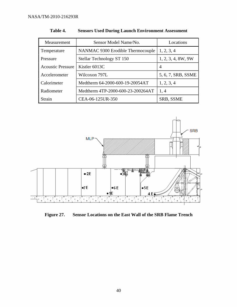
NASA/TM-2010-216293R
40
Table 4. Sensors Used During Launch Environment Assessment
Measurement Sensor Model Name/No. Locations
Temperature NANMAC 9300 Erodible Thermocouple 1, 2, 3, 4
Pressure Stellar Technology ST 150 1, 2, 3, 4, 8W, 9W
Acoustic Pressure Kistler 6013C 4
Accelerometer Wilcoxon 797L 5, 6, 7, SRB, SSME
Calorimeter Medtherm 64-2000-600-19-20054AT 1, 2, 3, 4
Radiometer Medtherm 4TP-2000-600-23-200264AT 1, 4
Strain CEA-06-125UR-350 SRB, SSME
Figure 27. Sensor Locations on the East Wall of the SRB Flame Trench

NASA/TM-2010-216293R
41
Figure 28. Sensor Locations on the West Wall of the SRB Flame Trench
Figure 29. Location of Pressure Sensor 9W Underneath the MLP

NASA/TM-2010-216293R
42
Figure 30. Sensor Locations on the SRB and SSME Flame Deflectors
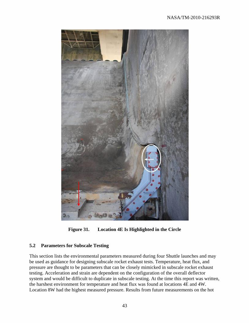
NASA/TM-2010-216293R
43
Figure 31. Location 4E Is Highlighted in the Circle
5.2 Parameters for Subscale Testing
This section lists the environmental parameters measured during four Shuttle launches and may be used as guidance for designing subscale rocket exhaust tests. Temperature, heat flux, and pressure are thought to be parameters that can be closely mimicked in subscale rocket exhaust testing. Acceleration and strain are dependent on the configuration of the overall deflector system and would be difficult to duplicate in subscale testing. At the time this report was written, the harshest environment for temperature and heat flux was found at locations 4E and 4W. Location 8W had the highest measured pressure. Results from future measurements on the hot
NASA/TM-2010-216293R
44
face of the flame deflector should exceed these values (for testing) and should be used when designing a subscale test. The maximum measured temperature, pressure, and heat flux (as of this date) are given in Table 5.
Table 5. Maximum Temperature, Pressure, and Heat Flux Measured During the Launch of STS-126, STS-119, STS-125, and STS-127
Parameter Maximum value Location
Temperature 2165 °F 4E
Pressure 99.4 psig 8W
Total heat flux (calorimeter) 2493 btu/ft2·sec 4W
Radiant heat flux (radiometer) 72.1 btu/ft2·sec 4W
The maximum values for temperature and radiant heat flux were relatively consistent for the launches, while the maximum pressure and total heat flux were highly variable. Currently, KSC-SPEC-P-0012 necessitates that the refractory material withstand a heat flux of 3300 btu/ft2·sec for approximately 10 seconds. This is the only environmental condition specifically called out in the specification. The value is consistent with this measured value, but it will likely be low when compared to the heat flux measured on the deflector face. The time of exposure, 10 seconds, is about twice as long as seen during a launch of the Shuttle. Further details are given in the following sections, while complete results are reported in the NASA/TM-2010-216294.
5.2.1 Temperature
The maximum temperatures measured at locations 4E and 4W are presented in Table 6. The temperatures were higher on the east wall than on the west wall. Location 4 is the hottest measured point on both walls, reaching maximum temperatures of 2165 and 1922 ºF on the east and west sides, respectively.
Table 6. Maximum Temperatures (F) Measured During Three Launches
Sensor Location STS-119 STS-125 STS-127 All Launches Max
4E 1936 F 2165 F 2165 F
4W 1654 F 1806 F 1922 F 1922 F

NASA/TM-2010-216293R
45
Figure 32 shows the temperatures at locations 4E and 4W during the launch of STS-125. At both locations, the temperature exhibits a double maximum. The two maxima occur about 2 and 5 seconds after the initial heating. This behavior is consistent with the measurements at 4E and 4W during all launches. At the other locations, a single temperature maximum is reached at about the same time as the second maximum at location 4. This behavior was consistent during the different launches.
Figure 32. Selected Temperature Measurements During the Launch of STS-125
5.2.2 Pressure
Table 7 gives the maximum and minimum pressures at locations 8W, 4E, and 4W for each launch. The maxima and minima over all launches for each location are also given. As would be expected, the highest pressures were found on the side flame deflector, location 8W. At locations 4 and 8, the pressure initially spikes for 0.2 to 0.4 second. After this, the reading is elevated, and it is consistent with the profile from other launches. At locations 1, 2, and 3, there is an initial increase in pressure, followed by a period of negative pressure, before returning to ambient atmospheric pressure. Figure 33 shows pressure data taken during STS-126 for location 8W, 4W, and 4E.

NASA/TM-2010-216293R
46
Table 7. Maximum and Minimum Pressures (psig) Measured During Three Launches
STS-126 STS-119 STS-125 All Launches
Sensor location Max Min Max Min Max Min Max Min
8W 91.5 -2.3 99.4 -2.1 56.4 -2.1 99.4 -2.3
4E 45.6 -2.9 36.8 -22.9 61.1 -0.6 61.1 -22.9
4W 45.1 -2.4 45.6 -3.1 42.1 -0.1 45.6 -3.1
Figure 33. Selected Pressure Measurements During STS-126
5.2.3 Calorimeter and Radiometer
Total heat flux and radiative heat flux were measured with a calorimeter and radiometer during two launches. Total heat flux was taken at locations 1 through 4 on both walls, while radiative flux was taken only at locations 1 and 4. The convective heat flux can be inferred by taking the difference between the two values.
Table 8 and Table 9 lists the maximum total heat flux measurements for locations 1 and 4 on both walls. The total heat flux was highest at location 4W. At this location, the flux has two broad maxima near 2 and 5 seconds after initial heating begins. This is the only location to exhibit this behavior. At all locations, the heat flux spikes to large values for short periods, ranging from 10 to 100 milliseconds, during the launch. Radiative heat flux is also highest at location 4W, and it has the double maxima similar to total heat flux. Radiative heat flux does not
-20
0
20
40
60
80
100
0 2 4 6 8 10
Pre
ssu
re (
psi
g)
Time (sec)
STS-126 Location 8W
STS-126 Location 4E
STS-126 Location 4W

NASA/TM-2010-216293R
47
exhibit the spiking behavior that total heat flux does. Figure 34 shows selected calorimeter measurements. Figure 35 shows selected radiometer measurements.
Table 8. Maximum Calorimeter Measurements (btu/ft2 sec) Obtained
During Two Launches
Sensor Location STS-126 STS-119 All Launches Max
1E 95.0 109.7 109.7
4E 306.8 155.0 306.8
1W 104.1 107.1 107.1
4W 652.2 2492.5 2492.5
Figure 34. Selected Calorimeter Measurements During STS-119
0.00
500.00
1000.00
1500.00
2000.00
2500.00
3000.00
0 2 4 6 8 10
Hea
t F
lux
(btu
/ft2
sec)
Time (sec)
STS-119 Location 4E
STS-119 Location 4W

NASA/TM-2010-216293R
48
Figure 35. Selected Radiometer Measurements During STS-126
5.3 Limitations of Subscale Testing
The measured values of temperature, pressure, and heat flux reported here are not the highest values the refractory material will see, since the sensors were not in the most severe locations. Future launches will attempt to measure these parameters directly in the SRB impingement zone. Before conducting a subscale test, these updated values and sensor locations should be taken into account.
Subscale testing is likely to cause more erosion than would occur during full-scale launch because of the concentrated rifling effect of the smaller rocket motor. Earlier subscale testing, reported in an AIAA 92-3978, ASRM Plume Deflector Analysis Program, found a smaller BATES aluminum oxide particle heat flux about three times larger than for the full-scale ASRM motor plume, because of the much smaller scaled radius.
It is not possible to duplicate the launch environment seen at LC-39A and 39B. Strain and acceleration are dependent not only on the characteristics of the rocket motor exhaust but on the design of the launch structure as well. In addition, all parameters of a subscale test may not directly correlate to full-scale launches.
Even if a material withstands a subscale launch test, it may not be successful in full-scale launches. The structural design of the flame deflector and trench, the reinforcement of the structural material, and other environmental conditions (e.g., weather) all affect refractory material performance.
0.00
10.00
20.00
30.00
40.00
50.00
60.00
70.00
80.00
0 2 4 6 8 10
Hea
t F
lux
(btu
/ft2
sec)
Time (sec)
STS-126 Location 1E
STS-126 Location 4W

NASA/TM-2010-216293R
49
6 ENGINE TEST STAND FACILITIES
There are a few rocket engine test stands with the potential to perform subscale testing. Facilities at John C. Stennis Space Center (SCC), Marshall Space Flight Center, and ATK Aerospace Systems are described here. Many factors go into the selection of a subscale test facility. These factors include the size of the rocket, the use of liquid or solid fuels, the ability to scale the test, and the cost of using the facility.
6.1 John C. Stennis Space Center
Stennis Space Center (SSC) is located in Hancock County, Mississippi, at the Mississippi/ Louisiana border. It is NASA's largest rocket engine test facility. It is the primary center for testing and flight certifying rocket propulsion systems for the Space Shuttle and future generations of space vehicles.
Construction of the 13,500-acre complex began in October 1961. The test area is surrounded by a 125,000-acre acoustical buffer zone. The facility's large concrete and metal test stands were originally used to test-fire the first and second stages of the Saturn V rockets and are now used to flight certify the Space Shuttle Main Engines.
The site was originally selected by the U.S. Government because it was located in a thinly populated area that had barge access. Furthermore, the site is advantageously located between the Michoud Assembly Facility and the launch facility in Cape Canaveral Air Force Station in Florida. SCC maintains a number of rocket motor test facilities with various capabilities of testing.
6.1.1 A-1 and A-2 Test Stands
Both test stands are a single-position, vertical firing fixture that can accommodate test articles up to 33 feet in diameter. An exterior view of the A-2 test complex is shown in Figure 36.
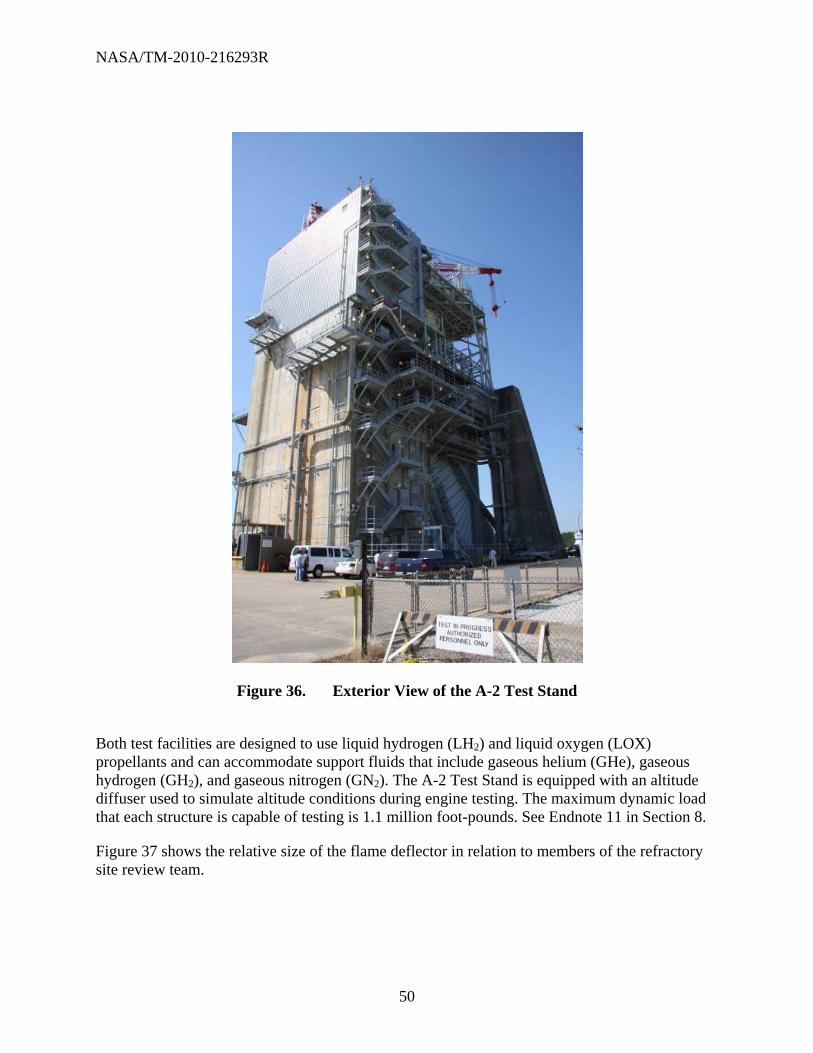
NASA/TM-2010-216293R
50
Figure 36. Exterior View of the A-2 Test Stand
Both test facilities are designed to use liquid hydrogen (LH2) and liquid oxygen (LOX) propellants and can accommodate support fluids that include gaseous helium (GHe), gaseous hydrogen (GH2), and gaseous nitrogen (GN2). The A-2 Test Stand is equipped with an altitude diffuser used to simulate altitude conditions during engine testing. The maximum dynamic load that each structure is capable of testing is 1.1 million foot-pounds. See Endnote 11 in Section 8.
Figure 37 shows the relative size of the flame deflector in relation to members of the refractory site review team.

NASA/TM-2010-216293R
51
Figure 37. View of the A-2 Flame Duct and Diffuser
6.1.2 B-1 and B-2 Test Stands
Each B-1 and B-2 Test Complex consists of a dual-position, vertical, static-firing test stand. The B Complex is 295 feet tall and is equipped with a 200-ton main derrick-lifting crane. The test stand was designed to use LH2 and LOX propellants and can accommodate various support fluids that include gaseous helium, gaseous hydrogen and gaseous nitrogen. The maximum dynamic load that each structure is capable of testing is 11 million foot-pounds. See Endnote 12 in Section 8.
The refractory material team from KSC intended to inspect one of the test stands. Unfortunately, a direct inspection at that time was impossible since the area was cleared for a test. The rocket test is shown in Figure 38.

NASA/TM-2010-216293R
52
Figure 38. Rocket Motor Test at Stennis B-1 Complex
As a part of a prior project, NASA Corrosion Test Laboratory personnel photo-documented the B-2 Test Stand flame deflector (Figure 39).
Similar to the A-2 Test Stand discussed in 6.1.1, the B-2 test stand is a steel structure that is much larger in scale. Figure 39 is used to give a comparative size of the B-2 flame duct in relation to others that are discussed in this report.

NASA/TM-2010-216293R
53
Figure 39. Stennis B-2 Flame Deflector
6.1.3 E-1 Test Facility
The E-1 Test Facility, originally designed as a developmental rocket engine component test facility for the National Launch System (NLS) Program, is available for developmental testing projects requiring high pressure and high flow rate cryogenic fluids, hydrogen, oxygen, inert gases, and industrial water. The E-1 facility is a multicell (3) with horizontal testing capabilities for large-scale propulsion programs (Figure 40).
Figure 40. Stennis E-1 Flame Deflector

NASA/TM-2010-216293R
54
The E-1, Cell 1 is primarily designed for pressure-fed LO2/LH2, LO2/HC, and hybrid-based motors with thrust loads up to 750K pound-force. The E1, Cell 2 is designed for LH2 and LO2 turbopump assembly testing with thrust loads up to 60K pound-force. The E1, Cell 3 is designed for LO2-rich turbopump assembly testing with thrust loads up to 60K pound-force.
6.1.4 E-2 Test Facility
The E-2 Test Facility was constructed to support materials development by subjecting test articles (including refractory concrete) to extreme temperature conditions and fluctuations. This facility has support capabilities, which include hot gas, cryogenic fluids, gas impingement, inert gases, industrial gases, specialized gases, hydraulics, and water.
The E-2 facility is a multicell complex that is capable of testing intermediate-size engines in both the vertical and horizontal configurations (Figure 41).
Figure 41. E-2 Cell 1 Test Stand at Stennis Space Center
E-2 Cell 1 is a horizontal test cell, and utilizes propellants such as LOX, LH2 and RP-1. The horizontal test cell is capable of testing motors with thrust loads up to 120 thousand foot-pounds. See Endnote 13 in Section 8. Cell 2 is the vertical test cell and utilizes LOX and RP-1 propellants. This test cell is capable of testing motors with up to 100 thousand foot-pounds of thrust. See Endnote 14 in Section 8.
Figure 42 shows an overview of the Cell 2 flame duct. As shown in the photo, the flame deflector was built from steel over an I-beam steel structure. The facility has a 4,000 gallon per minute (gpm) water deluge system that is used to protect the flame duct from plume radiant heating during testing. See Endnote 15 in Section 8.

NASA/TM-2010-216293R
55
Figure 42. Stennis Space Center E-2 2 Vertical Test Flame Duct
6.1.5 E-3 Test Facility
The E-3 horizontal test cell can test motors up to 60 thousand foot-pounds of thrust and has support capabilities that include LOX, GO2, and GH2. Cell 2 is a vertical test cell that is capable of testing engines that use LOX, hydrogen peroxide, and HC propellants. Cell 2 can accommodate engines with thrust loads up to 25 thousand foot-pounds of thrust. See Endnote 16 in Section 8. It can also be configured horizontally for using a Diagnostic Test Facility (DTF) rocket engine. This engine is used to generate a subscale (approximately 5% of full scale) rocket-deflector test bed that has a similar plume impingement environment (heat flux, pressure, turning angle, etc.). Instrumentation measures the time-dependent erosion rates of various refractory materials and visualizes the plume/deflector interactions.
Figure 43 shows the flame duct for the vertical E-3 test fixture. Numerous tests have been conducted at the vertical E-3 test stand. Tests have included small-scale combustion devices, such as catalyst beds, to larger devices such as ablative thrust chambers and a flight-type engine. See Endnote 17 in Section 8.

NASA/TM-2010-216293R
56
Figure 43. E-3 Vertical Configuration Test Cell Flame Duct
Figure 44 shows the horizontal E-3 test fixture. This configuration was set up specifically for testing erosion rates of candidate refractory materials.

NASA/TM-2010-216293R
57
Figure 44. E-3 horizontal Test Configuration
6.1.6 Building 3300 at Stennis Space Center
Building 3300 at Stennis Space Center contained remnants of components used for scale model testing of candidate refractory materials. Examples of these components are shown in Figure 45 and Figure 46.
Figure 45. Test Duct at Stennis Space Center

NASA/TM-2010-216293R
58
Figure 46. Refractory Concrete Apron at Stennis Space Center
These components were used as a part of a program designed to support the acquisition of data for baseline deflector design and refractory economical requirements. The program had four objectives:
Establish ROM bounds on the extent of material loss and damage.
Develop comparative data on the ability of various refractory materials to withstand the rocket plume environment.
Develop engineering and scientific data characterizing surface and plume interaction phenomena.
Evaluate (model scale) the operational capability of the deflector.
Scaling of the test articles was driven by the availability of the Bates motor and propellant cartridges. The Bates motor (approximately 6000 lb thrust) was fired down the apron in a manner geometrically similar to that for a full-scale deflector. The plume deflector was designed in the configuration shown in Figure 47. See Endnote 18 in Section 8.

NASA/TM-2010-216293R
59
Figure 47. Stennis Plume Deflector Test Rig
6.2 George C. Marshall Space Flight Center (MSFC)
The MSFC is the U.S. Government civilian rocketry and spacecraft propulsion research center. The original home of NASA, Marshall is today the agency's lead center for Space Shuttle propulsion and its external tank. Located on the Redstone Arsenal near Huntsville, Alabama, MSFC is named in honor of General of the Army George Marshall. Marshall’s East Test Area contains various explosionproof test cells, separated from each other and equipped with basic propellants for testing full- and subscale rocket engines. The Advanced Engine Test Facility in Marshall’s West Test Area is another area in the test laboratory used to test rocket engines. It is used to assess and validate new propulsion technologies and prototype hardware for large rocket engines. See Endnotes 18, 19, 20, 21, 22, and 23 in Section 8.
6.2.1 Dynamic Test Stand
The dynamic test stand is located in the East Test Area and is officially a Historic National Landmark. This test stand was built in 1964 for mechanical and vibration tests on fully assembled Saturn V rockets and was modified in 1977 for vibration tests on the mated Space Shuttle and for evaluation of the craft’s dynamic characteristics. See Figure 48.

NASA/TM-2010-216293R
60
Figure 48. MSFC Dynamic Test Stand
6.2.2 Load Test Annex Facility
Located in the East Test Area, this structural test stand features a multimillion pound, movable crosshead weight, mounted on four towers. The facility is capable of sustaining the force loads experienced by large launch vehicles and can accommodate stages of up to 100 feet high and 54 feet in diameter. See Figures 49 and 50.

NASA/TM-2010-216293R
61
Figure 49. MSFC Test Stand 116, Solid Fuel Torch Test
Figure 50. MSFC Test Stand 115, Solid Fuel Torch Test
6.2.3 Advanced Engine Test Facility
The Advanced Engine Test Facility is located in the West Test Area and was originally designed for testing the first stage of the Saturn V moon rockets. The rockets boasted five F-1 engines, which produced a combined thrust of 7.5 million pounds. See Figure 51.

NASA/TM-2010-216293R
62
Figure 51. A Scaled-Down 24-Inch Version of the Space Shuttle’s Reusable Solid Rocket
Motor Fired at a MSFC Test Stand
6.3 ATK Aerospace Systems
ATK is a pioneer in solid rocket propulsion systems, strategic missiles, missile defense, lightweight space deployables, solar arrays, and satellite thermal management systems. ATK’s space propulsion and ordnance products reflect more than 45 years of experience, providing high-performance and reliable propulsion for the aerospace industry. Their capabilities are focused mainly on solid rocket motors. SRMs range in size from full-scale Space Shuttle reusable solid rocket motor (RSRM), 126 feet long and 12 feet in diameter, to smaller sizes such as 3-inch STAR series. Rocket motor test stand configurations are either in the horizontal or vertical position, depending on motor size, and can be modified according to test requirements. Small-scale testing can be performed on thermal protection materials as short as approximately 1 second in duration. A typical 5-inch CP test would run approximately 2 to 3 seconds. Larger FPCs (40-pound charge) and SPCs (70- pound charge) motors configured horizontally will burn for up to approximately 35 seconds for the FPC and approximately 70 seconds for the SPC. Burn times and temperature depend on chosen propellant and throat diameter. See Figures 52, 53, and 54.
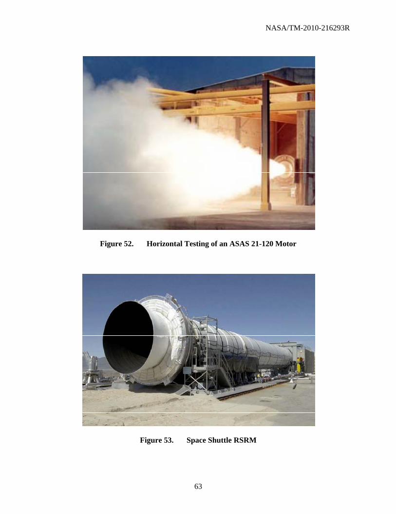
NASA/TM-2010-216293R
63
Figure 52. Horizontal Testing of an ASAS 21-120 Motor
Figure 53. Space Shuttle RSRM

NASA/TM-2010-216293R
64
Figure 54. Space Shuttle RSRM Test Firing at the ATK, Promontory, Utah Facility
7 LIST OF REFERENCES
AIAA 92-3978, ASRM Plume Deflector Analysis Program, Petersen, T.V.; Makel, D. B.; Thurman, C.
ASCE 7 Guide, Guide to the Use of the Wind Load Provisions of ASCE 7-02??
ASTM C20, Standard Test Methods for Apparent Porosity, Water Absorption, Apparent Specific Gravity, and Bulk Density of Burned Refractory Brick and Shapes by Boiling Water
ASTM C24, Standard Test Method for Pyrometric Cone Equivalent (PCE) of Fireclay and High Alumina Refractory Materials
ASTM C92, Standard Test Methods for Sieve analysis and Water Content of Refractory Materials
ASTM C133, Standard Test Methods for Cold Crushing Strength and Modulus of Rupture of Refractories
ASTM C179, Standard Test Method for Drying and Firing Linear Change of Refractory Plastic and Ramming Mix Specimens
ASTM C704, Standard Test Method for Abrasion Resistance of Refractory Materials at Room Temperature

NASA/TM-2010-216293R
65
ASTM C830, Standard Test Methods for Apparent Porosity, Liquid Absorption, Apparent Specific Gravity, and Bulk Density of Refractory Shapes by Vacuum Pressure
ASTM C832, Standard Test Method of Measuring the Thermal Expansion and Creep of Refractories Under Load
ASTM C862, Standard Practice for Preparing Refractory Concrete Specimens by Casting
ASTM C1113, Standard Test Method for Thermal Conductivity of Refractories by Hot Wire (Platinum Resistance Thermometer Technique)
ASTM C1140, Standard Practice for Preparing and Testing Specimens From Shotcrete Test Panels
ASTM C1148, Standard Test Method for Measuring the Drying Shrinkage of Masonry Mortar
ASTM C1171, Standard Test Method for Quantitatively Measuring the Effect of Thermal Shock and Thermal Cycling on Refractories
ASTM C1419, Standard Test Method for Sonic Velocity in Refractory Materials at Room Temperature and its Use in Obtaining an Approximate Young’s Modulus
ASTM E4, Standard Practices for Force Verification of Testing Machines
ASTM E228, Standard Test Method for Linear Thermal Expansion of Solid Materials With a Push-Rod Dilatometer
ASTM E1269, Standard Test Method for Determining Specific Heat Capacity by Differential Scanning Calorimetry
KSC-DD-818-TR, Summary of Measurement of KSC Launch-Induced Environmental Effects (STS-1 Through STS-11)
KSC-DE-512-SM, Facility, System, and Equipment General Design Requirements
KSC-DM-3649, Lift-Off Response Spectra to Space Shuttle Launch-Induced Acoustic Pressures
KSC-GP-1059, Environmental and Test Specification Levels Ground Support Equipment for Space Shuttle System Launch Complex 39
KSC-SPEC-P-0012, Refractory Concrete, Specification for
KSC-STD-164, Environmental Test Methods for Ground Support Equipment, Standard for
KSC-STD-G-0003, Launch Support and Facility Components, Qualification of, Standard for
KSC-STD-Z-0004, Structural Design, Standard for
NASA-STD-5005, Standard for the Design and Fabrication of Ground Support Equipment

NASA/TM-2010-216293R
66
NASA Technical Memorandum 83473, Terrestrial Environment (Climatic) Criteria Guidelines for Use in Aerospace Vehicle Development
NASA-TM-2010-216294, KSC Launch Pad Flame Trench Environment Assessment
NHB 7320.1, Facilities Engineering Handbook
NSTS -7700, Volume XIV, Space Shuttle System Payload Accommodations
SW-E-0002, Ground Support Equipment General Design Requirements
8 ENDNOTES
1. Coburn, S., “Atmospheric Corrosion,” American Society for Metals, Metals Handbook, Properties and Selection, Carbon Steels, Metals Park, Ohio, 1978, 9th ed., Vol. 1, p. 720.
2. Launch Complex 39A and 39B; http://science.ksc.nasa.gov/facilities/lc39a.html; Last
accessed on December 17, 2008. 3. Launch of Apollo 11; http://history.nasa.gov/ap11ann/kippsphotos/KSC-69PC-442.jpg; Last
accessed on September 28, 2010. 4. http://science.ksc.nasa.gov/shuttle/technology/sts-newsref/stsover-prep.html#stsover-sound;
Last accessed on March 8, 2010. 5. http://spaceflight.nasa.gov/shuttle/reference/basics/launch.html; Last accessed on
March 8, 2010. 6. Darrow, E.A., Lays, E.; “Solid-Propellant Rocket Exhaust Effects (SPREE) and Methods of
Attenuation – Volume I: Project Summary,” Report Martin-CR-65-93, Martin Marietta Corporation, January 1966.
7. Perusich, S.; Sampson J.; Curran, J.; Hintze, P.; Whitten, M.; Parlier, C.; “New Refractory
Materials for KSC Launch Pads 39A and 39B,” NASA/KSC Internal Report (2009). 8. Perusich, S.; Sampson J.; Curran, J.; Hintze, P.; Whitten, M.; Parlier, C.; “New Refractory
Materials for KSC Launch Pads 39A and 39B,” NASA/KSC Internal Report (2009). 9. Perusich, S.; Sampson J.; Curran, J.; Hintze, P.; Whitten, M.; Parlier, C.; “New Refractory
Materials for KSC Launch Pads 39A and 39B,” (2009). 10. Calle, L.M.; Kolody, M.; Curran, J.; Back, T.; Hintze, P.; Parlier, C.; Sampson, J.; Perusich,
S.; Bucherl, C.; “WBS 5.3.2 Commercial Off the Shelf (COTS) Refractory Material Evaluation Report” (2009).
11. A-2 Test Stand. http://sscfreedom.ssc.nasa.gov/esd/ESDTestFacilitiesA2.asp. Last accessed
on September 1, 2010.

NASA/TM-2010-216293R
67
12. B-1 Test Stand. http://sscfreedom.ssc.nasa.gov/esd/ESDTestFacilitiesB1.asp. Last Accessed
September 1, 2010. 13. Test Facilities Capability Handbook; Stennis Space Center; NP-2001-11-00021-SSC;
November 2001. 14. E-2 Test Facility. http://sscfreedom.ssc.nasa.gov/esd/ESDTestFacilitiesE2.asp. Last accessed
November 7, 2008. 15. Test Facilities Capability Handbook; Stennis Space Center; NP-2001-11-00021-SSC;
November 2001. 16. E-3 Test Facility. http://sscfreedom.ssc.nasa.gov/esd/ESDTestFacilitiesE3.asp. Last
accessed November 7, 2008. 17. Jacks, T.E.; Beisler, M. Expanding Hydrogen Peroxide Propulsion Test Capability at
NASA’s Stennis Space Center E-Complex; 39th AIAA/ASME/SAE/ASEE Joint Propulsion Conference and Exhibit; 20-23 July 2003, Huntsville, Alabama.
18. Douglas, F.; Dawson, M.C.; Orlin, P.A. ASRM Subscale Plume Deflector Testing;
AIAA 17th Aerospace Ground Testing Conference; July 6-8, 1992; Nashville, TN. 19. Sauvel, J. Static Test Defector for Ariane-6 SRM: Technical Design and Economic Choice.
Proceedings of the second European Conference on Progress in Space Transportation. May 22-24, 1989.
20. Orlin, P , F.; Dawson, D.M.; Bourgeois, S.; ASRM Plume Deflector Analysis; Sverdrup
Technology, Inc.; Report No. 3112-92-016.; NASA/SSC; March 1992. 21. Douglas, F.; Subscale Test Measurement Data Accuracy; Stennis Space Center Report
No. 3112-92-013; NASA/SSC February 1992. 22. ASRM Subscale Deflector Test Report. Vol. 1: Rough Order of Magnitude (ROM) Testing.
Sverdrup Technology, Inc. Report No.311292-008 NASA/SSC; December 1991. 23. http://marshallstar.msfc.nasa.gov/7-20-06.pdf, Last accessed on September 23, 2010.

NASA/TM-2010-216293R
68
This page intentionally left blank.

NASA/TM-2010-216293R
69
APPENDIX A. MMA-1918-80, STS-1

NASA/TM-2010-216293R
70
, /
,---,-,------ -, H __ ' -"'------'-::-CL,;; .. -, ,-',-C'-"'-2-'-, -7-, --)'-M-'-)-j-:;'-b---------l "
, , -,.-,
TASK REQUEST ., .. 0"'1'11; 1\oI.MITTI:O 111. CoIUIJII.O 'COM"I.II;T10N 0"'1'1( '0 "'UTHO"I;U~O CO<lUM&NT
.v; ., One Month after Launch of .- ,;:;-SePt. 29, I 980 -
STS-l , ..... ,....,\.II. o ... elllll,,"'IONI
" Refractory Concrete Test Sampl es: " 1 • Des i gn Concrete Company " .
.' !alFOndu, Fyre WA-I (Approved for Saturn) - 2. Test Samples b Fondu Fyre WA-l (Experimental) - 2. Test Samples
2. Wahl Refractory Products CompanY (a)H. T; Bond Mortar (Experimental) - 3 Test Samples
3. Harbison-Walker Refractories .. ' (al Refractory Concrete -------------, 2. Test Samples ~ " ... --,,? (b) Refractory Concrete (Stainless Steel Fibers) - 2 Test Samples
'J .... ,
I, • .,.ITtU., "'.'-'0"'''0 ""0I0Il/0,", \,11"0 INI ,/ Samples for test - Refractory Concrete.
Location to be SRB Flame' Deflector, 79K09546.
.,1\ .... "' .. YIII ""ltQ"'''II''&O,
SEE "REFRACTORY MATERIALS TEST PLAN" - attached. The three materials are on hand and testing is to be initiated by taking thickness measurements and color photographs of the initial condition of'the surfaces.
, After exposure to SRB exhaust during 5TS-l the samples are to be removed and , returned to the laboratory for further thickness measurements and a determination of surface erosion~ The final surface condition such as spall ing .. will be recorded and color photographs taken for comparison with initial surface conditions.
An evaluation of performance and acceptance or rejection recommendations will be made by formal report.
,/" ''''104'''''11.1"
-
•. ""CQU".Y.". iF. ~"'ON", 10, COM"''''N'f. 11. """' • .., eoo",
W. Clautice PRC-l2.J7 867-3243 PRe PRC-l217 '\:~ .. •••• ;?e{. t? g.,~ , .. IOHONII, I., "' .... 1 .. cou". II. I).TI4. , ~ . ~ 867-3748 DD-MED-l 9/29/80 M •• Osen. ,
FOR LAB USE ONLY 1 ........ UTIa."''fO'' TAl" M"""_"I'l ."'MPI"IL HV",.Itl'l
I L?V. tn7S
I /.I//tlJ1- 191t~ 'It I • ~ " .... "III \II , 'I'
,
I
I
I -l
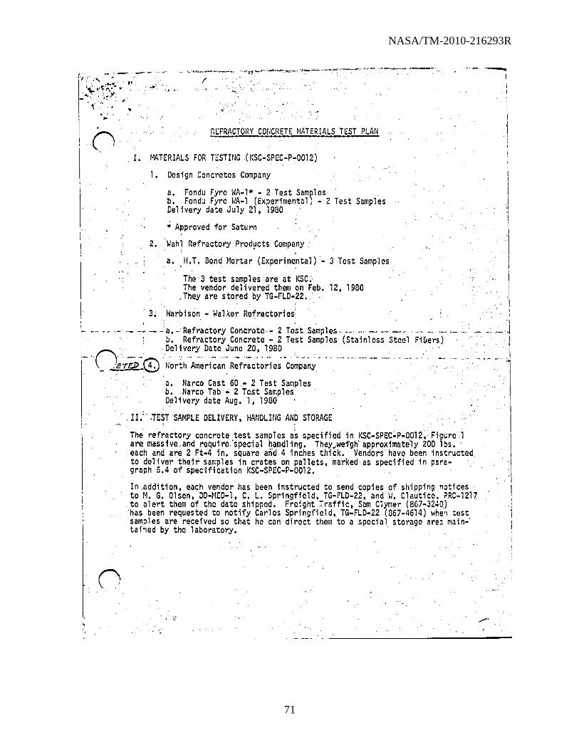
NASA/TM-2010-216293R
71
'"-""',",, -~. -- ,-'--',. . .. ',.. ,1 I\- I'~' 1\....., ~ ... , '
_ .. ", \ :.!,l; .~. r.· , ,
. ' , ~
RcFRACTOHY COIICHETE ~IATERIALS TEST PLAII
,r. MATERIALS FOR TcSTIIIG(KSC-SPEC-P-0012)
1. Design Concretes Company
a. Fondu Fyre WA-l* - 2 Test Samples ' b. Fondu Fyre WA-l (Experimental) - 2 Test Samples Delivery date July 21, 1900
• Approved for Saturn
2. Wahl Refractory Products Company' , ' . a. II.T. Oond Hortar (Experimental) - 3 Test Samples
The 3 test samples are at KSC .. The vendor del i vered thelll on Feb. 12, 1900
,They are stored by TG-FLD-22.
'3. Harbison - Walker Refractories: ,
I~· ., .. ,' .... - .- - . a.·' Refractory Concrete, - 2 Test Samples"
b. Refractory Concrete - 2 Test Samples (Stai nl ess Steel Fi flers)
I Delivery Date June 20, 1980
!- 'O~:ra,-8' Ilorth'A1~~ri~a~' R;f;;~t~;ie;-Co~p~~y - "
a. Narco Cast 60- 2 Test Samples b.Narco Tab - 2 Test Samples Delivery date Aug. 1, 1980
,II:' ,TEST SAMPLE DELIVERY, HAtIDLIIIG AND STORAGE , ,
The refractory concrete test samples as specified in KSC-SPEC-P-0D12, Figure 1 are. massive.,and require,'special handl ing. They.weigh' approximately 200 lbs. each and are 2 Ft"4 in. square and 4 inches thick. Vendors' have been instructed, to deliver their samples in crates on pallets, marked as specified in para-graph 5.4 of specification KSC-SPEC-P-0012.
In .addition, each vendor has been instructed to send copies of shipping notices to M. G. Olsen, DD-NCD-l, C. L. Springfield, TG-FLD-22, and II. Cloutice, PRC-12l7
. to alert them of the date shipped. Freight Troffic, Sam Clymer (8G7-3240) 'has been requested to notify Carlos Springfield, TG-FLD-22 (867-4614) whell test samples are received so that he can direct thelll to a special storage a,'e, maino' tained by the laboratory,
, :( /'

NASA/TM-2010-216293R
72
...... "
' . .
-~-""'-".'~~-"---~",~~,- ----- --,""
."', ,.. o Each vendor has been give the following address for shipment of samples:
-0
o
Chief, Freight Traffic, NASA Bldg. 1·17-6744 3rd St. and Avenue C Kennedy Space Center, FL 32899 ATTlI: Carlos Springfield, TG-FLD-22
III. INSTALLATION AND REMOVAL OF TEST SA~IPLES
TG-SMD-l (Wayne Parris/Bob Laakso) will initiate and manage the Support Request to BSI for the handling, installation, and removal of the refractory. concrete test samples in the existing SRB flame deflector test fixtures. A PCN will be issued to accommodate charges. BSI is to provide all services necessary. Bolt heads and scams are to be covered with ablative coating (Dow Corning Q3-6077) as specified inDwg. 79K09546 Sheets 1 and 2, attached.·.
After the launch\the samples nre to be. removed and transported to an area designated by the laboratory, TG-SMD-l, Carlos Springfield, 867-4614. Prior
. to removal of samples contact Carlos Springfield. Photographs arc to be
. taken of the samples prior to their removal •
. IV. SPECIMCII· ORIEilTATlON.- - ... ~. ..c·- .. · .... - - .. ..... _ .. -. --_. . .
The test fixture on the SRB flame deflector, DWG 79K09546 will accommodate six spocimen samples. The· number of samples to be submitted arey.r.IIThorefore, 3 launches will be required before the testing of all samples is accomplished •
. A pattern of testing orientation in the test fixtures is as follows:
walll l'oMU t:'~/'J",,", ,
liT Fire oW1\JfI- \IJo.1I \ .-~~~ H~W II/I~ Bond WA-l fE*P+ '+ Mortar * . "'A-"W .... S.S;
• Approved for Saturn : ~. LAUNCH 110. 1
-Fondu.(
~ I~ fondu .~ H/W Fyre >t Fyre
WA-l WA-l BcmO-'i'EXP) . * -Mol'-tal'-
'f""" * App roved for 5ilturn
W~lJl
N;.t
H/W IIi . + Bond S.S. ~1ortar
LAUNCH 110 .. 3
, I
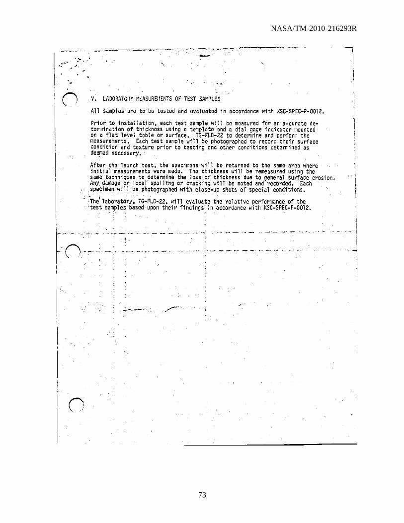
NASA/TM-2010-216293R
73
'---.~"" _. ;-", . '~ .. '.""'-'~'.'"'. -.,-' . .----------~ .. -.. ... '
n . V. LMORATORY rlEASUREIiENTS OF TEST SAMPLES
All samples are to be tested and evaluated in accordance with KSC-SPEC-P-0012.
Prior to installation, each test .ample will be measured for an a-curate detenllination of thickness using a template and a dial goge indicator mounted on a flat level toble or surface. TG-FLD-22 to detennine and perform the measurements. Each test sample will be photographed to record their surface condition and texture prior to tasting ond other conditions detannined as dee.med necessary.
After the 1 aunch test, the specimens wi 11 be returned to the same orao where initial measurements were made. The thickness will be remeosured using the same techniques to determine the loss of thickness due to general surface erosion •
. Any damoge or locol spolling or cracking will be noted and recorded. Eoch
. specimen will be photogrophed with close-up shots of special conditions • . :. I . . . .
.. ·The laboratory, TG-FLD-22, will evaluata tha ralotive performonce of the .. ··test sampl eS' based· upon thei r findings' in occordance with KSC-SPEC-P-0012.
,_ .. ..... - ~.~
: .
n-~·,,· ~ •.• ~, •• ',.'" _' _.,. "., ,_M ••••.• _._ .... _. ~_.' •. , _ __ . ~- -". ",.
l
'-I
i 1

NASA/TM-2010-216293R
74
, "
" '
, '
---.-".. .------... _., JO~ ,.'/ "-' .-
5."
. ",
'-_. --"- . -----_. -- \ -- ~- _ .. ,,"
I' ,,'., "T . .., '''.' ""
" .. _,
.'
. , J
o '
' . • o:S ~ s n ,(lIT E' ·:.Z:fEj7EZiOR.
'0 ,
1 I
,"' .... ',

NASA/TM-2010-216293R
75
o
-1
[
I,' 'I
, . -,
I r! t'
I:, " .,;. l !' , \~
t.
x
I
,?, "",:' .,'

NASA/TM-2010-216293R
76
;~ ..
I
·0
.. ,
.. :';
w.'O~ ,6 .' 1:1
-'!II ')11
,~O
. .. r
• I
..

NASA/TM-2010-216293R
77
'.~-"' '\
:~ - '"
.~ ____ ;;~~,;;r/~· .
REFRACTORY CONCRETE,
SPECIFICATION FOR
. , _"'#' --""",,' C
~-", .
·DESIGN ENGINEERING DIRECTORATE .
KSC-SPEC-P-00l2 .April25, 1979
i I
1 i i
--------~~---------------

NASA/TM-2010-216293R
78
r:------- "' 1
" I .. :-.- . I
• r .. :1 •
11,0, 1 CJI
'I
,
REFRACTORY CONCRETE. . SPECIFICATION FOR
Approved: "'
~dL. lfr(cK ~ ~ D'lrector of Des1gn Eng1neer1ng
JOHN F. KENNEDY SPACE CENTER, NASA , '
KSC-S PEC-P-OOl2 " April 25, 1979 '
I
I I
I I I
I ,I , ,
I
I , 'I

NASA/TM-2010-216293R
79
.. ','
Suction
1.0
2.0
2.1 ,2.1.1 2.2
3.0 '
3.1 , -3.2,
3.3 ',3.3 •. 1:, '3.,3; 2-3'.4 ' ' 3.5 3.6 3.7 '
4.0
4.1 4.2 4.3 4.3.1 4.3.1.1 4.3.1.2 4.3.1.3 4.3.1.4 4.3.2 4.3.3 4.4 4.5
5.0
5.1 5.2 5.3 5.4 5.5
I In I
I~
TAllLE OF CUNTENTS
5COfi[ ••
APPLICMLE DOCUMENTS
GovermnenLal St.nddrds. ., Non .. Governmental
RCQUIHEMENTS •
Qualification. Materi als . 1'_"
Properties- •• Fi neness Modul us •
.. Strength"'" • _, ':.. • .'" Stabil it,)"":" ••
, Rocket "Cngine Exhaust Workabil ity •••• '. Weathering •• ,
· .... · . . . . . · . ;"'-:". "'. · -'. . . . .' Resistance
· . . . QUAL ITYASSURANCE PROVISIONS
Responsibility • •• '" • Product Qualification Hcquirelllcnts Qual ification Tests. ',' Test Sampl e •• " •• Reinforcement ••••••• Cover for Rei nforcement •• Surface Fi ni sh ••• • Rocket Engine Exhaust Exposure Fineness Modulus ••• Strength' ., • • • • . . • Certificate of Conformance Test Reports I • " •
PREPARATION FOR DEL'IVERY
Packagi no •• Packing. • ••• Palletization • • •• Marking.. •• • •• • Mixing and Application Instructions
,0 I,
.
KSC·SPEC·P·OOI2 April 25. 1979
.
.
2
2 2 2 2 2 Z 2 2 2
Z
2 3 3 3 3 3 3 3 3 3 3 3
3
3 3 4 4 4
iii
.., I "
!
j I
I I
i I I
I , I I I I
I
I I
I I

NASA/TM-2010-216293R
80
n
iv
I I I I I
,
j

NASA/TM-2010-216293R
81
.,' ',,'
n
,I,)IIN J. KLNNeDY SPAce CCNTLH, NASA
ReFRACTORY CONCRETe,
SPECIFICATION FOR
KSC-SP£C-P-0012 April 25, 1979
This spec·Hic.tion has been .pproved by the Oeoign Cngineering Oirectorate of tile John F. Kennedy Space Center (KSC) and is mandatory for use by r.SC and associated contrdctors.
1.0 SCOPE
Thi~ spec1ficiltlOrl Covers requirements for refractory concrete used for the heat and .blast protection of flame deflectors, and other areas of a launch :~~~,~,~~~~,,: ,~~'" .. ,.-~, ~ .. -"., .. ':." 2.0 APPLICABLE DOCUMeNTS
". The pub"'ications 'orthe' issue~in' efreeCon. the 'date 'of issuance of invitation for bids fonn a part of this specification and, where referred to thereafter by basic desi9nation only, are app1 icable to the extent indicated .by the I'cferences thereto. In the event of difference between this specification or its accompanying drawings and the referenced specification, this specification ,nd its accompanying drawings shall govern to the extent of such difference.' ?.l. Governmenta 1.
<.1.1 Standards.
Mil it.ry
M IL-STD- 1 29 Marki ng for Shillment and Storage '>' ....
(Copies of standards required by .. ",e-contractor in connection with specific procurement functions should).e-:-6htained;ti'om the procuring activity or as -ctr .. ~cted by the. contr~'1Jfflcer.)~/ 2.2 Non-GovernmentaL;' ,
Ameri can Soci ety for Tes t i ng and Materi a 1 s (ASTM)
C 33
C 39
Concrete Aggregates
Comprossive 'Strength of Cylindrical Concr~tc Specimens
(AppliclltioTl for copies should be addrcssCt1 to the Amcricdfl Society for Testing. and Mdterials, 1916 Haec St., Philad"'phia, Pennsylvania, 19103.)
l ,
I
I I
i

NASA/TM-2010-216293R
82
-----" .. ,_.,,,. - ... ---------- ","-" .--------------.... ----:--,~.~ ,...,. . ...,..~.".----
" 3.Q REQUIREMENTS
"'. KSC·SPEC.P·0012 April 25, 1979
3.1 I)Ja 11 fi cat 1 on. The refractory concrete furnished under thi s s~ec i fi ca· t ion shall Ge a product that has been tested and has passed the qual Hication tests specified in 4.3, and has been listed or approved for ,listing on the rlpproved products list.
3.2 Materi.lls. The fine aggregate shall be hard. dense. durable. clean, sharp •. 1nd wei 1 gr.lded.
3.3 Properti.s.
3.3.1 Fineness Modulus. When tested in accordance with 4.3.Z, the fineness modul us sha 11 be between 3.75 and Z.75. 3.3.Z Strength. When tested in accordance with 4.3.3, refractory concrete ~nall develop. compressive strength of 4500 psi (minimum) at 7 days and 90 percent of the 7.day strength within Z4 hours. If desired to develop improved properties, use of randomly dispersed steel, wire fibers shall be pennitted provided,steel fibers do not segregate and clog nozzles. 3.4 Stabil1ty. When maintained in the original unopened bag for a peried of I year, the material shall meet the requirements of this specification. . 3.5 Rocket Ennine Exhaust Resistance. Test" samples installed at designated, dreas of the launch facil ity and then subject to rocket engine exhaust, shall 1'"'\ not crack, spall, or erode,more than I/B inch when tested in accordance with \ /4.3.1.4.' Heat flux will be up to 3300 Btu/ftZ.sec; time of exposure will be ". approximately 10 seconds.
"
\. ,
3 6 workabil ity. The refractory concrete shall be capabl e of being appl1ed ~neulllatically or manually (trowel) to a unifonn, smooth finish., .. ""'" ' 3.7 Weathering. The material shall resist degradation of thermal, protection characterlstlcs due to seacoa5t atmosphere exposure. 4.0 QUALITY ASSURANCE PROVISIONS 4.1 Responsibility. Unless otherwise specified, the manufacturer is respon· sible'for the perfOnnance of all inspection, requirements specified herein. Except as otherwise specified, the manufacturer may utilize his own or any other inspection facilities and services acceptable to NASA. Inspection rec· , ords of, the examinations and tests shall be kept complete and available to the Governmant for a period of five years, unless otherwise specified in the can· tract Or order. The Government reserves the right to perfonn any of the in. spections set forth in the specific.tion, where such inspections arc deemed necessary, to ensure supplies and service5 confonn to the prescribed requirements.
o Z
., I
I
I I
\ I
\
1

NASA/TM-2010-216293R
83
1. KSC-SPEC-P-0012 April 25, 1979
4.;~ Product udlificI1t1on RC(lJir·el;'t~nt~. To /)l~COll1e 11 qUdlified prodllct, mate .. ridl Tihil tll~ct t e requIrements 01 ::.ect'iul1. 3 I1nd 'pass the qual ifiCl1tion tests uf 4.3.1 through 4.3.3.
4.3 Qualification Tests.
4.3.1 Te,', Samel e. A test sample shall be required in accordance with figure I dnd the tollowlng reqUirements,
4.3.1.1 Relnforcoment. Reinforcing steel shall be Bufnel Gripsteel .s manuf.ctured by Keene Corpordtion. Sallta Fe Springs, California or equal. Reinforcing steel shal'l be free frorn rust, scale, grease, or other coating which may reuuce the bond.
4.3.1.2 Cover for Reinforcement. Minimum concrete. coverage for reinforcing steel from the surface exposed to the rocket engine exhaust shall ~ot be less. th.n 1-1/2 inches. .
1,.3.1.3 Surface Finish. Surface finish shall be unlfonn and smooth. 1,.3.1. ,Rocket En~ine Exhaust Exposure. The test sample shall be installed (~t t,ht! dcslgnatCdaunch Slee locatlon and exposed to a rocket engiM exhaust. ':I,e tes~ ,ample shall be examined for conformance to 3.5. Installation and examination of the test samples shall be performed by the Government. 4.3.2 Fineness MOdulus.· The fineness modulus. of the aggregate shall be detennined In accordance w.1th ASTM C 33.
4.3.3 stren~th. The compressive strength shall· be determined in accordance witl, AsiA t 9. ' ". ,
4.4 Certificate of Conformance. The manufacturer shall submit a certificate of confonlldnce statIng that the materldl furnished is essentially identical to the materi d I furni shed for qual i fi cat i on test i ng and compl i os wi th the r'equi ramp.nts spec i fi cd herei n.
4.5 Test Reeorts. The manufacturer shall submit a certified laboratory report deSCribIng the tests perfonlled in accordance with 4.3.2 and 4.3.3. 5.0 PREPARATION FOR DELIVERY
5.1 Packaging. Unless otherwise specified. material shall be furnished in bags containing 100 pounds of a prelilixed combination of refractory aggregate in hydraulic setting binder.
5.2 Packing. designation in lowest rate.
Pdcking sh.1I be in a manner which will ensure arrival at the satisfactory condition and be acceptable to the carrier at the
\
l
I
\
I
l I
I .1
I 1
i

NASA/TM-2010-216293R
84
n ....
KSC·SPEC·P·OOlZ . Apr1l n, 197~ ,
·1 ~.3 .!J~l l~tildtl(ln. ~~1~:1 s~~clflcd (SOC 6:2), shjppin~ containcr~ shdll De pillle"'("i""fioo USlnlj )t(p.'~Jrd wOad1" ~dl1ets. t>.4 Marking. III ddditi(lfl 1.0 ilny specIal marking required by the contract, or o"lor, ba~, 'h'll be m,,,,,od in ·accordance with MIL·STO·l29, Each bag shall <li~play the following 'nforlilation.
a. Title, number, and da:e. of t~is s~ecification
b. Name of the product
c. Batch nUlliber
d. Manufacturer's name and address
e. ~cight of contents
f. Date of manufacture
g. Toxic. precautions'
r,. Necessary sup~lementary .information to ensure safe and proper use of the lIIateri a 1 .
5.5 Mixinp and Application Instructions •. Mixing and application instructions shall 5e lncluded wlth each shlpment.
6.0 NOTCS·
5. 1 Intended Usc, The refractory concrete. is intended for use on the flame ~eflector and other areas of a'launch complex to protect the facility from .··.,l'ant heat and flame impingement effects of the rocket engine exhaust plume of d launch vehicle;
6.2 Ordering Data. Procurement documents should specify the following:
a. Title, number, and dateof ... this specification/~" .'
b. Number of lOO·pound bags
c. Certification of Conformance (see 4.4)
d. Test Report, (see 4.5)
e. Palletization,'if required (sec 5.~)
NOTIce; When Qovernment drawings, specifications, or other datil arc used for dny purpose other than in connection with a definitely related Government procurement operation, the United Stat~s Covernment. thereby incurs no responsi .. bil ity nor any ob' 19at1on whatsotlver~ ilnd the filet that the Government IlIdY
4
l

NASA/TM-2010-216293R
85
i-----" . . " ..... -,. < •
• KSC-SPEC-P-0012 April 25. 1979
hd'll: farlnulJtl!d. f'.:rnishcd, or in any WdY supp~ied the said drawings. !i.pcciflCflt ions, or othar" Cgtd is not to be regarded by i;l1pl ication Or otherwi~ a~ ~n dflj manner licensing the holder or any other person or corporation
t Or" convey
int; cny rights or pennission to manufacture t use, or sen any patented loven-. tion thdt" Ir.dj1 in any way be related thereto.
CUSTOJIAN:
NASA-John f. Kcnl"C'uy SlJdCl~ Center
PREPARING ACTIViTY:
John F. Kennedy Space C~nter Mechanical Design DivisIon Design Engineering Directorate

NA
SA
/TM
-2010-216293R
86
r-) 1)
- 1!C·"fl
TYPICAL SECTION
. '" V3..'4'"
0>
FIgure 1. Tost S .. pl. COnfIguratIon
,31.·
3/4-
NOte:
))
SVRF AC£ EXPOS,,- ()-ro ROCKET EN':iIl\l EXHAUST
- REFRACTORy CONCRETE
3ic·· X 14 G.a.UGE GRID STEEL REINfOnCING
ALL OJIoIENSIONAL TOLERANCES SHALL liE: .,.g
-li8INCH
, , .. ..; . . -. . ,
"
f'
I 1
~'
" >V> ~~ .... ~. V> ~"
'" "'~ on • . " • -C> "'<> ....,-'" '"
i
._ .... _ ........ J

NASA/TM-2010-216293R
87
. " . . . /~-", TASK REQUEST •
.... 0",'1'11: IUIMITT.a a. DIUIf'lII:C COMI"I"II:TION DATI. ~ •• ,",UTHOI'U<l:t,..G OOCUM.NT -/
4-9-76 4-77 Nf.A )"'''''1''1011: O.'CI'IIPTIO"" . , .. ,; Refracto,¥concrete used on flame deflectors.
'n"
~."V'TICM .... ...0 VIED 1"1'10101/01'1 VIICO 1"11
N/A ,
,
•• "'''1''1.,'1''11 "'''Qu ... nt!)1 Assist in the installation and evaluation of refractory cortetesamples on LC-17. Samples to be installed on carrier plates with Gripsteel. Samples shall be installed on the North side of,the umbilical tower base at a 'location where severe spalling is evident.
)
Also assist in the identification of appr~ate laboratory tests for evaluation of refractory concrete which would be suitable for specification purposes.
1. HI" •• ",,,,,-,
Arrangements have been made with Mr. Bob Wilson, the LC-17 Facility Manager, for installation of the test, samples.
, ~. I'lliQUlElTtOHI
8. "' ... 1;1,...:' 'D, COM ..... ,..'" II, MAU. CDUIC.
~ .. '"",0".' 'd, U, PHONICI , .. , MAIL. COD"'I ID. OAT":,
M. G. Olsen ~ • ~_ 7-2102 DD-SED-3 4-9-76 FOR LAB USE ONLY
IN ..... IITla ... TOI'I '1' .... 1'1. NU"'~IU' ....... 1"10 .. "11.1""11£1'11
,J"OE. M<> a.(i..sooJ .M-m. 071: .7 '-"Ie: 1I'0l'lM 12.R, tl'l ..... , 1"01
I N"""'I(IC NOV/?!

NASA/TM-2010-216293R
88
1.0 FOREWORD
NASA r
MALF~NCTION/MATERIALS ANALYSIS SECTION ~ATi~IALS .NALYSIS BRANCH
FLUIDS AND ANALYSIS DIVISION , . TG-FLD-22. ROOM 1218. O&C BUILDING
KENNEDY· SPACE CENTER, FLORIDA 32899 JULY 29, 1981
MMA-1918-80
1.1 On 29 Septembe", 1980, W. E. Clautice, PRC-1217; ( "equested testing of "ef"acto"y conc"ete test panels,
the testing to comp"ise thickness measu"ements, colo" photographs, and visual obse"vations· both befo"eand afte" exposu"e to SRO exhaust dU"ing STS-1 Launch.
_ .. 0. ," .. .• ..::.,..-- . .,!..
II
1.2 P"epa"ations foe this test had been unde"way foe some time. Test frames designed by PRC had been installed at LC39. Test panels p"epa"ed to KSC specification had been solicited f"om fOU" vendors. One vendor, No"th Ame"ican Ref"acto"i.s Company, had declined to furnish samples, foe "easons,outlined in thei" lette", which is "ep"oduced in the appendi x.Three vendors had fu"nished samples as follows:
I. 2.1 nesi~ned Conc"etes Co. 2 panels Fondu Fy"e WA-1 (App"oved fo"Satu"n) 1 panel Fondu ~y"e WA-1 with wi"e 1 panel F.ondu· Fy"e FSC-5

NASA/TM-2010-216293R
89
"' . . .- ,
" .) l'",~ .!,
2
o· 'j ,
MMA-1918-80
1.2.2 Wahl Refractory Products Co. I panel WRPI Color-White PSM Cast, H2 0"Fiber I panel'WRP2 Color-Cray Cement Fondu; Parry
Sand, H20, Fiber . I panel WRP3 Color-Cray Cement Fondu
50m Ball Mill Calcined Flint Clay
H2 0 Fiber
1.2.3 Harbison-Walker Refractories 2 panels' Tufshot 2 panels Tufshot with 3.25% type 310 SS melt
extracted fibers
1.3 Shipping documents for these panels are reproduced in the appendix.
1.4 In the interests of expediency the support requests for the,handling, installation, and removal of the test panels were initiated and managed by TG-FLO-22.
2.0 TEST PROCEDURE
2.1 TEST PANEL SELECTION The II test panels supplied by the three vendors were, examined by the requester. W. Eo Clautice, PRC-1217, R. J. Davis, DD-MED-33, and C. V. Moyers, TG-FLD-22. Mr. Clautice selected 6 panels for exposure during STS-I launch.

NASA/TM-2010-216293R
90
.' _ _ • _ J • .• _
1-
.;,1, .)' ,t,'...... .".1.
,. MMA-1918-80 3
2.2 ' TEST PANEL IOENTIFICATION The panels supplied'by Designed Concretes bore 1 inch black stencilled identifying marks on the upper surface. No identifying marks were found on the other panels. The six selected panels were assigned numbers as follows:
PANEL NO 1.
DESCRIPTION Wahl. (WRP-l). Contained silver-colored
, chopped wi reo 2. Designed Concretes, ~WA-l."
3.,' Designed Concretes. 'WA-l-W/WIRE' 4. Wahl. (WRP-3). Contained gold-colored
chopped wire. (WRP-3) 5. Harbison-walker. (Chopped wire). 6. Harbison-Walker.'
t.3 'PRE-EXPOSURE THICKNESS DETERMINATIONS A template to locate 13 pOints on each panel (Figure 1). and a ,caliper to determine thickness at each point were designed and fabricated. The 6 panels were placed on inspectlon racks which afforded access to both top and bottom surfaces (Fi gure 2). and thickness at each of the predetermined pOints was measured. Photographs were made o,f each panel. and they appear later in this report.
2.4 SRS EXHAUST EXPOSURE, The panels were then installed in the two refractory test frames (OWe 79K09546) at the bottom of the SRS flame ,deflector in the north end of the flame trench at LC39A(Figure 3). Each frame holds three panels. The holddown cJamps and the ,areas between panels were ,
, I

NASA/TM-2010-216293R
91
.' MMA-19IS-S0
coated with Oynatherm E-320 ablative coat1ng. The panels ~ere, 1nstalled 1n numer1'cal sequence from cast to west. F1gure 4 shows a test ,frame with panels installed. The,panels remained on the, test frames unt11 afterSTS-I launch.
2.5 POST-EXPOSURE THICKNESS DETERMINATIONS
4
After launch, the panels w~re photographed. They were, then removed from the test frames and transported to the 1nspect10n 'racks, where the same template and ca11per were used to make th1ckness determinations. The depths of representative spalled areas were determined, us1ng a depth gage prov1,ded w1th a dial 1nd1cator and a t1p with a rad1us of about 1/8 inch.
3.0 RESULTS
F1gures 5 through 28 show the 1nd1vidual panels as rece1ved, as 1nstalled in the test frames before launch, and as they appeared ~fter launch. Figures 29 through 34 show individ-, ual th1ckness measurements before and after launch, and the th1~kness, loss at each 10cat10n.
Table I shows the average thickness losses and observations of surface 'condit10ns after launch.
Based on examination ,of the ablative coati~g around the ' panels after launch, it appears that the east rack (panels 1,2, ~nd 3) received more severe exposure, and that the panels nearest the sides (panels I and 6) rece1ved slightly less exposure than the other panels on the same rack. Some variation in"exposure 1s t,o, be expected as the vehicle is steered during 11ftoff in response to the effects of wind at the time of launch.
.' "

NASA/TM-2010-216293R
92
,MMA-191S-S0 ,5
4.0 CONCLUSION
All of the panels lost more ,than the maximum 1'/8" permitted by: KSC-SPEC-p-OOr2.
5.0 'RECOMMENDATIONS
A ,second exposure of these ,panels to the SRB exhaust is recommended. 'with-the east to west positions of the panels changed, from 1. 2. 3 - 4. 5. 6 t04. 5. 6 - 1. 2.3. It is also recommended'that reference plates with a known thickness of ablative coating be, embedded flush with the surface of the ablative coating applied to the racks. This will permit assessment of the relative severity of exposure for each panel.
INVESTIGATOR: C. V. MOYERS
APPROVED: e, MMAS/NASA

NASA/TM-2010-216293R
93
MMA-1918-80
Panel
...l:!.2.!.... 1.
2.
3.
4.
Average.
Thickness Loss,
Inches ',0.163
0.256
0.325
0.235
6
TABLE 1
CONDITION OF PANELS AFTERSTS-l
Average Thickness
Loss, % of 4"
4.1
6.4
8.1
OBSERVATIONS Few spalls. mostly large. to 0.222" deep_ "Fibers" exposed.
Very few spalls, to-0.258" deep. Portions of pre-exist~ i n9 crack covered by fused layer. Surface generally
,rought but uniform. Panel remained intact when removed.
One spall 0.214 deep. Cracked, into six segments with some fused material over portions of cracks. Cracks measured to 0.373" deep, with deeper narrow fissures. Surface
, ,generally rough but uniform. --:Vranel remained Intact when
removed.
5.9- Small, numerous spall s, to 0.174" deep. Gouge' at edge 0.370 deep. Orange rust stain. Exposed carbon steel wires deeplY,oxidized, easily broken.

NASA/TM-2010-216293R
94
o ,'- .'
MMA-191B-BO
Panel
..1!.2..:.... 5 •
6.
Average Th1ckness
Loss, lnches 0.238
'0.192
7
TABLE 1 (Contfnued)
Avera ge Th1ckness
LOss. % of 4"
5.9
4.8
OBSERVATIONS Moderate number of spalls, med1um to small, to 0.346" deep. "Fibers" exposed.
Moderate. number of spalls, mostly large, to 0.258" deep. Corner 1nadvertently cracked dur1ng removal.
\~------------------------------------------------

NASA/TM-2010-216293R
95
o
,
, I'
·0 "
o
, , :-I '
I
·0 I
.
.
I :''':--~'T "'''i
o o
i. ;
, i
o
o o
o
o o
.
Le-----.. ··-·.-:.···-.. ··-·· __ 28:t:~-'6_-~_6-a+2~' -~---~------~-------30
0· ,
'. . '.

NASA/TM-2010-216293R
96
MMA-~918-80 9
FIGURE

NASA/TM-2010-216293R
97
MMA-191S-S0
FIGURE 3. SRB ME DEFLECTOR AND TE

NASA/TM-2010-216293R
98
MMA-1918-80
r
FIGURE 4.
~AS~~~AruM~~~W~~J-u~"~~~~~

NASA/TM-2010-216293R
99
M -1918-80
FIGURE 5 . eAN ~ ~l'i ED •

NASA/TM-2010-216293R
100
MMA-1918 - 80
r
FIGURE 6. PANEL I, INSTALLED IN TEST FRAME, BEFORE LAUNCH .
I

NASA/TM-2010-216293R
101
• MMA-1918-80 14
FIGURE 7 . PA~EL I, IN TEST FRAME, AFTER LAU~CH .

NASA/TM-2010-216293R
102
MKA-191S-S0
FIGURE S. PANEL I, ON INSPECTION RACK, AFTER LAUNCH .

NASA/TM-2010-216293R
103
MMA-1918-80
r"
FIGURE 9 . PANEL 2, AS RECEIVED .
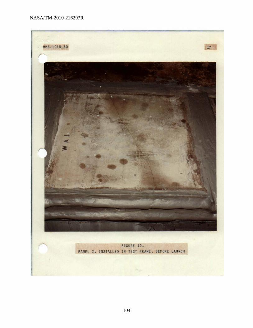
NASA/TM-2010-216293R
104
MMA-19lB-BO 17
FIGURE 10. PANEL 2, INSTALLEO IN TEST FRAME, BEFORE LAUNCH.

NASA/TM-2010-216293R
105
MMA-1918-80
r
r FIGURE 11. PANEL 2, IN TEST FRAME, AFTER LAUNCH.
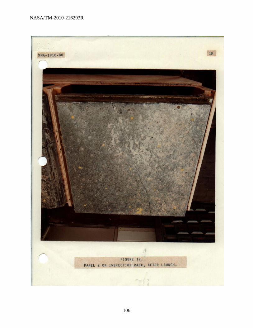
NASA/TM-2010-216293R
106
MMA-1918-80 19
r
r FIGURE 12 . PANEL 2 ON INSPECTION RACK, AFTER LAUNCH .

NASA/TM-2010-216293R
107
MMA - 1918-80 ZO
FIGURE 13.
"-_____ '-PA;.;;N,;.;E;.;-l 3. AS R ;;.EC;.;E;.:I~V~E;;.O .:... _===_~

NASA/TM-2010-216293R
108
MMA-1918 - 80 2
FIGURE 14 . PANEL 3, INSTALLED IN TEST FRAME, BEFORE LAUNCH .

NASA/TM-2010-216293R
109
MHA- I918 - 80 2
FIGURE IS . PANEL 3, IN TEST FRAME, AFTER LAUNCH

NASA/TM-2010-216293R
110
MMA-1918-80
FIGURE 16 . PANEL 3, IN INSPECTION RACK, AFTER LAUNCH .

NASA/TM-2010-216293R
111
MMA-19IB-BO
FIGURE 17. PANEL 4, AS RECEIVED.
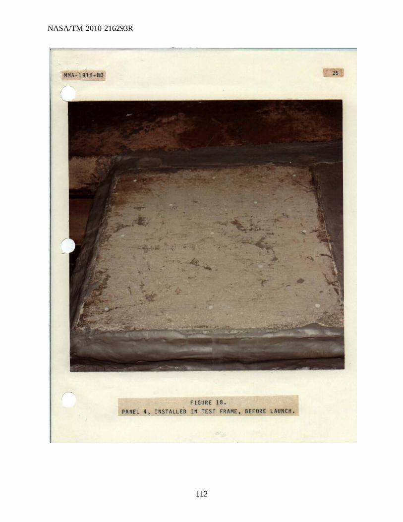
NASA/TM-2010-216293R
112
MMA-191B-BO
FIGURE lB. PANEL 4, INSTALLED IN TEST FRAME, BEFORE LAUNCH.

NASA/TM-2010-216293R
113
MMA-1918-80
FIGURE 19 . PANEL 4, IN TEST FRAME, AFTER LAUNCH.
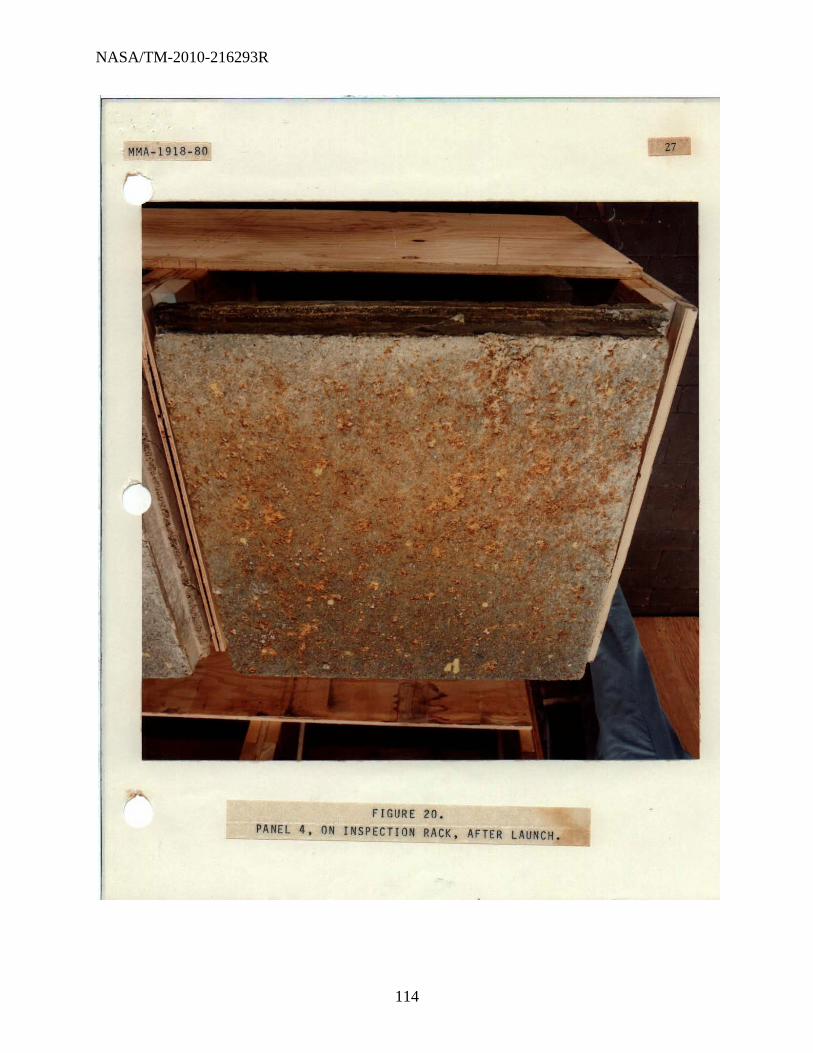
NASA/TM-2010-216293R
114
MMA-1918-80
FIGURE 20 . PANEL 4, ON INSPECTION RACK, AFTER LAUNCH .

NASA/TM-2010-216293R
115
MMA-1918-80
FIGURE 21. PANEL 5, AS RECEIVED .

NASA/TM-2010-216293R
116
MMA-1918-80
FIGURE 22 . PANEL 5, INSTALLED IN TEST FRAME, BEFORE LAUNCH .

NASA/TM-2010-216293R
117
MM~-1918 - 80
FIGURE 23 . PANEL 5, IN TEST FRAME, AFTER LAUNCH.
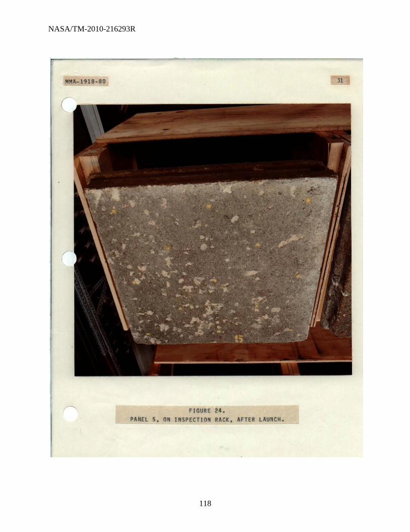
NASA/TM-2010-216293R
118
HA-PIlS-SO 31
FIGURE 24 . PANEL 5, ON INSPECTION RACK, AFTER LAUNCH .

NASA/TM-2010-216293R
119
MMA-1918-80
FIGURE 25 .
PAN E L 6. A S R,~E~C~E.:.I .:.V ~E D::':.:-. __ ~=~-I

NASA/TM-2010-216293R
120
MMA-1918-80 33
FIGURE 26 . PANEL 6, INSTALLED IN TEST FRAME, BEFORE LAUNCH.

NASA/TM-2010-216293R
121
~HA--1918-80 34
r
FIGURE 27 . PANEL 6, IN TEST FRAME, AFTER LAUNCH.
~~~~ ~~~---

NASA/TM-2010-216293R
122
MMA-19IB-BO 3S
FIGURE 2B . PANEL 6, ON INSPECTION RACK, AFTER LAUNCH .

NASA/TM-2010-216293R
123
~M~-1918-80
~'~2.s o ,& iJ I ().Ilf--S
). ---------
,33{)
o '+.105 /2. 0, z.z.~
14,2.2 or o 4-.06C; 2. f),lto
3175 o ,3 ()
10 (),/75
~Z35" o £1.177'5 5 (), /60
0
/3
0 5
36
f+--,!''fO
(;:f.:.!:J..!!... {).150
(f,2I:" '(U9 (), /'l.~
_ .. _'-,517
~~f~ ~l
---_.----_._-- ---
FIGIJR[ 29,
THICKNESS M[fIStJREMENTS. f)ANEL 1
,
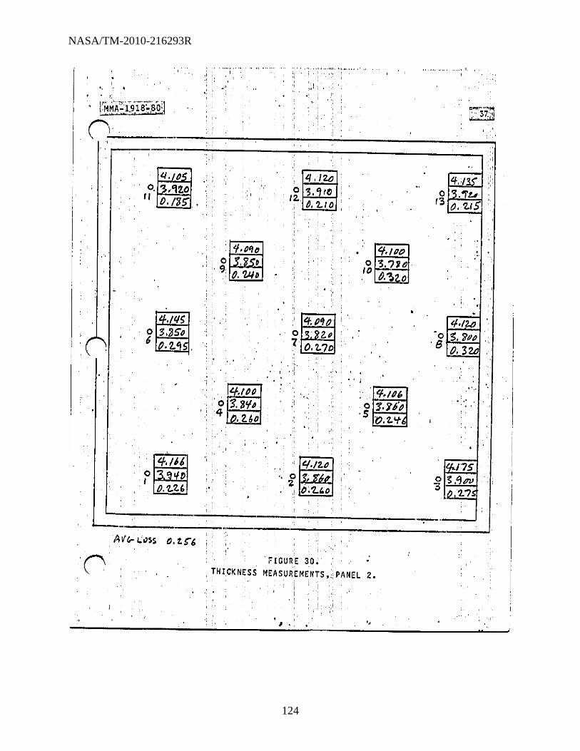
NASA/TM-2010-216293R
124
. ,
tMMA"~i9,187;8PJ ~~,- .
n-"--
I i ,I
"I: ·<t'l '
," 'j
I ' ,
"
,------~--~------------------------~~ ,':
4, f)
0, '3.'U.O II 1)./'6>
, , , ,
': I
", "I'f'''~ol " , o~ ,', '9 ' • ,
'.,' " I), U/D'
"
,
Izt.;, f)" ;'0 '$. 'J/fl 4 1".2.60 '
. " ,
' .
1/ ,/2.(;
o .'5 >,w' ql..!;l tI::..j 12. (-f). 'l..' 0
,
, .
, ,II , ,
'I-.,{}I) o '3, ?'ie 10 &:~2.0
, 'f./P" o '1. 'J6"p
, 5 0 ,'1..'+
. ,
4·' ,"3 S. 'JtJl O.3U
" . . . ~, . .. ' '. "
l..-_ , ____ , ___ .. _. ___ .:. __________ . __ _
FIGURE 30; • ,THICKNESS MEASUREMENTS"PANEL 2.
,
" " , " II

NASA/TM-2010-216293R
125
, .
-----· .. ·,,----'-';· .... i'· !., :;,
. '81r!ri~;:ijJ):S~80~'1
C~-. :';"Ys'\ I ...........
----------------------------------~--------~
.-'
. ' ,
n , .
[ti.o .'. o -:;? () .:
. II O.'ZSS . '
AOq.p 0 '3.7/0 I> in 'l, 30
,
lil.no .0 3. no I
f), 300
, ~ .
" i " I
. '
. ,
.
.. '
. ' . , .I
s 0 ~, 70f) z.
tI. ?,<.f ':
".
. 14.IPtJ 0 '].170
10 , /J.B"
., .lq.030 • 0 g,t.?o 5 p, 'Nt>
4. d'" ';. 03.~bO;
13 a 2.30 '
. . .
.15 c $ .. 65"IJ 8 O;t!·6';
. . , .- ." . .
.,
-,,;..-._._. __ ._------------,--_....! 0.·32.9
: FIGURE'3!. THICKNESS ~EASUREMENTS' ... PANEl. 3. , ,. i
" I . ,
i
I

NASA/TM-2010-216293R
126
.. . I,,'
I
0 1/
-
'"' 0 6'
.
If.! 111
• . ~ '3. "lifo . • O. 'l."lU
,:', 4;1l/S , ; 0 :S.:J?o .. ;~ M,SS
. '
" ,;.
ii:dsr o 7.
'3; 7"1 tI I). 'L6~
, .
.
" ..
q-.ISS" : 0 ?, .Y'/-" 10 0.31,
1"',2$5" o 3/1';' S {HIS
..
'J.J 'S . 0 ~. '11"
, B f).ZOG
. ' . • /'If) " .' ,U!5·
.---!-:~~ . _____ .. __ ---.;;...---------~_;.:;II ,
0 I
L-..
:/""'\ l ,_ .'
iHICKNESS MEASUREMENTS. PANEL 4.
, , . : , . j " I
J

NASA/TM-2010-216293R
127
,.
I
::. ,
;
0 o .0 6, .2.t..fD
.os o 3.<]70 I O. ?ooS
L.~ __ _ Art; (..()$S o~ Z.38
i i
: ; : i
:-:
. !.
i , .. !
;
,
.. 80 o ,"ISO
". 9 tJ.2S0 , i'
14.(5S o '5.'110
" ,4 () 2,.'1'5
:',
, .
, . " .. ; "
~." .j •. ",,,,','-" ~' .. -"-"" •• ", •• ---.+,
2.SS' o .oSo:
12. .W~
, .,'
, I'
" 'ff; ol{-/J o :z..
,
~ .'850 O./,qO
"
" ~'j() o • I" .U!o'
" ,
: .'
1'1: 33'0 ,0 l/-./J8'O '5 o 'L5tl
" ' : FIGUREi33~ , THICKNESS MEASUREMENTS, PANeL 5"
, ..... '
I'
" -
, ,
o . tiP , 8 o.2.7{)
," ".f.
'. : '
, , .t·
l'

NASA/TM-2010-216293R
128
''''.:j.W:··']i':· ,w ._, __ ........... ~ •• ~ ... ,
I ~. , I •
" II, ,
, , ,', ~
~--------------~------------------------~
tI,lSo o .poo /I 0./50
1";"1 .. , 0 0I2"1t6JJ /
"
, ' :, :
, ,
" "
• 14.2.101 '0 4./1Q:>
,,'/0 /),2.125
'" .i' I,
: tf, 'lIS
o 4, """ 7 12,2;/5
, , ,
, "
',IQ./zo i, 3."i"l "
, '
.' ". ,,, '
,'I ,
I
,0 2. ".I,~O
FIGURE, 34.' THICKNESS MEASUREMENTS, PANEL 6. I"~
" I " , • " , " .
'1· .
• •
" " ~, .,
, I,
",
. ,
-, I. I
I
I I
I
I 'I

NASA/TM-2010-216293R
129
· , MMA~1918-80
I· ' ..
". ,:
, ,,'
! I"
,
I
: ~
,I.'.' 'il
~ , '
, , .,1
.' APpeNDIX , ,," I
i' I
I
",''
,," ,
, ~:
',I
,,;
I" :
.,1,
i,
_____ ~ ____ ~ ________________ ~ __________ ~ __ ~ ______ ~ __ .J ____ ~'i'_" _ ~~ __________________ ~ ______________________ ___ ":' ': J

NASA/TM-2010-216293R
130
I
. I' '."
lI , .
""''''',,'
,
. i .. ·.:·~ 'i ~~ n ~--
. . ' 43
I ,I'
n
,NORTH A"'I!:RIC~N, REFRACTORIES CO~ HANNA BUILDING' •. EAST 14TH AND EUCLID • CLEVELAND. OHIO 44115 • 1216i 621·6200
July 21, 1980
til'. Bill Clautico Plannins Research Corp. ' Systems Servioo Co. P. O. Dox 21266 Kennody Space Contor, li'la. 32815 !.Io.il Code PRC 1217
Dear !.Ir. Cla~tioe,
Confirmins Our phone oonversation this, date, this lottor will oonfirm our oompany dooision'not to furlli9h toot sampleo of refraotory ponorete for possible uoeut l"unoh Oi"06.
As we disoussed, many of'the speoifioations outlined in KSC-SPEC-P-0012 were tooto not normally performod on rogular rofractory ~roduots, but rather were' teoto usod on'rogular portland cemont. ' Some, , <(, of tho finenoss,recuromentswould,~ave,limited us in tho typo of, product to '00 rocommcndod and aomo of,thc othor roquirements raised qU9pt1ono not ~rev1ouoly onoountere~.
We regret that we will '00 unable to furnish tho toot oomploo you re(luiro and hope you will bc ablo to obtain, onougll samples to run tho toot you have, indicated. ' '
Pcrha~oin tho fUture 1f'you':ha.vo':o'thor noeds':'we' will' .beable to work with you at that time. If wo can be of sorvico in any ,way,:, '00 ouro to call on us.
Sincoroly, '
/;./. y;: L I G. Tro.ot~"'" 84 Hatchinoha Road !lainos City, Fla. 33844 813':'439-4519
. .'"
',' .
cc: R. A. LUnd 84 HATCHINEHA Ito. ' 'TmPHONf HAINES CITY. FLORIDA 338<1,f ' OF"CE I 813 ... 39 ... .519
HOME I 813.439.3.568 J. "I. Sco.nil.on E. S. Chrzan Reaearch,Dept. File
"tl/o
;
NORTH AMERICAN REFRACTORIES' ~o.
an [ Elna') comp.~y MIEltml-...

NASA/TM-2010-216293R
131
1 ,
.
~IG,HT SIl.L OFl.AOING-SHORT FORM- Original-Not Nogotlable .. . '~, , .. ' . .... .. , -'-. ~'.
';
('OI'IWlH~i::J:~~~~~~~"2;4mt{~J!.:~~::f~!" _~ ___ !~~_~!~~~:~~~!!..~~, __ w ••• .:: ___ SH _ .. _. ____ ,'_ .. _., .. __ .. _ .. ___ ~_ ... ____ .. __ .. _ .......... _ .. __ IO .. _ ....... _ ......... _, .......... _ .. ___ ..
, _ .... __ ._ .... __ ........ ___ ...... _ .. __ .. ,_ ...... _ .... _____ .. _, ..... ____ ...... ____ .............. -1 ... _-
· .......... -... -~-.... -.... -, .. -~ .... --- ... - .. , ..... ---.-... --- ... , .. ,,- .. ~--.. -, .. __ ..... _ ............ _ ....... _ ... _ .... _ ...... __ ...... _ ..... _-. .............. __ ..... 11 ___ • ____ ....... __ ... _ ____ ... .... _ .. __ ... -:-. " CHIEf FRT' •. TRAFFIC" NASA"
2LDG r47-6744 . 3RD ~TREETAND AVE C KENNEDY SPCCNT FI. 32899 Attn, Carlos springfio~d
•• SPECIAL r~STRUCTI0ES • 311.1. TO PLANNING I~SE~RCH
.CORP. W. CLAUTICE COoE PRC-1217. PO SOX 21266 KENNEDY SPACE CENTER FL.
.. ~
'
~ CASH S.'H.c
.r o
," .. ., . ·n"·3 " , 3¢ . 07/22/80 C7l221~0 107-31-80 3-30IDELIVERE"
, . ~ ~r\uc:,: I~Rar';\ 10: SASTA ~
IS' . ~'L :';W~ . ,.:"1:;.:A- ".;"s·1,2,~i:.~, '9~99 usc ~ -*- ~ , "
::~:~";~.J: _",;i.; '.' ?5' ,\' ,," , ... ROUTE
'01 OU FYR'EWii~T-\~f\VlR"
.. '; ",~::~,,~,; ~;:N~'~' ". ....., " '.. " , .. ' . I I
:":":~-.~~ '1.'".. ?9m Y.j, -1- -0-,."' ..... r.~_ ... -"., ."- TTN~C{·~!i:'os~. i;'h'~'~i ~t~.': co'o :,' ::'
, .
.::: .. SAl:,!: LTs-- ~~·;{gR~i·~~~;~~S~ii: ..•........ ' ~ ( "
'-:~,; I.~"· ,.~';",," I .. . . ; :.;.. '-, ..... , ... ..;~,;, ,
, , .. ·
• ' !, "" " " ' . .' '.,,;;'
'~"": ",' ' .. '.
• ', . .< I .. .. . . ;. ' .. . , -;.- --.: . . : . .
~=r;7'"~,: ; ~ "r. 0':, ~" ""1; i:i' .,'-. , C,O.D.
SHIP· . =:hj{.~:: -"'," . ; .. .. MEHT
-
~I ~:;~H I PAi'~~Ls. FACEO DOUDL.E FAceo
, ..oT 1MI",11),-IIlIlIlACM OI'IO£n£O It....oWlI.L fIE ',",PHO A4100N ASItOSSUke. -J
, U!'OI'DIIta-fHla COI.UiofN IWOWI OHO, ... QUIINfmu OH ONHI" allON MNiNT II , .-. ..,. , """,'UN"'" "." • ,°'.....,· .... ·_1
, , ::=.:. co;:::;'. .. II.,..~I_"- ':,:;": · FIRE BRICK or FIRE BRICK
1wO"","b;'IIC."..,Dy_." _mqlll __ IMIIl.a' ......
. PLASTIC FIRE BRICK --:-:-,
"'1flMt'_~_~t:" ,
"OTS_WII.,. t"o '.'11 II: • . 'IJIIIOIHftl .., ....... • ~ •• ...,.,
. . -_11>"". ~-..., ... ... " HI TEMP BONDING
_11ft; _ .. _ tot oM¢\tIM ...... ....... ei 11'00 ---"" "
1 r /1 I A ~ U...t/~~7~1 . . -
/f.':.(fi Cr" -;;'~#'!-.A,!. J- CO JIIOI • ...,.,~o!_,.,...
~ V-"',_'__ '_.;, .• ,,,,Il<10''''_1,.,,.__ ., ' ., III_ Int-tll •• -ConI_" CoIMtillO_
IE' . ",., , ~A'c../L ~ '/. ) ffi ~llIM"..N
, P.O. Box , !I06011 (/f""VI u

NASA/TM-2010-216293R
132
----------~----~--------------------------------------------,.~
,~' -,;:,''r"'t;" , , ;':"c:,>"
. '\
. . ' .. ',
, " -'M_ot-. HOI"'.' '.'
. DESCRIPTION _.... .-----. . .
.
i[:i;ti~) 'US. - , . "-":"'-':"' •. -.... +--"""(r.~1 _ ..... e!~ Ji~)IJ III ........... ,.aa-.,.. :lID." '"""'.,"',., _1, _--... ,_ .
UNIT -'PlUCr.
.
,", \,'
"'. I
<t.: c, I ,,<,.; .. ,.
~~~:7'~~---------'------------r--+~:-;"-:+ \...):".y , .'. . . ,:''''''': ,
. -. '
. :" c ,;.';';' _,'._ •
,', !
, .
•
'.' .
h \" .,-
,
.
,'., . :, .' ..
, i' .. ' ',," i_~.I"7'"-__ .'''''-
-,."
.....
. ., ~ .. ,:.'.' ;'.:
, , . d'", , '~ .. ,

NASA/TM-2010-216293R
133
,.: ,to" .. , ... ,,, ... ' Phon.(419)~2658
46
AHL REFRACTORY PRODUCTS COMPANY P. O. Box 430. Green Springs Road. Fremont. Ohio 43420
o
o
January 7. 1981
Mr. Mel Olsen Jof. Konnedy Space Center. Fla. 32899 DI)..MED-l
Do.r I·lr. Olsen:
The following informatfon concerns our telephone convcrs.tfon of January 7. 1981.
Panel #
WRP 1 Color-White
WRP 2 Color-Gray .
WRP 3 Color-Gr~y'
Cons ti tuent
PSM Cast H20
Fiber
Cement Fondu Parry Sand
H20 Fiber
Cement Fondu 50m Ball Mill
Calcfned Flint Clay 3/F Flint Clay
H20 Fioer
'!' J,.
-If you have any questions concernfng this information. please don't hesitate to let me know ..
Sincerely.
(WAHL.' ~~CTFV • PRODUCTS COMPANY ,
, , t-J\\ ~ ~~"-o.,,, . ,\.J '\
Danfel H,'Lease
CASTABLES PLASTICS MORTARS REFRACTORY ENGINEERING
I I .i
I
I I ,

NASA/TM-2010-216293R
134
•• _,_ ... __ ,,, __ ,,_, _ M •• '" .,. __ ~, •• M ••• , •• _ .. .._ .., .. , ... " ...... ''':'' ........... .....----_ ....... .
TELEPHONE (419) 334,26.5.
de'TG-FLO-22 OBSCIIUPTION·
the \!i!J £00 [L refradory. products' company·· .. .47
I , HIGH ~TErV'IpeRATURE CEMENTS ~':'il~ ••• PLASTIC~.f:tRE'BRICK '
767 S. R. 19 South,
N A S A Chief, Freight Traffic B1 dg. M7-G744 3rd. St. & Ave. C.
P. O. Box 430
Kennedy Space Center, Florida 32899 I QUANTtn'
TERMS,
Fremont. Ohio 43420
Same Bldg. M7-G744 . Att: Carlos' Springfield 3Rd.· St. & Ave. C. Kennedy Space Center, Florida
3 Test Panels (appro •• 190# ea.) 570# .TEST NO CHARGE (
1 Pallet "
C' .... ,' .... ----...-,--------R-E-e-E-1P-r-O-F-s-H-IP-M-E-N-r-R-E-C-O-RD-·--~------···--·· r ~; ,. I
CA.RRII!R PRO NO. CiBL. flCS WEIGHT Mise DATE
,. :t
;,---1. ____ .1.--___ -'-I"-'F __ ....s..a.J..<~-=-,.,...--_
•••••••••••••••••••••••••••••• .... ua ......... a·~ •••••• :
HAND RECEIPT ' I
I , '\ . , REC'D ev~r:{)! Iij.&v. 1 + ,.,,, I
~ -; . .
o TI/oiEI I'~
I(IC 11'0"104 ' ... IOU. NI Ulllty. 1'77' DatUM!!NT CI:!NTI!"/I"RII~HT TRAfll'lC . .'/
. ••. _:"' __ .'._,"r.l •.. ' ._._ .. ,. --.,.-_ .•.... _ ..... '. ':1'"
, ..... '" .. ' "
I .... , ,

NASA/TM-2010-216293R
135
APPENDIX B. MTS-505-81, STS-2

NASA/TM-2010-216293R
136
NASA MATERIALS TESTING SECTION MATERIALS ANALYSIS BRANCH
FLUIDS AND ANALYSIS DIVISION TG-FLD-22, ROOM 1218, O&C BUILDING
KENNEDY SPACE CENTER, FLORIDA 32899 MARCH 1, 1982
MTS 505-81
SUBJECT: Exposure Test of Refractory Concrete Test Panels to Solid Rocket Booster (SRB) Exhaust During STS-2 Launch
RELATED DOCUMENTATION: MMA-1918-80, July 29,1981
1. 0 FOREWORD
1.1 On 3 C::on+omhoV' 10Q1 ....,'-pV'-IIlIJ~I, ,J"JUL, Gary Kurtz, n nt' 1 I) 1 '7
r ri.IJ -.L L.L , , requested testing of refractory concrete test panels, the testing to comprise thickness measurements, color photographs, and visual observations both before and after exposure to SRB exhaust during the launch of STS-2.
1.2 This test is a continuation of the testing reported in MMA 1918-80, dated July 29, 1981. The test panels provided by vendors and the test fixtures are described in that report, which covers the exposure of 6 panels to SRB exhaust during STS-1.

NASA/TM-2010-216293R
137
MTS 505-81 2
2.0 TEST PROCEDURES
2.1 TEST PANEL SELECTION AND IDENTIFICATION In Test Report MMA 1918-80 a second exposure of the initial panels to the SRB exhaust was recommended, with the east-to-west positions of the panels changed from 1, 2, 3 - 4, 5, 6 to 4, 5, 6 - 1, 2, 3. It was also recommended that reference plates with a known thickness of ablative coating be embedded flush with the surface of the ablative coating applied to the ~acks. This was intended to permit assessment of the relative severity of exposure for each panel. At the request of the vendor, Wahl Refractory Products Company, test panel 1 was removed from the test. It contained
chopped stainless steel wire which increased its cost with no apparent improvement in performance. This ,Panel was rep1 aced by a previous unexposed panel. The panels selected with their east-to-west exposure positions are as follows:
Exposure Position East-to-West
1
2
3 4
5
6
Panel NO.
4
r:: oJ
6
7
2
3
Wahl (WRP-3), Contained carbon steel wire Harbison-Walker Tufshot, Contained "fibers" (310 ss) Harbison-Walker Tufshot. Wahl (WRP-2) (Previously unexposed)
Designed Concretes, Fondu Fyre WA-1
Designed Concretes, Fondu Fyre WA-1 w/Wire

NASA/TM-2010-216293R
138
MTS 505-81 3
2.2 PRE-EXPOSURE THICKNESS DETERMINATIONS The 6 panels were placed on inspection racks which afforded access to both top and bottom surfaces, and thickness at each of the predetermined points was measured, using the template and caliper employed in previous measurements. Photographs of each previously exposed panel, made at that time, appear in MMA-1918-80. Figure 10 shows panel 7 before exposure.
2.3 SRB EXHAUST EXPOSURE The panels were then installed in the two refractory test frames (DWG 79K09546) at the bottom of the SRB flame deflector in the north end of the flame trench at LC39A. Each frame holds three panels. The holddown clamps and the areas between panels were coated with Dynatherm E-320 ablative coating. The panels were installed in the positions indicated in paragraph 2.1. Reference panels were embedded flush with the surface of the ablative coating in areas between test panels. The panels were then exposed to SRB exhaust during STS-2 launch.
2.4 POST-EXPOSURE THICKNESS DETERMINATIONS After launch, the panels were examined and photographed. It was observed that the steel reinforcing grid of test panel 6 in position 3 was compietely exposed. Later, when photographs were being made, it was found that position 3 was empty (see photograph, Figure 9). It is conjectured that the remaining portions of panel 6 may have been considered loose debris by the cleanup crew and removed inadvertently during cleanup of the flame trench. It was also observed that none of the reference plates remained in place after the launch.

NASA/TM-2010-216293R
139
MTS 505-81 4
The panels were then removed from the test frames and transported to the inspection racks, where the same template and caliper were used to make thickness determinations. The depths of representative spalled areas were determined, using a depth gage provided with a dial indicator and a tip with a radius of about 1/8 inch.
3.0 RESULTS Figures 1 through 12 show the individual panels in the test frames after launch, and on inspection racks after launch, as well as panel 7 as received. Figures 13 through 17 show individual thickness measurements before and after STS-1 and STS-2 launches, and the thickness losses at each location.
Table 1 shows the average thickness losses and observations
of surface conditions after launch.
3.1 All surviving previously-exposed panels showed surprisingly lower losses during their second exposure than during their first. Indeed, in a number of loca-tions, there was an actual increase in thickness during
STS-2 launch. This is attributed to exhaust residue buildup. Tests performed after STS-1 launch indicated that material on the surfaces of panels after exposure was probably SRB exhaust product. This work was not completed before the publication of MMA 1918-80. A report of the analysis is therefore included in this report as Appendix 1.
3.2 Panel 7, which was exposed for the first time during STS-2 launch, was in the worst condition of the panels surviving this launch. One corner was badly damaged, and large, deep pits covered a large part of its surface. Nevertheless, thickness measurements in some predetermined locations showed iosses comparable to those of the other panels during their first exposure.

NASA/TM-2010-216293R
140
MTS 505-81 5
4.0 CONCLUSIONS
4.1 The effect of previous launch exposure and differences in launch conditions could be factors in causing the difference in material losses during th~ first and second launch. For example, about four times as much water was consumed during the second launch as during the first launch because of changes in the sound suppression system.
4.2 Reference panels for exposure severity assessment must be securely fastened. Panels embedded in ablative coating as the only securing means will not survive a launch.
4.3 Panel 7 is badly deteriorated, and further exposure is not warranted.
4.4 The following panels are now on hand:
Number of Panel Launch No. Exposures Description
1 1 (STS-1) Wahl WRP-l. Contained "fibers" (stainless steel wire)
2 3
4
5
7
2 2
2
2
Undesig- 0 nated
o o
o
Designed Concretes, Fondu Fyre WA-1 Designed Concretes, Fondu Fyre WA-1 w/Wire Wahl WRP-3. Contained carbon steel Wlre Harbison-Walker Tufshot. Contained "fibers" (310 ss)
(STS-2) Wahl WRP-2 Designed Concretes, Fondu Fyre WA-l (same as Panel 2) Designed Concretes, Fondu Fyre FSC-5 Harbison-Walker Tufshot (same as Panel 6) Harbison-Walker Tufshot with "fibers" (310 55) (same as Panel 5)

NASA/TM-2010-216293R
141
~HS 505 -81
5.0 RECOMMENDATIONS
5.1 Six panels from the above list should be selected for exposure to STS-3 launch exhaust. Panel 7 should not be considered.
6
5.2 If time permits, a method of securing reference panels for assessing severity of exposure should be devised.
INVESTIGATOR: C V (YJP,~ C. V. MOYERS
APPROVED: __ ~CV~U_.~;(~.~~~~~~~~~ ______________________ __ C.
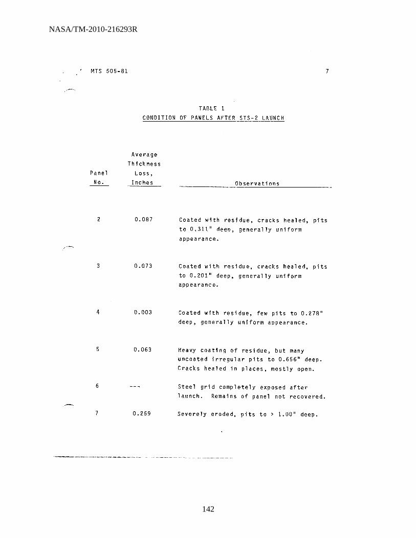
NASA/TM-2010-216293R
142
/'-
MTS 505-81
Panel No.
2
3
4
5
6
7
7
TABLE 1 CONDITION OF PANELS AFTER STS-2 LAUNCH
Average Thickness
Loss, Inches
0.087
0.073
0.003
0.063
0.259
Observations
Coated with residue, cracks healed, pits to 0.311" deep, generally uniform
appearance.
Coated with residue, cracks healed, pits to 0.201" deep, generally uniform appearance.
Coated with residue, few pits to 0.278" deep, generally uniform appearance.
Heavy coating of residue, but many uncoated irregular pits to 0.656" deep. Cracks healed in places, mostly open.
Steel grid completely exposed after launch. Remains of panel not recovered.
Severeiy eroded, pits to > 1.00n deep.

NASA/TM-2010-216293R
143
MrS-505-al
..
FIGURE I PANEL 2 IN rEST FRAME, POSITION 5, AFTER STS-2 LAUNCH. DESIGNED CONCRETES FONDU FYRE WA-l.

NASA/TM-2010-216293R
144
FIGURE 2 PANEL 2 IN INSPECTION RACK AFTER STS-2 LAUNCH

NASA/TM-2010-216293R
145
MTS-SOS-8!
FIGURE 3 PANEL 3 IN TEST FRAME, POSITION 6, AFTER STS-2 LAUNCH
DESIGNED CONCRETES FONDU FIRE WA-l, W/WIRE
10

NASA/TM-2010-216293R
146
FIGURE 4 PANEL 3 IN INSPECTION RACK AFTER STS-2 LAUNCH

NASA/TM-2010-216293R
147
MTS-505-al
FIGURE 5 PANEL 4 IN TEST FRAME, POSITION I, AFTER STS-2 LAUNCH
WAHL WRP-3 WITH CARBON STEEL WIRE.

NASA/TM-2010-216293R
148
MTS-SOS - B!
FIGURE 6 PANEL 4 IN INSPECTION RACK AFTER STS-2 LAUNCH .

NASA/TM-2010-216293R
149
MTS-505 - Bl
'~ ,<
• .. . ' " •
~,.. r 4 '
, •
.. .. '
, -, . , j!~":'
~ '. , " " , 'j,
" N
. ... "
FIGURE 7 PANEL 5 IN TEST FRAME, POSITION 2, AFTER STS-2 LAUNCH,
HARBISON-WALKER TUFSHOT WITH "FIBERS" (310SS)
14

NASA/TM-2010-216293R
150
MTS-505-8l
•
• • I
•
•
• ..
FIGURE 8
•
, -, , ; .. / "-- --
, -
•
•
PANEL 5 IN INSPECTION RACK AFTER ST5-2 LAUNCH
15
..
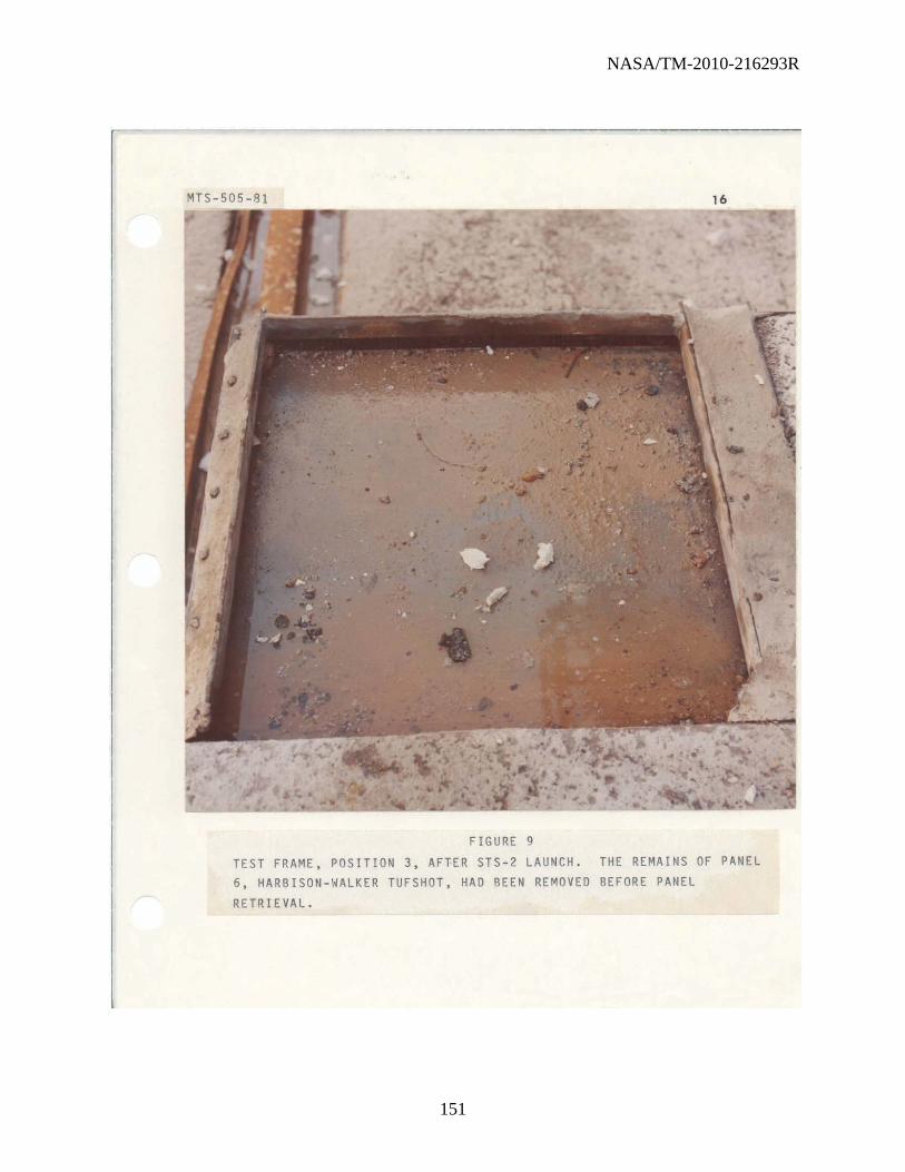
NASA/TM-2010-216293R
151
MTS-SOS-81
FIGURE 9 TEST FRAME, POSITION 3, AFTER STS-2 LAUNCH. THE REMAINS OF PANEL 6, HARBISON-WALKER TUFSHOT, HAO BEEN REMOVED BEFORE PANEL RETRIEVAL.

NASA/TM-2010-216293R
152
MTS - 505-al 17
FIGURE 10 PANEL 7, WAHL WRP-2, BEFORE EXPOSURE TO STS - 2 LAUNCH

NASA/TM-2010-216293R
153
PANEL 7 IN TEST
. ~. 7
FIGURE 11
FRAME, POSITION
. •
, . .:
AFTER STS - 2 LAUNCH 4,
•

NASA/TM-2010-216293R
154
MTS - 50s - al
FIGURE 12 PANEL 7 IN INSPECTION RACK AFTER STS-2 LAUNCH

NASA/TM-2010-216293R
155
MTS-505-81
20
STS-1 STS-2 STS-1 STS-2 STS-1 5T5-2
4.105 3.920 4.120 3.910 4.135 3.920 0 3.920 3,828 0 3.910 3,808 3.920 0 3.833 11 12
0:"102 13 0.185 Q.092 0.210 0.215 0.087
-STS-1 STS-2 STS-1 STS .. 2 4.090 3.850 4.100 3.780
'0 3.850 3.748 0 3.780 3.728 9 10
0.240 0.102 0.320 0.052
STS-1 STS-2 STS-1 STS-2 STS-1 5TS-2 4.145 3.850 4.090 3.820 4.120 3.800
0 3.850 3.728 0 3.820 3.693 3.800 0 3.788 6 7 8
0.295 0.122 0.270 0.127 0.320 0.012 .
STS-1 STS-2 STS-1 STS .. 2 4.100 3.840 4.106 3.860
: 0 3.840 3.778 0 3.860 3.748 4 0.260 0.062 5 0.246 0.112
"
'~.
STS-1 STS-2 STS~1 STS-2 STS-1 STS-2 . 4.166 3.940 4.120 3.860 4.175 3.900
0 3.940 3.868 0 3.860 3.798 " 3.900 0 3.768 1 2 3
0.226 0.072 0.260 0.062 0.275 0.132 ,
AVERAGE THICKNESS LOSS
STS-1 0.256 ~'S-2 0.087
JuTAL 0.343 FIGURE 13
THICKNESS MEASUREMENTS, PANEL l, nrSIGN CONCRETES FONDU FYRE WA-1

NASA/TM-2010-216293R
156
MTS-505-81
STS-1 4.045
0 3.790 11 0.255
5TS-1 4.040
0 3.710 6 0.330
5T5-1
4.080 0 3.780 1 0.300
AVERAGE THICKNESS lOSS
STS-1 0.325 ~.
S-2 0.073 10TAl 0.398
STS-2 3.790 3.748
0·042
'0 9
5TS-2 3.710
3.668
0.042
; 0 4
5T5-2
3.780
3.728 0.052
0 12
-STS-1 STS-2 4.065 3.760
3.760 3.728
0.305 0.032
0 7
STS-1 STS-2 4.030 3.680 3.680 3.458
0.350 0.222
0 2
FIGURE 14
21
STS-1 STS-2 STS-1 14.125 3.850 4.090 3.850 3.848 3.860 0
0.275 &:002 0.230 13
STS ... 1 ST5 ... 2 4.100 3.770
0 3.770 3.688 10 0.330 0.082
STS-1 ST5-2 5T5-1 4.055 3.700 4.115
3.700 3.598 3.650 0
0.355 0.102 0.465 8
STS-1 STS-2 4.030 3.690
0 3.690 3.578 5 0.340 0.112
,.
-~.
5T5-1 5T5-2 .STS-1
4.045 3.700 4.060
3.700 3.708 ~
0 3.720 3 0.345 -0.002 0.340 ,
.
THICKNESS MEASUREMENTS, PANE.l 3, DESIGN CONCRETES FONDU FYRE WA-1 W/WIRE
51"5-2 3.860 3.778
0.082
5T5-2 3.650
3.558
0.092
STS-2
3.720
3.628 0.092

NASA/TM-2010-216293R
157
MTS-505-81
STS-1 . STS-2 4.502 3.970
0 3.970 3.948 11 0.235 0.022
'0
STS-1 STS-2 4.140 3.900
0 3.900 3.798 6 0.240 0.102
:
STS-1 STS-2 4.190 3.980
0 3.980 3.978 1
0.210 0.002
AVERAGE THICKNESS lOSS
STS-1 0.235 ~'S-2 0.003
IOTAl 0.238
9
0 4
STS-1 4.110
3.840
0.270
STS-1 4.145
3.890
0.255
STS-1 STS-2 4.135 3.960
0 3.960 3.938 12
0.175 0:0: 022
-STS-2 STS-1
3.840 4.155
3.798 0 3.840 10
0.042 0.315
STS-1 STS-2 4.055 3.790
0 3.790 3.778 7 0.265 0.012
STS-2 STS-1 3.890 4.205 3.898 0 3.990
0.008 5 0.215 "
'\t,
STS-1 STS-2
4.205 3.990 0 3.990 '.
4.000 2
0.215 0.010 ,
FIGURE 15
THICKNESS MEA,SUREMENTS, PANEL 4, WAHL WRP .. 3
22
STS-1 515-2 4.120 3,870
3.870 0 3.908
0.250 13 0.038
STS,..2
3.840
3.858
-0.018
STS-1 STS-2 4.175 3.970 3.970 0 4.010
0.205 8 kl .040
STS-2 3.990
4.018
-0.028
.STS-1 5TS-2
4.205 4.000
4.000 0 4.020 3
0.205 kJ.020
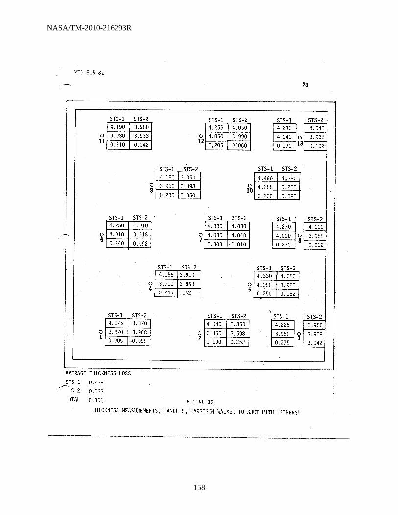
NASA/TM-2010-216293R
158
MTS-505-81
STS-1 STS-2 I 4. 190 I 3. 980 I o i 3.980 I 3.938 i 11 0.210 ~.042
'0
STS-1 STS-2 4.250 4.010
0 4.010 3.918 6 0.240 0.092
:
STS-1 STS-2 4.175 3.870
0 3.870 3.968 1 0.305 -0.098
AVERAGE THICKNESS LOSS
STS-1 0.238 r-'S_2 0.063
,uTAL 0.301
9
0 4
STS-1 4.180
3.950
0.230
STS-1 4.155
3.910
0.245
23
STS-1 STS-2 STS-1
1 4. 255 I 4.050 I I 4.210 I o 4.050 3.990 i ~O 12 0.205 C!": 060 0.170 13
-STS-2 STS-1 STS .. 2
3.950 4.480 4,280
3.898 0 4.280 0.200 10
0.050 0.200 0.080
STS-1 STS-2 STS-1 4.330 4.030 4.270
0 4.030 4.040 4.000 0 7
0.300 -0.010 8
0.270
STS-2 STS-1 STS-2 3.910 4.330 4.080 3.868 0 4.080 3.928 0042 5
0.250 0.152 '"
~.
STS-1 STS-2 STS-1 4.040 3.850 4.225
0 3,850 3.598 ". 3.950 0 2 0.252
3 0.190 0.275
FIGURE 16
THICKNESS J'.1EASUREMENTS, PANEL 5, HARBISON-WALKER TUFSHOT HITH "FIBERSII
STS-2 4.040
3.938
0.102
STS-2 4.000
3.988
0.012
STS-2 3.950 3.908 "
0.042

NASA/TM-2010-216293R
159
t4TS-505-81
STS-1 STS-2
~ o ---11
0 6
0 1
AVERAGE THICKNESS LOSS STS-1
/-'S-2 0.259
IlHAL 0.259
'0 9
STS-2 4.050 3.678 0.372
0 4
STS-2 3.990 3.618 0.372
24
STS-1 STS-2 STS-1
o~ 12 _~:.._ ~f3 - STS .. 1 STS ... 2 STS-1 STS-2
1X1;'~::1 m fo 3. 0.317 O. 57
STS-1 STS-2 STS~l:
4,030
~~ 0 3,838 7
0.192
STS-2 ST5 .. 2 4,010 3.990 3,498 0 3.733 0.512 5 0.257
\-.
STS-2 STS-1 4.010
,~~ 0 3.748 "
2 0.262
FIGURE 17 THICKNESS ;MEASUREMENTS, PANEL 7, WAHL WRP-2
ST5-2 3.990 3.718 0.272
STS-2 3.960 3,898 0.062
STS-2 3.910 3~838
0.072

NASA/TM-2010-216293R
160
MICROCHEMICAL ANALYSIS SECTION TG-FLD-21, Room 1274, O&C Building
NASAjKSC Sept. 16, 1981
SUBJECT: Analysis of Refractory Concrete Test Panels
LABORATORY REQUEST NO: MAS-310-81
1.0 Foreword
1.1 Requester: C. V. Moyers/NASA/TG-FLD-22 (867-4614)
APPENDIX I
1.2 Requester's Sample Description: Material removed from refractory concrete test panels after exposure to SRB Exhaust During STS-l Launch. Panel 1 - Surface layer and base material. Panel 2 -Fused material and base material.
1.3 Requested: Are blackened surface and fused material refractory concrete or SRB exhaust products?
2.0 Chemical Analysis and Results
2.1 The samples were analyzed by X-ray fluorescence spectrometry for qualitative elemental composition and by X-ray powder diffractometry for phase identification.
2.2 The results of both types of analysis are presented in Table I.
3.0 Conclusions'
Alpha aluminum oxide (corundum), the phase known to be formed in solid rocket booster exhaust product, was found in both the blackened surface and the fused material, but not in either Panel 1 or 2 base material. It therefore appears likely that the blackened surface and fused material are SRB exhaust products and not refractory concrete.
\ f til l1 Chemi s t: ".-:;JJ . ~ . d~~,-,,::a.:-
H. D. Bennett
Approved :---;-,.n..<;i:-?'1~~-'='---4.L----

NA
SA
/TM
-2010-216293R
161
Sample
Panel 1 - Blackened Surface
Panel 1 - Base Material
Pane 1 2 - Fused Material, Downstream Edge
Panel 2 - Base Material
MAS-' ')81
TABLI.. t
X-Ray Fluorescence
Major Al, Ca
Minor Fe, Ti
Trace Zr, Zn, K, Cl, S, Si, Ni
Major Al, Ca, Ti
Minor Fe, K, S1, Zn
Trace Ni, S, Zr
Major Al, Ca, Ti, Fe
Minor Zn, K, Si
Trace Ni, Cl, S
Major Ca, Ti, Fe
Minor K, S1
Trace Zn, S, C1, Ni, Zr
X-Ray Diffraction
~lpha Aluminum Oxide, ~- A1203 (Corundum)
Silicon Oxide, Si02 (Cristobalite) Aluminum Silicate, 3A1203' 2S102
(Mullite) Silicon Oxide, Si02 (Quartz) Calcium Carbonate, CaC03 (Aragonite) Aluminum Oxide Hydrate, A1203 . 3H20
(Gibbsite)
alpha Aluminum Oxide, ~ - A1203 (Corundum)
Titanium oxide, Ti02 (Rutile) Iron (II, III) Oxide, Fe304 (Magnetite) Calcium Magnesium meta Silicate, CaMg{Si03)2, (Diopside) Additional unidentified phases, probably silicates
1'0,) ()o
:J> -0 '"0 I"T1 Z o ....... x

NASA/TM-2010-216293R
162
SYMBOL/NAME
PRC-1217/KURTZ
ZK86/VAN DUSEN
PRO-1214/WALKER
DD-MED-l/OLSEN
S I -PRO-14/N. PERRY
SF~ENG/ROBERT MILLER
SF~ENG-3/R, GILLETT
TG-FLO",2
TG-FLD .. 22
DISTRIBUTION LIST
NUMBER OF COPIES
5
1
1
1
1
1
1
1
ALL THAT ARE LEFT

NASA/TM-2010-216293R
163
I
· , TASK REQUEST
1. DATE SU8MITTED 3. AUTHORIZING DOCUMENT
1
2. O~s~RMo~~th~fte~DL~~nch of 3 Sept 81 .~ STS-2
------------------------~L-------------------------~--------------------------4 SAMR~fr~E;t~I;;I(t~ncrete Test Samples:
1. Design Concrete Company (a) Fondu Fyre WA-l (Approved for Saturn) ;.. 2 Test Samples (b) Fondu Fyre WA-l (Experimental) - 2 Test Samples
2. Wahl Refractory Products Company (a) H. T. Bond Mortar (Experimental) - 3 Test Samples
3. Harbison-Walker Refractories (a) Refractory Concrete -------------- 2 Test Samples (b) Refractory Concrete (Stainless Steel Fibers) - 2 Test Samples
5. SYSTEM REMO VED FROM/OR USED IN:
Samples for test - Refractory Concrete
Location to be SRB Flame Deflector, 79K09546.
6. ANALYSIS REQUESTED:
SEE IIREFRACTORY MATERIALS TEST PLAN" - attached The materials are on hand. Six panels are to be exposed to SRB Exhaust during STS-2.
~ Testing is to be initiated by taking thickness measurements and color photographs of the initial condition of the surfaces.
After exposure to SRB exhaust during STS-2, the samples are to be removed and returned to the laboratory for further thickness measurements and a determination of surface erosion. The final surface condition such as spalling will be recorded and color photographs taken for comparison with initial surface conditions.
An evaluation of performance and acceptance or rejection recommendations will be made by formal report.
7. REMARKS:
9. PHONE: 10. COMPANY: 11. MAIL CODE:
867-3407 PRC PRC-12l7 13. PHONE:
tts 14. MAIL CODE: 15. DATE:
867-75£4 DD-MED-33 , FOR LAB USE ONL Y
INVESTIGATOR SAMPLE NUMBER
KSC FORM 22_81 (REV. 1/70)

NASA/TM-2010-216293R
164
~,
f~LFRJ\CTOnY COf~CRETE i'lA~~~IALS TEST PLAf~
1. rvlATERIALS FOR TlSnlJG (KSC-SPEC-P-0012)
1. Design Concretes Company
a. Fondu Fyre WA-l* - 2 Test Sam~les b. Fondu Fyre t·JA-l (Experimental) - 2 Test Samples Del ivery date July 21, 1980
* Approved for Saturn
2. Wah 1 Refractory Prod~cts Company
a. H.T. Bond Mortar (Experimental) - 3 Test Samples
The 3 test samples are at KSC. The vendor delivered them on Feb. 12, 1980 They are stored by TG-FLD-22.
3, Harbison - Walker Refractories
a. Refractory Concrete - 2 Test Samples b. Refractory Concrete ~ 2 Test Samples (Stainless Steel Fi~ers) Delivery Date June 20, 1980
I-E TW @ iiotth Ameri can Refractori es Company
a. Narco Cast 60 - 2 Test Samples b. Narco Tab - 2.Test Samples Delivery date Aug. 1,1980
II. TEST SAMPLE DELIVERY, HANDLING AND STORAGE
The refractory concrete test samples as specified in KSC-SPEC-P-0012, Fig re 1 are massive and require special handling. They weigh approximately 200 1 s. each and are 2 Ft-4 in. square and 4 inches thick. Vendors have been irs ructed to deliver their samples in crates on pallets, marked as specified in ~=~=graph 5.4 of specification KSC-SPEC-P-OOl2.
In addition, each vendor has been instructed to send copies of shipping notices to M. G. Olsen, DD-MED-l, C. L. Springfield, TG-FLD-22, and W. Clautice, PRC-12l7 to alert them of the date shipped. Freight Traffic, Sam Clymer (867-32!2' has tEen requested to notify Carlos Springfiel d, TG-FLO-22 (867-4614) hPe" test sar~ples are received so that he can direct them to a special storage are:: -'3.;ntaired by the laboratory.

NASA/TM-2010-216293R
165
Each vendot has been give the following address for shipJ"ent of samples:
Chief, Freight Traffic, NASA 81 dg. /·17-6744 3rd St. and Avenue C Kennedy Space Center, FL 32899 ATTfj: Ca r1 os Spri ngfi e 1 d, TG-FLD-22
II 1. INSTALLATION AND REMOVAL OF TEST SN1PLES
TG-SMO-l (Wayne Pa rri s/Bob Laakso) will i nit i ate and r,:anage the Support Request to BSI for the handling, installation, and removal of the refractory concrete test samples in the existing SRB flame deflector test fixtures. A peN will be issued to accommodate charges. BSI is to provide all services necessary. Bolt heads and seams are to be covered with ablative coating (Dow Corning Q3-6077) as specified in Dwg. 79K09546 Sheets 1 and 2, attached.
After the launch the samples are to be removed and transported to an area designated by the laboratory, TG-SMD-l, Carlos Springfield, 867-4614. Prior' to rer.1oval of samples contact Carlos Springfield. Photogra,phs are to be taken of the samples prior to their removal.
IV. SPECIMEN ORIENTATION
The test fixture on the SRB flame deflector, DWG 79K09546 will accommodate six specimen samples. The number of samples to be submitted are . .IS/' Therefore, 3 launches will be required before the testing of all samples is accomplished.
A pattern of testing orientation in the test fixtures is ~s follows:
Wattl Fondu HT Fire -wM;r \J.b ~ \
Bond WA-l ~ ~1ortar *
* Approved for Saturn LAUNCH NO.
Fondu Fan u -WafI+ I HjW Fyre )(
~~ fJar"eb Fyre -Hr-WA-l }AB WA-l =:-J (EXP) *
.7 l' *Approved for Saturn LAUNCH NO. 2
r-T:ahlr- I HjvJ : I I NM'co I +
:;;:)1Id I JAB S.S. L~_G_r_'t~al'i ' __ --'-____ _
I I I I I I ( , I I L..-___ --+-____ L ___ -~~
LAUNcH flO. 3

NASA/TM-2010-216293R
166
V. LABORATOfn ~llASUREI1ENTS OF TEST SAt1PLES
All samples are to be tested and evaluated in accordance with KSC-SPEC-P-0012. Prior to installation, each test sample will be measured for an a-curate determination of thickness using a template and a dial gage indicator mounted on a flat "level table or surface. TG-FLO-22 to determine and rerform t.he measurements. Each test sample will be photographed to record their surface condition and texture prior to testing and other conditions detenllined as deemed necessary.
After the 1 aunch test, the specimens wi 11 be returned to the same area ",here initial measurements were made. The thickness wi11 be remeasured using the same techniques to determine the loss of thickness due to general surface erosion. Any damage or local spalling or cracking will be noted and recorded. Each specimen will be photographed with close-up shots of special conditions. The laboratory, TG-FLD-22, will evaluate the relative ~)erformance of the test samples based upon their findings in accordance with KSC-SPEC-P-0012.

NASA/TM-2010-216293R
167
o.IVC£jVT~ ATEZ2 11 PIIj/t;Efl1 E NTJTT£RN '-_
.~-....... ,
------- ------~-- -----~ -- JOr' ,. :
-=SR8 f L 4J1£ -.- DEFLEc TO/Z ___ ~_ ----

NASA/TM-2010-216293R
168
DISTRIBUTION LIST
SYMBOL/NAME NUMBER OF COPIES
PRC-1217/KURTZ 5
ZK86/VAN DUSEN 1
PRO-1214/WALKER 1
DD-MED-l/OLSEN c_ SI-PRO-14/N. PERRY
SF~ENG/ROBERT MILLER 1
SF .. ENG-3/R. GILLETT 1
TG-FLD .. 2 1
TG-FLD-22 ALL THAT ARE LEFT

NASA/TM-2010-216293R
169
APPENDIX C. MTS-142-82, STS-3

NASA/TM-2010-216293R
170
I N~ S~
MA TERIAL S TE ST1Hij SEC TIUN MA TERIALS ANALYSIS BRA Nt l1
FLUIDS ANU ANALYSIS DIVISION
TG-FLD-22. ROOM 1218. 0&( BUILDING KENNEUY SPACE C[ NT ER, FLORIDA 32899
HAY 6 , 1982
MT S- 14 2-82
SUBJEC T: [xposur@ Test of Refractory Conc rete Test Panels to Solid Rocket Booster (5R8) Ex hau st During STS - 3 launc h
RE LATEU DOCU MENTATION: "HA-1918-S0. July 29 . 1981 MrS-50S -8 1. Har c h I. 1982
\.U FOREWORD
1.1 On I Har ch , 1982. M. G. Olsen, DO-HED-I. requested testing of refra c tory conc rete test panel s , t he test ing
t o co mprise thi c kne ss measure_ents, co l or photogra phs. and visual observ ati ons both be fo re and after exposure t o 5M B exhaust during the l au nc h of SIS-3 .
1.2 This test I s a continua t io n Of tile testing reported In MM~ 1918-80, dated July 29. 196 1. and MTS-50S -0 1. dated Mar c h I. 198 2 . The test panels provided by vendors and th e te5t fi ~ tur e5 are de sc ri bed in MMA 191 8 -80. whi ch co vers the exposure of 6 panels to SR B e~ hau 5t du ring SIS- I. Exp05 ure of les t pan e l s durI ng STS-2 l au nch Is
desc ri bed In HT S- SOS-SI .

NASA/TM-2010-216293R
171
rnS-142_82 , 2.0 rEST PROCEDURES
2.t rEsr PANEL SELECTION ANO IDENTIFICATION Starting wfth this test, the positions of the panels In the flame trench are designated as A, n, C, 0, E, lind F, from ellSt to west In alphabetical order. Of the panels exposed during STS-2 launch, panel 6 did not survive the launch, Ind panel 7 was considered too hadly deteriorated for further testing. The other four panels were selected f or reexposure during STS-3 launch. For the other two spaces, panel 1. which had heen exposed to STS-l launch, and a prev iousl y unexposed panel, deslgn&ted panel 8, were selected. The s ix panels with their exposure positions are as follows:
Exposure Posl tlon Panel East-to -We st NO. , 8 Designed Concretes, Fondu Fyre
FSC -5 B 3 Designed ConcreteS. Fondu Fyre
WA-I wtWlre C , Designed Concretes, Fondu Fyre WA-l 0 Wahl (WRP-l), conta I ned "flbers ~
{stainless s teet wi re I [ • Wahl (WRP-Jl. contalnerf carbon
stee l '" Ire F 5 Harblson-Wal~er Tufshot,
conta 1 ned "fibers" (310 ss)
2.2 PREEXPOSURE THICKNESS DETERMINATIONS Panel 8 was placed on an inspection rac~ which afforded
access to both top and bottom surfaces, and thlc~ness at ellch of the predetermined points was measurerf, Ilslng

NASA/TM-2010-216293R
172
MIS_142_S2
the te~plate and caliper employed In previous ~easurements. Photographs of each previously exposed panel, made after the last exposure, appear in
HT S-505 -St and MHA-1918-80. Figure 1 s how s panel S before exposure .
3
2 . 1 SRB EXHAUST EXP USURE The panels were then Installed In the two refractory test frames (DWG 79K09546) at the bottom of the SRB flame deflector In the north end of the flame trench at lC19A. Each frame holds three panels . The holddown c lamps and the areas between panels were coa ted with Dynatherm E- 12U ablative coating. The ~anel s were Installed In the position s Indicated In paragraph 2.1, and were then exposed to 5MB exhaust during STS-1 la unch .
2.4 PU ST-E XPOSURE IN SP ECTIUN
F.4.1 After STS - 1 laun c h, It was found that five of the six panels were gone, along with tile frames and many of the bolts. Two reinf or c ing grids. with fragments of concrete adhering, were found hanging on the perimeter fen ce to the north of the pad. Frames, ablative coating, reinforcing
yrids, and some refractory concrete frayments
were found scattered both Inside and outside the perimeter road.
2.4 . 2 The surviving panel. Number I In position D. was removed from the te st fra lRe and tran s po rted to
the Inspection rack, where the same te Mplate and caliper were used to make thickn ess determinations. The depths uf representative

NASA/TM-2010-216293R
173
HT S- 14Z-8Z 4
3. 0 RESULT S
spalled area s were deter~lned, using a depth gage provided with a dial Indicator and a tip with a radius of about 1/8 inch.
3.t FigUre 2 shows panel 1 after launCh, and Figures 3 through 8 show the condition of the test frames and s a~ple fram es after launch.
3 .2 Panel 1 was dark In color, with scattered light colored patches, apparently the result of shallow spalling whi c h removed the darker surface layer. The deepest pit was 0 . 270· deep. The average thickness lo s s during this launch was 0.155 Inches. Figure 9 sh ows Individual thickness measurements hefore and after hoth STS- I and STS-3 launches.
4 .0 CO NCLUSIONS
4.1 Only panel I, Wahl WRP-l, survived t he launch. The thickness loss and depth of pits were comparable to those eKperlen ced by this panel during the first launc h.
',1 Two factorl whIch may ha,@ contrlbut'~ to tho holt failures which resulted In the lo s s of sample frames and sa~ples are Inadequate cure of the ablative coating (Figure 8), and deterioration of the fasteners during the first two launches and intervening eKposure to weather and pad operattons.

NASA/TM-2010-216293R
174
tHS-14Z-8Z 5
4.3 Both contractor and government ~uality inspection will be requested for future sa~ple installations. This should assure cOMplete ~fxfng and adequate application of the ablatfve coating.
~.~ The samp le frames have been redesigned, using larger sturls which can he replaced when necessary. The grip length has heen shortened, reducing the bending moments . This should provide a longer life and prevent s ample loss.
4.5 Ele ven panels were re ce iv ed for this Inve st igation . Their present s tatus Is as follows:
Number or
Pitne! launc h No. Exposures
2 fSTS-l
• STS-3)
2' J
3' 3
4' J
5' 3
______ Oescrlptfon __________ _ Wahl WRP-1. Contained ·flbers· (stainless steel wire)
Designed Concretes, Fondu Fyre
"'"-1 Oosfgn.d Concretes, rO" du r yre
',11\-1 w/W! re
Wahl WRP-3. Contafne rl carbon steel wire
Harbison-Walker Tufshot. Conta ined ·f i bers· (310 ss)
~ Destroyed during STS-3 launch. __ H Destroyed during STS-2 launch.

NASA/TM-2010-216293R
175
-
111'; - 11 2- A2
• ••
Pane l
No .
7
'lumber of
launc h
E)(pO~~
, ( 5T5-2 1
IInrlf!slg- 0 nil terl
rtarblson-Walker Tu f shot
Wahl WRP- 2 (no longer u sab le)
Designed r:o nc retes, fo ndu Fyre
W~-l (same a~ Pll ne l 2)
8~ 1 ( 5T5-3) Designed Co nc retes, Fondu Fyre FS C -5
UnrtesiQ- 0 Ilarbtson-Walker Tuf sh ot (sallie
nat e d P"nel 6)
Undes l g- 0 Ilarbison -Wa l ker Tufshot .... Ith na ted ~flbers" (310 ,, )
( sue " Pane 1 5)
[)estroye d du r' n 9 STS-3 laun c h.
Oestroy er1 flu ring STS -2 laun c h.
6
"
APPROVED , _f!-,--t. l.'2ili~1,. ~~. ________ ______________ _ C . l. Sp~2ElO. g;"/I-;:F , MT S HASA

NASA/TM-2010-216293R
176
This page intentionally left blank.

NASA/TM-2010-216293R
177
APPENDIX D. MTS-340-82, STS-1, -2, AND 3

NASA/TM-2010-216293R
178
NASA
MATERIALS TESTING SECTION MATERIALS ANALYSIS BRANCH
FLUIDS AND ANALYSIS DIVISION TG-FLD-22, ROOM 1218, O&C BUILDING
KENNEDY SPACE CENTER, FLORIDA 32899 JUNE 7, 1982
MTS-340-82
SUBJECT: Exposure Tests of Refractory Concrete Test Panels to Solid Rocket Booster (SRB) Exhaust During the First Three STS Launches: Summary Report
RELATED DOCUMENTATION: MMA-1918-80, JULY 29, 1981 MTS-505-82, MARCH 1, 1982 MTS-142-82, MAY 6, 1982
1.0 FOREWORD
1.1 At the request of DD-MED-l, 6 refractory concrete test panels have been exposed to SRB exhaust during each of the first three STS-launches.
1.2 Panels were supplied by three vendors.
1.3 The purpose of the tests was to qualify additional suppliers of refractory concrete for use in flame trench refurbishment.
1.4, The three reports listed above in "Related
Documentation" relate procedures and results of tests conducted during each of the three launches.
1.5 This report summarizes those tests and their results.

NASA/TM-2010-216293R
179
2.0 TEST PROCEDURE
2.1 The thickness of each panel was measured before and after each launch exposure at 13 locations determined by a template. The maximum depths of pits were also determined.
2
2.2 The panels were secured in test frames at the bottom of the flame deflector in the north end of the flame trench of Launch Complex 39A. Figure 1 shows the flame trench and test frames. Ablative coating was applied
to the areas surrounding the panels. Figure 2 shows a test frame with panels installed.
3.0 TEST RESULTS
3.1 Table 1 summarizes test results for the three launches.
3.2 Figures 3 through 9 show test panels in the condition
in which measurements were last made. The graphics in the corners of the photographs showing average thickness loss and pit depth are the same as those included in Table 1.
4.0 DISCUSSION OF RESULTS
4.1 For the panels exposed, differences in average
thickness loss and maximum pit depth were small, with two exceptions. Wahl WRP-2, Panel 7, showed much greater overall loss than the others. Of the others,
Harbison-Walker Tufshot with fibers, Panel 5, showed much greater pit depth.

NASA/TM-2010-216293R
180
4.2 Harbison-Walker Tufshot, Panel 6, did well in STS-1 exposure, but was destroyed during STS-2 exposure.
4.3 Four products have each been subjected to two launch exposures with comparably good performances for thickness loss and pit depth:
Designed Concretes Company WA-1 Designed Concretes Company WA-1 with wire Wahl Refractory Products Company WRP-1 Wahl Refractory Products Company WRP-3
5.0 CONCLUSIONS
3
5.1 The four products listed in the paragraph above should be considered for further testing.
5.2 The two Harbison-Walker panels on hand (Tufshot and Tufshot with fibers) might be considered for testing.
INVESTIGATOR: ~ L! ~Ta~ C. V. MOYERS
APPROVED: __ C'=--~dC~~~.-c~~~~~~~ ______________________ __ C.
J
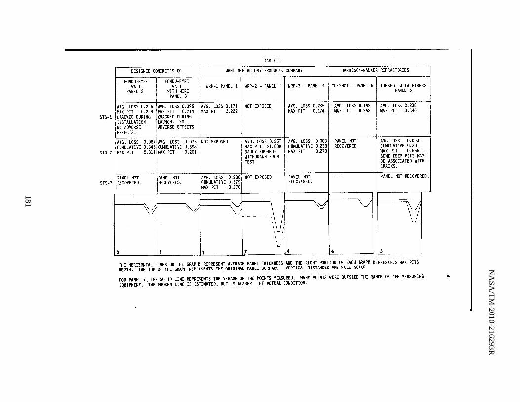
NA
SA
/TM
-2010-216293R
181
TABLE 1
DESIGNED CONCRETES CO. WAHL REFRACTORY PRODUCTS COMPANY HARB ISON-WALKER REFRACTORIES
FONDU-FYRE FONDU-FYRE WA-l WA-1 WRP-1 PANEL 1 WRP-2 - PANEL 7 WRP-3 - PANEL 4 TUFSHOT - PANEL 6 TUFSHOT WITH FI BERS
PANEL 2 WITH WIRE PANEL 5 PANEL 3
AVG. LOSS 0.256 AVG. LOSS 0.325 AVG. LOSS 0.171 NOT EXPOSED AVG. LOSS 0.235 AVG. LOSS 0.192 AVG. LOSS 0.238 MAX PIT 0.258 MAX PIT 0.214 MAX PIT 0.222 MAX PIT 0.174 MAX PIT 0.258 MAX PIT 0.346
STS-1 CRACKED DURING CRACKED DURING INSTALLATION. LAUNCH. NO NO ADVERSE ADVERSE EFFECTS EFFECTS.
AVG. LOSS 0.087 AVG. LOSS 0.073 NOT EXPOSED AVG. LOSS 0.257 AVG. LOSS 0.003 PANEL NOT AVG LOSS 0.063 CUMULATIVE 0.343 CUMULATIVE 0.398 MAX PIT >1.000 CUMULATIVE 0.238 RECOVERED CUMULATIVE 0.301
STS-2 MAX PIT 0.311 MAX PIT 0.201 BADL Y ERODED- MAX PIT 0.278 MAX PIT 0.656 WITHDRAWN FROM SOME DEEP PITS MAY
i
TEST. BE ASSOCIATED WITH CRACKS.
PANEL NOT PANEL NOT AVG. LOSS 0.208 NOT EXPOSEO PANEL NOT --- PANEL NOT RECOVERED. STS-3 RECOVERED. RECOVERED. CUMULATI VE 0.379 RECOVERED.
MAX PIT 0.270
~ ~ V Y '0j ~ - \j
\ I \ I
\ i LJ
2 3 1 1 4 6 5
THE HORIZONTAL LINES ON THE GRAPHS REPRESENT AVERAGE PANEL THICKNESS AND THE RIGHT PORTION (J' EACH GRAPH REPRESENTS MAX PITS DEPTH. THE TOP OF THE GRAPH REPRESENTS THE ORIGINAL PANEL SURFACE. VERTICAL DISTANCES ARE FULL SCALE.
FOR PANEL 7, THE SOLID LINE REPRESENTS THE VERAGE OF THE POINTS MEASURED. MANY POINTS WERE OUTSIDE THE RANGE (J' THE MEASURING .... EQUIPMENT. THE BROKEN LINE IS ESTIMATED, BUT IS NEARER THE ACTUAL CONDITION.
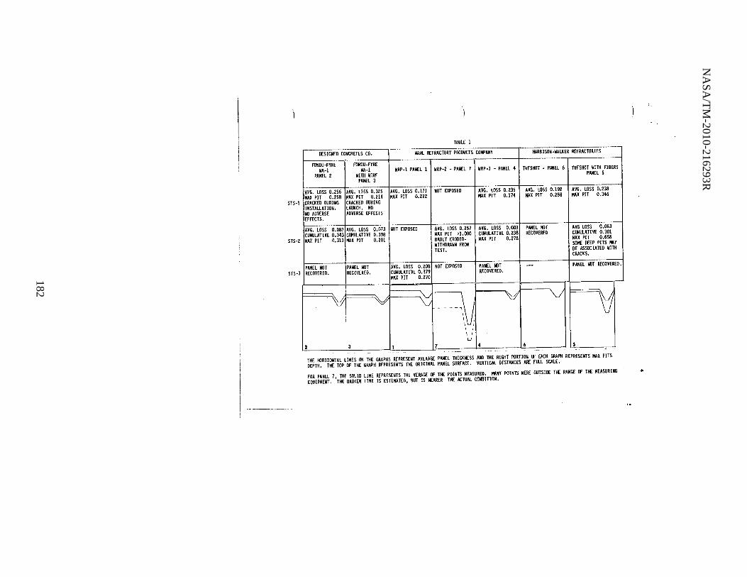
NA
SA
/TM
-2010-216293R
182
TABLE 1
DESIGNED CONCRETES CO. WAHL REFRACTORY PRODUCTS COMPANY HARBISON-WALKER REfRACTORIES
fONOU-FYRE FONOU-FYRE WA-l WA-l WRP-l PANEL 1 WRP-2 - PANEL 7 WRP-3 - PANEL 4 TUFSHOT - PANEL 6 TUFSHOT WITH FI BERS '
PANEL 2 WITH WIRE PANEL 5 PANEL 3
AVG. LOSS 0.256 AVG. LOSS 0.325 AVG. LOSS 0.171 NOT EXPOSED AVG. LOSS 0.235 AVG. LOSS 0.192 AVG. LOSS 0.238 MAX PIT 0.258 MAX PIT 0.214 MAX PIT o.m MAX PIT 0.174 MAX PIT 0.258 MAX PIT 0.346
STS-l CRACKED DURING CRACKED DURING I
INSTALLATION. LAUNCH. NO NO ADVERSE ADVERSE EFFECTS EFFECTS.
I
AVG. LOSS 0.087 AVG. LOSS 0.073 NOT EXPOSED AVG. LOSS 0.257 AVG. LOSS 0.003 PANEL NOT AVG LOSS 0.063 CUHULATI VE 0.343 CUMULATIVE 0.398 MAX PIT >1.000 CUMULATI VE 0.238 RECOVEREO CUMUlATIVE 0.301
I
MAX PIT 0.311 MAX PIT 0.201 BADLY ERODED- MAX PIT 0.278 MAX PIT 0.656 WITHDRAWN FROM SOME DEEP PITS MAY TEST. BE ASSOC IATED WITH
CRACKS. I
STS-2
PANEL NOT PANEL NOT AVG. LOSS 0.208 NOT EXPOSED PANEL NOT --- PANEL NOT RECOVERED. RECOVERED. RECOVERED. CUMULATIVE 0.379 RECOVERED.
I
MAX PIT 0.270 I
STS-3
~ V V \j 'V \J - - \) i
\ I \ I
\ I U
2 3 1 7 4 6 Is --, '" "',-
THE HORIZONTAL LINES ON THE GRAPHS REPRESENT AVERAGE PANEL THICKNESS AND THE RIGHT PORTION OF EACH GRAPH REPRESENTS MAX PITS DEPTH. THE TOP OF THE GRAPH REPRESENTS THE ORIGINAL PANEL SURFACE. VERTICAL DISTANCES ARE FULL SCALE.
FOR PANEL 7, THE SOLID LINE REPRESENTS THE VERAGE OF THE POINTS MEASURED. MANY POINTS WERE OUTSIDE THE RANGE OF THE MEASURING .. EQUIPMENT. THE BROKEN LINE IS ESTIMATED, BUT IS NEARER THE ACTUAL CONDlTION.

NASA/TM-2010-216293R
183
,
FIGURE FLAME TRENCK, SHOWING TEST fRAMES AT BOTTOH OF fLAME DEFLECTOR

NASA/TM-2010-216293R
184
•
f IGollRE l
TEST fRA"£ WITH TEST PANELS INSTALLED

NASA/TM-2010-216293R
185
7
FIGURE 3 DESIGNED CONCRETES WA-l AFTER STS-2

NASA/TM-2010-216293R
186
8
FIGURE 4 DESIGNED CONCRETES WA-l W/W AFTER STS-2

NASA/TM-2010-216293R
187
9
FIGURE 5 WAHL WRP-l AFTER STS-3

NASA/TM-2010-216293R
188
10
FIGURE 6 WAHL WRP-2 AFTER STS-2

NASA/TM-2010-216293R
189
11
FIGURE 7 WAHL WRP-3 AFTER 5T$-2
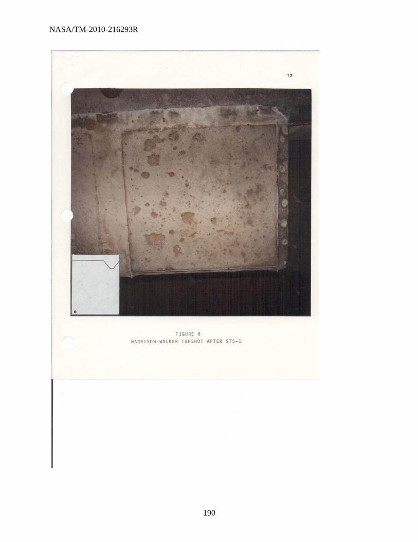
NASA/TM-2010-216293R
190
FIGURE 8
HARBISON . WALKER TUFSHOT AfTER ST5-1
"

NASA/TM-2010-216293R
191
13
FIGURE 9 HARBISON-WALKER TUFSHOT W/WI AFTER STS-2

NASA/TM-2010-216293R
192
DISTRIBUTION LIST
SYMBOL/NAME NUMBER OF COPIES
PRC-1217/KURTZ 5
ZKB6/VAN DUSEN
PRO-1214/WALKER
DD-MED-l/OLSEN 5
SI-PRO-14/N. PERRY ~
SF-ENG/ROBERT MILLER
SF-ENG-3/R. GILLETT
TG-FLD-2
TG-FLO-22 ALL THAT ARE LEFT
-,

NASA/TM-2010-216293R
193
APPENDIX E. MTS-425-82, STS-4

NASA/TM-2010-216293R
194
NASA
MATERIALS TESTING SECTION MATERIALS ANALYSIS BRANCH
FLUIDS AND ANALYSIS DIVISION TG-FLD-22, ROOM 1218, O&C BUILDING
KENNEDY SPACE CENTER, FLORIDA 32899 AUGUST 27, 1982
MTS-425-82
SUBJECT: Exposure Test of Refractory Concrete Test Panels During
STS-4 Launch
RELATED DOCUMENTATION: MTS-340-82 Exposure tests of Refractory Concrete Test Panels to Solid Rocket
Booster (SRB) Exhaust During the First Three STS Launches
1.0 FOREWORD
This test was a continuation of the test program described in MTS-340-82. Six test panels were prepared by the Development Testing Branch, using material from two manufacturers.
2.0 TEST PROCEDURE AND RESULTS
The test procedure was similar to that followed in previously reported tests of this kind. Results are as f 011 ow s:
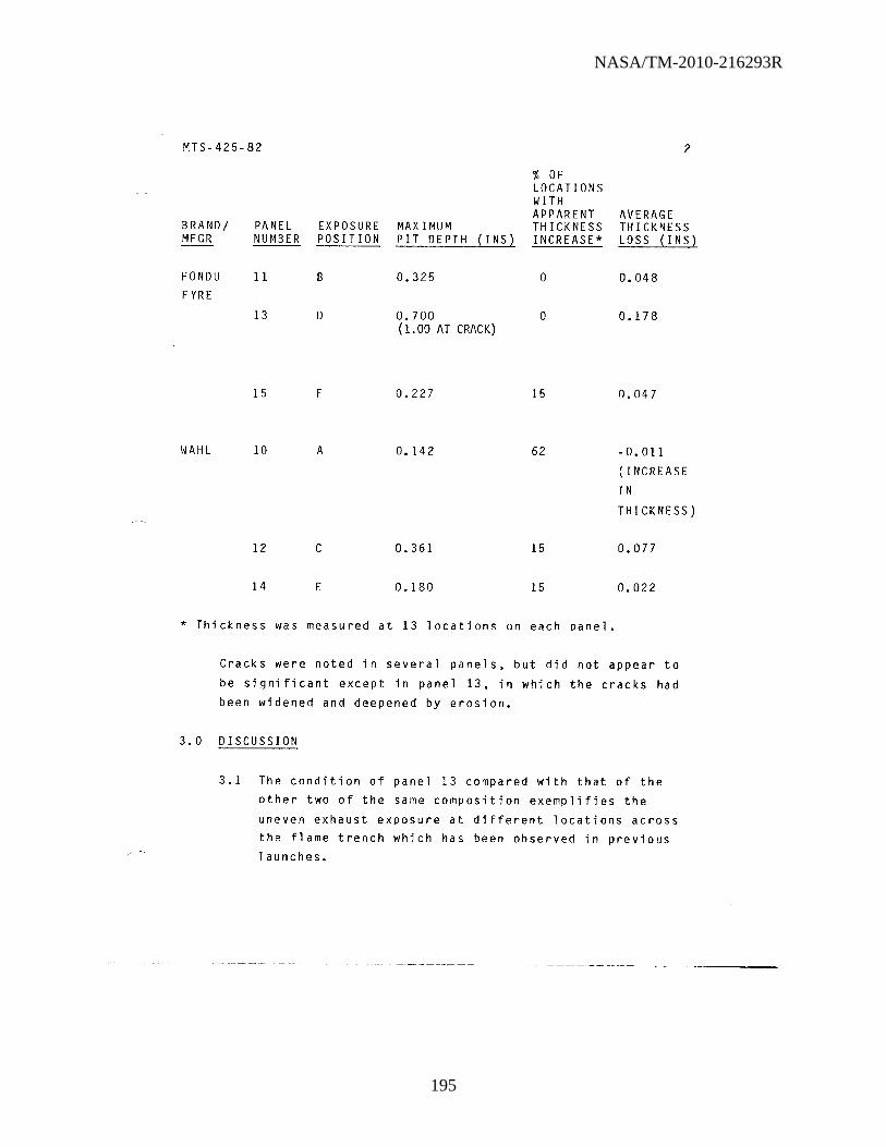
NASA/TM-2010-216293R
195
MTS-425-82 2
% OF LOCATIONS WITH APPARENT AVERAGE
BRANDI PANEL EXPOSURE MAXIMUM THICKNESS THICKNESS MFGR NUMBER POSITION PIT DEPTH (I NS) INCREASE* LOSS (INS)
FONDU 11 B 0.325 0 0.048 FYRE
13 D 0.700 0 0.178 (1.00 AT CRACK)
15 F 0.227 15 0.047
WAHL 10 A 0.142 62 -0.011 (INCREASE
IN
THICKNESS)
12 C 0.361 15 0.077
14 E 0.180 15 0.022
* Thickness was measured at 13 locations on each panel.
Cracks were noted in several panels, but did not appear to
be significant except in panel 13, in which the cracks had
been widened and deepened by erosion.
3.0 DISCUSSION
3.1 The condition of panel 13 compared with that of the other two of the same composition exemplifies the
uneven exhaust exposure at different locations across the flame trench which has been observed in previous launches.
-~ - -~--- - - - -~- ~-~- - - - - --~-----.----.-------
NASA/TM-2010-216293R
196
MTS-425-82 3
3.2 Apparent increases in thickness were measured in a
number of locations~ especially on the Wahl panels. As in some previous occurrences. they are attributed to the accretion of exhaust products.
CLYDE V. MOYERS
APPROVED: __ ~C!~'~~ __ ~-L~~~~~~~~~· ______________________ __
C. NASA

NASA/TM-2010-216293R
197
TASK REQUEST
I. DATE SUBMITTED 2. DESIRED COMPLETION DATE 3. AUTHORIZING DOCUMENT
SAMPLE DESCRI PTION:
5. SYSTEM REMOVED FROM/OR USED IN:
6. ANAL YSIS REQUESTED:
B. REQUESTER:
'ASA APPROVAL: 13. PHONE: 14. MAIL CODE: 15. DATE:
FOR LAB USE ONLY INVESTIGATOR
KSC FORM 22-Bl (REV. 1/701

NASA/TM-2010-216293R
198
This page intentionally left blank.

NASA/TM-2010-216293R
199
APPENDIX F. MTB-503-83, STS-5, -6, AND -7

NASA/TM-2010-216293R
200
NASA ENGINEERING DEVELOPMENT
GROUND SUPPORT OFFICE MATERIALS ANALYSIS OFFICE
MATERIALS TESTING BRANCH DE-MAO-2, ROOM 1218, O&C BUILDING, PHONE 867-4614
KENNEDY SPACE CENTER, FLORIDA 32899 SEPTEMBER 1, 1983
MTB-503-83
SUBJECT: Exposure Tests of Refractory Concrete Test panels to Solid Rocket Booster(SRB) Exhaust During the First Seven STS Lanches: Summary Report
RELATED DOCUMENTATION: MMA-1918-80, JULY 29, 1981 MTS-505-82, MARCH 1, 1982
MTS-142-82, MAY 6, 1982 MTS-340-82, JUNE 7, 1982
MTS-425-82, AUGUST 27, 1982
1.0 FOREWORD
1.1 At the request of DD-MED-l, refractory concrete test panels have been exposed to SRB exhaust during each of the first seven STS-launches.
1.2 Panels were supplied by three vendors, except for six
panels which were fabricated at KSC from vendor-supplied materials.
1.3 The purpose of the test was to qualify additional suppliers of refractory concrete for use in flame trench refurbishment.

NASA/TM-2010-216293R
201
MTB-503-83 2
1.4 The five reports listed above in IIRelated Documentation ll relate procedures and results of tests
conducted during the first four launches.
1.5 This report summarizes the results of those tests, as well as the hitherto unreported tests during STS-5,
STS-6 and STS-7 launches.
2.0 TEST PROCEDURE
2.1 The panel thickness was measured before and after each
launch exposure at 13 locations on each panel. A template was used to identify the locations to be
measured. The maximum depths of pits were also determined.
2.2 For launch exposure the panels were secured in test
frames at the bottom of the flame deflector in the north end of the flame trench of Launch Complex 39A.
Panel positions were designated A through F in alphabetical order from east to west. Ablative coating
was applied to the areas surrounding the panels to protect the fixtures used to secure the samples in
place.
3.0 RESULTS
3.1 Table 1 summarizes test results for the seven
launches.
results. Table 2 is a more detailed tabulation of
3.2 Figures 1 through 3 show graphically the effects of
launch exposure on individual panels.

NASA/TM-2010-216293R
202
MTB-503-83 3
4.0 DISCUSSION OF RESULTS
The material now in use in the flame trench is Designed Concretes' Fondu Fyre WA-l. The results for this material
shown in Figure 1 represent five panels with a total of seven launch exposures. Three of these panels were
fabricated at KSC. Three other materials show lower average thickness losses per launch than WA-l:
4.1 Harbison Walker Refractories 17-67
The average loss is low, but represents only two
exposures of one panel prepared by the vendor.
4.2 Wahl Refractory Products WRP-3 (Wi~h Wire)
The average loss is low, and represents eleven exposures of six panels, three of which were prepared
at KSC.
4.3 Wahl Refractory Products WRP-3 without wire The average loss is low, but represents only two
exposures of one panel prepared by the vendor.
4.4 In a memorandom to M.G. Olsen, DD-MED-l, dated August 22, 1983 Gary Kurtz, PRC 1211, has reviewed the
test program so far, and has discussed the problems in
test exposure and interpretation of results. In the
evaluation of results he suggests the following criteria:
"a. eliminate specific materials from contention that crack or form deep fissures. Exceptions to this rule would be panels that have knowingly been mishandled or otherwise, improperly installed. This would be consistent with the requirements as stated in KSC-SPEC-P-0012, section 3.5.

NASA/TM-2010-216293R
203
MTB-503-83 4
b. eliminate maximum spalling depth from the list of SPEC requirements. It appears to be basic property of the refractories that they all spall.
c. use a minimum of two panels of a specific
material for a minimum of three launch exposures. One of the panels should be prepared by NASA, KSC personnel or its contractor.
d. use Fondu Fyre WA-1 average loss as a minimum standard of acceptability. This may seem somewhat arbitrary, but then so was the 1/8"
loss quoted in the SPEC. Attempts to arrive at an acceptable figure for loss (other than zero) all seem subjective and without any real meaning. The only practical viewpoint with the information available at this time is that Fondu Fyre WA-1 did well but it would be beneficial to find better materials. Cost effectiveness has not been considered so far, however, material cost, labor, scheduling, and availability will have to be factored into the acceptability equation at some point."
Using these criteria, he says, "the only material that would qualify for usage, other than Fondu Fyre WA-1,
would be Wahl WRP-3 (w/w)." But he cautions that compatibility of the two materials and their performance as patches in repair work have not been investigated. Both Wahl WRP-3 without wire and Harbison Walker 17-67 would require additional successful launch exposures, including exposures of KSC-fabricated panels, before being qualified.

NASA/TM-2010-216293R
204
MTB-503-83 5
Mr. Kurtz suggests future work to study cost
effectiveness, compatibility, application methods, new
materials, and variables in material preparation.
5.0 RECOMMENDATIONS
Mr. Kurtz1s analysis seems reasonable and comprehensive.
Two alternate courses are suggested:
5.1 Exposure tests have now been conducted during seven
launches over a period of more than 2 years. If the
need for an additional qualified vendor is urgent
enough, then Wahl WRP-3 could be accepted on the basis
of the criteria outlined in paragraph 4.4. In this case the assumption would be made that any problems
which may arise in repairs and compatibility will be solved by appropriate application technique. Exposure
tests of Harbison Walker 17-67 and Wahl WRP-3 without
wire with additional panels fabricated at KSC would
continue. Mr. Kurtz1s suggestions should be considered
in planning future work.
5.2 Alternatively, acceptance of a new product could be
postponed pending repair and compatibility testing. In this case, a test plan should be made immediately,

NASA/TM-2010-216293R
205
MTB-503-83 6
using test panels, flame deflector patches, or both. Exposure tests of Harbison Walker 17-67 and Wahl WRP-3 without wire, using panels fabricated at KSC, would continue, and future work would be planned as in the first alternative.
INVESTIGATOR: C V /J1o~e-(} C. V. MOYERS
co, 1 .. APPROVED: __ ~~v~~~~~~~~&C~ ________________________ __
MTB, NASA

NASA/TM-2010-216293R
206
MTB-503-83
VENDOR
DESIGNED CONCRETES
HARBISON WALKER REFRACTORIES
WAHL REFRACTORY PRODUCTS
TABLE 1
SUMMARY-LAUNCH EXPOSURES
NUMBER OF LAUNCH EXPOSURES
FONDU FYRE WA-1 7 FONDU FYRE WA-1 WITH WIRE 2
TUFSHOT 1 TUFSHOT WITH FIBER 2 LI 1 17 -67 2
WRP-1 2 WRP-2 1 WRP-3 (WITH WIRE) 11 WRP-3 WITHOUT WIRE 2
AVERAGE THICKNESS LOSS PER LAU NCH, INS.
0.121 0.199
0.192 0.151 0.156 0.068
0.190 0.257 0.055 0.057
7
AVERAGE MAXIMUM PIT DEPTH, INS.
0.347 0.208
0.258 0.501 0.475 0.368
0.246 >1.000 0.231 0.468

NASA/TM-2010-216293R
207
MTB-503-83 8
TABLE 2
LAUNCH EXPOSURES
AVERAGE MAXIMUM PANEL THICKNESS PIT DEPTH
VENDOR DESIGNATION NUMBER LAUNCH POSITION LOSS, IN. IN.
DESIGNED FONDU FYRE WA-1 2 STS-1 B 0.256 0.258 CONCRETES STS-2 E .087 .311
18 STS-6 A .041 .159 STS-7 C .189 .450
11* STS-4 B .048 .325 STS-5 E (.038**)
13* STS-4 D .178 .700
15* STS-4 F .047 .227
AVERAGE PER LAUNCH - - - - - 0.121 0.347
FONDU FYRE WA-1 3 STS-1 C 0.325 0.215 WITH WIRE STS-2 F .073 .201
AVERAGE PER LAUNCH - - - - - 0.199 0.208
HARBISON TUFSHOT 6 STS-1 F 0.192 0.258 WALKER TUFSHOT WITH FIBER
5 STS-1 E 0.238 0.346 STS-2 B .063 .656
AVERAGE PER LAUNCH - - - - - 0.151 0.501
LI 21 STS 6 C 0.156 0.475
17-67 22 STS-6 E 0.037 0.375 STS-7 E .098 .360
AVERAGE PER LAUNCH - - - - - - 0.068 0.368
*FABRICATED AT KSC **ABOUT 15% OF PANEL SURFACE MISSING DOWN TO REINFORCEMENT. VALUE REPORTED MEASURED OVER REMAINING 85% - NOT INCLUDED IN AVERAGE PER LAUNCH.

NASA/TM-2010-216293R
208
MTB-503-83 9
TABLE 2 (CONT1D)
LAUNCH EXPOSURES
AVERAGE MAXIMUM PANEL THICKNESS PIT DEPTH
VENDOR DESIGNATION NUMBER LAUNCH POSITION LOSS, IN. IN.
WAHL WRP-1 STS-1 A 0.171 0.222 REFRACTORY STS-3 D 0.208 0.270 PRODUCTS
AVERAGE PER LAUNCH - - - - - 0.190 0.246
WRP-2 7 STS-2 D 0.257 >1.000
WRP-3 4 STS-1 D 0.235 0.174 STS-2 A 0.003 0.278
10* STS-4 A -.011 0.142 STS-5 D 0.072 0.171
12* STS-4 C 0.077 0.361
14* STS-4 E 0.022 0.180 STS-5 B 0.019 0.160 STS-6 F 0.045 0.140 STS-7 B 0.044 0.180
20 STS-6 D 0.049 0.280 STS-7 F 0.046 0.480
AVERAGE PER LAUNCH - - - - - - 0.055 0.231
WRP-3 WITHOUT WIRE 19 STS-6 B 0.019 0.600 STS-7 D 0.095 0.335
AVERAGE PER LAUNCH - - - - - - 0.057 0.468
*FABRICATED AT KSC

NASA/TM-2010-216293R
209
MTB-503-83
DESIGNED CONCRETES CO. ) t~~----------------------~
2 -=S:======~ 3
4
FONJW FYRE WA-l
PANEL 2
fONDU FYRE WA-l
PANEL 18
FONPU FYRE WA.:..1
;PANEL 15*c
FIGURE 1
FONDU FYRE WA-l
PANELl1*,**
FONDU FYRE WA-l WITH WIRE
PANEL 3
EFFECTS OF LAUNCH EXPOSURE ON REFRACTORY CONCRETE PANELS. DESIGNED CONCRETES COMPANY
FONDU FYRE WA-l
PANEL 13*
THESE GRAPHS SHOW AVERAGE THICKNESS LOSSES AND MAXIMUM PIT DEPTHS FOR INDIVIDUAL LAUNCH EXPOSURES. TYPICAL FEATURES ARE INDICATED ON PANEL 2:
1. ORIGINAL PANEL SURFACE 2. AVERAGE SURFACE LEVEL AFTER FIRST LAUNCH EXPOSURE. THE VERTICAL DISTANCE
FROM 1 TO 2 IS A FULL SCALE REPRESENTATION OF THICKNESS LOSS DURING THIS EXPOSURE.
3. AVERAGE SURFACE LEVEL AFTER SECOND LAUNCH EXPOSURE. THE VERTICAL DISTANCE BETWEEN 2 AND 3 IS A FULL SCALE REPRESENTATION OF THICKNESS LOSS DURING THE SECOND EXPOSURE.
4&5 MAXIMUM PIT DEPTHS MEASURED AFTER FIRST AND SECOND EXPOSURES. AS IN "1" AND "2", DEPTHS ARE SHOWN IN FULL SCALE.
JANEL FABRICATED AT KSC. 6*SECOND EXPOSURE OF PANEL 11 NOT INCLUDED IN AVERAGES IN TABLE 1 BECAUSE OF POSSIBLE ADVENTITIOUS MECHANICAL DAMAGE AND DIFFICULTY OF EVALUATION.

NASA/TM-2010-216293R
210
MTB-503-83
TUFSHOT PANEL 6
v HARBISON WALKER REFRACTORIES
TUFSHOT WITH FIBERS
PANEL 5
FIGURE 2
LI PANEL 21
EFFECTS OF LAUNCH EXPOSURE ON REFRACTORY CONCRETE PANELS. HARBISON WALKER REFRACTORIES.
11
17-67 PANEL 22
THESE GRAPHS SHOW AVERAGE THICKNESS LOSSES AND MAXIMUM PIT DEPTHS FOR INDIVIDUAL LAUNCH EXPOSURES. TYPICAL FEATURES ARE INDICATED AND EXPLAINED FOR PANEL 2, FIGURE 1, Q.V.

NASA/TM-2010-216293R
211
MTB-503-83
\.<JRP-l PANEL 1
WRP-3 PANEL 12*
WAHL REFRACTORY PRODUCJS __ _
WRP~2
PANEL 7
WRP-3 PANEL 14*
F I GU R E 3
WRP-3 PANEL 4
WRP-3 PANEL 20
12
_WRP-3 PANEL 10*
WRP-3 PANEL19
EFFECTS OF LAUNCH EXPOSURE ON REFRACTORY CONCRETE PANELS. WAHL REFRACTORY PRODUCTS.
THESE GRAPHS SHOW AVERAGE THICKNESS LOSSES AND MAXIMUM PIT DEPTHS FOR INDIVIDUAL LAUNCH EXPOSURES. TYPICAL FEATURES ARE INDICATED AND EXPLAINED FOR PANEL 2. FIGURE 1, Q.V.
*PANEL FABRICATED AT KSC.

NASA/TM-2010-216293R
212
MTB-503-83
DISTRIBUTION LIST
OFFICE SYMBOL/NAME
D D- M E D- 1 / M. 0 L SEN
SF-ENG/ROBERT MILLER
SF-SEC-3/RONALD GILLETT
SI-PRO-14
Z K 8 6 / V A N DU SEN
PRC-1372/J. WALKER
PRC-1211/GARY KURTZ
DE-MAO/C.W.HOPPESCH
D D- M E D- 3 3 / J. F. M C I N ERN Y
SL-ENG-l/WAYNE PARRIS
NASA, GODDARD SPACE FLIGHT CENTER GREENBELT, MARYLAND 20771 ATTN: MR. RICHARD MARRIOTT - CODE 313
DE-MAO-2
NO. OF COPIES
5
1
1
1
1
1
ALL THAT ARE LEFT
PLEASE NOTIFY THIS OFFICE {867-4614/DE-MAO-2} IF THERE ARE ANY CHANGES IN NAME, ADDRESS, OFFICE SYMBOL, ETC. - THANK YOUl

NASA/TM-2010-216293R
213
~'----------------------------------------------------------------------------~ I
! DATE SUBMITTED~ 1/21/93
I SAMPLE DESCRIPTION:
TASK REQUEST
DESIRED COMP DATE: 2/4193
AUTHORIZING DOC~
I Six (6) samples of material chipped from refractory concrete test
I I I I I
specimens:
SamEle No.
1. 2. 3. 4. 5. 6.
Identification
Fondu Fyre Mitec 1111A05071. Mitec A/O. Mitec Fondu Fyre Mitec 11215071.
TIS 1. MS 3 TIS 2. MS 1. TIS 3. MS 5. TIS 4. MS 6. TIS 5, MS 4. TIS 6, MS 2.
SYSTEM~ Evaluation of Refractorv Concrete, Flame Deflector. LC-39A
I I I I
ANALYSIS REOUESTED:
Preliminary Petroqraphic Analvsis:
, I Perform Semi-quantitative analysis of particulate.
REMARKS:
6 L REOUESTOR: P. J. Welch
IINVESTIGATOR
PHONE: 867-1403
FOR LAB USE ONLY
TASK NO.
COMPANY: NASA
SAMPLE NO.
MAIL CODE: DM-MSL-24

NASA/TM-2010-216293R
214
This page intentionally left blank.

NASA/TM-2010-216293R
215
APPENDIX G. MTB-250-84, STS-8 AND -9

NASA/TM-2010-216293R
216
(~
NASA
ENGINEERING DEVELOPMENT DIRECTORATE GROUND SUPPORT OfFICE
MAT[RIALS ANALYSIS OfFICE "AiERIAlS TESTING BRANCH
DE-HAQ_l. ROOM Ill8, ule BUILDING, PIIONE 667_4614 KENNEDY SPACE CENTER , FLORIDA 32899
HAY 22. 19R4
MTII-250-A4
SUBJECT: Exposure Tests of Refractory Concrete Test panels to Solid Rocket Booster(SRB) Exhaust During the First Ntne STS launches: Summary Report
R[lATEO DOCUMENTATION: I1MA-19lft-80 , JULY 29, " 19R f"- ·
1. 0 rOREWORD
'"I - 7 MTS-505_82, HARCH I, 19R2
~ HTS-14Z-RZ, HAY 6, 19R2 ""
HrS-340_82, JUNE 7,1982 /
HTS-42S-AZ, AUGUST 27, 19AZ '"
Hf8-503_83, SEPTEMBER I, 1983 "
1.1 At the request of oD-MED_l, refracto r y concrete test panels have been exposed to SR8 exhaust during each of the first nine STS-launch~5 .
l.2 Pan~ ls were suppl1ed by (our vendors, except (or six
panels which were fabrIcated at kSC from vendor·suppl1ed materials.
1.3 The purpose of the test was to qualify additional suppliers of refractory concrete for use fn fla~e
trench refurblsh~ent.

NASA/TM-2010-216293R
217
HTS· 250. R4 i
1.4 The s1ll report,s llste,d above tn "Re lated Oocumentation
relate procedures and ' results of tests conducted during the first seven launches.
1. 5 This repor t summarizes the results of tho se tests. as well as the hitherto unreported tests durlng STS·R and STS·9 launches.
2.0 TEST PROCEOURE
2.1 The panel thickness was measured bifore and after each launch exposure at 13 locations on uch panel. A te ~p late was used to Identify the locations to be measured, The ~ax lmum depths of pits were also determined.
2.2 For launch exposure the panels were secured In test fra~es at the bottom of the flame deflector In the north end of the flame trench of Launch Complex 39A. Panel positions were designated A through F In alphabettcal order fro_ east to west. Ablative coating
was applted to the areas surrounding the panels to protect the fIxtures used to secure the samp les In place.
3.0 RESULTS
3.1 Table 1 su~~arlzes test results for the nfne launches . Table 2 ts a more detailed tabulation of results,
3.2 Ftgures 1 through 4 show graphtcally the effects of launch exposure on tndlvldual panels.

NASA/TM-2010-216293R
218
MTB-250-R4 3 .
4.0 DISCUSSION Of RESULTS
The ~ater1al now tn use In the fl,me trench Is Designed Concretes' fondu F,re WA-I. The results for this Naterlal shown In Figure 1 represent 'Ive p.nels w1th a total of seven launch exposures. Three of these panels were fabrl~ated at ~SC. Four other materials show lower a,erage thickness losses per launch than WA-I:
4.1 Harbison Walker Refractories 11-67
The aver'ge loss Is low, but represents onl, three exposures of one p.ne l prepared by the vendor_
4.2 Wahl Refractory Products WRP_l (With W1re)
The average loss Is low, and represents thirteen exposures of six panels, three of which were prep.red at ~SC .
4.3 Wahl Refractory Products WRP_3 without wire
The average loss Is low, but represents onl, two exposures of one panel prepared by the vendor.
4.4 5auerelsen Cements Co~pany No. 7S
, The average loss Is low, but represents only two panels exposed to STS-9. These panels were prepared by the
vendor, and contain chopped wire. but no Gr1dsteel reinforcement. One panel was covered with a network of fine cracks after the launch, and the other had a few cracks, but both felt solid and withstood ~o' ing by truck and forklift and being placed on Inspection racks where the, were supported on two opposite edges without further ,Islble daMage.

NASA/TM-2010-216293R
219
MIS_ l SO . fl4
5.0 PROJECTED IESTING
Four panels are scheduled for exposure during the next la unch, 41-0 . The edge positions, A and F, which receive less exhaust exposure. will not by used.
5 . 1 .lwo previously exposed 11"_1 panels w111 have a strip sawn out and will be repaired , using WA-l for one repair and WRP 3 for the other.
5. Z An unexposed IIA-l panel will be exposed to provide the basis for D later repair test .
S.l A Sauerelsen No . 75 panel will be pre pared at KSC, using wire and Grldsteel relnfor cellent, and will be e xposed.
INVESTIGATOR: C VIY1&,.ert"l C. V. HOYERS
AP PR DVE D : ~(!.~ . ...o2I:':c:L.!'1':~~=*~~~-:::-:-:-------C. L.

NASA/TM-2010-216293R
220
DESIGNED CONCRETES
IlAABISDN WAlkER REfRACTOR IE S
WAUL
REFRACTORY
PRODUCTS
SAUEREISEN
COt1ENTS CO.
J AlIl£ 1
SUMMARY-LAUNCH EXPOSURES
rONDU rYRE IIA.} rONDU FYRE 111.-1 WITt! WIRE rONDU fYRE FSC.S FONDU fYR[ HT_I
TurSHOT TUFSHOT WITH FIBER II 17·67
WRP_I
WRP·2
WRP.J (WITH WIRE) WRP.3 WITHOUT WIRE
NO. 75
HUMBER OF LAUNCH EJtPDSURES
7
2 1
1
1 2 1 J
, 1
13 2
2
AVERAGE
THICKNESS LOSS PER LAUNCH! I tiS.
0.121 0.199 0,103 0.172
0. 192 0.151 0.156 0.080
0.190
0.257 0,053 0.057
0.069
5 .
AVERAGE MAXIMUM PIT DEPTH, INS.
0,347
0.20R 0.270 0.280
0.258 0.501 0,475 0."55
0.2-46
>1.000 0.246 0.468
0.310

NASA/TM-2010-216293R
221
HIS_2S0_R4 6.
TABLE Z
LAUNCH EXPOSURES
AVERAGE MAXIMUM PANEL THICKNESS PIT DEPTH
VENLIOR DES IGNATION truHBER LAUNCH POSITION LOSS, IN. IN.
DES IGNED FONDU FYRE WA-l , STS-l B 0.Z56 0.258 CONCRETES STS-Z E 0.087 0.311
I' SIS-6 A 0.041 0.159 STS.1 C 0.169 0.450
II' 5T5·4 B 0.04R 0.3ZS STS·5 , (0.03A"')
13' 5T5-4 D 0.176 0.700
15' ST5-4 F 0.047 O.Z27
AVERAGE PE' LAUNCH _ - . - - - O.IZI 0.347
FONOU fYRE IIA-I 3 5TS_] C 0.325 0.215 WITH WIRE STS- Z F 0.073 O.ZOI
AVERAGE PE' LAUNCH· -- -- - 0.199 O.ZOR
FONOU FYRE FSC-5 23 STS_9 C 0.103 0.270
FONDU fYRE HT-l 24 5TS-9 D 0.172 O.ZRO
IIARBI SON TUFSHOT 6 STS- 1 , 0.192 0.256 WALKER TUFSHOT WITH FIBER
5 SIS.l [ 0.1)6 0.)46 STS-2 B 0.063 0.656
AVERAGE PE' LAUNCH _ - - - - 0.151 O.SOI
1I 21 STS 6 C 0.156 0.475
17-61 22 5TS-6 , 0.031 0.315 STS-7 , 0.09A 0.360 STS-A C 0.105 0.630
AVERAGE PER LAUNCH - - - - - - 0.068 0.368 -ABRICATEO AT KSC
··A80UT 151 OF PANEL SURfACE MISSING DOWN TO REINFORCEMENT. VALUE REPORTED MEASURED OVER REMAINING ASI - HOT INCLUOEO IN AVERAGE PER LAUNCH.

NASA/TM-2010-216293R
222
"18_250_84 1
TABLE 2 (COIIT'O)
LAUNCH EXPOSURES
AVERAGE MAXIMUM
DES IGNATION PANEL THICkNESS PIT DEPTII
VENVOR NUM8ER ~ POSITION LOSS, IN. IN.
WAHL WRP-I STS- l A 0.171 0.222 REfRACTORY STS-3 D 0.20A 0.210 PRODUCTS
AVERAGE PER LAUNCH. - - - - - 0.190 0.246
WRP-2 1 STS-2 D 0.257 >1. 000
WRP-3 , 5TS-l D 0.235 0.114 5TS- 2 A 0_003 0.21A
W STS-4 A - .Oll 0.142 STS- 5 D 0.012 0.171
I'· STS-4 C 0.017 0.361
W STS-4 E 0.022 O.IAO 5T5-5 , 0.019 0. 160 5T5-6 F 0.045 0.140 ST5-1 , 0.044 0.180 STS_A , 0.070 0.130
2D STS . 6 D 0.049 0.2AO STS-1 , 0.046 0.41'10 STS-A E 0.017 0.530
AVERAGE PER LAUNCH _ - - - - 0.053 0.246
WRP-3 WITHOUT WIRE 1. STS-6 , 0.019 0.600 STS-7 D 0.095 0,335
AVERAGE PER LAUNCH - - - - - 0.051 0.46A
SAUEREISEH "0.15 25 ST5-9 , 0.103 0.410
( ... 'EN1S CO. " STS-9 E 0.035 0.330
AVERAGE PER LAUHCH - - - - - 0.069 0.310
·rABRICAT[O AT kSC

NASA/TM-2010-216293R
223
H18· 25 0·114 8
~ J t
-
fOllOU' FrRE WA·l
PAr:[L 2
V
fOHQU fYRE WA·l
PANEL 15*,
DESIGNED CONCRETES CO.
HlNOU nRE WA-I '
PANEL 18
~
. FONOU nRE WA-J WJTH WIRE
PANEL :3
fiGURE 1
,v:
FONDU nRE WA-l
PANElIl*,"
\J
FONDU FYRE fSC·5
PANEL 23
fONOU fYRE WA·l
PANEL ])*
V
FONDU fYRE HT-l
PANEL 24
EfFECTS OF LAUNCH EXPOSURE ON REFRACTORY CONCRETE PANELS. DESIGNED CONCRETES COMPANY
THESE GRAPHS SHOW AVERAGE THIC~NESS LOSSES AND MAXIMUM PIT DEPTHS fOR INDIVIDUAL LAUNCH EXPOSURES. TYPICAL FEATURES ARE INDICATEO ON PANEL 2:
I. ORIGINAL PANEL SURFACE 2. AVERAGE SURFACE LEVEL AfTER fiRST LAUNCH EXPOSURE. THE VERTICAL DISTANCE
FROM I TO 2 IS A FULL SCALE REPRESENTATION OF THICKNESS LOSS DURING THIS EXPOSURE.
3. AVERAGE SURfACE LEVEL AFTER SECONO LAUNCH EXPOSURE, THE VERTICAL DISTANCE BETWEEN 2 AND 3 IS A fULL SCALE REPRESENTATION OF THICkNESS LOSS DURING THE SECOND EXPOSURE .
4&5 MAXIMUM PIT DEPTHS MEASURED AfTER fiRST AND SECOND EXPOSURES. AS]N -]-f _ AND -2-. DEPTHS ARE SIIOWN IN FULL SCALE. Y *PAHEL FABRICATEO AT KSC.
' ·SECONO EXPOSURE Of PANEL 11 NOT INCLUOED IN AVERAGES IN TABLE 1 BECAUSE OF POSSIBLE ADV[NTITIOUS MECHANICAL DAMAGE AND DIFFICUlTY Of EVALUATION.

NASA/TM-2010-216293R
224
TUFSHOT PANEL 6
HARBISOIl WALkER RHRA(l OR IE S
TUFSHOl WITH FIBERS
PANEL -5
FIGURE 2
1I PAIIEl 21
EFFECTS OF LAUNCH EXPOSURE ON REFRACTORY CONCRETE PANELS. HARBISON WALKER REFRACTORIES.
,
17-67 PANEL 22
THESE GRAPH S SHOW AVERAGE THICKNESS LOS SES AND MAXIMUM PIT DEP1HS FOR INDIVIDUAL LAUNCH EXPOSURES. TYPICAL FEATURES ARE INDICATED AND EXPLAINED FOR PANEL 2, FIGURE 1. Q.V.

NASA/TM-2010-216293R
225
WRP-l PANEL 1
WRP-3 . PANEL 12"
v
WAHL R[fRA(TQRY PRODUCTS
WRP-3 PANEL 14"
FIGURE 3
.WRP-3 PArl[L 10"
EFFECTS OF LAUNCH EXPOSURE ON REFRACTORY CONCRETE PANELS. WAHL REFRACTORY PRODUCTS.
LO
THESE GRAPHS SHOW AVERAGE THICK NESS LOSSES AND HAXIHUH PIT DEPTHS FOR INDIVIDUAL LAUNCH EXPOSURES. TYPICAL FEATURES ARE INDICATED
(~ AND EXPLAINED FOR PANEL 2, FIGURE I, Q.V.
"PANEL FABRICAT[D AT KSC,

NASA/TM-2010-216293R
226
SAUREJSEN CEMENTS CO.
v
NO . 75 PANEL 25
FIGUR£ 4
NO. 75 PANEL 26
EFFECTS OF LAUNCH EXPOSURE ON REFRACTORY CONCRETE PANELS. SAUERElSEN CEMENTS COMPANY,
11
THESE GRAPHS SHOW AVERAGE THICKNESS LOSSES AND MAXIMUM PIT DEPTHS FOR INDIVIDUAL LAUNCH EXPOSURES. TYP I CAL FEATURES ARE INDICATED
r- AND .EXPLAINED FOR PANEl 2. FIGURE I. Q.V.

NASA/TM-2010-216293R
227
\
MTB-250-fl"
0lSTR1BUTION LIST
OFF ICE SYMBOL/NAME
.. DO_MEO_l/M. OLSEN
Sf - ENG/ROBERT HILLER
SF-SEC-J/RONALO GIL LETT
S I _ PRO_ 14
ZkA6/VAN DUSEN
PRC-2401/J. WAL~ER
PRC_121~/GARY ~URTZ
DE -MI\O/C.W.HOPPESCH
OE-GSO/~. ROWE
DO-MEO-33/J. F. MC INE RNY
SL - ENG-I/WAYNE PARRIS
NASA, GODDARD SPACE FLIGHT CENTER GREENBELT, MARYLAND 20771 ATTN: MR. RI CHARD MARRIOTT - CODE 313
DE-HAO-2
NO. OF COPIES
5
1
1
1
1
1
1
1
1
All THAT ARE LEFT
PLEASE NOTIFY THIS OFFICE (A67_4614/0E_I1AO_2) IF THERE ARE ANY CHANGES IN NAME, ADDRESS. OFFICE SYMBOL. ETC. - THANK YOUI

NASA/TM-2010-216293R
228
This page intentionally left blank.

NASA/TM-2010-216293R
229
APPENDIX H. 93-4436, STS-55

NASA/TM-2010-216293R
230
NASA DIRECTOR OF ENGINEERING DEVELOPMENT
DIRECTOR, MECHANICAL ENGINEERING MATERIALS SCIENCE LABORATORY
FAILURE ANALYSIS AND MATERIALS EVALUATION BRANCH PHYSICAL TESTING SECTION
DM-MSL-24, ROOM 1218, Q&C BUILDING KENNEDY SPACE CENTER, FLORIDA 32899
JULY 19, 1993 10('
REPORT NUMBER 93-4436
SUBJECT: EXPOSURE TEST OF REFRACTORY CONCRETE TEST SPECIMENS TO SOLID ROCKET BOOSTER (SRS) EXHAUST DURING LAUNCH OF STS-55, LC-39A
PARTICIPANTS: J. GAY, NASA/ DM-MSL-23 JOHN F. KENNEDY SPACE CENTER U8RARY H. KIM, NASA/ DM-MSL-l DOCUMENTS DEPARTMENT P. PETERSEN, NASA/ DM-MSL-23 REFERENCE COPY P. WELCH, NASA/ DM-MSL-24
A«7Lf33 RELATED DOCUMENTATION:
1. 0 FOREWORD
KSC-SPEC-P-0012, REFRACTORY CONCRETE, SPECIFICATION FOR
MTB-S03-83, EXPOSURE TEST OF REFRACTORY CONCRETE TEST PANELS TO SRS EXHAUST DURING THE FIRST SEVEN STS LAUNCHES : SUMMARY REPORT
MCB-34-93 AND MeB 429-93, MICROCHEMICAL ANALYSIS REPORTS
1.1 The Florida Product Innovation Center, a state university system service program, requested that the NASA Failure Analysis and Materials Evaluation Branch evaluate a refractory concrete product developed by Mitec, Inc., (Mitec) for potential applications such as the flame trenches at Kennedy Space Center (KSC).
1.2 Mitec was provided with a copy of KSC-SPEC-P-0012, which contains the requirements for qualification test samples .
1.3 Six refractory concrete test specimens, 75 cm square by 10 cm thick, were provided by Mitec for testing. Reference specimens of Fondu Fyre, the refractory material currently used at KSC, were fabricated by the Shuttle Processing Contracto r (SPC).
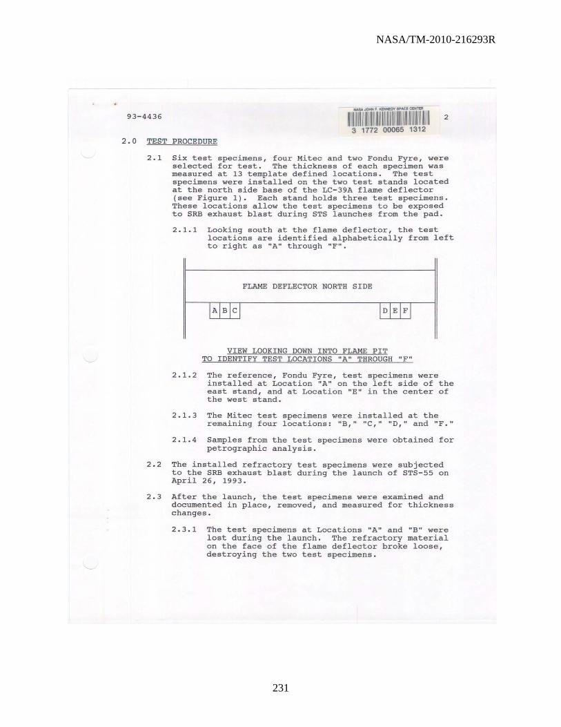
NASA/TM-2010-216293R
231
93-4436 2
2.0 TEST PROCEDURE
2.1 Six test specimens, four Mitec and two Fondu Fyre, were selected for test. The thickness of each specLroen was measured at 13 template defined locations. The test specimens were installed on the two test stands located at the north side base of the LC-39A flame deflector (see Figure 1). Each stand holds three test specimens. These locations allow the test specimens to be exposed to SRB exhaust blast during STS launches from the pad.
2.1.1 Looking south at the flame deflector, the test locations are identified alphabetically from left to right as itA" through "Fit.
FLAME DEFLECTOR NORTH SIDE
VIEW LOOKING DOWN INTO FLAME PIT TO IDENTIFY TEST LOCATIONS "A" THROUGH "F"
2.1.2 The reference, Fondu Fyre, test specimens were installed at Location "A" on the left side of the east stand, and at Location "E" in the center of the west stand.
2.1.3 The Mitec test specimens were installed at the remaining four locations: "B," "C," "0," and "F."
2.1.4 Samples from the test specimens were obtained for petrographic analysis.
2.2 The installed refractory test specimens were subjected to the SRB exhaust blast during the launch of STS-55 on April 26, 1993.
2.3 After the launch, the test specimens were examined and documented in place, removed, and measured for thickness changes.
2.3.1 The test specimens at Locations "A" and "B" were lost during the launch. The refractory material on the face of the flame deflector broke loose, destroying the two test specimens.

NASA/TM-2010-216293R
232
93-4436 3
2.3.2 The Mitec specimen at Location "e" (see Figures 2 and 3) was grossly eroded and broke into numerous small pieces when removed from the stand. Post test thickness measurements were not attempted on this specimen.
2.3.3 Balf of the Mitec specimen at Location liD" (see Figures 4 and 5) was missing and broke into several pieces when removed from the stand. Post test thickness measurements were not attempted on this specimen.
2 . 3 . 4 The Fondu Fyre reference test specimen at Locati on "E" appeared intact and was coated with a metallic material, except for the pitted areas. The test specimen was removed intact and post test thickness measurements were made of the major pieces. Chips of the metallic material were removed from the specimen to determine the layer thickness and identify the material.
2 . 3 . 5 The Mitec specimen at Location "F" (see Figures 8 and 9) appeared intact with only one noticeable crack traversing the face, and except for the pitted areas was coated with a metallic material. This specimen broke into seven major pieces when removed from the stand. Post-test thickness measurements were made of the major pieces .
3.0 RESULTS
Chips of the metallic material were removed from the specimen to determine the layer thickness and identify the material.
The metrology data for the test specimens are presented below:
Test Location "E" "F" Material Fondu Fyre Mitec
Original Thickness (Avg. ) 10.124 em 10.056 em
Post Test Thickness (Avg. ) 10.056 em 10.119 em
Metall i c Layer Thickness (Est. ) 0.173 em 0.178 em
Post Test Thickness (Est. ) 9 . 883 em 9 . 941 em
Thickness Loss (Est.) 0.241 em 0.111 em

NASA/TM-2010-216293R
233
93-4436 4
4.0 ANALYTICAL TESTS AND RESULTS
4.1 The samples were analyzed by optical microscope, electron microprobe with energy dispersive spectrometry, and X-ray diffraction.
4.2 The four Mitec samples were similar in composition and in petrographic features, and were described
4.3
collectively. The samples were moderately hard and compact. They were composed of coarse aggregate, fine sand, and cement paste.
4.2.1 The coarse aggregate appeared to be composed totally of white pumaceous material containing Si02 (alpha-cristoballite) and glass phase.
4.2.2 The fine sand was composed mainly of light and fine grained 5i-AI rich material.
4.2.3 The cement paste was light gray in color and contained small amounts of un hydrated portland cement and was moderately carbonated throughout. The cement paste was composed of glass, unhydrated portland cement, Ca55i60~6(OH)2 (tobermorite), Al(OH)3' CaC03 (calc~te), Ca3A1206' and Ca2(Si03)(OH)2'
4.2.4 The Mitec samples were air entrained. The air content was estimated to be less than seven percent.
The Fondu compact. sand, and
Fyre samples were also moderately hard and They were composed of coarse aggregate, fine cement paste.
4 . 3.1 The coarse aggregate appeared to be composed totally of dark coarse grained slag containing Fe2Ti04 (ulvospinel), CaFe3AISi06 (essenite), Ca(Fe,Mg)Si 20 6 (augite), glass, and CaSA12(Si2A12)OlO(OH)2 (margarite).
4.3.2 The fine sand was composed mainly of light colored and fine grained 5i-AI rich material.
4.3.3 The cement paste was dark gray in color, contained prominent amounts of un hydrated portland cement, and was moderately carbonated throughout. The cement paste was composed of CaSSi60 16 (OH)2 (tobermorite), Al(OH)3' CaC03 (calc1te), unhydrated portland cement, Ca3A1206' and amorphous materials.

NASA/TM-2010-216293R
234
93-4436 5
4 . 3.4 The Fondu Fyre samples were also air entrained. The air content was estimated to be less than seven percent .
4 . 4 The chips removed from the surface of the two refractory concrete test specimens were composed of AI2031 (corundum) •
5.0 CONCLUSIONS
5.1 Only two out of six test specimens survived the launch of STS- 55.
5.2 The poor performance of several Mitec refractory concrete test specimen resulted from their being fabricated without the steel mesh reinforcement as required in KSC- SPEC- P-0012 .
5.3 Mitec, Inc . , has indicated that they will fabricate two more test specimens with steel mesh reinforcement.
INVESTIGATOR: f ~I JAIL peter; J . Welch
APPROVAL:~~/1~.~.~~.~. ~L,~~~~~~~~~~~~~_ N. Salvail , Chief , Physical Testing Section

NASA/TM-2010-216293R
235
93-4436
FIGURE 1
VIEW LOOKING SOUTH IN LC-39A FLAME TRENCH TEST STANDS AT BOTTOM OF FLAME DEFLECTOR. LOCATED BENEATH THE TWO SRB FLAME PITS IN PLATFORMS.
AT REFRACTORY CONCRETE THE TEST STANDS ARE
THE MOBILE LAUNCH
6

NASA/TM-2010-216293R
236
93-4436
FIGURE 2
MITEC TEST SPECIMEN AT LOCATION "C" PRIOR TO LAUNCH . NOTE THE TEST SPECIMENS ARE GROUTED WITH SILICONE RUBBER TYPE ABLATIVE MATERIAL.
7

NASA/TM-2010-216293R
237
93-4436
FIGURE 3
MITEC TEST SPECIMEN AT LOCATION "e" AFTER LAUNCH. THE TEST SPECIMEN CONTAINED NUMEROUS CRACKS AND WAS GROSSLY ERODED, ESPECIALLY ALONG THE CRACK LINES.
B

NASA/TM-2010-216293R
238
93-4436 9
FIGURE 4
MITEC TEST SPECIMEN AT LOCATION "0" PRIOR TO LAUNCH.

NASA/TM-2010-216293R
239
93-4436 10
FIGURE 5
MITEC TEST SPECIMEN AT LOCATION "D " AFTER LAUNCH. OVER HALF OF THE TEST SPECIMEN WAS MISSING AND THE REMAINDER CONTAINED NUMEROUS CRACKS . AREAS OF HEAVY EROSION PITTING WERE NOTED ON THE FACE ADJACENT TO THE FLAME DEFLECTOR. THE SURFACE OF THE SPECIMEN APPEARED TO BE COATED WITH A ROUGH METALLIC LAYER EXCEPT IN THE AREAS OF THE PITTING .

NASA/TM-2010-216293R
240
93-4436 11
FIGURE 6
FONDU FYRE TEST SPECIMEN AT LOCATION "E" PRIOR TO LAUNCH.

NASA/TM-2010-216293R
241
93-4436 12
..
FIGURE 7
FONDU FYRE TEST SPECIMEN AT LOCATION "E" AFTER LAUNCH. AREAS OF HEAVY EROSION PITTING WERE NOTED ON THE FACE ADJACENT TO THE FLAME DEFLECTOR . THE SURFACE OF THE SPECIMEN APPEARED TO BE COATED WITH A ROUGH METALLIC LAYER EXCEPT IN THE AREAS OF THE PITTING.

NASA/TM-2010-216293R
242
93-44 3 6 13
FIGURE 8
MITEC TEST SPECIMEN AT LOCATION "F" PRIOR TO LAUNCH.
----~ -- -

NASA/TM-2010-216293R
243
93-4436 14
FIGURE 9
MITEC TEST SPECIMEN AT LOCATION "F" AFTER LAUNCH . SEVERAL CRACKS WERE EVIDENT IN THE FACE OF THE TEST SPECIMEN AND AREAS OF HEAVY EROSION PITTING WERE NOTED ON THE FACE ADJACENT TO THE FLAME DEFLECTOR. THE SURFACE OF THE SPECIMEN APPEARED TO BE COATED WITH A ROUGH METALLIC LAYER EXCEPT IN THE AREAS OF THE PITTING .
•

NASA/TM-2010-216293R
244
This page was intentionally left blank.

REPORT DOCUMENTATION PAGE Form Approved
OMB No. 0704-0188
The public reporting burden for this collection of information is estimated to average I hour per response, including the time for reviewing instructions, searching existing data sources, gathering and maintaining the data needed, and completing and reviewing the collection of information. Send comments regarding this burden estimate or any other aspect of this collection of information, including suggestions for reducing this burden, to Department of Defense, Washington Headquarters Services, Directorate for Information Operations and Reports (0704-0188), 1215 Jefferson Davis Highway, Suite 1204, Arlington, VA 22202-4302. Respondents should be aware that notwithstanding any other provision of law, no person shall be subject to any penalty for failing to comply with a collection of information if it does not display a currently valid OMB control number. PLEASE DO NOT RETURN YOUR FORM TO THE ABOVE ADDRESS. 1. REPORT DATE (DD-MM-YYYY)
31-12-2010 2. REPORT TYPE
Technical Memorandum 3. DATES COVERED (From — To)
2009 - 2010 4. TITLE AND SUBTITLE
Testing Requirements for Refractory Materials 5a. CONTRACT NUMBER
5b. GRANT NUMBER
5c. PROGRAM ELEMENT NUMBER
6. AUTHOR(S)
(1) Calle, Luz Marina (5) Kolody, Mark R. (2) Hintze, Paul E. (6) Sampson, Jeffrey W. (3) Parlier, Christopher R. (7) Montgomery, Eliza M. (4) Curran, Jerome P.
5d. PROJECT NUMBER
5e. TASK NUMBER
5f. WORK UNIT NUMBER
7. PERFORMING ORGANIZATION NAME(S) AND ADDRESS(ES)
1,2, 3, 5, 7NE-L2-C Kennedy Space Center, Florida 32899 4, 5ASRC Aerospace Kennedy Space Center 32899
8. PERFORMING ORGANIZATION REPORT NUMBER
9. SPONSORING/MONITORING AGENCY NAME(S) AND ADDRESS(ES)
National Aeronautics and Space Administration Washington, D.C. 20546-0001
10. SPONSORING/MONITOR’S ACRONYM(S)
11. SPONSORING/MONITORING REPORT NUMBER
NASA/TM-2010-216293R
12. DISTRIBUTION/AVAILABILITY STATEMENT
Unclassified – Unlimited Distribution: Standard Subject Category: Availability: NASA CASI (301) 621-0390
13. SUPPLEMENTARY NOTES
This revision changes paragraph ’10 days” to “14 days” in paragraph 3.2.9.
14. ABSTRACT Launch Pads 39A and 39B currently use refractory material (Fondu Fyre) in the flame trenches. This material was initially approved for the Saturn program. This material had a lifetime of 10 years according to the manufacturer, and it has been used for over 40 years. As a consequence, the Fondu Fyre at Launch Complex 39 requires repair subsequent to almost every launch. A review of the literature indicates that the gunned Fondu Fyre refractory product (WA-1G) was never tested prior to use. With the recent severe damage to the flame trenches, a new refractory material is sought to replace Fondu Fyre. In order to replace Fondu Fyre, a methodology to test and evaluate refractory products was developed. This paper outlines this methodology and discusses current testing requirements, as well as the laboratory testing that might be required. Furthermore, this report points out the necessity for subscale testing, the locations where this testing can be performed, and the parameters that will be necessary to qualify a product. The goal is to identify a more durable refractory material that has physical, chemical, and thermal properties suitable to withstand the harsh environment of the launch pads at KSC.
15. SUBJECT TERMS
refractory materials, Fondu Fyre, flame trench
16. SECURITY CLASSIFICATION OF: 17. LIMITATION OF
ABSTRACT
UU
18. NUMBER OF PAGES
252
19a. NAME OF RESPONSIBLE PERSON
Dr. Luz Marina Calle a. REPORT
U b. ABSTRACT
U c. THIS PAGE
U 19b. TELEPHONE NUMBER (Include area code)
(321) 867-3278 Standard Form 298 (Rev. 8-98) Prescribed by ANSI Std. Z39


Copyright © 2022 FDOKUMEN