TESTING HOT MET AL LADLES K. E. KNUDSEN·, Aas ...
8
TESTING HOT MET AL LADLES K. E. KNUDSEN·, Aas-Jakobsen, Oslo, Norway W. H. MUNSE .... University of Illinois, Urbana, Illinois B. G. JOHNSTON·, University of Michigan, Ann Arbor, Michigan • Formerly of Lehigh University SUMMARY Presented herein are test techniques applied in structural tests of hot-metal ladle models for the AssociationofIron and Steel Engineers. Strains were measured with SR-4 Electric Strain Gages, and deflections,by means of de- flection dials reading to 1/1000 inch. The loading of the ladle models involved special problems. INTRODUCTION Hot-metal ladles are vessels, lined with refractory material, and used for conveying molten metal in the steel mill from the fur- nace to the ingot mold. The ultimate goal of the investigation of these ladles was the de- velopment of rational design procedures. To this end, three typical models in linear scale ratio of 1:5 of 150 ton net capacity prototypes were tested in the Fritz Engineering Laboratory of the Lehigh University Civil Engineering Department. One of these models is shown in Fig. 1. The ladle consists basically of a com- paratively thin side shell of the shape of a frustum' of a cone, closed with a flat or dished bottom of about the same thickness as the side shell. The side shell is reinforced with stiffener rings at various levels. 'Two trunnion as- semblies distribute the concentrated reactions of the supports acting on the trunnion pins. Structural variables in the program were as follows: 1. Comparison of riveted and welded con- struction. 2. Comparison of circular and oval ladle cross section. 3. Comparison of flat and dished bottom shapes. 11 4. Effect of number and size of reinforcing rings. 5. Effect of size of trunnion assemblies. 6. Structural effect of refractory lining. Other test variables were: 7. Amount of load. 8. Effect of distance between the two points of support. 9. Effect of angle of tilt about the trunnion pin axis. The effect of temperature differentials caused by the molten metal was not considered in this investigation. Radial deflection of the side shell and rein- Fig. 1. Ladle Model. Height: 30 in. Top Dia- meter: 30 in. Surfac,ing- for Outside Gages and Drilled Holes for Leads from inside Gages Shown.
-
Upload
khangminh22 -
Category
Documents
-
view
3 -
download
0
Transcript of TESTING HOT MET AL LADLES K. E. KNUDSEN·, Aas ...
TESTING HOT MET AL LADLES
K. E. KNUDSEN·, Aas-Jakobsen, Oslo, NorwayW. H. MUNSE .... University of Illinois, Urbana, Illinois
B. G. JOHNSTON·, University of Michigan, Ann Arbor, Michigan• Formerly of Lehigh University
SUMMARY
Presented herein are test techniques appliedin structural tests of hot-metal ladle modelsfor the AssociationofIron and Steel Engineers.Strains were measured with SR-4 ElectricStrain Gages, and deflections,by means of deflection dials reading to 1/1000 inch. Theloading of the ladle models involved specialproblems.
INTRODUCTION
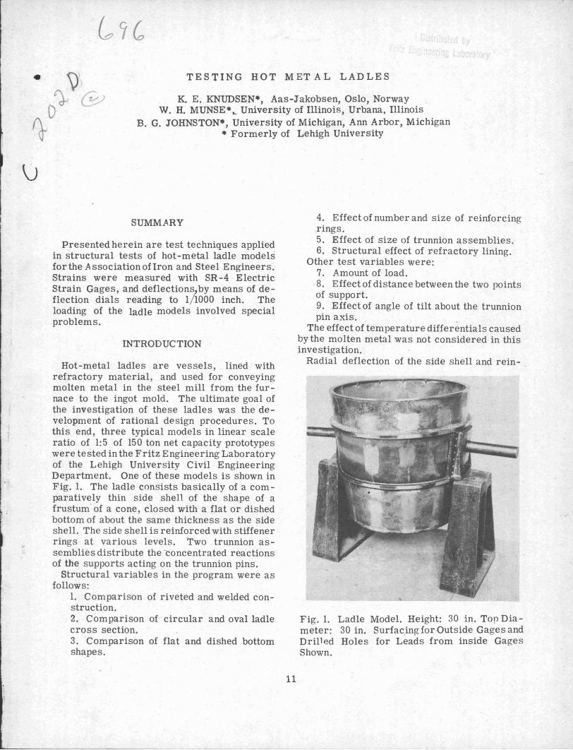
Hot-metal ladles are vessels, lined withrefractory material, and used for conveyingmolten metal in the steel mill from the furnace to the ingot mold. The ultimate goal ofthe investigation of these ladles was the development of rational design procedures. Tothis end, three typical models in linear scaleratio of 1:5 of 150 ton net capacity prototypeswere tested in the Fritz Engineering Laboratoryof the Lehigh University Civil EngineeringDepartment. One of these models is shown inFig. 1. The ladle consists basically of a comparatively thin side shell of the shape of afrustum' of a cone, closed with a flat or dishedbottom of about the same thickness as the sideshell. The side shell is reinforced with stiffenerrings at various levels. 'Two trunnion assemblies distribute the concentrated reactionsof the supports acting on the trunnion pins.
Structural variables in the program were asfollows:
1. Comparison of riveted and welded construction.2. Comparison of circular and oval ladlecross section.3. Comparison of flat and dished bottomshapes.
11
4. Effect of number and size of reinforcingrings.5. Effect of size of trunnion assemblies.6. Structural effect of refractory lining.
Other test variables were:7. Amount of load.8. Effect of distance between the two pointsof support.9. Effect of angle of tilt about the trunnionpin axis.
The effect of temperature differentials causedby the molten metal was not considered in thisinvestigation.
Radial deflection of the side shell and rein-
Fig. 1. Ladle Model. Height: 30 in. Top Diameter: 30 in. Surfac,ing- for Outside Gages andDrilled Holes for Leads from inside GagesShown.
12 EXPERIMENTAL STRESS ANALYSIS•
I,
Test Frome
.. . .. It ....
Position
"I'""I:
: i, ., II
metal weighing approximately 420 lbs per cubicfoot. Since, for the purpose of experimentalstress analysis, it is undesirable to load themodels in the laboratory with hot liquid metal,some substitute had to be found. Amount ofload was one of the test variables. This couldbe obtained in two ways:
1. By completely filling the ladles withseveral liquids of different specific gravities.
2. By using different amounts of one particular liquid, in which case the change in loadwould alter the stress distribution.
As the first of these solutions seemed mostsatisfactory from a theoretical point of view,the use of several liqUids with different specific gravities was proposed: water, carbontetrachloride, sodium Silicate, mercury, etc.Also, granular materials were considered,among which were sand, iron shot, and leadshot.
Serious inconveniences result in the case ofsome of these loading agents. The granular
5' - 6"
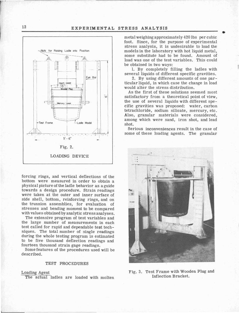
Fig. 2.
LOADING DEVICE
forcing rings, and vertical deflections of thebottom were measured in order to obtain aphysical picture of the ladle behavior as a guidetowards a design procedure. Strain readingswere taken at the outer and inner surface ofside shell, bottom, reinforcing rings, and onthe trunnion assemblies, for evaluation ofstresses and bending moment to be comparedwith values obtained by analytic stress analyses.
The extensive program of test variables andthe large number of measurements in eachtest called for rapid and dependable test techniques. The total number of single readingsduring the whole testing program is estimatedto be five thousand deflection readings andfourteen thousand strain gage readings.
Some features of the procedures used will bedescribed.
TEST PROCEDURES
Loading AgentThe actual ladles are loaded with molten
Fig. 3. Test Frame with Wooden Plug andInflection Bracket.
TESTING HOT METAL LADLES
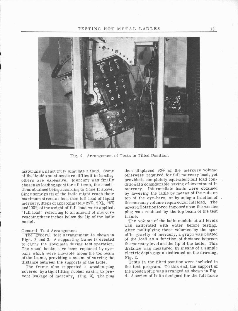
Fig. 4. ,A rrangement of Tests in Tilted Position.
13
materials will not truly simulate a fluid. Someof the liquids mentioned are difficult to handle,others are expensive. Mercury was finallychosen as loading agent for all tests, the conditions obtained being according to Case II above.Since some parts of the ladle might reach theirmaximum stress at less than full load of liquidmercury, steps of approximately 25%, 50%, 75%and 100% of the weight of full load were applied,"full load" referring to an amount of mercuryreaching three inches below the lip of the ladlemodel.
General Test ArrangementThe general test arrangement is shown in
Figs. 2 and 3. A supporting frame is erectedto carry the specimen during test operation.The usual hooks have been replaced by eyebars which were movable along the top beamof the frame, providing a means of varying thedistance between the supports of the ladle.
The frame also supported a wooden plugcovered by a tight fitting rubber casing to prevent leakage of mercury, (Fig. 3). The plug
then displaced 93% of the mercury volumeotherwise required for full mercury load, yetprovided a compl~tely equivalent full load condition at a considerable saving of investment inmercury. Intermediate loads were obtainedby lowering the ladle by means of the nuts ontop of the eye-bars, or by using a fraction of •the mercury volume requiredior full load. Theupward flotation force imposed upon the woodenplug was resisted by the top beam of the testframe.
TI-Je vo~ume of the ladle models at all levelswas calibrated with water before testiXlg.After multiplying these volumes by the specific gravity of mercury, a graph was plottedof the load as a function of distance betweenthe mercury level and the lip of the ladle. Thisdistance was measured by means of a simpleelectric depth gage as indicated on the drawing,Fig. 2.
Tests in the tilted position were included inthe test program. To this end, the support ofthe wooden plug was arranged as shown in Fig.4. A series of bolts designed for the full force
----,--- --- --
14 EXPERIMENTAL STRESS ANALYSIS
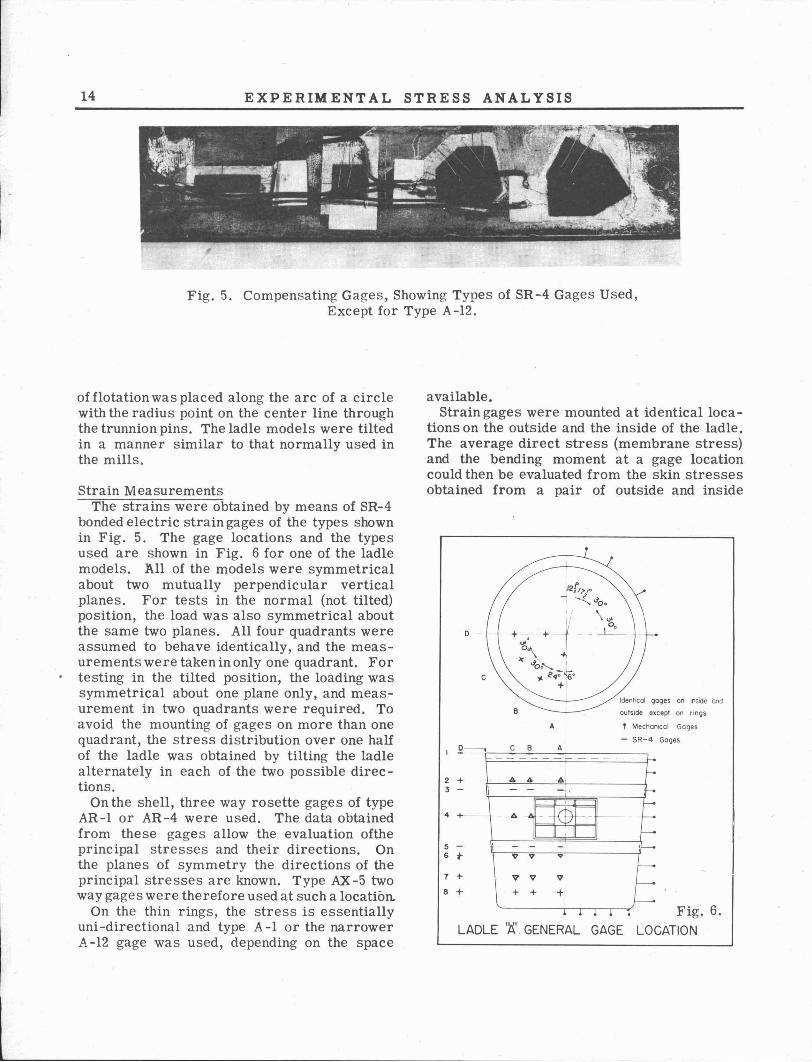
Fig. 5. Compensating Gages, Showing Types of SR-4 Gages Used,Except for Type A-12.
Identical gages on inside and
outside except on rings
T MechanIcal Gages
- SR-4 GagesA
A
B
C B
c
------
I---4- 4- ~
\ - - - f---
0~
- - --.ll. ~ - - - - f---- - --:f-
V V .... -~ V VI f---+ + +
J-• • • • 1
4 +-
2 +3 -
Fig. 6.LADLE '~'. GENERAL GAGE LOCATION
7 +
B +
5 6 t
available.Strain gages were mounted at identical loca
tions on the outside and the inside of the ladle.The average direct stress (membrane stress)and the bending moment at a gage locationcould then be evaluated from the skin stressesobtained from a pair of outside and inside
of flotation was placed along the arc of a circlewith the radius point on the center line throughthe trunnion pins. The ladle models were tiltedin a manner similar to that normally used inthe mills.
Strain MeasurementsThe strains were obtained by means of SR-4
bonded electric strain gages of the types shownin Fig. 5. The gage locations and the typesused are shown in Fig. 6 for one of the ladlemodels. A.ll of the models were symmetricalabout two mutually perpendicular verticalplanes. For tests in the normal (not tilted)position, the load was also symmetrical aboutthe same two planes. All four quadrants wereassumed to behave identically, and the measurements were taken in only one quadrant. Fortesting in the tilted position, the loading wassymmetrical about one plane only, and measurement in two quadrants were required. Toavoid the mounting of gages on more than onequadrant, the stress distribution over one halfof the ladle was obtained by tilting the ladlealternately in each of the two possible directions.
On the shell, three way rosette gages of typeAR-I or AR-4 were used. The data obtainedfrom these gages allow the evaluation oftheprincipal stresses and their directions. Onthe planes of symmetry the directions of theprincipal stresses are known. Type AX -5 twoway gages were therefore used at such a location.
On the thin rings, the stress is essentiallyuni -directional and type A-lor the narrowerA-12 gage was used, depending on the space
Deflection MeasurementsThe deflection measurements were obtained
by means of a series of 1/1000 inch dial gages.As in the case of strain measurements thesymmetry of the ladles permitted the measurements to be taken in one quadrant only. Theradial side deflections and the vertical bottom
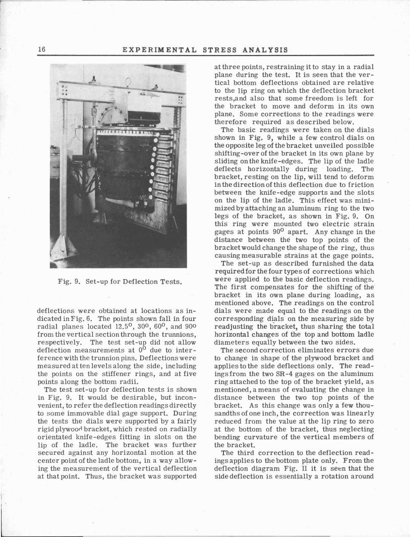
through small drilled holes in the ladle shell tothe outside, as may be seen in Fig. 1. Theinside strain gages were protected againstattack from moisture in the clay lining andfrom possible leakage of mercury or water usedfor loading or calibration by means of a coverof wax. Adetail of a cross section through theladle and the wooden plug is shown in Fig. 8.
Mohr's Circle'as well as numerical methodswere used in the calculation of stresses onbasis of the measured strains. The horizontaland vertical stress components, the principalstresses, and their directions were computed.It was found that untrained helpers obtaineddependable stress values by means of graphicalsolutions.
TESTING HOT METAL LADLES
Fig. 7. Set-up for Strain Tests
15
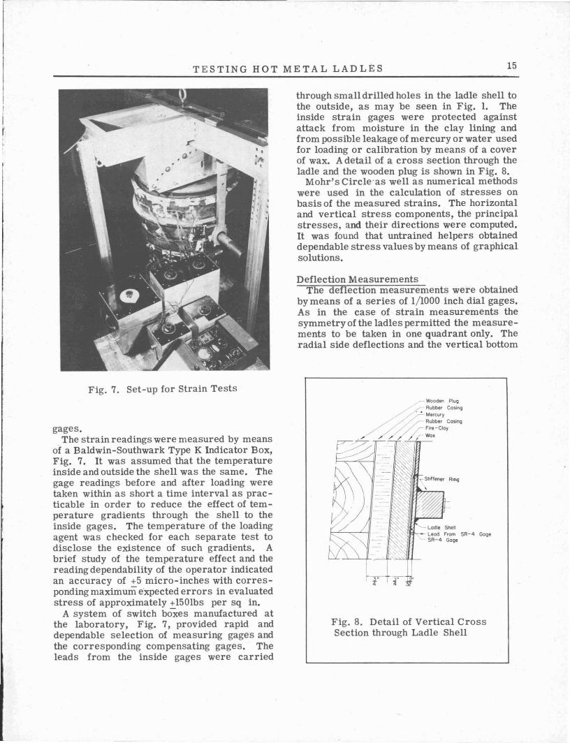
gages.The strain readings were measured by means
of a Baldwin-Southwark Type K Indicator Box,Fig. 7. It was assumed that the temperatureinside and outside the shell was the same. Thegage readings before and after loading weretaken within as short a time interval as practicable in order to reduce the effect of temperature gradients through the shell to theinside gages. The temperature of the loadingagent was checked for each separate test todisclose the existence of such gradients. Abrief study of the temperature effect and thereading dependability of the operator indicatedan accuracy of +5 micro-inches with corresponding maximum e'xpected errors in evaluatedstress of approximately +150lbs per sq in.
A system of switch boxes manufactured atthe laboratory, Fig. 7, provided rapid anddependable selection of measuring gages andthe corresponding compensating gages. Theleads from the inside gages were carried
,. Wooden P\ug
/.' Rubber Casingr- Mercury/ /':... Rubber Casing
/ ~./; Fire-Cloy
.."..::.-_ "/~//" We.
Ladle Shell"".""".-- Lead From SR-4 Gage
SR-4 Gage
11· I r
Fig. 8. Detail of Vertical CrossSection through Ladle Shell
16 EXPERIM ENTAL STRESS ANALYSIS
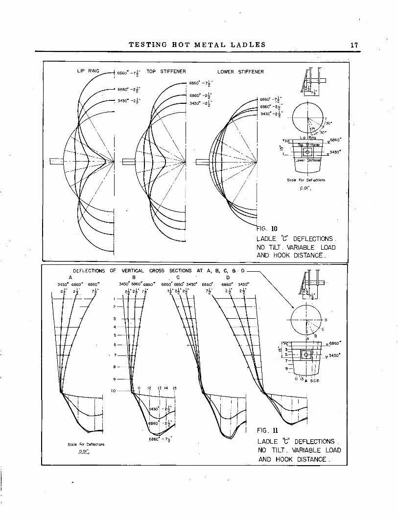
Fig. 9. Set-up for Deflection Tests.
deflections were obtained at locations as indicated in Fig. 6. The points shown fall in fourradial planes located 12.50 ,300 ,600 , and 900from the vertical section through the trunnions,respectively. The test set-up did not allowdeflection measurements at 00 due to interference with the trunnion pins. Deflections weremeasured at ten levels along the side, includingthe points on the stiffener rings, and at fivepoints along the bottom radii.
The test set-up for deflection tests is shownin Fig. 9. It would be desirable, but inconvenient, to refer the deflection readings directlyto some immovable dial gage support. Duringthe tests the dials were supported by a fairlyrigid plywoorl bracket, which rested on radiallyorientated knife-edges fitting in slots on thelip of the ladle. The bracket was furthersecured against any horizontal motion at thecenter point of the ladle bottom, in a way allowing the measurement of the vertical deflectionat that point. Thus, the bracket was supported
at three points, restraining it to stay in a radialplane during the test. It is seen that the vertical bottom deflections obtained are relativeto the lip r.ing on which the deflection bracketrests,and also that some freedom is left forthe bracket to move and deform in its ownplane. Some corrections to the readings weretherefore required as described below.
The basic readings were taken on the dialsshown in Fig. 9, while a few control dials onthe opposite leg of the bracket unveiled possibleshifting-over of the bracket in its own plane bysliding on the knife-edges. The lip of the ladledeflects horizontally during loading. Thebracket, resting on the lip, will tend to deformin the direction of this deflection due to frictionbetween the knife-edge supports and the slotson the lip of the ladle. This effect was minimized by attaching an aluminum ring to the twolegs of the bracket, as shown in Fig. 9. Onthis ring were mounted two electric straingages at points 900 apart. Any change in thedistance between the two top points of thebracketwould change the shape of the ring, thuscausing measurable strains at the gage points.
The set-up as described furnished the datarequired for the four types of corrections whichwere applied to the basic deflection readings.The first compensates for the shifting of the"bracket in its own plane during loading, asmentioned above. The readings on the controldials were made equal to the readings on thecorresponding dials on the measuring side byreadjusting the b-racket, thus sharing the totalhorizontal changes of the top and bottom ladlediameters equally between the two sides.
The second correction eliminates errors dueto change in shape of the plywood bracket andapplies to the side deflections only. The readingsfrom the two SR-4 gages on the aluminumring attached to the top of the bracket yield, asmentioned, a means of evaluating the change indistance between the two top points of thebracket. As this change was only a few thousandths of one inch, the correction was linearlyreduced from the value at the lip ring to zeroat the bottom of the bracket, thus neglectingbending curvature of the vertical members ofthe bracket.
The third correction to the deflection readings applies to the bottom plate only. From thedeflection diagram Fig. 11 it is seen that theside deflection is essentially a rotation around
TESTING HOT METAL LADLES 17
30·
Scole For Deflections
6860' -71 "_2
6860"-2t"
3430" -2i"
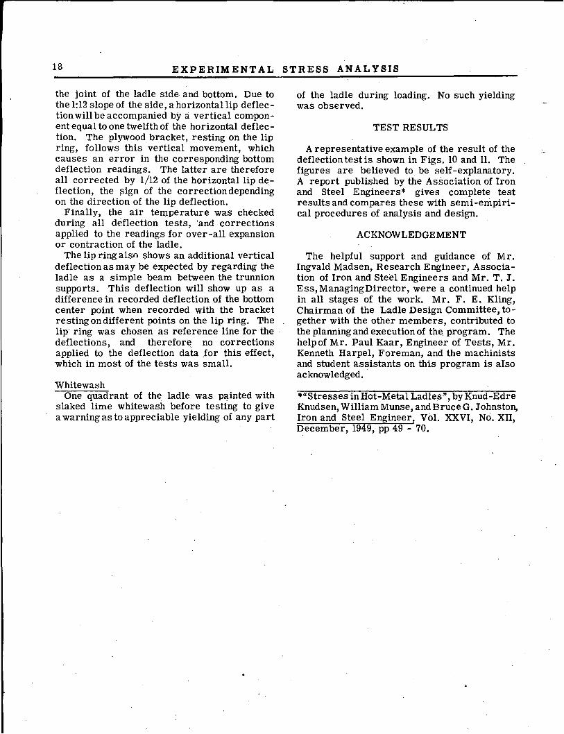
FIG. 10LADLE TIC' DEFLECTIONS.
NO TILT. VARIABLE LOADAND HOOK DISTANCE.
LOWER STIFFENER
6860' -7t"
6860' -2~"
3430· -2i"
TOP STIFFENER
6860· -2f
3430· -2~"
H·I'
1"
~o'A B
FIG. 11
LADLE 'Gil DEFLECTIONS.
NO TILT. VARIABLE LOAD
AND HOOK DISTANCE.
13 14
6860' -71 ". 2
VERTICAL CROSS SECTIONS AT A. e, C. a.. D
e . C 03430" 6860· 6860· 6860' 6860· 3430' 6860' 6860· 3430'
21 " 2f 7f 7!" 2~;' 2~" 7f 2~" 2f
I~
3-
2 ~H---+---1
9--
8--
10--
DEFLECTIONS OFA
Scale For Deflections
,0.01",
18 EXPERIMENTAL STRESS ANALYSIS
the joint of the ladle side. and bottom. Due tothe 1: 12 slope of the side, a horizontal lip deflection will be accompanied by a vertical component equal to one twelfth of the horizontal deflection. The plywood bracket, resting on the lipring, follows this vettical movement, whichcauses an error in the corresponding bottomdeflection readings. The latter are thereforeall corrected by 1/12 of the horizontal lip deflection, the pign of the correction dependingon the direction of the lip deflection.
Finally, the air temperature was checkedduring all deflection tests, 'and correctionsapplied to the readings for over-all expansionor contraction of the ladle.
The lip ring alsn ~hows an additional verticaldeflection as may be expected by regarding theladle as a simple beam between the trunnionsupports. This deflection will show up as adifference in recorded deflection of the bottomcenter point when recorded with the bracketresting on different points on the lip ring. Thelip ring was chosen as reference line for the .deflections, and therefore. no correctionsapplied to the deflection data for this effect,which in most of the tests was small.
WhitewashOne quadrant of the ladle was painted with
slaked lime whitewash before testing to givea warning as to appreciable yielding of any part
of the ladle during loading. No such yieldingwas observed.
TEST RESULTS
A representative example of the result of thedeflection test is shown in Figs. 10 and ll. Thefigures are believed to be self-explanatory.A report published by the Association of Ironand Steel Engineers* gives complete testresults and compares these with semi-empirical procedures of analysis and design.
ACKNOWLEDGEMENT
The helpful support and guidance of Mr.Ingvald Madsen, Research Engineer, Association of Iron and Steel Engineers and Mr. T; J.Ess,ManagingDirectbr, were a continued helpin all stages of the work. Mr. F. E. Kling,Chairman of the Ladle Design Committee, together with the other members, contributed tothe planning and execution of the program. Thehelp of Mr. Paul Kaar, Engineer of Tests, Mr.Kenneth Harpel, Foreman, and the machinistsand student assistants on this program is alsoacknowledged.
."Stresses in Hot-Metal Ladles", by Knud-EdreKnudsen, William Munse, andBruceG. Johnston,Iron and Steel Engineer, Vol. XXVI, No. XII,December, 1949, pp 49 - 70.


![AAS 20 [1928] - ACTA APOSTOLICAE SEDIS](https://static.fdokumen.com/doc/165x107/63268566051fac18490dccc0/aas-20-1928-acta-apostolicae-sedis.jpg)