Terra Owner Manual EN.pdf - NISSAN MOTOR THAILAND
292
PD23A1-CA59C8CB-C9EB-42C4-B504-F8AF8A73B8DE This manual was prepared to help you under- stand the operation and maintenance of your vehicle so that you may enjoy many kilometers (miles) of driving pleasure. Please read through this manual before operating your vehicle. A separate Warranty Information & Mainte- nance Booklet explains details about the war- ranties covering your vehicle. Your NISSAN dealer knows your vehicle best. When you require any service or have any questions, we will be glad to assist you with the extensive resources available for you. IMPORTANT SAFETY INFORMATION PD23A1-E20DF1AA-22BC-47CB-B7D0-017CE6DFFFB7 Reminders for safety! PD23A1-91D0EA2F-7DA9-46D7-92EF-017C6F603E88 Follow these important driving rules to help ensure a safe and complete trip for you and your passengers! . NEVER drive under the influence of alco- hol or drugs. . ALWAYS observe posted speed limits and never drive too fast for conditions. . ALWAYS use your seat belts and appro- priate child restraint systems. Preteen childrenshouldbeseatedintherearseat. . ALWAYS provide information about the proper use of vehicle safety features to all occupants of the vehicle. . ALWAYS review this Owner’s Manual for important safety information. When reading the manual PD23A1-B1BE6CF6-22AD-4020-A43D-3E1D2A7455D1 This manual includes information for all options available on this model. Therefore, you may find some information that does not apply to your vehicle. Throughout this manual, some illustrations may only show the layout for Left-Hand Drive (LHD) models. For Right-Hand Drive (RHD) models, the illustrated shape and location of some components may differ. All information, specifications and illustrations in this manual are those in effect at the time of printing. NISSAN reserves the right to change specifications or designs without notice and without obligation. MODIFICATION OF YOUR VEHICLE PD23A1-EF203BB2-ABA2-4612-8FCA-0ACC5C3CE29E This vehicle should not be modified. Modifica- tion could affect its performance, safety or durability, and may even violate governmental regulations. In addition, damage or perfor- mance problems resulting from modifications may not be covered under NISSAN warranties. Read first — then drive safely PD23A1-0E4A92DE-D1FE-4675-BF47-F7633898A4C8 Before driving your vehicle, read this Owner’s Manual carefully. This will ensure familiarity with controls and maintenance requirements, assisting you in the safe operation of your vehicle. Throughout this manual we have used the symbol followed by the word WARNING. This is used to indicate the presence of a hazard that could cause death or serious personal injury. To avoid or reduce the risk, the procedures must be followed precisely. The symbol followed by the word CAU- TION is also used throughout this manual to indicate the presence of a hazard that could cause minor or moderate personal injury or damages to your vehicle. To avoid or reduce the risk, the procedures must be followed carefully. SIC0697 If you see this symbol, it means “Donotdothis” or “Do not let this happen”. NOS1274 If you see a symbol similar to these in an illustration, it means the arrow points to the front of the vehicle. NOS1275 Arrows in an illustration that are similar to these indicate movement or action. NOS1276 Arrows in an illustration that are similar to these call attention to an item in the illustra- tion. Foreword
-
Upload
khangminh22 -
Category
Documents
-
view
3 -
download
0
Transcript of Terra Owner Manual EN.pdf - NISSAN MOTOR THAILAND
(3,1)
[ Edit: 2018/ 5/ 25 Model: PD23-A ]
PD23A1-CA59C8CB-C9EB-42C4-B504-F8AF8A73B8DEThis manual was prepared to help you under-stand the operation and maintenance of yourvehicle so that you may enjoy many kilometers(miles) of driving pleasure. Please read throughthis manual before operating your vehicle.A separate Warranty Information & Mainte-nance Booklet explains details about the war-ranties covering your vehicle.Your NISSAN dealer knows your vehicle best.When you require any service or have anyquestions, we will be glad to assist you withthe extensive resources available for you.
IMPORTANT SAFETY INFORMATIONPD23A1-E20DF1AA-22BC-47CB-B7D0-017CE6DFFFB7
Reminders for safety!PD23A1-91D0EA2F-7DA9-46D7-92EF-017C6F603E88
Follow these important driving rules to helpensure a safe and complete trip for you andyour passengers!. NEVER drive under the influence of alco-
hol or drugs.. ALWAYS observe posted speed limits and
never drive too fast for conditions.. ALWAYS use your seat belts and appro-
priate child restraint systems. Preteenchildren should be seated in the rear seat.
. ALWAYS provide information about theproper use of vehicle safety features toall occupants of the vehicle.
. ALWAYS review this Owner’s Manual forimportant safety information.
When reading the manualPD23A1-B1BE6CF6-22AD-4020-A43D-3E1D2A7455D1
This manual includes information for all optionsavailable on this model. Therefore, you may findsome information that does not apply to yourvehicle.Throughout this manual, some illustrationsmay only show the layout for Left-Hand Drive(LHD) models. For Right-Hand Drive (RHD)models, the illustrated shape and location ofsome components may differ.All information, specifications and illustrationsin this manual are those in effect at the time ofprinting. NISSAN reserves the right to changespecifications or designs without notice andwithout obligation.
MODIFICATION OF YOUR VEHICLEPD23A1-EF203BB2-ABA2-4612-8FCA-0ACC5C3CE29E
This vehicle should not be modified. Modifica-tion could affect its performance, safety ordurability, and may even violate governmentalregulations. In addition, damage or perfor-mance problems resulting from modificationsmay not be covered under NISSAN warranties.
Read first — then drive safelyPD23A1-0E4A92DE-D1FE-4675-BF47-F7633898A4C8
Before driving your vehicle, read this Owner’sManual carefully. This will ensure familiaritywith controls and maintenance requirements,assisting you in the safe operation of yourvehicle.Throughout this manual we have used thesymbol followed by the word WARNING.This is used to indicate the presence of ahazard that could cause death or seriouspersonal injury. To avoid or reduce the risk,the procedures must be followed precisely.The symbol followed by the word CAU-TION is also used throughout this manual toindicate the presence of a hazard that could
cause minor or moderate personal injury ordamages to your vehicle. To avoid or reducethe risk, the procedures must be followedcarefully.
SIC0697
If you see this symbol, it means “Do not do this”or “Do not let this happen”.
NOS1274
If you see a symbol similar to these in anillustration, it means the arrow points to thefront of the vehicle.
NOS1275
Arrows in an illustration that are similar tothese indicate movement or action.
NOS1276
Arrows in an illustration that are similar tothese call attention to an item in the illustra-tion.
Foreword
Condition: 'Except for China'/
(4,1)
[ Edit: 2018/ 5/ 25 Model: PD23-A ]
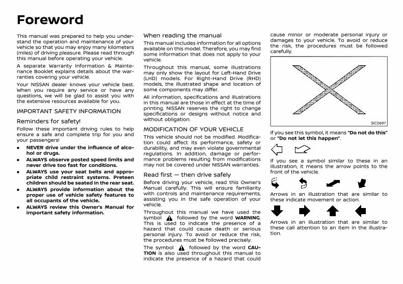
Air bag warning labels:GUID-9E14C2E6-2E9C-4731-980B-C45B899B977B
JVR0243X
“NEVER use a rearward facing child restraint ona seat protected by an ACTIVE AIRBAG in frontof it, DEATH or SERIOUS INJURY to the CHILDcan occur.”Be sure to read “Air bag warning labels” (P.1-32).
ON-PAVEMENT AND OFF-ROAD DRIV-ING
PD23A1-8349505F-8EC3-4524-B68F-65A3E4D55DE7This vehicle will handle and maneuver differ-ently from an ordinary passenger car, becauseit has a higher center of gravity. As with othervehicles with features of this type, failure tooperate this vehicle correctly may result in lossof control or an accident.Be sure to read “On-pavement and off-roaddriving precautions” (P.5-7).
NOS1617Bluetooth® is a trademarkowned by Bluetooth SIG,Inc., and licensed to VisteonCorporation.
© 2018 NISSAN MOTOR CO., LTD.
Condition: 'Except for China'/
(1,1)
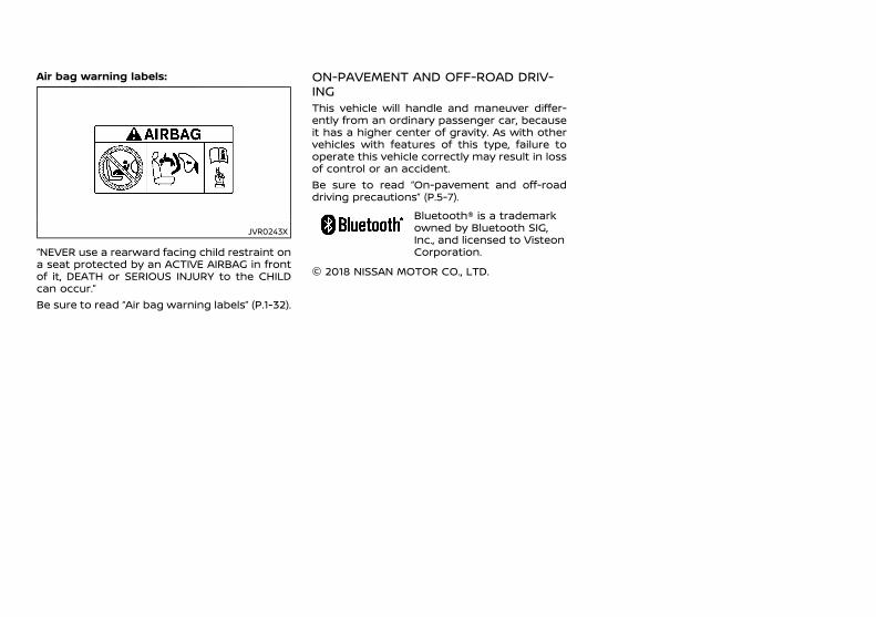
Illustrated table of contents 0Safety — seats, seat belts and supplementalrestraint system 1
Instruments and controls
Pre-driving checks and adjustments
Monitor, Heater and air conditioner, and audiosystem
Starting and driving
In case of emergency
Appearance and care
Maintenance and do-it-yourself
Technical information
Index
2
3
4
5
6
7
8
9
10
Table ofContents
[ Edit: 2018/ 5/ 25 Model: PD23-A ]Condition: 'Except for China'/

(2,1)

(5,1)
[ Edit: 2018/ 5/ 25 Model: PD23-A ]
0 Illustrated table of contents
Seats, seat belts and Supplemental RestraintSystem (SRS) ......................................................................................................... 0-2Exterior front ........................................................................................................ 0-3Exterior rear .......................................................................................................... 0-4Passenger compartment ........................................................................... 0-5Cockpit ...................................................................................................................... 0-6
Left-Hand Drive (LHD) model ........................................................... 0-6Right-Hand Drive (RHD) model ....................................................... 0-7
Instrument panel ............................................................................................. 0-8Left-Hand Drive (LHD) model ........................................................ 0-8Right-Hand Drive (RHD) model .................................................... 0-9
Meters and gauges ..................................................................................... 0-10Engine compartment ................................................................................ 0-11
YD25DDTi engine ................................................................................ 0-11YS23DDTT engine ............................................................................... 0-12
Condition: 'Except for China'/
(6,1)
[ Edit: 2018/ 5/ 25 Model: PD23-A ]
0-2 Illustrated table of contents
PD23A1-93031372-E355-481B-83A4-EC9F81506A6B
JVC1186X
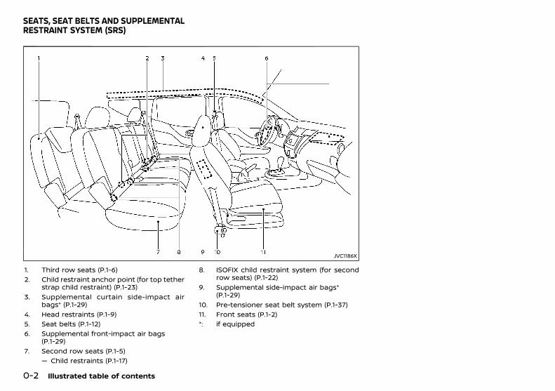
1. Third row seats (P.1-6)2. Child restraint anchor point (for top tether
strap child restraint) (P.1-23)3. Supplemental curtain side-impact air
bags* (P.1-29)4. Head restraints (P.1-9)5. Seat belts (P.1-12)6. Supplemental front-impact air bags
(P.1-29)7. Second row seats (P.1-5)
— Child restraints (P.1-17)
8. ISOFIX child restraint system (for secondrow seats) (P.1-22)
9. Supplemental side-impact air bags*(P.1-29)
10. Pre-tensioner seat belt system (P.1-37)11. Front seats (P.1-2)*: if equipped
SEATS, SEAT BELTS AND SUPPLEMENTALRESTRAINT SYSTEM (SRS)
Condition: 'Except for China'/
(7,1)
[ Edit: 2018/ 5/ 25 Model: PD23-A ]
PD23A1-A7D731C2-C58B-4FEB-B117-40A4E0B39DA1
JVC1187X
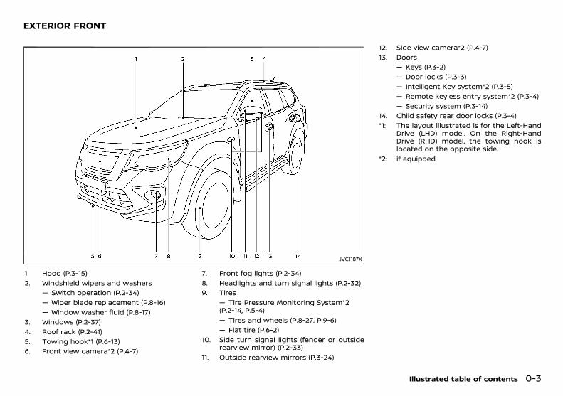
1. Hood (P.3-15)2. Windshield wipers and washers
— Switch operation (P.2-34)— Wiper blade replacement (P.8-16)— Window washer fluid (P.8-17)
3. Windows (P.2-37)4. Roof rack (P.2-41)5. Towing hook*1 (P.6-13)6. Front view camera*2 (P.4-7)
7. Front fog lights (P.2-34)8. Headlights and turn signal lights (P.2-32)9. Tires
— Tire Pressure Monitoring System*2(P.2-14, P.5-4)— Tires and wheels (P.8-27, P.9-6)— Flat tire (P.6-2)
10. Side turn signal lights (fender or outsiderearview mirror) (P.2-33)
11. Outside rearview mirrors (P.3-24)
12. Side view camera*2 (P.4-7)13. Doors
— Keys (P.3-2)— Door locks (P.3-3)— Intelligent Key system*2 (P.3-5)— Remote keyless entry system*2 (P.3-4)— Security system (P.3-14)
14. Child safety rear door locks (P.3-4)*1: The layout illustrated is for the Left-Hand
Drive (LHD) model. On the Right-HandDrive (RHD) model, the towing hook islocated on the opposite side.
*2: if equipped
Illustrated table of contents 0-3
EXTERIOR FRONT
Condition: 'Except for China'/

(8,1)
[ Edit: 2018/ 5/ 25 Model: PD23-A ]
0-4 Illustrated table of contents
PD23A1-74D041B7-1D60-49AD-9DE5-35CDEE6972C8
JVC1188X
1. Rear window defogger (P.2-36)2. Antenna (P.4-30)3. High-mounted stop light (P.8-23)4. Intelligent Rear View Mirror camera*
(P.3-19)5. Rear window wiper and washer
— Switch operation (P.2-35)— Window washer fluid (P.8-17)
6. Fuel-filler lid (P.3-18)
7. Rear combination lights (P.8-23)8. Parking (sonar) sensors
— Camera aiding parking sensor (sonar)function* (P.4-14)— Parking (sonar) sensor system (P.5-40)
9. Back door (P.3-16)— Intelligent Key system* (P.3-5)— Remote keyless entry system* (P.3-4)
10. Rear view camera* (P.4-3, P.4-7)*: if equipped
EXTERIOR REAR
Condition: 'Except for China'/
(9,1)
[ Edit: 2018/ 5/ 25 Model: PD23-A ]
PD23A1-3236BBA8-79B0-4858-9BB8-AC2BFDEC1572
JVC1189X
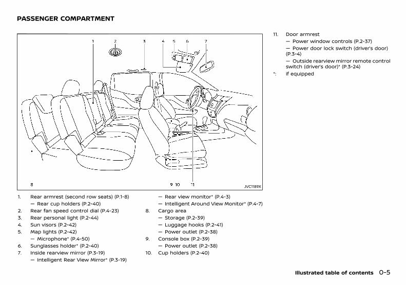
1. Rear armrest (second row seats) (P.1-8)— Rear cup holders (P.2-40)
2. Rear fan speed control dial (P.4-23)3. Rear personal light (P.2-44)4. Sun visors (P.2-42)5. Map lights (P.2-42)
— Microphone* (P.4-50)6. Sunglasses holder* (P.2-40)7. Inside rearview mirror (P.3-19)
— Intelligent Rear View Mirror* (P.3-19)
— Rear view monitor* (P.4-3)— Intelligent Around View Monitor* (P.4-7)
8. Cargo area— Storage (P.2-39)— Luggage hooks (P.2-41)— Power outlet (P.2-38)
9. Console box (P.2-39)— Power outlet (P.2-38)
10. Cup holders (P.2-40)
11. Door armrest— Power window controls (P.2-37)— Power door lock switch (driver’s door)(P.3-4)— Outside rearview mirror remote controlswitch (driver’s door)* (P.3-24)
*: if equipped
Illustrated table of contents 0-5
PASSENGER COMPARTMENT
Condition: 'Except for China'/

(10,1)
[ Edit: 2018/ 5/ 25 Model: PD23-A ]
0-6 Illustrated table of contents
PD23A1-1B613D6A-4853-4100-88F1-87CBA0869EC0
LEFT-HAND DRIVE (LHD) MODELPD23A1-A297B8CA-B368-4153-89A1-481E044D636A
JVC1190X
1. Cup holder (P.2-40)2. Instrument brightness control switch
(models with color display) (P.2-10)3. TRIP/RESET switch for twin trip odometer
(models with color display) (P.2-8)4. Instrument brightness control switch
(P.2-10)/Trip computer mode switch(models without color display) (P.2-18)
5. Headlight and turn signal switch (P.2-32)/Fog light switch (P.2-34)
6. TRIP/RESET switch for twin trip odometer(P.2-8)/Trip computer mode switch (mod-els without color display) (P.2-18)
7. Steering-wheel-mounted controls* (leftside)— Audio control steering switch (P.4-49)— Vehicle information display control
switch* (P.2-19)— Hands-Free Phone System switch*(P.4-50)
8. Steering wheel— Horn (P.2-36)— Driver’s supplemental front-impact airbag (P.1-29)
9. Wiper and washer switch (P.2-34)10. Steering-wheel-mounted controls* (right
side)— Cruise control system (P.5-36)— Hands-Free Phone System switch(P.4-50)
11. Shift lever— Automatic Transmission (AT) (P.5-14)— Manual Transmission (MT) (P.5-17)
12. Headlight aiming control switch (P.2-33)13. Vehicle Dynamic Control (VDC) OFF
switch* (P.5-23)14. Fuel-filler lid opener switch (P.3-18)15. Tilting steering wheel lever (P.3-18)*: if equipped
COCKPIT
Condition: 'Except for China'/
(11,1)
[ Edit: 2018/ 5/ 25 Model: PD23-A ]
RIGHT-HAND DRIVE (RHD) MODELPD23A1-62FCC69C-B9E2-41E6-88D8-4600F2449E75
JVC1191X
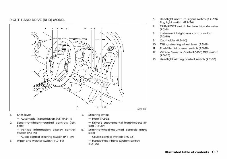
1. Shift lever— Automatic Transmission (AT) (P.5-14)
2. Steering-wheel-mounted controls (leftside)— Vehicle information display controlswitch (P.2-19)— Audio control steering switch (P.4-49)
3. Wiper and washer switch (P.2-34)
4. Steering wheel— Horn (P.2-36)— Driver’s supplemental front-impact airbag (P.1-29)
5. Steering-wheel-mounted controls (rightside)— Cruise control system (P.5-36)— Hands-Free Phone System switch(P.4-50)
6. Headlight and turn signal switch (P.2-32)/Fog light switch (P.2-34)
7. TRIP/RESET switch for twin trip odometer(P.2-8)
8. Instrument brightness control switch(P.2-10)
9. Cup holder (P.2-40)10. Tilting steering wheel lever (P.3-18)11. Fuel-filler lid opener switch (P.3-18)12. Vehicle Dynamic Control (VDC) OFF switch
(P.5-23)13. Headlight aiming control switch (P.2-33)
Illustrated table of contents 0-7
Condition: 'Except for China'/
(12,1)
[ Edit: 2018/ 5/ 25 Model: PD23-A ]
0-8 Illustrated table of contents
PD23A1-E7E5A3F7-B385-4AC2-8157-2543504FD64C
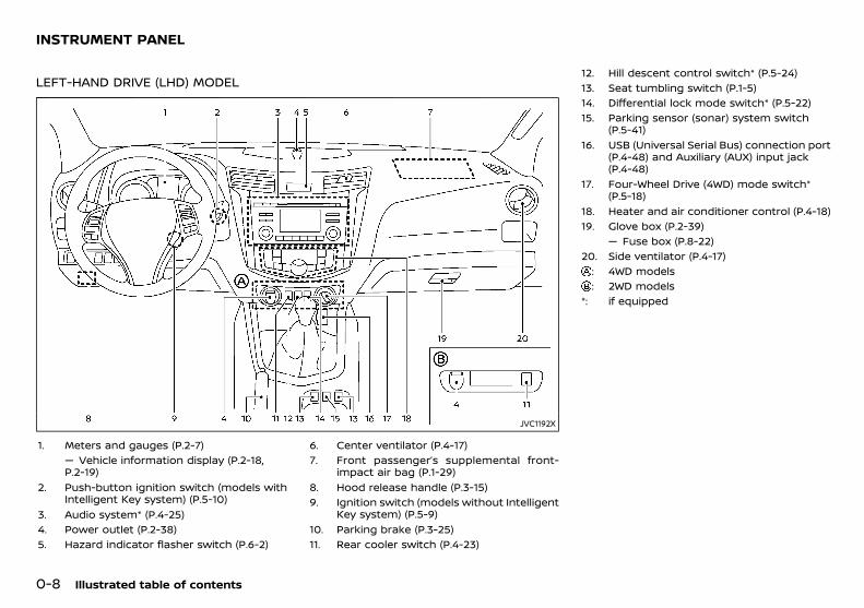
LEFT-HAND DRIVE (LHD) MODELPD23A1-6D48DE5E-E6B8-4E05-9494-9A537802FFED
JVC1192X
1. Meters and gauges (P.2-7)— Vehicle information display (P.2-18,P.2-19)
2. Push-button ignition switch (models withIntelligent Key system) (P.5-10)
3. Audio system* (P.4-25)4. Power outlet (P.2-38)5. Hazard indicator flasher switch (P.6-2)
6. Center ventilator (P.4-17)7. Front passenger’s supplemental front-
impact air bag (P.1-29)8. Hood release handle (P.3-15)9. Ignition switch (models without Intelligent
Key system) (P.5-9)10. Parking brake (P.3-25)11. Rear cooler switch (P.4-23)
12. Hill descent control switch* (P.5-24)13. Seat tumbling switch (P.1-5)14. Differential lock mode switch* (P.5-22)15. Parking sensor (sonar) system switch
(P.5-41)16. USB (Universal Serial Bus) connection port
(P.4-48) and Auxiliary (AUX) input jack(P.4-48)
17. Four-Wheel Drive (4WD) mode switch*(P.5-18)
18. Heater and air conditioner control (P.4-18)19. Glove box (P.2-39)
— Fuse box (P.8-22)20. Side ventilator (P.4-17)
: 4WD models: 2WD models
*: if equipped
INSTRUMENT PANEL
Condition: 'Except for China'/
(13,1)
[ Edit: 2018/ 5/ 25 Model: PD23-A ]
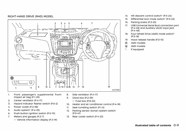
RIGHT-HAND DRIVE (RHD) MODELPD23A1-5D9F835B-1CCC-4710-93BC-EB5FC79176F2
JVC1193X
1. Front passenger’s supplemental front-impact air bag (P.1-29)
2. Center ventilator (P.4-17)3. Hazard indicator flasher switch (P.6-2)4. Power outlet (P.2-38)5. Audio system* (P.4-25)6. Push-button ignition switch (P.5-10)7. Meters and gauges (P.2-7)
— Vehicle information display (P.2-19)
8. Side ventilator (P.4-17)9. Glove box (P.2-39)
— Fuse box (P.8-22)10. Heater and air conditioner control (P.4-18)11. Seat tumbling switch (P.1-5)12. Parking sensor (sonar) system switch
(P.5-41)13. Rear cooler switch (P.4-23)
14. Hill descent control switch* (P.5-24)15. Differential lock mode switch* (P.5-22)16. Parking brake (P.3-25)17. USB (Universal Serial Bus) connection port
(P.4-48) and Auxiliary (AUX) input jack(P.4-48)
18. Four-Wheel Drive (4WD) mode switch*(P.5-18)
19. Hood release handle (P.3-15): 4WD models: 2WD models
*: if equipped
Illustrated table of contents 0-9
Condition: 'Except for China'/
(14,1)
[ Edit: 2018/ 5/ 25 Model: PD23-A ]
0-10 Illustrated table of contents
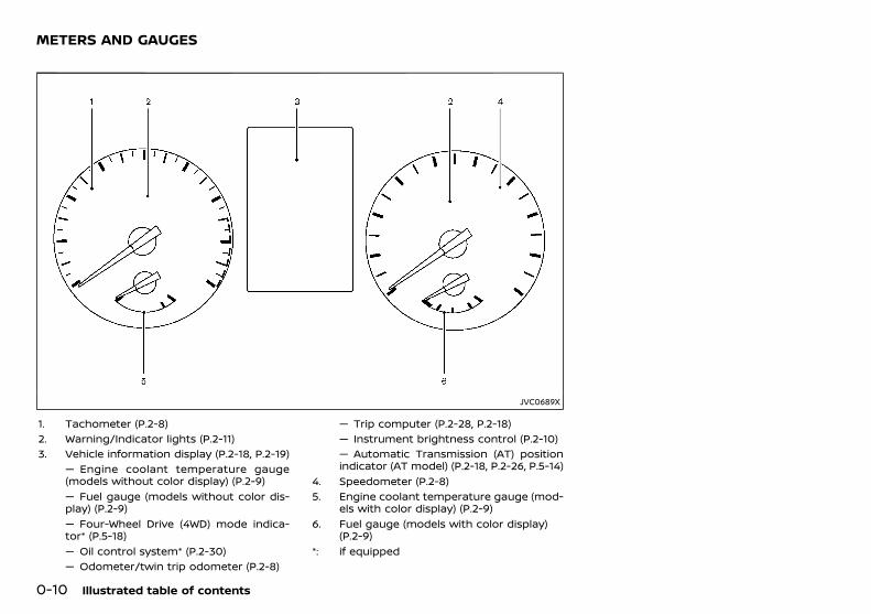
PD23A1-7D8141F7-2424-4721-884D-EA436364D19B
JVC0689X
1. Tachometer (P.2-8)2. Warning/Indicator lights (P.2-11)3. Vehicle information display (P.2-18, P.2-19)
— Engine coolant temperature gauge(models without color display) (P.2-9)— Fuel gauge (models without color dis-play) (P.2-9)— Four-Wheel Drive (4WD) mode indica-tor* (P.5-18)— Oil control system* (P.2-30)— Odometer/twin trip odometer (P.2-8)
— Trip computer (P.2-28, P.2-18)— Instrument brightness control (P.2-10)— Automatic Transmission (AT) positionindicator (AT model) (P.2-18, P.2-26, P.5-14)
4. Speedometer (P.2-8)5. Engine coolant temperature gauge (mod-
els with color display) (P.2-9)6. Fuel gauge (models with color display)
(P.2-9)*: if equipped
METERS AND GAUGES
Condition: 'Except for China'/
(15,1)
[ Edit: 2018/ 5/ 25 Model: PD23-A ]
PD23A1-A6D90333-9F08-48B9-AB33-7AA9C73BD806
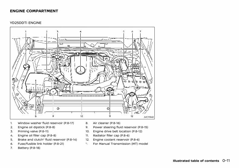
YD25DDTi ENGINEPD23A1-CF998BB6-751E-4779-86A2-588D74A375CF
JVC1194X
1. Window washer fluid reservoir (P.8-17)2. Engine oil dipstick (P.8-8)3. Priming valve (P.8-11)4. Engine oil filler cap (P.8-8)5. Brake and clutch* fluid reservoir (P.8-14)6. Fuse/fusible link holder (P.8-21)7. Battery (P.8-18)
8. Air cleaner (P.8-16)9. Power steering fluid reservoir (P.8-15)10. Engine drive belt location (P.8-12)11. Radiator filler cap (P.8-6)12. Engine coolant reservoir (P.8-6)*: For Manual Transmission (MT) model
Illustrated table of contents 0-11
ENGINE COMPARTMENT
Condition: 'Except for China'/
(16,1)
[ Edit: 2018/ 5/ 25 Model: PD23-A ]
0-12 Illustrated table of contents
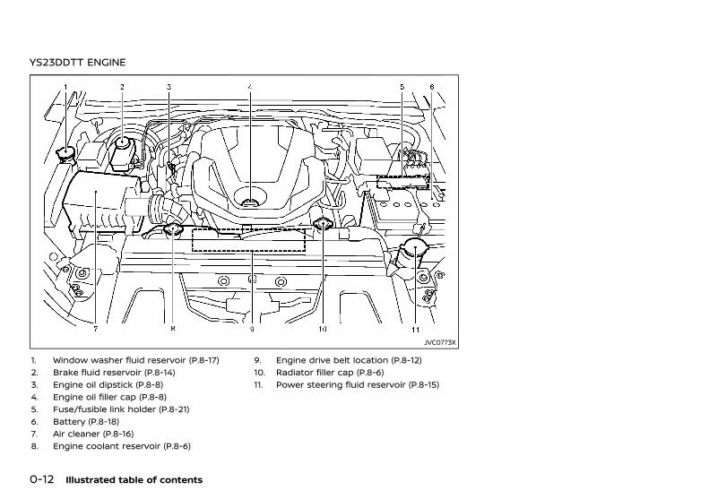
YS23DDTT ENGINEPD23A1-86AFFD37-354E-418D-96F7-AD1371D4CA3F
JVC0773X
1. Window washer fluid reservoir (P.8-17)2. Brake fluid reservoir (P.8-14)3. Engine oil dipstick (P.8-8)4. Engine oil filler cap (P.8-8)5. Fuse/fusible link holder (P.8-21)6. Battery (P.8-18)7. Air cleaner (P.8-16)8. Engine coolant reservoir (P.8-6)
9. Engine drive belt location (P.8-12)10. Radiator filler cap (P.8-6)11. Power steering fluid reservoir (P.8-15)
Condition: 'Except for China'/
(17,1)
[ Edit: 2018/ 5/ 25 Model: PD23-A ]
1 Safety — seats, seat belts and supplementalrestraint system
Seats ........................................................................................................................... 1-2Front seats ..................................................................................................... 1-2Second row seats ..................................................................................... 1-5Third row seats ........................................................................................... 1-6Armrest (second row seats) ............................................................. 1-8Flexible seating ........................................................................................... 1-8
Head restraints ................................................................................................... 1-9Adjustable head restraint components ............................... 1-10Non-adjustable head restraint components ................... 1-10Remove .......................................................................................................... 1-10Install ................................................................................................................ 1-10Adjust ............................................................................................................... 1-10
Seat belts ............................................................................................................. 1-12Precautions on seat belt usage ................................................. 1-12Child safety ................................................................................................. 1-13Pregnant women ................................................................................... 1-14Injured persons ........................................................................................ 1-14Center mark on seat belts ............................................................. 1-14Three-point type seat belts ........................................................... 1-14Two-point type seat belt (if equipped) ................................. 1-16Seat belt maintenance ...................................................................... 1-16
Child restraints ............................................................................................... 1-17Precautions on child restraint usage .................................. 1-17Universal child restraints for front seat andrear seats ................................................................................................... 1-18ISOFIX child restraint system (for secondrow seats) .................................................................................................. 1-22Child restraint anchorage (for secondrow seats) .................................................................................................. 1-23Child restraint installation using ISOFIX(for second row seats) .................................................................... 1-23Child restraint installation using three-point typeseat belt ...................................................................................................... 1-25Child restraint installation using two-point typeseat belt (if equipped) ...................................................................... 1-28
Supplemental Restraint System (SRS) ......................................... 1-29Precautions on Supplemental RestraintSystem (SRS) ........................................................................................... 1-29Supplemental air bag systems ................................................. 1-33SRS air bag deployment conditions .................................... 1-34Pre-tensioner seat belt system ................................................ 1-37Repair and replacement procedure ..................................... 1-37
Condition: 'Except for China'/
(18,1)
[ Edit: 2018/ 5/ 25 Model: PD23-A ]
1-2 Safety — seats, seat belts and supplemental restraint system
PD23A1-AF9D401E-0B20-43D9-8346-3BA2A7395517
SSS0133A
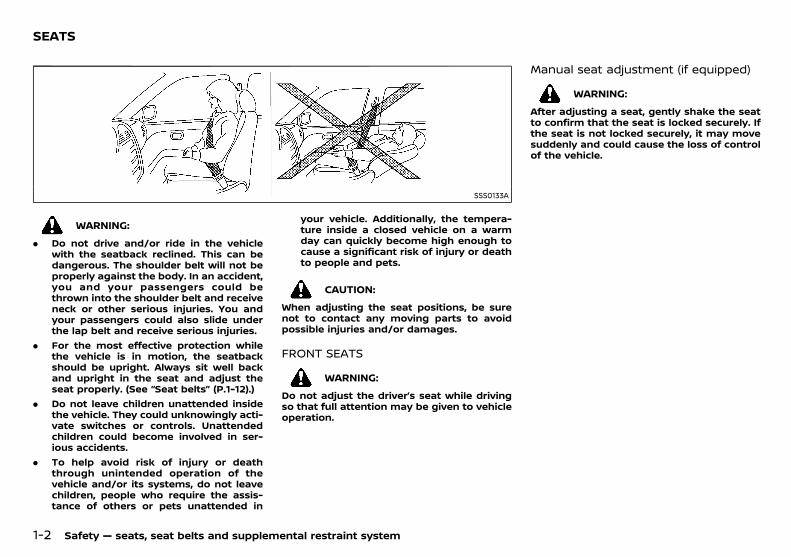
WARNING:
. Do not drive and/or ride in the vehiclewith the seatback reclined. This can bedangerous. The shoulder belt will not beproperly against the body. In an accident,you and your passengers could bethrown into the shoulder belt and receiveneck or other serious injuries. You andyour passengers could also slide underthe lap belt and receive serious injuries.
. For the most effective protection whilethe vehicle is in motion, the seatbackshould be upright. Always sit well backand upright in the seat and adjust theseat properly. (See “Seat belts” (P.1-12).)
. Do not leave children unattended insidethe vehicle. They could unknowingly acti-vate switches or controls. Unattendedchildren could become involved in ser-ious accidents.
. To help avoid risk of injury or deaththrough unintended operation of thevehicle and/or its systems, do not leavechildren, people who require the assis-tance of others or pets unattended in
your vehicle. Additionally, the tempera-ture inside a closed vehicle on a warmday can quickly become high enough tocause a significant risk of injury or deathto people and pets.
CAUTION:
When adjusting the seat positions, be surenot to contact any moving parts to avoidpossible injuries and/or damages.
FRONT SEATSPD23A1-8E6EDF11-E312-436C-8C93-90B9587BB033
WARNING:
Do not adjust the driver’s seat while drivingso that full attention may be given to vehicleoperation.
Manual seat adjustment (if equipped)PD23A1-C387F95D-BF50-4181-A1DE-A3A10A7A6EE4
WARNING:
After adjusting a seat, gently shake the seatto confirm that the seat is locked securely. Ifthe seat is not locked securely, it may movesuddenly and could cause the loss of controlof the vehicle.
SEATS
Condition: 'Except for China'/
(19,1)
[ Edit: 2018/ 5/ 25 Model: PD23-A ]
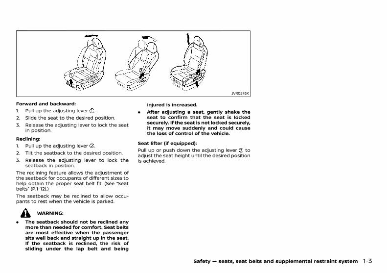
JVR0576X
Forward and backward:GUID-9E14C2E6-2E9C-4731-980B-C45B899B977B
1. Pull up the adjusting lever .2. Slide the seat to the desired position.3. Release the adjusting lever to lock the seat
in position.
Reclining:GUID-9E14C2E6-2E9C-4731-980B-C45B899B977B
1. Pull up the adjusting lever .2. Tilt the seatback to the desired position.3. Release the adjusting lever to lock the
seatback in position.The reclining feature allows the adjustment ofthe seatback for occupants of different sizes tohelp obtain the proper seat belt fit. (See “Seatbelts” (P.1-12).)The seatback may be reclined to allow occu-pants to rest when the vehicle is parked.
WARNING:
. The seatback should not be reclined anymore than needed for comfort. Seat beltsare most effective when the passengersits well back and straight up in the seat.If the seatback is reclined, the risk ofsliding under the lap belt and being
injured is increased.. After adjusting a seat, gently shake the
seat to confirm that the seat is lockedsecurely. If the seat is not locked securely,it may move suddenly and could causethe loss of control of the vehicle.
Seat lifter (if equipped):GUID-9E14C2E6-2E9C-4731-980B-C45B899B977B
Pull up or push down the adjusting lever toadjust the seat height until the desired positionis achieved.
Safety — seats, seat belts and supplemental restraint system 1-3
Condition: 'Except for China'/

(20,1)
[ Edit: 2018/ 5/ 25 Model: PD23-A ]
1-4 Safety — seats, seat belts and supplemental restraint system
Power seat adjustment (if equipped)PD23A1-624568FA-24F3-4D2B-AEE3-5FFE3CFDB812
Operating tips:GUID-9E14C2E6-2E9C-4731-980B-C45B899B977B
. The power seat motor has an auto-resetoverload protection circuit. If the motorstops during the seat adjustment, wait 30seconds, then reactivate the switch.
. To avoid discharge of the battery, do notoperate the power seats for a long periodof time when the engine is not running.
JVR0334X
Forward and backward:GUID-9E14C2E6-2E9C-4731-980B-C45B899B977B
Move forward or backward the adjustingswitch to the desired position.
Reclining:GUID-9E14C2E6-2E9C-4731-980B-C45B899B977B
Move forward or backward the adjustingswitch to the desired position.The reclining feature allows the adjustment ofthe seatback for occupants of different sizes tohelp obtain the proper seat belt fit. (See “Seatbelts” (P.1-12).)The seatback may be reclined to allow occu-pants to rest when the vehicle is parked.
WARNING:
The seatback should not be reclined anymore than needed for comfort. Seat beltsare most effective when the passenger sitswell back and straight up in the seat. If theseatback is reclined, the risk of sliding underthe lap belt and being injured is increased.
SSS1052
Seat lifter:GUID-9E14C2E6-2E9C-4731-980B-C45B899B977B
1. Pull up or push down the adjusting switchto adjust the seat height until the desiredposition is achieved.
2. Tilt up or down the adjusting switch toadjust the front angle of the seat until thedesired position is achieved.
Condition: 'Except for China'/
(21,1)
[ Edit: 2018/ 5/ 25 Model: PD23-A ]
SSS1053
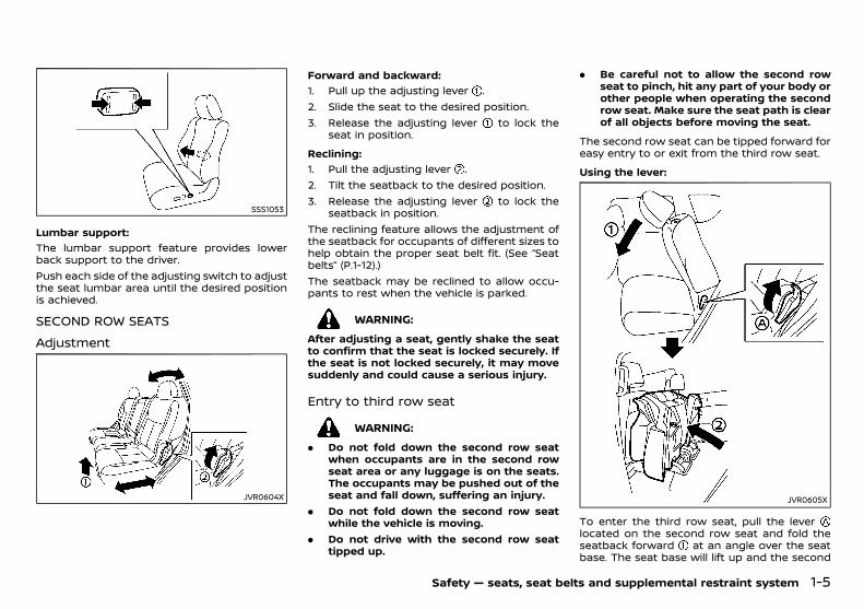
Lumbar support:GUID-9E14C2E6-2E9C-4731-980B-C45B899B977B
The lumbar support feature provides lowerback support to the driver.Push each side of the adjusting switch to adjustthe seat lumbar area until the desired positionis achieved.
SECOND ROW SEATSGUID-D6136959-3FC3-478C-A06C-9F0373411834
AdjustmentGUID-DF54C8C3-6EA6-4122-A2BD-EF47CCDFF5AA
JVR0604X
Forward and backward:GUID-9E14C2E6-2E9C-4731-980B-C45B899B977B
1. Pull up the adjusting lever .2. Slide the seat to the desired position.3. Release the adjusting lever to lock the
seat in position.
Reclining:GUID-9E14C2E6-2E9C-4731-980B-C45B899B977B
1. Pull the adjusting lever .2. Tilt the seatback to the desired position.3. Release the adjusting lever to lock the
seatback in position.The reclining feature allows the adjustment ofthe seatback for occupants of different sizes tohelp obtain the proper seat belt fit. (See “Seatbelts” (P.1-12).)The seatback may be reclined to allow occu-pants to rest when the vehicle is parked.
WARNING:
After adjusting a seat, gently shake the seatto confirm that the seat is locked securely. Ifthe seat is not locked securely, it may movesuddenly and could cause a serious injury.
Entry to third row seatGUID-13EA1F76-8559-47B2-B6BD-4DB1404BEF71
WARNING:
. Do not fold down the second row seatwhen occupants are in the second rowseat area or any luggage is on the seats.The occupants may be pushed out of theseat and fall down, suffering an injury.
. Do not fold down the second row seatwhile the vehicle is moving.
. Do not drive with the second row seattipped up.
. Be careful not to allow the second rowseat to pinch, hit any part of your body orother people when operating the secondrow seat. Make sure the seat path is clearof all objects before moving the seat.
The second row seat can be tipped forward foreasy entry to or exit from the third row seat.
Using the lever:GUID-9E14C2E6-2E9C-4731-980B-C45B899B977B
JVR0605X
To enter the third row seat, pull the leverlocated on the second row seat and fold theseatback forward at an angle over the seatbase. The seat base will lift up and the second
Safety — seats, seat belts and supplemental restraint system 1-5
Condition: 'Except for China'/
(22,1)
[ Edit: 2018/ 5/ 25 Model: PD23-A ]
1-6 Safety — seats, seat belts and supplemental restraint system
row seat will tip forward automatically. Thiswill release the back of the seat so it may betipped forward.To exit the third row seat, pull the lever andfold the seatback forward onto the seat base.The seat base will lift up and tip forwardautomatically.
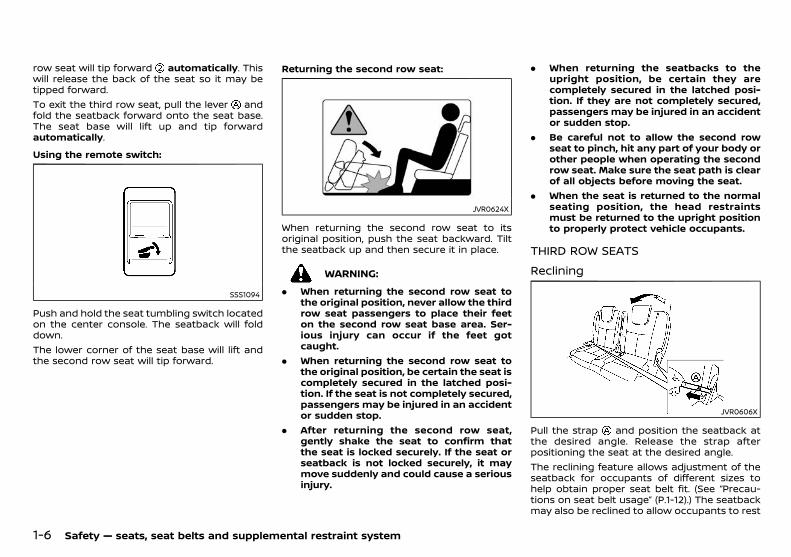
Using the remote switch:GUID-9E14C2E6-2E9C-4731-980B-C45B899B977B
SSS1094
Push and hold the seat tumbling switch locatedon the center console. The seatback will folddown.The lower corner of the seat base will lift andthe second row seat will tip forward.
Returning the second row seat:GUID-9E14C2E6-2E9C-4731-980B-C45B899B977B
JVR0624X
When returning the second row seat to itsoriginal position, push the seat backward. Tiltthe seatback up and then secure it in place.
WARNING:
. When returning the second row seat tothe original position, never allow the thirdrow seat passengers to place their feeton the second row seat base area. Ser-ious injury can occur if the feet gotcaught.
. When returning the second row seat tothe original position, be certain the seat iscompletely secured in the latched posi-tion. If the seat is not completely secured,passengers may be injured in an accidentor sudden stop.
. After returning the second row seat,gently shake the seat to confirm thatthe seat is locked securely. If the seat orseatback is not locked securely, it maymove suddenly and could cause a seriousinjury.
. When returning the seatbacks to theupright position, be certain they arecompletely secured in the latched posi-tion. If they are not completely secured,passengers may be injured in an accidentor sudden stop.
. Be careful not to allow the second rowseat to pinch, hit any part of your body orother people when operating the secondrow seat. Make sure the seat path is clearof all objects before moving the seat.
. When the seat is returned to the normalseating position, the head restraintsmust be returned to the upright positionto properly protect vehicle occupants.
THIRD ROW SEATSGUID-8FADE7DE-F737-462B-8430-ADFFF43EE95F
RecliningGUID-C3B5625E-E7E3-488F-8EA5-D2625E2E7CC1
JVR0606X
Pull the strap and position the seatback atthe desired angle. Release the strap afterpositioning the seat at the desired angle.The reclining feature allows adjustment of theseatback for occupants of different sizes tohelp obtain proper seat belt fit. (See “Precau-tions on seat belt usage” (P.1-12).) The seatbackmay also be reclined to allow occupants to rest
Condition: 'Except for China'/
(23,1)
[ Edit: 2018/ 5/ 25 Model: PD23-A ]
when the vehicle is parked.
WARNING:
. Do not ride in a moving vehicle when theseatback is reclined. This can be danger-ous. The shoulder belt will not be againstyour body. In an accident, you could bethrown into it and receive neck or otherserious injuries. You could also slideunder the lap belt and receive seriousinternal injuries.
. For the most effective protection whenthe vehicle is in motion, the seat shouldbe upright. Always sit well back andupright in the seat with both feet on thefloor and adjust the seat belt properly.See “Precautions on seat belt usage” (P.1-12).
. After adjustment, gently rock in the seatto make sure it is securely locked. If theseat is not locked securely, it may movesuddenly and could cause a seriousinjury.
FoldingGUID-C8F9D0DA-A5D6-42A4-B0E0-CC3925B4084B
WARNING:
. Never allow anyone to ride in the cargoarea or on the third row seat when it is inthe fold-down position. Use of theseareas by passengers without proper re-straints could result in serious injury in anaccident or sudden stop.
. Properly secure all cargo with ropes orstraps to help prevent it from sliding orshifting. Do not place cargo higher thanthe seatbacks. In a sudden stop or colli-sion, unsecured cargo could cause perso-nal injury.
. When returning the seatbacks to theupright position, be certain they arecompletely secured in the latched posi-tion. If they are not completely secured,passengers may be injured in an accidentor sudden stop.
. When the seat is returned to the normalseating position, the head restraintsmust be returned to the upright positionto properly protect vehicle occupants.
. Properly secure all cargo to help preventit from sliding or shifting. Do not placecargo higher than the seatbacks. In asudden stop or collision, unsecured cargocould cause personal injury.
CAUTION:
. Do not fold down the third row seat whenoccupants are in the seat area or anyluggage is on the seats.
. Be careful not to allow the third row seatto pinch, hit any part of your body orother people when operating the thirdrow seat. Make sure the seat path is clearof all objects before operating the seat.
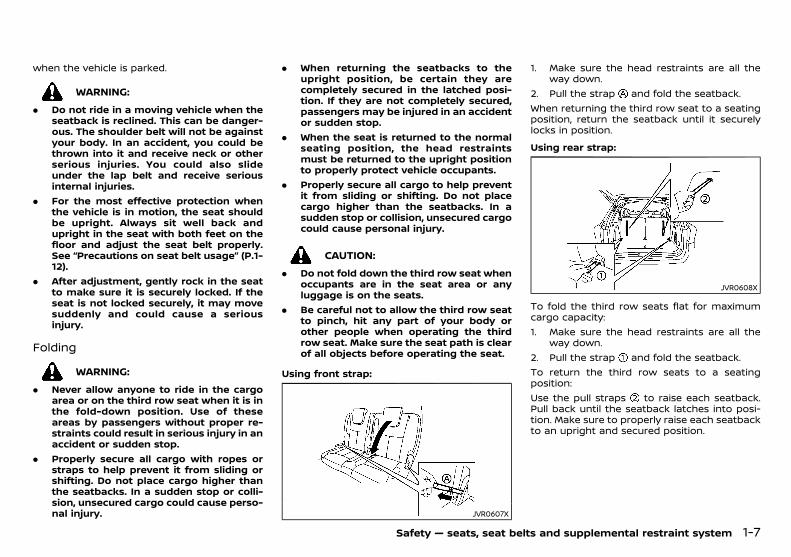
Using front strap:GUID-9E14C2E6-2E9C-4731-980B-C45B899B977B
JVR0607X
1. Make sure the head restraints are all theway down.
2. Pull the strap and fold the seatback.When returning the third row seat to a seatingposition, return the seatback until it securelylocks in position.
Using rear strap:GUID-9E14C2E6-2E9C-4731-980B-C45B899B977B
JVR0608X
To fold the third row seats flat for maximumcargo capacity:1. Make sure the head restraints are all the
way down.2. Pull the strap and fold the seatback.To return the third row seats to a seatingposition:Use the pull straps to raise each seatback.Pull back until the seatback latches into posi-tion. Make sure to properly raise each seatbackto an upright and secured position.
Safety — seats, seat belts and supplemental restraint system 1-7
Condition: 'Except for China'/
(24,1)
[ Edit: 2018/ 5/ 25 Model: PD23-A ]
1-8 Safety — seats, seat belts and supplemental restraint system
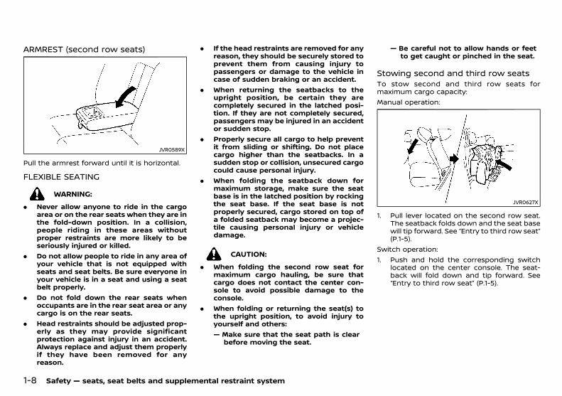
ARMREST (second row seats)GUID-A55A5057-2552-4A5E-B3BD-D00DBD5AA730
JVR0589X
Pull the armrest forward until it is horizontal.
FLEXIBLE SEATINGGUID-89AD0F42-A6FF-428E-A336-85BCD55E990B
WARNING:
. Never allow anyone to ride in the cargoarea or on the rear seats when they are inthe fold-down position. In a collision,people riding in these areas withoutproper restraints are more likely to beseriously injured or killed.
. Do not allow people to ride in any area ofyour vehicle that is not equipped withseats and seat belts. Be sure everyone inyour vehicle is in a seat and using a seatbelt properly.
. Do not fold down the rear seats whenoccupants are in the rear seat area or anycargo is on the rear seats.
. Head restraints should be adjusted prop-erly as they may provide significantprotection against injury in an accident.Always replace and adjust them properlyif they have been removed for anyreason.
. If the head restraints are removed for anyreason, they should be securely stored toprevent them from causing injury topassengers or damage to the vehicle incase of sudden braking or an accident.
. When returning the seatbacks to theupright position, be certain they arecompletely secured in the latched posi-tion. If they are not completely secured,passengers may be injured in an accidentor sudden stop.
. Properly secure all cargo to help preventit from sliding or shifting. Do not placecargo higher than the seatbacks. In asudden stop or collision, unsecured cargocould cause personal injury.
. When folding the seatback down formaximum storage, make sure the seatbase is in the latched position by rockingthe seat base. If the seat base is notproperly secured, cargo stored on top ofa folded seatback may become a projec-tile causing personal injury or vehicledamage.
CAUTION:
. When folding the second row seat formaximum cargo hauling, be sure thatcargo does not contact the center con-sole to avoid possible damage to theconsole.
. When folding or returning the seat(s) tothe upright position, to avoid injury toyourself and others:— Make sure that the seat path is clear
before moving the seat.
— Be careful not to allow hands or feetto get caught or pinched in the seat.
Stowing second and third row seatsGUID-B2EB04A4-2DA6-479C-BDE0-CD43624600C6
To stow second and third row seats formaximum cargo capacity:Manual operation:
JVR0627X
1. Pull lever located on the second row seat.The seatback folds down and the seat basewill tip forward. See “Entry to third row seat”(P.1-5).
Switch operation:1. Push and hold the corresponding switch
located on the center console. The seat-back will fold down and tip forward. See“Entry to third row seat” (P.1-5).
Condition: 'Except for China'/

(25,1)
[ Edit: 2018/ 5/ 25 Model: PD23-A ]
SSS1120
2. Push the folded seat down until it locks inposition.
JVR0628X
3. Fold the third row seat flat using the strapsin the seat. See “Folding” (P.1-7).
4. Return the third row seats to seatingpositions by raising the third row seatbacksto an upright position. Make sure the seat-back is locked in position. See “Folding” (P.1-7).
5. Return the second row seat to a seatingposition by raising the second row seat-backs to an upright position. Make sure theseatback is locked in position.
CAUTION:
When folding the second row seat for max-imum cargo hauling, be sure that cargo doesnot contact the center console to avoidpossible damage to the console.
PD23A1-756C0B1C-6DF9-49F9-B5B6-A1A9A73E2F26
WARNING:
Head restraints supplement the other vehiclesafety systems. They may provide additionalprotection against injury in certain rear endcollisions. Adjustable head restraints must beadjusted properly, as specified in this section.Check the adjustment after someone elseuses the seat. Do not attach anything to thehead restraint stalks or remove the headrestraint. Do not use the seat if the headrestraint has been removed. If the headrestraint was removed, reinstall and properlyadjust the head restraint before an occupantuses the seating position. Failure to followthese instructions can reduce the effective-ness of the head restraint. This may increasethe risk of serious injury or death in acollision.
. Your vehicle is equipped with a headrestraint that may be integrated, adjustableor non-adjustable.
. Adjustable head restraints have multiplenotches along the stalk to lock them in adesired adjustment position.
. The non-adjustable head restraints have asingle locking notch to secure them to theseat frame.
. Proper Adjustment:— For the adjustable type, align the head
restraint so the center of your ear isapproximately level with the center ofthe head restraint.
— If your ear position is still higher than therecommended alignment, place thehead restraint at the highest position.
. If the head restraint has been removed,ensure that it is reinstalled and locked inplace before riding in that designated
Safety — seats, seat belts and supplemental restraint system 1-9
HEAD RESTRAINTS
Condition: 'Except for China'/
(26,1)
[ Edit: 2018/ 5/ 25 Model: PD23-A ]
1-10 Safety — seats, seat belts and supplemental restraint system
seating position.
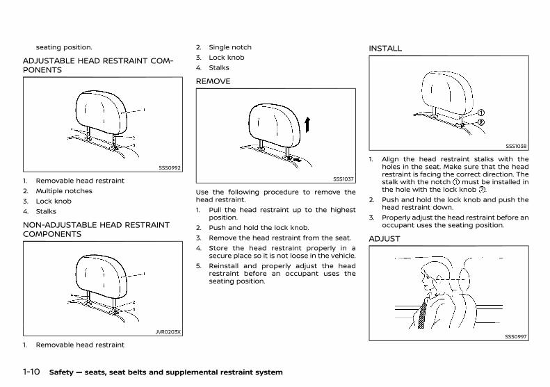
ADJUSTABLE HEAD RESTRAINT COM-PONENTS
PD23A1-F49D7BD2-0832-400D-B1B8-C5052218D6C2
SSS0992
1. Removable head restraint2. Multiple notches3. Lock knob4. Stalks
NON-ADJUSTABLE HEAD RESTRAINTCOMPONENTS
PD23A1-A1CE33B3-80D0-47EC-ADBE-9BB7F69BC68C
JVR0203X
1. Removable head restraint
2. Single notch3. Lock knob4. Stalks
REMOVEPD23A1-B364E605-9931-47E4-8630-70FB41ABFCCF
SSS1037
Use the following procedure to remove thehead restraint.1. Pull the head restraint up to the highest
position.2. Push and hold the lock knob.3. Remove the head restraint from the seat.4. Store the head restraint properly in a
secure place so it is not loose in the vehicle.5. Reinstall and properly adjust the head
restraint before an occupant uses theseating position.
INSTALLPD23A1-3F88B9C5-C281-42BE-93FD-E7D87816FC67
SSS1038
1. Align the head restraint stalks with theholes in the seat. Make sure that the headrestraint is facing the correct direction. Thestalk with the notch must be installed inthe hole with the lock knob .
2. Push and hold the lock knob and push thehead restraint down.
3. Properly adjust the head restraint before anoccupant uses the seating position.
ADJUSTPD23A1-12B60556-8078-4634-A022-BE94BA6D8817
SSS0997
Condition: 'Except for China'/
(27,1)
[ Edit: 2018/ 5/ 25 Model: PD23-A ]
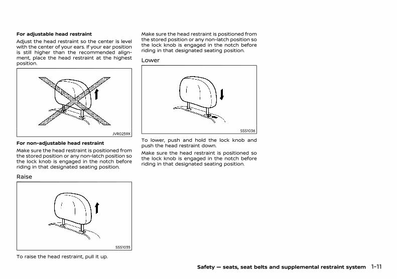
For adjustable head restraintAdjust the head restraint so the center is levelwith the center of your ears. If your ear positionis still higher than the recommended align-ment, place the head restraint at the highestposition.
JVR0259X
For non-adjustable head restraintMake sure the head restraint is positioned fromthe stored position or any non-latch position sothe lock knob is engaged in the notch beforeriding in that designated seating position.
RaisePD23A1-6B91C378-3061-4B70-8CFA-DC15822CD3B0
SSS1035
To raise the head restraint, pull it up.
Make sure the head restraint is positioned fromthe stored position or any non-latch position sothe lock knob is engaged in the notch beforeriding in that designated seating position.
LowerPD23A1-CB50355C-77B4-4D21-9683-DE81030A36FF
SSS1036
To lower, push and hold the lock knob andpush the head restraint down.Make sure the head restraint is positioned sothe lock knob is engaged in the notch beforeriding in that designated seating position.
Safety — seats, seat belts and supplemental restraint system 1-11
Condition: 'Except for China'/
(28,1)
[ Edit: 2018/ 5/ 25 Model: PD23-A ]
1-12 Safety — seats, seat belts and supplemental restraint system
PD23A1-E14362D8-0956-4A90-AA28-730EEA28AE4F
PRECAUTIONS ON SEAT BELT USAGEPD23A1-18940EF4-D22E-4D9C-A922-1F3396A16D5E
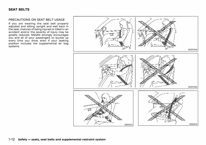
If you are wearing the seat belt properlyadjusted and sitting upright and well back inthe seat, chances of being injured or killed in anaccident and/or the severity of injury may begreatly reduced. NISSAN strongly encouragesyou and all of your passengers to buckle upevery time you drive, even if your seatingposition includes the supplemental air bagsystems.
SSS0134A
SSS0136A
SSS0014 SSS0016
SEAT BELTS
Condition: 'Except for China'/
(29,1)
[ Edit: 2018/ 5/ 25 Model: PD23-A ]
WARNING:
. Seatbelts are designed to bear upon thebony structure of the body, and should beworn low across the front of the pelvis orthe pelvis, chest and shoulders, as applic-able; wearing the lap section of the beltacross the abdominal area must beavoided. Serious injury may occur if aseat belt is not worn properly.
. Position the lap belt as low and snug aspossible around the hips, not the waist. Alap belt worn too high could increase therisk of internal injuries in an accident.
. Do not allowmore than one person to usethe same seat belt. Each belt assemblymust only be used by one occupant; it isdangerous to put a belt around a childbeing carried on the occupant’s lap.
. Never carry more people in the vehiclethan there are seat belts.
. Never wear seat belts inside out. Beltsshould not be worn with straps twisted.Doing so may reduce their effectiveness.
. Seatbelts should be adjusted as firmly aspossible, consistent with comfort, to pro-vide the protection for which they havebeen designed. A slack belt will greatlyreduce the protection afforded to thewearer.
. Every person who drives or rides in thisvehicle should use a seat belt at all times.Children should be properly restrained inthe rear seat and, if appropriate, in a childrestraint system.
. Do not put the belt behind your back orunder your arm. Always route theshoulder belt over your shoulder andacross your chest. The belt should be
away from your face and neck, but notfalling off your shoulder. Serious injurymay occur if a seat belt is not wornproperly.
. No modifications or additions should bemade by the user which will either pre-vent the seat belt adjusting devices fromoperating to remove slack, or prevent theseat belt assembly from being adjustedto remove slack.
. Care should be taken to avoid contam-ination of the webbing with polishes, oilsand chemicals, and particularly batteryacid. Cleaning may safely be carried outusing mild soap and water. The beltshould be replaced if webbing becomesfrayed, contaminated or damaged.
. It is essential to replace the entire as-sembly after it has been worn in a severeimpact even if damage to the assembly isnot obvious.
. All seat belt assemblies including retrac-tors and attaching hardware should beinspected after any collision by a NISSANdealer. NISSAN recommends that all seatbelt assemblies in use during a collisionbe replaced unless the collision wasminor and the belts show no damageand continue to operate properly. Seatbelt assemblies not in use during acollision should also be inspected and,when necessary, replaced if either da-mage or improper operation is noted.
. Once the pre-tensioner seat belt hasactivated, it cannot be reused. It mustbe replaced together with the retractor.Contact a NISSAN dealer.
. Removal and installation of the pre-ten-sioner seat belt system components
should be done by a NISSAN dealer.CHILD SAFETY
PD23A1-391C4AD6-2F06-4205-BE55-366EA6C5E424
WARNING:
. Infants and children need special protec-tion. The vehicle’s seat belts may not fitthem properly. The shoulder belt maycome too close to the face or neck. Thelap belt may not fit over their smallhipbones. In an accident, an improperlyfitted seat belt could cause serious orfatal injury.
. Always use an appropriate child restraintsystem.
Children need adults to help protect them.They need to be properly restrained. Theproper restraint depends on the child’s size.
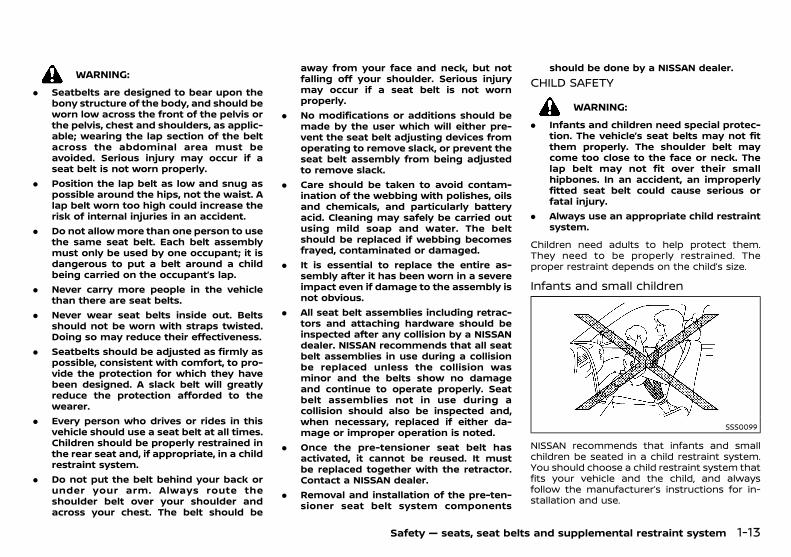
Infants and small childrenPD23A1-E94847D1-6A40-4650-955B-125C3ECA7686
SSS0099
NISSAN recommends that infants and smallchildren be seated in a child restraint system.You should choose a child restraint system thatfits your vehicle and the child, and alwaysfollow the manufacturer’s instructions for in-stallation and use.
Safety — seats, seat belts and supplemental restraint system 1-13
Condition: 'Except for China'/
(30,1)
[ Edit: 2018/ 5/ 25 Model: PD23-A ]
1-14 Safety — seats, seat belts and supplemental restraint system
Large childrenPD23A1-E7E81196-1AD1-4467-B945-35A94DE2AE24
WARNING:
. Never allow children to stand or kneel onany seats.
. Never allow children in the luggage areaswhile the vehicle is moving. A child couldbe seriously injured in an accident orsudden stop.
Children who are too large for a child restraintsystem should be seated and restrained by theseat belts that are provided.If the child’s seating position has a shoulderbelt that fits close to the face or neck, the useof a booster seat (commercially available) mayhelp overcome this. The booster seat shouldraise the child so that the shoulder belt isproperly positioned across the top, middleportion of the shoulder and the lap belt is lowon the hips. The booster seat should also fit thevehicle seat. Once the child has grown so thatthe shoulder belt is no longer on or near theface or neck of the child, use the shoulder beltwithout the booster seat. In addition, there aremany types of child restraint systems availablefor larger children that should be used formaximum protection.
PREGNANT WOMENPD23A1-AEA253B0-0EB2-45A3-8A7C-77A6C8748C8C
NISSAN recommends that pregnant womenuse seat belts. The seat belt should be wornsnug, and always position the lap belt as low aspossible around the hips, not the waist. Placethe shoulder belt over your shoulder andacross your chest. Never run the lap/shoulderbelt over your abdominal area. Contact yourdoctor for specific recommendations.
INJURED PERSONSPD23A1-B729A0D8-0A5A-472D-84AA-4609C350F628
NISSAN recommends that injured persons useseat belts. Contact your doctor for specificrecommendations.
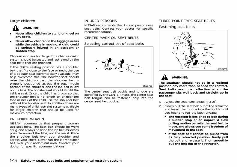
CENTER MARK ON SEAT BELTSPD23A1-C212F0B5-7284-4242-B5D0-1CE0FF552B0B
Selecting correct set of seat beltsPD23A1-FF5C1257-8A87-435E-A0D4-327B0293ED80
SSS0703
The center seat belt buckle and tongue areidentified by the CENTER mark. The center seatbelt tongue can be fastened only into thecenter seat belt buckle.
THREE-POINT TYPE SEAT BELTSPD23A1-3EB40FFA-D110-4A7F-B53A-87C147539DB9
Fastening seat beltsPD23A1-391FCFD2-B3B9-4010-9B4D-878A71128608
SSS0292
WARNING:
The seatback should not be in a reclinedposition any more than needed for comfort.Seat belts are most effective when thepassenger sits well back and straight up inthe seat.
1. Adjust the seat. (See “Seats” (P.1-2).)2. Slowly pull the seat belt out of the retractor
and insert the tongue into the buckle untilyou hear and feel the latch engage.. The retractor is designed to lock duringa sudden stop or on impact. A slowpulling motion permits the seat belt tomove, and allows you some freedom ofmovement in the seat.
. If the seat belt cannot be pulled fromits fully retracted position, firmly pullthe belt and release it. Then smoothlypull the belt out of the retractor.
Condition: 'Except for China'/

(31,1)
[ Edit: 2018/ 5/ 25 Model: PD23-A ]
SSS0467
3. Position the lap belt portion low and snugon the hips as shown.
4. Pull the shoulder belt portion toward theretractor to take up extra slack. Be sure theshoulder belt is routed over your shoulderand is snug across your chest.
Shoulder belt height adjustment (forfront seats)
PD23A1-F2656EA9-3735-451A-BE4A-2E4AF50ABE08
SSS0351A
WARNING:
. The shoulder belt anchor height shouldbe adjusted to the position best for you.Failure to do so may reduce the effec-
tiveness of the entire restraint systemand increase the chance or severity ofinjury in an accident.
. The shoulder belt should rest on themiddle of the shoulder. It must not restagainst the neck.
. Be sure that the seat belt is not twisted inany way.
. Be sure that the shoulder belt anchor issecured by trying to move the shoulderbelt anchor up and down after adjust-ment.
To adjust, pull in the release button andmove the shoulder belt anchor to the properposition , so that the belt passes over thecenter of the shoulder. The belt should be awayfrom your face and neck, but not falling off yourshoulder. Release the button to lock theshoulder belt anchor into position.
Unfastening seat beltsPD23A1-40FD8093-1590-4D59-83F0-2E67047746BC
Push the button on the buckle. The seat beltautomatically retracts.
Belt hook (for rear outer seats)GUID-67A6694D-6206-427B-A7F9-D34B289E5FC4
JVR0578X
Hook the seat belt on the belt hook when
folding down the rear seat.
Checking seat belt operationPD23A1-B794C01F-AA78-4BD9-BB79-DDC7CF7793DF
Seat belt retractors are designed to lock seatbelt movement:. When the seat belt is pulled quickly from
the retractor.. When the vehicle slows down rapidly.To increase your confidence in the seat belts,check the operation by grasping the shoulderbelt and pulling forward quickly. The retractorshould lock and restrict further belt movement.If the retractor does not lock during this check,contact a NISSAN dealer immediately.
Safety — seats, seat belts and supplemental restraint system 1-15
Condition: 'Except for China'/
(32,1)
[ Edit: 2018/ 5/ 25 Model: PD23-A ]
1-16 Safety — seats, seat belts and supplemental restraint system
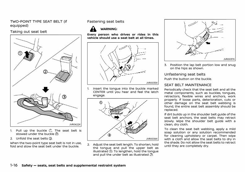
TWO-POINT TYPE SEAT BELT (ifequipped)
PD23A1-62240B1A-50FF-480E-9F1B-BA1128DD3E91
Taking out seat beltGUID-F53375D1-61E6-4197-AE95-D3ABB2CC0854
JVR0622X
1. Pull up the buckle . The seat belt isstowed under the buckle .
2. Unfold the seat belts .When the two-point type seat belt is not in use,fold and stow the seat belt under the buckle.
Fastening seat beltsPD23A1-9D5491FC-4CDF-4278-B294-097F2969E29A
WARNING:
Every person who drives or rides in thisvehicle should use a seat belt at all times.
JVR0035X
1. Insert the tongue into the buckle markedCENTER until you hear and feel the latchengage.
JVR0036X
2. Adjust the seat belt length. To shorten, holdthe tongue and pull the upper belt asillustrated . To lengthen, hold the tongueand pull the under belt as illustrated .
JVR0037X
3. Position the lap belt portion low and snugon the hips as shown.
Unfastening seat beltsPD23A1-58DDFB9C-2329-474B-A774-0BA343F15799
Push the button on the buckle.
SEAT BELT MAINTENANCEPD23A1-6BF4BB35-1E1E-49F1-ADEA-CFFF4CD99C75
Periodically check that the seat belt and all themetal components, such as buckles, tongues,retractors, flexible wires and anchors, workproperly. If loose parts, deterioration, cuts orother damage on the seat belt webbing isfound, the entire seat belt assembly should bereplaced.If dirt builds up in the shoulder belt guide of theseat belt anchors, the seat belts may retractslowly. Wipe the shoulder belt guide with aclean, dry cloth.To clean the seat belt webbing, apply a mildsoap solution or any solution recommendedfor cleaning upholstery or carpet. Then wipewith a cloth and allow the seat belts to dry inthe shade. Do not allow the seat belts to retractuntil they are completely dry.
Condition: 'Except for China'/
(33,1)
[ Edit: 2018/ 5/ 25 Model: PD23-A ]
PD23A1-13C5E90E-D7AE-4922-9F00-D9E6EAF19D7E
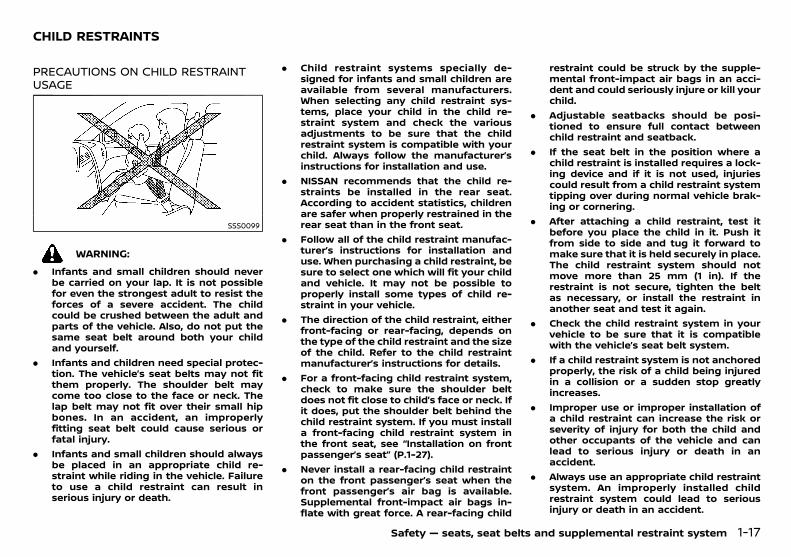
PRECAUTIONS ON CHILD RESTRAINTUSAGE
PD23A1-E1FB12A0-C2B8-4595-A074-B4658FD76E0A
SSS0099
WARNING:
. Infants and small children should neverbe carried on your lap. It is not possiblefor even the strongest adult to resist theforces of a severe accident. The childcould be crushed between the adult andparts of the vehicle. Also, do not put thesame seat belt around both your childand yourself.
. Infants and children need special protec-tion. The vehicle’s seat belts may not fitthem properly. The shoulder belt maycome too close to the face or neck. Thelap belt may not fit over their small hipbones. In an accident, an improperlyfitting seat belt could cause serious orfatal injury.
. Infants and small children should alwaysbe placed in an appropriate child re-straint while riding in the vehicle. Failureto use a child restraint can result inserious injury or death.
. Child restraint systems specially de-signed for infants and small children areavailable from several manufacturers.When selecting any child restraint sys-tems, place your child in the child re-straint system and check the variousadjustments to be sure that the childrestraint system is compatible with yourchild. Always follow the manufacturer’sinstructions for installation and use.
. NISSAN recommends that the child re-straints be installed in the rear seat.According to accident statistics, childrenare safer when properly restrained in therear seat than in the front seat.
. Follow all of the child restraint manufac-turer’s instructions for installation anduse. When purchasing a child restraint, besure to select one which will fit your childand vehicle. It may not be possible toproperly install some types of child re-straint in your vehicle.
. The direction of the child restraint, eitherfront-facing or rear-facing, depends onthe type of the child restraint and the sizeof the child. Refer to the child restraintmanufacturer’s instructions for details.
. For a front-facing child restraint system,check to make sure the shoulder beltdoes not fit close to child’s face or neck. Ifit does, put the shoulder belt behind thechild restraint system. If you must installa front-facing child restraint system inthe front seat, see “Installation on frontpassenger’s seat” (P.1-27).
. Never install a rear-facing child restrainton the front passenger’s seat when thefront passenger’s air bag is available.Supplemental front-impact air bags in-flate with great force. A rear-facing child
restraint could be struck by the supple-mental front-impact air bags in an acci-dent and could seriously injure or kill yourchild.
. Adjustable seatbacks should be posi-tioned to ensure full contact betweenchild restraint and seatback.
. If the seat belt in the position where achild restraint is installed requires a lock-ing device and if it is not used, injuriescould result from a child restraint systemtipping over during normal vehicle brak-ing or cornering.
. After attaching a child restraint, test itbefore you place the child in it. Push itfrom side to side and tug it forward tomake sure that it is held securely in place.The child restraint system should notmove more than 25 mm (1 in). If therestraint is not secure, tighten the beltas necessary, or install the restraint inanother seat and test it again.
. Check the child restraint system in yourvehicle to be sure that it is compatiblewith the vehicle’s seat belt system.
. If a child restraint system is not anchoredproperly, the risk of a child being injuredin a collision or a sudden stop greatlyincreases.
. Improper use or improper installation ofa child restraint can increase the risk orseverity of injury for both the child andother occupants of the vehicle and canlead to serious injury or death in anaccident.
. Always use an appropriate child restraintsystem. An improperly installed childrestraint system could lead to seriousinjury or death in an accident.
Safety — seats, seat belts and supplemental restraint system 1-17
CHILD RESTRAINTS
Condition: 'Except for China'/
(34,1)
[ Edit: 2018/ 5/ 25 Model: PD23-A ]
1-18 Safety — seats, seat belts and supplemental restraint system
. When the child restraint is not in use,keep it secured with the ISOFIX childrestraint system or a seat belt to preventit from being thrown around in case of asudden stop or accident.
NISSAN recommends that infants and smallchildren be seated in a child restraint system.You should choose a child restraint system thatfits your vehicle and always follow the manu-facturer’s instructions for installation and use.In addition, there are many types of childrestraint systems available for larger childrenthat should be used for maximum protection.
CAUTION:
Remember that a child restraint system leftin a closed vehicle can become very hot.Check the seating surface and buckles beforeplacing your child in a child restraint system.
UNIVERSAL CHILD RESTRAINTS FORFRONT SEAT AND REAR SEATS
GUID-C49427DE-4DC9-4475-BF60-BC6F291F19C6
WARNING:
In vehicles equipped with a side air bagsystem, do not let any infants or smallchildren sit in the front passenger’s seat asthe air bag may cause serious injury in caseof deployment during a collision.
NOTE:Universal child restraints approved to UNRegulation NO.44 (UN R44) or UN RegulationNO.129 (UN R129) are clearly marked “Uni-versal”.When selecting any child restraint, keep thefollowing points in mind:. Choose a child restraint that complies with
UN R44 or UN R129.. Place your child in the child restraint and
check the various adjustments to be surethe child restraint is compatible with yourchild. Always follow all of the recommendedprocedures.
. Check the child restraint in your vehicle tobe sure it is compatible with vehicle’s seatbelt system.
. Refer to the tables later in this section for alist of the recommended fitment positionsand the approved child restraints for yourvehicle.
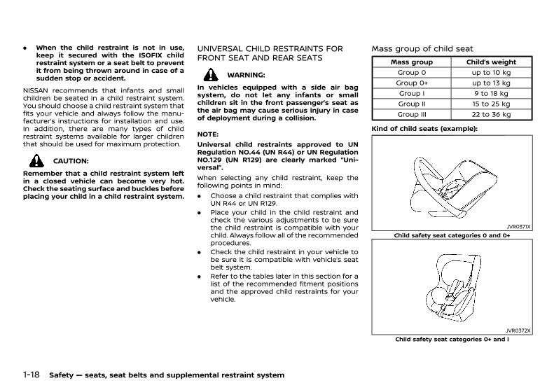
Mass group of child seatGUID-67C09C30-8F91-48A5-9075-8B23F1BD1807
Mass group Child’s weightGroup 0 up to 10 kgGroup 0+ up to 13 kgGroup I 9 to 18 kgGroup II 15 to 25 kgGroup III 22 to 36 kg
Kind of child seats (example):GUID-9E14C2E6-2E9C-4731-980B-C45B899B977B
JVR0371XChild safety seat categories 0 and 0+
JVR0372XChild safety seat categories 0+ and I
Condition: 'Except for China'/
(35,1)
[ Edit: 2018/ 5/ 25 Model: PD23-A ]
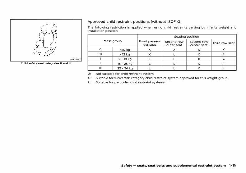
JVR0373XChild safety seat categories II and III
Approved child restraint positions (without ISOFIX)GUID-37CDC96B-BCE2-4392-A781-22F50A479A87
The following restriction is applied when using child restraints varying by infants weight andinstallation position.
Mass groupSeating position
Front passen-ger seat
Second rowouter seat
Second rowcenter seat
Third row seat
0 <10 kg X X X X0+ <13 kg X L X XI 9 - 18 kg L L X LII 15 - 25 kg L L X LIII 22 - 36 kg L L X L
X: Not suitable for child restraint system.U: Suitable for “universal” category child restraint system approved for this weight group.L: Suitable for particular child restraint systems.
Safety — seats, seat belts and supplemental restraint system 1-19
Condition: 'Except for China'/

(36,1)
[ Edit: 2018/ 5/ 25 Model: PD23-A ]
1-20 Safety — seats, seat belts and supplemental restraint system
Approved child restraint positions (with ISOFIX)GUID-CC2944DB-EDDF-46C6-BFAE-18791D9C5D5E
Mass groupSeating position
Front passengerseat
Second row outerseat
Second row centerseat
Third row seat
Carry-cotF ISO/L1 X X X X
G ISO/L2 X X X X0 (<10 kg) E ISO/R1 X IL X X
0+ (<13 kg)E ISO/R1 X IL X X
D ISO/R2 X IL X X
C ISO/R3 X IL X X
I (9 - 18 kg)
D ISO/R2 X IL X X
C ISO/R3 X IL X X
B ISO/F2 X IUF X X
B1 ISO/F2X X IUF X X
A ISO/F3 X IUF X XII (15 - 25 kg) — — X IL X XIII (22 - 36 kg) — — X IL X X
X: Position not suitable for installation of ISOFIX child restraint systems (CRS) in these seating positions.IUF: Suitable for universal category forward facing child restraint system approved for this weight group.IL: Suitable for ISOFIX CRS in semi-universal category or particular ISOFIX CRS.
Condition: 'Except for China'/
(37,1)
[ Edit: 2018/ 5/ 25 Model: PD23-A ]
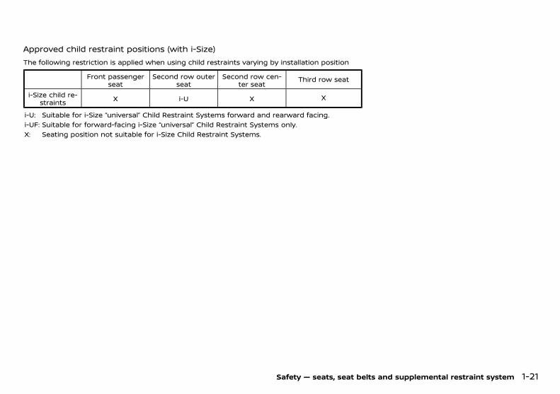
Approved child restraint positions (with i-Size)GUID-6EA6CB93-72A5-4D63-B368-EA5AE39C7609
The following restriction is applied when using child restraints varying by installation position
Front passengerseat
Second row outerseat
Second row cen-ter seat
Third row seat
i-Size child re-straints X i-U X X
i-U: Suitable for i-Size “universal” Child Restraint Systems forward and rearward facing.i-UF: Suitable for forward-facing i-Size “universal” Child Restraint Systems only.X: Seating position not suitable for i-Size Child Restraint Systems.
Safety — seats, seat belts and supplemental restraint system 1-21
Condition: 'Except for China'/
(38,1)
[ Edit: 2018/ 5/ 25 Model: PD23-A ]
1-22 Safety — seats, seat belts and supplemental restraint system
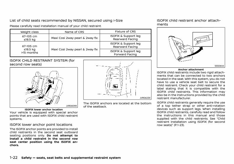
List of child seats recommended by NISSAN, secured using i-SizeGUID-2BE727DE-23F1-4B35-B01C-ECAD83796CFF
Please carefully read installation manual of your child restraint.
Weight class Name of CRS Fixture of CRS
67-105 cm≤18.5 kg Maxi Cosi 2way pearl & 2way fix
ISOFIX & Support legRearward Facing
67-105 cm≤18.5 kg
>15 monthsMaxi Cosi 2way pearl & 2way fix
ISOFIX & Support legRearward Facing
ISOFIX & Support legForward Facing
ISOFIX CHILD RESTRAINT SYSTEM (forsecond row seats)
PD23A1-7DC76B09-0EA2-4072-B4F4-426A6B9E5468
JVR0609XISOFIX lower anchor location
Your vehicle is equipped with special anchorpoints that are used with ISOFIX child restraintsystems.
ISOFIX lower anchor point locationsPD23A1-CAF37ADC-310A-44DC-8F73-6B3D6C154EB1
The ISOFIX anchor points are provided to installchild restraints in the second seat outboardseating positions only. Do not attempt toinstall a child restraint in the second rowseat center position using the ISOFIX an-chors.
JVR0623X
The ISOFIX anchors are located at the bottomof the seatback.
ISOFIX child restraint anchor attach-ments
PD23A1-1DCB5C34-B3C7-4A41-8A79-DA750298FBD7
SSS0644Anchor attachment
ISOFIX child restraints include two rigid attach-ments that can be connected to two anchorslocated in the seat. With this system, you do nothave to use a vehicle seat belt to secure thechild restraint. Check your child restraint for alabel stating that it is compatible with theISOFIX child restraints. This information mayalso be in the instructions provided by the childrestraint manufacturer.ISOFIX child restraints generally require the useof a top tether strap or other anti-rotationdevices such as support legs. When installingISOFIX child restraints, carefully read and followthe instructions in this manual and thosesupplied with the child restraints. See “Childrestraint installation using ISOFIX (for secondrow seats)” (P.1-23).
Condition: 'Except for China'/
(39,1)
[ Edit: 2018/ 5/ 25 Model: PD23-A ]
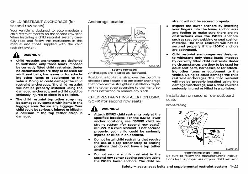
CHILD RESTRAINT ANCHORAGE (forsecond row seats)
PD23A1-447E8B16-98E2-4348-8705-99CD5A3FBB6AYour vehicle is designed to accommodate achild restraint system on the second row seat.When installing a child restraint system, care-fully read and follow the instructions in thismanual and those supplied with the childrestraint system.
WARNING:
. Child restraint anchorages are designedto withstand only those loads imposedby correctly fitted child restraints. Underno circumstances are they to be used foradult seat belts, harnesses or for attach-ing other items or equipment to thevehicle. Doing so could damage the childrestraint anchorages. The child restraintwill not be properly installed using thedamaged anchorage, and a child could beseriously injured or killed in a collision.
. The child restraint top tether strap maybe damaged by contact with items in theluggage area. Secure any luggage. Yourchild could be seriously injured or killed ina collision if the top tether strap isdamaged.
Anchorage locationPD23A1-5D3B4815-F77A-48B1-B607-0B34045C4EA2
JVR0610XSecond row seats
Anchorages are located as illustrated.Position the top tether strap over the top of theseatback and secure it to the tether anchoragethat provides the straightest installation. Tight-en the tether strap according to the manufac-turer’s instruction to remove any slack.
CHILD RESTRAINT INSTALLATION USINGISOFIX (for second row seats)
PD23A1-B85ED6A9-A4F0-44ED-B20E-D7C2486A3188
WARNING:
. Attach ISOFIX child restraints only at thespecified locations. For the ISOFIX loweranchor locations, see “ISOFIX child re-straint system (for second row seats)”(P.1-22). If a child restraint is not securedproperly, your child could be seriouslyinjured or killed in an accident.
. Do not install child restraints that requirethe use of a top tether strap to seatingpositions that do not have a top tetheranchor.
. Do not secure a child restraint in thesecond row center seating position usingthe ISOFIX lower anchors. The child re-
straint will not be secured properly.. Inspect the lower anchors by inserting
your fingers into the lower anchor areaand feeling to make sure there are noobstructions over the ISOFIX anchors,such as seat belt webbing or seat cushionmaterial. The child restraint will not besecured properly if the ISOFIX anchorsare obstructed.
. Child restraint anchorages are designedto withstand only those loads imposedby correctly fitted child restraints. Underno circumstances are they to be used foradult seat belts, harnesses or for attach-ing other items or equipment to thevehicle. Doing so could damage the childrestraint anchorages. The child restraintwill not be properly installed using thedamaged anchorage, and a child could beseriously injured or killed in a collision.
Installation on second row outboardseats
PD23A1-416D7C15-0486-47F4-B0B4-B7AE71CB1EA4
Front-facing:GUID-9E14C2E6-2E9C-4731-980B-C45B899B977B
SSS0646AFront-facing: Steps 1 and 2
Be sure to follow the manufacturer’s instruc-tions for the proper use of your child restraint.
Safety — seats, seat belts and supplemental restraint system 1-23
Condition: 'Except for China'/

(40,1)
[ Edit: 2018/ 5/ 25 Model: PD23-A ]
1-24 Safety — seats, seat belts and supplemental restraint system
Follow these steps to install a front-facing childrestraint on the second row outboard seatsusing ISOFIX:1. Position the child restraint on the seat .2. Secure the child restraint anchor attach-
ments to the ISOFIX lower anchors .3. The back of the child restraint should be
secured against the vehicle seatback. Re-move the head restraint to obtain thecorrect child restraint fit. (See “Head re-straints” (P.1-9).) Store the removed headrestraint in a secure place. Be sure to installthe head restraint when the child restraintis removed. If the seating position does nothave an adjustable head restraint and it isinterfering with the proper child restraintfit, try another seating position or a differ-ent child restraint.
SSS0754AFront-facing: Step 4
4. Shorten the rigid attachment to have thechild restraint firmly tightened; press down-ward and rearward firmly in the centerof the child restraint with your knee tocompress the vehicle seat cushion andseatback.
WARNING:
Adjustable seatbacks should be positioned toensure full contact between child restraintand seatback.
5. If the child restraint is equipped with a toptether strap, route the top tether strap andsecure the tether strap to the tetheranchor point. (See “Child restraint ancho-rage (for second row seats)” (P.1-23).)
6. If the child restraint is equipped with otheranti-rotation devices such as support legs,use them instead of the top tether strapfollowing the child restraint manufacturer’sinstructions.
SSS0755AFront-facing: Step 7
7. Test the child restraint before you place thechild in it . Push the child restraint fromside to side and tug it forward to make surethat it is held securely in place.
8. Check to make sure that the child restraintis properly secured prior to each use. If thechild restraint is loose, repeat steps 3through 7.
Rear-facing:GUID-9E14C2E6-2E9C-4731-980B-C45B899B977B
SSS0649ARear-facing: Steps 1 and 2
Be sure to follow the manufacturer’s instruc-tions for the proper use of your child restraint.Follow these steps to install a rear-facing childrestraint on the second row outboard seatsusing ISOFIX:1. Position the child restraint on the seat .2. Secure the child restraint anchor attach-
ments to the ISOFIX lower anchors .
SSS0756ARear-facing: Step 3
3. Shorten the rigid attachment to have thechild restraint firmly tightened; press down-ward and rearward firmly in the centerof the child restraint with your hand to
Condition: 'Except for China'/
(41,1)
[ Edit: 2018/ 5/ 25 Model: PD23-A ]
compress the vehicle seat cushion andseatback.
4. If the child restraint is equipped with a toptether strap, route the top tether strap andsecure the tether strap to the tetheranchor point. (See “Child restraint ancho-rage (for second row seats)” (P.1-23).)
5. If the child restraint is equipped with otheranti-rotation devices such as support legs,use them instead of the top tether strapfollowing the child restraint manufacturer’sinstructions.
SSS0757ARear-facing: Step 6
6. Test the child restraint before you place thechild in it . Push the child restraint fromside to side and tug it forward to make surethat it is held securely in place.
7. Check to make sure that the child restraintis properly secured prior to each use. If thechild restraint is loose, repeat steps 3through 6.
CHILD RESTRAINT INSTALLATION USINGTHREE-POINT TYPE SEAT BELT
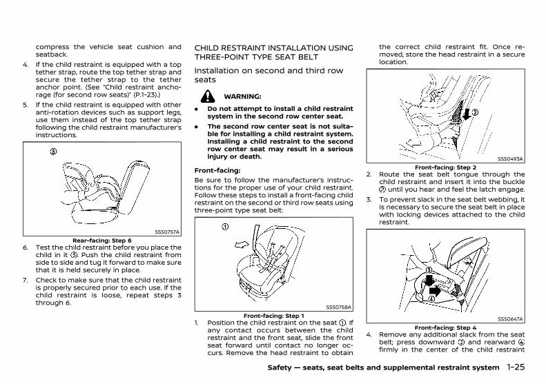
PD23A1-7523374E-6645-44D0-BCEC-CF9EFA4833FE
Installation on second and third rowseats
GUID-68A1FA7C-476E-4D37-A99C-82753F4033A4
WARNING:
. Do not attempt to install a child restraintsystem in the second row center seat.
. The second row center seat is not suita-ble for installing a child restraint system.Installing a child restraint to the secondrow center seat may result in a seriousinjury or death.
Front-facing:GUID-9E14C2E6-2E9C-4731-980B-C45B899B977B
Be sure to follow the manufacturer’s instruc-tions for the proper use of your child restraint.Follow these steps to install a front-facing childrestraint on the second or third row seats usingthree-point type seat belt:
SSS0758AFront-facing: Step 1
1. Position the child restraint on the seat . Ifany contact occurs between the childrestraint and the front seat, slide the frontseat forward until contact no longer oc-curs. Remove the head restraint to obtain
the correct child restraint fit. Once re-moved, store the head restraint in a securelocation.
SSS0493AFront-facing: Step 2
2. Route the seat belt tongue through thechild restraint and insert it into the buckle
until you hear and feel the latch engage.3. To prevent slack in the seat belt webbing, it
is necessary to secure the seat belt in placewith locking devices attached to the childrestraint.
SSS0647AFront-facing: Step 4
4. Remove any additional slack from the seatbelt; press downward and rearwardfirmly in the center of the child restraint
Safety — seats, seat belts and supplemental restraint system 1-25
Condition: 'Except for China'/

(42,1)
[ Edit: 2018/ 5/ 25 Model: PD23-A ]
1-26 Safety — seats, seat belts and supplemental restraint system
with your knee to compress the vehicleseat cushion and seatback while pulling upon the seat belt. Adjustable seatbacksshould be positioned to ensure full contactbetween child restraint and seatback.
SSS0638AFront-facing: Step 5
5. Test the child restraint before you place thechild in it . Push the child restraint fromside to side and tug it forward to make surethat it is held securely in place.
6. Check to make sure that the child restraintis properly secured prior to each use. If thechild restraint is loose, repeat steps 3through 5.
Rear-facing:GUID-9E14C2E6-2E9C-4731-980B-C45B899B977B
Be sure to follow the manufacturer’s instruc-tions for the proper use of your child restraint.Follow these steps to install a rear-facing childrestraint on the second or third row seats usingthree-point type seat belt:
SSS0759ARear-facing: Step 1
1. Position the child restraint on the seat .
SSS0654ARear-facing: Step 2
2. Route the seat belt tongue through thechild restraint and insert it into the buckle
until you hear and feel the latch engage.3. To prevent slack in the seat belt webbing, it
is necessary to secure the seat belt in placewith locking devices attached to the childrestraint.
SSS0639ARear-facing: Step 4
4. Remove any additional slack from the seatbelt; press downward and rearwardfirmly in the center of the child restraintwith your hand to compress the vehicleseat cushion and seatback while pulling upon the seat belt.
SSS0658ARear-facing: Step 5
5. Test the child restraint before you place thechild in it . Push the child restraint fromside to side and tug it forward to make surethat it is held securely in place.
6. Check to make sure that the child restraintis properly secured prior to each use. If thechild restraint is loose, repeat steps 3through 5.
Condition: 'Except for China'/
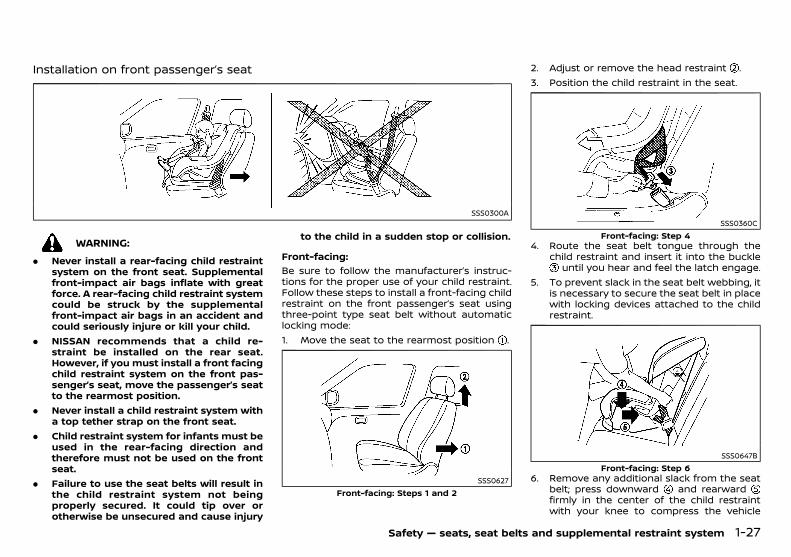
(43,1)
[ Edit: 2018/ 5/ 25 Model: PD23-A ]
Installation on front passenger’s seatPD23A1-4A862A3B-1836-4277-AED6-831F202B3E6E
SSS0300A
WARNING:
. Never install a rear-facing child restraintsystem on the front seat. Supplementalfront-impact air bags inflate with greatforce. A rear-facing child restraint systemcould be struck by the supplementalfront-impact air bags in an accident andcould seriously injure or kill your child.
. NISSAN recommends that a child re-straint be installed on the rear seat.However, if you must install a front facingchild restraint system on the front pas-senger’s seat, move the passenger’s seatto the rearmost position.
. Never install a child restraint system witha top tether strap on the front seat.
. Child restraint system for infants must beused in the rear-facing direction andtherefore must not be used on the frontseat.
. Failure to use the seat belts will result inthe child restraint system not beingproperly secured. It could tip over orotherwise be unsecured and cause injury
to the child in a sudden stop or collision.
Front-facing:GUID-9E14C2E6-2E9C-4731-980B-C45B899B977B
Be sure to follow the manufacturer’s instruc-tions for the proper use of your child restraint.Follow these steps to install a front-facing childrestraint on the front passenger’s seat usingthree-point type seat belt without automaticlocking mode:1. Move the seat to the rearmost position .
SSS0627Front-facing: Steps 1 and 2
2. Adjust or remove the head restraint .3. Position the child restraint in the seat.
SSS0360CFront-facing: Step 4
4. Route the seat belt tongue through thechild restraint and insert it into the buckle
until you hear and feel the latch engage.5. To prevent slack in the seat belt webbing, it
is necessary to secure the seat belt in placewith locking devices attached to the childrestraint.
SSS0647BFront-facing: Step 6
6. Remove any additional slack from the seatbelt; press downward and rearwardfirmly in the center of the child restraintwith your knee to compress the vehicle
Safety — seats, seat belts and supplemental restraint system 1-27
Condition: 'Except for China'/

(44,1)
[ Edit: 2018/ 5/ 25 Model: PD23-A ]
1-28 Safety — seats, seat belts and supplemental restraint system
seat cushion and seatback while pulling upon the seat belt.
WARNING:
Adjustable seatbacks should be positioned toensure full contact between child restraintand seatback.
SSS0302GFront-facing: Step 7
7. Test the child restraint before you place thechild in it . Push the child restraint fromside to side and tug it forward to make surethat it is held securely in place.
8. Check to make sure that the child restraintis properly secured prior to each use. If thechild restraint is loose, repeat steps 5through 7.
CHILD RESTRAINT INSTALLATION USINGTWO-POINT TYPE SEAT BELT (ifequipped)
PD23A1-AAB72E35-5E79-4AEF-BBD3-729415B4A871
WARNING:
. Do not attempt to install a child restraintsystem using the two-point type seatbelt.
. The seat position with two-point typeseat belt is not suitable for installing achild restraint system. Installing a childrestraint using the two-point type seatbelt may result in a serious injury ordeath.
Condition: 'Except for China'/
(45,1)
[ Edit: 2018/ 5/ 25 Model: PD23-A ]
PD23A1-7E26D5FA-E059-4E66-8A46-AC447D1179B5
PRECAUTIONS ON SUPPLEMENTAL RE-STRAINT SYSTEM (SRS)
PD23A1-18D44BAF-6407-48CB-B331-F5D77D606C52This Supplemental Restraint System (SRS) sec-tion contains important information concern-ing the driver’s and passenger’s supplementalfront-impact air bags, supplemental side-im-pact air bags (if equipped), supplemental cur-tain side-impact air bags (if equipped) and pre-tensioner seat belts.
Supplemental front-impact air bagsystem
PD23A1-B9681845-BDE7-497A-9508-59E96330653AThis system can help cushion the impact forceto the head and chest area of the driver and/orfront passenger in certain frontal collisions. Thesupplemental front-impact air bag is designedto inflate on the front where the vehicle isimpacted.
Supplemental side-impact air bag sys-tem (if equipped)
PD23A1-94BEE453-443C-4DCC-8159-04683775A22FThis system can help cushion the impact forceto the chest and pelvis area of the driver andfront passenger in certain side-impact colli-sions. The supplemental side-impact air bag isdesigned to inflate on the side where thevehicle is impacted.
Supplemental curtain side-impact airbag system (if equipped)
PD23A1-F16B7D13-E78E-480A-AC9D-DFDA1FC42E71This system can help cushion the impact forceto the head of the driver and passengers infront seating positions and rear (second andthird) outboard seating positions in certainside-impact collisions. The supplemental cur-tain side-impact air bag is designed to inflateon the side where the vehicle is impacted.The SRS is designed to supplement the acci-dent protection provided by the driver’s and
passenger’s seat belts and is not designed tosubstitute for them. The SRS can help savelives and reduce serious injuries. However,inflating air bags may cause abrasions or otherinjuries. Air bags do not provide protection tothe lower body. Seat belts should always becorrectly worn and the occupants should al-ways be seated a suitable distance away fromthe steering wheel, instrument panel and doorfinishers. (See “Seat belts” (P.1-12).) The air bagsinflate quickly in order to help protect theoccupants. The force of the air bags inflatingcan increase the risk of injury if the occupantsare too close to, or are against, the air bagmodules during inflation. The air bags willdeflate quickly after deployment.The SRS operates only when the ignitionswitch is in the “ON” position.When the ignition switch is in the “ON”position, the SRS air bag warning lightilluminates for about 7 seconds and thenturns off. This indicates that the SRS isoperational. (See “Warning lights, indicatorlights and audible reminders” (P.2-11).)
Safety — seats, seat belts and supplemental restraint system 1-29
SUPPLEMENTAL RESTRAINT SYSTEM (SRS)
Condition: 'Except for China'/
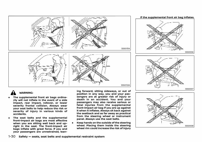
(46,1)
[ Edit: 2018/ 5/ 25 Model: PD23-A ]
1-30 Safety — seats, seat belts and supplemental restraint system
SSS0131A
SSS0132A
WARNING:
. The supplemental front air bags ordina-rily will not inflate in the event of a sideimpact, rear impact, rollover, or lowerseverity frontal collision. Always wearyour seat belts to help reduce the risk orseverity of injury in various kinds ofaccidents.
. The seat belts and the supplementalfront-impact air bags are most effectivewhen you are sitting well back and up-right in the seat. The front-impact airbags inflate with great force. If you andyour passengers are unrestrained, lean-
ing forward, sitting sideways, or out ofposition in any way, you and your pas-sengers are at greater risk of injury ordeath in an accident. You and yourpassengers may also receive serious orfatal injuries from the supplementalfront-impact air bag if you are up againstit when it inflates. Always sit back againstthe seatback and as far away as practicalfrom the steering wheel or instrumentpanel. Always use the seat belts.
. Keep hands on the outside of the steeringwheel. Placing them inside the steeringwheel rim could increase the risk of injury
if the supplemental front air bag inflates.
SSS0006
SSS0007
SSS0008
Condition: 'Except for China'/
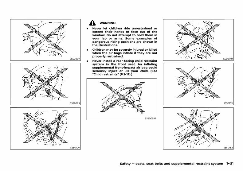
(47,1)
[ Edit: 2018/ 5/ 25 Model: PD23-A ]
SSS0009
SSS0099
SSS0100
WARNING:
. Never let children ride unrestrained orextend their hands or face out of thewindow. Do not attempt to hold them inyour lap or arms. Some examples ofdangerous riding positions are shown inthe illustrations.
. Children may be severely injured or killedwhen the air bags inflate if they are notproperly restrained.
. Never install a rear-facing child restraintsystem in the front seat. An inflatingsupplemental front-impact air bag couldseriously injure or kill your child. (See“Child restraints” (P.1-17).)
SSS0059A
SSS0140
SSS0159
SSS0162
Safety — seats, seat belts and supplemental restraint system 1-31
Condition: 'Except for China'/
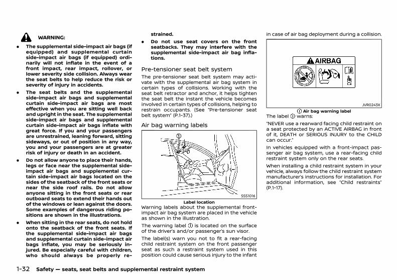
(48,1)
[ Edit: 2018/ 5/ 25 Model: PD23-A ]
1-32 Safety — seats, seat belts and supplemental restraint system
WARNING:
. The supplemental side-impact air bags (ifequipped) and supplemental curtainside-impact air bags (if equipped) ordi-narily will not inflate in the event of afront impact, rear impact, rollover, orlower severity side collision. Always wearthe seat belts to help reduce the risk orseverity of injury in accidents.
. The seat belts and the supplementalside-impact air bags and supplementalcurtain side-impact air bags are mosteffective when you are sitting well backand upright in the seat. The supplementalside-impact air bags and supplementalcurtain side-impact air bags inflate withgreat force. If you and your passengersare unrestrained, leaning forward, sittingsideways, or out of position in any way,you and your passengers are at greaterrisk of injury or death in an accident.
. Do not allow anyone to place their hands,legs or face near the supplemental side-impact air bags and supplemental cur-tain side-impact air bags located on thesides of the seatback of the front seats ornear the side roof rails. Do not allowanyone sitting in the front seats or rearoutboard seats to extend their hands outof the windows or lean against the doors.Some examples of dangerous riding po-sitions are shown in the illustrations.
. When sitting in the rear seats, do not holdonto the seatback of the front seats. Ifthe supplemental side-impact air bagsand supplemental curtain side-impact airbags inflate, you may be seriously in-jured. Be especially careful with children,who should always be properly re-
strained.. Do not use seat covers on the front
seatbacks. They may interfere with thesupplemental side-impact air bag infla-tions.
Pre-tensioner seat belt systemPD23A1-78B92E0D-9E66-4D4F-8ED1-2910D1555CBD
The pre-tensioner seat belt system may acti-vate with the supplemental air bag system incertain types of collisions. Working with theseat belt retractor and anchor, it helps tightenthe seat belt the instant the vehicle becomesinvolved in certain types of collisions, helping torestrain occupants. (See “Pre-tensioner seatbelt system” (P.1-37).)
Air bag warning labelsPD23A1-DFFFE86B-BAB2-44F5-8FF1-B78E4ECAC2AF
SSS1016Label location
Warning labels about the supplemental front-impact air bag system are placed in the vehicleas shown in the illustration.The warning label is located on the surfaceof the driver’s and/or passenger’s sun visor.The label(s) warn you not to fit a rear-facingchild restraint system on the front passengerseat as such a restraint system used in thisposition could cause serious injury to the infant
in case of air bag deployment during a collision.
JVR0243XAir bag warning label
The label warns:“NEVER use a rearward facing child restraint ona seat protected by an ACTIVE AIRBAG in frontof it, DEATH or SERIOUS INJURY to the CHILDcan occur.”In vehicles equipped with a front-impact pas-senger air bag system, use a rear-facing childrestraint system only on the rear seats.When installing a child restraint system in yourvehicle, always follow the child restraint systemmanufacturer’s instructions for installation. Foradditional information, see “Child restraints”(P.1-17).
Condition: 'Except for China'/
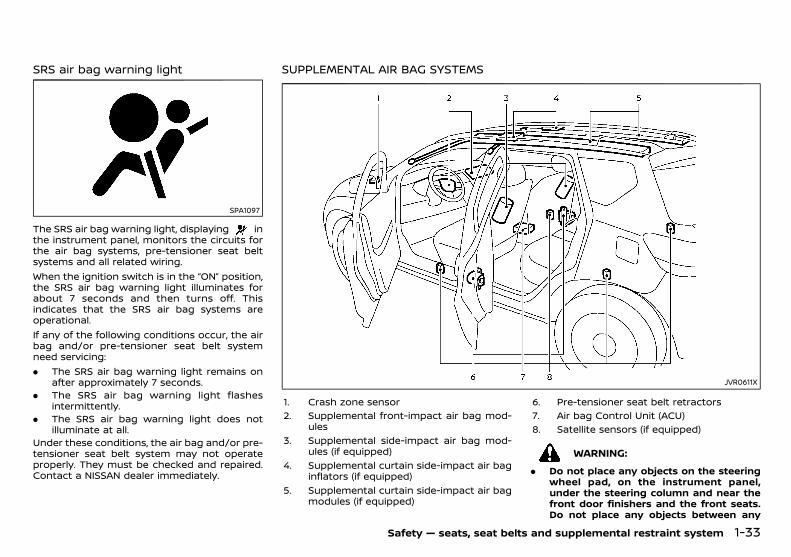
(49,1)
[ Edit: 2018/ 5/ 25 Model: PD23-A ]
SRS air bag warning lightPD23A1-16675603-0645-4F75-87FD-C93222A54D5D
SPA1097
The SRS air bag warning light, displaying inthe instrument panel, monitors the circuits forthe air bag systems, pre-tensioner seat beltsystems and all related wiring.When the ignition switch is in the “ON” position,the SRS air bag warning light illuminates forabout 7 seconds and then turns off. Thisindicates that the SRS air bag systems areoperational.If any of the following conditions occur, the airbag and/or pre-tensioner seat belt systemneed servicing:. The SRS air bag warning light remains on
after approximately 7 seconds.. The SRS air bag warning light flashes
intermittently.. The SRS air bag warning light does not
illuminate at all.Under these conditions, the air bag and/or pre-tensioner seat belt system may not operateproperly. They must be checked and repaired.Contact a NISSAN dealer immediately.
SUPPLEMENTAL AIR BAG SYSTEMSPD23A1-65D865B3-D7C4-4009-872D-A50CE16351E0
JVR0611X
1. Crash zone sensor2. Supplemental front-impact air bag mod-
ules3. Supplemental side-impact air bag mod-
ules (if equipped)4. Supplemental curtain side-impact air bag
inflators (if equipped)5. Supplemental curtain side-impact air bag
modules (if equipped)
6. Pre-tensioner seat belt retractors7. Air bag Control Unit (ACU)8. Satellite sensors (if equipped)
WARNING:
. Do not place any objects on the steeringwheel pad, on the instrument panel,under the steering column and near thefront door finishers and the front seats.Do not place any objects between any
Safety — seats, seat belts and supplemental restraint system 1-33
Condition: 'Except for China'/
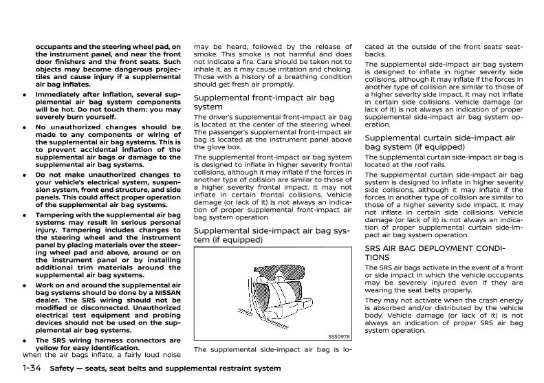
(50,1)
[ Edit: 2018/ 5/ 25 Model: PD23-A ]
1-34 Safety — seats, seat belts and supplemental restraint system
occupants and the steering wheel pad, onthe instrument panel, and near the frontdoor finishers and the front seats. Suchobjects may become dangerous projec-tiles and cause injury if a supplementalair bag inflates.
. Immediately after inflation, several sup-plemental air bag system componentswill be hot. Do not touch them: you mayseverely burn yourself.
. No unauthorized changes should bemade to any components or wiring ofthe supplemental air bag systems. This isto prevent accidental inflation of thesupplemental air bags or damage to thesupplemental air bag systems.
. Do not make unauthorized changes toyour vehicle’s electrical system, suspen-sion system, front end structure, and sidepanels. This could affect proper operationof the supplemental air bag systems.
. Tampering with the supplemental air bagsystems may result in serious personalinjury. Tampering includes changes tothe steering wheel and the instrumentpanel by placing materials over the steer-ing wheel pad and above, around or onthe instrument panel or by installingadditional trim materials around thesupplemental air bag systems.
. Work on and around the supplemental airbag systems should be done by a NISSANdealer. The SRS wiring should not bemodified or disconnected. Unauthorizedelectrical test equipment and probingdevices should not be used on the sup-plemental air bag systems.
. The SRS wiring harness connectors areyellow for easy identification.
When the air bags inflate, a fairly loud noise
may be heard, followed by the release ofsmoke. This smoke is not harmful and doesnot indicate a fire. Care should be taken not toinhale it, as it may cause irritation and choking.Those with a history of a breathing conditionshould get fresh air promptly.
Supplemental front-impact air bagsystem
PD23A1-E4940228-6BE9-4459-93FF-C3A09DCD9CAFThe driver’s supplemental front-impact air bagis located at the center of the steering wheel.The passenger’s supplemental front-impact airbag is located at the instrument panel abovethe glove box.The supplemental front-impact air bag systemis designed to inflate in higher severity frontalcollisions, although it may inflate if the forces inanother type of collision are similar to those ofa higher severity frontal impact. It may notinflate in certain frontal collisions. Vehicledamage (or lack of it) is not always an indica-tion of proper supplemental front-impact airbag system operation.
Supplemental side-impact air bag sys-tem (if equipped)
PD23A1-6D270FAE-2DEB-44BB-8BCE-8FAE26687FFC
SSS0978
The supplemental side-impact air bag is lo-
cated at the outside of the front seats’ seat-backs.The supplemental side-impact air bag systemis designed to inflate in higher severity sidecollisions, although it may inflate if the forces inanother type of collision are similar to those ofa higher severity side impact. It may not inflatein certain side collisions. Vehicle damage (orlack of it) is not always an indication of propersupplemental side-impact air bag system op-eration.
Supplemental curtain side-impact airbag system (if equipped)
PD23A1-AF9C33A5-50BD-4693-9B38-A98DBB4F4DB7The supplemental curtain side-impact air bag islocated at the roof rails.The supplemental curtain side-impact air bagsystem is designed to inflate in higher severityside collisions, although it may inflate if theforces in another type of collision are similar tothose of a higher severity side impact. It maynot inflate in certain side collisions. Vehicledamage (or lack of it) is not always an indica-tion of proper supplemental curtain side-im-pact air bag system operation.
SRS AIR BAG DEPLOYMENT CONDI-TIONS
PD23A1-55E3B910-F2B6-4285-A380-6EFF851E49FFThe SRS air bags activate in the event of a frontor side impact in which the vehicle occupantsmay be severely injured even if they arewearing the seat belts properly.They may not activate when the crash energyis absorbed and/or distributed by the vehiclebody. Vehicle damage (or lack of it) is notalways an indication of proper SRS air bagsystem operation.
Condition: 'Except for China'/

(51,1)
[ Edit: 2018/ 5/ 25 Model: PD23-A ]
When the SRS air bag will deployPD23A1-2435CBC7-E5F1-49AD-9B73-72DB79FDD393
Supplemental front-impact air bags:GUID-9E14C2E6-2E9C-4731-980B-C45B899B977B
The supplemental front-impact air bag systemis designed to inflate in higher severity frontalcollisions. Some examples are shown in thefollowing illustrations.
JVR0423X
The supplemental front-impact air bag systemwill deploy in the event of an impact whichexceeds a 25 km/h (16 MPH) frontal collisionwith a solid wall that does not move or deform.The supplemental front-impact air bag systemmay also deploy when the vehicle receivessevere damage to the undercarriage.
JVR0424X
. Hitting a curb, pavement edge or hardsurface at high speed
. Falling into a deep hole or ditch
. Landing hard on the ground after jumping
Supplemental side-impact and curtain side-impact air bags (if equipped):
GUID-9E14C2E6-2E9C-4731-980B-C45B899B977B
The supplemental side-impact and curtainside-impact air bag systems are designed toinflate in higher severity side collisions. Someexamples are shown in the following illustra-tions.
JVR0161X(supplemental side-impact air bag system)
JVR0162X(supplemental curtain side-impact air bag system). The supplemental side-impact and curtain
side-impact air bags will deploy in the eventof a side impact with a normal passengervehicle that exceeds at a speed of 25 km/h(16 MPH).
When the SRS air bag is unlikely todeploy
PD23A1-D9E3985E-CC2E-439B-91C9-EBECFF8D69A6The SRS air bags may not deploy in caseswhere the impact is not forceful enough toinflate the SRS air bags.For example, if the vehicle strikes an object,such as a parked vehicle or sign pole, which canmove or deform on impact, the SRS air bags are
Safety — seats, seat belts and supplemental restraint system 1-35
Condition: 'Except for China'/
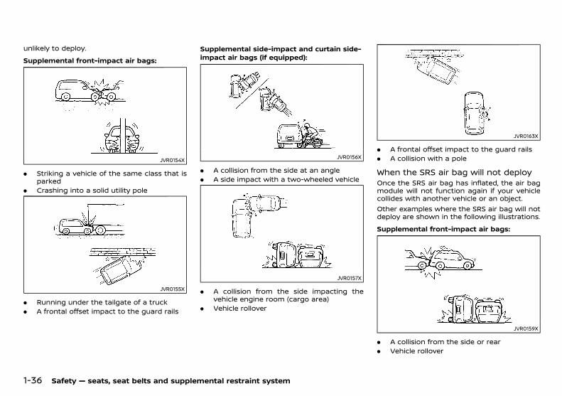
(52,1)
[ Edit: 2018/ 5/ 25 Model: PD23-A ]
1-36 Safety — seats, seat belts and supplemental restraint system
unlikely to deploy.
Supplemental front-impact air bags:GUID-9E14C2E6-2E9C-4731-980B-C45B899B977B
JVR0154X
. Striking a vehicle of the same class that isparked
. Crashing into a solid utility pole
JVR0155X
. Running under the tailgate of a truck
. A frontal offset impact to the guard rails
Supplemental side-impact and curtain side-impact air bags (if equipped):
GUID-9E14C2E6-2E9C-4731-980B-C45B899B977B
JVR0156X
. A collision from the side at an angle
. A side impact with a two-wheeled vehicle
JVR0157X
. A collision from the side impacting thevehicle engine room (cargo area)
. Vehicle rollover
JVR0163X
. A frontal offset impact to the guard rails
. A collision with a pole
When the SRS air bag will not deployPD23A1-7BB9F8D5-8904-42BB-B8E0-41DC3230822C
Once the SRS air bag has inflated, the air bagmodule will not function again if your vehiclecollides with another vehicle or an object.Other examples where the SRS air bag will notdeploy are shown in the following illustrations.
Supplemental front-impact air bags:GUID-9E14C2E6-2E9C-4731-980B-C45B899B977B
JVR0159X
. A collision from the side or rear
. Vehicle rollover
Condition: 'Except for China'/
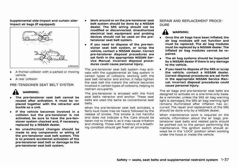
(53,1)
[ Edit: 2018/ 5/ 25 Model: PD23-A ]
Supplemental side-impact and curtain side-impact air bags (if equipped):
GUID-9E14C2E6-2E9C-4731-980B-C45B899B977B
JVR0160X
. A frontal collision with a parked or movingvehicle
. A rear collision
PRE-TENSIONER SEAT BELT SYSTEMPD23A1-CCC50FE5-1806-4BDE-8644-BB3B516367C8
WARNING:
. The pre-tensioner seat belt cannot bereused after activation. It must be re-placed together with the retractor andbuckle as a unit.
. If the vehicle becomes involved in acollision but the pre-tensioner is notactivated, be sure to have the pre-ten-sioner system checked and, if necessary,replaced by a NISSAN dealer.
. No unauthorized changes should bemade to any components or wiring ofthe pre-tensioner seat belt system. Thisis to prevent accidental activation of thepre-tensioner seat belt or damage to thepre-tensioner seat belt system.
. Work around or on the pre-tensioner seatbelt system should be done by a NISSANdealer. The SRS wiring should not bemodified or disconnected. Unauthorizedelectrical test equipment and probingdevices should not be used on the pre-tensioner seat belt system.
. If you need to dispose of the pre-ten-sioner seat belt system, or scrap thevehicle, contact a NISSAN dealer. Correctpre-tensioner disposal procedures areset forth in the appropriate NISSAN Ser-vice Manual. Incorrect disposal proce-dures could cause personal injury.
The pre-tensioner seat belt system may acti-vate with the supplemental air bag system incertain types of collisions. Working with theseat belt retractor and anchor, it helps tightenthe seat belt the instant the vehicle becomesinvolved in certain types of collisions, helping torestrain occupants.The pre-tensioner is encased with the frontseat belt’s retractor and anchor. These seatbelts are used the same as conventional seatbelts.When the pre-tensioner seat belt activates, afairly loud noise may be heard, followed by therelease of smoke. This smoke is not harmfuland does not indicate a fire. Care should betaken not to inhale it, as it may cause irritationand choking. Those with a history of a breath-ing condition should get fresh air promptly.
REPAIR AND REPLACEMENT PROCE-DURE
PD23A1-23B75FE5-42CC-48F7-967C-80EEEF7F7C50
WARNING:
. Once the air bags have been inflated, theair bag modules will not function andmust be replaced. The air bag modulesmust be replaced by a NISSAN dealer. Theinflated air bag modules cannot be re-paired.
. The air bag systems should be inspectedby a NISSAN dealer if there is any damageto the vehicle.
. If you need to dispose of the SRS or scrapthe vehicle, contact a NISSAN dealer.Correct disposal procedures are set forthin the appropriate NISSAN Service Man-ual. Incorrect disposal procedures couldcause personal injury.
The air bags and pre-tensioner seat belts aredesigned to activate on a one-time-only basis.As a reminder, unless the SRS air bag warninglight is damaged, the SRS air bag warning lightremains illuminated after inflation has oc-curred. The repair and replacement of the SRSshould be done only by a NISSAN dealer.When maintenance work is required on thevehicle, information about the air bags, pre-tensioner seat belts and related parts shouldbe pointed out to the person performing themaintenance. The ignition switch should al-ways be in the “LOCK” position when workingunder the hood or inside the vehicle.
Safety — seats, seat belts and supplemental restraint system 1-37
Condition: 'Except for China'/

(54,1)
[ Edit: 2018/ 5/ 25 Model: PD23-A ]
1-38 Safety — seats, seat belts and supplemental restraint system
MEMO
Condition: 'Except for China'/

(55,1)
[ Edit: 2018/ 5/ 25 Model: PD23-A ]
2 Instruments and controls
Cockpit ...................................................................................................................... 2-3Left-Hand Drive (LHD) model ........................................................... 2-3Right-Hand Drive (RHD) model ....................................................... 2-4
Instrument panel .............................................................................................. 2-5Left-Hand Drive (LHD) model ........................................................... 2-5Right-Hand Drive (RHD) model ....................................................... 2-6
Meters and gauges ......................................................................................... 2-7Speedometer and odometer ........................................................... 2-8Tachometer ................................................................................................... 2-8Engine coolant temperature gauge .......................................... 2-9Fuel gauge ...................................................................................................... 2-9Instrument brightness control .................................................... 2-10Automatic Transmission (AT) position indicator(if equipped) ................................................................................................ 2-10
Warning lights, indicator lights andaudible reminders ......................................................................................... 2-11
Checking lights ........................................................................................ 2-12Warning lights ........................................................................................... 2-12Indicator lights ......................................................................................... 2-16Audible reminders ................................................................................. 2-17
Vehicle information display (models withoutcolor display) ..................................................................................................... 2-18
Outside air temperature ................................................................... 2-18Trip computer ........................................................................................... 2-18
Vehicle information display (models withcolor display) ..................................................................................................... 2-19
How to use the vehicle information display .................... 2-19Startup display ......................................................................................... 2-19Settings .......................................................................................................... 2-20Vehicle information display warningsand indicators ........................................................................................... 2-24Trip computer ........................................................................................... 2-28
Oil control system (YS23DDTT engine models) .......... 2-30Clock and outside air temperature ...................................... 2-31
Headlight and turn signal switch .................................................... 2-32Headlight switch .................................................................................. 2-32Headlight aiming control .............................................................. 2-33Battery saver system ....................................................................... 2-33Turn signal switch .............................................................................. 2-33
Fog light switch ............................................................................................. 2-34Front fog lights ..................................................................................... 2-34
Wiper and washer switch ....................................................................... 2-34Windshield wiper and washer switch ................................. 2-34Rear window wiper and washer switch ........................... 2-35
Defogger switch ............................................................................................ 2-36Horn ......................................................................................................................... 2-36Windows ............................................................................................................... 2-37
Power windows .................................................................................... 2-37Power outlets ................................................................................................... 2-38Storage .................................................................................................................. 2-39
Glove box ................................................................................................... 2-39Console box ............................................................................................. 2-39Sunglasses holder (if equipped) .............................................. 2-40Cup holders .............................................................................................. 2-40Roof rack .................................................................................................... 2-41Luggage hooks ..................................................................................... 2-41Luggage floor box .............................................................................. 2-42Card holder .............................................................................................. 2-42
Sun visors ............................................................................................................ 2-42Interior lights .................................................................................................... 2-42
Interior light switch (if equipped) ........................................... 2-42Console light (if equipped) ........................................................... 2-43Map lights .................................................................................................. 2-43
Condition: 'Except for China'/
>
(56,1)
[ Edit: 2018/ 5/ 25 Model: PD23-A ]
Map light control switch (if equipped) .................................. 2-43Rear personal light ................................................................................ 2-44Vanity mirror lights ............................................................................... 2-44
Cargo light ................................................................................................ 2-44Battery saver system ....................................................................... 2-44
Condition: 'Except for China'/
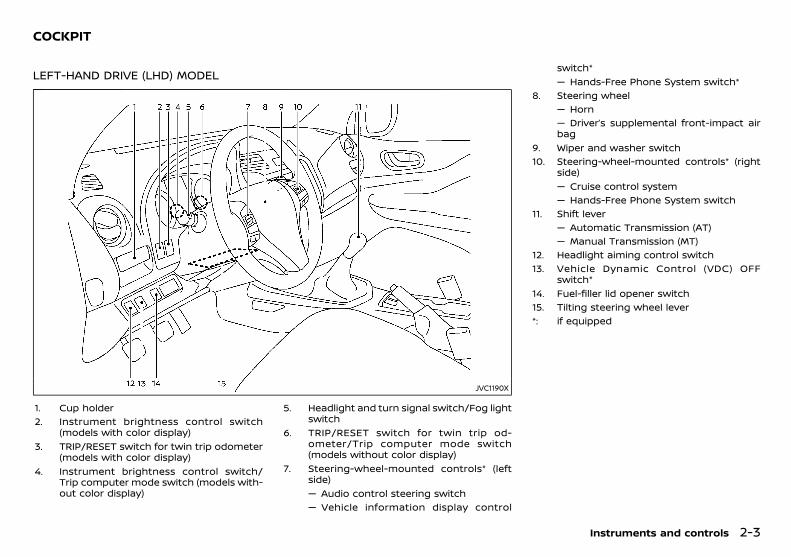
(57,1)
[ Edit: 2018/ 5/ 25 Model: PD23-A ]
PD23A1-EB56C13A-C6EE-4C84-8505-4D4397DB8CB5
LEFT-HAND DRIVE (LHD) MODELPD23A1-461D724C-E8D4-431A-A211-9398D746ADCD
JVC1190X
1. Cup holder2. Instrument brightness control switch
(models with color display)3. TRIP/RESET switch for twin trip odometer
(models with color display)4. Instrument brightness control switch/
Trip computer mode switch (models with-out color display)
5. Headlight and turn signal switch/Fog lightswitch
6. TRIP/RESET switch for twin trip od-ometer/Trip computer mode switch(models without color display)
7. Steering-wheel-mounted controls* (leftside)— Audio control steering switch— Vehicle information display control
switch*— Hands-Free Phone System switch*
8. Steering wheel— Horn— Driver’s supplemental front-impact airbag
9. Wiper and washer switch10. Steering-wheel-mounted controls* (right
side)— Cruise control system— Hands-Free Phone System switch
11. Shift lever— Automatic Transmission (AT)— Manual Transmission (MT)
12. Headlight aiming control switch13. Vehicle Dynamic Control (VDC) OFF
switch*14. Fuel-filler lid opener switch15. Tilting steering wheel lever*: if equipped
Instruments and controls 2-3
COCKPIT
Condition: 'Except for China'/
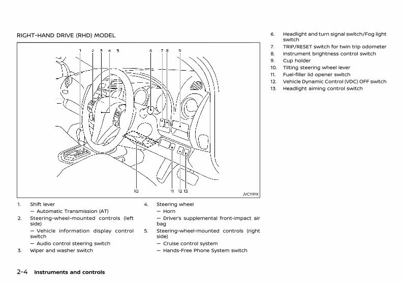
(58,1)
[ Edit: 2018/ 5/ 25 Model: PD23-A ]
2-4 Instruments and controls
RIGHT-HAND DRIVE (RHD) MODELPD23A1-2BA9F5D7-8161-4D7A-9F5D-F31107169F9F
JVC1191X
1. Shift lever— Automatic Transmission (AT)
2. Steering-wheel-mounted controls (leftside)— Vehicle information display controlswitch— Audio control steering switch
3. Wiper and washer switch
4. Steering wheel— Horn— Driver’s supplemental front-impact airbag
5. Steering-wheel-mounted controls (rightside)— Cruise control system— Hands-Free Phone System switch
6. Headlight and turn signal switch/Fog lightswitch
7. TRIP/RESET switch for twin trip odometer8. Instrument brightness control switch9. Cup holder10. Tilting steering wheel lever11. Fuel-filler lid opener switch12. Vehicle Dynamic Control (VDC) OFF switch13. Headlight aiming control switch
Condition: 'Except for China'/
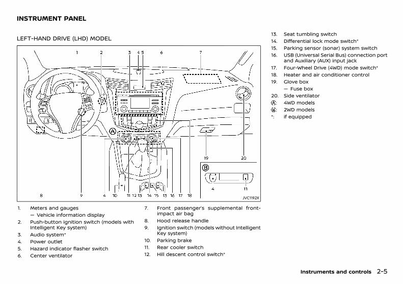
(59,1)
[ Edit: 2018/ 5/ 25 Model: PD23-A ]
PD23A1-A32C3578-39F4-4F2E-A8D4-97767F14EA26
LEFT-HAND DRIVE (LHD) MODELPD23A1-BF7DBE9A-3AB8-4A46-A5E5-E602A487762A
JVC1192X
1. Meters and gauges— Vehicle information display
2. Push-button ignition switch (models withIntelligent Key system)
3. Audio system*4. Power outlet5. Hazard indicator flasher switch6. Center ventilator
7. Front passenger’s supplemental front-impact air bag
8. Hood release handle9. Ignition switch (models without Intelligent
Key system)10. Parking brake11. Rear cooler switch12. Hill descent control switch*
13. Seat tumbling switch14. Differential lock mode switch*15. Parking sensor (sonar) system switch16. USB (Universal Serial Bus) connection port
and Auxiliary (AUX) input jack17. Four-Wheel Drive (4WD) mode switch*18. Heater and air conditioner control19. Glove box
— Fuse box20. Side ventilator
: 4WD models: 2WD models
*: if equipped
Instruments and controls 2-5
INSTRUMENT PANEL
Condition: 'Except for China'/
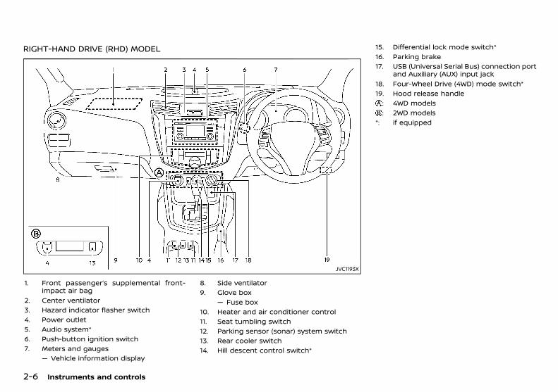
(60,1)
[ Edit: 2018/ 5/ 25 Model: PD23-A ]
2-6 Instruments and controls
RIGHT-HAND DRIVE (RHD) MODELPD23A1-5FA2A1E5-7EFC-4D9A-9A04-D2F72399C238
JVC1193X
1. Front passenger’s supplemental front-impact air bag
2. Center ventilator3. Hazard indicator flasher switch4. Power outlet5. Audio system*6. Push-button ignition switch7. Meters and gauges
— Vehicle information display
8. Side ventilator9. Glove box
— Fuse box10. Heater and air conditioner control11. Seat tumbling switch12. Parking sensor (sonar) system switch13. Rear cooler switch14. Hill descent control switch*
15. Differential lock mode switch*16. Parking brake17. USB (Universal Serial Bus) connection port
and Auxiliary (AUX) input jack18. Four-Wheel Drive (4WD) mode switch*19. Hood release handle
: 4WD models: 2WD models
*: if equipped
Condition: 'Except for China'/
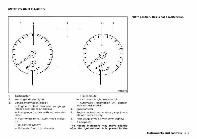
(61,1)
[ Edit: 2018/ 5/ 25 Model: PD23-A ]
PD23A1-D4E88DDF-8318-4796-9304-D1B3E060B8C6
JVC0689X
1. Tachometer2. Warning/Indicator lights3. Vehicle information display
— Engine coolant temperature gauge(models without color display)— Fuel gauge (models without color dis-play)— Four-Wheel Drive (4WD) mode indica-tor*— Oil control system*— Odometer/twin trip odometer
— Trip computer— Instrument brightness control— Automatic Transmission (AT) positionindicator (AT model)
4. Speedometer5. Engine coolant temperature gauge (mod-
els with color display)6. Fuel gauge (models with color display)*: If equippedThe needle indicators may move slightlyafter the ignition switch is placed in the
“OFF” position. This is not a malfunction.
Instruments and controls 2-7
METERS AND GAUGES
Condition: 'Except for China'/

(62,1)
[ Edit: 2018/ 5/ 25 Model: PD23-A ]
2-8 Instruments and controls
SPEEDOMETER AND ODOMETERPD23A1-7E6E68E9-F9BC-4A88-A81D-BC41B54485DC
SpeedometerPD23A1-9685759D-5FDC-4063-B5F7-3B9FB6483287
JVI1843X
The speedometer indicates the vehicle speed.
Odometer (models with color display)PD23A1-F3E7C26F-4F54-4860-8BC2-76B62D9BE4FE
JVI1041X
Odometer/Twin trip odometer:GUID-9E14C2E6-2E9C-4731-980B-C45B899B977B
The odometer/twin trip odometer is displayedin the vehicle information display when theignition switch is in the “ON” position.The odometer displays the total distance thevehicle has been driven.The twin trip odometer displays the distance
of individual trips.Changing twin trip odometer display:Push the TRIP RESET switch (located on theinstrument panel) to change the display asfollows:TRIP A ? TRIP B ? TRIP AResetting twin trip odometer:Push the TRIP RESET switch for more than 1second to reset the trip odometer to zero.
Odometer (models without color dis-play)
PD23A1-885503A1-DBC4-4337-B9C4-FDE194C23D86
JVI1233X
Odometer/twin trip odometer:GUID-9E14C2E6-2E9C-4731-980B-C45B899B977B
The odometer/twin trip odometer is displayedwhen the ignition switch is in the “ON” position.The odometer displays the total distance thevehicle has been driven.The twin trip odometer displays the distanceof individual trips.
Changing trip odometer display:GUID-9E14C2E6-2E9C-4731-980B-C45B899B977B
Push the trip odometer reset switch tochange the display as follows:TRIP A ? TRIP B ? Trip computer mode ?TRIPAFor trip computer information, see “Trip com-puter” (P.2-18).
Resetting trip odometer:GUID-9E14C2E6-2E9C-4731-980B-C45B899B977B
Push the trip odometer reset switch forapproximately 1 second to reset the tripodometer to zero.
TACHOMETERPD23A1-06253D39-9193-4F62-A944-DD6BDD06C0C9
JVI1844X
The tachometer indicates the engine speed inrevolutions per minute (rpm). Do not rev theengine into the red zone .The red zone varies with models.
Condition: 'Except for China'/
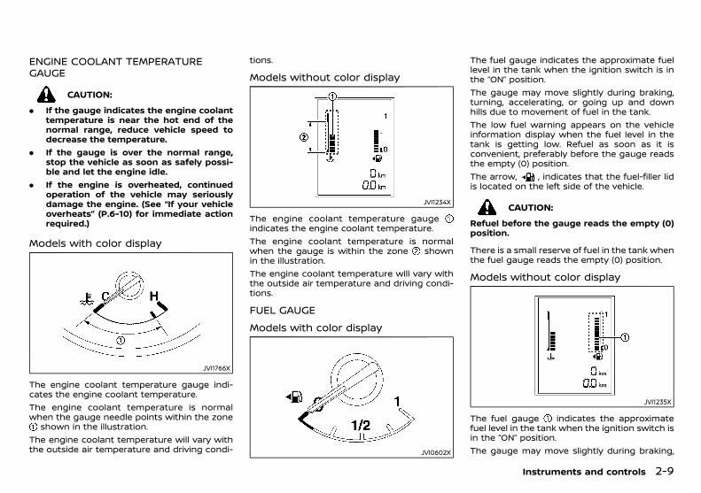
(63,1)
[ Edit: 2018/ 5/ 25 Model: PD23-A ]
ENGINE COOLANT TEMPERATUREGAUGE
PD23A1-AC507E4D-748F-49CB-9422-D729C2C86322
CAUTION:
. If the gauge indicates the engine coolanttemperature is near the hot end of thenormal range, reduce vehicle speed todecrease the temperature.
. If the gauge is over the normal range,stop the vehicle as soon as safely possi-ble and let the engine idle.
. If the engine is overheated, continuedoperation of the vehicle may seriouslydamage the engine. (See “If your vehicleoverheats” (P.6-10) for immediate actionrequired.)
Models with color displayPD23A1-3B43B9A7-DD7B-480D-A883-04AB63AF1C39
JVI1766X
The engine coolant temperature gauge indi-cates the engine coolant temperature.The engine coolant temperature is normalwhen the gauge needle points within the zone
shown in the illustration.The engine coolant temperature will vary withthe outside air temperature and driving condi-
tions.
Models without color displayPD23A1-1D5C54F2-271B-446D-994A-BBA16F914E78
JVI1234X
The engine coolant temperature gaugeindicates the engine coolant temperature.The engine coolant temperature is normalwhen the gauge is within the zone shownin the illustration.The engine coolant temperature will vary withthe outside air temperature and driving condi-tions.
FUEL GAUGEPD23A1-DE289BE5-492C-468F-9950-9FF1FBBC01FE
Models with color displayPD23A1-7A993D4D-F9D8-4D92-85CE-8A0DDDAD6F5B
JVI0602X
The fuel gauge indicates the approximate fuellevel in the tank when the ignition switch is inthe “ON” position.The gauge may move slightly during braking,turning, accelerating, or going up and downhills due to movement of fuel in the tank.The low fuel warning appears on the vehicleinformation display when the fuel level in thetank is getting low. Refuel as soon as it isconvenient, preferably before the gauge readsthe empty (0) position.The arrow, , indicates that the fuel-filler lidis located on the left side of the vehicle.
CAUTION:
Refuel before the gauge reads the empty (0)position.
There is a small reserve of fuel in the tank whenthe fuel gauge reads the empty (0) position.
Models without color displayPD23A1-D2AC8831-DA41-418E-9487-CFCBAE256991
JVI1235X
The fuel gauge indicates the approximatefuel level in the tank when the ignition switch isin the “ON” position.The gauge may move slightly during braking,
Instruments and controls 2-9
Condition: 'Except for China'/
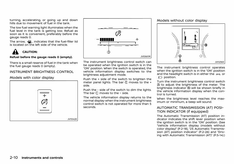
(64,1)
[ Edit: 2018/ 5/ 25 Model: PD23-A ]
2-10 Instruments and controls
turning, accelerating, or going up and downhills due to movement of fuel in the tank.The low fuel warning light illuminates when thefuel level in the tank is getting low. Refuel assoon as it is convenient, preferably before thegauge reads 0.The arrow, , indicates that the fuel-filler lidis located on the left side of the vehicle.
CAUTION:
Refuel before the gauge reads 0 (empty).
There is a small reserve of fuel in the tank whenthe fuel gauge reads 0 (empty).
INSTRUMENT BRIGHTNESS CONTROLPD23A1-DCB79E8B-13E0-4540-BE37-A0BB2FD164FB
Models with color displayPD23A1-43BE560D-2DD0-497A-9493-416D04B5D04B
JVI1042X
JVI0661M
The instrument brightness control switch canbe operated when the ignition switch is in the“ON” position. When the switch is operated, thevehicle information display switches to thebrightness adjustment mode.Push the + side of the switch to brighten themeter panel lights. The bar moves to the +side.Push the - side of the switch to dim the lights.The bar moves to the − side.The vehicle information display returns to thenormal display when the instrument brightnesscontrol switch is not operated for more than 5seconds.
Models without color displayPD23A1-8F280A5A-AB80-4BA8-8186-772245FC2C60
JVI1236X
The instrument brightness control operateswhen the ignition switch is in the “ON” positionand the headlight switch is in either the or
position.Turn the instrument brightness control switch
to adjust the brightness of the meter. Thebrightness indicator will be shown briefly inthe vehicle information display when the con-trol is turned.When the brightness level reaches the max-imum or minimum, a beep will sound.
AUTOMATIC TRANSMISSION (AT) POSI-TION INDICATOR (if equipped)
GUID-65C158FF-DF29-45E4-A0E9-C9C893FC1C0EThe Automatic Transmission (AT) position in-dicator indicates the shift lever position whenthe ignition switch is in the “ON” position. (See“Vehicle information display (models withoutcolor display)” (P.2-18), “23. Automatic Transmis-sion (AT) position indicator” (P.2-26) and “Driv-ing with Automatic Transmission (AT)” (P.5-14).)
Condition: 'Except for China'/

(65,1)
[ Edit: 2018/ 5/ 25 Model: PD23-A ]
PD23A1-AD8EF343-0C2A-4154-942C-A52FCBB257CF
Anti-lock Braking System (ABS) warn-ing light Low fuel warning light Glow plug indicator light
Automatic Transmission (AT) checkwarning light (AT model) Low tire pressure warning light* High beam indicator light
Automatic Transmission (AT) oil tem-perature warning light (AT model) Malfunction warning light (red)*
Hill descent control system on indica-tor light*
Automatic Transmission (AT) parkwarning light (AT model) Master warning light* Malfunction Indicator Light (MIL)
Brake warning light Seat belt warning light Security indicator light
Charge warning light Supplemental Restraint System (SRS)air bag warning light
Small light indicator light*
Door open warning light Vehicle Dynamic Control (VDC) warn-ing light*
Turn signals/hazard indicator lights
Engine oil pressure warning light Water-in-fuel-filter warning lightVehicle Dynamic Control (VDC) offindicator light*
Four-Wheel Drive (4WD) warning light(4WD model) Differential lock indicator light* *: if equipped
Headlight warning light* Front fog lights indicator light
Instruments and controls 2-11
WARNING LIGHTS, INDICATORLIGHTS AND AUDIBLE REMINDERS
Condition: 'Except for China'/
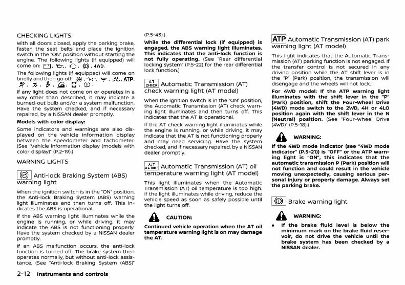
(66,1)
[ Edit: 2018/ 5/ 25 Model: PD23-A ]
2-12 Instruments and controls
CHECKING LIGHTSPD23A1-C3DCFB9F-3B36-48BF-B075-04BBF7FFE059
With all doors closed, apply the parking brake,fasten the seat belts and place the ignitionswitch in the “ON” position without starting theengine. The following lights (if equipped) willcome on: , , , , .The following lights (if equipped) will come onbriefly and then go off: , , , , ,
, , , , , .If any light does not come on or operates in away other than described, it may indicate aburned-out bulb and/or a system malfunction.Have the system checked, and if necessaryrepaired, by a NISSAN dealer promptly.Models with color display:Some indicators and warnings are also dis-played on the vehicle information displaybetween the speedometer and tachometer.(See “Vehicle information display (models withcolor display)” (P.2-19).)
WARNING LIGHTSPD23A1-AEC68437-7054-4650-9125-B914C7CC7484
Anti-lock Braking System (ABS)warning light
PD23A1-05218D0E-D7D7-4EBA-AF4B-BCC3A2E73B61When the ignition switch is in the “ON” position,the Anti-lock Braking System (ABS) warninglight illuminates and then turns off. This in-dicates the ABS is operational.If the ABS warning light illuminates while theengine is running, or while driving, it mayindicate the ABS is not functioning properly.Have the system checked by a NISSAN dealerpromptly.If an ABS malfunction occurs, the anti-lockfunction is turned off. The brake system thenoperates normally, but without anti-lock assis-tance. (See “Anti-lock Braking System (ABS)”
(P.5-43).)While the differential lock (if equipped) isengaged, the ABS warning light illuminates.This indicates that the anti-lock function isnot fully operating. (See “Rear differentiallocking system” (P.5-22) for the rear differentiallock function.)
Automatic Transmission (AT)check warning light (AT model)
PD23A1-7E363A6B-AA3B-4B27-97BB-4074A85B66A2When the ignition switch is in the “ON” position,the Automatic Transmission (AT) check warn-ing light illuminates and then turns off. Thisindicates that the AT is operational.If the AT check warning light illuminates whilethe engine is running, or while driving, it mayindicate that the AT is not functioning properlyand may need servicing. Have the systemchecked, and if necessary repaired, by a NISSANdealer promptly.
Automatic Transmission (AT) oiltemperature warning light (AT model)
PD23A1-9552F09A-923C-4CBE-9A3F-5A899478BD79This light illuminates when the AutomaticTransmission (AT) oil temperature is too high.If the light illuminates while driving, reduce thevehicle speed as soon as safely possible untilthe light turns off.
CAUTION:
Continued vehicle operation when the AT oiltemperature warning light is onmay damagethe AT.
Automatic Transmission (AT) parkwarning light (AT model)
PD23A1-AB3E74EE-50FC-409B-B44A-B2C1683A5A0DThis light indicates that the Automatic Trans-mission (AT) parking function is not engaged. Ifthe transfer control is not secured in anydriving position while the AT shift lever is inthe “P” (Park) position, the transmission willdisengage and the wheels will not lock.For 4WD model: If the ATP warning lightilluminates with the shift lever in the “P”(Park) position, shift the Four-Wheel Drive(4WD) mode switch to the 2WD, 4H or 4LOposition again with the shift lever in the N(Neutral) position. (See “Four-Wheel Drive(4WD)” (P.5-18).)
WARNING:
If the 4WD mode indicator (see “4WD modeindicator” (P.5-21)) is “OFF” or the ATP warn-ing light is “ON”, this indicates that theautomatic transmission P (Park) position willnot function and could result in the vehiclemoving unexpectedly, causing serious per-sonal injury or property damage. Always setthe parking brake.
Brake warning lightPD23A1-072B34F3-2D63-4028-A88A-893DA8182F4A
WARNING:
. If the brake fluid level is below theminimum mark on the brake fluid reser-voir, do not drive the vehicle until thebrake system has been checked by aNISSAN dealer.
Condition: 'Except for China'/
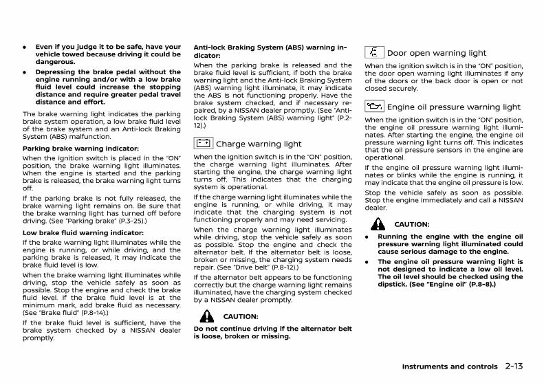
(67,1)
[ Edit: 2018/ 5/ 25 Model: PD23-A ]
. Even if you judge it to be safe, have yourvehicle towed because driving it could bedangerous.
. Depressing the brake pedal without theengine running and/or with a low brakefluid level could increase the stoppingdistance and require greater pedal traveldistance and effort.
The brake warning light indicates the parkingbrake system operation, a low brake fluid levelof the brake system and an Anti-lock BrakingSystem (ABS) malfunction.
Parking brake warning indicator:GUID-9E14C2E6-2E9C-4731-980B-C45B899B977B
When the ignition switch is placed in the “ON”position, the brake warning light illuminates.When the engine is started and the parkingbrake is released, the brake warning light turnsoff.If the parking brake is not fully released, thebrake warning light remains on. Be sure thatthe brake warning light has turned off beforedriving. (See “Parking brake” (P.3-25).)
Low brake fluid warning indicator:GUID-9E14C2E6-2E9C-4731-980B-C45B899B977B
If the brake warning light illuminates while theengine is running, or while driving, and theparking brake is released, it may indicate thebrake fluid level is low.When the brake warning light illuminates whiledriving, stop the vehicle safely as soon aspossible. Stop the engine and check the brakefluid level. If the brake fluid level is at theminimum mark, add brake fluid as necessary.(See “Brake fluid” (P.8-14).)If the brake fluid level is sufficient, have thebrake system checked by a NISSAN dealerpromptly.
Anti-lock Braking System (ABS) warning in-dicator:
GUID-9E14C2E6-2E9C-4731-980B-C45B899B977B
When the parking brake is released and thebrake fluid level is sufficient, if both the brakewarning light and the Anti-lock Braking System(ABS) warning light illuminate, it may indicatethe ABS is not functioning properly. Have thebrake system checked, and if necessary re-paired, by a NISSAN dealer promptly. (See “Anti-lock Braking System (ABS) warning light” (P.2-12).)
Charge warning lightPD23A1-6393B705-EF96-423F-A19C-E5F7A491FEEF
When the ignition switch is in the “ON” position,the charge warning light illuminates. Afterstarting the engine, the charge warning lightturns off. This indicates that the chargingsystem is operational.If the charge warning light illuminates while theengine is running, or while driving, it mayindicate that the charging system is notfunctioning properly and may need servicing.When the charge warning light illuminateswhile driving, stop the vehicle safely as soonas possible. Stop the engine and check thealternator belt. If the alternator belt is loose,broken or missing, the charging system needsrepair. (See “Drive belt” (P.8-12).)If the alternator belt appears to be functioningcorrectly but the charge warning light remainsilluminated, have the charging system checkedby a NISSAN dealer promptly.
CAUTION:
Do not continue driving if the alternator beltis loose, broken or missing.
Door open warning lightPD23A1-5F7F4230-2F74-4C29-9F67-424811C2787C
When the ignition switch is in the “ON” position,the door open warning light illuminates if anyof the doors or the back door is open or notclosed securely.
Engine oil pressure warning lightPD23A1-5E4356F4-6956-4764-AD9C-2DC72FDA1CF4
When the ignition switch is in the “ON” position,the engine oil pressure warning light illumi-nates. After starting the engine, the engine oilpressure warning light turns off. This indicatesthat the oil pressure sensors in the engine areoperational.If the engine oil pressure warning light illumi-nates or blinks while the engine is running, itmay indicate that the engine oil pressure is low.Stop the vehicle safely as soon as possible.Stop the engine immediately and call a NISSANdealer.
CAUTION:
. Running the engine with the engine oilpressure warning light illuminated couldcause serious damage to the engine.
. The engine oil pressure warning light isnot designed to indicate a low oil level.The oil level should be checked using thedipstick. (See “Engine oil” (P.8-8).)
Instruments and controls 2-13
Condition: 'Except for China'/
(68,1)
[ Edit: 2018/ 5/ 25 Model: PD23-A ]
2-14 Instruments and controls
Four-Wheel Drive (4WD) warninglight (4WD model)
PD23A1-5089F54D-2AC8-4F01-8A7E-76FA376EE652When the ignition switch is in the “ON” position,the Four-Wheel Drive (4WD) warning lightilluminates. After starting the engine, the 4WDwarning light turns off.If the 4WD system malfunctions or the revolu-tion or radius of the front and the rear wheeldiffers, the warning light will either remainilluminated or blink. (See “Four-Wheel Drive(4WD)” (P.5-18).)
CAUTION:
. If the 4WD warning light illuminates orblinks while driving, reduce the vehiclespeed and have your vehicle checked bya NISSAN dealer as soon as possible.
. If the Four-Wheel Drive (4WD) warninglight turns on when driving on dry hardsurface roads:— in the 4H position, shift the 4WDmode
switch to 2WD.
— in the 4LO position, stop the vehicleand shift the transmission lever tothe “N” (Neutral) position with thebrake pedal depressed and shift the4WD mode switch to 2WD.
If the warning light is still on after the aboveoperations, have your vehicle checked by aNISSAN dealer as soon as possible.
Headlight warning light (ifequipped)
GUID-E91DA942-D60B-4616-A91C-C782F201F2D2The headlight warning light illuminates if theLED headlights are malfunctioning. Contact aNISSAN dealer.
Low fuel warning lightPD23A1-98A780C9-A3F9-45A4-9CE8-8C23D4C61237
The low fuel warning light illuminates when thefuel level in the tank is getting low. Refuel assoon as it is convenient, preferably before thefuel gauge reaches the empty (0) position.There will be a small reserve of fuel remain-ing in the tank when the fuel gauge reachesthe empty (0) position.
Low tire pressure warning light (ifequipped)
GUID-5164EAAE-262C-40D4-BE4C-872502380C6AWhen the ignition switch is in the “ON” position,the low tire pressure warning light illuminatesand then turns off. This indicates that the lowtire pressure warning system is operational.This light illuminates if there is low tire pressureor a tire pressure warning system malfunction.The Tire Pressure Monitoring System (TPMS)monitors the tire pressure of all tires except thespare.
Low tire pressure warning:GUID-9E14C2E6-2E9C-4731-980B-C45B899B977B
If the vehicle is being driven with low tirepressure, the low tire pressure warning lightwill illuminate.When the low tire pressure warning lightilluminates, you should stop and adjust the tirepressure to the recommended COLD tire pres-sure shown on the tire placard. Use a tirepressure gauge to check the tire pressure. The
low tire pressure warning light may not auto-matically turn off when the tire pressure isadjusted. After the tire is inflated to therecommended pressure, reset the tire pres-sures registered in your vehicle and then drivethe vehicle at speeds above 25 km/h (16 MPH).These operations are required to activate theTPMS and turn off the low tire pressurewarning light.TPMS resetting must be also performed after atire or a wheel is replaced, or the tires arerotated.Depending on a change in the outside tem-perature, the low tire pressure warning lightmay illuminate even if the tire pressure hasbeen adjusted properly. Adjust the tire pressureto the recommended COLD tire pressure againwhen the tires are cold, and reset the TPMS.If the low tire pressure warning light stillcontinues to illuminate after the resettingoperation, it may indicate that the TPMS isnot functioning properly. Have the systemchecked by a NISSAN dealer.For additional information, see “Tire PressureMonitoring System (TPMS)” (P.5-4) and “TirePressure Monitoring System (TPMS)” (P.6-2).
TPMS malfunction:GUID-9E14C2E6-2E9C-4731-980B-C45B899B977B
If the TPMS is not functioning properly, the lowtire pressure warning light will flash for ap-proximately 1 minute when the ignition switchis placed in the “ON” position. The light willremain on after the 1 minute. Have the systemchecked by a NISSAN dealer.For additional information, see “Tire PressureMonitoring System (TPMS)” (P.5-4).
Condition: 'Except for China'/
(69,1)
[ Edit: 2018/ 5/ 25 Model: PD23-A ]
WARNING:
. If the light does not illuminate with theignition switch placed in the “ON” posi-tion, have the vehicle checked by aNISSAN dealer as soon as possible.
. If the light illuminates while driving, avoidsudden steering maneuvers or abruptbraking, reduce vehicle speed, pull offthe road to a safe location and stop thevehicle as soon as possible. Driving withunder-inflated tires may permanentlydamage the tires and increase the like-lihood of tire failure. Serious vehicledamage could occur and may lead to anaccident and could result in seriouspersonal injury. Check the tire pressurefor all four tires. Adjust the tire pressureto the recommended COLD tire pressureshown on the tire placard to turn the lowtire pressure warning light off. If the lightstill illuminates while driving after adjust-ing the tire pressure, a tire may be flat orthe TPMS may be malfunctioning. If youhave a flat tire, replace it with a spare tireas soon as possible. If no tire is flat and alltires are properly inflated, have the ve-hicle checked by a NISSAN dealer.
. After adjusting the tire pressure, be sureto reset the TPMS. Otherwise, the TPMSwill not warn of low tire pressure.
. Since the spare tire is not equipped withthe TPMS, when a spare tire is mountedor a wheel is replaced, the TPMS will notfunction and the low tire pressure warn-ing light will flash for approximately 1minute. The light will remain on after the1 minute. Contact your NISSAN dealer assoon as possible for tire replacementand/or system resetting.
. Replacing tires with those not originallyspecified by NISSAN could affect theproper operation of the TPMS.
CAUTION:
. The TPMS is not a substitute for theregular tire pressure check. Be sure tocheck the tire pressure regularly.
. If the vehicle is being driven at speeds ofless than 25 km/h (16 MPH), the TPMSmay not operate correctly.
. Be sure to install the specified size of tiresto all four wheels correctly.
Malfunction warning light (red) (ifequipped)
PD23A1-0E567A9E-4568-4221-927E-D35D93D9B087When the ignition switch is placed in the “ON”position, the malfunction warning light illumi-nates in red. This means that the system isoperational. After starting the engine, thewarning light turns off.For the orange Malfunction Indicator Light(MIL), see “Malfunction Indicator Light (MIL)”(P.2-17) for details.If the malfunction warning light (red) illumi-nates continuously while the engine is running,it may indicate an engine control systemmalfunction. Have your vehicle inspected by aNISSAN dealer. You do not need to have yourvehicle towed to the dealer.
CAUTION:
Continuing vehicle operation without properservicing of the engine control system couldlead to poor driveability, reduced fuel econ-omy, and damage to the engine controlsystem, which may affect the vehicle’s war-
ranty coverage.
Master warning light (if equipped)PD23A1-51CB32D6-7FE9-4CBE-A710-7584FA819D77
When the ignition switch is in the “ON” position,the master warning light illuminates if any ofthe following are displayed on the vehicleinformation display.. No Key Detected warning. Shift to Park warning. Key ID Incorrect warning. Release Parking Brake warning. Low fuel warning. Door open warning. Key System Error warning. Low Oil Pressure warning (if equipped). 4WD Error (if equipped). Shipping Mode On Push Storage Fuse
warning (if equipped). Headlight System Error warning. Automatic Transmission (AT) Error warning. Parking Sensor ErrorSee “Vehicle information display (models withcolor display)” (P.2-19).
Seat belt warning lightGUID-E63E0228-9348-4329-A720-5D6F458172D4
When the ignition switch is in the “ON” position,the seat belt warning light illuminates. The lightwill continue to illuminate until the driver’s and/or front passenger’s (if equipped) seat belts arefastened.When the vehicle speed exceeds 15 km/h (10MPH), the light will blink and the chime willsound unless the driver’s and/or front passen-ger’s (if equipped) seat beltss are securelyfastened. The chime will continue to sound forabout 95 seconds until the seat belts arefastened.
Instruments and controls 2-15
Condition: 'Except for China'/
(70,1)
[ Edit: 2018/ 5/ 25 Model: PD23-A ]
2-16 Instruments and controls
For precautions on seat belt usage, see “Seatbelts” (P.1-12).
Supplemental Restraint System(SRS) air bag warning light
PD23A1-65A75E10-BC1C-440D-88B5-3DAD079335F2When the ignition switch is in the “ON” position,the Supplemental Restraint System (SRS) airbag warning light illuminates for about 7seconds and then turns off. This indicates theSRS air bag system is operational.If any of the following conditions occur, the SRSair bag system and/or pre-tensioner seat beltneed servicing. Have the system checked, and ifnecessary repaired, by a NISSAN dealerpromptly.. The SRS air bag warning light remains
illuminated after about 7 seconds.. The SRS air bag warning light flashes
intermittently.. The SRS air bag warning light does not
come on at all.Unless checked and repaired, the SRS air bagsystem and/or pre-tensioner seat belt may notfunction properly. (See “Supplemental RestraintSystem (SRS)” (P.1-29).)
Vehicle Dynamic Control (VDC)warning light (if equipped)
PD23A1-3E7773DC-6BC0-4002-9116-4B0EBE340194When the ignition switch is in the “ON” position,the Vehicle Dynamic Control (VDC) warninglight illuminates and then turns off.The warning light blinks when the VDC systemis operating.When the warning light blinks while driving, thedriving condition is slippery and the vehicle’straction limit is about to be exceeded.If the VDC warning light illuminates while the
engine is running or while driving, it mayindicate that the VDC system is not functioningproperly and may need servicing. Have thesystem checked, and if necessary repaired, by aNISSAN dealer promptly. If a malfunction oc-curs, the VDC function is turned off, but thevehicle is still drivable. (See “Vehicle DynamicControl (VDC) system” (P.5-23).)
Water-in-fuel-filter warning lightPD23A1-5771FC1A-F17D-47B7-94A4-181B23BE9400
YD25DDTi engine model:GUID-9E14C2E6-2E9C-4731-980B-C45B899B977B
If the water-in-fuel-filter warning light illumi-nates while the engine is running, drain thewater from the fuel filter promptly. (See “Fuelfilter (YD25DDTi engine model)” (P.8-11).)
YS23DDTT engine model:GUID-9E14C2E6-2E9C-4731-980B-C45B899B977B
If the water-in-fuel-filter warning light illumi-nates while the engine is running, contact aNISSAN dealer as soon as possible.
CAUTION:
Continuing vehicle operation without prop-erly draining could cause serious damage tothe engine.
INDICATOR LIGHTSPD23A1-E1E02D55-A2C2-40E5-AA45-A99A557B60BC
Differential lock indicator light (ifequipped)
PD23A1-00B64D3E-05BC-4ECB-9167-7A053A169016When the ignition switch is in the “ON” position,the differential lock indicator light illuminatesand then turns off.When the differential lock mode switch is in the“ON” position, the differential lock indicator lightwill blink and then stay on after the differentialgear is completely locked.
See “Rear differential locking system” (P.5-22).
Front fog light indicator lightGUID-C7C00236-0168-4BC0-9C43-655BCDFB0410
The front fog light indicator light illuminateswhen the front fog lights are on. (See “Fog lightswitch” (P.2-34).)
Glow plug indicator lightPD23A1-B0711962-218E-4EF3-93A0-8BC3A0BFC4E6
When the ignition switch is in the “ON” position,the glow plug indicator light illuminates andturns off after the glow plugs have warmed up.If the glow plugs have already warmed up, theglow plug indicator flashes briefly and thenturns off.
High beam indicator lightPD23A1-FEF4DDF3-7F73-4905-A057-45AC536CD27A
The high beam indicator light illuminates whenthe headlight high beam is on. The indicatorturns off when the low beam is selected. (See“Headlight and turn signal switch” (P.2-32).)
Hill descent control system ONindicator light (if equipped)
PD23A1-EF25455E-E240-4499-AA83-B923F6BD3E7EWhen the ignition switch is in the “ON” positionthe hill descent control system on indicatorlight illuminates briefly and then turns off. Thisindicates that the hill descent control system isoperational.The light illuminates when the hill descentcontrol system is activated.If the hill descent control switch is on and theindicator light blinks, the system is not en-gaged.If the indicator light does not illuminate or blinkwhen the hill descent control switch is on, the
Condition: 'Except for China'/
(71,1)
[ Edit: 2018/ 5/ 25 Model: PD23-A ]
system may not be functioning properly. Havethe system checked by a NISSAN dealer.For additional information, see “Hill descentcontrol system” (P.5-24).
Malfunction Indicator Light (MIL)PD23A1-0B4283D4-EF4C-4DE4-A781-0CEEC7D95F90
CAUTION:
. Continuing vehicle operation withoutproper servicing of the engine controlsystem could lead to poor driveability,reduced fuel economy, and damage tothe engine control system, which mayaffect the vehicle’s warranty coverage.
. Incorrect setting of the engine controlsystem may lead to non-compliance oflocal and national emission laws andregulations.
When the ignition switch is in the “ON” position,the Malfunction Indicator Light (MIL) illumi-nates. After starting the engine, the MIL turnsoff. This indicates that the engine controlsystem is operational.If the MIL illuminates or blinks while the engineis running, it may indicate that the enginecontrol system is not functioning properly andmay need servicing. Have the system checked,and if necessary repaired, by a NISSAN dealerpromptly.
Precautions:GUID-9E14C2E6-2E9C-4731-980B-C45B899B977B
To reduce or avoid possible damage to theengine control system when the MIL blinks:. Avoid driving at speeds above 70 km/h (43
MPH).. Avoid sudden acceleration or deceleration.
. Avoid going up steep uphill grades.
. Avoid carrying or towing unnecessaryloads.
Security indicator lightPD23A1-C74EBAC9-9741-4A50-811A-6EB642B9C33A
The security indicator light blinks when theignition switch is in the “ACC”, “OFF” or “LOCK”position. This function indicates that the secur-ity system equipped on the vehicle is opera-tional.If the security system is malfunctioning, thislight will remain on while the ignition switch isin the “ON” position. (See “Security system” (P.3-14) for additional information.)
Small light indicator light (ifequipped)
GUID-0169B43D-E7DB-42DA-9A3C-8C8C34F75938The light illuminates when the headlight switchis turned to the position.
Turn signal/hazard indicatorlights
PD23A1-9E0C85D0-5B38-48BD-8B46-D02710E6F24AThe turn signal/hazard indicator lights blinkwhen the turn signal switch lever or hazardindicator flasher switch is on. (See “Headlightand turn signal switch” (P.2-32) or “Hazardindicator flasher switch” (P.6-2).)
Vehicle Dynamic Control (VDC) offindicator light (if equipped)
PD23A1-7A02E0E9-504B-4F4C-8A80-19F9EBB69E49When the ignition switch is in the “ON” position,the Vehicle Dynamic Control (VDC) off indicatorlight illuminates and then turns off.The VDC off indicator light illuminates when theVDC OFF switch is pushed to the “OFF” position.
When the VDC OFF switch is pushed to the“OFF” position, the VDC system is turned off.When the rear differential lock (if equipped) isengaged with the differential lock mode switchor the 4LO position is selected with the Four-Wheel Drive (4WD) mode switch, the VDCsystem is disabled and the VDC off indicatorlight illuminates. (See “Vehicle Dynamic Control(VDC) system” (P.5-23) and “Rear differentiallocking system” (P.5-22).)
AUDIBLE REMINDERSPD23A1-F5972024-F271-4F2A-B723-62196BC8F39A
Brake pad wear warningPD23A1-1AA598B7-5EEE-490E-9919-E25A422F1360
The disc brake pads have audible wear warn-ings. When a brake pad requires replacement, itwill make a high pitched scraping sound whenthe vehicle is in motion. This scraping soundwill first occur only when the brake pedal isdepressed. After more wear of the brake pad,the sound will always be heard even if thebrake pedal is not depressed. Have the brakeschecked as soon as possible if the wearwarning sound is heard.Have the system checked, and if necessaryrepaired, by a NISSAN dealer promptly. (See“Brakes” (P.8-12).)
Key reminder chimePD23A1-0B1FED55-2983-44EA-8186-66DB0B9F95D5
The chime will sound if any of the followingoperations are detected:
Models with Intelligent Key system:GUID-9E14C2E6-2E9C-4731-980B-C45B899B977B
The chime will sound if the driver side door isopened while the ignition switch is placed inthe “ACC” position.
Instruments and controls 2-17
Condition: 'Except for China'/
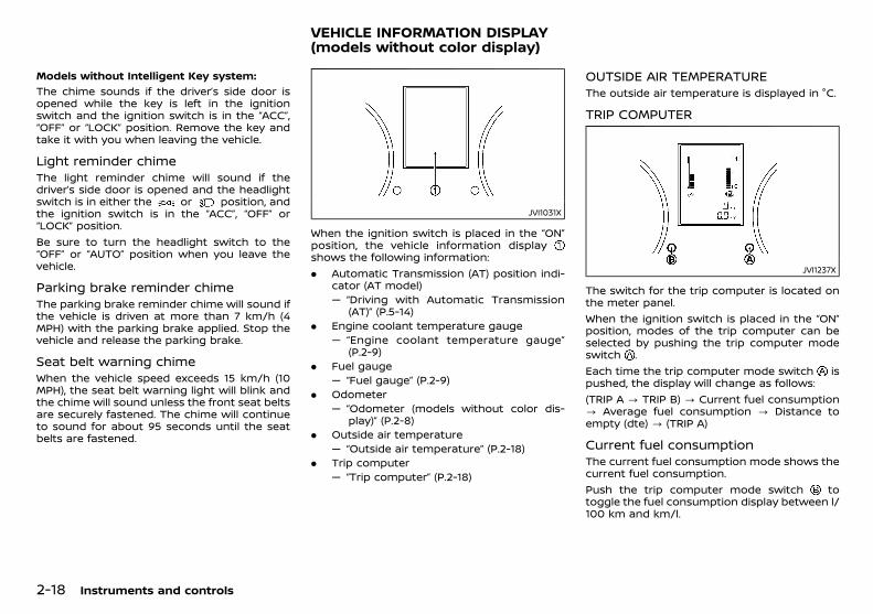
(72,1)
[ Edit: 2018/ 5/ 25 Model: PD23-A ]
2-18 Instruments and controls
Models without Intelligent Key system:GUID-9E14C2E6-2E9C-4731-980B-C45B899B977B
The chime sounds if the driver’s side door isopened while the key is left in the ignitionswitch and the ignition switch is in the “ACC”,“OFF” or “LOCK” position. Remove the key andtake it with you when leaving the vehicle.
Light reminder chimePD23A1-74A9AC67-D32F-488C-AE2D-89B350798479
The light reminder chime will sound if thedriver’s side door is opened and the headlightswitch is in either the or position, andthe ignition switch is in the “ACC”, “OFF” or“LOCK” position.Be sure to turn the headlight switch to the“OFF” or “AUTO” position when you leave thevehicle.
Parking brake reminder chimePD23A1-6E1C8FA1-9001-4734-97CC-BC4213A1A993
The parking brake reminder chime will sound ifthe vehicle is driven at more than 7 km/h (4MPH) with the parking brake applied. Stop thevehicle and release the parking brake.
Seat belt warning chimePD23A1-DD74E011-004E-4A74-AF17-C72AF1C8C413
When the vehicle speed exceeds 15 km/h (10MPH), the seat belt warning light will blink andthe chime will sound unless the front seat beltsare securely fastened. The chime will continueto sound for about 95 seconds until the seatbelts are fastened.
PD23A1-E99F149C-E75B-4170-A651-4D3DDCF82452
JVI1031X
When the ignition switch is placed in the “ON”position, the vehicle information displayshows the following information:. Automatic Transmission (AT) position indi-
cator (AT model)— “Driving with Automatic Transmission
(AT)” (P.5-14). Engine coolant temperature gauge
— “Engine coolant temperature gauge”(P.2-9)
. Fuel gauge— “Fuel gauge” (P.2-9)
. Odometer— “Odometer (models without color dis-
play)” (P.2-8). Outside air temperature
— “Outside air temperature” (P.2-18). Trip computer
— “Trip computer” (P.2-18)
OUTSIDE AIR TEMPERATUREPD23A1-9627DFE8-681F-4221-AB60-19552A76E779
The outside air temperature is displayed in °C.
TRIP COMPUTERPD23A1-D1EE2881-E1CC-45BC-8E26-25474EF7E92D
JVI1237X
The switch for the trip computer is located onthe meter panel.When the ignition switch is placed in the “ON”position, modes of the trip computer can beselected by pushing the trip computer modeswitch .Each time the trip computer mode switch ispushed, the display will change as follows:(TRIP A ? TRIP B) ? Current fuel consumption? Average fuel consumption ? Distance toempty (dte) ? (TRIP A)
Current fuel consumptionPD23A1-E2C3DC84-2033-4E3C-83FE-510F61C768AC
The current fuel consumption mode shows thecurrent fuel consumption.Push the trip computer mode switch totoggle the fuel consumption display between l/100 km and km/l.
VEHICLE INFORMATION DISPLAY(models without color display)
Condition: 'Except for China'/
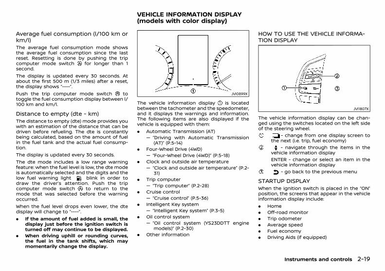
(73,1)
[ Edit: 2018/ 5/ 25 Model: PD23-A ]
Average fuel consumption (l/100 km orkm/l)
PD23A1-2FB7B0BC-A806-4306-9A02-75F69A5F7BE1The average fuel consumption mode showsthe average fuel consumption since the lastreset. Resetting is done by pushing the tripcomputer mode switch for longer than 1second.The display is updated every 30 seconds. Atabout the first 500 m (1/3 miles) after a reset,the display shows “----”.Push the trip computer mode switch totoggle the fuel consumption display between l/100 km and km/l.
Distance to empty (dte - km)PD23A1-56A214ED-0A50-4E41-A4F7-7BB6C46639F3
The distance to empty (dte) mode provides youwith an estimation of the distance that can bedriven before refueling. The dte is constantlybeing calculated, based on the amount of fuelin the fuel tank and the actual fuel consump-tion.The display is updated every 30 seconds.The dte mode includes a low range warningfeature: when the fuel level is low, the dte modeis automatically selected and the digits and thelow fuel warning light blink in order todraw the driver’s attention. Push the tripcomputer mode switch to return to themode that was selected before the warningoccurred.When the fuel level drops even lower, the dtedisplay will change to “----”.. If the amount of fuel added is small, the
display just before the ignition switch isturned off may continue to be displayed.
. When driving uphill or rounding curves,the fuel in the tank shifts, which maymomentarily change the display.
GUID-C4BFBF1A-9C05-4355-8261-40451D43B789
JVI0899X
The vehicle information display is locatedbetween the tachometer and the speedometer,and it displays the warnings and information.The following items are also displayed if thevehicle is equipped with them:. Automatic Transmission (AT)
— “Driving with Automatic Transmission(AT)” (P.5-14)
. Four-Wheel Drive (4WD)— “Four-Wheel Drive (4WD)” (P.5-18)
. Clock and outside air temperature— “Clock and outside air temperature” (P.2-
31). Trip computer
— “Trip computer” (P.2-28). Cruise control
— “Cruise control” (P.5-36). Intelligent Key system
— “Intelligent Key system” (P.3-5). Oil control system
— “Oil control system (YS23DDTT enginemodels)” (P.2-30)
. Other information
HOW TO USE THE VEHICLE INFORMA-TION DISPLAY
GUID-91599917-EC98-43FF-93B0-995AFE26AD26
JVI1807X
The vehicle information display can be chan-ged using the switches located on the left sideof the steering wheel.
- change from one display screen tothe next (i.e. trip, fuel economy)
- navigate through the items in thevehicle information displayENTER - change or select an item in thevehicle information display
- go back to the previous menu
STARTUP DISPLAYGUID-C5604061-D5AC-45C3-9794-A252A71C173D
When the ignition switch is placed in the “ON”position, the screens that appear in the vehicleinformation display include:. Home. Off-road monitor. Trip odometer. Average speed. Fuel economy. Driving Aids (if equipped)
Instruments and controls 2-19
VEHICLE INFORMATION DISPLAY(models with color display)
Condition: 'Except for China'/
(74,1)
[ Edit: 2018/ 5/ 25 Model: PD23-A ]
2-20 Instruments and controls
. Tire Pressures
. 4WD status (if equipped)
. WarningsWarnings will only appear if there are anypresent. For more information on warningsand indicators, see “Vehicle information displaywarnings and indicators” (P.2-24).To control what items are displayed in thevehicle information display, see “Meter Settings”(P.2-20).
SETTINGSGUID-C1AEFFB5-8D48-4C91-B423-C081D37FD32B
Settings cannot be made while driving.The and ENTER switch is used in thesetting mode.Use the switch to select a menu.Push ENTER to decide a menu.
Driver AssistanceGUID-FF2BA16C-1EFD-45B4-AAF7-FC7E8C5C669F
Select this submenu to change the status orturn on or off any of the systems displayed inthe menu.
Driving Aids (if equipped):GUID-9E14C2E6-2E9C-4731-980B-C45B899B977B
The following submenus are displayed underthe Driving Aids menu.. Lane (LDW)
Select this submenu to enable/disable theLane Departure Warning system.
For additional information, see “Lane DepartureWarning (LDW)” (P.5-26).. Blind Spot (BSW)
Select this submenu to enable/disable theBlind Spot Warning system.
For additional information, see “Blind SpotWarning (BSW)” (P.5-30).
Parking Aids:GUID-9E14C2E6-2E9C-4731-980B-C45B899B977B
The following submenus are displayed underthe Parking Aids menu.. Moving Object (if equipped)
Select this submenu to enable/disable theMoving Object Detection (MOD).
For additional information, see “Moving ObjectDetection (MOD)” (P.4-15).. Sensor
Select this submenu to enable/disable theparking sensor (sonar) system.
. VolumeSelect this submenu to change the parkingsensor (sonar) buzzer volume.
. RangeSelect this submenu to change the parkingsensor (sonar) detection range.
For additional information, see “Parking sensor(sonar) system” (P.5-40).
ClockGUID-A84D85D3-ED40-4672-AA86-88CE11EAB653
The following submenus are displayed underthe Clock menu.
Set Clock:GUID-9E14C2E6-2E9C-4731-980B-C45B899B977B
Select this submenu to adjust the time on theclock.
12H/24H:GUID-9E14C2E6-2E9C-4731-980B-C45B899B977B
Select this submenu to choose the clockformat between 12-hour and 24-hour.
Meter SettingsGUID-EE86A70F-784B-4C8E-9644-343F3C314092
The following submenus are displayed underthe Meter Settings menu.
Main Menu Selection:GUID-9E14C2E6-2E9C-4731-980B-C45B899B977B
Select this submenu to enable/disable theitems that are displayed.
ECO Drive Report:GUID-9E14C2E6-2E9C-4731-980B-C45B899B977B
The following submenus are displayed.. Display
Select this submenu to enable/disable theECO Drive Report in the vehicle informationdisplay.
. View HistorySelect this submenu to reset the pasthistory of the fuel economy and the bestfuel economy. See “ECO drive report” (P.5-37).
Welcome Effect:GUID-9E14C2E6-2E9C-4731-980B-C45B899B977B
Select this submenu to enable/disable thedisplay effect and the dial and pointer effectdescribed below to on or off.. Dial Effect
The indicator needles sweep in the meterswhen the engine is started.
. Display EffectThe welcome screen display appears whenthe ignition switch is turned on.
Vehicle SettingsGUID-65DD7252-2319-4881-AA78-BCA0F273712B
The following submenus are displayed underthe Vehicle Settings menu.
Condition: 'Except for China'/
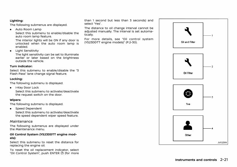
(75,1)
[ Edit: 2018/ 5/ 25 Model: PD23-A ]
Lighting:GUID-9E14C2E6-2E9C-4731-980B-C45B899B977B
The following submenus are displayed.. Auto Room Lamp
Select this submenu to enable/disable theauto room lamp feature.The interior lights will be ON if any door isunlocked when the auto room lamp isenabled.
. Light SensitivityThe light sensitivity can be set to illuminateearlier or later based on the brightnessoutside the vehicle.
Turn indicator:GUID-9E14C2E6-2E9C-4731-980B-C45B899B977B
Select this submenu to enable/disable the “3Flash Pass” lane change signal feature.
Locking:GUID-9E14C2E6-2E9C-4731-980B-C45B899B977B
The following submenu is displayed.. I-Key Door Lock
Select this submenu to activate/deactivatethe request switch on the door.
Wipers:GUID-9E14C2E6-2E9C-4731-980B-C45B899B977B
The following submenu is displayed.. Speed Dependent
Select this submenu to activate/deactivatethe speed dependent wiper speed feature.
MaintenanceGUID-0251AB5D-4F20-40B2-AF06-951CF60C1CD7
The following submenus are displayed underthe Maintenance menu.
Oil Control System (YS23DDTT engine mod-els):
GUID-9E14C2E6-2E9C-4731-980B-C45B899B977B
Select this submenu to reset the distance forreplacing the engine oil.To reset the oil replacement indicator, select“Oil Control System”, push ENTER (for more
than 1 second but less than 3 seconds) andselect “Yes”.The distance to oil change interval cannot beadjusted manually. The interval is set automa-tically.For more details, see “Oil control system(YS23DDTT engine models)” (P.2-30).
JVI1239X
Instruments and controls 2-21
Condition: 'Except for China'/

(76,1)
[ Edit: 2018/ 5/ 25 Model: PD23-A ]
2-22 Instruments and controls
1. Oil and Filter (except for YS23DDTT enginemodels):
GUID-9E14C2E6-2E9C-4731-980B-C45B899B977B
Select this submenu to set or reset the distancefor replacing the engine oil and oil filter.
NOTE:Be sure to reset the distance for replacing theengine oil and oil filter after replacing.Otherwise, the oil and filter replacementindicator will continue to be displayed.2. Oil Filter (YS23DDTT engine models):
GUID-9E14C2E6-2E9C-4731-980B-C45B899B977B
Select this submenu to set or reset the distancefor replacing the oil filter.
3. Tire:GUID-9E14C2E6-2E9C-4731-980B-C45B899B977B
Select this submenu to set or reset the distancefor replacing tires.
WARNING:
The tire replacement indicator is not a sub-stitute for regular tire checks, including tirepressure checks. See “Changing tires andwheels” (P.8-29). Many factors including tireinflation, alignment, driving habits and roadconditions affect tire wear and when tiresshould be replaced. Setting the tire replace-ment indicator for a certain driving distancedoes not mean your tires will last that long.Use the tire replacement indicator as a guideonly and always perform regular tire checks.Failure to perform regular tire checks, includ-ing tire pressure checks could result in tirefailure. Serious vehicle damage could occurand may lead to a collision, which couldresult in serious personal injury or death.
4. Other:GUID-9E14C2E6-2E9C-4731-980B-C45B899B977B
Select this submenu to set or reset the distancefor replacing items other than the engine oil, oilfilter and tires.
AlarmGUID-486B7137-5E59-4AF7-A2CC-D2559F172880
The following submenus are displayed underthe Alarm menu.
Outside Temp:GUID-9E14C2E6-2E9C-4731-980B-C45B899B977B
Select this submenu to enable/disable thealarm for outside air temperature in the vehicleinformation display.
Timer Alert:GUID-9E14C2E6-2E9C-4731-980B-C45B899B977B
Select this submenu to set an alert to notify thedriver that the set time has been reached.
Tire PressuresGUID-E3FC464A-E59F-4C21-A90B-6B770202E4F8
The settings in the “Tire Pressures” menu are allrelated to the Tire Pressure Monitoring System(TPMS). (See “Tire Pressure Monitoring System(TPMS)” (P.5-4).). Target front. Target rear. Tire Pressure Unit. TPMS Reset
Target front:GUID-9E14C2E6-2E9C-4731-980B-C45B899B977B
The “Target front” tire pressure is the pressurespecified for the front tires on the tire placard.(See “Tire placard” (P.9-8) and “Tire PressureMonitoring System (TPMS)” (P.5-4).)Use the and the ENTER switches toselect and change the value for the “TargetFront” tire pressure.
Target rear:GUID-9E14C2E6-2E9C-4731-980B-C45B899B977B
The “Target rear” tire pressure is the pressurespecified for the rear tires on the tire placard.(See “Tire placard” (P.9-8) and “Tire PressureMonitoring System (TPMS)” (P.5-4).)Use the and the ENTER switches toselect and change the value for the “TargetRear” tire pressure.
Tire Pressure Unit:GUID-9E14C2E6-2E9C-4731-980B-C45B899B977B
The unit for tire pressure that is shown in thevehicle information display can be changed to:. kPa. psi. bar. kgf/cm2
Use the and the ENTER switches toselect and change the unit.
TPMS Reset:GUID-9E14C2E6-2E9C-4731-980B-C45B899B977B
This setting allows the customer to reset theTPMS.Use the and the ENTER switches toselect and reset the TPMS. (See “TPMS reset-ting” (P.5-5).)
UnitGUID-58EB6BAC-FCB3-46EF-8631-2FA1B6B4F84C
The unit that is shown in the vehicle informa-tion display can be changed:. Mileage. Tire Pressures. TemperatureUse the and the ENTER switches toselect “Unit” and change the units of the vehicleinformation display.
Condition: 'Except for China'/
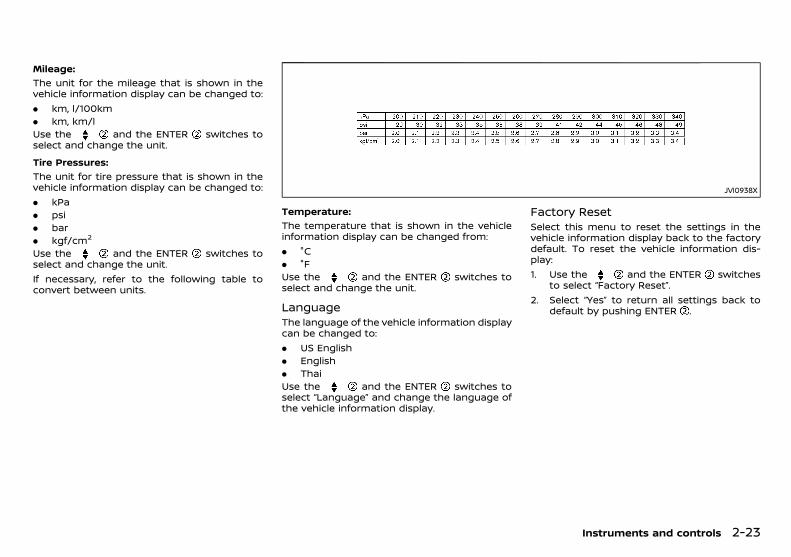
(77,1)
[ Edit: 2018/ 5/ 25 Model: PD23-A ]
Mileage:GUID-9E14C2E6-2E9C-4731-980B-C45B899B977B
The unit for the mileage that is shown in thevehicle information display can be changed to:. km, l/100km. km, km/lUse the and the ENTER switches toselect and change the unit.
Tire Pressures:GUID-9E14C2E6-2E9C-4731-980B-C45B899B977B
The unit for tire pressure that is shown in thevehicle information display can be changed to:. kPa. psi. bar. kgf/cm2
Use the and the ENTER switches toselect and change the unit.If necessary, refer to the following table toconvert between units.
JVI0938X
Temperature:GUID-9E14C2E6-2E9C-4731-980B-C45B899B977B
The temperature that is shown in the vehicleinformation display can be changed from:. °C. °FUse the and the ENTER switches toselect and change the unit.
LanguageGUID-C43AB309-D518-4CEC-A6C3-4D449F5FEAFC
The language of the vehicle information displaycan be changed to:. US English. English. ThaiUse the and the ENTER switches toselect “Language” and change the language ofthe vehicle information display.
Factory ResetGUID-B696FA09-CD79-4649-B9CB-4956E1D1A216
Select this menu to reset the settings in thevehicle information display back to the factorydefault. To reset the vehicle information dis-play:1. Use the and the ENTER switches
to select “Factory Reset”.2. Select “Yes” to return all settings back to
default by pushing ENTER .
Instruments and controls 2-23
Condition: 'Except for China'/
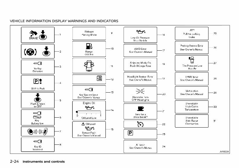
(78,1)
[ Edit: 2018/ 5/ 25 Model: PD23-A ]
2-24 Instruments and controls
VEHICLE INFORMATION DISPLAY WARNINGS AND INDICATORSGUID-93A09B60-8488-47F4-BB0B-9CA086A28843
JVI1822X
Condition: 'Except for China'/
(79,1)
[ Edit: 2018/ 5/ 25 Model: PD23-A ]
1. Engine start operation indicatorGUID-0A3152D1-AB18-4840-A0A8-5997E59286AB
This indicator appears when the shift lever is inthe “P” (Park) position.This indicator means that the engine will startby pushing the ignition switch with the brakepedal depressed. You can start the enginedirectly in any position of the ignition switch.
2. Steering lock release malfunctionindicator
GUID-85112A7B-1821-4C34-86D9-A7958376AB47This indicator appears when the steering wheelcannot be released from the “LOCK” position.If this indicator appears, push the ignitionswitch while lightly turning the steering wheelright and left.See “Steering lock” (P.5-11).
3. No Key Detected warningGUID-53105623-5DAF-45F7-BE2B-5D95DF5E234D
This warning appears when the door is closedwith the Intelligent Key left outside the vehicleand the ignition switch in the “ON” position.Make sure that the Intelligent Key is inside thevehicle.See “Intelligent Key system” (P.3-5) for moredetails.
4. Shift to Park warningGUID-B6A1BE33-5861-432C-B3AD-E6CDB2384A93
This warning appears when the ignition switchis pushed to stop the engine with the shift leverin any position except the “P” (Park) position.If this warning appears, move the shift lever tothe “P” (Park) position or push the ignitionswitch to the “ON” position.An inside warning chime will also sound. (See“Intelligent Key system” (P.3-5).)
5. “PUSH” warningGUID-B3273B26-9AB3-4221-B95D-EC9273EBC369
This warning appears when the shift lever ismoved to the “P” (Park) position with theignition switch in the “ACC” position after theShift to Park warning appears.To push the ignition switch to the “OFF”position, perform the following procedure:Shift to Park warning? (Move the shift lever to“P”) ? PUSH warning ? (Push the ignitionswitch ? ignition switch position is turned to“ON”) ? PUSH warning ? (Push the ignitionswitch ? ignition switch position is turned to“OFF”)
6. Key Battery low warningGUID-07D899C9-2D74-45C6-B3F6-A45400F5923D
This warning appears when the Intelligent Keybattery is running out of power.If this warning appears, replace the batterywith a new one. (See “Intelligent Key battery”(P.8-20).)
7. Engine start operation for IntelligentKey system indicator
GUID-2AC8E908-C547-4930-A89E-89E1F6ABE224This indicator appears when the Intelligent Keybattery is running out of power and when theIntelligent Key system and vehicle are notnormally communicated.If this indicator appears, touch the ignitionswitch with the Intelligent Key while depressingthe brake pedal. (See “Intelligent Key batterydischarge” (P.5-12).)
8. Key ID Incorrect warningGUID-D49EAF5E-6C58-423B-9610-59808348C8BB
This warning appears when the ignition switchis placed from the “LOCK” position and theIntelligent Key cannot be recognized by thesystem. You cannot start the engine with anunregistered key. Use the registered IntelligentKey.See “Intelligent Key system” (P.3-5).
9. Release Parking Brake warningGUID-58336C86-952C-4BB0-824F-F41561CF54E4
This warning appears when the vehicle speedis above 7 km/h (4 MPH) and the parking brakeis applied. Stop the vehicle and release theparking brake.
10. Low fuel warningGUID-DF652A02-35CD-4759-8945-7220B8C05F84
This warning appears when the fuel level in thetank is getting low. Refuel as soon as it isconvenient, preferably before the fuel gaugereaches the empty (0) position.There will be a small reserve of fuel remain-ing in the tank when the fuel gauge reachesthe empty (0) position.
11. Door/back door open warningGUID-085F6CB6-DB54-421B-B259-2225A0B7FF96
This warning appears if any of the doors and/or the back door are open or not closedsecurely. The vehicle icon indicates which dooror the back door is open on the display.
12. 4WD mode indicator (if equipped)GUID-B77675DB-F918-41C5-BD5C-79B74AE0036D
This indicator shows the drive mode of the 4WDsystem.See “Four-Wheel Drive (4WD)” (P.5-18) for details.
Instruments and controls 2-25
Condition: 'Except for China'/

(80,1)
[ Edit: 2018/ 5/ 25 Model: PD23-A ]
2-26 Instruments and controls
13. Key System Error warningGUID-3598F170-D28E-46BD-8D80-9D2A3F03CD6B
This warning appears if there is a malfunctionin the Intelligent Key system.If this warning appears while the engine isstopped, the engine cannot be started. If thiswarning appears while the engine is running,the vehicle can be driven. However, contact aNISSAN dealer for repair as soon as possible.
14. Oil Level Low indicator (if equipped)PD23A1-84290187-77C7-4E5B-A46C-63E9CA27F6FC
If the low level indicator is displayed, the engineoil level is low. If the low level indicator isdisplayed, check the level using the engine oildipstick. (See “Engine oil” (P.8-8).)
CAUTION:
The oil level should be checked regularlyusing the engine oil dipstick. Operating withan insufficient amount of oil can damage theengine and such damage is not covered bythe warranty.
15. Oil level sensor warning (if equipped)PD23A1-BB56E932-6C86-4F73-9AFB-A4112D942E59
If the oil level sensor warning is displayed, theengine oil level sensor may be malfunctioning.Contact a NISSAN dealer immediately.
16. Low Oil Pressure Stop vehiclewarning (if equipped)
GUID-94AA9B91-3436-4503-8DDC-3959FD63BD5CThis warning appears if low engine oil pressureis detected. If the warning appears duringnormal driving, pull off the road in a safe area,stop the engine immediately and call a NISSANdealer.The low oil pressure warning is not designed toindicate a low oil level. Use the dipstick to checkthe oil level. (See “Engine oil” (P.8-8).)
CAUTION:
Running the engine with the engine oilpressure warning displayed could causeserious damage to the engine.
17. 4WD Error warning (if equipped)GUID-A5996626-5DB8-4375-9FBA-08E2B83A96AA
This warning appears when the four wheeldrive (4WD) system is not functioning properlywhile the engine is running. Reduce vehiclespeed and have your vehicle checked by aNISSAN dealer. See “4WD warning” (P.5-21).
18. Shipping Mode On Push StorageFuse warning (if equipped)
GUID-FD4B748B-36FA-489F-991A-A30D4F8F536FThis warning may appear if the extendedstorage fuse switch is not pushed in (switchedon). When this warning appears, push in (switchon) the extended storage fuse switch to turnoff the warning. For more information, see“Extended storage fuse switch” (P.8-23).
19. Headlight System Error warningGUID-0279B14A-10E9-4893-A020-FD87FA211D62
This warning appears if the LED headlights aremalfunctioning. Have the system checked by aNISSAN dealer.
20. Reminder Turn OFF Headlightswarning
GUID-13393AA4-7A48-43A7-B025-6BA8C061FDB5This warning appears when the driver sidedoor is opened with the headlight switch is leftON and the ignition switch is placed in the“OFF”, “ACC” or “LOCK” position. Place the head-light switch in “OFF” or “AUTO” position. Foradditional information, see “Headlight and turnsignal switch” (P.2-32).
21. Time for a driver break? indicatorGUID-60EE7282-E909-4577-AB01-4A80274EB497
This indicator appears when the set “TimerAlert” alarm activates. You can set the time forup to 6 hours. (See “Trip computer” (P.2-28).)
22. Cruise control indicatorGUID-5EF81791-0394-460E-91D7-4392607D9FF3
This indicator shows the cruise control systemstatus. The status is shown by the color.See “Cruise control” (P.5-36) for details.
23. Automatic Transmission (AT) posi-tion indicator
GUID-A6ABC342-4A75-4D56-BC81-ABDD790F3FF0This indicator shows the automatic shift posi-tion.In the manual shift mode, when the transmis-sion does not shift to the selected gear due to atransmission protection mode, the AT positionindicator will blink and a chime will sound.For further details, see “Driving with AutomaticTransmission (AT)” (P.5-14).
24. Automatic Transmission (AT) Errorwarning
GUID-50737610-003F-41A4-B6DE-70574606EDECIf the Automatic Transmission (AT) Error warn-ing appears while the engine is running, orwhile driving, it may indicate that the AT is notfunctioning properly and may need servicing.Have the system checked, and if necessaryrepaired, by a NISSAN dealer promptly.
25. Automatic Transmission (AT) parkwarning
GUID-48D9A7AD-D2C3-4F9E-84EF-C35D3E15087AThis warning indicates that the AutomaticTransmission (AT) parking function is not en-gaged. If the transfer control is not secured inany driving position while the AT shift lever is inthe “P” (Park) position, the transmission willdisengage and the wheels will not lock.
Condition: 'Except for China'/
(81,1)
[ Edit: 2018/ 5/ 25 Model: PD23-A ]
For 4WD model: If the ATP warning appearswith the shift lever in the “P” (Park) position,shift the Four-Wheel Drive (4WD) modeswitch to the 2WD, 4H or 4LO position againwith the shift lever in the N (Neutral) position.(See “Four-Wheel Drive (4WD)” (P.5-18).)
WARNING:
If the 4WD mode indicator (see “4WD modeindicator” (P.5-21)) is “OFF” or the ATP warn-ing light is “ON”, this indicates that theautomatic transmission P (Park) position willnot function and could result in the vehiclemoving unexpectedly, causing serious per-sonal injury or property damage. Always setthe parking brake.
26. Parking Sensor Error warningGUID-B01826A1-5717-45C6-BC93-5A34040E234E
This warning appears when the parking sensor(sonar) system is not functioning properly. If thewarning appears, have the system checked bya NISSAN dealer.
27. Low Tire Pressure warningGUID-A916546D-B20B-40E8-BBC6-2989F90E1F47
This warning appears when the low tire pres-sure warning light in the meter illuminates andlow tire pressure is detected. The warningappears each time the ignition switch is placedin the “ON” position as long as the low tirepressure warning light remains illuminated. Ifthis warning appears, stop the vehicle andadjust the pressure to the recommended COLDtire pressure shown on the tire placard. (See“Low tire pressure warning light” (P.2-14) and“Tire Pressure Monitoring System (TPMS)” (P.5-4).)
28. TPMS Error warningGUID-EB20FE3A-C5FF-4ADA-9EAE-342B8A987946
This warning appears when there is a malfunc-tion with the Tire Pressure Monitoring System(TPMS).If this warning appears, have the systemchecked by a NISSAN dealer.
29. Malfunction warning (if equipped)GUID-5058B4FA-B125-46AA-9879-51B685A242EB
This warning appears when the followingsystems are not functioning properly.. Lane Departure Warning (LDW) system. Blind Spot Warning (BSW) systemFor more details, see “Lane Departure Warning(LDW)” (P.5-26) and “Blind Spot Warning (BSW)”(P.5-30).
30. Unavailable High Cabin Tempera-ture warning (if equipped)
GUID-D49848C9-B111-452C-AC60-AC64D555E8F3This warning appears if the interior tempera-ture of the vehicle has reached such a hightemperature that the sensor for the LaneDeparture Warning (LDW) can no longer func-tion reliably. Once the interior temperature hasreached normal levels, the warning shoulddisappear.If the warning continues to appear, have thesystem checked by a NISSAN dealer. For moredetails, see “Lane Departure Warning (LDW)”(P.5-26).
31. Unavailable Side Radar Obstructionwarning (if equipped)
GUID-1FEC8DFE-8A61-4C1D-B9A8-314D8E25B10FThis warning is displayed if the area near theradar units used by the Blind Spot Warningsystem is dirty or covered with snow or rain. Ifthe warning appears, park the vehicle in a safeplace, turn off the engine, and clean the area.Then restart the engine.
The system is not available until the conditionsno longer exist. See “Blind Spot Warning (BSW)”(P.5-30).
Instruments and controls 2-27
Condition: 'Except for China'/
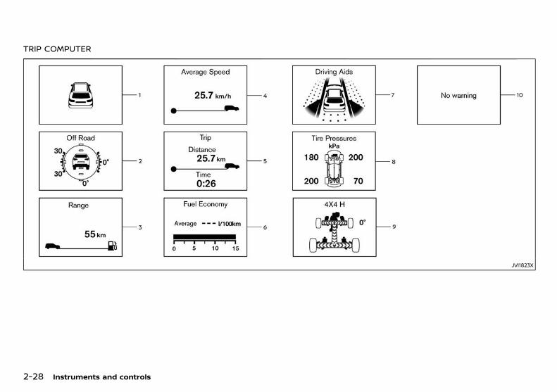
(82,1)
[ Edit: 2018/ 5/ 25 Model: PD23-A ]
2-28 Instruments and controls
TRIP COMPUTERGUID-460FD78A-2BDB-4BC6-8922-C03169EB2DF5
JVI1823X
Condition: 'Except for China'/
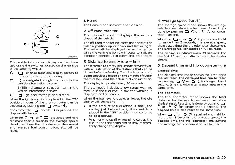
(83,1)
[ Edit: 2018/ 5/ 25 Model: PD23-A ]
JVI1807X
The vehicle information display can be chan-ged using the switches located on the left sideof the steering wheel.
- change from one display screen tothe next (i.e. trip, fuel economy)
- navigate through the items in thevehicle information displayENTER - change or select an item in thevehicle information display
- go back to the previous menuWhen the ignition switch is placed in the “ON”position, modes of the trip computer can beselected by pushing the switch .Each time the switch is pushed, thedisplay will change.When the or is pushed and heldfor more than 3 seconds, the average speed,the elapsed time, the trip odometer, the currentand average fuel consumption, etc. will bereset.
1. HomeGUID-FD840FC9-DECB-43B0-8719-F984D5481EE0
The Home mode shows the vehicle icon.
2. Off-road monitorGUID-01766840-4B43-4B2B-801D-05D18AAAD5AE
The off-road monitor displays the variousslopes of the vehicle.The off-road monitor indicates the angle of thevehicle position up or down and left or right.The value will be displayed below the gaugewhile the vehicle graphic will rotate to indicatecondition pointed up or down and left or right.
3. Distance to empty (dte — km)GUID-93239F2D-FFD9-416C-B6B6-A536ABF5BA22
The distance to empty (dte) mode provides youwith an estimation of the distance that can bedriven before refueling. The dte is constantlybeing calculated based on the amount of fuel inthe fuel tank and the actual fuel consumption.The display is updated every 30 seconds.The dte mode includes a low range warningfeature. If the fuel level is low, the warning isdisplayed on the screen.When the fuel level drops even lower, the dtedisplay will change to “----”.. If the amount of fuel added is small, the
display just before the ignition switch isplaced in the “OFF” position may continueto be displayed.
. When driving uphill or rounding curves, thefuel in the tank shifts, which may momen-tarily change the display.
4. Average speed (km/h)GUID-6A2BDD98-1152-40C3-8B5A-4E192EE672CA
The average speed mode shows the averagevehicle speed since the last reset. Resetting isdone by pushing or for longerthan 1 second.When the or is pushed and heldfor more than 3 seconds, the average speed,the elapsed time, the trip odometer, the currentand average fuel consumption will be reset.The display is updated every 30 seconds. Forthe first 30 seconds after a reset, the displayshows “----”.
5. Elapsed time and trip odometer (km)GUID-88D82603-E037-4AD2-BE71-5A43C51CF1F5
Elapsed time:GUID-9E14C2E6-2E9C-4731-980B-C45B899B977B
The elapsed time mode shows the time sincethe last reset. The displayed time can be resetby pushing or for longer than 1second. (The trip odometer is also reset at thesame time.)
Trip odometer:GUID-9E14C2E6-2E9C-4731-980B-C45B899B977B
The trip odometer mode shows the totaldistance that the vehicle has been driven sincethe last reset. Resetting is done by pushing
or for longer than 1 second. (Theelapsed time is also reset at the same time.)When or is pushed and held formore than 3 seconds, the average speed, theelapsed time, the trip odometer, the currentand average fuel consumption will be reset.
Instruments and controls 2-29
Condition: 'Except for China'/
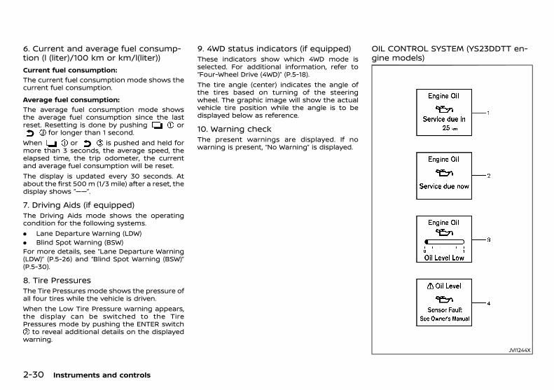
(84,1)
[ Edit: 2018/ 5/ 25 Model: PD23-A ]
2-30 Instruments and controls
6. Current and average fuel consump-tion (l (liter)/100 km or km/l(liter))
GUID-E6BAB36B-2A04-436C-A89B-FD013A637D62
Current fuel consumption:GUID-9E14C2E6-2E9C-4731-980B-C45B899B977B
The current fuel consumption mode shows thecurrent fuel consumption.
Average fuel consumption:GUID-9E14C2E6-2E9C-4731-980B-C45B899B977B
The average fuel consumption mode showsthe average fuel consumption since the lastreset. Resetting is done by pushing or
for longer than 1 second.When or is pushed and held formore than 3 seconds, the average speed, theelapsed time, the trip odometer, the currentand average fuel consumption will be reset.The display is updated every 30 seconds. Atabout the first 500 m (1/3 mile) after a reset, thedisplay shows “——”.
7. Driving Aids (if equipped)GUID-D2A57B03-A7C6-4806-B7B8-CBA0676D1A67
The Driving Aids mode shows the operatingcondition for the following systems.. Lane Departure Warning (LDW). Blind Spot Warning (BSW)For more details, see “Lane Departure Warning(LDW)” (P.5-26) and “Blind Spot Warning (BSW)”(P.5-30).
8. Tire PressuresGUID-D348A70C-56E9-4C21-AD65-433214561B9D
The Tire Pressures mode shows the pressure ofall four tires while the vehicle is driven.When the Low Tire Pressure warning appears,the display can be switched to the TirePressures mode by pushing the ENTER switch
to reveal additional details on the displayedwarning.
9. 4WD status indicators (if equipped)GUID-D2381FE3-9D46-4C94-9068-8C2D6A40662B
These indicators show which 4WD mode isselected. For additional information, refer to“Four-Wheel Drive (4WD)” (P.5-18).The tire angle (center) indicates the angle ofthe tires based on turning of the steeringwheel. The graphic image will show the actualvehicle tire position while the angle is to bedisplayed below as reference.
10. Warning checkGUID-39330DE5-4229-4AA9-BBC1-71648F31C81D
The present warnings are displayed. If nowarning is present, “No Warning” is displayed.
OIL CONTROL SYSTEM (YS23DDTT en-gine models)
PD23A1-1B546433-AA9C-4E04-AA9E-D90FAB0ED0F1
JVI1244X
Condition: 'Except for China'/

(85,1)
[ Edit: 2018/ 5/ 25 Model: PD23-A ]
When the ignition switch is in the “ON” position,engine oil information is displayed.Engine oil information informs the distance tooil change, oil level indication and malfunctionof oil level sensor.
1. Distance to oil changePD23A1-90CF766F-BDC3-489F-9398-606B168A3A25
The distance to oil change is displayed if thedistance to oil change is less than 1,500 km(930 miles).
2. Oil replacement indicatorPD23A1-36E5CFFE-51E7-4707-BBBB-50D92F37F7CA
When the set mileage approaches, the engineoil replacement indicator will appear on thedisplay. After the oil is changed, reset thedistance to oil change. The oil replacementindicator will not be reset automatically. Toreset this indicator, see “Settings” (P.2-20).The distance to oil change interval cannot beadjusted manually. The distance to oil changeinterval is set automatically.
CAUTION:
. If the oil replacement indicator is dis-played, change the engine oil as soon aspossible. Operating your vehicle withdeteriorated oil can damage the engine.
. Never perform reset if the engine oil wasnot changed. Always visit a NISSAN dealerto perform the engine oil change includ-ing an oil filter change and the reset.
NOTE:. It is not possible to undo the reset.. Resetting the oil change distance is only
possible when:— The distance to oil change is displayed
in the vehicle information display.
— The oil replacement indicator is dis-played in the vehicle information dis-play.
. The engine oil should be changed beforethe distance to oil change reaches 0 km(0 miles). Continued driving after thedistance to oil change reaches 0 km (0miles) may result in reduced engineperformance.
. The oil change interval will reduce fasterwith certain types of driving, especially atrow speeds in urban conditions.
3. Low level reminderPD23A1-C3820109-0CB1-4B08-8F40-A79450C5D7C0
If the low level indicator is displayed, the engineoil level is low. If the low level reminder isdisplayed, check the level using the engine oildipstick. (See “Engine oil” (P.8-8).)
CAUTION:
The oil level should be checked regularlyusing the engine oil dipstick. Operating withan insufficient amount of oil can damage theengine and such damage is not covered bythe warranty.
4. Oil level sensor warningPD23A1-FF918E07-88C3-4A51-9366-7A4C940E1FB4
If the oil sensor warning is displayed, the engineoil level sensor may be malfunctioning. Contacta NISSAN dealer immediately.
CLOCK AND OUTSIDE AIR TEMPERA-TURE
GUID-6B521DB4-BD5A-4D02-A076-9507594688E9
JVI0932X
The clock and outside air temperature aredisplayed on the upper side of the vehicleinformation display.
ClockGUID-8702736B-4DAE-4185-AB2E-9A4BAA6584D1
For clock adjustment, see “Clock” (P.2-20).
Outside air temperature (°C or °F )GUID-5D56CEEB-B9E5-4318-AC8F-CC8AD40FCFE4
The outside air temperature is displayed in °Cor °F in the range of −40 to 60°C (−40 to 140°F ).The outside air temperature mode includes alow temperature warning feature. If the outsideair temperature is below 3°C (37°F), the warning
is displayed on the screen.The outside temperature sensor is located infront of the radiator. The sensor may beaffected by road or engine heat, wind direc-tions and other driving conditions. The displaymay differ from the actual outside temperatureor the temperature displayed on various signsor billboards.
Instruments and controls 2-31
Condition: 'Except for China'/

(86,1)
[ Edit: 2018/ 5/ 25 Model: PD23-A ]
2-32 Instruments and controls
PD23A1-6BD41B7B-CF45-4CAD-97FD-5EB346C2B9B0
HEADLIGHT SWITCHPD23A1-8F22D1F3-29F1-4E2E-8F73-95D0077A17AA
SIC3782Type A
SIC3783Type B
The headlight switch varies depending on themodel.NISSAN recommends that you consult the localregulations concerning the use of lights.
AUTO positionGUID-811F3DC1-D130-4AB9-A797-2DC28EE2E538
When the ignition switch is in the “ON” positionand the headlight switch is in the “AUTO”position, the headlights, front clearance lights,instrument panel lights, rear combination lightsand other lights turn on automatically depend-ing on the brightness of the surroundings.The headlights will turn on automatically attwilight or in rainy weather (when the wind-shield wiper is operated continuously).When the ignition switch is placed in the “OFF”position, the lights will turn off automatically.
JVI1848X
CAUTION:
Do not place any objects on top of the sensor. The sensor senses the brightness level
and controls the Intelligent Auto Headlightfunction. If the sensor is covered, it reacts asif it is dark, and the headlights will illuminate.
positionPD23A1-B60F4D75-B29F-408F-8E76-A8B97DDFB986
The position turns on the front clearance,instrument panel, tail and license plate lights.
positionPD23A1-4DAB4169-1827-49E8-B896-70450926F885
The position turns on the headlights inaddition to the other lights.
Headlight beamPD23A1-78E65D41-DBAA-4ACA-83EF-06C8D93514A3
SIC3785
To turn on the high beam, push the levertowards the front position .To turn off the high beam, return the lever to
HEADLIGHT AND TURN SIGNAL SWITCH
Condition: 'Except for China'/
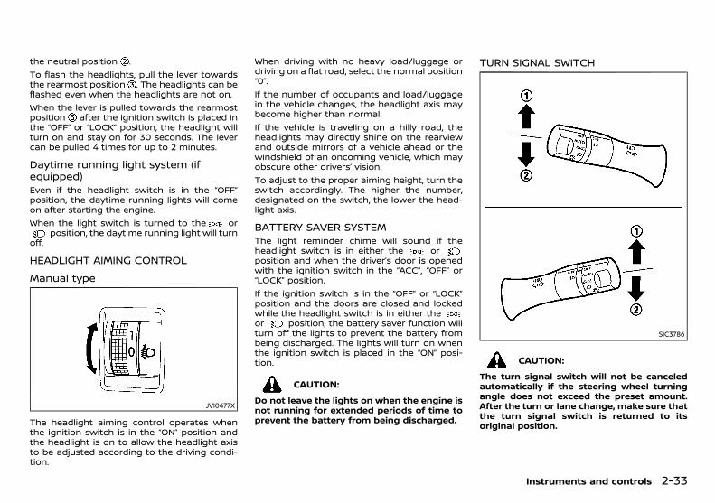
(87,1)
[ Edit: 2018/ 5/ 25 Model: PD23-A ]
the neutral position .To flash the headlights, pull the lever towardsthe rearmost position . The headlights can beflashed even when the headlights are not on.When the lever is pulled towards the rearmostposition after the ignition switch is placed inthe “OFF” or “LOCK” position, the headlight willturn on and stay on for 30 seconds. The levercan be pulled 4 times for up to 2 minutes.
Daytime running light system (ifequipped)
PD23A1-24196D50-C6DD-4A46-9F9C-967D3689AC01Even if the headlight switch is in the “OFF”position, the daytime running lights will comeon after starting the engine.When the light switch is turned to the or
position, the daytime running light will turnoff.
HEADLIGHT AIMING CONTROLPD23A1-59F97C06-0802-4175-A156-C550A1E0F0E5
Manual typePD23A1-1512B768-4E8E-429D-BF23-B8527D88297E
JVI0477X
The headlight aiming control operates whenthe ignition switch is in the “ON” position andthe headlight is on to allow the headlight axisto be adjusted according to the driving condi-tion.
When driving with no heavy load/luggage ordriving on a flat road, select the normal position“0”.If the number of occupants and load/luggagein the vehicle changes, the headlight axis maybecome higher than normal.If the vehicle is traveling on a hilly road, theheadlights may directly shine on the rearviewand outside mirrors of a vehicle ahead or thewindshield of an oncoming vehicle, which mayobscure other drivers’ vision.To adjust to the proper aiming height, turn theswitch accordingly. The higher the number,designated on the switch, the lower the head-light axis.
BATTERY SAVER SYSTEMPD23A1-416BDCC8-32EC-47FE-965C-0EA7AA8E281A
The light reminder chime will sound if theheadlight switch is in either the orposition and when the driver’s door is openedwith the ignition switch in the “ACC”, “OFF” or“LOCK” position.If the ignition switch is in the “OFF” or “LOCK”position and the doors are closed and lockedwhile the headlight switch is in either theor position, the battery saver function willturn off the lights to prevent the battery frombeing discharged. The lights will turn on whenthe ignition switch is placed in the “ON” posi-tion.
CAUTION:
Do not leave the lights on when the engine isnot running for extended periods of time toprevent the battery from being discharged.
TURN SIGNAL SWITCHPD23A1-E756AA92-11EB-46FA-A0DF-E301D3A32C48
SIC3786
CAUTION:
The turn signal switch will not be canceledautomatically if the steering wheel turningangle does not exceed the preset amount.After the turn or lane change, make sure thatthe turn signal switch is returned to itsoriginal position.
Instruments and controls 2-33
Condition: 'Except for China'/
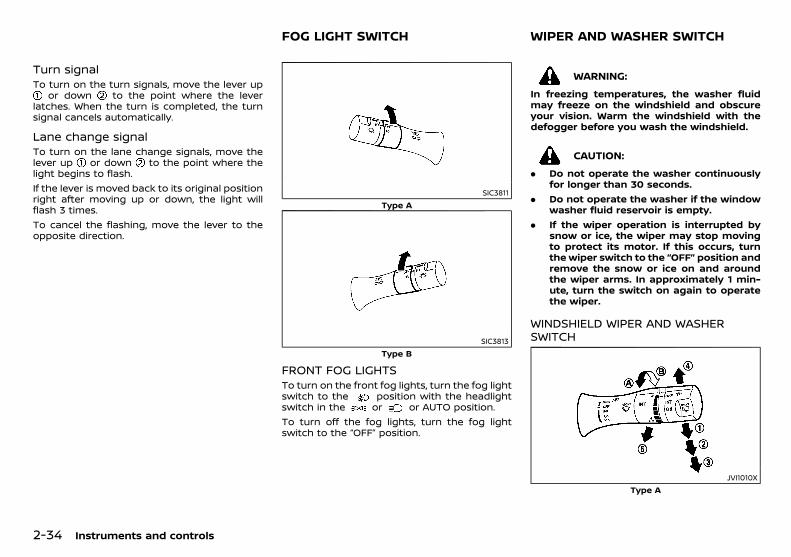
(88,1)
[ Edit: 2018/ 5/ 25 Model: PD23-A ]
2-34 Instruments and controls
Turn signalPD23A1-B798680C-0546-4E1F-A232-689AFE376B87
To turn on the turn signals, move the lever upor down to the point where the lever
latches. When the turn is completed, the turnsignal cancels automatically.
Lane change signalPD23A1-BDB58A07-C1CC-4CA8-A2BB-73EC4F9E5FD7
To turn on the lane change signals, move thelever up or down to the point where thelight begins to flash.If the lever is moved back to its original positionright after moving up or down, the light willflash 3 times.To cancel the flashing, move the lever to theopposite direction.
PD23A1-011E9CC1-DA20-416E-A390-DC409772A27C
SIC3811Type A
SIC3813Type B
FRONT FOG LIGHTSPD23A1-E1E703A4-8F0E-4356-9671-F82D9C08FF2C
To turn on the front fog lights, turn the fog lightswitch to the position with the headlightswitch in the or or AUTO position.To turn off the fog lights, turn the fog lightswitch to the “OFF” position.
PD23A1-28323B90-2B96-4C32-A0F2-BC87FE71DD71
WARNING:
In freezing temperatures, the washer fluidmay freeze on the windshield and obscureyour vision. Warm the windshield with thedefogger before you wash the windshield.
CAUTION:
. Do not operate the washer continuouslyfor longer than 30 seconds.
. Do not operate the washer if the windowwasher fluid reservoir is empty.
. If the wiper operation is interrupted bysnow or ice, the wiper may stop movingto protect its motor. If this occurs, turnthe wiper switch to the “OFF” position andremove the snow or ice on and aroundthe wiper arms. In approximately 1 min-ute, turn the switch on again to operatethe wiper.
WINDSHIELD WIPER AND WASHERSWITCH
PD23A1-E1F8A672-3BE2-4AE4-9491-C85650BBA454
JVI1010XType A
FOG LIGHT SWITCH WIPER AND WASHER SWITCH
Condition: 'Except for China'/

(89,1)
[ Edit: 2018/ 5/ 25 Model: PD23-A ]
JVI1141XType B
The windshield wiper and washer operatewhen the ignition switch is in the “ON” position.
Wiper operationPD23A1-6DF76079-383B-4207-8A41-F4630E87AB5B
The lever position “INT” operates the wiperintermittently.The intermittent operation can be adjusted byturning the adjustment control knob, (longer)
or (shorter) .The lever position “LO” operates the wiper atlow speed.The lever position “HI” operates the wiper athigh speed.To stop the wiper operation, move the lever upto the “OFF” position.The lever position “MIST” operates the wiperone sweep. The lever automatically returns toits original position.
Washer operationPD23A1-5268D467-1F46-4E5E-BBC6-BD09FA5B4906
To operate the washer, pull the lever towardthe back of the vehicle until the desiredamount of washer fluid is spread on the wind-shield. The wiper will automatically operateseveral times.
REAR WINDOW WIPER AND WASHERSWITCH
GUID-DF1DF640-8B84-4386-B618-BA217AE9CE27
JVI1014XType A
JVI1824XType B
The rear window wiper and washer operateswhen the ignition switch is in the “ON” position.
Wiper operationGUID-DD5A35EF-DA89-47C4-9BFD-65EADA9CCC51
The switch position “INT” operates the wiperintermittently.The switch position “ON” operates the wiperat low speed.If the rear window wiper operation is inter-rupted by snow or ice, the wiper may stopmoving to protect its motor. If this occurs,turn the wiper switch to the “OFF” positionand remove the snow or ice on and aroundthe wiper arms. In approximately 1 minute,turn the switch on again to operate thewiper.
Washer operationGUID-916B4E2C-C6A7-4F16-9BA7-B5A90B40CB5F
To operate the washer, push the lever towardthe front of the vehicle until the desiredamount of washer fluid is spread on the wind-shield. The wiper will automatically operateseveral times.
Instruments and controls 2-35
Condition: 'Except for China'/
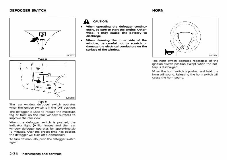
(90,1)
[ Edit: 2018/ 5/ 25 Model: PD23-A ]
2-36 Instruments and controls
PD23A1-BBFFE30E-1D67-4D70-B145-F3EE746350C3
SIC3537Type A
JVI1583XType B
The rear window defogger switch operateswhen the ignition switch is in the “ON” position.The defogger is used to reduce the moisture,fog or frost on the rear window surfaces toimprove the rear view.When the defogger switch is pushed, theindicator light illuminates and the rearwindow defogger operates for approximately15 minutes. After the preset time has passed,the defogger will turn off automatically.To turn off manually, push the defogger switchagain.
CAUTION:
. When operating the defogger continu-ously, be sure to start the engine. Other-wise, it may cause the battery todischarge.
. When cleaning the inner side of thewindow, be careful not to scratch ordamage the electrical conductors on thesurface of the window.
PD23A1-558C3494-5C96-43AB-A3EA-176750978BB3
JVI1755X
The horn switch operates regardless of theignition switch position except when the bat-tery is discharged.When the horn switch is pushed and held, thehorn will sound. Releasing the horn switch willcease the horn sound.
DEFOGGER SWITCH HORN
Condition: 'Except for China'/
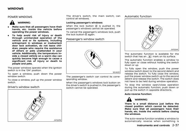
(91,1)
[ Edit: 2018/ 5/ 25 Model: PD23-A ]
PD23A1-037EA0C9-B46E-4467-B8E3-89747E9741CA
POWER WINDOWSPD23A1-35852136-64F1-4351-B8D2-2E6C10EEC8C1
WARNING:
. Make sure that all passengers have theirhands, etc. inside the vehicle beforeoperating the power windows.
. To help avoid risk of injury or deaththrough unintended operation of thevehicle and or its systems, includingentrapment in windows or inadvertentdoor lock activation, do not leave chil-dren, people who require the assistanceof others or pets unattended in yourvehicle. Additionally, the temperature in-side a closed vehicle on a warm day canquickly become high enough to cause asignificant risk of injury or death topeople and pets.
The power windows operate when the ignitionswitch is in the “ON” position.To open a window, push down the powerwindow switch.To close a window, pull up the power windowswitch.
Driver’s window switchPD23A1-A8E42E06-21A6-4EC7-ABEA-D7F6E652DC13
JVI1223X
The driver’s switch, the main switch, cancontrol all windows.
Locking passenger’s windows:GUID-9E14C2E6-2E9C-4731-980B-C45B899B977B
When the lock button is pushed in, thepassenger’s windows cannot be operated.To cancel the passenger’s windows lock, pushthe lock button again.
Passenger’s window switchPD23A1-31131CC7-3972-47B2-B4CA-1F394EF31CE1
SIC4523
The passenger’s switch can control its corre-sponding window.When the passenger’s windows lock button onthe driver’s switch is pushed in, the passenger’sswitch cannot be operated.
Automatic functionPD23A1-086B8371-8520-48F8-8013-A86E8DEA1B2C
JVI1224X
The automatic function is available for theswitch that has an mark on its surface.The automatic function enables a window tofully open or close without holding the switchdown or up.To fully open the window, push the powerwindow switch down to the second detent andrelease the switch. To fully close the window,pull the power window switch up to the seconddetent and release the switch. The switch doesnot have to be held during window operation.To stop the window open/close operationduring the automatic function, push down orpull up the switch in opposite directions.
Auto-reverse function:GUID-9E14C2E6-2E9C-4731-980B-C45B899B977B
WARNING:
There is a small distance just before theclosed position which cannot be detected.Make sure that all passengers have theirhands, etc. inside the vehicle before closingthe windows.
The auto-reverse function enables a window toautomatically reverse when something is
Instruments and controls 2-37
WINDOWS
Condition: 'Except for China'/
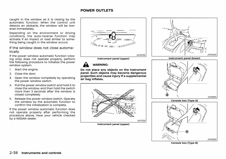
(92,1)
[ Edit: 2018/ 5/ 25 Model: PD23-A ]
2-38 Instruments and controls
caught in the window as it is closing by theautomatic function. When the control unitdetects an obstacle, the window will be low-ered immediately.Depending on the environment or drivingconditions, the auto-reverse function mayactivate if an impact or load similar to some-thing being caught in the window occurs.
If the window does not close automa-tically
PD23A1-C8E5C0D9-FFC3-40EE-9451-22704D8C1A99If the power window automatic function (clos-ing only) does not operate properly, performthe following procedure to initialize the powerwindow system.1. Start the engine.2. Close the door.3. Open the window completely by operating
the power window switch.4. Pull the power window switch and hold it to
close the window, and then hold the switchmore than 3 seconds after the window isclosed completely.
5. Release the power window switch. Operatethe window by the automatic function toconfirm the initialization is complete.
If the power window automatic function doesnot operate properly after performing theprocedure above, have your vehicle checkedby a NISSAN dealer.
PD23A1-71B10566-178F-44B7-9586-EB31A2CB2FF1
JVI1023XInstrument panel (upper)
WARNING:
Do not place any objects on the instrumentpanel. Such objects may become dangerousprojectiles and cause injury if a supplementalair bag inflates.
JVI1110XInstrument panel (upper)
JVI1024XInstrument panel (lower)
JVI1585XConsole box (Type A)
JVI1025XConsole box (Type B)
POWER OUTLETS
Condition: 'Except for China'/

(93,1)
[ Edit: 2018/ 5/ 25 Model: PD23-A ]
JVI1759XCargo area
The power outlet is used for powering electricalaccessories.Use the cutout between the lid and theconsole box to use a powering cable with theconsole box lid closed.
CAUTION:
. Do not leave a power cable on theinstrument panel in direct sunlight. Thesurface of the instrument panel maybecome very hot resulting in damage tothe power cable.
. Do not put a liquid container near thepower outlet. Spilled contents may getinto the power outlet and can result in amalfunction.
. The outlet and plug may be hot during orimmediately after use.
. This power outlet is not designed for usewith a cigarette lighter unit.
. Do not use accessories that exceed acombined power draw of 12 volt, 120W(10A). Do not use double adapters ormore than one electrical accessory.
. Use this power outlet with the enginerunning to avoid discharging the vehiclebattery.
. Avoid using when the air conditioner,headlights or rear window defogger is on.
. Push the plug in as far as it will go. If goodcontact is not made, the plug may over-heat or the internal temperature fusemay blow.
. Before inserting or disconnecting a plug,be sure that the electrical accessorybeing used is turned OFF.
. When not in use, be sure to close the cap.Do not allow water or any liquid tocontact the outlet.
PD23A1-E4DBC035-E53E-4441-88DA-A00F0E88CB21
WARNING:
. The storages should not be used whiledriving so that the full attention may begiven to vehicle operation.
. Keep the storage lids closed while drivingto help prevent injury in an accident or asudden stop.
GLOVE BOXPD23A1-EFAE8038-23E5-4DB0-AA90-2DED70AADF90
JVI1102X
To open the glove box, pull the handle .To close, push the lid in until the lock latches.
CONSOLE BOXPD23A1-2672CD53-B1EA-41EA-B2BA-1708E1C54DBD
JVI1588X
Instruments and controls 2-39
STORAGE
Condition: 'Except for China'/
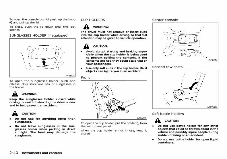
(94,1)
[ Edit: 2018/ 5/ 25 Model: PD23-A ]
2-40 Instruments and controls
To open the console box lid, push up the knoband pull up the lid.
To close, push the lid down until the locklatches.
SUNGLASSES HOLDER (if equipped)PD23A1-BE56EC99-6D94-411E-957E-594FAF359F97
JVI0619X
To open the sunglasses holder, push andrelease. Only store one pair of sunglasses inthe holder.
WARNING:
Keep the sunglasses holder closed whiledriving to avoid obstructing the driver’s viewand to help prevent an accident.
CAUTION:
. Do not use for anything other thansunglasses.
. Do not leave sunglasses in the sun-glasses holder while parking in directsunlight. The heat may damage thesunglasses.
CUP HOLDERSPD23A1-254417BA-3214-47CC-8182-9A8F0C55B921
WARNING:
The driver must not remove or insert cupsinto the cup holder while driving so that fullattention may be given to vehicle operation.
CAUTION:
. Avoid abrupt starting and braking espe-cially when the cup holder is being usedto prevent spilling the contents. If thecontents are hot, they could scald you oryour passengers.
. Use only soft cups in the cup holder. Hardobjects can injure you in an accident.
FrontGUID-E7C16608-1BA1-4F17-AACB-E70E01FE92F9
JVI1028X
To open the cup holder, pull the holder fromthe instrument panel.When the cup holder is not in use, keep itstored.
Center consolePD23A1-E3118FBB-283B-4006-91F6-FF2F5C0021D3
JVI1828X
Second row seatsGUID-F54705F0-670E-4DFE-8246-29B9B19315BF
JVR0589X
Soft bottle holdersPD23A1-61EFB93A-87D5-44A0-BA9E-DFAAA14CFFC7
CAUTION:
. Do not use bottle holder for any otherobjects that could be thrown about in thevehicle and possibly injure people duringsudden braking or an accident.
. Do not use bottle holder for open liquidcontainers.
Condition: 'Except for China'/

(95,1)
[ Edit: 2018/ 5/ 25 Model: PD23-A ]
Front seat and second row seat:GUID-9E14C2E6-2E9C-4731-980B-C45B899B977B
JVI1241X
The front and second row seat soft bottleholders are located on the doors.
Third row seat:GUID-9E14C2E6-2E9C-4731-980B-C45B899B977B
JVI1829X
ROOF RACKPD23A1-A254913F-D72A-475B-BC9B-87AC5AA250F7
JVI1575X
Do not apply any load directly to the roof siderails. Cross bars must be installed beforeapplying load/cargo/luggage to the roof ofthe vehicle. Genuine NISSAN accessory crossbars are available through a NISSAN dealer.Contact a NISSAN dealer for additional infor-mation.The service load capacity for the roof side railsis not more than 100 kg (221 lb), however do notexceed the accessory cross bars load capacity.
WARNING:
. Always install the cross bars onto theroof side rails before loading cargo of anykind. Loading cargo directly onto the roofside rails or the vehicle’s roof may causevehicle damage.
. Drive extra carefully when the vehicle isloaded at or near the cargo carryingcapacity, especially if the significant por-tion of that load is carried on the roofrack.
. Heavy loading of the roof rack has thepotential to affect the vehicle stabilityand handling during sudden or unusual
handling maneuvers.. Roof rack load should be evenly distrib-
uted.. Do not exceed maximum roof rack load
weight capacity.. Properly secure all cargo with ropes or
straps to help prevent it from sliding orshifting. In a sudden stop or collision,unsecured cargo could cause personalinjury.
LUGGAGE HOOKSGUID-5371DE93-9AA3-4DB6-B44A-78282682317A
JVI1830X
The hooks are located in the luggage area.
CAUTION:
. Always make sure that the luggage isproperly secured. Use the suitable ropesand hooks.
. Unsecured luggage can become danger-ous in an accident or sudden stop.
. Do not apply a total load of more than 3kg (7 lb) or 10 kg (22 lb) to a singlehook.
Instruments and controls 2-41
Condition: 'Except for China'/
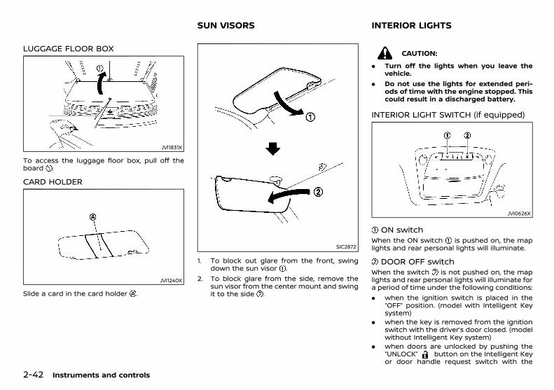
(96,1)
[ Edit: 2018/ 5/ 25 Model: PD23-A ]
2-42 Instruments and controls
LUGGAGE FLOOR BOXGUID-BF905898-2AE6-484C-AD83-941F6CF4419B
JVI1831X
To access the luggage floor box, pull off theboard .
CARD HOLDERGUID-975AB4D7-A123-400E-9106-91B7FD171048
JVI1240X
Slide a card in the card holder .
PD23A1-9FAD8DB4-278F-4DB9-847D-80BB3C4BAFC1
SIC2872
1. To block out glare from the front, swingdown the sun visor .
2. To block glare from the side, remove thesun visor from the center mount and swingit to the side .
PD23A1-FA9338D7-11A2-43A6-8438-0B351CFC6054
CAUTION:
. Turn off the lights when you leave thevehicle.
. Do not use the lights for extended peri-ods of time with the engine stopped. Thiscould result in a discharged battery.
INTERIOR LIGHT SWITCH (if equipped)PD23A1-98E7A242-41BF-4789-A1EC-E6A77067A5B5
JVI0626X
ON switchGUID-775DDD43-6DCE-45DC-9356-980249600CEB
When the ON switch is pushed on, the maplights and rear personal lights will illuminate.
DOOR OFF switchGUID-9C6333B6-D61D-4ACE-86B7-7184BD473A55
When the switch is not pushed on, the maplights and rear personal lights will illuminate fora period of time under the following conditions:. when the ignition switch is placed in the
“OFF” position. (model with Intelligent Keysystem)
. when the key is removed from the ignitionswitch with the driver’s door closed. (modelwithout Intelligent Key system)
. when doors are unlocked by pushing the“UNLOCK” button on the Intelligent Keyor door handle request switch with the
SUN VISORS INTERIOR LIGHTS
Condition: 'Except for China'/
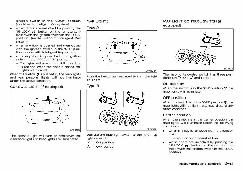
(97,1)
[ Edit: 2018/ 5/ 25 Model: PD23-A ]
ignition switch in the “LOCK” position.(model with Intelligent Key system)
. when doors are unlocked by pushing the“UNLOCK” button on the remote con-troller with the ignition switch in the “LOCK”position. (model without Intelligent Keysystem)
. when any door is opened and then closedwith the ignition switch in the “OFF” posi-tion. (model with Intelligent Key system)
. when any door is opened with the ignitionswitch in the “ACC” or “ON” position.— The lights will remain on while the door
is opened. When the door is closed, thelights will turn off.
When the switch is pushed in, the map lightsand rear personal lights will not illuminateunder the above condition.
CONSOLE LIGHT (if equipped)PD23A1-BE418176-8CF4-429E-996B-B8C81B5AA92C
JVI0627X
The console light will turn on whenever theclearance lights or headlights are illuminated.
MAP LIGHTSPD23A1-9A3E5C9F-5F2F-4425-8052-22F0EA398925
Type APD23A1-6EE2A1AB-A4D0-4841-A834-CEEC7B93BA7C
JVI0628X
Push the button as illustrated to turn the lighton or off.
Type BPD23A1-631C4AC0-D45C-48D7-BB40-322070A06A68
SIC4572
Operate the map light switch to turn the maplight on or off.
: ON position: OFF position
MAP LIGHT CONTROL SWITCH (ifequipped)
PD23A1-C4604864-748A-4907-85B7-53F512975704
SIC4573
The map lights control switch has three posi-tions: ON , OFF and center.
ON positionPD23A1-4502A2EF-9192-423A-8F0C-9B9C706AFC49
When the switch is in the “ON” position , themap lights will illuminate.
OFF positionPD23A1-6BC9F6AB-6F4D-4628-8A64-504F73946DD6
When the switch is in the “OFF” position , themap lights will not illuminate, regardless of anyother condition.
Center positionGUID-2016EF92-7BFB-41D3-990B-60E2A9F6F97A
When the switch is in the center position, themap lights will illuminate under the followingconditions:. when the key is removed from the ignition
switch— remain on for a period of time.
. when doors are unlocked by pushing the“UNLOCK” button on the remote con-troller with the ignition switch in the “LOCK”position
Instruments and controls 2-43
Condition: 'Except for China'/
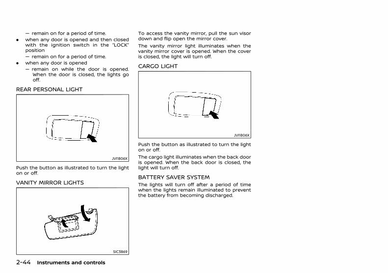
(98,1)
[ Edit: 2018/ 5/ 25 Model: PD23-A ]
2-44 Instruments and controls
— remain on for a period of time.. when any door is opened and then closed
with the ignition switch in the “LOCK”position— remain on for a period of time.
. when any door is opened— remain on while the door is opened.
When the door is closed, the lights gooff.
REAR PERSONAL LIGHTPD23A1-BDBEDFC0-D9C6-412F-B54E-4DD962C48041
JVI1806X
Push the button as illustrated to turn the lighton or off.
VANITY MIRROR LIGHTSGUID-3D6DF402-21C3-4E39-840F-146F19E5BDD2
SIC3869
To access the vanity mirror, pull the sun visordown and flip open the mirror cover.The vanity mirror light illuminates when thevanity mirror cover is opened. When the coveris closed, the light will turn off.
CARGO LIGHTGUID-129D93D3-196C-442B-96B9-BFD4E8FD143B
JVI1806X
Push the button as illustrated to turn the lighton or off.The cargo light illuminates when the back dooris opened. When the back door is closed, thelight will turn off.
BATTERY SAVER SYSTEMPD23A1-C241DC06-FBF7-4835-95A1-DEC0F43BB5C8
The lights will turn off after a period of timewhen the lights remain illuminated to preventthe battery from becoming discharged.
Condition: 'Except for China'/
(99,1)
[ Edit: 2018/ 5/ 25 Model: PD23-A ]
3 Pre-driving checks and adjustments
Keys ............................................................................................................................. 3-2NISSAN Anti-Theft System (NATS) key(if equipped) ................................................................................................... 3-2Intelligent Key (if equipped) .............................................................. 3-2
Doors .......................................................................................................................... 3-3Locking with key ........................................................................................ 3-3Locking with inside lock knob ........................................................ 3-3Locking with power door lock switch ...................................... 3-4Child safety rear door locks ............................................................. 3-4
Remote keyless entry system (if equipped) ................................ 3-4Using remote keyless entry system ........................................... 3-5
Intelligent Key system (if equipped) .................................................. 3-5Intelligent Key operating range ..................................................... 3-7Using Intelligent Key system ............................................................ 3-7Battery saver system ............................................................................. 3-9Warning and audible reminders .................................................... 3-9Troubleshooting guide ...................................................................... 3-10Using remote keyless entry system ........................................ 3-12Hazard indicator and horn operation ................................... 3-12
Security system .............................................................................................. 3-14Theft warning system ..................................................................... 3-14NISSAN Anti-Theft System (NATS) .......................................... 3-14
Hood ........................................................................................................................ 3-15Opening hood ........................................................................................ 3-16Closing hood ........................................................................................... 3-16
Back door ............................................................................................................ 3-16Opening back door ............................................................................ 3-17Closing back door ............................................................................... 3-17Back door release lever .................................................................. 3-17
Fuel-filler lid ....................................................................................................... 3-18Opening fuel-filler lid ........................................................................ 3-18Fuel-filler cap .......................................................................................... 3-18
Steering wheel ................................................................................................ 3-18Steering wheel adjustment ......................................................... 3-18
Mirrors .................................................................................................................... 3-19Inside rearview mirror ..................................................................... 3-19Outside rearview mirrors .............................................................. 3-24Vanity mirror ........................................................................................... 3-24
Parking brake ................................................................................................... 3-25
Condition: 'Except for China'/
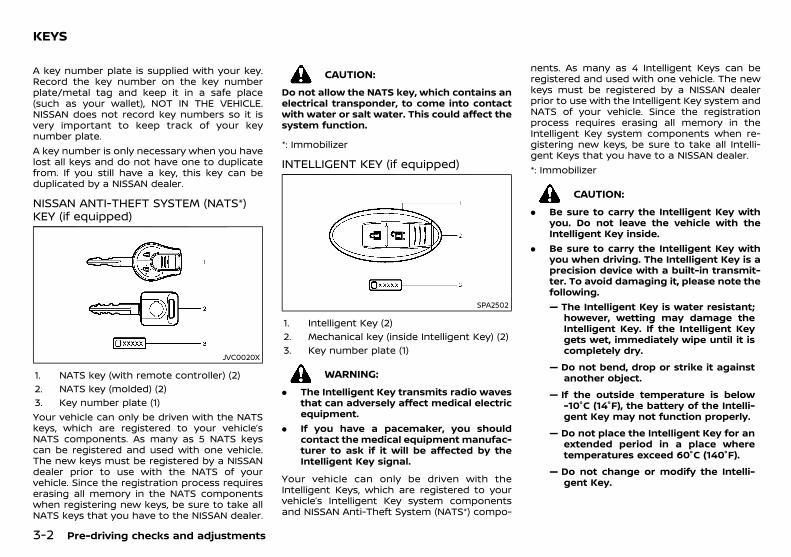
(100,1)
[ Edit: 2018/ 5/ 25 Model: PD23-A ]
3-2 Pre-driving checks and adjustments
PD23A1-ACCC2553-DC55-48E0-B662-29078F813DF5A key number plate is supplied with your key.Record the key number on the key numberplate/metal tag and keep it in a safe place(such as your wallet), NOT IN THE VEHICLE.NISSAN does not record key numbers so it isvery important to keep track of your keynumber plate.A key number is only necessary when you havelost all keys and do not have one to duplicatefrom. If you still have a key, this key can beduplicated by a NISSAN dealer.
NISSAN ANTI-THEFT SYSTEM (NATS*)KEY (if equipped)
PD23A1-0232DA76-8001-49B1-A511-7B7B4E425213
JVC0020X
1. NATS key (with remote controller) (2)2. NATS key (molded) (2)3. Key number plate (1)Your vehicle can only be driven with the NATSkeys, which are registered to your vehicle’sNATS components. As many as 5 NATS keyscan be registered and used with one vehicle.The new keys must be registered by a NISSANdealer prior to use with the NATS of yourvehicle. Since the registration process requireserasing all memory in the NATS componentswhen registering new keys, be sure to take allNATS keys that you have to the NISSAN dealer.
CAUTION:
Do not allow the NATS key, which contains anelectrical transponder, to come into contactwith water or salt water. This could affect thesystem function.
*: Immobilizer
INTELLIGENT KEY (if equipped)PD23A1-EC72DF8E-3839-4A10-B653-5A3C21AA4EAA
SPA2502
1. Intelligent Key (2)2. Mechanical key (inside Intelligent Key) (2)3. Key number plate (1)
WARNING:
. The Intelligent Key transmits radio wavesthat can adversely affect medical electricequipment.
. If you have a pacemaker, you shouldcontact the medical equipment manufac-turer to ask if it will be affected by theIntelligent Key signal.
Your vehicle can only be driven with theIntelligent Keys, which are registered to yourvehicle’s Intelligent Key system componentsand NISSAN Anti-Theft System (NATS*) compo-
nents. As many as 4 Intelligent Keys can beregistered and used with one vehicle. The newkeys must be registered by a NISSAN dealerprior to use with the Intelligent Key system andNATS of your vehicle. Since the registrationprocess requires erasing all memory in theIntelligent Key system components when re-gistering new keys, be sure to take all Intelli-gent Keys that you have to a NISSAN dealer.*: Immobilizer
CAUTION:
. Be sure to carry the Intelligent Key withyou. Do not leave the vehicle with theIntelligent Key inside.
. Be sure to carry the Intelligent Key withyou when driving. The Intelligent Key is aprecision device with a built-in transmit-ter. To avoid damaging it, please note thefollowing.— The Intelligent Key is water resistant;
however, wetting may damage theIntelligent Key. If the Intelligent Keygets wet, immediately wipe until it iscompletely dry.
— Do not bend, drop or strike it againstanother object.
— If the outside temperature is below-10°C (14°F), the battery of the Intelli-gent Key may not function properly.
— Do not place the Intelligent Key for anextended period in a place wheretemperatures exceed 60°C (140°F).
— Do not change or modify the Intelli-gent Key.
KEYS
Condition: 'Except for China'/
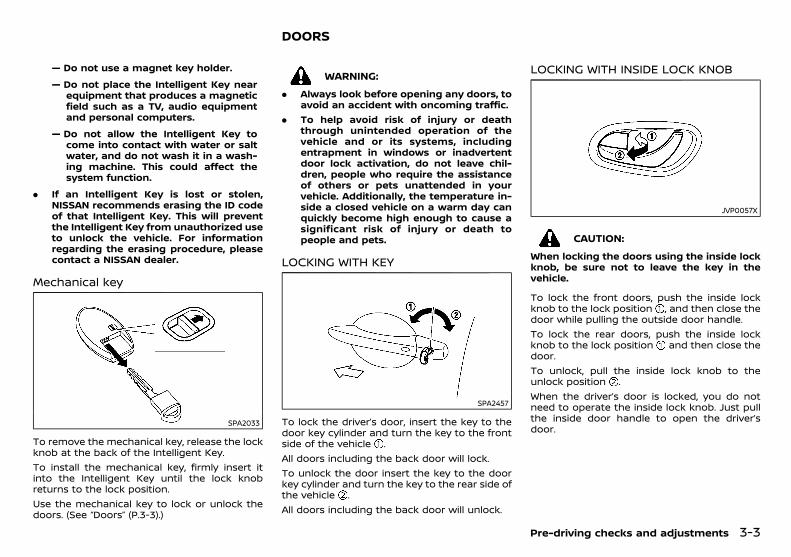
(101,1)
[ Edit: 2018/ 5/ 25 Model: PD23-A ]
— Do not use a magnet key holder.
— Do not place the Intelligent Key nearequipment that produces a magneticfield such as a TV, audio equipmentand personal computers.
— Do not allow the Intelligent Key tocome into contact with water or saltwater, and do not wash it in a wash-ing machine. This could affect thesystem function.
. If an Intelligent Key is lost or stolen,NISSAN recommends erasing the ID codeof that Intelligent Key. This will preventthe Intelligent Key from unauthorized useto unlock the vehicle. For informationregarding the erasing procedure, pleasecontact a NISSAN dealer.
Mechanical keyPD23A1-27686E3E-B0BA-4AE2-BC3C-098622CFBBB4
SPA2033
To remove the mechanical key, release the lockknob at the back of the Intelligent Key.To install the mechanical key, firmly insert itinto the Intelligent Key until the lock knobreturns to the lock position.Use the mechanical key to lock or unlock thedoors. (See “Doors” (P.3-3).)
PD23A1-31D89129-E8CB-49D1-AFC6-56EC9681D9FC
WARNING:
. Always look before opening any doors, toavoid an accident with oncoming traffic.
. To help avoid risk of injury or deaththrough unintended operation of thevehicle and or its systems, includingentrapment in windows or inadvertentdoor lock activation, do not leave chil-dren, people who require the assistanceof others or pets unattended in yourvehicle. Additionally, the temperature in-side a closed vehicle on a warm day canquickly become high enough to cause asignificant risk of injury or death topeople and pets.
LOCKING WITH KEYPD23A1-8B237026-903C-4D03-957E-B72E3EA5A527
SPA2457
To lock the driver’s door, insert the key to thedoor key cylinder and turn the key to the frontside of the vehicle .All doors including the back door will lock.To unlock the door insert the key to the doorkey cylinder and turn the key to the rear side ofthe vehicle .All doors including the back door will unlock.
LOCKING WITH INSIDE LOCK KNOBPD23A1-400056F2-0846-4545-85D1-1C86A35F664C
JVP0057X
CAUTION:
When locking the doors using the inside lockknob, be sure not to leave the key in thevehicle.
To lock the front doors, push the inside lockknob to the lock position , and then close thedoor while pulling the outside door handle.To lock the rear doors, push the inside lockknob to the lock position and then close thedoor.To unlock, pull the inside lock knob to theunlock position .When the driver’s door is locked, you do notneed to operate the inside lock knob. Just pullthe inside door handle to open the driver’sdoor.
Pre-driving checks and adjustments 3-3
DOORS
Condition: 'Except for China'/
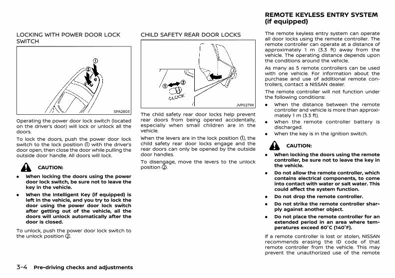
(102,1)
[ Edit: 2018/ 5/ 25 Model: PD23-A ]
3-4 Pre-driving checks and adjustments
LOCKING WITH POWER DOOR LOCKSWITCH
PD23A1-C1BC5CD1-4D66-45B1-AC0C-C52510A64912
SPA2803
Operating the power door lock switch (locatedon the driver’s door) will lock or unlock all thedoors.To lock the doors, push the power door lockswitch to the lock position with the driver’sdoor open, then close the door while pulling theoutside door handle. All doors will lock.
CAUTION:
. When locking the doors using the powerdoor lock switch, be sure not to leave thekey in the vehicle.
. When the Intelligent Key (if equipped) isleft in the vehicle, and you try to lock thedoor using the power door lock switchafter getting out of the vehicle, all thedoors will unlock automatically after thedoor is closed.
To unlock, push the power door lock switch tothe unlock position .
CHILD SAFETY REAR DOOR LOCKSPD23A1-4B3CD9E9-F4E3-43CB-B0BE-19EF1A341CCC
JVP0279X
The child safety rear door locks help preventrear doors from being opened accidentally,especially when small children are in thevehicle.When the levers are in the lock position , thechild safety rear door locks engage and therear doors can only be opened by the outsidedoor handles.To disengage, move the levers to the unlockposition .
PD23A1-09F7F79E-992E-4950-B016-A3D343FC0919The remote keyless entry system can operateall door locks using the remote controller. Theremote controller can operate at a distance ofapproximately 1 m (3.3 ft) away from thevehicle. The operating distance depends uponthe conditions around the vehicle.As many as 5 remote controllers can be usedwith one vehicle. For information about thepurchase and use of additional remote con-trollers, contact a NISSAN dealer.The remote controller will not function underthe following conditions:. When the distance between the remote
controller and vehicle is more than approxi-mately 1 m (3.3 ft).
. When the remote controller battery isdischarged.
. When the key is in the ignition switch.
CAUTION:
. When locking the doors using the remotecontroller, be sure not to leave the key inthe vehicle.
. Do not allow the remote controller, whichcontains electrical components, to comeinto contact with water or salt water. Thiscould affect the system function.
. Do not drop the remote controller.
. Do not strike the remote controller shar-ply against another object.
. Do not place the remote controller for anextended period in an area where tem-peratures exceed 60°C (140°F).
If a remote controller is lost or stolen, NISSANrecommends erasing the ID code of thatremote controller from the vehicle. This mayprevent the unauthorized use of the remote
REMOTE KEYLESS ENTRY SYSTEM(if equipped)
Condition: 'Except for China'/
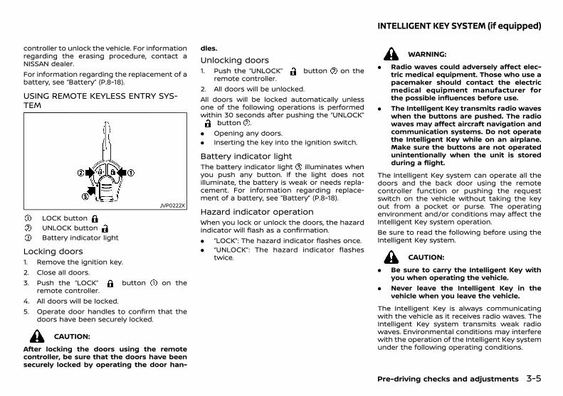
(103,1)
[ Edit: 2018/ 5/ 25 Model: PD23-A ]
controller to unlock the vehicle. For informationregarding the erasing procedure, contact aNISSAN dealer.For information regarding the replacement of abattery, see “Battery” (P.8-18).
USING REMOTE KEYLESS ENTRY SYS-TEM
PD23A1-AEEF344D-D897-46C0-84FD-B3934F636671
JVP0222X
LOCK buttonUNLOCK buttonBattery indicator light
Locking doorsPD23A1-366F2691-DCAF-4D8C-902D-0F5253D6A5DF
1. Remove the ignition key.2. Close all doors.3. Push the “LOCK” button on the
remote controller.4. All doors will be locked.5. Operate door handles to confirm that the
doors have been securely locked.
CAUTION:
After locking the doors using the remotecontroller, be sure that the doors have beensecurely locked by operating the door han-
dles.
Unlocking doorsPD23A1-48226AD4-4444-40FD-B291-87D3CECC6ECC
1. Push the “UNLOCK” button on theremote controller.
2. All doors will be unlocked.All doors will be locked automatically unlessone of the following operations is performedwithin 30 seconds after pushing the “UNLOCK”
button .. Opening any doors.. Inserting the key into the ignition switch.
Battery indicator lightPD23A1-4F9CC3F0-1407-48F7-8809-8F2A199AB6C8
The battery indicator light illuminates whenyou push any button. If the light does notilluminate, the battery is weak or needs repla-cement. For information regarding replace-ment of a battery, see “Battery” (P.8-18).
Hazard indicator operationPD23A1-E0034020-ACFD-4033-B233-6B8EEA7AB85D
When you lock or unlock the doors, the hazardindicator will flash as a confirmation.. “LOCK”: The hazard indicator flashes once.. “UNLOCK”: The hazard indicator flashes
twice.
GUID-367B5ED7-FE42-4F94-8001-97D84E83872E
WARNING:
. Radio waves could adversely affect elec-tric medical equipment. Those who use apacemaker should contact the electricmedical equipment manufacturer forthe possible influences before use.
. The Intelligent Key transmits radio waveswhen the buttons are pushed. The radiowaves may affect aircraft navigation andcommunication systems. Do not operatethe Intelligent Key while on an airplane.Make sure the buttons are not operatedunintentionally when the unit is storedduring a flight.
The Intelligent Key system can operate all thedoors and the back door using the remotecontroller function or pushing the requestswitch on the vehicle without taking the keyout from a pocket or purse. The operatingenvironment and/or conditions may affect theIntelligent Key system operation.Be sure to read the following before using theIntelligent Key system.
CAUTION:
. Be sure to carry the Intelligent Key withyou when operating the vehicle.
. Never leave the Intelligent Key in thevehicle when you leave the vehicle.
The Intelligent Key is always communicatingwith the vehicle as it receives radio waves. TheIntelligent Key system transmits weak radiowaves. Environmental conditions may interferewith the operation of the Intelligent Key systemunder the following operating conditions.
Pre-driving checks and adjustments 3-5
INTELLIGENT KEY SYSTEM (if equipped)
Condition: 'Except for China'/
(104,1)
[ Edit: 2018/ 5/ 25 Model: PD23-A ]
3-6 Pre-driving checks and adjustments
. When operating near a location wherestrong radio waves are transmitted, suchas a TV tower, power station and broad-casting station.
. When in possession of wireless equipment,such as a cellular telephone, transceiver,and CB radio.
. When the Intelligent Key is in contact withor covered by metallic materials.
. When any type of radio wave remotecontrol is used nearby.
. When the Intelligent Key is placed near anelectric appliance such as a personal com-puter.
In such cases, correct the operating conditionsbefore using the Intelligent Key function or usethe mechanical key.Although the life of the battery varies depend-ing on the operating conditions, the battery’slife is approximately 2 years. If the battery isdischarged, replace it with a new one.For information regarding replacement of abattery, see “Intelligent Key battery” (P.8-20).Since the Intelligent Key is continuously receiv-ing radio waves, if the key is left near equip-ment which transmits strong radio waves, suchas signals from a TV and personal computer,the battery life may become shorter.Because the steering wheel is locked electri-cally, unlocking the steering wheel with theignition switch in the “LOCK” position is im-possible when the vehicle battery is completelydischarged. Pay special attention that thevehicle battery is not completely discharged.As many as 4 Intelligent Keys can be registeredand used with one vehicle. For informationabout the purchase and use of additionalIntelligent Keys, contact a NISSAN dealer.
CAUTION:
. Do not allow the Intelligent Key, whichcontains electrical components, to comeinto contact with water or salt water. Thiscould affect the system function.
. Do not drop the Intelligent Key.
. Do not strike the Intelligent Key sharplyagainst another object.
. Do not change or modify the IntelligentKey.
. Wetting may damage the Intelligent Key.If the Intelligent Key gets wet, immedi-ately wipe until it is completely dry.
. If the outside temperature is below −10°C(14°F), the battery of the Intelligent Keymay not function properly.
. Do not place the Intelligent Key for anextended period in an area where tem-peratures exceed 60°C (140°F).
. Do not attach the Intelligent Key with akey holder that contains a magnet.
. Do not place the Intelligent Key nearequipment that produces a magneticfield, such as a TV, audio equipment andpersonal computers.
If an Intelligent Key is lost or stolen, NISSANrecommends erasing the ID code of thatIntelligent Key from the vehicle. This mayprevent the unauthorized use of the IntelligentKey to operate the vehicle. For informationregarding the erasing procedure, contact aNISSAN dealer.The Intelligent Key function can be disabled.For information about disabling the IntelligentKey function, contact a NISSAN dealer.
Condition: 'Except for China'/
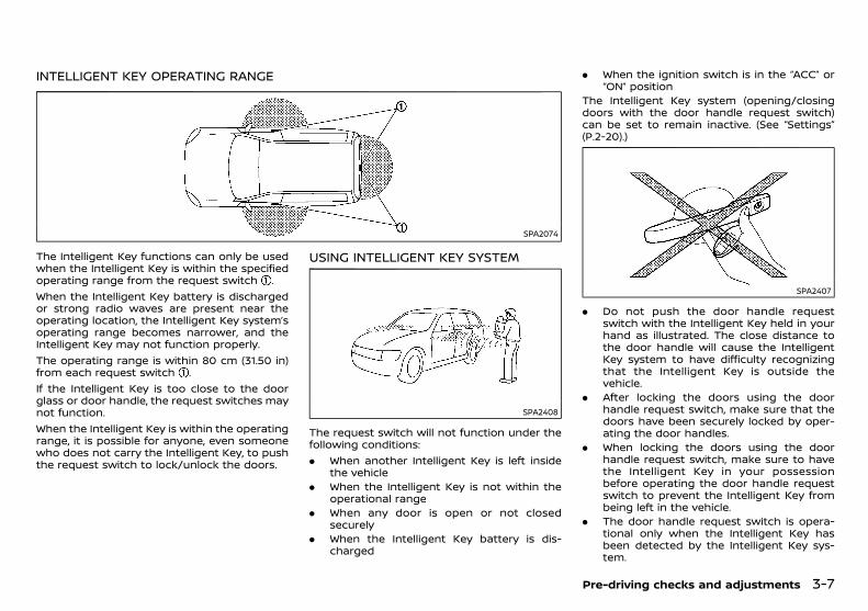
(105,1)
[ Edit: 2018/ 5/ 25 Model: PD23-A ]
INTELLIGENT KEY OPERATING RANGEGUID-42931885-4194-4E80-93A9-AA1E41237E77
SPA2074
The Intelligent Key functions can only be usedwhen the Intelligent Key is within the specifiedoperating range from the request switch .When the Intelligent Key battery is dischargedor strong radio waves are present near theoperating location, the Intelligent Key system’soperating range becomes narrower, and theIntelligent Key may not function properly.The operating range is within 80 cm (31.50 in)from each request switch .If the Intelligent Key is too close to the doorglass or door handle, the request switches maynot function.When the Intelligent Key is within the operatingrange, it is possible for anyone, even someonewho does not carry the Intelligent Key, to pushthe request switch to lock/unlock the doors.
USING INTELLIGENT KEY SYSTEMGUID-090D67B5-5C36-4958-817D-467781DAF44F
SPA2408
The request switch will not function under thefollowing conditions:. When another Intelligent Key is left inside
the vehicle. When the Intelligent Key is not within the
operational range. When any door is open or not closed
securely. When the Intelligent Key battery is dis-
charged
. When the ignition switch is in the “ACC” or“ON” position
The Intelligent Key system (opening/closingdoors with the door handle request switch)can be set to remain inactive. (See “Settings”(P.2-20).)
SPA2407
. Do not push the door handle requestswitch with the Intelligent Key held in yourhand as illustrated. The close distance tothe door handle will cause the IntelligentKey system to have difficulty recognizingthat the Intelligent Key is outside thevehicle.
. After locking the doors using the doorhandle request switch, make sure that thedoors have been securely locked by oper-ating the door handles.
. When locking the doors using the doorhandle request switch, make sure to havethe Intelligent Key in your possessionbefore operating the door handle requestswitch to prevent the Intelligent Key frombeing left in the vehicle.
. The door handle request switch is opera-tional only when the Intelligent Key hasbeen detected by the Intelligent Key sys-tem.
Pre-driving checks and adjustments 3-7
Condition: 'Except for China'/

(106,1)
[ Edit: 2018/ 5/ 25 Model: PD23-A ]
3-8 Pre-driving checks and adjustments
. Do not pull the door handle before pushingthe door handle request switch. The doorwill be unlocked but will not open. Releasethe door handle once and pull it again toopen the door.
SPA2710
SPA2545
When you carry the Intelligent Key with you,you can lock or unlock all doors by pushing thedoor handle request switch (driver’s or frontpassenger’s) or back door request switchwithin the range of operation.When you lock or unlock the doors or open theback door, the hazard indicator will flash andthe outside chime will sound as a confirmation.For details, see “Hazard indicator and hornoperation” (P.3-12).
Welcome light and farewell light func-tion
GUID-5B7D808A-F3B3-43AD-8A5F-1F1C6BC842A4When you lock or unlock the doors, theclearance lights, tail lights and the license platelights will illuminate for a period of time.
Locking doorsGUID-0585D1D2-94DD-4821-B668-85476915C5CE
1. Push the ignition switch to the “OFF”position.
2. Carry the Intelligent Key with you.3. Close all doors.4. Push the door handle request switch
(driver’s or front passenger’s door) or theback door request switch .
5. All doors will be locked.6. Operate door handles to confirm that the
doors have been securely locked.
Lockout protection:GUID-9E14C2E6-2E9C-4731-980B-C45B899B977B
To prevent the Intelligent Key from beingaccidentally locked in the vehicle, lockoutprotection is equipped with the Intelligent Keysystem.. When the Intelligent Key is left in the vehicle
while the driver’s door is opened and youtry to lock the door using the power doorlock switch after getting out of the vehicle,all the doors will unlock automatically afterthe power door lock switch is operated.
CAUTION:
The lockout protection may not functionunder the following conditions:
. When the Intelligent Key is placed on topof the instrument panel.
. When the Intelligent Key is placed insideof the glove box.
. When the Intelligent Key is placed insideof the door pockets.
. When the Intelligent Key is placed insideor near metallic materials.
The lockout protection may function whenthe Intelligent Key is outside the vehicle butis too close to the vehicle.
Unlocking doorsGUID-41D1264F-3D48-4A20-93EA-68F6FB8CE9B1
1. Carry the Intelligent Key with you.2. Push the door handle request switch or
the back door request switch .3. All doors will be unlocked.If a door handle is pulled while unlocking thedoors, that door may not be unlocked. Return-ing the door handle to its original position willunlock the door. If the door does not unlock,after returning the door handle, push the doorhandle request switch to unlock the door.
Automatic relock:GUID-9E14C2E6-2E9C-4731-980B-C45B899B977B
All doors will be locked automatically unlessone of the following operations is performedwithin 30 seconds after pushing the requestswitch while the doors are locked.. Opening any doors.. Pushing the ignition switch.If during the preset time period the “UNLOCK”
button on the Intelligent Key is pushed, alldoors will be locked automatically after thenext preset time.
Condition: 'Except for China'/

(107,1)
[ Edit: 2018/ 5/ 25 Model: PD23-A ]
Opening back doorGUID-3DAB1324-4117-44B2-B47C-C81B887E7957
1. Carry the Intelligent Key with you.2. Push the back door opener switch .3. The back door will unlock and open. (All the
other doors are unlocked.)
BATTERY SAVER SYSTEMGUID-1DD3EA15-7EDC-4776-8084-CBD01D7D4450
When all the following conditions are met for aperiod of time, the battery saver system will cutoff the power supply to prevent battery dis-charge.. The ignition switch is in the “ACC” or “ON”
position, and. All doors are closed, and. The shift lever is in the “P” (Park) position.
WARNING AND AUDIBLE REMINDERSGUID-A2F06DAE-6F5E-4B74-A6D5-EC6F6C7C5FA8
The Intelligent Key system is equipped with afunction that is designed to minimize improperoperations of the Intelligent Key and to helpprevent the vehicle from being stolen. A chimeor beep sounds inside and outside the vehicleand a warning message appears in the vehicleinformation display.See the troubleshooting guide on the nextpage and “Vehicle information display (modelswith color display)” (P.2-19).
CAUTION:
When the chime or beep sounds or thewarning message appears, be sure to checkboth the vehicle and the Intelligent Key.
Pre-driving checks and adjustments 3-9
Condition: 'Except for China'/
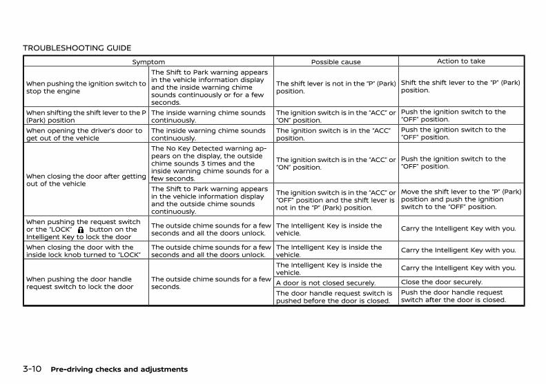
(108,1)
[ Edit: 2018/ 5/ 25 Model: PD23-A ]
3-10 Pre-driving checks and adjustments
TROUBLESHOOTING GUIDEGUID-8046F183-0177-43C0-9B8B-E0B87481924E
Symptom Possible cause Action to take
When pushing the ignition switch tostop the engine
The Shift to Park warning appearsin the vehicle information displayand the inside warning chimesounds continuously or for a fewseconds.
The shift lever is not in the “P” (Park)position.
Shift the shift lever to the “P” (Park)position.
When shifting the shift lever to the P(Park) position
The inside warning chime soundscontinuously.
The ignition switch is in the “ACC” or“ON” position.
Push the ignition switch to the“OFF” position.
When opening the driver’s door toget out of the vehicle
The inside warning chime soundscontinuously.
The ignition switch is in the “ACC”position.
Push the ignition switch to the“OFF” position.
When closing the door after gettingout of the vehicle
The No Key Detected warning ap-pears on the display, the outsidechime sounds 3 times and theinside warning chime sounds for afew seconds.
The ignition switch is in the “ACC” or“ON” position.
Push the ignition switch to the“OFF” position.
The Shift to Park warning appearsin the vehicle information displayand the outside chime soundscontinuously.
The ignition switch is in the “ACC” or“OFF” position and the shift lever isnot in the “P” (Park) position.
Move the shift lever to the “P” (Park)position and push the ignitionswitch to the “OFF” position.
When pushing the request switchor the “LOCK” button on theIntelligent Key to lock the door
The outside chime sounds for a fewseconds and all the doors unlock.
The Intelligent Key is inside thevehicle.
Carry the Intelligent Key with you.
When closing the door with theinside lock knob turned to “LOCK”
The outside chime sounds for a fewseconds and all the doors unlock.
The Intelligent Key is inside thevehicle.
Carry the Intelligent Key with you.
When pushing the door handlerequest switch to lock the door
The outside chime sounds for a fewseconds.
The Intelligent Key is inside thevehicle.
Carry the Intelligent Key with you.
A door is not closed securely. Close the door securely.
The door handle request switch ispushed before the door is closed.
Push the door handle requestswitch after the door is closed.
Condition: 'Except for China'/
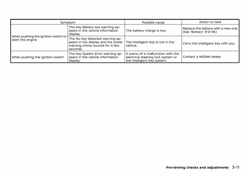
(109,1)
[ Edit: 2018/ 5/ 25 Model: PD23-A ]
Symptom Possible cause Action to take
When pushing the ignition switch tostart the engine
The Key Battery low warning ap-pears in the vehicle informationdisplay.
The battery charge is low.Replace the battery with a new one.(See “Battery” (P.8-18).)
The No Key Detected warning ap-pears in the display and the insidewarning chime sounds for a fewseconds.
The Intelligent Key is not in thevehicle.
Carry the Intelligent Key with you.
When pushing the ignition switchThe Key System Error warning ap-pears in the vehicle informationdisplay.
It warns of a malfunction with theelectrical steering lock system orthe Intelligent Key system.
Contact a NISSAN dealer.
Pre-driving checks and adjustments 3-11
Condition: 'Except for China'/
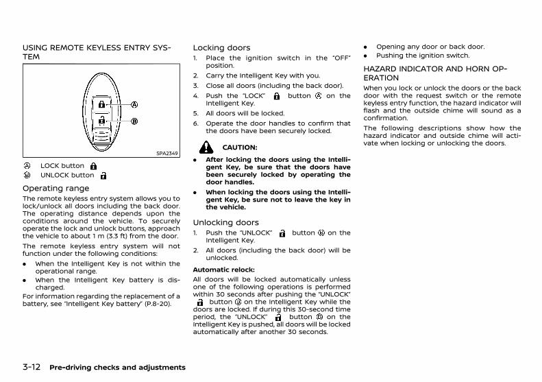
(110,1)
[ Edit: 2018/ 5/ 25 Model: PD23-A ]
3-12 Pre-driving checks and adjustments
USING REMOTE KEYLESS ENTRY SYS-TEM
GUID-DF9A5FE7-42F8-4685-B4C4-BAA45A6FB4F3
SPA2349
LOCK buttonUNLOCK button
Operating rangeGUID-723F4C54-0341-43BF-AABF-FF16D12D5CDF
The remote keyless entry system allows you tolock/unlock all doors including the back door.The operating distance depends upon theconditions around the vehicle. To securelyoperate the lock and unlock buttons, approachthe vehicle to about 1 m (3.3 ft) from the door.The remote keyless entry system will notfunction under the following conditions:. When the Intelligent Key is not within the
operational range.. When the Intelligent Key battery is dis-
charged.For information regarding the replacement of abattery, see “Intelligent Key battery” (P.8-20).
Locking doorsGUID-BD2B6C1A-1036-485E-A231-E3D872C58A86
1. Place the ignition switch in the “OFF”position.
2. Carry the Intelligent Key with you.3. Close all doors (including the back door).4. Push the “LOCK” button on the
Intelligent Key.5. All doors will be locked.6. Operate the door handles to confirm that
the doors have been securely locked.
CAUTION:
. After locking the doors using the Intelli-gent Key, be sure that the doors havebeen securely locked by operating thedoor handles.
. When locking the doors using the Intelli-gent Key, be sure not to leave the key inthe vehicle.
Unlocking doorsGUID-550F90C5-CBB7-4387-96DF-4F16AC5FBC69
1. Push the “UNLOCK” button on theIntelligent Key.
2. All doors (including the back door) will beunlocked.
Automatic relock:GUID-9E14C2E6-2E9C-4731-980B-C45B899B977B
All doors will be locked automatically unlessone of the following operations is performedwithin 30 seconds after pushing the “UNLOCK”
button on the Intelligent Key while thedoors are locked. If during this 30-second timeperiod, the “UNLOCK” button on theIntelligent Key is pushed, all doors will be lockedautomatically after another 30 seconds.
. Opening any door or back door.
. Pushing the ignition switch.
HAZARD INDICATOR AND HORN OP-ERATION
GUID-D8B755E4-20FA-4DA6-8255-B444BEBBE14EWhen you lock or unlock the doors or the backdoor with the request switch or the remotekeyless entry function, the hazard indicator willflash and the outside chime will sound as aconfirmation.The following descriptions show how thehazard indicator and outside chime will acti-vate when locking or unlocking the doors.
Condition: 'Except for China'/

(111,1)
[ Edit: 2018/ 5/ 25 Model: PD23-A ]
Operation DOOR LOCK DOOR UNLOCK
Intelligent Key system(using door handle or back door
request switch)
HAZARD - onceOUTSIDE CHIME - once
HAZARD - twiceOUTSIDE CHIME - twice
Remote keyless entry system(using or button) HAZARD - once
OUTSIDE CHIME - onceHAZARD - twiceOUTSIDE CHIME - twice
Pre-driving checks and adjustments 3-13
Condition: 'Except for China'/
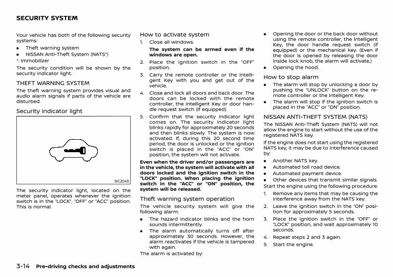
(112,1)
[ Edit: 2018/ 5/ 25 Model: PD23-A ]
3-14 Pre-driving checks and adjustments
PD23A1-29739652-5ED9-4FD5-8F38-8D3466951538Your vehicle has both of the following securitysystems:. Theft warning system. NISSAN Anti-Theft System (NATS*)*: ImmobilizerThe security condition will be shown by thesecurity indicator light.
THEFT WARNING SYSTEMPD23A1-E65DC1C3-0170-4689-8FE8-6BBD291A0C08
The theft warning system provides visual andaudio alarm signals if parts of the vehicle aredisturbed.
Security indicator lightPD23A1-F7A4BE61-F271-46B4-B093-14AA63B7102B
SIC2045
The security indicator light, located on themeter panel, operates whenever the ignitionswitch is in the “LOCK”, “OFF” or “ACC” position.This is normal.
How to activate systemPD23A1-B7239390-349E-4365-820C-68BB1239E500
1. Close all windows.The system can be armed even if thewindows are open.
2. Place the ignition switch in the “OFF”position.
3. Carry the remote controller or the Intelli-gent Key with you and get out of thevehicle.
4. Close and lock all doors and back door. Thedoors can be locked with the remotecontroller, the Intelligent Key or door han-dle request switch (if equipped).
5. Confirm that the security indicator lightcomes on. The security indicator lightblinks rapidly for approximately 20 secondsand then blinks slowly. The system is nowactivated. If, during this 20 second timeperiod, the door is unlocked or the ignitionswitch is placed in the “ACC” or “ON”position, the system will not activate.
Even when the driver and/or passengers arein the vehicle, the systemwill activate with alldoors locked and the ignition switch in the“LOCK” position. When placing the ignitionswitch in the “ACC” or “ON” position, thesystem will be released.
Theft warning system operationPD23A1-7D2FE163-57B0-47FF-9A1A-5A59BE19EF13
The vehicle security system will give thefollowing alarm:. The hazard indicator blinks and the horn
sounds intermittently.. The alarm automatically turns off after
approximately 30 seconds. However, thealarm reactivates if the vehicle is tamperedwith again.
The alarm is activated by:
. Opening the door or the back door withoutusing the remote controller, the IntelligentKey, the door handle request switch (ifequipped) or the mechanical key. (Even ifthe door is opened by releasing the doorinside lock knob, the alarm will activate.)
. Opening the hood.
How to stop alarmPD23A1-38681D4E-AD73-4401-983F-6E59F006210B
. The alarm will stop by unlocking a door bypushing the “UNLOCK” button on the re-mote controller or the Intelligent Key.
. The alarm will stop if the ignition switch isplaced in the “ACC” or “ON” position.
NISSAN ANTI-THEFT SYSTEM (NATS)PD23A1-6466DFA7-344C-45EE-BAEF-BADA8E5EC151
The NISSAN Anti-Theft System (NATS) will notallow the engine to start without the use of theregistered NATS key.If the engine does not start using the registeredNATS key, it may be due to interference causedby:. Another NATS key.. Automated toll road device.. Automated payment device.. Other devices that transmit similar signals.Start the engine using the following procedure:1. Remove any items that may be causing the
interference away from the NATS key.2. Leave the ignition switch in the “ON” posi-
tion for approximately 5 seconds.3. Place the ignition switch in the “OFF” or
“LOCK” position, and wait approximately 10seconds.
4. Repeat steps 2 and 3 again.5. Start the engine.
SECURITY SYSTEM
Condition: 'Except for China'/
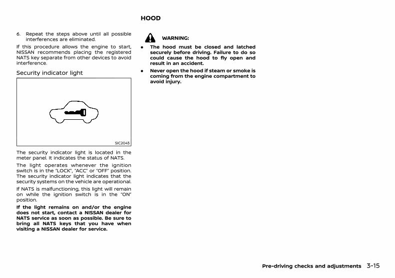
(113,1)
[ Edit: 2018/ 5/ 25 Model: PD23-A ]
6. Repeat the steps above until all possibleinterferences are eliminated.
If this procedure allows the engine to start,NISSAN recommends placing the registeredNATS key separate from other devices to avoidinterference.
Security indicator lightPD23A1-EA15431A-E4B2-406E-B918-FC6C45EB7F68
SIC2045
The security indicator light is located in themeter panel. It indicates the status of NATS.The light operates whenever the ignitionswitch is in the “LOCK”, “ACC” or “OFF” position.The security indicator light indicates that thesecurity systems on the vehicle are operational.If NATS is malfunctioning, this light will remainon while the ignition switch is in the “ON”position.If the light remains on and/or the enginedoes not start, contact a NISSAN dealer forNATS service as soon as possible. Be sure tobring all NATS keys that you have whenvisiting a NISSAN dealer for service.
PD23A1-8D1A6611-B742-4C67-9DEA-06DF085C8601
WARNING:
. The hood must be closed and latchedsecurely before driving. Failure to do socould cause the hood to fly open andresult in an accident.
. Never open the hood if steam or smoke iscoming from the engine compartment toavoid injury.
Pre-driving checks and adjustments 3-15
HOOD
Condition: 'Except for China'/
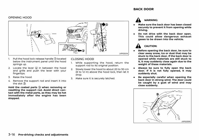
(114,1)
[ Edit: 2018/ 5/ 25 Model: PD23-A ]
3-16 Pre-driving checks and adjustments
OPENING HOODPD23A1-C77E2F1D-60B4-4D2B-B5AC-A9D195216B86
JVP0501X
1. Pull the hood lock release handle locatedbelow the instrument panel until the hoodsprings up.
2. Locate the lever in between the hoodand grille and push the lever with yourfingertips.
3. Raise the hood.4. Remove the support rod and insert it into
the slot .Hold the coated parts when removing orresetting the support rod. Avoid direct con-tact with the metal parts, as they may be hotimmediately after the engine has beenstopped.
CLOSING HOODPD23A1-8E45C7D5-FF02-4C67-9E5B-AD84F0F3834E
1. While supporting the hood, return thesupport rod to its original position.
2. Slowly lower the hood to about 20 to 30 cm(8 to 12 in) above the hood lock, then let itdrop.
3. Make sure it is securely latched.
GUID-8F301CEB-954F-4EEE-AAE5-E66EFA856057
WARNING:
. Make sure the back door has been closedsecurely to prevent it from opening whiledriving.
. Do not drive with the back door open.This could allow dangerous exhaustgases to be drawn into the vehicle.
CAUTION:
. Before opening the back door, be sure toclear away snow, ice or dust that may bestuck to the back door. If the back door isopened while materials are still stuck toit, it may suddenly close again due to theweight of these materials.
. Always be sure to fully open the backdoor. If it is not fully opened, it maysuddenly shut.
. Be especially careful when opening theback door in strong wind. The door couldbe caught by a gust of wind and mayclose suddenly.
JVP0059X
BACK DOOR
Condition: 'Except for China'/
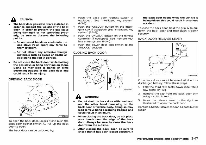
(115,1)
[ Edit: 2018/ 5/ 25 Model: PD23-A ]
CAUTION:
. The back door gas stays are installed inorder to support the weight of the backdoor. In order to prevent the gas staysbeing damaged or not operating prop-erly, be sure to observe the followingpoints.— Do not insert hands or cords into the
gas stays or apply any force tothem laterally.
— Do not attach any adhesive foreignmaterials such as pieces of plastic orstickers to the rod portion.
. Do not close the back door while holdingthe gas stays or hang anything on them.Doing so may lead to hands or armsbecoming trapped in the back door andcould result in an injury.
OPENING BACK DOORGUID-7B8BFBE7-DE82-4B48-8483-867DCE717074
JVP0582X
To open the back door, unlock it and push theback door opener switch . Pull up the backdoor to open.The back door can be unlocked by:
. Push the back door request switch (ifequipped). (See “Intelligent Key system”(P.3-5).)
. Push the “UNLOCK” button on the Intelli-gent Key (if equipped). (See “Intelligent Keysystem” (P.3-5).)
. Push the “UNLOCK” button on the remotecontroller (if equipped). (See “Remote key-less entry system” (P.3-4).)
. Push the power door lock switch to the“UNLOCK” position.
CLOSING BACK DOORGUID-D4E8496C-4B6F-4657-B0A5-806C2803A888
JVP0634X
WARNING:
. Do not shut the back door with one handand the other hand remaining on theback door or vehicle body. Doing so maylead to your hand becoming trapped andcould result in an injury.
. When closing the back door, do not placeyour hands near the edge of the backdoor. Always be sure to close the backdoor from the outside.
. After closing the back door, be sure tocheck that it has been closed securely. If
the back door opens while the vehicle isbeing driven, this could result in a seriousaccident.
To close the back door, hold the grip to pulldown the back door and then push it downsecurely.
BACK DOOR RELEASE LEVERGUID-0B99B2FA-7CF8-4891-8E7C-A7ED3C7A6A40
JVP0578X
If the back door cannot be unlocked due to adischarged battery, follow these steps.1. Fold the third row seats down. (See “Third
row seats” (P.1-6).)2. Remove the cap from the back door trim
using a suitable tool.3. Move the release lever to the right as
illustrated to open the back door.Contact a NISSAN dealer as soon as possible forrepair.
Pre-driving checks and adjustments 3-17
Condition: 'Except for China'/
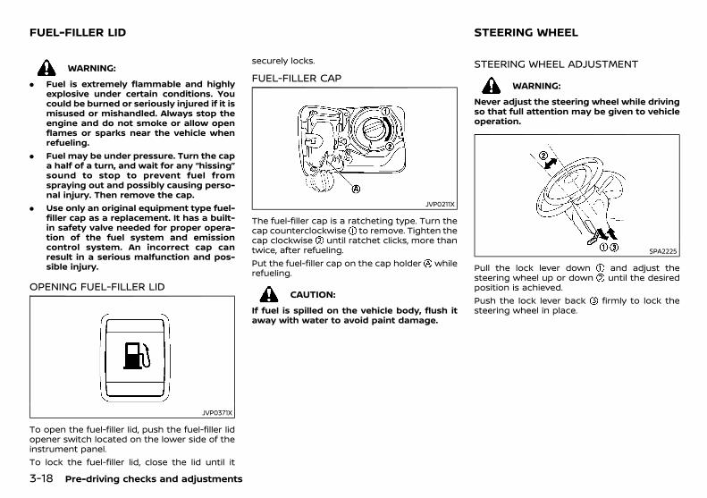
(116,1)
[ Edit: 2018/ 5/ 25 Model: PD23-A ]
3-18 Pre-driving checks and adjustments
PD23A1-75C5E040-E470-4D10-8395-5143E2BA5528
WARNING:
. Fuel is extremely flammable and highlyexplosive under certain conditions. Youcould be burned or seriously injured if it ismisused or mishandled. Always stop theengine and do not smoke or allow openflames or sparks near the vehicle whenrefueling.
. Fuel may be under pressure. Turn the capa half of a turn, and wait for any “hissing”sound to stop to prevent fuel fromspraying out and possibly causing perso-nal injury. Then remove the cap.
. Use only an original equipment type fuel-filler cap as a replacement. It has a built-in safety valve needed for proper opera-tion of the fuel system and emissioncontrol system. An incorrect cap canresult in a serious malfunction and pos-sible injury.
OPENING FUEL-FILLER LIDPD23A1-CEC7BD81-5892-444E-99ED-007B3F29DDAA
JVP0371X
To open the fuel-filler lid, push the fuel-filler lidopener switch located on the lower side of theinstrument panel.To lock the fuel-filler lid, close the lid until it
securely locks.
FUEL-FILLER CAPPD23A1-81E2E53F-1652-4A73-B8E6-C991347868D9
JVP0211X
The fuel-filler cap is a ratcheting type. Turn thecap counterclockwise to remove. Tighten thecap clockwise until ratchet clicks, more thantwice, after refueling.Put the fuel-filler cap on the cap holder whilerefueling.
CAUTION:
If fuel is spilled on the vehicle body, flush itaway with water to avoid paint damage.
PD23A1-8A7BE58E-154C-4BBC-95D3-B8F9DB5246CA
STEERING WHEEL ADJUSTMENTPD23A1-62163130-88CA-4469-8CF5-D8A9DD5E893A
WARNING:
Never adjust the steering wheel while drivingso that full attention may be given to vehicleoperation.
SPA2225
Pull the lock lever down and adjust thesteering wheel up or down until the desiredposition is achieved.Push the lock lever back firmly to lock thesteering wheel in place.
FUEL-FILLER LID STEERING WHEEL
Condition: 'Except for China'/
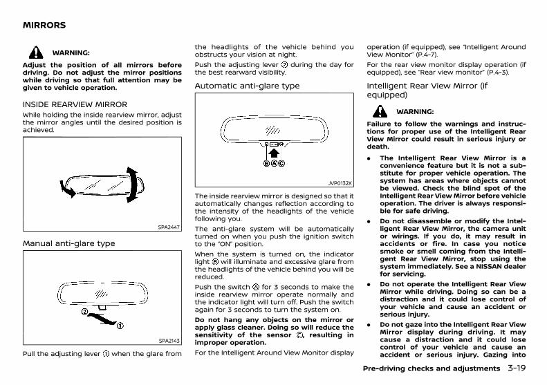
(117,1)
[ Edit: 2018/ 5/ 25 Model: PD23-A ]
PD23A1-7FC36ADA-46BB-4890-BDD2-D75687834708
WARNING:
Adjust the position of all mirrors beforedriving. Do not adjust the mirror positionswhile driving so that full attention may begiven to vehicle operation.
INSIDE REARVIEW MIRRORPD23A1-3D311780-23D0-4B3C-AF4C-8B38BCD0F0BB
While holding the inside rearview mirror, adjustthe mirror angles until the desired position isachieved.
SPA2447
Manual anti-glare typePD23A1-69390AAA-15FF-4756-90E5-258C9D86F713
SPA2143
Pull the adjusting lever when the glare from
the headlights of the vehicle behind youobstructs your vision at night.Push the adjusting lever during the day forthe best rearward visibility.
Automatic anti-glare typePD23A1-6F103A5E-198A-40B3-BAD0-E4628D528631
JVP0132X
The inside rearview mirror is designed so that itautomatically changes reflection according tothe intensity of the headlights of the vehiclefollowing you.The anti-glare system will be automaticallyturned on when you push the ignition switchto the “ON” position.When the system is turned on, the indicatorlight will illuminate and excessive glare fromthe headlights of the vehicle behind you will bereduced.Push the switch for 3 seconds to make theinside rearview mirror operate normally andthe indicator light will turn off. Push the switchagain for 3 seconds to turn the system on.Do not hang any objects on the mirror orapply glass cleaner. Doing so will reduce thesensitivity of the sensor , resulting inimproper operation.For the Intelligent Around View Monitor display
operation (if equipped), see “Intelligent AroundView Monitor” (P.4-7).For the rear view monitor display operation (ifequipped), see “Rear view monitor” (P.4-3).
Intelligent Rear View Mirror (ifequipped)
GUID-3CC6C5DE-4D73-43B6-ABE6-337402BAE465
WARNING:
Failure to follow the warnings and instruc-tions for proper use of the Intelligent RearView Mirror could result in serious injury ordeath.
. The Intelligent Rear View Mirror is aconvenience feature but it is not a sub-stitute for proper vehicle operation. Thesystem has areas where objects cannotbe viewed. Check the blind spot of theIntelligent Rear ViewMirror before vehicleoperation. The driver is always responsi-ble for safe driving.
. Do not disassemble or modify the Intel-ligent Rear View Mirror, the camera unitor wirings. If you do, it may result inaccidents or fire. In case you noticesmoke or smell coming from the Intelli-gent Rear View Mirror, stop using thesystem immediately. See a NISSAN dealerfor servicing.
. Do not operate the Intelligent Rear ViewMirror while driving. Doing so can be adistraction and it could lose control ofyour vehicle and cause an accident orserious injury.
. Do not gaze into the Intelligent Rear ViewMirror display during driving. It maycause a distraction and it could losecontrol of your vehicle and cause anaccident or serious injury. Gazing into
Pre-driving checks and adjustments 3-19
MIRRORS
Condition: 'Except for China'/

(118,1)
[ Edit: 2018/ 5/ 25 Model: PD23-A ]
3-20 Pre-driving checks and adjustments
the display screen during driving also canbe a cause of carsick for passengers.
. Do not put a cigarette or flames to theIntelligent Rear View Mirror, the cameraunit or wirings. It may cause a fire.
. Be sure to adjust the Intelligent Rear ViewMirror before driving. Switch the systemto the conventional rearviewmirror modeand be properly seated on the driver’sseat. Then adjust the rearview mirror soas to see the rear window properly.Driving without adjusting the rearviewmirror may cause difficulty in watchingthe display at Intelligent Rear View Mirrormode (camera view mode) due to thereflection from the surface of the mirror.
. If the Intelligent Rear View Mirror mal-functions, immediately switch the systemto the conventional rearview mirrormode. Have the system checked by aNISSAN dealer.
. When strong light (for example, sunlightor high beams from following vehicles)enters the camera, a light beam or aglaring light may appear on the displayscreen of the Intelligent Rear View Mirror.In that case, switch the system to theconventional rearview mirror mode ap-propriately.
. If dirt, rain or snow accumulates on theexterior glass surface covering the cam-era, the Intelligent Rear View Mirror maynot display objects clearly. Use of the rearwindow wiper/washer may improve vis-ibility, but if not, switch the IntelligentRear View Mirror to the conventionalrearview mirror mode until a time theglass covering the camera can becleaned.
Components:GUID-9E14C2E6-2E9C-4731-980B-C45B899B977B
JVP0488X
MENU buttonLeft buttonRight buttonMode select lever
Intelligent Rear View Mirror provides a clearrearview from a camera located on the rear ofthe vehicle. Intelligent Rear View Mirror has twomodes: conventional rearview mirror mode andIntelligent Rear View Mirror mode (camera viewmode). You can switch these two modes by themode select lever .When the Intelligent Rear View Mirror mode isselected, the indicator is displayed. (If amalfunction occurs in the Intelligent Rear ViewMirror, the indicator will turn off or notappear when the Intelligent Rear View Mirrormode is selected.)
How to change the mode:GUID-9E14C2E6-2E9C-4731-980B-C45B899B977B
JVP0489X
The mode can be switched when the ignitionswitch is in the “ON” position.. Pull the mode select lever to switch to
the Intelligent Rear View Mirror mode(camera view mode).
. Push the mode select lever to switch tothe conventional rearview mirror mode.
How to change night mode setting of Intel-ligent Rear View Mirror on initial screen:
GUID-9E14C2E6-2E9C-4731-980B-C45B899B977B
Once the headlights are turned on, the displayscreen will automatically enter night mode. Inthe night mode, the brightness of the displayscreen is decreased to reduce dazzling. Thissetting can be changed on the initial screen.
Condition: 'Except for China'/
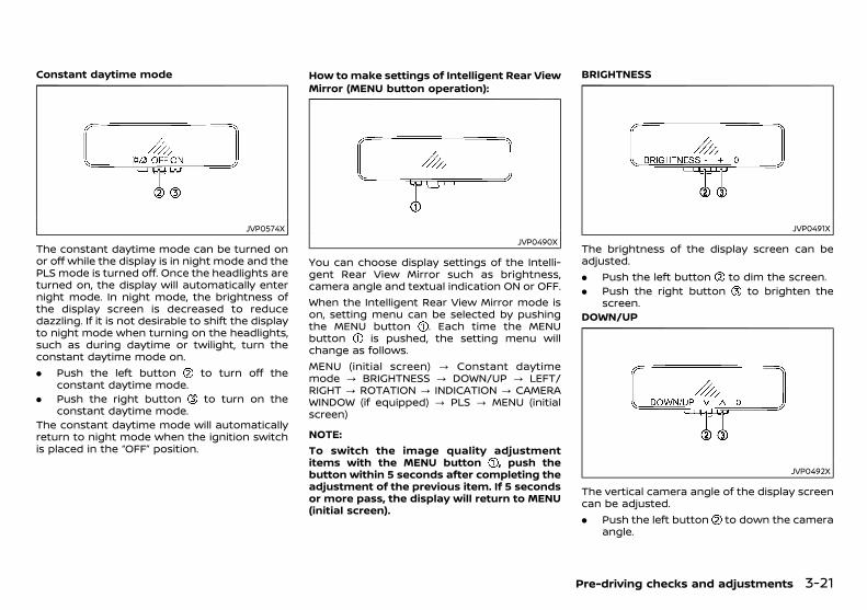
(119,1)
[ Edit: 2018/ 5/ 25 Model: PD23-A ]
Constant daytime mode
JVP0574X
The constant daytime mode can be turned onor off while the display is in night mode and thePLS mode is turned off. Once the headlights areturned on, the display will automatically enternight mode. In night mode, the brightness ofthe display screen is decreased to reducedazzling. If it is not desirable to shift the displayto night mode when turning on the headlights,such as during daytime or twilight, turn theconstant daytime mode on.. Push the left button to turn off the
constant daytime mode.. Push the right button to turn on the
constant daytime mode.The constant daytime mode will automaticallyreturn to night mode when the ignition switchis placed in the “OFF” position.
How to make settings of Intelligent Rear ViewMirror (MENU button operation):
GUID-9E14C2E6-2E9C-4731-980B-C45B899B977B
JVP0490X
You can choose display settings of the Intelli-gent Rear View Mirror such as brightness,camera angle and textual indication ON or OFF.When the Intelligent Rear View Mirror mode ison, setting menu can be selected by pushingthe MENU button . Each time the MENUbutton is pushed, the setting menu willchange as follows.MENU (initial screen) ? Constant daytimemode ? BRIGHTNESS ? DOWN/UP ? LEFT/RIGHT ? ROTATION ? INDICATION ? CAMERAWINDOW (if equipped) ? PLS ? MENU (initialscreen)
NOTE:To switch the image quality adjustmentitems with the MENU button , push thebutton within 5 seconds after completing theadjustment of the previous item. If 5 secondsor more pass, the display will return to MENU(initial screen).
BRIGHTNESS
JVP0491X
The brightness of the display screen can beadjusted.. Push the left button to dim the screen.. Push the right button to brighten the
screen.DOWN/UP
JVP0492X
The vertical camera angle of the display screencan be adjusted.. Push the left button to down the camera
angle.
Pre-driving checks and adjustments 3-21
Condition: 'Except for China'/

(120,1)
[ Edit: 2018/ 5/ 25 Model: PD23-A ]
3-22 Pre-driving checks and adjustments
. Push the right button to up the cameraangle.
LEFT/RIGHT
JVP0626X
The horizontal camera angle of the displayscreen can be adjusted.. Push the left button to move the camera
angle to the left.. Push the right button to move the
camera angle to the right.ROTATION
JVP0493X
The camera angle of the display screen can berotated.
. Push the left button to rotate the cameraangle to the left.
. Push the right button to rotate thecamera angle to the right.
INDICATION
JVP0494X
The textual indication can be turned on or offon the Intelligent Rear View Mirror displayscreen.. Push the left button to disable the
textual indication on the display screen.. Push the right button to enable the
textual indication on the display screen.CAMERA WINDOW (if equipped)
JVP0627X
The display position of the CAMERA window(Intelligent Around View Monitor or rear viewmonitor) can be selected.. Push the left button to move the
CAMERA window to the left.. Push the right button to move the
CAMERA window to the right.PLS
JVP0575X
The PLS (Point Light Source) mode can beturned on or off. When this mode is on, a highresolution image is displayed, which helpsrecognize the headlights of the vehicle behindin the distance, for example.. Push the left button to turn off the PLS
mode.. Push the right button to turn on the PLS
mode. (“PLS” appears in the upper rightcorner.)
The PLS mode will automatically be turned offwhen the ignition switch is placed in the “OFF”position.
Condition: 'Except for China'/
(121,1)
[ Edit: 2018/ 5/ 25 Model: PD23-A ]
Intelligent Rear View Mirror system precau-tions:
GUID-9E14C2E6-2E9C-4731-980B-C45B899B977B
NOTE:. Long-term use of this system in stopping
engine may cause battery to be dis-charged.
. Do not attach an antenna of wirelessdevice near the Intelligent Rear ViewMirror. Electric wave from wireless devicemay cause disturbed image in the Intel-ligent Rear View Mirror.
. Do not push the buttons excessively oroperating the lever roughly may cause asystem failure or the Intelligent Rear ViewMirror itself to drop.
. Never turn the body of Intelligent RearView Mirror by 90° or more. It maydamage the Intelligent Rear View Mirror.
. Do not apply strong shocks to the body ofIntelligent Rear View Mirror. It may causea system failure.
. Do not apply heavy load to the cameraand camera-cover on the rear of thevehicle. It may cause the camera to beremoved or may cause a system failure.
. If it is difficult to see the Intelligent RearView Mirror display screen because of astrong external light, switch the mode tothe conventional rearview mirror modefor better use.
. When LED headlights are viewed on theIntelligent Rear View Mirror display, theimages may flicker. This is normal.
. Due to diffused reflection from externalenvironment, images on the screen mayflicker. This is not a malfunction.
. A quick movement of a thing may not beable to display on the camera viewscreen. This is not a malfunction.
. Turn on the headlights at twilight or in atunnel, etc. When headlights are turnedon, the display and the camera systemsautomatically switched to the nightmode, which can prevent dazzling.
. The Intelligent Rear View Mirror mode(camera view mode) display is differentfrom the conventional rearview mirror.Objects in the display may differ fromactual distance. Do not solely rely on theIntelligent Rear View Mirror. Always relyon your own operation to avoid acci-dents.
. Immediately after the Intelligent RearView Mirror is switched from one modeto another, you may have difficulty infocusing on the image in the mirror/display screen with your eyes. Be cau-tious using the Intelligent Rear ViewMirror until your eyes get accustomed tothe selected mode. If it is necessary tocorrect eye focusing, the use of multifocalglasses, etc. is recommended.
. If the brightness of the camera viewdisplay is adjusted to excessive brightlevel, it may cause an eyestrain in thedriving. Adjust the brightness properly.
. Use the rear window wiper when it rains.If the camera view image is still unclearwhen the rear window wiper is in opera-tion, check the deterioration of the rearwindow wiper blade.
. When using the rear window wiper,images on the screen may flicker. This isnot a malfunction.
. Defog the rear window with defoggerwhen rear window is fogged. Use theconventional rearview mirror mode untilthe rear window is fully defogged.
. The display of the Intelligent Rear ViewMirror may become hot. This is not amalfunction.
. The color of an object in the distance or inthe dark may be difficult to be recog-nized. This is not a malfunction.
System maintenance (Intelligent Rear ViewMirror):
GUID-9E14C2E6-2E9C-4731-980B-C45B899B977B
. Always keep the mirror and camera area ofthe rear window clean.
. Clean the mirror and the camera lens witha dry soft cloth.
. When cleaning the camera area of the rearwindow, use a soft cloth dampened withwater and a few neutral detergent. Andafter that, dry it up with dry soft cloth.
. If the image on the Intelligent Rear ViewMirror display screen is still unclear evenafter cleaning the camera area of the rearwindow, an oil film may be adhering to therear window glass. Clean the rear windowglass with an oil film remover.
. Never use alcohol, benzine, thinner, or anysimilar material to clean the mirror orcamera lens. It will cause a discoloration,deterioration or a system malfunction.
. Do not attach a sticker (including transpar-ent material) on the camera area of therear window.
Pre-driving checks and adjustments 3-23
Condition: 'Except for China'/

(122,1)
[ Edit: 2018/ 5/ 25 Model: PD23-A ]
3-24 Pre-driving checks and adjustments
OUTSIDE REARVIEW MIRRORSPD23A1-A58F5C79-53BB-4B4C-99AE-FA7AA426C90E
WARNING:
. Never touch the outside rearview mirrorswhile they are in motion. Doing so maypinch your fingers or damage the mirror.
. Never drive the vehicle with the outsiderearviewmirrors folded. This reduces rearview visibility and may lead to an acci-dent.
. Objects viewed in the outside mirror arecloser than they appear (if equipped).
. The picture dimensions and distance inthe outside mirrors are not real.
AdjustingPD23A1-6CD14C69-6323-4940-BD8D-C96CE05BE1D2
JVP0537X
The outside rearview mirror remote controloperates when the ignition switch is in the“ACC” or “ON” position.1. Turn the switch to select the left (L) or right
(R) mirror .2. Adjust each mirror by pushing the switch
until the desired position is achieved .
FoldingPD23A1-C551A3E7-B939-41F3-A08E-85B4352893EF
Manual type:GUID-9E14C2E6-2E9C-4731-980B-C45B899B977B
SPA1829
Fold the outside rearview mirror by pushing ittoward the rear of the vehicle.
Remote control type:GUID-9E14C2E6-2E9C-4731-980B-C45B899B977B
JVP0327X
The outside rearview mirror remote controloperates when the ignition switch is in the“ACC” or “ON” position.The outside rearview mirrors automatically foldwhen the outside rearview mirror foldingswitch is pushed in. To unfold, push to theswitch again.
CAUTION:
Continuously performing the fold/unfold op-eration of the outside rearview mirror maycause the switch to stop the operation.
VANITY MIRRORGUID-0963776A-D035-420E-A11E-8CD34C5794F9
SIC3869
To use the vanity mirror, pull down the sunvisor and pull up the cover.
Condition: 'Except for China'/
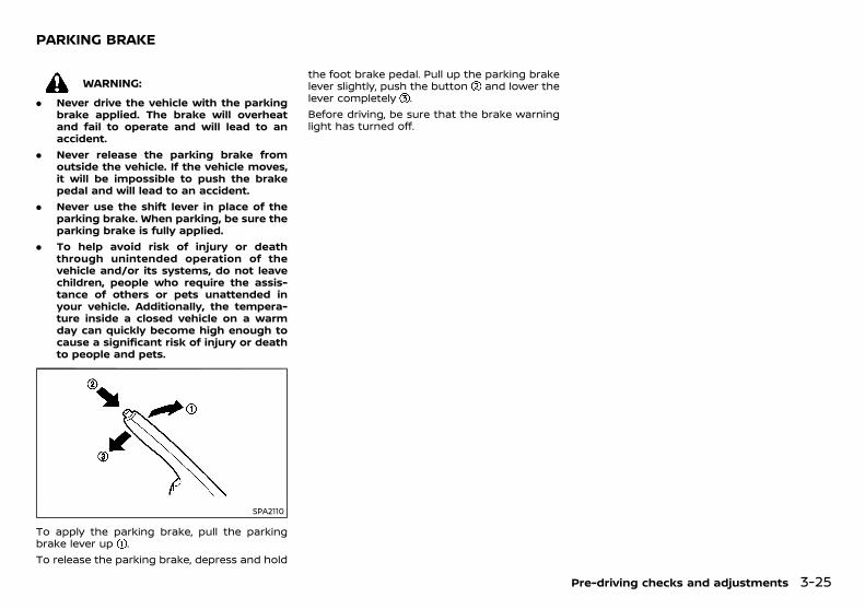
(123,1)
[ Edit: 2018/ 5/ 25 Model: PD23-A ]
PD23A1-13486B6E-8238-4DF0-9F9B-1B1BA4711EA7
WARNING:
. Never drive the vehicle with the parkingbrake applied. The brake will overheatand fail to operate and will lead to anaccident.
. Never release the parking brake fromoutside the vehicle. If the vehicle moves,it will be impossible to push the brakepedal and will lead to an accident.
. Never use the shift lever in place of theparking brake. When parking, be sure theparking brake is fully applied.
. To help avoid risk of injury or deaththrough unintended operation of thevehicle and/or its systems, do not leavechildren, people who require the assis-tance of others or pets unattended inyour vehicle. Additionally, the tempera-ture inside a closed vehicle on a warmday can quickly become high enough tocause a significant risk of injury or deathto people and pets.
SPA2110
To apply the parking brake, pull the parkingbrake lever up .To release the parking brake, depress and hold
the foot brake pedal. Pull up the parking brakelever slightly, push the button and lower thelever completely .Before driving, be sure that the brake warninglight has turned off.
Pre-driving checks and adjustments 3-25
PARKING BRAKE
Condition: 'Except for China'/

(124,1)
[ Edit: 2018/ 5/ 25 Model: PD23-A ]
3-26 Pre-driving checks and adjustments
MEMO
Condition: 'Except for China'/
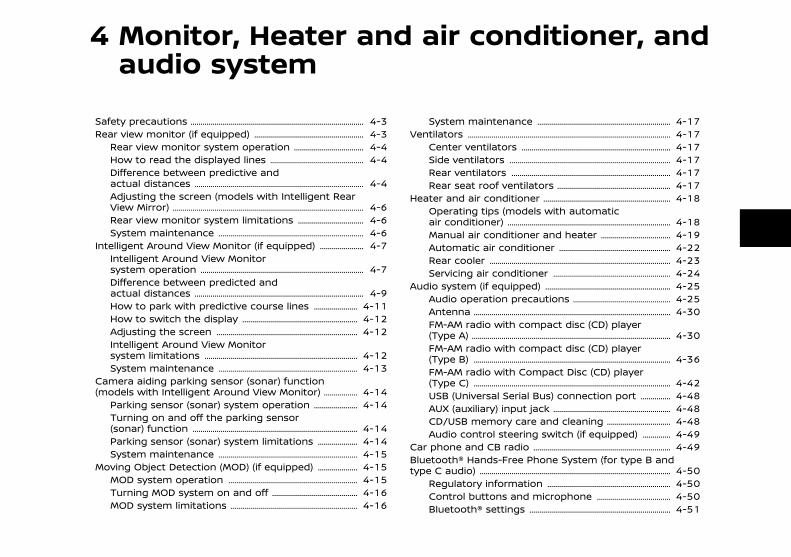
(125,1)
[ Edit: 2018/ 5/ 25 Model: PD23-A ]
4 Monitor, Heater and air conditioner, andaudio system
Safety precautions ........................................................................................... 4-3Rear view monitor (if equipped) ........................................................... 4-3
Rear view monitor system operation ....................................... 4-4How to read the displayed lines ................................................... 4-4Difference between predictive andactual distances ......................................................................................... 4-4Adjusting the screen (models with Intelligent RearView Mirror) .................................................................................................... 4-6Rear view monitor system limitations ..................................... 4-6System maintenance ............................................................................. 4-6
Intelligent Around View Monitor (if equipped) .......................... 4-7Intelligent Around View Monitorsystem operation ...................................................................................... 4-7Difference between predicted andactual distances ......................................................................................... 4-9How to park with predictive course lines .......................... 4-11How to switch the display .............................................................. 4-12Adjusting the screen ........................................................................... 4-12Intelligent Around View Monitorsystem limitations ................................................................................. 4-12System maintenance .......................................................................... 4-13
Camera aiding parking sensor (sonar) function(models with Intelligent Around View Monitor) ..................... 4-14
Parking sensor (sonar) system operation .......................... 4-14Turning on and off the parking sensor(sonar) function ....................................................................................... 4-14Parking sensor (sonar) system limitations ........................ 4-14System maintenance .......................................................................... 4-15
Moving Object Detection (MOD) (if equipped) ........................ 4-15MOD system operation ..................................................................... 4-15Turning MOD system on and off ............................................... 4-16MOD system limitations .................................................................... 4-16
System maintenance ....................................................................... 4-17Ventilators .......................................................................................................... 4-17
Center ventilators ............................................................................... 4-17Side ventilators ..................................................................................... 4-17Rear ventilators .................................................................................... 4-17Rear seat roof ventilators ............................................................. 4-17
Heater and air conditioner .................................................................... 4-18Operating tips (models with automaticair conditioner) ...................................................................................... 4-18Manual air conditioner and heater ....................................... 4-19Automatic air conditioner ............................................................ 4-22Rear cooler ............................................................................................... 4-23Servicing air conditioner ............................................................... 4-24
Audio system (if equipped) ................................................................... 4-25Audio operation precautions ..................................................... 4-25Antenna ....................................................................................................... 4-30FM-AM radio with compact disc (CD) player(Type A) ........................................................................................................ 4-30FM-AM radio with compact disc (CD) player(Type B) ....................................................................................................... 4-36FM-AM radio with Compact Disc (CD) player(Type C) ....................................................................................................... 4-42USB (Universal Serial Bus) connection port ................... 4-48AUX (auxiliary) input jack ............................................................... 4-48CD/USB memory care and cleaning .................................... 4-48Audio control steering switch (if equipped) .................. 4-49
Car phone and CB radio ......................................................................... 4-49Bluetooth® Hands-Free Phone System (for type B andtype C audio) .................................................................................................... 4-50
Regulatory information .................................................................. 4-50Control buttons and microphone ......................................... 4-50Bluetooth® settings ........................................................................... 4-51
Condition: 'Except for China'/

(126,1)
[ Edit: 2018/ 5/ 25 Model: PD23-A ]
Using the system ................................................................................... 4-53General settings ...................................................................................... 4-55
Condition: 'Except for China'/
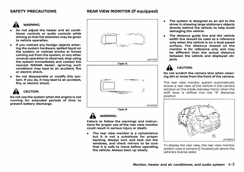
(127,1)
[ Edit: 2018/ 5/ 25 Model: PD23-A ]
GUID-EF958813-5C67-4D83-9644-1BC43093E9A0
WARNING:
. Do not adjust the heater and air condi-tioner controls or audio controls whiledriving so that full attentionmay be givento vehicle operation.
. If you noticed any foreign objects enter-ing the system hardware, spilled liquid onthe system, or noticed smoke or fumescoming out from the system, or any otherunusual operation is observed, stop usingthe system immediately and contact thenearest NISSAN dealer. Ignoring suchconditions may lead to an accident, fireor electric shock.
. Do not disassemble or modify this sys-tem. If you do, it may lead to an accident,fire, or electric shock.
CAUTION:
Do not use the systemwhen the engine is notrunning for extended periods of time toprevent battery discharge.
PD23A1-3CFB913B-C08F-4BCF-BC85-50F449ABAEC9
JVH1791XType A
JVH1878XType B
WARNING:
Failure to follow the warnings and instruc-tions for proper use of the rear view monitorcould result in serious injury or death.
. The rear view monitor is a conveniencebut it is not a substitute for properbacking. Always turn and look out thewindows, and check mirrors to be surethat it is safe to move before operatingthe vehicle. Always back up slowly.
. The system is designed as an aid to thedriver in showing large stationary objectsdirectly behind the vehicle, to help avoiddamaging the vehicle.
. The distance guide line and the vehiclewidth line should be used as a referenceonly when the vehicle is on a level pavedsurface. The distance viewed on themonitor is for reference only and maybe different than the actual distancebetween the vehicle and displayed ob-jects.
CAUTION:
Do not scratch the camera lens when clean-ing dirt or snow from the front of the camera.
The rear view monitor system automaticallyshows a rear view of the vehicle in the camerawindow on the inside rearview mirror when theshift lever is shifted into the "R” (Reverse)position.
JVH1884X
To display the rear view, the rear view monitorsystem uses a camera located just above thevehicle’s license plate.
Monitor, Heater and air conditioner, and audio system 4-3
SAFETY PRECAUTIONS REAR VIEW MONITOR (if equipped)
Condition: 'Except for China'/
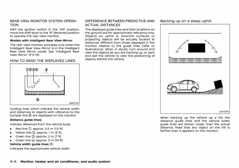
(128,1)
[ Edit: 2018/ 5/ 25 Model: PD23-A ]
4-4 Monitor, Heater and air conditioner, and audio system
REAR VIEW MONITOR SYSTEM OPERA-TION
GUID-5A917715-5DCC-41E9-B188-1CD0D1D00895With the ignition switch in the “ON” position,move the shift lever to the “R” (Reverse) positionto operate the rear view monitor.Models with Intelligent Rear View Mirror:The rear view monitor activates only when theIntelligent Rear View Mirror is in the IntelligentRear View Mirror mode. See “Intelligent RearView Mirror” (P.3-19).
HOW TO READ THE DISPLAYED LINESPD23A1-69BCFBFF-210C-4E9F-AE25-45A9D2F81450
SAA2776
Guiding lines which indicate the vehicle widthand distances to objects with reference to thebumper line are displayed on the monitor.Distance guide lines:Indicate distances from the vehicle body.. Red line : approx. 0.5 m (1.5 ft). Yellow line : approx. 1 m (3 ft). Green line : approx. 2 m (7 ft). Green line : approx. 3 m (10 ft)Vehicle width guide lines :Indicates the approximate vehicle width.
DIFFERENCE BETWEEN PREDICTIVE ANDACTUAL DISTANCES
PD23A1-1D951CEB-F579-4966-A4E2-5B3E688562F5The displayed guide lines and their locations onthe ground are for approximate reference only.Objects on uphill or downhill surfaces orprojecting objects will be actually located atdistances different from those displayed in themonitor relative to the guide lines (refer toillustrations). When in doubt, turn around andview the objects as you are backing up, or parkand exit the vehicle to view the positioning ofobjects behind the vehicle.
Backing up on a steep uphillPD23A1-5EB20995-EDAB-4CAD-9A09-281F884EE927
JVH1159X
When backing up the vehicle up a hill, thedistance guide lines and the vehicle widthguide lines are shown closer than the actualdistance. Note that any object on the hill isfarther than it appears on the monitor.
Condition: 'Except for China'/
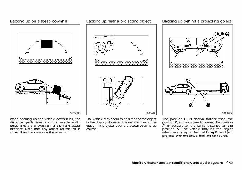
(129,1)
[ Edit: 2018/ 5/ 25 Model: PD23-A ]
Backing up on a steep downhillPD23A1-873A9F87-F191-4ECF-81EA-C16EBE93E44C
JVH1160X
When backing up the vehicle down a hill, thedistance guide lines and the vehicle widthguide lines are shown farther than the actualdistance. Note that any object on the hill iscloser than it appears on the monitor.
Backing up near a projecting objectPD23A1-C325ADAF-DDE4-4FEE-9CBA-1FF7880E0E17
SAA3440
The vehicle may seem to nearly clear the objectin the display. However, the vehicle may hit theobject if it projects over the actual backing upcourse.
Backing up behind a projecting objectPD23A1-4445394E-6B6A-4CB6-8B9E-6E1E5421D96B
SAA3475
The position is shown farther than theposition in the display. However, the position
is actually at the same distance as theposition . The vehicle may hit the objectwhen backing up to the position if the objectprojects over the actual backing up course.
Monitor, Heater and air conditioner, and audio system 4-5
Condition: 'Except for China'/
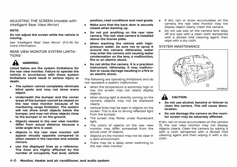
(130,1)
[ Edit: 2018/ 5/ 25 Model: PD23-A ]
4-6 Monitor, Heater and air conditioner, and audio system
ADJUSTING THE SCREEN (models withIntelligent Rear View Mirror)
PD23A1-4A4CC68B-5D78-4DF8-A648-700689845C2C
NOTE:Do not adjust the screen while the vehicle ismoving.See “Intelligent Rear View Mirror” (P.3-19) formore information.
REAR VIEW MONITOR SYSTEM LIMITA-TIONS
PD23A1-96C76C8D-C6E0-46C3-98CB-171E224A38D4
WARNING:
Listed below are the system limitations forthe rear view monitor. Failure to operate thevehicle in accordance with these systemlimitations could result in serious injury ordeath.
. The system cannot completely eliminateblind spots and may not show everyobject.
. Underneath the bumper and the cornerareas of the bumper cannot be viewed onthe rear view monitor because of itsmonitoring range limitation. The systemwill not show small objects below thebumper, and may not show objects closeto the bumper or on the ground.
. Objects viewed in the rear view monitordiffer from actual distance because awide-angle lens is used.
. Objects in the rear view monitor willappear visually opposite compared towhen viewed in the rearview and outsidemirrors.
. Use the displayed lines as a reference.The lines are highly affected by thenumber of occupants, fuel level, vehicle
position, road conditions and road grade.. Make sure that the back door is securely
closed when backing up.. Do not put anything on the rear view
camera. The rear view camera is installedabove the license plate.
. When washing the vehicle with high-pressure water, be sure not to spray itaround the camera. Otherwise, watermay enter the camera unit causing watercondensation on the lens, a malfunction,fire or an electric shock.
. Do not strike the camera. It is a precisioninstrument. Otherwise, it may malfunc-tion or cause damage resulting in a fire oran electric shock.
The following are operating limitations and donot represent a system malfunction:. When the temperature is extremely high or
low, the screen may not clearly displayobjects.
. When strong light is directly coming on thecamera, objects may not be displayedclearly.
. Vertical lines may be seen in objects on thescreen. This is due to strong reflected lightfrom the bumper.
. The screen may flicker under fluorescentlight.
. The colors of objects on the rear viewmonitor may differ somewhat from theactual color of objects.
. Objects on the monitor may not be clear ina dark environment.
. There may be a delay when switching tothe rear view monitor.
. If dirt, rain or snow accumulates on thecamera, the rear view monitor may notdisplay object clearly. Clean the camera.
. Do not use wax on the camera lens. Wipeoff any wax with a clean cloth dampenedwith a diluted mild cleaning agent, thenwipe with a dry cloth.
SYSTEM MAINTENANCEGUID-4BB8034F-67DA-4AD0-8E6C-6689089E570D
JVH1884X
CAUTION:
. Do not use alcohol, benzine or thinner toclean the camera. This will cause disco-loration.
. Do not damage the camera as the moni-tor screen may be adversely affected.
If dirt, rain or snow accumulates on the camera, the rear view monitor may not display
objects clearly. Clean the camera by wiping itwith a cloth dampened with a diluted mildcleaning agent and then wiping it with a drycloth.
Condition: 'Except for China'/

(131,1)
[ Edit: 2018/ 5/ 25 Model: PD23-A ]
GUID-43D1D59E-5AD8-47DB-9521-42A9F39DE43F
JVH1876X
1. CAMERA button
WARNING:
. Failure to follow the warnings and in-structions for the proper use of theIntelligent Around View Monitor systemcould result in serious injury or death.
. The Intelligent Around View Monitor is aconvenient feature but it is not a sub-stitute for proper vehicle operation be-cause it has areas where objects cannotbe viewed. The four corners of the vehiclein particular, are areas where objects donot always appear in the bird’s-eye, front,or rear views. Always check your sur-roundings to be sure that it is safe tomove before operating the vehicle. Al-ways operate the vehicle slowly. Alwayslook out the windows and check mirrorsto be sure that it is safe to move.
. The driver is always responsible forsafety during parking and other maneu-vers.
CAUTION:
Do not scratch the lens when cleaning dirt orsnow from the front of the camera.
The Intelligent Around View Monitor system isdesigned as an aid to the driver in situationssuch as slot parking or parallel parking.The monitor displays various views of theposition of the vehicle in a split screen format.Not all views are available at all times.Available views:. Front View
An approximately 150–degree view of thefront of the vehicle.
. Rear ViewAn approximately 150–degree view of therear of the vehicle.
. Bird’s-eye ViewThe surrounding views of the vehicle fromabove.
. Front-side ViewThe view around and ahead of the frontpassenger’s side wheel.
JVH1798X
To display the multiple views, the Intelligent
Around View Monitor system uses cameraslocated in the front grill, on the vehicle’s outsidemirrors and one just above the vehicle’s licenseplate.
INTELLIGENT AROUND VIEW MONITORSYSTEM OPERATION
GUID-457C99E7-2415-46F6-9319-2432E69AF800The Intelligent Around View Monitor is dis-played on the Intelligent Rear View Mirror.The Intelligent Around View Monitor activatesonly when the Intelligent Rear View Mirror is inthe Intelligent Rear View Mirror mode. See“Intelligent Rear View Mirror” (P.3-19).With the ignition switch in the “ON” position,move the shift lever to the “R” (Reverse) positionor push the CAMERA button to operate theIntelligent Around View Monitor.When the camera is first activated with thebird’s-eye view in the display, a red icon willflash on the screen. This indicates that theparking sensor (sonar) system is activated. Thegray icon will flash when the parking sensor(sonar) system is turned off. For additionalinformation on the parking sensor (sonar)system, refer to “Camera aiding parking sensor(sonar) function (models with IntelligentAround View Monitor)” (P.4-14).The screen displayed on the Intelligent AroundView Monitor will automatically turn off 3minutes after the CAMERA button has beenpushed with the shift lever in a position otherthan the “R” (Reverse) position.
Monitor, Heater and air conditioner, and audio system 4-7
INTELLIGENT AROUND VIEWMONITOR (if equipped)
Condition: 'Except for China'/

(132,1)
[ Edit: 2018/ 5/ 25 Model: PD23-A ]
4-8 Monitor, Heater and air conditioner, and audio system
Available viewsGUID-7DBD8171-2786-47B7-B90B-07213D579B10
WARNING:
. The distance guide line and the vehiclewidth line should be used as a referenceonly when the vehicle is on a paved, levelsurface. The distance viewed on themonitor is for reference only and maybe different than the actual distancebetween the vehicle and displayed ob-jects.
. Use the displayed lines and the bird’s-eyeview as a reference. The lines and thebird’s-eye view are greatly affected bythe number of occupants, fuel level,vehicle position, road condition and roadgrade.
. If the tires are replaced with differentsized tires, the predictive course line andthe bird’s-eye view may be displayedincorrectly.
. When driving the vehicle up a hill, objectsviewed in the monitor are further thanthey appear. When driving the vehicledown a hill, objects viewed in the monitorare closer than they appear.
. Objects in the rear view will appearvisually opposite compared to whenviewed in the rear view and outsidemirrors.
. Use the mirrors or actually look to prop-erly judge distances to other objects.
. The distance between objects viewed inthe rear view differs from actual distancebecause a wide-angle lens is used.
. On a snow-covered or slippery road,there may be a difference between thepredictive course line and the actual
course line.. The vehicle width and predictive course
lines are wider than the actual width andcourse.
. The displayed lines on the rear view willappear slightly off to the right becausethe rear view camera is not installed inthe rear center of the vehicle.
Front and rear view:GUID-9E14C2E6-2E9C-4731-980B-C45B899B977B
SAA1840Front view
SAA1896Rear view
Guiding lines that indicate the approximatevehicle width and distances to objects withreference to the vehicle body line , aredisplayed on the monitor.
Distance guide lines:Indicate distances from the vehicle body.. Red line : approximately 0.5 m (1.5 ft). Yellow line : approximately 1 m (3 ft). Green line : approximately 2 m (7 ft). Green line : approximately 3 m (10 ft)Vehicle width guide lines :Indicate the approximate vehicle width.Predictive course lines :Indicate the predicted course when operatingthe vehicle. The predictive course lines willmove depending on how much the steeringwheel is turned.The front view will not be displayed when thevehicle speed is above 10 km/h (6 MPH).
NOTE:When themonitor displays the front view andthe steering wheel turns about 90 degrees orless from the straight-ahead position, boththe right and left predictive course linesare displayed. When the steering wheel turnsabout 90 degrees or more, a line is displayedonly on the opposite side of the turn.Bird’s-eye view:
GUID-9E14C2E6-2E9C-4731-980B-C45B899B977B
SAA3570
Condition: 'Except for China'/
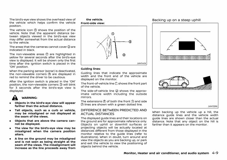
(133,1)
[ Edit: 2018/ 5/ 25 Model: PD23-A ]
The bird’s-eye view shows the overhead view ofthe vehicle which helps confirm the vehicleposition.The vehicle icon shows the position of thevehicle. Note that the apparent distance be-tween objects viewed in the bird’s-eye viewmay differ somewhat from the actual distanceto the vehicle.The areas that the cameras cannot cover areindicated in black.The non-viewable areas are highlighted inyellow for several seconds after the bird’s-eyeview is displayed. It will be shown only the firsttime after the ignition switch is placed in the“ON” position.When the parking sensor (sonar) is deactivated,the non-viewable corners are displayed inred to remind the driver to be cautious.After the ignition switch is placed in the “ON”position, the non-viewable corners will blinkfor 3 seconds after the bird’s-eye view isdisplayed.
WARNING:
. Objects in the bird’s-eye view will appearfarther than the actual distance.
. Tall objects, such as a curb or vehicle,may be misaligned or not displayed atthe seam of the views.
. Objects that are above the camera can-not be displayed.
. The view for the bird’s-eye view may bemisaligned when the camera positionalters.
. A line on the ground may be misalignedand is not seen as being straight at theseam of the views. The misalignment willincrease as the line proceeds away from
the vehicle.Front-side view:
GUID-9E14C2E6-2E9C-4731-980B-C45B899B977B
JVH1141X
Guiding lines:Guiding lines that indicate the approximatewidth and the front end of the vehicle aredisplayed on the monitor.The front-of-vehicle line shows the front partof the vehicle.The side-of-vehicle line shows the approx-imate vehicle width including the outsidemirrors.The extensions of both the front and side
lines are shown with a green dotted line.
DIFFERENCE BETWEEN PREDICTED ANDACTUAL DISTANCES
GUID-B8760E36-AF05-4726-8388-4A1796A0EA66The displayed guide lines and their locations onthe ground are for approximate reference only.Objects on uphill or downhill surfaces orprojecting objects will be actually located atdistances different from those displayed in themonitor relative to the guide lines (refer toillustrations). When in doubt, turn around andview the objects as you are backing up, or parkand exit the vehicle to view the positioning ofobjects behind the vehicle.
Backing up on a steep uphillGUID-397D9ED6-F144-48C0-BF84-B365B5C0F978
JVH1159X
When backing up the vehicle up a hill, thedistance guide lines and the vehicle widthguide lines are shown closer than the actualdistance. Note that any object on the hill isfarther than it appears on the monitor.
Monitor, Heater and air conditioner, and audio system 4-9
Condition: 'Except for China'/
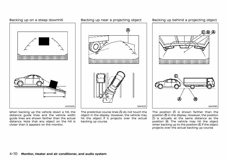
(134,1)
[ Edit: 2018/ 5/ 25 Model: PD23-A ]
4-10 Monitor, Heater and air conditioner, and audio system
Backing up on a steep downhillGUID-E7490096-05F9-4DD3-AA67-21F9B63E6FBD
JVH1160X
When backing up the vehicle down a hill, thedistance guide lines and the vehicle widthguide lines are shown farther than the actualdistance. Note that any object on the hill iscloser than it appears on the monitor.
Backing up near a projecting objectGUID-63C8C6D2-478F-4D4B-80B7-F1F3A6D585FF
SAA1923
The predictive course lines do not touch theobject in the display. However, the vehicle mayhit the object if it projects over the actualbacking up course.
Backing up behind a projecting objectGUID-FF99CC10-EC8A-44B8-9223-54442022DA0A
SAA1980
The position is shown farther than theposition in the display. However, the position
is actually at the same distance as theposition . The vehicle may hit the objectwhen backing up to the position if the objectprojects over the actual backing up course.
Condition: 'Except for China'/

(135,1)
[ Edit: 2018/ 5/ 25 Model: PD23-A ]
HOW TO PARK WITH PREDICTIVECOURSE LINES
GUID-07422D85-AFF6-41D8-AA11-CC15D9373DB3
WARNING:
. If the tires are replaced with differentsized tires, the predictive course linesmay be displayed incorrectly.
. On a snow-covered or slippery road,there may be a difference between thepredictive course line and the actualcourse line.
. If the battery is disconnected or becomesdischarged, the predictive course linesmay be displayed incorrectly. If thisoccurs, please perform the followingprocedures:— Turn the steering wheel from lock to
lock while the engine is running.
— Drive the vehicle on a straight road formore than 5 minutes.
. When the steering wheel is turned withthe ignition switch in the ACC position,the predictive course lines may be dis-played incorrectly. SAA1897
1. Visually check that the parking space issafe before parking your vehicle.
2. The rear view of the vehicle is displayed onthe screen when the shift lever is movedto the “R” (Reverse) position.
SAA1898
3. Slowly back up the vehicle adjusting thesteering wheel so that the predictivecourse lines enter the parking space .
4. Maneuver the steering wheel to make thevehicle width guide lines parallel to theparking space while referring to thepredictive course lines.
5. When the vehicle is parked in the spacecompletely, move the shift lever to the “P”(Park) position and apply the parking brake.
Monitor, Heater and air conditioner, and audio system 4-11
Condition: 'Except for China'/
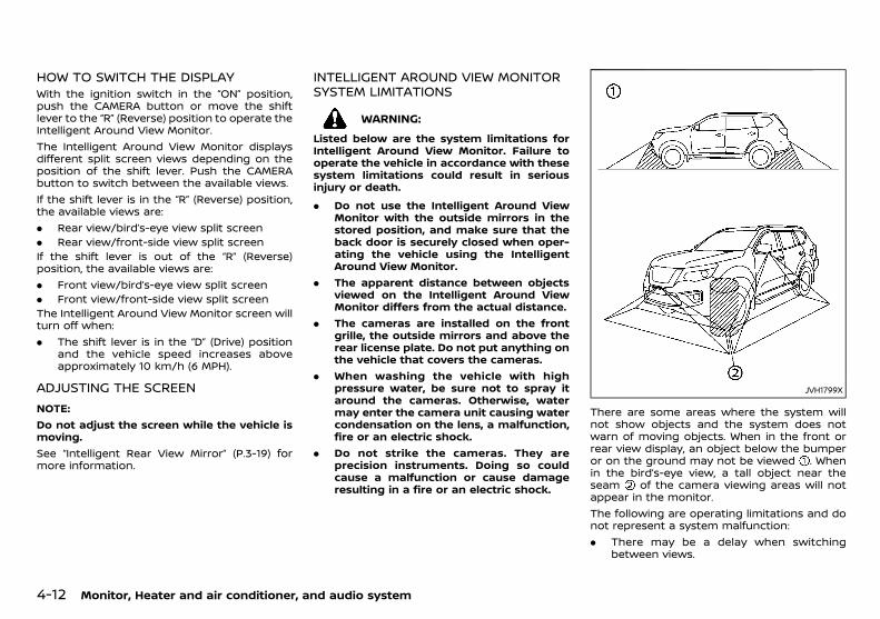
(136,1)
[ Edit: 2018/ 5/ 25 Model: PD23-A ]
4-12 Monitor, Heater and air conditioner, and audio system
HOW TO SWITCH THE DISPLAYGUID-20D3706A-A287-4766-8301-42CC20CFFD47
With the ignition switch in the “ON” position,push the CAMERA button or move the shiftlever to the “R” (Reverse) position to operate theIntelligent Around View Monitor.The Intelligent Around View Monitor displaysdifferent split screen views depending on theposition of the shift lever. Push the CAMERAbutton to switch between the available views.If the shift lever is in the “R” (Reverse) position,the available views are:. Rear view/bird’s-eye view split screen. Rear view/front-side view split screenIf the shift lever is out of the “R” (Reverse)position, the available views are:. Front view/bird’s-eye view split screen. Front view/front-side view split screenThe Intelligent Around View Monitor screen willturn off when:. The shift lever is in the “D” (Drive) position
and the vehicle speed increases aboveapproximately 10 km/h (6 MPH).
ADJUSTING THE SCREENGUID-5C97A12A-EDFB-4822-A3E1-BFEEF5E24CBA
NOTE:Do not adjust the screen while the vehicle ismoving.See “Intelligent Rear View Mirror” (P.3-19) formore information.
INTELLIGENT AROUND VIEW MONITORSYSTEM LIMITATIONS
GUID-AAE8CD28-246F-456F-9FB6-531D24D5CA25
WARNING:
Listed below are the system limitations forIntelligent Around View Monitor. Failure tooperate the vehicle in accordance with thesesystem limitations could result in seriousinjury or death.
. Do not use the Intelligent Around ViewMonitor with the outside mirrors in thestored position, and make sure that theback door is securely closed when oper-ating the vehicle using the IntelligentAround View Monitor.
. The apparent distance between objectsviewed on the Intelligent Around ViewMonitor differs from the actual distance.
. The cameras are installed on the frontgrille, the outside mirrors and above therear license plate. Do not put anything onthe vehicle that covers the cameras.
. When washing the vehicle with highpressure water, be sure not to spray itaround the cameras. Otherwise, watermay enter the camera unit causing watercondensation on the lens, a malfunction,fire or an electric shock.
. Do not strike the cameras. They areprecision instruments. Doing so couldcause a malfunction or cause damageresulting in a fire or an electric shock.
JVH1799X
There are some areas where the system willnot show objects and the system does notwarn of moving objects. When in the front orrear view display, an object below the bumperor on the ground may not be viewed . Whenin the bird’s-eye view, a tall object near theseam of the camera viewing areas will notappear in the monitor.The following are operating limitations and donot represent a system malfunction:. There may be a delay when switching
between views.
Condition: 'Except for China'/
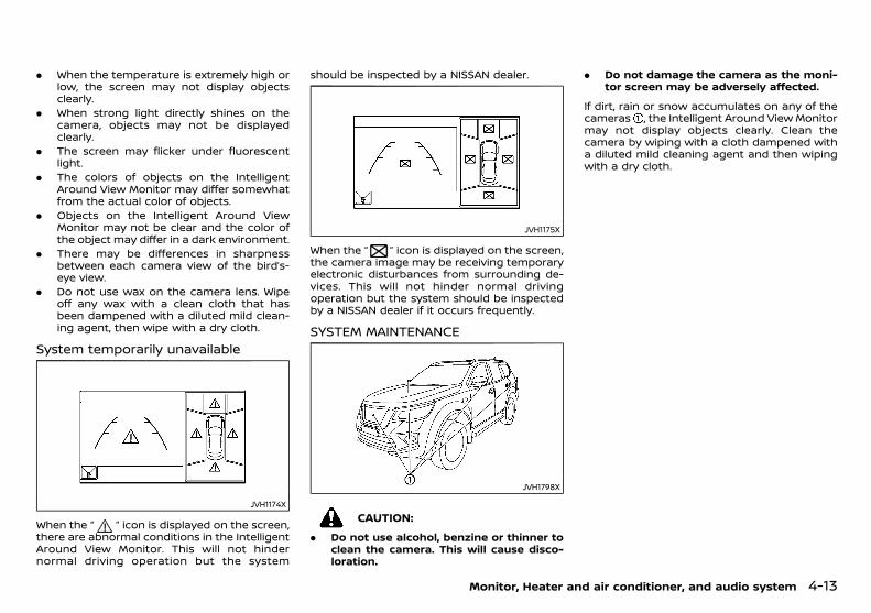
(137,1)
[ Edit: 2018/ 5/ 25 Model: PD23-A ]
. When the temperature is extremely high orlow, the screen may not display objectsclearly.
. When strong light directly shines on thecamera, objects may not be displayedclearly.
. The screen may flicker under fluorescentlight.
. The colors of objects on the IntelligentAround View Monitor may differ somewhatfrom the actual color of objects.
. Objects on the Intelligent Around ViewMonitor may not be clear and the color ofthe object may differ in a dark environment.
. There may be differences in sharpnessbetween each camera view of the bird’s-eye view.
. Do not use wax on the camera lens. Wipeoff any wax with a clean cloth that hasbeen dampened with a diluted mild clean-ing agent, then wipe with a dry cloth.
System temporarily unavailableGUID-ADA4B140-1D27-422D-B530-B29E4E5C802D
JVH1174X
When the “ ” icon is displayed on the screen,there are abnormal conditions in the IntelligentAround View Monitor. This will not hindernormal driving operation but the system
should be inspected by a NISSAN dealer.
JVH1175X
When the “ ” icon is displayed on the screen,the camera image may be receiving temporaryelectronic disturbances from surrounding de-vices. This will not hinder normal drivingoperation but the system should be inspectedby a NISSAN dealer if it occurs frequently.
SYSTEM MAINTENANCEGUID-D85A5F33-A03D-4B87-B8BA-D22D39DE08C0
JVH1798X
CAUTION:
. Do not use alcohol, benzine or thinner toclean the camera. This will cause disco-loration.
. Do not damage the camera as the moni-tor screen may be adversely affected.
If dirt, rain or snow accumulates on any of thecameras , the Intelligent Around View Monitormay not display objects clearly. Clean thecamera by wiping with a cloth dampened witha diluted mild cleaning agent and then wipingwith a dry cloth.
Monitor, Heater and air conditioner, and audio system 4-13
Condition: 'Except for China'/
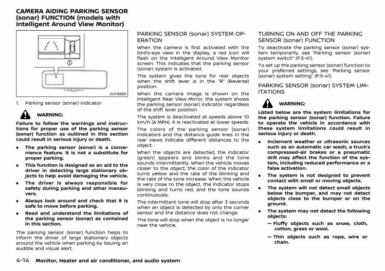
(138,1)
[ Edit: 2018/ 5/ 25 Model: PD23-A ]
4-14 Monitor, Heater and air conditioner, and audio system
GUID-7F805B6F-DD5A-47A3-889C-0441E02BA51E
JVH1888X
1. Parking sensor (sonar) indicator
WARNING:
Failure to follow the warnings and instruc-tions for proper use of the parking sensor(sonar) function as outlined in this sectioncould result in serious injury or death.
. The parking sensor (sonar) is a conve-nience feature. It is not a substitute forproper parking.
. This function is designed as an aid to thedriver in detecting large stationary ob-jects to help avoid damaging the vehicle.
. The driver is always responsible forsafety during parking and other maneu-vers.
. Always look around and check that it issafe to move before parking.
. Read and understand the limitations ofthe parking sensor (sonar) as containedin this section.
The parking sensor (sonar) function helps toinform the driver of large stationary objectsaround the vehicle when parking by issuing anaudible and visual alert.
PARKING SENSOR (sonar) SYSTEM OP-ERATION
GUID-DB0E33A2-B3EB-4C10-A140-E030E058770DWhen the camera is first activated with thebird’s-eye view in the display, a red icon willflash on the Intelligent Around View Monitorscreen. This indicates that the parking sensor(sonar) system is activated.The system gives the tone for rear objectswhen the shift lever is in the “R” (Reverse)position.When the camera image is shown on theIntelligent Rear View Mirror, the system showsthe parking sensor (sonar) indicator regardlessof the shift lever position.The system is deactivated at speeds above 10km/h (6 MPH). It is reactivated at lower speeds.The colors of the parking sensor (sonar)indicators and the distance guide lines in therear views indicate different distances to theobject.When the objects are detected, the indicator(green) appears and blinks and the tonesounds intermittently. When the vehicle movescloser to the object, the color of the indicatorturns yellow and the rate of the blinking andthe rate of the tone increase. When the vehicleis very close to the object, the indicator stopsblinking and turns red, and the tone soundscontinuously.The intermittent tone will stop after 3 secondswhen an object is detected by only the cornersensor and the distance does not change.The tone will stop when the object is no longernear the vehicle.
TURNING ON AND OFF THE PARKINGSENSOR (sonar) FUNCTION
GUID-7EE7263E-F0BA-4765-B875-ECD23EF9272FTo deactivate the parking sensor (sonar) sys-tem temporarily, see “Parking sensor (sonar)system switch” (P.5-41).To set up the parking sensor (sonar) function toyour preferred settings, see “Parking sensor(sonar) system setting” (P.5-41).
PARKING SENSOR (sonar) SYSTEM LIM-ITATIONS
GUID-D0153FC5-C08E-4E3E-A486-C536C53EB81F
WARNING:
Listed below are the system limitations forthe parking sensor (sonar) function. Failureto operate the vehicle in accordance withthese system limitations could result inserious injury or death.
. Inclement weather or ultrasonic sourcessuch as an automatic car wash, a truck’scompressed-air brakes or a pneumaticdrill may affect the function of the sys-tem, including reduced performance or afalse activation.
. The system is not designed to preventcontact with small or moving objects.
. The system will not detect small objectsbelow the bumper, and may not detectobjects close to the bumper or on theground.
. The system may not detect the followingobjects:— Fluffy objects such as snow, cloth,
cotton, grass or wool.
— Thin objects such as rope, wire orchain.
CAMERA AIDING PARKING SENSOR(sonar) FUNCTION (models withIntelligent Around View Monitor)
Condition: 'Except for China'/
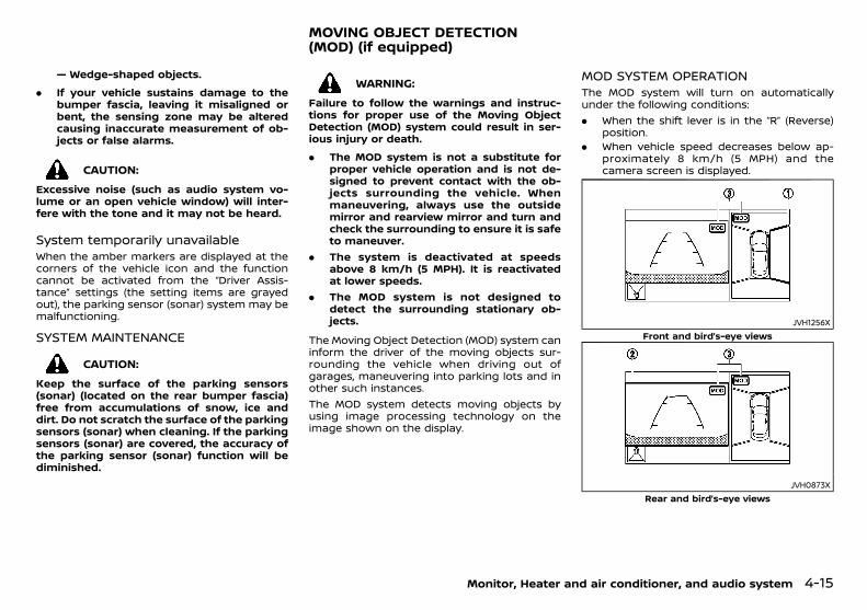
(139,1)
[ Edit: 2018/ 5/ 25 Model: PD23-A ]
— Wedge-shaped objects.
. If your vehicle sustains damage to thebumper fascia, leaving it misaligned orbent, the sensing zone may be alteredcausing inaccurate measurement of ob-jects or false alarms.
CAUTION:
Excessive noise (such as audio system vo-lume or an open vehicle window) will inter-fere with the tone and it may not be heard.
System temporarily unavailableGUID-00E23478-31AA-4669-B138-98A5D702CA62
When the amber markers are displayed at thecorners of the vehicle icon and the functioncannot be activated from the “Driver Assis-tance” settings (the setting items are grayedout), the parking sensor (sonar) system may bemalfunctioning.
SYSTEM MAINTENANCEGUID-ADD736E5-9EBF-44A9-B5CA-F16447C726E1
CAUTION:
Keep the surface of the parking sensors(sonar) (located on the rear bumper fascia)free from accumulations of snow, ice anddirt. Do not scratch the surface of the parkingsensors (sonar) when cleaning. If the parkingsensors (sonar) are covered, the accuracy ofthe parking sensor (sonar) function will bediminished.
GUID-837918E7-9B66-4743-BA16-E4E924F1C10A
WARNING:
Failure to follow the warnings and instruc-tions for proper use of the Moving ObjectDetection (MOD) system could result in ser-ious injury or death.
. The MOD system is not a substitute forproper vehicle operation and is not de-signed to prevent contact with the ob-jects surrounding the vehicle. Whenmaneuvering, always use the outsidemirror and rearview mirror and turn andcheck the surrounding to ensure it is safeto maneuver.
. The system is deactivated at speedsabove 8 km/h (5 MPH). It is reactivatedat lower speeds.
. The MOD system is not designed todetect the surrounding stationary ob-jects.
The Moving Object Detection (MOD) system caninform the driver of the moving objects sur-rounding the vehicle when driving out ofgarages, maneuvering into parking lots and inother such instances.The MOD system detects moving objects byusing image processing technology on theimage shown on the display.
MOD SYSTEM OPERATIONGUID-F8D5B760-7BF0-4FB7-A01C-0EFF4A0F93C9
The MOD system will turn on automaticallyunder the following conditions:. When the shift lever is in the “R” (Reverse)
position.. When vehicle speed decreases below ap-
proximately 8 km/h (5 MPH) and thecamera screen is displayed.
JVH1256XFront and bird’s-eye views
JVH0873XRear and bird’s-eye views
Monitor, Heater and air conditioner, and audio system 4-15
MOVING OBJECT DETECTION(MOD) (if equipped)
Condition: 'Except for China'/

(140,1)
[ Edit: 2018/ 5/ 25 Model: PD23-A ]
4-16 Monitor, Heater and air conditioner, and audio system
JVH1257XRear and front-side views
The MOD system operates in the followingconditions when the camera view is displayed:. When the shift lever is in the “P” (Park) or “N”
(Neutral) position and the vehicle isstopped, the MOD system detects movingobjects in the bird’s-eye view. The MODsystem will not operate if the outsidemirrors are moving in or out, in the stowedposition, or if either front door is opened.
. When the shift lever is in the “D” (Drive)position and the vehicle speed is belowapproximately 8 km/h (5 MPH), the MODsystem detects moving objects in the frontview.
. When the shift lever is in the “R” (Reverse)position and the vehicle speed is belowapproximately 8 km/h (5 MPH), the MODsystem detects moving objects in the rearview.
The MOD system will not operate if the backdoor is open.The MOD system does not detect movingobjects in the front-side view. The MOD icon isnot displayed on the screen when in this view.When the MOD system detects moving objectsnear the vehicle, a chime will be heard and ayellow frame will be displayed on the view
where the objects are detected. While the MODsystem continues to detect moving objects, theyellow frame continues to be displayed.In the bird’s-eye view, the yellow frame isdisplayed on each camera image (front, rear,right, left) depending on where moving objectsare detected.The yellow frame is displayed on each view inthe front view and rear view modes.A blue MOD icon is displayed in the viewwhere the MOD system is operative. A whiteMOD icon is displayed in the view where theMOD system is not operative.
TURNING MOD SYSTEM ON AND OFFGUID-AE86BA9D-FF96-4BD3-A23A-609670A846EC
The MOD system can be turned on and off.See “Driver Assistance” (P.2-20) for details.
MOD SYSTEM LIMITATIONSGUID-9AD940B3-458C-4597-AA05-8999DF240B13
WARNING:
Listed below are the system limitations forMOD. Failure to operate the vehicle in accor-dance with these system limitations couldresult in serious injury or death.
. Excessive noise (for example, audio sys-tem volume or open vehicle window) willinterfere with the chime sound, and itmay not be heard.
. The MOD system performance will belimited according to environmental con-ditions and surrounding objects such as:— When there is low contrast between
background and the moving objects.
— When there is blinking source of light.
— When strong light such as anothervehicle’s headlight or sunlight is pre-sent.
— When camera orientation is not in itsusual position, such as when mirror isfolded.
— When there is dirt, water drops orsnow on the camera lens.
— When the position of the movingobjects in the display is not changed.
. The MOD system might detect flowingwater droplets on the camera lens, whitesmoke from the muffler, moving sha-dows, etc.
. The MOD system may not function prop-erly depending on the speed, direction,distance or shape of the moving objects.
. If your vehicle sustains damage to theparts where the camera is installed, leav-ing it misaligned or bent, the sensingzone may be altered and the MOD systemmay not detect objects properly.
. When the temperature is extremely highor low, the screen may not display ob-jects clearly. This is not a malfunction.
NOTE:The blue MOD icon will change to orange ifone of the following has occurred.. When the system is malfunctioning.. When the component temperature
reaches a high level (icon will blink).. When the rear view camera has detected
a blockage (icon will blink).
If the icon light continues to illuminateorange, have the MOD system checked. It isrecommended that you visit a NISSAN dealer
Condition: 'Except for China'/

(141,1)
[ Edit: 2018/ 5/ 25 Model: PD23-A ]
for this service.
SYSTEM MAINTENANCEGUID-F3DE3907-A91B-4E82-AA22-2E26C7D52FFD
JVH1798X
CAUTION:
. Do not use alcohol, benzine or thinner toclean the camera. This will cause disco-loration.
. Do not damage the camera as the moni-tor screen may be adversely affected.
If dirt, rain or snow accumulates on any of thecameras , the MOD system may not operateproperly. Clean the camera by wiping with acloth dampened with a diluted mild cleaningagent and then wiping with a dry cloth.
PD23A1-B156BAE1-3CBA-4A6C-B9C4-1CD5773AD592
CENTER VENTILATORSPD23A1-9383EC3A-4097-492E-8244-610CB6AE9F11
JVH0887X
Adjust the air flow direction of the ventilatorsby moving the center knob (up/down, left/right) until the desired position is achieved.
SIDE VENTILATORSPD23A1-C9233727-9A1B-44B4-8D87-9BCD78DD2D77
SAA3126
Adjust the air flow direction of the ventilatorsby closing, opening or rotating.The side ventilators can be used for the sidedefogger.
REAR VENTILATORSPD23A1-1783D1C6-6CE5-4B45-AA3D-CE65B52E0C91
JVH0940X
Open/close the ventilators by moving thecontrol to either direction.
: This symbol indicates that the ventila-tors are open. Moving the control tothis direction will open the ventilators.
: This symbol indicates that the ventila-tors are closed. Moving the control tothis direction will close the ventilators.
Adjust the air flow direction of the ventilatorsby moving the center knob (up/down, left/right) until the desired position is achieved.
REAR SEAT ROOF VENTILATORSGUID-98D5EEC4-D39B-44E8-9350-C1081B406DED
JVH1867X
Monitor, Heater and air conditioner, and audio system 4-17
VENTILATORS
Condition: 'Except for China'/
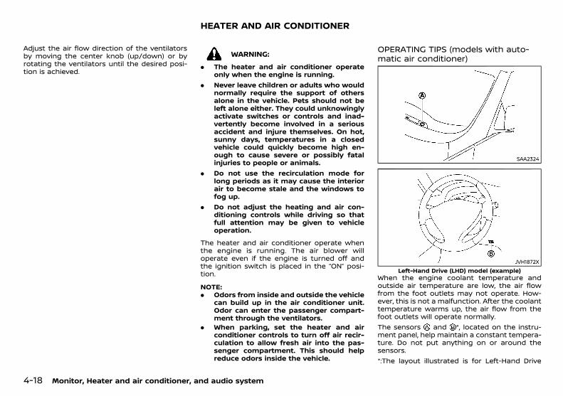
(142,1)
[ Edit: 2018/ 5/ 25 Model: PD23-A ]
4-18 Monitor, Heater and air conditioner, and audio system
Adjust the air flow direction of the ventilatorsby moving the center knob (up/down) or byrotating the ventilators until the desired posi-tion is achieved.
PD23A1-50D1923A-59AB-4F99-9D97-5F1AAE23ED73
WARNING:
. The heater and air conditioner operateonly when the engine is running.
. Never leave children or adults who wouldnormally require the support of othersalone in the vehicle. Pets should not beleft alone either. They could unknowinglyactivate switches or controls and inad-vertently become involved in a seriousaccident and injure themselves. On hot,sunny days, temperatures in a closedvehicle could quickly become high en-ough to cause severe or possibly fatalinjuries to people or animals.
. Do not use the recirculation mode forlong periods as it may cause the interiorair to become stale and the windows tofog up.
. Do not adjust the heating and air con-ditioning controls while driving so thatfull attention may be given to vehicleoperation.
The heater and air conditioner operate whenthe engine is running. The air blower willoperate even if the engine is turned off andthe ignition switch is placed in the “ON” posi-tion.
NOTE:. Odors from inside and outside the vehicle
can build up in the air conditioner unit.Odor can enter the passenger compart-ment through the ventilators.
. When parking, set the heater and airconditioner controls to turn off air recir-culation to allow fresh air into the pas-senger compartment. This should helpreduce odors inside the vehicle.
OPERATING TIPS (models with auto-matic air conditioner)
PD23A1-9930B28E-89DE-42C2-80F2-8C43A0077F1A
SAA2324
JVH1872XLeft-Hand Drive (LHD) model (example)
When the engine coolant temperature andoutside air temperature are low, the air flowfrom the foot outlets may not operate. How-ever, this is not a malfunction. After the coolanttemperature warms up, the air flow from thefoot outlets will operate normally.The sensors and *, located on the instru-ment panel, help maintain a constant tempera-ture. Do not put anything on or around thesensors.*:The layout illustrated is for Left-Hand Drive
HEATER AND AIR CONDITIONER
Condition: 'Except for China'/
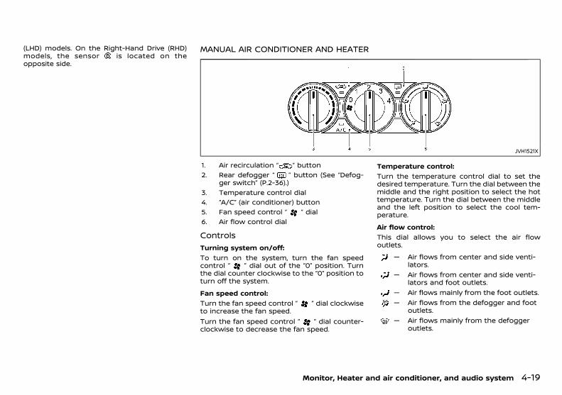
(143,1)
[ Edit: 2018/ 5/ 25 Model: PD23-A ]
(LHD) models. On the Right-Hand Drive (RHD)models, the sensor is located on theopposite side.
MANUAL AIR CONDITIONER AND HEATERGUID-39D5B4F0-1B3D-4F23-849A-485A5051A694
JVH1521X
1. Air recirculation “ ” button2. Rear defogger “ ” button (See “Defog-
ger switch” (P.2-36).)3. Temperature control dial4. “A/C” (air conditioner) button5. Fan speed control “ ” dial6. Air flow control dial
ControlsPD23A1-DD878423-7103-4289-BB7D-90BBECE6F20B
Turning system on/off:GUID-9E14C2E6-2E9C-4731-980B-C45B899B977B
To turn on the system, turn the fan speedcontrol “ ” dial out of the “0” position. Turnthe dial counter clockwise to the “0” position toturn off the system.
Fan speed control:GUID-9E14C2E6-2E9C-4731-980B-C45B899B977B
Turn the fan speed control “ ” dial clockwiseto increase the fan speed.Turn the fan speed control “ ” dial counter-clockwise to decrease the fan speed.
Temperature control:GUID-9E14C2E6-2E9C-4731-980B-C45B899B977B
Turn the temperature control dial to set thedesired temperature. Turn the dial between themiddle and the right position to select the hottemperature. Turn the dial between the middleand the left position to select the cool tem-perature.
Air flow control:GUID-9E14C2E6-2E9C-4731-980B-C45B899B977B
This dial allows you to select the air flowoutlets.
— Air flows from center and side venti-lators.
— Air flows from center and side venti-lators and foot outlets.
— Air flows mainly from the foot outlets.— Air flows from the defogger and foot
outlets.— Air flows mainly from the defogger
outlets.
Monitor, Heater and air conditioner, and audio system 4-19
Condition: 'Except for China'/

(144,1)
[ Edit: 2018/ 5/ 25 Model: PD23-A ]
4-20 Monitor, Heater and air conditioner, and audio system
Outside air circulation:GUID-9E14C2E6-2E9C-4731-980B-C45B899B977B
Push the air recirculation “ ” button. (Theindicator light will turn off.) The air flow isdrawn from outside the vehicle.Select the outside air circulation mode fornormal heating or air conditioning operation.
Air recirculation:GUID-9E14C2E6-2E9C-4731-980B-C45B899B977B
Push the air recirculation “ ” button. (Theindicator light will illuminate.)The air flow is recirculated inside the vehicle.
A/C (Air Conditioner) operation:GUID-9E14C2E6-2E9C-4731-980B-C45B899B977B
Push the “A/C” button to turn on or off the airconditioner. When the air conditioner is on, the“A/C” indicator light on the button illuminates.
Heater operationPD23A1-8D699E5C-7369-424D-87CD-C3FBFDD80AA8
Heating:GUID-9E14C2E6-2E9C-4731-980B-C45B899B977B
This mode is used to direct heated air from thefoot outlets.1. Push the air recirculation “ ” button for
normal heating. (The indicator light will turnoff.)
2. Turn the air flow control dial to the “ ”position.
3. Turn the fan speed control “ ” dial to thedesired position.
4. Turn the temperature control dial to thedesired position between the middle andthe hot (right) position.
Ventilation:GUID-9E14C2E6-2E9C-4731-980B-C45B899B977B
This mode directs outside air from the side andcenter ventilators.1. Push the air recirculation “ ” button. (The
indicator light will turn off.)
2. Turn the air flow control dial to the “ ”position.
3. Turn the fan speed control “ ” dial to thedesired position.
4. Turn the temperature control dial to thedesired position.
Defrosting or defogging:GUID-9E14C2E6-2E9C-4731-980B-C45B899B977B
This mode directs the air to the defoggeroutlets to defrost/defog the windows.1. Turn the air flow control dial to the “ ”
position.2. Push the air recirculation “ ” button. (The
indicator light will turn off.)3. Turn the fan speed control “ ” dial to the
desired position.4. Turn the temperature control dial to the
desired position between the middle andthe hot (right) position.
. To remove frost from the windshieldquickly, turn the temperature control dialto the maximum position and the fanspeed control “ ” dial to the maximumposition.
. If it is difficult to defog the windshield, turnthe “A/C” button on.
Bi-level heating:GUID-9E14C2E6-2E9C-4731-980B-C45B899B977B
This mode directs cool air from the side andcenter ventilators and warm air from the footoutlets. When the temperature control dial isturned to the maximum hot or cool position,the air between the ventilators and the footoutlets is the same temperature.1. Push the air recirculation “ ” button. (The
indicator light will turn off.)2. Turn the air flow control dial to the “ ”
position.
3. Turn the fan speed control “ ” dial to thedesired position.
4. Turn the temperature control dial to thedesired position.
Heating and defogging:GUID-9E14C2E6-2E9C-4731-980B-C45B899B977B
This mode heats the interior and defogs thewindows.1. Push the air recirculation “ ” button. (The
indicator light will turn off.)2. Turn the air flow control dial to the “ ”
position.3. Turn the fan speed control dial to the
desired position.4. Turn the temperature control dial to the
maximum hot (right) position.
Air conditioner operationPD23A1-E25A4B13-48B8-4DAA-8CA0-FCC074A9443B
The air conditioner system should be operatedfor approximately 10 minutes at least once amonth. This helps prevent damage to the airconditioner system due to the lack of lubrica-tion.
Cooling:GUID-9E14C2E6-2E9C-4731-980B-C45B899B977B
This mode is used to cool and dehumidify theair.1. Push the air recirculation “ ” button. (The
indicator light will turn off.)2. Turn the air flow control dial to the “ ”
position.3. Turn the fan speed control dial to the
desired position.4. Push the “A/C” button. (The “A/C” indicator
light will illuminate.)5. Turn the temperature control dial to the
desired position between the middle andthe cool (left) position.
Condition: 'Except for China'/
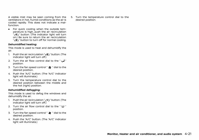
(145,1)
[ Edit: 2018/ 5/ 25 Model: PD23-A ]
A visible mist may be seen coming from theventilators in hot, humid conditions as the air iscooled rapidly. This does not indicate a mal-function.. For quick cooling when the outside tem-
perature is high, push the air recirculation“ ” button. (The indicator light will turnon.) Be sure to return the air recirculation“ ” button to turn off for normal cooling.
Dehumidified heating:GUID-9E14C2E6-2E9C-4731-980B-C45B899B977B
This mode is used to heat and dehumidify theair.1. Push the air recirculation “ ” button. (The
indicator light will turn off.)2. Turn the air flow control dial to the “ ”
position.3. Turn the fan speed control “ ” dial to the
desired position.4. Push the “A/C” button. (The “A/C” indicator
light will illuminate.)5. Turn the temperature control dial to the
desired position between the middle andthe hot (right) position.
Dehumidified defogging:GUID-9E14C2E6-2E9C-4731-980B-C45B899B977B
This mode is used to defog the windows anddehumidify the air.1. Push the air recirculation “ ” button. (The
indicator light will turn off.)2. Turn the air flow control dial to the “ ”
position.3. Turn the fan speed control “ ” dial to the
desired position.4. Push the “A/C” button. (The “A/C” indicator
light will illuminate.)
5. Turn the temperature control dial to thedesired position.
Monitor, Heater and air conditioner, and audio system 4-21
Condition: 'Except for China'/

(146,1)
[ Edit: 2018/ 5/ 25 Model: PD23-A ]
4-22 Monitor, Heater and air conditioner, and audio system
AUTOMATIC AIR CONDITIONERPD23A1-3CF22D9E-9051-4E31-A9FF-E392B2016D8B
JVH0332X
1. Temperature control buttons (left sideseat)
2. Rear defogger “ ” button* (See “Defog-ger switch” (P.2-36).)
3. Front defogger “ ” button*4. Display screen5. Air recirculation “ ” button*6. Outside air circulation “ ” button*7. Temperature control buttons (right side
seat)8. “ON·OFF” button*9. “AUTO” button*10. Fan speed control “ ” button11. “MODE” button12. “A/C” (Air Conditioner) button*13. “DUAL” (zone control ON/OFF) button**:The switch layout in the illustration is for theLeft-Hand Drive (LHD) model. For the Right-Hand Drive (RHD) model, the switch layout willbe opposite.
Automatic operation (AUTO)PD23A1-10E04568-915B-449B-987F-69AA13F0CB34
The “AUTO” mode may be used year-round asthe system automatically controls the air con-ditioner to a constant temperature, air flowdistribution and fan speed after the desiredtemperature is set manually.
Turning system on/off:GUID-9E14C2E6-2E9C-4731-980B-C45B899B977B
To turn the heater and air conditioner on or off,push the “ON·OFF” button.
Cooling and dehumidified heating:GUID-9E14C2E6-2E9C-4731-980B-C45B899B977B
1. Push the “AUTO” button (the “AUTO” indi-cator light will illuminate).
2. If the “A/C” indicator light is not illuminated,push the “A/C” button (the “A/C” indicatorlight will illuminate).
3. Push the temperature control buttons(“ ” and “ ”) to set the desired tem-perature.. When the “DUAL” indicator light is not
illuminated, pushing the “DUAL” button(the “DUAL” indicator light will illuminate)allows the user to independently changethe driver and passenger side tempera-
tures with the corresponding tempera-ture control buttons (“ ” and “ ”).
. To cancel the separate temperaturesetting, push the “DUAL” button (the“DUAL” indicator light will turn off) andthe driver’s side temperature setting willbe applied to both the driver and pas-senger sides.
4. Push either the outside air circulation “ ”button or the air recirculation “ ” button(the button with an indicator light illumi-nated) for approximately 2 seconds toswitch to the automatic air intake controlmode (the indicator lights will blink twice).
A visible mist may be seen coming from theventilators in hot, humid conditions as the air iscooled rapidly. This does not indicate a mal-function.
Heating (A/C off):GUID-9E14C2E6-2E9C-4731-980B-C45B899B977B
1. Push the “AUTO” button (the “AUTO” indi-cator light will illuminate).
2. If the “A/C” indicator light is illuminated,push the “A/C” button (the “A/C” indicatorlight will turn off).
3. Push the temperature control buttons(“ ” and “ ”) to set the desired tem-perature.. When the “DUAL” indicator light is not
illuminated, pushing the “DUAL” button(the “DUAL” indicator light will illuminate)allows the user to independently changethe driver and passenger side tempera-tures with the corresponding tempera-ture control buttons (“ ” and “ ”).
. To cancel the separate temperaturesetting, push the “DUAL” button (the“DUAL” indicator light will turn off) andthe driver’s side temperature setting willbe applied to both the driver and pas-
Condition: 'Except for China'/
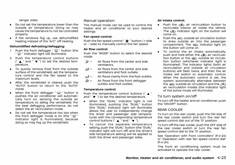
(147,1)
[ Edit: 2018/ 5/ 25 Model: PD23-A ]
senger sides.. Do not set the temperature lower than the
outside air temperature. Doing so maycause the temperature to not be controlledproperly.
. If the windows fog up, use dehumidifiedheating instead of the “A/C” off heating.
Dehumidified defrosting/defogging:GUID-9E14C2E6-2E9C-4731-980B-C45B899B977B
1. Push the front defogger “ ” button (the“ ” indicator light will illuminate).
2. Push the temperature control buttons(“ ” and “ ”) to set the desired tem-perature.
. To quickly remove frost from the outsidesurface of the windshield, set the tempera-ture control and the fan speed to themaximum levels.
. After the windshield is cleared, push the“AUTO” button to return to the “AUTO”mode.
. When the front defogger “ ” button ispushed, the air conditioner will automati-cally turn on, sensing the outside airtemperature to defog the windshield. Forthe best defogging performance, do notselect the air recirculation mode.
. Do not set the temperature too low whenthe front defogger mode is on (the “ ”indicator light is illuminated), becausedoing so may fog up the windshield.
Manual operationPD23A1-CFCC1143-7854-48F9-B014-962F1E7C884E
The manual mode can be used to control theheater and air conditioner to your desiredsettings.
Fan speed control:GUID-9E14C2E6-2E9C-4731-980B-C45B899B977B
Push the fan speed control “ ” button ( + sideor − side) to manually control the fan speed.
Air flow control:GUID-9E14C2E6-2E9C-4731-980B-C45B899B977B
Push the “MODE” button to select the desiredmode:
— Air flows from the center and sideventilators.
— Air flows from the center and sideventilators and foot outlets.
— Air flows mainly from the foot outlets— Air flows from the front defogger
outlets and foot outlets.
Temperature control:GUID-9E14C2E6-2E9C-4731-980B-C45B899B977B
Push the temperature control buttons (“ ”and “ ”) to set the desired temperature.. When the “DUAL” indicator light is not
illuminated, pushing the “DUAL” button(the “DUAL” indicator light will illuminate)allows the user to independently changethe driver and passenger side tempera-tures with the corresponding temperaturecontrol buttons (“ ” and “ ”).
. To cancel the separate temperaturesetting, push the “DUAL” button (the “DUAL”indicator light will turn off) and the driver’sside temperature setting will be applied toboth the driver and passenger sides.
Air intake control:GUID-9E14C2E6-2E9C-4731-980B-C45B899B977B
. Push the air recirculation button torecirculate interior air inside the vehicle.The indicator light on the button willcome on.
. Push the outside air circulation buttonto draw outside air into the passengercompartment. The indicator light onthe button will come on.
. To control the air intake automatically,push and hold either the air recircula-tion button or the outside air circula-tion button (whichever indicator light isilluminated). The indicator lights (both airrecirculation and outside air circulationbuttons) will flash twice, and then the airintake will switch to automatic control.When the automatic control is set, thesystem automatically alternates betweenthe outside air circulation and theair recirculation modes (the indicator lightof the active mode will illuminate).
To turn system on/offPD23A1-506BE360-B4B9-495B-9169-E981CE94E3E3
To turn off the heater and air conditioner, pushthe “ON·OFF” button.
REAR COOLERGUID-8F820C97-8138-47D8-BE13-88C9F1A8FA05
To turn on the rear cooler, push the ON side ofthe rear cooler switch and turn the rear fanspeed control dial out of the “0” position.To turn off the rear cooler, push the OFF side ofthe rear cooler switch or turn the rear fanspeed control dial to the “0” position.See “Operation with front controllers” (P.4-24)or “Operation with rear fan speed control dial”(P.4-24).The front air conditioning system must beactivated to operate the rear cooler.
Monitor, Heater and air conditioner, and audio system 4-23
Condition: 'Except for China'/
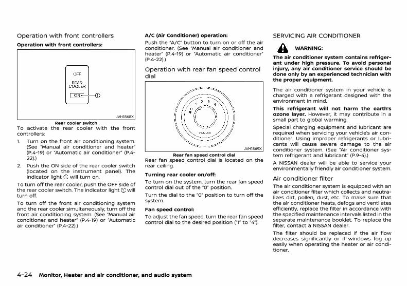
(148,1)
[ Edit: 2018/ 5/ 25 Model: PD23-A ]
4-24 Monitor, Heater and air conditioner, and audio system
Operation with front controllersGUID-B7B2FC41-BF75-4D58-BDDB-984B933F9331
Operation with front controllers:GUID-9E14C2E6-2E9C-4731-980B-C45B899B977B
JVH1868XRear cooler switch
To activate the rear cooler with the frontcontrollers:1. Turn on the front air conditioning system.
(See “Manual air conditioner and heater”(P.4-19) or “Automatic air conditioner” (P.4-22).)
2. Push the ON side of the rear cooler switch(located on the instrument panel). Theindicator light will turn on.
To turn off the rear cooler, push the OFF side ofthe rear cooler switch. The indicator light willturn off.To turn off the front air conditioning systemand the rear cooler simultaneously, turn off thefront air conditioning system. (See “Manual airconditioner and heater” (P.4-19) or “Automaticair conditioner” (P.4-22).)
A/C (Air Conditioner) operation:GUID-9E14C2E6-2E9C-4731-980B-C45B899B977B
Push the “A/C” button to turn on or off the airconditioner. (See “Manual air conditioner andheater” (P.4-19) or “Automatic air conditioner”(P.4-22).)
Operation with rear fan speed controldial
GUID-8C41F5D4-B273-4F43-A3E4-4D14B2B8C021
JVH1869XRear fan speed control dial
Rear fan speed control dial is located on therear ceiling.
Turning rear cooler on/off:GUID-9E14C2E6-2E9C-4731-980B-C45B899B977B
To turn on the system, turn the rear fan speedcontrol dial out of the “0” position.Turn the dial to the “0” position to turn off thesystem.
Fan speed control:GUID-9E14C2E6-2E9C-4731-980B-C45B899B977B
To adjust the fan speed, turn the rear fan speedcontrol dial to the desired position (“1” to “4”).
SERVICING AIR CONDITIONERPD23A1-A9D6EE48-CA00-428C-A22E-6ABEB78F0ACF
WARNING:
The air conditioner system contains refriger-ant under high pressure. To avoid personalinjury, any air conditioner service should bedone only by an experienced technician withthe proper equipment.
The air conditioner system in your vehicle ischarged with a refrigerant designed with theenvironment in mind.This refrigerant will not harm the earth’sozone layer. However, it may contribute in asmall part to global warming.Special charging equipment and lubricant arerequired when servicing your vehicle’s air con-ditioner. Using improper refrigerants or lubri-cants will cause severe damage to the airconditioner system. (See “Air conditioner sys-tem refrigerant and lubricant” (P.9-4).)A NISSAN dealer will be able to service yourenvironmentally friendly air conditioner system.
Air conditioner filterPD23A1-460220E3-C475-41C1-9ECB-B06044569703
The air conditioner system is equipped with anair conditioner filter which collects and neutra-lizes dirt, pollen, dust, etc. To make sure thatthe air conditioner heats, defogs and ventilatesefficiently, replace the filter in accordance withthe specified maintenance intervals listed in theseparate maintenance booklet. To replace thefilter, contact a NISSAN dealer.The filter should be replaced if the air flowdecreases significantly or if windows fog upeasily when operating the heater or air condi-tioner.
Condition: 'Except for China'/

(149,1)
[ Edit: 2018/ 5/ 25 Model: PD23-A ]
PD23A1-E18D8971-0757-4224-B300-B467F6BF2711
AUDIO OPERATION PRECAUTIONSPD23A1-CA00060F-2DDB-4CF3-B5D7-21131D87FD3D
WARNING:
Do not adjust the audio system while drivingso that full attention may be given to vehicleoperation.
RadioPD23A1-79E0692F-3B8D-4115-B18A-E6BE04D6E6CC
. Radio reception is affected by station signalstrength, distance from radio transmitter,buildings, bridges, mountains and otherexternal influences. Intermittent changesin reception quality normally are caused bythese external influences.
. Using a cellular phone in or near the vehiclemay influence radio reception quality.
Compact Disc (CD) playerPD23A1-5D608C43-501E-4BDB-92A6-EC978AAF5E19
SAA0480
. During cold weather or rainy days, theplayer may malfunction due to the humid-ity. If this occurs, remove the CD from CDplayer and dehumidify or ventilate theplayer completely.
. The player may skip while driving on roughroads.
. The CD player sometimes may not functionwhen the passenger compartment tem-perature is extremely high. Lower thetemperature before use.
. Do not expose the CD to direct sunlight.
. CDs that are of poor quality, or are dirty,scratched, covered with fingerprints, orthat have pin holes may not work properly.
. The following CDs may not work properly.— Copy control compact discs (CCCD)— Recordable compact discs (CD-R)— Rewritable compact discs (CD-RW)
. Do not use the following CDs as they maycause the CD player to malfunction.— 8 cm (3.1 in) discs— CDs that are not round— CDs with a paper label— CDs that are warped, scratched or have
unusual edges.. This audio system can only play prere-
corded CDs. It has no capabilities to recordor burn CDs.
USB (Universal Serial Bus) ConnectionPort
PD23A1-DD3A2103-D64D-477B-9DE0-597F033BD3B3
WARNING:
Do not connect, disconnect or operate theUSB device while driving. Doing so can be adistraction. If distracted you could lose con-trol of your vehicle and cause an accident orserious injury.
CAUTION:
. Do not force the USB device into the USBconnection port. Inserting the USB devicetilted or up-side-down into the port maydamage the port. Make sure that the USBdevice is connected correctly into the USBconnection port.
Monitor, Heater and air conditioner, and audio system 4-25
AUDIO SYSTEM (if equipped)
Condition: 'Except for China'/
(150,1)
[ Edit: 2018/ 5/ 25 Model: PD23-A ]
4-26 Monitor, Heater and air conditioner, and audio system
. Do not leave the USB cable in a placewhere it can be pulled unintentionally.Pulling the cable may damage the port.
The vehicle is not equipped with a USB device.USB devices should be purchased separately asnecessary.This system cannot be used to format USBdevices. To format a USB device, use a personalcomputer.In some states/area, the USB device for thefront seats plays only sound without images forregulatory reasons, even when the vehicle isparked.This system supports various USB memorydevices, USB hard drives and iPod players.Some USB devices may not be supported bythis system.. Partitioned USB devices may not be played
correctly.. Some characters used in other languages
(Chinese, Japanese, etc.) may not appearproperly in the display. Using English lan-guage characters with a USB device isrecommended.
General notes for USB use:Refer to your device manufacturer’s ownerinformation regarding the proper use and careof the device.Notes for iPod use:“Made for iPod”, “Made for iPhone”, and “Madefor iPad” mean that an electronic accessory hasbeen designed to connect specifically to iPod,iPhone, or iPad, respectively, and has beencertified by the developer to meet Appleperformance standards.Apple is not responsible for the operation ofthis device or its compliance with safety andregulatory standards.
Please note that the use of this accessory withiPod, iPhone, or iPad may affect wirelessperformance.iPad, iPhone, iPod, iPod classic, iPod nano, iPodshuffle, and iPod touch are trademarks of AppleInc., registered in the U.S. and other countries.Lightning is a trademark of Apple Inc.. Improperly plugging in the iPod may cause
a checkmark to be displayed on and off(flickering). Always make sure that the iPodis connected properly.
. An iPod nano (1st Generation) may remainin fast forward or rewind mode if it isconnected during a seek operation. In thiscase, please manually reset the iPod.
. An iPod nano (2nd Generation) will continueto fast-forward or rewind if it is discon-nected during a seek operation.
. An incorrect song title may appear whenthe Play Mode is changed while using aniPod nano (2nd Generation).
. Audiobooks may not play in the same orderas they appear on an iPod.
. Large video files cause slow responses inan iPod. The vehicle center display maymomentarily black out, but will soon re-cover.
. If an iPod automatically selects large videofiles while in the shuffle mode, the vehiclecenter display may momentarily black out,but will soon recover.
Bluetooth® audio player (if equipped)PD23A1-C82446EA-6506-4881-A55B-5A4E6F78E040
. Some Bluetooth® audio devices may not beused with this system. For detailed infor-mation about Bluetooth® audio devicesthat are available for use with this system,contact a NISSAN dealer.
. Before using a Bluetooth® audio system,the initial registration process for the audiodevice is necessary.
. Operation of the Bluetooth® audio systemmay vary depending on the audio devicethat is connected. Confirm the operationprocedure before use.
. The playback of Bluetooth® audio will bepaused under the following conditions. Theplayback will be resumed after the follow-ing conditions are completed.— while using a hands-free phone— while checking a connection with a cell
phone. The in-vehicle antenna for Bluetooth® com-
munication is built in the system. Do notplace the Bluetooth® audio device in anarea surrounded by metal, far away fromthe system or in a narrow space where thedevice closely contacts the body or theseat. Otherwise, sound degradation orconnection interference may occur.
. While a Bluetooth® audio device is con-nected through the Bluetooth® wirelessconnection, the battery power of the devicemay discharge quicker than usual.
. This system is compatible with the Blue-tooth® AV profile (A2DP and AVRCP).
Condition: 'Except for China'/
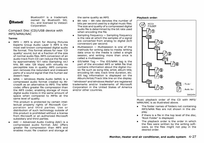
(151,1)
[ Edit: 2018/ 5/ 25 Model: PD23-A ]
Bluetooth® is a trademarkowned by Bluetooth SIG,Inc., and licensed to VisteonCorporation.
Compact Disc (CD)/USB device withMP3/WMA/AAC
PD23A1-5F81D0A0-D715-4B38-98BD-2ABA8AB39E62
Terms:GUID-9E14C2E6-2E9C-4731-980B-C45B899B977B
. MP3 — MP3 is short for Moving PicturesExperts Group Audio Layer 3. MP3 is themost well known compressed digital audiofile format. This format allows for near “CDquality” sound, but at a fraction of the sizeof normal audio files. MP3 conversion of anaudio track from CD can reduce the file sizeby approximately 10:1 ratio (Sampling: 44.1kHz, Bit rate: 128 kbps) with virtually noperceptible loss in quality. MP3 compres-sion removes the redundant and irrelevantparts of a sound signal that the human eardoesn’t hear.
. WMA — Windows Media Audio (WMA) is acompressed audio format created by Mi-crosoft as an alternative to MP3. The WMAcodec offers greater file compression thanthe MP3 codec, enabling storage of moredigital audio tracks in the same amount ofspace when compared to MP3s at thesame level of quality.This product is protected by certain intel-lectual property rights of Microsoft Cor-poration and third parties. Use ordistribution of such technology outside ofthis product is prohibited without a licensefrom Microsoft or an authorized Microsoftsubsidiary and third parties.
. AAC — Advanced Audio Coding (AAC) is acompressed audio format. AAC offersgreater file compression than MP3 andenables music file creation and storage at
the same quality as MP3.. Bit rate — Bit rate denotes the number of
bits per second used by a digital music files.The size and quality of a compressed digitalaudio file is determined by the bit rate usedwhen encoding the file.
. Sampling frequency — Sampling frequencyis the rate at which the samples of a signalare converted from analog to digital (A/Dconversion) per second.
. Multisession — Multisession is one of themethods for writing data to media. Writingdata once to the media is called a singlesession, and writing more than once iscalled a multisession.
. ID3/WMA Tag — The ID3/WMA tag is thepart of the encoded MP3 or WMA file thatcontains information about the digital mu-sic file such as song title, artist, album title,encoding bit rate, track time duration, etc.ID3 tag information is displayed on theAlbum/Artist/Track title line on the display.
* Windows® and Windows Media® are registeredtrademarks and/or trademarks of MicrosoftCorporation in the United States of Americaand/or other countries.
Playback order:GUID-9E14C2E6-2E9C-4731-980B-C45B899B977B
SAA2494
Music playback order of the CD with MP3/WMA/AAC is as illustrated above.. The folder names of folders not containing
MP3/WMA files are not shown in the dis-play.
. If there is a file in the top level of the disc,“Root Folder” is displayed.
. The playback order is the order in whichthe files were written by the writing soft-ware, so the files might not play in thedesired order.
Monitor, Heater and air conditioner, and audio system 4-27
Condition: 'Except for China'/
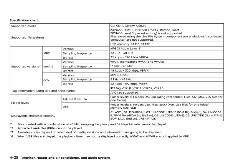
(152,1)
[ Edit: 2018/ 5/ 25 Model: PD23-A ]
4-28 Monitor, Heater and air conditioner, and audio system
Specification chart:GUID-9E14C2E6-2E9C-4731-980B-C45B899B977B
Supported media CD, CD-R, CD-RW, USB2.0
Supported file systems
ISO9660 LEVEL1, ISO9660 LEVEL2, Romeo, JolietISO9660 Level 3 (packet writing) is not supported.Files saved using the Live File System component (on a Windows Vista-basedcomputer) are not supported.USB memory: FAT16, FAT32
Supported versions*1
MP3Version MPEG1 Audio Layer 3
Sampling frequency 32 kHz - 48 kHz
Bit rate 32 kbps - 320 kbps VBR*4
WMA*2Version WMA9 (compatible WMA7 and WMA8)
Sampling frequency 16 kHz - 48 kHz
Bit rate 48 kbps - 320 kbps, VBR*4
AACVersion MPEG-4 AACSampling frequency 8 kHz - 48 kHzBit rate 32 kbps - 192 kbps, VBR*4
Tag information (Song title and Artist name)ID3 tag VER1.0, VER1.1, VER2.2, VER2.3AAC tag supported
Folder levelsCD, CD-R, CD-RW
Folder levels: 8, Folders: 255 (including root folder), Files: 512 (Max. 255 files forone folder)
USBFolder levels: 8, Folders 255, Files: 2500 (Max. 255 files for one folder)Memory size: 4GB
Displayable character codes*301: ASCII, 02: ISO-8859-1, 03: UNICODE (UTF-16 BOM Big Endian), 04: UNICODE(UTF-16 Non-BOM Big Endian), 05: UNICODE (UTF-8), 06: UNICODE (Non-UTF-16BOM Little Endian), 07:SHIFT-JIS
*1 Files created with a combination of 48 kHz sampling frequency and 64 kbps bit rate cannot be played.*2 Protected WMA files (DRM) cannot be played.*3 Available codes depend on what kind of media, versions and information are going to be displayed.*4 When VBR files are played, the playback time may not be displayed correctly. WMA7 and WMA8 are not applied to VBR.
Condition: 'Except for China'/
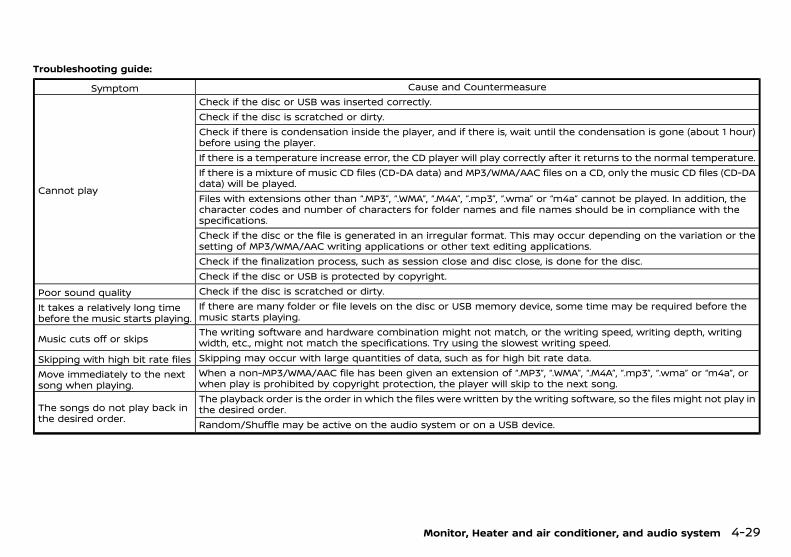
(153,1)
[ Edit: 2018/ 5/ 25 Model: PD23-A ]
Troubleshooting guide:GUID-9E14C2E6-2E9C-4731-980B-C45B899B977B
Symptom Cause and Countermeasure
Cannot play
Check if the disc or USB was inserted correctly.Check if the disc is scratched or dirty.Check if there is condensation inside the player, and if there is, wait until the condensation is gone (about 1 hour)before using the player.If there is a temperature increase error, the CD player will play correctly after it returns to the normal temperature.If there is a mixture of music CD files (CD-DA data) and MP3/WMA/AAC files on a CD, only the music CD files (CD-DAdata) will be played.Files with extensions other than “.MP3”, “.WMA”, “.M4A”, “.mp3”, “.wma” or “m4a” cannot be played. In addition, thecharacter codes and number of characters for folder names and file names should be in compliance with thespecifications.Check if the disc or the file is generated in an irregular format. This may occur depending on the variation or thesetting of MP3/WMA/AAC writing applications or other text editing applications.Check if the finalization process, such as session close and disc close, is done for the disc.Check if the disc or USB is protected by copyright.
Poor sound quality Check if the disc is scratched or dirty.
It takes a relatively long timebefore the music starts playing.
If there are many folder or file levels on the disc or USB memory device, some time may be required before themusic starts playing.
Music cuts off or skipsThe writing software and hardware combination might not match, or the writing speed, writing depth, writingwidth, etc., might not match the specifications. Try using the slowest writing speed.
Skipping with high bit rate files Skipping may occur with large quantities of data, such as for high bit rate data.
Move immediately to the nextsong when playing.
When a non-MP3/WMA/AAC file has been given an extension of “.MP3”, “.WMA”, “.M4A”, “.mp3”, “.wma” or “m4a”, orwhen play is prohibited by copyright protection, the player will skip to the next song.
The songs do not play back inthe desired order.
The playback order is the order in which the files were written by the writing software, so the files might not play inthe desired order.Random/Shuffle may be active on the audio system or on a USB device.
Monitor, Heater and air conditioner, and audio system 4-29
Condition: 'Except for China'/

(154,1)
[ Edit: 2018/ 5/ 25 Model: PD23-A ]
4-30 Monitor, Heater and air conditioner, and audio system
ANTENNAPD23A1-B07FDDFC-EA47-40CE-ADCF-49FC05B0A3F2
Roof antennaPD23A1-6F68D833-78CB-4E64-AFDE-8BE631134D64
SAA2102
The antenna can be removed if necessary.Hold the bottom of the antenna and remove byturning counterclockwise.To install the antenna, turn the antenna clock-wise and tighten.
CAUTION:
To avoid damaging or deforming the anten-na, be sure to remove the antenna under thefollowing conditions.
. The vehicle enters an automatic carwash.
. The vehicle enters a garage with a lowceiling.
. The vehicle is covered with a car cover.
FM-AM RADIO WITH COMPACT DISC (CD) PLAYER (Type A)PD23A1-F6FC2354-89F5-4A37-B9A6-3E137FDAD6EF
JVH0677X
1. DISP (Display) button2. RADIO button3. Day/Night button4. MIX button5. Seek/track (rewind) button6. Seek/track (fast forward) button7. SETUP button8. Back button
9. CD eject button10. MEDIA button11. MUTE button12. Power/VOL (Volume) dial13. RPT (Repeat) button14. Station memory buttons15. A-Z button16. MENU/ENTER dial
Condition: 'Except for China'/
(155,1)
[ Edit: 2018/ 5/ 25 Model: PD23-A ]
Audio main operationPD23A1-D3E0E55C-2000-48DE-A229-D32EAA7BFBAF
The audio system operates when the ignitionswitch is placed in the “ON” or “ACC” position.
Power/VOL dial:GUID-9E14C2E6-2E9C-4731-980B-C45B899B977B
Power ON/OFF:To turn on the audio system, push the Power/VOL dial.The system will turn on in the mode that wasused immediately before the system wasturned off.To turn off the audio system, push the Power/VOL dial.Volume control:To control the volume, turn the Power/VOL dial.Turn the Power/VOL dial clockwise to make thesound louder.Turn the Power/VOL dial counterclockwise tomake the sound quieter.The audio unit is equipped with a speedvolume. This means that the audio systemautomatically adjusts the volume level in rela-tion to vehicle speed.
SETUP button:GUID-9E14C2E6-2E9C-4731-980B-C45B899B977B
To configure Audio, Clock, Radio or Languagesettings, perform the following procedure.1. Push the SETUP button.2. Turn the MENU/ENTER dial clockwise or
counterclockwise, the display will appear inthe following order.Audio � Clock � Radio � Language
3. Push the MENU/ENTER dial to select theitem.
After the desired levels have been set, push theBack button repeatedly or push the SETUPbutton.Audio setting:Turn the MENU/ENTER dial until the Audio isdisplayed, and push the MENU/ENTER dial.Turn the MENU/ENTER dial, and the mode willchange as follows.Sound � Aux In � Speed Volume � AudioDefaultPush the MENU/ENTER dial to select the settingyou want to change. Turn the MENU/ENTERdial to adjust the selected item.. Sound:
Bass:Use this control to enhance or attenuatebass response sound.Treble:Use this control to enhance or attenuatethe treble.Bal. (Balance) :Use this control to adjust the balance of thevolume between the left and right speak-ers.Fade:Use this control to adjust the balance of thevolume between the front and the rearspeakers.
. Aux In:Use this control to adjust the volume out-put from the auxiliary source.
. Speed Vol. (Volume) :This mode controls the volume outputfrom the speakers automatically in relationto vehicle speed.Adjusting the setting to 0 (zero) turns offthe speed volume feature.
. Audio Default:The audio unit has a saved preset settingsas a factory default. Select “Yes” to changeall settings back to the factory presetsettings. Select “No” to exit the menukeeping the current settings.
Clock setting:Turn the MENU/ENTER dial until the Clock isdisplayed, and push the MENU/ENTER dial.Turn the MENU/ENTER dial, the mode willchange as follows:Set time � On/Off � Format. Set time
Select “Set time” then adjust the clock asfollows:The hour display will start flashing. Turn theMENU/ENTER dial to adjust the hour andpush the MENU/ENTER dial. The minutedisplay will start flashing. Turn the MENU/ENTER dial to adjust the minute and pushthe MENU/ENTER dial to finish the clockadjustment.
. On/OffThe clock display can be turned on and off.When the indicator is turned on, the clockwill be displayed. (The clock will keep beingdisplayed even after the power of the audiounit is turned off.) When the indicator isturned off, the clock will not be displayed.
. FormatSwitch the clock display between 24-hourmode and 12-hour clock mode.
Radio setting:Turn the MENU/ENTER dial until the Radio isdisplayed, and push the MENU/ENTER dial.The FM station which can be received will beupdated.
Monitor, Heater and air conditioner, and audio system 4-31
Condition: 'Except for China'/
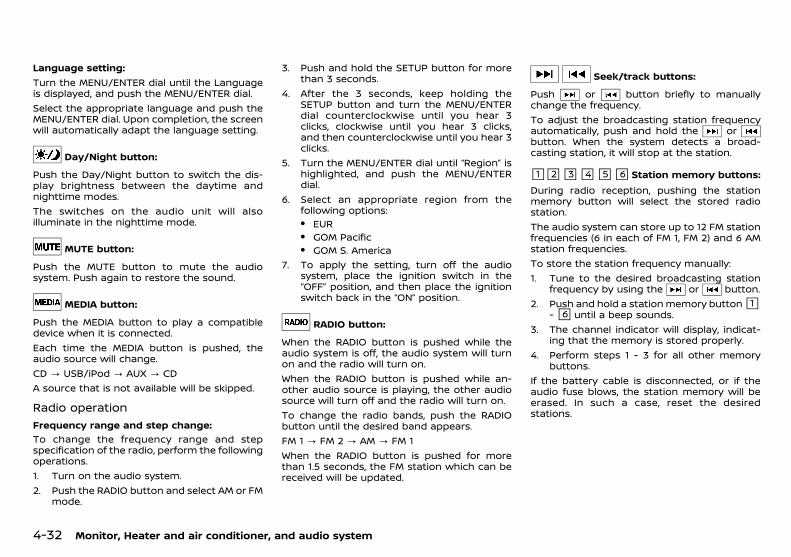
(156,1)
[ Edit: 2018/ 5/ 25 Model: PD23-A ]
4-32 Monitor, Heater and air conditioner, and audio system
Language setting:Turn the MENU/ENTER dial until the Languageis displayed, and push the MENU/ENTER dial.Select the appropriate language and push theMENU/ENTER dial. Upon completion, the screenwill automatically adapt the language setting.
Day/Night button:GUID-9E14C2E6-2E9C-4731-980B-C45B899B977B
Push the Day/Night button to switch the dis-play brightness between the daytime andnighttime modes.The switches on the audio unit will alsoilluminate in the nighttime mode.
MUTE button:GUID-9E14C2E6-2E9C-4731-980B-C45B899B977B
Push the MUTE button to mute the audiosystem. Push again to restore the sound.
MEDIA button:GUID-9E14C2E6-2E9C-4731-980B-C45B899B977B
Push the MEDIA button to play a compatibledevice when it is connected.Each time the MEDIA button is pushed, theaudio source will change.CD ? USB/iPod ? AUX ? CDA source that is not available will be skipped.
Radio operationPD23A1-8A1C78DA-F55D-4D5A-9BF0-7644CBCF9232
Frequency range and step change:GUID-9E14C2E6-2E9C-4731-980B-C45B899B977B
To change the frequency range and stepspecification of the radio, perform the followingoperations.1. Turn on the audio system.2. Push the RADIO button and select AM or FM
mode.
3. Push and hold the SETUP button for morethan 3 seconds.
4. After the 3 seconds, keep holding theSETUP button and turn the MENU/ENTERdial counterclockwise until you hear 3clicks, clockwise until you hear 3 clicks,and then counterclockwise until you hear 3clicks.
5. Turn the MENU/ENTER dial until “Region” ishighlighted, and push the MENU/ENTERdial.
6. Select an appropriate region from thefollowing options:. EUR. GOM Pacific. GOM S. America
7. To apply the setting, turn off the audiosystem, place the ignition switch in the“OFF” position, and then place the ignitionswitch back in the “ON” position.
RADIO button:GUID-9E14C2E6-2E9C-4731-980B-C45B899B977B
When the RADIO button is pushed while theaudio system is off, the audio system will turnon and the radio will turn on.When the RADIO button is pushed while an-other audio source is playing, the other audiosource will turn off and the radio will turn on.To change the radio bands, push the RADIObutton until the desired band appears.FM 1 ? FM 2 ? AM ? FM 1When the RADIO button is pushed for morethan 1.5 seconds, the FM station which can bereceived will be updated.
Seek/track buttons:GUID-9E14C2E6-2E9C-4731-980B-C45B899B977B
Push or button briefly to manuallychange the frequency.To adjust the broadcasting station frequencyautomatically, push and hold the orbutton. When the system detects a broad-casting station, it will stop at the station.
&1 &2 &3 &4 &5 &6 Station memory buttons:GUID-9E14C2E6-2E9C-4731-980B-C45B899B977B
During radio reception, pushing the stationmemory button will select the stored radiostation.The audio system can store up to 12 FM stationfrequencies (6 in each of FM 1, FM 2) and 6 AMstation frequencies.To store the station frequency manually:1. Tune to the desired broadcasting station
frequency by using the or button.2. Push and hold a station memory button&1
-&6 until a beep sounds.3. The channel indicator will display, indicat-
ing that the memory is stored properly.4. Perform steps 1 - 3 for all other memory
buttons.If the battery cable is disconnected, or if theaudio fuse blows, the station memory will beerased. In such a case, reset the desiredstations.
Condition: 'Except for China'/
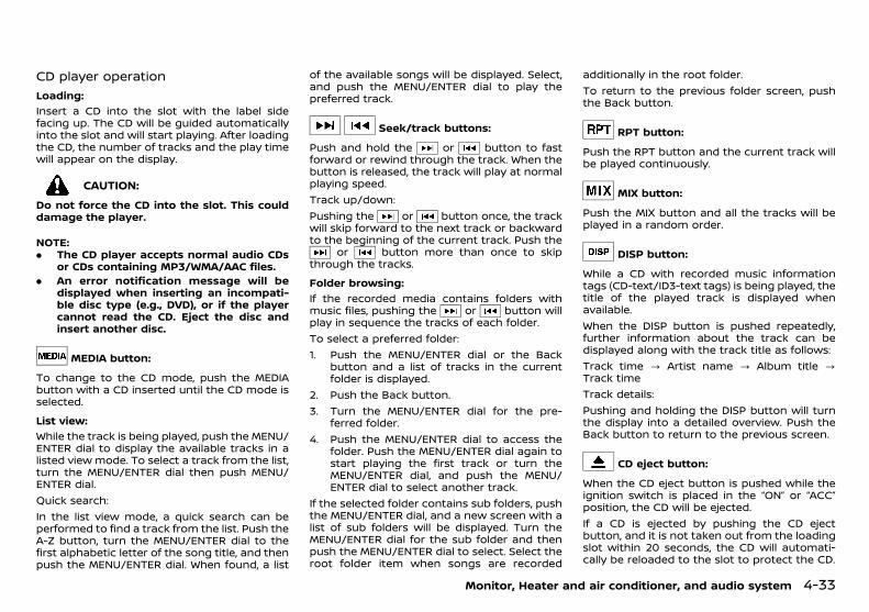
(157,1)
[ Edit: 2018/ 5/ 25 Model: PD23-A ]
CD player operationPD23A1-DA017C89-6AB9-4510-B03C-DCF2A562B3F7
Loading:GUID-9E14C2E6-2E9C-4731-980B-C45B899B977B
Insert a CD into the slot with the label sidefacing up. The CD will be guided automaticallyinto the slot and will start playing. After loadingthe CD, the number of tracks and the play timewill appear on the display.
CAUTION:
Do not force the CD into the slot. This coulddamage the player.
NOTE:. The CD player accepts normal audio CDs
or CDs containing MP3/WMA/AAC files.. An error notification message will be
displayed when inserting an incompati-ble disc type (e.g., DVD), or if the playercannot read the CD. Eject the disc andinsert another disc.
MEDIA button:GUID-9E14C2E6-2E9C-4731-980B-C45B899B977B
To change to the CD mode, push the MEDIAbutton with a CD inserted until the CD mode isselected.
List view:GUID-9E14C2E6-2E9C-4731-980B-C45B899B977B
While the track is being played, push the MENU/ENTER dial to display the available tracks in alisted view mode. To select a track from the list,turn the MENU/ENTER dial then push MENU/ENTER dial.Quick search:In the list view mode, a quick search can beperformed to find a track from the list. Push theA-Z button, turn the MENU/ENTER dial to thefirst alphabetic letter of the song title, and thenpush the MENU/ENTER dial. When found, a list
of the available songs will be displayed. Select,and push the MENU/ENTER dial to play thepreferred track.
Seek/track buttons:GUID-9E14C2E6-2E9C-4731-980B-C45B899B977B
Push and hold the or button to fastforward or rewind through the track. When thebutton is released, the track will play at normalplaying speed.Track up/down:Pushing the or button once, the trackwill skip forward to the next track or backwardto the beginning of the current track. Push the
or button more than once to skipthrough the tracks.
Folder browsing:GUID-9E14C2E6-2E9C-4731-980B-C45B899B977B
If the recorded media contains folders withmusic files, pushing the or button willplay in sequence the tracks of each folder.To select a preferred folder:1. Push the MENU/ENTER dial or the Back
button and a list of tracks in the currentfolder is displayed.
2. Push the Back button.3. Turn the MENU/ENTER dial for the pre-
ferred folder.4. Push the MENU/ENTER dial to access the
folder. Push the MENU/ENTER dial again tostart playing the first track or turn theMENU/ENTER dial, and push the MENU/ENTER dial to select another track.
If the selected folder contains sub folders, pushthe MENU/ENTER dial, and a new screen with alist of sub folders will be displayed. Turn theMENU/ENTER dial for the sub folder and thenpush the MENU/ENTER dial to select. Select theroot folder item when songs are recorded
additionally in the root folder.To return to the previous folder screen, pushthe Back button.
RPT button:GUID-9E14C2E6-2E9C-4731-980B-C45B899B977B
Push the RPT button and the current track willbe played continuously.
MIX button:GUID-9E14C2E6-2E9C-4731-980B-C45B899B977B
Push the MIX button and all the tracks will beplayed in a random order.
DISP button:GUID-9E14C2E6-2E9C-4731-980B-C45B899B977B
While a CD with recorded music informationtags (CD-text/ID3-text tags) is being played, thetitle of the played track is displayed whenavailable.When the DISP button is pushed repeatedly,further information about the track can bedisplayed along with the track title as follows:Track time ? Artist name ? Album title ?Track timeTrack details:Pushing and holding the DISP button will turnthe display into a detailed overview. Push theBack button to return to the previous screen.
CD eject button:GUID-9E14C2E6-2E9C-4731-980B-C45B899B977B
When the CD eject button is pushed while theignition switch is placed in the “ON” or “ACC”position, the CD will be ejected.If a CD is ejected by pushing the CD ejectbutton, and it is not taken out from the loadingslot within 20 seconds, the CD will automati-cally be reloaded to the slot to protect the CD.
Monitor, Heater and air conditioner, and audio system 4-33
Condition: 'Except for China'/
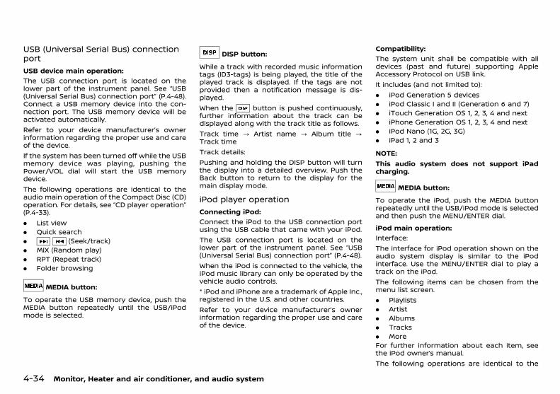
(158,1)
[ Edit: 2018/ 5/ 25 Model: PD23-A ]
4-34 Monitor, Heater and air conditioner, and audio system
USB (Universal Serial Bus) connectionport
PD23A1-DED64B54-7674-44A9-9B63-FE6451C3BF9B
USB device main operation:GUID-9E14C2E6-2E9C-4731-980B-C45B899B977B
The USB connection port is located on thelower part of the instrument panel. See “USB(Universal Serial Bus) connection port” (P.4-48).Connect a USB memory device into the con-nection port. The USB memory device will beactivated automatically.Refer to your device manufacturer’s ownerinformation regarding the proper use and careof the device.If the system has been turned off while the USBmemory device was playing, pushing thePower/VOL dial will start the USB memorydevice.The following operations are identical to theaudio main operation of the Compact Disc (CD)operation. For details, see “CD player operation”(P.4-33).. List view. Quick search. (Seek/track). MIX (Random play). RPT (Repeat track). Folder browsing
MEDIA button:GUID-9E14C2E6-2E9C-4731-980B-C45B899B977B
To operate the USB memory device, push theMEDIA button repeatedly until the USB/iPodmode is selected.
DISP button:GUID-9E14C2E6-2E9C-4731-980B-C45B899B977B
While a track with recorded music informationtags (ID3-tags) is being played, the title of theplayed track is displayed. If the tags are notprovided then a notification message is dis-played.When the button is pushed continuously,further information about the track can bedisplayed along with the track title as follows.Track time ? Artist name ? Album title ?Track timeTrack details:Pushing and holding the DISP button will turnthe display into a detailed overview. Push theBack button to return to the display for themain display mode.
iPod player operationPD23A1-4227010C-EDC8-4805-8414-4694B7255E14
Connecting iPod:GUID-9E14C2E6-2E9C-4731-980B-C45B899B977B
Connect the iPod to the USB connection portusing the USB cable that came with your iPod.The USB connection port is located on thelower part of the instrument panel. See “USB(Universal Serial Bus) connection port” (P.4-48).When the iPod is connected to the vehicle, theiPod music library can only be operated by thevehicle audio controls.* iPod and iPhone are a trademark of Apple Inc.,registered in the U.S. and other countries.Refer to your device manufacturer’s ownerinformation regarding the proper use and careof the device.
Compatibility:GUID-9E14C2E6-2E9C-4731-980B-C45B899B977B
The system unit shall be compatible with alldevices (past and future) supporting AppleAccessory Protocol on USB link.It includes (and not limited to):. iPod Generation 5 devices. iPod Classic I and II (Generation 6 and 7). iTouch Generation OS 1, 2, 3, 4 and next. iPhone Generation OS 1, 2, 3, 4 and next. iPod Nano (1G, 2G, 3G). iPad 1, 2 and 3
NOTE:This audio system does not support iPadcharging.
MEDIA button:GUID-9E14C2E6-2E9C-4731-980B-C45B899B977B
To operate the iPod, push the MEDIA buttonrepeatedly until the USB/iPod mode is selectedand then push the MENU/ENTER dial.
iPod main operation:GUID-9E14C2E6-2E9C-4731-980B-C45B899B977B
Interface:The interface for iPod operation shown on theaudio system display is similar to the iPodinterface. Use the MENU/ENTER dial to play atrack on the iPod.The following items can be chosen from themenu list screen.. Playlists. Artist. Albums. Tracks. MoreFor further information about each item, seethe iPod owner’s manual.The following operations are identical to the
Condition: 'Except for China'/
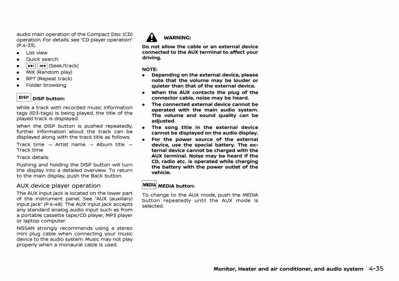
(159,1)
[ Edit: 2018/ 5/ 25 Model: PD23-A ]
audio main operation of the Compact Disc (CD)operation. For details, see “CD player operation”(P.4-33).. List view. Quick search. (Seek/track). MIX (Random play). RPT (Repeat track). Folder browsing
DISP button:GUID-9E14C2E6-2E9C-4731-980B-C45B899B977B
While a track with recorded music informationtags (ID3-tags) is being played, the title of theplayed track is displayed.When the DISP button is pushed repeatedly,further information about the track can bedisplayed along with the track title as follows:Track time ? Artist name ? Album title ?Track timeTrack details:Pushing and holding the DISP button will turnthe display into a detailed overview. To returnto the main display, push the Back button.
AUX device player operationPD23A1-49A57DF9-746E-4E99-BAAB-8BB80762EE08
The AUX input jack is located on the lower partof the instrument panel. See “AUX (auxiliary)input jack” (P.4-48). The AUX input jack acceptsany standard analog audio input such as froma portable cassette tape/CD player, MP3 playeror laptop computer.NISSAN strongly recommends using a stereomini plug cable when connecting your musicdevice to the audio system. Music may not playproperly when a monaural cable is used.
WARNING:
Do not allow the cable or an external deviceconnected to the AUX terminal to affect yourdriving.
NOTE:. Depending on the external device, please
note that the volume may be louder orquieter than that of the external device.
. When the AUX contacts the plug of theconnector cable, noise may be heard.
. The connected external device cannot beoperated with the main audio system.The volume and sound quality can beadjusted.
. The song title in the external devicecannot be displayed on the audio display.
. For the power source of the externaldevice, use the special battery. The ex-ternal device cannot be charged with theAUX terminal. Noise may be heard if theCD, radio etc. is operated while chargingthe battery with the power outlet of thevehicle.
MEDIA button:GUID-9E14C2E6-2E9C-4731-980B-C45B899B977B
To change to the AUX mode, push the MEDIAbutton repeatedly until the AUX mode isselected.
Monitor, Heater and air conditioner, and audio system 4-35
Condition: 'Except for China'/
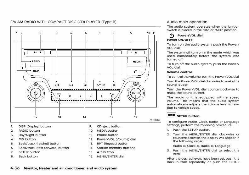
(160,1)
[ Edit: 2018/ 5/ 25 Model: PD23-A ]
4-36 Monitor, Heater and air conditioner, and audio system
FM-AM RADIO WITH COMPACT DISC (CD) PLAYER (Type B)PD23A1-C5FB7136-F09F-437C-A31B-B3D263F33E2D
JVH1078X
1. DISP (Display) button2. RADIO button3. Day/Night button4. MIX button5. Seek/track (rewind) button6. Seek/track (fast forward) button7. SETUP button8. Back button
9. CD eject button10. MEDIA button11. Phone button12. Power/VOL (Volume) dial13. RPT (Repeat) button14. Station memory buttons15. A-Z button16. MENU/ENTER dial
Audio main operationPD23A1-5E6C21DA-B0A8-474F-ACAE-B3D4580BE99A
The audio system operates when the ignitionswitch is placed in the “ON” or “ACC” position.
Power/VOL dial:GUID-9E14C2E6-2E9C-4731-980B-C45B899B977B
Power ON/OFF:To turn on the audio system, push the Power/VOL dial.The system will turn on in the mode, which wasused immediately before the system wasturned off.To turn off the audio system, push the Power/VOL dial.Volume control:To control the volume, turn the Power/VOL dial.Turn the Power/VOL dial clockwise to make thesound louder.Turn the Power/VOL dial counterclockwise tomake the sound quieter.The audio unit is equipped with a speedvolume. This means that the audio systemautomatically adjusts the volume level in rela-tion to vehicle speed.
SETUP button:GUID-9E14C2E6-2E9C-4731-980B-C45B899B977B
To configure Audio, Clock, Radio, or Languagesettings, perform the following procedure:1. Push the SETUP button.2. Turn the MENU/ENTER dial clockwise or
counterclockwise, the display will appear inthe following order.Audio � Clock � Radio � Language
3. Push the MENU/ENTER dial to select theitem.
After the desired levels have been set, push theBack button repeatedly or push the SETUP
Condition: 'Except for China'/

(161,1)
[ Edit: 2018/ 5/ 25 Model: PD23-A ]
button.Audio setting:Turn the MENU/ENTER dial until the Audio isdisplayed, and push the MENU/ENTER dial.Turn the MENU/ENTER dial, and the mode willchange as follows.Sound � Aux In � Speed Volume � AudioDefaultPush the MENU/ENTER dial to select the settingyou want to change. Turn the MENU/ENTERdial to adjust the selected item.. Sound:
Bass:Use this control to enhance or attenuatebass response sound.Treble:Use this control to enhance or attenuatethe treble.Bal. (Balance) :Use this control to adjust the balance of thevolume between the left and right speak-ers.Fade:Use this control to adjust the balance of thevolume between the front and the rearspeakers.
. Aux In:Use this control to adjust the volume out-put from the auxiliary source.
. Speed Vol. (Volume) :This mode controls the volume outputfrom the speakers automatically in relationto vehicle speed.Adjusting the setting to 0 (zero) turns offthe speed volume feature.
. Audio Default:The audio unit has a saved preset settingsas a factory default. Select “Yes” to changeall settings back to the factory presetsettings. Select “No” to exit the menukeeping the current settings.
Clock setting:Turn the MENU/ENTER dial until the Clock isdisplayed, and push the MENU/ENTER dial.Turn the MENU/ENTER dial, the mode willchange as follows:Set time � On/Off � Format. Set time
Select “Set time” then adjust the clock asfollows:The hour display will start flashing. Turn theMENU/ENTER dial to adjust the hour andpush the MENU/ENTER dial. The minutedisplay will start flashing. Turn the MENU/ENTER dial to adjust the minute and pushthe MENU/ENTER dial to finish the clockadjustment.
. On/OffThe clock display can be turned on and off.When the indicator is turned on, the clockwill be displayed. (The clock will keep beingdisplayed even after the power of the audiounit is turned off.) When the indicator isturned off, the clock will not be displayed.
. FormatSwitch the clock display between 24-hourmode and 12-hour clock mode.
Radio setting:Turn the MENU/ENTER dial until the Radio isdisplayed, and push the MENU/ENTER dial.The FM station which can be received will beupdated.
Language setting:Turn the MENU/ENTER dial until the Languageis displayed, and push the MENU/ENTER dial.Select the appropriate language and push theMENU/ENTER dial. Upon completion, the screenwill automatically adapt the language setting.
Day/Night button:GUID-9E14C2E6-2E9C-4731-980B-C45B899B977B
Push the Day/Night button to switch the dis-play brightness between the daytime andnighttime modes.The switches on the audio unit will alsoilluminate in the nighttime mode.
Phone button:GUID-9E14C2E6-2E9C-4731-980B-C45B899B977B
For information on how to use the phonebutton, see “Bluetooth® Hands-Free PhoneSystem (for type B and type C audio)” (P.4-50).
MEDIA button:GUID-9E14C2E6-2E9C-4731-980B-C45B899B977B
Push the MEDIA button to play a compatibledevice when it is connected.Each time the MEDIA button is pushed, theaudio source will change.CD? USB/iPod? BT (Bluetooth® audio)? AUX? CDA source that is not available will be skipped.
Monitor, Heater and air conditioner, and audio system 4-37
Condition: 'Except for China'/

(162,1)
[ Edit: 2018/ 5/ 25 Model: PD23-A ]
4-38 Monitor, Heater and air conditioner, and audio system
Radio operationPD23A1-FFE2D05C-7F4D-4D24-98FC-BD11CF0784C9
Frequency range and step change:GUID-9E14C2E6-2E9C-4731-980B-C45B899B977B
To change the frequency range and stepspecification of the radio, perform the followingoperations.1. Turn on the audio system.2. Push the RADIO button and select AM or FM
mode.3. Push and hold the SETUP button for more
than 3 seconds.4. After the 3 seconds, keep holding the
SETUP button and turn the MENU/ENTERdial counterclockwise until you hear 3clicks, clockwise until you hear 3 clicks,and then counterclockwise until you hear 3clicks.
5. Turn the MENU/ENTER dial until “Region” ishighlighted, and push the MENU/ENTERdial.
6. Select an appropriate region from thefollowing options:. EUR. GOM Pacific. GOM S. America
7. To apply the setting, turn off the audiosystem, place the ignition switch in the“OFF” position, and then place the ignitionswitch back in the “ON” position.
RADIO button:GUID-9E14C2E6-2E9C-4731-980B-C45B899B977B
When the RADIO button is pushed while theaudio system is off, the audio system will turnon and the radio will turn on.When the RADIO button is pushed while an-other audio source is playing, the other audiosource will turn off and the radio will turn on.
To change the radio bands, push the RADIObutton until the desired band appears.FM 1 ? FM 2 ? AM ? FM 1When the RADIO button is pushed for morethan 1.5 seconds, the FM station which can bereceived will be updated.
Seek/track buttons:GUID-9E14C2E6-2E9C-4731-980B-C45B899B977B
Push or button briefly to manuallychange the frequency.To adjust the broadcasting station frequencyautomatically, push and hold the orbutton. When the system detects a broad-casting station, it will stop at the station.
&1 &2 &3 &4 &5 &6 Station memory buttons:GUID-9E14C2E6-2E9C-4731-980B-C45B899B977B
During radio reception, pushing the stationmemory button will select the stored radiostation.The audio system can store up to 12 FM stationfrequencies (6 in each of FM 1, FM 2) and 6 AMstation frequencies.To store the station frequency manually:1. Tune to the desired broadcasting station
frequency by using the or button.2. Push and hold a station memory button&1
-&6 until a beep sounds.3. The channel indicator will display, indicat-
ing that the memory is stored properly.4. Perform steps 1 - 3 for all other memory
buttons.If the battery cable is disconnected, or if theaudio fuse blows, the station memory will beerased. In such a case, reset the desiredstations.
CD player operationPD23A1-F0A1999A-2BAB-44C0-9578-046512E59485
Loading:GUID-9E14C2E6-2E9C-4731-980B-C45B899B977B
Insert a CD into the slot with the label sidefacing up. The CD will be guided automaticallyinto the slot and will start playing. After loadingthe CD, the number of tracks and the playtimewill appear on the display.
CAUTION:
Do not force the CD into the slot. This coulddamage the player.
NOTE:. The CD player accepts normal audio CDs
or CDs containing MP3/WMA/AAC files.. An error notification message will be
displayed when inserting an incompati-ble disc type (e.g. DVD), or if the playercannot read the CD. Eject the disc andinsert another disc.
MEDIA button:GUID-9E14C2E6-2E9C-4731-980B-C45B899B977B
To change to the CD mode, push the MEDIAbutton with a CD inserted until the CD mode isselected.
List view:GUID-9E14C2E6-2E9C-4731-980B-C45B899B977B
While the track is being played, push the MENU/ENTER dial to display the available tracks in alisted view mode. To select a track from the list,turn the MENU/ENTER dial then push MENU/ENTER dial.Quick search:In the list view mode, a quick search can beperformed to find a track from the list. Push theA-Z button, turn the MENU/ENTER dial to thefirst alphabetic letter of the song title and thenpush the MENU/ENTER dial. When found, a list
Condition: 'Except for China'/
(163,1)
[ Edit: 2018/ 5/ 25 Model: PD23-A ]
of the available songs will be displayed. Select,and push the MENU/ENTER dial to play thepreferred track.
Seek/track buttons:GUID-9E14C2E6-2E9C-4731-980B-C45B899B977B
Push and hold the or button to fastforward or rewind through the track. When thebutton is released, the track will play at normalplaying speed.Track up/down:Pushing the or button once, the trackwill skip forward to the next track or backwardto the beginning of the current track. Push the
or button more than once to skipthrough the tracks.
Folder browsing:GUID-9E14C2E6-2E9C-4731-980B-C45B899B977B
If the recorded media contains folders withmusic files, pushing the or button willplay in sequence the tracks of each folder.To select a preferred folder:1. Push the MENU/ENTER dial or the Back
button and a list of tracks in the currentfolder is displayed.
2. Push the Back button.3. Turn the MENU/ENTER dial for the pre-
ferred folder.4. Push the MENU/ENTER dial to access the
folder. Push the MENU/ENTER dial again tostart playing the first track or turn theMENU/ENTER dial, and push the MENU/ENTER dial to select another track.
If the selected folder contains sub folders, pushthe MENU/ENTER dial, a new screen with a listof sub folders will be displayed. Turn the MENU/ENTER dial for the sub folder then push theMENU/ENTER dial to select. Select the rootfolder item when songs are recorded addition-
ally in the root folder.To return to the previous folder screen, pushthe Back button.
RPT button:GUID-9E14C2E6-2E9C-4731-980B-C45B899B977B
Push the RPT button and the current track willbe played continuously.
MIX button:GUID-9E14C2E6-2E9C-4731-980B-C45B899B977B
Push the MIX button and all the tracks will beplayed in a random order.
DISP button:GUID-9E14C2E6-2E9C-4731-980B-C45B899B977B
While a CD with recorded music informationtags (CD-text/ID3-text tags) is being played, thetitle of the played track is displayed whenavailable.When the DISP button is pushed repeatedly,further information about the track can bedisplayed along with the track title as follows:Track time ? Artist name ? Album title ?Track timeTrack details:Pushing and holding the DISP button will turnthe display into a detailed overview. Push theBack button to return to the previous screen.
CD eject button:GUID-9E14C2E6-2E9C-4731-980B-C45B899B977B
When the CD eject button is pushed while theignition switch is placed in the “ON” or “ACC”position, the CD will be ejected.If a CD is ejected by pushing the CD ejectbutton, and it is not taken out from the loadingslot within 20 seconds, the CD will automati-cally be reloaded to the slot to protect the CD.
USB (Universal Serial Bus) connectionport
PD23A1-DC8D8603-94A8-4483-B747-0CA47BEB16B5
USB device main operation:GUID-9E14C2E6-2E9C-4731-980B-C45B899B977B
The USB connection port is located on thelower part of the instrument panel. See “USB(Universal Serial Bus) connection port” (P.4-48).Connect a USB memory device into the con-nection port. The USB memory device will beactivated automatically.Refer to your device manufacturer’s ownerinformation regarding the proper use and careof the device.If the system has been turned off while the USBmemory device was playing, pushing thePower/VOL dial will start the USB memorydevice.The following operations are identical to theaudio main operation of the Compact Disc (CD)operation. For details, see “CD player operation”(P.4-38).. List view. Quick search. (Seek/track). MIX (Random play). RPT (Repeat track). Folder browsing
MEDIA button:GUID-9E14C2E6-2E9C-4731-980B-C45B899B977B
To operate the USB memory device, push theMEDIA button repeatedly until the USB/iPodmode is selected.
Monitor, Heater and air conditioner, and audio system 4-39
Condition: 'Except for China'/
(164,1)
[ Edit: 2018/ 5/ 25 Model: PD23-A ]
4-40 Monitor, Heater and air conditioner, and audio system
DISP button:GUID-9E14C2E6-2E9C-4731-980B-C45B899B977B
While a track with recorded music informationtags (ID3-tags) is being played, the title of theplayed track is displayed.When the DISP button is pushed repeatedly,further information about the track can bedisplayed along with the track title as follows:Track time ? Artist name ? Album title ?Track timeTrack details:Pushing and holding the DISP button will turnthe display into a detailed overview. Push theBack button to return to the display for themain display mode.
iPod player operationPD23A1-FB9E8512-B9E0-4AD6-B371-9AAE84E02EA2
Connecting iPod:GUID-9E14C2E6-2E9C-4731-980B-C45B899B977B
Connect the iPod to the USB connection portusing the USB cable that came with your iPod.The USB connection port is located on thelower part of the instrument panel. See “USB(Universal Serial Bus) connection port” (P.4-48).When the iPod is connected to the vehicle, theiPod music library can only be operated by thevehicle audio controls.* iPod and iPhone are a trademark of Apple Inc.,registered in the U.S. and other countries.Refer to your device manufacturer’s ownerinformation regarding the proper use and careof the device.
Compatibility:GUID-9E14C2E6-2E9C-4731-980B-C45B899B977B
The system unit shall be compatible with alldevices (past and future) supporting AppleAccessory Protocol on USB link.It includes (and not limited to):. iPod Generation 5 devices. iPod Classic I and II (Generation 6 and 7). iTouch Generation OS 1, 2, 3, 4 and next. iPhone Generation OS 1, 2, 3, 4 and next. iPod Nano (1G, 2G, 3G). iPad 1, 2 and 3
NOTE:This audio system do not support iPadcharging.
MEDIA button:GUID-9E14C2E6-2E9C-4731-980B-C45B899B977B
To operate the iPod, push the MEDIA buttonrepeatedly until the USB/iPod mode is selectedand then push the MENU/ENTER dial.
iPod main operation:GUID-9E14C2E6-2E9C-4731-980B-C45B899B977B
Interface:The interface for iPod operation shown on theaudio system display is similar to the iPodinterface. Use the MENU/ENTER dial to play atrack on the iPod.The following items can be chosen from themenu list screen.. Playlists. Artists. Albums. Tracks. MoreFor further information about each item, seethe iPod owner’s manual.The following operations are identical to the
audio main operation of the Compact Disc (CD)operation. For details, see “CD player operation”(P.4-38).. List view. Quick search. (Seek/track). MIX (Random play). RPT (Repeat track). Folder browsing
DISP button:GUID-9E14C2E6-2E9C-4731-980B-C45B899B977B
While a track with recorded music informationtags (ID3-tags) is being played, the title of theplayed track is displayed.When the DISP button is pushed repeatedly,further information about the track can bedisplayed along with the track title as follows:Track time ? Artist name ? Album title ?Track timeTrack details:Pushing and holding the DISP button will turnthe display into a detailed overview. To returnto the main display, push the Back button.
Bluetooth® audio player operationPD23A1-720E600C-59A3-4DEE-86E1-320AE83A8D9E
Regulatory information:GUID-9E14C2E6-2E9C-4731-980B-C45B899B977B
Bluetooth® is a trademarkowned by Bluetooth SIG, Inc.and licensed to Visteon Cor-poration.
Condition: 'Except for China'/

(165,1)
[ Edit: 2018/ 5/ 25 Model: PD23-A ]
CE statement:GUID-9E14C2E6-2E9C-4731-980B-C45B899B977B
Hereby Visteon Corp. declares that this systemis in compliance with the essential require-ments and other relevant provisions of Direc-tive 1999/5/EC.
NSY0105
NOTE:The audio system only supports Bluetooth®devices with AVRCP (Audio Video RemoteControl Profile) version 1.3, or 1.0 or earlier.Bluetooth® audio player main operation:
GUID-9E14C2E6-2E9C-4731-980B-C45B899B977B
JVH0848X
To play Bluetooth® audio, the Bluetooth® audiodevice needs to be paired to the in-vehiclesystem. For the pairing operation, see “Pairingdevice” (P.4-51).
MEDIA button:To operate the Bluetooth® audio streaming usethe following method:Push the MEDIA button repeatedly until “BTAudio” is shown.The type of display, or , shown on the
audio system can vary depending on the Blue-tooth® version of the device.
Seek/track buttonsPush and hold the or button to fastforward or rewind through the track. When thebutton is released, the track will play at normalplaying speed.Track up/down:Pushing the or button once, the trackwill skip forward to the next track or backwardto the beginning of the current track. Push the
or button more than once to skipthrough the tracks.
DISP button:If the song contains music information tags(ID3– tags), the title of the played song will bedisplayed. If tags are not provided then thedisplay will not show any messages.When the DISP button is pushed repeatedlyfurther information about the song can bedisplayed along with the song title.A long push on the DISP button will turn thedisplay into a detailed overview which after afew seconds returns to the main display; orpush the DISP button briefly.
AUX device player operationPD23A1-5961977E-9143-4E7B-89D9-70DA6723AD85
The AUX input jack is located on the lower partof the instrument panel. See “AUX (auxiliary)input jack” (P.4-48). The AUX input jack acceptsany standard analog audio input such as froma portable cassette tape/CD player, MP3 playeror laptop computer.NISSAN strongly recommends using a stereomini plug cable when connecting your musicdevice to the audio system. Music may not play
properly when a monaural cable is used.
WARNING:
Do not allow the cable or an external deviceconnected to the AUX terminal to affect yourdriving.
NOTE:. Depending on the external device, please
note that the volume may be louder orquieter than that of the external device.
. When the AUX contacts the plug of theconnector cable, noise may be heard.
. The connected external device cannot beoperated with the main audio system.The volume and sound quality can beadjusted.
. The song title in the external devicecannot be displayed on the audio display.
. For the power source of the externaldevice, use the special battery. The ex-ternal device cannot be charged with theAUX terminal. Noise may be heard if theCD, radio etc. is operated while chargingthe battery with the power outlet of thevehicle.
MEDIA button:GUID-9E14C2E6-2E9C-4731-980B-C45B899B977B
To change to the AUX mode, push the MEDIAbutton repeatedly until the AUX mode isselected.
Monitor, Heater and air conditioner, and audio system 4-41
Condition: 'Except for China'/
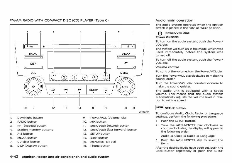
(166,1)
[ Edit: 2018/ 5/ 25 Model: PD23-A ]
4-42 Monitor, Heater and air conditioner, and audio system
FM-AM RADIO WITH COMPACT DISC (CD) PLAYER (Type C)GUID-C2C440AF-8A7D-45CD-BB8E-A434107093A0
JVH1870X
1. Day/Night button2. RADIO button3. RPT (Repeat) button4. Station memory buttons5. A-Z button6. MEDIA button7. CD eject button8. DISP (Display) button
9. Power/VOL (Volume) dial10. MIX button11. Seek/track (rewind) button12. Seek/track (fast forward) button13. SETUP button14. Back button15. MENU/ENTER dial16. Phone button
Audio main operationGUID-DD2452FB-F170-4AC3-9F4C-445C42ABB602
The audio system operates when the ignitionswitch is placed in the “ON” or “ACC” position.
Power/VOL dial:GUID-9E14C2E6-2E9C-4731-980B-C45B899B977B
Power ON/OFF:To turn on the audio system, push the Power/VOL dial.The system will turn on in the mode, which wasused immediately before the system wasturned off.To turn off the audio system, push the Power/VOL dial.Volume control:To control the volume, turn the Power/VOL dial.Turn the Power/VOL dial clockwise to make thesound louder.Turn the Power/VOL dial counterclockwise tomake the sound quieter.The audio unit is equipped with a speedvolume. This means that the audio systemautomatically adjusts the volume level in rela-tion to vehicle speed.
SETUP button:GUID-9E14C2E6-2E9C-4731-980B-C45B899B977B
To configure Audio, Clock, Radio, or Languagesettings, perform the following procedure:1. Push the SETUP button.2. Turn the MENU/ENTER dial clockwise or
counterclockwise, the display will appear inthe following order.Audio � Clock � Radio � Language
3. Push the MENU/ENTER dial to select theitem.
After the desired levels have been set, push theBack button repeatedly or push the SETUP
Condition: 'Except for China'/
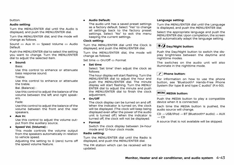
(167,1)
[ Edit: 2018/ 5/ 25 Model: PD23-A ]
button.Audio setting:Turn the MENU/ENTER dial until the Audio isdisplayed, and push the MENU/ENTER dial.Turn the MENU/ENTER dial, and the mode willchange as follows.Sound � Aux In � Speed Volume � AudioDefaultPush the MENU/ENTER dial to select the settingyou want to change. Turn the MENU/ENTERdial to adjust the selected item.. Sound:
Bass:Use this control to enhance or attenuatebass response sound.Treble:Use this control to enhance or attenuatethe treble.Bal. (Balance) :Use this control to adjust the balance of thevolume between the left and right speak-ers.Fade:Use this control to adjust the balance of thevolume between the front and the rearspeakers.
. Aux In:Use this control to adjust the volume out-put from the auxiliary source.
. Speed Vol. (Volume) :This mode controls the volume outputfrom the speakers automatically in relationto vehicle speed.Adjusting the setting to 0 (zero) turns offthe speed volume feature.
. Audio Default:The audio unit has a saved preset settingsas a factory default. Select “Yes” to changeall settings back to the factory presetsettings. Select “No” to exit the menukeeping the current settings.
Clock setting:Turn the MENU/ENTER dial until the Clock isdisplayed, and push the MENU/ENTER dial.Turn the MENU/ENTER dial, the mode willchange as follows:Set time � On/Off � Format. Set time
Select “Set time” then adjust the clock asfollows:The hour display will start flashing. Turn theMENU/ENTER dial to adjust the hour andpush the MENU/ENTER dial. The minutedisplay will start flashing. Turn the MENU/ENTER dial to adjust the minute and pushthe MENU/ENTER dial to finish the clockadjustment.
. On/OffThe clock display can be turned on and off.When the indicator is turned on, the clockwill be displayed. (The clock will keep beingdisplayed even after the power of the audiounit is turned off.) When the indicator isturned off, the clock will not be displayed.
. FormatSwitch the clock display between 24-hourmode and 12-hour clock mode.
Radio setting:Turn the MENU/ENTER dial until the Radio isdisplayed, and push the MENU/ENTER dial.The FM station which can be received will beupdated.
Language setting:Turn the MENU/ENTER dial until the Languageis displayed, and push the MENU/ENTER dial.Select the appropriate language and push theMENU/ENTER dial. Upon completion, the screenwill automatically adapt the language setting.
Day/Night button:GUID-9E14C2E6-2E9C-4731-980B-C45B899B977B
Push the Day/Night button to switch the dis-play brightness between the daytime andnighttime modes.The switches on the audio unit will alsoilluminate in the nighttime mode.
Phone button:GUID-9E14C2E6-2E9C-4731-980B-C45B899B977B
For information on how to use the phonebutton, see “Bluetooth® Hands-Free PhoneSystem (for type B and type C audio)” (P.4-50).
MEDIA button:GUID-9E14C2E6-2E9C-4731-980B-C45B899B977B
Push the MEDIA button to play a compatibledevice when it is connected.Each time the MEDIA button is pushed, theaudio source will change.CD? USB/iPod? BT (Bluetooth® audio)? AUX? CDA source that is not available will be skipped.
Monitor, Heater and air conditioner, and audio system 4-43
Condition: 'Except for China'/

(168,1)
[ Edit: 2018/ 5/ 25 Model: PD23-A ]
4-44 Monitor, Heater and air conditioner, and audio system
Radio operationGUID-3D7FFA68-3656-41A3-992D-07A446C73ECA
Frequency range and step change:GUID-9E14C2E6-2E9C-4731-980B-C45B899B977B
To change the frequency range and stepspecification of the radio, perform the followingoperations.1. Turn on the audio system.2. Push the RADIO button and select AM or FM
mode.3. Push and hold the SETUP button for more
than 3 seconds.4. After the 3 seconds, keep holding the
SETUP button and turn the MENU/ENTERdial counterclockwise until you hear 3clicks, clockwise until you hear 3 clicks,and then counterclockwise until you hear 3clicks.
5. Turn the MENU/ENTER dial until “Region” ishighlighted, and push the MENU/ENTERdial.
6. Select an appropriate region from thefollowing options:. EUR. GOM Pacific. GOM S. America
7. To apply the setting, turn off the audiosystem, place the ignition switch in the“OFF” position, and then place the ignitionswitch back in the “ON” position.
RADIO button:GUID-9E14C2E6-2E9C-4731-980B-C45B899B977B
When the RADIO button is pushed while theaudio system is off, the audio system will turnon and the radio will turn on.When the RADIO button is pushed while an-other audio source is playing, the other audiosource will turn off and the radio will turn on.
To change the radio bands, push the RADIObutton until the desired band appears.FM 1 ? FM 2 ? AM ? FM 1When the RADIO button is pushed for morethan 1.5 seconds, the FM station which can bereceived will be updated.
Seek/track buttons:GUID-9E14C2E6-2E9C-4731-980B-C45B899B977B
Push or button briefly to manuallychange the frequency.To adjust the broadcasting station frequencyautomatically, push and hold the orbutton. When the system detects a broad-casting station, it will stop at the station.
&1 &2 &3 &4 &5 &6 Station memory buttons:GUID-9E14C2E6-2E9C-4731-980B-C45B899B977B
During radio reception, pushing the stationmemory button will select the stored radiostation.The audio system can store up to 12 FM stationfrequencies (6 in each of FM 1, FM 2) and 6 AMstation frequencies.To store the station frequency manually:1. Tune to the desired broadcasting station
frequency by using the or button.2. Push and hold a station memory button&1
-&6 until a beep sounds.3. The channel indicator will display, indicat-
ing that the memory is stored properly.4. Perform steps 1 - 3 for all other memory
buttons.If the battery cable is disconnected, or if theaudio fuse blows, the station memory will beerased. In such a case, reset the desiredstations.
CD player operationGUID-16E8CAB3-FA75-4373-BFAB-350F7D29A1F1
Loading:GUID-9E14C2E6-2E9C-4731-980B-C45B899B977B
Insert a CD into the slot with the label sidefacing up. The CD will be guided automaticallyinto the slot and will start playing. After loadingthe CD, the number of tracks and the playtimewill appear on the display.
CAUTION:
Do not force the CD into the slot. This coulddamage the player.
NOTE:. The CD player accepts normal audio CDs
or CDs containing MP3/WMA/AAC files.. An error notification message will be
displayed when inserting an incompati-ble disc type (e.g. DVD), or if the playercannot read the CD. Eject the disc andinsert another disc.
MEDIA button:GUID-9E14C2E6-2E9C-4731-980B-C45B899B977B
To change to the CD mode, push the MEDIAbutton with a CD inserted until the CD mode isselected.
List view:GUID-9E14C2E6-2E9C-4731-980B-C45B899B977B
While the track is being played, push the MENU/ENTER dial to display the available tracks in alisted view mode. To select a track from the list,turn the MENU/ENTER dial then push MENU/ENTER dial.Quick search:In the list view mode, a quick search can beperformed to find a track from the list. Push theA-Z button, turn the MENU/ENTER dial to thefirst alphabetic letter of the song title and thenpush the MENU/ENTER dial. When found, a list
Condition: 'Except for China'/

(169,1)
[ Edit: 2018/ 5/ 25 Model: PD23-A ]
of the available songs will be displayed. Select,and push the MENU/ENTER dial to play thepreferred track.
Seek/track buttons:GUID-9E14C2E6-2E9C-4731-980B-C45B899B977B
Push and hold the or button to fastforward or rewind through the track. When thebutton is released, the track will play at normalplaying speed.Track up/down:Pushing the or button once, the trackwill skip forward to the next track or backwardto the beginning of the current track. Push the
or button more than once to skipthrough the tracks.
Folder browsing:GUID-9E14C2E6-2E9C-4731-980B-C45B899B977B
If the recorded media contains folders withmusic files, pushing the or button willplay in sequence the tracks of each folder.To select a preferred folder:1. Push the MENU/ENTER dial or the Back
button and a list of tracks in the currentfolder is displayed.
2. Push the Back button.3. Turn the MENU/ENTER dial for the pre-
ferred folder.4. Push the MENU/ENTER dial to access the
folder. Push the MENU/ENTER dial again tostart playing the first track or turn theMENU/ENTER dial, and push the MENU/ENTER dial to select another track.
If the selected folder contains sub folders, pushthe MENU/ENTER dial, a new screen with a listof sub folders will be displayed. Turn the MENU/ENTER dial for the sub folder then push theMENU/ENTER dial to select. Select the rootfolder item when songs are recorded addition-
ally in the root folder.To return to the previous folder screen, pushthe Back button.
RPT button:GUID-9E14C2E6-2E9C-4731-980B-C45B899B977B
Push the RPT button and the current track willbe played continuously.
MIX button:GUID-9E14C2E6-2E9C-4731-980B-C45B899B977B
Push the MIX button and all the tracks will beplayed in a random order.
DISP button:GUID-9E14C2E6-2E9C-4731-980B-C45B899B977B
While a CD with recorded music informationtags (CD-text/ID3-text tags) is being played, thetitle of the played track is displayed whenavailable.When the DISP button is pushed repeatedly,further information about the track can bedisplayed along with the track title as follows:Track time ? Artist name ? Album title ?Track timeTrack details:Pushing and holding the DISP button will turnthe display into a detailed overview. Push theBack button to return to the previous screen.
CD Eject button:GUID-9E14C2E6-2E9C-4731-980B-C45B899B977B
When the CD eject button is pushed while theignition switch is placed in the “ON” or “ACC”position, the CD will be ejected.If a CD is ejected by pushing the CD ejectbutton, and it is not taken out from the loadingslot within 20 seconds, the CD will automati-cally be reloaded to the slot to protect the CD.
USB (Universal Serial Bus) connectionport
GUID-26AD8EBE-5ED6-4FBE-AE59-CA42451FD8C9
USB device main operation:GUID-9E14C2E6-2E9C-4731-980B-C45B899B977B
The USB connection port is located on thelower part of the instrument panel. See “USB(Universal Serial Bus) connection port” (P.4-48).Connect a USB memory device into the con-nection port. The USB memory device will beactivated automatically.Refer to your device manufacturer’s ownerinformation regarding the proper use and careof the device.If the system has been turned off while the USBmemory device was playing, pushing thePower/VOL dial will start the USB memorydevice.The following operations are identical to theaudio main operation of the Compact Disc (CD)operation. For details, see “CD player operation”(P.4-44).. List view. Quick search. (Seek/track). MIX (Random play). RPT (Repeat track). Folder browsing
MEDIA button:GUID-9E14C2E6-2E9C-4731-980B-C45B899B977B
To operate the USB memory device, push theMEDIA button repeatedly until the USB/iPodmode is selected.
Monitor, Heater and air conditioner, and audio system 4-45
Condition: 'Except for China'/

(170,1)
[ Edit: 2018/ 5/ 25 Model: PD23-A ]
4-46 Monitor, Heater and air conditioner, and audio system
DISP button:GUID-9E14C2E6-2E9C-4731-980B-C45B899B977B
While a track with recorded music informationtags (ID3-tags) is being played, the title of theplayed track is displayed.When the DISP button is pushed repeatedly,further information about the track can bedisplayed along with the track title as follows:Track time ? Artist name ? Album title ?Track timeTrack details:Pushing and holding the DISP button will turnthe display into a detailed overview. Push theBack button to return to the display for themain display mode.
iPod player operationGUID-D22E6FAB-5094-4B8B-A8EF-05693106E5EE
Connecting iPod:GUID-9E14C2E6-2E9C-4731-980B-C45B899B977B
Connect the iPod to the USB connection portusing the USB cable that came with your iPod.The USB connection port is located on thelower part of the instrument panel. See “USB(Universal Serial Bus) connection port” (P.4-48).When the iPod is connected to the vehicle, theiPod music library can only be operated by thevehicle audio controls.* iPod and iPhone are a trademark of Apple Inc.,registered in the U.S. and other countries.Refer to your device manufacturer’s ownerinformation regarding the proper use and careof the device.
Compatibility:GUID-9E14C2E6-2E9C-4731-980B-C45B899B977B
The system unit shall be compatible with alldevices (past and future) supporting AppleAccessory Protocol on USB link.It includes (and not limited to):. iPod Generation 5 devices. iPod Classic I and II (Generation 6 and 7). iTouch Generation OS 1, 2, 3, 4 and next. iPhone Generation OS 1, 2, 3, 4 and next. iPod Nano (1G, 2G, 3G). iPad 1, 2 and 3
NOTE:This audio system do not support iPadcharging.
MEDIA button:GUID-9E14C2E6-2E9C-4731-980B-C45B899B977B
To operate the iPod, push the MEDIA buttonrepeatedly until the USB/iPod mode is selectedand then push the MENU/ENTER dial.
iPod main operation:GUID-9E14C2E6-2E9C-4731-980B-C45B899B977B
Interface:The interface for iPod operation shown on theaudio system display is similar to the iPodinterface. Use the MENU/ENTER dial to play atrack on the iPod.The following items can be chosen from themenu list screen.. Playlists. Artists. Albums. Tracks. MoreFor further information about each item, seethe iPod owner’s manual.The following operations are identical to the
audio main operation of the Compact Disc (CD)operation. For details, see “CD player operation”(P.4-44).. List view. Quick search. (Seek/track). MIX (Random play). RPT (Repeat track). Folder browsing
DISP button:GUID-9E14C2E6-2E9C-4731-980B-C45B899B977B
While a track with recorded music informationtags (ID3-tags) is being played, the title of theplayed track is displayed.When the DISP button is pushed repeatedly,further information about the track can bedisplayed along with the track title as follows:Track time ? Artist name ? Album title ?Track timeTrack details:Pushing and holding the DISP button will turnthe display into a detailed overview. To returnto the main display, push the Back button.
Bluetooth® audio player operationGUID-3EB18206-980E-45A6-BF68-3F770A602372
Regulatory information:GUID-9E14C2E6-2E9C-4731-980B-C45B899B977B
Bluetooth® is a trademarkowned by Bluetooth SIG, Inc.and licensed to Visteon Cor-poration.
Condition: 'Except for China'/
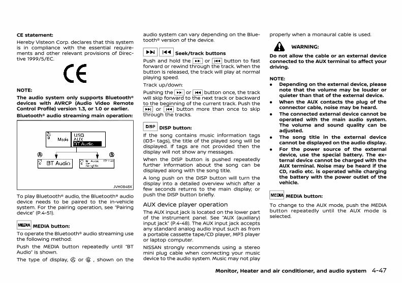
(171,1)
[ Edit: 2018/ 5/ 25 Model: PD23-A ]
CE statement:GUID-9E14C2E6-2E9C-4731-980B-C45B899B977B
Hereby Visteon Corp. declares that this systemis in compliance with the essential require-ments and other relevant provisions of Direc-tive 1999/5/EC.
NSY0105
NOTE:The audio system only supports Bluetooth®devices with AVRCP (Audio Video RemoteControl Profile) version 1.3, or 1.0 or earlier.Bluetooth® audio streaming main operation:
GUID-9E14C2E6-2E9C-4731-980B-C45B899B977B
JVH0848X
To play Bluetooth® audio, the Bluetooth® audiodevice needs to be paired to the in-vehiclesystem. For the pairing operation, see “Pairingdevice” (P.4-51).
MEDIA button:To operate the Bluetooth® audio streaming usethe following method:Push the MEDIA button repeatedly until “BTAudio” is shown.The type of display, or , shown on the
audio system can vary depending on the Blue-tooth® version of the device.
Seek/track buttonsPush and hold the or button to fastforward or rewind through the track. When thebutton is released, the track will play at normalplaying speed.Track up/down:Pushing the or button once, the trackwill skip forward to the next track or backwardto the beginning of the current track. Push the
or button more than once to skipthrough the tracks.
DISP button:If the song contains music information tags(ID3– tags), the title of the played song will bedisplayed. If tags are not provided then thedisplay will not show any messages.When the DISP button is pushed repeatedlyfurther information about the song can bedisplayed along with the song title.A long push on the DISP button will turn thedisplay into a detailed overview which after afew seconds returns to the main display; orpush the DISP button briefly.
AUX device player operationGUID-B0570C95-B35C-4874-B588-225A570A9A1D
The AUX input jack is located on the lower partof the instrument panel. See “AUX (auxiliary)input jack” (P.4-48). The AUX input jack acceptsany standard analog audio input such as froma portable cassette tape/CD player, MP3 playeror laptop computer.NISSAN strongly recommends using a stereomini plug cable when connecting your musicdevice to the audio system. Music may not play
properly when a monaural cable is used.
WARNING:
Do not allow the cable or an external deviceconnected to the AUX terminal to affect yourdriving.
NOTE:. Depending on the external device, please
note that the volume may be louder orquieter than that of the external device.
. When the AUX contacts the plug of theconnector cable, noise may be heard.
. The connected external device cannot beoperated with the main audio system.The volume and sound quality can beadjusted.
. The song title in the external devicecannot be displayed on the audio display.
. For the power source of the externaldevice, use the special battery. The ex-ternal device cannot be charged with theAUX terminal. Noise may be heard if theCD, radio etc. is operated while chargingthe battery with the power outlet of thevehicle.
MEDIA button:GUID-9E14C2E6-2E9C-4731-980B-C45B899B977B
To change to the AUX mode, push the MEDIAbutton repeatedly until the AUX mode isselected.
Monitor, Heater and air conditioner, and audio system 4-47
Condition: 'Except for China'/
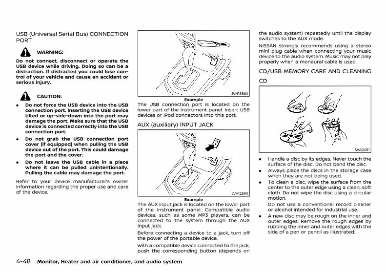
(172,1)
[ Edit: 2018/ 5/ 25 Model: PD23-A ]
4-48 Monitor, Heater and air conditioner, and audio system
USB (Universal Serial Bus) CONNECTIONPORT
PD23A1-4D9E5DFC-F734-4D3B-9979-B2B6CAC195D4
WARNING:
Do not connect, disconnect or operate theUSB device while driving. Doing so can be adistraction. If distracted you could lose con-trol of your vehicle and cause an accident orserious injury.
CAUTION:
. Do not force the USB device into the USBconnection port. Inserting the USB devicetilted or up-side-down into the port maydamage the port. Make sure that the USBdevice is connected correctly into the USBconnection port.
. Do not grab the USB connection portcover (if equipped) when pulling the USBdevice out of the port. This could damagethe port and the cover.
. Do not leave the USB cable in a placewhere it can be pulled unintentionally.Pulling the cable may damage the port.
Refer to your device manufacturer’s ownerinformation regarding the proper use and careof the device.
JVH1886XExample
The USB connection port is located on thelower part of the instrument panel. Insert USBdevices or iPod connectors into this port.
AUX (auxiliary) INPUT JACKPD23A1-BBD1AD38-69B3-4371-A83D-2ED934B3720E
JVH1259XExample
The AUX input jack is located on the lower partof the instrument panel. Compatible audiodevices, such as some MP3 players, can beconnected to the system through the AUXinput jack.Before connecting a device to a jack, turn offthe power of the portable device.With a compatible device connected to the jack,push the corresponding button (depends on
the audio system) repeatedly until the displayswitches to the AUX mode.NISSAN strongly recommends using a stereomini plug cable when connecting your musicdevice to the audio system. Music may not playproperly when a monaural cable is used.
CD/USB MEMORY CARE AND CLEANINGPD23A1-F386FC2F-5971-414B-AB0E-53F33CDC4C3E
CDPD23A1-A7E27739-B9E4-465D-9530-E602D0011802
SAA0451
. Handle a disc by its edges. Never touch thesurface of the disc. Do not bend the disc.
. Always place the discs in the storage casewhen they are not being used.
. To clean a disc, wipe the surface from thecenter to the outer edge using a clean, softcloth. Do not wipe the disc using a circularmotion.Do not use a conventional record cleaneror alcohol intended for industrial use.
. A new disc may be rough on the inner andouter edges. Remove the rough edges byrubbing the inner and outer edges with theside of a pen or pencil as illustrated.
Condition: 'Except for China'/

(173,1)
[ Edit: 2018/ 5/ 25 Model: PD23-A ]
USB memoryPD23A1-A8461194-D397-4FA0-9523-167D72022B4A
. Do not place heavy objects on the USBmemory.
. Do not store the USB memory in highlyhumid locations.
. Do not expose the USB memory to directsunlight.
. Do not spill any liquids on the USB memory.Refer to the USB memory Owner’s Manual fordetails.
AUDIO CONTROL STEERING SWITCH (ifequipped)
GUID-7A3C01F6-9830-4DD9-A05B-53B465CAD85E
JVH0686X
SOURCE select switchTuning switchVolume control switches
SOURCE select switchGUID-AC9F26CD-7DF4-4293-AF19-5091E4EC045A
Push the SOURCE select switch to change themode to available audio source.
Tuning switchGUID-A2B302DE-FC28-48C0-9754-E1B8EFF18C90
Push the switch upward or downward to selecta channel, track or folder when they are listedon the display.
RADIO:GUID-9E14C2E6-2E9C-4731-980B-C45B899B977B
. Pushing DOWN /UP shorterNext or previous preset channel
. Pushing DOWN /UP longerNext or previous station/channel
CD:GUID-9E14C2E6-2E9C-4731-980B-C45B899B977B
. Pushing DOWN /UP shorterNext track or the beginning of the currenttrack (the previous track if the button ispushed immediately after the current trackstarts playing)
. Pushing DOWN /UP longerForward or rewind
CD with MP3/WMA, iPod, USB device or Blue-tooth® audio (if equipped):
GUID-9E14C2E6-2E9C-4731-980B-C45B899B977B
. Pushing DOWN /UP shorterNext track or the beginning of the currenttrack (the previous track if the button ispushed immediately after the current trackstarts playing)
. Pushing DOWN /UP longerFolder change (When the last folder ischanged, the next disc will be selected.)
Volume control switchesGUID-6DD88099-AF2A-48F9-90BA-BA670942AB1A
Push the + or − button to increase ordecrease the volume.
PD23A1-EF6D36F4-7D99-4173-9F61-88742CFC33D7When installing a CB, ham radio or a car phonein your vehicle, be sure to observe the followingcautions, otherwise the new equipment mayadversely affect the Engine Control System andother electronic parts.
CAUTION:
. Keep the antenna as far away as possiblefrom the Electronic Control Module.
. Keep the antenna wire at least 20 cm (8in) away from the Engine Control har-nesses. Do not route the antenna wirenext to any harnesses.
. Adjust the antenna standing wave ratioas recommended by the manufacturer.
. Connect the ground wire from the radiochassis to the body.
. For details, consult a NISSAN dealer.
Monitor, Heater and air conditioner, and audio system 4-49
CAR PHONE AND CB RADIO
Condition: 'Except for China'/

(174,1)
[ Edit: 2018/ 5/ 25 Model: PD23-A ]
4-50 Monitor, Heater and air conditioner, and audio system
PD23A1-BD69E253-3F8D-4405-A2C0-4228B287ECD9
WARNING:
. Use a phone after stopping your vehiclein a safe location. If you have to use aphone while driving, exercise extremecaution at all times so full attention maybe given to vehicle operation.
. If you find yourself unable to devote fullattention to vehicle operation while usingthe phone, pull off the road to a safelocation and stop your vehicle beforedoing so.
CAUTION:
To avoid draining the vehicle battery, use aphone after starting the engine.
Bluetooth® is a wireless radio communicationstandard. This system offers a hands-freefacility for your cellular phone to enhancedriving comfort.To use the Bluetooth® Hands-Free PhoneSystem, your cellular phone must first be setup.For details, see “Bluetooth® settings” (P.4-51).Once it has been setup, the hands-free mode isautomatically activated on the registered cel-lular phone (via Bluetooth®) when it comes intorange.A notification message appears on the audiodisplay when the phone is connected, when anincoming call is being received, as well as whena call is initiated.When a call is active, the audio unit mountedcontrol buttons, microphone, and steeringwheel mounted control buttons enablehands-free communication.If the audio system is in use at the time, theradio, CD, iPod, USB audio, Bluetooth® audio orAUX source mode will be muted and will stay
muted until the active call has ended.The Bluetooth® system may not be able toconnect with your cellular phone for thefollowing reasons:. The cellular phone is too far away from the
vehicle.. The Bluetooth® mode on your cellular
phone has not been activated.. Your cellular phone has not been paired
with the Bluetooth® system of the audiounit.
. The cellular phone does not support Blue-tooth® technology.
NOTE:. For details, see your cellular phone’s
Owner’s Manual.. For assistance with your cellular phone
integration, please visit your local NISSANdealer.
REGULATORY INFORMATIONPD23A1-B5444140-C5EF-4D29-94F1-86FF505A8251
Bluetooth® trademarkPD23A1-9C05BAE4-DD4E-4AAC-9CEF-20F767C90AF7
Bluetooth® is a trademarkowned by Bluetooth SIG, Inc.and licensed to Visteon Cor-poration.
CE statementPD23A1-D83F5CFA-1A13-40A8-AC68-51C11222CBB8
Hereby Visteon Corp. declares that this systemis in compliance with the essential require-ments and other relevant provisions of Direc-tive 1999/5/EC.
NSY0105
NOTE:The audio system only supports Bluetooth®devices with AVRCP (Audio Video RemoteControl Profile) version 1.3, or 1.0 or earlier.
CONTROL BUTTONS AND MICROPHONEPD23A1-9DF2BF14-26E4-421F-8C28-693EF1EEDCE9
Audio unit:
JVH0856XFor type B audio
Bluetooth® HANDS-FREE PHONESYSTEM (for type B and type C audio)
Condition: 'Except for China'/
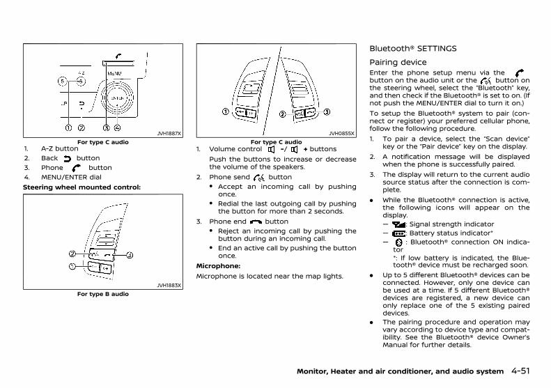
(175,1)
[ Edit: 2018/ 5/ 25 Model: PD23-A ]
JVH1887XFor type C audio
1. A-Z button2. Back button3. Phone button4. MENU/ENTER dialSteering wheel mounted control:
JVH1883XFor type B audio
JVH0855XFor type C audio
1. Volume control -/ + buttonsPush the buttons to increase or decreasethe volume of the speakers.
2. Phone send button. Accept an incoming call by pushing
once.. Redial the last outgoing call by pushing
the button for more than 2 seconds.3. Phone end button
. Reject an incoming call by pushing thebutton during an incoming call.
. End an active call by pushing the buttononce.
Microphone:Microphone is located near the map lights.
Bluetooth® SETTINGSPD23A1-452CA097-A896-41A8-98C1-BE034F64F2B0
Pairing devicePD23A1-4C128515-AD83-4D11-8948-344D0BCA3F99
Enter the phone setup menu via thebutton on the audio unit or the button onthe steering wheel, select the “Bluetooth” key,and then check if the Bluetooth® is set to on. (Ifnot push the MENU/ENTER dial to turn it on.)To setup the Bluetooth® system to pair (con-nect or register) your preferred cellular phone,follow the following procedure.1. To pair a device, select the “Scan device”
key or the “Pair device” key on the display.2. A notification message will be displayed
when the phone is successfully paired.3. The display will return to the current audio
source status after the connection is com-plete.
. While the Bluetooth® connection is active,the following icons will appear on thedisplay.— : Signal strength indicator— : Battery status indicator*— : Bluetooth® connection ON indica-
tor*: If low battery is indicated, the Blue-tooth® device must be recharged soon.
. Up to 5 different Bluetooth® devices can beconnected. However, only one device canbe used at a time. If 5 different Bluetooth®devices are registered, a new device canonly replace one of the 5 existing paireddevices.
. The pairing procedure and operation mayvary according to device type and compat-ibility. See the Bluetooth® device Owner’sManual for further details.
Monitor, Heater and air conditioner, and audio system 4-51
Condition: 'Except for China'/
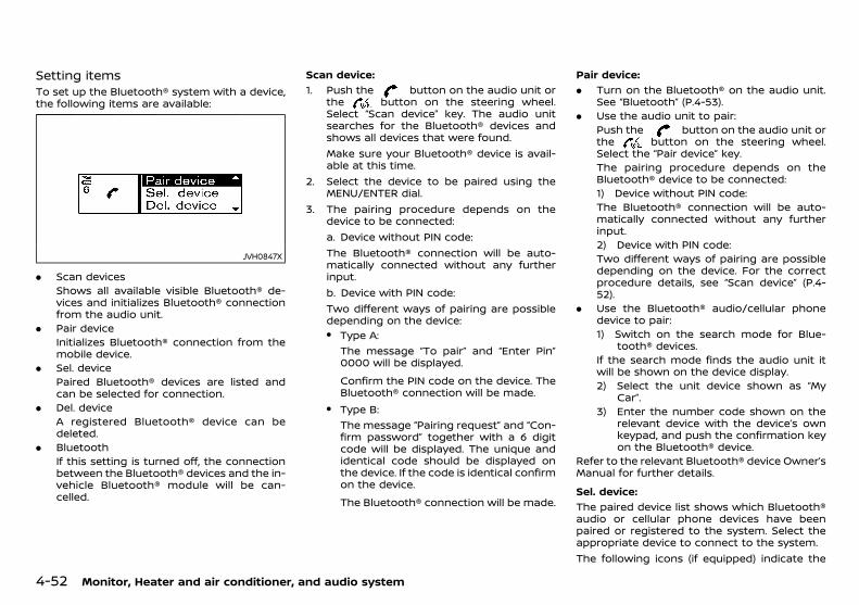
(176,1)
[ Edit: 2018/ 5/ 25 Model: PD23-A ]
4-52 Monitor, Heater and air conditioner, and audio system
Setting itemsPD23A1-0B3D36B4-9169-4636-B4C9-F7863A851717
To set up the Bluetooth® system with a device,the following items are available:
JVH0847X
. Scan devicesShows all available visible Bluetooth® de-vices and initializes Bluetooth® connectionfrom the audio unit.
. Pair deviceInitializes Bluetooth® connection from themobile device.
. Sel. devicePaired Bluetooth® devices are listed andcan be selected for connection.
. Del. deviceA registered Bluetooth® device can bedeleted.
. BluetoothIf this setting is turned off, the connectionbetween the Bluetooth® devices and the in-vehicle Bluetooth® module will be can-celled.
Scan device:GUID-9E14C2E6-2E9C-4731-980B-C45B899B977B
1. Push the button on the audio unit orthe button on the steering wheel.Select “Scan device” key. The audio unitsearches for the Bluetooth® devices andshows all devices that were found.Make sure your Bluetooth® device is avail-able at this time.
2. Select the device to be paired using theMENU/ENTER dial.
3. The pairing procedure depends on thedevice to be connected:a. Device without PIN code:The Bluetooth® connection will be auto-matically connected without any furtherinput.b. Device with PIN code:Two different ways of pairing are possibledepending on the device:. Type A:
The message “To pair” and “Enter Pin”0000 will be displayed.
Confirm the PIN code on the device. TheBluetooth® connection will be made.
. Type B:The message “Pairing request” and “Con-firm password” together with a 6 digitcode will be displayed. The unique andidentical code should be displayed onthe device. If the code is identical confirmon the device.
The Bluetooth® connection will be made.
Pair device:GUID-9E14C2E6-2E9C-4731-980B-C45B899B977B
. Turn on the Bluetooth® on the audio unit.See “Bluetooth” (P.4-53).
. Use the audio unit to pair:Push the button on the audio unit orthe button on the steering wheel.Select the “Pair device” key.The pairing procedure depends on theBluetooth® device to be connected:1) Device without PIN code:The Bluetooth® connection will be auto-matically connected without any furtherinput.2) Device with PIN code:Two different ways of pairing are possibledepending on the device. For the correctprocedure details, see “Scan device” (P.4-52).
. Use the Bluetooth® audio/cellular phonedevice to pair:1) Switch on the search mode for Blue-
tooth® devices.If the search mode finds the audio unit itwill be shown on the device display.2) Select the unit device shown as “My
Car”.3) Enter the number code shown on the
relevant device with the device’s ownkeypad, and push the confirmation keyon the Bluetooth® device.
Refer to the relevant Bluetooth® device Owner’sManual for further details.
Sel. device:GUID-9E14C2E6-2E9C-4731-980B-C45B899B977B
The paired device list shows which Bluetooth®audio or cellular phone devices have beenpaired or registered to the system. Select theappropriate device to connect to the system.The following icons (if equipped) indicate the
Condition: 'Except for China'/
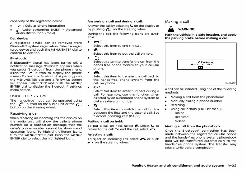
(177,1)
[ Edit: 2018/ 5/ 25 Model: PD23-A ]
capability of the registered device:. : Cellular phone integration. : Audio streaming (A2DP – Advanced
Audio Distribution Profile)
Del. device:GUID-9E14C2E6-2E9C-4731-980B-C45B899B977B
A registered device can be removed fromBluetooth® system registration. Select a regis-tered device and push the MENU/ENTER dial toconfirm to deletion.
Bluetooth:GUID-9E14C2E6-2E9C-4731-980B-C45B899B977B
If Bluetooth® signal has been turned off, anotification message “ON/OFF” appears whenyou select “Bluetooth” from the phone menu.(Push the button to display the phonemenu.) To turn the Bluetooth® signal on, pushthe MENU/ENTER dial and a follow up screenwill appear. Select “ON” and push the MENU/ENTER dial to display the Bluetooth® settingsmenu screen.
USING THE SYSTEMPD23A1-D7C021DB-4A95-4462-830D-C2CDD9870B63
The hands-free mode can be operated usingthe button on the audio unit or thebutton on the steering wheel.
Receiving a callPD23A1-88F22BBE-2750-46B8-95C1-F31E7E701D42
When receiving an incoming call, the display onthe audio unit will show the caller’s phonenumber (or a notification message that thecaller’s phone number cannot be shown) andoperation icons. To highlight different icons,turn the MENU/ENTER dial. Push the MENU/ENTER dial to select the highlighted icon.
Answering a call and during a call:GUID-9E14C2E6-2E9C-4731-980B-C45B899B977B
Answer the call by selecting on the display orby pushing on the steering wheel.During the call, the following icons are avail-able:. :
Select this item to end the call.. :
Select this item to put the call on hold.. :
Select this item to transfer the call from thehands-free phone system to your cellularphone.
. :Select this item to transfer the call back tothe hands-free phone system from thecellular phone.
. #123:Select this item to enter numbers during acall. For example, use this function whendirected by an automated phone system todial an extension number.
. :Select this item to switch the call on linebetween the first and the second call. See“Second incoming call” (P.4-55).
Putting a call on hold:GUID-9E14C2E6-2E9C-4731-980B-C45B899B977B
To put a call on hold, select . Select toreturn to the call. To end the call, select .
Rejecting a call:GUID-9E14C2E6-2E9C-4731-980B-C45B899B977B
To reject an incoming call, select or pushon the steering wheel.
Making a callPD23A1-4E5C0ACE-B370-455F-A75D-533FE6C32DE3
WARNING:
Park the vehicle in a safe location, and applythe parking brake before making a call.
JVH0863X
A call can be initiated using one of the followingmethods:. Making a call from the phonebook. Manually dialing a phone number. Redialing. Using call history (Call List menu)
— Dialed— Received— Missed
Making a call from the phonebook:GUID-9E14C2E6-2E9C-4731-980B-C45B899B977B
Once the Bluetooth® connection has beenmade between the registered cellular phoneand the hands-free phone system, phonebookdata will be transferred automatically to thehands-free phone system. The transfer maytake a while before completion.
Monitor, Heater and air conditioner, and audio system 4-53
Condition: 'Except for China'/
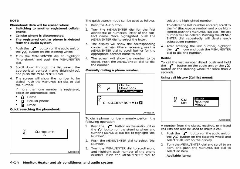
(178,1)
[ Edit: 2018/ 5/ 25 Model: PD23-A ]
4-54 Monitor, Heater and air conditioner, and audio system
NOTE:Phonebook data will be erased when:. Switching to another registered cellular
phone.. Cellular phone is disconnected.. The registered cellular phone is deleted
from the audio system.
1. Push the button on the audio unit orthe button on the steering wheel.
2. Turn the MENU/ENTER dial to highlight“Phonebook” and push the MENU/ENTERdial.
3. Scroll down through the list, select theappropriate contact name (highlighted),and push the MENU/ENTER dial.
4. The screen will show the number to bedialed. Push the MENU/ENTER dial to dialthe number.If more than one number is registered,select an appropriate icon.. : Home. : Cellular phone. : Office
Quick searching the phonebook:
JVH0858X
The quick search mode can be used as follows:1. Push the A-Z button.2. Turn the MENU/ENTER dial for the first
alphabetic or numerical letter of the con-tact name. Once highlighted, push theMENU/ENTER dial to select the letter.
3. The display will show the correspondingcontact name(s). Where necessary, use theMENU/ENTER dial to scroll further for theappropriate contact name to call.
4. The screen will show the number to bedialed. Push the MENU/ENTER dial to dialthe number.
Manually dialing a phone number:GUID-9E14C2E6-2E9C-4731-980B-C45B899B977B
JVH0859X
To dial a phone number manually, perform thefollowing operation:1. Push the button on the audio unit or
the button on the steering wheel andturn the MENU/ENTER dial to highlight “DialNumber”.
2. Push the MENU/ENTER dial to select “DialNumber”.
3. Turn the MENU/ENTER dial to scroll alongand highlight each number of the phonenumber. Push the MENU/ENTER dial to
select the highlighted number.To delete the last number entered, scroll tothe “/” (Backspace symbol) and once high-lighted, push the MENU/ENTER dial. The lastnumber will be deleted. Pushing the MENU/ENTER dial repeatedly will delete eachsubsequent number.
4. After entering the last number, highlightthe icon and push the MENU/ENTERdial to dial the number.
Redial:GUID-9E14C2E6-2E9C-4731-980B-C45B899B977B
To call the last number dialed, push and holdthe button on the audio unit or thebutton on the steering wheel for more than 2seconds.
Using call history (Call list menu):GUID-9E14C2E6-2E9C-4731-980B-C45B899B977B
JVH0860X
A number from the dialed, received, or missedcall lists can also be used to make a call.1. Push the button on the audio unit or
the button on the steering wheel andselect “Call List” on the display.
2. Turn the MENU/ENTER dial and scroll to anitem, and push the MENU/ENTER dial toselect an item.Available items:
Condition: 'Except for China'/

(179,1)
[ Edit: 2018/ 5/ 25 Model: PD23-A ]
. DialedUse the dialed call mode to make a callwhich is based on the list of outgoing(dialed) calls.
. ReceivedUse the received call mode to make a callwhich is based on the list of receivedcalls.
. MissedUse the missed call mode to make a callwhich is based on the list of missed calls.
3. Scroll to the preferred phone number andpush the MENU/ENTER dial, thebutton on the audio unit or the buttonon the steering wheel.
Second incoming callPD23A1-45C21DD7-EE91-43FB-959B-21FA46580765
JVH0861XExample
Whenever there is a second incoming call, anindication is shown on the display. By selectingthe icon the call is accepted and the currentcall is put on hold.Selecting the icon using the MENU/ENTERdial rejects the second incoming call. When thisis done during the conversation it ends the call.Selecting the icon using the MENU/ENTER
dial switches the call on line between the firstand the second call.
Ending a callPD23A1-FC22AEF1-3A90-4332-99D6-252EF04256E8
To end an active call, highlight the iconand push the ENTER/MENU dial or push the
button on the steering wheel.
GENERAL SETTINGSPD23A1-D58E0F36-F995-40FC-936B-C4764B014FED
JVH0862X
Using the MENU/ENTER dial, highlight “Settings”from the phone menu and push the MENU/ENTER dial.Volume settings and manually downloadingthe phonebook can be done using this menu.Menu operation:Turn the MENU/ENTER dial to change thehighlighted item and to change the volumesettings.Push the MENU/ENTER dial to select the high-lighted item and to apply the setting.Menu items:. Volume
— RingtoneSet the phone ringing volume.
— OngoingSet the volume of the conversationduring a call.
. Ringtone— Car
Switch the ringtone to ring from thevehicle or the cellular phone.
— PhoneSwitch the phone ringing volume on oroff.
. PB downloadDownload the phonebook of the mobiledevice to the audio unit manually.
Monitor, Heater and air conditioner, and audio system 4-55
Condition: 'Except for China'/

(180,1)
[ Edit: 2018/ 5/ 25 Model: PD23-A ]
4-56 Monitor, Heater and air conditioner, and audio system
MEMO
Condition: 'Except for China'/
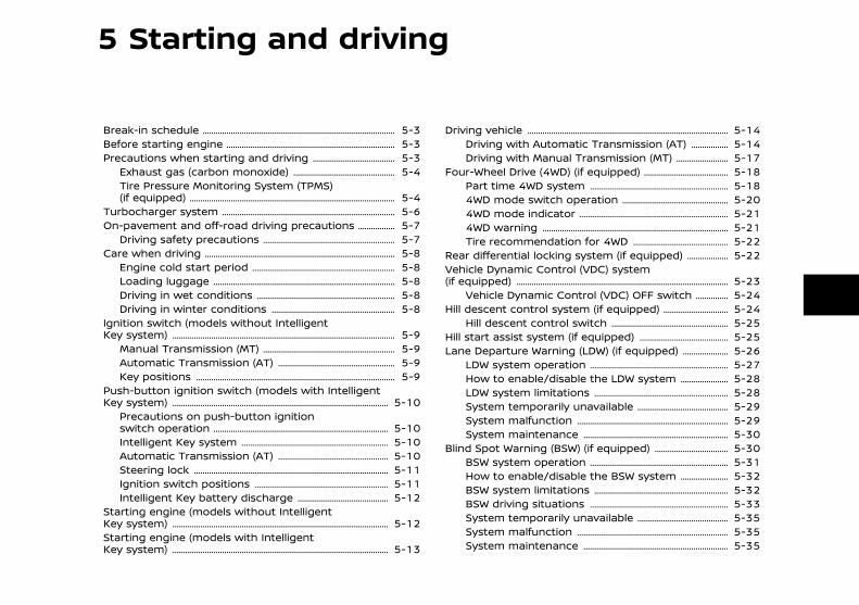
(181,1)
[ Edit: 2018/ 5/ 25 Model: PD23-A ]
5 Starting and driving
Break-in schedule ............................................................................................. 5-3Before starting engine .................................................................................. 5-3Precautions when starting and driving .......................................... 5-3
Exhaust gas (carbon monoxide) ................................................... 5-4Tire Pressure Monitoring System (TPMS)(if equipped) ................................................................................................... 5-4
Turbocharger system .................................................................................... 5-6On-pavement and off-road driving precautions ..................... 5-7
Driving safety precautions ................................................................. 5-7Care when driving ............................................................................................ 5-8
Engine cold start period ...................................................................... 5-8Loading luggage ........................................................................................ 5-8Driving in wet conditions .................................................................... 5-8Driving in winter conditions ............................................................. 5-8
Ignition switch (models without IntelligentKey system) ........................................................................................................... 5-9
Manual Transmission (MT) ................................................................. 5-9Automatic Transmission (AT) .......................................................... 5-9Key positions ................................................................................................ 5-9
Push-button ignition switch (models with IntelligentKey system) ........................................................................................................ 5-10
Precautions on push-button ignitionswitch operation ..................................................................................... 5-10Intelligent Key system ........................................................................ 5-10Automatic Transmission (AT) ....................................................... 5-10Steering lock .............................................................................................. 5-11Ignition switch positions .................................................................. 5-11Intelligent Key battery discharge .............................................. 5-12
Starting engine (models without IntelligentKey system) ........................................................................................................ 5-12Starting engine (models with IntelligentKey system) ........................................................................................................ 5-13
Driving vehicle ................................................................................................. 5-14Driving with Automatic Transmission (AT) ..................... 5-14Driving with Manual Transmission (MT) ............................ 5-17
Four-Wheel Drive (4WD) (if equipped) ........................................... 5-18Part time 4WD system .................................................................... 5-184WD mode switch operation ..................................................... 5-204WD mode indicator ......................................................................... 5-214WD warning .......................................................................................... 5-21Tire recommendation for 4WD ................................................ 5-22
Rear differential locking system (if equipped) ....................... 5-22Vehicle Dynamic Control (VDC) system(if equipped) ...................................................................................................... 5-23
Vehicle Dynamic Control (VDC) OFF switch ................... 5-24Hill descent control system (if equipped) .................................. 5-24
Hill descent control switch .......................................................... 5-25Hill start assist system (if equipped) ............................................. 5-25Lane Departure Warning (LDW) (if equipped) ......................... 5-26
LDW system operation .................................................................... 5-27How to enable/disable the LDW system .......................... 5-28LDW system limitations .................................................................. 5-28System temporarily unavailable .............................................. 5-29System malfunction .......................................................................... 5-29System maintenance ....................................................................... 5-30
Blind Spot Warning (BSW) (if equipped) ...................................... 5-30BSW system operation .................................................................... 5-31How to enable/disable the BSW system .......................... 5-32BSW system limitations .................................................................. 5-32BSW driving situations .................................................................... 5-33System temporarily unavailable .............................................. 5-35System malfunction .......................................................................... 5-35System maintenance ....................................................................... 5-35
Condition: 'Except for China'/
(182,1)
[ Edit: 2018/ 5/ 25 Model: PD23-A ]
Cruise control (if equipped) ................................................................... 5-36Precautions on cruise control ..................................................... 5-36Cruise control operations ............................................................... 5-36
ECO drive report (if equipped) ............................................................ 5-37Fuel Efficiency and Carbon Dioxide Reductiondriving tips .......................................................................................................... 5-37Increasing fuel economy and reducing CarbonDioxide emissions .......................................................................................... 5-38Parking ................................................................................................................... 5-38Parking sensor (sonar) system ........................................................... 5-40
Parking sensor (sonar) indicator (if equipped) ............... 5-40Parking sensor (sonar) system switch .................................. 5-41Parking sensor (sonar) system setting(if equipped) ................................................................................................ 5-41
Trailer towing .................................................................................................... 5-42
Power steering ................................................................................................ 5-42Brake system ................................................................................................... 5-42
Brake precautions .............................................................................. 5-42Brake assist .............................................................................................. 5-43Anti-lock Braking System (ABS) ............................................... 5-43
Vehicle security .............................................................................................. 5-44Cold weather driving ................................................................................. 5-44
Battery ......................................................................................................... 5-45Engine coolant ...................................................................................... 5-45Tire equipment ...................................................................................... 5-45Special winter equipment ............................................................ 5-45Parking brake ......................................................................................... 5-45Corrosion protection ........................................................................ 5-45
Condition: 'Except for China'/

(183,1)
[ Edit: 2018/ 5/ 25 Model: PD23-A ]
PD23A1-A49D9F41-2ED8-4FC3-9670-7475EE5E937DDuring the first 1,600 km (1,000 miles), followthese recommendations to obtain maximumengine performance and ensure the futurereliability and economy of your new vehicle.Failure to follow these recommendations mayresult in shortened engine life and reducedengine performance.. Do not drive at a constant speed, either fast
or slow, for long periods of time.. Do not run the engine over 4,000 rpm.. Do not accelerate at full throttle in any
gear.. Do not start quickly.. Do not brake hard as much as possible.
PD23A1-2B44AEEF-EA98-431C-A771-50D9ED42E601
WARNING:
The driving characteristics of your vehicle willchange remarkably by any additional loadand its distribution, as well as by addingoptional equipment (trailer coupling, etc.).Your driving style and speed must be ad-justed according to the circumstances. Espe-cially when carrying heavy loads, your speedmust be reduced adequately.
. Make sure the area around the vehicle isclear.
. Check fluid levels such as engine oil, cool-ant, brake (and clutch) fluid, windowwasher fluid as frequently as possible, atleast whenever you refuel.
. Visually inspect tires for their appearanceand condition. Measure and check the tirepressure for proper inflation.
. Check that all windows and lights are clean.
. Adjust the seat and head restraint posi-tions.
. Adjust the inside and outside rearviewmirror positions.
. Fasten your seat belt and ask all passen-gers to do the same.
. Check that all doors are closed.
. Check the operation of the warning lightswhen the ignition switch is placed in the“ON” position.
. Maintenance items in the “8. Maintenanceand do-it-yourself” section should bechecked periodically.
PD23A1-B129AECA-2865-40DF-8A4D-1A0AB4DFEEE7
WARNING:
. Never leave children or adults who wouldnormally require the support of othersalone in your vehicle. Pets should not beleft alone either. They could unknowinglyactivate switches or controls and inad-vertently become involved in a seriousaccident and injure themselves. On hot,sunny days, temperatures in a closedvehicle could quickly become high en-ough to cause severe or possibly fatalillness to people or animals.
. Properly secure all cargo to help preventit from sliding or shifting. Do not placecargo higher than the seatbacks. In asudden stop or collision, unsecured cargocould cause personal injury.
NOTE:During the first few months after purchasinga new vehicle, if you smell strong odors ofVolatile Organic Compounds (VOCs) insidethe vehicle, ventilate the passenger compart-ment thoroughly. Open all the windowsbefore entering or while in the vehicle. Inaddition, when the temperature in the pas-senger compartment rises, or when thevehicle is parked in direct sunlight for aperiod of time, turn off the air recirculationmode of the air conditioner and/or open thewindows to allow sufficient fresh air into thepassenger compartment.
Starting and driving 5-3
BREAK-IN SCHEDULE BEFORE STARTING ENGINE PRECAUTIONS WHEN STARTINGAND DRIVING
Condition: 'Except for China'/

(184,1)
[ Edit: 2018/ 5/ 25 Model: PD23-A ]
5-4 Starting and driving
EXHAUST GAS (carbon monoxide)PD23A1-5F1AD384-CD8D-48F8-9A11-E6AB3746A2F9
WARNING:
. Do not breathe exhaust gas; it containscolorless and odorless carbon monoxide.Carbon monoxide is dangerous. It cancause unconsciousness or death.
. If you suspect that exhaust fumes areentering the vehicle, drive with all win-dows fully open, and have the vehicleinspected immediately.
. Do not run the engine in closed spacessuch as a garage.
. Do not park the vehicle with the enginerunning for an extended period of time.
. Keep the back door closed while driving,otherwise exhaust gas could be drawninto the passenger compartment. If youmust drive with the back door open,follow these precautions:— Open all the windows.
— Turn the air recirculation mode offand set the fan speed control to thehighest level to circulate the air.
. If electrical wiring or other cable connec-tions must pass to a trailer through theseal of the back door or the body, followthe manufacturer’s recommendations toprevent carbon monoxide entry into thevehicle.
. If a special body or other equipment isadded for recreational or other usage,follow the manufacturer’s recommenda-tion to prevent carbon monoxide entryinto the vehicle. (Some recreational vehi-cle appliances such as stoves, refrigera-tors, heaters, etc. may also generate
carbon monoxide.). The exhaust system and body should be
inspected by a qualified mechanic when-ever:— Your vehicle is raised while being
serviced.
— You suspect that exhaust fumes areentering into the passenger compart-ment.
— You notice a change in the sound ofthe exhaust system.
— You have had an accident involvingdamage to the exhaust system, un-derbody, or rear of the vehicle.
TIRE PRESSURE MONITORING SYSTEM(TPMS) (if equipped)
GUID-D4EB56E8-CD55-4D3D-AEC9-D28CDAF3DF6CEach tire, including the spare (if provided),should be checked monthly when cold andinflated to the inflation pressure recommendedby the vehicle manufacturer on the vehicleplacard or tire inflation pressure label. (If yourvehicle has tires of a different size than the sizeindicated on the vehicle placard or tire inflationpressure label, you should determine the prop-er tire inflation pressure for those tires.)As an added safety feature, your vehicle hasbeen equipped with a Tire Pressure MonitoringSystem (TPMS) that illuminates a low tirepressure telltale when one or more of yourtires is significantly under-inflated. Accordingly,when the low tire pressure telltale illuminates,you should stop and check your tires as soonas possible, and inflate them to the properpressure. Driving on a significantly under-in-flated tire causes the tire to overheat and canlead to tire failure. Under-inflation also reducesfuel efficiency and tire tread life, and may affect
the vehicle’s handling and stopping ability.Please note that the TPMS is not a substitutefor proper tire maintenance, and it is thedriver’s responsibility to maintain correct tirepressure, even if under-inflation has notreached the level to trigger illumination of theTPMS low tire pressure telltale.Your vehicle has also been equipped with aTPMS malfunction indicator to indicate whenthe system is not operating properly. The TPMSmalfunction indicator is combined with the lowtire pressure telltale. When the system detectsa malfunction, the telltale will flash for approxi-mately one minute and then remain continu-ously illuminated. This sequence will continueupon subsequent vehicle start-ups as long asthe malfunction exists. When the malfunctionindicator is illuminated, the system may not beable to detect or signal low tire pressure asintended. TPMS malfunctions may occur for avariety of reasons, including the installation ofreplacement or alternate tires or wheels on thevehicle that prevent the TPMS from functioningproperly. Always check the TPMS malfunctiontelltale after replacing one or more tires orwheels on your vehicle to ensure that thereplacement or alternate tires and wheelsallow the TPMS to continue to function prop-erly.
Additional informationGUID-81E20A15-916B-4CAE-80D6-7194C9EDAEF7
. Since the spare tire is not equipped withthe TPMS, the TPMS does not monitor thetire pressure of the spare tire.
. The TPMS will activate only when thevehicle is driven at speeds above 25 km/h(16 MPH). Also, this system may not detect asudden drop in tire pressure (for example aflat tire while driving).
Condition: 'Except for China'/
(185,1)
[ Edit: 2018/ 5/ 25 Model: PD23-A ]
. The low tire pressure warning light may notautomatically turn off when the tire pres-sure is adjusted. After the tire is inflated tothe recommended pressure, reset the tirepressures registered in your vehicle andthen drive the vehicle at speeds above 25km/h (16 MPH) to activate the TPMS andturn off the low tire pressure warning light.
. Tire pressure rises and falls depending onthe heat caused by the vehicle’s operationand the outside temperature. Do not re-duce the tire pressure after driving becausethe tire pressure rises after driving. Lowoutside temperature can lower the tem-perature of the air inside the tire which cancause a lower tire inflation pressure. Thismay cause the low tire pressure warninglight to illuminate. If the warning lightilluminates in low ambient temperature,check the tire pressure for all four tires.
. Depending on a change in the outsidetemperature, the low tire pressure warninglight may illuminate even if the tire pressurehas been adjusted properly. Adjust the tirepressure to the recommended COLD tirepressure again when the tires are cold, andreset the TPMS.
. You can check the pressure of all tires inthe vehicle information display. (See “Tripcomputer” (P.2-28).)
For additional information, see “Low tire pres-sure warning light” (P.2-14).
WARNING:
. If the low tire pressure warning lightilluminates while driving, avoid suddensteering maneuvers or abrupt braking,reduce vehicle speed, pull off the road toa safe location and stop the vehicle assoon as possible. Driving with under-
inflated tires may permanently damagethe tires and increase the likelihood oftire failure. Serious vehicle damage couldoccur and may lead to an accident andcould result in serious personal injury.Check the tire pressure for all four tires.Adjust the tire pressure to the recom-mended COLD tire pressure shown on thetire placard to turn the low tire pressurewarning light off. If the light still illumi-nates while driving after adjusting thetire pressure, a tire may be flat or theTPMS may be malfunctioning. If you havea flat tire, replace it with a spare tire assoon as possible. If no tire is flat and alltires are properly inflated, have the ve-hicle checked by a NISSAN dealer. (See“Flat tire” (P.6-2) for changing a flat tire.)
. After adjusting the tire pressure, be sureto reset the TPMS. Otherwise, the TPMSwill not warn of low tire pressure.
. Since the spare tire is not equipped withthe TPMS, when a spare tire is mountedor a wheel is replaced, the TPMS will notfunction and the low tire pressure warn-ing light will flash for approximately 1minute. The light will remain on after the1 minute. Contact a NISSAN dealer assoon as possible for tire replacementand/or system resetting.
. Replacing tires with those not originallyspecified by NISSAN could affect theproper operation of the TPMS.
. Do not inject any tire liquid or aerosol tiresealant into the tires, as this may cause amalfunction of the tire pressure sensors.
CAUTION:
. The TPMS may not function properlywhen the wheels are equipped with tirechains or the wheels are buried in snow.
. Do not place metalized film or any metalparts (antenna, etc.) on the windows. Thismay cause poor reception of the signalsfrom the tire pressure sensors, and theTPMS will not function properly.
Some devices and transmitters may tempora-rily interfere with the operation of the TPMSand cause the low tire pressure warning lightto illuminate. Some examples are:. Facilities or electric devices using similar
radio frequencies are near the vehicle.. If a transmitter set to similar frequencies is
being used in or near the vehicle.. If a computer (or similar equipment) or a
DC/AC converter is being used in or nearthe vehicle.
Low tire pressure warning light may illuminatein the following cases.. If the vehicle is equipped with a wheel and
tire without TPMS.. If the TPMS has been replaced and the ID
has not been registered.. If the wheel is not originally specified by
NISSAN.
TPMS resettingGUID-7FC10F50-72D8-4131-B1D4-C27E849D5EA3
To keep the TPMS functioning properly, thereset operation must be performed in thefollowing cases.. when the tire pressure is adjusted. when a tire or a wheel is replaced
Starting and driving 5-5
Condition: 'Except for China'/
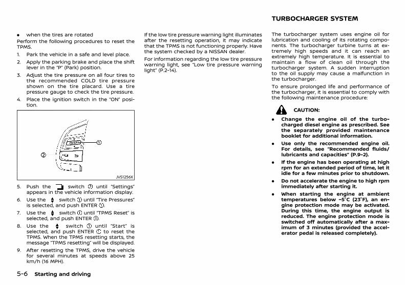
(186,1)
[ Edit: 2018/ 5/ 25 Model: PD23-A ]
5-6 Starting and driving
. when the tires are rotatedPerform the following procedures to reset theTPMS.1. Park the vehicle in a safe and level place.2. Apply the parking brake and place the shift
lever in the “P” (Park) position.3. Adjust the tire pressure on all four tires to
the recommended COLD tire pressureshown on the tire placard. Use a tirepressure gauge to check the tire pressure.
4. Place the ignition switch in the “ON” posi-tion.
JVS1256X
5. Push the switch until “Settings”appears in the vehicle information display.
6. Use the switch until “Tire Pressures”is selected, and push ENTER .
7. Use the switch until “TPMS Reset” isselected, and push ENTER .
8. Use the switch until “Start” isselected, and push ENTER to reset theTPMS. When the TPMS resetting starts, themessage “TPMS resetting” will be displayed.
9. After resetting the TPMS, drive the vehiclefor several minutes at speeds above 25km/h (16 MPH).
If the low tire pressure warning light illuminatesafter the resetting operation, it may indicatethat the TPMS is not functioning properly. Havethe system checked by a NISSAN dealer.For information regarding the low tire pressurewarning light, see “Low tire pressure warninglight” (P.2-14).
PD23A1-B4234B1A-6114-4D85-939B-C2549669BCD0The turbocharger system uses engine oil forlubrication and cooling of its rotating compo-nents. The turbocharger turbine turns at ex-tremely high speeds and it can reach anextremely high temperature. It is essential tomaintain a flow of clean oil through theturbocharger system. A sudden interruptionto the oil supply may cause a malfunction inthe turbocharger.To ensure prolonged life and performance ofthe turbocharger, it is essential to comply withthe following maintenance procedure:
CAUTION:
. Change the engine oil of the turbo-charged diesel engine as prescribed. Seethe separately provided maintenancebooklet for additional information.
. Use only the recommended engine oil.For details, see “Recommended fluids/lubricants and capacities” (P.9-2).
. If the engine has been operating at highrpm for an extended period of time, let itidle for a few minutes prior to shutdown.
. Do not accelerate the engine to high rpmimmediately after starting it.
. When starting the engine at ambienttemperatures below −5°C (23°F), an en-gine protection mode may be activated.During this time, the engine output isreduced. The engine protection mode isswitched off automatically after a max-imum of 3 minutes (provided the accel-erator pedal is released completely).
TURBOCHARGER SYSTEM
Condition: 'Except for China'/
(187,1)
[ Edit: 2018/ 5/ 25 Model: PD23-A ]
PD23A1-24C916D0-7EF3-4E4D-9021-B3F17E4CDBACUtility vehicles have a significantly higherrollover rate than other types of vehicles.They have higher ground clearance than pas-senger cars to make them capable of perform-ing in a wide variety of on-pavement and off-road applications. This gives them a highercenter of gravity than ordinary cars. An advan-tage of higher ground clearance is a betterview of the road, allowing you to anticipateproblems. However, they are not designed forcornering at the same speeds as conventionalpassenger cars any more than low-slungsports cars are designed to perform satisfac-torily under off-road conditions. If at all possi-ble, avoid sharp turns or abrupt maneuvers,particularly at high speeds. As with othervehicles of this type, failure to operate thisvehicle correctly may result in loss of control orvehicle rollover.For information about driving using Four-WheelDrive (4WD) (if equipped), see “Four-Wheel Drive(4WD)” (P.5-18).
DRIVING SAFETY PRECAUTIONSPD23A1-E071D5BB-5068-4A96-9FB2-01698070A082
Please observe the following precautions:
WARNING:
. Drive carefully when off the road andavoid dangerous areas. Every person whodrives or rides in this vehicle should beseated with their seat belt fastened. Thiswill keep you and your passengers inposition when driving over rough terrain.
. Do not drive across steep slopes. Insteaddrive either straight up or straight downthe slopes. Off-road vehicles can tip oversidewaysmuchmore easily than they canforward or backward.
. Many hills are too steep for any vehicle. Ifyou drive up them, you may stall. If youdrive down them, you may not be able tocontrol your speed. If you drive acrossthem, you may roll over.
. Do not shift ranges while driving ondownhill grades as this could cause lossof control of the vehicle.
. Stay alert when driving to the top of a hill.At the top there could be a drop-off orother hazard that could cause an acci-dent.
. If your engine stalls or you cannot makeit to the top of a steep hill, never attemptto turn around. Your vehicle could tip orroll over. Always back straight down in R(Reverse) range. Never back down in N(Neutral) or with the clutch pedal de-pressed (MT model) using only the brake,as this could cause loss of control.
. Heavy braking going down a hill couldcause your brakes to overheat and fade,resulting in loss of control and an acci-dent. Apply brakes lightly and use a lowrange to control your speed.
. Unsecured cargo can be thrown aroundwhen driving over rough terrain. Properlysecure all cargo so it will not be thrownforward and cause injury to you or yourpassengers.
. To avoid raising the center of gravityexcessively, do not exceed the ratedcapacity of the roof rack and evenlydistribute the load. Secure heavy loadsin the cargo area as far forward and aslow as possible. Do not equip the vehiclewith tires larger than specified in thismanual. This could cause your vehicle toroll over.
. Do not grip the inside or spokes of thesteering wheel when driving off-road.The steering wheel could move suddenlyand injure your hands. Instead drive withyour fingers and thumbs on the outsideof the rim.
. Before operating the vehicle, ensure thatthe driver and all passengers have theirseat belts fastened.
. Always drive with the floor mats in placeas the floor may became hot.
. Lower your speed when encounteringstrong crosswinds. With a higher centerof gravity, your NISSAN is more affectedby strong side winds. Slower speedsensure better vehicle control.
. Do not drive beyond the performancecapability of the tires, even with 4WDengaged. (4WD models)
. Do not attempt to raise two wheels offthe ground and shift the transmission toany drive or reverse position with theengine running. Doing so may result indrivetrain damage or unexpected vehiclemovement which could result in seriousvehicle damage or personal injury. (4WDmodels)
. Do not attempt to test a 4WD equippedvehicle on a 2-wheel dynamometer orsimilar equipment even if the other twowheels are raised off the ground. Makesure you inform test facility personnelthat your vehicle is equipped with 4WDbefore it is placed on a dynamometer.Using the wrong test equipment mayresult in drivetrain damage or unex-pected vehicle movement which couldresult in serious vehicle damage or per-sonal injury. (4WD models)
Starting and driving 5-7
ON-PAVEMENT AND OFF-ROADDRIVING PRECAUTIONS
Condition: 'Except for China'/
(188,1)
[ Edit: 2018/ 5/ 25 Model: PD23-A ]
5-8 Starting and driving
. When a wheel is off the ground due to anunlevel surface, do not spin the wheelexcessively.
. Accelerating quickly, sharp steering man-euvers or sudden braking may cause lossof control.
. If at all possible, avoid sharp turningmaneuvers, particularly at high speeds.Your vehicle has a higher center ofgravity than a conventional passengercar. The vehicle is not designed forcornering at the same speeds as conven-tional passenger cars. Failure to operatethis vehicle correctly could result in lossof control and/or a rollover accident.
. Always use tires of the same type, size,brand, construction (bias, bias-belted orradial), and tread pattern on all fourwheels. Install tire chains on the rearwheels when driving on slippery roadsand drive carefully.
. Be sure to check the brakes immediatelyafter driving in mud or water. See “Brakesystem” (P.5-42) for wet brakes.
. Avoid parking your vehicle on steep hills.If you get out of the vehicle and it rollsforward, backward or sideways, youcould be injured.
. Whenever you drive off-road throughsand, mud or water as deep as the wheelhub, more frequent maintenance may berequired. See the maintenance informa-tion in a separate maintenance booklet.
. Rinse the underside of the vehicle withfresh water after driving through mud orsand. Remove any brush or sticks thatare trapped.
PD23A1-A917C9CC-63C5-4B98-81ED-0EA08A5212FCDriving your vehicle to fit the circumstances isessential for your safety and comfort. As adriver, you should be the one who knows besthow to drive in the given circumstances.
ENGINE COLD START PERIODPD23A1-21A55567-B34C-4C27-B2B4-70B2DA1E5430
Due to the higher engine speeds, when theengine is cold, extra caution must be exercisedwhen selecting a gear during the engine warm-up period after starting the engine.
LOADING LUGGAGEPD23A1-528ED040-7127-4474-A856-D6E519A27850
Loads and their distribution and the attach-ment of equipment (roof baggage carriers, etc.)will considerably change the driving character-istics of the vehicle. Your driving style andspeed must be adjusted according to thecircumstances.
DRIVING IN WET CONDITIONSPD23A1-FD8038A7-F86E-43B5-96B6-CE9AF366EC0B
. Avoid accelerating or stopping suddenly.
. Avoid sharp turning or lane changingsuddenly.
. Avoid following too close to the vehicle infront.
When water covers the road surface with waterpuddles, small water streams, etc., reducespeed to prevent hydroplaning which cancause skidding and loss of control. Worn tireswill increase this risk.
DRIVING IN WINTER CONDITIONSPD23A1-D189FD17-30EF-4E56-AB9D-3C4D6A3A5B10
. Drive cautiously.
. Avoid accelerating or stopping suddenly.
. Avoid sharp turning or lane changingsuddenly.
. Avoid sudden steering.
. Avoid following too close to the vehicle infront.
CARE WHEN DRIVING
Condition: 'Except for China'/
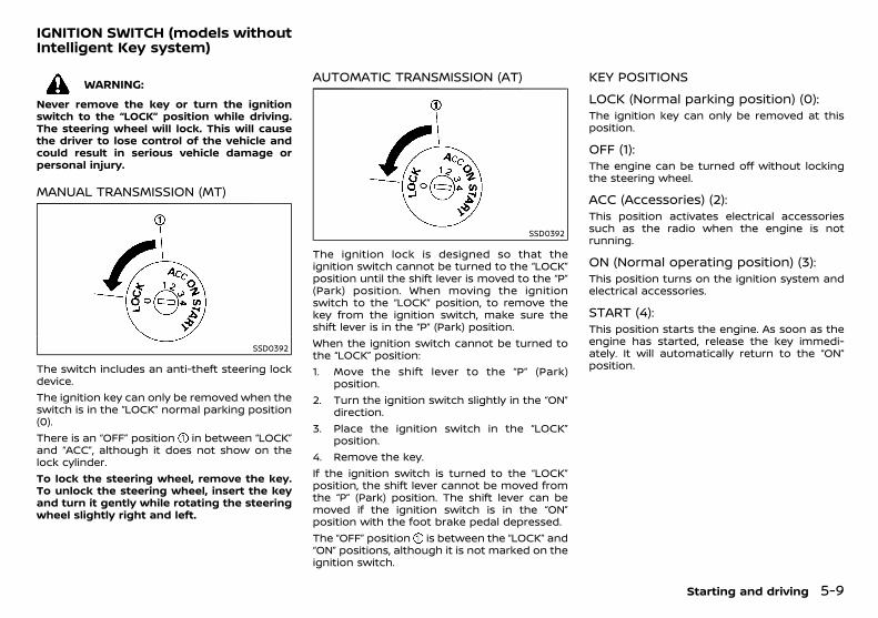
(189,1)
[ Edit: 2018/ 5/ 25 Model: PD23-A ]
PD23A1-3EF57A52-31D3-4FBD-B21F-C596432C7431
WARNING:
Never remove the key or turn the ignitionswitch to the “LOCK” position while driving.The steering wheel will lock. This will causethe driver to lose control of the vehicle andcould result in serious vehicle damage orpersonal injury.
MANUAL TRANSMISSION (MT)PD23A1-2B7511DE-02AE-4FAE-ADEF-8631672715FC
SSD0392
The switch includes an anti-theft steering lockdevice.The ignition key can only be removed when theswitch is in the “LOCK” normal parking position(0).There is an “OFF” position in between “LOCK”and “ACC”, although it does not show on thelock cylinder.To lock the steering wheel, remove the key.To unlock the steering wheel, insert the keyand turn it gently while rotating the steeringwheel slightly right and left.
AUTOMATIC TRANSMISSION (AT)PD23A1-E0D7F3B0-8127-4DD1-A0E8-4712947ED842
SSD0392
The ignition lock is designed so that theignition switch cannot be turned to the “LOCK”position until the shift lever is moved to the “P”(Park) position. When moving the ignitionswitch to the “LOCK” position, to remove thekey from the ignition switch, make sure theshift lever is in the “P” (Park) position.When the ignition switch cannot be turned tothe “LOCK” position:1. Move the shift lever to the “P” (Park)
position.2. Turn the ignition switch slightly in the “ON”
direction.3. Place the ignition switch in the “LOCK”
position.4. Remove the key.If the ignition switch is turned to the “LOCK”position, the shift lever cannot be moved fromthe “P” (Park) position. The shift lever can bemoved if the ignition switch is in the “ON”position with the foot brake pedal depressed.The “OFF” position is between the “LOCK” and“ON” positions, although it is not marked on theignition switch.
KEY POSITIONSPD23A1-B01DA190-659A-4512-979A-8084DEF0C827
LOCK (Normal parking position) (0):PD23A1-9F760DC6-F52D-4FA4-83D3-70F9ACBD0AC7
The ignition key can only be removed at thisposition.
OFF (1):PD23A1-E9505F49-BBAA-421E-B2C9-C38703120992
The engine can be turned off without lockingthe steering wheel.
ACC (Accessories) (2):PD23A1-17BC06EA-AF55-42AF-BFB9-1637CD53F750
This position activates electrical accessoriessuch as the radio when the engine is notrunning.
ON (Normal operating position) (3):PD23A1-19A6DFBB-AAD6-44A2-8601-EB8FE7EEC86C
This position turns on the ignition system andelectrical accessories.
START (4):PD23A1-D02E2BD6-DEA9-4A9B-A4F5-822AC53117FF
This position starts the engine. As soon as theengine has started, release the key immedi-ately. It will automatically return to the “ON”position.
Starting and driving 5-9
IGNITION SWITCH (models withoutIntelligent Key system)
Condition: 'Except for China'/

(190,1)
[ Edit: 2018/ 5/ 25 Model: PD23-A ]
5-10 Starting and driving
GUID-97A6874F-04D3-413D-B958-0BD94ADCCBC6
PRECAUTIONS ON PUSH-BUTTON IGNI-TION SWITCH OPERATION
GUID-73589175-7CB0-4D42-AC47-36B9097350F0
WARNING:
Do not operate the push-button ignitionswitch while driving the vehicle except in anemergency. (The engine will stop when theignition switch is pushed 3 consecutive timesor the ignition switch is pushed and held formore than 2 seconds.) The steering wheelmay lock and could cause the driver to losecontrol of the vehicle. This could result inserious vehicle damage or personal injury.
Before operating the push-button ignitionswitch, be sure to move the shift lever to the“P” (Park) position.
INTELLIGENT KEY SYSTEMGUID-9B0A6A9D-9263-4D8A-B8A8-A05F980F6414
The Intelligent Key system can operate theignition switch without taking the key out fromyour pocket or bag. The operating environmentand/or conditions may affect the IntelligentKey system operation.Some indicators and warnings for operationare displayed in the vehicle information display.(See “Vehicle information display (models withcolor display)” (P.2-19).)
CAUTION:
. Be sure to carry the Intelligent Key withyou when operating the vehicle.
. Never leave the Intelligent Key inside thevehicle when you leave the vehicle.
. If the vehicle battery is discharged, theignition switch cannot be switched fromthe “LOCK” position, and if the steeringlock is engaged, the steering wheel can-
not be moved. Charge the battery assoon as possible. (See “Jump starting”(P.6-7).)
Operating rangeGUID-A3388DB1-82D8-41BA-A7FE-3D9BBFEC57D2
SSD0436
The Intelligent Key can only be used for startingthe engine when the Intelligent Key is withinthe specified operating range as illustrated.When the Intelligent Key battery is almostdischarged or strong radio waves are presentnear the operating location, the Intelligent Keysystem’s operating range becomes narrowerand may not function properly.If the Intelligent Key is within the operatingrange, it is possible for anyone, even someonewho does not carry the Intelligent Key, to pushthe ignition switch to start the engine.. The cargo area is not included in the
operating range, but the Intelligent Keymay function.
. If the Intelligent Key is placed on theinstrument panel, inside the glove box, doorpocket or the corner of the interior com-partment, the Intelligent Key may notfunction.
. If the Intelligent Key is placed near the dooror window outside the vehicle, the Intelli-gent Key may function.
AUTOMATIC TRANSMISSION (AT)GUID-EB1C3258-508E-4414-8A6F-6F0081AEB5BD
The ignition lock is designed so that theignition switch cannot be switched to the“LOCK” position until the shift lever is movedto the “P” (Park) position. When pushing theignition switch to the “OFF” position, make surethe shift lever is in the “P” (Park) position.When the ignition switch cannot be switched tothe “LOCK” position:1. “Shift to Park” warning appears on the
vehicle information display and a chimesounds.
2. Move the shift lever to the “P” (Park)position.
3. If the ignition switch is in the “ACC” position,PUSH warning appears on the vehicleinformation display.
4. Push the ignition switch. The ignitionswitch is switched to the “OFF” position.
5. Open the door. The ignition switch turns tothe “LOCK” position.
For warnings and indicators on the vehicleinformation display, see “Vehicle informationdisplay (models with color display)” (P.2-19).If the ignition switch is switched to the “LOCK”position, the shift lever cannot be moved fromthe “P” (Park) position. The shift lever can bemoved if the ignition switch is in the “ON”position with the foot brake pedal depressed.
PUSH-BUTTON IGNITION SWITCH(models with Intelligent Key system)
Condition: 'Except for China'/
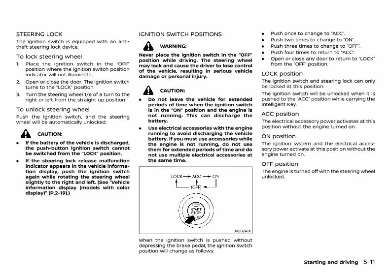
(191,1)
[ Edit: 2018/ 5/ 25 Model: PD23-A ]
STEERING LOCKGUID-54D9FD9F-6C7B-4AD2-AEA8-B5DF80D51DDF
The ignition switch is equipped with an anti-theft steering lock device.
To lock steering wheelGUID-9ECBAE16-6215-40F8-95ED-8A0B804FE371
1. Place the ignition switch in the “OFF”position where the ignition switch positionindicator will not illuminate.
2. Open or close the door. The ignition switchturns to the “LOCK” position.
3. Turn the steering wheel 1/6 of a turn to theright or left from the straight up position.
To unlock steering wheelGUID-C7F73FCF-7B52-4BE0-AFBC-DA62C983FDFC
Push the ignition switch, and the steeringwheel will be automatically unlocked.
CAUTION:
. If the battery of the vehicle is discharged,the push-button ignition switch cannotbe switched from the “LOCK” position.
. If the steering lock release malfunctionindicator appears in the vehicle informa-tion display, push the ignition switchagain while rotating the steering wheelslightly to the right and left. (See “Vehicleinformation display (models with colordisplay)” (P.2-19).)
IGNITION SWITCH POSITIONSGUID-10A24398-D2F5-4AD6-9797-79642012064D
WARNING:
Never place the ignition switch in the “OFF”position while driving. The steering wheelmay lock and cause the driver to lose controlof the vehicle, resulting in serious vehicledamage or personal injury.
CAUTION:
. Do not leave the vehicle for extendedperiods of time when the ignition switchis in the “ON” position and the engine isnot running. This can discharge thebattery.
. Use electrical accessories with the enginerunning to avoid discharging the vehiclebattery. If you must use accessories whilethe engine is not running, do not usethem for extended periods of time and donot use multiple electrical accessories atthe same time.
JVS0241X
When the ignition switch is pushed withoutdepressing the brake pedal, the ignition switchposition will change as follows:
. Push once to change to “ACC”.
. Push two times to change to “ON”.
. Push three times to change to “OFF”.
. Push four times to return to “ACC”.
. Open or close any door to return to “LOCK”from the “OFF” position.
LOCK positionGUID-FF3C816E-E8B5-4826-A5D8-BAB958F77151
The ignition switch and steering lock can onlybe locked at this position.The ignition switch will be unlocked when it ispushed to the “ACC” position while carrying theIntelligent Key.
ACC positionGUID-6497A2BA-C149-4E70-A641-1A29303A065F
The electrical accessory power activates at thisposition without the engine turned on.
ON positionGUID-0CE984BC-FD42-48F0-8978-3E4A0990EE27
The ignition system and the electrical acces-sory power activate at this position without theengine turned on.
OFF positionGUID-C8B11131-9FF0-46AD-AF42-220804D8027C
The engine is turned off with the steering wheelunlocked.
Starting and driving 5-11
Condition: 'Except for China'/
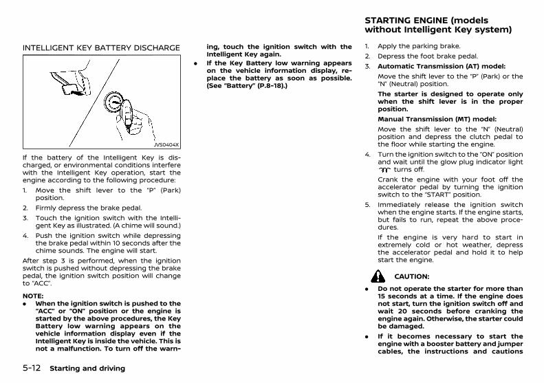
(192,1)
[ Edit: 2018/ 5/ 25 Model: PD23-A ]
5-12 Starting and driving
INTELLIGENT KEY BATTERY DISCHARGEGUID-6F91C951-DEC8-464E-94A3-E171F5D391B9
JVS0404X
If the battery of the Intelligent Key is dis-charged, or environmental conditions interferewith the Intelligent Key operation, start theengine according to the following procedure:1. Move the shift lever to the “P” (Park)
position.2. Firmly depress the brake pedal.3. Touch the ignition switch with the Intelli-
gent Key as illustrated. (A chime will sound.)4. Push the ignition switch while depressing
the brake pedal within 10 seconds after thechime sounds. The engine will start.
After step 3 is performed, when the ignitionswitch is pushed without depressing the brakepedal, the ignition switch position will changeto “ACC”.
NOTE:. When the ignition switch is pushed to the
“ACC” or “ON” position or the engine isstarted by the above procedures, the KeyBattery low warning appears on thevehicle information display even if theIntelligent Key is inside the vehicle. This isnot a malfunction. To turn off the warn-
ing, touch the ignition switch with theIntelligent Key again.
. If the Key Battery low warning appearson the vehicle information display, re-place the battery as soon as possible.(See “Battery” (P.8-18).)
PD23A1-F724F473-3759-4D1A-B537-C1D3BB5CEECE1. Apply the parking brake.2. Depress the foot brake pedal.3. Automatic Transmission (AT) model:
Move the shift lever to the “P” (Park) or the“N” (Neutral) position.The starter is designed to operate onlywhen the shift lever is in the properposition.Manual Transmission (MT) model:Move the shift lever to the “N” (Neutral)position and depress the clutch pedal tothe floor while starting the engine.
4. Turn the ignition switch to the “ON” positionand wait until the glow plug indicator light
turns off.Crank the engine with your foot off theaccelerator pedal by turning the ignitionswitch to the “START” position.
5. Immediately release the ignition switchwhen the engine starts. If the engine starts,but fails to run, repeat the above proce-dures.If the engine is very hard to start inextremely cold or hot weather, depressthe accelerator pedal and hold it to helpstart the engine.
CAUTION:
. Do not operate the starter for more than15 seconds at a time. If the engine doesnot start, turn the ignition switch off andwait 20 seconds before cranking theengine again. Otherwise, the starter couldbe damaged.
. If it becomes necessary to start theengine with a booster battery and jumpercables, the instructions and cautions
STARTING ENGINE (modelswithout Intelligent Key system)
Condition: 'Except for China'/

(193,1)
[ Edit: 2018/ 5/ 25 Model: PD23-A ]
contained in the “6. In case of emergency”section should be carefully followed.
6. Allow the engine to idle for at least 30seconds after starting the engine to warm-up. Drive at moderate speeds for a shortdistance first, especially in cold weather.
CAUTION:
Do not leave the vehicle unattended whilethe engine is warming up.
PD23A1-B04581AB-7C18-4436-B545-5C309BC381FA1. Apply the parking brake.2. Move the shift lever to the “P” (Park) or the
“N” (Neutral) position.The starter is designed to operate onlywhen the shift lever is in the properposition.The Intelligent Key must be carried whenoperating the ignition switch.
3. Place the ignition switch in the “ON” posi-tion. Firmly depress the brake pedal andpush the ignition switch to start the engine.Wait until the glow plug indicator lightturns off.To start the engine immediately, push andrelease the ignition switch while depressingthe brake pedal with the ignition switch inany position.
4. Immediately release the ignition switchwhen the engine starts. If the engine starts,but fails to run, repeat the above proce-dures.If the engine is very hard to start inextremely cold or hot weather, depressthe accelerator pedal and hold it. Push theignition switch for up to 15 seconds whileholding. Release the accelerator pedalwhen the engine starts.
CAUTION:
. As soon as the engine has started,release the ignition switch immediately.
. Do not operate the starter for more than15 seconds at a time. If the engine doesnot start, push the ignition switch to the“OFF” position and wait 20 seconds be-fore cranking the engine again. Other-wise, the starter could be damaged.
. If it becomes necessary to start theengine with a booster battery and jumpercables, the instructions and cautionscontained in the “6. In case of emergency”section should be carefully followed.
5. Allow the engine to idle for at least 30seconds after starting the engine to warm-up. Drive at moderate speeds for a shortdistance first, especially in cold weather.
CAUTION:
Do not leave the vehicle unattended whilethe engine is warming up.
6. To stop the engine, move the shift lever tothe “P” (Park) position, apply the parkingbrake, and push the ignition switch to the“OFF” position.
Starting and driving 5-13
STARTING ENGINE (models withIntelligent Key system)
Condition: 'Except for China'/
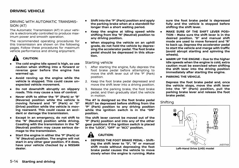
(194,1)
[ Edit: 2018/ 5/ 25 Model: PD23-A ]
5-14 Starting and driving
PD23A1-E7D545DD-C9D2-4F21-94C5-693AFF273F14
DRIVING WITH AUTOMATIC TRANSMIS-SION (AT)
PD23A1-D53AADA2-7E82-438E-A9C6-73261C06D641The Automatic Transmission (AT) in your vehi-cle is electronically controlled to produce max-imum power and smooth operation.The recommended operating procedures forthis transmission are shown on the followingpages. Follow these procedures for maximumvehicle performance and driving enjoyment.
CAUTION:
. The cold engine idle speed is high, so usecaution when shifting into a forward orreverse gear before the engine haswarmed up.
. Avoid revving up the engine while thevehicle is stopped. This could cause un-expected vehicle movement.
. Do not downshift abruptly on slipperyroads. This may cause a loss of control.
. Never shift to either the “P” (Park) or “R”(Reverse) position while the vehicle ismoving forward and “P” (Park) or “D”(Drive) position while the vehicle is mov-ing rearward. This could cause an acci-dent or damage the transmission.
. Except in an emergency, do not shift tothe “N” (Neutral) position while driving.Coasting with the transmission in the “N”(Neutral) position may cause serious da-mage to the transmission.
. Start the engine in either the “P” (Park) or“N” (Neutral) position. The engine will notstart in any other gear position. If it does,have your vehicle checked by a NISSANdealer.
. Shift into the “P” (Park) position and applythe parking brake when at a standstill forlonger than a short waiting period.
. Keep the engine at idling speed whileshifting from the “N” (Neutral) position toany driving position.
. When stopping the vehicle on an uphillgrade, do not hold the vehicle by depres-sing the accelerator pedal. The foot brakepedal should be depressed in this situa-tion.
Starting vehiclePD23A1-5203B09F-C87E-4EBF-9EF8-75C2FCD83BD7
1. After starting the engine, fully depress thefoot brake pedal before attempting tomove the shift lever out of the “P” (Park)position.
2. Keep the foot brake pedal depressed andmove the shift lever into a driving position.
3. Release the parking brake, the foot brakepedal, and then gradually start the vehiclein motion.
The AT is designed so the foot brake pedalMUST be depressed before shifting from the“P” (Park) position to any driving positionwhile the ignition switch is in the “ON”position.The shift lever cannot be moved out of the“P” (Park) position and into any of the othergear positions if the ignition switch is placedin the “LOCK”, “OFF” or “ACC” position.
CAUTION:
. DEPRESS THE FOOT BRAKE PEDAL - Shift-ing the shift lever to “D”, “R” or manualshift mode without depressing the footbrake pedal causes the vehicle to moveslowly when the engine is running. Make
sure the foot brake pedal is depressedfully and the vehicle is stopped beforeshifting the shift lever.
. MAKE SURE OF THE SHIFT LEVER POSI-TION - Make sure the shift lever is in thedesired position. “D” and manual shiftmode are used to move forward and “R”to back up. Depress the accelerator pedalto start the vehicle and merge with traffic(avoid abrupt starting and spinning thewheels).
. WARM UP THE ENGINE - Due to the higheridle speeds when the engine is cold, extracaution must be exercised when shiftingthe shift lever into the driving positionimmediately after starting the engine.
. PARKING THE VEHICLE.
Depress the foot brake pedal and, oncethe vehicle stops, move the shift leverinto the “P” (Park) position, pull theparking brake lever and release the footbrake pedal.
ShiftingPD23A1-9F637E0A-E3E2-4DA1-AFD5-A004185AD060
JVS1174XLeft-Hand Drive (LHD) model
DRIVING VEHICLE
Condition: 'Except for China'/
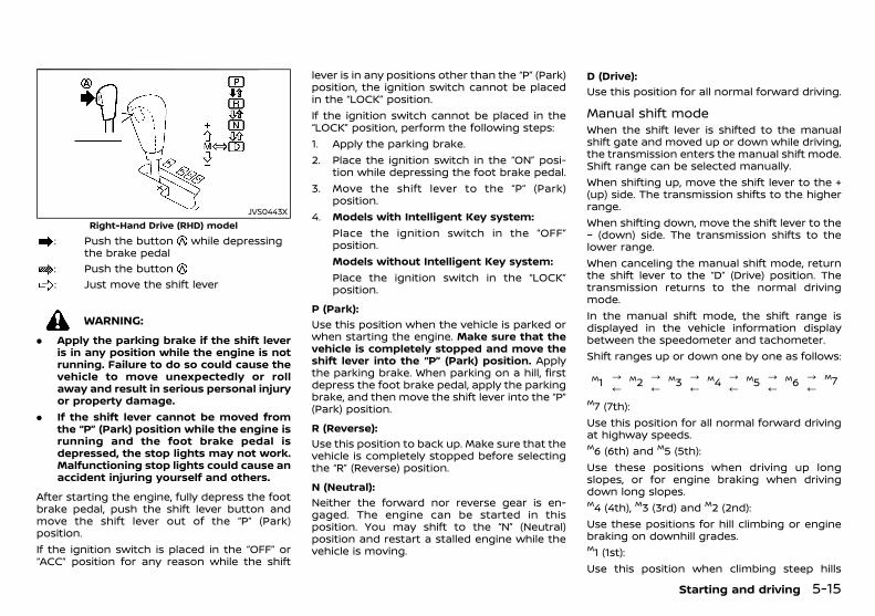
(195,1)
[ Edit: 2018/ 5/ 25 Model: PD23-A ]
JVS0443XRight-Hand Drive (RHD) model
: Push the button while depressingthe brake pedal
: Push the button: Just move the shift lever
WARNING:
. Apply the parking brake if the shift leveris in any position while the engine is notrunning. Failure to do so could cause thevehicle to move unexpectedly or rollaway and result in serious personal injuryor property damage.
. If the shift lever cannot be moved fromthe “P” (Park) position while the engine isrunning and the foot brake pedal isdepressed, the stop lights may not work.Malfunctioning stop lights could cause anaccident injuring yourself and others.
After starting the engine, fully depress the footbrake pedal, push the shift lever button andmove the shift lever out of the “P” (Park)position.If the ignition switch is placed in the “OFF” or“ACC” position for any reason while the shift
lever is in any positions other than the “P” (Park)position, the ignition switch cannot be placedin the “LOCK” position.If the ignition switch cannot be placed in the“LOCK” position, perform the following steps:1. Apply the parking brake.2. Place the ignition switch in the “ON” posi-
tion while depressing the foot brake pedal.3. Move the shift lever to the “P” (Park)
position.4. Models with Intelligent Key system:
Place the ignition switch in the “OFF”position.Models without Intelligent Key system:Place the ignition switch in the “LOCK”position.
P (Park):GUID-9E14C2E6-2E9C-4731-980B-C45B899B977B
Use this position when the vehicle is parked orwhen starting the engine. Make sure that thevehicle is completely stopped and move theshift lever into the “P” (Park) position. Applythe parking brake. When parking on a hill, firstdepress the foot brake pedal, apply the parkingbrake, and then move the shift lever into the “P”(Park) position.
R (Reverse):GUID-9E14C2E6-2E9C-4731-980B-C45B899B977B
Use this position to back up. Make sure that thevehicle is completely stopped before selectingthe “R” (Reverse) position.
N (Neutral):GUID-9E14C2E6-2E9C-4731-980B-C45B899B977B
Neither the forward nor reverse gear is en-gaged. The engine can be started in thisposition. You may shift to the “N” (Neutral)position and restart a stalled engine while thevehicle is moving.
D (Drive):GUID-9E14C2E6-2E9C-4731-980B-C45B899B977B
Use this position for all normal forward driving.
Manual shift modePD23A1-C44C5269-B111-4076-A731-A16FA94EA2DF
When the shift lever is shifted to the manualshift gate and moved up or down while driving,the transmission enters the manual shift mode.Shift range can be selected manually.When shifting up, move the shift lever to the +(up) side. The transmission shifts to the higherrange.When shifting down, move the shift lever to the− (down) side. The transmission shifts to thelower range.When canceling the manual shift mode, returnthe shift lever to the “D” (Drive) position. Thetransmission returns to the normal drivingmode.In the manual shift mode, the shift range isdisplayed in the vehicle information displaybetween the speedometer and tachometer.Shift ranges up or down one by one as follows:
M1 ?/
M2 ?/
M3 ?/
M4 ?/
M5 ?/
M6 ?/
M7
M7 (7th):Use this position for all normal forward drivingat highway speeds.M6 (6th) and M5 (5th):Use these positions when driving up longslopes, or for engine braking when drivingdown long slopes.M4 (4th), M3 (3rd) and M2 (2nd):Use these positions for hill climbing or enginebraking on downhill grades.M1 (1st):Use this position when climbing steep hills
Starting and driving 5-15
Condition: 'Except for China'/
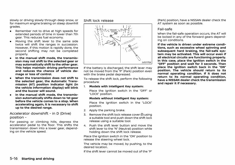
(196,1)
[ Edit: 2018/ 5/ 25 Model: PD23-A ]
5-16 Starting and driving
slowly or driving slowly through deep snow, orfor maximum engine braking on steep downhillgrades.. Remember not to drive at high speeds for
extended periods of time in lower than 7thgear. This reduces fuel economy.
. Moving the shift lever to the same sidetwice will shift the ranges in succession.However, if this motion is rapidly done, thesecond shifting may not be completedproperly.
. In the manual shift mode, the transmis-sion may not shift to the selected gear ormay automatically shift to the other gear.This helps maintain driving performanceand reduces the chance of vehicle da-mage or loss of control.
. When the transmission does not shift tothe selected gear, the Automatic Trans-mission (AT) position indicator light (inthe vehicle information display) will blinkand the buzzer will sound.
. In the manual shift mode, the transmis-sion automatically shifts down to 1st gearbefore the vehicle comes to a stop. Whenaccelerating again, it is necessary to shiftup to the desired range.
Accelerator downshift - in D (Drive)position -
PD23A1-DFCA6910-8FE6-42C8-9E08-0547E2580CC0For passing or climbing hills, depress theaccelerator pedal to the floor. This shifts thetransmission down into a lower gear, depend-ing on the vehicle speed.
Shift lock releasePD23A1-D542B7A3-4228-4AFB-B367-04BEFAD75B94
JVS1175X
If the battery is discharged, the shift lever maynot be moved from the “P” (Park) position evenwith the brake pedal depressed.To release the shift lock, perform the followingprocedure:1. Models with Intelligent Key system:
Place the ignition switch in the “OFF” or“LOCK” position.Models without Intelligent Key system:Place the ignition switch in the “LOCK”position.
2. Apply the parking brake.3. Remove the shift lock release cover using
a suitable tool and push down the shift lockrelease using a suitable tool.
4. Push the shift lever button and move theshift lever to the “N” (Neutral) position whileholding down the shift lock release.
Place the ignition switch in the “ON” position torelease the steering wheel lock.The vehicle may be moved, by pushing, to thedesired location.If the shift lever cannot be moved out of the “P”
(Park) position, have a NISSAN dealer check theAT system as soon as possible.
Fail-safePD23A1-CE544870-295F-4C51-AD1F-3CB783F5DA1D
When the fail-safe operation occurs, the AT willbe locked in any of the forward gears depend-ing on conditions.If the vehicle is driven under extreme condi-tions, such as excessive wheel spinning andsubsequent hard braking, the fail-safe sys-tem may be activated. This will occur even ifall electrical circuits are functioning properly.In this case, place the ignition switch in the“OFF” position and wait for 3 seconds. Thenplace the ignition switch back in the “ON”position. The vehicle should return to itsnormal operating condition. If it does notreturn to its normal operating condition,have a NISSAN dealer check the transmissionand repair it if necessary.
Condition: 'Except for China'/

(197,1)
[ Edit: 2018/ 5/ 25 Model: PD23-A ]
DRIVING WITH MANUAL TRANSMISSION(MT)
PD23A1-0AED9B2D-1854-402A-A6E5-BC1AAA4EE326
WARNING:
. Do not downshift abruptly on slipperyroads. This may cause a loss of control.
. Do not over-rev the engine when shiftingto a lower gear. This may cause a loss ofvehicle control or engine damage.
CAUTION:
. Do not rest your foot on the clutch pedalwhile driving. This may damage theclutch system.
. Fully depress the clutch pedal beforeshifting to help prevent transmissiondamage.
. Stop the vehicle completely before shift-ing into the “R” (Reverse) position.
. When the vehicle is stopped for a periodof time, for example, waiting at stop-lights, shift to the “N” (Neutral) positionand release the clutch pedal with the footbrake pedal depressed.
Starting vehiclePD23A1-4CE6E3AD-20C0-41BC-A155-EB94E6691A73
1. After starting the engine, depress theclutch pedal to the floor and move the shiftlever to the “1” (1st) or “R” (Reverse) position.
2. Slowly depress the accelerator pedal, re-leasing the clutch pedal and parking brakeat the same time.
Shifting gearPD23A1-12356AC8-B095-4E2A-AA0D-5BA898D10411
To change gears, or when upshifting or down-shifting, fully depress the clutch pedal, shift intothe appropriate gear, then slowly and smoothlyrelease the clutch pedal.Start the vehicle in the “1” (1st) position and shiftto the “2” (2nd), “3” (3rd), “4” (4th), “5” (5th) and “6”(6th) gear in sequence according to the vehiclespeedIf it is difficult to move the shift lever into the “R”(Reverse) or “1” (1st) position, shift to the “N”(Neutral) position, and then release the clutchpedal once. Fully depress the clutch pedalagain and shift into “R” or “1” position.
JVS0450X
To back up, depress the shift lever and thenmove it to the “R” (Reverse) position after thevehicle has completely stopped.
Suggested maximum speed in eachgear
PD23A1-05541A7D-6689-457D-907A-FB04913C940EDownshift to a lower gear if the engine is notrunning smoothly, or if you need to accelerate.Using 6th gear is recommended for achievingthe most fuel economy during highway driving.In addition, downshift to 5th gear if you needacceleration from 100 km/h (62 MPH), or when
the vehicle does not accelerate smoothly.Do not exceed the maximum suggested speed(shown below) in any gear. For level roaddriving, use the highest gear suggested forthat speed. Always observe posted speed limits,and drive according to the road conditionswhich will ensure safe operation. Do not over-rev the engine when shifting to a lower gear asit may cause engine damage or loss of vehiclecontrol.
km/h (MPH)1st 34 (21)2nd 65 (40)3rd 99 (62)4th 134 (83)5th — (—)6th — (—)
Starting and driving 5-17
Condition: 'Except for China'/
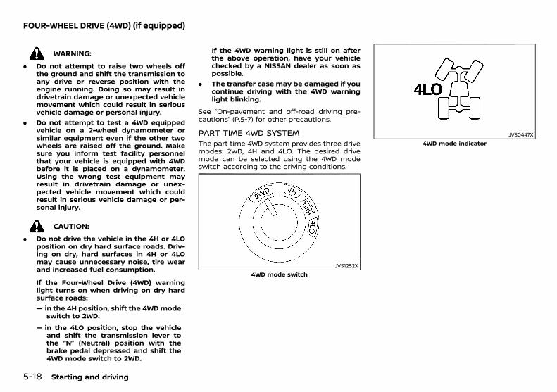
(198,1)
[ Edit: 2018/ 5/ 25 Model: PD23-A ]
5-18 Starting and driving
PD23A1-93BF1A9C-7115-4482-82D3-DF5ECF6F7F1D
WARNING:
. Do not attempt to raise two wheels offthe ground and shift the transmission toany drive or reverse position with theengine running. Doing so may result indrivetrain damage or unexpected vehiclemovement which could result in seriousvehicle damage or personal injury.
. Do not attempt to test a 4WD equippedvehicle on a 2-wheel dynamometer orsimilar equipment even if the other twowheels are raised off the ground. Makesure you inform test facility personnelthat your vehicle is equipped with 4WDbefore it is placed on a dynamometer.Using the wrong test equipment mayresult in drivetrain damage or unex-pected vehicle movement which couldresult in serious vehicle damage or per-sonal injury.
CAUTION:
. Do not drive the vehicle in the 4H or 4LOposition on dry hard surface roads. Driv-ing on dry, hard surfaces in 4H or 4LOmay cause unnecessary noise, tire wearand increased fuel consumption.
If the Four-Wheel Drive (4WD) warninglight turns on when driving on dry hardsurface roads:— in the 4H position, shift the 4WDmode
switch to 2WD.
— in the 4LO position, stop the vehicleand shift the transmission lever tothe “N” (Neutral) position with thebrake pedal depressed and shift the4WD mode switch to 2WD.
If the 4WD warning light is still on afterthe above operation, have your vehiclechecked by a NISSAN dealer as soon aspossible.
. The transfer case may be damaged if youcontinue driving with the 4WD warninglight blinking.
See “On-pavement and off-road driving pre-cautions” (P.5-7) for other precautions.
PART TIME 4WD SYSTEMPD23A1-E90D06BA-41D8-4D17-BC10-1F6A3B15AB30
The part time 4WD system provides three drivemodes: 2WD, 4H and 4LO. The desired drivemode can be selected using the 4WD modeswitch according to the driving conditions.
JVS1252X4WD mode switch
JVS0447X4WD mode indicator
FOUR-WHEEL DRIVE (4WD) (if equipped)
Condition: 'Except for China'/
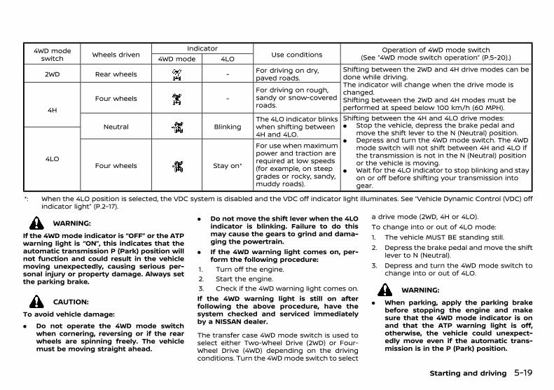
(199,1)
[ Edit: 2018/ 5/ 25 Model: PD23-A ]
4WD modeswitch Wheels driven
IndicatorUse conditions
Operation of 4WD mode switch(See “4WD mode switch operation” (P.5-20).)4WD mode 4LO
2WD Rear wheels - For driving on dry,paved roads.
Shifting between the 2WD and 4H drive modes can bedone while driving.The indicator will change when the drive mode ischanged.Shifting between the 2WD and 4H modes must beperformed at speed below 100 km/h (60 MPH).4H
Four wheels -For driving on rough,sandy or snow-coveredroads.
Neutral BlinkingThe 4LO indicator blinkswhen shifting between4H and 4LO.
Shifting between the 4H and 4LO drive modes:. Stop the vehicle, depress the brake pedal and
move the shift lever to the N (Neutral) position.. Depress and turn the 4WD mode switch. The 4WD
mode switch will not shift between 4H and 4LO ifthe transmission is not in the N (Neutral) positionor the vehicle is moving.
. Wait for the 4LO indicator to stop blinking and stayon or off before shifting your transmission intogear.
4LOFour wheels Stay on*
For use when maximumpower and traction arerequired at low speeds(for example, on steepgrades or rocky, sandy,muddy roads).
*: When the 4LO position is selected, the VDC system is disabled and the VDC off indicator light illuminates. See “Vehicle Dynamic Control (VDC) offindicator light” (P.2-17).
WARNING:
If the 4WD mode indicator is “OFF” or the ATPwarning light is “ON”, this indicates that theautomatic transmission P (Park) position willnot function and could result in the vehiclemoving unexpectedly, causing serious per-sonal injury or property damage. Always setthe parking brake.
CAUTION:
To avoid vehicle damage:
. Do not operate the 4WD mode switchwhen cornering, reversing or if the rearwheels are spinning freely. The vehiclemust be moving straight ahead.
. Do not move the shift lever when the 4LOindicator is blinking. Failure to do thismay cause the gears to grind and dama-ging the powertrain.
. If the 4WD warning light comes on, per-form the following procedure:
1. Turn off the engine.2. Start the engine.3. Check if the 4WD warning light comes on.If the 4WD warning light is still on afterfollowing the above procedure, have thesystem checked and serviced immediatelyby a NISSAN dealer.
The transfer case 4WD mode switch is used toselect either Two-Wheel Drive (2WD) or Four-Wheel Drive (4WD) depending on the drivingconditions. Turn the 4WD mode switch to select
a drive mode (2WD, 4H or 4LO).To change into or out of 4LO mode:1. The vehicle MUST BE standing still.2. Depress the brake pedal and move the shift
lever to N (Neutral).3. Depress and turn the 4WD mode switch to
change into or out of 4LO.
WARNING:
. When parking, apply the parking brakebefore stopping the engine and makesure that the 4WD mode indicator is onand that the ATP warning light is off,otherwise, the vehicle could unexpect-edly move even if the automatic trans-mission is in the P (Park) position.
Starting and driving 5-19
Condition: 'Except for China'/
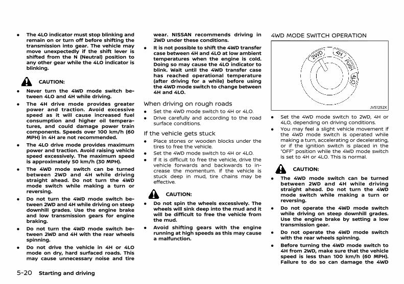
(200,1)
[ Edit: 2018/ 5/ 25 Model: PD23-A ]
5-20 Starting and driving
. The 4LO indicator must stop blinking andremain on or turn off before shifting thetransmission into gear. The vehicle maymove unexpectedly if the shift lever isshifted from the N (Neutral) position toany other gear while the 4LO indicator isblinking.
CAUTION:
. Never turn the 4WD mode switch be-tween 4LO and 4H while driving.
. The 4H drive mode provides greaterpower and traction. Avoid excessivespeed as it will cause increased fuelconsumption and higher oil tempera-tures, and could damage power traincomponents. Speeds over 100 km/h (60MPH) in 4H are not recommended.
. The 4LO drive mode provides maximumpower and traction. Avoid raising vehiclespeed excessively. The maximum speedis approximately 50 km/h (30 MPH).
. The 4WD mode switch can be turnedbetween 2WD and 4H while drivingstraight ahead. Do not turn the 4WDmode switch while making a turn orreversing.
. Do not turn the 4WD mode switch be-tween 2WD and 4H while driving on steepdownhill grades. Use the engine brakeand low transmission gears for enginebraking.
. Do not turn the 4WD mode switch be-tween 2WD and 4H with the rear wheelsspinning.
. Do not drive the vehicle in 4H or 4LOmode on dry, hard surfaced roads. Thismay cause unnecessary noise and tire
wear. NISSAN recommends driving in2WD under these conditions.
. It is not possible to shift the 4WD transfercase between 4H and 4LO at low ambienttemperatures when the engine is cold.Doing so may cause the 4LO indicator toblink. Wait until the 4WD transfer casehas reached operational temperature(after driving for a while) before usingthe 4WDmode switch to change between4H and 4LO.
When driving on rough roadsPD23A1-BA867A25-E388-4139-85A2-B6778A15CB2F
. Set the 4WD mode switch to 4H or 4LO.
. Drive carefully and according to the roadsurface conditions.
If the vehicle gets stuckPD23A1-645DF063-2BC8-4CC4-847C-31E61CC5A750
. Place stones or wooden blocks under thetires to free the vehicle.
. Set the 4WD mode switch to 4H or 4LO.
. If it is difficult to free the vehicle, drive thevehicle forwards and backwards to in-crease the momentum. If the vehicle isstuck deep in mud, tire chains may beeffective.
CAUTION:
. Do not spin the wheels excessively. Thewheels will sink deep into the mud and itwill be difficult to free the vehicle fromthe mud.
. Avoid shifting gears with the enginerunning at high speeds as this may causea malfunction.
4WD MODE SWITCH OPERATIONPD23A1-520BF100-A44E-44AC-B57F-91A162E58E30
JVS1252X
. Set the 4WD mode switch to 2WD, 4H or4LO, depending on driving conditions.
. You may feel a slight vehicle movement ifthe 4WD mode switch is operated whilemaking a turn, accelerating or decelerating,or if the ignition switch is placed in the“OFF” position while the 4WD mode switchis set to 4H or 4LO. This is normal.
CAUTION:
. The 4WD mode switch can be turnedbetween 2WD and 4H while drivingstraight ahead. Do not turn the 4WDmode switch while making a turn orreversing.
. Do not operate the 4WD mode switchwhile driving on steep downhill grades.Use the engine brake by setting a lowtransmission gear.
. Do not operate the 4WD mode switchwith the rear wheels spinning.
. Before turning the 4WD mode switch to4H from 2WD, make sure that the vehiclespeed is less than 100 km/h (60 MPH).Failure to do so can damage the 4WD
Condition: 'Except for China'/
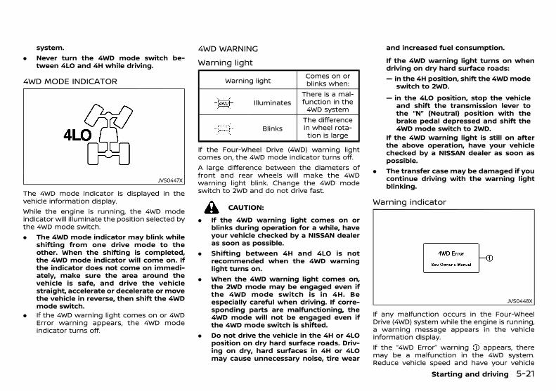
(201,1)
[ Edit: 2018/ 5/ 25 Model: PD23-A ]
system.. Never turn the 4WD mode switch be-
tween 4LO and 4H while driving.
4WD MODE INDICATORPD23A1-80CA9BD9-C099-4DDB-A298-95998425794D
JVS0447X
The 4WD mode indicator is displayed in thevehicle information display.While the engine is running, the 4WD modeindicator will illuminate the position selected bythe 4WD mode switch.. The 4WD mode indicator may blink while
shifting from one drive mode to theother. When the shifting is completed,the 4WD mode indicator will come on. Ifthe indicator does not come on immedi-ately, make sure the area around thevehicle is safe, and drive the vehiclestraight, accelerate or decelerate or movethe vehicle in reverse, then shift the 4WDmode switch.
. If the 4WD warning light comes on or 4WDError warning appears, the 4WD modeindicator turns off.
4WD WARNINGPD23A1-756BD005-A93B-49B9-968A-C3FB16BBA51A
Warning lightPD23A1-662D7D70-077C-4129-9623-D9A52BBB3DC4
Warning lightComes on orblinks when:
IlluminatesThere is a mal-function in the4WD system
BlinksThe differencein wheel rota-tion is large
If the Four-Wheel Drive (4WD) warning lightcomes on, the 4WD mode indicator turns off.A large difference between the diameters offront and rear wheels will make the 4WDwarning light blink. Change the 4WD modeswitch to 2WD and do not drive fast.
CAUTION:
. If the 4WD warning light comes on orblinks during operation for a while, haveyour vehicle checked by a NISSAN dealeras soon as possible.
. Shifting between 4H and 4LO is notrecommended when the 4WD warninglight turns on.
. When the 4WD warning light comes on,the 2WD mode may be engaged even ifthe 4WD mode switch is in 4H. Beespecially careful when driving. If corre-sponding parts are malfunctioning, the4WD mode will not be engaged even ifthe 4WD mode switch is shifted.
. Do not drive the vehicle in the 4H or 4LOposition on dry hard surface roads. Driv-ing on dry, hard surfaces in 4H or 4LOmay cause unnecessary noise, tire wear
and increased fuel consumption.
If the 4WD warning light turns on whendriving on dry hard surface roads:— in the 4H position, shift the 4WDmode
switch to 2WD.
— in the 4LO position, stop the vehicleand shift the transmission lever tothe “N” (Neutral) position with thebrake pedal depressed and shift the4WD mode switch to 2WD.
If the 4WD warning light is still on afterthe above operation, have your vehiclechecked by a NISSAN dealer as soon aspossible.
. The transfer case may be damaged if youcontinue driving with the warning lightblinking.
Warning indicatorPD23A1-CF438637-7BC7-4160-9CD8-3E6FD71C7607
JVS0448X
If any malfunction occurs in the Four-WheelDrive (4WD) system while the engine is running,a warning message appears in the vehicleinformation display.If the “4WD Error” warning appears, theremay be a malfunction in the 4WD system.Reduce vehicle speed and have your vehicle
Starting and driving 5-21
Condition: 'Except for China'/

(202,1)
[ Edit: 2018/ 5/ 25 Model: PD23-A ]
5-22 Starting and driving
checked by a NISSAN dealer as soon aspossible.
CAUTION:
. Do not operate the engine on a free rollerwhen any of the wheels raised.
. If the “4WD Error” warning appears whiledriving, there may be amalfunction in the4WD system. Reduce the vehicle speedand have your vehicle checked by aNISSAN dealer as soon as possible. Beespecially careful when driving.
. The power train may be damaged if youcontinue driving with the “4WD Error”warning on.
TIRE RECOMMENDATION FOR 4WDPD23A1-53677EED-C539-46EF-B15D-3F731FF9C130
CAUTION:
. Always use tires of the same size, brand,construction (bias, bias-belted or radial) ,and tread pattern on all four wheels.Failure to do so may result in a circum-ference difference between tires on thefront and rear axles, which will causeexcessive tire wear and may damage thetransmission, transfer case and differen-tial gears.
. ONLY use spare tires specified for theFour-Wheel Drive (4WD) models.
If excessive tire wear is found, it is recom-mended that all four tires be replaced with tiresof the same size, brand, construction and treadpattern. The tire pressure and wheel alignmentshould also be checked and corrected asnecessary. Contact a NISSAN dealer.
Snow tiresPD23A1-C6EDC0B1-9B9D-4558-9FBE-864637E7FFF4
If you install snow tires, they must also be of thesame size, brand, construction and treadpattern on all four wheels.
Tire inflation pressurePD23A1-72D85C38-1454-49AE-AE65-F055E9E0E475
Periodically check the pressures of all tires,including the spare, with a gauge while at aservice station. If necessary, adjust to thespecified pressure. Tire pressures are shownon the tire placard affixed to the driver’s sidecenter pillar.
Tire rotationPD23A1-A16FB5B8-EDEE-4809-BB68-74D839B7C799
NISSAN recommends that tires should berotated every 5,000 km (3,000 miles).
Snow chainsPD23A1-C10F938D-2A8A-474D-9E49-8735DE333128
Snow chains must be installed only on therear wheels and not on the front wheels.Do not drive with snow chains on paved roadsthat are clear of snow. Driving with chains insuch conditions can cause damage to thevarious mechanisms of the vehicle due tooverstress. When driving on clear paved roads,be sure to change to Two-Wheel Drive (2WD)mode.
PD23A1-957BD169-2EF0-411B-8129-2E0F2D7E55BD
JVS0533X
The rear differential lock is designed to trans-mit engine power to the left and right wheelsequally.If your vehicle is stuck in sand, snow, mud, etc.or one wheel is off the ground and thedifferential lock is not on, engine power istransmitted to one wheel causing it to spin,so leaving insufficient traction on the otherwheel. The rear differential lock allows the leftand right wheels to rotate as a unit, enablingyour vehicle to free itself.To lock the rear differential gear, reduce thevehicle speed below 7 km/h (4 MPH) and turnthe 4WD mode switch to the 4LO position. Thenpush the differential lock mode switch to the“ON” position. The differential lock indicatorlight “ ” will blink in the meter and then stayon when the differential gear is completelylocked.After using the rear differential lock, or duringnormal driving, push the differential lock modeswitch to the “OFF” position. The differentiallock indicator light will turn off after thedifferential lock is released.. The rear differential lock-up device oper-
ates only when the engine is running.
REAR DIFFERENTIAL LOCKINGSYSTEM (if equipped)
Condition: 'Except for China'/
(203,1)
[ Edit: 2018/ 5/ 25 Model: PD23-A ]
. In 4H mode, the rear differential lock-updevice does not operate when the differ-ential lock mode switch is turned to the“ON” position. (The differential lock indi-cator light will flash.)
WARNING:
. Use the rear differential lock only in anemergency when it is not possible to freea stuck vehicle even using the 4LO posi-tion.
. When the differential lock is in operation,turning the vehicle becomes hard and,especially at high speeds, is dangerous.
. While differential lock is on, the Anti-lockBraking System (ABS) warning light andthe Vehicle Dynamic Control (VDC) offindicator light illuminate. This indicatesthat anti-lock function may not fullyoperate.
. Do not operate the differential lock whenthe vehicle is turning or when one sidewheel is rotating. Otherwise the powertrain system parts could be damaged.
. Avoid quick starts while the differentiallock is in operation. Otherwise the powertrain system parts could be damaged.
Observe the above precautions. Otherwise,loss of normal steering control may result.
GUID-334F9BD6-7163-4222-8602-9AF5AE4B148C
WARNING:
. The Vehicle Dynamic Control (VDC) sys-tem is designed to help the driver main-tain stability but does not preventaccidents due to abrupt steering opera-tion at high speeds or by careless ordangerous driving techniques. Reducevehicle speed and be especially carefulwhen driving and cornering on slipperysurfaces and always drive carefully.
. Do not modify the vehicle’s suspension. Ifsuspension parts such as shock absor-bers, struts, springs, stabilizer bars, bush-ings and wheels are not NISSANrecommended for your vehicle or areextremely deteriorated, the VDC systemmay not operate properly. This couldadversely affect vehicle handling perfor-mance, and the VDC warning lightmay illuminate.
. If brake related parts such as brake pads,rotors and calipers are not NISSAN re-commended or are extremely deterio-rated, the VDC system may not operateproperly and the VDC warning lightmay illuminate.
. If engine control related parts are notNISSAN recommended or are extremelydeteriorated, the VDC warning lightmay illuminate.
. When driving on extremely inclined sur-faces such as higher banked corners, theVDC system may not operate properlyand the VDC warning light mayilluminate. Do not drive on these typesof roads.
. When driving on an unstable surface suchas a turntable, ferry, elevator or ramp, the
VDC warning light may illuminate.This is not a malfunction. Restart theengine after driving onto a stable surface.
. If wheels or tires other than the NISSANrecommended ones are used, the VDCsystemmay not operate properly and theVDC warning light may illuminate.
. The VDC system is not a substitute forwinter tires or tire chains on a snowcovered road.
The Vehicle Dynamic Control (VDC) systemuses various sensors to monitor driver inputsand vehicle motion. Under certain driving con-ditions, the VDC system helps to perform thefollowing functions.. Controls brake pressure to reduce wheel
slip on one slipping drive wheel so power istransferred to a non slipping drive wheel onthe same axle.
. Controls brake pressure and engine outputto reduce drive wheel slip based on vehiclespeed (traction control function).
. Controls brake pressure at individualwheels and engine output to help the drivermaintain control of the vehicle in thefollowing conditions:— understeer (vehicle tends to not follow
the steered path despite increasedsteering input)
— oversteer (vehicle tends to spin due tocertain road or driving conditions).
The VDC system can help the driver to maintaincontrol of the vehicle, but it cannot prevent lossof vehicle control in all driving situations.When the VDC system operates, the VDCwarning light in the instrument panelflashes so note the following:
Starting and driving 5-23
VEHICLE DYNAMIC CONTROL (VDC)SYSTEM (if equipped)
Condition: 'Except for China'/
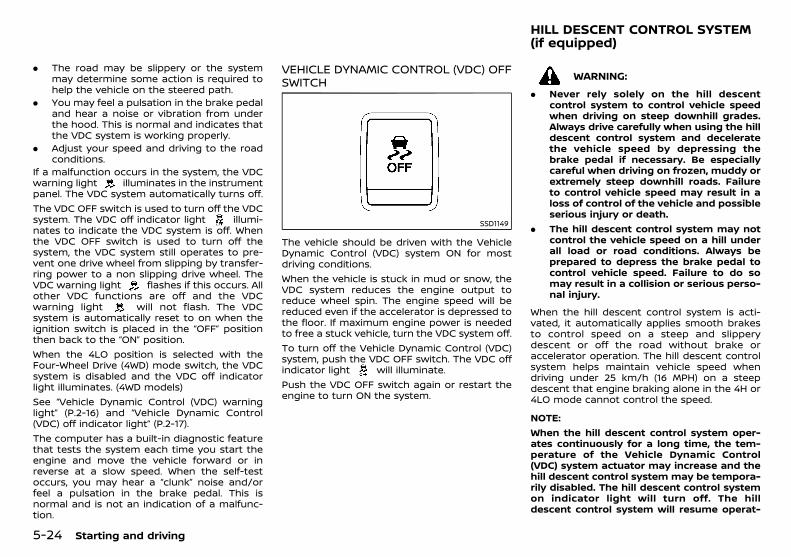
(204,1)
[ Edit: 2018/ 5/ 25 Model: PD23-A ]
5-24 Starting and driving
. The road may be slippery or the systemmay determine some action is required tohelp the vehicle on the steered path.
. You may feel a pulsation in the brake pedaland hear a noise or vibration from underthe hood. This is normal and indicates thatthe VDC system is working properly.
. Adjust your speed and driving to the roadconditions.
If a malfunction occurs in the system, the VDCwarning light illuminates in the instrumentpanel. The VDC system automatically turns off.The VDC OFF switch is used to turn off the VDCsystem. The VDC off indicator light illumi-nates to indicate the VDC system is off. Whenthe VDC OFF switch is used to turn off thesystem, the VDC system still operates to pre-vent one drive wheel from slipping by transfer-ring power to a non slipping drive wheel. TheVDC warning light flashes if this occurs. Allother VDC functions are off and the VDCwarning light will not flash. The VDCsystem is automatically reset to on when theignition switch is placed in the “OFF” positionthen back to the “ON” position.When the 4LO position is selected with theFour-Wheel Drive (4WD) mode switch, the VDCsystem is disabled and the VDC off indicatorlight illuminates. (4WD models)See “Vehicle Dynamic Control (VDC) warninglight” (P.2-16) and “Vehicle Dynamic Control(VDC) off indicator light” (P.2-17).The computer has a built-in diagnostic featurethat tests the system each time you start theengine and move the vehicle forward or inreverse at a slow speed. When the self-testoccurs, you may hear a “clunk” noise and/orfeel a pulsation in the brake pedal. This isnormal and is not an indication of a malfunc-tion.
VEHICLE DYNAMIC CONTROL (VDC) OFFSWITCH
GUID-8A53F696-0B6F-49E8-A149-B565106CD914
SSD1149
The vehicle should be driven with the VehicleDynamic Control (VDC) system ON for mostdriving conditions.When the vehicle is stuck in mud or snow, theVDC system reduces the engine output toreduce wheel spin. The engine speed will bereduced even if the accelerator is depressed tothe floor. If maximum engine power is neededto free a stuck vehicle, turn the VDC system off.To turn off the Vehicle Dynamic Control (VDC)system, push the VDC OFF switch. The VDC offindicator light will illuminate.Push the VDC OFF switch again or restart theengine to turn ON the system.
PD23A1-FC0AE4D0-852E-44C1-BC9F-4BB4C4E2556B
WARNING:
. Never rely solely on the hill descentcontrol system to control vehicle speedwhen driving on steep downhill grades.Always drive carefully when using the hilldescent control system and deceleratethe vehicle speed by depressing thebrake pedal if necessary. Be especiallycareful when driving on frozen, muddy orextremely steep downhill roads. Failureto control vehicle speed may result in aloss of control of the vehicle and possibleserious injury or death.
. The hill descent control system may notcontrol the vehicle speed on a hill underall load or road conditions. Always beprepared to depress the brake pedal tocontrol vehicle speed. Failure to do somay result in a collision or serious perso-nal injury.
When the hill descent control system is acti-vated, it automatically applies smooth brakesto control speed on a steep and slipperydescent or off the road without brake oraccelerator operation. The hill descent controlsystem helps maintain vehicle speed whendriving under 25 km/h (16 MPH) on a steepdescent that engine braking alone in the 4H or4LO mode cannot control the speed.
NOTE:When the hill descent control system oper-ates continuously for a long time, the tem-perature of the Vehicle Dynamic Control(VDC) system actuator may increase and thehill descent control system may be tempora-rily disabled. The hill descent control systemon indicator light will turn off. The hilldescent control system will resume operat-
HILL DESCENT CONTROL SYSTEM(if equipped)
Condition: 'Except for China'/
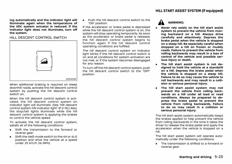
(205,1)
[ Edit: 2018/ 5/ 25 Model: PD23-A ]
ing automatically and the indicator light willilluminate again when the temperature ofthe VDC system actuator is reduced. If theindicator light does not illuminate, turn offthe system.
HILL DESCENT CONTROL SWITCHPD23A1-54DF8960-118D-468A-AF1F-E88EC10ABDD8
JVS0402X
When additional braking is required on steepdownhill roads, activate the hill descent controlsystem by pushing the hill descent controlswitch on.When the hill descent control system is acti-vated, the hill descent control system onindicator light will illuminate. (See “Hill descentcontrol system ON indicator light” (P.2-16).) Also,the stop/tail lights illuminate while the hilldescent control system is applying the brakesto control the vehicle speed.To activate the hill descent control system,satisfy all of the following conditions:. Shift the transmission to the forward or
reverse gear.. Shift the 4WD mode switch to the 4H or 4LO
position and drive the vehicle at a speedunder 25 km/h (16 MPH).
. Push the hill descent control switch to the“ON” position.
If the accelerator or brake pedal is depressedwhile the hill descent control system is on, thesystem will stop operating temporarily. As soonas the accelerator or brake pedal is released,the hill descent control system begins tofunction again if the hill descent controloperating conditions are fulfilled.The hill descent control system on indicatorlight blinks if the hill descent control switch ison and all conditions for system activation arenot met, or if the system becomes disengagedfor any reason.To turn off the hill descent control system, pushthe hill descent control switch to the “OFF”position.
GUID-C2DE6112-DBF9-41C4-A7C4-2661FA7C3E9B
WARNING:
. Never rely solely on the hill start assistsystem to prevent the vehicle from mov-ing backward on a hill. Always drivecarefully and attentively. Depress thebrake pedal when the vehicle is stoppedon a steep hill. Be especially careful whenstopped on a hill on frozen or muddyroads. Failure to prevent the vehicle fromrolling backwards may result in a loss ofcontrol of the vehicle and possible ser-ious injury or death.
. The hill start assist system is not de-signed to hold the vehicle at a standstillon a hill. Depress the brake pedal whenthe vehicle is stopped on a steep hill.Failure to do so may cause the vehicle toroll backwards and may result in a colli-sion or serious personal injury.
. The hill start assist system may notprevent the vehicle from rolling back-wards on a hill under all load or roadconditions. Always be prepared to de-press the brake pedal to prevent thevehicle from rolling backwards. Failureto do so may result in a collision orserious personal injury.
The hill start assist system automatically keepsthe brakes applied to help prevent the vehiclefrom rolling backwards in the time it takes thedriver to release the brake pedal and apply theaccelerator when the vehicle is stopped on ahill.The hill start assist system will operate auto-matically under the following conditions:. The transmission is shifted to a forward or
reverse gear.
Starting and driving 5-25
HILL START ASSIST SYSTEM (if equipped)
Condition: 'Except for China'/

(206,1)
[ Edit: 2018/ 5/ 25 Model: PD23-A ]
5-26 Starting and driving
. The vehicle is stopped completely on a hillby applying the brake.
The maximum holding time is 2 seconds. After2 seconds the vehicle will begin to roll back andthe hill start assist system will stop operatingcompletely.The hill start assist system will not operatewhen the transmission is shifted to the “N”(Neutral) or “P” (Park) position or on a flat andlevel road.When the Vehicle Dynamic Control (VDC) warn-ing light illuminates in the meter, the hill startassist system will not operate. (See “Warninglights, indicator lights and audible reminders”(P.2-11).)
GUID-6FD001AE-2D94-4829-A746-C35DDE420619
WARNING:
Failure to follow the warnings and instruc-tions for proper use of the LDW system couldresult in serious personal injury or death.
. The LDW system will not steer the vehicleor prevent loss of control. It is the driver’sresponsibility to stay alert, drive safely,keep the vehicle in the traveling lane, andbe in control of the vehicle at all times.
The LDW system will operate when the vehicleis driven at speeds of approximately 70 km/h(43 MPH) and above, and only when the lanemarkings are clearly visible on the road.
JVS1265X
The LDW system monitors the lane markers onthe traveling lane using the camera unitlocated above the inside rearview mirror.The LDW system warns the driver with the LDWindicator and chime that the vehicle is begin-ning to leave the driving lane. For additionalinformation, refer to “LDW system operation”(P.5-27).
LANE DEPARTURE WARNING (LDW)(if equipped)
Condition: 'Except for China'/
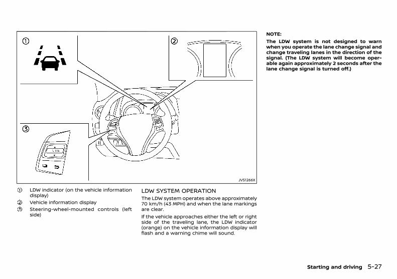
(207,1)
[ Edit: 2018/ 5/ 25 Model: PD23-A ]
JVS1266X
LDW indicator (on the vehicle informationdisplay)Vehicle information displaySteering-wheel-mounted controls (leftside)
LDW SYSTEM OPERATIONGUID-08BD4A68-132F-4B96-B58D-D5BE42C5A322
The LDW system operates above approximately70 km/h (43 MPH) and when the lane markingsare clear.If the vehicle approaches either the left or rightside of the traveling lane, the LDW indicator(orange) on the vehicle information display willflash and a warning chime will sound.
NOTE:The LDW system is not designed to warnwhen you operate the lane change signal andchange traveling lanes in the direction of thesignal. (The LDW system will become oper-able again approximately 2 seconds after thelane change signal is turned off.)
Starting and driving 5-27
Condition: 'Except for China'/
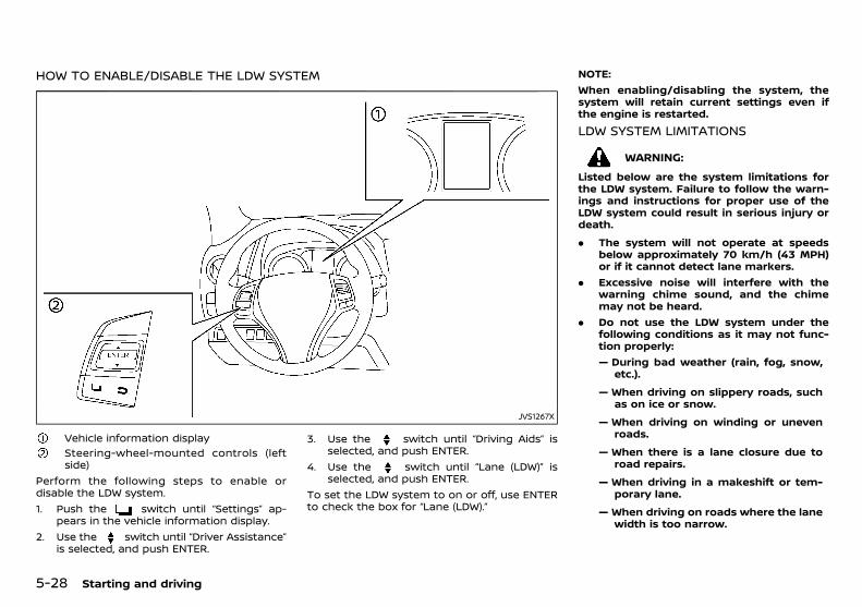
(208,1)
[ Edit: 2018/ 5/ 25 Model: PD23-A ]
5-28 Starting and driving
HOW TO ENABLE/DISABLE THE LDW SYSTEMGUID-5BC51585-2C5F-4EBC-83AA-758688AF43FB
JVS1267X
Vehicle information displaySteering-wheel-mounted controls (leftside)
Perform the following steps to enable ordisable the LDW system.1. Push the switch until “Settings” ap-
pears in the vehicle information display.2. Use the switch until “Driver Assistance”
is selected, and push ENTER.
3. Use the switch until “Driving Aids” isselected, and push ENTER.
4. Use the switch until “Lane (LDW)” isselected, and push ENTER.
To set the LDW system to on or off, use ENTERto check the box for “Lane (LDW).”
NOTE:When enabling/disabling the system, thesystem will retain current settings even ifthe engine is restarted.
LDW SYSTEM LIMITATIONSGUID-6447032B-75AE-4F40-9CD6-5C20E186B9DA
WARNING:
Listed below are the system limitations forthe LDW system. Failure to follow the warn-ings and instructions for proper use of theLDW system could result in serious injury ordeath.
. The system will not operate at speedsbelow approximately 70 km/h (43 MPH)or if it cannot detect lane markers.
. Excessive noise will interfere with thewarning chime sound, and the chimemay not be heard.
. Do not use the LDW system under thefollowing conditions as it may not func-tion properly:— During bad weather (rain, fog, snow,
etc.).
— When driving on slippery roads, suchas on ice or snow.
— When driving on winding or unevenroads.
— When there is a lane closure due toroad repairs.
— When driving in a makeshift or tem-porary lane.
— When driving on roads where the lanewidth is too narrow.
Condition: 'Except for China'/
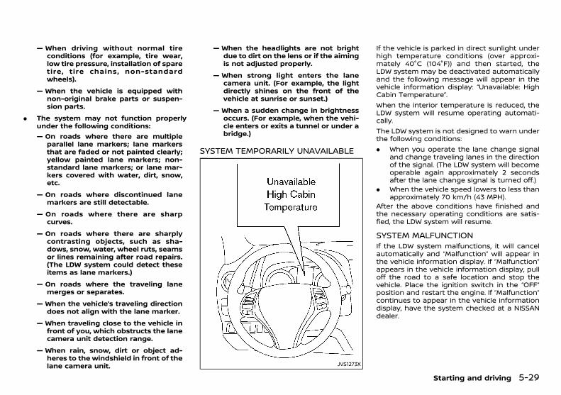
(209,1)
[ Edit: 2018/ 5/ 25 Model: PD23-A ]
— When driving without normal tireconditions (for example, tire wear,low tire pressure, installation of sparetire, tire chains, non-standardwheels).
— When the vehicle is equipped withnon-original brake parts or suspen-sion parts.
. The system may not function properlyunder the following conditions:— On roads where there are multiple
parallel lane markers; lane markersthat are faded or not painted clearly;yellow painted lane markers; non-standard lane markers; or lane mar-kers covered with water, dirt, snow,etc.
— On roads where discontinued lanemarkers are still detectable.
— On roads where there are sharpcurves.
— On roads where there are sharplycontrasting objects, such as sha-dows, snow, water, wheel ruts, seamsor lines remaining after road repairs.(The LDW system could detect theseitems as lane markers.)
— On roads where the traveling lanemerges or separates.
— When the vehicle’s traveling directiondoes not align with the lane marker.
— When traveling close to the vehicle infront of you, which obstructs the lanecamera unit detection range.
— When rain, snow, dirt or object ad-heres to the windshield in front of thelane camera unit.
— When the headlights are not brightdue to dirt on the lens or if the aimingis not adjusted properly.
— When strong light enters the lanecamera unit. (For example, the lightdirectly shines on the front of thevehicle at sunrise or sunset.)
— When a sudden change in brightnessoccurs. (For example, when the vehi-cle enters or exits a tunnel or under abridge.)
SYSTEM TEMPORARILY UNAVAILABLEGUID-12B4E7A2-13DE-4803-8776-A5289DF83531
JVS1273X
If the vehicle is parked in direct sunlight underhigh temperature conditions (over approxi-mately 40°C (104°F)) and then started, theLDW system may be deactivated automaticallyand the following message will appear in thevehicle information display: “Unavailable: HighCabin Temperature”.When the interior temperature is reduced, theLDW system will resume operating automati-cally.The LDW system is not designed to warn underthe following conditions:. When you operate the lane change signal
and change traveling lanes in the directionof the signal. (The LDW system will becomeoperable again approximately 2 secondsafter the lane change signal is turned off.)
. When the vehicle speed lowers to less thanapproximately 70 km/h (43 MPH).
After the above conditions have finished andthe necessary operating conditions are satis-fied, the LDW system will resume.
SYSTEM MALFUNCTIONGUID-42EC0F69-C03D-45FC-944A-1F4F376247F1
If the LDW system malfunctions, it will cancelautomatically and “Malfunction” will appear inthe vehicle information display. If “Malfunction”appears in the vehicle information display, pulloff the road to a safe location and stop thevehicle. Place the ignition switch in the “OFF”position and restart the engine. If “Malfunction”continues to appear in the vehicle informationdisplay, have the system checked at a NISSANdealer.
Starting and driving 5-29
Condition: 'Except for China'/
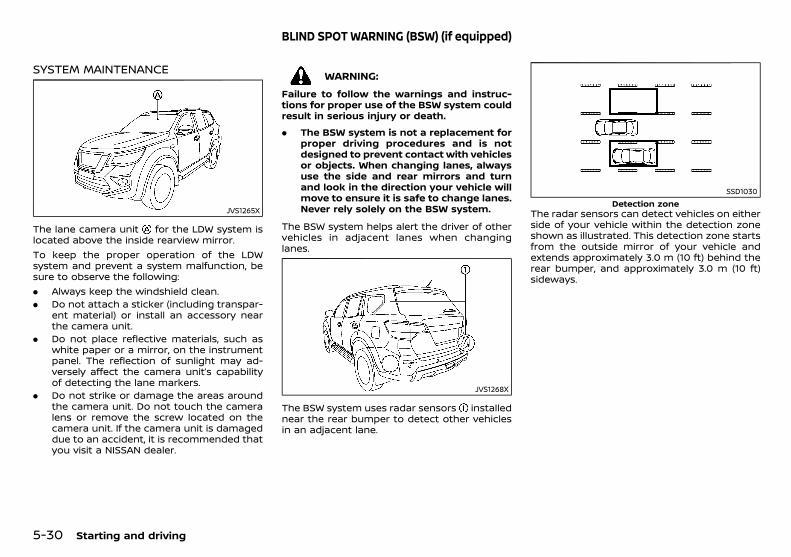
(210,1)
[ Edit: 2018/ 5/ 25 Model: PD23-A ]
5-30 Starting and driving
SYSTEM MAINTENANCEGUID-0C25DD49-24B5-4037-8479-B99197A4C130
JVS1265X
The lane camera unit for the LDW system islocated above the inside rearview mirror.To keep the proper operation of the LDWsystem and prevent a system malfunction, besure to observe the following:. Always keep the windshield clean.. Do not attach a sticker (including transpar-
ent material) or install an accessory nearthe camera unit.
. Do not place reflective materials, such aswhite paper or a mirror, on the instrumentpanel. The reflection of sunlight may ad-versely affect the camera unit’s capabilityof detecting the lane markers.
. Do not strike or damage the areas aroundthe camera unit. Do not touch the cameralens or remove the screw located on thecamera unit. If the camera unit is damageddue to an accident, it is recommended thatyou visit a NISSAN dealer.
GUID-5C20A4D3-9933-44CA-957F-7AEDAAD86EE2
WARNING:
Failure to follow the warnings and instruc-tions for proper use of the BSW system couldresult in serious injury or death.
. The BSW system is not a replacement forproper driving procedures and is notdesigned to prevent contact with vehiclesor objects. When changing lanes, alwaysuse the side and rear mirrors and turnand look in the direction your vehicle willmove to ensure it is safe to change lanes.Never rely solely on the BSW system.
The BSW system helps alert the driver of othervehicles in adjacent lanes when changinglanes.
JVS1268X
The BSW system uses radar sensors installednear the rear bumper to detect other vehiclesin an adjacent lane.
SSD1030Detection zone
The radar sensors can detect vehicles on eitherside of your vehicle within the detection zoneshown as illustrated. This detection zone startsfrom the outside mirror of your vehicle andextends approximately 3.0 m (10 ft) behind therear bumper, and approximately 3.0 m (10 ft)sideways.
BLIND SPOT WARNING (BSW) (if equipped)
Condition: 'Except for China'/
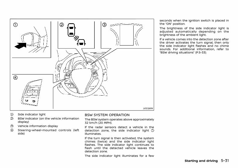
(211,1)
[ Edit: 2018/ 5/ 25 Model: PD23-A ]
JVS1269X
Side indicator lightBSW indicator (on the vehicle informationdisplay)Vehicle information displaySteering-wheel-mounted controls (leftside)
BSW SYSTEM OPERATIONGUID-FDBDC447-C2FD-43F9-989C-EAD6F9922E55
The BSW system operates above approximately32 km/h (20 MPH).If the radar sensors detect a vehicle in thedetection zone, the side indicator lightilluminates.If the turn signal is then activated, the systemchimes (twice) and the side indicator lightflashes. The side indicator light continues toflash until the detected vehicle leaves thedetection zone.The side indicator light illuminates for a few
seconds when the ignition switch is placed inthe “ON” position.The brightness of the side indicator light isadjusted automatically depending on thebrightness of the ambient light.If a vehicle comes into the detection zone afterthe driver activates the turn signal, then onlythe side indicator light flashes and no chimesounds. For additional information, refer to“BSW driving situations” (P.5-33).
Starting and driving 5-31
Condition: 'Except for China'/
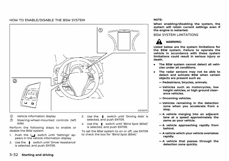
(212,1)
[ Edit: 2018/ 5/ 25 Model: PD23-A ]
5-32 Starting and driving
HOW TO ENABLE/DISABLE THE BSW SYSTEMGUID-6D374779-5717-4985-9FD8-25D16181992A
JVS1267X
Vehicle information displaySteering-wheel-mounted controls (leftside)
Perform the following steps to enable ordisable the BSW system.1. Push the switch until “Settings” ap-
pears in the vehicle information display.2. Use the switch until “Driver Assistance”
is selected, and push ENTER.
3. Use the switch until “Driving Aids” isselected, and push ENTER.
4. Use the switch until “Blind Spot (BSW)”is selected, and push ENTER.
To set the BSW system to on or off, use ENTERto check the box for “Blind Spot (BSW).”
NOTE:When enabling/disabling the system, thesystem will retain current settings even ifthe engine is restarted.
BSW SYSTEM LIMITATIONSGUID-DE50E1D7-E490-4952-B311-06149B4C37BF
WARNING:
Listed below are the system limitations forthe BSW system. Failure to operate thevehicle in accordance with these systemlimitations could result in serious injury ordeath.
. The BSW system cannot detect all vehi-cles under all conditions.
. The radar sensors may not be able todetect and activate BSW when certainobjects are present such as:— Pedestrians, bicycles, animals.
— Vehicles such as motorcycles, lowheight vehicles, or high ground clear-ance vehicles.
— Oncoming vehicles.
— Vehicles remaining in the detectionzone when you accelerate from astop.
— A vehicle merging into an adjacentlane at a speed approximately thesame as your vehicle.
— A vehicle approaching rapidly frombehind.
— A vehicle which your vehicle overtakesrapidly.
— A vehicle that passes through thedetection zone quickly.
Condition: 'Except for China'/
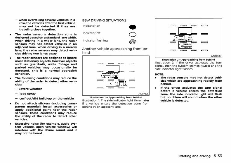
(213,1)
[ Edit: 2018/ 5/ 25 Model: PD23-A ]
— When overtaking several vehicles in arow, the vehicles after the first vehiclemay not be detected if they aretraveling close together.
. The radar sensor’s detection zone isdesigned based on a standard lane width.When driving in a wider lane, the radarsensors may not detect vehicles in anadjacent lane. When driving in a narrowlane, the radar sensors may detect vehi-cles driving two lanes away.
. The radar sensors are designed to ignoremost stationary objects, however objectssuch as guardrails, walls, foliage andparked vehicles may occasionally bedetected. This is a normal operationcondition.
. The following conditions may reduce theability of the radar to detect other vehi-cles:— Severe weather
— Road spray
— Ice/frost/dirt build-up on the vehicle
. Do not attach stickers (including trans-parent material), install accessories orapply additional paint near the radarsensors. These conditions may reducethe ability of the radar to detect othervehicles.
. Excessive noise (for example, audio sys-tem volume, open vehicle window) willinterfere with the chime sound, and itmay not be heard.
BSW DRIVING SITUATIONSGUID-4EBF2CDD-40B1-471F-83FB-E184B7ACECD1
Indicator on
Indicator off
Indicator flashing
Another vehicle approaching from be-hind
GUID-C43731D2-4096-4F59-8C5C-B9DBA96BB43A
JVS0737XIllustration 1 – Approaching from behind
Illustration 1: The side indicator light illuminatesif a vehicle enters the detection zone frombehind in an adjacent lane.
JVS0738XIllustration 2 – Approaching from behind
Illustration 2: If the driver activates the turnsignal, then the system chimes (twice) and theside indicator light flashes.
NOTE:. The radar sensors may not detect vehi-
cles which are approaching rapidly frombehind.
. If the driver activates the turn signalbefore a vehicle enters the detectionzone, the side indicator light will flashbut no chime will sound when the othervehicle is detected.
Starting and driving 5-33
Condition: 'Except for China'/

(214,1)
[ Edit: 2018/ 5/ 25 Model: PD23-A ]
5-34 Starting and driving
Overtaking another vehicleGUID-F9A9415C-FDB7-4D0F-A833-84B2CE617016
JVS0739XIllustration 3 – Overtaking another vehicle
Illustration 3: The side indicator light illuminatesif you overtake a vehicle and that vehicle staysin the detection zone for approximately 2seconds.
JVS0740XIllustration 4 – Overtaking another vehicle
Illustration 4: If the driver activates the turnsignal while another vehicle is in the detectionzone, then the system chimes (twice) and theside indicator light flashes.
NOTE:. When overtaking several vehicles in a
row, the vehicles after the first vehiclemay not be detected if they are travelingclose together.
. The radar sensors may not detect slowermoving vehicles if they are passedquickly.
. If the driver activates the turn signalbefore a vehicle enters the detectionzone, the side indicator light will flashbut no chime will sound when the othervehicle is detected.
Entering from the sideGUID-7A5E9DB2-48E6-471C-8F7F-293BE02AB0D2
JVS0741XIllustration 5 – Entering from the side
Illustration 5: The side indicator light illuminatesif a vehicle enters the detection zone fromeither side.
JVS0742XIllustration 6 – Entering from the side
If the driver activates the turn signal whileanother vehicle is in the detection zone, thenthe system chimes (twice) and the side indica-tor light flashes.
NOTE:. If the driver activates the turn signal
before a vehicle enters the detectionzone, the side indicator light will flashbut no chime will sound when the othervehicle is detected.
. The radar sensors may not detect avehicle which is traveling at about thesame speed as your vehicle when itenters the detection zone.
Condition: 'Except for China'/
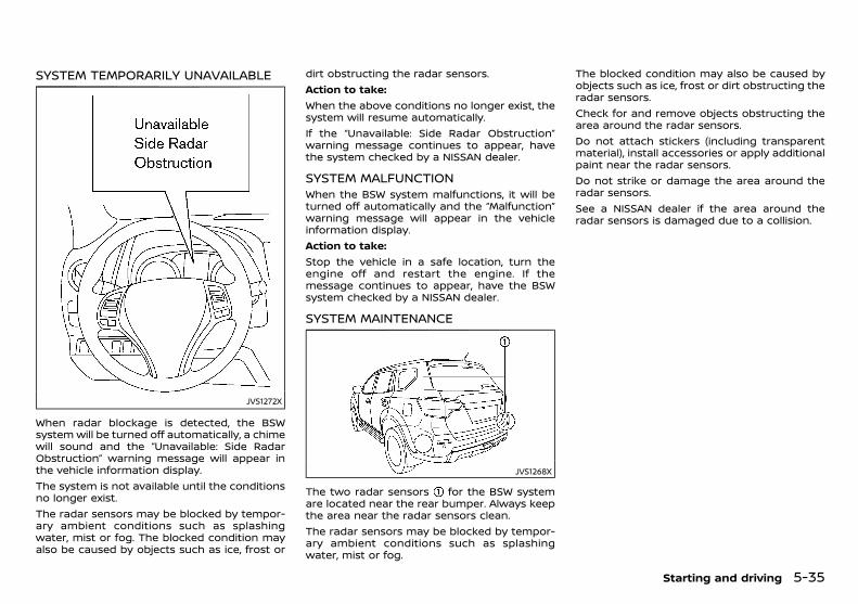
(215,1)
[ Edit: 2018/ 5/ 25 Model: PD23-A ]
SYSTEM TEMPORARILY UNAVAILABLEGUID-392B2274-E261-4445-877A-B231EF011339
JVS1272X
When radar blockage is detected, the BSWsystem will be turned off automatically, a chimewill sound and the “Unavailable: Side RadarObstruction” warning message will appear inthe vehicle information display.The system is not available until the conditionsno longer exist.The radar sensors may be blocked by tempor-ary ambient conditions such as splashingwater, mist or fog. The blocked condition mayalso be caused by objects such as ice, frost or
dirt obstructing the radar sensors.Action to take:When the above conditions no longer exist, thesystem will resume automatically.If the “Unavailable: Side Radar Obstruction”warning message continues to appear, havethe system checked by a NISSAN dealer.
SYSTEM MALFUNCTIONGUID-CEC42801-CD02-4437-9BD7-66C237B215AF
When the BSW system malfunctions, it will beturned off automatically and the “Malfunction”warning message will appear in the vehicleinformation display.Action to take:Stop the vehicle in a safe location, turn theengine off and restart the engine. If themessage continues to appear, have the BSWsystem checked by a NISSAN dealer.
SYSTEM MAINTENANCEGUID-125D9BF0-D949-45FD-9355-A62CCDAC208C
JVS1268X
The two radar sensors for the BSW systemare located near the rear bumper. Always keepthe area near the radar sensors clean.The radar sensors may be blocked by tempor-ary ambient conditions such as splashingwater, mist or fog.
The blocked condition may also be caused byobjects such as ice, frost or dirt obstructing theradar sensors.Check for and remove objects obstructing thearea around the radar sensors.Do not attach stickers (including transparentmaterial), install accessories or apply additionalpaint near the radar sensors.Do not strike or damage the area around theradar sensors.See a NISSAN dealer if the area around theradar sensors is damaged due to a collision.
Starting and driving 5-35
Condition: 'Except for China'/

(216,1)
[ Edit: 2018/ 5/ 25 Model: PD23-A ]
5-36 Starting and driving
PD23A1-A6EFB01C-011B-4484-9175-865FCB500F51
JVS1254X
1. CANCEL switch2. ACCELERATE/RESUME switch3. COAST/SET switch4. Cruise control MAIN switch
WARNING:
. Always observe the posted speed limitsand do not set the speed over them.
. Do not use the cruise control whendriving under the following conditions.Doing so could cause a loss of vehiclecontrol and result in an accident.— When it is not possible to keep the
vehicle at a constant speed
— When driving in heavy traffic
— When driving in traffic that variesspeed
— When driving in windy areas
— When driving on winding or hilly roads
— When driving on slippery (rain, snow,ice, etc.) roads
PRECAUTIONS ON CRUISE CONTROLPD23A1-B41AEA0B-A463-448F-8C6D-62A19D75EF7A
. If the cruise control system malfunctions, itwill cancel automatically. The CRUISE in-dicator in the vehicle information displaywill then blink to warn the driver.
. If the CRUISE indicator blinks, turn thecruise control MAIN switch off and havethe system checked by a NISSAN dealer.
. The CRUISE indicator may blink when thecruise control MAIN switch is turned ONwhile pushing the ACCELERATE/RESUME,COAST/SET or CANCEL switch. To properlyset the cruise control system, perform thefollowing procedures.
CRUISE CONTROL OPERATIONSPD23A1-E11A67AE-9ABE-40F0-A47C-CB17158BE060
The cruise control allows driving at speedsabove 40 km/h (25 MPH) without keeping yourfoot on the accelerator pedal.Except for YS23DDTT engine models, the cruisecontrol will automatically be canceled if thevehicle slows down more than approximately13 km/h (8 MPH) below the set speed.For YS23DDTT engine models, the cruise con-trol will automatically be canceled if the vehiclespeed slows to less than approximately 33km/h (21 MPH).Moving the shift lever to the “N” (Neutral)position will cancel the cruise control.
Turning on cruise controlPD23A1-173B1891-B5E6-473E-BA40-F0FC65E483C6
Push the cruise control MAIN switch . TheCRUISE indicator appears.
Setting cruising speedPD23A1-841C526E-EA4B-49A5-AF29-5EF5BD1CC631
1. Accelerate to the desired speed.2. Push the COAST/SET switch and release
it.3. Take your foot off the accelerator pedal.The vehicle will maintain the set speed.
Passing another vehicle:GUID-9E14C2E6-2E9C-4731-980B-C45B899B977B
Depress the accelerator pedal to accelerate.After releasing the accelerator pedal, the vehi-cle will return to the previously set speed.The vehicle may not maintain the set speedwhen going up or down steep hills. In suchcases, drive without the cruise control.
Resetting to slower speed:GUID-9E14C2E6-2E9C-4731-980B-C45B899B977B
Use any one of the following methods to resetto a slower speed.. Lightly tap the foot brake pedal. When the
vehicle reaches the desired speed, pushand release the COAST/SET switch .
. Push and hold the COAST/SET switch .When the vehicle reaches the desiredspeed, release the COAST/SET switch .
. Quickly push and release the COAST/SETswitch . This will reduce the vehicle speedby about 1 km/h (0.6 MPH).
Resetting to faster speed:GUID-9E14C2E6-2E9C-4731-980B-C45B899B977B
Use any one of the following methods to resetto a faster speed.. Depress the accelerator pedal. When the
vehicle reaches the desired speed, pushand release the COAST/SET switch .
. Push and hold the ACCELERATE/RESUMEswitch . When the vehicle reaches thedesired speed, release the ACCELERATE/RESUME switch .
CRUISE CONTROL (if equipped)
Condition: 'Except for China'/

(217,1)
[ Edit: 2018/ 5/ 25 Model: PD23-A ]
. Quickly push and release the ACCELERATE/RESUME switch . This will increase thevehicle speed by about 1 km/h (0.6 MPH).
Resuming at preset speed:GUID-9E14C2E6-2E9C-4731-980B-C45B899B977B
Push and release the ACCELERATE/RESUMEswitch .The vehicle will resume the last set cruisingspeed when the vehicle speed is over 40 km/h(25 MPH).
Canceling cruising speedPD23A1-DFDB4816-A5C3-4FF1-A538-2B8CE6C8149E
Use any one of the following methods to cancelthe set speed.. Push the CANCEL switch .. Tap the foot brake pedal.. Push the cruise control MAIN switch . The
CRUISE indicator will turn off.
GUID-AF4F80FA-C0E8-4659-A193-5EB9A63B0389
JVS1282X
When the ignition switch is in the “OFF” position,ECO management display appears.
Previous 5 times (History)Current fuel economyBest fuel economy
The result of ECO evaluation is displayed 30seconds after the ignition switch is placed inthe “ON” position and the vehicle is driven atleast 500 meters (1/3 miles).
: The average fuel economy for the previous 5times will be displayed.
: The average fuel economy since the lastreset will be displayed.
: The best fuel economy of the past historywill be displayed.The ECO drive report can be set to be “ON” or“OFF”. See “Settings” (P.2-20).
PD23A1-C71CF38B-BCAB-4A1E-ABB7-D0F5AA830F54Follow these easy-to-use Fuel Efficiency andCarbon Dioxide Reduction Driving Tips to helpyou achieve the most fuel economy from yourvehicle and reduce carbon dioxide emissions.1. Use smooth accelerator and brake pedal
application.. Avoid rapid starts and stops.. Use smooth, gentle accelerator and
brake application whenever possible.. Maintain constant speed while commut-
ing and coast whenever possible.2. Maintain constant speed.
. Look ahead to try and anticipate andminimize stops.
. Synchronizing your speed with trafficlights allows you to reduce your numberof stops.
. Maintaining a steady speed can mini-mize red light stops and improve fuelefficiency.
3. Drive at economical speeds and distances.. Observing the speed limit and not ex-
ceeding 97 km/h (60 MPH) (where legallyallowed) can improve fuel efficiency dueto reduced aerodynamic drag.
. Maintaining a safe following distancebehind other vehicles reduces unneces-sary braking.
. Safely monitoring traffic to anticipatechanges in speed permits reduced brak-ing and smooth acceleration changes.
. Select a gear range suitable to roadconditions.
4. Use cruise control (if equipped).. Using cruise control during highway
driving helps maintain a steady speed.
Starting and driving 5-37
ECO DRIVE REPORT (if equipped) FUEL EFFICIENCY AND CARBONDIOXIDE REDUCTION DRIVING TIPS
Condition: 'Except for China'/
(218,1)
[ Edit: 2018/ 5/ 25 Model: PD23-A ]
5-38 Starting and driving
. Cruise control is particularly effective inproviding fuel savings when driving onflat terrains.
5. Plan for the shortest route.. Utilize a map or navigation system (if
equipped) to determine the best route tosave time.
6. Avoid idling.. Shutting off your engine when safe for
stops exceeding 30-60 seconds savesfuel and reduces emissions.
7. Buy an automated pass for toll roads.. Automated passes permit drivers to use
special lanes to maintain cruising speedthrough the toll and avoid stopping andstarting.
8. Winter warm up.. Limit idling time to minimize impact to
fuel economy.. Vehicles typically need no more than 30
seconds of idling at start-up to effec-tively circulate the engine oil beforedriving.
. Your vehicle will reach its ideal operatingtemperature more quickly while drivingversus idling.
9. Keeping your vehicle cool.. Park your vehicle in a covered parking
area or in the shade whenever possible.. When entering a hot vehicle, opening the
windows will help to reduce the insidetemperature faster, resulting in reduceddemand on your A/C system.
10. Do not carry excessive weight.. Remove unnecessary objects from the
vehicle to reduce vehicle weight.
PD23A1-A805E530-ABDE-46DD-B4CA-04D54A407B5A. Keep your engine tuned up.. Follow the recommended scheduled main-
tenance.. Keep the tires inflated to the correct
pressure. Low tire pressure increases tirewear and lowers fuel economy.
. Keep the wheels in correct alignment.Improper alignment increases tire wearand lowers fuel economy.
. Use the recommended viscosity engine oil.(See “Recommended fluids/lubricants andcapacities” (P.9-2).)
PD23A1-3E4C4E3B-6B1C-4ECA-A585-021856F1DE28
WARNING:
. Do not stop or park the vehicle overflammable materials such as dry grass,waste paper or rags. They may ignite andcause a fire.
. Safe parking procedures require thatboth the parking brake be applied andthe shift lever placed into the “P” (Park)position for Automatic Transmission (AT)model or in an appropriate gear forManual Transmission (MT) model. Failureto do so could cause the vehicle to moveunexpectedly or roll away and result in anaccident.
. When parking the vehicle, make sure theshift lever is moved to the “P” (Park)position. The shift lever cannot be movedout of the “P” (Park) position withoutdepressing the foot brake pedal (ATmodel).
. Never leave the engine running while thevehicle is unattended.
. Do not leave children unattended insidethe vehicle. They could unknowingly acti-vate switches or controls. Unattendedchildren could become involved in ser-ious accidents.
. To help avoid risk of injury or deaththrough unintended operation of thevehicle and/or its systems, do not leavechildren, people who require the assis-tance of others or pets unattended inyour vehicle. Additionally, the tempera-ture inside a closed vehicle on a warmday can quickly become high enough tocause a significant risk of injury or deathto people and pets.
INCREASING FUEL ECONOMY ANDREDUCING CARBON DIOXIDE EMISSIONS PARKING
Condition: 'Except for China'/
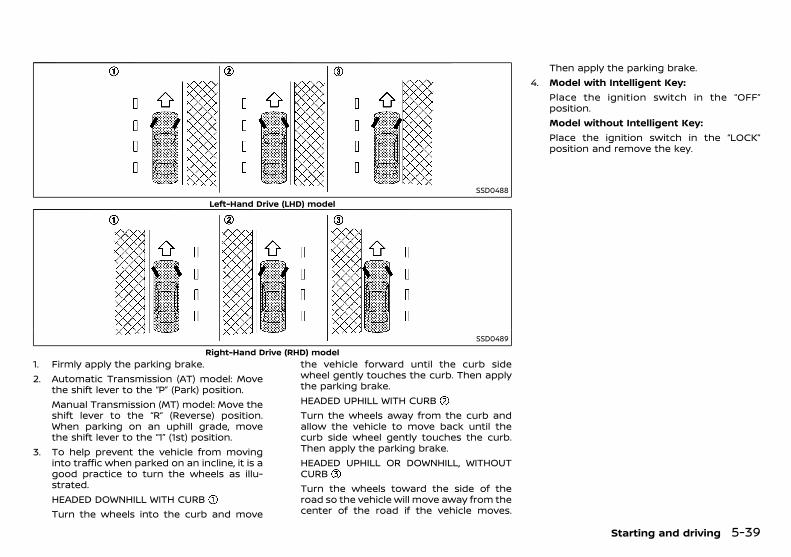
(219,1)
[ Edit: 2018/ 5/ 25 Model: PD23-A ]
SSD0488
Left-Hand Drive (LHD) model
SSD0489
Right-Hand Drive (RHD) model1. Firmly apply the parking brake.2. Automatic Transmission (AT) model: Move
the shift lever to the “P” (Park) position.Manual Transmission (MT) model: Move theshift lever to the “R” (Reverse) position.When parking on an uphill grade, movethe shift lever to the “1” (1st) position.
3. To help prevent the vehicle from movinginto traffic when parked on an incline, it is agood practice to turn the wheels as illu-strated.HEADED DOWNHILL WITH CURBTurn the wheels into the curb and move
the vehicle forward until the curb sidewheel gently touches the curb. Then applythe parking brake.HEADED UPHILL WITH CURBTurn the wheels away from the curb andallow the vehicle to move back until thecurb side wheel gently touches the curb.Then apply the parking brake.HEADED UPHILL OR DOWNHILL, WITHOUTCURBTurn the wheels toward the side of theroad so the vehicle will move away from thecenter of the road if the vehicle moves.
Then apply the parking brake.4. Model with Intelligent Key:
Place the ignition switch in the “OFF”position.Model without Intelligent Key:Place the ignition switch in the “LOCK”position and remove the key.
Starting and driving 5-39
Condition: 'Except for China'/
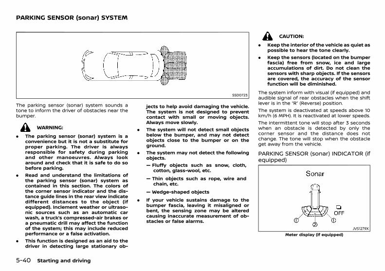
(220,1)
[ Edit: 2018/ 5/ 25 Model: PD23-A ]
5-40 Starting and driving
GUID-B59F202D-76DD-45C1-920D-543DAD14EB35
SSD0723
The parking sensor (sonar) system sounds atone to inform the driver of obstacles near thebumper.
WARNING:
. The parking sensor (sonar) system is aconvenience but it is not a substitute forproper parking. The driver is alwaysresponsible for safety during parkingand other manoeuvres. Always lookaround and check that it is safe to do sobefore parking.
. Read and understand the limitations ofthe parking sensor (sonar) system ascontained in this section. The colors ofthe corner sensor indicator and the dis-tance guide lines in the rear view indicatedifferent distances to the object (ifequipped). Inclement weather or ultraso-nic sources such as an automatic carwash, a truck’s compressed-air brakes ora pneumatic drill may affect the functionof the system; this may include reducedperformance or a false activation.
. This function is designed as an aid to thedriver in detecting large stationary ob-
jects to help avoid damaging the vehicle.The system is not designed to preventcontact with small or moving objects.Always move slowly.
. The system will not detect small objectsbelow the bumper, and may not detectobjects close to the bumper or on theground.
. The system may not detect the followingobjects.— Fluffy objects such as snow, cloth,
cotton, glass-wool, etc.
— Thin objects such as rope, wire andchain, etc.
— Wedge-shaped objects
. If your vehicle sustains damage to thebumper fascia, leaving it misaligned orbent, the sensing zone may be alteredcausing inaccurate measurement of ob-stacles or false alarms.
CAUTION:
. Keep the interior of the vehicle as quiet aspossible to hear the tone clearly.
. Keep the sensors (located on the bumperfascia) free from snow, ice and largeaccumulations of dirt. Do not clean thesensors with sharp objects. If the sensorsare covered, the accuracy of the sensorfunction will be diminished.
The system inform with visual (if equipped) andaudible signal of rear obstacles when the shiftlever is in the “R” (Reverse) position.The system is deactivated at speeds above 10km/h (6 MPH). It is reactivated at lower speeds.The intermittent tone will stop after 3 secondswhen an obstacle is detected by only thecorner sensor and the distance does notchange. The tone will stop when the obstacleget away from the vehicle.
PARKING SENSOR (sonar) INDICATOR (ifequipped)
GUID-59FAFEC8-AA12-43CE-945F-42F6BA12C214
JVS1279XMeter display (if equipped)
PARKING SENSOR (sonar) SYSTEM
Condition: 'Except for China'/
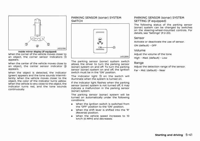
(221,1)
[ Edit: 2018/ 5/ 25 Model: PD23-A ]
JVS1278XInside mirror display (if equipped)
When the corner of the vehicle moves closer toan object, the corner sensor indicatorsappears.When the center of the vehicle moves close toan object, the center sensor indicatorappears.When the object is detected, the indicator(green) appears and the tone sounds intermit-tently. When the vehicle moves closer to theobject, the color of the indicator turns yellow.When the vehicle is very close to the object, theindicator turns red, and the tone soundscontinuously.
PARKING SENSOR (sonar) SYSTEMSWITCH
GUID-870D4498-0DEF-402A-844B-D78C8B95F513
JVS1289X
The parking sensor (sonar) system switchallows the driver to turn the parking sensor(sonar) system on and off. To turn the parkingsensor (sonar) system on and off, the ignitionswitch must be in the “ON” position.The indicator light on the switch willilluminate when the system is turned on.If the indicator light flashes when the parkingsensor (sonar) system is not turned off, it mayindicate a malfunction in the parking sensor(sonar) system.The parking sensor (sonar) system will beturned on automatically under the followingconditions:. When the ignition switch is switched from
the “OFF” position to the “ON” position.. When the shift lever is shifted into the “R”
(Reverse) position.. When the vehicle speed increases to 10
km/h (6 MPH) and decreases.
PARKING SENSOR (sonar) SYSTEMSETTING (if equipped)
GUID-5349C547-2BFF-4796-BC92-5EE775D4AE33The following status of the parking sensor(sonar) system can be changed by switcheson the steering-wheel-mounted controls. Fordetails, see “Settings” (P.2-20).
SensorGUID-44B98D43-CB6A-4859-BF44-D10EE28BA777
Activate or deactivate the use of sensor.ON (default) - OFF
VolumeGUID-2A4D0D1E-297F-4F2F-8114-317213C625E8
Adjust the volume of the tone.High - Med. (default) - Low
RangeGUID-93EC5FA7-4945-4FC5-9F78-2EE27447D475
Adjust the detection range of the sensor.Far - Mid. (default) - Near
Starting and driving 5-41
Condition: 'Except for China'/
(222,1)
[ Edit: 2018/ 5/ 25 Model: PD23-A ]
5-42 Starting and driving
PD23A1-6EF39720-109E-42B1-B05F-A878E365A8BCYour vehicle was designed to be used to carrypassengers and luggage. NISSAN does notrecommend trailer towing, because it placesadditional loads on your vehicle’s engine, drive-train, steering, braking, and other systems.
CAUTION:
Vehicle damage resulting from towing atrailer is not covered by the warranties.
PD23A1-87C8421D-559D-43F2-B29C-3246CB23890A
WARNING:
If the engine is not running or is turned offwhile driving, the power assist for the steer-ing will not work. The steering will be muchharder to operate.
The power assisted steering is designed to usea hydraulic pump driven by the engine, to assiststeering.If the engine stops or the drive belt breaks, youwill still have control of the vehicle. However,greater steering effort is needed, especially insharp turns and at low speeds.
PD23A1-943CB8CC-7A93-4635-838C-02D7D2292797The brake system has two separate hydrauliccircuits. If one circuit malfunctions, you will stillhave braking ability at two wheels.
BRAKE PRECAUTIONSPD23A1-B0E4998A-846B-4FEB-BFD6-689E6A742199
Vacuum assisted brakesPD23A1-B79B7AF5-3AF9-49F1-973E-41C0E1227FF7
The brake booster aids braking by using enginevacuum. If the engine stops, you can stop thevehicle by depressing the foot brake pedal.However, greater foot pressure on the footbrake pedal will be required to stop the vehicle.The stopping distance will be longer.If the engine is not running or is turned offwhile driving, the power assisted brakes will notfunction. Braking will be harder.
WARNING:
Do not coast with the engine stopped.
Using brakesPD23A1-87D8A2FA-59DD-4B7D-A620-25C82316B771
Avoid resting your foot on the foot brake pedalwhile driving. This will overheat the brakes,wear out the brake linings/pads faster, andincrease fuel consumption.To help reduce brake wear and to prevent thebrakes from overheating, reduce speed anddownshift to a lower gear before going down aslope or long grade. Overheated brakes mayreduce braking performance and could resultin loss of vehicle control.While driving on a slippery surface, be carefulwhen braking, accelerating or downshifting.Abrupt braking or acceleration could causethe wheels to skid and result in an accident.
TRAILER TOWING POWER STEERING BRAKE SYSTEM
Condition: 'Except for China'/

(223,1)
[ Edit: 2018/ 5/ 25 Model: PD23-A ]
Wet brakesPD23A1-47B5DF9F-42DB-4939-8B98-06F9D4E0CB02
When the vehicle is washed or driven throughwater, the brakes may get wet. As a result, yourbraking distance will be longer and the vehiclemay pull to one side during braking.To dry the brakes, drive the vehicle at a safespeed while lightly depressing the foot brakepedal to heat up the brakes. Do this until thebrakes return to normal. Avoid driving thevehicle at high speeds until the brakes functioncorrectly.
Parking brake break-inPD23A1-978FD217-606F-4D72-B7E4-297404318734
Break in the parking brake shoes whenever thestopping effect of the parking brake is wea-kened or whenever the parking brake shoesand/or drums/rotors are replaced, in order toassure the best braking performance.This procedure is described in the vehicleservice manual and can be performed by aNISSAN dealer.
BRAKE ASSISTPD23A1-A77131D5-3B31-4214-B572-224A585B4515
When the force applied to the brake pedalexceeds a certain level, the Brake Assist isactivated generating greater braking forcethan a conventional brake booster even withlight pedal force.
WARNING:
The Brake Assist is only an aid to assistbraking operation and is not a collisionwarning or avoidance device. It is the driver’sresponsibility to stay alert, drive safely andbe in control of the vehicle at all times.
ANTI-LOCK BRAKING SYSTEM (ABS)PD23A1-FDEEF061-833B-4B53-A201-8C8A8FB3603A
WARNING:
The Anti-lock Braking System (ABS) is asophisticated device, but it cannot preventaccidents resulting from careless or danger-ous driving techniques. It can help maintainvehicle control during braking on slipperysurfaces. Remember that stopping distanceson slippery surfaces will be longer than onnormal surfaces even with ABS. Stoppingdistances may also be longer on rough,gravel or snow covered roads, or if you areusing tire chains. Always maintain a safedistance from the vehicle in front of you.Ultimately, the driver is responsible forsafety.
Tire type and condition may also affectbraking effectiveness.. When replacing tires, install the specified
size of tires on all four wheels.. When installing a spare tire, make sure
that it is the proper size and type asspecified on the tire placard. (See “Tireplacard” (P.9-8).)
. For detailed information, see “Tires andwheels” (P.8-27).
The Anti-lock Braking System (ABS) controlsthe brakes so the wheels do not lock duringhard braking or when braking on slipperysurfaces. The system detects the rotationspeed at each wheel and varies the brake fluidpressure to prevent each wheel from lockingand sliding. By preventing each wheel fromlocking, the system helps the driver maintainsteering control and helps to minimize swer-ving and spinning on slippery surfaces.
Using systemPD23A1-1747FF21-B58C-4813-B0F8-B985C9ABE4CA
Depress the brake pedal and hold it down.Depress the brake pedal with firm steadypressure, but do not pump the brakes. TheABS will operate to prevent the wheels fromlocking up. Steer the vehicle to avoid obstacles.
WARNING:
Do not pump the brake pedal. Doing so mayresult in increased stopping distances.
Self-test featurePD23A1-CDDA223C-7FCF-4082-86D4-716B9EB14068
The ABS includes electronic sensors, electricpumps, hydraulic solenoids and a computer.The computer has a built-in diagnostic featurethat tests the system each time you start theengine and move the vehicle at a low speed inforward or reverse. When the self-test occurs,you may hear a “clunk” noise and/or feel apulsation in the brake pedal. This is normal anddoes not indicate a malfunction. If the compu-ter senses a malfunction, it switches the ABSoff and illuminates the ABS warning light on theinstrument panel. The brake system thenoperates normally, but without anti-lock assis-tance. If the ABS warning light illuminatesduring the self-test or while driving, have thevehicle checked by a NISSAN dealer.
Normal operationPD23A1-3B68016B-9D07-41D7-BCFF-CE9E1F934D0F
The ABS operates at speeds above 5 to 10km/h (3 to 6 MPH). The speed varies accordingto road conditions.When the ABS senses that one or more wheelsare close to locking up, the actuator rapidlyapplies and releases hydraulic pressure. Thisaction is similar to pumping the brakes veryquickly. You may feel a pulsation in the brakepedal and hear a noise from under the hood or
Starting and driving 5-43
Condition: 'Except for China'/
(224,1)
[ Edit: 2018/ 5/ 25 Model: PD23-A ]
5-44 Starting and driving
feel a vibration from the actuator when it isoperating. This is normal and indicates that theABS is operating properly. However, the pulsa-tion may indicate that road conditions arehazardous and extra care is required whiledriving.When the differential lock (if equipped) isengaged, the ABS warning light illuminates.This indicates that the anti-lock function is notfully operating. (See “Rear differential lockingsystem” (P.5-22) for the rear differential lockfunction.)
PD23A1-3379387A-C03F-4BBD-9228-95DD384B5AEFWhen leaving your vehicle unoccupied:. Always take the key with you - even when
leaving the vehicle in your own garage.. Close all windows completely and lock all
doors.. Always park your vehicle where it can be
seen. Park in a well lit area during the night.. If the security system is equipped, use it -
even for a short period.. Never leave children or pets in the vehicle
unattended.. Never leave valuables inside the vehicle.
Always take valuables with you.. Never leave the vehicle documents in the
vehicle.. Never leave articles on a roof rail. Remove
them from the rack and keep and lockthem inside the vehicle.
. Never leave the spare key in the vehicle.
PD23A1-34C6DF68-5354-4435-AB7D-D60EC96708E9
WARNING:
. Whatever the condition, drive with cau-tion. Accelerate and decelerate with greatcare. If accelerating or decelerating toofast, the drive wheels will lose even moretraction.
. Allow more stopping distance in coldweather driving. Braking should bestarted sooner than on dry pavement.
. Keep at a greater distance from thevehicle in front of you on slippery roads.
. Wet ice (0°C, 32°F and freezing rain), verycold snow and ice can be slick and verydifficult to drive on. The vehicle will havea lot less traction or grip under theseconditions. Try to avoid driving on wet iceuntil the road is salted or sanded.
. Watch for slippery spots (glaring ice).These may appear on an otherwise clearroad in shaded areas. If a patch of ice isseen ahead, brake before reaching it. Trynot to brake while actually on the ice, andavoid any sudden steering maneuvers.
. Do not use cruise control on slipperyroads. (if equipped)
. Snow can trap dangerous exhaust gasunder your vehicle. Keep snow clear ofthe exhaust pipe and from around yourvehicle.
VEHICLE SECURITY COLD WEATHER DRIVING
Condition: 'Except for China'/
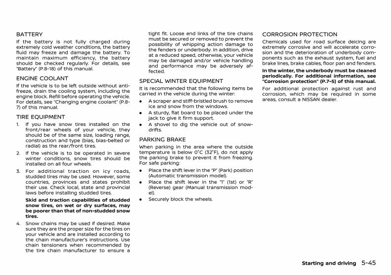
(225,1)
[ Edit: 2018/ 5/ 25 Model: PD23-A ]
BATTERYPD23A1-62AD019A-9B73-44D9-BF40-E02A5FC76E8A
If the battery is not fully charged duringextremely cold weather conditions, the batteryfluid may freeze and damage the battery. Tomaintain maximum efficiency, the batteryshould be checked regularly. For details, see“Battery” (P.8-18) of this manual.
ENGINE COOLANTPD23A1-AEA45FD1-54DC-4FE8-B96C-3C06886FFCF2
If the vehicle is to be left outside without anti-freeze, drain the cooling system, including theengine block. Refill before operating the vehicle.For details, see “Changing engine coolant” (P.8-7) of this manual.
TIRE EQUIPMENTPD23A1-47960355-89A2-4CC5-BB66-23F707B17A61
1. If you have snow tires installed on thefront/rear wheels of your vehicle, theyshould be of the same size, loading range,construction and type (bias, bias-belted orradial) as the rear/front tires.
2. If the vehicle is to be operated in severewinter conditions, snow tires should beinstalled on all four wheels.
3. For additional traction on icy roads,studded tires may be used. However, somecountries, provinces and states prohibittheir use. Check local, state and provinciallaws before installing studded tires.Skid and traction capabilities of studdedsnow tires, on wet or dry surfaces, maybe poorer than that of non-studded snowtires.
4. Snow chains may be used if desired. Makesure they are the proper size for the tires onyour vehicle and are installed according tothe chain manufacturer’s instructions. Usechain tensioners when recommended bythe tire chain manufacturer to ensure a
tight fit. Loose end links of the tire chainsmust be secured or removed to prevent thepossibility of whipping action damage tothe fenders or underbody. In addition, driveat a reduced speed, otherwise, your vehiclemay be damaged and/or vehicle handlingand performance may be adversely af-fected.
SPECIAL WINTER EQUIPMENTPD23A1-FFB9E7B0-B2EB-4567-8659-49F951A54F88
It is recommended that the following items becarried in the vehicle during the winter:. A scraper and stiff-bristled brush to remove
ice and snow from the windows.. A sturdy, flat board to be placed under the
jack to give it firm support.. A shovel to dig the vehicle out of snow-
drifts.
PARKING BRAKEPD23A1-511E41D9-29DF-41C3-B25D-2BDE4996FC30
When parking in the area where the outsidetemperature is below 0°C (32°F), do not applythe parking brake to prevent it from freezing.For safe parking:. Place the shift lever in the “P” (Park) position
(Automatic transmission model).. Place the shift lever in the “1” (1st) or “R”
(Reverse) gear (Manual transmission mod-el).
. Securely block the wheels.
CORROSION PROTECTIONPD23A1-D5D7F310-073E-4924-913D-1CBFB66C7D76
Chemicals used for road surface deicing areextremely corrosive and will accelerate corro-sion and the deterioration of underbody com-ponents such as the exhaust system, fuel andbrake lines, brake cables, floor pan and fenders.In the winter, the underbody must be cleanedperiodically. For additional information, see“Corrosion protection” (P.7-5) of this manual.For additional protection against rust andcorrosion, which may be required in someareas, consult a NISSAN dealer.
Starting and driving 5-45
Condition: 'Except for China'/

(226,1)
[ Edit: 2018/ 5/ 25 Model: PD23-A ]
5-46 Starting and driving
MEMO
Condition: 'Except for China'/
(227,1)
[ Edit: 2018/ 5/ 25 Model: PD23-A ]
6 In case of emergency
Hazard indicator flasher switch ............................................................ 6-2Flat tire ...................................................................................................................... 6-2
Tire Pressure Monitoring System (TPMS)(if equipped) ................................................................................................... 6-2Stopping vehicle ........................................................................................ 6-2Preparing tools ........................................................................................... 6-3Removing the spare tire ...................................................................... 6-4Blocking wheels ......................................................................................... 6-5Removing tire ............................................................................................... 6-5
Installing spare tire ............................................................................... 6-6Stowing damaged tire and tools .............................................. 6-7
Jump starting ..................................................................................................... 6-7Push starting .................................................................................................... 6-10If your vehicle overheats ........................................................................ 6-10Towing your vehicle ................................................................................... 6-11
Towing precautions .......................................................................... 6-11Towing recommended by NISSAN ........................................ 6-12
Condition: 'Except for China'/
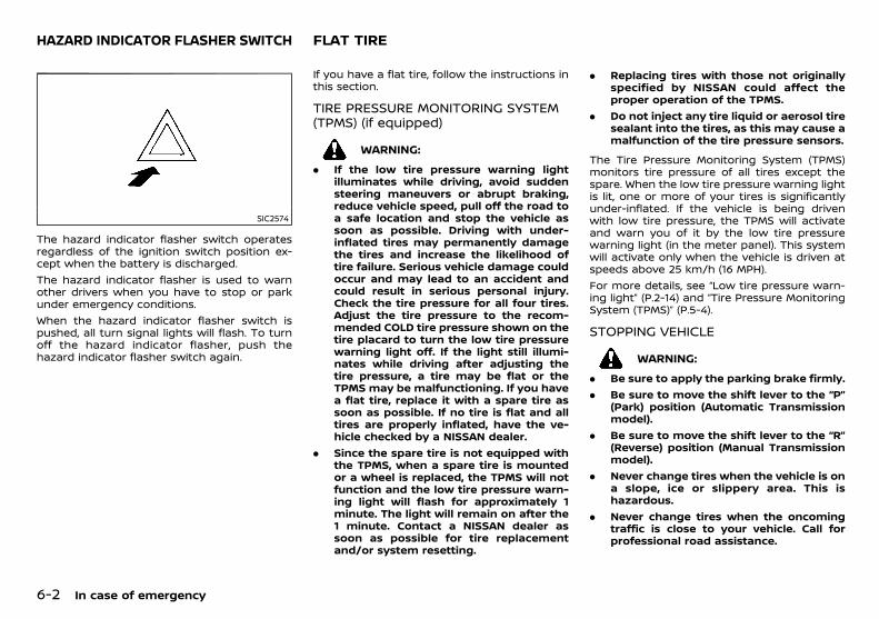
(228,1)
[ Edit: 2018/ 5/ 25 Model: PD23-A ]
6-2 In case of emergency
PD23A1-885105FE-6415-47AD-942A-9FA3F32FC607
SIC2574
The hazard indicator flasher switch operatesregardless of the ignition switch position ex-cept when the battery is discharged.The hazard indicator flasher is used to warnother drivers when you have to stop or parkunder emergency conditions.When the hazard indicator flasher switch ispushed, all turn signal lights will flash. To turnoff the hazard indicator flasher, push thehazard indicator flasher switch again.
PD23A1-087AADF5-1581-4F56-80C8-BA3D0364B3C2If you have a flat tire, follow the instructions inthis section.
TIRE PRESSURE MONITORING SYSTEM(TPMS) (if equipped)
GUID-AF8CFB9D-60F0-4512-8530-9F71D00890E3
WARNING:
. If the low tire pressure warning lightilluminates while driving, avoid suddensteering maneuvers or abrupt braking,reduce vehicle speed, pull off the road toa safe location and stop the vehicle assoon as possible. Driving with under-inflated tires may permanently damagethe tires and increase the likelihood oftire failure. Serious vehicle damage couldoccur and may lead to an accident andcould result in serious personal injury.Check the tire pressure for all four tires.Adjust the tire pressure to the recom-mended COLD tire pressure shown on thetire placard to turn the low tire pressurewarning light off. If the light still illumi-nates while driving after adjusting thetire pressure, a tire may be flat or theTPMS may be malfunctioning. If you havea flat tire, replace it with a spare tire assoon as possible. If no tire is flat and alltires are properly inflated, have the ve-hicle checked by a NISSAN dealer.
. Since the spare tire is not equipped withthe TPMS, when a spare tire is mountedor a wheel is replaced, the TPMS will notfunction and the low tire pressure warn-ing light will flash for approximately 1minute. The light will remain on after the1 minute. Contact a NISSAN dealer assoon as possible for tire replacementand/or system resetting.
. Replacing tires with those not originallyspecified by NISSAN could affect theproper operation of the TPMS.
. Do not inject any tire liquid or aerosol tiresealant into the tires, as this may cause amalfunction of the tire pressure sensors.
The Tire Pressure Monitoring System (TPMS)monitors tire pressure of all tires except thespare. When the low tire pressure warning lightis lit, one or more of your tires is significantlyunder-inflated. If the vehicle is being drivenwith low tire pressure, the TPMS will activateand warn you of it by the low tire pressurewarning light (in the meter panel). This systemwill activate only when the vehicle is driven atspeeds above 25 km/h (16 MPH).For more details, see “Low tire pressure warn-ing light” (P.2-14) and “Tire Pressure MonitoringSystem (TPMS)” (P.5-4).
STOPPING VEHICLEPD23A1-A2E722CC-0CAB-45A9-ACC2-8497528C2144
WARNING:
. Be sure to apply the parking brake firmly.
. Be sure to move the shift lever to the “P”(Park) position (Automatic Transmissionmodel).
. Be sure to move the shift lever to the “R”(Reverse) position (Manual Transmissionmodel).
. Never change tires when the vehicle is ona slope, ice or slippery area. This ishazardous.
. Never change tires when the oncomingtraffic is close to your vehicle. Call forprofessional road assistance.
HAZARD INDICATOR FLASHER SWITCH FLAT TIRE
Condition: 'Except for China'/

(229,1)
[ Edit: 2018/ 5/ 25 Model: PD23-A ]
1. Safely move the vehicle off the road awayfrom traffic.
2. Turn on the hazard indicator flasher lights.3. Park on a level surface.4. Apply the parking brake.5. Automatic Transmission model:
Move the shift lever to the “P” (Park)position.Manual Transmission model:Move the shift lever to the “R” (Reverse)position.
6. Turn off the engine.7. Open the hood:
. To warn other traffic.
. To signal professional road assistancepersonnel that you need assistance.
8. Have all passengers get out from thevehicle and stand in a safe place, awayfrom other traffic and clear of the vehicle.
PREPARING TOOLSPD23A1-29E6C8F0-9060-43E4-BB0D-98DBDF844232
JVE0482X
Remove the jack and necessary tools from thestorage area.
JVE0483X
1. Remove the storage door.2. Unhook the clips restraining the tool kit,
and then remove the tool kit.3. Loosen the jack by turning the jack lever
as shown in the illustration.4. Tilt the top of the jack towards you, and
then remove the jack slowly. To store thejack, perform this in the reverse order andthen tighten the jack lever so that it doesnot rattle.
In case of emergency 6-3
Condition: 'Except for China'/
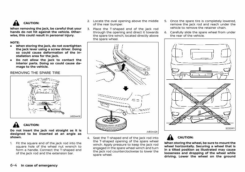
(230,1)
[ Edit: 2018/ 5/ 25 Model: PD23-A ]
6-4 In case of emergency
CAUTION:
When removing the jack, be careful that yourhands do not hit against the vehicle. Other-wise, this could result in personal injury.
NOTE:. When storing the jack, do not overtighten
the jack lever using a screw driver. Doingso could cause deformation of the in-stallation area for the jack.
. Do not allow the jack to contact theinterior parts. Doing so could cause da-mage to the vehicle.
REMOVING THE SPARE TIREPD23A1-40F76BEC-AF3F-4F5D-8B66-A0E091B1DB98
JVE0441X
CAUTION:
Do not insert the jack rod straight as it isdesigned to be inserted at an angle asshown.
1. Fit the square end of the jack rod into thesquare hole of the wheel nut wrench toform a handle. Connect the T-shaped endof the jack rod and the extension bar.
2. Locate the oval opening above the middleof the rear bumper.
3. Place the T-shaped end of the jack rodthrough the opening and direct it towardsthe spare tire winch, located directly abovethe spare wheel.
JVE0442X
4. Seat the T-shaped end of the jack rod intothe T-shaped opening of the spare wheelwinch. Apply pressure to keep the jack rodengaged in the spare wheel winch and turnthe jack rod counterclockwise to lower thespare wheel.
5. Once the spare tire is completely lowered,remove the jack rod and reach under thevehicle to remove the retainer chain.
6. Carefully slide the spare wheel from underthe rear of the vehicle.
SCE0911
CAUTION:
When storing the wheel, be sure to mount thewheel horizontally. Securing a wheel that isin a tilted position as illustrated may causelooseness and dropping of the wheel whiledriving. Lower the wheel on the ground
Condition: 'Except for China'/
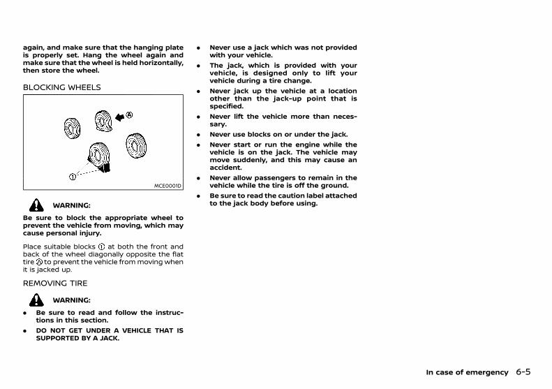
(231,1)
[ Edit: 2018/ 5/ 25 Model: PD23-A ]
again, and make sure that the hanging plateis properly set. Hang the wheel again andmake sure that the wheel is held horizontally,then store the wheel.
BLOCKING WHEELSPD23A1-8395098A-ABB8-49F8-B42E-63A3D5E2646F
MCE0001D
WARNING:
Be sure to block the appropriate wheel toprevent the vehicle from moving, which maycause personal injury.
Place suitable blocks at both the front andback of the wheel diagonally opposite the flattire to prevent the vehicle from moving whenit is jacked up.
REMOVING TIREPD23A1-243FE501-4417-4A86-9000-0AD1EFFC2758
WARNING:
. Be sure to read and follow the instruc-tions in this section.
. DO NOT GET UNDER A VEHICLE THAT ISSUPPORTED BY A JACK.
. Never use a jack which was not providedwith your vehicle.
. The jack, which is provided with yourvehicle, is designed only to lift yourvehicle during a tire change.
. Never jack up the vehicle at a locationother than the jack-up point that isspecified.
. Never lift the vehicle more than neces-sary.
. Never use blocks on or under the jack.
. Never start or run the engine while thevehicle is on the jack. The vehicle maymove suddenly, and this may cause anaccident.
. Never allow passengers to remain in thevehicle while the tire is off the ground.
. Be sure to read the caution label attachedto the jack body before using.
In case of emergency 6-5
Condition: 'Except for China'/
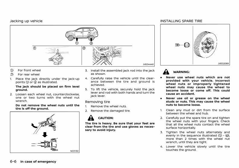
(232,1)
[ Edit: 2018/ 5/ 25 Model: PD23-A ]
6-6 In case of emergency
Jacking up vehiclePD23A1-57F60746-7772-477C-8E66-ABC596D11CC3
JVE0444X
For front wheelFor rear wheel
1. Place the jack directly under the jack-uppoints or as illustrated.The jack should be placed on firm levelground.
2. Loosen each wheel nut, counterclockwise,one or two turns with the wheel nutwrench.Do not remove the wheel nuts until thetire is off the ground.
NCE130
3. Install the assembled jack rod into the jackas shown.
4. Carefully raise the vehicle until the clear-ance between the tire and ground isachieved.
5. To lift the vehicle, securely hold the jacklever and rod with both hands and turn thejack lever.
Removing tirePD23A1-066AD6B2-BA09-42A4-85B3-B5EF13C4DC91
1. Remove the wheel nuts.2. Remove the damaged tire.
CAUTION:
The tire is heavy. Be sure that your feet areclear from the tire and use gloves as neces-sary to avoid injury.
INSTALLING SPARE TIREPD23A1-6B745FBE-4633-46DD-8F1C-63F78926B25C
JVE0208X
WARNING:
. Never use wheel nuts which are notprovided with your vehicle. Incorrectwheel nuts or improperly tightenedwheel nuts may cause the wheel tobecome loose or come off. This couldcause an accident.
. Never use oil or grease on the wheelstuds or nuts. This may cause the wheelnuts to become loose.
1. Clean any mud or dirt from the surfacebetween the wheel and hub.
2. Carefully put the spare tire on and tightenthe wheel nuts with your fingers. Checkthat all the wheel nuts contact the wheelsurface horizontally.
3. Tighten the wheel nuts alternately andevenly in the sequence illustrated ( - ),more than 2 times with the wheel nutwrench, until they are tight.
4. Lower the vehicle slowly until the tiretouches the ground.
Condition: 'Except for China'/
(233,1)
[ Edit: 2018/ 5/ 25 Model: PD23-A ]
5. Tighten the wheel nuts securely, with thewheel nut wrench, in the sequence illu-strated.
6. Lower the vehicle completely.Tighten the wheel nuts to the specifiedtorque with a torque wrench as soon aspossible.
Wheel nut tightening torque:133 N·m (13.6 kg-m, 98 ft-lb)
The wheel nuts must be kept tightened tospecification at all times. It is recommendedthat the wheel nuts be tightened to specifi-cation at each lubrication interval.
WARNING:
Retighten the wheel nuts when the vehiclehas been driven for 1,000 km (600 miles)(also in case of a flat tire, etc.).
For models equipped with Tire PressureMonitoring System (TPMS)
GUID-534D27BC-6C44-46C6-A117-081A468C15AA. After adjusting the tire pressure, the TPMS
must be reset. See “Tire Pressure Monitor-ing System (TPMS)” (P.5-4) for details aboutthe resetting procedure.
. After adjusting tire pressure to the COLDtire pressure, the display of the tire pres-sures may show higher pressure than theCOLD tire pressure after the vehicle hasbeen driven more than 1.6 km (1 mile). This isbecause the tire pressurizes as the tiretemperature rises. This does not indicate asystem malfunction.
STOWING DAMAGED TIRE AND TOOLSPD23A1-ADE46C5C-5C07-4076-AF08-8049224EE449
WARNING:
Be sure that the tire, jack and tools areproperly stored after use. Such items canbecome dangerous projectiles in an accidentor sudden stop.
Securely store the damaged tire, jack and toolsin the storage area in the reverse order ofremoval. (See “Preparing tools” (P.6-3) and“Removing the spare tire” (P.6-4).)
PD23A1-EE3D792C-AD0C-46DF-9465-D06434453F20
WARNING:
. Incorrect jump starting can lead to abattery explosion. The battery explosionmay result in severe injury or death. Itmay also result in damage to the vehicle.Be sure to follow the instructions in thissection.
. Explosive hydrogen gas is always presentin the vicinity of the battery. Keep allsparks and flames away from the battery.
. Always wear suitable eye protection andremove rings, bracelets, and any otherjewelry whenever working on or near abattery.
. Never lean over the battery while jumpstarting.
. Never allow battery fluid to come intocontact with eyes, skin, clothes or thevehicle’s painted surfaces. Battery fluid isa corrosive sulfuric acid which can causesevere burns. If the fluid comes intocontact with anything, immediately flushthe contacted area with plenty of water.
. Keep the battery out of the reach ofchildren.
. The booster battery must be rated at 12volts. Use of an incorrectly rated batterywill damage your vehicle.
. Never attempt to jump start a frozenbattery. It could explode and cause ser-ious injury.
In case of emergency 6-7
JUMP STARTING
Condition: 'Except for China'/
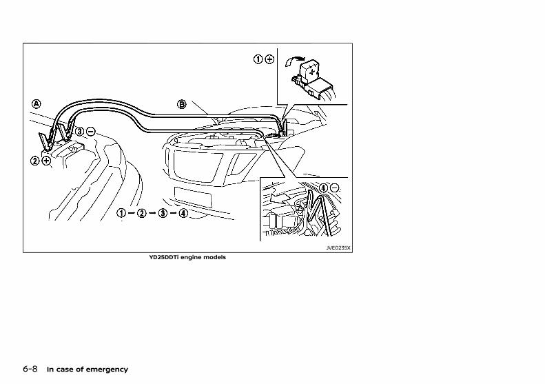
(234,1)
[ Edit: 2018/ 5/ 25 Model: PD23-A ]
6-8 In case of emergency
JVE0235X
YD25DDTi engine models
Condition: 'Except for China'/
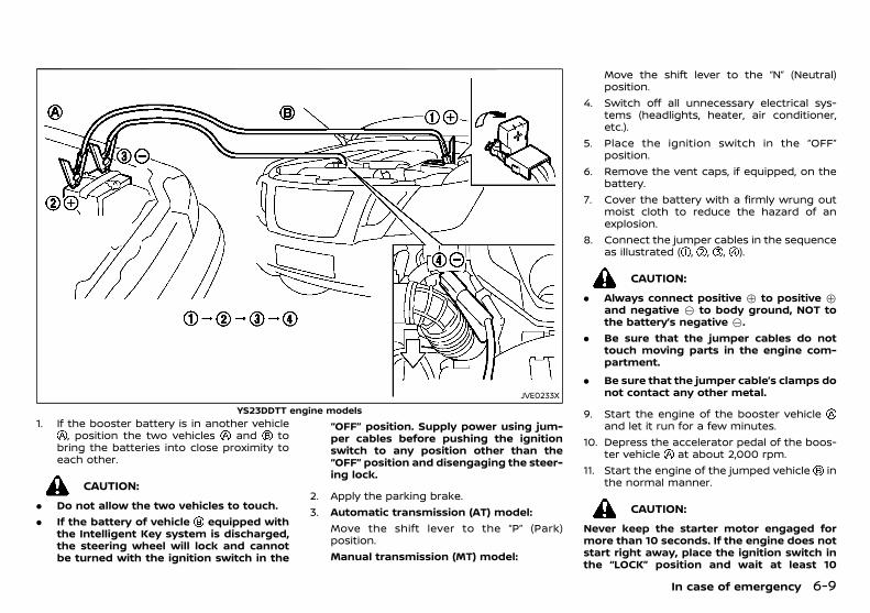
(235,1)
[ Edit: 2018/ 5/ 25 Model: PD23-A ]
JVE0233X
YS23DDTT engine models1. If the booster battery is in another vehicle
, position the two vehicles and tobring the batteries into close proximity toeach other.
CAUTION:
. Do not allow the two vehicles to touch.
. If the battery of vehicle equipped withthe Intelligent Key system is discharged,the steering wheel will lock and cannotbe turned with the ignition switch in the
“OFF” position. Supply power using jum-per cables before pushing the ignitionswitch to any position other than the“OFF” position and disengaging the steer-ing lock.
2. Apply the parking brake.3. Automatic transmission (AT) model:
Move the shift lever to the “P” (Park)position.Manual transmission (MT) model:
Move the shift lever to the “N” (Neutral)position.
4. Switch off all unnecessary electrical sys-tems (headlights, heater, air conditioner,etc.).
5. Place the ignition switch in the “OFF”position.
6. Remove the vent caps, if equipped, on thebattery.
7. Cover the battery with a firmly wrung outmoist cloth to reduce the hazard of anexplosion.
8. Connect the jumper cables in the sequenceas illustrated ( , , , ).
CAUTION:
. Always connect positive + to positive +and negative 7 to body ground, NOT tothe battery’s negative 7.
. Be sure that the jumper cables do nottouch moving parts in the engine com-partment.
. Be sure that the jumper cable’s clamps donot contact any other metal.
9. Start the engine of the booster vehicleand let it run for a few minutes.
10. Depress the accelerator pedal of the boos-ter vehicle at about 2,000 rpm.
11. Start the engine of the jumped vehicle inthe normal manner.
CAUTION:
Never keep the starter motor engaged formore than 10 seconds. If the engine does notstart right away, place the ignition switch inthe “LOCK” position and wait at least 10
In case of emergency 6-9
Condition: 'Except for China'/
(236,1)
[ Edit: 2018/ 5/ 25 Model: PD23-A ]
6-10 In case of emergency
seconds before trying again.12. After the engine is started, carefully dis-
connect the jumper cables in the oppositesequence from that illustrated ( , , , ).
13. Remove and dispose of the cloth properlyas it may be contaminated with corrosiveacid.
14. Replace the vent caps, if removed.
PD23A1-5CC36DFE-5276-41D3-8217-B03F2712B197Do not attempt to start the engine by pushingthe vehicle.
CAUTION:
. Automatic Transmission (AT) model can-not be started by pushing. Attempting todo so may cause damage to the trans-mission.
. Diesel Oxidation Catalyst equippedmodelshould not be started by pushing. At-tempting to do so may cause damage tothe catalyst.
. Never try to start the engine by towing.When the engine starts, the forwardsurge could cause the vehicle to collidewith the towing vehicle.
PD23A1-7014DDE8-5D3E-42F2-96D2-FBBBE965DF8F
WARNING:
. Never continue driving if your vehicleoverheats. Doing so could cause enginedamage and/or a vehicle fire.
. Never open the hood if steam is comingout.
. Never remove the radiator or coolantreservoir cap while the engine is hot. Ifthe radiator or coolant reservoir cap isremoved when the engine is hot, pres-surized hot water will spurt out andpossibly cause burning, scalding or ser-ious injury.
. If steam or coolant is coming from theengine, stand clear of the vehicle toprevent getting scalded.
. The engine cooling fan can start at anytime when the coolant temperature ex-ceeds preset degrees.
. Be careful not to allow your hands, hair,jewelry or clothing to come into contactwith, or to get caught in the cooling fan ordrive belts.
If your vehicle is overheating, or if you feel alack of engine power, detect unusual noise, etc.,take the following steps:1. Safely move the vehicle off the road away
from traffic.2. Turn on the hazard indicator flashers.3. Apply the parking brake.4. Automatic transmission model:
Move the shift lever to the “P” (Park)position.Manual transmission model:Move the shift lever to the “N” (Neutral)
PUSH STARTING IF YOUR VEHICLE OVERHEATS
Condition: 'Except for China'/
(237,1)
[ Edit: 2018/ 5/ 25 Model: PD23-A ]
position.DO NOT STOP THE ENGINE.
5. Open all the windows.6. Turn off the air conditioner. Move the
temperature control to maximum hot andthe fan control to high speed.
7. Get out from the vehicle.8. Visually inspect and listen for steam or
coolant escaping from the radiator beforeopening the hood. Wait until no steam orcoolant can be seen before proceeding.
9. Open the engine hood.10. Visually inspect if the cooling fan is running.11. Visually inspect the radiator and radiator
hoses for leakage. If the cooling fan is notrunning or the coolant is leaking, stop theengine.
12. After the engine cools down, check thecoolant level in the reservoir with theengine running. Do not open the radiatoror coolant reservoir cap.
13. Add coolant to the reservoir if necessary.Have your vehicle inspected/repaired at aNISSAN dealer.
PD23A1-48D6CD00-C971-4287-BB64-52A307F3A2ECWhen towing your vehicle, local regulations fortowing must be followed. Incorrect towingequipment could damage your vehicle. Toassure proper towing and to prevent acciden-tal damage to your vehicle, NISSAN recom-mends that you have professional roadassistance personnel tow your vehicle. It isadvisable to have the professional road assis-tant carefully read the following precautions.
TOWING PRECAUTIONSPD23A1-4F55A07C-277A-4C61-959B-DA70C4B44F55
. Be sure that the transmission, steeringsystem and powertrain are in workingcondition before towing. If any units aredamaged, the vehicle must be towed usinga dolly or flatbed tow truck. (Two-WheelDrive (2WD) model)
. NISSAN recommends that your vehicle betowed with the driving wheels off theground. (Two-Wheel Drive (2WD) model)
. Always attach safety chains before towing.
. Never tow Four-Wheel Drive (4WD) modelwith any of the wheels on the ground asthis may cause serious and expensivedamage to the drivetrain.
In case of emergency 6-11
TOWING YOUR VEHICLE
Condition: 'Except for China'/

(238,1)
[ Edit: 2018/ 5/ 25 Model: PD23-A ]
6-12 In case of emergency
TOWING RECOMMENDED BY NISSANPD23A1-CBEEFF0E-FEE6-4F26-8119-94C66A048852
Towing Two-Wheel Drive (2WD) modelsPD23A1-85A702C6-3335-4346-81CB-D3DE1DE0D8E3
SCE0925
Front wheels on the ground:1. Place the ignition switch in the “ON” posi-
tion and turn all accessories off.2. Secure the steering wheel in a straight
ahead position with rope or similar device.3. Move the shift lever to the “N” (Neutral)
position.4. Release the parking brake.5. Attach safety chains before towing.Rear wheels on the ground:NISSAN recommends that towing dollies beused under the rear wheels when towing yourvehicle or the vehicle be placed on a flatbedtow truck as illustrated.
CAUTION:
Never tow Automatic Transmission (AT) mod-el with the rear wheels on the ground. Doingso will cause serious and expensive damageto the transmission.
Manual Transmission (MT) model:If you have to tow a MT vehicle with rear wheelon the ground, perform the following proce-dures.
CAUTION:
Observe the following restricted towingspeeds and distances.
. Speed: Below 50 km/h (30 MPH)
. Distance: Less than 65 km (40 miles)
1. Place the ignition switch in the “ON” posi-tion and turn all accessories off.
2. Move the shift lever to the “N” (Neutral)position.
3. Release the parking brake.4. Attach safety chains whenever towing.All four wheels on the ground:NISSAN recommends that the vehicle be placedon a flatbed tow truck as illustrated.
CAUTION:
Never tow Automatic Transmission (AT) mod-el with all four wheels on the ground. Doingso will cause serious and expensive damageto the drivetrain.
Manual Transmission (MT) model:If you have to tow a MT vehicle with all fourwheels on the ground, perform the followingprocedures.
CAUTION:
. Never tow a Manual Transmission (MT)model backward with all four wheels onthe ground.
. Observe the following restricted towingspeeds and distances.— Speed: Below 50 km/h (30 MPH)
— Distance: Less than 65 km (40 miles)
1. Place the ignition switch in the “ON” posi-tion and turn all accessories off.
Condition: 'Except for China'/
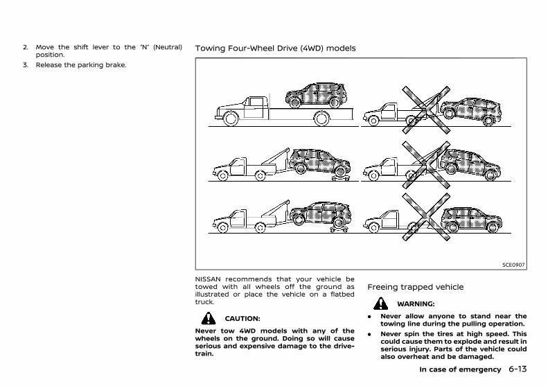
(239,1)
[ Edit: 2018/ 5/ 25 Model: PD23-A ]
2. Move the shift lever to the “N” (Neutral)position.
3. Release the parking brake.
Towing Four-Wheel Drive (4WD) modelsPD23A1-82446E9D-DF83-48FB-A6E3-C1573EFAAECB
SCE0907
NISSAN recommends that your vehicle betowed with all wheels off the ground asillustrated or place the vehicle on a flatbedtruck.
CAUTION:
Never tow 4WD models with any of thewheels on the ground. Doing so will causeserious and expensive damage to the drive-train.
Freeing trapped vehiclePD23A1-28A40C0C-F43D-48F6-9AF2-BBDDF72CFE7B
WARNING:
. Never allow anyone to stand near thetowing line during the pulling operation.
. Never spin the tires at high speed. Thiscould cause them to explode and result inserious injury. Parts of the vehicle couldalso overheat and be damaged.
In case of emergency 6-13
Condition: 'Except for China'/
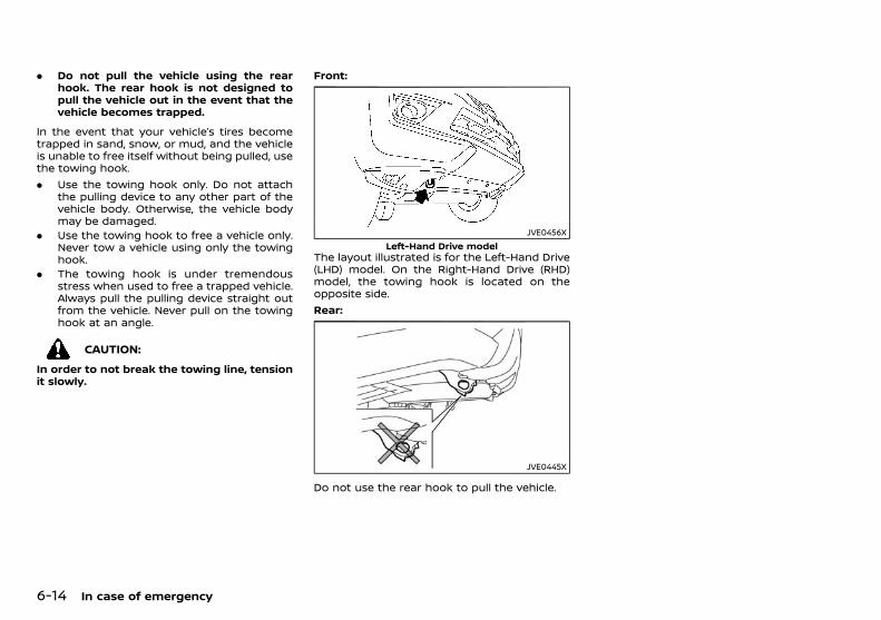
(240,1)
[ Edit: 2018/ 5/ 25 Model: PD23-A ]
6-14 In case of emergency
. Do not pull the vehicle using the rearhook. The rear hook is not designed topull the vehicle out in the event that thevehicle becomes trapped.
In the event that your vehicle’s tires becometrapped in sand, snow, or mud, and the vehicleis unable to free itself without being pulled, usethe towing hook.. Use the towing hook only. Do not attach
the pulling device to any other part of thevehicle body. Otherwise, the vehicle bodymay be damaged.
. Use the towing hook to free a vehicle only.Never tow a vehicle using only the towinghook.
. The towing hook is under tremendousstress when used to free a trapped vehicle.Always pull the pulling device straight outfrom the vehicle. Never pull on the towinghook at an angle.
CAUTION:
In order to not break the towing line, tensionit slowly.
Front:
JVE0456XLeft-Hand Drive model
The layout illustrated is for the Left-Hand Drive(LHD) model. On the Right-Hand Drive (RHD)model, the towing hook is located on theopposite side.Rear:
JVE0445X
Do not use the rear hook to pull the vehicle.
Condition: 'Except for China'/
(241,1)
[ Edit: 2018/ 5/ 25 Model: PD23-A ]
7 Appearance and care
Cleaning exterior ............................................................................................... 7-2Washing ............................................................................................................ 7-2Removing spots ......................................................................................... 7-2Waxing ................................................................................................................ 7-2Glass .................................................................................................................... 7-3Underbody ...................................................................................................... 7-3Wheels ................................................................................................................ 7-3Aluminum alloy wheels ........................................................................ 7-3Side step boards ........................................................................................ 7-3Chrome parts ............................................................................................... 7-3
Cleaning interior ............................................................................................... 7-4Air fresheners ............................................................................................ 7-4Floor mats .................................................................................................... 7-4Glass ................................................................................................................. 7-4Seat belts ...................................................................................................... 7-5
Corrosion protection .................................................................................... 7-5Most common factors contributing tovehicle corrosion .................................................................................... 7-5Environmental factors influence the rateof corrosion ................................................................................................ 7-5To protect your vehicle from corrosion .............................. 7-5
Condition: 'Except for China'/
(242,1)
[ Edit: 2018/ 5/ 25 Model: PD23-A ]
7-2 Appearance and care
PD23A1-2C1475A6-F2C1-42EF-BC13-19870821EE84In order to maintain the appearance of yourvehicle, it is important to take proper care of it.Whenever possible, park your vehicle inside agarage or in a covered area to minimize thechances of damaging the paint surface of yourvehicle.When it is necessary to park outside, park in ashady area or protect the vehicle with a bodycover. Be careful not to scratch the paintsurface when putting on or removing thebody cover.
WASHINGPD23A1-52CA2A90-9B93-4E97-985F-079D905A0AAE
In the following instances, wash your vehicle assoon as possible to protect the paint surface:. After a rainfall, which may cause the paint
surface damage from acid rain.. After driving on coastal roads, which may
cause rusting from the sea breeze.. When contaminants such as soot, bird
droppings, tree sap, metal particles or bugsget on the paint surface.
. When dust or mud builds up on the paintsurface.
1. Wash the vehicle surface with a wet spongeand plenty of water.
2. Clean the vehicle surface gently and thor-oughly using a mild soap, a special vehiclesoap or a general purpose dishwashingliquid mixed with clean, lukewarm (neverhot) water.
CAUTION:
. Do not wash the vehicle with stronghousehold soap, strong chemical deter-gents, gasoline or solvents.
. Do not wash the vehicle in direct sunlightor while the vehicle body is hot, as thepaint surface may become water-spotted.
. Avoid using tight-napped or rough cloths,such as washing mitts. Care must betaken when removing caked-on dirt orother foreign substances so the paintsurface is not scratched or damaged.
. Lock all doors before going throughautomatic car wash. Locking doors helpsprevent fuel-filler lid from opening andbecoming damaged.
3. Rinse the vehicle thoroughly with plenty ofclean water.
4. Use a dampened chamois to dry the paintsurface and avoid leaving water spots.
When washing the vehicle, take care of thefollowing:. Inside flanges, joints and folds on the doors,
hatches and hood are particularly vulner-able to the effects of road salt. Therefore,these areas must be cleaned regularly.
. Be sure that the drain holes in the loweredge of the doors are not clogged.
. Spray water to the underbody and in thewheel wells to loosen the dirt and/or washaway road salt.
REMOVING SPOTSPD23A1-6D039294-F855-4C03-8E99-80C6C84682C7
Remove tar and oil spots, industrial dust,insects, and tree sap as quickly as possiblefrom the paint surface to avoid lasting damageor staining. Special cleaning products areavailable at a NISSAN dealer or any automotiveaccessory store.
WAXINGPD23A1-24E6F882-0573-4260-86FB-6F3FA0A23C19
Regular waxing protects the paint surface andhelps maintain a new vehicle appearance.After waxing, polishing is recommended toremove built-up residue and to avoid a weath-ered appearance.A NISSAN dealer can assist you in choosing theappropriate waxing products.
CAUTION:
. Wash your vehicle thoroughly and com-pletely before applying wax to the paintsurface.
. Always follow themanufacturer’s instruc-tions supplied with the wax.
. Do not use a wax containing any abra-sives, cutting compounds or cleanersthat may damage the vehicle finish.
Machine compounding or aggressive polishingon a base coat/clear coat paint finish may dullthe finish or leave swirl marks.
CLEANING EXTERIOR
Condition: 'Except for China'/
(243,1)
[ Edit: 2018/ 5/ 25 Model: PD23-A ]
GLASSPD23A1-5F272933-652F-4477-9808-C6F712A65783
Use glass cleaner to remove smoke and dustfilm from the glass surfaces. It is normal forglass to become coated with a film after thevehicle is parked in the hot sun. Glass cleanerand a soft cloth will easily remove this film.
UNDERBODYPD23A1-E8FB3E0B-FA23-415E-AF19-FFD0C0F73D65
In areas where road salt is used in the winter, itis necessary to clean the vehicle’s underbodyregularly in order to prevent dirt and salt frombuilding up and causing the acceleration ofcorrosion on the underbody and suspension.Before the winter and again in the spring, theunderseal must be checked and, if necessary,re-treated.
WHEELSPD23A1-F3433C47-E23B-43DD-9EA7-BC455ABB3E7B
. Wash the wheels when washing the vehicleto maintain their appearance.
. Clean the inner side of the wheels when thewheel is changed or the underside of thevehicle is washed.
. Do not use abrasive cleaners when wash-ing the wheels.
. Inspect wheel rims regularly for dents orcorrosion. This may cause loss of pressureor damage the tire bead.
. NISSAN recommends that the road wheelsbe waxed to protect against road salt inareas where it is used during winter.
ALUMINUM ALLOY WHEELSPD23A1-9208A50C-BAB6-40FD-9E69-1ACA9E664A64
Wash the wheels regularly with a spongedampened in a mild soap solution, especiallyduring winter in areas where road salt is used.The salt residue from road salt could discolorthe wheels if it is not washed off regularly.
CAUTION:
Follow the directions below to avoid stainingor discoloring the wheels:
. Do not use a cleaner that uses strong acidor alkali contents to clean the wheels.
. Do not apply wheel cleaners to thewheels when they are hot. The wheeltemperature should be the same asambient temperature.
. Rinse the wheel to completely removethe cleaner within 15 minutes after thecleaner is applied.
SIDE STEP BOARDSPD23A1-2C643168-A941-49DD-A295-F7D1588D2EC7
CAUTION:
When cleaning the side step boards, followthe instructions below:
. Do not use a cleaner that uses strong acidor alkali contents to clean the side stepboards. Using strong acid or alkali con-tents may damage the side step boardsurface.
. Rinse off the cleaner completely from theside step boards right after it is applied.
CHROME PARTSPD23A1-A45ADD0A-D2C3-4DE6-9BA8-E87AAE41F658
Clean all chrome parts regularly with a non-abrasive chrome polish to maintain the finish.
Appearance and care 7-3
Condition: 'Except for China'/
(244,1)
[ Edit: 2018/ 5/ 25 Model: PD23-A ]
7-4 Appearance and care
PD23A1-2EB96DB0-EC26-4717-8559-EF1F5A9D89C1Occasionally remove loose dust from the inter-ior trim, plastic parts and seats using a vacuumcleaner or soft bristled brush. Wipe the vinyland leather surfaces with a clean, soft clothdampened in mild soap solution, then wipeclean with a dry, soft cloth.Regular care and cleaning is required in orderto maintain the appearance of the leather.Before using any fabric protector, read themanufacturer’s recommendations. Some fabricprotectors contain chemicals that may stain orbleach the seat material.Use a soft cloth dampened only with water toclean the meter and gauge lens covers.
CAUTION:
. Never use benzine, thinner or any similarmaterial.
. Small dirt particles can be abrasive anddamaging to leather surfaces and shouldbe removed promptly. Do not use saddlesoap, car waxes, polishes, oils, cleaningfluids, solvents, detergents or ammonia-based cleaners as they damage theleather natural finish.
. Never use fabric protectors unless re-commended by the manufacturer.
. Do not use glass or plastic cleaner onmeter or gauge lens covers. It maydamage the lens covers.
AIR FRESHENERSPD23A1-FA2A8AC5-49FC-4603-BBED-21B6BEFFA035
Most air fresheners use a solvent that couldaffect the vehicle interior. If you use an airfreshener, take the following precautions:. Hanging-type air fresheners can cause
permanent discoloration when they con-tact vehicle interior surfaces. Place the airfreshener in a location that allows it tohang free and not contact an interiorsurface.
. Liquid-type air fresheners typically clip onthe vents. These products can cause im-mediate damage and discoloration whenspilled on interior surfaces.
Carefully read and follow the manufacturer’sinstructions before using air fresheners.
FLOOR MATSPD23A1-1B314048-1190-4006-BB9A-CBB1718218B2
The use of genuine NISSAN floor mats (ifequipped) can extend the life of your vehiclecarpet and make it easier to clean the interior.Regardless of what mats are used, be sure theyare fitted for your vehicle and are properlypositioned in the foot well to prevent inter-ference with pedal operation. Mats should bemaintained with regular cleaning and replacedif they become excessively worn.
Floor mat positioning aidPD23A1-22B0FB6B-8E5A-4F97-A6CA-B63DA7A84991
JVA0018X
This vehicle includes floor mat brackets to actas a floor mat positioning aid. NISSAN floormats have been specially designed for yourvehicle model.Position the mat by placing the floor matbracket hook through the floor mat grommethole while centering the mat in the foot area.Periodically check that the mats are properlypositioned.
GLASSPD23A1-9761A1A8-C4ED-46D9-9C09-F4950BF5F3CC
Use glass cleaner to remove smoke and dustfilm from the glass surfaces. It is normal forglass to become coated with a film after thevehicle is parked in the hot sun. Glass cleanerand a soft cloth will easily remove this film.
CAUTION:
When cleaning the inside of the windows, donot use sharp-edged tools, abrasive cleanersor chlorine-based disinfectant cleaners. Theycould damage the electrical conductors, suchas radio antenna elements or rear windowdefogger elements.
CLEANING INTERIOR
Condition: 'Except for China'/
(245,1)
[ Edit: 2018/ 5/ 25 Model: PD23-A ]
SEAT BELTSPD23A1-FE5CC456-C87A-4BAB-BC26-0344E0699D4D
WARNING:
. Do not allow wet seat belts to roll up inthe retractor.
. Never use bleach, dye or chemical sol-vents to clean the seat belts, since thesematerials may severely weaken the seatbelt webbing.
The seat belts can be cleaned by wiping themwith a sponge dampened in a mild soapsolution.Allow the belts to dry completely in the shadebefore using them. (See “Seat belts” (P.1-12).)
PD23A1-88A6F4F0-C55B-4C54-9334-304853510A3E
MOST COMMON FACTORS CONTRI-BUTING TO VEHICLE CORROSION
PD23A1-68180AEC-B281-4CBA-8800-5C71C7841E52. The accumulation of moisture-retaining
dirt and debris in body panel sections,cavities, and other areas.
. Damage to the paint surface and otherprotective coatings caused by gravel andstone chips or minor traffic accidents.
ENVIRONMENTAL FACTORS INFLUENCETHE RATE OF CORROSION
PD23A1-9F4F2623-2EB3-4361-BD51-00CB2422B44F
MoisturePD23A1-4650C177-5FD9-4D3D-B04A-9C7C7BD90460
The accumulation of sand, dirt and water onthe inside floor of the vehicle can acceleratecorrosion. Wet floor carpet/floor mats will notdry completely inside the vehicle. They shouldbe removed and completely dried to avoid floorpanel corrosion.
Relative humidityPD23A1-4183169E-6E23-4B79-9D33-52C71E1DE663
Corrosion will be accelerated in areas of highrelative humidity.
TemperaturePD23A1-E477FDFB-4836-4774-8832-6318E7E4B86B
High temperatures accelerate the rate ofcorrosion to those parts which are not wellventilated.Corrosion will also be accelerated in areaswhere the temperatures stay above freezing.
Air pollutionPD23A1-05B60743-6EE4-46A4-BAF5-B6871C45413F
Industrial pollution, the presence of salt in theair in coastal areas, or heavy road salt useaccelerates the corrosion process. Road saltalso accelerates the disintegration of paintsurfaces.
TO PROTECT YOUR VEHICLE FROMCORROSION
PD23A1-3347F399-5EAD-40C8-8FE4-20C72DDAD308. Wash and wax your vehicle often to keep
the vehicle clean.. Always check for minor damage to the
paint surface and if any exists, repair it assoon as possible.
. Keep the drain holes in the lower edge ofthe doors open to avoid water accumula-tion.
. Check the vehicle underbody for accumu-lation of sand, dirt or salt. If present, washwith water as soon as possible.
CAUTION:
. Never remove dirt, sand or other debrisfrom the passenger compartment bywashing it out with a hose. Remove dirtwith a vacuum cleaner.
. Never allow water or other liquids tocome in contact with electronic compo-nents inside the vehicle as this maydamage them.
Chemicals used for road surface deicing areextremely corrosive. They accelerate corrosionand deterioration of underbody componentssuch as the exhaust system, fuel and brakelines, brake cables, floor pan and fenders.In the winter, the underbody must be cleanedperiodically.For additional protection against rust andcorrosion, which may be required in someareas, consult a NISSAN dealer.
Appearance and care 7-5
CORROSION PROTECTION
Condition: 'Except for China'/

(246,1)
[ Edit: 2018/ 5/ 25 Model: PD23-A ]
7-6 Appearance and care
MEMO
Condition: 'Except for China'/
(247,1)
[ Edit: 2018/ 5/ 25 Model: PD23-A ]
8 Maintenance and do-it-yourself
Maintenance requirements ...................................................................... 8-2Scheduled maintenance ...................................................................... 8-2General maintenance ............................................................................ 8-2Where to go for service ........................................................................ 8-2
General maintenance .................................................................................... 8-2Explanation of general maintenance items ........................ 8-2Maintenance precautions .................................................................. 8-4
Engine compartment check locations ............................................ 8-5YD25DDTi engine ...................................................................................... 8-5YS23DDTT engine ..................................................................................... 8-6
Engine cooling system ................................................................................. 8-6Checking engine coolant level ....................................................... 8-7Changing engine coolant ................................................................... 8-7
Engine oil ................................................................................................................. 8-8Checking engine oil level .................................................................... 8-8Changing engine oil and oil filter ................................................. 8-8Protect environment ........................................................................... 8-11
Fuel filter (YD25DDTi engine model) .............................................. 8-11Draining water .......................................................................................... 8-11Bleeding the fuel system ................................................................. 8-11
Drive belt .............................................................................................................. 8-12Brakes ..................................................................................................................... 8-12
Checking parking brake ................................................................... 8-12Checking foot brake ............................................................................ 8-13Brake booster ........................................................................................... 8-13
Brake fluid ............................................................................................................ 8-14Clutch fluid (if equipped) .......................................................................... 8-14Automatic Transmission Fluid (ATF) (if equipped) .............. 8-15
7-speed Automatic Transmission (AT) model ................ 8-15Power steering fluid .................................................................................... 8-15
Air cleaner filter .............................................................................................. 8-16Wiper blades ..................................................................................................... 8-16
Windshield wiper blades ................................................................ 8-16Rear window wiper blade ............................................................. 8-17
Window washer fluid .................................................................................. 8-17Battery ................................................................................................................... 8-18
Vehicle battery ...................................................................................... 8-18Remote controller battery (if equipped) ........................... 8-19Intelligent Key battery (if equipped) ..................................... 8-20
Variable voltage control system (if equipped) ...................... 8-21Fuses ....................................................................................................................... 8-21
Engine compartment ....................................................................... 8-21Passenger compartment .............................................................. 8-22
Lights ...................................................................................................................... 8-23Headlights ................................................................................................. 8-23Exterior lights ......................................................................................... 8-23Interior lights ........................................................................................... 8-24Light locations ....................................................................................... 8-24
Tires and wheels ........................................................................................... 8-27Tire Pressure Monitoring System (TPMS)(if equipped) ............................................................................................. 8-27Tire inflation pressure ..................................................................... 8-27Types of tires .......................................................................................... 8-27Tire chains ................................................................................................. 8-28Tire rotation ............................................................................................. 8-28Tire wear and damage ................................................................... 8-29Tire age ....................................................................................................... 8-29Changing tires and wheels ......................................................... 8-29Wheel balance ........................................................................................ 8-30Spare tire ................................................................................................... 8-30
Condition: 'Except for China'/
(248,1)
[ Edit: 2018/ 5/ 25 Model: PD23-A ]
8-2 Maintenance and do-it-yourself
PD23A1-657BA42B-68B2-4D12-884F-7E07F3608FADSome day-to-day and regular maintenance isessential to maintain your vehicle’s good me-chanical condition, as well as its emission andengine performance.It is the owner’s responsibility to make sure thatthe specified maintenance, as well as generalmaintenance, is performed.As the vehicle owner, you are the only one whocan ensure that your vehicle receives theproper maintenance care.
SCHEDULED MAINTENANCEPD23A1-8776E2C4-F455-4EC7-8E9C-884C20BF1210
For your convenience, the required scheduledmaintenance items are described and listed ina separate Warranty Information and Mainte-nance booklet. You must refer to that bookletto ensure that necessary maintenance is per-formed on your vehicle at regular intervals.
GENERAL MAINTENANCEPD23A1-49F086AD-E54B-4B05-AA60-0FCEA79B6754
General maintenance includes those itemswhich should be checked during normal day-to-day operation of the vehicle. They areessential if your vehicle is to continue tooperate properly. It is your responsibility toperform these procedures regularly as pre-scribed.Performing general maintenance checks re-quires minimal mechanical skill and only a fewgeneral automotive tools.These checks or inspections can be done byyourself, a qualified technician, or if you prefer,your NISSAN dealer.
WHERE TO GO FOR SERVICEPD23A1-A0CE9CE4-E7F2-479F-B6EC-ABBE69B3FC4A
If maintenance service is required or yourvehicle appears to malfunction, have the sys-tems checked and tuned by an authorisedNISSAN dealer.
PD23A1-B5A92B6E-ED44-4375-86B5-6618C49C8921During normal day-to-day operation of thevehicle, general maintenance should be per-formed regularly as prescribed in this section. Ifyou detect any unusual sounds, vibrations orsmells, be sure to check for the cause or have aNISSAN dealer do it promptly. In addition, youshould notify a NISSAN dealer if you think thatrepairs are required.When performing any checks or maintenancework, closely observe “Maintenance precau-tions” (P.8-4).
EXPLANATION OF GENERAL MAINTE-NANCE ITEMS
PD23A1-DCA24E7B-D710-452B-884D-AA69578F7AF9Additional information on the followingitems with “*” is found later in this section.
Outside vehiclePD23A1-B906E59F-E3CA-481E-B84E-25F0B03C367E
The maintenance items listed here should beperformed from time to time, unless otherwisespecified.
Doors and hood:GUID-9E14C2E6-2E9C-4731-980B-C45B899B977B
Check that all doors and the hood operatesmoothly as well as the back door, trunk lid andhatch. Also make sure that all latches locksecurely. Lubricate if necessary. Make sure thatthe secondary latch keeps the hood fromopening when the primary latch is released.When driving in areas using road salt or othercorrosive materials, check lubrication fre-quently.
Lights*:GUID-9E14C2E6-2E9C-4731-980B-C45B899B977B
Clean the headlights on a regular basis. Makesure that the headlights, stop lights, tail lights,turn signal lights, and other lights are alloperating properly and installed securely. Alsocheck the aim of the headlights.
MAINTENANCE REQUIREMENTS GENERAL MAINTENANCE
Condition: 'Except for China'/
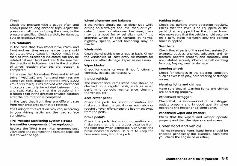
(249,1)
[ Edit: 2018/ 5/ 25 Model: PD23-A ]
Tires*:GUID-9E14C2E6-2E9C-4731-980B-C45B899B977B
Check the pressure with a gauge often andalways prior to long distance trips. Adjust thepressure in all tires, including the spare, to thepressure specified. Check carefully for damage,cuts or excessive wear.
Tire rotation*:GUID-9E14C2E6-2E9C-4731-980B-C45B899B977B
In the case that Two-Wheel Drive (2WD) andfront and rear tires are same size; tires shouldbe rotated every 10,000 km (6,000 miles). Tiresmarked with directional indicators can only berotated between front and rear. Make sure thatthe directional indicators point in the directionof wheel rotation after the tire rotation iscompleted.In the case that Four-Wheel Drive and All WheelDrive (4WD/AWD) and front and rear tires aresame size; tires should be rotated every 5,000km (3,000 miles). Tires marked with directionalindicators can only be rotated between frontand rear. Make sure that the directional in-dicators point in the direction of wheel rotationafter the tire rotation is completed.In the case that front tires are different sizefrom rear tires; tires cannot be rotated.The timing for tire rotation may vary accordingto your driving habits and the road surfaceconditions.
Tire Pressure Monitoring System (TPMS)transmitter components (if so equipped):
GUID-9E14C2E6-2E9C-4731-980B-C45B899B977B
Replace the TPMS transmitter grommet seal,valve core and cap when the tires are replaceddue to wear or age.
Wheel alignment and balance:GUID-9E14C2E6-2E9C-4731-980B-C45B899B977B
If the vehicle should pull to either side whiledriving on a straight and level road, or if youdetect uneven or abnormal tire wear, theremay be a need for wheel alignment. If thesteering wheel or seat vibrates at normalhighway speeds, wheel balancing may beneeded.
Windshield:GUID-9E14C2E6-2E9C-4731-980B-C45B899B977B
Clean the windshield on a regular basis. Checkthe windshield at least every six months forcracks or other damage. Repair as necessary.
Wiper blades*:GUID-9E14C2E6-2E9C-4731-980B-C45B899B977B
Check for cracks or wear if not functioningcorrectly. Replace as necessary.
Inside vehiclePD23A1-C30F89A2-BD24-450C-BE29-CACC3954D796
The maintenance items listed here should bechecked on a regular basis, such as whenperforming periodic maintenance, cleaningthe vehicle, etc.
Accelerator pedal:GUID-9E14C2E6-2E9C-4731-980B-C45B899B977B
Check the pedal for smooth operation andmake sure that the pedal does not catch orrequire uneven effort. Keep the floor mats awayfrom the pedal.
Brake pedal*:GUID-9E14C2E6-2E9C-4731-980B-C45B899B977B
Check the pedal for smooth operation andmake sure that it is the proper distance fromthe floor mat when depressed fully. Check thebrake booster function. Be sure to keep thefloor mats away from the pedal.
Parking brake*:GUID-9E14C2E6-2E9C-4731-980B-C45B899B977B
Check the parking brake operation regularly.Check that the lever (if so equipped) or thepedal (if so equipped) has the proper travel.Also make sure that the vehicle is held securelyon a fairly steep hill when only the parkingbrake is applied.
Seat belts:GUID-9E14C2E6-2E9C-4731-980B-C45B899B977B
Check that all parts of the seat belt system (forexample, buckles, anchors, adjusters and re-tractors) operate properly and smoothly, andare installed securely. Check the belt webbingfor cuts, fraying, wear or damage.
Steering wheel:GUID-9E14C2E6-2E9C-4731-980B-C45B899B977B
Check for changes in the steering condition,such as excessive play, hard steering or strangenoises.
Warning lights and chimes:GUID-9E14C2E6-2E9C-4731-980B-C45B899B977B
Make sure that all warning lights and chimesare operating properly.
Windshield defogger:GUID-9E14C2E6-2E9C-4731-980B-C45B899B977B
Check that the air comes out of the defoggeroutlets properly and in good quantity whenoperating the heater or air conditioner.
Windshield wiper and washer*:GUID-9E14C2E6-2E9C-4731-980B-C45B899B977B
Check that the wipers and washer operateproperly and that the wipers do not streak.
Under hood and vehiclePD23A1-292CAE27-FEEB-4E90-AF7A-3CF671B66363
The maintenance items listed here should bechecked periodically (for example, each timeyou check the engine oil or refuel).
Maintenance and do-it-yourself 8-3
Condition: 'Except for China'/
(250,1)
[ Edit: 2018/ 5/ 25 Model: PD23-A ]
8-4 Maintenance and do-it-yourself
Battery (except for maintenance free bat-teries)*:
GUID-9E14C2E6-2E9C-4731-980B-C45B899B977B
Check the fluid level in each cell. It should bebetween the UPPER and LOWER lines. Vehiclesoperated in high temperatures or under severeconditions require frequent checks of thebattery fluid level.
Brake (and clutch) fluid level(s)*:GUID-9E14C2E6-2E9C-4731-980B-C45B899B977B
For Manual Transmission (MT) model; makesure that the brake and clutch fluid levels arebetween the MAX and MIN lines on the reser-voirs.Except for Manual Transmission (MT) model;make sure that the brake fluid level is betweenthe MAX and MIN lines on the reservoir.
Engine coolant level*:GUID-9E14C2E6-2E9C-4731-980B-C45B899B977B
Check the coolant level when the engine iscold. Make sure that the coolant level isbetween the MAX and MIN lines on the reser-voir.
Engine drive belt(s)*:GUID-9E14C2E6-2E9C-4731-980B-C45B899B977B
Make sure that drive belt(s) is not frayed, worn,cracked or oily.
Engine oil level*:GUID-9E14C2E6-2E9C-4731-980B-C45B899B977B
Check the level after parking the vehicle (on alevel ground) and turning off the engine.
Fluid leaks:GUID-9E14C2E6-2E9C-4731-980B-C45B899B977B
Check under the vehicle for fuel, oil, water orother fluid leaks after the vehicle has beenparked for a while. Water dripping from the airconditioner after use is normal. If you shouldnotice any leaks or if fuel fumes are evident,check for cause and have it corrected immedi-ately.
Power steering fluid level and lines*:GUID-9E14C2E6-2E9C-4731-980B-C45B899B977B
Check the level when the fluid is cold with theengine off. Check the lines for proper attach-ment, leaks, cracks, etc.
Windshield washer fluid*:GUID-9E14C2E6-2E9C-4731-980B-C45B899B977B
Check that there is adequate fluid in thereservoir.
MAINTENANCE PRECAUTIONSPD23A1-043D059F-5005-4A6E-BCBD-FE125C83927C
When performing any inspection or mainte-nance work on your vehicle, always take care toprevent serious accidental injury to yourself ordamage to the vehicle. The following aregeneral precautions which should be closelyobserved.
WARNING:
. Park the vehicle on a level surface, applythe parking brake securely and block thewheels to prevent the vehicle from mov-ing. Move the shift lever to the “P” (Park)position (AT model) or the shift lever tothe “N” (Neutral) position (MT model).
. Be sure the ignition switch is in the “OFF”or “LOCK” position when performing anyparts replacement or repairs.
. Do not work under the hood while theengine is hot. Always turn off the engineand wait until it cools down.
. If youmust work with the engine running,keep your hands, clothing, hair and toolsaway from moving fans, belts and anyother moving parts.
. It is advisable to secure or remove anyloose clothing and any jewelry, such asrings, watches, etc. before working onyour vehicle.
. If you must run the engine in an enclosedspace such as a garage, be sure there isproper ventilation for exhaust gases toescape.
. Never get under the vehicle while it issupported by a jack.
. Keep smoking materials, flame andsparks away from fuel and the battery.
. Never connect or disconnect either thebattery or any transistorized componentconnector while the ignition switch is inthe “ON” position.
. On gasoline engine models with theMultiport Fuel Injection (MFI) system, thefuel filter and fuel lines should be ser-viced by a NISSAN dealer because the fuellines are under high pressure even whenthe engine is turned off.
. Your vehicle is equipped with an auto-matic engine cooling fan. It may come onat any time without warning, even if theignition switch is in the “OFF” positionand the engine is not running. To avoidinjury, always disconnect the negativebattery cable before working near thefan.
. Always wear eye protection wheneveryou work on your vehicle.
. Never leave the engine or the transmis-sion related component harness connec-tor disconnected while the ignitionswitch is in the “ON” position.
. Avoid direct contact with used engine oiland coolant. Improperly disposed engineoil, engine coolant, and/or other vehiclefluids can hurt the environment. Alwaysconform to local regulations for disposalof vehicle fluids.
This “8. Maintenance and do-it-yourself” section
Condition: 'Except for China'/
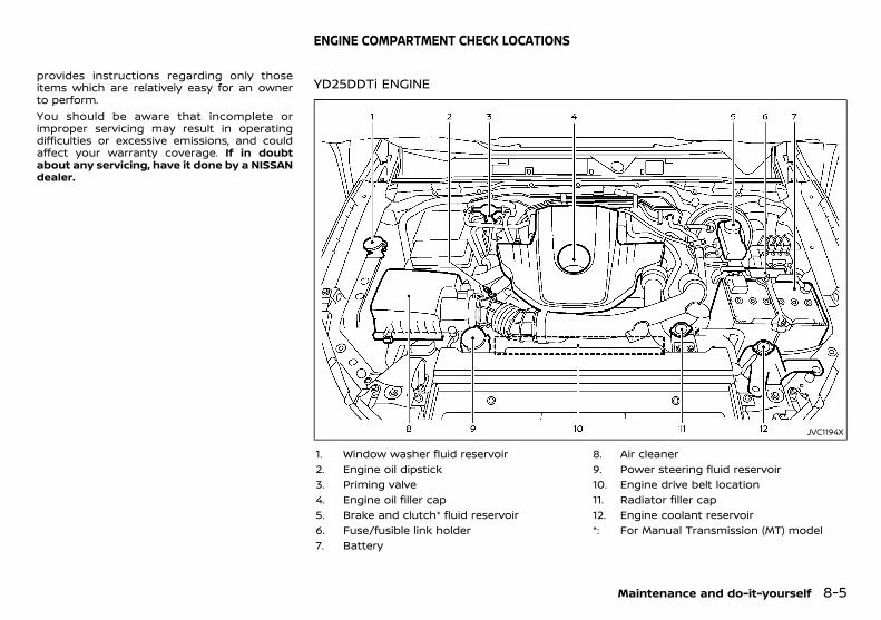
(251,1)
[ Edit: 2018/ 5/ 25 Model: PD23-A ]
provides instructions regarding only thoseitems which are relatively easy for an ownerto perform.You should be aware that incomplete orimproper servicing may result in operatingdifficulties or excessive emissions, and couldaffect your warranty coverage. If in doubtabout any servicing, have it done by a NISSANdealer.
PD23A1-B0E19A5D-2B8A-4CE8-8A3D-CF55C5F014E5
YD25DDTi ENGINEPD23A1-FE34AD79-9FED-4C44-B5AF-8F46493E8FB6
JVC1194X
1. Window washer fluid reservoir2. Engine oil dipstick3. Priming valve4. Engine oil filler cap5. Brake and clutch* fluid reservoir6. Fuse/fusible link holder7. Battery
8. Air cleaner9. Power steering fluid reservoir10. Engine drive belt location11. Radiator filler cap12. Engine coolant reservoir*: For Manual Transmission (MT) model
Maintenance and do-it-yourself 8-5
ENGINE COMPARTMENT CHECK LOCATIONS
Condition: 'Except for China'/
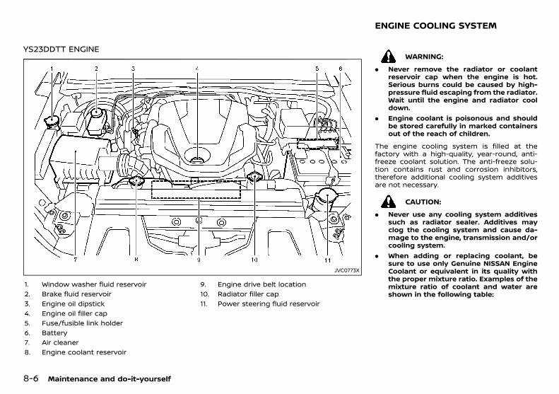
(252,1)
[ Edit: 2018/ 5/ 25 Model: PD23-A ]
8-6 Maintenance and do-it-yourself
YS23DDTT ENGINEPD23A1-13372FB9-1494-4646-97BA-9B8AE10B4232
JVC0773X
1. Window washer fluid reservoir2. Brake fluid reservoir3. Engine oil dipstick4. Engine oil filler cap5. Fuse/fusible link holder6. Battery7. Air cleaner8. Engine coolant reservoir
9. Engine drive belt location10. Radiator filler cap11. Power steering fluid reservoir
PD23A1-96329247-8EB6-4011-A05E-FCC3820809BB
WARNING:
. Never remove the radiator or coolantreservoir cap when the engine is hot.Serious burns could be caused by high-pressure fluid escaping from the radiator.Wait until the engine and radiator cooldown.
. Engine coolant is poisonous and shouldbe stored carefully in marked containersout of the reach of children.
The engine cooling system is filled at thefactory with a high-quality, year-round, anti-freeze coolant solution. The anti-freeze solu-tion contains rust and corrosion inhibitors,therefore additional cooling system additivesare not necessary.
CAUTION:
. Never use any cooling system additivessuch as radiator sealer. Additives mayclog the cooling system and cause da-mage to the engine, transmission and/orcooling system.
. When adding or replacing coolant, besure to use only Genuine NISSAN EngineCoolant or equivalent in its quality withthe proper mixture ratio. Examples of themixture ratio of coolant and water areshown in the following table:
ENGINE COOLING SYSTEM
Condition: 'Except for China'/
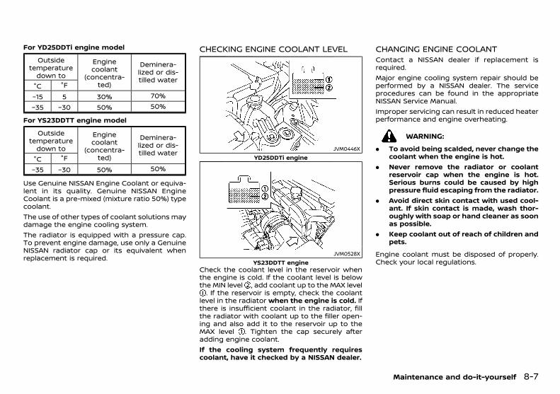
(253,1)
[ Edit: 2018/ 5/ 25 Model: PD23-A ]
For YD25DDTi engine modelPD23A1-96329247-8EB6-4011-A05E-FCC3820809BB
Outsidetemperature
down to
Enginecoolant
(concentra-ted)
Deminera-lized or dis-tilled water
°C °F
−15 5 30% 70%
−35 −30 50% 50%
For YS23DDTT engine modelPD23A1-96329247-8EB6-4011-A05E-FCC3820809BB
Outsidetemperature
down to
Enginecoolant
(concentra-ted)
Deminera-lized or dis-tilled water
°C °F
−35 −30 50% 50%
Use Genuine NISSAN Engine Coolant or equiva-lent in its quality. Genuine NISSAN EngineCoolant is a pre-mixed (mixture ratio 50%) typecoolant.The use of other types of coolant solutions maydamage the engine cooling system.The radiator is equipped with a pressure cap.To prevent engine damage, use only a GenuineNISSAN radiator cap or its equivalent whenreplacement is required.
CHECKING ENGINE COOLANT LEVELPD23A1-3B7E47D5-52CA-4B47-A1B2-25BEB0E9587D
JVM0446XYD25DDTi engine
JVM0528XYS23DDTT engine
Check the coolant level in the reservoir whenthe engine is cold. If the coolant level is belowthe MIN level , add coolant up to the MAX level
. If the reservoir is empty, check the coolantlevel in the radiator when the engine is cold. Ifthere is insufficient coolant in the radiator, fillthe radiator with coolant up to the filler open-ing and also add it to the reservoir up to theMAX level . Tighten the cap securely afteradding engine coolant.If the cooling system frequently requirescoolant, have it checked by a NISSAN dealer.
CHANGING ENGINE COOLANTPD23A1-2A172ABB-940C-4C2F-BE7D-E44BD59E98A1
Contact a NISSAN dealer if replacement isrequired.Major engine cooling system repair should beperformed by a NISSAN dealer. The serviceprocedures can be found in the appropriateNISSAN Service Manual.Improper servicing can result in reduced heaterperformance and engine overheating.
WARNING:
. To avoid being scalded, never change thecoolant when the engine is hot.
. Never remove the radiator or coolantreservoir cap when the engine is hot.Serious burns could be caused by highpressure fluid escaping from the radiator.
. Avoid direct skin contact with used cool-ant. If skin contact is made, wash thor-oughly with soap or hand cleaner as soonas possible.
. Keep coolant out of reach of children andpets.
Engine coolant must be disposed of properly.Check your local regulations.
Maintenance and do-it-yourself 8-7
Condition: 'Except for China'/
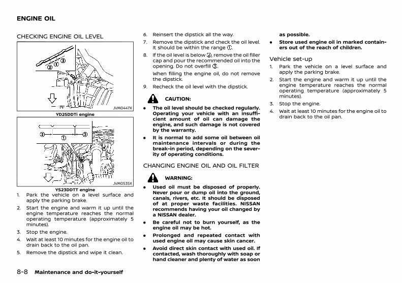
(254,1)
[ Edit: 2018/ 5/ 25 Model: PD23-A ]
8-8 Maintenance and do-it-yourself
PD23A1-10680CA8-8B78-40B1-A83A-227B79D2E364
CHECKING ENGINE OIL LEVELPD23A1-069FBAB5-4144-4EFE-901A-68C91CDE0C7D
JVM0447XYD25DDTi engine
JVM0535XYS23DDTT engine
1. Park the vehicle on a level surface andapply the parking brake.
2. Start the engine and warm it up until theengine temperature reaches the normaloperating temperature (approximately 5minutes).
3. Stop the engine.4. Wait at least 10 minutes for the engine oil to
drain back to the oil pan.5. Remove the dipstick and wipe it clean.
6. Reinsert the dipstick all the way.7. Remove the dipstick and check the oil level.
It should be within the range .8. If the oil level is below , remove the oil filler
cap and pour the recommended oil into theopening. Do not overfill .When filling the engine oil, do not removethe dipstick.
9. Recheck the oil level with the dipstick.
CAUTION:
. The oil level should be checked regularly.Operating your vehicle with an insuffi-cient amount of oil can damage theengine, and such damage is not coveredby the warranty.
. It is normal to add some oil between oilmaintenance intervals or during thebreak-in period, depending on the sever-ity of operating conditions.
CHANGING ENGINE OIL AND OIL FILTERPD23A1-0ACC8AC6-310B-4A22-9F0A-DF3A054A4253
WARNING:
. Used oil must be disposed of properly.Never pour or dump oil into the ground,canals, rivers, etc. It should be disposedof at proper waste facilities. NISSANrecommends having your oil changed bya NISSAN dealer.
. Be careful not to burn yourself, as theengine oil may be hot.
. Prolonged and repeated contact withused engine oil may cause skin cancer.
. Avoid direct skin contact with used oil. Ifcontacted, wash thoroughly with soap orhand cleaner and plenty of water as soon
as possible.. Store used engine oil in marked contain-
ers out of the reach of children.
Vehicle set-upPD23A1-0991D218-36C5-44BA-812E-3531DDC277C7
1. Park the vehicle on a level surface andapply the parking brake.
2. Start the engine and warm it up until theengine temperature reaches the normaloperating temperature (approximately 5minutes).
3. Stop the engine.4. Wait at least 10 minutes for the engine oil to
drain back to the oil pan.
ENGINE OIL
Condition: 'Except for China'/
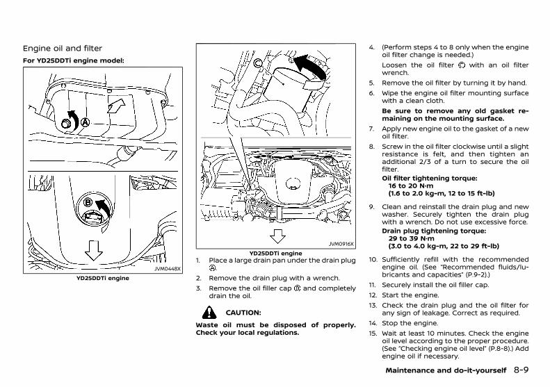
(255,1)
[ Edit: 2018/ 5/ 25 Model: PD23-A ]
Engine oil and filterPD23A1-3C60555F-9670-4DBC-90EA-5462503BFEF4
For YD25DDTi engine model:GUID-9E14C2E6-2E9C-4731-980B-C45B899B977B
JVM0448X
YD25DDTi engine
JVM0916X
YD25DDTi engine1. Place a large drain pan under the drain plug
.2. Remove the drain plug with a wrench.3. Remove the oil filler cap and completely
drain the oil.
CAUTION:
Waste oil must be disposed of properly.Check your local regulations.
4. (Perform steps 4 to 8 only when the engineoil filter change is needed.)Loosen the oil filter with an oil filterwrench.
5. Remove the oil filter by turning it by hand.6. Wipe the engine oil filter mounting surface
with a clean cloth.Be sure to remove any old gasket re-maining on the mounting surface.
7. Apply new engine oil to the gasket of a newoil filter.
8. Screw in the oil filter clockwise until a slightresistance is felt, and then tighten anadditional 2/3 of a turn to secure the oilfilter.Oil filter tightening torque:16 to 20 N·m(1.6 to 2.0 kg-m, 12 to 15 ft-lb)
9. Clean and reinstall the drain plug and newwasher. Securely tighten the drain plugwith a wrench. Do not use excessive force.Drain plug tightening torque:29 to 39 N·m(3.0 to 4.0 kg-m, 22 to 29 ft-lb)
10. Sufficiently refill with the recommendedengine oil. (See “Recommended fluids/lu-bricants and capacities” (P.9-2).)
11. Securely install the oil filler cap.12. Start the engine.13. Check the drain plug and the oil filter for
any sign of leakage. Correct as required.14. Stop the engine.15. Wait at least 10 minutes. Check the engine
oil level according to the proper procedure.(See “Checking engine oil level” (P.8-8).) Addengine oil if necessary.
Maintenance and do-it-yourself 8-9
Condition: 'Except for China'/
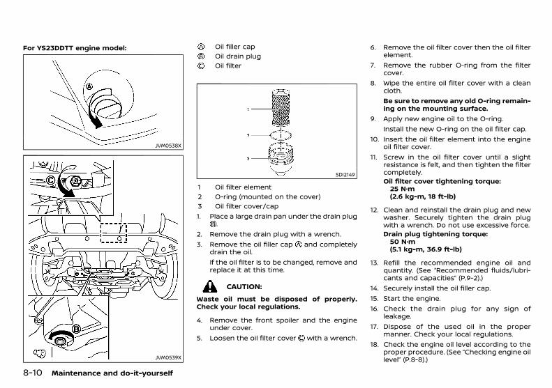
(256,1)
[ Edit: 2018/ 5/ 25 Model: PD23-A ]
8-10 Maintenance and do-it-yourself
For YS23DDTT engine model:GUID-9E14C2E6-2E9C-4731-980B-C45B899B977B
JVM0538X
JVM0539X
Oil filler capOil drain plugOil filter
SDI2149
1 Oil filter element2 O-ring (mounted on the cover)3 Oil filter cover/cap1. Place a large drain pan under the drain plug
.2. Remove the drain plug with a wrench.3. Remove the oil filler cap and completely
drain the oil.If the oil filter is to be changed, remove andreplace it at this time.
CAUTION:
Waste oil must be disposed of properly.Check your local regulations.
4. Remove the front spoiler and the engineunder cover.
5. Loosen the oil filter cover with a wrench.
6. Remove the oil filter cover then the oil filterelement.
7. Remove the rubber O-ring from the filtercover.
8. Wipe the entire oil filter cover with a cleancloth.Be sure to remove any old O-ring remain-ing on the mounting surface.
9. Apply new engine oil to the O-ring.Install the new O-ring on the oil filter cap.
10. Insert the oil filter element into the engineoil filter cover.
11. Screw in the oil filter cover until a slightresistance is felt, and then tighten the filtercompletely.Oil filter cover tightening torque:25 N·m(2.6 kg-m, 18 ft-lb)
12. Clean and reinstall the drain plug and newwasher. Securely tighten the drain plugwith a wrench. Do not use excessive force.Drain plug tightening torque:50 N·m(5.1 kg-m, 36.9 ft-lb)
13. Refill the recommended engine oil andquantity. (See “Recommended fluids/lubri-cants and capacities” (P.9-2).)
14. Securely install the oil filler cap.15. Start the engine.16. Check the drain plug for any sign of
leakage.17. Dispose of the used oil in the proper
manner. Check your local regulations.18. Check the engine oil level according to the
proper procedure. (See “Checking engine oillevel” (P.8-8).)
Condition: 'Except for China'/
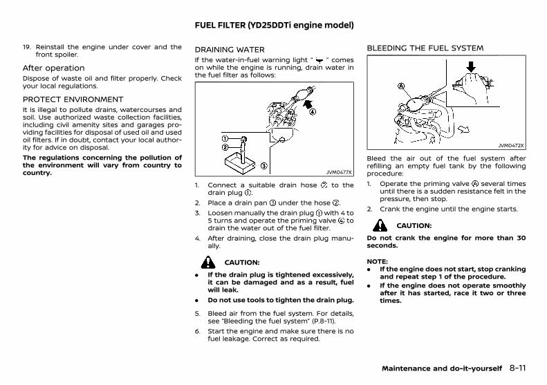
(257,1)
[ Edit: 2018/ 5/ 25 Model: PD23-A ]
19. Reinstall the engine under cover and thefront spoiler.
After operationPD23A1-F20DAB39-9CE9-4A22-97E2-601DD3FC578F
Dispose of waste oil and filter properly. Checkyour local regulations.
PROTECT ENVIRONMENTPD23A1-56A1B774-53AD-4829-9DF0-63C8F4E96BDF
It is illegal to pollute drains, watercourses andsoil. Use authorized waste collection facilities,including civil amenity sites and garages pro-viding facilities for disposal of used oil and usedoil filters. If in doubt, contact your local author-ity for advice on disposal.The regulations concerning the pollution ofthe environment will vary from country tocountry.
PD23A1-9DF73B82-4891-40BB-9702-37ED0CDB2EB0
DRAINING WATERPD23A1-D41E0A7D-14AA-4FA0-A63C-C1EBEAE069AD
If the water-in-fuel warning light “ ” comeson while the engine is running, drain water inthe fuel filter as follows:
JVM0477X
1. Connect a suitable drain hose to thedrain plug .
2. Place a drain pan under the hose .3. Loosen manually the drain plug with 4 to
5 turns and operate the priming valve todrain the water out of the fuel filter.
4. After draining, close the drain plug manu-ally.
CAUTION:
. If the drain plug is tightened excessively,it can be damaged and as a result, fuelwill leak.
. Do not use tools to tighten the drain plug.
5. Bleed air from the fuel system. For details,see “Bleeding the fuel system” (P.8-11).
6. Start the engine and make sure there is nofuel leakage. Correct as required.
BLEEDING THE FUEL SYSTEMPD23A1-8F64F299-3EB9-43D8-978B-94585FD9F670
JVM0472X
Bleed the air out of the fuel system afterrefilling an empty fuel tank by the followingprocedure:1. Operate the priming valve several times
until there is a sudden resistance felt in thepressure, then stop.
2. Crank the engine until the engine starts.
CAUTION:
Do not crank the engine for more than 30seconds.
NOTE:. If the engine does not start, stop cranking
and repeat step 1 of the procedure.. If the engine does not operate smoothly
after it has started, race it two or threetimes.
Maintenance and do-it-yourself 8-11
FUEL FILTER (YD25DDTi engine model)
Condition: 'Except for China'/
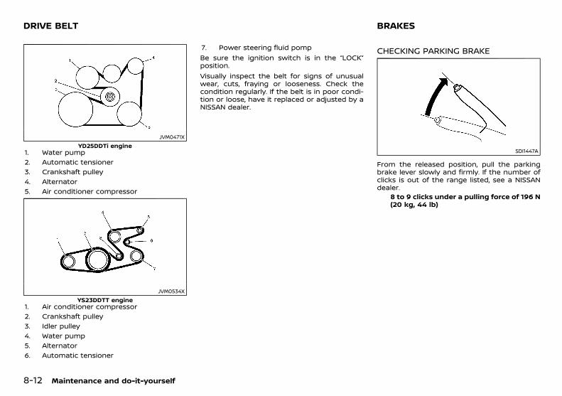
(258,1)
[ Edit: 2018/ 5/ 25 Model: PD23-A ]
8-12 Maintenance and do-it-yourself
PD23A1-C822882C-483C-4A63-B474-3253CCE55FAB
JVM0471XYD25DDTi engine
1. Water pump2. Automatic tensioner3. Crankshaft pulley4. Alternator5. Air conditioner compressor
JVM0534XYS23DDTT engine
1. Air conditioner compressor2. Crankshaft pulley3. Idler pulley4. Water pump5. Alternator6. Automatic tensioner
7. Power steering fluid pompBe sure the ignition switch is in the “LOCK”position.Visually inspect the belt for signs of unusualwear, cuts, fraying or looseness. Check thecondition regularly. If the belt is in poor condi-tion or loose, have it replaced or adjusted by aNISSAN dealer.
PD23A1-BE4EF884-FE90-4EB0-8511-BAF5D3759AD5
CHECKING PARKING BRAKEPD23A1-98E2AF65-2EA8-483F-8670-224474C4708F
SDI1447A
From the released position, pull the parkingbrake lever slowly and firmly. If the number ofclicks is out of the range listed, see a NISSANdealer.
8 to 9 clicks under a pulling force of 196 N(20 kg, 44 lb)
DRIVE BELT BRAKES
Condition: 'Except for China'/
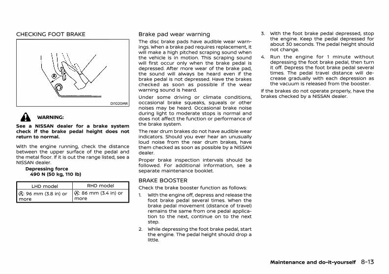
(259,1)
[ Edit: 2018/ 5/ 25 Model: PD23-A ]
CHECKING FOOT BRAKEPD23A1-A6E7990A-0C48-4A3D-83E8-86D5CF7CA546
DI1020MR
WARNING:
See a NISSAN dealer for a brake systemcheck if the brake pedal height does notreturn to normal.
With the engine running, check the distancebetween the upper surface of the pedal andthe metal floor. If it is out the range listed, see aNISSAN dealer.
Depressing force490 N (50 kg, 110 lb)
LHD model RHD model
: 96 mm (3.8 in) ormore
: 86 mm (3.4 in) ormore
Brake pad wear warningPD23A1-3E1D67C3-A509-4E87-A5FB-2771BC469217
The disc brake pads have audible wear warn-ings. When a brake pad requires replacement, itwill make a high pitched scraping sound whenthe vehicle is in motion. This scraping soundwill first occur only when the brake pedal isdepressed. After more wear of the brake pad,the sound will always be heard even if thebrake pedal is not depressed. Have the brakeschecked as soon as possible if the wearwarning sound is heard.Under some driving or climate conditions,occasional brake squeaks, squeals or othernoises may be heard. Occasional brake noiseduring light to moderate stops is normal anddoes not affect the function or performance ofthe brake system.The rear drum brakes do not have audible wearindicators. Should you ever hear an unusuallyloud noise from the rear drum brakes, havethem checked as soon as possible by a NISSANdealer.Proper brake inspection intervals should befollowed. For additional information, see aseparate maintenance booklet.
BRAKE BOOSTERPD23A1-55153F45-24C9-49B8-AEB9-07D36E1EF616
Check the brake booster function as follows:1. With the engine off, depress and release the
foot brake pedal several times. When thebrake pedal movement (distance of travel)remains the same from one pedal applica-tion to the next, continue on to the nextstep.
2. While depressing the foot brake pedal, startthe engine. The pedal height should drop alittle.
3. With the foot brake pedal depressed, stopthe engine. Keep the pedal depressed forabout 30 seconds. The pedal height shouldnot change.
4. Run the engine for 1 minute withoutdepressing the foot brake pedal, then turnit off. Depress the foot brake pedal severaltimes. The pedal travel distance will de-crease gradually with each depression asthe vacuum is released from the booster.
If the brakes do not operate properly, have thebrakes checked by a NISSAN dealer.
Maintenance and do-it-yourself 8-13
Condition: 'Except for China'/
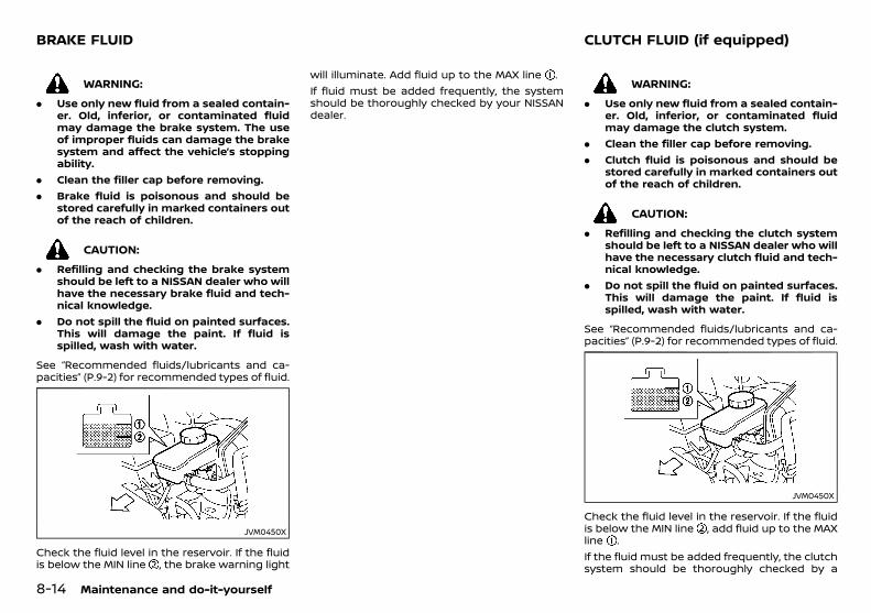
(260,1)
[ Edit: 2018/ 5/ 25 Model: PD23-A ]
8-14 Maintenance and do-it-yourself
PD23A1-91B9BF58-F889-4E42-B748-7B3FA793135D
WARNING:
. Use only new fluid from a sealed contain-er. Old, inferior, or contaminated fluidmay damage the brake system. The useof improper fluids can damage the brakesystem and affect the vehicle’s stoppingability.
. Clean the filler cap before removing.
. Brake fluid is poisonous and should bestored carefully in marked containers outof the reach of children.
CAUTION:
. Refilling and checking the brake systemshould be left to a NISSAN dealer who willhave the necessary brake fluid and tech-nical knowledge.
. Do not spill the fluid on painted surfaces.This will damage the paint. If fluid isspilled, wash with water.
See “Recommended fluids/lubricants and ca-pacities” (P.9-2) for recommended types of fluid.
JVM0450X
Check the fluid level in the reservoir. If the fluidis below the MIN line , the brake warning light
will illuminate. Add fluid up to the MAX line .If fluid must be added frequently, the systemshould be thoroughly checked by your NISSANdealer.
PD23A1-A94F3206-4AF7-4FF0-BD5C-133DC18D78FD
WARNING:
. Use only new fluid from a sealed contain-er. Old, inferior, or contaminated fluidmay damage the clutch system.
. Clean the filler cap before removing.
. Clutch fluid is poisonous and should bestored carefully in marked containers outof the reach of children.
CAUTION:
. Refilling and checking the clutch systemshould be left to a NISSAN dealer who willhave the necessary clutch fluid and tech-nical knowledge.
. Do not spill the fluid on painted surfaces.This will damage the paint. If fluid isspilled, wash with water.
See “Recommended fluids/lubricants and ca-pacities” (P.9-2) for recommended types of fluid.
JVM0450X
Check the fluid level in the reservoir. If the fluidis below the MIN line , add fluid up to the MAXline .If the fluid must be added frequently, the clutchsystem should be thoroughly checked by a
BRAKE FLUID CLUTCH FLUID (if equipped)
Condition: 'Except for China'/

(261,1)
[ Edit: 2018/ 5/ 25 Model: PD23-A ]
NISSAN dealer.PD23A1-80F68299-9A50-4059-B13A-F3C7214E6AF4
7-SPEED AUTOMATIC TRANSMISSION(AT) MODEL
PD23A1-E8E93B62-0798-4D05-BB8C-82AC15F03CCBContact a NISSAN dealer if checking or replace-ment is required.
CAUTION:
. Use only Genuine NISSAN Matic S ATF. Donot mix with other fluids.
. Using Automatic Transmission Fluid (ATF)other than Genuine NISSAN Matic S ATFwill cause deterioration in driveabilityand automatic transmission durability,and may damage the automatic trans-mission, which is not covered by thewarranty.
PD23A1-55392F99-C85E-48BA-AE4A-DEE2198E7F8D
SDI1718A
WARNING:
Power steering fluid is poisonous and shouldbe stored carefully in marked containers outof the reach of children.
Check the fluid level in the reservoir. The fluidlevel should be checked in the HOT range ( :HOT MAX., : HOT MIN.) at fluid temperatures of50 to 80°C (122 to 176°F) or in the COLD range( : COLD MAX., : COLD MIN.) at fluid tempera-tures of 0 to 30°C (32 to 86°F).If it is necessary to add fluid, use only specifiedfluid. Do not overfill. (See “Recommendedfluids/lubricants and capacities” (P.9-2) forrecommended types of fluid.)
Maintenance and do-it-yourself 8-15
AUTOMATIC TRANSMISSION FLUID(ATF) (if equipped) POWER STEERING FLUID
Condition: 'Except for China'/

(262,1)
[ Edit: 2018/ 5/ 25 Model: PD23-A ]
8-16 Maintenance and do-it-yourself
PD23A1-D7B6C71D-56EF-4C2F-B0AC-A8AC7FF0CC57
JVM0451X
WARNING:
. Operating the engine with the air cleanerfilter off can cause you or others to beburned. The air cleaner filter not onlycleans the intake air, it also stops flame ifthe engine backfires. If the air cleanerfilter is not installed and the enginebackfires, you could be burned. Neverdrive with the air cleaner filter off. Becautious working on the engine when theair cleaner filter is off.
. Never pour fuel into the throttle body orattempt to start the engine with the aircleaner removed. Doing so could result inserious injury.
To remove the filter, release the lock pins andpull the unit upward .The dry paper type filter element may becleaned and reused. Replace the air filteraccording to the maintenance schedule shownin a separate maintenance booklet.When replacing the filter, wipe the inside of theair cleaner housing and the cover with a dampcloth.
PD23A1-A8F4FAAC-58EC-4B82-B6BF-6D497F20DB48
WINDSHIELD WIPER BLADESPD23A1-458EB34C-8495-4162-AA3B-37E2DBD524DC
CleaningPD23A1-FD840453-EA93-4689-8C87-3D85BC14EC01
If the windshield does not become clear afterusing the windshield washer or if the wiperblades chatter when operating the windshieldwipers, wax or other materials may be on thewindshield and/or wiper blades.Clean the outside of the windshield surfacewith a washer solution or mild detergent. Yourwindshield is clean if beads do not form whenrinsing with water.Clean the blade by wiping it with a cloth soakedin a washer solution or a mild detergent. Rinsethe blade with water. If your windshield is stillnot clear after cleaning the blades and usingthe wipers, replace the blades.
SDI2693
Be careful not to clog the washer nozzle . Thismay cause improper windshield washer opera-tion. If the nozzle is clogged, remove anyobjects with a needle or small pin . Be carefulnot to damage the nozzle.
AIR CLEANER FILTER WIPER BLADES
Condition: 'Except for China'/
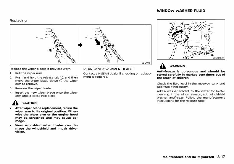
(263,1)
[ Edit: 2018/ 5/ 25 Model: PD23-A ]
ReplacingPD23A1-2E138D69-409B-4DC9-A988-26639F137809
SDI2048
Replace the wiper blades if they are worn.1. Pull the wiper arm.2. Push and hold the release tab , and then
move the wiper blade down the wiperarm to remove.
3. Remove the wiper blade.4. Insert the new wiper blade onto the wiper
arm until it clicks into place.
CAUTION:
. After wiper blade replacement, return thewiper arm to its original position. Other-wise the wiper arm or the engine hoodmay be scratched and may cause da-mage.
. Worn windshield wiper blades can da-mage the windshield and impair drivervision.
REAR WINDOW WIPER BLADEGUID-28394FA3-2025-48B0-853C-87A2B506C945
Contact a NISSAN dealer if checking or replace-ment is required.
PD23A1-6C0A13AC-963E-4B0B-B543-B6A448FD7E04
JVM0452X
WARNING:
Anti-freeze is poisonous and should bestored carefully in marked containers out ofthe reach of children.
Check the fluid level in the reservoir tank andadd fluid if necessary.Add a washer solvent to the water for bettercleaning. In the winter season, add windshieldwasher antifreeze. Follow the manufacturer’sinstructions for the mixture ratio.
Maintenance and do-it-yourself 8-17
WINDOW WASHER FLUID
Condition: 'Except for China'/

(264,1)
[ Edit: 2018/ 5/ 25 Model: PD23-A ]
8-18 Maintenance and do-it-yourself
PD23A1-9D14B82B-B588-42BC-9813-56308F54E782
SDI1573
VEHICLE BATTERYPD23A1-2B8F4112-43D6-4F22-8C12-423FCAA11BF4
WARNING:
Do not operate the vehicle if the fluid in thebattery is low. Low battery fluid can cause ahigher load on the battery which can gen-erate heat, reduce battery life, and in somecases lead to an explosion.
BATTERY
Condition: 'Except for China'/
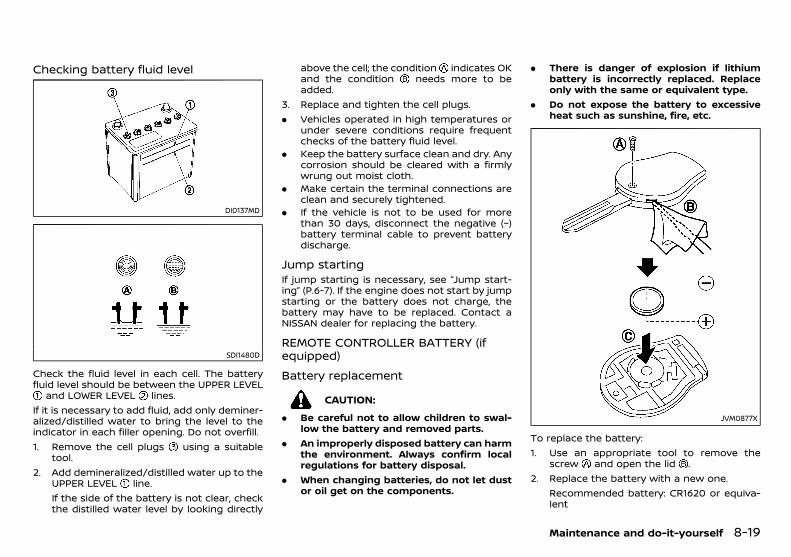
(265,1)
[ Edit: 2018/ 5/ 25 Model: PD23-A ]
Checking battery fluid levelPD23A1-3D0153AC-ACD1-4AEC-92F6-233F842AF00F
DI0137MD
SDI1480D
Check the fluid level in each cell. The batteryfluid level should be between the UPPER LEVEL
and LOWER LEVEL lines.If it is necessary to add fluid, add only deminer-alized/distilled water to bring the level to theindicator in each filler opening. Do not overfill.1. Remove the cell plugs using a suitable
tool.2. Add demineralized/distilled water up to the
UPPER LEVEL line.If the side of the battery is not clear, checkthe distilled water level by looking directly
above the cell; the condition indicates OKand the condition needs more to beadded.
3. Replace and tighten the cell plugs.. Vehicles operated in high temperatures or
under severe conditions require frequentchecks of the battery fluid level.
. Keep the battery surface clean and dry. Anycorrosion should be cleared with a firmlywrung out moist cloth.
. Make certain the terminal connections areclean and securely tightened.
. If the vehicle is not to be used for morethan 30 days, disconnect the negative (−)battery terminal cable to prevent batterydischarge.
Jump startingPD23A1-BE336D38-925A-44F9-B19D-862D45C27323
If jump starting is necessary, see “Jump start-ing” (P.6-7). If the engine does not start by jumpstarting or the battery does not charge, thebattery may have to be replaced. Contact aNISSAN dealer for replacing the battery.
REMOTE CONTROLLER BATTERY (ifequipped)
PD23A1-3799C71F-6051-43C4-A698-9EF75653C82B
Battery replacementPD23A1-2BFD8D25-A222-4D6E-AA53-954CC5107877
CAUTION:
. Be careful not to allow children to swal-low the battery and removed parts.
. An improperly disposed battery can harmthe environment. Always confirm localregulations for battery disposal.
. When changing batteries, do not let dustor oil get on the components.
. There is danger of explosion if lithiumbattery is incorrectly replaced. Replaceonly with the same or equivalent type.
. Do not expose the battery to excessiveheat such as sunshine, fire, etc.
JVM0877X
To replace the battery:1. Use an appropriate tool to remove the
screw and open the lid .2. Replace the battery with a new one.
Recommended battery: CR1620 or equiva-lent
Maintenance and do-it-yourself 8-19
Condition: 'Except for China'/
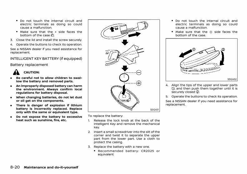
(266,1)
[ Edit: 2018/ 5/ 25 Model: PD23-A ]
8-20 Maintenance and do-it-yourself
. Do not touch the internal circuit andelectric terminals as doing so couldcause a malfunction.
. Make sure that the + side faces thebottom of the case .
3. Close the lid and install the screw securely.4. Operate the buttons to check its operation.See a NISSAN dealer if you need assistance forreplacement.
INTELLIGENT KEY BATTERY (if equipped)GUID-B8EBF89E-8338-4E37-9C65-C06473696422
Battery replacementGUID-4EFF727F-DCF0-451A-B1DA-A9D8C08B2F4A
CAUTION:
. Be careful not to allow children to swal-low the battery and removed parts.
. An improperly disposed battery can harmthe environment. Always confirm localregulations for battery disposal.
. When changing batteries, do not let dustor oil get on the components.
. There is danger of explosion if lithiumbattery is incorrectly replaced. Replaceonly with the same or equivalent type.
. Do not expose the battery to excessiveheat such as sunshine, fire, etc.
SDI2451
To replace the battery:1. Release the lock knob at the back of the
Intelligent Key and remove the mechanicalkey.
2. Insert a small screwdriver into the slit of thecorner and twist it to separate the upperpart from the lower part. Use a cloth toprotect the casing.
3. Replace the battery with a new one.. Recommended battery: CR2025 or
equivalent
. Do not touch the internal circuit andelectric terminals as doing so couldcause a malfunction.
. Make sure that the + side faces thebottom of the case.
SDI2452
4. Align the tips of the upper and lower parts, and then push them together until it is
securely closed .5. Operate the buttons to check its operation.See a NISSAN dealer if you need assistance forreplacement.
Condition: 'Except for China'/
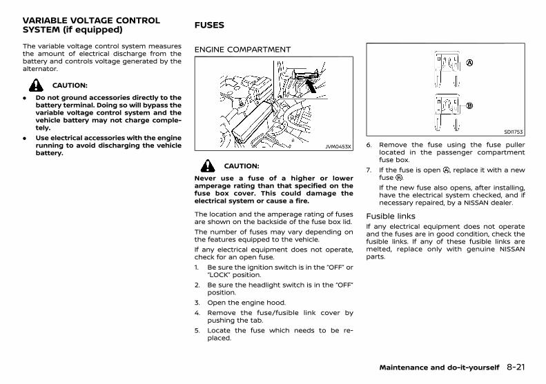
(267,1)
[ Edit: 2018/ 5/ 25 Model: PD23-A ]
PD23A1-F4B3BC6D-C385-4B1C-BB38-0C3317095856The variable voltage control system measuresthe amount of electrical discharge from thebattery and controls voltage generated by thealternator.
CAUTION:
. Do not ground accessories directly to thebattery terminal. Doing so will bypass thevariable voltage control system and thevehicle battery may not charge comple-tely.
. Use electrical accessories with the enginerunning to avoid discharging the vehiclebattery.
PD23A1-A0705B18-2E51-4E9E-8F82-63256F160676
ENGINE COMPARTMENTPD23A1-6BADCD3E-544E-4478-8E05-FDE788FEFDA1
JVM0453X
CAUTION:
Never use a fuse of a higher or loweramperage rating than that specified on thefuse box cover. This could damage theelectrical system or cause a fire.
The location and the amperage rating of fusesare shown on the backside of the fuse box lid.The number of fuses may vary depending onthe features equipped to the vehicle.If any electrical equipment does not operate,check for an open fuse.1. Be sure the ignition switch is in the “OFF” or
“LOCK” position.2. Be sure the headlight switch is in the “OFF”
position.3. Open the engine hood.4. Remove the fuse/fusible link cover by
pushing the tab.5. Locate the fuse which needs to be re-
placed.
SDI1753
6. Remove the fuse using the fuse pullerlocated in the passenger compartmentfuse box.
7. If the fuse is open , replace it with a newfuse .If the new fuse also opens, after installing,have the electrical system checked, and ifnecessary repaired, by a NISSAN dealer.
Fusible linksPD23A1-A3F371BD-6E7F-460C-BBE8-B484EB711BAA
If any electrical equipment does not operateand the fuses are in good condition, check thefusible links. If any of these fusible links aremelted, replace only with genuine NISSANparts.
Maintenance and do-it-yourself 8-21
VARIABLE VOLTAGE CONTROLSYSTEM (if equipped) FUSES
Condition: 'Except for China'/
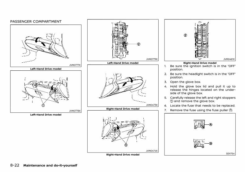
(268,1)
[ Edit: 2018/ 5/ 25 Model: PD23-A ]
8-22 Maintenance and do-it-yourself
PASSENGER COMPARTMENTPD23A1-9F4C187C-98E0-47F4-AC30-6B2F92D00A5B
JVM0777XLeft-Hand Drive model
JVM0778XLeft-Hand Drive model
JVM0779XLeft-Hand Drive model
JVM0473XRight-Hand Drive model
JVM0474XRight-Hand Drive model
JVM0461XRight-Hand Drive model
1. Be sure the ignition switch is in the “OFF”position.
2. Be sure the headlight switch is in the “OFF”position.
3. Open the glove box.4. Hold the glove box lid and pull it up to
release the hinges located on the under-side of the glove box.
5. Carefully release the left and right stoppersand remove the glove box.
6. Locate the fuse that needs to be replaced.7. Remove the fuse using the fuse puller .
SDI1754
Condition: 'Except for China'/
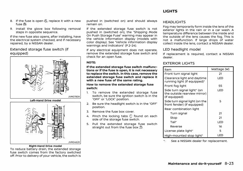
(269,1)
[ Edit: 2018/ 5/ 25 Model: PD23-A ]
8. If the fuse is open , replace it with a newfuse .
9. Install the glove box following removalsteps in opposite sequence.
If the new fuse also opens, after installing, havethe electrical system checked, and if necessaryrepaired, by a NISSAN dealer.
Extended storage fuse switch (ifequipped)
PD23A1-E2FC7D10-F4B1-4B15-ABE6-4C8A3FE8A432
JVM0780XLeft-Hand Drive model
JVM0462XRight-Hand Drive model
To reduce battery drain, the extended storagefuse switch comes from the factory switchedoff. Prior to delivery of your vehicle, the switch is
pushed in (switched on) and should alwaysremain on.If the extended storage fuse switch is notpushed in (switched on), the “Shipping ModeOn Push Storage Fuse” warning may appear inthe vehicle information display (models withcolor display). See “Vehicle information displaywarnings and indicators” (P.2-24).If any electrical equipment does not operate,remove the extended storage fuse switch andcheck for an open fuse.
NOTE:If the extended storage fuse switch malfunc-tions or if the fuse is open, it is not necessaryto replace the switch. In this case, remove theextended storage fuse switch and replace itwith a new fuse of the same rating.How to remove the extended storage fuseswitch:
GUID-9E14C2E6-2E9C-4731-980B-C45B899B977B
1. To remove the extended storage fuseswitch, be sure the ignition switch is in the“OFF” or “LOCK” position.
2. Be sure the headlight switch is in the “OFF”position.
3. Remove the fuse box cover.4. Pinch the locking tabs found on each
side of the storage fuse switch.5. Pull the extended storage fuse switch
straight out from the fuse box .
PD23A1-E98CB186-43DE-42CE-8114-D9E8A87B06F9
HEADLIGHTSPD23A1-2C489B1A-2225-4AEE-88D8-6F2B8F7820FE
Fog may temporarily form inside the lens of theexterior lights in the rain or in a car wash. Atemperature difference between the inside andthe outside of the lens causes the fog. This isnot a malfunction. If large drops of watercollect inside the lens, contact a NISSAN dealer.
LED headlight modelGUID-5D23BAFC-E952-4938-BD86-8F5C339626F8
If replacement is required, contact a NISSANdealer.
EXTERIOR LIGHTSPD23A1-4A1154A6-C2AF-406B-BB25-CDE38FCA506D
Item Wattage (W)Front turn signal light 21Clearance light and daytimerunning light (if equipped)*
LED
Front fog light 55Side turn signal light* (onthe outside rearview mirror)(if equipped)
LED
Side turn signal light (on thefront fender) (if equipped)
5
Rear combination lightTurn signal 21Stop 21Tail* LEDReverse 16
License plate light* 5High-mounted stop light* LED
*: See a NISSAN dealer for replacement.
Maintenance and do-it-yourself 8-23
LIGHTS
Condition: 'Except for China'/
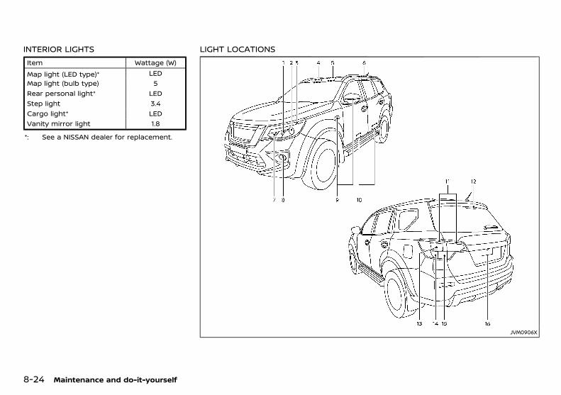
(270,1)
[ Edit: 2018/ 5/ 25 Model: PD23-A ]
8-24 Maintenance and do-it-yourself
INTERIOR LIGHTSPD23A1-41A861EB-5A1B-49A4-870F-83BAD8CB1E27
Item Wattage (W)
Map light (LED type)* LEDMap light (bulb type) 5Rear personal light* LEDStep light 3.4Cargo light* LEDVanity mirror light 1.8
*: See a NISSAN dealer for replacement.
LIGHT LOCATIONSGUID-AB77B776-7E19-4697-833A-A828A9B1D82B
JVM0906X
Condition: 'Except for China'/
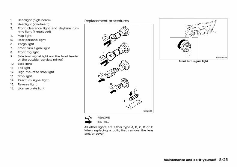
(271,1)
[ Edit: 2018/ 5/ 25 Model: PD23-A ]
1. Headlight (high-beam)2. Headlight (low-beam)3. Front clearance light and daytime run-
ning light (if equipped)4. Map light5. Rear personal light6. Cargo light7. Front turn signal light8. Front fog light9. Side turn signal light (on the front fender
or the outside rearview mirror)10. Step light11. Tail light12. High-mounted stop light13. Stop light14. Rear turn signal light15. Reverse light16. License plate light
Replacement proceduresGUID-A495FAA8-2305-48E0-BD60-D2B4FC8F441E
SDI2306
: REMOVE: INSTALL
All other lights are either type A, B, C, D or E.When replacing a bulb, first remove the lensand/or cover.
JVM0870XFront turn signal light
Maintenance and do-it-yourself 8-25
Condition: 'Except for China'/
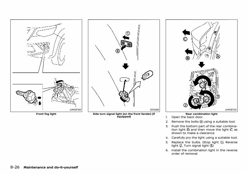
(272,1)
[ Edit: 2018/ 5/ 25 Model: PD23-A ]
8-26 Maintenance and do-it-yourself
JVM0878X
Front fog lightSDI1688
Side turn signal light (on the front fender) (ifequipped)
JVM0872X
Rear combination light1. Open the back door.2. Remove the bolts using a suitable tool.3. Push the bottom part of the rear combina-
tion light and then move the light asshown to make a clearance.
4. Carefully pry the light using a suitable tool.5. Replace the bulbs. (Stop light , Reverse
light , Turn signal light )6. Install the combination light in the reverse
order of removal.
Condition: 'Except for China'/
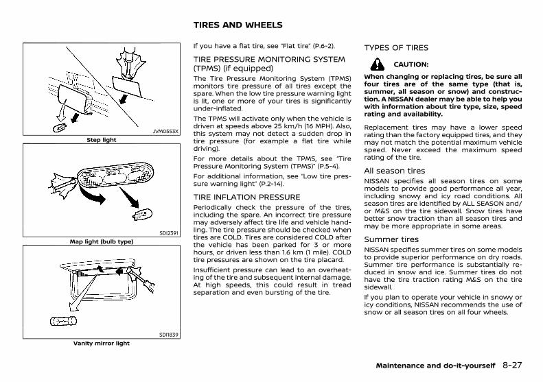
(273,1)
[ Edit: 2018/ 5/ 25 Model: PD23-A ]
JVM0553XStep light
SDI2391Map light (bulb type)
SDI1839Vanity mirror light
PD23A1-AE69B6E0-40C4-41BD-BBA1-219A674F9C1CIf you have a flat tire, see “Flat tire” (P.6-2).
TIRE PRESSURE MONITORING SYSTEM(TPMS) (if equipped)
GUID-9E4CFC77-63C5-44BD-B61E-42986415704BThe Tire Pressure Monitoring System (TPMS)monitors tire pressure of all tires except thespare. When the low tire pressure warning lightis lit, one or more of your tires is significantlyunder-inflated.The TPMS will activate only when the vehicle isdriven at speeds above 25 km/h (16 MPH). Also,this system may not detect a sudden drop intire pressure (for example a flat tire whiledriving).For more details about the TPMS, see “TirePressure Monitoring System (TPMS)” (P.5-4).For additional information, see “Low tire pres-sure warning light” (P.2-14).
TIRE INFLATION PRESSUREPD23A1-A3EC7C52-D2BB-4E17-9BE3-4E7D46CD905A
Periodically check the pressure of the tires,including the spare. An incorrect tire pressuremay adversely affect tire life and vehicle hand-ling. The tire pressure should be checked whentires are COLD. Tires are considered COLD afterthe vehicle has been parked for 3 or morehours, or driven less than 1.6 km (1 mile). COLDtire pressures are shown on the tire placard.Insufficient pressure can lead to an overheat-ing of the tire and subsequent internal damage.At high speeds, this could result in treadseparation and even bursting of the tire.
TYPES OF TIRESPD23A1-6795CDAA-3948-4877-927B-12072A6E5202
CAUTION:
When changing or replacing tires, be sure allfour tires are of the same type (that is,summer, all season or snow) and construc-tion. A NISSAN dealer may be able to help youwith information about tire type, size, speedrating and availability.
Replacement tires may have a lower speedrating than the factory equipped tires, and theymay not match the potential maximum vehiclespeed. Never exceed the maximum speedrating of the tire.
All season tiresPD23A1-E51B944F-1499-4173-868F-7269F630E6B0
NISSAN specifies all season tires on somemodels to provide good performance all year,including snowy and icy road conditions. Allseason tires are identified by ALL SEASON and/or M&S on the tire sidewall. Snow tires havebetter snow traction than all season tires andmay be more appropriate in some areas.
Summer tiresPD23A1-72AAA2F0-E863-456C-8C4C-6183FCCA6F67
NISSAN specifies summer tires on some modelsto provide superior performance on dry roads.Summer tire performance is substantially re-duced in snow and ice. Summer tires do nothave the tire traction rating M&S on the tiresidewall.If you plan to operate your vehicle in snowy oricy conditions, NISSAN recommends the use ofsnow or all season tires on all four wheels.
Maintenance and do-it-yourself 8-27
TIRES AND WHEELS
Condition: 'Except for China'/
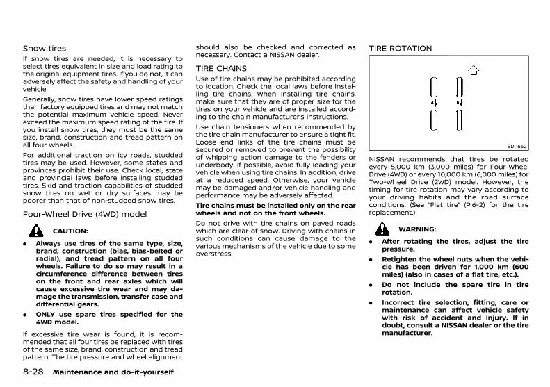
(274,1)
[ Edit: 2018/ 5/ 25 Model: PD23-A ]
8-28 Maintenance and do-it-yourself
Snow tiresPD23A1-57CB87E4-FACE-41F4-9BDB-65A1B2F5CFC5
If snow tires are needed, it is necessary toselect tires equivalent in size and load rating tothe original equipment tires. If you do not, it canadversely affect the safety and handling of yourvehicle.Generally, snow tires have lower speed ratingsthan factory equipped tires and may not matchthe potential maximum vehicle speed. Neverexceed the maximum speed rating of the tire. Ifyou install snow tires, they must be the samesize, brand, construction and tread pattern onall four wheels.For additional traction on icy roads, studdedtires may be used. However, some states andprovinces prohibit their use. Check local, stateand provincial laws before installing studdedtires. Skid and traction capabilities of studdedsnow tires on wet or dry surfaces may bepoorer than that of non-studded snow tires.
Four-Wheel Drive (4WD) modelPD23A1-5A000B3B-9C45-450E-B069-99CE03BFEA0C
CAUTION:
. Always use tires of the same type, size,brand, construction (bias, bias-belted orradial), and tread pattern on all fourwheels. Failure to do so may result in acircumference difference between tireson the front and rear axles which willcause excessive tire wear and may da-mage the transmission, transfer case anddifferential gears.
. ONLY use spare tires specified for the4WD model.
If excessive tire wear is found, it is recom-mended that all four tires be replaced with tiresof the same size, brand, construction and treadpattern. The tire pressure and wheel alignment
should also be checked and corrected asnecessary. Contact a NISSAN dealer.
TIRE CHAINSPD23A1-F2CF20EA-51D4-4282-AF61-8B4AA00858B3
Use of tire chains may be prohibited accordingto location. Check the local laws before instal-ling tire chains. When installing tire chains,make sure that they are of proper size for thetires on your vehicle and are installed accord-ing to the chain manufacturer’s instructions.Use chain tensioners when recommended bythe tire chain manufacturer to ensure a tight fit.Loose end links of the tire chains must besecured or removed to prevent the possibilityof whipping action damage to the fenders orunderbody. If possible, avoid fully loading yourvehicle when using tire chains. In addition, driveat a reduced speed. Otherwise, your vehiclemay be damaged and/or vehicle handling andperformance may be adversely affected.Tire chains must be installed only on the rearwheels and not on the front wheels.Do not drive with tire chains on paved roadswhich are clear of snow. Driving with chains insuch conditions can cause damage to thevarious mechanisms of the vehicle due to someoverstress.
TIRE ROTATIONPD23A1-ACE755DD-E4BB-46A4-9F62-496D13BFF28A
SDI1662
NISSAN recommends that tires be rotatedevery 5,000 km (3,000 miles) for Four-WheelDrive (4WD) or every 10,000 km (6,000 miles) forTwo-Wheel Drive (2WD) model. However, thetiming for tire rotation may vary according toyour driving habits and the road surfaceconditions. (See “Flat tire” (P.6-2) for the tirereplacement.)
WARNING:
. After rotating the tires, adjust the tirepressure.
. Retighten the wheel nuts when the vehi-cle has been driven for 1,000 km (600miles) (also in cases of a flat tire, etc.).
. Do not include the spare tire in tirerotation.
. Incorrect tire selection, fitting, care ormaintenance can affect vehicle safetywith risk of accident and injury. If indoubt, consult a NISSAN dealer or the tiremanufacturer.
Condition: 'Except for China'/
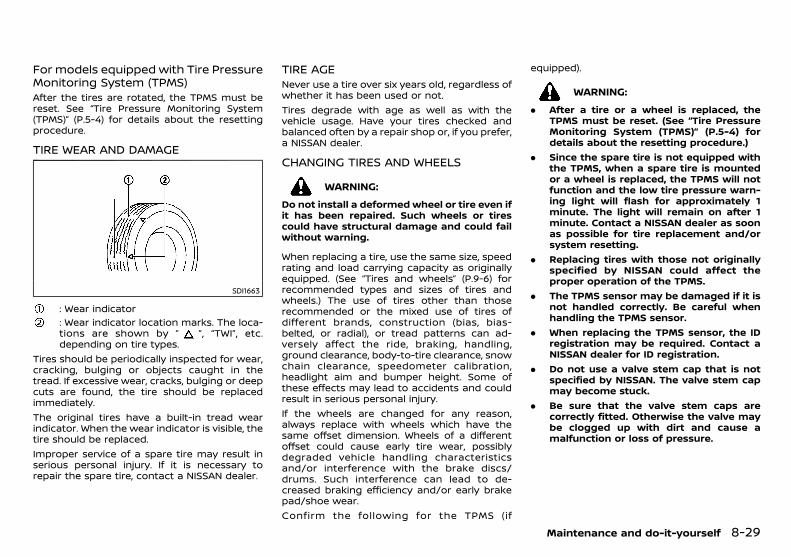
(275,1)
[ Edit: 2018/ 5/ 25 Model: PD23-A ]
For models equipped with Tire PressureMonitoring System (TPMS)
GUID-E2710563-2913-4908-8224-6E4268D813DEAfter the tires are rotated, the TPMS must bereset. See “Tire Pressure Monitoring System(TPMS)” (P.5-4) for details about the resettingprocedure.
TIRE WEAR AND DAMAGEPD23A1-30CC6DEB-1C96-46A9-841D-67EBB9AFB121
SDI1663
: Wear indicator: Wear indicator location marks. The loca-tions are shown by “ ”, “TWI”, etc.depending on tire types.
Tires should be periodically inspected for wear,cracking, bulging or objects caught in thetread. If excessive wear, cracks, bulging or deepcuts are found, the tire should be replacedimmediately.The original tires have a built-in tread wearindicator. When the wear indicator is visible, thetire should be replaced.Improper service of a spare tire may result inserious personal injury. If it is necessary torepair the spare tire, contact a NISSAN dealer.
TIRE AGEPD23A1-228B8BE1-7F61-4781-9F67-E03ABE1C166F
Never use a tire over six years old, regardless ofwhether it has been used or not.Tires degrade with age as well as with thevehicle usage. Have your tires checked andbalanced often by a repair shop or, if you prefer,a NISSAN dealer.
CHANGING TIRES AND WHEELSPD23A1-AE234277-C1BE-46F1-8E0D-ED221CBB7A84
WARNING:
Do not install a deformed wheel or tire even ifit has been repaired. Such wheels or tirescould have structural damage and could failwithout warning.
When replacing a tire, use the same size, speedrating and load carrying capacity as originallyequipped. (See “Tires and wheels” (P.9-6) forrecommended types and sizes of tires andwheels.) The use of tires other than thoserecommended or the mixed use of tires ofdifferent brands, construction (bias, bias-belted, or radial), or tread patterns can ad-versely affect the ride, braking, handling,ground clearance, body-to-tire clearance, snowchain clearance, speedometer calibration,headlight aim and bumper height. Some ofthese effects may lead to accidents and couldresult in serious personal injury.If the wheels are changed for any reason,always replace with wheels which have thesame offset dimension. Wheels of a differentoffset could cause early tire wear, possiblydegraded vehicle handling characteristicsand/or interference with the brake discs/drums. Such interference can lead to de-creased braking efficiency and/or early brakepad/shoe wear.Confirm the following for the TPMS (if
equipped).
WARNING:
. After a tire or a wheel is replaced, theTPMS must be reset. (See “Tire PressureMonitoring System (TPMS)” (P.5-4) fordetails about the resetting procedure.)
. Since the spare tire is not equipped withthe TPMS, when a spare tire is mountedor a wheel is replaced, the TPMS will notfunction and the low tire pressure warn-ing light will flash for approximately 1minute. The light will remain on after 1minute. Contact a NISSAN dealer as soonas possible for tire replacement and/orsystem resetting.
. Replacing tires with those not originallyspecified by NISSAN could affect theproper operation of the TPMS.
. The TPMS sensor may be damaged if it isnot handled correctly. Be careful whenhandling the TPMS sensor.
. When replacing the TPMS sensor, the IDregistration may be required. Contact aNISSAN dealer for ID registration.
. Do not use a valve stem cap that is notspecified by NISSAN. The valve stem capmay become stuck.
. Be sure that the valve stem caps arecorrectly fitted. Otherwise the valve maybe clogged up with dirt and cause amalfunction or loss of pressure.
Maintenance and do-it-yourself 8-29
Condition: 'Except for China'/
(276,1)
[ Edit: 2018/ 5/ 25 Model: PD23-A ]
8-30 Maintenance and do-it-yourself
WHEEL BALANCEPD23A1-0201BE0C-9A67-422C-A87B-6E890267D904
Unbalanced wheels may affect vehicle handlingand tire life. Even with regular use, wheels canget out of balance. Therefore, they should bebalanced as required.
SPARE TIREPD23A1-D2B7E6FC-9E87-4C2E-915B-26C37C0445AB
Conventional spare tirePD23A1-73F76A11-0310-4D30-8665-4E08702B40B0
A standard tire (the same size as the roadwheels) is supplied with your vehicle.
Condition: 'Except for China'/

(277,1)
[ Edit: 2018/ 5/ 25 Model: PD23-A ]
9 Technical information
Recommended fluids/lubricants and capacities .................... 9-2Fuel information ......................................................................................... 9-4Recommended SAE viscosity number (except forYS23DDTT engine model) .................................................................. 9-4Air conditioner system refrigerant and lubricant ........... 9-4
Engine ........................................................................................................................ 9-5Tires and wheels ............................................................................................... 9-6Dimensions ............................................................................................................ 9-6When travelling or registering in another country ................ 9-7
Vehicle identification ..................................................................................... 9-7Vehicle identification label .............................................................. 9-7Vehicle Identification Number (VIN) ......................................... 9-7Engine serial number .......................................................................... 9-7Tire placard ................................................................................................. 9-8Air conditioner specification label ............................................ 9-8
Installation of an RF-transmitter ......................................................... 9-8Radio approval number and information .................................... 9-8
For the Philippines ................................................................................. 9-8For Thailand ............................................................................................... 9-8
Condition: 'Except for China'/
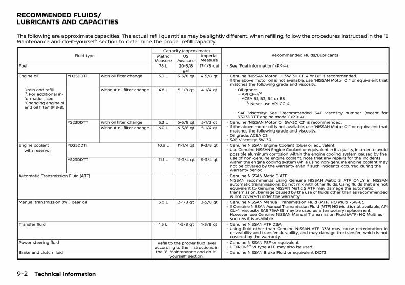
(278,1)
[ Edit: 2018/ 5/ 25 Model: PD23-A ]
9-2 Technical information
PD23A1-CEAE5A50-CAB8-4BA6-8D4B-FCC3B1B24D70The following are approximate capacities. The actual refill quantities may be slightly different. When refilling, follow the procedures instructed in the “8.Maintenance and do-it-yourself” section to determine the proper refill capacity.
Fluid typeCapacity (approximate)
Recommended Fluids/LubricantsMetricMeasure
USMeasure
ImperialMeasure
Fuel 78 L 20-5/8gal
17-1/8 gal · See “Fuel information” (P.9-4).
Engine oil*1 YD25DDTi With oil filter change 5.3 L 5-5/8 qt 4-5/8 qt · Genuine “NISSAN Motor Oil 5W-30 CF-4 or B1” is recommended.· If the above motor oil is not available, use “NISSAN Motor Oil” or equivalent that
matches the following grade and viscosity.Drain and refill*1: For additional in-formation, see“Changing engine oiland oil filter” (P.8-8).
Without oil filter change 4.8 L 5-1/8 qt 4-1/4 qt · Oil grade:– API CF-4*2
– ACEA B1, B3, B4 or B5*2: Never use API CG-4.
· SAE Viscosity: See “Recommended SAE viscosity number (except forYS23DDTT engine model)” (P.9-4).
YS23DDTT With oil filter change 6.3 L 6-5/8 qt 5-1/2 qt · Genuine “NISSAN Motor Oil 5W-30 C3” is recommended.· If the above motor oil is not available, use “NISSAN Motor Oil” or equivalent that
matches the following grade and viscosity.· Oil grade: ACEA C3· SAE Viscosity: 5W-30
Without oil filter change 6.0 L 6-3/8 qt 5-1/4 qt
Engine coolant YD25DDTi 10.6 L 11-1/4 qt 9-3/8 qt · Genuine NISSAN Engine Coolant (blue) or equivalent· Use Genuine NISSAN Engine Coolant or equivalent in its quality, in order to avoid
possible aluminum corrosion within the engine cooling system caused by theuse of non-genuine engine coolant. Note that any repairs for the incidentswithin the engine cooling system while using non-genuine engine coolant maynot be covered by the warranty even if such incidents occurred during thewarranty period.
with reservoir
YS23DDTT 11.1 L 11-3/4 qt 9-3/4 qt
Automatic Transmission Fluid (ATF) - - - · Genuine NISSAN Matic S ATF· NISSAN recommends using Genuine NISSAN Matic S ATF ONLY in NISSAN
automatic transmissions. Do not mix with other fluids. Using fluids that are notequivalent to Genuine NISSAN Matic S ATF may damage the automatictransmission. Damage caused by the use of fluids other than as recommendedis not covered under the warranty.
Manual transmission (MT) gear oil 3.0 L 3-1/8 qt 2-5/8 qt · Genuine NISSAN Manual Transmission Fluid (MTF) HQ Multi 75W-85· If Genuine NISSAN Manual Transmission Fluid (MTF) HQ Multi is not available, API
GL-4, Viscosity SAE 75W-85 may be used as a temporary replacement.However, use Genuine NISSAN Manual Transmission Fluid (MTF) HQ Multi assoon as it is available.
Transfer fluid 1.5 L 1-5/8 qt 1-3/8 qt · Genuine NISSAN ATF D3M· Using fluid other than Genuine NISSAN ATF D3M may cause deterioration in
driveability and transfer durability, and may damage the transfer, which is notcovered by the warranty.
Power steering fluid Refill to the proper fluid levelaccording to the instructions inthe “8. Maintenance and do-it-
yourself” section.
· Genuine NISSAN PSF or equivalent· DEXRONTM VI type ATF may also be used.
Brake and clutch fluid · Genuine NISSAN Brake Fluid or equivalent DOT3
RECOMMENDED FLUIDS/LUBRICANTS AND CAPACITIES
Condition: 'Except for China'/
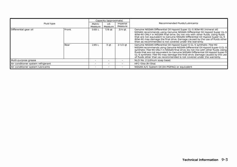
(279,1)
[ Edit: 2018/ 5/ 25 Model: PD23-A ]
Fluid typeCapacity (approximate)
Recommended Fluids/LubricantsMetricMeasure
USMeasure
ImperialMeasure
Differential gear oil Front 0.85 L 7/8 qt 3/4 qt · Genuine NISSAN Differential Oil Hypoid Super GL-5 80W-90 (mineral oil)· NISSAN recommends using Genuine NISSAN Differential Oil Hypoid Super GL-5
80W-90 ONLY in NISSAN final drive. Do not mix with other fluids. Using fluidsthat are not equivalent to Genuine NISSAN Differential Oil Hypoid Super GL-580W-90 may damage the final drive. Damage caused by the use of fluids otherthan as recommended is not covered under the warranty.
Rear 2.85 L 3 qt 2-1/2 qt · Genuine NISSAN Differential Oil Hypoid Super-S GL-5 synthetic 75W-90· NISSAN recommends using Genuine NISSAN Differential Oil Hypoid Super-S GL-5
synthetic 75W-90 ONLY in NISSAN final drive. Do not mix with other fluids. Usingfluids that are not equivalent to Genuine NISSAN Differential Oil Hypoid Super-SGL-5 synthetic 75W-90 may damage the final drive. Damage caused by the useof fluids other than as recommended is not covered under the warranty.
Multi-purpose grease - - - · NLGI No. 2 (Lithium soap base)Air conditioner system refrigerant - - - · HFC-134a (R-134a)Air conditioner system lubricants - - - · NISSAN A/C System Oil DH-PS(PAG) or equivalent
Technical information 9-3
Condition: 'Except for China'/
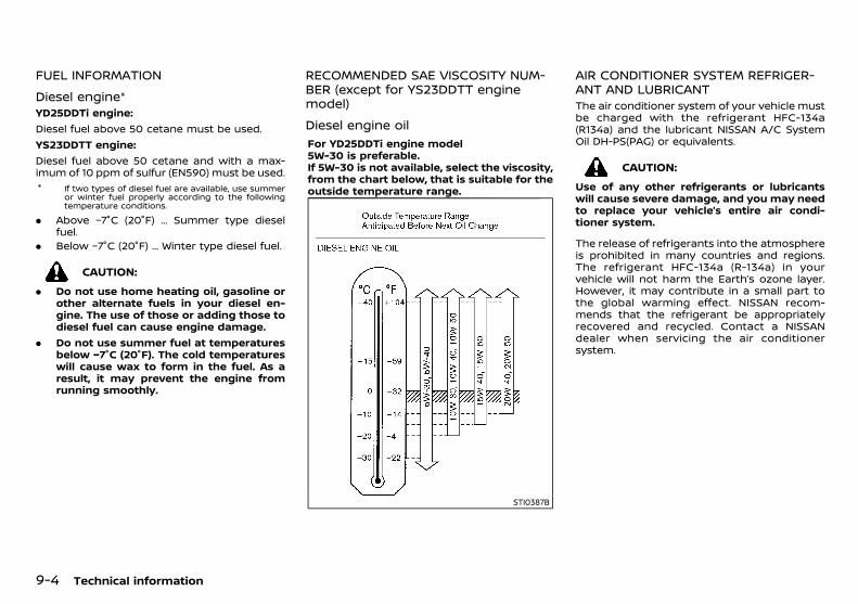
(280,1)
[ Edit: 2018/ 5/ 25 Model: PD23-A ]
9-4 Technical information
FUEL INFORMATIONPD23A1-98205A26-3AD9-4B1F-8857-A48DC4601D72
Diesel engine*PD23A1-97A49324-500D-48C4-ABCC-B5F9B3159362
YD25DDTi engine:Diesel fuel above 50 cetane must be used.YS23DDTT engine:Diesel fuel above 50 cetane and with a max-imum of 10 ppm of sulfur (EN590) must be used.* If two types of diesel fuel are available, use summer
or winter fuel properly according to the followingtemperature conditions.
. Above −7°C (20°F) ... Summer type dieselfuel.
. Below −7°C (20°F) ... Winter type diesel fuel.
CAUTION:
. Do not use home heating oil, gasoline orother alternate fuels in your diesel en-gine. The use of those or adding those todiesel fuel can cause engine damage.
. Do not use summer fuel at temperaturesbelow −7°C (20°F). The cold temperatureswill cause wax to form in the fuel. As aresult, it may prevent the engine fromrunning smoothly.
RECOMMENDED SAE VISCOSITY NUM-BER (except for YS23DDTT enginemodel)
PD23A1-881EDE31-CA7D-44C7-9994-FF3EC887607B
Diesel engine oilPD23A1-0ABA30D9-2D6D-4807-B64C-D607FFAF53D0
For YD25DDTi engine model5W-30 is preferable.If 5W-30 is not available, select the viscosity,from the chart below, that is suitable for theoutside temperature range.
STI0387B
AIR CONDITIONER SYSTEM REFRIGER-ANT AND LUBRICANT
PD23A1-C73B3F0F-D600-4BFE-8BA0-FCFEAD5D4992The air conditioner system of your vehicle mustbe charged with the refrigerant HFC-134a(R134a) and the lubricant NISSAN A/C SystemOil DH-PS(PAG) or equivalents.
CAUTION:
Use of any other refrigerants or lubricantswill cause severe damage, and you may needto replace your vehicle’s entire air condi-tioner system.
The release of refrigerants into the atmosphereis prohibited in many countries and regions.The refrigerant HFC-134a (R-134a) in yourvehicle will not harm the Earth’s ozone layer.However, it may contribute in a small part tothe global warming effect. NISSAN recom-mends that the refrigerant be appropriatelyrecovered and recycled. Contact a NISSANdealer when servicing the air conditionersystem.
Condition: 'Except for China'/
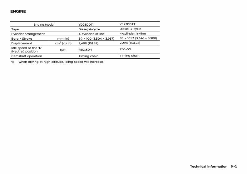
(281,1)
[ Edit: 2018/ 5/ 25 Model: PD23-A ]
PD23A1-0DBB8908-01C5-4F91-8E53-8E62D232FE7C
Engine Model YD25DDTi YS23DDTT
Type Diesel, 4-cycle Diesel, 4-cycle
Cylinder arrangement 4-cylinder, in-line 4-cylinder, in-line
Bore × Stroke mm (in) 89 × 100 (3.504 × 3.937) 85 × 101.3 (3.346 × 3.988)
Displacement cm3 (cu in) 2,488 (151.82) 2,298 (140.22)
Idle speed at the “N”(Neutral) position rpm 750±50*1 750±50
Camshaft operation Timing chain Timing chain
*1: When driving at high altitude, idling speed will increase.
Technical information 9-5
ENGINE
Condition: 'Except for China'/
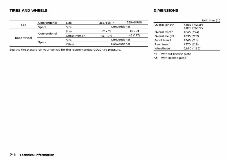
(282,1)
[ Edit: 2018/ 5/ 25 Model: PD23-A ]
9-6 Technical information
PD23A1-32D91669-C2F5-4E0E-BBEA-29474C1F1CB8
TireConventional Size 255/65R17 255/60R18
Spare Size Conventional
Road wheelConventional
Size 17 × 7J 18 × 7J
Offset mm (in) 45 (1.77) 45 (1.77)
SpareSize Conventional
Offset Conventional
See the tire placard on your vehicle for the recommended COLD tire pressure.
PD23A1-B71682FB-3F2F-4D32-B390-D729996F92A4Unit: mm (in)
Overall length 4,885 (192.3)*14,895 (192.7)*2
Overall width 1,865 (73.4)Overall height 1,835 (72.2)Front tread 1,565 (61.6)Rear tread 1,570 (61.8)Wheelbase 2,850 (112.2)
*1: Without license plate*2: With license plate
TIRES AND WHEELS DIMENSIONS
Condition: 'Except for China'/
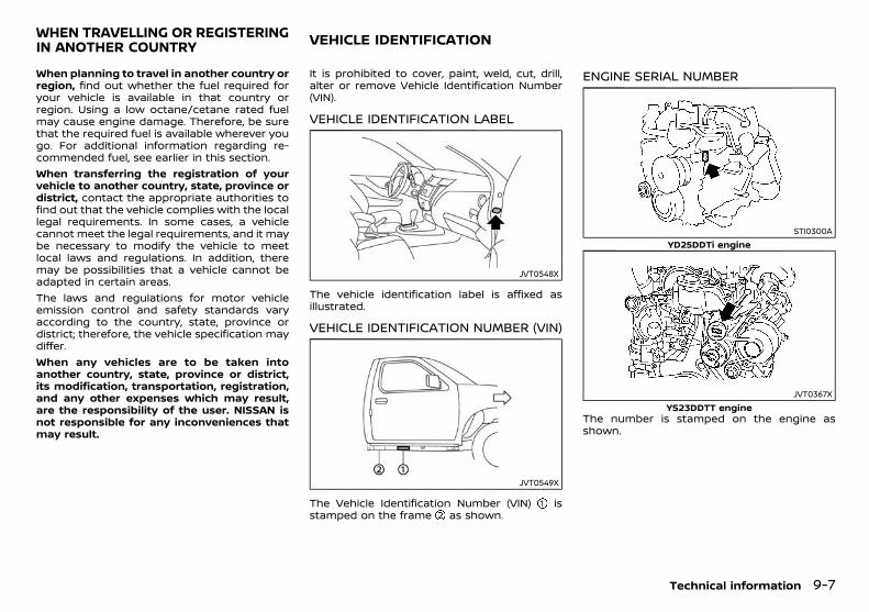
(283,1)
[ Edit: 2018/ 5/ 25 Model: PD23-A ]
PD23A1-5206BEA1-7A12-43CB-BA6A-7A72093E525EWhen planning to travel in another country orregion, find out whether the fuel required foryour vehicle is available in that country orregion. Using a low octane/cetane rated fuelmay cause engine damage. Therefore, be surethat the required fuel is available wherever yougo. For additional information regarding re-commended fuel, see earlier in this section.When transferring the registration of yourvehicle to another country, state, province ordistrict, contact the appropriate authorities tofind out that the vehicle complies with the locallegal requirements. In some cases, a vehiclecannot meet the legal requirements, and it maybe necessary to modify the vehicle to meetlocal laws and regulations. In addition, theremay be possibilities that a vehicle cannot beadapted in certain areas.The laws and regulations for motor vehicleemission control and safety standards varyaccording to the country, state, province ordistrict; therefore, the vehicle specification maydiffer.When any vehicles are to be taken intoanother country, state, province or district,its modification, transportation, registration,and any other expenses which may result,are the responsibility of the user. NISSAN isnot responsible for any inconveniences thatmay result.
PD23A1-78A4AF94-13F4-40B4-9A89-655F96477517It is prohibited to cover, paint, weld, cut, drill,alter or remove Vehicle Identification Number(VIN).
VEHICLE IDENTIFICATION LABELPD23A1-A0929215-3C8B-4CC6-8015-188DAF5B2B51
JVT0548X
The vehicle identification label is affixed asillustrated.
VEHICLE IDENTIFICATION NUMBER (VIN)PD23A1-991241BF-064B-465E-9D48-72665A1106C1
JVT0549X
The Vehicle Identification Number (VIN) isstamped on the frame as shown.
ENGINE SERIAL NUMBERPD23A1-7D293E5B-89BF-4B08-BF49-FB5689211300
STI0300AYD25DDTi engine
JVT0367XYS23DDTT engine
The number is stamped on the engine asshown.
Technical information 9-7
WHEN TRAVELLING OR REGISTERINGIN ANOTHER COUNTRY VEHICLE IDENTIFICATION
Condition: 'Except for China'/
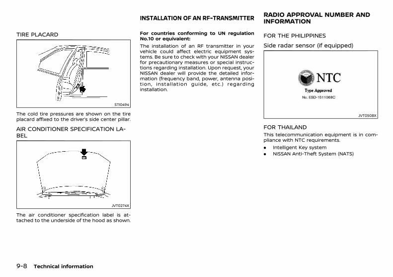
(284,1)
[ Edit: 2018/ 5/ 25 Model: PD23-A ]
9-8 Technical information
TIRE PLACARDPD23A1-315B3589-2C96-4DDF-9BBB-7B7AA6BAEEEB
STI0494
The cold tire pressures are shown on the tireplacard affixed to the driver’s side center pillar.
AIR CONDITIONER SPECIFICATION LA-BEL
PD23A1-6609D790-6DC1-4AD3-8CCC-920665A13E14
JVT0274X
The air conditioner specification label is at-tached to the underside of the hood as shown.
PD23A1-ED408375-C2BB-466F-8EAE-D2F5BB2F5A41For countries conforming to UN regulationNo.10 or equivalent:The installation of an RF transmitter in yourvehicle could affect electric equipment sys-tems. Be sure to check with your NISSAN dealerfor precautionary measures or special instruc-tions regarding installation. Upon request, yourNISSAN dealer will provide the detailed infor-mation (frequency band, power, antenna posi-tion, installation guide, etc.) regardinginstallation.
PD23A1-5A1E52D1-2BB1-4BF9-BA4C-2ACA9B768C1E
FOR THE PHILIPPINESGUID-7D6FCEBC-D9B3-474C-8C26-6F7B49C89D5B
Side radar sensor (if equipped)GUID-E51E50BD-34C5-49D1-9BD2-78692D469CAB
JVT0508X
FOR THAILANDPD23A1-08B3852A-8392-44F1-942E-E901B80FBF15
This telecommunication equipment is in com-pliance with NTC requirements.. Intelligent Key system. NISSAN Anti-Theft System (NATS)
INSTALLATION OF AN RF-TRANSMITTER RADIO APPROVAL NUMBER ANDINFORMATION
Condition: 'Except for China'/

(285,1)
[ Edit: 2018/ 5/ 25 Model: PD23-A ]
MEMO
Technical information 9-9
Condition: 'Except for China'/

(286,1)
[ Edit: 2018/ 5/ 25 Model: PD23-A ]
9-10 Technical information
MEMO
Condition: 'Except for China'/
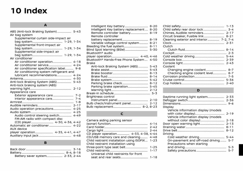
(287,1)
[ Edit: 2018/ 5/ 25 Model: PD23-A ]
10 IndexA
ABS (Anti-lock Braking System) .......................... 5-43Air bag system
Supplemental curtain side-impact airbag system .................................................... 1-29, 1-34Supplemental front-impact airbag system .................................................... 1-29, 1-34Supplemental side-impact airbag system .................................................... 1-29, 1-34
Air conditionerAir conditioner operation .................................. 4-18Air conditioner service ......................................... 4-24Air conditioner specification label ................. 9-8Air conditioning system refrigerant andlubricant recommendations ........................... 4-24
Antenna .................................................................................. 4-30Anti-lock Braking System (ABS) .......................... 5-43Anti-lock braking system (ABS)warning light ...................................................................... 2-12Appearance care
Exterior appearance care .................................... 7-2Interior appearance care ...................................... 7-4
Armrest ....................................................................................... 1-8Audible reminders .......................................................... 2-17Audio operation precautions ................................ 4-25Audio system ..................................................................... 4-25
Audio control steering switch ....................... 4-49FM-AM radio with compact disc(CD) player ....................................... 4-30, 4-36, 4-42
Automatic air conditioner ....................................... 4-22AUX deviceplayer operation ................................ 4-35, 4-41, 4-47Auxiliary input jack ........................................................ 4-48
B
Back door ............................................................................. 3-16Battery .......................................................................... 8-4, 8-18
Battery saver system ............................. 2-33, 2-44
Intelligent Key battery ......................................... 8-20Intelligent Key battery replacement ........ 8-20Remote controller battery ................................ 8-19Remote controllerbattery replacement ............................................. 8-19Variable voltage control system ................. 8-21
Bleeding the fuel system .......................................... 8-11Blind Spot Warning (BSW) ........................................ 5-30Bluetooth® audioplayer operation ............................................... 4-40, 4-46Bluetooth® Hands-Free Phone System ........ 4-50Brake
Anti-lock Braking System (ABS) ................... 5-43Brake assist .................................................................. 5-43Brake booster ............................................................. 8-13Brake fluid ..................................................................... 8-14Brake system .............................................................. 5-42Parking brake check ............................................. 8-12Parking brake operation .................................... 5-45Warning light ............................................................... 2-12
Break-in schedule .............................................................. 5-3Brightness control
Instrument panel ..................................................... 2-10Bulb check/instrument panel ............................... 2-12Bulb replacement ................................................ 8-2, 8-23
C
Camera aiding parking sensor(sonar) function ................................................................ 4-14Card holder .......................................................................... 2-42Cargo light ........................................................................... 2-44CD player operation ....................... 4-33, 4-38, 4-44CD/USB memory care and cleaning ............... 4-48Child restraint installation using ISOFIX ....... 1-23Child restraint installation usingthree-point type seat belt ....................................... 1-25Child restraints ................................................................. 1-17
Universal child restraints for frontseat and rear seats ................................................ 1-18
Child safety .......................................................................... 1-13Child safety rear door lock ......................................... 3-4Chimes, Audible reminders ..................................... 2-17Circuit breaker, Fusible link .................................... 8-21Cleaning exterior and interior ...................... 7-2, 7-4Clock ......................................................................................... 2-31Clutch
Clutch fluid .................................................................... 8-14Cockpit ........................................................................................ 2-3Cold weather driving ................................................... 5-44Console box ........................................................................ 2-39Console light ...................................................................... 2-43Coolant
Changing engine coolant .................................... 8-7Checking engine coolant level ......................... 8-7
Corrosion protection ....................................................... 7-5Cruise control .................................................................... 5-36Cup holders ......................................................................... 2-40
D
Daytime running light system .............................. 2-33Defogger switch .............................................................. 2-36Dimensions .............................................................................. 9-6Display
Vehicle information display (modelswith color display) ................................................... 2-19Vehicle information display (modelswithout color display) .......................................... 2-18
Door open warning light .......................................... 2-13Draining water .................................................................. 8-11Drive belt ............................................................................... 8-12Driving
Cold weather driving ............................................ 5-44On-pavement and off-road driving ............. 5-7Precautions when startingand driving ....................................................................... 5-3Safety precautions .................................................... 5-7
Condition: 'Except for China'/
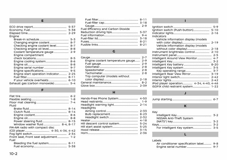
(288,1)
[ Edit: 2018/ 5/ 25 Model: PD23-A ]
10-2
E
ECO drive report .............................................................. 5-37Economy, Fuel ................................................................... 5-38Elapsed time ....................................................................... 2-29Engine
Break-in schedule ...................................................... 5-3Changing engine coolant .................................... 8-7Checking engine coolant level ......................... 8-7Checking engine oil level ...................................... 8-8Coolant temperature gauge ............................. 2-9Engine compartmentcheck locations ............................................................ 8-5Engine cooling system ........................................... 8-6Engine oil ........................................................................... 8-8Engine serial number .............................................. 9-7Engine specifications ............................................... 9-5Engine start operation indicator ................. 2-25Fuel filter ......................................................................... 8-11If your vehicle overheats ................................... 6-10
Exhaust gas (carbon monoxide) ............................ 5-4
F
Flat tire ........................................................................................ 6-2Flexible seating ..................................................................... 1-8Floor mat cleaning ............................................................ 7-4Fluid
Brake fluid ..................................................................... 8-14Clutch fluid .................................................................... 8-14Engine coolant .............................................................. 8-6Engine oil ........................................................................... 8-8Power steering fluid .............................................. 8-15Window washer fluid ................................ 8-4, 8-17
FM-AM radio with compact disc(CD) player .............................................. 4-30, 4-36, 4-42Fog light switch ............................................................... 2-34Front seat, Front seat adjustment ....................... 1-2Fuel
Bleeding the fuel system ................................... 8-11Fuel economy ............................................................. 5-38
Fuel filter ......................................................................... 8-11Fuel-filler cap ............................................................... 3-18Gauge ................................................................................... 2-9
Fuel Efficiency and Carbon DioxideReduction driving tips ................................................. 5-37Fuel information .................................................................. 9-4Fuel-filler lid ......................................................................... 3-18Fuses ......................................................................................... 8-21Fusible links ......................................................................... 8-21
G
Gauge ........................................................................................... 2-7Engine coolant temperature gauge ............ 2-9Fuel gauge ....................................................................... 2-9Odometer .......................................................................... 2-8Speedometer ................................................................. 2-8Tachometer ..................................................................... 2-8Trip computer (models withoutcolor display) ............................................................... 2-18
General maintenance ...................................................... 8-2Glove box .............................................................................. 2-39
H
Hands-Free Phone System ..................................... 4-50Head restraints ..................................................................... 1-9Headlight warning light ............................................. 2-14Headlights
Aiming control ........................................................... 2-33Bulb replacement .................................................... 8-23Headlight switch ...................................................... 2-32
Heater ...................................................................................... 4-18Hill descent control system .................................... 5-24Hill start assist system ............................................... 5-25Hood release ...................................................................... 3-15Horn ........................................................................................... 2-36
I
Ignition switch ...................................................................... 5-9Ignition switch (Push-button) ............................... 5-10Indicator lights .................................................................. 2-16Indicators
Vehicle information display (modelswith color display) ................................................... 2-19Vehicle information display (modelswithout color display) .......................................... 2-18
Instrument brightness control ............................ 2-10Instrument panel ................................................................ 2-5Intelligent Around View Monitor ............................ 4-7Intelligent Key ........................................................................ 3-2Intelligent Key battery ................................................ 8-20Intelligent Key system .................................................... 3-5
Key operating range ................................................ 3-7Intelligent Rear View Mirror .................................... 3-19Interior light switch ....................................................... 2-42Interior lights ...................................................................... 2-42iPod player operation .................... 4-34, 4-40, 4-46ISOFIX child restraint system ................................ 1-22
J
Jump starting ........................................................................ 6-7
K
KeyIntelligent Key ................................................................ 3-2NISSAN Anti-Theft System(NATS*) key ....................................................................... 3-2
Keys ............................................................................................... 3-2For Intelligent Key system ................................... 3-5
L
LabelsAir conditioner specification label ................. 9-8Engine serial number .............................................. 9-7
Condition: 'Except for China'/
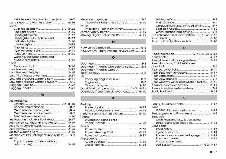
(289,1)
[ Edit: 2018/ 5/ 25 Model: PD23-A ]
Vehicle Identification Number (VIN) ............. 9-7Lane Departure Warning (LDW) ........................... 5-26Light
Bulb replacement ........................................ 8-2, 8-23Fog light switch ........................................................ 2-34Headlight switch ...................................................... 2-32Headlights bulb replacement ........................ 8-23Indicator lights ........................................................... 2-16Interior lights ............................................................... 2-42Map lights ...................................................................... 2-43Rear personal light ................................................. 2-44Replacement ................................................... 8-2, 8-23Warning/indicator lights andaudible reminders ................................................... 2-12
LockBack door lock ........................................................... 3-16
Low fuel warning ............................................................ 2-25Low fuel warning light ............................................... 2-14Low Tire Pressure warning ..................................... 2-27Low tire pressure warning light ......................... 2-14Low tire pressure warning system ...................... 5-4Luggage floor box ......................................................... 2-42Luggage hooks ................................................................ 2-41
M
MaintenanceBattery .................................................................. 8-4, 8-18General maintenance .............................................. 8-2Maintenance precautions .................................... 8-4Maintenance requirements ................................ 8-2Seat belt maintenance ........................................ 1-16
Malfunction indicator light (MIL) ......................... 2-17Manual air conditioner and heater .................. 4-19Map light control switch ........................................... 2-43Map lights ............................................................................. 2-43Master warning light .................................................... 2-15Mechanical key (Intelligent Key system) .......... 3-3Meter
Trip computer (models withoutcolor display) ............................................................... 2-18
Meters and gauges ........................................................... 2-7Instrument brightness control ..................... 2-10
MirrorIntelligent Rear View Mirror ............................. 3-19
Mirror, Vanity mirror ..................................................... 3-24Moving Object Detection (MOD) ......................... 4-15
N
New vehicle break-in ....................................................... 5-3NISSAN Anti-Theft System (NATS*) key ............. 3-2
O
Odometer .................................................................................. 2-8Odometer (models with color display) .............. 2-8Odometer (models withoutcolor display) .......................................................................... 2-8Oil
Checking engine oil level ...................................... 8-8Engine oil ........................................................................... 8-8Oil control system ................................................... 2-30
Outside air temperature ............................ 2-18, 2-31Overheat, If your vehicle overheats ................. 6-10
P
ParkingBrake break-in ........................................................... 5-43Parking brake operation .................................... 5-45
Parking sensor (sonar) system ............................ 5-40Phone
Bluetooth® Hands-FreePhone System ............................................................ 4-50
PowerPower outlet ................................................................ 2-38Power steering fluid .............................................. 8-15Power windows ........................................................ 2-37
PrecautionsAudio operation ........................................................ 4-25Cruise control ............................................................. 5-36
Driving safety ................................................................. 5-7Maintenance ................................................................... 8-4On-pavement and off-road driving ............. 5-7Seat belt usage ......................................................... 1-12When starting and driving ................................... 5-3
Pre-tensioner seat belt system ............ 1-32, 1-37Push starting ...................................................................... 6-10Push-button ignition switch .................................. 5-10
R
Radio operation ................................. 4-32, 4-38, 4-44Rear cooler .......................................................................... 4-23Rear differential locking system ......................... 5-22Rear door lock, Child safety reardoor lock ................................................................................... 3-4Rear personal light ........................................................ 2-44Rear seat roof ventilators ........................................ 4-17Rear ventilators ................................................................ 4-17Rear view monitor ............................................................. 4-3Rear window wiper and washer switch ....... 2-35Remote controller battery ....................................... 8-19Remote keyless entry system .................................. 3-4Roof, Roof rack ................................................................. 2-41
S
Safety, Child seat belts ............................................... 1-13Seat
ISOFIX child restraint system ......................... 1-22Seat adjustment, Front seats ................................... 1-2Seat belt
Child restraint installation usingthree-point type seat belt ................................ 1-25
Seat belt(s)Child safety ................................................................... 1-13Injured persons ......................................................... 1-14Precautions on seat belt usage ................... 1-12Pregnant women ..................................................... 1-14Pre-tensioner seatbelt system .................................................... 1-32, 1-37
10-3
Condition: 'Except for China'/
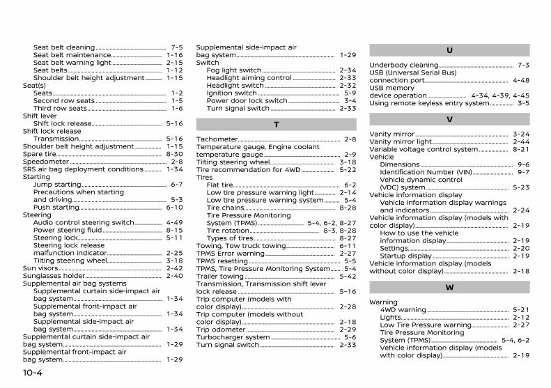
(290,1)
[ Edit: 2018/ 5/ 25 Model: PD23-A ]
10-4
Seat belt cleaning ...................................................... 7-5Seat belt maintenance ........................................ 1-16Seat belt warning light ....................................... 2-15Seat belts ....................................................................... 1-12Shoulder belt height adjustment ............... 1-15
Seat(s)Seats ..................................................................................... 1-2Second row seats ...................................................... 1-5Third row seats ............................................................ 1-6
Shift leverShift lock release ...................................................... 5-16
Shift lock releaseTransmission ............................................................... 5-16
Shoulder belt height adjustment ...................... 1-15Spare tire ............................................................................... 8-30Speedometer ......................................................................... 2-8SRS air bag deployment conditions ................ 1-34Starting
Jump starting ................................................................ 6-7Precautions when startingand driving ....................................................................... 5-3Push starting ............................................................... 6-10
SteeringAudio control steering switch ....................... 4-49Power steering fluid .............................................. 8-15Steering lock ................................................................ 5-11Steering lock releasemalfunction indicator ........................................... 2-25Tilting steering wheel ........................................... 3-18
Sun visors ............................................................................. 2-42Sunglasses holder .......................................................... 2-40Supplemental air bag systems
Supplemental curtain side-impact airbag system ................................................................... 1-34Supplemental front-impact airbag system ................................................................... 1-34Supplemental side-impact airbag system ................................................................... 1-34
Supplemental curtain side-impact airbag system .......................................................................... 1-29Supplemental front-impact airbag system .......................................................................... 1-29
Supplemental side-impact airbag system .......................................................................... 1-29Switch
Fog light switch ........................................................ 2-34Headlight aiming control .................................. 2-33Headlight switch ...................................................... 2-32Ignition switch .............................................................. 5-9Power door lock switch ........................................ 3-4Turn signal switch .................................................. 2-33
T
Tachometer ............................................................................. 2-8Temperature gauge, Engine coolanttemperature gauge .......................................................... 2-9Tilting steering wheel .................................................. 3-18Tire recommendation for 4WD ........................... 5-22Tires
Flat tire ................................................................................ 6-2Low tire pressure warning light .................. 2-14Low tire pressure warning system .............. 5-4Tire chains ..................................................................... 8-28Tire Pressure MonitoringSystem (TPMS) .................................... 5-4, 6-2, 8-27Tire rotation ..................................................... 8-3, 8-28Types of tires .............................................................. 8-27
Towing, Tow truck towing ...................................... 6-11TPMS Error warning ..................................................... 2-27TPMS resetting ..................................................................... 5-5TPMS, Tire Pressure Monitoring System .......... 5-4Trailer towing .................................................................... 5-42Transmission, Transmission shift leverlock release ......................................................................... 5-16Trip computer (models withcolor display) ...................................................................... 2-28Trip computer (models withoutcolor display) ...................................................................... 2-18Trip odometer ................................................................... 2-29Turbocharger system ..................................................... 5-6Turn signal switch ......................................................... 2-33
U
Underbody cleaning ......................................................... 7-3USB (Universal Serial Bus)connection port ............................................................... 4-48USB memorydevice operation ............................... 4-34, 4-39, 4-45Using remote keyless entry system .................... 3-5
V
Vanity mirror ...................................................................... 3-24Vanity mirror light .......................................................... 2-44Variable voltage control system ........................ 8-21Vehicle
Dimensions ...................................................................... 9-6Identification Number (VIN) ................................ 9-7Vehicle dynamic control(VDC) system ............................................................... 5-23
Vehicle information displayVehicle information display warningsand indicators ............................................................ 2-24
Vehicle information display (models withcolor display) ...................................................................... 2-19
How to use the vehicleinformation display ................................................ 2-19Settings ............................................................................ 2-20Startup display .......................................................... 2-19
Vehicle information display (modelswithout color display) ................................................. 2-18
W
Warning4WD warning .............................................................. 5-21Lights ................................................................................. 2-12Low Tire Pressure warning .............................. 2-27Tire Pressure MonitoringSystem (TPMS) ................................................... 5-4, 6-2Vehicle information display (modelswith color display) ................................................... 2-19
Condition: 'Except for China'/

(291,1)
[ Edit: 2018/ 5/ 25 Model: PD23-A ]
Vehicle information display (modelswithout color display) .......................................... 2-18Warning lights, indicator lights andaudible reminders ................................................... 2-11
Warning lightAnti-lock braking system (ABS)warning light ............................................................... 2-12Brake warning light ............................................... 2-12Door open warning light ................................... 2-13Headlight warning light ...................................... 2-14Low fuel warning light ........................................ 2-14Low tire pressure warning light .................. 2-14Seat belt warning light ....................................... 2-15
Washer switchRear window wiper andwasher switch ............................................................ 2-35
Washer switch, Windshield wiper andwasher switch ................................................................... 2-34Washing ...................................................................................... 7-2Waxing ......................................................................................... 7-2Welcome light and farewelllight function .......................................................................... 3-8Wheels and tires
Care of wheels .............................................................. 7-3Cleaning aluminum alloy wheels ................... 7-3Tires and wheels .......................................... 8-27, 9-6
Window washer fluid ........................................ 8-4, 8-17Window(s)
Cleaning .................................................................. 7-3, 7-4Power windows ........................................................ 2-37
Windshield wiper and washer switch ............. 2-34Wiper
Rear window wiper andwasher switch ............................................................ 2-35Rear window wiper blade ................................. 8-17Windshield wiper andwasher switch ............................................................ 2-34Wiper blades ................................................................ 8-16
10-5
Condition: 'Except for China'/
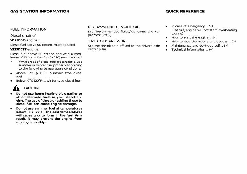
(295,1)
[ Edit: 2018/ 5/ 25 Model: PD23-A ]
11 EpiloguePD23A1-E382FEC2-1FED-4E52-9FEF-5BE26C4BBF3C
FUEL INFORMATIONPD23A1-44C177D5-CB2E-4D61-8B94-23469B24487D
Diesel engine*PD23A1-60E574A6-D3DA-4005-BA2D-E1F7281B4712
YD25DDTi engine:Diesel fuel above 50 cetane must be used.YS23DDTT engine:Diesel fuel above 50 cetane and with a max-imum of 10 ppm of sulfur (EN590) must be used.* If two types of diesel fuel are available, use
summer or winter fuel properly accordingto the following temperature conditions.
. Above −7°C (20°F) ... Summer type dieselfuel.
. Below −7°C (20°F) ... Winter type diesel fuel.
CAUTION:
. Do not use home heating oil, gasoline orother alternate fuels in your diesel en-gine. The use of those or adding those todiesel fuel can cause engine damage.
. Do not use summer fuel at temperaturesbelow −7°C (20°F). The cold temperatureswill cause wax to form in the fuel. As aresult, it may prevent the engine fromrunning smoothly.
RECOMMENDED ENGINE OILPD23A1-BDE335F3-46F3-4207-AFAB-941D2F10193B
See “Recommended fluids/lubricants and ca-pacities” (P.9-2).
TIRE COLD PRESSUREPD23A1-9E3CE568-A19B-4D0F-A7DD-98A8DCE3CE42
See the tire placard affixed to the driver’s sidecenter pillar.
PD23A1-CB8576A8-9B00-4E97-8E6F-F28C2AAD0786. In case of emergency ... 6-1
(Flat tire, engine will not start, overheating,towing)
. How to start the engine ... 5-1
. How to read the meters and gauges ... 2-1
. Maintenance and do-it-yourself ... 8-1
. Technical information ... 9-1
GAS STATION INFORMATION QUICK REFERENCE
Condition: 'Except for China'/