kronobuild-en.pdf - Kronospan Express
148
-
Upload
khangminh22 -
Category
Documents
-
view
0 -
download
0
Transcript of kronobuild-en.pdf - Kronospan Express


WORLD OF POSSIBILITIES FOR MODERN BUILDINGS In your hands you hold the key to the range of world´s leading manufacturer of products - large scale wood-based panels.
The width of building range KRONOSPANdraws from many year´s standing experience in the branch and knowledge of trends in building industry.
Behind the product line of construction materials is a one-hundred-fifteen history of continuous development, work and experience of our 30 manufacturing sites throughout the world.
All our benefits are combined in the new catalogue Kronobuild® which opens you the world of all construction products of the KRONOSPAN world.
Welcome to the world Kronobuild®. All you need you have available is included in this catalogue. Kronobuild® is the next step forward for you and offers countless opportunities while creating implementation of modern and ecological buildings.

3
Technical details and print errors are subject to change.

4
content
8
9
7
6
5
4
3
2
1Ecology and environment 5Kronobuild® – basic terms and definitions 6
PARTICLEBOARDS Particleboards P2, P3, P5 a P6 9QSB 9FireBoard 9
OSB SUPERFINISH OSB Superfinish 15Type OSB/1, OSB/2, OSB3 and OSB/4 15OSB Superfinish ECO 16OSB Firestop ECO 17OSB Airstop ECO 17OSB Reflex ECO 18OSB Ply 19
WOOD FIBRE BOARDS (MDF) MDF MR 23MDF B1 23DFP 24
CEMENT-BONDED PARTICLEBOARDS Betonyp 29
GUIDANCE ON THE USE OF LOAD-BEARING BOARDS Transport, storage 33Humidity content, conditioning and effect of humidity 34Marking of boards and on-site inspection 36Sawing, drilling, fixing 36Installation of boards on a construction site 41
BUILDING-PHYSICS REQUIREMENTS Essential requirements on wooden houses 47Timber framed construction 48Load bearing capacity 50Energy saving and heat retentions 57Moisture protection 65Weather protection 69Building airtightness 70Fire protection 74Noise protection 77Heath safety and environmental aspect 83
TIMBER FRAMED CONSTRUCTIONSDiffusion-open external structures 89Diffusion-closed external structures 103Interior structures of walls and floors 112
COMPACT BOARDS Krono Plan 127Krono Compact 127Guidance on the use of compact boards 129Façade applications Krono Plan 131Balcony sheathing Krono Plan 134Interior application Krono Compact 135System solution Krono Siding 136
FORMWORK BOARDS ProForm 139OSB Film 139Guidance on the use of formwork boards 143

Kronobuild® building products are materials suitable for wood framed houses - ecological structures with great perspective.
ENVIRONMENTALLY-FRIENDLY TIMBER FRAMED CONSTRUCTIONS During the design and construction not only architectural and engineering approach to balance the increasing demands on the environmental quality, but also economic development and ecological criteria in the context of sustainable development shall be taken into consideration. Sustainable development is understood as a long-term preservation of natural assets for fu-ture generations. In such respect renewable sources such as wood shall be used to the maximum capacity without doubt.
Kronobuild® construction materials represent a signifi cant con-tribution to this trend as they are 95% made of natural wood. Their use is therefore a signifi cant environmental benefi t for the following reasons:
• Renewable sources of raw materialsWood is one of the few sustainable raw materials with versatile use. It bears considerable energy potential obtained from solar energy (about 5 MWh / m3 wood biomass). The use of wood has a positive impact on the environmental protection and re-duces the need for mining non-renewable raw materials (lime, brick clay, stones, etc.).
• Reduction of harmful emissions in particular CO2In the process of tree growth - photosynthesis - carbonaceous substances from the air and land are converted and bound in biomass - in wood. The growth of wood contributes to redu-cing CO2 emissions in the atmosphere and consequently to the stability of temperature and Earth climate. Every 1 m3 of wood binds about 225 kg of carbon.
• Reduction of energy consumption for building constructionBuilding from wood brings a signifi cant reduction in energy con-sumption for construction compared to silicate-based materials (bricks, concrete). Silicate materials consume during its produc-tion several times the amount of energy.
• Reduction of energy consumption for building operationWood structures meet the demand on high thermal-insulation of low energy and passive houses. This can already be achieved with thin walls, thus increasing the usable space inside the build-ing. At the same time it facilitates the regulation of heat loss and reduces energy consumption for heating.
• Reduction of material transport on environmentLower weight of wood house (about 1 t /1 m2 fl oor area) results in signifi cant reduction of transported material weight in compa-rison to the massive construction.
• Reducing construction wasteWood waste is fully recyclable in the production of agglomera-ted materials (manufacture of chipboards).
• Certifi cation PEFC / FSCKronobuild® building materials are manufactured primarily from wood originating from forests certifi ed with FSC or PEFC system controlling principles of ecological sustainable forest manage-ment.
• 100% use of wood raw material in the production.Sorted materials that do not meet the strict quality requirements OSB boards’ production used in the manufacture of particle boards, without losing the energy invested into the chip drying. Wood dust is used as a sustainable fuel as well as bark.
• Use of rail transportDue to on site rail connection large proportion of wood is trans-ported by freight trains. This is also an important contributor to the intense environmental protection.
•Kronobuild® boards are 100% recyclable.
ECOLOGY AND ENVIRONMENT

BOARDS FOR FLOORS, WALLS AND ROOFSAmong Kronobuild® building products of KRONOSPAN belong various types of particle boards, OSB boards, wood fibreboards and cement- bonded particleboards. These are large panel con-struction materials for floors, walls and roofs. They are manu-factured and tested according to the valid European standards. Each type has its own characteristics for their intended final use.
Basic features of all these products meet requirements of the har-monized standards hEN 13986, part ZA and other valid regulations for distribution and sale of boards within the European Economic Area, which is verified by issued certificates with valid label.Validity of all certificates and protocols are continuously monito-red and updated as necessary. There are other certificates for countries outside the European Union issued under valid regu-lations of each country.
EN 13986 Standard „Wood-based panels for use in construction - Characteristics, evaluation of conformity and marking“ regula-tes all legal construction interests in respect of the Construction Products Directive (CPD). It applies to wood-based boards used as structural and non-structural components in dry, wet and out-door environment.
BOARDS FOR FINAL APPLICATIONSKronobuild® building products also includes the compact boards as material for final wall and ceiling cladding and lining. Simi-larly, as noted above, compact boards meet the requirements of the harmonized standards hEN 438-7, part ZA and possess relevant certificates.
FORMWORK BOARDSFormwork boards are special group of Kronobuild® products that are designed especially for the exposed concrete.
- basic terms and definitionsBASIC TECHNICAL DEFINITIONSKronobuild® construction products are divided according to their destined use in order to easier design of wood construc-tions regarding the basic European standard EN 1995-1-1 or some national standards.
Technical definitions and basic terms related to board classifica-tion according to EN 13986 is as follows:• Dry conditionConditions corresponding with service class 1 according to EN 1995-1-1 are characterized by a moisture content in structural materials, which corresponds to the temperature of 20 °C and relative humidity of the ambient air of 65% few weeks a year at the most. Most coniferous wood has the average moisture content not exceeding 12%.• Humid conditionConditions corresponding with service class 2 according to EN 1995-1-1 are characterized by a moisture content in structural ma-terials, which corresponds to the temperature of 20 °C and relative humidity of the ambient air exceeding 85% few weeks a year at the most. Most coniferous wood has the average moisture content not exceeding 20%.• External conditionConditions corresponding with service class 3 according to EN 1995-1-1 is characterized by climatic conditions leading to higher moisture content than the second service class.• Load-bearing (structural) useUsing the board under load as part of the building or other con-struction.• Structural floor deckingFloor set of wood-based boards placed on joists and over-lapping its span. The boards under load freely deflect between the joists.• Structural wall sheathingWood-based boards capable of providing mechanical strength for the wall construction.• Structural roof deckingA set of wood-based boards placed on the rafters and over-lapping their span. The boards under load deflect freely be-tween the rafters.


1. P
ARTI
CLE
boa
rds

9
PARTICLE boards
three - layered board
smooth surface
single - layered board
moisture resistance binder
Particleboards PB are one of the most used wood-based materi-als for various applications. They are made from wood chips and synthetic resin based binders. The boards are pressed under high temperatures and pressure.
KRONOSPAN manufactures a wide range of chipboards. Each board type has its own characteristics for its further intended use. Product line of particle boards Kronobuild® includes the following types of chipboard - P2, P3, P5, P6, QSB and FireBoard.
are three layered fl at pressed chipboards made of specially sort-ed wood chips bonded with high quality resin. Boards are availa-ble in thicknesses from 8-40 mm sanded on both sides with low thickness tolerances. All types of boards meet the requirements of European standard EN 312 which defi nes chipboard as follows:
For better differentiation the particleboards P3 and P5 are green colored in middle layer. Due to its smooth sanded surface the boards are suitable for coating foils, veneers, decorative melami-ne papers and for laminating with high pressure HPL laminates.
(QSB = Quality Strand Board) is a high quality single-layer par-ticle board made from specially sorted chips which provide com-pactness and high density of boards throughout the cross-sec-tion.QSB chipboard meets the requirements of EN 312 Type P5 - as structural boards for use in humid conditions.
Board type Dry conditions Humid conditions
Non load-bearing board P2 P3Load-bearing board P6 P5
1. P
ARTI
CLE
boa
rds

three - layered board
smooth surface
red - coloured
fl ame - retardant board
is a three layered chipboard type P2 with improved fi re proper-ties.FireBoard boards are manufactured in compliance with Euro-pean standard EN 312 Type P2 where they are defi ned as non--structural boards for use in dry conditions.The basic features of this board type include increased fi re resi-stance which is characterized by a higher class of reaction to fi re. According to the European classifi cation (EN 13501-1) class B-s1, d0 is achieved and according to the German classifi cation (DIN 4102) class B1 is achieved.For better differentiation from chipboards with regular fi re quali-ties, FireBoard is color coded with red pigment.

11
ADVANTAGES
APPLICATION AREA
P2 P3 P5 P6 QSB FireBoard
STRUCTURAL APPLICATIONS
Load-bearing cladding of exterior walls or roofs - - • - • -Structural roof decking - - • • • -Sub-floors and base boards for flooring systems • • • • • •Internal non load-bearing cladding of walls and ceilings, partitions • • • • • •Attic conversions or extensions - • • • • •Cladding in public buildings - - - - - •Construction site fencing - • • - • -Formwork: lost formwork, formwork foundations, etc. - - • - • -
FURNITURE APPLICATIONS
Possible surface finishing by laminating, backing, veneering • • • • - •Wet condition boards for bathroom and kitchen furniture - • • - - -Lining in places with high humidity - • • - • -
PACKAGE INDUSTRY
Cladding of transport crates and packaging - • • - • -Production of shelves and racks - • • - • -
P2 P3 P5 P6 QSB FireBoard
High dimensional stability and stiffness • • • • • •Same strength in all directions of board • • • • • •Increased resistance to humid conditions - • • - • -Low swelling in thickness • • • • • •Application in structures with increased fire requirements - - - - - •Simple processing with conventional woodworking tools • • • • • •Easy fixation using conventional fasteners (screws, nails, staples) • • • • • •Excellent grip of fasteners, also close to the edge • • • • • •Quick installation • • • • • •Suitable as a mat under thin floor surfaces such as PVC, vinyl, carpet • • • • - •Excellent price / performance ratio • • • • • •Possibility of recycling • • • • • •
1. P
ARTI
CLE
boa
rds

12
PARTICLEBOARDS TECHNICAL PRODUCTION SPECIFICATION
GENERAL PARTICLEBOARD DELIVERY REQUIREMENTS
Properties Test Method Requirement
Tolerance on nominal dimensionsThickness (sanded board)
EN 324-1± 0,3 mm
Thickness (unsanded board) -0,3 mm +1,7 mmLength and width ± 5 mm
Tolerance of edge straightnessEN 324-2
1,5 mm/mTolerance of squareness 2 mm/mTolerance of density EN 323 ± 10 %Formaldehyde release EN 120 Class E1 ≤ 8 mg/100 g
REQUIREMENTS FOR P2 PARTICLEBOARDS FOR INDOOR EQUIPMENT (INCLUDING FURNITURE) FOR USE IN DRY CONDITIONS
Properties Test Method Unit
Thickness (mm, nominal dimension)8 to 13 > 13 to 20 > 20 to 25 > 25 to 32 > 32 to 40
Bending strength EN 310 N/mm2 11 11 10,5 9,5 8,5Modulus of elasticity in bending EN 310 N/mm2 1800 1600 1500 1350 1200Internal Bond EN 319 N/mm2 0,40 0,35 0,30 0,25 0,20Swelling in thickness EN 311 N/mm2 0,8 0,8 0,8 0,8 0,8
REQUIREMENTS FOR P3 PARTICLEBOARDS AS NON-STRUCTURAL BOARDS FOR USE IN HUMID CONDITIONS
Properties Test Method Unit
Thickness (mm, nominal dimension)8 to 13 > 13 to 20 > 20 to 25 > 25 to 32 > 32 to 40
Bending strength EN 310 N/mm2 15 14 12 11 9Modulus of elasticity in bending EN 310 N/mm2 2050 1950 1850 1700 1550
Internal BondEN 319 N/mm2 0,45 0,45 0,40 0,35 0,30
After boil test2 EN 1087-1 N/mm2 0,09 0,08 0,07 0,07 0,06After cyclic test1 EN 321 N/mm2 0,15 0,13 0,12 0,10 0,09
Swelling in thicknessafter 24 h EN 317 % 17 14 13 13 12After cyclic test1 EN 321 % 14 13 12 12 11
REQUIREMENTS FOR P5 PARTICLEBOARDS AS STRUCTURAL BOARDS FOR USE IN HUMID CONDITIONS
Properties Test Method Unit
Thickness (mm, nominal dimension)8 to 10 > 10 to 13 > 13 to 20 > 20 to 25 > 25 to 32 > 32 to 40
Bending strength EN 310 N/mm2 18 18 16 14 12 10Modulus of elasticity in bending EN 310 N/mm2 2550 2550 2400 2150 1900 1700
Internal BondEN 319 N/mm2 0,45 0,45 0,40 0,35 0,30 0,30
After boil test2 EN 1087-1 N/mm2 0,15 0,15 0,14 0,12 0,11 0,10After cyclic test1 EN 321 N/mm2 0,25 0,25 0,22 0,20 0,17 0,15
Swelling in thickness
after 24 h EN 317 % 13 11 10 10 10 9After cyclic test 1 EN 321 % 12 12 12 11 10 9
REQUIREMENTS FOR P6 PARTICLEBOARDS AS STRUCTURAL BOARDS FOR USE IN DRY CONDITIONS
Properties Test Method Unit
Thickness (mm, nominal dimension)8 to 10 > 10 to 13 > 13 to 20 > 20 to 25 > 25 to 32 > 32 to 40
Bending strength EN 310 N/mm2 20 20 18 16 15 14Modulus of elasticity in bending EN 310 N/mm2 3150 3150 3000 2550 2400 2200Internal Bond EN 319 N/mm2 0,60 0,60 0,50 0,40 0,35 0,30Swelling in thickness EN 317 % 16 16 15 15 15 14
NOTE: The values are valid for moisture content in the materials corresponding to a relative humidity of 65 % and temperature 20 °C.1Option 1 , 2 Option 2; Manufacturer must follow one of these options. The table values of strength are not characteristic values for use in the design of framed structures (e.g. according to EN 1995-1-1).
1. P
ARTI
CLE
boa
rds


2. O
SB S
uper
finis
h

15
2. O
SB S
uper
finis
h
OSB SuperfinishOSB stands for “Oriented Strand Board” ie. a product made from thin strands stacked on each other in oriented layers connected by a synthetic resin. OSB boards are currently the most widespread wood-based ma-terials for a variety of building-structural applications. Boards do not contain natural solid wood defects (knots, cracks, etc.). Chips size in the surface layer makes apparent natural structure, color and rustic appearance of natural wood and brings new possibili-ties in interior design.OSB is manufactured from quality coniferous wood. Thin strands are gently dried, applied with a synthetic resin with a fixed pro-portion of paraffin emulsion. Board bonding is processed under high pressures and temperatures. Excellent mechanical proper-ties are achieved by selecting suitable wood, defined shape of wood strands, and in particular crosswise orientation stacking of the three individual layers. Dimension, shape and direction orien-tation of strands in individual layers make maximum use of the natural wood properties for achieving the best structural-physical boards parameters.The strands on OSB surface layers are oriented in the longitu-dinal direction and in the base layer the strands are oriented across the panel. These two directions of strand orientation in each layer give the board a higher level of dimensional stability and excellent mechanical efficiency. At the same time boards show several times higher strength in the longitudinal board (major axis) than in the crosswise direction (minor axis). Correct panel orientation towards support is important especially during installation. This is the main difference when comparing OSB to particleboards and wood fibreboards with strength being lower but the same in all board directions.
KRONOSPAN'S OSB boards are produced within basic trade-mark OSB Superfinish.
KRONOSPAN continuously invests in the development of new products based on OSB Superfinish. Product line is extended of special type boards OSB Firestop ECO, and surface finish boards OSB Airstop ECO, OSB Reflex ECO, and OSB Ply.

16
OSB/1, OSB/2, OSB/3 a OSB/4 TYPE OF OSB BOARD
According to EN 300 standards OSB Superfi nish is divided into OSB/1, OSB/2, OSB/3, and OSB/4. Boards are available in thicknesses from 8-30 mm in basic design as unsanded. Sanded on both sides are available also. All board types meet the requirements of EN 300 standard which defi nes the OSB as follows:
The most common OSB type is OSB/3 which is further used as the core material for special OSB types.
Board type Dry conditions Wet conditions
Non load-bearing board OSB/1 -Load-bearing board OSB/2 OSB/3
Heavy duty load-bearing board - OSB/4
three - layered board formaldehyde - free glue
sanded/unsanded surface very low VOC - emissions
3-4x higher load-bearing capacity in longitudinal difection three - layered board
OSB Superfi nish ECO is the most progressive OSB type that is currently available. OSB Superfi nish ECO is developed and manufactured entirely in compliance with the current demand of healthy living focused on organic materials. Selecting suita-ble wood and binder OSB Superfi nish ECO meets high require-ments of not only environmental buildings. Strands are bound with a formaldehyde-free binder. Formaldehyde emissions are limited to the natural content of formaldehyde in solid wood (<0.03 ppm).
2. O
SB S
uper
fi nis
h

1717
OSB Firestops’ core is OSB Superfi nish ECO described by EN 300 standard as OSB/3 type with special fl ame retardants added.The basic properties of this board type include improved fi re re-sistance and especially the ability not to contribute to fi re spread and not to form burning droplets. The boards are characterized by higher class in the reaction to fi re. According to the European classifi cation (EN 13501-1) class B-s1, d0 is achieved.These boards are being used particularly in public buildings whe-re strict national fi re regulations are in force.
OSB Airstops ECOs‘ core is OSB Superfi nish ECO described by EN 300 standard as OSB/3 type (load-bearing board for use in humid conditions). A special fi lm of cellulose is applied on this board via adhesive laminating. The foil reduces the differences in the boards heterogeneity therefore giving the precise defi ned values of airtightness and vapour resistance.OSB Airstop ECO is a specially designed building-constructional board with precisely defi ned properties in air and water vapour permeability. In the diffusion-open structure this allows for installa-tion of reinforced sheathing, airtight barrier and vapour check at once. OSB focuses closely on the needs of current construction trends of modern low-energy and, in particular, passive wooden houses which have higher requirements for airtightness of external buil-ding envelope.
formaldehyde-free glue
very low VOC emissions
OSB Superfi nish ECO
three-layered board
dispersion glue
fl ame retardant
cellulose-based foil
2. O
SB S
uper
fi nis
h

18
OSB Refl ex ECO’s core is OSB Superfi nish ECO OSB/3 type as load-bearing for use in humid conditions. Special refl ective aluminum foil with cellulose base is applied on this board via adhesive laminating.Highly refl ective aluminum foil excels by its low emissivity coating which effectively reduces transmission of radiant heat. This helps reduce heat loss in winter and also excessive solar gains in sum-mer. They can be used for example in roof structures or generally in worse thermal insulated buildings. Formwork boards are able to reduce radiant heat transfer of up to 97%, thereby reducing the temperature on a hot summer day under the roof by 5 to 15°C. They can also be well used in combination with an air gap where OSB Refl ex ECO can replace up to 50 mm of conventional thermal insulation.
OSB Plys‘ core is OSB/3 type as a load-bearing board for use in wet conditions. Special thin technical veneer is applied from both sides which further increases the board load properties in comparison to regular OSB/3 type thus expands the possibilities of its use.Double sided smooth surface of natural wood grain gives the possibility of using it as the fi nal cladding with different types of paints and varnishes.
OSB Superfi nish ECO
OSB Superfi nish
dispersion glue
technical veneer on both surfaces
cellulose-based foil
perforated aluminium foil
dispersion glue
2. O
SB S
uper
fi nis
h

19
ADVANTAGES
APPLICATION AREAS
OSB TECHNICAL PRODUCTION SPECIFICATION
OSB/1 OSB/2 OSB/3 OSB/4
OSB Firestop
ECO
OSB Airstop
ECO
OSB ReflexECO
OSB Ply
STRUCTURAL APPLICATIONS
Load-bearing cladding of exterior walls or roofs - - • • • • •Structural roof decking - - • • • • •Sub-floors and base boards for flooring systems • • • • • • •Internal non load-bearing cladding of walls and ceilings, partitions • • • • • • •Attic conversions or extensions - • • • • • •Cladding in public buildings with increased fire regulations - - - • - - -Construction site fencing - - • - - - •Formwork: lost formwork, formwork foundations, etc. - - • - - - •
FURNITURE APPLICATIONS
Decoration, furniture elements • • • • - - •Frameworks for upholstered furniture • • • • - - •Door panels • • • • - - -
OTHER APPLICATIONS
Exhibitions (display stands, kiosks) • • • • - - •Billboard production • • • • - - •Production of packaging materials, pallets, shipping containers with high technical demands - - • - - - •
Warehouse management (racks, fences, etc.) - - • - - - •
OSB/1 OSB/2 OSB/3 OSB/4
OSB Firestop
ECO
OSB Airstop
ECO
OSB ReflexECO
OSB PLY
Versatile building-constructional material with excellent mechanical properties - • • • • • •
High dimensional stability and stiffness • • • • • • •Environmentally friendly material suitable for exterior and interior use - - • • • • •Increased resistance to humid conditions - - • • • • •Application in structures with increased fire requirements - - - • - - -Simple processing with conventional woodworking tools • • • • • • •Easy fixation using conventional fasteners (screws, nails, staples) • • • • • • •
Excellent grip of fasteners, also close to the edge • • • • • • •Quick installation • • • • • • •Interesting design • • • • • • •Excellent price / performance ratio • • • • • • •Possibility of recycling • • • • • • •
GENERAL REQUIREMENTS FOR ALL OSB TYPES
Properties Test Method Requirement
Tolerance on nominal dimensionsThickness (sanded board)
EN 324-1± 0,3 mm
Thickness (unsanded board) ± 0,8 mmLength and width ± 3 mm
Tolerance of edge straightnessEN 324-2
1,5 mm/mTolerance of squareness 2 mm/mMoisture content EN 322 2 - 12 %Tolerance of density EN 323 ± 15 %Formaldehyde release – OSB Superfinish EN 120 Class E1 ≤ 8 mg/100 g Formaldehyde release – OSB Superfinish ECO EN 717-1 < 0,03 ppm
2. O
SB S
uper
finis
h

20
NOTE: The values are valid for moisture content in the materials corresponding to a relative humidity of 65 % and temperature 20 °C.1Option 1 , 2 Option 2; Manufacturer must follow one of these options. The table values of strength are not characteristic values for use in the design of framed structures (e.g. according to (EN 1995-1-1).
REQUIREMENTS FOR OSB/2 FOR LOAD-BEARING USE IN DRY CONDITIONS
Properties Test Method Unit
Thickness (mm, nominal dimension)8 to 10 > 10 to 18 > 18 to 25 > 25 to 30
Bending strengthMajor axis
EN 310 N/mm222 20 18 16
Minor axis 11 10 9 8
Modulus of elasticity in bendingMajor axis
EN 310 N/mm23500 3500 3500 3500
Minor axis 1400 1400 1400 1400Internal Bond EN 319 N/mm2 0,34 0,32 0,29 0,26Swelling in thickness after 24 hours EN 317 % 20 20 20 20
REQUIREMENTS FOR OSB/1 FOR GENERAL USE IN DRY CONDITIONS
Properties Test Method Unit
Thickness (mm, nominal dimension)8 to 10 > 10 to 18 > 18 to 25
Bending strengthMajor axis
EN 310 N/mm220 18 16
Minor axis 10 9 8
Modulus of elasticity in bendingMajor axis
EN 310 N/mm22500 2500 2500
Minor axis 1200 1200 1200Internal Bond EN 319 N/mm2 0,30 0,28 0,26Swelling in thickness after 24 hours EN 317 % 25 25 25
REQUIREMENTS FOR OSB/3 FOR LOAD-BEARING USE IN HUMID CONDITIONS
Properties Test Method Unit
Thickness (mm, nominal dimension)8 to 10 > 10 to 18 > 18 to 25 > 25 to 30
Bending strengthMajor axis
EN 310 N/mm222 20 18 16
Minor axis 11 10 9 8
Modulus of elasticity in bending
Major axisEN 310 N/mm2
3500 3500 3500 3500Minor axis 1400 1400 1400 1400
Internal BondEN 319
N/mm2
0,34 0,32 0,29 0,26After boil test 2 EN 321 0,15 0,13 0,12 0,06After cyclic test1 EN 321 0,18 0,15 0,13 0,10
Bending strength after cyclic test – main axis1 EN 1087-1 9 8 7 6Swelling in thickness after 24 hours EN 317 % 15 15 15 15
REQUIREMENTS FOR OSB/4 FOR HEAVY DUTY LOAD-BEARING USE IN HUMID CONDITIONS
Properties Test Method Unit
Thickness (mm, nominal dimension)8 to 10 > 10 to 18 > 18 to 25 > 25 to 30
Bending strengthMajor axis
EN 310 N/mm230 28 26 22
Minor axis 16 15 14 13
Modulus of elasticity in bending
Major axisEN 310 N/mm2
4800 4800 4800 4800Minor axis 1900 1900 1900 1900
Internal BondEN 319
N/mm2
0,50 0,45 0,40 0,35After boil test2 EN 321 0,17 0,15 0,13 0,06After cyclic test1 EN 321 0,21 0,17 0,15 0,10
Bending strength after cyclic test – main axis1 15 14 13 6Swelling in thickness after 24 hours % 12 12 12 12
REQUIREMENTS FOR OSB PLY FOR LOAD-BEARING USE IN HUMID CONDITIONS
Properties Test Method Unit
Thickness (mm, nominal dimension)8 to 10 > 10 to 18 > 18 to 25
Bending strengthMajor axis
EN 310 N/mm222 20 20
Minor axis 35 35 35
Modulus of elasticity in bending
Major axisEN 310 N/mm2
3500 3500 3500Minor axis 5000 5000 5000
Internal BondEN 319
N/mm20,45 0,45 0,45
After boil test EN 1087-1 0,15 0,13 0,12Swelling in thickness after 24 hours EN 317 % 15 15 15


3. W
OO
D-B
ASED
FIB
RE b
oard
s M
DF

23
WOOD-BASED FIBRE boards MDF
single - layered panel single - layered panel
moisture - resistant binder
green - coloured panel
fl ame - retardant
red-coloured panel
smooth surface smooth surface
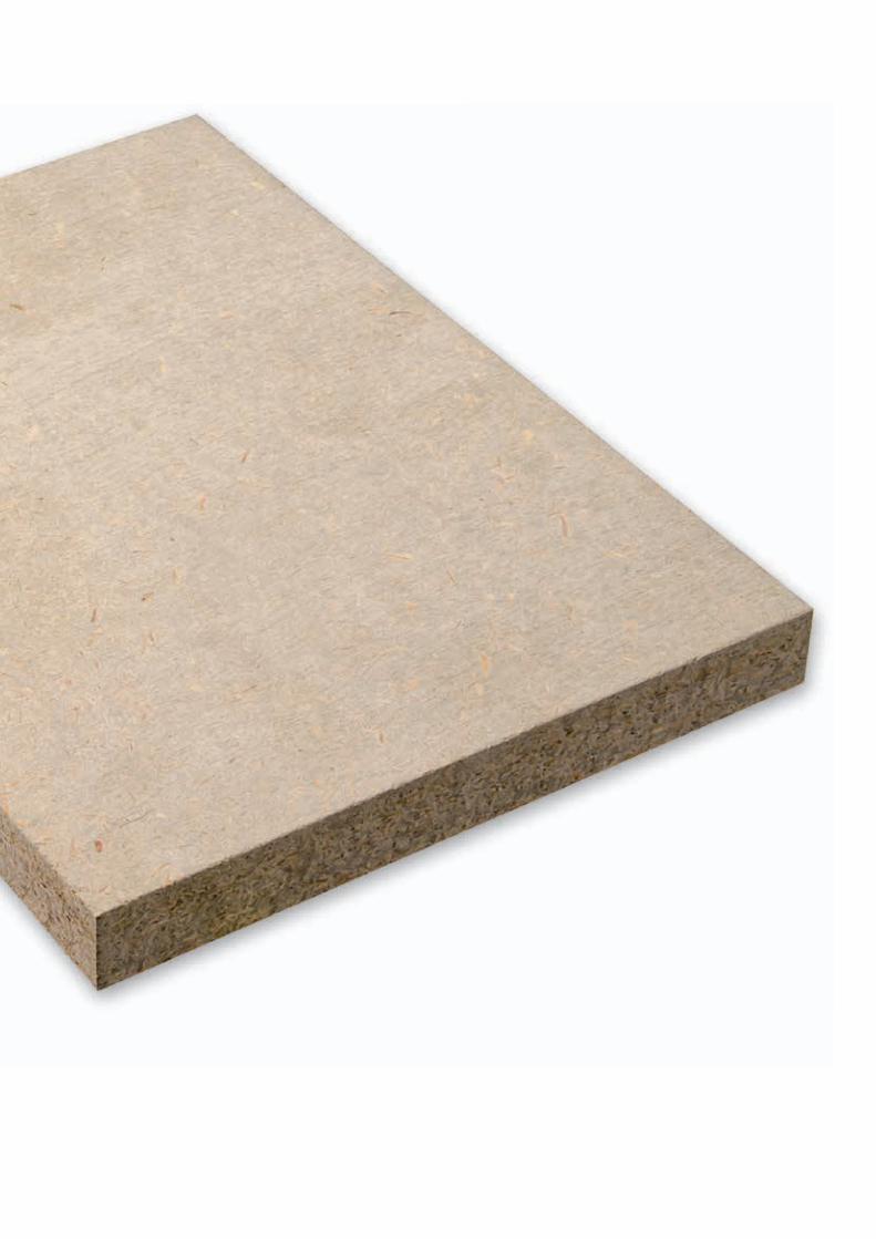
MDF are Medium Density Fibreboards manufactured in com-pliance with European standard EN 622-5. They are applicable particularly in furniture and indoor equipment production. Its spe-cial construction makes it suitable for further fi nishing (milling, lacquering, laminating and foiling).Product line of fi bre boards Kronobuild® includes besides stan-dard MDF also boards with improved fi re properties – MDF B1 and moisture resistance MDF MR and DFP types. These pro-ducts apply particularly in construction applications but also in
furniture and packaging industry. All types of boards are defi ned in European standard EN 622-5 as follows:
MDF MR are boards for load-bearing use in dry and wet condi-tions. MDF MR are manufactured in compliance with EN 622-5 as MDF.HLS type and are defi ned as structural components for use in wet conditions for instantaneous or short-term periods of load only.Boards are particularly suitable for construction applications that require panels with high load bearing capacity and moisture resi-stance and for a wide range of interior and design applications. Boards are very suitable for further processing and painting.
MDF B1 are non load-bearing boards with improved fi re proper-ties and are manufactured in compliance with European stan-dard EN 622-5 where they are defi ned as boards for general use in dry conditions. MDF B1 are increasingly used particularly in public buildings where strict fi re regulations must be met.Boards meet strict requirements regarding the products which include improved fi re resistance and especially the ability not to contribute to fi re spread and not to form burning droplets. Accor-ding to EN 13501-1 boards are classifi ed B-s2, d0 in terms of reac-tion to fi re. Boards are produced red-coloured as standard.
Board type Dry condition Humid condition
Non load-bearing board MDF, MDF B1 -
Load-bearing board -MDF MR,
DFP
3. W
OO
D-BA
SED
FIBR
E bo
ards
MDF

DPF (Diffusion Plate Fasser) are highly diffused open wood-ba-sed fi bre boards for load-bearing use in dry and wet conditions. Boards are manufactured in compliance with European standard EN 622-5 as MDF.RWH type and are defi ned as rigid underlays in roofs and walls. Thanks to its properties as low weight and high vapour permeability the material is suitable for special use in sandwich construction envelopes of wood-framed houses. DFP boards on the exterior side and with OSB boards on the interior side of the wood frame create so-called diffusion-open construc-tion system of building envelope.
single - layered
moisture resistance binder
formaldehyde free glue

25
ADVANTAGES
APPLICATION AREAS
MDF MR MDF B1 DFP
STRUCTURAL APPLICATIONS
Load-bearing cladding of walls or roofs • - •Non load-bearing walls, partitions and ceilings • • •Final lining of walls and ceilings (decorative surface, wall panels) • • •Production of I-joist • - -Shelter constructions • • •Temporary building site fencing • - -Temporary closure of openings in buildings • - •Formwork • - -Cladding in public buildings with increased fire regulations - • -
TECHNICAL AND INDUSTRIAL APPLICATIONS
Exhibitions (display stands, kiosks) • • -Door production with increased fire evaluation - • -Production of containers for building site etc. • - -Production of containers for building site etc. • • -Automotive Industry • • -Packaging industry • - -
FURNITURE APPLICATIONS
Very smooth surface suitable for melamine facing, foiling, lacquering, and HPL / CPL lamination for all furniture production • • -Furniture applications in public buildings (libraries, schools, hospitals, cinemas) usually with increased fire regulations - • -
Special applications requiring increased moisture resistance • - -Production of interior design elements • • -
MDF MR MDF B1 DFP
Production of interior design elements • • •Same strength in all board surface directions • • •Increased resistance to wet conditions • - •Low swelling in thickness • • •Homogenous surface • • •Application in constructions with increased fire regulations - • -Simple processing with conventional wood-working tools • • •Easy fixation using conventional fasteners (screws, nails, staples) • • •Excellent grip of fasteners, also close to the edge • • •Quick installation • • •Suitable for surface applications (melamine facing, foil, veneer, etc...) • • •Excellent price / performance ratio • • •Possibility of recycling • • •
3. W
OO
D-BA
SED
FIBR
E bo
ards
MDF

26
NOTE: The values are valid for moisture content in the materials corresponding to a relative humidity of 65 % and temperature 20 °C.1Option 1 , 2Option 2; Manufacturer must follow one of these options. The table values of strength are not characteristic values for use in the design of framed structures (e.g. according to (EN 1995-1-1).
MDF BOARDS TECHNICAL PRODUCTION SPECIFICATION
GENERAL REQUIREMENTS FOR ALL MDF TYPES
Properties Test Method Requirement
Tolerance on nominal dimensionsThickness (> 9 – 19 mm)
EN 324-1± 0,2 mm
Thickness (> 19 mm) ± 0,3 mmLength and width ± 2 mm, max. ± 5 mm
Tolerance of edge straightnessEN 324-2
1,5 mm/mTolerance of squareness 2 mm/mMoisture content EN 322 4 - 12 %Tolerance of density EN 323 ± 7 %Formaldehyde release EN 120 Class E1 ≤ 8 mg/100 g Content of sand ISO 3340 ≤ 0.5 %
REQUIREMENTS FOR MDF BOARDS FOR GENERAL USE IN DRY CONDITIONS
Properties Test Method UnitThickness (mm, nominal dimension)
> 9 – 12 > 12 - 19 > 19 - 25Bending strength EN 310 N/mm2 22 20 18Module of elasticity in bending EN 310 N/mm2 2500 2200 1900Internal Bond EN 319 N/mm2 0,60 0,55 0,55Swelling in thickness after 24 hours EN 317 % 15 12 10
REQUIREMENTS FOR MDF MR LOAD-BEARING BOARDS FOR USE IN HUMID CONDITIONS (MDF.HLS TYPE)
Properties Test Method UnitThickness (mm, nominal dimension)
> 9 – 12 > 12 - 19 > 19 - 25Density EN 323 kg/m3 ≥ 700 ≥ 700 ≥ 700Bending strength EN 310 N/mm2 32 30 28Module of elasticity in bending EN 310 N/mm2 2800 2700 2600
Internal BondEN 319
N/mm2
0,80 0,75 0,75After boil test 2 EN 1087-1 0,15 0,12 0,12After cyclic test 1 EN 321 0,25 0,20 0,15
Swelling in thickness
After 24 hours EN 317 % 10 8 7After cyclic test 1 EN 321 % 16 15 15
REQUIREMENTS FOR DFP AS RIGID UNDERLAYS IN ROOFS AND WALLS (MDF.RWH TYPE)
Properties Test Method UnitThickness (mm, nominal dimension)
12 - 20Density EN 323 kg/m3 555Bending strength EN 310 N/mm2 18Module of elasticity in bending EN 310 N/mm2 1800
Internal BondEN 319
N/mm2
0,31After boil test 2 EN 1087-1 0,06After cyclic test 1 EN 321 0,15
Swelling in thickness
After 24 hours EN 317 % 8After cyclic test 1 EN 321 % 14
3. W
OO
D-BA
SED
FIBR
E bo
ards
MDF

4. C
EMEN
T-BO
NDED
par
ticle
boar
ds B
eton
yp

29
4. C
EMEN
T-BO
NDED
par
ticle
boar
ds
CEMENT-BONDED particleboards BetonypCement-bonded particleboards Betonyp are manufactured in compliance with European standard EN 634-2. They are produ-ced from pine chips and Portland cement base binding. The boards are bound together under high pressure. Due to its composition the board has a high density and also excellent fi re resistance properties. The basic properties of this board type include improved fi re resistance and especially the ability not to contribute to fi re spread and not to form burning droplets. According to the European classifi cation (EN 13501-1) class B-s1, d0 is achieved.
APPLICATION AREAS
• Facade elements, e.g. exterior façade cladding, false ceilings, interior space dividers• Auxiliary panel elements for lightweight and traditional con-
struction systems, e.g. interior space dividers, ceiling and fl ooring elements, facing panels
• Shutters
ADVANTAGES
• Application in wet conditions and exterior• High abrasion and shock resistance• Moisture-proof and frost-resistance• Fungal and insect resistant• Flame and fi re resistance • Easy processing and fi xation• Extended durability• Free of formaldehyde and asbestos• Recyclable
single - layered board
fl ame resistant
moisture resistant
cement - based binder

BETONYP TECHNICAL AND PRODUCTION SPECIFICATIONS
GENERAL REQUIREMENTS FOR BETONYP BOARDS
Properties Test Method Requirement
Tolerance on nominal dimensions
Thickness ( < 12 mm)
EN 324-1
± 0,7 mmThickness (≥ 12 a < 19 mm) ± 1,0 mmThickness (≥ 15 a < 19 mm) ± 1,2 mmThickness (≥ 19 mm) ± 1,5 mmLength and width ± 5 mm
Tolerance of edge straightnessEN 324-2
1,5 mm/mTolerance of squareness 2 mm/mMoisture content EN 322 6 - 12 %
REQUIREMENTS FOR BETONYP BOARD FOR USE IN DRY, HUMID, AND EXTERNAL CONDITIONS
Properties Test Method UnitThickness (mm, nominal dimension)
All thicknessDensity EN 323 kg/m3 1350 ± 75 mmBending strength EN 310 N/mm2 9Module of elasticity in bending EN 310 N/mm2 class I : 4500, class II: 4000
Internal BondEN 319
N/mm20,5
After cyclic test 1 EN 321 0,3
Internal BondAfter 24 hours EN 317 % 1,5After cyclic test 1 EN 321 % 1,5
4. C
EMEN
T-BO
NDED
par
ticle
boar
ds


5. IN
STRU
CTIO
NS fo
r usin
g th
e lo
ad-b
earin
g bo
ards

33
5. IN
STRU
CTIO
N fo
r usi
ng
INSTRUCTIONS for using the load-bearing boardsfor floors, walls and roofsThis instruction manual gives general rules for using the Kronobuild® boards especially in the load-bearing structures with timber frame as the roof and floor sheathing on joists or wall cladding on studs.
Kronobuild® load-bearing boards include:• raw particleboard P5, P6 and QSB type• raw OSB Superfinish OSB/2, OSB/3 and OSB/4 type • OSB Firestop ECO type• sheathed boards OSB Airstop ECO, OSB Reflex ECO and OSB Ply• raw MDF boards MDF MR and DFP• Betonyp
The instructions can be used even for the non load-bearing Kro-nobuild® boards to which similar rules relating to the storage, hu-midity conditions and processing apply. These boards cannot be considered for load transfer in structures with timber frame.
The procedures stated in this chapter are based on the manu-facturer‘s own experience and are in full compliance with the recommendation stated in TS 12872:2007 and with the documen-tation of The European Panel Federation (EPF). As a guide you can also use European technical specification CEN/TS 12872:2007- Wood-based panels - Guidance on the use of load-bearing boards in floors, walls and roofs and also the in-formation presented on www.europanels.org.
TRANSPORT AND STORAGE
Proper transport and handling, stacking and storage is essential for trouble-free use of wood-based boards.Properties of the boards are not significantly different from the solid wood at which the moisture content changes with tempe-rature and relative humidity environment of the surrounding en-vironment. Dimensional changes (length, width and thickness) are dependent on changes in the moisture content. Therefore, it is important that the moisture of boards during storage is close to the balanced moisture of boards corresponding with environ-ment in which they will be subsequently assembled and used. Improper storage and wrong handling can lead to the devaluati-on of the boards.
• Packaging - StackingThe boards come in packages, fastened with tape. Every pac-kage is fitted with inserts fixed to the boards with a plastic tape. Board packages must always be stacked horizontally on a flat surface.
• Transport During transport the boards must be protected from direct expo-sure to water. The edges must be especially protected against rain or accidental soaking. The panels are slippery and should be fastened adequately to avoid movement during transporta- tion. The boards must be appropriately protected against damage with fastening ropes, belts or others. This particularly applies to tongue-and-groove panels.
• ManipulationWhen handling the board package it is recommended to use forklift truck rather than crane. During any handling of boards it is necessary to avoid damage to surfaces and especially edges with forks of the handling device or with the supporting ropes.
• Storage and stacking during reloadingThe boards must be stored in closed, dry and well ventilated buil-dings to avoid excessive moisture, which can cause warping or
buckling of the boards. Store the boards constantly lying down on a level and rigid base, this will prevent bending and twisting. Store the boards so the entire surface lays on each other with flush-fitting edges. The underlying spacers must be oriented in the direction of shorter edges of the boards (minor axis) with a maximum spacing of 600 mm. The length of underlying spacers must match the width of the boards. Insert a spacer after each twentieth to twenty-fifth board for perfect ventilation. The individu-al interlacing spacers must be placed exactly above each other. The upper board of the stack must be covered.
• Short period storage on construction siteIn case of temporary external storage the boards must be sto-red on elevated pallets or on tall bases to avoid contact with the ground, water or vegetation and at the same time it should be covered with waterproof but air permeable canvas allowing diff- use ventilation and air circulation under the boards and on their sides. The external storage of boards is recommended only for a necessary short period. It is not recommended to store the boards in a vertical position. This is possible only for a very short period of time (e.g. for conditioning the boards prior to installa-tion). In such case the boards should not be leaning against the walls. The best way is to create a base (rack) with general support at the bottom and back from the panel of a minimum thickness of 18 mm (image 2).If the boards were exposed to sunlight, the ultraviolet radiation could cause colour changes. This also applies to panels, which were in-stalled as part of decoration. Surface colour changes caused by the solar radiation do not affect the technical properties of boards.

34
MOISTURE CONTENT, CONDI- TIONING AND MOISTURE EFFECT
Moisture contentAbsolute moisture of wood and wood-based panels varies de-pending on the wet conditions of the surrounding environment and it is affected primarily on the temperature and relative hu-midity (RH) of the surrounding air. The moisture content is con-stantly changing in order to achieve equilibrium moisture content (EMC) with its surroundings.
The graph shows dependencies of the coniferous wood moistu-re on the relative humidity and ambient temperature:- In the green field the equilibrium mass moisture of wood in con-struction corresponds to the service class 1.- In the yellow and blue field the equilibrium mass moisture of wood in construction corresponds to the service class 2. In the yellow field the wood should not be dry rotted.- In the red field the equilibrium mass moisture of wood in con-struction corresponds to the service class 3 (e.g. unprotected exterior conditions).
• Equilibrium moisture content (EMC) For wood-based boards it is not possible to determine exact moist- ure content due to continuous balancing the surrounding en- vironment. Generally it can be assumed as moisture of boards in various conditions of use – see table 1.
• The output moistureThe boards immediately after their production have very low moisture, sometimes close to 2%. The output moisture from the production ranges from 4% to 7%. The moisture of boards during storage gradually increases to cope with the environment. It means boards delivered to the site for mounting immediately after their productions may have much lower moisture than the moisture in building construction or in the environment during construction works. This fact must always be kept in mind, and all other processes adapt to this!
Effect of moisture on the dimensional changes of the boardsWood and wood-based panels expand on taking up moisture from surrounding air, and shrink on losing moisture.Excessive changes in moisture content of the boards can lead to unacceptable dimensional changes which can cause bowing, buckling or open joists between panels.
The moisture changes of boards may be due to changes in the relative humidity of air, undesired soaking during rain, accidental wetting but also insufficient conditioning prior to installation. The boards must be protected against all these influences causing moisture changes. Installing the boards should always take place after conditioning with the environment. Problems can also arise if sufficient protection during storage on the construction site or conditioning is not provided. Typical signs are swelling of panel edges due to the accession of mois-ture on exposed board edges or local swelling of boards due to absorption of moisture from materials with higher moisture the boards are in contact with, e.g. undried wooden beams. Any increase in humidity causes mild expansion of the boards. The extent of moisture changes of the boards depend on the type of boards and their material composition therefore they are also different for the length, width and thickness of boards. The values listed in table 2 can be used for basic overview of moisture dimensional expansion and shrinkage of boards on the basis of changes in their volumetric moisture. As a quick reference guide for changes in relative air humidity the values of coefficient of moisture expansion can be used for the determination of moisture expansion in length and width:
α = 0,003 – 0,0035 [% / %] – for OSB, PB and MDF α = 0,005 [% / %] – for Betonyp i.e. x% expansion/shrinkage in length/width of the board at 1% changes in relative humidity RH of the ambient air.
The value is valid for RH between 35 % - 85 % and 20 °C.
Example: If there is a change of RH of the air in the interior from very dry (40%) to very humid (75 %) at the same temperature of 20 °C, there will be a gradual extension of the boards by approxi-mately 1 mm/1m of the board (α =0,0035).
ABS
OLU
TE M
OIS
TURE
CO
NTE
NT
OF
WO
OD
[%]
RELA
TIVE
AIR
HU
MID
ITY
[%]
TEMPERATURE [oC]
5. IN
STRU
CTIO
N fo
r usi
ng
Moi
stur
e co
nten
t, co
nditio
ning

35
Service class
Normal range of relative humidity (RH) at 20 °C
Approximate equilibrium moisture content (EMC) Conditions of use
1 30 % - 65 % 4 % -11 % - Installation in conditions of dry interior - No risk of boards taking moisture during usage
2 65 % - 85 % 11 %- 17 %- Potential risks of taking wetting during installation- There is a risk the occasional taking moisture during usage (note.: taking moisture by exposure to the high relative air humidity)
3 > 85 % > 17 %- Potential taking moisture or getting rained on during installation - Potential risks of frequent taking moisture during usage - Possible to re-dry after being rained on
Type of board Dimensional change (expansion/shrinkage) at 1% change in board moisture content
Length % Width % Thickness %
PB acc. EN 312PB type P2, P6 and FireBoard 0,05 0,05 0,7PB type P3 and P5 0,03 0,04 0,5
OSB acc. EN 300 type OSB/1 and OSB/2 0,03 0,04 0,7type OSB/3 and OSB/4 0,02 0,03 0,5
MDF acc. EN 622-5 MDF, MFD B1 0,05 0,05 0,7MDF MR a DFP 0,03 0,03 0,5
Betonyp acc. EN 634-2 Betonyp 0,05 0,05 0,4
Table 1- Equilibrium moisture content of the panels relative to their terms of intended use
Table 2 – Possible dimensional changes in change of the volume moisture of the boards by 1%
ConditioningSo called conditioning of boards should precede construction as-sembly to reduce dimensional changes. Conditioning of boards serves to balance the moisture with its environment for at least 48 hours in the thermal-humidity condition which corresponds to those of their future use. Boards can be conditioned by loose laying (for example on the floor) on the underlying battens or by alignment to each other (vertically/horizontally) with crossbars so the air can constantly circulate between them. Image 3 shows a suitable way of condi-tioning with battens. Boards left in the protective packaging from the manufacturer cannot be adequately conditioned! Optimal conditioning time varies depending on environmental conditions. The minimum required time of 48 hours conditioning may not be sufficient, recommended conditioning time is 1 week, in specific cases may be even longer.
Installation conditions Approximate moisture of material
Building with continuous heating 6 – 9% Building with occasional heating 9 – 10% Unheated building 16 – 18%
Image 3
5. IN
STRU
CTIO
N fo
r usi
ng
Moi
stur
e co
nten
t, co
nditio
ning

36
MARKING OF BOARDS AND IN-SPECTION AT THE BUILDING SITE
Kronobuild® products are delivered in individual packages (see previous chapter). Every package bears a label. The individual boards are also marked with a stamp- on the edge (board with straight edge) or - on the bottom surface (boards with tongue and groove). Part of product labeling is a precisely defi ned information regard-ing the CE marking of construction products destined for sale within the EEA, followed by other relevant facts about their manu-facture (date, time, etc.). Tongue and groove boards are labeled with „This side down“. This sign indicates the correct orientation for boards installation, shows the reverse side of the boards with a visible dilatation gap of 1 mm after the boards removal.
Image.4
Before using the boards (in the manufacture of prefabricated wood panels, on site, etc.) we recommend to check the boards, i.e. the compliance of boards and its documentation with the requirements in manufacturing or design documents for their intended use. The inspection should cover these issues in the minimum: - type of boards according to the relevant EN standards – thickness of boards - type of edge – straight edge, tongue+ groove - surface – sanded, unsanded- service class - main load-bearing direction, i.e. main axis (only OSB boards).
We also recommend doing visual inspection of the packaging for its damage which would cause more diffi cult board assembly (e.g. damage of edges, tongue and groove). Part of preinstallation inspection should also be checking of pro-per storage and protection of boards against direct rain, sprink-ling by water, sun and other weather infl uences. Complaints of fl awed boards caused by improper storage, in-stallation and exposure to excessive water and moisture cannot be recognized.
CUTTING, DRILLING, FIXING
CUTTING, DRILLING AND MACHINING
Boards can be machined with common procedures suitable for solid timber processing.The use of cutting or drilling tools with hard metal edges is more suitable. All cutting tools should be kept sharp. The feeding rate of electric cutting and drilling tools should be slightly lower than with solid timber. The quality of the machined surface of boards decreases with increasing moisture of boards. When a very small tolerance is needed, boards should be cut to size after conditioning to the moisture content appropriate to the end use. • Cutting All panels can be cut with common hand tools. Cutting with port-able electrical power tools is possible without problems. For fas-ter and more precise cutting it is suitable to use table circular instruments. Circular saws should be set as low as possible to avoid loss of chips and creating a saw-cuts – see image. The boards should be oriented when cutting in such direction that the saw blade cuts fi rst the visual upper or decorative layer as shown in the image below. The boards shift depends on the used instrument, generally could be recommended values slight-ly lower than in the processing of solid wood. The boards should be fi xed so they cannot vibrate.
Image 5 - Hand-held circular saw cutting:Image 6 - Using table circular saw:
1 – saw support2 – the direction of rotation of the saw blade3 – upper or decorated face 4 – the shift direction of boards (feed)
• Drilling Drilling should be performed with drill bits designated for drilling wood.
1 2 3
34
1 2 3
34
5. IN
STRU
CTIO
N fo
r usi
ng
Mar
king
boa
rds,
cut
ting

37
FIXING BOARDS TO THE UNDERLAYER
Boards can be mechanically attached using nails, wood screws, staples or glued. Attaching is the same as for solid wood. Corro-sion resistant fasteners should be used for load-bearing structu-res. For statically stressed wooden structures there must always be taken into account design rules for boards fixing specified in the relevant design standards (valid EN 1995-1-1, or in DIN 1052:2004). The rules should be included in the project docu-mentation. If the information is not listed, then the following reco-mmendations can be used. • Nails • When mounting the boards the priority should be given to
spiral, convex, ring, nails with threaded ends or grooved nails which possess greater pull-out resistance. Nails with a smooth shank are less suitable.
• Minimum nail length should be 2,5 times the board thickness or 50 mm, whichever is greater.
• The minimum diameter of the nail should be 0,16x the board thickness, but not less than 3 mm.
• Wood screws • The wood screws should be with countersunk head, may be
self-tapping or self-drilling types. • Minimum screw length should be 2,5 times the board
thickness or 45 mm whichever is greater. • The minimum diameter of the screw shank 4,2 mm. • For fixing to steel supporting structure it is possible to use self-
-tapping screws or other appropriate fasteners in accordance with the manufacturer’s instructions.
• StaplesRecommended principles of stapling the boards where staples make joints of boards used as wall panels bracing effecting ho-rizontal load: • minimum wire diameter of staples is 1,5 mm, length 50 mm
and width 11 mm • staples spacing min. 30 mm• staples at an angle to the strand direction, at least at an angle
of 30°
Image 7: Nails and staples for board fixation
• Adhesives Permanently flexible adhesives are suitable e.g. based on poly-urethane. It is necessary to ask the manufacturer for suitable type and procedure of bonding. The manufacturer must have appro-priate authorization.
5. IN
STRU
CTIO
N fo
r usi
ng
Cut
ting,
dril
ling,
fixin
g

38
JOINING THE BOARDS – EDGES
Boards are available in two basic formats of edges: • straight edge – without labeling or with labeling S.E. • tongue and grooveTongue and groove boards may be milled along all 4 sides mar-ked as 4T+G (or 4N+F) or only along two longitudinal edges mar-ked as 2T+G (or 2N+F). • Dilatation gaps Because of potential dimensional changes of boards arising mainly due to changing humidity of surrounding environment it is needed to incorporate expansion gaps between the boards to avoid buckling of boards or other undesirable states during the time of the use. We distinguish two basic cases when laying the boards:• boards with straight edges where we leave gap of minimum 2-3 mm between individual boards • panels with milled edges (tongue and groove), that create dila-tation gap automatically - 1 mm
Image 8
• Corrosion resistance of fastener elementsCorrosion resistant fasteners shall be used for attaching boards for use in service class 2 (humid condition) and higher. Corrosi-on-resistant materials include galvanized steel, hot-dip galvani-zing, austenitic stainless steel or bronze alloys. A poorly protec-ted element attacked by corrosion may lose its function after a very short period of time, even after several months, so an im-portant requirement is the level of corrosion resistance. It can be obtained by the load test in aggressive atmosphere according to DIN 50018, so called Kesternich cycle. Fastener elements protec-ted by a weak galvanizing (1-2 Kesternich cycles) are not suitable for use in the construction of the outer part of building envelopes where increased humidity can be expected. Table of resistance of various kinds of anti-corrosion treatment:
It is recommended to choose fastening elements made of non--magnetic austenitic stainless steels for all buildings with relative indoor humidity greater than 70% and building projects with gre-ater corrosion of internal environment (such as food, chemical, metallurgical plants, swimming pools, etc.).
• FixingCommon hand tools, portable electric tools, pneumatic scoring gun, etc. can be used for mounting. Proper adjustment of scoring device is especially important for accurate countersunk nails and staples into boards. Subbase wood should be of a maximum moisture weight of 15%. Fasteners should be countersunk by 2-3 mm below the board surface, not to interfere with other building processes such as e.g. floor coverings. It is convenient to pre-drill holes when using stronger countersunk screws or using self-drilling screws especi-ally with thicker boards. The following table can be used for the frequency of fasteners.
When the fixing forms are essential part of the design, the cha-racteristic load-carrying capacities and deformation characteri-stic for design of joints can by found by calculation of design standards (e.g. EN 1995-1-1) and project documentation.
Anticorrosion treatment Anticorrosive layer thickness
Number of Kester-nich cycles (SO2)
Galvanizing (yellow zinc) 3 – 7 μm 1Galvanizing (yellow zinc) 10 – 15 μm 2Hot-dip galvanizing 35 – 45 μm 6 – 8Special protection technologies 15 and more
Maximum faste-ner spacing
Centres at the perimeter of the boards
a = 150 mm (75 mm for staples)
Centres of intermediate supports of the boards
b = 300 mm (150 mm for staples)
Minimum faste-ner spacing from the edge of the board
Distance from the edge of the board
c = 10 mm (20 mm for staples)
Distance from the corner of the board d = 25 mm
5. IN
STRU
CTIO
N fo
r usi
ng
Cut
ting,
dril
ling,
fixin
g

39
• Panels with straight edgesBoards with straight edges need 2-3 mm dilatation gap at the edges of the boards for possible moisture expansion. To prevent bending or excessive gaps all edges should be supported by beams or by noggings.
Image 9
• Tongue and groove panels Panels with tongue and groove profile do not require any additio-nal auxiliary support, boards may interact. All tongue and groove joints should be glued with suitable adhesive e.g. polyurethane base or PVAC-D3, to prevent creaking and increase rigidity in use.
Image 10
CONNECTING PANELS - ACROSS THE BOARD (AREAL)
We can connect more panels for floor construction where we need to provide higher load-bearing capacity and more even lo-ad-bearing distribution. Boards may be on base or on flat support (e.g. floating floors). It is possible to use screws, staples, or glue for connecting boards. Using nails is less suitable.
• Screws Screws apply for the same conditions on type and dimensions as for connecting boards to the base. Creating a grid of screws at a distance of 300 mm is the recommended connection of boards. The advantage of screwing is easy mounting and disassembly of floor. The disadvantage is the increased work amount at large--area construction.
Image 11- Assembly of multiple layer boards e.g. for floating floors.
• Staples Stapling is a highly effective and fast way of connecting panels. Special clips with the saw cut are used for stapling which unfold after having been shot into the board and thus avoiding any possible extraction. Recommended type is e.g. staples Haubold KG 700 with special sharpening tips type CDNK. The dimen-sions of staples KG 700: wire diameter 1,53 mm, staple width 11,25 mm, length 18-50 mm according to connection board thickness:
Image12: Example of twisted staple after removing OSB board into which it was shot. Left: Specially treated staple tips. Right : Example of twisted staple after removing OSB board into which it was shot
Connection boards thickness Type / staple length in mm
10mm + 12mm KG 700 / 18 CDNK geh
12mm + 12mm KG 700 / 22 CDNK geh
15mm + 15mm KG 700 / 25 CDNK geh
18mm + 18mm KG 700 / 35 CDNK geh
5. IN
STRU
CTIO
N fo
r usi
ng
Cut
ting,
dril
ling,
fixin
g

• AdhesivesPermanently elastic adhesives based on polyurethane or silane are suitable. It is recommended to connect only particleboard and OSB boards. Sanded boards are more suitable for gluing. For the unsanded particleboards and OSB it is convenient to sli-ghtly sand the surfaces in order to disrupt hydrophobic surface and to increase the glue adhesion. The base board should be healthy, strong and dry, free of loose and crumbly particles, free of oil and dirt. All dust and loose particles must be completely mechanically removed. Gluing boards is possible in two ways:• Applying the adhesive on the bottom board with notched trowel across the surface • By creating longitudinal lines so called gluing „on-bead“ (image below). The adhesive is applied with a gun, „on-bead“ spaced 120 to 150 mm. Gluing is suitable for floors where the upper board is also the sur-face layer and therefore visible screws or pins are not desirable
Image13: Gluing OSB boards with gun
SURFACE TREATMENT AND COATING
It is recommended to use sanded boards for visible interior sur-faces with coating. You can use normal transparent or decorative wood coatings. We recommend to perform so called test painting because it can lead to intolerance to substances contained in the wood. Generally, it is necessary to follow instructions and regula-tions of the paint producers.Some chips can be released from the surface of boards during the coating application or immediately after the application, in the case of the water-soluble materials it can lead to partial swelling of chips. No products claims can be made in this respect.
WATER AND MOISTURE PROTECTION
Boards must always be secured against direct effects of water, both in storage and during construction works. These boards should be adequately protected against adverse weather condi-tions immediately after mounting on the outside of the building, on the walls and on the roof. For boards, that are exposed to inc-reased moisture absorption longer, the borders may slightly swell especially at the edges of panels. In this case it is necessary to evenly grind the edges of boards to ensure a flat surface before installation of finishing elements such as asphalt shingles for the roof, etc.

41
INSTALLATION – GENERAL CONSTRUCTION PRINCIPLES
STRUCTURAL FLOOR DECKING AND FLOORING
• Structural floor decking (subfloor)For structural floor decking on joists can be uses only load-bea-ring Kronobuild® boards. The board type is dependent upon the required extent of load, type of load and on the class of board use (service class 1 or 2). Board thickness can be determined by static calculation or more easily from the tables depending on the size of load and from support distances. Tables for preliminary dimensions are listed in chapter Bearing capacity and stability.
Basic installation requirements:• All supports (joists, noggings, corner supports) must be leve-
led to a single horizontal level. • Increasing local moisture in Kronobuild® boards from other
materials the boards may be in touch with must be eliminated.• All wooden supporting elements must be dry or dried out to
moisture content similar to humidity conditions in which the structure will be used.
• Axial distance of supports should be selected in relation to the board dimensions to reduce potential wastage. For the 2500 mm boards the suitable distances are 500, 625, 833 mm.
• The short edge joints of panels should be staggered (see Image 14 and 15).
• OSB boards must always be laid so that a higher strength of boards (main axis, the longitudinal direction boards) is in the direction perpendicular to the joists.
• Along the perimeter of the walls and other vertical pervading constructions dilatation gap of at least 15 mm must be main-tained for potential movement of boards.
• Straight edge boards can be used. Using of tongue and groo-ve boards is more suitable.
• Boards with a straight edge laid on a supporting beam with expansion gaps 2-3 mm apart (depending on the board size). It is necessary to support all board edges.
• Tongue and groove boards must be laid so that all shorter ed-ges are supported by joist. T+G joints shall be glued for higher rigidity (e.g. PVAC D3, polyurethane etc.). It is necessary to support all cut edges.
• Structural flooringFor floor constructions where the load is transferred from the boards to the joist can generally be applied the same principles as for the mounting of the load-bearing floor decking. To reduce the impact sound transmission an additional sound insulation la-yer should be installed on the joists (soft fiberboard, rubber belt, etc.).
• Floating floor constructions Construction of floating floor is made of a board with tongue and groove profiling and with thickness 25 mm or better two boards of thickness 18 mm. Distribution layer consisting of one layer is suitable for floors without high demands on dimensional stability or it is not supposed to concentrate the load over tongue and groove joint. In other cases, it is necessary to use a two-layer or multiple-layer floor composition.
Basic installation requirements: • Dry and flat subfloor is essential.• Boards are placed loosely on impact sound insulation (hard
boards from mineral wool or polystyrene, designed for floor constructions).
• Individual board layers are connected by screwing, stapling or gluing.
• Type of floor covering related to type of board
Kronobuild® boards are manufactured as boards with low thickness tolerance. Therefore they are suitable as an underlay-ment for classic parquet, laminate flooring Krono Original, carpet, linoleum, etc.For very thin floor coverings, linoleum, vinyl and carpets it is advi-sable to use sanded boards with very smooth surface (PB P3 etc.).It is possible to make floor without further floor covering. The Kro-nobuild® boards are suitable as floor covering (e.g. OSB) coated only by floor lacquers.
Board thickness for floors in residential and office rooms for load-bearing of 2,0 - 2,5 kN/m2 (up to 250 kg/m2):
Panel TypeLoad-bearing floors on beams
Floating floors On load-bearing bases500 625 833 1000
P3 - - - - ≥ 12 mm
P5, QSB, P6 ≥ 18 mm ≥ 22 mm ≥ 25 mm - 2 x ≥15 mm,or 25 mm ≥ 12 mm
OSB/3 ≥ 15 mm ≥ 18 mm ≥ 22 mm ≥ 25 mm 2 x ≥15 mm,or 22 mm ≥ 12 mm
OSB/4 15 mm ≥ 15 mm ≥ 18 mm ≥ 22 mm 2 x ≥15 mm,or 22 mm ≥ 12 mm
Betonyp 2 x ≥12 mm ≥ 12 mm
5. IN
STRU
CTIO
N fo
r usi
ng
Inst
alla
tion

42
Image 14: The tongued and grooved structural decking laid across the joists with short edged supported joists
Image 15: Straight edged structural decking laid across the joists and supported by noggings.
5. IN
STRU
CTIO
N fo
r usi
ng
Inst
alla
tion

43
STRUCTURAL WALL SHEATHING AND INTERNAL LINING
• Structural wall sheathing It is possible to use only load-bearing Kronobuild® boards for structural wall sheathing on the studs. Board type is determined by load-bearing characteristic, the centre to centre span and application class of use (service class 1 or 2).
• All wood structural studs and supporting elements must be dry or dried out to moisture content approaching the humidity conditions of intended use.
• Boards can be mounted vertically or horizontally on the wall. In the case of load-bearing walls boards running integrally along the entire height of the walls are preferable in order to facilitate structural design and assembly of the boards.
• When installing horizontally all edges should be supported by and fixed to a framing member.
• In timber-framed structures sheathing boards may be installed on one or on both sides of the framing. When applied to exte-rior walls, sheathing boards may be installed to the outside of the framing or internally to the frame.
• The minimum board thickness of 12 mm is recommended for distances of columns 400-625mm. In other cases the applied
rule is: span of supports in mm / 50 = board thickness, in mm.• Expansion gap between the bottom frame and concrete base
should be at least 25 mm to avoid possible water absorpti-on. Expansion gap can be created by fitting the entire wood structure on the shims and filling the gap under load-bearing wood frame with cement mortar. If you place the frame directly on the base, it is necessary to chemically protect and to lift the boards at least 25 mm above the base level (see detail bellow).
• Internal lining Before installing the MDF and Betonyp boards as internal lining it may be necessary to apply a pre-finish with appropriate primers.
Image. Wall installation form boards vertically on the pillars
5. IN
STRU
CTIO
N fo
r usi
ng
Inst
alla
tion

44
STRUCTURAL ROOF DECKING
Only load-bearing Kronobuild® boards may be used for structural roof decking. Board type depends on the required load-bearing characteristics, centre to centre span and application class of the board use (service class 2).
• Basic installation requirements:• Roof structural elements of timber and wood-based panels
should not be exposed to weather conditions more than it is necessary. Boards must be protected against rain and acci-dental soaking. Boards, which came into contact with water (e.g. limited rain), must be dried out again before laying of roof covering.
• Before installing the boards make sure the supporting rafters, joists and noggings are laid to line and leveled. Curved or uneven rafters affect the finished roof appearance.
• The short edge joints of boards should be staggered (see Image 14 and 15).
• The panels should be installed with their long edges across the rafters with short edges supported on rafters. The distan-ce between the rafters preferably should be 833 or 625 mm.
• When different or higher than 833 mm an additional structure of roof battens with a width of 80 to 100 mm should be used to avoid sagging. When installing these longitudinally every 417 or 625 mm, a reduction of the board thickness might be possible depending on the level of loading that is anticipated.
• The panels may be square edged or profiled, same as at the instructions for floors, but the following recommendations should be noted.
• Boards with straight edge should be laid on load-bearing jo-ists with expansion gaps of at least 3mm apart (depending on the board size). It is necessary to support all edges of the boards.
• Boards tongue and groove should be laid so all the shorter edges are supported by joist or rafters. Tongue and groove joints should be glued with adhesives to improve rigidity (e.g. PVAC D3, PU etc.). All cut edges must be supported.
• Cold roof deckingThe boards used as cold roof decking are on the external side roof structures. Cold roof decking of flat or pitched roofs is load--bearing underlayment for roof covering as asphalt strips, water-proof foil, asphalt shingles, metal roofing, etc. A sufficient ventila-ted air space should be always left under the boards to eliminate the risk of harmful vapor condensation occurring within the roof construction.
• Warm roof deckingThe boards used as warm roof decking are in roof structures on the interior side of thermal insulation. In addition to load-bearing properties the boards may perform more then one function. Then all edges must be protected (self-adhesive tapes, glues in ton-gue and grooves etc.).
Safety:Boards as OSB are made from thin veneer strands that are bon-ded together with a synthetic resin. This offers a remarkably smo-oth surface but might also be slippery, especially when wet or co-vered with sawdust. Installers therefore should follow accurately all applicable safety regulations.
5. IN
STRU
CTIO
N fo
r usi
ng
Inst
alla
tion


6. B
UILD
ING
PH
YSIC
S re
quire
men
ts

47
ESSENTIAL REQUIREMENTS FOR WOODEN HOUSES
When designing and constructing buildings always take into account all known current and future demands that will be im-posed on them during their lifespan. The current minimum requi-rements for buildings are set by the basic regulation of the Eu-ropean Union (Construction product directive-CPD) which mainly addresses the protection and safety of users during the entire time of the building usage. Among the basic requirements the protection of the building itself must also be included. The greatest challenge is placed on the external envelope of a building, which is the area where the conditioned internal air is separated from the unconditioned outside air. The external enve-lope of a building consists of the vertical exterior walls and the roof. The main demands include:• mechanical resistance and stability (load-bearing capacity)• energy economy and heat retention • climatic infl uences protection• moisture protection • airtightness• fi re safety• noise protection• hygiene, health and environment
• Static load-bearing capacity signifi cantly infl uences the entire stability of the building. It is critical for its durability and long lifespan. Modern buildings with wood are not limited only to imitations of historic buildings but correspond to current thinking and behaviour. In wood buildings modern-effective solutions with regard to the composition and ar-rangement of coat layers can be used. Light skeleton structures are used with the timber studs (or joists) posted relatively close together and fi xed to the upper and bottom threshold to form a wooden frame. Stabilisation (spacial rigidity) of the frame is pro-vided with reinforcing board material with the required load-bea-ring capacity where Kronobuild® boards are very suitable to use.
• Energy savings and heat protection Thermal insulating materials situated in the building envelopes are used to prevent heat loss, to prevent freezing in winter and excessive heat gain in summer. Suffi cient, well-designed and im-plemented thermal insulation contributes to a pleasant indoor cli-mate and avoids possible side condensation and mold formation on the inner surface of the envelopes. Well-insulated buildings are more energy effi cient (greener), excluding cost, also reduce energy consumption and CO2 pro-duction, which is also an EU goal. In directive 2010/31/ES on the energy performance of buildings it is determined the intention to build the new buildings as buildings with almost zero energy spendings from the end of 2020. Jump in the design and im-plementation of so called zero-energy houses (very similar to passive houses) is large in relation to the construction of the cu-rrent EU building. It is necessary to develop new technologies and products that will be able to meet the new requirements.
6. B
UILD
ING
PH
YSIC
S re
quire
men
ts
BUILDING PHYSICS requirements
• Climatic infl uences protection is provided with roof covering and facade cladding. In terms of building physics the best cladding is ventilated or aerated for im-proved dry out of the whole construction. Air distribution minimi-ses possible humidity inside the construction. Other common so-lutions are plastered façades, either aerated or compact (ETICS), and timber façades, ventilated or non-ventilated.
• Moisture protection is one of the essential demands on timber constructions. The aim is to reduce moisture as much as possible to avoid malfunc-tions throughout the lifetime.Moisture can be caused by: • atmospheric precipitation - see weather protection • building moisture (wet construction processes and the mois-
ture contained in building materials)• water vapour diffusion and moist air fl ow (convection) – see
below• surface condensation – e.g. thermal bridges at the penetrati-
on of steel structures• capillary transfer (for structures in contact with the ground, spraying
water, solid building elements - concrete foundation, wet masonry).
• AirtightnessAirtightness of the building envelope from the room is very im-portant. Local air permeability (leakage especially from the room) can lead to moisture faults due to possible penetration of moist air from the room into the building structure. These leaks and drafts associated with it may affect the thermal comfort and lead to increased energy consumption.
• Fire safetyFire protection is necessary to ensure the safe load-bearing ca-pacity of the building. Fire protection must have high priority in designing the structural design and planning of individual ele-ments and connections. There are distinguished two basic pa-rameters set for structural material, i.e. the burning behaviour of the material (as set out in the EU class of reaction to fi re) and the parameters design as a whole, especially where the fi re resistan-ce of the structure is evaluated.
Image 1: Main infl uences on the building’s exterior and interior

• Noise protectionAcoustic properties of structures are necessary for ensuring the quality of the indoor environment. It helps protection from radiated noise from the outside and from the noise from other rooms inside the building. The decisive factor is the location of the sound source. If the source is in direct contact with the solid material (structures) we talk about impact sound insulation Lnw (for ceiling and floors only), If it is not direct contact we are talking about airborne sound insulation Rw. The airborne sound insulati-on is better the bigger is its value, on the other hand, the impact sound insulation is better the lower its value is.Assessment of the acoustic properties and fire resistance of the structure always refers to particular structure as a whole. Optimi-zation is performed as suitable composition and choice of ma-terials, the right solution of joints and connections, and further knowledge within the implementation. More can be found in the following chapters and in examples of design in compositions with a wood frame where they are always mentioned together with their construction engineering parameters.
• Health safety and environmentNowadays people spend more than 90% of their life indoors. In-terior quality and environment is therefore of a great importance to the quality of healthy living conditions for building users. Cho-osing the right Kronobuild® boards can contribute to a healthier environment and thus greater air quality in buildings, especially the emission of free formaldehyde and VOC substances released from wood and wood-based products.
CONSTRUCTION WITH TIMBER FRAME
Structural system based on the timber frame is currently the most used modern wood house. The load-bearing structure consists of bar load-bearing elements forming the frame, and load-bearing sheathing which stabilizes the frame. Bar elements (studs, joists, rafters) transmit main vertical load from the roof and from indivi-dual floors, their casing made of wood-based panels transfers flat vertical load and also the horizontal loads resulting from wind effects and reinforcing forces.
• Construction structure and cladding composition The cladding composition is performed differently according to heating technology requirements and types of used layers. There are various ways of construction. Load-bearing walls can be con-structed of studs of dimension 60/120 mm. Currently, however, higher demands are imposed for thermal insulation than is 120 mm, determined by the dimensions of the pillars. This leads to using the studs of dimensions 60/160 or higher, alternatively the thermal insulation is carried out in two basic levels, initially be-tween the studs and then as outdoor cladding. Structural wall sheathing of timbe frame structure formed from wood-based panels is placed from external or internal side of the studs. For optimal securing of symmetric transferring of horizontal loads the wooden frame should be sheathed from both sides. Tmber frame with wood-based panel sheathing and thermal insulation between the pillar elements form the basic structural element of modern wooden houses which is gradually complemented by additional layers to secure all specified requirements imposed on the entire construction.

49
Information table using the various types of boards to determine the functional layer. It does not mean it is always possible to replace one material by another. Everything depends on the structural compositions, use of particular system, etc.
● – Appropriate use, ○ – possible use in certain casesh.1 – Boards with use only in moisture class 2 (see chapter – climatic influences protection). 2 – Surface treatment with painting, varnishing, laminating, etc. as appropriate for the type of board.
• Layers divided in terms of their function Most of the construction material is not able to completely fulfill all the functions relating to the above stated construction require-ments. Therefore it is composed from various types of materials which can be divided into individual layers according to their re-quired function. Order of layers is determined by building physi-cal rules - Image 2:
Image 2: 1a) Weather protection - external walls cladding, 1b) Weather protection – roof covering, 2 - Venting – roofs, external cladding , 3 - Protective layer of insulation – windproof layer, 4a) External load-bearing wall sheathing of the timber frame , 4b) External load-bearing roof decking of the timber frame, 5 - Thermal insulation among elements of load-bearing timber frame, 6 - Internal load-bearing she-athing of the timber frame, 7 - Water vapour control layer (VCL), 8 - Main airtight layer, 9 - Installation gap , 10 - Internal lining of walls and ceilings, 11 - Internal load-bearing floor decking and flooring, 12 – Non load-bearing base layer
For certain types of sandwich structures some layers are not necessary (eg. 2, 10) or on the contrary, some of the materials can meet the function of multiple layers (eg. 8+9, 7+8+9), or complement other layers (especially thermal insulation).
2
56
4a910
7, 8
910
7, 8
1a
11
12
103
2
56
4b
1b
3
Board typeLayer
1a 1b 2 3 4a 4b 5 6 7 8 9 10 11 12
P2 - - - - - - - - - - - - - -P3 - - - - - - - ○ - - - - - ●P5 ●1 ●1 - - ● ○ - ● ○ ○ - ●2 ● ●P6 - - - - - - - ○ - - - - ●QSB ●1 ●1 - - ● ○ - ● ○ ○ - ●2 ● ●FireBoard - - - - - - - ○ - - - ●2 - ●OSB Superfinish ECO ●1 ●1 - - ● ○ - ● ● ● - ●2 ● ●OSB Firestop ECO ●1 ●1 - - ● ○ - ● ● ● - ●2 ● ●OSB Airstop ECO - ●1 - - - - - - ● ● - ●2 - ●OSB Reflex ECO ●1 ●1 - - ● - - ● ● ● - ● ● ●OSB Ply ●1 ●1 - - ● - - ● ● ● - ●2 ● ●MDF MR - - - - ● - - ○ - ○ - ●2 ● ●MDF B1 - - - - - - - - - ○ - ●2 - ●DFP - - - ● ● ● - ● - - - - - -Betonyp ● - - - - ○ - ○ ○ ○ - ●2 - -Compact boards ● - - - - - - - - - - ● - -
6. B
UILD
ING
PH
YSIC
S re
quire
men
ts
Tim
ber f
ram
e co
nstru
ctio
n

50
STATIC LOAD-BEARING CAPACITY
CHARACTERISTIC VALUES OF STIFFNESS AND RIGIDITY FOR KRONOBUILD® LOAD-BEARING BOARDS
The tables below show the recommended informative values of characteristic strength and elasticity module in MPa for Krono-build® load-bearing boards. For the designing the timber structu-res the design standard EN 1995-1-1 or DIN 1052:2004 may be used. The following values can also be found in the attachement
PARTICLEBOARD TYPE P6 NOMINAL BOARD THICKNESS [MM]
Load impact direction 6 - 13 >13 – 20 >20 - 25 >25 - 32 >32 - 40
Bending perpendicular to the board plane
fm,kEm,mean
16,5 15,0 13,3 12,5 11,74400 4100 3500 3300 3100
Bending in the board plane fm,kEm,mean
10,5 9,5 8,5 8,3 7,82500 2400 2100 1900 1800
Tension in the board plane ft,kEt,mean
10,5 9,5 8,5 8,3 7,82500 2400 2100 1900 1800
Compression in the board plane
fc,kEc,mean
14,1 13,3 12,8 12,2 11,92500 2400 2100 1900 1800
Compression perpendicular to the board plane fc,90,k 10,0 10,0 10,0 8,0 6,0
Shearing in the board plane fv,k Gmean
1,9 1,7 1,7 1,7 1,7200 200 200 100 100
Shearing perpendicular to the board plane
fv,k Gmean
7,8 7,3 6,8 6,5 6,0
1200 1150 1050 950 900
PARTICLEBOARD TYPE P5 AND QSB NOMINAL BOARD THICKNESS [MM]
Load impact direction 6 - 13 >13 – 20 >20 - 25 >25 - 32 >32 - 40
Bending perpendicular to the board plane
fm,kEm,mean
15 13,3 11,7 10,0 8,3
3500 3300 3000 2600 2400
Bending in the board plane
fm,kEm,mean
9,4 8,5 7,4 6,6 5,6
2000 1900 1800 1500 1400
Tension in the board plane
ft,kEt,mean
9,4 8,5 7,4 6,6 5,6
2000 1900 1800 1500 1400
Compression in the board plane
fc,kEc,mean
12,7 11,8 10,3 9,8 8,52000 1900 1800 1500 1400
Compression perpendicular to the board plane fc,90,k 10,0 10,0 10,0 8,0 6,0
Shearing in the board plane fv,k Gmean
1,9 1,7 1,5 1,3 1,2200 200 200 100 100
Shearing perpendicular to the board plane
fv,k Gmean
7,0 6,5 5,9 5,2 4,8
960 930 860 750 6906.
BUI
LDIN
G P
HYS
ICS
requ
irem
ents
Load
bea
ring
capa
city
Particleboards
of these design standards, respectively in the standard EN 12369-1, which gives the minimum characteristic values for OSB, PB and MDF boards.It is valid:1 MPa = 1N/mm2
1 N ≈ 0.1 kg1kN ≈ 100 kg

51
OSB BOARDS
OSB SUPERFINISH, TYPE OSB/3
NOMINAL BOARD THICKNESS [MM]
Direction of load
Direction of the major axis 1) Direction of load
Direction of the minor axis8 - 10 >10-<18 18 - 308 – 10 >10-<18 18 - 30
Bending perpendicular to the board plane
fm,kEm,mean
184930
16,44930
14,84930
91980
8,21980
7,41980
Bending in the board plane
fm,kEm,mean
9,93800
9,43800
9,03800
7,23000
7,03000
6,83000
Tension in the board plane
ft,kEt,mean
9,93800
9,43800
93800
7,23000
73000
6,83000
Compression in the board plane
fc,kEc,mean
15,93800
15,43800
14,83800
12,9 3800
12,7 3000
12,4 3000
Shearing in the board plane
fv,kGmean
150
150
1 50
1 50
1 50
1 50
Shearing perpendicular to the board plane
fv,kGmean
6,81080
6,8 1080
6,8 1080
6,8 1080
6,8 1080
6,81080
1) The major axis is identical with the direction of the surface layers and the direction of the panel stamp. 2) In ENV 1995-1-1 this value is used for the specification of fv,90,d3) In ENV 1995-1-1 this value is used for the specification of fv,0,dEmean is the mean value of the modulus of elasticity. For the specification of the lower 5% value E05 the following is valid: E05 = 0.9 Emean , similar G05 = 0.9 Gmean
OSB 4 SUPERFINISH TYPE OSB / 4
NOMINAL BOARD THICKNESS [MM]
Direction of load
Direction of the major axis 1) Direction of load
Direction of the minor axis8 - 10 >10-<18 18 - 308 – 10 >10-<18 18 - 30
Bending perpendicular to the board plane
fm,kEm,mean
24,56780
23,06780
21,06780
13,02680
12,22680
11,42680
Bending in the board plane
fm,kEm,mean
11,94300
11,44300
10,94300
8,53200
8,23200
8,03200
Tension in the board plane
ft,kEt,mean
11,94300
11,44300
10,94300
8,53200
8,23200
8,03200
Compression in the board plane
fc,kEc,mean
18,14300
17,64300
17,04300
14,33200
14,03200
13,73200
Shearing in the board plane
fv,kGmean
1,160
1,160
1,160
1,1 60
1,1 60
1,1 60
Shearing perpendicular to the board plane
fv,kGmean
6,91090
6,9 1090
6,91090
6,9 1090
6,9 1090
6,91090
6. B
UILD
ING
PH
YSIC
S re
quire
men
ts
Load
bea
ring
capa
city
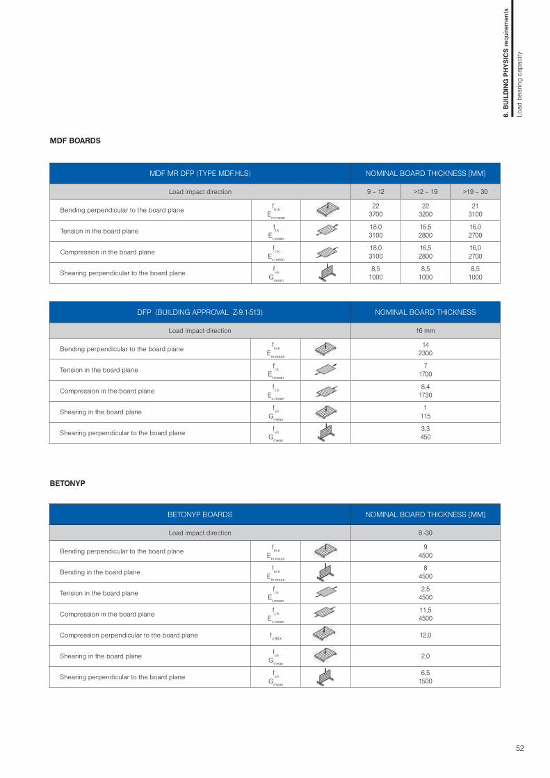
52
MDF BOARDS
BETONYP
MDF MR DFP (TYPE MDF.HLS) NOMINAL BOARD THICKNESS [MM]
Load impact direction 9 – 12 >12 – 19 >19 – 30
Bending perpendicular to the board plane fm,kEm,mean
223700
223200
213100
Tension in the board plane ft,kEt,mean
18,03100
16,52800
16,02700
Compression in the board plane fc,kEc,mean
18,03100
16,52800
16,02700
Shearing perpendicular to the board plane fv,k Gmean
8,51000
8,51000
8,51000
DFP (BUILDING APPROVAL Z-9.1-513) NOMINAL BOARD THICKNESS
Load impact direction 16 mm
Bending perpendicular to the board plane fm,kEm,mean
142300
Tension in the board plane ft,kEt,mean
71700
Compression in the board plane fc,kEc,mean
8,41730
Shearing in the board plane fv,k Gmean
1115
Shearing perpendicular to the board plane fv,kGmean
3,3450
BETONYP BOARDS NOMINAL BOARD THICKNESS [MM]
Load impact direction 8 -30
Bending perpendicular to the board plane fm,kEm,mean
94500
Bending in the board plane fm,kEm,mean
84500
Tension in the board plane ft,kEt,mean
2,54500
Compression in the board plane fc,kEc,mean
11,54500
Compression perpendicular to the board plane fc,90,k 12,0
Shearing in the board plane fv,k Gmean
2,0
Shearing perpendicular to the board plane fv,k Gmean
6,51500
6. B
UILD
ING
PH
YSIC
S re
quire
men
ts
Load
bea
ring
capa
city

53
TABLES FOR DIMENSIONING LOAD OF BOARDS FOR THE MAXIMUM DEFLECTION OF 1/300 SPAN
Values are determined from the limit deflection and limit states of strength in bending and shear during bending. The tabled values
refer to temporary load duration, in case of a permanent load duration the values should be reduced by 50%. The rated load is specified by multiplying the standard load with the relevant load coefficient.
Particleboards, Type P5 a QSB
Particleboards, Type P6
Load-bearing capacity values applicable in dry and humid conditions
Uniformly distributed load
Load-bearing capacity values applicable in dry conditions only
Uniformly distributed load
Linear (point) load
Linear (point) load
board thickness
l [mm] - span (axial distance between supports)312 400 417 500 600 625 700 750 800 833 900 950 1000
max.load-bearing capacity [kN/m2] for 1 m panel width12 mm 4,17 1,94 1,70 0,96 0,52 0,4515 mm 7,73 3,62 3,18 1,81 1,01 0,88 0,60 0,4718 mm 13,41 6,30 5,55 3,17 1,79 1,57 1,09 0,86 0,69 0,60 0,45 0,37 0,3022 mm 10,51 9,26 5,32 3,02 2,66 1,85 1,48 1,20 1,04 0,80 0,66 0,5525 mm 13,64 7,85 4,48 3,94 2,76 2,22 1,80 1,58 1,22 1,01 0,85
board thickness
l [mm] - span (axial distance between supports)312 400 417 500 600 625 700 750 800 833 900 950 1000
max.load-bearing capacity [kN] for 1 m panel width12 mm 0,75 0,43 0,39 0,2515 mm 1,43 0,89 0,81 0,54 0,34 0,31 0,2318 mm 2,52 1,49 1,36 0,91 0,60 0,55 0,41 0,34 0,29 0,26 0,2122 mm 2,53 2,32 1,57 1,05 0,96 0,74 0,62 0,53 0,48 0,39 0,34 0,2925 mm 3,44 2,35 1,58 1,45 1,12 0,96 0,82 0,75 0,62 0,54 0,47
board thickness
l [mm] - span (axial distance between supports)312 400 417 500 600 625 700 750 800 833 900 950 1000
max.load-bearing capacity [kN/m2] for 1 m panel width12 mm 5,27 2,46 2,16 1,22 0,68 0,5915 mm 9,63 4,52 3,98 2,27 1,27 1,11 0,77 0,61 0,4818 mm 7,86 6,92 3,97 2,25 1,98 1,38 1,10 0,88 0,77 0,59 0,4822 mm 12,29 10,8 6,23 3,55 3,12 2,18 1,75 1,42 1,24 0,96 0,79 0,6625 mm 15,9 9,2 5,25 4,63 3,25 2,61 2,13 1,87 1,45 1,21 1,01
board thickness
l [mm] - span (axial distance between supports)312 400 417 500 600 625 700 750 800 833 900 950 1000
max.load-bearing capacity [kN] for 1 m panel width 12 mm 0,97 0,56 0,51 0,33 0,2115 mm 1,80 1,14 1,04 0,70 0,46 0,41 0,31 0,26 0,2118 mm 3,16 1,88 1,72 1,16 0,77 0,70 0,54 0,46 0,39 0,35 0,28 0,24 0,2122 mm 2,97 2,72 1,85 1,25 1,14 0,88 0,75 0,64 0,58 0,48 0,42 0,3625 mm 4,40 4,04 2,76 1,87 1,71 1,34 1,14 0,99 0,90 0,75 0,66 0,58
6. B
UILD
ING
PH
YSIC
S re
quire
men
ts
Load
bea
ring
capa
city

54
board thickness
l [mm] - span (axial distance between supports)400 417 500 600 625 700 800 833 900 950 1000 1100 1250
max.load-bearing capacity [kN/m2] for 1 m panel width12 mm 1,07 0,94 0,5115 mm 2,14 1,88 1,05 0,57 0,5018 mm 3,75 3,29 1,87 1,04 0,91 0,62 0,3822 mm 6,90 6,08 3,47 1,96 1,72 1,19 0,75 0,65 0,4925 mm 8,96 5,14 2,92 2,56 1,78 1,15 1,00 0,77 0,63 0,52 0,3630 mm 8,96 5,11 4,50 3,16 2,06 1,81 1,40 1,16 0,97 0,69 0,42
tloušťka desky
l [mm] - span (axial distance between supports)400 417 500 600 625 700 800 833 900 950 1000 1100 1250
max.load-bearing capacity [kN] for 1 m panel width12 mm 0,22 0,1915 mm 0,47 0,43 0,27 0,1618 mm 0,86 0,78 0,51 0,33 0,29 0,2122 mm 1,63 1,49 1,00 0,66 0,59 0,45 0,31 0,28 0,2225 mm 2,44 2,23 1,51 1,01 0,92 0,70 0,50 0,45 0,37 0,32 0,27 0,2030 mm 3,93 2,68 1,81 1,66 1,29 0,95 0,86 0,71 0,62 0,54 0,42 0,29
OSB SUPERFINISH, Type OSB/2 a OSB/3OSB/2 - Load-bearing capacity values applicable in dry conditions onlyOSB/3 - Load-bearing capacity values applicable in dry and humid conditions
Uniformly distributed load on OSB/2, OSB/3 in major axis
Linear (point) load on OSB/2, OSB/3 in major axis
Uniformly distributed load on OSB/2, OSB/3 in minor axis
Linear (point) load on OSB/2, OSB/3 in minor axis
board thickness
l [mm] - span (axial distance between supports)400 417 500 600 625 700 800 833 900 950 1000 1100 1250
max.load-bearing capacity [kN/m2] for 1 m panel width12 mm 2,77 2,44 1,38 0,77 0,67 0,4615 mm 5,46 4,81 2,75 1,56 1,37 0,95 0,61 0,53 0,4018 mm 9,48 8,36 4,80 2,74 2,41 1,69 1,10 0,96 0,74 0,61 0,5122 mm 17,37 15,32 8,83 5,06 4,46 3,14 2,06 1,81 1,41 1,18 0,99 0,7225 mm 22,52 13,01 7,47 6,59 4,65 3,07 2,70 2,11 1,78 1,50 1,09 0,7030 mm 22,55 12,98 11,46 8,11 5,38 4,74 3,73 3,14 2,67 1,97 1,29
board thickness
l [mm] - span (axial distance between supports)400 417 500 600 625 700 800 833 900 950 1000 1100 1250
max.load-bearing capacity [kN] for 1 m panel width12 mm 0,64 0,58 0,38 0,25 0,2215 mm 1,30 1,19 0,80 0,53 0,48 0,37 0,26 0,23 0,1918 mm 2,29 2,10 1,43 0,96 0,88 0,68 0,50 0,45 0,37 0,32 0,28 0,2122 mm 4,25 3,90 2,67 1,82 1,67 1,30 0,97 0,88 0,74 0,65 0,57 0,45 0,3225 mm 6,28 5,77 3,97 2,71 2,49 1,96 1,46 1,34 1,13 1,00 0,89 0,71 0,5230 mm 6,93 4,76 4,38 3,45 2,61 2,39 2,02 1,80 1,61 1,30 0,97
6. B
UILD
ING
PH
YSIC
S re
quire
men
ts
Load
bea
ring
capa
city

55
OSB SUPERFINISH, Type OSB/4OSB/4 - Load-bearing capacity values applicable in dry and humid conditions
Uniformly distributed load on OSB/4 in major axis
Linear (point) load on OSB/4 in major axis
Uniformly distributed load on OSB/4 in minor axis
Linear (point) load on OSB/4 in minor axis
board thickness
l [mm] - span (axial distance between supports)400 417 500 600 625 700 800 833 900 950 1000 1100 1250
max.load-bearing capacity [kN/m2] for 1 m panel width12 mm 3,83 3,37 1,93 1,09 0,95 0,66 0,4215 mm 7,54 6,64 3,82 2,17 1,91 1,33 0,86 0,75 0,58 0,4818 mm 13,07 11,53 6,64 3,80 3,35 2,35 1,54 1,35 1,05 0,88 0,74 0,5322 mm 23,93 21,11 12,19 7,00 6,18 4,36 2,88 2,53 1,98 1,66 1,41 1,03 0,6625 mm 35,16 31,02 17,93 10,31 9,11 6,44 4,26 3,76 2,95 2,49 2,11 1,55 1,0130 mm 31,06 17,90 15,82 11,21 7,45 6,58 5,18 4,37 3,73 2,75 1,82
board thickness
l [mm] - span (axial distance between supports)400 417 500 600 625 700 800 833 900 950 1000 1100 1250
max.load-bearing capacity [kN] for 1 m panel width12 mm 0,90 0,83 0,55 0,36 0,33 0,2515 mm 1,82 1,66 1,13 0,76 0,69 0,53 0,39 0,35 0,29 0,25 0,2218 mm 3,19 2,92 2,00 1,36 1,24 0,97 0,72 0,65 0,54 0,48 0,42 0,3322 mm 5,88 5,40 3,72 2,54 2,33 1,83 1,37 1,26 1,06 0,93 0,83 0,66 0,4825 mm 8,68 7,97 5,50 3,77 3,47 2,73 2,06 1,89 1,59 1,42 1,26 1,02 0,7530 mm 9,58 6,60 6,07 4,80 3,63 3,34 2,83 2,52 2,26 1,84 1,38
board thickness
l [mm] - span (axial distance between supports)400 417 500 600 625 700 800 833 900 950 1000 1100 1250
max.load-bearing capacity [kN/m2] for 1 m panel width12 mm 1,47 1,29 0,72 0,3915 mm 2,93 2,57 1,45 0,80 0,70 0,4718 mm 5,10 4,49 2,56 1,44 1,26 0,86 0,54 0,4722 mm 9,38 8,26 4,74 2,69 2,36 1,64 1,06 0,92 0,70 0,58 0,48 0,3325 mm 13,81 12,17 7,00 3,99 3,51 2,45 1,59 1,40 1,08 0,89 0,74 0,52 0,3130 mm 12,17 6,97 6,14 4,32 2,84 2,49 1,94 1,62 1,36 0,98 0,61
board thickness
l [mm] - span (axial distance between supports)400 417 500 600 625 700 800 833 900 950 1000 1100 1250
max.load-bearing capacity [kN] for 1 m panel width12 mm 0,31 0,2815 mm 0,66 0,60 0,39 0,25 0,2218 mm 1,19 1,09 0,73 0,47 0,43 0,32 0,22 0,1922 mm 2,25 2,06 1,39 0,92 0,84 0,64 0,46 0,42 0,34 0,29 0,2525 mm 3,34 3,06 2,08 1,40 1,28 0,99 0,72 0,65 0,54 0,47 0,41 0,31 0,2130 mm 3,68 2,50 2,29 1,79 1,33 1,21 1,01 0,89 0,78 0,62 0,44
6. B
UILD
ING
PH
YSIC
S re
quire
men
ts
Load
bea
ring
capa
city

56
board thickness
l [mm] - span (axial distance between supports)350 400 417 467 500 533 600 625 640 700 800 900 933
max.load-bearing capacity [kN/m2] for 1 m panel width12 mm 3,71 2,43 2,13 1,47 1,17 0,93 0,61 0,52 0,4714 mm 5,96 3,93 3,44 2,4 1,92 1,55 1,03 0,89 0,82 0,5818 mm ● 10,74 ● 8,16 7,48 5,25 4,24 3,45 2,35 2,05 1,89 1,39 0,85 0,5322 mm ● 16,11 ● 12,26 ● 11,26 ● 8,92 ● 7,74 6,45 4,44 3,89 3,6 2,68 1,7 1,11 0,9624 mm ● 19,2 ● 14,62 ● 13,43 ● 10,64 ● 9,24 ● 8,09 5,82 5,11 4,74 3,55 2,27 1,5 1,3128 mm ● 19,97 ● 18,35 ● 14,55 ● 12,64 ● 11,08 ● 8,66 ● 7,95 ● 7,57 5,77 3,74 2,51 2,22
board thickness
l [mm] - span (axial distance between supports)350 400 417 467 500 533 600 625 640 700 800 900 933
max.load-bearing capacity [kN] for 1 m panel width12 mm 0,68 0,49 0,43 0,31 0,25 0,2014 mm ● 0,97 ● 0,82 0,76 0,57 0,47 0,39 0,27 0,23 0,2118 mm ● 1,67 ● 1,43 ● 1,37 ● 1,19 ● 1,1 0,99 0,73 0,65 0,61 0,47 0,30 0,1922 mm ● 2,57 ● 2,21 ● 2,11 ● 1,85 ● 1,71 ● 1,58 ● 1,37 ● 1,31 1,26 1,01 0,70 0,49 0,4424 mm ● 3,09 ● 2,66 ● 2,54 ● 2,23 ● 2,06 ● 1,92 ● 1,66 ● 1,59 ● 1,54 1,37 0,97 0,70 0,6328 mm ● 3,69 ● 3,52 ● 3,1 ● 2,87 ● 2,67 ● 2,33 ● 2,22 ● 2,16 ● 1,94 ● 1,65 1,25 1,14
Uniformly distributed load
Linear (point) load
Linear (point) load
BETONYP Load-bearing capacity values applicable in dry and humid conditions
Uniformly distributed load
● value is limit state in bending by humid condition (service class 2, kmod=0,45)
MDF MRLoad-bearing capacity values applicable in dry and humid conditions but only for short-term or instantaneous load-duration
board thickness
l [mm] - span (axial distance between supports)312 400 417 500 600 625 700 750 800 833 900 950 1000
max.load-bearing capacity [kN/m2] for 1 m panel width12 mm 4,4 2,04 1,79 1 0,54 0,4715 mm 7,47 3,49 3,06 1,73 0,95 0,83 0,5618 mm 6,09 5,36 3,05 1,71 1,5 1,03 0,81 0,64 0,5522 mm 9,55 5,47 3,1 2,72 1,89 1,5 1,21 1,05 0,8 0,66 0,5425 mm 8,08 4,6 4,05 2,83 2,26 1,83 1,6 1,23 1,02 0,85
board thickness
l [mm] - span (axial distance between supports)312 400 417 500 600 625 700 750 800 833 900 950 1000
max.load-bearing capacity [kN] for 1 m panel width12 mm 0,79 0,44 0,4 0,25 0,1515 mm 1,37 0,79 0,72 0,46 0,29 0,26 0,1818 mm 1,42 1,3 0,86 0,56 0,5 0,37 0,31 0,25 0,22 0,1722 mm 2,36 1,60 1,06 0,96 0,73 0,62 0,52 0,47 0,38 0,32 0,2825 mm 2,39 1,61 1,47 1,13 0,96 0,82 0,74 0,61 0,53 0,46
6. B
UILD
ING
PH
YSIC
S re
quire
men
ts
Load
bea
ring
capa
city

57
ENERGY SAVING
THERMAL BUILDING REQUIREMENTS Thermal building requirements are regulated by the relevant na-tional standards and local regulations. These thermal building regulations ensure fulfillment of basic requirements for construc-tion works, especially basic requirement for the energy savings and thermal protection of buildings and ensure health, healthy living conditions and the environment. Compliance with thermal building requirements provides the pre-vention of thermal defects and failures of buildings, which may affect the health, healthy living conditions and the environment. Further on, the thermal comfort of users, the desired state of the interior and buildings low energy.The thermal building requirements are assessed as follows: • Lowest internal surface temperature of structure • Construction thermal transmittance U • Average thermal transmittance Uem (whole building)• Heat transfer through the thermal binding between construc-
tions (thermal bridges) • Decrease of the touch temperature (for floors)• Transfer of moisture throughout the construction • Transfer of air throughout the construction and building (air
permeability and ventilation of the rooms)• Thermal stability of rooms in winter and summer time
• Transfer of heat, moisture and air The heat is transferred in three known ways:• conduction - especially in solids and liquids• convection - flow in liquids and gases • radiation - transfer of electromagnetic waves, or their combi-
nation. The transmission of moisture (water or steam) involves the use of various mechanisms, e.g. water vapor, moisture diffusivity, ab-sorbing water by capillarity, sorption). Air distribution is possible based on the pressure difference and air flow.
This chapter below discusses only the elimination of heat trans-fer by conduction. Other chapters are dedicated to reduction of moisture distribution, prevention of heat convection transfer and limitations of heat transfer radiation.
• Requirements for thermal resistance of structures Thermal building requirements apply to the whole structural composition. Protective layers are fundamental besides the thermal insulation layers. Thermal insulation layers must be able to prevent or significantly reduce the heat transfer throu-ghout the structure which it is integrated to. The basic factors characterizing the thermal insulation properties of building construction is transmission heat loss coefficient (U-value) and thermal resistance R. The required values U and R are different for distinct construction types and building types.
The wood frame itself sheathed with Kronobuild® boards is insu-fficient to ensure the current requirements imposed on the total heat transfer. Boards are important as a protective layer of ther-mal insulation that helps prevent convective heat transfer and limit moisture, which greatly reduce the thermal performances of insulation materials.
• Materials for thermal insulationHigh thermal insulation against heat transfer can be achieved by integrating insulating materials with low thermal conductivity (λ < 0,05 W/m.K). For filling gaps between the timber frame and ® sheathing suitable for thermal insulation from flexible porous and malleable materials should be used. These materials adapt better to cavity and prevent possible gaps between insulation and wood elements. Consequently mineral and glass wool, fi-ber, hemp boards or blown cellulose insulation are the prefe-rred boards instead of hard boards (e.g. based on polystyrene EPS). Sufficiently rigid and dense wood-fibre boards, mineral board or boards of EPS polystyrene are suitable as thermal in-sulation for entire layers without spacer battens (e.g. ETICS - external thermal insulation contact systems of buildings). These are attached from the outside to the outer frame of the Krono-build® wood boards with plate anchors with wood screws. The quality of good thermal insulation is achieved mainly by:• the higher thermal resistance of the insulating layer (lower λ
value) • the smaller proportion of load-bearing structures in insulation
layers (thermal bridges caused by materials) • the higher airtightness with suitable vapour resistance of the
entire structure (at surface and also at connections)• the better heat accumulation capacity• the lower thermal conductivity of the surface layer.
U= 0,08 - 0,12
U= 0,8U= 1,2
U= 0,15 - 0,25 U= 0,1 - 0,15
U= 0,15 - 0,20
U= 0,2 - 0,23 U= 0,12 - 0,15
6. B
UILD
ING
PH
YSIC
S re
quire
men
ts
Ener
gy s
avin
g
Image 3: Schematic visualization of different requirements for heat transfer coefficient U for various constructions between low-energy (LEH) and passive houses (PH).
LEH PH

58
• Surface temperature and thermal absorption The accumulation ability of materials and their behaviour due to the surface temperature effect the climate and the internal temperature in the room together with the low thermal con-ductivity of the insulating material, minimizing thermal brid-ges, and high airtightness, although this effect can not be easily classified.
Important benefit of Kronobuild® boards is low thermal capacity. The extent of thermal capacity or ability to dissipate heat affects our thermal comfort. Wood materials are generally due to the low thermal capacity perceived by touching at constant surface tem-perature as warmer than materials with higher thermal conducti-vity, such as concrete or steel. The interior surfaces are therefore perceived as more pleasant in winter, even though the surface has the same temperature.
HYDROTHERMAL PROPERTIES OF KRONOBUILD® BOARDS
It is necessary to know the hydrothermal properties of Kronobuild®
boards at the time of the construction design. These properties serves to thermal technical assessment (determined by calcula-tion), which is usually the basic tool for finding suitability of using the proposed structural composition.
• Thermal conductivity and heat capacity Thermal conductivity is determined for cases where the boards are used in the compositions with thermal insulation. The physi-cal properties to conduct the heat in the building is determined by using the thermal conductivity coefficient λ. Basic values can be determined from a table according to EN 13986 or by test according to EN 12664.
Table values of thermal conductivity λ and specific heat capacity c of boards Kronobuild®:
Since 2012 the measurements according to EN 12664 applies for verification of table values (values apply to boards in the dried state):
BASIC TERMINOLOGY IN THERMAL PROTECTION OF BUILDING
•Coefficient of thermal conductivity λ Generally, the ability of a material to conduct heat at a given tem-perature.
• Specific heat capacity cThermal capacity indicates the amount of heat necessary to add to the material to heat up by 1 °C (or 1 K). It can be determined by a specific thermal capacity c in J / kg.K.
• Heat transfer resistance of the structure RTThermal Resistance R of one material layer depends on the ma-terial thickness and thermal conductivity which is generally defi-ned by the relation R = d / λ. The total thermal resistance RT is the sum of the thermal resistance of all material layers and heat transfer resistance on the internal and external surface of the structure: RT = RSI + ΣR + RSE [m
2.K/W]
• Transmission heat loss coefficient (U-value)U-value or heat thermal transmittance value sets the overall heat exchange at a steady state between two environments separa-ted by building structure at thermal resistance R. It includes the effect of all thermal bridges including the influence pervading dowels and anchors that are part of the construction and ma-sonry. Heat permeability coefficient indicates the amount of heat loss in watts, that pervades the area of 1 m2 of construction, at environment temperature difference of 1 K. It is defined by: UT = 1 / RT [W/m2.K]
• Temperature diffusivity factor aThermal diffusivity is the ability of material to balance temperatu-re differences. It expresses the spreading speed of temperature difference in the material. The higher the thermal diffusivity of the material is, the more rapidly the temperature of the material will change compared to changes in the surface temperature. It is defined by: a=λ/(c.ρ) [m2/s]
• Thermal effusivity bThermal effusivity is the ability to absorb material heat. It allows to assess changes in the surface temperature depending on the heat flow on the surface. The lower the thermal effusivity of the material, the lower the cooling effect on a living organism is. It is defined by: b=√(λ.c.ρ) [J/(m2.K.s1/2)]
• Water vapour resistance factor μ It indicates how much greater the resistance of the material is compared to equally thick layer of stationery air at the same tem-perature.
• Water vapour diffusion equivalent air layer thickness sdThickness of a motionless air which has the same water vapour resistance, as a layer of material sd = μ . d [m]
Board type Volume weight [kg/m3] λ [W/m.K] c [J/kg.K]
PB 600 - 700 0,13 1500
OSB 550 - 600 0,10 1400MDF 720 - 750 0,13 1600DFP 550 0,10 1600Betonyp 1350 0,26 1600
Board type Volume weight of dry matter [kg/m3] λ c
[J/kg.K]a
[m2/s]OSB Superfinish ECO 550 0,098 1221 1,46 *10 -7
OSB Reflex ECO 550 0,098 1221 1,47 *10 -7
OSB Airstop ECO 550 0,098 1214 1,46 *10 -7
6. B
UILD
ING
PH
YSIC
S re
quire
men
ts
Ener
gy s
avin
g
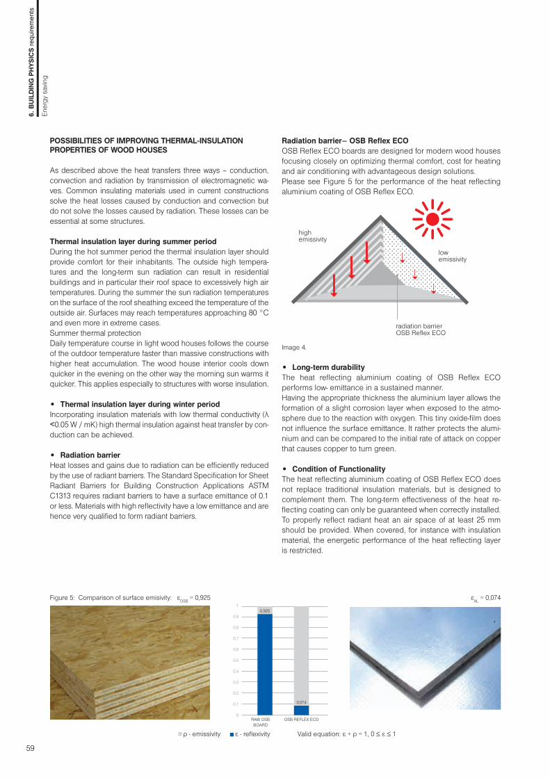
59
POSSIBILITIES OF IMPROVING THERMAL-INSULATION PROPERTIES OF WOOD HOUSES
As described above the heat transfers three ways – conduction, convection and radiation by transmission of electromagnetic wa-ves. Common insulating materials used in current constructions solve the heat losses caused by conduction and convection but do not solve the losses caused by radiation. These losses can be essential at some structures.
Thermal insulation layer during summer period During the hot summer period the thermal insulation layer should provide comfort for their inhabitants. The outside high tempera-tures and the long-term sun radiation can result in residential buildings and in particular their roof space to excessively high air temperatures. During the summer the sun radiation temperatures on the surface of the roof sheathing exceed the temperature of the outside air. Surfaces may reach temperatures approaching 80 °C and even more in extreme cases.Summer thermal protection Daily temperature course in light wood houses follows the course of the outdoor temperature faster than massive constructions with higher heat accumulation. The wood house interior cools down quicker in the evening on the other way the morning sun warms it quicker. This applies especially to structures with worse insulation.
• Thermal insulation layer during winter period Incorporating insulation materials with low thermal conductivity (λ <0.05 W / mK) high thermal insulation against heat transfer by con-duction can be achieved. • Radiation barrierHeat losses and gains due to radiation can be efficiently reduced by the use of radiant barriers. The Standard Specification for Sheet Radiant Barriers for Building Construction Applications ASTM C1313 requires radiant barriers to have a surface emittance of 0.1 or less. Materials with high reflectivity have a low emittance and are hence very qualified to form radiant barriers.
Radiation barrier– OSB Reflex ECOOSB Reflex ECO boards are designed for modern wood houses focusing closely on optimizing thermal comfort, cost for heating and air conditioning with advantageous design solutions.Please see Figure 5 for the performance of the heat reflecting aluminium coating of OSB Reflex ECO.
Image 4.
• Long-term durability The heat reflecting aluminium coating of OSB Reflex ECO performs low- emittance in a sustained manner. Having the appropriate thickness the aluminium layer allows the formation of a slight corrosion layer when exposed to the atmo-sphere due to the reaction with oxygen. This tiny oxide-film does not influence the surface emittance. It rather protects the alumi-nium and can be compared to the initial rate of attack on copper that causes copper to turn green.
• Condition of Functionality The heat reflecting aluminium coating of OSB Reflex ECO does not replace traditional insulation materials, but is designed to complement them. The long-term effectiveness of the heat re-flecting coating can only be guaranteed when correctly installed. To properly reflect radiant heat an air space of at least 25 mm should be provided. When covered, for instance with insulation material, the energetic performance of the heat reflecting layer is restricted.
highemissivity
lowemissivity
radiation barrierOSB Reflex ECO
Figure 5: Comparison of surface emisivity: εOSB = 0,925 εAL = 0,074
ρ - emissivity ε - reflexivity Valid equation: ε + ρ = 1, 0 ≤ ε ≤ 1
RAW OSBBOARD
OSB REFLEX ECO
1
0,9
0,8
0,7
0,6
0,5
0,4
0,3
0,2
0,1
0
0,925
0,074
6. B
UILD
ING
PH
YSIC
S re
quire
men
ts
Ener
gy s
avin
g

60
• OSB Reflex ECO in summer period OSB Reflex ECO with high effectivity prevents from overheating during the summer:
Image 5. In building envelopes the OSB-board functions as wall sheathing. The OSB Reflex ECO’s aluminium coating faces the unventilated air cavity.
• OSB Reflex ECO in the winter period OSB Reflex ECO prevents from quick cooling in the winter:
Image 7. For roof sheathing applications OSB Reflex ECO is installed with the heat reflecting aluminium foil facing to the ventilation cavity.
heat reflectionback to the
interior
reflective layer
reflective layer
Image 6. Low emisivity – prevention from overheating
OSB Reflex ECO is extremely efficient and highly functional, even when applied to constructions that are not saticfactorily thermally insulated.
• Advantages• the ENERGY PERFORMANCE – reduces the costs for air-conditioning in summer time, for heating in winter time • the REGULATED VAPOUR DIFFUSION – thanks to the perforated aluminum foil coating• the Stable value of airtightness – meets the passive house requirements
Image 8. High reflectivity – prevention of heat loses
• the THERMAL COMFORT – improves indoor temperature and ensures a comfortable interior climate • the Complete energy solution – complements conventional thermal insulation products• the Excellent price-performance ratio• the Saving of individual work stages – there is no need to install an additional foil, easy to cut and fix
heat reflection back to the
exterior
6. B
UILD
ING
PH
YSIC
S re
quire
men
ts
Ener
gy s
avin
g
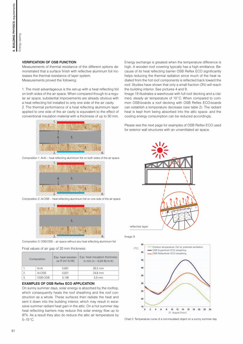
61
reflective layer
VERIFICATION OF OSB FUNCTIONMeasurements of thermal resistance of the different options de-monstrated that a surface finish with reflective aluminum foil inc-reases the thermal resistance of layer system.Measurements proved the following: 1. The most advantageous is the set-up with a heat reflecting foil on both sides of the air space. When compared though to a regu-lar air space, substantial improvements are already obvious with a heat reflecting foil installed to only one side of the air cavity.2. The thermal performance of a heat reflecting aluminium layer applied to one side of the air cavity is equivalent to the effect of conventional insulation material with a thickness of up to 50 mm.
Composition 1: Al-Al – heat reflecting aluminium foil on both sides of the air space
5.
3.
3.
1.
2.
4.
6.
Composition 2: Al-OSB – heat reflecting aluminium foil on one side of the air space
5.
3.
3.
1.
2.
4.
6.
Composition 3: OSB-OSB – air space without any heat reflecting aluminium foil
5.
3.
3.
1.
2. 6.
Final values of air gap of 20 mm thickness:
Composition Eqv. heat resistan-ce R [m2.K/W]
Eqv. heat insulation thickness in mm (λ = 0,04 W/m.K)
1. Al-Al 0,661 26,5 mm2. Al-OSB 0,621 24,8 mm3. OSB-OSB 0,148 5,9 mm
EXAMPLES OF OSB Reflex ECO APPLICATION On sunny summer days, solar energy is absorbed by the rooftop, which consequently heats the roof sheathing and the roof con-struction as a whole. These surfaces then radiate the heat and sent it down into the building interior, which may result in exce-ssive summer radiant heat gain in the attic. On a hot summer day heat reflecting barriers may reduce this solar energy flow up to 97%. As a result they also do reduce the attic air temperature by 5–15°C. Chart 2: Temperature curve of a non-insulated object on a sunny summer day
Image 9.
Outdoor temperature (Te) for potential ventilationOSB Superfinish ECO sheathingOSB Reflexfinish ECO sheathing
21. August [hour]
[ °C ]
Energy exchange is greatest when the temperature difference is high. A wooden roof covering typically has a high emittance. Be-cause of its heat reflecting barrier OSB Reflex ECO significantly helps reducing the thermal radiation since much of the heat ra-diated from the hot roof components is reflected back toward the roof. Studies have shown that only a small fraction (3%) will reach the building interior. See pictures 4 and 9.Image 19 illustrates a warehouse with full roof decking and a clai-med, steady air temperature of 10°C. When compared to com-mon OSB-boards a roof decking with OSB Reflex ECO-boards can establish a temperature decrease (see table 2). The radiant heat is kept from being absorbed into the attic space. and the cooling energy consumption can be reduced accordingly.
Please see the next page for examples of OSB Reflex ECO used for exterior wall structures with an unventilated air space.
6. B
UILD
ING
PH
YSIC
S re
quire
men
ts
Ener
gy s
avin
g

62
Diffusion-open timber framed construction with ventilated wood cladding and air cavity.Structures:
A - mineral fibre insulation 25 mm λ = 0,040 W/m.K)
B - air space of 25mm with OSB Superfinish ECO
C - air space of 25mm with OSB Reflex ECO
The thermal performance of OSB Reflex ECO’s heat reflecting aluminium barrier is based on the fact that the thermal resistance of the adjacent unventilated air cavity (8) improves significantly (see chart). This amelioration is equivalent to the effect of conventional insulation material (λ=0,040 W/m.K) of up to 30 mm. The results also illustrate that there is no need of including an air space larger than the required 25 mm.
The thermal properties, as well as the graphics, were determined in correspondence with EN ISO 6946. The calculation method takes in account that the performance of any radiant barrier is influenced by the thermal conductivity factor λ of its adjacent air space.
Structure (from the inside out) Th. [mm] A B C
1 Cladding 24 • • •2 Bearing battens 30/50 (possibly 30/80) + back ventilation 30 • • •3 Diffusion-open panels (KRONOSPAN DFP, MDF.RWH) 16 • • •4 Wood frame construction (60/160, e = 625 mm) 160 • • •5 Thermal insulation – mineral- or glaswool/blown cellulose insulation 160 • • •6 OSB Superfinish ECO (air tight connected with sealed joints) 15 • • -6´ OSB Reflex ECO (air tight connected with sealed joints) 15 - - •7 Mineral fibre insulation + battens (a = 500 mm) 25 • - -8 Unventilated air cavity + battens (a = 500 mm) 25 - • •9 Gypsum plasterboard 12,5 • • •
Thermal properties Thermal resistance R [m2.K / W] 4,21 3,62 4,18Thermal transmittance U [W / m2.K] 0,23 0,26 0,23
Radiant barrier
THERMAL RESISTANCE OF THE AIR SPACE(HORIZONTAL HEAT FLOW)
EXTERIOR WALL STRUCTUREINSTALLATION
Thermal resistanceR [m2.K/W]
Air space depth in cm
Thermal insulation – mineral wool (λ=0,04)Air space without radiant barrierRadiant barrier with ε = 0,07
Design:
6. B
UILD
ING
PH
YSIC
S re
quire
men
ts
Ener
gy s
avin
g

63
Diffusion-open wooden flooring construction over a vented crawl space. Structures:
A - mineral fibre insulation 50 mm (λ = 0,040 W/m.K)
B - air space of 50 mm with OSB Superfinish ECO
C - air space of 50 mm with OSB Reflex ECO
In winter time OSB Reflex ECO-boards that are installed adjacent to an air space may substitute conventional in-sulation of up to 50 mm (λ=0,040 W/m.K) (see table).
The thermal properties, as well as the graphics, were de-termined in correspondence with EN ISO 6946. The cal-culation method takes in account that the performance of any radiant barrier is influenced by the thermal conducti-vity factor λ of its adjacent air space.
Thermal propertiesThermal resistance R [m2.K / W] 5,02 4,02 5,01Thermal transmittance U [W / m2.K] 0,19 0,24 0,19
Radiant barrier
Structure (from the inside out) Th. [mm] A B C
1 Floor covering 8 • • •
2 Sound insulation layer 3 • • •
3 OSB Superfinish ECO (air tight connected with sealed joints) 22 • • -
3´ OSB Reflex ECO (air tight connected with sealed joints) 22 - - •
4 Thermal insulation – mineral wool + battens 40/50 (a=625 mm) 50 • - -
5 Air space + battens 40/50 (a = 625 mm) 50 - • •
6 Thermal insulation – mineral- or glaswool, blown cellulose insulation 160 • • •
7 Timber joists (60/160, e = 1000 m) 160 • • •
8 Diffusion-open panels (KRONOSPAN DFP, MDF.RWH) 16 • • •
Vented crawl space of at least 0,8 m • • •
THERMAL RESISTANCE OF THE AIR SPACE IN FLOORING OR CEILING (HEAT FLOW MOVES DOWNWARD)
FLOORING CONSTRUCTION ABOVE EXTERIOR SPACE
Air space depth in cm
Thermal insulation – mineral wool (λ=0,04)Air space without radiant barrierRadiant barrier with ε = 0,07
Thermal resistance
R [m2.K/W]
6. B
UILD
ING
PH
YSIC
S re
quire
men
ts
Ener
gy s
avin
g

64
In winter time OSB Reflex ECO-boards that are installed adjacent to an air space may substitute conventional insulation of up to 20 mm (λ=0,040 W/m.K) (see table). In summer time heat from prolonged exposure to the sun is absorbed. Thus less heat is transferred into the building envelope and an excessive radiant heat gain can be prevented. This increased thermal resistance value equalises insulation material of up to 50 mm.
The thermal properties, as well as the graphics, were determined in correspondence with EN ISO 6946. The calculation method takes in account that the performance of any radiant barrier is influenced by the thermal conductivity factor λ of its adjacent air space.
Structure (from the outside inward) Tl. [mm] A B C
1 Roof tiling – Clay or concrete roof tiling • • •2 Roof battens (30/50 mm) 30 • • •3 Inverted battens + air space of at least 50 mm 50 • • •4 Diffusion foil sd < 0,3 m 1 • • •5 Rafters construction (80/180, e = 1000 mm) + thermal insulation/mineral wool 180 • • •6 OSB Superfinish ECO (air tight connected with sealed joints) 15 • • -6´ OSB Reflex ECO (air tight connected with sealed joints) 15 - - •7 Mineral fibre insulation + battens (a = 500 mm) 40 • - -8 Air cavity + battens (a = 500 mm) 40 - • • 9 Gypsum plasterboard 12,5 • • •
Winter time: indoor heat losses are blocked (heat flow moves upwards)
Thermal resistance R [m2.K / W] 4,91 3,97 4,27Thermal transmittance U [W / m2.K] 0,20 0,24 0,23
Summer time: overheating (heat flow moves downwards)
Thermal resistance R [m2.K / W] 4,92 4,03 4,88Thermal transmittance U [W / m2.K] 0,19 0,23 0,19
Diffusion-open roof construction with insulation between the rafters. Structures:
A - mineral fibre insulation 40 mm (λ = 0,040 W/m.K)
B - air space of 40 mm with OSB Superfinish ECO
C - air space of 40 mm with OSB Reflex ECO
THERMAL RESISTANCE OF THE AIR SPACE IN THE ROOF (THE HEAT FLOW MOVES DOWNWARDS AND UPWARDS)
Radiant barrier
Air space depth in cm
Thermal insulation – mineral wool (λ=0,04)Air space without radiant barrierRadiant barrier with ε = 0,07 (heat flow moves upwards)Radiant barrier with ε = 0,07 (heat flow moves downwards)
summer time
winter time
Thermal resistanceR [m2.K/W]
ROOF CONSTRUCTION
6. B
UILD
ING
PH
YSIC
S re
quire
men
ts
Ener
gy s
avin
g

65
• Proper design of construction Proper design of construction is a prerequisite for flawless use of construction and its long lifespan. In terms of hydrothermal problems protection against moisture penetration must be addre-ssed by:• diffusion of water vapour• flow of hot moist air into the construction• ingress of external moisture and rain driven by wind
• Water vapour diffusionDiffusion of water vapour is a normal physical process where the water vapour molecules penetrate from places with higher con-centration to places with lower concentration in order to establish the balance. The diffusion of water vapour in a building structure is described as a transfer of water vapour through an airtight con-struction part (e.g. external wall) as a result of thermic differences of water vapour pressure between one and the other side of the building component. That may condense the vapour due to the temperature dropping below a certain value. This risk must be preceded by appropriate construction composition and by com-pliance with fundamental principles of calculations according to thermal and technical standards. Evaluation of water vapour transfer in structure by calculation method is one of the most im-portant tasks of building physics. It is used to verify the nature of the long-term hydrothermal behaviour of the structure and it must be part of any proper structure design.
Image 10. Schema of water vapour diffusion through basic structural panels in winter. There is a higher interior temperature, pressure and water vapour amount in the interior air which is trying to pass through the structure to ba-lance with the exterior.
Water vapour control layer (VCL)Transport of water vapour is the higher with bigger difference of hydrothermal conditions on both sides of the building element. In this respect winter is fundamental in central and northern Eu-rope. Water vapour control layer (vapour barrier and/or vapour retarder) is a layer within an exterior building component atta-ched to the inner side of the thermal insulation. VCL function is to hinder the migration of moisture by diffusion passing through the building component. Effective VCL reduces water vapor di-
MOISTURE PROTECTION
Moisture protection of wood building components is an impor-tant basis for perfect protection of wood and wood-based panels and for durability of construction. In general, the moisture in con-struction should be reduced to protected components against damage by biological attack, the loss of load-bearing capacity and stability.This shows that it is a must to avoid a large additional burden of moisture during the construction phase and during use. It is incorrect to believe that using diffusion-open materials may divert excess moisture diffusion alone. Building moisture or an increased amount of condensation wa-ter caused by convection (transfer of humidity by air movement) may exceed the ability of a construction to evaporate many times over. Therefore, convection must be structurally avoided.The following problems may occur at high moisture of the con-struction components:• greater deformation caused by the swelling and shrinkage of
wood and wood-based materials• reducing load-bearing capacity, and thereby increasing defor-
mation by a loading• increased moisture growth of embedded insulating materials
therefore resulting in decrease in efficiency• possibility of biological attack, the formation of mold inside the
building envelope or on the surface of building components and their connections.
Increased moisture and generation of other problems can be avoided by correct use of the building, but above all by right de-sign and quality construction.
• Proper building useIncrease of potential moisture by sufficient heating and ventilating, required air exchange is fundamental for proper building use.
• Quality construction During the construction of buildings should be avoided: • installation of wet materials• ingress of rainfall during the entire period of the construction• high construction moisture (coming primarily from using wet
construction processes such as floor screeds, plaster, etc.)• errors made in critical areas, imperfect connection of indi-
vidual materials, imperfect connections to penetrations and surrounding constructions
• technological indiscipline during construction• use of unsuitable materials and by this accelerated aging of
the connections
Pa Pi
Exterior Interior
6. B
UILD
ING
PH
YSIC
S re
quire
men
ts
Moi
stur
e pr
otec
tion

66
DIFFUSION PROPERTIES OF KRONOSPAN BOARDS
Vapour-permeable properties of wood and wood-based panels vary and are dependent on the moisture of wood material. Wa-ter vapour resistance factor is necessary to determine based on moisture conditions therefore the board material values for dry conditions are μDRY (25% RH and 23 °C) and for wet conditions μWET (72% RH and 23 °C). Basic values can be determined from the table according to EN 13986 or by testing according to EN ISO 12572.
The approximate value of the KRONOSPAN boards diffusion re-sistance:
Since 2012 the measurements according to EN ISO 12572 applies for verification of table values:
Values may vary for the individual production KRONOSPAN group plants. We recommend to verify the values directly with your supplier.
• Diffusion open and closed structural systems Possibilities of combining individual layer in a sandwich structu-re are countless. For easy identification among different design compositions we use their different hydrothermal performance. We describe the wood frame construction types as diffusion-open (DO) and diffusion-impermeable (closed -DU). The line between the structures defined as diffusion open and closed is not clearly determined. For our purposes the line is set by a definition of DO system as a structure where OSB Superfinish boards are used as a vapour control layer (VCL). In contrast, for DU structure diffuse resistance should be increased by adding another vapour barrier layer, as e.g. application of a thin plastic foil, etc.
ffusion to the point of harmful water condensation volume inside the external building component. The diffusion resistance rate of VCL is largely dependent on the composition of external building component, aeration and the climatic conditions in the interior and exterior.To guarantee a problem-free migration of the water vapour the individual layers of the building’s envelope should be composed in this way that their diffusion resistance rate decreases gradua-lly from the inside to the outside.
• Value sd and diffusion resistance factor μIn specialized literature, you may encounter a division of building products according to the values of equivalent diffusion air layer thickness. Equivalent diffusion air layer thickness sd describes the thickness of an imaginary air layer which under the same conditions gives the air vapour the same diffusion resistance as and appropriate structure layer:
sd = μ . d [m] μ – water vapour resistance factor [-] d – thickness of material [m] The fact is, the higher the value of sd and μ, the more the material protects from water vapour permeability.
• Vapour barrier, vapour retarders and diffusion-open boards Vapour barrier is a layer which prevents the penetration of water vapour diffusion into the building component. Products (plastic, aluminum foil or bitumen), which typically show values sd > 50 m (μ ~ 100 000) are generally called vapour-proof barriers. Vapour retarders in comparison to vapour barriers do not try to completely prevent the natural process of water vapour but only to slow it down so the steam in the construction is able to leave without condensation. These materials (different types of film, pa-per but mainly wood-based board materials) have an equivalent diffusion thickness of air gap with a value of sd > 0,50 m. Diffusion-open materials with high diffusion permeability are ma-terials with value of sd < 0,50 m.
Board type μWET (min.) μDRY (max.) sd (board thick. 15mm)P2,P3, P6 30 50 0,4 - 0,7P5, QSB 50 100 0,7 – 1,5OSB/2 30 50 0,4 - 0,7OSB/3 100 200 1,5 – 3,0OSB/4 150 300 2,2 – 4,5MDF, MDF MR 20 30 0,3 – 0,45DFP 8 10 0,13 – 0,16Betonyp 20 50 0,2 – 0,7
Board type μWET (min.) μDRY (max.) sd (board thick. 15mm)
OSB Superfinish ECO, Typ OSB/3 150 170 2,3 – 2,5
OSB Superfinish ECO, Typ OSB/4 320 340 4,8 – 5,1
OSB Airstop ECO 400 500 6,0 – 7,5OSB Reflex ECO 150 170 2,3 – 2,5
6. B
UILD
ING
PH
YSIC
S re
quire
men
ts
Moi
stur
e pr
otec
tion

67
Image 11. - left: External walls of construction with wood frame with double-sided OSB boards coating. Water vapour passes from the interior structure (right to left) and in front of the external OSB board leads to its accumulation which together with cooling leads to its condensation. Solution is to use another layer on the inside, which slows the water vapour and prevents condensation.Image 11. - right: Similar scheme with a very open-diffuse board DFP leads to rapid evaporation of water vapour without its condensation.
• Principle of diffusion open construction External walls and roofs are increasingly designed and imple-mented as diffusion-open construction.Diffusion-open construction is designed to be able to transmit water vapour spontaneously throughout the year through the building envelope without the accumulation and condensation, and thereby ensure a more secure building envelope function and prolong its lifespan.Materials on the external side of these constructions are so per-meable to water vapour that from the room side the layer with extremely high diffusion resistance is not necessary. The basis is the use of diffusion-open DFP boards on the protected outside wall with a value of d = 0.16 m with a board thickness of 16 mm. It is used as a load-bearing sheathing of the timber frame with a high vapour diffusion-permeable insulation. Design of all other interior layers necessary for proper functioning should be deter-mined by hydrothermal calculations that take into account all the necessary conditions. Material with the sd-value of about 10x gre-ater can be used for internal sheathing of the timber frame. OSB Superfinish boards in combination with DFP boards are suitable materials for diffusion-open construction. For these constructions they have a high enough and also variable diffusion resistance regulating the migration of water vapour from the inside out and from construction back to the interior.
AIRTIGHT LAYERS
• Conventions of water vapourIn contrast to the diffusion, the water vapour molecules are trans-ported by airflow at a convection transfer. Conventions of water vapour results from pressure differences especially in contacts of structural elements, at imperfectly connected penetrations etc. Convention of water vapour must be significantly and structurally avoided because moisture emerging from convention can many
Image 12. - left: Convection of water vapour in the structure can be safely prevented by an airtight bonding of OSB boards contact places. Image 12. - right: Windproof surface achieved by connecting tongue and groove joints or by gluing edges of the DFP panels.
times exceed evaporative potential and the results they can pro-duce. This may significantly damage the inside of structure. It can also lead to loss of heat caused by the penetration of warm air from the interior through the entire construction or by reducing the insulating effects due to humid thermal insulating layer. The air flow can be prevented by creating an airtight layer, both on the interior side (airtight layer) and also in the outer side of the building coating (windproof layer).
• Airtight layer Airtight layer is installed from the interior warm side of thermal insulation. It especially protects against the penetration of inter-nal warm and humid air into the structure where in a cooler area a condensation can occur. For airtight layer wood-based boards can be used. At the same time all connections, connections to the wall boards and penetrations areas should be sealed with suitable adhesive tapes and sealing materials to make this layer in the whole building envelope airtight.
• Windproof layer Windproof layer is installed on the external side of thermal insula-tion and it must effectively protect against the wind. It is especia-lly important for double-shell constructions with ventilated air gap, where the thermal insulation (based on mineral, glass wool or lightweight wood-fibre insulation) are easily air permeable. Win-dproof external layer prevents leakage of cold air throughout the insulation or wind-blown rain which leads again to heat loss and increased risk of condensation. Materials suitable for windproof layer may be wood-based panels, it is always necessary to look to their vapour diffuse properties. Board connections are also important. A tongue and groove connection may be sufficient, for straight cutting edges sealing the connections for windproof purposes is necessary.
OSB DFP OSBDFPOSB OSB DFP OSB
6. B
UILD
ING
PH
YSIC
S re
quire
men
ts
Moi
stur
e pr
otec
tion

68
EXAMPLES OF DIFFUSION OPEN SYSTEM
Diffusion open structure examples of building envelope without water vapour condensation with OSB Superfinish and DFP boards:
Image 14: External wall. Windproof surface with tongue and groove joints or gaps gluing
Image 15: Roof
PROTECTIVE INSULATION LAYER
Protective insulation layer separates the thermal insulating layer from ventilated layers. Prevents penetration of moisture into the thermal insulation and cooling of light and porous insulating ma-terials by airflow.
• Safety waterproof layer DFP boards can function as a second, water draining layer under ventilated roof covering with inclination from 6°. It is not nece-ssary to use an extra safety waterproof membrane. If the roof has a strong break-down by gutters, ridge, dormers and corners, it is often advantageous to obtain a complete surface diffusion--open membrane as well as all connections to seal with suitable adhesive tape.
Image 13: DFP as a secure waterproof layer.
• Under-roof layer The under-roof sheathing may be laid on all thermally insulated sloping roofs underneath ventilated coverings over the thermal insulation and over the load-bearing structures. Roof layers have a function of protection against weathering during construction until the final attachment of the roof cover. It also protects against moisture penetrating the roof cover (any wind driven rain, flying snow, etc.) for the entire roof lifespan. DFP boards based on their technical properties may be used as diffusion-open under-roof layers with the minimum roof slope of ≥ 16°. In Germany the Di-rectives of Roofers ZVDH can be applied. We distinguish: a) under-roof layer with tongue and groove b) under-roof layer in glued connection. More information can be found on the data sheet of the ZVDH Standard („Merkbläter für Unterdächer, Unteddeckungen und Unterspannungen). It is recommended to follow these directives besides the valid standards.
DFP OSB
DFP
OSB
6. B
UILD
ING
PH
YSIC
S re
quire
men
ts
Moi
stur
e pr
otec
tion

69
WEATHER PROTECTION
• Roof and facade covering The final external layer must protect other structural layers of the building from the weather, such as rain, snow, frost and also exce-ssive solar radiation and other extreme weather. Protective func-tion means protection from water and moisture penetration in-side the structure or possibly a penetration only to a small extent in case the water has possibility to run freely away without cau-sing damage or dry out. Insufficient protection from the weather can lead to far-reaching damage of the entire building envelope.
• Kronobuild® boards for external load-bearing cladding For external cladding of unprotected exterior can be used: A.) Self supporting boards without the need for further surface treatment, which are suitable for use in service class 3: • Krono Plan – decorative boards • Krono Siding – system solution• Betonyp – raw boards
B.) Load-bearing boards to use in class moisture 2 when the boards are protected by another layer against direct water and excessive moisture:• OSB – type OSB/3 and OSB/4 • PB – type P5, QSB boards These boards are used as a load-bearing underlayer for a thin final coating:- walls – sheeting (copper, titanium, zinc...)- flat roofs – waterproof membranes based on bitumen or plastic foil- sloping roofs – a base under bitumen shingles etc.
These boards can also be used for final load-bearing external sheathing in a protected exterior where panels are not directly exposed to water and excessive sunlight. Boards can be used only with top surface treatment (exterior paint with a protective UV component).
IT IS NECESSARY TO FOLLOW
Cladding of exterior walls and load-bearing boards of roof cove-rings using the Kronobuild® boards shall be carried out as ven-tilated. In case of wetting all boards must have the possibility to dry subsequently. This applies to the boards directly exposed to the weather (Compact boards and Betonyp) which must not be per-manently exposed to excessive moisture and water but also the panels in moisture class 2 which must not be continuously expo-sed to a relative humidity of 85% (at 20° C).
• Ventilated facades and ventilation of roofsVentilated facade and roof constructions have building physics benefits.Well made ventilation with sufficient supply and output openings improves drying of structure. Penetrating moisture is conducted by convective drain to the exterior.Thickness of ventilated gap and size of inlet and outlet openings should be carried out according to local regulations and stan-dards, verified by calculations based on local conditions.From the perspective of installation the Krono Plan and Be- tonyp boards can be mounted on a base with an air gap of 2 cm thickness. This gap, however, in most cases is not sufficient in consideration of proper function of the ventilated cladding layers.Ventilated layer thickness should be 40 to 60 mm for ventilated facades and sloping roofs. Inlet and outlet openings should be placed along the entire length of the air gap covered only with a protective grid against birds and insects.For flat double-layer roofs the minimum thickness is 80mm. The proper design of the whole structure is significant including input and output openings where thickness of 80 mm is usually not enough.
6. B
UILD
ING
PH
YSIC
S re
quire
men
ts
Wea
ther
pro
tect
ion
Image 16: Roof covering. In this case the protected exterior is under wood as a condition of use in moisture class 2.

70
AIRTIGHTNESS OF BUILDINGS AND ADVANTAGES OF OSB AIRSTOP ECO BOARDS
• Airtightness The entire building envelope must be basically non-permeable when all vents are closed. A very good building air-tightness is not against hygiene requirements for air exchange in the buil-ding. Fresh air to the building should be ensured in natural cont-rolled way, e.g. manual windows and vents opening or other suit- able air-technical equipment.
• Advantages of airtight building envelope • Energy saving – Leakages in the building envelope may con-
tribute to the total energy loss rate of more than 50%.• Preventing excessive air flow – Airflow through external
structures reduces the thermal comfort of its inhabitants. • Improving of thermal insulation – The air permeability preven-
tion significantly improves the thermal insulation properties. • Protection against vapour condensation – Avoiding moulds,
fungi and degradation of the whole wood structure• Amelioration of the heat recovery device efficiency – Leak-
ages significantly reduce their efficiency and increase ope-rating costs.
• Improved protection against noise – Airborne sound insula-tion wall of the house is very important for overall comfort of living.
• Improving the thermal inertia of structure – Improves comple-te thermal comfort inside the building year round.
• The most common sources of leaks in wooden housesWhile testing the air permeability of wood-framed structures, the following main sources of leakages were determined:• joints between the individual panels – improper glue bonding
application or tongue and groove-connection• leaks between window or door openings and construction• gaps between window or door frames and openings• instalation permeability through airtight layer• chimney flues, ventilation or air supply
Chart 3: Increased air permeability of building constructions has resulted in an increase of heat loss rate and thus the energy needed for heating. For ordinary buildings with conventional ventilation (n50 = 4.5 h-1) are the heat losses due to increased air permeability of the envelope nearly eight times higher than for passive houses with a value of n50 = 0.6 h-1. (see Figure 1) .
REQUIREMENTS TO PERMEABILITY
Regarding the permeability the following criteria shall be taken into consideration:• General building permeability must comply with the set requi-
rements• Individual construction parts must show required airtightness
– must be almost airtight• Local permeability (leaks) must be eliminated Testing of board permeability can be carried out two different ways. By testing the whole building for total airtightness and also by partial testing of boards for ensuring the areal permeability of one part.
• Blower door testThe blower-door test is a respected pressure method used to measure the complete airtightness of the building. A vent is pla-ced to outer door frame to create a pressure difference (under/overpressure) between building interior and exterior in order to find out the volume of added / taken air needed for keeping the pressure difference.The result is the air exchange value n50 [h
-1] which indicates how many times per hour the interior air volume of the heated buil-ding at a pressure difference of 50 Pa is exchanged.
Heat loss rate [kWh/m2.year]
Air l
eaka
ge ra
te n
50 [h
-1 ]
Image:17
6. B
UILD
ING
PH
YSIC
S re
quire
men
ts
Airti
ghtn
ess

71
• Permeability of individual partsTesting the permeability of boards or constructional parts can be carried out in test laboratories in a similar way as testing win-dows and door leaks. So far there are no specific regulations and requirements for airtight layer materials within EU. There is no requirement for airtightness regarding the wood-base boards for construction use. Basically the test result should be almost zero.
• Airtight layer materials In practice airtight layer is usually combined with vapour control layer VCL using foils or board material together with accesso-ry material (adhesive tape, adhesive coating and fixing beams) to ensure perfect airtightness in all connections of construction components, parts and penetrations. Achieving sufficient air- tightness of the building is checked both during construction and after its completion (e.g. using Blower Door Test). Use of mine-ral wool boards, wood-fibre boards, formworks made of sheets of paper windproof foils does not achieve required airtightness. Wood-based board may be a sufficient solution compared to thin foils which are easy to rip or perforate and thus may cause seve-re local damages. OSB Superfinish boards belong among the most common board materials used for wood-framed constructions. It serves not only as a large surface construction support but also is suitable for other layers functions such as layer with diffuse resistance and main airtight layer. For common wood houses with requirements for airtightness defined by building air exchange intensity n50 > 1,5 [h-1] is use of regular OSB boards in regard of airtightness pro-blematic. Increasing requirements on building airtightness grows with increasing requirements of low energy (LEH), passive (PH) and zero energy houses. This shows that not all the materials may not in all cases be sufficient to meet the high demands on airtightness.
In practice these deficiencies would be solved by using various additional foils. During foil application and other finishing works many risks may occur such as foil damage, non-quality connecti-ons or other installation penetrations.
Chart 4: Suitability of boards use regarding the building type and permeabi-lity requirements.
REQUIRED VALUES OF AIR CHANGE INTENSITY n50,N [h-1] IN INDIVIDUAL COUNTRIES
Country Czechia Germany Austria
Standard ČSN 73 0540-2
DIN 4107-8
ÖNORM B 8110-5
Ventilation in buiding n50,N [h-1] n50,N [h-1] n50,N [h-1]Conventional 4,5 3,0 3,0Forced 1,5 1,5 1,5Forced ventilation with heat recovery 1,0 – –
Forced ventilation with heat recovery in passive houses 0,6 0,6 0,6
PASSIVE HOUSE
LOW-ENERGY HOUSE WITH FORCED VENTILATION
LOW-ENERGY HOUSE
extremely energy-saving
very energy-saving
energy-saving
satisfactory
unsatisfactory
very unsatisfactory
extremely unsatisfactory
6. B
UILD
ING
PH
YSIC
S re
quire
men
ts
Airti
ghtn
ess
Requirements for building airtightness is still not a standard in all EU member countries. As an example required values specified in the technical standards or government regulations of some of the countries are listed bellow.

72
3
2,4
1,8
1,2
0,6
0Common
houseLEH PH
Other leakagenOSB influence
50n[h ]-¹
PH=0,8 h -¹
LEH=¹,5 h -¹
Chart 5: Demonstration of the impact of common OSB board with all the possible leaks on the result value n50 regardless of board type, thickness, or manufacturer. The influence of OSB board in a conventional house is insignificant, not in the passive house though.
IMPORTANCE OF OSB AIRSTOP ECO BOARD
OSB Airstop ECO preserves the most valuable properties of OSB boards while focusing closely on current trends in the construc-tion of modern low-energy and especially passive and zero ener-gy wood houses which have higher demands on the airtightness of the external building envelope. OSB Airstop ECO is a specially developed construction board with significantly improved and precisely defined properties of air and water vapour permeability. In diffusion-open structures, this allows for installation of reinforced sheathing, airtight barrier and vapour control layer at once. OSB Airstop ECO makes the installation easy, fast and above all safe. By combining two different materials – board and cellulo-se foil OSB Airstop ECO acquires unsurpassable properties for application in modern wooden structures.
• Advantages to common OSB (OSB/3 15 mm):• Improving of permeability of more than 15 times.• Easy to achieve the guaranteed values for passive houses!• With proper installation and meeting other requirements for
connections the common values of airtightness of the whole structure is about n50 = 0.2 h-1.
Chart 5:
50n
[h ]-¹
0,8
0,7
0,6
0,5
0,4
0,3
0,2
0,1
0,0
PH=0,6 h -¹
OSB/3 15 mm OSB AIRSTOPECO 12 mm
OSB AIRSTOPECO 15 mm
Impr
ovem
ent 1
5x
6. B
UILD
ING
PH
YSIC
S re
quire
men
ts
Airti
ghtn
ess

73
• Application of OSB Airstop ECO for external wallsExample 1: External wall sheathing with OSB and DFP panels:
1) Finished wood sheathing, 2) Wood battens, 3) Softwood fi breboard, 4) DFP diffusion board, 5) Thermal insulation between columns – e.g. mineral or glass pool, blown cellulose , 6) Timber framed construction – solid beam or OSB I-joist, 7) OSB Airstop ECO, 8) Wood battens, 9) Additional thermal insulation, 10) Gypsum plasterboard
Example 2: External wall cladding with two OSB panels:
1) Thin layer of mineral plaster, 2) Thermal insulation – mineral, wood fi bre-board, but also polystyrene with lower diffuse resistance , 3) OSB Superfi -nish ECO, 4) Thermal insulation between columns, e.g. mineral or glass pool, blown cellulose, 5) Timbre framed construction, 6) OSB Airstop ECO, 7) Addi-tional thermal insulation, 8) Wood battens, 9) Gypsum plasterboard
• Examples of application:
Image17: Example of wood house applying OSB Airstop boards when the structure is designed in a way to reduce the number of construction connections between the internal load-bearing walls and the sheathing to the minimum with a possibility to control the main airtight layer during the whole time of construction.
6. B
UILD
ING
PH
YSIC
S re
quire
men
ts
Airti
ghtn
ess

74
FIRE PROTECTION
Fire safety requirements must be fully considered and incorpora-ted into the design, manufacture, installation and use of construc-tion following the valid regulations. Fire protection regulations provi-de binding rules for building constructions, construction elements and construction materials used in the compositions. The precise requirements for fire protection are provided mostly in national fire- safety regulations of individual European countries, sometimes different rules are set by provincial or regional regulations. In the past the evaluation of building materials and structures was per-formed differently in different EU countries. Comparing the results was not quite possible because variety of evaluation methods and test equipment has been used. Nowadays common evaluation cri-teria (Euroclasses) are being used although some countries still apply parallel local classification system. Further text is focused on the common EU standards which divide the general fire classifica-tion of construction products and building constructions as follows:• Reaction to fire classification (EN 13501-1) • Fire resistance classification (EN 13501-2)
REACTION TO FIRE CLASSIFICATION
Reaction to fire provides information on the material flammability, i.e. how much the material contributes to the intensity and the fire spread. It mainly describes the material burning behaviour in the early stages when people are being evacuated.Unified European classification system distinguishes seven basic classes A1, A2, B, C, D, E, F (fl – flooring is added for floor cove-rings). Products in classes A2, B, C and D use additional classifica-tions which evaluates the smoke production during burning labe-led as s1 (minimum), s2 and s3 and falling off or dripping of flaming particles labeled as d0 (does not happen), d1 and d2. Complete classification is provided in the chart below.
• CWFT ClassificationBesides the classification based on testing there are agreed pro-cedures for sorting the building materials into classes of reaction to fire without the need of their testing - classification CWFT (Clas-sification Without Further Testing).CWFT relates to products with known and stable fire properties such as wood and wood-based products. The conditions are published in the Official Journal of the EU and must be implemented in the regu-lations and standards of the EU countries. The classification is based on minimum thickness and minimum volume density of the material.
• Classification based on testing Classification can be obtained on the basis of tests in compli-ance with EN 13501-1. The classification may be different for various base materials depending on the construction type (underlayment).
Euroclass chart in comparion to national material classifications (besides floors) :
Abreviations of name indication: nc - non combustible, lc - limited combustible, hc - hardly combustible, co – combustible ni - not ignitable, hi - hard ignitable, ei - easy ignitable, un = unclassified
EU classes according to EN 13 501-1 D F UK CZ SK AT IT PL LAT
A1 (non combustible–do not contribute to fire spread)
Stone, glass, concrete, mineral wool A1 Incom
-bustible nc A A A 0nc
nc
A2-s1,d0
A2-s2,d0A2-s3,d0
A2-s1,d1A2-s2,d1A2-s2,d1
A2-s3,d2A2-s3,d2A2-s3,d2
Glass wool, sandwich panels A2
M0
lc A B A 1
hcM1 ni
B -s1,d0 B -s1,d1 B -s2,d0B -s3,d0 B -s2,d1 B -s2,d1B -s3,d2 B -s3,d2 B -s3,d2
Wood materials non- contributive to fire spread
B1
0 B C1
B1/ B2 2C -s1,d0 C -s1,d1 C -s2,d0C -s3,d0 C -s2,d1 C-s2,d1C -s3,d2 C -s3,d2 C -s3,d2
Hard massive wood M2 1 C1 C2hi
co
D -s1,d0
D -s2,d0D -s3,d0
D -s1,d1D -s2,d1D -s2,d1
D -s3,d2D -s3,d2D -s3,d2
Standard wood-base boards B2
M3
3 C2 C2 B2 3M4 (non gouttant)
ei E E-d2 Soft woodfibre B2 M4 4
C3 C3B3 4
F (Unclassifiable–all others) Unclassifiable – all others B3 uc uc - -
6. B
UILD
ING
PH
YSIC
S re
quire
men
ts
Fire
pro
tect
ion

75
KRONOBUILD® BOARDS REACTION TO FIRE
Reaction to fire classes set by CWFT classifications should be understood as a minimum for standard products. Other specific products have classification based on testing according to EN 13501-1 or local standards in the country of intended use (e.g, according to the German DIN 4102). Based on test data the re-action to fire classification are set higher, Kronobuild® materials achieve better classification especially boards with improved fire properties.
Board type Thickness Euroclass(ev. other class)
Particleboards
P2, P3, P5, P6 a QSB ≥ 9 mm16 mm
D -s2,d01
D -s2,d02
FireBoard ≥ 12 mmB -s1,d03
(B1 acc. DIN 4102)
OSB boards
OSB Superfinish ECO (≥ 550 kg/m3)OSB Airstop ECOOSB Reflex ECO
≥ 8 mm≥ 18 mm
D -s2,d2
D -s1,d02
OSB Firestop 15 -18 mm B -s1,d03
MDF boards
MDF, MDF MR ≥ 9 mm D -s2,d01
DFP (MDF.RWH) - 550 kg/m3 16 mm E1
MDF B1 B-s2,d02
Cement– bonded particleboards
Betonyp ≥ 10 mm B -s1,d01
Compact boards
Krono Plan, typ EDS ≥ 4 mm10-15mm
D -s3,d03
B -s2,d03
Krono Plan, typ EDF 4 -15 mm B -s2,d03
Krono Compact, typ CGS ≥ 6 mm D -s2,d01
Krono Compact, typ CGF 4 -15 mm B -s2,d03
6. B
UILD
ING
PH
YSIC
S re
quire
men
ts
Fire
pro
tect
ion
CWFT Classification according to Decision 2007/348/EC:
CWFT Classification according to Decision 2003/593/EC:
Board type min.wgh in kg/m3
min. th.in mm
class (besides floors)
Class for
floors
Final use :- without air gap behind wood-based board
Cement-bonded particleboards 1000 10 B – s1,d0 Bfl - s1
PB, MDF, OSB 600 9 D – s2,d0 Dfl - s1- open, closed air gap behind board up to 22 mm PB, MDF, OSB 600 9 D – s2,d2 -- with closed air gap blind board PB, MDF, OSB 600 15 D – 2,d0 Dfl - s1- with open air gap blind boardPB, MDF, OSB 600 18 D – s2,d0 Dfl - s1- without conditionsPB, OSB 600 3 E Efl MDF 400 3 E Efl
Board type min. wgh.in kg/m3
min. th.in mm
class (besides floors)
HPL-CGS type 1350 6 D -s2,d0
HPL-Laminate on wood-based board (wb)
HPL-1350,wb-600
HPL-0,5mm, wb-12mm D – s2,d0
1 – CWFT classification applied. Depends on used conditions– see CWFT classification chart. 2 – Verified by test. Valid for use without base or with A1 or A2-s1,d0 mate-rial substrates3 – Achieved by testing. Valid for use without base or with A1 or A2-s1,d0 material substrates4 - Achieved by testing. Valid for use with A1 or A2-s1,d0 material substrates Boards classification achieved by applying CWFT does not need any proof.
Chart 7: Stages in building fire

76
FIRE RESISTANCE
Resistance is the ability of a material or structure to withstand or ideally prevent transfer of fire from one area to another. Unlike the building materials with specified reaction to fire, the fire resi-stance refers to the structural element which consists of one or more materials. There are national and European classification procedures for evaluating fire resistance.Accordingly to the unified European classification system the construction elements with their function or location in the con-struction shall provide fire resistance consisting of one or more criteria. The unified European classification system includes se-veral criteria:R - strength and stability (resistance) – ability to resist the effects of fire from one or both sides at a predetermined loadE - integrity (étanchiété) – ability to resist the effects of fire on one side, size of cracks, holes and continuous burning on the unexposed side of the board is evaluatedI - insulation – ability to resist the effects of fire on one side, tem-perature increase on the non-heated side max. up to 140 °C abo-ve the initial temperature W - radiation – ability to resist the heat transfer in order to dec-rease transfer of significant radiant heat on the non-heated side (up to 15 kW/m2)M – mechanical resistance – ability to resist the impact of other construction components collapseK – fire protection effectivity – ability of walls or roof cladding to protect panelled materials against ignition, glowing etc. during certain time period
Fire resistance of load-bearing walls with fire separating function is determined by several criteria including time of resistance in minutes (15, 30, 45, 60, 90, 120, 180). E and I criteria together provide the formation of fire sections. Thus the following applies:- R 15 – load-bearing not separating function for 15 mins - EI 30 – non- load-bearing, fire from one side - REI 60 – load-bearing function, fire separating, fire from one side for 60 minutes. Others: REW 60, REIM 30, K30 … (more in EU Directive 2000/367/EC).
Chart.: Simplified comparison on multi-stories building
• Fire resistance according to EN StandardsClassification of construction fire resistance can be determined in three ways: • according to EN 13501-2 based on fire resistance testing of
load-bearing, non load-bearing elements of walls, ceilings etc. • calculation based on standards for wood houses designing
for fire effect according to EN 1995-1-2, eventually chart values according to local valid regulations
• combination of both
• Fire resistance according to DIN 4102-2German national classification is based on the construction element; F stands for load-bearing walls, ceilings, columns with additional label A, B for use restriction of flammable building ma-terials.
Construction type DIN 4102-2 EN 13501-2
Load-bearing walls F60 R60 / REI 60
Non load-bearing walls F60 EI 60
Floor F60 REI 60
Fire exit walls F60 REIM 60
Fire resistant walls in basement F90-AB REI 90
6. B
UILD
ING
PH
YSIC
S re
quire
men
ts
Fire
pro
tect
ion

77
NOISE PROTECTION
• Acoustic insulation – protection from noiseNoise and sound are mechanical air waves that are transmitted to the human ear as vibrations. It is measured by the level of in-tensity or acoustic pressure in decibels (dB). Noise reduces our ability to concentrate on work, deteriorates the quality of rest and during long exposure causes hearing loss, stress and irritability.Compliance with sound insulation requirements in constructions is important for maintaining acoustic comfort inside the building and for privacy of the inhabitants.
ACOUSTIC PROPERTIES OF KRONOBUILD® BOARDS
• Airborne sound insulation Sound insulation R of individual plates measured in dB depends mainly on middle surface weight mA in kg/m2 and can be expressed by the following formula:R = 13 x lg (mA) +14The formula is only valid for the frequency range of 1000 - 3000 Hz and a weight of mA> 5 kg/m2.The table shows values of air sound insulation in dB using the above formula, neglecting the bending strength of plates:
The sound insulation is determined in laboratory according to EN ISO 140-3 and classified according to EN ISO 717-1. However the results do not differ from the table above. An example table of OSB testing of indicating the weight sound insulation Rw inclu-ding the adaptation to C and Ctr spectrum:
• Sound absorption Sound insulation can be determined in laboratory according to EN ISO 140-3 and classified according to EN ISO 717-1. However the results do not differ from measures in table above. An exam-ple table is from testing OSB boards indicating the weight sound insulation Rw including adaptation to C and Ctr spectrum:
BUILDING ACOUSTICS
In building acoustics the common sources of sound are genera-lly divided into two groups.The first group consists of sound sources that radiate the sound to the surrounding air (voices, music, etc.) where it spreads, hits the building structures, vibrates and is radiated back into the air in the next room. In this case we talk about the sound transmitted through the air (airborne sound).The second group consists of audio sources which are in direct contact with the building construction. For example the sound caused by walking on the floor, moving furniture, objects falling on the floor, etc. which is particularly important in building acoustics and is called impact sound.The sound transfer includes transmission through both air and construction.
Image 19 and 20:
• Airborne sound insulationConstruction properties to sound-insulate two adjoining rooms in terms of sound transmitted by air is called airborne sound insula-tion. Sound insulation R is logarithmic rate of proportion of sound energy hitting the wall and passing through the wall. It is frequen-cy dependent in third-octaves ranges from 100 to 3150 Hz.Weight airborne sound insulation Rw (laboratory) or R‘w (building) is the single number values derived from sound insulation by using the “reference value curve”. The relationship R‘W = RW - C applies where C usually equals to 2-3 db, in the case of external structures C = 0 dB.
• Impact sound insulation Impact sound insulation is in case of direct contact with the noise source. It is the ability of the construction to absorb this type of noise. To quantify the frequency ranges of 100 Hz to 3150 Hz in third-octave bands and 125 Hz - 2000 Hz in octave bands are being used. The weight impact sound level LNW (dB) is a single
Board th.OSB, PB, MDF boards
acc. to volume weight kg/m3
Betonyp and
Compact boards
550 600 650 750 13508 mm 22,5 23 23 24 27,510 mm 23,5 24 24,5 25,5 2912 mm 25 25 25,5 26,5 3015 mm 26 26,5 27 28 3118 mm 27 27,5 28 29 3222 mm 28 28,5 29 30 3325 mm 29 29 30 30,5 3430 mm 30 30 31 31,5 35
OSB board thickness Weight [kg/m2] Rw (C;Ctr) v dB
10 mm 6,3 kg/m2 25 (-1;-2)15 mm 9.6 kg/m2 26 (0;-1)18 mm 9.6 kg/m2 27 (0;-1)
Board typeSound absorption coefficient at the frequency range
250 to 500 Hz 1000 -2000 HzPB, OSB 0,10 0,25MDF 0,10 0,20Betonyp, Compact boards 0,10 0,30
6. B
UILD
ING
PH
YSIC
S re
quire
men
ts
Noi
se p
rote
ctio
n

78
number value derived from the reference value curve for the impact sound insulation. The higher the value, the lower the impact sound insulation between two rooms can be expected.
• Evaluation and requirements Measuring the airborne sound means measuring the difference. The better the construction element between two separated are-as, the higher decibel levels are required.Measuring the impact noise in contrast is an absolute measure-ment. The lower the measured values at the point of reception, the better the construction sound insulation. Lower values of the impact sound insulation actually mean improvement in contrast to airborne sound. Further adjustment to spectrum factors are being determined which correspond more with the real conditions (e.g., RW + C):C - for airborne sound against the internal noiseCtr - for airborne sound against the outside noiseCl - for impact sound
Requirements for sound insulation do not apply to single structu-ral elements but the whole structural composition.The required values for construction sound insulation are governed by the relevant national standards and government regulations.
• Sound insulation of constructions with wood frame Generally for building structures the areal weight is the deter-minative criteria for meeting the acoustic requirements. This applies especially for single layered massive structural elements (concrete fl oors etc.). Timber frame constructions are usually much lighter but always have multilayer structural composition. Other criteria are also essential so if the constructions are de-signed and constructed in accordance with the acoustic techni-cal regulations, very good results similar to massive construction ones can be achieved. Sound insulation of partitions and dividing walls Wall sound insulation is determined to control airborne sound from neighbouring rooms and exterior. Sound from a technical point of view needs to be distinguished into single-layered and double-layered dividing wall.Sound insulation of single-layered homogeneous dividing walls depends mainly on their areal weight, their bending strength and ultimate frequency. By doubling the areal weight, the sound in-sulation performance improves of about 4-6 dB (see Kronobuild® airborne sound insulation boards table). Bending strength fl exibi-lity depends on the material thickness and modulus of elasticity (E-module) is neglected. Kronobuild® boards E-module can be found in the chapter Static load-bearing capacity. The bending fl exibility is also a reason why for the wood-base board mate-rials (plaster also) the sound insulation value between 6-40kg is almost constant. The reason for this is that the increasing thickness of the material increases its stiffness which affects the sound insulation adversely.For one-layer walls panels of maximum weight and little bending stiffness shall be used. Good results can be achieved only at very high weight.
Sound insulation of double and multi-layer structures gives far more options. This means that in wood houses the very high values of sound insulation can be achieved only by multi-layer design solutions.
The effi ciency of sound insulation of multi-layer walls can be in-fl uenced especially by:• The type of each layer• Attachment of individual layers • Distance between layers• Dampening of hollow spaces • The distance between studs• Transmission by side tracks
• Sheathing types and its fi xing Boards should have the highest areal weight with low bending stiffness. Thick and stiff boards are more suitable than thin ones. Better results can be achieved with two thinner plates, doubling and combination of various board types such as hard fi berboard in combination with others.
The transmission of sound from wood-based sheathing to the timber frame occurs mainly in its connections. Using solid conne-ctions the transmission occurs directly to the timber frame. Point connections can signifi cantly improve the sound insulation pr-operties. This can be accomplished for example by using spring clamps or completely separate structures.
Image 21: Spring clamps for fi xing beams with exterior cladding to the load--bearing construction.
Load-bearing capacity of boards is an advantage while the main exterior sheathing can be connected by battens anchored to the structural board outside the main supporting studs. Anchoring of the light ventilated (wood) facade through battens to DPF boards outside the structural timber frame (see Image 23) may be used as an example.
Image 22: Improving of airborne sound insulation parameters on the exterior wall from original 42 dB (left) to 49 dB:- Base with the installation gap rotated by 90° (+3 dB)- Movement of the load-bearing base cladding of about 10 cm (+4 dB)
6. B
UILD
ING
PH
YSIC
S re
quire
men
ts
Noi
se p
rote
ctio
n

79
• Distance of sheathings and hollow space insulation There is an inverse proportion between the material mass and distance of sheathings which means that same sound insulation can be reached by using half of material with double distance of sheathings. Sufficient insulation of hollow space is required to prevent it from sound resonance effects. Significant improve-ment is already reached with sheathings distance of 50 or 80 mm. The hollow space insulation may be sufficient even at 2/3 of sheathings distance. Suitable materials include mineral wool insulation with a density of 30-70 kg/m3.
• Studs distance The studs distance decrease affects the sound-insulating ability of partition adversely. Therefore the studs distance should not be less than 600 mm. The optimal distance for basic board’s for-mat is 625 mm.
• Transmission by side tracks The above mentioned measures bring the desired result only if any other possible transmission through side tracks such as adja-cent constructional elements (roofs, ceilings, side walls), insuffici-ent connections or wrong installation are eliminated. Soundproof walls must be separated from the floating floor and connected to the ceiling construction flexibly.
SOUND INSULATION OF WOODEN FLOORS
Sound insulation is especially important for storey-separation soundproof floors. The impact sound insulation is being added to the airborne sound insulation.The negatives of wooden floors are particularly their low weight, small stiffness of the load-bearing construction and problems with tightness and connections. The rule for designing floors with impact sound insulation and airborne sound insulation is that im-pact sound insulation means sufficient airborne sound insulation at the same time. Very good results in noise protection can be also achieved due to multi-layered structural composition of wood floors. The basic recommendations which can increase the sound insulating abili-ties of wood joists floors need to be respected:• Adding the ceiling • Type and weight of ceiling • Making floating flooring – Kronobuild® boards can be placed
on soft load-bearing soundproof layer• Insulation of hollow space between beams and their distance• Adding material loads to the wood ceiling such as sand or
heavy-weight boards• Type of floor coverings – carpets, linoleum, wood floors, tiles• Reduction or elimination of transmission by side tracks
• CeilingsCeiling installation creates second sheathing of load-bearing floor construction which belongs to the best way to improve acoustic floor properties in comparison to the floor with visible beams. Ceiling should be installed via flexible, hanging connection which absorbs noise much better than solid connection of slats directly to beams (resilient ceiling). Resilient ceiling with insulation of the
space between beams improve the sound insulation of up to 15-16 dB and decrease the level of impact noise of 18-20 dB. Boards should have the highest areal weight with low bending stiffness. Thick and stiff boards are more suitable than thin ones. Better results can be achieved with two thinner plates, doubling and combination of various board types such as hard fibreboard in combination with others.For sheathing it is suitable to use wood-based boards. Wood sheathing makes lots of joints which are not as acoustic proof as the whole solid board.
Image 23: Method of resilient ceiling connection via flexible hanging steel profile
Overall the wall sheathing from common particleboards, OSB and fi-ber boards improves the sound insulation. Adding load to the ceiling sheathing or double board improves the sound insulation also. Board type is insignificant in case the boards have thickness of up to 15mm.
• Hollow space insulation and joists distance The hollow space between joists or beams shall be for impro-ving the sound insulation filled with suitable materials like mineral wool insulation with a density of 30-70 kg/m3. The hollow space does not have to be filled completely, insulation thickness around 100mm shall be sufficient. Insulation of hollow space between joists is suitable in case the joists are min 600 mm apart and the ceiling is not fixed as solid. Optimum distance for basic format boards is 625 mm or 833 mm.
• Floating flooring Sound insulation properties of floating layers from OSB boards, particleboards eventually cement-bonded particleboards as load layers are improved by using flexible base which interrupts the sound transmission to the load-bearing floor. Suitable base can be mineral fiber boards determined for impact insulations with 80-110 kg/m3 weight with low dynamic stiffness or soft wood fiber boards. More details in separate chapter.
• Influence of loading down the floorEssential improvement can be reached by loading down the cei-ling with bending soft materials such as sand or small format loa-ding concrete board. Used material type is insignificant, the areal weight is important. It is essential the load is placed directly on the ceiling and bending stiffness of sheathing is not increased. Using dried concrete panels (such as pavement tiles) they shall have dimensions of 30x30 cm with grouts between to prevent stiffness increase of wooden beam ceiling. Boards can be pla-ced into sand bedding, felt or non-woven fabrics of 2-3 mm thick glued to the floor.
6. B
UILD
ING
PH
YSIC
S re
quire
men
ts
Noi
se p
rote
ctio
n

80
• Light acoustic floating floor system Light acoustic floating floor system is a solution for using the highest possible values of impact damping with adequate load--bearing capacity. Sound-insulation layer is made by Steprock HD, product from Rockwool company made of mineral fiber with high volume weight which can due to its properties absorb large spectrum of sounds frequencies and change its energy to heat. The whole system is capable to transmit the load of up to 3,5 kN/m2 (which is approx. 350 kg/m2) and provides decrease of impact damping at the same time: - up to 30 dB on massive ceiling - more than 17 dB on the beam ceiling with load
• Light acoustic floating floor composition • Distribution layer –OSB Superfinish boards layed in 2 layer
crosswords with areal weight of > 15 kg/m2. Optimal thickness 2x15 mm or 2x18 mm.
• Acoustic insulation layer – Steprock HD, thickness 25-40 mm with areal weight over 200 kg/m3 and dynamic stiffness < 30 MPa.m-1.
Part of the system is floor edge solution via tapes around the whole perimeter and floor transmission: • Dilatation tape across the height of the whole floor composi-
tion created by mineral wool tape Steprock thickness 12 mm. The tape is an important acoustic insulation separating the floor from the surrounding overlapping horizontal construc-tions.
• Marginal strip with a width of 100 mm consisting of a soft fiberboard (event. in combination with OSB board) stacked on in height direction of the insulation boards Steprock HD (sha-ped). Marginal strip increases the floor load bearing capacity around the edges with a concentrated load (cabinets, etc.).
• Basic installation conditions Correct installation provides flooring solution with excellent flat-ness, stability and strength including high values of impact and airborne sound insulation. Subfloor layer must be dry, clean and mostly flat. Acoustic insulation board Steprock HD must be laid on a flat dry surface with a maximum base imperfections ± 2 mm / 2 m (measured on 2 m rod).
DILATION TAPE
COMPOSITION IN FLOOR AREA
LINING STRIP
FLOOR COVERINGLOAD-DISTRIBUTION LAYERACOUSTIC INSULATION – STEPROCK HD
OSB SUPERFINISH BOARDFIBREBOARD
STEPROCK
• Influence of floor coverings Hard floor coverings such as ceramics, wood flooring etc. have hardly any influence on the impact damping. On the contrary soft floor coverings such as carpets or other floor covers with soft bottom side may contribute to decrease of impact noise (espe-cially in middle and higher frequencies). For complex impact sound solution the whole construction composition is essential. Very good impact damping can be reached at coarse beam eventually massive concrete floors. The impact on floating floo-rings is minimal because the main impact insulation here is the floating flooring itself. Relatively thin floor coverings have minimal influence on damping of airborne sound.
• Transmission by side tracksThe above mentioned measures bring the desired result only if any other possible transmission through side tracks, canals or wrong installation are eliminated. This importance increases to-gether with higher requirements to sound insulations. At inter--apartment floors this transmission can be essential. The tran-smission by side tracks through non-tight connections or grouts can be eliminated by large area cladding. Non-tight connections must be sealed. The above mentioned conditions and recommendations are fur-ther listed in examples of structural compositions. For individual construction options please see the chapter Timber frame con-struction composition. SYSTEM OF LIGHT ACOUSTIC FLOATING FLOORING
• Light floating floorFloating floor is such floor which is separate from other construc-tions by flexible material, i.e. the floor “floats” in some kind of bathtub from such material. Perimeter walls must be acoustically separate by flexible material around the whole perimeter. Floa-ting floor usually consists of three basic layers – insulating, load--bearing and surface stepping layer. In general light floor is by its characteristic and materials more simple type of floor than heavy floors (usually made of concrete or anhydrite layer with areal weight of more than 75kg/m2 ). Light floor completion is easier through its light construction system. This speeds up the whole construction process because it can be used only few days after work initiation. It is being used not only for new constructions but also for reconstructions of wood or massive concrete ceilings.
Image 24. 6.
BUI
LDIN
G P
HYS
ICS
requ
irem
ents
Noi
se p
rote
ctio
n

81
Distribution layer consisting of OSB boards must be laid in a such way that the OSB joint grouts are not above each other, i.e. lay the boards alternatively on binding (see Image) In the case of a distribution layer of OSB boards the main dif-ferences are in load bearing capacity of major and minor axis. Therefore their correct orientation and way of layering of them on the top of each other is essential. Proper laying is important for the proper and smooth floor functioning.
• Installation steps1. Place the dilatation tape Steprock and load-bearing supporting marginal tape of 100 mm width along the perimeter room walls and individual dilatation sections and transmissions. Floor ope-nings bigger than 0,25 m2 shall be fixed the same way. 2. Place an acoustic insulation layer from mineral wool Steprock HD on a flattened ceiling construction binding. Note: Eventual height differences in board thickness up to 2 mm do not influen-ce the floor acoustics and stability.3. Lay the bottom layer from OSB Superfinish of 15 or 18 thicknesses on the top of acoustic boards (tongue and groove) vertically to the longitudinal side of acoustic boards and screw it to the marginal base layer from OSB board to prevent it from moving.4. Upper distribution layer OSB Superfinish (tongue and groove) of 15 or 18 cm thickness lay across on the bottom OSB layer for reaching even stiffness of distribution floor layer. Boards shall be screwed, clipped (raster ca 30x30 cm), eventually glued. 5. PE foil min. thickness of 0,2 mm glued in connections to pre-vent moisture penetration shall be used as a sub-base under the laminated floor.
By the walls the PE foil should be pulled out 3 cm above the floor. 6. Final forming of the floor - After the floor laying and loading it forms, settles. The amount of settling depends on the imposed load while the compression of Steprock HD boards is about 1-2 mm.
• Floating floor on the massive floor. The tables show improving of the impact sound ΔLW and airborne sound RW when using system solution of floating floors with Roc-kwool Steprock HD and OSB Superfinish OSB/3 type in various thickness compositions and possibly adding the top stepping layer.A referential concrete ceiling according to EN ISO 140-8 of 140 mm thickness with parameters LNW = 79dB, RW= 52 dB is used here for a rough massive ceiling.
• Floating floor on the wooden beam ceiling Used rough-beamed ceiling is in accordance with EN ISO 10140-5. The closure is from OSB board thickness 22 mm and false ceiling is firmly attached to the load-bearing beams of size 120x 180 mm with min. wool 100 mm thickness between them (LNTW = 74 dB, RW= 42 dB). Other possible values improvement is flexible han-ging of false ceiling.
Floor type Steprock [mm] OSB [mm] ΔLW [dB] RW
[dB]
Floor covering – OSB with lacquering
2515+15 24 5818+18 25 59
3015+15
26 6018+18
4015+1518+18 27 60
30 25 23 59
Floor covering – floating laminate floor
30
15+15 27
6018+18 28
4015+15 2818+18 29
Floor covering – ceramic tiles 12 mm thickness
30
15+15 ≥26
6018+18 29
4015+15 ≥2918+18 ≥29
6. B
UILD
ING
PH
YSIC
S re
quire
men
ts
Noi
se p
rote
ctio
n
Image 25.

82
• Dilatation gapsDilatation of the floor is formed automatically at the room perime-ter. Intermediate dilatation should be carried out approx. every 10 m. Grout width should be designed depending on the expansion of OSB panels, min. 10 mm. The dilatation gap should be left free (empty) or filled with a flexible material such as Steprock tape.
The floor expansion is the most common effect, however gaps can also occur due to boards shrinking (room with higher tem-peratures), dilatational fillings with expansion possibility shall be used.
• Installation stepsBefore the floor installation we should think about placing the individual installation penetrations. Vertical pipes must have the acoustic insulation on its perimeter and the whole length (e.g. the pipe casing) and permanently sealed with a flexible sealant at the stepping layer and false ceiling of structural ceiling.
Horizontal piping should be designed so that the access to the pipes is possible. This can be done e.g. by a separate board (OSB with straight edges) screwed to the base battens. The area around the lines must be acoustically sealed with Steprock HD boards with carved grooves for cabling.
• PartitionsLoad-bearing partitions must not be built, non load-bearing parti-tions are not recommended to build on the floating floor.
Floor type Steprock [mm] OSB [mm] ΔLW [dB] RW
[dB]
Floor covering – floating laminate floor
30
15+15 8 5218+18 ≥8 ≥52
4015+15
>8 >5218+18
Floor covering – floating laminate floor, incl. loading of the ceiling with concrete board of 5cm high
30
15+15 17 5818+18 ≥17 ≥ 58
4015+15
≥17 >5818+18
Image 28.
Image 26.
Image 27: Floor dilatation for example at doors to the rooms.
Image 29.
6. B
UILD
ING
PH
YSIC
S re
quire
men
ts
Noi
se p
rote
ctio
n

83
HEALTH SAFETY AND ENVIRON-MENTAL ASPECTS
All Kronobuild® materials are available on the market according to the current standards and they are harmless. The basic criteri-on for proving the wholesomeness of EU standards for panels for the building industry is to control the emission of formaldehyde. According to European rules exist 2 emission classes - E1 and E2. Besides legal requirements, there exist various other strin-gent evaluation criteria according to the intended use or the in-vestor‘s requirements are also applied. Requirements in terms of impact on the environment, e.g. impact on the quality interior environment, etc.
• Emission of formaldehyde All products Kronobuild® meet the requirements for lawfully the lowest possible class E1. The designation is always part of the product information, it can be found on the board (stamp), on the label or accompanying product documentation. KRONOSPAN provides, except basic boards, also boards with reduced form-aldehyde content than the required EN standards. OSB boards Superfinish and DFP boards are glued with formaldehyde-free adhesive. Formaldehyde emissions are thus reduced to more then ten times lower than E1 and apply only to the emission of formaldehyde contained in natural wood. Nevertheless, it is ne-cessary to mark the boards according to given legal rules, i.e. all the boards are in emission class E1. Differentiating whether it is a material with lower emissions can be determined from the name (e.g. ECO).
For the assessment it is possible to use several types of valid assessment methods according to EN standards. Among the various methods does not exist precisely defined conversion, different requirements for each method are set in the standards separately. Unfortunately, this often leads to confused and inco-rrect comparisons. The most commonly used is so called perforator method accor-ding to EN 120, where the advantage is very quick evaluation (in several hours) compared to chamber methods according to EN 717-1 and EN 717-2, which lasts several days. All plants of the KRONOSPAN group are equipped with laboratory facilities for testing in accordance with EN 120 and tests on boards are con-stantly carried out. The above mentioned methods of assessing various emissions are only valid for the evaluation of the boards themselves. Results can not be used to evaluate buildings which are subject to diffe-rent rules and criteria.The KRONOSPAN group dedicates to this great effort and it con-tinuously develops new products and technologies that contribu-te to creating environmental and healthy buildings.
• Building air quality evaluation Evaluation of air quality in the interior must consider all materi-als (not only construction, but furniture and other equipment as well), but also the behavior of inhabitants in the interior (frequen-cy of ventilation versus smoking, etc.). Logically, we can say that materials with lower emissions contribute to a healthier interior environment. Evaluation and requirements on quality of interiors in Europe are not uniform. There are different national methods of assess-ment, including regulatory requirements, such as AgBB-Schema (Germany), M1-classification (Finland), DICL scheme (Denmark), AFSSET (France). Especially, the values of so called VOC sub-stances.
Table of emission class and their limit values together with manufactured boards Kronobuild®:
Emission class
Perforator method EN 120 Chamber EN 717-1 Kronobuild® boards
E2 8 - 30 mg / 100 g dried boards > 0,1 ppm -
E1 ≤ 8 mg/100 g dried boards ≤ 0,1 ppm(≤ 0,124 mg/m3)
All basic boards E1 type: - PB E1 – all types if not stated otherwise- OSB E1 - MDF E1 - all types if not stated otherwise
„ E½ “ ≤ 4 mg / 100 g dried boards ≤ 0,05 ppm(approximately)
E-LE board type (boards are manufactured within the products for furniture industry therefore they are not included in this catalogue e.g. PB P2 E-LE, MDF E-LE)
„ E0 “ ≤ 2 mg / 100 g dried boards ≤ 0,03 ppm
Boards glued with formaldehyde-free adhesives and others:- OSB Superfinish ECO - OSB Firestop ECO- OSB Airstop ECO - OSB Reflex ECO- DFP - Compact boards- Betonyp
6. B
UILD
ING
PH
YSIC
S re
quire
men
ts
Hea
lth s
afet
y

84
• Emission of VOC substances Trees are a natural source of VOC, as everyone can smell, espe-cially when going through the woods on a warm summer day. Most people like the scent of freshly chopped wood board. Due to changes in the preferences of end consumers and for eco-building projects in wood and wood-based products are slowly becoming an important source of emissions into indoor air. This requirement is becoming increasingly significant con-temporaneous with the increasing demands on sealing of buil-dings (see airtightness of buildings).For buildings with forced ventilation (e.g. passive construction) is conducted the air flow over ventilation equipment that can not filter VOC substances. For the wood-based boards VOC is released from the wood it-self and it may also come from subsequent finishes (oils, waxes). Selection of suitable wood in board materials KRONOSPAN is able to offer products with very low emissions of VOC substances which are highly appraised by an independent ecological institu-tions, e.g. www.baubook.at.For construction materials Kronobuild® principles apply that the selection of low emitting materials can easily achieved strong environmental arranged interiors with very strict requirements. In respect to the use in building construction, this rule applies to all materials used in the structure composition from the main airtight coating layer (including) in direction towards the interior.


7. T
IMBE
R FR
AMED
con
stru
ctio
n

87
7. T
IMBE
R FR
AMED
con
stru
ctio
n
TIMBER FRAMED constructionI. 6 TIMBER FRAMED CONSTRUCTION STRUCTURES
Part Description Marking Details Page
A.1. Diffusion-open external structures (DO) DOA.1.1 Ventilated exterior constructions DO-W-V 3 89A.1.2 Exterior constructions with thermal insulation DO-W-K 6 92A.1.3 Flat roof constructions DO-R-F 2 98A.1.4 Pitched roof constructions DO-R-P 3 100A.2. Diffusion-closed external structures (DU) DUA.2.1 Ventilated exterior constructions DU-W-V 1 103A.2.2 Exterior constructions with thermal insulation DU-W-K 4 104A.2.3 Flat roof constructions DU-R-F 2 108A.2.4 Pitched roof constructions DU-R-P 2 110A.3. Interior constructions IA.3.1 Interior wall systems within living unit I-W-F 1 112A.3.2 Compartment walls between living units I-W-D 1 113A.3.3 Floor constructions within living unit I-F-F 6 114A.3.4 Floor constructions between living units I-F-D 2 120A.3.5 Floor constructions below unheated attic I-F-T 3 122
Note: The structural-physical construction characteristics as designated below have been gathered from: Dataholz.com, Informationsdienst Holz, “Holzbau mit System“ (Josef Kolb, 2007)
As concerns diffusion-open constructions with OSB-panels (roof, external walls) the following principles for air impermeability should be observed:

88

89
7. T
IMBE
R FR
AMED
con
stru
ctio
n
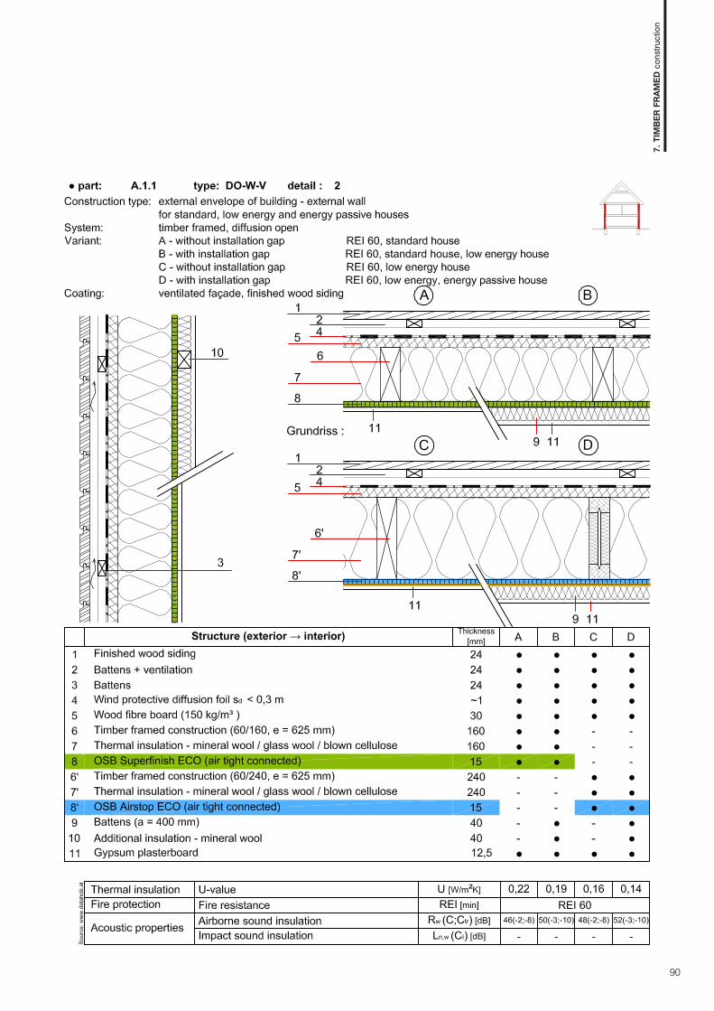
90
7. T
IMBE
R FR
AMED
con
stru
ctio
n

91
7. T
IMBE
R FR
AMED
con
stru
ctio
n

92
7. T
IMBE
R FR
AMED
con
stru
ctio
n

93
7. T
IMBE
R FR
AMED
con
stru
ctio
n

94
7. T
IMBE
R FR
AMED
con
stru
ctio
n

95
7. T
IMBE
R FR
AMED
con
stru
ctio
n

96
7. T
IMBE
R FR
AMED
con
stru
ctio
n

97
7. T
IMBE
R FR
AMED
con
stru
ctio
n

98
7. T
IMBE
R FR
AMED
con
stru
ctio
n

99
7. T
IMBE
R FR
AMED
con
stru
ctio
n

100
7. T
IMBE
R FR
AMED
con
stru
ctio
n
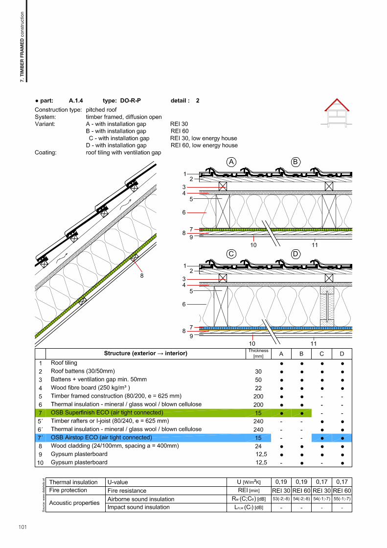
101
7. T
IMBE
R FR
AMED
con
stru
ctio
n

102
7. T
IMBE
R FR
AMED
con
stru
ctio
n

103
7. T
IMBE
R FR
AMED
con
stru
ctio
n

104
7. T
IMBE
R FR
AMED
con
stru
ctio
n

105
7. T
IMBE
R FR
AMED
con
stru
ctio
n

106
7. T
IMBE
R FR
AMED
con
stru
ctio
n

107
7. T
IMBE
R FR
AMED
con
stru
ctio
n

108
7. T
IMBE
R FR
AMED
con
stru
ctio
n

109
7. T
IMBE
R FR
AMED
con
stru
ctio
n

110
7. T
IMBE
R FR
AMED
con
stru
ctio
n

111
7. T
IMBE
R FR
AMED
con
stru
ctio
n

112
7. T
IMBE
R FR
AMED
con
stru
ctio
n

113
7. T
IMBE
R FR
AMED
con
stru
ctio
n

114
7. T
IMBE
R FR
AMED
con
stru
ctio
n

115
7. T
IMBE
R FR
AMED
con
stru
ctio
n

116
7. T
IMBE
R FR
AMED
con
stru
ctio
n

117
7. T
IMBE
R FR
AMED
con
stru
ctio
n

118
7. T
IMBE
R FR
AMED
con
stru
ctio
n

119
7. T
IMBE
R FR
AMED
con
stru
ctio
n

120
7. T
IMBE
R FR
AMED
con
stru
ctio
n

121
7. T
IMBE
R FR
AMED
con
stru
ctio
n

122
7. T
IMBE
R FR
AMED
con
stru
ctio
n

123
7. T
IMBE
R FR
AMED
con
stru
ctio
n

124
7. T
IMBE
R FR
AMED
con
stru
ctio
n


8. C
OM
PACT
boa
rds

127
Compact boardsINFORMATION ABOUT HPL PRODUCTS
Compact boards (High pressure laminates) are premium deco-rative boards representing functionality, elegance and design for everybody’s individual taste. They are engineered for a variety of applications both for interior and exterior use and allow for crea-tive freedom in architecture and design.Compact boards are premium, large-sized, decorative boards consisting of resin-impregnated cellulose sheet material that is bonded together by means of heat and high pressure into a homogeneous solid board. Compact boards are manufactured in accordance with the European Standard EN 438 and achieve a high degree of resis-tance. They are very durable with minimum maintenance costs and are available in a wide variety of decors. Compact boards are engineered for a variety of applications both for interior(Krono Compact) and exterior (Krono Plan) use and they meet the highest standards of comfort, practicability and aesthetics.
Compact boards Krono Plan are manufactured in compliance with European Standard EN 438-6 as load-bearing boards Type EDS (standard) and Type EDF (with increased fi re resistance). Krono Plan are compact boards for exterior use. They are highly color resistant to sunshine and UV radiation and intended for structural use. Some colours have additional protective UV foil. Compact boards are primarily used as a structural material for the fi nal faca-de cladding and sheathing of balcony railings.
Compact boards Krono Compact are manufactured in compliancewith European standard EN 438-4 as load-bearing boards Type CGS (standard) and Type CGF (with increased fi re resistance). Krono Compact boards are engineered for interior applications. They come in a wide variety of décors and patterns and offer unlimited design opportunities for each interior.
protective and decorative layer protective and decorative layer
standard brown or black core layer standard brown core layer
protective and decorative layer UV resitant protective and decorative layer
decorative celluose sheet with protective layer
core cellulose sheets - the number of sheets defi ne the board’s thickness
decorative cellulose sheet with protective layer
8. C
OM
PACT
boa
rds

128
APPLICATION AREAS
ADVANTAGES
Krono Plan Krono Compact
EXTERIOR STRUCTURAL APPLICATION
Ventilated façade facing • -Sheathing of balcony railings • -Balcony partition walls • -Shelter construction • -INTERIOR STRUCTURAL APPLICATION
Walls and ceilings lining - •Sanitary cells - •FURNITURE APPLICATION
Cabinet system for swimming pools - •Shop fitting and office furniture - •Furnishing for laboratories - •Hospital equipment (beds, wardrobes etc.) - •Frames for upholstery furniture - •Work desks for kitchens, offices, laboratories, conference halls and restaurants - •OTHER APPLICATIONS
Display stands - •Information and message boards - •Bus stops and shelters • -
Krono Plan Krono Compact
Resistance to climatic conditions • -Resistance to sunshine and UV radiation • -Resistance to extreme temperatures (-80°C to +120°C) • •Durability and colour stability • •Resistance to water, steam and moisture • •Excellent mechanical-physical properties • •Resistance to impact and abrasion • •Good fire resistance • •Insulating material – no electrostatic build-up • •Extremely chemical resistant - •Meets hygiene requirements for food contact - •Easy to work and process • •Easy maintenance and cleaning • •Environmentally friendly, recyclable • •
8. C
OM
PACT
boa
rds

129
TECHNICAL PRODUCTION SPECIFICATION OF compact boards
TECHNICAL INFORMATION
Property Standard Requirement Tolerances
Thickness 438-2.5
6 mm ± 0.4 mm8 mm ± 0.5 mm10 mm ± 0.5 mm13 mm ± 0.6 mm
Length and width 438 - 2.6 2800 - 5600 x 1300-2040 mm + 10/ - 0 mm
Flatness 438 - 2.96 - 8 mm ≤ 5.0 mm/m
10 – 13 mm ≤ 3.0 mm/mStraightness of edges 438 - 2.7 ≤1.5 mm/mSquareness 438 - 2.8 ≤ 1.5 mm/m
SURFACE PROPERTIES OF COMPACT BOARDS
Property Standard Requirement
Tear resistanceof the surface (abrasion)
initial abrasion levelEN 438-2.10
≥ 150 rotationsfinial abrasion level ≥ 350 rotations
Resistance to impact (large diameter ball)
fall heightEN 438-2.21
≥ 1800 mmball diameter 3 mm
Scratch resistancelevel
EN 438-2.25≥ level 3
force ≥ 4 N
Resistance to immersion in boiling water
mass gainEN 438-2.12
≤ 2.0 %thickness gain ≤ 2.0 %appearance ≥ level 3
Stain resistancegroups 1 and 2
EN 438-2.26≥ level 5
group 3 ≥ level 4Light fastness (Xenon arc light, grey scale) EN 438-2.27 4Steam resistance EN 438-2.14 ≥ level 3Cigarette burn resistance ≥ level 3Cracking resistance EN 438-2.24 ≥ level 4Flexural modulus EN ISO 178:2003 ≥ 9000 MPaBending strength EN ISO 178:2003 ≥ 80 MPaTensile strength EN ISO 527-2:1996 ≥ 60 MPaDensity EN ISO 1183-1:2004 ≥ 1.35 g/cm3
8. C
OM
PACT
boa
rds

130
INSTRUCTIONS FOR COMPACT PANELS USE FOR FINAL EXTERIOR AND INTERIOR APPLICATIONS
BASIC INFORMATION FOR COMPACT BOARDS USE
TransportationAlthough compact boards stand out for excellent strength; however cautious handling during transportation is essential to avoid any damange to the edges or board’s surface.
• Boards shall be fastened during transportation to avoid move-ment of entire stack or of the individual boards.
• Any dirt between the boards should be removed prior to stac-king the panels.
• Do not stack more than 3 pallets on each other.• Use a protective foil to prevent dirt on and between the pa-
nels.
Cutting, drilling, millingIt is recommended to use woodworking tools with hard metal cutting edges. It is recommended to use sharp tools when drilling, cutting and milling and avoid overheating of cutting board edges.
Threads can be carved, self-tapping screws may be used. When cutting boards the input tooth of circular saw should be on visible side. Sharp cut edges should be smoothed with sandpaper. Recommended wood processing parameters:
Blade saw or stationary circular saws:
Storage and handling Any damage must be recorded to the delivery note, signed by the driver and immediately report- ed to KRONOSPAN.
• Do not move pallets/boards on each other when unloading pallets/boards,it can cause damage to the surface or edges.
• Boards shall be stored on a flat, stable surface, max. 3 pallets on the top of each other.
• Special caution must be paid to cleanness during boards stacking.
• Boards must be taken from the stack always in vertical positi-on, never slide one after another (over edges etc.)
Following rules shall be followed before instalation:• Boards should be stored on a flat, stable and dry surface and
protected from water.• Only remove the original packaging immediately before pro-
cessing the panel.• Boards should be stored under regular climatic conditions.• Boards should be covered against rain and should not be in-
stalled during rainy days.• Dirt between boards must be removed.• Never stand or lean the boards against the wall in an angle.
It can cause non-repairable board damage (warping, twisting, deformation).
Packaging Compact boards Krono Plan are covered by protective foil with special UV layer on side. This foil should be removed after board installation.
CleaningCompact boards are easy to maintain and clean. Moderate staining can be usually removed with a soft clean cloth and warm water with soap and regular non-abrasive cleaning detergent. Tougher
stains can be removed by using a regular organic dissolvent (acethon, alcohol, gas, etc.). Always clean a small area first and check for visible surface changes before proceeding to larger areas.
Special cleaning instructions for boards with UV protection layerCompact boards Krono Plan cannot be cleaned with dissolving agents. Only cleaning detergents with an alcohol base are recommended (Isopropy-
lalcohol). Any sanding or scrubbing (powders, creams), polishing or whitening detergents cannot be used. Silicone removing from the surface can be carried out after drying.The cleaning can also be conducted by using a high pressure jet cleaner. In case a suitable agent is used the cleaning should be done from below cross-wise to the top and finally the cleaned surface should be rinsed with fresh water. Minimal distance from surface is approx.25-30 cm, the water temperature cannot exce-ed 90 - 100°C and maximum pressure of 100 BAR.
Tooth type: trapezoid flat tooth or exchangeable tooth
Tools : hard metal or diamond-tipped
Rake angle: a rake angle of 45°
Diameter(mm) Teeth Rot. speed
(x/min)
Blade thickness
(mm)
Overlap(mm)
300 72 6000 3,4 30
350 84 5000 4,0 35
400 96 4000 4,8 40
HSS drill – top angle 60-80°
Diameter(mm)
Rot. speed(x/min)
Input speed(mm/min)
5 3000 60 - 120
8 2000 40 - 80
10 1500 30 - 60
8. C
OM
PACT
boa
rds

131
EXTERIOR FACADE APPLICATION
VISIBLE FIXING WITH RIVETS AND SCREWS
Advantages of ventilated facade from compact boards Krono Plan:• Due to the ventilation the whole layer system holds an optimal
moisture level• Provides long façade lifespan • Permanent interior protection from overheating• Improves acoustic properties• Dry installation process is very flexible• Possible installation on uneven surface
Installation system is based on subframe made of aluminium or galvanized steel, which is fixed to the structural facade. Boards are fixed by means of rivets or screws. It is possible to match the color of the fixings to the compact boards. Decorative features can be integrated in order to give the facade an individual look in correspondence with the character of the house.
The ventilated facades have an air space between the compact board and the insulated layer. Such space should be at least 20 mm. The lack of such air or ventilation layer may cause steam condensation behind the board and cause its deformation. The moisture expansion coefficient both for the longitudinal and tran-sverse direction amounts to 2.5 mm/m.
Designing the ventilated facade the distance between fixing po-ints of the internal hard structure and placing the fixed and sli-ding points correctly should be taken to the account depending on the board’s thickness.. Installation is carried out using a single fixed point with the dia-meter of the drill hole the same as the diameter of the fastener, whereas the diameter of the sliding points should be at least 1.5 times bigger. The maximum length of one board is (Z; X) 3050 mm.
Due to its properties compact boards can be applied to curved facades with a min. radius of r = 2 m.
Firm point Sliding point
Thickness max.D max. B a b
6 400 400 20 - 40 20
8 550 500 20 - 50 20
10 700 600 20 - 60 20
Thickness max.D max. B a b
6 550 400 20 - 60 20 - 50
8 700 500 20 - 80 20 - 60
10 800 600 20 - 100 20 - 80
8. C
OM
PACT
boa
rds

132
Invisible fixing by means of bonding This installation method with the compact boards adhered (glued) to a subframe made of aluminium or galvanized steel may be a convincing alternative for building where compact boards pre-sent a decorative façade. This installation shall be performed by a company licensed for such bonding technology installation and work in compliance with standards given by the bond manu-facturer. At the time of fixing the ambient temperature should be within the range of +10 to +30°C and should not fall under +8°C during the glue setting period.
A
X
B B
Z
aluminum structure
Elastic glue (PUR)
double-sided adhesive tape
Krono Plan
In order to reach maximum adhesion the compact boards as well as the aluminium subframe structure should be cleaned and degreased prior to installation. Both adhesive and double-sided adhesive tape can only be applied once the subframe structure is completely dry, i.e. after about 30 minutes.
Double-sided adhesive tape is useful for initial board fixing until the adhesive is completely set. The adhesive has to be applied quickly, evenly and continuously.
Removing the protective strip from the double-sided adhesive tape.
Within 10 minutes the boards should be pressed and aligned so it is tightly and permanently fixed to the bottom structure. After fi-xation on the double-sided adhesive tape no further adjustments are possible.MAX. FIXING DISTANCE FOR LOW BUILDINGS (MAX. B)
Thickness [mm] Single-span ssembly Multiple-span assembly
6 440 540
8 590 640
10 640 640
8. C
OM
PACT
boa
rds

133
HIDDEN MOUNTING WITH INVISIBLE SCREWS The installation of ventilated facade systems with invisible mechanical fixing of compact Krono Plan boards is very flexible and can be performed under any weather conditions.
The invisible installation meets the highest functional and esthe-tic building requirements.
The invisible mechanically fixed façade structure is based on an aluminium subframe and the use of special clips into compact Krono Plan boards.
This system enables easy step-by-step installation and also dis- assembly of individual boards without the risk of their damage. The actual installation is carried out by means of special fixing clips which requires a minimum board thickness of 8mm. The board’s size, as well as the entire construction should be agre-ed with the suppliers of the subframe structure and the façade elements.
8. C
OM
PACT
boa
rds

134
BALCONY SHEATHING AND BALCONY PARTITIONS
Compact Krono Plan boards are ideal material for balcony panels, balcony partitions, sun protectors and terraces. Their properties and choice form wide decor range the balcony area made of compact boards adapt very well to the facade layout. Balcony sheathing made of compact boards make great wind and view protection. These boards have an extremly long lifespan and require minimum maintenance work.
There are a wide varieties of installation systems for compact boards fixing as balcony boards:
• Visible fixing to brackets, using clip for mechanical atta-chments to the balustrade supports
• Visible sectional fixing to the balustrade supports• Visible fixing balustrade supports –continuous board• Visible sectional fixing to the balustrade supports with Z
profile
Visible fixing with brackets resp. clips to the balustrade supports
Visible sectional fixing to the balustrade supports
Visible fixing to the balustrade supports - continuous board
Visible sectional fixing to the balustrade supports with “Z”-profiles
8. C
OM
PACT
boa
rds
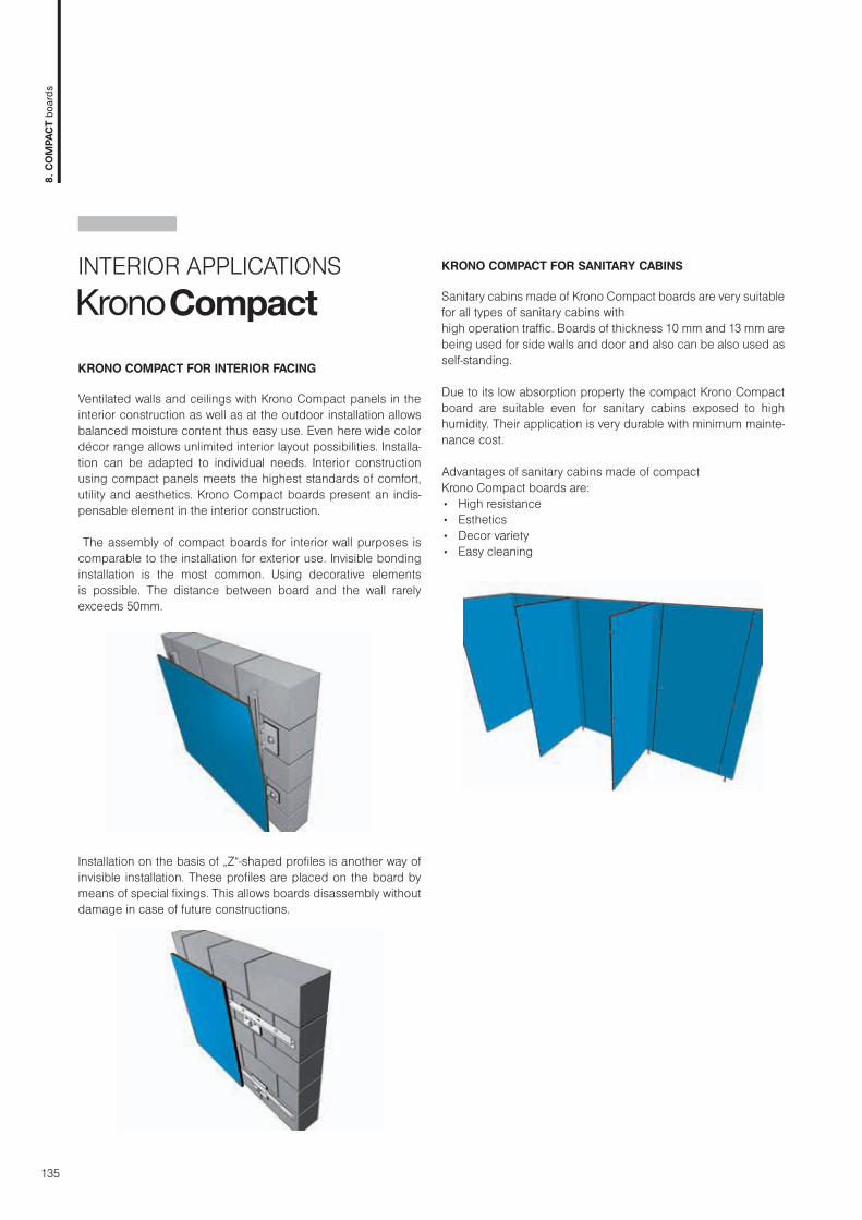
135
INTERIOR APPLICATIONS
KRONO COMPACT FOR INTERIOR FACING
Ventilated walls and ceilings with Krono Compact panels in the interior construction as well as at the outdoor installation allows balanced moisture content thus easy use. Even here wide color décor range allows unlimited interior layout possibilities. Installa-tion can be adapted to individual needs. Interior construction using compact panels meets the highest standards of comfort, utility and aesthetics. Krono Compact boards present an indis-pensable element in the interior construction.
The assembly of compact boards for interior wall purposes is comparable to the installation for exterior use. Invisible bonding installation is the most common. Using decorative elements is possible. The distance between board and the wall rarely exceeds 50mm.
Installation on the basis of „Z“-shaped profiles is another way of invisible installation. These profiles are placed on the board by means of special fixings. This allows boards disassembly without damage in case of future constructions.
KRONO COMPACT FOR SANITARY CABINS
Sanitary cabins made of Krono Compact boards are very suitable for all types of sanitary cabins with high operation traffic. Boards of thickness 10 mm and 13 mm are being used for side walls and door and also can be also used as self-standing.
Due to its low absorption property the compact Krono Compact board are suitable even for sanitary cabins exposed to high humidity. Their application is very durable with minimum mainte-nance cost.
Advantages of sanitary cabins made of compact Krono Compact boards are:• High resistance• Esthetics• Decor variety• Easy cleaning
8. C
OM
PACT
boa
rds
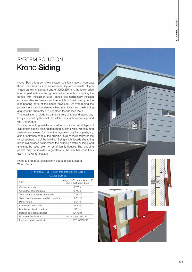
136
SYSTEM SOLUTION
Krono Siding is a complete system solution made of compact Krono Plan boards and accessories. System consists of pre--made panels in standard size of 3050x255 mm, the lower edge is equipped with a milled groove, which enables mounting the panels with installation clips. panels are horizontally installed on a wooden subframe structure which is fi xed directly to the load-bearing parts of the house envelope. By overlapping the panels the installation elements become hidden and the building acquires the character of a sheathed façade (see Pic. 1).The installation of cladding panels is very simple and fast so any-body can do it by themself. Installation instructions are supplied with the product.This clip mounting installation system is suitable for all types of cladding including old and damaged building walls. Krono Siding system can be used for the entire façade or only for its parts, e.g. attic or entrance parts of the building. In all cases it improves the visual appearance of the building. Being a light façade sheathing Krono Siding does not increase the building’s static building load and may be used even for small family houses. The cladding panels may be installed regardless of the weather conditions even in the winter season.
Krono Siding decor collection includes unicolours andWood decor.
TECHNICAL INFORMATION, PACKAGING AND ACCESSORIES
Size length: 3050 mm / width: 255 mm / thickness: 8 mm
One panel surface 0.778 m2 One panel covering area 0.702 m2
Total surface of panels in one box 3.89 m2
Total covering area of panels in one box 3.51 m2
Panel weight 8.71 kgNet weight of one box 43.55 kgNumber of clips in one box 30 pcsRelated european standard EN-438-6EDS fi re classifi cation according to EN 13501Hygienic quality certifi cate no. HZ/C/00750/07
8. C
OM
PACT
boa
rds


9. F
ORM
WO
RK b
oard
s

139
9. F
ORM
WO
RK b
oard
s
FORMWORK boards PRODUCT INFORMATIONFormwork boards Kronobuild® are especially engineered for the building and construction industry. Shuttering boards Krono-build® are panels with an excellent price/performance ratio and offers a wide range of possible applications for professional con-crete formwork. It is a cost-effi cient alternative to other formwork systems and multi-layered panels.
ProForm and OSB Film boards are resistant to moisture and me-chanical wear-off even in extreme conditions and also provide a perfect surface fi nish for exposed concrete surfaces even for multiple applications.
ProForm core board is a 3-layered chipboard P3 type in compli-ance with European standard EN 312 with increased resistance to moisture. Raw particle board is coated on both sides with foil impregnated with phenolic resin. All edges are protected with waterproof paraffi n coating. Fine structure of formwork board pro-vides a smooth surface for exposed concrete.
OSB Film is made of sanded OSB/3 board type according to EN 300 designed for use in humid conditions. Raw OSB board is a double sided laminated phenolic foil under high pressure and temperature. OSB Film edges have waterproof coating for better protection during construction work.
three-layered P3 chipboard
papers impregnated with phenol resin
sealed edges (paraffi n coating paint)
OSB board type OSB/3
papers impregnated with phenol resin
edges sealed with water proof paint

140
APPLICATION AREAS
ADVANTAGES
ProForm OSB Film
STRUCTURAL APPLICATION
Formwork material for construction of floor, walls and columns • •Exposed concrete formwork with smooth structure • •Load-bearing boards for technical structures – bridges, supporting walls etc. • •Formwork of floor rim • •Lining material for formworks • •Foundation formwork, minor concrete works • •
TECHNICAL AND INDUSTRIAL APPLICATIONS
High quality packaging and transportation systems • •Automotive industry - •
ProForm OSB Film
High dimensional accuracy and shape stability • •Long lifespan, multiple reuse • •Resistence to moisture from wet concrete • -Easy manipulation • •Easy processing and anchoring • •High load-bearing capacity in the longitudinal direction of the panel - •Perfectly smooth and resistant surface • •Ecological, recyclable material • •Easy maintenance and clearing thanks to anti-adhesive surface • •Cost-efficient alternative to other formwork and multi-layered panels • •
9. F
ORM
WO
RK b
oard
s

141
GENERAL REQUIREMENTS
Property Test method Requirement Tolerance on the mean density within a board EN 323 ±15%
Tolerance on nominal dimensionsThickness EN 324-1 ± 0,3 mmLength and width EN 324-1 ± 3 mm
Edge straightness tolerance EN 324-2 1,5 mm/mSquareness tolerance EN 324-2 2 mm/mMoisture content EN 322 2 - 12 %Formaldehyde content EN 120 class E1 ≤ 8 mg/100 g
REQUIREMENTS FOR OSB FILM
Properties Test Method UnitThickness (mm, nominal dimension)
18 21
Bending strengthMajor axis
EN 310 N/mm220 18
Minor axis 10 9
Modulus of elasticity in bending
Major axisEN 310 N/mm2
3500 3500Minor axis 1400 1400
Internal Bond EN 319 N/mm2 0,32 0,29Swelling in thickness after 24 h EN 317 % 15 15
REQUIREMENTS FOR PROFORM BOARDS
Properties Test Method UnitThickness (mm, nominal dimension)
21Bending strength EN 310 N/mm2 12Modulus of elasticity in bending EN 310 N/mm2 1850Internal Bond EN 319 N/mm2 0,40Swelling in thickness after 24 h EN 317 % 13
PROFORM AND OSB FILM PRODUCTION SPECIFICATIONS
9. F
ORM
WO
RK b
oard
s

142
STRUCTURAL SPECIFICATION – CHARACTERISTIC VALUES
PROFORM NOMINAL BOARD THICKNESS [MM]
Load impact direction 21 mm
Bending perpendicular to the board plane
fm,kEm,mean
11,73500
Shearing in the board plane fv,k 1,5 MPa
OSB FILMNOMINAL BOARD THICKNESS [MM]
Direction of loaddirection of the major axis 1)
Direction of loadDirection of the minor axis
18 21 18 21
Bending perpendicular to the board plane
fm,kEm,mean
16,44930
14,84930
8,21980
7,41980
Shearing in the board plane
fv,kGmean 1
50150
150
150
1) The major axis is identical with longitudinal direction of the panel.
9. F
ORM
WO
RK b
oard
s

143
INSTRUCTIONS FOR USE of formwork concrete slab and wall formworks
TRANSPORTATION AND STORAGE
Detailed information regarding transportation, storage, handling of Kronobuild® boards can be found in chapter 5. Instructions for using load-bearing boards in Transportation and storage part. Only the most important information regarding the formwork boards is mentioned here.
• Transportation Boards must be perfectly fixed against movement during trans-portation on a vehicle. When loading, unloading and handling of board stacks it is recommended to use the fork lift and necessa-ry to avoid any damage to the surfaces and the edges especially.
• Storage Formwork boards must be stored horizontally on a leveled and smooth surface to prevent their bending and twisting. Boards must be stored in such a way that they lay on the top of each other on the whole surface with flush-fitting edges. Underlying bars are oriented in the direction of the shorter board side with a maximum spacing of 600 mm, the base length corresponds to the board width. The minimum distance of the board stack from the ground is 100 - 300 mm to prevent contact with the ground, water or vegetation. When stored outdoors it is also necessary to protect the boards from direct sunlight, extreme heat and rain.
BOARDS PROCESSING AND MAINTENANCE
PROCESSING
• Cutting and drilling Boards can be processed with standard procedures suitable for the machining of solid wood. To prevent damage to the cover paper on the board surface it is recommended to use a saw with pre-cut (scoring unit) or judge by your own experience. When cutting make sure that the board is securely affixed on the work area and does not transmit vibrations. Always follow the safety precautions, recommendations given by machine tools manu-facturers, and use protective equipment. Bits for drilling wood should be used for drilling.
• Edges and holes in the boards To prevent moisture intake and thus to reduce the swelling of board thickness, the cut edges and holes must be covered with special coating and eventually sealed with putty.
In standard the boards are manufactured with coated edges to prevent excess water and air-humidity absorption. In the case of boards formating always protect edges with appropriate coating prior to application of concrete mixture (e.g. paints based on polyurethane-acrylic dispersions, paraffin agents, etc.). All holes drilled for fasteners must be coated together with the edges.
9. F
ORM
WO
RK b
oard
s

144
BASIC REQUIREMENTS FOR FORMWORK BOARDS USE
ATTACHEMENTS
The way of attachment depends on the type of the construction, concrete surface and the frequency of use. Boards can be used in two basic options
• Laid freely - especially for horizontal formwork• Mounted to the load-bearing frame with countersunk or flat
head screws, etc.
To achieve a very smooth surface of the exposed concrete it is required at the construction site to:• protect formwork boards against excessive moisture and drying• avoid direct sunlight• temporarily store formworks preferably in a vertical position
(in the shade during summer), horizontal storage can cause imprints of interlayers.
SEPARATION LAYER
Formwork boards must be protected before the first and each subsequent use in order to ensure easy cleaning and disassem-bly. Board surface must be covered with a thin, leveled and clear separation agent if possible (diassembly oil). Separation agent used must be compatible with color of edges to avoid its disruption and possible coloring of concrete surface. The formwork boards must be protected from dirt at the time be-tween coating with the diassembly oil and concreting.Only separation agent suitable for such surface type can be used for the forwork boards. Suitable agents include i.e. separation oils based on rapeseed and synthetic oils, etc.
CLEANING, MAINTENANCE
Clean the boards and remove all remains of concrete immedia-tely after use. Do not use sharp instruments, be careful not to damage the coating. Cover minor scratches with water repellent acrylic paint. Fill in deeper scratches and holes from fasteners with waterproof sealant. Apply a new coating of separation agent before each use. Follow the instructions for storage to store cle-an and dry boards.
REPAIRS OF DAMAGED BOARDS
Gentle board processing is the main requirement for smooth sur-face and long life-span. Repair the scratches and damage that occur during concrete work immediately to avoid any moisture increase.Mechanical surface damage can be repaired with sealant. Sea-led surface areas must be carefully sanded after hardening wit-hout damaging the original film.
The most common causes of foil damage are:• faulty hammering into the bonding nails• scratching i.e. with concrete framework, material storage, or
disposal of technical equipment, especially for slab formwork• scuffing during transportation• contact with the vibrator, protective vibrator head from hard
rubber reduces the surface film damage• slipping of drills or screwdrivers• countersunk screw heads recessed below the formwork
board surface
DO NOT FORGET! Proper handling, storage and maintenance of formwork boards means an increase in the number of possible uses. This extends the life-span of boards and reduces costs.
9. F
ORM
WO
RK b
oard
s

145
9. F
ORM
WO
RK b
oard
s
BOARDS LOAD CAPACITY DIAGRAM Values are determined under the conditions of ultimate bending and load capacity in bending and in skid while bending. The va-lues in the tables refer to a short-term load with board moisture up to 12%. The values must be reduced down to 50% for long--term load or multiple board using with assumed higher boards humidity.
250
300
350
400
450
500
L= 550mm
span distance
600
650700L/200
deflection limit
L/300
L/400L/500
0,00
1,00
2,00
3,00
4,00
0,0 1,0 2,0 3,0 4,0 5,0 6,0 7,0 8,0 9,0 10,0 11,0 12,0 13,0 14,0 15,0Load q [kN/m2]
ProF
orm
def
lect
ion
u [m
m]
21mm
EN
250
300
350
400
450
500
L= 550mm
span distance60
0650
700L/200
deflection limit
L/300L/400
L/500
0,00
1,00
2,00
3,00
4,00
0,0 1,0 2,0 3,0 4,0 5,0 6,0 7,0 8,0 9,0 10,0 11,0 12,0 13,0 14,0 15,0Load q [kN/m2]
OSB
Film
def
lect
ion
u [m
m]
18mm
EN
EN
250300
350
400
450
500
550
span distance
L =600 mm65
070
0L/200deflection limit
L/300
L/400
L/500
0,00
1,00
2,00
3,00
4,00
0,0 1,0 2,0 3,0 4,0 5,0 6,0 7,0 8,0 9,0 10,0 11,0 12,0 13,0 14,0 15,0Load q [kN/m2]
OSB
Film
def
lect
ion
u [m
m]
21mm

146
CONCRETE SLAB AND WALL FORMWORKS
All local regulations for the formwork installation and especially work in heights must be respected when creating formwork.
CONCRETE SLAB FORMWORKS
For slab formwork the boards can be laid freely side by side pre-ferably to special load-bearing systems.Installation steps for slab formwork assembly:1. First mount the main load-bearing steel props on a fl at and
load-bearing base and ensure their stability (tripod, coupling with other diagonal props, etc.). It is recommended to use pro-ps with a cross head or downward head with a possible height adjustment.
2. Mount the bottom beams on props and secure them against turning over.
3. Mount the top beams. The top beams must be positioned so that the shorter edges of formwork boards are supported with beams (beams optimum distance is 500 mm boards of 2500 mm lenght). The ends of boards must overlap by min. 15 cm. The top beams must be secured against over-turning.
4. Place the formwork boards on the top beams side by side and ensure their position at the edges against moving (e.g. nails).
5. Lay formwork horizontally and equip with a separation agent.
DANGER OF FALLING FROM HEIGHT! The edges of the slab formwork must be immediately secured against falling according to the valid regulations!
Steps for slab load-bearing formwork diassembly:1. The disassembly is possible only after a technological break.2. All props/heads must be lowered of about 4 cm.3. Tilt the top beams and then remove them. Beams in formwork
board contacts must remain.4. Remove the formwork boards and then the remaining top beams.5. Remove the bottom beams and subsequently the steel props.
FORMWORK OF CONCRETE WALLS, PILLARS AND BEAMS
For concrete wall and pillar formwork it is primarily recommen-ded to create a wood or steel load-bearing frame, and fasten the boards to it with fl at-headed screws. Formworks of vertical structures are then carried out through the whole formwork pa-nels using special formwork equipment.
• Means for connecting formwork panels Basic means for connecting formwork panels (e.g. system Dywidag):• Fastening rods for fastening of formwork• Nut with spherical or fl at washer• Spacing concrete or plastic pipes as formwork spacer.• Cones for distance pipes.• Corks and stoppers for closing holes from cones.
After installation pull the fastening rod together with the cones and fi ll the hole with sealant - see Pic.
xx
xx
xx
1m1m3m
0,3m 0,3m 0,3m
9. F
ORM
WO
RK b
oard
s
1.
2.
3.

KRONOSPAN CR spol. s.r.o.Na Hranici 6CZ–58704 JihlavaCzech RepublicT +420 567 124 204 ▪ F +420 567 124 [email protected] ▪ www.kronospan.cz
Falco Zrt. Tárnoki FióktelepHU-2461 Tárnok, Állomás u. 2HungaryT +36 23 521 580 ▪ F +36 23 361 [email protected] ▪ www.kronospan.hu
KRONOSPAN GmbHLeopoldstaler Strasse 195D – 32839 Steinheim-Sandebeck GermanyT +49 52 38 98 40 ▪ F +49 52 38 98 44 [email protected] ▪ www.kronospan.de KD
21-E
N 2
/201
3
Prei
s: 1
0€
www.kronospan-express.com