RE92-manual-EN.pdf - TME.eu.
200
DUAL LOOP CONTROLLER 96 x 96 mm RE92 USER’S MANUAL
-
Upload
khangminh22 -
Category
Documents
-
view
0 -
download
0
Transcript of RE92-manual-EN.pdf - TME.eu.

1
DUAL LOOP CONTROLLER 96 x 96 mm
RE92
USER’S MANUAL

2

3
Contents
1. IntroductIon ..................................................................... 51.1. Purpose ..................................................................................................51.2. Controller properties ...............................................................................5
2. controller set .................................................................. 63. basIc requIrements, operatIonal safety .............................. 74. InstallatIon ...................................................................... 7
4.1. Controller installation ..............................................................................74.2. Electrical connections .............................................................................94.3. Recommendations for installation ........................................................14
5. startIng work .................................................................. 156. startIng the controller ................................................... 15
6.1. Information bar .....................................................................................156.2. Button markings ...................................................................................166.3. Screen with fixed set-point control .......................................................166.4. Screen with programming control ........................................................176.5. Screen with the timer function ..............................................................176.6. Additional screens with values ..............................................................186.6.1. Visual alarms .....................................................................................196.6.2. Rescaling values ................................................................................206.7. Change of displayed screens ................................................................216.8. Edit mode .............................................................................................236.9. Context menu .......................................................................................25
7. controller confIguratIon ................................................. 257.1. Menu access password .........................................................................257.2. Programming matrix .............................................................................277.3. Parameters description .........................................................................28
8. Inputs and outputs of the controller ................................ 648.1. Measuring input 1 .................................................................................648.2. Measuring input 2 .................................................................................658.3. Measuring input 3 .................................................................................658.4. Interface inputs 1,2 ...............................................................................66 8.5. Binary inputs.........................................................................................66
9. controller outputs .......................................................... 689.1. Controlling outputs ...............................................................................689.2. Alarm outputs .......................................................................................809.3. Timer function ......................................................................................71

4
9.4. Retransmission outputs ........................................................................739.5. Signal outputs.......................................................................................74
10. loop confIguratIon ......................................................... 7610.1. Controlled signal .................................................................................7610.2. Control types ......................................................................................7610.3. Control range ......................................................................................8210.4. Set value in loop .................................................................................8210.5. Control algorithms ..............................................................................82
11. programmIng control ..................................................... 8711.1. Description of the programming control parameters ..........................8711.2. Defining the set value programs .........................................................90
12. modbus ........................................................................... 9312.1. Introduction ........................................................................................9312.2. Archiving configuration.......................................................................9312.3. Copying archive to SD card.................................................................9412.4. Archive file structure...........................................................................9512.5. Copying archive to SD card.................................................................9812.6. Status bar of the archiving.................................................................. 9912.6. Downloading archive files....................................................................99
13. modbus.......................................................................... 10013.1. Introduction.........................................................................................10013.2. Modbus master..................................................................................10013.3. Modbus slave......................................................................................10213.3.1 Error codes........................................................................................10313.3.2 Register map....................................................................................103
14. ftp serVer..................................................................... 19114.1. FTP User............................................................................................ 191
15. web serVer.................................................................... 19316. software upgrade.......................................................... 19417. technIcal data................................................................19418. controller orderIng code...............................................199
This manual is valid for the controller using software v1.11.09

5
1. IntroductIon
1.1. Purpose two-loop rE92 controller used to control temperature and other physical values (e.g. pressure, humidity, flow level). It can control two objects independently or control two physical values in one object (e.g. two-chamber furnaces).
1.2. controller properties
rE92 controller is characterized by the following features:• two-loop control and measurement,• 3,5’’ tFt full-color screen, resolution: 320 x 240 pixel,• intuitive handling via six buttons and graphic user interface,• two universal measuring inputs (for thermoresistors, thermo-
couples or standard linear signals),• additional input,• communication interfaces: rS-485 Modbus Slave, Modbus
tcP Slave,• six binary outputs (possible direct control via the interface),• two voltage and current analog outputs,• three binary inputs additional 3 binary inputs controlled from
the interface,• object transducers supply output,• software upgrade possibility using Sd card,• two-step control, three-step step-by-step control, three-step
control of heating-cooling type,• SMArt PId innovative algorithm,• alarms,• timers function,• FtP server,• three independent groups of data archiving of 10 values in
the group.• Web server (available in controller versions with Ethernet in-
terface),

6
2. controllEr SEt
complete set of the controller includes:1. controller ............................................. 1 pc2. seal...................................................... 1 pc3. holders to fix the meter in the panel .... 4 pcs 4. plug with 16 screw terminals ............... 2 pcs5. plug with 10 screw terminals ............... 2 pcs6. user manual ....................................... 1 pc7. guarantee card .................................... 1 pc
k
l
m n
• modbus master function - querying 2 devices 10 registers each time,
• two interface measurement inputs - readout of measured va-lues from external devices via rS-485 Modbus master,
• possibility to assign custom names to measurement channels.• extended functions of programming control,• additional 3 screens with the possibility of displaying up to 18
any values from the controller’s modbus registers.

7
3. Basic requirements, operational safety
the controller conforms to a safety standard En 61010-1.
Additional comments concerning safety:• Assembly and installation of the electrical connections
should conducted only by people authorized to perform assembly of electric devices.
• Always check the state of connections before turning the controller on.
• Prior to taking the controller housing off, always turn the supply off and disconnect measuring circuits.
• removal of the controller housing during the warranty period voids the warranty.
• the device is designed to installation and usage in the indu-strial electromagnetic environment.
• A switch or a circuit-breaker should be installed in the buil-ding or facility. this switch should be located near the device, easily accessible by the operator, and suitably marked.
4. InStAllAtIon
4.1. controller installation Fix the controller to the board with three screw brackets as shown in the fig. 1A slot in the panel must have the following dimensions: 92.5+0.6 x 92.5+0.6 mm. the thickness of the panel material cannot exceed 6 mm.

8
Fig. 1. Controller installation.
Fig. 2. Controller dimensions.
Dimensions of the controller are presented on the fig. 2.
96 76,769
22
92

9
4.2. Electrical connections the controller has three separate strips with screw terminals. two strips with 16 terminals each allow to connect all signal sources by a wire with a 2.5 mm2 cross-section, and two strips with 10 terminals each allow for connecting by a wire with 1.5 mm2 cross-section.
Fig. 3. Connection strips of the controller.
RS485 RS485
Supply Out1Out2Out3Out4Out5Out6++
In3 In2 In1
24 V+
Out
A AB BGND GND
slave master
GNDGND In1BIn2BIn3BI2U2 I1U1
Out1AOut2A
Eth
ern
et
US
B
SD
17
37
1
38
2
39
3
40
4
41
5
42
6
43
7
44
8
45
9
46
10
47
11
48
12
49
13
50
14
51
15
52
16
18192021222324252627282930313233343536

10
ConneCting the supply
supply should be connected to the terminals 51 and 52, according to technical data
ConneCtion of 1 And 2 input
thermoresistor Pt100 in 3-wire system
thermoresistor Pt100 in 2-wire system
thermoresistor Pt1000 thermocouples
supply
IN2
IN1
IN2
IN1
IN2
IN1
IN2
IN1

11
current input 0/4...20 mA
voltage input 0...5/10 V
ConneCtion of input 3
ConneCtion of the binAry outputs
current input 0/4..20 mA
voltage input 0...5/10 V
potentiometric input
output 1–6 – relay
IN2
IN1
IN2
IN1
OUT6 OUT5 OUT4 OUT3 OUT2 OUT1
load

12
output 1 and 2 – voltage 0/5 V
OUT2 OUT1
load
ConneCting the AnAlog outputs
output 1A – current 0/4–20 mA and voltage 0–10 V
output 2A – current 0/4–20 mA and voltage 0–10 V
OUT1Aload
load
OUT2Aload
load
ConneCting the binAry inputs
IN1B
IN2B
IN3B
volt-free binary inputs

13
ConneCting the rs-485 interfACe
supply object transducers of load up to 30 mA
ethernet ConneCtionFor Ethernet connection use the category 5 shielded twisted-pair wire with rJ-45 connector, compliant to the following standards:• EIA/tIA 568A for both connectors in strike-
-through connection (i.e. between rE92 and hub or switch),
• EIA/tIA 568A for the first connector and EIA/tIA 568B for the second one in the cross-over connection (i.e. when connecting rE92 to the computer).
ConneCting objeCt trAnsduCers supply
interfejs rS-485 slave15
12
16
13
14
11
B (-)
B (-)
GND
GND
A (+)
A (+)
RS-485
slave
RS-485
master
15
12
16
13
14
11
B (-)
B (-)
GND
GND
A (+)
A (+)
RS-485
slave
RS-485
master
interfejs rS-485 master

14
4.3. recommendations for installation to achieve full electromagnetic resistance of the con-troller, it is necessary to follow the rules described below: – do not supply the controller from the network in the proximi-
ty of devices generating high pulse noises and do not apply common earthing circuits,
– apply network filters, – wires leading measuring signal should be twisted in pairs
and for the resistance sensors in the three-wire connection they should use twisted wires of exactly the same length, cross-section and resistivity protected by shielding,
– all shields should be one-side earthed or connected to the protection wire, the nearest possible to the controller,
– as a rule of thumb, wires transmitting different signals sho-uld be spaced as far as it is possible (at least 30 cm) and should be crossed only at the right angle (90 degrees).
– to connect rE92 controller to the Ethernet it is recommen-ded to use:• u/FtP – twisted pair cable with separate foil shielding
for every pair,• F/FtP – twisted pair cable with separate foil shielding
for every pair and additional foil shielding for the cable,• S/FtP (former SFtP) – twisted pair cable with sepa-
rate foil shielding for every pair and additional mesh cable shielding,
• SF/FtP (former S-StP) – twisted pair cable with separate foil shielding for every pair and additional mesh and foil cable shielding.

15
Fig. 4. Information bar
6. starting the controller
6.1. Information bar Information bar displays the state of outputs, binary inputs and real-time clock. When active binary outputs and inputs are displayed in black, inactive ones are displayed in light grey color. State of the outputs, binary inputs and real-time clock can be hidden.
5. starting work
After turning a supply on, the controller displays logo and then moves to the normal operational mode.
Rys. 4. Pasek informacyjny
dateoutputs states
binary inputsstates
archivizationstate
time

16
6.2. Button markings depending on the service location, controller buttons can perform different functions. Functions are described in the bar on the bottom of the screen. If the button lacks description, it is inactive at the moment. Fig. 5 shows an example of the button marking.
Functionof button 1
Functionof button 2
Functionof button 3
Functionof button 4
Functionof button 5
Functionof button 6
Fig. 5. Buttons marking - example
6.3. Screen with fixed set-point control
Fig. 6. Screen with fixed set-point control

17
Fig. 7. Screen with programming control
6.4. Screen with programming control
6.5. Screens with the timer function
Fig. 9. Single Alarm Timer screen
Fig. 8. Alarm Timers screen
timer reset
pause/continuation of the countdown
countdown time bargraph
time to alarm switching on
time to alarm switching off
timer status
output holding type
time to alarm switching ontime to alarm switching off
measured value
timer alarm set point valuetimer alarm type
timer alarm set point value
timer resetpause/continuation
of the countdown
RE92 – 07 Rev. J Instrukcja obsługi 10
6.3. Ekran z regulacją stałowartościową
wartość mierzona
wyświetlany kanał
bie wartożąca ść zadana
pole zmiany wartości zadanej
pole zmiany wartości zadanej
bargraf sygna łu sterującego
bargraf wartości mierzonej
bargraf wartości zadanej
status regulacjibieżacy zestaw
parametrów PID
pole rozpoczęcia samostrojenia
pole start/stoppracy ręcznej
Rys. 6. Ekran z regulacją stałowartościową
6.4. Ekran z regulacją programową
wartość mierzona
wyświetlany kanał
bieżąca wartość zadana
bargraf i czasy dla odcinkabargraf i czasydla programu
bargraf sygnału sterującego
pole startu/wstrzymaniaregulacji
pole zatrzymania regulacji
pole numeru programu
pole numeru odcinka
status regulacjipozostała liczba cykli
narost/opadanie/wytrzymanie
bieżący zestawparametrów PID
data i godzina starturegulacji programowej
Rys. 7. Ekran z regulacją programową
6.5. Ekrany z funkcją Timer
Rys. 8. Ekran alarmu timerów
start/hold of controldate and time of program-
ming control start
stop of controlprogram numbersegment number
ramp/soak
control statusnumber of left cycles
set of piD parameters
displayed loop
measured value
set-point value
steering signal
segment time
program time

18
6.6. Additional screens with valuesthe rE92 controller allows displaying any value from the ava-ilable modbus registers of the controller. these values can be displayed on 3 additional screens of the controller, in the confi-guration from 1 to 6 displayed values on the screen. For each value it is possible to configure: - its name (up to 12 characters),- units from the unit table or entering your own name for the unit (up to 6 characters),- color in which the value on the screen is to be displayed,- display precision,- rescaling values with individual characteristics,- visual alarm (alarm type, alarm color, alarm signaling after its discontinuation).
unit
displayed value name
value number
alarm signaling
alarm signaling after its discon-tinuation
reset of alarm signaling
Fig. 10. An example of an additional screen with values

19
6.6.1. Visual alarmsFor each value on the screen, you can assign a visualization alarm. the alarm function is only used for visual signaling of exceeded values displayed and is not related to any controller output.
Fig. 11. Alarm types
RE92 – 07 Rev. J Instrukcja obsługi 12
1
0
Sta
n sy
gnal
izac
ji
wartośćwyświetlana
1 – sygnalizacja alarmu0 – brak sygnalizacji alarmu
Dolny prógalarmu
Powyżej progua)
Górny prógalarmu
Dolny prógalarmu
Stan
sy
gnal
izac
ji
wartośćwyświetlana
Dolny prógalarmu
Poniżej progub)
Górny prógalarmu
1
0
1 – sygnalizacja alarmu0 – brak sygnalizacji alarmu
Stan
sy
gnal
izac
ji
wartośćwyświetlana
Dolny prógalarmu
Pomiędzy progamic)
Górny prógalarmu
1
0
1 – sygnalizacja alarmu0 – brak sygnalizacji alarmu
Sta
n sy
gnal
izac
jiwartość
wyświetlanaDolny próg
alarmu
Poza progamid)
Górny prógalarmu
1
01 – sygnalizacja alarmu0 – brak sygnalizacji alarmu
Rys. 11. Typy alarmów
Pozostałe typy alarmów: - Ręcznie wł. - ciągła sygnalizacja alarmu (alarm załączony na stałe) - Ręcznie wył. - brak sygnalizacji alarmu (alarm wyłączony na stałe) Gdy funkcja sygnalizacji alarmu po jego ustąpieniu jest załączona, wówczas po ustąpieniu stanu alarmowego zaświeca się znacznik sygnalizujący taki stan.
Znacznik sygnalizacji alarmu po jego ustąpieniu jest aktywny do momentu skasowania go za pomocą przycisku Reset.
6.6.2. Przeskalowanie wartości Na podstawie podanych przez użytkownika współrzędnych dwóch punktów regulator wyznacza (z układu równań) współczynniki charakterystyki indywidualnej a i b.
Dolna wartość wyjściowa = a * Dolna wartość wejściowa + b
Górna wartość wyjściowa = a * Górna wartość wejściowa + b
gdzie: Dolna wartość wejściowa, Górna wartość wejściowa – wartości odczytane z rejestrów Dolna wartość wyjściowa, Górna wartość wyjściowa – wartości oczekiwane na wyświetlaczu
wartość wyświetlana
wartośćwejściowa
Dolna wartośćwejściowa
Gór
na
war
tość
wyjśc
iow
a
dowolne nachylenie
charakterystyki
dowolne przesunięcie
charakterystykiGórna wartość
wejściowa
Dol
na
war
tość
wyjśc
iow
a
wartość wyświetlana
wartośćwejściowa
Dolna wartośćwejściowa
Gór
na
war
tość
wyjśc
iow
a
dowolne nachylenie
charakterystyki
dowolne przesunięcie
charakterystykiGórna wartość
wejściowa
Dol
na
war
tość
wyjśc
iow
a
Rys. 12. Przeskalowanie wartości wyświetlanej
above threshold
1 - alarm signaling0 - no alarm signaling
alarm lower threshold
alarm upper threshold
displayed value sig
nalin
g st
atus
RE92 – 07 Rev. J Instrukcja obsługi 12
1
0
Sta
n sy
gnal
izac
ji
wartośćwyświetlana
1 – sygnalizacja alarmu0 – brak sygnalizacji alarmu
Dolny prógalarmu
Powyżej progua)
Górny prógalarmu
Dolny prógalarmu
Stan
sy
gnal
izac
ji
wartośćwyświetlana
Dolny prógalarmu
Poniżej progub)
Górny prógalarmu
1
0
1 – sygnalizacja alarmu0 – brak sygnalizacji alarmu
Stan
sy
gnal
izac
ji
wartośćwyświetlana
Dolny prógalarmu
Pomiędzy progamic)
Górny prógalarmu
1
0
1 – sygnalizacja alarmu0 – brak sygnalizacji alarmu
Sta
n sy
gnal
izac
ji
wartośćwyświetlana
Dolny prógalarmu
Poza progamid)
Górny prógalarmu
1
01 – sygnalizacja alarmu0 – brak sygnalizacji alarmu
Rys. 11. Typy alarmów
Pozostałe typy alarmów: - Ręcznie wł. - ciągła sygnalizacja alarmu (alarm załączony na stałe) - Ręcznie wył. - brak sygnalizacji alarmu (alarm wyłączony na stałe) Gdy funkcja sygnalizacji alarmu po jego ustąpieniu jest załączona, wówczas po ustąpieniu stanu alarmowego zaświeca się znacznik sygnalizujący taki stan.
Znacznik sygnalizacji alarmu po jego ustąpieniu jest aktywny do momentu skasowania go za pomocą przycisku Reset.
6.6.2. Przeskalowanie wartości Na podstawie podanych przez użytkownika współrzędnych dwóch punktów regulator wyznacza (z układu równań) współczynniki charakterystyki indywidualnej a i b.
Dolna wartość wyjściowa = a * Dolna wartość wejściowa + b
Górna wartość wyjściowa = a * Górna wartość wejściowa + b
gdzie: Dolna wartość wejściowa, Górna wartość wejściowa – wartości odczytane z rejestrów Dolna wartość wyjściowa, Górna wartość wyjściowa – wartości oczekiwane na wyświetlaczu
wartość wyświetlana
wartośćwejściowa
Dolna wartośćwejściowa
Gór
na
war
tość
wyjśc
iow
a
dowolne nachylenie
charakterystyki
dowolne przesunięcie
charakterystykiGórna wartość
wejściowa
Dol
na
war
tość
wyjśc
iow
a
wartość wyświetlana
wartośćwejściowa
Dolna wartośćwejściowa
Gór
na
war
tość
wyjśc
iow
a
dowolne nachylenie
charakterystyki
dowolne przesunięcie
charakterystykiGórna wartość
wejściowa
Dol
na
war
tość
wyjśc
iow
a
Rys. 12. Przeskalowanie wartości wyświetlanej
Below threshold
1 - alarm signaling0 - no alarm signaling
alarm lower threshold
alarm upper threshold
displayed value sig
nalin
g st
atus
RE92 – 07 Rev. J Instrukcja obsługi 12
1
0
Sta
n sy
gnal
izac
ji
wartośćwyświetlana
1 – sygnalizacja alarmu0 – brak sygnalizacji alarmu
Dolny prógalarmu
Powyżej progua)
Górny prógalarmu
Dolny prógalarmu
Stan
sy
gnal
izac
jiwartość
wyświetlanaDolny próg
alarmu
Poniżej progub)
Górny prógalarmu
1
0
1 – sygnalizacja alarmu0 – brak sygnalizacji alarmu
Stan
sy
gnal
izac
ji
wartośćwyświetlana
Dolny prógalarmu
Pomiędzy progamic)
Górny prógalarmu
1
0
1 – sygnalizacja alarmu0 – brak sygnalizacji alarmu
Sta
n sy
gnal
izac
ji
wartośćwyświetlana
Dolny prógalarmu
Poza progamid)
Górny prógalarmu
1
01 – sygnalizacja alarmu0 – brak sygnalizacji alarmu
Rys. 11. Typy alarmów
Pozostałe typy alarmów: - Ręcznie wł. - ciągła sygnalizacja alarmu (alarm załączony na stałe) - Ręcznie wył. - brak sygnalizacji alarmu (alarm wyłączony na stałe) Gdy funkcja sygnalizacji alarmu po jego ustąpieniu jest załączona, wówczas po ustąpieniu stanu alarmowego zaświeca się znacznik sygnalizujący taki stan.
Znacznik sygnalizacji alarmu po jego ustąpieniu jest aktywny do momentu skasowania go za pomocą przycisku Reset.
6.6.2. Przeskalowanie wartości Na podstawie podanych przez użytkownika współrzędnych dwóch punktów regulator wyznacza (z układu równań) współczynniki charakterystyki indywidualnej a i b.
Dolna wartość wyjściowa = a * Dolna wartość wejściowa + b
Górna wartość wyjściowa = a * Górna wartość wejściowa + b
gdzie: Dolna wartość wejściowa, Górna wartość wejściowa – wartości odczytane z rejestrów Dolna wartość wyjściowa, Górna wartość wyjściowa – wartości oczekiwane na wyświetlaczu
wartość wyświetlana
wartośćwejściowa
Dolna wartośćwejściowa
Gór
na
war
tość
wyjśc
iow
a
dowolne nachylenie
charakterystyki
dowolne przesunięcie
charakterystykiGórna wartość
wejściowa
Dol
na
war
tość
wyjśc
iow
a
wartość wyświetlana
wartośćwejściowa
Dolna wartośćwejściowa
Gór
na
war
tość
wyjśc
iow
a
dowolne nachylenie
charakterystyki
dowolne przesunięcie
charakterystykiGórna wartość
wejściowa
Dol
na
war
tość
wyjśc
iow
a
Rys. 12. Przeskalowanie wartości wyświetlanej
Between thresholds
1 - alarm signaling0 - no alarm signaling
alarm lower threshold
alarm upper threshold
displayed value sig
nalin
g st
atus
RE92 – 07 Rev. J Instrukcja obsługi 12
1
0
Sta
n sy
gnal
izac
ji
wartośćwyświetlana
1 – sygnalizacja alarmu0 – brak sygnalizacji alarmu
Dolny prógalarmu
Powyżej progua)
Górny prógalarmu
Dolny prógalarmu
Stan
sy
gnal
izac
ji
wartośćwyświetlana
Dolny prógalarmu
Poniżej progub)
Górny prógalarmu
1
0
1 – sygnalizacja alarmu0 – brak sygnalizacji alarmu
Stan
sy
gnal
izac
ji
wartośćwyświetlana
Dolny prógalarmu
Pomiędzy progamic)
Górny prógalarmu
1
0
1 – sygnalizacja alarmu0 – brak sygnalizacji alarmu
Sta
n sy
gnal
izac
ji
wartośćwyświetlana
Dolny prógalarmu
Poza progamid)
Górny prógalarmu
1
01 – sygnalizacja alarmu0 – brak sygnalizacji alarmu
Rys. 11. Typy alarmów
Pozostałe typy alarmów: - Ręcznie wł. - ciągła sygnalizacja alarmu (alarm załączony na stałe) - Ręcznie wył. - brak sygnalizacji alarmu (alarm wyłączony na stałe) Gdy funkcja sygnalizacji alarmu po jego ustąpieniu jest załączona, wówczas po ustąpieniu stanu alarmowego zaświeca się znacznik sygnalizujący taki stan.
Znacznik sygnalizacji alarmu po jego ustąpieniu jest aktywny do momentu skasowania go za pomocą przycisku Reset.
6.6.2. Przeskalowanie wartości Na podstawie podanych przez użytkownika współrzędnych dwóch punktów regulator wyznacza (z układu równań) współczynniki charakterystyki indywidualnej a i b.
Dolna wartość wyjściowa = a * Dolna wartość wejściowa + b
Górna wartość wyjściowa = a * Górna wartość wejściowa + b
gdzie: Dolna wartość wejściowa, Górna wartość wejściowa – wartości odczytane z rejestrów Dolna wartość wyjściowa, Górna wartość wyjściowa – wartości oczekiwane na wyświetlaczu
wartość wyświetlana
wartośćwejściowa
Dolna wartośćwejściowa
Gór
na
war
tość
wyjśc
iow
a
dowolne nachylenie
charakterystyki
dowolne przesunięcie
charakterystykiGórna wartość
wejściowa
Dol
na
war
tość
wyjśc
iow
a
wartość wyświetlana
wartośćwejściowa
Dolna wartośćwejściowa
Gór
na
war
tość
wyjśc
iow
a
dowolne nachylenie
charakterystyki
dowolne przesunięcie
charakterystykiGórna wartość
wejściowa
Dol
na
war
tość
wyjśc
iow
a
Rys. 12. Przeskalowanie wartości wyświetlanej
outside thresholds
1 - alarm signaling0 - no alarm signaling
alarm lower threshold
alarm upper threshold
displayed value sig
nalin
g st
atus

20
other alarm types:- Manually switched on - continuous alarm signaling (alarm per-manently enabled)- Manually switched off - no alarm signaling (alarm permanently disabled)
When the alarm signaling function after its discontinuation is switched on, then after the alarm state has disappeared, the indicator signaling such a state lights up.
After the alarm discontinuation the alarm signaling indicator is active until it is reset by means of the reset button.
6.6.2. rescaling valuesBased on the coordinates of two points given by the user, the controller determines (from the system of equations) the indivi-dual characteristics coefficients a and b.
lower output value = a * lower input value + bupper output value = a * upper input value + b
where:lower input value, upper input value - values read from registerslower output value, upper output value - expected values on the display
RE92 – 07 Rev. J Instrukcja obsługi 12
1
0
Sta
n sy
gnal
izac
ji
wartośćwyświetlana
1 – sygnalizacja alarmu0 – brak sygnalizacji alarmu
Dolny prógalarmu
Powyżej progua)
Górny prógalarmu
Dolny prógalarmu
Stan
sy
gnal
izac
ji
wartośćwyświetlana
Dolny prógalarmu
Poniżej progub)
Górny prógalarmu
1
0
1 – sygnalizacja alarmu0 – brak sygnalizacji alarmu
Stan
sy
gnal
izac
ji
wartośćwyświetlana
Dolny prógalarmu
Pomiędzy progamic)
Górny prógalarmu
1
0
1 – sygnalizacja alarmu0 – brak sygnalizacji alarmu
Sta
n sy
gnal
izac
ji
wartośćwyświetlana
Dolny prógalarmu
Poza progamid)
Górny prógalarmu
1
01 – sygnalizacja alarmu0 – brak sygnalizacji alarmu
Rys. 11. Typy alarmów
Pozostałe typy alarmów: - Ręcznie wł. - ciągła sygnalizacja alarmu (alarm załączony na stałe) - Ręcznie wył. - brak sygnalizacji alarmu (alarm wyłączony na stałe) Gdy funkcja sygnalizacji alarmu po jego ustąpieniu jest załączona, wówczas po ustąpieniu stanu alarmowego zaświeca się znacznik sygnalizujący taki stan.
Znacznik sygnalizacji alarmu po jego ustąpieniu jest aktywny do momentu skasowania go za pomocą przycisku Reset.
6.6.2. Przeskalowanie wartości Na podstawie podanych przez użytkownika współrzędnych dwóch punktów regulator wyznacza (z układu równań) współczynniki charakterystyki indywidualnej a i b.
Dolna wartość wyjściowa = a * Dolna wartość wejściowa + b
Górna wartość wyjściowa = a * Górna wartość wejściowa + b
gdzie: Dolna wartość wejściowa, Górna wartość wejściowa – wartości odczytane z rejestrów Dolna wartość wyjściowa, Górna wartość wyjściowa – wartości oczekiwane na wyświetlaczu
wartość wyświetlana
wartośćwejściowa
Dolna wartośćwejściowa
Gór
na
war
tość
wyjśc
iow
a
dowolne nachylenie
charakterystyki
dowolne przesunięcie
charakterystykiGórna wartość
wejściowa
Dol
na
war
tość
wyjśc
iow
a
wartość wyświetlana
wartośćwejściowa
Dolna wartośćwejściowa
Gór
na
war
tość
wyjśc
iow
a
dowolne nachylenie
charakterystyki
dowolne przesunięcie
charakterystykiGórna wartość
wejściowa
Dol
na
war
tość
wyjśc
iow
a
Rys. 12. Przeskalowanie wartości wyświetlanej
displayed value
input value
any slope of the characte-
ristics
any shift of the characte-
risticslower input value upper input value
uppe
r ou
tput
va
lue
low
er
outp
ut
valu
e
Fig. 12. Rescaling the displayed value

21
via context Menu
via context Menu
6.7. changing the display screens Pressing the Screens button,you can switch between the views of selected screens. the choice of screens to be displayed is made in the Settings -> Show screens. Figure 13 shows an example of a change in display screens for the regu-lator with the programming control.
Button Screens
Button Screens

22
Fig. 13. Change of the displayed screens - example
via contextMenu
Button Screens
23
Button: Edit
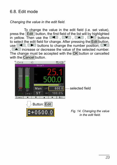
Fig. 14. Changing the value in the edit field.
selected field
6.8. Edit mode
Changing the value in the edit field.
to change the value in the edit field (i.e. set value), press the Edit button, the first field of the list will by highlighted in yellow. then use the , , , buttons to select the edit field for change. After pressing the Edit button, use , buttons to change the number position; , increase or decrease the value of the selected number. the change must be accepted with the oK button or cancelled with the cancel button.

24
Button Exec
Fig. 15. Using the button type field.
Using the button type field.
to use such field (e.g. start/stop control), press the Edit button; the first item in the list will be highlighted in yellow. then use the , , , buttons to select the button type field. Pressing the Exec button per-forms a function appropriate to the given button.

25
6.9. context menu
Pressing the contxtM button displays the context menu. this menu allows for quick access to a given feature.
Fig. 16. Context menu
7. controller configuration
7.1. Menu access passwordto switch to the controller configuration from the screen display level, choose the Menu button. use selection and access password window will appear. on the first run, there is only one user [Admin] with no set password. It is possible to create four users with different access rights. user [Admin] has all the rights, and can set them for the other users. user privileges are selected from the menu: Security g user g level. [Level 0] allows for changing all parameters, including the [security], [Level 1] allows to change all parame-ters with the exception of the [security] submenu, [Level 2] allows for changing the set values, current program, date and time.In case the user forgets the password, it is possible to delete it. In this case, when the power supply of the controller is off, turn on the power while holding down the two central buttons and wait until the display shows a message informing that the controller factory settings have been restored.

26
Button
Button oK
Button oK
Menu
Button
Button oK

27
7.2. Programming matrix
Fig. 17. Programming matrix
menu
inputs
Analog input 1
Analog input 2
outputs
output 1
Analog input 3
output 2
external input 1
output 3
external input 2
output 4
Binary input 1
output 5
Binary input 2
output 6
Binary input 3
Analog output 1
modb. Binary input 1
Analog output 2
modb. Binary input 2 modb. Binary input 3
loop 1
inputs
measured value
piD1
setpoint
PID2
control
piD3
piD parameters
piD4
Gain Scheduling
piDc name
loop 2
inputs
measured value
piD1
setpoint
PID2
control
piD3
piD parameters
piD4
Gain Scheduling
piDc name
screens with screen 1 Settings
values screen 2 Value 1
screen 3 ... Value 6
Programs
Program 1
confi Prg
...
Segment 1
Program 60
...
Segment 15
alarms
alarm 1
Alarm 2
timers
timer 1
alarm 3
timer 2
alarm 4
timer 3
alarm 5
timer 4
alarm 6
timer 5
timer 6
archivization
group 1
group 2
modbus
group 3
csV settings
modbus tcp
actions...
modbus master
Settings
master 1
ftp
Master 2
www
ethernet
Security
Settings
information

28
7.3. Parameters description
the list of parameters is presented in the table 1.
lista parametrów konfiguracji table 1
sym
bol
of p
aram
eter
parameter name
factory setting
parameter modification range
sensors linear input
Inputs
Analog input 1
Input type Pt100 Pt100 : thermoresistor Pt100Pt500 : thermoresistor Pt500Pt1000: thermoresistor Pt1000ni100 : thermoresistor ni100ni1000: thermoresistor ni1000cu100 : thermoresistor cu100tc J : J type thermocoupletc t : t type thermocoupletc K : K type thermocoupletc S : S type thermocoupletc r : r type thermocoupletc B : B type thermocoupletc E : E type thermocoupletc n : n type thermocoupletc l : l type thermocouple0..20mA: linear current 0-20mA4..20mA: linear current 4-20mA0..5V : linear voltage 0-5 V0..10V : linear voltage 0-10 V

29
unit °c c : degrees celsiusF : degrees FahrenheitPu: physical units%: percent%rH: relative humidity
dot.level dP1 dP0 : without a decimal placedP1 : 1 decimal place
dP0 : without a decimal placedP1 : 1 decimal placedP2 : 2 decimal places
compensation Auto AutoManual
comp. temp. 0°c 0...50°c -
MinInpAnalog 0 - -9999...99999
MaxInpAnalog 100 - -9999...99999
correction 0 -35.00...35.00
Filter 0.2 off: filter off 0.2: time constant 0.2 s 0.5: time constant 0.5 s 1: time constant 1 s 2: time constant 2 s 5: time constant 5 s 10: time constant 10 s 20: time constant 20 s 50: time constant 50 s100: time constant 100 s
Analog input 2
as per analog input 1

30
Analog input 3
Input type 1) 4..20mA0..10Vr100
0..20mA: linear current 0-20mA4..20mA: linear current 4-20mA 0..5V: linear voltage 0-5 V 0..10V: linear voltage 0-10 V r100: potentiometric input 100 ohm r1000: potentiometric input 1000 ohm
unit °c °c : degrees celsius °F : degrees Farenheit Pu: physical units %: percent%rH: relative humidity
digit Point dP1 dP0 : without a decimal placedP1 : 1 decimal placedP2 : 2 decimal places
lowScale 0 -9999...99999
HighScale 100 -9999...99999
Shift 0 -35.00...35.00
Filter 0.2 off: filter off 0.2: time constant 0.2 s 0.5: time constant 0.5 s 1: time constant 1 s 2: time constant 2 s 5: time constant 5 s 10: time constant 10 s 20: time constant 20 s 50: time constant 50 s100: time constant 100 s
Modbus input 1, Modbus input 2
Assignment Master 1 Master 1: modbus master 1Master 2: modbus master 2
registry name
0 list of 10 registers or their names read by the modbus master fun-ction

31
unit oc oc : degrees celsiusoF : degrees Fahrenheit Pu: physical units%: percentage%rH: relative humidity
digit Point dP1 dP0 : no decimal place dP1 : 1 decimal placedP2 : 2 decimal places
Shift 0.0 -35.00...35.00
Filter 0.2 off: filter off0.2: time constant 0.2 s0.5: time constant 0.5 s1: time constant 1 s2: time constant 2 s5: time constant 5 s10: time constant 10 s20: time constant 20 s50: time constant 50 s100: time constant 100 s
Binary input 1
Function none none: none Stop: stop automatic control (response to a level) Manualop: switching to manual operation (response to a level) SP+1: switching to subse quent SP (response to a level) SP1<->SP2, SP2<->SP3, SP3<->SP4, SP4<->SP1 StartPrg: program start (response to the rising edge) nextSegment: jump to the next segment (response to the rising edge) PrgBlock: stop the incrementing of the set point in the program (response to a level)

32
PrgEnd: end of the program (response to the rising edge) PrgStop: stop of the program with possible continuation (response to the rising edge)PrgStopBeg: stop the program and jump to the beginning (response to the rising edge) SP-In3: switching to subse- quent SP from the additional input (response to a level)reset timer1: alarm reset of timer 1reset timer2: alarm reset of timer 2reset timer3: alarm reset of timer 3reset timer4: alarm reset of timer 4reset timer5: alarm reset of timer 5reset timer6: alarm reset of timer 6 (response to a level) SP-In1: switching to SP from the first input (response to a level) SP-In2: switching to SP from the second input (response to a level)SP - Modbus In1: switching to SP from the first interface inputSP - Modbus In2: switching to SP from the second interface input (response to a level)SP-cyclic: switching to subsequent SP (response to the rising edge) SP1>>SP2>>SP3>>SP4 >>SPIn1>>SPIn2>>SPIn3 >>SPMd1>> SPMd2>>SP1out Min/Max 2: switching to the second set of parameters for limiting the control signal (response to a level)

33
Binary input 2
as per binary input 1
Binary input 3
as per binary input 1
Modbus binary input 1
as per Binary input 1
(Binary input function entered into register 7590)
Modbus binary input 2
as per Binary input 1
(Binary input function entered into register 7592)
Modbus binary input 3
as per Binary input 1
(Binary input function entered into register 7594)
outputs
output 1
Assignment none none: none loop 1: loop 1 loop 2: loop 2 Input 1: input 1 Input 2: input 2 Input 3: input 3 InP1+2+3: input 1 + input 2 + input 3 BinInp1: binary input 1 BinInp2: binary input 2 BinInp3: binary input 3 InvBinInp1: inverted binary input 1 InvBinInp2: inverted binary input 2 InvBinInp3: inverted binary input 3Modbus In1: interface input 1 Modbus In2: interface input 2 ModbEvIn1: interface binary input 1 (register 4055)

34
ModbEvIn2 – interface binary input 2 (register 4056)ModbEvIn3 – interface binary input 3 (register 4057)ModbEvIn1neg: inverted interface binary input 1 (register 4055) ModbEvIn2neg: inverted interface binary input 2 (register 4056) ModbEvIn3neg: inverted interface binary input 3 (register 4057)Modbreg: control from interface (register 4058) Modbreg neg: inverted control from interface (register 4058)
Function none none: none Heating: heating cooling: cooling opening: valve opening closing: valve closing Alarm: alarm Event Prg: progr. control eventcascadeSlv: signal of the slave loop with cascade control timer: alarm timeraCaution!When the heating-cooling function is selected, please keep in mind that it should be consistent with the type of control selected in the channel, which the output is assigned to.

35
Prg Event none none: noneocc.1.Sec: event 1 from a sectionocc.2.Seg: event 2 from a sectionocc.3.Sec: event 3 from a sectionocc.4.Sec: event 4 from a sectionocc.5.Sec: event 5 from a sectionocc.6.Sec: event 6 from a sectionPrg.Block.: deviation block
output type - none: nonetransmitter: relay putput SSr: SSr output
cycle time 20.0 0.5...99.0
output 2
Assignment none As per output 1, except for:Modbreg: control from interface (register 4059) Modbreg neg: inverted control from interface (register 4059)
Function none
As per output 1Prg. Event none
output type -
cycle time 20.0
output 3
Assignment none As per output 1, except for:Modbreg: control from interface (register 4060) Modbreg neg: inverted control from interface (register 4060)
Function none
As per output 1Prg. Event none
output type -
cycle time 20.0

36
output 4
Assignment none As per output 1, except for:Modbreg: control from interface (register 4061) Modbreg neg: inverted control from interface (register 4061)
Function none
As per output 1Prg. Event none
output type -
cycle time 20.0
output 5
Assignment none As per output 1, except for:Modbreg: control from interface (register 4062) Modbreg neg: inverted control from interface (register 4062)
Function none
As per output 1Prg. Event none
output type -
cycle time 20.0
output 6
Assignment none As per output 1, except for:Modbreg: control from interface (register 4063) Modbreg neg: inverted control from interface (register 4063)
Function none
As per output 1Prg. Event none
output type -
cycle time 20.0

37
Analog output 1
Assignment none none: none loop 1: loop 1 loop 2: loop 2 Input 1: input 1 Input 2: input 2 Input 3: input 3 InP1+2+3: input 1 + input 2 + input 3Modbus In1: interface input 1Modbus In2: interface input 2
Function none none: none Heating: heating cooling: coolingretransmission: retransmissionCaution!When the heating-cooling function is selected, please keep in mind that it should be consistent with the type of control selected in the channel, which the output is assigned to.
retr. source PV PV: measuring value SP: set value deviation: set value - measuring value
retr Min 0 -9999...99999
retr Max 100.0 -9999...99999
ouput type I 4-20 mA 4-20mA: current 4...20 mA0-20mA: current 0...20 mA
ouput type u 0-10V 0-10V: voltage 0...10 V
Analog output 2
as per analog output 1

38
loop 1
Inputs
Measuring value
Inp1: input 1 Inp2: input 2 Inp3: input 3Inp1+Inp2: input 1 + input 2Inp1+Inp3: input 1 + input 3Inp2+Inp3: input 2 + input 3Modbus In1: interface input 1Modbus In2: interface input 2
Factor In1 1 -10.00...10.00
Factor In2 1 -10.00...10.00
Factor In3 1 -10.00...10.00
Binary Inputs none: none EvIn1: binary input 1 EvIn2: binary input 2 EvIn3: binary input 3 EvIn1,2: binary input 1 and 2 EvIn1,3: binary input 1 and 3 EvIn2,3: binary input 2 and 3EvIn1,2,3: binary input 1, 2 and 3ModbEvIn1: interface binary input 1 ModbEvIn2: interface binary input 2 ModbEvIn3: interface binary input 3 ModbEvIn1,2: interface binary input 1 and 2 ModbEvIn1,3: interface binary input 1 and 3 ModbEvIn2,3: interface binary input 2 and 3 ModbEvIn1,2,3: interface binary input 1, 2 and 3

39
Setpoint
SP type SP1 SP1: SP1 set point value SP2: SP2 set point value SP3: SP3 set point value SP4: SP4 set point value In3: set point value from input 3PrG: set point value from programIn1: set point value from input 1In2: set point value from input 2Modbus In1: interface input 1Modbus In2: interface input 2
Prg number Prg01 Prg01: program no 1Prg02: program no 2Prg03: program no 3Prg04: program no 4Prg05: program no 5Prg06: program no 6Prg07: program no 7Prg08: program no 8Prg09: program no 9Prg10: program no 10Prg11: program number 11Prg12: program number 12Prg13: program number 13Prg14: program number 14Prg15: program number 15Prg16: program number 16Prg17: program number 17Prg18: program number 18Prg19: program number 19Prg20: program number 20Prg21: program number 21Prg22: program number 22Prg23: program number 23Prg24: program number 24Prg25: program number 25Prg26: program number 26Prg27: program number 27Prg28: program number 28Prg29: program number 29Prg30: program number 30(for loop 2: Prg31–Prg60)
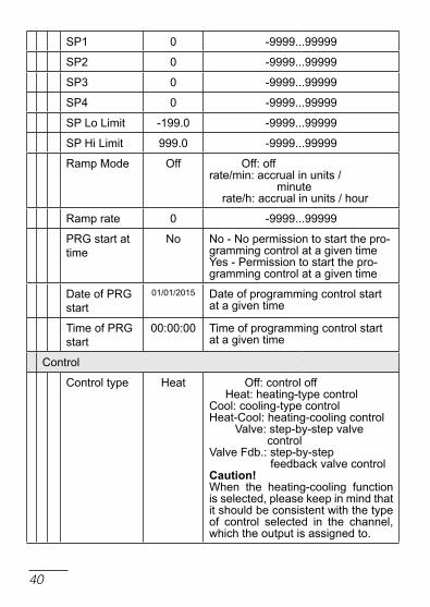
40
SP1 0 -9999...99999
SP2 0 -9999...99999
SP3 0 -9999...99999
SP4 0 -9999...99999
SP lo limit -199.0 -9999...99999
SP Hi limit 999.0 -9999...99999
ramp Mode off off: offrate/min: accrual in units / minute rate/h: accrual in units / hour
ramp rate 0 -9999...99999
PrG start at time
no no - no permission to start the pro-gramming control at a given time Yes - Permission to start the pro-gramming control at a given time
date of PrG start
01/01/2015 date of programming control start at a given time
time of PrG start
00:00:00 time of programming control start at a given time
control
control type Heat off: control off Heat: heating-type controlcool: cooling-type controlHeat-cool: heating-cooling control Valve: step-by-step valve controlValve Fdb.: step-by-step feedback valve controlCaution!When the heating-cooling function is selected, please keep in mind that it should be consistent with the type of control selected in the channel, which the output is assigned to.

41
control Alg PId on-off: on-off algorithm PId: PId algorithm
Hysteresis 2.0 0.1...100.0
dead Band 0.0 -99.9...99.9
Valve open time
30 s 3...600 s
Valve close time
30 s 3...600 s
Min Work time
0.1 s 0.1...99.0 s
out Min 0.00% 0.0...100.0 %
out max 100.00% 0.0...100.0 %
out Min 2 0.00% 0.0...100.0 %
out max 2 100.00% 0.0...100.0 %
out Fail 0 -100.0...100.0
ctrl lim lo 0 -9999...99999
ctrl lim Hi 800.0 -9999...99999
PId Parameters
PId 1
Pb 30.0 °c 0.1...550.0 °c(0.1...990.0 °F)
ti 300 s 0...9999 s
td 60.0 s 0.0...2500.0 s
Y0 0.00% 0...100.0 %
PId 2
PId 3
PId 4
as per PId1

42
PId c
Pb 100.00% 0.1...200.0 %
ti 300 s 0...9999 s
td 60.0 s 0.0...2500.0 s
Gain Scheduling
GS type off off: offSP: switched according to set valueSet: fixed set
GS level nb. 2 2: 2 PId sets used3: 3 PId sets used4: 4 PId sets used
GS level 1-2 0 -9999...99999
GS level 2-3 0 -9999...99999
GS level 3-4 0 -9999...99999
GS Set PId1 PId1: PId1 setPId2: PId2 setPId3: PId3 setPId4: PId4 set
name
name loop proper name - 10 characters
loop 2
as per loop 1 and additonal:
Setpoint
casc. SP lo 0.0 -9999...99999
casc. SP Hi 100.0 -9999...99999

43
control
control type Heat off: control offHeat : heating-type controlcool : cooling-type controlHeat-cool: heating-cooling controlValve: step-by-step valve controlValve Fdb: step-by-step feedback valve controlcascade: cascade controlCaution!When the heating-cooling functionis selected, please keep in mind that it should be consistent with the type of control selected in the chan-nel, which the output is assigned to.
Screens with values
Screen 1
Settings
Show values 6/6 # Value 1# Value 2# Value 3# Value 4# Value 5# Value 6
Value 1
Value name PV loop 1 12 AScII characters from the range 0x20 ... 0x7A
Value color green Green, red, Yellow, White, Blue, Purple
unit selection From the table
From the table - unit selected from the set, „unit” parameter,Manual entry - unit entered manual-ly, „unit name” parameter
unit °c c, F, Pu, %, %rH, g/m3, g/kg, kJ/kg, at, Pa, hPa, kPa, MPa, mmHg, bar, cmHg, inHg, kp/cm2, m2, m3, ug/m3

44
unit name 6 AScII characters from the range 0x20 ... 0x7A
register number
7006 Modbus register number of the controller
digit Point dP1 dP0 : no decimal placedP1 : 1 decimal placedP2 : 2 decimal placesdP3 : 3 decimal placesdP4 : 4 decimal places
Alarm type Hand off Above tresholdBelow tresholdBetween tresholdsBeyond tresholdsHand onHand off(Alarm description in Fig. 11)
lower alarm treshold
0.0 -999999.9...999999.9
upper alarm treshold
100.0 -999999.9...999999.9
Alarm sygna-ling delay
0 s 0...3600 sthe parameter is defined in se-conds. defines the time to elapse from the time of alarm occurence to the time when alarm is signaled on the screen.the alarm signaling is switched off without delay
uphold alarm signaling
off off : upholding the signaling after the alarm disontunuation offon : upholding the signaling after the alarm disontunuation on
Sygnaling of alarm
continuousFlashing

45
color below treshold
Green Black, Green, red, Yellow, White, Blue, Purple
color above treshold
red Black, Green, red, Yellow, White, Blue, Purple
Value resca-ling
off off : rescaling values offon : rescaling values on
lower input value
0.0 lower input value-9999.9...9999.9
lower output value
0.0 lower output value-999999.9...999999.9
upper input value
0.0 upper input value-9999.9...9999.9
upper output value
0.0 upper output value-999999.9...999999
Value 2
like Screen 1, Value 1 except
Value name SP loop 1
Value color red
register number
7008
Value 3
like Screen 1, Value 1 except
Value name MV loop 1
Value color Yellow
unit %
register number
7010

46
Value 4
like Screen 1, Value 1 except
Value name PV loop 2
register number 7014
Value 5
like Screen 1, Value 1 except
Value name SP loop 2
Value color red
register number
7010
Value 6
like Screen 1, Value 1 except
Value name MV loop 2
Value color Yellow
unit %
register number 7018
Screen 2
Settings
Show values 3/6 # Value 1# Value 2# Value 3) Value 4) Value 5) Value 6
Value 1
like Screen 1, Value 1 except
Value name PV Input 1 12 AScII characters from the range 0x20 ... 0x7A
register number
7000 Modbus register number of the controller

47
Value 2
like Screen 1, Value 1 except
Value name PV Input 2
register number
7002
Value 3
like Screen 1, Value 1 except
Value name PV Input 3
register number
7004
Value 4
like Screen 1, Value 1 except
Value name Year
Value color White
unit selection Manual entry
unit name
register number
4012
digit Point dP0
Value 5
like Screen 1, Value 1 except
Value name Month day
Value color White
unit selection Manual entry
unit name MM/dd
register number 4011
digit Point dP0
48
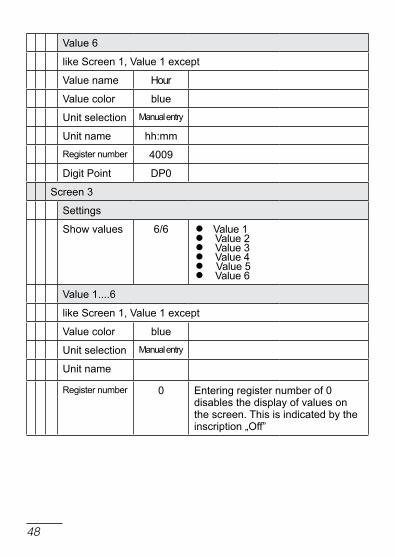
Value 6
like Screen 1, Value 1 except
Value name Hour
Value color blue
unit selection Manual entry
unit name hh:mm
register number 4009
digit Point dP0
Screen 3
Settings
Show values 6/6 # Value 1# Value 2# Value 3# Value 4# Value 5# Value 6
Value 1....6
like Screen 1, Value 1 except
Value color blue
unit selection Manual entry
unit name
register number 0 Entering register number of 0 disables the display of values on the screen. this is indicated by the inscription „off”

49
Programs
Program 1
config Prg
Start Prg Start PV Start SPStart PV
Start SP 0 -9999...99999
time unit mm:ss mm:sshh:mm
ramp unit Min MinHour
Holdback type
disable disablelowHighBand
cycles number 1 1...9999
Power Fail continue continueStop
End type Stop Stoplast SP
Gain scheduling
off offon
Segment 1
Seg.type time timeAccrualHoldEnd
target SP 0 -9999...99999
Seg. duration 00:00 00:00... 99:59
ramp rate 0.1 0.1...999.9
Holdback Val 0 -9999...99999

50
Event1 off offon
Event2 off offon
Event3 off offon
Event4 off offon
Event5 off offon
Event6 off offon
PId set PId1 PId1PId2PId3PId4
Segment 2
...
Segment 15
as Segment 1
Program 2
...
Program 60
as Program 1
Alarms
Alarm 1
type AbsHigh AbsHigh: absolute upperAbslo: absolute lowerdevHigh: relative upperdevlo.: relative lowerdevInBand: relative internaldevoutBand: relative external

51
SP 100 -9999...99999
deviation 0 -9999...99999
Hysteresis 2 0.1...99.9
latch off off: offon: on
overflow state
off off: offon: on
Alarm 2
...
Alarm 6
as Alarm 1
timers
timer 1
Function off off: alarm timer disabledon: alarm timer enabled
time 00:30:00 00:00:01...23:59:59
uphold output
continuous continuous: continuous output latch time: to latch the output for a certain
time
uphold time 00:30:00 00:00:01...23:59:59(active if uphold output: time)
type AbsHigh AbsHigh: absolute upperAbslo: absolute lower
(active if output –> Assignment: Input 1 or Input 2 or Input 3
or InP1+2+3)
SP 100,0 -9999...99999(active if output –> Assignment:
Input 1 or Input 2 or Input 3 or InP1+2+3)

52
timer 2
...
timer 6
as timer 1
Archiving
Group 1
Arch. on/off off off: archiving disabledon: archiving enabled
Parameters
PV_Input1PV_Input2PV_Input3
PV_Input1: measured value from input 1PV_Input2: measured value from input 2PV_Input3: measured value from input 3PV_loop1: measured value in loop 1SP_loop1: setpoint value for loop 1ctrl1_loop1: control loop 1 control signal in loop 1ctrl2_loop1: control loop 2 control signal in loop 1PV_loop2: measured value in loop 2SP_loop2: setpoint value for loop 2ctrl1_loop2: control loop 1 control signal in loop 2ctrl2_loop2: control loop 2 control signal in loop 2Modbus Input1: interface input 1 Modbus Input2: interface input 2Master 1 reg2: register 2 readout from master 1Master 1 reg3: register 3 readout. from master 1Master 1 reg4: register 4 readout. from master 1Master 1 reg5: register 5 readout. from master 1Master 1 reg6: register 6 readout. from master 1Master 1 reg7: register 7 readout. from master 1Master 1 reg8: register 8 readout. from master 1

53
Master 1 reg9: register 9 readout. from master 1Master 1 reg10: register 10 readout. from master 2Master 2 reg1: register 1 readout. from master 2Master 2 reg2: register 2 readout. from master 2Master 2 reg3: register 3 readout. from master 2Master 2 reg4: register 4 readout. from master 2Master 2 reg5: register 5 readout. from master 2Master 2 reg6: register 6 readout. from master 2Master 2 reg7: register 7 readout. from master 2Master 2 reg8: register 8 readout. from master 2Master 2 reg9: register 9 readout. from master 2Master 2 reg10: register 10 readout. from master 2
Archiv type Interval
Interval: archiving at specified time intervalAbsHigh: at a interval after ex-ceeding the upper threshold set by SP AbsAbslo.: at a interval after ex-ceeding the lower threshold set by SP AbsdevHigh: at a interval after ex-ceeding the relative upper thresholddevlo.: at a interval after ex-ceeding the relative lower thresholddevInBand: at a interval inside thelimits of relativedevoutBand: at a interval outside the limits of relative

54
tigger PV_loop 1
PV_Input1: measured value from input 1PV_Input2: measured value from input 2PV_Input3: measured value from input 3PV_loop1: measured value in loop 1SP_loop 1: setpoint value for loop 1ctrl1_loop1: control signal path 1 from loop 1ctrl2_loop1: control signal path 2 from loop 1PV_loop2: measured value in loop 2SP_loop2: setpoint value for loop 2ctrl1_loop2: control signal path 1 from loop 2ctrl2_loop2: control signal path 2 from loop 2Modbus Input1: interface input 1Modbus Input2: interface input 2Master1 reg1: register 1 readout from master 1Master 1 reg2: register 2 readout from master 1Master1 reg3: register 3 readout from master 1Master1 reg4: register 4 readout from master 1Master1 reg5: register 5 readout from master 1Master1 reg6: register 6 readout from master 1Master1 reg7: register 7 readout from master 1Master1 reg8: register 8 readout from master 1Master1 reg9: register 9 readout from master 1Master1 reg10: register 10 readout from master 2Master2 reg1: register 1 readout from master 2Master2 reg9: register 9 readout from master 2

55
Master2 reg2: register 2 readout from master 2Master2 reg3: register 3 readout from master 2Master2 reg4: register 4 readout from master 2Master2 reg5: register 5 readout from master 2Master2 reg6: register 6 readout from master 2Master2 reg7: register 7 readout from master 2Master2 reg8: register 8 readout from master 2Master2 reg10: register 10 readout from master 2(parameter active when Archiv type different from Interval)
Interval 00:00:30 00:00:05...24:00:00
SP Abs 100.0-9999...99999(parameter active, when Archiv type AbsHigh, Abslo)
SP dev SP_loop 1
PV_Input1: measured value from input 1PV_Input2: measured value from input 2PV_Input3: measured value from input 3PV_loop1: measured value in loop 1SP_loop 1: setpoint value for loop 1ctrl1_loop1: control signal path 1 from loop 1ctrl2_loop1: control signal path 2 from loop 1PV_loop2: measured value in loop 2SP_loop2: setpoint value for loop 2ctrl1_loop2: control signal path 1 from loop 2ctrl2_loop2: control signal path 2 from loop 2Modbus Input1: interface input 1Modbus Input2: interface input 2

56
Master1 reg1: register 1 readout from master 1Master 1 reg2: register 2 readout from master 1Master1 reg3: register 3 readout from master 1Master1 reg4: register 4 readout from master 1Master1 reg5: register 5 readout from master 1Master1 reg6: register 6 readout from master 1Master1 reg7: register 7 readout from master 1Master1 reg8: register 8 readout from master 1Master1 reg9: register 9 readout from master 1Master1 reg10: register 10 readout from master 2Master2 reg1: register 1 readout from master 2Master2 reg9: register 9 readout from master 2
Master2 reg3: register 3 readout from master 2Master2 reg4: register 4 readout from master 2Master2 reg5: register 5 readout from master 2Master2 reg6: register 6 readout from master 2Master2 reg7: register 7 readout from master 2Master2 reg8: register 8 readout from master 2Master2 reg10: register 10 readout from master 2(parameter active, when Archive typeAbsHigh, Abslo, devInBand, devout-Band)

57
deviation 2.0 -9999...99999
(parameter active, when the Archive typeAbsHigh, Abslo, devInBand, devout-
Band)
Histeresis 1.0 0,1...99999(parameter active, when the Archive type
is different from Interval)
Group 2
Group 3
same as Group 1
cSV settings
Value sepa-rator
comma comma: a separator is ‘,’Semicolon: a separator is ‘;’tabulator: a separator is a tabcharacter
decimalseparator
dot dot: a integer separator is ‘.’comma: a integer separator is ‘,’
Actions...
rip archiveon Sd card
Saving all the new records on theSd card(only records that have been recorded since the last download to the Sd card are downloaded)
clear archive clear the entire archive
Modbus
Address 1 1...247
Baudrate 9600 bps 4800 bps 9600 bps 19.2k bps 38.4k bps 57.6k bps115.2k bps

58
Mode rtu 8n2 offrtu 8n2rtu 8E1rtu 8o1rtu 8n1
Modbus tcP 2)
Enabled Yes noYes
Port 502 0...65535
Modbus master
Settings
Baudrate 9600 bps 4800 bps 9600 bps 19.2k bps 38.4k bps 57.6k bps115.2k bps
Mode rtu 8n2 offrtu 8n2rtu 8E1rtu 8o1rtu 8n1
delaybetween polls
300 100...5000 ms
Master 1
Master 1 off off: modbus master offon: modbus master on
Address 1 1...247
Work mode Manual Manual: it must be manually confi-gured: „Base register”, „nr of valu-es” and „Value type”template: reading the value from the device indicated in „template”

59
template P18, P18d, P19
p18, p18d, p19t - register 7501 - measured temp.rH - register 7502 - measured relative humidity, dP - register 7503 - dew point calculatedAH - register 7504 - calculated absolute humidityp30udISP VAl1 - register 7505 - displayed value,MEAS VAl - register 7510 - measured value,dISP VAl2 - register 7512 - second displayed valuep18st - register 7501 - measured temperature, rH - register 7502 - calculated absolute humiditydP - register 7503 - calculated dew pointAH - register 7504 - calculated absolute humidity
Base register 4000 0...65535
nr of registers 1 1...10
register type ushort 16 char 8: char register (8 bits with character) uchar 8: unsigned char register (8 bits without character)short 16: short register (16 bits with character) ushort 16: unsigned short register (16 bits without character)long 32: long register (32 bits with character) ulong 32: unsigned long register (32 bits without character)float 32: float register (32 bits, variable comma with character)sw float 2x16: swapped float register, value placed in two 16bit registers (byte order 3,2,1,0)

60
float 2x16: float register, value placed in two 16bit registers (byte order 1,0,3,2)long 2x16: long register, value placed in two 16bit registers (32 bits with character, byte order 1.0,3,2)sw long 2x16: swapped long register, value placed in two 16bit registers (32 bits with character, byte order 3,2,1,0)ulong 2x16: unsigned long register, value placed in two 16 bit registers (32 bits without character, byte order 1.0,3,2)sw ulong 2x16: swapped unsigned long register, value placed in two 16 bit registers (32 bits without character, byte order 3,2,1,)
Interval 5000 5...36000 ms
Max response time 2000 100...5000 ms
req. master function
Function 0x03
Function 0x03Function 0x04
Max nr of req 0 0...10
Master 2
same as Master 1
FtP 2)
Enabled Yes noYes
Port 21 0...65535

61
WWW 2)
Enabled Yes noYes
Port 80 80...32000
Ethernet 2)
dHcP on off: offon: on
Mode Auto Auto: autonegation of baudrate100M FdX: 100Mbit full duplex100M HdX: 100Mbit half duplex10M FdX: 10Mbit full duplex10M HdX: 10Mbit half duplex
IP Address 127.0.0.1 0.0.0.0...255.255.255.255
Subnet mask 255.0.0.1 0.0.0.0...255.255.255.255
Gateway Addres
0.0.0.0 0.0.0.0...255.255.255.255
Security
Admin
Enabled Yes noYes
Password 0...99999999
user 1
Enabled Yes noYes
level level 2 level 0: all parameters changelevel 1: change of all parameters .other than the Security submenulevel 2: change of SP, program number, clock settings
Password 0...99999999

62
user 2
same as user 1
user 3
same as user 1
Settings
lcd Backlight
100% 0...100 %
Backlight oFF
00:00:00 00:00:00…01:00:00Entering the value 00:00:00 disab-les the function
Show screens
5/13 #loop 1#loop 2#loop1/2#1st val screen)2nd val screen)3nd val screen)timers)timer 1)timer 2)timer 3)timer 4)timer 5)timer 6
Screens switching time
00:00:00 00:00:00.....01:00:00 (hh:mm:ss)range of changes from 1 sec to 1 hour
language Polish EnglishPolishdeutsch
Show outSta-tes
no noYes
Show EvSta-tes
no noYes
Show clock no noYes

63
Hours
date
Set defaults revert to manufacturer’s settings (other than Ethernet group settings)
Information
type rE92
Boot Version eg. 1.00
Program version
eg. 1.00.00
Serial number eg. 12010001
MAc Address 2)
1) – default setting and extent of the changes depends on input 3 field in the ordering code 2) – shown for Ethernet version

64
8. InPutS And outPutS oF tHE controllEr
rE92 controller is fitted with two measuring inputs, one two interface inputs (from slave devices through modbus ma-ster), three binary inputs -hardware, three modbus binary inputs.
8.1. Measuring inputs 1 Input 1 is the source of the measured value used for control and alarms.
Input 1 is an universal input capable of accommodating various sensors or standard signals. Input signal is selected with a [input type] parameter. displayed unit is set through the [unit] parameter. Position of the decimal point that determines measu-red and set values is set through the [digit point] parameter.
For thermocouple, a cold terminal compensation must be set through a [CjC type] parameter. When the [CjC type] parameter is set to [Auto], compensation is automatic; when it is set to [External], the compensation temperature is set by the [CjC temp] parameter.
For the linear inputs, set the indication for the lower and upper analog input threshold through the [lowscale] and [highscale] parameter.
correction of the indicated measuring value is done through the [shift] parameter.
When the measuring value is unstable, a digital filter with a programmable time constant value may be used. When using this feature, use the lowest filter time constant value that allows for the stable measuring value. When the time con-stant is too high, it may cause the control to become unstable. the range of a filter time constant – a [filter] parameter – may

65
be set to 0.2 to 100 seconds.Measuring input 1 parameters can be found in menu: Inputs g Analog input 1.
8.2. Measuring input 2 Input 1 is the source of the measured value used for control and alarms.
Measuring input 2 parameters are the same as the ones for input 1 can be found in menu: Inputs g Analog input 2.
8.3. Measuring input 3Input 3 may be used as:• signal controlled for any loop (as the independent input
or component for compound signal on different input),• set value for any loop,• additional measurement point – displayed on a measure-
ment screen.
Input 3 is an input that can accommodate the standard signals. Input signal is selected with a [input type] parameter. displayed unit is set through the [unit] parameter. Position of the decimal point that determines measured and set values is set through the [digit point] parameter.
Set the indication for a lower and upper analog input threshold through the [lowscale] and [highscale] parameter.
correction of the indicated measuring value is done through the [shift] parameter.
When the measuring value is unstable, a digital filter with a programmable time constant value may be used. the range of a filter time constant – a [filter] parameter – may be set to 0.2 to 100 seconds.Measuring input 3 parameters can be found in menu: Inputs g Analog input 3.

66
8.4. Interface inputs 1, 2
Interface inputs 1 and 2 can be used as:• adjustable signal for any loop,• set value for any loop.• reference signal for controlling the alarms,• source of retransmitted signal to analog output
Interface inputs 1 and 2 are inputs for which the measured valu-es are read by the function of modbus master 1 or 2. Selecting the measured value is done with the [Assignment] parameter, where you select the device from which you read the values of the registers (Master 1 or Master 2) and indicate the register to be assigned as the measured value [register number]. the displayed unit is set by the [unit] parameter. the position of the decimal point that determines the display format of the measu-red value and set point value is set by [digit point].
correction of the indicated measured value is done with the [shift] parameter.
If the measured value is unstable, a digital filter with program-mable time constant value can be used. Filter time constant – parameter [filter] can be set from 0.2 to 100 second.
Parameters concerning external inputs 1 and 2 can be found respectively in menu: Inputs g Input modbus 1, Inputs g Input modbus 2.
8.5. Binary inputs the function of the binary inputs are set through the [function] parameter that can be found in: menu: Inputs g Binary input 1, Inputs g Binary input 2 and Inputs g Binary input 3.

67
the controller is also equipped with three additional modbus bi-nary slave inputs - controlled via the interface.Function of interface binary inputs is set through the [Funkcja] parameter, that can be found in menu: Inputs g Modb binary input 1, Inputs gModb binary input 2 i Inputs gModb binary input 3.
then you need to allocate binary inputs to the appropriate loop.
the following functions of the binary input are available:• no function – state of binary input does not influence
the controller operation,• stop – during active binary input the control is interrupted
and control outputs start to function as after sensor failure; alarm and retransmission operate normally,
• switch to manual – during active binary input, the control-ler is in the manual operation mode,
• switch to the next sp – during active binary input the set point value is switched to another (eg. from SP1 to SP2)
• program start – after activation of binary input, the process of programming control starts,
• jump to next segment – after activation of binary input, follows the jump to the next segment of programming control,
• stop counting program set value – during active binary input, follows the stop of set value counting for program-ming control
• end of the program – jump to the end of the program after activation of the binary input,
• stop of the program with possible continuation – control stop and the program stop at the current position after acti-vation of the binary input,
• stop the program and jump to the beginning – control stop and the program jump to start after activating the binary input,
• source for sp from input 1, 2 or 3 – by active binary input
68
the set point is switched to the value from any measuring or interface input
• Alarm timer reset – enabling the binary input turns off the alarm relay responsible for the alarm timer and reset of the timer.
• cyclic switching between sp – after activating the binary input, the setpoint is switched to the next loop (SP1 >> SP2 >> SP3 >> SP4 >> SPIn1 >> SPIn2 >> SPIn3 >> SPMd1 >> SPMd2 >> SP1),
• out Min/Max 2 - switching to the second set of parameters for limiting the control signal
note! If one channel is assigned to more than one binary input, than for each of them must be set a different function.
9. controllEr outPutS
rE92 controller has six binary outputs and two analog outputs: current and voltage (optional).
9.1. controlling outputs [Heat] function output is a reverse output. It is used during con-trol, when the increase of the controlled signal causes the value of output signal to drop. Such output is allocated during the loop configuration to the heating control, heating loop in the heating cooling control or valve opening in the step-by-step control.
[Cool] function output is a non-reverse output (direct). It is used during control, when the increase of the controlled signal causes the value of output signal to increase. Such output is allocated during the loop configuration to the cooling control, cooling loop in the heating-cooling control or valve closing in the step-by-step control.

69
output impulse period is load
electromagnetic transmitter
recommended >20 s, min. 10 s 2 A/230 V a.c.
min. 5 s 1 A/230 V a.c.
transistor output 1...3 s semiconductor transmitter (ssr)
For the proportional control (with the exception of the analog outputs) an impulse period is also set. Impulse period is a time between two subsequent input engagements during proportio-nal control. Impulse period length should be adjusted for the dy-namic properties of the object and characteristics of the output device. It is recommended to use SSr transmitter for quick pro-cesses. relay output is used for a contactor control in the slow--changing processes. long impulse periods for quick-change processes may cause unnecessary oscillation. In theory, the shorter impulse period is, the better the control, however for the relay output a period should be as large, as possible to optimize lifespan of the relay.
Impulse period setting recommendations table 2

70
9.2. Alarm outputs
Alarm configuration is done in two steps:1. In [output k] submenu - where k=1...6 (menu: outputs):• select the number of loop or input allocated to the output
being configured – [Assignment] parameter,• set [function] parameter to [Alarm].
2. In [Alarms] submenu, for every output defined as alarm output, please set:• alarm type – [type] parameter,• set value – [sp] parameter - it is the controlled or measu-
ring signal value that engages the input,• deviation from the value set in the loop [deviation] para-
meter - it is the control deviation that engages the input,• input engagement hysteresis – [hysteresis] parameter
- a zone around the point of alarm operation in which output state does not change,
• alarm memory - [latch] parameter, [Yes] - means that the alarm will be locked until confirmed by operator.
absolute high[AbsHigh]
SP
absolute lower[AbsLo]
relative high[DevHigh.]
SPDeviation (>0)SPDeviation (<0)

71
relative lower[DevLo]
relative internal[DevInBand]
relative external[DevOutBand]
Fig.18. Alarm types
Deviation (>0)SPDeviation (<0)
Deviation SPDeviation
Deviation SPDeviation
9.3. timer function
timers configuration is done in two steps:1. In [output k] submenu - where k=1...6 (menu: outputs):
■ select the number of loop or input allocated to the output being configured – parameter [Assignment],
■ the parameter [function] set to [timer].
2. In [timer k] submenu - where k=1...6 (menu: timers) for each timer:
■ enable timer function – parametr [function], ■ set time – parametr [time] – it is time from which, upon the controler reaches the set point temperature (SP), the timer starts counting down. Alarm timer is set and a relay responsible for the alarm timer is actuated after deduction to zero,
■ select the type of output latch – parameter [uphold output] ■ select time of output latch – parameter [uphold time] – it is time which starts to be counted down when the alarm timer is set and the relay responsible for the alarm timer function is actuated. Alarm timer is reset and a relay is swit-ched off after deduction to zero,

72
■ select the alarm type – parameter [type] – set this para-meter if in the [output -> Assignment] submenu is selec-ted: input 1, input 2, input 3, inp1+2+3,
■ set a set point – parameter [SP] - set this parameter if in the [output -> Assignment] submenu is selected: input 1, input 2, input 3, inp1+2+3.
If in the [output -> Assignment] submenu is selected: loop 1 or loop 2 a timer function works for a control only: heating, cooling.reset the timer to update the parameters in case of any settings were changed on the enlarged timer screen.
Fig. 19. The principle of operation of the timer during a continuous latch.
time countdown
time [sec]
timer erasing
timer alarm

73
9.4. retransmission outputs
Analog output may be used for retransmission of the selected value, e.g. for registering object temperature or copying set values in multi-zone furnaces.
Signal retransmission is possible if the controller is fitted with analog output 1 or 2.
Set [function] parameter to [Retransmiss]. type of a signal to be retransmitted is set through the [retr source] parameter. Signal can be chosen from: [PV] – controlled signal, [Deviation] – control deviation a [SP] – set point value. the next parameter, [output type], sets the analog output range. Additionally, it is necessary to set upper and lower limit of the signal to be retransmitted [retr Min] and [retr Max].
retransmission output parameters can be found in menu: outputs g Analog output 1 and outputs g Analog output 2.
Picture 21 shows method of transforming the retransmitted signal into proper analog output signal.
Fig. 20. The principle of operation of the timer during a timer latch.
time countdowntimer latch countdown
time[sec]
timer alarm

74
Fig. 21. Transformation of the signal to be retransmitted
the [retr Min] parameter may be higher than [retr Max], but this will cause the output signal to be inverted.
9.5. Signal outputs Any binary output can be used for „retransmission” of the state of given binary input, the specified bina-ry input interface register, or the register directly con-trolling the binary output. to do this, while configuring the [Assignment] parameter choose the:• [EvIn1] – binary input 1 short-cut will activate the output,• [EvIn2] – binary input 2 short-cut will activate the output,• [EvIn 3] – binary input 3 short-cut will activate the output,• [EvIn1neg] – binary input 1 release will activate the output,

75
• [EvIn2neg] – binary input 2 release will activate the output,• [EvIn3neg] – binary input 3 release will activate the output.• [ModbEvIn1] – (register 4055) entering value 1 into register
activates the output,• [ModbEvIn2] – (register 4056) entering value 1 into register
activates the output,• [ModbEvIn3] – (register 4057) entering value 1 into register
activates the output,• [ModbEvIn1neg] – (register 4055) entering value 0 into re-
gister activates the output,• [ModbEvIn2neg] – (register 4056) entering value 0 into re-
gister activates the output,• [ModbEvIn3neg] – (register 4057) entering value 0 into re-
gister activates the output,• [Modbreg] – entering value 1 into the following register
activates the: - output 1 (register 4058), - output 2 (register 4059), - output 3 (register 4060), - output 4 (register 4061), - output 5 (register 4062), - output 6 (register 4063),• [Modbregneg] – entering value 0 into the following register
activates the: - output 1 (register 4058), - output 2 (register 4059), - output 3 (register 4060), - output 4 (register 4061), - output 5 (register 4062), - output 6 (register 4063).

76
10. looP conFIGurAtIon
10.1. controlled signal
the signal controlled in a loop might be a measure-ment from the selected source (Inp1, Inp2, Inp3, Modbus In1, Modbus In2) or combination of the measured values from two inputs ( Inp1 + Inp2, Inp1+ Inp3, Inp2 + Inp3).combined control signal is calculated by the controller, using the following formula:
controlled signal = [coeff. for Inp k] * Inp k + [coeff. for Inp k] * Inp k
Where k is a input number (1...3).
Example 1:to control the difference between input 2 and input 3 signals, enter:[pV]= [Inp2+Inp3]; [coeff for Inp 2] = 1,0 [coeff. for Inp 3] = -1,0.
Example 2:to control the mean of input 1 and input 2 signals, enter:[pV] = [Inp1+Inp2]; [coeff. for Inp 1] = 0.5 [coeff. for Inp 2] = 0.5.
10.2. control types
heating-type controlcontroller uses this type of control when the parameter [Control type] in menu: loop 1 g control or loop 2 g control is set to [Heat]. It is a reverse control, when the increase of the con-trolled signal causes the value of output signal to drop. output

77
Fig. 22. Control with two heating-cooling loops
100%
0%
wyjście sterujące
tor główny(grzanie)
[Rozsunięcie]tor pomocniczy
(chłodzenie)
temperatura [ c]°wartość zadana
steering output
[dead Band]main loop(cooling)
auxiliary loop(heat)
setpoint temperature [oc]
three-step, step-by-step controlthe controller offers two algorithms of the step-by-step control for cylinder control:• with no feedback signal from the valve – opening and closing
of the valve is based on PId parameters and control deviation,
• with the feedback signal from the valve positioning device – opening and closing of the valve is based on PId, control deviation and valve position read from the input 3.
to select the three-step step-by-step control, the [Control type] parameter in menu: loop 1 g control or loop 2 g control should be set to [Valve] or to [Valve Fdb]. For every control loop, set the insensitivity range for the set point, in which the valve does not change its position - the parameter [dead band] and select the set of PId parameters. Auto-tuning algorithm is not available for the step-by-step control.
Step-by-step control with no feedback additionally requires the parameters settings: valve open time [Valve open time], valve close time [Valve Close time], minimum valve work time [Min Work time].

78
Fig.23. Three-step step-by-step control with no feedback
the principle of the algorithm shown in Fig. 23 is based on conversion of changing the control signal to the relay opening / closing time referred to the full opening / closing time.the differences between the calculated and the actual valve position are unavoidable because of multiple changes in the di-rection of valve movement due to the inertia of a drive or its wear in the absence of a feedback. the controller uses the function of automatic positioning of a drive during operation to eliminate these differences. this function does not require user interven-tion and its function is to extend switching on time of the relay when the control signal reaches 0% or 100%.the relay for opening / closing will remain on for a time equal to the time of a valve full open / close from a moment of a signal reaching 100% / 0%.

79
the positioning of the valve will be stopped once the signal is equal to the maximum value.In the specific case, the positioning is performed by completely closing the valve, it is carried out each time after:
- turning the controller supply on- changing full open / close time.
the time of full opening of the valve can have a different value than the time of closing.Both parameters should be set to the same value when using a drive with identical times.
Cascade controlcascade control is used in the processes with a high latency to obtain the best quality of control.Second loop works as a slave controller which controls the out-put. First loop works as the master controller and sets the set point for the slave controller.
Fig. 24.Cascade control
piDkana³ 1sp
pV
pV
piDkana³ 2
wyjœciesteruj¹ ce
przeskalowa-nie na zakres
kana³u 2
-
-
PIdloop 1
rescaling to loop 2
range
PIdloop 2
control output

80
First loop should be set to PId control to select the cascade con-trol. In the second loop the parameter [Control type] in menu: loop 2 g control should be set to [Cascade]. For resca-ling the master loop output set the parameters [Casc.so lo] and [Casc.so hi] in menu: loop 2 g Set value.
„gain scheduling” functionFor control systems, where the object behaves decidedly differently in various temperatures, it is recommended to use the „Gain Scheduling” function. the controller allows to remem-ber up to four sets of PId parameters and switch them over automatically. Switching between PId sets runs percussiveless and with a hysteresis to eliminate the oscillations on switching limits.the parameter [typ gs] settles the way of the function operation.
[off] the function is disabled
[SP] a) Switching depending on the set point value.Additionally, one must also choose the number of PId sets – parameter [gs level nb], and set their switching levels in dependence from the number of PId sets [gs level 1-2], [gs level 2-3], [gs level 3-4].b) For the programmed control, one can set the PId set individually for each segment. First, for the given program, one must set the parameter [gain scheduling] in the menu: Programs g Program x g config Prg to [On].
[Set] Permanently setting of one PId set. the PId set is set through the [gs set] parameter.

81
Fig.25.”Gain Scheduling” switched over from SP
Fig. 26. „Gain Scheduling” switched over for each segment in the programmed control.
s p
G S P o z io m 1 - 2
G S P o z io m 2 - 3
g s p o z io m 3 - 4
p i D
p i D 1
P I D 2
p i D 3
p i D 4gs level 3 - 4
GS Level 2 - 3
GS Level 1 - 2
piD
1..
.piD
4
piD
1..
.piD
4
piD
1..
.piD
4
piD
1..
.piD
4
piD
1..
.piD
4
PV
czastime

82
10.3. control range
control range is defined by [Ctrl lim lo] and [Ctrl lim hi] parameters. control range defines limits for the PId control and auto-tuning algorithm.
10.4. Set value in loop
A set value in loop may be one of the four values defined as SP1, SP2, SP3, SP4, value read from the input 1, 2, 3, Modbus In1, Modbus In2 or one of the PrG programs.
soft startIf the value is controlled in loop via SP1, SP2, SP3 or SP4, it is possible to determine an allowable speed of controlled changes (i.e. soft start) during object activation or while chan-ging the set value. It allows for smooth achievement of a target value without re-regulation. When accrual process starts, temporary set value changes from the measured value to the set value allocated to a loop. Selection of the ramp rate unit between [rate/min] and [rate/h] is set in the [ramp Mode] parameter, and the ramp rate in the [ramp rate] parameter.
10.5. control algorithms
on-off algorithm When high accuracy of a temperature control is not required, especially for the high time constant and small delay, it is possible to use on-off control with hysteresis. this method ensures simple and reliable control, its downside is the oscillation, even at low hysteresis values.

83
Fig. 27. Heating output operation
sMArt pid algorithmWhen high precision of the temperature control is necessary, it is recommended to use PId algorithm. Innovative SMArt PId algorithm ensures increased precision in the extended range of the control object classes.
tuning of the controller to object is achieved by manual setting of the proportional term, derivation term or difference term or automatically – by auto-tuning function.
proceeding in case of a unsatisfactory pid controlPId parameters are best selected by doubling or halving the value. the following rules should be observed during changes: a) oscillations• increase the proportional band,• increase integration time,• decrease the differentiation time,b) over-regulations• increase the proportional band,• increase integration time,• increase the differentiation time,
załączone
wyłączonewartośćzadana
wartośćmierzona
histerezawyjście
output
on
off
hysteresis
setpointvalue
measuredvalue

84
c) Instability• decrease the proportional band,• decrease the differentiation time,d) Free jump response:• decrease the proportional band,• decrease integration time.
Fig.28. PID parameters correction method
t
x
t
x
t
x
t
x
Pb Pb td Pb
Pb
td
td
ti
ti
Pb ti
tiPb Pb Pb ti
Pb td
Pb PbPb td
Przebieg wielkościregulowanej
Algorytmy działania regulatora
P PD PI PID
Pb td
trace of controlled value
Controller operation algorithms

85
Auto-tuningthe controller has the function to select PId settings. In most cases these settings ensure an optimal control. to begin the auto-tuning, one must select the field St on the screen of a single loop with fixed set-point control and then press a button Exec. For the correct execution of the auto-tuning function, the setting of [Ctrl lim lo] and [Ctrl lim hi] para-meters is required. the parameter [Ctrl lim lo] should be set on the value corresponding to the measured value at the switched off control. For object temperature control, one can set 0oc. the parameter [Ctrl lim hi] should be set on the value corre-sponding to the maximum measured value when the control is switched on the full power.Message: SElF symbol in the control status field informs about the activity of the auto-tuning function. the duration of auto-tu-ning depends on dynamic object properties and can last maxi-mally 10 hours. during auto-tuning or directly after it, over-regu-lations can occur and because of this, one must set a smaller set point if possible.
the auto-tuning is composed of following stages:

86
the auto-tuning process will be stopped without coun-ting PId settings, if a supply decay occurs or the field St will be again selected and confirmed. If the auto-tuning is not achieved with success, the er-ror message will be displayed.
Auto-tuning and „gain scheduling” In case, when „Gain Scheduling” is used, one can carry out the auto-tuning in two ways. the first way consists on choosing a suitable set of PId parameters, in which calculated PId parameters will be stored and realizing the auto-tuningon the level of the currently chosen set point value for the fixed set point control. one must set the parameter [gs type] in the menu: loop x g Gain Scheduling to [Set], and select the parameter [gs set] between [PID1] and [PID4]. the second way enables an automatic realization of the auto-tuning for all PId sets. one must set the [gs type] to [SP], and choose a number of PId sets for setting - the pa-rameter [gs level nb] Set point values for the individual PId sets must be provided in the parameters [sp1], [sp2], [sp3], [sp4] in the menu: loop x g Set point value from the lowest to the highest.

87
11. ProGrAMMInG control
11.1. description of the programming control parameters
list of configuration parameters table 3 s [Programs] – programs defined for programming control
[Program 1] - program 1 submenu
...
[Program 60] - program 60 submenu
[Prg.conf.] - podmenu parametrów programu
Symbolof parameter
Parameter description
Fac-tory
setting
Parameter modification range
sensors linear input
PrgStart Program start method
Start SP
Start SP: from the value defined by SP0Start PV: from the current measured value
SP mode Initial set value
0,0 °c MIn…MAX 1)
time unit unit of the segment duration time
mm:ss mm:ss: minutes and secondshh:mm: hours and minutes
ramp unit unit of the set value ramp rate
Min Min: minutesHour: hours
Holdback type
Block from the control deviation
off off: inactivelower: lowerupper: upperIntern.: two-sided

88
cycles number
Program iteration no.
1 1…999
Power Fail control after supply decay
con-tinua-tion
continuation: program continuationStop: control stop
End type Program end control
Stop Stop: control stoplast SP: fixed set-point control with set value from last segment
Gain Sched.
„Gain Scheduling” function for program
off off: offon: on
[Segment 1] – segment no. 1 parameters submenu
...
[Segment 15] – segment no. 15 parameters submenu
Symbolof parame-
ter
Parameter description
Fac-tory
setting
Parameter modification range
sensors linear input
Seg.type Segment type
time time: time-defined segmentAccrual: accrual-defined segmentHold: set value holdEnd: program end
target SP Set value at the end of a segment
0,0 °c MIn…MAX 1)

89
Seg.dura-tion
Segment duration
00.01 00.01…99.59 2)
ramp rate
Set value ramp rate
0.1 0.1...550.0 °c / time unit 4)
(0.1...990.0 °F / time unit 4))
1...5500°c 3)/ time unit 4)
(1...9900 °F 3)/ time unit 4))
Holdback Val
upper con-trol devia-tion value; after it is exceeded, set value accrual is stopped
0 0.0... 200.0°c(0.0...360.0 °F)
0...2000 °c 3)
(0...3600 °F 3))
Event 1 Event 1 state
off off: offon: on
Event 2 Event 2 state
off off: offon: on
Event 3 Event 3 state
off off: offon: on
Event 4 Event 4 state
off off: offon: on
Event 5 Event 5 state
off off: offon: on
Event 6 Event 6 state
off off: offon: on
PId set PId set for a segment
PId1 PId1: PId1PId2: PId2PId3: PId3PId4: PId4
1) See tBd table.2) time unit is defined by the [time unit] parameter3) resolution of the parameter depends on the [dot.pos,] parameter, i.e. position of the decimal point.4) ramp unit is defined by the [ramp unit] parameter

90
11.2. defining the set value programs
up to 60 programs may be defined. one program may include up to 15 sections.to ensure that parameters related to the programming control are displayed in the menu, a [sp Mode] parame-ter must be set to [PRG]. It is then possible to set and addi-tionally enable the permission to start programming control at a given time. Every program must have parameters set in the program parameters submenu. For every segment, select a segment type and proper parameters according to the seg-ment type,as indicated in the table 4.
list of segment configuration parameters table 4
[seg.type] = [Time]
[seg.type] = [Rate]
[seg.type] = [Dwell]
[seg.type] = [End]
target SP target SP Segment time
Segment time ramp rate
Holdback Val Holdback Val
Picture 29 and table 5 show an example of set value program. the program assumes that the object temperature should increase from initial temperature to 800°c with a rate of 20°c per minute with active deviation block.the temperature is then maintained for 120 minutes (block disengaged), and then drops to 50°c through 100 minutes (block disengaged); during object cooling it is necessary to engage the fan connected to the output 2 (in outputs g output2 menu: [function] parameter set to [Prg Event] and [prg event] parameter set to [SegEvent1]).

91
PV
50°C
OUT2
40 min 120 min 100 min
800°C
ON
OFF
czas
czas
Fig.29. Example program
Parameter value for the example program table 5
Parameter Value Meaning
config.Prg
PrgStart Start PVSet value accrual start from the initial (current) temperature
time unit hh:mm the unit of time: hours and minutes
ramp unit Min ramp rate unit: minutes
Holdback Val Intern. Program block active -
double-sided
cycles number 1 Program iteration no.
Power Fail Continua-tion
Program continuation after supply decay
End type Stop control end after program closes
time
time

92
Seg-ment 1
Seg.type Accrual Segment type: ramp rate
target SP 800 target set value: 800.0 °c
ramp rate 20 ramp rate 20.0 °c / minute
Holdback Val 50 Block active when deviation
is higher than 50.0 °c
Event 1 Off Events 1 on output 2: off
Segment 2
Segment type
Segment time
Section type: segment duration time
Segment time 02.00 Segment time 2h00 = 120
minutes
Event 1 Off Events 1 on output 2: off
Seg-ment 3
Segment type
Segment time
Section type: segment duration time
target SP 50 target set value: 50.0 °c
Segment time 01.40 Segment time 1h40 = 100
minutes
Holdback Val 0 Block inactive
Event 1 On Events 1 on output 2: on
Seg-ment 4
Segment type End Section type: program end
Event1 Off Events 1 on output 2: on

93
12. ArcHIVInG
12.1. Introduction
the controllers with the Ethernet interface are equipped with an internal memory for storing archived data. Archiving is divided into three independent groups. the internal memory allows you to register up to 1.2 million records in each group. the memoryis a ring buffer type one.
12.2. Archiving configuration
to start the archiving in any group, select the submenu [group n], the group in which the archiving is to take place and then:•selectwhichvaluesaretobearchived–parameter[parameters],•selectthearchivingtype–parameter[Archive type],then, depending on the archiving type, you need to configure the other parameters:
Archiving type parameters to be set
interval Set the time at which you want to archive the selec-ted values – parameter [interval]
AbshighAbslo
Select a value triggering the archiving – parameter [trigger], set the time at which you want to archive the selected values – parameter [interval], set the archiving threshold – parameter [sp Abs] and the hysteresis – parameter [hysteresis]
AbshighAbslo
devinbanddevoutband
Select a value triggering the archiving – parameter[trigger], set the time at which you want to archivethe selected values – parameter [interval],set the relative archiving threshold – parameter[sp dev], deviation - parameter [deviation] andthe hysteresis – parameter [hysteresis]
• attach the group of archiving – parameter [Arch. on/off] set to [on]• configure cSV file settings – submenu [CsV settings] - para-
meter [Value separator] and [decimal separator]

94
12.3. copying archive to Sd card
Because the size of a single file on the Sd card is limitedto approx. 10 MB, after the internal memory is full with the number of the records (approx. 35 thous.), which correspond to a file size approx. 10MB, the recorded data will be copied to the Sd card in the text file with „.csv” extension . If the Sd card will not be inserted to the regulator, data being archived will be available in the internal memory as long as they are overwritten with the new ones. If until the last copy process of the archive, the regulator will archive over 35 thousand new records (equivalent of the file > 10 MB on the Sd card), then right after inserting the Sd card the controller will start to copy the archive to the Sd card dividing date by the file of approx. 10MB each.
Example: Before the oldest data will be overwritten, the internal memory with the archiving period of 5 seconds allows to register for about 73 days / group without having to copy them to the Sd card. note however, that copying the entire archive takes a lot of time. It is recommended not to remove the Sd card from the controller for a longer period of time or copy the archive to the Sd card more frequently.
copying recorded data on the Sd card can be forced at any time in the submenu [Archiving g Actions… g rip archive on sd card] or via the interface ModBuS, ModBuS tcP/IP (register 4037).
use an Sd card class 10 or higher for the archiving. If while coping the archive, the Sd card inserted into the controller will be too slow, then the message to use another Sd card will be displayed on a screen and copy of the archive on the card will be canceled.
Caution!data once copied to the sd card are marked in the controller as data to be erased, and they can not be re-copied to the card.

95
the controller creates the directories and the files on the memory card while the archive is being copied. An example of the directorystructure is shown in Fig. 30.
data on the Sd card are stored in the files in the directories (the serial number of the controller), then (year, month of archive copy) – see rys. 30. the file names are marked as a month, day and time of a copy of the first record, and they have the format MMddhhmm.csv where: MM-month, dd-day, hh-hour, mm-minute.
12.4. Archive files structure
the archived data files on the Sd card are in the form of the columns, where each column of data is separated by a comma (depends on the settings). A column description is in the first line of the file. data records are sequentially arranged in the rows. An example of the file is shown in Fig. 31.
Fig.31. An example of the archive data file
Fig.30. An example of the directory structure on the SD card

96
the fields in the line describing the record have the following meanings:• date – date of data recording, date separator is the cha-
racter „-”• time – hour, minute, second of recorded data, a separator
is the character „:”• record index – unique index record. Each record has a
unique number. this number increases when writing new records.
• block – the group number from which recorded data are copied from (1-group 1, 2-group 2, 3-group 3)
• register1 – Modbus register address of the first archived value
• name1 – Modbus register description of the first archived value
• value1 – first archived value. the decimal separator is „.” or „,”, the values are saved in a engineering notation format.
.
.
.
.
.
• register10 – Modbus register address of the tenth archived value
• name10 – Modbus register description of the tenth archi-ved value
• value10 – tenth archived value. the decimal separator is „.” or „,”, the values are saved in a engineering notation format.
name1 ... name10 correspond to the values as follows:PV_In1 - measuring value at input 1PV_In2 - measuring value at input 2

97
PV_In3 - measuring value at input 3PV_cH1 - measuring value in loop 1SP_cH1 - set point in loop 1Y1_cH1 - loop 1 control signal in loop 1Y2_cH1 - loop 2 control signal in loop 1PV_cH2 - measuring value in loop 2SP_cH2 - Set point in loop 2Y1_cH2 - loop 1 control signal in loop 2Y2_cH2 - loop 2 control signal in loop 2Md_In1 - value from interface input 1 Md_In2 - value from interface input 2 M1_V1 - value 1 from modbus master 1 M1_V2 - value 2 from modbus master 1 M1_V3 - value 3 from modbus master 1 M1_V4 - value 4 from modbus master 1 M1_V5 - value 5 from modbus master 1 M1_V6 - value 6 from modbus master 1 M1_V7 - value 7 from modbus master 1 M1_V8 - value 8 from modbus master 1 M1_V9 - value 9 from modbus master 1 M1_V10 - value 10 from modbus master 1 M2_V1 - value 1 from modbus master 2 M2_V2 - value 2 from modbus master 2 M2_V3 - value 3 from modbus master 2 M2_V4 - value 4 from modbus master 2 M2_V5 - value 5 from modbus master 2 M2_V6 - value 6 from modbus master 2 M2_V7 - value 7 from modbus master 2M2_V8 - value 8 from modbus master 2 M2_V9 - value 9 from modbus master 2 M2_V10 - value 10 from modbus master 2

98
12.5. Status bar of the archiving
registration status bar indicates the current state of the archiving as well as the status of the Sd card inserted in the con-troller.
Icon Icon color comments
current state of the archivingblack – archiving in a group enabled, waiting for the archiving conditions to be met.red – the archiving conditions have been met and saving the records is in progress.White – archiving in a group disabled
1 – 1 archiving group2 – 2 archiving group3 – 3 archiving group
black – card installed correctly
red – card installed correctly but other error has occurred
check if the card is not write-protected
black – other error of the card check if the Sd card is in the adapter.
red – wrong file system of the card
Format the card as FAt32.
black – Writing to Sd card is unblocked
the icon appears only when
black – Writing to Sd card blocked
unlock the write--protection switchon the Sd card
black – copying the records from the internal memory to Sd card

99
the percentage fill Sd card
green background Value in the range 0…70%
orange background 70% of Sd card spa-ce is full. Itis recommended to delete unnecessaryfiles.
red background It is less than 70 MB of free spaceon the Sd card left. Immediatelydelete any unne-cessary files orreplace the card with another one.
12.6. downloading archive files
Archive files can be downloaded in three different ways:1. By copying archive files directly from the Sd card removed from the controller.2. Via FtP server -> see section 14. FtP Server.
3. Via the web server -> see section 15. Web Server

100
13. ModBuS Protocol
13.1. Introduction
rE92 controller is equipped with two rS-485 serial interfaces, one Slave, the second Master or optionaly with Ethernt interface with implemented ModBuS Slave protocol.
13.2. Modbus master
rS-485 master interface of the controller (connectors 13-12-11) operates in Master mode and can query one or two slave devices connected to it. All devices must have the same communication parameters (see Modbus master g Settings). Before master mode is enabled, the following parame-ters must be configured: Modbus master menu g Settings
no
1 Baud rate Baud rate
2 Mode transmission mode on the connector
3 times of silence be-tween frames
times of silence between frames of Modbus protocol
Modbus master menu g Master 1 or Master 2:
no. Master 1 / Master 2
1 Address Address of queried device
2 operating mode Manual / Automatic (from template) configuration of the read values from the queried device

101
3 template If you select a template, select the de-vice to be queried from the list
4 Base register Base register number
5 number of registers number of queried registers
6 register type type of queried registers
7 Interval time of query [ms]
8 Max. response time Maximum response time [ms]
9 Master response fun-ction
Function selection for Master mode (0x03 or 0x04)
10 Max. cycles no. number of repeated queries in the ab-sence of response
All parameters can also be configured through rS-485 slave. Master 1 or master 2 is switched on by setting Modbus master menu g Master 1 / Master 2 g Act. or by typing the value of „1” into register 5048 (master 1) or 5070 (master 2). All values read in Master mode are projected at floa-ting point values and placed in the controller in registers 5200 ... 5218 (Master 1), 5220 ... 5238 (Master 2), the first read value is placed in the register 5200/5220, the second in register 5202/5222, etc. In Modbus master menu g Master1 / Master 2 of the controller there is a parameter „Maximum number of cycles” which defines the admissible number of incorrect answers to the controller’s query (number of repeated queries before the error is displayed). the values read by master 1 / Master 2 can be used in the con-troller loops as a measured value or setpoint value (see section „10. loop configuration”, and section. „8.4. Interface inputs 1, 2”) or as values for archiving (see section. „12. Archiving”).

102
13.3. Modbus Slave
Summary of the rE92 controller Modbus protocol: – device address: 1..247, – baud rate: 4800, 9600, 19200, 38400, 57600 bit/s,
115200 bit/s – operation modes: rtu, – mode: 8n2, 8E1, 8o1, 8n1, – maximum response time: 500 ms, – data format: float (2x16 bits), – maximum number of registers read/written in one com-
mand: 126.
In case of Modbus tcP slave, the parameters such as device address, baud rate, operating mode, information unit, maximal response time are not used. Additionally a port is set by default at 502.
registers addresses are identical for Modbus slave and Modbus tcP slave.
rE92 controller uses following protocol functions:
table 6
code Meaning
3 n-registers read
6 1 register write
16 n-registers write
17 slave device identification

103
13.3.1. Error codes
If the controller receives query with the transmis-sion error or checksum error, then such query will be ignored. When a query with correct syntax and invalid values is found, the controller returns an error code. table 7 shows error codes and their meaning.
Error codes table 7code Meaning cause
01 illegal function function is not handled by the con-troller
02 illegal data address register address out of range
03 illegal data value register value out of range or register is readout only
13.3.2.register map
register groups map table 8Address range Value type description
4000 – 4469 integer (16 bits)
value set in the 16-bit register
5000 – 5099 float (2x16 bits)
value set in the two subsequent 16-bit registers; readout and write registers
5200 – 5299 float (2x16 bits)
value set in the two subsequent 16-bit registers; readout only registers
6000 – 6223 float (2x16 bits)
value set in the two subsequent 16-bit registers; readout only registers
7000 – 7099 float (2x16 bits)
value set in the two subsequent 16-bit registers, readout only registers
7100 – 7599 float (2x16 bits)
value set in the two subsequent 16-bit registers, readout and write registers
7600 – 21338 float (2x16 bits)
value set in the two subsequent 16-bit registers, readout and write registers

104
Map of the registers from address 4000 table 9R
egis
ter
addr
ess
Mar
king
Ope
ra-
tions Parameter
range Description
4000 -W 1…11 command register1 – switch to manual operation in loop 12 – switch to manual operation in loop 23 – switch from manual operation to automatic control in loop 14 – switch from manual operation to automatic control in loop 25 – start auto-tuning in loop 16 – start auto-tuning in loop 27 – stop auto-tuning in loop 18 – stop auto-tuning in loop 29 – alarm reset10 – revert to default settings (with exception of Ethernet group and defined programs)11 – revert defined programs to default settings
4001 r- 100…999 loader version number [x100]
4002 r- 10000…65000 loader version number [x10000]

105
4003 r- controller manufacture codebit 1 0 – InPut 3: 0 0 – input 3 – none 1 0 – output 3 – current 0/4–20 mA 1 1 – output 3 – voltage 0–10 Vbit 3 2 – outPut 1 and 2: 0 1 – output 1 and 2 – relay 1 0 – output 1 and 2 – 0/5 Vbit 4 – AnAloG outPutS 0 0 – analog output - none 0 1 – analog output - 2
4004 r- 0…0xFFFF controller status – description in table 10
4005 r- 0…0xFFFF Alarm status – description in table 11
4006 r- 0…0xFFFF Error status – description in table 12
4007 rW -1000…1000 controlling signal from loop 1 [x10] (for writing during manu-al operation)
4008 rW -1000…1000 controlling signal from loop 2 [x10] (for writing during manu-al operation)
4009 rW 0…2359 current time – format: hour * 100 + minutes
4010 rW 0…59 current time – seconds
4011 rW 101…1231 current date – format: month * 100 + day
4012 rW 2000…2099 current date – year
4013 r- 1201…9999 Serial number (older part)
4014 r- 1…9999 Serial number (younger part)
4015 r- 0…0x7FFF Status of timer 1...3 (see tab.13)

106
4016 r- 0…0x7FFF Status of timer 4...6 (see tab.14)
4017 rW 0…1 Switching off/on the timer 10 – timer off1 – timer on
4018 rW 0…1 Switching off/on the timer 20 – timer off1 – timer on
4019 rW 0…1 Switching off/on the timer 30 – timer off1 – timer on
4020 rW 0…1 Switching off/on the timer 40 – timer off1 – timer on
4021 rW 0…1 Switching off/on the timer 50 – timer off1 – timer on
4022 rW 0…1 Switching off/on the timer 60 – timer off1 – timer on
4023 rW 0…1 latch type of the timer 1 output0 – continuous latch1 – timer latch
4024 rW 0…1 latch type of the timer 2 output0 – continuous latch1 – timer latch
4025 rW 0…1 latch type of the timer 3 output0 – continuous latch1 – timer latch
4026 rW 0…1 latch type of the timer 4 output0 – continuous latch1 – timer latch
4027 rW 0…1 latch type of the timer 5 output0 – continuous latch1 – timer latch
4028 rW 0…1 latch type of the timer 6 output0 – continuous latch1 – timer latch

107
4029 rW 0…1 Alarm type of timer 10 – absolute upper1 – absolute lower
4030 rW 0…1 Alarm type of timer 20 – absolute upper1 – absolute lower
4031 rW 0…1 Alarm type of timer 30 – absolute upper1 – absolute lower
4032 rW 0…1 Alarm type of timer 40 – absolute upper1 – absolute lower
4033 rW 0…1 Alarm type of timer 50 – absolute upper1 – absolute lower
4034 rW 0…1 Alarm type of timer 60 – absolute upper1 – absolute lower
4035 r- Archiving status – descriptionin the table 15
4036 r- Percentage of Sd card spaceused
4037 rW 0…1 copy the archive to Sd card0 – no activity1 – all the new records on theSd card(only those records are copiedwhich have been registeredsince the last copy on the Sdcard)
4038 rW 0…1 deleting the entire archive
4039 rW 0…1 Enabling only archiving in thearchiving group 10 – disabling archiving1 – enabling archiving
4040 rW 0…1 Enabling only archiving in thearchiving group 20 – disabling archiving1 – enabling archiving

108
4041 rW 0…1 Enabling only archiving in thearchiving group 30 – disabling archiving1 – enabling archiving
4042 rW 0…6 Archiving type in the archivinggroup 10 – Interval: archiving at a de-fined time interval1 - Absolute upper: archivingat the interval after exceedingthe upper threshold set by ab-solute SP2 - Absolute lower: archivingat the interval after exceedingthe lower threshold set by ab-solute SP3 - relative upper: archivingat the interval after exceedingthe upper relative threshold4 - relative lower: archivingat the interval after exceedingthe lower relative threshold5 - relative internal: archivingat the interval within the limitsof relative6 - relative external: archivingat the interval outside the li-mits of relative
4043 rW 0…6 Archiving type in the archivinggroup 2 as for 4042
4044 rW 0…6 Archiving type in the archivinggroup 3 as for 4042

109
4045 rW 0…32 the parameter triggering thethreshold archiving in archi-ving group 10 – PV_Inp1: measuring valueat input 11 – PV_Inp2: measuring valueat input 22 – PV_Inp3: measuring valueat input 33 – PV_loop 1: measuring va-lue in loop 14 – SP_loop 1: set point forloop 15 – ctrl1_loop 1: controlloop 1 control signal at loop 16 – ctrl2_loop 1: controlloop 2 control signal at loop 17 – PV_loop 2: measuring va-lue in loop 28 – SP_loop 2: set point forloop 29 – ctrl1_loop 2: loop 1control signal at loop 210 – ctrl2_loop 2:11 – Modbus In1: value from interface input 112 – Modbus In2: value from interface input 213 – Master1 reg1: value 1 from modbus master 114 – Master1 reg2: value 2 from modbus master 115 – Master1 reg3: value 3 from modbus master 116 – Master1 reg4: value 4 from modbus master 117 – Master1 reg5: value 5 from modbus master 118 – Master1 reg6: value 6 from modbus master 119 – Master1 reg7: value 7 from modbus master 120 – Master1 reg8: value 8 from modbus master 1

110
21 – Master1 reg9: value 9 from modbus master 122 – Master1 reg10: value 10 from modbus master 123 – Master2 reg1: value 1 from modbus master 224 – Master2 reg2: value 2 from modbus master 225 – Master2 reg3: value 3 from modbus master 226 – Master2 reg4: value 4 from modbus master 227 – Master2 reg5: value 5 from modbus master 228 – Master2 reg6: value 6 from modbus master 229 – Master2 reg7: value 7 from modbus master 230 – Master2 reg8: value 8 from modbus master 231 – Master2 reg9: value 9 from modbus master 232 – Master2 reg10: value 10 from modbus master 2
4046 rW 0…32 the parameter triggering thethreshold archiving in archi-ving group 2 as for 4045
4047 rW 0…32 the parameter triggering thethreshold archiving in archi-ving group 3 as for 4045
4048 rW 0…32 the set point for archivinggroup 1 with the archivingtype: relative upper, relativelower, relative internal, relati-ve external0 – PV_Input1: measuring va-lue at input 11 – PV_Input2: measuring va-lue at input 22 – PV_Input3: measuring va-lue at input 3

111
3 – PV_ loop1: measuring va-lue in loop 14 – SP_ loop1: set point forloop 15 –ctrl1_loop1: controlloop 1 control signal at loop 16 – ctrl2_loop1: controlloop 2 control signal at loop 17 – PV_ loop2: measuring va-lue in loop 28 – SP_loop 2: set point forloop 29 – ctrl1_loop2: controlloop 1 control signal at loop 210 – ctrl2_loop2: controlloop 2 control signal at loop 211 – In1: value from interface input 1 12 – Modbus In2: value from interface input 2 13 – Master1 reg1: value 1 from modbus master 114 – Master1 reg2: value 2 from modbus master 1 15 – Master1 reg3: value 3 from modbus master 1 16 – Master1 reg4: value 4 from modbus master 1 17 – Master1 reg5: value 5 from modbus master 1 18 – Master1 reg6: value 6 from modbus master 1 19 – Master1 reg7: value 7 from modbus master 120 – Master1 reg8: value 8 from modbus master 1 21 – Master1 reg9: value 9 from modbus master 122 – Master1 reg10: value 10 from modbus master 1 23 – Master2 reg1: value 1 from modbus master 2 24 – Master2 reg2: value 2 from modbus master 2 25 – Master2 reg3: value 3 from modbus master 2 26 – Master2 reg4: value 4 from modbus master 2 27 – Master2 reg5: value 5 from modbus master 2

112
28 – Master2 reg6: value 6 from modbus master 2 29 – Master2 reg7: value 7 from modbus master 2 30 – Master2 reg8: value 8 from modbus master 2 31 – Master2 reg9: value 9 from modbus master 2 32 – Master2 reg10: value 10 from modbus master 2
4049 rW 0…32 the set point for archivinggroup 2 with the archivingtype: relative upper, relativelower, relative internal, relati-ve external as for 4048
4050 rW 0…32 the set point for archivinggroup 3 with the archivingtype: relative upper, relativelower, relative internal, relati-ve external as for 4048
4051 rW 0…2 Field separator of cSV file0 – comma: a separator is ‘,’1 – Semicolon: a separatoris ‘;’2 – tab: a separator is a tabcharacter
4052 rW 0…1 decimal separator of cSV file0 – dot: separator of the num-bers is the character ‚.’1 – comma: separator of thenumbers is the character ‚,’
4053 rW 0…1 Enabling FtP Server0 – FtP server disabled1 – FtP server enabled
4054 rW 0…65535 FtP port number
4055 rW 0…1 Enabling Web server0 – Web server disabled 1 – Web server enabled
4056 rW 80…32000 Web port number
4057 rW 0…1 Interface binary input 1 0 - inactive input1 - active input

113
4058 rW 0…1 Interface binary input 2 0 - inactive input1 - active input
4059 rW 0…1 Interface binary input 3 0 - inactive input1 - active input
4060 rW 0…1 control of binary output 1 0 - inactive output1 - active output
4061 rW 0…1 control of binary output 2 0 - inactive output1 - active output
4062 rW 0…1 control of binary output 3 0 - inactive output1 - active output
4063 rW 0…1 control of binary output 40 - inactive output1 - active output
4064 rW 0…1 control of binary output 5 0 - inactive output1 - active output
4065 rW 0…1 control of binary output 6 0 - inactive output1 - active output
4066 rW 0...65535 character 1 and 2 of loop 1 proper name
4067 rW 0...65535 character 3 and 4 of loop 1 proper name
4068 rW 0...65535 character 5 and 6 of loop 1 proper name
4069 rW 0...65535 character 7 and 8 of loop 1 proper name
4070 rW 0...65535 character 9 and 10 of loop 1 proper name
4071 rW 0...65535 character 1 and 2 of loop 2 proper name

114
4072 rW 0...65535 character 3 and 4 of loop 2 proper name
4073 rW 0...65535 character 5 and 6 of loop 2 proper name
4074 rW 0...65535 character 7 and 8 of loop 2 proper name
4075 rW 0...65535 character 9 and 10 of loop 2 proper name
4076 rW 0...1 0 - no permission to start the programming control at a gi-ven time for channel 11 - permission to start the pro-gramming control at a given time for channel 1
4077 rW 0...2359 time of the programming con-trol start at a given time for channel 1format: hour *100 + minutes
4078 rW 0...59 Seconds of the programming control start at a given time for channel 1
4079 rW 101...1231 Month and day of the pro-gramming control start at a given time for channel 1format: month * 100 + day
4080 rW 2015...2077 Year of the programming con-trol start at a given time for channel 1
4081 rW 0...1 0 - no permission to start the programming control at a gi-ven time for channel 21 - permission to start the pro-gramming control at a given time for channel 2
4082 rW 0...2359 time of the programming con-trol start at a given time for channel 2format: hour *100 + minutes

115
4083 rW 0...59 Seconds of the programming control start at a given time for channel 2
4084 rW 101...1231 Month and day of the pro-gramming control start at a given time for channel 2format: month * 100 + day
4085 rW 2015...2077 Year of the programming con-trol start at a given time for channel 2
4086 rW 0...65535 character 1 and 2 of the value name screen 1
4087 rW 0...65535 character 3 and 4 of the value name screen 1
4088 rW 0...65535 character 5 and 6 of the value name screen 1
4089 rW 0...65535 character 7 and 8 of the value name screen 1
4090 rW 0...65535 character 10 and 10 of the va-lue name screen 1
4091 rW 0...65535 character 11 and 12 of the va-lue name screen 1
4092 rW 0…5 color of value 1, screen 10 - Green1 - red2 - Yellow3 - White4 - Blue5 - Purple
4093 rW 0…1 Selection of unit, value 1, screen 10 - From the table1 - Manual entry

116
4094 rW 0…20 unit, value 1, screen 10 - c, 1 - F, 2 - Pu, 3 - %, 4 - %rH, 5 - g/m3, 6 - g/kg, 7 - kJ/kg, 8 - at, 9 - Pa, 10 - hPa, 11 - kPa, 12 - MPa, 13 - mmHg, 14 - bar, 15 - cmHg, 16 - inHg, 17 - kp/cm2, 18 - m2, 19 - m3, 20 - ug/m3
4095 rW 0...65535 character 1 and 2 value 1 unit name screen 1
4096 rW 0...65535 character 3 and 4 value 1 unit name screen 1
4097 rW 0...65535 character 5 and 6 value 1 unit name screen 1
4098 rW 0…5 Alarm type, value 1, screen 10 - Above the threshold1 - Below the threshold2 - Between the thresholds3 - outside the thresholds4 - Manually switched on5 - Manually switched off
4099 rW 0…3600 s Alarm signaling delay, value 1, screen 1
4100 rW 0…1 Alarm signaling upholding, va-lue 1, screen 10 - off1 - on
4101 rW 0…1 Alarm occurence signaling, value 1, screen 10 - continuous1 - Flashing

117
4102 rW 0…6 color below the lower alarm threshold, value 1, screen 10 - Black1 - Green2 - red3 - Yellow4 - White5 - Blue6 - Purple
4103 rW 0…6 color above the lower alarm threshold, value 1, screen 10 - Black1 - Green2 - red3 - Yellow4 - White5 - Blue6 - Purple
4104 rW 0...65535 register number, value 1, screen 1
4105 rW 0…4 decimal point, value 1, screen 10 - dP01 - dP12 - dP23 - dP34 - dP4
4106 rW 0…1 rescaling values, values 1, screen 10 - off1 - on
4107-4127
rW Value 2, screen 1the scope of changes is simi-lar to the registers 4086 - 4106
4128-4148
rW Value 3, screen 1the scope of changes is simi-lar to the registers 4086 - 4106
4149-4169
rW Value 4, screen 1the scope of changes is simi-lar to the registers 4086 - 4106

118
4170-4190
rW Value 5, screen 1the scope of changes is simi-lar to the registers 4086 - 4106
4191-4211
rW Value 6, screen 1the scope of changes is simi-lar to the registers 4086 - 4106
4212-4232
rW Value 1, screen 2the scope of changes is simi-lar to the registers 4086 - 4106
4233-4253
rW Value 2, screen 2the scope of changes is simi-lar to the registers 4086 - 4106
4254-4274
rW Value 3, screen 2the scope of changes is simi-lar to the registers 4086 - 4106
4275-4295
rW Value 4, screen 2the scope of changes is simi-lar to the registers 4086 - 4106
4296-4216
rW Value 5, screen 2the scope of changes is simi-lar to the registers 4086 - 4106
4317-4337
rW Value 6, screen 2the scope of changes is simi-lar to the registers 4086 - 4106
4338-4358
rW Value 1, screen 3the scope of changes is simi-lar to the registers 4086 - 4106
4359-4379
rW Value 2, screen 3the scope of changes is simi-lar to the registers 4086 - 4106
4380-4400
rW Value 3, screen 3the scope of changes is simi-lar to the registers 4086 - 4106
4401-4421
rW Value 4, screen 3the scope of changes is simi-lar to the registers 4086 - 4106

119
4422-4442
rW Value 5, screen 3the scope of changes is simi-lar to the registers 4086 - 4106
4443-4463
rW Value 6, screen 3the scope of changes is simi-lar to the registers 4086 - 4106
4464 rW 0x0000……0x003F
list of values to display on screen 10x0001 - Value 10x0002 - Value 20x0004 - Value 30x0008 - Value 40x0010 - Value 50x0020 - Value 6
4465 rW 0x0000……0x003F
list of values to display on screen 20x0001 - Value 10x0002 - Value 20x0004 - Value 30x0008 - Value 40x0010 - Value 50x0020 - Value 6
4466 rW 0x0000……0x003F
list of values to display on screen 30x0001 - Value 10x0002 - Value 20x0004 - Value 30x0008 - Value 40x0010 - Value 50x0020 - Value 6
4467 r - Visual alarm status, screen 1
4468 r - Visual alarm status, screen 2
4469 r - Visual alarm status, screen 3
4470 rW 0…1 reseting of signaling uphol-ding for all alarms for 1 screen with values0 - no operation1 – indicators reset

120
register 4004 – controller status table 10
bit description
0 Input 1 measuring value out of measurement range
1 Input 2 measuring value out of measurement range
2 Input 3 measuring value out of measurement range
3 loop 1 measuring value out of measurement range
4 loop 2 measuring value out of measurement range
5 Manual operation in loop 1: 1 – active, 0 – inactive
6 Manual operation in loop 2: 1 – active, 0 – inactive
7 Auto-tuning in loop 1: 1 – active, 0 – inactive
8 Auto-tuning in loop 2: 1 – active, 0 – inactive
9 Auto-tuning in loop 1 failed
10 Auto-tuning in loop 2 failed
11 Soft start in loop 1: 1 – active, 0 – inactive
12 Soft start in loop 2: 1 – active, 0 – inactive
13-14 reserved
15 controller error – check the error register
4471 rW 0…1 reseting of signaling uphol-ding for all alarms for 2 screen with values0 - no operation1 – indicators reset
4472 rW 0…1 reseting of signaling uphol-ding for all alarms for 3 screen with values0 - no operation1 – indicators reset

121
register 4005 – alarm state table 11bit description
0 State of the alarm 1.:1 – active, 0 – inactive
1 Status of the alarm 2.:1 – active, 0 – inactive
2 Status of the alarm 3.:1 – active, 0 – inactive
3 Status of the alarm 4.:1 – active, 0 – inactive
4 Status of the alarm 5.:1 – active, 0 – inactive
5 Status of the alarm 6.:1 – active, 0 – inactive
6 Status of binary input 1 (terminal 2 of controller connector): 1 - terminal 2 shorted to terminal 1
7 Status of binary input 2 (terminal 3 of controller connector): 1 - terminal 3 shorted to terminal 1
8 Status of binary input 3 (terminal 4 of controller connector): 1 - terminal 4 shorted to terminal 1
9 Status of binary output 1: 1 - active output, 0 - inactive output
10 Status of binary output 2: 1 - active output, 0 - inactive output
11 Status of binary output 3: 1 - active output, 0 - inactive output
12 Status of binary output 4: 1 - active output, 0 - inactive output
13 Status of binary output 5: 1 - active output, 0 - inactive output
14 Status of binary output 6: 1 - active output, 0 - inactive output
15 reserved

122
register 4006 – error register table 12
bit description
0 uncalibrated input 1
1 uncalibrated input 2
2 uncalibrated input 3
2 uncalibrated input 1 (current)
3 uncalibrated input 1 (voltage)
4 uncalibrated input 2 (current)
5 uncalibrated input 2 (voltage)
6-14 reserved
15 controller memory checksum error

123
bit description
4...0 timer 1bxxxxxxxxxxx00000 – other statusesbxxxxxxxxxxx00001 – timer enabled waiting for eventbxxxxxxxxxxx00010 – countdownbxxxxxxxxxxx00100 – timer pausebxxxxxxxxxxx01000 – end of the countdownbxxxxxxxxxxx10000 – alarm timer on (output actuated)
9…5 timer 2bxxxxxx00000xxxxx – other statusesbxxxxxx00001xxxxx – timer enabled waiting for eventbxxxxxx00010xxxxx – countdownbxxxxxx00100xxxxx – timer pausebxxxxxx01000xxxxx – end of the countdownbxxxxxx10000xxxxx – alarm timer on (output actuated)
14…10 timer 3bx00000xxxxxxxxxx – other statusesbx00001xxxxxxxxxx – timer enabled waiting for eventbx00010xxxxxxxxxx – countdownbx00100xxxxxxxxxx – timer pausebx01000xxxxxxxxxx – end of the countdownbx10000xxxxxxxxxx – alarm timer on (output actuated)
15 reserved
register 4015 – status of the timers 1..3 table 13
bit description
4...0 timer 4bxxxxxxxxxxx00000 – other statusesbxxxxxxxxxxx00001 – timer enabled waiting for eventbxxxxxxxxxxx00010 – countdownbxxxxxxxxxxx00100 – timer pausebxxxxxxxxxxx01000 – end of the countdownbxxxxxxxxxxx10000 – alarm timer on (output actuated)
register 4016 – status of the timers 4..6 table 14

124
Map of the registers from address 7000 table 15
regi-ster ad-dress
ope-rations description
7000 r Measuring value at input 1
7002 r Measuring value at input 2
7004 r Measuring value at input 3
7006 r Measuring value in loop 1
7008 r Set point value in loop 1
7010 r loop 1 controlling signal in loop 1
7012 r loop 2 controlling signal in loop 1
7014 r Measuring value in loop 2
7016 r Set point value in loop 2
7018 r loop 1 controlling signal in loop 2
7020 r loop 2 controlling signal in loop 2
9…5 timer 5bxxxxxx00000xxxxx – other statusesbxxxxxx00001xxxxx – timer enabled waiting for eventbxxxxxx00010xxxxx – countdownbxxxxxx00100xxxxx – timer pausebxxxxxx01000xxxxx – end of the countdownbxxxxxx10000xxxxx – alarm timer on (output actuated)
14…10 timer 6bx00000xxxxxxxxxx – other statusesbx00001xxxxxxxxxx – timer enabled waiting for eventbx00010xxxxxxxxxx – countdownbx00100xxxxxxxxxx – timer pausebx01000xxxxxxxxxx – end of the countdownbx10000xxxxxxxxxx – alarm timer on (output actuated)
15 reserved

125
7058 r time to switch on the alarm timer 1
7060 r time to switch on the alarm timer 2
7062 r time to switch on the alarm timer 3
7064 r time to switch on the alarm timer 4
7066 r time to switch on the alarm timer 5
7068 r time to switch on the alarm timer 6
7070 r time to switch off the alarm timer 1 latch
7072 r time to switch off the alarm timer 2 latch
7074 r time to switch off the alarm timer 3 latch
7076 r time to switch off the alarm timer 4 latch
7078 r time to switch off the alarm timer 5 latch
7080 r time to switch off the alarm timer 6 latch
register 4467 - Visual alarm status, screen 1register 4468 - Visual alarm status, screen 2register 4469 - Visual alarm status, screen 3
Bit description
0 0 - no visual alarm signaling for value 1, 1 - Visual alarm signaling for value 1
1 0 - no visual alarm signaling for value 1, 1 - Visual alarm signaling for value 2
2 0 - no visual alarm signaling for value 1, 1 - Visual alarm signaling for value 3
3 0 - no visual alarm signaling for value 1, 1 - Visual alarm signaling for value 4
4 0 - no visual alarm signaling for value 1, 1 - Visual alarm signaling for value 5
5 0 - no visual alarm signaling for value 1, 1 - Visual alarm signaling for value 6
6 reserved
table 16

126
Map of the registers from address 5000 table 17
regi
ster
ad
dres
s
mar
king
oper
atio
ns
parameter range description
5000 rW 0…1 Assignment for interface input 1 0 – master 11 – master 2
5002 rW 0...9 Value number for interface input 1 from list of 10 values read with function modbus master
5004 rW 0...4 unit of interface input 1 0 - oc : degree celsius1 - oF : degrees Fahrenheit 2 - Pu: physical units3 - %: percentage4 - %rH: relative humidity,
7 reserved
8 0 - no signaling after alarm discontinuation for value 1,1 - Signaling after alarm discontinuation for value 1,
9 0 - no signaling after alarm discontinuation for value 2,1 - Signaling after alarm discontinuation for value 2,
10 0 - no signaling after alarm discontinuation for value 3,1 - Signaling after alarm discontinuation for value 3,
11 0 - no signaling after alarm discontinuation for value 4,1 - Signaling after alarm discontinuation for value 4,
12 0 - no signaling after alarm discontinuation for value 5,1 - Signaling after alarm discontinuation for value 5,
13 0 - no signaling after alarm discontinuation for value 6,1 - Signaling after alarm discontinuation for value 6,
14 reserved
15 reserved

127
5006 rW 0...2 Position of decimal place of interface input 1 0 - dP0 : without decimal place1 - dP1 : 1 decimal place2 - dP2 : 2 decimal places
5008 rW -35...35 Interface input 1 value shift (value selected in register 5002)
5010 rW 0...9 digital filter of interface input 1: 0 - filter off1- time constant 0.2 s2- time constant 0.5 s3- time constant 1 s4- time constant 2 s5- time constant 5 s6- time constant 10 s7- time constant 20 s8- time constant 50 s9- time constant 100 s
5012 rW 0…1 Assignment for interface input 2 0 – master 11 – master 2
5014 rW 0...9 Value number for interface input 2 from list of 10 values read with function modbus master
5016 rW 0...4 unit of interface input 20 - oc : degree celsius1 - oF : degrees Fahrenheit 2 - Pu: physical units3 - %: percentage4 - %rH: relative humidity,
5018 rW 0...2 Position of decimal place of interface input 2 0 - dP0 : without decimal place1 - dP1 : 1 decimal place 2 - dP2 : 2 decimal places
5020 rW -35...35 Interface input 2 value shift (value selected in register 5014)

128
5022 rW 0...9 digital filter of interface input 2: 0 - filter off1- time constant 0.2 s2- time constant 0.5 s3- time constant 1 s4- time constant 2 s5- time constant 5 s6- time constant 10 s7- time constant 20 s8- time constant 50 s9- time constant 100 s
5024 reserved
5026 reserved
5028 reserved
5030 reserved
5032 reserved
5034 reserved
5036 rW 0...0x00080000
list of modbus master parameters selected for archiving in archiving group 1 0x00000001 - M1_V1 : value 1 from modbus master 10x00000002 - M1_V2 : value 2 from modbus master 1 0x00000004 - M1_V3 : value 3 from modbus master 1 0x00000008 - M1_V4 : value 4 from modbus master 1 0x00000010 - M1_V5 : value 5 from modbus master 1 0x00000020 - M1_V6 : value 6 from modbus master 1 0x00000040 - M1_V7 : value 7 from modbus master 1 0x00000080 - M1_V8 : value 8 from modbus master 1 0x00000100 - M1_V9 : value 9 from modbus master 1

129
0x00000200 - M1_V10 : value 10 from modbus master 1 0x00000400 - M2_V1 : value 1 from modbus master 2 0x00000800 - M2_V2 : value 2 from modbus master 2 0x00001000 - M2_V3 : value 3 from modbus master 2 0x00002000 - M2_V4 : value 4 from modbus master 20x00004000 - M2_V5 : value 5 from modbus master 20x00008000 - M2_V6 :value 6 from modbus master 20x00010000 - M2_V7 : value 7 from modbus master 20x00020000 - M2_V8 : value 8 from modbus master 2 0x00040000 - M2_V9 : value 9 from modbus master 2 0x00080000 - M2_V10 : value 10 from modbus master 2
5038 rW 0...0x00080000
list of modbus master parameters selected for archiving in archiving group 2 (as per register 5036)
5040 rW 0...0x00080000
list of modbus master parameters selected for archiving in archiving group 3 (as per register 5036)
5042 rW 0...5 Baud rate of modbus master 0 - 4800 bps1 - 9600 bps 2 - 19.2k bps 3 - 38.4k bps 4 - 57.6k bps 5 - 115.2k bps
5044 rW 0...3 transmission protocol of modbus master0 - rtu 8n21 - rtu 8E12 - rtu 8o13 - rtu 8n1

130
5046 rW 100...5000 [ms]
times of silence between frames of Modbus protocol
5048 rW 0...1 Modbus Master 10 - disabled1 - Enabled
5050 rW 1...247 Address of modbus master 1
5052 rW 0...1 operating mode of modbus master 10 - Manual (to be configured manual-ly: „Base register”, „Value number” and „Value type”)1 - template (value readout from device indicated in „template”)
5054 rW 0...65535 Base register of modbus master 1
5056 rW 1...10 number of registers of modbus master 1
5058 rW 0...12 register type of modbus master 10 - char 8: char register (8 bits with character)1 - uchar 8: unsigned char register (8 bits without character)2 - short 16: short register (16 bits with character)3 - ushort 16: unsigned short register (16 bits without character)4 - long 32: long register (32 bits with character)5 - ulong 32: unsigned long register (32 bits without character)6 - float 32: float register (32 bits, variable comma with character)7 - sw float 2x16: swapped float register, value set in two 16-bit registers (byte order 3,2,1,0)8 - float 2x16: float register, value set in two 16-bit registers (byte order 1,0,3,2)

131
9 - long 2x16: long register, value set in two 16-bit registers (32 bits with character, byte order 1,0,3,2)10 - sw long 2x16: swapped long register, value set in two 16-bit registers (32 bits with character, byte order 3,2,1,0)11 - ulong 2x16: unsigned long register, value set in two 16-bit registers (32 bits without character, byte order 1,0,3,2) 12 - sw ulong 2x16 : swapped unsigned long register, value set in two 16-bit registers (32 bits without character, byte order 3,2,1,)
5060 rW 0...2 template of modbus master 10 - p18, p18d, p19 t - register 7501 - measured tempe- rature,rH - register 7502 - calculated absolute humiditydP - register 7503 - calculated dew pointAH - register 7504 - calculated absolute humidity1 - p30udISP VAl1 - register 7505 - displayed value,MEAS VAl1 - register 7510 - measured value,dISP VAl2 - register 7512 - second displayed value2 - p18s t - register 7501 - measured temperature,rH - register 7502 - calculated abso-lute humiditydP - register 7503 - calculated dew pointAH - register 7504 - calculated abso-lute humidity

132
5062 rW 5...36000 [ms]
Query interval of modbus master 1
5064 rW 100...5000 [ms]
Maximum response time to query frame of modbus master 1
5066 rW 0...1 Function type of modbus master 1 protocol0 - 0x03: querying with function 0x031 - 0x04: querying with function 0x04
5068 rW 0...10 Maximum number of modbus master 1 repetitionsMaximum number of repeated queries in absence of response from device
5070 rW 0...1 Modbus Master 20 - off1 - on
5072 rW 1...247 Address of modbus master 2
5074 rW 0...1 operating mode of modbus master 20 - Manual (to be configured manu-ally: “Base register”, „Value numer” and „Value type”)1 - template (value readout from device indicated in „template”)
5076 rW 0...65535 Base register of modbus master 2
5078 rW 1...10 number of registers of modbus master 2
5080 rW 0...12 register type of modbus master 2register type of modbus master 20 - char 8: char register (8 bits with character)1- uchar 8: unsigned char register (8 bits without character)2- short 16: short register (16 bits with character)3- ushort 16: unsigned short register (16 bits without character)4- long 32: long register (32 bits with character)
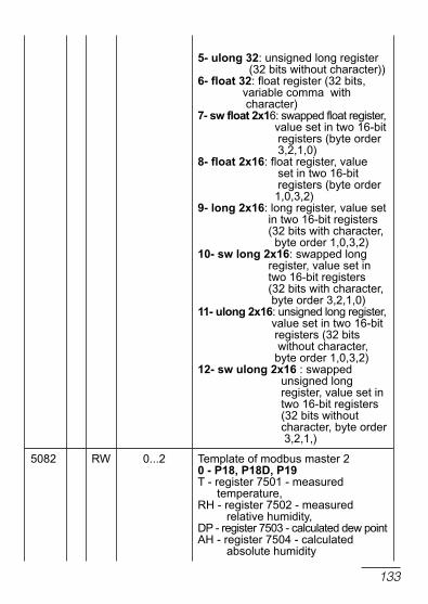
133
5- ulong 32: unsigned long register (32 bits without character))6- float 32: float register (32 bits, variable comma with character)7- sw float 2x16: swapped float register, value set in two 16-bit registers (byte order 3,2,1,0)8- float 2x16: float register, value set in two 16-bit registers (byte order 1,0,3,2)9- long 2x16: long register, value set in two 16-bit registers (32 bits with character, byte order 1,0,3,2)10- sw long 2x16: swapped long register, value set in two 16-bit registers (32 bits with character, byte order 3,2,1,0)11- ulong 2x16: unsigned long register, value set in two 16-bit registers (32 bits without character, byte order 1,0,3,2)12- sw ulong 2x16 : swapped unsigned long register, value set in two 16-bit registers (32 bits without character, byte order 3,2,1,)
5082 rW 0...2 template of modbus master 20 - p18, p18d, p19t - register 7501 - measured temperature,rH - register 7502 - measured relative humidity, dP - register 7503 - calculated dew pointAH - register 7504 - calculated absolute humidity
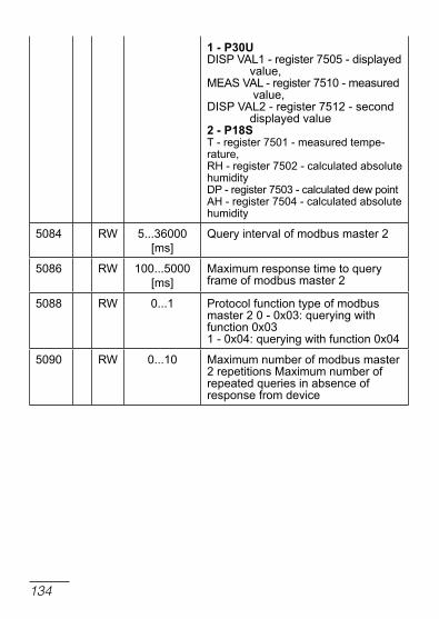
134
1 - p30udISP VAl1 - register 7505 - displayed value, MEAS VAl - register 7510 - measured value,dISP VAl2 - register 7512 - second displayed value2 - p18s t - register 7501 - measured tempe-rature,rH - register 7502 - calculated absolute humiditydP - register 7503 - calculated dew pointAH - register 7504 - calculated absolute humidity
5084 rW 5...36000 [ms]
Query interval of modbus master 2
5086 rW 100...5000 [ms]
Maximum response time to query frame of modbus master 2
5088 rW 0...1 Protocol function type of modbus master 2 0 - 0x03: querying with function 0x031 - 0x04: querying with function 0x04
5090 rW 0...10 Maximum number of modbus master 2 repetitions Maximum number of repeated queries in absence of response from device

135
Map of the registers from address 5200 table 18
register address
ope
ratio
nsdescription
5200 r Value 1 read by modbus master 1
5202 r Value 2 read by modbus master 1
5204 r Value 3 read by modbus master 1
5206 r Value 4 read by modbus master 1
5208 r Value 5 read by modbus master 1
5210 r Value 6 read by modbus master 1
5212 r Value 7 read by modbus master 1
5214 r Value 8 read by modbus master 1
5216 r Value 9 read by modbus master 1
5218 r Value 10 read by modbus master 1
5220 r Value 1 read by modbus master 2
5222 r Value 2 read by modbus master 2
5224 r Value 3 read by modbus master 2
5226 r Value 4 read by modbus master 2
5228 r Value 5 read by modbus master 2
5230 r Value 6 read by modbus master 2
5232 r Value 7 read by modbus master 2
5234 r Value 8 read by modbus master 2
5236 r Value 9 read by modbus master 2
5238 r Value 10 read by modbus master 2

136
Regi-ster
address
ope-ra-tion
Description
6000 rw 0.0...100.0 [%] Minimum control signal (set2) in channel 1
6002 rw 0.0...100.0 [%] Maximum control signal (set2) in channel 1
6004 rw 0.0...100.0 [%] Minimum control signal (set2) in channel 2
6006 rw 0.0...100.0 [%] Maximum control signal (set2) in channel 2
screen 1 with values
Value 1
6008 rw -999999.0…999999.9
lower alarm threshold
6010 rw -999999.0…999999.9
upper alarm threshold
6012 rw -9999.0…9999.9 Lower input value (rescaling values)
6014 rw -999999.0…999999.9
Lower output value (rescaling values)
6016 rw -9999.0…9999.9 Upper input value (rescaling values)
6018 rw -999999.0…999999.9
Upper output value (rescaling values)
Value 2
6020 - 6030
rw The scope of changes is simi-lar to the registers 6008 - 6018
Map of the registers from address 6000 table 19

137
Value 3
6032 - 6042
rw The scope of changes is simi-lar to the registers 6008 - 6018
Value 4
6044 - 6054
rw The scope of changes is simi-lar to the registers 6008 - 6018
Value5
6056 - 6066
rw The scope of changes is simi-lar to the registers 6008 - 6018
Value 6
6068 - 6078
rw The scope of changes is simi-lar to the registers 6008 - 6018
Screen 2 with values
Value 1
6080 - 6090
rw The scope of changes is simi-lar to the registers 6008 - 6018
Value 2
6092 - 6102
rw The scope of changes is simi-lar to the registers 6008 - 6018
Value 3
6104 - 6114
rw The scope of changes is simi-lar to the registers 6008 - 6018
Value 4
6116 - 6126
rw The scope of changes is simi-lar to the registers 6008 - 6018
Value 5
6128 - 6138
rw The scope of changes is simi-lar to the registers 6008 - 6018

138
Value 6
6140 - 6150
rw The scope of changes is simi-lar to the registers 6008 - 6018
screen 3 with values
Value 1
6152 - 6162
rw The scope of changes is simi-lar to the registers 6008 - 6018
Value 2
6164 - 6174
rw The scope of changes is simi-lar to the registers 6008 - 6018
Value 3
6176 - 6186
rw The scope of changes is simi-lar to the registers 6008 - 6018
Value 4
6188 - 6198
rw The scope of changes is simi-lar to the registers 6008 - 6018
Value 5
6200 - 6210
rw The scope of changes is simi-lar to the registers 6008 - 6018
Value 6
6212 - 6222
rw The scope of changes is simi-lar to the registers 6008 - 6018

139
Map of the registers from address 7000 table 20
register address
ope
ratio
nsdescription
7000 r Measuring value at input 1
7002 r Measuring value at input 2
7004 r Measuring value at input 3
7006 r Measuring value in loop 1
7008 r Set point value in loop 1
7010 r loop 1 controlling signal in loop 1
7012 r loop 2 controlling signal in loop 1
7014 r Measuring value in loop 2
7016 r Set point value in loop 2
7018 r loop 1 controlling signal in loop 2
7020 r loop 2 controlling signal in loop 2
7058 r time to switch on the alarm timer 1
7060 r time to switch on the alarm timer 2
7062 r time to switch on the alarm timer 3
7064 r time to switch on the alarm timer 4
7066 r time to switch on the alarm timer 5
7068 r time to switch on the alarm timer 6
7070 r time to switch off the alarm timer 1 latch
7072 r time to switch off the alarm timer 2 latch
7074 r time to switch off the alarm timer 3 latch
7076 r time to switch off the alarm timer 4 latch

140
7078 r time to switch off the alarm timer 5 latch
7080 r time to switch off the alarm timer 6 latch
7082 r the number of the records to be copied to Sdcard in archiving group 1
7084 r the number of the records to be copied to Sdcard in archiving group 2
7086 r the number of the records to be copied to Sdcard in archiving group 3
7088 r Value from interface input 1
7090 r Value from interface input 2

141
Map of the registers from address 7100 table 21R
egis
ter
addr
ess
Ope
ratio
nsParameter
range Description
7100 rW 0…18 type of input no. 1: 0 – thermoresistor Pt100 1 – thermoresistor Pt500 2 – thermoresistor Pt1000 3 – thermoresistor ni100 4 – thermoresistor ni1000 5 – thermoresistor cu100 6 – J type thermocouple 7 – t type thermocouple 8 – K type thermocouple9 – S type thermocouple10 – r type thermocouple11 – B type thermocouple12 – E type thermocouple13 – n type thermocouple14 – l type thermocouple15 – current input 0-20 mA16 – current input 4-20 mA17 – voltage input 0-5 V18 – voltage input 0-10 V
7102 rW 0…2 unit of input no 1:0 – degrees celsius1 – degrees Fahrenheit2 – physical units
7104 rW 0…1 3) 4)
0…2 5)decimal point position for input 1:0 – without a decimal place1 – 1 decimal place2 – 2 decimal places
7106 rW 0…1 compensation of thermocouple cold terminals for input 1:0 – automatic1 – manual

142
7108 rW 0…50.0 cold terminals temperature with manual compensation for input 1
7110 rW -9999…99999 Indication for the lower limit for input 1 (linear input)
7112 rW -9999…99999 Indication for the upper limit for input 1 (linear input)
7114 rW -35.00…35.00 Measured value shift for input 1
7116 rW 0…9 digital filter of input no 1: 0 – filter off 1 – time constant 0.2 s 2 – time constant 0.5 s 3 – time constant 1 s 4 – time constant 2 s 5 – time constant 5 s 6 – time constant 10 s 7 – time constant 20 s 8 – time constant 50 s 9 – time constant 100 s
7118 rW 0…18 type of input no. 2: 0 – thermoresistor Pt100 1 – thermoresistor Pt500 2 – thermoresistor Pt1000 3 – thermoresistor ni100 4 – thermoresistor ni1000 5 – thermoresistor cu100 6 – J type thermocouple 7 – t type thermocouple 8 – K type thermocouple 9 – S type thermocouple10 – r type thermocouple11 – B type thermocouple12 – E type thermocouple13 – n type thermocouple14 – l type thermocouple15 – current input 0-20 mA16 – current input 4-20 mA17 – voltage input 0-5 V18 – voltage input 0-10 V

143
7120 rW 0…2 unit of input no 2:0 – degrees celsius1 – degrees Fahrenheit2 – physical units
7122 rW 0…1 3) 4)
0…2 5)decimal point position for input 2:0 – without a decimal place1 – 1 decimal place2 – 2 decimal places
7124 rW 0…1 compensation of thermocouple cold terminals for input 2:0 – automatic1 – manual
7126 rW 0…50.0 cold terminals temperature with manual compensation for input 2
7128 rW -9999…99999
Indication for the lower limit for input 2 (linear input)
7130 rW -9999…99999
Indication for the upper limit for input 2 (linear input)
7132 rW -35.00…35.00
Measured value shift for input 2
7134 rW 0…9 digital filter of input no 2: 0 – filter off 1 – time constant 0.2 s 2 – time constant 0.5 s 3 – time constant 1 s 4 – time constant 2 s 5 – time constant 5 s 6 – time constant 10 s 7 – time constant 20 s 8 – time constant 50 s 9 – time constant 100 s
7136 rW 0…6 type of input no. 3:0 – none1 – current input 0-20 mA2 – current input 4-20 mA3 – voltage input 0-5 V4 – voltage input 0-10 V5 – potentiometric input 100 ohm6 – potentiometric input 1000 ohm

144
7138 rW 0…2 unit of input no 3:0 – degrees celsius1 – degrees Fahrenheit2 – physical units
7140 rW 0…1 3) 4)
0…2 5)decimal point position for input 3:0 – without a decimal place1 – 1 decimal place2 – 2 decimal places
7142 rW -9999…99999
Indication for the lower limit for input 3 (linear input)
7144 rW -9999…99999
Indication for the upper limit for input 3 (linear input)
7146 rW -35.00…35.00 Measured value shift for input 3
7148 rW 0…9 digital filter of input no 3: 0 – filter off 1 – time constant 0.2 s 2 – time constant 0.5 s 3 – time constant 1 s 4 – time constant 2 s 5 – time constant 5 s 6 – time constant 10 s 7 – time constant 20 s 8 – time constant 50 s 9 – time constant 100 s
7150 rW 0…22 Function of binary input 1: 0 – none 1 – stop automatic control 2 – switch to manual operation 3 – switches to subsequent SP SP1<->SP2, SP2<->SP3, SP3<->SP4, SP4<->SP1 4 – program start 5 – jump to the next segment 6 – stops the incrementing of the set value in program 7 – end of the program 8 – stop of the program with possible continuation 9 – stop the program and jump to the beginning10 – switching to subsequent SP from the additional input - In3

145
11 – alarm reset of timer 112 – alarm reset of timer 213 – alarm reset of timer 314 – alarm reset of timer 415 – alarm reset of timer 516 – alarm reset of timer 617 – switching to SP from the input 118 – switching to SP from the input 219 – switches to SP from first interface input 20 – switches to SP from second inter- face input21 -switches to subsequent SP: SP1>>SP2>>SP3>>SP4>> SPIn1>>SPIn2>>SPIn3>> SPMd1>> SPMd2>>SP122 - switching to the second set of para-meters for limiting the control signal
7152 rW 0…22 Function of binary input 2: 0 – none 1 – stop automatic control 2 – switch to manual operation 3 – switches to subsequent SP SP1<->SP2, SP2<->SP3, SP3<->SP4, SP4<->SP1 4 – program start 5 – jump to the next segment 6 – stops the incrementing of the set value in program 7 – end of the program 8 – stop of the program with possible continuation9 – stop the program and jump to the beginning10 – switching to subsequent SP from the additional input - In311 – alarm reset of timer 112 – alarm reset of timer 213 – alarm reset of timer 314 – alarm reset of timer 415 – alarm reset of timer 516 – alarm reset of timer 617 – switching to SP from the input 118 – switching to SP from the input 219 – switches to SP from first interface input

146
20 – switches to SP from second inter- face input21 - switches to subsequent SP: SP1>>SP2>>SP3>>SP4>> SPIn1>>SPIn2>>SPIn3>> SPMd1>> SPMd2>>SP122 - switching to the second set of para-meters for limiting the control signal
7154 rW 0…22 Function of binary input 3: 0 – none 1 – stop automatic control 2 – switch to manual operation 3 – switches to subsequent SP SP1<->SP2, SP2<->SP3, SP3<->SP4, SP4<->SP1 4 – program start 5 – jump to the next segment 6 – stops the incrementing of the set value in program 7 – end of the program 8 – stop of the program with possible continuation 9 – stop the program and jump to the beginning10 – switching to subsequent SP from the additional input - In311 – alarm reset of timer 112 – alarm reset of timer 213 – alarm reset of timer 314 – alarm reset of timer 415 – alarm reset of timer 516 – alarm reset of timer 617 – switching to SP from the input 118 – switching to SP from the input 219 – switches to SP from first interface input20 – switches to SP from second inter- face input21 - switches to subsequent SP: SP1>>SP2>>SP3>>SP4>> SPIn1>>SPIn2>>SPIn3>> SPMd1>> SPMd2>>SP122 - switching to the second set of para-meters for limiting the control signal

147
7156 rW 0…22 Allocation of output 1: 0 – none 1 – loop 1 2 – loop 2 3 – input 1 4 – input 2 5 – input 3 6 – input 1 + input 2 + input 3 7 – binary input 18 – binary input 2 9 – binary input 310 – inverted binary input 111 – inverted binary input 212 – inverted binary input 313 – interface input 114 – interface input 215 – interface binary input 1 (register 4055)16 – interface binary input 2 (register 4056)17 – interface binary input 3 (register 4057)18 – inverted interface binary input 1 (register 4055)19 – inverted interface binary input 2 (register 4056)20 – inverted interface binary input 3 (register 4057)21 – control of output 1 through interface (register 4058)22 – inverted control of output 1 through interface (register 4058)
7158 rW 0…7 output 1 function: 0 – none 1 – heating 2 – cooling 3 – opening a valve 4 – closing a valve 5 – alarm 1 6 – programming control event 7 – slave loop signal by cascade control 8 – timer 1 alarm

148
7160 rW 0…7 output 1 program event: 0 – none 1 – event 1 from a segment 2 – event 2 from a segment 3 – event 3 from a segment 4 – event 4 from a segment 5 – event 5 from a segment 6 – event 6 from a segment 7 – deviation block
7162 rW 0.5…99.9 output 1 imp. period
7164 rW 0…22 Allocation of output 2: 0 – none 1 – loop 1 2 – loop 2 3 – input 1 4 – input 2 5 – input 3 6 – input 1 + input 2 + input 3 7 – binary input 1 8 – binary input 2 9 – binary input 310 – inverted binary input 111 – inverted binary input 212 – inverted binary input 313 – interface input 114 – interface input 215 – interface binary input 1 (register 4055)16 – interface binary input 2 (register 4056)17 – interface binary input 3 (register 4057)18 – inverted interface binary input 1 (register 4055)19 – inverted interface binary input 2 (register 4056)20 – inverted interface binary input 3 (register 4057)21 – control of output 2 through interface (register 4059)22 – inverted control of output 2 through interface (register 4059)

149
7166 rW 0…7 output 2 function: 0 – none 1 – heating 2 – cooling 3 – opening a valve 4 – closing a valve 5 – alarm 2 6 – programming control event 7 – slave loop signal by cascade control 8 – timer 2 alarm
7168 0…7 output 2 program event: 0 – none 1 – event 1 from a segment 2 – event 2 from a segment 3 – event 3 from a segment 4 – event 4 from a segment 5 – event 5 from a segment 6 – event 6 from a segment 7 – deviation block
7170 rW 0.5…99.9 output 2 imp. period
7172 rW 0…22 Allocation of input 3: 0 – none 1 – loop 1 2 – loop 2 3 – input 1 4 – input 2 5 – input 36 – input 1 + input 2 + input 3 7 – binary input 1 8 – binary input 2 9 – binary input 310 – inverted binary input 111 – inverted binary input 212 – inverted binary input 313 – interface input 114 – interface input 215 – interface binary input 1 (register 4055)16 – interface binary input 2 (register 4056)17 – interface binary input 3 (register 4057)18 – inverted interface binary input 1 (register 4055)

150
19 – inverted interface binary input 2 (register 4056)20 – inverted interface binary input 3 (register 4057)21 – control of output 2 through interface (register 4060)22 – inverted control of output 2 through interface (register 4060)
7174 rW 0…7 output 3 function: 0 – none 1 – heating 2 – cooling 3 – opening a valve 4 – closing a valve 5 – alarm 3 6 – programming control event 7 – slave loop signal by cascade control 8 – timer 3 alarm
7176 0…7 output 3 program event: 0 – none 1 – event 1 from a segment 2 – event 2 from a segment 3 – event 3 from a segment 4 – event 4 from a segment 5 – event 5 from a segment 6 – event 6 from a segment 7 – deviation block
7178 rW 0.5…99.9 output 3 imp. period
7180 rW 0…22 Allocation of input 4: 0 – none 1 – loop 1 2 – loop 2 3 – input 1 4 – input 2 5 – input 3 6 – input 1 + input 2 + input 3 7 – binary input 1 8 – binary input 2 9 – binary input 310 – inverted binary input 111 – inverted binary input 212 – inverted binary input 3

151
13 – interface input 114 – interface input 215 – interface binary input 1 (register 4055)16 – interface binary input 2 (register 4056)17 – interface binary input 3 (register 4057)18 – inverted interface binary input 1 (register 4055)19 – inverted interface binary input 2 (register 4056)20 – inverted interface binary input 3 (register 4057)21 – control of output 4 through interface (register 4061)22 – inverted control of output 4 through interface (register 4061)
7182 rW 0…7 output 4 function: 0 – none 1 – heating 2 – cooling 3 – opening a valve 4 – closing a valve 5 – alarm 4 6 – programming control event 7 – slave loop signal by cascade control 8 – timer 4 alarm
7184 0…7 output 4 program event: 0 – none 1 – event 1 from a segment 2 – event 2 from a segment 3 – event 3 from a segment 4 – event 4 from a segment 5 – event 5 from a segment 6 – event 6 from a segment 7 – deviation block
7186 rW 0.5…99.9 output 4 imp. period

152
7188 rW 0…12 Allocation of input 5: 0 – none 1 – loop 1 2 – loop 2 3 – input 1 4 – input 2 5 – input 3 6 – input 1 + input 2 + input 3 7 – binary input 1 8 – binary input 2 9 – binary input 310 – inverted binary input 111 – inverted binary input 212 – inverted binary input 313 – interface input 114 – interface input 215 – interface binary input 1 (register 4055)16 – interface binary input 2 (register 4056)17 – interface binary input 3 (register 4057)18 – inverted interface binary input 1 (register 4055)19 – inverted interface binary input 2 (register 4056)20 – inverted interface binary input 3 (register 4057)21 – control of output 5 through interface (register 4062)22 – inverted control of output 5 through interface (register 4062)
7190 rW 0…7 output 5 function: 0 – none 1 – heating 2 – cooling 3 – opening a valve 4 – closing a valve 5 – alarm 56 – programming control event7 – slave loop signal by cascade control8 – timer 5 alarm

153
7192 0…7 output 5 program event: 0 – none 1 – event 1 from a segment 2 – event 2 from a segment 3 – event 3 from a segment 4 – event 4 from a segment 5 – event 5 from a segment 6 – event 6 from a segment 7 – deviation block
7194 rW 0.5…99.9 output 5 imp. period
7196 rW 0…22 Allocation of input 6: 0 – none 1 – loop 1 2 – loop 2 3 – input 1 4 – input 25 – input 3 6 – input 1 + input 2 + input 3 7 – binary input 1 8 – binary input 2 9 – binary input 310 – inverted binary input 111 – inverted binary input 212 – inverted binary input 313 – interface input 114 – interface input 215 – interface binary input 1 (register 4055)16 – interface binary input 2 (register 4056)17 – interface binary input 3 (register 4057)18 – inverted interface binary input 1 (register 4055)19 – inverted interface binary input 2 (register 4056)20 – inverted interface binary input 3 (register 4057)21 – control of output 6 through interface (register 4063)22 – inverted control of output 6 through interface (register 4063)

154
7198 0…7 output 6 function: 0 – none 1 – heating 2 – cooling 3 – opening a valve 4 – closing a valve 5 – alarm 6 6 – programming control event7 – slave loop signal by cascade control8 – timer 6 alarm
7200 rW 0…7 output 6 program event: 0 – none 1 – event 1 from a segment 2 – event 2 from a segment
3 – event 3 from a segment 4 – event 4 from a segment 5 – event 5 from a segment 6 – event 6 from a segment 7 – deviation block
7202 rW 0.5…99.9 output 6 imp. period
7204 rW 0…8 Allocation of analog output 1: 0 – none 1 – loop 1 2 – loop 2 3 – input 1 4 – input 2 5 – input 3 6 – input 1 + input 2 + input 3 7 – interface input 1 8 – interface input 2
7206 rW 0…3 linear output 1 function: 0 – none 1 – heating 2 – cooling 3 – retransmission
7208 rW 0…2 Analog output 1 retransmission source: 0 – measuring value 1 – set value 2 – set value – measuring value

155
7210 rW -9999…99999
Min for retr. of analog output 1
7212 rW -9999…99999
Max for retr. of analog output 1
7214 rW 0…2 I-output type for analog output 1: 0 – none 1 – 4…20 mA 2 – 0…20 mA
7216 rW 0…2 u-output type for analog output 1: 0 – none 1 – 0…5 V 2 – 0…10 V
7218 rW 0…8 Allocation of analog output 2: 0 – none 1 – loop 1 2 – loop 2 3 – input 1 4 – input 2 5 – input 3 6 – input 1 + input 2 + input 3 7 – interface input 1 8 – interface input 2
7220 rW 0…3 linear output 2 function: 0 – none 1 – heating 2 – cooling 3 – retransmission
7222 rW 0…2 Analog output 2 retransmission source: 0 – measuring value 1 – set point value 2 – set point value – measuring value
7224 rW -9999…99999
Min for retr. of analog output 2
7226 rW -9999…99999
Max for retr. of analog output 2

156
7228 rW 0…2 I-output type for analog output 2: 0 – none 1 – 4…20 mA 2 – 0…20 mA
7230 rW 0…2 u-output type for analog output 2: 0 – none 1 – 0…5 V 2 – 0…10 V
7232 rW 0…7 Measuring value in loop 1: 0 – input 1 1 – input 2 2 – input 3 3 – input 1 + input 2 4 – input 1 + input 3 5 – input 2 + input 3 6 – interface input 1 7 – interface input 2
7234 rW -10.0…10.0 Input 1 coefficient in loop 1
7236 rW -10.0…10.0 Input 2 coefficient in loop 1
7238 rW -10.0…10.0 Input 3 coefficient in loop 1
7240 rW 0…14 Binary inputs in loop 1: 0 – none 1 – binary input 1 2 – binary input 2 3 – binary input 3 4 – binary input 1 and 2 5 – binary input 1 and 3 6 – binary input 2 and 3 7 – binary input 1, 2 and 38 – interface binary input 19 – interface binary input 2 10 – interface binary input 311 – interface binary input 1 and 212 – interface binary input 1 and 313 – interface binary input 2 and 314 – interface binary input 1, 2 and 3

157
7242 rW 0…9 SP type in loop 1: 0 – SP1 set point value 1 – SP2 set point value 2 – SP3 set point value 3 – SP4 set point value 4 – set point value from input 3 5 – set point value from program 6 – set point value from input 1 7 – set point value from input 2 8 – setpoint value from interface input 1 9 – setpoint value from interface input 2
7244 rW 0…29 Program number on loop 1: 0 – program number 1 1 – program number 2 2 – program number 3 3 – program number 4 4 – program number 5 5 – program number 6 6 – program number 7 7 – program number 8 8 – program number 9 9 – program number 1010 – program numer 1111 – program numer 1212 – program numer 1313 – program numer 1414 – program numer 1515 – program numer 1616 – program numer 1717 – program numer 1818 – program numer 1919 – program numer 2020 – program numer 2121 – program numer 2222 – program numer 2323 – program numer 2424 – program numer 2525 – program numer 2626 – program numer 2727 – program numer 2828 – program numer 2929 – program numer 30
7246 rW -9999...99999 SP1 set value in loop 1

158
7248 rW -9999...99999 SP2 set value in loop 1
7250 rW -9999...99999 SP3 set value in loop 1
7252 rW -9999...99999 SP4 set value in loop 1
7254 rW -9999...99999 SP setting lower limit in loop 1
7256 rW -9999...99999 SP setting upper limit in loop 1
7258 rW 0…2 Set value accrual in loop 1: 0 – off 1 – accrual in units / minute 2 – accrual in units / hour
7260 rW -9999...99999 Set value ramp rate in loop 1
7262 rW 0…5 control type in loop 1: 0 – control off 1 – heating-type control 2 – cooling-type control 3 – heating-cooling control 4 – step-by-step valve control 5 – step-by-step feedback valve control
7264 rW 0…1 control algorithm in loop 1: 0 – on-off algorithm 1 – PId algorithm
7266 rW 0,1...100,0 Hysteresis in loop 1
7268 rW -99.9...99.9 distance range in loop 1
7270 rW -100.0...100.0 control signal in loop 1
7272 rW -9999...99999 control lower limit in loop 1
7274 rW -9999...99999 control upper limit in loop 1
7276 rW 0...550.0 [oc]0...990.0 [oF]
PId1 set proportional band in loop 1
7278 rW 0...9999 Integration time constant [s] from PId1 set in the loop 1
7280 rW 0.0...2500.0 differentiation time constant [s] from PId1 set in the loop 1

159
7282 rW 0.0...100.0 control signal correction for P or Pd of PId1 set in loop 1
7284 rW 0...550.0 [oc]0...990.0 [oF]
PId2 set proportional band in loop 1
7286 rW 0...9999 Integration time constant [s] from PId2 set in the loop 1
7288 rW 0.0...2500.0 differentiation time constant [s] from PId2 set in the loop 1
7290 rW 0.0...100.0 control signal correction for P or Pd of PId2 set in loop 1
7292 rW 0...550.0 [oc]0...990.0 [oF]
PId3 set proportional band in loop 1
7294 rW 0...9999 Integration time constant [s] from PId3 set in the loop 1
7296 rW 0.0...2500.0 differentiation time constant [s] from PId3 set in the loop 1
7298 rW 0.0...100.0 control signal correction for P or Pd of PId3 set in loop 1
7300 rW 0...550.0 [oc]0...990.0 [oF]
PId4 set proportional band in loop 1
7302 rW 0...9999 Integration time constant [s] from PId4 set in the loop 1
7304 rW 0.0...2500.0 differentiation time constant [s] from PId4 set in the loop 1
7306 rW 0.0...100.0 control signal correction for P or Pd of PId4 set in loop 1
7308 rW 0.1...200.0 [%]
Proportional band of cooling loop in loop 1
7310 rW 0...9999 Integration time constant [s] of cooling loop in the loop 1
7312 rW 0.0...2500.0 differentiation time constant [s] of coo-ling loop in the loop 1

160
7314 rW 0...2 „Gain Scheduling” function in loop 1: 0 – off 1 – switched according to set value 2 – selected fixed PId set
7316 rW 0...2 number of PId sets for Gain Schedu-ling, switched according to the value set in loop 1: 0 – 2 PId sets used 1 – 3 PId sets used 2 – 4 PId sets used
7318 rW -9999...99999 Switching level for PId1 and PId2 set, switched as per value set in loop 1
7320 rW -9999...99999 Switching level for PId2 and PId3 set, switched as per value set in loop 1
7322 rW -9999...99999 Switching level for PId3 and PId4 set, switched as per value set in loop 1
7324 rW 0...3 Fixed PId set for Gain Scheduling in loop 1: 0 – PId1 set 1 – PId2 set 2 – PId3 set 3 – PId4 set
7326 rW 0…7 Measuring value in loop 2: 0 – input 1 1 – input 2 2 – input 3 3 – input 1 + input 2 4 – input 1 + input 3 5 – input 2 + input 3 6 – interface input 1 7 – interface input 2
7328 rW -10.0…10.0 Input 1 coefficient in loop 2
7330 rW -10.0…10.0 Input 2 coefficient in loop 2
7332 rW -10.0…10.0 Input 3 coefficient in loop 2

161
7334 rW 0…14 Binary inputs in loop 2: 0 – none 1 – binary input 1 2 – binary input 2 3 – binary input 3 4 – binary input 1 and 2 5 – binary input 1 and 3 6 – binary input 2 and 3 7 – binary input 1, 2 and 3 8 – interface binary input 19 – interface binary input 2 10 – interface binary input 311 – interface binary input 1 and 212 – interface binary input 1 and 313 – interface binary input 2 and 314 – interface binary input 1, 2 and 3
7336 rW 0…9 SP type in loop 2: 0 – SP1 set point value 1 – SP2 set point value 2 – SP3 set point value 3 – SP4 set point value 4 – set point value from input 3 5 – set point value from program 6 – set point value from input 1 7 – set point value from input 2 8 – setpoint value from interface input 1 9 – setpoint value from interface input 2
7338 rW 30…59 Program number on loop 2:30 – program numer 3131 – program numer 3232 – program numer 3333 – program numer 3434 – program numer 3535 – program numer 3636 – program numer 3737 – program numer 3838 – program numer 3939 – program numer 4040 – program numer 4141 – program numer 4242 – program numer 4343 – program numer 4444 – program numer 45

162
45 – program numer 4646 – program numer 4747 – program numer 4848 – program numer 4949 – program numer 5050 – program numer 5151 – program numer 5252 – program numer 5353 – program numer 5454 – program numer 5555 – program numer 5656 – program numer 5757 – program numer 5858 – program numer 5959 – program numer 60
7340 rW -9999...99999 SP1 set value in loop 2
7342 rW -9999...99999 SP2 set value in loop 2
7344 rW -9999...99999 SP3 set value in loop 2
7346 rW -9999...99999 SP4 set value in loop 2
7348 rW -9999...99999 SP setting lower limit in loop 2
7350 rW -9999...99999 SP setting upper limit in loop 2
7352 rW 0…2 Set value accrual in loop 2: 0 – off 1 – accrual in units / minute 2 – accrual in units / hour
7354 rW -9999...99999 Set value ramp rate in loop 2
7356 rW 0…5 control type in loop 2: 0 – control off 1 – heating-type control 2 – cooling-type control 3 – heating-cooling control 4 – step-by-step valve control 5 – step-by-step feedback valve control 6 – cascade control
7358 rW 0…1 control algorithm in loop 2: 0 – on-off algorithm 1 – PId algorithm

163
7360 rW 0.1...100.0 Hysteresis in loop 2
7362 rW -99.9...99.9 distance range in loop 2
7364 rW -100.0...100.0 control signal in loop 2
7366 rW -9999...99999 control lower limit in loop 2
7368 rW -9999...99999 control upper limit in loop 2
7370 rW 0...550.0 [oc]0...990.0 [oF]
PId1 set proportional band in loop 2
7372 rW 0...9999 Integration time constant [s] from PId1 set in the loop 2
7374 rW 0.0...2500.0 differentiation time constant [s] from PId1 set in the loop 2
7376 rW 0.0...100.0 control signal correction for P or Pd of PId1 set in loop 2
7378 rW 0...550.0 [oc]0...990.0 [oF]
PId2 set proportional band in loop 2
7380 rW 0...9999 Integration time constant [s] from PId2 set in the loop 2
7382 rW 0.0...2500.0 differentiation time constant [s] from PId2 set in the loop 2
7384 rW 0.0...100.0 control signal correction for P or Pd of PId2 set in loop 2
7386 rW 0...550.0 [oc]0...990.0 [oF]
PId3 set proportional band in loop 2
7388 rW 0...9999 Integration time constant [s] from PId3 set in the loop 2
7390 rW 0.0...2500.0 differentiation time constant [s] from PId3 set in the loop 2
7392 rW 0.0...100.0 control signal correction for P or Pd of PId3 set in loop 2
7394 rW 0...550.0 [oc]0...990.0 [oF]
PId4 set proportional band in loop 2

164
7396 rW 0...9999 Integration time constant [s] from PId4 set in the loop 2
7398 rW 0.0...2500.0 differentiation time constant [s] from PId4 set in the loop 2
7400 rW 0.0...100.0 control signal correction for P or Pd of PId4 set in loop 2
7402 rW 0.1...200.0 [%]
Proportional band of cooling loop in loop 2
7404 rW 0...9999 Integration time constant [s] of cooling loop in the loop 2
7406 rW 0.0...2500.0 differentiation time constant [s] of coo-ling loop in the loop 2
7408 rW 0...2 Gain Scheduling function in loop 2: 0 – off 1 – switched according to set value 2 – selected fixed PId set
7410 rW 0...2 number of PId sets for Gain Schedu-ling, switched according to the value set in loop 2: 0 – 2 PId sets used 1 – 3 PId sets used 2 – 4 PId sets used
7412 rW -9999...99999 Switching level for PId1 and PId2 set, switched as per value set in loop 2
7414 rW -9999...99999 Switching level for PId2 and PId3 set, switched as per value set in loop 2
7416 rW -9999...99999 Switching level for PId3 and PId4 set, switched as per value set in loop 2
7418 rW 0...3 Fixed PId set for Gain Scheduling in loop 2: 0 – PId1 set 1 – PId2 set 2 – PId3 set 3 – PId4 set

165
7420 rW 0...5 Alarm type 1: 0 – absolute upper 1 – absolute lower 2 – relative upper 3 – relative lower 4 – relative internal 5 – relative internal
7422 rW -9999...99999 Alarm 1 set value
7424 rW -9999...99999 Alarm 1 deviation (for relative alarms)
7426 rW 0.1...99.9 Alarm 1 hysteresis
7428 rW 0...1 Memory of the alarm 1: 0 – off 1 – on
7430 rW 0...5 Alarm type 2: 0 – absolute upper 1 – absolute lower 2 – relative upper 3 – relative lower 4 – relative internal 5 – relative internal
7432 rW -9999...99999 Alarm 2 set point value
7434 rW -9999...99999 Alarm 2 deviation (for relative alarms)
7436 rW 0.1...99.9 Alarm 2 hysteresis
7438 rW 0...1 Memory of the alarm 2: 0 – off 1 – on
7440 rW 0...5 Alarm type 3: 0 – absolute upper 1 – absolute lower 2 – relative upper 3 – relative lower 4 – relative internal 5 – relative internal
7442 rW -9999...99999 Alarm 3 set point value

166
7444 rW -9999...99999 Alarm 3 deviation (for relative alarms)
7446 rW 0.1...99.9 Alarm 3 hysteresis
7448 rW 0...1 Memory of the alarm 3: 0 – off 1 – on
7450 rW 0...5 Alarm type 4: 0 – absolute upper 1 – absolute lower 2 – relative upper 3 – relative lower 4 – relative internal 5 – relative internal
7452 rW -9999...99999 Alarm 4 set point value
7454 rW -9999...99999 Alarm 4 deviation (for relative alarms)
7456 rW 0.1...99.9 Alarm 4 hysteresis
7458 rW 0...1 Memory of the alarm 4: 0 – off 1 – on
7460 rW 0...5 Alarm type 5: 0 – absolute upper 1 – absolute lower 2 – relative upper 3 – relative lower 4 – relative internal 5 – relative internal
7462 rW -9999...99999 Alarm 5 set point value
7464 rW -9999...99999 Alarm 5 deviation (for relative alarms)
7466 rW 0.1...99.9 Alarm 5 hysteresis
7468 rW 0...1 Memory of the alarm 5: 0 – off 1 – on

167
7470 rW 0...5 Alarm type 6: 0 – absolute upper 1 – absolute lower 2 – relative upper 3 – relative lower 4 – relative internal 5 – relative internal
7472 rW -9999...99999 Alarm 6 set point value
7474 rW -9999...99999 Alarm 6 deviation (for relative alarms)
7476 rW 0.1...99.9 Alarm 6 hysteresis
7478 rW 0...1 Memory of the alarm 6: 0 – off 1 – on
7480 rW 1...247 Address
7482 rW 0...5 Baud rate 0 – 4800 bps 1 – 9600 bps 2 – 19.2k bps 3 – 38.4k bps 4 – 57.6k bps 5 – 115.2k bps
7484 rW 0...4 transmission protocol: 0 – none 1 – rtu 8n2 2 – rtu 8E1 3 – rtu 8o1 4 – rtu 8n1
7486 rW 0...10 lcd illumination
7488 rW 0...1 language 0 – English 1 – Polish
7490 rW 0...1 Shot outputs state 0 – no 1 – yes
7492 rW 0...1 Show binary inputs state 0 – no 1 – yes

168
7494 rW 0...1 Show clock 0 – no 1 – yes
7496 rW 0.0...100.0 [%]
Minimum control signal in loop 1
7498 rW 0.0...100.0 [%]
Maximum control signal in loop 1
7500 rW 0.0...100.0 [%]
Minimum control signal in loop 2
7502 rW 0.0...100.0 [%]
Maximum control signal in loop 2
7504 rW -9999...99999 cascade control set point lo
7506 rW -9999...99999 cascade control set point Hi
7508 rW 1..86400 [s] countdown time of alarm timer 1
7510 rW 1..86400 [s] countdown time of alarm timer 2
7512 rW 1..86400 [s] countdown time of alarm timer 3
7514 rW 1..86400 [s] countdown time of alarm timer 4
7516 rW 1..86400 [s] countdown time of alarm timer 5
7518 rW 1..86400 [s] countdown time of alarm timer 6
7520 rW 1..86400 [s] countdown time of alarm timer 1 latch
7522 rW 1..86400 [s] countdown time of alarm timer 2 latch
7524 rW 1..86400 [s] countdown time of alarm timer 3 latch
7526 rW 1..86400 [s] countdown time of alarm timer 4 latch
7528 rW 1..86400 [s] countdown time of alarm timer 5 latch
7530 rW 1..86400 [s] countdown time of alarm timer 6 latch
7532 rW -9999...99999 Set point value for alarm timer 1
7534 rW -9999...99999 Set point value for alarm timer 2
7536 rW -9999...99999 Set point value for alarm timer 3

169
7538 rW -9999...99999 Set point value for alarm timer 4
7540 rW -9999...99999 Set point value for alarm timer 5
7542 rW -9999...99999 Set point value for alarm timer 6
7544 rW 0…1 Alarm 1 status if the measuring range isexceeded:0- disabled1- enabled
7546 rW 0…1 Alarm 2 status if the measuring range isexceeded:0- disabled1- enabled
7548 rW 0…1 Alarm 3 status if the measuring range isexceeded:0- disabled1- enabled
7550 rW 0…1 Alarm 4 status if the measuring range isexceeded:0- disabled1- enabled
7552 rW 0…1 Alarm 5 status if the measuring range isexceeded:0- disabled1- enabled
7554 rW 0…1 Alarm 6 status if the measuring range isexceeded:0- disabled1- enabled
7556 rW 0...3600 turning the backlight off after the enteredtime (in sec.) has passed. Enterin 0disables the function.
7558 rW 0...1 Show achriving status:0 – no1 – yes
7560 rW 5...86400 Archiving interval for group 1 archiving
7562 rW 5...86400 Archiving interval for group 2 archiving
7564 rW 5...86400 Archiving interval for group 3 archiving
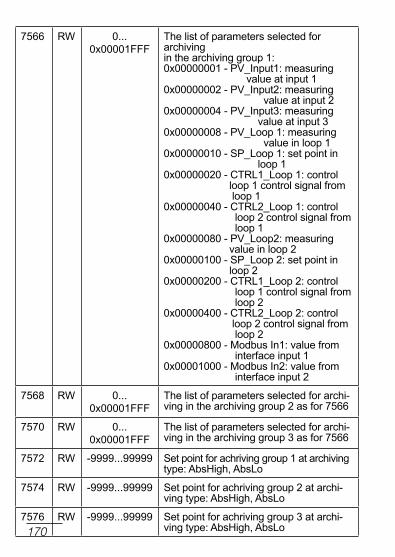
170
7566 rW 0...0x00001FFF
the list of parameters selected for archivingin the archiving group 1:0x00000001 - PV_Input1: measuring value at input 10x00000002 - PV_Input2: measuring value at input 20x00000004 - PV_Input3: measuring value at input 30x00000008 - PV_loop 1: measuring value in loop 10x00000010 - SP_loop 1: set point in loop 10x00000020 - ctrl1_loop 1: control loop 1 control signal from loop 10x00000040 - ctrl2_loop 1: control loop 2 control signal from loop 10x00000080 - PV_loop2: measuring value in loop 20x00000100 - SP_loop 2: set point in loop 20x00000200 - ctrl1_loop 2: control loop 1 control signal from loop 20x00000400 - ctrl2_loop 2: control loop 2 control signal from loop 20x00000800 - Modbus In1: value from interface input 10x00001000 - Modbus In2: value from interface input 2
7568 rW 0... 0x00001FFF
the list of parameters selected for archi-ving in the archiving group 2 as for 7566
7570 rW 0... 0x00001FFF
the list of parameters selected for archi-ving in the archiving group 3 as for 7566
7572 rW -9999...99999 Set point for achriving group 1 at archivingtype: AbsHigh, Abslo
7574 rW -9999...99999 Set point for achriving group 2 at archi-ving type: AbsHigh, Abslo
7576 rW -9999...99999 Set point for achriving group 3 at archi-ving type: AbsHigh, Abslo

171
7578 rW -9999...99999 deviation for archiving group 1 at relativearchiving type
7580 rW -9999...99999 deviation for archiving group 2 at relativearchiving type
7582 rW -9999...99999 deviation for archiving group 3 at relativearchiving type
7584 rW 0,1...99999 Hysteresis for achriving group 1 at relati-ve and absolute archiving type
7586 rW 0,1...99999 Hysteresis for achriving group 2 at relati-ve and absolute archiving type
7588 rW 0,1...99999 Hysteresis for achriving group 3 at relati-ve and absolute archiving type
7590 rW 0…22 Function of interface binary input 1: 0 – none1 – stop automatic control 2 – switch to manual operation3 – switches to subsequent SPSP1<->SP2, SP2<->SP3, SP3<->SP4, SP4<->SP14 – program start5 – jump to the next segment6 – stops the incrementing of the set value in program 7 – end of the program8 – stop of the program with possible continuation 9 – stop the program and jump to the beginning10 – switching to SP from the additional input – WE3 11 – alarm reset of timer 112 – alarm reset of timer 213 – alarm reset of timer 314 – alarm reset of timer 415 – alarm reset of timer 516 – alarm reset of timer 617 – switching to SP from the nput 118 – switching to SP from the input 219 – switching to SP from the first inter-face input 20 – switching to SP from the second interface input

172
21 - switching to subsequent SP: SP1>>SP2>>SP3>>SP4>>SPIn1>>SPIn2>>SPIn3>>SPMd1>> SPMd2>>SP122 - switching to the second set of para-meters for limiting the control signal
7592 rW 0…22 Function of interface binary input 2: 0 – none1 – stop automatic control 2 – switch to manual operation3 – switches to subsequent SPSP1<->SP2, SP2<->SP3, SP3<->SP4, SP4<->SP14 – program start5 – jump to the next segment6 – stops the incrementing of the set value in program 7 – end of the program8 – stop of the program with possible continuation 9 – stop the program and jump to the beginning10 – switching to SP from the additional input – WE3 11 – alarm reset of timer 112 – alarm reset of timer 213 – alarm reset of timer 314 – alarm reset of timer 415 – alarm reset of timer 516 – alarm reset of timer 617 – switching to SP from the input 1 18 – switching to SP from the input 219 – switching to SP from the first inter-face input 20 – switching to SP from the second interface input 21 - switching to subsequent SP: SP1>>SP2>>SP3>>SP4>>SPIn1>>SPIn2>>SPIn3>>SPMd1>> SPMd2>>SP122 - switching to the second set of para-meters for limiting the control signal

173
7594 rW 0…22 Function of interface binary input 3: 0 – none1 – stop automatic control 2 – switch to manual operation3 – switches to subsequent SPSP1<->SP2, SP2<->SP3, SP3<->SP4, SP4<->SP14 – program start5 – jump to the next segment6 – stops the incrementing of the set value in program 7 – end of the program8 – stop of the program with possible continuation 9 – stop the program and jump to the beginning10 – switching to SP from the additional input – WE3 11 – alarm reset of timer 112 – alarm reset of timer 213 – alarm reset of timer 314 – alarm reset of timer 415 – alarm reset of timer 516 – alarm reset of timer 617 – switching to SP from the input 1 18 – switching to SP from the input 219 – switching to SP from the first inter-face input 20 – switching to SP from the second interface input 21 - switching to subsequent SP: SP1>>SP2>>SP3>>SP4>>SPIn1>>SPIn2>>SPIn3>>SPMd1>> SPMd2>>SP122 - switching to the second set of para-meters for limiting the control signal

174
7596 rW 0x0000……0x1FFF
list of the displayed controller screens selection0x0001 - show the „channel 1” screen,0x0002 - show the „channel 2” screen,0x0004 - show the „channel 1/2” screen,0x0008 - show the screen „1 screen of values”,0x0010 - show the screen „2 screen of values”,0x0020 - show the screen „3 screen of values”,0x0040 - show the „timers” screen,0x0080 - show the „timer 1” screen,0x0100 - show the „timer 2” screen,0x0200 - show the „timer 3” screen,0x0400 - show the „timer 4” screen,0x0800 - show the „timer 5” screen,0x1000 - show the „timer 6” screen,
7598 rW 0…3600 s time of automatic switching between successive screens0 - automatic switching off,1 ... 3600 - time in seconds between successive screens switching

175
Map of the registers from address 7600 table 22R
egis
ter
addr
ess
Mar
king
Ope
ratio
ns
Parameter range Description
7600 rW 0…29 number of realized program (30 means thirty-first program) – loop 2
7602 rW 0…1 Program start/stop – loop 10 – program stop1 – program start (saving causes program to start from the beginning)
7604 rW 0…1 Program set value accrual stop – loop 10 – off1 – on
7606 rW 0…14 realized segment (0 means first segment) – loop 1Saving causes a jump to the given segment
7608 r- control status – loop 10 – control stop (in the first section)1 – control stop (in the current section)2 – program running 3 – control deviation block active 4 – set value accrual stop (via button, binary input or interface)5 – program end
7610 r- number of cycles left - loop 1
7612 r- Section time elapsed [s] - loop 1
7614 r- Segment time remaining [s] – loop 1

176
7616 r- Program time elapsed [s] - loop 1
7618 r- Program time remaining [s] – loop 1
7620 rW reserved
7622 rW reserved
7624 rW reserved
7626 rW reserved
7628 rW reserved
7630 rW 30…59 number of realized program (30 means program) – loop 2
7632 rW 0…1 Program start/stop – loop 20 – program stop1 – program start (saving causes program to start from the beginning)
7634 rW 0…1 Program set value accrual stop – loop 20 – off1 – on
7636 rW 0…14 realized segment (0 means first segment) – loop 2Saving causes a jump to the given segment
7638 r- control status – loop 20 – control stop (in the first section)1 – control stop (in the current section)2 – program running 3 – control deviation block active 4 – set value accrual stop (via button, binary input or interface)5 – program end
7640 r- number of cycles left - loop 2

177
7642 r- Section time elapsed [s] - loop 2
7644 r- Segment time remaining [s] – loop 2
7646 r- Program time elapsed [s] - loop 2
7648 r- Program time remaining [s] – loop 2
7650 rW reserved
7652 rW reserved
7654 rW reserved
7656 rW reserved
7658 rW reserved

178
Map of the registers from address 7660 table 23
Addressfirst
register
Last register address Description
7660 7676 Program 1 parameters
7678 7886 Sections 1 – 15 of program 1
7888 7904 Program 2 parameters
7906 8114 Sections 1 – 15 of program 2
8116 8132 Program 3 parameters
8134 8342 Sections 1 – 15 of program 3
8344 8360 Program 4 parameters
8362 8570 Sections 1 – 15 of program 4
8572 8588 Program 5 parameters
8590 8798 Sections 1 – 15 of program 5
8800 8816 Program 6 parameters
8818 9028 Sections 1 – 15 of program 6
9028 9044 Program 7 parameters
9046 9254 Sections 1 – 15 of program 7
9256 9272 Program 8 parameters
9274 9482 Sections 1 – 15 of program 8
9484 9500 Program 9 parameters
9502 9710 Sections 1 – 15 of program 9
9712 9728 Program 10 parameters
9730 9938 Sections 1 – 15 of program 10
9940 9956 Program 11 parameters

179
9958 10166 Sections 1 – 15 of program 11
10168 10184 Program 12 parameters
10186 10394 Sections 1 – 15 of program 12
10396 10412 Program 13 parameters
10414 10622 Sections 1 – 15 of program 13
10624 10640 Program 14 parameters
10642 10850 Sections 1 – 15 of program 14
10852 10868 Program 15 parameters
10870 11078 Sections 1 – 15 of program 15
11080 11096 Program 16 parameters
11098 11306 Sections 1 – 15 of program 16
11308 11324 Program 17 parameters
11326 11534 Sections 1 – 15 of program 17
11536 11552 Program 18 parameters
11554 11762 Sections 1 – 15 of program 18
11764 11780 Program 19 parameters
11782 11990 Sections 1 – 15 of program 19
11992 12008 Program 20 parameters
12010 12218 Sections 1 – 15 of program 20
12220 12236 Program 21 parameters
12238 12446 Sections 1-15 of program 21
12448 12464 Program 22 parameters
12466 12674 Sections 1-15 of program 22
12676 12692 Program 23 parameters
12694 12902 Sections 1-15 of program 23

180
12904 12920 Program 24 parameters
12922 13130 Sections 1-15 of program 24
13132 13148 Program 25 parameters
13150 13358 Sections 1-15 of program 25
13360 13376 Program 26 parameters
13378 13568 Sections 1-15 of program 26
13588 13604 Program 27 parameters
13606 13814 Sections 1-15 of program 27
13816 13832 Program 28 parameters
13834 14042 Sections 1-15 of program 28
14044 14060 Program 29 parameters
14062 14270 Sections 1-15 of program 29
14272 14228 Program 30 parameters 0
14290 14498 Sections 1-15 of program 30
14500 14516 Program 31 parameters
14518 14726 Sections 1-15 of program 31
14728 14744 Program 32 parameters
14746 14954 Sections 1-15 of program 32
14956 14972 Program 33 parameters
14974 15182 Sections 1-15 of program 33
15184 15200 Program 34 parameters
15202 15410 Sections 1-15 of program 34
15412 15428 Program 35 parameters
15430 15638 Sections 1-15 of program 35
15640 15656 Program 36 parameters

181
15658 15866 Sections 1-15 of program 36
15868 15884 Program 37 parameters
15886 16094 Sections 1-15 of program 37
16096 16112 Program 38 parameters
16114 16322 Sections 1-15 of program 38
16324 16340 Program 39 parameters
16342 16550 Sections 1-15 of program 39
16552 16568 Program 40 parameters
16570 16778 Sections 1-15 of program 40
16780 16796 Program 41 parameters
16798 17006 Sections 1-15 of program 41
17008 17024 Program 42 parameters
17026 17234 Sections 1-15 of program 42
17236 17252 Program 43 parameters
17254 17462 Sections 1-15 of program 43
17464 17480 Program 44 parameters
17482 17690 Sections 1-15 of program 44
17692 17708 Program 45 parameters
17710 17918 Sections 1-15 of program 45
17920 17936 Program 46 parameters
17938 18146 Sections 1-15 of program 46
18148 18164 Program 47 parameters
18166 18374 Sections 1-15 of program 47
18376 18392 Program 48 parameters
18394 18602 Sections 1-15 of program 48

182
18604 18620 Program 49 parameters
18622 18830 Sections 1-15 of program 49
18832 18848 Program 50 parameters
18850 19058 Sections 1-15 of program 50
19060 19076 Program 51 parameters
19078 19286 Sections 1-15 of program 51
19288 19304 Program 52 parameters
19306 19514 Sections 1-15 of program 52
19516 19532 Program 53 parameters
19534 19742 Sections 1-15 of program 53
19744 19760 Program 54 parameters
19762 19970 Sections 1-15 of program 54
19972 19988 Program 55 parameters
19990 20198 Sections 1-15 of program 55
20200 20216 Program 56 parameters
20218 20426 Sections 1-15 of program 56
20428 20444 Program 57 parameters
20446 20654 Sections 1-15 of program 57
20656 20672 Program 58 parameters
20674 20882 Sections 1-15 of program 58
20884 20900 Program 59 parameters
20902 21110 Sections 1-15 of program 59
21112 21128 Program 60 parameters
21130 21338 Sections 1-15 of program 60

183
register map for single program table 24r
egis
ter a
ddre
ss
Marking
ope
ratio
ns
Parameter range description
+ 0
Pro
gram
par
amet
ers
PrgStart rW 0…1 Program start method0 – from the value defined by SP01 – from the current measured value
+ 2 Start SP rW MIn..MAX 1)
Initial set point value
+ 4 time unit rW 0…1 unit of the segment duration time0 – minutes and seconds1 – hours and minutes
+ 6 ramp unit
rW 0…1 unit of the set value ramp rate0 – minutes1 – hours
+ 8 Holdback type
rW 0…3 control deviation block0 – inactive1 – lower 2 – upper3 – double-sided
+ 10 cycles number
rW 1…999 Program iteration no.

184
+ 12 Power Fail
rW 0…1 control after supply decay0 – program continu- ation1 – control stop
+ 14 End type rW 0…1 Program end control0 – control stop1 – fixed set-point con-trol with set value from last segment
+ 16 Gain Sched.
rW 0…1 „Gain Scheduling” function for program0 – off1 – on
+ 0
Seg
men
t 1
Seg.type rW 0…3 Segment type0 – time-defined segment1 – accrual-defined segment2 – set value hold3 – program end
+ 2 target SP rW MIn..MAX 1)
Set value at the end of a segment
+ 4 Seg.duration
rW 1…5999 Segment duration time
+ 6 ramp rate
rW 1…5500 1)
Set value ramp rate
+ 8 Holdback Val
rW 0…2000 1)
upper control deviation value; when it is exceeded, set value accrual is stopped

185
+ 10 Events rW 0…7 Events state (bit sum)bit 0 set – event 1bit 1 set – event 2bit 2 set – event 3bit 3 set – event 4bit 4 set – event 5bit 5 set – event 6
+ 12 PId rW 0…3 PId set for a segment0 – PId11 – PId22 – PId33 – PId4
+ 14
Seg
men
t 2
Seg.type
as per segment 1
+ 16 target SP
+ 18 Segment time
+ 20 ramp rate
+ 22 Holdback Val
+ 24 Events
+ 26 PId
+ 28
Seg
men
t 3
Seg.type
as per segment 1
+ 30 target SP
+ 32 Segment time
+ 34 ramp rate
+ 36 Holdback Val
+ 38 Events
+ 40 PId

186
+ 42
Seg
men
t 4
Seg.type
as per segment 1
+ 44 target SP
+ 46 Segment time
+ 48 ramp rate
+ 50 Holdback Val
+ 52 Events
+ 54 PId
+ 56
Seg
men
t 5
Seg.type
as per segment 1
+ 58 target SP
+ 60 Segment time
+ 62 ramp rate
+ 64 Holdback Val
+ 66 Events
+ 68 PId

187
+ 70
Seg
men
t 6
Seg.type
as per segment 1
+ 72 target SP
+ 74 Segment time
+ 76 ramp rate
+ 78 Holdback Val
+ 80 Events
+ 82 PId
+ 84
Seg
men
t 7
Seg.type
as per segment 1
+ 86 target SP
+ 88 Segment time
+ 90 ramp rate
+ 92 Holdback Val
+ 94 Events
+ 96 PId

188
+ 98
Seg
men
t 8
Seg.type
as per segment 1
+ 100 target SP
+ 102 Segment time
+ 104 ramp rate
+ 106 Holdback Val
+ 108 Events
+ 110 PId
+ 112
Seg
men
t 9
Seg.type
as per segment 1
+ 114 target SP
+ 116 Segment time
+ 118 ramp rate
+ 120 Holdback Val
+ 122 Events
+ 124 PId
+ 126
Seg
men
t 10
Seg.type
as per segment 1
+ 128 target SP
+ 130 Segment time
+ 132 ramp rate
+ 134 Holdback Val
+ 136 Events
+ 138 PId

189
+ 140
Seg
men
t 11
Seg.type
as per segment 1
+ 142 target SP
+ 144 Segment time
+ 146 ramp rate
+ 148 Holdback Val
+ 150 Events
+ 152 PId
+ 154
Seg
men
t 12
Seg.type
as per segment 1
+ 156 target SP
+ 158 Segment time
+ 160 ramp rate
+ 162 Holdback Val
+ 164 Events
+ 166 PId
+168
Seg
men
t 13
Seg.type
as per segment 1
+ 170 target SP
+ 172 Segment time
+ 174 ramp rate
+ 176 Holdback Val
+ 178 Events
+ 180 PId

190
+ 182
Seg
men
t 14
Seg.type
as per segment 1
+ 184 target SP
+ 186 Segment time
+ 188 ramp rate
+ 190 Holdback Val
+ 192 Events
+ 194 PId
+ 196
Seg
men
t 15
Seg.type
as per segment 1
+ 198 target SP
+ 200 Segment time
+ 202 ramp rate
+ 204 Holdback Val
+ 206 Events
+ 208 PId

191
14. FtP SErVEr
the controllers with Ethernet interface have built-in FtP file exchange protocol. the controller works as a server, allowing the clients to access the file system on the Sd card inserted in the controller. Access to the files is possible using a computer, a tablet with installed FtP client or other device ac-ting as a FtP client. As standard the port „21” is use to transfer files using FtP protocol. A user can change the port number used by the FtP protocol if necessary. Please note, that the port configuration of the FtP server and the client must be the same.the FtP client program can work in either active or passive mode. It is recommended to set the passive mode, because theconnection is fully made by the FtP client (most web browsers use this mode). the client connection in active mode can be blocked by the security systems in the networks and the com-puters (router, firewall, antivirus). It is possible to use up to oneconnection at the same time for the file transfer with the con-troller, so you should limit the maximum number of a FtP clientconnections to „1”.
14.1. FtP user
the controller has one user account for the FtP server with an individual password protection option:user: „admin”, password: the same as the password to access the controller menu for the user „admin”.FtP user name cannot be changed while you can change a user password by changing the password to access the controller menu for the user „admin”.the passwords can be up to 8 characters. If the password is lost, what disables using the FtP server, restore the default settings of Ethernet interface by entering the value of „10” to the register 4000. All standard controller parameters will be restored (except for Ethernet group and the defined programs settings).

192
the program FileZilla could be an example of the FtP client (Fig. 32). You can view and download the archive files by entering the IP address of the controller in the address field.
Fig. 32. View of the FTP session in the program FileZilla

193
15. WEB SErVEr
Access to the Web server is achieved by entering the meter IP address in the web browser, e.g .: http://192.168.1.030 (where 192.168.1.030 is the set address of the meter). the stan-dard port for web server is port „80”. Server port may be chan-ged by the user.Caution: For proper web page operation a browser with JavaScript enabled and compatible with XHtMl 1.0 is required (all popular browsers, Internet Explorer, version 8 minimum).
Fig. 33. An example web server page view

194
16. SoFtWArE uPGrAdE
controller software may be upgraded. new software versions are available as a one file on the website: www.lumel.com.pl.the correct file name is „rE92.img”. If it is different, please change it to the correct name. After copying this file to the main directory of the Sd card, controller software may begin to do this: when controller is off, press and hold left button and then turn a controller supply on.
17. tEcHnIcAl dAtAinput 1 and 2Input signals and measuring ranges table 25
Sensor type Standard RangeIntrin-
sic error
pt100en
60751:2009
-200...850 °C -328...1562 °F 0.2%
pt500 -200...850 °C -328...1562 °F 0.2%
pt1000 -200...850 °C -328...1562 °F 0.2%
ni100 -60...180 °C -76...356 °F 0.2%
ni1000 -60...150 °C -76...302 °F 0.2%
cu100 -50...180 °C -58...356 °F 0.2%
fe-cuni (J)
en 60584-1:1997
-100...1200 °C -148...2192 °F 0.3%
cu-cuni (t) -100...400 °C -148...752 °F 0.3%
nicr-nial (k) -100...1372 °C -148...2501.6 °F 0.3%
ptrh10-pt (s) 0...1767 °C 32...3212.6 °F 0.5%
ptrh13-pt (r) 0...1767 °C 32...3212.6 °F 0.5%
ptrh30-ptrh6 (B) 0...1767 °C 1) 32...3212.6 °F 1) 0.5%
nicr-cuni (e) -100...1000 °C -148...1832 °F 0.3%
nicrsi-nisi (n) -100...1300 °C -148...2372 °F 0.3%

195
Additional errors: – from automatic compensation
reference junction temperature 2c – from automatic resistance compensation
of resistance thermometer wires 0.3c
Current flowing through resistance thermometer sensor 0.22 mA
Measurement time 0.25 s
input resistance: – for voltage input 100 k – for current input 10
error detection in the measurement circuit:- thermocouple, Pt100, Pt1000 measuring range exceeded- 010 V over 11 V- 05 V over 5.5 V- 020 mA over 22 mA- 420 mA over 1 mA and over 22 mA
chromel – kopel (l) gost r 8.585-2001
-100...800 °C -148...1472 °F 0.3%
linear current (i) 0...20 mA 0...20 mA 0.2% ± 1 digit
linear current (i) 4...20 mA 4...20 mA 0.2% ± 1 digit
linear voltage (U) 0...5 V 0...5 V 0.2% ± 1 digit
linear voltage (U) 0...10 V 0...10 V 0.2% ± 1 digit
1) Intrinsic error is related to the measuring range 200…1767 °c (392...3212,6 °F)

196
Sensor type Range intrinsic error
linear current 0...20 mA 0.2% ± 1 digit
linear current 4...20 mA 0.2% ± 1 digit
linear voltage 0...5 V 0.2% ± 1 digit
linear voltage 0...10 V 0.2% ± 1 digit
potentiometric 100 0...100 0.2% ± 1 digit
potentiometric 1000 0...1000 0.2% ± 1 digit
input 3 (depends on input 3 in ordering code)
Measurement time 0.25 s input resistance: – for voltage input 100 k – for current input 50
setting range of controller parameters:see table 1
binary inputs 1…3 voltageless – shorting resistance 10 k – opening out resistance 100 k
output 1 and 2 types: – relay voltageless noc contact,
load capacity 2 A/230 VAc – voltage transistor 0/5 V, max load capacity
40 mAoutput 3…6 types: – relay voltageless noc contact,
load capacity 2 A/230 VAc

197
Analog output types 1A and 2A: – analog voltage 0…10 V atrload 1 k – analog current 0…20 mA, 4…20 mA
at rload 500
Way of output operation: – reverse for heating – direct for cooling
Analog outputs error 0.5% of the range
digital interface rs-485 – protocol Modbus – baud rate 4800, 9600, 19200, 38400,
57600, 115200 bit/s – mode rtu – 8n2, 8E1, 8o1, 8n1 – address 1…247 – maximal response time 500 ms
digital interface Ethernet – protocol Modbus tcP slave
supply of object transducers 24V d.c. 5 %, max.: 30 mA
rated operating conditions: – supply voltage 85…253 V a.c./d.c. – supply voltage frequency 40…440 Hz – ambient temperature 0…23…50 °c – storage temperature -20…+70 °c – relative air humidity < 85 % (no condensation) – preheating time 30 min – operating position any

198
– resistance of wires connecting the resistance thermometer or
thermocouple with controller < 20 / wire
power input < 16 VA
Weight < 0.5 kg
protection grade ensured by the housing acc. to En 60529 – from the frontal plate IP65 – from the terminal side IP20
Additional errors in rated operating conditions caused by: – ambient temperature change 100 % intrinsic error
value /10 K.
safety requirements acc. to en 61010-1 – installation category III, – pollution level 2, – maximum phase-to-earth operating voltage:
– for supply circuit, output 300 V – for input circuits 50 V
– altitude a.s.l. < 2000 m
electromagnetic compatibility: – noise immunity, acc. to standard En 61000-6-2 – noise emission, acc. to standard En 61000-6-4

199
18. controller orDering coDeVersions and ordering Table 26
1) - the code will be established by the manufacturer2) - only after agreeing with a manufacturer
RE92 X X X X X XX X XInput 3:none 0current: 0/4...20 mA 1voltage: 0...5/10 V 2potentiometric transmitter: 100/ 1000 Ω 3Output 1 and 2:2 relays 12 binary outputs 0/5 V 2Analog outputs:none 02 analog outputs 0/4...20 mA and 0...10 V 1Ethernet:none 0with ethernet 1Transducer supply:none 024 V d.c. 1Version:standard 00custom-made1) XXLanguage:polish pEnglish eother 2) XAdditional quality requirements:without additional quality requirements 0with extra quality inspection certificate 1with calibration certificate 2acc. to customer’s request 2) X

200
Export department:tel.: (+48 68) 45 75 139, 45 75 233, 45 75 321, 45 75 386fax.: (+48 68) 32 54 091e-mail: [email protected]
RE92
-09J
60-0
06-0
0-00
860
LUMEL S.A.ul. Sulechowska, 65-022 Zielona Góra, POLANDtel.: +48 68 45 75 100www.lumel.com.pl