Antal_2019_ EN.pdf - Antal Srl
211
2019 / 2020
-
Upload
khangminh22 -
Category
Documents
-
view
0 -
download
0
Transcript of Antal_2019_ EN.pdf - Antal Srl

ANTAL srl - Via del Progresso 10 - 35127 Padova - Italy - Tel. 049 8702655 - 8701265 - Fax 049 760906 www.antal.it - [email protected]
HONG KONGSTORM FORCE MARINE LTDTel.: +852 2866 0114Fax: +852 2866 9260Email: [email protected]
MALTASEALINK MARINE CENTRETel.: +356 213 15505Email: [email protected]
NEW ZEALANDHALL SPARS NZ LTDTel.: +64 9-4275472Email: [email protected]
POLANDTAURUS SEA POWER LTDTel.: +48 58-3020225Fax: +48 58-3020225Email: [email protected]
SOUTH AFRICAMANEX & POWER MARINE LTDTel.: +27 21 5117292Fax: +27 21 5101487Email: [email protected]
SPAINTACK VELAS S.L.Tel.: +34 93 2218212Mob.: +34 620388754Email: [email protected]
THAILANDEAST MARINE CO. LTDTel.: +66 76 239113Mob.: +66 8 10828811Email: [email protected]
TURKEYBARAN MAKINATel.: +90 216-3499024Fax: +90 216-3499025Email: [email protected]
UNITED KINGDOMMARINEWARE LTDTel.: +44 2380-624555Fax: +44 2380-624559Email: [email protected]
U.S.A.EURO MARINE TRADING INC.Tel.: +1 401-8490060Fax: +1 401-8493230Email: [email protected]
ARGENTINAC.D.S.N. PABLO MONSEGURMob.: +54 911 159058118 +54 911 59058222Email: [email protected]
AUSTRALIASAILFORCE PTY LTDMob.: +61 404033121Email: [email protected]
CARIBBEANFKG MARINE RIGGING NVTel.: +1 721 544 4733Voip: +1 954 495 4497Email: [email protected]
CROATIAVIRGA SAILING EQUIPMENTTel.:+385 21 358188Mob.:+385 98 510652Email: [email protected]
DENMARKRIGGERNE ApSTel.: +45 31793001Email: [email protected]
FRANCEXPO ANTAL FRANCETel.: +33 5464 52582Fax: +33 5464 48178Email: [email protected]
GERMANYPFEIFFER MARINE GMBHTel.: +49 7732 99500Fax: +49 7732 995050Email: [email protected]
GREECEMELTEMI YACHT RIGGING LTDTel.: +30 210 9849983Fax: +30 210 9844356Email: [email protected]
HOLLANDALLPA BVTel.: +31 24 3777773Fax: +31 24 3777770Email: [email protected]
HOLLANDA+ RIGGING NEDERLAND BVTel.: +31 227 544096Email: [email protected]
2019 / 2020
2019/2020
Anitra 12m SI - Martin Yacht
INNOVATIVE DESIGN BY ANTALAntal has been committed to the design and production of innovative solutions and has introduced into the market products that have established themselves for their effectiveness and reliability:
Speedylock : the speedy way to lock-unlock the winch handle
V-grip : rope-locking system for clutches
Snatch block : a full range of openable blocks with revolving cheekplates
Halyard slider on automatic track : for secure halyard locking even under extreme loads
OPF block : a full range of one-piece-frame blocks
Ring : the first on the market with a series production of Low Friction Rings
Roller cleat : the folding cleat with rotating horns
Powered Line Driver : a self-tailing sheave to control a rope loop
HS slider : Full batten system on fibre guides
Hook : the openable ring with snap loop
Tulip : the sheave done for different lead angles
cover image from photo of Green Challenge Team - Kika - photo A.Carlon

What we are skilful in, is mechanic.What we are keen on, is the beauty of a silent sailing-boat in the wind: that’s why we make sailing equipment in the best possible way, so that you can find in our products the high level of our job.
CATA LO G U E2 0 19 - 2 0 2 0

new products
Tulip Foot-block size 45
WBC: powered winches load control
Turning Tulip sheavesize 50
BB flat series
Mast fairleadDouble deck ring
Hydraulic powered line driver
Roller bearing sheaves
QR series
Organizersize 70
BB transversegenoa car
Hook carriage
Sliding pad-eye
p. 89p. 55
p. 17 p. 29
p. 42
p. 90 p. 90
p. 131
p. 181p. 177
p. 94
p. 135
p. 170
p. 190
40 mm tackles
- 1 -
Class 40 Leyton France - Arthur Le Vaillant - ph. Christophe Breschi
index winches
clutches
blocks
“T” track sliders
ball bearing cars
full batten systems
soft linkaccessories
- 2 -
Hylas 70

- 3 -
standard......................6
electric ......................12
handles .....................30
line-driver ..................27
powered line driver ...28
winch XT .....................8
maxi winch ................20
racing XT ..................22
hydraulic ...................18
pedestal ....................24
classic .......................26
winches

- 4 -
F(kg)
30(kg)
P
S
P
F
F
2°-10°
Ømin Ømax
winches: technical informationWINCH POWER AND MAXIMUM FORCETo calculate the maximum force (F), first use the tables to find winch power (P). Assuming the efficiency is 70% and the maximum force exerted on the handle is 30 kg, the maximum force obtainable will be:F = 20xP (kg) i.e. twenty times the winch power.For example, for a model with a winch power 50, the maximum force would be F = 20x50 = 1000 Kg
RECOVERY SPEEDThe recovery speed (S) is the length of line recovered with one turn of the handle. It is the converse of the winch power (P), and can be calculated using the formula: S = 1600/P (mm) For example, a model with winch power 50 would have a recovery speed of S = 1600/50 = 32 mm for each 360° turn of the handle.
WINCH MOUNTINGLine drum lead angle: it is correct to provide an angle of between 2 and 10 degrees. It is advisable for the output gear of 2 speed models to be positioned with respect to pull direction, as shown in the figure (90°).
SPRING-LOADED SELF-TAILINGThe new self-tailing winches with spring-loaded disks adapt automatically to even the thinnest lines. We recommend to put three or four wraps of line on the drum, otherwise excessive load on the self-tailing disks could cause the line to slip.
MAINTENANCEClean the winch by removing any old grease with a solvent (e.g. using diesel fuel). Spread a thin layer of marine grease on all moving parts. Grease will protect aluminium from corrosion (where contact with dissimilar metal occurs). It is useful to use some grease especially on stainless steel screws, threads and stainless washers.For a complete documentation ask for the "Winch User’s Guide".LUBRICATIONAntal uses HYDROLUB (mod. HDR) for winch and gear lubrication.This grease can be supplied (in 150 gr tubes) on request. SPARE PARTSAntal can supply you with a universal repair kit (mod. XTKIT) suitable for all winch types, including 4 pawls and 4 pawl springs.

- 5 -
7 8 9 10 11 12 13 14 15 16 18 21
23 26 30 33 36 39 43 46 49 53 60 70
10 15 23 30 38 47 56 63 72 79 95 120
14 17 24 32 40 49 57 65 75 82 100 130
22 34 52 68 88 105 122 140 158 175 210 270
8 16 30 40 44 48 52 62 62/66 70 66/70 80
- - - - 16 30 40 44 48 52 66 66
7/8 8 16 30 40 40 44 44/48 48 62 66 66
7 8 16 16 30 40 44 44 48 52 62 66
7/8 8 16 30 30/40 40/44 44 48 48 52 62 66
7/8 8 16 16 30 40 40 44 48 48 62 62
- - 8 8 16 16 30 40 44 44 48 52
- - 8 8 16 16 30 40 44 44 48 52
- 8 16 16 30 40 40 44 48 52 62 66
- - - 8 16 30 30 40 44 44 52 62
- 16 30 40 40/44 44 48 52 62 66 66 70
7 8 9 10 11 12 13 14 15 16 18 21
23 26 30 33 36 39 43 46 49 53 60 70
18 24 32 40 50 63 78 92 110 130 180 230
12 14 16 18 23 29 35 42 52 65 80 100
28 40 55 75 92 120 150 185 225 270 360 460
8/16 16/30 30/40 40/44 44/48 52 62 66 66/70 70/80 70/80 80
- - - - 16 30 30/40 40 44 52 62 66
7/8 8/16 16/30 30 40 44 48 48 52 62/66 66 70
7/8 8 16 30 30/40 40/44 44 44 48 52 62 66
7/8 8 16 30 40 44 44 44/48 48 52 62 66
7/8 8 16 16 30 40 44 44 48 52 62 66
- - 8 8 16 30 30/40 40 44 48 52 62
- - 8 8 16 30 30/40 40 44 48 52 62
- 8 8 16 30 40 40/44 40/44 48 52 62 66
- - - 8 8 16 30 30 40 44 52 62
- - - - 8 16 16 30/40 40 44 52 62
winch selection guide
MASTHEAD RIG
FRACTIONAL RIG
LOA up to (m)
LOA up to (ft)
GENOA (m2)
MAIN (m2)
SPIN (m2)
GENOA SHEET
MAIN SHEET
SPIN SHEET
GENOA HALYARD
MAIN HALYARD
SPIN HALYARD
TOPPING LIFT
FOREGUY
REEFING
VANG
RUNNERS
LOA up to (m)
LOA up to (ft)
GENOA (m2)
MAIN (m2)
SPIN (m2)
GENOA SHEET
MAIN SHEET
SPIN SHEET
GENOA HALYARD
MAIN HALYARD
SPIN HALYARD
TOPPING LIFT
FOREGUY
REEFING
VANG
RUNNERS
WINCH POWER
WINCH POWER

- 6 -
Mod. W8 AL
Mod. W8 CH
W6 W7 W8
6.7 6.7 7.3
188 188 220
0.43* 0.70 1.60
- - 2.10
5 x Ø6 5 x Ø6 5 x Ø6
105
11070
97
95
6094
87
60
W5
80
66
193
4 x Ø 6Mod. W5
Tod 33 - Jacopin
standard winchesSTANDARD WINCHES
There are three series of standard winches:one direct speed winches, small and fast models for boats up to 6-7 m.two speed winches, direct and reduced: medium size models for boats up to 9-10 m.two reduced speed winches, medium-large size models for boats up to 12-13 m.
ONE DIRECT SPEED WINCHESW6 - W7 - W8
Turn the handle clockwise to engage the single direct gear; the handle turns freely counterclockwise.
Model W6 is the smallest and lightest in the range, with a glass-fibre resin base and drum and an aluminium central rod.
Model W7 is similar but with a hard black anodized aluminium drum.
Model W8 has an AISI 316 stainless steel central rod, a bronze base and a black anodized aluminium (AL) or chrome-plated (CH) drum mounted on roller bearings.
*Glass fibre resin drum. For mod. W6 and W7 winch power is calculated with short handle (L = 200 mm).
SCREWS N x Ø (mm)
WEIGHT CH (kg)
WEIGHT AL (kg)
RECOVERY S1 (mm)
POWER P1
MODEL
SCREWS N x Ø (mm)
WEIGHT (gr)
HEIGHT (mm)
BASE (mm)
MODELSNUBBING WINCHW5
Basic model, snubbing winch without handle, completely glass-fiber resin made.
1 SPEED WINCHES

- 7 -
Mod. W52 CH
Mod. W52 AL
W44 W48 W52
20.0 / 43.0 19.0 / 47.4 14.9 / 51.1
81 / 38 84 / 34 107 / 31
5.50 6.30 7.80
8.50 9.50 11.50
6 x Ø8 6 x Ø8 6 x Ø8
211
224105
204
194
104182
189
93173
177
93
Mod. W42 AL
Mod. W42 CH
170
1729182
144
145
128
125
75110
106
71
W16 W30 W42
7.3 / 14.5 7.0 / 28.0 6.4 / 42.5
220 / 110 235 / 60 250 / 37
2.00 2.80 4.10
2.90 3.80 6.00
5 x Ø6 5 x Ø6 5 x Ø8SCREWS N x Ø (mm)
WEIGHT CH (kg)
WEIGHT AL (kg)
RECOVERY S1-S2 (mm)
POWER P1-P2
MODEL
SCREWS N x Ø (mm)
WEIGHT CH (kg)
WEIGHT AL (kg)
RECOVERY S1-S2 (mm)
POWER P1-P2
MODEL
TWO SPEED WINCHES: DIRECT, REDUCEDW16 - W30 - W42
The first speed is direct (one turn of the drum for each turn of the handle); the second speed is reduced: slower but more powerful. Bronze base and gears, AISI 316 stainless steel central rod and roller bearings, and black anodized aluminium (AL) or chrome-plated (CH) drums.
TWO REDUCED SPEED WINCHW44 - W48 - W52
Quick and powerful operation is obtainable with the first reduced speed, then with increasing load, simply wind in the opposite direction the second gear and maximum power is automatically selected. Marine bronze is used for gears, AISI 316 stainless steel for central rod and roller bearings, CNC aluminium base, hard black anodized aluminium (AL) or chrome-plated (CH) drum.
P1,P2 : power with the first (fast) and second (slow) gear.S1,S2 : recovery speed, the length of line recovered with one turn of the handle in first gear and in second gear.
2 SPEED WINCHES
2 SPEED WINCHES
- 8 -
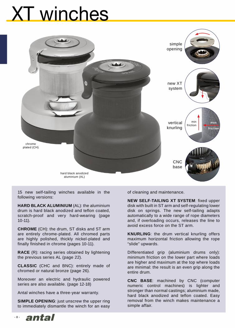
15 new self-tailing winches available in the following versions:
HARD BLACK ALUMINIUM (AL): the aluminium drum is hard black anodized and teflon coated, scratch-proof and very hard-wearing (page 10-11).
CHROME (CH): the drum, ST disks and ST arm are entirely chrome-plated. All chromed parts are highly polished, thickly nickel-plated and finally finished in chrome (pages 10-11).
RACE (R): racing series obtained by lightening the previous series AL (page 22).
CLASSIC (CHC and BNC): entirely made of chromed or natural bronze (page 26).
Moreover an electric and hydraulic powered series are also available. (page 12-18)
Antal winches have a three-year warranty.
SIMPLE OPENING: just unscrew the upper ring to immediately dismantle the winch for an easy
of cleaning and maintenance.
NEW SELF-TAILING XT SYSTEM: fixed upper disk with built in ST arm and self-regulating lower disk on springs. The new self-tailing adapts automatically to a wide range of rope diameters and, if overloading occurs, releases the line to avoid excess force on the ST arm.
KNURLING: the drum vertical knurling offers maximum horizontal friction allowing the rope “slide” upwards.
Differentiated grip (aluminium drums only): minimum friction on the lower part where loads are higher and maximum at the top where loads are minimal: the result is an even grip along the entire drum.
CNC BASE: machined by CNC (computer numeric control machines) is lighter and stronger than normal castings; aluminium made, hard black anodized and teflon coated. Easy removal from the winch makes maintenance a simple affair.
new XTsystem
verticalknurling
simpleopening
CNCbase
hard black anodized aluminium (AL)
XT winches
minfriction
max
friction
chrome plated (CH)
- 9 -
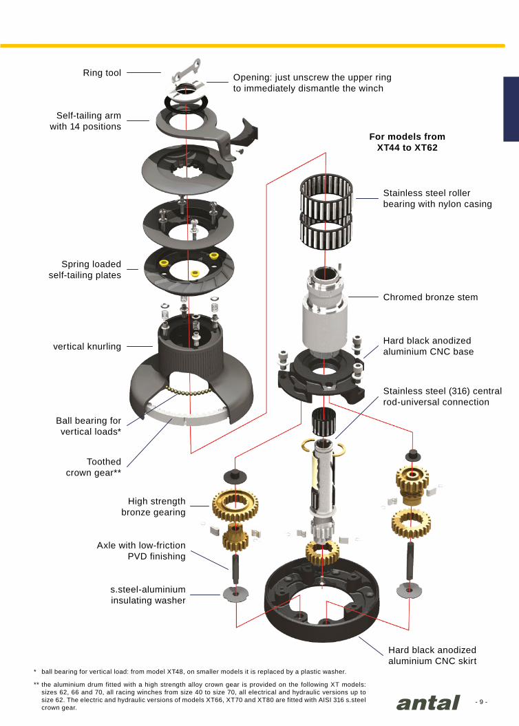
Hard black anodized aluminium CNC skirt
Ball bearing forvertical loads*
Toothed crown gear**
Chromed bronze stem
Stainless steel roller bearing with nylon casing
Opening: just unscrew the upper ring to immediately dismantle the winch
High strengthbronze gearing
Axle with low-frictionPVD finishing
s.steel-aluminium insulating washer
Self-tailing armwith 14 positions
Ring tool
Spring loadedself-tailing plates
vertical knurlingHard black anodized aluminium CNC base
Stainless steel (316) central rod-universal connection
* ball bearing for vertical load: from model XT48, on smaller models it is replaced by a plastic washer.
** the aluminium drum fitted with a high strength alloy crown gear is provided on the following XT models: sizes 62, 66 and 70, all racing winches from size 40 to size 70, all electrical and hydraulic versions up to size 62. The electric and hydraulic versions of models XT66, XT70 and XT80 are fitted with AISI 316 s.steel crown gear.
For models fromXT44 to XT62
- 10 -
219
224
120
182
197
93
204
217
105
173
185
93
153
157
80
128
135
73
112
119
71
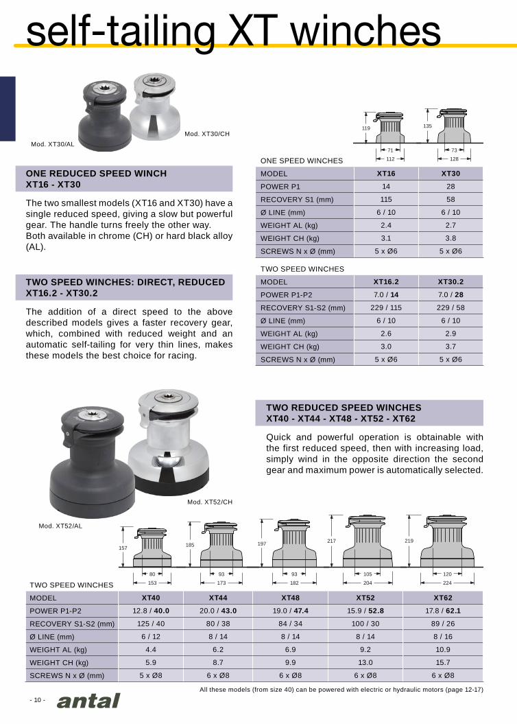
XT16.2 XT30.2
7.0 / 14 7.0 / 28
229 / 115 229 / 58
6 / 10 6 / 10
2.6 2.9
3.0 3.7
5 x Ø6 5 x Ø6
XT16 XT30
14 28
115 58
6 / 10 6 / 10
2.4 2.7
3.1 3.8
5 x Ø6 5 x Ø6
Mod. XT52/CH
Mod. XT52/AL
Mod. XT30/AL
Mod. XT30/CH
XT40 XT44 XT48 XT52 XT62
12.8 / 40.0 20.0 / 43.0 19.0 / 47.4 15.9 / 52.8 17.8 / 62.1
125 / 40 80 / 38 84 / 34 100 / 30 89 / 26
6 / 12 8 / 14 8 / 14 8 / 14 8 / 16
4.4 6.2 6.9 9.2 10.9
5.9 8.7 9.9 13.0 15.7
5 x Ø8 6 x Ø8 6 x Ø8 6 x Ø8 6 x Ø8
TWO REDUCED SPEED WINCHES XT40 - XT44 - XT48 - XT52 - XT62
Quick and powerful operation is obtainable with the first reduced speed, then with increasing load, simply wind in the opposite direction the second gear and maximum power is automatically selected.
self-tailing XT winches
SCREWS N x Ø (mm)
WEIGHT CH (kg)
WEIGHT AL (kg)
RECOVERY S1-S2 (mm)
Ø LINE (mm)
POWER P1-P2
MODEL
TWO SPEED WINCHES
SCREWS N x Ø (mm)
WEIGHT CH (kg)
WEIGHT AL (kg)
RECOVERY S1 (mm)
Ø LINE (mm)
POWER P1
MODEL
ONE SPEED WINCHES
ONE REDUCED SPEED WINCHXT16 - XT30
The two smallest models (XT16 and XT30) have a single reduced speed, giving a slow but powerful gear. The handle turns freely the other way.Both available in chrome (CH) or hard black alloy (AL).
TWO SPEED WINCHES: DIRECT, REDUCEDXT16.2 - XT30.2
The addition of a direct speed to the above described models gives a faster recovery gear, which, combined with reduced weight and an automatic self-tailing for very thin lines, makes these models the best choice for racing.
SCREWS N x Ø (mm)
WEIGHT CH (kg)
WEIGHT AL (kg)
RECOVERY S1-S2 (mm)
Ø LINE (mm)
POWER P1-P2
MODEL
TWO SPEED WINCHES
All these models (from size 40) can be powered with electric or hydraulic motors (page 12-17)

- 11 -
339
326
210
224
245
120
248
293
144
256
248
144
290
312
144
285
290
144
XT66 XT70
18.0 / 65.6 27.1 / 69.8
89 / 24 59 / 23
10 / 18 10 / 18
14.8 18.5
24.6 30.0
6 x Ø10 6 x Ø10
XT62.3 XT66.3 XT70.3 XT80.3
6.6 / 17.8 / 62.1 10.7 / 20.8 / 65.3 10.7 / 27.1 / 69.8 11.0 / 30.0 / 81.4
241 / 89 / 26 151 / 77 / 24 151 / 59 / 23 147 / 53 / 20
8 / 16 10 / 18 10 / 18 12 / 20
12.8 18.6 22.8 47.0
17.6 28.4 34.4 52.0
6 x Ø8 6 x Ø10 6 x Ø10 8 x Ø10
Mod. XT70/AL
Mod. XT70.3/AL
Mod. XT70/CH
Mod. XT70.3/CH
TWO REDUCED SPEED WINCHES XT66 - XT70
Large drum winches for 15-18 m boats. All the gears are fitted with roller bearings and the drum works on a very wide diameter roller-ball bearings.
THREE REDUCED SPEED WINCHESXT62.3 - XT66.3 - XT70.3 - XT80.3
The push-button on the base starts the first gear (the fastest); second and third gear are automatically selected simply by reversing the rotation of the handle.
P1, P2, P3 : power with the first (fast), second (medium) and third (slow) gear.S1, S2, S3 : recovery speed, the length of line recovered with one turn of the handle in first, second and third gear.
SCREWS N x Ø (mm)
WEIGHT CH (kg)
WEIGHT AL (kg)
RECOVERY S1-S2 (mm)
Ø LINE (mm)
POWER P1-P2
MODEL
TWO SPEED WINCHES
SCREWS N x Ø (mm)
WEIGHT CH (kg)
WEIGHT AL (kg)
RECOVERY S1-S2-S3 (mm)
Ø LINE (mm)
POWER P1-P2-P3
MODEL
THREE SPEED WINCHES
- 12 -
electric winches
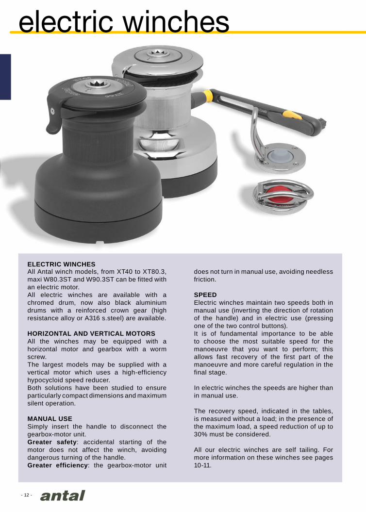
All Antal winch models, from XT40 to XT80.3, maxi W80.3ST and W90.3ST can be fitted with an electric motor.All electric winches are available with a chromed drum, now also black aluminium drums with a reinforced crown gear (high resistance alloy or A316 s.steel) are available.
HORIZONTAL AND VERTICAL MOTORSAll the winches may be equipped with a horizontal motor and gearbox with a worm screw.The largest models may be supplied with a vertical motor which uses a high-efficiency hypocycloid speed reducer.Both solutions have been studied to ensure particularly compact dimensions and maximum silent operation.
MANUAL USESimply insert the handle to disconnect the gearbox-motor unit.Greater safety: accidental starting of the motor does not affect the winch, avoiding dangerous turning of the handle.Greater efficiency: the gearbox-motor unit
does not turn in manual use, avoiding needless friction.
SPEEDElectric winches maintain two speeds both in manual use (inverting the direction of rotation of the handle) and in electric use (pressing one of the two control buttons).It is of fundamental importance to be able to choose the most suitable speed for the manoeuvre that you want to perform; this allows fast recovery of the first part of the manoeuvre and more careful regulation in the final stage.
In electric winches the speeds are higher than in manual use.
The recovery speed, indicated in the tables, is measured without a load; in the presence of the maximum load, a speed reduction of up to 30% must be considered.
All our electric winches are self tailing. For more information on these winches see pages 10-11.
ELECTRIC WINCHES

- 13 -
50
100
150
200 400 600 800
6
4
2
0
Yamila 13m - Heinrich Yard
F1 screws: for fastening the winch to the flange
F2 screws: for fastening the motor unit to the flange
motor unit-winch flange
motor unit
deck
gearbox
disengagement system
F3 screws: for fastening the flange to the deck
winch
ELECTRIC WINCHES:FORCE - ABSORPTION - SPEEDThe force of the winch (pulling load), the current absorption (Amp) of the motor and the line recovery speed are related as shown in the diagrams obtained experimentally with load and recovery tests. These diagrams are available for each model and clearly show the values of the maximum force with the fast and slow gears, the corresponding speed, and maximum electric absorption.
The documentation, including the force-absorption-speed diagrams, is available on request.
Force
(kg)
max Amp
1st gear 2nd gear
Abs
orpt
ion
(Am
p)S
peed
(m
/min
)
- 14 -
XT40EH12/AL
XT52EH12/AL
XT40EH12/CH
XT52EH12/CH
214
93
182
189
263
700 W
64115
261
120
224
205
311
1000 W
80115
202
93
173
189
263
700 W
64115
205
311
1000 W
80115
235
120
224
233
105
204
205
311
1000 W
80115
172
80
154
189
263
700 W
64115
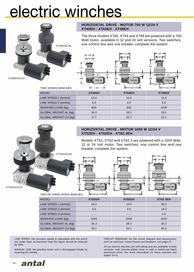
XT40EH XT44EH XT48EH
12.0 11.0 11.0
4.5 4.0 4.0
800 900 1000
16.2 18.2 19.1
17.7 20.7 22.1
XT52EH XT62EH XT62.3EH
15.0 14.0 36.0
4.0 4.0 14.0
- - - - - - 4.0
1200 1500 1500
26.3 28.3 30.2
30.1 33.1 35.0
GLOBAL WEIGHT AL (kg)
GLOBAL WEIGHT AL (kg)
GLOBAL WEIGHT CH (kg)
GLOBAL WEIGHT CH (kg)
HORIZONTAL DRIVE - MOTOR 1000 W 12/24 VXT52EH - XT62EH - XT62.3EH
Models XT52, XT62 and XT62.3 are powered with a 1000 Watt, 12 or 24 Volt motor. Two switches, one control box and one breaker complete the system.
HORIZONTAL DRIVE - MOTOR 700 W 12/24 VXT40EH - XT44EH - XT48EH
The three models XT40, XT44 and XT48 are powered with a 700 Watt motor, available in 12 and 24 volt versions. Two switches, one control box and one breaker complete the system.
MODEL
LINE SPEED 1 (m/min)
LINE SPEED 2 (m/min)
WORKING LOAD (kg)
MODEL
LINE SPEED 1 (m/min)
LINE SPEED 2 (m/min)
LINE SPEED 3 (m/min)
WORKING LOAD (kg)
TWO OR THREE-SPEED WINCHES
TWO SPEED WINCHES
LINE SPEED: the recovery speed is calculated with the winch not under load; at maximum load the figure should be reduced by 30%.
MANUAL USE: the gearbox-motor unit is disengaged simply by inserting the handle.
CIRCUIT DIAGRAM: for the circuit diagram and accessories, such as switches, control boxes and breakers, see page 17.
All our electric winches are self-tailing and are available in both versions: with chrome-plated drum or with a reinforced black aluminium drum. For more information on these winches see pages 10-11.
electric winches
- 15 -
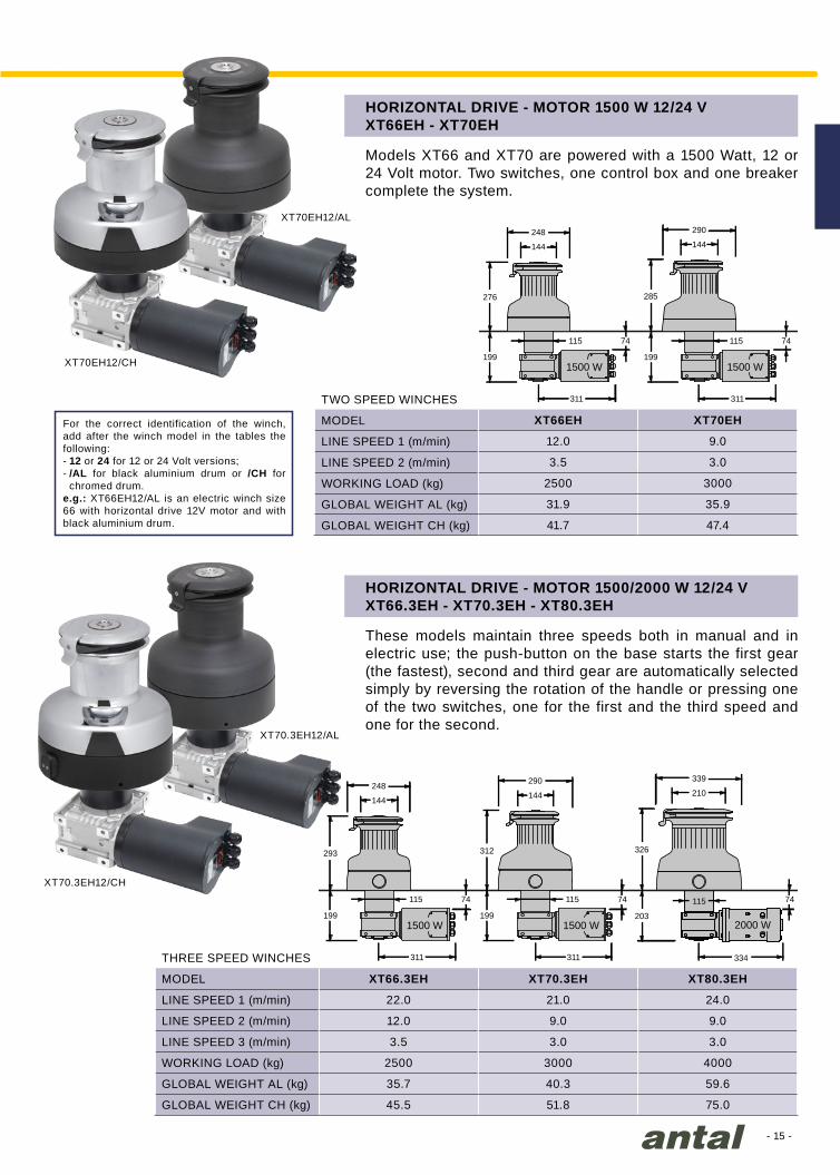
XT66EH XT70EH
12.0 9.0
3.5 3.0
2500 3000
31.9 35.9
41.7 47.4
XT66.3EH XT70.3EH XT80.3EH
22.0 21.0 24.0
12.0 9.0 9.0
3.5 3.0 3.0
2500 3000 4000
35.7 40.3 59.6
45.5 51.8 75.0
XT70EH12/AL
XT70.3EH12/AL
XT70EH12/CH
XT70.3EH12/CH
199
311
1500 W
74115
285
144
290
199
311
1500 W
74115
312
144
290
203
334
115
2000 W
326
210
339
74
199
311
1500 W
74115
276
144
248
199
311
1500 W
74115
293
144
248
HORIZONTAL DRIVE - MOTOR 1500 W 12/24 VXT66EH - XT70EH
Models XT66 and XT70 are powered with a 1500 Watt, 12 or 24 Volt motor. Two switches, one control box and one breaker complete the system.
HORIZONTAL DRIVE - MOTOR 1500/2000 W 12/24 VXT66.3EH - XT70.3EH - XT80.3EH
These models maintain three speeds both in manual and in electric use; the push-button on the base starts the first gear (the fastest), second and third gear are automatically selected simply by reversing the rotation of the handle or pressing one of the two switches, one for the first and the third speed and one for the second.
MODEL
LINE SPEED 1 (m/min)
LINE SPEED 2 (m/min)
WORKING LOAD (kg)
GLOBAL WEIGHT AL (kg)
GLOBAL WEIGHT AL (kg)
GLOBAL WEIGHT CH (kg)
GLOBAL WEIGHT CH (kg)
MODEL
LINE SPEED 1 (m/min)
LINE SPEED 2 (m/min)
LINE SPEED 3 (m/min)
WORKING LOAD (kg)
TWO SPEED WINCHES
THREE SPEED WINCHES
For the correct identification of the winch, add after the winch model in the tables the following:- 12 or 24 for 12 or 24 Volt versions;- /AL for black aluminium drum or /CH for
chromed drum.e.g.: XT66EH12/AL is an electric winch size 66 with horizontal drive 12V motor and with black aluminium drum.
- 16 -
XT70EV12/CH
XT70EV12/AL
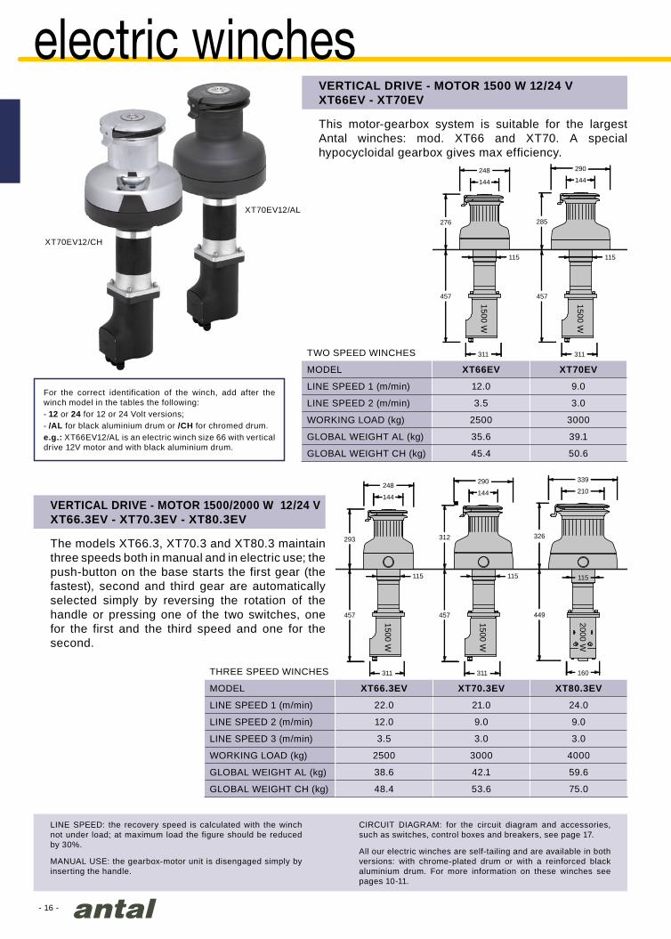
XT66.3EV XT70.3EV XT80.3EV
22.0 21.0 24.0
12.0 9.0 9.0
3.5 3.0 3.0
2500 3000 4000
38.6 42.1 59.6
48.4 53.6 75.0
XT66EV XT70EV
12.0 9.0
3.5 3.0
2500 3000
35.6 39.1
45.4 50.6
115
285
144
290
457
311
1500 W
457
311
1500 W
115
312
144
290210
339
326
449
160
115
2000 W
457
311
1500 W
115
276
144
248
293
144
248
457
311
1500 W
115
VERTICAL DRIVE - MOTOR 1500 W 12/24 VXT66EV - XT70EV
This motor-gearbox system is suitable for the largest Antal winches: mod. XT66 and XT70. A special hypocycloidal gearbox gives max efficiency.
VERTICAL DRIVE - MOTOR 1500/2000 W 12/24 V XT66.3EV - XT70.3EV - XT80.3EV
The models XT66.3, XT70.3 and XT80.3 maintain three speeds both in manual and in electric use; the push-button on the base starts the first gear (the fastest), second and third gear are automatically selected simply by reversing the rotation of the handle or pressing one of the two switches, one for the first and the third speed and one for the second.
MODEL
LINE SPEED 1 (m/min)
LINE SPEED 2 (m/min)
WORKING LOAD (kg)
GLOBAL WEIGHT AL (kg)
GLOBAL WEIGHT CH (kg)
MODEL
LINE SPEED 1 (m/min)
LINE SPEED 2 (m/min)
LINE SPEED 3 (m/min)
WORKING LOAD (kg)
GLOBAL WEIGHT AL (kg)
GLOBAL WEIGHT CH (kg)
TWO SPEED WINCHES
THREE SPEED WINCHES
For the correct identification of the winch, add after the winch model in the tables the following:- 12 or 24 for 12 or 24 Volt versions;- /AL for black aluminium drum or /CH for chromed drum.e.g.: XT66EV12/AL is an electric winch size 66 with vertical drive 12V motor and with black aluminium drum.
LINE SPEED: the recovery speed is calculated with the winch not under load; at maximum load the figure should be reduced by 30%.
MANUAL USE: the gearbox-motor unit is disengaged simply by inserting the handle.
CIRCUIT DIAGRAM: for the circuit diagram and accessories, such as switches, control boxes and breakers, see page 17.
All our electric winches are self-tailing and are available in both versions: with chrome-plated drum or with a reinforced black aluminium drum. For more information on these winches see pages 10-11.
electric winches

- 17 -
WATT VOLT AMP
XT40XT44 - XT48 700
12 A071 70 T6315/12
24 A041 40 T6315/24
XT52 - XT62 100012 A101 100 T6315/12
24 A051 50 T6315/24
XT66 - XT70 150012 A151 150 T6315/12
24 A071 70 T6315/24
XT80.3 - W80.3 2000 24 A101 100 T6315/24
W90.3 3000 24 A151 150 T6415/24
Mod. 251.035/SG
Mod. 251.035/QG
Mod. 251.035/AG
Mod. 251.035/SR
Mod. 251.035/QR
Mod. 251.035/AR
Mod. WBC
S.steel cover, grey button
Plastic cover, grey button
Aluminium cover, grey button
S.steel cover, red button
Plastic cover, red button
Aluminium cover, red button
CONTROL BOXSolenoids are contained in a water tight “control box”; they are available for both 12 and 24 Volt.
BREAKERA breaker should be mounted to protect the motor against overload.
BATTERY
BREAKER
CONTROLBOX
SP
EE
D 1
SP
EE
D 2
WINCHMODEL
MOTOR BREAKER
MODELCONTROL BOX
MODEL
electric system & accessories
SQUARE SWITCHESNew model with hard black anodized aluminium cover. Sizes 59x66 mm only.
To guarantee complete protection for powered winches, Antal offers the WBC, which keeps the winch from reaching its maximum working load. The winch is generally activated in the fastest gear. When maximum absorption is reached, this gear is deactivated by the WBC and the slow gear must be used. This reduces the
winch stress until maximum absorption (max load) is reached and the WBC also deactivates this slow gear.Another safety device is the breaker that protects the motor from overheating due to too intensive use. However, it does not protect the winch from sudden excessive loads. Therefore, both are necessary for complete protection.The WBC is suitable for two-speed Antal winches, with motors up to 2000 W and maximum absorption of 250 amps.
POWERED WINCHES LOAD CONTROL

- 18 -
XT44HD XT48HD XT52HD XT62HD XT62.3HD
12.0 12.5 16.0 13.0 36.9
5.5 5.0 4.6 4.0 13.0
- - - - 4.0
900 1000 1200 1400 1400
17.2 18.2 20.4 22.2 24.1
19.7 21.2 24.2 27.0 28.9
50 50 50 50 50
100 100 120 120 120
7.5 7.5 7.5 7.5 7.5
202
93
173
265
130
233
105
204
265
130
214
93
182
265
130
235
120
224
265
130
261
120
224
265
130
XT62HD/AL
XT62HD/CH
HYDRAULIC SYSTEMHydraulic motors are available for Antal winches from model XT44 to XT80.3, as well as to maxi W80.3 and W90.3.The pressure of the system varies from 100 to 120 bars for the larger winches. Connections are to be carried out with 3/8” pipes.All hydraulic winches are available with a chromed drum, now also black aluminum drum with a reinforced crown gear (high resistance alloy or A316 s.steel) is available.For more information, see pages 10-11.For manual use, the motor unit is released simply by inserting the handle.
LINE SPEEDLine speeds are calculated in absence of load conditions and considering the flow of the lower table. The effective speed will be evaluated according to the actual size of the hydraulic unit.
hydraulic winch
MODEL
LINE SPEED 1 (m/min)
LINE SPEED 2 (m/min)
LINE SPEED 3 (m/min)
WORKING LOAD (kg)
GLOBAL WEIGHT AL (kg)
GLOBAL WEIGHT CH (kg)
HYDRAULIC MOTOR
SIZE (cc)
PRESSURE (bar)
FLOW (l/min)
For the correct identification of the winch, add after the winch model in the tables /AL for black aluminium drum or /CH for chromed drum.e.g.: XT66HD/AL is a hydraulic winch size 66 with black aluminium drum.

- 19 -
XT66HD XT66.3HD XT70HD XT70.3HD XT80.3HD
13.0 23.0 9.0 23.0 22.0
3.6 12.0 3.5 9.0 8.0
- 3.6 - 3.5 3.0
2600 2600 2900 2900 4000
24.5 28.3 28.4 32.7 48.0
34.3 38.1 39.8 44.2 63.4
80 80 100 100 160
120 120 120 120 120
12 12 15 15 24
276
144
248
265
130
285
144
290
265
130
293
144
248
265
130
312
144
290
265
130
210
339
326
280
130
Mod. 251.035/SG
Mod. 251.035/QG
Mod. 251.035/AG
Mod. 251.035/SR
Mod. 251.035/QR
Mod. 251.035/AR
HYDRAULIC UNITThese units are designed for the different requirements of each boat.The winch speed is proportional to the flow from the hydraulic unit, the load of the winch is proportional to the pressure.The hydraulic unit that must work a number of winches at the same time, must guarantee a flow equal to the sum of the flows required from each one.The flow and pressure levels given in the table for each winch must not be exceeded.
All these models are fitted with Danfoss hydraulic motors series OMR or equivalent.
SWITCHES
POWERUNIT
BATTERY
HYDROPUMP
CONTROLBOX
MODEL
LINE SPEED 1 (m/min)
LINE SPEED 2 (m/min)
LINE SPEED 3 (m/min)
WORKING LOAD (kg)
GLOBAL WEIGHT AL (kg)
GLOBAL WEIGHT CH (kg)
HYDRAULIC MOTOR
SIZE (cc)
PRESSURE (bar)
FLOW (l/min)
Switches with s.steel cover
Switches with plastic cover
Switches with aluminium cover
SWITCHESTwo switches with watertight protection must be installed for each winch. To identify the first and the second speed 2 colours are used: gray and red, s.steel, plastic or aluminium version available.
Grey button
Grey button
Grey button
Red button
Red button
Red button

- 20 -
Mod. W80.3 ST
W80.3ST W90.3ST
11.0 / 30.0 / 81.4 13.7 / 35.8 / 90.2
147 / 53 / 20 116 / 45 / 18
12 / 22 16 / 30
52.0 102.0
8 x Ø10 8 x Ø12
404
429300
280
140
W80.3HD W90.3HD
22.0 18.0
8.0 7.0
3.0 2.5
4000 8000
63.4 118
160 200
120 120
24 30
280
130
338
339210
THREE REDUCED SPEED MAXI WINCHESW80.3ST - W90.3ST
Maxi winches for boats more than 20 m long. These models are almost always powered with electric motors or hydraulic motors and available only with a chromed drum (CH).All the gears are fitted with roller bearings and the drum works on a very wide diameter roller-ball bearings.The push-button on the base starts the first gear (the fastest); second and third gear are automatically selected simply by reversing the rotation of the handle.
SCREWS N x Ø (mm)
WEIGHT CH (kg)
RECOVERY S1-S2-S3 (mm)
Ø LINE (mm)
POWER P1-P2-P3
MODEL
THREE SPEED WINCHES
HYDRAULIC MOTORSW80.3HD - W90.3HD
The maxi winches W80.3 and W90.3 can be powered by a hydraulic motor.
MODEL
LINE SPEED 1 (m/min)
LINE SPEED 2 (m/min)
LINE SPEED 3 (m/min)
WORKING LOAD (kg)
GLOBAL WEIGHT (kg)
HYDRAULIC MOTOR
SIZE (cc)
PRESSURE (bar)
FLOW (l/min)
maxi winches

- 21 -
W80.3EH W90.3EH
24.0 18.0
9.0 7.0
3.0 2.5
4000 8000
75.0 145.0
2000 3000
254
401
140 75
3000 W
454
179
140
3000 W
449
160
115
2000 W
W80.3EV W90.3EV
24.0 18.0
9.0 7.0
3.0 2.5
4000 8000
75.0 145.0
2000 3000
203
73
334
115
2000 W
Adriatica 21.37 m
HORIZONTAL DRIVE - 2000 or 3000 W - 24 VW80.3EH - W90.3EH
Model W80.3 is fitted with a 2000 W (24 V) motor and model W90.3 with a 3000 W (24 V) motor.For the circuit diagram and accessories, such as switches, control-boxes and breakers, see page 17.
Vertical drive version is also available for models W80.3 and W90.3 (2000 W on the 80.3, 3000 W on the 90.3, both 24 V) with a hypocycloidal gearbox.For the circuit diagram and accessories, such as switches, control-boxes and breakers, see page 17.
VERTICAL DRIVE - 2000 or 3000 W - 24 VW80.3EV - W90.3EV
MODEL
LINE SPEED 1 (m/min)
LINE SPEED 2 (m/min)
LINE SPEED 3 (m/min)
WORKING LOAD (kg)
GLOBAL WEIGHT (kg)
MOTOR (W)
MODEL
LINE SPEED 1 (m/min)
LINE SPEED 2 (m/min)
LINE SPEED 3 (m/min)
WORKING LOAD (kg)
GLOBAL WEIGHT (kg)
MOTOR (W)
THREE SPEED WINCHES
THREE SPEED WINCHES
electric maxi winches
- 22 -
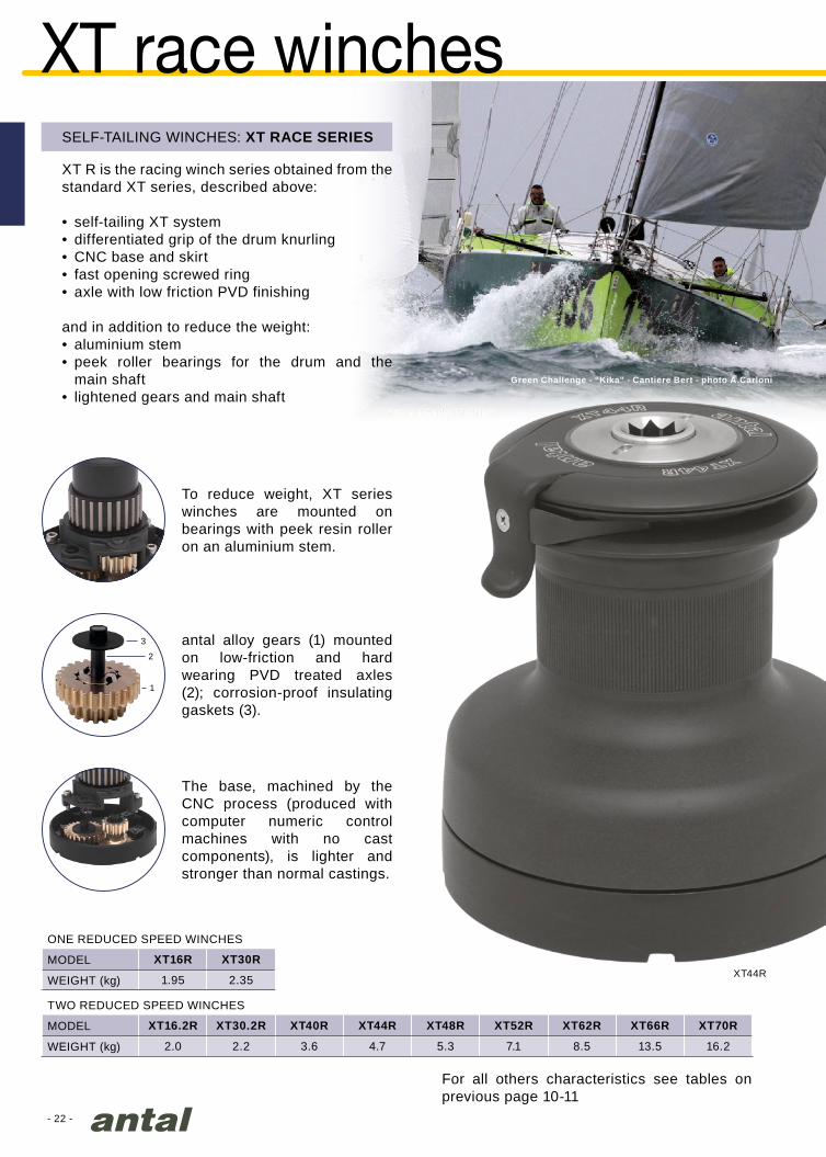
XT16.2R XT30.2R XT40R XT44R XT48R XT52R XT62R XT66R XT70R
2.0 2.2 3.6 4.7 5.3 7.1 8.5 13.5 16.2
XT16R XT30R
1.95 2.35 XT44R
3
2
1
Green Challenge - “Kika” - Cantiere Bert - photo A.Carloni
SELF-TAILING WINCHES: XT RACE SERIES
XT R is the racing winch series obtained from the standard XT series, described above:
• self-tailing XT system• differentiated grip of the drum knurling• CNC base and skirt• fast opening screwed ring• axle with low friction PVD finishing
and in addition to reduce the weight:• aluminium stem• peek roller bearings for the drum and the
main shaft• lightened gears and main shaft
For all others characteristics see tables on previous page 10-11
antal alloy gears (1) mounted on low-friction and hard wearing PVD treated axles (2); corrosion-proof insulating gaskets (3).
To reduce weight, XT series winches are mounted on bearings with peek resin roller on an aluminium stem.
The base, machined by the CNC process (produced with computer numeric control machines with no cast components), is lighter and stronger than normal castings.
XT race winches
WEIGHT (kg)
WEIGHT (kg)
MODEL
MODEL
ONE REDUCED SPEED WINCHES
TWO REDUCED SPEED WINCHES
- 23 -
XT52.3RD
XT62.3RD
204
222
105
224
224
120
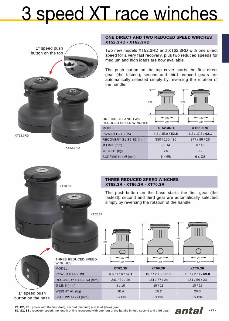
XT52.3RD XT62.3RD
4.8 / 15.9 / 52.8 4.2 / 17.8 / 62.1
330 / 100 / 30 377 / 89 / 26
8 / 14 8 / 16
7.5 9.2
6 x Ø8 6 x Ø8
224
245
120
248
293
144
290
312
144
XT62.3R XT66.3R XT70.3R
6.6 / 17.8 / 62.1 10.7 / 20.8 / 65.3 10.7 / 27.1 / 69.8
241 / 89 / 26 151 / 77 / 24 151 / 59 / 23
8 / 16 10 / 18 10 / 18
10.4 16.2 20.3
6 x Ø8 6 x Ø10 6 x Ø10
XT70.3R
XT62.3R
3 speed XT race winches
Two new models XT52.3RD and XT62.3RD with one direct speed for a very fast recovery, plus two reduced speeds for medium and high loads are now available.
The push button on the top cover starts the first direct gear (the fastest), second and third reduced gears are automatically selected simply by reversing the rotation of the handle.
1st speed push button on the top
THREE REDUCED SPEED WINCHESXT62.3R - XT66.3R - XT70.3R
ONE DIRECT AND TWO REDUCED SPEED WINCHESXT52.3RD - XT62.3RD
The push-button on the base starts the first gear (the fastest); second and third gear are automatically selected simply by reversing the rotation of the handle.
P1, P2, P3 : power with the first (fast), second (medium) and third (slow) gear.S1, S2, S3 : recovery speed, the length of line recovered with one turn of the handle in first, second and third gear.
SCREWS N x Ø (mm)
WEIGHT AL (kg)
RECOVERY S1-S2-S3 (mm)
Ø LINE (mm)
POWER P1-P2-P3
MODEL
THREE REDUCED SPEEDWINCHES
SCREWS N x Ø (mm)
WEIGHT (kg)
RECOVERY S1-S2-S3 (mm)
Ø LINE (mm)
POWER P1-P2-P3
MODEL
ONE DIRECT AND TWO REDUCED SPEED WINCHES
1st speed push button on the base
- 24 -Farnova 45
1
2
3
4
56
4
pedestals for winch
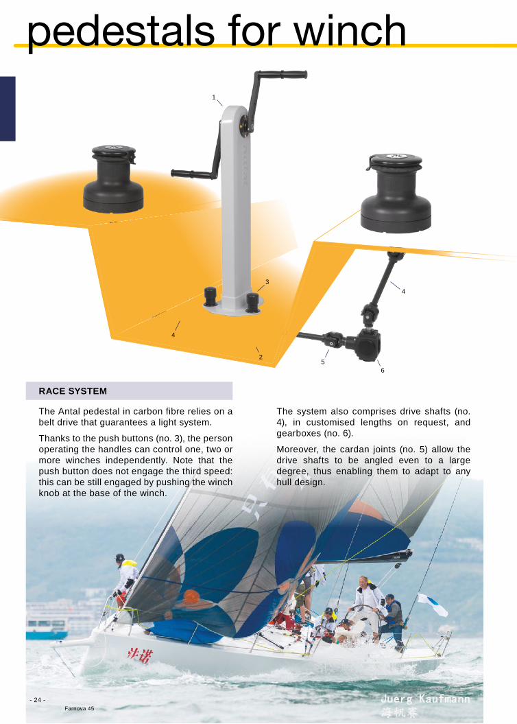
RACE SYSTEM
The Antal pedestal in carbon fibre relies on a belt drive that guarantees a light system.
Thanks to the push buttons (no. 3), the person operating the handles can control one, two or more winches independently. Note that the push button does not engage the third speed: this can be still engaged by pushing the winch knob at the base of the winch.
The system also comprises drive shafts (no. 4), in customised lengths on request, and gearboxes (no. 6).
Moreover, the cardan joints (no. 5) allow the drive shafts to be angled even to a large degree, thus enabling them to adapt to any hull design.
- 25 -
“Stella Polare” - Marina Militare Italiana - photo J.R. Taylor
Mod. C001
Mod. C002
Mod. C003
Mod. C004/xx
Mod. C005
Mod. C006
1
2
3
4
5
5
6
66
4
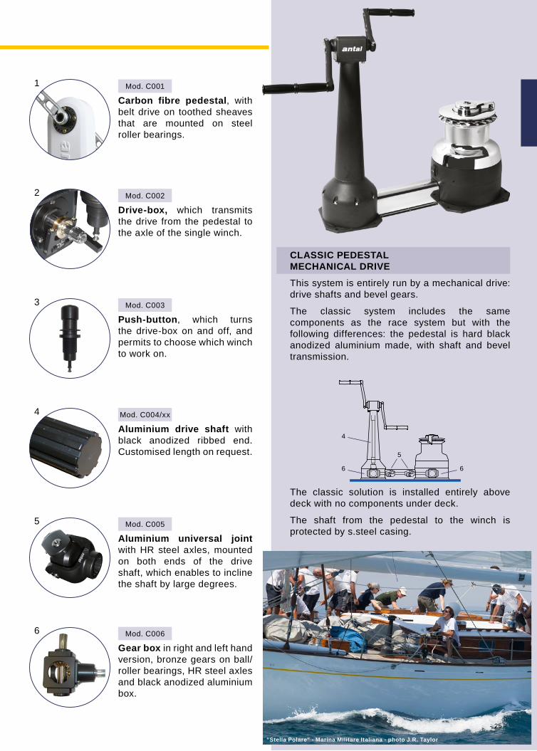
Carbon fibre pedestal, with belt drive on toothed sheaves that are mounted on steel roller bearings.
Gear box in right and left hand version, bronze gears on ball/roller bearings, HR steel axles and black anodized aluminium box.
Aluminium universal joint with HR steel axles, mounted on both ends of the drive shaft, which enables to incline the shaft by large degrees.
Aluminium drive shaft with black anodized ribbed end. Customised length on request.
Push-button, which turns the drive-box on and off, and permits to choose which winch to work on.
Drive-box, which transmits the drive from the pedestal to the axle of the single winch.
CLASSIC PEDESTALMECHANICAL DRIVE
This system is entirely run by a mechanical drive: drive shafts and bevel gears.
The classic system includes the same components as the race system but with the following differences: the pedestal is hard black anodized aluminium made, with shaft and bevel transmission.
The classic solution is installed entirely above deck with no components under deck.
The shaft from the pedestal to the winch is protected by s.steel casing.

- 26 -
XT48/CHC
W42/CHCXT48/BNC
W42/BNC
Anitra 12m SI - Martin Yacht - Germany
classic winches
Classic series winches (CHC) are supplied not only with a chromed drum, ST disks and ST arm, as the chrome series models (CH) described on pages 10-11, but also with a chromed lower skirt, thus being completely chromed.The chrome-plating is carried out with great care to guarantee maximum durability. First the unit are highly polished, then thickly nickel-plated and finally finisched in chrome.
CLASSIC SERIES WINCHES
Natural bronze winch handle with wooden grip.
On request, Antal classic winches can be supplied (with drum, ST disks, ST arm and skirt) entirely made of polished bronze (add /BNC after the winch model).
POLISHED BRONZE
- 27 -
122150
58
90
Amel 50 - photo JS Evrard
240.010
10
8 : 1
1.40
3 x Ø8
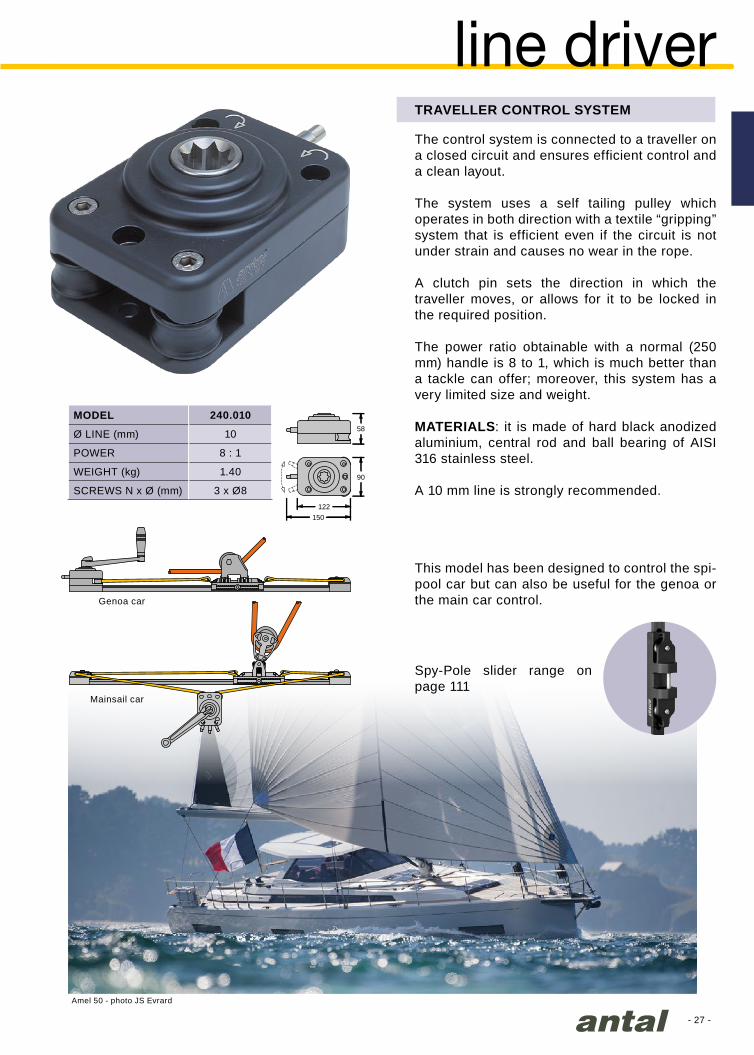
line driverThe control system is connected to a traveller on a closed circuit and ensures efficient control and a clean layout.
The system uses a self tailing pulley which operates in both direction with a textile “gripping” system that is efficient even if the circuit is not under strain and causes no wear in the rope.
A clutch pin sets the direction in which the traveller moves, or allows for it to be locked in the required position.
The power ratio obtainable with a normal (250 mm) handle is 8 to 1, which is much better than a tackle can offer; moreover, this system has a very limited size and weight.
MATERIALS: it is made of hard black anodized aluminium, central rod and ball bearing of AISI 316 stainless steel.
A 10 mm line is strongly recommended.
TRAVELLER CONTROL SYSTEM
Genoa car
Mainsail car
Spy-Pole slider range on page 111
This model has been designed to control the spi-pool car but can also be useful for the genoa or the main car control.
Ø LINE (mm)
POWER
WEIGHT (kg)
SCREWS N x Ø (mm)
MODEL

- 28 -
284
197
200
246
423100
85100
62
274
1500 W278
197
140
246
275100
114100
62
274
229
167
160
220
33587
1000 W
6380
56
219
222
149
160
183
29373
700 W
5880
56
207
LD700 LD1000 LD1500 LD1500 HD
10 / 12 12 / 14 12 / 14 12 / 14
15 20 22 22
4 x Ø8 4 x Ø8 4 x Ø8 4 x Ø8
47 x 230 47 x 330 47 x 430 47 x 430
614.219 614.229 614.239 614.239
800 1260 1600 1800*
0.08 0.10 0.12 0.10**
Mod. LD1000
Courtesy of Fountaine-Pajot - Sanya 57Photo Gilles Martin-Raget
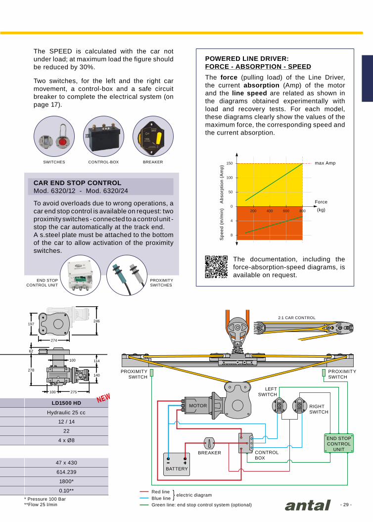
powered line driverThis is a solution done for the control of the main car with a simple “self-tailing” sheave on the deck, a motor and gearbox under the deck.Three sizes available with 700, 1000 and 1500 W motors in 12 or 24 Volt version.The largest model is also available in the hydraulic version. This model offers a maximum load on the circuit of 900 kg (100 bar pressure) with a line speed according to the flow rate of the hydraulic system.
POWERED LINE DRIVER
MOTOR Electric 700 W Electric 1000 W Electric 1500 W
Ø LINE (mm)
WEIGHT (kg)
SCREWS N x Ø (mm)
MODEL
MAIN CAR MODEL
2:1 CAR CONTROL
Car speed and working load are based on a 2:1 car control as described in the figure on the following page. For a direct 1:1 control, the speed is doubled and the load is halved. Under the maximum load, the speed is reduced by up to even 50%. For cars, see page 138.
WORKING LOAD (kg)
MAIN CAR SIZE (mm)
CAR SPEED (m/sec)
For the correct identification of the line-driver, add after the LD model in the tables /12 or /24 for 12 or 24 Volt version.
- 29 -
278
197
140
246
275100
114100
62
274
LD700 LD1000 LD1500 LD1500 HD
10 / 12 12 / 14 12 / 14 12 / 14
15 20 22 22
4 x Ø8 4 x Ø8 4 x Ø8 4 x Ø8
47 x 230 47 x 330 47 x 430 47 x 430
614.219 614.229 614.239 614.239
800 1260 1600 1800*
0.08 0.10 0.12 0.10**
50
100
150
200 400 600 800
8
4
0
Hydraulic 25 cc
* Pressure 100 Bar**Flow 25 l/min
To avoid overloads due to wrong operations, a car end stop control is available on request: two proximity switches - connected to a control unit - stop the car automatically at the track end.A s.steel plate must be attached to the bottom of the car to allow activation of the proximity switches.
CAR END STOP CONTROLMod. 6320/12 - Mod. 6320/24
The SPEED is calculated with the car not under load; at maximum load the figure should be reduced by 30%.
Two switches, for the left and the right car movement, a control-box and a safe circuit breaker to complete the electrical system (on page 17).
Red lineelectric diagram}Blue line
Green line: end stop control system (optional)
BATTERY
END STOP CONTROL
UNIT
MOTOR
2:1 CAR CONTROL
CONTROLBOX
BREAKER
LEFT SWITCH
PROXIMITY SWITCH
PROXIMITY SWITCH
RIGHT SWITCH
SWITCHES
END STOPCONTROL UNIT
CONTROL-BOX
PROXIMITYSWITCHES
BREAKER
POWERED LINE DRIVER:FORCE - ABSORPTION - SPEEDThe force (pulling load) of the Line Driver, the current absorption (Amp) of the motor and the line speed are related as shown in the diagrams obtained experimentally with load and recovery tests. For each model, these diagrams clearly show the values of the maximum force, the corresponding speed and the current absorption.
The documentation, including the force-absorption-speed diagrams, is available on request.
Force
(kg)
max Amp
Abs
orpt
ion
(Am
p)S
peed
(m
/min
)

- 30 -
2021 0.43
2022 0.53
2023 0.62
2031 0.87
2032 0.97
2033 1.07
2011 0.38
2012 0.48
2014 0.36
/NL
2021
2031
2022
2032
2023
2033
2011 20142012
WINCH HANDLES
In addition to the extremely light black aluminium handles in two sizes: 200 mm (8 inches) and 250 mm (10 inches), there is also the classic chromed or natural polished bronze solution, always 250 mm long.
Three different grips are available: the single, the double and the new “ball-grip”.
The handle arm made of forged aluminium with lightening holes is extremely light and resists the heaviest torsion.
winch handlesThe grip is covered with rubber to give a firm hold and runs on two ball bearings to increase its efficiency (single-grip and ball-grip only).
All the models are available with or without the lock system which automatically locks the handle on the winch. To refer to the “no lock” version add /NL to the code.
Custom solutions are available on request: wooden grips (model /W), different colours, natural bronze (model /BN), special engravings...
CUSTOMSOLUTIONS
MODEL HAND GRIP
single
ball-grip
mini ball-grip
WEIGHT (kg)
ALUMINIUM L = 200 mm
MODEL HAND GRIP
single
ball-grip
double
WEIGHT (kg)
ALUMINIUM L = 250 mm
MODEL HAND GRIP
single
ball-grip
double
WEIGHT (kg)
CHROMED BRONZE L = 250 mm

- 31 -
2121 0.43
2122 0.53
2123 0.62
212121222123
Trimarine Compositos - IRC 39 - “LANN AEL 2” - Joubert / Nivelt
Speedylock is the new Antal winch handle, available with the 250 mm lever with single, ball and double grip.
Hard black anodized forged aluminium lever, rubber grip on two ball bearings (on single-grip and ball-grip version).
THE SPEEDY WAY TO LOCK-UNLOCK THE WINCH HANDLE
MODEL HAND GRIP
single
ball-grip
double
WEIGHT (kg)
ALUMINIUM L = 250 mm
speedylock

- 32 -
Class 40 “Colombre” - M.Juris / P.Luciani
- 33 -
Mod. V-Grip Plus
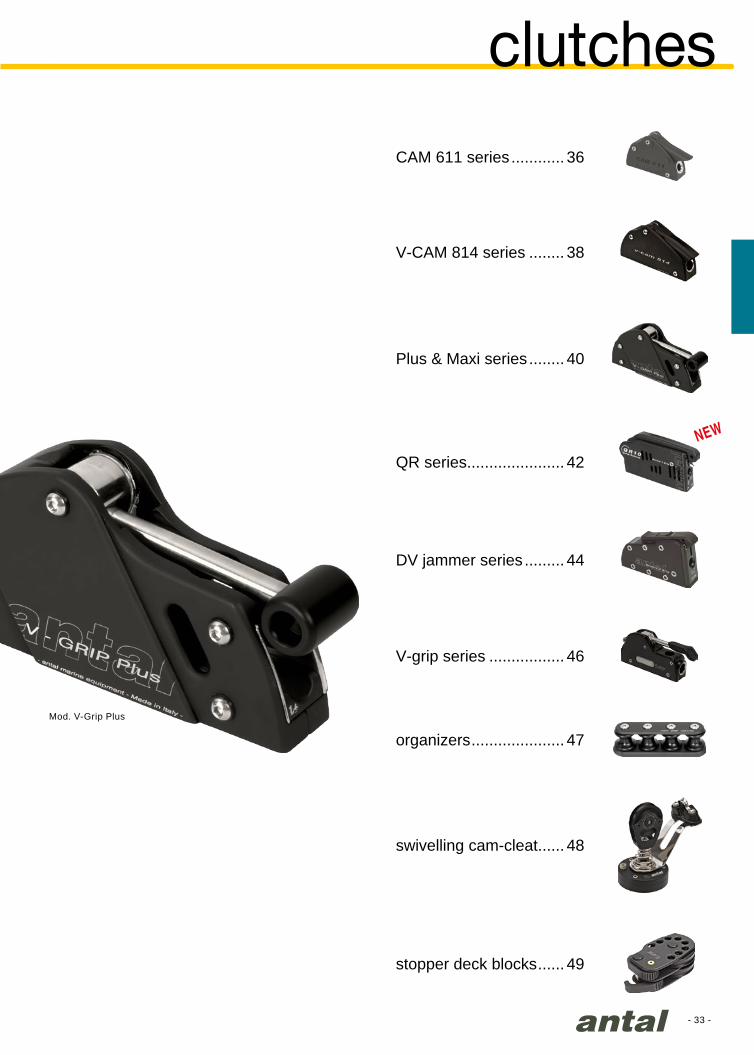
clutches
swivelling cam-cleat...... 48
CAM 611 series ............ 36
V-CAM 814 series ........ 38
Plus & Maxi series ........ 40
QR series...................... 42
stopper deck blocks ...... 49
DV jammer series ......... 44
V-grip series ................. 46
organizers ..................... 47

- 34 -
CAM611 CAM 611/V V-GRIP V-CAM 814 V-GRIP PLUS V-GRIP MAXI QR DV JAMMERS
6 8 10 12 14 10 12 14 12 14 16 14 16 18 20 22 10 12 8 10 12 14 16 18
Ø = 6 mm 250 400 Ø = 6 mm
Ø = 8 mm 380 600 500 600 Ø = 8 mm 1500
Ø = 10 mm 500 700 700 850 850 1050 Ø = 10 mm 1600 2000
Ø = 12 mm 1000 1000 1000 1200 1200 1400 1400 Ø = 12 mm 1400 2200 3000
Ø = 14 mm 1300 1300 1500 1700 1700 Ø = 14 mm 1700 1700 4000
Ø = 16 mm 1600 2100 Ø = 16 mm 2100 2100 5000
Ø = 18 mm Ø = 18 mm 2600 2600 6000
Ø = 20 mm Ø = 20 mm 3000 3000
Ø = 22 mm Ø = 22 mm 3400
1. 2. 3. 4.
clutch selection guide
* These models are fitted with the V-GRIP system that is internationally patented.
LINEDIAMETER
CLUTCH MAX LOAD (kg)
Emergency opening
Line retrieval with closed lever
Load distribution
Pressure on3 sides

- 35 -
CAM611 CAM 611/V V-GRIP V-CAM 814 V-GRIP PLUS V-GRIP MAXI QR DV JAMMERS
6 8 10 12 14 10 12 14 12 14 16 14 16 18 20 22 10 12 8 10 12 14 16 18
Ø = 6 mm 250 400 Ø = 6 mm
Ø = 8 mm 380 600 500 600 Ø = 8 mm 1500
Ø = 10 mm 500 700 700 850 850 1050 Ø = 10 mm 1600 2000
Ø = 12 mm 1000 1000 1000 1200 1200 1400 1400 Ø = 12 mm 1400 2200 3000
Ø = 14 mm 1300 1300 1500 1700 1700 Ø = 14 mm 1700 1700 4000
Ø = 16 mm 1600 2100 Ø = 16 mm 2100 2100 5000
Ø = 18 mm Ø = 18 mm 2600 2600 6000
Ø = 20 mm Ø = 20 mm 3000 3000
Ø = 22 mm Ø = 22 mm 3400
V-GRIP SYSTEM CLUTCHES
The V-Grip is an Antal patented system for rope locking. It works with a pressure exerted on 3 sides of the line with a higher friction and, consequently, with a lower pressure, in order not to damage manoeuvres.
All Antal clutches, except the Cam 611, are fitted with the V-Grip system.
The V-Grip system has the following characteristics:
1. Pressure on three sides. Unlike the usual flat cam, V-Grip is fitted with a V-shaped cam that improves the holding strength without damaging the line cover.
2. Load distribution. The curved base-V-Cam pair increases the bearing surface, preventing the load from being concentrated at a critical point.
3. Line retrieval with closed lever. Line retrieval can be achieved with the lever closed. The line stops automatically in the new position with no slippage.
4. Emergency opening. The line can be released under load without the use of a winch because the Antal mechanism guarantees easy opening even under heavy conditions.
CLUTCH RANGE
A complete range with 7 different models for lines from 6 to 22 mm.All Antal models, except the Maxi, the QR and the DV-Jammer, are available in single, double, triple and quadruple versions.The Cam 611 and Cam 814 are also available in a silver version with the new ergonomic aluminium lever.
CLUTCH SELECTION
Max loads of the lower table for each model and for different line diameters have been obtained from extensive tests.
Tests reveal best results on Dyneema with composite Kevlar/Polyester covers, while traditional pure-Polyester covers over a Dyneema core prove to have poor resistance. Also “all-Polyester” core/cover versions give excellent results.
LINEDIAMETER
- 36 -
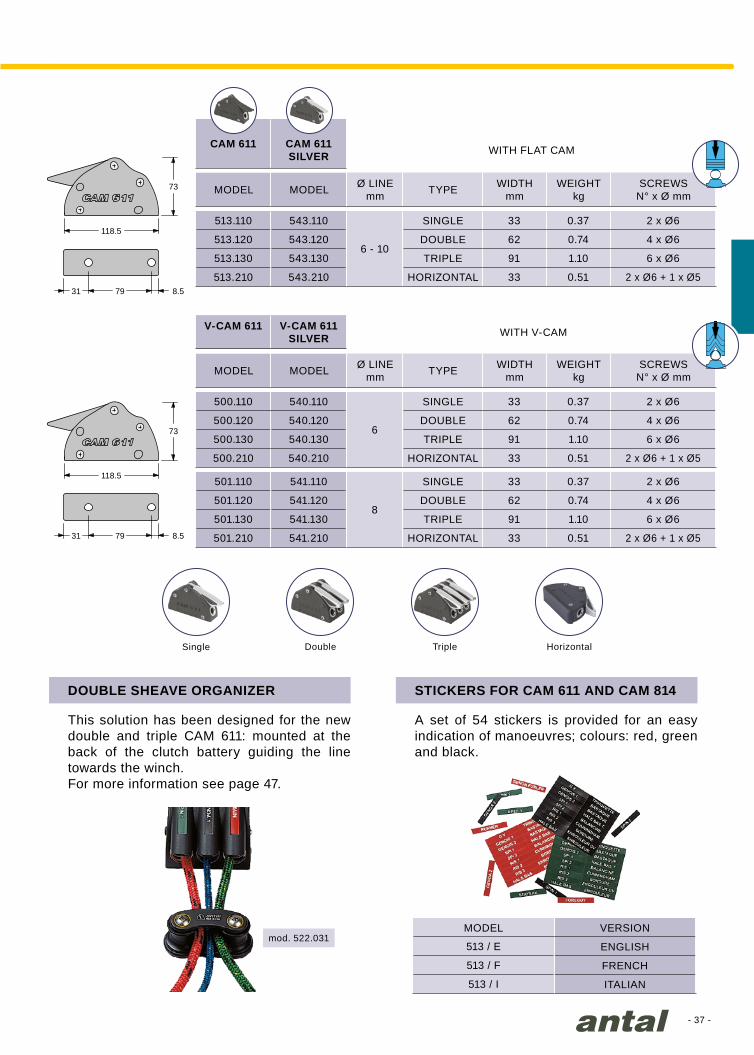
CAM 611 mod. 513.110V-CAM 611 mod. 500.110
CAM 611 Silver mod. 543.110V-CAM 611 Silver mod. 540.110
Heinrich Yunikon
cam 611 series
V-CAM 611 SILVER
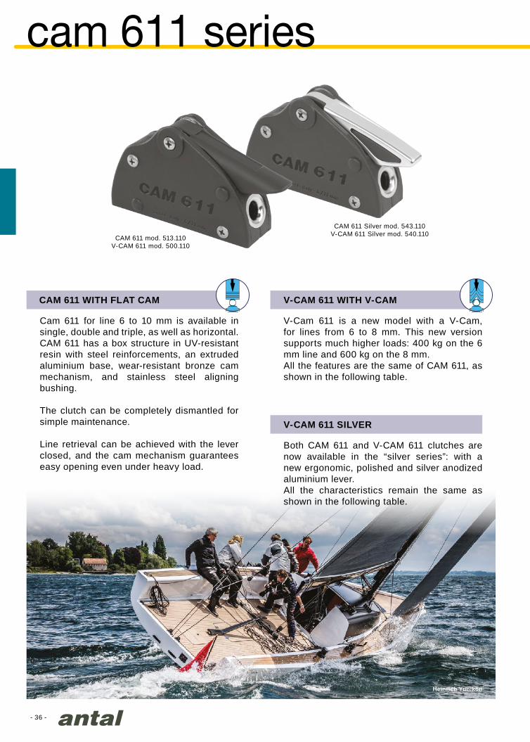
Both CAM 611 and V-CAM 611 clutches are now available in the “silver series”: with a new ergonomic, polished and silver anodized aluminium lever. All the characteristics remain the same as shown in the following table.
V-CAM 611 WITH V-CAM
V-Cam 611 is a new model with a V-Cam, for lines from 6 to 8 mm. This new version supports much higher loads: 400 kg on the 6 mm line and 600 kg on the 8 mm.All the features are the same of CAM 611, as shown in the following table.
CAM 611 WITH FLAT CAM
Cam 611 for line 6 to 10 mm is available in single, double and triple, as well as horizontal. CAM 611 has a box structure in UV-resistant resin with steel reinforcements, an extruded aluminium base, wear-resistant bronze cam mechanism, and stainless steel aligning bushing.
The clutch can be completely dismantled for simple maintenance.
Line retrieval can be achieved with the lever closed, and the cam mechanism guarantees easy opening even under heavy load.
- 37 -
513/E
118.5
73
79 8.531
118.5
73
79 8.531
513 / E
513 / F
513 / I
mod. 522.031
V-CAM 611 V-CAM 611SILVER
500.110 540.110
6
33 0.37 2 x Ø6
500.120 540.120 62 0.74 4 x Ø6
500.130 540.130 91 1.10 6 x Ø6
500.210 540.210 33 0.51 2 x Ø6 + 1 x Ø5
501.110 541.110
8
33 0.37 2 x Ø6
501.120 541.120 62 0.74 4 x Ø6
501.130 541.130 91 1.10 6 x Ø6
501.210 541.210 33 0.51 2 x Ø6 + 1 x Ø5
CAM 611 CAM 611SILVER
513.110 543.110
6 - 10
33 0.37 2 x Ø6
513.120 543.120 62 0.74 4 x Ø6
513.130 543.130 91 1.10 6 x Ø6
513.210 543.210 33 0.51 2 x Ø6 + 1 x Ø5
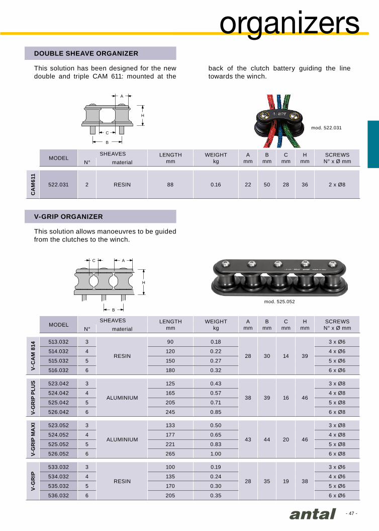
DOUBLE SHEAVE ORGANIZER
This solution has been designed for the new double and triple CAM 611: mounted at the back of the clutch battery guiding the line towards the winch.For more information see page 47.
STICKERS FOR CAM 611 AND CAM 814
A set of 54 stickers is provided for an easy indication of manoeuvres; colours: red, green and black.
Single Double Triple Horizontal
MODEL
MODEL
MODEL
MODEL
DOUBLE
DOUBLE
DOUBLE
SINGLE
SINGLE
SINGLE
TRIPLE
TRIPLE
TRIPLE
HORIZONTAL
HORIZONTAL
HORIZONTAL
Ø LINEmm
Ø LINEmm
TYPE
TYPE
WIDTHmm
WIDTHmm
WEIGHTkg
WEIGHTkg
SCREWSN° x Ø mm
SCREWSN° x Ø mm
WITH FLAT CAM
WITH V-CAM
MODEL VERSION
ENGLISH
FRENCH
ITALIAN
- 38 -
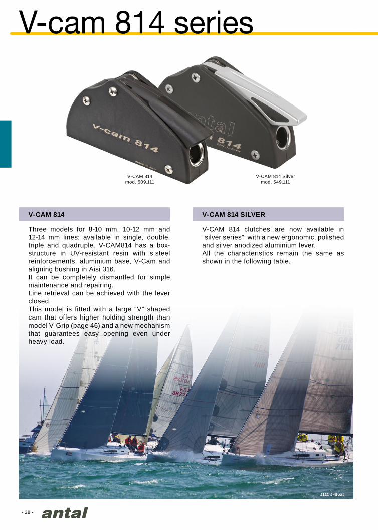
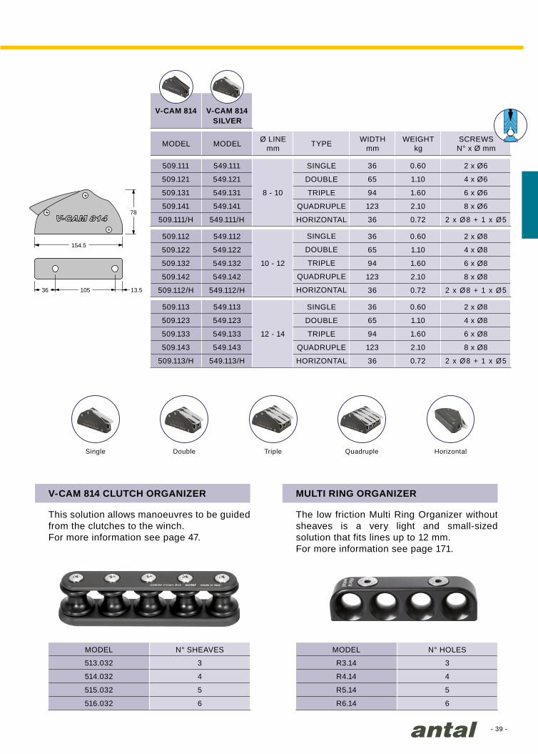
V-CAM 814mod. 509.111
J111 J-Boat
V-cam 814 series
V-CAM 814
Three models for 8-10 mm, 10-12 mm and 12-14 mm lines; available in single, double, triple and quadruple. V-CAM814 has a box-structure in UV-resistant resin with s.steel reinforcements, aluminium base, V-Cam and aligning bushing in Aisi 316.It can be completely dismantled for simple maintenance and repairing.Line retrieval can be achieved with the lever closed.This model is fitted with a large “V” shaped cam that offers higher holding strength than model V-Grip (page 46) and a new mechanism that guarantees easy opening even under heavy load.
V-CAM 814 SILVER
V-CAM 814 clutches are now available in “silver series”: with a new ergonomic, polished and silver anodized aluminium lever. All the characteristics remain the same as shown in the following table.
V-CAM 814 Silvermod. 549.111
- 39 -
R3.14 3
R4.14 4
R5.14 5
R6.14 6
V-CAM 814
V-CAM 814
509.111 549.111
8 - 10
36 0.60 2 x Ø6
509.121 549.121 65 1.10 4 x Ø6
509.131 549.131 94 1.60 6 x Ø6
509.141 549.141 123 2.10 8 x Ø6
509.111/H 549.111/H 36 0.72 2 x Ø8 + 1 x Ø5
509.112 549.112
10 - 12
36 0.60 2 x Ø8
509.122 549.122 65 1.10 4 x Ø8
509.132 549.132 94 1.60 6 x Ø8
509.142 549.142 123 2.10 8 x Ø8
509.112/H 549.112/H 36 0.72 2 x Ø8 + 1 x Ø5
509.113 549.113
12 - 14
36 0.60 2 x Ø8
509.123 549.123 65 1.10 4 x Ø8
509.133 549.133 94 1.60 6 x Ø8
509.143 549.143 123 2.10 8 x Ø8
509.113/H 549.113/H 36 0.72 2 x Ø8 + 1 x Ø5
513.032 3
514.032 4
515.032 5
516.032 6
78
154.5
105 13.536
MULTI RING ORGANIZER
The low friction Multi Ring Organizer without sheaves is a very light and small-sized solution that fits lines up to 12 mm.For more information see page 171.
Single Double Triple Quadruple
V-CAM 814 CLUTCH ORGANIZER
This solution allows manoeuvres to be guided from the clutches to the winch.For more information see page 47.
MODEL MODELN° SHEAVES N° HOLES
Horizontal
MODEL MODEL
DOUBLE
DOUBLE
DOUBLE
SINGLE
SINGLE
SINGLE
TRIPLE
TRIPLE
TRIPLE
HORIZONTAL
HORIZONTAL
HORIZONTAL
QUADRUPLE
QUADRUPLE
QUADRUPLE
Ø LINEmm TYPE WIDTH
mmWEIGHT
kgSCREWS
N° x Ø mm
SILVER
- 40 -
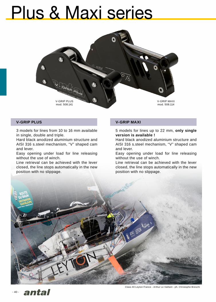
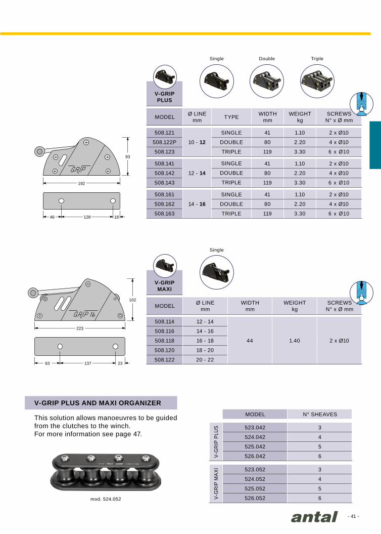
V-GRIP PLUSmod. 508.141
V-GRIP MAXImod. 508.114
Class 40 Leyton France - Arthur Le Vaillant - ph. Christophe Breschi
Plus & Maxi series
V-GRIP PLUS
3 models for lines from 10 to 16 mm available in single, double and triple.Hard black anodized aluminium structure and AISI 316 s.steel mechanism, “V” shaped cam and lever.Easy opening under load for line releasing without the use of winch.Line retrieval can be achieved with the lever closed, the line stops automatically in the new position with no slippage.
V-GRIP MAXI
5 models for lines up to 22 mm, only single version is available !Hard black anodized aluminium structure and AISI 316 s.steel mechanism, “V” shaped cam and lever.Easy opening under load for line releasing without the use of winch.Line retrieval can be achieved with the lever closed, the line stops automatically in the new position with no slippage.
- 41 -
V-GRIPPLUS
508.121
10 - 12
41 1.10 2 x Ø10
508.122P 80 2.20 4 x Ø10
508.123 119 3.30 6 x Ø10
508.141
12 - 14
41 1.10 2 x Ø10
508.142 80 2.20 4 x Ø10
508.143 119 3.30 6 x Ø10
508.161
14 - 16
41 1.10 2 x Ø10
508.162 80 2.20 4 x Ø10
508.163 119 3.30 6 x Ø10
V-GRIPMAXI
508.114 12 - 14
44 1.40 2 x Ø10
508.116 14 - 16
508.118 16 - 18
508.120 18 - 20
508.122 20 - 22
V-G
RIP
PLU
S 523.042 3
524.042 4
525.042 5
526.042 6
V-G
RIP
MA
XI 523.052 3
524.052 4
525.052 5
526.052 6
93
192
128 1846
102
223
137 2363
mod. 524.052
V-GRIP PLUS AND MAXI ORGANIZER
This solution allows manoeuvres to be guided from the clutches to the winch.For more information see page 47.
Single
Single
Double Triple
MODEL
MODEL
DOUBLE
DOUBLE
DOUBLE
SINGLE
SINGLE
SINGLE
TRIPLE
TRIPLE
TRIPLE
Ø LINEmm
Ø LINEmm
TYPE WIDTHmm
WIDTHmm
WEIGHTkg
WEIGHTkg
SCREWSN° x Ø mm
SCREWSN° x Ø mm
MODEL N° SHEAVES
- 42 -
mod. 506.101
mod. 506.121
mod. 506.101
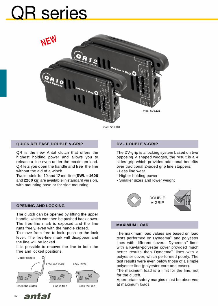
QR series
QR is the new Antal clutch that offers the highest holding power and allows you to release a line even under the maximum load.QR lets you open the handle and free the line without the aid of a winch.Two models for 10 and 12 mm line (SWL = 1600 and 2200 kg) are available in standard version, with mounting base or for side mounting.
Open the clutch Line is free Lock the line
Lock leverFree line mark
Upper handle
The DV-grip is a locking system based on two opposing V shaped wedges, the result is a 4 sides grip which provides additional benefits over traditional 2-sided grip line stoppers:- Less line wear- Higher holding power- Smaller sizes and lower weight
QUICK RELEASE DOUBLE V-GRIP DV - DOUBLE V-GRIP
The clutch can be opened by lifting the upper handle, which can then be pushed back down. The free-line mark is exposed and the line runs freely, even with the handle closed.To move from free to lock, push up the lock lever. The free-line mark will disappear and the line will be locked.It is possible to recover the line in both the free and locked positions.
The maximum load values are based on load tests performed on Dyneema™ and polyester lines with different covers. Dyneema™ lines with a Kevlar-polyester cover provided much better results than Dyneema™ lines with a polyester cover, which performed poorly. The test results were even below those of a simple polyester line (polyester core and cover).The maximum load is a limit for the line, not for the clutch. Appropriate safety margins must be observed at maximum loads.
MAXIMUM LOAD
OPENING AND LOCKING
DOUBLEV-GRIP

- 43 -
L1mm
L2mm
Hmm
Tmm
506.101 10 154 170 96 34 1.00 3 x Ø8
506.121 12 176 193 101 37 1.35 3 x Ø10
H
L1L2
T
H
LT
H
T
L
Lmm
Hmm
Tmm
506.106 10 216 102 34 1.12 2 x Ø10
506.126 12 249 109 37 1.52 2 x Ø12
Lmm
Hmm
Tmm
506.103 10 170 115 34 1.14 3 x Ø8
506.123 12 193 125 37 1.54 3 x Ø10
Ice Yacht 52
When it is not possible to access the mounting studs from the bottom side of the clutch (for example, when mounting on a mast), Antal offers a special base that can be mounted from above with 2 screws (included).
QR WITH MOUNTING BASE
Ø LINEmm
Ø LINEmm
Ø LINEmm
MODEL
MODEL
MODEL
WEIGHTkg
WEIGHTkg
WEIGHTkg
FASTENERSN° x Ø mm
STUDSN° x Ø mm
STUDSN° x Ø mm
QR clutches are also available for side mounting. The same model can be mounted on either the left or the right side.Screws, washers and nuts in AISI 316 are included.
QR SIDE-MOUNTING VERSION
QR STANDARD MODELS
Mounting studs, nuts and washers are included.
- 44 -
mod. 505.081
mod. 505.101
mod. 505.121
mod. 505.141
4000
3000
2000
1000
8 10 12 14 16 18
5000
6000
(Kg)
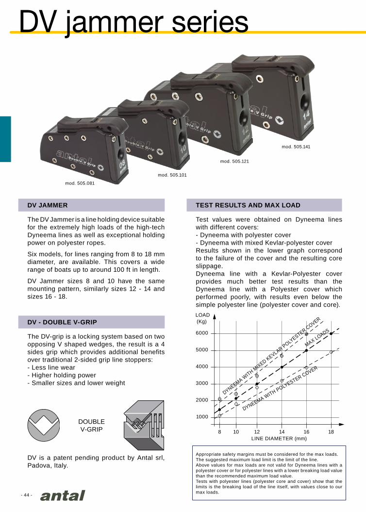
DV jammer series
The DV Jammer is a line holding device suitable for the extremely high loads of the high-tech Dyneema lines as well as exceptional holding power on polyester ropes.
Six models, for lines ranging from 8 to 18 mm diameter, are available. This covers a wide range of boats up to around 100 ft in length.
DV Jammer sizes 8 and 10 have the same mounting pattern, similarly sizes 12 - 14 and sizes 16 - 18.
The DV-grip is a locking system based on two opposing V shaped wedges, the result is a 4 sides grip which provides additional benefits over traditional 2-sided grip line stoppers:- Less line wear- Higher holding power- Smaller sizes and lower weight
DV JAMMER
DV - DOUBLE V-GRIP
Test values were obtained on Dyneema lines with different covers: - Dyneema with polyester cover- Dyneema with mixed Kevlar-polyester coverResults shown in the lower graph correspond to the failure of the cover and the resulting core slippage.Dyneema line with a Kevlar-Polyester cover provides much better test results than the Dyneema line with a Polyester cover which performed poorly, with results even below the simple polyester line (polyester cover and core).
TEST RESULTS AND MAX LOAD
DV is a patent pending product by Antal srl, Padova, Italy.
Appropriate safety margins must be considered for the max loads. The suggested maximum load limit is the limit of the line.Above values for max loads are not valid for Dyneema lines with a polyester cover or for polyester lines with a lower breaking load value than the recommended maximum load value.Tests with polyester lines (polyester core and cover) show that the limits is the breaking load of the line itself, with values close to our max loads.
DOUBLEV-GRIP
DYNEEMA WITH M
IXED KEVLAR POLYESTER COVER
MAX LOADS
DYNEEMA WITH POLYESTER COVER
LINE DIAMETER (mm)
LOAD

- 45 -
Lmm
Hmm
Tmm
505.081 505.082 8 126 8634
0.60 4 x Ø6
505.101 505.102 10 141 90 0.69 4 x Ø8
505.121 505.122 12 169 10842
1.204 x Ø10
505.141 505.142 14 185 113 1.36
505.161 505.162 16 209 12550
2.204 x Ø12
505.181 505.182 18 209 125 2.20
Lmm
Hmm
Tmm
505.086 505.087 8 134 9334
0.69 4 x Ø6
505.106 505.107 10 149 97 0.79 4 x Ø8
505.126 505.127 12 178 11842
1.394 x Ø10
505.146 505.147 14 194 123 1.57
505.166 505.167 16 218 13550
2.564 x Ø12
505.186 505.187 18 218 135 2.56
Lmm
Hmm
Tmm
505.083 505.085 8 135 9534
0.63 4 x Ø6
505.103 505.105 10 150 99 0.72 5 x Ø6
505.123 505.125 12 179 11842
1.22 4 x Ø8
505.143 505.145 14 195 122 1.35 5 x Ø8
505.163 505.165 16 213 13550
2.47 6 x Ø8
505.183 505.185 18 213 135 2.47 8 x Ø8
H
LT
H
L
T
H
LT
Six models, for 8, 10, 12, 14, 16 and 18 mm lines are offered.
A “remote control” version is also available: this model does not have the upper manual control slider, the opening is done with a control line.
When it is not possible to access the mounting studs/nuts/washers from the bottom side of the jammer (for example when mounting on a mast), Antal offers a special mounting base that can be mounted from above with 4 screws (not included).
DV Jammers are also available for side-mounting; the same model can be mounted on either left or right side.Screws, washers and nuts in AISI 316 are included.
Mounting studs, nuts and washers are included.
Mounting screws, nuts and washers are included.
The 4 lower base mounting screws are not included.
DV JAMMERS: STANDARD MODELS
DV JAMMERS: REMOTE CONTROL
DV JAMMERS WITH MOUNTING BASE
DV JAMMER: SIDE-MOUNTING VERSION
DVSTANDARD
mod.
DV STANDARDWITH BASE
mod.
DV STANDARDSIDE-MOUNTING
mod.
REMOTECONTROL
mod.
REMOTE CONTROLWITH BASE
mod.
REMOTE CONTROLSIDE-MOUNTING
mod.
Ø LINEmm
Ø LINEmm
Ø LINEmm
WEIGHTkg
WEIGHTkg
WEIGHTkg
STUDSN° x Ø mm
SCREWSN° x Ø mm
SCREWSN° x Ø mm
- 46 -
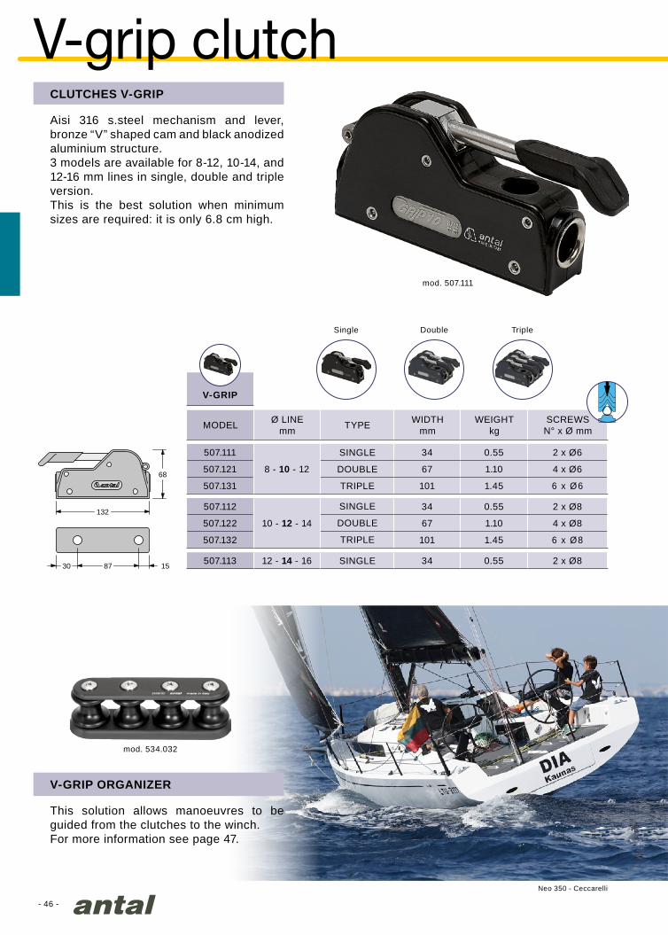
mod. 507.111
mod. 534.032
V-GRIP
507.111
8 - 10 - 12
34 0.55 2 x Ø6
507.121 67 1.10 4 x Ø6
507.131 101 1.45 6 x Ø6
507.112
10 - 12 - 14
34 0.55 2 x Ø8
507.122 67 1.10 4 x Ø8
507.132 101 1.45 6 x Ø8
507.113 12 - 14 - 16 34 0.55 2 x Ø8
68
132
87 1530
Neo 350 - Ceccarelli
CLUTCHES V-GRIP
Aisi 316 s.steel mechanism and lever, bronze “V” shaped cam and black anodized aluminium structure.3 models are available for 8-12, 10-14, and 12-16 mm lines in single, double and triple version.This is the best solution when minimum sizes are required: it is only 6.8 cm high.
V-grip clutch
Single Double Triple
MODEL
DOUBLE
DOUBLE
SINGLE
SINGLE
SINGLE
TRIPLE
TRIPLE
Ø LINEmm TYPE WIDTH
mmWEIGHT
kgSCREWS
N° x Ø mm
V-GRIP ORGANIZER
This solution allows manoeuvres to be guided from the clutches to the winch.For more information see page 47.
- 47 -
mod. 525.052
mod. 522.031
AC
H
B
B
H
A
C
Amm
Bmm
Cmm
Hmm
V-C
AM
814
513.032 3 90 0.18
28 30 14 39
3 x Ø6
514.032 4 120 0.22 4 x Ø6
515.032 5 150 0.27 5 x Ø6
516.032 6 180 0.32 6 x Ø6
V-G
RIP
PLU
S 523.042 3 125 0.43
38 39 16 46
3 x Ø8
524.042 4 165 0.57 4 x Ø8
525.042 5 205 0.71 5 x Ø8
526.042 6 245 0.85 6 x Ø8
V-G
RIP
MA
XI 523.052 3 133 0.50
43 44 20 46
3 x Ø8
524.052 4 177 0.65 4 x Ø8
525.052 5 221 0.83 5 x Ø8
526.052 6 265 1.00 6 x Ø8
V-G
RIP
533.032 3 100 0.19
28 35 19 38
3 x Ø6
534.032 4 135 0.24 4 x Ø6
535.032 5 170 0.30 5 x Ø6
536.032 6 205 0.35 6 x Ø6
Amm
Bmm
Cmm
Hmm
CA
M61
1
522.031 2 88 0.16 22 50 28 36 2 x Ø8
organizers
MODEL
MODEL
SHEAVES
SHEAVES
LENGTHmm
LENGTHmm
WEIGHTkg
WEIGHTkg
SCREWSN° x Ø mm
SCREWSN° x Ø mm
V-GRIP ORGANIZER
This solution allows manoeuvres to be guided from the clutches to the winch.
material
material
RESIN
RESIN
RESIN
ALUMINIUM
ALUMINIUM
N°
N°
DOUBLE SHEAVE ORGANIZER
This solution has been designed for the new double and triple CAM 611: mounted at the
back of the clutch battery guiding the line towards the winch.
- 48 -
I
L
59
28
64
74
104
360°
82
147
148
60
360°
502.011 3 - 7 27 48 2 x Ø4
502.22/37 6 - 10 37 64 2 x Ø5
502.022 6 - 12 42 70 2 x Ø5
502.033 10 - 14 52 86 2 x Ø6
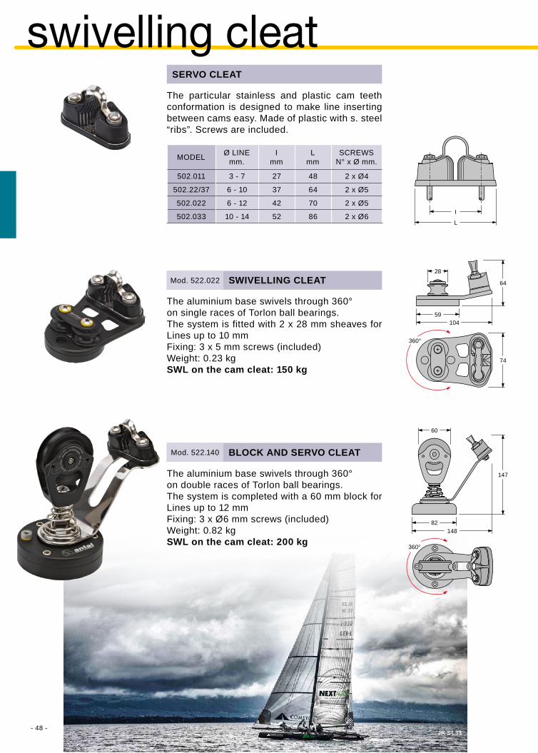
Mod. 522.022
Mod. 522.140
JK SL33
The aluminium base swivels through 360°on double races of Torlon ball bearings.The system is completed with a 60 mm block for Lines up to 12 mmFixing: 3 x Ø6 mm screws (included)Weight: 0.82 kgSWL on the cam cleat: 200 kg
The aluminium base swivels through 360°on single races of Torlon ball bearings.The system is fitted with 2 x 28 mm sheaves for Lines up to 10 mmFixing: 3 x 5 mm screws (included)Weight: 0.23 kgSWL on the cam cleat: 150 kg
SERVO CLEAT
The particular stainless and plastic cam teeth conformation is designed to make line inserting between cams easy. Made of plastic with s. steel “ribs”. Screws are included.
swivelling cleat
SWIVELLING CLEAT
BLOCK AND SERVO CLEAT
MODEL SCREWSN° x Ø mm.
Ø LINEmm.
Imm
Lmm
- 49 -
851.065* 6 - 12 65 116 800 0.23 2 x Ø8
851.080 6 - 14 80 131 1000 0.33 2 x Ø8
851.100 8 - 16 100 152 2000 0.65 2 x Ø10
851.125 10 - 18 125 174 3500 1.10 1 x Ø12 + 2 x Ø10
852.065* 6 - 12 65 116 800 0.38 2 x Ø8
852.080 6 - 14 80 131 1000 0.56 2 x Ø8
852.100 8 - 16 100 152 2000 1.50 2 x Ø10
852.125 10 - 18 125 174 3500 1.85 1 x Ø12 + 2 x Ø10
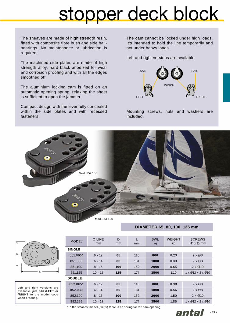
Mod. 852.100
Mod. 851.100
L
D
FM27 OD ‘Saphire’ - C. Maletto
stopper deck blockThe sheaves are made of high strength resin, fitted with composite fibre bush and side ball-bearings. No maintenance or lubrication is required.
The machined side plates are made of high strength alloy, hard black anodized for wear and corrosion proofing and with all the edges smoothed off.
The aluminium locking cam is fitted on an automatic opening spring: relaxing the sheet is sufficient to open the jammer.
Compact design with the lever fully concealed within the side plates and with recessed fasteners.
The cam cannot be locked under high loads. It’s intended to hold the line temporarily and not under heavy loads.
Left and right versions are available.
* In the smallest model (D=65) there is no spring for the cam opening.
SAIL SAIL
WINCH
LEFT RIGHT
DIAMETER 65, 80, 100, 125 mm
MODEL Ø LINEmm
Dmm
Lmm
SWLkg
WEIGHTkg
SCREWSN° x Ø mm
SINGLE
DOUBLE
Left and right versions are available, just add /LEFT or /RIGHT to the model code when ordering.
Mounting screws, nuts and washers are included.

- 50 -- 50 -
Bel 60’ - Photo Gilles Martin Raget
- 51 -
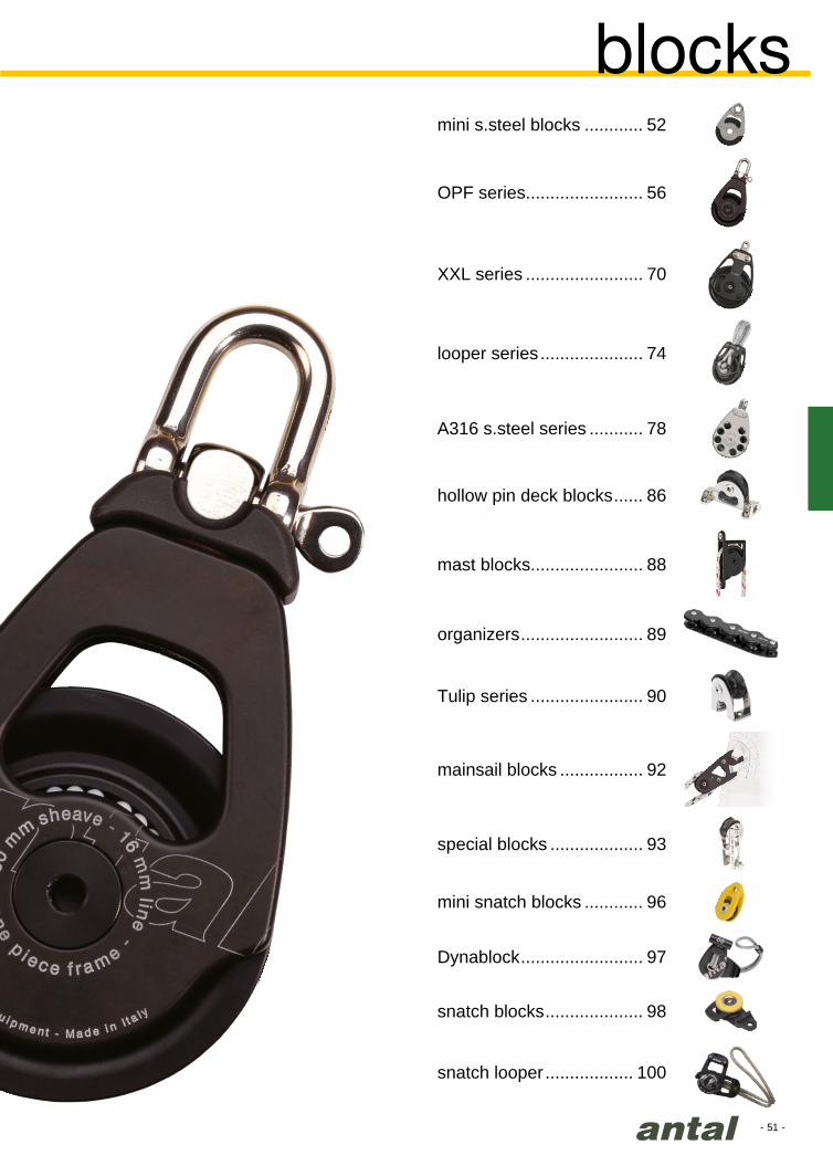
blocks
XXL series ........................ 70
OPF series........................ 56
Tulip series ....................... 90
mainsail blocks ................. 92
mast blocks....................... 88
special blocks ................... 93
organizers ......................... 89
Dynablock ......................... 97
snatch looper .................. 100
snatch blocks .................... 98
A316 s.steel series ........... 78
looper series ..................... 74
hollow pin deck blocks ...... 86
mini snatch blocks ............ 96
mini s.steel blocks ............ 52
- 52 -
Mod. 00301
Mod. 003XX/C
Mod. 03411/M Mod. 04013/M
Mod. 003XX/SW Mod. 004XX/SWMod. 004XX/C
Banga Formula 18 - Luca Filippi
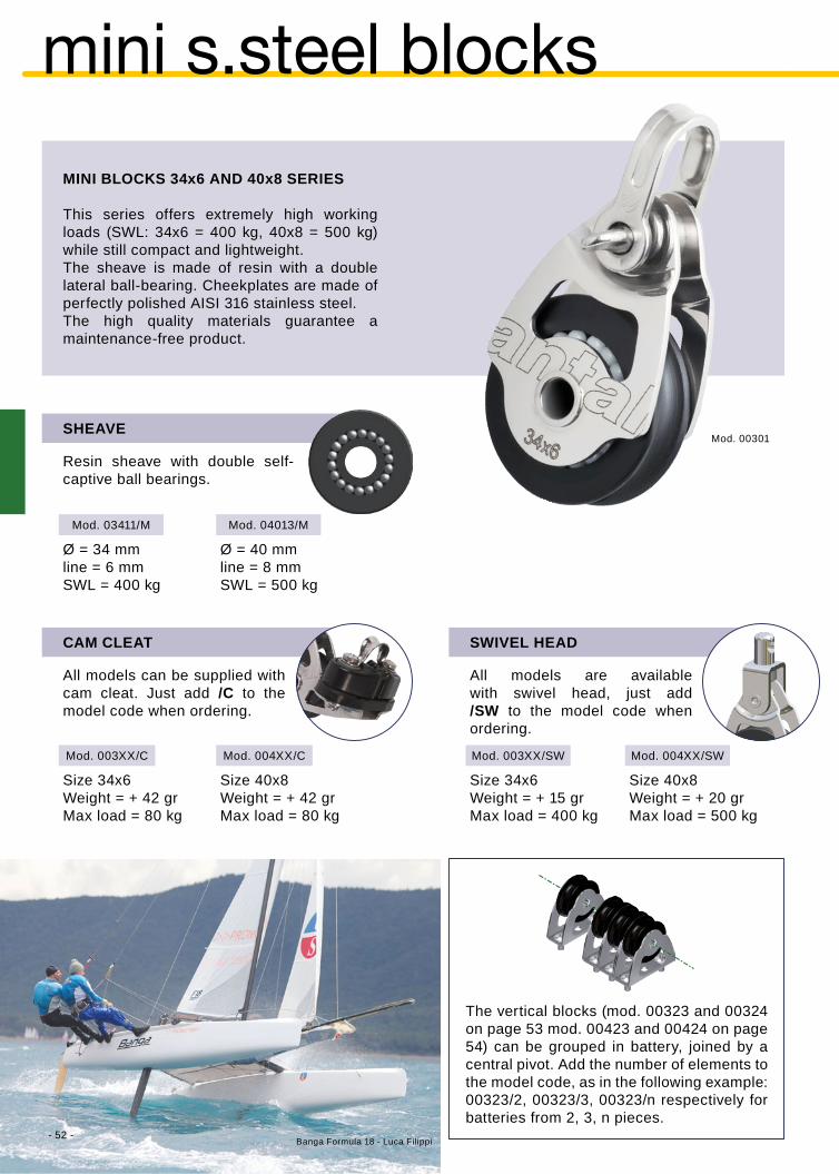
Ø = 34 mmline = 6 mmSWL = 400 kg
Ø = 40 mmline = 8 mmSWL = 500 kg
mini s.steel blocks
Size 34x6Weight = + 42 grMax load = 80 kg
Size 34x6Weight = + 15 grMax load = 400 kg
Size 40x8Weight = + 20 grMax load = 500 kg
MINI BLOCKS 34x6 AND 40x8 SERIES
This series offers extremely high working loads (SWL: 34x6 = 400 kg, 40x8 = 500 kg) while still compact and lightweight.The sheave is made of resin with a double lateral ball-bearing. Cheekplates are made of perfectly polished AISI 316 stainless steel.The high quality materials guarantee a maintenance-free product.
SHEAVE
CAM CLEAT
All models can be supplied with cam cleat. Just add /C to the model code when ordering.
SWIVEL HEAD
All models are available with swivel head, just add /SW to the model code when ordering.
The vertical blocks (mod. 00323 and 00324 on page 53 mod. 00423 and 00424 on page 54) can be grouped in battery, joined by a central pivot. Add the number of elements to the model code, as in the following example: 00323/2, 00323/3, 00323/n respectively for batteries from 2, 3, n pieces.
Resin sheave with double self-captive ball bearings.
Size 40x8Weight = + 42 grMax load = 80 kg

- 53 -
Mod. 00301
Mod. 00320
Mod. 00302
Mod. 00321
Mod. 00330
Mod. 00303
Mod. 00304
Mod. 00331Mod. 00305
Mod. 00306
Mod. 00322Mod. 00316
Mod. 00311
Mod. 00323
Mod. 03413/M
Mod. 00324
34 mm sheave for 6 mm line Safe working load = 400 kg
Single U-headWeight = 40 grSWL = 400 kg
Shackle BlockWeight = 44 grSWL = 400 kg
Fiddle BlockWeight = 65 grSWL = 400 kg
Single BecketWeight = 52 grSWL = 400 kg
Fiddle BecketWeight = 76 grSWL = 400 kg
Saddle BlockWeight* = 46 grSWL = 400 kg2 x Ø4 mm screws
(included)
Foot BlockWeight* = 36 grSWL = 400 kg2 x Ø6 mm screws
(included)
Stand-UpWeight* = 46 grSWL = 400 kg1 x Ø6 mm screw
(included)
U-head BecketWeight = 43 grSWL = 400 kg
doUBle BecketWeight = 90 grSWL = 600 kg
doUBle BlockWeight = 82 grSWL = 600 kg
triple BecketWeight = 102 grSWL = 600 kg
triple BlockWeight = 94 grSWL = 600 kg
UprightWeight* = 55 grSWL = 400 kg2 x Ø5 mm screws
(included)
“over the top”Weight* = 65 grSWL = 400 kg2 x Ø5 mm screws
(included)
Ø = 34 mmline = 8 mmSWL = 400 kg
* screws not included

- 54 -
Mod. 00401
Mod. 00420
Mod. 00402
Mod. 00421
Mod. 00430
Mod. 00403
Mod. 00404
Mod. 00431Mod. 00405
Mod. 00406
Mod. 00422Mod. 00416
Mod. 00411
Mod. 00423
Mod. 00424
Mod. 04514/M
40 mm sheave for 8 mm line Safe working load = 500 kg
Single U-headWeight = 56 grSWL = 500 kg
Shackle BlockWeight = 62 grSWL = 500 kg
Fiddle BlockWeight = 91 grSWL = 500 kg
Single BecketWeight = 73 grSWL = 500 kg
Fiddle BecketWeight = 106 grSWL = 500 kg
Saddle BlockWeight* = 64 grSWL = 500 kg2 x Ø5 mm screws
(included)
Foot BlockWeight* = 50 grSWL = 500 kg2 x Ø6 mm screws
(included)
Stand-UpWeight* = 64 grSWL = 500 kg1 x Ø6 mm screw
(included)
U-head BecketWeight = 60 grSWL = 500 kg
doUBle BecketWeight = 126 grSWL = 600 kg
doUBle BlockWeight = 115 grSWL = 600 kg
triple BecketWeight = 143 grSWL = 600 kg
triple BlockWeight = 132 grSWL = 600 kg
UprightWeight* = 77 grSWL = 600 kg2 x Ø6 mm screws
(included)
“over the top”Weight* = 91 grSWL = 600 kg2 x Ø6 mm screws
(included)
Ø = 45 mmline = 8 mmSWL = 600 kg
* screws not included
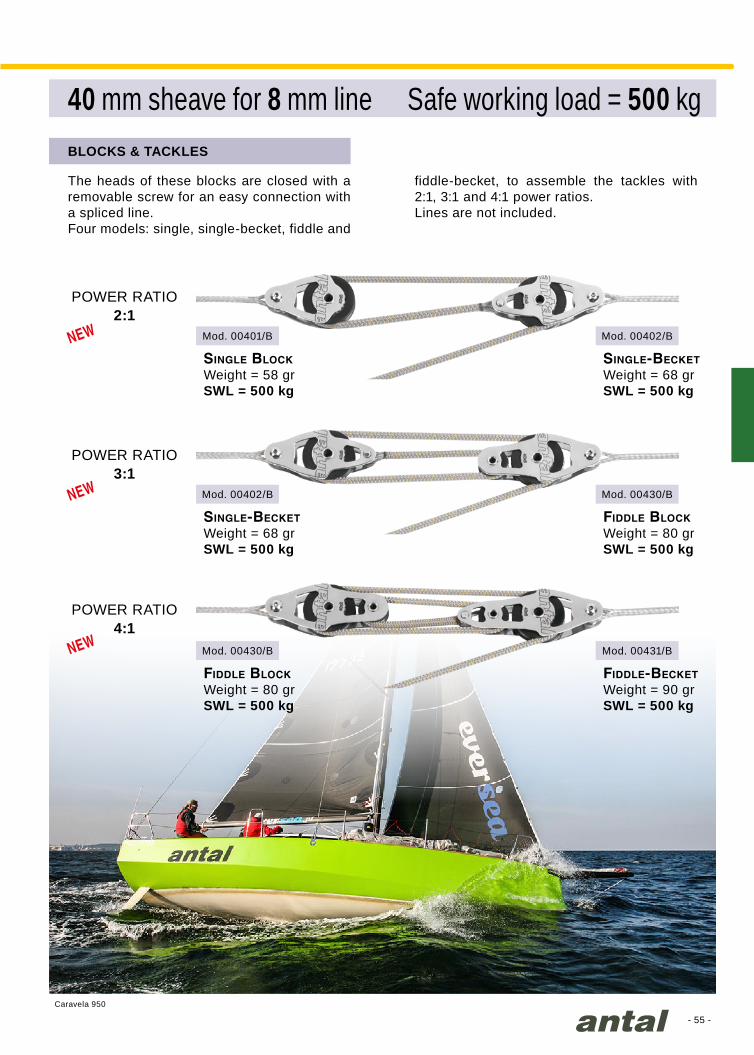
- 55 -
Mod. 00401/B
Mod. 00402/B
Mod. 00430/B
Mod. 00402/B
Mod. 00430/B
Mod. 00431/B
Caravela 950
40 mm sheave for 8 mm line Safe working load = 500 kg
Single BlockWeight = 58 grSWL = 500 kg
Single-BecketWeight = 68 grSWL = 500 kg
Fiddle BlockWeight = 80 grSWL = 500 kg
Single-BecketWeight = 68 grSWL = 500 kg
Fiddle BlockWeight = 80 grSWL = 500 kg
Fiddle-BecketWeight = 90 grSWL = 500 kg
BLOCKS & TACKLES
The heads of these blocks are closed with a removable screw for an easy connection with a spliced line.Four models: single, single-becket, fiddle and
fiddle-becket, to assemble the tackles with 2:1, 3:1 and 4:1 power ratios.Lines are not included.
POWER RATIO2:1
POWER RATIO3:1
POWER RATIO4:1
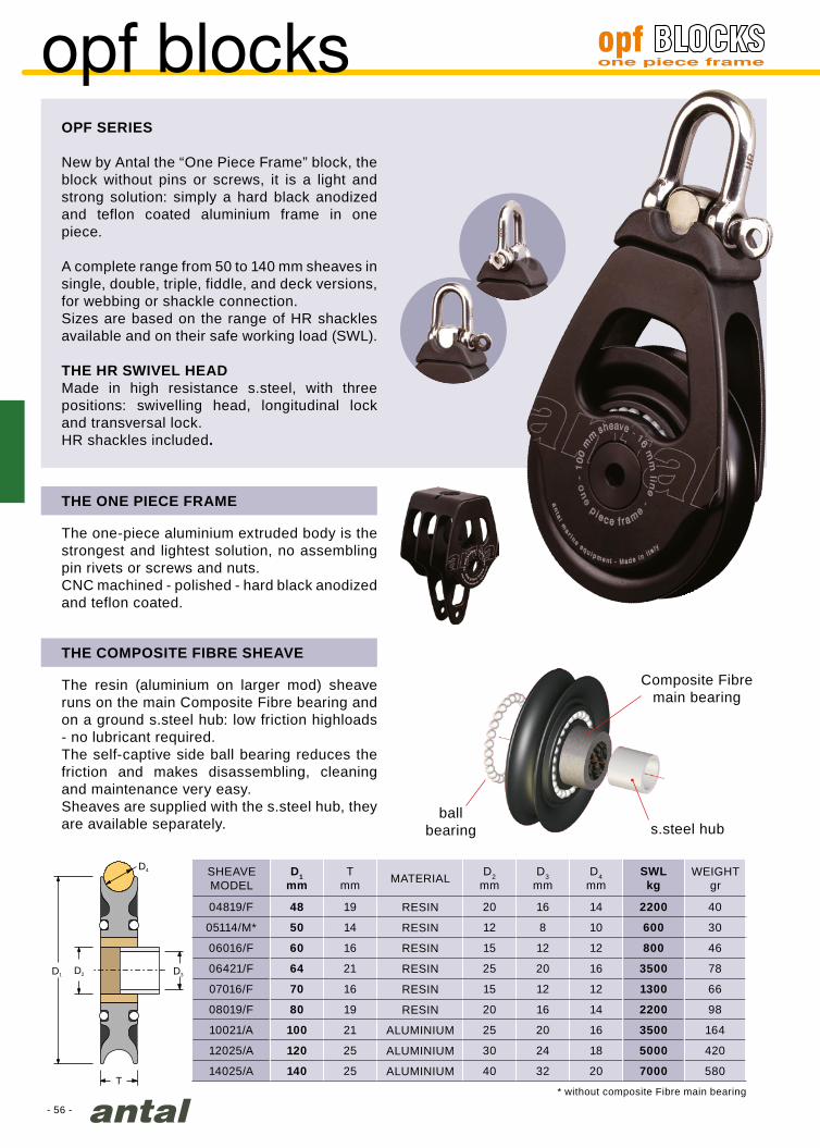
- 56 -
D1mm
Tmm
D2mm
D3mm
D4mm
SWLkg
04819/F 48 19 20 16 14 2200 40
05114/M* 50 14 12 8 10 600 30
06016/F 60 16 15 12 12 800 46
06421/F 64 21 25 20 16 3500 78
07016/F 70 16 15 12 12 1300 66
08019/F 80 19 20 16 14 2200 98
10021/A 100 21 25 20 16 3500 164
12025/A 120 25 30 24 18 5000 420
14025/A 140 25 40 32 20 7000 580T
D4
D3D2D1
opf blocks
THE COMPOSITE FIBRE SHEAVE
The resin (aluminium on larger mod) sheave runs on the main Composite Fibre bearing and on a ground s.steel hub: low friction highloads - no lubricant required.The self-captive side ball bearing reduces the friction and makes disassembling, cleaning and maintenance very easy.Sheaves are supplied with the s.steel hub, they are available separately.
THE ONE PIECE FRAME
The one-piece aluminium extruded body is the strongest and lightest solution, no assembling pin rivets or screws and nuts.CNC machined - polished - hard black anodized and teflon coated.
OPF SERIES
New by Antal the “One Piece Frame” block, the block without pins or screws, it is a light and strong solution: simply a hard black anodized and teflon coated aluminium frame in one piece.
A complete range from 50 to 140 mm sheaves in single, double, triple, fiddle, and deck versions, for webbing or shackle connection.Sizes are based on the range of HR shackles available and on their safe working load (SWL).
THE HR SWIVEL HEADMade in high resistance s.steel, with three positions: swivelling head, longitudinal lock and transversal lock.HR shackles included.
ballbearing s.steel hub
Composite Fibremain bearing
SHEAVEMODEL MATERIAL
ALUMINIUM
ALUMINIUM
ALUMINIUM
RESIN
RESIN
RESIN
RESIN
RESIN
RESIN
WEIGHTgr
* without composite Fibre main bearing
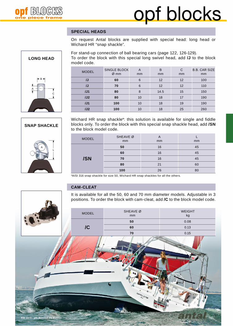
- 57 -
C
A
B
LA
Amm
Bmm
Cmm
/J 60 6 12 12 100
/J 70 6 12 12 110
/J1 80 8 14.5 15 150
/J2 80 10 18 17 190
/J1 100 10 18 19 190
/J2 100 10 18 25 260
Amm
Lmm
/SN
50 16 45
60 16 45
70 16 45
80 21 60
100 26 80
/C50 0.08
60 0.13
70 0.15
RM 1370 - ph. Arnaud De Buyzer
opf blocksSPECIAL HEADS
On request Antal blocks are supplied with special head: long head or Wichard HR “snap shackle”.
CAM-CLEAT
SNAP SHACKLE
LONG HEAD
It is available for all the 50, 60 and 70 mm diameter models. Adjustable in 3 positions. To order the block with cam-cleat, add /C to the block model code.
MODEL
MODEL
MODEL
SINGLE BLOCKØ mm
SHEAVE Ømm
SHEAVE Ømm
WEIGHTkg
Wichard HR snap shackle*: this solution is available for single and fiddle blocks only. To order the block with this special snap shackle head, add /SN to the block model code.
For stand-up connection of ball bearing cars (page 122, 126-129).To order the block with this special long swivel head, add /J to the block model code.
*AISI 316 snap shackle for size 50, Wichard HR snap shackles for all the others.
B.B. CAR SIZEmm

- 58 -- 58 -
Mod. 00501
Mod. 00507
Mod. 00503
Mod. 00505
Mod. 00509
Mod. 00502
Mod. 00508
Mod. 00504
Mod. 00506
Mod. 00510
blocks 50
Swivel BlockWeight* = 90 grSWL = 600 kg5 mm shackle Becket Block
Weight* = 104 grSWL = 600 kg5 mm shackle
doUBle SheaveWeight* = 169 grSWL = 800 kg6 mm shackle doUBle Becket
Weight* = 184 grSWL = 800 kg6 mm shackle
triple SheaveWeight* = 225 grSWL = 800 kg6 mm shackle triple Becket
Weight* = 240 grSWL = 800 kg6 mm shackle
Single FiddleWeight* = 122 grSWL = 600 kg5 mm shackle Becket Fiddle
Weight* = 136 grSWL = 600 kg5 mm shackle
Simple weBWeight = 64 grSWL = 600 kgFor line connection weB Becket
Weight = 78 grSWL = 600 kgFor line connection
* with shackle
full scale
50 mm sheave for 10 mm line Safe working load = 600 kg
cam cleat
With 3 different positions for single, double and triple.SWL = 100 kgWeight = 80 grFor blocks with cleat add /C to the block model code.
In the OPF 50 series sheaves are riveted and not removable.
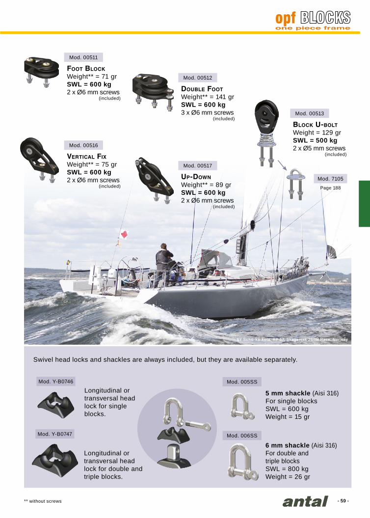
- 59 -- 59 -
Mod. 00511
Mod. 00516
Mod. 00512
Mod. Y-B0746 Mod. 005SS
Mod. Y-B0747 Mod. 006SS
Mod. 00517
Mod. 00513
Mod. 7105
SY Scho-ka-kola, RP 57, Skagerrak 2Star Race, Norway
5 mm shackle (Aisi 316)For single blocksSWL = 600 kgWeight = 15 gr
6 mm shackle (Aisi 316)For double andtriple blocksSWL = 800 kgWeight = 26 gr
Longitudinal or transversal head lock for single blocks.
Longitudinal or transversal head lock for double and triple blocks.
Block U-BoltWeight = 129 grSWL = 500 kg2 x Ø5 mm screws
(included)
Page 188
Swivel head locks and shackles are always included, but they are available separately.
Foot BlockWeight** = 71 grSWL = 600 kg2 x Ø6 mm screws
(included)
doUBle FootWeight** = 141 grSWL = 600 kg3 x Ø6 mm screws
(included)
vertical FixWeight** = 75 grSWL = 600 kg2 x Ø6 mm screws
(included)
Up-downWeight** = 89 grSWL = 600 kg2 x Ø6 mm screws
(included)
** without screws

- 60 -- 60 -
Mod. 00601
Mod. 00607
Mod. 00603
Mod. 00605
Mod. 00609
Mod. 00602
Mod. 00608
Mod. 00604
Mod. 00606
Mod. 00610
blocks 60
Swivel BlockWeight* = 0.16 kgSWL = 800 kg6 mm shackle Becket Block
Weight* = 0.18 kgSWL = 800 kg6 mm shackle
doUBle SheaveWeight* = 0.31 kgSWL = 1300 kg8 mm shackle doUBle Becket
Weight* = 0.33 kgSWL = 1300 kg8 mm shackle
triple SheaveWeight* = 0.41 kgSWL = 1300 kg8 mm shackle triple Becket
Weight* = 0.43 kgSWL = 1300 kg8 mm shackle
Single FiddleWeight* = 0.21 kgSWL = 800 kg6 mm shackle Becket Fiddle
Weight* = 0.23 kgSWL = 800 kg6 mm shackle
Simple weBWeight = 0.10 kgSWL = 800 kgFor line connection weB Becket
Weight = 0.12 kgSWL = 800 kgFor line connection
full scale
60 mm sheave for 12 mm line Safe working load = 800 kg
* with shackle
cam cleat
With 3 different positions for single, double and triple.SWL = 150 kgWeight = 0.13 kgFor blocks with cleat add /C to the block model code.

- 61 -- 61 -
Cantiere Bonin - 31’ Cossutti
Mod. 00613
Mod. 7106
Mod. 00611
Mod. 00616
Mod. Y-B0748 Mod. 006SS
Mod. Y-B0749 Mod. 008SS
Mod. 00614
Mod. 7206
Mod. 00612
Mod. 00617
Mod. 00615
Mod. 7306
6 mm shackle (Aisi 316)For single blocksSWL = 800 kgWeight = 26 gr
8 mm shackle (Aisi 316)For double andtriple blocksSWL = 1300 kgWeight = 62 gr
Longitudinal or transversal head lock for single blocks.
Longitudinal or transversal head lock for double and triple blocks.
Block U-BoltWeight = 0.22 kgSWL = 800 kg2 x Ø6 mm screws
(included)
Pag 188
Block pad-eyeWeight = 0.26 kgSWL = 800 kg2 x Ø6 mm screws
(not included)
Page 189
Block ScrewedWeight = 0.32 kgSWL = 800 kg2 x Ø6 mm screws
(not included)
Page 189
Swivel head locks and shackles are always included, but they are available separately.
Foot BlockWeight** = 0.13 kgSWL = 800 kg2 x Ø6 mm screws
(included)
doUBle FootWeight** = 0.23 kgSWL = 800 kg3 x Ø6 mm screws
(included)
vertical FixWeight** = 0.14 kgSWL = 800 kg2 x Ø6 mm screws
(included)
Up-downWeight** = 0.18 kgSWL = 800 kg2 x Ø6 mm screws
(included)
** without screws

- 62 -- 62 -
Mod. 00701
Mod. 00707
Mod. 00703
Mod. 00705
Mod. 00709
Mod. 00702
Mod. 00708
Mod. 00704
Mod. 00706
Mod. 00710
blocks 70
Swivel BlockWeight* = 0.20 kgSWL = 1300 kg6 mm HR shackle Becket Block
Weight* = 0.22 kgSWL = 1300 kg6 mm HR shackle
doUBle SheaveWeight* = 0.38 kgSWL = 2200 kg8 mm HR shackle doUBle Becket
Weight* = 0.40 kgSWL = 2200 kg8 mm HR shackle
triple SheaveWeight* = 0.50 kgSWL = 2200 kg8 mm HR shackle triple Becket
Weight* = 0.52 kgSWL = 2200 kg8 mm HR shackle
Single FiddleWeight* = 0.26 kgSWL = 1300 kg6 mm HR shackle Becket Fiddle
Weight* = 0.28 kgSWL = 1300 kg6 mm HR shackle
Simple weBWeight = 0.14 kgSWL = 1300 kgFor line connection weB Becket
Weight = 0.16 kgSWL = 1300 kgFor line connection
* with shackle
full scale
70 mm sheave for 12 mm line Safe working load = 1300 kg
cam cleat
With 3 different positions for single, double and triple.SWL=150 kgWeight=0.15 kgFor blocks with cleat add /C to the block model code.

- 63 -- 63 -
Mod. 00713
Mod. 7108
Mod. 00711
Mod. 00716
Mod. Y-B0748 Mod. 006HR
Mod. Y-B0749 Mod. 008HR
Mod. 00714
Mod. 7208
Mod. 00712
Mod. 00717
Mod. 00715
Mod. 7308
Saphire - C. Maletto
6 mm HR shackleFor single blocksSWL = 1300 kgWeight = 26 gr
8 mm HR shackleFor double and triple blocksSWL = 2200 kgWeight = 62 gr
Longitudinal or transversal head lock for single blocks.
Longitudinal or transversal head lock for double and triple blocks.
Block U-BoltWeight = 0.32 kgSWL = 1300 kg2 x Ø8 mm screws
(included)
Page 188
Block pad-eyeWeight = 0.41 kgSWL = 1300 kg4 x Ø6 mm screws
(not included)
Page 189
Block ScrewedWeight = 0.75 kgSWL = 1300 kg4 x Ø6 mm screws
(not included)
Page 189
Swivel head locks and shackles are always included, but they are available separately.
Foot BlockWeight** = 0.16 kgSWL = 1300 kg2 x Ø8 mm screws
(included)
doUBle FootWeight** = 0.26 kgSWL = 1300 kg3 x Ø8 mm screws
(included)
vertical FixWeight** = 0.18 kgSWL = 1300 kg2 x Ø8 mm screws
(included)
Up-downWeight** = 0.20 kgSWL = 1300 kg2 x Ø8 mm screws
(included)
** without screws
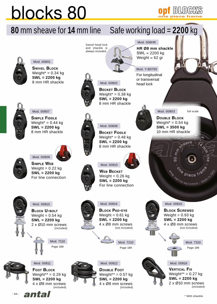
- 64 -
Mod. 00801
Mod. 00803Mod. 00807
Mod. 00809
Mod. 00813
Mod. 00811
Mod. 7110
Mod. 00802
Mod. 008HR
Mod. Y-B0750
Mod. 00808
Mod. 00810
Mod. 00814 Mod. 00815
Mod. 00812
Mod. 7210
Mod. 00816
Mod. 7310
full scale
Swivel BlockWeight* = 0.34 kgSWL = 2200 kg8 mm HR shackle
doUBle BlockWeight* = 0.54 kgSWL = 3500 kg10 mm HR shackle
Becket BlockWeight* = 0.38 kgSWL = 2200 kg8 mm HR shackle
Simple FiddleWeight* = 0.44 kgSWL = 2200 kg8 mm HR shackle Becket Fiddle
Weight* = 0.48 kgSWL = 2200 kg8 mm HR shackle
Simple weBWeight = 0.22 kgSWL = 2200 kgFor line connection
weB BecketWeight = 0.26 kgSWL = 2200 kgFor line connection
Block U-BoltWeight = 0.54 kgSWL = 2200 kg2 x Ø10 mm screws
(included)
vertical FixWeight** = 0.27 kgSWL = 2200 kg2 x Ø10 mm screws
(included)
Block pad-eyeWeight = 0.61 kgSWL = 2200 kg4 x Ø8 mm screws
(not included)
Block ScrewedWeight = 0.93 kgSWL = 2200 kg4 x Ø8 mm screws
(not included)
Foot BlockWeight** = 0.29 kgSWL = 2200 kg4 x Ø8 mm screws
(included)
doUBle FootWeight** = 0.57 kgSWL = 2200 kg4 x Ø8 mm screws
(included)
For longitudinalor transversalhead lock
HR Ø8 mm shackleSWL = 2200 kgWeight = 62 gr
Swivel head lock and shackle is always included.
* With shackle
Page 188 Page 189 Page 189
blocks 8080 mm sheave for 14 mm line Safe working load = 2200 kg
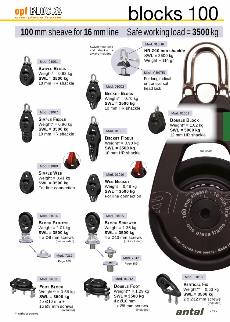
- 65 -
Mod. 01003
Mod. 01001
Mod. 01007
Mod. 01009
Mod. 01014
Mod. 01011
Mod. 7212
Mod. 01002
Mod. 010HR
Mod. Y-B0751
Mod. 01008
Mod. 01010
Mod. 01015
Mod. 01012
Mod. 7312
Mod. 01016
full scale
doUBle BlockWeight* = 1.02 kgSWL = 5000 kg12 mm HR shackle
blocks 100100 mm sheave for 16 mm line Safe working load = 3500 kg
Swivel BlockWeight* = 0.63 kgSWL = 3500 kg10 mm HR shackle
Becket BlockWeight* = 0.70 kgSWL = 3500 kg10 mm HR shackle
Simple FiddleWeight* = 0.90 kgSWL = 3500 kg10 mm HR shackle
Becket FiddleWeight* = 0.90 kgSWL = 3500 kg10 mm HR shackle
Simple weBWeight = 0.41 kgSWL = 3500 kgFor line connection
weB BecketWeight = 0.48 kgSWL = 3500 kgFor line connection
vertical FixWeight** = 0.63 kgSWL = 3500 kg2 x Ø12 mm screws
(included)
Block pad-eyeWeight = 1.01 kgSWL = 3500 kg4 x Ø8 mm screws
(not included)
Block ScrewedWeight = 1.35 kgSWL = 3500 kg4 x Ø10 mm screws
(not included)
Foot BlockWeight** = 0.56 kgSWL = 3500 kg4 x Ø10 mm +1 x Ø8 mm screws
(included)
doUBle FootWeight** = 1.29 kgSWL = 3500 kg4 x Ø10 mm +1 x Ø8 mm screws
(included)
For longitudinalor transversalhead lock
HR Ø10 mm shackleSWL = 3500 kgWeight = 114 gr
Swivel head lock and shackle is always included.
Page 189Page 189
** without screws

- 66 -
Mod. 01201
Mod. 01209
Mod. 01214
Mod. 01216
Mod. 7214
Mod. 01202
Mod. 012HR
Mod. Y-B0752
Mod. 01210
Mod. 01215
Mod. 01212
Mod. 7314Mod. 01211
Block pad-eyeWeight = 1.70 kgSWL = 5000 kg4 x Ø10 mm screws
(not included)
Page 189
Block ScrewedWeight = 2.00 kgSWL = 5000 kg4 x Ø10 mm screws
(not included)
Page 189
full scale
Swivel BlockWeight* = 1.08 kgSWL = 5000 kg12 mm HR shackle
Becket BlockWeight* = 1.22 kgSWL = 5000 kg12 mm HR shackle
Simple weBWeight = 0.74 kgSWL = 5000 kgFor line connection
weB BecketWeight = 0.88 kgSWL = 5000 kgFor line connection
vertical FixWeight** = 0.96 kgSWL = 5000 kg2 x Ø14 mm screws
(included)
Foot BlockWeight** = 0.80 kgSWL = 5000 kg5 x Ø10 mm screws
(included)
doUBle FootWeight** = 1.97 kgSWL = 5000 kg5 x Ø10 mm screws
(included)
* With shackle
blocks 120120 mm sheave for 18 mm line Safe working load = 5000 kg
For longitudinalor transversalhead lock
HR Ø12 mm shackleSWL = 5000 kgWeight = 186 gr
Swivel head lock and shackle is always included.
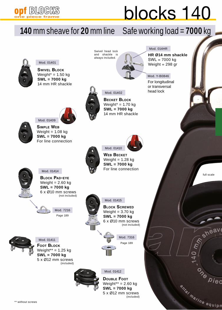
- 67 -
Mod. 01401
Mod. 01409
Mod. 01414
Mod. 01411
Mod. 7216
Mod. 01402
Mod. 014HR
Mod. Y-B0846
Mod. 01410
Mod. 01415
Mod. 01412
Mod. 7316
full scale
Swivel BlockWeight* = 1.50 kgSWL = 7000 kg14 mm HR shackle
Becket BlockWeight* = 1.70 kgSWL = 7000 kg14 mm HR shackle
Simple weBWeight = 1.08 kgSWL = 7000 kgFor line connection
weB BecketWeight = 1.28 kgSWL = 7000 kgFor line connection
Foot BlockWeight** = 1.25 kgSWL = 7000 kg5 x Ø12 mm screws
(included)
doUBle FootWeight** = 2.60 kgSWL = 7000 kg5 x Ø12 mm screws
(included)
Block pad-eyeWeight = 2.60 kgSWL = 7000 kg6 x Ø10 mm screws
(not included)
Page 189
Block ScrewedWeight = 3.70 kgSWL = 7000 kg6 x Ø10 mm screws
(not included)
Page 189
blocks 140140 mm sheave for 20 mm line Safe working load = 7000 kg
For longitudinalor transversalhead lock
HR Ø14 mm shackleSWL = 7000 kgWeight = 298 gr
Swivel head lock and shackle is always included.
** without screws
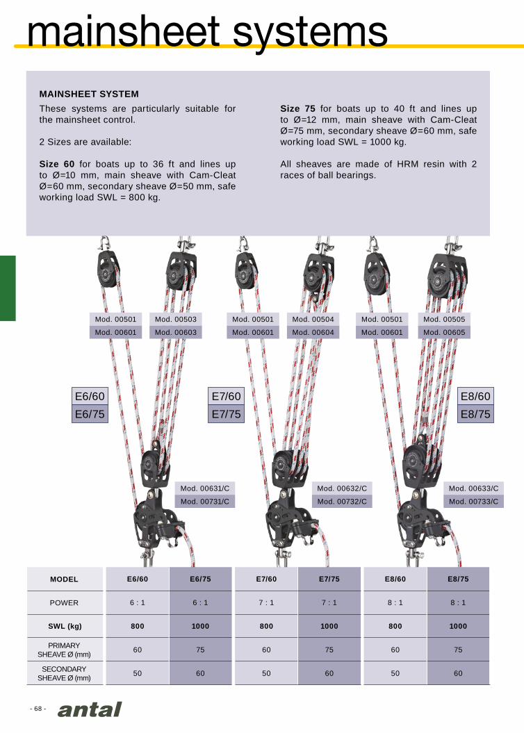
- 68 -
E6/60 E6/75 E7/60 E7/75 E8/60 E8/75
6 : 1 6 : 1 7 : 1 7 : 1 8 : 1 8 : 1
SWL (kg) 800 1000 800 1000 800 1000
60 75 60 75 60 75
50 60 50 60 50 60
E6/60 E7/60 E8/60
E6/75 E7/75 E8/75
Mod. 00631/C
Mod. 00731/C
Mod. 00503
Mod. 00603
Mod. 00501
Mod. 00601
Mod. 00632/C
Mod. 00732/C
Mod. 00501
Mod. 00601
Mod. 00504
Mod. 00604
Mod. 00501
Mod. 00601
Mod. 00505
Mod. 00605
Mod. 00633/C
Mod. 00733/C
SECONDARY SHEAVE Ø (mm)
POWER
PRIMARYSHEAVE Ø (mm)
MODEL
mainsheet systems
These systems are particularly suitable for the mainsheet control.
2 Sizes are available:
Size 60 for boats up to 36 ft and lines up to Ø=10 mm, main sheave with Cam-Cleat Ø=60 mm, secondary sheave Ø=50 mm, safe working load SWL = 800 kg.
Size 75 for boats up to 40 ft and lines up to Ø=12 mm, main sheave with Cam-Cleat Ø=75 mm, secondary sheave Ø=60 mm, safe working load SWL = 1000 kg.
All sheaves are made of HRM resin with 2 races of ball bearings.
MAINSHEET SYSTEM

- 69 -
8:1
4:1
18:1
6:1
J80 Breschi - photo - video.com
F4 F6
4 : 1 6 : 1
8 : 1 18 : 1
800 SWL (Kg) 1000
60 65
0.88 1.54
F4 F6
Mod. 922.602
Mod. 992.602
Mod. 00320
Mod. 932.652
Mod. 993.653/C
Mod. 00321
The particular configuration adopted permits the use of large diameter sheaves which improve performance of the system; it also ensures maximum block orientation capabilities and therefore the possibility to operate on both sides of the boat. Furthermore,
this reduces the necessary sheet length.The two speeds are controlled by means of two independent lines.
Use 10 mm line for the first speed and 6 mm line for the second speed.
TWO SPEED MAINSHEET TACKLE :4/8 AND 6/18
For boats up to 36 ft For boats up to 40 ft
MODEL
2st SPEED
SHEAVE Ø (mm)
TOTAL WEIGHT (Kg)
1st SPEED

- 70 -
D1mm
Tmm
D2mm
D3mm
D4mm
SWLkg
15029/A 150 29 40 34 20 0.90 6500
18035/A 180 35 50 40 24 1.40 9000
21843/A 220 40 50 40 33 3.20 13000
24856/A 250 56 65 48 40 4.70 20000T
D4
D3D2D1
Vm50 Vismara
XXL blocksCOMPOSITE FIBRE SERIES
The whole “composite fibre” range uses sheaves on composite fibre bearings and double self-captive Delrin ball thrust bearings.
The sheaves are easy to dismantle for cleaning and need no lubrication.The sides are made of 3571 TA16 light alloy and are thickly anodized to ensure absolute wear-and corrosion proofing, with all the edges smoothed off for better handling.
The nuts and bolts have been replaced with recessed screws and pins, considerably reducing weight and eliminating any projecting parts.
The steel coupling revolves on a fibre washer and can easily be locked in one of two main positions.
HIGH-STRENGTH ALUMINIUM SHEAVES
Sizes 150, 180, 220 and 250 mm use thickly anodized aluminium sheaves. The main bearing is made of high-strength composite fibre impregnated with self-lubricating substances. A double lateral Delrin ball bearing makes the sheaves slide perfectly smoothly.
Sheaves are supplied with the s.steel central hub, they are available separately.
SHEAVEMODEL MATERIAL WEIGHT
kg
ALUMINIUM
ALUMINIUM
ALUMINIUM
ALUMINIUM

- 71 -
Mod. 911.154
Mod. 910.155/Z
Mod. 812.154
Mod. 7216
Mod. 831.154
Mod. 941.154
Mod. 981.154
Mod. 940.155/Z
Mod. 813.154
Mod. 7316
Mod. 832.154
full scale
Block on pad-eyeWeight = 3.10 kgSWL = 6500 kg6 x Ø10 mm screws
(not included)
Page 189
Block on
Screwed pad-eyeWeight = 4.10 kgSWL = 6500 kg6 x Ø10 mm screws (not included)
Page 189
XXL blocks 150
weB Block“Strengthened”Weight = 1.90 kgSWL = 8000 kgFor line connection
weB with Becket“Strengthened”Weight = 2.02 kgSWL = 8000 kgFor line connection
Single BlockWeight = 1.80 kgSWL = 6500 kgSwivel head for14 mm HR shackle Fiddle with Becket
Weight = 2.80 kgSWL = 6500 kgSwivel head for14 mm HR shackle
Block with BecketWeight = 2.00 kgSWL = 6500 kgSwivel head for14 mm HR shackle
deck BlockWeight = 1.40 kgSWL = 6500 kgScrews = 2 x Ø12 mm + 1 x Ø14 mm (included)
doUBle
deck BlockWeight = 2.30 kgSWL = 6500 kgScrews = 2 x Ø12 mm + 1 x Ø14 mm (included)
150 mm sheave for 20 mm line Safe working load = 6500 kg
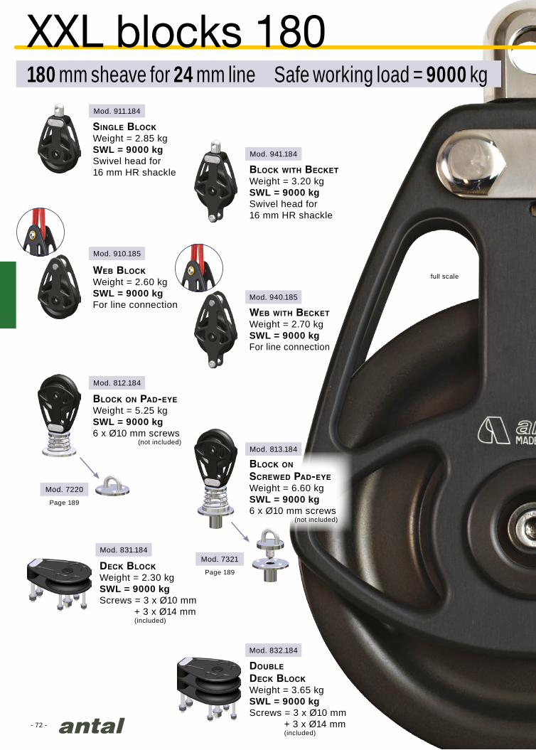
- 72 -
Mod. 911.184
Mod. 941.184
Mod. 940.185
Mod. 813.184
Mod. 832.184
Mod. 7321
Mod. 910.185
Mod. 812.184
Mod. 831.184
Mod. 7220
180 mm sheave for 24 mm line Safe working load = 9000 kg
XXL blocks 180
weB BlockWeight = 2.60 kgSWL = 9000 kgFor line connection
weB with BecketWeight = 2.70 kgSWL = 9000 kgFor line connection
Page 189
Page 189
Single BlockWeight = 2.85 kgSWL = 9000 kgSwivel head for16 mm HR shackle Block with Becket
Weight = 3.20 kgSWL = 9000 kgSwivel head for16 mm HR shackle
doUBle
deck BlockWeight = 3.65 kgSWL = 9000 kgScrews = 3 x Ø10 mm + 3 x Ø14 mm (included)
deck BlockWeight = 2.30 kgSWL = 9000 kgScrews = 3 x Ø10 mm + 3 x Ø14 mm (included)
Block on pad-eyeWeight = 5.25 kgSWL = 9000 kg6 x Ø10 mm screws
(not included)
Block on
Screwed pad-eyeWeight = 6.60 kgSWL = 9000 kg6 x Ø10 mm screws
(not included)
full scale

- 73 -
Mod. 941.224
Mod. 941.254
Mod. 911.224
Mod. 911.254
Mod. 940.225
Mod. 940.255
Mod. 910.225
Mod. 910.255
weB with BecketWeight = 8.25 kgSWL = 13000 kgFor line connection
weB with BecketWeight = 11.05 kgSWL = 20000 kgFor line connection
Block with BecketWeight = 10.20 kgSWL = 13000 kg Swivel head for20 mm HR shackle
Block with BecketWeight = 15.05 kgSWL = 20000 kgSwivel head for24 mm HR shackle
full scale220 mm
220 mm sheave for 30 mm line Safe working load = 13000 kg
250 mm sheave for 40 mm line Safe working load = 20000 kg
XXL blocks 220 / 250
weB BlockWeight = 7.65 kgSWL = 13000 kgFor line connection
weB BlockWeight = 10.35 kgSWL = 20000 kgFor line connection
Single BlockWeight = 9.60 kgSWL = 13000 kg Swivel head for20 mm HR shackle
Single BlockWeight = 14.35 kgSWL = 20000 kgSwivel head for24 mm HR shackle
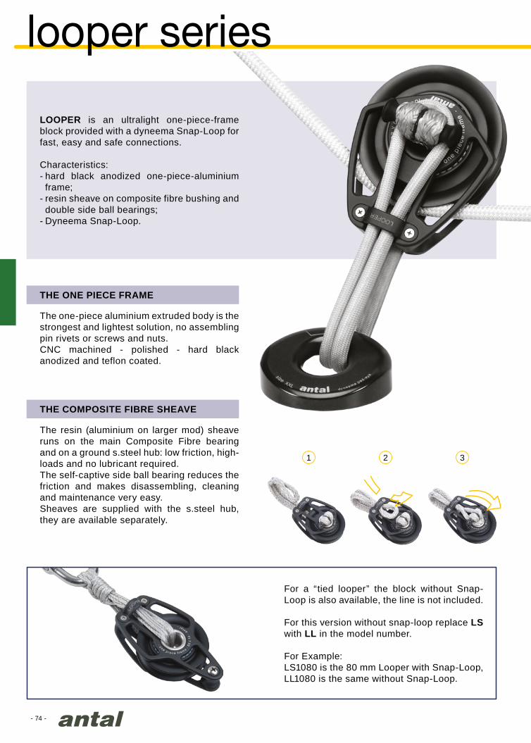
- 74 -
1 2 3
looper series
LOOPER is an ultralight one-piece-frame block provided with a dyneema Snap-Loop for fast, easy and safe connections.
Characteristics:- hard black anodized one-piece-aluminium
frame;- resin sheave on composite fibre bushing and
double side ball bearings;- Dyneema Snap-Loop.
The resin (aluminium on larger mod) sheave runs on the main Composite Fibre bearing and on a ground s.steel hub: low friction, high-loads and no lubricant required.The self-captive side ball bearing reduces the friction and makes disassembling, cleaning and maintenance very easy.Sheaves are supplied with the s.steel hub, they are available separately.
THE COMPOSITE FIBRE SHEAVE
The one-piece aluminium extruded body is the strongest and lightest solution, no assembling pin rivets or screws and nuts.CNC machined - polished - hard black anodized and teflon coated.
THE ONE PIECE FRAME
For a “tied looper” the block without Snap-Loop is also available, the line is not included.
For this version without snap-loop replace LS with LL in the model number.
For Example:LS1080 is the 80 mm Looper with Snap-Loop, LL1080 is the same without Snap-Loop.

- 75 -
Ø
L
L
DYNEEMAØ mm
BLkg
SWL*kg
Lmm
LS2060 4 3000 1000 100 11
LS2070 5 5200 1600 110 20
LS2080 6 6600 2200 125 44
LS2100 8 11000 3500 160 81
Ømm
Lmm
LS2062 4 6.5 30 3
LS2072 5 8.0 37 6
LS2082 6 10.0 46 13
LS2102 8 11.5 55 22
LS2122 10 13.5 67 36
LS2142 12 16.0 79 55
mod. LS2070
Morelli Melvin SL33, Ginger Photography
SNAP LOOPThese snap loops are obtained with a spliced Dyneema line without cover and an aluminium dog-bone.
DOG-BONE
You can prepare your special snap loop using Antal aluminium dog-bones, separately available.
DYNEEMA PAD-EYE
MODEL
MODEL FOR DYNEEMAØ mm
WEIGHTgr
WEIGHTgr
Special eye-strap designed for Dyneema Loop, aluminium made, hard black anodizing.For more information, see pag. 174
Dyneema Snap Loops including “Dog-Bone” aluminium fastenings are available.Dog-Bone fastenings are also available separately so that Loops of any length can be prepared.
SNAP LOOP AND DOG-BONE FASTENINGS
* The Safe Working Load SWL is 1/3 of the breaking load, obtained from traction tests on a new Loop.

- 76 -
Mod. LS1060
Mod. LS1062
Mod. LS1061Mod. LS1063
Mod. LS2060
Mod. LS1070
Mod. LS1080
Mod. LS2070
Mod. LS1072
Mod. LS1071
Mod. LS1081
Mod. LS1082
Mod. LS1073
Mod. LS1083
Mod. LS2080
looper
SimpleWeight* = 106 gr
4 mm Dyneema loopWeight = 11 gr
DoubleWeight* = 196 gr
Simple becketWeight* = 116 gr Double becket
Weight* = 206 gr
SIZE 60
sheave diameter = 60 mmline diameter = 10 mmSWL = 1000 kg
SimpleWeight* = 155 gr
5 mm Dyneema loopWeight = 20 gr
DoubleWeight* = 285 gr
Simple becketWeight* = 172 gr
Simple becketWeight* = 290 gr
Double becketWeight* = 302 gr
Double becketWeight* = 510 gr
SIZE 70
sheave diameter = 70 mmline diameter = 12 mmSWL = 1600 kg
SimpleWeight* = 268 gr
6 mm Dyneema loopWeight = 44 gr
DoubleWeight* = 490 gr
SIZE 80
sheave diameter = 80 mmline diameter = 14 mmSWL = 2200 kg
* Dyneema Loop included

- 77 -
Mod. LS1100
Mod. LS1120
Mod. LS1101
Mod. LS1121
Mod. LS1141
Mod. LS2120
Mod. LS2140
Mod. LS1140
Mod. LS2100
SimpleWeight* = 438 gr
8 mm Dyneema loopWeight = 81 gr
Simple becketWeight* = 473 gr
SIZE 100
sheave diameter = 100 mmline diameter = 16 mmSWL = 3500 kg
SimpleWeight* = 890 gr
SimpleWeight* = 1129 gr
10 mm Dyneema loopWeight = 150 gr
12 mm Dyneema loopWeight = 219 gr
Simple becketWeight* = 925 gr
Simple becketWeight* = 1179 gr
SIZE 120
sheave diameter = 120 mmline diameter = 18 mmSWL = 6000 kg
SIZE 140
sheave diameter = 140 mmline diameter = 20 mmSWL = 8000 kg

- 78 -
Sphinx 12m SI - Robbe & Berking - Germany
A316 s.steel seriesCLASSIC LINE
This stainless steel series, with a traditional design, is conceived especially for classic boats.The line includes 6 different sizes with diameters from 65 to 180 mm and Safe Working Load up to 9000 kg.Perfectly polished AISI 316 stainless steel cheekplates and accessories, fully rounded corners for greater manageability, nuts and bolts replaced by pins and recessed screws to eliminate any protruding parts.Each size is available in numerous versions as described in the following pages.
SHEAVES
Resin or aluminium sheaves in larger models are easy to dismantle and work on a main composite fibre bearing and two side ball bearings (self-captive).
CAM CLEAT
All models can be supplied with cam cleat. Just add /C to the model code when ordering.

- 79 -
Mod. S0601
Mod. S0602
Mod. S0604
Mod. S0603
Mod. S0605
Mod. S0609
Mod. S0611
Mod. S0613
Mod. 7106
Mod. S0606
Mod. S0616
Mod. S0612
Mod. S0614
Mod. 7206
Mod. S0615
Mod. 7306
block on u-boltWeight = 0.36 kgSWL = 800 kg2 x Ø6 mm screws (included)
block on paD-eyeWeight = 0.38 kgSWL = 800 kg2 x Ø6 mm screws (not included)
block on
ScreweD paD-eyeWeight = 0.45 kgSWL = 800 kg2 x Ø6 mm screws (not included)
Page 188
Page 189
Page 189
Single blockWeight = 0.29 kgSWL = 800 kgSwivel head for6 mm shackle*
Double blockWeight = 0.51 kgSWL = 1200 kgFixed head for8 mm shackle*
triple blockWeight = 0.70 kgSWL = 1200 kgFixed head for8 mm shackle*
Deck blockWeight = 0.30 kgSWL = 800 kg2 x Ø8 mm screws (included)
Single with becketWeight = 0.32 kgSWL = 800 kgSwivel head for6 mm shackle*
Double with becketWeight = 0.54 kgSWL = 1200 kgFixed head for8 mm shackle*
triple with becketWeight = 0.73 kgSWL = 1200 kgFixed head for8 mm shackle*
Double Deck blockWeight = 0.46 kgSWL = 800 kg2 x Ø8 mm screws (included)
StanD-up blockWeight = 0.37 kgSWL = 800 kg1 x Ø12 mm screw (included)
webbing blockWeight = 0.25 kgSWL = 800 kgFor line connection
s.steel block 6565 mm sheave for 12 mm line Safe working load = 800 kg
cam-cleatAll models are available with cam-cleat, add /C to the model code.Weight = + 0.18 kgMax load = 160 kg
real size
* shackle not included
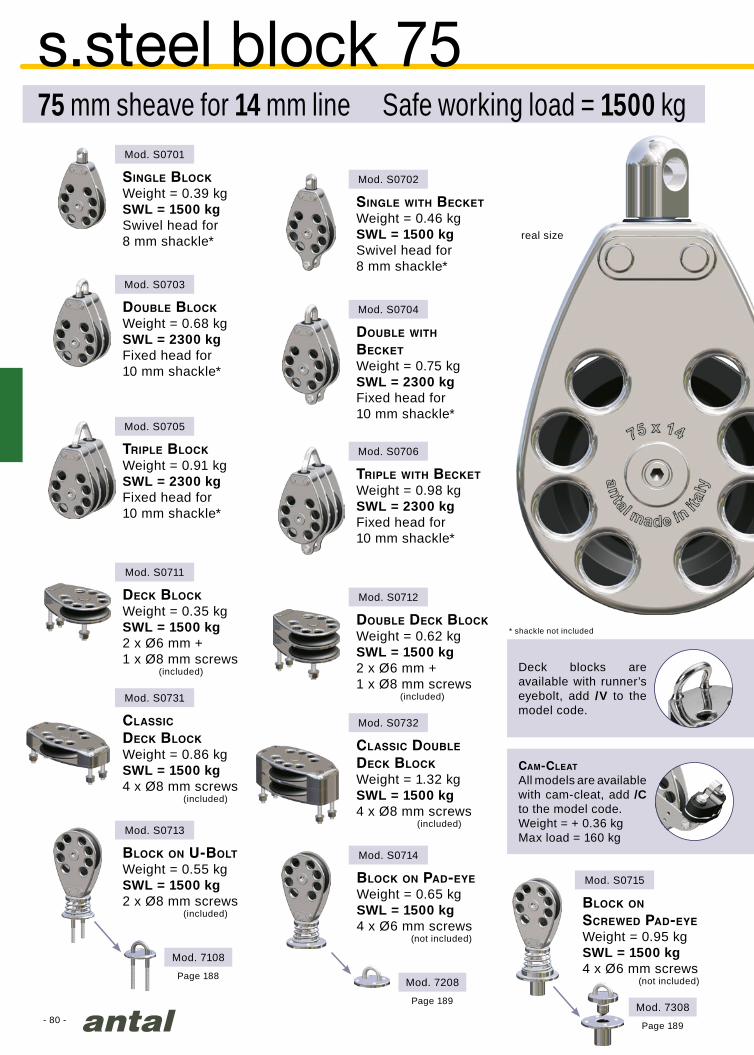
Mod. 7308- 80 -
Mod. S0701
Mod. S0702
Mod. S0704
Mod. S0703
Mod. S0705
Mod. S0711
Mod. S0731
Mod. S0713
Mod. 7108
Mod. S0706
Mod. S0712
Mod. S0732
Mod. S0714
Mod. 7208
Mod. S0715
block on u-boltWeight = 0.55 kgSWL = 1500 kg2 x Ø8 mm screws (included)
block on paD-eyeWeight = 0.65 kgSWL = 1500 kg4 x Ø6 mm screws (not included)
block on ScreweD paD-eyeWeight = 0.95 kgSWL = 1500 kg4 x Ø6 mm screws (not included)Page 188
Page 189
Page 189
Single blockWeight = 0.39 kgSWL = 1500 kgSwivel head for8 mm shackle*
Double blockWeight = 0.68 kgSWL = 2300 kgFixed head for10 mm shackle*
triple blockWeight = 0.91 kgSWL = 2300 kgFixed head for10 mm shackle*
claSSic
Deck blockWeight = 0.86 kgSWL = 1500 kg4 x Ø8 mm screws (included)
Deck blockWeight = 0.35 kgSWL = 1500 kg2 x Ø6 mm +1 x Ø8 mm screws
(included)
Single with becketWeight = 0.46 kgSWL = 1500 kgSwivel head for8 mm shackle*
Double with becketWeight = 0.75 kgSWL = 2300 kgFixed head for10 mm shackle*
triple with becketWeight = 0.98 kgSWL = 2300 kgFixed head for10 mm shackle*
claSSic Double
Deck blockWeight = 1.32 kgSWL = 1500 kg4 x Ø8 mm screws (included)
Double Deck blockWeight = 0.62 kgSWL = 1500 kg2 x Ø6 mm +1 x Ø8 mm screws
(included)
s.steel block 7575 mm sheave for 14 mm line Safe working load = 1500 kg
cam-cleat
All models are available with cam-cleat, add /C to the model code. Weight = + 0.36 kgMax load = 160 kg
* shackle not included
real size
Deck blocks are available with runner’s eyebolt, add /V to the model code.
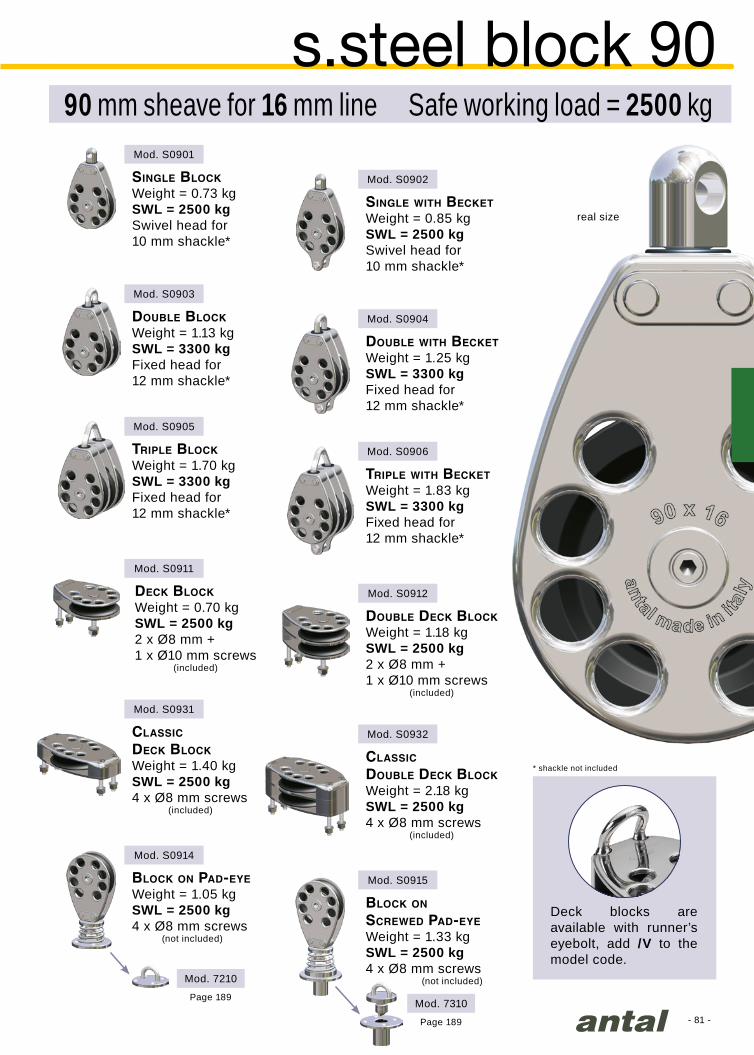
- 81 -
Mod. S0901
Mod. S0902
Mod. S0904
Mod. S0903
Mod. S0905
Mod. S0911
Mod. S0931
Mod. S0914
Mod. 7210
Mod. S0906
Mod. S0912
Mod. S0932
Mod. S0915
Mod. 7310
block on paD-eyeWeight = 1.05 kgSWL = 2500 kg4 x Ø8 mm screws
(not included)
block on ScreweD paD-eyeWeight = 1.33 kgSWL = 2500 kg4 x Ø8 mm screws
(not included)
Page 189
Page 189
Single blockWeight = 0.73 kgSWL = 2500 kgSwivel head for10 mm shackle*
Double blockWeight = 1.13 kgSWL = 3300 kgFixed head for12 mm shackle*
triple blockWeight = 1.70 kgSWL = 3300 kgFixed head for12 mm shackle*
claSSic
Deck blockWeight = 1.40 kgSWL = 2500 kg4 x Ø8 mm screws
(included)
Deck blockWeight = 0.70 kgSWL = 2500 kg2 x Ø8 mm +1 x Ø10 mm screws
(included)
Single with becketWeight = 0.85 kgSWL = 2500 kgSwivel head for10 mm shackle*
Double with becketWeight = 1.25 kgSWL = 3300 kgFixed head for12 mm shackle*
triple with becketWeight = 1.83 kgSWL = 3300 kgFixed head for12 mm shackle*
claSSic
Double Deck blockWeight = 2.18 kgSWL = 2500 kg4 x Ø8 mm screws
(included)
Double Deck blockWeight = 1.18 kgSWL = 2500 kg2 x Ø8 mm +1 x Ø10 mm screws
(included)
s.steel block 9090 mm sheave for 16 mm line Safe working load = 2500 kg
Deck blocks are available with runner’s eyebolt, add /V to the model code.
* shackle not included
real size
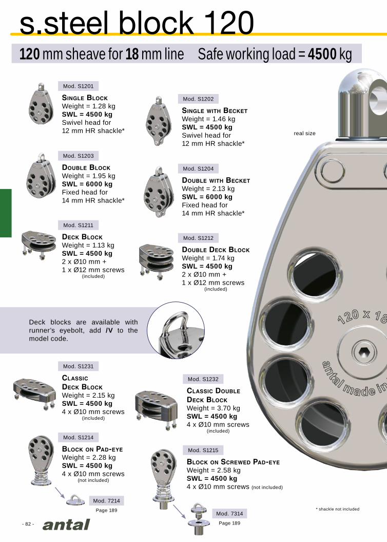
- 82 -
Mod. S1201
Mod. S1202
Mod. S1204
Mod. S1203
Mod. S1211
Mod. S1231
Mod. S1214
Mod. S1212
Mod. S1232
Mod. S1215
Mod. 7314
Mod. 7214
block on paD-eyeWeight = 2.28 kgSWL = 4500 kg4 x Ø10 mm screws
(not included)
block on ScreweD paD-eyeWeight = 2.58 kgSWL = 4500 kg4 x Ø10 mm screws (not included)
Page 189
Page 189
Single blockWeight = 1.28 kgSWL = 4500 kgSwivel head for12 mm HR shackle*
Double blockWeight = 1.95 kgSWL = 6000 kgFixed head for14 mm HR shackle*
claSSic
Deck blockWeight = 2.15 kgSWL = 4500 kg4 x Ø10 mm screws
(included)
Deck blockWeight = 1.13 kgSWL = 4500 kg2 x Ø10 mm +1 x Ø12 mm screws
(included)
Single with becketWeight = 1.46 kgSWL = 4500 kgSwivel head for12 mm HR shackle*
Double with becketWeight = 2.13 kgSWL = 6000 kgFixed head for14 mm HR shackle*
claSSic Double Deck blockWeight = 3.70 kgSWL = 4500 kg4 x Ø10 mm screws
(included)
Double Deck blockWeight = 1.74 kgSWL = 4500 kg2 x Ø10 mm +1 x Ø12 mm screws
(included)
s.steel block 120120 mm sheave for 18 mm line Safe working load = 4500 kg
Deck blocks are available with runner’s eyebolt, add /V to the model code.
* shackle not included
real size

- 83 -
Mod. S1501
Mod. S1502
Mod. S1511
Mod. S1531
Mod. S1514
Mod. S1512
Mod. S1532
Mod. S1515
Mod. 7316
Mod. 7216
block on paD-eyeWeight = 4.71 kgSWL = 6500 kg6 x Ø10 mm screws
(not included)
block on
ScreweD paD-eyeWeight = 6.24 kgSWL = 6500 kg6 x Ø10 mm screws
(not included)
Page 189
Page 189
Single blockWeight = 2.74 kgSWL = 6500 kgSwivel head for14 mm HR shackle*
claSSic
Deck blockWeight = 4.57 kgSWL = 6500 kg4 x Ø12 mm screws
(included)
Deck blockWeight = 2.13 kgSWL = 6500 kg2 x Ø12 mm +1 x Ø14 mm screws
(included)
Single with becketWeight = 3.04 kgSWL = 6500 kgSwivel head for14 mm HR shackle*
claSSic Double Deck blockWeight = 7.91 kgSWL = 6500 kg4 x Ø12 mm screws
(included)
Double Deck blockWeight = 3.50 kgSWL = 6500 kg2 x Ø12 mm +1 x Ø14 mm screws
(included)
s.steel block 150150 mm sheave for 20 mm line Safe working load = 6500 kg
real size
Deck blocks are available with runner’s eyebolt, add /V to the model code.
* shackle not included

- 84 -
Mod. S1801
Mod. S1802
Mod. S1811
Mod. S1831
Mod. S1814
Mod. S1812
Mod. S1832
Mod. S1815
Mod. 7321
Mod. 7220
block on paD-eyeWeight = 7.57 kgSWL = 9000 kg6 x Ø10 mm screws
(not included)
block on
ScreweD paD-eyeWeight = 9.51 kgSWL = 9000 kg6 x Ø10 mm screws
(not included)Page 189
Page 189
Single blockWeight = 4.11 kgSWL = 9000 kgSwivel head for16 mm HR shackle*
claSSic
Deck blockWeight = 6.86 kgSWL = 9000 kg4 x Ø14 mm screws
(included)
Deck blockWeight = 3.31 kgSWL = 9000 kg2 x Ø14 mm +1 x Ø16 mm screws
(included)
Single with becketWeight = 4.61 kgSWL = 9000 kgSwivel head for16 mm HR shackle*
claSSic Double Deck blockWeight = 11.8 kgSWL = 9000 kg4 x Ø14 mm screws
(included)
Double Deck blockWeight = 5.26 kgSWL = 9000 kg2 x Ø14 mm +1 x Ø16 mm screws
(included)
s.steel block 180180 mm sheave for 24 mm line Safe working load = 9000 kg
real size
Deck blocks are available with runner’s eyebolt, add /V to the model code.
* shackle not included
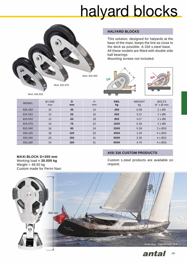
- 85 -
H
D
OK NOMod. 815.090
Mod. 815.652
Mod. 815.075
655 mm
Dmm
Hmm
SWLkg
815.452 10 45 14 450 0.08 2 x Ø5
815.552 12 55 16 600 0.12 2 x Ø6
815.652 12 65 18 800 0.17 2 x Ø8
815.075 14 75 22 1500 0.26 2 x Ø8
815.090 16 90 24 2500 0.39 2 x Ø10
815.120 18 120 32 4500 1.20 4 x Ø10
815.150 20 150 41 6500 3.30 4 x Ø12
815.180 24 180 51 9000 4.70 4 x Ø16
Perini Navi - State of Grace 40 m
halyard blocksHALYARD BLOCKS
This solution, designed for halyards at the base of the mast, keeps the line as close to the deck as possible. A-316 s.steel base.All these models are fitted with double side ball bearings.Mounting screws not included.
MODEL WEIGHT kg
Ø LINEmm
BOLTSN° x Ø mm
MAXI BLOCK D=300 mmWorking load = 30.000 kgWeight = 48,50 kgCustom made for Perini Navi
AISI 316 CUSTOM PRODUCTS
Custom s.steel products are available on request.

- 86 -
H
L B
D
H
L B
D
Mod. 816.075Mod. 816.090
α≥90°
Dmm
Hmm
Lmm
Bmm
SWLkg
816.075 12 75 20 132 60 1500 0.62 4 x Ø8
816.090 14 90 24 157 66 2500 1.15 4 x Ø10
816.120 18 120 32 190 80 4500 1.95 4 x Ø12
Dmm
Hmm
Lmm
Bmm
SWLkg
816.150 20 150 30 315 94 6500 5.70 8 x Ø10
816.180 22 180 33 373 108 9000 8.70 8 x Ø12
“Nave Italia” onlus
Mod. 816.150
hollow pin deck blocksHOLLOW PIN DECK BLOCK 75, 90, 120 mm
The sheave rotates on a hollow pin with the line passing through the pin’s centre.This type of arrangement reduces the height of the line off the deck, and the side loads on the block.The line position and its direction to the winch does not change, even when the sheave is articulated off-centre.Body completely made in polished s.steel. Sheave on Composite Fibre bearing and two side ball bearing.Mounting screws, nuts and washers are included.
HOLLOW PIN DECK BLOCK 150, 180 mm
The larger models with 150 and 180 mm sheaves are equipped with a double base, where each base is fixed with 4 screws.Mounting screws, nuts and washers are included.
MODEL
MODEL
BOLTSN° x Ø mm
BOLTSN° x Ø mm
Ø LINEmm
Ø LINEmm
WEIGHT*kg
WEIGHT*kg
* without screws
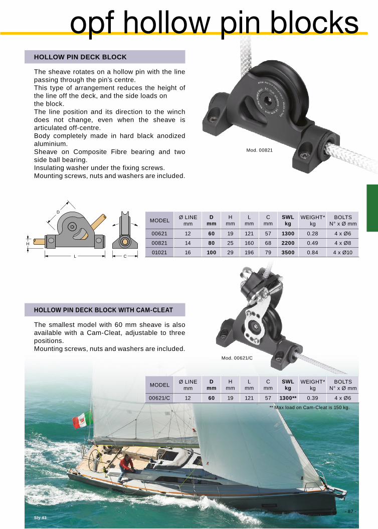
- 87 -Sly 43
H
L C
A
B
D
Mod. 00621/C
Dmm
Hmm
Lmm
Cmm
SWLkg
00621 12 60 19 121 57 1300 0.28 4 x Ø6
00821 14 80 25 160 68 2200 0.49 4 x Ø8
01021 16 100 29 196 79 3500 0.84 4 x Ø10
Dmm
Hmm
Lmm
Cmm
SWLkg
00621/C 12 60 19 121 57 1300** 0.39 4 x Ø6
Mod. 00821
HOLLOW PIN DECK BLOCK
The sheave rotates on a hollow pin with the line passing through the pin’s centre.This type of arrangement reduces the height of the line off the deck, and the side loads onthe block.The line position and its direction to the winch does not change, even when the sheave is articulated off-centre.Body completely made in hard black anodized aluminium.Sheave on Composite Fibre bearing and two side ball bearing.Insulating washer under the fixing screws.Mounting screws, nuts and washers are included.
opf hollow pin blocks
Ø LINEmm
Ø LINEmm
MODEL
MODEL
BOLTSN° x Ø mm
BOLTSN° x Ø mm
WEIGHT*kg
WEIGHT*kg
HOLLOW PIN DECK BLOCK WITH CAM-CLEAT
The smallest model with 60 mm sheave is also available with a Cam-Cleat, adjustable to three positions.Mounting screws, nuts and washers are included.
** Max load on Cam-Cleat is 150 kg.

- 88 -
Mod. 00818/Z
CE
B A
D
DIA
80
CE
B A
D
Mod. 00418/D
00418/D 2 x 40 16 198 138 36 28 29 2500** 0.26 2 x Ø8
DIAmm
Amm
Bmm
Cmm
Dmm
Emm
SWLkg
00418 40 8 107 58 24.2 18.2 31.5 400* 0.07 2 x Ø6
00518 50 12 118 69.5 29.5 22.5 37 800* 0.12 2 x Ø6
00618 60 12 130 81.5 29.5 22.5 49 800* 0.15 2 x Ø6
0071870 12
14091.5 29.5 22.5 53.5
1300* 0.16 2 x Ø6
00718/Z 158 2000* 0.23 3 x Ø6
0081880 14
162103 34.5 27 62.5
2200* 0.24 2 x Ø8
00818/Z 187 3000* 0.34 3 x Ø8
01018100 16
198126 39 31 81.5
3500* 0.44 2 x Ø10
01018/Z 226 4500* 0.62 3 x Ø10
01218120 18
251151 47 37 103
5000* 0.97 3 x Ø10
01218/Z 263 7000* 1.08 3 x Ø12
01418/Z 140 20 286 174 49 39 120 9000* 1.55 3 x Ø12
DUAL SHEAVE MAST BLOCK
The Dual sheave mast block with 2 x 40 mm sheaves for lines up to 16 mm solves the problem of the wear of the halyards coming out of the mast.This solution is also suitable for running a line from above to below deck.
mast blocksMAST BLOCKS
12 different sizes with diameters from 40 to 140 mm for working loads (SWL) up to 9000 kg.Hard black anodized aluminium frame with insulating washers for corrosion protection.Resin sheaves (aluminium sheaves for 100, 120 and 140 mm only) with composite fibre main bearing (not on size 40) and double side self-captive ball bearing.On request custom models for higher loads are also available.
MODEL BOLTSN° x Ø mm
WEIGHTkg
Ø LINEmm
* Safe Working Load for the sheave
** Safe Working Load for the halyard

- 89 -
Dmm
Pmm
40 Ø 14
2 D420 111
44
0.13
800
800 3 x Ø6
3 D430 155 0.19 1200 4 x Ø6
4 D440 199 0.24 1600 5 x Ø6
5 D450 243 0.30 2000 6 x Ø6
6 D460 287 0.35 2400 7 x Ø6
50 Ø 16
2 D520 133
52
0.20
1200
1200 3 x Ø8
3 D530 185 0.29 1800 4 x Ø8
4 D540 237 0.37 2400 5 x Ø8
5 D550 289 0.46 3000 6 x Ø8
6 D560 341 0.54 3600 7 x Ø8
60 Ø 18
2 D620 163
65
0.48
2200
2200 3 x Ø10
3 D630 228 0.69 3300 4 x Ø10
4 D640 293 0.91 4400 5 x Ø10
5 D650 358 1.13 5500 6 x Ø10
6 D660 423 1.35 6600 7 x Ø10
70 Ø 20
2 D720 190
76
0.74
3200
3200 3 x Ø12
3 D730 266 1.07 4800 4 x Ø12
4 D740 342 1.40 6400 5 x Ø12
5 D750 418 1.74 8000 6 x Ø12
6 D760 494 2.07 9600 7 x Ø12
Mod. 821.062
Mod. D530
Mod. D540
Mod. D550
D
P
H
D
Dmm
Hmm
SWLkg
821.052 50 33 800 0.10 1 x Ø10
821.062 60 38 1200 0.12 1 x Ø12
821.074 70 44 1800 0.45 4 x Ø8
organizerORGANIZERS D=40, 50, 60 AND 70 mm
Groups of 2 to 6 sheaves in 4 diameters of 40, 50, 60 and 70 mm.The 40 and 50 mm sheaves are manufactured in high-strength resin with a double side ball bearing. The 60 and 70 mm sheaves are manufactured in aluminium, hard black anodized, with a main composite fibre bearing and 2 side ball bearings.Mounting screws, nuts and washers are included.These new organizers do not disassemble after tacking off the screws.
Double version also available, just add /D to the model number.
N°SHEAVES
LINEmm MODEL LENGTH
mmBOLTS
N° x Ø mmSHEAVESWL (kg)
ORGANIZERSWL (kg)
WEIGHT*kg
TURNING SHEAVES
Mounted aft of a set of rope clutches, the turning sheave redirects each line to the most suitable winch.Mounting screws, nuts and washers are included.
MODEL BOLTSN° x Ø mm
WEIGHT*kg
* Weight without screws, washers and nuts.
SHEAVE SWL: the maximum Safe Working Load on the single sheave.
ORGANIZER SWL: the maximum Safe Working Load on the organizer.

- 90 -
D
d
t
H
D
H
D
L
Dmm
dmm
tmm
SWLkg
801.045* 45 12 12 31 1000 0.04
801.060 60 14 15 38 2200 0.16
801.071 70 14 15 38 3000 0.19
801.090 90 14 20 50 5000 0.45
801.110 110 16 30 60 9000 0.83
Dmm
Hmm
SWLkg
821.050 50 10 40 1000 0.14 1 x Ø10
821.070 70 12 52 1400 0.35 1 x Ø12
821.100 100 14 66 3000 0.90 4 x Ø8
Dmm
Lmm
Hmm
SWLkg
819.045 45 12 92 42 1000 0.19 1xØ8 + 2xØ6
819.060 60 14 116 51 1600 0.43 1xØ10 + 2xØ8
819.070 70 14 132 51 2200 0.60 1xØ10 + 2xØ8
819.090 90 14 163 63 3000 1.10 1xØ12 + 2xØ10
TURNING TULIP SHEAVE
This sheave is fitted with 4 wide Torlon ball bearings, this is the best solution when it is necessary to redirect the line to any angle.Mounting screws, nuts and washers are included.
TULIP FOOTBLOCK
Base and cover in hard black aluminium.Mounting screws, nuts and washers are included.
SCREWS N° x Ø mm
SCREWS N° x Ø mm
WEIGHT* kg
WEIGHT* kg
WEIGHT kg
MODEL
MODEL
MODEL
Ø LINEmm
Ø LINEmm
Ø LINEmm
TULIP SERIES SHEAVES
The TULIP sheaves are fixed sheaves that do not turn in the direction of manoeuvres since they accept quite different lead angles.The choice of a Tulip sheave instead of a revolving block comes from the need to reduce bulk and weight.The sheave, with an axial bearing in composite fibre and large round bearings (self-captive) in Torlon for side loads, is in anodized and Teflon coated aluminium and can handle very high loads.
tulip series
* Weight without screws, washers and nuts.
* Weight without screws, washers and nuts.
* The D=45 mm sheave is resin made with Delrin side ball bearings.
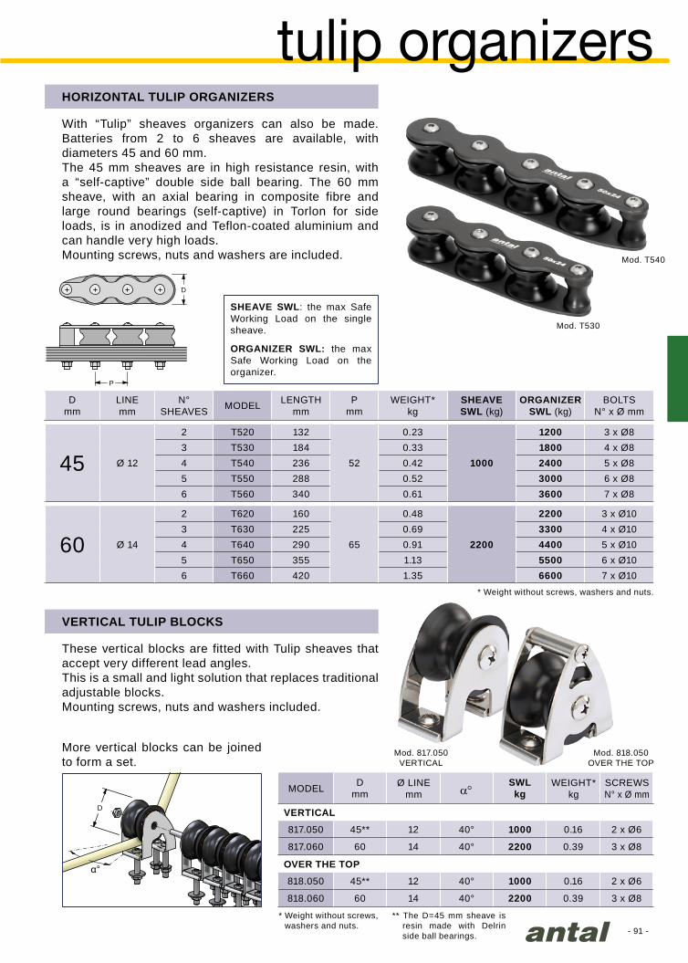
- 91 -
D
α°
Mod. T530
Mod. T540
P
D
Mod. 817.050VERTICAL
Mod. 818.050OVER THE TOP
Dmm a°
SWLkg
817.050 45** 12 40° 1000 0.16 2 x Ø6
817.060 60 14 40° 2200 0.39 3 x Ø8
818.050 45** 12 40° 1000 0.16 2 x Ø6
818.060 60 14 40° 2200 0.39 3 x Ø8
Dmm
Pmm
45 Ø 12
2 T520 132
52
0.23
1000
1200 3 x Ø8
3 T530 184 0.33 1800 4 x Ø8
4 T540 236 0.42 2400 5 x Ø8
5 T550 288 0.52 3000 6 x Ø8
6 T560 340 0.61 3600 7 x Ø8
60 Ø 14
2 T620 160
65
0.48
2200
2200 3 x Ø10
3 T630 225 0.69 3300 4 x Ø10
4 T640 290 0.91 4400 5 x Ø10
5 T650 355 1.13 5500 6 x Ø10
6 T660 420 1.35 6600 7 x Ø10
tulip organizersHORIZONTAL TULIP ORGANIZERS
With “Tulip” sheaves organizers can also be made. Batteries from 2 to 6 sheaves are available, with diameters 45 and 60 mm.The 45 mm sheaves are in high resistance resin, with a “self-captive” double side ball bearing. The 60 mm sheave, with an axial bearing in composite fibre and large round bearings (self-captive) in Torlon for side loads, is in anodized and Teflon-coated aluminium and can handle very high loads.Mounting screws, nuts and washers are included.
VERTICAL TULIP BLOCKS
These vertical blocks are fitted with Tulip sheaves that accept very different lead angles.This is a small and light solution that replaces traditional adjustable blocks.Mounting screws, nuts and washers included.
More vertical blocks can be joined to form a set.
** The D=45 mm sheave is resin made with Delrin side ball bearings.
* Weight without screws, washers and nuts.
MODEL
OVER THE TOP
SCREWS N° x Ø mm
Ø LINEmm
WEIGHT* kg
VERTICAL
N°SHEAVES
LINEmm MODEL LENGTH
mmBOLTS
N° x Ø mmSHEAVESWL (kg)
ORGANIZERSWL (kg)
WEIGHT*kg
* Weight without screws, washers and nuts.
SHEAVE SWL: the max Safe Working Load on the single sheave.
ORGANIZER SWL: the max Safe Working Load on the organizer.

Dmm
Lmm
Bmm
Zmm
SWLkg
994.055 14 50 143 65 20 1500 0.22
994.065 16 60 178 79 20 3000 0.37
994.075 18 70 204 88 25 4500 0.70
994.085 20 80 238 112 35 5500 0.90
994.095 24 100 292 140 45 8000 1.30
994.125 28 120 357 170 60 10000 2.90
Dmm
Lmm
Bmm
SWLkg
991.073 14 70 112 3 x 36 1000 0.23
991.093 16 90 145 3 x 46 2000 0.45
991.124 18 120 190 4 x 46 3000 1.04
991.154 20 150 225 4 x 52 4000 2.05
991.184 24 180 265 5 x 52 8000 2.65
- 92 -
D
L
B
B
Z
D
L
Mod. 994.075
mainsail blocks
REEF BLOCKS
The blocks are connected to the leech of the mainsail with webbing, and reduce point loading on the mainsail when reefing. The small diameter sheaves are suitable to very high loads.The center hole can be used as a safety connection to the boom when reefed.The small version (D=50 mm) is for boats to 50 ft, larger (D=120 mm) for boats to 100 ft.
If a larger sheave is required and if higher weight and larger sizes are acceptable, then the clew blocks described above can be considered.
CLEW BLOCKS
Solution designed to solve the connection of a sheave to the furling mainsail clew efficiently.The block is contained within the size of the sail, thus allowing a larger surface of the mainsail to be used.The choice of materials guarantees the least weight as well as a very good mechanical resistance to the environment. Particular care has been taken over the ease of connection which is obtained by normal “webbing”. This ensures moreover a very good distribution of the load on the sail.
MATERIALS: Cheek plates are made of anodized aluminium. Also polished s. steel solutions are available on request.
MODEL
MODEL
Ø LINEmm
Ø LINEmm
WEIGHTkg
WEIGHTkg

Dmm
dmm
Amm
Bmm
Cmm
SWLkg
H020 8 - 10 28 8 16 15.5 53.5 1300 0.08
H030 10 - 12 34 10 18 20.5 65.0 2200 0.15
H040 12 - 14 42 12 21 24.5 80.0 3500 0.28
H050 14 - 16 49 14 21 34.0 89.0 5000 0.54
Dmm
Hmm.
SWLkg
H130 6 - 8 30 59 600 0.05
H140 8 - 10 40 74 1200 0.08
H150 10 - 12 55 91 2400 0.18
H160 12 - 16 70 116 3500 0.33
- 93 -
A
D
d
B
C
H
D
2:1
8:1
TWIN HALYARD BLOCKS
The “Twin-halyard block” is specially made for a 2 to 1 main halyard.The very small sheave is aluminium made with a Composite Fibre bushing.The body is completely made in “High-resistance” stainless steel Nitronic 50.4 sizes for breaking loads from 2600 to 10000 kg, for boats up to 70 ft.
Captive pin
Self-locking pin
HIGH LOAD BLOCKS
These small and light blocks are the best solution for very high loads when sliding is not important.
The very small sheave is fitted with a Composite Fibre bushing.The one piece frame is made for line connection.
The 3 blocks (D=30, 40 and 55 mm) give an 8 to 1 system.This system is specially designed for the backstay or the boom-vang.
Set of blocks:8:1 system
special blocks
MODEL
MODEL
WEIGHT kg
WEIGHT kg
Ø LINEmm
Ø LINEmm
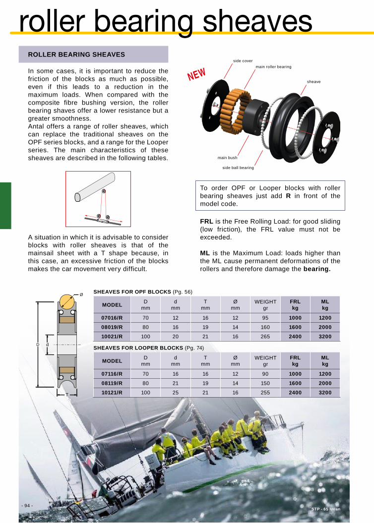
- 94 -STP - 65 Milan
Ø
D d
T
Dmm
dmm
Tmm
Ømm
FRLkg
MLkg
07116/R 70 16 16 12 90 1000 1200
08119/R 80 21 19 14 150 1600 2000
10121/R 100 25 21 16 255 2400 3200
Dmm
dmm
Tmm
Ømm
FRLkg
MLkg
07016/R 70 12 16 12 95 1000 1200
08019/R 80 16 19 14 160 1600 2000
10021/R 100 20 21 16 265 2400 3200
roller bearing sheavesROLLER BEARING SHEAVES
In some cases, it is important to reduce the friction of the blocks as much as possible, even if this leads to a reduction in the maximum loads. When compared with the composite fibre bushing version, the roller bearing shaves offer a lower resistance but a greater smoothness. Antal offers a range of roller sheaves, which can replace the traditional sheaves on the OPF series blocks, and a range for the Looper series. The main characteristics of these sheaves are described in the following tables.
A situation in which it is advisable to consider blocks with roller sheaves is that of the mainsail sheet with a T shape because, in this case, an excessive friction of the blocks makes the car movement very difficult.
WEIGHTgr
WEIGHTgr
MODEL
MODEL
To order OPF or Looper blocks with roller bearing sheaves just add R in front of the model code.
FRL is the Free Rolling Load: for good sliding (low friction), the FRL value must not be exceeded.
ML is the Maximum Load: loads higher than the ML cause permanent deformations of the rollers and therefore damage the bearing.
SHEAVES FOR LOOPER BLOCKS (Pg. 74)
SHEAVES FOR OPF BLOCKS (Pg. 56)
main roller bearing
main bush
sheave
side ball bearing
side cover

- 95 -
RM 1370 - ph. Arnaud De Buyzer
BLOCKS & T-LOCK
BLOCKS & DYNEEMA PAD-EYE
Blocks designed to be linked with Dyneema loops as Looper Blocks (see page 74) can be tied to a special Antal swivelling toggle and then fitted into the new Antal T-Lock base (see page 175).The result is a removable deck block that rotates in any direction of the load.
Blocks provided with a Dyneema snap-loop as Looper Blocks (page 74) or Snatch Looper (page 100) may be connected to the proper Dyneema pad-eye (page 174).
An easy and safe way to tie the block down is with multiple wraps of thin Dyneema line (e.g. size 3 mm) then splice the two ends and wrap everything with a thin wire (e.g. size 1 mm).
Consider that 8 wraps of well spliced 3 mm Dyneema without cover reach a breaking load higher than 6 tons.
The link in the picture is obtained with 2.60 m of 3 mm Dyneema line and a block size 80 mm (mod. LL1080).
blocks & soft links
Swivelling toggle
8 wraps
T-Lock base
2nd spliced end
1st spliced end
Looper +Dyneema pad-eye
Snatch Looper +Dyneema pad-eye
Looper block & toggle
Swivelling & removable deck block
Wrapping

- 96 -
Mod. 9031
Mod. 9030
Mod. 9001
Citroen - Feel Good - Vittorio e Nico Malingri
mini snatch blocks
MINI SNATCH BLOCK D=32 mm
It is a very light solution suitable for many riggings, completely made in U-V resistant high strength resin. It can be fastened both with a line or with a shackle.
It is a simple and original line loop with a snap that offers an easy fastening and avoids accidental opening.SWL = 250 kgFor more info, see pg. 182
SNAP LOOP
For line connection
open closed locked
For 5 mm shackle
mini Snatch blockSheave = Ø32 mmWeight = 39 grMax line = Ø8 mmSWL = 250 kg
blackMod. 9030
yellowMod. 9030/Y
full scale
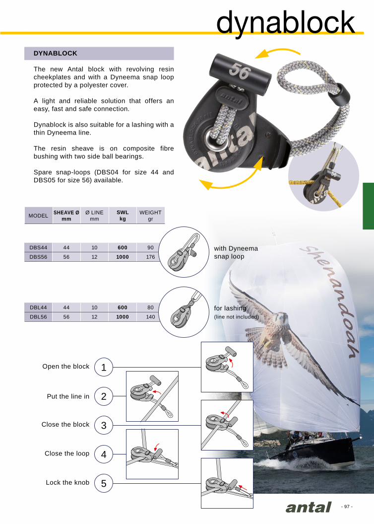
- 97 -
DBS44 44 10 600 90
DBS56 56 12 1000 176
DBL44 44 10 600 80
DBL56 56 12 1000 140
SWLkg
1
2
3
4
5
DYNABLOCK
The new Antal block with revolving resin cheekplates and with a Dyneema snap loop protected by a polyester cover.
A light and reliable solution that offers an easy, fast and safe connection.
Dynablock is also suitable for a lashing with a thin Dyneema line.
The resin sheave is on composite fibre bushing with two side ball bearings.
Spare snap-loops (DBS04 for size 44 and DBS05 for size 56) available.
dynablock
MODEL SHEAVE Ømm
Ø LINEmm
WEIGHTgr
Open the block
Put the line in
Close the block
Close the loop
Lock the knob
with Dyneemasnap loop
for lashing(line not included)

- 98 -
Dmm
SWLkg
9040 40 12 700 0.11
9060 60 14 1300 0.26
Class Mini 6.5 - Emergency
snatch blocksSNATCH BLOCKS D=40 and 60 mm
The cheekplate revolves around the sheave axle allowing the block to open; a safety ball stops the block from opening with an adjustable screw to set the ball on locked position.There is a becket for the “hanging line”.
MATERIAL: sheave with composite fibre main bearing and double side ball bearing. Hard anodized and teflon coated aluminium cheekplates with side rubber protections (yellow rubber on the revolving cheekplate).
Model /SH is supplied with a shackle.
Standard model can be attached with highly resistant spectra line.
Model /SN is supplied with a snap-shackle (HR).
SNAP LOOPSIt is a simple and original line loop with a snap that offers an easy fastening and avoids accidental opening.
Mod. SL4S -- Loop for 9040 block (pg. 182)Mod. SL5S -- Loop for 9060 block (pg. 182)
MODEL Ø LINEmm
WEIGHT kg
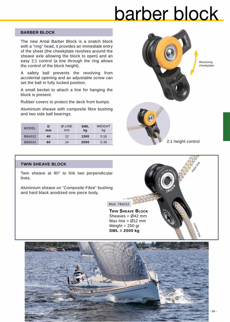
- 99 -
Dmm
SWLkg
BB4012 40 12 1300 0.16
BB6014 60 14 2000 0.36
Swan 54 - Nautor
Mod. TB4212
Twin sheave at 90° to link two perpendicular lines.
Aluminium sheave on “Composite Fibre” bushing and hard black anodized one piece body.
barber block
Revolvingcheekplate
mai
n lin
e
MODEL Ø LINEmm
WEIGHT kg
twin Sheave blockSheaves = Ø42 mmMax line = Ø12 mmWeight = 250 grSWL = 2000 kg
The new Antal Barber Block is a snatch block with a “ring” head, it provides an immediate entry of the sheet (the cheekplate revolves around the sheave axle allowing the block to open) and an easy 2:1 control (a line through the ring allows the control of the block height).
A safety ball prevents the revolving from accidental opening and an adjustable screw can set the ball in fully locked position.
A small becket to attach a line for hanging the block is present.
Rubber covers to protect the deck from bumps.
Aluminium sheave with composite fibre bushing and two side ball bearings.
BARBER BLOCK
TWIN SHEAVE BLOCK
2:1 height control
control line

- 100 -
LS046 46 14 2200 230
LS054 54 16 3500 368
LL046 46 14 2200 170
LL054 54 16 3500 277
SWLkg
2
3
4
1
Class 40 - S. Manuard
MODEL SHEAVE Ømm
Ø LINEmm
WEIGHTgr
SNATCH LOOPER
New Antal Snatch block with a small sheave suitable for high loads, particularly designed for 2:1 main halyards.
Hard black aluminium rotating cheek plates with a Dyneema Snap Loop protected by a polyester cover, aluminium sheave on fibre bearing.
Two sizes are available with and without a Snap Loop. The Dyneema Snap Loop, including the Dog Bone fitting, is also available separately.
Open the block and put the line in
Close the block
Lock the Loop
Insert the Loop
snatch looper
WITH DYNEEMA SNAP LOOP
WITHOUT DYNEEMA SNAP LOOP

- 101 -
Dmm
SWLkg
908.095 90 16 2500 0.41
908.125 120 20 4500 1.12
Mod. 908.095
Mod. 908.125
SWLkgD
mm
918.095 90 26 18 2500 0.82 7210
918.125 120 36 20 4500 2.05 7214
918.155 150 46 28 6500 4.20 7216
928.095 90 26 18 2500 1.14 7310
928.125 120 36 20 4500 2.70 7314
928.155 150 46 28 6500 5.30 7316
SNATCH BLOCKS D=90 and 120 mm
The cheekplate revolves around the sheave axle allowing the block to open; a safety pin, which engages automatically on closing, stops the block from opening accidentally.Materials: high-strength resin sheaves, hard anodized alloy cheekplates, high-strength stainless steel (17-4-PH) structural pins.
Model /SH is supplied with a shackle.
Model /SN is supplied with a HR Wichard snap shackle.
The block can be attached with webbing or better still with a fine highly resistant line made of material such as Kevlar or Spectra.
maxi snatch blocks
Block on“4 screws” pad-eye
SNATCH BLOCK ON PAD-EYED = 90, 120 AND 150 mm
Three snatch blocks 90, 120 and 150 mm diameter, on pad-eye and stand-up spring are available.The cheekplate revolves to open the block, a safety pin stops the block from opening.Above blocks are available also on screwed pad-eye.
MODELSHEAVE
Ø LINEmm
WEIGHT kg
EYEBOLTmod.
SCREWED PAD-EYES
“4 SCREWS” PAD-EYES
WIDTHmm
MODEL Ø LINEmm
WEIGHT kg

- 102 -
Green Challenge Team - “Kika” - Cantiere Bert - photo A.Carloni

- 103 -
“T” track sliders
spi-pole sliders............... 111
outhaul sliders ............... 114
halyard sliders ............... 113
genoa cars ..................... 104
classic s.steel ................ 116

- 104 -
96 38
29
91
45
123
50
96 38
Ø6
58
96 38
Mod. 602.211
Mod. 621.492
Mod. 691.141
Mod. 690.151
Mod. 690.152
Mod. 621.492
Mod. 621.452
Mod. 621.462
26
114
26x4 genoa carsHigh resistance silver anodized light alloy extrusion.Max length = 3 m Weight = 0.5 kg/mFasteners = 5 mm screws Hole spacing = 50 mm
“T” TRACK 26x4
SIMPLE END FITTINGPlastic made, fastened with one 5 mm screw.
A forward end fitting with one or two sheaves for theslider control is available.Hard black anodized aluminium base and resin sheave with side ball bearings.Fasteners = 2 x Ø6 mm screws
END FITTING WITH ONE SHEAVE
END FITTING WITH TWO SHEAVES
A 6 mm shackle is fitted on the hard blackanodized slider. AISI 316 s. steel stop pinand nylon sliding inserts.Weight = 0.21 kg SWL = 800 kgStop pin Ø = 8 mm
SIMPLE SLIDER
Hard black anodized with A316 stop pin and nylon sliding inserts.The sheave structure, made in AISI 316 s. steel, turns left and right (±50°).Resin sheave with 2 side ball bearings, wide section for two sheets.Weight = 0.35 kg SWL = 800 kg Stop pin Ø = 8 mm
GENOA CAR 26x4
A 50 mm block with spring is fitted on the aluminium slider. Also this model is supplied with the stop pin.Weight = 0.25 kg SWL = 500 kgStop pin Ø = 8 mm
GENOA CAR 26x4
For boats up to 33 ft
For boats up to 30 ft

- 105 -
96 38
34
Pichon
Mod. 621.492
Mod. 621.492
Mod. 00320
Mod. 00321
Mod. 690.151
Mod. 690.152
Mod. 621.472
Mod. 621.472/DBL44
Mod. 621.472/DBL44
CAR CONTROL
To regulate the car position, tackles with 2:1 and 3:1 purchase can be produced. A special end fitting with 1 or 2 sheaves can be mounted on the track with one block connected to the car.
CAR CONTROL 2:1
CAR CONTROL 3:1
For the car control, mini blocks have been used (see page 52). Mini Blocks have a 34 mm sheave and are suitable for a 6 mm line.
RACE GENOA CAR On an aluminium car a sheet block (Dynablock mod. DBL44, see p. 97) is tied with a Dyneema line.There is a 34 mm block with becket on the car that requires an end-fitting with a double block (Mod. 690.152) for a 3:1 car control.No stop pin for this solution.Weight = 0.26 kg SWL = 600 kg
slider without sheet block
slider with sheet block
For boats up to 30 ft
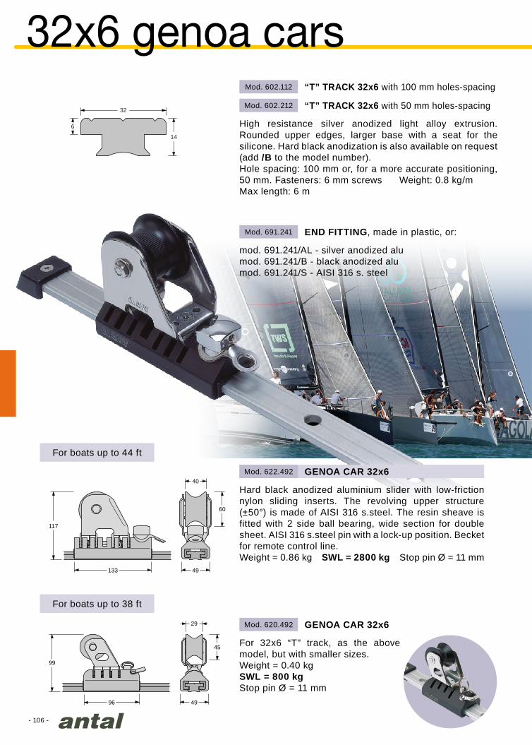
- 106 -
Mod. 602.112
Mod. 602.212
Mod. 691.241
Mod. 620.492
Mod. 622.492
32
14
6
133 49
40
117
60
96
29
99
45
49
32x6 genoa cars“T” TRACK 32x6 with 100 mm holes-spacing
High resistance silver anodized light alloy extrusion. Rounded upper edges, larger base with a seat for the silicone. Hard black anodization is also available on request (add /B to the model number).Hole spacing: 100 mm or, for a more accurate positioning, 50 mm. Fasteners: 6 mm screws Weight: 0.8 kg/mMax length: 6 m
“T” TRACK 32x6 with 50 mm holes-spacing
mod. 691.241/AL - silver anodized alumod. 691.241/B - black anodized alumod. 691.241/S - AISI 316 s. steel
END FITTING, made in plastic, or:
Hard black anodized aluminium slider with low-friction nylon sliding inserts. The revolving upper structure (±50°) is made of AISI 316 s.steel. The resin sheave is fitted with 2 side ball bearing, wide section for double sheet. AISI 316 s.steel pin with a lock-up position. Becket for remote control line.Weight = 0.86 kg SWL = 2800 kg Stop pin Ø = 11 mm
GENOA CAR 32x6
For 32x6 “T” track, as the above model, but with smaller sizes.Weight = 0.40 kgSWL = 800 kgStop pin Ø = 11 mm
GENOA CAR 32x6
For boats up to 44 ft
For boats up to 38 ft

- 107 -
Mod. 622.462
Mod. 622.492
Mod. 622.492
Mod. 909.502
Mod. 909.502
Mod. 949.502
Mod. 949.502
Mod. 690.251
Mod. 690.251
Mod. 690.252
Mod. 690.252
170
143
75
49
44
133 49
77
Ø10
Mod. 625.492
SIMPLE SLIDER
A 10 mm shackle is fitted on the aluminium slider. Also this model is supplied with the stop pin.Weight = 0.45 kg SWL = 2200 kgStop pin Ø = 11 mm
CAR CONTROL
To regulate the car position, tackles with 2:1 and 3:1 purchase can be produced. A special end fitting with 1 or 2 sheaves can be mounted on the track and one block connected to the car.
50 mm block connected to the car.
Black aluminium end fitting with two 50 mm sheave.
Black aluminium end fitting with one 50 mm sheave.
50 mm block with becket connected to the car.
CAR CONTROL 2:1
CAR CONTROL 3:1
The “plus” genoa car runs on HS fibre sliding inserts on 32x6 “T” track.It is fitted with a “screwed” stop pin done for 11 mm holes (smaller diameter are available on request).Weight = 1.34 kg SWL = 3800 kg
GENOA CAR 32x6 PLUSFor boats up to 52 ft

- 108 -
Mod. 602.113
Mod. 602.213
Mod. 691.341
Mod. 623.492
Mod. 624.492
Mod. 691.722/AL
40
18
8
75
160 60
142
44
100
172 60
166
44
40x8 genoa cars“T” TRACK 40x8 with 100 mm holes-spacing
High resistance silver anodized light alloy extrusion. Rounded upper edges, larger base with a seat for the silicone. Hard black anodization is also available on request (add /B to the mod. number).Hole spacing: 100 mm or, for a more accurate positioning, 50 mm.Fasteners: 8 mm screws Weight: 1.3 kg/mMax length: 6 m
“T” TRACK 40x8 with 50 mm holes-spacing
mod. 691.341/AL - silver anodized alumod. 691.341/B - black anodized alumod. 691.341/S - AISI 316 s. steel
END FITTING, made in plastic, or:
GENOA CAR 40x8
GENOA CAR 40x8 MAXI
Hard black anodized aluminium slider with low-friction nylon sliding inserts. The revolving upper structure (±50°) is made of AISI 316 s.steel. The aluminium sheave is fitted with one main Composite Fibre bearing and 2 side ball bearing, wide section for double sheet. AISI 316 s.steel pin with a lock-up position. Becket for remote control line.Weight = 1.50 kg SWL = 3800 kg Stop pin Ø = 14 mm
DOUBLE STOP PIN
For the double stop pin with alu slider the 50 mm hole spacing track (mod. 602.213) is necessary.Stop pin Ø = 14 mm
The maxi slider, for boats up to 60 ft, runs on HS fibre sliding inserts on 40x8 “T” track (mod. 602.213).Weight = 1.94 kg SWL = 4800 kg
For boats up to 60 ft
For boats up to 52 ft

- 109 -
Mod. 623.462
Mod. 909.502
Mod. 949.502
Mod. 690.351
Mod. 690.352
Mod. 623.492
Mod. 623.492
Mod. 909.502
Mod. 949.502
Mod. 690.351
Mod. 690.352
S/Y - Isabel - 75’
Ø12
97
160 60
SIMPLE SLIDER
A 12 mm shackle is fitted on the aluminium slider. Also this model is supplied with the stop pin.Weight = 0.79 kg SWL = 3300 kgStop pin Ø = 14 mm
CAR CONTROL
To regulate the car position, tackles with 2:1 and 3:1 purchase can be produced. A special end fitting with 1 or 2 sheaves can be mounted on the track and one block connected to the car.
CAR CONTROL 2:1
CAR CONTROL 3:1
50 mm block connected to the car.
Black aluminium end fitting with two 50 mm sheave.
Black aluminium end fitting with one 50 mm sheave.
50 mm block with becket connected to the car.

- 110 -
L
D
Dmm
Lmm
SWLkg
623.120/AL 120 330 5000 3.10
623.150/AL 150 330 6500 4.25
623.180/AL 180 375 9000 6.20
Mod. 623.180/S
Mod. 691.722/AL
Mod. 691.722/S
Mod. 623.180/AL
Mod. 623.150/AL
Mod. 623.120/AL
Sunreef 60 - photo Sunreef Yachts40
18
8
double 40x8 genoa carsDOUBLE 40x8 GENOA CARS SHEAVES 120, 150, 180 mm
The double 40x8 genoa cars are made for maxi yachts (larger than 60 ft), they run on 40x8 T-track (see page 108).Two hard black anodized aluminium sliders (add /AL after the model number) or two polished s.steel sliders (add /S after the model number) running on nylon guides are connected with a revolving (±50°) link structure.The sheave, with a wide sections for a double sheet, is fitted with a main Composite Fibre bearing and two side self-captive ball bearings.
STOP PIN
A special double stop pin (Ø14 mm) is available to lock the car in position on the track:
mod. 691.722/AL - hard black anodized alumod. 691.722/S - polished s.steel
With the double stop pin the 50 mm hole spacing track (mod. 602.213) is necessary.
MODEL WEIGHTkg
All the above double cars are available with stainless steel sliders.The double stop pin and the T-track are also available in s.steel.Substitute /S for /AL in the model number.
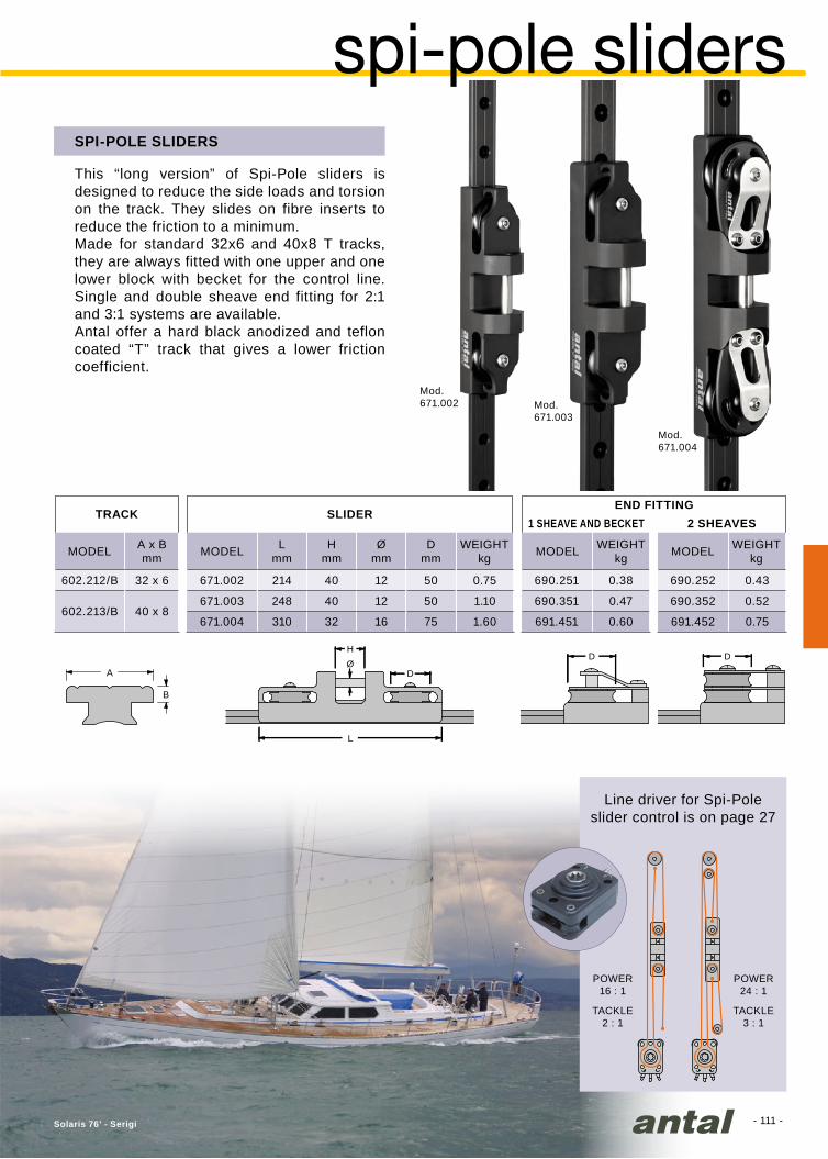
- 111 -
Mod.671.004
Mod.671.003
Mod.671.002
H
L
ØD
B
A
D D
Lmm
Hmm
Ømm
Dmm
671.002 214 40 12 50 0.75
671.003 248 40 12 50 1.10
671.004 310 32 16 75 1.60
A x Bmm
602.212/B 32 x 6
602.213/B 40 x 8
690.251 0.38
690.351 0.47
691.451 0.60
690.252 0.43
690.352 0.52
691.452 0.75
Solaris 76’ - Serigi
spi-pole slidersSPI-POLE SLIDERS
This “long version” of Spi-Pole sliders is designed to reduce the side loads and torsion on the track. They slides on fibre inserts to reduce the friction to a minimum.Made for standard 32x6 and 40x8 T tracks, they are always fitted with one upper and one lower block with becket for the control line. Single and double sheave end fitting for 2:1 and 3:1 systems are available.Antal offer a hard black anodized and teflon coated “T” track that gives a lower friction coefficient.
Line driver for Spi-Pole slider control is on page 27
POWER16 : 1
TACKLE2 : 1
POWER24 : 1
TACKLE3 : 1
SLIDER
MODEL MODEL MODEL MODELWEIGHTkg
WEIGHTkg
WEIGHTkg
TRACK1 SHEAVE AND BECKET 2 SHEAVES
END FITTING

- 112 -
26 X 4 50 602.211 602.211/B - - -
32 x 650 602.212 602.212/B 602.212/S
100 602.112 602.112/B 602.112/S
40 x 850 602.213 602.213/B 602.213/S
100 602.113 602.113/B 602.113/S
32 x 6 50 602.312/SI 602.312 - - -
40 x 8 50 602.313/SI 602.313 - - -
Class 40 Nivea
40
18
8
32
14
6
26
114
‘T’ tracks‘T’ TRACKS
Antal produces three sizes of ‘T’ tracks: 26x4, 32x6 and 40x8.
‘T’ tracks are available in the three versions silver aluminium, hard black anodized aluminium and s.steel, all with 50 and 100 mm hole spacing.
Moreover, 32x6 and 40x8 sizes are also made with holes for automatic locking of the slider, in both the silver and hard black anodized versions.
On request, track will be machined with “rounded ends” and then anodized.
SIZE SILVERHOLE SPACINGmm BLACK S.STEEL
hard black anodizing
automatic track
silver anodizing
s.steel withrounded head
real size
STANDARD TRACK
AUTOMATIC TRACK

- 113 -
A
B L
1
2
3 4
SWLkg
Lmm
Amm
Bmm
622.422 2800 602.412 32X6 990 622.402 50 135 691.241/B
623.422 3800 602.413 40X8 1130 623.402 60 160 691.341/B
624.422 5800 602.413 40X8 1130 624.402 60 210* 691.341/B
THE COMPLETE SYSTEM INCLUDES:
- Hard black aluminium ‘T’ track automatic version, with fixed length and with numbered positions of the slider, positioning holes spacing = 50 mm, fixing screws spacing = 100 mm.
- The halyard slider with the 2-positions stop-pin: locked and automatic insertion.
- 2 simple aluminium end fittings for ‘T’ track.
Also automatic tracks of any length, up to 6 m, are available. In this case, the positioning holes are not numbered (32x6 mod. 602.312, 40x8 mod. 602.313).
TRACK
SIZEmm
SLIDER END FITTINGCOMPLETE SYSTEM
MODEL MODEL MODEL MODEL
1. hook the halyard to the slider2. connect the winch3. put the halyard under tension and lock it
in place4. free the slider from the winch
ADJUSTING AND BLOCKING THE HALYARD
The special shape of the holes allows the car moving with the stop pin on and the automatic car lock in the new position.
AUTOMATIC TRACK
free
lock
ed
halyard systemThe “halyard slider” has been specifically planned for wire halyards and for those halyards which are subject to such high strain as to preclude use of a stopper. This solution permits easy adjustment and secure locking of halyards.
HALYARD SLIDER
numbered slider positions
* Car with double Stop-pin
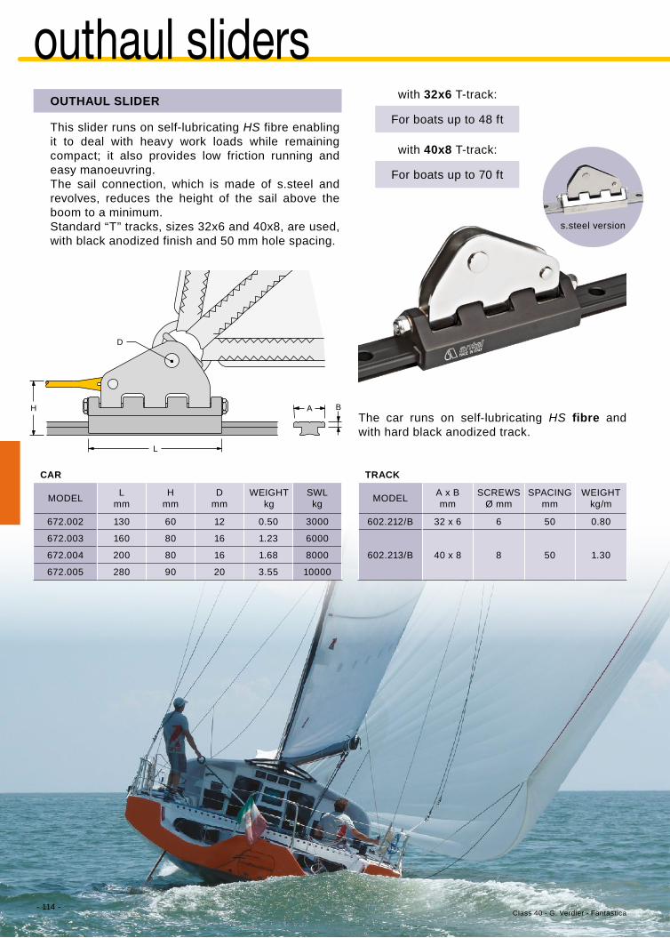
- 114 -
Lmm
Hmm
Dmm
SWLkg
672.002 130 60 12 0.50 3000
672.003 160 80 16 1.23 6000
672.004 200 80 16 1.68 8000
672.005 280 90 20 3.55 10000
A x Bmm
602.212/B 32 x 6 6 50 0.80
602.213/B 40 x 8 8 50 1.30
L
D
H A B
Class 40 - G. Verdier - Fantastica
outhaul slidersOUTHAUL SLIDER
This slider runs on self-lubricating HS fibre enabling it to deal with heavy work loads while remaining compact; it also provides low friction running and easy manoeuvring.The sail connection, which is made of s.steel and revolves, reduces the height of the sail above the boom to a minimum.Standard “T” tracks, sizes 32x6 and 40x8, are used, with black anodized finish and 50 mm hole spacing.
The car runs on self-lubricating HS fibre and with hard black anodized track.
with 32x6 T-track:
with 40x8 T-track:
MODEL
CAR TRACK
MODEL WEIGHTkg/m
SPACINGmm
SCREWSØ mm
WEIGHTkg
For boats up to 48 ft
For boats up to 70 ft
s.steel version

- 115 -
Mod. 4110/SH
Mod. 991.073
Mod. 991.093
Mod. 4190/H Mod. 4271
Mod. 4271
Lmm
SWLkg
4190/H 190 60 1900 1.10
4260/H 260 90 2800 1.65
Lmm
SWLKg
4110/SH 110 1000 0.50
4150/SH 150 1400 1.10
4190/SH 190 1900 1.65
991.093 90
991.124 120
991.073 75
991.093 90
991.124 120
Mod. 4260/H
Mod. 991.124
Mod. 991.093
Mod. 4150/SH
Mod. 4190/SH
Mod. 991.124
31
21
Mod. 4510
Mod. 4560
outhaul cars - furling main
OUTHAUL CAR - DIRECT CONNECTION
This simple solution reduces the load on the car but increases the tension of the line. Three sizes with cars 110, 150 and 190 mm long, on Antal 4Race 21x31 tracks. In this case too a special clew block completes the system.
CAR
CAR
CLEW BLOCK
CLEW BLOCK
SHEAVE Ø mm
SHEAVE Ø mm
MODEL
MODEL
SHEAVE Ø mmMODEL
MODEL
WEIGHTkg
WEIGHTkg
For boats up to 48 ft
For boats up to 40 ft
For boats up to 56 ft
Two track models are available for the cars described on this page.For both models 4510 & 4560:- fixing with Ø8 mm screws- 100 mm hole spacing- 0,77 kg/m weight- end-fitting Mod. 4271
TRACK
boom
boom
screw
screw
slug
directmounting track
track for slugs
For further information on cars and tracks see p. 120.For further information on clew blocks see p 92.
OUTHAUL CAR WITH SHEAVE
A ball bearing car is necessary for the outhaul of a furling main sail. Two sizes: 190 mm car with a 60 mm sheave and 260 mm car with a 90 mm sheave, both on Antal 4Race 21x31 tracks. A special clew-block completes the system.
For boats up to 48 ftFor boats up to 56 ft
DIRECT MOUNTING
SLUG MOUNTING
The track is directly screwed to threaded holes on the boom.
The track is screwed to the slugs.Slugs are custom made to fit the groove of the boom.

- 116 -Invader
32
14
6
40
18
8
Mod. 691.242/S
Mod. 691.243/S
Mod. 691.244/S
Mod. 691.241/S
Mod. 691.241/S
Mod. 691.241/S
Mod. 691.342/S
Mod. 691.343/S
Mod. 691.344/S
Mod. 691.341/S
Mod. 691.341/S
Mod. 691.341/S
Mod. 602.212/S
Mod. 602.212/SMod. 909.552/S
Mod. 949.552/SMod. 602.212/S
Mod. 602.213/S
Mod. 602.213/SMod. 909.552/S
Mod. 949.552/SMod. 602.213/S
Mod. 622.492/S
Mod. 622.492/S
Mod. 622.492/S
Mod. 623.492/S
Mod. 623.492/S
Mod. 623.492/S
CAR CONTROL 1:1
CAR CONTROL 2:1
CAR CONTROL 3:1
Classic s.steel for genoa
Antal offers a complete series of cars for genoa and mainsail with tracks and accessories completely made in 316 polished s.steel.Particularly designed for classic boats.
Two sizes: with 32x6 and 40x8 s.steel T-tracks.50 mm sheaves for all cars control.
Models on are for T-track size 32x6
Models on are for T-track size 40x8
32x6 genoa car - L = 132 mm - Sheave Ø = 60 mm - SWL = 2800 kg
40x8 genoa car - L = 160 mm - Sheave Ø = 75 mm - SWL = 3800 kg
32x6
T-track
40x8
T-track

- 117 -
Mod. 691.241/S
Mod. 691.243/S
Mod. 691.244/S
Mod. 691.244/S
Mod. 602.212/S
Mod. 602.212/S
Mod. 602.212/S
Mod. 602.212/S
Mod. 622.511/S0701
Mod. 622.512/S0701
Mod. 622.513/S0701
Mod. 622.523/S0701
Mod. 691.711/S
Mod. 691.240/S
Mod. 691.240/S
Mod. 691.240/S
32
14
6
40
18
8
Mod. 602.213/S
Mod. 602.213/S
Mod. 602.213/S
Mod. 602.213/S
Mod. 623.511/S0901
Mod. 623.512/S0901
Mod. 623.513/S0901
Mod. 623.523/S0901
Mod. 691.341/S
Mod. 691.343/S
Mod. 691.344/S
Mod. 691.344/S
Mod. 691.721/S
Mod. 622.512/S
Classic s.steel for main sail
CAR CONTROL 1:1
CAR CONTROL 2:1
CAR CONTROL 3:1
CAR CONTROL 3:1double block version
40x8 car with one block size 90 mm - L = 160 mm - SWL = 2500 kg40x8 car with two blocks size 90 mm - L = 200 mm - SWL = 3500 kg
32x6 car with one block size 75 mm - L = 132 mm - SWL = 1500 kg32x6 car with two blocks size 75 mm - L = 180 mm - SWL = 2000 kg
50 mm sheaves for all cars control. For classic Blocks, see page 78.
32x6
T-track
40x8
T-track
All the cars on this page are also available without the sheet block and with a simple eyebolt.To order this version, just end the model code after “/S”.For example, Mod. 622.512/S
75 mm block included
75 mm block included
75 mm block included
2 x 75 mm block included
90 mm block included
90 mm block included
90 mm block included
2 x 90 mm block included
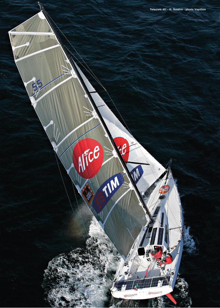
- 118 -
Telecom 40’ - G. Soldini - photo Vapillon
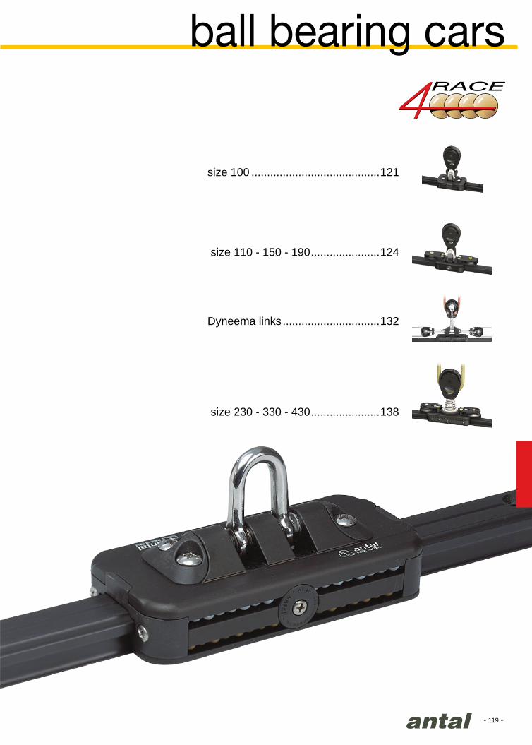
- 119 -
ball bearing cars
size 100 .........................................121
Dyneema links ...............................132
size 230 - 330 - 430 ......................138
size 110 - 150 - 190 ......................124

- 120 -
V
H
M
67
31.5
47
31.5
31
21
27
20.5100 mm 33 ft 121
110 mm 36 ft
124150 mm 42 ft
190 mm 48 ft
230 mm 60 ft
138330 mm 70 ft
430 mm 80 ft
330 mm 70 ft142
430 mm 80 ftOpen 40’ - Vaquita
ball bearing carsSYSTEM
• Higher efficiency and smoother running.• Better load resistance to vertical (V),
horizontal (H) and torsional (M) loads.• Higher safety margin as the car will remain
on the track even after ball bearing failure (overload).
• Travellers are fitted with 2 Torlon ball circuits (lower) and 2 Delrin ball circuits (upper).
• Single double and triple control sheaves, with or without becket, can be fitted on the car.
• One-piece extruded body.• The traveller, the track and all components
are extruded in high strength alloy and hard black anodized. (Steel parts: AISI 316)
• Side windows for easy maintenance and ball bearing cleaning and/or replacement.
Standard shackle or special “stand-up” joint.
CAR SIZE FOR BOATS UP TO PAGE

- 121 -
42
54
32
32
Ø35
46
50
Ø35
61
50
Ø35
61
50
9862
Mod. 4102/SH
Mod. 601.121
Mod. 601.221
Mod. 691.421
Mod. 4261
Mod. 4262
Mod. 4263
Mod. 4264
Mod. 4266
27
20.5
size 100
STANDARD TRACK
TRAVELLER SIZE 100
STOP PIN TRACK
STOP PIN
SIMPLE END FITTING
END FITTING WITH ONE SHEAVE
END FITTING WITH 2 SHEAVE
END FITTING CAM-CLEAT
END FITTING WITH ONE SHEAVEAND BECKET
Tubular hard black anodized aluminium extrusion.Fasteners = 6 mm screws / 100 mm hole spacingWeight = 0.69 kg/m Max length = 6 m
Weight = 0.23 kg SWL = 820 kgThis car is fitted with 54 Delrin + 54 Torlon balls
As the above model but with holes (50 mmspacing) for the stop pin.
Aluminium slider on nylon inserts and AISI 316s.steel pin. The stop pin needs to be fitted on the mod. 601.221 track.
High strength resin made with one Ø=35 mm sheave.Completed with a shock proof rubber.Weight = 0.08 kgScrews = 3 x Ø5 mm
High strength resin made with one Ø=35 mm sheave. Completed with a shock proof rubber.Weight = 0.10 kgScrews = 3 x Ø5 mm
High strength resin made with two Ø35 mm sheaves.Completed with a shock proof rubber.Weight = 0.10 kgScrews = 3 x Ø5 mm
Plastic made, mounted with a 6 mm screw.
This cam-cleat revolving in 3 different positions can be fitted on the end fitting with one or two sheaves.
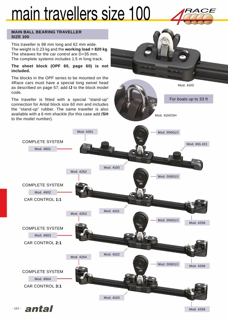
- 122 -
Mod. 4100
Mod. 4100/SH
Mod. 691.421
Mod. 4262
Mod. 4263
Mod. 4264
Mod. 4266
Mod. 4266
Mod. 4266
Mod. 4100
Mod. 4901
Mod. 4902
Mod. 4903
Mod. 4904
Mod. 4101
Mod. 4102
Mod. 4103
Mod. 4261 Mod. 00601/J
Mod. 00601/J
Mod. 00601/J
Mod. 00601/J
main travellers size 100MAIN BALL BEARING TRAVELLERSIZE 100
This traveller is 98 mm long and 62 mm wide.The weight is 0.23 kg and the working load = 820 kg.The sheaves for the car control are D=35 mm.The complete systems includes 1.5 m long track.
The sheet block (OPF 60, page 60) is not included.
The blocks in the OPF series to be mounted on the 4Race cars must have a special long swivel head as described on page 57; add /J to the block model code.
The traveller is fitted with a special “stand-up” connection for Antal block size 60 mm and includes the “stand-up” rubber. The same traveller is also available with a 6 mm shackle (for this case add /SH to the model number).
COMPLETE SYSTEM
COMPLETE SYSTEM
CAR CONTROL 1:1
COMPLETE SYSTEM
CAR CONTROL 2:1
COMPLETE SYSTEM
CAR CONTROL 3:1
For boats up to 33 ft

- 123 -
Mod. 4603
Mod. 4633
Pogo 36 - photo Adrien Conq
Mod. 4601
Mod. 4631
Mod. 4603
Mod. 4633
Mod. 4264
Mod. 4264/Z
Mod. 4261
Mod. 4261
genoa cars size 100 / 130BALL BEARING GENOA TRAVELLERSIZE 100
BALL BEARING GENOA TRAVELLERSIZE 130
This traveller is 98 mm long and 62 mm wide.The weight is 0.40 kg and the working load = 820 kg.Can be fitted with a front sheave with becket for a 3:1 control.Main sheave (diameter 45 mm) with 2 side ball bearings and a wide section suitable for 2 sheet.The sheaves for the car control are D=35 mm.
This traveller is 130 mm long and 62 mm wide.The weight is 0.50 kg and the working load = 1100 kg.Can be fitted with a front sheave with becket for a 3:1 control.Main sheave (diameter 48 mm) with 2 side ball bearings and a wide section suitable for 2 sheet.The sheaves for the car control are D=35 mm.
For boats up to 33 ft
For boats up to 38 ft

- 124 -
L
F
B
Lmm
Bmm
SWLkg
4110/SH 110
70
1000 0.50 62 Delrin + 62 Torlon
4150/SH 150 1400 0.70 86 Delrin + 86 Torlon
4190/SH 190 1900 0.90 112 Delrin + 112 Torlon
31
21
Mod. 4541
30 32 34 36 38 40 42 44 46 48
Mod. 4551
Mod. 4510
Mod. 4520
Mod. 4530
Mod. 4540
Mod. 4550 Mod. 4541
Mod. 4110 (110 mm)
Mod. 4150 (150 mm)
Mod. 4190 (190 mm)
sizes 110/150/190
TRAVELLER SIZE AND LOAD TABLEThree models: 110, 150 and 190 mm long, for boats up to 48 ft.These cars are fitted with standard shackle (/SH), but also special “stand-up” joint for 70, 80 and 100 mm blocks is available.Longer cars are available: L=230 mm (SWL= 2400 kg) and L=260 mm (SWL= 2800 kg) described in the following page 129.
TRAVELLER SELECTION GUIDE FOR:MAINSHEET (END BOOM) & GENOA SHEET
TRACKLow profile track suitable for both mainsheet and genoa systems.Standard track 31x21:
• fastening screws from the top• 8 mm screws• 100 mm hole spacing• weight 0.77 kg/m
Standard track with stop pin holes:• fastening from the top• 8 mm screws• 100 mm hole spacing• stop pin holes 50 mm spacing• weight 0.75 kg/m
Race track 31x21: with lightening holes• fastening screws from the bottom• 8 mm screws, 100 mm hole spacing• weight 0.64 kg/m
Adjustable fastener track 31x21:• bolts can be fixed in any position, for pre-
existing holes• 8 mm screws on sliding slugs• weight 0.72 kg/m
Adjustable fastener track 48x60:• bolts can be fixed in any position, for pre-
existing holes• 8 mm screws on sliding slugs• weight 3.2 kg/m• unsupported span max = 1.5 m
MODEL WEIGHTkg
TRAVELLER SIZE AND LOAD TABLE
Special end fitting for 48x60 track
LOA(ft)
N° of Balls
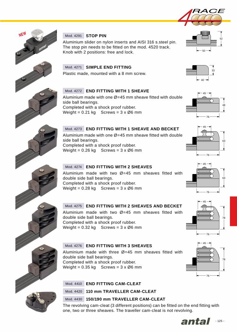
- 125 -
33
40
45
76
78
45
76
78
45
76
63
45
76
63
45
76
48
33
40
50
52
45
76
48
45
76
63
45
76
63
45
76
78
45
76
78
Mod. 4291
Mod. 4271
Mod. 4272
Mod. 4273
Mod. 4274
Mod. 4275
Mod. 4276
Mod. 4410
Mod. 4420
Mod. 4430
STOP PIN
SIMPLE END FITTING
END FITTING WITH 1 SHEAVE
END FITTING WITH 2 SHEAVES
END FITTING WITH 3 SHEAVES
150/190 mm TRAVELLER CAM-CLEAT
110 mm TRAVELLER CAM-CLEAT
END FITTING CAM-CLEAT
END FITTING WITH 1 SHEAVE AND BECKET
END FITTING WITH 2 SHEAVES AND BECKET
Aluminium slider on nylon inserts and AISI 316 s.steel pin.The stop pin needs to be fitted on the mod. 4520 track.Knob with 2 positions: free and lock.
Aluminium made with one Ø=45 mm sheave fitted with double side ball bearings.Completed with a shock proof rubber.Weight = 0.21 kg Screws = 3 x Ø6 mm
Aluminium made with one Ø=45 mm sheave fitted with double side ball bearings.Completed with a shock proof rubber.Weight = 0.26 kg Screws = 3 x Ø6 mm
Aluminium made with two Ø=45 mm sheaves fitted with double side ball bearings.Completed with a shock proof rubber.Weight = 0.32 kg Screws = 3 x Ø6 mm
Aluminium made with two Ø=45 mm sheaves fitted with double side ball bearings.Completed with a shock proof rubber.Weight = 0.28 kg Screws = 3 x Ø6 mm
Aluminium made with three Ø=45 mm sheaves fitted with double side ball bearings.Completed with a shock proof rubber.Weight = 0.35 kg Screws = 3 x Ø6 mm
Plastic made, mounted with a 8 mm screw.
The revolving cam-cleat (3 different positions) can be fitted on the end fitting with one, two or three sheaves. The traveller cam-cleat is not revolving.
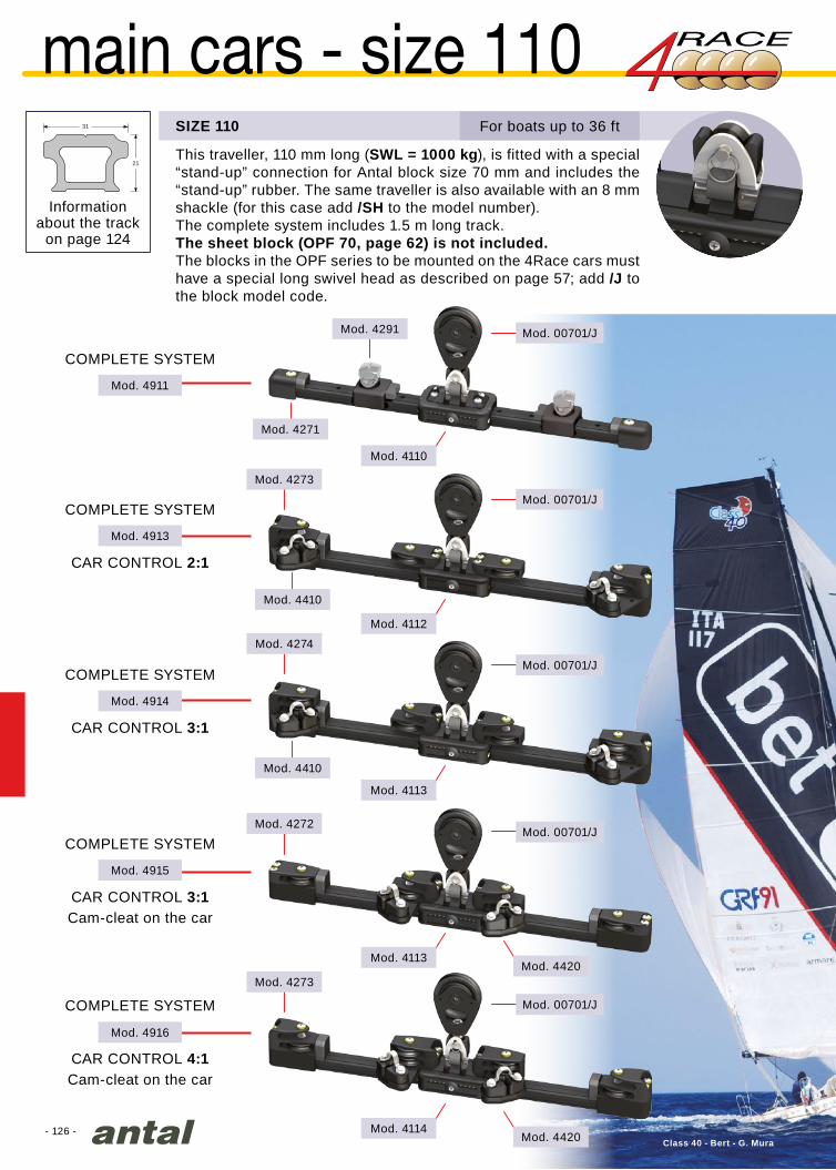
- 126 -
31
21
Mod. 4291
Mod. 4273
Mod. 4274
Mod. 4272
Mod. 4273
Mod. 4110
Mod. 00701/J
Mod. 00701/J
Mod. 00701/J
Mod. 00701/J
Mod. 00701/J
Mod. 4911
Mod. 4913
Mod. 4914
Mod. 4915
Mod. 4916
Mod. 4112
Mod. 4113
Mod. 4113
Mod. 4114
Mod. 4271
Mod. 4410
Mod. 4410
Mod. 4420
Mod. 4420 Class 40 - Bert - G. Mura
main cars - size 110
COMPLETE SYSTEM
COMPLETE SYSTEM
CAR CONTROL 2:1
COMPLETE SYSTEM
CAR CONTROL 3:1
COMPLETE SYSTEM
CAR CONTROL 3:1
COMPLETE SYSTEM
CAR CONTROL 4:1
Cam-cleat on the car
Cam-cleat on the car
SIZE 110
This traveller, 110 mm long (SWL = 1000 kg), is fitted with a special “stand-up” connection for Antal block size 70 mm and includes the “stand-up” rubber. The same traveller is also available with an 8 mm shackle (for this case add /SH to the model number).The complete system includes 1.5 m long track. The sheet block (OPF 70, page 62) is not included. The blocks in the OPF series to be mounted on the 4Race cars must have a special long swivel head as described on page 57; add /J to the block model code.
For boats up to 36 ft
Information about the track
on page 124
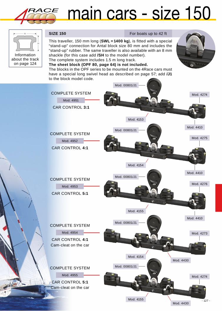
- 127 -
Mod. 4952
Mod. 4951
Mod. 4953
Mod. 4955
Mod. 4954
Mod. 4275
Mod. 4274
Mod. 4276
Mod. 4273
Mod. 4274
Mod. 00801/J1
Mod. 00801/J1
Mod. 00801/J1
Mod. 00801/J1
Mod. 00801/J1
Mod. 4153
Mod. 4154
Mod. 4155
Mod. 4154
Mod. 4155
Mod. 4410
Mod. 4410
Mod. 4410
Mod. 4430
Mod. 4430Class 40 - Bert - G. Mura
31
21
Information about the track
on page 124
main cars - size 150
COMPLETE SYSTEM
CAR CONTROL 4:1
COMPLETE SYSTEM
CAR CONTROL 3:1
COMPLETE SYSTEM
CAR CONTROL 5:1
COMPLETE SYSTEM
CAR CONTROL 5:1
COMPLETE SYSTEM
CAR CONTROL 4:1
Cam-cleat on the car
Cam-cleat on the car
SIZE 150 For boats up to 42 ft
This traveller, 150 mm long (SWL = 1400 kg), is fitted with a special “stand-up” connection for Antal block size 80 mm and includes the “stand-up” rubber. The same traveller is also available with an 8 mm shackle (for this case add /SH to the model number).The complete system includes 1.5 m long track.The sheet block (OPF 80, page 64) is not included. The blocks in the OPF series to be mounted on the 4Race cars must have a special long swivel head as described on page 57; add /J1 to the block model code.

- 128 -
Mod. 4992
Mod. 4991
Mod. 4994
Mod. 4995
Mod. 4993
Mod. 4276
Mod. 4275
Mod. 4275
Mod. 4274
Mod. 4275
Mod. 4410
Mod. 4194
Mod. 4195
Mod. 4195
Mod. 4196
Mod. 4199
Mod. 4410
Mod. 4410
Mod. 4430
Mod. 4430
31
21
Mod. 00801/J2
Mod. 00801/J2
Mod. 00801/J2
Mod. 00801/J2
Mod. 00801/J2
COMPLETE SYSTEM
CAR CONTROL 5:1
COMPLETE SYSTEM
CAR CONTROL 4:1
This traveller, 190 mm long (SWL = 1900 kg), is fitted with a special “stand-up” connection for one or two Antal sheet blocks (size 80 mm) and includes the “stand-up” rubber. The same traveller is also available with a 10 mm shackle (for this case add /SH to the model number). The complete system includes 2 m long track.The sheet blocks (OPF 80, page 64) are not included.The blocks in the OPF series to be mounted on the 4Race cars must have a special long swivel head as described on page 57; add /J2 to the block model code.
SIZE 190
COMPLETE SYSTEM
CAR CONTROL 6:1
COMPLETE SYSTEM
CAR CONTROL 4:1
COMPLETE SYSTEM
CAR CONTROL 5:1
Cam-cleat on the car
Double block version
Cam-cleat on the car
For boats up to 48 ft
main cars - size 190
Information about the track
on page 124

- 129 -
Mod. 4921
Mod. 4922
Mod. 4925
Mod. 4123
Mod. 4124
Mod. 4127
Mod. 4275/Z
Mod. 4274/Z
Mod. 4410/Z
Mod. 4410/Z
Mod. 4274/Z
Mod. 4410/Z
Vm62C Vismara
31
21
Mod. 01001/J2
Mod. 00803/J2
Mod. 00801/J2
COMPLETE SYSTEM
CAR CONTROL 3:1
COMPLETE SYSTEM
CAR CONTROL 4:1
COMPLETE SYSTEM
CAR CONTROL 3:1
SIZE 260
Information about the track
on page 124
main cars - size 260This traveller, 260 mm long (SWL = 2800 kg), is fitted with a special connection for one (size 100 mm) or two (size 80 mm) Antal sheet blocks and with 55 mm control sheaves. The complete system includes 2,5 m long track.The sheet blocks (OPF 80 and 100, page 64-65) are not included.The blocks in the OPF series to be mounted on the 4Race cars must have a special long swivel head as described on page 57; add /J2 to the block model code.
For boats up to 52 ft
MAINSHEETSYSTEM 2:1
MAINSHEETSYSTEM 2:1
MAINSHEETSYSTEM 4:1
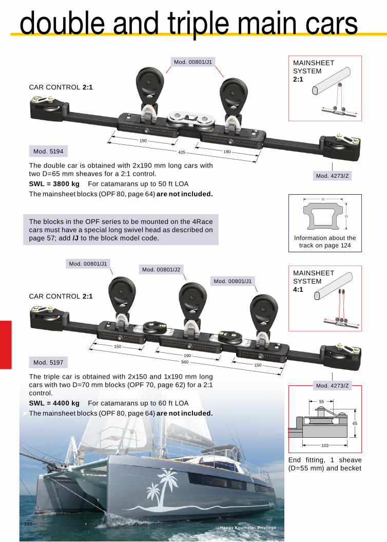
- 130 -
190
425 190
150
150
190560
55
103
65
Happy Koumata - Privilege
Mod. 4273/Z
Mod. 4273/Z
Mod. 5197
Mod. 5194
31
21
Mod. 00801/J2Mod. 00801/J1
Mod. 00801/J1
Mod. 00801/J1
CAR CONTROL 2:1
CAR CONTROL 2:1
End fitting, 1 sheave (D=55 mm) and becket
MAINSHEETSYSTEM2:1
MAINSHEETSYSTEM4:1
Information about the track on page 124
double and triple main cars
The blocks in the OPF series to be mounted on the 4Race cars must have a special long swivel head as described on page 57; add /J to the block model code.
The double car is obtained with 2x190 mm long cars with two D=65 mm sheaves for a 2:1 control.SWL = 3800 kg For catamarans up to 50 ft LOAThe mainsheet blocks (OPF 80, page 64) are not included.
The triple car is obtained with 2x150 and 1x190 mm long cars with two D=70 mm blocks (OPF 70, page 62) for a 2:1 control.SWL = 4400 kg For catamarans up to 60 ft LOAThe mainsheet blocks (OPF 80, page 64) are not included.

- 131 -
S/Y “In Love”
B
T
C
D
H
L
Lmm
Bmm
Cmm
Dmm
Hmm
Tmm
SWLkg
4100/F 27 x 20.5 100 62 43 6 36 24 820 0.20 108
4110/F
31 x 21
110
70
65 8
39 26
1000 0.44 124
4150/F 150 80 10 1400 0.64 172
4190/F 190 103 10 1900 0.79 224
Mod. 4100/F
Mod. 4110/F
Mod. 4150/F
Mod. 4190/F31
21
31
21
31
21
27
20.5
flat series
All the 4Race ball-bearing cars are also available in “flat” versions with 2 threaded holes for an easy connection with other systems, for example, in steering systems or for driving large sliding hatches, etc.These cars are fitted with 4 circuits of Torlon balls providing compression loads as high as the pulling loads and greater torsional resistance.
More information about the 27x20 track on page 121 and about the 31x21 track on page 124
4RACE BB CARS FLAT SERIES
MODEL TRACK SIZE mm
WEIGHTkg
TRAVELLER SIZE AND LOAD TABLE
BALLSn°

- 132 -
LB
Lmm
Bmm
SWLkg
4110/D 110
70
1000 0.45
4150/D 150 1400 0.65
4190/D 190 1900 0.85
4230/D 230 2400 1.05
Farnova 60
ball bearing cars for Dyneema linksCARS FOR DYNEEMA LINKS
Four ball bearing models, 110, 150, 190 and 230 mm long, for the same track 31x21 (see page 124) fitted with a special aluminium pivoting bracket suitable for Dyneema links, for both: 2 side control lines and one central connection for a sheet block or a sheet Ring.
TRANSVERSAL CARS FOR GENOA SHEET
The transversal car is fitted with a direct control for car moving outwards and inwards. A ring, through which the sheet runs, allows the height control of the genoa sheet. For tracks and track end fittings, see page 124.For Rings, see the Ring section on page 178.
For tracks and track end fittings, see page 124.
MODEL WEIGHTkg
Height control
Genoa sheet
OutwardsInwards

- 133 -Ice Yacht 61
CARS FOR MAINSHEET
A Looper block, size 80 or 100, for the mainsheet in the centre and two smaller side blocks, size 60, for the car control are linked by Dyneema Snap Loops to a size 190 or 230 ball bearing car.This solution, with SWL=1900/2400 kg is suitable for boats up to 48/50 ft.
For larger boats up to 60 ft and SWL up to 3800 kg, two cars can be linked together.Two Looper blocks, size 80, for the sheet and two Looper blocks, size 60, for car control complete this double 190 mm car.
Custom solution with two extra-long cars (2 x 230 mm) and SWL 4800 kg.Two Looper blocks, size 100, for the mainsheet and two Looper blocks, size 70, for the side control, complete this solution designed for a 65 ft boat.
For Looper blocks see page 74.For Dyneema Snap Loop, see page 183.For tracks and accesories, see page 124.
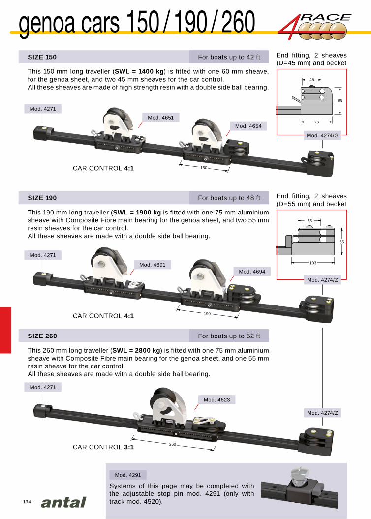
- 134 -
260
45
76
66
55
103
65
150
190
Mod. 4271
Mod. 4271
Mod. 4271
Mod. 4651
Mod. 4691
Mod. 4654
Mod. 4694
Mod. 4623
Mod. 4274/G
Mod. 4291
Mod. 4274/Z
Mod. 4274/Z
CAR CONTROL 4:1
CAR CONTROL 3:1
SIZE 150
This 150 mm long traveller (SWL = 1400 kg) is fitted with one 60 mm sheave, for the genoa sheet, and two 45 mm sheaves for the car control.All these sheaves are made of high strength resin with a double side ball bearing.
CAR CONTROL 4:1
End fitting, 2 sheaves (D=45 mm) and becket
Systems of this page may be completed with the adjustable stop pin mod. 4291 (only with track mod. 4520).
End fitting, 2 sheaves (D=55 mm) and becket
SIZE 190
SIZE 260
This 190 mm long traveller (SWL = 1900 kg is fitted with one 75 mm aluminium sheave with Composite Fibre main bearing for the genoa sheet, and two 55 mm resin sheaves for the car control.All these sheaves are made with a double side ball bearing.
This 260 mm long traveller (SWL = 2800 kg) is fitted with one 75 mm aluminium sheave with Composite Fibre main bearing for the genoa sheet, and one 55 mm resin sheave for the car control.All these sheaves are made with a double side ball bearing.
For boats up to 42 ft
For boats up to 48 ft
For boats up to 52 ft
genoa cars 150 / 190 / 260

- 135 -
Mod. TB4212
Mod. BB4012
Mod. BB6014
Mod. 4150/C
31
21
Club Swan 50 - Nautor
transverse Genoa car
This 150 mm long traveller (SWL = 1400 kg) is fitted with two high-load Ø20 mm sheaves and one integrated side ring for a 2:1 control to move the car inward. It moves outwards automatically.Weight = 0.80 kg
For boats up to 50 ftTransverse Genoa Car
42 mm sheave for 12 mm line
40 mm sheave for 12 mm line
or snatch-blocks:
sheet blocks on page 98-99
60 mm sheave for 14 mm line
Height control
Genoa sheet
Inwards
Information about the track on page 124
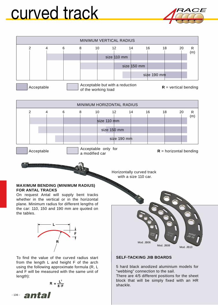
- 136 -
Mod. JB06Mod. JB08 Mod. JB10
2 204 6 8 10 12 14 16 18 R(m)
2 204 6 8 10 12 14 16 18 R(m)
curved track
MAXIMUM BENDING (MINIMUM RADIUS)FOR ANTAL TRACKSOn request Antal will supply bent tracks whether in the vertical or in the horizontal plane. Minimum radius for different lengths of the car: 110, 150 and 190 mm are quoted on the tables.
SELF-TACKING JIB BOARDS
5 hard black anodized aluminium models for “webbing” connection to the sail.There are 4/5 different positions for the sheet block that will be simply fixed with an HR shackle.
To find the value of the curved radius start from the length L and height F of the arch using the following approximate formula (R, L and F will be measured with the same unit of length):
Horizontally curved track with a size 110 car.
MINIMUM VERTICAL RADIUS
MINIMUM HORIZONTAL RADIUS
size 150 mm
size 150 mm
size 190 mm
size 190 mm
size 110 mm
size 110 mm
Acceptable
Acceptable
R = vertical bending
R = horizontal bending
Acceptable but with a reduction of the working load
Acceptable only for a modified car
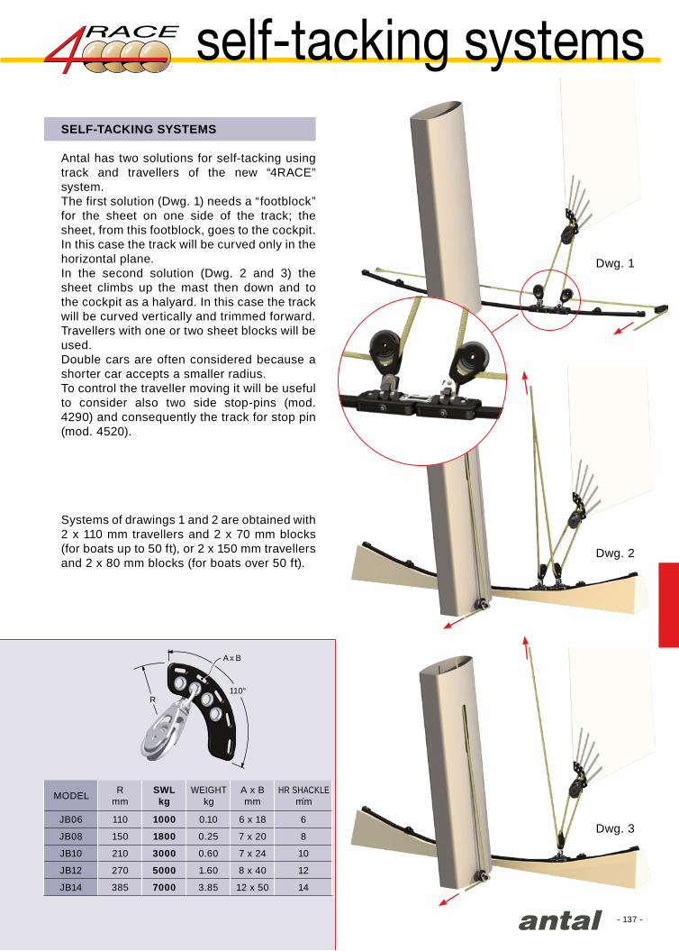
- 137 -
Rmm
SWLkg
A x Bmm .
JB06 110 1000 0.10 6 x 18 6
JB08 150 1800 0.25 7 x 20 8
JB10 210 3000 0.60 7 x 24 10
JB12 270 5000 1.60 8 x 40 12
JB14 385 7000 3.85 12 x 50 14
A x B
R110°
self-tacking systemsSELF-TACKING SYSTEMS
Antal has two solutions for self-tacking using track and travellers of the new “4RACE” system.The first solution (Dwg. 1) needs a “footblock” for the sheet on one side of the track; the sheet, from this footblock, goes to the cockpit. In this case the track will be curved only in the horizontal plane.In the second solution (Dwg. 2 and 3) the sheet climbs up the mast then down and to the cockpit as a halyard. In this case the track will be curved vertically and trimmed forward.Travellers with one or two sheet blocks will be used.Double cars are often considered because a shorter car accepts a smaller radius.To control the traveller moving it will be useful to consider also two side stop-pins (mod. 4290) and consequently the track for stop pin (mod. 4520).
Systems of drawings 1 and 2 are obtained with 2 x 110 mm travellers and 2 x 70 mm blocks (for boats up to 50 ft), or 2 x 150 mm travellers and 2 x 80 mm blocks (for boats over 50 ft).
MODEL WEIGHTkg
HR SHACKLEmm
Dwg. 1
Dwg. 2
Dwg. 3
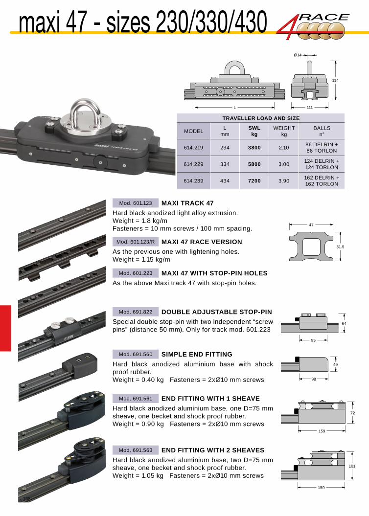
- 138 -
L 111
Ø14
114
Lmm
SWLkg
614.219 234 3800 2.10 86 DELRIN +86 TORLON
614.229 334 5800 3.00 124 DELRIN +124 TORLON
614.239 434 7200 3.90 162 DELRIN +162 TORLON
47
31.5
95
64
98
49
159
72
159
101
Mod. 601.123
Mod. 601.123/R
Mod. 691.561
Mod. 691.563
Mod. 691.560
Mod. 691.822
Mod. 601.223
maxi 47 - sizes 230/330/430
TRAVELLER LOAD AND SIZE
WEIGHTkg
BALLSn°MODEL
Hard black anodized light alloy extrusion.Weight = 1.8 kg/mFasteners = 10 mm screws / 100 mm spacing.
As the previous one with lightening holes.Weight = 1.15 kg/m
MAXI TRACK 47
MAXI 47 RACE VERSION
Hard black anodized aluminium base, one D=75 mm sheave, one becket and shock proof rubber.Weight = 0.90 kg Fasteners = 2xØ10 mm screws
END FITTING WITH 1 SHEAVE
Hard black anodized aluminium base, two D=75 mm sheave, one becket and shock proof rubber.Weight = 1.05 kg Fasteners = 2xØ10 mm screws
END FITTING WITH 2 SHEAVES
Hard black anodized aluminium base with shock proof rubber.Weight = 0.40 kg Fasteners = 2xØ10 mm screws
Special double stop-pin with two independent “screw pins” (distance 50 mm). Only for track mod. 601.223
As the above Maxi track 47 with stop-pin holes.
SIMPLE END FITTING
DOUBLE ADJUSTABLE STOP-PIN
MAXI 47 WITH STOP-PIN HOLES

- 139 -
Ø120
Ø120
Ø120
Mod. 691.561
Mod. 691.563
Mod. 691.563
Mod. 691.560
Mod. 614.212/1224
Mod. 614.213/1224
Mod. 614.214/1224
Mod. 614.210/1024
Rimar 45 RS
maxi 47 - size 230MAINSHEET SYSTEM, MAXI 47 TRACKSIZE 230 TRAVELLER
One 120 mm block, OPF series, is fitted with a padeye and spring on the car for the mainsheet; one or two 75 mm sheaves for the car control.Car control 2:1, 3:1 and 4:1 are shown below.SWL = 3800 kg
All the cars on this page are also available without the sheet block and with a simple pad-eye. To order this version, just end the model code before the “/” (for example, Mod. 614.212).
SELF-TACKING SOLUTIONOn the maxi 47 track there is a 230 mm with 2 blocks size 100 mm (OPF series).
CAR CONTROL 2:1
CAR CONTROL 3:1
CAR CONTROL 4:1
For boats up to 60 ft
120 mm block included
120 mm block included
120 mm block included
2 x 100 mm blocks included

- 140 -
Ø120
Ø120
Mod. 691.561
Mod. 691.563
Mod. 691.561
Mod. 691.563
47
31.5
Mod. 614.222/1424
Mod. 614.223/1424
Mod. 614.224/1224
Mod. 614.225/1224
maxi 47 - size 330
CAR CONTROL 2:1
CAR CONTROL 2:1
CAR CONTROL 3:1
CAR CONTROL 3:1
MAINSHEET SYSTEM, MAXI 47 TRACKSIZE 330 TRAVELLER
1 x 140 or 2 x 120 mm blocks (OPF series) are fitted with a padeye and spring on the car for the mainsheet; one or two 75 mm sheaves for the car control.Car control 2:1 and 3:1 are shown below.SWL = 5800 kg
For boats up to 70 ft Information about the track on page 138
ll the cars on this page are also available without the sheet block and with a simple pad-eye. To order this version, just end the model code before the “/” (for example mod. 614.222).
140 mm block included
140 mm block included
2 x 120 mm blocks included
2 x 120 mm blocks included
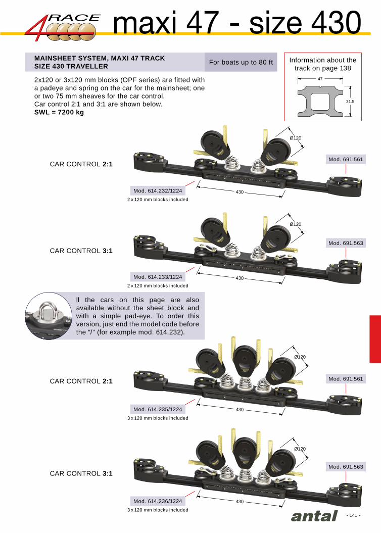
- 141 -
Ø120
Ø120
Ø120
Ø120
Mod. 691.563
Mod. 691.561
Mod. 691.563
Mod. 691.561
47
31.5
Mod. 614.233/1224
Mod. 614.232/1224
Mod. 614.235/1224
Mod. 614.236/1224
maxi 47 - size 430
CAR CONTROL 2:1
CAR CONTROL 2:1
CAR CONTROL 3:1
CAR CONTROL 3:1
Information about the track on page 138
MAINSHEET SYSTEM, MAXI 47 TRACKSIZE 430 TRAVELLER
2x120 or 3x120 mm blocks (OPF series) are fitted with a padeye and spring on the car for the mainsheet; one or two 75 mm sheaves for the car control.Car control 2:1 and 3:1 are shown below.SWL = 7200 kg
For boats up to 80 ft
ll the cars on this page are also available without the sheet block and with a simple pad-eye. To order this version, just end the model code before the “/” (for example mod. 614.232).
2 x 120 mm blocks included
2 x 120 mm blocks included
3 x 120 mm blocks included
3 x 120 mm blocks included

- 142 -
Mod. 601.124
Mod. 691.661
Mod. 691.663
Mod. 691.660
L 131
Ø14
114
67
31.5
113
49
176
106
176
112
Lmm
SWLkg
615.229 334 5800 4.30 124 DELRIN +124 TORLON
615.239 434 7200 5.50 162 DELRIN +162 TORLON
615.249 534 9000 6.80 206 DELRIN +206 TORLON
maxi 67 - sizes 330 / 430 / 530
Hard black anodized light alloy extrusion.Weight = 2.4 kg/mFasteners = 12 mm screws / 100 mm spacing.
MAXI TRACK 67
Hard black anodized aluminium base, one D=100 mm sheave (Opf series p.65), one becket and shock proof rubber.Weight = 1.30 kg Fasteners = 2xØ12 mm screws
END FITTING WITH 1 SHEAVE
Hard black anodized aluminium base, two D=100 mm sheave (Opf series p.65), one becket and shock proof rubber.Weight = 1.50 kg Fasteners = 2xØ12 mm screws
END FITTING WITH 2 SHEAVES
Hard black anodized aluminium base with shock proof rubber.Weight = 0.60 kg Fasteners = 2xØ12 mm screws
SIMPLE END FITTING
CUSTOM MODELTwo cars 330 mm long and two blocks 150 mm diameter.SWL = 2 x 5800 kg
TRAVELLER LOAD AND SIZE
WEIGHTkgMODEL BALLS
n°

- 143 -
Mod. 691.663
Mod. 691.663
Mod. 691.663
Mod. 691.661
67
31.5
Mod. 615.222/1424
Mod. 615.223/1424
Mod. 615.233/1424
Mod. 615.236/1224
CAR CONTROL 2:1
CAR CONTROL 3:1
MAINSHEET SYSTEM, MAXI 67 TRACKSIZE 330 - 430 TRAVELLER SWL = 5800 - 7200 kg
D=140 mm or D=120 mm blocks (OPF series) can be fitted with a padeye and spring on the car for the mainsheet; two D=100 mm sheaves for the car control. Car control 2:1 and 3:1 are shown below.
Information about the track on page 142
CAR CONTROL 3:1
CAR CONTROL 3:1
ll the cars on this page are also available without the sheet block and with a simple pad-eye. To order this version, just end the model code before the “/” (for example mod. 615.222).
140 mm block included
140 mm block included
2 x 140 mm blocks included
3 x 120 mm blocks included
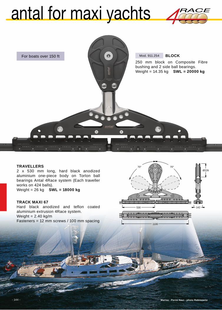
- 144 -
Ø22670°70°
530
1100
142
Mod. 911.254
Marisa - Perini Navi - photo Rabinowitz- 144 -
antal for maxi yachts
250 mm block on Composite Fibre bushing and 2 side ball bearings.Weight = 14.35 kg SWL = 20000 kg
BLOCKFor boats over 150 ft
TRAVELLERS2 x 530 mm long, hard black anodized aluminium one-piece body on Torlon ball bearings Antal 4Race system (Each traveller works on 424 balls).Weight = 26 kg SWL = 18000 kg
TRACK MAXI 67Hard black anodized and teflon coated aluminium extrusion 4Race system.Weight = 2.40 kg/m Fasteners = 12 mm screws / 100 mm spacing

- 145 -
110
226
68
Mod. 4523
Mod. 4271/B
Mod. 4118
Mod. 4291
Mod. 4283
Mod. 4118
Mod. 4271/B
Mod. 4291
Mod. 4523
Mod. 4119/SP
Mod. 4119/SP
The operator (using a suitable harness) is tied to a double traveller that slides horizontally on the rail and is free to reach the working area in perfect safety.
The double traveller is fitted with two shackles and a stop pin:
• stop pin open: it allows the traveller to slide along the whole track;
• stop pin closed: it locks the traveller when it intercepts the first hole in the rail.
Other travellers (without any stop pin) can be connected to the main traveller for further security and for carrying tools or any other material (bosun’s chair, etc.)
The track can be fixed both on a horizontal surface and on a vertical wall.
More information in the LRS user’s guide available on request.
The system consists of:
safety device for outboard cleaning and maintenance
Tubular track (31 x 21 mm) in high resistance hard black (silver on request) anodized extruded aluminium, Ø8 mm fixing screws every 100 mm, holes to stop the traveller every 50 mm, weight 0.75 kg/m, available in 3 m lengths.
Aluminium end-fitting with rubber protection.
Hard black anodized aluminium double traveller (2 x 110 mm). The traveller slides on four circuits of Torlon balls and its hold is guaranteed even in the event of the balls failing. Two AISI 316 steel shackles with 180° rotation.
Aluminium stop pin on nylon guides.
Track joint, aluminium made.
verticalwall
horizontalsurface
life rail system
The car with the stop-pin is also available individually.
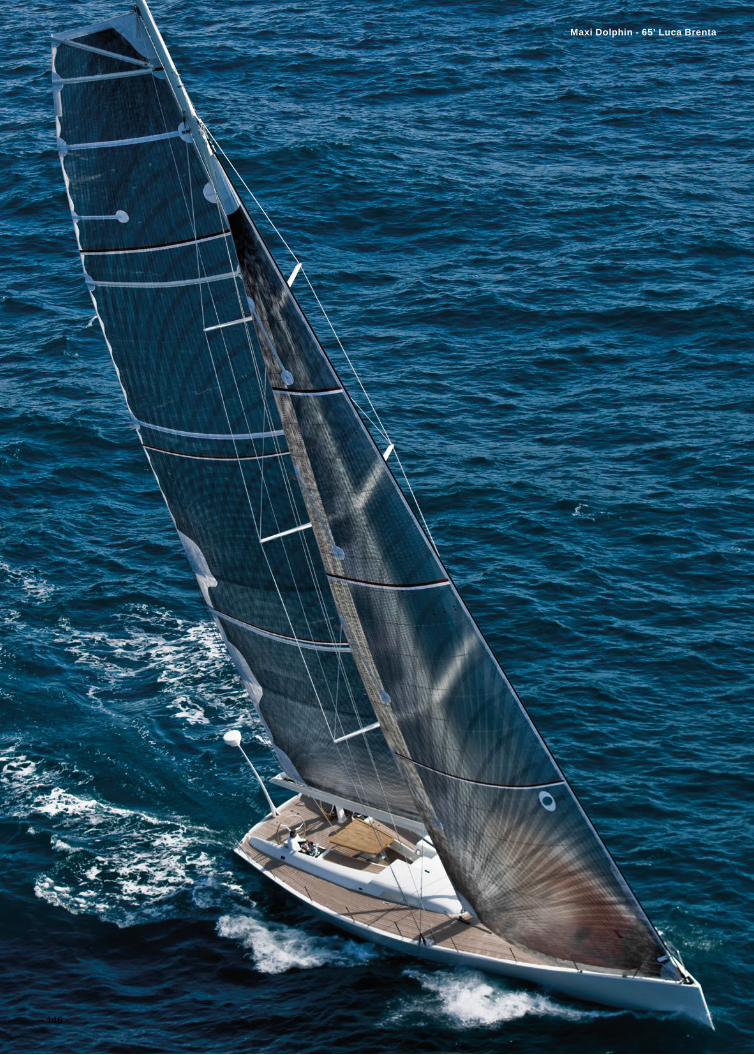
- 146 -
Maxi Dolphin - 65’ Luca Brenta

- 147 -
HS guide systems...........148
Fibreball systems............157
special products..............167
hook carriages ................170
batten receptacles ..........168
full batten systems
6 different tracks and 14 slider systems, a wide and complete range for full-batten mainsails, for boats from 30 to 100 ft and for multihulls.
HS GUIDE SYSTEMSA simple and efficient solution with minimum sizes for very high loads, designed for racing. The HS guide systems have been developed also for cruising and charter boats.
FIBREBALL SYSTEMSDesigned for large boats and for mainsails with a large roach, they offer the high strength of HS Fibre Guides (for tension load) and the low friction of the Torlon ball bearing (for compression).

- 148 -
22
11
24
15.6
30
13
HS 2240 40’ 149
50/R 50’ 150
60/R 60’ 151
HS 2450 50’ 152
60 60’ 153
70 70’ 154
HS 3090 80’ 155
130 100’ 156
full batten HS guide systemsHS SYSTEM
The Antal HS Guide System is designed for boats with full batten mainsails that experience high loads and compression-loading on the mainsail luff. The system’s aluminium sliders contain HS composite fibre inserts that run on aluminium track mounted on the mast. HS composite fibre is a new material that is durable over long periods of use and offers extremely low friction coefficients. The material is made from special resins strengthened with fibre and is self lubricating.The HS Guide System provides the following advantages:• the low friction properties of the HS composite
fibre allows the cars to be shorter than standard ball-bearing car systems, thereby reducing the stacking height at the mast when the sail is down;
• the lower cars can easily be removed from the track when the sail is reefed, thereby keeping the tack low to the boom;
• minimum friction under load;• less maintenance than ball bearing car systems;• cars can easily be removed and re-installed on
the track whenever the mainsail is changed.
Each batten end fitting is attached to a slider with a triaxial joint to ensure that the batten can freely orient itself under all points of sail. At least one simple slider should be attached to the sail with nylon webbing between two battens.A headboard is attached to the sail with webbing and is secured to the slider (double or triple) with a clevis pin which allows the headboard to pivot and to be removed.
TRACK SYSTEM FOR BOATS UP TO PAGE
(Racing)
(Racing)
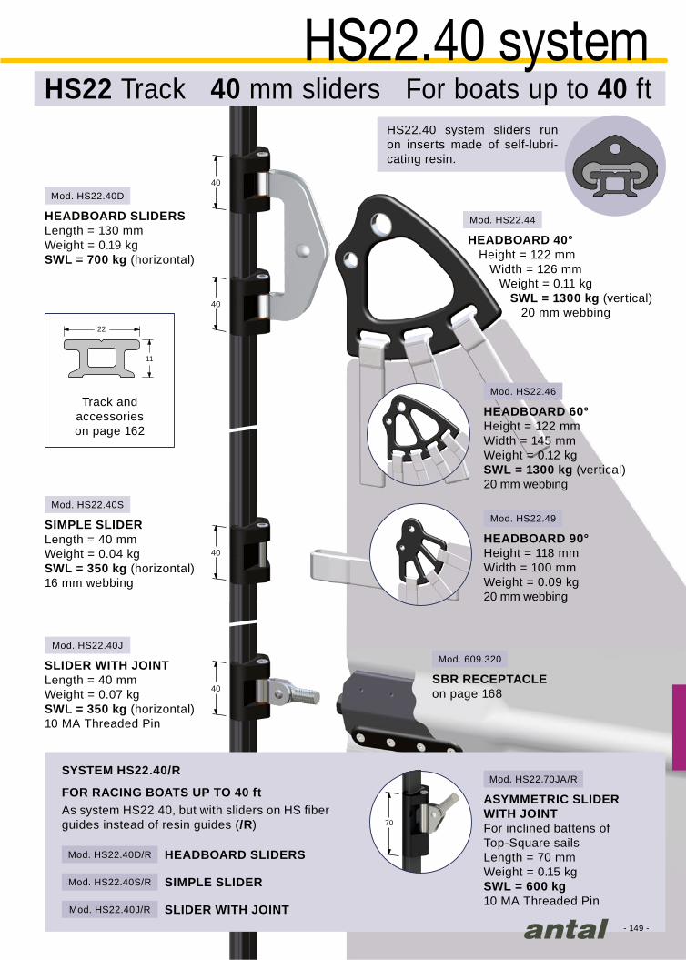
40
40
40
40
40
40
40
40
- 149 -
Mod. 609.320
Mod. HS22.40S
Mod. HS22.40J
Mod. HS22.40D/R
Mod. HS22.40S/R
Mod. HS22.40J/R
70
Mod. HS22.70JA/R
Mod. HS22.44
Mod. HS22.46
Mod. HS22.40D
Mod. HS22.49
22
11
HS22.40 systemHS22 Track 40 mm sliders For boats up to 40 ft
Track andaccessorieson page 162
As system HS22.40, but with sliders on HS fiber guides instead of resin guides (/R)
HS22.40 system sliders run on inserts made of self-lubri-cating resin.
HEADBOARD SLIDERS Length = 130 mmWeight = 0.19 kgSWL = 700 kg (horizontal)
HEADBOARD SLIDERS
SYSTEM HS22.40/R
FOR RACING BOATS UP TO 40 ft
SIMPLE SLIDER
SLIDER WITH JOINT
SIMPLE SLIDERLength = 40 mmWeight = 0.04 kgSWL = 350 kg (horizontal)16 mm webbing
SLIDER WITH JOINT Length = 40 mmWeight = 0.07 kgSWL = 350 kg (horizontal)10 MA Threaded Pin
ASYMMETRIC SLIDER WITH JOINTFor inclined battens of Top-Square sailsLength = 70 mmWeight = 0.15 kgSWL = 600 kg10 MA Threaded Pin
SBR RECEPTACLEon page 168
HEADBOARD 40°Height = 122 mm
Width = 126 mmWeight = 0.11 kg
SWL = 1300 kg (vertical)20 mm webbing
HEADBOARD 60°Height = 122 mmWidth = 145 mmWeight = 0.12 kgSWL = 1300 kg (vertical)20 mm webbing
HEADBOARD 90°Height = 118 mmWidth = 100 mmWeight = 0.09 kg20 mm webbing
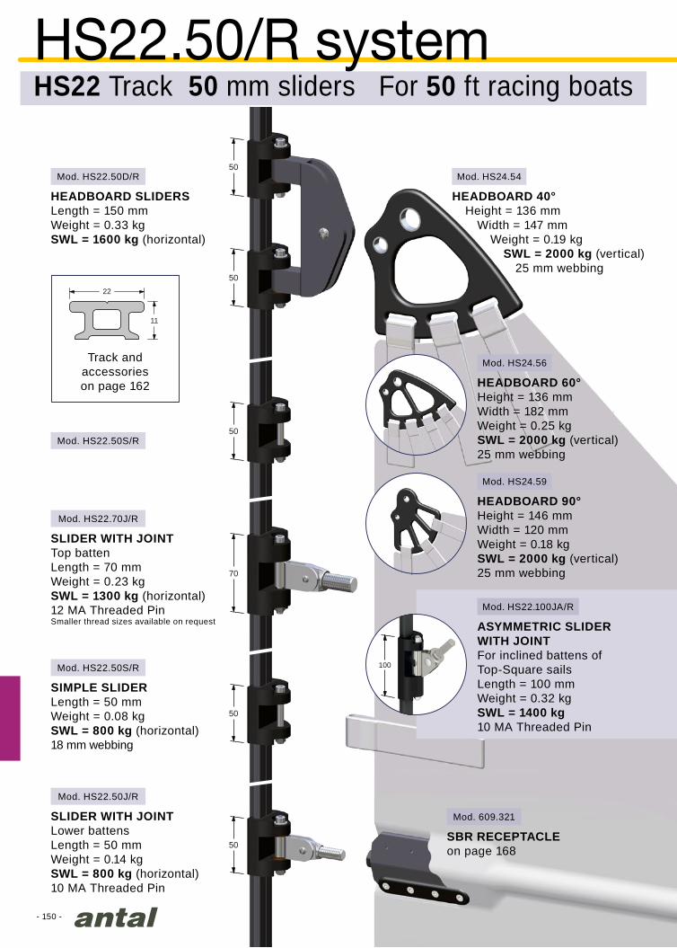
70
50
50
50
50
50
- 150 -
22
11
100
Mod. HS22.50D/R Mod. HS24.54
Mod. HS24.56
Mod. HS24.59
Mod. HS22.100JA/R
Mod. HS22.50S/R
Mod. HS22.50J/R
Mod. HS22.50S/R
Mod. HS22.70J/R
HS22.50/R systemHS22 Track 50 mm sliders For 50 ft racing boats
Track andaccessorieson page 162
HEADBOARD SLIDERS Length = 150 mmWeight = 0.33 kgSWL = 1600 kg (horizontal)
HEADBOARD 40°Height = 136 mm
Width = 147 mmWeight = 0.19 kg
SWL = 2000 kg (vertical)25 mm webbing
SBR RECEPTACLEon page 168
HEADBOARD 60°Height = 136 mmWidth = 182 mmWeight = 0.25 kgSWL = 2000 kg (vertical)25 mm webbing
HEADBOARD 90°Height = 146 mmWidth = 120 mmWeight = 0.18 kgSWL = 2000 kg (vertical)25 mm webbing
SLIDER WITH JOINTLower battens Length = 50 mmWeight = 0.14 kgSWL = 800 kg (horizontal)10 MA Threaded Pin
SLIDER WITH JOINTTop batten Length = 70 mmWeight = 0.23 kgSWL = 1300 kg (horizontal)12 MA Threaded PinSmaller thread sizes available on request
SIMPLE SLIDER Length = 50 mmWeight = 0.08 kgSWL = 800 kg (horizontal)18 mm webbing
ASYMMETRIC SLIDER WITH JOINTFor inclined battens of Top-Square sailsLength = 100 mmWeight = 0.32 kgSWL = 1400 kg10 MA Threaded Pin
Mod. 609.321

70
50
50
50
50
50
60
60
60
60
110
50
50
90
- 151 -
22
11
Mod. HS22.60T/R
Mod. HS24.64
Mod. HS24.66
Mod. HS24.69
Mod. 609.323
Mod. HS22.50S/R
Mod. HS22.50S/R
Mod. HS22.60J/R
Mod. HS22.110
Mod. HS22.90J/R
HS22.60/R systemHS22 Track 60 mm sliders For 60 ft racing boats
Track andaccessorieson page 162
HEADBOARD SLIDERSLength = 201 mmWeight = 0.65 kgSWL = 3900 kg (horizontal)
HEADBOARD 40°Height = 182 mm
Width = 193 mmWeight = 0.43 kg
SWL = 3500 kg (vertical)35 mm webbing
HEADBOARD60°Height = 182 mmWidth = 240 mmWeight = 0.54 kgSWL = 3500 kg (vertical)For 35 mm webbing
SBR RECEPTACLE on page 169
SLIDER WITH JOINTTop batten Length = 90 mmWeight = 0.29 kgSWL = 1300 kg (horizontal)12 MA Threaded PinSmaller thread sizes available on request
SIMPLE SLIDER Length = 50 mmWeight = 0.08 kgSWL = 800 kg (horizontal)20 mm webbing
SLIDER WITH JOINTLower battens Length = 60 mmWeight = 0.20 kgSWL = 1300 kg (horizontal)12 MA Threaded PinSmaller thread sizes available on request
SLIDER OUTHAULLength = 110 mmWeight = 0.30 kgSWL = 1800 kg (horizontal)For two 25 mm webbing
HEADBOARD 90°Height = 180 mmWidth = 142 mmWeight = 0.38 kgSWL = 3500 kg (vertical)35 mm webbing

50
50
50
50
- 152 -
Mod. HS24.50D
Mod. HS24.54
Mod. HS24.50S
Mod. HS24.50J
Mod. HS24.56
Mod. HS24.59
Mod. HS24.110JA
110
24
15.6
HS24.50 systemTrack HS24 50 mm Sliders For 50 ft boats
Track and accessories on page 164
HEADBOARD SLIDERSLength = 150 mmWeight = 0.37 kgSWL = 1600 kg (horizontal)
HEADBOARD 40°Height = 136 mm
Width = 147 mmWeight = 0.19 kg
SWL = 2000 kg (vertical)25 mm webbing
SIMPLE SLIDERLength = 50 mmWeight = 0.09 kgSWL = 800 kg (horizontal)18 mm webbing
SLIDER WITH JOINT Length = 50 mmWeight = 0.14 kgSWL = 800 kg (horizontal)10 MA Threaded Pin
SBR RECEPTACLE on page 168
HEADBOARD 60°Height = 136 mmWidth = 182 mmWeight = 0.25 kgSWL = 2000 kg (vertical)25 mm webbing
HEADBOARD 90°Height = 146 mmWidth = 120 mmWeight = 0.18 kgSWL = 2000 kg (vertical)25 mm webbing
ASYMMETRIC SLIDER WITH JOINTFor inclined battens of Top-Square sailsLength = 110 mmWeight = 0.38 kgSWL = 1600 kg10 MA Threaded Pin
Mod. 609.321
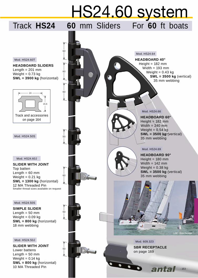
60
60
60
60
50
50
50
- 153 -
Mod. 609.323
Mod. HS24.60T
Mod. HS24.64
Mod. HS24.66
Mod. HS24.69
Mod. HS24.50S
Mod. HS24.50S
Mod. HS24.50J
Mod. HS24.60J
24
15.6
L30 - One Design
Track and accessories on page 164
HEADBOARD SLIDERSLength = 201 mmWeight = 0.73 kgSWL = 3900 kg (horizontal)
HEADBOARD 40°Height = 182 mm
Width = 193 mmWeight = 0.43 kg
SWL = 3500 kg (vertical) 35 mm webbing
HEADBOARD 60°Height = 182 mmWidth = 240 mmWeight = 0.54 kgSWL = 3500 kg (vertical)35 mm webbing
HEADBOARD 90°Height = 180 mmWidth = 142 mmWeight = 0.38 kgSWL = 3500 kg (vertical)35 mm webbing
SLIDER WITH JOINTTop batten Length = 60 mmWeight = 0.21 kgSWL = 1300 kg (horizontal)12 MA Threaded PinSmaller thread sizes available on request
SIMPLE SLIDERLength = 50 mmWeight = 0.09 kgSWL = 800 kg (horizontal)18 mm webbing
SLIDER WITH JOINTLower battens Length = 50 mmWeight = 0.14 kgSWL = 800 kg (horizontal)10 MA Threaded Pin
SBR RECEPTACLEon page 169
HS24.60 systemTrack HS24 60 mm Sliders For 60 ft boats

70
70
70
70
70
50
50
60
- 154 -
Mod. 609.325
Mod. HS24.74
Mod. HS24.70Q
Mod. HS24.50S
Mod. HS24.50S
Mod. HS24.70J
Mod. HS24.60J
Mod. HS24.76
Mod. HS24.79
24
15.6
system HS24.70Track HS24 Sliders 70 mm For boats 70 ft
Track and accessorieson page 164
HEADBOARD SLIDERSLength = 340 mmWeight = 1.28 kgSWL = 5200 kg (horizontal) HEADBOARD 40°
Height = 281 mmWidth = 279 mm
Thickness = 12 mmWeight = 1.06 kg
SWL = 5000 kg (vertical)40 mm webbing
SIMPLE SLIDER Length = 50 mmWeight = 0.09 kgSWL = 800 kg (horizontal)18 mm webbing
SLIDER WITH JOINTTop batten Length = 70 mmWeight = 0.24 kgSWL = 1500 kg (horizontal)14 MA Threaded PinSmaller thread sizes available on request
SLIDER WITH JOINTLower batten Length = 60 mmWeight = 0.21 kgSWL = 1300 kg (horizontal)12 MA Threaded PinSmaller thread sizes available on request
SBR RECEPTACLEon page 169
HEADBOARD 90°Height = 225 mmWidth = 180 mmWeight = 0.71 kgSWL = 5000 kg (vertical)40 mm webbing
HEADBOARD 60°Height = 281 mmWidth = 359 mmWeight = 1.18 kgSWL = 5000 kg (vertical)40 mm webbing

70
70
70
70
70
50
50
60
70
70
70
70
70
70
110
90
116
- 155 -
Mod. 609.325
Mod. HS30.74Mod. HS30.70Q
Mod. HS30.70S
Mod. HS30.70S
Mod. HS30.110J
Mod. HS30.90J
Mod. HS30.116
Mod. HS30.76
Mod. HS30.79
30
13
Mod. HS30.120JA
120
system HS30.90Track HS30 Sliders 90/110 mm For boats 80-90 ft
Track and accessories on page 165
HEADBOARD SLIDERSLength = 340 mmWeight = 1.63 kgSWL = 5200 kg (horizontal)
HEADBOARD 40°Height = 281 mm
Width = 279 mmThickness = 15 mm
Weight = 1.30 kgSWL = 6200 kg (vertical)
40 mm webbing
HEADBOARD 90°Height = 225 mmWidth = 180 mmWeight = 0.88 kgSWL = 6200 kg (vertical)40 mm webbing
SIMPLE SLIDERLength = 70 mmWeight = 0.20 kgSWL = 1300 kg (horizontal)25 mm webbing
SLIDER WITH JOINTTop batten Length = 110 mmWeight = 0.47 kgSWL = 2200 kg (horizontal)14 MA Threaded PinSmaller thread sizes available on request
SLIDER WITH JOINTLower batten Length = 90 mmWeight = 0.39 kgSWL = 1900 kg (horizontal)14 MA Threaded PinSmaller thread sizes available on request
SLIDER OUTHAULLength = 116 mmWeight = 0.32 kgSWL = 2500 kg (horizontal)2 X 25 mm webbings
SBR RECEPTACLEon page 169
HEADBOARD 60°Height = 281 mmWidth = 359 mmWeight = 1.47 kgSWL = 6200 kg (vertical)40 mm webbing
ASYMMETRIC SLIDER WITH JOINTFor inclined battens of Top-Square sailsLength = 120 mmWeight = 0.42 kgSWL = 2200 kg14 MA Threaded PinSmaller thread sizes available on request

90
90
90
90
70
130
116
- 156 -
Mod. HS30.74
Mod. HS30.76
Mod. HS30.79
Mod. 609.326
Mod. HS30.90Q
Mod. HS30.70S
Mod. HS30.130J
Mod. HS30.116
30
13
HEADBOARD 90°Height = 225 mmWidth = 180 mmWeight = 0.88 kgSWL = 6200 kg (vertical)40 mm webbing
HEADBOARD 60°Height = 281 mmWidth = 359 mmWeight = 1.47 kgSWL = 6200 kg (vertical)40 mm webbing
HS30.130 systemHS30 Track 130 mm Sliders For 100 ft boats
track and accessories on page 165
HEADBOARD SLIDERS Length = 366 mmWeight = 1.88 kgSWL = 6600 kg (horizontal)
SIMPLE SLIDER Length = 70 mmWeight = 0.20 kgSWL = 1300 kg (horizontal)25 mm webbing
SLIDER WITH JOINTLength = 130 mmWeight = 0.75 kgSWL = 3000 kg (horizontal)16 MA Threaded Pin(Smaller thread sizes available on request)
SLIDER OUTHAULLength = 116 mmWeight = 0.32 kgSWL = 2500 kg (horizontal)2 X 25 mm webbing
SBR RECEPTACLE on page 169
HEADBOARD 40°Height = 281 mm
Width = 279 mmThickness = 15 mm
Weight = 1.30 kgSWL = 6200 kg (vertical)
40 mm webbing
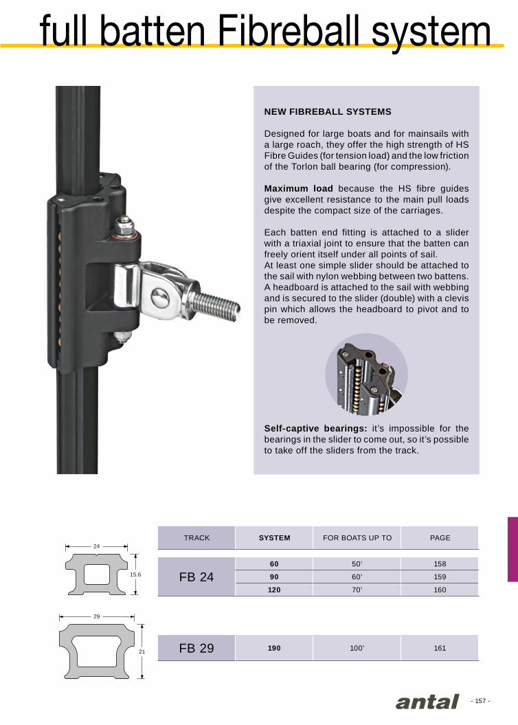
- 157 -
24
15.6
29
21
FB 2460 50’ 158
90 60’ 159
120 70’ 160
FB 29 190 100’ 161
full batten Fibreball system
NEW FIBREBALL SYSTEMS
Designed for large boats and for mainsails with a large roach, they offer the high strength of HS Fibre Guides (for tension load) and the low friction of the Torlon ball bearing (for compression).
Maximum load because the HS fibre guides give excellent resistance to the main pull loads despite the compact size of the carriages.
Each batten end fitting is attached to a slider with a triaxial joint to ensure that the batten can freely orient itself under all points of sail. At least one simple slider should be attached to the sail with nylon webbing between two battens.A headboard is attached to the sail with webbing and is secured to the slider (double) with a clevis pin which allows the headboard to pivot and to be removed.
Self-captive bearings: it’s impossible for the bearings in the slider to come out, so it’s possible to take off the sliders from the track.
TRACK SYSTEM FOR BOATS UP TO PAGE

60
60
60
60
- 158 -
Mod. HS24.54
Mod. HS24.56
Mod. HS24.59
24
15.6
Mod. FB24.60D
Mod. FB24.60S
Mod. FB24.60J
HEADBOARD 40°Height = 136 mm
Width = 147 mmWeight = 0.19 kg
SWL = 2000 kg (vertical)25 mm webbing
HEADBOARD 60°Height = 136 mmWidth = 182 mmWeight = 0.25 kgSWL = 2000 kg (vertical)25 mm webbing
HEADBOARD 90°Height = 146 mmWidth = 120 mmWeight = 0.18 kgSWL = 2000 kg (vertical)25 mm webbing
HEADBOARD SLIDERS Length = 160 mmWeight = 0.30 kgSWL = 1600 kg (horizontal)
Track and accessories on page 164
SIMPLE SLIDER Length = 60 mmWeight = 0.12 kgSWL = 800 kg (horizontal) 25 mm webbing
SLIDER WITH JOINTLength = 60 mmWeight = 0.16 kgSWL = 800 kg (horizontal)10 MA Threaded Pin
SBR RECEPTACLE on page 168
FB24.60 systemHS24 Track 60 mm sliders For 50 ft boats
Mod. 609.321
SELFCAPTIVEBALLS
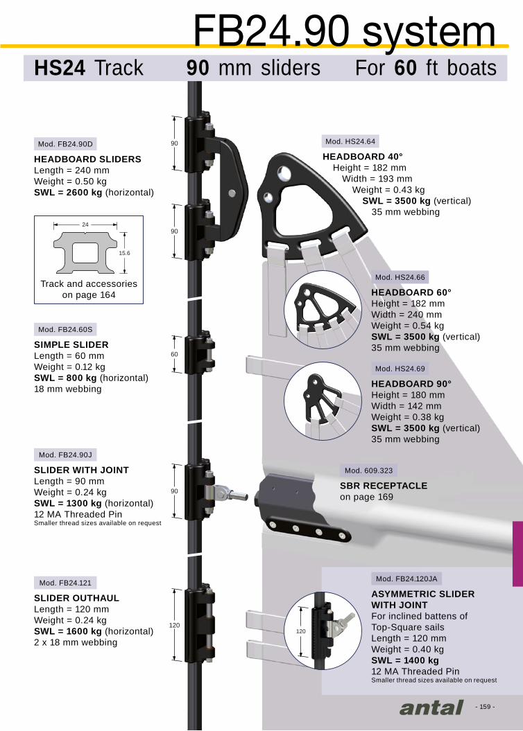
90
90
90
60
120
- 159 -
24
15.6
Mod. 609.323
Mod. FB24.90D
Mod. FB24.60S
Mod. FB24.90J
Mod. FB24.121
Mod. HS24.64
Mod. HS24.66
Mod. HS24.69
120
Mod. FB24.120JA
HEADBOARD SLIDERSLength = 240 mmWeight = 0.50 kgSWL = 2600 kg (horizontal)
Track and accessories on page 164
SIMPLE SLIDERLength = 60 mmWeight = 0.12 kgSWL = 800 kg (horizontal)18 mm webbing
SLIDER WITH JOINTLength = 90 mmWeight = 0.24 kgSWL = 1300 kg (horizontal)12 MA Threaded PinSmaller thread sizes available on request
SBR RECEPTACLEon page 169
SLIDER OUTHAULLength = 120 mmWeight = 0.24 kgSWL = 1600 kg (horizontal)2 x 18 mm webbing
FB24.90 systemHS24 Track 90 mm sliders For 60 ft boats
HEADBOARD 40°Height = 182 mm
Width = 193 mmWeight = 0.43 kg
SWL = 3500 kg (vertical) 35 mm webbing
HEADBOARD 60°Height = 182 mmWidth = 240 mmWeight = 0.54 kgSWL = 3500 kg (vertical)35 mm webbing
HEADBOARD 90°Height = 180 mmWidth = 142 mmWeight = 0.38 kgSWL = 3500 kg (vertical)35 mm webbing
ASYMMETRIC SLIDER WITH JOINTFor inclined battens of Top-Square sailsLength = 120 mmWeight = 0.40 kgSWL = 1400 kg12 MA Threaded PinSmaller thread sizes available on request
SELFCAPTIVEBALLS

120
120
60
120
120
- 160 -
Mod. HS24.74
Mod. FB24.120D
Mod. FB24.60S
Mod. FB24.120J
Mod. FB24.121
Mod. HS24.76
Mod. HS24.79
24
15.6
Mod. 609.325
HEADBOARD 90°Height = 225 mmWidth = 180 mmWeight = 0.71 kgSWL = 5000 kg (vertical)40 mm webbing
HEADBOARD 60°Height = 281 mmWidth = 359 mmWeight = 1.18 kgSWL = 5000 kg (vertical)40 mm webbing
Track and accessorieson page 164
SIMPLE SLIDER Length = 60 mmWeight = 0.12 kgSWL = 800 kg (Horizontal)18 mm webbing
SLIDER WITH JOINTLength = 120 mmWeight = 0.36 kgSWL = 1600 kg (Horizontal)14 MA Threaded PinSmaller thread sizes available on request
SLIDER OUTHAULLength = 120 mmWeight = 0.24 kgSWL = 1600 kg (Horizontal)2 x 18 mm webbing
SBR RECEPTACLEon page 169
HEADBOARD SLIDERS Length = 340 mmWeight = 0.90 kgSWL = 3200 kg (Horizontal)
FB24.120 systemHS24 Track 120 mm sliders For 70 ft boats
HEADBOARD 40°Height = 281 mm
Width = 279 mmThickness = 12 mm
Weight = 1.06 kgSWL = 5000 kg (vertical)
40 mm webbing

190
190
190
190
90
90
150
- 161 -
Mod. HS30.74
Mod. HS30.76
Mod. HS30.79
Mod. FB29.190D
Mod. FB29.90S
Mod. FB29.90S
Mod. FB29.190J
Mod. FB29.150J
Mod. FB29.191
29
21
Mod. 609.326
HEADBOARD 90°Height = 225 mmWidth = 180 mmWeight = 0.88 kgSWL = 6200 kg (vertical)40 mm webbing
HEADBOARD 60°Height = 281 mmWidth = 359 mmWeight = 1.47 kgSWL = 6200 kg (vertical)40 mm webbing
HEADBOARD SLIDERS Length = 390 mmWeight = 2.09 kgSWL = 6000 kg (Horizontal)
Track and accessories on page 166
SLIDER WITH JOINTTop battenLength = 190 mmWeight = 1.10 kgSWL = 3000 kg (Horizontal)16 MA Threaded PinSmaller thread sizes available on request
SIMPLE SLIDER Length = 90 mmWeight = 0.31 kgSWL = 1600 kg (Horizontal)25 mm webbing
SLIDER WITH JOINTLower battensLength = 150 mmWeight = 0.88 kgSWL = 2200 kg (Horizontal)14 MA Threaded PinSmaller thread sizes available on request
SLIDER OUTHAULLength = 190 mmWeight = 0.65 kgSWL = 3000 kg (Horizontal)2 x 25 mm webbing
SBR RECEPTACLEon page 169
FB29.190 systemFB29 Track 190 mm sliders For 100 ft boats
HEADBOARD 40°Height = 281 mm
Width = 279 mmThickness = 15 mm
Weight = 1.30 kgSWL = 6200 kg (vertical)
40 mm webbing
SELFCAPTIVE
BALLS

- 162 -
D
H T
D
H
T
Ø 5 mm
22
11
D
H T
Tmm
Dmm
Hmm
HS22R04 3.9 8.7 2.0
HS22R05 4.7 9.5 2.0
Tmm
Dmm
Hmm
HS22F05 4.7 18.0 4.6
HS22F08 7.8 20.0 4.6
HS22F10 9.8 20.0 2.0
HS22F12 11.8 22.0 3.0
HS22F14 13.6 24.0 3.0
HS22.311 120 mm3 m
HS22.312 60 mm
HS22.221 120 mm2 m
HS22.222 60 mm
HS22.321 120 mm3 m
HS22.322 60 mm
Mod. HS22.13
Mod. HS22.12
Mod. HS22.15
Mod. HS22.11
HS22 track
TRACKThe TRACK is an aluminium extrusion hard black anodized and teflon coated.Weight = 0.34 kg/m
Made in plastic; should be attached to the mast with 2 X 5 mm screws.
MODEL HOLESPACING LENGTH
DIRECT MOUNTING
SLUG MOUNTINGVERTICAL MAST
SLUG MOUNTINGHORIZONTAL MAST
SLUGS & SCREWS
7 standard models for round or flat grooves are available, custom slugs for special grooves are made on request.Consider 17 slugs for 2 m of track with 120 mm hole spacing or 1 m of track with 60 mm hole spacing.Screws (included) must be fixed using Loctite 222 or similar.
Direct mounting requires drilling and tapping holes in the mast, slug mounting does not.120 mm hole spacing for 40-50 ft boats, 60 mm hole spacing for 50-60 ft boats.
It is necessary to position the slugs with the mast in vertical position (with track mod. HS22.221 and HS22.222).
INSTALLATION TOOL
END FITTING
JOINT
LOADER
In order to ensure proper alignment the sections of the track can be jointed together with a nylon fitting; track joint is supplied with 2 screws.
It allows the cars to be loaded and unloaded easily; the loader includes a stop pin which provides 2 positions: open and closed. Fixing = 2 X 5 screws L = 176 mm Weight = 0.10 kg
HS22 track is made for systems:HS22.40, HS22.40/R (page 149),HS22.50/R (page 150) andHS22.60/R (page 151).
The HS22 is also available in the glued version, which is particularly suitable for carbon masts. Tracks and accessories on the following pages.
For boats up to 40 ft andracing boats from 35 to 55 ft
SLUGS - FLAT GROOVE
SLUGS - ROUND GROOVE
Ø5 x 10 mm screws
Ø5 x 10 mm screws
MODEL
MODEL

- 163 -
3.4
15.7
22
32
216 x Ø5 mm
100
Xema 50 - Privilege
Mod. HS22.03
Mod. HS22.05
Mod. HS22.02
Mod. HS22.01
Mod. HS22.330
TRACK FOR CARBON FIBER MASTAluminium profile hard black anodized and teflon coated. Weight = 0.56 kg/mIt’s available in 3 m sections.
FIXINGThe track will be glued to the mast (SP SYSTEM - SPABOND 345). For an easier gluing each track is fixed with 3 positioning screws.
END FITTING
SIDE PLATES
TRACK JOINT
LOADER
Fixing can be improved, on most loaded zones (mast head and reefing positions), with 2 aluminium side plates screwed to the mast.
GLUED TRACKS Wide base profiles for secure strong gluing, particularly suitable for carbon masts.Use for gluing “SP SYstem Spabond 345” or similar.These tracks always have bolt-rope groove.
HS22.carbon track
Made in plastic; should be attached to the mast with 2 X 5 mm screws.
Connection of different sections will be done with 2 s.steel pins.
It allows the cars to be loaded and unloaded easily; the loader includes a stop pin which provides 2 positions: open and closed. L = 500 mm Weight = 0.30 kg
For racing boatsfrom 40 to 60 ft
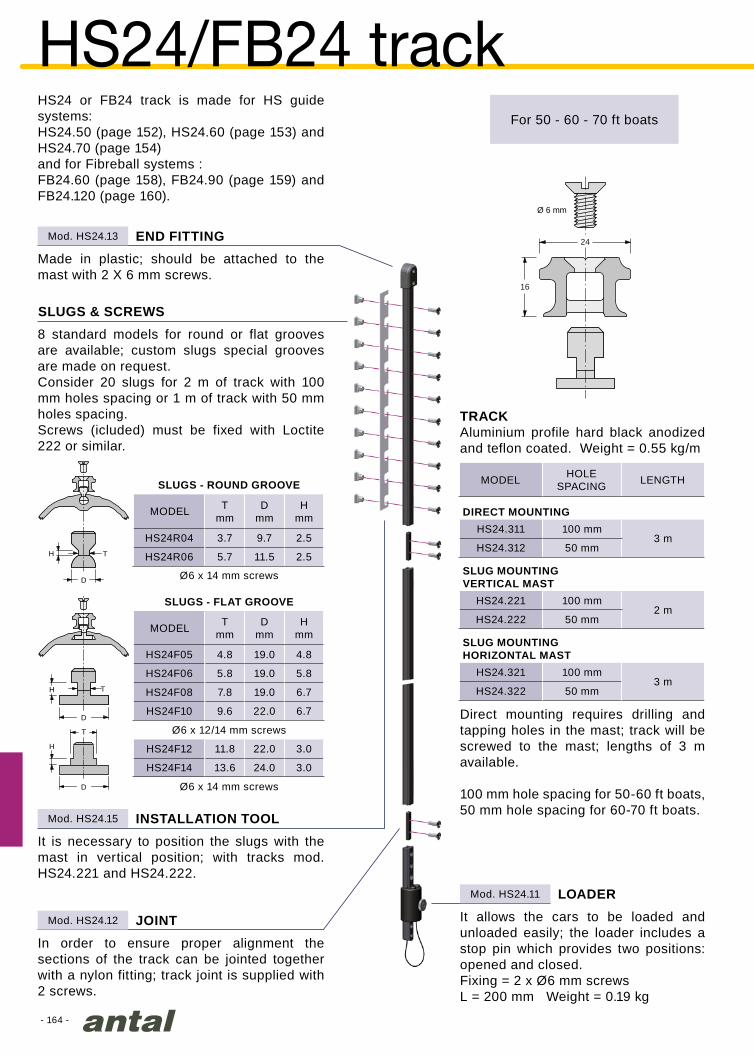
- 164 -
24
16
Ø 6 mm
HS24.311 100 mm3 m
HS24.312 50 mm
HS24.221 100 mm2 m
HS24.222 50 mm
HS24.321 100 mm3 m
HS24.322 50 mm
Tmm
Dmm
Hmm
HS24R04 3.7 9.7 2.5
HS24R06 5.7 11.5 2.5
Tmm
Dmm
Hmm
HS24F05 4.8 19.0 4.8
HS24F06 5.8 19.0 5.8
HS24F08 7.8 19.0 6.7
HS24F10 9.6 22.0 6.7
HS24F12 11.8 22.0 3.0
HS24F14 13.6 24.0 3.0
Mod. HS24.13
Mod. HS24.15
Mod. HS24.12
Mod. HS24.11
D
H T
D
H T
D
H
T
HS24/FB24 track
TRACKAluminium profile hard black anodized and teflon coated. Weight = 0.55 kg/m
Made in plastic; should be attached to the mast with 2 X 6 mm screws.
MODEL HOLESPACING LENGTH
DIRECT MOUNTING
SLUG MOUNTINGVERTICAL MAST
SLUG MOUNTINGHORIZONTAL MAST
SLUGS & SCREWS
8 standard models for round or flat grooves are available; custom slugs special grooves are made on request.Consider 20 slugs for 2 m of track with 100 mm holes spacing or 1 m of track with 50 mm holes spacing.Screws (icluded) must be fixed with Loctite 222 or similar.
Direct mounting requires drilling and tapping holes in the mast; track will be screwed to the mast; lengths of 3 m available.
100 mm hole spacing for 50-60 ft boats, 50 mm hole spacing for 60-70 ft boats.
It is necessary to position the slugs with the mast in vertical position; with tracks mod. HS24.221 and HS24.222.
INSTALLATION TOOL
For 50 - 60 - 70 ft boats
END FITTING
JOINT
LOADER
In order to ensure proper alignment the sections of the track can be jointed together with a nylon fitting; track joint is supplied with 2 screws.
It allows the cars to be loaded and unloaded easily; the loader includes a stop pin which provides two positions: opened and closed.Fixing = 2 x Ø6 mm screwsL = 200 mm Weight = 0.19 kg
HS24 or FB24 track is made for HS guide systems:HS24.50 (page 152), HS24.60 (page 153) and HS24.70 (page 154)and for Fibreball systems :FB24.60 (page 158), FB24.90 (page 159) and FB24.120 (page 160).
SLUGS - FLAT GROOVE
SLUGS - ROUND GROOVE
Ø6 x 12/14 mm screws
Ø6 x 14 mm screws
Ø6 x 14 mm screws
MODEL
MODEL

- 165 -
30
13
Ø 6 mm
228 x Ø6 mm
174
5
19.5
30
54
Mod. HS30.13
Mod. HS30.12
Mod. HS30.11
Mod. HS30.03
Mod. HS30.330
Mod. HS30.05
Mod. HS30.02
Mod. HS30.01
Mod. HS30.313
Mod. HS30.313/R
The extremely light (500 gr/m) hard black anodized and teflon coated aluminium profile is very small (only 13x30 mm). It is fixed directly to the mast with 6 mm screws every 50 or 25 mm (without inserts) and is available in 3 m sections.Weight = 0.50 kg/m
As above with lightening holes.Weight = 0.46 kg/m
TRACK
TRACK RACE
Made in aluminium, should be attached to the mast with the 2 x 6 mm screws.
END FITTING
JOINT
LOADER
In order to ensure proper alignment the sections of the track can be joined together with an aluminium fitting; track joint is supplied with 2 screws.
It allows the cars to be loaded and unloaded easily; the loader includes a stop pin which provides two positions: opened and closed.Fixing: 2 screws X 6 mm.L = 210 mm Weight = 0.20 kg
TRACK FOR CARBON FIBER MASTAluminium profile hard black anodized and teflon coated. Weight = 1.10 kg/mIt’s available in 3 m sections.
FIXINGThe track will be glued to the mast (SP SYSTEM - SPABOND 345). For an easier gluing each track is fixed with 3 positioning screws.
END FITTING
SIDE PLATES
JOINT
LOADER
Fixing can be improved, on most loaded zones (mast head and reefing positions), with 2 alu side plates screwed to the mast
Made in aluminium; should be attached to the mast with 3 x 6 mm screws.
Connection of different sections will be done with 2 s.steel pins.
It allows the cars to be easily loaded and unloaded.L = 990 mm Weight = 1.20 kg
The HS30 track is made for HS guide systems:HS30.90 (page 155) and HS30.130 (page 156)
HS30 BOLTROPE TRACK FOR CARBON FIBER MAST
HS30 trackFor 80 - 90 - 100 ft boats

- 166 -
FB29.311 100 mm. 3 m
Fb29.221 100 mm. 2 m
FB29.321 100 mm. 3 m
29
21
Ø 8 mm
FB29.311 100 mm 3 m
FB29.221 100 mm 2 m
FB29.321 100 mm 3 m
Cotonella 40’ - C. Manzoli
Mod. FB29.13
Mod. FB29.12
Mod. FB29.15
Mod. FB29.11
FB29 trackFor boats
from 80 to 100 ft
The FB29 track is made for Fibreball system FB29.190 on page 161.
Made in aluminium, should be attached to the mast with the 2 X 8 mm screws.
END FITTING
SLUGS
Available on request, for 8 mm screws.
JOINT
In order to ensure proper alignment the section of the track will be joined together with this nylon fitting: it is supplied with 2 screws.
LOADER
It allows the cars to be easily loaded and unloaded.Fixing = 2 x Ø8 mm screws.L = 300 mm Weight = 0.24kg
TRACKAluminium profile hard black anodized and teflon coated. Weight = 0.72 kg/m
MODEL HOLESPACING LENGTH
DIRECT MOUNTING
SLUG MOUNTINGVERTICAL MAST
SLUG MOUNTINGHORIZONTAL MAST
Direct mounting requires drilling and tapping holes in the mast, slug mounting does not.
It is necessary to position the slugs with the mast in vertical position; with tracks mod. FB29.221.
INSTALLATION TOOL
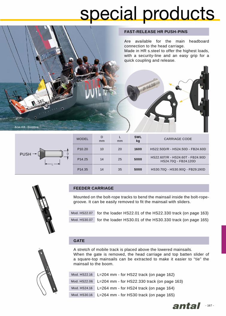
- 167 -
Dmm
Lmm
SWLkg
P10.20 10 20 1600 HS22.50D/R - HS24.50D - FB24.60D
P14.25 14 25 5000 HS22.60T/R - HS24.60T - FB24.90DHS24.70Q - FB24.120D
P14.35 14 35 5000 HS30.70Q - HS30.90Q - FB29.190D
L
D
Arya 415 - Duvetica
Mod. HS22.07
Mod. HS22.16
Mod. HS30.07
Mod. HS22.06
Mod. HS24.16
Mod. HS30.16
special productsFAST-RELEASE HR PUSH-PINS
Are available for the main headboard connection to the head carriage.Made in HR s.steel to offer the highest loads, with a security-line and an easy grip for a quick coupling and release.
FEEDER CARRIAGE
Mounted on the bolt-rope tracks to bend the mainsail inside the bolt-rope-groove. It can be easily removed to fit the mainsail with sliders.
GATE
A stretch of mobile track is placed above the lowered mainsails.When the gate is removed, the head carriage and top batten slider of a square-top mainsails can be extracted to make it easier to “tie” the mainsail to the boom.
for the loader HS22.01 of the HS22.330 track (on page 163)
L=204 mm - for HS22 track (on page 162)
for the loader HS30.01 of the HS30.330 track (on page 165)
L=204 mm - for HS22.330 track (on page 163)
L=264 mm - for HS24 track (on page 164)
L=264 mm - for HS30 track (on page 165)
MODEL CARRIAGE CODE
PUSH
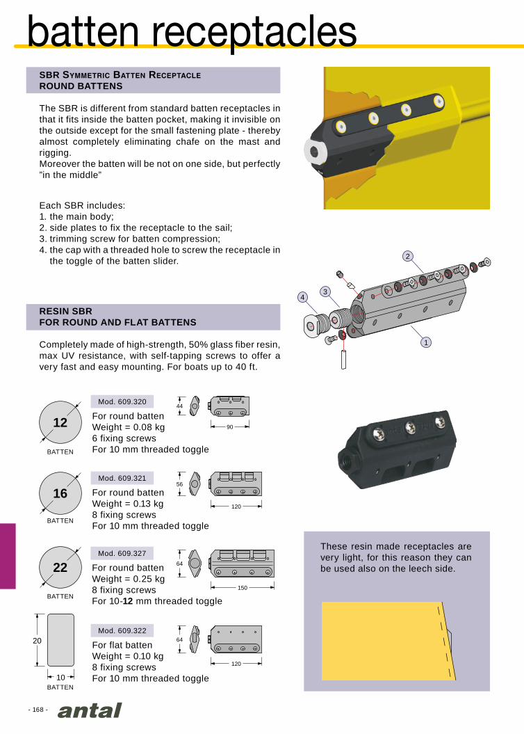
- 168 -
90
44
120
64
120
56
20
10
16
12
1
2
34
22150
64
SBR Symmetric Batten ReceptacleROUND BATTENS
The SBR is different from standard batten receptacles in that it fits inside the batten pocket, making it invisible on the outside except for the small fastening plate - thereby almost completely eliminating chafe on the mast and rigging.Moreover the batten will be not on one side, but perfectly ”in the middle”
RESIN SBR FOR ROUND AND FLAT BATTENS
Completely made of high-strength, 50% glass fiber resin, max UV resistance, with self-tapping screws to offer a very fast and easy mounting. For boats up to 40 ft.
These resin made receptacles are very light, for this reason they can be used also on the leech side.
Each SBR includes:1. the main body;2. side plates to fix the receptacle to the sail;3. trimming screw for batten compression;4. the cap with a threaded hole to screw the receptacle in
the toggle of the batten slider.
batten receptacles
For round battenWeight = 0.08 kg6 fixing screwsFor 10 mm threaded toggle
For round battenWeight = 0.13 kg8 fixing screwsFor 10 mm threaded toggle
For flat battenWeight = 0.10 kg8 fixing screwsFor 10 mm threaded toggle
For round battenWeight = 0.25 kg8 fixing screwsFor 10-12 mm threaded toggle
BATTEN
BATTEN
BATTEN
BATTEN
Mod. 609.320
Mod. 609.327
Mod. 609.321
Mod. 609.322
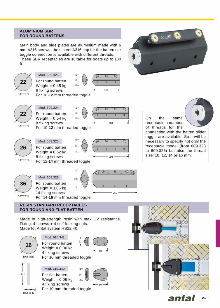
- 169 -
Mod. 609.323
Mod. 609.324
Mod. 609.325
Mod. 609.326
Mod. 610.341
Mod. 610.340
22
22
26
36250
105
200
73
200
64
150
64
80
68
80
52
40
6
16
RESIN STANDARD RECEPTACLESFOR ROUND AND FLAT BATTEN
Made of high-strength resin with max UV resistance. Fixing: 4 screws + 4 self-locking nuts.Made fot Antal system HS22.40.
ALUMINIUM SBRFOR ROUND BATTENS
Main body and side plates are aluminium made with 6 mm A316 screws, the s.steel A316 cap for the batten car toggle connection is available with different threads.These SBR receptacles are suitable for boats up to 100 ft.
On the same receptacle a number of threads for the connection with the batten slider toggle are available. So it will be necessary to specify not only the receptacle model (from 609.323 to 609.326) but also the thread size: 10, 12, 14 or 16 mm.
For round battenWeight = 0.45 kg6 fixing screwsFor 10-12 mm threaded toggle
For round battenWeight = 0.54 kg8 fixing screwsFor 10-12 mm threaded toggle
For round battenWeight = 0.62 kg8 fixing screwsFor 12-14 mm threaded toggle
For round battenWeight = 1.05 kg14 fixing screwsFor 14-16 mm threaded toggle
For round battenWeight = 0.06 kg4 fixing screwsFor 10 mm threaded toggle
For flat battenWeight = 0.06 kg4 fixing screwsFor 10 mm threaded toggle
BATTEN
BATTEN
BATTEN
BATTEN
BATTEN
BATTEN

- 170 -
1 2
Mod. HS24.17
Mod. HS22.17
Mod. HS22.27
Mod. HS24.210
Mod. HS22.160R
Mod. HS24.61
Mod. HS24.18
1 2
hook carriages
HOOK CARRIAGE
MINI HOOK CARRIAGE
This head carriage has been designed for Antal track HS24 (page.164).It is fitted with a hook that automatically catches specific hook stops on the mast track to unload the halyard.Two lines from the carriage run down the sail:1 - to disengage the hook so that the carriage is free to descend; 2 - to load the hook, which attaches to the first hook-stop.These two lines are connected so when one is pulled the other is automatically released.
This head carriage has been designed for Antal track HS22 (page 162).It is fitted with a hook that automatically catches specific hook stops on the mast track to unload the halyard.Two lines from the carriage run down the sail:1 - to disengage the hook so that the carriage is free to descend; 2 - to load the hook, which attaches to the first hook-stop.
The carriage is fitted with a swivelling bracket on which it is possible to mount any headboard from the HS24.6 series (page 153) or the HS24.61 model, specifically designed for this carriage. The halyard is fixed to the headboard.
Sizes 120x130 mm Weight = 0,25 kg SWL = 2400kg
Weight = 1.06 kg Length = 210 mm SWL = 2400 kg
To avoid too many junctions in the track, Antal offers custom tracks with hook-stops that are already fitted at the required points based on the design of the mainsail and reef locations: one hook-stop at the top and two or three for the reefs along the track.
Similar to the previous model, it has been designed for the mast head.By simply pulling the halyard for a few centimeters, the carriage moves up, the hook is automatically disengaged and the carriage is free to descend. Therefore, even in the event of breakage of the line that frees the hook, the sail can be lowered.
Fitted on a 350 mm long track that is screwed to the mast with 7 x Ø6 mm screws.
Hook-stop for HS24 track (on page 164)
Hook-stop for HS22 track (page 162)
Fitted on a 340 mm long track that is screwed to the mast with 7 x Ø5 mm screws
Weight = 042 kg Length = 160 mm SWL = 1400 kg
Fitted on a 340 mm long track that is glued or screwed to the mast with 4 x Ø5 mm screws
Hook carriage for HS24 track
Mini hook carriage for HS22 track
Special headboard for Hook carriage
Automatic Hook-stop for HS24 track (on page 164)
For boats up to 60 ft
For boats up to 40 ft
Hook-stop for HS22 carbon track (page 163)

- 171 -
Mod. HS24.90/DY
Mod. HS22.185
Mod. HS24.90/DX
Mod. HS30.90/DY
Mod. HS30.90/DX
Rustler 36 - P.Peche - Golden Globe Race 2018
2:1 MINI HEADBOARD SLIDER FOR HS22 TRACK
DOUBLE HEAD SLIDER FOR RING CONNECTION
DOUBLE HEAD SLIDER WITH SOFT-LINK
This model, designed for class 40ft, is fitted with a 40 mm high load sheave for a 2:1 halyard; the mainsail head will be simply tied to the slider with a line.Weight = 0.45 kg Length = 185 mm SWL = 2000 kg
Two 90 mm long sliders with a bracket will be connected to the ring on the head of the mainsail.Weight = 0.87 kg Length = 240 mm SWL = 3200 kg
Two 90 mm long sliders with a bracket will be tied to the ring on the head of the mainsail.Weight = 0.65 kg Length = 240 mm SWL = 3200 kg
For HS22 track (on page 162)
For HS24 track (on page 164)
For HS24 track (on page 164)
For HS30 track (on page 165)
For HS30 track (on page 165)

- 172 -Class 40 Vaquita

- 173 -
solid rings ................... 179
hook ............................ 180
mast fairlead ............... 181
Dyneema pad-eye ...... 168
rings & loops ............... 180
low friction rings .......... 178
deck rings ................... 176
T-Lock......................... 175
snap-loops .................. 182
soft links

- 174 -
HC
B
A
Amm
Bmm
Hmm
Cmm
SWLkg
7505 7605 5 43 34 16 7 600 22 2 x 6
7506 7606 6 58 45 21 10 1300 50 3 x 6
7508 7608 8 77 60 27 12 2200 90 3 x 8
7510 7610 10 93 74 34 16 3500 180 3 x 10
7512 7612 12 112 89 41 19 5000 370 3 x 12
7514 7614 14 123 97 46 21 6800 520 4 x 12
mod. 7608
mod. LS1120
90°
soft links
DYNEEMA PAD-EYES
Special extremely light, “low profile” pad-eye, designed for Dyneema loop in hard black anodized aluminium. The Dyneema pad-eye is available in two versions:
1) with studs from the bottom and a perfectly smooth upper surface;
2) with screws from above.Studs or screws, washers and nuts included.
The Study of the Pull DirectionDPE offers great performance on a wide angle. DPE’s profile is so low and smooth that it is walkable. This is because we designed this pad-eye starting from its Pull Direction, and not for a simple coupling.
SOFT LINKS
The use of Dyneema lines, characterized by high stiffness and strength and by excellent smoothness, resulted in the development of new equipment that exalts these properties.
First the fastenings called “soft-links”: Dyneema loops and snap-loops that replace shackles, snap-shackles and other metal connections.
Then the rings, now produced in different versions and many sizes that exploit the excellent sliding of Dyneema lines, replace sheaves and blocks for more and more manoeuvres.
The advantages of this new equipment are: high resistance, increased lightness, a reduction in size and significant cost savings.
MODEL
WITH SCREWS
MODEL
WITH STUDS
SOFT LINKØ mm
SCREWSN° x Ø mm
WEIGHT*gr
* without screws-nuts
LOADDIRECTION
Screwsfrom above
Do not use Antal Dyneema Pad Eyes for boat lifting

- 175 -
Dmm
SWLkg
TL22.32 64 33 44 2200 170 TT22.32 TD22.32 R20.14
TL28.40 74 44 54 3500 300 TT28.40 TD28.40 R28.20
H
Ø
D
mod. TL22.32
90°
30°
T-lockT-Lock is a flush-mounted deck base to which a loop can be connected.A special toggle, which automatically locks-in, fits into the base. It cannot be removed under load, but can easily be removed without a load on it. The toggle can be locked-in permanently which makes it not-removable.The toggle is swivelling, it can take a load in any direction.When used as a dog-bone it will adapt to any Dyneema loop, such as a simple loop, low friction ring with loop and a snatch block with loop.Two models are available, sizes and characteristics are shown in the table.
there are two positions for the sealing plug:1) low position (unscrewed): in this position it
is possible to fit the toggle into the base or to take it off (only if not under load).
2) high position (screwed): in this position the toggle is permanently locked into the base and it is not possible to take it off.For load directions with angles of less than 30°, the sealing plug must be completely tightened so as to lock the slug and avoid accidental unhooking.
- Loop & toggle: this is a multi-ring Dyneema loop with a cover linked to the toggle, it is always included in the T-Lock.
- Low friction ring: a ring can be inserted in the Dyneema loop, models in the above table are available on request.
- Simple toggle: this is an aluminium dog-bone suitable for splicing your own loop, models in the above table are available on request.
- Blocks: Looper blocks (page 74) can be lashed to the toggle and easily locked-in the T-Lock base. This feature is optional.
T-LOCK FOR SWIVELLING& REMOVABLE DECK LOOPS
ACCESSORIES
MODEL TOGGLEmod.
WEIGHTgr
MAX DECKH mm
LOOP & TOGGLE
mod.RINGmod.
DECK HOLEØ mm
toggle
self tapping screws
flush-deckbase
cap
load direction
spring
sealing plugspring ring
o-ring
ring nut
T-Lock Basis +Looper blocks
Do not use Antal T-Lock for boat lifting
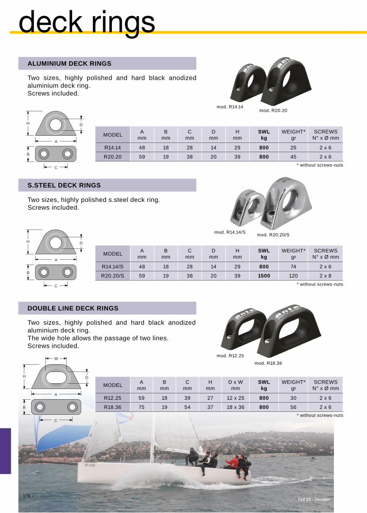
- 176 -
Amm
Bmm
Cmm
Dmm
Hmm
SWLkg
R14.14 48 18 28 14 29 800 25 2 x 6
R20.20 59 19 38 20 39 800 45 2 x 6
Amm
Bmm
Cmm
Dmm
Hmm
SWLkg
R14.14/S 48 18 28 14 29 800 74 2 x 6
R20.20/S 59 19 38 20 39 1500 120 2 x 8
Amm
Bmm
Cmm
Hmm
D x Wmm
SWLkg
R12.25 59 18 39 27 12 x 25 800 30 2 x 6
R18.36 75 19 54 37 18 x 36 800 56 2 x 6
H D
C
A
B
H D
C
A
B
H D
C
W
A
B
mod. R14.14
mod. R14.14/S
mod. R12.25
mod. R20.20
mod. R20.20/S
mod. R18.36
Tod 33 - Jacopin
deck rings
Two sizes, highly polished and hard black anodized aluminium deck ring. The wide hole allows the passage of two lines.Screws included.
DOUBLE LINE DECK RINGS
MODEL SCREWSN° x Ø mm
WEIGHT*gr
Two sizes, highly polished and hard black anodized aluminium deck ring.Screws included.
Two sizes, highly polished s.steel deck ring.Screws included.
ALUMINIUM DECK RINGS
S.STEEL DECK RINGS
MODEL
MODEL
SCREWSN° x Ø mm
SCREWSN° x Ø mm
WEIGHT*gr
WEIGHT*gr
* without screws-nuts
* without screws-nuts
* without screws-nuts
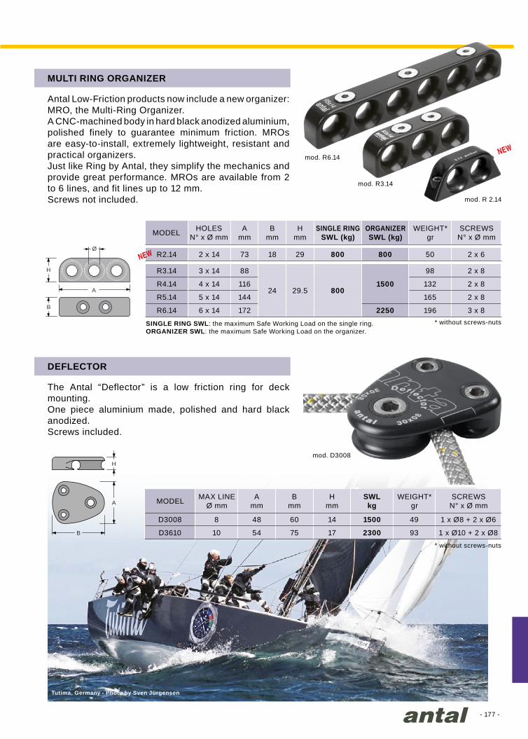
- 177 -
Amm
Bmm
Hmm
R2.14 2 x 14 73 18 29 800 800 50 2 x 6
R3.14 3 x 14 88
24 29.5 8001500
98 2 x 8
R4.14 4 x 14 116 132 2 x 8
R5.14 5 x 14 144 165 2 x 8
R6.14 6 x 14 172 2250 196 3 x 8
Amm
Bmm
Hmm
SWLkg
D3008 8 48 60 14 1500 49 1 x Ø8 + 2 x Ø6
D3610 10 54 75 17 2300 93 1 x Ø10 + 2 x Ø8
H
A
B
Ø
H
B
A
mod. R6.14
mod. D3008
mod. R3.14
Tutima, Germany - Photo by Sven Jürgensen
mod. R 2.14
Antal Low-Friction products now include a new organizer: MRO, the Multi-Ring Organizer.A CNC-machined body in hard black anodized aluminium, polished finely to guarantee minimum friction. MROs are easy-to-install, extremely lightweight, resistant and practical organizers.Just like Ring by Antal, they simplify the mechanics and provide great performance. MROs are available from 2 to 6 lines, and fit lines up to 12 mm.Screws not included.
The Antal “Deflector” is a low friction ring for deck mounting.One piece aluminium made, polished and hard black anodized.Screws included.
MULTI RING ORGANIZER
DEFLECTOR
MODEL
MODEL
HOLESN° x Ø mm
ORGANIZERSWL (kg)
SINGLE RINGSWL (kg)
MAX LINEØ mm
SCREWSN° x Ø mm
SCREWSN° x Ø mm
WEIGHT*gr
WEIGHT*gr
* without screws-nuts
* without screws-nutsSINGLE RING SWL: the maximum Safe Working Load on the single ring.ORGANIZER SWL: the maximum Safe Working Load on the organizer.
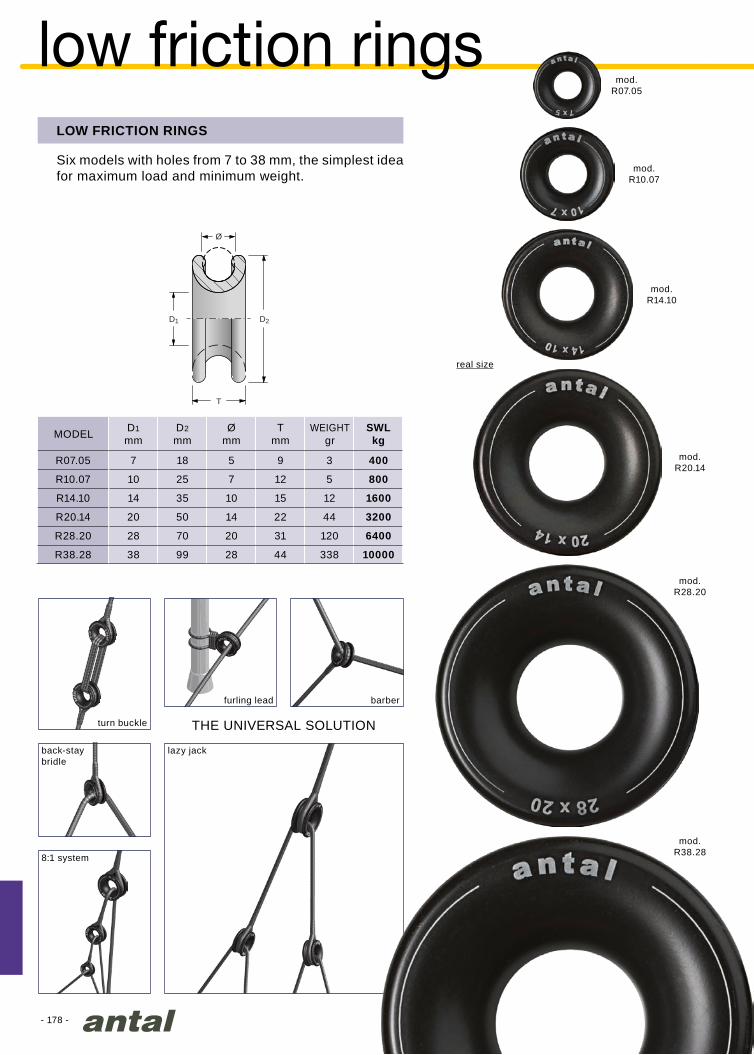
- 178 -
D1
mmD2
mmØ
mmT
mmSWLkg
R07.05 7 18 5 9 3 400
R10.07 10 25 7 12 5 800
R14.10 14 35 10 15 12 1600
R20.14 20 50 14 22 44 3200
R28.20 28 70 20 31 120 6400
R38.28 38 99 28 44 338 10000
T
D1 D2
Ø
mod.R38.28
mod.R28.20
mod.R20.14
mod.R14.10
mod.R10.07
mod.R07.05
low friction ringsLOW FRICTION RINGS
Six models with holes from 7 to 38 mm, the simplest idea for maximum load and minimum weight.
MODEL WEIGHTgr
real size
THE UNIVERSAL SOLUTION
barber
8:1 system
furling lead
turn buckle
back-staybridle
lazy jack
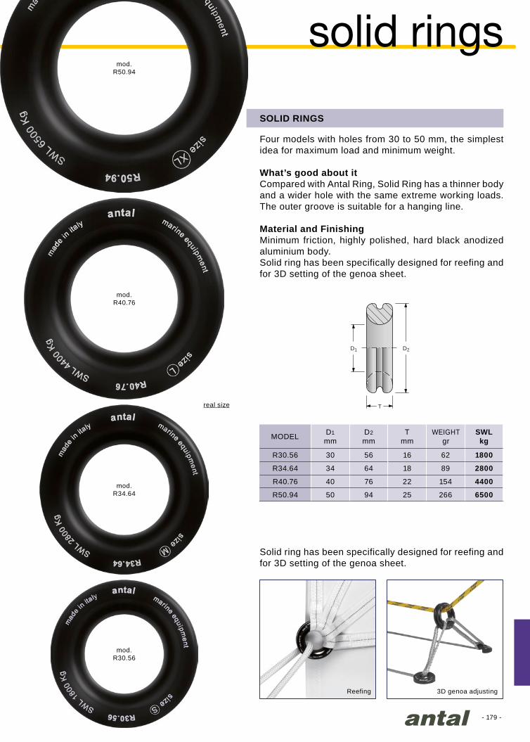
- 179 -
mod.R50.94
mod.R40.76
mod.R34.64
mod.R30.56
D1
mmD2
mmT
mmSWLkg
R30.56 30 56 16 62 1800
R34.64 34 64 18 89 2800
R40.76 40 76 22 154 4400
R50.94 50 94 25 266 6500
T
D1 D2
real size
SOLID RINGS
Four models with holes from 30 to 50 mm, the simplest idea for maximum load and minimum weight.
What’s good about itCompared with Antal Ring, Solid Ring has a thinner body and a wider hole with the same extreme working loads. The outer groove is suitable for a hanging line.
Material and FinishingMinimum friction, highly polished, hard black anodized aluminium body.Solid ring has been specifically designed for reefing and for 3D setting of the genoa sheet.
MODEL WEIGHTgr
solid rings
Reefing 3D genoa adjusting
Solid ring has been specifically designed for reefing and for 3D setting of the genoa sheet.
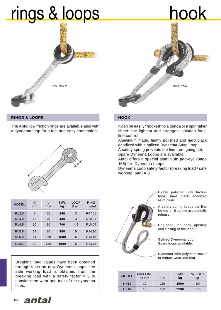
L
- 180 -
Lmm
SWLkg
HK12 12 110 1500 80
HK16 16 120 2200 130
mod. HK12mod. RL6.0
Dmm
Lmm
SWLkg
RL3.0 7 60 240 3 R07.05
RL4.0 10 70 400 4 R10.07
RL4.5 10 80 700 4.5 R10.07
RL5.0 14 90 900 5 R14.10
RL6.0 14 110 1500 6 R14.10
RL6.1 20 130 1500 6 R20.14
DL
hook
HOOK
It can be easily “hooked” to a genoa or a spinnaker sheet: the lightest and strongest solution for a line control.Aluminium made, highly polished and hard black anodized with a spliced Dyneema Snap Loop. A safety spring prevents the line from going out.Spare Dyneena Loops are available.Antal offers a special aluminium pad-eye (page 168) for Dyneema Loops.Dyneema Loop safety factor (breaking load / safe working load) = 3.
MODEL MAX LINEØ mm
A safety spring keeps the line locked-in, it cannot accidentally release.
Dyneema with polyester cover to reduce wear and tear.
Highly polished low friction hook, hard black anodized aluminium.
Dog-bone for easy opening and closing of the loop.
Spliced Dyneema loop.Spare loops available.
The Antal low friction rings are available also with a dyneema loop for a fast and easy connection.
Breaking load values have been obtained through tests on new Dyneema loops, the safe working load is obtained from the breaking load with a safety factor = 3 to consider the wear and tear of the dyneema lines.
rings & loops
MODEL LOOPØ mm
RING model
RINGS & LOOPS
WEIGHTgr
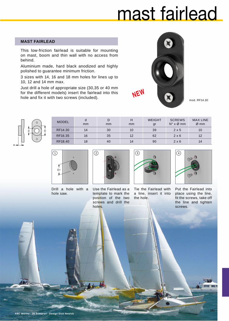
- 181 -
mod. RF14.30
dmm
Dmm
Hmm
RF14.30 14 30 10 39 2 x 5 10
RF16.35 16 35 12 62 2 x 6 12
RF18.40 18 40 14 90 2 x 6 14
Dd
H
D+
31 2 4
ABC Marine - 39 Trimaran - Design Dick Newick
mast fairlead
This low-friction fairlead is suitable for mounting on mast, boom and thin wall with no access from behind.Aluminium made, hard black anodized and highly polished to guarantee minimum friction.3 sizes with 14, 16 and 18 mm holes for lines up to 10, 12 and 14 mm max.Just drill a hole of appropriate size (30,35 or 40 mm for the different models) insert the fairlead into this hole and fix it with two screws (included).
Drill a hole with a hole saw.
Use the Fairlead as a template to mark the position of the two screws and drill the holes.
Tie the Fairlead with a line, insert it into the hole.
Put the Fairlead into place using the line, fit the screws, take off the line and tighten screws.
MAST FAIRLEAD
MODEL SCREWSN° x Ø mm
WEIGHTgr
MAX LINEØ mm

- 182 -
100 mm
Ømm
SWLkg
9001 2.5 20 250
SL4S
4
30 600
SL4D 50 1200
SL4T 70 1800
SL5S
5
30 1000
SL5D 50 2000
SL5T 70 3000
Class 40 Eco - M. Miceli
MINI SNAP LOOP
It’s a Dyneema loop that can be opened, with an easy and safe lock system. Three sizes with 2.5, 4 or 5 mm lines with different lengths. It will be used as a single, double or triple ring.
doublesingle triple
closedopen locked
mini snap loops
MODEL FORTOTAL LENGHTcm
SINGLE
SINGLE
SINGLE
DOUBLE
DOUBLE
TRIPLE
TRIPLE
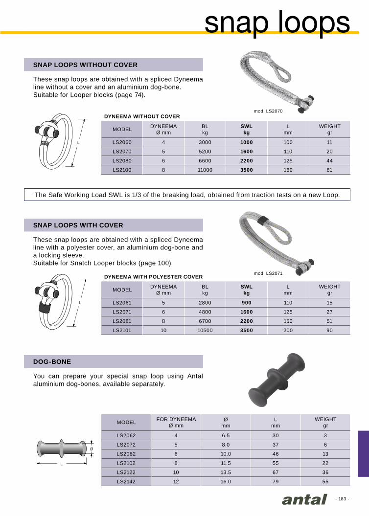
- 183 -
Ø
L
L
L
DYNEEMAØ mm
BLkg
SWLkg
Lmm
LS2060 4 3000 1000 100 11
LS2070 5 5200 1600 110 20
LS2080 6 6600 2200 125 44
LS2100 8 11000 3500 160 81
DYNEEMAØ mm
BLkg
SWLkg
Lmm
LS2061 5 2800 900 110 15
LS2071 6 4800 1600 125 27
LS2081 8 6700 2200 150 51
LS2101 10 10500 3500 200 90
Ømm
Lmm
LS2062 4 6.5 30 3
LS2072 5 8.0 37 6
LS2082 6 10.0 46 13
LS2102 8 11.5 55 22
LS2122 10 13.5 67 36
LS2142 12 16.0 79 55
mod. LS2070
mod. LS2071
snap loops
These snap loops are obtained with a spliced Dyneema line without a cover and an aluminium dog-bone.Suitable for Looper blocks (page 74).
These snap loops are obtained with a spliced Dyneema line with a polyester cover, an aluminium dog-bone and a locking sleeve.Suitable for Snatch Looper blocks (page 100).
You can prepare your special snap loop using Antal aluminium dog-bones, available separately.
SNAP LOOPS WITHOUT COVER
SNAP LOOPS WITH COVER
DOG-BONE
MODEL
MODEL
MODEL FOR DYNEEMAØ mm
WEIGHTgr
WEIGHTgr
WEIGHTgr
DYNEEMA WITHOUT COVER
DYNEEMA WITH POLYESTER COVER
The Safe Working Load SWL is 1/3 of the breaking load, obtained from traction tests on a new Loop.

- 184 -
Corsaro II - Marina Militare Italiana - photo J.R. Taylor
- 185 -
cleats .............................. 186
shackle & pad-eyes ........ 188
sliding pad-eyes.............. 190
promotional items ........... 192
model index ............200
accessories
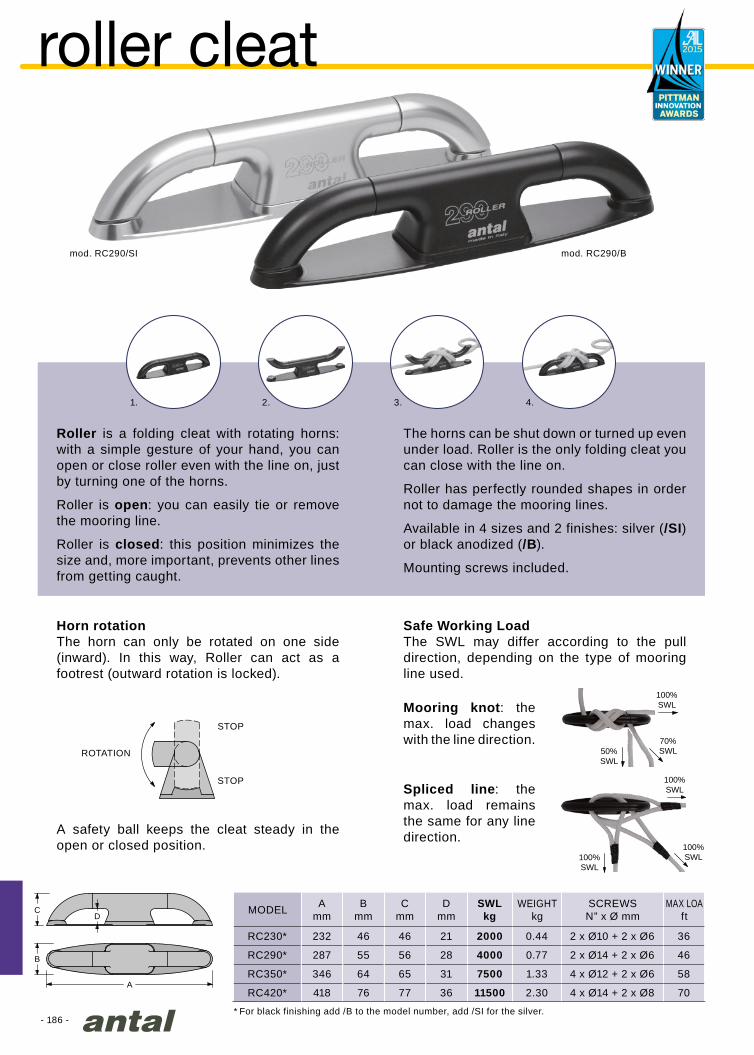
- 186 -
Amm
Bmm
Cmm
Dmm
SWLkg
RC230* 232 46 46 21 2000 0.44 2 x Ø10 + 2 x Ø6 36
RC290* 287 55 56 28 4000 0.77 2 x Ø14 + 2 x Ø6 46
RC350* 346 64 65 31 7500 1.33 4 x Ø12 + 2 x Ø6 58
RC420* 418 76 77 36 11500 2.30 4 x Ø14 + 2 x Ø8 70
1. 2. 3. 4.
A
B
CD
100%SWL
100%SWL100%
SWL
100%SWL
70%SWL50%
SWL
mod. RC290/SI mod. RC290/B
roller cleat
Roller is a folding cleat with rotating horns: with a simple gesture of your hand, you can open or close roller even with the line on, just by turning one of the horns.
Roller is open: you can easily tie or remove the mooring line.
Roller is closed: this position minimizes the size and, more important, prevents other lines from getting caught.
The horns can be shut down or turned up even under load. Roller is the only folding cleat you can close with the line on.
Roller has perfectly rounded shapes in order not to damage the mooring lines.
Available in 4 sizes and 2 finishes: silver (/SI) or black anodized (/B).
Mounting screws included.
Horn rotationThe horn can only be rotated on one side (inward). In this way, Roller can act as a footrest (outward rotation is locked).
A safety ball keeps the cleat steady in the open or closed position.
Safe Working LoadThe SWL may differ according to the pull direction, depending on the type of mooring line used.
Spliced line: the max. load remains the same for any line direction.
Mooring knot: the max. load changes with the line direction.
MODEL MAX LOAft
WEIGHTkg
SCREWSN” x Ø mm
ROTATION
STOP
STOP
* For black finishing add /B to the model number, add /SI for the silver.

- 187 -
Amm
Bmm
Hmm
Lmm
7412 36 26 60 320 10
7413 48 31 73 400 16
Amm
Bmm
Hmm
Lmm
622.412 32x6 11 170 49 55 132 0.45
623.412 40x8 14 200 60 67 160 0.78
L
B
A
H
L
HB
A
Trimarine Compositos - IRC 40 - Juobert Nivelt
track adjustable cleat
MODEL
MODEL T TRACKmm
PINØ mm
WEIGHTgr
SCREWSØ mm
This cleat is a classical look cleat formed by a teak beam and a double s.steel basis.Teak Cleat is available in two sizes.
Two moveable cleats for either 32 mm or 40 mm T-track.Cleats and slider are CNC machined from hard black anodized aluminum, low profile design.Single screw-in stop pin keeps the cleat firmly locked in any position along the track, or locked open for easy of movement.Nylon insert on the slider for easier movement.S.steel version available.
TRACK ADJUSTABLE CLEAT
CLASSIC CLEATS
s.steel version

- 188 -
L
D
I
Ø
7105 7106 7108 7110
Ø mm 5 6 8 10
I mm 17 22 28 35
D mm 38 44 54 63
L mm 50 55 67 67
0.05 0.06 0.13 0.17
SWL kg 500 800 1500 2500
50 60 70 80
“Ciolita” - photo J.R.Taylor
2D
D
4D
Dmm
SWLkg
005SS 5 600 50
006SS 6 800 60
008SS 8 1300 - - -
010SS 10 1900 - - -
012SS 12 2600 - - -
014SS 14 3500 - - -
016SS 16 4400 - - -
Dmm
SWLkg
- - - - - - - - - - - -
006HR 6 1300 70
008HR 8 2200 80
010HR 10 3500 100
012HR 12 5000 120
014HR 14 7000 140 - 150
016HR 16 9000 180
shackles & pad-eyes
Made of AISI 316 stainless steel.They can be fitted with a block and a “stand-up” spring.
“U” BOLTS
MODEL
WEIGHT kg
BLOCKØ mm
SHACKLES AISI 316 & HR
Antal supplies standard shackles made in AISI 316 and HR high resistance s.steel. The HR version offers higher values of the Safe Working Load.
SHACKLES AISI 316
MODEL ANTALBLOCKS Ø mm
SHACKLES HR
MODEL ANTAL BLOCKS Ø mm
Do not use Antal U-Bolt for boat lifting

- 189 -
D1
D2
Ø 7206 7208 7210 7212 7214 7216 7220
Ø mm 6 8 10 12 14 16 20
D1 mm 44 65 75 80 99 110 129
D2 mm 32 49 53 59 74 84 104
2 x Ø6 4 x Ø6 4 x Ø8 4 x Ø8 4 x Ø10 6 x Ø10 6 x Ø10
0.10 0.16 0.26 0.38 0.68 1.10 1.80
SWL kg 800 1500 2500 3600 4600 6500 9000
60 70 80 100 120 140 - 150 180
D4
Ø
D3
D5
H
D
D2
1
7308 7310 7312 7314 7316 7321
Ø mm 6 8 10 12 14 16 20
D1 mm 12 20 20 24 24 30 36
D2 mm 40 50 60 70 78 84 100
D3 mm 46 70 80 90 90 120 120
D4 mm 30 50 56 64 64 92 92
D5 mm - - - 28 28 32 32 42 46
H mm - - - 35 35 38 38 56 56
2 x Ø6 4 x Ø6 4 x Ø8 4 x Ø10 4 x Ø10 6 x Ø10 6 x Ø10
0.23 0.56 0.58 0.72 1.09 2.20 3.60
SWL kg 800 1500 2500 3600 4600 6500 9000
60 70 80 100 120 140 - 150 180
“4 SCREWS” PAD-EYES
These models, made in AISI 316 s. steel, are fixed to the deck with 4/6 screws that guarantee the best distribution of the load, making them the right solution for heavy loads. They can be fitted with a block and a “stand-up” spring.
SCREWED EYEBOLTS
Made of AISI 316 stainless steel. This solution allows an easy removal of the eyebolt from the deck. They can be fitted with a block and a “stand-up” spring.Blocks with screwed eyebolts include: block with spring and (removable) eyebolt and the base (fixed to the deck).The same base is suitable for blocks of different sizes: same base for 70 and 80 mm blocks, same for 100 and 120 mm blocks and one for 140, 150 and 180 mm.
MODEL
SCREWS N° x Ø mm
WEIGHT kg
BLOCK Ø mm
MODEL
SCREWS N° x Ø mm
WEIGHT kg
BLOCK Ø mm
The small mod. 7306 is not build-in but is completely over the deck.
Do not use Antal Pad-Eyes or Eyebolts for boat lifting
7306

- 190 -
Ø48
21
20÷55
Ø74
33 14
66
35003000
2000
35003500
3500
Mod. SP10.48
Marina Militare - Capricia
E
C
B
D
F
A
SAFE WORKING LOAD
sliding pad-eye
- Drill a Ø48 mm hole (A) on a reinforced area of the deck.
- Center washer B on the hole and turn it so that the pad-eye is along the direction of the maximum load.
- Put some sealant under the washer and fix it with the 4 self-tapping screws C (first drill 4 holes of Ø3 mm D).
- Put some sealant on the washer and insert cylinder E into the hole. Rotate the cylinder until it enters the square hole of the washer.
- Lock the cylinder by screwing ring-nut F from under the deck. The ring-nut is provided with two threaded holes for Ø5 mm screws (not supplied) that can be used for strong tightening.
UP
DOWN
Do not use Antal Sliding Pad-Eye for boat lifting
SLIDING PAD-EYE
A sliding pad-eye with two positions:- open: for a Dyneema™ line connection or an HR shackle
10 mm connection;- closed: to offer a completely flush deck.Made from highly polished 316 stainless steel.Weight = 850 gr SWL = 3500 kg
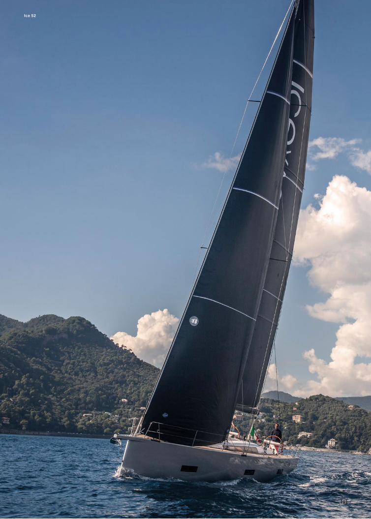
- 191 -
Ice 52
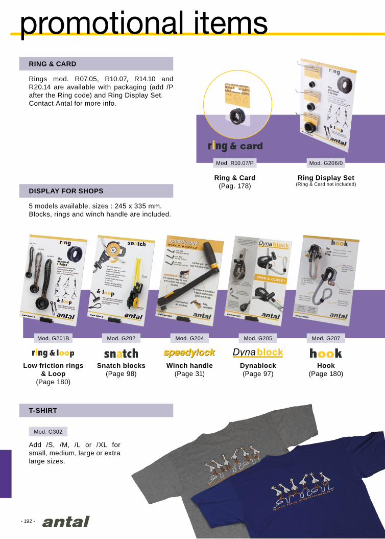
- 192 -
Mod. G201B
Mod. G302
Mod. G202 Mod. G207Mod. G204 Mod. G205
Mod. G206/0Mod. R10.07/P
promotional items
T-SHIRT
Add /S, /M, /L or /XL for small, medium, large or extra large sizes.
DISPLAY FOR SHOPS
5 models available, sizes : 245 x 335 mm. Blocks, rings and winch handle are included.
Hook(Page 180)
Winch handle(Page 31)
Low friction rings& Loop
(Page 180)
Snatch blocks(Page 98)
Dynablock(Page 97)
RING & CARD
Ring Display Set(Ring & Card not included)
Rings mod. R07.05, R10.07, R14.10 and R20.14 are available with packaging (add /P after the Ring code) and Ring Display Set. Contact Antal for more info.
Ring & Card(Pag. 178)

- 193 -
Vismara V50DS
info
CD-ROM
2019 4 languages Antal catalogue and CAD library is available in CD-Rom.
USER’S GUIDE
Winches user’s guide and many products exploded view are available on request.
CUSTOM
Custom products are designed, produced and tested on request.
2019 CATALOGUE
Photo: Studio LightPrinting: CentrooffsetPrinted in October 2018
Products are continuously improved and Antal reserves the right to modify them without notice. Antal has no responsibility for possible mistakes in this catalogue.
ANTAL is a registered trade-mark.
WEB SITE
2019 Antal catalogue is available on www.antal.it.CAD library is available in dowload section of www.antal.it
Follow us on Facebook

- 194 -
29
21
22
11
14.8
3.7
4.7
24
15.6
25
5.7
5
24
15.6
24
15.6
3.4
15.7
22
32
30
13
5
19.5
30
54
Class 40 Campagne de France
antal tracksFULL BATTEN MAST TRACKS
Material & finish: hard black anodized and Teflon-coated aluminium. Silver finish only on request.
For sliders with plastic or HS fibre guides
For sliders with HS fibre guides
For sliders with HS fibre guides or Fibreball sliders
For Fibreball sliders
size 29x21 mmfasteners: Ø8 mm screwsmounting slugs available
length: 3 mpage 166
size 22x11 mmfasteners: Ø5 mm screwsmounting slugs available
length : 2 or 3 mpage 162
size 24x16 / 4x15 mmno fasteners
mast groove 4x15 mmlength : 3 m
size 24x16 / 6x25 mmno fasteners
mast groove 6x25 mmlength : 3 m
size 24x16 mmfasteners: Ø6 mm screwsmounting slugs available
length : 2 or 3 mpage 164
size 22x16 mmprofile to be glued
length: 3 mpage 163
size 30x13 mmfasteners: Ø6 mm screws
no slugs availablelength : 3 or 6 m
page 165
size 30x20 mmprofile to be glued
length: 3 mpage 165

- 195 -
67.2
31.5
47.2
31.5
27
20.5
26
114
32
14
6
32
14
6
40
18
8
40
18
8
31
21
31
21
60
48
Material & finish: polished 316 stainless steel
size 67x31.5 mmfasteners: Ø12 mm screws
any length up to 6 mpage 142
size 47x31.5 mmfasteners: Ø10 mm screws
any length up to 6 mpage 138
size 27x20 mmfasteners: Ø6 mm screws
any length up to 6 mpage 121
size 26x4 mmfasteners: Ø5 mm screws
any length up to 3 mpage 104
size 32x6 mmfasteners: Ø6 mm screws
any length up to 6 mpage 106
size 32x6 mmfasteners: Ø6 mm screws
any length up to 6 mpage 112
size 40x8 mmfasteners: Ø8 mm screws
any length up to 6 mpage 108
size 40x8 mmfasteners: Ø8 mm screws
any length up to 6 mpage 112
size 31x21 mmfasteners: Ø8 mm screws
any length up to 6 mpage 124
size 31x60 mmfasteners: Ø8 mm screws on
sliding slugsany length up to 6 m
page 124
“T” TRACKS
4RACE TRACKS
“T” tracks for sliders with plastic guides.Material & finish: hard black or silver anodized and Teflon-coated aluminium.
4Race tracks for ball bearings sliders.Material & finish: hard black anodized and Teflon-coated aluminium. Silver finish only on request.
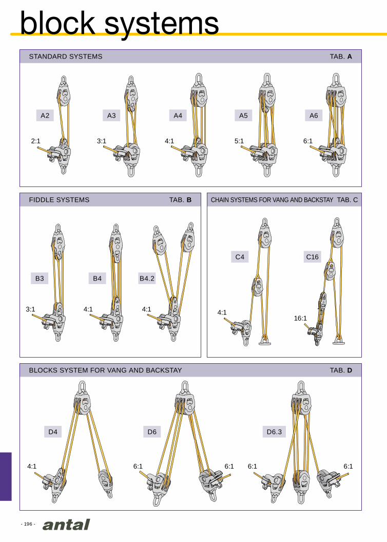
- 196 -
2:1
4:1
A2
D4 D6 D6.3
A3
B3 B4
C4
B4.2
C16
A4 A5 A6
3:1
3:1
6:1 6:1 6:1 6:1
4:1
4:1 4:14:116:1
5:1 6:1
TAB. D
TAB. B TAB. C
TAB. A
block systems
BLOCKS SYSTEM FOR VANG AND BACKSTAY
FIDDLE SYSTEMS CHAIN SYSTEMS FOR VANG AND BACKSTAY
STANDARD SYSTEMS
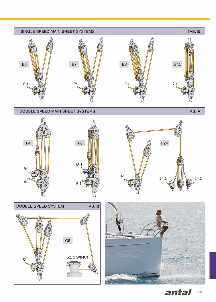
- 197 -
6:1
8:118:1
4:1 6:1
5:1
E6
F4
E7
F6
E8
F24
E7.1
7:1
5:1 x WINCH
8:1
4:1
7:1
24:1 24:1
TAB. E
TAB. F
TAB. G
G5
SINGLE SPEED MAIN SHEET SYSTEMS
DOUBLE SPEED MAIN SHEET SYSTEMS
DOUBLE SPEED SYSTEM

- 198 -
1.41
1
0.75
1
1
2
1
1
0.7
0.31
1
1.85
1
1
Ømm.
BLkg
Øinch
BLlb.
4 450 5/32 1000
5 600 3/16 1300
6 750 1/4 1650
8 1300 5/16 2850
10 2100 3/8 4600
12 2900 1/2 6400
14 3900 9/16 8600
16 5000 5/8 11000
18 6200 11/16 13600
20 7500 13/16 16500
22 9000 7/8 19800
Ømm.
BLkg
Øinch
BLlb.
3 800 1/8 1700
4 1400 5/32 3100
5 2100 3/16 4600
6 3100 1/4 6800
7 4100 9/32 9100
8 5200 5/16 11400
10 8000 3/8 17600
12 11000 1/2 24200
14 14500 9/16 31900
16 19000 5/8 41900
18 23500 11/16 51800
Ømm.
BLkg
Øinch
BLlb.
4 700 5/32 1550
5 1000 3/16 2200
6 1800 1/4 3950
8 3000 5/16 6600
10 4600 3/8 10100
12 6600 1/2 14500
14 8900 9/16 19600
16 11000 5/8 24200
Ømm.
BLkg
Øinch
BLlb.
3 550 1/8 1200
4 900 5/32 2000
5 1500 3/16 3300
6 2200 1/4 4800
7 2900 9/32 6400
8 3800 5/16 8400
10 6000 3/8 13200
12 8500 1/2 18700
Dmm
BLkg
BLkg
5 1000 600
6 1400 800
8 2600 1500
10 4000 2400
12 5600 3300
14 7600 4600
mm = inch x 25.4
cm = inch x 2.54
cm = ft x 30.48
m = ft x 0.305
m2 = ft2 x 0.093
gr = oz. x 28.35
kg = lb x 0.454
inch = mm x 0.039
inch = cm x 0.394
ft = cm x 0.033
ft = m x 3.281
ft2 = m2 x 10.76
oz. = gr x 0.035
lb = kg x 2.205
rigging loads
BREAKING LOADS
Screws AISI 316 class 50
BLOCK LOADING
Block loading depends on the angle of the line.
Values for typical angles are reported in the table.
ANGLE = 0°
TENSILE STRESS
SHEARING STRESS
ANGLE = 135°ANGLE = 90°ANGLE = 45° ANGLE = 135°
BREAKING LOADS
Reported “breaking loads” are “average values”: real values may vary greatly according to the supplier.
“Working loads” will be obtained with appropriate safety factors: 1/2 for steel wire, 1/4 for rope.
CONVERSION FACTOR
POLYESTERcover and core
POLYESTER (cover)DYNEEMA (core)
S. STEEL AISI 3161 x 19
S. STEEL AISI 3167 x 19
TENSILESTRESS
SHEARINGSTRESS
SWL is the abbreviation of Safe Working Load, it is half of the Breaking Load (BL).
Tensostructure
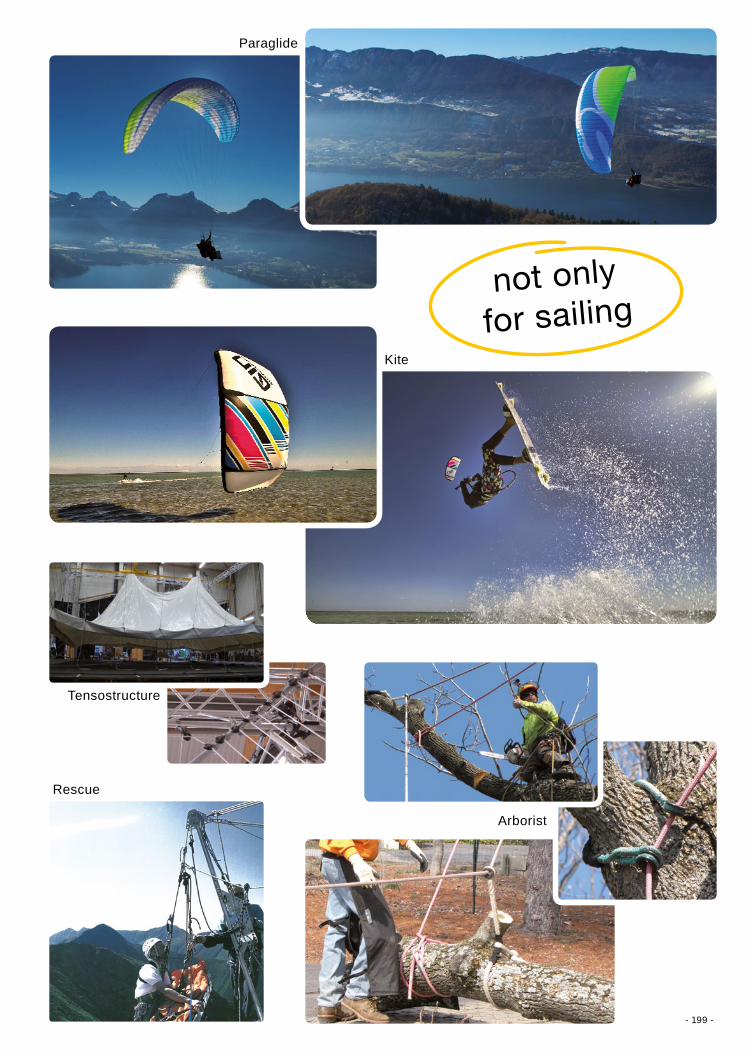
- 199 -
Kite
Paraglide
Rescue
Tensostructure
Arborist
not only
for sailing
- 200 -
00301 ...................5300302 ...................5300303 ...................5300304 ...................5300305 ...................5300306 ...................5300311 ...................5300316 ...................5300320 ...................5300321 ...................5300322 ...................5300323 ...................5300324 ...................5300330 ...................5300331 ...................5300401 ...................5400401/B ................5500402 ...................5400402/B ...............5500403 ...................5400404 ...................5400405 ...................5400406 ...................5400411 ...................5400416 ...................5400418 ...................8800418/D ................88
00420 ...................5400421 ...................5400422 ...................5400423 ...................5400424 ...................5400430 ...................5400430/B ...............5500431 ...................5400431/B ................5500501 ...................5800502 ...................5800503 ...................5800504 ...................5800505 ...................5800506 ...................5800507 ...................5800508 ...................5800509 ...................5800510 ...................5800511 ...................5900512 ...................5900513 ...................5900516 ...................5900517 ...................5900518 ...................88005SS ................18800601 ...................6000601/J ..............12200602 ...................60
00603 ...................6000604 ...................6000605 ...................6000606 ...................6000607 ...................6000608 ...................6000609 ...................6000610 ...................6000611 ...................6100612 ...................6100613 ...................6100614 ...................6100615 ...................6100616 ...................6100617 ...................6100618 ...................8800621 ...................8700621/C ................8700631/C................6800632/C ...............6800633/C ...............68006HR ................188006SS ................18800701 ...................6200701/J...............12600702 ...................6200703 ...................6200704 ...................6200705 ...................62
00706 ...................6200707 ...................6200708 ...................6200709 ...................6200710 ...................6200711 ...................6300712 ...................6300713 ...................6300714 ...................6300715 ...................6300716 ...................6300717 ...................6300718 ...................8800718/Z ................8800731/C ................6800732/C ...............6800733/C ...............6800801 ...................6400801/J1............. 12700801/J2 ............ 12800802 ...................6400803 ...................6400803/J2 ............12900807 ...................6400808 ...................6400809 ...................6400810 ...................6400811 ...................6400812 ...................64
00813 ...................6400814 ...................6400815 ...................6400816 ...................6400818 ...................8800818/Z ................8800821 ...................87008HR ................188008SS ................18801001 ...................6501001/J2 .............12901002 ...................6501003 ...................6501007 ...................6501008 ...................6501009 ...................6501010 ...................6501011 ....................6501012 ...................6501014 ...................6501015 ...................6501016 ...................6501018 ...................8801018/Z ................8801021 ...................87010HR ................188010SS ................18801201 ...................6601202 ...................66
0
Amel 50 - photo JS Evrard
model indexModel ...............page Model ...............page Model ...............page Model ...............page Model ...............page

- 201 -
01209 ...................6601210 ...................6601211 ....................6601212 ...................6601214 ...................6601215 ...................6601216 ...................6601218 ...................8801218/Z ................88012HR ................188012SS ................18801401 ...................6701402 ...................6701409 ...................6701410 ....................6701411 ....................6701412 ....................6701414 ....................6701415 ....................6701418/Z ................88014HR ................188014SS ................188016HR ................188016SS ................18803411/M ................5203413/M ...............5304013/M ...............5204514/M ...............5404819/F ................5605114/M ................5606016/F ................5606421/F ................5607016/F ................5607016/R ................9407116/R ................9408019/F ................5608019/R ................9408119/R ................94
10021/A ................5610021/R ................9410121/R ................9412025/A ................5614025/A ................5615029/A ................7018035/A ................70
2011 .....................302012 .....................302014 .....................302021 .....................302022 .....................302023 .....................30
2031 .....................302032 .....................302033 .....................302121 .....................312122 .....................312123 .....................3121843/A ................70240.010 ................2724856/A ................70251.035/AG ...........17251.035/AR ...........17251.035/QG ..........17251.035/QR ..........17251.035/SG ..........17251.035/SR ...........17
4100 ...................1224100/F ................ 1314101 ...................1224102 ...................1224102/SH ............. 1214103 ...................1224110....................1264110/D ................1324110/F ................ 1314110/SH .............. 1244112 ....................1264113 ....................1264114 ....................1264118 ....................1454119/SP ..............1454123 ...................1294124 ...................1294127 ...................1294150/C ................1354150/D ................1324150/F ................ 1314150/SH ............. 1244153 ...................1274154 ...................1274155 ...................1274190/D ................1324190/F ................ 1314190/H ................ 1154190/SH ............. 1244194 ................... 1284195 ................... 1284196 ................... 1284199 ................... 1284230/D ...............1324260/H ............... 1154261 ................... 1214262 ................... 1214263 ................... 121
4264 ................... 1214264/Z ................1234266 ................... 1214271 ...................1254271/B ................1454272 ...................1254273 ...................1254273/Z ................1304274 ...................1254274/G ...............1344274/Z ................1294275 ...................1254275/Z ................1294276 ...................1254283 ...................1454291 ...................1254410 ...................1254410/Z ................1294420 ...................1254430 ...................1254510 ................... 1244520 ................... 1244523 ...................1454530 ................... 1244540 ................... 1244541 ................... 1244550 ................... 1244560 ................... 1154601 ...................1234603 ...................1234623 ...................1344631 ...................1234633 ...................1234651 ...................1344654 ...................1344691 ...................1344694 ...................1344901 ...................1224902 ...................1224903 ...................1224904 ...................1224911 ...................1264913 ...................1264914 ...................1264915 ...................1264916 ...................1264921 ...................1294922 ...................1294925 ...................1294951 ...................1274952 ...................1274953 ...................1274954 ...................1274955 ...................1274991 ................... 128
4992 ................... 1284993 ................... 1284994 ................... 1284995 ................... 128
500.110 .................37500.120 ................37500.130 ................37500.210 ................37501.110 .................37501.120 .................37501.130 .................37501.210 ................37502.011 ................48502.022 ................48502.033 ................48502.22/37 .............48505.081 ................45505.082 ................45505.083 ................45505.085 ................45505.086 ................45505.087 ................45505.101 ................45505.102 ................45505.103 ................45505.105 ................45505.106 ................45505.107 ................45505.121 ................45505.122 ................45505.123 ................45505.125 ................45505.126 ................45505.127 ................45505.141 .................45505.142 ................45505.143 ................45505.145 ................45505.146 ................45505.147 .................45505.161 ................45505.162 ................45505.163 ................45505.165 ................45505.166 ................45505.167 ................45505.181 ................45505.182 ................45505.183 ................45505.185 ................45505.186 ................45505.187 ................45506.101 ................43
506.103 ................43506.106 ................43506.121 ................43506.123 ................43506.126 ................43507.111 .................46507.112 .................46507.113 .................46507.121 .................46507.122 .................46507.131 .................46507.132 .................46508.114 .................41508.116 .................41508.118 .................41508.120 ................41508.121 ................41508.122 ................41508.122P ..............41508.123 ................41508.141 .................41508.142 ................41508.143 ................41508.161 ................41508.162 ................41508.163 ................41509.111 .................39509.111/H..............39509.112 .................39509.112/H .............39509.113 .................39509.113/H .............39509.121.................39509.122 ................39509.123 ................39509.131 .................39509.132 ................39509.133 ................39509.141 .................39509.142 ................39509.143 ................39513.032 ................47513.110 .................37513.120 .................37513.130 .................37513.210 ................37513/E ....................37513/F ....................37513/I .....................37514.032 ................47515.032 ................47516.032 ................475194 ...................1305197 ...................130522.022 ................48
1
2
4
5
Model ...............page Model ...............page Model ...............page Model ...............page Model ...............page

- 202 -
522.031 ................47522.140 ................48523.042 ................47523.052 ................47524.042 ................47524.052 ................47525.042 ................47525.052 ................47526.042 ................47526.052 ................47533.032 ................47534.032 ................47535.032 ................47536.032 ................47540.110 .................37540.120 ................37540.130 ................37540.210 ................37541.110 .................37541.120 .................37541.130 .................37541.210.................37543.110 .................37543.120 ................37543.130 ................37543.210 ................37549.111 .................39549.111/H..............39549.112 .................39
549.112/H .............39549.113 .................39549.113/H .............39549.121.................39549.122 ................39549.123 ................39549.131 .................39549.132 ................39549.133 ................39549.141 .................39549.142 ................39549.143 ................39
601.121 ............... 121601.123 ...............138601.123/R ...........138601.124 ............... 142601.221 .............. 121601.223 ..............138602.112 ............... 112602.112/B ........... 112602.112/S ........... 112602.113 ............... 112602.113/B ........... 112602.113/S ........... 112602.211 .............. 112602.211/B ........... 112602.212 .............. 112
602.212/B ........... 112602.212/S ........... 112602.213 .............. 112602.213/B ........... 112602.213/S ........... 112602.312 .............. 112602.312/SI .......... 112602.313 .............. 112602.313/SI .......... 112602.412 .............. 113602.413 .............. 113609.320 ..............168609.321 ..............168609.322 ..............168609.323 ..............169609.324 ..............169609.325 ..............169609.326 ..............169609.327 ..............168610.340 ..............169610.341 ..............169614.210/1024 ......139614.212/1224 ......139614.213/1224 ......139614.214/1224 ......139614.219 ..............138614.222/1424 ......140614.223/1424 ......140614.224/1224 ......140
614.225/1224 ......140614.229 ..............138614.232/1224 ...... 141614.233/1224 ...... 141614.235/1224 ...... 141614.236/1224 ...... 141614.239 ..............138615.222/1424 ......143615.223/1424 ......143615.229 .............. 142615.233/1424 ......143615.236/1224 ......143615.239 .............. 142615.249 .............. 142620.492 ..............106621.452 ..............104621.462 ..............104621.472 ..............105621.492 ..............104622.402 .............. 113622.412 .............. 187622.422 .............. 113622.462 .............. 107622.492 ..............106622.492/S ........... 116622.511/S0701 .... 117622.512/S ........... 117622.512/S0701 ... 117622.513/S0701 ... 117
622.523/S0701 ... 117623.120/AL ......... 110623.150/AL ......... 110623.180/AL ......... 110623.402 .............. 113623.412 .............. 187623.422 .............. 113623.462 ..............109623.492 ..............108623.492/S ........... 116623.511/S0901 .... 117623.512/S0901 ... 117623.513/S0901 ... 117623.523/S0901 ... 117624.402 .............. 113624.422 .............. 113624.492 ..............108625.492 .............. 1076320/12 ................296320/24 ................29671.002 .............. 111671.003 .............. 111671.004 .............. 111672.002 .............. 114672.003 .............. 114672.004 .............. 114672.005 .............. 114681.822 ..............138690.151 ...............104
HH 6601 Cat
6
model indexModel ...............page Model ...............page Model ...............page Model ...............page Model ...............page
- 203 -
690.152 ..............104690.251 .............. 107690.252 .............. 107690.351 ..............109690.352 ..............109691.141 ...............104691.240/S ........... 117691.241 ..............106691.241/B ........... 113691.241/S ........... 116691.242/S ........... 116691.243/S ........... 116691.244/S ........... 116691.341 ..............108691.341/B ........... 113691.341/S ........... 116691.342/S ........... 116691.343/S ........... 116691.344/S ........... 116691.421 .............. 121691.451 .............. 111691.452 .............. 111691.560 ..............138691.561 ..............138691.563 ..............138691.660 .............. 142691.661 .............. 142691.663 .............. 142691.711/S ............ 117691.721/S ........... 117691.722/AL .........108691.722/S ........... 110691.822 ..............138
7105 ...................1887106 ...................1887108 ...................1887110 ...................1887206 ...................1897208 ...................1897210 ...................1897212 ...................1897214 ...................1897216 ...................1897220 ...................1897306 ...................1897308 ...................1897310 ...................1897312 ...................1897314 ...................1897316 ...................1897321 ...................1897412 ................... 1877413 ................... 187
7505 ................... 1747506 ................... 1747508 ................... 1747510 ................... 1747512 ................... 1747514 ................... 1747605 ................... 1747606 ................... 1747608 ................... 1747610 ................... 1747612 ................... 1747614 ................... 174
801.045 ................90801.060 ................90801.071 ................90801.090 ................90801.110 .................90812.154 .................71812.184 .................72813.154 .................71813.184 .................72815.075 ................85815.090 ................85815.120 .................85815.150 .................85815.180 .................85815.452 ................85815.552 ................85815.652 ................85816.075 ................86816.090 ................86816.120 .................86816.150 .................86816.180 .................86817.050 .................91817.060 .................91818.050 ................91818.060 ................91819.045 ................90819.060 ................90819.070 ................90819.090 ................90821.050 ................90821.052 ................89821.062 ................89821.070 ................90821.074 .................89821.100 .................90831.154 .................71831.184 .................72832.154 ................71832.184 ................72851.065 ................49
851.080 ................49851.100 .................49851.125 .................49852.065 ................49852.080 ................49852.100 ................49852.125 ................49
9001 .....................969030 .....................969031 .....................969040 .....................989060 .....................98908.095 .............. 101908.125 .............. 101909.502 .............. 107909.552/S........... 116910.155/Z .............71910.185 .................72910.225 ................73910.255 ................73911.154 .................71911.184 .................72911.224.................73911.254 ................73918.095 .............. 101918.125 ............... 101918.155 ............... 101922.602 ................69928.095 .............. 101928.125 .............. 101928.155 .............. 101932.652 ................69940.155/Z .............71940.185 ................72940.225 ................73940.255 ................73941.154 .................71941.184 .................72941.224 ................73941.254 ................73949.502 .............. 107949.552/S ........... 116981.154 .................71991.073 ................92991.093 ................92991.124 .................92991.154 .................92991.184 .................92992.602 ................69993.653/C ............69994.055 ................92994.065 ................92994.075 ................92
994.085 ................92994.095 ................92994.125 ................92
A041 .....................17A051 .....................17A071 .....................17A101 .....................17A151 .....................17
BB4012 ................99BB6014 ................99
C001 ....................25C002 ....................25C003 ....................25C004 ....................25C005 ....................25C006 ....................25
D3008 ................177D3610 .................177D420 ....................89D430 ....................89D440 ....................89D450 ....................89D460 ....................89D520 ....................89D530 ....................89D540 ....................89D550 ....................89D560 ....................89D620 ....................89D630 ....................89D640 ....................89D650 ....................89D660 ....................89D720 ....................89D730 ....................89D740 .....................89D750 ....................89D760 ....................89DBL44 ..................97DBL56 ..................97DBS44..................97DBS56 ..................97
E6/60 ...................68E6/75 ...................68E7/60 ....................68
E7/75 ....................68E8/60 ...................68E8/75 ...................68
F4 .........................69F6 .........................69FB24.120D ..........160FB24.120J ..........160FB24.120JA ........159FB24.121 ............159FB24.60D ...........158FB24.60J ............158FB24.60S ...........158FB24.90D ...........159FB24.90J ............159FB29.11 ..............166FB29.12 ..............166FB29.13 ..............166FB29.150J .......... 161FB29.15 ..............166FB29.190D ......... 161FB29.190J .......... 161FB29.191 ............ 161FB29.221 ............166FB29.311 ............166FB29.321 ............166FB29.90S ........... 161
G201B ................192G202 ..................192G204 ..................192G205 ..................192G206/0 ...............192G207 ..................192G302 ..................192
H020 ....................93H030 ....................93H040 ....................93H050 ....................93H130 .....................93H140 .....................93H150 .....................93H160.....................93HDR .......................4HK12 ..................180HK16 ..................180HS22.01 .............163HS22.02 .............163HS22.03 .............163HS22.05 .............163HS22.06 .............167
8
G
H
9
A
B
C
D
E
F
7
Model ...............page Model ...............page Model ...............page Model ...............page Model ...............page

- 204 -
HS22.07 .............167HS22.100JA/R ....150HS22.110 ............ 151HS22.11 ..............162HS22.12 .............162HS22.13 .............162HS22.15 .............162HS22.160R ......... 170HS22.16 .............167HS22.17.............. 170HS22.185............ 171HS22.221 ...........162HS22.222 ...........162HS22.27 ............. 170HS22.311............162HS22.312 ...........162HS22.321 ...........162HS22.322 ...........162HS22.330 ...........163HS22.40D...........149HS22.40D/R ....... 149HS22.40J ...........149HS22.40J/R ........149HS22.40S ...........149HS22.40S/R ....... 149HS22.44 .............149HS22.46 .............149
HS22.49 .............149HS22.50D/R .......150HS22.50J/R ........150HS22.50S/R .......150HS22.60J/R ........ 151HS22.60T/R ........ 151HS22.70JA/R ..... 149HS22.70J/R ........150HS22.90J/R ........ 151HS22F05 ............162HS22F08 ............162HS22F10 ............162HS22F12 ............162HS22F14 ............162HS22R04............162HS22R05............162HS24.110JA ........152HS24.11 ..............164HS24.12 ..............164HS24.13 ..............164HS24.15 ..............164HS24.16 ..............167HS24.17 .............. 170HS24.18 .............. 170HS24.210 ........... 170HS24.221 ...........164HS24.222 ...........164
HS24.311 ............164HS24.312 ...........164HS24.321 ...........164HS24.322 ...........164HS24.50D ...........152HS24.50J ...........152HS24.50S ...........152HS24.54 .............152HS24.56 .............152HS24.59 .............152HS24.60J ...........153HS24.60T ...........153HS24.61 ............. 170HS24.64 .............153HS24.66 .............153HS24.69 .............153HS24.70J............154HS24.70Q ...........154HS24.74 ..............154HS24.76 .............154HS24.79 .............154HS24.90/DX ....... 171HS24.90/DY ....... 171HS24F05 ............164HS24F06 ............164HS24F08 ............164HS24F10 ............164
HS24F12 ............164HS24F14 ............164HS24R04 ............164HS24R06 ............164HS30.01 .............165HS30.02 .............165HS30.03 .............165HS30.05 .............165HS30.07 .............167HS30.110J ..........155HS30.116 ............155HS30.11 ..............165HS30.12 .............165HS30.120JA........155HS30.130J ..........156HS30.13 .............165HS30.16 .............167HS30.313 ...........165HS30.313/R ........165HS30.330 ...........165HS30.70Q ..........155HS30.70S ...........155HS30.74 .............155HS30.76 .............155HS30.79 .............155HS30.90/DX ....... 171HS30.90/DY ....... 171
HS30.90J ...........155HS30.90Q ..........156
JB06 ................... 137JB08 ................... 137JB10 ................... 137JB12 ................... 137JB14 ................... 137
LD1000 .................28LD1500 .................28LD1500HD ............29LD700 ..................28LL046 .................100LL054 .................100LS046 ................100LS054 ................100LS1060 .................76LS1061 .................76LS1062 .................76LS1063 .................76LS1070 .................76LS1071 .................76LS1072 .................76LS1073 .................76
L30 - One Design
J
L
model indexModel ...............page Model ...............page Model ...............page Model ...............page Model ...............page
- 205 -
LS1080 .................76LS1081 .................76LS1082 .................76LS1083 .................76LS1100 .................77LS1101 .................77LS1120 .................77LS1121 .................77LS1140 .................77LS1141 .................77LS2060...............183LS2061 ...............183LS2062...............183LS2070 ...............183LS2071 ...............183LS2072 ...............183LS2080...............183LS2081 ...............183LS2082 ...............183LS2100 ...............183LS2101 ...............183LS2102 ...............183LS2120 .................77LS2122 ...............183LS2140 .................77 LS2142 ...............183
P10.20 ................167P14.25 ................167P14.35 ................167
R07.05 ................ 178R10.07 ................ 178R10.07/P .............192R12.25 ................ 176R14.10 ................ 178R14.14 ................ 176R14.14/S ............. 176R18.36 ................ 176R20.14 ................ 178R20.20 ............... 176R20.20/S ............ 176R2.14 ..................177R28.20 ............... 178R30.56 ............... 179R3.14 ..................177R34.64 ............... 179R38.28 ............... 178R40.76................ 179R4.14 ..................177R50.94 ............... 179R5.14 ..................177
R6.14 ..................177RC230 ................186RC290 ................186RC350 ................186RC420 ................186RF14.30 ..............180RF16.35 .............180RF18.40..............180RL3.0 .................180RL4.0 .................180RL4.5 .................180RL5.0 .................180RL6.0 .................180RL6.1 ..................180
S0601...................79S0602 ..................79S0603 ..................79S0604 ..................79S0605 ..................79S0606 ..................79S0609 ..................79S0611 ...................79S0612 ...................79S0613 ...................79S0614 ...................79S0615 ...................79S0616 ...................79S0701 ...................80S0702 ...................80S0703 ...................80S0704 ...................80S0705 ...................80S0706 ...................80S0711 ...................80S0712 ...................80S0713 ...................80S0714 ...................80S0715 ...................80S0731 ...................80S0732 ...................80S0901...................81S0902 ..................81S0903 ..................81S0904 ..................81S0905 ..................81S0906 ..................81S0911 ...................81S0912 ...................81S0914 ...................81S0915 ...................81S0931 ...................81S0932 ..................81
S1201 ...................82S1202 ...................82S1203 ...................82S1204 ...................82S1211 ...................82S1212 ...................82S1214 ...................82S1215 ...................82S1231 ...................82S1232 ...................82S1501 ...................83S1502 ...................83S1511 ...................83S1512 ...................83S1514 ...................83S1515 ...................83S1531 ...................83S1532 ...................83S1801 ...................84S1802 ...................84S1811 ...................84S1812 ...................84S1814 ...................84S1815 ...................84S1831 ...................84S1832 ...................84SL4D ..................182SL4S ..................182SL4T ..................182SL5D ..................182SL5S ..................182SL5T ..................182SP10.48 .............190
T520 .....................91T530 .....................91T540 .....................91T550 .....................91T560 .....................91T620 .....................91T630 .....................91T6315/12 ..............17T6315/24 ..............17T640 .....................91T6415/24 ..............17T650 .....................91T660 .....................91TB4212 .................99TD22.32 ............. 175TD28.40 ............. 175TL22.32 .............. 175TL28.40 .............. 175TT22.32 ............. 175
TT28.40.............. 175
W16 ........................7W30 .......................7W42 ........................7W42/BNC .............26W42/CHC .............26W44........................7W48 ........................7W48/CHC .............26W52........................7W5 .........................6W6 .........................6W7 .........................6W80.3EH ..............21W80.3EV ..............21W80.3HD ..............20W80.3ST ..............20W8 .........................6W90.3EH ..............21W90.3EV ..............21W90.3HD..............20W90.3ST ..............20WBC .....................17
XT16.2 .................10XT16.2R ...............22XT16 ....................10XT16R ..................22XT30.2 .................10XT30.2R ...............22XT30 ....................10XT30R ..................22XT40 ....................10XT40EH ................14XT40R ..................22XT44 ....................10XT44EH ................14XT44HD ...............18XT44R ..................22XT48 ....................10XT48/BNC ............26XT48EH ................14XT48HD ...............18XT48R ..................22XT52.3RD ............23XT52 ....................10XT52EH ................14XT52HD ...............18XT52R ..................22XT62.3 ................. 11XT62.3EH .............14
XT62.3HD ............18XT62.3R ...............23XT62.3RD ............23XT62 ....................10XT62EH ................14XT62HD ...............18XT62R ..................22XT66.3 ................. 11XT66.3EH.............15XT66.3EV .............16XT66.3HD ............19XT66.3R ...............23XT66 .................... 11XT66EH ...............15XT66EV ................16XT66HD ...............19XT66R ..................22XT70.3 ................. 11XT70.3EH.............15XT70.3EV .............16XT70.3HD ............19XT70.3R ...............23XT70 .................... 11XT70EH ...............15XT70EV ................16XT70HD ...............19XT70R ..................22XT80.3 ................. 11XT80.3EH.............15XT80.3EV .............16XT80.3HD ............19XTKIT .....................4
Y-B0746 ...............59Y-B0747 ................59Y-B0748 ...............61Y-B0749................61Y-B0750 ...............64Y-B0751 ...............65Y-B0752 ...............66Y-B0846 ...............67
P
S
T Y
X
W
R
Model ...............page Model ...............page Model ...............page Model ...............page Model ...............page

- 206 -
www.ranzatoimpianti.it
Stealth 93’
LIMITED WARRANTYAntal guarantees its equipment to be free of defects in material and workmanship for 3 years from the date of purchase. During this period defective parts will be repaired or replaced by Antal.Warranty does not cover: - products incorrectly installed; - products used in applications for which they are not intended;
- products used under loads exceeding the product’s stated loads;
- products not properly maintained.Warranty does not cover defects due to corrosion, U-V degradation, and normal wear and tear.Products subject to warranty claim will be returned to Antal for examination and possible repairing or replacement. Antal is not responsible for installation or shipping costs.
SOLAR PLANTThe new Antal photovoltaic solar plant with a surface of 500 m2 and a power of 20 kw will supply 20% of the energy necessary for the production. Our passion for sailing is also care for the environment.
MAINTENANCERemove salt deposits with fresh water; frequently washing will avoid corrosion that is activated from salt water.Grease (Hydrolub) or Loctite or anticorrosive product will protect aluminium; it will be useful to use some grease on s. steel parts: screws, washers, pin to reduce the contact with aluminium.Although all Antal products are made only with anti U-V plastic it will be better to reduce the exposure to sunlight.

ANTAL srl - Via del Progresso 10 - 35127 Padova - Italy - Tel. 049 8702655 - 8701265 - Fax 049 760906 www.antal.it - [email protected]
HONG KONGSTORM FORCE MARINE LTDTel.: +852 2866 0114Fax: +852 2866 9260Email: [email protected]
MALTASEALINK MARINE CENTRETel.: +356 213 15505Email: [email protected]
NEW ZEALANDHALL SPARS NZ LTDTel.: +64 9-4275472Email: [email protected]
POLANDTAURUS SEA POWER LTDTel.: +48 58-3020225Fax: +48 58-3020225Email: [email protected]
SOUTH AFRICAMANEX & POWER MARINE LTDTel.: +27 21 5117292Fax: +27 21 5101487Email: [email protected]
SPAINTACK VELAS S.L.Tel.: +34 93 2218212Mob.: +34 620388754Email: [email protected]
THAILANDEAST MARINE CO. LTDTel.: +66 76 239113Mob.: +66 8 10828811Email: [email protected]
TURKEYBARAN MAKINATel.: +90 216-3499024Fax: +90 216-3499025Email: [email protected]
UNITED KINGDOMMARINEWARE LTDTel.: +44 2380-624555Fax: +44 2380-624559Email: [email protected]
U.S.A.EURO MARINE TRADING INC.Tel.: +1 401-8490060Fax: +1 401-8493230Email: [email protected]
ARGENTINAC.D.S.N. PABLO MONSEGURMob.: +54 911 159058118 +54 911 59058222Email: [email protected]
AUSTRALIASAILFORCE PTY LTDMob.: +61 404033121Email: [email protected]
CARIBBEANFKG MARINE RIGGING NVTel.: +1 721 544 4733Voip: +1 954 495 4497Email: [email protected]
CROATIAVIRGA SAILING EQUIPMENTTel.:+385 21 358188Mob.:+385 98 510652Email: [email protected]
DENMARKRIGGERNE ApSTel.: +45 31793001Email: [email protected]
FRANCEXPO ANTAL FRANCETel.: +33 5464 52582Fax: +33 5464 48178Email: [email protected]
GERMANYPFEIFFER MARINE GMBHTel.: +49 7732 99500Fax: +49 7732 995050Email: [email protected]
GREECEMELTEMI YACHT RIGGING LTDTel.: +30 210 9849983Fax: +30 210 9844356Email: [email protected]
HOLLANDALLPA BVTel.: +31 24 3777773Fax: +31 24 3777770Email: [email protected]
HOLLANDA+ RIGGING NEDERLAND BVTel.: +31 227 544096Email: [email protected]
2019 / 2020
2019/2020