CATALOGO - CAI srl
118
A B servi ce & soluti o ns CATALOGO ACCESSORI ARIA COMPRESSA COMPRESSED AIR ACCESSORIES
-
Upload
khangminh22 -
Category
Documents
-
view
0 -
download
0
Transcript of CATALOGO - CAI srl

A
A B
C
service & solutions
TITAN ENGINEERING S.p.A.Via dei Cerri, 16/1847899 Zona Artigianale Ciarulla RSM(C.O.E. SM 04813)Tel. 0549 961121Fax 0549 [email protected]
CATALOGOACCESSORI ARIA COMPRESSA
COMPRESSED AIR ACCESSORIES
Prin
ted
in I
taly
09/
2015
C
M
Y
CM
MY
CY
CMY
K

1the overall dimensions and technical information are provided solely for informative reasons and may be subject to change without prior notice
i nostri cataloghi
raccordi automatici in ottone “RAP”
raccordi automatici in ottone “RAP OT/OV”
raccordi automatici in tecnopolimero “TECNO-RAP”
astine per raccordi ad anello girevole
regolatori di flusso “RAP, T-RAP, L-RAP”
raccordi automatici in acciaio “INOX SS”
raccordi automatici in ottone “MINI”
raccordi automatici in tecnopolimero serie “COMPACT”
raccordi standard “100” in ottone
raccordi ad ogiva “200” in ottone
raccordi a calzamento “300” in ottone
raccordi funzione “TECNO-FUN”
raccordi automatici
raccordi a doppia ogiva
valvole di scarico rapido
raccordi in linea
regolatori di flusso in linea
valvole modulari
valvole a sfera mini
valvole a sfera
valvole a spillo
valvole di ritegno
2dimensioni di ingombro e informazioni tecniche sono fornite a puro titolo informativo e possono essere soggette a modifica senza preavviso
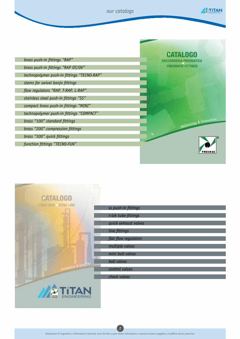
our catalogs
brass push-in fittings “RAP”
brass push-in fittings “RAP OT/OV”
technopolymer push-in fittings “TECNO-RAP”
stems for swivel banjo fittings
flow regulators “RAP, T-RAP, L-RAP”
stainless steel push-in fittings “SS”
compact brass push-in fittings “MINI”
technopolymer push-in fittings “COMPACT”
brass “100” standard fittings
brass “200” compression fittings
brass “300” quick fittings
function fittings ”TECNO-FUN”
ss push-in fittings
t-lok tube fittings
quick exhaust valves
line fittings
flat flow regulators
multiple valves
mini ball valves
ball valves
control valves
check valves

3the overall dimensions and technical information are provided solely for informative reasons and may be subject to change without prior notice
La Titan Engineering S.p.A. fondata nel 1993, é una
società del Gruppo Pneumax, nata con l’obiettivo di
diventare la sede produttiva e il magazzino centrale,
per la raccorderia e gli accessori per l’aria compressa,
di tutta la rete distributiva Pneumax, italiana e
internazionale, attraverso un percorso sostenuto da
iniziative strettamente legate alle strategie di sviluppo
portate avanti dalla casa madre in questi ultimi 20 anni.
L’elemento che ha contribuito in modo determinante
alla crescita dell’Azienda, nel corso di questi anni, è
stato la capacità di sapersi modellare sulle esigenze e
sulle indicazioni trasferite dalla Clientela, grazie alle
quali sono stati fatti investimenti mirati in attività
produttive interne, in accordi di collaborazione con i
migliori partner italiani ed esteri, e si sono potenziati
gli aspetti legati alla qualità e flessibilità del servizio
offerto. L’obiettivo si è concretizzato con la realizzazione
del “Catalogo Blue Line”, uno strumento complementare
per gli specialisti della raccorderia pneumatica e per i
distributori di articoli tecnici.
Titan Engineering S.p.A.
47890 Zona Artigianale Ciarulla - RSMVia dei Cerri, 16Tel. 0549/961121Fax 0549/960421Cod. op. SM04813www.titanengineering.sm
La vendita dei componenti illustrati e descritti nel pre-sente catalogo viene effettuata in Italia e all’estero attraverso l’organizzazione indicata nella sez. “orga-nizzazione commerciale”. Dimensioni di ingombro e informazioni tecniche sono fornite a puro titolo infor-mativo e possono essere modificate senza preavviso.
Pneumax S.p.A.
24050 LURANO (BG) ItalyVia Cascina Barbellina, 10Tel. 035/4192777www.pneumaxspa.com
CAPITALE SOCIALE EUR 2.700.000 I.V. R.E.A. BERGAMO N. 160798R.E.A. MILANO N. 931262COD. FISC. E P. IVA 02893330163COD. MECC. MI 322178
L’azienda
Titan Engineering S.p.A. - Pneumax Group

4dimensioni di ingombro e informazioni tecniche sono fornite a puro titolo informativo e possono essere soggette a modifica senza preavviso
Titan Engineering S.p.A. founded in 1993, is a company
of the Pneumax Group, started with the goal of becoming
the production site and warehouse, of fittings and
accessories for compressed air, for the entire Pneumax
distribution network (Italian and international), through
a path supported by initiatives closely linked to the
development strategies pursued by the mother Company
over the past 20 years.
The element that has contributed to the growth of the
Company, during these years, was to be capable of
modeling itself on the needs and directions transferred
from the customers, through which have been made
targeted investments in production activities, in co-
operation agreements with the best Italian and foreign
partners, and have enhanced the aspects related to the
quality and flexibility of the service.
The goal has been reflected in the creation of the “Blue
Line Catalog“, a complementary tool for specialists of
pneumatic fittings and accessories dealers.
The company
Titan Engineering S.p.A.
47890 Zona Artigianale Ciarulla - RSMVia dei Cerri, 16Tel. 0549/961121Fax 0549/960421Cod. op. SM04813www.titanengineering.sm
Sales of the components illustrated and described in the present catalogue in Italy and abroad are handled throu-gh the organization indicated in the section “sales net-work”.The overall dimensions and technical information are pro-vided solely for informative reasons and may be subject to change without notice.
Pneumax S.p.A.
24050 LURANO (BG) ItalyVia Cascina Barbellina, 10Tel. 035/4192777www.pneumaxspa.com
CAPITALE SOCIALE EUR 2.700.000 I.V. R.E.A. BERGAMO N. 160798R.E.A. MILANO N. 931262COD. FISC. E P. IVA 02893330163COD. MECC. MI 322178
Titan Engineering S.p.A. - Pneumax Group

5the overall dimensions and technical information are provided solely for informative reasons and may be subject to change without prior notice
certificazioni e qualità · certifications and quality
Qualità non solo come fine, ma come stile comportamentale, animato da una intensa attività di sensibilizzazione e coinvolgimento; sulla base di questa premessa, i principali elementi con cui si è deciso di edificare il nostro Sistema Qualità sono: l’AZIENDA, la PERSONA, il LAVORO. Valori autentici che, in un contesto generale mutevole ed imprevedibile, diventano punti di riferimento imprescindibili. Ogni componente è parte attiva in un sistema fatto di reciprocità: dove l’azienda promuove il rispetto dei valori etici e dei diritti e della dignità delle persone, dove ogni persona è parte attiva e fattiva per il bene dell’azienda e dove il lavoro ne rappresenta il legante, ritornando ad essere un modello dinamico di crescita per se stessi e per il tessuto socio-economico. Il raggiungimento della Certificazione ISO 9001:2008 è una ulteriore garanzia verso i nostri Clienti e soprattutto il riconoscimento in qualcosa in cui crediamo.
Quality not only as an end, but as a behavioral style, animated by an intense awareness and involvement, on the basis of this premise, the main elements with which it was decided to build our Quality System are: the COMPANY, the PERSON, the JOB. Authentic values which, in a general context changeable and unpredictable, they become points of reference indispensable. Each component has an active part in a system made up of reciprocity: where the company promotes respect for ethical values and the rights and dignity of persons, where each person is an active and effective for the good of the company’ and where the work represents the binder, returning to be a dynamic model of growth for themselves and for the socio-economic context. Achieving ISO 9001:2008 certification is an additional guarantee to our Customers, and above all the recognition in something we believe in.
Mission

6dimensioni di ingombro e informazioni tecniche sono fornite a puro titolo informativo e possono essere soggette a modifica senza preavviso
certificazioni e qualità · certifications and quality
TESTING BENCH
FEMALE GO-NOGO GAUGEMALE GO-NOGO GAUGE
PRESSURE DISPLAY CHECK
AIR LEAKAGE TEST
HEX KEY MEASURE
DIGITAL PRESSURE SWITCH
TOOLS SET

7the overall dimensions and technical information are provided solely for informative reasons and may be subject to change without prior notice
indice
silenziatori e filtri 9
silenziatori in bronzo e a filo 10
ugelli di flusso 18
scarichi automatici 22
tubi e terminali 25
tubi in rotoli e spiralati 26
morsetteria e pinze 36
pistole per aria 38
raccorderia con molla e con dado capettato 41
valvole e rubinetti 45
valvole manuali 46
valvole di scarico rapido 48
valvole e rubinetti unidirezionali 51
valvole a pedale 57
accessori per impianti e vari 59
innesti rapidi 60
rubinetti a sfera 71
ripartitori in alluminio 76
deceleratori 78
serbatoi 81
strumentazione e dispositivi elettrici 87
pressostati digitali 88
pressostati regolabili 99
manometri 107

8dimensioni di ingombro e informazioni tecniche sono fornite a puro titolo informativo e possono essere soggette a modifica senza preavviso
index
silencer and filtering 9
brass and wire silencers 10
flow nozzles 18
auto drain 22
tubes and terminals 25
tubes in rolls and coiled 26
terminals and tube cutter 36
air guns 38
fittings with spring and milled nut 41
valves and taps 45
hand valves 46
quick exhaust valves 48
unidirectional valves and taps 51
foot valves 57
plant accessories and more 59
quick couplings 60
ball taps 71
aluminium manifolds 76
shock absorbers 78
tanks 81
instruments and electric devices 87
digital pressure switches 88
adjustable switches 99
gauges 107

silenziatori e filtri silencer and filtering
9the overall dimensions and technical information are provided solely for informative reasons and may be subject to change without prior notice
silenziatori e filtri • silencer and filtering

10dimensioni di ingombro e informazioni tecniche sono fornite a puro titolo informativo e possono essere soggette a modifica senza preavviso
silenziatori in bronzo e a filo • brass and wire silencers
SCHEDA TECNICA FILTRI SILENZIATORII silenziatori metallici in filo d’acciao inox, bronzo, ottone, polvere di bronzo e acciaio inox sono prodotti in Italia in conformità alla normativa ISO 9002 e costituiscono la soluzione ad ogni tipo di esigenza, dalla depurazione di fluidi (liquidi e gassosi) all’assorbimento dei rumori e degli urti di liquidi e gas.
FLUIDOFluidi liquidi e gassosi, aria compressa (per specifiche contattare il nostro UT)
APPLICAZIONIApparecchiature pneumatiche, sistemi di filtraggio, riduzione, abbattimento e protezione connessi all’uso di fluidi
TUBI DI COLLEGAMENTONormalmente non applicati direttamente a tubi, comunque presenti negli impianti e definiti in funzione delle applicazioni
TEMPERATURA E PRESSIONINelle applicazioni pneumatiche si uniformano ai requisiti degli altri componenti, quali la raccorderia, l’elemento saliente, il livello di rumore massimo, viene determinato a 4 e a 6 bar
FILETTATUREBSP gas cilindrica non nichelata (nichelato di serie solo nel modello SC)
MATERIALI UTILIZZATIOttone (corpi), acciaio inox (filo e corpi), bronzo sinterizzato (filtri), acciaio ramato (corpi), resina acetalica e nylon (corpi)
SILENCERS FILTERS TECHNICAL SHEET The silencers metal wire stainless steel, bronze, brass, bronze powder and stainless steel are produced in Italy in accordance with ISO 9002 and are the solution to every need, from the purification of fluids (liquids and gases) to shock and noise absorption of liquids and gases.
FLUIDSLiquids and gases, compressed air (for information contact our UT)
APPLICATIONSPneumatic equipment, filtration systems, reduction, abatement and protection related to the use of fluids
CONNECTING TUBESNormally not applied directly to pipes, however defined according to the applications
TEMPERATURES AND PRESSURES In pneumatic applications they follow the requirements of other similar components, such as fittings, the salient element, the maximum noise level, is anyway determined at 4 and 6 bar
THREAD TYPEBSP pipe thread no nickel (standard nickel-plated on SC model only)
MATERIALSBrass (bodies), stainless steel (wire and bodies), sintered bronze (filters), copper-plated steel (bodies), acetal resin and nylon (bodies)

11the overall dimensions and technical information are provided solely for informative reasons and may be subject to change without prior notice
silenziatori in bronzo e a filo • brass and wire silencers
ART. SBE
CODICE A N F L H
SBE18 1/8" BSP 8 6 15 29 13 50
SBE14 1/4" BSP 8 7 17 32 16 50
SBE38 3/8" BSP 7 8 25 40 19 25
SBE12 1/2" BSP 9 9 27 45 24 25
SBE34 3/4" BSP 10 9 37 56 30 5
SBE01 1" BSP 10 11 45 66 36 5
SBE5MA M5" 4 4 9 17 8 100
SBE18FEM 1/8" FEM BSP 8 7 15 30 13 50
H
A
FN
LBronzo sinterizzatoSyntherized bronze
OttoneBrass
ART. SAC
CODICE A N F L H
SAC18 1/8" BSP 8 6 30 44 13 100
SAC14 1/4" BSP 8 7 35 50 16 50
SAC38 3/8" BSP 7 8 39 54 19 25
SAC12 1/2" BSP 9 9 49 67 24 25
SAC34 3/4" BSP 10 9 46 65 30 5
SAC01 1" BSP 10 11 56 77 36 5
SAC5MA M5" 4 4 18 26 8 100
SAC18FEM 1/8" FEM BSP 8 7 30 45 13 50
H
A
FN
L
Bronzo sinterizzatoSyntherized bronze
OttoneBrass
ART. SBT
CODICE A E F L H N
SBT18 1/8" BSP 12 6 15 25 4 100
SBT14 1/4" BSP 16 7 20 30 3 50
SBT38 3/8" BSP 19 8 27 38 3 25
SBT12 1/2" BSP 23 10 28 42 4 25
SBT34 3/4" BSP 29 10 38 52 4 5
SBT01 1" BSP 36 12 46 65,5 7,5 5
H
A
FN
L
Bronzo sinterizzatoSyntherized bronze
OttoneBrass
E
H
AE
FN
L
Bronzo sinterizzatoSyntherized bronze
OttoneBrass
ART. SBTE-SBTT
CODICE A E F L H N
SBTT18 1/8" BSP 12 6 15 25 4 6 100
SBTT14 1/4" BSP 16 7 20 30 3 7 50
SBTT38 3/8" BSP 19 8 27 38 3 10 25
SBTT12 1/2" BSP 23 10 28 42 4 13 25
SBTT34 3/4" BSP 29 10 38 52 4 17 10
SBTT01 1" BSP 36 12 46 65,5 7,5 22 10
SBTE18 1/8" BSP 12 6 15 25 4 6 100
SBTE14 1/4" BSP 16 7 20 30 3 7 50
SBTE38 3/8" BSP 19 8 27 38 3 10 25
SBTE12 1/2" BSP 23 10 28 42 4 13 25
SBTE34 3/4" BSP 29 10 38 52 4 17 5
SBTE01 1" BSP 36 12 46 65,5 7,5 22 5
SBTE = Senza taglioSBTE = Without screwdriver

12dimensioni di ingombro e informazioni tecniche sono fornite a puro titolo informativo e possono essere soggette a modifica senza preavviso
silenziatori in bronzo e a filo • brass and wire silencers
H
AB
FL
Resina acetalicaAcetalic resin
ART. SPL DinamicoDynamic
CODICE A B F L H
SPL18 1/8" BSP 15 8 27 35 100
SPL14 1/4" BSP 19,5 9 36 45 50
SPL38 3/8" BSP 24,5 11 47 58 50
SPL12 1/2" BSP 24,5 11 47 58 50
SPL34 3/4" BSP 48 18 96 114 10
SPL01 1" BSP 48 18 96 114 10
E
A
C
DB
Resina acetalicaAcetalic resin
ART. SPLF Feltro - StaticoFelt - Static
CODICE A B C D E
SPLF18 1/8" BSP 28 16 6 34 10 100
SPLF14 1/4" BSP 36 19 8 44 12 50
SPLF38 3/8" BSP 46 24 10 56 17 50
SPLF12 1/2" BSP 46 24 10 56 17 50
ART. SVE
CODICE A min B max C
SVE18 1/8" BSP 20 - 22 6 50
SVE14 1/4" BSP 22 - 24 8 50
SVE38 3/8" BSP 25 - 28 10 25
SVE12 1/2" BSP 26 - 29 11 25
SVE34 3/4" BSP 32 - 37 12 5
SVE01 1" BSP 32 - 37 12 5
A
B
OttoneBrass
Bronzo sinterizzatoSyntherized bronze
C
ART. RBP
CODICE A min B max C
RBP18 1/8" BSP 14 - 19 6 12 50
RBP14 1/4" BSP 17 - 22 8 15 50
RBP38 3/8" BSP 18 - 24 9 19 25
RBP12 1/2" BSP 18 - 24 10,5 22 10
A
B
OttoneBrass
Bronzo sinterizzatoSyntherized bronze
C

13the overall dimensions and technical information are provided solely for informative reasons and may be subject to change without prior notice
silenziatori in bronzo e a filo • brass and wire silencers
ART. SC
CODICE A E F L H
SC18 1/8" BSP 12 6 15 21 100
SC14 1/4" BSP 15 6 19 25 50
SC38 3/8" BSP 19 8 28 36 25
SC12 1/2" BSP 23 10 33 43 25
SC34 3/4" BSP 29 13 40 53 5
SC01 1" BSP 36 15 48 63 5
SC5MA M5" 6 4,5 8,5 13 100
H
AE
FL
Bronzo sinterizzatoSyntherized bronze
OttoneBrass
ART. SET
CODICE A E F L H
SET18 1/8" BSP 11,5 4,5 13 17,5 8 100
SET14 1/4" BSP 15 6 18 24 10 50
SET38 3/8" BSP 19 7 24 31 13 25
SET12 1/2" BSP 23 8 29 37 14 25
SET34 3/4" BSP 30 9 41 50 19 5
SET01 1" BSP 37 11 51 62 24 5
SET5MA M5" 8,5 5 15 20 27 100
H
AE
FL
Bronzo sinterizzatoSyntherized bronze
Acciaio ramatoCopper plated steel
ART. SEB
CODICE A C E F H
SEB18 1/8" BSP 12,6 4,5 3,8 20,5 12 100
SEB14 1/4" BSP 16 6 4,5 26,5 15 50
SEB38 3/8" BSP 20 7 5,4 33,9 19 25
SEB12 1/2" BSP 24,5 8 7 40,5 23 25
SEB34 3/4" BSP 32 9 7,5 51,5 30 5
SEB01 1" BSP 38,5 11 9 66 36 5
SEB5MA M5" 8 5,5 3,5 17 7 100
H
AC
EF
Bronzo sinterizzatoSyntherized bronze
Acciaio ramatoCopper plated steel
ART. SM
CODICE A L
SM1018 1/8" BSP 30 14 50
SM2014 1/4" BSP 36 19 25
SM3038 3/8" BSP 45 27 25
SM4012 1/2" BSP 50 20 25
L
OttoneBrass
Polvere acciaio inoxStainless steel powder
A

14dimensioni di ingombro e informazioni tecniche sono fornite a puro titolo informativo e possono essere soggette a modifica senza preavviso
silenziatori in bronzo e a filo • brass and wire silencers
ART. SCQ
CODICE A E F L H
SCQ18 1/8" BSP 12 6 15 21 7 100
SCQ14 1/4" BSP 15 6 19 25 9 50
SCQ38 3/8" BSP 19 8 28 38 10 25
SCQ12 1/2" BSP 23 10 33 43 14 25
SCQ34 3/4" BSP 29 13 40 53 17 5
SCQ01 1" BSP 36 15 48 63 23 5
H
A
E
FL
Bronzo sinterizzatoSyntherized bronze
OttoneBrass
ART. STT
CODICE A B F L H C
STT18 1/8" BSP 10 6 6 12 1,5 100
STT14 1/4" BSP 13 6 6 12 1,5 50
STT38 3/8" BSP 17 7 8 15 1,5 25
STT12 1/2" BSP 21 10 8 18 1,5 25
STT34 3/4" BSP 26 13 9 22 1,5 5
STT01 1" BSP 33 14 11 25 1,5 5
H
A
FL
Bronzo sinterizzatoSyntherized bronze
OttoneBrass
B
C
ART. SFT
CODICE A F H ØE
SFT18 1/8" BSP 6 13 12 100
SFT14 1/4" BSP 7 14 16 50
SFT38 3/8" BSP 8 18 19 25
SFT12 1/2" BSP 10 19 23 25
SFT34 3/4" BSP 10 22 29 5
SFT01 1" BSP 12 23 36 5
SFT5MA M5" 5 12 11 100
H
A
ØE
F
Filo acciaio inoxStainless steel wire
OttoneBrass
ART. SFE
CODICE A F H
SFE18 1/8" BSP 6 15 13 100
SFE14 1/4" BSP 7 18 16 50
SFE38 3/8" BSP 8 20 19 50
SFE12 1/2" BSP 10 22 24 25
SFE34 3/4" BSP 10 26 30 25
SFE01 1" BSP 12 28 36 10
SFE5MA M5" 4 8 8 100
SFE18FEM 1/8" FEM BSP 7 18 14 50
H
A
F
Filo acciaio inoxStainless steel wire
OttoneBrass

15the overall dimensions and technical information are provided solely for informative reasons and may be subject to change without prior notice
silenziatori in bronzo e a filo • brass and wire silencers
ART. SFEX
CODICE A F H
SFEX18 1/8" BSP 6 15 13 50
SFEX14 1/4" BSP 7 18 16 50
SFEX38 3/8" BSP 8 20 19 50
SFEX12 1/2" BSP 10 22 24 25
SFEX34 3/4" BSP 10 26 30 5
SFEX01 1" BSP 12 28 36 5
H
A
FFilo acciaio inoxStainless steel wire
Acciaio inox Stainless steel
ART. SEP
CODICE A B F H
SEP18 1/8" BSP 11 6 14 13 100
SEP14 1/4" BSP 14 7 17 16 50
SEP38 3/8" BSP 17 8 18 19 25
SEP12 1/2" BSP 22 10 20 24 25
SEP34 3/4" BSP 28 10 23 30 5
SEP01 1" BSP 35 12 25 36 5
SEP5MA M5" 7 5 12 8 100
SEP18FEM 1/8" FEM BSP 11 7 17 14 50
H
A
F
OttoneBrass
Bronzo sinterizzatoSyntherized bronze
ØB
ART. SBP
CODICE A B E F H
SBP18 1/8" BSP 11 12 6 12 100
SBP14 1/4" BSP 14 16 7 13 50
SBP38 3/8" BSP 17 19 8 17 25
SBP12 1/2" BSP 22 23 10 18 25
SBP34 3/4" BSP 28 29 10 20 5
SBP01 1" BSP 35 36 12 21 5
SBP5MA M5" 11 12 5 11,5 100
H
A
B
F
OttoneBrass
Bronzo sinterizzatoSyntherized bronze
E
ART. SP
CODICE A B H
SP18 1/8" BSP 6 5 100
SP14 1/4" BSP 8 6 50
SP38 3/8" BSP 10 7 25
SP12 1/2" BSP 15 8 25
SP34 3/4" BSP 20 9 5
SP01 1" BSP 26 10 5
H
A
B
OttoneBrass
Bronzo sinterizzatoSyntherized bronze

16dimensioni di ingombro e informazioni tecniche sono fornite a puro titolo informativo e possono essere soggette a modifica senza preavviso
silenziatori in bronzo e a filo • brass and wire silencers
ART. SPL-P Silenziatore in polietilene-
CODICE A D H h
SPLP-M5 M5 6,5 21,5 4,0 50
SPLP-18 1/8 12,5 34,0 5,5 50
SPLP-14 1/4 15,5 42,5 8,0 50
SPLP-38 3/8 18,5 67,5 11,5 50
SPLP-12 1/2 23,5 77,5 11,0 50
SPLP-34 3/4 38,5 131,5 16,0 50
SPLP-1 1” 49,0 161,0 21,0 50
ART. SPL-R Silenziatore in polietilene-
CODICE A D H h
SPLR-04 4,0 7,0 32,0 16,0 50
SPLR-06 6,0 12,5 45,0 20,5 50
SPLR-08 8,0 13,5 43,5 21,5 50
SPLR-10 10,0 15,5 57,5 26,5 50
SPLR-12 12,0 18,5 82,0 29,0 50
17the overall dimensions and technical information are provided solely for informative reasons and may be subject to change without prior notice
silenziatori in bronzo e a filo • brass and wire silencers
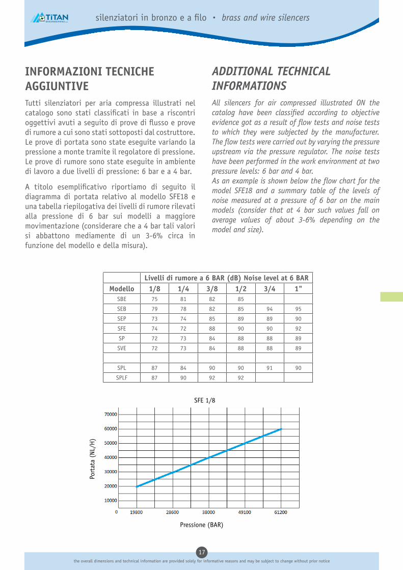
ADDITIONAL TECHNICAL INFORMATIONSAll silencers for air compressed illustrated ON the catalog have been classified according to objective evidence got as a result of flow tests and noise tests to which they were subjected by the manufacturer. The flow tests were carried out by varying the pressure upstream via the pressure regulator. The noise tests have been performed in the work environment at two pressure levels: 6 bar and 4 bar.As an example is shown below the flow chart for the model SFE18 and a summary table of the levels of noise measured at a pressure of 6 bar on the main models (consider that at 4 bar such values fall on average values of about 3-6% depending on the model and size).
INFORMAZIONI TECNICHE AGGIUNTIVETutti silenziatori per aria compressa illustrati nel catalogo sono stati classificati in base a riscontri oggettivi avuti a seguito di prove di flusso e prove di rumore a cui sono stati sottoposti dal costruttore. Le prove di portata sono state eseguite variando la pressione a monte tramite il regolatore di pressione. Le prove di rumore sono state eseguite in ambiente di lavoro a due livelli di pressione: 6 bar e a 4 bar.
A titolo esemplificativo riportiamo di seguito il diagramma di portata relativo al modello SFE18 e una tabella riepilogativa dei livelli di rumore rilevati alla pressione di 6 bar sui modelli a maggiore movimentazione (considerare che a 4 bar tali valori si abbattono mediamente di un 3-6% circa in funzione del modello e della misura).
Livelli di rumore a 6 BAR (dB) Noise level at 6 BARModello 1/8 1/4 3/8 1/2 3/4 1"
SBE 75 81 82 85
SEB 79 78 82 85 94 95
SEP 73 74 85 89 89 90
SFE 74 72 88 90 90 92
SP 72 73 84 88 88 89
SVE 72 73 84 88 88 89
SPL 87 84 90 90 91 90
SPLF 87 90 92 92
Pressione (BAR)
Port
ata
(NL/
H)
SFE 1/8

18dimensioni di ingombro e informazioni tecniche sono fornite a puro titolo informativo e possono essere soggette a modifica senza preavviso
ugelli di flusso • flow nozzles
SCHEDA TECNICA UGELLI SOFFIANTIGli ugelli soffianti a pettine (Titan-Jet) e rotondi (in alluminio e tecnopolimero) sono realizzati in Italia, a garanzia di elevati standard di qualità, secondo le normative ISO di riferimento, e rispondono alle seguenti specifiche tecniche e applicative
FLUIDOFluidi liquidi e gassosi, aria compressa (per specifiche contattare il nostro UT)
APPLICAZIONISistemi di pulizia e raffreddamento fluido, abbattimento rumore, impieghi come cortine d’aria. Linee di irrigazione
TUBI DI COLLEGAMENTONormalmente non applicati direttamente a tubi, comunque presenti negli impianti e definiti in funzione delle applicazioni
TEMPERATURA E PRESSIONINelle applicazioni pneumatiche si uniformano ai requisiti degli altri componenti, stesso materiale, quali la raccorderia. Nelle versioni in POM l’indeformabilità è garantita fino a +90°C mentre la resistenza agli urti fino a -40°C
FILETTATUREBSPP 1/4 gas cilindrica
MATERIALI UTILIZZATIABS-GP40 norme ASTM/IEC/UL (modello piatto)POM antiurto (modello rotondo)Alluminio (modello rotondo AL)
FLOW NOZZLES TECHNICAL SHEET
The multi-channels flow nozzles, flat (Titan-Jet) and circular (in aluminium and plastic), are produced in Italy according to the reference ISO norms as warranty of high quality level and answer to the followings technical specifications and applications:
FLUIDSLiquids and gases, compressed air (for information contact our UT)
APPLICATIONSFluid methods for cleaning and cooling fluid, noise abatement, uses as air curtains, irrigation systems
CONNECTING TUBESNormally not applied directly to pipes, however defined according to the applications
TEMPERATURES AND PRESSURES In pneumatic applications they follow the requirements of other same materials components, such as fittings. In the POM versions indeformability is guaranteed up to + 90 °C, while the impact resistance down to -40 °C.
THREAD TYPEBSPP 1/4 gas parallel
MATERIALSABS-GP40 norms ASTM/IEC/UL (flast model)POM shockproof (round model)Aluminium (round model AL)

19the overall dimensions and technical information are provided solely for informative reasons and may be subject to change without prior notice
ugelli di flusso • flow nozzles
Ugello rotondo a più canali POMCircular multi-channel nozzle POM
Pezzo di precisione stampato in plastica antiurto POM.In questo modello sono incorporati tutti i pregi dell’ugello piatto, in più ne amplia il campo d’impiego ed è pure idoneo per un impiego fisso.Note: la forza soffiante è stata misurata a 50 mm dall’uscita e i valori sulla rumorosità sono dentro i parametri DIN 45645.Nel montaggio di questo ugello a più canali, deve essere sfruttata tutta la lunghezza del pezzo filettato.
Dimensioni:55 x 23 x 10(lunghezza x diametro est. x lunghezza filettatura)Raccordo del tubo:R1/4” (filettatura esterna all’imbocco)Caratteristiche:antiurto sino a –40°Cindeformabile sino a +90°Cresistente a combustibili, oli minerali, lubrificanti e ogni tipo di solvente.Cod. 838.926
Circular multi-channel nozzle POM.Material:impact-resistant plasticThis model combines the undisputed advantages of the flat jet nozzle with a broader range of application and is ideal for stationary tasks.Note: the blowing force was measured 50 mm in front of the nozzle. The sound levels were measured in compliance with DIN 45635.When installing the multi-channel nozzles, the full thread length should be used.
Dimensions:55 x 23 x10(L x ext. diam. x thread length)Pipe connection:R 1/4” (external thread on air inlet)Characteristics:Impact-resistant down to –40°CDimensional stability up to +90°CResistant to fuels, mineral oils, lubrificants and commonly used solvents.
Ugello rotondo a più canali ALCircular multi-channel nozzle AL
Pezzo di precisione stampato in alluminio.Raccomandato in particolari condizioni d’impiego es. fonderia.Campo d’impiego principale: pistole ad aria.Note: la forza soffiante è stata misurata a 50 mm dall’uscita e i valori sulla rumorosità sono dentro i parametri DIN 45645.
Dimensioni:31,5 x 18,5 x 8(lunghezza x diametro est. x lunghezza filettatura)Raccordo per tubo:R1/4” (filettatura esterna all’imbocco)Codice: 923.702
Material: aluminium.Recommended for particularly harsh operating conditions, such as high temperatures (foundries, etc.) Principle application: blow guns.Note: the blowing force was measured 50 mm in front of the nozzle. The sound levels were measured in compliance with DIN 45635.
Dimensions:31.5 x 18.5 x 8(L x ext. diam. x thread length)Pipe connection:R 1/4” (external thread on air inlet)
ART. 838.926
ART. 923.702
55.5
10
G 1
/4
�23
.8
8in
gres
so a
ria Ø
�19
31.5
8
�18
.5
19
�10
.5
9In
gres
so a
ria Ø
G 1
/4

20dimensioni di ingombro e informazioni tecniche sono fornite a puro titolo informativo e possono essere soggette a modifica senza preavviso
ugelli di flusso • flow nozzles
Dimensioni:90 x 47 x 14.5(lunghezza x larghezza x altezza)Tubo di raccordo:R1/4” (filettatura esterna sul tubo di entrata)Caratteristiche:Antiurto sino a –40° CIndeformabile sino a +90°CResistente a combustibili, oli minerali o solventi di ogni tipo.Fornibile come:Ugello piatto a più canali.
La forza soffiante mirata.La disposizione parallela dei getti d’aria, permette di avere un ampio raggio di soffiatura nei pezzi trasportati.Anche pezzi di piccole dimensioni lavorati su torni automatici, possono venire investiti da un getto d’aria ben preciso.La nuova forma ne permette la totale intercambiabilità con i modelli presenti sul mercato e garantisce un aumento della linea di soffiature.
Dimensions:90 x 47 x 14,5 (LxWxH)Pipe connection:R 1/4 “ (external thread on air inlet)Characteristics:Impact-resistant down to-40°C Dimensional stability up to +90°CResistant to fuels, mineral oils, lubrificants and commonly used solventsForm of delivery:Multi-channel flat jet nozzle
Concentrated blowing power.The parallel arrangement of the component air streams gives an optinum blow-out width for work piece conveyance.Even the smallest finisched parts, e.g. on lathes, can be accurately and efficiently blown out.The new design enables the interchangeability with the main models available on the market and grant a larger blow-out line.
Ugello piatto a più canaliMulti-channel flat jet nozzle ART. 069.523
47
R 1/4
25
50
30.5
Ø5
� 5

21the overall dimensions and technical information are provided solely for informative reasons and may be subject to change without prior notice
ugelli di flusso • flow nozzles
Ugello Piatto a più canaliMulti channels flat nozzle
Pressione ingresso (Bar) Input pressure (Bar)
Picco Massimo (dB)Max peak (dB)
2 61
4 66
6 71
8 75
Ugello tondo in alluminioAluminium round nozzle
Pressione ingresso (Bar) Input pressure (Bar)
Picco Massimo (dB)Max peak (dB)
2 65
4 69
6 75
8 79
Ugello tondo in plasticaPlastic round nozzle
Pressione ingresso (Bar) Input pressure (Bar)
Picco Massimo (dB)Max peak (dB)
2 65
4 69
6 75
8 79
Punto uscita aria
Punto ingresso aria
A = Distanza punto ingresso-punto uscita fluido
B = Distanza punto di uscita-punto di misurazione
A = 270 mmB = 400 mm
A = Distance between the air inlet and outlet point
Air output
B = Distance between the outlet and measuring point
Air input
A = 200 mmB = 400 mm
A = 240 mmB = 400 mm
Test livello sonoro • Noise level test

22dimensioni di ingombro e informazioni tecniche sono fornite a puro titolo informativo e possono essere soggette a modifica senza preavviso
scarichi automatici • auto drain
SCHEDA TECNICA SCARICATORI AUTOMATICIGli scaricatori automatici di condensa (separatori di drenaggio), di importazione, sono realizzati in conformità ad elevati standard di qualità, secondo le normative di riferimento, e rispondono alle seguenti specifiche tecniche e applicative:
FLUIDOAria compressa (per specifiche contattare il nostro UT)
APPLICAZIONIImpianti ove sia normalmente necessario filtrare la condensa dell’acqua per prevenire il rischio che rimanga nel circuito dell’aria.
TUBI DI COLLEGAMENTONormalmente non applicati direttamente a tubi, comunque presenti negli impianti e definiti in funzione delle applicazioni
TEMPERATURA E PRESSIONIIl campo di impiego consigliato è all’interno di un intervallo di temperatura compreso fra +5°C e +60°C e pressioni comprese fra 0,3MPa (3 Bar)e 0,8MPa (8 Bar).
FILETTATUREIngressi = G1/4, G3/8, G1/2Scarichi = G1/8
MATERIALI UTILIZZATICorpo e alloggiamento in alluminio pressofusoTazza in vetro temperatoElementi interni in resina
AUTO DRAIN TECHNICAL SHEET
The drainage separators (auto drain) of our imports, are made in following high quality standards and in accordance with reference norms, and meet the following specifications and application:
FLUIDSCompressed air (for information contact our UT)
APPLICATIONSInstallations where it is usually necessary to filter the water condense to prevent the risk that it remains in the air circuit.
CONNECTING TUBESNormally not applied directly to pipes, however defined according to the applications
TEMPERATURES AND PRESSURES The reccomended field of use is within a temperature range between +5 °C to +60 °C and a pressures range between 0.3MPa (3 Bar)and 0,8MPa (8 Bar)
THREAD TYPEPort size = G1/4, G3/8, G1/2 Drain Port size = G1/8
MATERIALSBody and housing in aluminium die castingTempered glass cupInternal elements in resin

23the overall dimensions and technical information are provided solely for informative reasons and may be subject to change without prior notice
scarichi automatici • auto drain
ART. JAD402-S Scaricatore automaticoAuto drain
ModelloModel JAD402-S-02 JAD402-S-03 JAD402-S-04
Pressione garantitaEnsured pressure resistance 1.5MPa
Pressione di esercizio Operating pressure 0.3-0.8MPa
Temperatura ambiente e del fluidoAmbient and fluid temperaure 5-60°C
Misura attaccoPort size G1/4 G3/8 G1/2
Misura scaricoDrain port size G3/8
Stato scaricoDrain status Tipo normalmente aperto - Normal Open Type
Fluido impiegatoWorking medium Aria compressa - Compressed air
ScopoQuesto prodotto é spesso applicato per rimuovere automaticamente le infiltrazioni dai fondi delle tubazioni, negli essiccatori d’aria per congela-tori, nei separatori d’olio, nei serbatoi d’aria e a valle dei vari filtri dell’aria. Può essere installato in luoghi scomodi per lo scarico manuale delle acque reflue, in alto, in basso, o angusti, soprattutto ove vi è un consumo di aria e frequenti scarichi d’acqua. Permette di evitare che l’aria compressa risulti inquinata da acqua di condensa derivante da scarichi manuali negligenti.
PurposeThis product often applies to auto remove the seeping at the lower places of piping, air drying machine, oil separator, air storage tanks and the bottom of various air filters. It can be installed in the places inconvenient for manual discharge of sewage such as higher, lower and narrow places, specially there is consumption of air of frequent water drains. It can prevent the compressed air being polluted by condense water resulting from neglect of manual drain.
CaratteristicheScarico automatico / intercettazione aria di scaricoLa tazza dell’acqua è provvista di coperchio di protezione in metallo
FeaturesAuto drain / Air shut off drainThe water cup is provided with metal protective cover
AttenzioneQuando si utilizza, lo scarico dovrebbe essere installato in verticale, la porta di scarico rivolta verso il basso
AttentionWhen using the drainer should be installed vertically, the drain port facing down
Lega di alluminioAluminium alloy
PoliuretanoPolyurethane
PCPC
FerroIron
Lega di alluminioAluminium alloy

24dimensioni di ingombro e informazioni tecniche sono fornite a puro titolo informativo e possono essere soggette a modifica senza preavviso
scarichi automatici • auto drain
ART. JAD402-X Scaricatore automaticoAuto drain
ModelloModel JAD402-X-02 JAD402-X-03 JAD402-X-04
Pressione garantitaEnsured pressure resistance 1.5MPa
Pressione di esercizio Operating pressure 0.2-0.8MPa
Temperatura ambiente e del fluidoAmbient and fluid temperaure 5-60°C
Misura attaccoPort size G1/4 G3/8 G1/2
Misura scaricoDrain port size R1/8
Stato scaricoDrain status Tipo normalmente aperto - Normal Open Type
Fluido impiegatoWorking medium Aria compressa - Compressed air
ScopoQuesto prodotto é spesso applicato per rimuovere automaticamente le infiltrazioni dai fondi delle tubazioni, negli essiccatori d’aria per congela-tori, nei separatori d’olio, nei serbatoi d’aria e a valle dei vari filtri dell’aria. Può essere installato in luoghi scomodi per lo scarico manuale delle acque reflue, in alto, in basso, o angusti, soprattutto ove vi è un consumo di aria e frequenti scarichi d’acqua. Permette di evitare che l’aria compressa risulti inquinata da acqua di condensa derivante da scarichi manuali negligenti.
PurposeThis product often applies to auto remove the seeping at the lower places of piping, air drying machine, oil separator, air storage tanks and the bottom of various air filters. It can be installed in the places inconvenient for manual discharge of sewage such as higher, lower and narrow places ,especially there is consumption of air of frequent water drains. It can prevent the compressed air being polluted by condense water resulting from neglect of manual drain.
CaratteristicheScarico automatico / intercettazione aria di scarico / scarico manualeLa tazza dell’acqua è provvista di coperchio di protezione in metallo
FeaturesAuto drain / Air shut off drain / Manual drainThe water cup is provided with metal protective cover
AttenzioneQuando si utilizza, lo scarico dovrebbe essere installato in verticale, la porta di scarico rivolta verso il basso
AttentionWhen using ,the drainer should be installed vertically, the drain port facing down
Lega di alluminioAluminium alloy
PoliuretanoPolyurethane
PCPC
FerroIron
Lega di alluminioAluminium alloy

tubi e terminali tubes and terminals
25the overall dimensions and technical information are provided solely for informative reasons and may be subject to change without prior notice
tubi e terminali • tubes and terminals

26dimensioni di ingombro e informazioni tecniche sono fornite a puro titolo informativo e possono essere soggette a modifica senza preavviso
tubi in rotoli • tubes in rolls
SCHEDA TECNICA TUBO PER ARIAI tubi per aria compressa in poliuretano, poliammide a copoliestere sono realizzate in Italia, a garanzia di elevati standard di qualità, secondo le normative ISO di riferimento, e rispondono alle seguenti specifiche tecniche e applicative
FLUIDOFluidi liquidi e gassosi, aria compressa (per specifiche contattare il nostro UT)
APPLICAZIONIPneumatica, idraulica a bassa pressione, secondo normativa DIN 3861-3870
RACCORDI DI COLLEGAMENTOLe serie di raccordi Rap, Tecno-Rap e a seguire, illustrati nel catalogo “Grenline” sono tutti compatibili
TEMPERATURA E PRESSIONILe temperature e le pressioni dipendono generalmente dalle caratteristiche del tubo e sono specificate nelle pagine successive
MATERIALI UTILIZZATIPoliueratano TPUPoliammide PA12Copoliestere COPEY PA SUPERFLEX
AIR TUBE TECHNICAL SHEET
The polyurethane, polyammide and copolyester tubes are produced in Italy according to the reference ISO norms as warranty of high quality level and answer to the followings technical specifications and applications:
FLUIDSLiquids and gases, compressed air (for information contact our UT)
APPLICATIONSPneumatic circuits, low pressure hydraulic applications, according to DIN 3861-3870 norms
CONNECTING FITTINGSFittings Rap, Tecno-Rap series and further, illustrated on our “Greenline” catalogue are all suitable
TEMPERATURES AND PRESSURES Temperatures and pressures usually depend by the features of the employed tubes and are detailed on the following pages
MATERIALSPolyuerathane TPUPolyamide PA12Copolyester COPEY PA SUPERFLEX

27the overall dimensions and technical information are provided solely for informative reasons and may be subject to change without prior notice
tubi in rotoli • tubes in rolls
ART. TPU Tubo PoliuretanoPolyurethane tube
CODICE Dxdmm.
Pbar
P1bar
Rmm.
TPU0315 3 x 1,5 13,5 54 7,5 200 25
TPU0402 4 x 2 15 60 11 100 25
TPU0425 4 x 2,5 10(10) 40(40) 15 100 25
TPU0604 6 x 4 10 40(36) 18 100 25
TPU0805 8 x 5 13 52 25 100 25
TPU0855 8 x 5,5 9 (8) 37 (34) 30 100 25
TPU0806 8 x 6 7 28 35 100 25
TPU1065 10 x 6,5 10(7) 40(28) 30 100 25
TPU1075 10 x 7,5 6,5(6) 27(25) 40 100 25
TPU1008 10 x 8 5,5 22 45 100 25
TPU1209 12 x 9 6 (6) 25(24) 50 100 25
Nota: i dati fra parentesi si riferiscono alle misure disponibili anche nelle colorazioni traslucide (durezza 95 shoreA).Notice: data between parenthesis refer to cristal colour types (hardness 95 shoreA).
[ ] = Neutro/Neutral, [B] = Nero/Black, [BU] = Azzurro/Light Blue, [G] = Verde/Green, [R] = Rosso/Red, [GR] = Grigio/Grey, [T] = Trasparente/Cristal, [Y] = Giallo/Yellow
D
d
- 30°C 0°C +23°C +30°C +40°C +60°C +80°C
2.0 1.5 1 0.84 0.90 0.85 0.80
D = diametro esterno – external diameterd = diametro interno – internal diameter P = pressione di esercizio – working pressure
P1 = pressione di scoppio – breaking pressureR = raggio di curvatura – bending radius
= rotolo confezione – roll packing = scatola cartone – cartoon box
Scala di correzione in funzione della TemperaturaAdjusting scale on atmospheric temperature basis

28dimensioni di ingombro e informazioni tecniche sono fornite a puro titolo informativo e possono essere soggette a modifica senza preavviso
tubi in rotoli • tubes in rolls
ART. PA12 Tubo PoliammidePolyamide tube
CODICE Dxdmm.
Pbar
P1bar
Rmm.
PA120402 (*) 4 x 2 37 130 20 100 25
PA120425 4 x 2,5 32 112 20 100 25
PA120427 4 x 2,7 23 80 25 100 25
PA120604 6 x 4 26 90 30 100 25
PA120806 8 x 6 20 70 40 100 25
PA121007 (*) 10 x 7 25 88 70 100 25
PA121008 10 x 8 15 52 60 100 25
PA121210 12 x 10 12 42 85 100 25
PA121412 14 x 12 11 33 90 100 25
Nota: le misure contrassegnate con asterisco sono disponibili solo su richiesta.Notice: (*) = sizes available on demand only.
[N] = Neutro/Neutral, [B] = Nero/Black, [BU] = Azzurro/Light Blue, [G] = Verde/Green, [R] = Rosso/Red, [Y] = Giallo/Yellow
D
d
- 20°C 0°C +23°C +30°C +40°C +50°C +60°C
1.87 1.4 1 0.80 0.60 0.50 0.40
D = diametro esterno – external diameterd = diametro interno – internal diameter P = pressione di esercizio – working pressure
P1 = pressione di scoppio – breaking pressureR = raggio di curvatura – bending radius
= rotolo confezione – roll packing = scatola cartone – cartoon box
Scala di correzione in funzione della TemperaturaAdjusting scale on atmospheric temperature basis

29the overall dimensions and technical information are provided solely for informative reasons and may be subject to change without prior notice
tubi in rotoli • tubes in rolls
ART. COPEY Tubo CopoliestereCopolyester tube
CODICE Dxdmm.
Pbar
P1bar
Rmm.
CO0402 4 x 2 30 120 15 100 25
CO0425 4 x 2,5 22 88 20 100 25
CO0427 4 x 2,7 16 64 25 100 25
CO0604 6 x 4 16 64 35 100 25
CO0806 8 x 6 15 60 40 100 25
CO1007 10 x 7 17 70 50 100 25
CO1008 10 x 8 14 56 55 100 25
CO1209 12 x 9 13 50 80 100 25
CO1210 12 x 10 10 40 80 100 25
Nota: per gli altri colori consultare i nostri ufficiNote: for different colors please ask out office
[N] = Neutro/Neutral, [B] = Nero/Black, [BU] = Azzurro/Light Blue, [G] = Verde/Green, [R] = Rosso/Red, [Y] = Giallo/Yellow
D
d
- 30°C 0°C +23°C +40°C +60°C +80°C
2 1,5 1 0.90 0.85 0.80
D = diametro esterno – external diameterd = diametro interno – internal diameter P = pressione di esercizio – working pressure
P1 = pressione di scoppio – breaking pressureR = raggio di curvatura – bending radius
= rotolo confezione – roll packing = scatola cartone – cartoon box
Scala di correzione in funzione della TemperaturaAdjusting scale on atmospheric temperature basis

30dimensioni di ingombro e informazioni tecniche sono fornite a puro titolo informativo e possono essere soggette a modifica senza preavviso
tubi spiralati • coiled tubes
ART. SPF Spirali calibrate in poliuretano 98 ShAPolyurethane 98 ShA calibrated spiral tubes
CODICE Dxdmm.
Pbar
P1bar
Smm.
Lmm.
SPF0805050 8 x 5 13 52 13 5 10
SPF0805075 8 x 5 13 52 13 7,5 10
SPF0805100 8 x 5 13 52 13 10 10
SPF0805150 8 x 5 13 52 13 15 10
SPF1065075 10 x 6,5 10 40 10 7,5 10
SPF1065100 10 x 6,5 10 40 10 10 10
SPF1065150 10 x 6,5 10 40 10 15 10
SPF1208050 12 x 8 9 36 9 5 10
SPF1208075 12 x 8 9 36 9 7,5 10
SPF1208100 12 x 8 9 36 9 10 10
SPF1208150 12 x 8 9 36 9 15 10
- 20°C 0°C +23°C +30°C +40°C +50°C +60°C +70°C
1,87 1,4 1 0,84 0,70 0,60 0,52 0,47
D = diametro esterno – external diameterd = diametro interno – internal diameter P = pressione di esercizio – working pressureL = lunghezza estesa – extended lenght
P1 = pressione di scoppio – breaking pressureS = spire
= rotolo confezione – roll packing
Scala di correzione in funzione della TemperaturaAdjusting scale on atmospheric temperature basis
Proprietà fisiche / MeccanichePhysical/Mechanical properties
Metodo di provaTrial method
ValoreValue
Durezza - Hardness DIN 53505 - ISO868 98 ShA / 52 ShD
Assorbimento acqua - Water absorption a 23°C 50% r.h. < 1%
Densità - Density DIN 53479 - ISO1183 1,22 g/cm3
Allungamento alla rottura - Elongation at break DIN 53504 - ISO37 500%
Resistenza allo strappo - Tear resistance DIN 53515 - ISO34 130 N/mm
Modulo elastico a flessione - Flexural elastic modulus ASTMD 790 140 MPa
Perdità di abrasione - Abrasion loss DIN 53516 - ISO4649 25 mm3
Resistenza alla rottura - Break resistance DIN 53504 - ISO37 55 MPa
Temperatura di applicazione - Working temperature - -40°C / +60°C
L= Lunghezza estesa
S= Numero spire

31the overall dimensions and technical information are provided solely for informative reasons and may be subject to change without prior notice
tubi spiralati • coiled tubes
ART. SPFR Spirali calibrate in poliuretano 98 ShA con raccordiPolyurethane 98 ShA calibrated spiral tubes with fittings
CODICE Dxdmm.
Pbar
P1bar
Smm.
Lmm.
SPFR0805050 8 x 5 13 52 13 5 10
SPFR0805075 8 x 5 13 52 13 7,5 10
SPFR0805100 8 x 5 13 52 13 10 10
SPFR0805150 8 x 5 13 52 13 15 10
SPFR1065075 10 x 6,5 10 40 10 7,5 10
SPFR1065100 10 x 6,5 10 40 10 10 10
SPFR1065150 10 x 6,5 10 40 10 15 10
SPFR1208050 12 x 8 9 36 9 5 10
SPFR1208075 12 x 8 9 36 9 7,5 10
SPFR1208100 12 x 8 9 36 9 10 10
SPFR1208150 12 x 8 9 36 9 15 10
- 20°C 0°C +23°C +30°C +40°C +50°C +60°C +70°C
1,87 1,4 1 0,84 0,70 0,60 0,52 0,47
D = diametro esterno – external diameterd = diametro interno – internal diameter P = pressione di esercizio – working pressureL = lunghezza estesa – extended lenght
P1 = pressione di scoppio – breaking pressureS = spire
Scala di correzione in funzione della TemperaturaAdjusting scale on atmospheric temperature basis
Proprietà fisiche / MeccanichePhysical/Mechanical properties
Metodo di provaTrial method
ValoreValue
Durezza - Hardness DIN 53505 - ISO868 98 ShA / 52 ShD
Assorbimento acqua - Water absorption a 23°C 50% r.h. < 1%
Densità - Density DIN 53479 - ISO1183 1,22 g/cm3
Allungamento alla rottura - Elongation at break DIN 53504 - ISO37 500%
Resistenza allo strappo - Tear resistance DIN 53515 - ISO34 130 N/mm
Modulo elastico a flessione - Flexural elastic modulus ASTMD 790 140 MPa
Perdità di abrasione - Abrasion loss DIN 53516 - ISO4649 25 mm3
Resistenza alla rottura - Break resistance DIN 53504 - ISO37 55 MPa
Temperatura di applicazione - Working temperature - -40°C / +60°C
S= Numero spire
L=Lunhghezza estesa

32dimensioni di ingombro e informazioni tecniche sono fornite a puro titolo informativo e possono essere soggette a modifica senza preavviso
tubi spiralati • coiled tubes
ART. SP Spirali calibrate in poliammide nylon PA6Polyamide nylon PA6 calibrated spiral tubes
CODICE Dxdmm.
Pbar
P1bar
Smm.
Lmm.
SP0604300 6 x 4 27 81 50 30 10
SP0806150 8 x 6 20 60 70 15 10
SP0806300 8 x 6 20 60 70 30 10
SP1008150 10 x 8 15 45 85 15 10
SP1008300 10 x 8 15 45 85 30 10
SP1210300 12 x10 13 39 115 30 10
- 20°C 0°C +23°C +30°C +40°C +50°C +60°C
1,87 1,4 1 0,90 0,80 0,70 0,70
D = diametro esterno – external diameterd = diametro interno – internal diameter P = pressione di esercizio – working pressureL = lunghezza estesa – extended lenght
P1 = pressione di scoppio – breaking pressureS = spire
Scala di correzione in funzione della TemperaturaAdjusting scale on atmospheric temperature basis
Proprietà fisiche / MeccanichePhysical/Mechanical properties
Metodo di provaTrial method
Valore - Value
Secco - Dry Umido - Wet2,4H2O
Modulo elastico a trazione - Traction elastic modulus ASTM D638 29 MPa 17 MPa
Allungamento - Elongation ASTM D638 > 300% > 300%
Resistenza alla flessione - Resistance to flexion ASTM D790 24 MPa 14 MPa
Modulo elastico a flessione - Flexural elastic modulus ASTMD 790 600 MPa 300 MPa
Punto di fuzione - Melting point ISO 11357 220°C
Assorbimento acqua - Water absorption a 23°C 50% r.h. < 3%
Temperatura di applicazione - Working temperature - -20°C / +80°C
S= Numero spire
L=Lunghezza estesa

33the overall dimensions and technical information are provided solely for informative reasons and may be subject to change without prior notice
tubi spiralati • coiled tubes
ART. SPR Spirali calibrate in poliammide nylon PA6 con rubinetto universale con molla e innesto serie Italia con mollaPolyamide nylon PA6 calibrated spiral tubes with universal coupling with ball and italian connector with springs
CODICE Dxdmm.
Pbar
P1bar
Smm.
Lmm.
SPR0806150 8 x 6 20 60 70 15 10
SPR0806300 8 x 6 20 60 70 30 10
SPR1008150 10 x 8 15 45 85 15 10
SPR1008300 10 x 8 15 45 85 30 10
- 20°C 0°C +23°C +30°C +40°C +50°C +60°C
1,87 1,4 1 0,90 0,80 0,70 0,70
D = diametro esterno – external diameterd = diametro interno – internal diameter P = pressione di esercizio – working pressureL = lunghezza estesa – extended lenght
P1 = pressione di scoppio – breaking pressureS = spire
= rotolo confezione – roll packing
Scala di correzione in funzione della TemperaturaAdjusting scale on atmospheric temperature basis
Proprietà fisiche / MeccanichePhysical/Mechanical properties
Metodo di provaTrial method
Valore - Value
Secco - Dry Umido - Wet2,4H2O
Modulo elastico a trazione - Traction elastic modulus ASTM D638 29 MPa 17 MPa
Allungamento - Elongation ASTM D638 > 300% > 300%
Resistenza alla flessione - Resistance to flexion ASTM D790 24 MPa 14 MPa
Modulo elastico a flessione - Flexural elastic modulus ASTMD 790 600 MPa 300 MPa
Punto di fuzione - Melting point ISO 11357 220°C
Assorbimento acqua - Water absorption a 23°C 50% r.h. < 3%
Temperatura di applicazione - Working temperature - -20°C / +80°C
S=Numero spire
L=Lunghezza estesa

34dimensioni di ingombro e informazioni tecniche sono fornite a puro titolo informativo e possono essere soggette a modifica senza preavviso
tubi in rotoli • tubes in rolls
Materiale dalle eccezionali caratteristiche meccaniche, questo tubo nasce per risolvere le problematiche legate ad applicazioni particolarmente gravose.
PROPRIETÀ TECNICHE:
CARATTERISTICHE TECNICHE:
ALTRE CARATTERISTICHE:
PRINCIPALI APPLICAZIONI:
INFORMAZIONI GENERALI:
Durezza Shore A 98Temperatura di applicazione - 20°C +70°CAllungamento a rottura 540% (DIN 53504)Densità (gr./cm3) 1.18 (DIN 53479)Perdita di abrasione (mm3) 55 (DIN 53516) Resistenza allo strappo (KN/m) 120 (DIN 53515)
Eccellente resistenza all’abrasione.Altissima flessibilità alle basse temperature.Buona resistenza agli agenti atmosferici.Buon invecchiamento nel tempo. Estremamente resistente alla fatica. Poco sensibile all’effetto “click” e “stress cracking”. Tolleranze: Diametro esterno +/- 0,1 mm Spessore +/-0,1 mmColore: Azzurro, rosso, nero, verde, giallo, neutro, grigio, blu trasparente, cristallinoConfezione: Bobine da mt. 100
Robotica, Agricoltura, Pneumatica, Autofficine, ecc…
I poliuretani, pur essendo molto resistenti alla fatica o alle tensioflessioni, hanno la tendenza ad accumulare calore laddove vengono impiegati con pressioni pulsanti continue. Se tali condizioni si verificano in concomitanza con un’elevata temperatura ambiente, possono verificarsi rigonfiamenti o addirittura rotture del tubo, caratteristica che si evidenzia specialmente nelle misure 8x6, 10x8, 14x12.Il poliuretano è in generale resistente all’ozono, idrocarburi, olii grassi, carburanti e soluzioni chimiche moderate. Non è resistente, o debolmente, ad acidi concentrati, ketoni, idrocarburi clorurati.
Sul tubo viene marcato il diametro int. x est., il tipo di materiale e il numero di lotto per la rintracciabilità.Ogni lotto di materiale viene accompagnato da certificato di conformità.
TUBO POLIURETANO
Il poliammide è tra i materiali più diffusi nelle applicazioni tecniche per le sue caratteristiche di flessibilità, prestazioni meccaniche come specificato di seguito.
CARATTERISTICHE:
APPLICAZIONI:
NORMATIVE:
Elevate proprietà meccaniche alla trazione ed alla flessione continua ed alterna, notevole flessibilità, buona stabilità al calore, notevole resistenza all’invecchiamento, basso assorbimento d’acqua, notevole resistenza agli idrocarburi e olii e buona inerzia agli agenti chimici.
PROPRIETÀ FISICHE/MECCANICHE METODO DI PROVA VALORE Densità ASTM D-792 1,03g/cm3
Durezza ASTM D-2240 65ShD Allungamento alla rottura ASTM-D638 >300% Modulo elastico ASTM D-790 410MPa Temperature di applicazione - -40°C/+70°C
Tolleranze: Diametro esterno +/- 0,1 mm Spessore +/-0,1 mmColore: Azzurro, nero, rosso e neutro.Confezione: Bobine da mt. 100
Questo tipo di materiale risulta essere particolarmente indicato per la realizzazione di tubi per pneumatica, robotica, utensileria, macchine industriali, ecc..., ovvero quando vi sia l’esigenza di una notevole flessibilità in special modo a freddo.
ISO 1874 - DIN 73378 - DIN 74324
TUBO POLIAMMIDE
Il copoliestere è un materiale che ha fatto il suo ingresso nelle applicazioni pneumatiche negli ultimi anni, in particolare per venire incontro ad esigenze applicative e di reperibilità. Oggi costituisce una valida alternativa sia tecnica che economica ai tubi storicamente utilizzati.
CARATTERISTICHE:
APPLICAZIONI:
NORMATIVE:
Eccellente resistenza al “creep” e all’impatto, nonché agli agenti chimici, oli, solventi e agenti atmosferici. Stabilizzato UV. Ottima stabilità delle proprietà a temperature elevate e al calore per periodi prolungati.
PROPRIETÀ FISICHE/MECCANICHE METODO DI PROVA VALORE Durezza - 60/65 ShD Assorbimento acqua ISO 62 - a 23°C 50% R.H. <1% Modulo a flessione ASTN D790 320 kg/cm2
Allungamento alla rottura ASTM D638 350% Temperatura di deflessione ASTM D648 110 °C Temperatura di applicazione - -30°C - +80°C
Tolleranze: Diametro esterno +/- 0,2 mm (+/- 0,3 dal diam. 8mm). Spessore +/- 0,1 mm)Colore: Vedi tabella tecnica pag. xxConfezione: Bobine da mt. 100
Tubi prodotti con questo materiale hanno tutte le credenziali per inserirsi nelle applicazioni pneumatiche, robotica, macchine industriali, agricoltura, in generale quando sia richiesta stabilità di utilizzo sia a freddo che a caldo
Conformità a D.M. 21/03/1973 e successivi aggiornamenti, a direttiva 2007/19/CE, al Reg. UE n. 10/2011
TUBO COPOLIESTERE

35the overall dimensions and technical information are provided solely for informative reasons and may be subject to change without prior notice
tubi in rotoli • tubes in rolls
Materiale dalle eccezionali caratteristiche meccaniche, questo tubo nasce per risolvere le problematiche legate ad applicazioni particolarmente gravose.
TECHNICAL PROPERTY:
TECHNICAL FEATURES:
OTHER FEATURES:
MAIN APPLICATIONS:
GENERAL NOTICES:
Hardness Shore A 98Temperature working range - 20°C +70°CBreaking Elongation 540% (DIN 53504)Density (gr./cm3) 1,18 (DIN 53479)Abrasion loss (mm3) 55 (DIN 53516)Tensile strenght (N/mm2) 120 (DIN 53515)
Excelent resistance at the abrasionGood resistance at the atmospheric effectsGood process of becomming oldHigh flexbility at the lowest temperaturesExtremely endeavor resistanceVery low “click” and “stress cracking” effects
Tolerances: O.D. +/-0,1 mm Thickness +/-0,1 mmColours avalaible: Light blue, Red, Black, Green, Yellow, Neutral, Cristal blue, CristalPacking: 100 mt. Rolls in plastic film Pneumatic, Robotic, agriculture, garage, etc.
Polyurethane tube material has excelent mechanical features and it is particularly addressed to mostly solve the heavy applications.Anyway polyurethanes, althoughthey are much resistant at the endeavor and at the flexion stress, trend to keep heat when working with continuous variable pressure and in case of high atmosphere temperature it could bring to the swelling or breaking of the tubing itself, specially on sizes 8x6, 10x8, 14x12.Polyurethane is normally also resistant to ozone, hydrocarbon, oils and greases, fuel and moderate chemical solutions.It is not, or very low, resistant to concentrated acids, ketons, esters and clhloride hydrocarbons.
POLYURETHANE TUBE
The polyamide is the most diffused material among the technical applications for its characteristics of flexibility and mechanical performances.
CHARACTERISTICS:
APPLICATION:
REFERENCE NORMS:
High mechanicl properies to traction and to continuous & alternate flexion, notable flexibility, good stability to heat, notable resistance to ageing, law water absorption, notable resistance to hydrocarbons and oils and good inertness to chemical agents.
MECHANICAL/PHYSICAL PROPERTIES TRIAL METHOD VALUE Density ASTM D-792 1,03g/cm3
Hardness ASTM D-2240 65ShD Elongation at break ASTM-D638 >300% Elastic modulus ASTM D-790 410MPa Working pressure - -40°C/+70°C
Tolerances: O.D. +/- 0,1 mm Thickness +/-0,1 mmColours avalaible: Light blue, black, red and neutral.Packing: 100 mt. Rolls in plastic film
This kind of material is particularly indicated for the realization of tubing for pneumatic, robotic, steel, industrial machineries, ecc..., when there is the necessity of notable flexibility.
ISO 1874 - DIN 73378 - DIN 74324
POLYAMIDE TUBE
The copolyester is a material that has made its entry into the pneumatic applications in the recent years, in particular to meet the needs of applications and availability. Today is a good alternative for both, technical and economic reasons, to the tubes storically used.
FEATURES:
APPLICATION:
REFERENCE NORMS:
Excellent resistance to “creep” and impact, as well as to chemicals, oils, solvents and weathering. UV stabilized. Excellent stability properties at high temperatures and heat for prolonged periods.
MECHANICAL/PHYSICAL PROPERTIES TESTING METHODA VALUE Hardness - 60/65 ShD Water absorpion ISO 62 - a 23°C 50% R.H. <1% Deflection temperature ASTN D790 320 kg/cm2
Elongation at break ASTM D638 350% Deflession temperature ASTM D648 110 °C Working temperature - -30°C - +80°C
Tolerances: Diametro esterno +/- 0,2 mm (+/- 0,3 dal diam. 8mm). Spessore +/- 0,1 mm)Colours available: See technical page xxPacking: 100 mt. Rolls in plastic film
Tubes made with this row material have all the credentials to fit in pneumatics, robotics, industrial machinery, agriculture, in general when is required stability to use both in hot and cold enviroments
Compliance with M.D. 21/03/1973 and subsequent amendments to Directive 2007/19 / EC, the EU Reg. N. 10/2011
COPOLYESTER TUBE

36dimensioni di ingombro e informazioni tecniche sono fornite a puro titolo informativo e possono essere soggette a modifica senza preavviso
morsetteria e pinze • terminals and tube cutter
SCHEDA TECNICA PINZE TAGLIATUBOLe pinze tagliatubo, realizzate in Italia nella versione metallica, e di importazione, nella versione in nylon, sono state concepite per essere utilizzate con tutti i tubi per l’aria e tutte le misure illustrate nel presente catalogo, per garantire tagli di precisione.
PRECAUZIONI D’USOTagliare il tubo perpendicolarmente all’asse, con una operazione decisa, avendo l’attenzione di evitare anomale inclinazioni del taglio che potrebbero compromettere il corretto inserimento del tubo nel raccordo e conseguentemente dare luogo ad eventuali perdite. Eliminare possibili bave interne ed esterne
MATERIALI UTILIZZATICorpo in materiale metallico pressofuso e cromatoCorpo in resina poliacetalica (POM)Lama (intercambiabile) in acciaio temprato ad alta resistenza
TUBE CUTTERS TECHNICAL SHEET
The tube cutters, made in Italy in the metal version, and imported, in the plastic version, are designed to be used with all air hoses and measures shown in this catalog, they ensure precision cuts.
PRECAUTIONSCut the tube at right angles to the axis, with a resolute operation, having the attention to avoid abnormal inclinations of the cut that may compromise the proper insertion of the tube into the fitting and consequently result in air leakage. Eliminate possible internal and external burrs.
MATERIALSBody in chrome metal die-castBody in polyacetal resin (POM)Blade (interchangeable) hardened high strenght steel

37the overall dimensions and technical information are provided solely for informative reasons and may be subject to change without prior notice
morsetteria e pinze • terminals and tube cutter
ART. PSVA853 Pinza tagliatubo grandeBig tube cutter
CODICE A B C
PSVA853 130 40 63 1
ART. PSVA854 Pinza tagliatubo piccolaSmall tube cutter
CODICE A B C
PSVA854 185 55 88 1
ART. MORS MorsettiereTerminals
CODICE Ø mm. lunghezza / lengthmm.
lunghezza / widthmm.
altezza / height mm.
706.004 4 185 14 9 10
706.006 6 215 14 13 10
706.008 8 235 14 15 10
706.010 10 275 14 17 10
706.012 12 305 14 19 10
706.015 15 276 14 21 8
ART. TC Pinza tagliatubo in plasticaPlastic tube cutter
CODICE Colore / Color A B V
TC (B) Nero / Black 80.5 35 61 1
TC (BU) Azzurro / Blue 80.5 35 61 1
A
C
B

38dimensioni di ingombro e informazioni tecniche sono fornite a puro titolo informativo e possono essere soggette a modifica senza preavviso
pistole per aria • air guns
SCHEDA TECNICA PISTOLE PER ARIALe pistole modelli Airset e Tucano, riconosciute per la loro affidabilità e sicurezza, sono progettate e realizzate in Italia per fare fronte alle differenti esigenze di pulizia con aria compressa in tutti i settori ove sono richiesti requisiti quali: ergonomia, solidità, progressività e silenziosità.
FLUIDOAria compressa
APPLICAZIONIImpianti pneumatici industriali, macchinari e hobbistica
TUBI DI COLLEGAMENTOPlastici: TPU, PA6, ecc. normalmente spiralati
TEMPERATURA E PRESSIONILe temperature dipendono generalmente dalle caratteristiche del tubo impiegato. Si consiglia una pressione di utilizzo fra 3,5 bar e 6 bar.
FILETTATURE1/4 F-BSPNPT e PT disponibili a richiesta
MATERIALI UTILIZZATICorpo e leva in resina acetalica (POM) ad alte prestazioniBoccola filettata in ottoneTubetto e molle interne in acciaio inox
AIR BLOWGUNS TECHNICAL SHEET The air blowguns Airset and Tucano, well known for their realiability and safety, are designed and manufactured in Italy to satisfy the needs of compressed air cleaning and are suitable for use in various production fields for they features as:ergonomics, solidity, progressiveness and silent operation.
FLUIDSCompressed air
APPLICATIONSPneumatics industrial machinery and leisure
CONNECTING TUBESPlastic: TPU, PA6, etc. normally coiled
TEMPERATURES AND PRESSURES Temperatures usually depend by the technical features of the employed tubes. The suggested working pressure range is from 3,5 bar to 6 bar
THREAD TYPE1/4 F-BSPNPT and PT available on demand
MATERIALSBody and handle in high performance acetal resin (POM)Brass threaded bushTube and inner springs in stainless steel

39the overall dimensions and technical information are provided solely for informative reasons and may be subject to change without prior notice
pistole per aria • air guns
ART. TCN 30 4040 Airset Tucano L130Airset Tucano L130
Modello - Model Airset Tucano L130
Filettatura - Thread ¼” BSP
Valore di portata - Flow Rates 300 l/m a 0,6 Mpa
Tubo - Tube Length Metal pipe 108mm
Livello di emissione sonora - Noise pressure level < 85 dB(A)
Peso - Weight 136 gr
Pezzi - Pieces Box 20
Confezione - Packaging 1
ART. STD 3010 02 Airset Standard L130Airset Standard L130
Modello - Model Airset Standard L130
Filettatura - Thread ¼” BSP
Valore di portata - Flow Rates 300 l/m’
Tubo - Tube Length 103 mm
Livello di emissione sonora - Noise pressure level < 85 dB(A)
Peso - Weight 116 gr
Pezzi - Pieces Box 20
Confezione - Packaging 1
ART. RTE 30 4040 Tucano Pressure Reducer 130 EuropeTucano Pressure Reducer 130 Europe
Modello - Model Tucano PressureReducer 130 Europe
Filettatura - Thread ¼” BSP
Valore di portata - Flow Rates 0,35 MPa
Livello di emissione sonora - Noise pressure level < 85 dB(A)
Pezzi - Pieces Box 20
Confezione - Packaging 1
ART. IAG Pistole ad aria standardStandard air guns
CODICE Colore Color
BU Azzurro Blue 1
R Rosso Red 1

40dimensioni di ingombro e informazioni tecniche sono fornite a puro titolo informativo e possono essere soggette a modifica senza preavviso
pistole per aria • air guns
ADDITIONAL TECHNICAL INFORMATIONSThe high quality materials used for the airguns Airset and Tucano give solidity and reliability, perceptible at first glance, as well as the control of air flow, accurate and easy with both hands for prolonged use. Peculiarities appreciated both by the professional and bricolage users. The threaded connection made with a brass bushing is a guarantee of optimal reliability thanks to a clamping force up to 10 Nm.
INFORMAZIONI TECNICHE AGGIUNTIVEI materiali di alta qualità con cui sono costruite le pistole Airset e Tucano ne conferiscono solidità e affidabilità, percepibile al primo impatto, così come il controllo del flusso dell’aria, preciso e agevole con entrambe le mani per un uso prolungato. Peculiarità apprezzate sia dal professionista che dall’appasionato del bricolage. L’attacco filettato realizzato con una bussola in ottone è garanzia di affidabilità ottimale grazie ad una forza di serraggio fino a 10 Nm.
Modello Model
PortataFlow
Pressione uscitaOutlet pressure
Livello di emissione sonoraNoise level
TCN 30 4040 300 l/m - 75,9 dB(A)
STD 3010 02 300 l/m - 75,9 dB(A)
RTE 3040 40 175 l/m 0,35 MPa 70,2 dB(A)

41the overall dimensions and technical information are provided solely for informative reasons and may be subject to change without prior notice
raccorderia con molla • fittings with spring
SCHEDA TECNICA SERIE A CALZAMENTO CON MOLLAI raccordi a calzamento della nostra serie con molla, sono realizzati in Italia, a garanzia di elevati standard di qualità, secondo le normative ISO di riferimento, e rispondono alle seguenti specifiche tecniche e applicative
FLUIDOAria compressa, acqua fino 100 °C (per altri fluidi contattare il nostro UT)
APPLICAZIONICircuiti pneumatici, oleodinamici e idraulici
TUBI DI COLLEGAMENTOPlastici: TPU, PE, PA, PET, PVC intrecciato, PTFE, FEP
TEMPERATURA E PRESSIONILe temperature e le pressioni dipendono generalmente dalle caratteristiche del tubo impiegato e delle tenute. La pressione massima consigliata è 18 bar
FILETTATUREBSPP gas cilindrica ISO 228 BSPT gas conica ISO 7 - DIN 2999 Metrica ISO R/262
MATERIALI UTILIZZATIOttone UNI EN 12164 CW614N (nichelato) Ottone UNI EN 12165 CW617N (nichelato) NBR 70 DWGV-EN549 UL157 (o-ring di tenuta) VITON (FKN) (o-ring di tenuta) Nylon/Alluminio (rondelle)
SPRING QUICK FITTINGS SERIES TECHNICAL SHEET The quick 300/400 series fittings are produced in Italy according to the reference ISO norms as warranty of high quality level and answer to the followings technical specifications and applications
FLUIDSCompressed air, water up to 100 °C (for different fluid pls contact our Technical Dept.)
APPLICATIONSPneumatic, oleodynamic and hydraulic circuits
CONNECTING TUBESPlastic: TPU, PE, PA, PET, braided PVC, PTFE, FEP
TEMPERATURES AND PRESSURES Temperatures and pressures usually depend by the technical features of the employed seals and tubes. Max pressure suggested 18 bar.
THREAD TYPEBSPP paralell UNI-ISO 228 BSPT tapered UNI-ISO 7 Metric ISO R/262
MATERIALSBrass UNI EN 12164 CW614N (nickel plated) Brass UNI EN 12165 CW617N (nickel plated) NBR 70 DWGV-EN549 UL157 (o-ring seals) VITON (FKN) (o-ring seals) Nylon/Aluminium (washers)

42dimensioni di ingombro e informazioni tecniche sono fornite a puro titolo informativo e possono essere soggette a modifica senza preavviso
raccorderia con molla • fittings with spring
CH1
CH2
CH3
L1
D
F
I
ART. 2950 Diritto girevole maschio con mollaSwivel male straight with spring
CODICE ØD F L
29501220 6/4 1/8 110 12 12 13 1
29501230 6/4 1/4 113 12 14 15 1
*29505600 8/5 1/4 110 14 12 13 1
*29505610 8/5 1/4 113 14 16 15 1
29501280 8/6 1/8 110 14 12 13 1
29501290 8/6 1/4 113 14 14 15 1
*29505800 10/6,5 1/4 117 16 14 15 1
29501350 10/8 1/4 117 16 14 15 1
*29505900 12/8 3/8 125,5 18 17 17 1
29505900 12/10 3/8 125,5 18 19 17 1
* = Misure specifiche per tubi in poliuretano
CH1
CH2
CH3
L1
D
I
F
ART. 2951 Diritto gire vole maschio con OR e mollaSwivel male straight with OR and spring
CODICE ØD F L
29511220 6/4 1/8 106 12 12 14 1
29511230 6/4 1/4 108 12 14 17 1
*29515600 8/5 1/8 106 14 12 14 1
*29515610 8/5 1/4 108 14 16 17 1
29511280 8/6 1/8 106 14 12 14 1
29511290 8/6 1/4 108 14 14 17 1
*29515800 10/6,5 1/4 112 16 14 17 1
29511350 10/8 1/4 112 16 14 17 1
*29515900 12/8 3/8 123 18 17 18 1
29511400 12/10 3/8 123 18 19 18 1
* = Misure specifiche per tubi in poliuretano
F
L
I
CH
CH1
ART. 2952 Diritto maschio conico con mollaTapered male straight with spring
CODICE ØD F I L
29521220 6/4 1/8 8 109,5 12 12 1
29521230 6/4 1/4 11 113 12 14 1
29521280 8/6 1/8 8 124,5 14 12 1
29521290 8/6 1/4 11 128 14 14 1
29521300 8/6 3/8 11,5 128,5 14 17 1
29521310 8/6 1/2 14 131,5 14 22 1
29521340 10/8 1/8 8 123 16 14 1
29521350 10/8 1/4 11 125 16 14 1
29521360 10/8 3/8 11,5 125,5 16 17 1
29521370 10/8 1/2 14 130 16 22 1
29521400 12/10 3/8 11,5 134,5 18 17 1
29521410 12/10 1/2 14 140 18 22 1
L
I
F
CH
CH1
ART. 2953 Diritto maschio metrico con OR e mollaMetric male straight with OR and spring
CODICE ØD F I L
29531220 6/4 1/8 6 110 13 12 1
29531230 6/4 1/4 8 111 16 12 1
29531240 6/4 3/8 9 112 19 12 1
29535500 6/4 1/2 10 113 24 12 1
29531280 8/6 1/8 6 110 14 14 1
29531290 8/6 1/4 8 111 16 14 1
29531300 8/6 3/8 9 112 19 14 1
29531310 8/6 1/2 10 113 24 14 1
29531340 10/8 1/8 6 116 14 16 1
29531350 10/8 1/4 8 117 16 16 1
29531360 10/8 3/8 9 118 19 16 1
29531370 10/8 1/2 10 119 24 16 1
29531400 12/10 3/8 9 129 19 18 1
29531410 12/10 1/2 10 130 24 18 1

43the overall dimensions and technical information are provided solely for informative reasons and may be subject to change without prior notice
raccorderia con molla • fittings with spring
LI
F
CH
CH1
ART. 2954 Diritto maschio metrico con OR e mollaMetric male straight with OR and spring
CODICE ØD F I L
29541190 6/4 M12X1 8 108 15 12 1
29541200 6/4 M12X1,25 8 108 15 12 1
29541210 6/4 M12X1,25 8 108 15 12 1
L
I
F
CH
CH1
ART. 2955 Diritto femmina con mollaFemale straight with spring
CODICE ØD F I L
29551220 6/4 1/8 8 105 12 14 1
29551230 6/4 1/4 11 109 12 17 1
29551240 6/4 3/8 11,5 110 12 20 1
29551280 8/6 1/8 8 110 14 14 1
29551290 8/6 1/4 11 114 14 17 1
29551300 8/6 3/8 11,5 114,5 14 20 1
29551310 8/6 1/2 15 118 14 24 1
29551350 10/8 1/4 11 122 16 17 1
29551360 10/8 3/8 11,5 122,5 16 20 1
29551370 10/8 1/2 15 126 16 24 1
29551400 12/10 3/8 11,5 130,5 18 20 1
ART. 3289 Dado con mollaNut with spring
CODICE ØD F H
32897600 6/4 M10X1 95 12 1
32898400 8/6 M12X1 93,5 14 1
32899100 10/8 M14X1 96,5 16 1
32899800 12/10 M16X1 106 18 1
32895910 8/5 M12X1 93,5 14 1
32895920 10/6 M14X1 96,5 16 1
32895930 12/8 M16X1 106 18 1

44dimensioni di ingombro e informazioni tecniche sono fornite a puro titolo informativo e possono essere soggette a modifica senza preavviso
raccorderia con dado capettato • fittings with milled nut
ART. 3610 T attacco baionetta/ghieraTee bayonet + milled nut
CODICE F H L
36101700 1/4 25,3 50,6 13 1
ART. 3611 Diritto maschio attacco baionetta/ghieraStraight male bayonet + milled nut
CODICE F I H
36111700 1/4 10 28,5 15 1
36112600 3/8 10 28,5 17 1
ART. 3615 Diritto intermedio attacco baionetta/ghieraStraight connector bayonet + milled nut
CODICE F H
36151700 1/4 32 15 1

valvole e rubinetti valves and taps
45the overall dimensions and technical information are provided solely for informative reasons and may be subject to change without prior notice
valvole e rubinetti • valves and taps

46dimensioni di ingombro e informazioni tecniche sono fornite a puro titolo informativo e possono essere soggette a modifica senza preavviso
valvole manuali • hand valves
SCHEDA TECNICA VALVOLE MANUALI SERIE “504-505”Le valvole manuali serie 504-505, sono realizzate in Italia, a garanzia di elevati standard di qualità, secondo le normative ISO di riferimento, e rispondono alle seguenti specifiche tecniche e applicative
FLUIDOAria compressa (per altri fluidi contattare il nostro UT)
APPLICAZIONICircuiti pneumatici, idralici, oleodinamici
TUBI DI COLLEGAMENTONormalmente non applicate direttamente a tubi, comunque presenti negli impianti e definiti in funzione delle applicazioni
TEMPERATURA E PRESSIONITemperatura di esercizio da -20° a +70° °C Pressione di esercizio max consigliata 10 bar
FILETTATUREBSPP gas cilindrica ISO 228
MATERIALI UTILIZZATIOttone UNI EN 12165 CW617N (corpo Serie 505) Alluminio anodizzato (corpo Serie 504, corsoio Serie 504-505)NBR 70 DWGV-EN549 UL157 (guarnizione tenuta)
MANUALLY VALVES “504-500” SERIES TECHNICAL SHEET The manually valves, 504-505 series, are produced in Italy according to the reference ISO norms as warranty of high quality level and answer to the followings technical specifications and applications
FLUIDSCompressed air (for different fluid pls contact our Technical Dept.)
APPLICATIONSPneumatic, hydraulic, oleodynamics circuitsCONNECTING TUBESNormally not applied directly to pipes, however defined according to the applications
TEMPERATURES AND PRESSURES Working temperature from -20° to +70° °C Max suggested working pressure 10 bar
THREAD TYPEBSP cilindrica UNI-ISO 228
MATERIALSBrass UNI EN 12165 CW617N (body 505 Series) Anodized aluminum (body 504 Series, slider 504-505 Series)NBR 70 DWGV-EN549 UL157 (seals gasket)

47the overall dimensions and technical information are provided solely for informative reasons and may be subject to change without prior notice
valvole manuali • hand valves
A
AB
C
ART. 504 Valvola a corsoio manuale in alluminioHand slide valve
CODICE A C F L
50418 G1/8 6,5 7 40 10
50414 G1/4 7,5 8 46 10
50438 G3/8 8,5 9 52 10
50412 G1/2 10 10 62 10
50434 G3/4 11 12 68 10
50401 G1 13 14 80 10
ART. 505 Valvola a corsoio manuale in ottoneHand slide valve
CODICE F D I L
505M5 M5 14 5 30,5 10
50518 G1/8 25 9 48 10
50514 G1/4 30 11,5 58 10
50538 G3/8 35 12 70 10
50512 G1/2 40 15 75 10
50534 G3/4 50 16,5 83 10

48dimensioni di ingombro e informazioni tecniche sono fornite a puro titolo informativo e possono essere soggette a modifica senza preavviso
valvole di scarico rapido • quick exhaust valves
SCHEDA TECNICA VALVOLE SCARICO RAPIDO E MANUALI SERIE “503”Le valvole di scarico rapido serie 503, sono realizzate in Italia, a garanzia di elevati standard di qualità, secondo le normative ISO di riferimento, e rispondono alle seguenti specifiche tecniche e applicative
FLUIDOAria compressa (per altri fluidi contattare il nostro UT)
APPLICAZIONICircuiti pneumatici
TEMPERATURA E PRESSIONITemperatura di esercizio da -20° a +50° °C Pressione di esercizio da 0,30 a 10 bar
FILETTATUREBSPP gas cilindrica ISO 228
MATERIALI UTILIZZATIOttone UNI EN 12165 CW617N (corpo, tappo)POM copolimero ISO1043-1 (corpo, tappo versione “503P”)Elastomero poliuretanico (elemento di tenuta)
QUICK EXHAUST AND MANUALLY VALVES “503” SERIES TECHNICAL SHEET The quick exhaust valves and the manually valves, 503 series, are produced in Italy according to the reference ISO norms as warranty of high quality level and answer to the followings technical specifications and applications:
FLUIDSCompressed air (for different fluid pls contact our Technical Dept.)
APPLICATIONSPneumatic systems (503 Series)
TEMPERATURES AND PRESSURES Working temperature from -20° to +50° °C Working pressure from 0,30 to 10 bar
THREAD TYPEBSP cilindrica UNI-ISO 228
MATERIALSBrass UNI EN 12165 CW617N (body, plug) POM copolymer ISO1043-1 (body, plug “503P” version)Polyurethane elastomer (sealing element)

49the overall dimensions and technical information are provided solely for informative reasons and may be subject to change without prior notice
valvole di scarico rapido • quick exhaust valves
A
A
A BB
L2
L1
A
RP
ART. 503 Valvola scarico rapido in ottoneBrass quick exhaust valve
CODICE A B L1 L2
50318 G1/8 8 42 28 14 25
50314 G1/4 11 53,3 34,5 19 10
50338 G3/8 12 58 36 21 10
50312 G1/2 14 71 44 26 10
50334 G3/4 18 86 52 32 2
50301 G1" 19 94 56 38 1
ART. JXQ Valvola di scarico rapido “Heavy Duty”“Heavy Duty” quick exhaust valve
CODICE T H L
JXQ2000-06 3/4 112 92 1
JXQ2500-10 1” 112 92 1
ART. JAQ Valvolo di scarico rapido “Cube”“Cube” quick exhaust valve
CODICE T MxL L H
JAQ2000-01 1/8 45 45 40 1
JAQ2000-02 1/4 45 45 40 1
JAQ3000-02 1/4 56 56 50 1
JAQ3000-03 3/8 56 56 50 1
JAQ5000-03 1/2 85 85 75 1
JAQ5000-06 3/4 85 85 75 1
A
A
A BB
L2
L1
A
RP
ART. 503P Valvola scarico rapido in tecnopolimeroTechnopolymer quick exhaust valve
CODICE A B L1 L2
50318P* G1/8 8 42 28 14 25
50314P G1/4 11 53,3 34,5 19 10
50338P* G3/8 12 58 36 21 10
* = Articoli non disponibili* = Items not available
T
T
T
LT
MxL
T
H

50dimensioni di ingombro e informazioni tecniche sono fornite a puro titolo informativo e possono essere soggette a modifica senza preavviso
valvole di scarico rapido • quick exhaust valves
ADDITIONAL TECHNICAL FEATURES QUICK EXHAUST VALVES 503/503P SERIESGeneral test conditions and life test:Fluid: Filtered airTemperature: 20 ° CPressure: 6 barTank capacity: 5 liters
Test ResultsThe technopolymer valves have the same flow rate as the brass version, the time of pressurization and emptying of the tank is the same.The opening and the exhaust time of the valves do not change by varying the operating temperature, from -20 ° C to +50 ° C.The breakout of the threads, for the technopolymer version, is inversely proportional to the temperature rise.Subjecting the valves to 50,000 charge/discharge continuous cycles, at a constant pressure of 7 bar, the functioning was showing none irregularities.
QUICK EXHAUST TEST - VOLUME 5 LITERSVersione in tecnopolimero - Technopolymer version
CARATTERISTICHE TECNICHE VALVOLE SCARICO RAPIDO SERIE 503/503PCondizioni generali di prova e prova di durata:Fluido: Aria filtrataTemperatura: 20 ° CPressione: 6 barCapacità serbatoio: 5 litri
Risultati della provaLe valvole in tecnopolimero hanno la stessa portata della versione in ottone, anche il tempo di pressurizzazione e di svuotamento del serbatoio è il medesimo.Il tempo di apertura e di scarico delle valvole non cambia variando la temperatura di esercizio, da -20 °C a +50°C.La forza di strappo dei filetti per il tecnopolimero è inversamente proporzionale all’aumento della temperatura.Sottoponendo le valvole ad un ciclo continuo di 50000 carichi/scarichi, alla pressione costante di 7 bar, il comportamento non ha evidenziato irregolarità.
TEST SCARICO RAPIDO - VOLUME 5 LITRIVersione in ottone - Brass version
Valvola Valve
Portata (l/min) Flow rate (l/min)
PA AR50314ottonebrass
6 bar Δp=1 1070 1590
6 bar max 2050 2360
503P14tecnopolimerotechnopolymer
6 bar Δp=1 1130 1590
max 2170 2350
RESISTENZA FILETTI (tecnopolimero)THREADS RESISTANCE (technoplymer)
Temperatura (°C)Temperature (°C)
Forza di rottura (Kgf)Breaking load (Kgf)
Coppia di strappo (Nm)Breakout torque (Nm)
+20°C 525 5,0
+50°C 465 4,2
-20°C 640 5,5
tempo carica 1,5 secondi - load time 1,5 seconds tempo carica 2 secondi - load time 2 seconds tempo carica 1,5 secondi - load time 1,5 seconds tempo carica 2 secondi - load time 2 seconds

51the overall dimensions and technical information are provided solely for informative reasons and may be subject to change without prior notice
valvole e rubinetti unidirezionali • unidirectional valves and taps
I
ØFCH
ØG
ØP
ØF
L
L
H
1
1
ART. 1000 Valvola orizzontale F.M.Horizontal valve F.M.
CODICE F F1 P I G H L L1
10002900 3/8 9 9 11 6 23 48,5 28 20 1
10003900 1/2 1/2 11 12,5 6 27 62 36 26 1
H
ØF
ØG
ØP
L
L
I
CH1
ART. 1020 Valvola orizzontale F. con biconoHorizontal valve F. with bicone
CODICE F P I G H L L1
10202200 3/8 8 11 6 23 57,5 37,5 20 1
10202210 3/8 10 11 6 23 55,5 35,5 20 1
10202280 1/2 12 12,5 6 27 70,5 45,5 26 1
10202290 1/2 14 12,5 6 27 70,5 45,5 26 1
10202300 1/2 15 12,5 6 27 70,5 45,5 26 1
ØP ØF
ØG
L
LØF conico
H
I
CH1
1
ART. 1200 Valvola orizzontale M.M.Horizontal valve M.M.
CODICE F F1 P I G H L L1
12002900 3/8 3/8 9 11 6 27,5 47,5 30 30 1
12003800 1/2 3/8 9 12,5 6 30 49 28,5 28,5 1
12003900 1/2 1/2 11 12,5 6 30 60,5 37,5 22 1
12004800 3/4 1/2 11 12 6 32 60,5 35 28 1
69.5
Ø6
Ø14
12
32
CH.28
44.5
3/4" NPT
Filett. 1/2"MASCHIO CILINDRICO
ART. 1220 Valvola orizzontale M. con biconoHorizontal valve M. with bicone
CODICE F P I G H L L1
12202200 3/8 8 11 6 26,5 58 40 19 1
12202210 3/8 10 11 6 26,5 55 37 19 1
12202270 1/2 10 12,5 6 30 57 57 22 1
12202281 1/2 12 12,5 6 30 59,5 38,5 22 1
12202290 1/2 14 12,5 6 31 68,5 46 22 1
12202290 1/2 15 12,5 6 12,5 71 48,5 22 1
12202360 3/4 12 12 6 32 69 44 28 1
12202370 3/4 14 12 6 32 69,5 44,5 28 1
12202370 3/4 15 12 6 32 32 45,5 28 1

52dimensioni di ingombro e informazioni tecniche sono fornite a puro titolo informativo e possono essere soggette a modifica senza preavviso
valvole e rubinetti unidirezionali • unidirectional valves and taps
ØP
ØF
ØF
L
I
H
H
CH
ØG
1
1
ART. 1400 Valvola verticale F.M.Vertical valve F.M.
CODICE F F1 P I G H H1 L1
14003800 1/2 3/8 9 11 6 44,5 21,5 34 25 1
14003800 1/2 1/2 11 12,5 6 53,5 25 37 27 1
14004800 3/4 1/2 11 12 6 56,5 26,5 39,5 32 1
14004900 3/4 3/4 14 12 6 56,5 26,5 39,5 32 1
ØF
I
H
H
ØP
L
ØG
CH.
1
ART. 1420 Valvola verticale F. con biconoVertical valve F. with bicone
CODICE F P I G H H1 L
14202270 1/2 10 12,5 6 44,5 21,5 41 25 1
ØP
ØF
L
ØF conico
I
H
CH
H
ØG
1
1
ART. 1600 Valvola verticale M.M.Vertical valve M.M. with bicone
CODICE F F1 P I G H H1 l
16003800 1/2 3/8 9 12,5 6 47,5 12 34 26 1
16004800 3/4 1/2 11 13,5 6 55 13,5 36 33 1
16005800 1" 3/4 15 16 6 67 16 45 43 1
ØP
L
ØF conico
I
H
CHH
ØG
1
ART. 1620 Valvola verticale M. con biconoVertical valve M. with bicone
CODICE F P I G H H1 L
16202270 1/2 10 12,5 6 48 12 42 26 1
16202360 3/4 12 13,5 6 55 13,5 46,5 33 1
16202370 3/4 14 13,5 6 55 13,5 47 33 1
16202380 3/4 15 13,5 6 55 13,5 48 33 1
16202450 1" 18 15 6 67 16 57 43 1
ØF
ØF
H
I
H
CHL
ØG
1
ART. 1800 Valvola verticale F.F.Vertical valve F.F.
CODICE F F1 I G H H1 L
18005900 1" 1" 22 6 73 35,5 46,5 40 1
ØP
ØF
IØ
GH
L
CH CH.33
68 Ø6
14
G 3/4"
Ø18
57
32
F 1
H 1
ART. 1900 Valvola verticale F.M. pesanteVertical valve F.M. heavy
CODICE F F1 P I G H H1 L
19004900 3/4 3/4 15 14,5 6 68 32 45 33 1

53the overall dimensions and technical information are provided solely for informative reasons and may be subject to change without prior notice
valvole e rubinetti unidirezionali • unidirectional valves and taps
ØP
CH 1
I
H
ØF conico
CH
L 1
H 1
ART. 1950 Valvola in linea M.F.Inline valve M.F.
CODICE F F1 P I L1 H H1
19503900 1/2 1/2 13 14 18 84 49 27 27 1
ØF
con
ico
M
I L 1
H
CH
F 1
L
ART. 2000 Valvola taratura ghieraValve calibration nut
CODICE F F1 I H L L1 M
20002800 3/8 1/4 11,5 44 50,5 12 26,5 17 1
ØP
L
H
CH CH 1
ART. 2050 Valvola unidirezionaleUnidirectional valve
CODICE P H L
20507500 6 31 89 12 14 1
F 1
ØF conico
ØM
ØF conico
II
H
L
CH
P
ART. 2070 Portamanometro flangiatoFlanged manometer housing
CODICE F F1 P I H L M
20701900 1/4 1/4 6 11 64,5 21 39,5 17 1
ØP
ØF
ØF conico
I
I 1
ØF conico
I
L
H 1
H
CH
1
ART. 2090 Portamanometro sempliceSimple manometer housing
CODICE F F1 P I L1 H H1 L
20901900 1/4 1/4 7 11 11 72 42,5 25 14 1
ØM
CH
ØF conico
I
H
ART. 2100 Flangia controllo ANCCANCC check flange
CODICE F I H M
21001700 1/4 10 21 39,5 17 1

54dimensioni di ingombro e informazioni tecniche sono fornite a puro titolo informativo e possono essere soggette a modifica senza preavviso
valvole e rubinetti unidirezionali • unidirectional valves and taps
I
HCH
ØF conico
ART. 2150 Rubinetto spurgoDrain tap
CODICE F I H
21500800 1/8 8 28 14 1
21501700 1/4 9 27 14 1
21502600 3/8 9 24 17 1
M
I L 1
L
ØF
con
icoH CH
F 1
ART. 2200 Rubinetto spillo - levetta - ghieraSpiked tap - lever - ring
CODICE F F1 I H L L1 M
22001000 1/8 1/4 9 37,5 46,5 16 34 13 1
22001900 1/4 1/4 11 44 59,5 21 43 15 1
22001901 1/4 1/4 10,5 37,5 51 18,5 34 14 1
22002800 3/8 1/4 11,5 44 59,5 20,5 43 15 1
22003700 1/2 1/4 12,5 44 63,5 23,5 43 22 1
M
I L 1
ØF
co
nico
L
F 1
HCH
ART. 2240 Rubinetto spillo - levettaSpiked tap - lever
CODICE F F1 I H L L1 M
22401000 1/8 1/4 9 37,5 46,5 16 34 13 1
22401900 1/4 1/4 11 44 59,5 21 43 15 1
22401901 1/4 1/4 10,5 37,5 51 18,5 34 14 1
22402800 3/8 1/4 11,5 44 59,5 20,5 43 15 1
22403700 1/2 1/4 12,5 44 63,5 23,5 43 22 1
MØ
F
co
nico
Q
I L
L
ØFHCH
1 1
ART. 2260 Rubinetto spillo - volantino - ghieraSpiked tap - wheel - ring
CODICE F F1 I H L L1 M
22601900 1/4 1/4 11 44,5 59,5 21 45 15 1
22602800 3/8 1/4 11,5 44,5 59,5 20,5 45 15 1
22603700 1/2 1/4 12,5 44,5 63,5 23,5 45 22 1
M
ØF
coni
co
Q
I L 1L
HCH
F 1
ART. 2300 Rubinetto spillo - volantinoSpiked tap - wheel
CODICE F F1 I H L L1 M
23001900 1/4 1/4 11 44,5 59,5 21 45 15 1
23002800 3/8 1/4 11,5 44,5 59,5 20,5 45 15 1
23003700 1/2 1/4 12,5 44,5 63,5 23,5 45 22 1
A
ART. 2310 GhieraRing
CODICE F
23101700 1/4 1

55the overall dimensions and technical information are provided solely for informative reasons and may be subject to change without prior notice
valvole e rubinetti unidirezionali • unidirectional valves and taps
ØP
25°
CH
H
ØF
ART. 2400 Dado per biconoBicone nut
CODICE F P H
24002210 3/8 10 16 19 1
24002220 3/8 12 18,5 19 1
24002280 1/2 12 22 24 1
24002290 1/2 14 21 24 1
24002300 1/2 15 21 24 1
24002390 3/4 16 24 30 1
24002400 3/4 18 24 30 1
ØP
45°
CH
ØF
H
ART. 2420 Dado bloccaggio tubo bordatoLocking nut edge tube
CODICE F P H
24202210 3/8 10 16 19 1
24202220 3/8 12 16 19 1
24202280 1/2 12 20 24 1
24202290 1/2 14 20 24 1
24202300 1/2 15 20 24 1
24202310 1/2 16 20 24 1
24202390 3/4 16 23 30 1
24202400 3/4 18 23 30 1
24202420 3/4 20 23 30 1
ØP
F 1
ØF conico
IH
L
CH
ART. 2430 Raccordo a "L" maschio smusso 45°Male "L" fitting 45° beveled
CODICE F F1 P I H L
24302900 3/8 3/8 9 11,5 27 27 14 1
24303800 1/2 3/8 9 14 28 28 17 1
24303900 1/2 1/2 11 14 28 28 17 1
CHL
ØP
H
ØF conico
I
L
ART. 2435 Raccordo "L" maschio con biconoMale "L" fitting with bicone
CODICE F P I H L
24352210 3/8 10 11,5 27 34,5 14 1
24352220 3/8 12 11,5 27 38 14 1
24352270 1/2 10 14 28,5 40 17 1
24352280 1/2 12 14 28,5 42 17 1
24352290 1/2 14 14 30 43 17 1
24352300 1/2 15 14 30 43 17 1

56dimensioni di ingombro e informazioni tecniche sono fornite a puro titolo informativo e possono essere soggette a modifica senza preavviso
valvole e rubinetti unidirezionali • unidirectional valves and taps
ØPF 1
I
CHH
ØF conico
ART. 2450 Raccordo nipplo "M" smusso 45°Nipple "M" fitting 45° beveled
CODICE F F1 P I H
24502900 3/8 3/8 9 11,5 30 17 1
24503000 3/8 1/2 11 14 33 22 1
24503800 1/2 3/8 9 11,5 33 22 1
24503900 1/2 1/2 11 14 35,5 22 1
24504900 3/4 3/4 16 16 41,5 27 1
ART. Q Pastiglie viton valvola ritegnoVitol pad for restraint valve
CODICE A B Material
Q10 15,5 8,5 NBR* 1
Q15 15,5 6,5 NBR* 1
Q20 17 9 VITON 1
Q25 20,5 8 VITON 1
Q30 26 10 VITON 1* = A richiesta anche in VITON. Cod articolo preceduto da *
B
A
C
ART. A Guarnizioni - alluminio - OR valvola ritegnoSeals - Alumynium - OR restraint valve
CODICE A B C
A15 27 24,3 1 1
A25 33,5 30,4 1 1
A30 43 38,4 1 1
A40 36 32,3 1 1
OR2075 22,33 18,77 1,78 1
ØB
ØA
C
ART. M Molla per valvola ritegno - taratura - unidirezionaleRestraint valve spring - unidirectional - calibration
CODICE A B C
M15 16,3 10 9,5 1
M20 18,2 11,5 16 1
M25 21,8 11,5 11,5 1
M30 27,2 14 15 1
M45 8 8 21 1
M50 7,5 7,5 29,5 1
CH.
H1
H
ØF
ØP
ART. PRE PremibiconoBicone pusher
CODICE F P H H1
PRE08 1/8 6 13 4,5 12 1
PRE09 1/4 8 16 5 14 1
ØA
ART. BI BiconoBicone
CODICE A
BI075 6 1
BI083 8 1
BI090 10 1
BI097 12 1
BI101 14 1
BI103 15 1
BI194 16 1
BI204 18 1

57the overall dimensions and technical information are provided solely for informative reasons and may be subject to change without prior notice
valvole a pedale • foot valves
ART. JVFA240 Valvola a pedale 2P4V2P4V foot valve
Modello JVFA-240
Misura porte Rc1/4
Numero porte 4
Posizioni 2
Fluido utilizzato Aria compressa filtrata
Intervallo temperatura ambiente 5-60 °C
Resistenza alla pressione garantita 1.0Mpa (10kgf/cm2)
Intervallo pressioni di esercizio 0.2-0.8Mpa (2-8kgf/cm2)
Sezione effettiva 8mm2
Dimensioni di massima senza cappotta 112x80x50 mm
Flussometro - Flowmeter
Mpa P2 Q (m3/h)0.8 0.7 29
0.7 0.6 27
0.6 0.5 24
0.5 0.4 22
0.4 0.3 19.5
0.3 0.2 16.7
0.2 0.1 14.2
A B C D E
JVFA 240 8A L CEsempi di ordinazioneOrdering examples
B 240=
C 8A=
D L=
E C=
Due posizioni - quattro vieTwo position - four ways
Filettatura conica Rc 1/4Tapered thread Rc 1/4
Con scatto - With latch
Senza scatto - Without latch
Con cappotta - With cover
Senza cappotta - Without cover
Codifica delle valvole a pedale - Coding of foot valves
Model JVFA-240
Port size Rc1/4
Port number 4
Positions 2
Working fluid Filtered compressed air
Ambient temperature range 5-60 °C
Ensured pressure restistance 1.0Mpa (10kgf/cm2)
Working pressure range 0.2-0.8Mpa (2-8kgf/cm2)
Effective sectional area 8mm2
Overall dimensions without cover 112x80x50 mm

58dimensioni di ingombro e informazioni tecniche sono fornite a puro titolo informativo e possono essere soggette a modifica senza preavviso
valvole a pedale • foot valves
ART. JVFA230 Valvola a pedale 2P3V2P3V foot valve
Modello JVFA-230/231
Misura porte Rc1/4
Numero porte 3
Posizioni 2
Fluido utilizzato Aria compressa filtrata
Intervallo temperatura ambiente 5-60 °C
Resistenza alla pressione garantita 1.0Mpa (10kgf/cm2)
Intervallo pressioni di esercizio 0.2-0.8Mpa (2-8kgf/cm2)
Sezione effettiva 8mm2
Dimensioni di massima senza cappotta 112x80x50 mm
Flussometro - Flowmeter
Mpa P2 Q (m3/h)0.8 0.7 29
0.7 0.6 27
0.6 0.5 24
0.5 0.4 22
0.4 0.3 19.5
0.3 0.2 16.7
0.2 0.1 14.2
A B C D E
JVFA 230 8A L C
B 230
231
=
C 8A=
D L=
E C=
Due posizioni - tre vie - norm. chiusaTwo position - three ways - norm. closedDue posizioni - tre vie - norm. apertaTwo position - three ways - norm. open
Filettatura conica Rc 1/4Tapered thread Rc 1/4
Con scatto - With latch
Senza scatto - Without latch
Con cappotta - With cover
Senza cappotta - Without cover
Codifica delle valvole a pedale - Coding of foot valves
Model JVFA-230/231
Port size Rc1/4
Port number 3
Positions 2
Working fluid Filtered compressed air
Ambient temperature range 5-60 °C
Ensured pressure restistance 1.0Mpa (10kgf/cm2)
Working pressure range 0.2-0.8Mpa (2-8kgf/cm2)
Effective sectional area 8mm2
Overall dimensions without cover 112x80x50 mm
Esempi di ordinazioneOrdering examples

accessori per impianti e vari plant accessories and more
59the overall dimensions and technical information are provided solely for informative reasons and may be subject to change without prior notice
accessori per impianti e vari • plant accessories and more

60dimensioni di ingombro e informazioni tecniche sono fornite a puro titolo informativo e possono essere soggette a modifica senza preavviso
innesti rapidi • quick couplings
SCHEDA TECNICA “prevoG” RACCORDI RAPIDII raccordi di sicurezza “G” sono dei prodotti di marca PREVOST, fabbricati in Francia, di concezione originale, unica e di qualità. La loro tecnologia, associata agli innesti realizzati in acciao trattato, offre la soluzione ideale per un’energia pneumatica completamente sotto controllo.
FLUIDOAria compressa
APPLICAZIONIImpianti e apparecchiature pneumatiche nelle principali industrie (automobilistica, plastica, legno, tessile e agro-alimentare)
TUBI DI COLLEGAMENTOTubi plastici commerciali, quali TPU, PA, ecc.
TEMPERATURA E PRESSIONITemperatura di esercizio da -15° a +70° °C Pressione di esercizio da 2 a 12 bar
FILETTATUREBSP(G) gas cilindrica e BSP(R) gas conica preteflonata, per un montaggio rapido ed una tenuta perfettamente stagna
MATERIALI UTILIZZATII raccordi sono realizzati in materiale composito leggero, consentendo all’utente di eseguire lavori precisi, senza alcuna fatica; gli innesti sono realizzati in acciao trattato con protezione anticorrosione.
QUICK COUPLERS “prevoG” TECHNICAL SHEET The safety “G” couplers, produced by PREVOST, are made in France, and have an original, unique and high-quality design. Their technology, associated with plugs made of hardened steel, is ideal for a pneumatic energy completely under control.
FLUIDSCompressed air
APPLICATIONSEquipments and pneumatic machinery in main industries (automotive, plastic, wood, textile and agro-food)
CONNECTING TUBESNormal plastic tubing, such as TPU, PA, etc.
TEMPERATURES AND PRESSURES Working temperature from -15° to +70° °C Working pressure from 2 to 12 bar
THREAD TYPEBSP(G) parallel thread and BSP(R) coated tapered thread precoated, to allow rapid assemblyand complete sealing.
MATERIALSThe couplers are made in light composite material, the plugs are made from treated steel with anticorrosion protection.

61the overall dimensions and technical information are provided solely for informative reasons and may be subject to change without prior notice
innesti rapidi • quick couplings
ART. ESG07 1 Raccordo di sicurezza filettato femmina cilindricoSafety female socket
ART. ESG07 2 Raccordo di sicurezza filettato maschioSafety male socket
ART. ESG07 3 Raccordo di sicurezza per flessibiliSafety barb socket
CODICE G A B C
ESG071101 G1/4 64 32 21 1
ESG071102 G3/8 71 32 21 1
ESG071103 G1/2 77 32 25 1
CODICE R/G A B C
ESG071151 R1/4 71 32 21 1
ESG071152 R3/8 72 32 21 1
ESG071153 R1/2 75 32 23 1
ESG071151Z G1/4 75 32 23 1
ESG071152Z G3/8 75 32 23 1
ESG071153Z G1/2 75 32 23 1
CODICE G A B C
ESG071806 Ø6mm 78 32 1
ESG071808 Ø8mm 78 32 1
ESG071810 Ø9-10mm 78 32 1
ESG071813 Ø13mm 83 32 1
ART. ERP07 1 Innesto femmina cilindricoFemale plug
CODICE R/G A B
ERP076101 G1/4 40 15 1
ERP076102 G3/8 41 21 1
ERP076103 G1/2 54 24 1
ART. ERP07 2 Innesto filettato maschio conico preteflonatoCoated male plug
CODICE R/G A B
ERP076151 R1/4 35,5 13 1
ERP076152 R3/8 41 17 1
ERP076153 R1/2 54 24 1
ART. ERP07 3 Innesto per flessibiliBarb plug
CODICE R/G A
ERP076806 Ø6-7mm 44,5 1
ERP076808 Ø8mm 46 1
ERP076809 Ø9mm 54 1
ERP076810 Ø10mm 46 1
ERP076813 Ø13mm 51,5 1
Profilo Europeo - European profile

62dimensioni di ingombro e informazioni tecniche sono fornite a puro titolo informativo e possono essere soggette a modifica senza preavviso
innesti rapidi • quick couplings
ART. OSG08 1 Raccordo filettato femminaFemale Socket
CODICE R/G A B C
OSG081101 G/14 54 33 27 1
OSG081102 G3/8 55 33 27 1
OSG081103 G1/2 60 33 27 1
OSG081111 R1/4 54 33 27 1
OSG081112 R3/8 55 33 27 1
OSG081113 R1/2 60 33 27 1
ART. OSG08 2 Raccordo filettato maschio conico preteflonatoMale socket
CODICE R/G A B C
OSG081161 R/14 59 33 27 1
OSG081162 R3/8 59 33 27 1
OSG081163 R1/2 63 33 27 1
ART. OSG08 3 Raccordo per flessibiliBarb socket
CODICE R/G A B C
OSG081808 Ø8mm 72 33 33 1
OSG081810 Ø10mm 72 33 27 1
OSG081813 Ø13mm 77 33 27 1
ART. ORP08 1 Innesto filettato femminaFemale plug
CODICE R/G A B
ORP086111 R1/4 38 17 1
ORP086112 R3/8 38 21 1
ART. ORP08 2 Innesto filettato maschio conico preteflonatoCoated male plug
CODICE R/G A B
ORP086161 R1/4 42 14 1
ORP086162 R3/8 42 17 1
ART. ORP08 3 Innesto per flessibiliBarb plug
CODICE R/G A B
ORP086808 Ø8mm 58 15 1
ORP086810 Ø10mm 58 15 1
ORP086813 Ø13mm 62 18
Profilo Asiatico - Asian profile

63the overall dimensions and technical information are provided solely for informative reasons and may be subject to change without prior notice
innesti rapidi • quick couplings
ADDITIONAL TECHNICAL INFORMATIONSTechnology and ConceptionThe “prevoG” coupling technology is protected by U.S. Patents: 5 630 570 - 5 634 624 and featuring an innovative clamping system granting minimum effort to connect and optimum tightness.
Compatibility and IdentificationThe whole range is compatible with ISO, European and Asian profiles, have a color ring to allow immediate recognition (ISO=blue ring, EU=green, ASIA=grey)
Main featuresThe “prevoG” couplers are manufactured without silicon, and this guarantees the user against the risk of flaws caused when paint is applied, further, the bodies, manufactured with extremely resistant shock-absorbing fiber reinforced composite materials, offers high resistance to abrasion, to shockproof, to crush and to vibrations, and more it is light and scratch resistant. The “prevoG” couplers are antistatic, a feature that allows to avoid the attraction of dust on the working surface during application of lacquers or paints.
Precautions for useConnection and disconnection are made with confidence, thanks to a decompression system that prevents the risk of whiplash. Just stop the air flow by pulling the sleeve towards the hand and then disconnect the plug by pushing the sleeve in the opposite direction.Compliance with the ISO 4414 – DIN EN 983 Standards
Performances
INFORMAZIONI TECNICHE AGGIUNTIVETecnologia e DesignLa tecnologia dei raccordi “prevoG” è coperta da brevetti (U.S. Patents 5-630-570, 5-634-624) e sfrutta un sistema di aggancio a spine garantendo minimo sforzo di accoppiamento e tenuta ottimale.
Compatibilità e IdentificazioneLa gamma completa è compatibile con i profili: ISO, Europeo e Asiatico, ed è distinguibile attraverso una fascetta con differenti colorazioni (ISO=blu, EU=verde, ASIA=grigio)
Principali caratteristicheI raccordi della gamma “prevoG” sono realizzati senza silicone, caratteristica che garantisce l’utente contro il rischio di difetti durante la verniciatura, inoltre, il corpo in materiale composito a base di fibre di vetro offre una alta resistenza all’abrasione, agli urti, allo schiacciamento e alle vibrazioni, oltre ad essere leggero e antigraffio. I raccordi “prevoG” sono antistatici, caratteristica che permette di evitare l’attrazione della polvere sulla superficie di lavoro durante l’applicazione di lacche o vernici.
Precauzioni d’usoConnessione e sgancio avvengono in tutta sicurezza grazie ad un meccanismo di decompressione che previene dal rischio di colpo di frusta. E’ sufficiente una prima trazione del manicotto verso il palmo della mano ed una seconda spinta in senso inverso, così facendo si decomprime l’aria a valle e si disconnette l’innesto in completa sicurezza.Conforme alla norma ISO 4414 - DIN EN 983
Prestazioni
Gamma/Profilo Range/Profile D. Portata a 6 bar
Flow at 6 barPressionePressure
TemperaturaTemperature
PesoWeight
ESG - EuropeoESG - Europe 7,2 mm 1470 l/min. 2 - 12 bar -15°C +70°C 80g
OSG - AsiaticoOSG - Asia 8,0 mm 1966 l/min. 2 - 12 bar -15°C +70°C 71g

64dimensioni di ingombro e informazioni tecniche sono fornite a puro titolo informativo e possono essere soggette a modifica senza preavviso
innesti rapidi • quick couplings
SCHEDA TECNICA INNESTI RAPIDI “UNIVERSAL”La gamma degli innesti rapidi “Universal” è nata per soddisfare tutte le esigenze applicative ed economiche. Sotto tale denominazione sono infatti compresi, oltre i modelli con profilo “Europeo”, dal quale prendono il nome, i modelli con profilo “Italiano” e “Tedesco”.
FLUIDOAria compressa
APPLICAZIONIImpianti e apparecchiature pneumatiche nelle principali industrie, autofficine, hobbistica, ecc.
TUBI DI COLLEGAMENTOTubi plastici commerciali, quali TPU, PA, ecc.
TEMPERATURA E PRESSIONITemperatura di esercizio da -20° a +70° °C Massima pressione di esercizio 10 Bar (150 Psi)
FILETTATUREISO228 gas cilindrica e ISO7- BSP gas conica
MATERIALI UTILIZZATIOttone UNI-EN 12614 CW614N (serie profilo Italiano)Acciaio FE360B (serie profili EU-universale e EG-tedesco)
“UNIVERSAL” QUICK COUPLERS TECHNICAL SHEET The range of couplings “universal” has borned to satisfy all the application and economic requirements. Under that name they in fact include, besides the model profile “European”, from which they take the name, also the models with “Italian” and “German” profiles.
FLUIDSCompressed air
APPLICATIONSEquipments and pneumatic machinery in main industries, garages, leisure, etc.
CONNECTING TUBESNormal plastic tubing, such as TPU, PA, etc.
TEMPERATURES AND PRESSURES Working temperature from -20° to +70° °C Max working pressure 10 Bar (150 Psi)
THREAD TYPEISO228 gas parallel and ISO7- BSP gas conical
MATERIALSBrass UNI-EN 12614 CW614N (Italian profile series)Steel FE360B (EU-universal and EG-german profile series)

65the overall dimensions and technical information are provided solely for informative reasons and may be subject to change without prior notice
innesti rapidi • quick couplings
ART. EC1-SF Rubinetto femminaFemale Socket
CODICE L ØD L1 SW FT
EC1-SF20 41,5 19 13 16 1/4” BSP 1
EC1-SF30 42,5 19 14 20 3/8” BSP 1
ART. EC1-SM Rubinetto maschioMale Socket
CODICE L ØD L1 SW FT
EC1-SM20 45 19 10,5 16 1/4” BSP 1
EC1-SM30 46 19 11 17 3/8” BSP 1
ART. EC1-PF Innesto femminaFemale Plug
CODICE L ØD L1 SW FT
EC1-PF20 32,5 5,5 13 16 1/4” BSP 1
EC1-PF30 34 5,5 14,5 20 3/8” BSP 1
ART. EC1-PM Innesto maschioMale Plug
CODICE L ØD L1 SW FT
EC1-PM20 33 5,5 8,5 14 1/4” BSP 1
EC1-PM30 35,5 5,5 10,5 17 3/8” BSP 1
EU-COMPACT
H
F
D
H2
H3
CH
ART. 5000 Rubinetto maschioMale quick coupler tap
CODICE F H H1 H2 D
50001700 1/4 51 25 13 22,7 15 1
50002600 3/8 45 25 5 22,7 17 1
50003500 1/2 47 25 7 22,7 21 1
H
D
H2
H3CH
ART. 5010 Rubinetto femminaFemale quick coupler tap
CODICE F H H1 H2 D
50101700 1/4 48,5 25 19 22,7 17 1
50102600 3/8 49,5 25 20 22,7 18 1
ITALIA ITALIA
EU-COMPACT
EU-COMPACT
EU-COMPACT

66dimensioni di ingombro e informazioni tecniche sono fornite a puro titolo informativo e possono essere soggette a modifica senza preavviso
innesti rapidi • quick couplings
H
DH
2H
3
CH
CH2
D2
ART. 5020 Rubinetto portagommaHose adapter quick coupler tao
CODICE F H H1 H2 D D1
50208100 6 X 14 72,5 25 12 22,7 16,5 15 17 1
50208600 8 X 12 71 25 12 22,7 15 15 15 1
50208900 8 X 17 72 25 12 22,7 18,5 15 19 1
50209500 10 X 19 73 25 12 22,7 21 15 22 1
H
D
H2
H3
CH
CH2
ART. 5030 Rubinetto spiraleSpiral quick coupler tap
CODICE F H H1 H2 D
50308400 8 X 6 138 25 23,5 22,7 15 13 1
50309100 10 X 8 138 25 23,5 22,7 15 15 1
50309800 12 X 10 140 25 23,5 22,7 15 17 1
D1
D2
H1
H2
F
CH
CH1
H
ART. 5300 Innesto rapido portagommaHose adapter quick coupler
CODICE F H H1 H2 D1 D2
53008100 6 X 14 58,6 23,7 35 7,5 10,5 13 17 1
53008600 8 X 12 58,6 23,7 31,5 7,5 10,5 13 15 1
53008900 8 X 17 58,6 23,7 35 7,5 10,5 13 19 1
53009500 10 X 19 62 25 37 7,5 10,5 14 22 1
D1
D2H
1H
2
F
CH
H
I
ART. 5310 Innesto rapido maschioMale quick coupler
CODICE F I H H1 H2 D1 D2
53101700 1/4 8 37 14 5 7,5 12 14 1
53102600 3/8 8 37 14 5 7,5 12 17 1
D1
D2
H1
H2
F
CH
H
I
ART. 5320 Innesto rapido maschioTempered steel male quick coupler
CODICE F I H H1 H2 D1 D2
53201700 1/4 8 37 14 5 7,5 12 14 1
D1
D2
H1
H2
CHH
ØF
ART. 5330 Innesto rapido femminaFemale quick coupler
CODICE F H H1 H2 D1 D2
53301700 1/4 37 23 14 7,5 12 15 1
53302600 3/8 38 24 14 7,5 12 19 1
ITALIA ITALIA
ITALIAITALIA
ITALIA ITALIA

67the overall dimensions and technical information are provided solely for informative reasons and may be subject to change without prior notice
innesti rapidi • quick couplings
D1
H1
H2
H
H3
D2
D3
ART. 5340 Innesto rapido a baionettaBayonet quick coupler
CODICE H H1 H2 H3 D1 D2 D3
53400000 37 2,6 4 5,5 7,5 10,5 15 1
D1
D2
H1
H2
F
CH
CH1H
ART. 5350 Innesto rapido a spiraleSpiral quick coupler
CODICE F H H1 H2 D1 D2
53508400 8 X 6 127 23,7 14 7,5 12 13 13 1
53509100 10 X 8 124 23,7 14 7,5 12 13 15 1
53509800 12 X 10 130 23,7 16 7,5 12 15 17 1
ITALIA ITALIA
ART. EU1-SF Rubinetto femminaFemale Socket
CODICE L ØD L1 SW FT
EU1-SF20 56 23 21 19 1/4” BSP 1
EU1-SF30 55 23 21 19 3/8” BSP 1
EU1-SF40 58 23 21 24 1/2” BSP 1
ART. EU1-SM Rubinetto maschioMale Socket
CODICE L ØD L1 SW MT
EU1-SM20 60 23 12 19 1/4” BSP 1
EU1-SM30 60 23 12 19 3/8” BSP 1
EU1-SM40 61 23 17 22 1/2” BSP 1
ART. EU1-SH Rubinetto portagommaBarb Socket
CODICE L ØD L1 SW ØH
EU1-SH20 74 23 25 19 6.35 mm 1
EU1-SH30 74 23 25 19 8 mm 1
EU1-SH40 74 23 25 19 10 mm 1
ART. EU1-SP Rubinetto con mollaSocket with Spring Sleeve
CODICE L ØD L1 SW ØH
EU1-SP10 135 23 90 19 4*6 mm 1
EU1-SP20 145 23 100 19 5*8 mm 1
EU1-SP30 150 23 105 19 6.5*10 mm 1
EU1-SP40 155 23 110 19 8*12 mm 1
UNIVERSAL UNIVERSAL
UNIVERSAL UNIVERSAL

68dimensioni di ingombro e informazioni tecniche sono fornite a puro titolo informativo e possono essere soggette a modifica senza preavviso
innesti rapidi • quick couplings
ART. EUPP Innesto con mollaPlug with Spring Sleeve
CODICE L ØD L1 SW ØH
EUPP10 119 9.9 90 14 4*6 mm 1
EUPP20 129 9.9 100 14 5*8 mm 1
EUPP30 145 9.9 105 16 6.5*10 mm 1
EUPP40 140 9.9 110 17 8*12 mm 1
ART. EUPF Innesto femminaFemale Plug
CODICE L ØD L1 SW FT
EUPF20 38.5 9.9 15 16 1/4” BSP 1
EUPF30 39 9.9 15 19 3/8” BSP 1
EUPF40 44 9.9 17 24 1/2” BSP 1
ART. EUPM Innesto maschioMale Plug
CODICE L ØD L1 SW MT
EUPM20 36.5 9.9 12 14 1/4” BSP 1
EUPM30 37 9.9 12 17 3/8” BSP 1
EUPM40 43 9.9 17 22 1/2” BSP 1
ART. EU1-SH Barb PlugBarb Plug
CODICE L ØD L1 SW ØH
EUPH20 48 9.9 25 14 6.35 mm 1
EUPH30 48 9.9 25 14 8 mm 1
EUPH40 48 9.9 25 14 10 mm 1
UNIVERSAL UNIVERSAL
UNIVERSAL UNIVERSAL
ART. EG1-SF Rubinetto femminaFemale Socket
CODICE L ØD L1 SW FT
EG1-SF20 41 26 17 21 1/4” BSP 1
EG1-SF30 42 26 18 21 3/8” BSP 1
EG1-SF40 45 26 21 24 1/2” BSP 1
ART. EG1-SM Rubinetto maschioMale Socket
CODICE L ØD L1 SW MT
EG1-SM20 42.5 26 10.5 21 1/4” BSP 1
EG1-SM30 43 26 11 21 3/8” BSP 1
EG1-SM40 47 26 13.5 21 1/2” BSP 1
GERMAN GERMAN

69the overall dimensions and technical information are provided solely for informative reasons and may be subject to change without prior notice
innesti rapidi • quick couplings
ART. EG1-SH Rubinetto portagommaBarb Socket
CODICE L ØD L1 SW ØH
EG1-SH20 53 26 20 21 6.35 mm 1
EG1-SH30 53 26 20 21 8 mm 1
EG1-SH40 53 26 20 21 10 mm 1
ART. EG1-PF Innesto femminaFemale Plug
CODICE L ØD L1 SW FT
EG1-PF20 38.5 9.9 15 16 1/4” BSP 1
EG1-PF30 39 9.9 15 19 3/8” BSP 1
EG1-PF40 44 9.9 17 24 1/2” BSP 1
ART. EG1-PM Innesto maschioMale Plug
CODICE L ØD L1 SW MT
EG1-PM20 36.5 9.9 12 14 1/4” BSP 1
EG1-PM30 37 9.9 12 17 3/8” BSP 1
EG1-PM40 43 9.9 17 22 1/2” BSP 1
ART. EG1-PH Innesto portagommaBarb Plug
CODICE L ØD L1 SW ØH
EG1-PH20 48 9.9 25 14 6.35 mm 1
EG1-PH30 48 9.9 25 14 8 mm 1
EG1-PH40 48 9.9 25 14 10 mm 1
GERMAN GERMAN
GERMAN GERMAN

70dimensioni di ingombro e informazioni tecniche sono fornite a puro titolo informativo e possono essere soggette a modifica senza preavviso
innesti rapidi • quick couplings
ADDITIONAL TECHNICAL INFORMATIONSThe range of couplings, already wide for types and versions, provides interesting variables that increase the field of use and versatility, we point out below some alternative solutions available on request:
Series 5000 (made in Italy)In addition to the “Italian” profile, is available the “Universal” profile, also known as “European”, always in nickel plated brass and in accordance with RoHS 2002/95 / EC
Series EU1 (imported product)Available versions: EU2, always in steel and with “Universal” profile, exactly interchangeable, with knurled surface of the sleeve, and EU3 in not nickel-plated brass, with technopolymer sleeve.
Series EG1 (imported product)Available version EG2, always with the “German”profile, completely made in not nickel-plated CW612N brass.
More profiles (imported product)On request are also available, among others, the above models with profiles: “English” and “Japanese”.
INFORMAZIONI TECNICHE AGGIUNTIVELa gamma degli innesti rapidi, già ampia per tipologie e versioni, prevede interessanti variabili che ne aumentano i campi di utilizzo e la versatilità, segnaliamo di seguito alcune soluzioni alternative disponibili su richiesta:
Serie 5000 (prodotta in Italia)Oltre al profilo “Italiano”, è fornibile con il profilo “Universale”, conosciuto anche come “Europeo”, sempre in ottone nichelato e in conformità alla direttiva RoHS 2002/95/EC
Serie EU1 (prodotto di importazione)Disponibili le versioni: EU2, sempre in acciaio e con profilo “Universale” esattamente intercambiabile, con la superficie del manicotto zigrinata e EU3, in ottone non nichelato, con manicotto in tecnopolimero.
Serie EG1 (prodotto di importazione)Disponibile la versione EG2, sempre con profilo “Tedesco”, completamente in ottone non nichelato CW612N.
Altri profili (prodotto di importazione)Su richiesta sono inoltre disponibili, tra gli altri, i modelli di cui sopra con i profili: “Inglese” e “Giapponese”.

71the overall dimensions and technical information are provided solely for informative reasons and may be subject to change without prior notice
rubinetti a sfera • ball taps
SCHEDA TECNICA RUBINETTI A SFERAI rubinetti a sfera con leva di regolazione, sono realizzati in Italia, a garanzia di elevati standard di qualità, secondo le normative ISO di riferimento, e rispondono alle seguenti specifiche tecniche e applicative
FLUIDOAria compressa (per altri fluidi contattare il nostro Uff. Tecnico)
APPLICAZIONICircuiti pneumatici, oleodinamici e idraulici
TUBI DI COLLEGAMENTOPlastici: TPU, PA, PE, ecc. Metallici: rame, alluminio, acciaio
TEMPERATURA E PRESSIONILe temperature di utilizzo sono comprese fra -20°C e +80°C, la pressione massima consigliata è 20 bar.
FILETTATUREBSPP gas cilindrica ISO 228 BSPT gas conica ISO 7 - DIN 2999
MATERIALI UTILIZZATISfera, ogiva, dado, ghiera e alberino: ottone UNI EN 12164 CW614N (nichelato) Corpo: ottone UNI EN 12165 CW617N (nichelato) Leva: materiale plastico PA66Vite: acciaioGuarnizione sede sfera: PTFEO-Ring: NBR 70
MINI BALL VALVES TECHNICAL SHEET The mini ball valves with handle are produced in Italy according to the reference ISO norms as warranty of high quality level and answer to the followings technical specifications and applications.
FLUIDSCompressed air (for different fluid pls contact our Technical Dept.)
APPLICATIONSPneumatic, oleodynamic and hydraulic circuits
CONNECTING TUBESPlastic: TPU, PA, PE, etc. Metal: copper, aluminium, steel
TEMPERATURES AND PRESSURES Working temperature range -20°C to +80°C, max working pressure 20 bar
THREAD TYPEBSPP paralell UNI-ISO 228 BSPT tapered UNI-ISO 7 - DIN 2999
MATERIALSBall, olive, nut, ring nut and shaft: brass UNI EN 12164 CW614N (nickel plated) Body: brass UNI EN 12165 CW617N (nickel plated) Handle: PA66 plastic materialScrew: steelWasher ball seat: PTFEO-Ring seal: NBR 70

72dimensioni di ingombro e informazioni tecniche sono fornite a puro titolo informativo e possono essere soggette a modifica senza preavviso
rubinetti a sfera • ball taps
I
ØF
I
H
ØF
L
L
CH
ØP 1
1
1
ART. 4000 Valvola a sfera femmina/femminaFemale/female ball valve
CODICE F F1 P I I1 L L1 H
40000900 1/8 1/8 5,5 8 8 36,5 19 21,5 14 1
40001900 1/4 1/4 5,5 11 11 11 19 21,5 14 1
40002900 3/8 3/8 7 11,5 16 48 19 22,5 18 1
40003900 1/2 1/2 10 16 23 59 25 32 32 1
I
H
ØF
coni
co
ØF
ØP
I
L
L
CH
1
1
1
ART. 4010 Valvola a sfera maschio conico/femminaTapered male/female ball valve
CODICE F F1 P I I1 L L1 H
40100900 1/8 1/8 5,5 8 8 35,5 19 21,5 14 1
40101800 1/4 1/8 5,5 11 8 38 19 21,5 14 1
40101900 1/4 1/4 5,5 11 11 40,5 19 21,5 14 1
40102800 3/8 1/4 5,5 11,5 11 41,5 19 21,5 14 1
40102900 3/8 3/8 7 13 16 48 19 22,5 18 1
40103900 1/2 1/2 10 17 23 58 25 25 22 1
I
H
ØF
CIL
. Ø
F ØP
I
L
L
CH
1
1
1
ART. 4020 Valvole a sfera maschio cilindrico/femminaParallel male/female ball valve
CODICE F F1 P I I1 L L1 H
40200900 1/8 1/8 5,5 7 8 34,5 19 21,5 14 1
40201800 1/4 1/8 5,5 8 8 35,5 19 21,5 14 1
40201900 1/4 1/4 5,5 8 11 37,5 19 21,5 14 1
40202800 3/8 1/4 5,5 5,5 9 11 19 21,5 14 1
40202900 3/8 3/8 7 10 16 43 19 22,5 18 1
40203900 1/2 1/2 1/2 15 23 58 25 32 22 1
ART. VSTT Valvola a sfera tubo/tuboTube/tube ball valve
CODICE A L Ø TUBO ØB
VSTT0404 23 46 4 9 1
VSTT0606 23 50 6 11 1
VSTT0808 23 52 8 13 1
ØB
L
Ø T
UB
O
ØBØ
TU
BO
A

73the overall dimensions and technical information are provided solely for informative reasons and may be subject to change without prior notice
rubinetti a sfera • ball taps
I
H
ØF
CO
NIC
O
ØF
ØP
I
L
L
CH
1
1
1
ART. 4030 Valvola a sfera maschio conico/maschio cilindricoTapered/parallel male ball valve
CODICE F F1 P I I1 L L1 H
40300900 1/8 1/8 5,5 8 7 33 19 21,5 14 1
40301000 1/8 1/4 5,5 8 7,5 33,5 19 21,5 14 1
40301800 1/4 1/8 5,5 11 7 35,5 19 21,5 14 1
40301900 1/4 1/4 5,5 11 7,5 7,5 19 21,5 14 1
40302800 3/8 1/4 5,5 11,5 7,5 37 19 21,5 14 1
40302900 3/8 3/8 7 13 10 10 19 22,5 18 1
40303900 1/2 1/2 1/2 10 10 48 25 32 22 1Ø
P
coni
co
ØF
I CH
L
L
ØD
H
1
ART. 4050 Valvola a sfera maschio conico attacco biconoTapered male ball valve bicone connection
CODICE F D P I L L1 H
40501570 1/8 6 5,5 8 40,5 19 21,5 14 1
40501580 1/4 6 5,5 11 43,5 19 21,5 14 1
40501660 1/8 8 5,5 8 41,5 19 21,5 14 1
40501660 1/4 8 5,5 11 11 19 21,5 14 1
40501680 3/8 8 5,5 11,5 45 19 21,5 14 1
I
H
ØF
CIL
. Ø
F ØP
I
L
L
CH
1
1
1
ART. 4070 Valvola a sfera maschio cilindrico/femmina (serie corta)Parallel male/female ball valve (short series)
CODICE F F1 P I I1 L L1 H
40700900 1/8 1/8 5,5 7 7 33,5 19 21,5 14 1
40701800 1/4 1/8 5,5 8 7 34,5 19 21,5 14 1
40701900 1/4 1/4 5,5 8 8 35 19 21,5 14 1
40702900 3/8 3/8 7 8 16 16 19 22,5 18 1
40703900 1/2 1/2 10 10 23 53 25 32 22 1
I
H
ØF
cilin
dric
o
ØF
ØP
I
L
L
CH
1
1
1
ART. 4080 Valvola a sfera maschio cilindrico/maschio cilindricoParallel/parallel ball valve
CODICE F F1 P I I1 L L1 H
40800900 1/8 1/8 5,5 7 7 32 19 21,5 14 1
40801600 1/8 1/4 5,5 7 8 32,5 19 21,5 14 1
40801900 1/4 1/4 5,5 8 8 33,5 19 21,5 14 1
40802800 3/8 1/4 5,5 9 8 34,5 19 21,5 14 1
40802900 3/8 3/8 7 10 10 40 19 22,5 18 1
40803900 1/2 1/2 10 17 10 48 25 32 22 1

74dimensioni di ingombro e informazioni tecniche sono fornite a puro titolo informativo e possono essere soggette a modifica senza preavviso
rubinetti a sfera • ball taps
H
CH ØD
L
ØD ØP1
1
L
ART. 4110 Valvola a sfera bicono - biconoBicone - bicone ball valve
CODICE D1 D P L L1 H
41105900 6 6 5,5 47 19 21,5 14 1
41106000 6 8 5,5 48 19 21,5 14 1
41106100 8 8 5,5 49 19 21,5 14 1
L
H
ØP
coni
co
ØF
I CH
L
1
ART. 4120 Valvola a sfera maschio conico attacco a baionetta con ghieraTapered male ball valve bayonet connection with nut
CODICE F P I L L1 H
41201000 1/8 5,5 8 38,5 19 21,5 14 1
41201900 1/4 5,5 11 41 19 21,5 14 1
H
CH
Ø
Lco
nico
Ø
F
I
ØP
1
ART. 4160 Valvola a sfera maschio con attacco tubo automaticoMale ball valve with automatic tube connection
CODICE D F P I L L1 H
41601490 4 1/8 5,5 8,5 41 19 21,5 14 1
41601500 4 1/4 5,5 11,5 44 19 21,5 14 1
41601570 6 1/8 5,5 8,5 41 19 21,5 14 1
41601580 6 1/4 5,5 11,5 44 19 21,5 14 1
41601590 6 3/8 5,5 12 45 19 21,5 14 1
41601670 8 1/4 5,5 11,5 48 19 21,5 14 1
41601680 8 3/8 5,5 12 48,5 19 21,5 14 1
ØD
H CH
ØF
ART. 4190 Dado per valvola a sfera con biconoBall valve nut with bicone
CODICE F D H
41901570 1/8 6 11,5 12 1
41901670 1/4 8 12 15 1
ØD
H
ART. 4200 Bicono in ottone per valvola a sferaBrass bicone for ball valve
CODICE D H
42007500 6 6,6 1
42008300 8 6,6 1
ØP
ØF
LØ
D
I CH
L
H
1
ART. 4100 Valvola a sfera maschio cilindrico attaco biconoParallel male ball valve bicone connection
CODICE F D P I L L1 H
41001570 1/8 6 5,5 7 39,5 19 21,5 14 1
41001580 1/4 6 5,5 8 40,5 19 21,5 14 1
41001660 1/8 8 5,5 7 40,5 19 21,5 14 1
41001670 1/4 8 5,5 8 41,5 19 21,5 14 1
41001680 3/8 8 5,5 9 42,5 19 21,5 14 1

75the overall dimensions and technical information are provided solely for informative reasons and may be subject to change without prior notice
rubinetti a sfera • ball taps
ADDITIONAL TECHNICAL INFORMATIONSEach VSTT taps series batch is tested according to severe cyclics “lot breaker” controls along all the production period, which include shape observation, leakage verification, functionality, at the working pressure of 8 bar.Then all samples taken from the lot are tested by a traction machine which simulate a breaking pressure of 50 bar.Here below are indicated the traction loads (in Newton) for each size:
INFORMAZIONI TECNICHE AGGIUNTIVEOgni lotto dei rubinetti serie VSTT viene sottoposto a controlli cosiddetti “rompilotto” durante tutto il ciclo produttivo, che comprendono, oltre all’osservazione estetica, la verifica di funzionalità e di eventuali perdite, un test in pressione a 8 bar per verificarne la conformità anche in condizioni di utilizzo nominali. Successivamente viene eseguito un test a campione di rottura (simulazione scoppio a 50 bar di pressione) con una macchina dedicata che sollecita gli attacchi rapidi del rubinetto. Di seguito viene indicata la forza minima di strappo (in Newton) ammessa per ogni diametro:
Diam. tubo Tube diam. Forza di strappo Breaking loadØ4 63 NØ6 141 NØ8 251 N
Nota importante:
I valori indicati si riferiscono alla tenuta della pinza di aggraffaggio, “core part” come per il raccordo RAP in ottone e il Tecno-RAP in tecnopolimero, per cui omogenei. I valori di rottura sperimentali misurati sono stati, in base al diametro, anche da 1,2 a 2,5 volte superiori.
Important note:
The values refer to the resistance of the crimping gripper, “core part” as per the two fittings series, the brass RAP and the technopolymer Tecno-RAP, whereby homogeneous. The breaking experimental values measured, according to the diameter, were from 1.2 to 2.5 times higher.
Informazioni complementari sulle temperature di utilizzo:
Tutte le necessarie valutazioni sull’utilizzo dei rubinetti VSTT in condizioni di esercizio differenti da quelle suggerite nella scheda tecnica iniziale debbono anche tenere conto, con riferimento alle temperature, dei dati nominali relativi al tubo utilizzato e del limite imposto dal componente più critico. Le resine acetaliche, ad esempio, con cui sono realizzati alcuni particolari, e gli stessi o-ring, suggeriscono campi di utilizzo ben precisi. Specificatamente agli o-ring in NBR il fornitore dichiara una forbice compresa fra -25°C e +100°C.
Additional information regarding the working temperatures:
Further to all the necessary assessments on the use of the VSTT taps in operating conditions different from how suggested in the initial technical sheet must be considered, with reference to temperatures, the nominal data regarding the type of the used tube and the limit imposed by the most critical component. Acetal resins with which some components are made, and the O-ring itself, suggest precise range of usage. Specifically to the NBR O-rings the supplier declares a fork between -25°C and +100°C.
Pressione di esercizio e pressione di scoppio (bar) alle diverse temperature Working pressute and breaking pressutre (bar) at different temperatures
EsempioExample T-20°C T-20°C T+23°C T+23°C T+60°C T+60°C
Tubo 6x4 coloratoTube 6x4 colored
P esercizio barworking P bar
P scoppio barbreaking P bar
P esercizio barworking P bar
P scoppio barbreaking P bar
P esercizio barworking P bar
P scoppio barbreaking P bar
TPU 18,7 74,8 10,0 40,0 5,2 20,8
PA11 37,4 149,6 20,0 80,0 10,4 41,6
PA12 48,6 168,3 26,0 90,0 10,4 36,0
PE 18,7 74,8 10,0 40,0 5,0 20,0

76dimensioni di ingombro e informazioni tecniche sono fornite a puro titolo informativo e possono essere soggette a modifica senza preavviso
ripartitori in alluminio • aluminium manifolds
ART. RIP4V Ripartitore a 4 vieAluminium cross manifold
CODICE A B C D E
RIP4V1815 1/8" 17 25 15 4,5 25
RIP4V1816 1/8" 23 30 16 4,5 25
RIP4V1418 1/4" 23 30 18 4,5 25
RIP4V1420 1/4" 26 40 20 5,5 25
RIP4V3820 3/8" 30 40 20 5,5 25
RIP4V3825 3/8" 33 50 25 5,5 10
RIP4V1230 1/2" 33 50 30 5,5 10
A
BC
B C
D
E
ART. RIPUC Ripartitori con uscite contrapposteOpposite output manifolds
CODICE FIG. A B C D E F G H K L M FILETTATURA / THREAD
RIPUC15122 1 1/4" 1/8" 4 15 30 60 30 4,5 5,25 30 20 6 VIE 2-1/4" 4-1/8" 5
RIPUC15133 2 1/4" 1/8" 6 15 30 90 30 4,5 5,25 30 20 8 VIE 2 1/4" 6-1/8" 5
RIPUC15144 2 1/4" 1/8" 8 15 30 120 30 4,5 5,25 30 20 10 VIE 2-1/4" 8-1/8" 5
RIPUC15155 2 1/4" 1/8" 10 15 30 150 30 4,5 5,25 30 20 12 VIE 2-1/4" 10-1/8" 5
RIPUC15222 1 3/8" 1/4" 4 18 36 72 36 6 6,5 40 20 6 VIE 2-3/8" 4-1/4" 5
RIPUC15233 2 3/8" 1/4" 6 18 36 108 36 6 6,5 40 20 8 VIE 2-3/8" 6-1/4" 5
RIPUC15244 2 3/8" 1/4" 8 18 36 144 36 6 6,5 40 20 10 VIE 2-3/8" 8-1/4" 5
RIPUC15255 2 3/8" 1/4" 10 18 36 180 36 6 6,5 40 20 12 VIE 2-3/8" 10-1/4" 5
RIPUC15422 1 1/2" 1/4" 4 22 36 80 40 6 6,5 40 28 6 VIE 2-1/2" 4-1/4" 5
RIPUC15433 2 1/2" 1/4" 6 22 36 116 40 6 6,5 40 28 8 VIE 2-1/2" 6-1/4" 5
RIPUC15444 2 1/2" 1/4" 8 22 36 152 40 6 6,5 40 28 10 VIE 2-1/2" 8-1/4" 5
RIPUC15455 2 1/2" 1/4" 10 22 36 188 40 6 6,5 40 28 12 VIE 2-1/2" 10-1/4" 5
RIPUC15522 1 1/2" 3/8" 4 22 36 80 40 6 6,5 40 28 6 VIE 2-1/2" 4-3/8" 5
RIPUC15533 2 1/2" 3/8" 6 22 36 116 40 6 6,5 40 28 8 VIE 2-1/2" 6-3/8" 5
RIPUC15544 2 1/2" 3/8" 8 22 36 152 40 6 6,5 40 28 10 VIE 2-1/2" 10-3/8" 5
RIPUC15555 2 1/2" 3/8" 10 22 36 188 40 6 6,5 40 28 12 VIE 2-1/2" 10-3/8" 5
A A
B B
G G
L L
G GK
B B BC C C
H
H
F FD DE E ED D
K N° FORI = C N° FORI = CM M= = = =
==
==

77the overall dimensions and technical information are provided solely for informative reasons and may be subject to change without prior notice
ripartitori in alluminio • aluminium manifolds
ART. RIPUL Ripartitori con uscite lineariIn-line output manifolds
CODICE FIG. A B C D E F G H K L M N O FILETTATURA / THREAD
RIPUL1512 3 1/4" 1/8" 2 15 30 60 30 4,5 5,25 30 20 4 VIE 2-1/4" 2-1/8" 5
RIPUL1513 1 1/4" 1/8" 3 15 30 90 30 4,5 5,25 30 20 5 VIE 2-1/4" 3-1/8" 5
RIPUL1514 1 1/4" 1/8" 4 15 30 120 30 4,5 5,25 30 20 6 VIE 2-1/4" 4-1/8" 5
RIPUL1515 1 1/4" 1/8" 5 15 30 150 30 4,5 5,25 30 20 7 VIE 2-1/4" 5-1/8" 5
RIPUL1516 1 1/4" 1/8" 6 15 30 180 30 4,5 5,25 30 20 8 VIE 2-1/4" 6-1/8" 5
RIPUL1522 3 3/8" 1/4" 4 18 36 72 36 6 6,5 40 20 4 VIE 2-3/8" 2-1/4" 5
RIPUL1523 2 3/8" 1/4" 3 18 36 108 36 6 6,5 19 11 30 20 5 VIE 2-3/8" 3-1/4" 5
RIPUL1524 2 3/8" 1/4" 4 18 36 144 36 6 4,5 19 11 30 20 6 VIE 2-3/8" 4-1/4" 5
RIPUL1525 2 3/8" 1/4" 5 18 36 180 36 6 6,5 19 11 30 20 7 VIE 2-3/8" 5-1/4" 5
RIPUL1526 2 3/8" 1/4" 6 18 36 216 36 6 6,5 19 11 30 20 8 VIE 2-3/8" 6-1/4" 5
RIPUL1542 3 1/2" 1/4" 2 22 36 80 40 6 6,5 40 28 4 VIE 2-1/2" 2-1/4" 5
RIPUL1543 1 1/2" 1/4" 3 22 36 116 40 6 6,5 40 28 5 VIE 2-1/2" 3-1/4" 5
RIPUL1544 1 1/2" 1/4" 4 22 36 152 40 6 6,5 40 28 6 VIE 2-1/2" 4-1/4" 5
RIPUL1545 1 1/2" 1/4" 5 22 36 188 40 6 6,5 40 28 7 VIE 2-1/2" 5-1/4" 5
RIPUL1546 1 1/2" 1/4" 6 22 36 224 40 6 6,5 40 28 8 VIE 2-1/2" 6-1/4" 5
RIPUL1552 3 1/2" 3/8" 2 22 36 80 40 6 6,5 40 28 4 VIE 2-1/2" 2-3/8" 5
RIPUL1553 1 1/2" 3/8" 3 22 36 116 40 6 6,5 40 28 5 VIE 2-1/2" 3-3/8" 5
RIPUL1554 1 1/2" 3/8" 4 22 36 152 40 6 6,5 40 28 6 VIE 2-1/2" 4-3/8" 5
RIPUL1555 1 1/2" 3/8" 5 22 36 188 40 6 6,5 40 28 7 VIE 2-1/2" 5-3/8" 5
RIPUL1556 1 1/2" 3/8" 6 22 36 224 40 6 6,5 40 28 8 VIE 2-1/2" 6-3/8" 5
A
A A
B
B B
G
GG
L
N N
G
GG
K
K
B
B BB B
C
C CC C
H
H
M
F
F F
D
D D
E
E EE E
D
D D
K N° FORI = C
N° FORI = C N° FORI = C
M
O O
L
H
= = = =
= =
==
==

78dimensioni di ingombro e informazioni tecniche sono fornite a puro titolo informativo e possono essere soggette a modifica senza preavviso
deceleratori • shock absorbers
ESEMPIO DI ORDINAZIONEORDERING INFORMATIONS
COME SELEZIONARE I DECELERATORI - HOW TO CHOOSE SHOCK ABSORBERS
Alessaggio - Bore Ø10 Ø12 Ø16 Ø20 Ø25 Ø32 Ø40 Ø50 Ø63 Ø80 Ø100
Spinta - Boost 5 Kgf /cm ² 3.9 5.7 10 15.7 24.5 40 62.8 98 155 251 393
SAC - 0806SAC - 1008SAC - 1210SAC - 1416SAC - 1410SAC - 2020SAD - 2016SAC - 2050SAC - 2525SAD - 2525SAC - 2540SAD - 2540SAC - 3660SAD - 3650
Articolo - Item
= con cappuccio paracolpi - With bumpering cap
= senza cappuccio paracolpi - Without bumpering cap
SAC: NON regolabile - Self-compensatingSAD: Regolabile - Adjustable
Corsa - Stroke16 -16 mm 20 - 20 mm
SAC 5020
N
- Tavola basata su movimenti orizzontali - Prospetto solo di riferimento
- Pressione applicata in 5 kgf/cm² (~4,9bar ~ 0,49 MPa) - Velocità ~ 0,5 m/s - Carico al disotto della metà della forza applicata
SPECIFICHE TECNICHE - TECHNICAL SPECIFICATIONS
Modello - ModelsAutocompensante - Self compensanting Regolabile - Adjustable
SAC 0806
SAC 1008
SAC 1210
SAC 1416
SAC 2020
SAC2050
SAC2525
SAC2540
SAC 3660
SAD 1410
SAD 2016
SAD 2525
SAD 2540
SAD 3650
Energia max assorbita per cicloMax energy consumption per cycle Kgf/mm 0.1 0.15 0.6 2.1 4.5 4.5 7.1 18.3 25 0.3 1.2 7.1 18.3 25
Corsa - Stroke mm 6 8 10 16 20 50 25 40 60 10 16 25 40 40Energia totale per oraTotal energy per hour kgf 122 360 2000 3060 4100 4100 6630 7350 11100 2040 3200 6630 7350 11100
Energia max per impattoImpact Max energy kgf 55 70 90 200 300 300 400 400 750 55 136 400 400 750
Max urto ammissibileMaximum allowable shock kgf 6 9 22 54 87 87 153 220 222 36 68 136 204 222
Max velocità all’urtoMaximum speed impact m/s 1.0 2.0 1.0 2.0
Temperatura di esercizioWorking temperature °C -10~60 -10~60
Peso - Weight gf 11 15 42 100 200 300 380 480 740 160 240 380 500 740
Cappuccio di serie - Cap series SSC - 8
SSC - 10
SSC - 12
SSC - 14
SSC - 20 SSC - 25SSC -
36SSC -
14SSC -
20SSC - 25
SSC - 36
Nota: misure disponibili fuori catalogo SAC 1412 - SAC 2015Note: Out of catalogue available sizes, SAC 1412 - SAC 2015
CARATTERISTICHE DECELERATORI SERIE SAC (AUTOCOMPENSANTI)SAC SERIES SHOCK-ABSORBERS FEATURES (SELF-COMPENSATING)
CARATTERISTICHE DECELERATORI SERIE SAD (REGOLABILI)SAD SERIES SHOCK ABSORBERS FEATURES (ADJUSTABLE)
Ideali per l’assorbimento degli urti sia con carichi leggeri, sia con carichi a bassa, me-dia, alta velocità. L’arresto degli oggetti è silenzioso, morbido.Ideal for shock absorption with light loads and loads with low, medium and high speed. The stop of the objects is smooth and silent.
La serie regolabile è adatta per l’assorbimento degli urti in molteplici casi. Idonei per applicazioni di carichi gravosi.The adjustable series is suitable for shock absorption in multiple cases, particularly for applica-tions with heavy loads.
NOTA - NOTELe serie SAC-SAD sono normalmente disponibili a magazzino con cappuccio paracolpi.Series SAC-SAD are usually available from stock including bumpering cap.
ART. SAC-SAD Deceleratori SAC-SADSAC-SAD shock absorbers
Diametro filetto - Thread diameter12 - M12x125 - M25x1,5
- Table based on horizontal motions- Table for reference only
- Pressure applied in 5 kgf/cm² (~4,9bar ~ 0,49 MPa) - Speed ~ 0,5 m/s - Load lower than half of the applied force

79the overall dimensions and technical information are provided solely for informative reasons and may be subject to change without prior notice
deceleratori • shock absorbers
Nota: SAC 0806, SAC 1008, SAC 1210 sono senza cappuccio
Modello/Type Corsa/Stroke A B C D E F G H I J K L
SAD - 1410 10 113.5 73 10 Ø4 14.5 16 Ø12 Ø9 M14X1.5 Ch. esag. 19 6 21.6
SAD - 2016 16 149.5 101 16 Ø6 16.5 16 Ø18 Ø15 M20X1.5 Ch. esag. 26 8 29.7
SAD - 2525 25 161.8 101 25 Ø8 18.3 17.5 Ø22 Ø18 M25X1.5 Ch. esag. 32 10 36.7
SAD - 2540 40 215.8 127 40 Ø8 31.3 17.5 Ø22 Ø18 M25X1.5 Ch. esag. 32 10 36.7
SAD - 3650 50 240 146 50 Ø10 19 20 Ø35 - M36X1.5 Ch. esag. 46 15 53
Modello/Type Corsa/Stroke A B C D E F G H I J K L
SAC - 0806 6 44 33 6 Ø2.8 - 5 - - M8X1 Ch. esag. 11 3 12.6
SAC - 1008 8 52 38 8 Ø3 - 8 - - M10X1 Ch. esag. 14 4 16
SAC - 1210 10 70 42 10 Ø3 - 8 - - M12X1 Ch. esag. 17 5 19.6
SAC - 1416 16 125.5 66 16 Ø4 14.5 9 Ø12 Ø9 M14X1.5 Ch. esag. 19 6 21.6
SAC - 2020 20 146.5 101 20 Ø6 16.5 9 Ø18 Ø15 M20X1.5 Ch. esag. 26 8 29.7
SAC - 2050 50 233.5 158 50 Ø6 16.5 9 Ø18 Ø15 M20X1.5 Ch. esag. 26 8 29.7
SAC - 2525 25 154.3 101 25 Ø8 18.3 10 Ø22 Ø18 M25X1.5 Ch. esag. 32 10 36.7
SAC - 2540 40 208.3 127 40 Ø8 31.3 10 Ø22 Ø18 M25X1.5 Ch. esag. 32 10 36.7
SAC - 3660 60 241 151 60 Ø10 19 10 Ø35 - M36X1.5 Ch. esag. 46 15 53
SAD - 2540, 3650
SAD - 1410, 2016, 2525
SAC - 2540, 3650
SAC - 1416, 2020, 2050, 2525
ART. SAD Deceleratori regolabiliAdjustable shock absorbers
ART. SAC Deceleratori NON regolabiliNOT adjustable shock absorbers
Note: SAC 0806, SAC 1008, SAC 1210 have no cap

80dimensioni di ingombro e informazioni tecniche sono fornite a puro titolo informativo e possono essere soggette a modifica senza preavviso
deceleratori • shock absorbers
Modello/Type A B Corsa massimaMax stroke
Temperatura di esercizioWorking temperature
Carico massimoMax load
PesoWeight
HR 15 151 136 15mm 0-60°C 15-350 kgf 470 g
HR 30 202 172 30mm 0-60°C 15-350 kgf 495 g
HR 60 282.5 222.5 60mm 0-60°C 15-350 kgf 615 g
HR 80 336.5 256.5 80mm 0-60°C 15-350 kgf 690 g
HR 100 390 290 100mm 0-60°C 15-350 kgf 765 g
I Regolatori Idraulici sono ideali per tutte le applicazioni con utensili da taglio su macchine dove sono richieste velocità costanti e stabili. Grazie ad una costruzione completamente stagna sono particolarmente indicati nelle applicazioni dove sia richiesta una protezione dalle polveri ed una garanzia totale dal rischio di perdite d’olio. L’ apposita ghiera di regolazione permette di variare la risposta dell’ammortizzatore e quindi di adattare il regolatore a qualsiasi applicazione. Facile installazione grazie ad ingombri contenuti, ideale per macchine di foratura, nastri trasportatori, utensili pneumatici, macchine lavorazione legno, macchine da taglio e da rettifica.The hydraulic regulators are suitable for all applications with cutting tools machines, where are required constant and stable speed. Thanks to a completely sealed construction are particularly addressed to applications requiring protection against dust and a full guarantee against the risk of oil leakage. Thanks to the special regulator nut is possible to adjust the response of the shock absorber and adapt the regulator to any application. Easy installation is guarantee by compact dimensions, so to be ideal for drilling machines, conveyor belts, pneumatic tools, woodworking machines, cutting and grinding machines.
ForatriciDrilling machines
FresetriciMilling machines
TorneriaTurning machines
Foratrici orizzontaliHorizontal drilling
machines
Foratrici pneumatichePneumatic drilling
machines
Guide scorrimento lineareLinear slide guides
ESEMPI DI APPLICAZIONE - APPLICATION EXAMPLES
ART. HR Regolatore idraulicoHydraulic regulator

81the overall dimensions and technical information are provided solely for informative reasons and may be subject to change without prior notice
serbatoi• tanks
SCHEDA TECNICA SERBATOII serbatoi di piccole dimensioni in acciaio al carbonio verniciati RAL 5015 e certificati CE sono disponibili nei litraggi: 0,5-1-2,5-4,8-7-12. Gli attacchi standard sui fondelli e sul fasciame sono da 1/2”. Vengono eseguite su richiesta ottimizzazioni tecniche e di verniciatura.
I serbatoi mini in acciaio inox AISI 304 sono disponibili nei litraggi: 1,3-3-5-8-10, altre capacità disponibili a richiesta. Corredati di targa dati e dichiarazione di conformità Art. 3.3 Direttiva 97/23/CE (PED) e libretto di istruzioni, uso e manutenzione per i volumi < 5 Lt.
I serbatoi orizzontali, nudi e verticali sono disponibili nei litraggi fino a 50 Lt. Per pressioni di ultizzo standard 11 e 15 bar, altre su richiesta. Le certificazioni di collaudo interno e in conformità alle direttive CE specifiche per volumi e pressioni rientrano nella attività di preparazioni e sviluppo di progetti condivisi con il Cliente.
TANK TECHNICAL SHEET The small tanks in carbon steel painted RAL 5015 and certificated EC are available with liter capacities as: 0,5-1-2,5-4,8-7-12. Standard connection on bottoms and on the plating are 1/2 “. Technical optimization and painting can be made on demand.
The stainless stell mini tanks in AISI 304 are available with liter capacities as: 1,3-3-5-8-10, other capabilities available on request. Equipped with nameplate and Declaration of Conformity Art. 3.3 Directive 97/23 / EC (PED) and instruction manual, operation and maintenance for volums <5 Lt.
The horizontal tanks, nude and vertical have liters capacities available up to 50 Lt. For standard working pressure of 11 and 15 bar, others on request. The test and conformity certifications, in accordance with EC Directives, specific for volumes and pressures, come within the activities of projects preparation and development made with customer.

82dimensioni di ingombro e informazioni tecniche sono fornite a puro titolo informativo e possono essere soggette a modifica senza preavviso
serbatoi• tanks
ART. SERB04 Serbatoi piccole dimensioni - 0,5 LitriSmall tanks - Half liter
Lt Versione Bar ØD mm L mm Manicotti Kg
0,5 2 Attacchi 80 148 1/2” 0,500
Capacità 0,5 lt
Pressione 10 bar
Materiale Acciaio al carbonio
Finitura Verniciato RAL 5015
Capacity 0,5 lt
Pressure 10 bar
Material Carbon steel
Finishing Painted RAL 5015
ART. SERB04 Serbatoi piccole dimensioni - 1 - 2,5 - 4,8 - 7 - 12 LitriSmall tanks - 1 - 2,5 - 4,8 - 7 - 12 liters
Lt Versione Bar Test ØD mm L mm Manicotti sui fondi
Manicotti sul fasciame Kg
1 2 Attacchi 11 - 80 237 1/2” - 1
1 4 Attacchi 11 - 80 237 1/2” 1/2” 1
2,5 2 Attacchi 11 - 160 180 1/2” - 1,4
2,5 4 Attacchi 11 - 160 180 1/2” 1/2” 1,4
4,8 2 Attacchi 11 CE 194 210 1/2” - 2,5
4,8 4 Attacchi 11 CE 194 210 1/2” 1/2” 2,5
7 2 Attacchi 11 CE 194 300 1/2” - 3,2
7 4 Attacchi 11 CE 194 300 1/2” 1/2” 3,2
12 2 Attacchi 11 CE 243 320 1/2” - 4,2
12 4 Attacchi 11 CE 243 320 1/2” 1/2” 4,2
Capacità 1 - 2,5 - 4,8 - 7 - 12 lt
Pressione 11 bar
Test 2009/105 CE
Materiale Acciaio al carbonio
Finitura Verniciato RAL 5015
Capacity 1 - 2,5 - 4,8 - 7 - 12 lt
Pressure 11 bar
Testing 2009/105 CE
Material Carbon steel
Finishing Painted RAL 5015

83the overall dimensions and technical information are provided solely for informative reasons and may be subject to change without prior notice
serbatoi• tanks
ART. SERB01 Serbatoi orizzontaliHorizontal tanks
Lt Amm
Bmm
Cmm
C1mm D E F G H I
mmL
mmM
mm N Pmm
Qmm
Rmm
Smm
Tmm
5* 140 240 308 - 1/2” 3/8” - - - - - 40 30° - 120 - - -
10 170 400 512 544 1/2” 3/8” - - 3/8” 100 - 50 36° 320 40 120 170 203
15 210 450 574 606 1/2” 3/8” - - 3/8” 120 - 50 26° 310 70 150 170 203
25 240 420 544 576 1/2” 3/8” - - 3/8” 100 - 50 36° 340 40 189 140 218
50 280 685 863 895 1/2” 3/8” 3/8” 3/4” - 60 100 - 46° 460 112,5 202 245 302
* Senza certificazione - Without certification
Capacità 5 - 50 lt
Pressione 11 - 15 bar (8 bar per il 5 lt)
Test 2009/105 CE Ex: 87/404 CE
Temperatura -10 °C +120 °C
Materiale Acciaio al carbonio
Finitura Grezzo - Verniciato RAL 5015 Zincato
Capacity 5 - 50 lt
Pressure 11 - 15 bar (8 bar for 5 lt)
Testing 2009/105 CE Ex: 87/404 CE
Operating -10 °C +120 °C
Material Carbon steel
Finishing Unpainted - Painted RAL 5015 Galvanized
ART. SERB05 Serbatoi mini acciaio InoxStainless steel minitanks
Lt Versione Bar ØD mm L mm Manicotti sui fondi Manicotti sul fasciame
1,3 2 Attacchi 10 152 126 1/4” -
1,3 4 Attacchi 10 152 126 1/4” 1/4”
3 2 Attacchi 10 152 222 3/8” -
3 4 Attacchi 10 152 222 3/8” 3/8”
5 2 Attacchi 8 213 203 3/8” -
5 4 Attacchi 8 213 203 3/8” 3/8”
8 2 Attacchi 6 213 288 3/8” -
8 4 Attacchi 6 213 288 3/8” 3/8”
Su richiesta disponibili anche CE - Also available EC
Capacità 1,3 - 3 - 5 - 8 lt
Pressione 6 - 8 - 10 bar (vedi tabella)
Materiale Acciaio Inox (Aisi 304)
Capacity 1,3 - 3 - 5 - 8 lt
Pressure 6 - 8 - 10 bar (see technical sheet)
Material Stainless steel (Aisi 304)

84dimensioni di ingombro e informazioni tecniche sono fornite a puro titolo informativo e possono essere soggette a modifica senza preavviso
serbatoi• tanks
ART. SERB02 Serbatoi nudiNaked tanks
Lt Amm
Bmm
Cmm
C1mm D E F G H I
mmL
mmM
mm N Pmm
Qmm
Rmm
Smm
Tmm
5* 140 240 308 - 1/2” 3/8” - - - - - 40 30° - 120 - - -
10 170 400 512 544 1/2” 3/8” - - 3/8” 100 - 50 36° 320 40 120 170 203
15 210 450 574 606 1/2” 3/8” - - 3/8” 120 - 50 26° 310 70 150 170 203
25 240 420 544 576 1/2” 3/8” - - 3/8” 100 - 50 36° 340 40 189 140 218
50 280 685 863 895 1/2” 3/8” 3/8” 3/4” - 60 100 - 46° 460 112,5 202 245 302
Capacità 5 - 50 lt
Pressione 11 - 15 bar (8 bar per il 5 lt)
Test 2009/105 CE Ex: 87/404 CE
Temperatura -10 °C +120 °C
Materiale Acciaio al carbonio
Finitura Grezzo - Verniciato RAL 5015 Zincato
Capacity 5 - 50 lt
Pressure 11 - 15 bar (8 bar for 5 lt)
Testing 2009/105 CE Ex: 87/404 CE
Operating -10 °C +120 °C
Material Carbon steel
Finishing Unpainted - Painted RAL 5015 Galvanized
ART. SERB03 Serbatoi verticaliVertical tanks
Lt Amm
Bmm
Cmm
C1mm D E F G H I
mmL
mmM
mmN
mmO
mmP
mmR
mmS
mmT
mm
15 210 450 574 606 1/2” 3/8” 3/8” - - 1/2” 100 100 165 72 134 234 484 646
25 240 420 544 576 1/2” 3/8” 3/8” - - 1/2” 100 100 196 78 140 240 460 622
50 300 590 774 806 1/2” 3/8” 3/8” - - 1/2” 100 100 252 152 244 344 734 926
Capacità 25 - 50 lt
Pressione 11 - 15 bar
Test 2009/105 CE
Temperatura -10 °C +120 °C
Materiale Acciaio al carbonio
Finitura Grezzo - RAL 5015 - Zincato - Aisi 304
Capacity 25 - 50 lt
Pressure 11 - 15 bar
Testing 2009/105 CE
Operating -10 °C +120 °C
Material Carbon steel
Finishing Unpainted - Painted - RAL 5015 - Galvanized

85the overall dimensions and technical information are provided solely for informative reasons and may be subject to change without prior notice
serbatoi• tanks
ART. KITVM11/M15Kit Valvola e Manometro 11 e 15 barKit Valve and Pressure guage 11 e 15 bar
CODICE Ø mm Attacco Connection
TenutaGasket
TaraturaCalibration
VAL00165 - 3/8” Viton 10,5 bar CE 1
MIS00062 63 1/4” - 0:16 bar 1
VAL00368 - 3/8” Viton 13,5 bar CE 1
MIS00099 80 3/8” - 0:25 bar 1
ART. STA01 Staffa per serbatoi piccole dimensioniBracket for small tanks
CODICE Dimensioni Dimensions
ACC00120 30x150x35x65 mm 1
ART. TW1 Valvola di sicurezzaSafety valve
CODICE A E H (0,5-16 bar) mm
H (16-45 bar) mm
TW1-14 1/4” 17 65 69 1
TW1-38 3/8” 20 67 71 1
TW1-12 1/2” 22 69 73 1
ART. TA21 Valvola di sicurezzaSafety valve
CODICE A E H mm
TA21-1 1” 38 118 1
ART. TW3 Valvola di sicurezzaSafety valve
CODICE A E H (0,5-16 bar) mm
H (16-45 bar) mm
TW3-38 3/8” 22 81 103 1
TW3-12 1/2” 22 82 104 1
ART. TW3C Valvola di sicurezzaSafety valve
CODICE A E H(0,5-20 bar)
H(20-45bar) I mm U
TW3C-38 3/8” 24 86 mm 108 mm 32,5 1/2” 1
TW3C-12 1/2” 24 87 mm 109 mm 32,5 1/2” 1

86dimensioni di ingombro e informazioni tecniche sono fornite a puro titolo informativo e possono essere soggette a modifica senza preavviso
serbatoi• tanks
ADDITIONAL TECHNICAL INFORMATIONSTW1
The TW1 safety valve is a safety device designed to protect the system on which it is installed from overpressures caused by the malfunction of one or more system components. Designed and constructed in compliance with Directive 97/23/CE, and according to AD 2000 MERKBLATT A2 by the TUV Organisation, the safety valve can be used for air, coolants and inert gases belonging to group 2 (Article 9 Directive 97/23/CE) and can be installed on a wide range of class IV systems. The valve opens when the pressure accumulated inside the container exceeds the calibrated valve pressure value and then re-closes when the pressure drops by more than 10%.
TW3
The TW3 safety valve is a safety device designed to protect the system on which it is installed from overpressures caused by the malfunction of one or more system components. Designed and constructed in compliance with Directive 97/23/CE, and according to AD 2000 MERKBLATT A2 by the TUV Organisation, the safety valve can be used for air, coolants and inert gases belonging to group 2 (Article 9 Directive 97/23/CE) and can be installed on a wide range of class IV systems. The valve opens when the pressure accumulated inside the container exceeds the calibrated valve pressure value and then re-closes when the pressure drops by more than 10%.
TA21
The TA21 safety valve is a safety device designed to protect the system on which it is installed from overpressures caused by the malfunction of one or more system components. Designed and constructed in compliance with Directive 97/23/CE, and the E Collection by the I.S.P.E.S.L. Organisation, the safety valve can be used for air, coolants and inert gases belonging to group 2 (Article 9 Directive 97/23/CE) and can be installed on a wide range of class IV systems. The valve opens when the pressure accumulated inside the container exceeds the calibrated valve pressure value by 10% and then re-closes when the pressure drops by more than 20%.
INFORMAZIONI TECNICHE AGGIUNTIVETW1
La valvola di sicurezza modello TW1 è un accessorio di sicurezza concepito per proteggere l’impianto su cui è installato da sovrapressioni causate dal malfunzionamento di uno o più componenti dell’impianto stesso. Progettata e costruita nel rispetto della Direttiva 97/23/CE e della Norma AD2000-MERKBLATT dell’ Ente TUV, può essere impiegata per: aria, fluidi refrigeranti e gas inerti del gruppo 2 (Art. 9 Direttiva 97/23/CE) e installata su una vasta gamma di impianti rientrando in IV° categoria. La sua funzione è quella di aprirsi quando la pressione accumulata all’interno del recipiente supera il valore di taratura della valvola stessa per poi richiudersi quando ridiscende al di sotto del 10%.
TW3
La valvola di sicurezza modello TW3 è un accessorio di sicurezza concepito per proteggere l’impianto su cui è installato da sovrapressioni causate dal malfunzionamento di uno o più componenti dell’impianto stesso. Progettata e costruita nel rispetto della Direttiva 97/23/CE e della Norma AD2000-MERKBLATT dell’ Ente TUV, può essere impiegata per: aria, fluidi refrigeranti e gas inerti del gruppo 2 (Art. 9 Direttiva 97/23/CE) e installata su una vasta gamma di impianti rientrando in IV° categoria. La sua funzione è quella di aprirsi quando la pressione accumulata all’interno del recipiente supera il valore di taratura della valvola stessa per poi richiudersi quando ridiscende al di sotto del 10%.
TA21
La valvola di sicurezza modello TA21 è un accessorio di sicurezza concepito per proteggere l’impianto su cui è installato da sovrapressioni causate dal malfunzionamento di uno o più componenti dell’impianto stesso. Progettata e costruita nel rispetto della Direttiva 97/23/CE e della Raccolta E dell’ Ente I.S.P.E.S.L., può essere impiegata per: aria, fluidi refrigeranti e gas inerti del gruppo 2 (Art. 9 Direttiva 97/23/CE) e installata su una vasta gamma di impianti rientrando in IV° categoria. La sua funzione è quella di aprirsi quando la pressione accumulata all’interno del recipiente supera del 10% il valore di taratura della valvola stessa per poi richiudersi quando ridiscende al di sotto del 20%.

strumentazione e dispositivi elettriciinstruments and electric devices
87the overall dimensions and technical information are provided solely for informative reasons and may be subject to change without prior notice
strumentazione e dispositivi elettrici • instruments and electric devices

88dimensioni di ingombro e informazioni tecniche sono fornite a puro titolo informativo e possono essere soggette a modifica senza preavviso
pressostati digitali • digital pressure switches
CARATTERISTICHE | FEATURES
• Codolo per innesto con raccordi rapidi Plug-in port for Push-in fitting• Misure compatte Compact size • Semplice da usare Simple to use • Costi contenuti Low cost
SPECIFICHE TECNICHE SPECIFICATIONS KP101 KP102
Intervallo pressione di esercizio Operating pressure range -1~10 bar -0.1~1.0 MPa
Intervallo di regolazione pressione Setting pressure range -1~10 bar -0.1~0.4 MPa
Fluidi ammessi Fluid Aria Air
Tensione di alimentazione Load Voltage12 a 24 VDC ± 10% Ondulazione (P-P) 10% o
meno 12 to 24 VDC ± 10% Ripple (P-P) 10% or less
Corrente di alimentazione Load Current 5~40 mA 5~40 mA
Assorbimento di corrente Leak Current ≤ 1mA ≤ 1mA
Caduta di tensione interna Inner Drop Voltage ≤ 5V ≤ 5V
Uscita digitale Switch output Pressione Presente . ≤ Pressione Impostata. ON Present Press . ≤ Set Press.: ON
Ripetitività (Uscita) Repeatability (Switch output) ≤ ± 1% Fondo Scala ≤ ± 1% F.S
Isteresi Hysteresis ≤ 4% Fondo Scala ≤ 4% F.S.
Indicatore Indicator ON: LED rosso indica ON ON: red LED turns ON
Caratteristica termica Temperature characteristic≤ 3% Fondo Scala della pressione di taratura (a 25°C) nell’intervallo da 0 a 50°C
≤ 3% F.S. of detected pressure (25°C) at temp. Range of 0 ~50°C
Temperatura di stoccaggio Ambient temp. RangeOperazione: da 0 a 60°C (senza condensa o
ghiaccio) Operation: 0~60°C (No condensation or freezing)
Attacco pneumatico Piping method Innesto diametro 6 mm. Ø 6 Reducer
Cavo elettrico Lead wire Gromment type oil - proof captyrecord, 2 wires Ø 2.6 , 0.18 mm ², 2M
Peso (approssimativo) Weight 28 g (con 2 metri di cavo) 28 g (with 2-meter lead wire)
vite regolazione pressione setting trimmer pressure
Ø 6
30
1320
DIMENSIONI | DIMENSION Unit: mm
ISTRUZIONI PER L’ORDINE | ORDERING INFORMATION
Specifiche Pressostato | Switch Specifications
101: Normalmente aperto. Switch turns ON when the pressure is larger than setting pressure. 102: Normalmente chiuso. Switch turns On when the pressure is smaller than setting pressure.
KP 101Alimentazione
Load
Circ
uito
pri
ncip
ale
Swit
ch m
ain
circ
uit
CIRCUIT WIRING GRAPH
DC(+)
DC12-24V
(marrone brown)
DC(-)(blu blue)
ART. KP101/102 KITA SensorKITA Sensor

89the overall dimensions and technical information are provided solely for informative reasons and may be subject to change without prior notice
pressostati digitali • digital pressure switches
SPECIFICHE TECNICHE SPECIFICATIONS KP1-1 (Vuoto) (Vacuum)
KP1-2 (Bassa Pressione) (Low Pressure)
KP1-3 (Positivo) (Positive)
Intervallo /Regolazione pressione di esercizio Operating pressure range / Set
pressure range- 101 to 0 kPa 0 to 100 kPa 0 to 1 Mpa
Resistenza pressione Withstand pressure 500kPa 1.5Mpa
Fluidi ammessi Fluid Aria, Gas non corrosivi/Non infiammabili | Air, Non-corrosive/Non-flammable gas
Tensione di alimentazione Power supply voltage 12 a 24 VDC ± 10% Ondulazione (P-P) 10% o meno | 12 to 24 VDC ± 10% Ripple (P-P) 10% or less
Tempo di risposta Response time 5ms o meno | 5ms or less
Ripetitività Repeatability ± 1% F.S | ± 1% F.S
Consumo corrente Current consumption1 uscita: NPN & PNP : 21mA MAX., 2 uscite: 25mA MAX. 1 output: NPN & PNP : 21mA MAX., 2 output: 25mA MAX.
Resistenza all’ambienteEnvironment
Grado di protezione Enclosure
IP40 IP40
Temperatura di esercizio Ambient temp. range
Esercizio: 0~50°C, Stoccaggio: -20 ~60°C (Senza condensa o ghiaccio) Operation: 0~50°C, Storage: -20 ~60°C (No condensation or freezing)
Grado di umidità ammesso Ambient humidity range
Esercizio/Stoccaggio: 35 ~85 % RH (Senza condensa) Operation/Storage: 35 ~85 % RH (No condensation)
Tensione sopportata Withstand voltage
1000VAC in 1-min (fra corpo e cavo) 1000VAC in 1-min (between case and lead wire)
Resistenza isolamento Insulation resistance
50Mohm min. (a 500VDC M, fra corpo e cavo) 50Mohm min. (at 500VDC M, between case and lead wire)
Vibrazioni ammesse Vibration
Ampiezza totale: 1.5mm, 10Hz-55Hz-10Hz controllo ogni 1 minuto, due ore ogni direzione X,Y and ZTotal amplitude: 1.5mm, 10Hz-55Hz-10Hz scan for 1 minute, two hours each direction of X,Y and Z
Resistenza agli urtiShock
980 m/s ²(100G),3 volte ogni direzione X,Y e Z
980 m/s ²(100G),3 times each in direction of X,Y e Z
Caratteristica termica Temperature characteristic ± 3% Fondo Scala (Standard: 25°C) | ± 3% F.S. (Standard: 25°C)
Attacchi disponibili Port size 1/8”PT,M5; 1/8”NPT,M5;G1/8”,M5 | 1/8”PT,M5; 1/8”NPT,M5;G1/8”,M5
Peso approssimativo Weight 50 g (con 1 metro di cavo) | 50 g (each including 1 M lead wires)
SPECIFICHE USCITA | OUTPUT SPECIFICATIONSDIAGRAMMI COLLEGAMENTO
CONNECT DIAGRAM
KP1 - - 01 KP1 - - 02 KP1 - - 03
Metodo uscita | Output metod NPN collettore aperto 30V 80mA | NPN open colletor 30V 80mA
PNP collettore aperto 80mA | PNP open collector 80mA
NPN collettore aperto 30V 80mA | NPN open collector 30V 80MA
Isteresi | Hysteresis 1~10% della pressione tarata (Regolabile) | 1~10% of setting pressure (Adjustable) 3% F.S. o meno (Fisso) | 3% F.S. or less (Fixed)
Punti di Settaggio | Setting points 1 Punto | 1 Point 2 Punto | 2 Point
Spia indicatore Esercizio | Operation indicating Lamp
Luce su ON (Rossa) | Light at ON (Red) Luce su ON (uscita 1 Rossa, uscita 2 Verde) | Light at On (out 1 Red, out 2 Green)
CARATTERISTICHE CHARACTERISTICS
CARATTERISTICHE | FEATURES
• Alta Ripetitività: ±1% F.S. High Repeatability: ±1% F.S.• Risposta veloce: 5ms Quick response: 5ms• Isteresi regolabile Hysteresis adjustable• Costi contenuti Low cost
DIMENSIONI | DIMENSION1/8”PT,M5 1/8”NPT,M5 G 1/8”,M5
15.5
53
M5
23.5 13.1
3.4
Ø3.4
8.5 44.5
L
Indicatore | Indicator
QD PINOUT
(1) Marrone | Brown (+) (2) Bianco | White (OUT2) (3) Blu | Blue (-) (4) Nero | Black (OUT1)
ART. KP1 KITA SensorKITA Sensor

90dimensioni di ingombro e informazioni tecniche sono fornite a puro titolo informativo e possono essere soggette a modifica senza preavviso
pressostati digitali • digital pressure switches
ISTRUZIONI PER L’ORDINE | ORDERING INFORMATION
Tipo di Attacco | Pressure Port PT : 1/8” PT, M5NPT : 1/8” NPT, M%G : G 1/8”, M5
Lunghezza Cavo/Connettore | Cable Length/Connector01: Con 1 metro di cavo | With 1 meter cable03: Con 2 metri di cavo | With 2 meter cable C: Con attacco M8, connettore maschio a 4 Pin | With M8, 4 Pin male connettor
Tipi di uscita | Output Specifications 01: Uscita NPN | NPN output 02: Uscita PNP | PNP output03: 2 uscite NPN | 2NPN ouput
Intervallo di pressione | Pressure range 1: Vuoto ( -1~0 bar ) | Vacuum ( -101~0 kPa ) 2: Bassa pressione ( 0~ 1 bar ) | Low Pressure ( 0~100 kPa )3: Positivo ( 0~ 10 bar ) | Positive ( 0~1 MPA )
COME REGOLARE LA PRESSIONE | HOW TO SET PRESSURE
• Rimuovere la protezione prima di effettuare ogni regolazione. Appena terminato rimettere subito la protezione per prevenire l’ingresso d’impurità. • Remove dust cover to make any adjustment. Replace dust cover when finished to prevent foreign object from entering.• La vite regolazione pressione (SET) serve per regolare la pressione in uscita (ON). Ruotare la vite SET in senso antiorario per aumentare (Positivo o vuoto) il valore di ON. Ruotare in senso orario per diminuire la pressione. • Pressure setting trimmer (SET) is for setting the output (ON) pressure. Rotate SET trimmer counter-clockwise to increase (Pressure or vacu-um) the ON point. Rotate clockwise will decrease the setting pressure. • La vite di regolazione dell’isteresi (HYS) serve per cambiare l’isteresi. Ruotare la vite in senso antiorario per aumentare il campo 1~10%. • Hysteresis setting trimmer (HYS) is for changing the hysteresis. Rotate trimmer counter-clockwise to increase the range 1~10%.• Usare utensili idonei per ruotare le viti di regolazione. Ruotare il giravite delicatamente durante la regolazione. Non forzare la vite quando arriva a fine corsa. • Use appropriate size screwdriver for the setting trimmers. Gently turn the screwdriver to make adjustments. Do not force the trimmer when it comes to a stop to prevent damage to the setting trimmer.
KP1 - - 03
• Rimuovere la protezione prima di effettuare ogni regolazione. Appena terminato rimettere subito la protezione per prevenire l’ingresso d’impurità. • Remove dust cover to make any adjustment. Replace dust cover when finished to prevent foreign object from entering.• La vite regolazione pressione (SET1, SET2) serve per regolare la pressione in uscita (ON). Ruotare la vite SET in senso antiorario per aumen-tare (Positivo o vuoto) il valore di ON. Ruotare in senso orario per diminuire la pressione. • Pressure setting trimmer (SET1, SET2) is for setting the output (ON) pressure. Rotate SET trimmer counter-clockwise to increase (Pressure or vacuum) the ON point. Rotate clockwise will decrease the setting pressure.• L’isteresi per i modelli con due uscite è fissa al 3%. • Hysteresis for models with two outputs is 3% fixed.
Vite regolazione pressione (SET) Pressure setting trimmer (SET)
Indicatore uscita (LED Rosso) Output indicator(Red LED)
Vite regolazione isteresi Hysteresis setting trimmer
Protezione Dust cover
Indicatori Uscita Uscita 1: LED RossoUscita 2: LED Verde Output Indicators
Out 1: Red LED Out 2: Green LED
Vite regolazione pressione (SET2) Pressure setting trimmer (SET2)
Protezione Dust cover
Vite regolazione pressione (SET1) Pressure setting trimmer (SET1)
KP1 1 01 01 NPT- - - -

91the overall dimensions and technical information are provided solely for informative reasons and may be subject to change without prior notice
pressostati digitali • digital pressure switches
ART. KP23 KITA SensorKITA Sensor
CARATTERISTICHE | FEATURES• Intervallo pressione:Pressure range:Composito -101~100kPa | Compound -101~100kPaPositivo 0~1MPa | Positive 0~1MPa• Elevata precisione e risoluzioneHigh accuracy and resolution• Costi contenutiLow cost
SPECIFICHE TECNICHE | SPECIFICATIONS KP23C - - (Composito) (Compound) KP20P - - (Positivo) (Positive)
Intervallo di pressione di esercizio | Rated pressure range -1~1 bar -100.0~100.0kPa 0~10 bar -0.100~1.000MPa
Pressione sopportata | Withstand pressure 300kPa 1.5MPa
Fluidi ammessi | Fluid Aria, Gas non corrosivi, Gas non combustibili | Air, Non corrosive gases, incombustible gases
Tensione di alimentazione | Power supply voltage Da 12 a 24 VDC ± 10% , Ondulazione (P-P) 10% o meno | 12 to 24 VDC ± 10%, Ripple (P-P) 10% or less
Assorbimemto di corrente | Current consumption 55mA
Visualizzatore LED a 7 segmenti | 7 segment LED displayVisualizatore LED a 3 1/2 digit (campionamento 5 volte al sec.) | 3 1/2 digit LED display (Sampling rate 5 times/1
sec.)
Precisione indicatore | Indicator accuracy ±2% F. S. ±1 digit (a temperatura ambiente di 25°C ±3°C) | ±2% F.S. ±1 digit (ambient temperature 25 ±3°C)
Indicatore | Indicator LED verde (uscita1) LED rosso (uscita2) | Green LED (OUT1) Red LED (OUT2)
Resistenza all’ambienteEnvironment
Protezione | Enclosure IP40 (IP50 con filtro sinterizzato | IP50 with sinterized filter)
Temperatura ambiente | Ambient temp. rangeOperativa: 0~50°C, Magazzino: -20 ~60°C (senza condensa o ghiaccio) | Operation: 0~50°C, Storage: -20
~60°C (No condensation or freezing)
Umidità ambiente | Ambient humidity range Operativa/Magazzino: 35 ~85% RH (senza condensa) | Operation/Storage: 35 ~85% RH (senza condensa)
Tensione supportata | Withstand voltage 1000VAC in 1-min. (fra scatola e cavo) | 1000VAC in 1-min. (between case and lead wire)
Resistenza all’isolamento | Insulation resistance 50Mohm min. (a 500VDC M, fra scatola e cavo) | 50Mohm min. (at 500VDC M between case and lead wire)
VibrazioneVibration
Ampiezza totale 1.5mm.,10Hz-55Hz-10Hz scansione per 1 minuto, 2 ore in ogni direzione di X, Y e ZTotal amplitude 1.5mm.,10Hz-55Hz-10Hz scan for 1 minute, 2 hours each direction di X, Y and Z
Urti | Shock 980m/s ² (100G), 3 volte in ogni direzione di X, Y e Z | 980m/s ² (100G) 3 times each in direction of X,Y and Z
Caratteristica di temperatura | Temperature characteristic±2% F. S. della pressione rilevata (25°C). Nell’intervallo fra 0 ~50°C | ±2% F. S. of detected pressure (25°C). At
temp. range of 0 ~50°C
Misura attacchi | Port size F 1.1/8” PT, F 2:1/8” NPT, F 3:G1/8”
Cavo elettrico | Lead wire 2-cavi resistenti agli olii | 2- conductor Oil-resistance cable (0.15mm ²)
Peso | Weight Circa 102g (con 2 metri di cavo) | Appro*102g (with 2 meter lead wire)
INFORMAZIONI PER L’ORDINE | ORDERING INFORMATION
KP 23 C - F1 -Intervallo pressionePressure rangeC: CompositoCompound (-100.0 ~100.0KPa)P: PositivoPositive ( -0.100~1.000 MPa )
Attacchi PressionePressure PortF1: 1/8” PTF2: 1/8” NPTF3: G1/8”
Lunghezza cavo/ConnettoreCable Length/ConnettorBlank: Con 2 metri di cavoBlank: With 2 meter cableQD: Con connettore da M8 a 4 Pin maschioQD: With M8, 4 Pin male connector
Accessori opzionali | Option spare partK20-A: Staffa di montaggio | Mounting bracket (BT-1+BT-2)K20-B: Pannello adattatore | Panel adapter (PA-1+PA-2)K20-C: Pannello adattatore + Coperchio frontale| Panel adapter + Front protective lid (PA-1+PA-2+FPC-1)
Tasto di zero e Regolazione |Zero & Unit Setting Button
Circ
uito
prin
cipa
le
|
Mai
n ci
rcui
t
DC (+)(Marrone) (Brown)
DC 12-24V
DC (-)(Blu) (Blue)
ISTRUZIONI PANNELLOP ANEL INSTRUCTIONS
Display LED a 3 cifre | 3 digit LED displayVisualizza il valore di pressione misurata, i contenuti di ogni serie e il codice di errore.Display the measured pressure value, eachset content and error code.
SCHEMA CABLAGGIO CIRCUITO | CIRCUIT WIRING GRAPH|

92dimensioni di ingombro e informazioni tecniche sono fornite a puro titolo informativo e possono essere soggette a modifica senza preavviso
pressostati digitali • digital pressure switches
DIMENSIONI | DIMENSIONS
QD USCITA PIN | QD PINOUT
(1) Marrone (+) (1) Brown (+) (2) Non utilizzato (2) Not used (3) Blu (-)(3) Blue) (-) (4) Non utilizzato(4) Not used
1. Questo prodotto è dotato di due porte in ingresso. Selezionare quella più conveniente per l’installazione.
Select the one most convenient for installation.
2. Si prega di chiudere l’ingresso non utilizzato con il tappo in dotazione. Utilizzare nastro isolante per evitare perdite di pressione.2. Please plug the unused inlet port with supplied port plug. Use seal tape to prevent pressure leak.
INSTALLAZIONE | INSTALLATION
Grano (vite)Bolt (screw)
Unit:mm
ACCESSORI/SCHEMI DIMENSIONALI | TYPE OF SPARE PARTS/DIMENSION GRAPH
1 | Mounting bracket
2 Pannello | Panel type
BT-1BT-2
Coperchio frontale FPC-1 | Front protective lid FPC-1
t 4.5mm
36x36 ± 0.3mm
PA-1 PA-2
BT-1 BT-2
PA-1 PA-2
FPC-1

93the overall dimensions and technical information are provided solely for informative reasons and may be subject to change without prior notice
pressostati digitali • digital pressure switches
ART. KP25 KITA SensorKITA Sensor
CARATTERISTICHE | FEATURES• Intervallo pressione:Pressure range:Composito -101~100kPa | Compound -101~100kPaVuoto 0~ -101.3kPa | Vacuum 0~ -101.3kPaPositivo 0~1MPa | Positive 0~1MPa• Due uscite digitali e una uscita analogicaTwo switch output & one analog output• Isteresi regolabileHysteresis adjustable• Elevata precisione e risoluzioneHigh accuracy and resolution
SPECIFICHE TECNICHE | SPECIFICATIONS KP25C - - (Composito)(Compound)
KP25V - - (Vuoto)(Vacum)
KP25P - - (Positivo)(Positive)
Intervallo di pressione di esercizio| Rated pressure range -1~1 bar -100.0~100.0kPa 0~-1 bar 0.0~ -101.3kPa 0~10 bar 0.000~ -1.000MPa
Intervallo pressione esercizio/regolazione | Operating/Setting pressure range -1~1 bar -100.0~100.0kPa 0~-1 bar 10.0~ -101.3kPa -1 ~10 bar -0.100~1.000MPa
Pressione sopportataWithstand pressure
3 volte la soglia di esercizio3 times of rated pressure range
1,5 volte la soglia di esercizio1,5 times of rated pressure range
Fluidi ammessi | Fluid Aria, Gas non corrosivi, Gas non combustibili | Air, Non corrosive gases, incombustible gases
Risoluzione taratura pressioneSet pressure resolution
kPa 0.1 -
MPa - 0.001
kgf/cm ² 0.001 0.01
bar 0.001 0.01
psi 0.01 0.1
InHg 0.1 -
mmHg 1 -
mm 0.1 -
Tensione di alimentazione | Power supply voltage Da 12 a 24 VDC ± 10%, Ondulazione (P-P) 10% o meno | 12 to 24 VDC ± 10%, Ripple (P-P) 10% or less
Assorbimemto di corrente | Current consumption 55mA
Uscita digitale | Switch output
NPN o PNP collettore aperto 2 usciteMassima corrente di carico: 80mA
Massima tensione di alimentazione: 30VDCTensione residua : 1V (corrente 80 mA)
NPN or PNP open collector 2 outputsMax. load current: 80mA
Max. supply voltage: 30VDCResidual voltage: 1V (load current
80 mA)
Ripetibilità (Uscita digitale) | Repeatability (Switch output) ± 0.2% Fondo Scala ± 1 digit | ± 0.2% F. S. ± 1 digit
IsteresiHysteresis
Tipo di isteresi | Hysteresis mode Variabile | Adjustable
Tipo a finestra comparativaWindow comparator mode
Fissa (3 digits)Fixed (3 digits)
Tempo di rispostaReponse time
2,5 ms (funzione anti disturbo: 24ms, 192ms e 768 ms selezionabile)2,5 ms (chattering-proof function: 24ms, 192ms and 768 ms selections)
Protezione da corto circuito in uscita | Output short circuit protection Disponibile | Yes
Visualizzatore LED a 7 segmenti | 7 segment LED display Visualizatore LED a 3 1/2 digit (campionamento 5 volte al sec.) | 3 1/2 digit LED display (Sampling rate 5 times/1 sec.)
Precisione indicatore | Indicator accuracy ±2% F. S. ±1 digit (a temperatura ambiente di 25°C ±3°C) | ±2% F.S. ±1 digit (ambient temperature 25 ±3°C)
Indicatore | Indicator LED verde (uscita1) LED rosso (uscita2) | Green LED (OUT1) Red LED (OUT2)
Uscita analogica (solo tipi KP20 -01, KP20 -03- )Analog output ( only type KP20 -01, KP20 -03- )
Tensione uscita: da 1 a 5V ±5% F. S.(entro l’intervallo di pressione di
esercizio)Linearità: ±1% F. S
Output voltage: 1 to 5V ±5% F. S.(within rated pressure range)
Linearity: ±1% F. S
Tensione uscita: da 1 a 5V ±2,5% F. S.(entro l’intervallo di pressione di esercizio)
Linearità: ±1% F. SOutput voltage: 1 to 5V ±5% F. S.
(within rated pressure range)Linearity: ±1% F. S
Resistenza all’ambienteEnvironment
Protezione | Enclosure IP65
Temperatura ambiente | Ambient temp. range Operativa: 0~50°C, Magazzino: -20 ~60°C (senza condensa o ghiaccio) | Operation: 0~50°C, Storage: -20 ~60°C (No condensation or freezing)
Umidità ambiente | Ambient humidity range Operativa/Magazzino: 35 ~85% RH (senza condensa) | Operation/Storage: 35 ~85% RH (senza condensa)
Tensione supportata | Withstand voltage 1000VAC in 1-min. (fra scatola e cavo) | 1000VAC in 1-min. (between case and lead wire)
Resistenza all’isolamento | Insulation resistance 50Mohm min. (a 500VDC M, fra scatola e cavo) | 50Mohm min. (at 500VDC M between case and lead wire)
VibrazioneVibration
Ampiezza totale 1.5mm.,10Hz-55Hz-10Hz scansione per 1 minuto, 2 ore in ogni direzione di X, Y e ZTotal amplitude 1.5mm.,10Hz-55Hz-10Hz scan for 1 minute, 2 hours each direction di X, Y and Z
Urti | Shock 980m/s ² (100G), 3 volte in ogni direzione di X, Y e Z | 980m/s ² (100G) 3 times each in direction of X,Y and Z
Caratteristica di temperatura | Temperature characteristic ±2% F. S. della pressione rilevata (25°C). Nell’intervallo fra 0 ~50°C | ±2% F. S. of detected pressure (25°C). At temp. range of 0 ~50°C
Misura attacchi | Port size F1: 1/8” PT, F2: 1/8” NPT, F3: G1/8”
Cavo elettrico | Lead wire Cavo resistente agli olii | Oil-resistance cable (0.15mm ²)
Peso | Weight Circa 105g (con 2 metri di cavo), circa 71g (con connettore maschio) | Appro*105g (with 2 meter lead wire), appro*71g (with male connector)

94dimensioni di ingombro e informazioni tecniche sono fornite a puro titolo informativo e possono essere soggette a modifica senza preavviso
pressostati digitali • digital pressure switches
INFORMAZIONI PER L’ORDINE | ORDERING INFORMATION
KP 25 C 01- - F1 -IP65
Intervallo pressionePressure rangeC: CompositoCompound (-100.0 ~100.0KPa)V: VuotoVacuum ( 0.0~-101.3 KPa )P: PositivoPositive ( -0.100~1 MPa )
Tipi di uscita | Output Specifications01: 2 uscite NPN e 1 uscita analogica01: 2 NPN output & 1 Analog output02: 2 uscite NPN02: 2 NPN output03: 2 uscite PNP e 1 uscita analogica03: 2 PNP output & 1 Analog output04: 2 uscite PNP04: 2 PNP output
Attacchi PressionePressure PortF1: 1/8” PTF2: 1/8” NPTF3: G1/8”
Lunghezza cavo/ConnettoreCable Length/ConnettorBlank: Con 2 metri di cavoBlank: With 2 meter cableQD: Con connettore da M8 a 4 Pin maschioQD: With M8, 4 Pin male connector*(Solo tipi KP20 -02- , KP20 -04- )*(Only typeKP20 -02- , KP20 -04- )
Accessori opzionali | Option spare partK20-A: Staffa di montaggio | Mounting bracket (BT-1+BT-2)K20-B: Pannello adattatore | Panel adapter (PA-1+PA-2)K20-C: Pannello adattatore + Coperchio frontale| Panel adapter + Front protective lid (PA-1+PA-2+FPC-1)
Tasto | Switch (out1)(LED verde) | (Green LED) Tasto | Switch (out2)
(LED rosso) | (Red LED)
1. Questo prodotto è dotato di due porte in ingresso. Selezionare quella più conveniente per l’installazione.
Select the one most convenient for installation.
2. Si prega di chiudere l’ingresso non utilizzato con il tappo in dotazione. Utilizzare nastro isolante per evitare perdite di pressione.2. Please plug the unused inlet port with supplied port plug. Use seal tape to prevent pressure leak.
INGOMBRI/ISTRUZIONI PANNELLO | UNIT DIMENSION/PANEL INSTRUCTION IS NSTALLAZIONE | INSTALLATION
Grano (vite)Bolt (screw)
QD USCITA PIN | QD PINOUT
(1) Marrone (+) (1) Brown (+) (2) Bianco (OUT2) (2) White (OUT2) (3) Blu (-)(3) Blue) (-) (4) Black (OUT1) (4) Black (OUT1)
Displa LED a 3 cifre | 3 digit LED displasualizza il valore di pressione misura
i contenuti di ogni serie e il codice di errore.Displa e measured pressure vset content and error code.
Utilizzare il tasto per c dalit iimpostazione e pre-impostare il valore desiderato.Use th utton to change setting mode and pre-set desired value.
( ) Tasto | Button
Tasto impostazioni | Sett tonCa odalit ostazione e pre-selezione
Utilizzare il tasto per c dali diimpostazione e pre-impostare il valore desiderato.Use the to change setting modeand pre-set desired value.
( ) Tasto | Button
ACCESSORI/SC MI DIMENSIONALI | PE O ARE PARTS/DIMENSION GRA1 | Moun et
2 Pannello | Panel pe
BT-1
BT-2
Coperchio frontale PC-1 | ec -1
t 4 mm
.3mm
PA-1 PA-2
BT-1 BT-2
PA-1
PA-2
C-1
Unit m
SCHEMA CABLAGGIO CIRCUITO DI USCITAOUTPUT CIRCUIT WIRING GRAPH
KP25 - 01 - -Uscita NPN NPN output
KP25 - 02 - - Uscita NPN NPN output
KP25 - 03 - -Uscita PNP PNP output
KP25 - 04 - - Uscita PNP PNP output

95the overall dimensions and technical information are provided solely for informative reasons and may be subject to change without prior notice
pressostati digitali • digital pressure switches
ART. KP30 KITA SensorKITA Sensor
CARATTERISTICHE | FEATURES• Intervallo pressione:Pressure range:Composito -101~100kPa | Compound -101~100kPaVuoto 0~ -101.3kPa | Vacuum 0~ -101.3kPaPositivo 0~1MPa | Positive 0~1MPa• Due uscite digitali e una uscita analogicaTwo switch output & one analog output• Isteresi regolabile
Hysteresis adjustable• Elevata precisione e risoluzioneHigh accuracy and resolution• Costi contenutiLow cost
SPECIFICHE TECNICHE | SPECIFICATIONS KP30C - - (Composito)(Compound)
KP30V - - (Vuoto)(Vacum)
KP30P - - (Positivo)(Positive)
Intervallo di pressione di esercizio| Rated pressure range -1~1 bar -100.0~100.0kPa 0~-1 bar 0.0~ -101.3kPa 0~10 bar 0.000~ -1.000MPa
Intervallo pressione esercizio/regolazione | Operating/Setting pressure range -1~1 bar -100.0~100.0kPa 0~-1 bar 10.0~ -101.3kPa 0~10 bar -0.100~1.000MPa
Pressione sopportataWithstand pressure
3 volte la soglia di esercizio3 times of rated pressure range
1,5 volte la soglia di esercizio1,5 times of rated pressure range
Fluidi ammessi | Fluid Aria, Gas non corrosivi, Gas non combustibili | Air, Non corrosive gases, incombustible gases
Risoluzione taratura pressioneSet pressure resolution
kPa 0.1 -
MPa - 0.001
kgf/cm ² 0.001 0.01
bar 0.001 0.01
psi 0.01 0.1
InHg 0.1 -
mmHg 1 -
mmH²O 0.1 -
Tensione di alimentazione | Power supply voltage Da 12 a 24 VDC ± 10%, Ondulazione (P-P) 10% o meno | 12 to 24 VDC ± 10%, Ripple (P-P) 10% or less
Assorbimemto di corrente | Current consumption 55mA
Uscita digitale | Switch output
NPN o PNP collettore aperto 2 usciteMassima corrente di carico: 80mA
Massima tensione di alimentazione: 30VDCTensione residua : 1V (corrente 80 mA)
NPN or PNP open collector 2 outputsMax. load current: 80mA
Max. supply voltage: 30VDCResidual voltage: 1V (load current
80 mA)
Ripetibilità (Uscita digitale) | Repeatability (Switch output) ± 0.2% Fondo Scala ± 1 digit | ± 0.2% F. S. ± 1 digit
IsteresiHysteresis
Tipo di isteresi | Hysteresis mode Variabile | Adjustable
Tipo a finestra comparativaWindow comparator mode
Fissa (3 digits)Fixed (3 digits)
Tempo di rispostaReponse time
2,5 ms (funzione anti disturbo: 24ms, 192ms e 768 ms selezionabile)2,5 ms (chattering-proof function: 24ms, 192ms and 768 ms selections)
Protezione da corto circuito in uscita | Output short circuit protection Disponibile | Yes
Visualizzatore LED a 7 segmenti | 7 segment LED display Visualizatore LED a 3 1/2 digit (campionamento 5 volte al sec.) | 3 1/2 digit LED display (Sampling rate 5 times/1 sec.)
Precisione indicatore | Indicator accuracy ±2% F. S. ±1 digit (a temperatura ambiente di 25°C ±3°C) | ±2% F.S. ±1 digit (ambient temperature 25 ±3°C)
Indicatore | Indicator LED verde (uscita1) LED rosso (uscita2) | Green LED (OUT1) Red LED (OUT2)
Uscita analogica (solo tipi KP20 -01, KP20 -03- )Analog output ( only type KP20 -01, KP20 -03- )
Tensione uscita: da 1 a 5V ±5% F. S.(entro l’intervallo di pressione di
esercizio)Linearità: ±1% F. S
Output voltage: 1 to 5V ±5% F. S.(within rated pressure range)
Linearity: ±1% F. S
Tensione uscita: da 1 a 5V ±2,5% F. S.(entro l’intervallo di pressione di esercizio)
Linearità: ±1% F. SOutput voltage: 1 to 5V ±5% F. S.
(within rated pressure range)Linearity: ±1% F. S
Resistenza all’ambienteEnvironment
Protezione | Enclosure IP40
Temperatura ambiente | Ambient temp. rangeOperativa: 0~50°C, Magazzino: -20 ~60°C (senza condensa o ghiaccio) | Operation: 0~50°C, Storage: -20 ~60°C (No
condensation or freezing)
Umidità ambiente | Ambient humidity range Operativa/Magazzino: 35 ~85% RH (senza condensa) | Operation/Storage: 35 ~85% RH (senza condensa)
Tensione supportata | Withstand voltage 1000VAC in 1-min. (fra scatola e cavo) | 1000VAC in 1-min. (between case and lead wire)
Resistenza all’isolamento | Insulation resistance
50Mohm min. (a 500VDC M, fra scatola e cavo) | 50Mohm min. (at 500VDC M between case and lead wire)
VibrazioneVibration
Ampiezza totale 1.5mm.,10Hz-55Hz-10Hz scansione per 1 minuto, 2 ore in ogni direzione di X, Y e ZTotal amplitude 1.5mm.,10Hz-55Hz-10Hz scan for 1 minute, 2 hours each direction di X, Y and Z
Urti | Shock 980m/s ² (100G), 3 volte in ogni direzione di X, Y e Z | 980m/s ² (100G) 3 times each in direction of X,Y and Z
Caratteristica di temperatura | Temperature characteristic±2% F. S. della pressione rilevata (25°C). Nell’intervallo fra 0 ~50°C | ±2% F. S. of detected pressure (25°C). At temp. range
of 0 ~50°C
Misura attacchi | Port size F1: 1/8” PT, M5; F2: 1/8” NPT, M5; F3: G1/8”M5
Cavo elettrico | Lead wire Cavo resistente agli olii | Oil-resistance cable (0.15mm ²)
Peso | WeightCirca 67g (con 2 metri di cavo), circa 35g (con connettore maschio) | Appro * 67g (with 2 meter lead wire), appro * 35g (with
male connector)

96dimensioni di ingombro e informazioni tecniche sono fornite a puro titolo informativo e possono essere soggette a modifica senza preavviso
pressostati digitali • digital pressure switches
INFORMAZIONI PER L’ORDINE | ORDERING INFORMATION
KP 30 C 01- - F1 -
Intervallo pressionePressure rangeC: CompositoCompound (-100.0 ~100.0kPa)V: VuotoVacuum ( 0.0~-101.3kPa)P: PositivoPositive ( -0.100~1.000 MPa)
Tipi di uscita | Output Specifications01: 2 uscite NPN e 1 uscita analogica01: 2 NPN output & 1 Analog output02: 2 uscite NPN02: 2 NPN output03: 2 uscite PNP e 1 uscita analogica03: 2 PNP output & 1 Analog output04: 2 uscite PNP04: 2 PNP output
Attacchi PressionePressure PortF1: 1/8” PTF2: 1/8” NPTF3: G1/8”
Lunghezza cavo/ConnettoreCable Length/ConnettorBlank: Con 2 metri di cavoBlank: With 2 meter cableQD: Con connettore da M8 a 4 Pin maschioQD: With M8, 4 Pin male connector*(Solo tipi KP30 -02- , KP30 -04- )*(Only typeKP30 -02- , KP30 -04- )
Accessori opzionali | Option spare partK20-A: Staffa di montaggio | Mounting bracket (BT-1+BT-2)K20-B: Pannello adattatore | Panel adapter (PA-1+PA-2)K20-C: Pannello adattatore + Coperchio frontale| Panel adapter + Front protective lid (PA-1+PA-2+FPC-1)

97the overall dimensions and technical information are provided solely for informative reasons and may be subject to change without prior notice
pressostati digitali • digital pressure switches
ART. KP42 KITA SensorKITA Sensor
CARATTERISTICHE | FEATURES• Display a 2 colori.2 Color Display.• Impostazione disponibile.Unit Setting Available.• Quando viene impostata la pressione, il valore viene visualizzato nella parte bassa del display.The status os setting mode can display, on the sub-display section.
• Lo stato di impostazione viene visualiz-zato nella parte bassa del display.When setting the pressure unit, it will display on the sub-display section.• Compatibile con le direttive RoHs.RoHs Directive Compliant.• Dimensioni contenute.Saving Space.
SPECIFICHE TECNICHE | SPECIFICATIONS KP42C - - (Composito)(Compound)
KP42V - - (Vuoto)(Vacum)
KP42P - - (Positivo)(Positive)
Intervallo di pressione di esercizio| Rated pressure range -1~1 bar -100.0~100.0kPa 0~-1 bar 0.0~ -101.3kPa 0~10 bar 0~ -1.000kPaIntervallo pressione esercizio/regolazione | Operating/Setting pressure range -1~1 bar -101.0~101.0kPa 0~-1 bar 10.0~ -101.3kPa -1~10 bar -100~1.000kPaPressione sopportataWithstand pressure
300kPa 1,5MPa
Fluidi ammessi | Fluid Aria, Gas non corrosivi, Gas non combustibili | Air, Non corrosive gases, incombustible gases
Risoluzione taratura pressioneSet pressure resolution
kPa 0.1 1kgf/cm ² 0.001 0.01bar 0.001 0.01psi 0.01 0.1InHg 0.1 -mmHg 1 -
Tensione di alimentazione | Power supply voltage Da 12 a 24 VDC ± 10%, Ondulazione (P-P) 10% o meno | 12 to 24 VDC ± 10%, Ripple (P-P) 10% or lessAssorbimemto di corrente | Current consumption 45mA
Uscita digitale | Switch output
NPN o PNP collettore apertoMassima corrente di carico: 125mA
Massima tensione di alimentazione: 24VDCTensione residua : 1.5V (corrente 125 mA)
NPN or PNP open collectorMax. load current: 125mA
Max. supply voltage: 24VDCResidual voltage: 1.5V (load current
125 mA)Ripetibilità (Uscita digitale) | Repeatability (Switch output) ± 0.2% Fondo Scala ± 1 digit | ± 0.2% F. S. ± 1 digit
IsteresiHysteresis
Tipo di isteresi | Hysteresis modeVariabile | AdjustableTipo a finestra comparativa
Window comparator modeTempo di rispostaReponse time
2,5 ms (funzione anti disturbo: 24ms, 250ms, 500ms, 1000ms e 1500ms selezionabile)2,5 ms (chattering-proof function: 24ms, 250ms, 500ms, 1000ms e 1500ms selections)
Protezione da corto circuito in uscita | Output short circuit protection Disponibile | Yes
Visualizzatore LED a 7 segmenti | 7 segment LED displayDisplay 2 colori (Rosso/Verde) - (campionamento: 5 volte al sec.) | 2 colors (Red/Green) display - (Sampling rate: 5 times/1
sec.)Precisione indicatore | Indicator accuracy ±2% F. S. ±1 digit (a temperatura ambiente di 25°C ±3°C) | ±2% F.S. ±1 digit (ambient temperature 25 ±3°C)Indicatore | Indicator Indicatore verde | Green OUT Indicator
Uscita analogica (solo tipi KP20 -01, KP20 -03- )Analog output ( only type KP20 -01, KP20 -03- )
Tensione uscita: da 1 a 5V ±2,5% F. S. (entro l’intervallo di pressione di esercizio)Linearità: ±1% F. S
Impedenza di uscita: circa 1k ΩOutput Voltage: 1 to 5V ±2,5% F. S. (within rated pressure range)
Linearity: ±1% F. SOutput impedance: about 1k Ω
Sezione display | Display Section
Corrente di uscita da 4 a 20 mA ±2.5%F.S . (entro l’intervallo di pressione di esercizio)Linearità: ±1% F. S
Massima impedenza di carico: 300Ω con alimentazione di 12V, 600Ω con alimentazione a 24VMinima impedenza di carico: 50Ω
Output Current: 4 to 20mA ±2,5% F. S. (within rated pressure range)Linearity: ±1% F. S
Max. Load impedance: 300Ω at power supply of 12V, 600Ω at power supply of 24VMin. load impedance: 50Ω
Resistenza all’ambienteEnvironment
Protezione | Enclosure IP40
Temperatura ambiente | Ambient temp. rangeOperativa: 0~50°C, Magazzino: -20 ~60°C (senza condensa o ghiaccio) | Operation: 0~50°C, Storage: -20 ~60°C (No
condensation or freezing)Umidità ambiente | Ambient humidity range Operativa/Magazzino: 35 ~85% RH (senza condensa) | Operation/Storage: 35 ~85% RH (senza condensa)Tensione supportata | Withstand voltage 1000VAC in 1-min. (fra scatola e cavo) | 1000VAC in 1-min. (between case and lead wire)Resistenza all’isolamento | Insulation resistance
50Mohm min. (a 500VDC M, fra scatola e cavo) | 50Mohm min. (at 500VDC M between case and lead wire)
VibrazioneVibration
Ampiezza totale 1.5mm.,10Hz-55Hz-10Hz scansione per 1 minuto, 2 ore in ogni direzione di X, Y e ZTotal amplitude 1.5mm.,10Hz-55Hz-10Hz scan for 1 minute, 2 hours each direction di X, Y and Z
Urti | Shock 100m/s ² (10G), 3 volte in ogni direzione di X, Y e Z | 100m/s ² (10G) 3 times each in direction of X,Y and Z
Caratteristica di temperatura | Temperature characteristic±2% F. S. della pressione rilevata (25°C). Nell’intervallo fra 0 ~50°C | ±2% F. S. of detected pressure (25°C). At temp. range
of 0 ~50°CMisura attacchi | Port size F1: 1/8” PT, M5; F2: 1/8” NPT, M5; F3: G1/8”M5Cavo elettrico | Lead wire Cavo resistente agli olii | Oil-resistance cable (0.15mm ²)
Peso | WeightCirca 75g (con 2 metri di cavo), circa 45g (con connettore maschio) | Appro*75g (with 2 meter lead wire), appro*45g (with
male connector)

98dimensioni di ingombro e informazioni tecniche sono fornite a puro titolo informativo e possono essere soggette a modifica senza preavviso
pressostati digitali • digital pressure switches
INFORMAZIONI PER L’ORDINE | ORDERING INFORMATION
KP 42 C 02- - F1 -
Intervallo pressionePressure rangeC: CompositoCompound (-101.0 ~101.0kPa)V: VuotoVacuum ( 0~-101.3 kPa)P: PositivoPositive ( -100~1000 kPa )
Tipi di uscita | Output Specifications010: 1 uscita NPN e 1 uscita analogica (1-5V)010: 1 NPN output & 1 Analog output (1-5V)011: 1 uscita NPN e 1 uscita analogica (4-20 mA)011: 1 NPN output & 1 Analog output (4-20mA)02: 2 uscite NPN02: 2 NPN output030: 1 uscita PNP e 1 uscita analogica (1-5V)030: 1 NPN output & 1 Analog output (1-5V)031: 1 uscita PNP e 1 uscita analogica (4-20 mA)031: 1 PNP output & 1 Analog output (4-20 mA)04: 2 uscite PNP04: 2 PNP output
Attacchi PressionePressure PortF1: 1/8” PT, M5F2: 1/8” NPT, M5F3: G1/8”, M5
Accessori opzionali | Option partM84R-W0085-2M: Con connettore da M8 a 4 Pin femmina | With M8, 4 Pin female connectorK40-A: Staffa di montaggio | Mounting bracket (BT-1+BT-2)K40-B: Pannello adattatore | Panel adapter (PA-1+PA-2)K40-C: Pannello adattatore + Coperchio frontale| Panel adapter + Front protective lid (PA-3+PA-4+FPC-2)
J-
Lunghezza cavo/ConnettoreCable Length/ConnettorBlank: Con 2 metri di cavoBlank: With 2 meter cableQD: Con connettore da M8 a 4 Pin maschioQD: With M8, 4 Pin male connector
Unità di pressionePressure UnitBlank: Unità variabileBlank: Unit changeableJ: Unità fissa (l’unità fissa è il kPa)J: Unit unchangeable (Fixed unit is kPa)

99the overall dimensions and technical information are provided solely for informative reasons and may be subject to change without prior notice
pressostati regolabili • adjustable switches
ART. PS271 Pressostati regolabili SPDT Serie PS271Adjustable Pressure Switch SPDT PS271 Series
Tensione Massima: 250 Volt
Intensità di corrente: 6 A Resistivi - 2 Induttivi
Certificazione: CE
Contatti elettrici: SPDT (In Scambio)
Materiali standard Corpo Acciao Zincato
Membrana HNBR
Portacontatti Nylon 6/6
Contatti elettrici Argentati
Protezione Elettrica: IP65 con Connettore
DIN 43650-A
Vita Meccanica: 10^6 cicli
Vita Elettrica: 10^5 cicli
Regolazione: Vite interna
Montaggio: Chiave 27
SIGLA DI ORDINAZIONE / ORDERING CODE SPIEGAZIONE SIGLA / CODE EXPLANATION
PS271 50 ZP S 14 T42
TIPO / TYPEPressostato SPDT Chiave 27Pressure Switch SPD SW 27
CAMPO DI REGOLAZIONE / ADJUSTABLE RANGE
1 - 2 - 10 - 20 - 50 - 300
MATERIALE CORPO / BODY MATERIALS
ZP - BR - SS3 - SS6
MATERIALE MEMBRANE / MEMBRANE MATERIALS
HN - V - S - E - SS
ATTACCO PROCESSO / PROCESS CONNECTIONS
18 - 14 - 10K - 18C - 14C
ESECUZIONI SPECIALI / SPECIAL EXECUTION
S - SD - G - SG
TIPO / TYPEPS271 Pressostato Regolabile SPDT Chiave 27 Adjustable Pressure Switch SPDT SW 27RANGE / RANGE1 0,1 ÷ 1 bar2 0,2 ÷ 2 bar10 1 ÷ 10 bar20 10 ÷ 20 bar50 20 ÷ 50 bar300 40 ÷ 300 bar
MATERIALE CORPO / BODY MATERIALSZP Acciao Zincato (standard) - Zinc plated steel (standard)BR Ottone (P. Max 80 bar) - Brass (P. Max 80 bar)SS3 Acciaio Inox AISI 303 - Stainless steel AISI 303SS6 Acciaio Inox AISI 316 - Stainless steel AISI 316MATERIALE MEMBRANA/GUARNIZIONE - TEMPERATUREMEMBRANE/GASKET MATERIALS - TEMPERATUREHN HNBR -25 ... +130 °C (standard)V FKM -5 ... +110 °CS Silicone -40 ... +140 °CE EPDM -20 ... + 120 °CSS Acc. Inox -30 ... +140 °C - Stainless Steel -30 ... +140 °CATTACCO AL PROCESSO Quota A / PROCESS CONNECTIONS Quote A18 1/8 Gas Conico - 1/8 Gas Taper14 1/4 Gas Conico - 1/4 Gas Taper10K M10 x 1 Conico - M10 x 1 Taper18C 1/8 Gas Cilindrico - 1/8 Gas Parallel14C 1/4 Gas Cilindrico - 1/4 Gas ParallelESECUZIONI SPECIALI / SPECIAL EXECUTIONST Taratura settata in fabbrica al valore indicato Increasing set point @ indicated valueTD Taratura in Discesa settata in fabbrica al valore indicato Decreasing set point @ indicated valueG Contatti Dorati per microcorrenti Gold plated contact for low currentSG Sgrassaggio per utilizzo con ossigeno Degreased for oxigen
ModelloType
Campo di regolazione (bar rel.)
Adjustable range
(bar rel.)
Pressione massima statica
supportabile
Maximum static pressure
Differenziale @ 25°C (bar)
Hysteresis @ 25°C (bar)
Tolleranza di intervento @ 25°C (bar)
Set Pointtolerance @25°C (bar)
Esecuzione
Execution
PS271
1 0,1 ÷ 1 300 bar 15% VdT* ±0,14 MembranaMembrane
2 05 ÷ 2 300 bar 15% VdT* ±0,2 MembranaMembrane
10 1 ÷ 10 300 bar 15% VdT* ±0,5 MembranaMembrane
20 10 ÷ 20 300 bar 15% VdT* ±1,6 MembranaMembrane
50 20 ÷ 50 300 bar 15% VdT* ±2,8 MembranaMembrane
300 40 ÷ 300 600 bar 15% VdT* ±12 PistonePiston
* VdT = Valore di Taratura - Set Point
Max voltage: 250 VoltCurrent: 6 A Resistive - 2 InductiveCertification: CEContact: Changeover SPDTStandard materials: Zinc plated steel Body HNBR membrane Switch housing Nylon 6/6 Silver plated ContactElectrical protection: IP65 with DIN43650 ConnectorMechanical life: 10^6 cyclesElectrical life: 10^5 cyclesPressure Setting: Internal screwMounting: SW 27

100dimensioni di ingombro e informazioni tecniche sono fornite a puro titolo informativo e possono essere soggette a modifica senza preavviso
pressostati regolabili • adjustable switches
PF243 10 BR V C 14 T5D
ART. PF243 Pressostati regolabili IP54 Serie PF243Adjustable Pressure switch PF243 Series
Tensione Massima: 48 Volt
Intensità di corrente: 0,5 A Resistivi - 0,2 A Induttivi
Certificazione: CE
Contatti elettrici: SPST-NO (Normalmente Aperto)
SPST-NC (Normalmente Chiuso)
Connessione elettrica: Faston 6,3x0,8
Materiali standard Corpo Acciao Zincato
Membrana HNBR
Portacontatti Nylon 6/6
Contatti elettrici Argentati
Protezione elettrica: IP00
IP54 con Cappuccio CP54
Vita Meccanica: 10^6 cicli
Vita Elettrica: 10^5 cicli
Regolazione: Vite interna
SIGLA DI ORDINAZIONE / ORDERING CODE
TIPO / TYPEPressostato Faston Chiave 24
Faston Adjustable Pressure switch
CAMPO DI REGOLAZIONE / ADJUSTABLE RANGE
1 - 2 - 10 - 20 - 50 - 300
MATERIALE CORPO / BODY MATERIALS
ZP - BR - SS3 - SS6
MATERIALE MEMBRANE / MEMBRANE MATERIALS
HN - NB - V - S - E - SS
ATTACCO PROCESSO / PROCESS CONNECTIONS
18 - 14 - 10K - 18C - 14C
ESECUZIONI SPECIALI / SPECIAL EXECUTION
T - TD - G - SG
TIPO / TYPEPF243 Pressostato Regolabile Connettori Faston Faston Adjustable Pressure switchRANGE / RANGE1 0,1 ÷ 1 bar2 0,2 ÷ 2 bar10 1 ÷ 10 bar20 10 ÷ 20 bar50 20 ÷ 50 bar300 50 ÷ 300 bar
MATERIALE CORPO / BODY MATERIALSZP Acciao Zincato (standard) - Zinc plated steel (standard)BR Ottone Press. Max 80 bar (solo Range 1,2,10 bar) - Brass Max Press. 80 bar (Only range 1,2,10 bar)SS3 Acciaio Inox AISI 303 - Stainless steel AISI 303SS6 Acciaio Inox AISI 316 - Stainless steel AISI 316MATERIALE MEMBRANA/GUARNIZIONE - TEMPERATUREDIAPHRAGM/GASKET MATERIALS - TEMPERATUREHN HNBR -25 ... +130 °C (standard)NB NBR -5 ... +60 °CV FKM -5 ... +110 °CS Silicone -40 ... +140 °CE EPDM -20 ... + 120 °CSS Acc. Inox -30 ... +140 °C - Stainless Steel -30 ... +140 °CCONTATTO ELETTRICO - ELECTRICAL CONTACTO Normalmente Aperto - Normally OpenC Normalmente Chiuso - Normally ClosedATTACCO AL PROCESSO Quota A / PROCESS CONNECTIONS Quote A18 1/8 Gas Conico L1=10 mm - 1/8 Gas Taper L1=10 mm14 1/4 gas Conico L1=12 mm - 1/4 Gas Taper L1=12 mm10K M10 x 1 Conico L1=10 mm - M10 x 1 Taper L1=10 mm18C 1/8 Gas Cilindrico L1=10 mm - 1/8 Gas Parallel L1=10 mm14C 1/4 Gas Cilindrico L1=12 mm - 1/4 Gas Parallel L1=12 mmESECUZIONI SPECIALI / SPECIAL EXECUTIONST Taratura settata in fabbrica al valore indicato Increasing set point @ indicated valueTD Taratura in Discesa settata in fabbrica al valore indicato Decreasing set point @ indicated valueG Contatti Dorati per microcorrenti Gold plated contact for low currentSG Sgrassaggio per utilizzo con ossigeno Degreased for oxigen
CONTATTO ELETTRICO / ELECTRICAL SWITCH
O - C
ModelloType
Campo di regolazione (bar rel.)
Adjustable range
(bar rel.)
Pressione massima statica
supportabile
Maximum static pressure
Differenziale @ 25°C (bar)
Hysteresis @ 25°C (bar)
Tolleranza di intervento @ 25°C (bar)
Set Pointtolerance @25°C (bar)
Esecuzione
Execution
PF243
1 0,1 ÷ 1 300 bar 0,1 ±0,14 MembranaMembrane
2 0,2 ÷ 2 300 bar 0,15 ±0,25 MembranaMembrane
10 1 ÷ 10 300 bar 0,2 ±0,6 MembranaMembrane
20 10 ÷ 20 300 bar 0,3 ±1,8 MembranaMembrane
50 20 ÷ 50 300 bar 0,8 ±2,2 MembranaMembrane
300 50 ÷ 300 600 bar 20 ±9.0 PistonePiston
PF243 CP54
SPIEGAZIONE SIGLA / CODE EXPLANATION
Max voltage: 48 VoltCurrent: 0,5 A Resistive - 0,2 A InductiveCertification: CEElectrical Contact: SPST-NO (Normally Open) SPST-NC (Normally Closed)Electrical connection: Faston 6,3x0,8Standard materials: Zinc plated steel Body HNBR membrane Switch housing Nylon 6/6 Silver plated ContactElectrical protection: IP00 IP54with CP54 Protection capMechanical life: 10^6 cyclesElectrical life: 10^5 cyclesPressure Setting: Internal screw
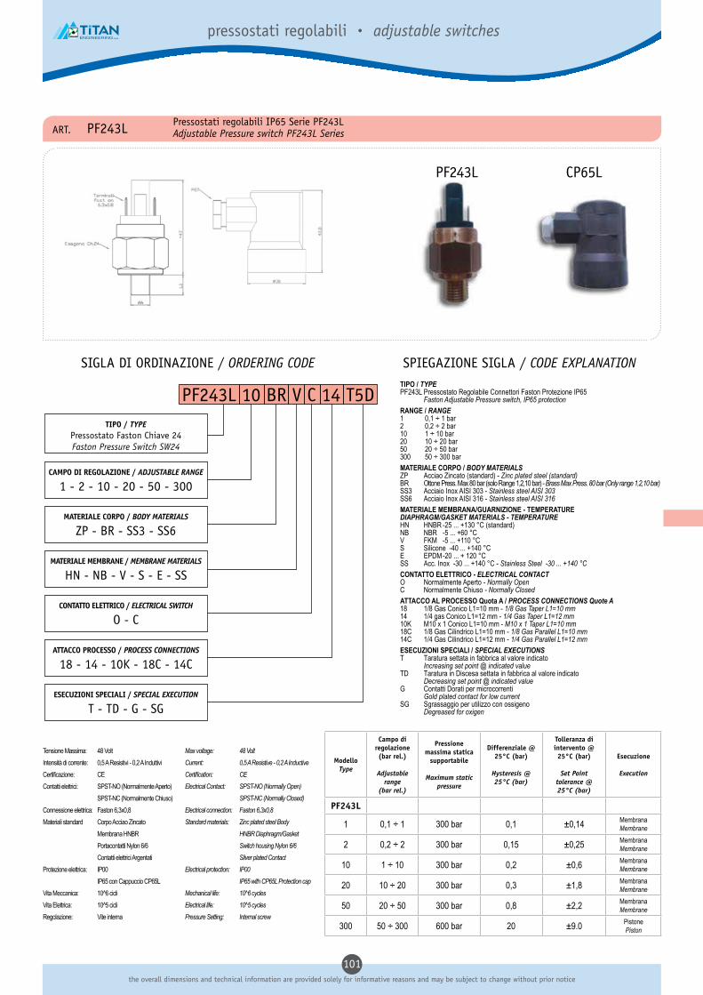
101the overall dimensions and technical information are provided solely for informative reasons and may be subject to change without prior notice
pressostati regolabili • adjustable switches
PF243L 10 BR V C 14 T5D
ART. PF243L Pressostati regolabili IP65 Serie PF243LAdjustable Pressure switch PF243L Series
SIGLA DI ORDINAZIONE / ORDERING CODE SPIEGAZIONE SIGLA / CODE EXPLANATION
TIPO / TYPEPressostato Faston Chiave 24Faston Pressure Switch SW24
CAMPO DI REGOLAZIONE / ADJUSTABLE RANGE
1 - 2 - 10 - 20 - 50 - 300
MATERIALE CORPO / BODY MATERIALS
ZP - BR - SS3 - SS6
MATERIALE MEMBRANE / MEMBRANE MATERIALS
HN - NB - V - S - E - SS
ATTACCO PROCESSO / PROCESS CONNECTIONS
18 - 14 - 10K - 18C - 14C
ESECUZIONI SPECIALI / SPECIAL EXECUTION
T - TD - G - SG
TIPO / TYPEPF243L Pressostato Regolabile Connettori Faston Protezione IP65 Faston Adjustable Pressure switch, IP65 protectionRANGE / RANGE1 0,1 ÷ 1 bar2 0,2 ÷ 2 bar10 1 ÷ 10 bar20 10 ÷ 20 bar50 20 ÷ 50 bar300 50 ÷ 300 bar
MATERIALE CORPO / BODY MATERIALSZP Acciao Zincato (standard) - Zinc plated steel (standard)BR Ottone Press. Max 80 bar (solo Range 1,2,10 bar) - Brass Max Press. 80 bar (Only range 1,2,10 bar)SS3 Acciaio Inox AISI 303 - Stainless steel AISI 303SS6 Acciaio Inox AISI 316 - Stainless steel AISI 316MATERIALE MEMBRANA/GUARNIZIONE - TEMPERATUREDIAPHRAGM/GASKET MATERIALS - TEMPERATUREHN HNBR -25 ... +130 °C (standard)NB NBR -5 ... +60 °CV FKM -5 ... +110 °CS Silicone -40 ... +140 °CE EPDM -20 ... + 120 °CSS Acc. Inox -30 ... +140 °C - Stainless Steel -30 ... +140 °CCONTATTO ELETTRICO - ELECTRICAL CONTACTO Normalmente Aperto - Normally OpenC Normalmente Chiuso - Normally ClosedATTACCO AL PROCESSO Quota A / PROCESS CONNECTIONS Quote A18 1/8 Gas Conico L1=10 mm - 1/8 Gas Taper L1=10 mm14 1/4 gas Conico L1=12 mm - 1/4 Gas Taper L1=12 mm10K M10 x 1 Conico L1=10 mm - M10 x 1 Taper L1=10 mm18C 1/8 Gas Cilindrico L1=10 mm - 1/8 Gas Parallel L1=10 mm14C 1/4 Gas Cilindrico L1=12 mm - 1/4 Gas Parallel L1=12 mmESECUZIONI SPECIALI / SPECIAL EXECUTIONST Taratura settata in fabbrica al valore indicato Increasing set point @ indicated valueTD Taratura in Discesa settata in fabbrica al valore indicato Decreasing set point @ indicated valueG Contatti Dorati per microcorrenti Gold plated contact for low currentSG Sgrassaggio per utilizzo con ossigeno Degreased for oxigen
CONTATTO ELETTRICO / ELECTRICAL SWITCH
O - C
ModelloType
Campo di regolazione (bar rel.)
Adjustable range
(bar rel.)
Pressione massima statica
supportabile
Maximum static pressure
Differenziale @ 25°C (bar)
Hysteresis @ 25°C (bar)
Tolleranza di intervento @ 25°C (bar)
Set Pointtolerance @25°C (bar)
Esecuzione
Execution
PF243L
1 0,1 ÷ 1 300 bar 0,1 ±0,14 MembranaMembrane
2 0,2 ÷ 2 300 bar 0,15 ±0,25 MembranaMembrane
10 1 ÷ 10 300 bar 0,2 ±0,6 MembranaMembrane
20 10 ÷ 20 300 bar 0,3 ±1,8 MembranaMembrane
50 20 ÷ 50 300 bar 0,8 ±2,2 MembranaMembrane
300 50 ÷ 300 600 bar 20 ±9.0 PistonePiston
PF243L CP65L
Tensione Massima: 48 Volt
Intensità di corrente: 0,5 A Resistivi - 0,2 A Induttivi
Certificazione: CE
Contatti elettrici: SPST-NO (Normalmente Aperto)
SPST-NC (Normalmente Chiuso)
Connessione elettrica: Faston 6,3x0,8
Materiali standard Corpo Acciao Zincato
Membrana HNBR
Portacontatti Nylon 6/6
Contatti elettrici Argentati
Protezione elettrica: IP00
IP65 con Cappuccio CP65L
Vita Meccanica: 10^6 cicli
Vita Elettrica: 10^5 cicli
Regolazione: Vite interna
Max voltage: 48 VoltCurrent: 0,5 A Resistive - 0,2 A InductiveCertification: CEElectrical Contact: SPST-NO (Normally Open) SPST-NC (Normally Closed)Electrical connection: Faston 6,3x0,8Standard materials: Zinc plated steel Body HNBR Diaphragm/Gasket Switch housing Nylon 6/6 Silver plated ContactElectrical protection: IP00 IP65 with CP65L Protection capMechanical life: 10^6 cyclesElectrical life: 10^5 cyclesPressure Setting: Internal screw

102dimensioni di ingombro e informazioni tecniche sono fornite a puro titolo informativo e possono essere soggette a modifica senza preavviso
pressostati regolabili • adjustable switches
PF244 10 BR V C 14 T5D
ART. PF244 Pressostati regolabili 250 Volt Serie PF244Adjustable Pressure switch 250 Volt
SIGLA DI ORDINAZIONE / ORDERING CODE SPIEGAZIONE SIGLA / CODE EXPLANATION
TIPO / TYPEPressostato Faston Chiave 24Faston Pressure Switch CH24
CAMPO DI REGOLAZIONE / ADJUSTABLE RANGE
1 - 2 - 10 - 20 - 50 - 300
MATERIALE CORPO / BODY MATERIALS
ZP - BR - SS3 - SS6
MATERIALE MEMBRANE / MEMBRANE MATERIALS
HN - NB - V - S - E - SS
ATTACCO PROCESSO / PROCESS CONNECTIONS
18 - 14 - 10K - 18C - 14C
ESECUZIONI SPECIALI / SPECIAL EXECUTION
T - TD - G - SG
TIPO / TYPEPF244 Pressostato Regolabile Connettori Faston Adjustable with Faston pressure switchRANGE / RANGE1 0,1 ÷ 1 bar2 0,2 ÷ 2 bar10 1 ÷ 10 bar20 10 ÷ 20 bar50 20 ÷ 50 bar300 50 ÷ 300 bar
MATERIALE CORPO / BODY MATERIALSZP Acciao Zincato (standard) - Zinc plated steel (standard)BR Ottone Press. Max 80 bar (solo Range 1,2,10 bar) - Brass Max Press. 80 bar (Only range 1,2,10 bar)SS3 Acciaio Inox AISI 303 - Stainless steel AISI 303SS6 Acciaio Inox AISI 316 - Stainless steel AISI 316MATERIALE MEMBRANA/GUARNIZIONE - TEMPERATUREDIAPHRAGM/GASKET MATERIALS - TEMPERATUREHN HNBR -25 ... +130 °C (standard)NB NBR -5 ... +60 °CV FKM -5 ... +110 °CS Silicone -40 ... +140 °CE EPDM -20 ... + 120 °CSS Acc. Inox -30 ... +140 °C - Stainless Steel -30 ... +140 °CCONTATTO ELETTRICO - ELECTRICAL CONTACTO Normalmente Aperto - Normally OpenC Normalmente Chiuso - Normally ClosedATTACCO AL PROCESSO Quota A / PROCESS CONNECTIONS Quote A18 1/8 Gas Conico L1=10 mm - 1/8 Gas Taper L1=10 mm14 1/4 gas Conico L1=12 mm - 1/4 Gas Taper L1=12 mm10K M10 x 1 Conico L1=10 mm - M10 x 1 Taper L1=10 mm18C 1/8 Gas Cilindrico L1=10 mm - 1/8 Gas Parallel L1=10 mm14C 1/4 Gas Cilindrico L1=12 mm - 1/4 Gas Parallel L1=12 mmESECUZIONI SPECIALI / SPECIAL EXECUTIONST Taratura settata in fabbrica al valore indicato Increasing set point @ indicated valueTD Taratura in Discesa settata in fabbrica al valore indicato Decreasing set point @ indicated valueG Contatti Dorati per microcorrenti Gold plated contact for low currentSG Sgrassaggio per utilizzo con ossigeno Degreased for oxigen
CONTATTO ELETTRICO / ELECTRICAL SWITCH
O - C
ModelloType
Campo di regolazione (bar rel.)
Adjustable range
(bar rel.)
Pressione massima statica
supportabile
Maximum static pressure
Differenziale @ 25°C (bar)
Hysteresis @ 25°C (bar)
Tolleranza di intervento @ 25°C (bar)
Set Pointtolerance @25°C (bar)
Esecuzione
Execution
PF244
1 0,1 ÷ 1 300 bar 0,1 ±0,14 MembranaMembrane
2 0,2 ÷ 2 300 bar 0,15 ±0,25 MembranaMembrane
10 1 ÷ 10 300 bar 0,2 ±0,6 MembranaMembrane
20 2 ÷ 20 300 bar 0,3 ±1,8 MembranaMembrane
50 20 ÷ 50 300 bar 0,8 ±2,2 MembranaMembrane
300 50 ÷ 300 600 bar 20 ±9.0 PistonePiston
PF244 CP54
Tensione Massima: 250 Volt
Intensità di corrente: 0,3 A Resistivi
Certificazione: CE
Contatti elettrici: SPST-NO (Normalmente Aperto)
SPST-NC (Normalmente Chiuso)
Connessione elettrica: Faston
Materiali standard Corpo Acciao Zincato
Membrana HNBR
Portacontatti Nylon 6/6
Contatti elettrici Argentati
Protezione elettrica: IP00
IP54 con Cappuccio CP54
Vita Meccanica: 10^6 cicli
Vita Elettrica: 10^5 cicli
Regolazione: Vite interna
Max voltage: 250 VoltCurrent: 0,3A ResistiveCertification: CEElectrical Contact: SPST-NO (Normally Open) SPST-NC (Normally Closed)Electrical connection: FastonStandard materials: Zinc plated steel Body HNBR Diaphragm/Gasket Switch housing Nylon 6/6 Silver plated ContactElectrical protection: IP00 IP54 with CP54 Protection capMechanical life: 10^6 cyclesElectrical life: 10^5 cyclesPressure Setting: Internal screw

103the overall dimensions and technical information are provided solely for informative reasons and may be subject to change without prior notice
pressostati regolabili • adjustable switches
ART. PFS243 Pressostati regolabili SPDT Serie PFS243Adjustable Pressure switch SPDT type
SIGLA DI ORDINAZIONE / ORDERING CODE SPIEGAZIONE SIGLA / CODE EXPLANATION
PFS243 10 BR V 14 T5D
TIPO / TYPEPressostato Faston SPDT
Faston pressure switch SPDT
CAMPO DI REGOLAZIONE / ADJUSTABLE RANGE
1 - 2 - 10 - 20 - 50 - 80 - 300
MATERIALE CORPO / BODY MATERIALS
ZP - BR - SS3 - SS6
MATERIALE MEMBRANE / MEMBRANE MATERIALS
HN - V - S - E - SS
ATTACCO PROCESSO / PROCESS CONNECTIONS
18 - 14 - 18C - 14C - M10 - 18N - 14N
ESECUZIONI SPECIALI / SPECIAL EXECUTION
T - TD - FS
TIPO / TYPEPFS243 Pressostato Regolabile Connettori Faston Contatto SPDT Adjustable pressure switch - SPDT contactRANGE1 0,1 ÷ 1 bar2 0,2 ÷ 2 bar10 1 ÷ 10 bar20 10 ÷ 20 bar50 20 ÷ 50 bar80 30 ÷ 80 bar300 50 ÷ 300 bar
MATERIALE CORPO / BODY MATERIALSZP Acciao Zincato (standard) - Zinc plated steel (standard)BR Ottone Press. Max 80 bar - Brass Max Press. 80 barSS3 Acciaio Inox AISI 303 - Stainless steel AISI 303SS6 Acciaio Inox AISI 316 - Stainless steel AISI 316MATERIALE MEMBRANA/GUARNIZIONE - TEMPERATUREDIAPHRAGM/GASKET MATERIALS - TEMPERATUREHN HNBR -25 ... +130 °C (standard)NB NBR -20 ... +90 °CV FKM -25 ... +120 °CS Silicone -40 ... +130 °CE EPDM -20 ... + 120 °CSS Acc. Inox -25 ... +120 °C - Stainless Steel -25 ... +120 °CATTACCO AL PROCESSO Quota A / PROCESS CONNECTIONS Quote A18 1/8 Gas Conico L1=10 mm - 1/8 Gas Taper L1=10 mm14 1/4 gas Conico L1=12 mm - 1/4 Gas Taper L1=12 mm18C 1/8” BSPP L1=10 mm - 1/8” Parallel L1=10 mm14C 1/4” BSPP L1=12 mm - 1/4” Parallel L1=12 mmM10 M10x1L1=10 mm18N 1/8”-27NPT L1=10 mm14N 1/4”-18 NPT L1=12 mm
ESECUZIONI SPECIALI / SPECIAL EXECUTIONST Taratura settata in fabbrica al valore indicato Increasing set point @ indicated valueTD Taratura in Discesa settata in fabbrica al valore indicato Decreasing set point @ indicated valueFS Filettature speciali su richiesta Special threads connections on request
ModelloType
Campo di regolazione (bar rel.)
Adjustable range
(bar rel.)
Pressione massima statica
supportabile
Maximum static pressure
Differenziale @ 25°C (bar)
Hysteresis @ 25°C (bar)
Tolleranza di intervento @ 25°C (bar)
Set Pointtolerance @25°C (bar)
Esecuzione
Execution
PFS243
1 0,1 ÷ 1 300 bar 30% VdT* ±0,14 MembranaMembrane
2 0,2 ÷ 2 300 bar 30% VdT* ±0,25 MembranaMembrane
10 1 ÷ 10 300 bar 30% VdT* ±0,6 MembranaMembrane
20 10 ÷ 20 300 bar 30% VdT* ±1,8 MembranaMembrane
50 20 ÷ 50 300 bar 30% VdT* ±2,2 MembranaMembrane
80 30 ÷ 80 300 bar 30% VdT* ±5.0 MembranaMembrane
300 50 ÷ 300 550 bar 30% VdT* ±9.0 PistonePiston
* VdT = Valore di Taratura - Set Point
PFS243 CP65
Tensione Massima: 250 Volt
Intensità di corrente: 6/2 A
Certificazione: CE
Contatti elettrici: SPDT
Connessione elettrica: Faston 6,3x0,8
Materiali standard Corpo Acciao Zincato
Membrana HNBR
Portacontatti Nylon 6/6 fv.30
Contatti elettrici Argentati
Protezione elettrica: IP00
IP65 con Cappuccio CP65
Vita Meccanica: 10^6 cicli
Isteresi: ~30% valore di taratura
Regolazione: Vite interna
Max voltage: 250 VoltCurrent: 6/2 ACertification: CEElectrical Contact: SPDTElectrical connection: Faston 6,3x0,8Standard materials: Zinc plated steel Body HNBR Diaphragm/Gasket Nylon 6/6 fv.30 Switch housing Silver plated ContactElectrical protection: IP00 IP65 with CP65 Protection capMechanical life: 10^6 cyclesIsteresys: ~30% of set pointPressure Setting: Internal screw
Ottone/Brass Acciaio/Steel

104dimensioni di ingombro e informazioni tecniche sono fornite a puro titolo informativo e possono essere soggette a modifica senza preavviso
pressostati regolabili • adjustable switches
PS245 10 BR V C 14 T5D
ART. PS245 Pressostati regolabili a morsetto Serie PS245Screw terminals Adjustable Pressure switch PS245 Series
SIGLA DI ORDINAZIONE / ORDERING CODE SPIEGAZIONE SIGLA / CODE EXPLANATION
TIPO / TYPEPressostato a morsetto 48 V.
Screw terminals Pressure switch 48 V.
CAMPO DI REGOLAZIONE / ADJUSTABLE RANGE
1 - 2 - 10 - 20 - 50 - 300
MATERIALE CORPO / BODY MATERIALS
ZP - BR - SS3 - SS6
MATERIALE CORPO / BODY MATERIALS
HN - NB - V - S - E - SS
ATTACCO PROCESSO / PROCESS CONNECTIONS
18 - 14 - 10K - 18C - 14C
ESECUZIONI SPECIALI / SPECIAL EXECUTION
T - TD - G - SG
TIPO / TYPEPS245 Pressostato Regolabile Connettori a Morsetto Screw terminals Adjustable Pressure switchRANGE1 0,1 ÷ 1 bar2 0,2 ÷ 2 bar10 1 ÷ 10 bar20 10 ÷ 20 bar50 20 ÷ 50 bar300 50 ÷ 300 bar
MATERIALE CORPO / BODY MATERIALSZP Acciao Zincato (standard) - Zinc plated steel (standard)BR Ottone Press. Max 80 bar (solo Range 1,2,10 bar) - Brass Max Press. 80 bar (Only range 1,2,10 bar)SS3 Acciaio Inox AISI 303 - Stainless steel AISI 303SS6 Acciaio Inox AISI 316 - Stainless steel AISI 316MATERIALE MEMBRANA/GUARNIZIONE - TEMPERATUREDIAPHRAGM/GASKET MATERIALS - TEMPERATUREHN HNBR -25 ... +130 °C (standard)NB NBR -5 ... +60 °CV FKM -5 ... +110 °CS Silicone -40 ... +140 °CE EPDM -20 ... + 120 °CSS Acc. Inox -30 ... +140 °C - Stainless Steel -30 ... +140 °CCONTATTO ELETTRICO - ELECTRICAL CONTACTO Normalmente Aperto - Normally OpenC Normalmente Chiuso - Normally ClosedATTACCO AL PROCESSO Quota A / PROCESS CONNECTIONS Quote A18 1/8 Gas Conico L1=10 mm - 1/8 Gas Taper L1=10 mm14 1/4 gas Conico L1=10 mm - 1/4 Gas Taper L1=10 mm10K M10 x 1 Conico L1=10 mm - M10 x 1 Taper L1=10 mm18C 1/8 Gas Cilindrico L1=10 mm - 1/8 Gas Parallel L1=10 mm14C 1/4 Gas Cilindrico L1=10 mm - 1/4 Gas Parallel L1=10 mmESECUZIONI SPECIALI / SPECIAL EXECUTIONST Taratura settata in fabbrica al valore indicato Increasing set point @ indicated valueTD Taratura in Discesa settata in fabbrica al valore indicato Decreasing set point @ indicated valueG Contatti Dorati per microcorrenti Gold plated contact for low currentSG Sgrassaggio per utilizzo con ossigeno Degreased for oxigen
CONTATTO ELETTRICO / ELECTRICAL SWITCH
O - C
ModelloType
Campo di regolazione (bar rel.)
Adjustable range
(bar rel.)
Pressione massima statica
supportabile
Maximum static pressure
Differenziale @ 25°C (bar)
Hysteresis @ 25°C (bar)
Tolleranza di intervento @ 25°C (bar)
Set Pointtolerance @25°C (bar)
Esecuzione
Execution
PS245
1 0,1 ÷ 1 300 bar 0,1 ±0,14 MembranaMembrane
2 0,2 ÷ 2 300 bar 0,15 ±0,25 MembranaMembrane
10 1 ÷ 10 300 bar 0,2 ±0,6 MembranaMembrane
20 10 ÷ 20 300 bar 0,3 ±1,8 MembranaMembrane
50 20 ÷ 50 300 bar 0,8 ±2,2 MembranaMembrane
300 50 ÷ 300 600 bar 20 ±9.0 PistonePiston
PS245 CP65
Tensione Massima: 48 Volt
Intensità di corrente: 0,5 A Resistivi - 0,2 A Induttivi
Certificazione: CE
Contatti elettrici: SPST-NO (Normalmente Aperto)
SPST-NC (Normalmente Chiuso)
Connessione elettrica: Morsetto con vite
Materiali standard Corpo Acciao Zincato
Membrana HNBR
Portacontatti Nylon 6/6
Contatti elettrici Argentati
Protezione elettrica: IP00
IP65 con Cappuccio CP65
Vita Meccanica: 10^6 cicli
Vita Elettrica: 10^5 cicli
Regolazione: Vite interna
Max voltage: 48 VoltCurrent: 0,5 A Resistive - 0,2 A InductiveCertification: CEElectrical Contact: SPST-NO (Normally Open) SPST-NC (Normally Closed)Electrical connection: Screw terminalsStandard materials: Zinc plated steel Body HNBR Diaphragm/Gasket Switch housing Nylon 6/6 Silver plated ContactElectrical protection: IP00 IP65 with CP65 Protection capMechanical life: 10^6 cyclesElectrical life: 10^5 cyclesPressure Setting: Internal screw

105the overall dimensions and technical information are provided solely for informative reasons and may be subject to change without prior notice
pressostati regolabili • adjustable switches
VF243 29 ZP E C 14 T480
ART. VF243 Vuotostati regolabili IP54 Serie VF243Adjustable vacuum switch VF243 Series
SIGLA DI ORDINAZIONE / ORDERING CODE SPIEGAZIONE SIGLA / CODE EXPLANATION
TIPO / TYPEVuotostato Faston Chiave 24Faston Vacuum Switch CH24
CAMPO DI REGOLAZIONE / ADJUSTABLE RANGE
29 (-200 ... -900 mbar)
MATERIALE CORPO / BODY MATERIALS
ZP - BR - SS3 - SS6
MATERIALE CORPO / BODY MATERIALS
HN - NB - V - S - E - SS
ATTACCO PROCESSO / PROCESS CONNECTIONS
18 - 14 - 10K - 18C - 14C
ESECUZIONI SPECIALI / SPECIAL EXECUTION
T - TD - G - SG
TIPO / TYPEVF243 Vuotostato Regolabile Connettori Faston Faston Adjustable vacuum switchRANGE29 -200 ÷ -900 mbar
MATERIALE CORPO / BODY MATERIALSZP Acciao Zincato (standard) - Zinc plated steel (standard)BR Ottone Press. Max 80 bar (solo Range 1,2,10 bar) - Brass Max Press. 80 bar (Only range 1,2,10 bar)SS3 Acciaio Inox AISI 303 - Stainless steel AISI 303SS6 Acciaio Inox AISI 316 - Stainless steel AISI 316MATERIALE MEMBRANA/GUARNIZIONE - TEMPERATUREDIAPHRAGM/GASKET MATERIALS - TEMPERATUREHN HNBR -25 ... +130 °C (standard)NB NBR -5 ... +60 °CV FKM -5 ... +110 °CS Silicone -40 ... +140 °CE EPDM -20 ... + 120 °CSS Acc. Inox -30 ... +140 °C - Stainless Steel -30 ... +140 °CCONTATTO ELETTRICO - ELECTRICAL CONTACTO Normalmente Aperto - Normally OpenC Normalmente Chiuso - Normally ClosedATTACCO AL PROCESSO Quota A / PROCESS CONNECTIONS Quote A18 1/8 Gas Conico L1=10 mm - 1/8 Gas Taper L1=10 mm14 1/4 gas Conico L1=12 mm - 1/4 Gas Taper L1=12 mm10K M10 x 1 Conico L1=10 mm - M10 x 1 Taper L1=10 mm18C 1/8 Gas Cilindrico L1=10 mm - 1/8 Gas Parallel L1=10 mm14C 1/4 Gas Cilindrico L1=12 mm - 1/4 Gas Parallel L1=12 mmESECUZIONI SPECIALI / SPECIAL EXECUTIONST Taratura settata in fabbrica al valore indicato Increasing set point @ indicated valueTD Taratura in Discesa settata in fabbrica al valore indicato Decreasing set point @ indicated valueG Contatti Dorati per microcorrenti Gold plated contact for low currentSG Sgrassaggio per utilizzo con ossigeno Degreased for oxigen
CONTATTO ELETTRICO / ELECTRICAL SWITCH
O - C
ModelloType
Campo di regolazione (bar rel.)
Adjustable range
(bar rel.)
Pressione massima statica
supportabile
Maximum static pressure
Differenziale @ 25°C (bar)
Hysteresis @ 25°C (bar)
Tolleranza di intervento @ 25°C (bar)
Set Pointtolerance @25°C (bar)
Esecuzione
Execution
VF243
29-200
÷-900
20 bar 20 ±50 MembranaMembrane
VF243 CP54
Tensione Massima: 48 Volt
Intensità di corrente: 0,5 A Resistivi - 0,2 A Induttivi
Certificazione: CE
Contatti elettrici: SPST-NO (Normalmente Aperto)
SPST-NC (Normalmente Chiuso)
Connessione elettrica: Faston 6,3x0,8
Materiali standard Corpo Acciao Zincato
Membrana HNBR
Portacontatti Nylon 6/6
Contatti elettrici Argentati
Protezione elettrica: IP00
IP54 con Cappuccio CP54
Vita Meccanica: 10^6 cicli
Vita Elettrica: 10^5 cicli
Regolazione: Vite interna
Max voltage: 48 VoltCurrent: 0,5 A Resistive - 0,2 A InductiveCertification: CEElectrical Contact: SPST-NO (Normally Open) SPST-NC (Normally Closed)Electrical connection: Faston 6,3x0,8Standard materials: Zinc plated steel Body HNBR Diaphragm/Gasket Switch housing Nylon 6/6 Silver plated ContactElectrical protection: IP00 IP54 with CP54 Protection capMechanical life: 10^6 cyclesElectrical life: 10^5 cyclesPressure Setting: Internal screw

106dimensioni di ingombro e informazioni tecniche sono fornite a puro titolo informativo e possono essere soggette a modifica senza preavviso
pressostati regolabili • adjustable switches
VS245 29 ZP E C 14 T650
ART. VS245 Vuotostati regolabili a morsetto Serie VS245Screw terminals Adjustable vacuum switch VS245 Series
SIGLA DI ORDINAZIONE / ORDERING CODE SPIEGAZIONE SIGLA / CODE EXPLANATION
TIPO / TYPEVuotostato Vite Chiave 24
Screw terminals Vacuum switch CH24
CAMPO DI REGOLAZIONE / ADJUSTABLE RANGE
29 (-200 ... -900 mbar)
MATERIALE CORPO / BODY MATERIALS
ZP - BR - SS3 - SS6
MATERIALE CORPO / BODY MATERIALS
HN - NB - V - S - E - SS
ATTACCO PROCESSO / PROCESS CONNECTIONS
18 - 14 - 10K - 18C - 14C
ESECUZIONI SPECIALI / SPECIAL EXECUTION
T - TD - G - SG
TIPO / TYPEVS245 Vuotostato Regolabile Connettori a Vite Faston Adjustable vacuum switchRANGE29 -200 ÷ -900 mbar
MATERIALE CORPO / BODY MATERIALSZP Acciao Zincato (standard) - Zinc plated steel (standard)BR Ottone Press. Max 80 bar (solo Range 1,2,10 bar) - Brass Max Press. 80 bar (Only range 1,2,10 bar)SS3 Acciaio Inox AISI 303 - Stainless steel AISI 303SS6 Acciaio Inox AISI 316 - Stainless steel AISI 316MATERIALE MEMBRANA/GUARNIZIONE - TEMPERATUREDIAPHRAGM/GASKET MATERIALS - TEMPERATUREHN HNBR -25 ... +130 °C (standard)NB NBR -5 ... +60 °CV FKM -5 ... +110 °CS Silicone -40 ... +140 °CE EPDM -20 ... + 120 °CSS Acc. Inox -30 ... +140 °C - Stainless Steel -30 ... +140 °CCONTATTO ELETTRICO - ELECTRICAL CONTACTO Normalmente Aperto - Normally OpenC Normalmente Chiuso - Normally ClosedATTACCO AL PROCESSO Quota A / PROCESS CONNECTIONS Quote A18 1/8 Gas Conico L1=10 mm - 1/8 Gas Taper L1=10 mm14 1/4 gas Conico L1=12 mm - 1/4 Gas Taper L1=12 mm10K M10 x 1 Conico L1=10 mm - M10 x 1 Taper L1=10 mm18C 1/8 Gas Cilindrico L1=10 mm - 1/8 Gas Parallel L1=10 mm14C 1/4 Gas Cilindrico L1=12 mm - 1/4 Gas Parallel L1=12 mmESECUZIONI SPECIALI / SPECIAL EXECUTIONST Taratura settata in fabbrica al valore indicato Increasing set point @ indicated valueTD Taratura in Discesa settata in fabbrica al valore indicato Decreasing set point @ indicated valueG Contatti Dorati per microcorrenti Gold plated contact for low currentSG Sgrassaggio per utilizzo con ossigeno Degreased for oxigen
CONTATTO ELETTRICO / ELECTRICAL SWITCH
O - C
ModelloType
Campo di regolazione (bar rel.)
Adjustable range
(bar rel.)
Pressione massima statica
supportabile
Maximum static pressure
Differenziale @ 25°C (bar)
Hysteresis @ 25°C (bar)
Tolleranza di intervento @ 25°C (bar)
Set Pointtolerance @25°C (bar)
Esecuzione
Execution
VF243
29-200
÷-900
20 bar 20 ±50 MembranaMembrane
VS245 CP65
Tensione Massima: 48 Volt
Intensità di corrente: 0,5 A Resistivi - 0,2 A Induttivi
Certificazione: CE
Contatti elettrici: SPST-NO (Normalmente Aperto)
SPST-NC (Normalmente Chiuso)
Connessione elettrica: Morsetto con vite
Materiali standard Corpo Acciao Zincato
Membrana HNBR
Portacontatti Nylon 6/6
Contatti elettrici Argentati
Protezione elettrica: IP00
IP65 con Cappuccio CP65
Vita Meccanica: 10^6 cicli
Vita Elettrica: 10^5 cicli
Regolazione: Vite interna
Max voltage: 48 VoltCurrent: 0,5 A Resistive - 0,2 A InductiveCertification: CEElectrical Contact: SPST-NO (Normally Open) SPST-NC (Normally Closed)Electrical connection: Screw terminalsStandard materials: Zinc plated steel Body HNBR Diaphragm/Gasket Switch housing Nylon 6/6 Silver plated ContactElectrical protection: IP00 IP65 with CP65 Protection capMechanical life: 10^6 cyclesElectrical life: 10^5 cyclesPressure Setting: Internal screw

107the overall dimensions and technical information are provided solely for informative reasons and may be subject to change without prior notice
manometri• gauges
ART. MP1 Manometro Ø 40 attacco posterioreGauge Ø 40 back connection
CODICE Scala(bar)
b1 ± 0.5 b2 ± 1 D G
MP118P006 0/0.6 26 44 41 1/8 A 14
MP118P010 0/1 26 44 41 1/8 A 14
MP118P016 0/1.6 26 44 41 1/8 A 14
MP118P025 0/2.5 26 44 41 1/8 A 14
MP118P040 0/4 26 44 41 1/8 A 14
MP118P060 0/6 26 44 41 1/8 A 14
MP118P100 0/10 26 44 41 1/8 A 14
MP118P120 0/12 26 44 41 1/8 A 14
MP118P160 0/16 26 44 41 1/8 A 14
MP118P250 0/25 26 44 41 1/8 A 14
MP118P400 0/40 26 44 41 1/8 A 14
MP118P600 0/60 26 44 41 1/8 A 14
MP118N000 -1/0 26 44 41 1/8 A 14
ART. MP2 Manometro Ø 50 attacco posterioreGauge Ø 50 back connection
CODICE Scala(bar)
b1 ± 0.5 b2 ± 1 D G
MP214P010 0/1 26.5 47.5 49 1/4 A 14
MP214P016 0/1.6 26.5 47.5 49 1/4 A 14
MP214P025 0/2.5 26.5 47.5 49 1/4 A 14
MP214P040 0/4 26.5 47.5 49 1/4 A 14
MP214P060 0/6 26.5 47.5 49 1/4 A 14
MP214P100 0/10 26.5 47.5 49 1/4 A 14
MP214P120 0/12 26.5 47.5 49 1/4 A 14
MP214P160 0/16 26.5 47.5 49 1/4 A 14
MP214P250 0/25 26.5 47.5 49 1/4 A 14
MP214P400 0/40 26.5 47.5 49 1/4 A 14
MP214P600 0/60 26.5 47.5 49 1/4 A 14
MP214N000 -1/0 26 44 41 1/8 A 14
ART. MP3 Manometro Ø 63 attacco posterioreGauge Ø 63 back connection
CODICE Scala(bar)
b1 ± 0.5 b2 ± 1 D G
MP314P006 0/0.6 27.5 48 62 1/4 A 14
MP314P010 0/1 27.5 48 62 1/4 A 14
MP314P016 0/1.6 27.5 48 62 1/4 A 14
MP314P025 0/2.5 27.5 48 62 1/4 A 14
MP314P040 0/4 27.5 48 62 1/4 A 14
MP314P060 0/6 27.5 48 62 1/4 A 14
MP314P100 0/10 27.5 48 62 1/4 A 14
MP314P120 0/12 27.5 48 62 1/4 A 14
MP314P160 0/16 27.5 48 62 1/4 A 14
MP314P250 0/25 27.5 48 62 1/4 A 14
MP314P400 0/40 27.5 48 62 1/4 A 14
MP314P600 0/60 27.5 48 62 1/4 A 14
MP314N000 -1/0 27.5 48 62 1/4 A 14
ART. MR1 Manometro Ø 40 attacco radialeGauge Ø 40 bottom connection
CODICE Scala(bar) A B D G h ±1
MR118P010 0/1 8 23 40.5 1/8 A 36 12
MR118P016 0/1.6 8 23 40.5 1/8 A 36 12
MR118P025 0/2.5 8 23 40.5 1/8 A 36 12
MR118P040 0/4 8 23 40.5 1/8 A 36 12
MR118P060 0/6 8 23 40.5 1/8 A 36 12
MR118P100 0/10 8 23 40.5 1/8 A 36 12
MR118P120 0/12 8 23 40.5 1/8 A 36 12
MR118P160 0/16 8 23 40.5 1/8 A 36 12
MR118P250 0/25 8 23 40.5 1/8 A 36 12
MR118P400 0/40 8 23 40.5 1/8 A 36 12
MR118P600 0/60 8 23 40.5 1/8 A 36 12
MR118N000 -1/0 8 23 40.5 1/8 A 36 12

108dimensioni di ingombro e informazioni tecniche sono fornite a puro titolo informativo e possono essere soggette a modifica senza preavviso
manometri• gauges
ART. MR2 Manometro Ø 50 attacco radialeGauge Ø 50 bottom connection
CODICE Scala(bar) A B D G h ±1
MR214P006 0/06 10 27 51 1/4 A 45 14
MR214P010 0/1 10 27 51 1/4 A 45 14
MR214P016 0/1.6 10 27 51 1/4 A 45 14
MR214P025 0/2.5 10 27 51 1/4 A 45 14
MR214P040 0/4 10 27 51 1/4 A 45 14
MR214P060 0/6 10 27 51 1/4 A 45 14
MR214P100 0/10 10 27 51 1/4 A 45 14
MR214P120 0/12 10 27 51 1/4 A 45 14
MR214P160 0/16 10 27 51 1/4 A 45 14
MR214P250 0/25 10 27 51 1/4 A 45 14
MR214P400 0/40 10 27 51 1/4 A 45 14
MR214P600 0/60 10 27 51 1/4 A 45 14
MR214N000 -1/0 8 23 51 1/4 A 45 14
ART. MR3 Manometro Ø 63 attacco radialeGauge Ø 63 bottom connection
CODICE Scala(bar) A B D G h ±1
MR314P006 0/0.6 10 28 63.5 1/4 A 14
MR314P010 0/1 10 28 63.5 1/4 A 14
MR314P016 0/1.6 10 28 63.5 1/4 A 14
MR314P025 0/2.5 10 28 63.5 1/4 A 14
MR314P040 0/4 10 28 63.5 1/4 A 14
MR314P060 0/6 10 28 63.5 1/4 A 14
MR314P100 0/10 10 28 63.5 1/4 A 14
MR314P120 0/12 10 28 63.5 1/4 A 14
MR314P160 0/16 10 28 63.5 1/4 A 14
MR314P250 0/25 10 28 63.5 1/4 A 14
MR314P400 0/40 10 28 63.5 1/4 A 14
MR314P600 0/60 10 28 63.5 1/4 A 14
MR314N000 0/1 10 28 63.5 1/4 A 14
ART. MPF1 Manometro Ø 40 con flangia 3 foriGauge Ø 40 3 holes flange connection
CODICE Scala(bar) A B C D E F G H
MPF118P010 0/1 40.5 10 24.5 39 12 40.5 1/8 A 61
MPF118P025 0/2.5 40.5 10 24.5 39 12 40.5 1/8 A 61
MPF118P040 0/4 40.5 10 24.5 39 12 40.5 1/8 A 61
MPF118P060 0/6 40.5 10 24.5 39 12 40.5 1/8 A 61
MPF118P100 0/10 40.5 10 24.5 39 12 40.5 1/8 A 61
MPF118P120 0/12 40.5 10 24.5 39 12 40.5 1/8 A 61
MPF118P250 0/25 40.5 10 24.5 39 12 40.5 1/8 A 61
ART. MPF2 Manometro Ø 50 con flangia 3 foriGauge Ø 50 3 holes flange connection
CODICE Scala(bar) A B C D E F G H
MPF214P060 0/6 48.5 15 28.5 49 14 50 1/4 A 71
MPF214P100 0/10 48.5 15 28.5 49 14 50 1/4 A 71
MPF214P120 0/12 48.5 15 28.5 49 14 50 1/4 A 71

109the overall dimensions and technical information are provided solely for informative reasons and may be subject to change without prior notice
manometri• gauges
ART. MPF3 Manometro Ø 63 con flangia 3 foriGauge Ø 63 3 holes flange connection
CODICE Scala(bar) A B C D E F G H
MPF314P010 0/1 49 15 28.5 62 14 63.5 1/4 A 85
MPF314P025 0/2.5 49 15 28.5 62 14 63.5 1/4 A 85
MPF314P040 0/4 49 15 28.5 62 14 63.5 1/4 A 85
MPF314P060 0/6 49 15 28.5 62 14 63.5 1/4 A 85
MPF314P100 0/10 49 15 28.5 62 14 63.5 1/4 A 85
MPF314P120 0/12 49 15 28.5 62 14 63.5 1/4 A 85
MPF314P160 0/16 49 15 28.5 62 14 63.5 1/4 A 85
MPF314P250 0/25 49 15 28.5 62 14 63.5 1/4 A 85
MPF314N000 -1/0 49 15 28.5 62 14 63.5 1/4 A 85
ART. MPS1 Manometro Ø 40 con staffa posterioreGauge Ø 40 clamp back connection
CODICE Scala(bar) A B C D E G H
MPS118P010 0/1 52 15 26.5 39.5 12 1/8 A 44
MPS118P016 0/1.6 52 15 26.5 39.5 12 1/8 A 44
MPS118P025 0/2.5 52 15 26.5 39.5 12 1/8 A 44
MPS118P040 0/4 52 15 26.5 39.5 12 1/8 A 44
MPS118P060 0/6 52 15 26.5 39.5 12 1/8 A 44
MPS118P100 0/10 52 15 26.5 39.5 12 1/8 A 44
MPS118P120 0/12 52 15 26.5 39.5 12 1/8 A 44
MPS118P160 0/16 52 15 26.5 39.5 12 1/8 A 44
MPS118P250 0/25 52 15 26.5 39.5 12 1/8 A 44
MPS118P400 0/40 52 15 26.5 39.5 12 1/8 A 44
MPS118N000 -1/0 52 15 26.5 39.5 12 1/8 A 44
ART. MPS2 Manometro Ø 50 con staffa posterioreGauge Ø 50 clamp back connection
CODICE Scala(bar) A B C D E G H I
MPS214P010 0/1 58 15 30 49.5 14 1/4 A 54 56.5
MPS214P016 0/1.6 58 15 30 49.5 14 1/4 A 54 56.5
MPS214P025 0/2.5 58 15 30 49.5 14 1/4 A 54 56.5
MPS214P040 0/4 58 15 30 49.5 14 1/4 A 54 56.5
MPS214P060 0/6 58 15 30 49.5 14 1/4 A 54 56.5
MPS214P100 0/10 58 15 30 49.5 14 1/4 A 54 56.5
MPS214P120 0/12 58 15 30 49.5 14 1/4 A 54 56.5
MPS214P160 0/16 58 15 30 49.5 14 1/4 A 54 56.5
MPS214P250 0/25 58 15 30 49.5 14 1/4 A 54 56.5
MPS214P400 0/40 58 15 30 49.5 14 1/4 A 54 56.5
MPS214N000 -1/0 58 15 30 49.5 14 1/4 A 54 56.5
ART. MPS3 Manometro Ø 63 con staffa posterioreGauge Ø 63 clamp back connection
CODICE Scala(bar) A B C D E G H I
MPS314P010 0/1 60 15 32 62.5 14 1/4 A 67 77.5
MPS314P016 0/1.6 60 15 32 62.5 14 1/4 A 67 77.5
MPS314P025 0/2.5 60 15 32 62.5 14 1/4 A 67 77.5
MPS314P040 0/4 60 15 32 62.5 14 1/4 A 67 77.5
MPS314P060 0/6 60 15 32 62.5 14 1/4 A 67 77.5
MPS314P100 0/10 60 15 32 62.5 14 1/4 A 67 77.5
MPS314P160 0/16 60 15 32 62.5 14 1/4 A 67 77.5
MPS314P250 0/25 60 15 32 62.5 14 1/4 A 67 77.5
MPS314P400 0/40 60 15 32 62.5 14 1/4 A 67 77.5
MPS314P600 0/60 60 15 32 62.5 14 1/4 A 67 77.5
MPS314N000 -1/0 60 15 32 62.5 14 1/4 A 67 77.5

110dimensioni di ingombro e informazioni tecniche sono fornite a puro titolo informativo e possono essere soggette a modifica senza preavviso
manometri• gauges
ART. MRL3 Manometro Ø 63 radiale a riempimento di liquidoGauge Ø 63 bottom connection liquid fillable
CODICE Scala(bar) A B D1 D2 E G H±1
MRL314P010 0/1 9.5 33 63 62 11.5 1/4 A 53 14
MRL314P016 0/1.6 9.5 33 63 62 11.5 1/4 A 53 14
MRL314P025 0/2.5 9.5 33 63 62 11.5 1/4 A 53 14
MRL314P040 0/4 9.5 33 63 62 11.5 1/4 A 53 14
MRL314P060 0/6 9.5 33 63 62 11.5 1/4 A 53 14
MRL314P100 0/10 9.5 33 63 62 11.5 1/4 A 53 14
MRL314P160 0/16 9.5 33 63 62 11.5 1/4 A 53 14
MRL314P250 0/25 9.5 33 63 62 11.5 1/4 A 53 14
MRL314P400 0/40 9.5 33 63 62 11.5 1/4 A 53 14
MRL314P600 0/60 9.5 33 63 62 11.5 1/4 A 53 14
MRL314N000 -1/0 9.5 33 63 62 11.5 1/4 A 53 14
ART. MRL5 Manometro Ø 100 radiale a riempimento di liquidoGauge Ø 100 bottom connection liquid fillable
CODICE Scala(bar) A B D1 D2 E G H±1
MRL512P006 0/0.6 15.5 49.5 101 99 17.5 1/2 A 87 22
MRL512P010 0/1 15.5 49.5 101 99 17.5 1/2 A 87 22
MRL512P016 0/1.6 15.5 49.5 101 99 17.5 1/2 A 87 22
MRL512P025 0/2.5 15.5 49.5 101 99 17.5 1/2 A 87 22
MRL512P040 0/4 15.5 49.5 101 99 17.5 1/2 A 87 22
MRL512P060 0/6 15.5 49.5 101 99 17.5 1/2 A 87 22
MRL512P100 0/10 15.5 49.5 101 99 17.5 1/2 A 87 22
MRL512P160 0/16 15.5 49.5 101 99 17.5 1/2 A 87 22
MRL512P250 0/25 15.5 49.5 101 99 17.5 1/2 A 87 22
MRL512P400 0/40 15.5 49.5 101 99 17.5 1/2 A 87 22
MRL512P600 0/60 15.5 49.5 101 99 17.5 1/2 A 87 22
MRL512N000 -1/0 15.5 49.5 101 99 17.5 1/2 A 87 22
ART. MRL6 Manometro Ø 160 radiale a riempimento di liquidoGauge Ø 160 bottom connection liquid fillable
CODICE Scala(bar) A B D1 D2 E G H±1
MRL612P006 0/0.6 15.5 49.5 161 159 17.5 1/2 A 118 22
MRL612P010 0/1 15.5 49.5 161 159 17.5 1/2 A 118 22
MRL612P016 0/1.6 15.5 49.5 161 159 17.5 1/2 A 118 22
MRL612P025 0/2.5 15.5 49.5 161 159 17.5 1/2 A 118 22
MRL612P040 0/4 15.5 49.5 161 159 17.5 1/2 A 118 22
MRL612P060 0/6 15.5 49.5 161 159 17.5 1/2 A 118 22
MRL612P100 0/10 15.5 49.5 161 159 17.5 1/2 A 118 22
MRL612P160 0/16 15.5 49.5 161 159 17.5 1/2 A 118 22
MRL612P250 0/25 15.5 49.5 161 159 17.5 1/2 A 118 22
MRL612P400 0/40 15.5 49.5 161 159 17.5 1/2 A 118 22
MRL612P600 0/60 15.5 49.5 161 159 17.5 1/2 A 118 22
MRL612N000 -1/0 15.5 49.5 161 159 17.5 1/2 A 118 22
ART. MRLP2 Manometro a riempimento di liquido Ø 50 cassa in plastica radialePlastic Gauge Ø 50 bottom connection liquid fillable
CODICE Scala(bar) A B D1 D2 E G H±1
MRLP2141000 0/100 11.5 27 55 51 5 1/4 48 14
MRLP2141600 0/160 11.5 27 55 51 5 1/4 48 14
MRLP2142500 0/250 11.5 27 55 51 5 1/4 48 14
MRLP2143150 0/315 11.5 27 55 51 5 1/4 48 14

111the overall dimensions and technical information are provided solely for informative reasons and may be subject to change without prior notice
manometri• gauges
ART. MRLP3 Manometro riempimento di liquido Ø 63 cassa in plastica radialePlastic Gauge Ø 63 bottom connection liquid fillable
CODICE Scala(bar) A B D1 D2 E G H±1
MRLP314P010 0/1 11.5 27 68 63 5 1/4 54 14
MRLP314P016 0/1.6 11.5 27 68 63 5 1/4 54 14
MRLP314P025 0/2.5 11.5 27 68 63 5 1/4 54 14
MRLP314P040 0/4 11.5 27 68 63 5 1/4 54 14
MRLP314P060 0/6 11.5 27 68 63 5 1/4 54 14
MRLP314P100 0/10 11.5 27 68 63 5 1/4 54 14
MRLP314P160 0/16 11.5 27 68 63 5 1/4 54 14
MRLP314P250 0/25 11.5 27 68 63 5 1/4 54 14
MRLP314P400 0/40 11.5 27 68 63 5 1/4 54 14
MRLP314P600 0/60 11.5 27 68 63 5 1/4 54 14
MRLP3141000 0/100 11.5 27 68 63 5 1/4 54 14
MRLP314N000 -1/0 11.5 27 68 63 5 1/4 54 14
ART. MPLX2 Manometro Ø 50 cassa inox attacco posteriore a riempimento liquidoStainless steel Gauge Ø 50 back connection liquid fillable
CODICE Scala(bar) A B ±
0.5B ± 1 D1 D2 E G H±1
MPLX214P016 0/1.6 12 30 55 55 50 5.5 1/4 48 14
MPLX214P025 0/2.5 12 30 55 55 50 5.5 1/4 48 14
MPLX214P040 0/4 12 30 55 55 50 5.5 1/4 48 14
MPLX214P060 0/6 12 30 55 55 50 5.5 1/4 48 14
MPLX214P100 0/10 12 30 55 55 50 5.5 1/4 48 14
MPLX214P160 0/16 12 30 55 55 50 5.5 1/4 48 14
MPLX214P250 0/25 12 30 55 55 50 5.5 1/4 48 14
MPLX2141000 0/100 12 30 55 55 50 5.5 1/4 48 14
MPLX2141600 0/160 12 30 55 55 50 5.5 1/4 48 14
MPLX2142500 0/250 12 30 55 55 50 5.5 1/4 48 14
ART. MPLX3 Manometro Ø 63 cassa inox attacco posteriore a riempimento liquidoStainless steel Gauge Ø 63 back connection liquid fillable
CODICE Scala(bar) A B ±
0.5B ± 1 D1 D2 E G H±1
MPLX314P006 0/0.6 13 32 56 68 62 6.5 1/4 54 14
MPLX314P010 0/1 13 32 56 68 62 6.5 1/4 54 14
MPLX314P016 0/1.6 13 32 56 68 62 6.5 1/4 54 14
MPLX314P025 0/2.5 13 32 56 68 62 6.5 1/4 54 14
MPLX314P040 0/4 13 32 56 68 62 6.5 1/4 54 14
MPLX314P060 0/6 13 32 56 68 62 6.5 1/4 54 14
MPLX314P100 0/10 13 32 56 68 62 6.5 1/4 54 14
MPLX314P160 0/16 13 32 56 68 62 6.5 1/4 54 14
MPLX314P250 0/25 13 32 56 68 62 6.5 1/4 54 14
MPLX314P040 0/40 13 32 56 68 62 6.5 1/4 54 14
MPLX314P060 0/60 13 32 56 68 62 6.5 1/4 54 14
MPLX314N000 -1/0 13 32 56 68 62 6.5 1/4 54 14
ART. MPLX5 Manometro Ø 100 cassa inox attacco posteriore a riempimento liquidoStainless steel Gauge Ø 100 back connection liquid fillable
CODICE Scala(bar) A B ±
0.5B ± 1 D1 D2 E F G H±1
MPLX512P006 0/0.6 15.5 48 81.5 107 100 8 30 1/2 87 22
MPLX512P010 0/1 15.5 48 81.5 107 100 8 30 1/2 87 22
MPLX512P016 0/1.6 15.5 48 81.5 107 100 8 30 1/2 87 22
MPLX512P025 0/2.5 15.5 48 81.5 107 100 8 30 1/2 87 22
MPLX512P040 0/4 15.5 48 81.5 107 100 8 30 1/2 87 22
MPLX512P060 0/6 15.5 48 81.5 107 100 8 30 1/2 87 22
MPLX512P100 0/10 15.5 48 81.5 107 100 8 30 1/2 87 22
MPLX512P160 0/16 15.5 48 81.5 107 100 8 30 1/2 87 22
MPLX512P250 0/25 15.5 48 81.5 107 100 8 30 1/2 87 22
MPLX512P040 0/40 15.5 48 81.5 107 100 8 30 1/2 87 22
MPLX512P060 0/60 15.5 48 81.5 107 100 8 30 1/2 87 22
MPLX5121000 0/100 15.5 48 81.5 107 100 8 30 1/2 87 22
MPLX5121600 0/160 15.5 48 81.5 107 100 8 30 1/2 87 22
MPLX5122500 0/250 15.5 48 81.5 107 100 8 30 1/2 87 22
MPLX512N000 -1/0 15.5 48 81.5 107 100 8 30 1/2 87 22

112dimensioni di ingombro e informazioni tecniche sono fornite a puro titolo informativo e possono essere soggette a modifica senza preavviso
RoHs 2 - REACH
Direttiva 2011/65/UE (RoHs 2)
TITAN ENGINEERING SPA produce e commercializza raccordi e accessori per la pneumatica che potrebbero essere utilizzati come componenti/accessori in apparecchiature elettriche ed elettroniche In base alle dichiarazioni rilasciate dai nostri Fornitori , dichiariamo che i seguenti prodotti da noi fabbricati e commercializzati e illustrati nel catalogo Green Line:• RACCORDI AUTOMATICI IN OTTONE• RACCORDI AUTOMATICI IN TECNOPOLIMERO• REGOLATORI DI FLUSSO IN OTTONE E
TECNOPOLIMERO• ASTINE IN OTTONE • RACCORDI AUTOMATICI MINIATURIZZATI E INOX• RACCORDI AD OGIVA IN OTTONE• RACCORDI A CALZAMENTO IN OTTONE
hanno un contenuto di sostanze, di seguito riportate, “con restrizione d’uso” inferiori ai valori prescritti nell’allegato II Direttiva 2011/65/UE (RoHs 2) – Sostanze con restrizioni d’uso e valori delle concentrazioni massime tollerate per peso nei materiali omogenei.
Piombo (0,1%)Mercurio (0,1%)Cadmio (0,01%)Cromo esavalente (0,1%)Bifenili polibromurati (PBB) (0,1%)Eteri di bifenile polibromurato (PBDE) (0,1%)
Regolamento CE 1907/2006 (REACH)
In base alle dichiarazioni rilasciate dai nostri Fornitori , TITAN ENGINEERING SPA dichiara di aver ottenuto:relativa dichiarazione da cui risulti che i Fornitori stessi sono al corrente dei propri obblighi e che operano conformemente al regolamento REACHrelativa dichiarazione di prodotti/sostanze non ricadenti nelle disposizione previste dal regolamento REACHImpegno dai propri Fornitori ad informare tempestivamente TITAN ENGINEERING SPA nel caso di variazioni/aggiornamenti nella necessità di utilizzare sostanze di cui al regolamento REACH
Directive 2011/65 / EU (RoHS 2)
TITAN ENGINEERING SPA manufactures and sells fittings and accessories for air pneumatic that could be used as components / accessories in electrical and electronic equipmentAccording to statements made by our suppliers, we declare that the following products, manufactured and marketed by us, and illustrated in the Green Line catalog:
• PUSH-IN BRASS FITTINGS• PUSH-IN TECHNOPOLYMER FITTINGS• BRASS AND POLYMER SPEED CONTROLLERS• BRASS STEMS• COMPACT AND STAINLESS STEEL PUSH-IN
FITTINGS• COMPRESSED BRASS FITTINGS• QUICK BRASS FITTINGS
have a content of substances, shown below, “with restricted use” lower than the values prescribed in Annex II of the Directive 2011/65 / EU (RoHS 2) - Substances with restrictions on use and maximum concentration values tolerated by weight in homogeneous materials.
Lead (0,1%)Mercury (0.1%)Cadmium (0.01%)Hexavalent chromium (0.1%)Polybrominated biphenyls (PBB) (0.1%)Polybrominated diphenyl ethers (PBDE) (0.1%)
Regulation EC 1907/2006 (REACH)
According to statements made by our suppliers, TITAN ENGINEERING SPA declares that it has obtained:its statement to the effect that the suppliers themselves are aware of their obligations and operating in accordance with REACHrelevant declaration of products / substances not covered by points available under REACHCommitment from suppliers themselves to inform TITAN ENGINEERING SPA in case of changes / updates in the need of using substances under REACH regulation

113the overall dimensions and technical information are provided solely for informative reasons and may be subject to change without prior notice
rete vendita Italia
ABRUZZO
ZETATECHVia Scienza 9/1165016 MONTESILVANO (PE)Tel. 085 [email protected]
CAMPANIA - CALABRIA
FLUID SERVICE S.r.l.Via Sannio, 9 80146 NAPOLITel. 081 5621607 Fax. 081 5621197
EMILIA-ROMAGNA
AIR FLUID CENTERVia Machiavelli (angolo Via Pirandello)29100 PIACENZATel. 0523 [email protected]
A.I.R. PNEUMATIC CENTER S.r.l.Via J. Gutemberg47038 SANTARCANGELOdi ROMAGNA (RN)Tel. 0541 [email protected]
C.A.I. Centro Aut. Industriali S.r.l.Via Piave, 33/3540064, OZZANO EMILIA ( BO )Tel. 051 [email protected] www.cai-srl.it
F.I.A.P. S.r.l.Via Palach 75 (angolo via dalla costa)Villaggio Torrazzi, 41122 MODENATel. 059 [email protected] www.fiapspa.it
F.I.P. S.r.l.Via Beniamino Franklin, 31Q.re SPIP, zona commerciale Cittadella43100,PARMATel. 0521 [email protected] www.fipsrl.it
LAZIO
S.I.R.I. S.r.l.Via dell’Industria, 904011 APRILIA (LT)Tel. 06 9258640 www.grisnet.it/siri
LOMBARDIA
PNEUMAX MILANO BRIANZA S.r.l.Via Alberto I° Re dei Belgi, 1320900 MONZA (MB)Tel. 39 039 [email protected]
PNEUMAX SERVICE S.r.l.Via Mons. Portaluppi, 1324049 VERDELLO (BG)Tel. 035 [email protected]
ATREBOR PNEUMATIC S.r.l.Viale Lombardia, 15/322048 MOLTENO (LC)Tel. 031 [email protected]
FLUIDMEC S.p.A.Via Gussalli, 4 25131 Brescia (BS)Tel. 030 [email protected]
INTERFLUID S.r.l.Via Lazzaretto, 10 F21013 GALLARATE (VA)Tel. 0331 [email protected]
MARCHE
PNEUMATEC S.r.l.Via Ancona, 4261010 TAVULLIA (PU)Tel. 0721 [email protected]
PIEMONTE
PNEUMAX TORINO S.r.l.Corso Allamano 3410095,Grugliasco (TO)Tel. 011 [email protected]
PROCOM CONTROL FLUID S.r.l.Via P. De Mosso 20/a13900 BIELLATel. 015 [email protected]
PUGLIA - MOLISE - BASILICATA
PNEUMAX SUD S.r.l.Via dei Bucaneve snc70026 MODUGNO (BA)Tel. 080 [email protected]
SICILIA
MANUIMPVia Alfio Berretta n.995125 CATANIATel. 095 347705www.manuimp.it
TOSCANA
FLUIDODINAMICA TOSCANA S.r.l.Via Caravaggio,1950028, Tavarnelle val di Pesa (FI)Tel. 055 [email protected]
UMBRIA
OLEODINAMICA PALMERINI S.r.l.Via dell’industria - Zona Ind.Molinaccio06087 PONTE SAN GIOVANNI (PG)Tel. 075 393753 - 398541/[email protected]
VENETO / TRENTINO / FRIULI
PNEUMAX VENETO S.r.l.Viale della Tecnica36100 VICENZATel. 0444 [email protected]
LIGURIA
PNEUMAX TORINO S.r.l.Corso Allamano 3410095,Grugliasco (TO)Tel. 011 [email protected]

114dimensioni di ingombro e informazioni tecniche sono fornite a puro titolo informativo e possono essere soggette a modifica senza preavviso
Worldwide network
EUROPA
AUSTRIA, BELGIO E SVIZZERAPneumax G.m.b.H.
BELGIODoedijns Fluidap NV/SA - AmayTel. +32 (0) 85 51 96 96Doedijns Fluidap NV/SA - PuursTel. +32 (0) 3 570 93 83www.fluidindustry.comwebsite@ fluidindustry.com
BULGARIAHABERKORN EOODTel. 00359 2 270561Fax. 00359 2 273354
DANIMARCABS Specialslanger A/STel. 0045 43 444614www.bssp.dkPneumatics ApSTel. 0045 86 453 453www.pneumatics.dk
ESTONIAPolarteknik ASTel. 0372 5230200www.polarteknik.com
FRANCIAPneumax S.a.r.l.SelestatTel. (+33)3-88-580450www.pneumax-france.fr
GERMANIAPneumax G.m.b.H.GelnhausenTel. (+49)-06051-97770www.pneumax.de
GRECIAHydropneumatik HellasTel. 0030 210 3474181Fax. 0030 210 3423370Theodoros Sofroniadis & Co.Tel. 0030 231 0527243Fax. 0030 231 515403
ISLANDABarki Ltd.Tel. 00354 554 6499Fax. 00354 554 6401
INGHILTERRAPneumax Ltd.Nursling - SouthamptonTel. 0044 02380 [email protected]
LITUANIADominga PrekybaTel. 00370 5 2322231www.dominga.lt
NORVEGIAKolberg Caspary Lautom AsTel. 0047 66753140www.kcl.no
OLANDAPneu/Tec BVTel. 0031 23 5699090www.pneutec.nl
POLONIARECTUS POLSKA sp. z o.o.Tel. 0048 33 857 98 00www.rectus.com.pl
PORTOGALLOPortugal Pneumax LdaVialongaTel. (+351)219-737390 - 2625607Complezo industrialda Granja-Ed.H
REPUBBLICA CECAPneumax Automation s.r.o.Tel. 0042 0553 760952-9www.pneumaxsro.cz
ROMANIAGICA Import Export SrlTel. 0040 257 259816Fax. 0040 257 257259816
RUSSIA / CISPneumax Ltd MoscowMoscowTel. (+7)-095-7393999www.pneumax.ru
SPAGNAPneumax S.A.ElgoibarTel. (+34)-943-744174www.pneumax.esPneumax Catalunia S.A.Molins De ReiTel. (+34)-93-6802530www.pneumax.es
SVEZIAPneumax ScandinaviaLommaTel. 0046 723 233223www.pneumax.se
TURCHIAHipel Endüstriyel Otomasyon Ltd.sti.Tel. 0090 212 2932768www.hipel.com.tr
AMERICA DEL NORD
CANADAManufacture Scorpion Inc.Tel. 001 450 378 [email protected]
STATI UNITI D’AMERICAHydradyne HydraulicsTel. 001 704 392 6185Fax. 001 504 227 0852www.hydra-dyne.com
AMERICA DEL SUD
BRASILEPneumax BrasilTel. 0055 41 [email protected]
CILESchultz Automat. e Ing.Tel. 0056 2 5550838jschultz@schultzautomatizacion
COLOMBIAIshi LtdaTel. 0057 1 [email protected]
PERÙNeumatec Perù S.A.C.Tel. 0051 1 [email protected]
ECUADORAinsa S.A.Tel. 00593 4 [email protected]
MESSICOPneumatecnia S.A. DE C.V.Tel. 0052 33 [email protected]
VENEZUELASinteco BarquisimetoTel. 0058 251 4432555Fax. 0058 251 [email protected]

115the overall dimensions and technical information are provided solely for informative reasons and may be subject to change without prior notice
Worldwide network
AFRICA
ALGERIASarl C.M.P.R.Tel. 00213 21 527686Fax. 00213 21 527687
EGITTOTechnical center for machienry supplyTel. +2 (02) 26989348Fax. +2 (02) [email protected]
MAROCCOIH.P. MarocTel. 00212 22 358282Fax. 00212 2 358291
SUD AFRICAPneumax Southern AfricaTel. 0027 11 573 [email protected]
TUNISIAL’Equipement moderneTel. 00216 71 343844Fax. 00216 71 [email protected]
ASIA
ARABIA SAUDITAArabian-Universal Est. for TradingTel. 00966 26 477159Fax. 00966 1 4622838
CINAPneumaxPneumatic Equipments Co. [email protected]
FILIPPINEIntegrated Hydro-PneumaticTel. 0063 2 [email protected]
GIORDANIATechnical centerfor machinery suppliesTel. 00962 6 4746901Fax. 00962 6 [email protected]
INDIAPneumaxPneumatic India Pvt. LtdNoidaTel.(+91)-120-5352560/61/[email protected]
INDONESIAPneumax Singapore Pte Ltd
PT. Mutiara Citramulia TeknindoTel. 0062 21 71425077Fax. 0062 21 [email protected]
IRANItal Electro PneumaticTel. 0098 (21) 33919177Fax. 0098 (21) [email protected]
ISRAELEIlan & GavishTel. 00972 3 9221824Fax. 00972 3 [email protected]
LIBANOYammine Trading Company SARLTel. 00961 1 [email protected]
MALESIAPneumax Singapore Pte LtdPSI Pneumatic Control Sdn BhdTel. 0060 4 6592627Fax. 0060 4 [email protected]
OMANTechnical engineering company L.L.CTel. 00968 591670Fax. 00968 [email protected]
PAKISTANFluid technikTel. 0092 21 [email protected]
SINGAPOREPneumaxPneumax Singapore Pte LtdSingaporeTel. 0065 6392 [email protected]
SIRIAAl Rowad TradingTel. 00963 11 6350530Fax. 00963 11 [email protected]
THAILANDIAThai Agency Engineering. Co. Ltd.Tel. 0066 2 [email protected]
U.A.E.Fine Industries Eng. Serv.Tel. 0971 6 5335434Fax. 0971 6 5335405
VIETNAMPneumax Singapore Pte Ltd

116dimensioni di ingombro e informazioni tecniche sono fornite a puro titolo informativo e possono essere soggette a modifica senza preavviso
note • notes

A
A B
C
service & solutions
TITAN ENGINEERING S.p.A.Via dei Cerri, 16/1847899 Zona Artigianale Ciarulla RSM(C.O.E. SM 04813)Tel. 0549 961121Fax 0549 [email protected]
CATALOGOACCESSORI ARIA COMPRESSA
COMPRESSED AIR ACCESSORIES
Prin
ted
in I
taly
09/
2015
C
M
Y
CM
MY
CY
CMY
K