SRM-3006 - MPB srl
270
SRM-3006 Selective Radiation Meter Operating Manual
-
Upload
khangminh22 -
Category
Documents
-
view
2 -
download
0
Transcript of SRM-3006 - MPB srl
SRM-3006Selective Radiation Meter
Operating Manual

Narda Safety Test Solutions GmbHSandwiesenstraße 772793 Pfullingen, Germany
® Name and logo are registered trademarks
of Narda Safety Test Solutions GmbH and L3
Communications Holdings, Inc. - Trade
names are trademarks of their respective
owners.
© 2017
Order no.: 3006/98.21
Issue: 06/03.2017, A ...Previous issues: 05/05.2012, A ...
Subject to change.
Our normal terms of warranty and delivery apply.
Printed in Germany
Contents
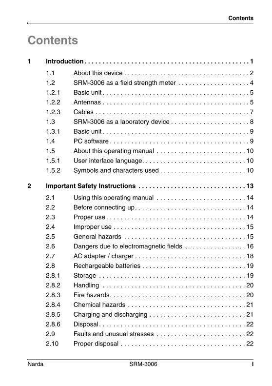
Contents1 Introduction . . . . . . . . . . . . . . . . . . . . . . . . . . . . . . . . . . . . . . . . . . . . . . 1
1.1 About this device . . . . . . . . . . . . . . . . . . . . . . . . . . . . . . . . . . . 2
1.2 SRM-3006 as a field strength meter . . . . . . . . . . . . . . . . . . . . 4
1.2.1 Basic unit . . . . . . . . . . . . . . . . . . . . . . . . . . . . . . . . . . . . . . . . . 5
1.2.2 Antennas . . . . . . . . . . . . . . . . . . . . . . . . . . . . . . . . . . . . . . . . . 5
1.2.3 Cables . . . . . . . . . . . . . . . . . . . . . . . . . . . . . . . . . . . . . . . . . . . 7
1.3 SRM-3006 as a laboratory device . . . . . . . . . . . . . . . . . . . . . . 8
1.3.1 Basic unit . . . . . . . . . . . . . . . . . . . . . . . . . . . . . . . . . . . . . . . . . 9
1.4 PC software . . . . . . . . . . . . . . . . . . . . . . . . . . . . . . . . . . . . . . . 9
1.5 About this operating manual . . . . . . . . . . . . . . . . . . . . . . . . . 10
1.5.1 User interface language. . . . . . . . . . . . . . . . . . . . . . . . . . . . . 10
1.5.2 Symbols and characters used . . . . . . . . . . . . . . . . . . . . . . . . 10
2 Important Safety Instructions . . . . . . . . . . . . . . . . . . . . . . . . . . . . . . 13
2.1 Using this operating manual . . . . . . . . . . . . . . . . . . . . . . . . . 14
2.2 Before connecting up. . . . . . . . . . . . . . . . . . . . . . . . . . . . . . . 14
2.3 Proper use . . . . . . . . . . . . . . . . . . . . . . . . . . . . . . . . . . . . . . . 14
2.4 Improper use . . . . . . . . . . . . . . . . . . . . . . . . . . . . . . . . . . . . . 15
2.5 General hazards . . . . . . . . . . . . . . . . . . . . . . . . . . . . . . . . . . 15
2.6 Dangers due to electromagnetic fields . . . . . . . . . . . . . . . . . 16
2.7 AC adapter / charger . . . . . . . . . . . . . . . . . . . . . . . . . . . . . . . 18
2.8 Rechargeable batteries . . . . . . . . . . . . . . . . . . . . . . . . . . . . . 19
2.8.1 Storage . . . . . . . . . . . . . . . . . . . . . . . . . . . . . . . . . . . . . . . . . 19
2.8.2 Handling . . . . . . . . . . . . . . . . . . . . . . . . . . . . . . . . . . . . . . . . 20
2.8.3 Fire hazards. . . . . . . . . . . . . . . . . . . . . . . . . . . . . . . . . . . . . . 20
2.8.4 Chemical hazards . . . . . . . . . . . . . . . . . . . . . . . . . . . . . . . . . 21
2.8.5 Charging and discharging . . . . . . . . . . . . . . . . . . . . . . . . . . . 21
2.8.6 Disposal . . . . . . . . . . . . . . . . . . . . . . . . . . . . . . . . . . . . . . . . . 22
2.9 Faults and unusual stresses . . . . . . . . . . . . . . . . . . . . . . . . . 22
2.10 Proper disposal . . . . . . . . . . . . . . . . . . . . . . . . . . . . . . . . . . . 22
Narda SRM-3006 I

Contents
3 Connecting Up and Starting to Use the Device. . . . . . . . . . . . . . . . 23
3.1 Unpacking the device . . . . . . . . . . . . . . . . . . . . . . . . . . . . . . 24
3.1.1 Packaging . . . . . . . . . . . . . . . . . . . . . . . . . . . . . . . . . . . . . . . 24
3.1.2 Package contents . . . . . . . . . . . . . . . . . . . . . . . . . . . . . . . . . 24
3.1.3 Checking the device for shipping damage . . . . . . . . . . . . . . 24
3.1.4 Recovery after shipping and storage . . . . . . . . . . . . . . . . . . 24
3.2 Device overview . . . . . . . . . . . . . . . . . . . . . . . . . . . . . . . . . . 25
3.2.1 Display and control panels . . . . . . . . . . . . . . . . . . . . . . . . . . 25
3.2.2 Device side panel with antenna / cable connectors . . . . . . . 26
3.2.3 Device side panel with battery compartment . . . . . . . . . . . . 26
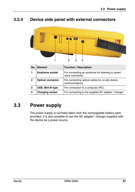
3.2.4 Device side panel with external connectors . . . . . . . . . . . . . 27
3.3 Power supply . . . . . . . . . . . . . . . . . . . . . . . . . . . . . . . . . . . . 27
3.3.1 Operation from battery pack . . . . . . . . . . . . . . . . . . . . . . . . . 28
3.3.2 Handling battery packs . . . . . . . . . . . . . . . . . . . . . . . . . . . . . 29
3.3.3 Operation from AC adapter / charger . . . . . . . . . . . . . . . . . . 30
3.4 Fitting the antenna . . . . . . . . . . . . . . . . . . . . . . . . . . . . . . . . 30
3.4.1 Fitting a Narda antenna directly on the Basic Unit . . . . . . . . 30
3.4.2 Connecting a Narda antenna to the Basic Unit using a Narda cable. . . . . . . . . . . . . . . . . . 31
3.4.3 Using commercially-available cables and antennas . . . . . . . 34
3.4.4 Fitting a Narda antenna on a tripod . . . . . . . . . . . . . . . . . . . 34
4 Operation and Basic Settings. . . . . . . . . . . . . . . . . . . . . . . . . . . . . . 39
4.1 Controls . . . . . . . . . . . . . . . . . . . . . . . . . . . . . . . . . . . . . . . . 40
4.1.1 Rotary control and keys . . . . . . . . . . . . . . . . . . . . . . . . . . . . 40
4.1.2 Softkeys . . . . . . . . . . . . . . . . . . . . . . . . . . . . . . . . . . . . . . . . 41
4.2 Switching the device on and off . . . . . . . . . . . . . . . . . . . . . . 41
4.3 LCD screen elements . . . . . . . . . . . . . . . . . . . . . . . . . . . . . . 42
4.3.1 The upper status bar. . . . . . . . . . . . . . . . . . . . . . . . . . . . . . . 43
4.3.2 The lower status bar . . . . . . . . . . . . . . . . . . . . . . . . . . . . . . . 44
4.3.3 The navigator bar . . . . . . . . . . . . . . . . . . . . . . . . . . . . . . . . . 45
4.3.4 Activating / deactivating status and info bars . . . . . . . . . . . . 45
II SRM-3006 Narda

Contents
4.4 Fundamental operating steps . . . . . . . . . . . . . . . . . . . . . . . . 46
4.4.1 Navigating in the menus . . . . . . . . . . . . . . . . . . . . . . . . . . . . 46
4.4.2 Forwards / Backwards . . . . . . . . . . . . . . . . . . . . . . . . . . . . . . 47
4.4.3 Selecting entries from a list . . . . . . . . . . . . . . . . . . . . . . . . . . 48
4.4.4 Changing numerical values . . . . . . . . . . . . . . . . . . . . . . . . . . 50
4.4.5 Entering text. . . . . . . . . . . . . . . . . . . . . . . . . . . . . . . . . . . . . . 51
4.4.6 Softkeys with toggle function . . . . . . . . . . . . . . . . . . . . . . . . . 52
4.4.7 Creating a screenshot . . . . . . . . . . . . . . . . . . . . . . . . . . . . . . 52
5 The Main Menu . . . . . . . . . . . . . . . . . . . . . . . . . . . . . . . . . . . . . . . . . . 53
5.1 Overview of functions and operating modes . . . . . . . . . . . . . 54
5.2 Display and editing device and component settings . . . . . . . 55
5.2.1 Changing the language, battery type, date, and time . . . . . . 56
5.2.2 Editing device-specific settings . . . . . . . . . . . . . . . . . . . . . . . 57
5.2.3 Displaying device information . . . . . . . . . . . . . . . . . . . . . . . . 58
5.2.4 Displaying GPS information. . . . . . . . . . . . . . . . . . . . . . . . . . 60
5.2.5 Resetting settings . . . . . . . . . . . . . . . . . . . . . . . . . . . . . . . . . 60
5.2.6 Performing device diagnosis . . . . . . . . . . . . . . . . . . . . . . . . . 61
5.2.7 Displaying and selecting the available antennas . . . . . . . . . . 62
5.2.8 Displaying and selecting the available cables . . . . . . . . . . . . 63
5.2.9 Displaying and selecting the safety standards. . . . . . . . . . . . 63
5.2.10 Displaying and creating service tables . . . . . . . . . . . . . . . . . 64
5.3 The memory menu . . . . . . . . . . . . . . . . . . . . . . . . . . . . . . . . 66
5.4 Using measurement routines. . . . . . . . . . . . . . . . . . . . . . . . . 66
5.4.1 Displaying measurement routines . . . . . . . . . . . . . . . . . . . . . 67
5.4.2 Starting a measurement routine . . . . . . . . . . . . . . . . . . . . . . 67
5.5 Saving and loading setups. . . . . . . . . . . . . . . . . . . . . . . . . . . 67
5.5.1 Saving settings as a setup. . . . . . . . . . . . . . . . . . . . . . . . . . . 68
5.5.2 Loading settings from a setup . . . . . . . . . . . . . . . . . . . . . . . . 68
5.5.3 Editing the setup list. . . . . . . . . . . . . . . . . . . . . . . . . . . . . . . . 68
5.5.4 Deleting setups . . . . . . . . . . . . . . . . . . . . . . . . . . . . . . . . . . . 69
5.5.5 Changing the switch on behavior. . . . . . . . . . . . . . . . . . . . . . 70
Narda SRM-3006 III
Contents
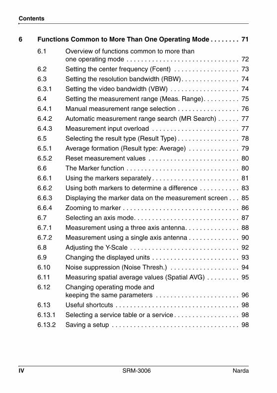
6 Functions Common to More Than One Operating Mode . . . . . . . . 71
6.1 Overview of functions common to more than one operating mode . . . . . . . . . . . . . . . . . . . . . . . . . . . . . . . 72
6.2 Setting the center frequency (Fcent) . . . . . . . . . . . . . . . . . . 73
6.3 Setting the resolution bandwidth (RBW). . . . . . . . . . . . . . . . 74
6.3.1 Setting the video bandwidth (VBW) . . . . . . . . . . . . . . . . . . . 74
6.4 Setting the measurement range (Meas. Range). . . . . . . . . . 75
6.4.1 Manual measurement range selection . . . . . . . . . . . . . . . . . 76
6.4.2 Automatic measurement range search (MR Search) . . . . . . 77
6.4.3 Measurement input overload . . . . . . . . . . . . . . . . . . . . . . . . 77
6.5 Selecting the result type (Result Type) . . . . . . . . . . . . . . . . . 78
6.5.1 Average formation (Result type: Average) . . . . . . . . . . . . . . 79
6.5.2 Reset measurement values . . . . . . . . . . . . . . . . . . . . . . . . . 80
6.6 The Marker function . . . . . . . . . . . . . . . . . . . . . . . . . . . . . . . 80
6.6.1 Using the markers separately . . . . . . . . . . . . . . . . . . . . . . . . 81
6.6.2 Using both markers to determine a difference . . . . . . . . . . . 83
6.6.3 Displaying the marker data on the measurement screen . . . 85
6.6.4 Zooming to marker . . . . . . . . . . . . . . . . . . . . . . . . . . . . . . . . 86
6.7 Selecting an axis mode. . . . . . . . . . . . . . . . . . . . . . . . . . . . . 87
6.7.1 Measurement using a three axis antenna. . . . . . . . . . . . . . . 88
6.7.2 Measurement using a single axis antenna . . . . . . . . . . . . . . 90
6.8 Adjusting the Y-Scale . . . . . . . . . . . . . . . . . . . . . . . . . . . . . . 92
6.9 Changing the displayed units . . . . . . . . . . . . . . . . . . . . . . . . 93
6.10 Noise suppression (Noise Thresh.) . . . . . . . . . . . . . . . . . . . 94
6.11 Measuring spatial average values (Spatial AVG) . . . . . . . . . 95
6.12 Changing operating mode and keeping the same parameters . . . . . . . . . . . . . . . . . . . . . . . 96
6.13 Useful shortcuts . . . . . . . . . . . . . . . . . . . . . . . . . . . . . . . . . . 98
6.13.1 Selecting a service table or a service . . . . . . . . . . . . . . . . . . 98
6.13.2 Saving a setup . . . . . . . . . . . . . . . . . . . . . . . . . . . . . . . . . . . 98
IV SRM-3006 Narda
Contents
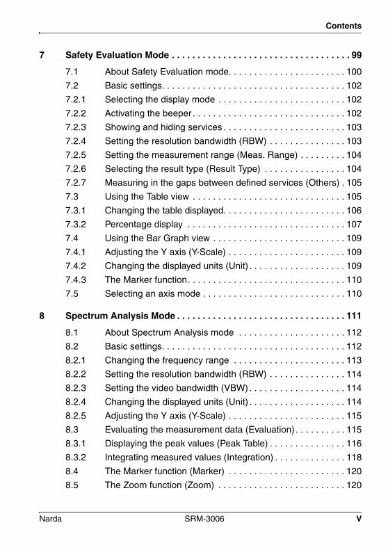
7 Safety Evaluation Mode . . . . . . . . . . . . . . . . . . . . . . . . . . . . . . . . . . . 99
7.1 About Safety Evaluation mode. . . . . . . . . . . . . . . . . . . . . . . 100
7.2 Basic settings. . . . . . . . . . . . . . . . . . . . . . . . . . . . . . . . . . . . 102
7.2.1 Selecting the display mode . . . . . . . . . . . . . . . . . . . . . . . . . 102
7.2.2 Activating the beeper . . . . . . . . . . . . . . . . . . . . . . . . . . . . . . 102
7.2.3 Showing and hiding services . . . . . . . . . . . . . . . . . . . . . . . . 103
7.2.4 Setting the resolution bandwidth (RBW) . . . . . . . . . . . . . . . 103
7.2.5 Setting the measurement range (Meas. Range) . . . . . . . . . 104
7.2.6 Selecting the result type (Result Type) . . . . . . . . . . . . . . . . 104
7.2.7 Measuring in the gaps between defined services (Others) . 105
7.3 Using the Table view . . . . . . . . . . . . . . . . . . . . . . . . . . . . . . 105
7.3.1 Changing the table displayed. . . . . . . . . . . . . . . . . . . . . . . . 106
7.3.2 Percentage display . . . . . . . . . . . . . . . . . . . . . . . . . . . . . . . 107
7.4 Using the Bar Graph view . . . . . . . . . . . . . . . . . . . . . . . . . . 109
7.4.1 Adjusting the Y axis (Y-Scale) . . . . . . . . . . . . . . . . . . . . . . . 109
7.4.2 Changing the displayed units (Unit) . . . . . . . . . . . . . . . . . . . 109
7.4.3 The Marker function. . . . . . . . . . . . . . . . . . . . . . . . . . . . . . . 110
7.5 Selecting an axis mode . . . . . . . . . . . . . . . . . . . . . . . . . . . . 110
8 Spectrum Analysis Mode . . . . . . . . . . . . . . . . . . . . . . . . . . . . . . . . . 111
8.1 About Spectrum Analysis mode . . . . . . . . . . . . . . . . . . . . . 112
8.2 Basic settings. . . . . . . . . . . . . . . . . . . . . . . . . . . . . . . . . . . . 112
8.2.1 Changing the frequency range . . . . . . . . . . . . . . . . . . . . . . 113
8.2.2 Setting the resolution bandwidth (RBW) . . . . . . . . . . . . . . . 114
8.2.3 Setting the video bandwidth (VBW). . . . . . . . . . . . . . . . . . . 114
8.2.4 Changing the displayed units (Unit) . . . . . . . . . . . . . . . . . . . 114
8.2.5 Adjusting the Y axis (Y-Scale) . . . . . . . . . . . . . . . . . . . . . . . 115
8.3 Evaluating the measurement data (Evaluation) . . . . . . . . . . 115
8.3.1 Displaying the peak values (Peak Table) . . . . . . . . . . . . . . . 116
8.3.2 Integrating measured values (Integration) . . . . . . . . . . . . . . 118
8.4 The Marker function (Marker) . . . . . . . . . . . . . . . . . . . . . . . 120
8.5 The Zoom function (Zoom) . . . . . . . . . . . . . . . . . . . . . . . . . 120
Narda SRM-3006 V

Contents
9 Level Recorder Mode. . . . . . . . . . . . . . . . . . . . . . . . . . . . . . . . . . . . 123
9.1 About Level Recorder mode . . . . . . . . . . . . . . . . . . . . . . . . 124
9.2 Display overview . . . . . . . . . . . . . . . . . . . . . . . . . . . . . . . . . 125
9.2.1 Activating the beeper . . . . . . . . . . . . . . . . . . . . . . . . . . . . . 126
9.3 Basic settings . . . . . . . . . . . . . . . . . . . . . . . . . . . . . . . . . . . 126
9.3.1 Selecting the center frequency (Fcent). . . . . . . . . . . . . . . . 126
9.3.2 Setting the resolution bandwidth (RBW). . . . . . . . . . . . . . . 126
9.3.3 Setting the video bandwidth (VBW) . . . . . . . . . . . . . . . . . . 126
9.3.4 Setting the measurement range (Meas. Range). . . . . . . . . 127
9.3.5 Selecting the result type (Result Type) . . . . . . . . . . . . . . . . 127
9.4 Selecting an axis mode (Axis) . . . . . . . . . . . . . . . . . . . . . . 128
9.5 Using noise suppression (Noise Thresh.). . . . . . . . . . . . . . 128
10 Scope Mode . . . . . . . . . . . . . . . . . . . . . . . . . . . . . . . . . . . . . . . . . . . 129
10.1 About Scope mode . . . . . . . . . . . . . . . . . . . . . . . . . . . . . . . 130
10.2 Display overview . . . . . . . . . . . . . . . . . . . . . . . . . . . . . . . . . 130
10.3 Basic settings . . . . . . . . . . . . . . . . . . . . . . . . . . . . . . . . . . . 131
10.3.1 Limits of values that can be set . . . . . . . . . . . . . . . . . . . . . 132
10.3.2 Selecting the center frequency (Fcent). . . . . . . . . . . . . . . . 132
10.3.3 Selecting Sweep Time, Time Resolution . . . . . . . . . . . . . . 133
10.3.4 Setting the resolution bandwidth (RBW). . . . . . . . . . . . . . . 133
10.3.5 Setting the video bandwidth (VBW) . . . . . . . . . . . . . . . . . . 133
10.3.6 Selecting the result type (Result Type) . . . . . . . . . . . . . . . . 134
10.3.7 Adjusting the Y axis (Y-Scale). . . . . . . . . . . . . . . . . . . . . . . 134
10.3.8 Changing the displayed units (Unit) . . . . . . . . . . . . . . . . . . 134
10.3.9 Extras . . . . . . . . . . . . . . . . . . . . . . . . . . . . . . . . . . . . . . . . . 134
10.4 Examples for measurement parameters. . . . . . . . . . . . . . . 134
10.4.1 Example 1: GSM. . . . . . . . . . . . . . . . . . . . . . . . . . . . . . . . . 135
10.4.2 Example 2: DECT telephone . . . . . . . . . . . . . . . . . . . . . . . 135
10.4.3 Example 3: WLAN . . . . . . . . . . . . . . . . . . . . . . . . . . . . . . . 136
10.4.4 Example 4: Remote automobile key (ISM band) . . . . . . . . 138
10.5 Using the trigger function . . . . . . . . . . . . . . . . . . . . . . . . . . 139
VI SRM-3006 Narda
Contents
10.5.1 Free Run . . . . . . . . . . . . . . . . . . . . . . . . . . . . . . . . . . . . . . . 139
10.5.2 Single and Multiple . . . . . . . . . . . . . . . . . . . . . . . . . . . . . . . 139
10.5.3 Manual Start . . . . . . . . . . . . . . . . . . . . . . . . . . . . . . . . . . . . 141
10.5.4 Time Controlled . . . . . . . . . . . . . . . . . . . . . . . . . . . . . . . . . . 142
10.6 Evaluating the measurement results (Evaluation) . . . . . . . . 142
11 UMTS Mode . . . . . . . . . . . . . . . . . . . . . . . . . . . . . . . . . . . . . . . . . . . . 143
11.1 About UMTS mode . . . . . . . . . . . . . . . . . . . . . . . . . . . . . . . 144
11.2 Display overview . . . . . . . . . . . . . . . . . . . . . . . . . . . . . . . . . 145
11.3 Explanation of measurement result display . . . . . . . . . . . . . 146
11.3.1 Individual results . . . . . . . . . . . . . . . . . . . . . . . . . . . . . . . . . 146
11.3.2 Total result (Total) . . . . . . . . . . . . . . . . . . . . . . . . . . . . . . . . 146
11.3.3 Partial results for certain radio cells (scrambling codes) . . . . . . . . . . . . . . . . . . . . . . . . . . . . . . . 147
11.3.4 Analog measurement result (Analog) . . . . . . . . . . . . . . . . . 147
11.4 Basic settings. . . . . . . . . . . . . . . . . . . . . . . . . . . . . . . . . . . . 147
11.4.1 Setting the center frequency (Fcent) . . . . . . . . . . . . . . . . . . 147
11.4.2 Showing and hiding services . . . . . . . . . . . . . . . . . . . . . . . . 148
11.4.3 Resetting the table (Reset Table) . . . . . . . . . . . . . . . . . . . . 148
11.4.4 Setting the measurement range (Meas. Range) . . . . . . . . . 148
11.4.5 Selecting the result type (Result Type) . . . . . . . . . . . . . . . . 149
11.4.6 Using an extrapolation factor . . . . . . . . . . . . . . . . . . . . . . . . 149
11.5 Performing a coverage measurement . . . . . . . . . . . . . . . . . 150
11.6 Using noise suppression (Noise Thresh.) . . . . . . . . . . . . . . 150
12 LTE mode. . . . . . . . . . . . . . . . . . . . . . . . . . . . . . . . . . . . . . . . . . . . . . 151
12.1 About LTE mode . . . . . . . . . . . . . . . . . . . . . . . . . . . . . . . . . 152
12.2 Display overview . . . . . . . . . . . . . . . . . . . . . . . . . . . . . . . . . 153
12.3 Explanation of measurement result display . . . . . . . . . . . . . 154
12.3.1 Individual results . . . . . . . . . . . . . . . . . . . . . . . . . . . . . . . . . 154
12.3.2 Total result (Total) . . . . . . . . . . . . . . . . . . . . . . . . . . . . . . . . 154
12.3.3 Partial results for certain cells . . . . . . . . . . . . . . . . . . . . . . . 155
12.3.4 Analog measurement result (Analog) . . . . . . . . . . . . . . . . . 155
Narda SRM-3006 VII

Contents
12.4 Basic settings . . . . . . . . . . . . . . . . . . . . . . . . . . . . . . . . . . . 155
12.4.1 Setting the center frequency (Fcent) and channel bandwidth (CBW) . . . . . . . . . . . . . . . . . . . . . . . . . 156
12.4.2 Selecting signals (Signal) . . . . . . . . . . . . . . . . . . . . . . . . . . 158
12.4.3 Changing CP Length and Cell Sync. . . . . . . . . . . . . . . . . . 158
12.4.4 Selecting the result type (Result Type) . . . . . . . . . . . . . . . . 159
12.4.5 Setting the measurement range (Meas. Range). . . . . . . . . 159
12.4.6 Using an extrapolation factor . . . . . . . . . . . . . . . . . . . . . . . 159
12.5 Using noise suppression (Noise Thresh.). . . . . . . . . . . . . . 160
12.6 LTE TDD . . . . . . . . . . . . . . . . . . . . . . . . . . . . . . . . . . . . . . . 161
12.6.1 Select and change the up-/downlink configuration . . . . . . . 162
13 Spatial Averaging. . . . . . . . . . . . . . . . . . . . . . . . . . . . . . . . . . . . . . . 163
13.1 About the Spatial Averaging function . . . . . . . . . . . . . . . . . 164
13.2 Description of averaging functions . . . . . . . . . . . . . . . . . . . 165
13.2.1 Continuous . . . . . . . . . . . . . . . . . . . . . . . . . . . . . . . . . . . . . 166
13.2.2 Discrete. . . . . . . . . . . . . . . . . . . . . . . . . . . . . . . . . . . . . . . . 167
13.2.3 Discrete Axis. . . . . . . . . . . . . . . . . . . . . . . . . . . . . . . . . . . . 168
13.3 Spatial Averaging – Continuous . . . . . . . . . . . . . . . . . . . . . 169
13.4 Spatial Averaging – Discrete. . . . . . . . . . . . . . . . . . . . . . . . 171
13.5 Spatial Averaging – Discrete Axis . . . . . . . . . . . . . . . . . . . . 173
14 Measurement Data Memory . . . . . . . . . . . . . . . . . . . . . . . . . . . . . . 177
14.1 About the Memory menu . . . . . . . . . . . . . . . . . . . . . . . . . . 178
14.2 Viewing data sets . . . . . . . . . . . . . . . . . . . . . . . . . . . . . . . . 179
14.3 Viewing screenshots. . . . . . . . . . . . . . . . . . . . . . . . . . . . . . 181
14.4 Saving measured values automatically. . . . . . . . . . . . . . . . 182
14.4.1 Conditional Storing of measured values . . . . . . . . . . . . . . . 182
14.4.2 Time Controlled Storing of measured values . . . . . . . . . . . 184
14.5 Changing the comment modes. . . . . . . . . . . . . . . . . . . . . . 186
VIII SRM-3006 Narda

Contents
15 Maintenance and Repairs. . . . . . . . . . . . . . . . . . . . . . . . . . . . . . . . . 187
15.1 Changing the battery pack. . . . . . . . . . . . . . . . . . . . . . . . . . 188
15.2 Cleaning . . . . . . . . . . . . . . . . . . . . . . . . . . . . . . . . . . . . . . . 188
15.3 AC adapter / charger . . . . . . . . . . . . . . . . . . . . . . . . . . . . . . 189
15.4 Updating the device software . . . . . . . . . . . . . . . . . . . . . . . 190
15.5 Activating options. . . . . . . . . . . . . . . . . . . . . . . . . . . . . . . . . 190
16 PC Software. . . . . . . . . . . . . . . . . . . . . . . . . . . . . . . . . . . . . . . . . . . . 191
16.1 PC software versions and functions . . . . . . . . . . . . . . . . . . 192
16.2 Connecting to the PC. . . . . . . . . . . . . . . . . . . . . . . . . . . . . . 193
16.3 Working with the PC software . . . . . . . . . . . . . . . . . . . . . . . 194
17 Remote Control . . . . . . . . . . . . . . . . . . . . . . . . . . . . . . . . . . . . . . . . . 195
17.1 About remote control . . . . . . . . . . . . . . . . . . . . . . . . . . . . . . 196
17.2 Connecting to the PC. . . . . . . . . . . . . . . . . . . . . . . . . . . . . . 196
17.3 Activating / deactivating remote control . . . . . . . . . . . . . . . . 197
17.3.1 Solving problems . . . . . . . . . . . . . . . . . . . . . . . . . . . . . . . . . 197
17.4 Syntax rules for remote control commands . . . . . . . . . . . . . 197
17.4.1 Commands to the SRM-3006 . . . . . . . . . . . . . . . . . . . . . . . 197
17.4.2 SRM-3006 responses . . . . . . . . . . . . . . . . . . . . . . . . . . . . . 198
17.4.3 Example of a command sequence . . . . . . . . . . . . . . . . . . . 199
18 Specifications . . . . . . . . . . . . . . . . . . . . . . . . . . . . . . . . . . . . . . . . . . 201
18.1 Definitions and conditions . . . . . . . . . . . . . . . . . . . . . . . . . . 202
18.2 SRM-3006 . . . . . . . . . . . . . . . . . . . . . . . . . . . . . . . . . . . . . . 203
18.2.1 Operating Modes . . . . . . . . . . . . . . . . . . . . . . . . . . . . . . . . . 203
18.2.2 RF data . . . . . . . . . . . . . . . . . . . . . . . . . . . . . . . . . . . . . . . . 203
18.2.3 Modes . . . . . . . . . . . . . . . . . . . . . . . . . . . . . . . . . . . . . . . . . 205
18.2.4 Measurement functions . . . . . . . . . . . . . . . . . . . . . . . . . . . . 215
18.2.5 General specifications . . . . . . . . . . . . . . . . . . . . . . . . . . . . . 218
18.3 Three axis E-field antenna 3501/03. . . . . . . . . . . . . . . . . . . 220
18.3.1 Characteristics. . . . . . . . . . . . . . . . . . . . . . . . . . . . . . . . . . . 220
Narda SRM-3006 IX

Contents
18.3.2 Uncertainty . . . . . . . . . . . . . . . . . . . . . . . . . . . . . . . . . . . . . 221
18.3.3 General specifications . . . . . . . . . . . . . . . . . . . . . . . . . . . . 221
18.4 Three axis E-field antenna 3502/01 . . . . . . . . . . . . . . . . . . 222
18.4.1 Characteristics . . . . . . . . . . . . . . . . . . . . . . . . . . . . . . . . . . 222
18.4.2 Uncertainty . . . . . . . . . . . . . . . . . . . . . . . . . . . . . . . . . . . . . 223
18.4.3 General specifications . . . . . . . . . . . . . . . . . . . . . . . . . . . . 223
18.5 Three axis H-field antenna 3581/02 . . . . . . . . . . . . . . . . . . 224
18.5.1 Characteristics . . . . . . . . . . . . . . . . . . . . . . . . . . . . . . . . . . 224
18.5.2 Uncertainty . . . . . . . . . . . . . . . . . . . . . . . . . . . . . . . . . . . . . 225
18.5.3 General specifications . . . . . . . . . . . . . . . . . . . . . . . . . . . . 225
18.6 Single axis E-field antenna 3531/01 . . . . . . . . . . . . . . . . . . 226
18.6.1 Characteristics . . . . . . . . . . . . . . . . . . . . . . . . . . . . . . . . . . 226
18.6.2 Uncertainty . . . . . . . . . . . . . . . . . . . . . . . . . . . . . . . . . . . . . 226
18.6.3 General specifications . . . . . . . . . . . . . . . . . . . . . . . . . . . . 227
18.7 Single axis E-field antenna 3531/04 . . . . . . . . . . . . . . . . . . 228
18.7.1 Characteristics . . . . . . . . . . . . . . . . . . . . . . . . . . . . . . . . . . 228
18.7.2 Uncertainty . . . . . . . . . . . . . . . . . . . . . . . . . . . . . . . . . . . . . 228
18.7.3 General specifications . . . . . . . . . . . . . . . . . . . . . . . . . . . . 229
18.8 Single axis H-field antenna 3551/02 . . . . . . . . . . . . . . . . . . 230
18.8.1 Characteristics . . . . . . . . . . . . . . . . . . . . . . . . . . . . . . . . . . 230
18.8.2 Uncertainty . . . . . . . . . . . . . . . . . . . . . . . . . . . . . . . . . . . . . 230
18.8.3 General specifications . . . . . . . . . . . . . . . . . . . . . . . . . . . . 231
18.9 Declaration of Conformity . . . . . . . . . . . . . . . . . . . . . . . . . . 232
19 Annex A. . . . . . . . . . . . . . . . . . . . . . . . . . . . . . . . . . . . . . . . . . . . . . . 235
19.1 Pendulum method. . . . . . . . . . . . . . . . . . . . . . . . . . . . . . . . 236
19.2 Matrix method (precision measurement) . . . . . . . . . . . . . . 238
X SRM-3006 Narda
Contents
20 Ordering Information . . . . . . . . . . . . . . . . . . . . . . . . . . . . . . . . . . . . 241
20.1 SRM-3006 sets . . . . . . . . . . . . . . . . . . . . . . . . . . . . . . . . . . 242
20.2 Antennas . . . . . . . . . . . . . . . . . . . . . . . . . . . . . . . . . . . . . . . 244
20.3 Options . . . . . . . . . . . . . . . . . . . . . . . . . . . . . . . . . . . . . . . . 244
20.4 Accessories . . . . . . . . . . . . . . . . . . . . . . . . . . . . . . . . . . . . . 244
21 Glossary. . . . . . . . . . . . . . . . . . . . . . . . . . . . . . . . . . . . . . . . . . . . . . . 247
Index. . . . . . . . . . . . . . . . . . . . . . . . . . . . . . . . . . . . . . . . . . . . . . . . . . 251
Narda SRM-3006 XI

Contents
XII SRM-3006 Narda

1 Introduction
This chapter contains basic information on measuring electromagnetic fields, on using the SRM-3006, and on how this manual is laid out.
1.1 About this device (page 2)
1.2 SRM-3006 as a field strength meter (page 4)
1.3 SRM-3006 as a laboratory device (page 8)
1.4 PC software (page 9)
1.5 About this operating manual (page 10)
Narda SRM-3006 1

1 Introduction
1.1 About this deviceThe SRM-3006 (Selective Radiation Meter) is a handy-sized frequency-selective measuring system for safety analysis and environmental measurements in high frequency electromagnetic fields in the frequency range from 9 kHz to 6 GHz. Because signals with frequencies of this magnitude are very difficult to sample digitally, the SRM-3006 uses a combination of analog and digital signal processing. It is ideal for measuring absolute and limit values of high-frequency electromagnetic fields such as those due to broadcast radio (AM, FM), TV (analog, DVB-T), BOS (Tetra), mobile telecommunications (GSM, UMTS, LTE), radar, and wireless communications (WiMax, WLAN).
In unknown field environments such as those around so-called shared sites, where several providers of mobile telephone services share a common antenna site, the SRM-3006 displays the total field level as well as the contributions made by the individual services, either as absolute values or as a percentage of the permitted limit level. Each service can be resolved down to its individual channels and the contribution made by each channel to the overall field emission measured using the SRM-3006. In the same way, the value can be integrated over the frequency band of the service and the total value displayed, again as an absolute value or in terms of the relevant limit value. The SRM-3006 naturally also includes all the typical functions of a spectrum analyzer and as such can be universally applied. An added bonus is the high measurement speed at small resolution bandwidths (RBW).
The device combines a very wide and varied range of functions within an extremely lightweight and handy design. This makes it possible to use the device particularly under the kind of conditions where good mobility and ruggedness are required.
The complete SRM-3006 measuring system comprises the Basic Unit SRM-3006 and the three axis antenna. Narda Safety Test Solutions also supplies other antennas for the Basic unit, including single axis antennas, covering various applications and frequency ranges. All Narda antennas can be mounted directly on the Basic Unit or connected to it using a special RF cable.
Other commercially available antennas can be connected to the SRM-3006 by cables; these cables can also be of types other than those supplied by Narda.
2 SRM-3006 Narda
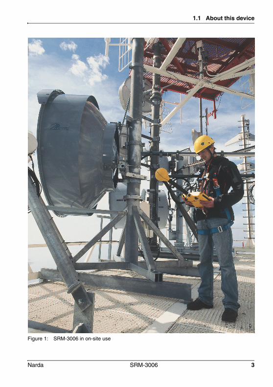
1.1 About this device
Figure 1: SRM-3006 in on-site use
Narda SRM-3006 3

1 Introduction
1.2 SRM-3006 as a field strength meterThe SRM-3006 is a device for measuring electromagnetic fields in the frequency range 9 kHz to 6 GHz. The main measurement task here is the determination of the field strength.
Several operating modes can be selected. Each operating mode is designed to deliver in-situ immediate, informative results that do not require any further processing or evaluation.
In the simplest case, the complete measuring equipment for determining the field strength consists of the Basic Unit with an antenna mounted directly on it.
Depending on the selected measurement method, it may be useful or even necessary not to mount the antenna directly on the Basic Unit but to place it some distance away and use a cable to connect it.
A 1.5 m long cable is included in all SRM-3006 field strength measuring system sets including antenna that are offered by Narda Safety Test Solutions. A 5 m long cable is available for special applications (see Ordering Information on page 241).
The antenna needs to be exactly positioned and undisturbed for precision measurements. An optionally available tripod with a suitable antenna holder can be added to the measuring equipment for this purpose.
Regardless of the package described, cables and antennas not made by Narda can also be connected to the Basic Unit in order to perform the desired measurements (see Using commercially-available cables and antennas on page 34).
4 SRM-3006 Narda
1.2 SRM-3006 as a field strength meter
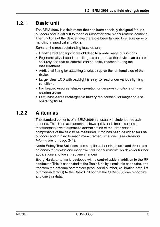
1.2.1 Basic unitThe SRM-3006 is a field meter that has been specially designed for use outdoors and in difficult to reach or uncomfortable measurement locations. The functions of the device have therefore been tailored to ensure ease of handling in practical situations.
Some of the most outstanding features are:
• Handy sized and light in weight despite a wide range of functions• Ergonomically shaped non-slip grips ensure that the device can be held
securely and that all controls can be easily reached during the measurement
• Additional fitting for attaching a wrist strap on the left hand side of the device
• Large, clear LCD with backlight is easy to read under various lighting conditions
• Foil keypad ensures reliable operation under poor conditions or when wearing gloves
• Fast, hassle-free rechargeable battery replacement for longer on-site operating times
1.2.2 AntennasThe standard contents of a SRM-3006 set usually include a three axis antenna. This three axis antenna allows quick and simple isotropic measurements with automatic determination of the three spatial components of the field to be measured. It too has been designed for use outdoors and in hard to reach measurement locations (see Ordering Information on page 241).
Narda Safety Test Solutions also supplies other single axis and three axis antennas for electric and magnetic field measurements which cover further applications and lower frequency ranges.
Every Narda antenna is equipped with a control cable in addition to the RF conductor. This is connected to the Basic Unit by a multi-pin connector, and transfers the antenna parameters (type, serial number, calibration date, list of antenna factors) to the Basic Unit so that the SRM-3006 can recognize and use this data.
Narda SRM-3006 5
1 Introduction
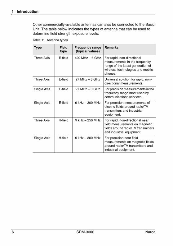
Other commercially-available antennas can also be connected to the Basic Unit. The table below indicates the types of antenna that can be used to determine field strength exposure levels.
Table 1: Antenna types
Type Field type
Frequency range (typical values)
Remarks
Three Axis E-field 420 MHz – 6 GHz For rapid, non-directional measurements in the frequency range of the latest generation of wireless technologies and mobile phones.
Three Axis E-field 27 MHz – 3 GHz Universal solution for rapid, non-directional measurements.
Single Axis E-field 27 MHz – 3 GHz For precision measurements in the frequency range most used by communications services.
Single Axis E-field 9 kHz – 300 MHz For precision measurements of electric fields around radio/TV transmitters and industrial equipment.
Three Axis H-field 9 kHz – 250 MHz For rapid, non-directional near field measurements on magnetic fields around radio/TV transmitters and industrial equipment.
Single Axis H-field 9 kHz – 300 MHz For precision near field measurements on magnetic fields around radio/TV transmitters and industrial equipment.
6 SRM-3006 Narda
1.2 SRM-3006 as a field strength meter
1.2.3 CablesNarda Safety Test Solutions supplies two cables for the connection between the antenna and the Basic Unit. Both cables are suitable for the frequency range between 9 kHz and 6 GHz. The cables are 1.5 m and 5 m long and contain ferrite to reduce the effect of the external field on the measurement results. The cables include a control cable along with the RF conductor. This control cable is connected to the Basic Unit by a multi-pin connector, and transfers the antenna parameters (type, serial number, calibration date, list of attenuation factors) to the Basic Unit so that the SRM-3006 can recognize and use this data. This cable also allows the SRM-3006 to control successive measurement of each of the three axes to determine the isotropic result, or selection of a single axis to determine directional information.
Commercially-available cables can also be used for the connection between the Basic Unit and the antenna. However, three axis antennas cannot be controlled using such cables.
Narda SRM-3006 7

1 Introduction
1.3 SRM-3006 as a laboratory deviceSince the SRM-3006 Basic Unit has all the typical features of a spectrum analyzer, it can also be used in this capacity under laboratory conditions.
Figure 2: SRM-3006 in laboratory use
The SRM-3006 can be integrated into the required measurement environment directly via the N connector or by means of a cable. The test generator signals can be fed directly into the basic unit via the N connector.
The SRM-3006 set includes a 1.5 m long cable. A 5 m long cable can be ordered as an optional accessory (see Ordering Information on page 241).
8 SRM-3006 Narda

1.4 PC software
1.3.1 Basic unitThe SRM-3006 Basic Unit has the following standard features of a spectrum analyzer:
• The Integration over Frequency Band function in Spectrum Analysis mode can be used to determine the wide band value for an individual channel (Channel Power).
• The service tables in Safety Evaluation mode can be used as channel tables for channel measurements (Channel Power Plus). Clarity is given by displaying the results as a bar graph.
• Noisy signals can be smoothed by adjusting the video bandwidth or by selecting a narrow RBW in Safety Evaluation mode. A compromise with regard to time must be found when smoothing the signals.
• Signals can be observed against time in Spectrum Analysis mode using very narrow and very wide RBWs.
In addition to the above, the SRM-3006 has the following functions (among others):
• The field strength of pulsed signals can be determined rapidly in Level Recorder mode.
• Signals can be analyzed in real time or monitored over a long period of up to 24 hours in Scope mode.
• Spatial averaging and normal averaging provide important information for standard-compliant measurements e.g. for 6-minute intervals.
• Peak Table and Extrapolation functions are provided for evaluating measurements.
• UMTS mode enables P-CPICH demodulation and therefore field strength measurements for individual UMTS cells.
• The field strengths of cell-specific signals (particularly the reference and secondary sync signals) are measured in LTE mode.
• Certain store events (time, threshold value) can be set to enable recording of specific measurement results.
1.4 PC softwareThe device can be connected to a PC via the optical interface or the USB port (Mini B type). This allows access to the device functions and measurement results. You can find detailed information about this in the following chapters:• PC Software on page 191• Remote Control on page 195
Narda SRM-3006 9

1 Introduction
1.5 About this operating manual
1.5.1 User interface languageThis operating manual uses English terminology to describe the user interface.
The user interface of the SRM-3006 can however be displayed in other languages.
If you select another language for the user interface, the displayed terms will differ from the ones described in this manual.
1.5.2 Symbols and characters usedVarious elements are used in this operating manual to draw attention to special meanings or important points in the text.
Symbols and terms used in warningsThe following warnings, symbols and terms are used in this document in compliance with the American National Standard ANSI Z535.6-2006:
This general danger symbol in conjunction with the terms CAUTION, WARNING, or DANGER warns of the risk of severe injury. Follow all subsequent instructions to avoid injury or death.
NOTICE Indicates a danger that could lead to damage or destruction of the device.
CAUTION Indicates a danger that represents a low or medium risk of injury.
WARNING Indicates a danger that could lead to death or severe injury.
DANGER Indicates a danger that will result in death or severe injury.
10 SRM-3006 Narda

1.5 About this operating manual
Warning formatAll warnings have the following format:
Symbols and characters
WARNING TERMType and source of dangerConsequences of ignoring the warning Action needed to avoid danger
! Important action instructionIndicates an instruction for action that must be followed in order to avoid danger.
RequirementIndicates a requirement that must be fulfilled before the subsequent action can be taken. Example: The measurement screen is displayed.
ActionIndicates a single action. Example:
Switch the device on.
1.2.3.
Sequence of actionsIndicates a sequence of actions that must be performed in the order given.
ResultIndicates the result of an action. Example: The device starts a self test.
Bold text Control element or menu nameIndicates device control elements and menu names. Example:
Press the OK key.
Gray text OrientationYou will find a line of gray text at the start of every section in the descriptions of the menus and functions. This indicates the order of selection of the menus and sub-menus. Example:
Main Menu • Safety Evaluation • Select Menu
Note: Important additional information or details of special features or situations.
Narda SRM-3006 11

1 Introduction
12 SRM-3006 Narda
2 Important Safety Instructions
This chapter explains important terms that are used in this operating manual.
2.1 Using this operating manual (page 14)
2.2 Before connecting up (page 14)
2.3 Proper use (page 14)
2.4 Improper use (page 15)
2.5 General hazards (page 15)
2.6 Dangers due to electromagnetic fields (page 16)
2.7 AC adapter / charger (page 18)
2.8 Rechargeable batteries (page 19)
2.9 Faults and unusual stresses (page 22)
2.10 Proper disposal (page 22)
Narda SRM-3006 13

2 Important Safety Instructions
2.1 Using this operating manual Please read this manual carefully and completely before using the
device.
Keep this manual so that it is readily available to all users of the device.
Always make sure that this manual accompanies the device if it is given to a third party.
2.2 Before connecting upThe device left the factory in perfect condition. We recommend that the following instructions be followed to ensure that this condition is maintained and that operation of the device is without danger.
2.3 Proper useThe device may only be used under the conditions and for the purpose for which it was constructed.
The SRM-3006 is designed for measuring and evaluating electromagnetic fields.
Only use the device under the conditions and for the purpose for which it was constructed.
Proper use also includes the following: Following the national accident prevention rules that apply at the place of
use.
Only allowing appropriately qualified and trained persons to use the device.
14 SRM-3006 Narda
2.4 Improper use
2.4 Improper useThe SRM-3006 is not a warning device that gives indication of the presence of dangerous fields by means of visible or audible signals.
Always consider the device as a measuring device, never as a warning device.
Always carefully observe the actual measurement value display when approaching unknown fields.
In case of doubt, use an additional warning device such as RadMan (XT) or Nardalert (XT) from Narda Safety Test Solutions.
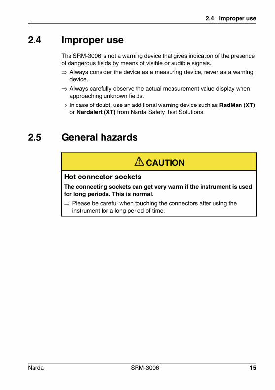
2.5 General hazards
CAUTIONHot connector socketsThe connecting sockets can get very warm if the instrument is used for long periods. This is normal. Please be careful when touching the connectors after using the
instrument for a long period of time.
Narda SRM-3006 15
2 Important Safety Instructions
2.6 Dangers due to electromagnetic fields
WARNINGStrong fieldsVery strong fields can occur in the vicinity of some radiation sources Be aware of and observe any safety barriers and markings.
In particular, persons fitted with electronic implants (e.g. pacemakers) must keep away from dangerous areas.
WARNINGUnsuitable frequency rangeDangerous fields may not be detected if an unsuitable frequency range is selected Always select the largest available or the most suitable frequency
range.
Always carefully observe the actual measurement value display when approaching unknown fields.
In case of doubt, use an additional wideband warning device such as RadMan (XT) or Nardalert (XT) from Narda Safety Test Solutions.
WARNINGMisinterpretation of results when using single axis antennasWhen a single axis antenna is used, only the field components that are parallel to the antenna axis will be detected. If the antenna is not correctly oriented in the field, there is a danger that the field strength value displayed will be low or even zero despite the presence of a strong field. Always use a suitable measurement setup when making
measurements with a single axis antenna.
Be aware of the polarization direction when aligning the antenna.
16 SRM-3006 Narda

2.6 Dangers due to electromagnetic fields
WARNINGElectric shockHigh voltages may occur within the device. Do not bring the measuring device or the antenna into contact with any
electrically conductive items.
Do not open the device. (Opening the device will void any claim under warranty.)
Do not handle or use a device that is opened or that is visibly damaged.
Only use the accessories supplied with and designed for the SRM-3006.
NOTICEMalfunctionImproper use, damage, and unauthorized repairs can impair the accuracy and function of the device Only use the device under the conditions and for the purpose for which
it was constructed.
Regularly check the device for signs of damage.
Only allow qualified persons to make repairs.
Metallic stickers in the (yellow) sensor area of the antenna can lead to measurement errors, specifically to an underestimation of the electromagnetic field strength. Only apply stickers of any kind to the (black) shaft of the antenna.
Metallic stickers in the (yellow) area above the display can cause malfunction of the GPS receiver. Only apply stickers of any kind to the back or sides of the device.
Narda SRM-3006 17
2 Important Safety Instructions
2.7 AC adapter / charger
WARNINGElectric shockParts carrying dangerous voltages may be exposed and cause injury through electric shock if the AC adapter / charger is damaged. Do not use an AC adapter / charger that is damaged.
NOTICEDestruction of the AC adapter / chargerThe AC adapter / charger can be destroyed by an incorrect AC line voltage, condensation, temperatures that are too high or too low, and insufficient ventilation. Make sure that the AC line voltage is the same as the operating voltage
of the AC adapter / charger before you connect it up.
Do not use the AC adapter charger if condensation has formed on it. If condensation is unavoidable, e.g. when the AC adapter charger is cold and is brought into a warm room, it must be allowed to dry out before you connect it up.
Only use the AC adapter / charger indoors and at temperatures between 0 °C and +40 °C.
18 SRM-3006 Narda

2.8 Rechargeable batteries
2.8 Rechargeable batteriesThe SRM-3006 is fitted with a rechargeable Lithium-ion battery to allow portable operation.
2.8.1 Storage
CAUTIONUnsuitable environmental conditionsExcessive temperatures and humidity can lead to a short circuit which can result in a fire, which may cause injury or destroy the battery pack. Make sure that the storage conditions are within the following limits:
– Temperature: -10 °C to +50 °C– Air humidity: 0% to 80%
Check regularly to ensure that the storage temperature and humidity are within the prescribed limits.
Do not leave discharged batteries in the instrument for an extended period of time.
Do not store the batteries for more than 6 months without recharging them in the meantime.
Do not store the batteries together with any other metallic objects.
Long-term storage can reduce the battery capacity and shorten battery life. The casing can also be damaged internally by leaking electrolyte.
Narda SRM-3006 19

2 Important Safety Instructions
2.8.2 Handling Observe the following instructions for correct and safe handling of the
battery pack.
2.8.3 Fire hazards
CAUTIONMechanical stressesIncorrect handling and unsuitable mechanical stresses can lead to explosion, fire, or chemical leakages, which may cause injury or destroy the battery pack. Do not open, crush, or dismantle the battery pack.
Do not drop the battery pack from a great height.
Do not attempt to solder anything on to the battery pack.
CAUTIONIgnition of battery packThe battery pack may catch fire if it is not used correctly. This may result in injury and will damage the battery pack. Do not expose the batteries to high temperatures for an extended
period of time.
If the anode or cathode of the battery comes into contact with another metal, heat may be generated and the electrolyte may leak. The electrolyte is flammable. The battery must be removed immediately from proximity to fire if electrolyte leakage occurs.
If a fire occurs, only use a Type D (dry powder) extinguisher to extinguish the fire. Make sure that you are upwind of the fire before attempting to extinguish it to prevent inhaling poisonous vapors.
Irritation of the eyes, skin, and respiratory tract can occur due to smoke or vapors from a burning battery (see next section).
20 SRM-3006 Narda

2.8 Rechargeable batteries
2.8.4 Chemical hazards
2.8.5 Charging and discharging
CAUTIONLeakage of dangerous substancesDangerous substances cannot leak from the battery pack during normal use, so there is no danger of contact with toxic materials. Leakage can only occur due to mechanical damage to the casing. If there is a chemical leak, please note the following information: Gases released by a fire or by mechanical damage can cause
breathing difficulties. Ventilate the area immediately or go outside into the fresh air. In case of emergency, seek medical attention.
The chemicals may cause irritation if they come into contact with your skin. If this happens, wash the affected area thoroughly with soap and water.
Your eyes may also be irritated; if this happens, wash your eyes thoroughly with water and seek medical attention.
Mop up any leaked electrolyte using some absorbent material, taking care that you protect your skin and eyes from contact with the electrolyte and that you do not breathe it in.
CAUTIONIncorrect charging and dischargingIncorrectly charging or discharging the batteries can cause explosion, fire, or leakage of chemical materials. This may result in injury or in destruction of the battery pack. Only charge the batteries in accordance with the instructions in this
manual using the specified charger unit.
The charging temperature must be between 0 °C and 40 °C.
The batteries must not be discharged at temperatures outside the range from -20 °C to +60 °C (-10 °C to +50 °C when fitted in the device).
Narda SRM-3006 21
2 Important Safety Instructions
2.8.6 DisposalThe batteries do not cause any environmental damage during normal use. However, because they contain dangerous chemicals, they must be disposed of separately when they reach the end of their useful life.
The batteries are classed as dangerous waste.
Batteries must be disposed of through an approved return for disposal system. They must never be thrown away in the normal trash. Please refer to Proper disposal on page 22.
2.9 Faults and unusual stressesTake the device out of service and secure it against unauthorized use if it can no longer be used safely, for example as in the following situations:
• The device is visibly damaged.• The device does not work any more.• The permitted limits have been exceeded due to excessive stresses in
any form.
Contact your local Sales Partner for assistance in such cases.
2.10 Proper disposalThe SRM-3006 is a high quality device that can be expected to function for a long time. Nevertheless at some point even this device will come to the end of its useful life. Be aware that electrical equipment must be disposed of in the proper manner.
The SRM-3006 complies with the WEEE regulation of the European Union (2002/96/EC) and comes within Category 9 (Monitoring and control instruments).
As manufacturers of the device, we will ensure that the device is disposed of in the proper manner if you return it to us. There is no charge for this service.
You can obtain more information from your local Narda Sales Partner or from www.narda-sts.de.
22 SRM-3006 Narda

3 Connecting Up and Starting to Use the Device
This chapter describes field and laboratory use of the SRM-3006, as well as the general concept of the device.
3.1 Unpacking the device (page 24)
3.2 Device overview (page 25)
3.3 Power supply (page 27)
3.4 Fitting the antenna (page 30)
Narda SRM-3006 23

3 Connecting Up and Starting to Use the Device
3.1 Unpacking the device
3.1.1 PackagingThe packaging is designed to be re-used as long as it has not been damaged during previous shipping. Please keep the original packaging and use it again whenever the device is shipped.
3.1.2 Package contentsFor details of the package contents, please refer to Ordering Information on page 241.
3.1.3 Checking the device for shipping damageAfter unpacking, check the device and all accessories for any damage that may have occurred during shipping. Damage may have occurred if the packaging itself has been clearly damaged. Do not attempt to use a device that has been damaged.
3.1.4 Recovery after shipping and storageCondensation can form on a device that has been stored or shipped at a low temperature when it is brought into a warmer environment. To prevent damage, wait until all condensation on the surface of the device has evaporated. The device is not ready for use until it has reached a temperature that is within the guaranteed operating range of -10 to +50 °C.
24 SRM-3006 Narda

3.2 Device overview
3.2 Device overview
3.2.1 Display and control panels
No. Element Function / Description
1 LCD panel Screened, high-resolution liquid crystal display.
2 GPS receiver GPS receiver antenna area. Do not attach any metallic stickers to this area.
3 Vertical softkeys
Context-dependent, operating mode and function selection, changing settings.
4 Microphone For recording voice comments.
5 Keypad and rotary control
Navigation, changing settings, entering values, confirming or cancelling entries.
6 Status display • LED green: device is ready for use.• LED red: device is initializing or device error.
7 Charging indicator
• LED red: Battery is charging.• LED green: Charging cycle finished or AC adapter /
charger still connected to device charging socket.
8 On/Off key Switches device on or off (hold down key).
9 Horizontal softkeys
Context-dependent, function selection, changing settings.
1
9
3
5
78 6
2 4
Narda SRM-3006 25
3 Connecting Up and Starting to Use the Device
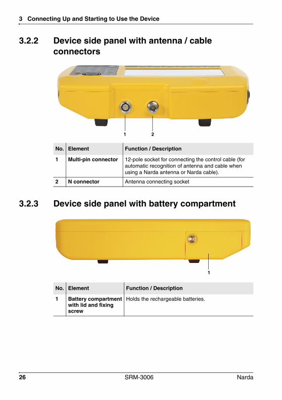
3.2.2 Device side panel with antenna / cable connectors
3.2.3 Device side panel with battery compartment
No. Element Function / Description
1 Multi-pin connector 12-pole socket for connecting the control cable (for automatic recognition of antenna and cable when using a Narda antenna or Narda cable).
2 N connector Antenna connecting socket
1 2
No. Element Function / Description
1 Battery compartmentwith lid and fixing screw
Holds the rechargeable batteries.
1
26 SRM-3006 Narda
3.3 Power supply
3.2.4 Device side panel with external connectors
3.3 Power supplyThe power supply is normally taken from the rechargeable battery pack provided. It is also possible to use the AC adapter / charger supplied with the device as a power source.
No. Element Function / Description
1 Earphone socket For connecting an earphone for listening to saved voice comments.
2 Optical connector For connecting optical cables for on-site device communications.
3 USB, Mini-B type For connection to a computer (PC).
4 Charging socket For connecting to the supplied AC adapter / charger.
1 2 3 4
Narda SRM-3006 27

3 Connecting Up and Starting to Use the Device
3.3.1 Operation from battery packA fully charged battery pack is sufficient for about 2.5 hours of operation (with GPS and display backlight). This operating time can be increased significantly by using the energy saving options (Power Save) such as automatic backlight switch off (Backlight switches off after). The battery pack is supplied in a pre-charged state and must be fully charged before being used for the first time.
NOTE: Only use type 3001/90.15 battery packs or the earlier type 3001/90.01. If you are using the different types of battery pack, the device setting in the main menu under Settings (see Changing the language, battery type, date, and time on page 56) must be adjusted so that the device shows the remaining capacity correctly. The part number (P/N) of the battery type in use is printed at the lower end of the battery label. If the capacity of these battery packs is insufficient for your needs, additional battery packs can be obtained as accessories.
Charge indicatorThe charge state of the battery pack is shown in the upper status line.
Charging the battery packA complete recharge takes about 4.5 hours.
The batteries can be charged in the device using the AC adapter / charger supplied, or externally using the charging tray available as an option.
Display Meaning
The battery is fully charged.
The battery is almost discharged.
Batt. flashes The battery charge state is critical.
You should now switch the device off or connect it to the AC adapter / charger. If you continue to operate the device from the batteries, it will switch off automatically after a short time. The device configuration will however be saved before it switches off.
28 SRM-3006 Narda

3.3 Power supply
Starting the charge cycle The AC line voltage must be the same as the operating voltage of the AC
adapter / charger.
1. Connect the AC adapter / charger to the charge socket of the SRM-3006.2. Connect the AC adapter / charger to the AC line. The charge cycle starts. The Charge LED glows red during the charge cycle. The AC adapter / charger switches to trickle charge mode
automatically and the Charge LED glows green when the charge cycle is completed.
3.3.2 Handling battery packs• Do not drop, damage, or disassemble the battery packs.• Only recharge the battery packs in the way described in this operating
manual.• Do not expose the battery packs to very high temperatures for an
extended period of time either separately or inside the device.• Do not leave discharged battery packs in the device for an extended
period of time.• Do not store the battery packs for longer than six months without
recharging them in the meantime.
Replacing the battery pack:
1
2
Narda SRM-3006 29

3 Connecting Up and Starting to Use the Device
1. Undo the fixing screw (1) in the lid of the battery compartment.2. Pull out the battery pack using the tab (2).3. Hold the tab on the new battery pack and slide the battery pack into the
compartment.4. Replace the lid of the battery compartment and do up the fixing screw
(finger tight).
NOTE: If the old battery pack is no longer required, do not simply throw it away with the normal trash. Dispose of it according to the regulations applicable in the country of use (also refer to Proper disposal on page 22).
3.3.3 Operation from AC adapter / chargerThe SRM-3006 can also be operated and powered from the AC adapter / charger.
However, this is not recommended for general use, as the measurement characteristics can be significantly affected by the presence of the power supply cable in the electromagnetic field when the SRM-3006 is operated with the AC adapter / charger connected to it.
3.4 Fitting the antennaThis section describes the facilities and requirements for connecting an antenna to the SRM-3006.
3.4.1 Fitting a Narda antenna directly on the Basic Unit The SRM-3006 is switched off.
1. Stand the Basic Unit up in a vertical position.2. Place the N connector of the antenna on to the N connector of the Basic
Unit.3. Screw the coupling nut of the antenna N connector slowly on to the Basic
Unit N connector taking care not to cross-thread it.
30 SRM-3006 Narda

3.4 Fitting the antenna
NOTE: If the coupling nut does not turn easily, reposition it and start again. Approximately 4 full turns are needed to fully tighten the connection.
4. Place the control cable plug of the cable on to the multipin connector on the Basic Unit so that the red mark on the control cable plug is aligned with the notch in the multipin connector.
5. Push the control cable plug into the connector using the locking sleeve until the plug lock engages. The Narda antenna is connected.
The device automatically recognizes the antenna type that is connected. This information is shown in the display in the general device configuration section while the device is switched on.
3.4.2 Connecting a Narda antenna to the Basic Unit using a Narda cableThe connection is made in two stages:
1. Connecting the Narda cable to the SRM-3006 (page 33)2. Connecting the Narda cable to the Narda antenna (page 33)
Narda SRM-3006 31

3 Connecting Up and Starting to Use the Device
Figure 3: Connecting the SRM-3006 to an antenna using a cable.
32 SRM-3006 Narda
3.4 Fitting the antenna
Connecting the Narda cable to the SRM-3006 The SRM-3006 is switched off.
1. Stand the Basic Unit up in a vertical position.2. Place the N connector of the cable on to the N connector of the Basic
Unit.3. Screw the coupling nut of the cable N connector slowly on to the Basic
Unit N connector taking care not to cross-thread it.
NOTE: If the coupling nut does not turn easily, reposition it and start again. Approximately 4 full turns are needed to fully tighten the connection.
4. Place the control cable plug of the cable on to the multipin connector on the Basic Unit so that the red dot on the control cable plug is aligned with the red dot on the multipin connector.
5. Push the control cable plug into the connector using the locking sleeve until the plug lock engages. The Narda cable is connected.
The device automatically recognizes the cable type that is connected. This information is shown in the display in the general device configuration section while the device is switched on.
Connecting the Narda cable to the Narda antenna The SRM-3006 is switched off.
1. Place the N connector of the cable on to the N connector of the antenna.2. Screw the coupling nut of the cable N connector slowly on to the antenna
N connector taking care not to cross-thread it.
NOTE: If the coupling nut does not turn easily, reposition it and start again. Approximately 4 full turns are needed to fully tighten the connection.
3. Place the control cable connector of the cable on to the control cable connector of the antenna so that the red dot on the control cable connector is aligned with the red dot on the antenna control cable connector.
4. Push the antenna control cable plug into the connector using the locking sleeve until the plug lock engages. The Narda antenna is connected.
The device automatically recognizes the antenna type that is connected. This information is shown in the display in the general device configuration section while the device is switched on.
Narda SRM-3006 33

3 Connecting Up and Starting to Use the Device
3.4.3 Using commercially-available cables and antennasAutomatic recognition of the cable or antenna type that is connected is not possible if third party products (commercially available cables and antennas) are used instead of Narda components.
This means that when other cables are used the cable loss will not be taken into account automatically. And the results will not be shown automatically in units of field strength or as a percentage of the selected human safety standard limit value if other antennas are used.
NOTE: The data for the connected cable and antennas must be entered in the SRM-3006 manually using the PC software if third party products are used (see description below).
Manually entering the data for third party componentsThe data must first be entered in the PC software, after which they can be uploaded to the SRM-3006.
To enter the data:1. Enter the data from the calibration report for the third party components
into the PC software (refer to the PC software online help for details).2. Save the created configuration on the PC.3. Upload the configuration data to the SRM-3006.4. Select the cable and / or antenna on the SRM-3006.
3.4.4 Fitting a Narda antenna on a tripodSpecial devices are needed for attaching the Narda antennas to a tripod. Two types of antenna holder are available from Narda for this purpose.
Antenna holder for three axis antennasThis antenna holder can be attached to the tripod to allow vertical or horizontal alignment of the antenna. Because the antenna is non-directional (three axis) the alignment should not influence the result in any way. Nevertheless, it is a good idea to align the antenna head roughly in the (presumed) direction of the field source in order to minimize any side effects.
34 SRM-3006 Narda

3.4 Fitting the antenna
Assembly1. Screw the antenna holder vertically or horizontally on to the tripod.2. Attach the antenna to the holder using the Velcro strips.3. Connect the antenna and the Basic Unit together using a cable (see
Connecting a Narda antenna to the Basic Unit using a Narda cable on page 31).
Figure 4: Antenna attached to the antenna holder for three axis (isotropic) antennas (3501•90.02), assembled horizontally (left) and vertically (right)
Antenna holder for single axis and three axis antennasThis antenna holder aligns the antenna in precisely defined positions.
This covers two applications:
• Single axis antennas can be simply rotated into three mutually perpendicular (orthogonal) positions in order to perform isotropic measurements.
• Three axis (isotropic) antennas can be precisely aligned in order to measure a specific single axis.
Narda SRM-3006 35
3 Connecting Up and Starting to Use the Device
Assembly
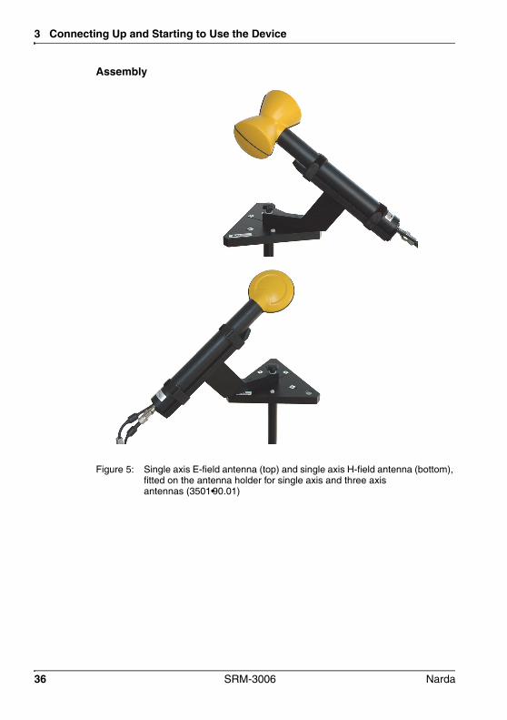
Figure 5: Single axis E-field antenna (top) and single axis H-field antenna (bottom), fitted on the antenna holder for single axis and three axis antennas (3501•90.01)
36 SRM-3006 Narda

3.4 Fitting the antenna
1. Screw the antenna holder plate on to the tripod.2. Screw the antenna holder on to the antenna holder plate.3. Undo the Velcro strips and place the antenna in the holder so that the N
connector and the control cable fit into the guideway (see Figure 6 on page 38).
4. Do up the Velcro strips.5. Turn the antenna to the desired position (marked on the antenna holder)
and do up the screw to fix it in position.6. Connect the antenna and the Basic Unit together using a cable (see
Connecting a Narda antenna to the Basic Unit using a Narda cable on page 31).
NOTICEDamage caused by spacing screwsThe black coating can be damaged by the spacing screws. When removing the antenna from the holder, slide it up in the direction
of the antenna head first before removing it from the holder.
Narda SRM-3006 37

3 Connecting Up and Starting to Use the Device
Figure 6: Cable and N connector in guideway
38 SRM-3006 Narda

4 Operation and Basic Settings
This chapter describes the controls and connectors on the device.
4.1 Controls (page 40)
4.2 Switching the device on and off (page 41)
4.3 LCD screen elements (page 42)
4.4 Fundamental operating steps (page 46)
Narda SRM-3006 39

4 Operation and Basic Settings
4.1 ControlsThe following controls are provided for operating the SRM-3006:
• Rotary control • Hardware keys (referred to as keys in this manual)• Software keys (referred to as softkeys in this manual)
4.1.1 Rotary control and keys
Element Function / Description
Selects functions and values.
Moves to the left or right in entry boxes.
Confirms changes in settings.
• Cancels the current operating step; changes in values are not made.
• Returns to the next higher menu level.
Opens the main menu for selecting operating modes and changing system and device settings.
Freezes the display; the measurement continues. Press again to update the display to show the actual values again.
Saves the data in the data logger.
For entering numbers and the decimal point.
Switches the device on and off (hold down key).
40 SRM-3006 Narda
4.2 Switching the device on and off
4.1.2 SoftkeysThe softkey functions depend on the selected menu level, operating mode, or function. The softkeys are therefore described in the menu and operating mode descriptions.
4.2 Switching the device on and offSwitching on Press and hold down the ON/OFF key for a few seconds. The device switches on.You can terminate the switch on process by pressing the Quit softkey.
The device performs a self test during the boot up process. The results are displayed on the screen.
The screen displayed after switch on depends on the setting of the Power on function. For more information about this, see Changing the switch on behavior on page 70.
Switching off Press and hold down the ON/OFF key for a few seconds. The device switches off.
Narda SRM-3006 41

4 Operation and Basic Settings
4.3 LCD screen elements
Figure 7: LCD screen
12
3
4
5
6
7
Table 2: LCD screen elements
No. Element Description
1 Upper status bar Indicates general parameter settings.
2 Navigation bar Shows information about the selected function.
3 Display area Graphical or numerical display of measurement values.
4 Info bar • Shows menu path to the current function.• Shows text entered by the user
(for measurement routines, entry from PC only).• Indication of corrected parameters.
5 Lower status bar Indicates settings and process analysis; displays error messages.
6 Horizontal softkeys Displayed functions are context-sensitive.
7 Vertical softkeys Displayed functions are context-sensitive.
42 SRM-3006 Narda

4.3 LCD screen elements
4.3.1 The upper status barThe upper status bar gives information about the device, the components used, and the general settings.
Figure 8: Upper status bar
Table 3: Upper status bar elements
Element Description
Battery Power supply indicator:
Ext. Power External supply from AC adapter.
Battery fully charged.
Battery almost discharged.
Batt. (flashes)
Battery discharged, device powers down immediately and switches off.
Date, time Indicates the date and time.
GPS GPS receiver status and coordinates:
DGPS reception.
Coordinates GPS reception, coordinates are displayed
When the signal is lost, the last GPS coordinates are used until a signal is received again or the device is switched off.
No GPS reception.
Ant. Antenna used (displayed only if the type is automatically recognized or has been entered manually).
Cable Cable used (displayed only if the type is automatically recognized or has been entered manually).
Service Table Selected service table.
Standard Selected measurement standard.
Narda SRM-3006 43

4 Operation and Basic Settings
4.3.2 The lower status barThe lower status bar gives information about the current measurement. The contents of the display may vary, depending on the operating mode.
Figure 9: Lower status bar
Table 4: Lower status bar elements
Element Description
MR Measurement range.
RBW Resolution bandwidth.
Sweep Time Duration of each measurement cycle.
Noise Suppr. Noise suppression (on/off)
Progress Measurement progress (checks the progress of processor-intensive measurements until the first results are displayed on the screen)
No. of Runs Number of measurements made since the measurement was last started.
AVG Number of measurements used to form the average or time for average formation.
44 SRM-3006 Narda

4.3 LCD screen elements
4.3.3 The navigator barThe screen displays various elements that make navigation easier and which give you information about the actual position in the menu and the selected function.
The actual display mode selection is shown at the left hand edge of the navigation bar.
Arrow symbols at the right hand edge of the bar indicate further information which can be displayed by pressing the arrow keys or by turning the rotary control:
4.3.4 Activating / deactivating status and info barsThe upper status bar, info bar and lower status bar can be individually activated or deactivated. If you do not need the information that is displayed in these bars, you can deactivate all of them to maximize the area of the screen that is available to display the measurement values.
To change the screen arrangement: You have selected an operating mode.
1. Press the Display softkey.2. Press the Screen Arrangement softkey.3. Use the rotary control and softkeys to select the settings you want and
then press the OK key to implement the changes.
Symbol Meaning
Pressing the key displays further information (e.g. in a column of the table).
Pressing the key displays further information (e.g. in a column of the table).
Pressing the key as well as the key displays further information.
Paging up by turning the rotary control displays further information (e.g. lines in the table).
Paging down by turning the rotary control displays further information (e.g. lines in the table).
Paging up or down by turning the rotary control displays further information (e.g. lines in the table).
Narda SRM-3006 45
4 Operation and Basic Settings
4.4 Fundamental operating stepsThe operating steps described in this section are repeated in every menu and function. They are therefore described only once here. In all subsequent descriptions of operating modes, it is assumed that you are familiar with these fundamental steps.
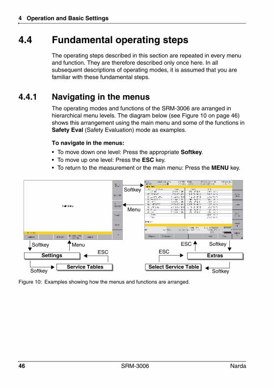
4.4.1 Navigating in the menusThe operating modes and functions of the SRM-3006 are arranged in hierarchical menu levels. The diagram below (see Figure 10 on page 46) shows this arrangement using the main menu and some of the functions in Safety Eval (Safety Evaluation) mode as examples.
To navigate in the menus:• To move down one level: Press the appropriate Softkey.• To move up one level: Press the ESC key.• To return to the measurement or the main menu: Press the MENU key.
Figure 10: Examples showing how the menus and functions are arranged.
Service TablesSoftkey
ESCMenuSoftkey
Settings
Softkey
Menu
Select Service TableSoftkey
ESC
ESC
Softkey
Extras
46 SRM-3006 Narda

4.4 Fundamental operating steps
4.4.2 Forwards / BackwardsWhen you are changing setting parameters, two softkeys labeled Forwards and Backwards are provided to allow you to move forwards or backwards through the setting parameter history within the active operating mode.
Changes to the following parameter settings are taken into account depending on the selected operating mode:
To move backwards or forwards: Press the Extras softkey, then the Backwards or Forwards softkey.
The Forwards softkey is not displayed until you have pressed the Backwards softkey at least once.
Mode Parameter
Safety Evaluation Function not available
Spectrum Fcent, Fspan, RBW
Level Recorder Fcent, RBW
Scope Fcent, RBW, Magnitude Condensed, Sweep Time, Time Resolution
UMTS Fcent
LTE Fcent, CBW
Narda SRM-3006 47

4 Operation and Basic Settings
4.4.3 Selecting entries from a listSettings are often made by selecting entries or items from a list.
Simple listYou can only select a single item from a simple list. This is demonstrated by the selection of a measurement range (Meas. Range) in the example below.
Figure 11: Example of a simple list: Select Meas Range
To select an item:1. Use the rotary control to highlight the desired item.2. Press the OK key to confirm your selection. The new value is set.
48 SRM-3006 Narda

4.4 Fundamental operating steps
Extended listYou can select more than one entry or item from an extended list. You can select one item at a time or use the softkeys to select all the items. This is demonstrated by the selection of services (Select Services) in the example below.
Figure 12: Example of an extended list: Select menu
To select or deselect items individually using the rotary control:1. Use the rotary control to highlight the desired item.2. Press the Select Deselect key to select or deselect the item. The selection box shows the actual status.
3. Press the OK key to return to the measurement display.
To select or deselect several items at the same time:Use the following softkeys, to select or deselect all the items or a group of items in a list.
NOTE: The softkeys that are actually available depend on the Select menu that is opened.
When you have selected the items you want, press the OK key to revert to the measurement display again.
A selection box indicates if the option has been selected or not in an extended list.
Narda SRM-3006 49
4 Operation and Basic Settings
Select Deselect All• If all the items were selected, they will all be deselected.• If all the items were deselected, they will all be selected.• If some items were selected and others deselected, they will all be
selected or deselected.
Invert SelectionChanges the status of every item in the list.
Select First / Select LastYou can use these softkeys to select a group of items from the list.
1. First deselect all items using the Select Deselect All softkey.2. Use the rotary control to highlight the first item in the group that you want
to select and then press the Select First softkey.3. Use the rotary control to highlight the last item in the group that you want
to select and then press the Select Last softkey.4. The highlighted section is now selected.
4.4.4 Changing numerical valuesYou can change numerical values using the rotary control or by using the keys.
NOTE: If you use the rotary control to change a numerical value, you cannot then use the keys to change the value or vice versa in the same setting step. To change from one control to the other, you must first exit the Select menu and then open it again.
To change a value using the rotary control:1. Open the Select menu.
2. Use the arrow keys to select the digit you want to change and then use the rotary control to set the desired value.
3. Press the OK key to set the new value.
To change a value using the keys:1. Open the Select menu.2. Use the number keys and decimal point key to enter the desired value
and enter the desired units using the appropriate softkey. (You can delete digits using the Backspace softkey.) The new value is set and the Select menu closes as soon as you have
entered the units.
50 SRM-3006 Narda

4.4 Fundamental operating steps
4.4.5 Entering textA simple text editor opens so that you can enter alphanumeric characters (e.g. when saving setups):
Figure 13: Text editor for entering alphanumeric characters
To enter text:1. Use the rotary control to select a character from the character field.
(You can select a line directly using the ▲ and ▼ softkeys.) The selected character is marked by a circle.
2. Press the Select Character to enter the character.3. Press the OK key when you have finished entering the characters you
want.
There are some further functions that you can use to enter text:
Softkey Function
Space Enters a space.
Backspace Deletes the last character entered.
Delete All Deletes all characters entered.
Case Switches between upper and lower case characters:• Lower: lower case characters.• Upper: upper case characters.
Narda SRM-3006 51

4 Operation and Basic Settings
4.4.6 Softkeys with toggle function
4.4.7 Creating a screenshotYou can download the saved screenshots in PNG format from the device using the SRM-3006 PC software applications SRM-3006 Tools or SRM-3006 TS.
To create a screenshot:1. Press the Display softkey.2. Press the Save Screenshot softkey.
A black marked right lower corner indicates a toggle function.
The displayed function is the one that can be selected. In this example: Others = On, pressing the softkey will set Other to Off.
52 SRM-3006 Narda

5 The Main Menu
This chapter describes all the Main Menu with all the settings that apply to the device itself and to the components connected to it. Furthermore you will find here how to use the memory, to run measurement routines and to use setups.
5.1 Overview of functions and operating modes (page 54)
5.2 Display and editing device and component settings (page 55)
5.3 The memory menu (page 66)
5.4 Using measurement routines (page 66)
5.5 Saving and loading setups (page 67)
Narda SRM-3006 53

5 The Main Menu
5.1 Overview of functions and operating modes
Figure 14: Overview of operating modes and functions.
Settings (Device settings, Antenna, Cable, Service Tables, Standards) / Memory management / Measurement routines / Setups
Rapid overview of field situation (graphical or as a table) / Overall distribution
Details of field situation (graphical or as a table) / Peak values (table) / Wideband values (integrated/channel power measurement)
Rapid level measurement also suitable for pulsed signals
P-CPICH Demodulation
Real time / Long-term measurement
Saf
ety
Eva
luat
ion
Spe
ctru
m A
naly
sis
Leve
l Rec
orde
r
UM
TS (o
ptio
n)S
cope
(opt
ion)
LTE
(opt
ion)
Measuring cell-specific signals for LTE wireless communications.
54 SRM-3006 Narda

5.2 Display and editing device and component settings
5.2 Display and editing device and component settings
Main Menu • Settings
The Settings menu contains all the settings for the device, the connected antenna and cable, the applied measurement standard and the selected service table.
Figure 15: Settings menu
All device specific settings can be edited immediately by selecting an entry from the list using the rotary control. All other settings (e.g. antennas, cables, etc.) can be reached by means of the softkeys on the right side.
This menu allows you to perform the following actions:
• Changing the language, battery type, date, and time (page 56)• Editing device-specific settings (page 57)• Displaying device information (page 58)• Displaying GPS information (page 60)• Resetting settings (page 60)• Performing device diagnosis (page 61)• Displaying and selecting the available antennas (page 62)• Displaying and selecting the available cables (page 63)• Displaying and selecting the safety standards (page 63)• Displaying and creating service tables (page 64)
Narda SRM-3006 55

5 The Main Menu
5.2.1 Changing the language, battery type, date, and time
Main Menu • Settings
To change the settings:1. Use the rotary control to highlight the item and select it by pressing OK.2. Use the rotary control to change the setting and press OK to confirm the
change or press ESC to cancel the changes.Use the arrow keys to move the cursor by one digit.
3. Press ESC to return to the Main menu.
To synchronize the clock to the GPS clock: Press the Sync Time with GPS softkey. The time is synchronized to the GPS clock.
Table 5: Descriptions of Device Settings
Item Description and available options
Language User interface language
Battery Type Battery type used: 3001/90.15 (3001_90_15)
Note: The remaining battery capacity is only shown correctly if the right battery type is selected.
Date Format Date format:• yy.mm.dd (year.month.day)• yy-mm-dd (year-month-day)• mm/dd/yy (month/day/year)• dd.mm.yy (day.month.year)
Date Date
Time Format Time format:• 12 h (12-hour clock)• 24 h (24-hour clock)
Time Time (hour:minute:second)
Time Zone Time zoneDaylight Saving Time Summer / winter time change:
• Off (Standard / winter time)• On (Summer time)
56 SRM-3006 Narda

5.2 Display and editing device and component settings
5.2.2 Editing device-specific settingsMain Menu • Settings
To change the settings:1. Use the rotary control to highlight the item and select it by pressing OK.2. Use the rotary control to change the setting and press OK to confirm the
change or press ESC to cancel the changes.3. Press ESC to return to the Main menu.
Table 6: Description of device-specific settings
Item Description and available options
GPS Format GPS data display format:• DegDec (-)ddd.ddddd• MinDec (-)ddd°mm.mmm• DMS deg°mm’ss” N(S,E,W)
Remote Interface Interface used for remote control:• Optical• USB
Playback Level Earphone playback volume control:• In steps from 1% to 100%
Color Scheme Display color scheme• Default (display with bright background)• Night (night design)
High contrast
Brightness LCD screen brightness• In 5 % steps from 1 % to 100 %
Power Save (Backlight switches off after):
Power save mode, backlight switches off automatically:• In steps from 1 min. to 30 min• On permanently
MR Search on Setup Recall
Search for measurement range when a setup is recalled:• On• Off
MR Search Type Measurement range search type:• Normal: The measurement range is selected so that no saturation
occurs in a normal environment.• Conservative: The measurement range is selected so that no saturation
occurs even in an environment with extremely variable signal strengths (multi-frequency environment).
Beep on new Maximum
Beep when new maximum detected:• Yes• No
Narda SRM-3006 57

5 The Main Menu
5.2.3 Displaying device informationMain Menu • Settings • Device Info
Press the Device Info softkey. A list of the device information is displayed.
Table 7: Description of Device Info list
Information Description
Device Model Device model name
Production ID Production number
Serial Number Device serial number
ID Number Unique device identification number
Firmware Version Device software version
Firmware Date Device software date
Bootloader Version Bootloader software version
Manufacturer Calibration Date Date of last calibration
Options
Option name Option status:• Activated• Deactivated
58 SRM-3006 Narda

5.2 Display and editing device and component settings
Displaying connected antenna informationMain Menu • Settings • Device Info • Antenna Info
NOTE: Information about the connected antenna is only displayed when you use a Narda antenna.
Press the Antenna Info softkey. The antenna information is displayed as a list.
Displaying connected cable informationMain Menu • Settings • Device Info • Cable Info
NOTE: Information about the connected cable is only displayed when you use a Narda cable.
Press the Cable Info softkey. The cable information is displayed as a list.
Table 8: Description of Antenna Info list
Information Description
Long Name Antenna description
Serial Number Antenna serial number
Manufacturer Calibration Date Date of last calibration
Table 9: Description of Cable Info list
Information Description
Long Name Cable description
Serial Number Cable serial number
Manufacturer Calibration Date Date of last calibration
Narda SRM-3006 59

5 The Main Menu
5.2.4 Displaying GPS informationMain Menu • Settings • GPS Info
Press the GPS Info softkey. A list of the GPS information is displayed.
i
5.2.5 Resetting settings
Resetting the system settingsMain Menu • Settings
The system settings (i.e. those shown in the Settings menu) are reset to their factory defaults. The following are not reset: Language, Battery Type, Date, Time, Time Zone, Daylight Saving Time, and Color Scheme.
To reset the system settings: Main Menu • Settings is displayed.
Press the Reset Settings softkey.
Table 10: Description of GPS Info list
Information Description
GPS module detected Status of GPS module: • Yes• No
Satellites in Use Number of satellites received
GPS Quality Indicator • NO = no GPS reception• GPS = standard GPS• DGPS = differential GPS with better
accuracy than GPS
Latitude Latitude of actual position
Longitude Longitude of actual position
Altitude Altitude of actual position
UTC Time Universal Time Coordinate
60 SRM-3006 Narda
5.2 Display and editing device and component settings
Resetting the measurement settingsMain Menu • Setups
The measurement settings (i.e. parameters used in the operating modes) are reset to their factory defaults. The system settings are not reset.
To reset the measurement settings: Main Menu • Setups is displayed.
1. Select Factory Setup using the rotary control.2. Press OK to confirm the reset.
Resetting the device settingsMain Menu • Settings • Service Menu
You can reset the system settings (except those mentioned under Resetting the system settings) and the measurement settings with this function.
To reset the device settings: Main Menu • Settings • Service Menu is displayed.
1. Press the Factory Settings softkey.
2. Press OK to confirm the reset.
5.2.6 Performing device diagnosisMain Menu • Settings • Service Menu
This menu allows you to check the display and to monitor some basic device data.
Press the Service Menu softkey. The Service Menu is displayed.
To check the display: Press the Display Test softkey. The basic colors red, green and blue are displayed in turn.
The test stops after three cycles.
Press the ESC key to end the test immediately.
To display the device diagnostics: Press the Device Diag softkey. A list of some basic data is displayed.
Narda SRM-3006 61

5 The Main Menu
NOTE: The displayed data is intended primarily for servicing purposes.
5.2.7 Displaying and selecting the available antennasMain Menu • Settings • Antenna
Press the Antenna softkey. The available antennas are listed with their characteristic data.
Only the automatically detected antenna type will be displayed when you use a Narda antenna.
n
NOTE: The axis configuration can be selected in the measurement menus using the Axis function according to the antenna type (single axis or isotropic). See Selecting an axis mode on page 87.
Table 11: Description of Device Diagnostics list
Information Description
Mainboard Temperature Temperature of main circuit board
RFboard Temperature Temperature of RF circuit board
Battery Voltage Actual battery voltage
Battery Capacity Remaining battery capacity
Buffer Battery Voltage Internal buffer battery voltage
Free Memory Free memory space in megabytes, absolute
Free Memory in Percent Free memory space in percent, relative
Calibration Data Available Indicates whether the initial device calibration has been carried out successfully
Operating Hours Counter Number of hours of operation so far
Table 12: Description of Antennas list
Item Description
Short Name Short name for the antenna (shown on the screen)
Fmin Lower frequency limit
Fmax Upper frequency limit
Property Field type (E-field, H-field)
Cal. Date Date of last calibration
62 SRM-3006 Narda

5.2 Display and editing device and component settings
5.2.8 Displaying and selecting the available cablesMain Menu • Settings • Cable
Press the Cable softkey. The available cables are listed with their characteristic data.
You can still select a different cable even if the cable connected is detected automatically. This manual selection allows for the use of an attenuator, for example.
To select a cable: Use the rotary control to select an item and press OK to confirm the
selection.
5.2.9 Displaying and selecting the safety standardsMain Menu • Settings • Standard
Press the Standard softkey. The available safety standards are listed.
To select a standard: Use the rotary control to select an item and press OK to confirm the
selection.
Table 13: Description of Cables list
Item Description
Short Name Short name for the cable (shown on the screen)
Fmin Lower frequency limit
Fmax Upper frequency limit
Cal. Date Date of last calibration
Table 14: Description of Safety Standards list
Item Description
Short Name Short name for the standard (shown on the screen)
Long Name Full name of the standard (shown in the Select menu)
Narda SRM-3006 63

5 The Main Menu
5.2.10 Displaying and creating service tablesMain Menu • Settings • Service Tables
Press the Service Tables softkey. The available service tables are listed.
NOTE: Some service table items may not be available for selection because of the antenna that is being used.
To select a service table: Use the rotary control to select an item and press OK to confirm the
selection.
Displaying the services in a service tableMain Menu • Settings • Service Tables • View
Press the View softkey. The services included in the table are listed.
Table 15: Description of Service Tables list
Item Description
Short Name Short name for the service table (shown on the screen)
Long Name Full name of the service table (shown in the Select menu)
Table 16: Description of Service Table list
Information Description
Service Service name
Fmin Lower frequency limit
Fmax Upper frequency limit
RBW Resolution bandwidth
64 SRM-3006 Narda

5.2 Display and editing device and component settings
Creating a new service tableMain Menu • Settings • Service Tables • Create
You can create a new service table using this menu.
NOTE: The facilities for creating service tables using the SRM-3006 itself are limited. You cannot enter individual services manually or change the service names. It is much more convenient to use the SRM-3006 Tools or SRM-3006 TS PC software to create service tables. You can then upload these service tables to the SRM-3006.
To create a new service table:1. Press the Create softkey and enter the desired values.2. Press the Save Table softkey when you have entered all the values.3. Enter a name for the service table and save it.
The example below shows the parameters for the GSM-900 service. The corresponding entries in the service table are found in column 3 of Table 17 (the example values are shown in bold type).
Example: GSM-900Downlink: 935.2 – 960 MHzChannel number: 1 – 124Channel width: 200 kHz–> without gap–> all channels have the same width
Table 17: Description of Create Service Table list
Item Description Entries for the example GSM-900P
First Service Start Frequency Starting frequency for the service 935.3(center frequency of 935.2 – 935.4 MHz
First Service Channel Number First channel number in the service 1
Channel Step Width Channel bandwidth 200 kHz
Service Bandwidth Service bandwidth 200 kHz
Number of Services Number of services 124
Preferred RBW Preferred resolution bandwidth 50 kHz (200 kHz/4)
Narda SRM-3006 65
5 The Main Menu
5.3 The memory menuMain Menu • Memory
The following functions are contained in the Memory menu:
• Display data sets• Display saved screenshots• Conditional saving• Timer controlled saving• Set comment function
You can find detailed information about all these functions in chapter 14 Measurement Data Memory on page 177.
5.4 Using measurement routinesMain Menu • Measurement Routines
Measurement routines are automated sequences of setups. They are particularly useful for the following applications:
• for eliminating errors when performing repetitive measurement tasks• for ensuring compliance with company regulations for sequences /
procedures• as a guide for semi-skilled staff.
NOTE: When you have saved setups on the device, you can create measurement routines only with the aid of the PC software on a PC. These routines must then be uploaded to the device. You can only display and start the measurement routines on the device itself.
66 SRM-3006 Narda

5.5 Saving and loading setups
5.4.1 Displaying measurement routinesMain Menu • Measurement Routines • View Routine
Press the View Routine softkey. A list of the setups contained in the routine and the sequence criteria
is displayed.
5.4.2 Starting a measurement routineMain Menu • Measurement Routines • Start Routine
Use the rotary control to highlight the desired measurement routine and press the Start Routine softkey or press OK. The measurement routine starts.
5.5 Saving and loading setupsMain Menu • Setups
You can use this menu to save all the settings as a setup or recall and load setups that you have saved previously.
NOTE: Setups can only be created on the device itself. You cannot create setups on a PC. In contrast, you can only delete setups using the PC software. You cannot delete setups on the device itself.
Table 18: Description of Measurement Routine ... list
Item Description
Index Sequential index number
Setup Name Name of setup
Storing Condition Condition for storing the results
Time Measurement duration for timer controlled storing.
No. of Runs Number of measurements for measurement cycle controlled storing
Auto Next Step Start next setup automatically (On, Off)
Narda SRM-3006 67

5 The Main Menu
5.5.1 Saving settings as a setupMain Menu • Setups • Save Setup
1. Make the desired settings on the device.2. Switch to the Main Menu • Setups menu and press the Save Setup
softkey. The entry box opens.
NOTE: You can also save a setup directly from an operating mode. This function is found in the Display menu of the operating mode.
3. Enter a suitable name and press OK to confirm your entry. The settings are saved as a new setup and displayed in the overview
bar.
5.5.2 Loading settings from a setupMain Menu • Setups • Recall Setup
Use the rotary control to highlight the desired setup and press the Recall Setup softkey or the OK key. The settings saved in the selected setup will be loaded and the
display switches to the measurement screen.
5.5.3 Editing the setup listMain Menu • Setups
You can edit the setup list as well as save and recall setups.
Sorting the setup listMain Menu • Setups • Sort
1. Press the Sort softkey.2. Select sort by Name or Mode (operating mode) and press OK. The list will be resorted according to the selected criterion.
68 SRM-3006 Narda

5.5 Saving and loading setups
Overwriting a setupMain Menu • Setups • Overwrite Setup
1. Use the rotary control to highlight the setup to be overwritten and press the Overwrite Setup softkey.
2. Confirm the action by pressing OK. (You can cancel the action by pressing ESC.) The settings in the existing setup will be overwritten with the actual
device settings.
5.5.4 Deleting setupsYou cannot delete setups in the instrument itself. You can only delete them using the PC software.
Narda SRM-3006 69

5 The Main Menu
5.5.5 Changing the switch on behaviorMain Menu • Setups • Power onMain Menu • Setups • Mark Power on Setup
You can specify the settings to be used by the device when it starts up after being switched on:
• Factory Setup: The factory settings will be used.
• Last Settings: The settings in use at the time the device was last switched off will be used.
• Power On Setup: The setup marked in the Setups menu as the Power on Setup will be used.
To start up using the settings last used: Press the Power on softkey until Last Settings is shown (toggle
function). The settings in use at the time the device was last switched off will be
used when it is next switched on.
To start up using a selected setup:1. Press the Power on softkey until Power On Setup is shown (toggle
function).2. Use the rotary control to highlight the desired setup and press the
Mark Power on Setup softkey. The selected setup is marked in the list (‹‹...››) and will be loaded the
next time the device is switched on.
70 SRM-3006 Narda

6 Functions Common to More Than One Operating Mode
This chapter describes the functions that are common to more than one operating mode. These functions are then indicated in the descriptions of the individual operating modes by a cross reference to the relevant section of this chapter.
6.1 Overview of functions common to more than one operating mode (page 72)
6.2 Setting the center frequency (Fcent) (page 73)
6.3 Setting the resolution bandwidth (RBW) (page 74)
6.4 Setting the measurement range (Meas. Range) (page 75)
6.5 Selecting the result type (Result Type) (page 78)
6.6 The Marker function (page 80)
6.7 Selecting an axis mode (page 87)
6.8 Adjusting the Y-Scale (page 92)
6.9 Changing the displayed units (page 93)
6.10 Noise suppression (Noise Thresh.) (page 94)
6.11 Measuring spatial average values (Spatial AVG) (page 95)
6.12 Changing operating mode and keeping the same parameters (page 96)
6.13 Useful shortcuts (page 98)
Narda SRM-3006 71

6 Functions Common to More Than One Operating Mode
6.1 Overview of functions common to more than one operating modeThe table below indicates the operating modes that use the functions described in this chapter.
The menu paths shown in gray immediately below the section heading indicate the operating modes and sub-menus where the function described can be found.
Screenshots, where used, only serve to illustrate the function. As a rule, the settings described apply in the same way in the other operating modes although the display on the screen may not be the same as the screenshot used in this manual.
Table 19: Functions and operating modes
FunctionSafety Eval.
Spectrum Level Rec.
Scope UMTS LTE
Center frequency (Fcent) – (x) x x (x) (x)
Resolution bandwidth (RBW)Video bandwidth (VBW)
(x) x x x –1) –
Channel bandwidth (CBW) – – – – – x
Meas. Range x x x x x x
Result type x x (x) (x) x x
Marker x2) x – x – –
Axis x x x x x x
Y-Scale x 2) x x x – –
Unit x x x x x x
Noise Thresh. x – x – x x
Spatial AVG x x x – – –
x = identical in all these modes, described in this chapter(x) = present but not identical (description given in the chapter covering the operating mode)– = not present in this operating mode
1) Fixed at 3.84 MHz2) For Bargraph only
72 SRM-3006 Narda

6.2 Setting the center frequency (Fcent)
6.2 Setting the center frequency (Fcent)SpectrumLevel RecorderScopeUMTSLTE
You can change the center frequency in the following ways:
Enter the center frequency using the keypad:1. Press the Fcent softkey.2. Enter the frequency using the number keys and select the units using
one of the softkeys kHz, MHz or GHz.
Alter the center frequency step by step using the rotary control (Fstep):1. Press the Fcent softkey.2. Press the Fstep softkey until Off is displayed (toggle function).3. Press the Set Fstep softkey, select step by step using the rotary control
and press OK to confirm the selection.4. Change the center frequency using the rotary control. The change is applied immediately.
5. 5. Press ESC or OK to return to the measurement menu.
Alter the center frequency using the arrow keys and rotary control:1. Press the Fcent softkey. The Fstep function is deactivated (Fstep softkey: indicates On).
2. Select a decimal place with the arrow keys and change the value using the rotary control.
3. Press OK to apply the value.
Narda SRM-3006 73

6 Functions Common to More Than One Operating Mode
6.3 Setting the resolution bandwidth (RBW)Spectrum • RBWLevel Recorder • RBWScope • RBW
The resolution bandwidth (RBW) determines the characteristics of the spectrum analyzer with regard to its ability to distinguish between signals having the same amplitude. but different frequencies. Only signals having a frequency spacing that is greater than the defined resolution bandwidth can be distinguished from one another.
To set the resolution bandwidth:1. Press the RBW softkey.2. Use the rotary control to select the desired value and press the OK key. The selected value is applied.
6.3.1 Setting the video bandwidth (VBW)Spectrum • RBW • VBWLevel Recorder • RBW • VBWScope • RBW • VBW
Noisy signals can be smoothed by selecting a suitable video bandwidth. There are two possible ways to make the setting:
• Off: The SRM-3006 will automatically select the correct VBW value.• Manual selection
Background information:The RBW selected for measuring signals having very close frequency spacing must be correspondingly small. A larger resolution bandwidth can be used for measuring wideband signals.
• The indicated level will be too low if the RBW is too small.• Individual signals cannot be separated from one another if the RBW is
too big.
Example: GSM frequency spacing / signal channel width = 200kHz, RBW = 200 kHz.
74 SRM-3006 Narda
6.4 Setting the measurement range (Meas. Range)
To set the video bandwidth:1. Press the VBW softkey, followed by the VBW softkey. The Select Video Bandwidth (VBW) entry box opens.
2. Use the rotary control to select the desired setting and press the OK key. The selected value is applied.
NOTE: The smaller the VBW, the longer the measurement time (sweep time).
6.4 Setting the measurement range (Meas. Range)
Safety Eval • Meas. RangeSpectrum • Meas. RangeLevel Recorder • Meas. RangeScope • Meas. RangeUMTS • Meas. RangeLTE • Meas. Range
To set the measurement range: Press the Meas. Range softkey.
You can now select the measurement range as follows:
• Manual measurement range selection• Automatic measurement range search (MR Search)
Background information:The sensitivity of the system depends on the input attenuator setting. This setting is determined by the Measurement Range (MR) parameter. High measurement sensitivity avoids falsification of the results due to noise generated internally by the device. On the other hand, it is important that the device is not overloaded (saturated). Saturation can also be caused by signals outside the frequency band of the services being measured (shown under Others), e.g. high power radio transmitters when measuring mobile telephone signals.
Narda SRM-3006 75
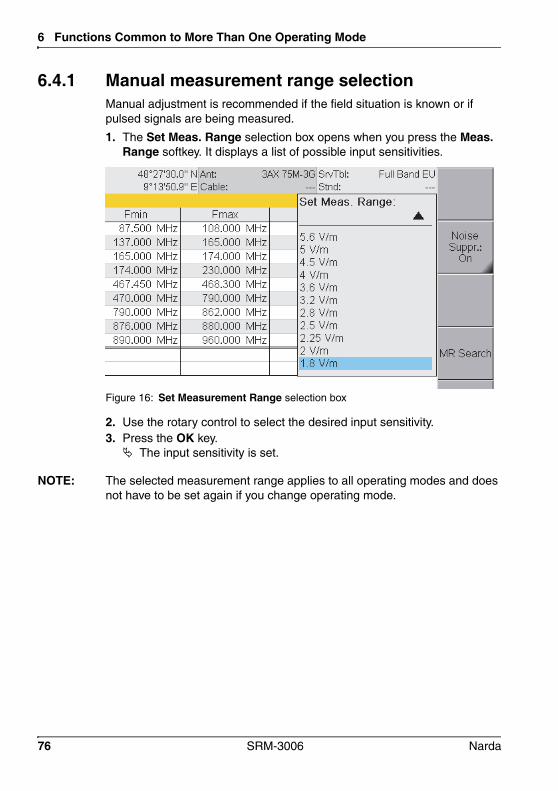
6 Functions Common to More Than One Operating Mode
6.4.1 Manual measurement range selectionManual adjustment is recommended if the field situation is known or if pulsed signals are being measured.
1. The Set Meas. Range selection box opens when you press the Meas. Range softkey. It displays a list of possible input sensitivities.
Figure 16: Set Measurement Range selection box
2. Use the rotary control to select the desired input sensitivity.3. Press the OK key. The input sensitivity is set.
NOTE: The selected measurement range applies to all operating modes and does not have to be set again if you change operating mode.
76 SRM-3006 Narda
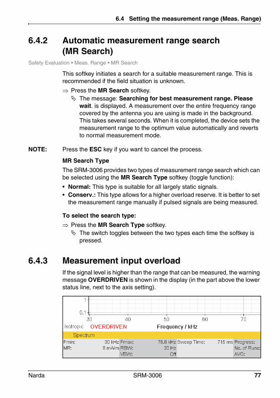
6.4 Setting the measurement range (Meas. Range)
6.4.2 Automatic measurement range search (MR Search)
Safety Evaluation • Meas. Range • MR Search
This softkey initiates a search for a suitable measurement range. This is recommended if the field situation is unknown.
Press the MR Search softkey. The message: Searching for best measurement range. Please
wait. is displayed. A measurement over the entire frequency range covered by the antenna you are using is made in the background. This takes several seconds. When it is completed, the device sets the measurement range to the optimum value automatically and reverts to normal measurement mode.
NOTE: Press the ESC key if you want to cancel the process.
MR Search TypeThe SRM-3006 provides two types of measurement range search which can be selected using the MR Search Type softkey (toggle function):
• Normal: This type is suitable for all largely static signals.• Conserv.: This type allows for a higher overload reserve. It is better to set
the measurement range manually if pulsed signals are being measured.
To select the search type: Press the MR Search Type softkey. The switch toggles between the two types each time the softkey is
pressed.
6.4.3 Measurement input overloadIf the signal level is higher than the range that can be measured, the warning message OVERDRIVEN is shown in the display (in the part above the lower status line, next to the axis setting).
Narda SRM-3006 77

6 Functions Common to More Than One Operating Mode
6.5 Selecting the result type (Result Type)Safety Eval • Result TypeSpectrum • Result TypeUMTS • Result TypeLTE • Result Type
The result type defines how the measured values are evaluated. One value for each type is shown for each service.
The following Result Types can be selected / deselected (more than one can be selected at the same time):
To select or deselect a result type:1. Press the Result Type softkey.2. Use the rotary control and the softkeys to make the desired selection.
For information on how to do this, see Selecting entries from a list on page 48.
3. When you have made your selection, press the OK key. The selected result types will be used.
Information about the Standard (Std) result type:• The Standard (Std) result type is only displayed when an antenna has
been selected or a Narda antenna is used.• If you set the units to “%”, Standard (Std) will be set to 100%.• Std corresponds to the unweighted limit value curve when field strength
units are used. If this value is way above the measured values, it is possible that the limit value curve may no longer be displayed.
Table 20: Result types listed in the Result Type box
Type Abbreviation Explanation
Actual Act Actual value measured at the moment.
Maximum Max Maximum value measured.
Maximum Average MxA Maximum value of all averaged values.
Average Avg Average value over a specified number of measurements or over a specified time (RMS).
Minimum Average MnA Minimum value of all averaged values.
Minimum Min Minimum value measured.
Standard Std Shows the permitted limit value as an unweighted limit curve.
78 SRM-3006 Narda

6.5 Selecting the result type (Result Type)
6.5.1 Average formation (Result type: Average)An average can be formed over a specific number of measurements or over a period of time.
Taking the average of a number of measurements: Result type Average is selected (the actions described below can
nevertheless be carried out even if this result type is not selected).
1. Press the Result Type softkey.2. Press the Average Type softkey until Average Time is shown (toggle
function).
NOTE: If you operate the rotary control after opening the selection window, the softkeys for selecting the average type and the parameters for forming the average will be blanked out. If this happens, close the selection window (press ESC) and then open it again.
3. Press the No. of Avg softkey, then use the rotary control to select the desired number of measurements, and then press the OK key. The measurements start. The AVG line shows the selected number
of measurement values and a bar graph next to this shows the progress towards the formation of the first average value.
Taking the average over a period of time: Result type Average is selected (the actions described below can
nevertheless be carried out even if this result type is not selected).
1. Press the Result Type softkey.2. Press the Average Type softkey until No. of Avg is shown.
NOTE: If you operate the rotary control after opening the selection window, the softkeys for selecting the average type and the parameters for forming the average will be blanked out. If this happens, close the selection window (press ESC) and then open it again.
3. Press the Average Time softkey, then use the rotary control to select the desired time period, and then press the OK key. The measurements start. The AVG line shows the selected time
period numerically and a bar graph next to this shows the progress towards the formation of the first average value.
Narda SRM-3006 79

6 Functions Common to More Than One Operating Mode
6.5.2 Reset measurement valuesYou can reset the values for Max, MxA, Avg, MnA, and Min:
6.6 The Marker functionSafety Eval • MarkerSpectrum • MarkerScope • Marker
The Marker function is very useful for marking and comparing specific individual frequencies in the display. The following types of marker function can be selected:
• Two independent markers.• Individual display of each marker or display of the difference between the
markers.• Automatic location of the highest peak value.• Automatic location of the next peak values.
NOTE: The markers allow access to all measured values, e.g. to every spectral line measured. The spacing between two measured values (two spectral lines) is approximately half the currently selected resolution bandwidth.
Tip: Turning the rotary control slowly causes the marker to jump in small frequency steps. Turning the control faster causes larger frequency jumps. Briefly turning the control in the opposite direction stops the marker movement.
• Reset All: Resets all the above-mentioned measurement values.
• Reset Min & Max: Resets the Minimum (Min) and Maximum (Max) measurement values only.
80 SRM-3006 Narda

6.6 The Marker function
6.6.1 Using the markers separatelyThe two markers A and B can be displayed separately and set independently of each other by using the Single marker function.
Figure 17: Single marker display
58
1
2
3
6
4
79
No. Function / Description
1 Graphical display of the measurement value at the marker position.
2 Marker information: • Marker A: Marker A is active.• Service: Selected service.• Freq: Frequency at the marker position.• Max. Pk: Selected result type and measured value.
3 Graphical display of the marker position (for result type Max in the example).
4 Marker functions for peak value selection (see Table 21 on page 82).
5 Zoom function: Sets the marker to the center frequency and enlarges the display around the marker (reduces the span).
6 Active marker (Marker A is active in the example).
7 Marker display on the measurement screen (Marker A is shown in the example).
8 Display type (Single is selected in the example).
9 Result type selection for the active marker.
Narda SRM-3006 81

6 Functions Common to More Than One Operating Mode
To use the markers separately:
NOTE: Remember that the softkeys always show the function that can be selected, not the function that is currently active. Example: if Delta B-A is shown, this means that the Single marker function is active.
1. Press the Marker softkey until Delta B-A is shown (toggle function).2. Press the Active Marker softkey until Marker A (if you want to use
Marker B) or B (if you want to use Marker A) is shown (toggle function).3. Select a result type by pressing the Select Result Type softkey,
selecting a result type with the rotary control and then pressing the OK key.
You can now use the available functions separately for markers A and B:
NOTE: An algorithm that covers all the measurement values contained in the spectrum is used for the Peak markers.
Table 21: Marker functions for selecting peak values
Selection Function
Rotary control Moves the marker to the desired position manually.
Highest Peak softkey Places the marker on the highest peak value.
Next Lower Peak softkey Places the marker on the next lower peak value.
Next Higher Peak softkey Places the marker on the next higher peak value.
Next Peak Left softkey Places the marker on the next peak value to the left of the previous position.
Next Peak Right softkey Places the marker on the next peak value to the right of the previous position.
82 SRM-3006 Narda

6.6 The Marker function
6.6.2 Using both markers to determine a differenceThe difference between the two marker positions can be determined using the Delta B-A marker function.
Figure 18: Display with both markers
68
1
2
3
579
4
No. Function / Description
1 Graphical display of the measurement values at the marker positions.
2 Marker information: • Marker...: Marker A is active (black lettering), Display of difference B-A.• Service: Selected services.• Freq: Frequencies at the marker positions, frequency difference fB - fA.• Max. Pk: Selected result types and measured values, ratio of measured values B/A.
3 Graphical display of the marker positions (for result types Act and Max in the example).
4 Marker functions for peak value selection (see Table 21 on page 82).
5 Zoom function: Sets the marker to the center frequency and enlarges the display around the marker (reduces the span). See also The Zoom function (Zoom) on page 120.
6 Active marker (Marker B is active in the example)
7 Marker display on the measurement screen (Marker B is not shown on the measurement screen in the example).
8 Display type (the difference (Delta B-A) is selected in the example.
9 Result type selection for the active marker.
Narda SRM-3006 83
6 Functions Common to More Than One Operating Mode
To use the Delta function:
NOTE: Remember that the softkeys always show the function that can be selected, not the function that is currently active. Example: if Single is shown, this means that the difference function Delta B-A is active.
1. Press the Marker softkey until Single is shown (toggle function).2. Press the Active Marker softkey until Marker B is shown: this means
that Marker A is selected (toggle function).3. Select a result type for Marker A using the Select Result Marker softkey.4. Move Marker A to the desired position (either manually or using the Peak
functions).5. Press the Active Marker softkey until Marker A is shown: this means
that Marker B is selected (toggle function).6. Select a result type for Marker B.
The difference determined depends on the result types selected for Marker A and Marker B:
• Same result type for Marker A and Marker B: The difference between the measured values of one result type at two different frequencies is determined.
• Different result types for Marker A and Marker B: The difference in the measured values between the two result types at one frequency is determined.
7. Move Marker B to the desired position (either manually or using the Peak functions). The selected frequencies and the corresponding measured values
along with the difference are displayed in the upper status bar.
84 SRM-3006 Narda

6.6 The Marker function
6.6.3 Displaying the marker data on the measurement screenIf you activate the Marker function (Keep Marker = On), the frequency and measured value corresponding to the active marker are displayed in the upper status bar instead of the GPS data.
Figure 19: Display of marker data in the upper status bar.
To activate the display function: The Marker menu is active.
1. Press the Keep Marker A or Keep Marker B softkey until On is shown. (If you select the other marker, the Keep Marker softkey changes to reflect the choice of the new marker.)
2. Press the ESC key to return to the measurement screen.
Narda SRM-3006 85

6 Functions Common to More Than One Operating Mode
6.6.4 Zooming to markerThe Zoom to Marker function allows you to display an enlargement of a section around the current marker position. The marker position is used here as the center frequency of the zoomed display, and the frequency limits are adjusted to suit.
To zoom to the marker:1. Set the marker to the desired position.2. Press the Zoom to Marker softkey. The display is adjusted accordingly.
3. Press Zoom to Marker again to further enlarge the display.
To reset the display to the full frequency range:1. Exit from the Marker menu.2. Press the Set Freq softkey until Fmin & Fmax is displayed.3. Press the Fspan softkey and then select Full Span. The full frequency range is displayed once more.
86 SRM-3006 Narda

6.7 Selecting an axis mode
6.7 Selecting an axis modeSafety Eval • AxisSpectrum • AxisLevel Recorder • AxisScope • AxisUMTS • AxisLTE • Axis
Depending on the antenna type being used (single axis or isotropic) you can use the Axis softkey to select the axis to be measured or the axis mode in the case of isotropic antennas.
To select the axis or the axis mode:1. Press the Axis softkey. The selection window opens.
– X-Axis, Y-Axis, Z-Axis: Individual axis selection for three axis Narda antennas
– Automatic Isotropic: Automatic isotropic measurement (for three axis Narda antennas only)
– Manual Isotropic: Isotropic measurement by sequential measurement of the individual spatial axes, also with single axis antennas
2. Select the item you require (see descriptions below) and confirm by pressing OK.
The various constellations for measurements with single axis and three axis antennas are described below.
Narda SRM-3006 87

6 Functions Common to More Than One Operating Mode
6.7.1 Measurement using a three axis antennaThree axis (isotropic) antennas allow you to make simple and quick isotropic measurements by automatically detecting the three spatial components of the field to be measured. Narda Safety Test Solutions offers three antennas for measuring electric or magnetic field strength:
Measuring a single axisYou can measure each axis separately from the Axis menu for those applications where additional information about the spatial components of the field is required.
The measurement is only useful if the orientation of the sensors relative to the field is known. A tripod with a special antenna holder can be used for Narda antennas (see Fitting a Narda antenna on a tripod on page 34). The positions of the three measurement axes are marked on this special holder.
To measure individual axes with a three axis antenna: Select one of the three axes from the Axis menu and press OK to
confirm the selection. The selected axis is shown at lower left and the measurement values
refer to this axis.
To revert to isotropic measurement mode: Select Automatic Isotropic in the Axis menu and press OK to confirm
the selection. Isotropic is shown at lower left.
Table 22: Three axis antenna types
Type Frequency range Preferred application
E-field antenna (isotropic), dipole array, passive
420 MHz – 6 GHz Fast, non-directional measurements e.g. at mobile communications and WiMAX frequencies.
E-field antenna (isotropic), dipole array, passive
27 MHz – 3 GHz Fast, non-directional measurements e.g. at mobile communications frequencies.
H-field antenna (isotropic), coil array, active
9 kHz – 250 MHz Fast, non-directional near-field magnetic field measurements on radio/TV transmitters and industrial equipment.
88 SRM-3006 Narda
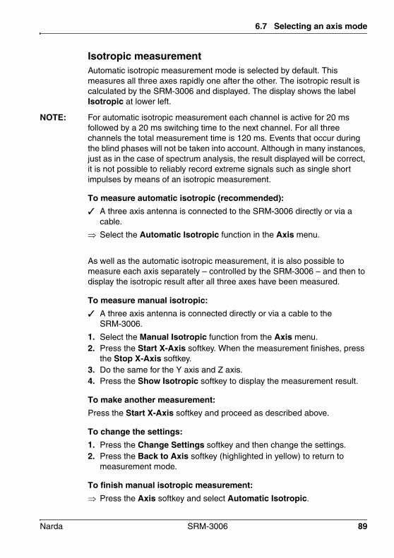
6.7 Selecting an axis mode
Isotropic measurementAutomatic isotropic measurement mode is selected by default. This measures all three axes rapidly one after the other. The isotropic result is calculated by the SRM-3006 and displayed. The display shows the label Isotropic at lower left.
NOTE: For automatic isotropic measurement each channel is active for 20 ms followed by a 20 ms switching time to the next channel. For all three channels the total measurement time is 120 ms. Events that occur during the blind phases will not be taken into account. Although in many instances, just as in the case of spectrum analysis, the result displayed will be correct, it is not possible to reliably record extreme signals such as single short impulses by means of an isotropic measurement.
To measure automatic isotropic (recommended): A three axis antenna is connected to the SRM-3006 directly or via a
cable.
Select the Automatic Isotropic function in the Axis menu.
As well as the automatic isotropic measurement, it is also possible to measure each axis separately – controlled by the SRM-3006 – and then to display the isotropic result after all three axes have been measured.
To measure manual isotropic: A three axis antenna is connected directly or via a cable to the
SRM-3006.
1. Select the Manual Isotropic function from the Axis menu.2. Press the Start X-Axis softkey. When the measurement finishes, press
the Stop X-Axis softkey.3. Do the same for the Y axis and Z axis.4. Press the Show Isotropic softkey to display the measurement result.
To make another measurement:Press the Start X-Axis softkey and proceed as described above.
To change the settings:1. Press the Change Settings softkey and then change the settings.2. Press the Back to Axis softkey (highlighted in yellow) to return to
measurement mode.
To finish manual isotropic measurement: Press the Axis softkey and select Automatic Isotropic.
Narda SRM-3006 89
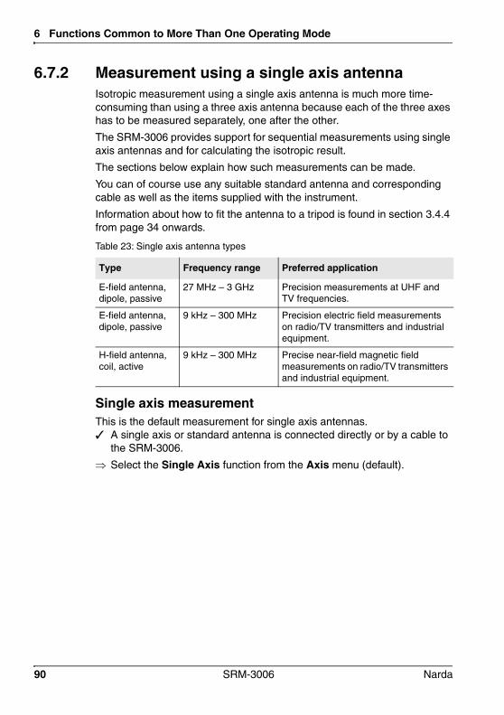
6 Functions Common to More Than One Operating Mode
6.7.2 Measurement using a single axis antennaIsotropic measurement using a single axis antenna is much more time-consuming than using a three axis antenna because each of the three axes has to be measured separately, one after the other.
The SRM-3006 provides support for sequential measurements using single axis antennas and for calculating the isotropic result.
The sections below explain how such measurements can be made.
You can of course use any suitable standard antenna and corresponding cable as well as the items supplied with the instrument.
Information about how to fit the antenna to a tripod is found in section 3.4.4 from page 34 onwards.
Single axis measurementThis is the default measurement for single axis antennas. A single axis or standard antenna is connected directly or by a cable to
the SRM-3006.
Select the Single Axis function from the Axis menu (default).
Table 23: Single axis antenna types
Type Frequency range Preferred application
E-field antenna, dipole, passive
27 MHz – 3 GHz Precision measurements at UHF and TV frequencies.
E-field antenna, dipole, passive
9 kHz – 300 MHz Precision electric field measurements on radio/TV transmitters and industrial equipment.
H-field antenna, coil, active
9 kHz – 300 MHz Precise near-field magnetic field measurements on radio/TV transmitters and industrial equipment.
90 SRM-3006 Narda

6.7 Selecting an axis mode
Isotropic measurementThe SRM-3006 provides a sequential measurement for making an isotropic measurement using a single axis antenna. The three separate measurements are made one after the other and the overall result is calculated and displayed.
NOTE: Directional antennas such as log-periodic antennas are basically unsuitable for such sequential measurements.
To make an isotropic measurement with a single axis antenna: A single axis or standard antenna is connected directly or by a cable to
the SRM-3006.
1. Select the Manual Isotropic function from the Axis menu.2. Position the antenna in the direction of the X axis, and press the
Start X-Axis softkey. When the measurement has finished, press the Stop X-Axis softkey.
3. Follow the same procedure for the Y axis and the Z axis.4. Press the Show Isotropic softkey to display the measurement result.
To make another measurement:Press the Start X-Axis softkey and proceed as described above.
To change the settings:1. Press the Change Settings softkey and then change the settings.2. Press the Back to Axis softkey (highlighted in yellow) to return to
measurement mode.
To finish isotropic measurement: Press the Axis softkey and select Single Axis.
Narda SRM-3006 91
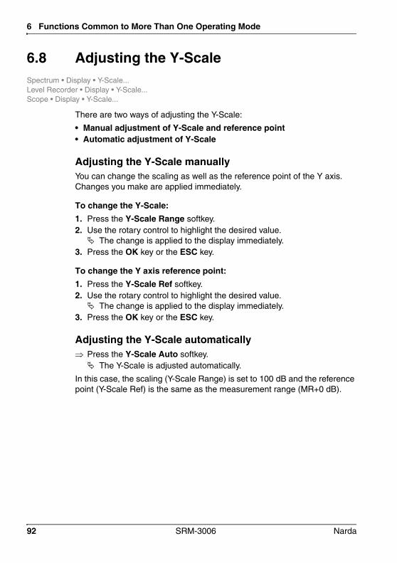
6 Functions Common to More Than One Operating Mode
6.8 Adjusting the Y-ScaleSpectrum • Display • Y-Scale...Level Recorder • Display • Y-Scale...Scope • Display • Y-Scale...
There are two ways of adjusting the Y-Scale:
• Manual adjustment of Y-Scale and reference point• Automatic adjustment of Y-Scale
Adjusting the Y-Scale manuallyYou can change the scaling as well as the reference point of the Y axis. Changes you make are applied immediately.
To change the Y-Scale:1. Press the Y-Scale Range softkey.2. Use the rotary control to highlight the desired value. The change is applied to the display immediately.
3. Press the OK key or the ESC key.
To change the Y axis reference point:1. Press the Y-Scale Ref softkey.2. Use the rotary control to highlight the desired value. The change is applied to the display immediately.
3. Press the OK key or the ESC key.
Adjusting the Y-Scale automatically Press the Y-Scale Auto softkey. The Y-Scale is adjusted automatically.
In this case, the scaling (Y-Scale Range) is set to 100 dB and the reference point (Y-Scale Ref) is the same as the measurement range (MR+0 dB).
92 SRM-3006 Narda

6.9 Changing the displayed units
6.9 Changing the displayed unitsSafety Eval • Display • UnitSpectrum • Display • UnitLevel Recorder • Display • UnitScope • Display • UnitUMTS • Display • UnitLTE • Display • Unit
The following power and voltage units can be selected when there is no antenna connected or selected:
The following units can be selected additionally when an antenna is connected or selected:
Table 24: Units that can be selected (without antenna)
Units Description
dBm Power level, referred to 1 mW
dBV Voltage level, referred to 1 V
dBmV Voltage level, referred to 1 mV
dBµV Voltage level, referred to 1 µV
Table 25: Units that can be selected additionally (with antenna)
Units Measured quantity Description
V/m Electric field strength Converted using the characteristic impedance of a vacuum Z0 = 377 unless measured directly.
A/m Magnetic field strength
dBV/m Electric field strength Expressed as a logarithmic value referred to 1 V/m.
dBmV/m Electric field strength Expressed as a logarithmic value referred to 1 mV/m.
dBµV/m Electric field strength Expressed as a logarithmic value referred to 1 µV/m.
dBA/m Magnetic field strength Expressed as a logarithmic value referred to 1 A/m.
W/m2 Power density Calculated using the characteristic impedance of a vacuum Z0 = 377 .mW/cm2 Power density
% % of limit value defined in a selected human safety standard
Narda SRM-3006 93
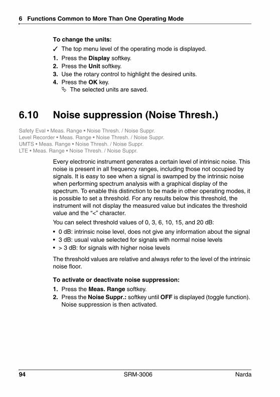
6 Functions Common to More Than One Operating Mode
To change the units: The top menu level of the operating mode is displayed.
1. Press the Display softkey.2. Press the Unit softkey.3. Use the rotary control to highlight the desired units.4. Press the OK key. The selected units are saved.
6.10 Noise suppression (Noise Thresh.)Safety Eval • Meas. Range • Noise Thresh. / Noise Suppr.Level Recorder • Meas. Range • Noise Thresh. / Noise Suppr.UMTS • Meas. Range • Noise Thresh. / Noise Suppr.LTE • Meas. Range • Noise Thresh. / Noise Suppr.
Every electronic instrument generates a certain level of intrinsic noise. This noise is present in all frequency ranges, including those not occupied by signals. It is easy to see when a signal is swamped by the intrinsic noise when performing spectrum analysis with a graphical display of the spectrum. To enable this distinction to be made in other operating modes, it is possible to set a threshold. For any results below this threshold, the instrument will not display the measured value but indicates the threshold value and the “<” character.
You can select threshold values of 0, 3, 6, 10, 15, and 20 dB:
• 0 dB: intrinsic noise level, does not give any information about the signal• 3 dB: usual value selected for signals with normal noise levels• > 3 dB: for signals with higher noise levels
The threshold values are relative and always refer to the level of the intrinsic noise floor.
To activate or deactivate noise suppression:1. Press the Meas. Range softkey.2. Press the Noise Suppr.: softkey until OFF is displayed (toggle function).
Noise suppression is then activated.
94 SRM-3006 Narda

6.11 Measuring spatial average values (Spatial AVG)
To select the threshold value for noise suppression: Noise suppression must be activated before you can set the threshold.
1. Press the Meas. Range softkey and then the Noise Thresh. softkey.2. Use the rotary control to set the desired input sensitivity and then press
the OK key. The threshold value is set.
6.11 Measuring spatial average values (Spatial AVG)
Safety Eval • Result Type • Spatial AVGSpectrum • Result Type • Spatial AVGLevel Recorder • Result Type • Spatial AVG
Due to the scope of the Spatial Averaging function, it is handled separately in Chapter 13 Spatial Averaging, starting on page 163.
Narda SRM-3006 95
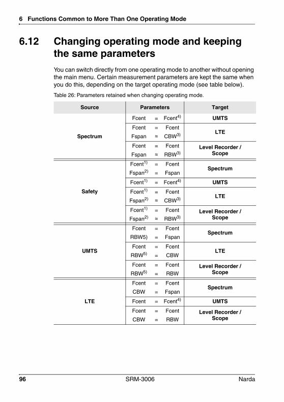
6 Functions Common to More Than One Operating Mode
6.12 Changing operating mode and keeping the same parametersYou can switch directly from one operating mode to another without opening the main menu. Certain measurement parameters are kept the same when you do this, depending on the target operating mode (see table below).
Table 26: Parameters retained when changing operating mode.
Source Parameters Target
Spectrum
Fcent = Fcent4) UMTS
Fcent
Fspan
=
≈Fcent
CBW3) LTE
Fcent
Fspan
=
≈Fcent
RBW3)Level Recorder /
Scope
Safety
Fcent1)
Fspan2)
=
=
Fcent
FspanSpectrum
Fcent1) = Fcent4) UMTS
Fcent1)
Fspan2)
=
≈Fcent
CBW3) LTE
Fcent1)
Fspan2)
=
≈Fcent
RBW3)Level Recorder /
Scope
UMTS
Fcent
RBW5)
=
=
Fcent
FspanSpectrum
Fcent
RBW5)
=
=
Fcent
CBWLTE
Fcent
RBW5)
=
=
Fcent
RBWLevel Recorder /
Scope
LTE
Fcent
CBW
=
=
Fcent
FspanSpectrum
Fcent = Fcent4) UMTS
Fcent
CBW
=
=
Fcent
RBWLevel Recorder /
Scope
96 SRM-3006 Narda

6.12 Changing operating mode and keeping the same parameters
To change operating mode directly: Press the Extras softkey, then select the desired operating mode from
NOTE: The RBW values set in the service tables have no function when parameters are retained as these RBW values are only used in Safety Eval mode.
Level Recorder
Fcent
RBW
=
=
Fcent
FspanSpectrum
Fcent = Fcent4) UMTS
Fcent
RBW
=
=
Fcent
CBWLTE
Fcent
RBW
=
=
Fcent
RBWScope
Scope
Fcent
RBW
=
=
Fcent
FspanSpectrum
Fcent = Fcent4) UMTS
Fcent
RBW
=
=
Fcent
CBWLTE
Fcent
RBW
=
=
Fcent
RBWLevel Recorder
1) In Safety mode: Fcent = (Service_Fmax + Service_F_min)/22) In Safety mode: Fspan = Service_Fmax - Service_F_min3) The Fspan in the source mode will be transferred into the next nearest CBW/RBW
in the target mode4) In UMTS: Fcent will be an exact multiple of 100 kHz5) In UMTS: RBW fixed, not adjustable/settable
Table 26: Parameters retained when changing operating mode.
Source Parameters Target
Narda SRM-3006 97

6 Functions Common to More Than One Operating Mode
6.13 Useful shortcutsYou can access several of the main menu functions directly from an operating mode. The functions and corresponding softkeys are described in the sections below.
6.13.1 Selecting a service table or a serviceNOTE: Only a service table can be selected in Safety Evaluation mode.
Press the Extras softkey, then press the Select Service Table or Select Service softkey. You can now select a service table or a service.
6.13.2 Saving a setup Press the Display softkey, then press the Save Setup softkey. The current settings are saved when you have entered a name for the
setup.
98 SRM-3006 Narda

7 Safety Evaluation Mode
This chapter describes the Safety Evaluation operating mode. Following a short introduction on the use of this operating mode, this chapter contains an overview of the different display modes and information about the basic setting functions.
7.1 About Safety Evaluation mode (page 100)
7.2 Basic settings (page 102)
7.3 Using the Table view (page 105)
7.4 Using the Bar Graph view (page 109)
7.5 Selecting an axis mode (page 110)
Narda SRM-3006 99

7 Safety Evaluation Mode
7.1 About Safety Evaluation modeDemonstrating safety in electromagnetic fields means providing answers to the following questions:
• How high is the overall exposure level in relation to the permitted limit value?
• What proportion of the emissions is due to which service?• Which service perhaps needs to reduce its transmission power?
To do this, the entire spectrum needs to be measured selectively. Nevertheless, only a few values are rally of interest: the overall level of emissions and the contributions made by the individual services in terms of field strength or as a percentage of the permitted limit value.
The SRM-3006 as expertAs a specialized instrument, the SRM-3006 provides Safety Eval mode for this purpose. This has been specifically developed for assessing the field strength exposure level in a multi-frequency environment. It delivers an overview of the exposure level values for selected frequency bands, or services, in terms of field strength units or in % of a selected human safety standard. This means that information regarding compliance with defined limit values is available directly at the site of the measurement, along with data about the contributions made by frequency bands of interest to the overall exposure level.
Service tables, which form the basis of Safety Eval mode, are normally created using the SRM-3006 Tools or SRM-3006 TS PC software and uploaded to the SRM-3006. You can find further information about this under PC Software on page 191 and in the on-line help for the PC software.
You can also create service tables using the SRM-3006 itself, but with a limited range of functions (see Displaying and creating service tables on page 64 for details).
100 SRM-3006 Narda
7.1 About Safety Evaluation mode
Using the operating modeFirst select from the Configuration menu the services you want to record and the standard according to which they are to be assessed. The frequency tables and weighting factors for the most common services and standards are recorded and stored in the instrument as supplied from the factory. These tables can be edited or new ones created using the PC software: Simply assign a name to the service, enter the lower and upper frequency limits, and upload the data to the instrument via the serial interface.
Now you only have to press a button to run the measurement. The SRM-3006 measures the bands corresponding to the services one after the other and also captures what is happening between the bands. It automatically sets the resolution bandwidth so that four spectral lines can still be detected in the narrowest band. In this way, the SRM-3006 achieves a high degree of measurement accuracy without wasting time.
None of this is visible, as you don’t have to do anything about it. The only thing you will see is the result, the field strength proportions due to individual services (such as GSM and UMTS), the proportions due to the frequencies between services (Others), and the total field exposure level (Total). The SRM-3006 automatically integrates all the corresponding spectral lines for this purpose.
As a rule, the measurement service requires the result in terms of a percentage of the permitted limit value. To do this, the SRM-3006 automatically evaluates each individual spectral line according to the specified standard or regulation. If you want absolute values, however, simply switch to display field strength (V/m) or power density (W/m2). The standard weighting is not then taken into account.
Narda SRM-3006 101

7 Safety Evaluation Mode
7.2 Basic settingsThis section describes the settings that are identical for both display modes Table and Bar Graph.
7.2.1 Selecting the display modeSafety Evaluation • Display • Views
Two display modes are available:
• Table (see page 105)• Bar Graph (see page 109)
To switch the display mode:1. Press the Display softkey.2. Press the Views softkey. The Select View window opens.
3. Use the rotary control to highlight a view and press the OK key:– Table– Bar Graph The selected view will be displayed.
NOTE: Pressing the ESC key returns you to the top menu level in the measurement screen. (Press the MENU key to return to the Main menu.)
7.2.2 Activating the beeperMain Menu • Settings • Beep on new Maximum
A new maximum level can also be indicated by a beeper. To do this, you must activate the Beep on new Maximum function in the main menu under Settings.
To activate the beeper: See Editing device-specific settings on page 57.
102 SRM-3006 Narda
7.2 Basic settings
7.2.3 Showing and hiding servicesSafety Evaluation • Select Menu
You can specify the services that are to be measured in the Select Menu.
To show or hide specific services:1. Press the Select Menu softkey. The Select menu opens.
2. Select the services required using the rotary control and the softkeys.You can find information on how to select items from a list under Selecting entries from a list on page 48.
3. After you have selected the services, press the OK key. The selected services will be displayed.
7.2.4 Setting the resolution bandwidth (RBW)Safety Evaluation: RBW
Setting RBW automaticallyThe SRM-3006 sets the RBW automatically using the basic setting Automatic:
(The next smaller available RBW value will be used.)
This ensures that the narrowest service to be measured is resolved finely enough.
RBW Fspan narrowest service 4
----------------------------------------------------------------------------
Narda SRM-3006 103

7 Safety Evaluation Mode
Setting the RBW manually for the entire tableYou can also enter the resolution bandwidth manually:
1. Press the RBW softkey.2. Use the rotary control to highlight the desired value.
(The largest value displayed is the only largest possible value of all services shown.)
3. Press the OK key.
NOTE: Finer resolution normally means slower measurement speed.
Regardless of the selected value, the narrowest resolution bandwidth is limited by the narrowest service:
Setting the RBW separately for each serviceNOTE: Separate RBWs cannot be selected unless Others = OFF.
The value selected manually on the device applies to the entire table. You can also enter the resolution bandwidth for each service separately using the PC software. Refer to the online Help function of the PC software for information on how to do this.
Tip: More information about the RBW is found in the Glossary on page 247.
7.2.5 Setting the measurement range (Meas. Range)Safety Eval • Meas. Range
See Setting the measurement range (Meas. Range) on page 75.
7.2.6 Selecting the result type (Result Type)Safety Eval • Result Type
See Selecting the result type (Result Type) on page 78.
RBW Fspan narrowest service 4
----------------------------------------------------------------------------
104 SRM-3006 Narda

7.3 Using the Table view
7.2.7 Measuring in the gaps between defined services (Others)
Safety Evaluation • Others
The field strengths of the services not selected in the service table can be measured and their overall value shown by activating the Others function.
NOTE: Only those other services between the first and last service to be measured are taken into account.
To activate and deactivate the function: Press the Others key until the desired status (On, Off) is displayed. The table view shows Others; the graphical view shows O.
Tip: The measurement can be speeded up by deactivating Others.
7.3 Using the Table viewThe services and measured values are displayed as a table in the Table view. The values displayed depend on the table type (see page 106) and from the selected result types (see page 78).
Figure 20: Table view in Safety Evaluation mode
NOTE: Information about the status bars is found under The upper status bar on page 43 and The lower status bar on page 44.
Narda SRM-3006 105

7 Safety Evaluation Mode
7.3.1 Changing the table displayedYou can make changes to the following table settings:
• Table type• Units• Sort order
Changing the table typeSafety Evaluation • Display • Table
The table below shows the measured values that are displayed depending on the table type and the selected result types.
To change the table type:1. Press the Display softkey.2. Press the Table softkey until the desired table type is shown (toggle
function).3. Press the ESC key to return to the measurement menu.
Table 27: Table type Condensed
Index Service Result types, e.g. Max
These columns are displayed continuously.
A maximum of three result types can be displayed.
If more than three result types have been selected, you can use the keys to scroll through all of the result types. Arrow symbols in the navigation bar indicate that further result types are available and the possible scrolling direction.
Table 28: Table type Detailed
Index Service Fmin,Fmax
RBW Result types, e.g. Max
These columns are displayed continuously.
RBW is only displayed if he resolution bandwidth is selected individually using the PC software. If this is not done, the RBW is shown only in the lower status bar.
A maximum of three result types can be displayed.
If more than three result types have been selected, you can use the keys to scroll through all of the result types. Arrow symbols in the navigation bar indicate that further result types are available and the possible scrolling direction.
106 SRM-3006 Narda

7.3 Using the Table view
Changing the displayed unitsSafety Evaluation • Display • Unit
1. Press the Display softkey.2. Press the Unit softkey.3. Use the rotary control to select the desired units and press the OK key.4. Press the ESC key to return to the measurement menu.
Changing the sort orderSafety Evaluation • Display • Sort
1. Press the Display softkey.2. Press the Sort softkey.3. Use the rotary control to select the desired sort order and press the OK
key. The list is re-sorted.
4. Press the ESC key to return to the measurement menu.
7.3.2 Percentage displayThe SRM-3006 can also display values as percentages in various menus. These values express different factors depending on the context. These various uses are explained in the table below:
Application Selection Explanation
Safety Evaluation • Table View
Unit = %
Displays the result types Act, Max, ...
The measured values for the result types indicate the percentage of the selected measurement standard limit value.
Unit = %
Displays the result type Std
Because the measurement standard is the reference quantity in the corresponding frequency band (e.g. 60 V/m), the result type Standard will always show 100% if percentage units are selected.
Safety Evaluation • Distribution
– The measured value shows the percentage contributed by the service to the overall level.
Safety Evaluation • Bar Graph: Marker
Spectrum: Marker
Marker: Single:(Delta B-A is active)
Unit = V/m, A/m, W/m, mW/cm2, %
The difference is displayed as a percentage.
Spectrum • Peak Table – Actual measured value as a percentage of the maximum value.
Narda SRM-3006 107
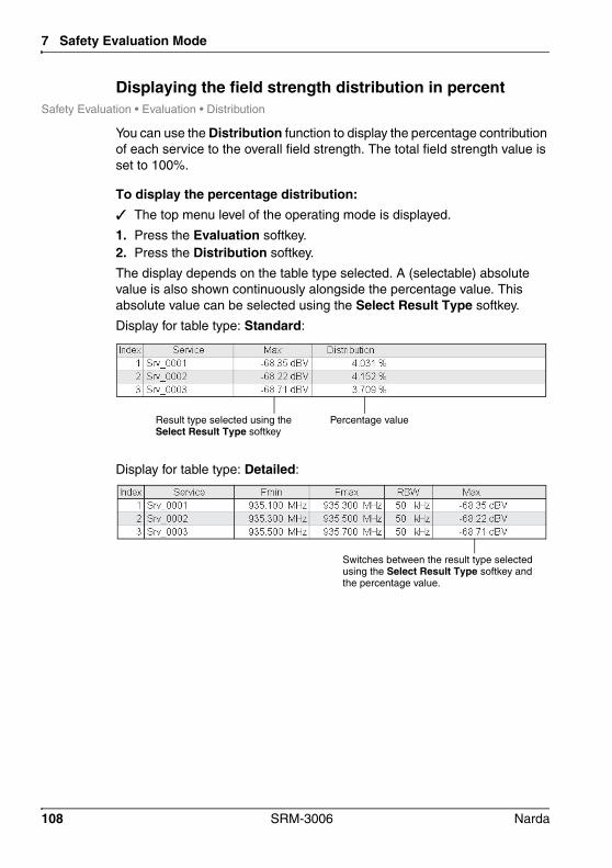
7 Safety Evaluation Mode
Displaying the field strength distribution in percentSafety Evaluation • Evaluation • Distribution
You can use the Distribution function to display the percentage contribution of each service to the overall field strength. The total field strength value is set to 100%.
To display the percentage distribution: The top menu level of the operating mode is displayed.
1. Press the Evaluation softkey.2. Press the Distribution softkey.
The display depends on the table type selected. A (selectable) absolute value is also shown continuously alongside the percentage value. This absolute value can be selected using the Select Result Type softkey.
Display for table type: Standard:
Display for table type: Detailed:
Result type selected using the Select Result Type softkey
Percentage value
Switches between the result type selected using the Select Result Type softkey and the percentage value.
108 SRM-3006 Narda

7.4 Using the Bar Graph view
7.4 Using the Bar Graph viewThe measured values are shown as bars in the Bar Graph view. The selected result types are shown as abbreviations in the diagram on the right and shown in the corresponding colors in the diagram.
Figure 21: Bar Graph view in Safety Evaluation mode
NOTE: Information about the status bars is found under The upper status bar on page 43 and The lower status bar on page 44.
7.4.1 Adjusting the Y axis (Y-Scale)Safety Eval • Display • Y-Scale RangeSafety Eval • Display • Y-Scale RefSafety Eval • Display • Y-Scale Auto
See Adjusting the Y-Scale on page 92.
7.4.2 Changing the displayed units (Unit)Safety Eval • Display • Unit
See Changing the displayed units on page 93.
Narda SRM-3006 109

7 Safety Evaluation Mode
7.4.3 The Marker functionSafety Eval • Marker
See The Marker function on page 80.
7.5 Selecting an axis modeSafety Eval • Axis
See Selecting an axis mode on page 87.
110 SRM-3006 Narda

8 Spectrum Analysis Mode
This chapter describes the Spectrum Analysis operating mode. Following a short introduction on the use of this operating mode, this chapter contains an overview of the basic settings and information about evaluating the results.
8.1 About Spectrum Analysis mode (page 112)
8.2 Basic settings (page 112)
8.3 Evaluating the measurement data (Evaluation) (page 115)
8.4 The Marker function (Marker) (page 120)
8.5 The Zoom function (Zoom) (page 120)
Narda SRM-3006 111

8 Spectrum Analysis Mode
8.1 About Spectrum Analysis modeAll the field components in the selected range can be recorded to give an overview of the detected spectrum or to determine the maximum values in Spectrum Analysis mode. The extended functions of the device enable you to perform optimum evaluation of the measured values directly on site. Marker functions and a peak table are provided for rapid assessment of the results of spectrum analysis. You can also display the wideband value of the integrated level for a freely-definable frequency band.
8.2 Basic settingsThis section describes the basic settings for the measurement screen.
If the settings are identical in several operating modes, a cross reference will indicate the appropriate description in Chapter 6, Functions Common to More Than One Operating Mode on page 71.
112 SRM-3006 Narda

8.2 Basic settings
8.2.1 Changing the frequency rangeSpectrum • Set FreqSpectrum • Fcent, Fspan, Fmin, Fmax
You can set the frequency range in two ways in Spectrum Analysis mode:
• By entering the lower and upper frequency limits: Fmin, Fmax• By entering the center frequency and the bandwidth: Fcent, Fspan
Figure 22: Entering the frequency range
1
23
45
No. Function / Description
1 Indication of Fmin / Fmax or Fcent / Fspan in the lower status bar.
2 Fmin in the diagram
3 Fmax in the diagram
4 Fspan = Fmax - Fmin
5 Fcent = (Fmin + Fmax) / 2
Narda SRM-3006 113
8 Spectrum Analysis Mode
To change the frequency range:1. Press the Set Freq softkey until the desired entry parameters are shown
(toggle function): Fmin & Fmax Fcent & Fspan The labels on the softkeys also change to match the entry parameters
Fmin Fcent and Fmax Fspan.2. If Fmin & Fmax selected: Enter the desired values using the Fmin and
Fmax softkeys.If Fcent & Fspan is selected: Enter the desired values using the Fcent and Fspan softkeys.
NOTE: You can enter the frequency values using the rotary control or using the keypad. For information on how to enter numerical values, see under Changing numerical values on page 50.
Selecting the maximum possible frequency rangeYou can use the Full Span function to reset all the frequency values already set using Fmin, Fmax, Fcent or Fspan to their limit values. In this case, the frequency range will be determined by the antenna connected, by the cable used, or by the SRM-3006 itself.
When entering Fmin, Fmax, Fcent or Fspan press the Full Span softkey.
8.2.2 Setting the resolution bandwidth (RBW)Spectrum • RBW
See Setting the center frequency (Fcent) on page 73
8.2.3 Setting the video bandwidth (VBW)Spectrum • RBW • VBW
See Setting the video bandwidth (VBW) on page 74
8.2.4 Changing the displayed units (Unit)Spectrum • Display • Unit
See Changing the displayed units on page 93
114 SRM-3006 Narda

8.3 Evaluating the measurement data (Evaluation)
8.2.5 Adjusting the Y axis (Y-Scale)Spectrum • Display • Y-Scale RangeSpectrum • Display • Y-Scale RefSpectrum • Display • Y-Scale Auto
See Adjusting the Y-Scale on page 92
8.3 Evaluating the measurement data (Evaluation)The Evaluation menu contains the following functions for evaluating the measurement data:
• Peak Table Generates a table containing 50 measured peak values.
• IntegrationIntegrates the measured values over a defined frequency range.
Narda SRM-3006 115

8 Spectrum Analysis Mode
8.3.1 Displaying the peak values (Peak Table)Spectrum • Evaluation • Peak Table
The highest peaks (up to 50) in the frequency spectrum under consideration are listed in the Peak Table. These are true peak values.
Figure 23: Peak Table in Spectrum Analysis mode
Table 29: Elements in the Peak Table
Column header Description
Index Sequence number of the peak (up to 50)
Frequency Frequency value of the peak
Service Service to which the peak (frequency value) belongs
Avg
Max
Result types
The columns displayed depend on the result types that have been selected (see next section).
116 SRM-3006 Narda

8.3 Evaluating the measurement data (Evaluation)
Specifying the number of peaks to be displayedSpectrum • Evaluation • Peak Table • Number of Peaks
A maximum of 50 peaks can be displayed.
1. Press the Number of Peaks softkey.2. Use the rotary control to highlight the desired number and then press the
OK key.
Selecting the result typesSpectrum • Evaluation • Peak Table • Select Result Type
The Select Result Type softkey is used to select the result type to be displayed in the first column after the Service column. You can only select from the result types that were highlighted under Spectrum • Result Type. The selected result type is shown relative to the actual value if the relative display mode is selected.
1. Press the Select Result Type softkey.2. Use the rotary control to select the desired result type and press the OK
key.
Selecting absolute or relative display modeSpectrum • Evaluation • Peak Table • Results:
The measured values are shown relative to the selected result type in relative display mode.
Press the Results softkey:– For absolute values: The softkey label must show Relative.– For relative values: The softkey label must show Absolute.
Setting a thresholdSpectrum • Evaluation • Peak Table • Thrsh:
When a threshold is activated, only the peaks that are above the selected threshold will be shown in the table.
1. Press the Thrsh softkey until the label shows On (toggle function).2. Press the Set Thrsh softkey and use the rotary control to select a
threshold value.3. Press the OK key.
Narda SRM-3006 117

8 Spectrum Analysis Mode
8.3.2 Integrating measured values (Integration)Spectrum • Evaluation • Integration
You can determine the wideband value for the measured values in a defined frequency band using the Integration over Frequency Band function. This allows you to make measurements of channel power levels.
Figure 24: Integration in Spectrum Analysis mode.Int. Val: Shows the result of the integration.
NOTE: The integration function takes all the spectral lines within the integration range into account, including those which lie within the noise floor. The result of this evaluation function is therefore very dependent on the intrinsic noise level and therefore from the selected measurement range if the signal levels present are close to the intrinsic noise level.
Possible entry methodsThe type of entry method is selected using the Entry softkey:
• Numerical: Numerical entry using the number keys and decimal point key in the keypad.
• Graphical: Entry using the rotary control together with the arrow keys.
NOTE: The description of how to define the frequency range given here does not explain how to use the rotary control and keypad. Information about this is found under Fundamental operating steps on page 46.
118 SRM-3006 Narda
8.3 Evaluating the measurement data (Evaluation)
Selecting the result typeThe Select Result Type softkey is used to select the result type to be used for integration. You can only select from the result types that were highlighted under Spectrum • Result Type.
1. Press the Select Result Type softkey.2. Use the rotary control to select the desired result type and press the OK
key.
Setting the integration range using frequency limits1. Press the Frequency Integration Min softkey to set the lower frequency
limit. The diamond of the left marker will be filled out in black if graphical
entry is selected.2. Use the rotary control or the keypad to specify the lower frequency limit
and then press the OK key to save the setting.3. Softkey Frequency Integration Max softkey to set the upper frequency
limit. The diamond of the right marker will be filled out in black if graphical
entry is selected.4. Use the rotary control or the keypad to specify the upper frequency limit
and then press the OK key to save the setting.
Setting the integration range using a center frequency and a frequency band1. Press the Frequency Integration Cent softkey to set the center
frequency. The diamond of the center marker will be filled out in black if graphical
entry is selected.2. Use the rotary control or the keypad to specify the center frequency and
then press the OK key to save the setting.3. Press the Frequency Integration Span softkey to set the frequency
band. The diamonds of both markers will be filled out in black if graphical
entry is selected.4. Use the rotary control or the keypad to specify the frequency band and
then press the OK key to save the setting.
Narda SRM-3006 119
8 Spectrum Analysis Mode
8.4 The Marker function (Marker)Spectrum • Marker
See The Marker function on page 80.
8.5 The Zoom function (Zoom)Spectrum • Zoom
You can display a narrower section of the selected frequency band in more detail so that you can examine the measurement trace more precisely. A new measurement is performed when you activate this function. New measurement parameters such as a new resolution bandwidth might be set automatically for this measurement.
Possible entry methodsThe type of entry method is selected using the Entry softkey:
• Numerical: Numerical entry using the number keys and decimal point key in the keypad.
• Graphical: Entry using the rotary control together with the arrow keys.
NOTE: The description of how to define the zoom range given here does not explain how to use the rotary control and keypad. Information about this is found under Fundamental operating steps on page 46.
Setting the zoom range using frequency limits1. Press the Zoom Min softkey to set the lower frequency limit. The diamond of the left marker will be filled out in black if graphical
entry is selected.2. Use the rotary control or the keypad to specify the lower frequency limit
and then press the OK key to save the setting.3. Press the Zoom Max softkey to set the upper frequency limit. The diamond of the right marker will be filled out in black if graphical
entry is selected.4. Use the rotary control or the keypad to specify the upper frequency limit
and then press the OK key to save the setting.
120 SRM-3006 Narda

8.5 The Zoom function (Zoom)
Setting the zoom range using the center frequency and frequency band1. Press the Zoom Cent softkey to set the center frequency. The diamond of the center marker will be filled out in black if graphical
entry is selected.2. Use the rotary control or the keypad to specify the center frequency and
then press the OK key to save the setting.3. Press the Zoom Span softkey to set the frequency band. The diamonds of both markers will be filled out in black if graphical
entry is selected.4. Use the rotary control or the keypad to specify the frequency band and
then press the OK key to save the setting.
Zooming to markerThe Zoom to Marker function allows you to display an enlargement of a section around the marker. As this is a marker function, it is described under Zooming to marker on page 86.
Narda SRM-3006 121

8 Spectrum Analysis Mode
122 SRM-3006 Narda
9 Level Recorder Mode
This chapter describes Level Recorder mode. Following a short introduction to the operating mode, an overview of the measurement screen is given along with information about the settings.
9.1 About Level Recorder mode (page 124)
9.2 Display overview (page 125)
9.3 Basic settings (page 126)
9.4 Selecting an axis mode (Axis) (page 128)
9.5 Using noise suppression (Noise Thresh.) (page 128)
Narda SRM-3006 123

9 Level Recorder Mode
9.1 About Level Recorder modeLevel Recorder mode allows you to make selective measurements at a defined frequency (Fcent) e.g. for monitoring the field strength of a DECT channel. You can set the resolution bandwidth (RBW) according to the channel width, and averaging over selectable time periods such as 6 minutes is possible. Max-Hold functions make it easier to evaluate the results on site.
The results are displayed numerically and as bar graphs. One advantage of Level Recorder mode is that there are no time gaps in the recording of the results if a single axis antenna is used or only one axis is measured using a three axis antenna. The operating mode is therefore also particularly useful for measuring pulses.
Successive measurement of three axes is not compatible with real-time determination of measurement values versus time. Nevertheless, you can make isotropic measurements using single axis measuring antennas in Level Recorder mode.
124 SRM-3006 Narda

9.2 Display overview
9.2 Display overview
Figure 25: Level Recorder mode with display of Peak and RMS.
1
2
4
5
3
No. Function / Explanation
1 Display area with selectable detector types Peak and RMS
2 Bar graph displaying the current level:• Red line: indicates the maximum measured level• Bar: indicates the level at the moment
NOTE:The maximum extent of the bar corresponds to the selected measurement range (Meas. Range softkey)
3 Selected axis type
4 Numerical display of current measured value
5 Numerical display of maximum measured value
Narda SRM-3006 125

9 Level Recorder Mode
9.2.1 Activating the beeperMain Menu • Settings • Beep on new Maximum
A new maximum level can also be indicated by a beeper. To do this, you must activate the Beep on new Maximum function in the main menu under Settings.
To activate the beeper: See Editing device-specific settings on page 57.
9.3 Basic settingsThis section describes the basic settings. If these settings are identical in more than one operating mode, a cross-reference will indicate the relevant section in Chapter 6 Functions Common to More Than One Operating Mode on page 71 where the setting is described.
9.3.1 Selecting the center frequency (Fcent)Level Recorder • Fcent
1. Press the Fcent softkey.
2. Use the arrow keys to select a decimal digit and then change the value using the rotary control.
3. Press the OK key to set the value.
9.3.2 Setting the resolution bandwidth (RBW)Level Recorder • RBW
See Setting the center frequency (Fcent) on page 73.
9.3.3 Setting the video bandwidth (VBW)Level Recorder • RBW • VBW
See Setting the video bandwidth (VBW) on page 74.
126 SRM-3006 Narda

9.3 Basic settings
9.3.4 Setting the measurement range (Meas. Range)Level Recorder • Meas. Range
The sensitivity of the system depends on the setting of the input attenuator, which is determined by the Measurement Range parameter. A high measurement sensitivity setting avoids falsification of the result due to intrinsic noise. On the other hand, it is important that the instrument is not overdriven. Such overloading can also be caused by signals that are outside the frequency range of the service you want to measure, e.g. from a powerful radio transmitter although you are only measuring mobile phone signals.
To set the measurement range: See Setting the measurement range (Meas. Range) on page 75.
NOTE: The measurement range setting defines the maximum value indicated by the bar graph (right-hand limit of bar frame).
9.3.5 Selecting the result type (Result Type)Level Recorder • Result Type
In contrast with other operating modes, the Result Type menu in Level Recorder mode allows selection of the detector type, i.e. Peak and RMS. The following can be displayed:
• Peak only• RMS only• Peak and RMS
To select a detector type:1. Press the Result Type softkey.2. Use the rotary control to select the desired result type and then press the
OK key to make the setting.
To select the averaging time:1. Press the Result Type softkey.2. Press the RMS Average Time softkey.3. Use the rotary control to select the desired averaging time and then
press the OK key to make the setting.
Narda SRM-3006 127

9 Level Recorder Mode
The maximum values are also shown in addition to the actual or mean values:
9.4 Selecting an axis mode (Axis)Level Recorder • Axis
See Selecting an axis mode on page 87.
9.5 Using noise suppression (Noise Thresh.)Level Recorder • Meas. Range • Noise Thresh. / Noise Suppr.
See Noise suppression (Noise Thresh.) on page 94.
Table 30: Values displayed in Level Recorder mode
Type Explanation
Peak Displays the instantaneous measured value.
NOTE:The peak value display (Peak) is held for 480 ms. The value displayed therefore corresponds to the highest level measured within the last 480 ms. This means that the numerical display is more stable and the graphical display is smoothed.
Max: Displays the maximum value that has occurred since the measurement started.
RMS Displays the RMS value averaged over a defined period of time.
The bar AVG in the lower status bar indicates the progress of the measurement until the averaging time is reached. When this time is reached (complete bar), the instrument refreshes the resulting value using the new measurement results and discards the oldest results (progressive averaging over time).
Max: Displays the maximum value of the averaged values that has occurred since the measurement started.
128 SRM-3006 Narda

10 Scope Mode
In Scope mode, the SRM-3006 measures continuously and selectively at a fixed frequency setting. This enables it to also detect brief peaks, e.g. from pulsed radar equipment. The operating mode is also suitable for timer-controlled measurements.
10.1 About Scope mode (page 130)
10.2 Display overview (page 130)
10.3 Basic settings (page 131)
10.4 Examples for measurement parameters (page 134)
10.5 Using the trigger function (page 139)
10.6 Evaluating the measurement results (Evaluation) (page 142)
Narda SRM-3006 129

10 Scope Mode
10.1 About Scope modeIn Scope mode, the SRM-3006 measures selectively at a pre-selected frequency and displays the result as a graph continuously versus time. The display can be “frozen” by means of a trigger function with variable threshold. It is also possible to make long-term measurements over periods of up to 24 hours.
10.2 Display overview
Figure 26: Scope mode with activated trigger function
1
2
4
53
No. Function / Explanation
1 Display of the measured signal versus time
2 Trigger: • horizontal line = Trigger Level• vertical line = Trigger Delay
3 Axis type: X axis shown here (isotropic for long-term measurements)
4 Result type: The result type used depends on various factors, such as the measurement period and resolution• Act = real-time measurement (for shorter measurement times)• Max/Avg/Min = compressed values over longer measurement periods
5 Measurement “frozen” by trigger function
130 SRM-3006 Narda

10.3 Basic settings
10.3 Basic settingsThis section describes the basic settings. If the settings are identical in several operating modes, a cross reference will indicate the appropriate description in Chapter 6, Functions Common to More Than One Operating Mode on page 71.
The parameters described in Table 31 must be set to match the channel being measured to obtain meaningful results.
Table 31: Measurement parameters and their functions
Parameter Function / Setting
Fcent Center frequency of channel under observation
RBW Resolution bandwidth (e.g. channel bandwidth)
Result Type Before you make any other settings, select here between ACTUAL and CONDENSED.
Sweep Time
Time Resolution
Measurement duration, e.g. total time for the channels of a service.
Time resolution = 1 / RBW
Narda SRM-3006 131

10 Scope Mode
10.3.1 Limits of values that can be setThe values that can be entered for Fcent, Sweep Time, Time Resolution and RBW are subject to certain more or less strict limits, which result from interdependence between the parameters and from measurement restrictions. The table below shows the relationships. The SRM-3006 will therefore correct your entries to sensible or permissible values where necessary.
10.3.2 Selecting the center frequency (Fcent) Press the Fcent softkey and enter the desired values.
NOTE: You can alternatively select the center frequency and bandwidth in Spectrum mode and keep these parameter settings by switching to Scope mode using Extras/Scope (see Changing operating mode and keeping the same parameters on page 96).
Table 32: Measurement parameter limiting
Increase in limiting
Parameter Limiting Reason for limiting
Fcent none –
RBW none –
Time Resolution(31.25 ns – 90 min)
• > 1/RBW: Result type Max, Avg, Mincompressed display
• = 1/RBW:Result type ActDisplay in real time
Physical relationship with
the RBW
Sweep Time (500 ns – 24 h)
≥ 16 x Time Resolution≤ 16000 x Time Resolution (Actual)≤ 4000 x Time Resolution (Condensed)
At least 16 measured values per
measurement
132 SRM-3006 Narda

10.3 Basic settings
10.3.3 Selecting Sweep Time, Time Resolution1. Press the Sweep Time softkey. Entry is in seconds by default.
2. Enter the desired time. This can be done in the following ways:– Keys: Type in a value using the numerical keys and select the units
using the softkeys.– Rotary control + arrow keys: Change the value with the rotary control:
To increase: Keep turning the rotary control or use the key to select a higher value digit and then use the rotary control to change the value. (Additional digits can be displayed using the key. The starting value is always “0”, e.g. 0 028 s).To decrease: Keep turning the rotary control or use the key to select a lower value digit and then use the rotary control to change the value. Press the key when a digit reaches “0”. You can then decrease the value further.
– Entry in hh:mm:ss format: Press the Mode softkey. Select a section using the keys and change the value using the rotary control.
3. Press the Time Resolution softkey and enter the time in the same way.4. Press OK to complete entry.
10.3.4 Setting the resolution bandwidth (RBW)You must choose a resolution bandwidth that allows the entire signal to be captured. The maximum possible time resolution (1/RBW) results from the bandwidth setting.Axis:
See Setting the resolution bandwidth (RBW) on page 74.
10.3.5 Setting the video bandwidth (VBW) See Setting the video bandwidth (VBW) on page 74.
Narda SRM-3006 133

10 Scope Mode
10.3.6 Selecting the result type (Result Type)
To select a result type:1. Press the Result Type softkey.2. Use the rotary control to select an item and press OK to confirm.
10.3.7 Adjusting the Y axis (Y-Scale)Scope • Display
See Adjusting the Y-Scale on page 92.
10.3.8 Changing the displayed units (Unit)Scope • Display
See Changing the displayed units on page 93.
10.3.9 ExtrasScope • Extras
See Changing operating mode and keeping the same parameters on page 96.
10.4 Examples for measurement parametersIn this section you find some examples for setting the measurement parameters of typical applications.
Table 33: Result types available in the Result Type window
Type Abbrev. Description
Magnitude Actual Act Value measured at the moment
Magnitude Condensed
Max, Avg, Min
Maximum, averaged, and minimum value
Magnitude Actual & Standard
Std Value measured at the moment and standard
Magnitude Condensed & Standard
Std Maximum, averaged, and minimum valueand standard
134 SRM-3006 Narda

10.4 Examples for measurement parameters
10.4.1 Example 1: GSMGSM is characterized by the following properties:
• BCCH and several traffic channels• Channel bandwidth 200 kHz• Cycle time: 8 timeslots of 577 s each = 4.6 ms
This results in the following settings:
10.4.2 Example 2: DECT telephoneDECT is characterized by the following properties:
• Frequency range: 1880 MHz – 1900 MHz• Base station is permanently active• Number of channels: 10• Channel bandwidth: 1728 kHz• Cycle time: 24 timeslots of 368 µs each = 8 ms
This results in the following settings:
Parameter Function / Setting
Fcent Center frequency of GSM channel to be observed,e.g. 931.1879 MHz
RBW 200 kHz
Result Type Act
Sweep Time > 4,6 ms, selected: 5 ms
Time Resolution Automatic from 1/RBW = 5 s
Parameter Function / Setting
Fcent e.g. Channel 10: 1897.344 MHz
RBW 1728 kHz –> selected: 2 MHz
Result Type Act
Sweep Time 24 timeslots x 368 s = 8 ms
Time Resolution Automatic from 1/RBW = 500 ns
Narda SRM-3006 135

10 Scope Mode
10.4.3 Example 3: WLANWLAN is characterized by the following properties:• Frequency ranges:
– 2.400 GHz – 2.497 GHz– 5.150 GHz – 5.350 GHz– 5.725 GHz – 5.825 GHz
• Number of channels:– 2.4 GHz: 14 (overlapping), 3 (non-overlapping)– 5 GHz: 12 (non-overlapping)
• Channel bandwidth: – 10 MHz, 20 MHz, 40 MHz– 16.6 MHz and 20 MHz are most often used
• Cycle time: 0.25 ms – 2 ms
This results in the following settings:
Because of the large spread of possible setting values, it is not possible to specify fixed values. However, two representative examples are given below.
Parameter Function / Setting
Fcent e.g. Channel 10: 2.457 GHz
RBW 20 MHz
Result Type Condensed
Sweep Time 1 ms
Time Resolution 400 ns
136 SRM-3006 Narda

10.4 Examples for measurement parameters
Procedure for example 3:1. Switch to Spectrum mode, select a suitable frequency using the marker
function, and then switch to Scope mode (parameters are retained) Frequency hopping can make this selection more difficult.
2. Examples of different settings, RBW = 20 MHz and Result Type = Condensed:
Spectrum Analysis mode Frequency hopping
• Sweep Time = 1 ms• Time resolution = 400 ns
• Sweep Time = 5 ms• Time resolution = 1400 ns
Narda SRM-3006 137

10 Scope Mode
10.4.4 Example 4: Remote automobile key (ISM band)Only the frequency range 433.05 MHz - 434.79 MHz can be specified for remote automobile keys using the ISM band. The following describes how the other parameters can be determined:
1. Switch to Spectrum mode and activate the marker function:– Find Fcent: Set the marker to the maximum (here: 434.422 MHz).– Find RBW: Set markers A and B: Bandwidth is the difference between
the two frequency points (here: 1.615 MHz = 2 MHz).
2. Switch to Scope mode.3. Settings in the example:
– Fcent = 434.422 MHz– RBW = 2 MHz (from the spectrum)– Result Type = Actual– Sweep Time = 8 ms– Time Resolution = 1/RBW = 1/2 MHz = 500 ns
Find Fcent Find RBW
138 SRM-3006 Narda
10.5 Using the trigger function
10.5 Using the trigger functionThe trigger function allows you to synchronize the measurement cycle with the signal. The result is that after triggering, the display appears “frozen” so that the signal characteristics can be seen and you can measure the individual signal components, for example.
NOTE: You cannot generate a screenshot if the trigger function has been selected but not started. You must either start the trigger (Arm softkey) or exit from the Trigger menu to generate a screenshot.
You can select the following trigger types:
• Free Run: No trigger function• Single: The display is frozen after the first valid event.• Multiple: The display is frozen after each valid event.• Manual Start: The measurement is started manually and stops as soon
as the sweep time has elapsed.• Time Controlled: The measurement is timer controlled; it starts at the
date and time set and stops as soon as the sweep time has elapsed.
10.5.1 Free RunThe display updates continuously. Free Run is displayed at the lower right of the screen.
10.5.2 Single and MultipleThese trigger types freeze the display after the first valid event (Single) or after every new valid event (Multiple). If you select one of these trigger types, you must then set the following functions:
• Trigger Level: Level activating the trigger• Trigger Slope: Signal edge activating the trigger:
– Rising– Falling
• Trigger Delay: Delay in activating the trigger
Narda SRM-3006 139

10 Scope Mode
To use the Single or Multiple trigger types:1. Press the Trigger Mode softkey and select the appropriate function.2. Press the Trigger Level softkey and use the rotary control to set a
threshold value. The threshold is indicated by a horizontal blue line in the display.
3. Press the Trigger Edge softkey to select the edge (toggle function):– Softkey is labeled Falling: rising edge is selected (= Rising).– Softkey is labeled Rising: falling edge is selected (= Falling).
4. Press the Trigger Delay softkey and select a value:– Negative value: earlier time– Positive value: later time When you select a negative value, the trigger delay will be shown as
a vertical blue line in the display.
When you have selected Single or Multiple, the readiness of the trigger function is indicated at the lower right of the measurement screen:
Figure 27: Scope operating mode, trigger function Single selected but not yet started
140 SRM-3006 Narda

10.5 Using the trigger function
The following status messages are possible:
To start the recording: Press the Arm softkey. The message Armed appears on the screen and the Arm softkey is
now labeled Break.
To break off recording: Press the Break softkey.
10.5.3 Manual StartYou can start the recording manually using this trigger type. The recording stops as soon as the sweep time has elapsed.
To start the recording:1. Press the Trigger Mode softkey and select Manual Start.2. Press the Start Now softkey. The message Triggered appears on the screen and the Arm softkey
is now labeled Break. The display stops refreshing after the sweep time has elapsed and the message Stopped is displayed.
To break off recording: Press the Break softkey.
Table 34: Trigger messages
Message Explanation
Waiting for Arm Trigger mode has been activated (Single or Multiple) but the trigger function has not yet been started (Arm softkey)
Armed The trigger function has been activated (Arm softkey has been pressed) but no valid event has occurred yet
Triggered This message appears only briefly when the trigger condition is met.
Stopped An event has fulfilled the trigger condition, the display stops and the signal characteristic is frozen
Narda SRM-3006 141

10 Scope Mode
10.5.4 Time ControlledThis trigger type allows you to start the recording at a specified time. Recording stops as soon as the sweep time has elapsed.
To start the recording:1. Press the Trigger Mode softkey and select Time Controlled. The message Waiting for Arm appears on the screen.
2. Press the Start Date softkey and enter the desired date.3. Press the Start Time softkey and enter the desired time. The start date and time are displayed in the lower status line.
4. Press the Prog Start softkey to activate the trigger function. The message Armed is displayed on the screen. (If the start time pre-
cedes the actual time, the trigger function starts immediately.)
The recording starts when the specified time has been reached and stops when the sweep time has elapsed.
To deactivate the trigger function or break off recording: Press the Break softkey.
10.6 Evaluating the measurement results (Evaluation)The Duty Cycle function is provided for evaluating the results in Scope mode. This function automatically displays the ratio of the average to the maximum power level (Pavg/Ppeak), calculated for the displayed time period. This evaluation can be used to determine the duty cycle of transmitters.
To activate the Duty Cycle function: Press the Evaluation softkey, then press the Duty Cycle softkey. The ratio Pavg/Ppeak is displayed in the upper information pane.
142 SRM-3006 Narda

11 UMTS Mode
This chapter describes UMTS mode. An overview of the measurement screen and information about the settings follow a brief introduction to the operating mode.
11.1 About UMTS mode (page 144)
11.2 Display overview (page 145)
11.3 Explanation of measurement result display (page 146)
11.4 Basic settings (page 147)
11.5 Performing a coverage measurement (page 150)
11.6 Using noise suppression (Noise Thresh.) (page 150)
Narda SRM-3006 143
11 UMTS Mode
11.1 About UMTS modeWith GSM, individual channels can simply be measured frequency-selectively and allocated to a particular radio cell. This is not possible for UMTS because the information for the individual channels here is scrambled and spread over an entire frequency channel of 5 MHz. This procedure is also called W-CDMA (Wideband Code Division Multiple Access). A P-CPICH (Primary Common Pilot Channel) is embedded in the multiplex signal for each radio cell. This channel transmits continuously at a constant level. Every radio cell has its own P-CPICH with its own scrambling code.
In UMTS P-CPICH Demodulation mode (or UMTS mode for short), the SRM-3006 decodes all the scrambling codes that are present in a selected UMTS frequency channel. In this way, it can record and list separately the contributions made by each of the individual radio cells to the overall field exposure level. It also calculates the total of these contributions. It is then possible to use a selectable extrapolation factor to determine the worst case situation that would occur if all traffic channels were fully loaded. The SRM-3006 additionally indicates the analog measurement value. This corresponds to the actual field exposure level integrated over the complete UMTS frequency channel of 5 MHz.
NOTE: The SRM-3006 also records even those UMTS channels that have levels up to 15 dB below the highest measured channel level.
144 SRM-3006 Narda
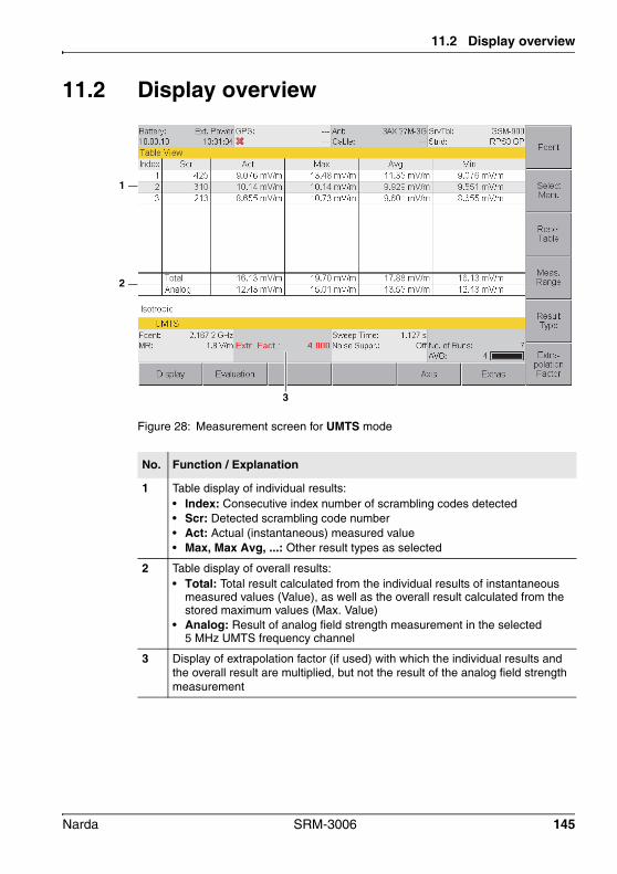
11.2 Display overview
11.2 Display overview
Figure 28: Measurement screen for UMTS mode
1
3
2
No. Function / Explanation
1 Table display of individual results:• Index: Consecutive index number of scrambling codes detected• Scr: Detected scrambling code number• Act: Actual (instantaneous) measured value• Max, Max Avg, ...: Other result types as selected
2 Table display of overall results:• Total: Total result calculated from the individual results of instantaneous
measured values (Value), as well as the overall result calculated from the stored maximum values (Max. Value)
• Analog: Result of analog field strength measurement in the selected 5 MHz UMTS frequency channel
3 Display of extrapolation factor (if used) with which the individual results and the overall result are multiplied, but not the result of the analog field strength measurement
Narda SRM-3006 145

11 UMTS Mode
11.3 Explanation of measurement result displayWhen you start the measurement, the SRM-3006 searches through the specified UMTS frequency channel for scrambling codes and measures the associated field strengths. It also makes an analog measurement of the total power level of the UMTS frequency channel. The sections below explain the various measurement results that are displayed.
11.3.1 Individual resultsThe Scr column successively shows the numbers of the scrambling codes that are detected (numbers between 0 and 511), sorted in ascending order and numbered consecutively in the Index column. The list can contain up to 16 scrambling codes.
NOTE: If no scrambling code is detected, the message No Scr. Code found is displayed. This could be due to the center frequency Fcent not being set correctly. Fcent must be set to an exact multiple of 100 kHz.
The Act column shows the actual measurement results for each scrambling code multiplied by the extrapolation factor (Extr. Fact.).
The remaining columns show the selected result types (Result Type), e.g. the maximum, average, and minimum values that occurred since the start of the measurement, multiplied by the extrapolation factor (Extr. Fact).
The maximum and minimum values can be cleared using the Result Type / Reset Min & Max softkeys. The entire table can be cleared using the Result Type / Table Reset softkeys. You can clear the scrambling codes no longer received from the list in this way to make room for new ones.
NOTE: Any change in parameters resets the entire table (same as Reset All).
11.3.2 Total result (Total)This value corresponds to the total power of all the scrambling codes listed, multiplied by the extrapolation factor (Extr. Fact.). A total result is determined from both the instantaneous and maximum individual results.
146 SRM-3006 Narda
11.4 Basic settings
11.3.3 Partial results for certain radio cells (scrambling codes)It is often necessary to determine the proportion of the overall field strength within a UMTS frequency channel that is due to certain cells only. You can use the Select Menu softkey function to select the cells of interest by means of their scrambling codes.
To select individual cells:1. Press the Select Menu softkey.2. Use the rotary control to highlight items and select them with the
softkeys.3. Press the OK key to confirm the selection.
The selection applies to all display types and all evaluations, i.e. the numerical overall result (Total) as well as the graphical display versus time only take the selected scrambling codes into account.
If you select only one scrambling code, you can display the field strength versus time for this one cell.
11.3.4 Analog measurement result (Analog)This value directly shows the result for the selected UMTS frequency channel, determined by analog measurement using a fixed resolution bandwidth (RBW) of 5 MHz. The extrapolation factor is not applied to this result.
11.4 Basic settingsThis section describes the basic settings. If these settings are identical in more than one operating mode, a cross-reference will indicate the relevant section in Chapter 6 Functions Common to More Than One Operating Mode on page 71 where the setting is described.
11.4.1 Setting the center frequency (Fcent)UMTS • Fcent
NOTE: The center frequency must be set to an exact multiple of 100 kHz.
Narda SRM-3006 147

11 UMTS Mode
To set the center frequency:1. Press the Fcent softkey.
2. Use the arrow keys to select a decimal digit and use the rotary control to change the value.
3. Press the OK key to set the value.
The frequency can be transferred from another operating mode, e.g. from Spectrum mode:
1. Switch to Spectrum mode and select a frequency using the marker function– or –
use the Span and Fcent values directly without using the marker function.
2. Use the Extra softkey to switch back to UMTS mode directly. The marker frequency is set as the new center frequency (the RBW
is not transferred!).
11.4.2 Showing and hiding servicesUMTS • Select Menu
You can specify the services to be measured using the Select Menu.
To show or hide services:1. Press the Select Menu softkey. The Select menu opens.
2. Use the rotary control and the softkeys to select the services required.Information on how to select items from a list is found under Selecting entries from a list on page 48.
3. When you have made your selection, press the OK key. The selected services are displayed.
11.4.3 Resetting the table (Reset Table)UMTS • Reset Table
Resets the maximum, minimum, and average values.
11.4.4 Setting the measurement range (Meas. Range)UMTS • Meas. Range
See Setting the measurement range (Meas. Range) on page 75.
148 SRM-3006 Narda
11.4 Basic settings
11.4.5 Selecting the result type (Result Type)UMTS • Result Type
See Selecting the result type (Result Type) on page 78.
11.4.6 Using an extrapolation factorUMTS • Extrapolation Factor
The traffic channel levels can be extrapolated on the basis of the values measured for the control channels by means of the extrapolation factor. Up to three digits can be entered after the decimal point. This allows you to enter a close approximation of values such as .
Example: The factor 3 is chosen for 3 traffic channels. The level found is then multiplied by 3.
NOTE: The extrapolation factor is applied to the power level. The analog value (Analog display) is not multiplied by the extrapolation factor, which also does not affect the Ratio Pilot/Analog function.
To set the factor:1. Press the Extrapolation Factor softkey, then press the Extrapolation
softkey until the label shows Off (toggle function). Extrapolation is now activated and the lower part of the display shows
the current value of the factor in red.2. To change the factor: Press the Extrapolation Factor softkey and enter
a factor using the keypad or select a decimal digit using the arrow keys
and use the rotary control to change the value. You can enter values precisely to three decimal places.
3. Press the OK key to set the value.
2
Narda SRM-3006 149

11 UMTS Mode
11.5 Performing a coverage measurementA coverage measurement determines the ratio of the pilot signal to the analog value.
Press the Evaluation softkey, then press the Ratio Pilot / Analog softkey. The pilot to analog ratio is displayed in the right hand column.
Figure 29: UMTS mode with display of Pilot / Analog.
11.6 Using noise suppression (Noise Thresh.)UMTS • Meas. Range • Noise Thresh. / Noise Suppr.
See Noise suppression (Noise Thresh.) on page 94.
150 SRM-3006 Narda

12 LTE mode
This chapter describes the LTE operating mode. Two LTE options are available: – LTE (for FDD networks)– LTE (for TDD networks)
Because operation and functions are mostly identical both options are called LTE only in this chapter. The TDD specific functions are described In chapter LTE TDD on page 161.
12.1 About LTE mode (page 152)
12.2 Display overview (page 153)
12.3 Explanation of measurement result display (page 154)
12.4 Basic settings (page 155)
12.5 Using noise suppression (Noise Thresh.) (page 160)
12.6 LTE TDD (page 161)
Narda SRM-3006 151

12 LTE mode
12.1 About LTE modeLTE (Long Term Evolution) is a new wireless communications standard, which can achieve considerably higher download rates of up to 300 megabits per second. LTE is also known as “4G” (fourth generation) and can be considered as the successor to UMTS. The SRM-3006 supports all LTE channel bandwidths (CBW) from 1.4 MHz up to 20 MHz.
The PSS (primary sync signal) and SSS (secondary sync signal) are only transmitted in the center 0.96 MHz of the TBW and are used for synchronization to the system. There are only three different PSS (one for each of the three sectors in a group) and 168 different groups. The cell ID can be determined unambiguously from the SSS: Cell ID = Group ID *3 + Sector ID.
The RS (reference signal) is distributed over the entire TBW. The SRM-3006 measures the RS within the TBW that corresponds to the CBW setting. The CBW setting on the SRM-3006 can also be selected to be smaller than the CBW of the signal to be measured. This has the advantage of a shorter measurement duration but the disadvantage of increased inaccuracy, particularly if the signal being measured is subject to strong fading.
The RS can be transmitted from either one, two, or four antennas. The SRM-3006 detects the number of antennas used and measures the RS power on all antennas separately (RS 0, RS 1, RS 2, and RS 3). The SRM-3006 can also display the average power of all antennas used (RS Avg), the sum power of all antennas used (RS Sum), and the maximum power of all antennas used (RS Max).
NOTE: The user should be aware that when measuring LTE (TDD or FDD) the decoding algorithm can, in rare cases, detect Cell IDs not actually existing. For example, when measuring LTE FDD in a LTE TDD network there is a small chance that Cell IDs are detected. Such results must be critically evaluated and disregarded if not plausible. False Cell IDs are detected only sporadically and normally with much lower field strength levels than real Cell IDs.
Table 35: Channel bandwidths supported
CBW (MHz)
TBW (MHz)1)
1) TBW (transmit bandwidth) is the actual bandwidth occupied by all the carriers. Frequency spacing is 15 kHz. The center carrier is not used. The CBW corresponds to the minimum permissible channel separation.
Number of sub-carriers
CBW (MHz)
TBW (MHz)1)
Number of sub-carriers
1.4 1.08 72 10 9.00 600
3 2.70 180 15 13.50 900
5 4.50 300 20 18.00 1200
152 SRM-3006 Narda

12.2 Display overview
12.2 Display overview
Figure 30: Measurement screen for LTE FDD mode (example)
1
3
2
No. Function / Explanation
1 Tabular display of individual results:• Index: Consecutive index number of cells detected• Cell ID: ID of detected cell• No. Ant: Number of antennas (up to 4 antennas can be active)• Act, Max, Avg, ...: Result and signal types as selected
2 Tabular display of total results:• Total: Total result calculated from the individual results• Analog: Result of analog field strength measurement
3 Display of settings and measurement parameters:• Extr. Fact.: Extrapolation factor (where used) by which the individual
results and the total result are multiplied, but not the analog field strength measurement result.
• Cell Sync.: Cell synchronization setting: No Sync., Sync.• CP Length: Selected cyclic prefix length: Normal, Extended
Narda SRM-3006 153
12 LTE mode
12.3 Explanation of measurement result displayAfter the measurement is started, the SRM-3006 searches for cells in the frequency channel that has been set and measures the corresponding field strengths. It also makes an analog measurement of the total power of the LTE frequency channel at the same time. The sections below explain the results that are displayed.
12.3.1 Individual resultsThe IDs of the cells that are detected are shown one after the other in the Cell ID column, sorted in ascending order and numbered consecutively in the Index column.
NOTE: The table remains empty if no cell can be detected. This can happen if the center frequency Fcent has not been set correctly. Fcent must be set to an exact multiple of 100 kHz.
The columns show the values for the result and signal types selected that have occurred since the start of the measurement, multiplied by the extrapolation factor (Extr. Fact.). The maximum and minimum values can be deleted using the Result Type / Reset Min & Max softkeys. All the result types are reset using the Result Type / Reset All softkey. To reset the entire table including the Cell IDs, press the Result Type / Reset Table softkey. This allows you to clear cells that can no longer be received from the list and make space for new ones.
NOTE: Every change in the parameters resets the entire table (corresponds to Reset Table).
12.3.2 Total result (Total)This value corresponds to the total power of all cells listed multiplied by the extrapolation factor (Extr. Fact.).
154 SRM-3006 Narda
12.4 Basic settings
12.3.3 Partial results for certain cellsOften, only the contribution to the overall field strength due to certain cells within an LTE frequency channel needs to be determined. You can select the cells that you are interested in by means of their Cell ID using the Select Menu softkey function.
To select individual cells:1. Press the Select Menu softkey.2. Highlight an item using the rotary control and select it using the softkeys.3. Press the OK key to confirm the selection.
The selection applies to all display types and all evaluations.
12.3.4 Analog measurement result (Analog)The Analog line displays the actual received analog power of the set LTE frequency channel. The extrapolation factor is not applied to this result. The measurement bandwidth corresponds to the selected channel bandwidth CBW (-6 dB).
12.4 Basic settingsThis section describes the basic settings. If these settings are identical in more than one operating mode, a cross-reference will indicate the relevant section in Chapter 6 Functions Common to More Than One Operating Mode on page 71 where the setting is described.
Narda SRM-3006 155

12 LTE mode
12.4.1 Setting the center frequency (Fcent) and channel bandwidth (CBW)
LTE • CBWLTE • Fcent
Before measuring an unknown transmitter, the TBW of the signal and its center frequency in the spectrum must first be determined to the exact multiple of 100 kHz. Only then can the center frequency (Fcent) and channel bandwidth (CBW) be set to meaningful values.
The choice of channel bandwidth (along with CP Length and Cell Sync) also determines the measurement speed.
The following relationships apply:• Small CBW
– Fast measurement– Less accurate– At least the cell IDs are recognized because the sync channels are in
the center of the bandwidth• Matched CBW
– Longer measurement time– Accurate measurement
The figures below show the effects of different channel bandwidths on the measurement result.
Figure 31: LTE FDD mode: CBW = 1.4 MHz (example)
156 SRM-3006 Narda

12.4 Basic settings
Figure 32: LTE FDD mode: CBW = 20 MHz (example)
To set Fcent and CBW from Spectrum mode:1. Switch to Spectrum mode and select a frequency using the marker
function.– or –
Use Fcent and Span directly without using the marker function.2. Use the Extra softkey to switch directly back to LTE mode. Fcent is set as Fcent and Span as CBW.
To set Fcent directly:1. Press the Fcent softkey.
2. Use the arrow keys to select a digit and use the rotary control to change the value.
3. Press OK to set the value.
To set CBW directly:1. Press the CBW softkey.2. Use the rotary control to select a value and press OK to set the value.
Narda SRM-3006 157

12 LTE mode
12.4.2 Selecting signals (Signal)LTE • Signal
• PSS (Primary Sync Signal)• SSS (Secondary Sync Signal)• RS Avg (Reference Signal Average)• RS Sum (Reference Signal Sum)• RS Max (Reference Signal Maximum)• RS 0 (Reference Signal antenna 0)• RS 1 (Reference Signal antenna 1)• RS 2 (Reference Signal antenna 2)• RS 3 (Reference Signal antenna 3)
NOTE: The average power per resource element from all elements of the signal type under investigation is displayed.
These signals can be combined with the usual result types. If all signals and result types are selected, 54 values will be shown for each cell.
To select signals:1. Press the Signal softkey. The selection menu opens.
2. Use the rotary control and softkeys to select the desired signals.Information on how to select items from a list is given under Selecting entries from a list on page 48.
3. Press OK when you have selected the signals you want. The selected signals are displayed.
12.4.3 Changing CP Length and Cell Sync.LTE • Signal
The CP Length and Cell Sync. parameters only need to be adjusted if no Cell ID or too few Cell IDs are found.
• If no Cell ID is found:Change the Cyclic Prefix Length from Normal (default) to Extended. The extended CP is sometimes used for very large cells or in rural areas.
• To ensure that all Cell IDs are found:Change Cell Sync. from Sync. (default) to No Sync. and select the setting for which the most Cell IDs are displayed.In general, the synchronization parameter should be left set on Sync since the Cells from one operator are typically synchronized. If however, expected Cell IDs are missing or when changing the setting from Sync to
158 SRM-3006 Narda

12.4 Basic settings
No Sync more Cell IDs are detected, then some Cells are after all probably not synchronized and the No Sync setting is necessary to detect all Cell IDs. The disadvantage of the No Sync setting is that it will increase the decoding time. Therefore, it should only be used when necessary.
To change the settings: 1. Press the Signal softkey.2. Press the CP Length softkey (toggle function). The setting shown is the
one that can be selected (i.e. the setting that is inactive at the moment). You can switch between Normal and Extended.
3. Press the Cell Sync. softkey (toggle function). The setting shown is the one that can be selected (i.e. the setting that is inactive at the moment). You can switch between Sync. und No Sync.
Both functions are activated immediately they are selected.
12.4.4 Selecting the result type (Result Type)LTE • Result Type
See Selecting the result type (Result Type) on page 78.
12.4.5 Setting the measurement range (Meas. Range)LTE • Meas. Range
See Setting the measurement range (Meas. Range) on page 75.
12.4.6 Using an extrapolation factorLTE • Extrapolation Factor
The extrapolation factor is used to determine the total power under full load from the measured signals. The extrapolation factor to be used corresponds approximately to the number of sub carriers in the system under investigation.
Example: The factor 600 is selected for an LTE system with channel bandwidth 10 MHz and 600 sub carriers. The measured power is then multiplied by 600.
You can enter up to 3 places after the decimal point. This allows you to enter the exact value where the extrapolation factor is known.
Narda SRM-3006 159

12 LTE mode
NOTE: The extrapolation factor applies to the power and is visible directly when units of power are shown (W/m2, mW/cm2). It is not applied to the analog value (Analog display).
To set the factor:1. Press the Extrapolation Factor softkey, then press the Extrapolation
softkey until Off appears (toggle function). Extrapolation is now activated and the currently selected factor is
shown in red in the lower part of the display.2. To change the factor: Press the Extrapolation Factor softkey and enter
a factor using the keypad or use the arrow keys to select a digit and use the rotary control to change the value. The value can be entered with an accuracy of up to three decimal places.
3. Press the OK key to set the value.
12.5 Using noise suppression (Noise Thresh.)LTE • Meas. Range • Noise Thresh. / Noise Suppr.
See Noise suppression (Noise Thresh.) on page 94.
160 SRM-3006 Narda
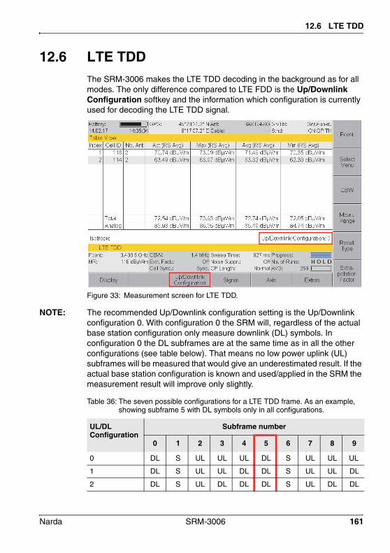
12.6 LTE TDD
12.6 LTE TDDThe SRM-3006 makes the LTE TDD decoding in the background as for all modes. The only difference compared to LTE FDD is the Up/Downlink Configuration softkey and the information which configuration is currently used for decoding the LTE TDD signal.
Figure 33: Measurement screen for LTE TDD.
NOTE: The recommended Up/Downlink configuration setting is the Up/Downlink configuration 0. With configuration 0 the SRM will, regardless of the actual base station configuration only measure downlink (DL) symbols. In configuration 0 the DL subframes are at the same time as in all the other configurations (see table below). That means no low power uplink (UL) subframes will be measured that would give an underestimated result. If the actual base station configuration is known and used/applied in the SRM the measurement result will improve only slightly.
Table 36: The seven possible configurations for a LTE TDD frame. As an example, showing subframe 5 with DL symbols only in all configurations.
UL/DLConfiguration
Subframe number
0 1 2 3 4 5 6 7 8 9
0 DL S UL UL UL DL S UL UL UL
1 DL S UL UL DL DL S UL UL DL
2 DL S UL DL DL DL S UL DL DL
Narda SRM-3006 161

12 LTE mode
12.6.1 Select and change the up-/downlink configuration
Main menu • LTE TDD
You can select and change the up- and downlink configuration in a scroll down list.
1. Press the Up/Downlink Configuration softkey.2. Use the rotary control to highlight the desired configuration (choosing
from the scroll down list a configuration between 0 and 6).3. Press the OK key to confirm the selection.
3 DL S UL UL UL DL DL DL DL DL
4 DL S UL UL DL DL DL DL DL DL
5 DL S UL DL DL DL DL DL DL DL
6 DL S UL UL UL DL S UL UL DL
Table 36: The seven possible configurations for a LTE TDD frame. As an example, showing subframe 5 with DL symbols only in all configurations.
UL/DLConfiguration
Subframe number
0 1 2 3 4 5 6 7 8 9
162 SRM-3006 Narda

13 Spatial Averaging
This chapter describes the Spatial Averaging mode.
13.1 About the Spatial Averaging function (page 164)
13.2 Description of averaging functions (page 165)
13.3 Spatial Averaging – Continuous (page 169)
13.4 Spatial Averaging – Discrete (page 171)
13.5 Spatial Averaging – Discrete Axis (page 173)
Narda SRM-3006 163

13 Spatial Averaging
13.1 About the Spatial Averaging functionThe standards and regulations governing the protection of humans from high-frequency radiation specify limit values which normally have to be averaged over the entire human body. This is because the fields may vary greatly within a given volume. This is particularly the case in the vicinity of the antennas used for mobile telecommunications, which have a primary lobe in the desired direction of radiation but many secondary lobes in different directions. As a result, the measured value depends on the spatial height as well as the distance from the antenna.
The standard method of spatial averaging uses a simplified model of the human body, often in the form of a dummy made of non-conducting material. The dummy is the same size as a normal adult and is marked at specific heights. The field strength is measured at each of these heights, and the results averaged mathematically. The spacing and heights of these markings vary from one standard to another. For example, IEEE C95.1-1999 requires measurements from 0 cm (floor level) to 200 cm at equal intervals of 20 cm. Other standards, such as Canada’s Safety Code 6 require two-dimensional measurements in vertical and horizontal directions. The revised ECC Recommendation (02)04 of October 2003 specifies measurements at 1.1, 1.5 and 1.7 m above floor level.
Such measurements are difficult, particularly in the vicinity of modern mobile communications sites shared by several providers, because the field strengths are changing all the time: paging systems transmit sporadically, the number of occupied mobile phone channels changes continually, and so on. For this reason, the results of measurements can often depend more on the time than on the spatial location.
164 SRM-3006 Narda

13.2 Description of averaging functions
The averaging processThe SRM-3006 simplifies the measurement by automatically averaging the values measured at different points in the room. The SRM-3006 determines the root mean square value (RMS), i.e. the average power level. For this reason it is a good idea to set the detector function in Level Recorder mode to RMS, although the PEAK setting is also available.
Spatial Averaging can be applied in the following operating modes:
• Safety Evaluation (see page 99)• Spectrum Analysis (see page 111)• Level Recorder (see page 143)
It cannot be used in UMTS P-CPICH Demodulation and LTE mode.
According to the operating mode, the SRM-3006 determines the average of:
• the individual results for the different services (Safety Eval mode),• the individual spectral values (Spectrum mode), or• the individual measured values (Level Recorder mode).
13.2 Description of averaging functionsThe following types of Spatial Averaging are available:
• Continuous: measured values are recorded continuously• Discrete: one measured value recorded each time a key is pressed• Discrete Axis: one single axis measured value recorded each time a key
is pressed
These three averaging functions are described briefly below.
Narda SRM-3006 165

13 Spatial Averaging
13.2.1 ContinuousIn Continuous Averaging mode, the SRM-3006 records the values continuously and averages them. In this way, particular paths can be tracked through the room with the antenna. Recording of measurement values is started by pressing the Start key and can be halted by pressing the Pause key and then restarted at a different point in the room by pressing the Continue key. The measurement continues in the background even if the instrument is switched to “Pause”; this can be seen by the incrementing of the “No. of Runs” indicator. These results are not, however, used for the evaluation. This is indicated by the “No. of SAVG” display remaining static. Intermediate and final results can be saved at any time by pressing the SAVE key.
The SRM-3006 averages all the measured values recorded between “Start” and “Pause” or “Continue” and “Clear”, regardless of when the measurement was started or resumed. If several parallel paths are to be traversed with the antenna, for example, you should try to keep the speed of movement the same.
Figure 34: Example of continuous recording of values at three points in a room
Example application for Continuous Averaging:
FCC RFR Guidelines (USA)
Start Continue Continue
Pause Pause Pause
166 SRM-3006 Narda

13.2 Description of averaging functions
13.2.2 DiscreteThe measurement is controlled manually by pressing the Add Value key. Each time you press the key, the SRM-3006 performs just one measurement, confirms this with a beep, and increments the value of “No. of SAVG” by one. The SRM-3006 averages all the measured values obtained in this way. The order in which you measure the various points in the room therefore does not matter if the field is constant over time. Intermediate and final results can be saved at any time by pressing the SAVE key.
Figure 35: Discrete recording of three measured values at each of three points in the room
* Basic standard for the in-situ measurement of electromagnetic field strength related to human exposure in the vicinity of base stations.
Example application for Discrete Averaging:
EN 50492:2008*
Add Value
Add Value
Add Value
Add Value
Add Value
Add Value
Add Value
Add Value
Add Value
Narda SRM-3006 167

13 Spatial Averaging
13.2.3 Discrete AxisDiscrete Axis allows you to determine the average value using a single axis antenna. Three measurements will then need to be performed at every measurement point within the room. The SRM-3006 calculates the isotropic result for each measurement point and averages the isotropic results of all measurement points. Intermediate and final results can be saved at any time by pressing the SAVE key.
Figure 36: Three separate measurements must be performed at each point in the room if a single axis antenna is used
* Basic standard for the in-situ measurement of electromagnetic field strength related to human exposure in the vicinity of base stations.
Example application for Discrete Axis:
EN 50492:2008* with single axis antenna
Add X-AxisAdd Y-AxisAdd Z-Axis
Add X-AxisAdd Y-AxisAdd Z-Axis
Add X-AxisAdd Y-AxisAdd Z-Axis
Add X-AxisAdd Y-AxisAdd Z-Axis
Add X-AxisAdd Y-AxisAdd Z-Axis
Add X-AxisAdd Y-AxisAdd Z-Axis
Add X-AxisAdd Y-AxisAdd Z-Axis
Add X-AxisAdd Y-AxisAdd Z-Axis
Add X-AxisAdd Y-AxisAdd Z-Axis
168 SRM-3006 Narda

13.3 Spatial Averaging – Continuous
13.3 Spatial Averaging – ContinuousSafety Eval • Result Type • Spatial AVGSpectrum • Result Type • Spatial AVGLevel Recorder • Result Type • Spatial AVG
You have selected the desired operating mode and made all the settings you want.
1. Press the Result Type softkey. The Result Type selection box opens.
NOTE: The selection of a Result Type has no relevance here, as the SRM-3006 always uses the actual value (Act or Peak) for Spatial Averaging regardless of the result type selected.
Figure 37: Example: Safety Eval • Result Type • Spatial AVG (Continuous)
2. Press the Spatial AVG Type softkey, select Continuous using the rotary control, and press the OK key.
3. Move to the desired position in the room and press the Spatial AVG softkeys to switch the instrument so it is ready to measure.
4. Press the Start softkey to start the measurement. The instrument starts measuring and indicates the number of
measurements made (No. of Runs) and the number of averages determined (No. of SAVG) in the display.
5. Move the antenna along the path to be measured in the room.
Narda SRM-3006 169

13 Spatial Averaging
To pause the measurement:6. Press the Pause softkey. The instrument stops averaging (No. of SAVG is static) and displays
the averaged result. It continues measuring in the background (indicated by No. of Runs) but does not use these values for determining the average.
7. If required, move to a new position in the room and press the Continue softkey. The instrument resumes averaging (indicated by No. of SAVG).
8. Move the antenna along the next path to be measured in the room.9. You can repeat steps 6 through 8 as often as necessary until you have
the final result.
To save the result in the measurement data memory: Press the SAVE key.
To delete the result: Press the Clear softkey.
To exit from Spatial Averaging: Press the ESC key.
NOTE: The instrument saves the actual (current) result of spatial averaging in the measurement data memory when you press the SAVE key. You can therefore use this function to save intermediate results. When you press the Continue softkey, the instrument resumes averaging and takes account of all the measured values obtained so far. The instrument does not clear all the measurement values recorded and start a new spatial averaging procedure until you press the Clear softkey.
170 SRM-3006 Narda

13.4 Spatial Averaging – Discrete
13.4 Spatial Averaging – DiscreteSafety Eval • Result Type • Spatial AVGSpectrum • Result Type • Spatial AVGLevel Recorder • Result Type • Spatial AVG
You have selected the desired operating mode and made all the settings you want.
1. Press the Result Type softkey. The Result Type selection box opens.
NOTE: The selection of a Result Type has no relevance here, as the SRM-3006 always uses the actual value (Act or Peak) for Spatial Averaging regardless of the result type selected.
Figure 38: Example: Level Recorder • Result Type • Spatial AVG (Discrete)
2. Press the Spatial AVG Type softkey, select Discrete using the rotary control, and press the OK key.
3. Move the antenna to the first position in the room to be measured and press the Spatial AVG softkeys to switch the instrument so it is ready to measure.
4. Press the Add Value softkey to start the measurement. The instrument makes the measurement and confirms this with a
short beep. The number of averaged values (No. of SAVG) now indicates 1. The instrument continues measuring in the background (indicated by No. of Runs) but does not use these values for determining the average.
Narda SRM-3006 171
13 Spatial Averaging
NOTE: The measuring antenna must not be moved during the measurement, i.e. from the time you press the Add Value key until the beeper sounds.
5. Move the antenna to the next position in the room to be measured and press the Add Value softkey. The number of averaged values (No. of SAVG) now indicates 2.
6. Repeat the process for all of the points in the room that are to be recorded.
To save the result in the measurement data memory: Press the SAVE key.
To delete the result: Press the Clear softkey.
To exit from Spatial Averaging: Press the ESC key.
NOTE: The instrument saves the actual (current) result of spatial averaging in the measurement data memory when you press the SAVE key. You can therefore use this function to save intermediate results. When you press the Continue softkey, the instrument resumes averaging and takes account of all the measured values obtained so far. The instrument does not clear all the measurement values recorded and start a new spatial averaging procedure until you press the Clear softkey.
172 SRM-3006 Narda

13.5 Spatial Averaging – Discrete Axis
13.5 Spatial Averaging – Discrete AxisSafety Eval • Result Type • Spatial AVGSpectrum • Result Type • Spatial AVGLevel Recorder • Result Type • Spatial AVG
The antenna is fitted on a tripod by means of the antenna holder. See Fitting a Narda antenna on a tripod on page 34.
You have selected the desired operating mode and made all the settings you want.
1. Press the Result Type softkey. The Result Type selection box opens.
NOTE: The selection of a Result Type has no relevance here, as the SRM-3006 always uses the actual value (Act or Peak) for Spatial Averaging regardless of the result type selected.
Figure 39: Example: Spectrum • Result Type • Spatial AVG (Discrete Axis)
2. Press the Spatial AVG Type softkey, select Discrete Axis using the rotary control, and press the OK key.
3. Move the antenna to the first position in the room to be measured, orient the antenna in the direction of the X axis, and press the Spatial AVG softkeys to switch the instrument so it is ready to measure.
Narda SRM-3006 173

13 Spatial Averaging
4. Press the Add X-Axis softkey. The instrument makes the measurement and confirms this with a
short beep. The number of averaged values (No. of SAVG) still indicates 0. The instrument continues measuring in the background (indicated by No. of Runs) but does not use these values for determining the average.
NOTE: The measuring antenna must not be moved during the measurement, i.e. from the time you press the Add Axis key until the beeper sounds.
5. Orient the antenna in the direction of the Y axis and press the Add Y-Axis softkey. The instrument makes the measurement and confirms this with a
short beep. The number of averaged values (No. of SAVG) still indicates 0. The instrument continues measuring in the background (indicated by No. of Runs) but does not use these values for determining the average.
6. Orient the antenna in the direction of the Z axis and press the Add Z-Axis softkey. The instrument makes the measurement and confirms this with two
beeps. The number of averaged values (No. of SAVG) now indicates 1 because the isotropic measurement for the first measurement point has now been completed. The instrument continues measuring in the background (indicated by No. of Runs) but does not use these values for determining the average.
7. Move the antenna to the next position in the room to be measured and repeat the process for the X, Y, and Z axis positions. The number of averaged values (No. of SAVG) now indicates 2. The
instrument averages the two isotropic results and displays the overall result numerically. The instrument continues measuring in the background (indicated by No. of Runs).
8. Repeat the process for all of the points in the room that are to be recorded.
174 SRM-3006 Narda

13.5 Spatial Averaging – Discrete Axis
To save the result in the measurement data memory: Press the SAVE key.
To delete the result: Press the Clear softkey.
To exit from Spatial Averaging: Press the ESC key.
NOTE: The instrument saves the actual (current) result of spatial averaging in the measurement data memory when you press the SAVE key. You can therefore use this function to save intermediate results. When you press the Add Axis softkey, the instrument resumes averaging and takes account of all the measured values obtained so far. The instrument does not clear all the measurement values recorded and start a new spatial averaging procedure until you press the Clear softkey.
Narda SRM-3006 175
13 Spatial Averaging
176 SRM-3006 Narda

14 Measurement Data Memory
This chapter describes how to display measurement data and screenshots, how to save data by condition and timer controls, and how to use the comment function.
14.1 About the Memory menu (page 178)
14.2 Viewing data sets (page 179)
14.3 Viewing screenshots (page 181)
14.4 Saving measured values automatically (page 182)
14.5 Changing the comment modes (page 186)
Narda SRM-3006 177

14 Measurement Data Memory
14.1 About the Memory menuMain Menu • Memory Menu
The Memory sub menu of the Main menu contains the following functions:
• Recall or delete stored data• Display screenshots• Save results using conditions or timers• Activate comment mode
To open the menu: Switch to the Main menu and press the Memory softkey. The Memory menu is displayed with the stored data.
Figure 40: Memory menu
178 SRM-3006 Narda

14.2 Viewing data sets
14.2 Viewing data setsMain Menu • Memory • Data Viewer
Press the Data Viewer softkey. The list of the stored data sets is displayed.
To view a data set: Select a data subset using the rotary control and press the Recall Data
Set softkey or the OK key. The data set is displayed in the form that it was saved. RECALL on
the screen indicates that the data set is a saved data set.
To delete a data set: Use the rotary control to select a data set and press the Delete Dataset
softkey.
Function Explanation
Total Memory Total memory space
Free Memory Memory space still available
Number of Antenna Data Sets Number of antenna data sets saved
Number of Cable Data Sets Number of cable data sets saved
Number of Safety Standards Number of safety standards saved
Number of Service Tables Number of service tables saved
Number of Setups Number of setups saved
Number of Measurement Routines Number of measurement routines saved
Number of Measurement Data Sets
Number of measurement data sets saved
Number of Screenshots Number of screenshots saved
Tip: • You can use the ▲▼ softkeys to page through the list.• You can use the softkeys to jump to the previous or next data subset
without having to go back to the Memory menu.• You can use the softkeys to jump to the previous or next data subset
if several results are saved in one data set.
Narda SRM-3006 179

14 Measurement Data Memory
To delete all data sets:1. Press the Delete Menu softkey.2. Press the Select All softkey.3. Press the Delete Selection softkey.
To delete a range of data sets:1. Press the Delete Menu softkey.2. Select the range you want to delete using the appropriate softkey.
There are several ways to select a range using the Invert Selection, Select, Select First and Select Last softkeys.
3. Press the Delete Selection softkey.
180 SRM-3006 Narda

14.3 Viewing screenshots
14.3 Viewing screenshotsMain Menu • Memory • Screenshot Viewer
Press the Screenshot Viewer softkey. The list of the stored screenshots is displayed.
To view a screenshot: Use the rotary control to select a screenshot and press the
Recall Screenshot softkey to display it. (Press the ▲▼ softkeys to show the first or last entries of the list.) The selected screenshot is displayed.
NOTE: The SRM-3006 displays the original image at reduced size on a black background. These images may appear blurred due to the reduced number of pixels. Nevertheless, the screenshot remains saved with full resolution and will be displayed full size on the PC screen.
Press Previous Screenshot or Next Screenshot softkey to skip through the list.
Press ESC to return to the Screenshot Viewer menu.
To delete a screenshot: Use the rotary control to select a data set and press the
Delete Screenshot softkey.
To delete all screenshots:1. Press the Delete Menu softkey.2. Press the Select All softkey.3. Press the Delete Selection softkey.
To delete a range of screenshots:1. Press the Delete Menu softkey.2. Select the range you want to delete using the appropriate softkey.
There are several ways to select a range using the Invert Selection, Select, Select First and Select Last softkeys.
3. Press the Delete Selection softkey.
Narda SRM-3006 181

14 Measurement Data Memory
14.4 Saving measured values automaticallyYou can also save results automatically in the data memory instead of pressing the SAVE key each time you want to save a result. There are two memory functions for this purpose:
• Conditional storing: As soon as a value exceeds a predefined threshold, the instrument begins saving results.
• Timer-controlled storing: Storing of data is controlled by a start time and a duration.
NOTE: After saving the results Min and Max are reset, whereas Min Avg and Max Avg are not.
NOTE: The internal memory of the SRM-3006 has the capacity to store large quantities of data. A large number of data sets can take a long time to upload to a PC, so it is a good idea not to let the data memory fill up too much and to update and manage the data regularly.
14.4.1 Conditional Storing of measured valuesMain Menu • Memory Menu • Conditional Storing
In conditional storing mode, the instrument starts storing results as soon as a measured value exceeds a predefined threshold value. The threshold along with other parameters can be set in the Conditional Storing menu.
Figure 41: Conditional storing
182 SRM-3006 Narda

14.4 Saving measured values automatically
To store measured values by conditional control:1. Select the desired operating mode and then press the MENU key to
open the Main menu.2. Press the Memory softkey, then press the Conditional Storing softkey
and set the parameters:
3. Press the Start Now softkey. Automatic storage is activated.
The screen displays the view of the operating mode previously selected. The info line shows Conditional Storing and the number of records still to be recorded.
To stop storing values: Storing stops automatically when the Max. Number of Records is
reached. To stop storing values before this, press the Stop softkey. The operating mode is again displayed normally. You can view the
stored measurement values from the Memory menu (see Viewing data sets on page 179).
Figure 42: Conditional Storing parameters
Condition Explanation Possible settings
Threshold Threshold above which storage of values begins
–
Conditional Storing Options
Number of values to be stored
• First Value Over Threshold: only the first value exceeding the threshold
• All Values Over Threshold: all the values exceeding the threshold
Max Number of Records
• As many as possible• 2, 3, 5, 10, 20, 30, 50, 100, 200, 300,
500
Result Type Result type viewed • Peak• Maximum Peak
Narda SRM-3006 183

14 Measurement Data Memory
14.4.2 Time Controlled Storing of measured valuesMain Menu • Memory Menu • Time Controlled Storing
For time controlled storing you specify the start time, duration, and interval between store events in the Time Controlled Storing menu.
Figure 43: Time controlled storing
To save measured values by time control:1. Select the desired operating mode and then press the MENU key to
open the Main menu.2. Press the Memory softkey, then press the Time Controlled Storing
softkey and set the parameters:
Figure 44: Time Controlled Storing parameters
Condition Explanation Possible settings
Start Date You can use the date and time settings from the SRM-3006 by pressing the Adjust Date & Time softkeyStart Time
Duration Duration of recording
Maximum 99 hours 59 minutes 59 seconds
Time Interval • As often as possible• Maximum 60 minutes
184 SRM-3006 Narda

14.4 Saving measured values automatically
To start storing values immediately:3. Press the Start Now softkey. Automatic storage is activated.
The screen displays the view of the operating mode previously selected. The info line shows Time Controlled Storing and the remaining recording time (duration).
To start storing at the specified time: 4. Press the Prog Start softkey. Automatic storage is activated. The screen displays the view of the operating mode previously
selected. The info line shows Time Controlled Storing and the remaining time until the start of recording. Storing starts when the countdown reaches 0.
To stop storing: Storing stops automatically when the specified duration has elapsed. To
stop storing values before this, press the Stop softkey.
The operating mode is again displayed normally. You can view the stored measurement values from the Memory menu (see Viewing data sets on page 179).
Narda SRM-3006 185

14 Measurement Data Memory
14.5 Changing the comment modesMain Menu • Memory • Comment
Press the Comment softkey. The Comment dialog is displayed.
Comments can be added to data sets or screenshots. In both cases the comment mode and the default comment text can be set individually. Following table shows the available comment modes:
To change the comment mode:1. Use the rotary control to select Dataset Comment Mode or
Screenshot Comment Mode and press OK.2. Use the rotary control to change the mode and press OK.
To change the default comment text:1. Use the rotary control to select Standard Data Set Comment Text or
Standard Scr.shot Comment Text and press OK. The text editor opens.
2. Enter the default text and press OK. This text will be used when Standard Text is set as Comment Mode.
When Individual Text is set, the entered text is suggested in the editor and can be complemented or overwritten.
Table 37: Comment modes
Mode When saving a dataset or a screenshot ...
No Comment ... no comment can be added.
Standard Text ... the text saved in Standard Data Set Comment Text or Standard Scr.shot Comment Text is added as a comment.
Individual Text ... the text saved in Standard Data Set Comment Text or Standard Scr.shot Comment Text is displayed in the text editor and can be edited.
Voice Comment ... a voice comment can be added (voice comment is available for datasets only).
186 SRM-3006 Narda
15 Maintenance and Repairs
This chapter describes the maintenance and repairs that can be undertaken by the user.
15.1 Changing the battery pack (page 188)
15.2 Cleaning (page 188)
15.3 AC adapter / charger (page 189)
15.4 Updating the device software (page 190)
15.5 Activating options (page 190)
Narda SRM-3006 187

15 Maintenance and Repairs
15.1 Changing the battery pack
1. Undo the fixing screw (1) in the lid of the battery compartment.2. Pull out the battery pack using the tab (2).3. Hold the tab on the new battery pack and slide the battery pack into the
compartment.4. Replace the lid of the battery compartment and do up the fixing screw
(finger tight).
NOTE: If the old battery pack is no longer required, do not simply throw it away with the normal trash. Dispose of it according to the regulations applicable in the country of use (also refer to Proper disposal on page 22).
15.2 Cleaning• Do not use solvents to clean the Basic Unit, the antennas, or the AC
adapter / charger. We recommend the use of lukewarm water to which a drop of liquid detergent has been added as cleaning fluid.
• Only use a lightly moistened cloth for cleaning. Water must not get into the device under any circumstances.
• To avoid spots and drying marks, wipe off the device while it is still damp with a dry cloth.
1
2
188 SRM-3006 Narda

15.3 AC adapter / charger
15.3 AC adapter / charger
Opening the device
Damage to the device
Spare parts
WARNINGElectric shockParts carrying dangerous voltages that can cause injury through electric shock may be exposed if the AC adapter / charger is opened. The AC adapter / charger is not designed to be repaired. If it is
defective or malfunctioning, the entire device should be replaced.
Do not open the AC adapter / charger.
NOTICEDamage to the deviceImproper repairs may change the characteristics of the AC adapter / charger to the extent that it could be destroyed by short circuits e.g. across creepage and air paths. Repairs must only be performed by qualified persons.
NOTICEDamage to the deviceIf constructional changes are made to the AC adapter / charger, the safety of the device can no longer be guaranteed. Only use original spare parts for repairs to the AC adapter / charger.
Narda SRM-3006 189

15 Maintenance and Repairs
15.4 Updating the device softwareThe device software is updated using the PC software. You will find information about the PC software and about connecting the device to a PC in Chapter 16 starting on page 191.
You will find detailed information on how to use the PC software in the online help provided with each PC software version.
15.5 Activating optionsOptions are activated using the PC software. You will find information about the PC software and about connecting the device to a PC in Chapter 16 starting on page 191.
You will find detailed information on how to use the PC software in the online help provided with each PC software version.
190 SRM-3006 Narda

16 PC Software
The PC software is an application for PC that allows convenient handling and management of the SRM-3006.
16.1 PC software versions and functions (page 192)
16.2 Connecting to the PC (page 193)
16.3 Working with the PC software (page 194)
Narda SRM-3006 191
16 PC Software
16.1 PC software versions and functionsThere are two versions of the PC software for the SRM-3006:
SRM-3006 ToolsThe Tools version is free and is included with the SRM-3006.
It contains the following functions:
• Download measurement data to the PC • Download screenshots to the PC • Create antenna, cable, and service tables, measurement routines, and
user standards • Set the instrument configuration • Activate options and update the device software (firmware)
SRM-3006 TSThe TS version can be ordered as an option at additional cost.
All the functions of SRM-3006 Tools are included. Additional functions include:
• Visualizing stored measurement results• Offline analysis of stored measurement results• Remote control of the SRM (image based, transfer and display of the
device display on a PC)• Convenient export of measurement results to Microsoft Office
applications • Management of measurement data in databases• Direct printout of measurement results
192 SRM-3006 Narda

16.2 Connecting to the PC
16.2 Connecting to the PCThe connectors for the optical interface (RS 232) and the USB port (Mini B type) are located on the left hand side panel of the device.
Figure 45: Optical interface (1) and USB port (2)
The following types of connection between the SRM-3006 and the PC are possible (cables and adapters are shown in the table below):
• USB – USB: The fastest and most used type of connection. The electrical signals transmitted can affect the field being measured.
• Optical – USB: Slower transmission speed than USB – USB. However, the field being measured is unaffected by the optical signals transmitted.
• Optical – Serial: The only connection possible for systems not equipped with USB ports or if COM1of the PC must be used.
The following cables and adapters are needed for these connection types:
Neues figure
1 2
SRM-3006 connector
Link PC connector
USB USB
Optical USB
Optical Serial
1) Included with the device2) Available as an option
USB1)
SRM Fiber Optic2)
OE Converter RPO2 to USB2)
OE Converter RPO2 to serial2)
SRM Fiber Optic2)
Narda SRM-3006 193

16 PC Software
To make a connection:1. Connect the SRM-3006 and PC together using one of the connection
types shown above.2. Set the appropriate interface on the SRM-3006:
– Open the Settings menu (Main Menu • Settings), select the Remote Interface command and press OK to confirm.
– Use the rotary control to select the interface being used on the SRM-3006: Optical if you are using the optical cable, USB if you are using a USB cable.
– Press OK to confirm the setting.
16.3 Working with the PC softwareDetailed information on how to use the PC software is provided in the online Help function in each version of the PC software.
194 SRM-3006 Narda
17 Remote Control
This chapter gives some basic information about remote control of the SRM-3006 from a PC. Remote controlled operation of the SRM-3006 is only necessary for very specific applications. All other applications can be handled comfortably using the PC software applications SRM-3006 Tools or SRM-3006 TS.
17.1 About remote control (page 196)
17.2 Connecting to the PC (page 196)
17.3 Activating / deactivating remote control (page 197)
17.4 Syntax rules for remote control commands (page 197)
Narda SRM-3006 195

17 Remote Control
17.1 About remote controlRemote control of the SRM-3006 is possible using a suitable program (e.g. standard terminal emulators such as Hyperterminal) and is therefore an alternative to operation using the Narda PC software applications. Since all device functions can be remote-controlled, the full potential of the SRM-3006 can also be realized in remote operation.
NOTE: Because the software for the SRM-3006 is being constantly developed and updated, there is a separate document that covers remote control. This contains the individual remote control commands and some example programs along with other information. The latest version of the document in PDF format can be obtained from Narda Safety Test Solutions on request. Directly requesting the document in this way ensures that you will receive the remote control instructions that correspond to the firmware you are using.
17.2 Connecting to the PCNotes on connecting the SRM-3006 to the PC are found under Connecting to the PC on page 193.
To make the connection:1. Connect the SRM-3006 and the PC together using one of the options
described.2. Start the application for controlling and managing the PC interface and
set the following interface parameters:
3. Switch on the SRM-3006, open the Main Menu / Device Settings and set Remote Interface to Optical or USB as appropriate.
Parameter Setting
COM Port Optical or USB, as selected by connection made (item 1 above)
Baud rate 115200 Baud
Start bits 1
Data bits 8
Stop bits 1
Parity None
Handshake None (the SRM-3006 does not support any software handshake)
196 SRM-3006 Narda
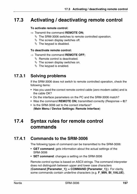
17.3 Activating / deactivating remote control
17.3 Activating / deactivating remote controlTo activate remote control: Transmit the command REMOTE ON; The SRM-3006 switches to remote controlled operation. The screen display switches off. The keypad is disabled.
To deactivate remote control: Transmit the command REMOTE OFF; Remote control is deactivated. The screen display switches on. The keypad is enabled.
17.3.1 Solving problemsIf the SRM-3006 does not switch to remote controlled operation, check the following items:
• Has you used the correct remote control cable (zero modem cable) and is the cable OK?
• Do the interface parameters on the PC and the SRM-3006 match?• Was the command REMOTE ON; transmitted correctly (Response = 0)?• Is the SRM-3006 set to the correct interface?
(Main Menu / Device Settings: Remote Interface)
17.4 Syntax rules for remote control commands
17.4.1 Commands to the SRM-3006The following types of command can be transmitted to the SRM-3006:
• GET command: gets information about the actual settings of the SRM-3006
• SET command: changes a setting on the SRM-3006
Remote control syntax is based on ASCII strings. The command interpreter does not distinguish between upper and lower case characters (Command [Parameter_1]; = COMMAND [Parameter_1];). For clarity, some commands contain underline characters (e.g. F_MIN, BI_VALUE).
Narda SRM-3006 197
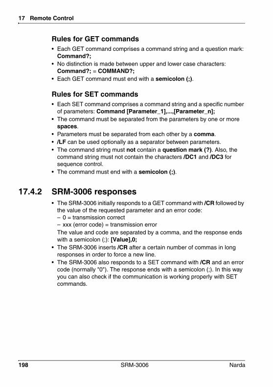
17 Remote Control
Rules for GET commands• Each GET command comprises a command string and a question mark:
Command?;• No distinction is made between upper and lower case characters:
Command?; = COMMAND?;• Each GET command must end with a semicolon (;).
Rules for SET commands• Each SET command comprises a command string and a specific number
of parameters: Command [Parameter_1],...,[Parameter_n];• The command must be separated from the parameters by one or more
spaces.• Parameters must be separated from each other by a comma.• /LF can be used optionally as a separator between parameters.• The command string must not contain a question mark (?). Also, the
command string must not contain the characters /DC1 and /DC3 for sequence control.
• The command must end with a semicolon (;).
17.4.2 SRM-3006 responses• The SRM-3006 initially responds to a GET command with /CR followed by
the value of the requested parameter and an error code:– 0 = transmission correct– xxx (error code) = transmission errorThe value and code are separated by a comma, and the response ends with a semicolon (;): [Value],0;
• The SRM-3006 inserts /CR after a certain number of commas in long responses in order to force a new line.
• The SRM-3006 also responds to a SET command with /CR and an error code (normally "0"). The response ends with a semicolon (;). In this way you can also check if the communication is working properly with SET commands.
198 SRM-3006 Narda
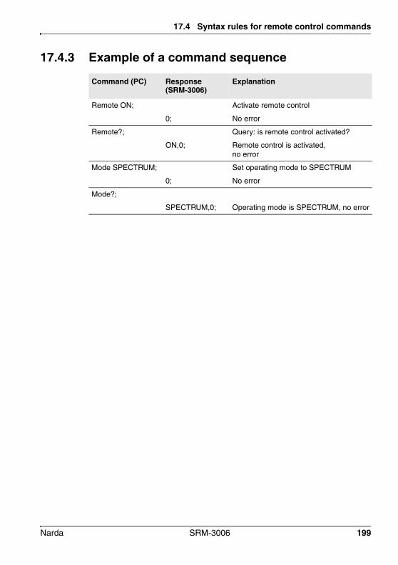
17.4 Syntax rules for remote control commands
17.4.3 Example of a command sequence
Command (PC) Response (SRM-3006)
Explanation
Remote ON; Activate remote control
0; No error
Remote?; Query: is remote control activated?
ON,0; Remote control is activated, no error
Mode SPECTRUM; Set operating mode to SPECTRUM
0; No error
Mode?;
SPECTRUM,0; Operating mode is SPECTRUM, no error
Narda SRM-3006 199

17 Remote Control
200 SRM-3006 Narda

18 Specifications
The specifications of the SRM-3006 Basic Unit and the available E/H-field antennas are listed in this chapter.
All specifications are subject to change without prior notice.
18.1 Definitions and conditions (page 202)
18.2 SRM-3006 (page 203)
18.3 Three axis E-field antenna 3501/03 (page 220)
18.4 Three axis E-field antenna 3502/01 (page 222)
18.5 Three axis H-field antenna 3581/02 (page 224)
18.6 Single axis E-field antenna 3531/01 (page 226)
18.7 Single axis E-field antenna 3531/04 (page 228)
18.8 Single axis H-field antenna 3551/02 (page 230)
18.9 Declaration of Conformity (page 232)
Narda SRM-3006 201
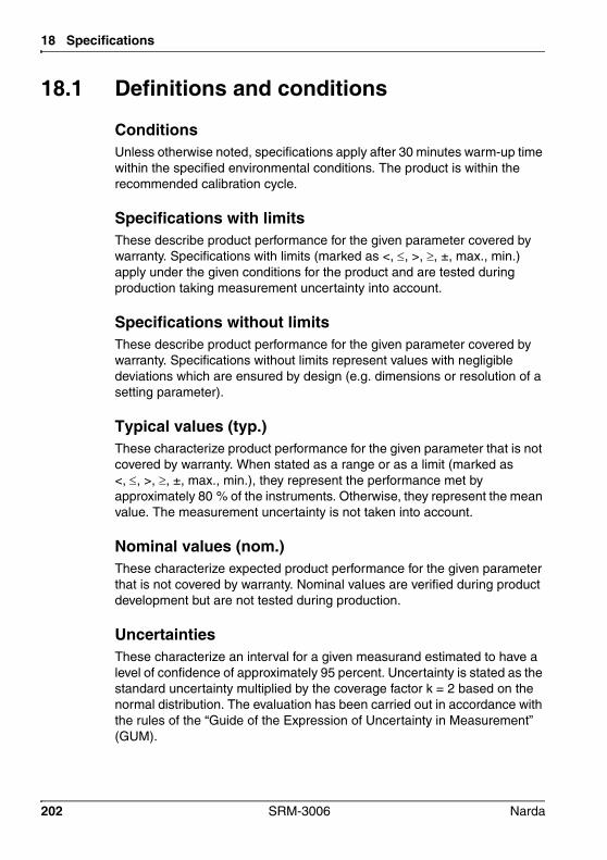
18 Specifications
18.1 Definitions and conditions
ConditionsUnless otherwise noted, specifications apply after 30 minutes warm-up time within the specified environmental conditions. The product is within the recommended calibration cycle.
Specifications with limitsThese describe product performance for the given parameter covered by warranty. Specifications with limits (marked as <, , >, , ±, max., min.) apply under the given conditions for the product and are tested during production taking measurement uncertainty into account.
Specifications without limitsThese describe product performance for the given parameter covered by warranty. Specifications without limits represent values with negligible deviations which are ensured by design (e.g. dimensions or resolution of a setting parameter).
Typical values (typ.)These characterize product performance for the given parameter that is not covered by warranty. When stated as a range or as a limit (marked as <, , >, , ±, max., min.), they represent the performance met by approximately 80 % of the instruments. Otherwise, they represent the mean value. The measurement uncertainty is not taken into account.
Nominal values (nom.)These characterize expected product performance for the given parameter that is not covered by warranty. Nominal values are verified during product development but are not tested during production.
UncertaintiesThese characterize an interval for a given measurand estimated to have a level of confidence of approximately 95 percent. Uncertainty is stated as the standard uncertainty multiplied by the coverage factor k = 2 based on the normal distribution. The evaluation has been carried out in accordance with the rules of the “Guide of the Expression of Uncertainty in Measurement” (GUM).
202 SRM-3006 Narda

18.2 SRM-3006
18.2 SRM-3006
18.2.1 Operating Modes
18.2.2 RF dataThe RF data are valid in the temperature range from 20 °C to 26 °C at a relative air humidity of 25 % to 75 %.
Frequency
Measurements vs. frequency • Spectrum Analysis• Safety Evaluation
Measurements vs. time (Zero Span)
• Level Recorder• Scope (option)
Measurements on mobile networks
• UMTS P-CPICH Demodulation (option)• LTE (for FDD networks) (option)• LTE (for TDD networks) (option)
Frequency range 9 kHz to 6 GHz
Resolution bandwidth (RBW) See specifications for each mode
Phase noise (SSB) < -100 dBc/Hz (300 kHz carrier offset)verified at (57.5 / 2140.5 / 4500.5) MHz
Reference frequency Initial deviation < 1.0 ppm
Aging < 1 ppm/year< 5 ppm over 15 years
Thermal drift < 1.5 ppm (-10 °C to +50 °C)
Narda SRM-3006 203

18 Specifications
Amplitude
RF input
Display range From Displayed Average Noise Level (DANL) to +20 dBm
Measurement range (MR) -30 dBm to +20 dBm (in 1 dB steps)
RF input attenuation 0 to 50 dB in steps of 1 dB (coupled with measurement range)
Measurement range setting
Set individually from a list or using the “MR Search” function for determining the optimum measurement range at a given time
Level uncertainty 1.2 dB (15 °C to 30 °C)valid for Spectrum Analysis and Safety Evaluation modes
Displayed Average Noise Level (DANL)
• f ≤ 30 MHz: < -160 dBm/Hz (noise figure < 14 dB)• f ≤ 2 GHz: < -156 dBm/Hz (noise figure < 18 dB)• f ≤ 4 GHz: < -155 dBm/Hz (noise figure < 19 dB)• f ≤ 6 GHz: < -150 dBm/Hz (noise figure < 24 dB)
MR = -30 dB (RF input attenuation = 0 dB)
3rd order intermodulation products
< -60 dBc for two single signals of level 6 dB below MR and a spectral line spacing of more than 1 MHz
Spurious responses (input related)
< -60 dBc or MR -60 dB (whichever is worse)and a carrier offset of 1 MHz or more
Spurious responses (residual)
< -90 dBm (MR = -30 dBm, RF input attenuation = 0 dB)
For 294 MHz to 306 MHz and 4534 MHz to 4586 MHz limited to < -85 dBm
Type N connector, 50 , female
Maximum RF power level +27 dBm (destruction limit)
Maximum DC voltage ±50 V
Return loss > 12 dB (typ.), f ≤ 4.5 GHz> 10 dB (typ.), f > 4.5 GHz
MR ≥ -28 dBm (RF input attenuation ≥ 2 dB)
204 SRM-3006 Narda

18.2 SRM-3006
18.2.3 Modes
Spectrum Analysis mode
Measurement principle Spectrum analysis
Resolution bandwidth RBW (-3 dB nominal)
10 Hz to 20 MHz (in steps of 1, 2, 3, 5, 10, 20)
List of available RBWs depends on selected sweep SPAN
Video bandwidth VBW Off, 0.2 Hz to 2 MHz (in steps of 1, 2, 3, 5, 10, 20, … coupled with selected RBW)
Filter • Type: Gaussian• Shape factor (- 60 dB/- 3 dB): 3.8 (typical)
Result Type Individually selectable traces for:• ACT: Displays current (actual) spectrum• MAX: Maximum hold function• AVG: Average over a selectable number of spectra (4
to 256) or a selectable time period (1 to 30 minutes)• Max AVG: Maximum hold function after averaging
over a defined number of spectra• Min: Minimum hold function• Min AVG: Minimum hold function after averaging over
a defined number of spectra• Standard: Display of the selected safety standard.
• SAVG: Spatial Averaging; variants “continuous” or “discrete”
Marker functions • Highest peak, next peak right, next peak left, next higher peak, next lower peak
• Information provided by Marker: frequency, level, service name according to the selected service table.
• Delta marker to measure difference in level and frequency of the same trace or to display the difference between two different traces, e.g. average and maximum at the same frequency.
Evaluation functions • Peak table (list of 50 highest peaks)• Integration over a user-specified frequency range
Axis • Isotropic measurement (isotropic result displayed directly)
• Measurement of X-, Y- or Z- axis (separate measurement of a single axis using the isotropic / three axis antenna)
Narda SRM-3006 205

18 Specifications
Safety Evaluation mode
Display functions • Y-scale range 20, 40, 60, 80, 100 or 120 dB• Y-scale reference MR-100 dB to MR+ 20 dB
(-130 dBm to 40 dBm)• Screen arrangement: Enlarges result display area by
hiding other information.
Zoom • Zoom Min: Sets the lower frequency limit of the zoom window
• Zoom Max: Sets the upper frequency limit of the zoom window
• Zoom Cent: Moves the zoom window along the frequency axis
• Zoom Span: Changes the scale of the zoom window• Execute Zoom: Sets the zoom window limits to the
selected frequency values
Extras (transfer of parameters)
• “Go to: mode“ changes the operating mode with automatic parameter transfer for Fcent and Fspan.
• “Select Service“ allows easy frequency settings by means of predefined service tables.
Measurement principle Spectrum analysis, followed by integration over user-defined frequency bands (services)
Number of services 1 to 500, predefined by service tables on the instrument or created by PC software SRM-3006 Tools
Name of services User definable, maximum 15 characters set by PC software SRM-3006 Tools
Resolution bandwidths RBW, (-3 dB nom.)
Available bandwidths as for Spectrum Analysis mode. The following condition applies: RBW ≤ CBW(narrowest service) / 4• Automatic: RBW setting depending on of the
narrowest service• Manual: Can be set in the range of available RBWs• Individual: Separately defined for each individual
service by PC software SRM-3006 Tools (“Others” needs to be switched off)
Detection Root mean square value (RMS), integration time = 1/RBW
Filter See Spectrum Analysis modeResult Type See Spectrum Analysis mode
206 SRM-3006 Narda

18.2 SRM-3006
UMTS P-CPICH DEMODULATION mode (option)
Marker functions for bar graph view
• Highest peak, next peak right, next peak left, next higher peak, next lower peak
• Information provided by Marker: frequency, level, service name according to the selected service table.
• Delta marker to measure difference in level and frequency of the same trace or to display the difference between two different traces (Result Types) at the same frequency.
Evaluation Function Distribution (percentage contribution of each service)
Axis • X, Y, Z axis selection for single-axis measurements using a Narda Three-Axis Antenna or selection of isotropic measurements
Display functions • Table view showing service names, the corresponding frequency bands, field strength per result type and RBW (when set to individual)
• Screen arrangement: help line, status lines on/off• Sort function according to various criteria
• Bar graph of services showing contribution of different Result Types
Noise threshold • Displays results only if they are above the typical noise floor when activated.
• The threshold is selectable (0, 3, 6, 10, 15, or 20 dB relative to the typical DANL).
• Measurement values below the threshold are shown as the absolute threshold value marked with “<” (less than threshold)
Others On/Off • Others On: field strength in the frequency gaps between the specified services is measured
• Others Off: field strength in the frequency gaps between the specified services is ignored
Extras (Transfer Parameters)
• “Go to: mode“ changes the operating mode with automatic parameter transfer for Fcent and Fspan.
• “Select Service Table” allows switching between predefined service tables
Measurement principle Demodulation of the P-CPICH (Primary Common Pilot Channel) as the basis for automatic assignment of measured field strength values to the individual UMTS radio cells
UMTS channel selection By entering the center frequency (Fcent)
Frequency setting resolution
100 kHz (for Fcent frequency entry)
Resolution bandwidth RBW, (-3 dB nom.)
3.84 MHz (fixed)
Detection RMS (integration time = 10 ms)
Narda SRM-3006 207

18 Specifications
Filter • Type: Root-raised cosine (RRC) • Roll-off factor: = 0.22
Demodulation algorithms
P-CPICH decoding dynamic typically -20 dB after EN 50492 / IEC 62232
Result types Individually selectable for:• ACT: Displays the current (actual) measured value• MAX: Max hold function• AVG: Averaging over a selectable number of
measurement runs (4 to 256) or over a selectable time period (1 to 30 min)
• Max AVG: Max hold function after averaging over a selectable number of measurement runs
• Min: Min hold function• Min AVG: Min hold function after averaging over a
selectable number of measurement runs• Standard: Displays the selected safety standard
Evaluation functions • Extrapolation factor adjustable from 1 to 100 in steps of 0.001
• Ratio Pilot/Analog in dB
Axis X, Y, Z axis selection for single-axis measurements using a Narda Three-Axis Antenna or selection of isotropic measurements
Results display Displayed items• Up to 16 scrambling codes simultaneously• Selection of individual scrambling codes• Channel power for the selected result types• Number of measurement runs since last reset
Table layout• Table format: Index, Scrambling Code, selected
result types• Total: Total power of all listed scrambling codes• Analog: Analog measurement result for the selected
UMTS frequency channel (no extrapolation)
Noise threshold • In case of “Analog” results: values are displayed only if they are above the typical noise floor when activated.
• The threshold is selectable (0, 3, 6, 10, 15, or 20 dB relative to the typical DANL).
• Measurement values below the threshold are shown as the absolute threshold value marked with “<” (less than threshold)
Extras (transfer of parameters)
• “Go to: mode“ changes the operating mode with automatic parameter transfer for Fcent and RBW.
• “Select Service“ allows easy frequency settings by means of predefined service tables
208 SRM-3006 Narda
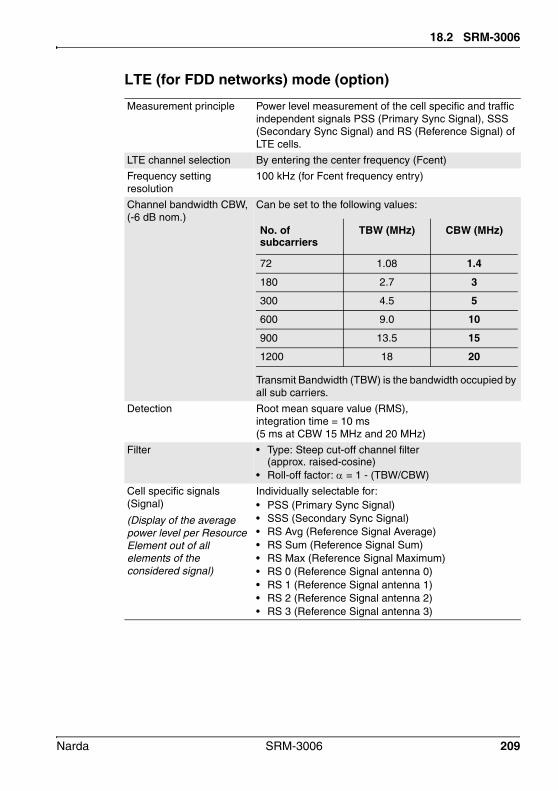
18.2 SRM-3006
LTE (for FDD networks) mode (option)
Measurement principle Power level measurement of the cell specific and traffic independent signals PSS (Primary Sync Signal), SSS (Secondary Sync Signal) and RS (Reference Signal) of LTE cells.
LTE channel selection By entering the center frequency (Fcent)
Frequency setting resolution
100 kHz (for Fcent frequency entry)
Channel bandwidth CBW, (-6 dB nom.)
Can be set to the following values:
Transmit Bandwidth (TBW) is the bandwidth occupied by all sub carriers.
Detection Root mean square value (RMS), integration time = 10 ms (5 ms at CBW 15 MHz and 20 MHz)
Filter • Type: Steep cut-off channel filter (approx. raised-cosine)
• Roll-off factor: = 1 - (TBW/CBW)
Cell specific signals (Signal)
(Display of the average power level per Resource Element out of all elements of the considered signal)
Individually selectable for:• PSS (Primary Sync Signal)• SSS (Secondary Sync Signal)• RS Avg (Reference Signal Average)• RS Sum (Reference Signal Sum)• RS Max (Reference Signal Maximum)• RS 0 (Reference Signal antenna 0)• RS 1 (Reference Signal antenna 1)• RS 2 (Reference Signal antenna 2)• RS 3 (Reference Signal antenna 3)
No. of subcarriers
TBW (MHz) CBW (MHz)
72 1.08 1.4
180 2.7 3
300 4.5 5
600 9.0 10
900 13.5 15
1200 18 20
Narda SRM-3006 209
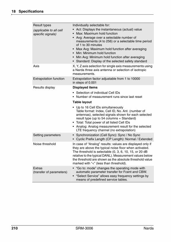
18 Specifications
Result types
(applicable to all cell specific signals)
Individually selectable for:• Act: Displays the instantaneous (actual) value• Max: Maximum hold function• Avg: Average over a selectable number of
measurements (4 to 256) or a selectable time period of 1 to 30 minutes
• Max Avg: Maximum hold function after averaging• Min: Minimum hold function• Min Avg: Minimum hold function after averaging • Standard: Display of the selected safety standard
Axis X, Y, Z axis selection for single axis measurements using a Narda three axis antenna or selection of isotropic measurements.
Extrapolation function Extrapolation factor adjustable from 1 to 10000 in steps of 0.001
Results display Displayed items• Selection of individual Cell IDs• Number of measurement runs since last reset
Table layout• Up to 16 Cell IDs simultaneously
Table format: Index, Cell ID, No. Ant. (number of antennas), selected signals shown for each selected result type (up to 54 columns + Standard)
• Total: Total power of all listed Cell IDs• Analog: Analog measurement result for the selected
LTE frequency channel (no extrapolation)
Setting parameters • Synchronization (Cell Sync): Sync / No Sync• Cyclic Prefix Length (CP Length): Normal / Extended
Noise threshold In case of “Analog” results: values are displayed only if they are above the typical noise floor when activated. The threshold is selectable (0, 3, 6, 10, 15, or 20 dB relative to the typical DANL). Measurement values below the threshold are shown as the absolute threshold value marked with “<” (less than threshold).
Extras (transfer of parameters)
• “Go to: mode” changes the operating mode with automatic parameter transfer for Fcent and CBW.
• “Select Service” allows easy frequency settings by means of predefined service tables.
210 SRM-3006 Narda

18.2 SRM-3006
LTE (for TDD networks) mode (option)
Measurement principle Power level measurement of the cell specific and traffic independent signals PSS (Primary Sync Signal), SSS (Secondary Sync Signal) and RS (Reference Signal) of LTE cells.
LTE channel selection By entering the center frequency (Fcent)
Frequency setting resolution
100 kHz (for Fcent frequency entry)
Uplink-downlink configuration (3GPP TS 36.211)
Seven uplink-downlink configurations (0–6) according to the standard 3GPP TS 36.211 are supported. To obtain a reliable result the instrument should be adapted to the uplink-downlink configuration of the base station.
Channel bandwidth CBW, (-6 dB nom.)
Can be set to the following values:
Transmit Bandwidth (TBW) is the bandwidth occupied by all sub carriers.
Detection Root mean square value (RMS), integration time = 10 ms (5 ms at CBW 15 MHz and 20 MHz)
Filter • Type: Steep cut-off channel filter (approx. raised-cosine)
• Roll-off factor: = 1 - (TBW/CBW)
Cell specific signals (Signal)
(Display of the average power level per resource element from all elements of the signal under investigation.)
Individually selectable for:• PSS (Primary Sync Signal)• SSS (Secondary Sync Signal)• RS Avg (Reference Signal Average)• RS Sum (Reference Signal Sum)• RS Max (Reference Signal Maximum)• RS 0 (Reference Signal antenna 0)• RS 1 (Reference Signal antenna 1)• RS 2 (Reference Signal antenna 2)• RS 3 (Reference Signal antenna 3)
No. of subcarriers
TBW (MHz) CBW (MHz)
72 1.08 1.4
180 2.7 3
300 4.5 5
600 9.0 10
900 13.5 15
1200 18 20
Narda SRM-3006 211

18 Specifications
Result types
(Applicable to all cell specific signals.)
Individually selectable for:• Act: Displays the instantaneous (actual) value• Max: Maximum hold function• Avg: Average over a selectable number of
measurements (4 to 256) or a selectable time period of 1 to 30 minutes
• Max Avg: Maximum hold function after averaging• Min: Minimum hold function• Min Avg: Minimum hold function after averaging • Standard: Display of the selected safety standard
Axis X, Y, Z axis selection for single axis measurements using a Narda three axis antenna or selection of isotropic measurements.
Extrapolation function Extrapolation factor adjustable from 1 to 10000 in steps of 0.001
Results display Displayed items• Selection of individual Cell IDs• Number of measurement runs since last reset
Table layout• Up to 16 Cell IDs simultaneously
Table format: Index, Cell ID, No. Ant. (number of antennas), selected signals shown for each selected result type (up to 54 columns + Standard)
• Total: Total power of all listed Cell IDs• Analog: Analog measurement result for the selected
LTE frequency channel (no extrapolation)
Setting parameters • Synchronization (Cell Sync): Sync / No Sync• Cyclic Prefix Length (CP Length): Normal / Extended
Noise threshold In case of “Analog” results: values are displayed only if they are above the typical noise floor when activated. The threshold is selectable (0, 3, 6, 10, 15, or 20 dB relative to the typical DANL). Measurement values below the threshold are shown as the absolute threshold value marked with “<” (less than threshold).
Extras (transfer of parameters)
• “Go to: mode” changes the operating mode with automatic parameter transfer for Fcent and CBW.
• “Select Service” allows easy frequency settings by means of predefined service tables.
212 SRM-3006 Narda

18.2 SRM-3006
Level Recorder mode
Measurement principle Selective level measurement at a fixed frequency setting.
Detection • Peak (holding time 480 ms)• Root mean square value (RMS), RMS average
time adjustable from 480 ms up to 30 min
Filter Type • Type: Steep cutoff channel filter (app. raised cosine),
• Roll-off factor: = 0.16
Resolution bandwidth RBW, (-6 dB nom.)
100 Hz to 32 MHz (in steps of 100, 125, 160, 200, 250, 320, 400, 500, 640, 800, 1000, …, 10 MHz, 13.333 MHz, 16 MHz, 20 MHz, 26.666 MHz, 32 MHz)
Video bandwidth VBW Off, 0.01 Hz to 32 MHz (depending on the selected RBW)
Result Type • Peak ACT: Displays the current (actual) value• Peak MAX: Max hold function• RMS ACT: Averaging over a defined time period
(0.48 s to 30 min)• RMS MAX: Max hold function over the averaged
values, with RMS detector only.
• SAVG: Spatial Averaging; Types: „continuous“ or „discrete“
Axis X, Y, Z axis selection for single-axis measurements using a Narda Three-Axis Antenna or selection of isotropic measurements
Noise threshold • Displays results only if they are above the typical noise floor when activated.
• The threshold is selectable (0, 3, 6, 10, 15, or 20 dB relative to the typical DANL).
• Measurement values below the threshold are shown as the absolute threshold value marked with “<” (less than threshold). Only applies to the numerical result display (Value)
Extras (transfer of parameters)
• “Go to: mode” changes the operating mode with automatic parameter transfer for Fcent and RBW.
• “Select Service” allows easy frequency settings by means of predefined service tables.
Narda SRM-3006 213

18 Specifications
Scope mode (option)
Measurement principle Selective level measurement at a fixed frequency
Filter Type • Type: Steep cutoff channel filter (app. raised cosine)• Roll-off factor: = 0.16
Sweep Time 500 ns to 24 h
Time Resolution 31.25 ns up to 90 min
Resolution bandwidth RBW, (-6 dB nom.)
100 Hz to 32 MHz (in steps of 100, 125, 160, 200, 250, 320, 400, 500, 640, 800, 1000, …, 10 MHz, 13.333 MHz, 16 MHz, 20 MHz, 26.666 MHz, 32 MHz)
Video bandwidth VBW Off, 0.01 Hz to 32 MHz (depending on the selected RBW)
Result Type Magnitude Actual (high resolution)• ACT: Displays the instantaneous (actual) value
(time resolution = 1/RBW)• Standard: Displays the limit of the selected safety standard
Magnitude Condensed (long observation)Magnitude Condensed allows to display the results over a long time period• MAX: Maximum value within the time resolution
interval (corresponds to peak detector).• AVG: Average value within the time resolution interval
(corresponds to RMS detector).• MIN: Minimum value within the time resolution interval.• Standard: Displays the limit of the selected safety
standard.
Marker function Delta marker, Marker, highest peak, next peak right, next peak left, next highest peak, next lowest peak
Evaluation functions Duty Cycle (ratio of average power to maximum power)
Triggering Settable Trigger Delay, Trigger Edge and Trigger Level
Trigger Mode • Free Run: The time signal is not influenced. • Single Level: Entering a Trigger Level, a Trigger Delay
and the Trigger Edge displays the signal at exactly this point in time.
• Multiple Level: Single Level, which runs several times one after the other.
• Manual Start: The signal at the time when the key was pressed manually is displayed.
• Time Controlled: The signal at the time defined by the start date and start time is displayed.
Axis X, Y, Z axis selection for single-axis measurements using a Narda Three-Axis Antenna or selection of isotropic measurements
Extras (transfer of parameters)
• “Go to: mode“ changes the operating mode with automatic parameter transfer for Fcent and RBW.
• “Select Service“ allows easy frequency settings by means of predefined service tables.
214 SRM-3006 Narda

18.2 SRM-3006
18.2.4 Measurement functionsDetection of Narda measurement antennas
Automatic consideration of antenna parameters after antenna is plugged in:• antenna type• serial number• calibration date• antenna factors (see below)
Automatic limitation of the frequency range according to the frequency range of the connected antenna
Antenna factors • Used for display in field strength units• Saved in all Narda antennas during calibration• Antenna factor lists for antennas from other
manufacturers can be saved (these lists defined using the PC configuration software SRM-3006 Tools or SRM-3006 TS)
Detection of Narda Cables
Automatic consideration of cable parameters after cable is plugged in: • Cable type• serial number• calibration date• loss factors (see below)
Automatic limitation of the frequency range according to the frequency range of the connected cable
Cable loss factors Used for compensation of the power level display
Saved in all Narda cables during calibration
Cable loss lists for cables from other manufacturers can be saved (these lists defined using the PC configuration software SRM-3006 Tools or SRM-3006 TS included in delivery)
Units With antenna% (of the standard), V/m, A/m, W/m2, mW/cm2, dBV/m, dBmV/m, dBA/m, dBµV/m, dBm, dBV, dBmV, dBµV
Without antennadBm, dBV, dBmV, dBµV
Isotropic Measurements
Automatic switching of the antenna axes when using Narda’s three axis measurement antenna followed by computation of the isotropic result
Sequential measurements using single axis antennas with subsequent computation of the isotropic result are supported.
Both results are directly displayed as a spectrum curve or as numerical values
Narda SRM-3006 215

18 Specifications
Weighted Display In % of standard for human safety standards like ICNIRP, IEEE, FCC etc.
New lists of exposure limits can be created and transferred to the instrument using the PC software SRM-3006 Tools/TS.
Correlation of results with telecom service
Service Tables specify the used frequency band, the name and the required resolution bandwidth (RBW) of up to 500 individual services in a single list.
Thus measurement results can be easily assigned to a service even without the knowledge of the frequency (marker functions, peak table evaluation function, Safety Evaluation mode).
Service Tables can be created either directly on the instrument or conveniently created and transferred to the instrument using the PC software SRM-3006 Tools/TS.
Setups Complete device configurations provide fast switching between different measurement tasks.
Saved setups can be downloaded to a PC for archiving and uploaded back to the instrument using the PC software SRM-3006 Tools/TS.
Measurement Routines
Automated sequences of setups (created using the PC software SRM-3006 Tools/TS).
216 SRM-3006 Narda

18.2 SRM-3006
Results Memory Memory modes Result stored as: • Spectrum in Spectrum Analysis mode (SPECTRUM)• Table in Safety Evaluation mode (SAFETY)• Values in UMTS P-CPICH Demodulation mode (UMTS)
as well as for LTE mode (LTE FDD and LTE TDD)• Values for Level Recorder (LEVEL) and Scope (SCOPE)
Conditional Storing Conditional storing of results exceeding a specified threshold value (in all operating modes except Scope.) with individual storage rates and reset function
Time Controlled Storing• Long term monitoring up to 99 hours (in all operating
modes except “Scope”). Settings for: start date, start time, duration and time interval (6 s to 60 min).
• Start date and start time settable with a resolution of one second
• Measurement duration settable from 1 second to 99 hours in 1 second steps
• Storage rate settable to every 1.2 s, 2.4 s, 3.6 s, 6 s, 12 s, 18 s, 30 s, 1 min, 2 min, 3 min, 5 min, 6 min, 10 min, 15 min, 20 min, 30 min
• Reset function for automatically resetting the stored maximum values, either after every result save (Always), or when the measurement starts (On start), or never (Never)
Memory capacity128 MB (up to 8000 spectra, 4000 screen shots)
Hold Button that “freezes” the display; the measurement continues in the background.
Multilingual Selectable: English (Default), French, Spanish, Turkish, Simplified Chinese
Narda SRM-3006 217

18 Specifications
18.2.5 General specifications
Compliance
Dimensions and weight
Display
Operating temperature range • -10 °C to +50 °C (battery operation)• 0 °C to +40 °C (operation with external AC/DC
adapter)
RF Immunity 200 V/m
Air humidity (operating range) RF
< 29 g/m3 (< 93 % at +30 °C)
Climatic Storage 1K3 (IEC 60721-3), extended to-10 °C to +50 °C
Transport 2K4 (IEC 60721-3), restricted to -30 °C to +70 °C due to display
Operating 7K2 (IEC 60721-3), extended to -10 °C to +50 °C
Mechanical Storage 1M3 (IEC 60721-3)
Transport 2M3 (IEC 60721-3)
Operating 7M3 (IEC 60721-3)
Ingress protection IP 52 (with antenna attached and interface protector closed)
EMC • Complies with EMC Directive 2014/30/EU and EN 61326-1: 2013
• Immunity: EN: 61000-4-2, 61000-4-3, 61000-4-4, 61000-4-5, 61000-4-6, 61000-4-8, 61000-4-11
• Emissions: EN: 61000-3-2, 61000-3-3, EN 55011 (CISPR 11) Class B
Safety Complies with European Low Voltage Directive 2014/35/EU and EN 61010-1: 2010
Country of origin Germany
Dimensions (H x W x D) 213 mm x 297 mm x 77 mm (8.4” x 11.7” x 3.0”)
Weight 2.8 kg / 6.2 lbs (basic unit including battery)
Type • Color display TFT-LCD• With backlight, for indoor and outdoor use
Size, resolution 152 x 91 mm (7 Inch), 800 x 480 pixels
218 SRM-3006 Narda

18.2 SRM-3006
Interface
Power supply
Calibration interval
USB mini B (USB 2.0)
Optical / RS232 Baud rate: 115200
Earphone 3.5 mm TRS
Battery • Lithium-Ion rechargeable battery pack• Operating time: 2.5 hours (nom.)• Charging time: 4.5 hours (nom.)
External power supply • Input: 9 to 15 VDC• Adapter 100-240 VAC / 12 VDC , 2.5 A
(plug DIN 45323)
Recommended calibration interval
24 months
Narda SRM-3006 219

18 Specifications
18.3 Three axis E-field antenna 3501/03
18.3.1 CharacteristicsFrequency range 27 MHz – 3 GHz
The correction factors determined individually during calibration are stored in an EEPROM and are applied automatically when used in conjunction with the SRM-3006 basic unit.
Antenna type E-field
Sensor type Three axis design with scanned axes
Dynamic range1)
1) Typical measurement dynamic range for 10 dB signal to noise ratio (RBW = 1 kHz); 800 MHz – 1.8 GHz
0.2 mV/m – 200 V/m (typ.)
Maximum field strength (destruction limit)
435 V/m or 50 mW/cm2 (nom.)
Displayed Average Noise Level (DANL) in conjunction with the SRM basic unit2)
2) Typical values
• 25 µV/m at 900 MHz with 1 kHz resolution bandwidth (RBW)
• 40 µV/m at 2.1 GHz with 1 kHz resolution bandwidth (RBW)
Intrinsic noise display in conjunction with the SRM-3006 basic unit (for isotropic result) 2)
• 40 µV/m at 900 MHz with 1 kHz resolution bandwidth (RBW)
• 70 µV/m at 2.1 GHz with 1 kHz resolution bandwidth (RBW)
Measurement range limit(for single CW signal) 2)
• 300 V/m (typ.)• 1000 V/m (typ.) for f 110 MHz
RF connector N connector, 50
220 SRM-3006 Narda
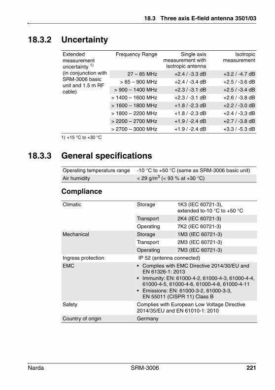
18.3 Three axis E-field antenna 3501/03
18.3.2 Uncertainty
1) +15 °C to +30 °C
18.3.3 General specifications
Compliance
Extended measurement uncertainty 1)
(in conjunction with SRM-3006 basic unit and 1.5 m RF cable)
Frequency Range Single axismeasurement withisotropic antenna
Isotropicmeasurement
27 – 85 MHz +2.4 / -3.3 dB +3.2 / -4.7 dB
> 85 – 900 MHz +2.4 / -3.4 dB +2.5 / -3.6 dB
> 900 – 1400 MHz +2.3 / -3.1 dB +2.5 / -3.4 dB
> 1400 – 1600 MHz +2.3 / -3.1 dB +2.6 / -3.8 dB
> 1600 – 1800 MHz +1.8 / -2.3 dB +2.2 / -3.0 dB
> 1800 – 2200 MHz +1.8 / -2.3 dB +2.4 / -3.3 dB
> 2200 – 2700 MHz +1.9 / -2.4 dB +2.7 / -3.8 dB
> 2700 – 3000 MHz +1.9 / -2.4 dB +3.3 / -5.3 dB
Operating temperature range -10 °C to +50 °C (same as SRM-3006 basic unit)
Air humidity < 29 g/m3 (< 93 % at +30 °C)
Climatic Storage 1K3 (IEC 60721-3), extended to-10 °C to +50 °C
Transport 2K4 (IEC 60721-3)
Operating 7K2 (IEC 60721-3)
Mechanical Storage 1M3 (IEC 60721-3)
Transport 2M3 (IEC 60721-3)
Operating 7M3 (IEC 60721-3)
Ingress protection IP 52 (antenna connected)
EMC • Complies with EMC Directive 2014/30/EU and EN 61326-1: 2013
• Immunity: EN: 61000-4-2, 61000-4-3, 61000-4-4, 61000-4-5, 61000-4-6, 61000-4-8, 61000-4-11
• Emissions: EN: 61000-3-2, 61000-3-3, EN 55011 (CISPR 11) Class B
Safety Complies with European Low Voltage Directive 2014/35/EU and EN 61010-1: 2010
Country of origin Germany
Narda SRM-3006 221

18 Specifications
Dimensions and weight
Calibration
18.4 Three axis E-field antenna 3502/01
18.4.1 Characteristics
1) Typical measurement dynamic range for 10 dB signal to noise ratio (RBW = 1 kHz); 1.8 GHz – 2.2 GHz
2) Typical values
Dimensions • Length: 450 mm • Antenna head diameter: 120 mm
Weight 450 g
Calibration 20 reference points: (26, 45, 75, 100, 200, 300, 433, 600, 750, 900) MHz, (1, 1.2, 1.4, 1.6, 1.8, 2, 2.2, 2.45, 2.7, 3) GHz
The SRM-3006 basic unit applies linear interpolation between reference points
Recommended calibration interval
24 months
Frequency range 420 MHz to 6 GHz
The correction factors determined individually during calibration are stored in an EEPROM and are applied automatically when used in conjunction with the SRM-3006 basic unit.
Antenna type E-field
Sensor type Three axis design with scanned axes
Dynamic range 1) 0.14 mV/m to 160 V/m (typ.)
Maximum field strength (destruction limit)
435 V/m or 50 mW/cm2 (nom.)
Displayed Average Noise Level (DANL) in conjunction with the SRM basic unit 2)
Single-axis measurement with isotropic antenna• 33 µV/m (typ.) at 900 MHz (RBW = 1 kHz)• 25 µV/m (typ.) at 2,1 GHz (RBW = 1 kHz)
Isotropic measurement• 60 µV/m (typ.) at 900 MHz (RBW = 1 kHz)• 43 µV/m (typ.) at 2,1 GHz (RBW = 1 kHz)
Measurement range limit (for single CW signal) 2)
200 V/m (typ.)
RF connector N connector, 50
222 SRM-3006 Narda

18.4 Three axis E-field antenna 3502/01
18.4.2 Uncertainty
1) +15 °C to +30 °C
18.4.3 General specifications
Compliance
Dimensions and weight
Extended measurement uncertainty 1)
(in conjunction with SRM-3006 basic unit and 1.5 m RF cable)
Frequency range Single axismeasurement withisotropic antenna
Isotropicmeasurement
420 – 750 MHz +2.1 / -2.9 dB +2.6 / -3.8 dB
> 750 – 1800 MHz +2.1 / -2.8 dB +2.3 / -3.1 dB
> 1800 – 4000 MHz +1.7 / -2.2 dB +2.0 / -2.6 dB
> 4000 – 4500 MHz +1.8 / -2.3 dB +2.2 / -3.0 dB
> 4500 – 5000 MHz +1.9 / -2.5 dB +2.5 / -3.5 dB
> 5000 – 6000 MHz +1.9 / -2.5 dB +3.1 / -4.9 dB
Operating temperature range -10 °C to +50 °C (same as SRM-3006 basic unit)
Air humidity < 29 g/m3 (< 93 % at +30 °C)
Climatic Storage 1K3 (IEC 60721-3), extended to -10 °C to +50 °C
Transport 2K4 (IEC 60721-3)
Operation 7K2 (IEC 60721-3)
Mechanical Storage 1M3 (IEC 60721-3)
Transport 2M3 (IEC 60721-3)
Operation 7M3 (IEC 60721-3)
Ingress protection IP 52 (antenna connected)
EMC • Complies with EMC Directive 2014/30/EU and EN 61326-1: 2013
• Immunity: EN: 61000-4-2, 61000-4-3, 61000-4-4, 61000-4-5, 61000-4-6, 61000-4-8, 61000-4-11
• Emissions: EN: 61000-3-2, 61000-3-3, EN 55011 (CISPR 11) Class B
Safety Complies with European Low Voltage Directive 2014/35/EU and EN 61010-1: 2010
Country of origin Germany
Dimensions • Length: 450 mm• Antenna head diameter: 120 mm
Weight 400 g
Narda SRM-3006 223

18 Specifications
Calibration
18.5 Three axis H-field antenna 3581/02
18.5.1 Characteristics
1) Typical measurement dynamic range for 10 dB signal to noise ratio (RBW = 1 kHz); 3 MHz – 250 MHz
2) Typical values
Calibration 21 reference points: (420, 600, 750, 900) MHz, (1, 1.2, 1.4, 1.6, 1.8, 2, 2.2, 2.45, 2.7, 3, 3.5, 4, 4.5, 5, 5.5, 5.8, 6) GHz.
The SRM-3006 basic unit applies linear interpolation between reference points.
Recommended calibration interval
24 months
Frequency range 9 kHz – 250 MHz
The correction factors determined individually during calibration are stored in an EEPROM and are applied automatically when used in conjunction with the SRM-3006 basic unit.
Antenna type H-Field
Sensor type Three axis active magnetic loop design with scanned axes
Dynamic range 1) 2.5 µA to 560 mA/m (typ.)
Maximum field strength (destruction limit)
250 A/m / f [MHz] (nom.)
Displayed Average Noise Level (DANL) in conjunction with the SRM basic unit 2))
Frequency range: > 1 MHz (RBW = 1 kHz)• Single-axis measurement with isotropic
antenna:0.5 µA/m (typ.)• Isotropic measurement 0.85 µA/m (typ.)
RF connector N connector, 50
224 SRM-3006 Narda

18.5 Three axis H-field antenna 3581/02
18.5.2 Uncertainty
1) +15 °C to +30 °C
18.5.3 General specifications
Compliance
Dimensions and weight
Extended measurement uncertainty 1))
(in conjunction with SRM-3006 basic unit and 1.5 m RF cable)
Frequency Range Single axismeasurement withisotropic antenna
Isotropicmeasurement
0.009 – 60 MHz ±2.2 dB ±2.5 dB
> 60 – 250 MHz ±2.3 dB ±3.3 dB
Operating temperature range -10 °C to +50 °C (same as SRM-3006 basic unit)
Air humidity < 29 g/m3 (< 93 % at +30 °C)
Climatic Storage 1K3 (IEC 60721-3), extended to -10 °C to +50 °C
Transport 2K4 (IEC 60721-3)
Operating 7K2 (IEC 60721-3)
Mechanical Storage 1M3 (IEC 60721-3)
Transport 2M3 (IEC 60721-3)
Operating 7M3 (IEC 60721-3)
Ingress protection IP 52 (antenna connected)
EMC • Complies with EMC Directive 2014/30/EU and EN 61326-1: 2013
• Immunity: EN: 61000-4-2, 61000-4-3, 61000-4-4, 61000-4-5, 61000-4-6, 61000-4-8, 61000-4-11
• Emissions: EN: 61000-3-2, 61000-3-3, EN 55011 (CISPR 11) Class B
Safety Complies with European Low Voltage Directive 2014/35/EU and EN 61010-1: 2010
Country of origin Germany
Dimensions • Length: 450 mm• Antenna head diameter: 120 mm
Weight 470 g
Narda SRM-3006 225
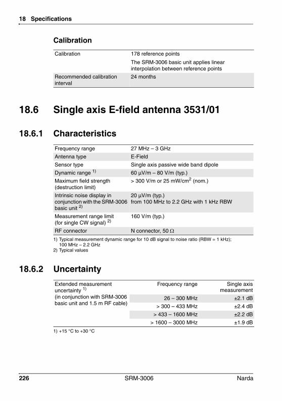
18 Specifications
Calibration
18.6 Single axis E-field antenna 3531/01
18.6.1 Characteristics
1) Typical measurement dynamic range for 10 dB signal to noise ratio (RBW = 1 kHz); 100 MHz – 2.2 GHz
2) Typical values
18.6.2 Uncertainty
1) +15 °C to +30 °C
Calibration 178 reference points
The SRM-3006 basic unit applies linear interpolation between reference points
Recommended calibration interval
24 months
Frequency range 27 MHz – 3 GHz
Antenna type E-Field
Sensor type Single axis passive wide band dipole
Dynamic range 1) 60 µV/m – 80 V/m (typ.)
Maximum field strength (destruction limit)
> 300 V/m or 25 mW/cm2 (nom.)
Intrinsic noise display in conjunction with the SRM-3006 basic unit 2)
20 µV/m (typ.)from 100 MHz to 2.2 GHz with 1 kHz RBW
Measurement range limit (for single CW signal) 2)
160 V/m (typ.)
RF connector N connector, 50
Extended measurement uncertainty 1)
(in conjunction with SRM-3006 basic unit and 1.5 m RF cable)
Frequency range Single axismeasurement
26 – 300 MHz ±2.1 dB
> 300 – 433 MHz ±2.4 dB
> 433 – 1600 MHz ±2.2 dB
> 1600 – 3000 MHz ±1.9 dB
226 SRM-3006 Narda

18.6 Single axis E-field antenna 3531/01
18.6.3 General specifications
Compliance
Dimensions and weight
Calibration
Operating temperature range -10 °C to +50 °C (same as SRM-3006 basic unit)
Air humidity < 29 g/m3 (< 93% at +30 °C)
Climatic Storage 1K3 (IEC 60721-3), extended to -10 °C to +50 °C
Transport 2K4 (IEC 60721-3)
Operating 7K2 (IEC 60721-3)
Mechanical Storage 1M3 (IEC 60721-3)
Transport 2M3 (IEC 60721-3)
Operating 7M3 (IEC 60721-3)
Ingress protection IP 52 (antenna connected)
EMC • Complies with EMC Directive 2014/30/EU and EN 61326-1: 2013
• Immunity: EN: 61000-4-2, 61000-4-3, 61000-4-4, 61000-4-5, 61000-4-6, 61000-4-8, 61000-4-11
• Emissions: EN: 61000-3-2, 61000-3-3, EN 55011 (CISPR 11) Class B
Safety Complies with European Low Voltage Directive 2014/35/EU and EN 61010-1: 2010
Country of origin Germany
Dimensions • Length: 460 mm• Antenna head dimensions: 135 x 90 mm
Weight 450 g
Calibration 24 reference points:(26, 30, 40, 50, 60, 75, 100, 200, 300, 433, 600, 750, 900) MHz;(1, 1.2, 1.4, 1.6, 1.8, 2, 2.2, 2.45, 2.6, 2.8 , 3) GHz
The SRM-3006 applies linear interpolation between reference points.
Recommended calibration interval
24 months
Narda SRM-3006 227

18 Specifications
18.7 Single axis E-field antenna 3531/04
18.7.1 Characteristics
1) Typical measurement dynamic range for 10 dB signal to noise radio (RBW = 1 kHz)2) Typical values
18.7.2 Uncertainty
1) +15 °C to +30 °C
Frequency range 9 kHz – 300 MHz
The correction factors determined individually during calibration are stored in an EEPROM and are applied automatically when used in conjunction with the SRM-3006 basic unit.
Antenna type E-field
Sensor type Single axis active broadband dipole
Dynamic range 1) • 50 µV/m – 16 V/m (typ.) for 300 kHz – 10 MHz• 50 µV/m – 36 V/m (typ.) for > 10 MHz – 300 MHz
Maximum field strength (destruction limit)
> 1000 V/m (nom.)
Displayed Average Noise Level (DANL) in conjunction with the SRM basic unit 2)
20 µV/m (typ.) for each frequency > 1 MHz with RBW = 1 kHz
Measurement range limit (for single CW signal) 2)
50 V/m (typ.)
RF connector N-Connector, 50
Extended measurement uncertainty 1)
(in conjunction with SRM-3006 basic unit and 1.5 m RF cable)
Frequency range Single axismeasurement
0.009 – 300 MHz ±2.0 dB
228 SRM-3006 Narda

18.7 Single axis E-field antenna 3531/04
18.7.3 General specifications
Compliance
Dimensions and weight
Calibration
Operating temperature range -10 °C to +50 °C (same as SRM-3006 basic unit)
Air humidity < 29 g/m3 (< 93 % at +30 °C)
Climatic Storage 1K3 (IEC 60721-3), extended to -10 °C to +50 °C
Transport 2K4 (IEC 60721-3)
Operating 7K2 (IEC 60721-3)
Mechanical Storage 1M3 (IEC 60721-3)
Transport 2M3 (IEC 60721-3)
Operating 7M3 (IEC 60721-3)
Ingress protection IP 52 (antenna connected)
EMC • Complies with EMC Directive 2014/30/EU and EN 61326-1: 2013
• Immunity: EN: 61000-4-2, 61000-4-3, 61000-4-4, 61000-4-5, 61000-4-6, 61000-4-8, 61000-4-11
• Emissions: EN: 61000-3-2, 61000-3-3, EN 55011 (CISPR 11) Class B
Safety Complies with European Low Voltage Directive 2014/35/EU and EN 61010-1: 2010
Country of origin Germany
Dimensions • Length: 460 mm• Antenna head dimension: 135 mm x 90 mm
Weight 550 g
Calibration 183 reference points
The SRM-3006 applies linear interpolation between reference points.
Recommended calibration interval
24 months
Narda SRM-3006 229
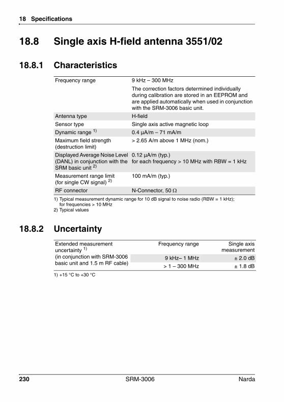
18 Specifications
18.8 Single axis H-field antenna 3551/02
18.8.1 Characteristics
1) Typical measurement dynamic range for 10 dB signal to noise radio (RBW = 1 kHz); for frequencies > 10 MHz
2) Typical values
18.8.2 Uncertainty
1) +15 °C to +30 °C
Frequency range 9 kHz – 300 MHz
The correction factors determined individually during calibration are stored in an EEPROM and are applied automatically when used in conjunction with the SRM-3006 basic unit.
Antenna type H-field
Sensor type Single axis active magnetic loop
Dynamic range 1) 0.4 µA/m – 71 mA/m
Maximum field strength (destruction limit)
> 2.65 A/m above 1 MHz (nom.)
Displayed Average Noise Level (DANL) in conjunction with the SRM basic unit 2)
0.12 µA/m (typ.)for each frequency > 10 MHz with RBW = 1 kHz
Measurement range limit (for single CW signal) 2)
100 mA/m (typ.)
RF connector N-Connector, 50
Extended measurement uncertainty 1)
(in conjunction with SRM-3006 basic unit and 1.5 m RF cable)
Frequency range Single axismeasurement
9 kHz– 1 MHz ± 2.0 dB
> 1 – 300 MHz ± 1.8 dB
230 SRM-3006 Narda
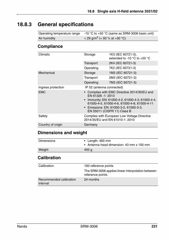
18.8 Single axis H-field antenna 3551/02
18.8.3 General specifications
Compliance
Dimensions and weight
Calibration
Operating temperature range -10 °C to +50 °C (same as SRM-3006 basic unit)
Air humidity < 29 g/m3 (< 93 % at +30 °C)
Climatic Storage 1K3 (IEC 60721-3), extended to -10 °C to +50 °C
Transport 2K4 (IEC 60721-3)
Operating 7K2 (IEC 60721-3)
Mechanical Storage 1M3 (IEC 60721-3)
Transport 2M3 (IEC 60721-3)
Operating 7M3 (IEC 60721-3)
Ingress protection IP 52 (antenna connected)
EMC • Complies with EMC Directive 2014/30/EU and EN 61326 -1: 2013
• Immunity: EN: 61000-4-2, 61000-4-3, 61000-4-4, 61000-4-5, 61000-4-6, 61000-4-8, 61000-4-11
• Emissions: EN: 61000-3-2, 61000-3-3, EN 55011 (CISPR 11) Class B
Safety Complies with European Low Voltage Directive 2014/35/EU and EN 61010-1: 2010
Country of origin Germany
Dimensions • Length: 460 mm• Antenna head dimension: 43 mm x 100 mm
Weight 450 g
Calibration 183 reference points
The SRM-3006 applies linear interpolation between reference points.
Recommended calibration interval
24 months
Narda SRM-3006 231
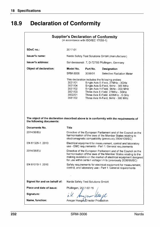
18 Specifications
18.9 Declaration of Conformity
232 SRM-3006 Narda

18.9 Declaration of Conformity
Narda SRM-3006 233

18 Specifications
234 SRM-3006 Narda

19 Annex A
This chapter contains general information about making measurements.
19.1 Pendulum method (page 236)
19.2 Matrix method (precision measurement) (page 238)
Narda SRM-3006 235
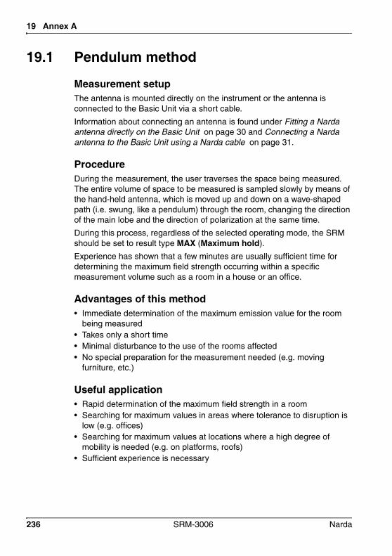
19 Annex A
19.1 Pendulum method
Measurement setupThe antenna is mounted directly on the instrument or the antenna is connected to the Basic Unit via a short cable.
Information about connecting an antenna is found under Fitting a Narda antenna directly on the Basic Unit on page 30 and Connecting a Narda antenna to the Basic Unit using a Narda cable on page 31.
ProcedureDuring the measurement, the user traverses the space being measured. The entire volume of space to be measured is sampled slowly by means of the hand-held antenna, which is moved up and down on a wave-shaped path (i.e. swung, like a pendulum) through the room, changing the direction of the main lobe and the direction of polarization at the same time.
During this process, regardless of the selected operating mode, the SRM should be set to result type MAX (Maximum hold).
Experience has shown that a few minutes are usually sufficient time for determining the maximum field strength occurring within a specific measurement volume such as a room in a house or an office.
Advantages of this method• Immediate determination of the maximum emission value for the room
being measured• Takes only a short time• Minimal disturbance to the use of the rooms affected• No special preparation for the measurement needed (e.g. moving
furniture, etc.)
Useful application• Rapid determination of the maximum field strength in a room• Searching for maximum values in areas where tolerance to disruption is
low (e.g. offices)• Searching for maximum values at locations where a high degree of
mobility is needed (e.g. on platforms, roofs)• Sufficient experience is necessary
236 SRM-3006 Narda

19.1 Pendulum method
Disadvantages of this method• Non-reproducible measurement• No possibility of subsequently determining the location in the measured
volume where the maximum values occurred• Requires a degree of experience in order to obtain meaningful results• Measurement uncertainty is non-quantifiable: If a dipole-type antenna is
used, only those field components parallel to the dipole axis of the antenna will be detected. If the antenna is not correctly oriented in the field, there is a danger that only low emission levels or even no emission will be detected, despite the presence of strong fields.
Limitations• Spatial averaging of emissions not possible (see Chapter 13
Spatial Averaging starting on page 163 for more information).• Underestimates the emissions in the presence of strongly elliptical
polarization.• Non-definable measurement uncertainty: Measurement using a single
axis antenna only records the field components that are parallel to the antenna axis. If the antenna is not correctly oriented in the field, there is a danger that only low emission levels or even no emission will be detected, despite the presence of strong fields.
Narda SRM-3006 237
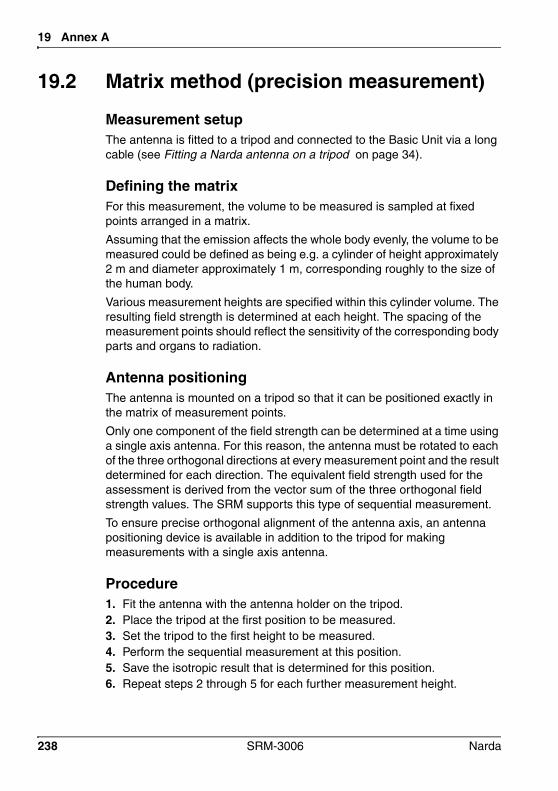
19 Annex A
19.2 Matrix method (precision measurement)
Measurement setupThe antenna is fitted to a tripod and connected to the Basic Unit via a long cable (see Fitting a Narda antenna on a tripod on page 34).
Defining the matrixFor this measurement, the volume to be measured is sampled at fixed points arranged in a matrix.
Assuming that the emission affects the whole body evenly, the volume to be measured could be defined as being e.g. a cylinder of height approximately 2 m and diameter approximately 1 m, corresponding roughly to the size of the human body.
Various measurement heights are specified within this cylinder volume. The resulting field strength is determined at each height. The spacing of the measurement points should reflect the sensitivity of the corresponding body parts and organs to radiation.
Antenna positioningThe antenna is mounted on a tripod so that it can be positioned exactly in the matrix of measurement points.
Only one component of the field strength can be determined at a time using a single axis antenna. For this reason, the antenna must be rotated to each of the three orthogonal directions at every measurement point and the result determined for each direction. The equivalent field strength used for the assessment is derived from the vector sum of the three orthogonal field strength values. The SRM supports this type of sequential measurement.
To ensure precise orthogonal alignment of the antenna axis, an antenna positioning device is available in addition to the tripod for making measurements with a single axis antenna.
Procedure1. Fit the antenna with the antenna holder on the tripod.2. Place the tripod at the first position to be measured.3. Set the tripod to the first height to be measured.4. Perform the sequential measurement at this position.5. Save the isotropic result that is determined for this position.6. Repeat steps 2 through 5 for each further measurement height.
238 SRM-3006 Narda

19.2 Matrix method (precision measurement)
Advantages of this method• Good measurement reproducibility• Allows spatial averaging of emissions (required by some standards)• Local maxima can be located using a few measurement points.
Useful application• Exact measurement of a defined space with the aid of a tripod• Spatial averaging of emissions desirable (required by some standards)• Location of local maxima
Disadvantages of this method• The signal to be measured must remain constant for the measurement
time to record the three spatial components• Time-consuming: the already quite complex task of measuring the
defined measurement volume must be repeated at different points in the room for the entire room to be surveyed.
• Relatively high degree of disruption for the affected rooms: no conducting objects or persons should move within the defined measurement volume during the measurement. A minimum distance between the antenna and interfering objects or elements (e.g. furniture, walls) must be maintained to prevent any adverse effect on the receiving characteristics of the antenna.
Limitations• Maximum values cannot be determined quickly because a large number
of measurement points must be recorded• The signal does not remain constant over the entire period of the
measurement• Searching for maximum values in locations where there is low tolerance
to disruption (e.g. offices)• Searching for maximum values in locations where a high degree of
mobility is required (e.g. platforms, roofs)• Locations where a tripod cannot be used (e.g. platforms, roofs)
Narda SRM-3006 239

19 Annex A
240 SRM-3006 Narda

20 Ordering Information
This chapter contains the ordering information for the SRM-3006, antennas and accessories. Your local Narda representative will inform you of all possible options as well as the current ordering information and will be pleased to provide you with advice.
All ordering information is subject to change without notice.
20.1 SRM-3006 sets (page 242)
20.2 Antennas (page 244)
20.3 Options (page 244)
20.4 Accessories (page 244)
Narda SRM-3006 241
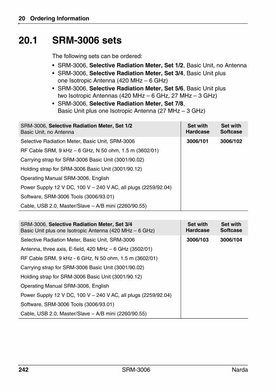
20 Ordering Information
20.1 SRM-3006 setsThe following sets can be ordered:
• SRM-3006, Selective Radiation Meter, Set 1/2, Basic Unit, no Antenna• SRM-3006, Selective Radiation Meter, Set 3/4, Basic Unit plus
one Isotropic Antenna (420 MHz – 6 GHz)• SRM-3006, Selective Radiation Meter, Set 5/6, Basic Unit plus
two Isotropic Antennas (420 MHz – 6 GHz, 27 MHz – 3 GHz)• SRM-3006, Selective Radiation Meter, Set 7/8,
Basic Unit plus one Isotropic Antenna (27 MHz – 3 GHz)
SRM-3006, Selective Radiation Meter, Set 1/2 Basic Unit, no Antenna
Set with Hardcase
Set with Softcase
Selective Radiation Meter, Basic Unit, SRM-3006 3006/101 3006/102
RF Cable SRM, 9 kHz – 6 GHz, N 50 ohm, 1.5 m (3602/01)
Carrying strap for SRM-3006 Basic Unit (3001/90.02)
Holding strap for SRM-3006 Basic Unit (3001/90.12)
Operating Manual SRM-3006, English
Power Supply 12 V DC, 100 V – 240 V AC, all plugs (2259/92.04)
Software, SRM-3006 Tools (3006/93.01)
Cable, USB 2.0, Master/Slave – A/B mini (2260/90.55)
SRM-3006, Selective Radiation Meter, Set 3/4Basic Unit plus one Isotropic Antenna (420 MHz – 6 GHz)
Set with Hardcase
Set with Softcase
Selective Radiation Meter, Basic Unit, SRM-3006 3006/103 3006/104
Antenna, three axis, E-field, 420 MHz – 6 GHz (3502/01)
RF Cable SRM, 9 kHz - 6 GHz, N 50 ohm, 1.5 m (3602/01)
Carrying strap for SRM-3006 Basic Unit (3001/90.02)
Holding strap for SRM-3006 Basic Unit (3001/90.12)
Operating Manual SRM-3006, English
Power Supply 12 V DC, 100 V – 240 V AC, all plugs (2259/92.04)
Software, SRM-3006 Tools (3006/93.01)
Cable, USB 2.0, Master/Slave – A/B mini (2260/90.55)
242 SRM-3006 Narda
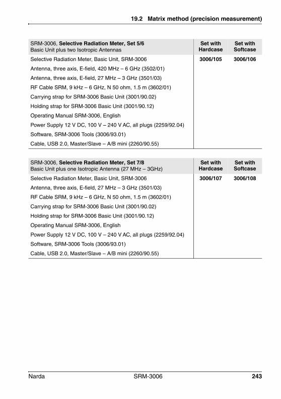
19.2 Matrix method (precision measurement)
SRM-3006, Selective Radiation Meter, Set 5/6Basic Unit plus two Isotropic Antennas
Set with Hardcase
Set with Softcase
Selective Radiation Meter, Basic Unit, SRM-3006 3006/105 3006/106
Antenna, three axis, E-field, 420 MHz – 6 GHz (3502/01)
Antenna, three axis, E-field, 27 MHz – 3 GHz (3501/03)
RF Cable SRM, 9 kHz – 6 GHz, N 50 ohm, 1.5 m (3602/01)
Carrying strap for SRM-3006 Basic Unit (3001/90.02)
Holding strap for SRM-3006 Basic Unit (3001/90.12)
Operating Manual SRM-3006, English
Power Supply 12 V DC, 100 V – 240 V AC, all plugs (2259/92.04)
Software, SRM-3006 Tools (3006/93.01)
Cable, USB 2.0, Master/Slave – A/B mini (2260/90.55)
SRM-3006, Selective Radiation Meter, Set 7/8 Basic Unit plus one Isotropic Antenna (27 MHz – 3GHz)
Set with Hardcase
Set with Softcase
Selective Radiation Meter, Basic Unit, SRM-3006 3006/107 3006/108
Antenna, three axis, E-field, 27 MHz – 3 GHz (3501/03)
RF Cable SRM, 9 kHz – 6 GHz, N 50 ohm, 1.5 m (3602/01)
Carrying strap for SRM-3006 Basic Unit (3001/90.02)
Holding strap for SRM-3006 Basic Unit (3001/90.12)
Operating Manual SRM-3006, English
Power Supply 12 V DC, 100 V – 240 V AC, all plugs (2259/92.04)
Software, SRM-3006 Tools (3006/93.01)
Cable, USB 2.0, Master/Slave – A/B mini (2260/90.55)
Narda SRM-3006 243
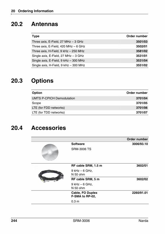
20 Ordering Information
20.2 Antennas
20.3 Options
20.4 Accessories
Type Order number
Three axis, E-Field, 27 MHz – 3 GHz 3501/03Three axis, E-Field, 420 MHz – 6 GHz 3502/01Three axis, H-Field, 9 kHz – 250 MHz 3581/02Single axis, E-Field, 27 MHz – 3 GHz 3531/01Single axis, E-Field, 9 kHz – 300 MHz 3531/04Single axis, H-Field, 9 kHz – 300 MHz 3551/02
Option Order number
UMTS P-CPICH Demodulation 3701/04Scope 3701/05LTE (for FDD networks) 3701/06LTE (for TDD networks) 3701/07
Order numberSoftwareSRM-3006 TS
3006/93.10
RF cable SRM, 1.5 m9 kHz – 6 GHz, N 50 ohm
3602/01
RF cable SRM, 5 m9 kHz – 6 GHz, N 50 ohm
3602/02
Cable, FO Duplex F-SMA to RP-02, 0.3 m
2260/91.01
244 SRM-3006 Narda

20.4 Accessories
Cable, FO Duplex RP-022 m
2260/91.02
Cable, FO Duplex RP-025 m
2260/91.09
Cable, FO Duplex RP-0210 m
2260/91.07
Cable, FO Duplex, RP-0220 m
2260/91.03
Cable, FO Duplex, RP-0250 m
2260/91.04
Antenna Holder for single axis / three axis antenna
3501⁄90.01
Antenna Holder for three axis antenna
3501/90.02
Battery PackRechargeable, 7V2 / 6200 mAh
3001/90.15
TripodNon conductive, 1,65 mwith carrying bag
2244/90.31
Tripod ExtensionNon-Conductive, 0.50 m
2244/90.45
Charger Set for Battery Pack, External
3001/90.07
Power Supply DC Vehicle Adapter
2260/90.56
Order number
Narda SRM-3006 245

20 Ordering Information
Hardcase for SRM-3006
3001/90.03
Carrying Strap for Hardcase(included in all sets with hardcase)
3001/90.04
Softcase for SRM-3006
3001/90.05
Protective Soft Carrying Bag for SRM-3006 Basic Unit
3001/90.13
Earphone3.5 mm jack
2400/90.03
O/E Converter USBRP-02/USB
2260/90.07
N-Connector Saver for SRM 3001/90.14
Order number
246 SRM-3006 Narda

21 Glossary
The meanings of terms and abbreviations are explained in this chapter.
Narda SRM-3006 247

21 Glossary
Term or Abbreviation
Meaning Explanation
AM Amplitude modulation Modulation method (used for radio broadcasting, for example)
Avg Average The measured values are averaged over a certain number of measurements or over a specific time period. The resulting value (also called the RMS value) is displayed.
BOS Behörden und Organisationen mit Sicherheitsaufgaben
(Security authorities and organizations)
BOS radio is a non-public mobile UHF terrestrial radio service used in Germany by police, customs, fire brigades, rescue services and other emergency services.
Tetra is a subgroup of BOS.
DVB-T Digital Video Broadcasting Terrestrial
Terrestrial digital transmission of television signals.
Fcent Center frequency Center frequency in a frequency range.
FDD Frequency Division Duplex Frequency division duplex is a method of frequency multiplexing for duplex connections. The wireless channels for the uplink and downlink between the receiving and the base station occupy two different frequency ranges.
FM Frequency modulation Modulation method.
Fmax Upper limit frequency Highest frequency in a frequency range.
Fmin Lower limit frequency Lowest frequency in a frequency range.
Fspan Frequency span Frequency band centered about the center frequency Fcent.
Full Span Full bandwidth All frequency values set using Fmin, Fmax, Fcent or Fspan are reset to the maximum possible frequency range that is defined by the antenna connected, by the cable used, or by the SRM-3006 itself.
GPRS General Packet Radio Service
Packet-switched service used for data communications in GSM networks.
GSM Global System for Mobile Communications
Standard for fully digital mobile telecommunications networks; mainly used for telephony but also used for circuit- and packet-switched data communications.
ICNIRP International Commission on Non-Ionizing Radiation Protection)
Independent international group of scientists researching the effects of non-ionizing radiation on human health.
Isotropic measurement
Measurement of radiation uniformly radiated in all directions of 3-dimensional space.
248 SRM-3006 Narda

20.4 Accessories
LTE Long Term Evolution Fourth generation (4G) wireless communications standard
Max Maximum Maximum value of all measurement values.
Max Avg Maximum Average Maximum value of all averaged measurement values.
Min Minimum Minimum value of all measurement values.
Min Avg Minimum Average Minimum value of all averaged measurement values.
MR Measurement Range Parameter setting that affects the drive range and sensitivity of the measuring device. This sets the input attenuator, among other things. Signals below the Measurement Range can be measured without saturating the device. Lower MR levels reduce the intrinsic noise and provide increased sensitivity.
P-CPICH Primary Common Pilot Channel
UMTS control channel.
PSS Primary Sync Signal Signal for synchronization to the system in LTE. Also contains the Sector ID.
RBW Resolution bandwidth Signal selectivity.
Only signals having a frequency spacing that is greater than the defined resolution bandwidth can be distinguished from one another. The RBW selected for measuring signals having very close frequency spacing must be correspondingly small. A larger resolution bandwidth can be used for measuring wideband signals.• The indicated level will be too low if the RBW
is too small.• Individual signals cannot be separated from
one another if the RBW is too big.
Result Type Defines the way in which the measured values are evaluated.
SSS Secondary Sync Signal Signal for synchronization to the system in LTE. Also contains the Cell ID.
Term or Abbreviation
Meaning Explanation
Narda SRM-3006 249

21 Glossary
TDD Time Division Duplex Time division duplex is a method of time multiplexing for wireless transmissions. In TDD, the wireless channels for the uplink and downlink between the receiving and the base station use the same transmission frequency in contrast with FDD but are separated in time multiplex by periodically switching between them.
Tetra Terrestrial trunked radio Standard for digital trunked radio as a universal platform for widely differing mobile communications services for users with special security requirements, e.g. BOS, industry, public transport, airports, military, etc.
UMTS Universal Mobile Telecommunications System
Third-generation mobile telecommunications standard (3G)
VBW Video Band Width The VBW is used to smooth the signals, particularly to reduce the noise. The selected VBW influences the sweep time. The smaller the VBW selected, the more the noise will be smoothed but the longer the sweep time will be. If you are measuring unknown signals, the VBW should be reduced step by step from the largest VBW to the smallest VBW.
WiMax Worldwide Interoperability for Microwave Access
Radio system conforming to IEEE Standard 802.16 for fixed systems (e.g. radio links) as well as for use with portable devices.
WLAN Wireless Local Area Network
Wireless local area network conforming to the IEEE-802.11 standard.
Term or Abbreviation
Meaning Explanation
250 SRM-3006 Narda

Index
AAC adapter / charger
Maintenance 189Operation from 30
Accessories 244Activating options 190Antenna
Connecting with a cable 31Connectors 26Displaying and selecting available 62Displaying information 59Fitting on a tripod 34Fitting on the Basic Unit 30Using other products 34
Antennas, ordering 244Axis (Y) adjustment 92Axis mode, selecting 87
BBar Graph view 109Basic settings 39Battery
Changing pack 188Compartment 26Handling 29Operation from 28
BeeperLevel Recorder 126Safety Evaluation 102
CCable
Connecting the device and antenna 31
Connectors 26Displaying and selecting available 63Displaying information 59Using other products 34
CBW (LTE) 156
Center frequencyLTE 156UMTS 147
ChangingDevice settings 57Language, date, time 56
Channel bandwidth (LTE) 156Charging socket 27Checking the display 61Cleaning 188Commands, remote control 197Comment mode, changing 186Conditional storing 182Conformity, declaration 235Connecting the device to a PC 193Connector
Multi-pin 26N 26
Connectorsantenna and cable 26external 27
Continuous (Spatial AVG)Description 166Use 169
Coverage measurement 150Creating service tables 64
DData sets, viewing 179Date, changing 56Declaration of conformity 235DECT, Scope example 135Device
changing settings 57Cleaning 188Diagnosis 61Displaying information 58Overview 25Reset settings 60
Difference, determine with marker 83
Narda SRM-3006 251

Index
Discrete (Spatial AVG)Description 167Use 171
Discrete Axis (Spatial AVG)Description 168Use 173
DisplayLCD screen elements 42Test 61
Display mode, selecting 102Displaying
Antenna information 59Available antennas 62Available cables 63Cable information 59Device information 58GPS information 60Safety standards 63Service tables 64
Disposal 22Distribution 108Duty Cycle 142
EEarphone socket 27Entering text 51Evaluation
Scope 142Spectrum Analysis 115
External connectors 27Extrapolation factor
LTE 159UMTS 149
FFcent
LTE 156UMTS 147
Free Run 139Frequency range, changing 113Functions, overview 54
GGlossary 247
GPS, displaying information 60GSM, Scope example 135
IImproper use 15Info bar, activating / deactivating 45Integrating measured values 118ISM band, Scope example 138Isotropic measurement
Single axis antenna 91Three axis antenna 89
KKeys 40
LLanguage, changing 56LCD screen 42List
Extended 49Selecting items 48Simple 48
LTECBW 156Fcent 156General information 152Overview 153Signal selection 158TDD 161Up-/downlink configuration 162
MMain menu 53Manual Start, trigger 141Marker
Determine a difference 83Function 80Using separately 81Zoom to 86
Matrix method 238Measurement data, evaluation 115Measurement input, overdriven 77
252 SRM-3006 Narda

Index
Measurement methodsMatrix 238Pendulum 236
Measurement rangeAutomatic search 77Manual selection 76
Measurement routines 66Memory menu 178Menu navigation 46MR Search 77Multi-pin connector 26Multiple, trigger 139
NN connector 26Navigating in the menus 46Navigator bar 45Noise suppression 94Noise Threshold 94Numerical values, changing 50
OOperating modes, overview 54Optical connector 27Options 244Ordering information 241Others 105Overload of measurement input 77Overview, functions and operating
modes 54
PParameters, keeping when changing
operating mode 96PC software 191
About 192Working with 194
PC, connecting to 193Peak Table, displaying values 116Pendulum method 236Percentage display 107Percentage field strength, displaying 108Pilot / Analog Ratio 150Power on behavior, changing 70
Power supplyAC adapter / charger 30Battery pack 28
Proper use 14
RRatio Pilot / Analog 150RBW
General 74Safety Evaluation 103
Remote control 195About 196Activation / deactivation 197Commands 197
Resetting the device settings 60Resolution bandwidth
General 74Safety Evaluation 103
Result type, selecting 78Rotary control 40
SSafety instructions 13Safety standards, displaying and
selecting 63Scrambling codes 147Screen 42Screenshot
Creating 52Viewing 181
Service tables, displaying and creating 64
Services, showing / hidingSafety Evaluation 103UMTS 148
Settings, displaying and editing 55Setup
Editing the list 68Saving and loading 67Switch on behavior 70
Shortcuts 98Signal selection (LTE) 158Single axis antenna, using a 90Single, trigger 139
Narda SRM-3006 253
Index
Software update 190Spatial averaging
Continuous 169Discrete 171Discrete Axis 173
Specifications 201SRM-3006 Tools 192SRM-3006 TS 192Status bar
Activating / deactivating 45Lower 44Upper 43
StoringConditional 182Time controlled 184
Switch on behavior, changing 70Switching on / off 41Symbols and characters 11
TTable type, changing 106Table view 105TDD (LTE) 161Text, entering 51Three axis antenna, using a 88Time controlled storing 184Time Controlled, Trigger 142Time, changing 56Trigger
Free Run 139Manual start 141Single, Multiple 139Time Controlled 142
Trigger function 139
UUnits, changing 93Unpacking the device 24Up-/downlink configuration, LTE 162Update 190Updating device software 190USB port 27
VValues, changing 50VBW 74Video bandwidth, setting 74View
Bar Graph 109Table 105
WWLAN, Scope example 136
YY axis adjustment 92
ZZoom to marker 86Zoom, function 120
254 SRM-3006 Narda


Narda Safety Test Solutions GmbHSandwiesenstraße 772793 Pfullingen, Germany
Phone: +49 7121 9732-0Fax: +49 7121 9732-790
E-mail: [email protected]
Narda Safety Test Solutions435 Moreland RoadHauppauge, NY11788, USA
Phone: +1 631-231-1700Fax: +1 631-231-1711
E-mail: [email protected]
Narda Safety Test Solutions SrlVia Leonardo da Vinci, 21/2320090 Segrate (Milano), Italy
Phone: +39 02 2699871Fax: +39 02 26998700
E-mail: [email protected]