


Honda-CBR250RR-Service-Manual-EN.pdf - Moto TH
471
CBR250R,RR INDEX Maintenance Information Inspection Adjustment ENGINE Oil lubrication system Fuel system Cooling system Engine attach/detachment Cylinder head valve Crank case Cylinder, piston, crankshaft Clutch, AC generator Gear shift linkage Transmission FRAME Front wheel suspension steering Rear wheel, brake, suspension Braking system (Disc Brake) Exhaust pipe, rear fender ELECTRICAL SYSTEM Battery, alternator Ignition system Self starter system Light, meters, switches SUPPLEMENTAL CBR250R(H) CBR250R(J) CBR250R(K) CBR250R(L) CBR250R(R) http://mototh.com
-
Upload
khangminh22 -
Category
Documents
-
view
2 -
download
0
Transcript of Honda-CBR250RR-Service-Manual-EN.pdf - Moto TH
CBR250R,RR
INDEX Maintenance Information
Inspection Adjustment
ENGINE
Oil lubrication system
Fuel system
Cooling system
Engine attach/detachment
Cylinder head valve
Crank case
Cylinder, piston, crankshaft
Clutch, AC generator
Gear shift linkage
Transmission
FRAME
Front wheel suspension steering
Rear wheel, brake, suspension
Braking system (Disc Brake)
Exhaust pipe, rear fender
ELECTRICAL SYSTEM
Battery, alternator
Ignition system
Self starter system
Light, meters, switches
SUPPLEMENTAL
CBR250R(H)
CBR250R(J)
CBR250R(K)
CBR250R(L)
CBR250R(R)
http://mototh.com

CBR250R,RR
• Preface
This service manual includes the service information for HondaCBR250FOUR and CBR250R. However, only the part which differs from 250FOUR is described for 250R. Amended points from CBR250R(H) are described for CBR250R(J), so for CBR250R(K). Differences such as the outlook are not mentioned as they do not affect the maintenance.
Section 1 - includes general cautions for maintenance work. Please use this manual after reading the section.
Section 2 - describes about procedures for inspection and adjustments. Please conduct regular inspection by following the procedure.
Section 3 - and onwards describes procedures for inspection and assembly/disassembly of individual parts.
In the first pages of each sections, you find the figures, maintenance information, troubleshooting charts for your convenience.
Please note: The contents may change without prior notice due to modifications of the model.
http://mototh.com

CBR250R,RR 1. Maintenance Information
• SERVICE INFORMATION
Location of Serial number and color 1-1 Exclusive / Common tools 1-16 labels Specifications 1-2 Applying Oil 1-19
Summary of structure 1-3 Circuit Diagram 1-20
General cautions 1-6 Wiring 1-21
Tightening Torque 1-14 Troubleshooting 1-24
• LOCATION OF SERIAL NUMBER AND COLOR LABLES
Top right figure:----------------------------------- Frame Serial Number Label
Bottom left figure:---------------------------------. Engine Serial Number Label
Bottom right figure:------------------------------- Colour label
When ordering the colored part, use the model name and the color code.
1-1
http://mototh.com

CBR250R,RR 1. Maintenance Information
• Specifications
Item Specification Model Code Honda MC14 Length 2.000mm Width 0.685m Height 1.120m Wheel-base 1.370m Power-plant model MC14E Total displacement 0.2491itres Fuel type Petrol
Front Axle 77 kg Vehicle empty weight Rear Axle 76 kg
Total 153 kg Maximum capacity 2 people
Front Axle 97 kg Vehicle gross weight Rear Axle 166 kg
Total 263 kQ
Tyre Front 100/80 - 17 52H Rear 130/70 - 17 62H
Minimum clearance 0.140m Braking Distance 14.0m (50km/h) Minimum turning radius 2.6m
Starter type Electric Type of engine Petrol 4 Stroke Cylinders 2 abreast Configuration Inline 4 cylinder Valve operation DOHC Bore X Stroke 48.5 x 33.8mm Compression ratio 11.0 Compression Pressure 13.0kg/cm2
- 400rpm Maximum output 45 PS 114,500 rpm Maximum torque 2.5 kg-m 1 10,500 rpm
Powerplant Intake Open 10° BTDC (1 mm lifted) Valve Close 40° ABDC (1 mm lifted)
Valve operation time Exhaust Open 30° BBDC (1 mm lifted) Valve Close 10° BTDC (1 mm lifted)
Valve Clearance In 0.16mm (cold) Out 0.23mm (cold)
Idle Speed 1,500rpm Lubrication Forced Pressure Oil filter Total flow Oil pump Trochoid Rotor Oil capacity 2.7 litres Cooling System Liquid cooled
1-2
http://mototh.com

CBR250R,RR 1. Maintenance Information
• Specifications
Item Specification Air filter Type Viscous Paper
Fuel Capacity 14.0 litres
Carburetor Carburettor VG01 Piston size 28mm Venturi diameter 25mm IQnition TiminQ 20° BTDC 11 ,500 rpm Spark INGK C8EH - 9, C9EH - 9 Plug IND U24FE 9, U27FE 9 Plug Gap 0.8-0.9 mm Battery 12V 8AH
Fuel system Clutch Type Multi-wet plate Operation Mechanical Primary Reduction 2.966 Type Constant Mesh
1 st 2.733
Transmission 2nd 2.000
Gear 3rd 1.590 ratio 4th 1.333
5th 1.153 6th 1.035
Reduction: First Gear type Chain Reduction ratio 3.071
Tyre Pressure Front 26° 00' Rear 97mm
Steering system Steering stem Left 35° angle RiQht 35°
Braking system Front Hydraulic Disc Rear Hydraulic Disc
Shock Front wheel Telescopic fork absorbing Suspension system Rear wheel Swing arm
Frame Type Diamond
1-3 -----------------------------------------------
http://mototh.com

CBR250R,RR 1. Maintenance Information
Structure Description
Engine
The vehicle is equipped with a water cooled inline 4 cylinder engine. The engine is inclined forward- 35° This inclination enables an improved straight intake manifold port, which allows smooth flow of air-fuel mixture gas.
Gear drive system was applied to the cam shaft instead of chain drive system. The gear system is optimised for high speed operation. In order to provide smooth valve operation at high speed, the engine has lower shim design. Also, carbon hardened connecting rods used to reduce friction loss.
Valve lifter Shim
To provide smooth valve operation in high speed, the valve spring was computer designed to endure higher stress.
Conventional cross-section Eclipse cross-section
1-4
http://mototh.com

CBR250R,RR 1. Maintenance Information
In order to reduce friction loss and to operate valves in accurate timing, gear driven cam system is applied. The figure below shows the linkage between the crankshaft and the cam gears. The crankshaft power is transmitted to the cam gear through the primary driven gear (clutch outer gear), which is on the same axle for the transmission main shaft. This mechanism is quite different from the V-gear drive system, which the crankshaft directly drives cam gears.
3rd Cam gear
2nd Cam gear -----f1J-J§~~~
1st Cam gear
1-5 -----------------------------------------------
http://mototh.com
CBR250R,RR 1. Maintenance Information
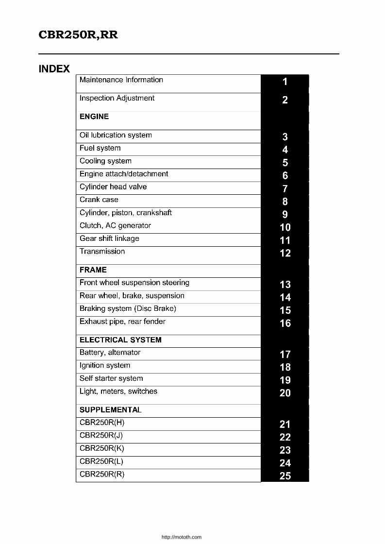
Ignition System
A newly designed digital ignition unit with a built-in micro computer provides best ignition throughout its operating speed range. A pulse rotor has seven projections. From (1) - (7) have 45°separation and 900 for (7) to (1). The engine rpm and crank position for each cylinder are detected from the relative position of the seven projections and two pulser coils. The two pulser coils are installed so as to have 15° inclination from level line for PC2 end, compared to PC1. This angular offset is to detect crank positions. The time when the pulse rotor's projection passes the PC1 pulser coil is referred as "O-reference". By detecting the time required to have the projection at the pulser coil again, the engine rpm is determined and the micro computer determines ignition timing.
r No.1 Ignition Coil
Kill Switch Main Fuse
~~~~~:~:::::JbJ~=f=i=i=~ ~>--.q,-..,...., II Ignition Switch
m.---.'..
ulse Rotor
Ignition Tachome r Coil
Battery
No.2 Ignition Coil Output Circuit
______ No.1 Ignition Coil t..==!....1-.!:::===-_==~ Output Circuit
-= Spark Plug
1-6 -----------------------------------------------
http://mototh.com
CBR250R,RR 1. Maintenance Information
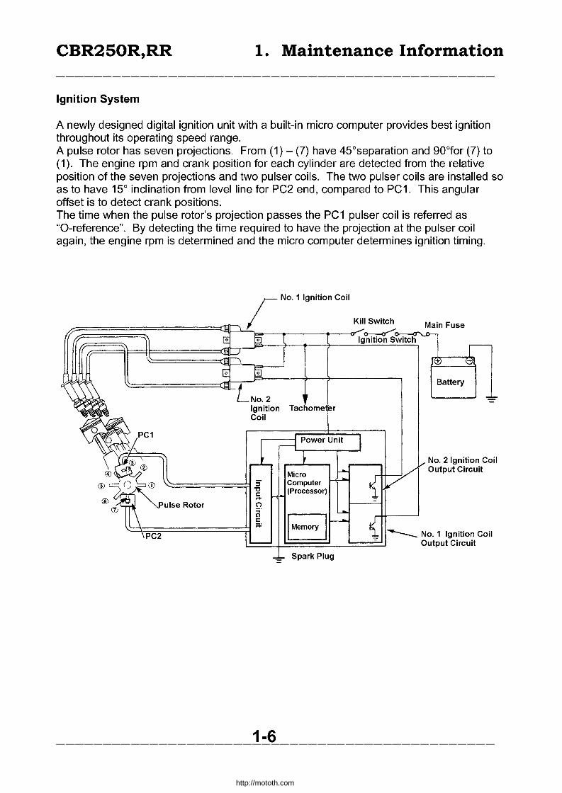
General Caution
• Replace gaskets, O-Rings, circlips and cotter pins when they are removed.
• When screwing, temporarily tighten screws/bolts. Screw bigger diameter first, then smaller diameter. Inner ones first, then outer ones. Tighten in criss-cross way whenever possible. Apply designated torque.
• Use genuine Honda or recommended parts, lubricants, and other products.
• Use special/ common tools as instructed.
• Disassembled parts are to be cleaned before the inspection/measurement. Apply oil to contact area when installing them.
1-7
http://mototh.com

CBR250R,RR 1. Maintenance Information
• Apply grease or equivalent to designated parts.
• After assembling, check the operation and fittings.
• When multiple people are working at the same time, always confirm each other's safety.
• Disconnect (-) lead from the battery prior to servicing the vehicle.
• Do not touch the frame with a wrench or any other metal tools.
• After servicing the vehicle, check each connection, fittings and routing.
• If the battery has been disconnected, connect (+) lead first.
• Apply grease to the terminals after connecting leads.
• Attach covers to the terminals.
1-8
(
-----------------------------------------------
http://mototh.com

CBR250R,RR 1. Maintenance Information
• If a fuse has blown, inspect and fix the cause and install the new fuse with the correct capacity.
• Apply covers to terminals after servicing.
• When disconnecting locked couplers, unlock before disconnecting.
• When disconnecting couplers, hold the coupler body. Do not pull the wire harness.
• Before connecting couplers, make sure there is no damage or any abnormalities on the terminals.
1-9
o
-----------------------------------------------
http://mototh.com
CBR250R,RR 1. Maintenance Information
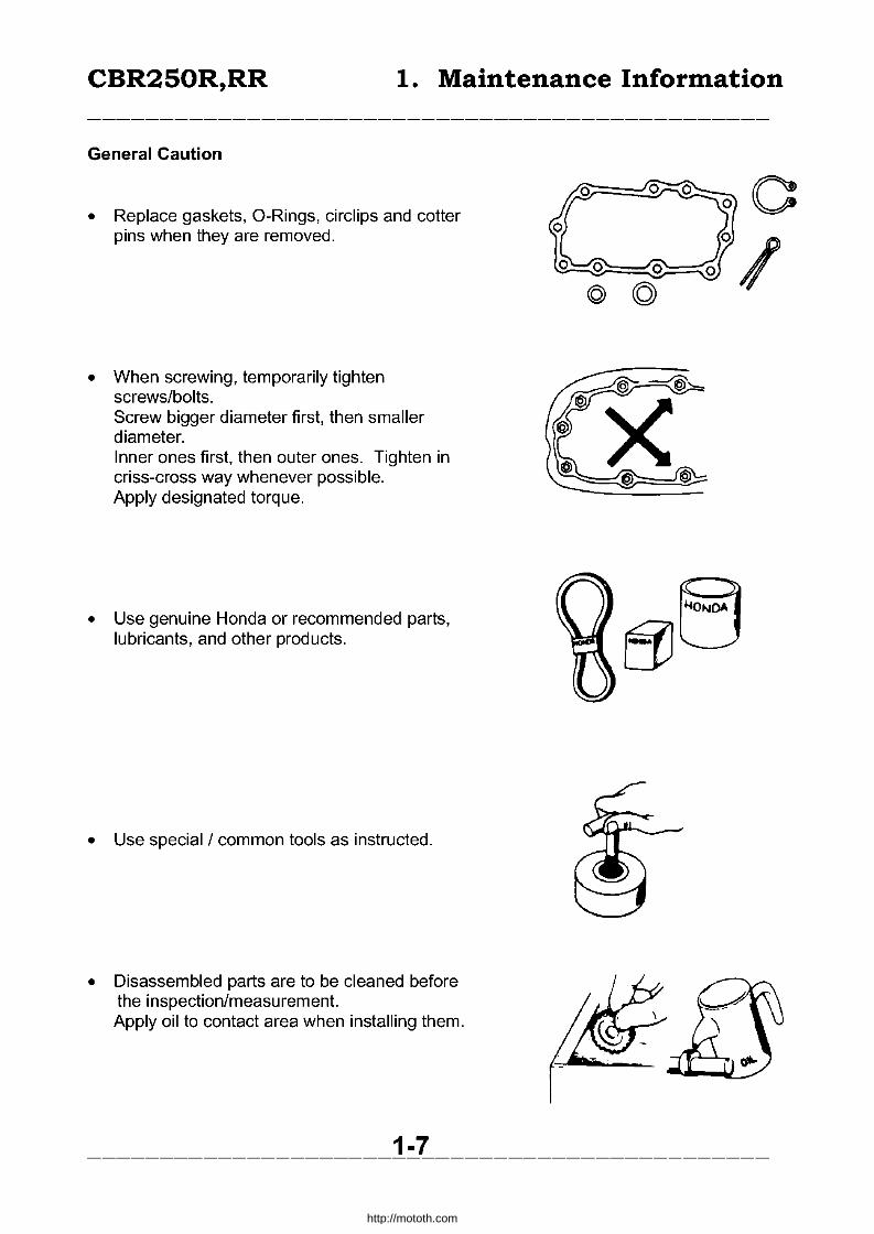
• Firmly insert couplers. • Check couplers are locked if the
couplers have locks. • Check all harnesses are connected.
• Coupler covers should cover whole coupler unit without any peels.
• Connector covers should not be damaged and female terminals should not be loose.
• Firmly secure the connectors. • Covers should wrap whole terminals. • Open end of the covers should not face
upwards.
• Fix wire steps to designated position on the frame.
• Clamp wire harnesses at the coated area when aluminium straps are used.
1-10
rT:D O
-----------------------------------------------
http://mototh.com
CBR250R,RR 1. Maintenance Information
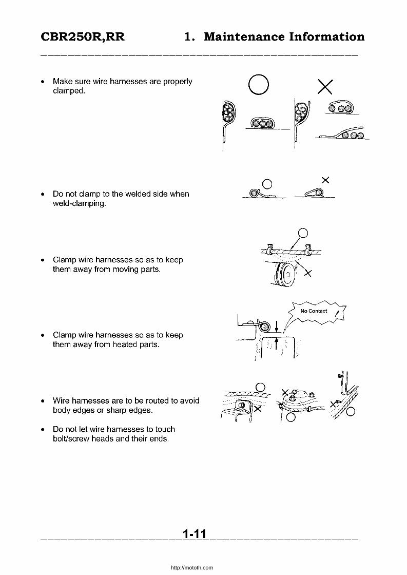
• Make sure wire harnesses are properly clamped.
• Do not clamp to the welded side when weld-clamping.
• Clamp wire harnesses so as to keep them away from moving parts.
• Clamp wire harnesses so as to keep them away from heated parts.
• Wire harnesses are to be routed to avoid body edges or sharp edges.
• Do not let wire harnesses to touch bolUscrew heads and their ends.
1-11
o
o ~<,b&:z -m)~
-----------------------------------------------
http://mototh.com

CBR250R,RR 1. Maintenance Information
• Do not apply excessive tension / slack to the wire harnesses.
• If there is no other alternatives but to route wire harnesses through sharp edges, protect the part with tubes or tape.
• Firmly set grommets if available.
• Do not unwrap wire harnesses. • Wrap the wire harness with adhesive
vinyl tape if it is unwrapped.
• Do not catch wire harnesses when installing parts.
1-12
o
http://mototh.com

CBR250R,RR 1. Maintenance Information
• Do not twist wire harnesses.
• Make sure wire harnesses are not overtensioned or over-slack when the handlebar is fully turned to either side. Also, they should not have any sharp bending, catching or contact with sharp edges.
• Read instructions when using a multi meter, and follow the instruction on the service manual.
• Do not drop or throw parts.
• If rust is forming on the terminal, remove with sandpaper before re-connecting.
• Do not twist or sharply bend cables. Such deformations or damages may cause failure.
1-13
o x
, ,
-----------------------------------------------
http://mototh.com

CBR250R,RR 1. Maintenance Information
Symbol Meaning Symbol Meaning Important:
Danger: ~mportant Its neglect may lead to minor injury or
Its neglect may lead to dama in the parts. serious injuries. * General
General caution: Caution Tips of the work
Symbol Meaning Symbol Meaning Apply oil: ., Unless specified, use
_l .. ~r.·'l! Apply sealant
designated or recommended oil.
Apply Molybdenum solution:
.~ -, The solution is a mixture of Replace with new parts engine oil and Molybdenum whenever
grease at .... ~ disassembled.
Apply multi-purpose grease.
I ~ (Lithium soap based NLG #2 Apply brake fluid.
.. equivalent. Use recommended Example: SHELL Albania grade
EP-2 (DOT4) Apply Molybdenum grease
~ (3% or more Molybdenum, 4111 NLGI#2 equivalent) Apply recommended
Mitsubishi multi purpose M2 cushion oil. Dow Corning Molycoat
BR-2 PLUS Apply Molybdenum paste. (s ~OLJ (40% or more Disulphide
~ Molybdenum. NLGI#2 Use exclusive tools equivalent). Local paste
Molycote G-n Paste (Dow CorninQ)
Apply silicone grease [0 p--;oo~) O.P. (Option) tool.
~ Silicone grease G40M Refer to parts list as (ShinEtsu) these tools are
considered to be parts.
CW Apply screw locker. Use medium class unless -> 3-1 Reference pages.
specified.
1-14
http://mototh.com
CBR250R,RR 1. Maintenance Information
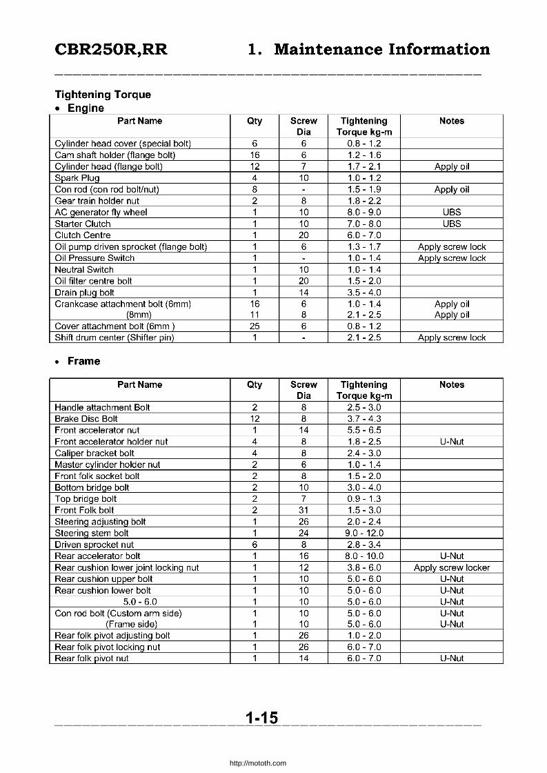
Tightening Torque • Engine
Part Name Qty Screw Tightening Notes Dia Torque kg-m
Cylinder head cover (special bolt) 6 6 0.8 - 1.2 Cam shaft holder (flange bolt) 16 6 1.2 - 1.6 Cylinder head (flanqe bolt) 12 7 1.7-2.1 Apply oil Spark Pluq 4 10 1.0-1.2 Can rod (can rod bolt/nut) 8 - 1.5-1.9 Apply oil Gear train holder nut 2 8 1.8 - 2.2 AC generator fly wheel 1 10 8.0 - 9.0 UBS Starter Clutch 1 10 7.0 - 8.0 UBS Clutch Centre 1 20 6.0 - 7.0 Oil pump driven sprocket (flanqe bolt) 1 6 1.3-1.7 Apply screw lock Oil Pressure Switch 1 - 1.0-1.4 Apply screw lock Neutral Switch 1 10 1.0-1.4 Oil filter centre bolt 1 20 1.5 - 2.0 Drain plug bolt 1 14 3.5 - 4.0 Crankcase attachment bolt (6mm) 16 6 1.0-1.4 Apply oil
(8mm) 11 8 2.1 - 2.5 Apply oil Cover attachment bolt (6mm ) 25 6 0.8 - 1.2 Shift drum center (Shifter pin) 1 - 2.1 - 2.5 Apply screw lock
• Frame
Part Name Qty Screw Tightening Notes Dia Torque kg-m
Handle attachment Bolt 2 8 2.5 - 3.0 Brake Disc Bolt 12 8 3.7-4.3 Front accelerator nut 1 14 5.5 - 6.5 Front accelerator holder nut 4 8 1.8 - 2.5 U-Nut Caliper bracket bolt 4 8 2.4 - 3.0 Master cylinder holder nut 2 6 1.0-1.4 Front folk socket bolt 2 8 1.5 - 2.0 Bottom bridge bolt 2 10 3.0 - 4.0 Top bridge bolt 2 7 0.9 - 1.3 Front Folk bolt 2 31 1.5 - 3.0 Steering adjusting bolt 1 26 2.0 - 2.4 Steerinq stem bolt 1 24 9.0 - 12.0 Driven sprocket nut 6 8 2.8 - 3.4 Rear accelerator bolt 1 16 8.0 - 10.0 U-Nut Rear cushion lower joint locking nut 1 12 3.8 - 6.0 Apply screw locker Rear cushion upper bolt 1 10 5.0 - 6.0 U-Nut Rear cushion lower bolt 1 10 5.0 - 6.0 U-Nut
5.0 - 6.0 1 10 5.0 - 6.0 U-Nut Can rod bolt (Custom arm side) 1 10 5.0 - 6.0 U-Nut
(Frame side) 1 10 5.0 - 6.0 U-Nut Rear folk pivot adjustinq bolt 1 26 1.0 - 2.0 Rear folk pivot locking nut 1 26 6.0 - 7.0 Rear folk pivot nut 1 14 6.0 - 7.0 U-Nut
1-15 -----------------------------------------------
http://mototh.com

CBR250R,RR 1. Maintenance Information
Part Name Qty Screw Tigtening Notes Dia. Torque kg-m
Hanger pin 4 10 1.5 - 2.0 Hanger pin plug 4 10 0.1 - 0.2 Brake hose attachment bolt 4 10 2.5 - 3.5 Brake hose tightening bolt 1 10 3.0 - 4.0 Right side under a
bottom bridge Exhaust pipe joint nut B 6 O.B -1.2 Muffler attachment bolt 1 B 2.4 - 3.0 Change pedal 1 6 1.0 - 1.4 Engine mount bolt B 10 4.5 - 5.5 Engine hanger bracket 4 10 3.5 - 4.5 Sub frame 4 10 4.5 - 5.5 Side stand bracket 2 B 2.5 - 3.0 Step holder 4 B 2.5 - 3.0 Tandem step holder 4 B 2.5 - 3.0 Ignition switch 2 B 2.5 - 3.0 Thermostat case 2 6 1.0-1.4 Radiator upper stay 2 6 1.0 - 1.4 Radiator grill 2 6 O.B -1.2 Fuel cock 1 22 2.0 - 2.5 Fuel tank attachment nut 1 6 O.B -1.2 Fuel tank attachment bolt 1 B 1.B - 2.5 Air cleaner case (step bolt) 6 5 0.6 -1.0 Air cleaner duct 1 6 0.5 - O.B Sub air cleaner 1 6 0.5 - O.B Fairing 6 6 0.7-1.1 Fairing inside cover 4 6 0.6 -1.0 Head light 4 6 0.3 - 0.5 Fairing stay 2 10 3.0 - 4.0 Meter 2 6 O.B -1.2 Cooling fan switch 1 16 2.4 - 3.2 Apply sealer Front fender (6mm bolt) 4 6 O.B -1.2
(6mm bis) 2 6 0.7-1.1 Read fender A 4 6 0.7-1.1 Rear fender B 5 6 O.B -1.2 Taillight 2 6 O.B -1.2 Starter motor terminal cable 1 6 O.B -1.2 Front direction indicator 2 5 0.35 - 0.50 Horn stay 1 6 O.B -1.2
• For the parts not specified in the above tables, use the following standards.
• Standard Tightening Torque SH (Small Head) Bolt: 8mm flange head 6mm bolt Type of bolt/nut Torque kg-m Type of bolt/screw/nut Torque kg-m
5mm bolUnut 0.45 - 0.6 5mm screw 0.35 - 0.5 6mm bolUnut O.B -1.2 6mm screw, 6mm flange bolt 0.7-1.1 Bmm bolUnut 1.B - 2.5 6mm flange bolUnut 1.0 - 1.4 10mm bolUnut 3.0 - 4.0 Bmm flange bolUnut 2.4 - 3.0 12mm bolUnut 5.0 - 6.0 1 Omm flange bolUnut 3.5 - 4.5
• Exclusive I Common Tools
1-16 -----------------------------------------------
http://mototh.com

CBR250R,RR 1. Maintenance Information
• New Exclusive tools
Name of the tool Tool Number Application Section in the Manual
Compression gauge attachment 07GMJ-KT70 1 00 Cylinder compression meas. 2 Clutch center holder 07GMB-KT70100 Clutch 10
assembly/disassembly Valve spring compressor 07GME-KT70200 Valve assembly/disassembly 7 attachment Tappet hole protector 07GME-KT70200 Valve assembly/disassembly 7 Valve guide remover (4mm) 07GMD-KT70100 Valve guide 7
assembly/disassembly Socket wrench (Dodecagon) 07GMA-KT70100 Cylinder head 7mm bold 7
(dodecagon) attach/detachment
Needle bearing remover 07GMA-KT70200 Rear fork L-bearing 14 detachment
Lock nut wrench 07GMA-KT70200 Rear fork attach/detachment 14
• E . f XIS m9 exc uSlve t OOS Name of the tool Tool number Application Section in
the manual Oil pressure qauqe attachment 07510-4220100 Oil pressure measurement 3 Steerinq stem attachment 07916-3710100 Adjust nut attach/detachment 13 Bearing remover 07936-3710300 Detachment of needle 14 - Remover handle 07936-3710100 bearings of rear fork and 8
suspension linkage, main - remover sliding weight 07741-00110201 shaft L-bearing Driver attachment (28X30mm) 07946-1870100 Attachment of rear fork 14
L-bearing Steerinq stem driver 07946-MBOOOOO Inner race attachment 13 Driver shaft 07946-MJ00100 Rear fork bearing 14
detachment Fork seal driver attachment 07947 -KA20200 Front fork assembly 13 Ball race remover set 07946-KM90000 Ball race attach/detachment 13 - driver shaft assy(incl. nut) 07946-KM90300 - assembly base - driver attachment A 07946-KM90600 - driver attachment B 07946-KM90100 - bearing remover A 07946-KM90200 - bearing remover B 07946-KM90400
07946-KM90500 Rear cushion compressor 07959-MB 10000 Rear cushion 14 attachment Assembly/disassembly Valve quide reamer 07964-8840000 Valve quide clean/finish 7 Snap rinq pliers 07914-3230001 Snap rinq attach/detachment 15 Piston ring compressor 07955-ZGOOOOO Piston assembly 9
1-17
http://mototh.com

CBR250R,RR 1. Maintenance Information
• Common Tools
Name of the tool Tool number Application Section in the
manual Float level gauge 07401-0010000 Carburettor float level 4
measurement Lock nut wrench (26x30mm) 07716-0020203 Clutch lock nut 10
attach/detachment Extension bar 07716-0020500 Attach to the lock nut wrench 10,13 Lock nut wrench (30x32mm) 07716-0020400 Steering stem nut 13
attach/detachment Fly wheel holder 07725-0040000 Fly wheel attach/detachment 10 Rotor puller 07733-0020001 Fly wheel detachment 10 Outer driver (32x35mm) 07746-0010100 Front wheel R-bearing, Rear 13
fork R-bearinQ attachment 14
Outer driver (37x40mm) 07746-0010200 Rear wheel bearing, main 14 shaft, L-bearinQ attachment 8
Outer driver (42x47mm) 07746-0010300 Front wheel L-bearing driven 13 flanQe bearinQ attachment 14
Outer driver (24x26mm) 07746-0010700 Suspension linkage needle 14 bearinQ attachment
Pilot (15mm) 07746-0040300 Front wheel bearing, rear 13 fork R-bearing attachment 14
Pilot (17mm) 07746-0040400 Rear wheel, suspension 8 linkage, driven sprocket, 14 main shaft L-bearing attachment
Pilot (22mm) 07746-0041000 Rear fork L-bearing 14 Bearing remover head (15mm) 07746-0050400 Front wheel bearing removal 13 Bearing remover shaft 07746-0050100 Wheel bearing removal 13,14 BearinQ remover head (17mm) 07746-0050500 Rear wheel bearinQ removal 14 Fork seal driver 07747 -0010100 Front fork assembly 13 Driver handle A 07749-0010000 Bearing attachment 8,13,14 Valve spring compressor 07959-3290001 Rear cushion 14
assembly/disassembly
1-18 -----------------------------------------------
http://mototh.com

CBR250R,RR 1. Maintenance Information
• Measurement tools
Name of the tool Tool number Application Section in the
manual Digital circuit multimeter (KOWA) 07411-002000 Kowa circuit multi meter (TH- 17,18,19,
5H) Or Sanwa's 07309- 20 0020000 'Use the multimeter to check the charge of MF battery.
Oil pressure gauge 07506-3000000 Oil pressure measurement 3 Vacuum gauge 07404-0030000 Carburettor synchronizing 4
adjust Compression qauqe 07305-0010000 Cylinder compression meas. 2
Valve seat cutting tools Name of the tool Tool number Application Section
in the manual
Sheet surface cutter (20.5mm) 07780-0011000 45U IN) valve sheet 7 adjustment
Sheet surface cutter (17mm)* 07GMH-KT70500 (45u EX) valve sheet 7 adjustment
Plane cutter (17mm)* 07GMH-KT70100 (32u l N) valve sheet 7 adjustment
Plane cutter (17mm)* 07GMH-KT70200 (32u EX) valve sheet 7 adjustment
Inner surface cutter (20.5mm) 07780-0014300 (60u l N) valve sheet 7 adjustment
Inner surface cutter (17mm)* 07GMH-KT70400 (60D EX) valve sheet 7 adjustment
Cutter holder (4mm)* 07GMH-KT70300 Attach the cutter 7
'Newly-organized tools
1-19 -----------------------------------------------
http://mototh.com
CBR250R,RR 1. Maintenance Information
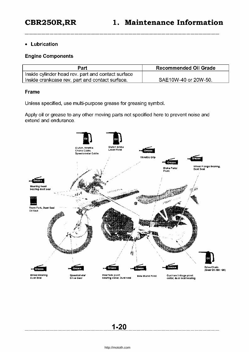
• Lubrication
Engine Components
Part Recommended Oil Grade Inside cylinder head rev. part and contact surface Inside crankcase rev. part and contact surface. SAE10W-40 or 20W-50.
Frame
Unless specified, use multi-purpose grease for greasing symbol.
Apply oil or grease to any other moving parts not specified here to prevent noise and extend and endurance.
Steering head bearing dust seal
Front Fork, Dust 58al 0115e31
Wheel Bearing Dust Seal
Clutch, throttle Choke Cable, Sp@@dom@t@rCabl@
speedometer Ori"eGear
Clutch brake Le-ver Pivot
Throttle Glip
Rearfork pivot Sidlil Stand Pivot beat1ng collar, Dust seal
1-20
Brake Pedal Wheel Flange Bearing, Dust Seal
Pivot
/
Cushion linkage pivot collar, dust seal beating
Drive Chain (Gear 011 #20 -eo)
-----------------------------------------------
http://mototh.com

I....lo. I • IN ....lo.
Indicator Illuminatio
Tachomete
Water Temperatu
Speedome
Speed Sensor
1. Pilot Lights 2. L-Winker pilot light 3. High beam pilot light 4. Neutral pilot light 5. Oil pressure light 6. R-Winker pilot light
~
F .. - I (tJ;~i R-Front winker lighl
~' I . ~..: U,'
Headlight
L-front winker light
"",til '" IFuiTlliTLilp~ I ~iW'
Ki , ..... ,! I I I Switch
Main Switch
FUSE10A 1. Fan motor 2. Marking 3. Front position tail 4. Head light 5. Head light
Main 6. Neutral, oil temp Switch 7. Winker, F.R.stop
I !II ill I Rear Stop SW Starter Magnetic Switch
.~ I ~ -- ~ ~. fID.'~ (i rn ~Maln 1./ -;;n " Fuse ~M '". • Plate TI''''~ -;- .. ~'lii'IU' " StarterW ,. ta a , II ~
I II M.". '''.' ffiffi Thermo Motor Winker Relay 101 ,. Unit Q T
I w;=2]11 1111i1 0 _ ~ ilt ~ ~ ,., I
I
;1;:j'J):;'-3\Et rlh ~ rrrr
"
:0 R-rear winker light
Stop/tail Light
D L-rear Winker Light
~ ~ Horn 0030Z--KT7 --0000 Switch
Winker---Direction---Indicator
• m CD () -.., o· III
(") .., () C -I/J
(") ta ~ t.) en 0 ~ .. ~ ~
I-' -is: ~ loA-
= ,... (D
= ~
= n (D -= ~ ... e ~ ,... loA-o =
http://mototh.com

CBR250R,RR 1. Maintenance Information
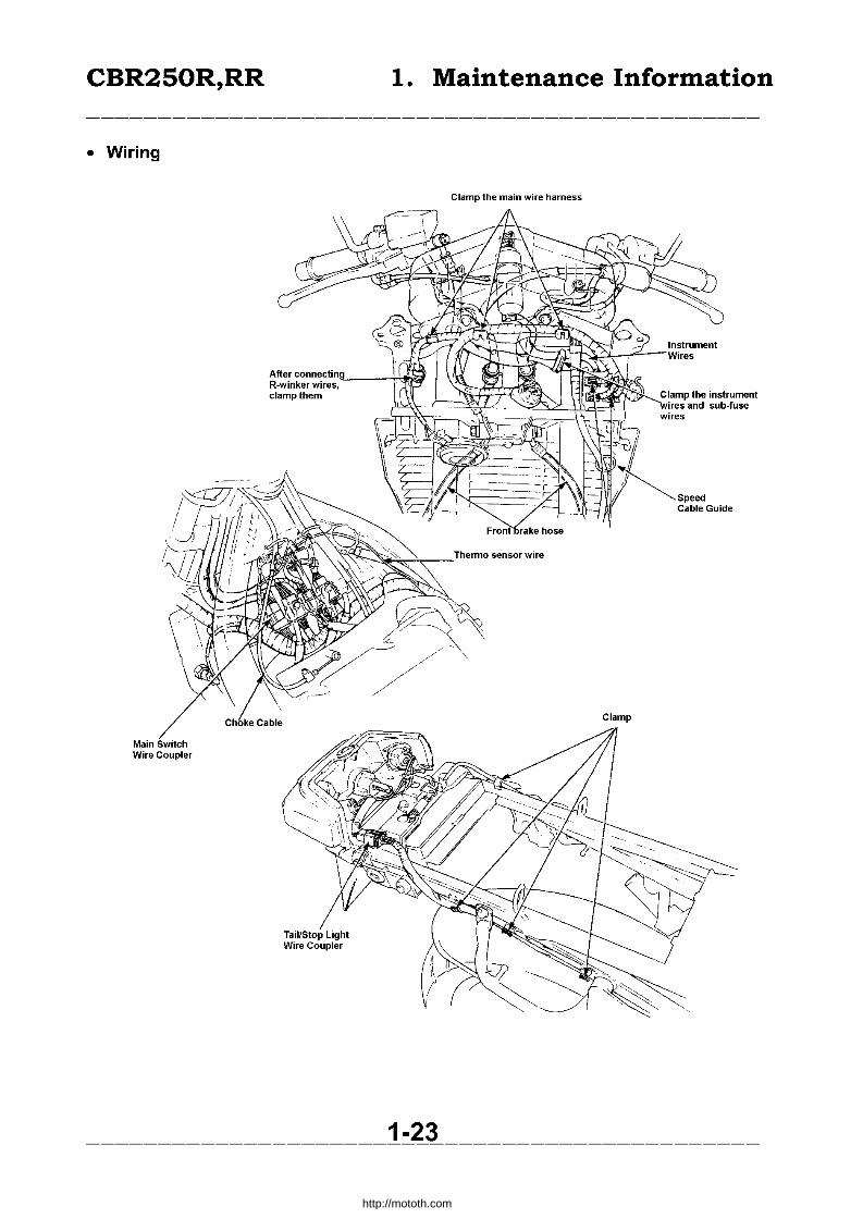
• Wiring
L-Handle Switch Wire
Clamp
Wire Harness Guide
Cooling Fan Switch
Speedometer Cable
Front Brake Hose
~\;!~~~~-IR-Winker Wire
Main Wire Harness
1-22
http://mototh.com
CBR250R,RR
• Wiring
Main Switch Wire Coupler
1. Maintenance Information
Clamp the main wire harness
Clamp the instrument
~, t, w:;:~ and sub-fuse
~~ ~speed
Cable Guide
Clamp
1-23 -----------------------------------------------
http://mototh.com

CBR250R,RR
• Wiring
Reserve Tank
Starter Motor Cable
1. Maintenance Information
Vacuum Tube Fuel Tube
Switch Wire
Air Cleaner Case Drain Tube
1-24
Regulator/Rectifier Coupler
Carburettor Breather Tube
Spark Unit
Radiator Overflow Tube
http://mototh.com
CBR250R,RR 1. Maintenance Information
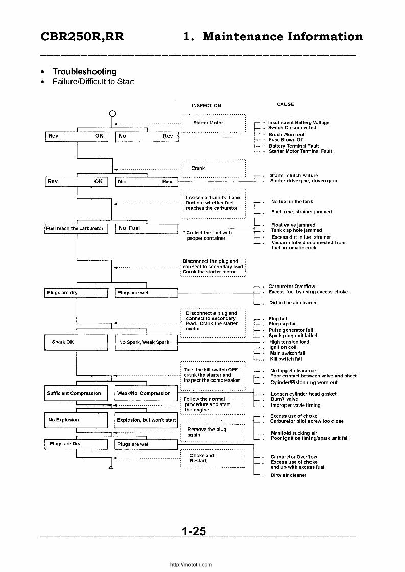
• Troubleshooting • Failure/Difficult to Start
Fuel reach the carburetor
Sufficient Compression
No Fuel
INSPECTION
* Collect the fuel with proper container
r ofscorin"ect "the- pfLi~f a-rief--• _____________________________ ..: connect to secondary lead.
: Crank the starter motor
,-----------------------------Disconnect a plug and connect to secondary lead. Crank the starter motor
.-----'~---,,----------- ......... -
Weak/No Compression
Turn the kill switch OFF crank the starter and inspect the compression
,----------------------
Explosion, but won't start I--------------l_
,------------------------.-- -----,
Choke and Restart
, , '._-------------------------------,
1-25
CAUSE
Insufficient Battery Voltage Switch Disconnected
Brush Worn out Fuse Blown Off Battery Terminal Fault Starter Motor Terminal Fault
Starter clutch Failure Starter drive gear, driven gear
No fuel in the tank
Fuel tube, strainer jammed
Float valve jammed Tank cap hole jammed
Excess dirt in fuel strainer Vacuum tube disconnected from fuel automatic cock
Carburetor Overflow Excess fuel by using excess choke
Dirt in the air cleaner
Plug fail Plug cap fail Pulse generator fail Spark plug unit failed High tension load Ignition coil Main switch fail Kill switch fail
No tappet clearance Poor contact between valve and sheet Cylinder/Piston ring worn out
Loosen cylinder head gasket Burn't valve Improper vavle timing
Excess use of choke Carburetor pilot screw too close
Manifold sucking air Poor ignition timing/spark unit fail
Carburetor Overflow Excess use of choke end up with excess fuel
Dirty air cleaner
-----------------------------------------------
http://mototh.com
CBR250R,RR 1. Maintenance Information
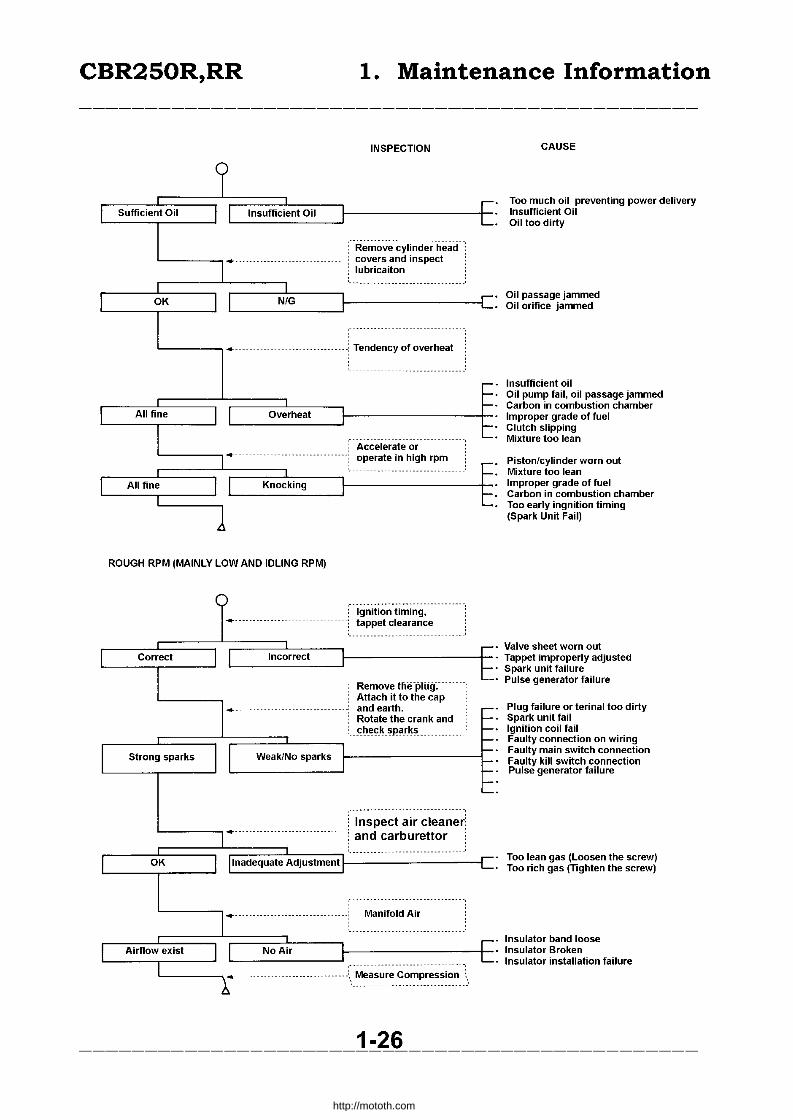
Sufficient Oil Insufficient Oil
INSPECTION
---------_._. -------------
Remove cylinder head covers and inspect lubricaiton
ROUGH RPM (MAINLY LOW AND IDLING RPM)
I Correct I I '-----r-----'
Incorrect
: Ignition timing, ----------! tappet clearance
. Remove lhe ·plii!f. Attach it to the cap and earth. Rotate the crank and
_~tI_~~_~ _ ~p-~.rJ~.~ _____________ .:
,..... 1-. r· 1-.
I Strong sparks II WeakiNo sparksJ I~ _____ -----{I--·
'------,----' '-----------' f:: 1-. ~.
: Inspect air cleaner 1+·············· ............. : and carburettor .
'._------_. - ._-------------- ---I OK I I Inadequate Adjustment L-----r--....J
: Manifold Air :
,---------------------------------
1 ...... _A_ir_fl_oW,--e_Xi_s_t _----'J l 1
NoAir
------- ------------ ------', Measure Compression
1-26
CAUSE
Too much oil preventing power delivery Insufficient Oil Oil too dirty
Oil passage jammed Oil orifice jammed
Insufficient oil Oil pump fail, oil passage jammed Carbon in combustion chamber Improper grade of fuel Clutch slipping Mixture too lean
Piston/cylinder worn out Mixture too lean Improper grade of fuel Carbon in combustion chamber Too early ingnition timing (Spark Unit Fail)
Valve sheet worn out Tappet improperly adjusted Spark unit failure Pulse generator failure
Plug failure or terinal too dirty Spark unit fail Ignition coil fail Faulty connection on wiring Faulty main switch connection Faulty kill switch connection Pulse generator failure
Too lean gas (Loosen the screw) Too rich gas (Tighten the screw)
Insulator band loose Insulator Broken Insulator installation failure
-----------------------------------------------
http://mototh.com
CBR250R,RR 1. Maintenance Information
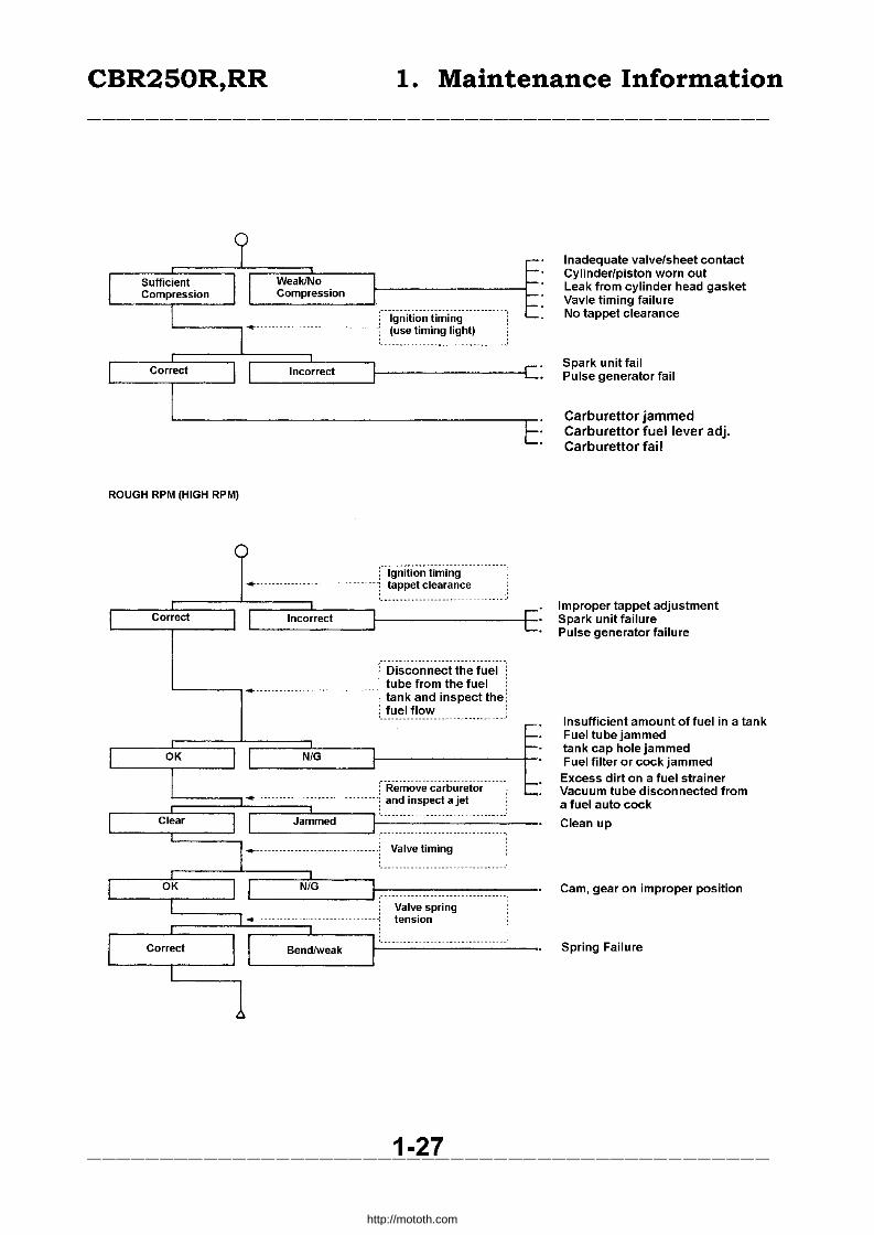
ROUGH RPM (HIGH RPM)
o ----
r Correct l I L------,.--------l
WeaklNo Compression
Incorrect
Incorrect
Ignition timing (use timing light)
Ignition timing tappet clearance
i- iJisco-rinect-the fuel L ___ ~_--------_-_-- , tube from the fuel
.... , tank and inspect the , fuel flow '._-----------_._. -
r OK l r NIG L-__ ~---1
r Clear l r
r OK l I I ,-
r Correct I I
1
: Remove carburetor -.- ._---.----- ---------! and inspect a jet
Jammed
----····-----------·--------i Valve timing
NIG -- ---_.- .. --
Valve spring ----------------------- -------: tension
I:· - -- --.--- ... -----Bendlweak r
1-27
,...... ~. ~.
Inadequate valve/sheet contact Cylinder/piston worn out Leak from cylinder head gasket Vavle timing failure No tappet clearance
Spark unit fail Pulse generator fail
Carburettor jammed Carburettor fuel lever adj. Carburettor fail
Improper tappet adjustment Spark unit failure Pulse generator failure
Insufficient amount of fuel in a tank Fuel tube jammed tank cap hole jammed Fuel filter or cock jammed Excess dirt on a fuel strainer Vacuum tube disconnected from a fuel auto cock
Clean up
Cam, gear on improper position
Spring Failure
-----------------------------------------------
http://mototh.com
CBR250R,RR 1. Maintenance Information
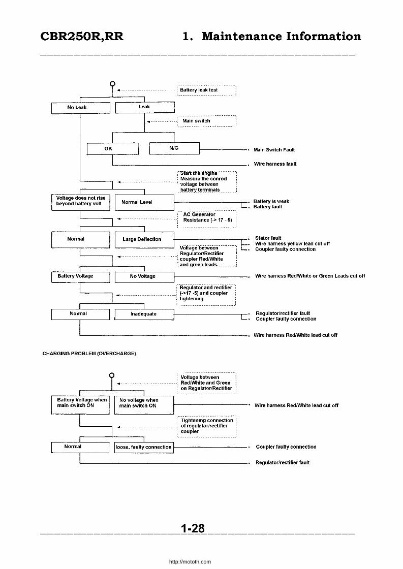
rSlartUie erigiiie ... _. __ j Measure the con rod
: voltage between ,-____ '---___ -, : __ t?~_t.t_~~Y..~~~~J~~J~ ______ _
--.---------_. AC Generator Resistance (-> 17 - 5)
'------------' ,-VOliiigeoefweeii-: Regulator/Rectifier
--- .. ---; coupler RedlWhite
:_~I)~.Q[~~IJ.l~~~t~~
Main Switch Fault
Wire harness fault
Battery is weak Battery fault
Stator fault Wire harness yellow lead cut off Coupler faulty connection
r-r;~Vo:t;;g;--I~-----------. Wire harness RedlWhite or Green Leads cut off
-Regulato-r' an-d- rectifier· (->17 -5) and coupler tightening
Regulator/rectifier fault Coupler faulty connection
'-------------------------_____ .. Wire harness RedlWhite lead cut off
CHARGING PROBLEM (OVERCHARGE)
Voltage between RedlWhite and Green on R~gulator!Rectifier
t-------------. Wire harness RedlWhite lead cut off
Tightening connection of regulatorlrectifier coupler
1-28
Coupler faulty connection
Regulator/rectifier fault
-----------------------------------------------
http://mototh.com
CBR250R,RR 1. Maintenance Information -----------------------------------------------
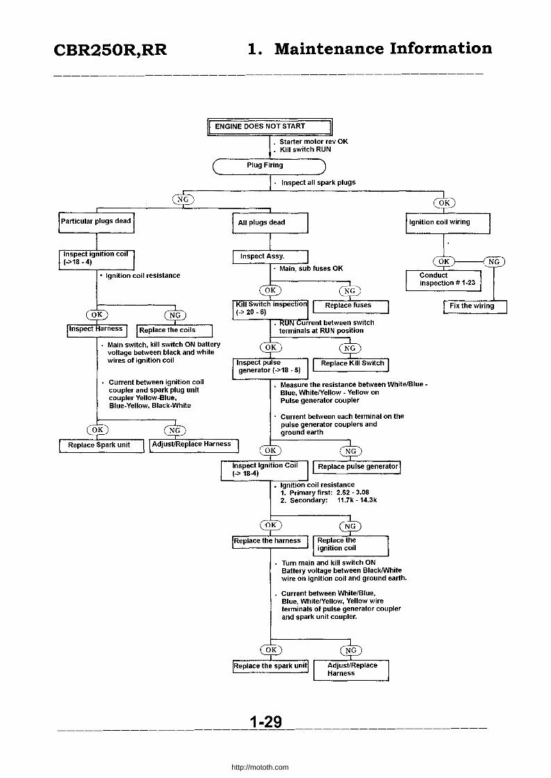
ENGINE DOES NOT START
Main switch, kill switch ON battery voltage between black and white wires of ignition coil
Current between ignition coil coupler and spark plug unit coupler Yellow-Blue, Blue·Yeliow. Black·White
· Starter motor rev OK • Kill switch RUN
Plug Firing
• Inspect all spark plugs
Measure the resistance between White/Blue -Blue. White/Yellow· Yellow on Pulse generator coupler
Current between each terminal on the pulse generator couplers and ground earth
Turn main and kill switch ON Battery voltage between BlacklWhite wire on ignition coil and ground earth.
Current between White/Blue, Blue, White/Yellow, Yellow wire terminals of pulse generator coupler and spark unit coupler.
1-29
Fix the wiring
-----------------------------------------------
http://mototh.com

CBR250R,RR 1. Maintenance Information
TACHOMETER NOT WORKING
C NORMAL SPARK ON #1 (MOST LEFT)
OK NG
Tachometer Wiring Refer - Ignition Syste
Replace Tacho Ass
Main switch "ON" and Battery voltage between
(Yellow/Blue - Green Wire) (Black/Brown - Green Wire) Current between Green-Ground earth
Tighten screws Adjust
1-30
Ground earth green wire
Power supply black/brown wire
-----------------------------------------------
http://mototh.com

CBR250R,RR 1. Maintenance Information
Indicates "e" while the actual temp is high
TIghten the upper case bolt for a thermostat
* 0 not earth for more than 5 seconds
Voltage between the thermo sensor Green/Blue and earth when main switch ON
Battery voltage between Black/Brown and earth when main switch ON Continuenty between Green and earth
1-31
Voltage regulator Green/Blue (to thermo sensor)
-----------------------------------------------
http://mototh.com

CBR250R,RR 1. Maintenance Information
ilNDICATES "H" WHILE THE ACTUAL TEMP. IS LOW
• Disconnect thermo sensor wire and turn the main switch ON. Water temp. meter indicates "C"
1-32
Disconnect the meter coupler inside the fairing. Confirm there is no short circuit between Green/Blue and Green
Thermo sensor wire
Power supply Black/Brown Wire
regulator GreenfBlue wire (to thermo sensor)
-----------------------------------------------
http://mototh.com
CBR250R,RR
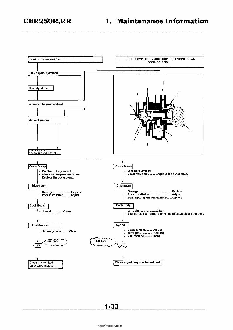
Manifold tube jammed Check valve operation failure Replace the cover compo
Damage ......................... Replace · Poor Instaliation .......... Adjust
• Jam, dirt ............. Clean
Fuel Strainer
• Screen jammed ......... Clean
~ NG~
Clean the fuel tank adjust and replace
1. Maintenance Information
FUEL FLOWS AFTER SHUTTING THE ENGINE DOWN (COCK ON RES)
Leak hole jammed . Check valve failure ........ replace the cover temp.
Damage ............................................. Replace Poor instaliation ............................... Adjust Seating compartment damage ...... Replace
Jam, dirt ....................... Clean • Seat surface damaged, centre line offset..replacee the body
Displacement.. ......... Adjust damaged ••••••••........... Replace Not installed ............. lnstall
~ ~NG
Clean, adjust I replace the fuel tank
1-33 -----------------------------------------------
http://mototh.com
CBR250R,RR 1. Maintenance Information
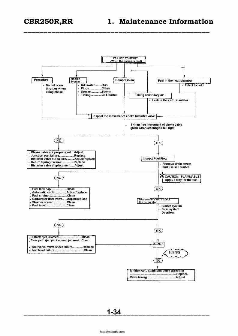
II FAiLURE ~ sTAR r ,When the e!!-ine is cold) II I I I I
1 Procedure I 11_9nlllon System I I compreSSiO~ I Fuel in the float chamber J
Do not open Kill switch ........ Run I . Petrol too old throttles when Plugs ................ Clean using choke Sparks .............. Strong
Timing .............. Cell starter I Taking secondary air I leak in the carbo insulator
(Inspect the movemet of choke bistarter valve
. 1-4mm free movement of choke cable guide when steering to full right
.cr c$ • Choke cable not properly set....~djust • Junction part failure ................... Replace I Inspect Fuel Flow I Bistarter valve nut failure ........... Adjustireplace
Return Spring failure ................ Replace Remove drain screw Bistarter valve displacement ..... Adjust and use sell starter
cr * CAUTION: FLAMMABLE I I Apply a tray for the fuel
cr • Fuel tank cap .................... l,;lean • Automatic cock ................ AdjusUreplace. • Fuel strainer ...................... Clean • Carburetor float valve .... Adjust/replace I ~lsassemDl.e ana Inspect I • Strainer screen ................. Clean the carburetor • Fuel tube ........................... Clean • Starter system
• Slow system • Overflow
cr T • Bistarter jet jammed ............................. Clean • Slow path (jet, pilot screw) jammed .. Clean.
• Float valve, valve sheet failure ............. Replace ..startl
• Float level failure .................................... Clean
~ ~
• IgnitIOn COli, spar. unlI pUlse genera(or .......................................................... Replace
• Valve timing ................................... Adjust
1-34 -----------------------------------------------
http://mototh.com

CBR250R,RR 1. Maintenance Information
IIDIFFICULT TO START (Cold start) II
J I ! I
I Procedure I I gm Ion
I Icompressionl I Fuel in the float chamber
~ystem
. Do not open throttles Kill Switch ............. RUN • Petrol too old when using choke Plug cap leak
Plugs ..................... Clean Sparks ................... Strong
I Any secondary air I Timing . Lead in the carburettor insulator
_I Choke Bistater Valve Operation
1 @
I · Choke cable not properly set ..... Adjust • Junction part failure .................... Replace • Bistarter valve nut failure ........... Adjustfreplace • Return spring failure ................... Replace • Bistarter valve displacement. ..... Adjust
1-4mm free movement of choke cable guide when steered to full right
I
Turn the pilot screw for 1,2 revs to both directions and confirm the rpm changes (50-100 rpm)
Conduct this after synchronising check Idling 1.500 + 100 rpm
@----------------------------~
@ , ANU " '"~''''' T · Bistarter jet jammed ................... Clean
• Slow path jammed ....................... Clean • Pilot screw not properly attached .. Adjust/repl. I Adjust the pilot screw I • Overflow • Float valve, valve seat failure .... Replace • Float level failure ........................ Adjustfreplace
Re-start I
~ T I' Igntion coil. spark unit .............................. Replace
• P~lse generator ....... : .................................... Replace • Air cleaner, muffler Jammed ...................... Clean/replace
1-35
I
1
-----------------------------------------------
http://mototh.com
CBR250R,RR 1. Maintenance Information
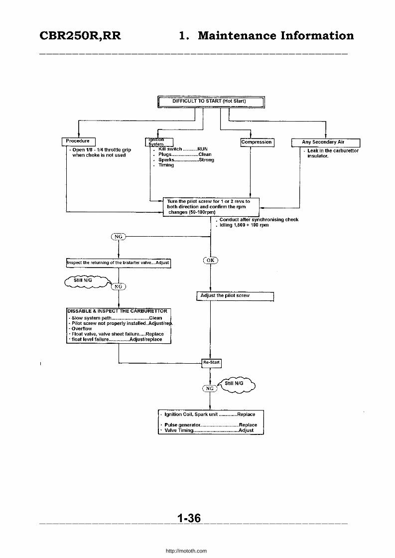
I DIFFICULT TO START (Hot Start) I I I
I l I j L Procedure I I gm~lon
5 stem I ICompression I L Any Secondary Air I • Open 1/8 - 1/4 throttle grip Kill switch ........... RUN Leak in the carburettor
when choke is not used Plugs ..................... Clean insulator. Sparks ................... Strong Timing
L....- Turn the pilot screw for 1 or 2 revs to both direction and confirm the rpm changes (50-100rpm)
• Conduct after synchronising check • Idling 1,500 + 100 rpm
NiG
Inspect the returning of the bistarter valve .... Adjust OK
( Still N/G ~ ~ /j I Adjust the pilot screw I
DISSABLE & INSPECT THE CARBURETTOR
• Slow system path ............................. Clean • Pilot screw not properly instaUed .. Adjustfre • Overflow • Float valve, valve sheet failure ..... Replace • float level failure ................ Adjustfreplace
Re-Start
NG fC5 Ignition Coil, Spark unit .............. Replace
Pulse generator .............................. Replace Valve Timing ................................... Adjust
1-36 -----------------------------------------------
http://mototh.com
CBR250R,RR 1. Maintenance Information
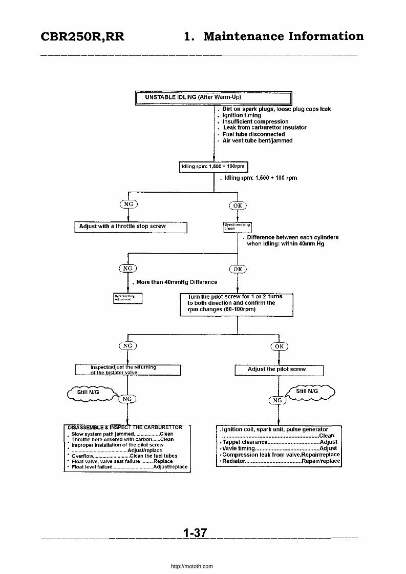
UNSTABLE IDLING (After Warm-Up)
Adjust with a throttle stop screw
Dirt on spark plugs, loose plug caps leak Ignition timing Insufficient compression Leak from carburettor insulator Fuel tube disconnected Air vent tube bent/jammed
Idling rpm: 1,500+ 100rpm
• Idling rpm: 1,500 + 100 rpm
Difference between each cylinders when idling: within 40mm Hg
• More than 40mmHg Difference
DISASSEMBLE & • Slow system path jammed ................... Clean
Throttle bore covered with carbon ...... Clean Improper installation of the pilot screw
• ......................................... Adjustfreplace • Overflow ........................... Clean the fuel tubes
Float valve, valve seat failure ......... Replace • Float level failure .............................. Adjustireplace
Turn the pilot screw for 1 or 2 urns to both direction and confirm the rpm changes (50-100rpm)
Adjust the pilot screw
_Ignition coil, spark unit, pulse generator ............................................................... Clean
• Tappet clearance .................................. Adjust • Vavle timing .......................................... Adjust • Compression leak from valve.Repair/replace • Radiator ..................................... Repair/replace
1-37 -----------------------------------------------
http://mototh.com

CBR250R,RR 1. Maintenance Information
II SOME CYLINDERS WOULD NOT HAVE COMBUSTION WHILE IDLING (After-Warm-Up) I Dirty spark plugs, loose plug caps, leak Inadequate ignition timing Insufficient compression
- Leak from carburetor insulator Fuel tube disconnected . Air vent tube bent/jammed
I Idling rpm: 1,500 + 100rpml
Idling rpm: 1,500 + 100rpm Difference between the cylinders: < 40mm Hg
c$ • More than 40mm Hg
® Difference
I SynChrOniSingl Adjustment Turn the pilot screw for 1 or 2 turns
to both direction and confirm the rpm changes (50-100 rpm)
® OK
rlnspect/Adjust the returning of the bistarter valve I
e::> I Adjust the pilot screw I NG
~<E:) NG DISASSEMBLE & INSPECT THE CARBURETTOR
• Slow system path jammed ........ Clean • Carbon on a throttle bore ......... Clean - Improper installation of the pilot screw. Adj st/replace
Ignition coil failure ................ Replace - Overflow .................. Clean the fuel tubes . - Float valve, valve seat failure ....... Replace Spark unit failure ................... Replace • Float level failure ............... Adjust/replace . Pulse generator failure ......... Repalce
1-38 -----------------------------------------------
http://mototh.com
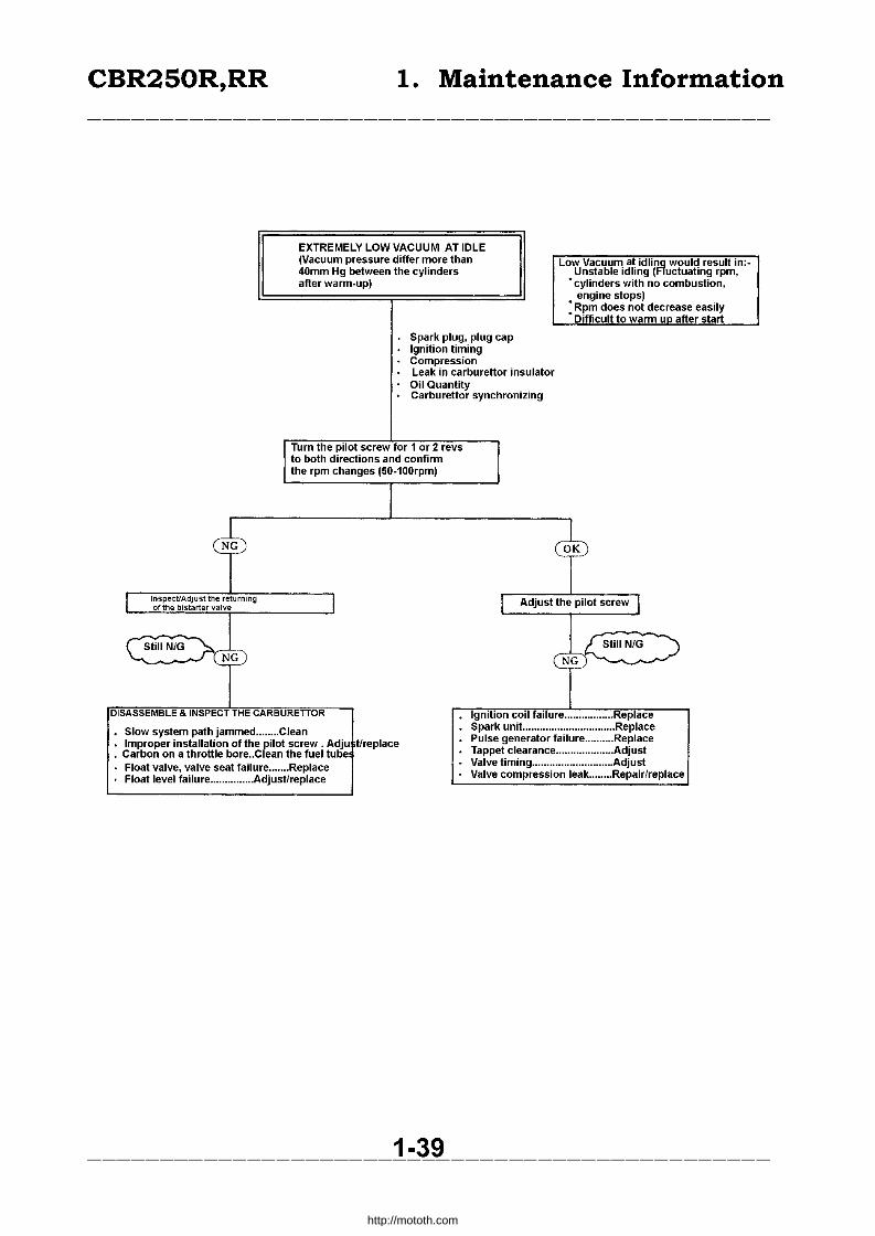
CBR250R,RR 1. Maintenance Information
EXTREMELY LOW VACUUM AT IDLE (Vacuum pressure differ more than 40mm Hg between the cylinders after warm-up)
Low Vacuum at idli~ woul Unstable idling ( uctua
d result in:ting rpm, ustion, • cylinders with no comb
engine stops) • Rpm does not decrease • Difficult to warm UD afte
Spark plug, plug cap Ignition timing Compression Leak in carburettor insulator Oil Quantity Carburettor synchronizing
Turn the pilot screw for 1 or 2 revs to both directions and confirm the rpm changes (50-100rpm)
t CT) I InspectfAdjust the returning I l Adjust the pilot screw J of the bistarter valve
1 L StiliNIG C;tiliNIG '.:,. ./'UJ{D
i DISASSEMBLE & INSPECT THE CARBURETTOR Ignition coil failure ................. Repl.ace
Slow system path jammed ........ Clean Spark unit. ............................... Replace
Improper installation of the pilot screw. Adju tlreplace Pulse generator failure .......... Replace
• Carbon on a throttle bore .. Clean the fuel tube Tappet clearance .................... Adjust
Float valve, valve seat failure ....... Replace Valve timing ............................ Adjust
Float level failure ............... Adjust/replace Valve compression leak ........ Repair/replace
1-39
easily r start
-----------------------------------------------
http://mototh.com

CBR250R,RR 1. Maintenance Information
II RPM DOES NOT DECREASE FAST 11 Free movement of a throttle grop: 2-6mm
• Wiring • Ignition timing • Insufficient compression • Leak from carburettor insulator
I I r nspec~A.~Ju~1 me returning
of the blstarter valve I I Inspect Carburettor I
Cf ~K T • Choke cable setting failure ...... AaJusl • Stiff movement of throttle shaft.Adjust/replace • Jucntion part failure ................. Adjust/Replace · Throttle valve failure ..................... Replace · Bistarter valve nut failure ......... Adust/Replace • Return spring failure .................... Replace · Return spring failure ................. Replace · Bistarter vavle displacemenl. ... Adjust
I~ynchr<:mizing I InspeCllon
I
~. ~ Difference more than 40mm Hg between the cylinders
I ~~~us I Turn the pilot screw or 1 or 2 revs to
Synchro both direction and confirm the rpm changes (SD-1DDrpm)
T OK DISASSEMBLE & INSPECT THE CARBURETTOR Slow system path jammed ........ Clean Improper installation of the pilot screw. Adju tlreplace Carbon on a throttle bore Clean the fuel tube IPilot Screw Adjustment I
-~e Spark unit failure .................... Replace Pulse generator failure .......... Replace Tappet clearance .................... Adjust Valve timing ............................ Adjust Valve compression leak ........ Repair/replace
___________________ 1-4Q _____________________ _
http://mototh.com
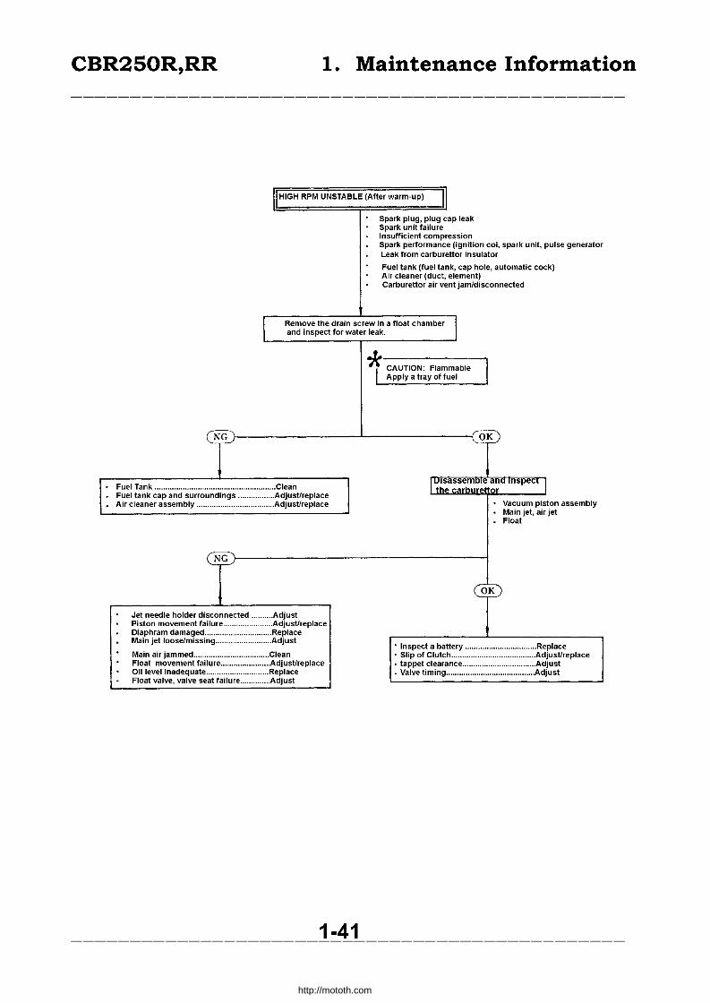
CBR250R,RR 1. Maintenance Information
II HIGH RPM UNSTABLE (Atter warm-up) II Spark plug, plug cap leak Spark unit failure Insufficient compression Spark performance (ignition coi, spark unit, pulse generator Leak from carburettor insulator
Fuel tank (fuel tank, cap hole, automatic cock) Air cleaner (duct, element) Carburetlor air vent jam/disconnected
I Remove the drain screw in a float chamber I and inspect for water leak.
~ CAUTION: Flammable Apply a tray of fuel
N~ ~K
Fuel Tank ........................................................ Clean IUlsassemDleanolnspeCI I
the carburettor Fuel tank cap and surroundings ................. Adjust/replace Air cleaner assembly .................................... Adjustlreplace Vacuum piston assembly
Main jet, air jet Float
N~
OK
Jet needle holder disconnected .......... Adjust Piston movement failure ....... ........ . .... Adjustlreplace Diaphram damaged .... ..................... . ... Replace Main jet 100se/missing .......................... Adjust
• Inspect a battery ................................. Replace Main air jammed ................................... Clean • Slip of Clutch ....................................... Adjustlreplace Float movement failure ....................... Adjustireplace • tappet clearance .................................. Adjust Oil level inadequate ............................. Replace • Valve timing ......................................... Adjust Float valve, valve seat failure .............. Adjust
1-41
http://mototh.com
CBR250R,RR 1. Maintenance Information
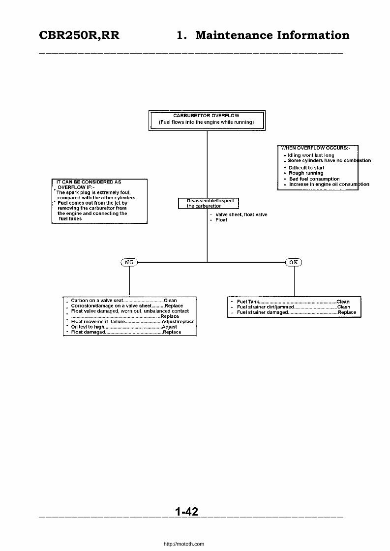
II CARBURETTOR OVERFLOW
(Fuel flows into the engine while running)
IT CAN BE CONSIDERED AS VERFLOW IF:-'T~ e spark plug is extremely foul,
c ompared with the other cylinders • F uel comes out from the jet by
moving the carbureUor from e engine and connecting the
re th f uel tubes
NG
. Carbon on a valve seat.. ............................. Clean
I
. Corrosion/damage on a valve sheet .......... Replace
WHEN OVERFLOW OCCURS:-
• Idling wont last long • Some cylinders have no comb
· Difficult to start
· Rough running
· Bad fuel consumption
· Increase in engine oil consum
Disassemblellnspect I the carburettor
Valve sheet, float valve Float
'-.2.K
Fuel Tank ........................................................... Clean . Fuel strainer dirt/jammed ................................. Clean Float valve damaged, worn out, unbalanced contact Fuel strainer damaged ...................................... Replace ................................................................... Replace Float movement failure ............................ Adjust/replace Oil levi to high ............................................ Adjust Float damaged ............................................ Replace
_____________________ 1-4~ _____________________ _
sti on
pli on
http://mototh.com
CBR250R,RR 2. Inspection! Adjustment
Service schedule 2 - 1 Drive system 2-8
Steering system 2-4 Electrical system 2 -10
Braking system 2-4 Powerplant 2 -11
Driving system 2-6 Lubrication 2 -16
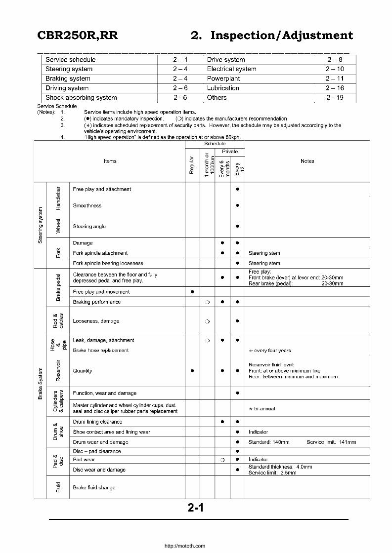
Shock absorbing system 2-6 Others 2 - 19 Service Schedule (Notes): 1. Service items include high speed operation items.
2. (.) indicates mandatory inspection. (0) indicates the manufacturers recommendation.
3. ('k) indicates scheduled replacement of security parts. However, the schedule may be adjusted accordingly to the vehicle's operating environment.
4 H' h d ". d f d h b 80k h .. 11qr spee operation IS e Ine as t e operation at or a ave Kpr. Schedule
o E Private
Items .li! ,s-", <.0 Ul Notes :J c:0 ~,s >.
OJ 00 :UN " E;:' " c: >~ 0:: > 0 w ~ wE
:;; Free play and attachment • -" <ll 'C c: <1l Smoothness • E I
i Qj Ul
OJ <ll Steering angle • -" c: S .~
J!l (fJ Damage • •
-i" Fork spindle attachment • • Steering stem 0
LL
Fork spindle bearing looseness • Steering stem
<Ii Clearance between the floor and fully Free play:
"0 depressed pedal and free play. • • Front brake (lever) at lever end: 20-30mm <ll Rear brake (pedal): 20-30mm "'-<ll
Free play and movement • -'" [!l III Braking performance 0 • • ~Ul
<ll 15:0 Looseness, damage 0 • o::rl
<ll Leak, damage, attachment :> • • Ul <ll o oe5 .9-
I "'- Brake hose replacement 71:: every four years
'0 Reservoir fluid level: E c:
Quantity • • • Front: at or above minimum line <ll J!l Ul Ul <ll Rear: between minimum and maximum >. 0::
(fJ
" -'" !" !" Function, wear and damage [!l • " " III "0"'-~«I Master cylinder and wheel cylinder cups, dust ;.,U 7t bi-annual O~ seal and disc caliper rubber parts replacement
~ Drum lining clearance • •
E ~ Shoe contact area and lining wear • Indicator ::>-" ~ Ul 0
Drum wear and damage • Standard: 140mm Service limit: 141mm
Disc - pad clearance • ~u
Pad wear 0 • Indicator "OUl
&'6 Disc wear and damage
Standard thickness: 4.0mm • Service limit: 3.5mm
"0 ·s Brake fluid change iL
2-1
http://mototh.com

CBR250R,RR 2. Inspection! Adjustment
Schedule
Private
(ij :s Items -'= E N", Notes :J --'< <D '"
'" cO o>-,s ~-'= 00 ~c Q) E;:'
~ c 0:: ~ 0 Q) 0
~ LU E J'jE
(unit: kg/em'
Front Rear
One Normal 2.00 2.25
lyre pressure • • • person High 2.00 2.25
speed Two
Normal 2.00 2.25 people
lyre specification 100/S0 130/70 -1752H -1752H
E lyre crack, damage • • • * Cii 0>- Q)
lyre tread and unusual wear Tread depth.$. O.8mm front, rear CfJ -'= • • • Q) S > <5 Any debris on lyres • • •
Axle nuts / holders:
Wheel nuts and wheel bolts tightness • • Front axle holder torque: 1.S-2.5kg-m Front axle torque: 5.5-6.5kg-m Rear axle nut torque: 8.0-10.0kg-m Wheel rim runout at rim edge. Front: Axial 2.0mm or less
Rim, side ring, and wheel disc damage 0 • Radial 2.0mm or less Rear: Axial 2.0mm or less
Radial 2.0mm or less
Front wheel bearing looseness • Rear wheel bearing looseness •
'" '" 'in
'" c Damage • Cushion spring '" '§.
-'= 0 '" E
2 '" 0>-
'" C
'" 0 c 'in :e c E Joint looseness and arm damage • 0 '" ~ '" "-'" Ll '" '"
:J
-'< CfJ
U 0
Air - contained cushion -'= CfJ
(unit: kg/em') -,<w Oil leak and damage • u Ll I Air pressure o ~
-,=0 Front I 0-04 CfJ.l'l
'" Attachment looseness • -'= Lever free play • • Clutch lever free play: 10-20mm .8 :J
0 Clutch function 0 • • c 0 'in c
'" 0 Leak and fluid level • • Dipstick between min-max lines E 'in
'" '" c E '" '" e= c
Control looseness [!l • f-
O/J'" a Chain slack C) • • Mid point between two sprockets, Sidestand is used 15-25mm
2-2
http://mototh.com

CBR250R,RR 2. Inspection! Adjustment
I I I Sprocket installation / wear I I I I· I
Schedule
Private
Items ro 5 E ~~ Notes :; =-" '" "' OJ co
~= 00 ,.,-Ql E~ Ql c ~ c
0:: > 0 ~ ~ ~ wE w
c :2 Spark plug status • • Plug gap: 0.8 - 0.9mm 'c
E E>
* >, ~ "' ~ <ii Terminal connection • u <1l
~ III
Ql UJ
OJ c
Connection and damage ~ •
Starting and noise • • C Ql Low speed and acceleration D • • Idling rpm: 1,500 ± 100 rpm c 0 D-E Exhaust • • 8 c Air filter element replacement Every 20,000km 'iii :;;; Intake: 0.13-0.19mm)when
Valve clearance 0 • Exhaust: 0.20 - 0.26mm)' cooled
Oil contamination and level • • Dipstick between min-max levels
E Oil leak .l'l • •
~ (JJ
Oil quantity (level) • c 0
~ Initial: 1,000km u Oil change ::) :§ 6,000km after initial change ::l
C ..J
Initial: 1,000km <1l Oil filter change
12,000km after initial change (i
~ Fuel leak • • 0 0.
Carburettor linkage system • E
i Throttle valve / choke valve status • (JJ
Oi Fuel filter • ::l u-Fuel level • Fuel hose change Every four years
E Coolant level • • • Reservoir should be between min-max lines .l'l ~ Coolant leak • • (JJ
OJ .~ Radiator cap function '0 • O.75-1.05kg/cm2 valve opening pressure 0 U Coolant change Bi-annual
2-3
http://mototh.com

CBR250R,RR 2. Inspection! Adjustment
Steering System
• Steering fork
Lift the front wheel. Check for smooth movement by turning the handle bars left and right.
Inspect the steering head bearing if resistance was found. Replace the bearing as required (13-26). Adjust the steering adjust nut (13-29). Confirm no obstruction on wires and cables.
Brake System
• Brake pedal.
[ Height adjustment 1
• Adjust the height by loosening a locking nut and rotating the stopper bolt.
• Tighten the locking nut. • After the adjustment confirm the function of
rear stoplight switch and adjust as required (2-19).
• Inspect the free movement of a brake pedal (20-30mm).
2-4
,
http://mototh.com

CBR250R,RR 2. Inspection! Adjustment
Brake Lever
Operate the front brake lever and inspect its operation for air in the system. If air is suspected to exist, drain the air (15-3).
(Brake Fluid)
• Check the quantity of the brake fluid. If the fluid level is low, inspect for any leaks. Remove the two screws on the reservoir cap and refill with DOT3 or DOT 4 standard brake fluid till the upper limit is reached.
• Do not mix different suppliers' fluids to avoid chemical reaction.
• Make sure no water or debris go in when refilling.
• The fluid may damage the paint, plastic and rubber surface.
Brake disk/pad.
Hold the brake lever to its limit and inspect inner/outer brake pads. Inspect the wear from the direction shown in the figure. If they were worn out to the limit mark, replace them (15-4).
IRePlace pads in a set.
Inspect the brake disk contact surface for abnormal wear or damage.
2-5
Screws
Uppeor Limit lin@
i I I
I ,
J . --,-- 1 ~
i I ·~·.""1 . -. '~ ,
:-1~ Wi I, '-' I F'>;' / • ~-- . j
I I[""?- -...... ""- '.
I I . '. I >-< I I I I ' "
I' .. Wear Limit
http://mototh.com

CBR250R,RR 2. Inspection! Adjustment
Wheels
• Measure the tyre air pressure.
IMeasure when the tyres are cold.
Tyre air pressure:
Normal One person High speed Two people Normal
Front kpa 2.00 2.00 2.00
Tyre specification 100/80-1752H • Wheel nuts and wheel bolts. Inspect the tightness of wheel axial nut, axial holder nut on the front wheel and rear axial nut. Tighten as required.
Tightening torques:
Front axial: Axial holder nut: Rear axial nut:
5.5 - 6.5 kg.m 1.8 - 2.5 kg.m 8.0 - 10.0 kg.m
• Rim and wheel disk damage Inspect corrosion of front/rear rims /misalignment of wheels (13-10,14-3)
Dampers
• Oil leak, damage apply a front brake and compress the front cushion for several times and check it's operation.
Inspect the front fork for oil leak, damage and loose parts.
Compress the rear cushion for several times and check its movement. Inspect the rear cushion for oil leak, damage and loose parts.
Lift the rear wheel, push the wheel to left and right, inspect the rattling of rear fork pivot bearing. Inspect the bearing if there is any rattling and replace it as required.
2-6
I . ,
...... \
~."t..' •......... * ,T,' .... ,'1' , ,/ t --'~.
1IIIIL Rear kpa
2.25 2.25 2.50 130/70-1762H
Front Axial NtJI!
I
::.. I
AxiaJ hO'ltl' Nut
http://mototh.com

CBR250R,RR 2. Inspection! Adjustment
Front fork air pressure.
Support the frame and lift the front wheel. Remove the valve cap. Measure the air pressure with an air pressure gauge.
Max Air pressure: 0.4 kpa
In order to adjust the air pressure, increase the pressure by manual pump and gradually drain the air and adjust to the same pressure on both sides.
• When adjusting the air pressure, increase the pressure gradually.
Transmission
Clutch. Inspect the free movement of clutch lever.
10 - 20 mm.
Major adjustment can be done by loosening the locking nut and rotating the adjusting nut.
Precise adjustment can be done by loosening the locking nut on the handle side and rotating the adjuster.
Do not expose the threaded part of the adjuster for more than 8mm.
2-7
Adjusting Nut
\ \ \
http://mototh.com

CBR250R,RR 2. Inspection/Adjustment
Chain and Sprocket
Never inspect/adjust the drive chain r-vhile the engine is running.
Replace the chain, chain roller and pin as required.
• Loose drive chain.
Set the gear to neutral and apply a side stand. Inspect the tension of the chain at the mid point from sprockets on the lower side.
Max. amplitude: 15-25mm (with side stand)
Adjustment 1. Loosen the axial nut. 2. Loosen the locking nut
and rotate the adjusting nut.
• Always align the arrow in a chain adjuster to the scales on both sides.
• If the arrow of a chain adjuster behind the axial shaft is aligned with the red zone of the rear fork, replace the drive chain.
Tighten the axial nut. Torque: 8.0-10.0 kgm. Tighten the adjusting nut and a locking nut. Apply SAE#90 oil on drive chain.
• Do not use steam washer, high pressure vehicle washer, or washing oil as they damage O-rings.
• Do not use chain spray contains thinner to avoid damaging O-rings.
• Installation and wear of sprockets. Inspect and replace the drive, driven sprockets as required.
Replace drive chain and both sprockets at a same time.
2-8
Locking Nut
/
/' /
/ ./
:(:'''''''' ,. \-
Adjusting Nut
Locking Nut Adjusting Nut
Wear I R ,Damage
'\M'J ----
Normal
http://mototh.com
CBR250R,RR 2. Inspection/Adjustment
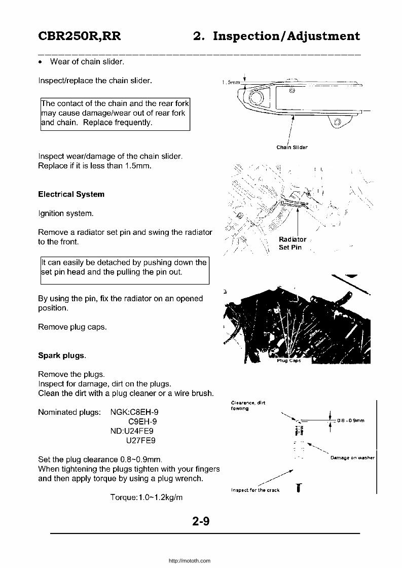
• Wear of chain slider.
Inspect/replace the chain slider.
The contact of the chain and the rear fork may cause damage/wear out of rear fork and chain. Replace frequently.
Inspect wear/damage of the chain slider. Replace if it is less than 1.5mm.
Electrical System
Ignition system.
Remove a radiator set pin and swing the radiator to the front.
It can easily be detached by pushing down the set pin head and the pulling the pin out.
By using the pin, fix the radiator on an opened position.
Remove plug caps.
Spark plugs.
Remove the plugs. Inspect for damage, dirt on the plugs. Clean the dirt with a plug cleaner or a wire brush.
Nominated plugs: NGK:CSEH-9 C9EH-9
ND:U24FE9 U27FE9
Set the plug clearance O.S-O.9mm. When tightening the plugs tighten with your fingers and then apply torque by using a plug wrench.
Torque:1.0-1.2kg/m
2-9
Clnrer.clt. dirt foming
Chain Sli der
,-J
',\
http://mototh.com
CBR250R,RR 2. Inspection! Adjustment
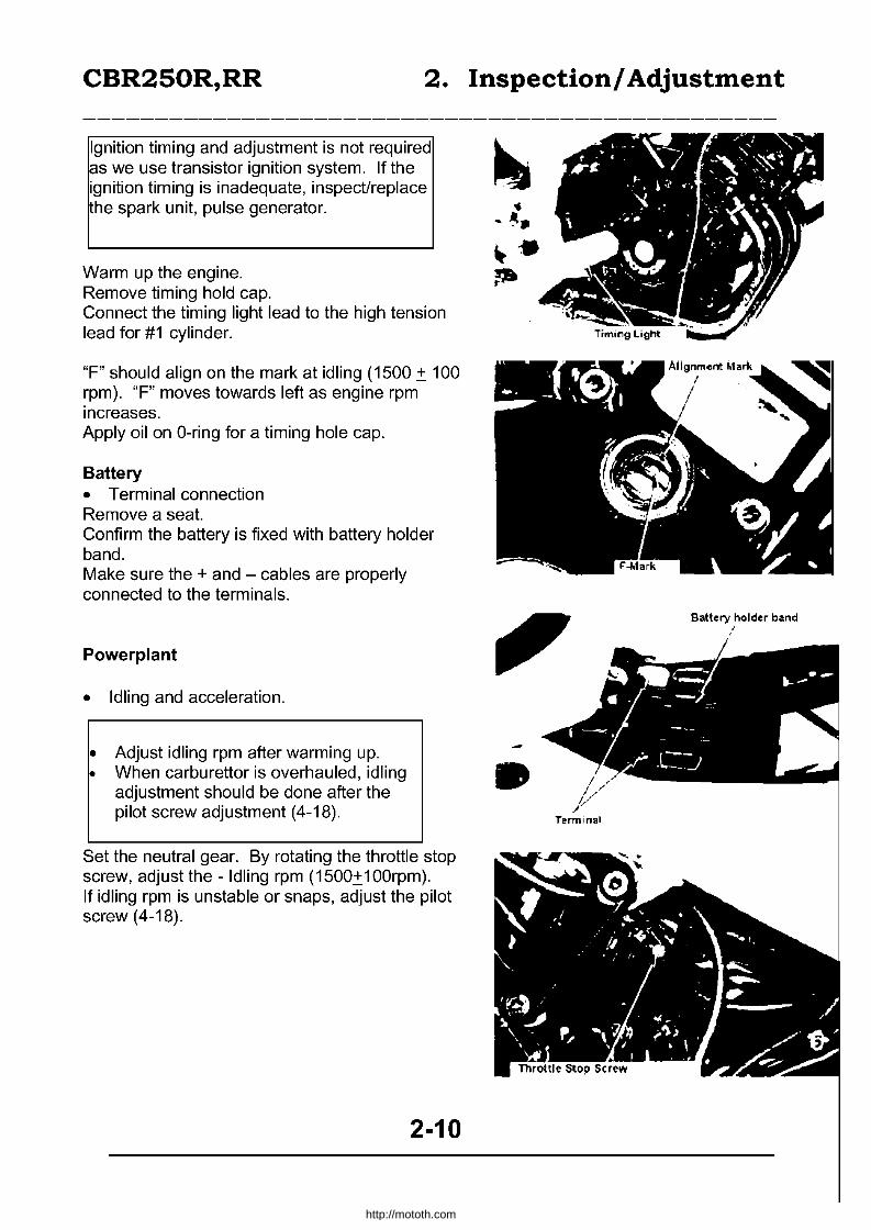
Ignition timing and adjustment is not required as we use transistor ignition system. If the ignition timing is inadequate, inspect/replace the spark unit, pulse generator. • -~ ..
~. Warm up the engine. ~ Remove timing hold cap. Connect the timing light lead to the high tension lead for #1 cylinder.
"F" should align on the mark at idling (1500.:': 100 rpm). "F" moves towards left as engine rpm increases. Apply oil on O-ring for a timing hole cap.
Battery • Terminal connection Remove a seat. Confirm the battery is fixed with battery holder band. Make sure the + and - cables are properly connected to the terminals.
Powerplant
• Idling and acceleration.
• Adjust idling rpm after warming up. • When carburettor is overhauled, idling
adjustment should be done after the pilot screw adjustment (4-18).
Set the neutral gear. By rotating the throttle stop screw, adjust the - Idling rpm (1500.:':100rpm). If idling rpm is unstable or snaps, adjust the pilot screw (4-18).
2-10
,
•
Battery holder band "
http://mototh.com

CBR250R,RR
(Replacement of an air cleaner). Remove the fuel tank. (4-3). Remove a bolt, then a duct.
Inspect the element for dirt and damage.
2. Inspection! Adjustment
If there are severe dirt/damages, replace with the new unit. Recommended part change: every 20,000km.
• The filter paper in the element contains oil. ~ (viscous type). Do not wipe or clean.
• If the vehicle is to be used in dusty conditions replace earlier than the period recommended.
Reverse the above procedure for installation.
(Cleaning the sub air cleaner). Remove the fuel tank. (4-3). Remove the sub air cleaner cap.
If the filter is jammed or dirty, clean by using washing oil and dry. Attach the filter and tighten the bis.
ITightening torque: 0.5-0.8 kgm.
2-11
http://mototh.com
CBR250R,RR 2. Inspection! Adjustment
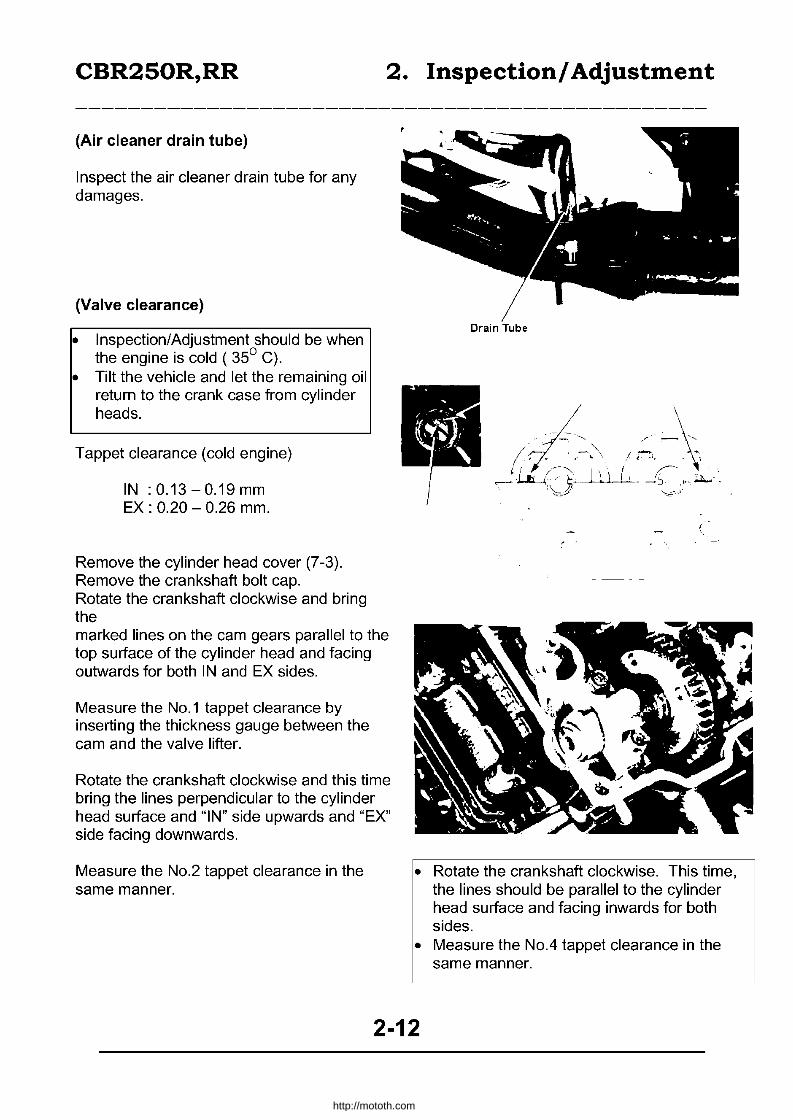
(Air cleaner drain tube)
Inspect the air cleaner drain tube for any damages.
(Valve clearance)
• Inspection/Adjustment should be when the engine is cold ( 35° C).
• Tilt the vehicle and let the remaining oil return to the crank case from cylinder heads.
Tappet clearance (cold engine)
IN :0.13-0.19mm EX : 0.20 - 0.26 mm.
Remove the cylinder head cover (7-3). Remove the crankshaft bolt cap. Rotate the crankshaft clockwise and bring the marked lines on the cam gears parallel to the top surface of the cylinder head and facing outwards for both IN and EX sides.
Measure the No.1 tappet clearance by inserting the thickness gauge between the cam and the valve lifter.
Rotate the crankshaft clockwise and this time bring the lines perpendicular to the cylinder head surface and "IN" side upwards and "EX" side facing downwards.
Measure the No.2 tappet clearance in the same manner.
• Rotate the crankshaft clockwise. This time, the lines should be parallel to the cylinder head surface and facing inwards for both sides.
• Measure the No.4 tappet clearance in the same manner.
2-12
http://mototh.com
CBR250R,RR 2. Inspection! Adjustment
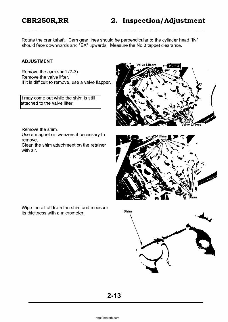
Rotate the crankshaft. Cam gear lines should be perpendicular to the cylinder head "IN" should face downwards and "EX" upwards. Measure the No.3 tappet clearance.
ADJUSTMENT
Remove the cam shaft (7-3). Remove the valve lifter. If it is difficult to remove, use a valve flapper.
It may come out while the shim is still attached to the valve lifter.
Remove the shim. Use a magnet or tweezers if necessary to remove. Clean the shim attachment on the retainer with air.
Wipe the oil off from the shim and measure its thickness with a micrometer.
2-13
Shim
..... . .... .
http://mototh.com

CBR250R,RR
How to select a proper shim
There are 65 different shims ranging ~rom 1.2mm to 2.8mm, in 0.025mm steps.
Required shim thickness Recorded tappet clearance; Specified tappet clearance Attached shim thickness
a=b-c+d
(Example)
b a
c d
Intake tappet clearance Attached shim thickness Specified tappet clearance
0.06 mm - b 1.875mm - d 0.16 mm - c
A=0.06 - 0.16 + 1.875 =1.775.
• Use a micrometer to measure the new and the attached shims' thickness.
• If the required shim thickness is greater than 2.80mm, remove carbon from a valve seat and adjust the seat.
Attach the selected shim. Apply MoS2 on the valve lifter and attach it. Install the camshaft (7-19).
2. Inspection! Adjustment
~ ~ '0 ~1a8' (0
1.80mm 1.825mm 1.85mm 1.875mm
Rotate the crankshaft for a couple of times and allow the shims to fit and re-inspect the tappet clearance. Attach the cylinder head cover (7-21).
2-14
( "
http://mototh.com
CBR250R,RR 2. Inspection! Adjustment
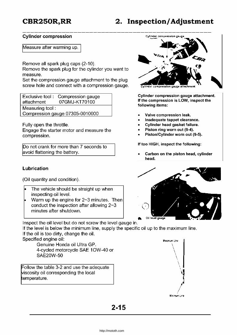
Cylinder compression
IMeasure after warming up. I
Remove all spark plug caps (2-10). Remove the spark plug for the cylinder you want to measure. Set the compression gauge attachment to the plug screw hole and connect with a compression gauge.
Exclusive tool: Compression gauge attachment 07GMJ-KT70100 Measuring tool: Compression QauQe 07305-0010000
Fully open the throttle. Engage the starter motor and measure the compression.
Do not crank for more than 7 seconds to avoid flattening the battery.
Lubrication
(Oil quantity and condition).
• The vehicle should be straight up when inspecting oil level.
• Warm up the engine for 2-3 minutes. Then conduct the inspection after allowing 2-3 minutes after shutdown.
Inspect the oil level but do not screw the level gauge in.
Cylinder compression gauge attachment. If the compression is LOW, inspect the following items:
• Valve compression leak. • Inadequate tappet clearance. • Cylinder head gasket failure. • Piston ring worn out (9-4). • Piston/Cylinder worn out (9-5).
If too HIGH, inspect the following:
• Carbon on the piston head, cylinder head.
:-:j \.. ..
~ 0,1
If the level is below the minimum line, supply the specific oil up to the maximum line. If the oil is too dirty, change the oil. Specified engine oil:
Genuine Honda oil Ultra GP. 4-cycled motorcycle SAE 1 OW -40 or SAE20W-50
Follow the table 3-2 and use the adequate viscosity oil corresponding the local emperature.
2-15
Muim;lm Lin~ \ \ \
http://mototh.com
CBR250R,RR 2. Inspection! Adjustment
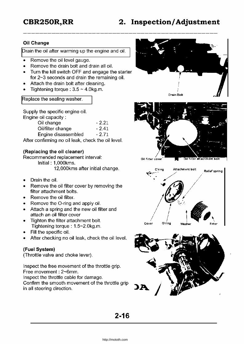
Oil Change
Drain the oil after warming up the engine and oil.
• Remove the oil level gauge. • Remove the drain bolt and drain all oil. • Turn the kill switch OFF and engage the starter
for 2-3 seconds and drain the remaining oil. • Attach the drain bolt after cleaning. • Tightening torque: 3.5 - 4.0kg.m.
IRe place the sealing washer.
Supply the specific engine oil. Engine oil capacity:
Oil change - 2.21 Oil/filter change - 2.41 Engine disassembled - 2.71
After confirming no oil leak, check the oil level.
(Replacing the oil cleaner) Recommended replacement interval:
Initial: 1,OOOkms. 12,OOOkms after initial change.
• Drain the oil. • Remove the oil filter cover by removing the
filter attachment bolts. • Remove the oil filter. • Remove the O-ring and apply oil. • Attach a spring and the new oil filter and
attach an oil filter cover • Tighten the filter attachment bolt.
Tightening torque: 1.5-2.0kg.m. • Fill the specific oil. • After checking no oil leak, check the oil level.
(Fuel System) (Throttle valve and choke lever).
Inspect the free movement of the throttle grip. Free movement: 2-6mm. Inspect the throttle cable for damage.
, I
Drain bolt
O'rlng Attachment bolt ~....-:-- - .. /,--'.' . /~
';':(1,/ ~~.
/ I I I
I I • j Cover O'rlng
Confirm the smooth movement of the throttle grip 'A J' in all steering direction. J
2-16
Rell.r spnng
Filter
http://mototh.com
CBR250R,RR 2. Inspection! Adjustment
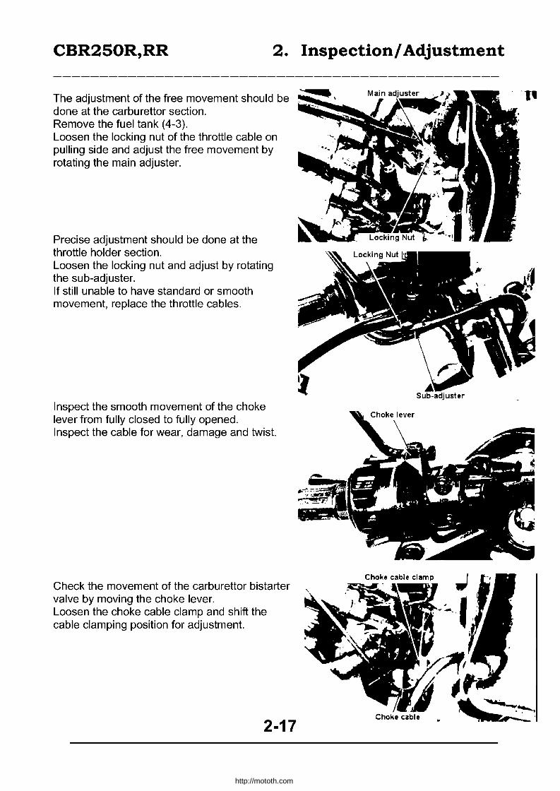
The adjustment of the free movement should be done at the carburettor section. Remove the fuel tank (4-3). Loosen the locking nut of the throttle cable on pulling side and adjust the free movement by rotating the main adjuster.
Precise adjustment should be done at the throttle holder section. Loosen the locking nut and adjust by rotating the sub-adjuster. If still unable to have standard or smooth movement, replace the throttle cables.
Inspect the smooth movement of the choke lever from fully closed to fully opened. Inspect the cable for wear, damage and twist.
Check the movement of the carburettor bistarter valve by moving the choke lever. Loosen the choke cable clamp and shift the cable clamping position for adjustment.
2-17
http://mototh.com

CBR250R,RR 2. Inspection! Adjustment
(Clogged fuel strainer)
Remove the seat, fuel tank attachment bolts and nuts. Turn the fuel cock OFF. Remove the strainer cup, and remove the O-ring and the strainer screen from the fuel cock body. Clean the strainer cup and the screen with washing oil. Attach the strainer screen to the cock body. After attaching the new O-ring, tighten the strainer cup.
Do not over tighten the strainer cup.
Turn the fuel cock ON and check no fuel leak.
Cooling System (Water level)
• When inspecting the radiator water level, place the body vertically.
• Inspect the water level at the reserve tank.
Remove the righthand side cover. Check that the water level in the reservoir tank is between UPPER and LOWER. If the level is below LOWER, refill the specified radiator liquid to UPPER line. Specified radiator liquid:
Genuine Honda Ultra radiator liquid. (30% standard concentration)
Fuel cock
. ~, Strainer cup
2-18
Stralner Scr •• n
http://mototh.com
CBR250R,RR 2. Inspection! Adjustment
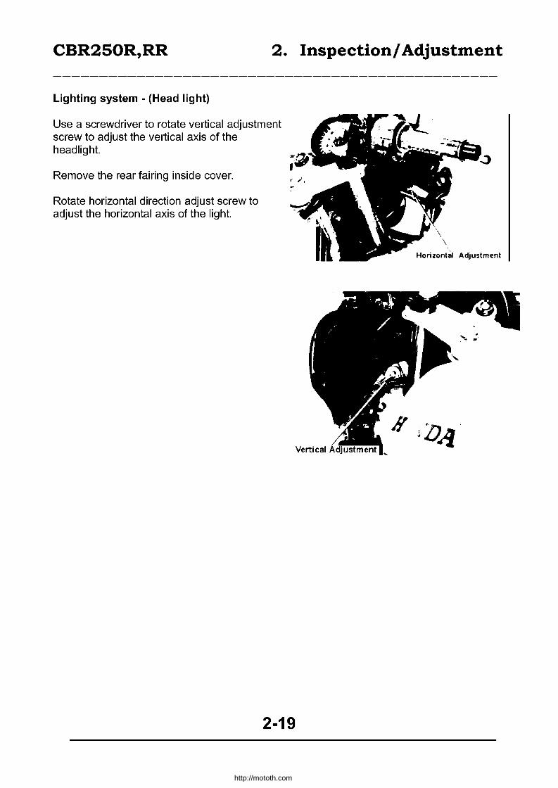
Lighting system - (Head light)
Use a screwdriver to rotate vertical adjustment screw to adjust the vertical axis of the headlight.
Remove the rear fairing inside cover.
Rotate horizontal direction adjust screw to adjust the horizontal axis of the light.
2-19
http://mototh.com

CBR250R,RR
(Stop lighUBrake light)
Conduct after adjusting the brake pedal height.
Adjust by rotating the adjuster while holding the stoplight switch so as to illuminate the light when the brake pedal is pushed for 20mm. After adjusting, check by pressing the brake pedal.
There is no need to adjust the front brake light switch.
Side stand
Support the frame and lift the rear wheel. As shown in the figure, apply 2.0-3.0kg. load on the edge of the stand and confirm its retraction. If there is no smooth movement, apply grease on the pivot area. If it retracts too easily, inspect the wear of the side stand spring? Inspect for lateral tension. Tighten the pivot bolt if it is loose. Inspect the side stand rubber and replace the rubber if it is worn out till the limit line.
Tightening torque:
Side stand bracket: 2.5-3.0kg-m.
2. Inspection! Adjustment
Stop light switch
• - 5.~· ~. .. -
2-20
http://mototh.com

CBR250R,RR System
eAssembly
3.5-4.0kg-m
3. Oil Lubrication
1.5-2.0kg-m
1. 3-1. 7kg-m
3-0
http://mototh.com

CBR250R,RR System
• Lubrication System Diagram
3. Oil Lubrication
/E'xh"ust Camshaft
Crankshaft
counterShaft ___ -t-:+H!!J-.:'l~~j~ng ,I~",*,,_
J:.Io~--fi-----------Pressure relief valve
'>..._----- Oil Strainer
3-1
http://mototh.com
CBR250R,RR System
3. Oil Lubrication
Assembly 3-0 Removing the oil strainer pressure relief valve
Lubrication Diagram 3 - 1 Removing the oil Pump Maintenance Information 3-2 Attaching the oil pump TroubleshootinQ 3-3 AttachinQ the oil strainer pressure valve Oil Pressure 3-4
• Maintenance Information
General Caution • All of the works on this chapter can be done on the vehicle. • Do not allow debris to enter the engine when removing an oil pump. • Replace by assy when the oil pump is on its limit.
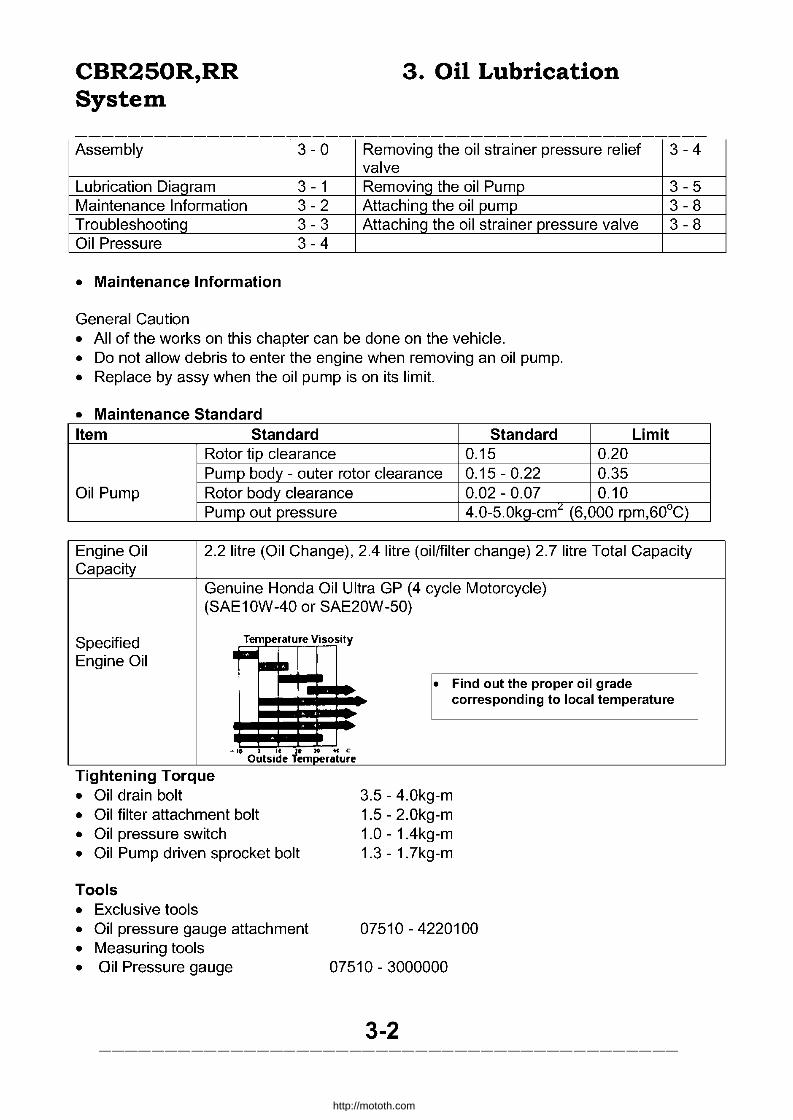
• Maintenance Standard Item Standard Standard Limit
Rotor tip clearance 0.15 0.20 Pump body - outer rotor clearance 0.15-0.22 0.35
Oil Pump Rotor body clearance 0.02 - 0.07 0.10
3-4
3-5 3-8 3-8
Pump out pressure 4.0-5.0kg-cmL (6,000 rpm,60°C)
Engine Oil 2.2 litre (Oil Change), 2.4 litre (oil/filter change) 2.7 litre Total Capacity Capacity
Genuine Honda Oil Ultra GP (4 cycle Motorcycle) (SAE10W-40 or SAE20W-50)
Specified Temperature Visosity
Engine Oil r -a • Find out the proper oil grade
corresponding to local temperature
-" • " .. .. .. c Outside Temperature
Tightening Torque • Oil drain bolt • Oil filter attachment bolt • Oil pressure switch • Oil Pump driven sprocket bolt
Tools • Exclusive tools
3.5 - 4.0kg-m 1.5 - 2.0kg-m 1.0 - 1.4kg-m 1.3 - 1.7kg-m
• Oil pressure gauge attachment 07510 - 4220100 • Measuring tools • Oil Pressure gauge 07510 - 3000000
3-2
http://mototh.com

CBR250R,RR System
• Troubleshooting
Low oil level
• Naturally consumed the oil. • Oil leak. • Piston ring worn out. • Valve guide or seal worn out.
Dirty oil
• Unchanged/Out of Service. • Head gasket failure. • Piston ring worn out.
Low oil pressure
• Low oil level. • Pressure relief valve does not close. • Oil strainer clogged. • Oil pump worn out. • Oil leak. • Improper oil grade.
High oil pressure
• Pressure relief valve does not open. • Oil filter, oil tube, orifice clogged. • Improper grade of oil.
No oil pressure
• Low oil level. • Oil pump drive sprocket failure. • Oil pump drive chain failure. • Oil pump failure. • Internal oil leak.
3. Oil Lubrication
3-3
http://mototh.com

CBR250R,RR System
3. Oil Lubrication
• Oil Pressure Inspection
IConduct after warm up. I
Remove the cover and screw for oil pressure switch. Disconnect the oil pressure warning light wiring. Remove the oil pressure switch. Connect the oil pressure gauge to the pressure switch hole. Inspect the oil quantity. Start the engine and measure the oil pressure at 6000 rpm.
Standard Oil Pressure :4.0-5.0kg/cm2 (6000rpm, oiI60°C)
Shutdown the engine. Apply sealer on the screw of the oil pressure switch and tighten.
Tightening torque: 1.0-1.4kgm.
Connect the oil pressure warning light wiring. Restart the engine and check the warning light turns off 1-2 seconds after starting. Exclusive tool : Oil pressure gauge attachment 07510-4220100. Measuring tool: Oil pressure gauge 07506-3000000.
Oil strainer, pressure relief valve
Remove the cover and screw for oil pressure switch. Remove the exhaust pipe (16-2). Drain engine oil (2-17). Remove the oil filter attachment bolt. Remove 12 bolts and remove oil pan, gaskets. Remove the bolts and remove the oil strainer from oil pump, clean the strainer. Remove the oil pressure relief valve. Remove O-ring and knocking pin.
3-4
Screw 011 Pressure switch
Oil pressure gauge
http://mototh.com
CBR250R,RR System
3. Oil Lubrication
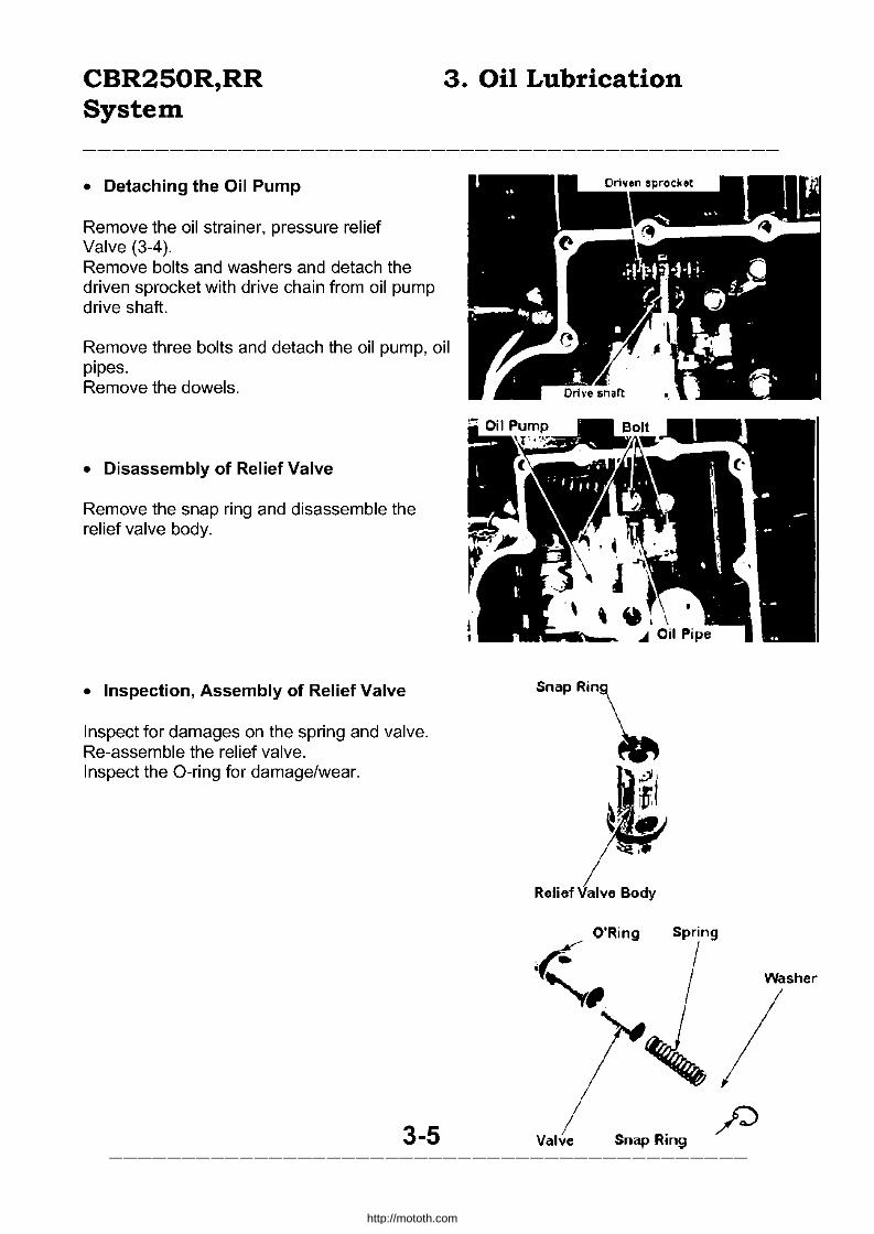
• Detaching the Oil Pump
Remove the oil strainer, pressure relief Valve (3-4). Remove bolts and washers and detach the driven sprocket with drive chain from oil pump drive shaft.
Remove three bolts and detach the oil pump, oil pipes. Remove the dowels.
• Disassembly of Relief Valve
Remove the snap ring and disassemble the relief valve body.
• Inspection, Assembly of Relief Valve
Inspect for damages on the spring and valve. Re-assemble the relief valve. Inspect the O-ring for damage/wear.
3-5
Snap Rin\
Relief
.~ '''/ ~
O'Ring Spring
«,1 j,
VYasher
/ / p
Valve Snap Ring
http://mototh.com
CBR250R,RR 3. Oil Lubrication System
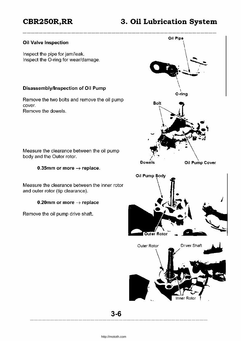
Oil Valve Inspection
Inspect the pipe for jam/leak. Inspect the O-ring for wear/damage.
Disassembly/Inspection of Oil Pump
Remove the two bolts and remove the oil pump cover. Remove the dowels.
Measure the clearance between the oil pump body and the Outer rotor.
O.35mm or more -7 replace.
Measure the clearance between the inner rotor and outer rotor (tip clearance).
O.20mm or more -7 replace
Remove the oil pump drive shaft.
3-6
Oil Pipe
\
~. \~ . '
. ~ .. ,\ i. . -
~'1 "J t -,
I. Dowels
Outer Rotor
..
\ \
O-ring
Ojl Pump Cover
j
Driver Shaft.~
http://mototh.com

CBR250R,RR System
3. Oil Lubrication
Measure the clearance between the edge surface of inner/outer rotor and the pump body.
0.10mm or more --7 replace.
Assembly of the Oil Pump.
Apply the specified oil to the contact surface of the oil pump. Insert the pin in the pump shaft and attach the thrust washer. Align the key slit on the inner rotor and the pin and attach the drive shaft to the oil pump body.
Attach the dowels to the oil pump body.
Attach the oil pump cover.
Attach two bolts and rotate the drive shaft to check for smooth movement.
3-7
Drive Shaft
\
Washer
http://mototh.com

CBR250R,RR System
Attachment of the Oil Pump
Attach the dowel. Apply oil to the O-ring and attach.
Attach the oil pump, oil pipe and tighten the three screws.
Attach the drive chain to the oil pump driven sprocket and attach to the drive shaft. Apply locking agent to the bolt and tighten with washers fitted.
Tightening torque: 1.3-1.7KGm
Attachment of the Oil Strainer Pressure Relief Valve
Apply oil to the pressure relief valve's O-ring and attach to the oil pump.
3. Oil Lubrication
3-8
http://mototh.com

CBR250R,RR System
Apply oil to the O-ring for the oil strainer and attach to the oil pump.
Tighten the bolt for the oil strainer. Attach the dowel, attach the O-ring after applying oil on it.
Clean the oil pan and attach with new gaskets.
Attach 12 oil pan attachment bolts. Attach the oil filter attachment bolts.
Tightening torque: 1.5-2.0kgm
3-9
3. Oil Lubrication
..... J
• Jt Oil PMl ..
http://mototh.com

CBR250R,RR 3. Oil Lubrication System
Tighten the oil pressure switch screw and attach the cover.
Fill the engine oil (2-17). Attach the exhaust pipe (16-2). Start the engine and confirm there is no oil leak.
3-10
http://mototh.com

CBR250R,RR 4. Fuel System
Assembly 4-0 Air cleaner case 4-6 Maintenance Information 4-1 Carburettor 4-8 Troubleshooting 4-2 Pilot screw adjustment 4 - 18 Fuel Tank 4-3 Carburettor synchronism adjustment 4 - 19 Fuel auto cock 4-4
• Maintenance Information
General Caution • Do not overstress the cables to bend or twist. Damaged or deformed cables may cause
failure or binding. • Exercise caution to avoid flames when handling fuel. • Always check the position of O-Ring when installing them. Replace with new ones upon
assembly. • Before disassembly, loosen the drain screw in float chamber and collect the drained fuel
with a tray. • The vacuum chamber and float chamber are able to accessed without removing the
carburettor.
Maintenance Standard Item Standard Value
Venturi Diameter 25mm Setting Mark VG01A
Fuel level 7mm Main jet #85 Slow jet #35
Idle speed 1 ,500 + 100rpm Free movement of a throttle grip 2-6mm
Air screw 2-}2 turns Total 141
Reserve 2.5 1
Tightening Torque Fuel cock Fuel tank attachment nut Fuel tank attachment bolt Air cleaner case Air cleaner duct
Tools Common Tools Float level gauge
Measuring Tools Vacuum gauge
2.0 - 2.5kg-m 0.8 - 1.2kg-m 1.8 - 2.5kg-m 0.6 - 1.0kg-m 0.5 - 0.8kg-m
07401 - 0010000
07404 - 0020000
4-1
http://mototh.com

CBR250R,RR
• Fuel System Troubleshooting
Starter Engages, but fails to start
• No fuel in a tank. • Fuel is not reaching to the carburettor. • The engine is flooded with fuel.
Clogged fuel filter. Clogged fuel tube. Float valve fixed in one position. Inadequate fuel level. Clogged air vent hole on a tank cap. Fuel Auto cock failure. Clogged/damaged vacuum tube.
• No sparks ( --,)Sec.18) • Clogged air cleaner element. • Manifold air leak. • Throttle grip failure.
Difficult to start/starts but stops soon.
• Faulty ignition (--')sec. 18) • Faulty synchronizing. • Faulty carburetor. • Bad quality fuel. • Vacuum leak from manifold. • Faulty bistarter valve. • Choke lever, cable failure.
• Inadequate tappet clearance ( --,)Sec.2).
Unstable idling.
• Faulty ignition (--,)18) • Inadequate idling. • Inadequate synchronizing. • Faulty carburettor. • Bad quality fuel. • Clogged air filter. • Vacuum leak from manifold. • Inadequate tappet clearance (--,)2)
4-2
4. Fuel System
Misfire during acceleration • Faulty ignition (-> Sec 18) • Too lean mixture
After burn • Faulty ignition (-> Sec18) • Too lean mixture
Unable to achieve power/bad fuel consumptiion • Clogged fuel system • Faulty igniton • Clogged air cleaner element
Too Lean Mixture
• Clogged fuel jet • Faulty vacuum piston • Faulty float valve • Fuel level too low • Clogged air vent on a fuel tank cap • Clogged fuel strainer screen • Clogged/bent/damaged fuel tube • Clogged air vent tube • Air from manifold • Clogged fuel filter • Faulty fuel auto cock • Clogged./damaged vacuum tube • Inadequate pilot screw adjustment
Too Rich Mixture
• Choke lever fixed in pulled position • Faulty float valve • Fuel level too high • Clogged air jet • Dirt on air cleaner element • Inadequate pilot screw adjustment
http://mototh.com
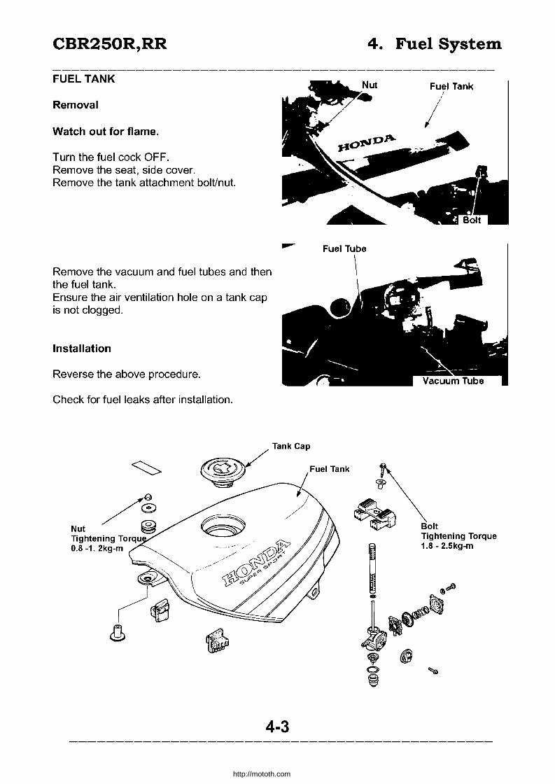
CBR250R,RR
FUEL TANK
Removal
Watch out for flame.
Turn the fuel cock OFF. Remove the seat, side cover. Remove the tank attachment bolt/nut.
Remove the vacuum and fuel tubes and then the fuel tank. Ensure the air ventilation hole on a tank cap is not clogged.
Installation
Reverse the above procedure.
Check for fuel leaks after installation.
--
4-3
4. Fuel System
Fuel Tank
//'
Fuel Tube
~ Bolt Tightening Torque
~ 1.8 - 2.Skg-m
~ ~~
1~~ • ts 0> @
http://mototh.com
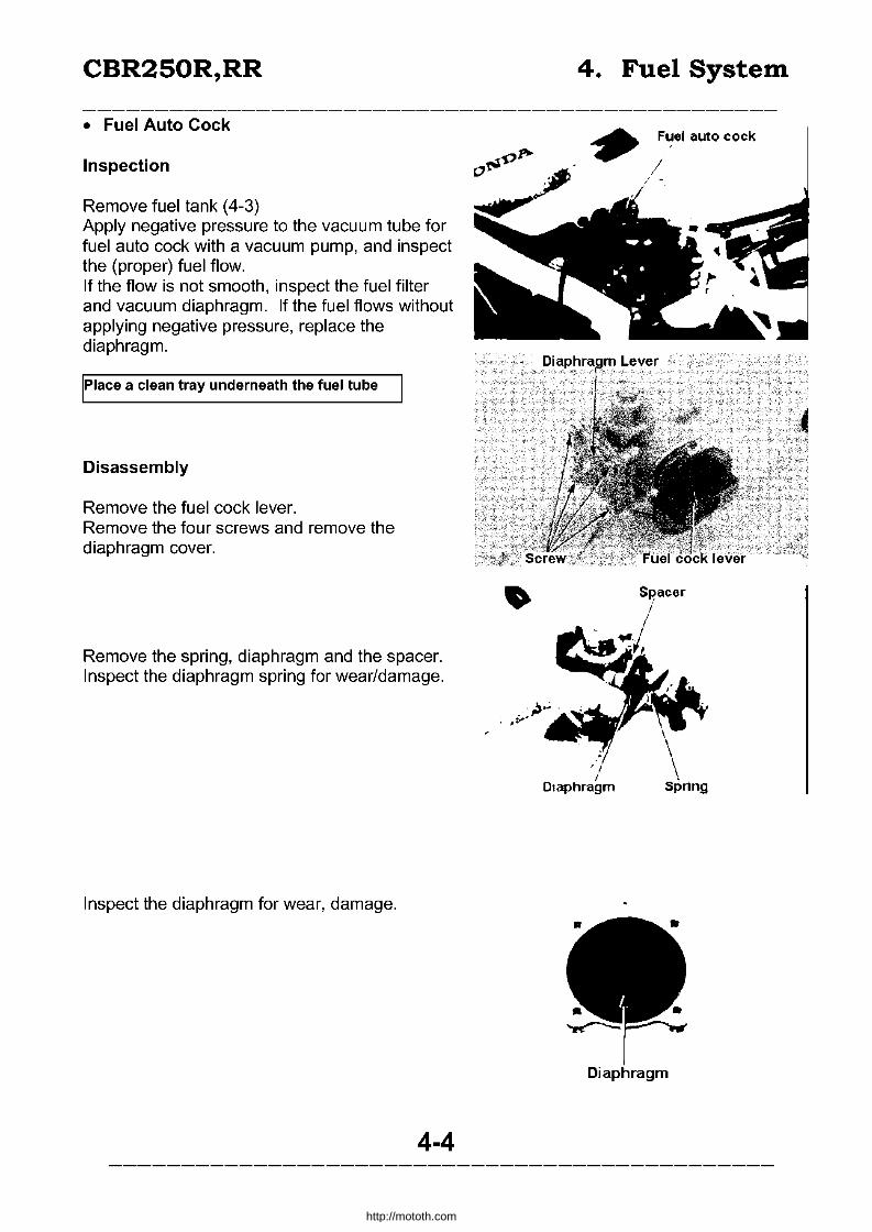
CBR250R,RR
• Fuel Auto Cock
Inspection
Remove fuel tank (4-3) Apply negative pressure to the vacuum tube for fuel auto cock with a vacuum pump, and inspect the (proper) fuel flow. If the flow is not smooth, inspect the fuel filter and vacuum diaphragm. If the fuel flows without applying negative pressure, replace the diaphragm.
Place a clean tray underneath the fuel tube
Disassembly
Remove the fuel cock lever. Remove the four screws and remove the diaphragm cover.
Remove the spring, diaphragm and the spacer. Inspect the diaphragm spring for wear/damage.
Inspect the diaphragm for wear, damage.
4-4
4. Fuel System
Fuel auto cock
DIaphragm
http://mototh.com

CBR250R,RR
Remove the fuel strainer cap, O-ring, strainer screen. Clean the strainer screen. Inspect the O-ring for wear.
Loosen the locking nut and remove the fuel auto cock from fuel tank. Remove the fuel filter and the O-ring. Clean the fuel filter. Inspect the O-ring for wear.
Assembly
Attach the fuel filter and the O-ring to the fuel auto cock.
Attach the fuel auto cock to the tank.
ITightening torque: 2.0-2.5kg m I
100 not overtighten the locking nut.
Attach the strainer screen. Attach the O-ring to the strainer cap and attach the cap to the fuel auto cock.
100 not overtighten the fuel strainer cap.
4-5
4. Fuel System
Strainer Screen C·Ring
'\' ~
Strainer Cap
C-Ring
• Fuel Filter
Fuel Auto Cock
Strainer Screen C-Ring
\ .... .~
http://mototh.com
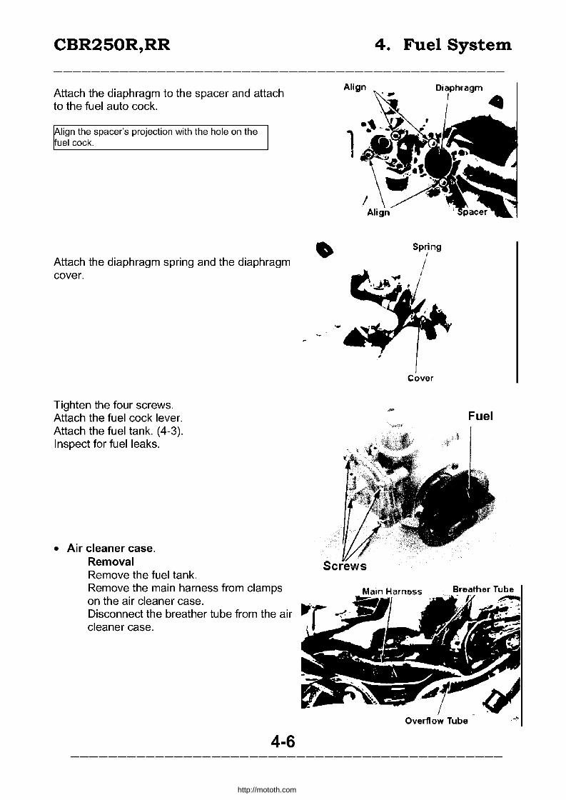
CBR250R,RR
Attach the diaphragm to the spacer and attach to the fuel auto cock.
lign the spacer's projection with the hole on the uel cock.
Attach the diaphragm spring and the diaphragm cover.
Tighten the four screws. Attach the fuel cock lever. Attach the fuel tank. (4-3). Inspect for fuel leaks.
• Air cleaner case. Removal Remove the fuel tank. Remove the main harness from clamps on the air cleaner case. Disconnect the breather tube from the air cleaner case.
4-6
4. Fuel System
1
Fuel
Screws
Overflow Tube
http://mototh.com

CBR250R,RR
Remove the seven bolts for the air cleaner case.
Disconnect the air cleaner drain tubes and remove the air cleaner.
Attachment
Reverse the above procedure.
Make sure the air cleaner drain tube and main wire harness are correctly attached.
Tightening Torque 0.6 - 1.0kg-m
Breather Cleaner Cap
Filter
Air Cleaner Case
4-7
4. Fuel System
d Air Cleaner Drain Tube
Bolt /lTightening Torque
/ 0.5 - 0.8kg-m
Duct
1"----Element
http://mototh.com

CBR250R,RR
• Carburettor
Removal
Remove the fuel tank (4-3) and the air cleaner (4-6).
Loosen the 4 screws on the carburetor insulator band (4 on cylinder side).
Disconnect the throttle and choke cables and remove carburetor assy.
Disassembly
Disassembly of the vacuum chamber and the float chamber are possible without removing the carbu rettor.
Remove the insulator from the carburettor.
Rotate the throttle stop screw and set so as to have all carburettors' bypass holes visible.
4-8
4. Fuel System
.4
, Throttle Stop Screw
http://mototh.com

CBR250R,RR
Loosen the bolts on bistarter arms and remove the bistarter arm shaft and spring.
Remove the bistarter arms.
Raise the catch (projection). Remove the screw to remove the rear bracket.
Remove the eight dowels. Inspect the air funnels for damage.
Remove the eight screws and remove the front bracket.
• The two carburettors thrust springs and three synchro adjust springs come off at the same time. Make sure not to lose them.
• Separate horizontally in order to avoid damaging the fuel and air joint pipe.
4-9
4. Fuel System
http://mototh.com
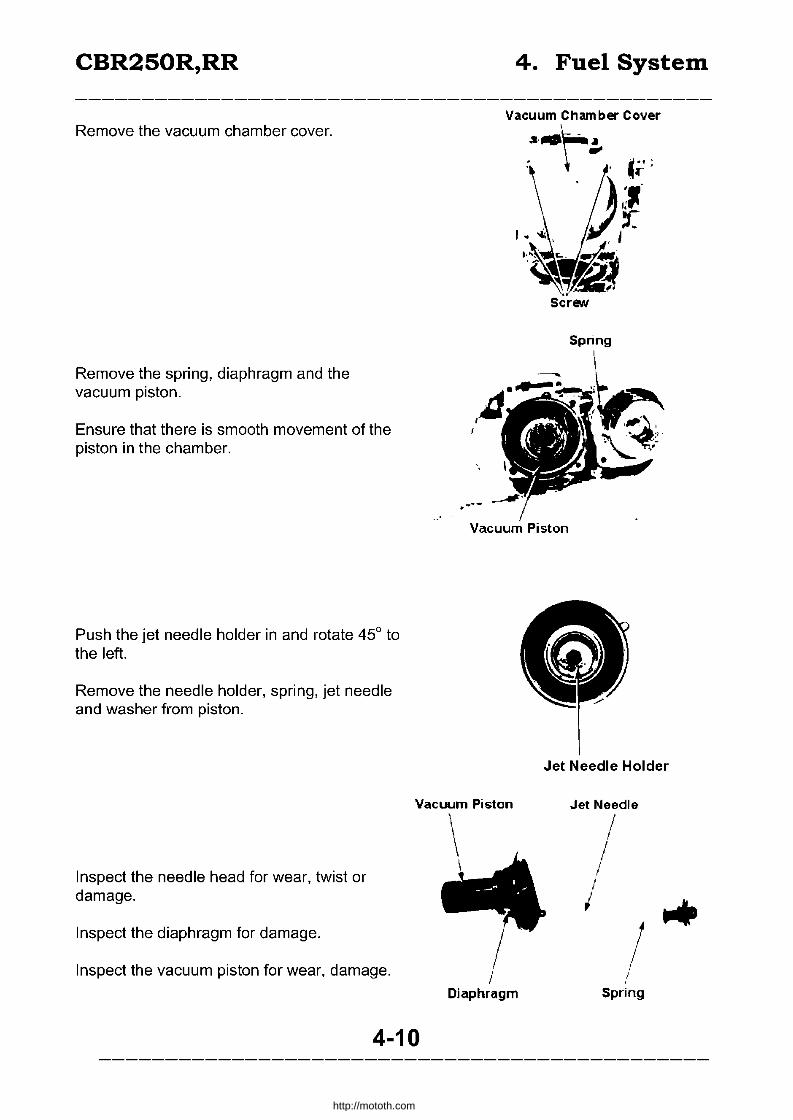
CBR250R,RR
Remove the vacuum chamber cover.
Remove the spring, diaphragm and the vacuum piston.
Ensure that there is smooth movement of the piston in the chamber.
Push the jet needle holder in and rotate 45° to the left.
Remove the needle holder, spring, jet needle and washer from piston.
4. Fuel System
Vacuum Chamber Cover
Screw
Spring
..---Vacuum Piston
Jet Needle Holder
Vacuum Piston Jet Needle
Inspect the needle head for wear, twist or damage.
Inspect the diaphragm for damage.
Inspect the vacuum piston for wear, damage.
4-10
/ Diaphragm
/ /
/ /
Spring
http://mototh.com

CBR250R,RR
Remove the float chamber.
Pull out the float pin and remove the float and the float valve.
Inspect the float.
Inspect the float valve and a valve seat for damage, clogging.
Inspect the contact surface between the valve and the seat for wear.
Remove the main jet, needle jet holder, slow jet and the valve seats.
Record the number of turns on the pilot screw to fully-tighten. Then remove the screw.
Do not overtighten the pilot screw. May cause damage on the seats.
Clean the jets with clean fuel.
4-11
Float
4. Fuel System
Vacuum Chamber Cover
,-' / ~
I I
Float Pin
'~"-....
Main Jet
~
http://mototh.com
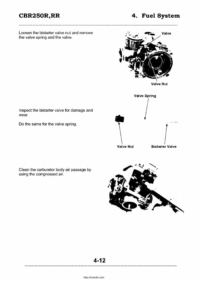
CBR250R,RR
Loosen the bistarter valve nut and remove the valve spring and the valve.
Inspect the bistarter valve for damage and wear.
Do the same for the valve spring.
Clean the carburetor body air passage by using the compressed air.
4-12
4. Fuel System
Valve
\' ,
Valve Nut
Valve Spring
Valve Nut Bistarter Valve
http://mototh.com
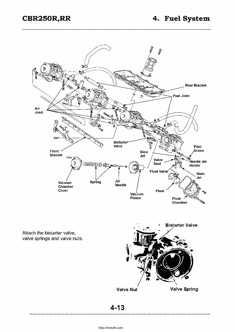
CBR250R,RR
Air Joint
Bracket
-p' Vacuum Chamber Cover
Attach the bistarter valve, valve springs and valve nuts.
Spring
Vacuum Piston
Valve Nut
4-13
4. Fuel System
Float Chamber
Bistarter Valve
\
Valve Spring
http://mototh.com

CBR250R,RR
Attach the needle jet holder, main jet, slowjet, valve sheet and the pilot screw to the carburettor body.
Fully tighten the pilot screw and wind back number of urns recorded upon disassembly. Do not tighten hard
or it may damage the seat surface.
Attach the float and the float valve with the float pin to the carburetor body.
Fuel Level
Set the float chamber attachment surface vertically.
Tilt the carburettor to forward 30° (the float valve and the float arm contact) and measure the fuel level.
Standard level: 7mm.
Bend the lip of the float arm to adjust the level.
Common Tool
Float level gauge
Use the gauge at a position for main jet and set perpendicular to the float chamber attachment surface.
Inspect the G-ring for wear.
Apply oil on the G-ring and attach the float chamber.
4-14
4. Fuel System
O-Ring "..
http://mototh.com

CBR250R,RR
Tighten with four screws.
Tighten and attach the throttle stop screw holder to a carburettor body with 2 screws.
Attach the washer, jet needle and a spring to the vacuum piston. Push the jet needle holder in and rotate 45° to the right.
Push the bottom of the vacuum piston towards vacuum chamber side and make it nearly full open position.
Firmly fit the rib of the diaphragm to the slit on the body.
Attach the spring and align the hole on the diaphragm and the slit on the cover to attach the cover.
Ehe cover should not catch the diaphram.
Tighten the 4 screws.
4-15
4. Fuel System
Holder -~::;-';~
Jet Needle Holder
Screw
http://mototh.com
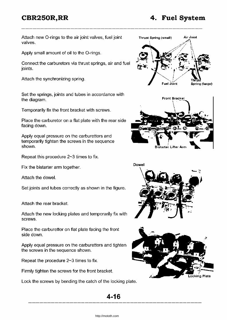
CBR250R,RR
Attach new O-rings to the air joint valves, fuel joint valves.
Apply small amount of oil to the O-rings.
Connect the carburetors via thrust springs, air and fuel joints.
Attach the synchronizing spring.
Set the springs, joints and tubes in accordance with the diagram.
Temporarily fix the front bracket with screws.
Place the carburetor on a flat plate with the rear side facing down.
Apply equal pressure on the carburettors and temporarily tighten the screws in the sequence shown.
Repeat this procedure 2-3 times to fix.
Fix the bistarter arm together.
Attach the dowel.
Set joints and tubes correctly as shown in the figure.
Attach the rear bracket.
Attach the new locking plates and temporarily fix with screws.
Place the carburettor on flat plate facing the front side down.
Apply equal pressure on the carburettors and tighten the screws in the sequence shown.
Repeat the procedure 2-3 times to fix.
Firmly tighten the screws for the front bracket.
Dowel
Lock the screws by bending the catch of the locking plate.
4-16
4. Fuel System
http://mototh.com

CBR250R,RR
Attach the bistarter arms to bistarter valves.
Attach the spring and the arm shaft.
Fix the bistarter arms to the shaft. Move the bistarter lifter arm and ensure the movement of the bistarter valves.
Inspect the throttle movement by following the procedure: • Push the throttle linkage and open the throttle a
bit and ensure the throttle returns smoothly. • Open and close the throttle and ensure the
smooth movement.
Rotate the synchronizing adjust screw and align all carburettor bypass holes and the position of the throttle valve.
Use No.3 carburettor as a reference.
Attach insulator to carburettor.
Set the insulator screws to the direction indicated by arrow symbols.
4-17
4. Fuel System
L
Carburettor
Spring \ , \ .....
Bvpass Hole
Insulators
http://mototh.com
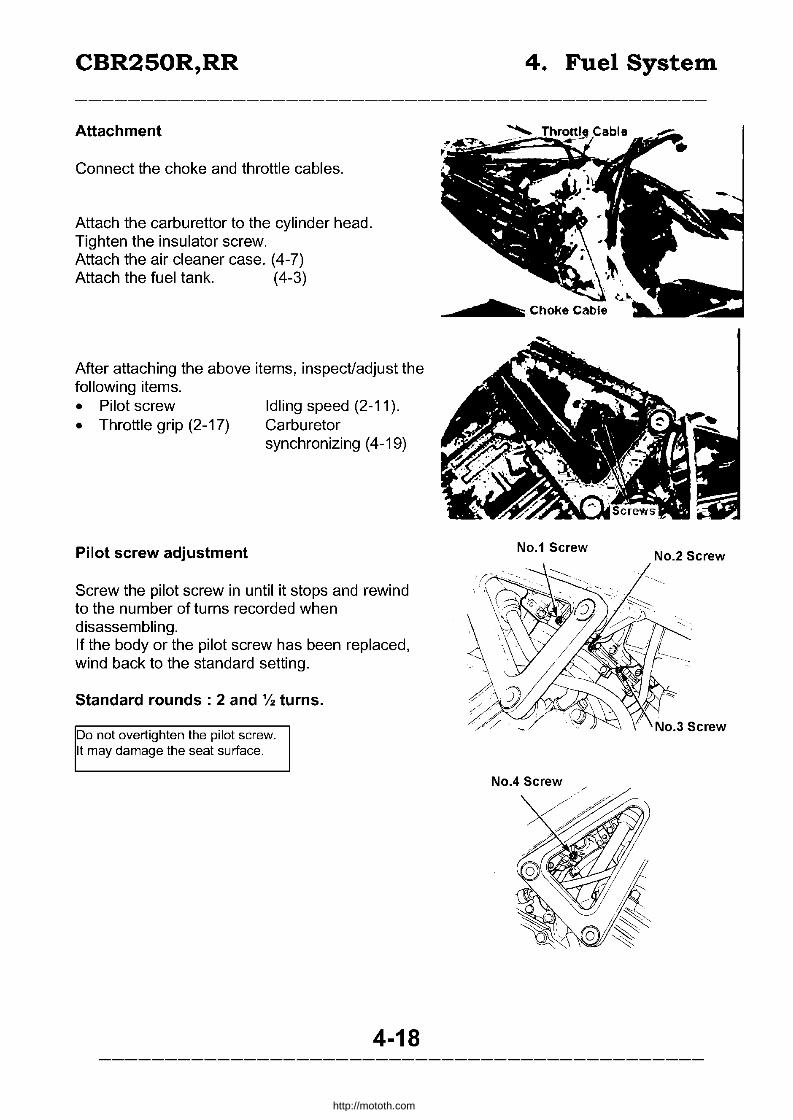
CBR250R,RR
Attachment
Connect the choke and throttle cables.
Attach the carburettor to the cylinder head. Tighten the insulator screw. Attach the air cleaner case. (4-7) Attach the fuel tank. (4-3)
After attaching the above items, inspect/adjust the following items. • Pilot screw • Throttle grip (2-17)
Pilot screw adjustment
Idling speed (2-11). Carburetor synchronizing (4-19)
Screw the pilot screw in until it stops and rewind to the number of tums recorded when disassembling. If the body or the pilot screw has been replaced, wind back to the standard setting.
Standard rounds: 2 and'!. turns.
Do not overtighten the pilot screw. It may damage the seat surface.
4-18
4. Fuel System
No.1 Screw No.2 Screw
http://mototh.com
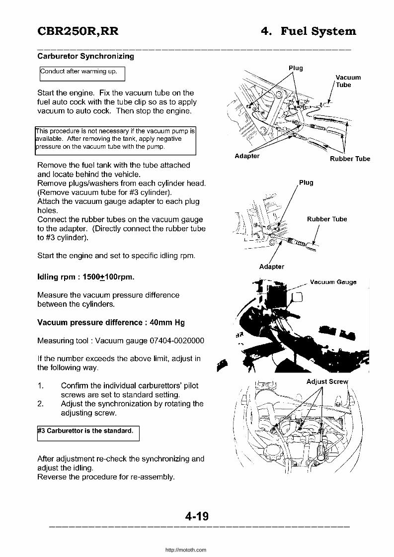
CBR250R,RR
Carburetor Synchronizing
Iconduct after warming up. I
Start the engine. Fix the vacuum tube on the fuel auto cock with the tube clip so as to apply vacuum to auto cock. Then stop the engine.
This procedure is not necessary if the vacuum pump is available. After removing the tank, apply negative pressure on the vacuum tube with the pump.
Remove the fuel tank with the tube attached and locate behind the vehicle. Remove plugs/washers from each cylinder head. (Remove vacuum tube for #3 cylinder). Attach the vacuum gauge adapter to each plug holes. Connect the rubber tubes on the vacuum gauge to the adapter. (Directly connect the rubber tube to #3 cylinder).
Start the engine and set to specific idling rpm.
Idling rpm: 1500:!:100rpm.
Measure the vacuum pressure difference between the cylinders.
Vacuum pressure difference: 40mm Hg
Measuring tool: Vacuum gauge 07404-0020000
If the number exceeds the above limit, adjust in ... the following way. rr
1. Confirm the individual carburettors' pilot screws are set to standard setting.
2. Adjust the synchronization by rotating the adjusting screw.
F3 Carburettor is the standard.
After adjustment re-check the synchronizing and adjust the idling. Reverse the procedure for re-assembly.
4-19
4. Fuel System
Plug
Adapter Rubber Tube
Vacuum Gauge
http://mototh.com

CBR250R,RR
Assembly Maintenance Information T roubleshootinq Radiator
• Maintenance Information General Caution
5-0 5-1 5-1 5-3
5. Cooling System
Thermostat 5-6 Thermal Sensor 5-8 Water Pump 5-9 Reservoir Tank 5 - 11
• Conduct the maintenance while the engine is cool. • Do not open the radiator cap when it is hot. • All of the cooling system maintenance can be conducted on the vehicle. • Refill of the radiator fluid should be done through the reservoir tank. Do not remove the
radiator cap except for radiator fluid refill/drain purposes. • Radiator coolant may damage the painted surface. Wash off with water immediately. • After the work, inspect all joints / seals for water leak by using a radiator cap tester.
Maintenance Standard Standard Limitation Radiator Cap Valve Opening Press 0.75 - 1.05kg/cm2 ~O. 75kg/cm2 or ~ 1.05kg/cm2
-4 Replace Thermostat Valve Initial Opening SO - 84°C -
OpeninQ Temperature Full Open 95°C -
Full Open Lift Smm or more -
Total Approx. Radiator Side Approx 1.1 OOcc Cooling Water Capacity 1.300cc Reservoi r Tanked 200cc
Tightening Torque
Radiator Upper Stay Thermostat Cover Radiator Grill
1.0 - 1.4kg-m
Troubleshooting Too High water temperature
• Water Temp indicator or the thermal sensor failure
• Radiator Cap failure
• Thermostat failure
• Radiator liquid level too low
• Clogged water hose / jacket
• Bent Pin
• Clogged radiator
• Water pump failure
1.0 - 1.4kg-m 0.8 - 1.2kg-m
Water Leak
• Mechanical seal failure
• Worn out / damaged water hose
• Worn out / loose 0 rings
Water temp too low or slow rise
• Temp indicator / thermal sensor failure
• Thermal sensor failure
• Thermostat Failure
5-1
http://mototh.com

CBR250R,RR 5. Cooling System
Radiator Liquid Specific Gravity
Density % Temp 0 5 10 15 20 25 30 35 40 45 50 5 1.009 1.009 1.008 1.008 1.007 1.006 1.005 1.003 1.001 0.999 0.997
10 1.018 1.017 1.017 1.016 1.015 1.014 1.013 1.001 1009 1.007 1.005
15 1.028 1.027 1.026 1.025 1.024 1.022 1.020 1.018 1.016 1.014 1.012
20 1.036 1.035 1.034 1.033 1.031 1.029 1.027 1.025 1.023 1.021 1.019
25 1.045 1.044 1.043 1.042 1.040 1.038 1.036 1034 1031 1.028 1.025
*30 1.053 1.052 1.051 1.049 1.047 1.045 1.043 1.041 1.038 1.035 1.032
35 1.063 1.062 1.060 1.058 1.056 1.054 1.052 1.049 1.046 1.043 1.040
40 1.072 1.070 1.068 1.066 1.064 1.062 1.059 1.056 1.053 1.050 1.047
45 1080 1.078 1.076 1.074 1.072 1.069 1.056 1063 1060 1.057 1.054
50 1086 1.084 1082 1080 1.077 1.074 1.071 1068 1065 1062 1.059
55 1.095 1.093 1.091 1.088 1.085 1.082 1.079 1.076 1.073 1.070 1.067
60 1.100 1.098 1095 1092 1089 1.086 1.083 1080 1.077 1.074 1.071
* Standard
Radiator liquid mixture table (anti-corrosion I ice-free)
Minimum Temp Mixture Honda Ultra Radiator Liquid Purified Water -9c 20% 260cc 1.040cc
-16c 30% 390cc 910cc -25c 40% 520cc 780cc -37c 50% 650cc 650cc
-44.5c 55% 715cc 585cc
General caution for the radiator liquid • Use Honda Ultra radiator liquid or equivalent • Do not mix with the other product • Toxic. Do not drink • Apply 5°c allowance to the minimum temperature
5-2
http://mototh.com
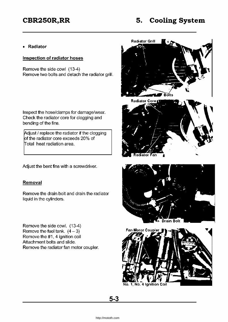
CBR250R,RR
• Radiator
Inspection of radiator hoses
Remove the side cowl (13-4) Remove two bolts and detach the radiator grill.
Inspect the hose/clamps for damage/wear. Check the radiator core for clogging and bending of the fins.
~djust / replace the radiator if the clogging pf the radiator core exceeds 20% of ~otal heat radiation area.
Adjust the bent fins with a screwdriver.
Removal
Remove the drain bolt and drain the radiator liquid in the cylinders.
Remove the side cowl. (13-4) Remove the fuel tank. (4 - 3) Remove the #1, 4 ignition coil Attachment bolts and slide. Remove the radiator fan motor coupler.
5-3
5. Cooling System
http://mototh.com

CBR250R,RR
Remove the radiator attachment bolt. Remove the cooling fan switch wire connector.
Remove the radiator set pin. Remove the lower radiator hose.
Pull the radiator forward. Disconnect the upper radiator hose and remove the radiator.
100 not damage radiator fins.
Disassembly
Remove the two bolts and detach the radiator grill.
5-4
5. Cooling System
. , Attachment Bolt ""I
Set Pin
Attachment Bolt Bolts
http://mototh.com

CBR250R,RR
Remove the three bolts behind the radiator and detach the fan shroud and the fan motor at the ASSY.
Remove nuts and remove the fan.
Detach the wire from the clamp. Remove three screws and detach the motor from fan shroud.
Assembly
Inspect all parts for damage. Reverse the disassembly procedure for the assembly.
~Iign the fan motor axis and the slit on the fan when assembling the fan.
5. Cooling System
5-5
http://mototh.com

CBR250R,RR
Attachment
Reverse the detachment procedure. Tightening torque. Radiator upper stay: 1.0 - 1.4kg m Radiator grill : 0.8 - 1.2kg m Fill the radiator liquid. (2-19) Apply pressure to the radiator and inspect for water leak.
Radiator cap inspection
Inspect the cap with a radiator cap tester. It should sustain 6 sec for standard pressure.
• Apply water on the seal surface of the cap when attaching the tester
Radiator cap valve opening pressure: 0.9 kg/cm2
Radiator pressurization test
Apply standard pressure with the tester. Should sustain for 6 sec. Standard pressure: 0.75 - 1.05kg/cm2
Inspect the hoses, each joint, bottom of the water pump for water leak.
Thermostat
Removal
Remove the radiator cap. Drain radiator liquid (5-3)
5-6
5. Cooling System
Radiator Cap
http://mototh.com

CBR250R,RR
Remove two bolts and detach the pipe.
Remove O-Ring on the thermostat upper case.
Disconnect the overflow tube. Remove two attachment bolts and detach the thermostat uppercase.
Remove the O-Ring and the thermostat.
5-7
5. Cooling System
http://mototh.com
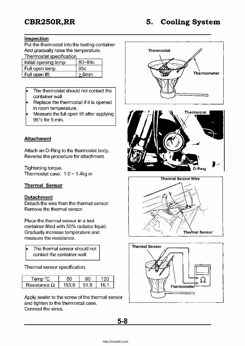
CBR250R,RR
Inspection Put the thermostat into the testing container And gradually raise the temperature. Thermostat specification Initial opening temp 80-84c Full open temp 95c Full open lift >8mm
• The thermostat should not contact the container wall.
• Replace the thermostat if it is opened in room temperature.
• Measure the full open lift after applying 95°c for 5 min.
Attachment
Attach an O-Ring to the thermostat body. Reverse the procedure for attachment.
Tightening torque. Thermostat case: 1.0 - 1.4kg m
Thermal Sensor
Detachment Detach the wire from the thermal sensor. Remove the thermal sensor.
Place the thermal sensor in a test container filled with 50% radiator liquid. Gradually increase temperature and measure the resistance.
• The thermal sensor should not contact the container wall.
Thermal sensor specification.
Temp °C 50 80 Resistance Q 153.9 51.9
120 16.1
Apply sealer to the screw of the thermal sensor and tighten to the thermostat case. Connect the wires.
5-8
5. Cooling System
\ Thermometer
Thermal Sensor Wire
~ Q
Thermo;:;m~e~te~--=-:=-.J
http://mototh.com
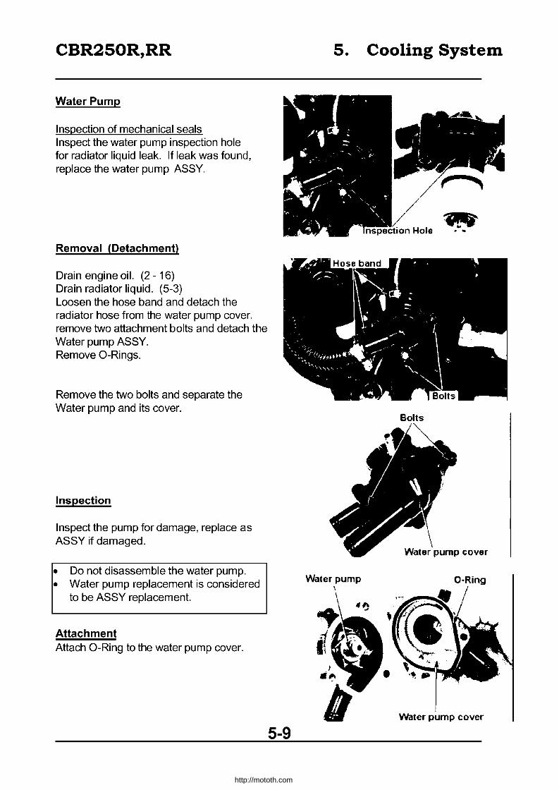
CBR250R,RR
Water Pump
Inspection of mechanical seals Inspect the water pump inspection hole for radiator liquid leak. If leak was found, replace the water pump ASSY.
Removal (Detachment)
Drain engine oil. (2 - 16) Drain radiator liquid. (5-3) Loosen the hose band and detach the radiator hose from the water pump cover. remove two attachment bolts and detach the Water pump ASSY. Remove O-Rings.
Remove the two bolts and separate the Water pump and its cover.
Inspection
Inspect the pump for damage, replace as ASSY if damaged.
• Do not disassemble the water pump. • Water pump replacement is considered
to be ASSY replacement.
Attachment Attach O-Ring to the water pump cover.
5-9
5. Cooling System
Water pump \
't:'f
Bolts
O-Ring
Water pump cover
http://mototh.com

CBR250R,RR
Attach cover to the pump and Tighten the two bolts.
Attach the O-Ring to the water pump.
Align the oil pump shaft and the slit of the water pump shaft and attach the water pump ASSY to the crank case.
Tighten the two attachment bolts. Attach the radiator hose to the water pump cover and tighten the hose band. Fill the radiator liquid (2 - 19). Fill the engine oil (2 - 17)
Ensure there are no leaks after the work is completed.
5-10
5. Cooling System
Water Pump Cover
O-Ring
. ..
http://mototh.com
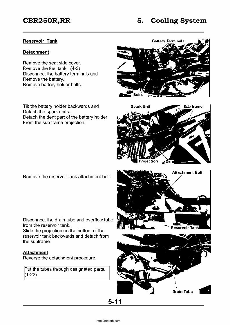
CBR250R,RR
Reservoir Tank
Detachment
Remove the seat side cover. Remove the fuel tank. (4-3) Disconnect the battery terminals and Remove the battery. Remove battery holder bolts.
Tilt the battery holder backwards and Detach the spark units. Detach the dent part of the battery holder From the sub frame projection.
Remove the reservoir tank attachment bolt.
Disconnect the drain tube and overflow tube from the reservoir tank. Slide the projection on the bottom of the reservoir tank backwards and detach from the subframe.
Attachment Reverse the detachment procedure.
Put the tubes through designated parts. (1-22)
5-11
5. Cooling System
\ ........... Drain Tube ...
http://mototh.com

CBR250R,RR 6. Engine Installation/Removal
• Assembly
4.5-5.5kg-m
~o--~~4.5-5.5kg-m
I.O-I.4kg-m
6-0
http://mototh.com
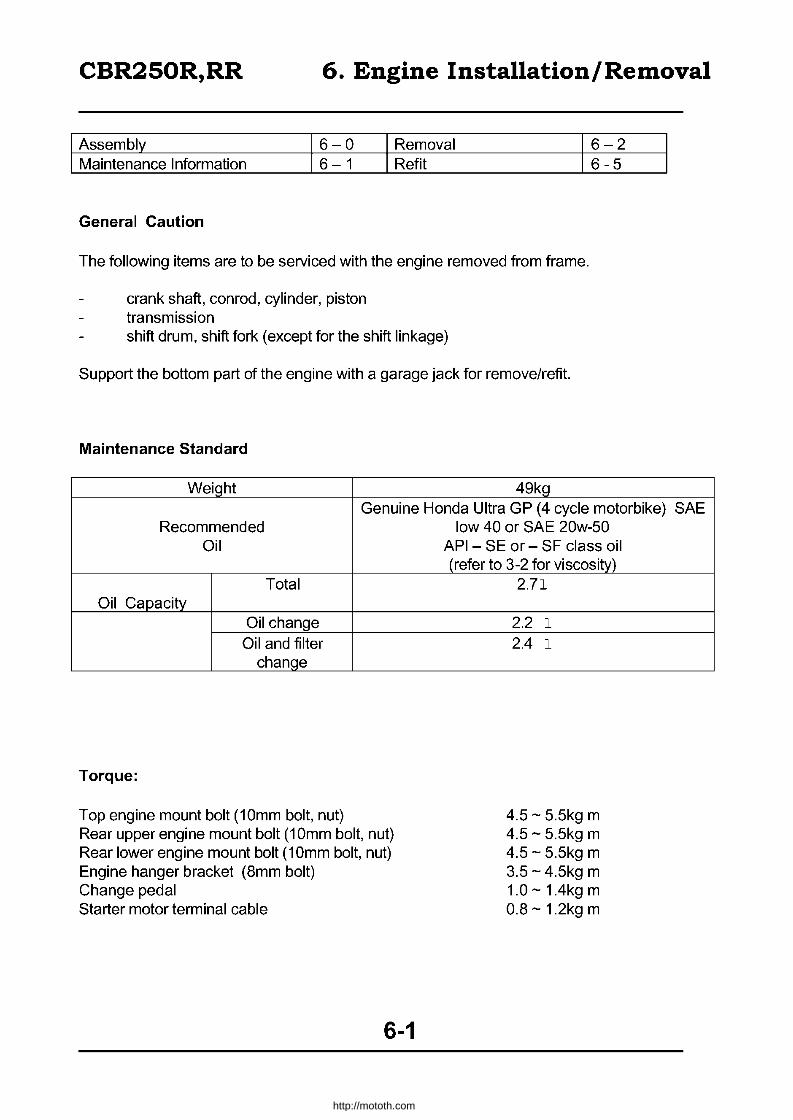
CBR250R,RR 6. Engine Installation/Removal
Assembly 6-0 Removal 6-2 Maintenance Information 6-1 Refit 6-5
General Caution
The following items are to be serviced with the engine removed from frame.
crank shaft, conrod, cylinder, piston transmission shift drum, shift fork (except for the shift linkage)
Support the bottom part of the engine with a garage jack for remove/refit.
Maintenance Standard
Weight 49kg Genuine Honda Ultra GP (4 cycle motorbike) SAE
Recommended Oil
Total Oil Capacity
Oil change Oil and filter
change
Torque:
Top engine mount bolt (10mm bolt, nut) Rear upper engine mount bolt (1 Omm bolt, nut) Rear lower engine mount bolt (10mm bolt, nut) Engine hanger bracket (Bmm bolt) Change pedal Starter motor terminal cable
6-1
low 40 or SAE 20w-50 API - SE or - SF class oil (refer to 3-2 for viscosity)
2.71
2.2 1 2.4 1
4.5 - 5.5kg m 4.5 - 5.5kg m 4.5 - 5.5kg m 3.5 -4.5kg m 1.0 -1.4kg m O.B -1.2kg m
http://mototh.com

CBR250R,RR
Drain engine oil (2-16) Drain radiator fluid (5-3) Remove the seat and side covers. Remove the fuel tank (4-3)
6. Engine Installation/Removal
Disconnect the leads from the battery. Disconnect the two connectors and detach, the wire harness from an air cleaner case. Detach the air cleaner case by removing 7 bolts.
IRemove the carburettor (4-8)
After detaching the carburettor, seal the intake manifold with adhesive tape.
Disconnect the two water hoses and four plug caps.
Disconnect the earth cable and the terminal cable.
6-2
http://mototh.com
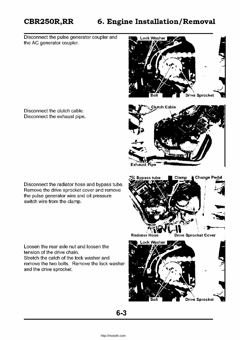
CBR250R,RR 6. Engine Installation/Removal
Disconnect the pulse generator coupler and the AC generator coupler.
Disconnect the clutch cable. Disconnect the exhaust pipe.
Disconnect the radiator hose and bypass tube. Remove the drive sprocket cover and remove the pulse generator wire and oil pressure switch wire from the clamp.
Loosen the rear axle nut and loosen the tension of the drive chain. Stretch the catch of the lock washer and remove the two bolts. Remove the lock washer and the drive sprocket.
6-3
http://mototh.com
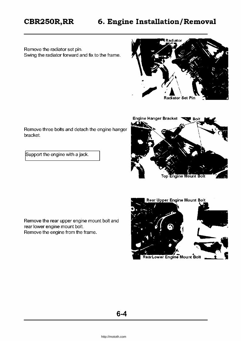
CBR250R,RR 6. Engine Installation/Removal
Remove the radiator set pin. Swing the radiator forward and fix to the frame.
Remove three bolts and detach the engine hanger bracket.
Eupport the engine with a jack.
Remove the rear upper engine mount bolt and rear lower engine mount bolt. Remove the engine from the frame.
6-4
~
\ .'! \ Radiator Set Pin
http://mototh.com

CBR250R,RR 6. Engine Installation/Removal
Engine Refit
Reverse the removal procedure for the refit.
~ Do not damage the harness and cables.
~ Do not damage the frame, bolts and screws.
~ Firmly lock the drive sprocket bolt with a catch or a lock washer.
~ Apply leads, tubes and hoses through the proper places (1-22)
Torque:
Top engine mount bolt Rear upper engine mount bolt Rear lower engine mount bolt Engine hanger bracket Change pedal
4.5 - 5.5kg m 4.5 - 5.5kg m 4.5 - 5.5kg m 3.5 -4.5kg m 1.0 -1.4kg m
After the refit, conduct the following inspections I adjustments.
Free movement of the clutch lever (2-8) Free movement of the throttle grip (2-17) Drive chain (2-9) Brake pedal (2-5) Engine Oil (2-15) Choke lever (2-17) Radiator (2-18)
6-5
http://mototh.com
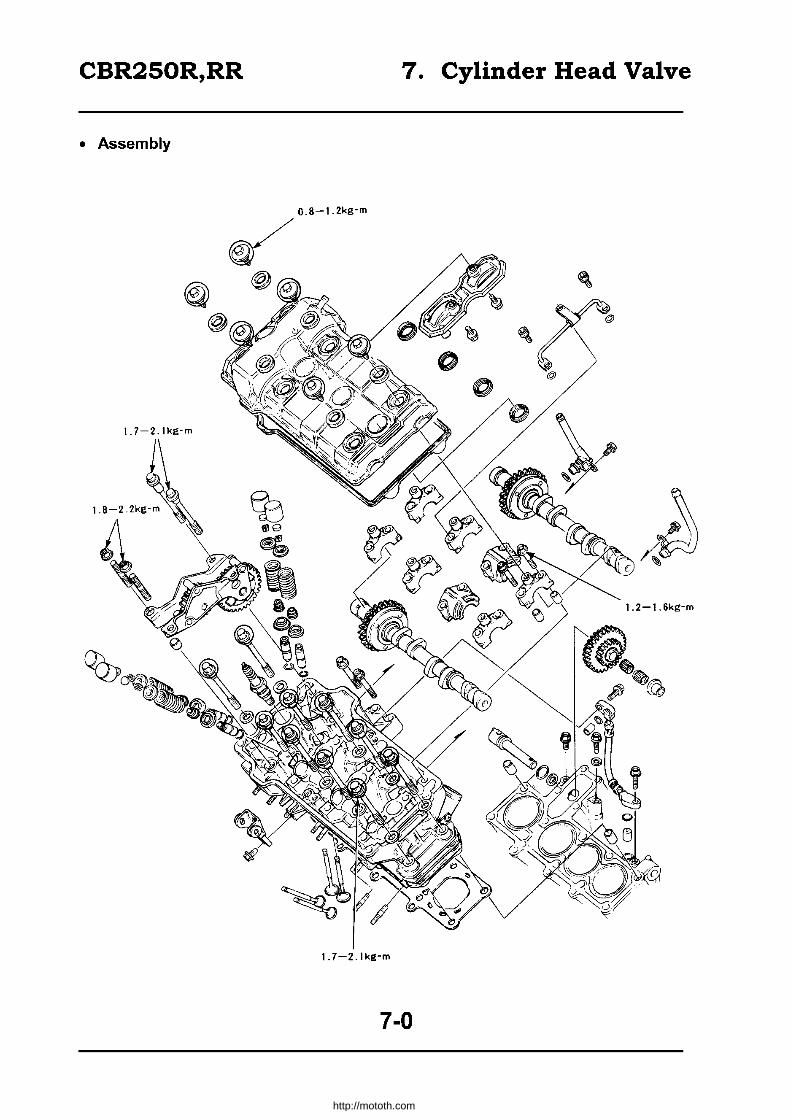
CBR250R,RR 7. Cylinder Head Valve
• Assembly
O.8-1.2kg-m
~
1.7-2.1kg-m
7-0
http://mototh.com
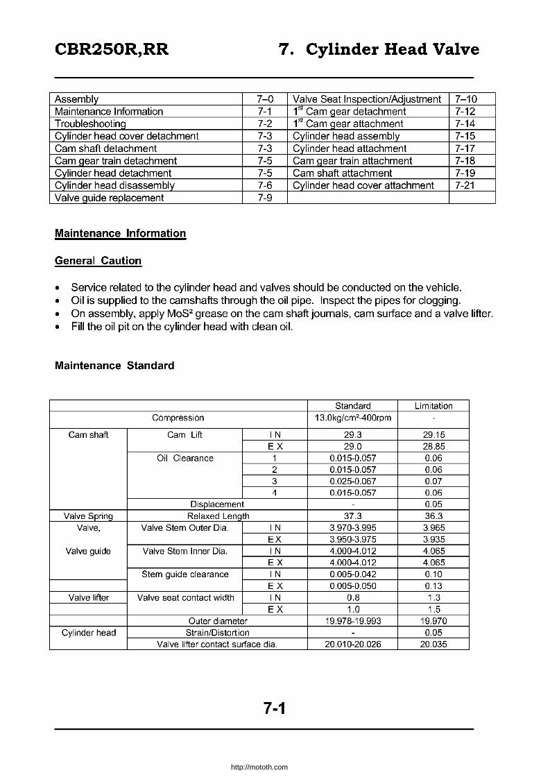
CBR250R,RR 7. Cylinder Head Valve
Assembly 7-0 Valve Seat Inspection/Adjustment 7-10 Maintenance Information 7-1 1st Cam gear detachment 7-12 Troubleshooting 7-2 1st Cam gear attachment 7-14 Cylinder head cover detachment 7-3 Cylinder head assembly 7-15 Cam shaft detachment 7-3 Cylinder head attachment 7-17 Cam gear train detachment 7-5 Cam gear train attachment 7-18 Cylinder head detachment 7-5 Cam shaft attachment 7-19 Cylinder head disassembly 7-6 Cylinder head cover attachment 7-21 Valve guide replacement 7-9
Maintenance Information
General Caution
• Service related to the cylinder head and valves should be conducted on the vehicle. • Oil is supplied to the camshafts through the oil pipe. Inspect the pipes for clogging. • On assembly, apply MoS2 grease on the cam shaft journals, cam surface and a valve lifter. • Fill the oil pit on the cylinder head with clean oil.
Maintenance Standard
Standard Limitation Compression 13.0kg/cm2400rpm -
Cam shaft Cam Lift IN 29.3 29.15 EX 29.0 28.85
Oil Clearance 1 0.015-0.057 0.06 2 0.015-0.057 0.06 3 0.025-0.067 0.07 4 0.015-0.057 0.06
Displacement - 0.05 Valve Sprinq Relaxed Len, th 37.3 36.3
Valve, Valve Stem Outer Dia. IN 3.970-3.995 3.965 EX 3.950-3.975 3.935
Valve guide Valve Stem Inner Dia. IN 4.000-4.012 4.065 EX 4.000-4.012 4.065
Stem guide clearance IN 0.005-0.042 0.10 EX 0.005-0.050 0.13
Valve lifter Valve seat contact width IN 0.8 1.3 EX 1.0 1.5
Outer diameter 19.978-19.993 19.970 Cylinder head Strain/Distortion - 0.05
Valve lifter contact surface dia. 20.010-20.026 20.035
7-1
http://mototh.com

CBR250R,RR 7. Cylinder Head Valve
Torgue
Cylinder head cover O.S-1.2kg m Cylinder head (7mm bolt, apply oil) 1.7-2.1kg m Cam shaft holder 1.2-1.6kg m Gear train holder (7mm bolt, apply oil) 1.7-2.1kg m Engine mount bolt 4.5-5.5kg m (Smm nut) 1.S-2,2kg m
Tools Exclusive Tools Common Tools
Valve guide reamer Valve guide remover Valve Spring Compressor Attachment Tappet hole protector Socket wrench
07984-8840000 07GMD-KT70100
07GME-KT70200 07GME-KT70100 07GMA-KT70100
Valve Spring Compressor 07757-0010000
Valve seat cutter Seat surface cutter Seat surface cutter Flat surface cutter Flat surface cutter Inner surface cutter Inner surface cutter Cutter holder
(20.5mm, 45° IN) 07780-0011000 (17mm, 45° EX) 07GMH-KT70500 (20mm, 32° IN) 07GMH-KT70100 (17mm, 32° EX) 07GMH-KT70200 (20.5mm, 60° IN) 07780-0014300 (17mm, 60° EX) 07GMH-KT70400
(4mm) 07GMH-KT70300
Troubleshooting Cylinder head related troubles are detected by compression measurement or a noise from the top part of the engine.
Too low or unstable compression • Valve
Inadequate valve clearance Valve bent/heat deformation valve spring failure
• Cylinder Head Head gasket leak
• Cylinder / Piston failure (~Sec. 9)
Too high compression
- valve timing failure - insufficient valve seat
contact
- Head distortion / crack
• Carbon on pistons, combustion chambers.
Noise • Inadequate valve clearance • Valve heat deformed or valve spring damaged / worn out • Cam shaft damaged / worn out • Cam gear train damaged / worn out • Cam sprocket worn out
7-2
http://mototh.com

CBR250R,RR 7. Cylinder Head Valve
Cylinder head cover detachment
Detach the side cowl (13-4) Remove the radiator set pin. Swing the radiator forward and fix it to the frame.
It can be easily removed by pushing the head of the radiator set pin down and pulling out.
Disconnect the radiator holder from the cylinder head. Disconnect the breather tube from the cylinder head cover. Remove spark plug caps.
Inspect the cylinder head cover gaskets.
Cam shaft detachment
Remove the cylinder head cover. Remove oil pipe attachment bolt. Remove the cam shaft holder attachment bolt and detach the oil pipe, O-Ring, and the cam shaft holder.
No need to remove the knock pin on the camshaft holder if it is difficult.
Detach the camshaft. Inspect the oil pipe for clogging, deformation and damage.
7-3
Gasket I
http://mototh.com

CBR250R,RR 7. Cylinder Head Valve
Cam shaft inspection
Inspect the cam gear for damage. Inspect the journal surface for wear/damage. Support the both ends of the shaft and measure its bend with a dial gauge. Take half of the indicated valve.
More than O.05mm ~ Replace
Inspect the cam surface for irregular wear/damage. Measure each cam lobe height.
IN: Less than 29.15mm ~ Replace EX: Less than 28.85mm ~ Replace
Camshaft oil clearance inspection
Wipe off the oil from camshaft journal, camshaft holder and cylinder head journals.
Attach the camshaft. Apply plastic gauges on each journal surface.
Attach the cam shaft holder and tighten the bolts. Torque: 1.2-1.6kg m
• Take caution with the cam gear contact. • Ensure the camshaft will not spin. • Tighten the bolts equally.
7-4
http://mototh.com
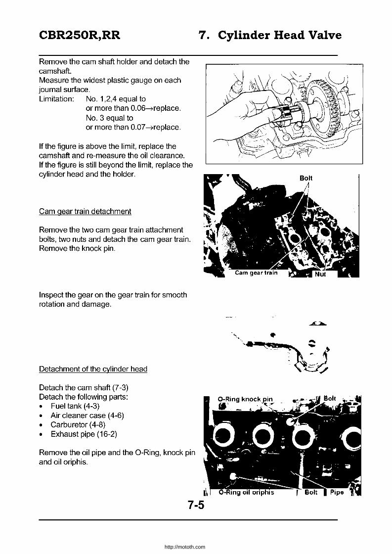
CBR250R,RR
Remove the cam shaft holder and detach the camshaft. Measure the widest plastic gauge on each journal surface. Limitation: No.1 ,2,4 equal to
or more than 0.06-Heplace. No.3 equal to or more than 0.07 --7replace.
If the figure is above the limit, replace the camshaft and re-measure the oil clearance. If the figure is still beyond the limit, replace the cylinder head and the holder.
Cam gear train detachment
Remove the two cam gear train attachment bolts, two nuts and detach the cam gear train. Remove the knock pin.
Inspect the gear on the gear train for smooth rotation and damage.
Detachment of the cylinder head
Detach the cam shaft (7-3) Detach the following parts: • Fuel tank (4-3) • Air cleaner case (4-6) • Carburetor (4-8) • Exhaust pipe (16-2)
Remove the oil pipe and the O-Ring, knock pin and oil oriphis.
7. Cylinder Head Valve
~.. . '.-~-
http://mototh.com

CBR250R,RR 7. Cylinder Head Valve
Disconnect the hoses from the water pipe on the cylinder head.
Remove the cylinder attachment bolts and detach the cylinder head.
• Loosen the bolts in two or three steps by opposite comers.
• Use of the exclusive tool is recommended to remove the bolts.
• Exclusive tool: Socket wrench 07GMAKT70100
Remove gasket and knock pin.
Cylinder head disassemble
Remove O-Ring and water pipe from the cylinder head.
Remove valve lifters and shims.
Mark the attachment position on the lifters and shims.
7-6
Bolts
http://mototh.com

CBR250R,RR 7. Cylinder Head Valve
Attach the tappet hole protectors to the cylinder heads. Exclusive tool: Tappet hole protector
07GME-KT70100
Remove the following items by using a valve spring compressor and the attachment.
cotter retainer spring
=} valve =} valve stem seal =} spring seat
Common tool: Valve spring compressor 07757-0010000
Exclusive tool: Valve spring compressor attachment 07GME-KT70200
• Do not apply excess load on the valve springs.
• Mark the attachment position on each part.
Cylinder head inspection
Remove carbon in combustion chambers. Remove the gasket pieces from the head gasket surface.
IDo not damage the gasket surface
Inspect the spark plug hole and valve hole for cracks. Measure the distortion of the cylinder head by using a straight edge and a thickness gauge. Equal to or more than 0.05mm~replace.
Inspect the oil path on the cylinder head for clogging.
7-7
I · l!, .. .,~~ .. , ...
I
Hole Protector .. ';'''t ~Jr_ CI;.j - "
Valve Spring Compressor
Oil Path
I
http://mototh.com

CBR250R,RR
Inspect the valve lifter bore for damage and irregular wear. Measure the inner diameter.
Equal to or less than 20.035mm-treplace.
Inspection of the valve lifter.
Inspect the lifter for damage/irregular wear. Measure the out diameter
Equal to or less than 19.970mm -t replace.
Valve spring relaxed length
Equal to or less than 36.3mm -t replace.
Valve stem / valve guide inspection
Inspect each valve for bend, heat damage, damage, irregular wear at the stem edge. Place the valve to a guide and check for smooth operation. Measure the outer diameter of each valves stems.
IN: Equal to or less than 3.965mm -t replace. EX: Equal to or less than 3.9350mm -t replace.
7. Cylinder Head Valve
Valve Lifter
\
~~ .. .. ~ ....
. ~
7-8
http://mototh.com

CBR250R,RR
• Before measuring the valve guide, apply a reamer through a guide and remove carbon.
IExc. Tool I Valve guide reamer - 07984 - 884000
Measure inner diameter of each guides. Equal to or greater than 4.065mm --7 replace.
(Stem-guide clearance) = (valve guide inner diameter) -(corresponding valve stem outer diameter).
Stem to guide clearance IN: Equal to or greater than 0.1 Omm --7 replace. EX: Equal to or greater than 0.13mm --7 replace.
If the figure is beyond the limit, calculate the clearance assuming the guide is the new one. If the assumption falls into the acceptable range, replace the guides only.
If the assumption still exceeds the limit, replace both the guide and the valve.
Cut the valve seat when the guide is replaced.
Valve guide replacement
Hit the valve guide through the cylinder head.
100 not damage the cylinder head.
IExc, Tool I Valve guide remover 07GMO- KT70100
Hit the oversized valve guide in.
IExC. Tool Valve guide remover 07GMO- KT70100
7. Cylinder Head Valve
V~lve Guide Remover
Valve Guide Remover
7-9
http://mototh.com

CBR250R,RR
Finish the valve guide with a reamer.
luse lubrication when reaming.
IEXC. Tools Valve guide reamer 07984 - 8840000
Clean the cylinder head and remove all debris. Adjust the contact of the valve seat.
Valve seat inspection I adjustment
Valve seat inspection
Remove carbon from valves. Apply lead (red dye) powder over the contact surface. Contact the valve by using a valve lapping stick.
Detach valves and inspect the valve faces.
Replace if you discover irregular wear or roughness on the surface.
Standard: IN: 0.8mm
Circuit: ~ adjust
EX: 1.0mm
IN: Equal to or above 1.3mm
7. Cylinder Head Valve
EX: Equal to or above 1.5mm ~ adjust
If the contact span is unequal, too wide, too narrow, contacting only at the top or bottom, adjust the valve seat with a valve seat cutter.
Valve seat adjustment
See the valve seat cutter manual.
7-10
l nSO' I" )132'
IN : 07780-0014300 IN : 07GMH-KT70100
EX : 07GMH-KT70400 EX: 07GMH-KT70200
C }S45'
IN : 07780-0011000
EX: 07GMH-KTl0500
http://mototh.com

CBR250R,RR 7. Cylinder Head Valve
Apply 4 - 5kg pressure by hand and rotate the cutter for the adjustment.
~pply engine oil to the cutter to remove the ~ebris
Use 45° cutter to grind the surface until the roughness or pin holes disappear from the seat surface.
100 not grind too much.
Use 32° cutter for flat surface adjustment.
Use 60° cutter for inner surface adjustment.
Use 45° cutter to adjust the seat surface until it reaches to the specific width.
Standard valve seat width
IN: 0.8mm EX: 1.0mm
7-11
Cutter Holder
32· Cutter
Valve Seat
Roughness on the seat surface
alve -'----'-- Seat
IN : 07GMH-KTlOI00
IN : 07780-0014300
EX: 07GMH-KT70400
45· Cutter IN: 07780-001100
EX: 07GMH-KT70500 I
http://mototh.com

CBR250R,RR 7. Cylinder Head Valve
Apply the red dye on the valve seat. Attach the valve. Confirm the contact position by gently pushing and rotating the valve.
If the contact position is too high, grind with a 32° cutter and adjust to the stand ard width with a 45° cutter.
If the position is too low, use 60° cutter and adjust to standard with a 45° cutter.
After the adjustment, apply compound over the valve face and chafe with a valve lapping stick. Clean and wash the cylinder head and valve.
• Do not press the valve hard as it scratches the surface.
• The compound should not go into the stem or the guide.
After the adjustment, use the red dye to check the 45° seat surface contacts with the valve equally on it's centre.
First Cam gear detachment
Remove the right engine hanger bracket.
Remove two bolts. Pull out the shaft. Detach the 1 st cam gear and the collar.
7-12
Contact too high
~ Too Low
~
g ~i r
http://mototh.com
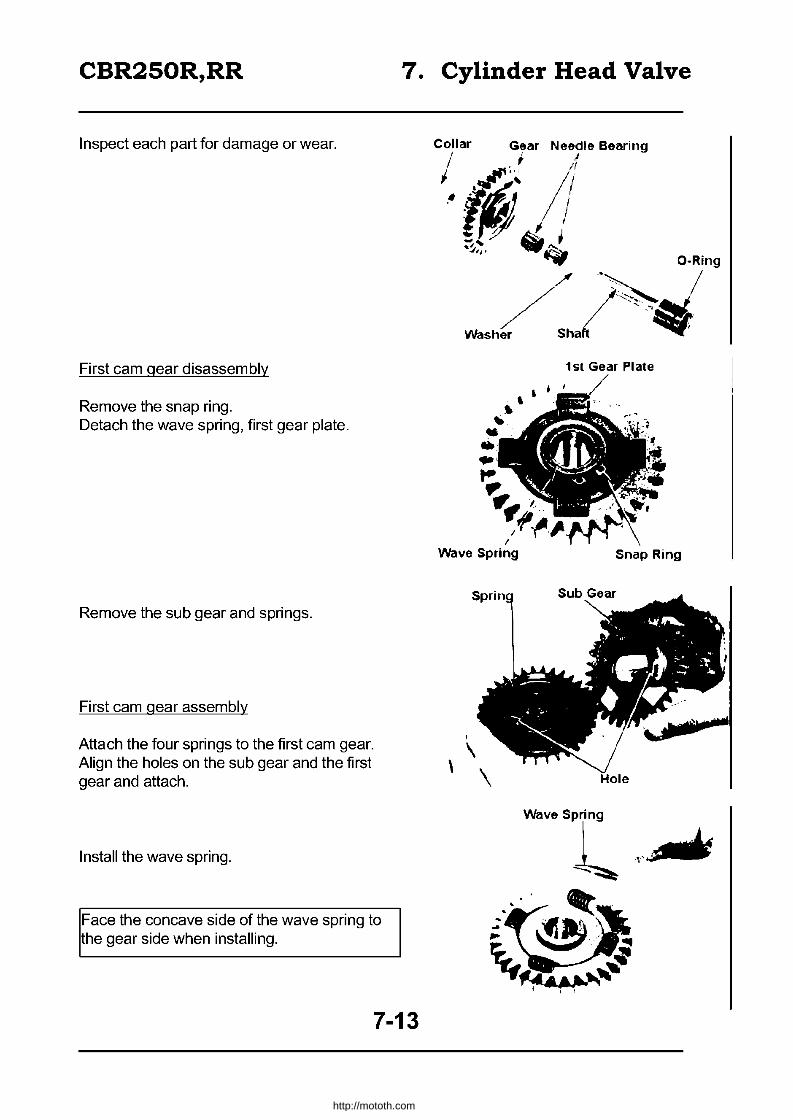
CBR250R,RR 7. Cylinder Head Valve
Inspect each part for damage or wear.
First cam gear disassembly
Remove the snap ring. Detach the wave spring, first gear plate.
Remove the sub gear and springs.
First cam gear assembly
Attach the four springs to the first cam gear. Align the holes on the sub gear and the first gear and attach.
Install the wave spring.
Face the concave side of the wave spring to the gear side when installing.
7-13
Collar Gear Needle 8eMing
I ~.' J
I.~' ;l ,~ ~)
'JIJ' "1i:fI
\
a.Ring
/'~ / / ··I/'~~..t.. Washer Sha ~ .. ~~
, \
~
-..
\
1 sl Gear PI ale
, . •
Snap Ring
http://mototh.com

CBR250R,RR 7. Cylinder Head Valve
Attach the first gear plate.
Firmly attach the snap ring to the slit on the first cam gear.
First cam gear attachment
Attach the collar to the hole in the cylinder block. Attach two needle bearings to the first cam gear and attach it to the cylinder block.
Attach the washer to the shaft and apply engine oil to the O-Ring. Match the first cam gear and sub gear and insert the shaft.
• Do not damage the gear. • Align the carved line parallel to the
cylinder block top surface.
Fix the shaft with two bolts and sealing washers.
Tighten in accordance with the order shown in the figure.
7-14
.. .. t;, .,~ .'
t' ~ ~""" • I ,
Snap ring
Gear , t
http://mototh.com

CBR250R,RR
Attach the rear engine hanger bracket and tighten the bolts / nuts.
Torque: 4.5 - 5.5kg m
Cylinder head assembly
Attach the spring seats, new stem seals. Apply small amounts of MOS2 grease to the valve stems and insert to the guides. Attach the valve springs and retainers.
• The narrow pitch of the valve springs come to the head side.
• Replace with new valve stem seals if they were detached.
• Slowly turn the valve stem and insert to the guide.
Attach tappet hole protectors.
IExC. tools Tappet hole protectors 07GME- KT70100
Attach the valve cotter by using a valve spring compressor and an attachment.
~ommon ~ools
IExC. tools
Valve spring compressor 07757 - 0010000
Valve spring compressor attachment
07GME - KT70200
IDo not over compress the valve spring
7. Cylinder Head Valve
Snr;nn Seat
//~ .. Cj /" ./ t '--',
Stem seal Spring Retainer Cotter
Attachment
Valve spring Compressor
7-15
http://mototh.com

CBR250R,RR 7. Cylinder Head Valve
Gently hit the valve stem end a few times and let the valve and the cotter match.
IDo not damage the valve
Attach new O-Rings to the water pipes. Attach the pipes to the cylinder head. Tighten the bolts.
Attach the lifter shim in to it's original position.
Apply grease on the contact surface over the outer surface of the lifter. Place the lifter in to it's original position.
7-16
Shim
I
http://mototh.com

CBR250R,RR 7. Cylinder Head Valve
Cylinder head attachment
Inspect the oil oriphis on the cylinder block for clogging.
Apply engine oil to the O-Ring and attach it.
Connect the oil path pipe to the cylinder block.
Apply sealer to the thread of the attachment bolt and tighten.
Attach knock pins and a new gasket.
Attach cylinder head. Apply engine oil to the cylinder head attachment bolts and washers. Attach them to the cylinder heads and tighten. Torque: 1.7-2.1kgm (7mmbolt)
• Tighten from inner corners to opposite outer corners. Do not tighten at once.
• Use of an exclusive tool is recommended.
Socket wrench - 07GMA - KT701 00
7-17
t ·01 "Oil Path Pipe ~~/
http://mototh.com

CBR250R,RR 7. Cylinder Head Valve
Apply engine oil to the new O-Ring and install it to the cylinder head. Attach the knock pin. Attach the oil path pipe to the cylinder head.
Connect water hoses to water pipes.
[ighten the hoses with clamps.
Attach the following parts: exhaust pipe (16-2) carburetor (4-18) air cleaner case (4-7) fuel tank (4-3)
Cam gear train attachment
Attach the knock pin to the cylinder head.
When replacing the stud bolt, apply screw locker (sealer) to the head attachment bolts before attachment.
Be aware that there are two different 7mm bolts.
7-18
ii
-,It" LdJ"91i1r DidlT1etlilr
Water Hose
(1 I~
u \ Smaller Diameter
http://mototh.com

CBR250R,RR
Attach the cam gear train. Tighten the bolts and nuts.
Torque: 7mm bolts: 1.7 - 2.1kg m 8mm nuts: 1.8 - 2.2kg m
IEnsure the proper gear match.
Cam shaft attachment
Remove the crankshaft hole cap and the timing hole cap. Rotate the crankshaft clockwise and align the "1" mark on the fly wheel with the alignment mark.
There are "IN" "EX" identification marks on the camshafts.
Apply grease on the journal and the cam surface of the camshaft.
Apply grease on the journal or the cylinder head.
Attach the camshaft to the cylinder head.
7. Cylinder Head Valve
Gear Train
Mark
7-19
http://mototh.com

CBR250R,RR
Place the cam shafts so as the two carved marks face each other and the lines are parallel to the cylinder head top surface.
Apply grease on the journal or the cam shaft holder. Place it in it's original place.
Attach a new O-Ring to the oil pipe and apply engine oil. Temporarily fix the oil pipe to the cylinder head with attachment bolts.
Evenly tighten the cam shaft holder attachment bolts in several steps.
IEnsure the cam gear is matching
Torque: 1.2-1.6kgm
7. Cylinder Head Valve
Apply locker (sealer) to oil pipe attachment bolts and tighten them up.
7-20
http://mototh.com
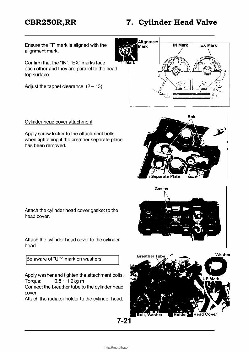
CBR250R,RR
Ensure the "1" mark is aligned with the alignment mark.
Confirm that the "IN", "EX" marks face each other and they are parallel to the head top surface.
Adjust the tappet clearance (2 - 13)
Cylinder head cover attachment
Apply screw locker to the attachment bolts when tightening if the breather separate place has been removed.
Attach the cylinder head cover gasket to the head cover.
Attach the cylinder head cover to the cylinder head.
IBe aware of "UP" mark on washers.
Apply washer and tighten the attachment bolts. Torque: 0.8 - 1.2kg m Connect the breather tube to the cylinder head cover. Attach the radiator holder to the cylinder head.
7. Cylinder Head Valve
Washer
o
7-21
http://mototh.com
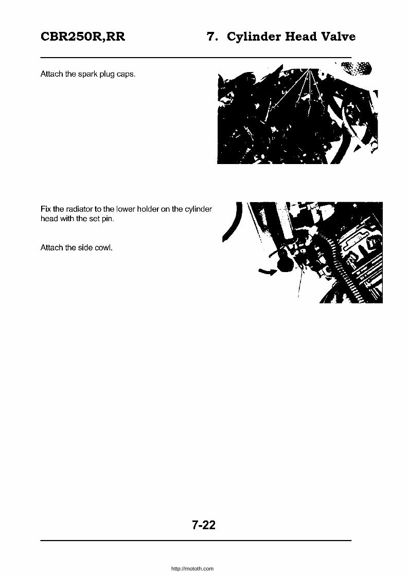
CBR250R,RR 7. Cylinder Head Valve
Attach the spark plug caps.
Fix the radiator to the lower holder on the cylinder ) head with the set pin.
Attach the side cowl.
7-22
http://mototh.com
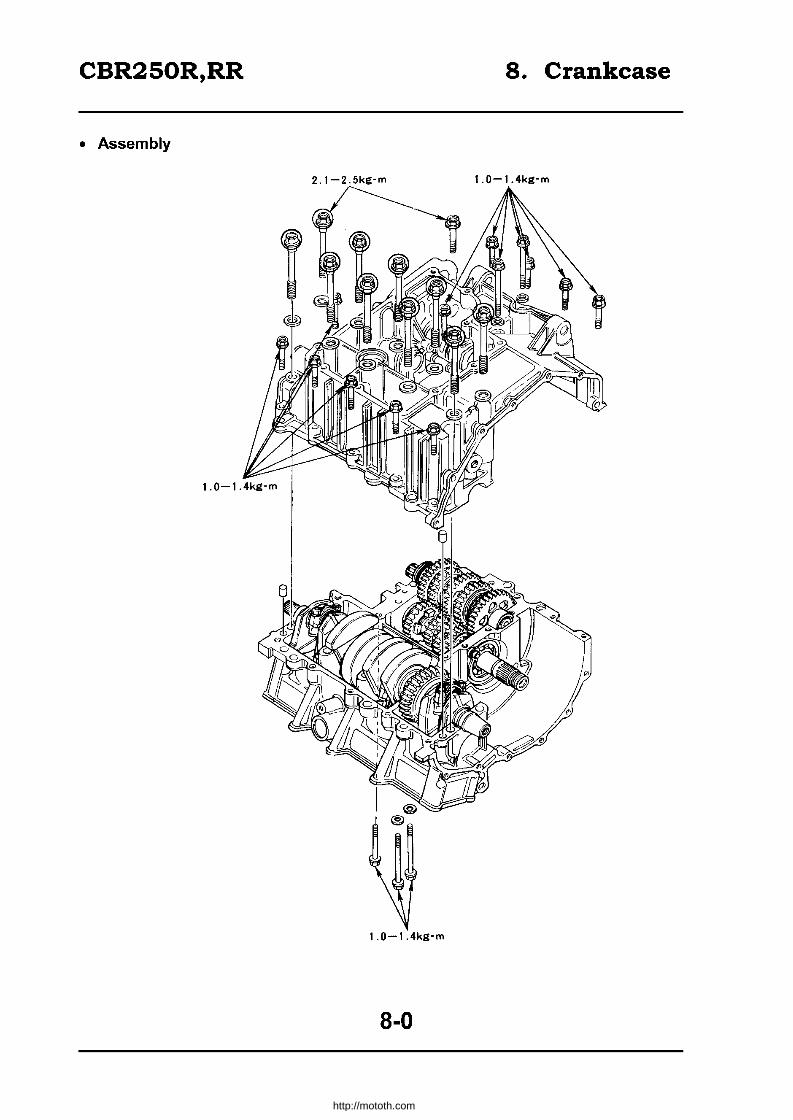
CBR250R,RR 8. Crankcase
• Assembly
2.1-2.5kg-m 1. 0-1.4kg-m
1.0-1.4kg-m
8-0
http://mototh.com

CBR250R,RR 8. Crankcase
Assembly 8-0 ReplacinQ bearinQs 8-3 Maintenance Information 8-1 Crank case assembly 8-3 SeparatinQ the crankcase 8-2
Maintenance Information
General caution • Service the crankshaft, conrod, cylinder, piston and transmission (including shift fork drum)
after separating the crankcase. • The following parts should be detached before separating the crankcase. • Procedures / photos in this section are after the detachment.
Parts to be serviced Parts to be detached Cam shaft (Sec.?), Clutch outer (Sec. 1 0), Oil pump
Conrod, cylinder block, piston (Sec.3) Fly wheel (Sec. 1 0), Starter clutch (Sec.19),
Crankshaft Camshaft (Sec.?), Oil pump (Sec. 3)
Transmission
Clutch (Sec. 1 0), gear shift linkage (Sec.11), Oil
The main shaft and the counter pump (Sec.3)
shaft can be serviced without disconnecting the linkage.
Torque 8mm Bolt Crankcase 6mm
2.1 - 2.5kg m 1.0 - 1.4kg m
Tools
Exclusive Common Bearing remover 07936-3710300 37x40mm 07746-0010200 Remover handle 07936-3710100 (17mm) 07746-0040400
Remover sliding weight 07741-0010201 Driver handle A 07749-0010000 Outer driver (37 x 40mm) 07746-0010200
Pilot (17mm) 07746-0040400
8-1
http://mototh.com

CBR250R,RR
Separating the crankcase
Detach the items specified in the maintenance information (8-1)
Remove the cylinder block tightening bolt.
Face the cylinder head side downwards and remove the lower crankcase bolt.
Loosen the bolts in opposite angles so as to avoid distortion. Split into 2-3 sequences.
Detach the lower crankcase.
~AUTION: Do not insert a screwdriver to the contact slit.
8-2
8. Crankcase
http://mototh.com

CBR250R,RR
Replacing bearings
Detach the following items from the cylinder block. Crankshaft (9-3) Piston (9-3) Counter shaft (12-3) Main shaft (12-3)
Replace the main shaft bearing if it fails to rotate smoothly. Remove the bearing.
IExCI. tools I
Bearing remover Remover handle Remover sliding weight
Install new bearing
!Common Tools
Driver handle A Outer driver (37 x 40mm) Pilot (17mm)
07936-3710300 3710100 07741-0010201
07749-0010000 07746-0010200 07746-0040400
Insert the bearing horizontally. Face the marked side downward.
Attach the following parts to the cylinder block. piston (9-9) crankshaft ((9-9) main shaft (12-7) counter shaft (12-7)
Crank case assembly
Clean the crankcase contact surface. Attach the knock pin and oil orifice. Apply liquid sealer to the contact surfaces on the cylinder block and a lower crankcase.
• Do not apply near the main bearing. • Ensure the orifice is not jammed. • Face the larger hole outward.
8-3
8. Crankcase
Driver Handle A Pilot
Knock Pin
http://mototh.com
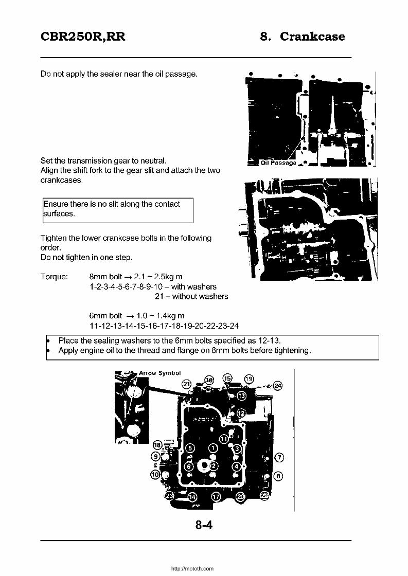
CBR250R,RR
Do not apply the sealer near the oil passage.
Set the transmission gear to neutral. Align the shift fork to the gear slit and attach the two crankcases.
Ensure there is no slit along the contact ~urfaces.
Tighten the lower crankcase bolts in the following order. Do not tighten in one step.
Torque: 8mm bolt --t 2.1 - 2.5kg m 1-2-3-4-5-6-7 -8-9-10 - with washers
21 - without washers
6mm bolt --t 1.0 - 1.4kg m 11-12-13-14-15-16-17 -18-19-20-22-23-24
8. Crankcase
~ Place the sealing washers to the 6mm bolts specified as 12-13. ~ Apply engine oil to the thread and flange on 8mm bolts before tightening.
8-4
http://mototh.com
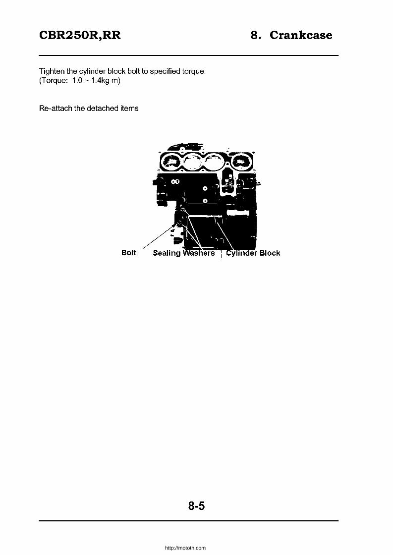
CBR250R,RR
Tighten the cylinder block bolt to specified torque. (Torque: 1.0 -1.4kg m)
Re-attach the detached items
Bolt
8-5
8. Crankcase
http://mototh.com

CBR250R,RR 9. Cylinder, Piston, Crankshaft
• Assembly
1.5-1.9kg-m
9-0
http://mototh.com
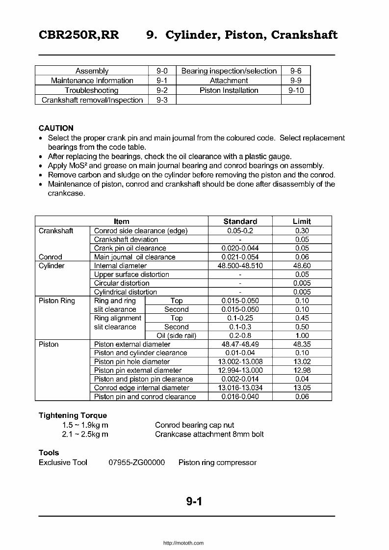
CBR250R,RR 9. Cylinder, Piston, Crankshaft
Assembly 9-0 Bearing inspection/selection 9-6 Maintenance Information 9-1 Attachment 9-9
T roubleshootinQ 9-2 Piston Installation 9-10 Crankshaft removal/I nspection 9-3
CAUTION • Select the proper crank pin and main joumal from the coloured code. Select replacement
bearings from the code table. • After replacing the bearings, check the oil clearance with a plastic gauge. • Apply MoS2 and grease on main journal bearing and con rod bearings on assembly. • Remove carbon and sludge on the cylinder before removing the piston and the conrod. • Maintenance of piston, conrod and crankshaft should be done after disassembly of the
crankcase.
Item Standard Crankshaft Conrod side clearance (edqe) 0.05-0.2
Crankshaft deviation -Crank pin oil clearance 0.020-0.044
Conrod Main journal oil clearance 0.021-0.054 Cylinder Internal diameter 48.500-48.510
Upper surface distortion -Circular distortion -Cylindrical distortion -
Piston Ring Ring and ring Top 0.015-0.050 slit clearance Second 0.015-0.050 Ring alignment Top 0.1-0.25 slit clearance Second 0.1-0.3
Oil (side rail) 0.2-0.8 Piston Piston external diameter 48.4 7 -48.49
Piston and cylinder clearance 0.01-0.04 Piston pin hole diameter 13.002-13.008 Piston pin external diameter 12.994-13.000 Piston and piston pin clearance 0.002-0.014 Conrod edge internal diameter 13.016-13.034 Piston pin and con rod clearance 0.016-0.040
Tightening Torque 1.5-1.9kgm 2.1 - 2.5kg m
Con rod bearing cap nut Crankcase attachment 8mm bolt
Tools Exclusive Tool 07955-ZGOOOOO Piston ring compressor
9-1
Limit 0.30 0.05 0.05 0.06
48.60 0.05
0.005 0.005 0.10 0.10 0.45 0.50 1.00
48.35 0.10 13.02 12.98 0.04 13.05 0.06
http://mototh.com

CBR250R,RR 9. Cylinder, Piston, Crankshaft
Troubleshooting Engine Noise • Main journal bearing worn out • Crank pin bearing worn out • Piston, cylinder worn out • Piston pin, piston pin hole, conrod little end worn out • Piston ring worn out / stuck! damaged.
Low compression, failure to start, rough idling
• Piston ring worn out / stuck / damaged • Cylinder, piston worn out / damaged
High Compression • Carbon on the cylinder head or piston top
Overheat • Carbon on piston top • Blocked cooling system
Smoke from a muffler • Cylinder, piston, piston ring worn out • Inadequate installation of the piston ring • Piston / cylinder damaged
9-2
http://mototh.com

CBR250R,RR 9. Cylinder, Piston, Crankshaft
Removal of the piston, conrad and crankshaft
Separate the crankcase (8-2)
Remove the counter shaft (12-3)
Inspect the conrod side clearance
More than O.30mm ~ replace
Remove the bearing cap nut and remove the bearing cap.
Push the piston and pull the piston and the conrad out.
Mark the removed parts so as to remember the original place.
Remove the crankshaft.
Crankshaft inspection
Support both sides of the shaft and measure the displacement of the journal.
Greater than O.05mm ~ replace
Disassembly of piston Remove the piston pin clip and pull out the piston pin. Remove the piston fram the conrad.
9-3
.. -- Crankshaft
~.-~ I'
Piston Pin
http://mototh.com

CBR250R,RR 9. Cylinder, Piston, Crankshaft
Remove the piston rings.
~eparate rings for individual cylinders pistons.
Remove sludge fram the piston head.
Inspect the piston for scratch, crack, unequal
ring groove and carbon.
Inspection of Piston, Piston ring, conrad
Measure the clearance between the piston ring and the groove.
Top ~ 0.1 Omm --+ replace Second > 0.1 Omm --+ replace
Attach each ring with piston head to the bottom of the cylinders so as to be horizontal.
Measure the clearance.
Piston Ring
Top > 0.45mm Second ~ 0.50mm Oil (Side rail) ~ 1.00mm
Replace i . •
~.~~lerGauge
Measure the inner diameter of the piston pin hole.
Greater than 13.02mm --+ replace
9-4
http://mototh.com

CBR250R,RR 9. Cylinder, Piston, Crankshaft
Measure the inner diameter of conrad little end.
Greater than 13.05mm --7 replace
Measure the outside diameter of the piston pin.
Smaller than 12.98mm --7 replace
Calculate the clearance between the piston and piston pin.
Greater than O.06mm--7replace
Measure the outside diameter of a piston
Measure at 14mm from the bottom end of the skirt and perpendicular to the piston pin hole.
Smaller than 48.35mm --7 replace
Cylinder Inspection Measure the distortion of the cylinder top surface.
Greater than O.05mm --7 Adjust or replace
9-5
,.
•
http://mototh.com

CBR250R,RR 9. Cylinder, Piston, Crankshaft
Inspect the inner surface of the cylinder. Measure the inner diameter for X - Y direction at upper, middle, lower part of the cylinder, and record the six numbers. The maximum number is considered as an inner diameter.
Greater than 48.60mm --7 adjust or replace
Calculate the clearance between the cylinder and a piston by measuring the outside diameter of a piston. Take the maximum value.
Greater than 0.1 Omm --7 adjust or replace
Calculate the following parameters and take maximum number: Circular distortion:
= (X - direction diameter) = (Y - direction diameter)
Cylindrical distortion: = (Difference in X or Y direction
Diameter between three parts).
Both parameters should be ~ O.05mm
If greater --7 adjust I replace
Inspection I Selection of bearings Crank pin bearing Inspect the bearing for scratch,or separation. Wipe off the oil on the bearing and the crank pin. Attach the crankshaft. Avoid oil hole and apply plastic gauge.
Attach the conrod bearing caps to individual crank pins and tighten the bolts. Tightening Torque: 1.5 - 1.9kg m
Ensure the crankshaft and con rod do not rotate while measuring.
9-6 Conrods
http://mototh.com
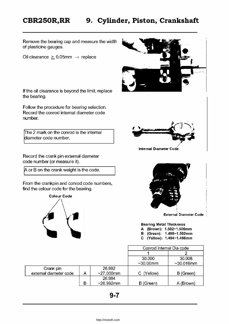
CBR250R,RR 9. Cylinder, Piston, Crankshaft
Remove the bearing cap and measure the width of plasticine gauges.
Oil clearance > O.05mm ~ replace
If the oil clearance is beyond the limit, replace the bearing.
Follow the procedure for bearing selection. Record the conrod internal diameter code number.
~he 2 mark on the con rod is the internal ~iameter code number.
Record the crank pin external diameter code number (or measure it).
f or B on the crank weight is the code.
From the crankpin and conrod code numbers, find the colour code for the bearing.
Colour Code
I Crank pin 26.992
external diameter code A -27.000mm 26.984
B -26.992mm
9-7
~1-" ~N'''''Syj Internal Diameter Code
, External Diameter Code
Bearing Metal Thickness A (Brown): 1.502-1.506mm B (Green): 1.498-1.502mm C (Yellow): 1.494-1.498mm
Conrod Internal Dia code 1 2
30.000 30.008 -30.00mm -30.016mm
C (Yellow) B (Green)
B (Green) A (Brown)
http://mototh.com

CBR250R,RR 9. Cylinder, Piston, Crankshaft
Main Bearing Inspect for scratch or separation.
Wipe the oil off on the bearing and journal surface. Place the plastic gauges avoiding the oil holes.
Attach the lower crankcase and fix with 8mm attachment bolts (x10). Tightening torque: 2.1 - 2.5kg m
Ensure the crankshaft will not I,urn while measuring.
Remove the lower crankcase and measure the width of the plasticine gauges.
Oil clearance > O.06mm --7 replace
Record the crankcase internal diameter code.
rrhe A, B or C mark on the rear part pf the upper crankcase.
9-8
http://mototh.com

CBR250R,RR 9. Cylinder, Piston, Crankshaft
Record the crankshaft main journal external diameter code (or measure it).
[he symbol 1,2 on the crankweight
Find out the corresponding bearing colour code from the crankcase and the crankshaft code numbers.
Bearing metal thickness A 1.507-1.511mm B 1.503 - 1.507mm C 1.499 - 1.503mm D 1.495 - 1.499mm
Brown Green Yellow Pink
External Diameter Code
.J I ,. '.
Colour Code
Case Internal Diameter Code A
31.000 -31.00Bmm
1 27.992-Main journal external 2B.000mm D (Pink)
diameter code 2 27.9B4 -
27.992mm C (yellow)
Piston, con rod, crankshaft attachment
Attach the main bearing to the cylinder block, lower crankcase.
Apply MOS2 Grease on the main bearing surface.
~Iign the key on the bearing to the key slit on the rylinder block and lower crankcase.
9-9
B C 31.00B - 31.016 -
31.016mm 31.024mm
C (Yellow) B (Green)
B (Green) A (Brown)
http://mototh.com

CBR250R,RR 9. Cylinder, Piston, Crankshaft
Piston Ring Remove the carbon on the piston head and ring slits.
Attach the piston rings.
~ Exercise caution not to damage the piston or the ring.
~ Marked face on the ring should face up.
~ Ensure 1200 offset between the alignment slit.
~ Avoid attaching the ring on piston pin hole direction and perpendicular to the pin.
~ Offset the alignment slits on side rails to left and right.
~ After attaching the rings, confirm the smooth movement of the rings.
Assembly of the piston and the con rod
Attach the bearing to the conrod and bearing cap.
• Align the key on the bearing to the key slit on the con rod and bearing cap.
• Apply MoS2 Grease on the bearing surface.
9-10
J.. D Top
~Dsecond ~:IOil
{Oil Ring}
Alignment
http://mototh.com

CBR250R,RR 9. Cylinder, Piston, Crankshaft
Apply oil to the conrod little end, piston pin external surface and piston pin hole surface. Attach the piston to the conrod. Attach the piston pin and set the piston pin clip to the piston slit firmly.
• Face the IN mark on the piston to the slit on the conrod.
• Align the marks which where made on disassembly
Attachment of the piston and the con rod Apply oil on external surface of the piston. Insert the conrod and piston to the top of the cylinder on the crankcase. Compress the piston ring by using a piston ring compressor and insert the piston to the cylinder by lightly pushing the piston head.
Beware of damaging the piston ~nd piston ring
Exclusive tool:
Piston ring compressor 07955 - ZGOOOO
Confirm the IN marks are facing towards the intake side.
Attachment of the crankshaft Apply MoS2 grease to the journal of the crankshaft and the crankpin and attach to the cylinder block.
In order to avoid damaging the crankshaft with he conrod, align the larger edge of the conrod
1,0 the crankpin.
9-11
"IN" Mark
\ ~=
Piston Slit
Piston (Apply Oil)
http://mototh.com

CBR250R,RR 9. Cylinder, Piston, Crankshaft
Attach the conrad bearing cap.
Ensure the bearing cap is attached in the ~irection the same as before ~isassembly.
Attach cap nuts and tighten. Tightening Torque: 1.5 - 1.9 kg m
rrighten the nuts in parallel so as to have ~qual torque among the nuts.
After tightening the nuts, confirm the smooth movement of the conrads by rotating the crankshaft.
9-12
... , ~
http://mototh.com

CBR250R,RR 10. Clutch, AC Generator
Assembly 10-0 AC Generator detachment Maintenance Information 10-1 Clutch
Troubleshooting 10-2 AC Generator attachment Right crankcase cover detachment 10-3
• Engine detachment is not required for the works in this chapter. • Remove gasket materials on the attachment surfaces of the case. • Keep the engine away from debris / mud. • Do not damage the attachment surface when disassembling. • AC generator troubleshooting (~Sec. 17,18) • Refer to 1-27 for AC generator total system troubleshooting.
Standard
Item Standard Clutch Free movement of the clutch lever 10-20
Clutch spring resting length 34.79 Clutch disk thickness 2.9-3.0 Clutch plate distortion -
Clutch out guide inner diameter 21.995-22.015 Oil pump drive sprocket inner diameter 30.025-30.075
Inner dia 21.995-22.015 Oil pump drive gear collar Outer dia 29.987 -30.000
Height 22.300-22.400 Main shaft outer dia (clutch outer guide contact area) 21.980-21.990
Torgue Oil pump driven sprocket bolt Clutch lock nut
1.3-1.7kg m apply screw locking fluid
6.0-7.0kg m Flywheel bolt Right crankcase cover bolt
Tools
Exclusive Tools Clutch centre holder
Common tools
Flywheel holder Rotor puller Lock nut wrench (26x30mm) Extension Bar
8.0-9.0kg m 0.8-1.2kg m
07GMB - KT70100
07725 - 0040000 07733 - 0020001 07716 - 0020203 07716 - 0020500
10-1
Limitation -
33.79 2.6 0.3
22.03 30.09 22.03 29.97 22.20 21.97
10-4 10-5 10-12
http://mototh.com

CBR250R,RR 10. Clutch, AC Generator
Clutch, AC Generator
Troubleshooting
Majority of the clutch troubles, come from inadequate free movement of the clutch lever. Inspect and adjust this before disassembling the clutch.
The clutch slips when accelerating
• Too small free movement of the lever. • Clutch disks worn out. • Clutch springs weak/sagged.
Unable to part the clutch
• Too much free movement of the lever. • Distorted / bent clutch plate.
Unstable clutch movement
• Clutch outer slit worn out.
The lever is stiff
• Clutch cable damaged or clogged with mud. • Lifter mechanism failure. • The cable is not going through the proper places.
10-2
http://mototh.com

CBR250R,RR
Crankcase detachment
Drain engine oil (2-16) Detach the seat Remove the side cover
10. Clutch, AC Generator
Remove regulator I rectifier attachment nuts.
Disconnect the 3P coupler on the regulator I rectifier.
Loosen the clutch cable adjust nut and lock nut. Remove the clutch cable.
Remove the right crankcase cover attachment bolts and detach the crankcase cover.
10-3
http://mototh.com
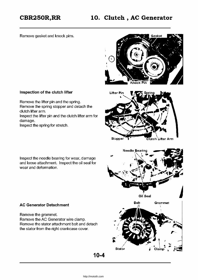
CBR250R,RR 10. Clutch, AC Generator
Remove gasket and knock pins.
Inspection of the clutch lifter
Remove the lifter pin and the spring. Remove the spring stopper and detach the clutch lifter arm. Inspect the lifter pin and the clutch lifter arm for damage. Inspect the spring for stretch.
Inspect the needle bearing for wear, damage and loose attachment. Inspect the oil seal for wear and deformation.
AC Generator Detachment
Remove the grommet. Remove the AC Generator wire clamp. Remove the stator attachment bolt and detach the stator from the right crankcase cover.
10-4
Oil Seal
Bolt Grommet
t ) . ~ \ '\ ~ ~-.
i Clamp ~
http://mototh.com
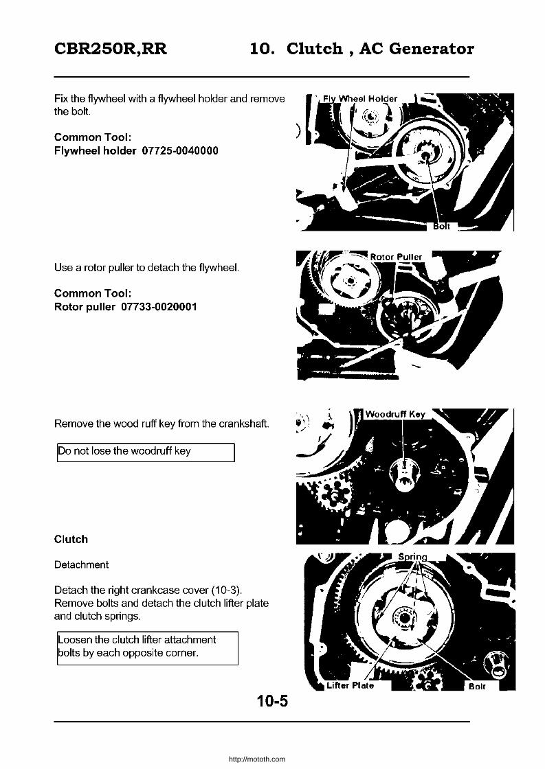
CBR250R,RR 10. Clutch, AC Generator
Fix the flywheel with a flywheel holder and remove the bolt.
Common Tool: Flywheel holder 07725-0040000
Use a rotor puller to detach the flywheel.
Common Tool: Rotor puller 07733-0020001
Remove the wood ruff key from the crankshaft.
100 not lose the woodruff key
Clutch
Detachment
Detach the right crankcase cover (10-3). Remove bolts and detach the clutch lifter plate and clutch springs.
Loosen the clutch lifter attachment bolts by each opposite corner.
10-5
http://mototh.com

CBR250R,RR 10. Clutch, AC Generator
Fix the clutch with the clutch centre holder and remove the clutch centre lock nut.
Exclusive Tool: Clutch centre holder 07GMB-KT0100
Common Tool: Lock nut wrench (26 x 30mm)
07716-0020203 Extension bar 07716-0020500
Detach the clutch centre holder. Detach the lock washer, clutch centre, shudder spring, disc, plate and the pressure plate.
Remove the thrust washer
Attach the woodruff key to the crankshaft and attach the flywheel. Rotate the flywheel clockwise until the weight and con rods on the crankshaft do not obstruct when detaching the primary driver gear.
Paint the engaging part between the primary driver gear and a primary drive gear, first cam gear as shown in the photo on the right.
IWipe off oil when painting
Detach the stopper plate. Detach the flywheel and the clutch outer.
Do not rotate the crankshaft while ~etaching the clutch outer.
10-6
http://mototh.com
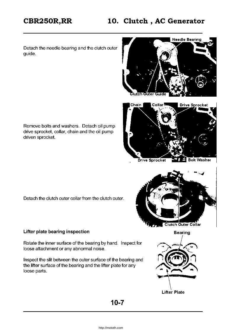
CBR250R,RR 10. Clutch, AC Generator
Detach the needle bearing and the clutch outer guide.
Remove bolts and washers. Detach oil pump drive sprocket, collar, chain and the oil pump driven sprocket.
Detach the clutch outer collar from the clutch outer.
Lifter plate bearing inspection
Rotate the inner surface of the bearing by hand. Inspect for loose attachment or any abnormal noise.
Inspect the slit between the outer surface of the bearing and the lifter surface of the bearing and the lifter plate for any loose parts.
10-7
Bearing
http://mototh.com

CBR250R,RR 10. Clutch, AC Generator
Clutch Springs Inspection
Measure the resting length of the spring
~ 33.79 --t replace
IReplace all springs at the same ti me
Clutch Disc Inspection
Replace the disc if there is any damage or irregular colour.
Measure the thickness of the disc.
~ 2.6mm --t replace
Replace both disc and the plate at the ~ametime.
Clutch Plate Inspection
Place the plate on a working table. Measure the distortion of the plate with a thickness gauge.
~ O.3mm --t replace
Clutch Centre and the Spring Seat Inspection
Inspect the slits on the clutch centre for stop wear, damage or cracking. Inspect the spring seat for deformation, wear and damage.
10-8
••
Spring Seat
http://mototh.com
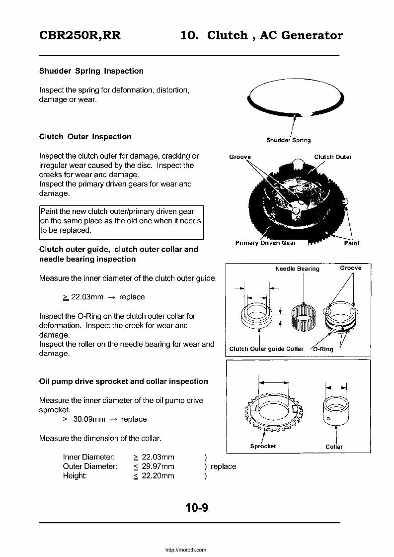
CBR250R,RR 10. Clutch, AC Generator
Shudder Spring Inspection
Inspect the spring for deformation, distortion, damage or wear.
Clutch Outer Inspection
Inspect the clutch outer for damage, cracking or irregular wear caused by the disc. Inspect the creeks for wear and damage. Inspect the primary driven gears for wear and damage.
Paint the new clutch outer/primary driven gear on the same place as the old one when it needs to be replaced.
Clutch outer guide, clutch outer collar and needle bearing inspection
Measure the inner diameter of the clutch outer guide.
> 22.03mm --7 replace
Inspect the O-Ring on the clutch outer collar for deformation. Inspect the creek for wear and damage. Inspect the roller on the needle bearing for wear and damage.
Oil pump drive sprocket and collar inspection
Measure the inner diameter of the oil pump drive sprocket.
~ 30.09mm --7 replace
Measure the dimension of the collar.
Inner Diameter:
/ Shudder Sprin9
Needle Bearing
Clutch Ou er guide Collar L.
Outer Diameter: ~ 22.03mm ~ 29.97mm ~ 22.20mm
replace Height:
10-9
nl
Groove
http://mototh.com
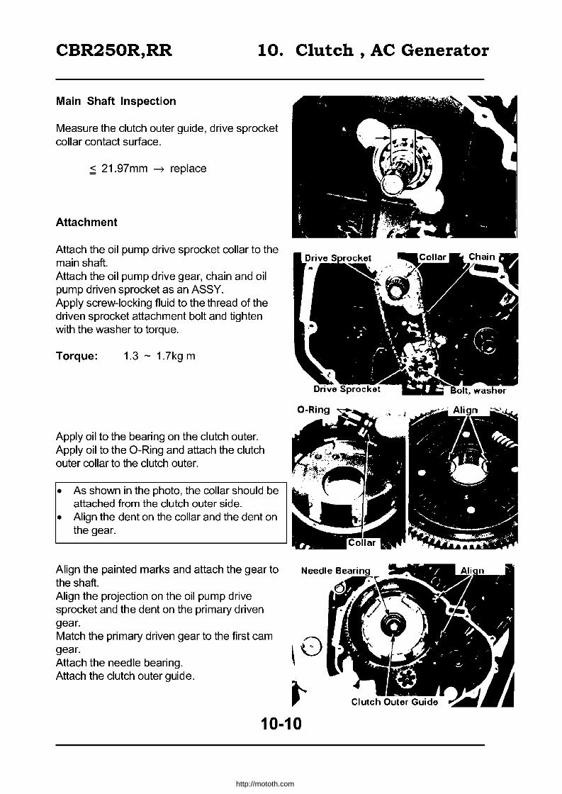
CBR250R,RR 10. Clutch, AC Generator
Main Shaft Inspection
Measure the clutch outer guide, drive sprocket collar contact surface.
~ 21.97mm ~ replace
Attachment
Attach the oil pump drive sprocket collar to the main shaft. Attach the oil pump drive gear, chain and oil pump driven sprocket as an ASSY. Apply screw-locking fluid to the thread of the driven sprocket attachment bolt and tighten with the washer to torque.
Torque: 1.3 - 1.7kgm
Apply oil to the bearing on the clutch outer. Apply oil to the O-Ring and attach the clutch outer collar to the clutch outer.
• As shown in the photo, the collar should be attached from the clutch outer side.
• Align the dent on the collar and the dent on the gear.
Align the painted marks and attach the gear to the shaft. Align the projection on the oil pump drive sprocket and the dent on the primary driven gear. Match the primary driven gear to the first cam gear. Attach the needle bearing. Attach the clutch outer guide.
~0
~ 10-10
http://mototh.com

CBR250R,RR 10. Clutch, AC Generator
Firmly attach the stopper plate.
Attach the thrust washer to the main shaft.
Apply engine oil to the clutch disc and the clutch plate. Attach the shudder spring seat, shudder spring, disk, plate and the washer plate to the clutch centre.
Refer this figure to install a shudder spring, ~hudder spring seat and the clutch disc A.
Clutch Centre Shudder Spring Seat
~ ~ Shudder Spring
\::JJ Plate Clutch disc A
, Clutch disc B Pressure Plate
Attach the clutch centre, spring seat, shudder spring, disc, plate and the pressure plate as an ASSY to the clutch outer.
Attach the lock washer.
10-11
http://mototh.com

CBR250R,RR 10. Clutch, AC Generator
Attach the new lock nut. Attach the clutch centre holder. Fix the clutch and tighten the lock nut.
Torque: 6.0 - 7.0kg m
IExcl. Tool I
ICQmmQn TQQI
Extension Bar
Clutch centre holder: 07GMB - KT70100
Locknut wrench (26 x 30mm) 07716-0020203 07716-0020500
Firmly tighten the remaining thread of the locknut.
Install the clutch spring. Attach the clutch lifter plate, tighten with bolts.
ITighten the opposite corner bolts each time.
AC Generator Attachment
Attach the woodruff key to the crankshaft.
It is already attached if the clutch r-vas disassembled.
10-12
Firmly '-. .
http://mototh.com

CBR250R,RR 10. Clutch, AC Generator
Attach the flywheel to the crankshaft. Fix the flywheel with the flywheel holder and tighten the bolt.
Torque: 8.0 - 9.0kg m
!Common Tool Ilywheel holder: 07725-004000
Attach the stator to the right crankcase cover. Apply screw locking fluid to the thread on the bolts and attach the AC Generator wire clamp. Install the grommet correctly.
Right crankcase cover attachment
Assembly
Install the clutch lifter arm and attach the spring stopper.
Check the free rotation of the arm after installing the stopper.
Install the spring, then the lifter pin.
~ One side of the stopper attachment hole on the lifter arm has a round edge. The spring is supposed to be attached.
~ Align the lifter pin to the dent on the lifter arm. Push the pin and firmly set.
Attach knock pins and the gasket.
10-13
Bolt Grommet ,
i~
~. .",
.. ~I ,.'.....--Stator Clamp attachment bolt!!
http://mototh.com
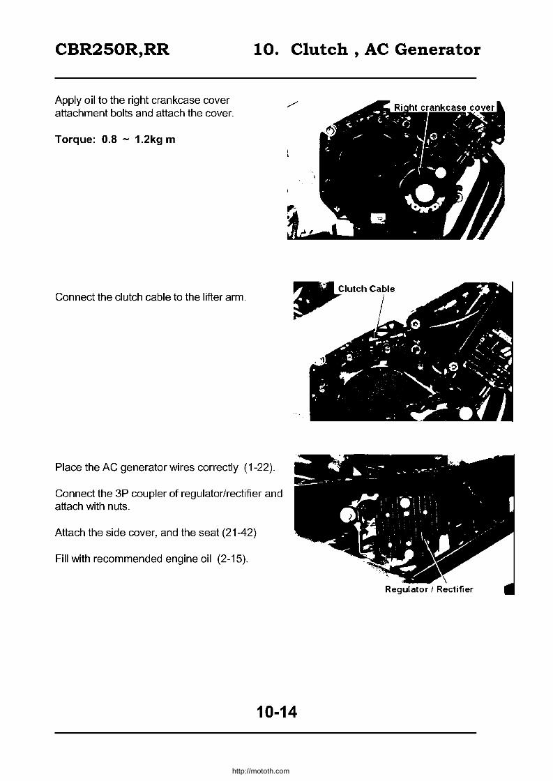
CBR250R,RR
Apply oil to the right crankcase cover attachment bolts and attach the cover.
Torque: 0.8 - 1.2kg m
Connect the clutch cable to the lifter arm.
10. Clutch, AC Generator
Place the AC generator wires correctly (1-22).
Connect the 3P coupler of regulator/rectifier and attach with nuts.
Attach the side cover, and the seat (21-42)
Fill with recommended engine oil (2-15).
10-14
http://mototh.com

CBR250R,RR 11. Gear Shift Linkage
Disassembly 11-0 Gear shift linkaQe detachment 11-2 Service information 11-1 Gear shift linkage attachment 11-4
TroubleshootinQ 11-1
Service Information
General Caution
• The gear shift linkage can be serviced without dismounting from the vehicle. • When the transmission, shift drum and the shift fork need to be serviced, disassemble the
crankcase.
Torque • Change Pedal 1.0 - 1.4kg-m • Drum centre bolt 2.1 - 2.5kg-m (apply screw locker)
Troubleshooting
Difficult to shift the gear
• Inadequate clutch adjustment • Shift fork deformed • Cam slit on the shift drum damaged • A catch on the gear shift spindle bent
The gear disconnects
• Gear dog worn • Shift shaft bent • Stopper arm damaged • Shift fork bent I damaged
11-1
http://mototh.com

CBR250R,RR
Gear Shift Linkage Detachment
Remove the water pump (5-9) Remove the change pedal Detach the drive sprocket cover
Note: ~et the gear to neutral before removing the change pedal.
Remove the five change cover attachment bolts. Push the shift spindle in and remove the change cover.
Remove the gasket and knock pins.
Remove the gear shift spindle and washer. Remove the shifter collar.
Remove the two bolts and detach the guide plate with the drive shifter.
~aution: ~ ratchet pole may pop out.
11-2
11. Gear Shift Linkage
4 f ..... .J -'~
j.~. Pedal
http://mototh.com
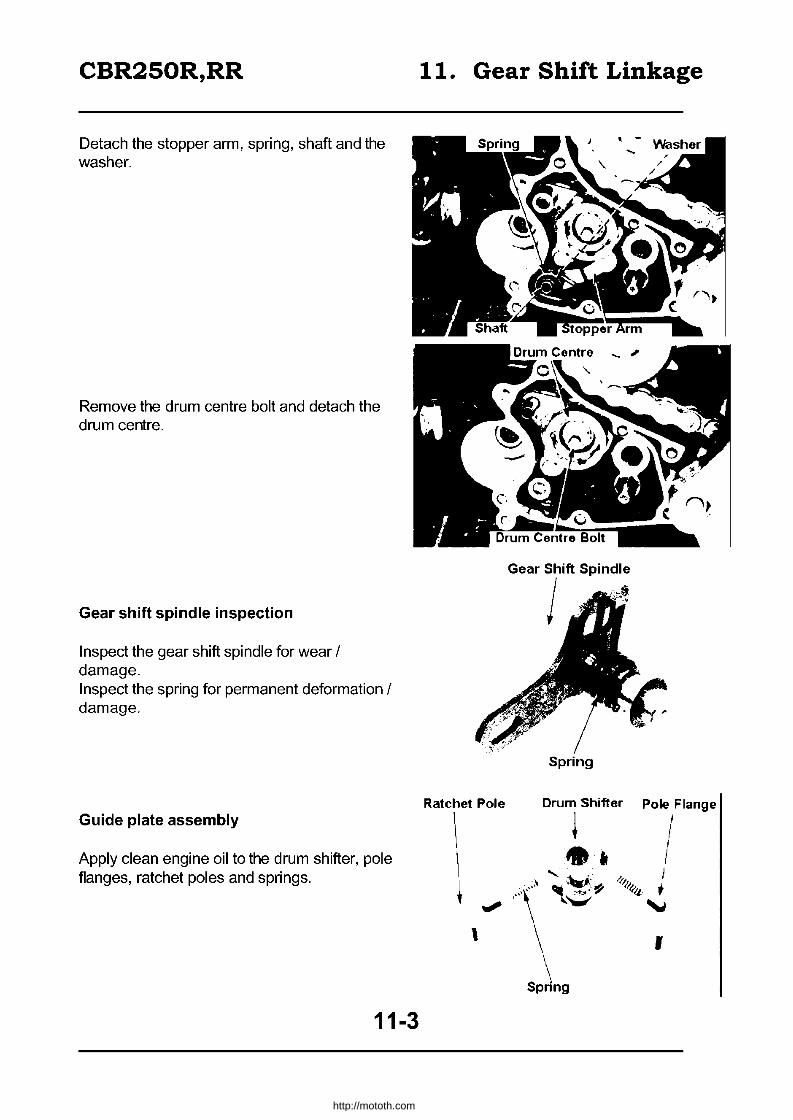
CBR250R,RR
Detach the stopper arm, spring, shaft and the washer.
Remove the drum centre bolt and detach the drum centre.
Gear shift spindle inspection
Inspect the gear shift spindle for wear / damage. Inspect the spring for permanent deformation / damage.
Guide plate assembly
Apply clean engine oil to the drum shifter, pole flanges, ratchet poles and springs.
11-3
11. Gear Shift Linkage
Ratchet Pole
\ \
t.", ,
G •• , Tft Spindl.
Spring
Drum Shifter Pole Flange
~, I 'oL... /, I ,~~ r
l/I4'1/ ~
,
http://mototh.com

CBR250R,RR 11. Gear Shift Linkage
Attach the drum shifter, pole flanges, springs and Guide Plate ratchet poles to the guide plate.
Gear shift linkage attachment
Align the key slit on the drum centre to the drum pin and attach.
Apply screw locker to the thread and tighten the drum centre bolt.
Torque: 2-1 - 2.5kg-m
Attach the stopper arm shaft and the washer.
11-4
http://mototh.com

CBR250R,RR
Attach the stopper arm and the spring to the stopper arm shaft.
Attach the drum shifter and the guide plate.
Firmly tighten the two guide plate attachment bolts.
Cover the projection of the drum shifter with the shifter collar.
11-5
11. Gear Shift Linkage
Guide Plate
http://mototh.com
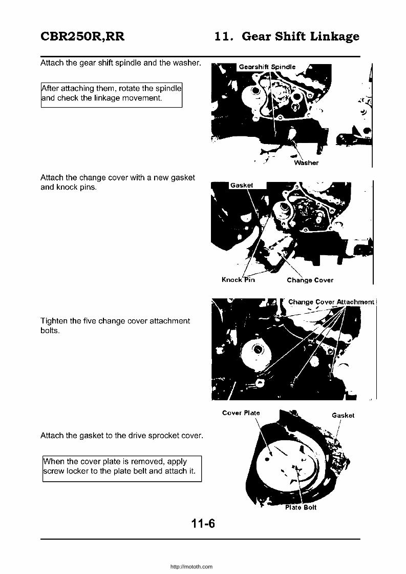
CBR250R,RR
Attach the gear shift spindle and the washer.
~fter attaching them, rotate the spindle and check the linkage movement.
Attach the change cover with a new gasket and knock pins.
Tighten the five change cover attachment bolts.
Attach the gasket to the drive sprocket cover.
When the cover plate is removed, apply screw locker to the plate belt and attach it.
11-6
11. Gear Shift Linkage
Change Covor Attachmont ! . ~"
http://mototh.com
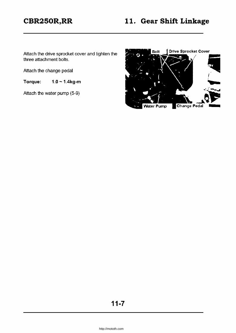
CBR250R,RR
Attach the drive sprocket cover and tighten the three attachment bolts.
Attach the change pedal
Torque: 1.0 - 1.4kg-m
Attach the water pump (5-9)
11-7
11. Gear Shift Linkage
Drive Sprocket Cover
iii , ,
" -'~~
http://mototh.com

CBR250R,RR 12. Transmission
Transmission
Disassembly 12-0 Transmission Disassembly 12-3 Service Information 12-1 Transmission Inspection 12-5
Troubleshooting 12-2 Transmission Assembly 12-7
Service Information
General Caution • Inspection of the transmission inside the crankcase should be conducted after separating
the case. • Separation of the crankcase ~ Sec. 8
Service Standard Unit: mm Item Standard Limitation
Transmission Backlash 0.044-0.140 0.3 Gear inner M5 25.000-25021 25.05 diameter M6 25.000-25.021 25.05
C1 23.000-23.021 23.05 C2 28.000-28.021 28.05 C3 28.000-28.021 28.05 C4 28.000-28.021 28.05
Gear M5 innerdia 21.985-22.006 22.07 Bush M5 outer dia 24.959-24.980 24.92
M6 outer dia 24.959-24.980 24.92 C1 outer dia 22.959-22.980 22.92 C1 inner dia 20.007-20.028 20.10 C2 outer dia 27.959-27.980 27.92 C3 outer dia 27.959-27.980 27.92 C4 outer dia 27.959-27.980 27.92
Main shaft M5 atM5 21.959-21.980 21.92 outer diameter At clutch outer guide 21.980-21.990 22.20 Counter shaft
outer dia C1 at C1 19.987-20.000 19.77 Gear-bush or M5- bush - 0.10
Bush-shaft M5 bush - shaft - 0.15 clearance M6- bush - 0.10
C1 - bush - 0.10 C1 - bush-shaft - 0.15
C2- bush - 0.10 C3- bush - 0.10 C4- bush - 0.10
Shift fork Thickness of a catch - 5.60 Inner dia - 12.04
Shift fork shaft Outer dia - 11.90
12-1
http://mototh.com

CBR250R,RR 12. Transmission
Troubleshooting
Difficult to select a gear
• Inadequate clutch setting (too much free movement) • Shift fork bent • Shift fork shaft bent • Gear shift spindle damaged • Shift drum guide slit damaged • Guide pin damaged
The gear disengages
• Gear dog worn out • Shift fork shaft bent • Shift drum stopper damaged • Shift fork bent • Shift drum guide slit worn out
12-2
http://mototh.com

CBR250R,RR
Transmission disassembly
Separate the crankcase (Sec. 8) Measure the backlash of each gear
Backlash > O.3mm -7 replace
Remove the countershaft.
Detach the knock pin and the bearing set ring.
Remove two bolts and detach the stopper plate.
Pull out the bearing.
Remove the main shaft.
12-3
12. Transmission
j
~ . .. ... ... ..
-
http://mototh.com

CBR250R,RR
Fold the catch on the lock washer and remove the bolt and washer.
Pull out the shift fork shaft and detach shift forks.
Remove the bolt to detach the set plate and knock pin.
Detach the shift drum.
Inspect bearings for the shift fork shaft and the shift drum.
12-4
12. Transmission
, ... t
&
http://mototh.com
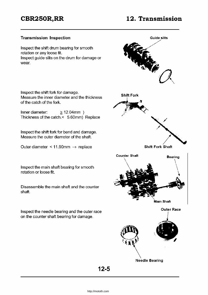
CBR250R,RR
Transmission Inspection
Inspect the shift drum bearing for smooth rotation or any loose fit. Inspect guide slits on the drum for damage or wear.
Inspect the shift fork for damage. Measure the inner diameter and the thickness of the catch of the fork.
Inner diameter: ~ 12.04mm ) Thickness of the catch.< 5.60mm) Replace
Inspect the shift fork for bend and damage. Measure the outer diameter of the shaft.
Outer diameter < 11.90mm ~ replace
Inspect the main shaft bearing for smooth rotation or loose fit.
Disassemble the main shaft and the counter shaft.
Inspect the needle bearing and the outer race on the counter shaft bearing for damage.
12-5
12. Transmission
Shift Fork
Guide slits
Shift Fork Shaft
B8aring
\ \ \ \
Outer Race
J .. ~ . ~
/ . ' -. __ . I
Needle Bearing
http://mototh.com

CBR250R,RR
Inspect the main shaft and the counter shaft for damage.
Inspect the countershaft bearing for smooth rotation and loose fit.
Measure outer diameter of each shaft.
M5 part: Clutch outer guide: C1 part:
,::; 21.92mm ,::; 21.95mm ,::; 19.97mm
Inspect each gear for damage.
Measure the inner diameters.
M5: M6: C1: C2: C3: C4:
~ 25.05 ~ 25.05 ~23.05
~28.05 ~28.05 ~28.05
Inspect each bush for damage.
Replace
Replace
Measure inner / outer diameter for each bush.
M5 inner: ~22.07mm
M5 outer: ,::;24.92mm M6 outer: ,::;24.92mm C1 inner: ~20.10mm Replace C1outer: ,::;22.92mm C2 outer: ,::;27.92mm C3 outer: ,::;27.92mm C4 outer: ,::;27.92mm
12. Transmission
Clutch Outer Guide
M5 I
Cl
-0-- -Calculate the clearance between the bush and the gear or the shaft.
Bush- gear Bush - shaft
~ 0.10mm ~ 0.15mm Replace
12-6
http://mototh.com

CBR250R,RR 12. Transmission
Transmission Assembly
Apply engine oil to all contact parts.
Apply grease on shift fork slits of M3/4, C5 and C6 gears.
Apply grease and engine oil to the bush on C 1.
Washer C1 Gear (41T))
n & Mainshaft
~ ~"",,",M'ol1 Gear (15T)
Spline !Jl Washer
~d M5Bush reJifA
C5 Gear (30T)
M5 Gear (26T) ~ CirCIiP/ ~
.".,G:: .... "',:? ~(j (24T I 22T) Washer wa~er
Important Align an oil hole on the bush with an oil hole on the shaft.
12-7
http://mototh.com

CBR250R,RR
Attach the mainshaft.
Face the marked surface of the bearing outward.
Apply screw holder on bolts and tighten the set plate.
Attach the bearing set ring and the knock pin to the cylinder block.
Align the slit of the bearing with the ring, hole on the collar with knock pin, attach the counter shaft.
Attach the shift drum and bearing.
12-8
12. Transmission
http://mototh.com
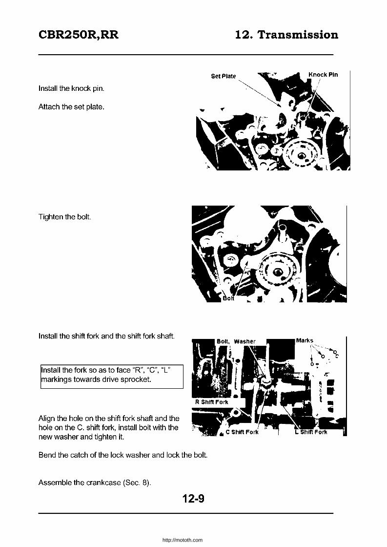
CBR250R,RR
Install the knock pin.
Attach the set plate.
Tighten the bolt.
Install the shift fork and the shift fork shaft.
Install the fork so as to face "R", "C", "L" markings towards drive sprocket.
Align the hole on the shift fork shaft and the hole on the C. shift fork, install bolt with the new washer and tighten it.
Bend the catch of the lock washer and lock the bolt.
Assemble the crankcase (Sec. 8).
12-9
Set Plate
12. Transmission
r~-:~~ boo ' .
.0;:
~. ~. t
http://mototh.com
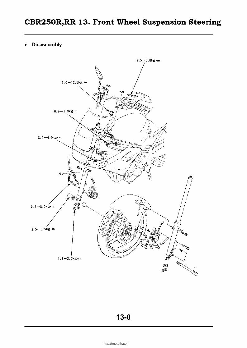
CBR250R,RR 13. Front Wheel Suspension Steering
• Disassembly
2.5-3.0kg-m
5.5-6.5kg-m
1.8-2.5kg-m
13-0
http://mototh.com
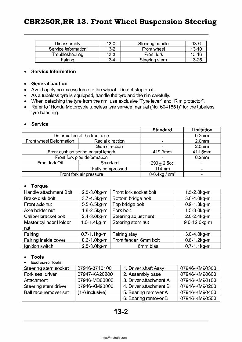
CBR250R,RR 13. Front Wheel Suspension Steering
Disassembly 13-0 Steering handle 13-6 Service information 13-2 Front wheel 13-10
Troubleshooting 13-3 Front fork 13-16 Fairing 13-4 Steering stem 13-25
• Service Information
• General caution • Avoid applying excess force to the wheel. Do not step on it. • As a tubeless tyre is equipped, handle the tyre and the rim carefully. • When detaching the tyre from the rim, use exclusive "Tyre lever" and "Rim protector". • Refer to "Honda Motorcycle tubeless tyre service manual (No. 6041551)" for the tubeless
tyre handling.
• Service Standard Limitation
Deformation of the front axle - 0.2mm Front wheel Deformation Radial direction - 2.0mm
Side direction - 2.0mm Front cushion spring natural length 419.9mm 411.5mm
Front fork pipe deformation - 0.2mm Front fork Oil Standard 290 + 2.5cc -
Fully compressed 114mm -Front fork air pressure O-OAkQ / cm2 -
• Torque Handle attachment Bolt 2.5-3.0kq-m Front fork socket bolt 1.5-2.0kQ-m Brake disk bolt 3.7-4.3kq-m Bottom bridQe bolt 3.0-4.0kQ-m Front axle nut 5.5-6.5kg-m Top bridge bolt 0.9-1.3kg-m Axle holder nut 1.8-2.5kq-m Fork bolt 1.5-3.0kq-m Caliper bracket bolt 2A-3.0kg-m Steering adjustment 2.0-2.4kg-m Master cylinder Holder 1.0-1.4kg-m Steering stem nut 9.0-12.0kg-m nut Fairinq 0.7-1.1 kq-m Fairinq stay 3.0-4.0kq-m Fairinq inside cover 0.6-1.0kq-m Front fender 6mm bolt 0.8-1.2kq-m Ignition switch 2.5-3.0kg-m 6mm biss 0.7-1.1kg-m
• Tools • Exclusive Tools
Steering stem socket 07916-3710100 1. Driver shaft Assy 07946-KM90300 Fork seal driver 07947 -KA20200 2. Assembly base 07946-KM90600 Attachment 07946-M BOOOOO 3. Driver attachment A 07946-KM90 100 Steering stem driver 07946-KM90000 4. Driver attachment B 07946-KM90200 Ball race remover set (1-6 inclusive) 5. Bearinq remover A 07946-KM90400
6. Bearing remover B 07946-KM90500
13-2
http://mototh.com

CBR250R,RR 13. Front Wheel Suspension Steering
• Common tool Fork seal driver 07747-0010100 Driver handle A 07749-0010000 Extension bar 07716-0020500 Pilot (15mm) 07746-0040300 Lock nut wrench (30 07716-002400 Outer driver 07746-0010300 x 32mm) (42 x 47mm) Bearing remover Shaft 07746-0050100 Outer driver 07746-0010100
(32 x 35mm) Bearing remover 07746-0050400 Head (15mm)
• Troubleshooting
Heavy Steering • Steering adjust nut excessively tightened. • Steering bearing damaged. • Interference between wires and cables • Tyre pressure too low.
Too Light Steering • Frontfork bent. • Front axle bent, tyre tilted. • Rear axle bent.
Front wheel track unstable • Rim deformed. • Loose attachment of the front wheel bearing. • Poor quality tyre. • Inadequate tightening around the axle.
Noise from the front cushion • Contact between a fork pipe and the bottom case. • Lack of fork oil. • Cushion attachment bolts loose.
Front cushion too soft • Spring distorted. • Lack of fork oil. • Inadequate fork air pressure. • Improper viscosity of oil.
Front cushion too hard • Inadequate fork oil. • Inadequate fork air pressure. • Fork pipe bent. • Oil path jammed. • Inadequate viscosity of oil.
13-3
http://mototh.com

CBR250R,RR 13. Front Wheel Suspension Steering
• Fairing
• Fairing detachment
Remove attachment screw on a side cowl.
Slide the projection of the side cowl to the position lower than the alignment marking of the radiator and detach the side cowl.
Remove the screw and detach fairing inside cover.
Remove the fairing attachment bolt and the screw from the meter stay.
13-4
\ :c:;;o~~.,. Fairing
http://mototh.com

CBR250R,RR 13. Front Wheel Suspension Steering
Remove two screws on lower part of the fairing. Pull the fairing forward
Slide the headlight cover and disconnect the socket. Disconnect blinker couplers.
Fairing attachment
Reverse the detachment procedure.
Torque: Fairing 0.7 - 1.1 kg-m Fairing inside cover 0.6 - 1.0kg-m
~Iign the slit on a fairing inside cover to the ~teering stay when attaching the cover.
Steering stay detachment
Detach the fairing (13-4) Disconnect the indicators and fuse couplers. Detach the indicators (20-3).
Detach the hamess from steering stay clamps. Disconnect the hom switch wirings.
13-5
)
,
Headlight Socket
http://mototh.com
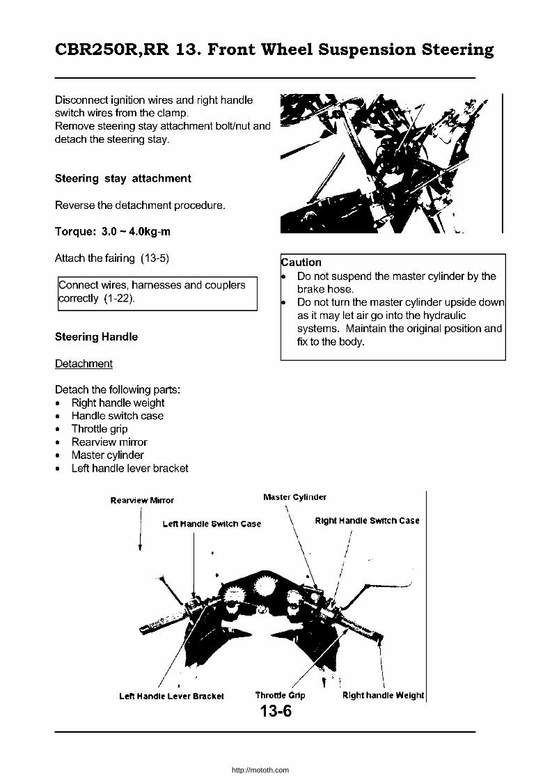
CBR250R,RR 13. Front Wheel Suspension Steering
Disconnect ignition wires and right handle switch wires from the clamp. Remove steering stay attachment bolUnut and detach the steering stay.
Steering stay attachment
Reverse the detachment procedure.
Torque: 3.0 - 4.0kg-m
Attach the fairi ng (13-5)
Connect wires, harnesses and couplers ~orrectly (1-22).
Steering Handle
Detachment
Detach the following parts: • Right handle weight • Handle switch case • Throttle grip • Rearview mirror • Master cylinder • Left handle lever bracket
Rearview Mirror
Caution • Do not suspend the master cylinder by the
brake hose. • Do not turn the master cylinder upside down
as it may let air go into the hydraulic systems. Maintain the original position and fix to the body.
Ma.ster Cylinder
L.eft Handle SWitch Case
t > t L.eft Handle L.ever Bracket Throttle Crip Right handle Weight
13-6
http://mototh.com

CBR250R,RR 13. Front Wheel Suspension Steering
Left hand detachment
Remove the handle weight and detach the grip and choke lever. Detach the stopper ring and remove the handle attachment bolt. Detach the left handle from the fork pipe.
Right handle detachment
Detach the stopper ring and remove the handle attachment bolt. Detach the right handle from the fork pipe.
Left handle attachment
Align the handle position fixing pin with the dent on the top bridge and attach the pin to the fork pipe.
Firmly set the stopper ring to the slit on the fork pipe and tighten the handle attachment bolt. Torque: 2.5 - 3.0kg-m
Attach the choke lever to the handle. Remove dirt, oil from the left handle grip bonding surface and let it dry. Apply genuine Honda "Honda bond A" or "Cemedyne #540" to bonding surface and attach the grip by twisting it.
flloW a couple of hours for bond to dry.
Attach the handle weight.
Gri
Grip \
\ \
Choke Lever -. Stopper Ring
I
Handle Weight
13-7
http://mototh.com

CBR250R,RR 13. Front Wheel Suspension Steering
Connect the choke cable to the choke lever.
Align the projection on the left switch case with the hole on the handle and attach it.
Fix the switchcase with two screws.
Front screws first, then the rear ~crews second to tighten.
Attach the left handle over bracket and the holder and tighten the bolts.
• Align the alignment surface of the holder to the punched mark on the handle.
• Face the "UP" mark on the holder upwards.
• Tighten the top bolt first, then the bottom one.
13-8
Choke Lever
Hole
Left Handle lever Holder Connector
http://mototh.com

CBR250R,RR 13. Front Wheel Suspension Steering
Right handle attachment
Align the handle positioning pin with the slit on the top bridge and attach the pin to the fork pipe.
Firmly attach the stopper ring to the slit on the forkpipe. Tighten the handle attachment bolt. Torque: 2.5 - 3.0kg-m
Clean the contact surface for the throttle grip on the handle. Attach the throttle grip.
Attach the handle weight.
13-9
Throttle Grip
Handle Weight
http://mototh.com

CBR250R,RR 13. Front Wheel Suspension Steering
Connect throttle cables to the grip.
Align the projection of the right handle switch case and the hole on the handle.
Attach the case to the handle.
Tighten the front screw for the right handle switch case, then tighten the rear screws.
Face the "UP" making on the holder upwards, attach the master cylinder to the handle. Align the alignment surface of the master cylinder and the holder with the punched mark on the handle. Tighten the top bolt first, then the bottom one.
Torque: 1.0 - 1.4kg-m
Connect wires to the front stop indicator switch. Adjust free movement of the throttle grip (2-17).
Front Wheel Detachment
Support bottom of the engine and float the wheel. Remove screws and disconnect speed indicator cables from the gear box. Remove the brake caliper with the bracket. Remove nuts and detach right and left axle holders. Remove the front wheel.
13-10
Throttle Cables
http://mototh.com

CBR250R,RR 13. Front Wheel Suspension Steering
Front axle detachment
Support the axle from speed the indicator gear box side and remove axle nut. Detach the front axle and the speed indicator gear box.
Inspection
Inspect the front axle for deformation. Place the axle on V-blocks and measure with a dial gauge. Take half of the indicated value.
2: O.2mm --7 replace
Inspect the wheel for deformation.
Radial: Side:
2: 2.0mm 2: 2.0mm Replace
• You cannot adjust a cast wheel. • Replace with new wheels, if the limit is
exceeded.
Rotate the bearing inner race by finger and replace if there is a noise or loose fit.
~Iways replace both sides at the same ime.
13-11
Wheel Bearing
http://mototh.com
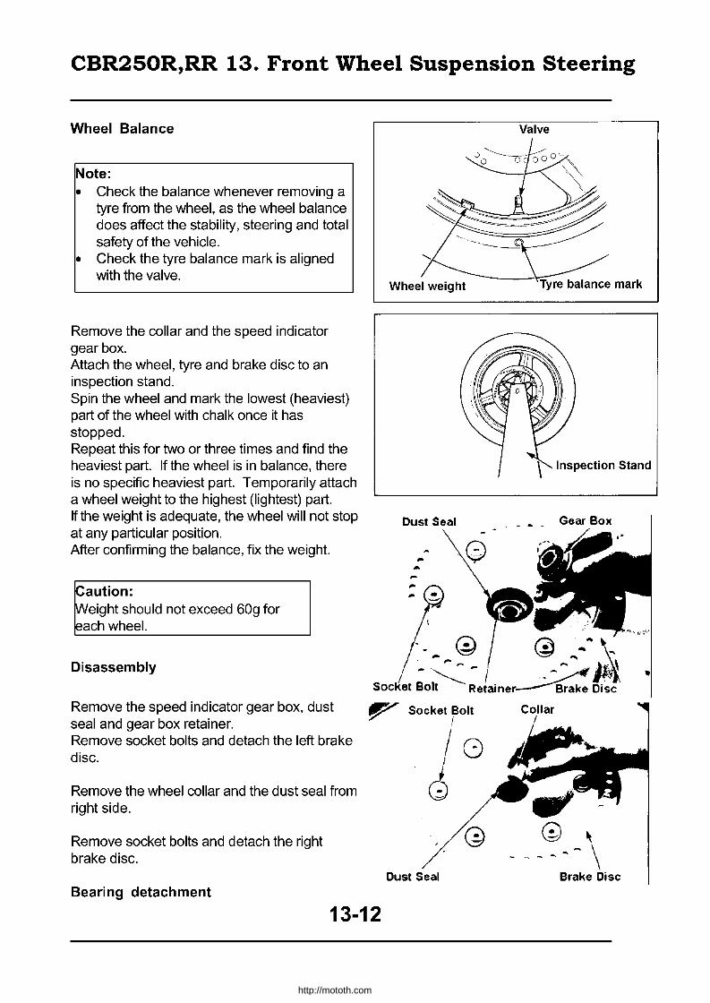
CBR250R,RR 13. Front Wheel Suspension Steering
Wheel Balance
Note: • Check the balance whenever removing a
tyre from the wheel, as the wheel balance does affect the stability, steering and total safety of the vehicle.
• Check the tyre balance mark is aligned with the valve.
Remove the collar and the speed indicator gear box. Attach the wheel, tyre and brake disc to an inspection stand. Spin the wheel and mark the lowest (heaviest) part of the wheel with chalk once it has stopped. Repeat this for two or three times and find the heaviest part. If the wheel is in balance, there is no specific heaviest part. Temporarily attach a wheel weight to the highest (lightest) part. If the weight is adequate, the wheel will not stop at any particular position. After confirming the balance, fix the weight.
~aution: ~eight should not exceed 60g for ~ach wheel.
Disassembly
Dust Seal
... ...
:~
Valve
Gear Box
~' ;'
/'- G) @ .... ~ ~ .... ,.~,. ~~"".:it; .. ~ /~, It~
SOcKet Bolt Retaine~ Brake Disc
Remove the speed indicator gear box, dust seal and gear box retainer. Remove socket bolts and detach the left brake disc.
Remove the wheel collar and the dust seal from right side.
Remove socket bolts and detach the right brake disc.
Bearing detachment
13-12
Socket Bolt
" 18 ~
Dust Seal
http://mototh.com

CBR250R,RR 13. Front Wheel Suspension Steering
Detach the bearing and the distance collar.
Icommon Tools I
Bearing remover shaft Bearing remover head
07746-0050100 07746-0040300
8A,.nn,n remover shaft \
J Assembly
~-.-
Bearing remover Head
Never let oil/grease touch the brake disk as it may result in reducing break performance. Wipe any dirt off from the disk.
Bearings should be set parallel. Set the right bearing and attach the distance collar.
Check the position of the distance collar before attaching the bearings. • , ,-
/ /
(LI
Set the left bearing.
!Common tools · . ", /~ At • 4A~i'~_ "
Driver handle A 07749-0010000 Pilot (15mm) 07746-0040300 (L) Outer driver (42x47mm) 07746-0010300 (R) Outer driver (32x35mm) 00746-00101 00
13-13
a
http://mototh.com

CBR250R,RR 13. Front Wheel Suspension Steering
Attach brake disc shims to the right wheel hub.
Attach the right brake disc with six socket bolts.
Torque: 3.7 - 4.3kg-m
Attach the dust seal and wheel collar to the right hub.
Attach the gear box retainer to the left wheel hub by aligning the projection on the retainer with the slits on the hub.
Attach the dust seal.
Attach brake disc shims to the left wheel hub.
t
13-14
Shim "-
\~
Brako Disk
\ \
o-iW, Dust Seal
Shim
"8 ~
• @
@ ®..J~
http://mototh.com

CBR250R,RR 13. Front Wheel Suspension Steering
Apply grease to the speed indicator gear box, washer and gear.
washer I
Brake Disc Attach the left brake disc with six socket bolts.
Torque: 3.7 - 4.3kg-m
Attach the speed indicator gear box and the retainer to the gear by aligning the projection of the box and the retainer with the slits on the gear.
Insert the front axle from the speed indicator gear box side and tighten axle nut.
Torque: 5.5 - 6.5kg-m
Attachment
Set the brake disc between brake pads and set the front wheel.
Align the stopper of the speed indicator gear box with the rear part of the stopper on a left fork bottom case.
Set the arrow symbol on the axle holder forward and attach.
13-15
'\ Q
-:J - .-,. . ,.. ,.' ~-Socket Bolt
http://mototh.com

CBR250R,RR 13. Front Wheel Suspension Steering
Tighten the front nut on the right axle holder and then tighten the rear nut. Torque: 1.8 - 2.5kg-m , Axle ~older
Attach the caliper and tighten the caliper bracket bolt. Torque: 2.4 - 3.0kg-m
100 not damage the brake pads.
Connect the speed indicator cable to the gear box and tighten the screw. (
Measure the clearance between the left brake disc and the caliper bracket with a 0.7mm thickness gauge. If you cannot insert the gauge, pull the left fork outward until the gauge fits in. Check the clearance is at least 0.7mm on both sides of the left brake disc. Tighten the front nut on the left axle holder first, then the rear nut. Torque: 1.8 - 2.5kg-m Operate the brake lever for several times and inspect the clearance between the caliper bracket and the disk on both sides.
Insufficient clearance may damage the disc.
Front Fork Detachment
Remove the front wheel (13-10) Remove the brake caliper with the bracket. Remove front fender attachment bolts and screws. Detach the front fender. Detach the steering handle (13-6)
~aution • Do not suspend the front brake master
cylinder with the brake hose. • Do not tum the master cylinder upside down.
It may let air enter the hydraulic system. Maintain the attached position and fix to the body.
Remove the air valve cap. Push the air valve to drain air in the front fork.
13-16
Brake Caliper
Front Fender
\
1'1
J .. • '~Screw
Brake Caliper
Brake Disc
Caliper
..-
http://mototh.com

CBR250R,RR 13. Front Wheel Suspension Steering
Loosen the fork bolt. Loosen the top bridge bolt.
Loosen the bottom bridge bolt. Remove the front fork.
Disassembly
Remove the fork bolt.
• When using a vice, use a cloth to avoid damaging the fork pipe.
• Avoid the contact area of the pipe when setting to a vice.
Remove the spacer, spring seat and the spring. Drain oil by compressing the front fork for several times.
13-17
Fork Bolt ;/
It-1\
•
Fork Bolt
\
\
http://mototh.com
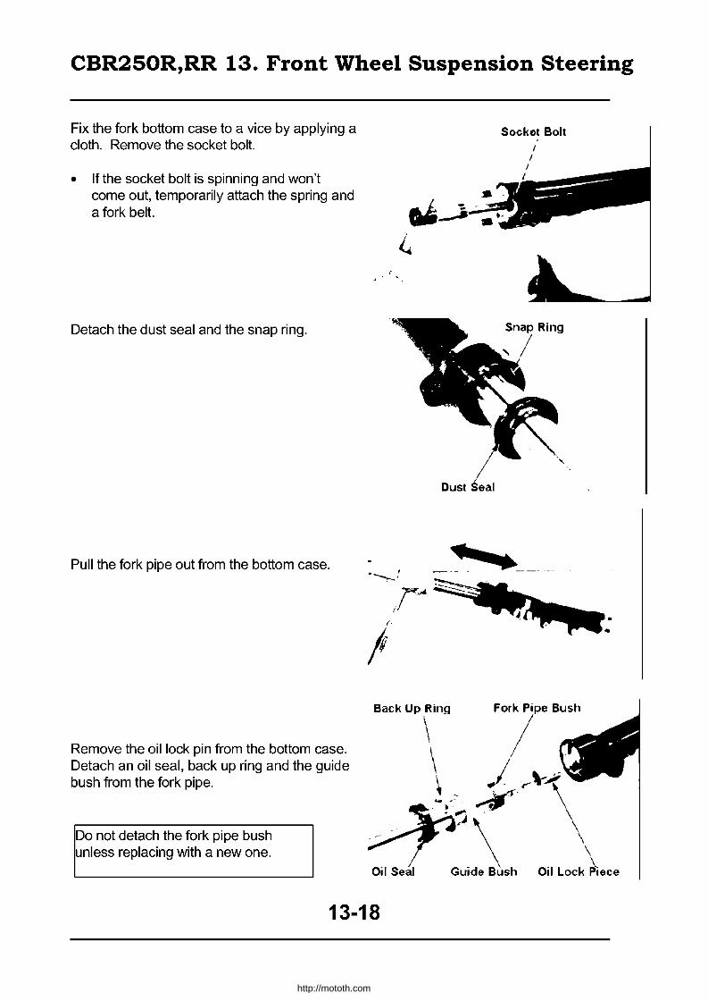
CBR250R,RR 13. Front Wheel Suspension Steering
Fix the fork bottom case to a vice by applying a cloth. Remove the socket bolt.
• If the socket bolt is spinning and won't come out, temporarily attach the spring and a fork belt.
Detach the dust seal and the snap ring.
Pull the fork pipe out from the bottom case.
Sockot Bolt
_____ ,I
Remove the oil lock pin from the bottom case. Detach an oil seal, back up ring and the guide bush from the fork pipe.
B," Up \;ng F07' Bu,"
\ J . .... \-'\'. Do not detach the fork pipe bush unless replacing with a new one.
13-18
\' ~. .",. .
"\ \ Guide B~sh Oil Lock ~ece
http://mototh.com
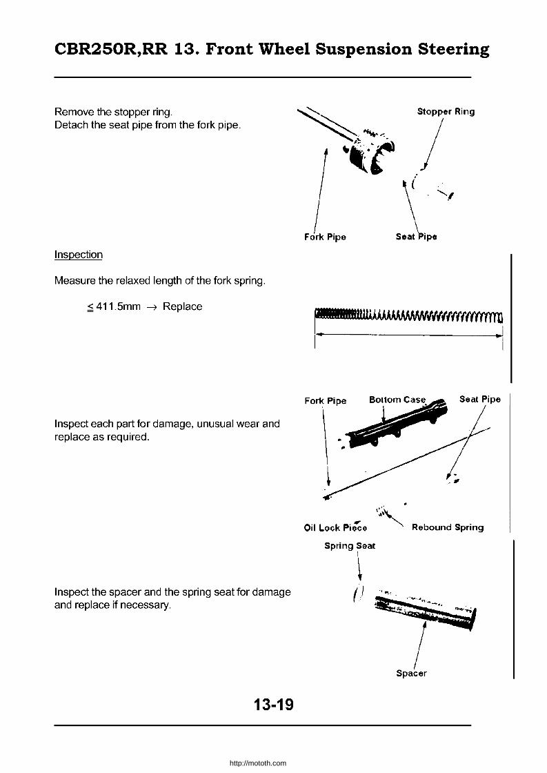
CBR250R,RR 13. Front Wheel Suspension Steering
Remove the stopper ring. Detach the seat pipe from the fork pipe.
Inspection
Measure the relaxed length of the fork spring.
:;;; 411.5mm --7 Replace
Inspect each part for damage, unusual wear and replace as required.
Inspect the spacer and the spring seat for damage and replace if necessary.
13-19
~.:.,,--.:-! ·,·r ,1.. P;p.
Fork Pipe
Stopper Ring
I \ 'I
Seat\iPe
Seat Pipe
Oil Lock Pi~o <\. .' .""'-
Rebound Spring
Spring Seat I
~ (.' "p..
http://mototh.com
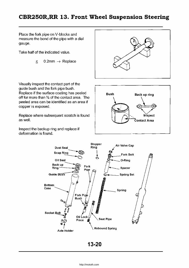
CBR250R,RR 13. Front Wheel Suspension Steering
Place the fork pipe on V -blocks and measure the bend of the pipe with a dial gauge.
Take half of the indicated value.
< O.2mm ~ Replace
Visually inspect the contact part of the guide bush and the fork pipe bush. Replace if the surface coating has peeled off for more than :y. of the contact area. The peeled area can be identified as an area if copper is exposed.
Replace where subsequent scratch is found as well.
Inspect the backup ring and replace if deformation is found.
Dust Seal
Snap Ring-----e
--------Q Oil Seal
Back up ---------(9) Ring~ Fork
PI e ~
Guide 5 A Bottom Ie...f Case I
Fork Pi Bush
Stopper Ring
~ C'>
\ ~
Oil Lock
BUSh~_ ..... " B~
'" Inspect
Contact Area
~ Air Valve Cap
t_ForkBolt
~ __ O-Rin9
U'---- Spacer
©-of Spring Set
_ _ Spring
socket~1 ((J) @t
J~ Piece. Seat Pipe
\ Rebound Spring Axle Holder
13-20
http://mototh.com

CBR250R,RR 13. Front Wheel Suspension Steering
Insert the rebound spring and the seat pipe to the fork pipe.
Attach the stopper ring to the seat pipe.
Attach the guide bush and the backup ring to the fork pipe.
Attach oil lock piece to the seat pipe. Insert the fork pipe to the bottom case.
Apply cloth around the bottom case and fix the case to a vice. Tighten the socket bolt to the seat pipe. Torque: 0.5 - 2.0kg-m
13-21
Fork Pipe
. /' '-....1
. .....
~.~~.(
Stopper ring
/ /( Seat Pipe
Back Up ~ing
"'~~
4?~ Fork Pipe Guide Bush Oil L.ock Piece
Socket Bolt
http://mototh.com
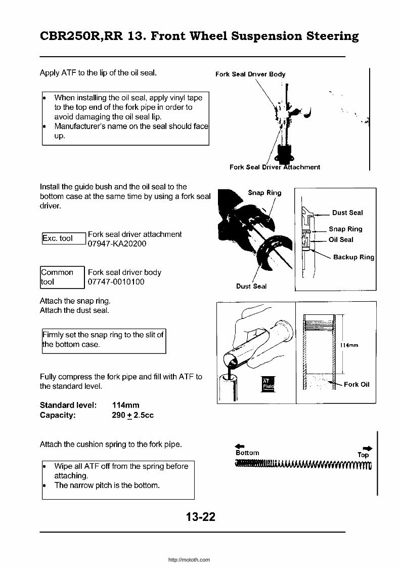
CBR250R,RR 13. Front Wheel Suspension Steering
Apply ATF to the lip of the oil seal.
• When installing the oil seal, apply vinyl tape to the top end of the fork pipe in order to avoid damaging the oil seal lip.
• Manufacturer's name on the seal should face up.
Install the guide bush and the oil seal to the bottom case at the same time by using a fork seal driver.
IExc. tool I Fork seal driver attachment 07947 -KA20200
Common Fork seal driver body tool 07747-0010100
Attach the snap ring. Attach the dust seal.
Firmly set the snap ring to the slit of he bottom case.
Fully compress the fork pipe and fill with ATF to the standard level.
Standard level: Capacity:
114mm 290 + 2.5cc
Attach the cushion spring to the fork pipe.
• Wipe all ATF off from the spring before attaching.
• The narrow pitch is the bottom.
13-22
F 011< Seal Driver Body
\1 Fork Seal
Dust Seal
.. Bottom
Backup Ring
114mm
Fork Oil
.. Top
MlliIIIIIIIIUI1UM),»j.J,J.J./oI(/(((f(ffY'fYTrrJ
http://mototh.com
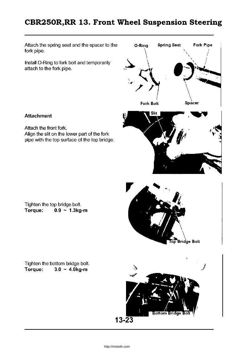
CBR250R,RR 13. Front Wheel Suspension Steering
Attach the spring seat and the spacer to the fork pipe.
O-Ring Spring Seat Fork Pipe
Install O-Ring to fork bolt and temporarily attach to the fork pipe.
Attachment
Attach the front fork. Align the slit on the lower part of the fork pipe with the top surface of the top bridge.
Tighten the top bridge bolt. Torque: 0.9 - 1.3kg-m
Tighten the bottom bridge bolt. Torque: 3.0 - 4.0kg-m
\ ~
Fork Bolt
~ ...
13-23
, I " I
.\ /
.~~~~\j .. \ ~....J \ \
Spacer
8n.1nA Bolt
)
http://mototh.com
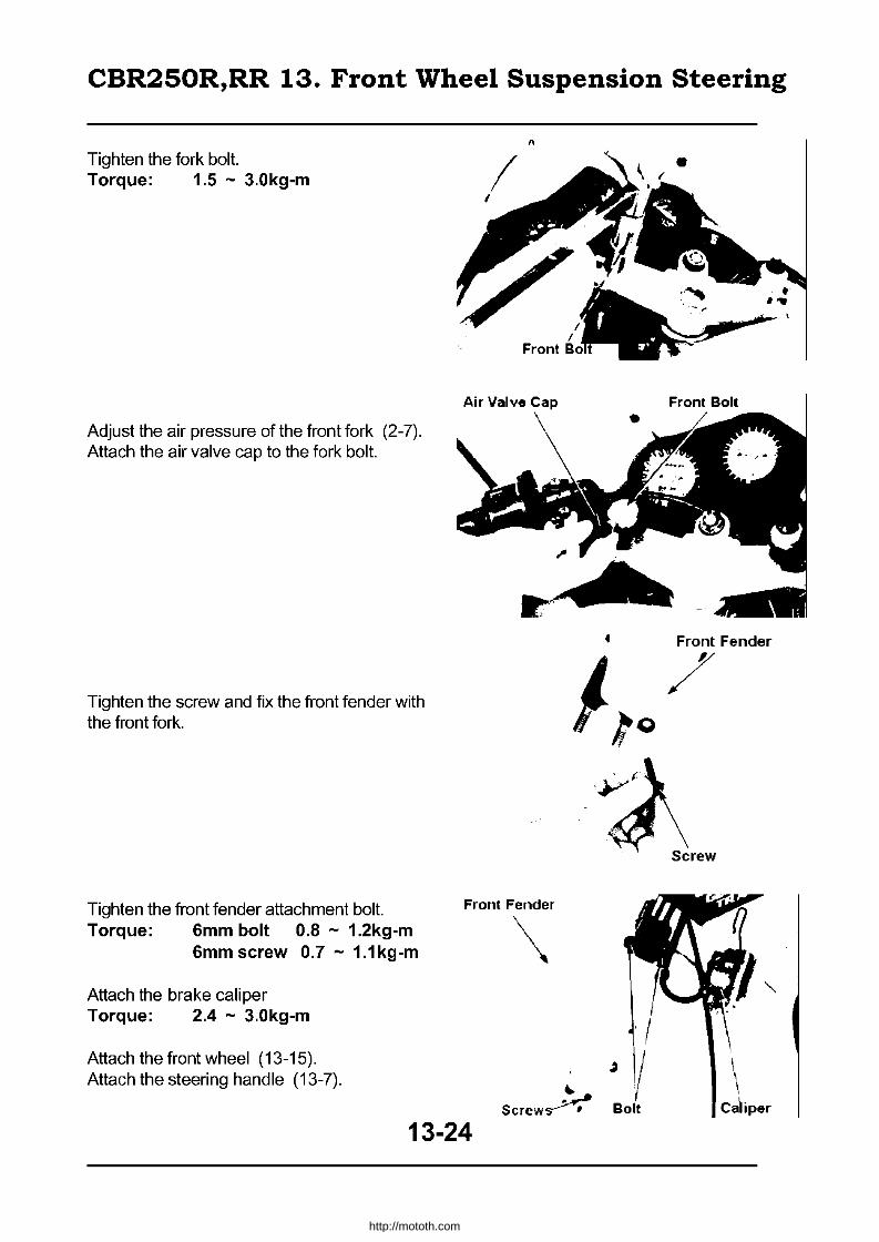
CBR250R,RR 13. Front Wheel Suspension Steering
Tighten the fork bolt. Torque: 1.5 - 3.0kg-m
Adjust the air pressure of the front fork (2-7). Attach the air valve cap to the fork bolt.
Tighten the screw and fix the front fender with the front fork.
"
• Front Fender
J / 'to
Tighten the front fender attachment bolt. Front Fender
Torque: 6mm bolt 0.8 - 1.2kg-m 6mm screw 0.7 - 1.1kg-m
Attach the brake caliper Torque: 2.4 - 3.0kg-m
Attach the front wheel (13-15). Attach the steering handle (13-7).
13-24
\
.. Scrcw~
http://mototh.com
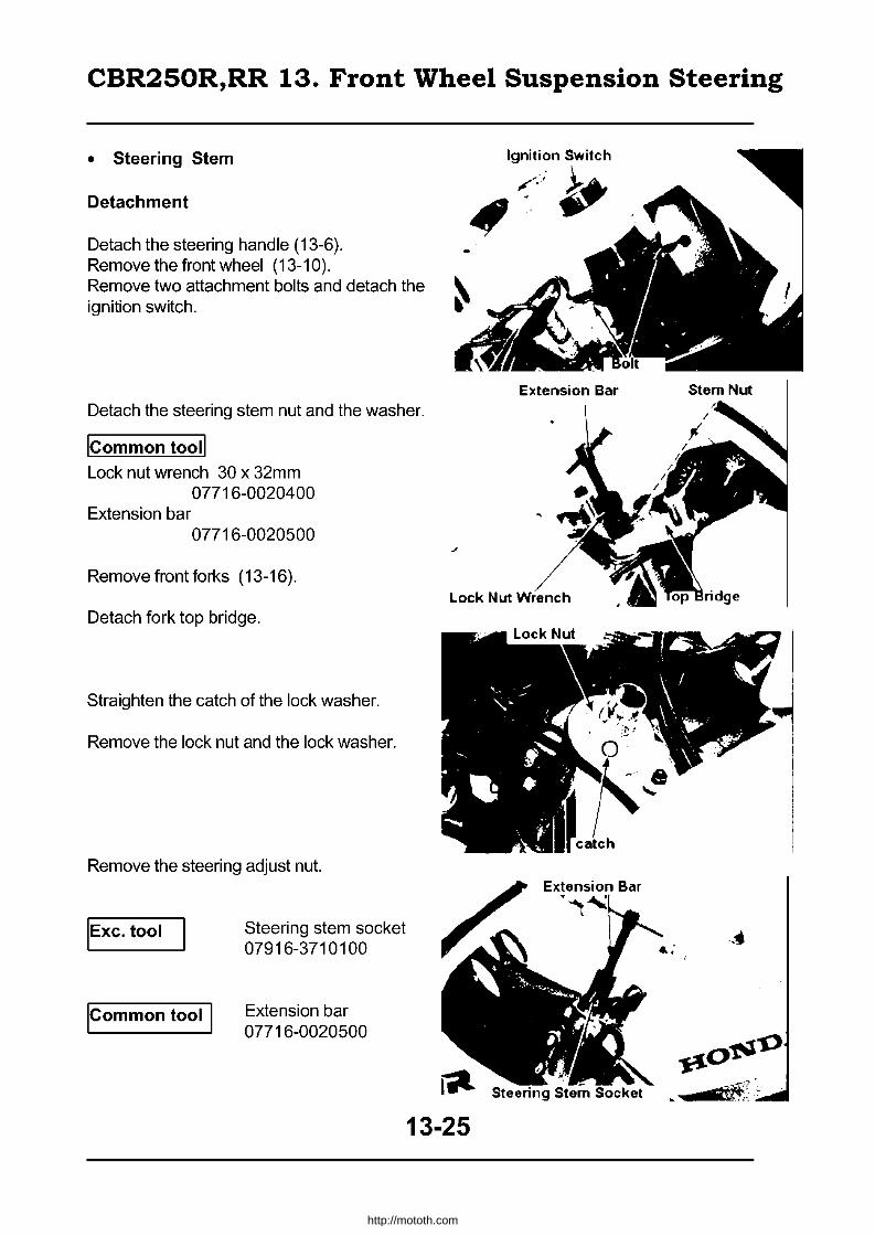
CBR250R,RR 13. Front Wheel Suspension Steering
• Steering Stem
Detachment
Detach the steering handle (13-6). Remove the front wheel (13-10). Remove two attachment bolts and detach the ignition switch.
Detach the steering stem nut and the washer.
ICommon tooll Lock nut wrench 30 x 32mm
07716-0020400 Extension bar
07716-0020500
Remove front forks (13-16).
Detach fork top bridge.
Straighten the catch of the lock washer.
Remove the lock nut and the lock washer.
Remove the steering adjust nut.
IEXC. tool
Icommon tool I
Steering stem socket 07916-3710100
Extension bar 07716-0020500
13-25
Ignition Switch
~
http://mototh.com

CBR250R,RR 13. Front Wheel Suspension Steering
Detach the front brake two-way joint.
Remove the steering stem, dust seal, upper bearing inner race and an upper bearing.
Detach the lower bearing from the stem.
Inspection
Inspect upper and lower bearings for wear and damage.
Inspect the inner race and the dust seal on lower bearing for wear and damage.
Inspect the bearing outer race of the steering head pipe for wear and damage.
Bearing Replacement
Replace inner and outer races together ~ith the bearing.
Detach the lower bearing inner race.
• Attach the stem nut to the stem to protect the thread.
• Do not damage the stem.
Remove the dust seal.
13-26
... .! ' .11
rj ! 1 ~/.' u
Lower~ Stem Nut
I
I ~ j
Inner Race, Dust Sei'll
http://mototh.com

CBR250R,RR 13. Front Wheel Suspension Steering
Attach the new dust seal to the steering stem and press the inner race in.
IExc. tool
Steering Stem Driver
:1 .;1 ". j;
Oust Sea. Inner Race
I ! [
Steering stem driver 07946-M BOOOOO
!!t~ ,1-.
't
Ball Race Replacement
IEXC. tools
Ball race remover set (incl. 1-6) 07946-KM90000
1. Driver shaft Assy (incl. Nuts A&B) 07946-KM90300
2. Assembly base 07946-KM90600 3. Driver attachment A 07946-KM90 1 00 4. Driver attachment B 07946-KM90200 5. Bearing remover A 07946-KM90400 6. Bearing remover B 07946-KM90500
Set a ball race remover to head pipe as shown in the figure.
• Align the bearing remover A with the slit on the head pipe.
• Lightly tighten the nut B. • Watch out the direction of an assembly
base.
Hold the driver shaft with the wrench and remove the upper outer race by loosening the nut A.
Remove the lower outer race in same manner.
• Align the bearing remover B with the slit on the head pipe to attach.
·V· ·i t· » : ; -;~ .-~
[ll • A , B
3. Driver Attachment A
Upper Outer \ ~ race ........... ® 1 -......G .... I--~ 2. Assembly . !., . I' Base
5. Beanng~/ . '. r Nut Remover A
1. Driver Shaft:' 'J I
4. Driver Wrench Attachment B
1. Driver Shaft
3. Driver Attachment
6. Bearing Re~er B"
Lower Outer ~ \ race ............. tI
~ 4. Driver
Attachment B
Wrench
1. Nut B
2. Assembly Base
Set the upper outer race and the ball race remover to the head pipe as shown in the figure.
13-27
http://mototh.com

CBR250R,RR 13. Front Wheel Suspension Steering
Hold the driver shaft with a wrench and attach the upper outer race by gradually rotating the nut A.
Attach the lower outer race in the same manner.
Attachment
3. Driver Attachment A --.... ~~
Upper Outer race ),
4. Driver Attachment
2. Assembly Base
Lower Outer race
'" 4. Driver ~ Attachment B ..:.....<=ur
~.. Lock Nut
~ Lock Washer ~.. Steering Adjust Nut ~-DustSeal ~-- Upper Inner race ~ Upper Bearing ~- Upper Outer race
~ Lower Outer race ~ Lower Bearing ~. Lower Inner race
~ Dust Seal
Apply enough grease to the bearing.
Attach the lower bearing to the steering stem.
s II( rl
r f
1. Driver Shaft
Nut A
•1.1
U
4#igLOW~ 13-28
http://mototh.com

CBR250R,RR 13. Front Wheel Suspension Steering
Attach the steering stem to the steering head.
Attach the upper bearing, inner race and the dust seal.
Tighten the steering adjust nut. Torque: 2.0 - 2.4kg-m
IExc. tool
ICommon too II
Steering stem socket 07916-3710100
Extension bar 07716-0020500
Steer full deflection both ways 5 - 6 times to smooth the bearings on the stem.
Re-tighten the steering adjust nut to specified torque.
Attach the front brake two-way joint.
Attach the catch of the new lock washer to the slit of the steering, adjust nut and attach the washer. Tighten the lock nut until it touches the lock washer by hand. Hold the steering, adjust nut and tighten the lock nut enough to align the catch of the lock washer with the slit on the lock nut. Bend the catch of the lock washer to the slit of the lock nut.
13-29
Extension Bar
http://mototh.com
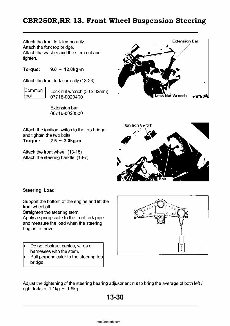
CBR250R,RR 13. Front Wheel Suspension Steering
Attach the front fork temporarily. Attach the fork top bridge. Attach the washer and the stem nut and tighten.
Torque: 9.0 - 12.0kg-m
Attach the front fork correctly (13-23).
Common Lock nut wrench (30 x 32mm) 001 07716-0020400
Extension bar 00716-0020500
Attach the ignition switch to the top bridge and tighten the two bolts. Torque: 2.5 - 3.0kg-m
Attach the front wheel (13-15) Attach the steering handle (13-7).
Steering Load
Support the bottom of the engine and lift the front wheel off. Straighten the steering stem. Apply a spring scale to the front fork pipe and measure the load when the steering begins to move.
• Do not obstruct cables, wires or harnesses with the stem.
• Pull perpendicular to the steering top bridge.
Ignition Switch
/.;~
~
Extension Bar
Adjust the tightening of the steering bearing adjustment nut to bring the average of both left / right forks of 1.1 kg - 1.6kg.
13-30
http://mototh.com

CBR250R,RR 14. Rear Wheel, Brake & Suspension
• Disassembly
5.0-S.0kg-m
£~~ ___ 1.0-2.0kg-m
~~ __ - 5.0-6.0kg-m
,0-. •• "._/
2.5-3.0kg-m
5.0-S.0kg-m
14-0
http://mototh.com

CBR250R,RR 14. Rear Wheel, Brake & Suspension
Disassembly 14-0 Brake pedal 14-10 Service information 14-1 Rear cushion 14-11 Troubleshooting 14-2 Suspension linkage 14-15 Rear wheel 14-3 Rear fork 14-18 Rear brake 14-7
~aution • Follow the safety instructions as the damper unit of the shock absorber is filled with
highly pressurized nitrogen gas.
• Do not heat or disassemble the damper unit or it may explode or spill the oil. • Drain the gas from the damper unit when disposing of the shock absorber.
• Do not step on the wheel or apply excess force on the wheel. • Exercise caution not to damage the wheel. • Exercise caution not to damage the tyre or rim as a tubeless tyre is equipped. • When detaching the tyre from the rim, use "tyre lever" and "rim protector". • Refer to "Honda Motorcycle Tubeless Tyre Service Manual" (No. 6041551) when
detaching / attaching the tubeless tyre. • Use only specified products for the rear suspension linkage and the rear cushion
attachment bolts / nuts. Use caution to the direction of the bolts. • Refer to 13-12 for balancing the rear wheel.
• Service Standard Item Standard Limitation
Rear axle bend - 0.2mm Rear wheel rim deformation I Radial - 2.0mm
I side - 2.0mm Brake drum inner diameter 140mm 141mm
Brake lininq thickness 4.0mm 2.0mm Rear cushion damper compression 12.3-16.0kg 9.8kg
Rear cushion sprinq attachment lenqth 173.8mm -Rear cushion spring natural length 189.9mm 186.0mm
• Torque Driven sprocket nut 2.8-4kg-m Conrod bolt (cushion arm 5.0-6.0kg-m
side) Rear axle nut 8.0-10kg-m frame side 5.0-6.0kg-m Rear cushion lower joint lock nut 3.8-6.0kg-m Rear fork pivot adj ust bolt 1.0-2.0kg-m (apply screw locking liquid) Rear cushion upper bolt 5.0-6.0kg-m Rear fork pivot lock nut 6.0-7.0kg-m Rear cushion lower bolt 5.0-6.0kg-m Rear fork pivot nut 6.0-7.0kg-m Cushion arm bolt 5.0-6.0kg-m
14-1
http://mototh.com

CBR250R,RR 14. Rear Wheel, Brake & Suspension
I Stop holder I 2.5-3.0kg-m
Tools
• Exclusive Tools Needle bearing remover 07GMD KT70200 Outer driver (28x30mm) 07946-1870100 Bearing remover 07936-3710300 Driver shaft 07946-MJOO 100 remover handle 07936-3710100 Rear cushion compressor Attachment 07959-MB10000 remover sliding weight 07741-0010201
• Common tools Outer driver (32 x 35mm 07746-0010100 Pilot (22mm) 07746-0041000 Outer driver (37 x 40mm) 07746-0010200 Bearing remover shaft 07746-0050100 Outer driver (42 x 47mm) 07746-0010300 Bearing remover head (17mm) 07746-0050500 Outer driver (24 x 26mm) 07746-0010700 Driver handle A 07749-0010000 Pilot (15mm) 07746-0040300 Rear cushion compressor 07959-3290001 Pilot (17mm) 07746-0040400
• Troubleshooting
Vibration of the rear wheel • Rim deformed • Loose rear wheel bearing • Bad quality tyre • Insufficient tightening around the axle • Insufficient lyre air pressure • Rear fork pivot bearing failure
Rear cushion too soft • Spring deformed • Inadequate adjustment of the rear cushion adjuster • Rear damper getting loose
Rear cushion too hard • Inadequate adjustment of the rear cushion adjuster • Damper rod bent
Noise from a rear cushion • Cushion case touching something • Loose tightening
Loose brake • Inadequate brake adjustment • Dirt/damage on the brake shoe surface • Brake shoe cam worn out • Brake cam worn out • Brake drum worn out • Brake arm collation attachment failure
14-2
http://mototh.com
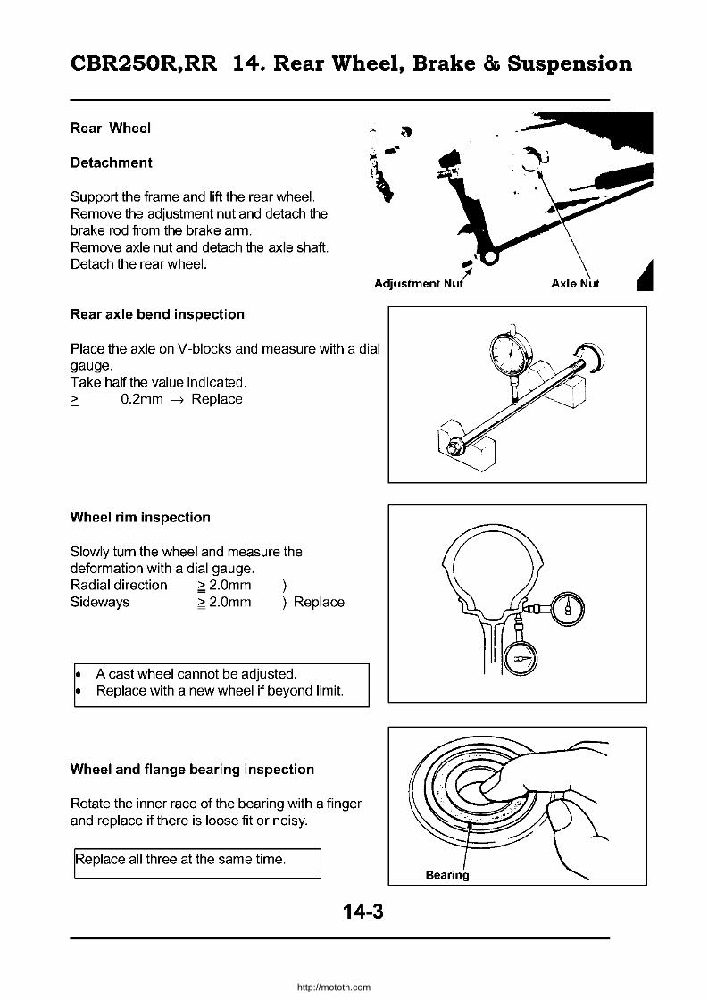
CBR250R,RR 14. Rear Wheel, Brake & Suspension
Rear Wheel
Detachment
Support the frame and lift the rear wheel. Remove the adjustment nut and detach the brake rod from the brake arm.
--\
Remove axle nut and detach the axle shaft. Detach the rear wheel. ;.
Adjustment Nul
Rear axle bend inspection
Place the axle on V-blocks and measure with a dial gauge. Take half the value indicated. > O.2mm ~ Replace
Wheel rim inspection
Slowly turn the wheel and measure the deformation with a dial gauge. Radial direction ;;: 2.0mm Sideways ;;: 2.0mm Replace
• A cast wheel cannot be adjusted. • Replace with a new wheel if beyond limit.
Wheel and flange bearing inspection
Rotate the inner race of the bearing with a finger and replace if there is loose fit or noisy.
IRe place all three at the same time.
14-3
http://mototh.com

CBR250R,RR 14. Rear Wheel, Brake & Suspension
Final driven sprocket inspection
Inspect ~ final driven sprocket for wear I damage.
Inspect the drive chain and drive sprocket at the same time.
Disassembly
Remove the side collar. Remove the dust seal.
Remove the driven flange.
Remove the damper rubber.
Remove the O-Ring.
o f>f\4 ~
Good
Driven Flange --
14-4
/ . I
O-Ring
No Good
,.
Seal
http://mototh.com
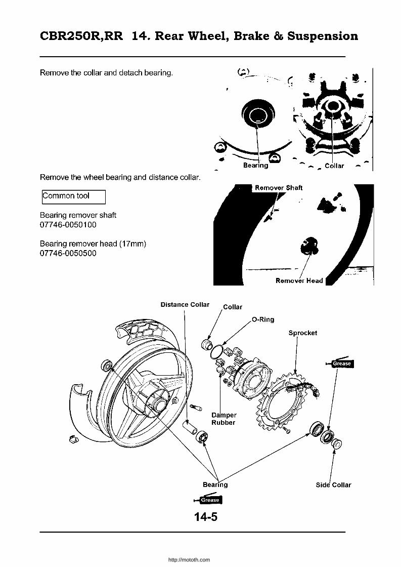
CBR250R,RR 14. Rear Wheel, Brake & Suspension
Remove the collar and detach bearing. •• '<' •
. ~~ .. Beanng- -. Collar
Remove the wheel bearing and distance collar.
Icommon tool
Bearing remover shaft 07746-0050100
Bearing remover head (17mm) 07746-0050500
Damper Rubber
.... w. 14-5
-
-----~ / Remover Head
Sprocket
http://mototh.com

CBR250R,RR 14. Rear Wheel, Brake & Suspension
Apply enough grease to the bearing. Install the left bearing first. Insert distance collar. Install the right bearing.
• Install the bearings in parallel. • Sealed side of the bearings should
face outward.
Icommon tools
Driver handle A Outer driver (37x40mm) Pilot (17mm)
07749-0010000 07746-0010200 07746-0040400
Place the bearing on a level surface and attach the collar.
Apply enough grease to the bearing. Install the bearing to the driven flange.
Install firmly so that the bearing does not Iproject.
Icommon tools
Driver handle A Outer driver (42x47mm) Pilot (17mm)
07749-0010000 07746-0010300 07746-0040400
Inspect the damper rubber and the O-Ring for deformation, damage and wear.
Attach the O-Ring.
Attach the final driven sprocket. If the driven sprocket nut was removed, attach the washer and apply oil to the nut, then tighten the nut. Torque: 2.8 - 3.4kg-m
, 00; Outer Dri ver
~ Bearing Collar
~o 1;
Driver H
J. ,-'-
'>, .' 0' , Pilot
14-6
http://mototh.com

CBR250R,RR 14. Rear Wheel, Brake & Suspension
Apply grease to the lip of the dust seal and attach it to the driven flange.
Attach the side collar.
Attachment
Attach the brake panel to the rear wheel. Align the rear fork stopper with the slit on the brake panel.
Connect drive chain to the sprocket.
Attach the chain adjuster and fit the axle shaft from left side.
Tighten the axle nut: Torque: 8.0 - 10.0kg-m
Adjust the drive chain (2-8)
Rear Brake
Inspection
Measure the inner diameter of the brake drum.
~ 141mm --,) Replace.
Measure the brake lining thickness.
~ 2.0mm --,) Replace
~ Side Collar
fI';..( .. ~
,~!,... ...
-,.
Adj
.....
.. ... .... .......
Oust Sew -fifiFH.
I .
14-7
http://mototh.com

CBR250R,RR 14. Rear Wheel, Brake & Suspension
Disassembly
~hen re-using the brake shoes, mark on !the side of the shoe so that the shoe can be re-fitted to the original place.
Remove the cotter pin and the washer. Shoe Spring
Remove brake shoes from the brake panel by pushing them outwards. Detach shoe springs from the shoes. Remove the brake arm, wear indicator and the felt seal. Remove the brake cam.
Wear Indicator
Brake Arm
Apply small amount of grease to the brake cam and anchor pin. Attach the brake cam.
14-8
• • . ~
Washer
Brake Cam
Brake Cam
http://mototh.com
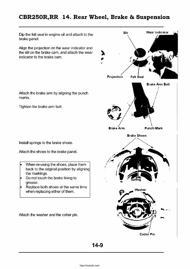
CBR250R,RR 14. Rear Wheel, Brake & Suspension
Dip the felt seal in engine oil and attach to the brake panel.
Align the projection on the wear indicator and the slit on the brake cam, and attach the wear indicator to the brake cam.
Attach the brake arm by aligning the punch marks.
Tighten the brake arm bolt.
Install springs to the brake shoes.
Attach the shoes to the brake panel.
• When re-using the shoes, place them back to the original position by aligning the markings.
• Do not touch the brake lining to grease.
• Replace both shoes at the same time when replacing either of them.
Attach the washer and the cotter pin.
14-9
http://mototh.com

CBR250R,RR 14. Rear Wheel, Brake & Suspension
Brake Pedal
Detachment
Remove the rear brake adjust nut (14-3). Remove the return spring. Remove two bolts and detach the right step. Detach the rear brake switch spring. Remove the circlip and detach the brake pedal.
Attachment
Apply grease on the pivot and attach the brake pedal to the right step pivot.
Finally, attach the circlip to the slit on the brake pedal pivot.
Attach the rear brake switch spring to the brake pedal.
Tighten the two bolts for the right step attachment. Torque: 2.5 - 3.0kg-m
Attach the return spring to the rear brake rod.
Attach the rear brake, adjust nut and adjust the free movement of the brake pedal (2-5).
~.
14-10
I
I
Right Stop
~ \ \
Brake Pedal
Brake Switch Spring ,
~'I .. \ -1 8
.. ~~~.~ ~>
~.
http://mototh.com

CBR250R,RR 14. Rear Wheel, Brake & Suspension
Rear cushion
Detachment
Support the frame with the stand to lift the wheel.
Detach the left side cover. Remove the conrad bolt (cushion arm side).
Remove the rear cushion lower bolt.
Remove the rear cushion upper bolt to detach the rear cushion.
Disassembly
Attach the rear cushion compressor
Icommon tool
Rear cushion compressor 07959-3290001
IExc. tool
Rear cushion compressor attachment 07959-MB 10000
Compress the spring to the position so that a lock nut can be removed. Loosen the lock nut and disconnect the lower joint. Remove the compressor and remove the seat stopper, dust seal, spring guide, lower spring seat, spring, upper spring seat and the adjuster.
14-11
, .
. L~ 'J
I compressor Lock Nul
http://mototh.com

CBR250R,RR 14. Rear Wheel, Brake & Suspension
Inspection
Measure the relaxed length of the cushion spring.
~ 186.0mm --,) Replace
Inspect the rear damper for deformation, oil leak, bent rod and inspect the damper rubber for wear and damage.
Check smooth operation of the rear damper.
Fully stretch the rear damper and mark at 1 Omm from a damper edge. Place on a scale vertically and press the damper until the mark (use hydraulic power).
Scale: 12.3 - 16.0kg
Replace the damper if the compression is less than 9.8kg.
Inspect the adjuster, upper seat, lower seat, spring guide and the dust seal for wear, deformation,or damage.
14-12
..
Damper Damper Rod
~,.\
Upper Seat Spring Guide
. It:
r Lower Seat
http://mototh.com
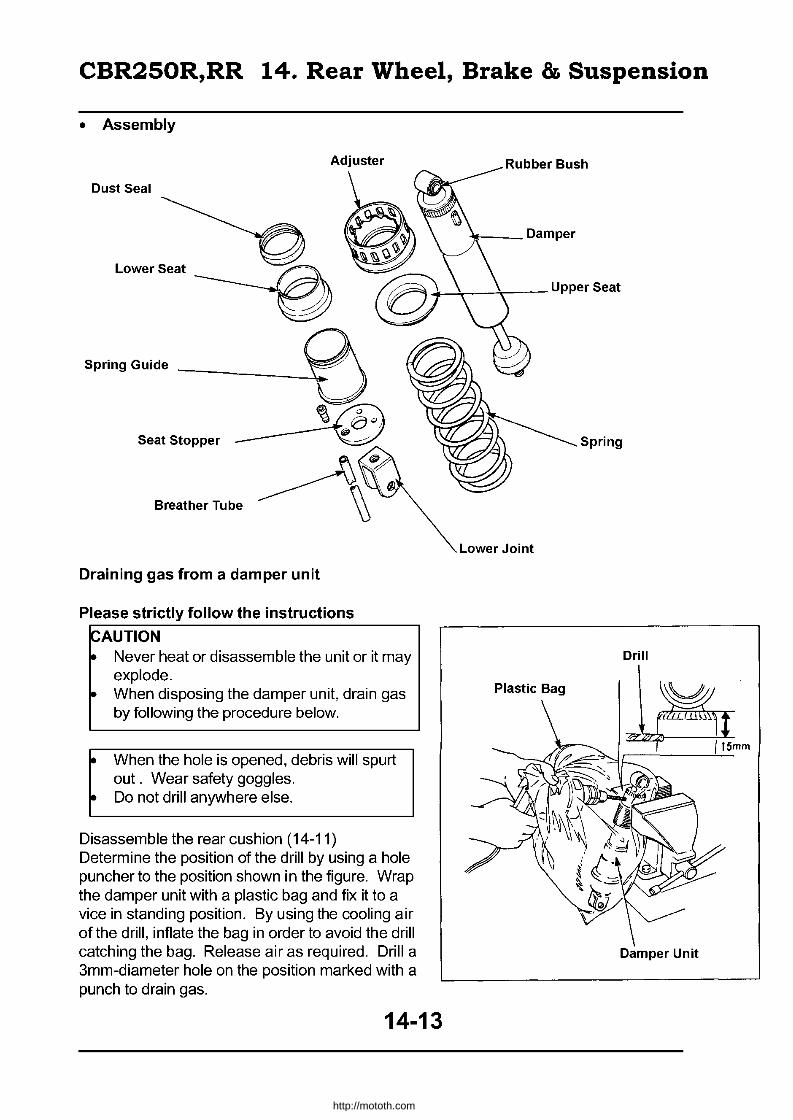
CBR250R,RR 14. Rear Wheel, Brake & Suspension
• Assembly
Adjuster
Dust Seal
Lower Seat
Spring Guide ______ _
Seat Stopper
Draining gas from a damper unit
Please strictly follow the instructions
~AUTION ~ Never heat or disassemble the unit or it may
explode. ~ When disposing the damper unit, drain gas
by following the procedure below.
~ When the hole is opened, debris will spurt out. Wear safety goggles.
~ Do not drill anywhere else.
Disassemble the rear cushion (14-11) Determine the position of the drill by using a hole puncher to the position shown in the figure. Wrap the damper unit with a plastic bag and fix it to a vice in standing position. By using the cooling air of the drill, inflate the bag in order to avoid the drill catching the bag. Release air as required. Drill a 3mm-diameter hole on the position marked with a punch to drain gas.
1f--- Damper
+-~--T-- Upper Seat
Spring
Lower Joint
Drill
Plastic Bag
Damper Unit
14-13
http://mototh.com

CBR250R,RR 14. Rear Wheel, Brake & Suspension
Attach the adjuster, upper seat, spring, lower seat, dust seal, spring guide and the seat stopper to the damper.
Compress the spring until the lower joint can be attached by using the rear cushion compressor.
ICommon tool
Rear cushion compressor
07959-3290001
Rear cushion compressor attachment 07959-M B 10000
Attach the lower joint so as to have the end of the damper rod thread 1 Omm from the inner edge surface of the lower joint.
Spring attachment length: 173.8mm
Fix the lower joint and tighten the lock nut.
Torque: 3.8 - 6.0kg-m
~pply screw locking liquid to the thread of he damper rod.
Firmly attach the breather tube to the lower joint.
Bush inspection
Inspect an upper joint collar and the rubber bush for wear and damage.
Rear Cushion Compressor
LOVier Joint Lock Nut
\\
Upper Joint Collar
, j
~ 14-14
http://mototh.com
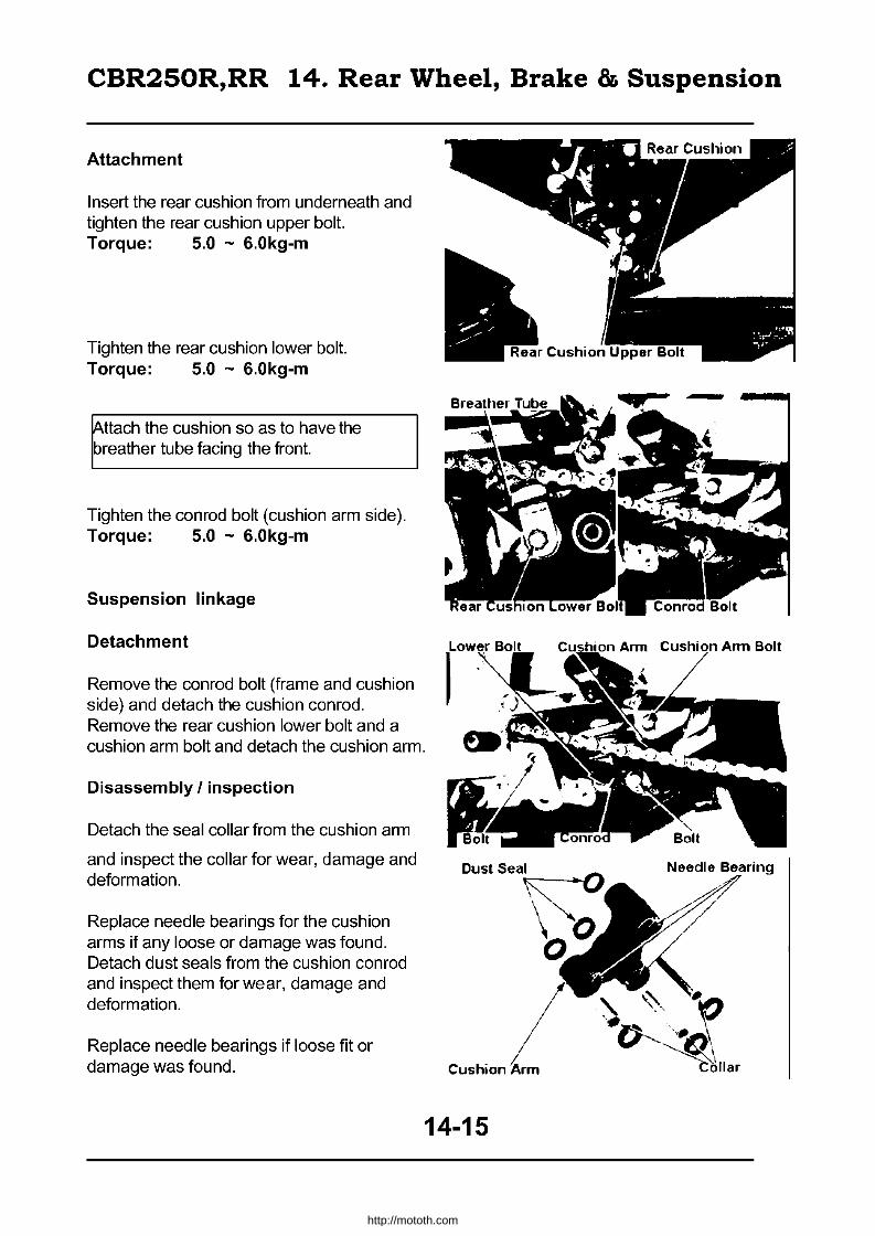
CBR250R,RR 14. Rear Wheel, Brake & Suspension
Attachment
Insert the rear cushion from underneath and tighten the rear cushion upper bolt. Torque: 5.0 - 6.0kg-m
Tighten the rear cushion lower bolt. Torque: 5.0 - 6.0kg-m
~ttach the cushion so as to have the breather tube facing the front.
Tighten the conrod bolt (cushion arm side). Torque: 5.0 - 6.0kg-m
Suspension linkage
Detachment
Remove the conrod bolt (frame and cushion side) and detach the cushion conrod. Remove the rear cushion lower bolt and a cushion arm bolt and detach the cushion arm.
Disassembly I inspection
Detach the seal collar from the cushion arm
and inspect the collar for wear, damage and deformation.
Replace needle bearings for the cushion arms if any loose or damage was found. Detach dust seals from the cushion conrod and inspect them for wear, damage and deformation.
Replace needle bearings if loose fit or damage was found. Cushion
14-15
Needle Bearing
http://mototh.com

CBR250R,RR 14. Rear Wheel, Brake & Suspension
Detach dust seals fram the cushion conrad and inspect them for wear, damage and deformation. Replace needle bearings if loose fit or damage was found.
Needle bearing replacement
Remove the cushion arm needle bearing.
IEXC. tools
Bearing remover Remover handle Remover sliding weight
07936-3710300 07936-3710100 07741-0010201
Detach the cushion conrad needle bearing
IEXC. tools
Bearing remover Remover handle Remover sliding weight
07936-3710300 07936-3710100 07741-0010201
Apply grease to the cushion arm needle bearing.
By using a hydraulic compressor, attach the needle bearing to the cushion arm.
pommon tools
Driver handle A Outer driver (24x36mm) Pilot (17mm)
07749-0010000 07746-0010700 07746-0040400
I. Press the marked surface in.
Needle Bearing Dust Seal
\ I '.
Collar
Sliding Weight
,. J
Remover Handle
Sliding Weight
R .. mov •• r Handle
Driver HiUldle A
. Needle
Cushion Conrod
Remover
Remover
Outer Driver
14-16
http://mototh.com
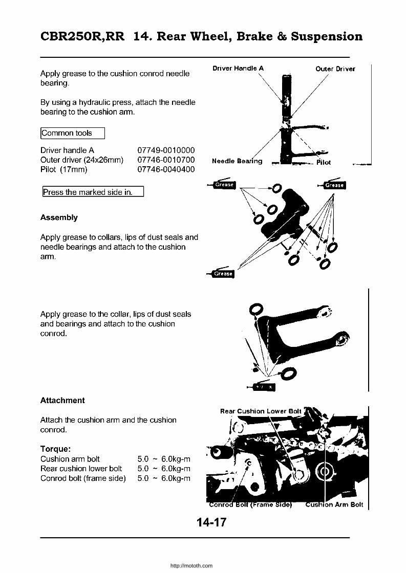
CBR250R,RR 14. Rear Wheel, Brake & Suspension
Apply grease to the cushion conrad needle bearing.
By using a hydraulic press, attach the needle bearing to the cushion arm.
ICommon tools
Driver handle A Outer driver (24x26mm) Pilot (17mm)
IPress the marked side in.
Assembly
07749-0010000 07746-0010700 07746-0040400
Apply grease to collars, lips of dust seals and needle bearings and attach to the cushion arm.
Apply grease to the collar, lips of dust seals and bearings and attach to the cushion conrad.
Attachment
Attach the cushion arm and the cushion conrod.
Torque: Cushion arm bolt Rear cushion lower bolt Conrod bolt (frame side)
5.0 - 6.0kg-m 5.0 - 6.0kg-m 5.0 - 6.0kg-m
Driver Handle A
Needle
-4iji
14-17
Outer Driver
.... m.
http://mototh.com
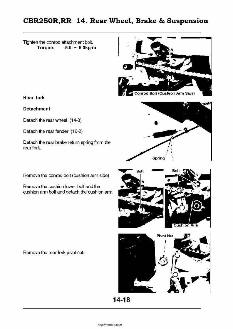
CBR250R,RR 14. Rear Wheel, Brake & Suspension
Tighten the conrad attachment bolt. Torque: 5.0 - 6.0kg-m
Rear fork
Detachment
Detach the rear wheel (14-3)
Detach the rear fender (16-2)
Detach the rear brake return spring fram the rear fork.
Remove the conrad bolt (cushion arm side)
Remove the cushion lower bolt and the cushion arm bolt and detach the cushion arm.
Remove the rear fork pivot nut.
14-18
/ Spring
Pivot Nut
I
.4/l !O
i~'"
http://mototh.com

CBR250R,RR 14. Rear Wheel, Brake & Suspension
Remove the rear fork pivot lock nut.
IExc. tool
Lock nut wrench 07GMA-KT70200
Remove the rear fork pivot adjust bolt and the pivot bolt at the same time. Detach the rear fork.
Disassembly
Detach the chain slider and the left pivot collar from the rear fork.
Inspect the pivot collar for damage.
Detach the dust seal.
Detach the distance collar.
Inspect the dust seal and the distance collar for damage.
Inspect needle bearing for damage.
Detach the right pivot collar.
Detach the dust seal.
Inspect the pivot collar and the dust seal for damage.
Inspect the ballbearing for loose fit, sand and smooth spin.
Remove the circiip when replacing the bearing.
Chain Slider
Left Pivot Collar
Needle Bearing
( I ''''
q Dust Seal
Ball Bearing
Right Pivot Collar
14-19
http://mototh.com

CBR250R,RR 14. Rear Wheel, Brake & Suspension
Bearing Replacement
Detach the right pivot bearing (ball bearing).
IExc. tool
Driver shaft 07946-MJ00100
Set the exclusive tool to the left pivot bearing (needle bearing).
IExc. tool Needle bearing remover 07GMD-KTl0200
Set the driver shaft as shown in the figure. Detach the left pivot bearing.
IExc. tools
Driver shaft 07946-MJ00100 Needle bearing remover 07GMD-KT70200
By using a hydraulic press, set the left pivot bearing (needle bearing).
IExc. tool I
Outer driver (28x30mm) 07946-1870100
ICommon tool
Pilot (22mm) Driver handle A
077 46-0041000 07749-0010000
IPress the marked side in.
14-20
• 1"'C
/r~ Right Pivot Bearing
http://mototh.com

CBR250R,RR 14. Rear Wheel, Brake & Suspension
By using hydraulic press, insert the right pivot bearing (ball bearing).
ICommon tool
Outer driver (32 x 35mm) Pilot (15mm) Driver handle A
Assembly
Attach the circiip to the slit.
07746-0010100 07746-0040300 07749-0010000
Apply grease to the lip of the right pivot dust seal and attach the seal.
Attach the right pivot colla r.
Apply enough grease to the left pivot bearing.
Attach the distance collar.
Apply grease to the lip of the left pivot dust seal and attach the dust seal.
Attach the left pivot collar.
Attach the chain slider.
Bearing
Circlip
Distance Collar
\ \
\
Driver Handle A
_a.:..: \:.~~'~.' __ ~Pilot
Right Pivot Collar
,~
1'. f.O
...... Mij Dust Seal Needle Bearing Chain Slider
14-21
http://mototh.com

CBR250R,RR 14. Rear Wheel, Brake & Suspension
Attachment
Screw in the rear fork pivot adjust bolt and stop before it's edge goes beyond the inner surface of the frame.
Attach the rear fork and insert the pivot bolt from an adjust bolt side and align the hexagon part.
Rotate the pivot bolt and tighten the adjust bolt. Torque: 1.0 - 2.0kg-m
Attach the lock nut and tighten.
IExc. tool
Lock nut wrench 07GMA-KT70200
~hen tightening the lock nut, hold the pivot bolt in order to prevent an adjust bolt from ~pinning together.
Torque: 6.0 - 7.0kg-m
Attach and tighten the pivot nut.
Torque: 6.0 - 7.0kg-m
Frame
Outside
Adjust Bolt
Pivot Nut
1~/j
14-22
Inside
Lock Nut Wrench
http://mototh.com

CBR250R,RR 14. Rear Wheel, Brake & Suspension
Attach the cushion arm and tighten the bolt.
Torque:
Cushion arm bolt Rear cushion lower bolt Conrad bolt (cushion arm side)
5.0 - 6.0kg-m 5.0 - 6.0kg-m 5.0 - 6.0kg-m
Attach the rear brake return spring to the rear fork.
Attach the rear fender chain guard (16-2)
Attach the rear wheel (14-7)
Rear Cushion Cushion Arm Bolt -Lower Bolt
Return Spring
14-23
http://mototh.com

CBR250R,RR 15. Braking System (Disc Brake)
• Disassembly
3.0-4.0kg-m
_--2.4-3.0kg-m
_---0.4-0.7kg-m
1.5-2.0kg-m
15-0
http://mototh.com

CBR250R,RR 15. Braking System (Disc Brake)
Disassembly 15-0 Brake pad I disk 15-4 Service information 15-1 Master cylinder 15-6
Troubleshooting 15-2 Brake caliper 15-9 Brake fluid replacement I air bleed 15-3
Service information
General caution • When replacing brake fluid, keep away from debris and water. • In order to avoid chemical reaction, do not mix different brands of brake fluids. • Do not re-use the drained brake fluid. • Keep the fluid away from other parts as the brake fluid will damage the paint, plastic or
rubber surfaces. • Split brake fluid should be wiped off with a cloth. • Cover the joint on hoses to prevent brake fluid leaks. • Clean the detached parts with brake fluid and check air passages with compressed air. • Keep the detached parts away from dust or debris. • Re-assemble the parts after checking they have no dust or debris attached. • Do replace all of the designated parts. • Brake pads can be replaced without disconnecting hoses. • Bleed air from the system after disconnecting the brake hose.
Service standards
Item Brake disk thickness
Brake disk deformation Master cylinder inner diameter Master piston outer diameter
Caliper cylinder inner diameter Caliper piston outer diameter
Torque Front caliper bracket 2.4-3.0kg-m Hanqer pin 1.5-2.0kq-m Master cylinder Holder bolt 1.0-1.4kg-m Hanger pin plug
Tools
Exclusive tool Snap ring pliers
0.1-0.2kg-m
07914-3230001
Standard 3.8-4.2
-14.000-14.043 13.957-13.984 27.000-27.050 26.918-26.968
Brake hose attachment Bolt Brake hose tiqhteninq Bolt Bleeder valve
15-1
Limit 3.5 0.3
14.055 13.945 27.06 26.91
2.5-3.5kg-m 3.0-4.0kq-m 04-0.7kg-m
http://mototh.com

CBR250R,RR 15. Braking System (Disc Brake)
Troubleshooting
Poor brake performance
• Air in brake system • Lack of brake fluid • Brake fluid leak • Brake pad wear • Dirty pad / disk surface
Brake lever heavy or unable to release
• Caliper piston fixed • Brake system jammed • Master piston jammed
Noise from brake
• Pad dirty / worn out • Disk deflection / wear / dirt • Poor caliper attachment • Misalignment of the disk or the wheel • Lack of lubrication at hanger pin - pad contact
15-2
http://mototh.com
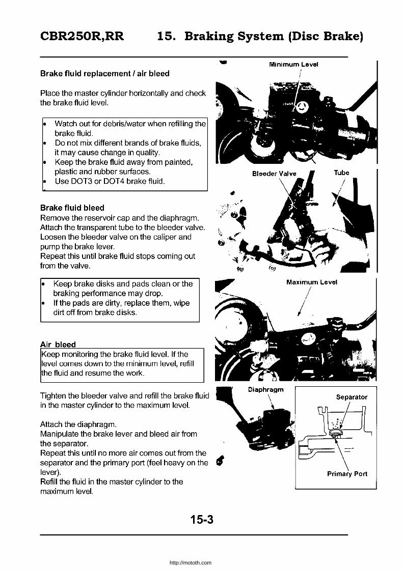
CBR250R,RR 15. Braking System (Disc Brake)
Brake fluid replacement I air bleed
Place the master cylinder horizontally and check the brake fluid level.
• Watch out for debris/water when refilling the brake fluid.
• 00 not mix different brands of brake fluids, it may cause change in quality.
• Keep the brake fluid away from painted, plastic and rubber surfaces.
• Use 00T3 or 00T4 brake fluid.
Brake fluid bleed Remove the reservoir cap and the diaphragm. Attach the transparent tube to the bleeder valve. Loosen the bleeder valve on the caliper and pump the brake lever. Repeat this until brake fluid stops coming out from the valve.
• Keep brake disks and pads clean or the braking performance may drop.
• If the pads are dirty, replace them, wipe dirt off from brake disks.
Air bleed Keep monitoring the brake fluid level. If the level comes down to the minimum level, refill the fluid and resume the work.
Tighten the bleeder valve and refill the brake fluid in the master cylinder to the maximum level.
Attach the diaphragm. Manipulate the brake lever and bleed air from the separator.
-
.'/:j .';';/ 4(».,-~t~ r ti/'!Io.;'
Repeat this until no more air comes out from the A separator and the primary port (feel heavy on the fP lever). Refill the fluid in the master cylinder to the maximum level.
15-3
Minimum Level
Maximum Level !
/
I.
Primary Port
http://mototh.com
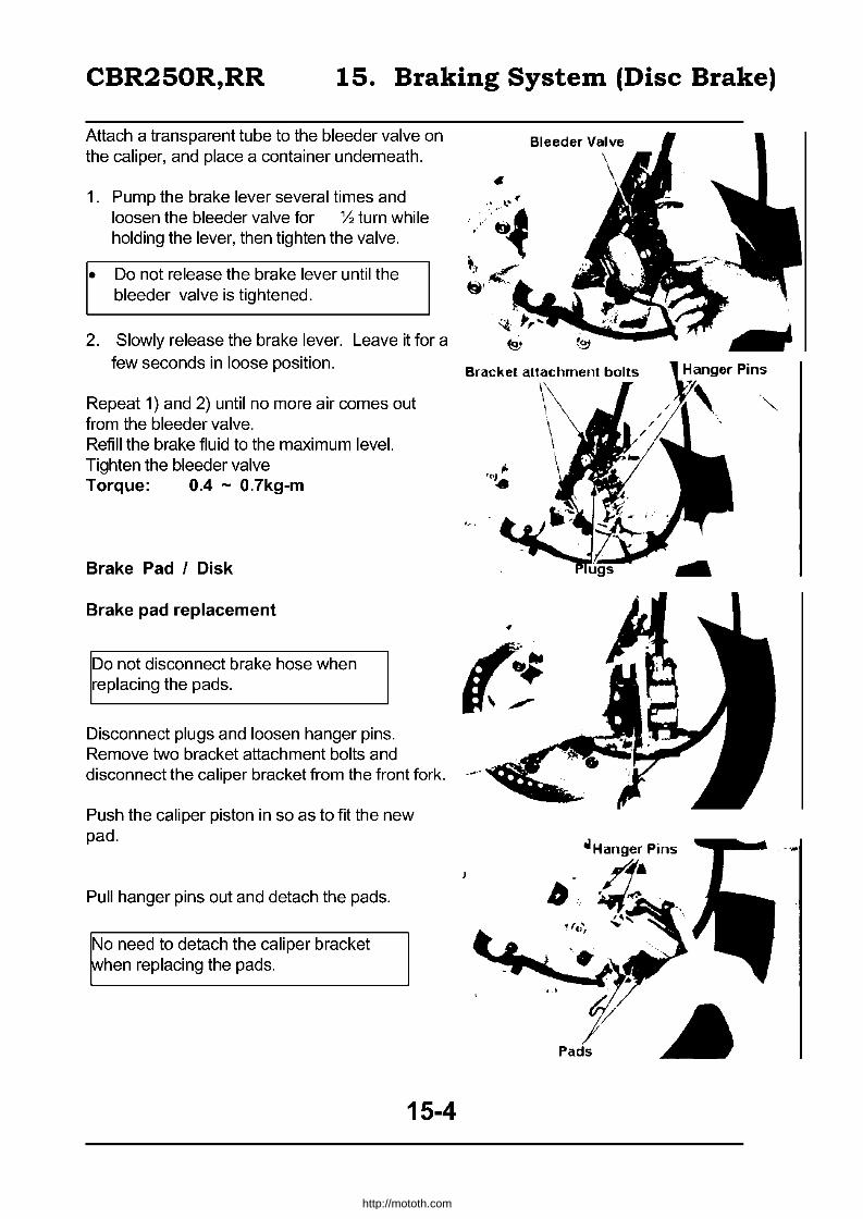
CBR250R,RR 15. Braking System (Disc Brake)
Attach a transparent tube to the bleeder valve on the caliper, and place a container underneath.
1. Pump the brake lever several times and loosen the bleeder valve for Y, turn while holding the lever, then tighten the valve.
• Do not release the brake lever until the bleeder valve is tightened.
2. Slowly release the brake lever. Leave it for a few seconds in loose position.
Repeat 1) and 2) until no more air comes out from the bleeder valve. Refill the brake fluid to the maximum level. Tighten the bleeder valve Torque: 0.4 - 0.7kg-m
Brake Pad I Disk
Brake pad replacement
Do not disconnect brake hose when replacing the pads.
Disconnect plugs and loosen hanger pins. Remove two bracket attachment bolts and disconnect the caliper bracket from the front fork.
Push the caliper piston in so as to fit the new pad.
Pull hanger pins out and detach the pads.
No need to detach the caliper bracket ~hen replacing the pads.
15-4
http://mototh.com
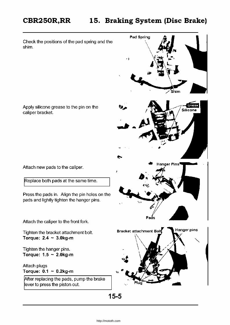
CBR250R,RR 15. Braking System (Disc Brake)
Check the positions of the pad spring and the shim.
Apply silicone grease to the pin on the caliper bracket.
Attach new pads to the caliper.
IRePlace both pads at the same time.
Press the pads in. Align the pin holes on the pads and lightly tighten the hanger pins.
Attach the caliper to the front fork.
Tighten the bracket attachment bolt. Torque: 2.4 - 3.0kg-m
Tighten the hanger pins. Torque: 1.5 - 2.0kg-m
Attach plugs Torque: 0.1 - 0.2kg-m
~fter replacing the pads, pump the brake lever to press the piston out.
15-5
Pad Spring ,
'J
http://mototh.com
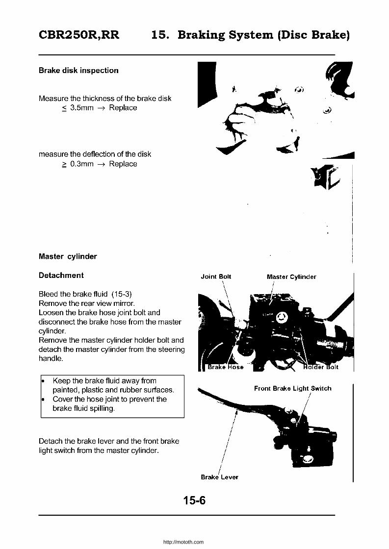
CBR250R,RR 15. Braking System (Disc Brake)
Brake disk inspection
Measure the thickness of the brake disk ~ 3.5mm -7 Replace
measure the deflection of the disk ~ O.3mm -7 Replace
Master cylinder
Detachment
Bleed the brake fluid (15-3) Remove the rear view mirror. Loosen the brake hose joint bolt and disconnect the brake hose from the master cylinder. Remove the master cylinder holder bolt and detach the master cylinder from the steering handle.
• Keep the brake fluid away from painted, plastic and rubber surfaces.
• Cover the hose joint to prevent the brake fluid spilling.
Detach the brake lever and the front brake light switch from the master cylinder.
Joint Bolt
15-6
:.::!)
c
Master Cylinder
http://mototh.com

CBR250R,RR 15. Braking System (Disc Brake)
Disassembly
Remove the dust boot and then the snap ring.
IExc. tool I Snap ring pliers
07914-3230001
Remove piston, primary cup and the spring from the master cylinder and clean the master cylinder and reservoir with brake fluid.
• Clean each part with brake fluid and check air path by applying compressed air.
• Store all the detached parts to keep away from dust/debris.
Inspection
Inspect the contact surface of the master cylinder (with master piston) for scratches and damage.
Measure the inner diameter of the master cylinder.
> 14.055mm ~ Replace
Inspect the surface of the master piston for damage and scratch. Inspect the piston cup for wear/damage. Measure the outer diameter of the master piston.
< 13.945mm ~ Replace
15-7
Snap Ring
Snap Ring Pliers
II{fll /';'; .. S ./
pnng
Piston
I / / .
rr~~ /'~
. J Piston Cup
1
1,( ..
Pisti>n
. .-
http://mototh.com
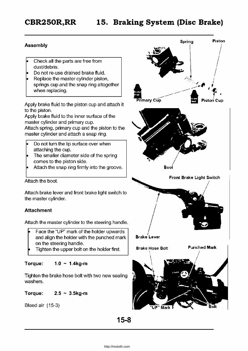
CBR250R,RR 15. Braking System (Disc Brake)
Assembly
• Check all the parts are free from dust/debris.
• Do not re-use drained brake fluid. • Replace the master cylinder piston,
springs cup and the snap ring altogether when replacing.
Apply brake fluid to the piston cup and attach it to the piston. Apply brake fluid to the inner surface of the master cylinder and primary cup. Attach spring, primary cup and the piston to the master cylinder and attach a snap ring.
• Do not turn the lip surface over when attaching the cup.
• The smaller diameter side of the spring comes to the piston side.
• Attach the snap ring firmly into the groove.
Attach the boot.
Attach brake lever and front brake light switch to the master cylinder.
Attachment
Attach the master cylinder to the steering handle.
~ Face the "UP" mark of the holder upwards and align the holder with the punched mark on the steering handle.
~ Tighten the upper bolt on the holder first.
Torque: 1.0 - 1.4kg-m
Tighten the brake hose bolt with two new sealing washers.
Torque: 2.5 - 3.5kg-m
Bleed air (15-3)
15-8
Spring Piston
.;~'/ ' .... , .
I I I . '
~·J~1' I
I ~ ... ~ I~ --------------I 't: . -------- i .
Primary C~ . Piston Cup
Brake Hose Bolt \
Punched Mark
http://mototh.com
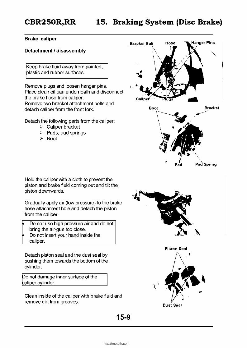
CBR250R,RR 15. Braking System (Disc Brake)
Brake caliper
Detachment I disassembly
Keep brake fluid away from painted, plastic and rubber surfaces.
Remove plugs and loosen hanger pins. Place clean oil pan underneath and disconnect the brake hose from caliper. Remove two bracket attachment bolts and detach caliper from the front fork.
Detach the following parts from the caliper: ~ Caliper bracket ~ Pads, pad springs ~ Boot
Hold the caliper with a cloth to prevent the piston and brake fluid coming out and tilt the piston downwards.
Gradually apply air (low pressure) to the brake hose attachment hole and detach the piston from the caliper.
• Do not use high pressure air and do not bring the air-gun too close.
• Do not insert your hand inside the caliper.
Detach piston seal and the dust seal by pushing them towards the bottom of the cylinder.
Do not damage inner surface of the caliper cylinder.
Clean inside of the caliper with brake fluid and remove dirt from grooves.
15-9
-.1 ~ ,
Piston Seal
Bracket .--~~
,
, , , Pad Spring
http://mototh.com

CBR250R,RR 15. Braking System (Disc Brake)
Inspection
Inspect the exterior surface of the caliper piston for scratch/damage.
Measure the outside diameter of the piston. ,:s 26.91 mm -7 Replace
Inspect the inner surface of the cylinder for scratch/damage.
Measure the inner diameter of the cylinder. ;;: 27.06mm -7 Replace
Caliper assembly I attachment
• Make sure all parts are free from dust / debris before assembly.
• Do not re-use drained brake fluid. • Replace piston seals and dust seals
when disassembling the caliper.
Apply silicone grease or brake fluid to all inner surfaces of seals and attach to the caliper.
Attach pistons to the caliper.
Face the open side of the piston owards brake pads.
Attach the pad spring to the caliper.
15-10
Piston
: .... "
Dust Sea
Pad Spring
/'-1 -
\
http://mototh.com

CBR250R,RR 15. Braking System (Disc Brake)
Attach brake pad, boot and the bracket to the caliper.
• Apply silicone grease to the boot and the pin on the caliper bracket.
• Firmly set the boot to the groove on the caliper.
Attach hanger pin.
Attach caliper bracket to the front fork and tighten the bolt.
Torque: 2.4 - 3.0kg-m
Fix the brake hose and new sealing washers (two) with the brake hose bolt.
Torque: 2.5 - 3.5kg-m
Install hanger pin
Torque: 1.5 - 2.0kg-m
Install plugs
Torque: 0.1 - 0.2kg-m
Fill the master cylinder with brake fluid and bleed air (15-3).
15-11
Bracket
http://mototh.com
CBR250R,RR 16. Exhaust Pipe, Rear Fender
Service information 16 - 1 Rear fender 16-2 Exhaust pipe 16-2 Sub-frame 16-3
Service Information
General Caution
ervice the exhaust pipe and the muffler when they are cooled down.
Torque
Exhaust pipe joint nut 0.8 - 1.2kg-m
Muffler attachment bolt 2.4 - 3.0kg-m
Rear fender A 0.7-1.1kg-m
Rear fender B 0.8 - 1.2kg-m
Tandem step holder 2.5 - 3.0kg-m
Sub-frame 4.5 - 5.5kg-m
16-1
http://mototh.com

CBR250R,RR 16. Exhaust Pipe, Rear Fender
Exhaust pipe
Detachment
Detach when the pipe and muffler are cool.
Remove the exhaust pipe joint nut. Remove muffler attachment bolt and nut and detach exhaust pipe.
Attachment
Reverse the detachment procedure.
Torque: Exhaust pipe joint nut Muffler attachment bolt
Rear Fender
Detachment
0.8 - 1.2kg-m 2.4 - 3.0kg-m
Remove the side cover. Remove bolts and detach the left tandem step holder. Remove five rear fender bolts.
Detach the rear fender B by pulling it towards the back and to the left. Remove seat and the rear cowl and
disconnect couplers for the tail/stoplight. Remove four bolts and detach the rear fender A. Attachment
Reverse the detachment procedure.
Torque: Rear fender A Rear fender B Tandem step holder
0.7 - 1.1kg-m 0.8 - 1.2kg-m 2.5 - 3.0kg-m
Mufti er Bolt
I Jomt Nut
16-2
Muffler Attachment Bolt ~ ,
http://mototh.com

CBR250R,RR
Sub-frame
Detachment
Remove the following items to detach the sub-frame.
Fuel tank (4-3) Rear cowl (20-2) Tail-light (20-2) Regulator / rectifier (17-5) Battery case (5-11) Reservoir tank (5-11) Rear Fender (16-2) Tandem step holder Sub-frame attachment bolt
16. Exhaust Pipe, Rear Fender
2.5-3.0kg-m
Attachment
Reverse the detachment procedure.
Torque: Sub-frame 4.5 - 5.5kg-m
Tandem step holder 2.5 - 3.0kg-m
Rear fender A 0.7 - 1.1 kg-m
~-m
"7 O.7-1.lkg-m
4.5-5.5kg-m
16-3
http://mototh.com
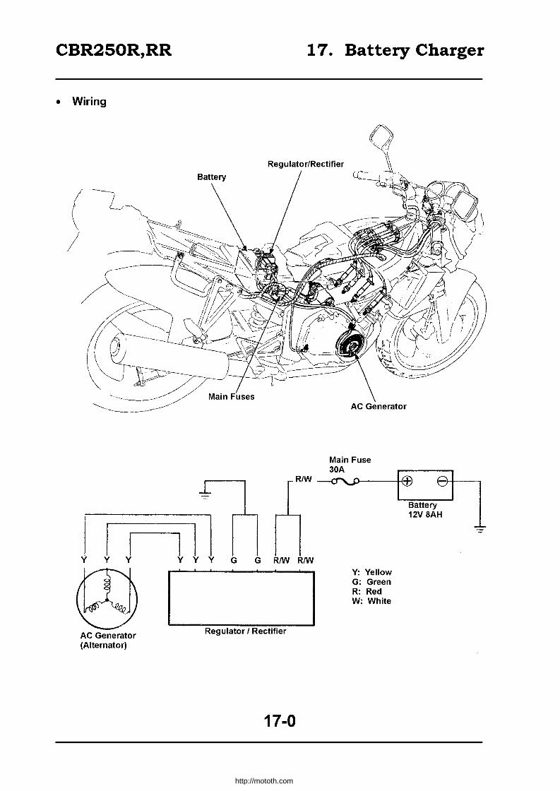
CBR250R,RR 17. Battery Charger
• Wiring
Regulator/Rectifier
( /
II r-----1 I I I Y Y Y YYY G GRIWRIW
AC Generator (Alternator)
Regulator / Rectifier
17-0
Y: Yellow G: Green R: Red W: White
Battery 12V 8AH
http://mototh.com
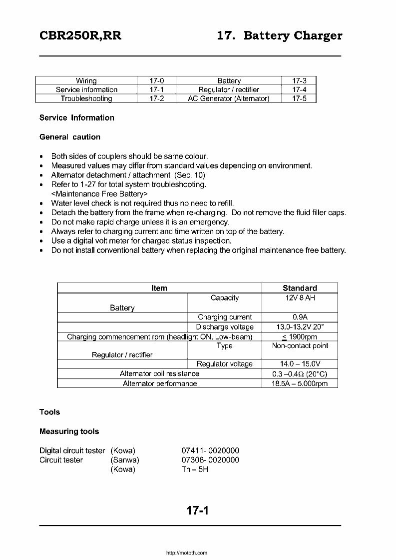
CBR250R,RR 17. Battery Charger
Wiring 17-0 Battery 17-3 Service information 17-1 ReQulator / rectifier 17-4
Troubleshooting 17-2 AC Generator (Altemator) 17-5
Service Information
General caution
• Both sides of couplers should be same colour. • Measured values may differ from standard values depending on environment. • Alternator detachment / attachment (Sec. 10) • Refer to 1-27 for total system troubleshooting.
<Maintenance Free Battery> • Water level check is not required thus no need to refill. • Detach the battery from the frame when re-charging. Do not remove the fluid filler caps. • Do not make rapid charge unless it is an emergency. • Always refer to charging current and time written on top of the battery. • Use a digital volt meter for charged status inspection. • Do not install conventional battery when replacing the original maintenance free battery.
Item Capacity
Battery Charging current Discharge voltage
Charging commencement rpm (headlight ON, Low-beam) Type
Regulator / rectifier
Tools
Measuring tools
Digital circuit tester Circuit tester
Regulator voltage Alternator coil resistance Alternator performance
(Kowa) (Sanwa) (Kowa)
07411-0020000 07308-0020000 Th-5H
17-1
Standard 12V8AH
0.9A 13.0-13.2V 20°
< 1900rpm Non-contact point
14.0 -15.0V 0.3 -OAn (20°C) 18.5A - 5.000rpm
http://mototh.com
CBR250R,RR 17. Battery Charger
Troubleshooting
No current (with main switch ON)
• Battery discharge • Leak • Regulator / rectifier fault • AC generator fault
• Battery cables disconnected • Fuses blown (inspect main fuses) • Main switch fault • Couplers disconnected I short circuit.
Re-charge system failure
• Connector or couplers disconnected I cut I short circuit between: • AC generator and regulator / rectifier (Y) • Regulator / rectifier and starter magnetic switches (R/w) • Starter magnetic switches and battery
• Regulator / rectifier fault • AC generator fault
Low voltage
• Insufficient charging or discharging • Regulator / rectifier fault • AC generator fault
Intermittent current
• Battery cables connection fault • Charging system connection fault • Ignition system connection fault / short circuit
17-2
http://mototh.com
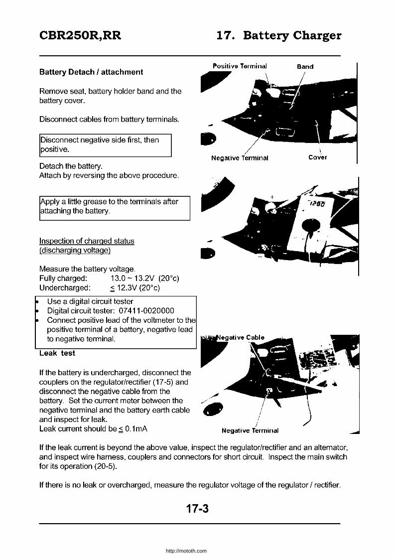
CBR250R,RR
Battery Detach I attachment
Remove seat, battery holder band and the battery cover.
Disconnect cables from battery terminals.
Disconnect negative side first, then positive.
Detach the battery. Attach by reversing the above procedure.
Apply a little grease to the terminals after attaching the battery.
Inspection of charged status (discharging voltage)
Measure the battery voltage. Fully charged: 13.0 - 13.2V (20°c) Undercharged: ~ 12.3V (20°c)
• Use a digital circuit tester • Digital circuit tester: 07411-0020000 • Connect positive lead of the voltmeter to the
positive terminal of a battery, negative lead to negative terminal.
Leak test
If the battery is undercharged, disconnect the couplers on the regulator/rectifier (17-5) and disconnect the negative cable from the battery. Set the current meter between the negative terminal and the battery earth cable and inspect for leak. Leak current should be ~ 0.1 rnA
17. Battery Charger
" -• Negative T .. nmin,,,'
-•
I
/ Negative Terminal
\ Cover
If the leak current is beyond the above value, inspect the regulator/rectifier and an alternator, and inspect wire harness, couplers and connectors for short circuit. Inspect the main switch for its operation (20-5).
If there is no leak or overcharged, measure the regulator voltage of the regulator / rectifier.
17-3
http://mototh.com

CBR250R,RR
Charging
Connection: Charger (+) = Battery (+) Charger (-) = Battery (-)
• Keep out of fire • Use the charger switch to start/stop
charging. Connecting /disconnecting at the terminal cause spark and it may create explosion.
• Always refer to charging current and time specified on top of the battery.
• Do not make rapid charge except in case of emergency.
• Measure the voltage 30 min. after charging.
CharQinQ current Standard Rapid
Charging time Standard Rapid
Fully charQed voltaQe
Regulator I rectifier
Regulator voltage inspection
I. Inspect with fully charged battery
Warm up engine. Stop the engine and remove a seat. Start the engine and set a voltmeter between the battery terminals.
• Voltmeter (+) lead = (+) battery terminal (-) lead = (-) battery terminal
Do not short circuit
Regulated voltage: 14.0 - 15.0V
17. Battery Charger
0.9A 4.0A
5 hours 1 hour 13.0V
• -, Terminal
If the voltage was out of the above range, inspect wire harness and couplers between the alternator and the battery and measure again.
If the voltage is still out of range, inspect the regulator/rectifier for its resistance (17-5) and inspect the alternator (17-5).
17-4
http://mototh.com

CBR250R,RR
Conduction inspection
Remove a seat and a left side cover. Remove a regulator/rectifier attachment bolt. Disconnect 4P and 3P couplers and detach the regulator/rectifier.
Test the conduction between each coupler on
the table below.
If there is conduction in positive direction and no conduction in reverse direction, that part is ok.
Positive Direction: Conduction
(+) (-) I Yellow Green
II Red /white yellow
Reverse Direction: Conduction
(+) (-) I Green Yellow
II Yellow Red /white
Alternator inspection
Detach a regulator/rectifier. Measure the resistance between two yellow terminals on the alternator side.
Standard: 0.3 - 0.4!l (20°c)
Confirm there is no conduction between each terminal on the alternator and ground earth. If the resistance is out of the range above or if there is any conduction between the terminals and ground earth, replace the alternator.
These measurements can be conducted while the alternator is mounted on the engine.
17-5
17. Battery Charger
Green
~\ .. 1it. V.llow
RedlWhite Positive
~ ~ ~ .. ~ ~ Yellow V""
V""
j~ ~ ~ ~ ~
Green Reverse
http://mototh.com
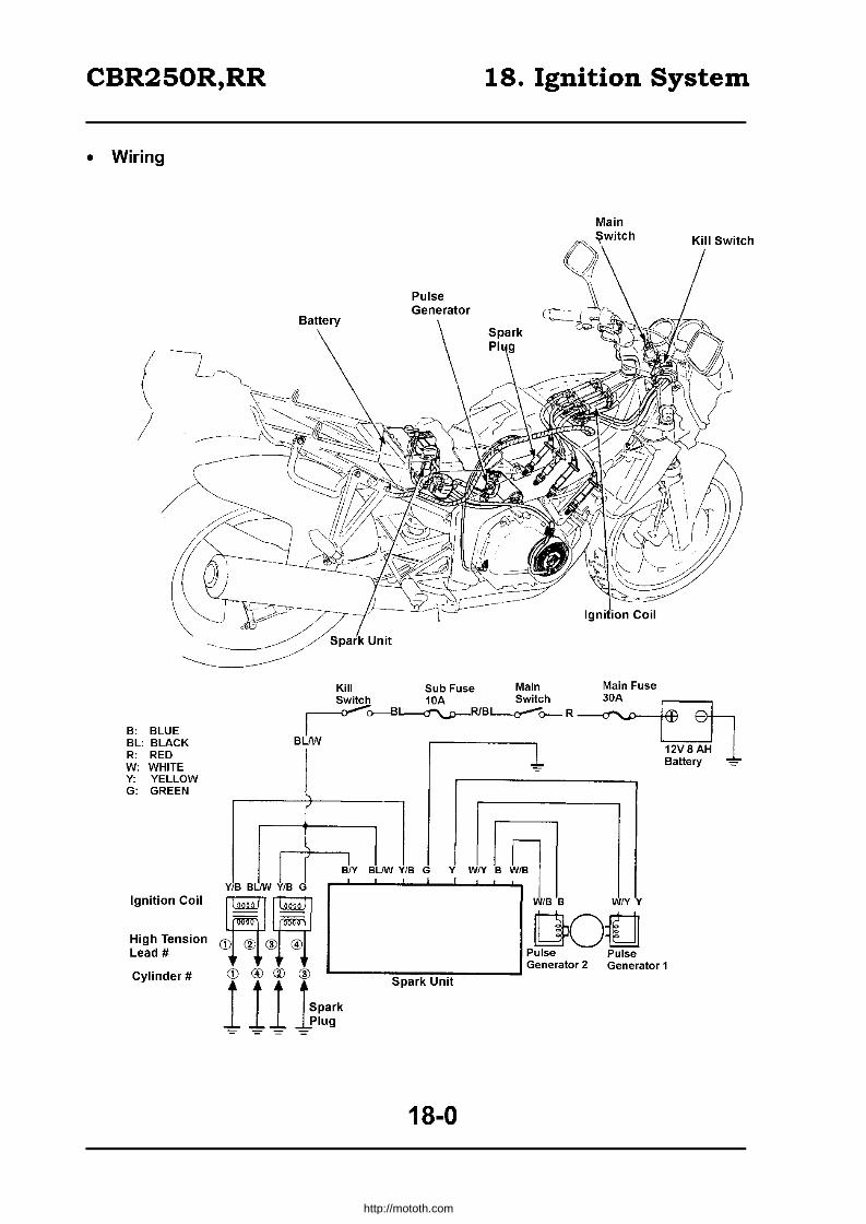
CBR250R,RR 18. Ignition System
• Wiring
( I
B: BLUE BL: BLACK R: RED W: WHITE Y: YELLOW G: GREEN
Ignition Coil
High Tension Lead #
Cylinder #
Main
Kill Sub Fuse Main Switch 10A Switch r o--B'---<t""\...p-RlB~o- R ---<f''''>---~:e
BLIW '-:-:-:-:-:-..,..,.J
Y B--I....-0
" ~ Q.ll ~~
W/BB WNY
G) ® ® ® ~Ot] Pulse Pulse
L-___ ~=~~---...J Generator 2 Generator 1 I II 1r"~' s, •• """
B\v JIW YI
B BLIW 1B G
18-0
http://mototh.com
CBR250R,RR 18. Ignition System
Wiring 18-0 Spark system inspection 18-3 Service information 18-1 IQnition coil
Troubleshooting 18-2 Pulse generator
Service information
General caution
• No adjustment is required as it is a transistor type ignition. • Ignition timing (2-10) • Spark plugs (2-9) • Connect couplers with couplers of same colour. • Resistance may vary with environment.
Service standard
Item
Spark plug
Spark plug clearance TiminQ "F" markinQ
Ignition coil Primary coil resistance
(20°) Secondary With high tension lead
coil Without high tension lead
Pulse generator coil resistance (20°
Tools
Measuring tools
Digital circuit multi meter Circuit multimeter
(Kowa) (Sanwa)
07411 - 0020000 07308 - 0020000
18-1
18-4 18-5
Standard NGK ND
C8EH -9 U24FE9 C9EH -9 U27FE9
0.8 - .09mm 20 0 BTDC/1.500rpm
2.6 - 3.2Q
21 - 29k U
13 -17k Q 315-385n
http://mototh.com

CBR250R,RR 18. Ignition System
Ignition system
Troubleshooting
No ignition spark from any of the plugs • Kill switch is OFF • Kill switch fault • Main switch fault • Pulse generator fault • Spark unit fault • Main fuse out • Sub fuse out • Wire connection fault / cutoff / short circuit between:
• Starter magnetic switch and main switch (red) • Main switch and sub fuse (red/black) • Sub fuse and kill switch (black) • Kill switch and spark unit or ignition coil (blacklwhite) • Ignition coil and spark unit (yellow/blue and blue/yellow) • Spark unit and earth (green) • Pulse generator and spark unit (white/blue and white/yellow)
• Battery undercharged
One particular plug does not give spark • Plug fault • High tension lead fault • Ignition coil fault • Wire connection fault / cutoff / short circuit between spark unit and ignition coil (blue/yellow,
black/white and yellow/blue) • Spark unit fault
• Rough / inadeguate rpm
• Primary ignition circuit
• Loose wiring
• Kill switch fault
• Main switch fault
• Battery undercharged
• Spark unit fault
• Pulse generator fault
• Pulse rotor fault
• Ignition timing • Spark unit fault • Pulse generator fault • Pulse rotor fault
Secondary ignition circuit Plug fault High tension lead fault High tension lead cap screw loose Plug cap leak Ignition coil fault
Advance angle fault Pulse generator fault Spark unit fault Pulse rotor fault
18-2
http://mototh.com
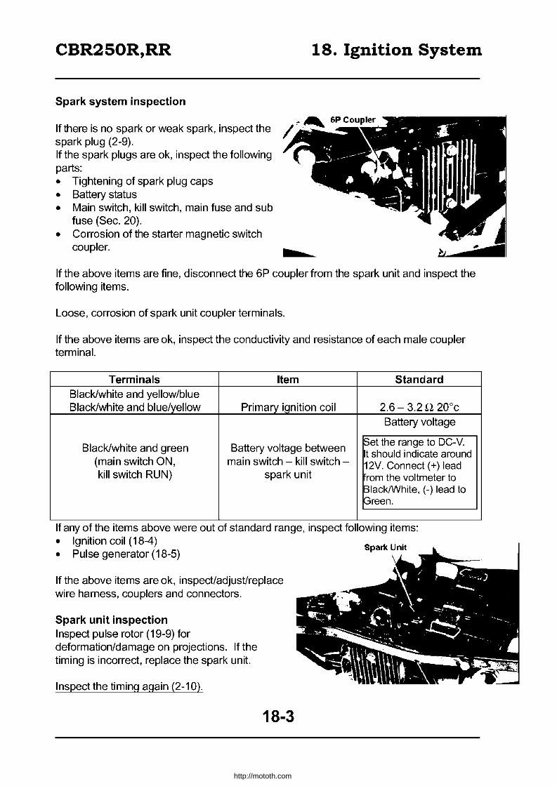
CBR250R,RR 18. Ignition System
Spark system inspection
If there is no spark or weak spark, inspect the spark plug (2-9). If the spark plugs are ok, inspect the following parts: • Tightening of spark plug caps • Battery status • Main switch, kill switch, main fuse and sub
fuse (Sec. 20). • Corrosion of the starter magnetic switch
coupler.
If the above items are fine, disconnect the 6P coupler from the spark unit and inspect the following items.
Loose, corrosion of spark unit coupler terminals.
If the above items are ok, inspect the conductivity and resistance of each male coupler terminal.
Terminals Item Standard Black/white and yellow/blue Black/white and blue/yellow Primary ignition coil 2.6 - 3.2 Q 20°c
Battery voltage
Black/white and green Battery voltage between ~et the range to DC-V. It should indicate around
(main switch ON, main switch - kill switch - 12V. Connect (+) lead kill switch RUN) spark unit rom the voltmeter to
Black/White, (-) lead to f3reen.
If any of the items above were out of standard range, inspect following items: • Ignition coil (18-4) • Pulse generator (18-5)
If the above items are ok, inspect/adjust/replace wire harness, couplers and connectors.
Spark unit inspection Inspect pulse rotor (19-9) for deformation/damage on projections. If the timing is incorrect, replace the spark unit.
Inspect the timing again (2-10).
18-3
http://mototh.com
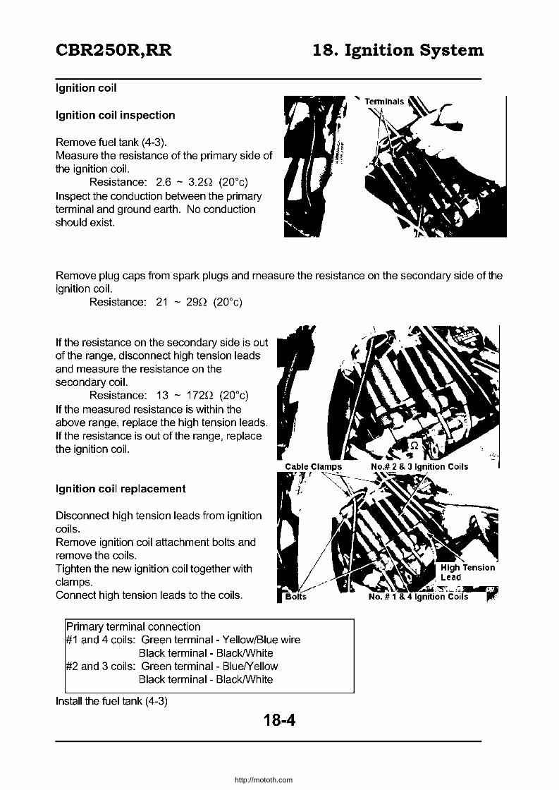
CBR250R,RR
Ignition coil
Ignition coil inspection
Remove fuel tank (4-3). Measure the resistance of the primary side of the ignition coil.
Resistance: 2.6 - 3.2Q (20°c) Inspect the conduction between the primary terminal and ground earth. No conduction should exist.
18. Ignition System
Remove plug caps from spark plugs and measure the resistance on the secondary side of the ignition coil.
Resistance: 21 - 29Q (20°c)
If the resistance on the secondary side is out of the range, disconnect high tension leads and measure the resistance on the secondary coil.
Resistance: 13 - 172Q (20°c) If the measured resistance is within the above range, replace the high tension leads. If the resistance is out of the range, replace the ignition coil.
Ignition coil replacement
Disconnect high tension leads from ignition coils. Remove ignition coil attachment bolts and remove the coils. Tighten the new ignition coil together with clamps. Connect high tension leads to the coils.
Primary terminal connection #1 and 4 coils: Green terminal- Yellow/Blue wire
Black terminal - BlacklWhite #2 and 3 coils: Green terminal- BluelYeliow
Black terminal - BlacklWhite
Install the fuel tank (4-3)
18-4
http://mototh.com

CBR250R,RR
Pulse generator
Pulse generator coil inspection
Remove the left side cover. Disconnect the 4P coupler (white) for pulse generator wires and measure the resistance between coupler terminals (White/Blue - Blue, WhitelYeliow - Yellow) on the engine side.
Standard: 315 - 385(2 (20°c)
18. Ignition System
Check the conduction between each terminal and ground earth. No conduction should exist.
IRefer to Sec.19 for pulse generator / rotor replacement.
18-5
http://mototh.com

CBR250R,RR
• Wiring
( /
Main Switch
1''1 RIB R
19. Self Starter System
Main Fuse
Battery 12V BAH
Starter Magnetic Switch
Sub-fuse ,------. 10A Sub-fuse
10A
B
Main Fuse 30A
~o- Y/R ---------1 Starter Switch
B/BR
Neutral ~ Pilot W-- LG/R ------, Clutch Switch
Neutral Switch
LG/R ~ Diode
19-0
G/R----~~rG/R
http://mototh.com

CBR250R,RR 19. Self Starter System
Wiring 19-0 Diode 19-7 Disassembly 19-1 Left crankcase cover removal 19-8
Service information 19-2 Starter clutch 19-9 T roubleshootinQ 19-3 Left crankcase cover installation 19-12
Starter motor 19-4 MaQnetic switch 19-7
Service information
General caution
• The starter motor can be detached with the engine mounted. • Pulse generator troubleshooting (Sec.18).
Service standard
Item Standard Starter motor Brush sprinQ tension
Torque
Starter clutch Left crankcase cover Starter motor terminal cable
Brush length
8.0 - 9.0kg-m 0.8 - 1.2kg-m 0.8 - 1.2kg-m
19-2
Standard 630 -8S0Q
11.00 - 11.0Smm
Limitation -
4.Smm
http://mototh.com

CBR250R,RR 19. Self Starter System
Troubleshooting
Starter does not work • Undercharged battery • Main switch fault • Starter switch fault • Neutral switch fault • Starter magnetic switch fault • Wire harness, coupler or connector connection or open circuit • Clutch diode fault • Clutch switch fault • Fuse blown (inspect sub, then main)
Starter motor operates but the engine does not spin • Starter clutch fault • Starter drive gear fault • Starter driven gear fault
Insufficient power on the starter motor • Battery undercharged • High resistance in the circuit • Motor catching debris/obstruction
Both starter motor and the engine spins but does not start • Ignition system fault (Sec.18) • Engine fault
19-3
http://mototh.com
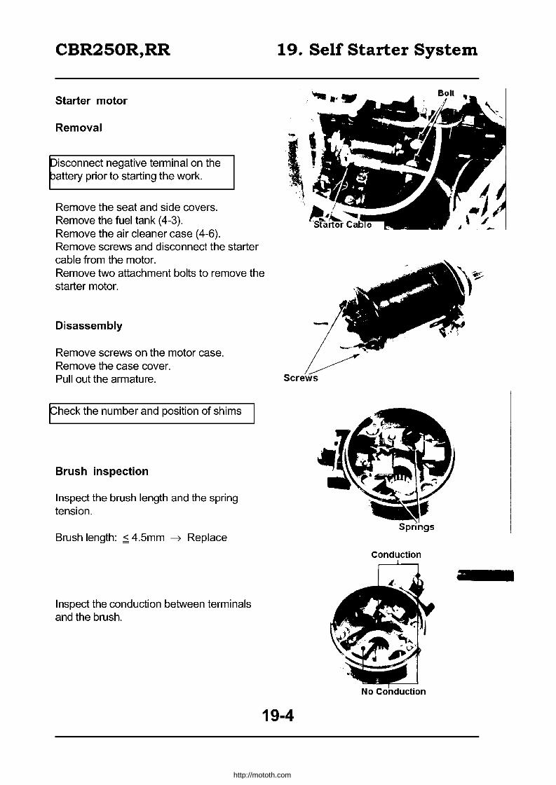
CBR250R,RR
Starter motor
Removal
Disconnect negative terminal on the battery prior to starting the work.
Remove the seat and side covers. Remove the fuel tank (4-3). Remove the air cleaner case (4-6). Remove screws and disconnect the starter cable from the motor. Remove two attachment bolts to remove the starter motor.
Disassembly
Remove screws on the motor case. Remove the case cover. Pull out the armature.
fheck the number and position of shims
Brush inspection
Inspect the brush length and the spring tension.
Brush length: ,::; 4.5mm ~ Replace
Inspect the conduction between terminals and the brush.
19. Self Starter System
Conduction
19-4
http://mototh.com

CBR250R,RR 19. Self Starter System
Needle bearing, dust seal and O-Ring inspection
Inspect the needle bearing for wear, damage and loose fit. Inspect the dust seal for wear and apply small amount of grease. Inspect the O-Ring for wear.
Armature inspection
Check the colour of the cores. If two or more cores are an irregular colour, replace them as they indicate the short circuit of the coil.
Check the conduction between armatures, between the armature and the shaft. It should have conduction between the armatures but not between the armature and the shaft.
19-5
Needle Bearing
I
Armature I
"-.. /
tJ";J, Conduction Conduction
No Conduction No Conduction
http://mototh.com

CBR250R,RR
• Assembly
,~ ~,
Washer
O-Ring
Inspect O-Rings for wear. Set locking washers correctly to the slit on the cover and set shims in the order which was recorded when disassembling. Set the brush and install the armature to the starter motor cover. Align the slit on the cover and the punched mark on the case and attach the motor case.
Attach washers, set plates and O-Rings to screws and tighten them.
19. Self Starter System
Spring
O-Ring
washer
\
Needle Bearing
({)--O-Ring
Align
Set Plate
,
19-6
http://mototh.com
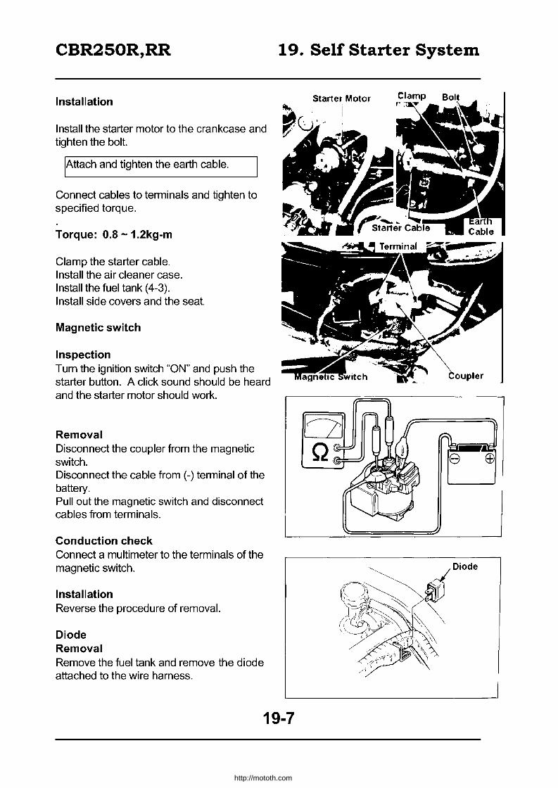
CBR250R,RR
Installation
Install the starter motor to the crankcase and tighten the bolt.
IAttach and tighten the earth cable.
Connect cables to terminals and tighten to specified torque.
Torque: 0.8 -1.2kg-m
Clamp the starter cable. Install the air cleaner case. Install the fuel tank (4-3). Install side covers and the seat.
Magnetic switch
Inspection Turn the ignition switch "ON" and push the starter button. A click sound should be heard and the starter motor should work.
Removal Disconnect the coupler from the magnetic switch. Disconnect the cable from (-) terminal of the battery. Pull out the magnetic switch and disconnect cables from terminals.
Conduction check Connect a multimeter to the terminals of the magnetic switch.
Installation Reverse the procedure of removal.
Diode Removal Remove the fuel tank and remove the diode attached to the wire harness.
19. Self Starter System
Starter Motor
19-7
http://mototh.com

CBR250R,RR 19. Self Starter System
Inspection Inspect the conductance with an ohmmeter. @ Conduction occurs in one direction only.
Installation Reverse the removal procedure.
Left crankcase cover removal
Drain engine oil (2-16). Remove the seat. Remove the left side cover. Disconnect the pulse generator 4P coupler.
Remove bolts and remove the left crankcase cover.
Remove the gasket and the knock pin.
19-8
I I
Generator Coupler
http://mototh.com

CBR250R,RR 19. Self Starter System
Pulse generator removal Remove the grommet. Remove five socket bolts and remove the wire clamp and the pulse generator.
Starter clutch
Removal Remove starter clutch attachment bolt.
Remove pulse rotor.
Remove starter driven gear with ASSY.
19-9
Grommet
If' • TO.
'", ~ ,.
I~
•••••••
• • • • • /f' •• 'r
http://mototh.com

CBR250R,RR 19. Self Starter System
Remove washer.
Remove starter drive gear and the shaft.
Disassembly I inspection
The starter driven gear should rotate only to the direction shown in the figure (counter-clockwise ).
Detach the starter driven gear from one-way clutch.
Inspect the starter driven gear for wear/damage.
19-10
Starter 'Driven Gear
." iii . ~
• • . ' .. ~ .: .,..... " .. ' .. ..... ...
:.,-..... ...... . • • • • •
http://mototh.com
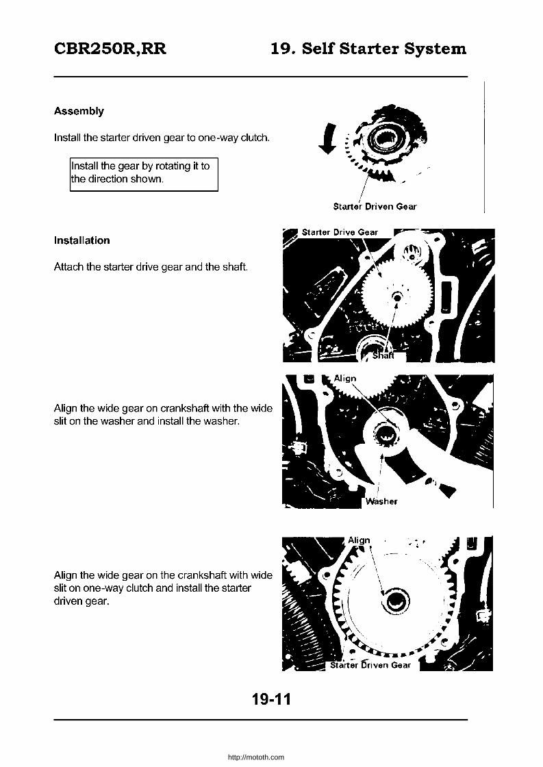
CBR250R,RR 19. Self Starter System
Assembly
Install the starter driven gear to one-way clutch.
Install the gear by rotating it to the direction shown.
Installation
Attach the starter drive gear and the shaft.
Align the wide gear on crankshaft with the wide slit on the washer and install the washer.
Align the wide gear on the crankshaft with wide slit on one-way clutch and install the starter driven gear.
19-11
\ \ "
~
http://mototh.com
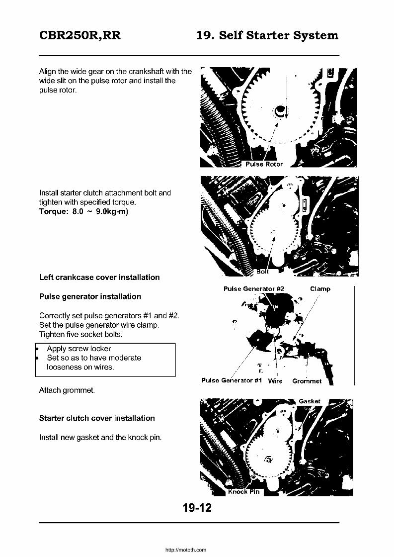
CBR250R,RR
Align the wide gear on the crankshaft with the wide slit on the pulse rotor and install the pulse rotor.
Install starter clutch attachment bolt and tighten with specified torque. Torque: 8.0 - 9.0kg-m)
Left crankcase cover installation
Pulse generator installation
Correctly set pulse generators #1 and #2. Set the pulse generator wire clamp. Tighten five socket bolts.
• Apply screw locker • Set so as to have moderate
looseness on wires.
Attach grommet.
Starter clutch cover installation
Install new gasket and the knock pin.
19. Self Starter System
Pulse Generator #2 Clamp
Wire Grommet
19-12
http://mototh.com
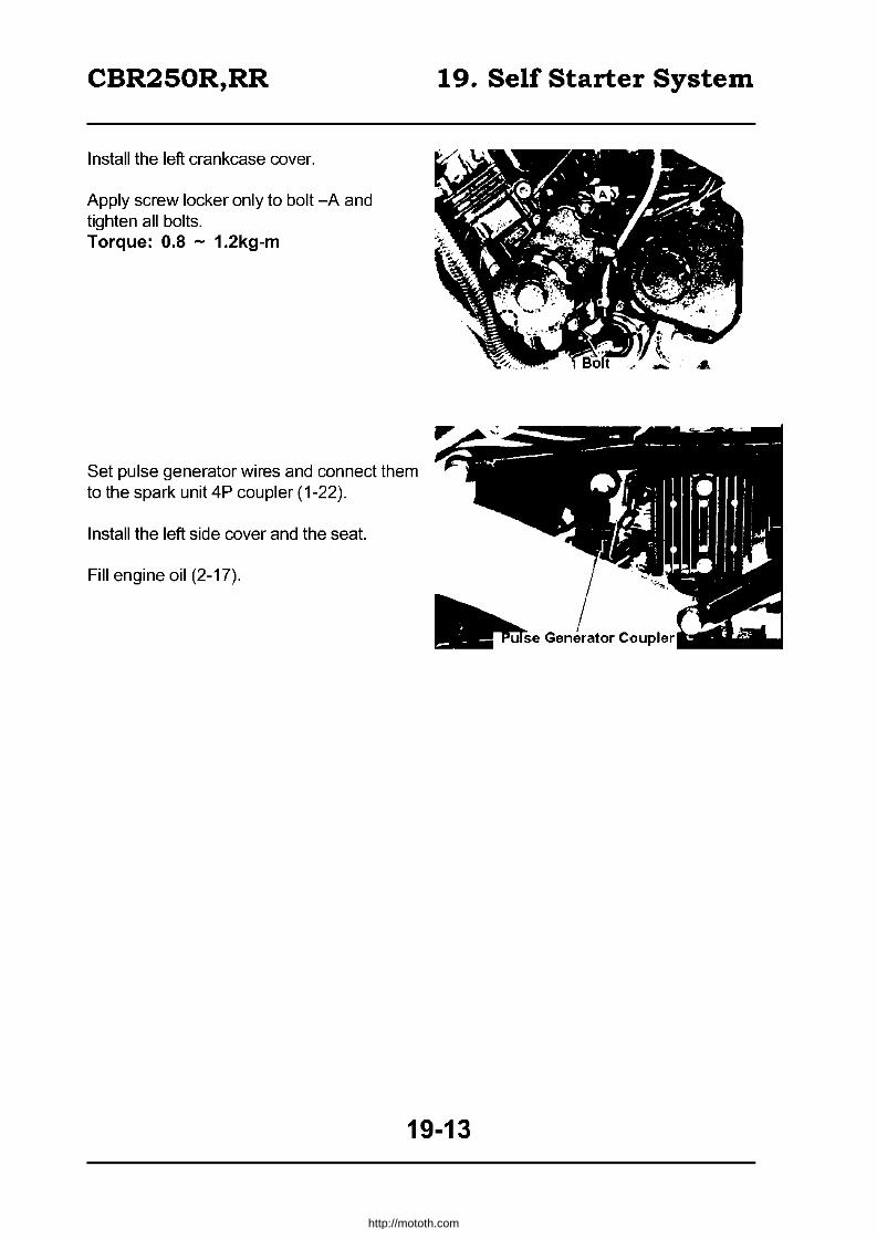
CBR250R,RR
Install the left crankcase cover.
Apply screw locker only to bolt -A and tighten all bolts. Torque: 0.8 - 1.2kg-m
Set pulse generator wires and connect them to the spark unit 4P coupler (1-22).
Install the left side cover and the seat.
Fill engine oil (2-17).
19. Self Starter System
19-13
http://mototh.com

CBR250R,RR 20. Light, Instruments & Switches
Service information 20-1 Water temperature gauge 20-S Troubleshooting
Lens replacement Instruments Main switch
SteerinQ handle switches Oil pressure switches
Service information General caution
20-1 20-2 20-3 20-5 20-6 20-7
Tachometer 20-S Cooling fan switch 20-S
Neutral switch 20-9 Brake light switch 20-9
Clutch 20-10 Horn 20-10
• Connect same coloured leads. If colours are different on each side, there should be a coloured tube near the connector on one side. Connect couplers of same colours.
• Switch conduction test can be done without detaching from the vehicle.
Standard Item
Headlight bulb Front turn siQnal bulb Rear turn signal bulb Stop / tail IiQht bulb
Pilot lamps (excluding speed warning) Speed warning light
Tacho, temperature gauge illuminator Speedometer illuminating light
Main fuse Turn signal, brakelight, horn, passing
switch sub fuse Sub fuse other than the above
Torque Ignition switch Headlight Instruments
Troubleshooting
2.5-3.0kg-m 0.3-0.5kg-rn 0.S-1.2kg-m
Lights do not illuminate • Bulb out • Switch fault • Wires open circuit • Fuse out (inspect a sub fuse under
instruments before inspecting a main fuse). • Battery discharged • Wiring fault
standard 12V60 /55W 12V23/ SW
12V23W 12V23/ SW 12V1.7W x 5
12V3W 12V 3.4W x2
12V3.4W. 12V 3W 30A
15A 10Ax6
Taillight Front turn signal Cooling fan switch
0.S-1.2kg-m 0.35-0.50kg-m 2.4-3.2kg-m
Lights too dark Battery discharged Bulb fault
Unable to switch Hi-Lo off a headlight Bulb fault Dimmer switch fault Wiring fault
20-1
http://mototh.com
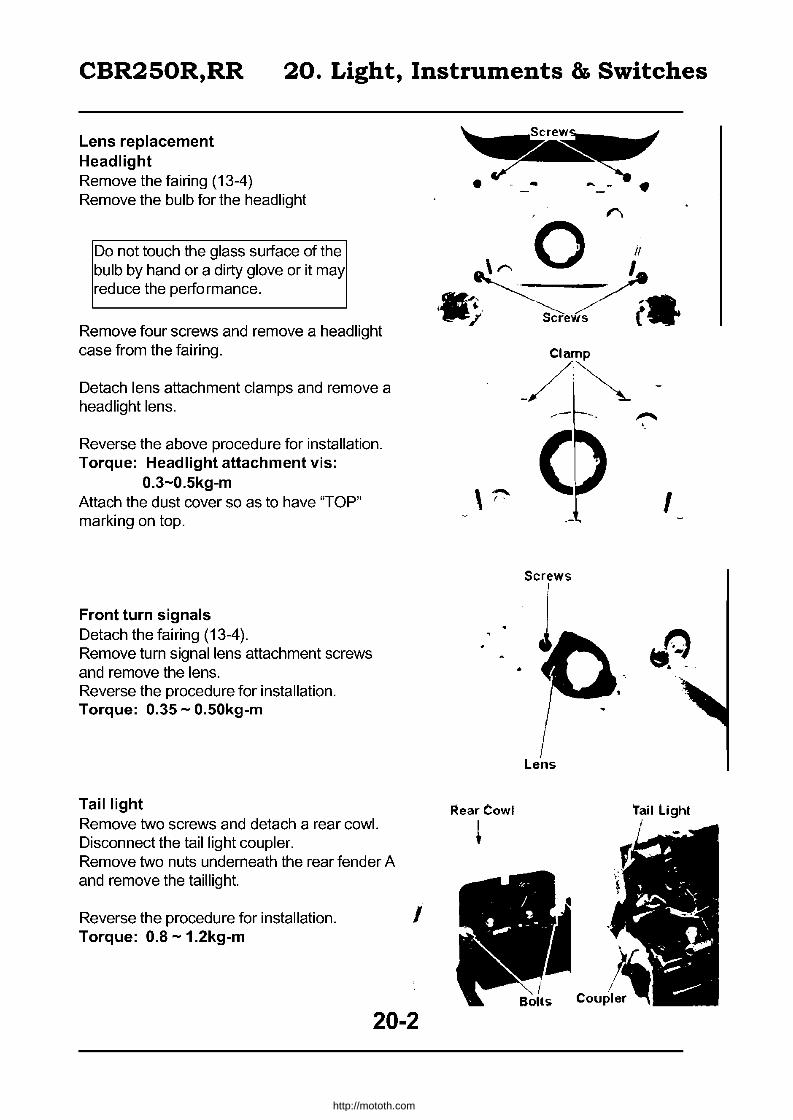
CBR250R,RR 20. Light, Instruments & Switches
Lens replacement Headlight Remove the fairing (13-4) Remove the bulb for the headlight
Do not touch the glass surface of the bulb by hand or a dirty glove or it may reduce the performance.
Remove four screws and remove a headlight case from the fairing.
Detach lens attachment clamps and remove a headlight lens.
Reverse the above procedure for installation. Torque: Headlight attachment vis:
0.3-0.5kg-m Attach the dust cover so as to have "TOP" marking on top.
Front turn signals Detach the fairing (13-4). Remove turn signal lens attachment screws and remove the lens. Reverse the procedure for installation. Torque: 0.35 - 0.50kg-m
Taillight Remove two screws and detach a rear cowl. Disconnect the taillight coupler. Remove two nuts underneath the rear fender A and remove the taillight.
Reverse the procedure for installation. Torque: 0.8 -1.2kg-m
I
20-2
~ • -4O - - •
I
Screws
~ear Cowl 'rail Light
*
http://mototh.com

CBR250R,RR 20. Light, Instruments & Switches
Instruments
Removal
Remove instrument stay bolts.
Disconnect the speedometer cable.
Disconnect instrument couplers.
Detach the wire harness from the damper and remove instruments.
Disassembly
Remove four screws and remove the instrument lower cover.
Remove two screws and detach the sub fuse holder.
20-3
Bolts
Instruments
Speedometer Cable
Screws
http://mototh.com

CBR250R,RR 20. Light, Instruments & Switches
Remove two screws and detach the instrument upper cover.
Detach connectors, bulb socket, trip meter reset knob and individual instruments attachment screws and separate the instruments.
Assembly I installation
Reverse the removal! disassembly procedure. Torque: Instruments - 0.8 - 1.2kg-m
I I
Screws
• Properly apply instrument wire hamess (1-21), • Connect the wires correctly to terminals check for security.
Instrumental Lower Cover Brown/Black Wire
Upper Cover
~X/ /)~e~'
~ - I, ~
\ / I
\ /" I '. , ~~""'-"
Screws
Green/Blue Wire
Reset Knob
Instruments Stay Instrument Upper Cover
20-4
http://mototh.com

CBR250R,RR 20. Light, Instruments & Switches
Bulb replacement
Remove instruments from the instrument stay and detach the lower cover (20-3). Remove a bulb socket and replace the bulbs.
Main switch
Inspection
Remove the fuel tank and disconnect the coupler for the main switch.
Conduction should exist between 0-0 symbols.
BAT 1 IG FAN Red Red / Black Blue / Amber
ON 0 0 0 OFF
P.LOCK 0 LOCK
Removal
Remove the fuel tank and disconnect the main switch GP coupler. Remove two main switch attachment bolts and remove the main switch.
Disassembly Cut the band and remove three screws. Detach the switch from the switch cylinder.
20-5
Bulb SockBt
TL#1 TL#2 PA Brown / White Brown Yellow
/Black 0 ()
0
Screws
• ,
http://mototh.com

CBR250R,RR 20. Light, Instruments & Switches
Assembly Align the cylinder shaft to the slit on the switch and attach it.
Tighten three screws and clamp it with the band.
IFirmly clamp it so as not to loosen the wires.
Cut off unnecessary band. Check the switch conduction after assembly
Installation
Reverse the removal procedure. Torque: Ignition switch attachment bolt:
2.5 - 3.0kg-m
After installation, check the operation of the switch.
Steering handle switches Remove fuel tank (4-3). Disconnect #1, #4 ignition coil attachment bolts and terminals (18-4). Remove harness for each switch and disconnect couplers. Check conduction for 0-0 section
<Kill Switch> IG BAT 2
Black/White Black
OFF RUN v v
<Starter Switch> BAT 2 ST Black Yellow/Red
FREE PUSH IJ v
<Lighting Switch> BAT4 TL BAT5
Brown/Blue BrownlWhite Black/Red
• P 0 0 H 0 0 0.
20-6
HL
Slit \,
\.
BluelWhite
0
Screws
Left Handle Switch Coupler
http://mototh.com
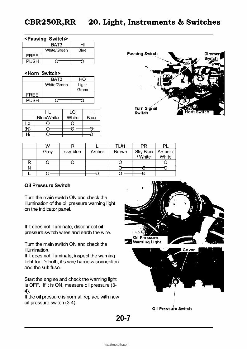
CBR250R,RR 20. Light, Instruments & Switches
<Passing Switch> BAT3 HI
White/Green Blue
FREE PUSH 0 -u
<Horn Switch> BAT3 HO
White/Green Light Green
FREE PUSH 0 v
HL LO HI Blue/white White Blue
La 0 0 (N) 0 v v
Hi 0
W R L TL#1 Grey sky-blue Amber Brown
R 0 v
N L 0 :)
Oil Pressure Switch
Turn the main switch ON and check the illumination of the oil pressure warning light on the indicator panel.
If it does not illuminate, disconnect oil pressure switch wires and earth the wire.
Turn the main switch ON and check the illumination. If it does not illuminate, inspect the warning light for it's bulb, it's wire harness connection and the sub fuse.
Start the engine and check the warning light is OFF. If it is ON, measure oil pressure (3-4).
0 l
0
If the oil pressure is normal, replace with new oil pressure switch (3-4).
Passing Switch -~-~--
-
/ //
Turn Signal Switch
PR PL Sky Blue Amber / / White White
-u :.J
Oil pressuL Switch
20-7
http://mototh.com

CBR250R,RR 20. Light, Instruments & Switches
Water temperature gauge Remove the side cowl. Disconnect the connector from thermo-sensor on the thermostat case. Earth the connect terminal by using a jumper wire. Tum the main switch ON and check the water temperature gauge fully deflects to its side. Inspect the wire hamess if it doesn't deflect. Replace the gauge if wire hamess is ok (20-4).
Do not earth the thermo-sensor for more than five seconds.
Tachometer
Inspect the following points if the tachometer is faulty. Inspect No.1 coil for proper spark. If there is no spark on the spark plug, inspect the ignition system (18-3). If spark is ok, remove the fairing and the fuel tank. Disconnect the 4P mini coupler for the instrument, Yellow/Blue wire for the ignition coil and spark unit 4P mini coupler and check the conduction of Yellow/Blue wire.
Conduction --+ replace the tachometer No conduction --+ replace the wire hamess
Cooling fan switch
The cooling fan activates when the cooling fan switch detects the radiator water temperature very high.
Run the engine until the radiator water temperature reaches 98°c - 102°c and check the operation of the fan motor. Check the motor stops when the temperature comes down to 93 - 9rc.
20-8
4P Mini Coupler
\ Spark Unit
http://mototh.com

CBR250R,RR 20. Light, Instruments & Switches
If the fan motor does not work, remove the connector from the cooling fan switch and earth the connector by using jumper leads. Turn the main switch ON. If the fan motor works, the cooling fan switch is faulty. If the fan motor does not work, measure voltage between the connector terminal and ground earth. If the voltage is zero, inspect the following items: • sub fuse • looseness of terminal/connector • wire harness open / short circuit. If sufficient voltage exists, the fan motor is faulty.
Neutral switch
Remove the fuel tank (4-3) Disconnect the neutral switch connector and inspect conduction between light green/red wire and ground earth. Conduction only exists when the transmission is set to neutral.
Brake light switch
Front Disconnect the brake light switch connector. Inspect the conduction by operating the brake lever. Lever pulled: conduction Lever released: no conduction
Rear
Remove the rear side cover and disconnect the rear brake light switch coupler. Inspect the conduction by operating the brake pedal. Pedal pushed in: conduction Pedal released: no conduction
Neutral Switch Connector I
• I ~ .. ~4 II
\ . I ~ront Brake Light Switch
20-9
'II .. ,.
"-
http://mototh.com

CBR250R,RR 20. Light, Instruments & Switches
Clutch switch
Disconnect the clutch switch connector. Operate the clutch switch and check conduction between terminals. Lever pulled: conduction Lever released: no conduction
Horn
Disconnect wires from the horn. Connect a 12V battery directly to the horn. The horn should work.
20-10
http://mototh.com
CBR250R(H) 21. Supplement
TABLE OF CONTENTS
Service Information:..... ............... ...... ... ...... ... .............. 21 - 2
Inspection: ................................................................. 21 - 6
Fuel System:.............................................................. 21 -12
Cooling System: ......................................................... 21 - 13
Engine Mount / Dismount: ... ... ... ... ... ... ... ... ... .............. ... 21 - 13
Cylinder Head, Valve: ................................................... 21 -13
Cylinder, Piston and Crankshaft: ................................... 21 - 18
Clutch: ....................................................................... 21 - 20
Change Cover attachment/detachment: ......................... 21 - 20
Front Wheel, Suspension and steering: ......................... 21 - 21
Rear wheel and Suspension: ........................................ 21 - 24
Brake System: ... ... ... ... ... ............... ... ... ... ... ... ... ... ... ... ... 21 - 31
Seat Cowl:............ ... ... ... ... ... . . . . . . ... ... ... ... ... ... . . . . . . ... ...... 21 - 41
Sub-Frame:................................................................ .21 - 43
21-1
http://mototh.com

CBR250R(H) 21. Supplement
Service Information
Specifications Thick-lined parts differ from CBR250FOUR Name MC17 Air filter Filter paper type
Length 2.000m E Fuel tank capacity 14.01
Width 0.680m
Height 1.120m
Wheelbase 1.365m
Q) Type VG03
~ ~ Qi ::l Valve diameter 30mm ::l -"
LL ro 0
Venturi diameter 27mm
Powerplant MC14E
Displacement 0.2491 Type of fuel Unleaded Gasoline (petrol)
Front 78kg
Type Full transistor, E Battery ignited 2 c:
~ 0 Timing 20'BTDC/1500rpm '"
Cii E Spark I NGK C8EH-9 C9EH-9 u Plug I NO U24FE9, U27FE9 ·c
Weight Rear 77kg Total 155kg
tl Clearance 0.8-0.9mm Q)
Battery 12V 8AH w Capacity
Max capacity 2 Clutch Multiple wet Type Coil spring
Max Front 98kg Operation Mechanical Weight Rear 167kg Motor to transaxle ratio 2.966
Total 265kg Type Constant mesh
Front 100 80-17 52H Low 2.733 Tyre Rear 13070-1762H c: Second 2.000
0 Minimum clearance 0.140m 'iii
Gear Third 1.590 "'
Q)
Stop distance 14.0m u c: '" (Initial speed) 50km/h E
E ro.Q Ratio Fourth 1.333 "' c: ~~ ::: ::: Fifth 1.153 f-
.g Sixth 1035 Q)
Min turning radius 2.7m "-
Starter Self start Gear type Chain
Type Gasoline - 4 cycle
Cylinders Direct four abreast
c: NO. Reduction 3.142 -.Q c:~ 1 ratio
I- o u ~ ::l
26' 00 LL'C Q)
"' 0:: Castor
Combustion chamber Pent Roof type Valve system Gear driven inlet 2
Valve exhaust 2 Valve
Qi Trail 97mm Q)
.c: s: Tyre air Front 2.00kg/cm' Bore x stroke 48.5x33.8mm Pressure Rear 2.50kg/cm'
Compression ratio 11.0 34'
Compression pressure 13.0kg cm' - 400rpm Steering angle 34'
Max. output power 45PS 15.000rpm Front Hyctaulic disk brake
Max. torque 2.6kg-m 10.500rpm Brake system Rear Hydraulic disk brake
Open 18'BTDC Front Telescopic Inlet 1mm lifted Suspension
Q). Close 34' ABDC
C 1mm lifted '" -'" c. '" Open 36' BBDC > ~ exhau 1mm lifted 0 st close 11'ATDC "- 1mm lifted
Rear Swing arm
Frame type Diamond
Valve I Inlet I 0.66mm (cool) clearance I exhaust I 0.23mm (cool)
Unloaded rev. 1,00rpm
Type Compress-spray Frame no. J H2MC22UXXMOOOOO 1-c: type .Q 1ii Pump type Trocoid type u ." Filter type Total flow. filter net -" ::l and paper ---' Engine no. MC14E -1000001-
Oil capacity 2.71 Cooling system Water cooled
21-2
http://mototh.com
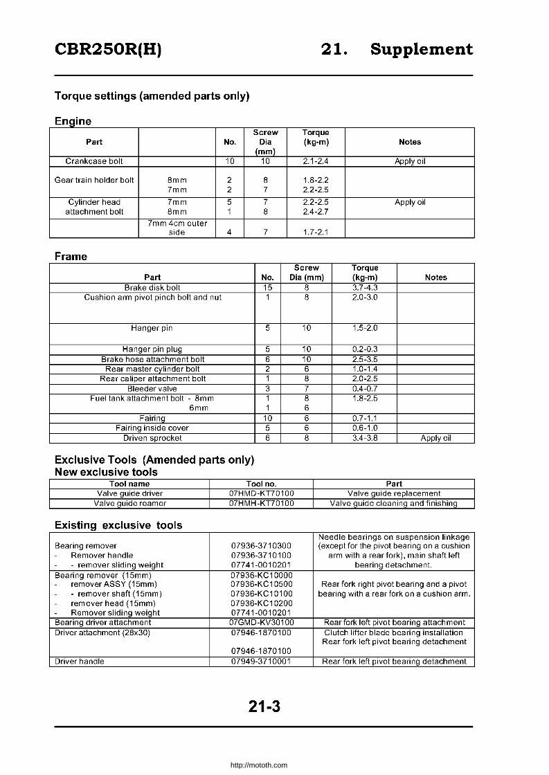
CBR250R(H) 21. Supplement
Torque settings (amended parts only)
Engine Screw Torque
Part No. Dia (kg-m) Notes (mm)
Crankcase bolt 10 10 2.1-2.4 Apply oil
Gear train holder bolt 8mm 2 8 1.8-2.2 7mm 2 7 2.2-2.5
Cylinder head 7mm 5 7 2.2-2.5 Apply oil attachment bolt 8mm 1 8 2.4-2.7
7mm 4cm outer side 4 7 1.7-2.1
Frame Screw Torque
Part No. Dia (mm) (kg-m) Notes Brake disk bolt 15
Cushion arm pivot pinch bolt and nut 1
Hanger pin 5
Hanger pin plug 5 Brake hose attachment bolt 6 Rear master cylinder bolt 2
Rear caliper attachment bolt 1 Bleeder valve 3
Fuel tank attachment bolt - 8m m 1 6mm 1
Fairinq 10 Fairing inside cover 5
Driven sprocket 6
Exclusive Tools (Amended parts only) New exclusive tools
Tool name Tool no. Valve guide driver 07HMD-KT70100
Valve guide reamer 07HMH -KT701 00
Existing exclusive tools
Bearing remover 07936-3710300 - Remover handle 07936-3710100 - - remover sliding weight 07741-0010201 Bearing remover (15mm) 07936-KC 10000 - remover ASSY (15mm) 07936-KC 10500 - - remover shaft (15mm) 07936-KC1 01 00 - remover head (15mm) 07936-KC 10200 - Remover sliding weight 07741-0010201 Bearing driver attachment 07GMD-KV30100 Driver attachment (28x30) 07946-1870100
07946-1870100 Driver handle 07949-3710001
21-3
8 3.7-4.3 8 2.0-3.0
10 1.5-2.0
10 0.2-0.3 10 2.5-3.5 6 1.0-1.4 8 2.0-2.5 7 0.4-0.7 8 1.8-2.5 6 6 0.7-1.1 6 0.6-1.0 8 3.4-3.8 Apply oil
Part Valve guide replacement
Valve guide cleaning and finishing
Needle bearings on suspension linkage (exceptfor the pivot bearing on a cushion
arm with a rear fork), main shaft left bearing detachment.
Rear fork right pivot bearing and a pivot bearing with a rear fork on a cushion arm.
Rear fork left pivot bearing attachment Clutch lifter blade bearing installation Rear fork left pivot bearing detachment
Rear fork left pivot bearing detachment
http://mototh.com

CBR250R(H)
Common Tools
Tool name Pilot (15mm)
Pilot (17mm)
Pilot (12mm) Rear cushion com pressor or Shock absorber compressor - compressor screw ASSY
Valve seat cutter
Tool name
Cutter holder (3.5mm)
Newly established tool
• Wiring
Tool No. 077 46-0040300
077 46-0040400
077 46-0040200 07959-3290001
07GME-0010000 07GME-0010100
Tool No.
07HMH -KT70200
21. Supplement
Application Front wheel bearing, rear fork right pivot bearing, pivot bearing on a cushion arm
with a rear fork. Rear wheel. suspension linkage (except for a pivot bearing on a cushion arm with
a rear fork), driven sprocket and main shaft left bearinQ.
Clutch filter plate bearing Rear cushion disassembly/assembly
Application
Attach a cutter and adjust the valve seat.
Clutch Cable
Front Brake Hose
~~~~~ Right Turn 'I' Signal Wire
Clamp
Reservoir Hose
21-4
Rear Cushion Breather Tube
http://mototh.com

CBR250R(H) 21.
Clamp at the cable protector
Supplement
Thermo-sensor Wire
Cooling fan switch wire
Speed omete r
Top: Cooling fan coupler Bottom: Left handle
switch coupler
Clamp after connecting righ turn signal coupler
Clamp main wire harness.
Cable
Do not squash the clam per and leall 10mm of opened area
Front Brake Hose
21-5
Clutch Cable
Choke Cable
Clamp instrument wire and sub fuse wire
Speedometer Lead
http://mototh.com

CBR250R(H) 21. Supplement
Inspection I adjustment - Procedure 1. Items for inspection include high speed driving inspection items. 2. (.) express compulsory inspection schedule and "0" mark is the recommendation of the
manufacturer. 3. (e) indicates regular replacement.
Replacement schedule is based on ordinary use. The schedule should be adjusted with operating condition.
4 "High speed" or "High speed driving" means driving at or above BOkm/h
Items to be serviced
'" '" Free play I looseness _~ "'0 '" ~ '" c
'" '" -~ 2.c '" (f) .0 Smoothness
'" '" -§m Turning (steering) angle c "'.c ·c 3S $: '" '" Iii
-i" Damage
.E
'" Fork, spindle attachment c
-ffi
'" Iii Fork, spindle bearing looseness
Free play and clearance from ground when fully
Schedule
.c "E o E
Kilometres
.c "E
"'0 E
•
•
•
Notes
~ m ~~~ ~~r-__ ~~~~~~de~,p~,r~e~s~s~ed~. ~~~~~~--r-----r----f-----r-----r--------~~~~~~~~~~~--------~
OJ a. Pedal travelling length and effectiveness _ ~--------~B~ra~k~i~ng~e~ff~e~ct~iv~e~n~e~s~s~--------~~~~~~+-----~----~------------------------------------~
ill Ql Leak, damage and attachment
~~r---------~B~ra~k-e~ho-s-e--re-p~la-c-e-m--e-nt~--------r-----r----f-----r-----r--------------------------------------~
Fluid level •
• Biennial
Function wear and damage < - - ill ill- ...... a.
E 1il ~ ~ ~ ~ Cups for the master/wheel "* ~:§ ~ :§ ~ cylinder, dust seal, rubber >. ..::: () () _~ parts for disk caliper
(f) "0 replacement
lrr---,---------~D~iS~k~/-p-ad~c~le~a~r~a~nc~e~~------~----~----+---~---.--~------------------------------------~
Indicator
Standard: Front4.0mm ~ ~~--------------p-a-d-we--a-r--------------t_----t_--~----_t--.--_t~~~~--~==~~~~------__________ ~
'" Thickness: Rear 5.0mm • ~
~ Disk wear I damage
'" Limitation: Front 3.5mm Rear4.0mm
Brake fluid damage • Annual
Unit Kg I cm2
Front Rear 1 person Normal 2.00 2.25
Tyre air pressure • • • High speed 2.00 2.25 2 people Normal 2.00 2.50
Tyre Type 100-80 130-70 17-52H 17-62H
21-6
http://mototh.com

CBR250R(H) 21. Supplement
.LQ; 0"" 00 ~"' (J).o
"
I I
E
"* ,., "' <il 0
{i <1> ill
co " c. ~ 0 "-
~ o "5 13
Items to be serviced
Crack and damage on tyres
Depth of tread and wear
Metal piece and other objects
Wheel nut and wheel bolt looseness
Rim, side ring and wheel disk damage
Front wheel bearing looseness
Rear wheel bearing looseness
Damage
Looseness on the jointed arm damage
Oil leak and damage
Attachment / looseness
Lever free play
Operation
Oil leak and oil level
Control system looseness
• • •
Schedule
*' c o E
Kilometres
~ co <Do E
• • • • • •
• •
•
• • •
•
• • • • •
• •
•
Notes
Tread front O.8mm - rear O.8mm
Axle nut, axle holder, front axle holder, torque 1.8-2.5kg-m
front axle torque 5.5-6.5kg-m rear axle nut torque 8.0-10.0kQ-m
Wheel rim deflection at rim edge Front wheel rim 2.0mm
Rear wheel rim .. 2.0mm
.2.0mm 2.0mm
Cushion spring
Clutch lever free play 10-20mm
Oil level ba, gauge (dipstick) between min-max.
I When using sidestand, at the centre of front I
~~ r-___________ c_h_a_in __ te_n_s_i_o_n __________ -+ ______ r-____ t-_. __ -r __ • __ -t ____ '_e_a_,_s_p_ro_c_k_e_t_:_m_a_x __ d_e_fl_e_ct_io_n __ 1_5_-_2_5_m __ m __ --l
.()-~ (J)~ I I -"- Sprocket attachment and wear • c 0 Spark plug • • Plug gap: 0.8 - 0.9mm ;2 c E'
~ Terminal connection ~ m
0> c Joint looseness I damage
~ co Starting and sound • • <1> Low speed and acceleration • • Idling 'pm 1.500 ! 100'pm c 0 Co Exhaust gas • • E 0 Air cleaner element replacement 20,000km every 0 c
'0; Valve clearance Inlet (cool): 0.13 - 0.19mm :2 • Exhaust (cool): 0.20 - 0.26mm
21-7
http://mototh.com

CBR250R(H) 21. Supplement
Schedule
ill C>
" Items to be serviced ~ c
~ :~ 0 j; -'= E c "''' "'-0 ~
<D 0 ~O
I Kilometres Notes
E E
E Oil level ill Oil dirty I quantity Dipstick - between min - max ~ • • w Oil leak • • c 0 Oil quantity • ~ .g Engine oil change InitiaI1.000km, every 6000km after that .c ~ Oil filter Initial 13.000km, every 12,OOOkm after that ...J
Fuel leak • • " Carburetor linkage system m E • "i'i
* W Throttle valve and choke valve • >,
" w Fuel filter • Fuel quantity •
I
Fuel hose replacement '* Every four years
Coolant level • • • Reservoir tank between min-max.
~~ Coolant leak • • g~ Radiator cap • O.95-1.25kg/cm2 valve opening pressure Uw
Coolant replacement Biannual Function • • .g .$
ill-'= - C> Uj=
Illumination, dirt and damage • .L
" Function • 0 ...J
:u " is ill <Il t:: CC :;: "e Images • Only rearview mirrors
(5.Q~,-1:5 1§ a.~ ~1fj05o Dirt and damage • & "6>1§ L
~"-
YO C <Il E
Function 2 • ti E
~o.O~ Looseness of attachment damage • m<llOo -'= "- ~ Uj "0.. E
Muffler function • >,
Looseness and damage -0 • 0
'" ~""OI/) 6~u Inspect the corresponding part • "S: 2 '* .t~-o
w Greasing and lubrication of chassis • • -'= 0
21-8
http://mototh.com

CBR250R(H)
Brake System
Brake pedal height adjustment
Loosen the rear master cylinder push rod's lock nut and rotate the push rod to adjust the height of the brake pedal. Check the rear stoplight switch function after adjusting. Adjust if required (2-20).
Brake lever adjustment
By rotating the adjuster, the distance (A) from the grip to the edge of the brake lever can be adjusted.
Always align the symbol on the adjuster to the arrow symbol on the brake lever.
Rear brake fluid level
Check the brake fluid level. Check for the fluid leak if the level is low. Remove the right side cover. Remove two reservoir cap attachments screws and remove the cap. Fill DOT 3 or DOT 4 standard brake fluid to the upper limit line.
• Do not mix different products of brake fluids.
• The top surface of the reservoir cap should be level when inspecting/refilling brake fluid.
• Keep the brake fluid away from dust/debris.
• Keep the fluid away from painted/plastic / rubber surfaces.
Rear brake pad wear
Fully depress the brake pedal and inspect wear of inner / outer brake pads. Inspect the wear from back of the vehicle. Replace pads if the pad is worn to the maximum wear line (21-33)
I. Replace pads in a set.
Inspect the contact surface of the brake disk for unusual wear and damage (21-35).
21-9
21. Supplement
r
http://mototh.com

CBR250R(H)
Transaxle system Clutch
Clutch lever free play
Inspect the free play of the clutch lever (2-7). Remove the quick screw and detach the right maintenance cover boss from a lower fairing grommet and detach the right maintenance cover.
Major adjustments can be done by loosening the lock nut and rotating the adjust nut. Minor adjustments (2-7)
The following parts can be inspected by detaching the right maintenance cover.
ignition timing (2-10) oil colour and quantity (2-15)
Chain and sprocket
Drive chain tension
Drive chain adjustment (2-8)
Replace the drive chain if the index marking on the rear axle spacer is aligned with the red label on rear fork.
Powerplant
Main body
Idle speed adjustment
Remove the quick screw and detach the left maintenance cover boss from the left lower fairing grommet and detach the left maintenance cover.
Lock Nut
21. Supplement
Quick Screw \
~/ /
-_. J Right Maintenance Cover
Red Zone (Replacement,
, .V . ~ ·h.~~ ~~~
Index Marking-"""IiII
J Left Maintenance Cover I~ I .
Boss L .
21-10
http://mototh.com

CBR250R(H)
Adjust to standard idling rpm by rotating the throttle stop screw (2-10).
Lubrication
Engine oil drain
Warm up the engine before draining the oil.
Detach the oil level gauge. Remove the drain bolt and drain the engine oil. Turn the kill switch OFF and engage starter for a few seconds to drain remaining oil. Attach the drain bolt after cleaning. Torque: 3.0 - 4.0kg-m
Replace the sealing washer if damaged.
Fill with engine oil.
Others
Illumination
Front light
Remove upper fairing inside covers from both sides.
Adjust the vertical adjustment screws to (horizontal).
Adjust the (vertical/horizontal) beam path.
21-11
21. Supplement
! Drain Bolt
http://mototh.com

CBR250R(H) 21. Supplement
Fuel system
Service information
Standard thick lined cells differ from CBR250 four.
Venturi diameter
Setting symbol Float level Main jet Slow jet
Idling the rpm Free play of the throttle grip Pilot screw rewindin~ revs.
Fuel tank capacity Total Reserve
Fuel tank detachment I attachment
I Keep out of fire
Turn off the fuel cock. Remove the side cover and seat. Remove two tank attachment bolts.
Primary: 9.8mm equivalent. Secondary: 27mm equivalent
VG03A 7mm = 88 = 35
1 ,500 = 100rpm 2-6mm 2-y:' revs
141 2.51
Disconnect the vacuum tube and the fuel tube and remove the fuel tank (4-3). Attach the fuel tank.
21-12
Torque 1.8 - 2.5kg-m
http://mototh.com
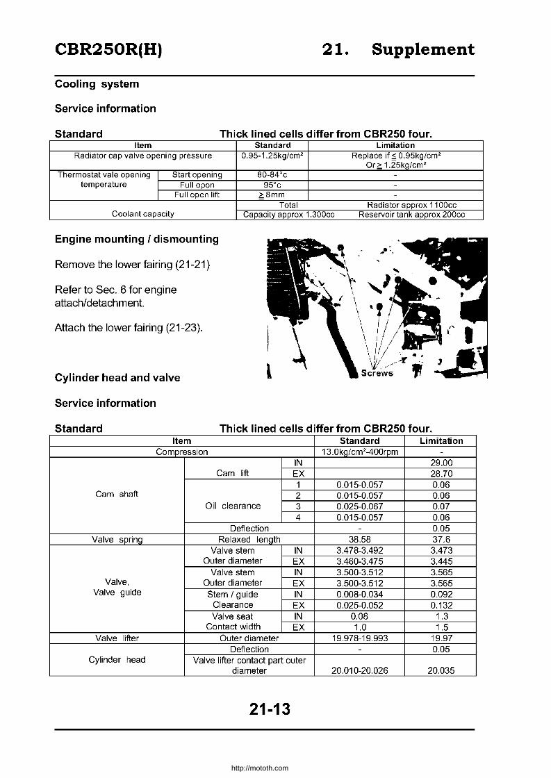
CBR250R(H) 21. Supplement
Cooling system
Service information
Standard Thick lined cells differ from CBR250 four. Item Standard Limitation
Radiator cap valve opening pressure O.95-1.25kg/cm2 Replace if ~ O.95kg/cm2
Or> 1.25kg/cm2
Thermostat vale opening Start opening SO-S4'c -temperature Full open 95'c -
Full open lift ?Smm -
Total Radiator approx 1100cc Coolant capacity Capacity approx 1.300cc Reservoir tank approx 200cc
Engine mounting I dismounting
Remove the lower fairing (21-21)
Refer to Sec. 6 for engine attach/detachment.
Attach the lower fairing (21-23).
Cylinder head and valve
Service information
Standard Thick lined cells differ from CBR250 four Item Standard Limitation
Compression 13.0kg/cm2-400rpm -
IN 29.00 Cam lift EX 28.70
1 0.015-0.057 0.06 Cam shaft 2 0.015-0.057 0.06
Oil clearance 3 0.025-0.067 0.07 4 0.015-0.057 0.06
Deflection - 0.05 Valve spring Relaxed length 38.58 37.6
Valve stem IN 3.478-3.492 3.473 Outer diameter EX 3.460-3.475 3.445
Valve stem IN 3.500-3.512 3.565 Valve, Outer diameter EX 3.500-3.512 3.565
Valve guide Stem / guide IN 0.008-0.034 0.092 Clearance EX 0.025-0.052 0.132 Valve seat IN 0.08 1.3
Contact width EX 1.0 1.5 Valve lifter Outer diameter 19.978-19.993 19.97
Deflection - 0.05 Cylinder head Valve lifter contact part outer
diameter 20.010-20.026 20.035
21-13
http://mototh.com
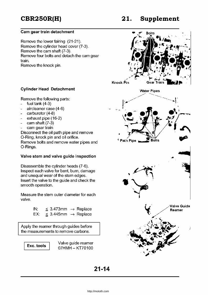
CBR250R(H)
Cam gear train detachment
Remove the lower fairing (21-21). Remove the cylinder head cover (7-3). Remove the cam shaft (7-3). Remove four bolts and detach the cam gear train. Remove the knock pin.
Cylinder Head Detachment
Remove the following parts: fuel tank (4-3) aircleaner case (4-6) carburetor (4-8) exhaust pipe (16-2) cam shaft (7-3) cam gear train
Disconnect the oil path pipe and remove O-Ring, knock pin and oil orifice. Remove bolts and remove water pipes and O-Rings.
Valve stem and valve guide inspection
Disassemble the cylinder heads (7-6). Inspect each valve for bent, bum, damage and unequal wear of the stem edges. Insert the valve to the guide and check the smooth operation.
Measure the stem outer diameter for each valve.
IN: ~ 3.473mm ~ Replace EX: ~ 3.445mm ~ Replace
Apply the reamer through guides before the measurements to remove carbons.
Exc. tools Valve guide reamer 07HMH - KT70100
21-14
21.
;..J"
Knock Pin
Supplement
http://mototh.com

CBR250R(H)
Measure inner diameter of each guide. ;;: 3.565mm --7 Replace
Valve stem guide clearance is the difference between each guides inner diameter and corresponding valve stem outside diameter. Valve stem guide clearance: IN: ;;: 0.092mm --7 Replace EX: ;;: 0.132mm --7 Replace
Calculate the clearance before replacing with a new guide. If the calculated valve falls within the limits, replace the guide.
If the clearance will be out of the limits even replacing with new guides, replace the valve as well.
• When the guide is replaced, adjust the valve seat (7-10).
• Use 07HMH-KT70200 cutter holder.
Valve guide replacement Gradually warm up the cylinder head to 100 - 150°c.
Do not use bumers to avoid deformation of the cylinder heads.
Remove the valve guide.
Wear safety gloves.
Exercise caution not to damage the cylinder head.
Exc. Tool Valve guide driver 07HMD - KT701 00
Install oversized valve guide.
I Wear safety gloves.
Exc Tool Valve guide driver 07HMD - KT701 00
After installing, finish the valve guide with a reamer. Exc Tool Valve guide driver
OlHMD - KTl0100
... "
21.
_.
•
Supplement
/"
Valve Guide //DriVer
Use proper lubrication for reaming.
Wash the cylinder head to remove debris. Inspect /adjust the valve seat contact (7-10).
Use a cutter holder 07HMH-KTl0200 I
21-15
http://mototh.com
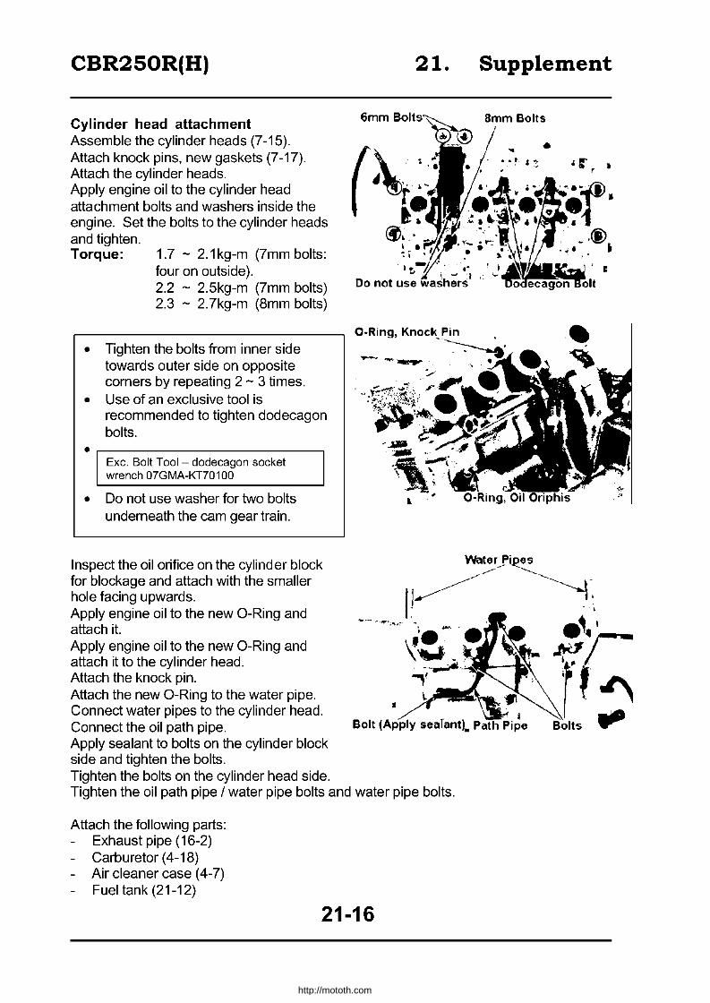
CBR250R(H) 21. Supplement
Cylinder head attachment Assemble the cylinder heads (7-15). Attach knock pins, new gaskets (7-17). Attach the cylinder heads. Apply engine oil to the cylinder head attachment bolts and washers inside the engine. Set the bolts to the cylinder heads and tighten. Torque: 1.7 - 2.1 kg-m (7mm bolts:
four on outside). 2.2 - 2.5kg-m (7mm bolts) 2.3 - 2.7kg-m (8mm bolts)
• Tighten the bolts from inner side towards outer side on opposite corners by repeating 2 - 3 times.
• Use of an exclusive tool is recommended to tighten dodecagon bolts. · ,------------------------, Exc. Bolt Tool - dodecagon socket wrench 07GMA-KT701 00
• Do not use washer for two bolts underneath the cam gear train.
Inspect the oil orifice on the cylinder block for blockage and attach with the smaller hole facing upwards. Apply engine oil to the new a-Ring and attach it. Apply engine oil to the new a-Ring and attach it to the cylinder head. Attach the knock pin. Attach the new a-Ring to the water pipe. Connect water pipes to the cylinder head. Connect the oil path pipe. Apply sealant to bolts on the cylinder block side and tighten the bolts. Tighten the bolts on the cylinder head side.
6mm Bollls~,-
... • .~. , !
Do not use wa·iher·~·
a-Ring, Knock Pin
• I
Bolt (Apply searant). Path Pipe
Tighten the oil path pipe / water pipe bolts and water pipe bolts.
Attach the following parts: Exhaust pipe (16-2) Carburetor (4-18)
- Air cleaner case (4-7) Fuel tank (21-12)
21-16
• • r I r
•
.~4;Jrdl
rf~ Bolts ....
http://mototh.com

CBR250R(H)
Cam gear train attachment
Attach the knock pin to a cylinder head.
There are two different types of 7mm bolts.
Attach the cam gear train and tighten the bolts. Torque: Bmm bolts: 1.B - 2.2kg-m
7mm bolts: 2.2 - 2.5kg-m
Attach the camshaft (7-19)
Attach the cylinder head cover (7-21)
Attach the lower cowling (21-23)
21-17
21. Supplement
7mm Bolt
__ Small Diameter
http://mototh.com
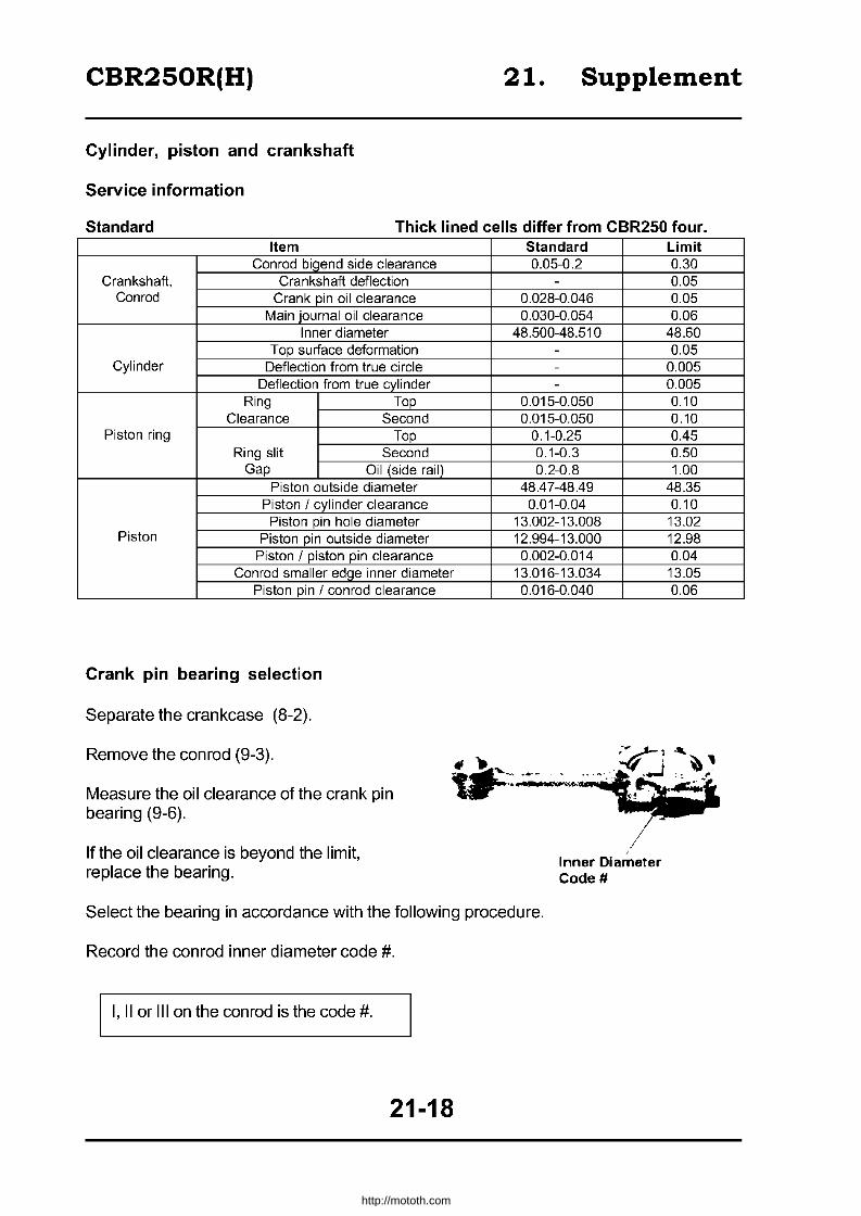
CBR250R(H) 21. Supplement
Cylinder, piston and crankshaft
Service information
Standard Thick lined cells differ from CBR250 four. Item
Con rod bigend side clearance Crankshaft, Crankshaft deflection
Con rod Crank pin oil clearance Main journal oil clearance
Inner diameter Top surface deformation
Cylinder Deflection from true ci rcle Deflection from true cylinder
Ring Top Clearance Second
Piston ring Top Ring slit Second
Gap Oil (side rail) Piston outside diameter
Piston I cylinder clearance Piston pin hole diameter
Piston Piston pin outside diameter Piston I piston pin clearance
Con rod smaller edge inner diameter Piston pin I conrod clearance
Crank pin bearing selection
Separate the crankcase (8-2).
Remove the conrod (9-3).
Measure the oil clearance of the crank pin bearing (9-6).
If the oil clearance is beyond the limit, replace the bearing.
Standard 0.05-0.2
-0.028-0.046 0.030-0.054
48.500-48.510 --
-0.015-0.050 0.015-0.050
0.1-0.25 0.1-0.3 0.2-0.8
48.4 7 -48.49 0.01-0.04
13.002-13.008 12.994-13.000 0.002-0.014
13.016-13.034 0.016-0.040
Inner Diameter Code #
Select the bearing in accordance with the following procedure.
Record the conrod inner diameter code #.
I, II or Ilion the con rod is the code #.
21-18
Limit 0.30 0.05 0.05 0.06
48.60 0.05
0.005 0.005 0.10 0.10 0.45 0.50 1.00
48.35 0.10 13.02 12.98 0.04 13.05 0.06
http://mototh.com

CBR250R(H)
Record the outside diameter code # of the crankpins, or measure the outside diameter.
A, B or C on crank weights are the codes of the crankpins.
21. Supplement
,
Outside Diameter Code
Find out the bearing colour from crankpin and conrod codes.
1 30.000 -30.005mm
A 26.994 - 27.000mm E (Yellow) B 26.988 - 26.993mm D (Green) C 29.982 - 26.987mm C (Brown)
Bearing metal thickness: A (Blue) 1.499 - 1.502 B (Black) 1.496 - 1.498 C (Brown) 1.493 - 1.495 D (Green) 1.490 - 1.492 E (Yellow) 1.487 - 1.489
Piston, conrod and crankshaft installation
Install pistons and conrods (9-10). I nstall the crankshaft (9-11).
Attach conrod bearing caps.
• Attach the cap to the same position it was detached.
• Inner diameter codes should face towards exhaust.
Tighten cap nuts (9-12).
21-19
2 3 30.006 - 30.012 -30.011mm 30.018mm D (Green) C (Brown) C (Brown) B (Black) B (Black) A (Blue)
http://mototh.com

CBR250R(H)
Clutch
Right crankcase cover detachment I attachment
Drain engine oil (2-16). Remove the left side cover. Remove the regulate / rectifier. Loosen the clutch cable, adjust nut and lock nut to disconnect the clutch cable. Remove right crankcase cover attachment bolts and detach the right crankcase cover and the lower fairing stay. Reverse the procedure for attachment.
Lifter plate bearing replacement
Disconnect the clutch (10-5). Inspect the lifter plate bearing (10-7) and replace as required. Detach the bearing. Attach the new bearing to the lifter plate, facing marked surface outwards.
Exc. tool I Driver attachment (28 x 30mm) 07946 -1870100
21.
Clutch Cable , .1
•
Pilot .- ---
Common tools Pilot (12mm) Driver handle A
Attach the clutch (10-1 0).
07746-0040200 07749-0010000
Attach the right crankcase cover.
Change cover attachment I detachment
Detach the left lower fairing (21-21). Remove the drive sprocket cover and the change pedal. Disconnect water pump (5-9).
The water pump can be disconnected without disconnecting the tubes.
Remove five change cover attachment bolts.
Supplement
Driver Handle A
Lifter Plate
/
./ /
- Attachment
By pushing the shift spindle in, detach the change cover and the lower fairing stay. Remove the gasket and the knock pin. Reverse the procedure for attachment.
21-20
http://mototh.com

CBR250R(H) 21. Supplement
Front wheel, Suspension and Steering
Service information
Standard Thick lined cells differ from CBR250 four. Item
Front axle bent Front wheel rim deflection I Radial
I Sideways Front cushion spring relaxed length
Front fork pipe bent
Front fork oil capacity I Standard I Fully compressed
Fairing
Detachment
Disconnect the spring clip on the lower fairing.
Remove the quick screw and detach the boss of the maintenance cover from the lower fairing grommet and detach the maintenance cover.
21-21
--
-
-
Standard
396.6mm
302 + 2.5cc 100mm
Limitation 0.2mm 2.0mm 2.0mm
388mm
0.2mm
--
Screw
I ...
Boss I I
I
http://mototh.com

CBR250R(H)
Remove screws
Detach the lower fairing boss from the frame grommet and detach the lower fairing.
Remove screws and detach the upper fairing inside cover.
Disconnect the turn signal coupler. Disconnect the head coupler. Remove two bolts.
Remove two screws and detach the upper fairing.
21-22
21.
9 !
Supplement
P I
.'
http://mototh.com

CBR250R(H) 21. Supplement
Attachment
Reverse the detachment procedure.
Set the spring clip as shown in the figure below.
~CliP
Lower Fairing
Fairing
21-23
http://mototh.com
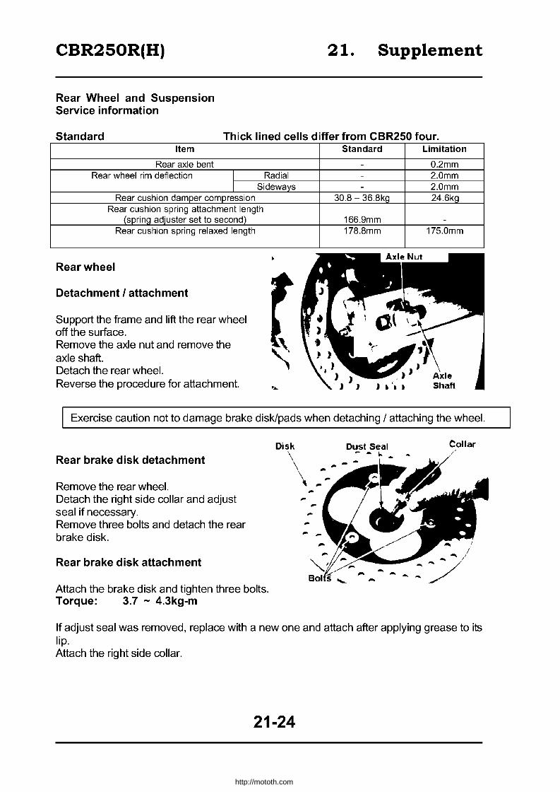
CBR250R(H)
Rear Wheel and Suspension Service information
21. Supplement
Standard Thick lined cells differ from CBR250 four. Item
Rear axle bent Rear wheel rim deflection I Radial
I Sideways Rear cushion damper compression
Rear cushion spring attachment length (sprinQ adiuster set to second)
Rear cushion spring relaxed length
Rear wheel
Detachment I attachment
Support the frame and lift the rear wheel off the surface. Remove the axle nut and remove the axle shaft. Detach the rear wheel. Reverse the procedure for attachment.
Standard Limitation
- 0.2mm - 2.0mm - 2.0mm
30.8 - 36.8kQ 24.6kQ
166.9mm -
178.8mm 175.0mm
Exercise caution not to damage brake disk/pads when detaching / attaching the wheel.
Rear brake disk detachment
Remove the rear wheel. Detach the right side collar and adjust seal if necessary. Remove three bolts and detach the rear brake disk.
Rear brake disk attachment
Attach the brake disk and tighten three bolts. Torque: 3.7 - 4.3kg-m
Disk
\ \
Collar
If adjust seal was removed, replace with a new one and attach after applying grease to its lip. Attach the right side collar.
21-24
http://mototh.com
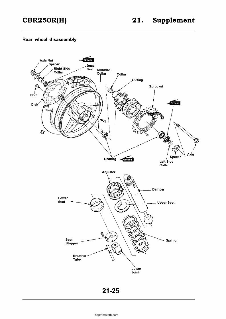
CBR250R(H)
Rear wheel disassembly
Lower Seat
Bearmg
Adjuster
21-25
21. Supplement
Left Side Collar
~ __ Damper
+-'~-T-- Upper Seat
Lower Joint
Spring
http://mototh.com

CBR250R(H)
Suspension linkage
Detachment Remove conrad bolts (frame and cushion sides) and remove the cushion conrad. Remove the rear cushion lower bolt. Remove the cushion arm - rear fork pivot pinch bolt. Remove the pivot shaft and detach the cushion arm. Cushion arm - rear fork pivot bearing replacement
Remove the dust seal. Remove the needle bearing by using a bearing remover.
I Exc. tools
Bearing remover (15mm) Remover ASSY Remover shaft Remover head Remover sliding weight
07936-KC 1 0000 07936-KC 10500 07936-KC10100 07936-KC 1 0200 07741-0010201
Fill grease to the needle bearing. Attach the needle bearing to the cushion arm by using a hydraulic press machine.
I Common tools I Driver handle A Outer driver (24x26mm) Pilot (15mm)
07749-0010000 07746-0010700 07746-0040300
21. Supplement
Cushion Arm
J
Needle Bearing
... Driver Handle A
I Press the marked surface in I
Assemble the cushion arm (14-17). Conrod PI vot .. Pinch Bolt
Attachment Attach the cushion arm and a cushion conrod. Attach the cushion arm - rear fork pivot shaft. Tighten each bolt with torque specified as follows:
Torque:
Bolt· ,
Cushion arm - rear fork pivot pinch bolt Rear cushion lower bolt Conrad bolt (frame side)
2.0 - 3.0kg-m 5.0 - 6.0kg-m 5.0 - 6.0kg-m
21-26
http://mototh.com

CBR250R(H)
Tighten the conrod bolt (cushion arm side).
Torque: 5.0 - 6.0kg-m
Rear fork bearing replacement
Detach the rear wheel (21-24) Detach the rear fender B (16-2) Detach the cushion arm (21-26) Remove the rear fork (14-18) Remove the right pivot collar and dust seal.
Remove the chain slider. Remove the left pivot collar and the dust seal.
Remove the circlip.
21.
//
Supplement
Dust Seal
//
~
/~ .' Pivot Collar
. ... ,~
Chain Slider !
By using a bearing remover, remove the right pivot bearing (ball-bearing).
Pivot COllar Dusi Seal
I Exc. tools
Bearing remover (15mm) 07936-KC 10000 Remover ASSY (15mm) 07936-KC 10500 Remover shaft (15mm) 07936-KC10100 Remover head (15mm) 07936-KC 10200 Remover sliding weight 07741-0010201
/
Circlip
21-27
,
http://mototh.com

CBR250R(H)
Remove the distance collar.
Remove the left pivot bearing (needle bearing).
I Exc. tool I Driver handle Driver attachment
07949-3710001 (28 x 30mm) 07946-1870100
21.
21-28
Supplement
...
, /~
/ Distance Collar
0V Driver Handle
Attachment
Dust Seal
~..am ~Left Pivot
Bearing
http://mototh.com

CBR250R(H)
Fill grease to a roller of the needle bearing. By using hydraulic press machine, insert the left pivot bearing (needle bearing).
I Exc. tool
Needle bearing driver attachment 07HMD-KV30100
I Common tool
Driver handle A 07749-0010000
Push the marked surface in.
Install the distance collar.
Fill the bearing with grease. By using hydraulic press machine, insert the right pivot bearing (ball-bearing).
I Common tools
Outer driver (32x35mm) Pilot (15mm) Driver handle A
07746-0010100 07746-0040300 07749-0010000
Press the marked surface in.
Firmly attach the circlip to the groove. Apply grease to the lip of the left pivot dust seal and attach it. Attach the left pivot collar. Attach the chain slider.
, I
~.
21-29
21.
Driver Handle A
..
Supplement
,
Needle Bearing
~ Distancl Collar
\ \\
Driver Handle A I,
Outer Driver
, \
. \ .. ___ , _ Bearmg, Pilot
Chain Slider
~MiJ Dust Seal
,~ Pivot Collar
http://mototh.com

CBR250R(H)
Apply grease to the lip of the right pivot dust seal and attach it.
Attach the right pivot collar.
Attach the rear fork (14-22).
Attach the rear fender B (16-2).
Attach the cushion arm (21-27).
Attach the rear caliper to a rear fork by aligning the projection on the caliper with the slit on the fork.
Attach the rear wheel (21-24).
r
•
21-30
21. Supplement
Dust Seal
/-fMij
~
~ - .-1 ,
http://mototh.com
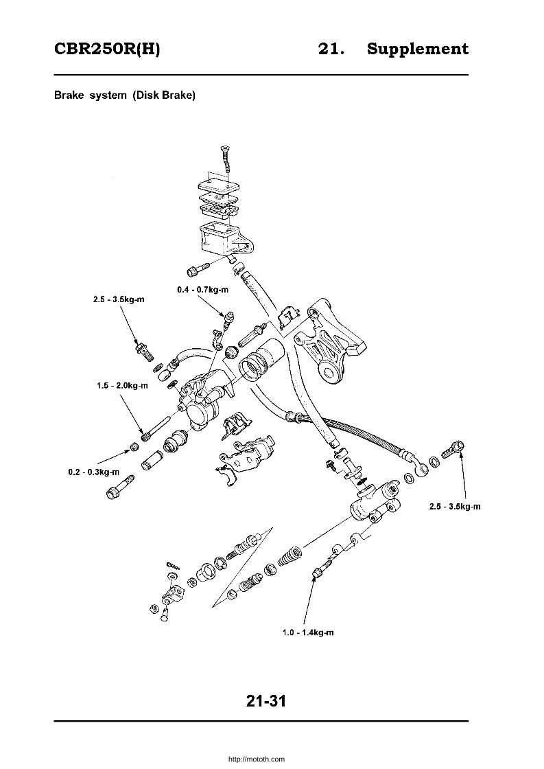
CBR250R(H) 21. Supplement
Brake system (Disk Brake)
2.5 - 3.5kg-m
2.5 - 3.5kg-m
1.0 - 1.4kg-m
21-31
http://mototh.com
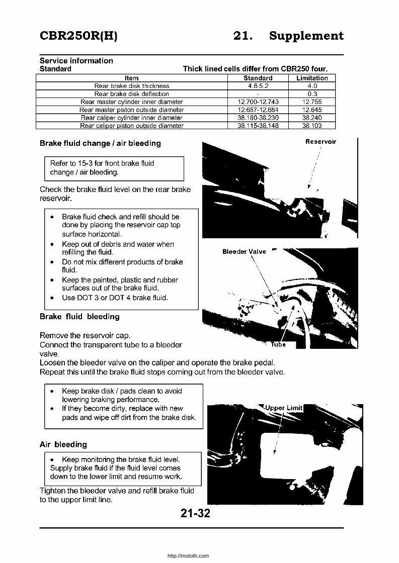
CBR250R(H) 21. Supplement
Service information Standard Thick lined cells differ from CBR250 four.
Item Rear brake disk thickness Rear brake disk deflection
Rear master cylinder inner diameter Rear master piston outside diameter Rear caliper cylinder inner diameter Rear caliper piston outside diameter
Brake fluid change I air bleeding
Refer to 15-3 for front brake fluid change / air bleeding.
Check the brake fluid level on the rear brake reservoir.
• Brake fluid check and refill should be done by placing the reservoir cap top surface horizontal.
• Keep out of debris and water when refilling the fluid.
• Do not mix different products of brake fluid.
• Keep the painted, plastic and rubber surfaces out of the brake fluid.
• Use DOT 3 or DOT 4 brake fluid.
Brake fluid bleeding
Remove the reservoir cap. Connect the transparent tube to a bleeder valve.
Standard 4.8-5.2
-
12.700-12.743 12.657-12.684 38.180-38.230 38.115-38.148
...
Loosen the bleeder valve on the caliper and operate the brake pedal. Repeat this until the brake fluid stops coming out from the bleeder valve.
• Keep brake disk / pads clean to avoid lowering braking performance.
• If they become dirty, replace with new pads and wipe off dirt from the brake disk.
Air bleeding
• Keep monitoring the brake fluid level. Supply brake fluid if the fluid level comes down to the lower limit and resume work.
Tighten the bleeder valve and refill brake fluid to the upper limit line.
21-32
Limitation 4.0 0.3
12.755 12.645 38.240 38.103
Reservoir
,
http://mototh.com
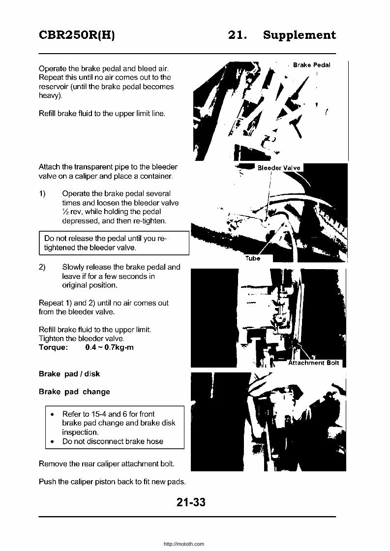
CBR250R(H)
Operate the brake pedal and bleed air. Repeat this until no air comes out to the reservoir (until the brake pedal becomes heavy).
Refill brake fluid to the upper limit line.
Attach the transparent pipe to the bleeder valve on a caliper and place a container.
1) Operate the brake pedal several times and loosen the bleeder valve y, rev, while holding the pedal depressed, and then re-tighten.
Do not release the pedal until you retightened the bleeder valve.
2) Slowly release the brake pedal and leave if for a few seconds in original position.
Repeat 1) and 2) until no air comes out from the bleeder valve.
Refill brake fluid to the upper limit. Tighten the bleeder valve. Torque: 0.4 - 0.7kg-m
Brake pad I disk
Brake pad change
• Refer to 15-4 and 6 for front brake pad change and brake disk inspection.
• Do not disconnect brake hose
Remove the rear caliper attachment bolt.
Push the caliper piston back to fit new pads.
21-33
21. Supplement
r
~ Bleeder Valve .... I • I
I
http://mototh.com

CBR250R(H)
Remove the plug and the hanger pin.
Detach the pads from the caliper. Confirm the pad spring attachment position. Attach new pads to the caliper.
• Replace brake pads in a pair. • Attach the retainer-fitted pad to
the piston side.
Attach the caliper to the caliper bracket and attach the hanger pin and tighten. Torque: 1.5 - 2.0kg-m
Attach the hanger pin plug. Torque: 0.2 - 0.3kg-m
Apply silicone grease to the rear caliper attachment bolt and tighten it. Torque: 2.0 - 2.5kg-m
Operate the brake pedal after replacing the pads to push the piston
21.
21-34
Supplement
..... un Silicon Grease ~ ,.,.-..... ,
http://mototh.com

CBR250R(H)
Brake disk inspection
Measure the brake thickness. :;;; 4.0mm --t Replace
Measure the disk deflection. ~ O.3mm --t Replace
Master cylinder
Refer to 15-6, -7, -8 for front master cylinder.
Front brake lever adjuster
Remove the front master cylinder (15-6). Detach the brake lever from the master cylinder and remove screws, adjuster arm, rod, adjuster and the joint pin. Inspect the spring for its tension. Apply small amount of grease on the joint pin hole and attach it to the brake lever. Attach the adjuster and a rod and attach them to the joint pin. Attach the adjuster arm to the brake lever and tighten the screws.
Align the marking on the adjuster with the arrow symbol on the joint pin when attaching.
Attach the brake lever to the master cylinder and attach the front master cylinder (15-8).
21-35
21. Supplement
----
Joint pad
Rod
.' • , \ 'l \~
Adjuster Arm
\ ": ... " Spring Adjuster Screw
http://mototh.com

CBR250R(H)
Rear master cylinder
Detachment
• Keep the painted, plastic and rubber surface away from brake fluid.
• Apply cover to the hose joint to prevent brake fluid leak.
Bleed brake fluid (21-32). Remove the brake hose attachment bolt and disconnect the brake hose from the master cylinder. Remove the lock nut and remove a push rod from a joint. Remove one attachment screw and disconnect the reservoir hose from the master cylinder. Remove two master cylinder attachment bolts and detach the master cylinder.
Disassembly
Remove the dust boot and remove the circlip.
I Exc. tool I Snap ring pliers 07914-3230001
Remove the piston, piston cup and spring from the master cylinder and clean the inside of the cylinder with brake fluid.
• Clean the removed parts with brake fluid and check the path of each part with compressed air.
• Sort the parts to keep them away from dust and debris.
Inspection
Inspect the master pistons contact surface for damage or scratch. Measure the inner diameter of the master cylinder.
~ 12.755mm ~ Replace
21-36
21. Supplement
()\ Boits JI
Master Cylinder
Piston Cup /~ .. //
r "~'I /1 /
i ., I. i // r'·,. sp~ng I (/
.1 Piston
(-J
http://mototh.com
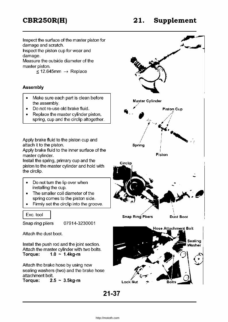
CBR250R(H)
Inspect the surface of the master piston for damage and scratch. Inspect the piston cup for wear and damage. Measure the outside diameter of the master piston.
:s 12.645mm ~ Replace
Assembly
• Make sure each part is clean before the assembly.
• Do not re-use old brake fluid. • Replace the master cylinder piston,
spring, cup and the circlip altogether.
Apply brake fluid to the piston cup and attach it to the piston. Apply brake fluid to the inner surface of the master cylinder.
21. Supplement
Master Cylinder
" / Piston Cup .- , 4
/"''!/ / 1"" ...
/ i 'I'j Spring I I
Piston
Install the spring, primary cup and the piston to the master cylinder and hold with the circlip.
Circlip
• Do not tum the lip over when installing the cup.
• The smaller coil diameter of the spring comes to the piston side.
• Firmly set the circlip into the groove.
Exc. tool
Snap ring pliers 07914-3230001
Attach the dust boot.
Install the push rod and the joint section. Attach the master cylinder with two bolts. Torque: 1.0 - 1.4kg-m
Attach the brake hose by using new sealing washers (two) and the brake hose attachment bolt. Torque: 2.5 - 3.5kg-m
21-37
.. -.~J#"
\, ,
Oust Boot
.6tt,."hrnAlnt Bolt
Sealing Washer
http://mototh.com

CBR250R(H)
Attach an O-Ring to the reservoir hose and connect the hose to a master cylinder with attachment bolt.
Refill brake fluid and bleed air (21-32).
Brake caliper
Refer to 15-9, -10, -11 for front brake caliper.
Caliper detachment I disassembly
I Keep all parts away from brake fluid.
Bleed brake fluid (21-32). Remove the brake hose attachment bolt and detach the brake hose from the master cylinder. Remove the rear caliper attachment bolt and detach the rear caliper. Remove the pad, pad spring, boot and the pivot collar from the caliper. Wrap with the cloth to prevent piston and brake fluid coming out, and turn the piston downwards. Gradually apply low pressure air from the brake hose attachment and remove the piston from the caliper.
• Do not use high pressure air or bring the air gun too close.
• Do not insert your hand inside the caliper.
Remove the piston seal and adjust seal by pushing them into the piston.
Exercise caution not to damage the inner surface of the calioer cvlinder.
Clean the inner surface of the caliper with brake fluid and remove dirt from creeks.
21-38
21. Supplement
Dust Seal
http://mototh.com

CBR250R(H)
Inspection
Inspect the exterior surface of the caliper piston for damage and scratch. Measure the outside diameter of the piston
~ 38.1 05mm ~ Replace Inspect the inner surface of the cylinder for damage scratches. Measure the inner diameter of the caliper cylinder.
~ 38.240mm ~ Replace Caliper assembly / attachment
• Check all parts are clean before the assembly.
• Do not re-use old brake fluid. • Replace the piston seal and the dust
seal whenever the caliper is reassembled.
Apply brake fluid to new piston seal and dust seal and set them to the grooves on the caliper cylinder. Install the piston to the caliper. Attach the boot, collar and the pad spring.
• Apply silicone grease to the boot. • Firmly set the boot to the groove on the
caliper.
Attach brake pads to the caliper and attach the caliper to the bracket. Set the rear caliper by tightening the attachment bolt. Torque: 2.0 - 2.5kg-m
Attach the hanger pin to the caliper. Torque: 1.5 - 2.0kg-m
Attach the hanger pin plug. Torque: 0.2 - 0.3kg-m Attach the brake hose with two new sealing washers and the brake hose attachment bolt.
I Set the hose to groove on a caliper.
Torque: 2.5 - 3.5kg-m Fill brake fluid and bleed air (21-32).
21-39
21.
Collar ,
Supplement
Pislon Seal
t I
,I
Pislon
°PiiiI ,I Dust Seal
Bool
, I .... I ",~I
Spring
http://mototh.com
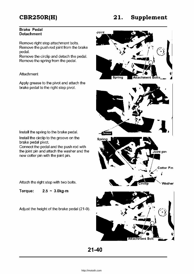
CBR250R(H)
Brake Pedal Detachment
Remove right step attachment bolts. Remove the push rod joint from the brake pedal. Remove the circlip and detach the pedal. Remove the spring from the pedal.
Attachment
Apply grease to the pivot and attach the brake pedal to the right step pivot.
Install the spring to the brake pedal.
Install the circlip to the groove on the brake pedal pivot. Connect the pedal and the push rod with the joint pin and attach the washer and the new cotter pin with the joint pin.
Attach the right step with two bolts.
Torque: 2.5 - 3.0kg-m
Adjust the height of the brake pedal (21-9).
s
21-40
21. Supplement
-~.
pin
.,. ~~. f
~~""" Washer
http://mototh.com

CBR250R(H)
Seat Cowl
Detachment
It is not necessary to detach side covers and the front seat in order to detach only the seat cowl.
Remove side cover attachment screws. Release four catches on the side cover and detach the side cover.
Remove two bolts and detach the front seat. Release the lock of the helmet holder. Lift and slide the tandem seat back.
Remove two rear cowl attachment bolts and detach the rear cowl from the rear catch.
21.
Helmet Holder
21-41
Supplement
Sid6 COV6r
Catch
, , '- ,
http://mototh.com
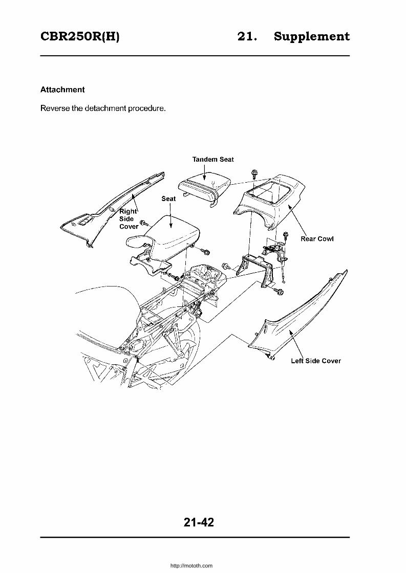
CBR250R(H) 21. Supplement
Attachment
Reverse the detachment procedure.
Tandem Seat
21-42
http://mototh.com

CBR250R(H)
Sub Frame Plastic clips detachment / attachment
When detaching wire harness and hose, release the lock by opening the catch with a screwdriver. Detach the harness and hose from the clip. When attaching them to the clip, set them to the clip and push in until the catch is locked ("click" sound).
Replace with new clips whenever dismounted from the frame.
21-43
21. Supplement
http://mototh.com

CBR250R (J)
Table of Contents
Specifications ............................................................... 22-2
Torque Settings ............................................................. 22-3
Exclusive I Common Tools ............................................ 22-3
Wiring .......................................................................... 22-4
Circuits ......................................................................... 22-8
Service Data .................................................................. 22-9
Inspection I Adjustment.. ............................................... 22-15
Fuel System ................................................................... 22-19
Engine mounting I dismounting ....................................... 22-22
Cylinder Head, valve ...................................................... 22-23
Front wheel attachment I detachment.. ............................ 22-24
Rearwheel, Suspension ................................................. 22-25
Brake system (Disc brake) ............................................. 22-29
Fairing ......................................................................... 22-30
Lights, Instructions and Switches ................................... 22-32
22-1
http://mototh.com

CBR250R (J)
Specifications
Type
Length
Width
Height
Wheelbase
Type of povverplant
Total displacement
Type of fuel
Vehicle Front weight Rear
Total
Maximum capacity
Gross Front weight
Rear
Total
Tyres Front
Rear
Minimum clearance
., Brake stop u Distance " <Il (initial km/h) E .g Minimum ., Turning CL
radius Engine start
Type of engine
Cylinders
Combustion chamber
Valve system
Bore x stroke
Compression ratio
C Compression <Il <i Max output j Max torque 0 0.. I Open ., 0> N Close > '" "
~ CL'-o E E Open +'
X close Valve IN
clearance EX Idle rpm
Type
" Oil pump .12 1ii
Oil filter u ." .c ~
...J Oil capacity
Cooling
Thick lined cells are different from CBR250FOUR I CBR250R
Honda MC19 Air cleaner
2.020m
0.685m
1.075m
1.365m
E Fuel capacity 131 ., Type VG05
~ 5 Qi ~ Gas valve diameter 32mm
~ ~ -e LL
<Il Venturi diameter 28.5mm U
MC14E Full transistor
E Type Battery ignition 0.2491
Petrol
77kg
2 " Timing 23' BTOC 11500 rpm ~
0 +'
I '" Spark NGK CR9EH-9, CR10EH-9 <il .2' plug I u NO U27FER9, U31FER9 ."
77kg 1:3 Plug gap O.B-O.9mm ., 154kg UJ
Battery capacity 12V6AH
2 .<= Type Multiple wet plate coil
94kg .8 spring ~
Operation Mechanical U
170kg Engine transmission reduction 2.966
264kg Type Constant Mesh
100/80 -17 52H First 2.733
140/70 - 17 66H Second 2.000
0.135m
14.0m (50km/h)
" 0 Third 1.590
0 'in ~ Gear 1.333 '" E ffi ratio Fourth
'" ., " (!) ~ f-- 1.153
2.9m Fifth
Self start Sixth 1.035 Petrol, 4 - cycle
" Gear type 0
4 in-line sideways U ffi First ~ ., '0 0> Reduction 3.176 ., ~ ratio
Pent roof type C Caster 25"00'
DOHC gear driven Inlet 2, exhaust 2
48.5 x 33.8mm
'" e Qi LL ., Trail B9mm .<=
s: Tyre air Front 2.25kg/cm"
11.0 pressure Rear 2.50kg/cm' 13.0kg/cm2
- 400rpm Left 31'
45PS 1 15,000rpm Steering angle Right 31'
2.6kg-m 11 0,500rpm Front Hydraulic disk
19' BTOC (1 mm lifted) Braking system Rear Hydraulic disk
33' ABOC (1 mm lifted) Suspension Front Telescopic
36' BBOC (1 mm lifted) System Rear Swing arm
11' ATDC (1mm lifted) 0.16mm (cooled) Frame type Backbone
0.23mm (cooled) 1,500rpm
Compress/splash Frame No. MC19 -1000001 -
Tocoloid
Total flow filter. Net I paper filter Engine No . MC14E - 1000001 -
2.71
Water - cooled
22-2
http://mototh.com

CBR250R (J)
Torque setting (only for amended parts)
Engine Part No. Screw dia (mm) Torque (kg-m) Notes
Cylinder head (flange bolt) 12 7 2.7-3.0 Spark plug 4 10 1.0-1.4
Right crankcase cover cap bolt 1 14 0.8-1.2
Frame Part No. Screw dia (mm) Torque (kg-m) Notes
Side stand bracket 2 10 4.5-5.5 Radiator reserve tank
attach ment bolt 2 6 1.0-1.4 Fuel tank attachment bolt (front
Rear) 2 6 1.0-1.4 1 8 2.4-3.0
Air cleaner case attachment 6 5 0.35-0.5 screw
Air cleaner case attachment bolt 1 6 1.0-1.4 Top bridge split bolt 2 8 2.0-2.5
Front axle nut 1 14 5.5-6.5 Front axle pinch bolt 4 8 1.8-2.5
Front master cylinder holder bolt 2 6 1.0-1.4 Rear cushion upper bolt 1 10 4.5-5.5
Cushion conrad (frame side) 1 10 4.5-5.5 Cushion arm side 1 10 4.5-5.5
Cushion arm (rear cushion side) 1 10 4.5-5.5 Lower cowl stay (top, R side) 1 6 0.7-1.1
(top, L side) 1 6 1.0-1.4 (Bottom) 4 6 0.7-1.1
Change pedal attachment bolt 1 8 2.4-3.0 ChanQe arm 1 6 1.4-1.8
Exhaust pipe joint nut 8 6 1.0-1.4 Side cover attachment bolt 2 6 0.7-1.1
Hook bolt 2 6 1.0-1.4
Exclusive I common tools (amended part only)
Existing exclusive tools Tools Tool no. Part (Application)
Bush driver Assy 07GMD-KT80100 Rear cushion, cushion linkage swing arm
Bali lace remover set 07946-KM9000 1 Ball lace detach/attachment Disassembly tool 07964-M B00200 Swing arm bearing
detach/attachment
Common tools Tools Tool no. Part (Application)
Driver outer 42 x 47mm 07746-0010300 Front wheel R.L. bearing installation Remover head (20mm) 07746-0050600 Front wheel R.L bearing removal
Fork seal driver attachment 07747-0010600 Front fork assembly
22-3
http://mototh.com
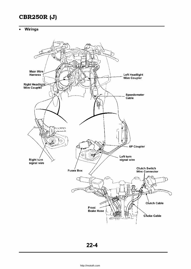
CBR250R (J)
• Wirings
!~~t:!-il)t--"""~lt--- Left Headlight i Wire Coupler
I\~b~--+::Oi-~-- Speedometer Cable
signal wire
22-4
Clutch Switch Wire Connector
http://mototh.com

CBR250R (J)
• Wirings I Cables
Speedometer Cable
Left Turn Signal Wire
Choke Cable
Main Wire
22-5
http://mototh.com
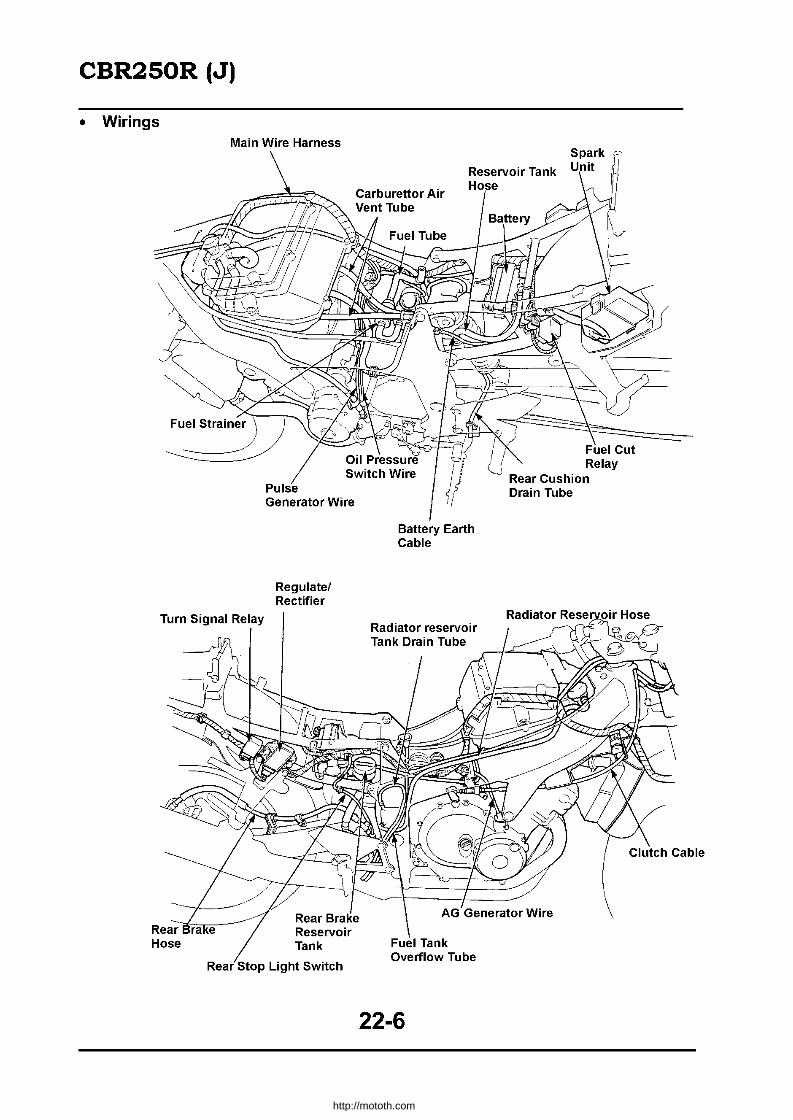
CBR250R (J)
• Wirings Main Wire Harness
Turn Signal Relay
Pulse Generator Wire
Regulate! Rectifier
Reservoir Tank Hose
~o-""j ) Fuel Cut
Battery Earth Cable
Radiator reservoir Tank Drain Tube
22-6
U Relay Rear Cushion Drain Tube
http://mototh.com

CBR250R (J)
• Wirings
Pulse Generator Wire
Grommet
Throttle Cable
Fuel
22-7
2-3 Ignition Coil
To No.2 Cylinder
To No.4 Cylinder
To No.1 Cylinder
Radiator Reservoir Hose
T LOR T
LOR
http://mototh.com

I\) I\) I
CO
Speed
--l ij'" Starter Magnetic Switch
LStarter ";,, 12 Motor ;0;0:0:
~_ i~ !,~~I',m
11111111" ~,
I~ ~ ~ ~ ~
l [ CI,toh ~! SWltc~
'=~~~i~~~J~~1~~~7~~SW'TCH CONNECTION ~ HII rifflL:';!! I T'mi-,w-~t-r-I~-':-II-S::1" F1rr~:~-:-,"-:-~-i:~' .... ....'H. " I'IJS>o PliSH
" ,
o
rB --D<l--SB ~ Right Rear rG-D<O----G~ Turn Signal
~ -DjI=;::.-<tI-.'G/~ G~G.::....=:fli.R ,.
G
LG--c:::Jq----c~ Left Rear LA-c::KJ---A~TUrn Signal
A: AMBER S" BLUE BL: BLACK SR" BROWN G; GREEN S8: SKY BLUE R: RED P: PINK GR: GREY W WHITE Y: YELLOW
0030Z-KY1-OOOO
• I (")
:E ta ::;" ~ 5"
IC ~ C'JI 0 ~ -Cot -
http://mototh.com
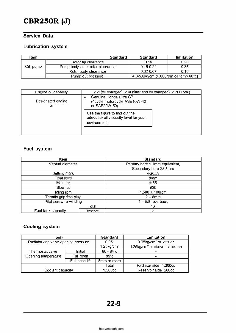
CBR250R (J)
Service Data
Lubrication system
Item Standard Standard limitation Rotor tip clearance 0.15 0.20
Oil pump Pump body-outer rotor clearance 0.15-0.22 0.35 Rotor-body clearance 0.02-0.07 0.10 Pump out pressure 4.0-5.0kg/cm2(6.000rpm oil temp 60'c)
Engine oil capacity 2.21 (oil changed). 2.41 (filter and oil changed). 2.71 (Total)
• Genuine Honda Ultra GP Designated engine (4cycle motorcycle ASE10W-40
oil or SAE20W -50)
Use the figure to find out the adequate oil viscosity level for your environment.
Fuel system
Item Standard Venturi diameter Primary bore 9.1 mm equivalent,
Secondary bore 28.5mm Setting mark VG05A
Float level 8mm Main jet #85 Slow jet #35
Idling rpm 1.500 + 100rpm Throttle grip free play 2-6mm Pilot screw re-winding 1 - 5/8 revs back
Total 131 Fuel tank capacity Reserve 21
Cooling system
Item Standard Limitation Radiator cap valve opening pressure 0.95- 0.95kg/cm2 or less or
1.25kg/cm2 1.25kg/cm2 or above ---7replace Thermostat valve Initial 80 - 84'c -
Opening temperature Full open 95'c -Full open lift Bmm or more -
Total Radiator side 1.300cc Coolant capacity 1.500cc Reservoir side 200cc
22-9
http://mototh.com

CBR250R (J)
Engine Mount I Dismount
Engine weight (service) Approx 49kg Genuine Honda Ultra GP (4 cycle motor cycle
Recommended SAE10W-40 or SAE20W-50 Engine oil APC class SE or SF engine oil -4
See 3-2 for viscosity Total capacity 2.71
Engine oil Oil changed 2.21 capacity Oil/filter changed 2.41
Cylinder Head, Valve
Item Standard Standard Service Limit Compression 13.0kg/cm2 -
IN 29.44-29.68 29.41 Cam lift EX 28.96-29.20 28.85
Camshaft 1 0.015-0.057 0.06 Oil clearance 2 0.015-0.057 0.06
3 0.025-0.067 0.07 4 0.015-0.057 0.06
Deflection - 0.05 Valve spring 37.3 36.3
Valve stem IN 3.481-3.495 3.47 Outside diameter EX 3.460-3.475 3.44
Valve, Valve guide bore IN 3.500-3.512 3.57 Valve guide EX 0.005-0.042 3.57
Stem - guide IN 0.005-0.042 0.10 clearance EX 0.005-0.050 0.13
Valve seat contact IN 0.8 1.3 Length (span) EX 1.0 1.5
Valve lifter Diameter 20.010-20.026 20.035 Cylinder Deflection - 0.05
head Valve lifter contact part diameter 19.978-19.993 19.970
22-10
http://mototh.com

CBR250R (J)
Cylinder, Piston, Crankshaft
Item Con rod bigger end side clearance
Crankshaft. Crankshaft deflection conrad Crank pin oil clearance
Main journal oil clearance Bore
Top surface distortion Cylinder Round dimension (distortion from true circle)
Cylinder distortion Ring slit - ring Top
clearance Second Piston Top
ring Ring gap Second Oil (side rail)
Piston diameter Piston - cylinder clearance
Piston pin hole diameter Piston Piston pin diameter
Piston - piston pin clearance Con rod smaller edqe bore
Piston pin - con rod clearance
B = Blue Conrad Bore Code BR=Brown Bl=Black 1 2 3 Y=Yeliow 30.000- 30.006- 30.012-G=Green 30.005mm 30.011mm 30.018mm
A 26.993.27.000mm E(Y) D(G) C(BR)
c .5. B 26.987-26.994mm D(G) C(BR) B (Bl) '" c
[" U
C 26.982-26.988mm C(BR) B (Bl) A(B)
Case Bore P = Pink 1 2 3
31000- 31006- 31012-31.005mm 31.011mm 31.018mm
A 26.993.27.000mm E(P) D (Y) C(G) -'" "'"8 §u B 26.987-26.994mm D(Y) C(G) B(BR) o ~ -,2 c '" .~ ~
C 26.982-26.988mm C(G) B(BR) A (Bl) :;'0
22-11
Standard Service Limit 0.05-.02 0.30
- 0.05 0.028-0.046 0.05 0.030-0.048 0.06
48.500-48.510 48.60 - 0.05 - 0.005 - 0.005
0.015-0.050 0.10 0.015-0.050 0.10
0.1-0.25 0.45 0.15-0.30 0.45
0.2-0.8 1.00 48.4 7-48.49 48.35 0.01-0.04 0.10
13.002-13.008 13.02 12.994-13.000 12.98 0.002-0.014 0.04
13.016-13.034 13.05 0.016-0.040 0.06
Bearing Metal thickness A(B): 1.502-1.505mm B (Bl) : 1.499-1.502mm C (BR): 1.496-1.499mm D (G): 1.493-1.496mm E (Y): 1.490-1.493mm
Bearing Metal thickness A 1.508-1.511mm B 1.505-1.508mm C 1.502-1.505mm D 1.499-1.502mm E 1.496-1.499mm
http://mototh.com

CBR250R (J)
Clutch AC Generator
Item Standard Standard Limitation Clutch lever free play 10-20 -
Clutch spring relaxed length 36 35 Clutch Clutch disk thickness 2.9-3.0 2.6
Clutch plate distortion - 0.3 Clutch outer guide bore 21.995-22.015 22.03
Oil pump drive sprocket bore 30.025-30.075 30.09 Bore 21.995-22.015 22.03
Oil pump drive gear collar Diameter 29.987-30.000 29.97 Length 22.300-22.400 22.20
Main shaft diameter (clutch outer guide contact area) 21.980-21.990 21.97
Transmission
Item Standard Standard Limitation Backlash 0.044-0.140 0.3
M5 25.000-25.021 25.05 Transmission M6 25.000-25.021 25.05
Gear bore C1 23.000-23.021 23.05 C2 28.000-28.021 28.05 C3 28.000-28.021 28.05 C4 28.000-28.021 28.05
M5bore 21.985-22.006 22.07 M5 diameter 24.959-24.980 24.92 M6 diameter 24.959-24.980 24.92 C1 diameter 22.959-22.980 22.92
Gear bush C1 bore 20.020-20.041 20.11 C2 diameter 27.959-27.980 27.92 C3 diameter 27.959-27.980 27.92 C4 diameter 27.959-27.980 27.92
Main shaft M5 area 21.963-21.977 21.93 diameter Clutch outer quide 21.980-21.990 22.20
Counter shaft diameter C1 area 19.987-20.000 19.77
M5 - bush - 0.10 Gear and bush or M5 bush-shaft - 0.15 shaft clearance M6 - bush - 0.10
C1 - bush - 0.10 C 1 bush-shaft - 0.15
C2 - bush - 0.10 C3 - bush - 0.10 C4 - bush - 0.10
Shift Catch thickness 5.93-6.00 5.60 Fork Bore 12.000-12.021 12.04
Shift fork shaft Diameter 11.960-11.971 11.90
22-12
http://mototh.com

CBR250R (J)
Front wheel, Suspension and Steering
Item Standard Limitation Front axle runout - 0.2mm
I Radial - 2.0mm Front wheel rim deflection I Side - 2.0mm
Front cushion spring relaxed length 303mm 297mm Front fork pipe bent - 0.2mm
I Standard 362+2.5cc -
Front fork oil capacity I Fully compressed 95+6mm -Front fork air pressure 0-0.4kg/cm2 -
Rear wheel, Brake, Suspension
Item Standard Limitation Rear axle bent - 0.2mm
I Radial - 2.0mm Rear wheel rim deflection I Side - 2.0mm
Rear cushion damper compression 12.3-16.0kg 9.8kg Rear cushion spring attachment length 162.3mm -
Rear cushion spring relaxed length 172.1mm 168.7mm
Brake System (Disk Brake)
Item Standard Standard Limitation Brake disk thickness 4.8-5.2 4.0 Brake disk deflection - 3.0
Front master cylinder bore 11.000-11.043 11.055 Rear master cylinder bore 12.700-12.743 12.755
Front master piston diameter 10.957-10.984 10.945 Rear master piston diameter 12.657-12.684 12.645
Front caliper cylinder bore 27.00-27.05 27.06 Rear caliper cylinder bore 27.00-27.05 27.06
Front caliper piston diameter 26.918-26.968 26.91 Rear caliper piston diameter 26.918-26.968 26.91
22-13
http://mototh.com

CBR250R (J)
Battery Alternator
Item Standard Capacity 12V 6AH
Battery Charging current 0.6A (1 OH) Discharging vOltage 13.0 - 13.2V (20'c)
Charging commencement rpm (Headlamp - ON low beam selected) 1,900 RPM
Regulate / Type = non-contact point Rectifier Regulated voltage 14.0-15.0V
AC alternator coil resistance 0.3-0.4 11 (20'c) AC alternator performance 18.5A15.000rpm
Ignition System
Item Standard NGK NO
Spark plug CR9EH-9 U27FER-9 CR10EH-9 U31 FER-9
Spark plug clearance 0.B-0.9mm Timing "F" marking 23'c BTDC / 1.500rpm
Primary coil 2.52 -3.08 11 Ignition coil With high 11.7k - 14.3k 11
Resistance (20'c) Secondary tension lead coil Without high 11.7k - 14.3k 11
tension lead Pulse generator coil resistance (20'c) 315 -385 11
Self Starter System
Item Standard Standard Limitation Starter I Brush spring tension 630-850g -
Motor I Brush length 11.00-11.05mm 4.5mm
Lamp, Instruments and Switches
Item Standard Headlamp bulb 12V60/35W x 2
Front turn signal bulb 12V 18W Rear turn signal bulb 12V /5W Stop / Tail lamp bulb 12V18/ 5W x 2
Pilot lamps (excluding the speed warning) 12V1.7Wx4 Speed warning lamp 12V 3.4W
Tachometer, water temp gauge illuminator bulb 12V1.7Wx2 Speedometer illuminator bulb 12V1.7Wx2
Main fuse 30A Headlamp sub fuse 15A
Other fuses 10A x 3
22-14
http://mototh.com
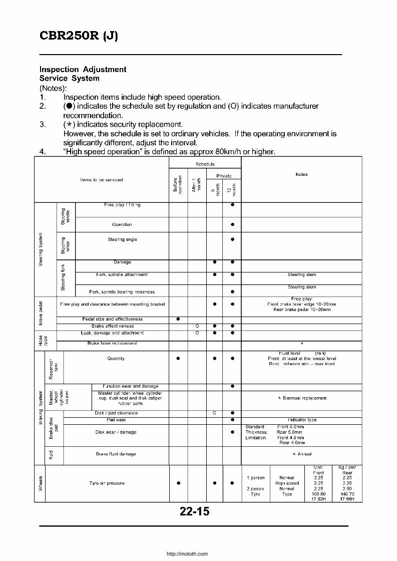
CBR250R (J)
Inspection Adjustment Service System (Notes): 1. Inspection items include high speed operation. 2. (e) indicates the schedule set by regulation and (0) indicates manufacturer
recommendation. 3. (*) indicates security replacement.
However, the schedule is set to ordinary vehicles. If the operating environment is significantly different, adjust the interval.
4 "High speed operation" is defined as approx 80km/h or higher
Schedule
Items to be serviced
• •
Free play and clearance between mounting bracket • Pedal size and effectiveness •
Brake effectiveness 0 • Leak, damage and attachment 0 •
Brake hose replacement
Quantity • •
Function wear and damage
E ! ~ ~ ~ Master cylinder, wheel cylinder ~ ~ i ~ ~ cup, dust seal and disk caliper "J "'" ....,..... rubber parts
Private
" NO ~O
E
•
• •
• • • •
• •
•
•
Notes
Steering stem
Steering stem
Free play: Front brake lever edge 10-20mm
Rear brake pedal 10-20mm
Fluid level (min) Front at least at the lowest level Rear between min - max level
'* Biannual replacement
~~----r--------LnD~iS~k'/~p~ad~C~le~a~ra~n~ce~--------+-----+-----+-ro'-+-__ ~t-------------------------------------1
" • ~ t:l Pad wear tIl '6"'0
• ro ~o.
~ <Il
Disk wear I damage
Brake fluid damage
Tyre air pressure •
22-15
• Standard
• Thickness Limitation
1 person
• • 2 people
Tyre
I ndicator type
Front S.Omm Rear S.Omm Front 4.0mm Rear 4.0mm
"* Annual
Unit: Kg/cm2 Front Rear
Normal 2.25 2.25 High speed 2.25 2.25
Normal 2.25 2.50 Type 100·80 140·70
17·52H 17·66H
http://mototh.com
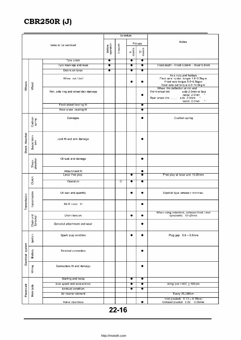
CBR250R (J)
Schedule
Private Notes
Items to be serviced 0 j; .0
£~ 0 0 j; j; •• E
"'~ "'6 NO 0 - _0
E E
Tyre crack • • • Tyre markings and wear • • • Tread depth Front O.Bmm Rear O.Bmm
Debris on tyres • • • Axle nuts and holders
Wheel nut I bolt Front axle holder, torque 1.a-2.Skg-m ~
" • • Front axle torque 5.5-6.5kg-m
" Rear axle nut torque 8.0-10.0kg-m • • ~ ~
Wheel rim deflection a1 rim end
" " Rim, side ring and wheel disk damage Front wheel rim side 2.0mm or less
• radial 2.0mm Rear wheel rim. side .2.0mm
radial 2.0mm Front wheel bearing fit • Rear wheel bearing fit •
0 Damages • Cushion spring 00>
~-§ ~~ O~
~ -e 0
0 0 Joint fit and arm damage • ~ "in
D o E
" • L
~rn
~ ~
u ~
0 W ~
W
1· Oil leak and damage • g.e ~g WD
rn Attachment fit •
Lever free play • • Free play at lever end 10-20mm ~ u '5 Operation 0 • • (j
0 Oil leak and quantity • • Dipstick type between min-max. 0 0 0 "in "in ~
~ E E ~
~ 0 Shift Lever fit • 0 J:: 2
When using sidestand, between front J rear
~~ Chain tension • • sprockets 15-25mm
o u '(0 e
Sprocket attachment and wear • ~~ OW
0 Spark plug condition • • Plug gap 0.8 - 0.9mm 0 ~
"c 5!'
E
fA ,., ~ Terminal connection • ~
2
" 15 u
"' "C
t3 • iii 0> Connectors fit and damage • 0
"C
~
Starting and noise • • c £
Low speed and acceleration • • Idling rpm 1.500 .:!: 100rpm rn ~
0 Exhaust condition • • D
• 0
~ ro Air cleaner element Every 20,000km a. " Inlet (cooled) 0"13 0.19mm
Valve clearance • Exhaust (cooled: 0.20 - 0.26mm
22-16
http://mototh.com
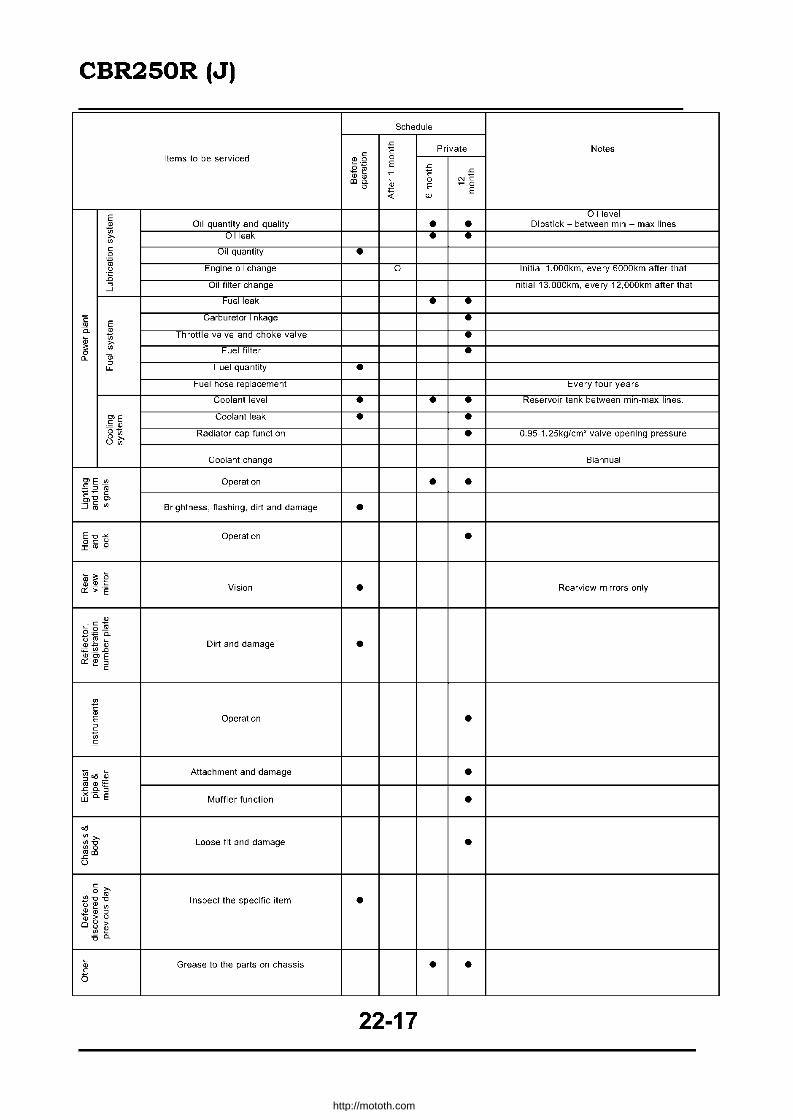
CBR250R (J)
Schedule
~
Private Notes c C Items to be serviced .0 0
£~ E ~
~ C ~
•• NC "'0. 0 0
~o 0
'" E E
'" ~
E Oil level
• Oil quantity and quality • • Dipstick - between min - max lines ;;
Oil leak • • » " c Oil quantity • 0
~ 0 Engine oil change 0 Initial 1.000km, every 6000km after that E a Oil filter change Initial 13.000km, every 12,OOOkm after that -"
Fuel leak • • C E m
Lamuretor InKage • a. • Throttle valve and choke valve • i
;; » " Fuel filter • 0- m a
Fuel quantity • "-
Fuel hose replacement Every four years
Coolant level • • • Reservoir tank between min-max lines.
f~ Coolant leak • •
0- Radiator cap function • 0.95 1.25kg/cm2 valve opening pressure 0" o~
Coolant change Biannual
:?E~ Operation • • :E:; ~ ~ffi(fj Brightness, flashing, dirt and damage • E-o ..::.::: Operation • o c 0 I<tI~
~-~ g Vision • Rearview mirrors only cc> E
• EBi ~~ :0 Dirt and damage • '<=_~ ..Cl
·"'E cr:::~::::l
c
00
C ~
E Operation • E 00 ~
~od~ Attachment and damage • mID'" ~ 0. a t.lj"o.. E Muffler function • 06 ~»
~"8 .l"'"
Loose fit and damage • 0
c » o m
2-0-0 Inspect the specific item • (.) ~ (/l
2~a ·0 -"0 >
00 ~ 'C 0.
0 Grease to the parts on chassis • • ~
(5
22-17
http://mototh.com

CBR250R (J)
Wheel nut I bolt tightness
Inspect the front axle bolt and rear axle nut for tightness. Inspect the bottom case pinch bolt for tightness. Tighten as required. Torque: Front axle Bottom case pinch bolt Rear axle
6.0kg-m 2.2kg-m 9.0kg-m
Air cleaner element change
Remove the fuel tank (22-19). Remove screws and detach air cleaner case cover.
Inspect the element for dirt and damage. Replace if dirt or damage is significant.
• Do not clean filter papers as they contain oil (viscous type).
• If the vehicle is operated under severe conditions, replace earlier than recommended.
Recommended interval: every 20,OOOkm
Reverse the above procedure for attachment.
Headlamp
Rotate the vertical and horizontal adjusting screws to adjust the lamp direction.
22-18
I
't) I ~ , .:~
Bottom Ci'lse Pinch Boll ".:.
I', Vertical Adjusting Screw
http://mototh.com

CBR250R (J)
Side Stand
Inspect the side stand rubber for wear. If the rubber is worn to the limit line, replace it. Check the operation of the side stand. When the stand stops at the first notch and the rubber contacts ground, the stand moves forward and supports the body. When the body is stood up and the stand rubber comes off from the ground, the stand moves to the first notch and it should smoothly be retracted.
If the above operation is not smooth, disassemble and inspect the sidestand. Remove the return spring at the retracted position. Remove the pivot bolt and disassemble the side stand. Inspect the pivot bore, pivot collar and dust seals for wear and damage. After the inspection, apply grease to the pivot and assembly the stand.
• Attach dust seals so as to have springs facing outward.
• Attach the side stand after confirmi ng the dust seal spring is attached.
After the attachment, check its operation.
Fuel System
Fuel tank detachment I attachment
Remove bolts and detach the seat. Detach left and right side covers (22-30).
Turn the fuel cock "OFF".
Remove three bolts.
22-19
Spring
http://mototh.com

CBR250R (J)
Lift the rear of the tank and disconnect the fuel tube. Detach the fuel tank.
Reverse the procedure for attachment.
After the attachment, check for fuel leak.
Fuel Tank Mount Bolts
Air cleaner case attachment I detachment Remove the seat and fuel tank (22-19). Detach the air cleaner element (22-18).
If the air cleaner case is not to be disassembled, the air cleaner does not have to be detached.
22-20
~: •
Fuel Tank Mount Bolts
\
http://mototh.com
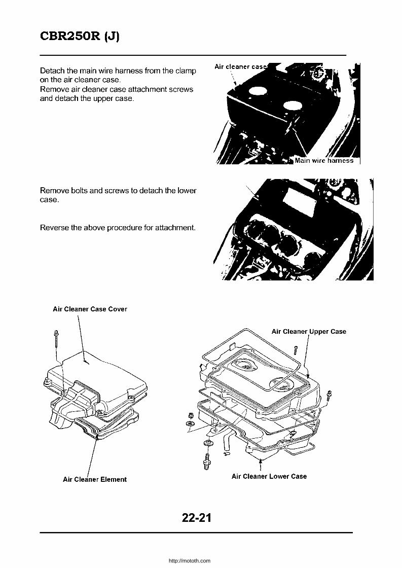
CBR250R (J)
Detach the main wire harness from the clamp on the air cleaner case. Remove air cleaner case attachment screws and detach the upper case.
Remove bolts and screws to detach the lower case.
Reverse the above procedure for attachment.
Air Cleaner Case Cover
Air Cleaner Element
22-21
Air Cleaner Lower Case
http://mototh.com

CBR250R (J)
Carburetlor synchronisation adjustment
I Adjust after warming up the engine.
Place the fuel tank at the rear while the tube is connected. Remove plugs and washers from each cylinder head intake ports. Connect the vacuum gauge adaptor to each plug hole. Connect rubber tube of the vacuum gauge to the adaptor.
Start the engine and set up the idling rpm. Idling rpm: 1500 :!: 100rpm
Measure the vacuum difference between the cylinders. Vacuum difference: :!: 20mmHg
I Measuring tool I Vacuum gauge: 07404-0020000
Adjust in the following manner if the difference is exceeding the limit. 1) Check the position of pilot screws on
the carburettor. 2) Adjust synchronisation by rotating
the adjusting screw.
I Use NO.3 carburettor as a standard.
* #1, 2 carburettor synchronisation> Detach air cleaner case cover. Rotate the adjust screw from front of the carburetor. * #4 carburettor synchronisation>
Rotate the adjust screw from behind the air cleaner case. After the adjustment, check the synchronisation and set to idle. Attach each part by reversing the detachment procedure.
Engine Mount I Dismount <Drive sprocket attachment I detachment> Remove three bolts and detach the drive
22-22
Vacuum Gauge Adaptor
Vacuum Gauge
Drive Sprocket Cover
http://mototh.com

CBR250R (J)
sprocket cover. Loosen the rear axle nut, lock nut and chain adjusting nut and ease the tension of the drive chain.
Remove the bolt and detach the drive sprocket and the cushion rubber.
• Change Pedal Detachment
Remove the bolt and pull out the change pedal arm from the shaft. Remove the bolt and detach the pedal.
Engine Attachment
Reverse the detachment procedure.
• When attaching the change pedal, align punched marks on the change shaft and the change arm.
• After installing the drive sprocket, set the cushion rubber and the set plate.
'-------------' " Torque: Top engine mount bolt 4.5 - 5.5kg-m Rear upper engine mount bolt 4.5 - 5.5kg-m Rear lower engine mount bolt 4.5 - 5.5kg-m Change arm bolt Engine hanger bracket
1.4 - 1.8kg-m 3.5 - 4.5kg-m
Cylinder Head, Valve
Cylinder head cover attachment I detachment Detach the lower cowl (22-31). Detach the radiator (5-3). Disconnect the breather tube from the cylinder head cover. Remove plug caps. Remove bolts to detach cylinder head covers.
22-23
http://mototh.com

CBR250R (J)
Reverse the procedure for the attachment.
Front Wheel Attachment I Detachment
Detachment
Remove the screw and disconnect the speedometer cable.
Remove the axle bolt. Loosen four bottom case pinch bolts.
Pull the axle shaft towards the left and detach.
Disc Plate detachment
Remove socket bolts and detach the disk plate.
Do not disassemble after detaching the disc plate.
Attachment
Widen the brake pads separation with the screwdriver.
Align the speedometer gear box stopper with the back of the left fork bottom case stopper.
Install the axle shaft from left hand side.
22-24
(i
•
~.
j J
, Spl~edIDm'B1er Gearbox
http://mototh.com

CBR250R (J)
Tighten the axle bolt. Torque: 6.0kg-m
Tighten the bottom case pinch bolt. Torque: 2.2kg-m
Connect the speedometer cable.
Rear Wheel, Suspension
Rear cushion
Detachment
Support the frame and lift the rear wheel. Detach the left side cover. Remove the conrad bolt (cushion arm side). Remove the rear cushion lower bolt.
Remove the rear cushion upper bolt and detach the rear cushion downwards.
22-25
C~~) ~ ,\
- -~ Bottom Case pinch Bolt
C~~) \' ,
t)_~ ase pinch Bolt
Rear Cushion Lower Bolt
http://mototh.com
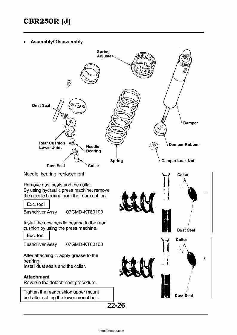
CBR250R (J)
• AssemblylDisassembly
Spring Adjuste
Dust Seal ~ ~
Rear Cushion ~ Lower Joint . '- Needle
~ '."ri", Dust Seal Q'collar
Needle bearing replacement
Remove dust seals and the collar. By using hydraulic press machine, remove the needle bearing from the rear cushion.
I Exc. tool I Bushdriver Assy 07GMD-KT80100
Install the new needle bearing to the rear cushion by using the press machine.
I Exc. tool I Bushdriver Assy 07GMD-KT80100
After attaching it, apply grease to the bearing. Install dust seals and the collar.
Attachment Reverse the detachment procedure.
Tighten the rear cushion upper mount bolt after setting the lower mount bolt.
Spring
22-26
1'1 i j I
1'1 ;
I - I
~I
Collar \ (\
" \ ,
I , , ,
, ,. ,
Dust Seal
Collar \ (\
II. \ I :
~ "
i I
Dust Seal
http://mototh.com

CBR250R (J)
Suspension linkage
Detachment
Loosen the rear cushion upper mount bolt prior to detaching the suspension linkage.
Remove conrod bolts (frame side and the cushion arm side) and detach the cushion conrod.
Rear Cushion Lower Mount Bolt ~ .-
Remove the rear cushion lower bolt and the cushion arm bolt and detach the cushion arm. The arrow symbol should point forward
Cushion Arm Plate
~DustSeal Needle bearing replacement
Remove dust seals and collars. Detach the needle bearings from the conrod by using a hydraulic press machine.
I Exc. tool
Bushdriver Assy 07GMD-KT80100
22-27
-
http://mototh.com
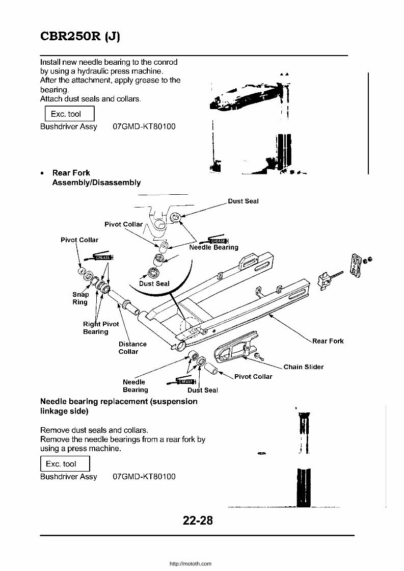
CBR250R (J)
Install new needle bearing to the conrad by using a hydraulic press machine. After the attachment, apply grease to the bearing. Attach dust seals and collars.
I Exc. tool
Bushdriver Assy 07GMD-KT80100
• Rear Fork AssemblylDisassembly
Pivot Collar
Needle bearing replacement (suspension linkage side)
Remove dust seals and collars. Remove the needle bearings fram a rear fork by using a press machine.
I Exc. tool
Bushdriver Assy 07GMD-KT80100
i
1
22-28
Rear Fork
Chain Slider
http://mototh.com
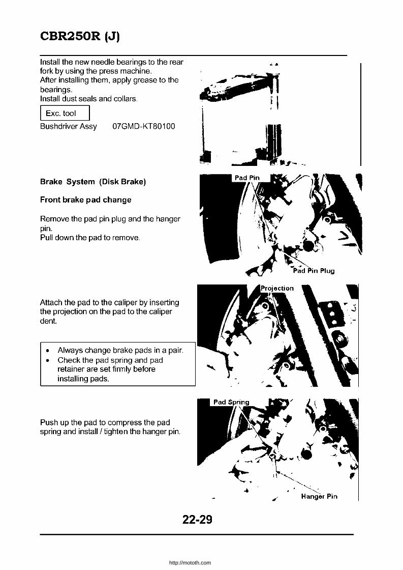
CBR250R (J)
Install the new needle bearings to the rear fork by using the press machine. After installing them, apply grease to the bearings. Install dust seals and collars.
I Exc. tool
Bushdriver Assy 07GMD-KT80100
Brake System (Disk Brake)
Front brake pad change
Remove the pad pin plug and the hanger pin. Pull down the pad to remove.
Attach the pad to the caliper by inserting the projection on the pad to the caliper dent.
• Always change brake pads in a pair. • Check the pad spring and pad
retainer are set firmly before installing pads.
Push up the pad to compress the pad spring and install / tighten the hanger pin.
22-29
http://mototh.com

CBR250R (J)
Fairing
Upper Cowl
Trim Clip
Right J/ ... f-----Lower Cowl
Lower Cowl
Side cover attachment I detachment
Remove the seat and the rear seat. Remove screws underneath the rear cowl.
22-30
Rear Seat
~
http://mototh.com
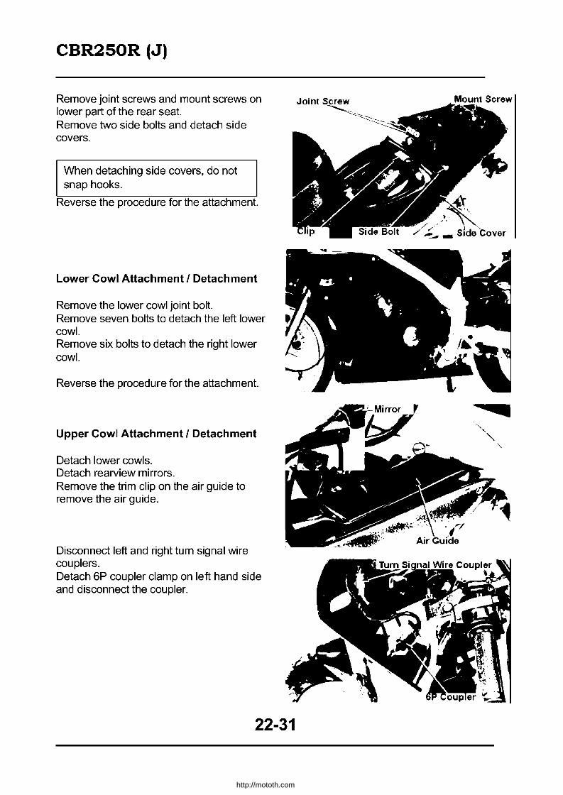
CBR250R (J)
Remove joint screws and mount screws on lower part of the rear seat. Remove two side bolts and detach side covers.
When detaching side covers, do not snap hooks.
Reverse the procedure for the attachment.
Lower Cowl Attachment I Detachment
Remove the lower cowl joint bolt. Remove seven bolts to detach the left lower cowl. Remove six bolts to detach the right lower cowl.
Reverse the procedure for the attachment.
Upper Cowl Attachment I Detachment
Detach lower cowls. Detach rearview mirrors. Remove the trim clip on the air guide to remove the air guide.
Disconnect left and right turn signal wire couplers. Detach 6P coupler clamp on left hand side and disconnect the coupler.
22-31
http://mototh.com

CBR250R (J)
Remove the upper cowl mount screw to detach the upper cowl.
Reverse the procedure for the attachment.
Rear Cowl attachment I detachment
Remove side covers. Disconnect four hooks and detach the rear cowl.
Reverse the procedure for the attachment.
Lamps, Instruments and Switches
Headlamp case attachment/detachment
The headlamp can be detached individually.
Detach the upper cowl. By pushing the catch of the headlamp wire connector, disconnect it. Remove three bolts to detach the head lamp case.
Headlamp light bulb change
Detach the upper cowl (22-31). By pushing the catch of the headlamp wire connector, disconnect it. Remove the socket cover.
Rear Cowl ~
H'~oks
22-32
http://mototh.com
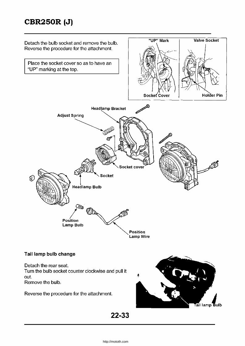
CBR250R (J)
Detach the bulb socket and remove the bulb. Reverse the procedure for the attachment.
Place the socket cover so as to have an "UP" marking at the top.
Headlamp Bracket
~SO'k.t (?j<- Headlamp Bulb
~
/ Position Lamp Bulb
Tail lamp bulb change
Detach the rear seat. Turn the bulb socket counter clockwise and pull it out. Remove the bulb.
Reverse the procedure for the attachment.
22-33
"UP" Mark Valve Socket
http://mototh.com

CBR250R (J)
Instruments attachment I detachment
Disconnect the speedometer cable.
Disconnect the right air guide (22-31). Disconnect instrument wire couplers. Remove instrument mount bolt.
Instrument ASSY can be detached by rotating it clockwise around the speedometer and lifting it up.
Instrument bulb change
Detach the bulb socket and replace the bulb.
22-34
Speedometer Cable
Speedometer
http://mototh.com

CBR250R (J)
Instruments disassembly
Remove screws and detach the instrument lower cover.
Remove connectors, bulb socket, trip meter reset knobs and individual instruments mount screws and disassemble them.
If you are removing screw tightening instrument wires, check the colour of the wires.
Instruments assembly I attachment
Reverse the detachment / disassembly procedure.
• Correctly apply instrument wire harness. • Firmly connect the wires with screws to corresponding terminals. • When installing instruments, firmly attach four grommets to the stay.
Grommet
Stay
22-35
http://mototh.com

CBR250R (J)
Fuel pump system check
Top off the fuel tank (131). Detach the left lower cowl and the left side cover. Disconnect the fuel tube (fuel pump -carburettor) from the carburettor and put the end to the container. Turn the ignition "ON". Disconnect the fuel cut relay wire coupler (Black/Blue - Black) and short circuit for 5 seconds. From the amount of fuel coming out from the tube, calculate the fuel flow per minute.
Standard: 1,800c.c.! min
If there is a significant difference with the standard, inspect the fuel cut-off relay.
Fuel pump inspection
Detach the fuel tank (22-19). Disconnect the fuel pump wire coupler. Disconnect the fuel tube from carburettor and pull the tube and the wire connector to the right side of the frame and re-attach the fuel tank (as shown in the figure). Do not use pliers to disconnect the tube as they may damage the tube. A commercialised rubber tube remover may be an alternative.
Connect the battery to the fuel pump wire coupler and measure the fuel flow. If the flow is far out of the standard, replace the fuel pump. If the flow rate is ok, inspect the fuel cut off relay.
Fuel Tube
Fuel Pum \
• Sparks may come out when connecting the battery. Exercise extreme caution so petrol does not catch fire.
• Check (+) (-) when connecting a battery. Reverse connection may end up with a fuel pump failure.
22-36
http://mototh.com
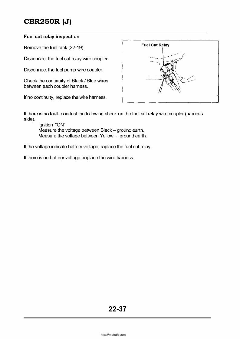
CBR250R (J)
Fuel cut relay inspection
Remove the fuel tank (22-19).
Disconnect the fuel cut relay wire coupler.
Disconnect the fuel pump wire coupler.
Check the continuity of Black / Blue wires between each coupler harness.
If no continuity, replace the wire harness.
Fuel Cut Relay
If there is no fault, conduct the following check on the fuel cut relay wire coupler (harness side).
Ignition "ON" Measure the voltage between Black - ground earth. Measure the voltage between Yellow - ground earth.
If the voltage indicate battery voltage, replace the fuel cut relay.
If there is no battery voltage, replace the wire harness.
22-37
http://mototh.com
CRBR250R (K)
Table of Contents
W·· D· Iring lag ram ............................................................... . 23-2
Circuit Wiring Diagram ..................................................... . 23-3
23-1
http://mototh.com

CRBR250R (K)
• Wiring Diagram
Main Wire
Sub air Cleaner
Carburettor air vent tube
Tank Breather Tu e
Reservoir Tank Hose
Fuel Cut Relay
Battery Earth Cable
Main Wire
23-2
Carburettor Air Vent Tube
Spark Unit
http://mototh.com
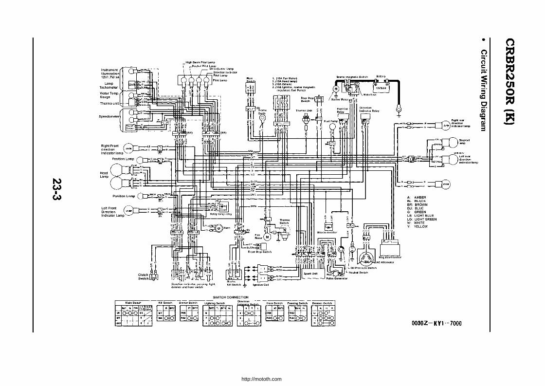
N W • W
Main Switch
"I .... I~~~ "'~I/
.~
Kill Switch
~M"
"' U
SWITCH CONNECTION
Lighllng Switch L._J _~ i_._
Direction
•
1. (10A Fan Mo'or~ 2. (15A Head lampl 3. (10A Others) 4. (10A Ignition, slaner magnetic
regulators fuel Pump)
~"om::,~ ... ,o~~."."m~':": ~ ~ ~
~ ~ I~ .
G~G:::Q3 .--c:>o-•
A" AMBER BL BLACK BR: BROWN BU: BLUE G GREEN LB LIGHT BLUE LG: LIGHT GREEN W WHITE Y: YELLOW
Right rear direction indicator lamp
0030Z-KYI-7000
• (')
c:l !: ;::;:
~ ::::!. ::::I Ie
o iii· Ie .., II)
3
(") ::a tJ:J ::a I.\) en o ::a -~ -
http://mototh.com
CBR250RR (L)
Table of Contents
Specification ................................................................ 24 - 2 Description of the mechanism ................................... 24 - 3 Torque setting ............................................................. 24 - 5 Exclusive I Common tools .......................................... 24 - 5 Wiring ........................................................................... 24 - 6 Wiring diagram ............................................................ 24 - 10 Maintenance data ........................................................ 24 - 11 Troubleshooting .......................................................... 24 - 14 Maintenance ................................................................ 24 - 16 Fuel System ................................................................. 24 - 20 Cooling System ........................................................... 24 - 36 Engine mount I dismount ........................................... 24 - 41 Cylinder head and valve ............................................. 24 - 43 Cylinder, Piston and Crankshaft ................................ 24 - 44 Gear shift linkage ........................................................ 24 - 45 Front wheel, Suspension and Steering ...................... 24 - 46 Rear wheel and Suspension .... ................................... 24 - 48 Brake System .............................................................. 24 - 56 Fairing and Exhaust Pipe ............................................ 24 - 58 Battery and Charging System .................................... 24 - 61 Ignition System ............................................................ 24 - 62 Lamps, Instruments and Switches ... .......................... 24 - 66
24-1
http://mototh.com
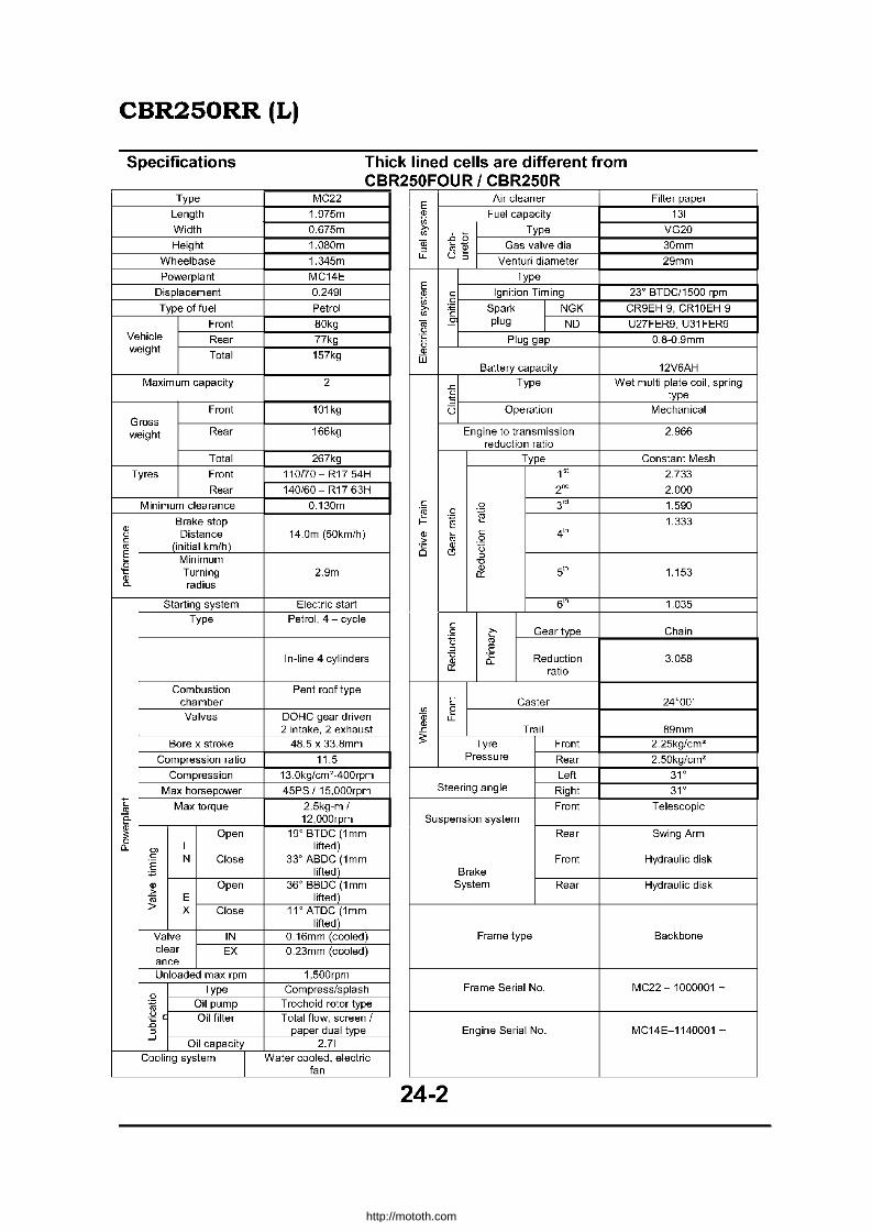
CBR250RR (L)
Specifications
Type
Length
Width
Height
Wheelbase
Powerplant
Displacement
Type of fuel
Front Vehicle Rear weight
Total
Maximum capacity
Front Gross weight Rear
Total
Tyres Front Rear
Minimum clearance
<1l Brake stop
" Distance c (initial km/h) " E Minimum
{! Turning <1l 0. radius
Starting system Type
Combustion chamber
Valves
Bore x stroke
Compression ratio
Compression
Max horsepower 'E Max torque " e-<1l
Open 3 a I a. 0> .~ N Close § <1l Open >
E ro > X Close
Valve IN clear EX ance Unloaded max rpm
a Type
~ Oil pump
~ c Oil filter ~
...J Oil capacity
Cooling system
I
Thick lined cells are different from CBR250FOUR I CBR250R
MC22 I E
Air cleaner Filter paper
1.975m ~ Fuel capacity 131
0.675m
1.080m
1.345m
>- Type VG20 '" ..6 a w ro~ Gas valve dia 30mm ~ u. U ~ Venturi diameter 29mm
MC14E
0.2491
Petrol 80kg
E Type
<1l c Ignition Timing 23' BTOC/1500 rpm 05 a
I >- :E Spark NGK CR9EH-9, CR10EH-9 '" 1i ro plug
I NO U27FER9,U31FER9 " 77kg ." Plug gap 0.8-0.9mm 1:5
157kg <1l OJ
Battery capacity 12V6AH 2
-'= Type Wet multi plate coil, spring
" type -S 101kg U Operation Mechanical
166kg Engine to transmission 2.966 reduction ratio
267kg Type Constant Mesh
110170 - R17 54H 1" 2.733
140/60 - R17 63H 2"' 2.000
0.130m
14.0m (50km/h)
c a 3" 1.590 .~ a ~ f- ~ 1.333
<1l ~ C 4'h
> a
is <1l 13 C9 ~ "0
2.9m &! 5'h 1.153
Electric start 6'" 1.035 Petrol, 4 - cycle
c Gear type Chain 0 i':'
~ " ~ E In-line 4 cylinders "0 it Reduction 3.058 &! ratio
Pent roof type 'E Caster 24'00'
DOHC gear driven 2 intake, 2 exhaust
48.5 x 33.8mm
J!J e <1l u. <1l
Trail 89mm -'= ;;: Tyre Front 2.25kg/cm2
11.5 Pressure Rear 2.50kg/cm'
13.0kg/cm'-400rpm Left 31'
45PS 1 15,000rpm Steering angle Right 31'
2.5kg-m 1 Front Telescopic 12,000rpm Suspension system
19' BTOC (1 mm Rear Swing Arm lifted)
33' ABOC (1mm Front Hydraulic disk lifted) Brake
36' BBOC (1 mm lifted)'
System Rear Hydraulic disk
11' ATOC (1mm lifted)
0.16mm (cooled) Frame type Backbone
0.23mm (cooled)
1,500rpm Compress/splash Frame Serial No. MC22 - 1000001 -
Trochoid rotor type
Total flow, screen I paper dual type Engine Serial No. MC14E-1140001 -
2.71 Water cooled, electric
fan
24-2
http://mototh.com

CBR250RR (L)
Description of the mechanism
VP carburetor
The CBR250RR is equipped with a VP type carburettor, which has a flat type vacuum piston. The bottom area of the piston was reduced from the area of the conventional circular cross-section piston. This reduces the downward force on the piston bottom (which resists the piston to lift), resulting in improved throttle control response.
Moreover, the dead volume in the carburettor main bore (which is resisting the incoming airflow) is reduced and therefore the intake efficiency is improved.
Diaphragm Jet needle holder
type vacuum piston
vacuum piston vacuum piston
24-3
http://mototh.com
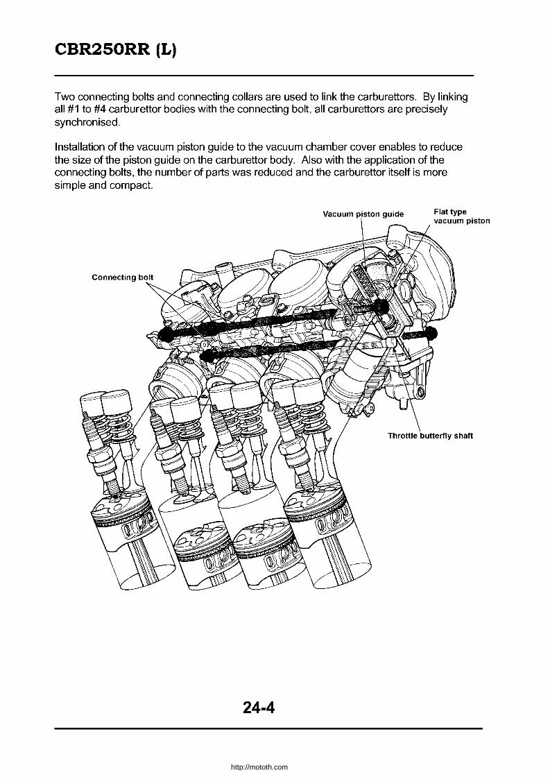
CBR250RR (L)
Two connecting bolts and connecting collars are used to link the carburettors. By linking all #1 to #4 carburettor bodies with the connecting bolt, all carburettors are precisely synchronised.
Installation of the vacuum piston guide to the vacuum chamber cover enables to reduce the size of the piston guide on the carburettor body. Also with the application of the connecting bolts, the number of parts was reduced and the carburettor itself is more simple and compact.
Vacuum piston guide
24-4
Flat type vacuum piston
http://mototh.com

CBR250RR (L)
Torgue Settings
Engine
Qty Screw Torque Item Dia Setting Notes
(mm) (kg-m)
Connecting rod bearing cap nut 8 8 1.6 - 2.0 Apply oil to the thread and the seat (Molybdenum oil not permitted).
Lower case sealing bolt 1 18 4.0 - 5.0 Apply screw locker (right side only)
Screw Torque Item Qty. Dia Setting Notes
(mm) (kg-m) Rear upper engine mount bracket bolt 4 8 3.0 - 4.0 Rear lower engine mount bracket bolt 2 10 4.5 - 5.5 Sub frame upper bolt / lower bolt 4 10 4.5 - 5.5 Side stand bracket bolt 2 10 4.5 - 5.5 Bottom bridge bolt 2 10 3.0 - 4.0 Brake hose mount bolt 5 10 3.0 - 4.0 Rear cushion lower bolt 1 10 4.5 - 5.5 AIIoc bolt Cushion arm bolt 1 10 4.5 - 5.5 AIIoc bolt Rear cushion protection plate bolt 3 5 0.5 - 0.7 Apply screw locker Change arm bolt 1 6 1.4-1.8 Right / left step pivot bolt 2 8 3.5 - 4.5 AIIoc bolt Silencer bolt 3 6 1.6 - 2.0 Torx bolt Ignition switch mount bolt 2 8 2.4 - 3.0 AIIoc bolt Iqnition coil mount screw 4 6 0.7-1.1 AIIoc bolt Notes: replace with new ones when the alloc bolts are removed.
Special tools Tool name Tool No. Qty. Application
Drive chain staking tool 07HMH-MR10101 1 Drive chain replacement Bearing remover attachment 07LMC-KV30200 1 Rear fork left pivot bearing removal
Ball race remover 07946-KM9000 1 1 Ball race replacement (only the
- bearing remover A 07946-KM9040 1 1 bearing remover A is different from 07946-KM90000) .
Valve guide remover (3.5mm) 07HMH-KT70101 1 Valve guide clearing / finishing Pilot screw wrench 07908-4220201 1 Pilot screw adjustment
Common Tools Tool name Tool No. Qty. Application
Pilot (20mm) 07746-0040500 1 Front wheel bearing, rear driven flange bearing installation
Torx bit: TAO 07703-0010100 1 Iqnition switch removal/installation Torx bit: T-30 07703-0010200 1 Muffler removal/installation
Torx bit: T-10H - 1 Ignition switch disassembly/assembly (available in market)
Tool No. Application 07HGJ-0020100 nition inspection
24-5
http://mototh.com
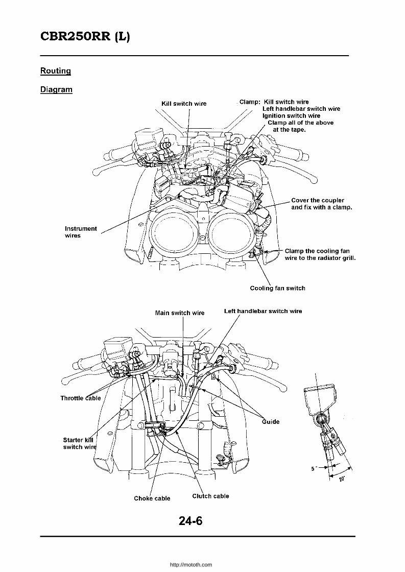
CBR250RR (L)
Routing
Diagram
Instrument wires
Clamp: Kill switch wire Left handlebar switch wire Ignition switch wire
Clamp all of the above at the tape.
Cover the coupler and fix with a clamp.
fff _~~~~r--,r 'AiU~~r Clamp the cooling fan ~ ,'___ __ --'1 wire to the radiator grill.
J---"--'--
Cooling fan switch
Main switch wire Left handlebar switch wire
Choke cable
24-6
http://mototh.com

CBR250RR (L)
Clamp the following at the tape. (Kill switch wire (Left handlebar switch wire (Ignition switch wire
Main wire harness
Throttle cable
Clutch cable
Choke cable
~~~=~-- Fan motor coupler
Throttle cable
24-7
http://mototh.com

CBR250RR (L)
Ground earth cable
switch wire
Alternator wire earth cable
24-8
Side stand switch wire
Throttle cable
http://mototh.com

CBR250RR (L)
Clamp in front of the silicone rectifier
Silicone rectifier
Regulator/Rectifier
Oil pressure switch neutral switch connector
Clamp
24-9
Throttle cable
Rear brake lamp switch coupler
http://mototh.com

~ ~ • ....lo.
o
Temp Gauge
~'IBr.1 Ie, ~,
Thermo unit
1, Highbeampilollamp 2 Neutral pilollamp 3. Oil Pressure lamp 4. Direction inducator pilot lamp 5. Side stand pilot lamp
Main Switch
~ l~ " ~~
LGiR~ _0
A iDA (Fan Molor) B 15A (Head lamp) C iDA (Other) D i0A (Charging. start, ignition)
Thermo Unit • ~I~'!' r! fl
~<l _
~
Rear stop switch
rtf ~BI '0 o~
Starler Relay Switch
Starler Motor
~~~
II Direction Indicator lamp
rs ~~01
(0
r-
0" 11o=n1 CD=G~Frtt II~~ lit"':' s «<O!
Left front d"ectlon A --t>C}-nAB"He:dLampIRe,ay ~ (il -<-<-< c:J Indlcalorlamp 12V15W ~e":;;:l>r ~",.,ol!,! ~ [@ ~ ~ !'!>;" m c. ; 0 ~"~BI ~~ •• 0 r-, ~ I D:!t I
CDBI BI
~ ij Jfu-' "" " "' , , ~"~ r=5~' , !_! I "' ~ ---L':'-SL -
Q Iii 'i,: i ,l:{ITh ,I!' . '", "' ~ ~ : ~ ),J ~BIM' Pulse
Horn Clutch l _________ -' ,,~BUI\' Spark Unit Generator
SWitch Direction Indicator dimmer a er WI ch [ngmlron COIl and Kill SWitch -=-
o.
CH CONNECT_~'O::N~===
mug",,"g,sw,:,,~ °m"·O':O":"':O"'O~'HO':,sw"o" ~""'":::"O"~" • R FIlEt FREE
p ~ I'\ISIt PIS;
" ,
Main Switch '" Kill SWitch Starler Switch
" . FAIl K.
'" ~~ '"V 0> ~
~ -v. Out
Oil Pressure Switch
Right rear direction indictator lamp -12V15W
(") ta ~ ~ C'JI o ~ ~ -t"'I -
http://mototh.com
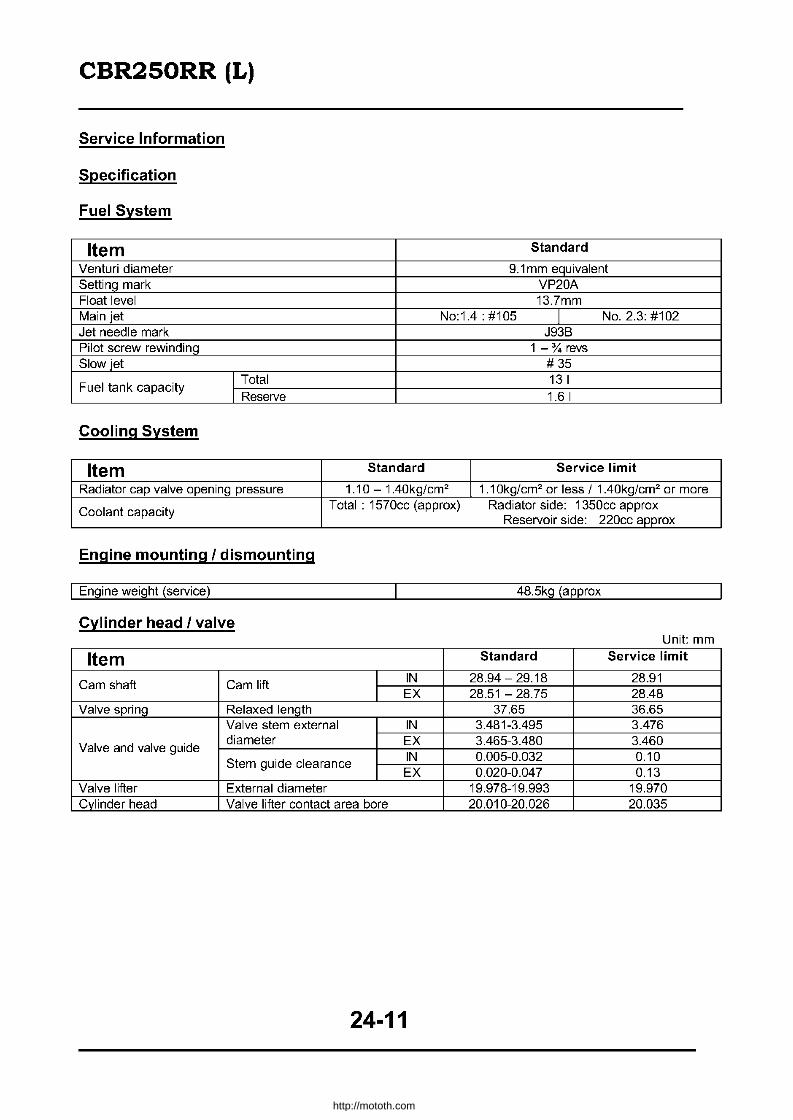
CBR250RR (L)
Service Information
Specification
Fuel System
Item Standard
Venturi diameter 9.1 mm equivalent Setti ng mark VP20A Float level 13.7mm Main jet No:1.4: #105 I No. 2.3: #102 Jet needle mark J93B Pilot screw rewinding 1 - 'Y. revs Slow jet # 35
Fuel tank capacity I Total 13 I I Reserve 1.6 I
Cooling System
Item Standard Service limit
Radiator cap valve opening pressure 1.10 - 1.40kg/cm2 1.1 Okg/cm 2 or less I 1 .40kg/cm2 or more
Coolant capacity Total: 1570cc (approx) Radiator side: 1350cc approx Reservoir side: 220cc approx
Engine mounting I dismounting
I Engine weight (service) 48.5kg (approx
Cylinder head I valve Unit· mm
Item Standard Service limit
Cam shaft Cam lift IN 28.94-29.18 28.91 EX 28.51 - 28.75 28.48
Valve spring Relaxed length 37.65 36.65 Valve stem external IN 3.481-3.495 3.476
Valve and valve guide diameter EX 3.465-3.480 3.460
IN 0.005-0.032 0.10 Stem guide clearance
EX 0.020-0.047 0.13 Valve lifter External diameter 19.978-19.993 19.970 Cvlinder head Valve lifter contact area bore 20.010-20.026 20.035
24-11
http://mototh.com
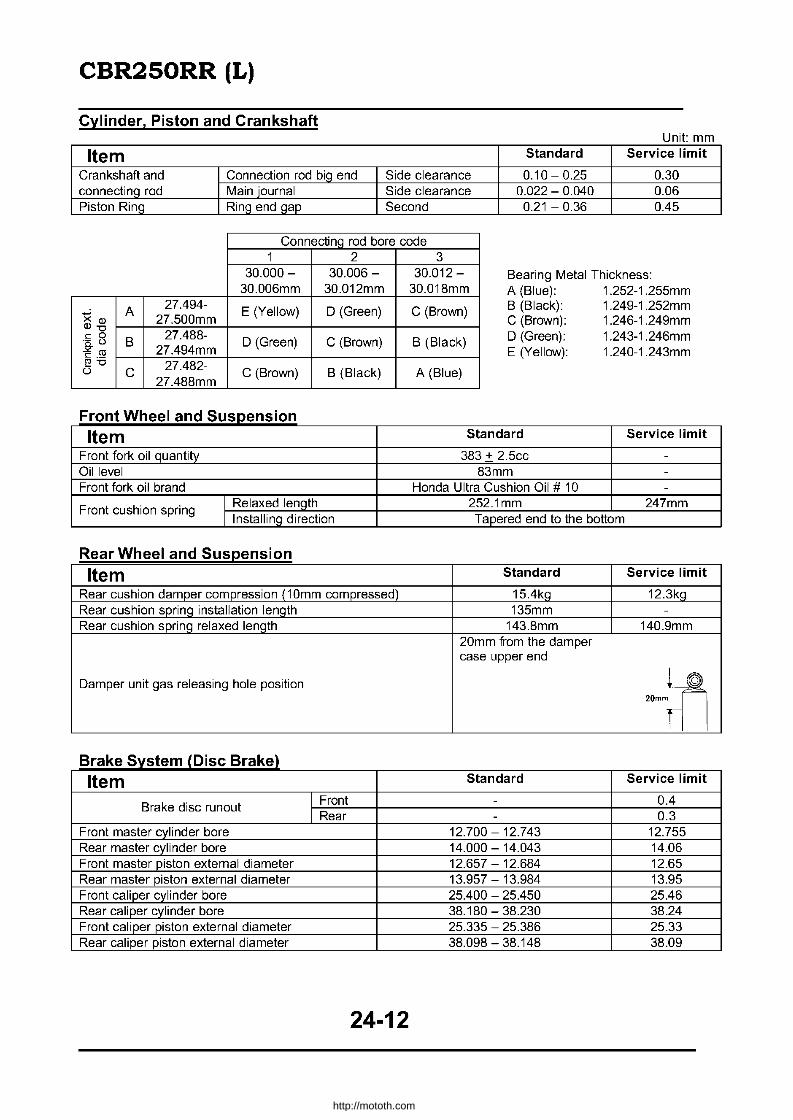
CBR250RR (L)
Cylinder, Piston and Crankshaft Unit· mm
Item Standard Service limit
Crankshaft and Connection rod biQ end Side clearance 0.10 - 0.25 0.30 connecting rod Main journal Side clearance 0.022 - 0.040 0.06 Piston Ring Ring end gap Second 0.21 - 0.36 0.45
ConnectinQ rod bore code 1 2 3
30.000 - 30.006 - 30.012 - Bearing Metal Thickness: 30.006mm 30.012mm 30.018mm A (Blue): 1.252-1.255mm
A 27.494-E (Yellow) D (Green) C (Brown)
xQ) 27.500mm Q)"O
27.488-c 0 B D (Green) C (Brown) B (Black) .- t.l
Z'" 27.494mm c ._ ~"O 27.482-U C C (Brown) B (Black) A (Blue)
27.488mm
B (Black): 1.249-1.252mm C (Brown): 1.246-1.249mm D (Green): 1.243-1.246mm E (Yellow): 1.240-1.243mm
F ron tWh ee an dS uspenslon Item Standard Service limit
Front fork oil quantity 383 + 2.5cc -
Oil level 83mm -Front fork oil brand Honda Ultra Cushion Oil # 10 -
Front cushion spring I Relaxed length 252.1mm 247mm I Installing direction Tapered end to the bottom
Rear Wheel and Suspension
Item Standard Service limit
Rear cushion damper compression (1 Omm compressed) 15.4kg 12.3kg Rear cushion spring installation length 135mm -
Rear cushion sprinQ relaxed lenQth 143.8mm 140.9mm 20mm fi"om the damper case upper end
Damper unit gas releasing hole position rll 20mm
Brake System (Disc Brake) Item Standard Service limit
Brake disc runout I Front - 0.4 I Rear - 0.3
Front master cylinder bore 12.700 - 12.743 12.755 Rear master cylinder bore 14.000 - 14.043 14.06 Front master piston external diameter 12.657 - 12.684 12.65 Rear master piston external diameter 13.957 - 13.984 13.95 Front caliper cylinder bore 25.400 - 25.450 25.46 Rear caliper cylinder bore 38.180 - 38.230 38.24 Front caliper piston external diameter 25.335 - 25.386 25.33 Rear caliper piston external diameter 38.098 - 38.148 38.09
24-12
http://mototh.com
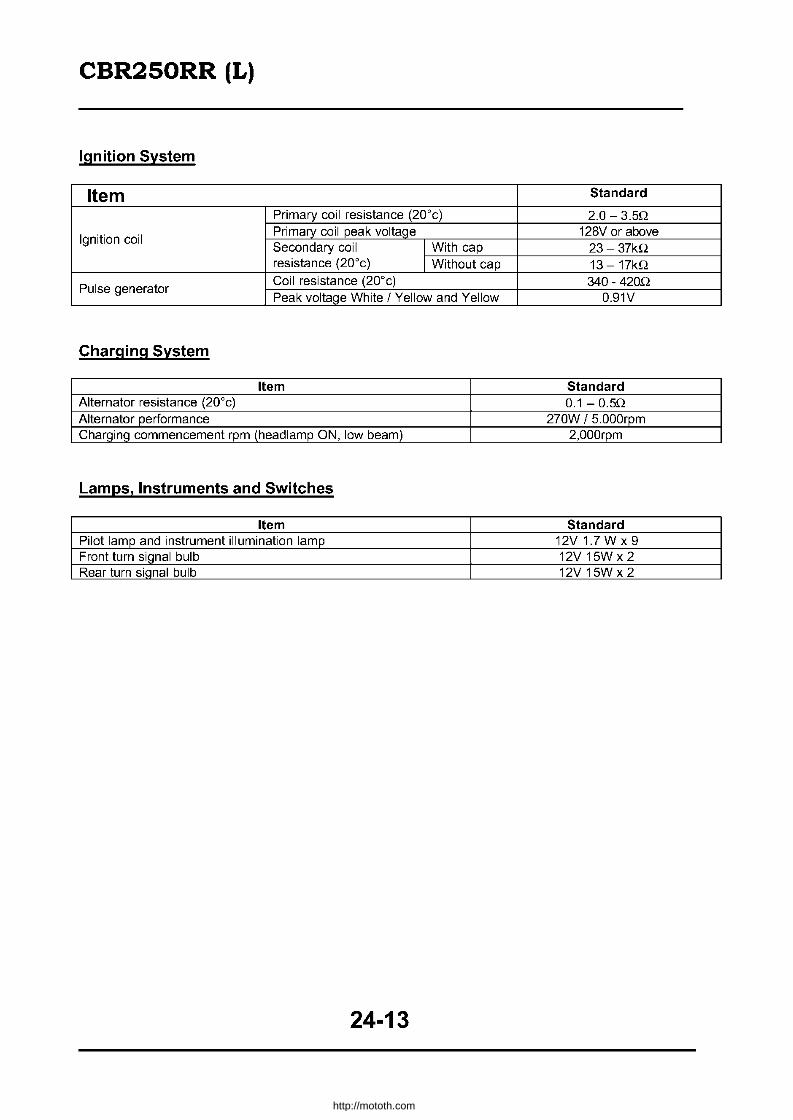
CBR250RR (L)
Ignition System
Item Standard
Primary coil resistance (20"c) 2.0 - 3.50
Ignition coil Primary coil peak voltage 128V or above Secondary coil I With cap 23- 37kO resistance (20"c) I Without cap 13 - 17kO
Pulse generator Coil resistance (20"c) 340 - 4200 Peak voltage White / Yellow and Yellow 0.91V
Charging System
Item Standard Alternator resistance (20"c) 0.1 - 0.50 Alternator performance 270W / 5.000rpm Charging commencement rpm (headlamp ON, low beam) 2,000rpm
Lamps, Instruments and Switches
Item Standard Pilot lamp and instrument illumination lamp 12V 1.7 W x 9 Front turn siQnal bulb 12V 15W x 2 Rear turn signal bulb 12V 15W x 2
24-13
http://mototh.com

CBR250RR (L)
Troubleshooting Faulty charging (flat battery)
Voltage does not rise beyond battery voltage
Off from the standard
Faulty charging (overcharging)
Start the engine and measure the regulated voltage between battery terminals (17-4)
Measure the resistance of the alternator (17-5)
Measure the voltage between Red/White (+) and Green (-) at the regulator/rectifier coupler
Measure the voltage between Red/White (+) and Green (-) at the regulator/rectifier coupler
regulator / rectifier coupler
24-14
Possible cause
Ignition switch fault
Wire harness fault
Battery fault Battery ran out of life
Stator fault Wire harness yellow lead open circuit Coupler connection fault
Wire harness Red / White or Green leads open circuit.
Regulator/Rectifier fault Coupler connection fault
Alternator Assy fault
Wire harness Red/White
Coupler connection fault
Regulator/Rectifier fault
http://mototh.com

CBR250RR (L)
No Spark on the Spark Plugs
• Before starting the troubleshooting, test with a good spark plug to eliminate the possibility of the spark plug fault. Also, make sure the connection of plug caps and high tension leads are fine and there is no secondary current leak from the ignition coil due to moisture.
• If a particular ignition coil does not generate spark, swap the ignition coil and test again. If the symptom is still the same, measure the primary voltage of the ignition coil. If spark is generated normally by swapping the ignition coils, the original coil is faulty.
• The "initial voltage" of the ignition coil primary voltage is the one measured when the ignition switch is turned ON with the kill switch ON (while the engine is not cranked).
Symptom Suspected cause (check from (j)
(j) Faulty kill switch.
No initial voltage when the ignition C1l Open circuit between the switch and the ignition coil.
switch is ON and the kill switch is @ Faulty connection/open circuit on the ignition primary
RUN, but other electrical voltage leads/coupler (measure the resistance of the primary
accessories are operating normally. vOltage lines between spark unit terminals). @ If the initial voltage is normal when the spark unit is removed, the spark unit is faulty. (j) Peak voltage adapter misconnected. C1l Battery almost fiat (large voltage drop when cranking). @ No voltage on Black/White lead on the spark unit, or the
<ll spark unit coupler connection fault. OJ @ Spark unit green lead open circuit or connection fault. !!l Initial voltage is normal. "0 (\) Ignition coil - spark unit (Yellow/Blue or BluelYellow > However, the voltage drops 2 - 4 c- volts when cranking.
leads) open circuit or coupler connection fault.
'" © Ignition coil primary voltage lead short circuit. E '§' (1) Side stand switch or relevant (Green/White, Green lead,
'0 and couplers) parts fault. <) ® Pulse generator fault (measure peak voltage). c ® Spark unit fault (if all of (j) - ® are normal). 0 ~ Initial voltage is normal, but very (j) Peak I.Oltage adapter misconnected. c .2' little or no peak vOltage while C1l Peak vOltage adapter fault.
cranking. @ Spark unit fault (if all of (j) - C1l are normal). (j) Internal resistance of the multi meter is low. C1l Too low cranking speed
Initial vOltage is normal but the • Battery almost fl at
peak voltage is low. @ Effect of the sampling time of the multi meter (measure few times). @ Spark unit fault (if all of (j) - @ are normal and no spark on plugs).
Both initial and peak voltage are (j) Spark unit fault or ignition coil secondary current leak. normal but no spark. C1l Faulty ignition coil.
~ (j) Internal resistance (impedance) of the multi meter is low.
~ C1l Too low cranking speed
<ll Low peak voltage. • Battery almost flat c @ Effect of the sampling time of the multi meter (measure <ll (9 few times). <ll
@ Pulse generator fault (if all of (j) - @ are normal). <f)
:; (j) Faulty peak voltage adapter. 0.. Little or no peak voltage C1l Faulty pulse generator.
24-15
http://mototh.com

CBR250RR (L)
Inspection I Adjustment - Service Schedule Notes: 1. 2. 3.
4
E
"* >.
CfJ Cl C
-a5 2 CfJ
Service items include high speed operation service items.
(e) are mandatory service items, while (0) are the manufacturers recommendation.
(:'-) are regular replacement of security parts.
However, regular intervals are designed to the vehicles operated in standard condition.
The interval may be varied considering the vehicles specific operating environment. H' h d .. h b SDk Ih IIgl spee operation IS suc an operation at or a ave m
Schedule
~oE Private
Service Item ~
Notes '" ::; -.r:;-'" £; £;
iil' :£$e8 C NC r:r: "c 0 a CD 0 ~O
-E~ E E
~~ Free play / loose fit • ·c "'C
ill ffi ii5.r:; Controllability • Cl .;; Q5 ~ Ql Steering angle of the wheel • Ql.r:;
8l?:
Cl Damage • • .§~ Fork. spindle attachment Ql 0
2- • • Steering stem CfJ Fork, spindle bearing • Steering stem
Clearance between the pedal and Free Play: Cii the floor when the pedal is fully • • Front brake (lever) at lever end: 20 - 30mm al depressed. Rear brake (pedal): 10 - 20mm c.
~ Free play and effectiveness • ~ <Il
Braking performance 0 • • ~ o1l .~ Leak. damage and attachment 0 • •
I "- Brake hose replacement ,,< every four years
'0 Reservoir brake fluid level: E c: 2 ill Brake fluid level (quantity) • • • Front Above minimum level
"' Ql Rear: Between min-max level >. r:r: CfJ rn C
Q)"C Function, wear and damage • J< ~ " C .r:;",~
<Il ?: ~ Ql I::: CD.9- Master / Wheel cylinder cup, dust
*~~ seal and disc caliper rubber parts ~ Bi-annual "'>' :2;<..l replacement.
Disc pad clearance • "0
Pad wear 0 • Indicator type '" "-- Standard thickness: Front 4.0mm Vl Rear5.0mm is Disc wear and damage • Service limit Front 3.5mm
Rear4.0mm
Fluid Brake fluid change fr Annual
(unit kg/cm') E Front Rear Ql
Normal 2.25 2.25 00 "' >. Q) 1 person High CfJ Ql Tyre Pressure • • • 2.25 2.25 Cl .r:; speed C 5': .s; 2 people Normal 2.25 2.50 ;§ 110/70 140/60
Tyre specification R1754H R1763H
24-16
http://mototh.com

CBR250RR (L)
C E Q w =C" ",» -"
~ ~ E 8 C .. "
Service Item
Tyre crack and damage
Tyre tread and unusual wear
Debris etc.
Wheel nuts / bolts tightness
Rim, side ring and wheel disc damage
Front wheel bearing fit
Rear wheel bearing fit
Damage
Joint looseness and arm damage
Oil leak and damage
Mount fit
Lever free play
Operation
Oil leak and level
Mechanical operation
Chain slack
Sprocket attachment and wear
Spark plug status
Terminal connection
Connection, damage on cables
Starting and noise
Low speed and acceleration
Exhaust
Air filter change
Valve clearance
Schedule
• • • •
o
o
o
24-17
Private
~
c '" a
E
• •
•
• • •
•
•
• • •
• • • •
•
• • •
•
• • • • •
•
• •
•
•
• • • •
•
Notes
Tread - O.Bmm front, O.Bmm rear
Axle bolts I nuts: Front axle holder torque: 1.8 - 2.5kg-m Front axle bolt torque: 5.5 - 6.Skg-m Rear axle nut torque 8.0 - 10.0kg-m Wheel rim runout at rim edge Front wheel rim Axial 2.0mm
Radial 2.0mm Rear wheel rim:
Cushion spring
Axial 2.0mm Radial 2.0mm
Free play at lever end 10 - 20mm
Dipstick type: Between min - max lines
Side stand extended at the midpoint between two sprockets 15 - 25mm maximum
Plug gap: 0.8 - 0.9mm
Idling rpm 1,500.:!: 100rpm
Every 20,000km
Intake (cooled): 0.13 0.19mm Exhaust (cooled) 0.20 - 0.26mm
http://mototh.com

CBR250RR (L)
" " ";:: 0. o E "' ro UJ-
" " o F 2 en o
o E ~
LL
E o en » " '" o
"0 o u
Service Item
Oil dirt and quantity
Oil leak
Oil level
Engine oil change
Oil cleaner change
Fuel leak
Carburettor link
Throttle valve and choke valve
Fuel filter
Fuel quantity
Fuel hose change
Coolant level
Coolant leak
Radiator cap function
Coolant change
Operation
Flashing, dirt and damage
Operation
Vision
Dirt and damage
Operation
Attachment and damage
Muffler function
Attachment and damage
Being serviced and normal
Greasing to the vehicle
Schedule
Private Notes
'" NO ~O
E
• • Dipstick type: Between min max lines
• • • Initial 1,OOOkm then every 6,OOOkm
Initial 13,OOOkm then every 12,QOOkm
• • • • • • ::.'c every four years
• • • Reservoir between min - max lines
• • • 1.10 -1.40kg/cm2 valve opening pressure
Bi-annually
• • •
•
• Rearview mirrors only
•
•
• •
•
•
• •
24-18
http://mototh.com
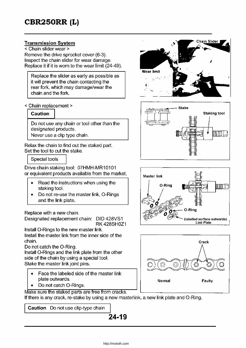
CBR250RR (L)
Transmission System < Chain slider wear> Remove the drive sprocket cover (6-3). Inspect the chain slider for wear damage. Replace it if it is worn to the wear limit (24-49).
Replace the slider as early as possible as it will prevent the chain contacting the rear fork, which may damage/wear the chain and the fork.
< Chain replacement>
I Caution I Do not use any chain or tool other than the designated products. Never use a clip type chain.
Relax the chain to find out the staked part. Set the tool to cut the stake.
I Special tools
Drive chain staking tool: 07HMH-MR10101 or equivalent products available from the market.
• Read the instructions when using the staking tool.
• Do not re-use the master link, O-Rings and the link plate.
Replace with a new chain. Designated replacement chain: DID 428VS1
RK428SHOZ1 Install O-Rings to the new master link. Install the master link from the inner side of the chain. Do not catch the O-Ring. Install O-Rings and the link plate from the other side of the chain by using a special tool. Stake the master link joint pins.
• Face the labeled side of the master link plate outwards.
• Do not catch O-Rings. Make sure the staked parts are free from cracks.
Master link
I 7~ing/~//" ~o 00
ch~lide~
I
Staking tool
O~~ O-Ring 0'
(labelled surface outwards) Link Plate
Crack
Normal Faulty
If there is any crack, re-stake by using a new masterlink, a new link plate and O-Ring.
Caution Do not use clip-type chain I
24-19
http://mototh.com
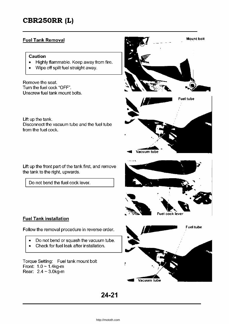
CBR250RR (L)
Fuel Tank Removal
Caution • Highly flammable. Keep away from fire. • Wipe off spilt fuel straight away.
Remove the seat. Turn the fuel cock "OFF". Unscrew fuel tank mount bolts.
Lift up the tank. Disconnect the vacuum tube and the fuel tube from the fuel cock.
Lift up the front part of the tank first, and remove the tank to the right, upwards.
Do not bend the fuel cock lever.
Fuel Tank installation
Follow the removal procedure in reverse order.
Mount bolt
Fuel tube
/ . -.... Vacuum tube
..
~.... .• ~. ··c ~~ ,." ~ .;~. Fuel cock lever
~ • ~ Fuellube
• Do not bend or squash the vacuum tube. ~. • Check for fuel leak after installation.
~--------------------~~ Torque Setting: Fuel tank mount bolt Front: 1.0 - 1.4kg-m Rear: 2.4 - 3.0kg-m
24-21
http://mototh.com

CBR250RR (L)
'H~~ 1.0-1.4kg-m r ~ ~~-~
Air Filter Case Removal
Remove the fuel tank (24-21). Unscrew to remove the air filter case cover.
Remove the air filter element. Unscrew to remove air filter element bases.
24-22
r
Screws -',~
http://mototh.com

CBR250RR (L)
Loosen the air filter upper case mount screws and the bolt.
Lift up the air filter upper case to disconnect the breather tube. Remove the air filter upper case.
Set an air filter lower case to the carburettor to remove/install the case.
Air Filter Case Installation
Follow the removal procedure in reverse order.
• Connect the breather tube to the air filter upper case. • Firmly clamp the sub air filter tube.
Filter Case Cover
24-23
http://mototh.com
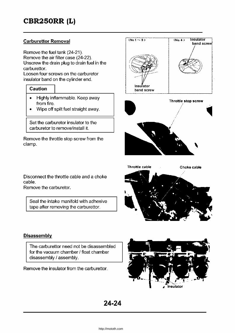
CBR250RR (L)
Carburettor Removal
Remove the fuel tank (24-21). Remove the air filter case (24-22). Unscrew the drain plug to drain fuel in the carbu rettor. Loosen four screws on the carburetor insulator band on the cylinder end.
Caution I • Highly inflammable. Keep away
from fire.
• Wipe off spilt fuel straight away .
Set the carburetor insulator to the carburetor to remove/install it.
Remove the throttle stop screw from the clamp.
Disconnect the throttle cable and a choke cable. Remove the carburetor.
Seal the intake manifold with adhesive tape after removing the carburettor.
Disassembly
The carburettor need not be disassembled for the vacuum chamber / float chamber disassembly / assembly.
Remove the insulator from the carburettor.
24-24
<No 1- 3 >
Insu ator band screw
Throttle cable
<No.4> nsu ator band screw
Throttle stop screw
Choke cable
http://mototh.com

CBR250RR (L)
Wind the throttle stop screw to have all carburettor bi-pass holes visible.
Unscrew bi-starter lever mount screws to remove the washer and the bi-starter lever. Remove the retum spring, spring collar, and the spring.
Lift a catch on the lock plate and unscrew the lock plate screws.
Remove the air filter lower case together with the air funnel.
Remove O-Rings.
24-25
LOCk Plate SCR'W
Catch
Lowercase Air Funnel
http://mototh.com

CBR250RR (L)
Unscrew carburettor nuts and remove nuts on the left hand side. Pull carburettor connecting bolts out to the right. Separate the carburettors.
• Two carburettor thrust springs and three synchronisation adjust springs will come off at the same time. Do not lose them.
• Separate carburettors horizontally to avoid damaging the fuel joints and the air vent joints.
Unscrew vacuum chamber mount screws to remove the vacuum chamber cover.
Remove the spring and the vacuum piston. Check for the smooth operation of the piston in the chamber.
Screw the vacuum chamber cover mount bolt to the jet needle holder to pull the holder out. Remove the spring, jet needle and the washer from the piston.
24-26
No I Carburetor I
i
Vacuum piston
";', ,.,
Jet needle holder
Nc- 4 Carburetor I
~
Spring
Screw
http://mototh.com

CBR250RR (L)
Inspect the jet needle tip for wear, twist and damage. Inspect the diaphragm for damage. Inspect the vacuum piston for wear and damage.
Unscrew float chamber mount screws. Remove the float chamber.
Remove the float pin to remove the float valve. I nspect the float.
Inspect the float valve and the valve seat for blockages and damage. Inspect the valve seat contact area for wear.
24-27
,""
Jet needle
Screw
Float valve Float pin
As iet a
Valve seat Float valve
http://mototh.com

CBR250RR (L)
Remove the main jet, the needle jet holder and the slow jet.
Record the number of winds to fully tighten the pilot screw, then unscrew. Remove the spring, the washer and the O-Ring.
Do not overtighten the pilot screw to avoid damaging the seat.
Clean the main I slow jets.
Loosen the bi-starter valve nut to remove valve spring and valve.
Insert the bi-starter valve to inspect, for unequal wear and damage. Inspect the valve spring for deformation and damage. Inspect the dust seal for damage.
Clean the carburettor air passage with compressed air. Clean the threaded part of the air filter lower case. Clean the filter in a float valve seat with compressed air.
24-28
Dust seal -'/
• • /
Valve Spring
/
~;tI /
Pilot screw
Main jet
Bi starter valve
http://mototh.com

CBR250RR (L)
• Assembly
Collar
\ Connecting collar
\"~
Connecting bolt
Sub air joint
Throttle stop screw
Install the bi-starter valve and the valve spring. Tighten the bi-starter valve nut.
24-29
Main jet
Slow jet Needle jet holder
http://mototh.com

CBR250RR (L)
Install the needle jet holder, the main jet and the slow jet to the carburettor body. Install a washer, an G-Ring and the pilot screw to the carburettor body.
Install the float and the float valve to the carburettor body with the float pin.
Float level check
Hold the float chamber mount surface vertical and tilt the carburettor 30° from that position. Measure the float level at the position where the float valve and the float arm contact.
Standard float level: 13.7mm
Common Tools: Float level gauge: 07401-0010000
Place the gauge perpendicular to the float chamber mount surface at the main jet.
Install a new G-Ring to the float chamber and install the chamber.
24-30
Pilot screw
Main jet \
Needle jet holder
Float valve
Float level gauge
Float chamber O-Ring
http://mototh.com
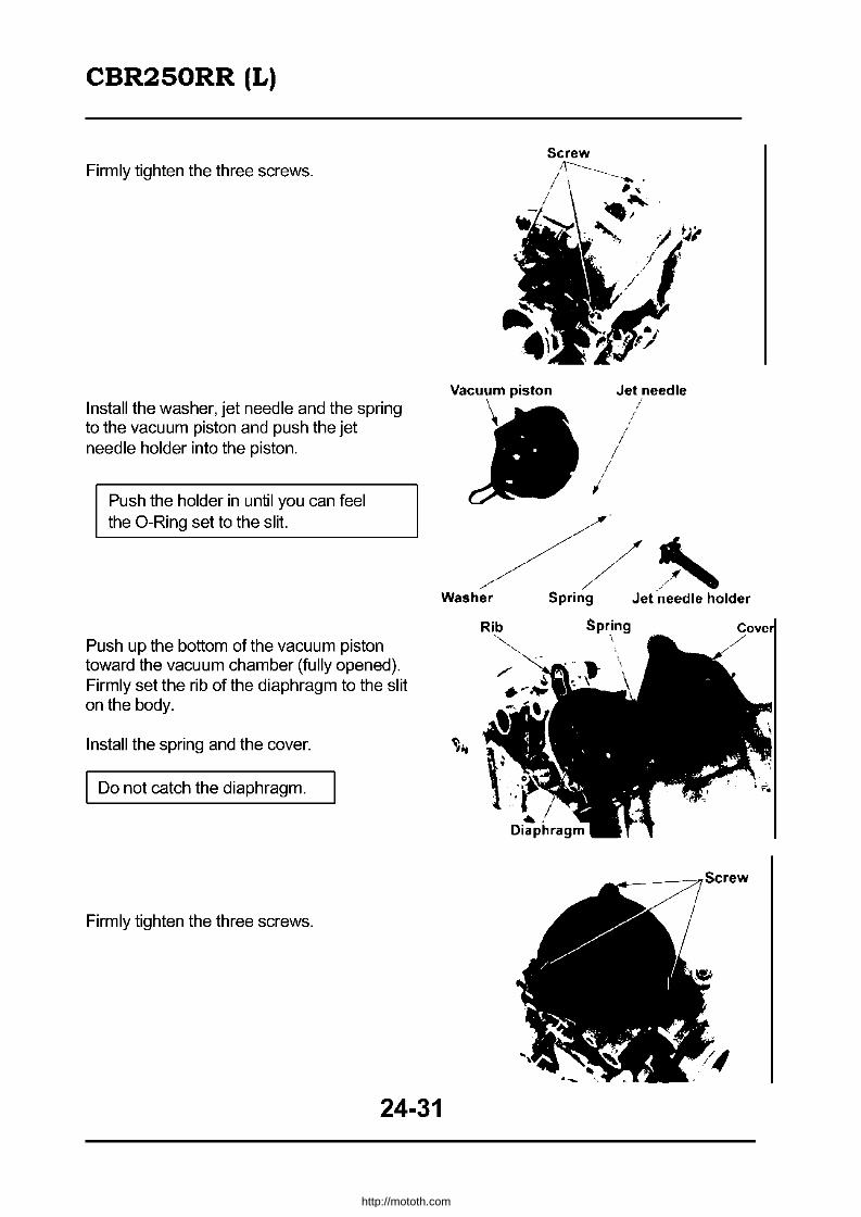
CBR250RR (L)
Firmly tighten the three screws.
Install the washer, jet needle and the spring to the vacuum piston and push the jet needle holder into the piston.
Push the holder in until you can feel the O-Ring set to the slit.
Push up the bottom of the vacuum piston toward the vacuum chamber (fully opened). Firmly set the rib of the diaphragm to the slit on the body.
Install the spring and the cover.
Do not catch the diaphragm.
Firmly tighten the three screws.
24-31
Screw
Vacuum piston
/ I
Jet needle
/ I
//
~~/~~ .~ Washer Spring Jet needle holder
http://mototh.com
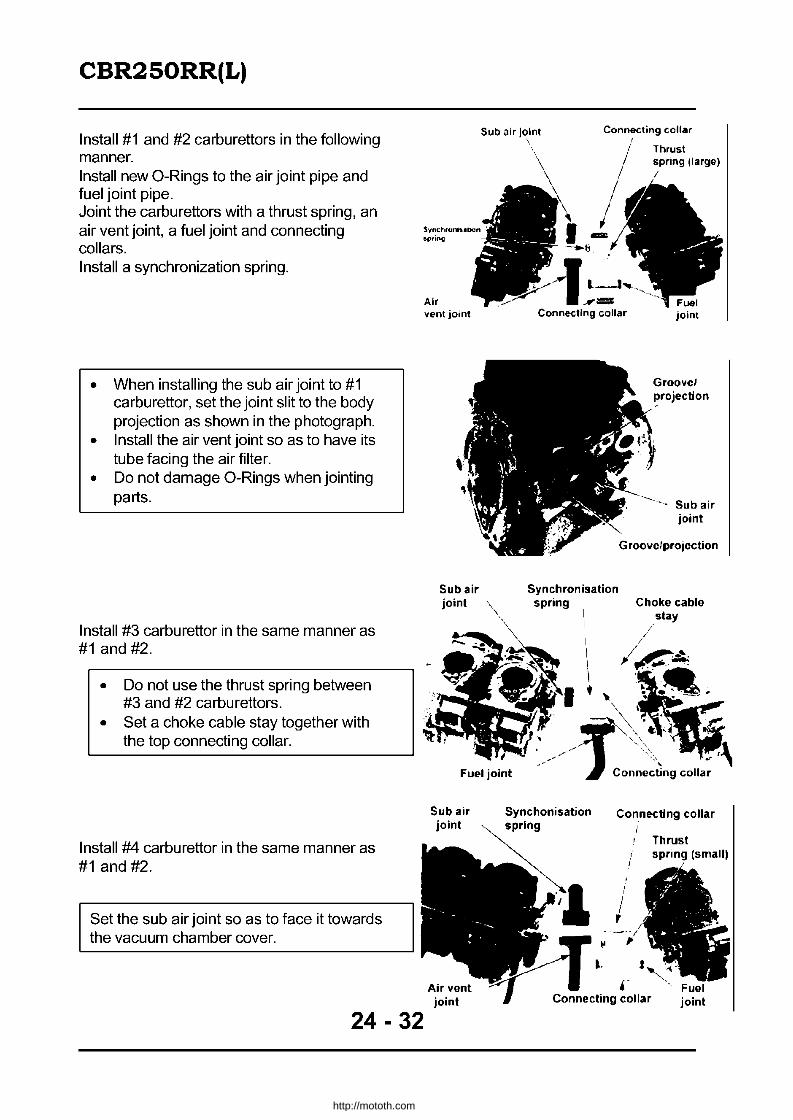
CBR2S0RR(L)
Install #1 and #2 carburettors in the following manner. Install new O-Rings to the air joint pipe and fuel joint pipe. Joint the carburettors with a thrust spring, an air vent joint, a fuel joint and connecting collars. Install a synchronization spring.
• When installing the sub air joint to #1 carburettor, set the joint slit to the body projection as shown in the photograph.
• Install the air vent joint so as to have its tube facing the air filter.
• Do not damage O-Rings when jointing parts.
Install #3 carburettor in the same manner as #1 and #2.
• Do not use the thrust spring between #3 and #2 carburettors.
• Set a choke cable stay together with the top connecting collar.
Install #4 carburettor in the same manner as #1 and #2.
Set the sub air joint so as to face it towards the vacuum chamber cover.
24 - 32
Sub air j~lnt Connecting collar ,.
Air vent jOint
Sub air joint
Fuel joint
Sub air joint
joint
Synchronisation
joint
Groovel projection
Sub air joint
spring C hoke cable
Connecting collar
/ , , ,
, Connecting collar joint
http://mototh.com
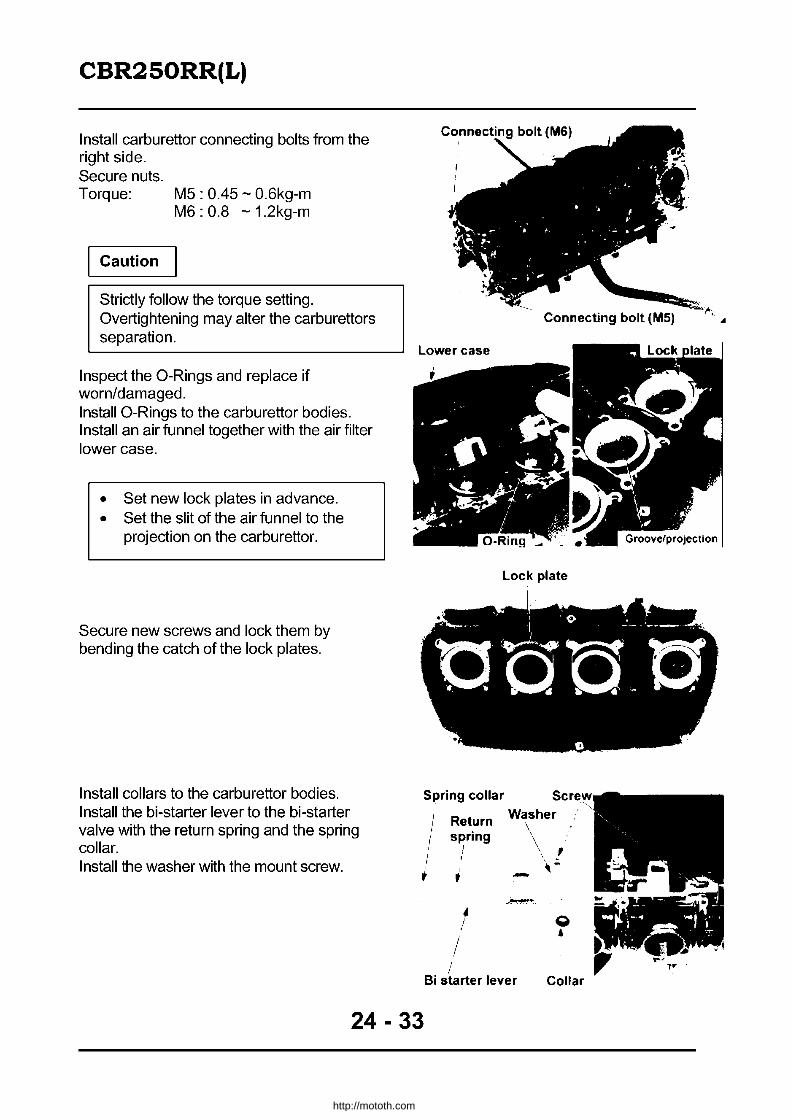
CBR2S0RR(L)
Install carburettor connecting bolts from the right side. Secure nuts. Torque: M5 : 0.45 - 0.6kg-m
M6 : 0.8 - 1.2kg-m
Caution
Strictly follow the torque setting. Overtightening may alter the carburettors separation.
Inspect the a-Rings and replace if worn/damaged. Install a-Rings to the carburettor bodies. Install an air funnel together with the air filter lowercase.
• Set new lock plates in advance. • Set the slit of the air funnel to the
projection on the carburettor.
Secure new screws and lock them by bending the catch of the lock plates.
Install collars to the carburettor bodies. Install the bi-starter lever to the bi-starter valve with the retum spring and the spring collar. Install the washer with the mount screw.
Connecting bolt (MS)
Lowercase
Lock plate
, . '0 _' __ ; __ _ . I . .
0-00.'0 Spring collar
" Return , , , spring , ,
,
t t
i .'
~ !
Washer
o • Bi starter lever Collar
24 - 33
http://mototh.com

CBR2S0RR(L)
Move the bi-starter lever to check the valve operation. Check the throttle operation with the following procedure. • Rotate the throttle drum to open the throttle
a small amount. Check the smooth retuming of the throttle.
• Open/close the throttle for its smooth operation.
Wind synchronization adjust screws to align bypass holes of all carburettors with the throttle valve position.
Use #3 carburettor as a reference.
Install insulators to the carburettors.
Set the insulator strap screws correctly as shown in the photograph.
24 - 34
Bi starter lever
Insulator
http://mototh.com

CBR2S0RR(L)
CarbureUor Installation
Connect the choke cable and throttle cables.
Install carburettors to cylinder heads and secure the insulator straps with screws. Install the air filter case (24-23). Install the fuel tank (24-21). After installation, adjust the following items: • Pilot screw adjustment (24-35) • Throttle grip free play (2-16) • Carburettor synchronization (24-36) • Idling speed (2-10)
Pilot screw adjustment
Remove lower cowls. By using the following tool, wind the pilot screw to the end and wind back as recorded when disassembled.
Special tool: Pilot screw wrench: 07908-4220201
If the pilot screw or the body was replaced, wind back to the standard setting.
Standard setting: 1 - % winds.
Do not overtighten the pilot screw or it may damage the seat surface.
CarbureUor synchronization
Adjust the synchronization after warming up the engine.
Apply vacuum to the auto cock (4-19). Remove the fuel tank (24-22).
Throttle cable
<No. I - 3 >
strap screw
<No.1-3 >
Choke cable
<No.4>
<No.4)
Insulator
Pilot screw
Remove rubber caps from #2 and #3 cylinder head intake parts and directly connects the rubber tubes of a vacuum gauge.
24 - 35
http://mototh.com

CBR2S0RR(L)
Disconnect the vacuum tube from #1 cylinder head intake port and directly connect the rubber tube of a vacuum gauge. Remove the plug and the washer from #4 cylinder head intake port and connect a genuine joint plug (part #16214-MBO-OOO). Joint Plug: Genuine Honda 16214-MBO-OOO Connect the rubber tube of the vacuum tube to the adapter.
Start the engine and set it to the standard idling rpm.
Idling rpm: 1500.:!: 100rpm
Measure the difference in vacuum between each cylinder.
Standard vacuum difference: 40mmHg
Measuring Tool: Vacuum gauge: 07404-0020000
<No.1 ) Rubber tube
plug Plug, washer
~cuum gauge
If the vacuum difference is above the standard, adjust in the following manner:
1) Confirm all pilot screws are rewound to the standard or recorded winds.
2) Wing adjust screws to adjust the synchronization.
Use #3 carburettor as a standard.
Re-check the synchronization and adjust the idling (24-35). Install all parts by following the removal procedure in reverse order.
Cooling System
Thermostat removal
Remove lower cowls (24-59). Drain radiator coolant by unscrewing the drain bolt. Unscrew two bolts to remove the right air guide.
24 - 36
Adjust screw
Air guide
http://mototh.com

CBR2S0RR(L)
Remove the radiator cap to drain coolant (5-3).
Unscrew two wire hamess clamp mount bolts.
Unscrew two mount bolts to remove the thermostat upper case.
Remove the thermostat and the O-Ring,
24 - 37
Radiator cap
,
"
Clamp mount bolt J. -.
O-Ring
http://mototh.com
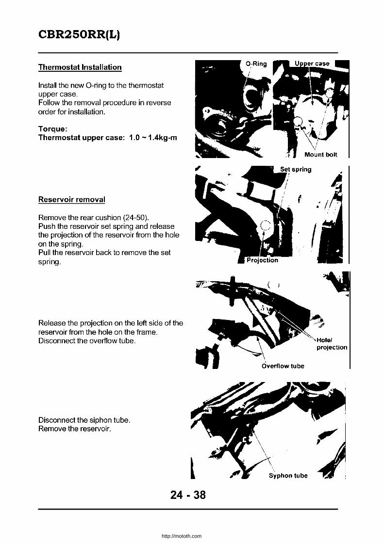
CBR2S0RR(L)
Thermostat Installation
Install the new O-ring to the thermostat upper case. Follow the removal procedure in reverse order for installation.
Torque: Thermostat upper case: 1.0 - 1.4kg-m
Reservoir removal
Remove the rear cushion (24-50). Push the reservoir set spring and release the projection of the reservoir from the hole on the spring. Pull the reservoir back to remove the set spring.
Release the projection on the left side of the reservoir from the hole on the frame. Disconnect the overflow tube.
Disconnect the siphon tube. Remove the reservoir.
24 - 38
(
I
...
Overflow tube
Syphon tube
http://mototh.com

CBR2S0RR(L)
Reservoir Installation
Follow the removal procedure in reverse order for installation.
• Set the hole on the reservoir set spring to the projection on the frame. • Refer to (24-8) for routing tubes.
.-
Projectionl hole Set spring )
24 - 39
http://mototh.com

CBR2S0RR(L)
Engine M " ountmg I D" Ismounting
\
\ \
~ I.O-I.4kg-m
24 - 40
http://mototh.com
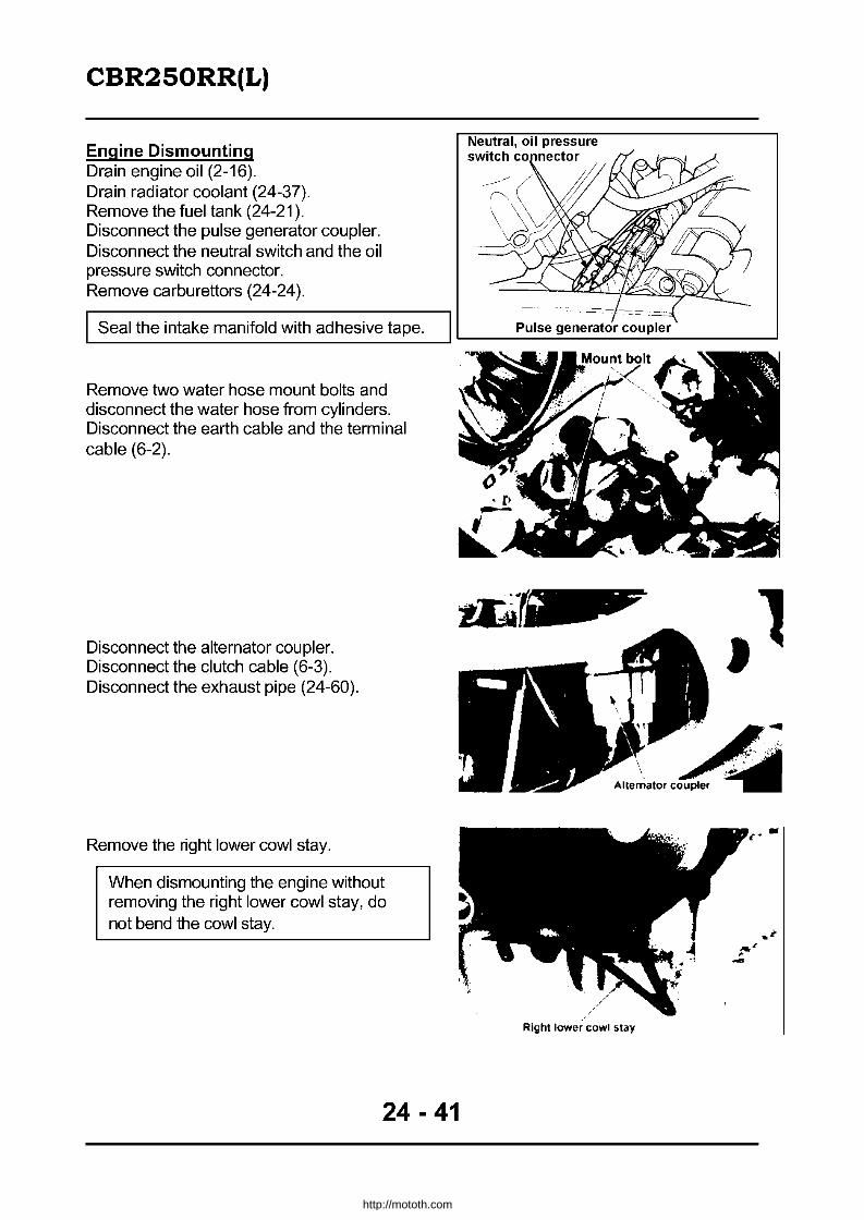
CBR2S0RR(L)
Engine Dismounting Drain engine oil (2-16). Drain radiator coolant (24-37). Remove the fuel tank (24-21). Disconnect the pulse generator coupler. Disconnect the neutral switch and the oil pressure switch connector. Remove carburettors (24-24).
Seal the intake manifold with adhesive tape.
Remove two water hose mount bolts and disconnect the water hose from cylinders. Disconnect the earth cable and the terminal cable (6-2).
Disconnect the alternator coupler. Disconnect the clutch cable (6-3). Disconnect the exhaust pipe (24-60).
Remove the right lower cowl stay.
When dismounting the engine without removing the right lower cowl stay, do not bend the cowl stay.
24 - 41
Neutral, oil pressure switch co nector
:~;~) f} ~
~~ifi!
Right lower cowl stay
-
http://mototh.com

CBR2S0RR(L)
Unscrew the bolt to pull the gearshift pedal arm out from the gear shift spindle. Remove the drive sprocket cover (6-3). Loosen the drive chain and unscrew the bolt to remove the drive sprocket and the washer. Disconnect the radiator hose and the bypass tube (6-3).
Remove the radiator set pin. Swing the radiator forward and fix it to the frame. Remove four plug caps.
Unscrew the front engine mount bolt from the right side. Remove the front engine mount bolt spacer and the nut from the left side.
I Jack up the engine in advance.
Unscrew the rear upper engine mount bolt and the rear lower engine mount bolt to dismount the engine from the frame.
Engine Mounting Follow the dismounting procedure in reverse order.
• Install the rear upper engine mount bolt from the right side.
• Install the rear lower engine mount bolt from the left side.
Torque: Front engine mount bolt 4.5 - 5.5kg-m Rear upper engine mount bolt
4.5 - 5.5kg-m Rear lower engine mount bolt
4.5 - 5.5kg-m Gear shift arm bolt Drive sprocket bolt Lower cowl stay bolt
1.4 - 1.8kg-m 5.0 - 6.0kg-m 0.8 - 1.2kg-m
24 - 42
http://mototh.com

CBR2S0RR(L)
Install the speedometer gearbox retainer by setting it to the drive sprocket bolt.
Install the new O-Ring to the hose joint and connect the water hose to cylinders. Screw the mount bolt for the oil pass pipe stay.
Cylinder Head & Valve
Cylinder head cover removal! installation
Remove both right and left lower cowls (24-59). Remove both right and left lower guides (24-36). Remove a radiator set pin and swing the rad iator to the front. Unscrew two mount bolts to remove the fan shroud and the fan motor in whole Assy. Remove plug caps.
Remove the fuel tank (24-21). Remove the air filter case cover (24-22). Disconnect the ignition coil mount bolt to remove the ignition coil and the heat guard plate in whole Assy to the bottom.
24 - 43
Earth lead
Fan motor, fan shroud
\'( ~
Ignition coil coupler
http://mototh.com

CBR2S0RR(L)
Unscrew bolts to remove the cylinder head cover. Follow the removal procedure in reverse order.
• Note there are "UP" marks on each washer.
• Tighten the top fan shroud mount bolt together with the earth lead.
• Screw the bolts at "T" marks (two) on the head cover first, then the rest.
• When dismounting cylinder head I cylinder block, install the oil orifice so as to have smaller hole at the bottom.
Torque: Cylinder head mount bolt: 0.8 - 1.2kg-m
Cylinder, Piston and Crankshaft Bearing inspection and selection • Crank pin bearing
Avoid the oil hole and place a plasticine gauge. Install connecting rods and bearing caps to each crankpin. Apply oil to threads and seats and screw nuts (9-6). Torque: 1.6 - 2.0kg-m
Do not rotate the crankshaft or the connecting rod while measuring.
Remove the bearing cap and select the plasticine size.
Oil clearance service limit 0.05mm or above --t replace.
Replace the bearing if the oil clearance is above the service limit (9-7).
"1
Cylinder head cover bolt
Bore code
Find out the colour code of the bearing from the code numbers on the crankpin and the connectinq rod.
A(Blue) Thick Connecting rod bore code B (Black) t Bearing metal thickness C (Brown) 30.000 - 30.006 30.006 - 30.012 30.012 - 30.018 D (Green) E (Yellow) Thin 1 2 3
27.500 27.494 A E (Yellow) D (Green) C (Brown) Crankpin diameter code 27.494 - 27.488 B D (Green) C (Brown) B (Black)
27.488 27.482 C C {Brown B Black A{Blue
24 - 44
http://mototh.com
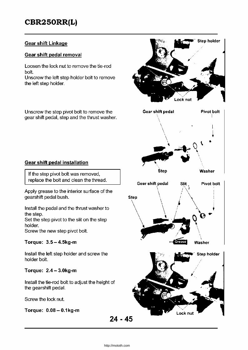
CBR2S0RR(L)
Gear shift Linkage
Gear shift pedal removal
Loosen the lock nut to remove the tie-rod bolt. Unscrew the left step holder bolt to remove the left step holder.
Unscrew the step pivot bolt to remove the gear shift pedal, step and the thrust washer.
Gear shift pedal installation
If the step pivot bolt was removed, replace the bolt and clean the thread.
Apply grease to the interior surface of the gearshift pedal bush.
Install the pedal and the thrust washer to the step. Set the step pivot to the slit on the step holder. Screw the new step pivot bolt.
Torque: 3.5 - 4.5kg-m
Install the left step holder and screw the holder bolt.
Torque: 2.4- 3.0kg-m
Install the tie-rod bolt to adjust the height of the gearshift pedal.
Screw the lock nut.
Torque: 0.08- 0.1kg-m
Gear shift pedal \
Step
Step holder
Pivot bolt I
•
I I •
Washer
Gear shift pedal Slit Pivot bolt \ I\"! \ / \
Step , I \
\ '\ i \ · ~~~\~.
• __ I,
..... Mli Washer
24 - 45
http://mototh.com
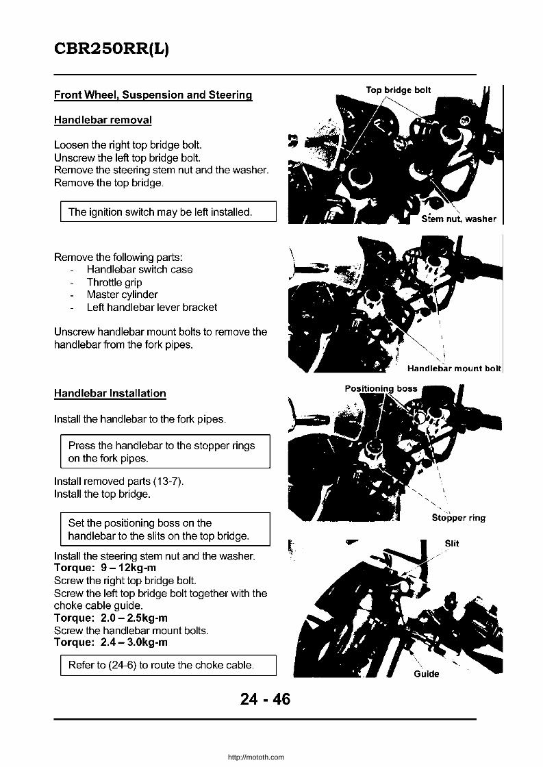
CBR2S0RR(L)
Front Wheel, Suspension and Steering
Handlebar removal
Loosen the right top bridge bolt. Unscrew the left top bridge bolt. Remove the steering stem nut and the washer. Remove the top bridge.
The ignition switch may be left installed.
Remove the following parts: Handlebar switch case Throttle grip Master cylinder Left handlebar lever bracket
Unscrew handlebar mount bolts to remove the handlebar from the fork pipes.
Handlebar Installation
Install the handlebar to the fork pipes.
Press the handlebar to the stopper rings on the fork pipes.
Install removed parts (13-7). Install the top bridge.
Set the positioning boss on the handlebar to the slits on the top bridge.
Install the steering stem nut and the washer. Torque: 9 -12kg-m Screw the right top bridge bolt. Screw the left top bridge bolt together with the choke cable guide. Torque: 2.0 - 2.5kg-m Screw the handlebar mount bolts. Torque: 2.4- 3.0kg-m
Refer to (24-6) to route the choke cable.
\.
24 - 46
"
" Handlebar mount
St~pper ring
http://mototh.com
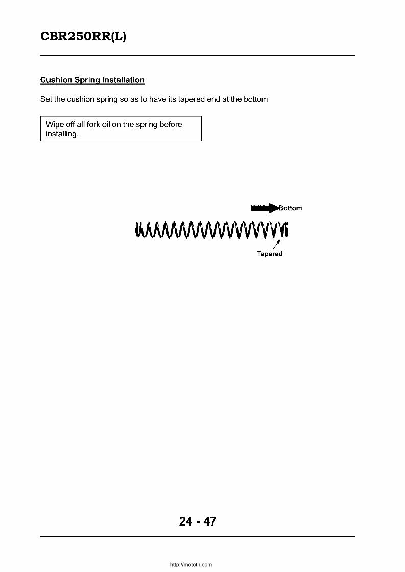
CBR2S0RR(L)
Cushion Spring Installation
Set the cushion spring so as to have its tapered end at the bottom
Wipe off all fork oil on the spring before installing.
_.'~Bottom
~A~VVVVV~ I
Tapered
24 - 47
http://mototh.com

CBR2S0RR(L)
d Suspension Rear Wheel an
4.5-5.5kg-m
/ 1.0-2.0kg-m
24 - 48
http://mototh.com
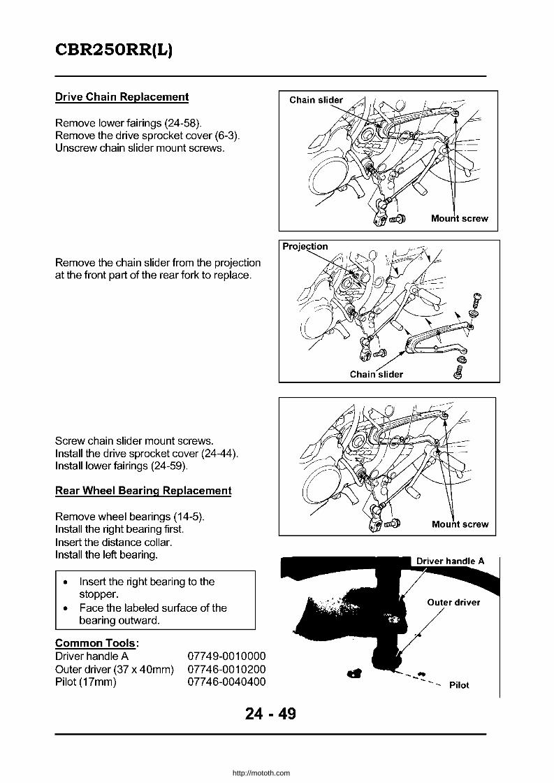
CBR2S0RR(L)
Drive Chain Replacement
Remove lower fairings (24-58). Remove the drive sprocket cover (6-3). Unscrew chain slider mount screws.
Remove the chain slider from the projection at the front part of the rear fork to replace.
Screw chain slider mount screws. Install the drive sprocket cover (24-44). Install lower fairings (24-59).
Rear Wheel Bearing Replacement
Remove wheel bearings (14-5). Install the right bearing first. Insert the distance collar. Install the left bearing.
• Insert the right bearing to the stopper.
• Face the labeled surface of the bearing outward.
Common Tools: Driver handle A Outer driver (37 x 40mm) Pilot (17mm)
07749-0010000 07746-0010200 07746-0040400
24 - 49
Mount screw
Mount screw
- Pilot
http://mototh.com
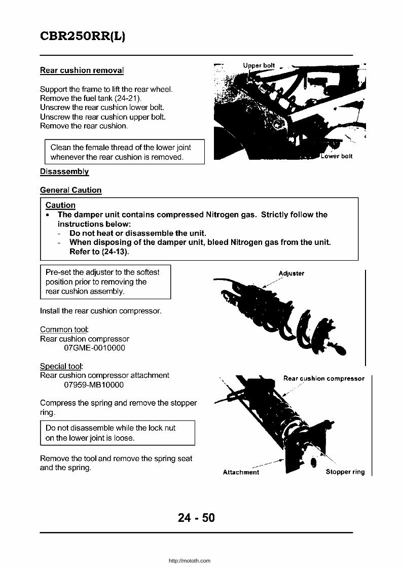
CBR2S0RR(L)
Rear cushion removal
Support the frame to lift the rear wheel. Remove the fuel tank (24-21). Unscrew the rear cushion lower bolt. Unscrew the rear cushion upper bolt. Remove the rear cushion.
Clean the female thread of the lower joint whenever the rear cushion is removed.
Disassembly
General Caution
Caution • The damper unit contains compressed Nitrogen gas. Strictly follow the
instructions below: Do not heat or disassemble the unit. When disposing of the damper unit, bleed Nitrogen gas from the unit. Refer to (24-13).
Pre-set the adjuster to the softest position prior to removing the rear cushion assembly.
Install the rear cushion compressor.
Common tool: Rear cushion compressor
07GME-0010000
Special tool: Rear cushion compressor attachment
07959-MB 10000
Compress the spring and remove the stopper ring.
Do not disassemble while the lock nut on the lower joint is loose.
Remove the tool and remove the spring seat and the spring.
24 - 50
Adjuster
Rear cushion compressor
- -------- ----~ Attachment
http://mototh.com
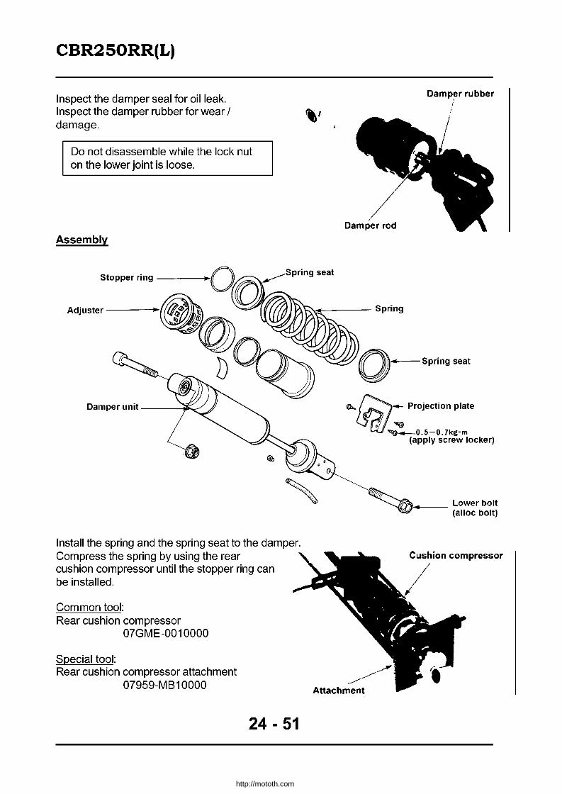
CBR2S0RR(L)
Inspect the damper seal for oil leak. Inspect the damper rubber for wear / damage.
Do not disassemble while the lock nut on the lower joint is loose.
Assembly
Stopper ring ---_
Adjuster -----f
Damper unit --_~~
Install the spring and the spring seat to the damper. Compress the spring by using the rear cushion compressor until the stopper ring can be installed.
Common tool: Rear cushion compressor
07GME-0010000
Special tool: Rear cushion compressor attachment
07959-M B 10000
24 - 51
Damp~r rubber
\:!-____ Spring
,--Spring seat
Q,., ~_ Projection plate
fSr!I..~ ~_O.5-0.7kg-m
(apply screw locker)
~-, ...... __ Lower bolt ~ (alloc bolt)
http://mototh.com

CBR2S0RR(L)
Install the stopper ring. Remove the rear cushion compressor from the rear cushion.
Rear cushion installation
Install the rear cushion. Install an upper bolt and a nut.
Torque: 4.5- 5.5kg-m
Install the new rear cushion lower bolt.
Torque: 4.5- 5.5kg-m
• Refer to (24-8) to route the rear drain tube.
• Replace the rear cushion lower bolt with a new one when removed.
Install the fuel tank (24-21).
Suspension Linkage removal
Support the frame to lift the rear wheel. Remove the left step holder (24-45). Unscrew the connecting rod bolt (frame side). Unscrew the rear cushion lower bolt and the cushion arm bolt. Remove the suspension linkage in assy.
Disassembly
Unscrew the connecting rod bolt (cushion arm side) to separate the arm and the rod.
24 - 52
)
Connecting bolt (cushion arm end)
http://mototh.com

CBR2S0RR(L)
Needle bearing replacement
Remove the dust seal and the collar from the cushion connecting rod. Replace the needle bearing by using a press machine.
Special tool: Bush driver Assy 07GMD-KT80100
• Press the labeled side of the needle bearing in.
• Press in the needle bearing for 7.5mm from the connecting rod end.
Cushion ~onnecting
\ \
'. ,
" ,
L
I
T r:- ~m r'\
, Remove the dust seal and the collar from the cushion arm.
Special tool: Bush driver Assy
07GMD-KT80100
• Press the labeled side of the needle bearing in.
• Press in the needle bearing for 5.5mm from the cushion arm end.
Cushion connecting \
\
5.5mm
\. '. .,
24 - 53
Needle bearing
I .... -, • Cushion arm
j
n \
Needle bearing
http://mototh.com

CBR2S0RR(L)
Assembly
Screw the cushion arm connecting rod bolt and assemble the arm and the connecting rod.
Torque: 4.5 - 5.5kg-m
Suspension Linkage Installation
Set the linkage to its mounting position. Cushion arm connecting bolt
Set the cushion arm mark (KA8t UP) upwards when installing.
Install the new rear cushion lower bolt and the cushion arm bolt (24-52).
Torque: 4.5- 5.5kg-m
Install the connecting rod bolt and the nut (frame side).
Torque: 4.5- 5.5kg-m
Install the left step holder (24-45).
Rear fork removal
Support the frame to lift the rear wheel. Remove the rear wheel (21-24). Remove the lower fairings (24-58). Remove the drive sprocket (24-42). Remove the rear cushion (24-50). Remove the suspension linkage (24-52). Remove the rear hose clamp from the rear fork. Unscrew the rear fork pivot bolt/nut to remove the rear fork (14-18).
Pivot bearing replacement
Remove the right pivot collar and the dust seal (14-19). Remove the left pivot collar and the dust seal (14-19).
-
Remove the distance collar from the rear fork pivot (14-19). Remove the circlip.
24 - 54
"
)
http://mototh.com
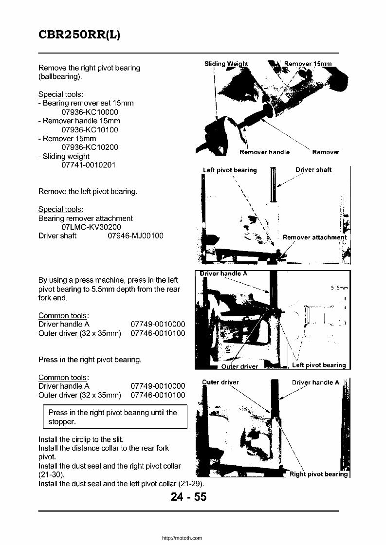
CBR2S0RR(L)
Remove the right pivot bearing (ballbearing).
Special tools: - Bearing remover set 15mm
07936-KC 1 0000 - Remover handle 15mm
07936-KC 1 01 00 - Remover 15mm
07936-KC 1 0200 - Sliding weight
07741-0010201
Remove the left pivot bearing.
Special tools: Bearing remover attachment
07LMC-KV30200 Driver shaft 07946-MJ00100
By using a press machine, press in the left pivot bearing to 5.5mm depth from the rear fork end.
Common tools: Driver handle A Outer driver (32 x 35mm)
07749-0010000 07746-0010100
Press in the right pivot bearing.
Common tools: Driver handle A Outer driver (32 x 35mm)
07749-0010000 07746-0010100
Press in the right pivot bearing until the stopper.
Install the circiip to the slit. Install the distance collar to the rear fork pivot. Install the dust seal and the right pivot collar (21-30).
Sliding W"iaht
I
\
Left pivot bearing \
Install the dust seal and the left pivot collar (21-29).
24 - 55
~ Remover 1 ...... -; \.
. ,
, ~) ,'''-
r
handle A
http://mototh.com

CBR2S0RR(L)
Rear fork installation
Install rear fork. Clamp the rear brake hose to the rear fork. Screw the pivot bolt, the lock nut and the pivot nut (14-22). Install the rear cushion (24-52). Install suspension linkage (24-54). Install the rear wheel (21-24). Install the drive sprocket (24-43). Install the drive sprocket cover (6-3). Install the lower fairings (24-58).
Braking System
Brake Pedal removal
Unscrew rear master cylinder mount bolts to remove the right step guard. Unscrew the right step holder bolt.
Remove the cotter pin and the joint pin to detach the master cylinder from the brake pedal. Remove the brake switch spring to remove the brake switch. Remove the return spring.
Unscrew the stop pivot bolt to remove the brake pedal, the step and the wave washer.
-
." Brake hose clamp
~ Step~d
~
Pivot bolt ,
\ ".
\ '.
, q..,
/~ -wit' . / ,I'
/ /
/ /
Washer
Brake pedal //
24 - 56
http://mototh.com

CBR2S0RR(L)
Installation
Replace the step pivot bolt whenever it is removed and clean the female thread.
Apply grease to the interior surface of the brake pedal bush. Install the brake pedal and the wave washer to the step. Set the slit on the step pivot to the slit on the step holder and screw the new step pivot bolt.
Torque: 3.5 - 4.5kg-m
Install the brake pedal and the master cylinder push rod with the joint pin. Then install new cotter pin. Install the brake switch and the brake switch spring. Set the return spring.
Install the rear master cylinder and the right step guard and temporarily screw the rear master cylinder mount bolts. Install the right step holder and screw the holder bolts.
Torque: 2.4- 3.0kg-m
Screw the rear master cylinder mount bolts.
Torque: 1.0 -1.4kg-m
Pivot bolt
Cj ,
// .,-'*/ /
was~: .... M"
Step guard ",
r '~
'"
24 - 57
Brake pedal
http://mototh.com

CBR2S0RR(L)
Fairing & Exhaust Pipe
Refer to (22-30) for removal/installation.
24 - 58
http://mototh.com

CBR2S0RR(L)
Refer to (22-30) for removal/installation.
2.4-3.0kg-m
1.0-1.4kg-m
1. 1.4kg-m
24 - 59
http://mototh.com
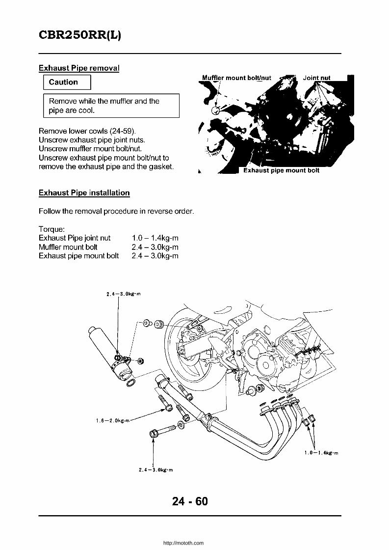
CBR2S0RR(L)
Exhaust Pipe removal
Caution
Remove while the muffler and the pipe are cool.
Remove lower cowls (24-59). Unscrew exhaust pipe joint nuts. Unscrew muffler mount bolUnut. Unscrew exhaust pipe mount bolUnut to remove the exhaust pipe and the gasket.
Exhaust Pipe installation
Follow the removal procedure in reverse order.
Torque: Exhaust Pipe joint nut Muffler mount bolt Exhaust pipe mount bolt
1.0 - 1.4kg-m 2.4 - 3.0kg-m 2.4 - 3.0kg-m
2.4-3.0kg-m
2.4-3.0kg-m
24 - 60
1.0-1.4kg-m
http://mototh.com

CBR2S0RR(L)
Muffler removal
Caution
Remove while the muffler and the pipe are cool.
Unscrew muffler joint bolts.
Common tools: Torx bit (T30) 07703-0010200
~uff19r ":I0unt bolt
Unscrew the muffler mount bolUnut to remove the muffler and gasket.
Muffler installation
Install the new gasket. Follow the removal procedure in reverse order.
Torque: Muffler joint bolt: 1.6 - 2.0kg-m
2.4 - 3.0kg-m Muffler mount bolt
Battery & Charging System
Reaulator I rectifier inspection
• Do not touch the probes while measuring.
• Use one of the following multi meters. Other products may indicate different resistance values. - KOWA 07411-0020000 digital multi
meter - SANWA 07308-0020001 analogue
multi meter - KOWATH -SH
• Set the range as follows: - SANWA k n range - KOWA Rx100n range
(CDI n, Rx1 00 for digital multi meter)
• Multi meters may have false indication when their batteries are low. Check the battery first if the measured value is faulty.
• Multiply by 100 to the indicated value to obtain measured value in KOWA products.
24 - 61
..
Regulator I \Rectifier
~ \
~~~:~I~ ~ ~
Unit: k!l
~ e CD ® ® @ ® -
CD -.............. 00 00 00 00
® 0.5-10 -.............. 00 = 00
® 0.5-10 00 -.............. 00 00
@ 0.5-10 00 00 ~ 00
® 0.7-15 0.5-10 0.5-10 0.5-10 ~
http://mototh.com

CBR2S0RR(L)
Ignition System
Side stand indicator
Side stand switch
Fuse lOA
Clutch switch
Ignition M - f
I
Speed sensor I
I I
I I
I larliti()n switch
.-I----<r-------or----8I1Br·---o----....c>-------;\. switch am use
30A
Speed
Neutral lamp
YIBI
Diode .r:st:rter
switch
Starter magnetic switcp;h;.,.. ...........
Clutch sw·tch
to Tacho meter
Spark unit
24 - 62
~R~ ~ BuN Battery
--1---.--.,,(
i.~0) Pulse generator
A: Amber BI: Black Br: Brown Bu: Blue G: Green LG: Light Green W: White Y: Yellow R: Red
http://mototh.com

CBR2S0RR(L)
General Information • Follow the troubleshooting chart (24-15) for the ignition system check. • The ignition timing cannot be adjusted as the electrical advancing system is internally
mounted in the unit. • The ignition system unit is fragile. Handle with care. Whenever connecting /
disconnecting the connectors or couplers, turn the ignition switch OFF beforehand. • The majority of causes of the ignition trouble are connection problems. Inspect all
connection. • Use reasonably well charged battery. Low charged battery might not produce sufficient
cranking and spark voltage. • Use proper spark plugs. Improper spark plugs may cause engine trouble/damage. • This section describes peak voltage inspection. Although the coil resistance inspection
is also mentioned, it may not give correct idea. • Refer to (20-9) for the neutral switch inspection and the locations of the switches /
couplers. • Refer to (20-6) for the ignition / kill switch inspection. • This model is equipped with an ignition cut off style side stand. The system allows the
ignition to activate when the gear is in neutral or the side stand is extended, or both.
Ignition system inspection
• If there is no spark, check all wiring connections and then measure the peak voltage. • Use genuine multi meter or a model which has an impedance of 1 OMQ / DCV or above.
Connect the peak voltage adapter to the multi meter.
Measuring tools: Peak voltage adapter 07HGJ-0020100 Genuine KOWA multi meter 07411-0020000 Or multi meter of 1 OMQ/DCV or above impedance.
Ignition Coil primary voltage
• Check all wiring connections before measuring
Digital multimeter
• Measure the peak voltage while having cylinder compression and plugs/caps properly installed. If the plug caps were removed, the peak voltage may be over read.
If the engine ignites with normal spark, the cranking speed becomes unstable. In the same manner as a normal spark test, leave the spark plug in the cylinder head and set new (good) spark plugs to each plug caps and earth to the engine.
24 - 63
http://mototh.com

CBR2S0RR(L)
Remove the fuel tank (24-21). Leave the leads connected to the ignition coil and connect the peak voltage adapter between the primary voltage terminal and the body earth. Connection: #1 and #4 ignition coils
Yellow/Blue (+) - body earth (-) #2 and #3 ignition coils
BluelYeliow (+) - body earth (-) Turn the ignition switch ON and the kill switch RUN. Monitor the initial voltage at this moment. It should be close to the battery voltage. If there is no voltage, the ignition power circuit is faulty. Refer to the troubleshooting to inspect the circuit before measuring the peak voltage. Turn the ignition switch ON and the kill switch RUN. Crank the engine with the starter motor and measure each peak voltage. Peak Voltage: 128 volts or above ,...------------""'""".,,---------,
CAUTION: Do not touch the probe while measuring.
The measured peak voltages can be different between each ignition coil, as long as the values are at or above the standard.
If the measured peak voltages are out of the range, connect the adapter to the ignition coil 3P-coupler terminal. Re-measure the peak voltage and compare the result with the original value.
CAUTION: Do not touch the probe while measuring. I
The measured peak voltages can be different between each ignition coil, as long as the values are at or above the standard.
Pulse Generator peak voltage
• Check the wiring connection. • Measure the peak voltage with cylinder
compression and plugs/caps properly installed. If the plug caps were removed, the peak voltage may be over read.
Remove the seat. Disconnect a coupler on the spark unit. Connect the peak voltage adapter probe to the following terminals on the harness end: Connection: White I Yellow (-) - Yellow (+) Turn the ignition on, the kill switch RUN. Crank the engine and measure the peak voltage. Peak Voltage: 0.91 volts or more
24 - 64
http://mototh.com

CBR2S0RR(L)
CAUTION: Do not touch the probe while measuring.
If the peak voltages at the spark unit coupler are faulty, disconnect the pulse generator 2P {White} coupler and re-measure the peak voltage between the above terminals. Peak voltage: 0.91 volts or above • If the values at the unit end are faulty and
the ones at the pulse generator coupler are fine, check coupler connections and wire harness.
• If both values are faulty, follow the troubleshooting chart to check each item and judge the pulse generator is faulty.
Side Stand Switch
Operation
Move the side stand to check its operation. Set the transmission neutral and start the engine with the side stand retracted. Hold the clutch lever and select any gear position. The engine should stop by extending the side stand. If the engine does not stop, inspect the side stand switc,h_{.>..,.2_4_-6,;".5'-!.,}_. _____ -=_::-:---:-:-_---,
Inspect the side stand switch attachment.
Torque: Side stand pivot bolt Side stand pivot nut Side stand switch mount bolt
Inspection
Turn the ignition "OFF".
0.5 - 1.0kg-m 3.5 - 4.5kg-m 0.8 - 1.2kg-m
Remove the spark unit from the rear fender and disconnect its coupler. Inspect continuity between the GreenIWhite and Green terminals on the harness end coupler. The continuity should only exist when the side stand is retracted. If the result is fault, inspect the wire harness and the side stand switch unit.
24 - 65
mount bolt
•
_ Green/While
http://mototh.com

CBR2S0RR(L)
Side stand switch unit inspection
Disconnect the side stand switch 3P coupler and inspect its continuity by following the table below. Continuity should exist between 0 -e.
Lead colour Green Green Yellow IWhite IBlack
Side stand extended 0 ...n
Side stand retracted 0
Side stand switch removal
Turn the ignition switch "OFF". Disconnect the side stand switch 3P coupler. Unscrew the side stand switch mount bolt to remove the switch.
Side stand switch installation
Set the projection on the switch to the hole on the side stand to install the switch. Screw the switch mount bolt. Connect the 3P coupler.
Lamps. Instruments and switches
Headlamp relay
Unable to turn the headlamp "off'
Inspect the lighting switch and the dimmer switch (24-67). If the lighting switch is fine, inspect the headlamp relay (refer to the next page). If the relay is fine, inspect the wire harness for short circuit.
24 - 66
l'~ SIde stand switch coupler
-----Hole
http://mototh.com

CBR2S0RR(L)
Headlamp and Switches
Inspect the headlamp bulb and the sub fuse (headlamp 15A). Disconnect the headlamp relay coupler. Conduct the following inspection:
Check the wiring connection Inspection continuity between the green terminal on the coupler and the body earth. If there is no continuity, repair or replace the wire harness. If there is continuity, turn the ignition ON and measure the voltage between black/red terminal and the body earth. It should have battery voltage. If there is no voltage, the black/red lead between the headlamp relay and the fuse box has open circuit. If the battery voltage exists, inspect the headlamp relay. If the relay unit is fine, the leads between the headlamp relay and the headlamp coupler, or, between the head lamp relay and the lighting switch, have open circuit. Replace the wire harness.
Headlamp Relay Inspection
Remove the relay unit. Connect the battery between the BluelYeliow and Green terminals (equivalent). Continuity should exist between Black/Red and Blue terminals (equivalent).
Sub Fuses replacement
Unscrew two left air guide mount bolts. Unscrew the lower cowl mount bolt. Remove the trim clip.
Remove the left air guide cover to replace sub fuses.
24 - 67
http://mototh.com

CBR2S0RR(L)
Instruments removal! installation
Unscrew two instruments mount bolts.
The upper fairing may be left attached to remove/install instruments.
Disconnect the speedometer cable (22-34). Lift up the instruments Assy to disconnect the wire coupler. Remove the instruments Assy.
Instruments disassembly
Remove the trip meter reset knob. Unscrew to remove the upper cover. Disconnect all connectors, bulb sockets and unscrew individual instruments mount screws to disassemble the instruments.
Record the colour of leads if the screw is holding the lead before unscrewing.
Speedometer cable V
24 - 68
Bolt
http://mototh.com
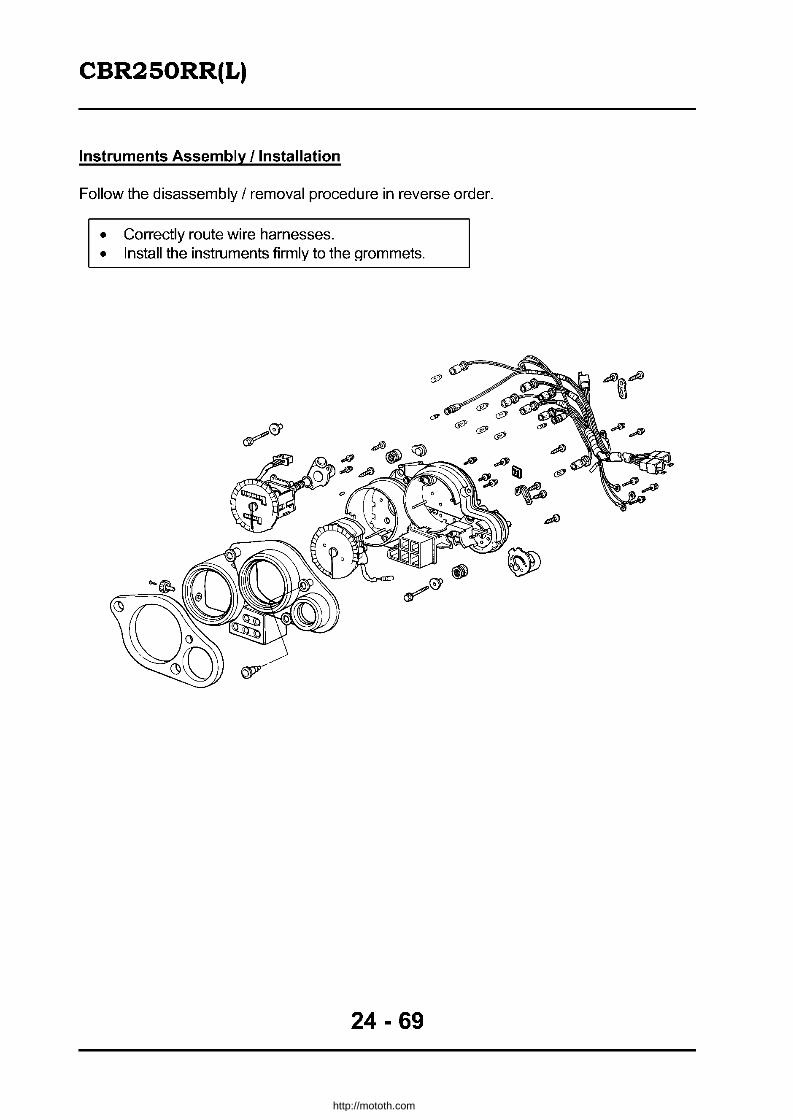
CBR2S0RR(L)
Instruments Assembly I Installation
Follow the disassembly / removal procedure in reverse order.
• Correctly route wire harnesses. • Install the instruments firmly to the Qrommets.
24 - 69
http://mototh.com
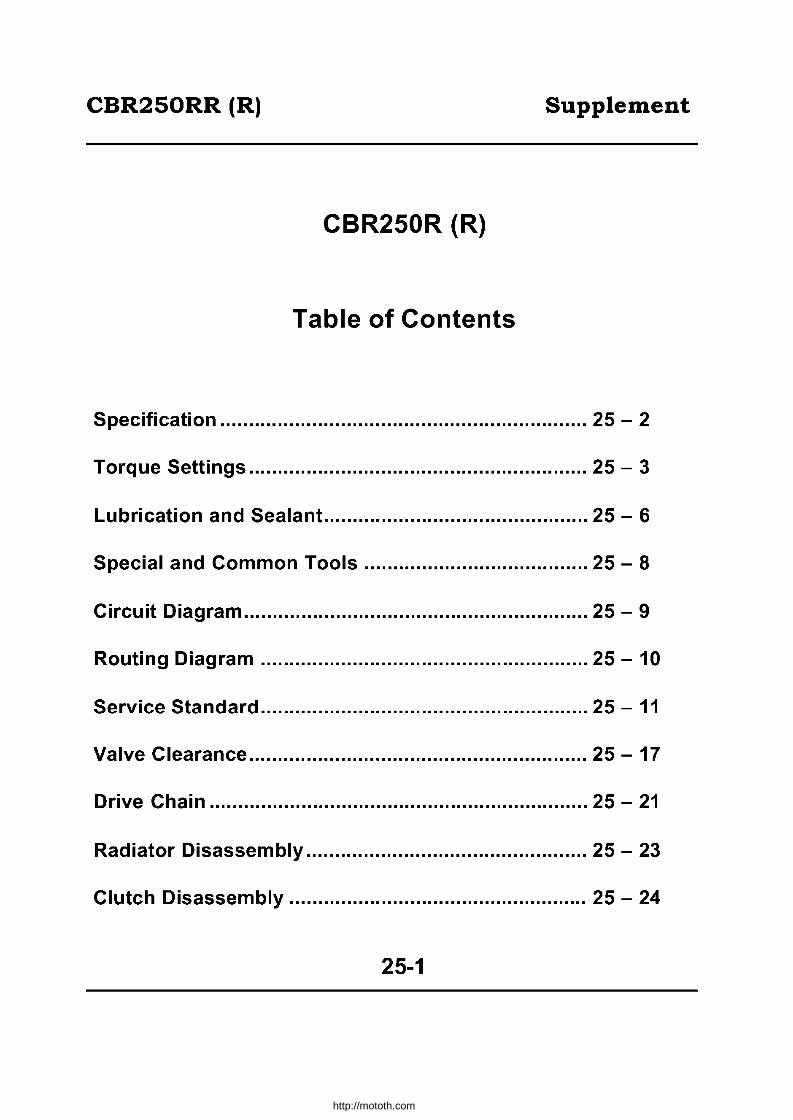
CBR250RR (R) Supplement
CBR250R (R)
Table of Contents
Specification ................................................................ 25 - 2
Torque Settings ........................................................... 25 - 3
Lubrication and Sealant .............................................. 25 - 6
Special and Common Tools ....................................... 25 - 8
Circuit Diagram ............................................................ 25 - 9
Routing Diagram ......................................................... 25 - 10
Service Standard ......................................................... 25 - 11
Valve Clearance ........................................................... 25 - 17
Drive Chain .................................................................. 25 - 21
Radiator Disassem bly ................................................. 25 - 23
Clutch Disassembly .................................................... 25 - 24
25-1
http://mototh.com

CBR250RR (R) Supplement
Specification
Name Honda MC22 Air filter type Filter paper LenQth 1.975m E Fuel tank capacity 13.01
Width 0.675m
Height 1.080m '* is Type VP20
>- '" (f] i" Throttle valve
OJ => diameter
30mm => € LL ro
Wheel base 1.345m U Venturi diameter 29mm
Powerplant type MC14E
Total displacement 0.2491 Type of fuel Petrol
I Front 81kg Vehicle weight I Rear 77kq
Type Full transistor, battery ignition
~ E .§ ~ Timinq 20 o BTOC I 1,500rpm .[:0):0:::-
uCii ~~ Spark I NGK CR 9 EH 9, CR10EH 9 (l,) >. - (f.l plug I NO U27FER-9, U31 FER-9 w(f]
Pluq qap 0.8 - 0.9mm I Total 158kg Battery capacity 12V 6AH
Maximum capacity 2 .<: Type Multiple wet spring coil .8 =>
Front 102kg (3 Operation Mechanical Vehicle gross weight
Rear 166kQ Motor to transaxle ratio 2.966 Total 268kg Type Constant Mesh
Tyres Front 110170R1754H Rear 140/60R1763H
Low 2.733
" Second 2.000
Minimum clearance 0.130m
'" " Brake stop distance " 14.0m (50km/h) ro (initial km/h) E 0 't
" 0 Third 1.590 0 t5 0 .~ =>
~ ~ u E '" a: Fourth 1.333 ~ a:
ro " rn ~ '" >- (9 (9
'" Minimum turning radius 2.9m 0.. Fifth 1.153
Starting system Electric Sixth 1.035
Type Petrol 4 cycle " Gear type Chain 0 t5 N01 =>
Cylinder layout Inline 4 cylinder u Reduction '" 3.058 a: ratio
Combustion chamber Pent Roof type
Valve operation DOHC gear driven, inlet 2, exhaust 2
Bore x stroke 48.5 x 33.8mm
'E Caster 24°00'
~ e OJ LL
Trail 89mm '" Compression ratio 11.5
Compression 13.0kg/cm' - 400rpm
"E Maximum output 40PS/14,500rpm ro Maximum torque 2.4kQ-m I 11 ,500rpm ~ '" " Inlet
Open 20 0 BTOC (1 mm lifted)
" g;£ 0 Close 20 0 ABOC (1mm lifted) 0.. ro~
>i!i Exhaust Open 29°BBOC (1 mm lifted)
0 Close 3°BTDC (1mm lifted)
.<:
S Front 2.25kg I cm' Tyre pressure
Rear 2.50kg/cm2
Front 31°
Steering angle
Rear 31°
Valve clearance liN 0.16mm (cool)
I EX 0.23mm (cool) Front Hydraulic disc brake
Brake system
Unloaded rev 1,500rpm Rear Hydraulic disc brake
" Type Compress - spray
0 Pump type Trochoid ~
Front Telescopic Suspension
Rear Swing arm
" Total flow filtering ." Filtertype .c Screen and paper => ...J
Frame type Diamond
Oil capacity 2.71 Frame number MC22 -1100001
Cooling system Water cooled, electrical
Engine number MC14E - 1400001
25-2
http://mototh.com

CBR250RR (R) Supplement
• Torque Settings En!:)ine
Part Qty Screw Dia Torque
Notes (mm) (kg-m)
Cylinder head cover special bolt 6 6 0.8 -1.2 Camshaft holder flan!]e bolt 16 6 1.2-1.6 Cylinder head flange bolt 7mm 9 7 2.7 - 3.0 Apply oil
8mm 1 8 2.4 - 2.7 Apply oil Spark plu!] 4 10 1.0-1.4 Connectin!] rod (connectin!] rod bolt 1 nut) 8 - 1.6 -2.0 Apply oil Gear train holder bolt 2 8 1.8 - 2.2 Alternator flVWheel 1 10 8.0 - 9.0 UBS Starter clutch 1 10 8.0 - 9.0 UBS Clutch centre lock nut 1 20 10.0-12.0 Stake Oil pump driven sprocket flange bolt 1 6 1.3 -1.7 Apply screw locker Oil pressure switch 1 PT 11/8 1.0 -1.4 Apply sealant Neutral switch 1 10 1.0 - 1.4 Oil filter centre bolt 1 20 1.5 - 2.0 Drain plu!] bolt 1 14 2.5 - 3.5 Crankcase flange bolt 6mm 16 6 1.0 - 1.4 Apply oil
8mm 11 8 2.1 -2.5 Apply oil Shift drum centre (shifter pin) 1 - 2.1 - 2.5 Apply screw locker Gear shift return sprin!] pin 1 8 2.1 - 2.5 Centre shift fork lock bolt 1 7 1.6 -2.5 Lower crankcase 1 18 4.0 - 5.0 Apply screw locker Timing hole cap 1 14 0.8 -1.2 Crankshaft hole cap 1 30 0.8 - 1.2 Drive sprocket special bolt 1 10 5.0 - 6.0 Carburetor synchronisation joint 4 5 0.2 - 0.3
Frame
Part Qty Screw Dia Torque
Notes (mm) (kg-m)
Engine mount Front right 1 10 4.5 - 5.5 Front left 1 10 4.5 - 5.5 Rear upper 1 10 4.5 - 5.5 Rear lower 1 10 4.5 - 5.5 Rear upper bracket 2 8 3.0 -4.0 Rear lower bracket 2 10 4.5 - 5.5
Sub frame Upper 2 10 4.5 - 5.5 Lower 2 10 4.5 - 5.5
Side stand bracket bolt 2 10 4.5 - 5.5 Side stand pivot boll 1 nut 1/1 10 4.5 - 5.5 Handlebar splil boll 2 8 2.4 - 3.0 Handle wei!]ht mount screw 2 6 0.7 - 1.1 Handle lever bracket bolt 4 6 0.7 - 1.1 Radiator mount bolt upper 2 6 1.0-1.4
Lower 1 6 1.0 - 1.4 Fan motor switch 1 16 1.5 - 2.0 Thermostat case mount bolt 2 6 1.0-1.4 Water hose strap - - 0.1 - 0.2 Fuel tank mount bolt Front 1 6 1.0 - 1.4
Rear 1 8 2.4 - 3.0 Fuel cock mount nut 1 22 3.0 - 4.0 Fuel cock lever mount bolt 1 4 0.2 - 0.3 Fuel cap socket bolt 3 4 0.2 - 0.3
25-3
http://mototh.com

CBR250RR (R) Supplement
Part Qty Screw Dia Torque
Notes (mm) (kg-m)
Air filter case screw 13 5 0.1 - 0.2 Air filter case front stay bolt 1 6 1.0-1.4 Upper cowl socket bolt 1 6 0.7-1.1 Upper cowl stay A 2/2 8 2.4 - 3.0 Instruments mount bolt 2 6 1.0 -1.4 Horn mount bolt 1 6 1.0 -1.4 Headlamp mount bolt 3 6 1.0 -1.4 Upper cowl stay B SH bolt 2 6 1.0 -1.4 Rearview mirror cap nut 4 6 0.8 -1.2 Upper cowl stay C 2 6 1.0 -1.4 Steerinq stem adiust nut 1 26 2.0 - 2.4 Steering stem nut 1 24 9.0 -12.0 Bottom bridge split bolt 2 10 3.0 - 4.0 Top bridqe split bolt 2 8 2.0 -2.5 Rear axle nut 1 16 8.0 -10.0 Front axle bolt 1 14 5.5 - 6.5 Axle holder split bolt 4 8 1.8 -2.5 Front brake disc bolt 12 8 4.0 -4.5 Driven sprocket nut 6 8 2.8 - 3.4 Rear brake disc bolt 4 6 1.8 - 2.2 Brake hose oil bolt 6 10 3.0 - 4.0 Rear brake caliper slide pin - Main 1 12 2.5 - 3.0
- Sub 1 8 2.0 - 2.5 Hanger pin 3 10 1.5 - 2.0 Hanger pin plug 3 10 0.2 - 0.3 Brake bleeder valve 3 8 0.4 - 0.7 Front brake caliper mount bolt 4 8 2.8 - 3.4 Rear master cylinder hose joint screw 1 4 0.1 -0.2 Rear master cylinder push rod joint nut 1 8 1.5 - 2.0 Front brake master cylinder cap screw 2 4 0.1 -0.2 Front brake switch screw 1 4 0.08-0.15 Brake lever pivot bolt 1 6 0.05 - 0.15 Brake lever pivot nut 1 6 0.5 - 0.7 Front brake master cylinder holder nut 2 6 1.0 -1.4 Rear fork pivot nut 1 14 6.0 - 7.0 Drive chain slider screw 2 6 0.45 -0.60 Rear fork pivot adjust bolt 1 26 1.0 - 2.0 Rear fork adjust bolt lock nut 1 26 6.0 - 7.0 Fork bolt 2 34 1.5 - 3.0 Fork damper lock nut 2 8 1.5 - 2.5 Rear cushion mount bolt Upper 1 10 4.5 - 5.5
Lower 1 10 4.5 - 5.5 Cushion connecting rod Frame end 1 10 4.5 - 5.5
Cushion arm end 1 10 4.5 - 5.5 Cushion arm Swing arm end 1 10 4.5 - 5.5 Rear cushion plate screw 3 5 0.5 - 0.7 Apply screw locker Lower cowl socket bolt 6 6 0.7-1.1 Lower cowl stay Right upper 1 6 0.7 -1.1
Left upper 1 6 1.0 -1.4 Lower 2 6 0.7 -1.1
Chanqe arm flanqe bolt 1 6 1.4-1.8 Exhaust pipe ioint nut 8 6 1.0-1.4 Muffler mount bolt I nut 2/2 8 2.4 - 3.0 Silencer mount bolt 3 6 1.6 -2.0 Step holder socket bolt 4 8 2.4 - 3.0 Rear master cylinder mount bolt 2 6 1.0-1.4
25-4
http://mototh.com

CBR250RR (R) Supplement
Part Qty Screw Dia Torque
Notes (mm) (kg-m)
Pillion step holder flange bolt 4 8 2.4-3.0 Pillion step lock lever bolt 2 6 1.0 - 1.4 Rear fender mount bolt 4 6 1.0 - 1.4 Rear turn signal screw 2 5 0.35 - 0.50 Reflector nut 1 6 0.7-1.1 Front fender mount bolt 4 6 0.7-1.1 Side cover socket bolt 4 6 0.7-1.1 Side cover joint screw 1 5 0.35 - 0.50 Side cover hook socket bolt 2 6 1.0 - 1.4 Seat cowl screw 2 5 0.3 - 0.4 Seat screw 2 5 0.35 - 0.50 Pillion seat catch 1 6 1.0 - 1.4 Drive chain case bolt 1 6 0.8 -1.2 Throttle cable adjust nut (carburetor end) 1 6 0.8 -1.2 Throttle housing screw 2 5 0.35 - 0.50 Clutch cable nut (engine side) 1 8 0.8 -1.2 Choke cable screw (carburetor side) 1 4 0.15 - 0.30 Ignition coil bracket bolt 4 6 1.0 - 1.4 Ignition coil screw 2 6 0.7-1.1 Ignition switch socket bolt 2 8 2.4 - 3.0 Tail lamp cap nut 2 6 0.8 -1.2
25-5
http://mototh.com
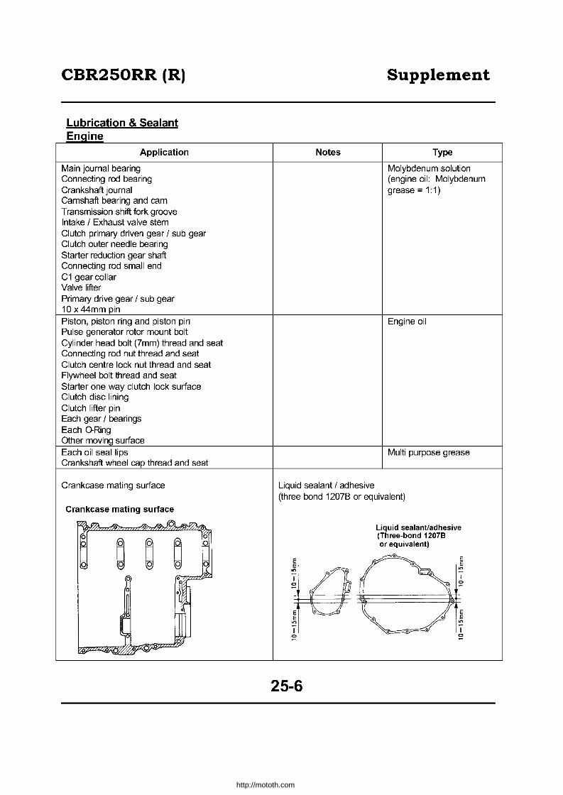
CBR250RR (R) Supplement
Lubrication & Sealant E n~:lIne
Application Notes Type
Main journal bearing Molybdenum solution Connecting rod bearing (engine oil: Molybdenum Crankshaft journal grease = 1 :1) Camshaft bearing and cam Transmission shift fork groove Intake / Exhaust valve stem Clutch primary driven gear / sub gear Clutch outer needle bearing Starter reduction gear shaft Connecting rod small end C1 gear collar Valve lifter Primary drive gear / sub gear 10 x 44mm pin Piston, piston ring and piston pin Engine oil Pulse generator rotor mount bolt Cylinder head bolt (7mm) thread and seat Connecting rod nut thread and seat Clutch centre lock nut thread and seat Flywheel bolt thread and seat Starter one way clutch lock surface Clutch disc lining Clutch lifter pin Each gear / bearings Each O-Ring Other moving surface Each oil seal lips Multi purpose grease Crankshaft wheel cap thread and seat
Crankcase mating surface Liquid sealant / adhesive (three bond 1207B or equivalent)
Crankcase mating surface
"" ~ ~ tal ~l77l Liquid sealant/adhesive 0
~ ~ ~ 0 (Three-bond 12078 0 or equivalent)
~ E Iq E r:r 0 E E IA ~ ~
0 0 I ~ 0
I := 0 :=
•
~ E ~ E E 0 0 E
::? ::? I .e- o 0 I
:= := ~ ~~
25-6
http://mototh.com
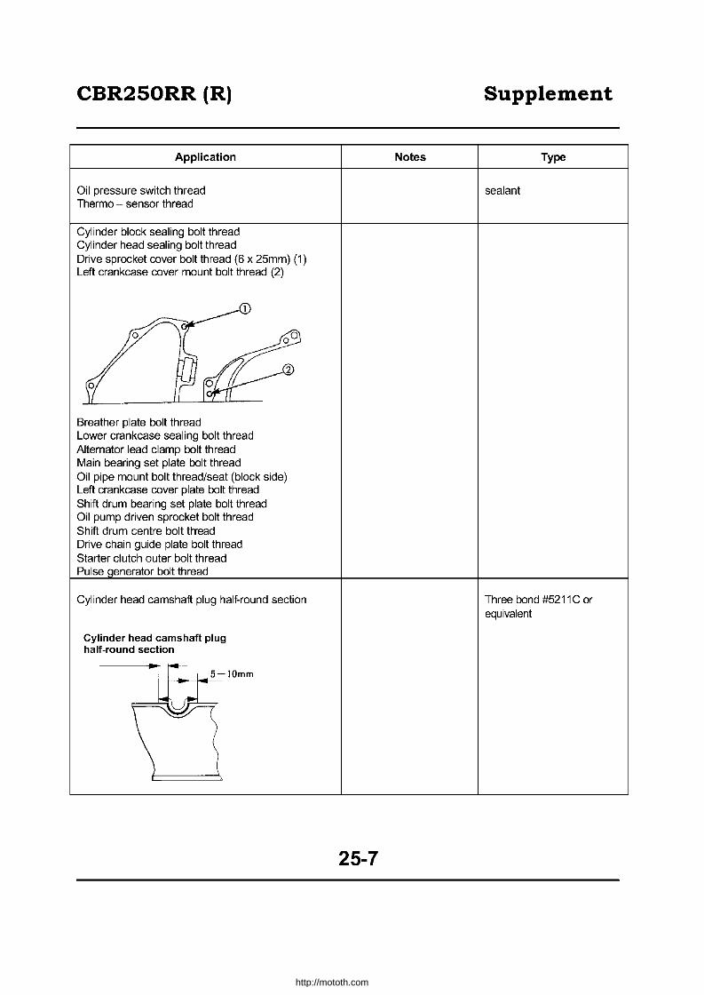
CBR250RR (R)
Application
Oil pressure switch thread Thermo - sensor thread
Cylinder block sealing bolt thread Cylinder head sealing bolt thread Drive sprocket cover bolt thread (6 x 25mm) (1) Left crankcase cover mount bolt thread (2)
Breather plate bolt thread Lower crankcase sealing bolt thread Alternator lead clarnp bolt thread Main bearing set plate bolt thread Oil pipe mount bolt thread/seat (block side) Left crankcase cover plate bolt thread Shift drurn bearing set plate bolt thread Oil purnp driven sprocket bolt thread Shift drurn centre bolt thread Drive chain guide plate bolt thread Starter clutch outer bolt thread Pulse enerator bolt thread
Cylinder head camshaft plug half-round section
Cylinder head camshaft plug half-round section
Notes
25-7
Supplement
Type
sealant
Three bond #5211C or equivalent
http://mototh.com

CBR250RR (R) Supplement
Frame
Application Notes Type
Rear brake pedal pivot Throttle grip pipe Left handle lever pivot Gear shift pedal pivot
Multi purpose grease Seat catch hook Steering stem bearing Stem dust seal lip Pillion seat hinge
Steering stem adjust nut thread Engine oil
Side stand pivot Molybdenum grease
Special & Common Tools
Special Tool
Tool Name Tool No. Qty Application
Drive chain staking tool 07HMH - MR10103 1 Drive chain replacement
25-8
http://mototh.com

~ 0'1
I CD
Speedometer Illuminator Lam~ 12Vl.7WX2 -7 IDA (Fan Motor)
15A (Head lamp, starte,) IDA (Illuminator, tum signal,tail,
stop, position lamps and horn) D IDA (Ignition, starte, magnetic switch)
Starter Magnetic Switch
I i III ,."",., .. ,"" _
H" ' ,,," PI.. ~ "",., Jr::~fn';~i~~ G : " ~ ~ Ule
0 Motor Lamp Ylr; ~ ... Thermo 12Vl.7W G : 61 Unit ~ S!!
El' I 11'
'.m,G"o,. " ~ o~~o ~. Illuminator ElllSr ;u ~~ ~ ~Fi~- ~ ~
,',~~'", , :;: - ---- <0'" ",0< ILD;f 1 IIII ="0 'l M ~ ~o_ ~61 ~BI ~~;~ ~g':r;~~~ ", I' Right Front turn signal lamp Vial
I III Mi:;,;J I ?iN
::!':iR ,,-iiiE~l:
"""""iii
Oc +--, 811W,
I r
~ Horn
LOCK
HomSwilch
~M" m,
"""
paSSin,' SW'''" ["II ~
'"' .,,,., FRO:E Lo
PUSH !", .,
Tum signal relay
~ fu1 1'0
o Right rear tum signal
,L8DQ----~~12VI5W
GN lamp ~;;:':'&
: 12V1815Wx2
-" .," :~ "-<J8:g
1 G--f""""""l\ 12V15W L...-A-c::::J<J---A ~
A Amber B[ Black Br Brown Bu Blue G Green LB Light Brown LG Light Green R Red W White Y Yellow
Left Rear turn signal lamp
0030Z-KAZ-7800 -7900
(') tu ~ ~ en o ~ ~ -~ -
UJ s::
'tS 'tS -(D
B (D
= ,...
http://mototh.com

CBR250RR (R) Supplement
Unit· mm Standard
Standard Service Limit Item
Rotor tip clearance 0.15 0.20
Oil Pump Pump body - outer rotor Qap 0.15-0.22 0.35 Rotor - body Qap 0.02 - 0.07 0.10 Pressure 4.0 - 5.0kQicm 2 (6,000 oil temp 60°c)
Engine oil capacity 2.2L(oil change) 2.4L (oil & filter change) 2.7L (total capacity)
• Genuine Honda Ultra GP (4 cycle motorcycle, SAE 10W - 40 or SAE 20W - 50)
Temperature-viscosity
Designated engine oil -- a !lIE ~ Select proper oil based on operation temperature.
I '" " '" " '" '" , Out~ide airtemper<lture
Fuel System
Item Standard
Venturi Diameter Primary bore 9.1 mm equivalent,
Secondary bore 29mm equivalent SettinQ mark VP20B
Float level 13.7mm Main jet No.1,4: #112 I No.2, 3: #110 Slow Jet #35
Idling rpm 1 ,500 + 1 OOrpm Throttle grip free play 2-6mm
Pilot screw initial setting 2 118 turns out
Fuel tank capacity I Total 13L
I Reserve Approx 1.6L
Cooling System
Item Standard Service limit
Radiator cap valve opening pressure 1.10 - 1.40kgicm2 Replace if out of the range: 1.10 - 1.40kgicm2
Thermostat valve Opening temp 80 - 84° -
opening temperature Full open 95'c -
Full open lift 8mm or above -
Total approx: 1570cc Coolant capacity (Radiator: 1350cc)
(Reservoir: 220cc)
25-11
http://mototh.com

CBR250RR (R) Supplement
Engine Mounting I Dismounting
Engine Weight (service) Approx 48.5kg
"Genuine Honda Ultra GP (4 cycle motorcycle,
Recommended engine oil SAE 10W - 40 or SAE 2fJW 50)"
• API classification SE, SF or SG grade oil (Refer to (3-2) for viscosity)
Total capacity 2.7L Engine oil capacity Oil chance 2.2L
Oil and filter change 2.4L
Cylinder Head & Valve
Unit· mm Standard
Standard Service Limit Item
Compression 13.0kg/cm2 - 400rpm -
Cam lift IN 28.72 - 28.80 28.69 EX 28.51 - 28.75 28.48 1 0.Q15 - 0.057 0.06
Cam shaft Oil clearance
2 0.Q15 - 0.057 0.06 3 0.025 - 0.067 0.07 4 0.Q15 - 0.057 0.06
Runout - 0.05 Valve spring Relaxed length 37.65 36.65
Valve stem diameter IN 3.481 - 3.495 3.476 EX 3.465 - 3.480 3.460
Valve guide bore IN 3.500 - 3.512 3.57
Valve & EX 3.500 - 3.512 3.57 Valve guide
Stem guide clearance IN 0.005 - 0.032 0.10 EX 0.020 - 0.047 0.13
Valve seat contact width IN 0.8 1.3 EX 1.0 1.5
Valve lifter Diameter 19.978 - 19.993 19.970
Cylinder head Warpage - 0.05
Valve lifter contact area bore 20.010 - 20.026 20.035
25-12
http://mototh.com

CBR250RR (R) Supplement
Cylinder, Piston and Crankshaft Unit· mm
Item Standard Service limit Connecting rod big end side clearance 0.10-0.25 0.30
Crankshaft and Crankshaft runout - 0.05 connecting rod Crank pin oil clearance 0.028 - 0.046 0.05
Main journal oil clearance 0.022 - 0.040 0.06 Bore 48.500 - 48.51 0 48.60
Cylinder Top warpage - 0.05 Out of round - 0.005 Taper - 0.005
Ring groove - ring Top 0.015 - 0.050 0.10 clearance Second 0.21 - 0.36 0.10
Piston Ring Top 0.1 - 0.25 0.45 Ring end gap Second 0.15 - 0.30 0.45
Oil (side rail) 0.2 - 0.8 1.00 Piston diameter 48.4 7 - 48.49 48.35 Piston - cylinder clearance 0.01 - 0.04 0.10 Piston pin hole diarneter 13.002 - 13.008 13.02
Piston Piston pin diameter 12.994 - 13.000 12.98 Piston - Piston pin clearance 0.002 - 0.014 0.04 Connecting rod small end bore 13.016 -13.034 13.05 Piston pin - connecting rod clearance 0.016 - 0.040 0.06
Connecting rod bore code 1 2 3
30.000 - 30.006 - 30.012 - Bearing Metal Thickness: 30.006mm 30.012mm 30.018mm A (Blue): 1.252-1.255mm
(J) A 27.494-
E (Yellow) D (Green) C (Brown) "0 27.500mm cO '0.. ()
27.488-""~ B D (Green) C (Brown) B (Black) c2 27.494mm '" (J) ~ E
u'" C 27.482-
C (Brown) B (Black) A (Blue) '5 27.488mm
B (Black): 1.249-1.252mm C (Brown): 1.246-1.249mm D (Green): 1.243-1.246mm E (Yellow): 1.240-1.243mm
Case bore A B C
31.000 - 31.006 - 31.012 - Bearing Metal Thickness: 31.005mm 31.011mm 31.018mm A (Blue): 1.508-1.511 mm
- 1 27.993-
E (Pink) D (Yellow) C (Green) rn 28.000mm c(])
~"C
i30 2 27.987-
D (Yellow) C (Green) B (Brown) ._0 27.994mm crn
'co :a 27.982- A (Blue) :2: 3 27.988mm C (Green) B (Brown)
B (Brown): 1.505-1.508mm C (Green): 1.502-1.505mm D (Yellow): 1.499-1.502mm E (Pink): 1.496-1.499mm
BI: Black Br: Brown Bu: Blue G: Green P: Pink Y: Yellow
25-13
http://mototh.com

CBR250RR (R) Supplement
Clutch & Alternator Standard
Standard Service Limit Item
Clutch lever free plav 10-20 -
Clutch spring relaxed length 36 35 Clutch Clutch disc thickness 2.9- 3.0 2.6
Clutch plate warpaQe - 0.3 Clutch outer Quide bore 21.995 - 22.015 22.03
Oil pump drive sprocket bore 30.025 - 30.075 30.09 Bore 21.995 - 22.015 22.03
Oil pump drive gear collar Ex. dia 29.987 - 30.000 29.97 Height 22.300 - 22.400 22.20
Main shaft diameter (at clutch outer guide) 21.980 - 21.990 21.97
Transmission Unit· mm
Standard Standard Service Limit
Item Backlash 0.044 - 0.140 0.3
M5 25.000 - 25.021 25.05 M6 25.000 - 25.021 25.05
Gear bore C 1 23.000 - 23.021 23.05 C2 28.000 - 28.021 28.05 C3 28.000 - 28.021 28.05 C4 28.000 - 28.021 28.05
M 5 bore 21.985 - 22.006 22.07 M 5 diameter 24.959 - 24.980 24.92 M 6 diameter 24.959 - 24.980 24.92
Gear bush C 1 diameter 22.959 - 22.980 22.92 C 1 bore 20.020 - 20.041 20.11
C 2 diameter 27.959 - 27.980 27.92 C 3 diameter 27.959 - 27.980 27.92
Transmission C 4 diameter 27.959 - 27.980 27.92 Main shaft M5 21.963 - 21.977 21.93 diameter Clutch outer guide 21.980 - 21.990 22.20
Counter shaft C 1 19.987 - 20.000 19.77 diameter
M 5 bush - 0.10 M 5 bush-shaft - 0.15
M 6 bush - 0.10 Gear bush or C 1 bush - 0.10
shaft clearance C 1 bush-shaft - 0.15 C2 bush - 0.10 C 3 bush - 0.10 C 4 bush - 0.10
Shift fork Catch thickness 5.93 - 6.00 5.60 Bore 12.000 - 12.021 12.04
Shift fork shaft Diameter 11.960 - 11.971 11.90
25-14
http://mototh.com
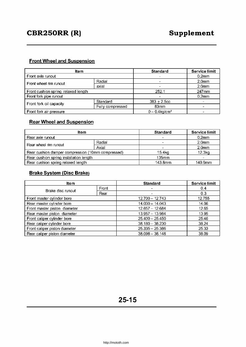
CBR250RR (R) Supplement
Front Wheel and Suspension
Item Standard Service limit Front axle runout - 0.2mm
Front wheel rim runout I Radial - 2.0mm I axial - 2.0mm
Front cushion sprinq relaxed lenqth 252.1 247mm Front fork pipe runout - 0.2mm
Front fork oil capacity I Standard 383 + 2.5cc -
I Fully compressed 83mm -Front fork air pressure 0- 0.4kg/cm2 -
Rear Wheel and Suspension
Item Standard Service limit Rear axle runout - 0.2mm
Rear wheel rim runout I Radial - 2.0mm I Axial - 2.0mm
Rear cushion damper compression (1 Omm compressed) 15.4kg 12.3kg Rear cushion sprina installation lenath 135mm -
Rear cushion sprinq relaxed lenqth 143.8mm 140.9mm
Brake System (Disc Brake)
Item Standard Service limit
Brake disc runout I Front - 0.4 I Rear - 0.3
Front master cylinder bore 12.700 - 12.743 12.755 Rear master cvlinder bore 14.000 - 14.043 14.06 Front master piston diameter 12.657 - 12.684 12.65 Rear master piston diameter 13.957 - 13.984 13.95 Front caliper cylinder bore 25.400 - 25.450 25.46 Rear caliper cylinder bore 38.180 - 38.230 38.24 Front caliper piston diameter 25.335 - 25.386 25.33 Rear caliper piston diameter 38.098 - 38.148 38.09
25-15
http://mototh.com
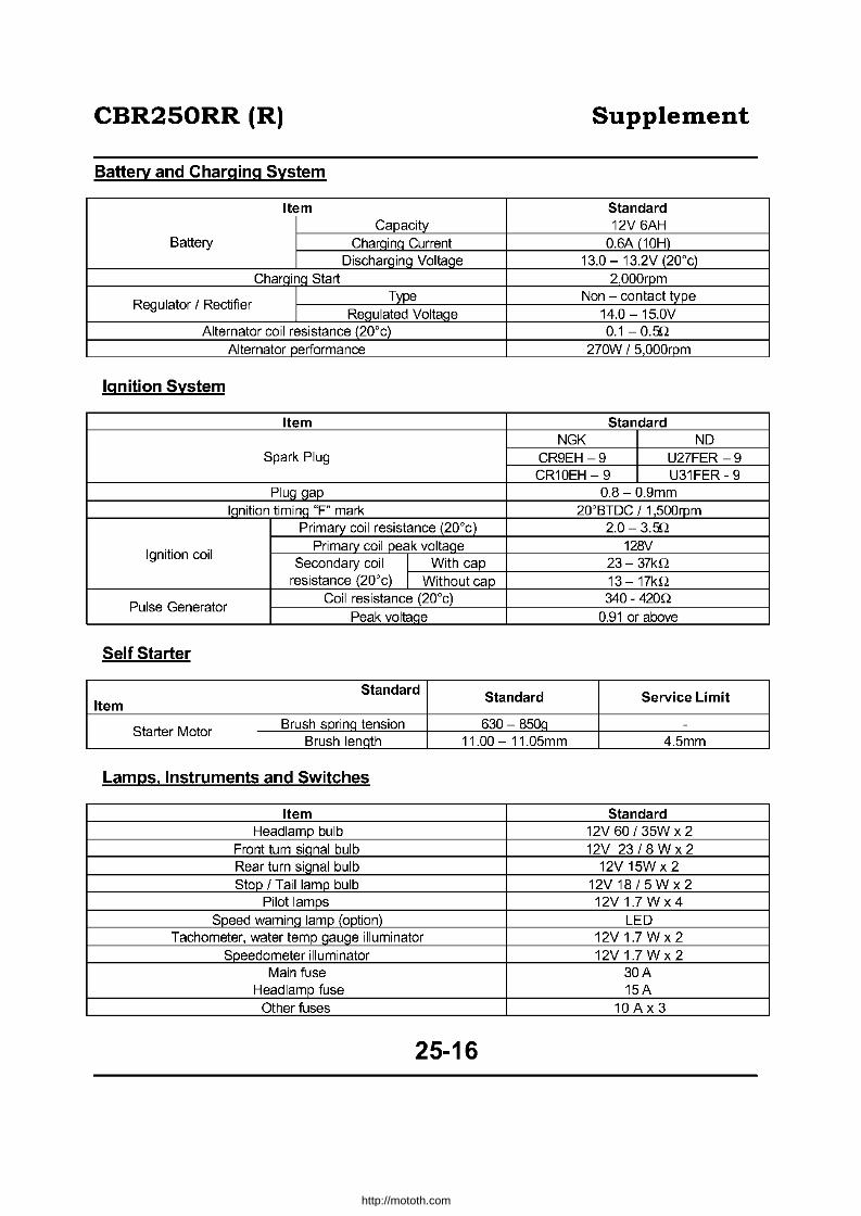
CBR250RR (R) Supplement
Battery and Charging System
Item Standard Capacity 12V 6AH
Battery CharQinQ Current 0.6A (10H) Discharging Voltage 13.0 - 13.2V (20"c)
CharQinQ Start 2000rpm
Regulator / Rectifier Type Non - contact type
Regulated Voltage 14.0 -15.0V Alternator coil resistance (20"c) 0.1 - 0.f!2
Alternator performance 270W / 5,000rpm
Ignition System
Item Standard NGK ND
Spark Plug CR9EH -9 U27FER -9 CR10EH - 9 U31FER - 9
PluQ Qap 0.8-0.9mm IQnition timinQ "F" mark 20"BTDC / 1 500rpm
Primary coil resistance (20"c) 2.0- 3.f!2
Ignition coil Primary coil peak voltaQe 128V
Secondary coil I With cap 23- 37kQ resistance (20"c) I Without cap 13-17kQ
Pulse Generator Coil resistance (20"c) 340 - 420Q
Peak voltaQe 0.91 or above
Self Starter
Standard Standard Service Limit Item
Starter Motor Brush sprinQ tension 630 - 850Q -
Brush lenQth 11.00 - 11.05mm 4.5mm
Lamps. Instruments and Switches
Item Standard Headlamp bulb 12V 60 / 35W x 2
Front turn sianal bulb 12V 23/8 Wx 2 Rear turn siQnal bulb 12V 15W x 2 Stop / Tail lamp bulb 12V 18/5 W x 2
Pilot lamps 12V1.7Wx4 Speed warning larnp (option) LED
Tachometer, water ternp gauge illurninator 12V1.7Wx2 Speedometer illurninator 12V1.7Wx2
Main fuse 30A Headlarnp fuse 15A
Other fuses 10 A x 3
25-16
http://mototh.com
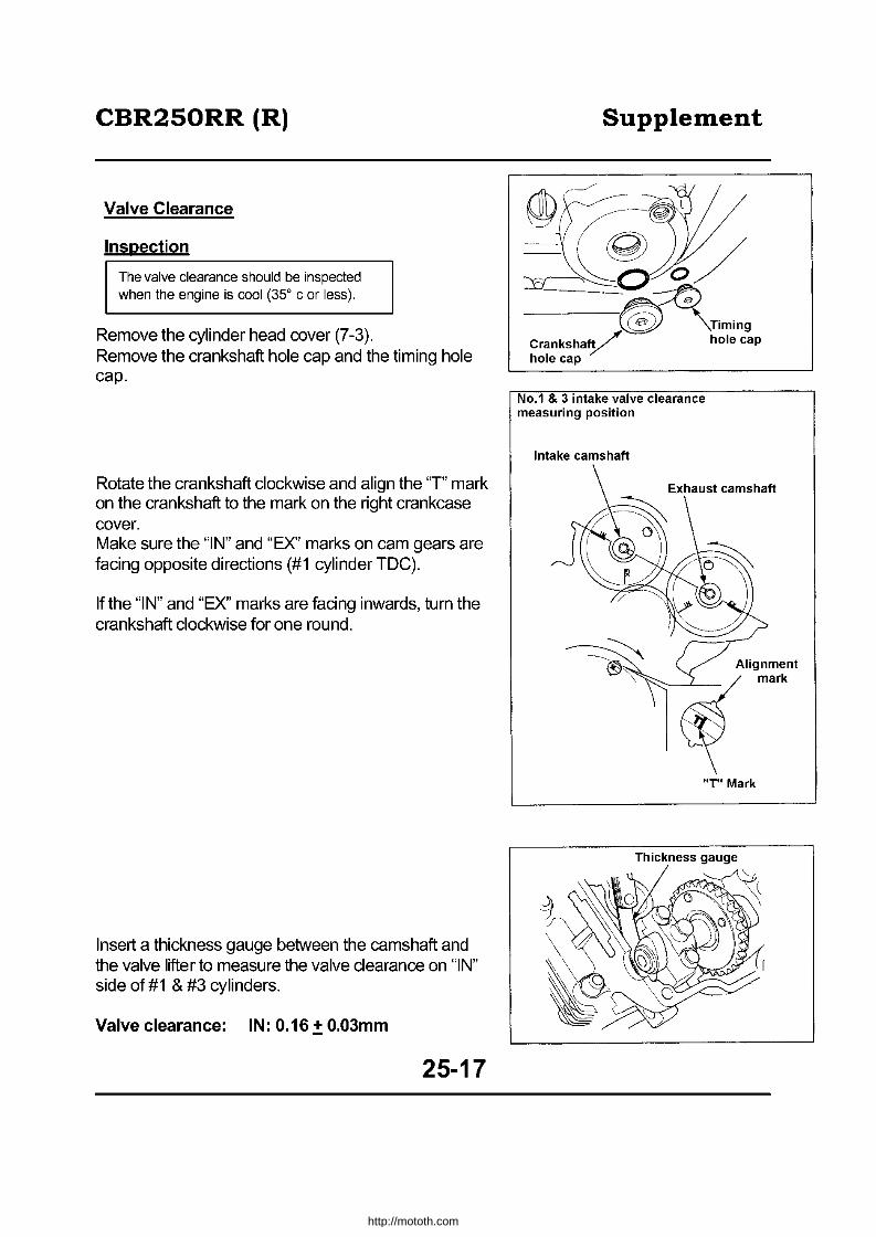
CBR250RR (R)
Valve Clearance
Inspection
The valve clearance should be inspected when the engine is cool (350 c or less).
Remove the cylinder head cover (7-3). Remove the crankshaft hole cap and the timing hole cap.
Rotate the crankshaft clockwise and align the 'T' mark on the crankshaft to the mark on the right crankcase cover. Make sure the "IN" and "EX" marks on cam gears are facing opposite directions (#1 cylinder TOC).
If the "I N" and "EX" marks are facing inwards, turn the crankshaft clockwise for one round.
Insert a thickness gauge between the camshaft and the valve lifter to measure the valve clearance on "IN" side of #1 & #3 cylinders.
Valve clearance: IN: 0.16.:!: 0.03mm
25-17
Supplement
No.1 & 3 intake valve clearance measuring position
Intake camshaft
Alignment
\""':--~_/ mark
~ "T" Mark
http://mototh.com
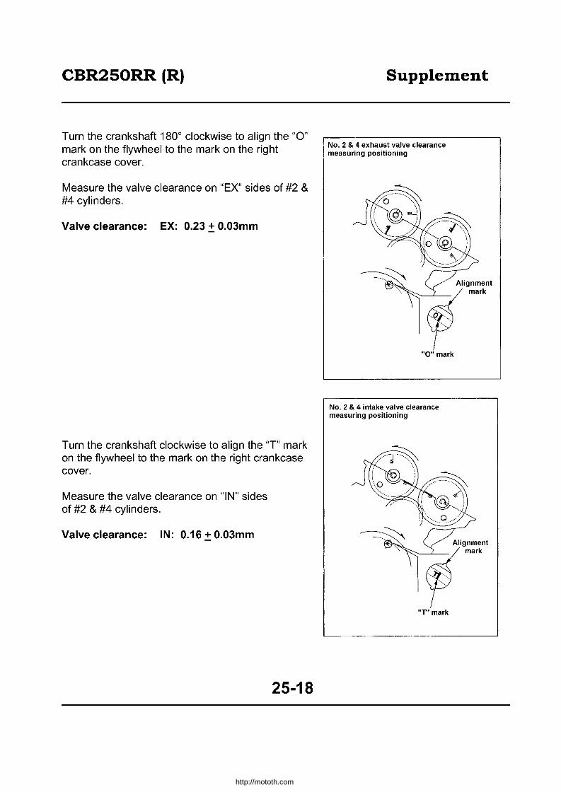
CBR250RR (R)
Turn the crankshaft 1800 clockwise to align the "0" mark on the flywheel to the mark on the right crankcase cover.
Measure the valve clearance on "EX" sides of #2 & #4 cylinders.
Valve clearance: EX: 0.23.:!: 0.03mm
Turn the crankshaft clockwise to align the "T" mark on the flywheel to the mark on the right crankcase cover.
Measure the valve clearance on "IN" sides of #2 & #4 cylinders.
Valve clearance: IN: 0.16.:!: 0.03mm
25-18
Supplement
No.2 & 4 exhaust valve clearance measuring positioning
No.2 & 4 intake valve clearance measuring positioning
·T· mark
http://mototh.com

CBR250RR (R)
Tum the crankshaft 1800 clockwise to align the "0" mark on the flywheel to the mark on the right crankcase cover.
Measure the valve clearance on "EX" sides of #1 & #3 cylinders.
Valve clearance: EX: 0.23 + 0.03mm
Adjustment
Remove the camshaft (7-3). Remove valve lifters and shims.
• If the lifter is difficult to remove, use tools such as a valve wrapper.
• Shim may come out together with the valve lifter.
• If the shim is difficult to remove, use tweezers ora magnet.
• Re-install the lifters and the shims to the original position.
• Sort and store the lifters and shims.
Supplement
No.1 & 3 exhaust valve clearance measuring position
"0" mark
Clean the valve lifter and the shim attachment with compressed air.
25-19
http://mototh.com

CBR250RR (R)
Wipe off oil on the shim and measure / record its thickness.
How to select a new shim
There are 65 different types of shims, ranging from 1.200mm to 2.800mm with O.025mm step.
Select the proper size by using the following equation:
A = B- C + D Where A: new shim thickness
B: measured valve clearance C: standard valve clearance D: removed (old) shim thickness
Example: Measured valve clearance: 0.16mm Removed shim thickness: 1.725mm Standard valve clearance: 0.21 mm
A= (0.16-0.21) + 1.725 = 1.675mm
• Use a micrometer to measure new/old shim thickness accurately.
• If the required shim thickness is above 2.800mm remove buill-uD carbon on a valve seat to adiust it.
Install the selected shim to the valve spring retainer. Apply Molybdenum dis-sulphide to the valve lifter and install the valve lifter. Install the camshaft (7-19). Tum the crankshaft several revolutions to ensure shim is settled. Re-measure the valve clearance. Install all removed parts by reversing the removal procedure.
Install the crankshaft hole cap and the timing hole cap.
• Inspect the O-Ring condition and replace if necessary.
• Apply qrease to the cap thread.
Torque: Crankshaft hole cap: 0.8 - 1.2kg-m
25-20
e 1.80mm
Supplement
e 1.825mm
e e 1.85mm 1.875mm
Timing hole cap
http://mototh.com

CBR250RR (R) Supplement
Timing hole cap: 0.8 - 1.2kg-m
Drive Chain
Replacement
• CAUTION • Use a special tool and genuine replacement chain to
replace the drive chain. • Never use clip-type chain.
Loosen the drive chain. Assemble the special tool.
Special Tool: Drive chain staking tool: 07HMH-MR10103
Read the instructions before using the staking tool.
Set the tool to the staked section of the drive chain and cut the staked section.
Special Tool: Drive chain staking tool: 07HMH-MR10103
Adjust the number of links of the new drive chain by using the staking tool.
Include the master link to the number of links.
Standard links: Replacement drive chain:
134 links DID 428VS1 RK428SHOZI
25-21
Drive chain staking tool
Master link
One Master link
link~ 1(1
I
i ... ---- 134 links-----!. I
http://mototh.com

CBR250RR (R)
Do not re-use the master link, the O-Ring, and the link plate.
Install O-Rings to the new master link and set the master link from inside of the chain.
• Install the master link plate so as to face its labeled surface outwards.
• Do not catch O-Rings.
By using the staking tool, install O-Rings and the link plate to the link. Confirm the end of the master link joint pins are coming outfrom the link plate.
Standard: RK-1.0-1.2mm DID -0.9 -1.25mm
Stake the end of the joint pins.
Measure the staked area with a caliper.
Staked area: 4.75 - 4.95mm
If the measured value is out of the above range, restake with a new master link, link plate and 0-Rings.
Make sure there is no crack on the staked area. If there is any crack, re -stake with the new master link, link plate and O-Rings.
Caution: Never use clip-type chain.
25-22
Supplement
:11 Plate
~ I
Drive chain staking tool
Master link
staking tool
o X Good No Good
http://mototh.com
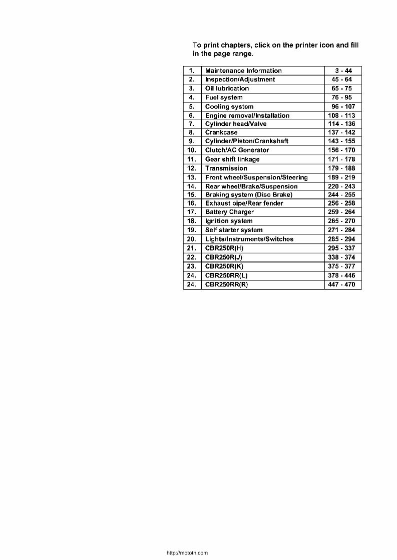
To print chapters, click on the printer icon and fill in the page range.
1. Maintenance Information 3 - 44 2. Inspection/Adjustment 45 - 64 3. Oil lubrication 65 - 75 4. Fuel system 76 - 95
5. Cooling system 96 - 107 6. Engine removaillnstallation 108 - 113 7. Cylinder headNalve 114-136 8. Crankcase 137 - 142 9. Cylinder/Piston/Crankshaft 143 - 155 10. Clutch/AC Generator 156 - 170
11. Gear shift linkage 171 - 178 12. Transmission 179 - 188
13. Front wheel/Suspension/Steering 189 - 219 14. Rear wheel/Brake/Suspension 220 - 243 15. Braking system (Disc Brake) 244 - 255 16. Exhaust pipe/Rear fender 256 - 258 17. Battery Charger 259 - 264 18. Ignition system 265 - 270 19. Self starter system 271 - 284 20. Lights/Instruments/Switches 285 - 294 21. CBR250R(H) 295 - 337 22. CBR250R(J) 338 - 374 23. CBR250R(K) 375 - 377 24. CBR250RR(L) 378 - 446 24. CBR250RR(R) 447 - 470
http://mototh.com