Template Free Synthesis of CuS Nanosheets-based Hierarchical Microspheres: An Efficient Natural...
9
This is an Accepted Manuscript, which has been through the Royal Society of Chemistry peer review process and has been accepted for publication. Accepted Manuscripts are published online shortly after acceptance, before technical editing, formatting and proof reading. Using this free service, authors can make their results available to the community, in citable form, before we publish the edited article. We will replace this Accepted Manuscript with the edited and formatted Advance Article as soon as it is available. You can find more information about Accepted Manuscripts in the Information for Authors. Please note that technical editing may introduce minor changes to the text and/or graphics, which may alter content. The journal’s standard Terms & Conditions and the Ethical guidelines still apply. In no event shall the Royal Society of Chemistry be held responsible for any errors or omissions in this Accepted Manuscript or any consequences arising from the use of any information it contains. Accepted Manuscript www.rsc.org/crystengcomm CrystEngComm View Article Online View Journal This article can be cited before page numbers have been issued, to do this please use: M. Tanvir, C. Cao, W. S. Khan, Z. Ali, I. Aslam, F. K. Butt, F. Idrees, M. Tahir and N. Mahmood, CrystEngComm, 2014, DOI: 10.1039/C4CE00090K.
-
Upload
independent -
Category
Documents
-
view
0 -
download
0
Transcript of Template Free Synthesis of CuS Nanosheets-based Hierarchical Microspheres: An Efficient Natural...

This is an Accepted Manuscript, which has been through the Royal Society of Chemistry peer review process and has been accepted for publication.
Accepted Manuscripts are published online shortly after acceptance, before technical editing, formatting and proof reading. Using this free service, authors can make their results available to the community, in citable form, before we publish the edited article. We will replace this Accepted Manuscript with the edited and formatted Advance Article as soon as it is available.
You can find more information about Accepted Manuscripts in the Information for Authors.
Please note that technical editing may introduce minor changes to the text and/or graphics, which may alter content. The journal’s standard Terms & Conditions and the Ethical guidelines still apply. In no event shall the Royal Society of Chemistry be held responsible for any errors or omissions in this Accepted Manuscript or any consequences arising from the use of any information it contains.
Accepted Manuscript
www.rsc.org/crystengcomm
CrystEngComm
View Article OnlineView Journal
This article can be cited before page numbers have been issued, to do this please use: M. Tanvir, C. Cao,
W. S. Khan, Z. Ali, I. Aslam, F. K. Butt, F. Idrees, M. Tahir and N. Mahmood, CrystEngComm, 2014, DOI:
10.1039/C4CE00090K.

Journal Name RSCPublishing
ARTICLE
This journal is © The Royal Society of Chemistry 2013 J. Name., 2013, 00, 1-3 | 1
Cite this: DOI: 10.1039/x0xx00000x
Received 00th January 2012,
Accepted 00th January 2012
DOI: 10.1039/x0xx00000x
www.rsc.org/
Template Free Synthesis of CuS Nanosheet-based
Hierarchical Microspheres: An Efficient Natural Light
Driven Photocatalyst
M. Tanveera, Chuanbao Caoa*, Waheed S. Khana, Zulfiqar Alia, Imran Aslama, Faheem K. Buta, Faryal Idreesa, Muhammad Tahira and Nasir Mahmoodb
Well controlled Nanosheets-based hierarchical Microspheres (NSHMS) of pure covellite phase CuS have been synthesized using a facile PVP assisted solvothermal process. The reaction conditions were optimized using various amounts of PVP to develop unique hierarchical structured hollow microspheres. CuS hollow structures have a bandgap of ~1.97 eV. These mesoporous structures exhibit excellent photocatalytic activity in degradation of organic dyes (methylene blue) under natural light in comparison to other structures of copper sulphide. These photocatalysts show extraordinary reusability with over 96.5% degradation of organic dye after 6th cycle. A “bottom-up” assembly has been successfully developed to synthesize hollow microspheres with unique and well defined architectures at large scale, which offer a good opportunity to understand the fundamental significance of unusual and complex hierarchical structures for their potential applications.
Introduction
It is well known fact that both physical and chemical properties are significantly affected by the structure, size, morphology, composition and crystallinity of materials.1 Moreover, inorganic micro and nanostructures with hollow interiors are attracting an ever increasing attention owing to their unique properties, such as distinguish morphology, large surface area, void space, good surface permeability, low density, low coefficients of thermal expansion and refractive indexes,2–5 Particularly, the hierarchically structured spheres are in stimulated extensive research interest owing to their unusual structural features and extraordinary optical/electrical behaviours which can bring wide potential applications in a numerous fields such as catalysts, drug-delivery carriers, sensors, biomedical diagnosis agents, rechargeable batteries and chemical reactors, etc.6–9 Tremendous interests in the synthesis of, nano or microstructures and hierarchically structured spheres have been aroused. The conventional approaches to preparation of hollow structures in different shapes have involved the use of various removable or sacrificial templates, including hard ones (e.g., metal nanoparticles, silica spheres, and carbon spheres)10,11 and soft ones (e.g., liquid drops, micelles, emulsion droplets, and even bacteria).12-
14 A diverse portfolio of hollow structures were prepared by template methods and typically physicochemical routes for CuS semiconductor.15-16 But the above-mentioned typical approaches to fabrication of hollow CuS architectures might inevitably increase the reaction complexity, suffer tedious synthetic procedures, mostly cause impurity in the products. Currently, most of the obtained hollow spherical architectures have polycrystalline shells.17 Therefore; the structural and morphological tailoring of the shells of hollow architectures has been an exciting challenge for material design because of the special shape- and
structure dependent effects, which would develop their significant scientific values and widespread potential applications. Mesocrystals, as a new class of fashionable highly ordering unique superstructures, have been successfully elucidated by Colfen et al. for the growth of minerals via a non-classical oriented attachment and mesoscale transformation.18–19 It is a unique colloid crystal composed of individual nanocrystals as the building units that are aligned in a common crystallographic fashion with notable internal porosity, as well as exhibiting elongated diffraction spots resembling those of a single crystal.20 The study of mesocrystals is not only helpful for to construct the novel morphology by using anisotropic building blocks but also to provide a new opportunity for constructing multifunctional materials with potentially unique and exciting properties. However, to the best of our knowledge, the template free and shape controlled synthesis of hollow and hierarchical, mesoporous microspheres, which can exhibit excellent physical and chemical properties, are rarely reported. Consequently, to develop a template free hollow material with hierarchical and unique building blocks is a topic of great interest for researchers. As a non-stoichiometric p-type semiconductor with unique optical, electric and thermal properties,3–4 covellite (CuS) is an important semiconductor material with prospective and numerous applications such as in solar cells, optical filters, nanoswitches, thermoelectric and photoelectric transformers, superconductors, gas sensors, lithium-ion batteries and photo catalysis. 3–5,13,16 Recently, many efforts have been devoted to fabricate covellite CuS in different shapes such as hollow spheres21 plates,22 rods,23 tubes,24 wires,25 flowers26. Therefore, a large number of fabrication methods have been explored including chemical vapor deposition, thermolysis, hydrothermal or solvothermal, ultrasonic and microwave irradiation,
Page 1 of 8 CrystEngComm
Cry
stE
ngC
omm
Acc
epte
dM
anus
crip
t
Publ
ishe
d on
13
Mar
ch 2
014.
Dow
nloa
ded
by B
eijin
g U
nive
rsity
on
14/0
3/20
14 0
3:52
:00.
View Article OnlineDOI: 10.1039/C4CE00090K

ARTICLE Journal Name
2 | J. Name., 2012, 00, 1-3 This journal is © The Royal Society of Chemistry 2012
as well as microemulsion, electrodeposition and template-assisted methods21–29 also have been employed in this regard. Herein, we present the evidence on the controlled and large scale synthesis of CuS hollow and hierarchical microspheres with unique complex and unusual structures, considerable high specific surface area with entirely nanosheets building blocks through a simply PVP derived solvothermal technique. The study has great importance in “bottom-up” assembly of well ordered CuS hollow hierarchical microspheres, and offers a good opportunity to understand the fundamental significance of hollow mesoporous microspheres with nanosheets building blocks, displaying excellent natural light driven photocatlyst properties.
Experimental
Sample preparation
Mesoporous structured hollow spheres with nanosheets building blocks were synthesized through a surfactant mediated solvothermal pathway and without using any prefabricated template. All reagents (analytical-grade purity) used in this work were purchased from the commercial market, and were used without any further purification. In a typical experimental process, 2 mmol of Cu(NO3)2.3H2O and 2 mmol of thiourea each were separately dissolved in 20 mL ethylene glycol (EG), and stirred until they were dissolved totally to obtain a clear solution. Then the two solutions were mixed under stirring. Afterwards, 2.0 g polyvinylpyrrolidone (PVP K-30, Mw = 58 000) was added into the solution under vigorous stirring. The solution was then transferred into a 50 mL Teflon-lined autoclave, sealed and heated at 160o C for 24 hrs. The final solid products were collected by centrifugation at 8000 rpm for 3 minutes and washed several times with de-ionized water, absolute ethanol and acetone for more than 6 times to dissolve any excess surfactant present, afterward dried at 80o C for 6 hrs in vacuum and collected in the form of dark-blue powder. In the comparative experiments, in order to observe the growth mechanism and effect of PVP, the same experiment was repeated with different concentrations of PVP (PVP= 0.0, 0.5, 1.0, 1.5), different sulfur, copper sources and variety of solvents, while precursors ratios and all other experimental conditions were kept the same as the typical experimental process. The as prepared products were then charactrized through different charactrization techniques, moreover the superior photocatalytic properties of as prepared NSHMS were witnessed.
Chracterization
The structure, phase purity and chemical composition of the products were examined by X-ray powder diffraction (XRD, Philips ’XPert Pro MPD) with CuKa radiation (λ= 0.15406 nm), X-ray photoelectron spectroscopy (XPS), energy dispersive spectroscopy (EDS). The morphologies of the products were examined by scanning electron microscopy (SEM, Hitachi TM-1000). Transmission electron microscopy (TEM), high resolution transmission electron microscopy (HRTEM) and selected area electron diffraction (SAED) analysis were conducted using a FEI Tecnai-T20 electron microscope (FEI, USA) using a 200 kV accelerating voltage. Optical properties of as prepared products were ascertained at room temperature using Ultraviolet–visible–near infrared (UV–vis–NIR) transmittance spectrophotometer (U-4100) and Photoluminescence spectroscopy (Hitachi FL-4500 Fluorescence Spectrophotometer). The Brunauer–Emmett–Teller (BET) specific surface area of the as prepared powders was analyzed by nitrogen adsorption in a Micromeritics ASAP 2020 nitrogen adsorption apparatus (USA).
Photocatalytic activity evaluation
MB is a popular probe molecule in heterogeneous catalytic reactions because of being a typical dye resistant to biodegradation and direct photolysis. For the evaluation of catalytic activity, experiments for the oxidation and de-coloration of the methylene blue (MB) dye with the assistance of hydrogen peroxide (H2O2) were carried out under natural light at ambient temperature. The original solution was prepared by adding 3 mL H2O2 (30%, w/w) and 3 mL MB solution (400 mg L−1) in 100 mL of de-ionized water, then 20 mg of the as-prepared CuS mesoporous hierarchical microspheres with nanosheets building blocks was added into the solution to form the aqueous dispersion. The solution was magnetically stirred in the dark for 30 min to ensure the establishment of an adsorption–desorption equilibrium before illumination. Afterwards, the dispersion was irradiated by natural light during continuous magnetic stirring. Then during given time intervals, about 4 mL of the suspension was taken from the reactor and centrifuged to separate the catalyst. The UV–vis absorption spectra were recorded at different intervals and the characteristic absorption peak at 604 nm of MB was monitored to follow the catalytic degradation process using a UV/vis/NIR spectrophotometer (Hitachi U-4100).
Results and Discussion
Structural and morphological characterizations
The phase purity and crystallinity of the as prepared CuS products was characterized using XRD technique. As shown in Figure 1, all of the diffraction peaks match well with the standard data of covellite-type CuS with hexagonal lattice parameters of a= 3.7920 Å, b= 3.7920 Å c= 16.3440 Å (covellite, syn, JCPDS No: 00-006-0464).
Figure 1. XRD spectrums of as prepared CuS products; (a) CuS non spherical aggregate, (b) Hollow microspheres with rough surfaces, (c) NSHMS of CuS.
The XRD pattern shows that the products are devoid of any detectable impurities or any other copper sulphide phases such as Cu1.96S, Cu1.94S, Cu1.8S, Cu7S4, and Cu2S indicating the high purity of the obtained products. Moreover the strong and sharp diffraction peaks of NSHMS are obviously due to its much better crystallinity
Page 2 of 8CrystEngComm
Cry
stE
ngC
omm
Acc
epte
dM
anus
crip
t
Publ
ishe
d on
13
Mar
ch 2
014.
Dow
nloa
ded
by B
eijin
g U
nive
rsity
on
14/0
3/20
14 0
3:52
:00.
View Article OnlineDOI: 10.1039/C4CE00090K

Journal Name ARTICLE
This journal is © The Royal Society of Chemistry 2012 J. Name., 2012, 00, 1-3 | 3
as compared to the other as synthesized products. The energy-dispersive spectra (EDS) analysis of the as prepared product NSHMS is shown in the Figure 3d demonstrates that the chemical components only consist of Cu and S elements with an atomic ratio (Cu: S= 1:1), in agreement with the above XRD result. XPS analysis of NSHMS was carried out to confirm the composition and purity of the as prepared product. The full spectrum, shown in Figure 2a indicates the presence of Cu, S along with C, N and O peaks. The presence of the C and N peaks are derived from PVP molecules, the peak O may also be due to the absorption of air on the surface of the NSHMS. Figure 2b is representing high resolution spectrum of Cu 2p and it is obvious that the presence of two strong peaks at 932.6eV and 952.5eV for Cu 2p3/2 and Cu 2p1/2, respectively, separated by 20.0eV are essentially identical binding energies for the Cu 2p orbital in accord with Cu(II)30. In addition, a small chemical shift about (0.3eV) occurs compared to the elemental copper. In Figure 2c, the high resolution survey at the S 2p region shows the presence of two peaks at 162.6eV and 163.5eV, all these peak positions are well matched with literature31. The Cu/S ratio was calculated from the peak areas of Cu and S-cores, the value was found to be 1.04 that is closely matched with the Cu/S value (1.0) estimated from EDS analysis.
Figure 2. XPS spectrum of the as-synthesized CuS NSHMS. (a) XPS spectra of survey of the as-synthesized CuS NSHMS. (b) XPS spectra of close-up survey in the Cu 2p region. (c) XPS spectra of close-up survey in the S 2p region.
Figure 3 displays the typical SEM images of the as prepared NSHMS obtained in the presence of large concentration of PVP= 2.0 g, at different magnifications. From the low-magnification SEM result (Figure 3a), it is obvious that CuS microspheres have high yield, the excellent spherical architectures and fully exposed with amazingly unique nanosheets as building blocks at large scale. The
images in Figure 3b clearly indicate all of the spheres are well defined, quite consistent and separately displaced. The presence of microspheres with open structures as presented in Figure 3b, indicate that the microspheres with hollow interiors are formed. The inset of Figure 3b displays the cross sectional view of NSHMS, two partitions of a broken hollow microsphere with curvy interiors describes the hollow nature of the NSHMS. And the edges of broken spheres clearly indicate the nanosheets accumulated threading within the entire shell walls of NSHMS. In the corresponding magnified image in Figure 3c, it can also be ascertained the spheres are threaded identically with nanosheets, hollow in nature and nanosheets are well interconnected. The average diameter of microspheres is about ca. 2.3 µm.
Figure 3. (a) Large scale SEM image of CuS NSHMS. (b) SEM image of CuS NSHMS (Inset is the cross sectional view of CuS NSHMS). (c) High magnification SEM image of CuS NSHMS. (d) EDS spectrum of as prepared NSHMS. Further detailed structural characterizations of as prepared CuS NSHMS were performed by TEM and HRTEM. Figure 4a displays the TEM image of the as prepared NSHMS the strong contrast between the dark edge and pale center is the obvious evidence for their hollow nature and cavities within the entire shell walls of the hollow hierarchical architectures. From the high magnification TEM image of NSHMS (inset of Figure 4a), it is clear that the shell of the hollow microsphere is composed of nanosheets having thickness in a few nanometers and threaded in a well defined manners within the entire shell walls of NSHMS, being in agreement with SEM results. The HRTEM image conducted on the scattered nanosheets is given in Figure 4b. From the top view of HRTEM image, the regular spacing of the clear lattice planes is calculated to be 0.311 nm, which is in good agreement with the interlayer spacing’s of (102) crystallographic plane of hexagonal CuS, being consistent with the orientation of the nanoplatelet, reported by Li et al.32 To further investigate the crystallographic features of the as prepared product, the scattered area electron diffraction (SAED) pattern (Figure 4b, inset) was recorded which displays clear image of lattice fringes well-matched with XRD results, indicating the good crystalline nature of CuS NSHMS, having a hexagonal crystal structure. The formation of NSHMS started from a nucleus directed by PVP which acted as structure directing agent. As soon as PVP concentration reached the optimized amount, these nuclei started growth in specific directions to form sheets which then join together to form highly connected structures by self assembly involving bending and aggregation as suggested by Fang et al.33 Furthermore
Page 3 of 8 CrystEngComm
Cry
stE
ngC
omm
Acc
epte
dM
anus
crip
t
Publ
ishe
d on
13
Mar
ch 2
014.
Dow
nloa
ded
by B
eijin
g U
nive
rsity
on
14/0
3/20
14 0
3:52
:00.
View Article OnlineDOI: 10.1039/C4CE00090K
ARTICLE Journal Name
4 | J. Name., 2012, 00, 1-3 This journal is © The Royal Society of Chemistry 2012
the well-defined spots in the SAED spectra illustrate the perfect growth of single crystals of CuS. Thus, these observations confirmed that microspheres have same crystallographic orientation along the nanosheet axis as a perfect single crystal.
Figure 4. (a) TEM image of CuS NSHMS, (inset is the high magnification TEM image of CuS NSHMS) (b) HRTEM image of CuS NSHMS, and the (inset is the SAED pattern of CuS NSHMS).
Effect of solvent To investigate the effect of the solvent on the formation of CuS NSHMS, a series of comparative experiments was carried under similar conditions utilizing a variety of solvents. It is found that the solvent has a significant influence on the morphology of the as-synthesized CuS products, since different solvents have different viscosities, dissolution capability and chemical nature as well such as ethanol, Ethylene glycol and Dimethyl formamide.
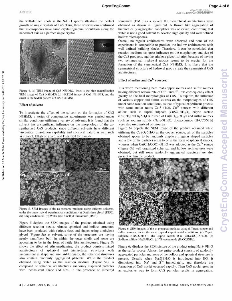
Figure 5. SEM images of the as prepared products using different solvents, under the same typical experimental conditions. (a) Diethylene glycol (DEG). (b) Ethylenediamine. (c) Water (d) Dimethyl formamide (DMF).
Figure 5 depicts the SEM images of the product obtained using different reaction media. Almost spherical and hollow structures have been produced with various sizes and shapes using diethylene glycol (Figure 5a) as solvent, some of the structures are having nearly nanofibers built in within the outer shells and some are appearing to be in the form of rattle like architectures. Figure 5b shows the effect of ethylenediamine, the product consists mixed architectures of spherical and hierarchical structures with inconsistent in shape and size. Additionally, the spherical structures also contain randomly aggregated platelets. While the product obtained using water as the reaction medium (Figure 5c), is composed of spherical architectures, randomly displaced particles with inconsistent shape and size. In the presence of dimethyl
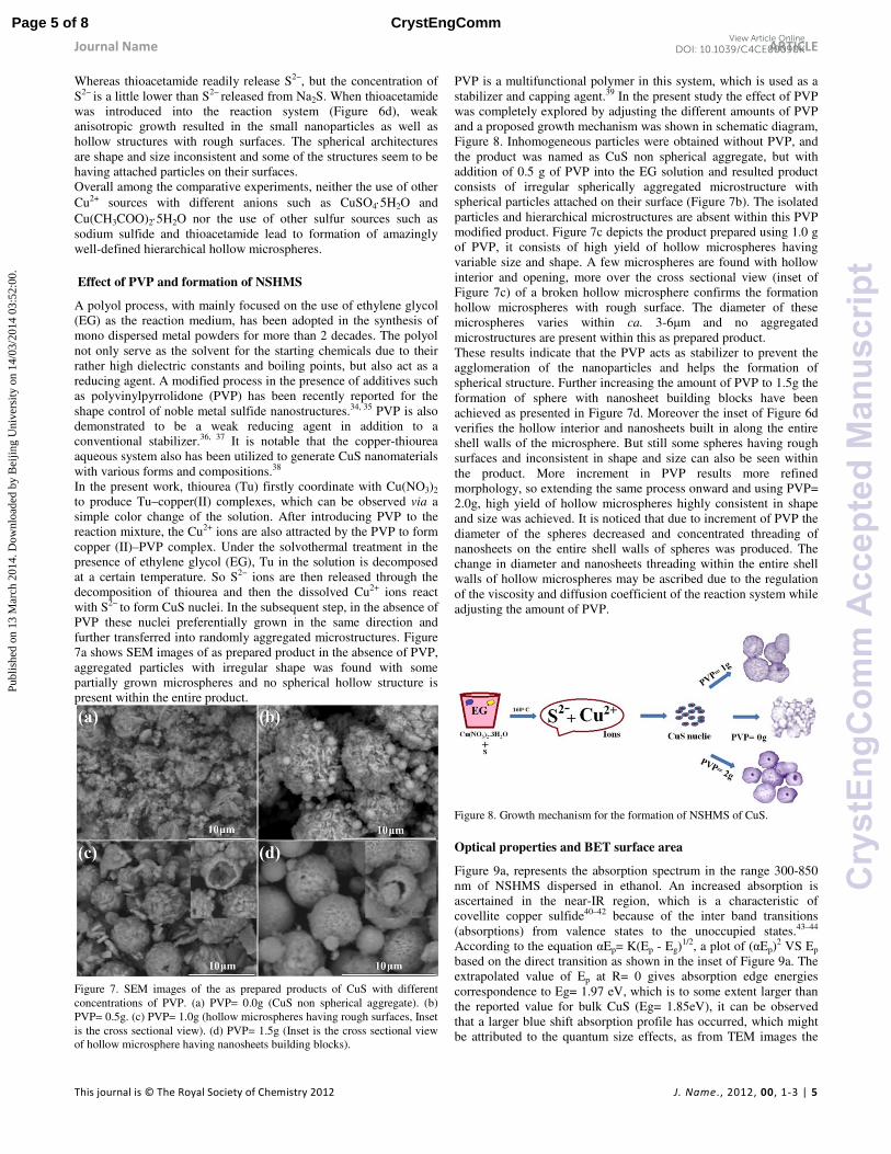
fomamide (DMF) as a solvent the hierarchical architectures were obtained as shown in Figure 5d. A flower like aggregation of hierarchically aggregated nanoplates was observed, confirming that water is not a good solvent to develop high quality and well defined hollow microspheres. Overall no regular architectures were observed and none of the experiment is compatible to produce the hollow architectures with well defined building blocks. Therefore, it can be concluded that reaction medium has great influence on the morphology and size of the CuS products, and the ethylene glycol solution because of having two symmetrical hydroxyl groups seems to be crucial for the formation of the symmetrical CuS NSHMS. It is likely that the symmetrical structure of hydroxyl group create the symmetrical CuS architectures. Effect of sulfur and Cu2+ sources: It is worth mentioning here that copper sources and sulfur sources having different release rate of Cu2+ and S2− ions consequently effect greatly on the final morphologies of CuS. To explore, the influence of various copper and sulfur sources on the morphologies of CuS under same reaction conditions, as that of typical experiment process with same molar ratios Cu:S (1:2). Cu2+ sources with different anions such as cupric sulphate (CuSO4⋅5H2O), cupric acetate (Cu(CH3COO)2⋅5H2O) instead of Cu(NO3)2⋅3H2O and sulfur sources such as sodium sulfide (Na2S⋅9H2O), thioacetamide (H3CCSNH2) were also used instead of thiourea. Figure 6a depicts the SEM image of the product obtained while utilizing the CuSO4⋅5H2O as the copper source, all of the particles obtained appear to be randomly displace irregular shaped particles and a few of the particles seem to be in the form of spherical shapes, whereas when Cu(CH3COO)2⋅5H2O was adopted as the Cu2+ source (Figure 6b) well organized spherical and hollow architectures were obtained, but still some randomly aggregated structures are also present within the product.
Figure 6. SEM images of the as prepared products using different copper and sulfur sources, under the same typical experimental conditions. (a) Cupric sulphate (CuSO4.5H2O). (b) Cupric acetate (Cu (CH3COO)2.5H2O). (c) Sodium sulfide (Na2S.9H2O). (d) Thioacetamide (H3CCSNH2).
Figure 6c displays the SEM picture of the product using Na2S⋅ 9H2O as the sulfur source. Almost the entire product consists of randomly aggregated particles and none of the hollow and spherical structure is present. Usually when Na2S⋅9H2O is introduced into EG, it dissociated into Na+ and S2− immediately, and therefore the formation of CuS nuclei occurred rapidly. Then CuS nuclei grew in an explosive way to form CuS particles results in aggregation.
Page 4 of 8CrystEngComm
Cry
stE
ngC
omm
Acc
epte
dM
anus
crip
t
Publ
ishe
d on
13
Mar
ch 2
014.
Dow
nloa
ded
by B
eijin
g U
nive
rsity
on
14/0
3/20
14 0
3:52
:00.
View Article OnlineDOI: 10.1039/C4CE00090K
Journal Name ARTICLE
This journal is © The Royal Society of Chemistry 2012 J. Name., 2012, 00, 1-3 | 5
Whereas thioacetamide readily release S2−, but the concentration of S2− is a little lower than S2− released from Na2S. When thioacetamide was introduced into the reaction system (Figure 6d), weak anisotropic growth resulted in the small nanoparticles as well as hollow structures with rough surfaces. The spherical architectures are shape and size inconsistent and some of the structures seem to be having attached particles on their surfaces. Overall among the comparative experiments, neither the use of other Cu2+ sources with different anions such as CuSO4⋅5H2O and Cu(CH3COO)2⋅5H2O nor the use of other sulfur sources such as sodium sulfide and thioacetamide lead to formation of amazingly well-defined hierarchical hollow microspheres.
Effect of PVP and formation of NSHMS
A polyol process, with mainly focused on the use of ethylene glycol (EG) as the reaction medium, has been adopted in the synthesis of mono dispersed metal powders for more than 2 decades. The polyol not only serve as the solvent for the starting chemicals due to their rather high dielectric constants and boiling points, but also act as a reducing agent. A modified process in the presence of additives such as polyvinylpyrrolidone (PVP) has been recently reported for the shape control of noble metal sulfide nanostructures.34, 35 PVP is also demonstrated to be a weak reducing agent in addition to a conventional stabilizer.36, 37 It is notable that the copper-thiourea aqueous system also has been utilized to generate CuS nanomaterials with various forms and compositions.38
In the present work, thiourea (Tu) firstly coordinate with Cu(NO3)2 to produce Tu–copper(II) complexes, which can be observed via a simple color change of the solution. After introducing PVP to the reaction mixture, the Cu2+ ions are also attracted by the PVP to form copper (II)–PVP complex. Under the solvothermal treatment in the presence of ethylene glycol (EG), Tu in the solution is decomposed at a certain temperature. So S2− ions are then released through the decomposition of thiourea and then the dissolved Cu2+ ions react with S2− to form CuS nuclei. In the subsequent step, in the absence of PVP these nuclei preferentially grown in the same direction and further transferred into randomly aggregated microstructures. Figure 7a shows SEM images of as prepared product in the absence of PVP, aggregated particles with irregular shape was found with some partially grown microspheres and no spherical hollow structure is present within the entire product.
Figure 7. SEM images of the as prepared products of CuS with different concentrations of PVP. (a) PVP= 0.0g (CuS non spherical aggregate). (b) PVP= 0.5g. (c) PVP= 1.0g (hollow microspheres having rough surfaces, Inset is the cross sectional view). (d) PVP= 1.5g (Inset is the cross sectional view of hollow microsphere having nanosheets building blocks).
PVP is a multifunctional polymer in this system, which is used as a stabilizer and capping agent.39 In the present study the effect of PVP was completely explored by adjusting the different amounts of PVP and a proposed growth mechanism was shown in schematic diagram, Figure 8. Inhomogeneous particles were obtained without PVP, and the product was named as CuS non spherical aggregate, but with addition of 0.5 g of PVP into the EG solution and resulted product consists of irregular spherically aggregated microstructure with spherical particles attached on their surface (Figure 7b). The isolated particles and hierarchical microstructures are absent within this PVP modified product. Figure 7c depicts the product prepared using 1.0 g of PVP, it consists of high yield of hollow microspheres having variable size and shape. A few microspheres are found with hollow interior and opening, more over the cross sectional view (inset of Figure 7c) of a broken hollow microsphere confirms the formation hollow microspheres with rough surface. The diameter of these microspheres varies within ca. 3-6µm and no aggregated microstructures are present within this as prepared product. These results indicate that the PVP acts as stabilizer to prevent the agglomeration of the nanoparticles and helps the formation of spherical structure. Further increasing the amount of PVP to 1.5g the formation of sphere with nanosheet building blocks have been achieved as presented in Figure 7d. Moreover the inset of Figure 6d verifies the hollow interior and nanosheets built in along the entire shell walls of the microsphere. But still some spheres having rough surfaces and inconsistent in shape and size can also be seen within the product. More increment in PVP results more refined morphology, so extending the same process onward and using PVP= 2.0g, high yield of hollow microspheres highly consistent in shape and size was achieved. It is noticed that due to increment of PVP the diameter of the spheres decreased and concentrated threading of nanosheets on the entire shell walls of spheres was produced. The change in diameter and nanosheets threading within the entire shell walls of hollow microspheres may be ascribed due to the regulation of the viscosity and diffusion coefficient of the reaction system while adjusting the amount of PVP.
Figure 8. Growth mechanism for the formation of NSHMS of CuS.
Optical properties and BET surface area
Figure 9a, represents the absorption spectrum in the range 300-850 nm of NSHMS dispersed in ethanol. An increased absorption is ascertained in the near-IR region, which is a characteristic of covellite copper sulfide40–42 because of the inter band transitions (absorptions) from valence states to the unoccupied states.43–44 According to the equation αEp= K(Ep - Eg)
1/2, a plot of (αEp)2 VS Ep
based on the direct transition as shown in the inset of Figure 9a. The extrapolated value of Ep at R= 0 gives absorption edge energies correspondence to Eg= 1.97 eV, which is to some extent larger than the reported value for bulk CuS (Eg= 1.85eV), it can be observed that a larger blue shift absorption profile has occurred, which might be attributed to the quantum size effects, as from TEM images the
Page 5 of 8 CrystEngComm
Cry
stE
ngC
omm
Acc
epte
dM
anus
crip
t
Publ
ishe
d on
13
Mar
ch 2
014.
Dow
nloa
ded
by B
eijin
g U
nive
rsity
on
14/0
3/20
14 0
3:52
:00.
View Article OnlineDOI: 10.1039/C4CE00090K

ARTICLE Journal Name
6 | J. Name., 2012, 00, 1-3 This journal is © The Royal Society of Chemistry 2012
nanosheets which are the building units of NSHMS, are more thin than 20nm. So the quantum confinement is obvious in this case.44
Figure 9. (a) UV-visible absorption spectrum of CuS NSHMS. (inset) Band gap energy of NSHMS of CuS. (b) PL spectrum of as-prepared NSHMS of CuS.
The photo luminescent (PL) property of CuS is of great interest because of its excellent photoconductive, photovoltaic and rectifying response under illumination. The room temperature PL activity is investigated exploiting ethanolic dispersion of the as-prepared NSHMS of CuS. The PL spectrum (Figure 9b) showed a broad emission peaks in the 462 nm (2.68eV) region under an excitation wavelength of 370 nm (3.35eV). Although Jiang and co-workers 46 reported that there is no emission peak for CuS in the range of 400-800 nm, our result is very consistent with the PL result reported by Ou et al.47 According to them, various morphologies of copper sulfide may be responsible for this unique phenomenon of PL. However, from the reported literature it can be suggested that the nature of the emission spectrum of CuS depends on the morphology and inherent structure of the samples.43, 48 Thus, the excitonic emission herein is because of the high optical quality of NSHMS of CuS.
Figure 10 (a). Nitrogen adsorption-desorption isotherms of the as-synthesized CuS products, (b) pore size distribution curves of as prepared CuS products. To be a good candidate for a photocatalyst, its specific surface area is most important. Normally, the larger surface area of the catalyst will result in higher photocatalytic activity.49 Since higher specific surface area can provide more active catalytic sites for photocatalytic reactions. The Brunauer–Emmett–Teller (BET) specific surface area of synthesized CuS products was investigated by nitrogen adsorption-desorption measurements. Figure 10a shows the nitrogen adsorption-desorption isotherms of as prepared CuS products. The BET surface areas of the CuS NSHMS, CuS hollow microspheres with rough surfaces and CuS non spherical aggregate were measured to be 36, 14.0 and 3.8 m2 g−1, respectively. The BET surface area of NSHMS has been found to be higher than the other as mentioned CuS products. Moreover the spherical architectures appeared to be having double pore size (Figure 10b). The unique double pore structures along with considerable high surface area makes a photocatalyst promising candidate as a catalyst for the degradation of dye pollutions in wastewater.
Photocatalytic properties
To demonstrate the potential application of as-synthesized NSHMS in the degradation of organic contaminants, we have investigated their photo catalytic activities by choosing the photo catalytic degradation of MB dye in the presence of hydrogen peroxide. In our experiments, H2O2 yielded highly reactive hydroxyl radicals that could oxidize MB into smaller molecules such as CO2, H2O, etc. The catalytic property of CuS was found closely dependent to the amount of hydroxyl radicals; furthermore the assistance of H2O2 can be in favor of the bleaching of MB.50– 51 The H2O2 alone was found incapable to the degradation of dye solutions without the assistance of the catalyst. Meanwhile, it is also observed that CuS catalyst without H2O2 is not capable to degrade the MB. However, it is confirmed that the presence of H2O2 is necessary to assist the catalytic activity of the CuS. Figure 11b shows the optical absorption spectra of MB at different time intervals in the presence of common CuS microspheres having rough surfaces instead of nanofiber building blocks. The intensity of the absorption peak at 604 nm of MB decreased rapidly with the extended exposure time, indicating the noticeable photocatalytic degradation of MB, and about 74% of the MB (Figure 11d, Panel B) was degraded after 48 min. So the above results indicate that the presence of CuS catalysts can effectively accelerate the degradation of MB, which confirmed the significant role of CuS played in the photocatalytic degradation of MB. Moreover, it was found that the photo catalytic activity of microspheres with consistent shape and size was higher than the non-spherical and randomly aggregated structures (Figure 11d, Panel A). Further experiments were carried out to compare the catalytic activity of the as-prepared NSHMS of CuS (Figure 11c). Interestingly the intensity of the absorption peak of MB at 604 nm decreased faster than that of the above hollow CuS microspheres with rough surfaces (Figure 11b) and about 93% of the MB (Figure 11d, Panel C) was degraded after 48 min.
Figure 11. Absorption spectra of photo degradation of MB by different catalysts under natural light. (a) as prepared non spherical aggregate of CuS+H2O2 (b) hollow CuS microspheres with rough surfaces + H2O2. (c) CuS NSHMS + H2O2. (d) A plot of the extent of photodegradation of MB by different catalysts under natural light. Panel A: non spherical CuS powder; Panel B: hollow CuS microspheres with rough surfaces; Panel C: the as prepared CuS NSHMS.
The decomposition of the MB aqueous solution at 48 min in the presence of the above as prepared samples is as follows: NSHMS of
Page 6 of 8CrystEngComm
Cry
stE
ngC
omm
Acc
epte
dM
anus
crip
t
Publ
ishe
d on
13
Mar
ch 2
014.
Dow
nloa
ded
by B
eijin
g U
nive
rsity
on
14/0
3/20
14 0
3:52
:00.
View Article OnlineDOI: 10.1039/C4CE00090K

Journal Name ARTICLE
This journal is © The Royal Society of Chemistry 2012 J. Name., 2012, 00, 1-3 | 7
CuS (93%) > hollow CuS microspheres having rough surfaces (74%) > as prepared CuS non spherical aggregate (61%). The relationship between Ln (C0/C) and time for the as prepared CuS products is shown in Figure 12a. Where C0 is initial concentration of MB and C is concentration of the dye at time t. The curve for CuS NSHMS is linear, ratio of Ln (C0/C) increased at a constant rate with an increase in time. A clear demonstration of CuS NSHMS superiority over the as prepared products of CuS is shown in Figure 12b in which first order rate constant (k /min) of CuS NSHMS (0.02418 /min), CuS microspheres having rough surfaces (0.01662 /min) and CuS non spherical aggregate (0.01081 /min) are given. First order rate constant is calculated by following equation.
Ln(C0/C) = kt (1) The k value of CuS NSHMS shows a significant improvement in photodegradation as compared to other aforementioned as-synthesized CuS products. Moreover the CuS NSHMS were recycled 6 times for degradation of MB and results shows its excellent stability and recycling capability, shown in Figure 12c. In the recycling process, catalyst was separated by centrifugation and reused after washing for degradation of same concentration of MB. Almost same time was taken by CuS NSHMS to degrade the MB without any significant loss of efficiency even for 6th cycle.
Figure 12 (a). Ln (C0/C) of the as prepared CuS products. (b) First order rate constant k (min-1) of the as prepared CuS products. (c) Stability test of as prepared CuS NSHMS. (d) Triplet graph among Crystallite size, BET surface area and first order rate constant ( K) of as synthesized products.
The underlying photo degradation mechanism might involve the acceleration in photodecomposition of H2O2 over CuS NSHMS to give a large number of oxidants. The amount of oxidant is usually determined by the surface active sites of catalysts.52 The relevant chemical reactions include the separation of electron–hole pairs due to irradiation and subsequent scavenging of these electrons and trapping of holes by H2O2 molecules, as shown below: CuS + hv → hvb+ + ecb
- (1) H2O2 + hvb+ →.OOH + H+ (2) H2O2 + ecb
- → .OH + OH- (3) .OOH →.O2
- + H+ (4) When the as prepared NSHMS of CuS were irradiated with natural light in the presence of H2O2, holes present in the conduction band (CB) would be excited to the valence band (VB), with the simultaneous formation of electrons in the CB.53 These electrons and
holes can be captured by H2O2 molecules, so the formations of oxidants (equation (1)–(4)) taken place. It has been demonstrated that because of their high oxidative capacities, the photo generated oxidant species are in favor of oxidizing organic contaminants.50 The obtained CuS NSHMS possesses the highest photocatalytic activity among all the as prepared CuS products due to at least the following several factors. Firstly, the NSHMS have the largest surface area (36 m2 g − 1) due to coexistence of hollow interior, hierarchical shell walls with nanosheet building blocks and unique double pore sizes. The as obtained unusual and special complex hollow architectures absorb more MB-molecules, which allowed for the more efficient transport of the injected electrons to them from the excited MB dye, leading to an enhancement of the photocatalytic performance.54, 55 Secondly, the special hierarchical architectured shell walls due to cavities within the entire shell walls not only reduces reflection and thus harvests the light well, but also promotes the transfer of light-generated charge carriers to the reactive surface and allows the rapid diffusion of reactants and products during the reaction.56 The crystallinity of the CuS NSHMS is better than that of the other as prepared products as shown in Figure 1, since poorly crystallized CuS products leads to fewer defects acting as electron–hole recombination centers in the CuS products. Moreover the crystallite size (34nm) of the CuS NSHMS (Figure 12d) is smaller than the other as synthesized products; contribute highly in the photocatalytic degradation of organic dye. These results are consistent with the finding by Tian et al.57 In addition, good dispersing and uniformity also can provide a large active surface area.58, 59 Based on the above discussion, it is excellently believable that the photocatalytic superiority of the as prepared CuS NSHMS with nanosheets building blocks is attributed to their high specific surface area, unique existence of double pore sizes, wholly exposed nanosheets building blocks, coexistence of hollow interiors and hierarchical shell walls, good crystallinity, small crystallite size, excellent dispersing and uniformity. Moreover; it is to be noted that the photo degradation experiment of MB dye here was carried out under illumination by natural light. This suggests that the potential application might be quite feasible in practice.
Conclusions
In summary, a facile and well-controlled synthesis of CuS hollow microspheres fully exposed with uniquely well defined nanosheets building blocks has been successfully achieved via a template free solvothermal method. The photocatalytic superiority of the as-prepared CuS NSHMS have been attributed to their high specific surface area, active components and entirely nanosheets building blocks and entirely isolated existence of CuS NSHMS, along with so many influencing factors for enhancing photocatalytic degradation of MB dye under natural light. The present study not only opens a new horizon for the synthesis of entirely isolated, hollow microspheres based on unique building blocks with fully exposed surfaces for many other chalcogenides, but also is of fundamental importance for the investigation of their potential applications in other fields, including sensors, optics, and so forth.
Acknowledgements
This work was supported by National Natural Science Foundation of China (21371023, 50972017) and the Research Fund for the Doctoral Program of Higher Education of China (20101101110026).
Notes and references
Page 7 of 8 CrystEngComm
Cry
stE
ngC
omm
Acc
epte
dM
anus
crip
t
Publ
ishe
d on
13
Mar
ch 2
014.
Dow
nloa
ded
by B
eijin
g U
nive
rsity
on
14/0
3/20
14 0
3:52
:00.
View Article OnlineDOI: 10.1039/C4CE00090K

ARTICLE Journal Name
8 | J. Name., 2012, 00, 1-3 This journal is © The Royal Society of Chemistry 2012
a Research Centre of Materials Science, Beijing Institute of Technology,
Beijing 100081, P. R. China b Department of Materials Science and Engineering, College of Engineering,
Peking University Beijing 100871, China
1. C. Burda, X. B. Chen, R. Narayanan and M. A. El-Sayed, Chem. Rev. 2005, 105, 1025. ; (b) F. K. Butt, C. Cao, W. S. Khan, M. Safdar, X. Fu, M. Tahir, F. Idrees, Z. Ali, G. Nabi and D. Yu, CrystEngComm, 2013,15, 2106.; (c) Yu Xuelian, Chuanbao Cao*, Hesun Zhu, Advanced Functional Materials, 2007, 17, 1397.; (d) X.L. Yu, Y. Wang, H.L.W. Chan, C. B. Cao, Microporous and Mesoporous
Materials, 2009,118, 423. 2. C. H. Lu, L. M. Qi, J. H. Yang, X. Y. Wang, D. Y. Zhang, J. L. Xie and J.
M. Ma, Adv. Mater. 2005, 17, 2562. ; (b) Muhammad Tahir, Chuanbao Cao, Faheem K. Butt, Faryal Idrees, Nasir Mahmood, Zulfiqar Ali, Imran Aslam, M. Tanveer, Muhammad Rizwan and Tariq Mahmood, J. Mater. Chem. A, 2013, 1, 13949; (c) Muhammad Tahir, Chuanbao Cao, Nasir Mahmood, Faheem K. Butt, Asif Mahmood, Faryal Idrees, Sajad Hussain, M. Tanveer, Zulfiqar Ali, Imran Aslam, ACS Appl. Mater.
Interfaces 2014, 6, 1258.; (d) Muhammad Tahir, Chuanbao Cao, Faheem K. Butt, Sajid Butt, Faryal Idrees, Zulfiqar Ali, Imran Aslam, M. Tanveer, Asif Mahmood, Nasir Mahmood, CrystEngComm, 2014, 16,1825.
3. S. H. Jiao, L. F. Xu, K. Jiang and D. S. Xu, Adv. Mater. 2006, 18, 1174. ; (b) F. Idrees, C. Cao, F.K. Butt, M. Tahir, M. Tanveer, I. Aslam, Z. Ali, T. Mahmood and J. Hou, CrystEngComm, 2013, 15, 8146.
4. W. X. Zhang, Z. X. Chen and Z. H. Yang, Phys. Chem. Chem. Phys. 2009, 11, 6263
5. H. L. Cao, X. F. Qian, C. Wang, X. D. Ma, J. Yin and Z. K. Zhu, J. Am. Chem. Soc. 2005, 127, 16024.
6. Z. Y. Wang, D. Y. Luan, C. M. Li, F. B. Su, S. Madhavi, F. Y. C. Boey and X. W. Lou, J. Am. Chem. Soc. 2010, 132, 16271.
7. Y. D. Yin, R. M. Rioux, C. K. Erdonmez, S. Hughes, G. A. Somorjai and A. P. Alivisatos, Science, 2004, 304, 711.
8. H. G. Zhang, Q. S. Zhu, Y. Zhang, Y. Wang, L. Zhao and B. Yu, Adv. Funct. Mater, 2007, 17, 2766
9. F. Caruso, R. A. Caruso and H. Mohwald, Science, 1998, 282, 1111. 10. X. L. Xu and S. A. Asher, J. Am. Chem. Soc., 2004, 126, 7940. 11. J. S. Zhou, H. H. Song, X. H. Chen, L. J. Zhi, S. B. Yang, J. P. Huo and W. T. Yang, Chem. Mater., 2009, 21, 2935. 12. F. Caruso, R .A. Caruso and H. Mohwald, Science, 1998, 282, 1111- 1114. 13. Q. Liu, H. Liu, M. Han, J. Zhu, Y. Liang, Z. Xu and Y. Song, Adv.
Mater., 2005, 17, 1995-1999. 14. D. Walsh, B. Lebeau and S. Mann, Adv. Mater., 1999, 11, 324-328. 15. S. M. Wan, F. Guo, L. Shi, Y. Y. Peng, X. Z. Liu, Y. G. Zhang and Y. T. Qian, J. Mater. Chem., 2004, 14, 2489-2491. 16. Z. G. Cheng, S. Z. Wang, Q. Wang and B. Y. Geng, CrystEngComm. 2010, 12, 144. 17. S. H. Jiao, L. F. Xu, K. Jiang and D. S. Xu, Adv. Mater., 2006, 18, 1174. 18. H. Colfen and S. Mann, Angew. Chem., Int. Ed., 2003, 42, 2350. 19. H. Colfen and M. Antonietti, Angew. Chem., Int. Ed., 2005, 44, 5576. 20. J. X. Fang, P. M. Leufkea, R. Kruka, D. Wanga, T. Scherera and H. Hahna, Nano Today, 2010, 5, 175. 21. J. Gao, Q. Li, H. Zhao, L. Li, C. Liu, Q. Gong and L. Qi, Chem. Mater.
2008, 20, 6263. 22. J. Liu and D. Xue, J. Mater. Chem. 2011, 21, 223. 23. J. S. Chunga and H. J. Sohn, J. Power Sources, 2002, 108, 226. 24. (a) K. J. Wang, G. D. Li, J. X. Li, Q. Wang and J. S. Chen, Cryst. Growth
Des. 2007, 7, 2265. (b) W. Du, X. Qian, X. Ma, Q. Gong, H. Cao and J. Yin, Chem.–Eur. J. 2007,13, 3241.
25. G. Mao, W. Dong, D. G. Kurth and H. Molhwald, Nano Lett. 2004, 4, 249.
26. C. Wu, S. Yu, S. Chen, G. Liu and B. Liu, J. Mater. Chem. 2006, 16, 3326.
27. P. Roy and S. K. Srivastava, Cryst. Growth Des. 2006, 6, 1921. 28. K. B. Tang, D. Chen, Y. F. Liu, G. Z. Shen, H. G. Zheng and Y. T. Qian,
J. Cryst. Growth, 2004, 263, 232.
29. L. Y. Zhu, Y. Xie, X. W. Zheng, X. Liu and G. E. Zhou, J. Cryst. Growth, 2004, 260, 494.
30. (a) Feng, X. Li, Y. Liu, H. Li, Y. Cui, Nanotechnology, 2007, 18, 145706. (b) Jiang, X. Xie,Y. Lu, J. He, W. Zhu, L. Qian, Y. J. Mater. Chem. 2000, 10, 2193.
31. Todd, E. C.; Sherman, D. M. Am. Mineral. 2003, 88, 1652. 32. F. Li, J. F. Wu, Q. H. Qin, Z. Li and X. T. Huang, Powder Technol., 2010, 198, 267.
33. Jixiang Fang, Bingjun Ding, and Xiaoping Song, crystal growth & design 2008, 8, 3616.
34. Wiley, B. Sun, Y. G. Mayers, B. Xia, Y. N. Chem. Eur. J. 2005, 11, 454. 35. Toneguzzo, P. Viau, G. Acher, O. Fievet-Vincent, F. Fievet, F. AdV.
Mater. 1998, 10, 1032. 36. Xiong, Y. J. Washio, I. Chen, J. Y.; Cai, H. G. Li, Z. Y. Xia, Y. N.
Langmuir, 2006, 22, 8563. 37. Hoppe, C. E. Lazzari, M. Pardinas-Blanco, I. Lopez-Quintela, M. A.
Langmuir, 2006, 22, 7027. 38. A.M. Qin, Y.P. Fang, H.D. Ou, H.Q. Liu, C.Y. Su, Cryst. Growth Des.
2005, 5, 855. 39. Y. J. Xiong, I. Washio, J. Y. Chen, H. G. Cai, Z. Y. Li and Y. N. Xia,
Langmuir 2006, 22, 8563. 40. Zhang, P. Gao, L. J. Mater.Chem. 2003, 13, 2007. 41. Gao, J. Li, Q. Zhao, H. Li, L. Liu, C. Gong, Q. Qi, L. Chem. Mater. 2008,
20, 6263. 42. Haram, S. K. Mahadeshwar, A. R. Dixit, S. G. J. Phys. Chem. 1996, 100,
5868. 43. Kalyanikutty, K. P. Nikhila, M. Maitra, U. Rao, C. N. R. Chem.Phys.
Lett. 2006, 432, 190. 44. D. F. Zhang, H. Zhang, Y. Shang and L. Guo, Cryst. Growth Des., 2011, 11, 3748. ; (b) Chen, L. Yu, W. Li, Y. Powder Technology, 2009, 191,
52.; (c) Nagcu, C. Pop, I. Ionescu, V. Indrea, E. Bratu, I. Mater. Lett. 1997, 32, 73.
45. Nagcu, C. Pop, I. Ionescu, V. Indrea, E. Bratu, I. Mater. Lett. 1997, 32, 73.
46. Jiang, X. Xie, Y. Lu, J. He, W. Zhu, L. Qian, Y. J. Mater. Chem. 2000, 10, 2193.
47. Ou, S. Xie, Q. Ma, D. Liang, J. Hu, X. Yu, W. Qian, Y. Mater.Phys. Chem. 2005, 94, 460.
48. Wang, X. Y.; Fang, Z.; Lin, X. J. Nanopart. Res. 2009, 11, 731. 49. L. Zhang, H. Yang, J. Yu, F. Shao, L. Li, F. Zhang, H. Zhao, J. Phys.
Chem. C, 2009, 113, 5434. 50. J. Shi, J. Li, X. J. Huang and Y. W. Tan, Nano Res. 2011, 4, 488. 51. H. Xu, W. Wang and W. Zhu, J. Phys. Chem. B, 2006, 110, 13829. 52. J. L. Elechiguerra, J. R. Gasga and M. J. Yacaman, J. Mater. Chem. 2006,
16, 3906. 53. Z. H. Wang, S. P. Zhao, S. Y. Zhu, Y. L. Sun and M. Fang,
CrystEngComm. 2011, 13, 2262. 54. J. Xiong, G. Cheng, G. Li, F. Qin and R. Chen, RSC Adv., 2011, 1, 1542. 55. C. Chen, W. Ma and J. Zhao, Chem. Soc. Rev., 2010, 39, 4206. 56. L.-P. Zhu, G.-H. Liao, N.-C. Bing, L.-L. Wang, Y. Yang and H.-Y. Xie, CrystEngComm, 2010, 12, 3791. 57. G. Tian, Y. Chen, W. Zhou, K. Pan, Y. Dong, C. Tian, H. Fu, J. Mater. Chem. (2010). 58. C. H. Ye, Y. Bando, G. Z. Shen and D. Golberg, J. Phys. Chem. B, 2006, 110, 15146. 59. J. S. Hu, L. L. Ren, Y. G. Guo, H. P. Liang, A. M. Cao, L. J. Wan and C. L. Bai, Angew. Chem., Int. Ed., 2005, 44, 1269.
Page 8 of 8CrystEngComm
Cry
stE
ngC
omm
Acc
epte
dM
anus
crip
t
Publ
ishe
d on
13
Mar
ch 2
014.
Dow
nloa
ded
by B
eijin
g U
nive
rsity
on
14/0
3/20
14 0
3:52
:00.
View Article OnlineDOI: 10.1039/C4CE00090K