TELEVISION - World Radio History
166
1 1 1 TELEVISION In This Issue: Class -B Transistor Push -Pull Amplifier Problems in Co or TV Adjustment Easy -to- Construct Sound -Activated Controller Service to Satisfy The Custome Build a Three -in -One (Pentode- U -L -Tr ode) Audio Amplifier 35 U. S. and CANADA www.americanradiohistory.com
-
Upload
khangminh22 -
Category
Documents
-
view
0 -
download
0
Transcript of TELEVISION - World Radio History

1
1 1
TELEVISION
In This Issue:
Class -B Transistor Push -Pull Amplifier
Problems in Co or TV Adjustment
Easy -to- Construct Sound -Activated
Controller
Service to Satisfy The Custome
Build a Three -in -One (Pentode- U -L -Tr ode)
Audio Amplifier
35 U. S. and CANADA
www.americanradiohistory.com

i
For A/mûcf Everything.. there is the
.......... ............................... .
ee -** . PERFECT * ..........................................
ßEPL_1C1W:FNT Some things can't be revitalized, no matter how many "boosters" are used -you have to face it, you can't get that original quality back again. However, a worn out, faded television picture can be done away with - because Du Mont has a Perfect Replacement for an old picture tube. To go even further, a Twin -Screen Hi -Lites picture tube will give a brighter, sharper, sparkling new picture -for a cost no greater than that of ordinary aluminized picture tubes. For picture perfection, for the perfect replacement, insist on Du Mont.
The ultimate in aluminized picture tubes.
nU MONt®
H j1'et4T
E ct
CATH ODE -RAY TUBE DIVISION, ALLEN B. DU MONT LABORATORIES, INC., CLIFTON, N. J.
www.americanradiohistory.com

J. E SMITH
Kational Ra-
dio 40 years'
experienc2 training
men
at hohe tor Radio-INI.
I Will Send You A
SAMPLE LESSON FREE to show you how easy, practical it is to
Train at Home for Good
Radio -Television Jobs
Make $10, $15 a Week Extra Many men I train fix neighbors' Radios, make extra money, soon after they en- roll Actual equipment you build gives you practical experience.
America's Fast Growing Industry Offers You Good
Pay Plus a Bright Future TRAINING plus OPPORTUNITY is the PERFECT combination for ambitious men. Let me send you a sample lesson from my course to prove you can keep your job while TRAINING at home in your spare time for better pay and a brighter future. I will also send my 64 -page book to show you that Radio - Television is today's field of OPPORTUNITY for properly trained men.
Television's Growth is Making More Jobs, Prosperity
Radio is bigger than ever and television is growing fast. Government, Aviation, Police, Ship, Micro- wave Relay, Two Way Communications for buses, taxis, railroads are other growing fields for Radio - Television trained men.
Mail Coupon - Find Out About
This Tested Way to Better Pay Take NRI training for as little as $5 a month. Many NRI graduates make more in two weeks than the total cost of my training. Mail coupon today for Actual Lesson and 64 -page Book -Both FREE. J. E. SMITH, National Radio Institute, Dept. 6CF, Washington 9, D. C. Our 40th Year.
You Learn by Practicing / 4Be a tCCQSS
with Equipment I Sende,; Nothing takes the place of practical experience. That's why NRI train-
ing is based on LEARNING BY DOING. My training includes kits of parts which you use to build equipment and get prac- tical experience on circuits common to both Radio and Television. Shown at left is the low -power Broadcasting Trans- mitter you build as part of my Communications Course.
I Trained These Men ..I have a regular job as a police captain and also have a good spare time Radio and Television service business. Just opened my new showrooms and shop." - C. W. LEWIS, Pensacola, Florida.
"I decided to quit my job and do TV work full time. I love my work and am doing all right. If fellows knew what a wonderful investment NRI is, they would not hesi- tate."-W. F. KLINE, Cincinnati, Ohio.
"Thanks to NRI, I operated a successful Radio repair shop. Then I got a job with WPAQ, later WBOB and now am an engineer for WHPE." -VAN W. WORK- MAN, High Point, N. Carolina.
AVAILABLE VETERANS
DER
Name
Mr. J. E. Smith, President, Dept. 6CF,
National Radio Institute, Washington 9, D.C.
Mail me Sample Lesson and 64 -page Book, FREE. (No salesman will call. Please write plainly.)
Age
Address
City Zone State
VETS write in date of discharge
Approved Member, National Home Study Council
MARCH, 1956 3
www.americanradiohistory.com

RADIO E LEI: MIMICS
Formerly RADIO CRAFT is Incorporating SHORT WAVE CRAFT TELEVISION NEWS RADIO & TELEVISION*
Hugo Gernsback Editor and Publisher
M. Harvey Gernsback Editorial Director
Fred Shunaman Managing Editor
Robert F. Scott W2PWG, Technical Editor
Jerome Kass Associate Editor
I. Queen Editorial Associate
Matthew Mandl Television Consultant
Elizabeth Stalcup Production Manager
Angie Pascale Editorial Production
Wm. Lyon McLaughlin Tech. Illustration Director
Sol Ehrlich Art Director
Lee Robinson General Manager
John J. Lamson Sales Manager
G. Aliquo Circulation Manager
Adam J. Smith Director, Newsstand Sales
Robert Fallath Promotion Manager
GERNSBACK PUBLICATIONS, INC.
Executive, Editorial and Adver- tising Offices, 25 West Broad- way, New York 7, N. Y. Tele- phone REctor 2 -8630.
Hugo Gernsback Chairman of the Board
M. Harvey Gernsback President
6. Aliquo Secretary
ON THE COVER
Model Polly Aarons listens to an elusive tune with the solar - powered transistor radio de- scribed on page 34.
Color original by Dan Rubin
nu e c a'4%
Average Paid Circulation over 175,000
MARCH 1956 Vol. XXVII, No. 3
Editorial (Page 33)
"National TV Servicemen's Week" by Hugo Gernsback 33
Radio (Pages 34-43) Build a Solar- Powered Radio (Cover Feature) by Edwin Bohr 34
Time Constants -What They Do by H. P. Manly 36
Service From the Customer's Viewpoint by J. Bruning 39
50 Years of Home Radio by Hugo Gernsback 42
TeL$vision (Pages 44-52)
Color TV Adjustment Problems by Matthew Mandl 44
Vertical Synchronization Problems by Carl J. Quirk 48
TV Service Clinic Conducted by Jerry Kass 51
Audio -High Fidelity (Pages 53 -62)
3 -in -I Amplifier by Robert Sharpe 53
Synthetic Music vie Electronics by Sol Heller 56
Transistorized Amplifier for Interflex Tuner by Dr. William H. Grace 59
For Golden Ears Only: The Concertone 20/20 recorder; Recoton- Goldring pickup cartridge; record destaticizer and cleaners by Monitor 61
Tube Advertising -Some Reactions
Test Instruments (Pages 64-90)
Intermittent Set Tester by John A. Dewar 64
Something New in High -Voltage Supplies by Val Sanford and Leighton Burnham 77
New TV Tube Testers by Robert F. Scott 81
Understand Your Sweep Generator Better by Robert G. Middleton 88
Electronics (Pages 91 -104)
Sound- Activated Controller by Richard J. Sandretto Portable Scintillation Counter, Part II -Probe construction and assembly,
adjusting and operating the counter by James W. Bray Electronic Counter Tube by J. R. Davies
Miscellany (Pages 106 -110)
Help Freddie Walk 106
Electronic Terms, Our Abbreviations 108
63
91
97
104
DEPARTMENTS
Books
Business
Corrections Correspondance New De
New Re
New Tu bas and Transistors
Patents
158 People 149
152 Question Box 139
148 Radio Month 6
10 Radio -Electronic Circuits 136
vices 116 Technical Literature 156
cords 132 Technicians' News 122
129 Technotes 143
112 Try This One 146 h'A "^ Associate Member of Institute of High Fidelity Mfrs., Inc. , ®'
y'INC S
RADIO- ELECTRONICS, March, 1956. Vol. XXVII, No. 3. Published monthly at Mt. Morris, Ill., by Gernsback Publications, Inc. Second -class mail privileges authorized at. Mt. Morris, Ill. Copyright 1956 by Gernsback Publications, Inc. All rights reserved under Universal, International and Pan -American Copyright Conventions. SUBSCRIPTIONS: Address correspondence to Radio -Electronics, Subscription Dept., 404 N. Wesley Ave., Mt. Morris, Ill., or 25 West Broadway. New York 7, N. Y. When ordering a change please furnish an address stencil impression from a recent wrapper. Allow one month for change of address. SUBSCRIPTION RATES: U. S., U. S. possessions and Canada, $3.50 for one year; $6.00 for two years; $8.00 for three years; single copies 35e. Pan -American countries $4.00 for one year; $7.00 for two years; $9.50 for three years. All other countries $4.50 a year; $8.00 for two years; $11.00 for three years. BRANCH ADVERTISING OFFICES: Chicago: 1413 Howard St. Tel. ROgers Park 4 -8000. Los Angeles: Ralph W. Harker and Associates, 600 South New Hampshire. Tel. DUnkirk 7- 2328. San Francisco: Ralph W. Harker and Associates, 582 Market St.. Tel., GArfield 1 -2481. FOREIGN AGENTS: Great Britain: Atlas Publishing and Distrib- uting Co.. Ltd., London E.C. 4. Australia: McGill's Agency. Melbourne. France: Brentano's, Paris 2e, Belgium: Agence et Messageries de la Presse, Brussels, Holland: Trilectron. IIeemstede. Greece: International Book & News Agency, Athens. So. Africa: Central News Agency Ltd., Johannesburg; Capetown, Durban. Natal. Universal Book Agency. Johan - nesburg. Middle East: Steimatz Middle East Agency, Jerusalem. India: Broadway News Centre. Dallar, Bombay #14. Pakistan: Paradise Book Stall. Karachi 3. POSTMASTER: If undeliverable send form 3578 to: RADIO -ELECTRONICS. 25 West Broadway, New York 7, N. Y. *Trademark registered U. S. Patent Office.
4 RADIO -ELECTRONICS
www.americanradiohistory.com

Get more money out of li {e Qre securríy More
learn
Get the best! Get National Schools' SHOP- METHOD HOME TRAINING! Start now! Why wait arourd for that raise cr romotion that may never come? Get starter now in high- paying TV- Radio -Electronics ! National Schools' SHOP METHOD Home Training prepares you for success in a top -salary job or in your own business. You learn_ all th -ee. Televi- sion,Radio, Electronics...in Dne complete course. Our Shop - Tested lessons and manuals help yo i master all phases in shortest possible time!! Send coupon, find out todLy!
WHY NATIONAL SCHOOLS LEADS THE FIELD Located in the "Television Center" of :he wo 'ld, o it staff is in close touch with latest develo- mr-ents and opportun- ities. We give you personalized job placement assistance. We also give you confidential help with both technical and personal problems relating to your training. We show you how to make Part Time Earnings as you progress. Whether you live 30 miles away, or 3,C00, you will always be pleased with our prompt, friendly service! DRAFT AGE? Our home training helps you acíieve special- ized ratings and higher pay grades if you go in service.
30 MILLION TV SETS need regular repair! Color TV means more sets than ever be- fore. NOW is the golden oppor- tunity to cash in on this multi- billion- dollar industry. Or "write your own ticket" in broadcast-
ing, manufacturing, and other special- ized phases!
>. ug ip. ' Your
ure
YOUR FUTURE
IN RADIO TELEVISION
: itA 1 tit.
YOUR AGE
IS NO
OBSTACLE!
We send you this precision -tested. Multitester' Plus parts to build Oscillators. Receivers, Signal Generator, Contin- uity Checker, Combination Short Wave and Standard
this NO
Broadcast Superhet Receiver. All equipment is part of your National Schools course. EXTRA CHARGES! Send coupon for free books!
NATIONAL SCHOOLS, ' /_. rrrrr world -famous technical _ rr I, 111
trade school. Now in our 50th year!
NATIONAL SCHOOLS TECHNICAL TRADE TRAINING SINCE 190.5,E
LOS ANGELES 37, Calif. CHICAGO: 22 W. Madison St. IN CANADA: 811 West Hastings Street, Vancouver, B. C.
APPROVED FOR G. I. TRAINING BOTH HOME STUDY AND RESIDENT COURSES OFFERED
Send for FREE LESSON!
1 FREE BOOK & SAMPLE LESSON will convince you!
SEND COUPON TODAY!
MARCH, 1956
I
(mail in envelope or paste on postal card)
NATIONAL SCHOOLS, Dept. RG -36 4000 SOUTH FIGUEROA STREET 22 WEST MADISON ST.
LOS ANGELES 37, CALIFORNIA OR CHICAGO 2, ILL.
Please rush FREE BOOK, "My Future in Radio -Tele- I
vision -Electronics;" and FREE LESSON at once. I un- derstand there is no obligation, and no salesman will call. I
I I
NAME BIRTHDAY_ __ 19
ADDRESS
CITY ZONE STATE
Check if interested ONLY in Resident Training at Los Angeles.
LVETERANS: Give date of discharge
5
www.americanradiohistory.com
TUBES FOR THE FINEST IN HI -FI
Almost without exception, makers of the fimest high -fidelity sets
depend upon Tung -Sol Audio Am-
plifier Tubes to help deliver the
performance expected of their products.
Througl.. these tubes -the "5881" and the "6550 " -Tung -Sol clearly demonstraes its ability to meet
and maintain high -fidelity's criti- cal design requirements in volume
production.
This achievement is indicative of the quality and dependability of Tung -Sol Hi -Fi, Radio and TV
Tubes . . . products of America's largest independent electron tube ma nufactu -er. Tung -Sol Electric Inc.
Newark 4, N. J.
°TUNGSOLG ELECTRON TUBES
Tung -Sol Automotive & Electronic Products
t Miniature
Lamps Sealed Beam Headlamps
1 Signal
Hashers
Aluminized Special Purpose Semiconductors Picture Tubes Tubes
6
the
Radio month
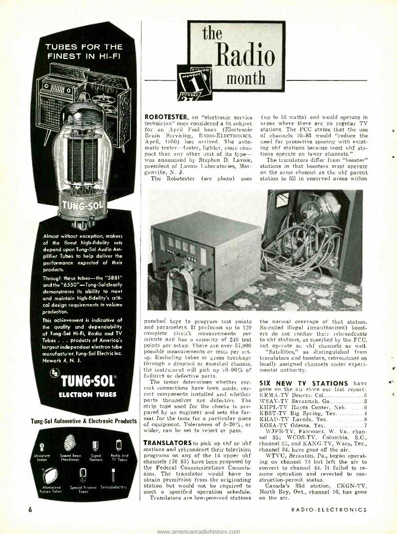
ROBOT ESTER, an "electronic service technician" once considered a fit subject for an April Fool hoax (Electronic Brain Servicing, RADIO- ELECTRONICS, April, 1950) has arrived. The auto- matic tester -faster, lighter, more com- pact than any other unit of its type - was announced by Stephen D. Lavoie, president of Lavoie Laboratories, Mor- ganville, N. J.
The Robotester (see photo) uses
(up to 10 watts) and would operate in areas where there are no regular TV stations. The FCC states that the use of channels 70 -83 would "reduce the need for protective spacing with exist- ing uhf stations because most uhf sta- tions operate on lower channels."
The translators differ from "booster" stations in that boosters must operate on the same channel as the uhf parent station to fill in unserved areas within
punched tape to program test points and parameters. It performs up to 120 complete circuit measurements per minute and has a capacity of 240 test points per setup. There are over 57,000 possible measurements or tests per set- up. Excluding tubes or gross breakage through a dropped or smashed chassis, the instrument will pick up 70 -90 / of failures or defective parts.
The tester determines whether cor- rect connections have been made, cor- rect components installed and whether parts themselves are defective. The strip tape used for the checks is pre- pared by an engineer and sets the for- mat for the tests for a particular piece of equipment. Tolerances of 5 -20%, or wider, can be set to reject or pass.
TRANSLATORS to pick up vhf or uhf stations and rebroadcast their television programs on any of the 14 upper uhf channels (70 -83) have been proposed by the Federal Communications Commis- sion. The translator would have to obtain permission from the originating station but would not be required to meet a specified operation schedule.
Translators are low- powered stations
the normal coverage of that station. So- called illegal (unauthorized) boost- ers do not confine their rebroadcasts to uhf stations, as specified by the FCC, but operate on vhf channels as well.
"Satellites," as distinguished from translators and boosters, rebroadcast on locally assigned channels under experi- mental authority.
SIX NEW TV STATIONS have gone on the air since our last report: KRMA -TV Denver, Col 6 WSAV -TV Savannah, Ga 3 KHPL -TV Hayes Center, Neb 6 KBST -TV Big Spring, Tex. 4 KHAD -TV Laredo, Tex. 8 KOSA -TV Odessa, Tex. 7
WJPB -TV, Fairmont, W. Va., chan- nel 35; WCOS -TV, Columbia, S.C., channel 25, and KANG -TV, Waco, Tex., channel 34, have gone off the air.
WTVU, Scranton, Pa., began operat- ing on channel 73 but left the air to convert to channel 44. It failed to re- sume operation and reverted to con- struction- permit status.
Canada's 33d station, CKGN -TV, North Bay, Ont., channel 10, has gone on the air.
RADIO -ELECTRONICS
www.americanradiohistory.com

LEARN uTOMATION
ELECTRONICS
TELEVISION RADIO ELECTRONICS
FASTER and EASIER with the aid of
THESE TWO D.T.I. EXCLUSIVE FEATURES
Exclusive! DeVry Electro -Lab i, aid Home Movies Speed Training
Only with DeVry can you get the speed and ease of training which the Electro -Lab affords. Through its transparent base you see both top and bottom of a circuit. You follow any wiring diagram placed underneath. Cuts dcwn time- wasting soldering! You use quick - operating spring connectors. Understand- ing of each circuit is faster ... better .. .
by this method. You see principles, too, with DeVry
home movies. You watch electrons on the march; you run the projector as slow or as fast as you want. All this with many mod- ern, easy -to -read, fold -out diagrams right alongside reading matter, re- edited often to include current developments. You get frequent consultation. That's why training is so practical, so interesting, so thorough, at DeVry. *Trade -mark
HOME MOVIES
OSCILLOSCOPES
f INCH
"SCOPE"
OPPORTUNITIES ARE GROWING Right this minute Automation is creeping up on many unskilled jobs. Right now, the field of Automation - Electronics, Radio, Television, Electronics has advanced from last year- that's why it's smart to insist on 1956 - model training.
You need training that's up -to -date, yet down -to- earth ... with unnecessary theories combed out of it, but essential principles kept in it. A program that's based on today's practical problems. That's the kind of training you need -the kind DeVry Tech offers you.
Why DeVry Tech Training Wins Thousands of D.T.I. men have finished their training, and stepped out into good jobs -familiar with the operating principles of modern commercial equipment, in step with current commercial techniques. They can do their jobs because they have been doing something very similar in DeVry training! Over 300 practical projects developed from 16 shipments of equipment. They have built their own instruments. They have learned from highly- trained instructors who take a personal inter- est. That's why the DeVry method is so much in demand.
Build, Use, and Keep Your Own Equipment To measure voltage and resistance you'll need a high -quality Vacuum Tube Voltmeter. To analyze pulses and waveforms of modern cir- cuits, you'll need a commercial -type 5 -inch Oscilloscope. No need to buy such eupensive equipment -you can buird it -you know every connec- tion in it. You'll use it all through your training, and in a profitable electronic career later. Let us give you all the facts -prove to you why DeVry training is better!
FREE
MM.
Get Free Information Folder.
Just Mail us the Coupon "One of America's Foremost
Electronics Training
Centers"
YEARS
lrlf
DeVry
Technical
Institute
Member of National Home Study Council
DEVRY TECHNICAL INSTITUTE CHICAGO 41, ILLINOIS
FORMERLY
DEFOREST'S TRAINING, INC.
MARCH, 1956
NO PREVIOUS TECHNICAL TRAINING NEEDED!
DeVry prepares you thoroughly, even though you have never wired up a circuit; even though you are not familiar with electricity. You learn in your own home, build your own laboratory equipment, broadcast from room to room in your home. Earn while you train - scores have paid for their course by servicing TV and Radio sets in their spare time. And DeVry helps you getstarted when you'retrained.
Valuable information for men subject to military service
DeVRY TECHNICAL INSTITUTE 4141 Belmont Ave., Chicago 41, III. Dept. RE -3 -M
I would like complete facts including "89 Ways to Earn Money in Television- Radio- Electronics."
(PLEASE PRINT)
Age
Street Apt
City _ -Zone State
1021 D.T.I.'s training is available in Canada.
7
www.americanradiohistory.com

"UNIDYNES" are the only small size, all- purpose moving coil
Dynamic Microphones that reduce the pickup of
random noise energy by 67 %.
The Unidynes, 55s and 556s, simplify P. A.
installation ... enhance your reputation ... insure
customer satisfaction by eliminating or reducing
callbacks due to critical gain control settings - often necessary when
conventional microphones have been installed.
No wonder the Unidynes are used the World over -
more than any other microphones -for
finest quality public address ..
theater stage sound systems
... professional recording
... remote broadcasting.
SHURE BROTHERS, Inc. Microphones and Acoustic Devices
225 W. Huron St., Chicago 10, Illinois Cable Address: SHUREMICRO
8
THE RADIO MONTH
LIGHT AMPLIFIERS, far more sen- sitive than anything previously known, have been announced both by the Air Force and Bendix. The Air Force device picks up the little light available under "darkness" conditions and focuses it upon the sensitive surface of an image intensifier (RADIO- CRAFT; August, 1948; page 23) which transforms the photons to electrons, accelerates them and uses them to produce a second image similar to the picture on a TV screen. The sen- sitivity of the device was stated to be at least 1,000 times that of a standard TV camera.
Not as much information is available on the Bendix amplifier, which also works on television principles. A cam- era with a standard image orthicon tube picks up the image and transmits it over a closed circuit through ampli- fiers to a viewer unit. Special advanced circuity permits the viewer to see an image more than 40,000 times as bright as the object scanned.
FM MULTIPLEXING went on the air recently when station WFLY, FM out- let of The Record Newspapers in Troy, New York, broadcast the first commer- cial program of this type in the United States. Without affecting the station's regular broadcast, a second program was simultaneously transmitted "piggy-
Multiplexing equipment installed in WFLY. Standing, left to right, K. Schabinger, WFLY chief engineer; W. S. Halstead, president of Multiplex Services; R. C. Goodrich, WFLY man- ager; B. Lord, Multiplex Services' chief
engineer.
back" over WFLY's wavelength. The second program could be received only by special receivers designed for this purpose and will be used for transmit- ting background music for banks, res- taurants, factories, etc.
This type of transmission, authorized last year by the FCC, permits FM broadcast stations for the first time to transmit simultaneously programs not intended for the general public.
TV SET REPLACEMENT BOOM ex- pected in 1956. Based on the estimate of 1,630,000 TV sets scrapped in 1954 and 2,370,000 in 1955, by Frank W. Mansfield, Sylvania's sales research di- rector, this year should be a banner
(Continued)
year for television sales. On the sup- position of G -E's tube market research manager, R. B. Yepsen, that TV sets are scrapped when they require a sec- ond replacement picture tube, nearly all of the 3,533,000 sets purchased in 1948 -49 should become eligible for re- placement in 1956.
Calendar of Events 3rd Annual Cleveland Electonics Confer- ence, March 2 -3, Old Gymnasium, West- ern Reserve University, Cleveland, Ohio. IRE Show, March 19 -22, Kingsbridge \rmory and Palace, Bronx, N. Y.
Exhibit of Airborne Electrical Apparatus. Components and Auxiliary Equipment, Southwestern District Meeting of the AIEE. April 2 -4, Baker Hotel, Dallas, Tex. Special Technical Conference on Mag- netic Amplifiers, April 5 -6, Hotel Syra- cuse, Syracuse, N. Y.
13th Annual Radio Component Show, April 10 -12, Grosvenor House, London, England.
GREENLEAF WHITTIER PICKARD, one of the great pioneer figures of radio, died Jan. 8 at the age of 78. He had worked in the electronics field as engineer and inventor since 1898. In the early years of the century he was a research engineer for the American Telephone & Telegraph (Bell) Co. and from 1907 to 1930 was consulting en- gineer for the old Wireless Specialty Co., at one time one of the country's leading communications companies. One of the first to transmit speech by radio (1902), Pickard did important early work in the development of the direc- tion finder (radio compass). He is con- sidered by many to be the inventor of the crystal detector and was one of the country's foremost students of static reduction and wave polarization. Dur- ing World War I his systems main- tained communication through static which destroyed reception from ordi- nary antennas.
He was a past president and Fellow of the Institute of Radio Engineers and a fellow and member of many other
scientific and technical societies, an author of a number of books and nu- merous papers, and holder of more than 100 U. S. patents. An ardent amateur (W1FUR), some of his papers on wave polarization frrst appeared in amateurs' magazines. END
RADIO -ELECTRONICS
www.americanradiohistory.com

i
Cot» ercio/.Rodio Operator
WE GUARANTEE TO TRAIN AND COACH YOU AT HOME IN SPARE TIME UNTIL YOU GET
YOUR FCC LICENSE
If you have any practical ex- perience- Amateur, Army, Navy, radio, repair, or experimenting.
HERE IS YOUR GUARANTEE If you fail to pass your Com- mercial License exam after complet- ing our course, we guarantee to continue your training, without additional cost of any kind, until you successfully obtain your Commercial license.
INFOR4,74
TV Enqiueet.,nq `NTEVaEV
COACH/NO-
TO
AND ._` ACH/NG-
EFFECTIVE JOB -FINDING SERVICE HELPS CIRE TRAINEES GET BETTER JOBS. HERE ARE JUST A FEW RECENT EXAMPLES OF JOB -FINDING RESULTS:
ELECTRONICS TECHNICIAN "I am now employed by the Collins Radio Company as a
Lab Technician. (This job was listed in your bulletin). I
have used the information gathered from your course In
so many ways and I know that my training with CI RE helped me a great deal to obtain this job."
Charles D. Sindelar, Cedar Rapids, Iowa
AIRLINES "I replied to the ¡ob Opportu -ities you sent me and I am now a radio operator with American Airlines. You have my hearty recommendation for your training and your Job - Finding Service."
James A. Wright, Beltsville, Md.
INDUSTRIAL ELECTRONICS "Upon my disdiarge from the Navy I used your Job -Finding Service and as a result I was employed by North American Aviation in electronic assembly (final checkout)."
Glen A. Furlong, Fresno, Calif.
HERE'S PROOF FCC LICENSES ARE OFTEN SECURED IN A FEW HOURS OF STUDY WITH OUR COACHING AT HOME IN SPARE TIME:
Name and Address A /1C Ronald H. Person St. Lows 20, Mo. Milton L. Geisler, ET3 FPO, San Francisco, Calif. Marvin F. Kimball Lafayette, Ind. L. M. Bonino Harlingen AFB, Tex
John E. Hutchison Bluefield, W. Va.
License Time
1st Class 25 Weeks
1st Class 26 Weeks
2nd Class 21 Weeks
2nd Class 16 Weeks
1st Class 27 Weeks
EMPLOYERS MAKE JOB OFFERS LIKE THESE TO OUR GRADUATES EVERY MONTH!
Broadcast Station in Illinois: "We are in need of an en- gineer with a first clam phone license, lit lily- a student of EIRE; 40 hour ¢eek' phis S hours overtime."
West Coast Manufacturer: "We are currently in need Of men with electronics training or experience in radar main- tenance, and too wuul4 alp eciate if you will refer inter- ested persons to us."
Letter from nationally -known Manufacturer: "We have a sirs great need at the present time for radio- electronics technicians and would appreciate any helpful sug_estious that you may be able to offer-,'
These are just a few of the examples of the job offers that come to our office periodically. Some licensed ra- dioman filled each of these lobs. It might have been you!
OURS IS THE ONLY H O M E S T U D Y COURSE WHICH SUP- PLIES FCC -TYPE EX- AMINATIONS WITH ALL LESSONS AND FINAL TESTS.
An Approved Member
ACT NOW/
st ALL 3
FREE
CARL E. SMITH, Consulting Engineer, President
CLEVELAND INSTITUTE OF RADIO ELECTRONICS Desk RE -89, 4900 Euclid Bldg., Cleveland 3, Ohio
MARCH, 1956
Y Ticket
f your ers as
nicFCC proof of Y
techal ability.
MAIL COUPON NOW!
Cleveland Institute of Radio Electronics Desk RE -89 -4900 Euclid Bldg. Cleveland 3, Ohio
I cant to knots how I can get my F('(' ticket iu a minimum of time. Send vnur FREE booklet, "How to Pass FCC I.i, en se Examinations" (doe,
wa cover exams for Amateur Lieensel, as veil a- a sample FCC-type lesson and the amazing booklet. "Money -Making F('(' License Information." Re ,war to tell me about your Television Engineering- ('muse.
PLEASE PRINT CLEARLY
p City
Age
Zone State (Address to Desk No. RE89 to avoid delay) FOR PROMPT RESULTS, SEND AIR MAIL
Special tuition rates to members of the U. s. Armed Forces Electronic Training also available to Canadian Residents,
= =- =- - - - - -- s -- -- - -- M - I. 9
www.americanradiohistory.com
famous
PHILCO.. PHI LCO
High Fidelity Model 1347
manufacturer of Hi -Fi Phonographs, Radio and Television
CHOOSES GENERAL INDUSTRIES
21010-tget. PHONOMOTORS
Philco specifies GI phonomotors as original equipment in its world famous line of top quality Hi -Fi record players for a good reason. In this highly competitive field where quality, perfor- mance and economy really count, long experi- ence has proved to Philco that it pays to rely on G/! So when you have an original equipment or replacement requirement, take a tip from Philco and . .. specify G!!
3 SPEED HI -FI MOTOR
Other General In- dustries AC induc- tion type motors for applications rang- ing from 1/40 HP to 1/1100 HP.
Write today for specifications and quantify -price quotations.
Q THE GENERAL INDUSTRIES co.
DEPT. GE ELYRIA, OHIO
Look what RADIO -ELECTRONICS has in store for you in
BUILD THIS MINIATURE RECEIVER FOR MODEL CONTROL
B y Rufus Turner MORE ABOUT LOAD LINES
B y Norman Crowhurst HIGH -GAIN TRANSISTOR AUDIO AMPLIFIER
B y Joseph Braunbeek TROUBLESHOOTING AGC CIRCUITS
B y Cyrus Gliekstein TRANSISTOR OPERATED GEIGER COUNTER
By Thomas G. Knight
the months ahead . . .
UNDERSTANDING COLOR BAR GENERATORS
B y Robert G. Middleton CLASS -B TRANSISTORS
By Edwin Bohr BACKGROUND NOISE LEVEL RE- DUCTION' IN MAGNETIC RECORDING
By James A. McRoberts LOSS OF SYNC IN DC RESTORERS
B y James A. McRoberts INEXPENSIVE CIVIL DEFENSE RADIATION METER
B y E. N. Kaufman
The APRIL issue of RADIO -ELECTRONICS goes on sale March 22d at better parts distributors and newsstands.
SUBSCRIPTION RATES Two years $6.00 One year $3.50
25 WEST BROADWAY Three Years $8.00
NEW YORK 7, N.Y.
10
orres1)oildene ia,- 4"..,1
P. G. A. H. VOIGT WRITES Dear Editor:
Mr. Hartley's reference (January, page 14) to my Edison Bell days (1922 -33) evoked memories of Mr. Johnstone, the chief recording engineer. He had discovered "the hard way," using recording sound boxes with flat glass diaphragms, just which trumpet best suited each particular artist for recording purposes. When I suggested microphones, amplifiers, electric cutters, etc, for this work, he must have known that his experience might soon become useless. Yet he never obstructed my ex- periments. Instead he taught me much that was to prove of special value later on when during several foreign record- ing expeditions, I recorded over 1,000 titles. To me Mr. Johnstone will always rank as one of the finest gentlemen I ever knew.
While at Edison Bell I developed the Tractrix horn shape (in 1926). Later this was incorporated in my earliest corner horns for domestic use (1934). Thank you Mr. Augspurger for the nice things you said about that horn (May, 1955, page 83) and thanks to Mr. Briggs for calling attention to its "antiquity" (January, 1956, page 14) .
Thanks also to Mr. Chave (present owner of the Lowther Manufacturing Co.) for calling attention to my inven- tion of the twin diaphragm for moving - coil loudspeakers (1933) (July, 1955, page 16), to Mr. Felix (November, 1955, page 14) for indicating that I had done more and to Mr. Beckett (Decem- ber, 1955, page 10) for pointing out that I had taught Lowthers my special tricks for making these.
For a speaker manufacturer to teach another firm how to make his specialty diaphragms must seem strange unless accompanied by a sale of interests or other arrangement.
Before the war, when Mr. Lowther personally was running the Lowther company, and Mr. Chave was his chief assistant, there had been a friendly "alliance" between Lowthers and my little company. They made tuners and amplifiers while we made speakers.
Apparently I did not make myself quite clear to Mr. Hartley in regard to my business arrangements with Low - thers. I did not sell out. The gentlemen's agreement between Mr. Chave and my company was more complicated and in- cluded commissions on sales.
I am indebted to Mr. Hartley for the spirited way in which he champions my fundamental work on speaker design.
(Continued on page 14)
RADIO -ELECTRONICS
www.americanradiohistory.com

here's a NEW Wau to Reach
the Top in
TV SERVICING
All - practice method professional techniques,
skills, knowledge of circuits, etc.
Includes 17" picture tube, all other tubes, components for a TV Receiver, Scope, Signal Generator, HF Probe. Low Introductory price under $200, on easy terms. Mail Coupon today.
IF YOU HAVE some Radio or Television experience, or if you know basic Radio -Television principles but lack experience -
NRI's new Professional Television Servicing course can train you to go places in TV servicing. This advertisement is your personal invitation to get a free copy of our booklet which describes this training in detail.
r LEARN -BY -DOING eeALL TIIE WAY"
This is 100% learn -by- doing, practical training. We supply all the components, all tubes, including a 17 -inch picture tube, and com- prehensive manuals covering a thoroughly planned program of practice. You learn how experts diagnose TV receiver defects quickly. You see how various defects affect the performance of a TV receiver- picture and sound; learn to know the causes of defects, accurately, easily, and how to fix them. You do more than just build circuits. You get practice recognizing, isolating, and fixing innumerable TV receiver troubles.
You get actual experience aligning TV receivers, diagnosing the causes of complaints from scope patterns, eliminating inter- ference, using germanium crystals to rectify the TV picture signal, obtaining maximum brightness and definition by properly adjusting the ion trap and centering magnets, etc. There isn't room on this or even several pages of this magazine to list all the servicing experience you get.
MARCH, 1956
CIIF AND COLOR TV MAKING NEW BOOM Installing front -end channel selector strips in modern UHF -VIIF Television receivers and learnixwb UHF servicing problems and their solution is part of the practice you get if you live in a LIIF area. To cash in on the coining color TV boom you'll need the kind of knowledge and experience which this training gives.
GET DETAILS OF NEW COURSE FREE Once again -if you want to go places in TV servicing, we invite, you to find out what you get, what you practice, what you learn from NRI's new course in Professional Television Servicing. See pictures of equipment supplied, read what you practice. Judge for yourself whether this training will further your am- bition to reach the top in TV serv- icing. We believe it will. We be- lieve many of tomorrow's top TV servicemen will be graduates of this training. Mailing the coupon in- volves no obligation. r
:.. HO& TO
,
REA- 1 TNF TOP
IN TV SERVICING
National Radio Institute, Dept. 6CFT 16th and U Sts., NW. Washington 9, D. C. Please send my FREE copy of "How to Reach the Top in TV Servicing." I understand no salesman will call.
Name Age
Address
City Zone State -- Approved Member, national Home Study Council
L
11
www.americanradiohistory.com

the first really new pickup in a decade
Made by perfectionists -for perfectionists. The FLUXVALVE is literally the cartridge of the future, its unique design meets the demands of all presently envisioned recording developments, including those utiliz- ing less than 1 mil styli.
There is absolutely nothing like it! The FLUXVALVE Turnover Pickup pro- vides the first flat frequency re- sponse beyond 20kc! Flat response assures undistorted high frequency reproduction - and new records
retain their top "sheen" indefinitely, exhibiting no increase in noise . . .
Even a perfect stylus can't prevent a pickup with poor frequency char- acteristics from permanently dam- aging your "wide range" recordings. With this revolutionary new pickup, tracking distortion, record and stylus wear are reduced to new low levels. The FLUXVALVE will last a lifetime! It is hermetically sealed, virtually impervious to humidity, shock and wear...with no internal moving parts.
The FLU XVALVE has easily replaceable styli. The styli for standard and microgroove record playing can be inserted or removed by hand, without the use of tools.
For a new listening experience, ask your deafer to demonstrate the new FLUXVALVE ...words cannot describe the difference... but you will hear it!
"FOR THOSE WHO CAN
THE DIFFERENCE"
HEAR
PICKERING & CO., INC. O C E A N S I D E , L O N G ISLAND, N. Y. P I O N E E R S I N H I G H F I D E L I T Y
... Demonstrated and sold by Leading Radio Parts Distributors everywhere. For the one nearest you and for detailed literature: write Dept. W.9.
12 RADIO -ELECTRONICS
www.americanradiohistory.com
A REVOLUTIONARY IDEA ... the greatest thing that has happened for music -lovers
since the introduction of long -playing records" -DEEMS TAYLOR
* YOU GET A 12 -INCH 331/3 R.P.M.
RECORDING OF A GREAT WORK OF MUSIC WITH AN OUTSTANDING ARTIST, ORCHESTRA OR CONDUCTOR...
* ALWAYS ACCOMPANIED -AT NO
EXTRA CHARGE -BY MUSICAL
PROGRAM NOTES -THAT IS, A 10-
INCH RECORD OF COMMENTARY, FULL OF MUSICAL
ILLUSTRATIONS, TO ENHANCE YOUR ENJOYMENT AND
UNDERSTANDING OF THE WORK
music appreciation ecorrls Ills new idea, originated a year
1 ago by the Book -of- the -Month Club, has a twofold purpose: first, to
help you build, systematically, a repre- sentative collection of recorded music -all the great works which are recog- nized as being necessities in every "basic" record library; and second, to enable music- lovers (particularly where there are young persons in the family) to increase their enjoyment and understanding of these masterpieces - and, indeed, all the music they hear.
HEART OF THE IDEA - MUSICAL ILLUSTRATIONS -The ten -inch record- ing sensibly takes the place of the time -honored printed "program notes" -almost necessarily inadequate, and usually impossible to follow by persons who have had no formal musical train- ing. By contrast, this new idea now en- ables the writer of program notes to show you, by having a full orchestra demonstrate the main features of the
MARCH, 1956
work, what to listen for in order to get the maximum enjoyment.
EVERY MONTH a great work of re- corded music, featuring some of the world's most distinguished musicians, is announced and described in ad- vance. You let it come, if you want it. If not, you can reject it by sending in an instruction form, always provided. When you decide you want the work described, the 12 -inch Performance Record and the 10 -inch Musical Pro- gram Notes are shipped together at a combined price of $3.90, plus a small charge for mailing expenses.
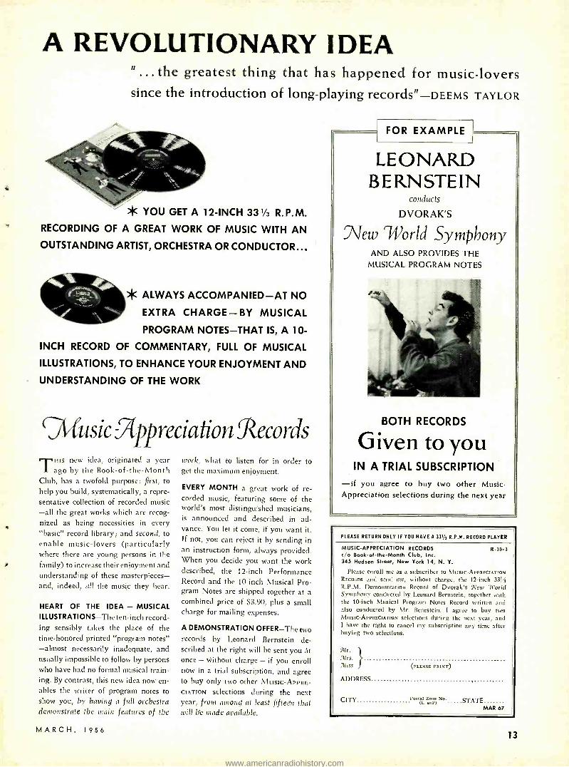
A DEMONSTRATION OFFER -The two records by Leonard Bernstein de- scribed at the right will be sent you At
once - without charge - if you enroll now in a trial subscription, and agree to buy only two other MUSIC- APPRE-
CIATION selections during the next year, from among at least fifteen that will lie made available.
FOR EXAMPLE
LEONARD BERNSTEIN
conducts
DVORAK'S
.TTew World Symphony AND ALSO PROVIDES THE
MUSICAL PROGRAM NOTES
BOTH RECORDS
Given to you IN A TRIAL SUBSCRIPTION
-if you agree to buy two other Music - Appreciation selections during the next year
PLEASE RETURN ONLY IF YOU HAVE A 33y, R.P.M. RECORD PLAYER
MUSIC -APPRECIATION RECORDS R -39.3 c/o Book -of- the -Month Club, Inc. 345 Hudson Street, New York 14, N. Y.
Please enroll me as a subscriber to MUSIC- APPRECIATION RECORDS and send me, without charge, the 12 -inch 3314 R.P.M. Demonstration Record of Dvorak's New 'World Symphony conducted by Leonard Bernstein, together with the 10 -inch Musical Program Notes Record written and also conducted by Mr. Bernstein. I agree to buy two MUSIC- APPRECIATION selections during the next year, and I have the right to cancel my subscription any time after buying two selections.
7Hr.
7Hrs. 7Híss (PLEASE PRINT)
ADDRESS
CITY Postal Zone No. STATE any) MAR 67
13
www.americanradiohistory.com

Pat Atiovintebt New Sonotone
"3" Series SUPER - FIDELITY
Ceramic Cartridges
Turnover Model, 3T
(Actual Size, 1 -7/16 inch) Single -needle Model 3P
also available
Super compliance (2.0 min.) -drops distortion below "negligible" point.
Super response -flat from 20 to 15,000 cycles, without equalization!
PARDON US IF WE CALL THEM "REVOLUTIONARY "... but these new cartridges obsolete pre -amplifiers, equalizers, and old -style pickups!
If you've followed the development of ceramic cartridges since Sonotone pio- neered them in 1946, you know we've made enormous advances.
Recently Sonotone has offered ceramic cartridges equal, by test, to most velocity types. Now, Sonotone presents the "3" Series, which set utterly new standards of finest performance, by all the measure- ments engineers know how to make.
These new cartridges make the inherent advantages of the ceramic type loom larger than ever. Consider:
WHY A PRE -AMP?
There is only one reason for a pre- ampli- fier -a velocity pickup puts out too feeble a voltage to drive your amplifier directly. But these Sonotone "3" Series cartridges deliver a whopping 0.5 volts- roughly 50 times as much as most velocity types. So you can eliminate the circuitry, noise, space and expense a pre -amp involves. (If you now have a pre -amp, our simple adaptor permits immediate use of Sonotone "3" Series cartridges in your present system.)
EQUALIZING UNNECESSARY
Sonotone "3" Series cartridges end equal- ization nuisance because ceramic cartridges respond to amount of needle movement not velocity. Result, they self -equalize.
These new cartridges eliminate mag-
14
netic hum problems. Fit any of the widely used arms.
Single needle model, with diamond, only $30.00 LIST. Turnover model with sapphire - diamond needles, $32.50 LIST. Less with sapphires.
NEW SONOTONE AMPLIFIER
We built this HFA -100 to realize the full excellence of Super- Fidelity ceramics.
Hum, noise and distortion are vir- tually unmeasur- able-at maximum settings. distortion isonly0.15%!Cab- inetry is superb solid walnut or
solid mahogany, with solid brushed brass panel. $117.50 NET. Similar control unit, for use with power amplifier, $59.00 NET.
"Revolutionary" is a big word. But these Sonotone developments are pretty big news, if you like music!
SO N OTO N E° CORPORATION, ELMSFORD, N. Y.
CORRESPONDENCE (Cont'd from pg. 10)
My understanding of magnet design grew in the mid -Twenties while design- ing magnets for dynamic recording cut- ters in which maximum possible gap flux density was needed. The trick is mainly a matter of reducing leakage and providing adequate cross -sectional area everywhere. Later (1929) I devel- oped a loudspeaker magnet, bearing the same dominating principles. For maximum cooling, and also to minimize leakage, I used an open construction in the commercial model. This was fitted with a twin diaphragm. For PA work, weather protection was added.
When the war ended, it was already clear that excited speakers would soon be regarded as obsolete and so both Mr. Chave and I were evolving a PM ver- sion of the excited magnet. I insisted that we work independently till the de- sign changes had been crystallized, when we would compare notes. I adopted the central block type of PM while Mr. Chave preferred the material in ring form around the center pole.
A PM speaker requires no cooling fins. Imagine the protected unit without cooling fins, and the pedigree of the Lowther -manufactured unit becomes obvious.
However, I do want to point out that in spite of the similarity in styling and the many internal similarities, the Low- ther magnet is not 100,;4 my work as some seem to think. Mr. Chave is re- sponsible for including a design feature aimed at reducing leakage and for pro- viding adequate cross- sectional area in various parts of the magnet ring. The details were settled as the result of con- siderable experiment, and it is only fair that he should be given proper credit for what he has done.
P. G. A. H. VOIGT
Toronto, Canada
LIST PRICES Dear Editor:
I firmly believe in the use of list prices. Cut -throat competition reduces dealer profits and leads the customer to believe that dealers that hold the line are reaping enormous profits. Stand- ards should be set on just how much an old television set is worth on a trade -in.
Not helping the situation is the print- ing of net prices in magazines by manu- facturers. Why not quote list prices? People in the trade can easily determine their net prices. Why should the cus- tomer know how much I pay for parts?
The "standard -brand tubes at bar- gain prices" is another sore spot but fortunately tube manufacturers and magazines like RADIO- ELECTRONICS are doing something about that. [See Page 63. Editor] JOSEPH J. KELLY Westmere Television Albany, N. Y.
AUTO RADIO Dear Editor:
I found the article on car radios by Jack Darr (November, 1955) very corn -
(Continued on page 18)
RADIO-ELECTRONICS
www.americanradiohistory.com

the only COMPLETE catalog for everything in TV, Radio, Hi -Fi
and Industrial Electronics
w,rs,;y.Elhatasa
p,LLIED RADIO M WfttlaN aYaNOF CNICII.O O. Ill.
Aosa 14Aym°r`t11-61100
Get ALLIED'S 1956 Catalog -it's complete, up -to- date -324 pages packed
with the world's largest selection of quality electronic equipment at
lowest, money- saving prices. Get every buying advantage at ALLIED: fastest
shipment, expert personal help, lowest prices, assured satisfaction. Send today for your FREE copy of
the big 1956 ALLIED Catalog.
1956 INNI ON NC 11
Featuring Super -Value Knight-Kits- top quality electronic equipment in precision -designed kit form
BUY DIRECT AND SAVE
EASY -PAY TERMS Use our liberal Easy Payment Plan -only 10', down, 12 months to pay -no carrying charges if you pay in 60 days. Available on Hi -Fi and P.A. units, recorders, TV chassis, test instruments, kits, Ama- teur gear, etc,.
HI -FI SPECIALISTS To keep up with the latest and best. in High Fidelity, look to ALLIED. Count on us for all the latest releases and largest stocks of Hi -Fi equipment. We specialize, too, in TV supply -and are foremost in the field of Builders' Kits.
UJodcü Moen &goat gittdoi, Latest Hi -Fi Systems and Components
P.A. Systems and Accessories Recorders and Supplies TV Tubes,
Antennas, Accessories Amateur
Receivers, Transmitters, Station Gear
Specialized Industrial Electronic
Equipment Test and Lab Instruments
Huge Listings of Parts, Tubes,
Transistors, Tools, Books
send for the leading electronic supply guide _____ INN ___ NMI __,
I ALLIED RADIO CORP., Dept. 2 -C -6 III 100 N. Western Ave., Chicago 80, III.
Send FREE 324 -Page 1956 ALLIED Catalog.
Name
Address
I I I
-_ALLIED RADIO: World's Largest Electronic Supply House
City Zone State
mi - - - --J MARCH, 1956 15
I I I I
I I
www.americanradiohistory.com

Dealers by the thousands are
making tile Vi[`ir t ja to this great insulator idea!
when we say
SWITCH we mean
business!
IMI1111EL:
New indoor antenna has
gliding UTCUW
Copyright 1956, Channel Master Corp.
www.americanradiohistory.com

Only CHANNEL MASTER'
insulators have this revolutionary
2 in 1 design It's a wood -screw insulator
... it's a machine -screw insulator ... and it's BETTER in both applications!
STANDOUT insulators and buckles are already outselling all others - after only a few months on the market! This remarkable record provides positive proof of the solid ac- ceptance STANDOUTs have won among dealers all over the country.
Why has the response to STANDOUTs been so enthusi- astic? BECAUSE they cut space and dollar investments in accessories by more than 65% ... BECAUSE they increase space and dollar turnover by more than 200% ... BECAUSE they are easier to install, stronger, more durable.
Millions already sold!
Here's why: 'T -Nut" buckle with 8 threads.
More threads than any other buckle (nut type or extruded) - 8 full machined threadsl Tighten as hard as you want, you can't strip it!
Pointed Screw makes positive contact.
Strap won't slip while you're tightening. Won't twist or slip on most after installa- tion. Straps have con- venient "taper- tip."
Needle -sharp point Finer thread, sharper point means easier starting - even in hardwood. Minimizes possibility of splitting.
444114414444*
t. Mí\4\Mlli`1\tWtt1411,ql STANDOUT point.
All popular types and sizes available, including
full assortment of specialized hardware.
See your Channel Master distributor
CHANNEL
Glide
MASTER'S new
'D -MafiC INDOOR TV ANTENNA
The Glide -o- Matic's sensational low -loss gliding switch is different from all others! Provides highest electrical effi- ciency ... AND - it's the most convenient to operate!
Glide- o -Matic also gives you:
e Maximum performance on all channels - VHF and UHF.
,s Weighted tip -proof base - with "can't scratch" felt covering.
Ready for COLOR TV.
Powerful retail merchandising support.
Available in , Mahogany
4 with brass
Ebony
popular color , Ivory
harmonies: Ebony
with brass
with brass
Trod. 111-1 d.y u.i d.. 011
with aluminum
model no. 3700
model no. 3701
model no. 3702
model no. 3703
A performance hit
with men ... A style hit with women !
Glide- o -Matic practically sells itself. Smartly styled ... blends into any setting. Packed in colorful "tell and sell" car- ton with convenient ;'carry away" handle.
Also available:
$9.95 list
CHANNEL MASTERS ALL -VU model no. 381, all -VHF, all UHF.
$895
un
CHANNEL MASTERS PRE -VU model no. 380 all- channel VHF.
519s
(flANNEL MASTER CORP. WORLD'S LARGEST MANUFACTURER OF TV ANTENNAS AND ACCESSORIES
www.americanradiohistory.com

All the Facts About TAPE RECORDING
only $ 27 5 ORDER TODAY
"TAPE RECORDERS
How They Work" by Charles G. Westcott
'This is the book for everyone interested in Tape Recording
Now you can have an expert understanding of tape recording. Explains magnetic recording theory; describes characteristics of tape. Tells how a recorder operates; discusses motorboard mechanism,drive motors, volume indicators, bias oscillators, equalization circuits, amplifiers and magnetic heads- includes diagrams, photographs and schematics. Tells you how to get best fre- quency response with lowest noise, how to avoid tape overload, how to obtain best bias settings; includes procedures for testing tape recorders and tape. The comprehensive book about Tape Recorders. 176 pages; 5M x 8' "; over 150 illus- trations. Postpaid, only $2.75
USE HANDY ORDER FORM BELOW r Sams books cover every phase of Electronics for the service technician, engineer,
student or experimenter. Listed below are a few of the many valuable Sams books available at electronic
parts distributors and leading book stores.
USE THIS ORDER FORM
TAPE RECORDERS - HOW THEY WORK $2.75
7 Transistors -Their Application in Television - Radio- Electronics. The first practical, com- plete book on transistors; explains cir- cuitry, installation, testing techniques, theory and servicing. 100 pages; 5% x 8 W illustrated $1.50
D Fundamentals of Color Television. An up -to- date explanation of Color TV, its theory, operation, installation and servicing, with photos, block diagrams and schematics. 224 pages; 5% x 8W; illustrated . . $2.00
O Servicing TV Sweep Systems. Describes the operation, circuit function and circuit vari- ation of vertical and horizontal sweep sys- tems common to most TV receivers. Tells how to analyze circuits; trouble -shoots for you. 212 pages; 5% x 8H "; illus- trated $2.75 Technical Dictionary. Over 4,000 definitions of radio, television, electronic, electrical and radar terms. Includes valuable charts, graphs, diagrams and symbols. Flexible binding for "on- the -job" use. 160 pages; 5H x 8W $2.00
D TV Test Instruments. Tells how each instru- ment operates, how to use it in actual servicing. Covers Vacuum Tube VM's, AM Signal Generators, Sweep Signal Gen- erators, Scopes, Video Signal Generators, Field Intensity Meters and Voltage Cali- brators. 180 pages; 8%1 x 11" $3.00
DThe Recording and Reproduction of Sound. The largest selling book in its field. Widely used by Audio engineers, Hi -Fi enthusi- asts, P.A. technicians, broadcasting sta- tions and recording studios. Authoritative chapters cover: behavior of sound waves; basic recording methods; lateral disc re- cording; micro -groove recording; the deci- bel; phono reproducers; cutting styli; mi- crophones; loud speakers and enclosures; home music systems; public address sys- tems; amplifiers; tuners, etc. 810 pages, 6 x S''; illustrated $7.95
D Atomic Radiation, Defection and Measurement. Provides a basic understanding of nuclear science and its applications. Includes a full discussion of equipment and tech- niques required for detecting and measur- ing radiation. The service technician will be particularly interested in chapters deal- ing with the circuitry and operation of the many types of detection devices. 200 pages; Sys x 8%" $3.00
Audio Amplifier Service Manuals
D Vol. 6. Schematic diagrams, illustrations, parts lists and invaluable servicing data on 36 amplifiers, 18 preamps and 13 tuners produced in 1953 -54. All data is based on analysis of the actual equipment. 352 pages, 8% x 11" $3.95
D Vol. 5. Covers 37 amplifiers, 12 preamps, 14 tuners, 1952 -53. 352 pages $3.95
D Vol. 4. Covers 75 amplifiers and tuners produced in 1951 -52. 352 pages $3.95
O Vol. 3. Covers 50 amplifiers and 22 tuners produced in 1950. 352 pages $3.95
Record Changer Service Manuals ri Vol. 6. Includes diagrams, photos, exclu- '-' sive "exploded "views, parts lists and serv-
ice data for 20 popular record changers and recorders produced during 1953 -54. All data based on lab analysis of the actual equipment. 288 pages, 8%g x 11 " $3.00
D Vol. 5.32 models; 1952 -53; 288 pages $3.00 Vol. 4.38 models; 1950 -51; 288 pages $3.00
ID Vol. 3.44 models; 1949 -50; 288 pages $3.00 Vol. 2.45 models; 1948 -49; 432 pages $4.95
There is an authoritative Sams book on virtually any Electronic subject in which you're interested. Check be- low for FREE Book List describ- ing all Sams books.
El Send Book List
.iauuHOWARD W. SAMS & CO., INC.aaaaaaaa a Order from your Parts Jobber today, or mail to Howard W. Sams & Co., Inc., Dept. 2 -C6, 2201 East 46th St., Indianapolis 5, Indiana. Send books checked above. My (check) (money order) for $ is enclosed.
Name
Address
City Zone State (outside U.S.A. priced slightly higher) La aaa aaaa aaamaaaasa
Look for SAMS BOOKS
on the "Book Tree" at your Parts
Distributor
18
u
a a
a u
CORRESPONDENCE (Cont'd from pg. 14)
plete. However, one common failure, usually in the more recent models, was omitted. I have found numerous cases of defective on -off switches, either in- termittent or open. As these units are usually a mess to get out, we bridge the old one and sell the customer a new switch which we mount under the edge of the dashboard. This way the switch can be easily replaced when it goes bad.
ROBERT D. LAYTON Hemet, Calif.
TECHNOTE IMPROVEMENT Dear Editor:
In your November, 1955, issue, your Technotes section carried an item by Mr. Keller which contained a remedy for vertical noise pulses in the Admiral 21B1 chassis.
He recommends changing the vertical peaking resistor to 460 ohms. I have had perhaps upward of 20 Admiral chassis of that series with a similar complaint and in all cases either a de- fective filter capacitor or a defective vertical output transformer was the trouble. The transformer was the defec- tive component in over 907, of the cases. With a defective transformer, lowering the vertical spike amplitude relieves the condition but does not cure the trouble and tends to lead to prob- lems in vertical height and linearity.
Apparently, lowering the spike ampli- tude slows the rate at which the 6S4 goes into cutoff. Consequently, the ver- tical retrace spike is smaller and the transformer will not arc over.
LEE RAMSAUER Tonawanda, N. Y.
FREE ENTERPRISE Dear Editor:
Screwdriver mechanics -let them con- tinue with no restrictions. Competition is a stimulant to progress; control is stagnating. Competition forces the capable technician to expand his tal- ents, especially if he charges higher rates than the screwdriver mechanic.
How many "trained" men use their skills much beyond tube changing? So many of them are either lazy or do not understand what they have been taught. The screwdriver mechanics do foul up some sets, but not so much more than many of our "trained" technicians. At any rate, let the public have inexpensive service where it gives sufficient results; the cheap Ford eventually benefited everyone.
A highly skilled man should switch from general servicing to specialized work on the dogs brought in by screw- driver mechanics. Let the screwdriver boys make their money changing tubes, the skilled men fixing the tough ones.
The specialist could probably make more money this way and never have to make a house call. All sets would be brought to him -but he would have to use his brains more.
A. W. CLEMENT Galion, Ohio END
RADIO -ELECTRONICS
www.americanradiohistory.com

The book that Launched
Thousands of Careers
is yours FREE TELLS HOW YOU CAN BE SUCCESSFUL
IN RADIO -TV- ELECTRONICS
Send for Your Free Copy Today!
YOU CAN PLOD ALONG for years, getting a paltry increase now and
then, enjoying little security, find- ing your work dull and drab.
Then something happens. Things look up. You become more confident. Your earnings rise. You feel more important.
"Luck," some may say. "Contacts," others may suggest. But in your heart, you will
know the answer: "Training." And it all may have started the moment you filled out a coupon requesting a copy of a free booklet named "Your Future in the New World of Elec- tronics." From this data you get knowledge of where you stand in Electronics. Tremendous expansion leaves this gigantic industry p.ead- ing for trained men. Top manufac- turers sold billions of dollars worth of electronic merchandise in 1955. By 1960, the radio -electronics indus- try should do no less than 15 billion dollars per year, not counting mili- tary orders.
Today, there are over 118,000 radio -equipped police cars; over 92,000 radio -equipped taxis; over 30,000 civilian planes have radio; near- ly 50,000 American ships have radio.
Today, there are over 132 000, - ` 000 radios in use. There are 38.,000,-
000 TV sets and 477 TV stations in operation. Color TV is coming into high gear. Countless positions must be filled -in development, research, design, production, testing and in- spection, manufacture, broadcast- ing, telecasting and servicing. To fill these posts, trained men are
See Our Ad On The Next Page
I needed -men who somewhere along the line take time to improve their knowledge, their skills. Men who, today, perhaps, take two minutes to send for a booklet.
`'Your Future in the New World of Electronics shows you how CREI Home Study leads the way to greater earnings through the invit- ing opportunities described above.
However, CREI does not prom- ise you a "snap." With an accredited technical school such as this, you must study to convert your ambi- tion into technical knowledge you can sell in the fabulous Electronics market.
Since its founding in 1927, CREI has provided thousands of professional radio men with techni- cal educations. During World War II CREI trained thousands for the Armed Services. Leading firms choose CREI courses for group training in electronics, at company expense, among them United Air Lines, Canadian Broadcasting Cor- poration, Trans -Canada Airlines, Douglas Aircraft Co., Columbia Broadcasting System, All- American Cables and Radio, Inc., and Radio Corporation of America.
CREI courses are prepared by recognized experts, in a practical, easily understood manner. You get
the benefit of time -tested materials, under the personal supervision of a CREI Staff Instructor, who knows and teaches you what industry wants. This is accomplished on your own time, during hours selected by you, and controlled by your own will power. This complete training is the reason that graduates find their CREI diplomas keys -to- success in Radio, TV and Electronics. CREI alumni hold top positions in Amer- ica's leading firms. At your service is the CREI Placement Bureau, which finds positions for advanced students and graduates. Although CREI does not guarantee jobs, re- quests for personnel far exceed cur- rent supply.
Now is the time of decision for you. Luck will not propel you for- ward unless it finds you trained. Contacts won't budge you an inch unless you have the skill to back them up. The answer is: Technical Training . and willingness to learn. Together they will bring you increased earnings in this new Age of Electronics. Fill out the postage - free reply card and mail it now. We'll promptly send you your free copy of "Your Future in the New World of Electronics." The rest - your future -is up to you.
MAIL THIS POSTAGE -FREE POSTCARD TODAY
CAPITOL RADIO ENGINEERING INSTITUTE Accredited Technical Institute Curricula
3224 16th St., N.W., Washington 10, D. C. Dept. 143-C
(R. N. Apr. 1 956) BA
Please send me your course outline and FREE Illustrated Booklet Your Future in the New World of Electronics" . describing
opportunities and CREI home study courses in Practical Electronics Engineering.
CHECK Practical Radio Electronics Engineering FIELD OF Broadcast Radio Engineering (AM, FM, TV) GREATEST Practical Television Engineering INTEREST Practical Aeronautical Electronics Engineering
Name_. Age
Street
City Zone_ _ _ _ State
Check: Home Study Residence School Veteran
To help us answer your request intelligently, please give the fol- lowing information:
EMPLOYED BY........
TYPE OF PRESENT WORK
SCHOOL BACKGROUND
ELECTRONICS EXPERIENCE
IN WHAT BRANCH OF ELECTRONICS ARE YOU MOST INTERESTED?
www.americanradiohistory.com

CREI prepares you quickly for Success
The future is in your hands! The signs are plain as to the future of the trained men in the electronics industry. It is a tremendous industry, and -at the present time there are more jobs than there are trained men to fill them. But -when there's a choice between a trained and untrained applicant, the trained man will get the job. Your biggest problem is to decide on -and begin the best possible training program.
CREI Home Study .. .
The Quick Way to Get There.
Since 1927, CREI has given thousands of ambitious young men the technical knowl- edge that leads to more money and security. The time- tested CREI procedure can help you, too -if you really want to be helped. CREI lessons are prepared by experts in easy -to- understand form. There is a course of instruction geared to the field in which you want to specialize. You study at your convenience, at your rate of speed. Your CREI instructors guide you carefully through the material, and grade your written work personally (not by machine).
Industry Recognizes
CREI Training. CREI courses are prepared, and taught
with an eye to the needs and demands of
industry, so your CREI diploma can open many doors for you. Countless CREI grad- uates now enjoy important, good -paying positions with America's most important companies. Many famous organizations have arranged CREI group training for their radio -electronics -television personnel. To name a few : All America Cables and Radio, Inc.; Canadian Aviation Electronics, Ltd.; Canadian Broadcasting Corporation ; Co- lumbia Broadcasting System; Canadian Marconi Company; Hoffman Radio Cor- poration; Machlett Laboratories ; Glenn L. Martin Company ; Magnavox Company; Pan American Airways, Atlantic Division; Radio Corporation of America ; Technical Appliance Corporation; Trans -Canada Air Lines ; United Air Lines. Their choice for training of their own personnel is a good cue for your choice of a school.
1st Class
Permit No. 288 -R
Sec. 34.9 P.L.R.
Washington, D. C.
BUSINESS REPLY CARD No Postage Stamp Necessary If Mailed in United States
3c Postage Will Be Paid By
CAPITOL RADIO ENGINEERING INSTITUTE
3224 16th Street, N.W.
Washington 10, D. C. I 1
I
in J BROADCASTING
E TELEVISION
El MANUFACTURING
D COMMUNICATIONS
N SERVICING
FiAERONAUTICAL
ELECTRONICS
Almost immediately you feel the benefits of CREI training. Your employer, when informed of your step toward advancement (only at your request), is certain to take new interest in you and in your future. What you learn in CREI Home Study can start helping you do a better job immediately.
CREI also offers Resident Instruction
at the same high technical level -day or night, in Washington, D. C. New classes start once a month. If this instruction meets your requirements, check the coupon for Residence School catalog. PAYS FOR ITSELF QUICKLY. Your very first raise could repay your investment in CREI training, and leave you a profit the very first year. Your increases in pay thereafter are all pure profit, and you'll be prepared for many more promotions and pay raises in the future years of your life.
KOREAN VETERANS If you were discharged after June 27, 1950, let the new G.I. Bill of Rights help you obtain resident instruction. Check the coupon for full information.
Called "Your Future in the New World of Electronics," this free illustrated booklet gives you the latest picture of the growth and future of the gigantic electronics world. It includes a complete outline of the courses CREI offers together with all the facts you need to judge and compare. Take 2 minutes to send for this booklet right now. We'll promptly send your copy. The rest -your future -is up to you.
www.americanradiohistory.com

HI -FI LOUDSPEAKERS & ENCLOSURES
by Abraham R. Cohen
Here is a Ion_ -needed, long- awaited book
that is destined to become a classic volume in the field of hi -fi literature. The subject is covered so completely, that every ques- tion any hi -fi fan may ask about high fidelity loudspeakers and enclosures is
answered in its information -packed pages. It is supremely authoritative and brilliantly written! The author is a recognized author- ity, a musician and an engineer who has been intimately connected with the field
of acoustics. and particularly with loud- speaker and enclosure design. His richly imaginative writing skill has resulted in a
book that is not only informative, it makes for very interesting reading as well. Vivid
and equally imaginative illustrations in-
crease this effectiveness, and further help you in selecting, using and enjoying hi-fi
loudspeakers and enclosures. It is a volume that will increase your pleasure in hi -fi
reproduction, and save you money while doing so. It is a MUST book for all audio and hi -fi technicians and enthusiasts!
#176, only $4.60
Economical
ELECTRONICS KNOW -HOW!
RIDER BOOKS ARE TAILORED TO TEACH
TELEVISION -HOW IT WORKS
(2nd Edition)
by J. Richard Johnson
A completely rewritten, up -to -the- minute 2nd edition of a book that has proven itself first in its field! Authoritative and informative, this revised edition is the latest and most comprehensive text on the subject, which it covers fully and in down - to- earth, readily understandable language. The text follows the progress of the received signal from the antenna to the picture tube and loudspeaker, and the specially conceived and prepared illustrations have been worked out in a manner which makes every portion of the text clearly under. standable to anyone.
#101, Leather Finish MARCO Cover: 352 pp., 51/2x81/2", illus., only $4.60
REVIEW SERIES edited by Alex. Schure, Ph.D.,
Ed.D. Six titles of a popular series written expressly for the technician, student and radio amateur. Each thorough. ly and clearly covers the basic concepts of an indi- vidual part of electronics principles. Soft Covers: 51/2 x W'_. ", illus.
R -C & R -L TIME CONSTANT i Iir lira. tical application of Time Constant, and how it affects circuit operation. #166: 52 pp., only $.90 F -M LIMITERS & DETECTORS Discusses modern f -m detectors, the operation and use of fm limiter circuits and their application to Al frequency modulated signal systems.
=166-2: 48 pp., only $.90 FREQUENCY MODULATION A rcvictc of ñ.Sic o
t,
cep t -. circuits and their appli- cation, written in ra simple and easy- tounderstand niannc r.
#166 -3: 52 pp., only $.90 CRYSTAL OSCILLATORS A discussion of the crystal oscillator, of special value and interest to the technician and radio amateur.
166 -4 : 72 pp., only $1.25 A -M DETECTORS Cun nis itacII t. ith the fundamental concepts of a -m detectors. and the basic operation of the a -nt detector circuit. #166 -5: 64 pp., only $1.25 LIMITERS & CLIPPERS Discusses all types of diode, triode and pentode limiters and clippers; circuit operation is analyzed and practical applications of all circuits are included. #166 -6: 64 pp., only $1.25
COLOR TELEVISION
RECEIVER PRACTICES
by Hazeltine Corp. Laboratory Staff
Satisfies the need for a readily understand- able text which explains the principles of color television receivers. It is the finest and most complete text on the intricacies and design of color television receivers. For schools, engineers, designers and laboratory workers. #162, Soft Cover: 200 pp., 5% x8% ", illus., only $4.50
RIDER'S SPECIALIZED HI -FI AM -FM TUNER MANUAL (Vol. 1)
A handy reference manual which tells you how to service the hi -fi tuners made by the 21 most popular manufacturers. It covers more than 5 years of production -1950 to 1955 -and tells you everything you need to know about servicing these tuners. #7001, Soft Cover: 220 pp., 81/2 x11 ", illus., only $3.50
FREE CATALOG ON REQUEST
BASIC ELECTRICITY
BASIC ELECTRONICS
BASIC SYNCHROS &
SERVOMECHANISMS
by Van Valkenburgh, Nooger & Neville, Inc.
The fabulous picture -text books derived from the U.S. Navy's present training pro- gram! They are being made available to you at such an economical price, they're within the reach of everyone. Each set features the "show -how" drawings -over 2,000 of them! -that make every topic of the text picture clear. There's a complete idea on every page, and on that same page there's at least one big, clear illustration, which helps you to fully under- stand the topic being discussed. At the end of every section, review questions high- light the material just covered. In this thorough, step -by -step manner, a solid foundation of knowledge is built up, enabling the reader to rapidly understand electrical and electronics concepts.
# 169: BASIC ELECTRICITY
Soft Covers: 5 volumes, 624 pp., 6x9", only $9.00 per set. Cloth Bound : all 5 volumes in a single binding, only $10.50.
# 170: BASIC ELECTRONICS
Soft Covers: 5 volumes, 550 pp., 6 x 9 ", only $9.00 per set. Cloth Bound : all 5 volumes in a single binding, only $10.50.
# 180: BASIC SYNCHROS &
SERVOMECHANISMS
Soft Covers: 2 volumes, 270 pp., 6x9 ", only $5.50 per set. Cloth Bound : both volumes in a single binding, only $6.95.
THESE AND MANY OTHER RIDER BOOKS ARE AVAILABLE AT YOUR BOOKSTORE OR PARTS JOBBER -LOOK FOR THE RIDER DISPLAY RACK
JOHN F. RIDER PUBLISHER, Inc. 480 CANAL ST., NEW YORK 13, N. Y.
In Canada: Charles W. Pointon, Ltd. 6 Alcina Ave., Toronto, Ontario
Canadian Prices approx. 5% higher
MARCH, 1956 21
www.americanradiohistory.com
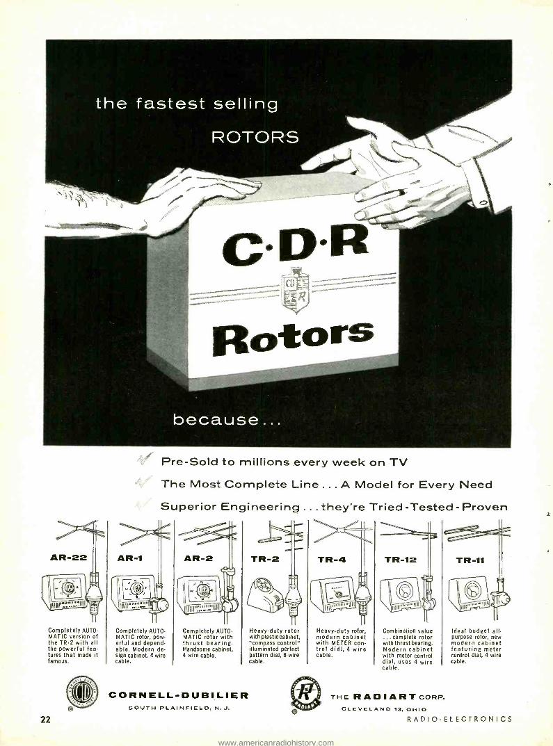
Pre -Sold to millions every week on TV
The Most Complete Line ... A Model for Every Need
Superior Engineering ...they're Tried -Tested - Proven
TR-2
IIIIIIIIY'".':".'"'=:°111111 I
Completely AUTO. MATIC version of the TR -2 with all the powerful fea- tures that made it famous.
22
Completely AUTO- MATIC rotor, pow- erful and depend- able. Modern de- sign cabinet. 4 wire cable.
Completely AUTO- MATIC rotor with thrust bearing. Handsome cabinet, 4 wire cable.
CORNELL-DUBILIER SOUTH PLAINFIELD, N.J.
Heavy -duty rotor with plastic cabinet, "compass control" illuminated perfect pattern dial, 8 wire cable.
Heavy -duty rotor, modern cabinet with METER con- trol dial, 4 wire cable.
$.0
""IIIII uu11p,,,,,,."
Combination value . complete rotor
with thrust bearing. Modern cabinet with meter control dial, uses 4 wire cable.
THE RADIARTcoRP.
Ideal budget all - purpose rotor, new modern cabinet featuring meter control dial, 4 wire cable.
CLEVELAND 13, OHIO RADIO -ELECTRONICS
www.americanradiohistory.com

Start
Become a top -notch television service technician
Now ... RCA INSTITUTES offers modern TV KIT with Comprehensive Television Servicing Course
START to build with a TV Kit developed by one of America's foremost radio -tv schools - RCA Institutes. LEARN with simple step - by -step instruction how to build a modern, large- screen receiver. TEST each stage, as you build, and see how it works. Learn how "trouble- shooting" is applied. FINISH your Home Study Course ready and able to service all make and model sets! Easy -to- follow instructions are planned and prepared for you through the efforts of RCA Institutes' instructors, engineers at RCA Laboratories, and training specialists of the RCA Service Company.
RCA INSTITUTES, INC. A SERVICE OF RADIO CORPORATION of AMERICA
350 WEST FOURTH STREET, NEW YORK 14, N.Y.
The RCA Institutes' TV Kil utilizes up -to -date circuits including:
Synchro -Guide horizontal automatic frequency control circuit. Horizontal magnetic reaction scanning. Latest deflection circuits. FM sound discriminator. High -gain, low -noise cascode tuner.
Join the many thousands who have been successfully trained by RCA Institutes for a good job (or business of their own) in tele- vision servicing. BASIC KNOWLEDGE OF RADIO NECESSARY NO NEED FOR PREVIOUS TV TRAINING
r FREE BOOKLET! MAIL COUPON NOW.
RCA INSTITUTES, INC., Home Study Dept. E -36
350 West Fourth Street, New York 14, N.Y. With no obligation on my part, please send me a copy of your booklet on the TV Servicing Home Study Course and Kit. I understand no salesman will call.
Name
Address:
City Zone: State
(Please print)
MARCH, 1956 23
www.americanradiohistory.com
ONLY RAYTHEON PICTURE TUBES... give you these
major advantages CROSS -CHECK CONTROL
Raytheon Picture Tubes are right when you get them, thanks to RAYTHEON'S CROSS -CHECK QUALITY CONTROL. This comprehensive Raytheon quality control method includes daily tests made on tubes for pressure, base torque and outside coating adhesion. Engineering controls check screen color and brightness and tube life under both ideal and extremely adverse conditions. And, most important of all, a substantial percent- age of every day's production is actually unpacked and tested for physical appearance and electrical characteristics before quality control headquarters will permit release of a single tube for shipment.
CORONA INHIBITOR
This Raytheon development insures brightness rain or shine. Ordinary tubes lose up to 10% of their brightness on humid, damp days. Not so, Raytheon Picture Tubes. Tests prove no toss of brightness even under a water spray on the high voltage contact - thanks to Corona Inhibitor.
LUMIN ;FZED
LUMILAC -- a lacquer especially, ended and used exclusively by Raytheon is the secret of the superiorit Raytheon Aluminized Picture Tubes.
This amazing lacquer produces a : ra smooth, unbroken surface for the
pure auminum coating, yet leaves no -producing residues which could im- pair cathode emission and shorten tube Ti
The result - all the benefits of aluminized - bes, sharper picture, superior contrast, high light outp,_ - plus excellent tube e.
EY'RE
yr
o r
o +0 t ..
gNp S,G
Raytheon Picture Tubes have the distinct advantage of precision produc- tion in one of the world's most modern plants. The Raytheon Cathode
Roy Tube Plant in Quincy, Mass. houses some of the world's largest
equipment and was designed and built solely for the manufacture of
today's large screen Raytheon Picture Tubes.
RAYTHEON MANUFACTURING COMPANY Receiving and Cathode Ray Tube Operations
Newton, Mass. Chicago Atlanta, Ga. Los Angeles, Calif.
Raytheon makes l Receiving and Picture Tubes, Reliable Subminiaturearid Miniature Tubes, Semicon
all these s ductor Diodes, Power Rectifiers and Transistors, Nucleonic tubes, Microwave Tubes óssarllene+t in elo/wwies
24 RADIO -ELECTRONICS
www.americanradiohistory.com

You Get This Valuable Book
Just for Examining OYNE'S NEW 6- VOLUME SET
ON 7 DAYS FREE TRIAL !!
.41101- Now! The most liberal "get-acquainted" offer you've ever seen! Think of it -Coyne gives you this big, new 1956 Edition of book, "150 Radio -Television Picture Patterns and Diagrams Ex- plained ", ABSOLUTELY FREE. This up -to- the -minute, practi- cal book gives you complete 11 x 211." Schematic Diagrams cover- ing 170 models Radic and Televisi. n Sets. Also analysis of TV
Servicing with picture tube patterns including many actual trouble- shooting patterns. Large 81/2 x H" pages. Full instructions show y..1 how to read and use the diagrams. This valuable took is a FREE GIFT to you, for just ask_ng to see the great new Coyne 6 -book set. "Applieci Practical Radic - Television "!
AT LAST! MONEY -MAILING "KNOW -HOW" ON TRANSIS -ORS, COLOR TV AND SERVICING
Z1 Ora WOW- tamsr»
44E1.
2500 PAGES OF PRACTICAL RADIO AND TELEVISION FACTS AT HOUR FINGER TIPS!
vol. 1. APPLICATION OF - ELEYISIOI42ADIO PRINCIPLES: 300 pages, covers resonance & tuning, amplifiers, oscillators, etc. Vol. 2. RADIO. TELEVISION & FM RECEIVERS: 403 rages, covers rectifiers, high frequency, short wave, FM, antennas. etc. Vol. 3. RADIO- TELEVISION CIRCUITS: 335 pages, covers power tubes, de- coupling, distortion, photo- tubes, prase ir_ve:ters, etc. Vol. 4. LATEST INSTRUMENTS FOR SERVICING RADIO - TELEVISION: 343 pages, covers all types o- testing instruments, their use in service work. Vol. 5. TELEVISION SERVICING & TROUBLE- SHOOTING MANUAL: 400 pages, practical servicing of all types of TV sets, UHF, boosters, color TV, etc. - * PLUS TV CYCLOPEDIA! A "must" for the TV serviceman. Quick answers to all TV problems in A -B -C order, cross- indexed. 900 pages, fully illustrated; covers hundreds of facts on servicing, installation. alignment, UHF, transistors, much more.
MARCH, 1956
1
You get all he right answers to today's TELEVISION -RADIO servicing prob ems -and get diem quickly -in Coyne's great new 6- volume set. Right at your lager -tips is the TV -Radio knowl- edge that ma =es you worth more money! Over 5,000 practical facts and data are fully covered in easy -to- understand fashion in volumes I thuough 5. Every step is completely explained -from principles of -adio and telcvi9 in to installing, servicing, trouble- shooting cod aligning includies full facts on COLOR TV and UHF. Also i.cludes the ver7 latest information on TRAN- SISTORS- Ht.ndreds of photos, illustrations. charts and diagrams help you understand quicker. For speedy on- the -job use. I'll also include tie binons 900 page Coyne TELEVISION SERVICING CYCLOPEDIA- covering today's Lebec isiun problems in easy -to -find alphabetical order. Use this - ouplete 6 volume TV- RADIO LI- BRARY FREE for 7 days.. T valuable Picture Pattern -Diagram Book ABSOLL TELY FREE!
AC- NOW -SEND NO MONEY! Just mail the ìoupon for Coyn- s 6 volume set on 7 days free trial. I'll induce tie book of 150 ^VRADIO Patterns & Diagrams. I you keep the set, pay $2 in 7 days and $2 per month until $22.50 plus postage is paid. (Cash mire, $20.95.) Or you can return the library at our expense in 7 days and owe nothing. Either may, t e
book of TV -Radio Patterns is rurs to keep FREE! Take advanta of this oiler FT ONCE!
FREE BOOK-- -- FREE TRIAL COUPON! Roy Snyder, SOOY$E ELEC
R. ALnSCHOOI POyi
5 0-, ,I r' longer] I'l mer,. 6-book Dept. 36 -T; Chicago
12, (I per your s`'t- take adva rida,. 111.
°ffer Include l d
Practical . 1,rio
V RA1) fluai,,.- fcle1tia Cet.- 4equaioted \arm'.. IO x,tt,ru, for Offer! P
n Sen,) Diagrams 7 days FREE TRIAI. Address. Bonk FREE!
..Age I city....... e
o U P
o
Y
i . Where Em n ....
'..... ..
. p/oyea.-----------...- -.. ..Zone-........g .
... O Cheek here if yrnt . tate..,
.....
c.o.n .... .. . postage
on want
librar d..l,, y sri,tt ..... r..o. .. 7-day blut=3.r ßa.D- You pay postro .........
Cutarante ao ZY0,g5 pI us
I
25
www.americanradiohistory.com

_..
... v .!
V
ROHN NO. 6 TOWER - "All- Purpose" Tower
Self- supporting to 50 ft., or guyed to 120 ft. Utilizes mass production
techniques to give you lowest prices, yet highest profits for a
tower of this type. Ideal for home and industrial requirements. Permanent
hot -dipped galvanized coating inside and out. Dependability -a
feature customers demand - is assured with the Rohn No. 6 Tower .. .
designed to "stand up" for years to the rigors of weather and climatic
conditions. Easy to climb for fast, efficient servicing. In ID ft. sections.
v J
ROHN PACKAGED TOWER
"Space Sayer" Po,. Pending
cuts storage space 300% or more!
Popular PT -48 has almost 50' of sturdy tower within a compact 8' x 20 "package! "Magic Triangle" design is adapted to a pyramid shape using a wide 19" base with progressively decreasing size up- ward. Decreases your overhead . . . easy to transport and assemble; cuts shipping costs! , Galvanized through- out. Available in heights of 24', 32', 40', 48', 56' and 64'.
- I I I I
' I ' 1 l
.. ..
V
V
a#,et)To-tuvLo I`/
L MAGIC TRIANGLE CONSTRUCTION
Famous wrap- around design with full 21/2" corrugated cross -bracing welded to tub- ular steel legs.
2. INTERLOCKING JOINTS ... formed by swaging tower ends so that they overlap each other, becoming a sin- gle unit in structure. Proved by tests to be superior.
3. WEATHER SEALED ... against condensation and moisture.
4. HOT DIPPED GALVANIZING
. both inside and out gives the finest protective coating known. This sales point is one of the best you can offer
the finest quality and at lower than compétitive prices!
these two HOT DIPPED GALVANIZED
Rohn Towers will satisfy 90% of your TV tower needs!
HEAVY DUTY NO. 30 TOWER
Heights up to 200' or more when guyed Self- supporting up to 60'
Sturdy communication or TV tower that will withstand heavy wind
and ice loading. Heavy gauge tubular steel, electrically welded throughout.
Weather resistant, non -corrosive double coating provides durable finish.
All sections in 10' lengths. Only 2 -4 manhours required for installing
50' tower! Tremendous sales potential for you in this tower/
26
SPECIAL INSULA- TOR SECTIONS are available to permit the Rohn No. 30 Tower to be used as guyed "series fed" radiators for amateur and corn - mercial uses.
NEW LINE OF ROHN ROOF TOWERS
Four superior designed "Roof Towers" are
1
available for inexpen- sive, yet sturdy roof in- stallations. 3', 5' and 10' sizes are available. These completely gal-
vanized Rohn Towers have unbeatable sales appeal when this type installa- tion is desired.
HANDLE THE COMPLETE LINE
OF ROHN GALVANIZED ACCESSORIES
... house brackets, special bases, peak and flat roof mounts, instant drive -in bases, telescoping masts with matching bases, special Rohn Fold -Over Tower, guying brackets, UHF antenna mounts, erection fixtures, variety of mounts and supports for masts or tub- ing, tower installation accessories, TV service tables, mast and TV hot dipped galvanized tubing, guy rings, etc.
for larger profits customer satisfaction greater ease in ordering, handling and shipping
CALL YOUR ROSIN REPRESENTATIVE FOR COMPLETE CATALOG, SALES
LITERATURE AND I'RICES - OR WRITE - PHONE - WIRE DIRECT
GET ALL YOUR REQUIREMENTS
FROM ONE RELIABLE SOURCE
ROHN Manufacturing Company 116 Limestone Avenue, Bellevue, Peoria, Illinois
RADIO -ELECTRONICS
4
www.americanradiohistory.com

SPECIAL OFFER! (SAVE $15.00)
FASTER SERVICING-BIGGER PROFITS
WITH B & B PIX TUBE TESTER - R EACTI VATO R
B & B's revolutionary eight position Selector Switch and single lead hook -up
quickly checks both picture tube and receiver in a fraction of your normal testing time. Abnormalities are instantly readable on big meter dial - no
involved circuitry connections - no questionable readings - your examina- tion is finished accurately, dependably in a jiffy.
Servicemen everywhere are making extra dollars by bringing old tubes back
to life and tying up future picture tube sales with this instrument on each
service call. Single Selector Switch provides twelve separate tests of both picture tube and receiver:
UNIVERSAL HIGH VOLTAGE PROBE
THIS IS THE ONLY PROBE THAT
CAN BE USED WITH ANY METER
Up to 0 to 60 KV ON ANY METER
with NO EXTRAS TO BUY
INSTRUCTIONS FOR USE WITH METERS OF
ALL TYPES (10,000 OHMS PER VOLT OR
MORE) CLEARLY AND SIMPLY SHOWN WITH
PICTURES, CHARTS, GRAPHS AND TABLES
INCLUDED WITH THE INSTRUMENT.
If you change your meter, you can alter your B & B Model 702 High Voltage Probe to suit without additional pats or resistors to buy.
PRICE--Complete with four universally matched precision High Voltage Resistors $13.95 and full instructions, only
ANY BIAS VOLTAGE FROM O TO 30 VOLTS FROM A PERMANENT SOURCE - THE MODEL 704 BIAS BOX
Why buy bias batteries which wear out, can't be adjusted, and whose
voltage is not constant, when you can get
Exact Specified Substitute Bias Voltage For Troubleshooting ANC Circuits in Radio Receivers Troubleshooting AGC Circuits in TV Receivers Visual Sweep Alignment of TV and
Other Receivers Industrial Equipment Checking Troubleshooting and Adjustment of A -F and R -F Amplifiers.
The Boland and Boyce Model 704 BIAS BOX is designed so the whole unit clips neatly onto the chassis apron, thus supporting it mechanically while at the same time providing an electrical ground. Manufacturers of TV
receivers specify in the service data for alignment and other checks that a definite fixed bias voltage must be substituted for the AGC voltage so the AGC action will not interfere with development of visual response curves This substitution is also necessary in trouble shooting the AGC circuits of the TV receiver.
The value of the voltage is adjusted by setting pointer to value on a convenient calibrated "voltage set" scale. Thus, the receivers AGC supply is removed - the Boland and Boyce Model 704 BIAS BOX output applied in its place - and the bias voltage adjusted exactly to that specified by the receiver manufacturer in his service instructions.
Assembled, Wired and Tested $9.90
(LÒ:h1
BOLA RESEARCH
MARCH, 1956
Tests leakage between grid and cathode Tests leakage between heater and cathode Tests leakage between grid and screen Tests grid- cathode voltage from receiver Tests effectiveness of receiver brightness control Tests receiver screen voltage supply Tests receiver video output signal Tests effectiveness of brightness receiver control Tests beam current MEASURED AT HV ANODE Tests grid control of beam current Tests overall receiver performance dynamically
One out of every three TV PIX TUBES can be reactivated success-
fully the B & B way. Just set Selector Switch in "Beam -Curr" position, turn on HV for three minutes and the job is done safely without damage to the cathode.
OUTSTANDING FEATURES OF THIS INSTRUMENT INCLUDE:
Sensitive 100 Micrometer meter movement'
Built -in 0 -600 Voltmeter (1% accuracy)
Bench Model 701 $54.90 HV PROBE 13.95
$68.85 Special Combination Price $53.85 --
YOU SAVE $15.00
INTRODUCTORY OFFER - LIMITED TIME ONLY - ACT NOW! 10 DAY MONEY -BACK GUARANTEE
- - Ì Boland & Boyce Inc., 236 Washington Ave., Belleville, N. J.
Kindly ship me as per special offer one Model 701 TV PIX TUBE
TESTER REACTIVATOR and one HV PROBE both for $53.85.
Also include leatherette carry case for $5 additional.
Send me Universal High Voltage Probe separately at $13.95.
Send Bias box at $9 90
Enclosed Find $ Full price to be shipped prepaid.
$ 25% down- shipped balance C.O.D. Railway Express.
Name
Street
City State ............... ........
ND and B OYC E, INC Washington A Bellev236 ille, New Jersey
DESIGN ENGINEERING CONSULTANTS
27
www.americanradiohistory.com

Irre #ea4có ZVOVGI3
reaeèibd -only "Staminized" Astron Capacitors really deliver better performance. Astron's capacitor "know -how" insures
better performance 3 important ways - better designs, better materials, better
production techniques - the secret of
"Staminizing"
Learn the facts, as thousands of service
technicians have, why Astron's extra -
rugged capacitors build consumer
satisfaction and repeat business - eliminates callbacks!
You'll find there's a dependable Astron
exact replacement capacitor for every
radio and TV requirement - write for FREE "Astron Replacement Catalog AC -4D ". Ask your jobber for "Staminized"
Astron Capacitors - today!
PROVED BEST IN SERVICE!
28
ALW111111tCONI C O R P O R A T I O N 255 GRANT AVENUE EAST NEWARK. N. J.
WEST COAST WAREHOUSE: 9041 WEST PICO BLVD., LOS ANGELES EXPORT DIVISION: ROCKE INTERNATIONAL CORP., 13 EAST 40TH ST., N. Y., N. Y.
IN CANADA: CHARLES W. POINTON, 6 ALCINA AVE., TORONTO, ONTARIO
RADIO -ELECTRONICS
www.americanradiohistory.com

t. C. Lane, S.S., M.A. President, Radlo -Tele- vision Training Asso- -lotion. Executive Director, Pierce School of Radio & Television.
VETERANS -- NON -VETERANS
TRAIN NOW FOR A TOP- PAV1SIQN TEL E r
Needed ' AT H0 PARE T
NOW - while the Television- Radio -Electronics industry is
expanding at the fastest rate in history - is the time for
you to prepare for a top -pay lifetime job ... or your own
prof table business.
Nev. TV stations are going up constantly ... sales of TV
sets are breaking all past records ... new products are
being announced almost every day ... new plants are
LEARN - !NG As part of your training I give you the equipment you need to set up your own home laboratory and prepare for a BETTER -
PAY TV JOB. You build and keep an Electromagnetic TV RECE VER designed and engineered to take any size picture tube up to 21 -inch, (10 -inch tube furnished. Slight extra cost for larger sizes.) ... also a Super -Het Radio Receiver, AF -RF
Signal Generator, Combination Voltmeter- Ammeter -Ohmmeter, C -W Telephone Transmitter, Public Address System, AC -DC Power supply. Everything supplied, including all tubes.
springing up to meet the heavy demand for these products.
Trained men are needed urgently. The head of CBS- Colum-
bia product service department estimates that the industry
will need 200,000 service men by 1959. The best jobs will
go to the men Nho are reacy for them. Right now is the time
for you to prepare yoursel. Delay can be costly.
4W Telephone
Transmitter
AF RE Sgrc'.
erleraror
SuperNel
Radio Receive,
Combination VoIlmelr. Ammeler.Ohmmeler
STUDY NEWEST DEVELOPMENTS My training covers all the latest developments in the fast -growing Television -
Radio- Electronics industry. You learn about FM - RADAR - COLOR TV - TRANSISTORS - PRINTED CIRCUITS, etc.
CHOOSE FROM THREE COMPLETE COURSES covering all phases of Radio, FM and TV
1. Radio, FM and Television Technician Course - no previous experience needed.
2. FM -TV Technician Course - previous training or experience in radio required.
3. TV Cameraman and Studio Technician Course - advanced training for men
with Radio or TV training or experience.
After you finish your home study train- ing in Course 1 or 2 you can have two
weeks, 50 hours, of intensive Lab work
on modern electronic equipment at our
associate resident school, Pierce School
of Radio & Television. THIS EXTRA TRAINING IS YOURS AT NO
EXTRA COST WHATSOEVER!
EXTRA TRAINING IN N.Y.C. AT NO EXTRA COST!
FCC COACHING COURSE
Important for BETTER -PAY JOBS requiring FCC License!
You get this training AT NO EXTRA COST! Top TV jobs
go to FCC- licensed technicians.
I1tL I)vLbLøt aútn,9
FREE! I'll send you my new 40-
page book, "How to Make Money in Television - Radio -
Electronics," a Free sample lesson, and other literature showing how and where you can get a top -pay lob in Television.
t,a,t%eti1,
52 EAST 19th STREET NEW YORK 3, N. Y. Licensed by the State of New York Approved for Veteran Training
MARCH, 1956
EARN WHILE YOU LEARN
Almost from the very start of your course you can earn extra
mcney by repairing sets for friends and neighbors. Many of
my students earn up to $25 a week ... pay for their entire training with spare time earnings ... start their own profit.
able service business.
My School fully approved to train Veterans under new Korean G.I. Bill. Don't lose your school benefits by waiting too long. Write discharge date on coupon.
MAIL TI-IS COUPON TODAY! - -- lit- = - --fi' Mr. Leonard C. Lane, President
I RADIO -TELEVISION TRAINING ASSOCIATION Dept. R -3C, i2 East 19th Street. New York 3, N. Y.
Dear Mr. Lane: Send me your NEW FREE BOOK, FREE
SAMPLE LESSON, and FREE aids that will show me
how I can make BIG MONEY IN TELEVISION. I under- stand I am under no obligation.
Name
Addres
(PLEASE PRINT PLAINLY)
Age
City Zone State
I AM INTERESTED IN:
Radio -FM -TV rechnician Course
FM -TV Technician Course
TV Cameraman 8 Studio Technician (ourse
MI !I lilt NM o ® MI
VETERANS! Write discharge date
N O OBLIGATION! 29
www.americanradiohistory.com

topee r rNrl ircoí,.0* ,ib
Crystal structure models. Top row, left to right: cuprite, zincblende, rutile, perovskite, tridymite. Second row: cristobalite, potassium dihydrogen phosphate, diamond, pyrites, arsenic. Third row: caesium chloride, sodium chloride, wurtzite, copper, niccolite. Fourth row: spine], graphite, beryllium, carbon dioxide, alpha -quartz.
PROM ATOMS TO STARS Research at Bell Telephone Lab-
oratories ranges from the ultimate structure of solids to the radio sig- nals from outer space. Radio inter- ference research created the new science of radio astronomy ; research in solids produced the transistor and the Bell Solar Battery.
Between atoms and stars lie great areas of effort and achievement in physics, electronics, metallurgy, chemistry and biology. Mechanical engineers visualize and design new devices. Mathematicians foreshadow new communications techniques.
Despite the diversity of their tal- ents, Bell Laboratories scientists and engineers have much in common. A habit of teamwork channels these talents into great communications advances. These men have developed
Models of the atomic patterns in solids help Bell Laboratories scientists visualize their electrical behavior.
the world's finest telephone system. In doing so, many have become lead- ers in their fields. Opportunities for achievement await properly qualified scientists and engineers at Bell Tele- phone Laboratories.
Directional antenna used by Karl G. Jansky in discovery of stellar radio signals at Bell Telephone Laboratories in 1932.
BELL TELEPHONE LABORATORIES
WORLD CENTER OF COMMUNICATIONS RESEARCH LARGEST 'bN4 USTRIAL LABORATORY IN THE UNITED STATES
30 RADIO -ELECTRONICS
www.americanradiohistory.com

NEW! COLOR and Black -& -White LAB & TV 5" OSCILLOSCOPE #460
KIT $79.95. Wired $129.50 The FINEST professional 5 mc wide -band scope value. Ideal for research, h -f & complex waves, plus Color & Monochrome TV servicing. Flat from DC to 3.58 mc ±1 db (color burst freq.), flat DC to 4.5 mc +1, -3 db. Vert. sens. 25 rms mv/in. Vert. Z 3 megs. Has the following outstanding fea- tures not found in scopes up to several times its price, kit or wired: VERTICAL AMPLIFIER: direct. coupled (DC) thruout to eliminate 1 -f phase shift; push -pull thruout for negligible distortion; K- follower coup-
ling between push -pull pentode stages for extended h -f resp. (minimizes h -f phase shift, extends use- ful resp. to 10 mc); full- screen undistorted vert. deft; 4 -step freq- compensated decade step attenu ator up to 1000:1. SWEEP CIRCUIT: perfectly linear sweeps, 10 cps - 100 kc (ext. cap. for down to 1 cps); pre -set TV vert. & hor. positions (30 & 7875 cps); automatic sync. ampi. & limiter elim- inates sync amplitude adj. PLUS: direct or cap. coupling; bal. or unbal. inputs; edge -lit engraved Incite graph screen; dimmer; antiglare filter; bezel fits std photo equip;. OTHER IMPORTANT FEATURES: High intensity trace CRT. Finest sq. wave resp. (.06 usec rise time). Push-pull hor. ampl., flat to 400 kc, sens. 0.6 rms mv/in. Built-in voltage calibration. Intensity mod. Sawtooth & 60 cps outputs. Astigmatism control. Retrace blank-
ing. Instant, drift -free full- screen vert. positioning & 2X full -screen hor. positioning. Bal., cal., astig. adj. externally accessible. 5UPI CRT, 2 -6AÚ8, 2.6C56, l- I2AU7A, 2.6J6, 1.6AX5, I -IV2. Deep -etched satin aluminum panel, rugged grey wrinkle steel cabinet. Designed for easy building at home with no special equipment. 13" x 81/2" x 16 ". 30 lbs. SCOPE DIRECT PROBE #PD: KIT $2.75. Wired $3.95. Eliminates stray pick -up & signal re- radiation. SCOPE DEMODULATOR PROBE #PSD: KIT $3.75. Wired $5.75. Demodu lates AM carriers between 150 kc and 250 mc. SCOPE LOW CAPACITY PROBE #PLC: KIT $3.75. Wired $5.75. For signal tracing in high frequency, high impedance & wide -band circuits (as in TV) without distortion from overloading or frequency discrimination.
for COLOR and Monochrome TV servicing
New! PEAK -to -PEAK VTVM #232 & UNI -PROBE ¡pat. Pend.)
KIT $29.95. Wired $49.95 UNI- PROBE: exclusive with EICOt Terrific
time- saver! Only 1 probe performs all func- tions-a half -turn of probe -tip selects DC or AC -Ohms. The new leader in professional peak -to -peak VTVMs. Latest circuitry, high sensitivity & precision, wide ranges & versatility. Calibration without removing from cabinet. New balanced bridge circuit. High Z input for negligible loading. 41/2" meter, can't -burn- out circuit. 7 non -skip ranges on every funetion.4 functions: +DC Volts, -DC Volts, AC Volts, Ohms.
Uniform 3 to 1 scale ratio for extreme wide - range accuracy. Zero center. One zero -adj. for all functions & ranges. 1% precision ceramic multi- plier resistors. Measure directly peak -to -peak voltage of complex & sine waves: 0.4, 14, 42, 140, 420, 1400, 4200. DC /RMS sine volts: 0 -1.5, 5, 15, 50, 150, 500, 1500 (up to 30,000 v. with HVP
probe, & 250 mc with I'RF probe). Ohms: 0.2 ohms to 1000 megs. 12AÚ7, 6AL5, selenium rectifier; xfmr- operated. 81" x 5" x 5 ". Deep - etched satin aluminum panel, rugged grey wrinkle steel cabinet. 7 lbs.
New! DELUXE PEAK -to -PEAK VTVM #249 with 71/2" METER a UNI -PROBE (pat. pend.)
KIT $39.95. Wired $59.95 All the advanced & exclusive features of #232 -PLUS the extra convenience and readability of its big 71/2" meter. Your ideal bench instrument.
VTVM RF PROBES* #PRF -11 or PRF -25: KIT $3.75. Wired $4.95. Accuracy ±10 %. Use with any
I I or 25 megohm VTVM. VTVM HV PROBE #HVP -2: Wired $4.95. Complete with multiplier resistor. Measures up to 30 kv with any VTVM or 20,000 ohms /volt VOM.
150 kc to 435 mc with ONE generator! New! RF SIGNAL GENERATOR #324
KIT $26.95. Wired $39.95 for COLOR and Monochrome TV servicing
New wide- range, stable generator - better value then genera- tors selling at 2 or 3 times its costi Ideal for: IF -RF alignment, signal tracing & trouble -shooting of TV, FM & AM sets; mar- ker gen.; 400 cps audio testing; lab. work. 6 fund. ranges: 150-400 kc, 400-1200 kc, 1.2 -3.5 mc, 3.5.11 mc, 11 -37 mc, 37 -145 me; 1 harmonic band 111.435 mc. Freq. accurate to ±1.5 %; 6:1 vernier tuning & excellent spread at most import- ant alignment freqs. Etched tuning dial, plexiglass windows, edge -lit hairlines. Colpitts RF ose., directly plate -modulated by K- follower for improved mod. Variable depth of int. mod. 0 -50% by 400 cps Colpitts osc. Variable gain ext. mod. ampli- fier: only 3.0 volts needed for 30% mod. Turret -mounted coils slug -tuned for max. accuracy. Fine & Coarse (3 -step) RF attenuators. RF output 100,000 uv; AF sine wave output to 10 volts. 50 -ohm output Z. 5 -way jack -top binding posts for AF in /out; coaxial connector & shielded cable for RF out. Tubes: 12AÚ7, 12ÁV7, selenium rectifier; xfmr- operated. Deep -etched satin aluminum panel, rugged grey wrinkle steel cabinet. 8" x 10" x 43/4". 10 lbs.
The specs are the proof...
4 NEW BEST BUYS
by L7E /CO4
lalibr without removing from cabinet
Visit our BOOTH 209 -2/ IRE SHOW
COMPLETE with Preamplifier, Eaualizer and Control Section
New! 20 -WATT Ultra- Linear Williamson - type HIGH FIDELITY AMPLIFIER #HF20
KIT $49.95. Wired $79.95 A low -cost, complete -facility amplifier of the highest quality that sets a new standard of performance at the price, kit or wired. Every detail, down to the etched, brushed solid brass control plate, is of the fine quality EICO is famous for. Rated power output: 20 watts (34 w peak). IM distortion (60 cps: 6 kc /4:1) at rated power: 1.3 %. Mid -band harmonie distortion at rated power: 0.3 %. Maximum harmonic distor- tion between 20 and 20,000 cps at 1 db under rated power: approx. 1%. Power response (20w) : ±0.5 db 20- 20,000 cps; ±1.5 db 10- 40,000 cps. Frequency response (1 /aw): ±0.5 db ±13.35,000 cps; -±-1.5 db 7-50,000 cps. 5 feedback equalizations for LP's & 78's including RIAA. Variable turnover feedback tone controls do not affect volume & permit large boosts or cuts at either end of audio spectrum with midfregs. unaffected. Loudness control & separate level set control on front panel. Low Z output to tape recorder. 4 hi -level switched inputs: tuner, te, tape, auxiliary (xtal/cer- amic phono or 2nd tuner); 2 low -level inputs for proper loading with all leading magnetic, FM & quality xtal cart- ridges. Hum bal. control. Extremely fine output transformer has interleaved windings, tight coupling, careful balancing & grain -oriented steel. 81/2" x 15" x 10 ". 24 lbs. Only EICO Probes have all these
features: fully shielded; rugged term board parts mounting; chock- mounted floating construction; swivel- action; color -coding; easy parts accessibility.
® 56
MARCH, I956
These amazing EICO values are NOW IN STOCK at your nearest distributor. Examine them side -by -side with ANY competitor. You'll see for yourself why indeed EICO is your BEST BUY. Fill out coupon on reverse page.
TURN PAGE FOR MORE EICO VALUES .. 84 Withers Street, Brooklyn 11, New York Prices 5c,ó higher on West Coast.
31
www.americanradiohistory.com
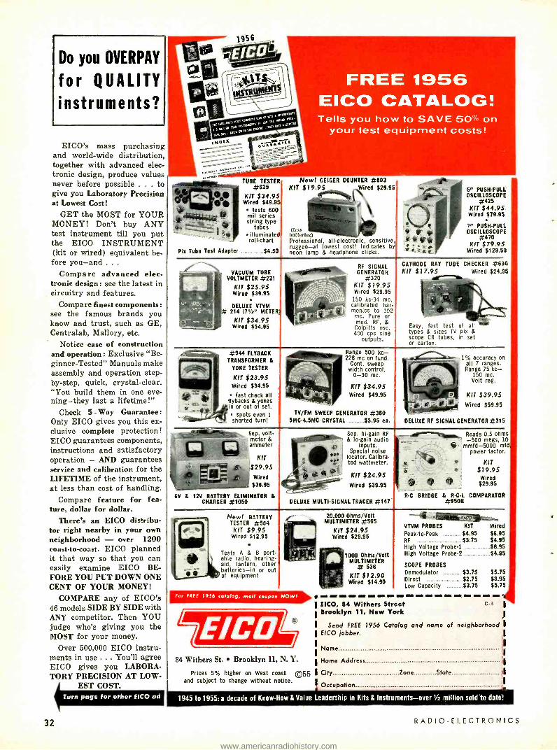
Do you OVERPAY
for QUALITY
instruments?
EICO's mass purchasing and world -wide distribution, together with advanced elec- tronic design, produce values never before possible ... to give you Laboratory Precision at Lowest Cost!
GET the MOST for YOUR MONEY! Don't buy ANY test instrument till you put the EICO INSTRUMENT (kit or wired) equivalent be- fore you -and . . .
Compare advanced elec- tronic design : see the latest in circuitry and features.
Compare finest components: see the famous brands you know and trust, such as GE, Centralab, Mallory, etc.
Notice ease of construction and operation: Exclusive "Be- ginner- Tested" Manuals make assembly and operation step - by -step, quick, crystal -clear. " You build them in one eve- ning -they last a lifetime!"
Check 5 - Way Guarantee: Only EICO gives you this ex- clusive complete protection! EICO guarantees components, instructions and satisfactory operation - AND guarantees service and calibration for the LIFETIME of the instrument, at less than cost of handling.
Compare feature for fea- ture, dollar for dollar.
There's an EICO distribu- tor right nearby in your own neighborhood - over 1200 coast -to- coast. EICO planned it that way so that you can easily examine EICO BE- FORE YOU PUT DOWN ONE CENT OF YOUR MONEY!
COMPARE any of EICO's 46 models SIDE BY SIDE with ANY competitor. Then YOU judge who's giving you the MOST for your money.
Over 500,000 EICO instru- ments in use ... You'll agree EICO gives you LABORA- TORY PRECISION AT LOW-
EST COST.
1956
FREE 1956 EICO CATALOG! Tells you how to SAVE 50% on
your test equipment costs!
TUBE TESTER #625
KIT $34.95 Wired $49.9 a
tests 600 mil series string type
tubes illuminated roll -chart
Pix Tube Test Adapter $4.50
New! GEIGER COUNTER #803 KIT $19.95 ,Wired $29.95
(less batteries) Professional, all- electronic, sensitive, rugged -at lowest cost! Indicates by neon lamp & headphone clicks.
VACUUM TUBE VOLTMETER #221
KIT $25.95 Wired $39.95
DELUXE VTVM # 214 (7'/2" METER
KIT $34.95 Wired $54.95
#944 FLYBACK
TRANSFORMER &
YOKE TESTER
KIT $23.95 Wired $34.95
fast check all flybacks & yokes in or out of set.
spots even 1
shorted turn!
Sep. volt - meter & ammeter
KIT
$29.95 Wired $38.95
6V & 12V BATTERY ELIMINATOR & CHARGER #1050
RF SIGNAL GENERATOR
#320 KIT $79.95 Wired $29.95
150 kc -34 mc, calibrated har- monics to 102 mc. Pure or mod. RF, &
Colpitts osc. 400 cps sine
outputs.
Range 500 kc- 228 me on fund.
Cont. sweep width control,
0 -30 mc.
KIT $34.95 Wired $49.95
TV /FM SWEEP GENERATOR #360 5MC -4.5MC CRYSTAL $3.95 ea.
Sep. hi -gain RF & lo -gain audio
0 ,e) I inputs. Special noise r locator. Calibra - r , ted wattmeter.
trà00_. KIT $24.95 Wired $39.95
DELUXE MULTI -SIGNAL TRACER #147*
f pì
t t r CATHODE RAY
KIT $17.95
5,, PUSH -PULL OSCILLOSCOPE
#425 KIT $44.95
Wired $79.95
PUSH-PULL OSCILLOSCOPE
#470 KIT $79.95
Wired $129.50
TUBE CHECKER #630 Wired $24.95
Easy, fast test of all types & sizes TV pix & scope CR tubes, in set or carton.
.1 : y!--'at
DELUXE RF SIGNAL GENERATOR #315
I% accuracy on all 7 ranges. Range 75 kc-
150 mc. Volt reg.
KIT $39.95 Wired $59.95
. Reads 0.5 ohms -500 meas, 10
mmfd -5000 mfd power factor.
KIT $19.95 Wired $29.95 St
R -C BRIDGE & R -C -L COMPARATOR #9508
New! BATTERY TESTER #584
KIT $9.95 Wired $12.95
Tests A & B port- able radio, hearing- aid, lantern, other batteries -in or out of equipment.
84 Withers St. Brooklyn 11, N. Y.
Prices 5% higher on West coast ©55 and subject to change without notice.
32
20,000 Ohms /Volt MULTIMETER #565
KIT $24.95 Wired $29.95
1000 Ohms /Volt MULTIMETER # 536
KIT $12.90 Wired $14.90
VTVM PROBES KIT Wired Peak -to -Peak $4.95 $6.95 RF $3.75 $4.95 High Voltage Probe -1 $6.95 High Voltage Probe -2 $4.95
SCOPE PROBES
Demodulator $3.75 $5.75 Direct $2.75 $3.95 Low Capacity $3.75 $5.75
EICO, 84 Withers Street Brooklyn 11, New York
C -3 '
Send FREE 1956 Catalog and name of neighborhood EICO jobber.
Name
Home Address
City Zone State ti
Occupation
1945 to 1955: a decade of Know -How & Value Leadership in Kits & Instruments -over 1/2 million soid'to date!
RADIO -ELECTRONICS
www.americanradiohistory.com
RA11110 - 1:1.11:r: RONIt:S Hugo Gernsback. Editor
"NATIONAL TV SERVICEMEN'S WEEK"
.... The Servicing Industry Has Come of Age ... .
ON March 5, 1956, the service technicians of the United States will celebrate the anniversary of National TV Servicemen's Week, originated last year by RCA (see page 122).
On this occasion RADIO -ELECTRONICS magazine salutes the more than 125,000 service technicians and wishes them a rousing Happy Birthday and a well deserved prosperity. Every member of the servicing industry will note with justifiable pride that National TV Service- men's Week has been recognized by no less a body than the United States Chamber of Commerce.
With this impressive stamp of approval it may be said that the servicing industry has finally come of age. And let no one think that this industry is puny -in 1955 it had an esti- mated total turnover of more than $11 /2 billions. It is bound to be much higher in 1956.
wiz" to repair their silent receivers. It wasn't long before professional radio repair and radio service shops appeared in various cities in the United States to take care of this new demand. And the owners of these shops (in most cases) prospered.
We of Gernsback Publications recognized the radio service technician from the start and devoted many pages of every issue to his trade. One of the earliest issues of this publication (then called RADIO- CRAFT),
the September, 1929, issue, editorially announced that henceforth the magazine was to be de- voted to The Professional, The Service Man, the Radiotrician. Even before that, in the July, 1929, issue, there was a department en- titled "Serviceman's Data."
Then in the spring of 1930 your editor or- ganized the first service association in this
What the servicing industry will do , . country, the National Radio Service in 1957 and thereafter, due to the im-
1930 service technicians emblem ens Association. M' Aiati A full-page account designed by this magazine. p pact of color television, is not too dif- can be found on page 616 of the June, ficult to forecast. It certainly is reasonable to as- 1930, issue. A number of well known radio personalities sume that it will go close to $21/2 $3 billions by 1958. were among its board of directors : Laurence M. Cocka-
It may even go a good deal higher if the present impe- day, David Grimes, John F. Rider and the writer. Pros - tus of closed- circuit TV and closed- circuit color TV mush- pective members had to fill special examination and rooms into big business, as these branches are certain to application papers before they were issued membership do. Add to this transistor radios when they finally go cards and lapel buttons. into multimillion production -as they surely will -and The timing of the association, unfortunately, was pre - one does not require an IBM electronic computer to figure mature. It was started at the very beginning of the out the staggering amount of business the servicing in- country's severest depression and, despite the outlay dustry is bound to do by 1960. of a considerable sum of money and months of effort,
It wasn't always thus. Indeed, the electronic servicing did not succeed. So much for the early history of radio industry grew into manhood from minuscule beginnings. servicing in the United States. This writer, who was present at the very birth of the This was 25 years ago -the antediluvial epoch of elec- industry, finds it quite impossible to pinpoint the exact tronic servicing. That serene period when we knew no year of its beginning. ac dc receivers, no cathode -ray tubes, no FM, no signal
Originally -that is in the early Twenties -there was tracers, no television, no radar, no printed circuits, no no radio servicing, strictly speaking. Instead, we had transistors -to name but a few newcomers. thousands of radio experimenters, constructors, set But now the electronic flood has engulfed humanity - builders and radio amateurs, all of whom were pressed yet we are only at the merest beginning ! On March 5 we into service when the first factory -made radio sets devel- celebrate the second birthday of National TV Service - oped troubles -which they did unfailingly. Most manu- men's Week. It will be most interesting when the present facturers of radio receivers in those halcyon days seldom younger service technicians can look back to 1956 on the stooped to repair any of their sets -if they were returned 25th birthday of the National TV Servicemen's Week to the factory they reluctantly did the necessary repair, in 1980. Most of you will have prospered -and what usually at fantastic prices. For these reasons it was up fabulous coming electronic wonders you will have wit - to the set owners to find a bright radio amateur or "radio nessed ! How we oldsters envy you ! -H. G.
MARCH, 1956 33
www.americanradiohistory.com

RADIO
SOLAR-powered RADIO
SOLAR CELLS
Fitnrutomü power supply feeds
trans i.rtoriz ed receiver ver
By EDWIN ItOI I1\
UST think of it! As long as the sun shines -even a very cloudy day will do -this radio operates from a solar power supply. When there
is no sunlight, an auxiliary mercury cell can be switched into operation.
Anyone can build this solar -powered radio. The .solar energy converter is a modified self -generating selenium photocell. Previously described solar radios and transmitters have been laboratory -built devices, very expensive and next to impossible for the hobbyist to reproduce. This solar radio, how- ever, uses only standard components and can be built for around $15.
A high -gain transistor (Fig. 1) pro- vides plenty of amplification; a Superex- Grayburne type EFL Loopstick gives souped -up sensitivity and selectivity. Actually the circuit is a crystal set followed by a stage of transistor ampli- f.cation, but the sensitivity and selec- tivity are very much better than usu- ally associated with this type of radio.
A fabulously high Q of 350 is the hallmark of the new "energized" loop - stick. Detector loading of the tuned circuit can quickly degrade this figure. Nevertheless, by using loose coupling between coil and detector, we retain a single tuned circuit with exceptionally sharp selectivity.
One end of Ll connects directly to the antenna. The opposite end seems to float without any electrical connec- tion to the remainder of the circuit. Coupling does exist though in the form of stray capacitance between Ll, the loopstick core and L2.
A padder type variable capacitor with an attached knob is used for sta- tion tuning but does not have sufficient
34
Self -generating cell is seen at top.
range to cover the lower end of the broadcast band. Thus, an extra capaci- tance is used to permit low -end tuning. (Diagram shows variable unit, but 200- µµf fixed capacitor may be used.) This capacitor parallels the tuned circuit through S1 and effectively splits the broadcast band in two.
L2 is a winding added to the loop - stick. Nominally, this coil should be 12 turns wound at one end of L1 as shown in Fig. 2. Increasing the number of turns gives increased sensitivity or loudness, accompanied by some loss in selectivity, and, of course, decreasing
Fig. 1- Schematic of the receiver.
the L2 turns gives better selectivity at the expense of signal volume. The size of the wire used to wind L2 is non- critical, but space the turns slightly apart.
The detector is a germanium diode. Any of the many available types are satisfactory. The surplus silicon "radar" crystals, however, are not suitable. Typical crystals that can be used are the Raytheon CK705, Sylvania or Radio Receptor 1N34 and the G -E 1N69.
Crystal- detector receivers operate the diode in the low millivolt region. In this low -level signal range no diode is a really good rectifier. Detection takes place because the diode is a nonlinear resistance element passing more cur-
Fig. 2- Windings on the loopstick.
RADIO -ELECTRONICS
www.americanradiohistory.com

TRANSISTOR
CK705 DIODE
PADDER TUNING CAPACITOR
S2
LOOP STICK
1.345 VOLT MERCURY CELL
ANT CLIP
Internal view of solar -powered radio.
rent in one direction than the other. This is termed "square -law detection," the name being derived from the diode characteristics at low signal levels.
Crystal detectors, with no exceptions, operate on this principle. And despite indications to the contrary in some articles, they are not distortion -free. All produce some second -harmonic dis- tortion.
Audio output from the detector is coupled to the transistor by a 0.1 -µf capacitor. This can be one of the miniature 200- or 120 -volt units com- monly found in personal radios. Since the capacitor can discharge back through the nonlinear diode resistance, there is no need for a diode load resis- tor between the diode and capacitor - they are connected directly together.
The transistor should be a high -gain type, the CK721 for example. Using the CK722 results in a considerable lowering of performance. With a CK721
INC0EI4r UCffT
BOTTOM ELECTRODE
SOLDERTO TOP ELECTRODE
nLOERTO BOrTCMAELEC RODE
B -15 PNOTOCELLIINTERNATIONAL RECTIFIER CORP)
CUT INTO 4 SECTIONS
Fig. 3- Details of the solar cell.
MARCH, 1956
and 2,000 -ohm earphones, the power gain of the transistor stage should be at least 160. A hermetically sealed type of high -gain transistor was used in the original receiver and is visible in the photograph. Except for the metal case, it is almost identical to the CK721.
Solar power supply A type B -15 self -generating photo-
cell, manufactured by International Rectifier Corp., forms the basis for the solar power supply. This manufacturer also currently advertises a smaller cell, of the same type, called the "Sun Battery."
The B -15 cell is unmounted. A rec- tangular silver band around the per- imeter of the cell is the negative or front electrode. The solid silver back- ing is the positive terminal.
For our purpose, the cell must be cut into four equal -area sections. A small hacksaw is suitable for the cutting operation. To avoid overheating the edges, cut slowly. If the cell is clamped in a vise, use cardboard buffers to avoid mutilation of the cell's surface.
Check each of the four photocells by connecting a milliammeter -O -1 ma will do- across its terminals. The -four cells should all give approximately the same output. For checking, each cell can be held near a 100 -watt light bulb. If any cell gives appreciably lower output, the edge formed by the cut may be partially shorted. This can be cor- rected by scraping the edge with a screwdriver or knife blade until the cell reads normal.
Pieces of small, flexible, stranded wire connect the cells in series. The wiring arrangement is given in Fig. 3. The wires should be tinned first and
RADIO
then quickly soldered to the appropriate silver band or back ; otherwise, the silver may melt away from the solder connection. When the cells are soldered together, check them again by connect- ing a voltmeter across the two output wires. In sunlight, the meter reading should be in excess of 1.5 volts. After the final check, place the cells face dowi on asquare piece of clear plastic and bind them to the plastic with cloth adhesive tape. The modified cell is then ready for installation in the re- ceiver.
Construction and operation The original receiver was mounted
in a small aluminum case. However, I discovered the closed aluminum box reduced the Q of the loopstick. A non- metallic case is recommended.
To attach a tuning knob to the padder, take a piece of 14-inch shaft and drill a hole in its center very slightly smaller than the padder shaft. Then heat the % -inch shaft until the hole enlarges enough to be pushed onto the padder. When the shaft cools, it will be solidly mounted to the tuning capacitor.
The remaining mechanical details are simple and the parts may be placed wherever most convenient. An easy way to mount the mercury cells is simply to solder the metal extension tab (nega- tive terminal) to the S2 terminal. To avoid damage, soldering to any part of the mercury cell must be done quickly and the cell should be checked after- ward with a voltmeter.
For an operational check, clip the antenna lead to something metallic. A screen door, clothesline or short length of wire, say 15 feet long, should do. By tuning the receiver, stations should be heard with the power switch in the mercury cell position. Hold the receiver facing through an open window and flip the switch to the solar cell posi- tion. The station should come in just as loud as with the RM cell. Direct sunlight can have an intensity of 10,000 foot -candles; yet the radio operates satisfactorily with only 100 foot -candles.
Parts for solar -powered radio I- 200 -pµf mica capacitor; I- 0.1 -µf 200 -volt capaci- tor; I- 65-340 -6tµf padder (Arco 303 or equivalent); I -CK721 transistor (see text); I -CK705 diode; (- self- generating photocell (International Rectifier Corp. B -15); I- Superex- Grayburne type EFL loop - stick; I- mercury cell (Mallory RM- 625 -RT or equiva- lent); I- s.p.s.t. slide switch; 2 -phone tip jacks; I -5 -Pin hearing -aid tube socket; I -piece of clear plastic; I- nonmetallic case; I -piece of 1 /4-inch shaft; I -knob; I- antenna wire and clip.
Most people are amazed by the vol- ume and selectivity obtainable from such a simple circuit. Strong stations are loud enough to be heard with the phones pushed back from the ears. Selectivity is good enough to separate three stations located at 1550, 1450 and 1230 kc and it "takes some going" to do this with only one tuned circuit. Full credit for this achievement goes jointly to the super loopstick and the high -gain transistor. END
35
www.americanradiohistory.com
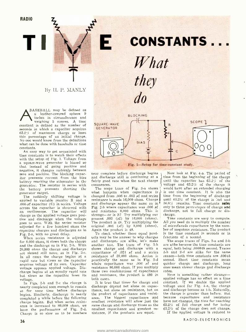
RADIO
TI E
T By H. P. MANLY
AßASEBALL may be defined as a leather- covered sphere 9 inches in circumference and weighing 5 ounces. A time
constant is defined as the number of seconds in which a capacitor acquires 63.2% of maximum charge or loses this percentage of an initial charge. No one would know from the definitions what can be done with baseballs or time constants.
An easy way to get acquainted with time constants is to watch their effects with the setup of Fig. 1. Voltage from a square -wave generator is biased so that instead of going positive and negative, it changes suddenly between zero and positive. The blocking capac- itor prevents current from the bias battery reaching the attenuator in the generator. The resistor in series with the battery prevents shorting the generator output.
The suddenly shifting voltage is applied to variable resistor R and a .006 -µf capacitor (C) in series. Voltage across the capacitor is observed with an oscilloscope. The capacitor will charge as the applied voltage goes posi- tive and discharge when the voltage goes to zero. With the series resistor adjusted for a few hundred ohms the capacitor charges and discharges as in Fig. 2 -a, with no great delay.
When series resistance is adjusted for 8,000 ohms, it slows both the charge and the discharge as in Fig. 2 -b. With 20,000 ohms the charge and discharge are slowed still more, as in Fig. 2 -c. In all cases the charge begins at a rapid rate but slows as the capacitor acquires voltage of its own. Capacitor voltage opposes applied voltage. Dis- charge begins at an equally rapid rate but slows as the capacitor loses its voltage.
In Figs. 2 -b and 2 -c the charge is nearly completed soon enough to remain so for some time before discharge begins. Similarly, discharge is nearly completed a while before the following charge begins. But when series resist- ance is increased to 80,000 ohms, we have the performance of Fig. 2 -d. Charge is so slow as to be nowhere
36
SQUARE -WAVE GENERATOR
O -- Fig,. I-Setup for
CONSTANTS.
What they
do BLOCf<ING
SCOPE
..
C
near complete before discharge begins and discharge still is continuing at a fairly good rate when the next charge commences.
The scope trace of Fig. 3 -a shows what happens when capacitance is changed from .006 to .003 µf and series resistance is made 16,000 ohms. Charge and discharge appear the same as in Fig. 2 -b where capacitance was .006 µf and resistance 8,000 ohms. This is strange -or is it? Try multiplying our present .003 (µf) by 16,000 (ohms). The product is 48. Try multiplying the original .006 (µf) by 8,000 (ohms). Again the product is 48.
To check whether these equal prod- ucts may be the answer to why charges and discharges are alike, let's make another test. The trace of Fig. 3 -b shows charge and discharge with a capacitance of .024 µf and a series resistance of 20,000 ohms. Action is practically the same as in Fig. 2 -d where capacitance was .006 µf and resistance 80,000 ohms. If you multiply these two combinations of capacitance and resistance, the product is 480 in both cases.
It is true that times for charge and discharge depend not alone on capac- itance, not alone on resistance, but on the product of capacitance and resist- ance. The biggest capacitance and smallest resistance will allow just the same charge and discharge times as the smallest capacitance and greatest re- sistance, if the products are equal.
time -constant stud).
Now look at Fig. 4 -a. The period of time from the beginning of the charge until the capacitor has 63.2'/, of the voltage and 63.2% of the charge it would have after an extended charging is one time constant. It is also the time from the beginning of discharge until 63.2%, of the charge is lost and 36.8' remains. Time constants refer only to these percentages of charge and discharge, not to full charge or dis- charge.
Time constants are easy to compute. All you need do is multiply the number of microfarads capacitance by the num- ber of megohms resistance. The product is the time constant in seconds or in fractions of a second.
The scope traces of Figs. 3 -a and 2 -b are alike because the time constants are equal, both being .000048 second. Traces 3 -b and 2 -d are alike for the same reason -both time constants are .00048 second. Short time constants mean quicker charge and discharge, long ones mean slower charge and discharge rates.
Here is something rather strange - applied voltage has no effect on a time constant. If we double the applied voltage used for Fig. 4 -a, the charge and discharge become as 4 -b. Naturally, the charge is greater than before. But because capacitance and resistance have not changed, the time for reaching 63.2% of full charge and for losing 63.2% of the charge does not change.
If the applied voltage is reduced to
RADIO -ELECTRONICS
www.americanradiohistory.com

a
b
C
a
Fig. 2 -Effect of varying R in Fig. 1.
b
Fig. 3- Changing resistance capacitance values gives waveforms as in Figs. 2 -b. d.
half that used for Fig. 4 -a, we have the charge and discharge of Fig. ,4 -c. Although full charge is now relatively small, the time for reaching 63.2% of full charge is the same as before be- cause capacitance and resistance are the same as before.
Frequency has no effect on the time
MARCH, 1956
100% - 63.2 % -
36.8%-
0 -
a
RADIO
63.2 % -
36.8Y. -
0 --
b
....
. I-->1 TIME CONSTANT
OOY.-- 83.2%-
0 -- C
Fig. 4- Waveforms show that changes in voltage do not affect a time constant.
a
b
C
Fig. 5- Frequency effects on waveform.
constant of any given capacitance and resistance. However, any change of either time constant or frequency with respect to the other may have great effect on circuit performance.
Frequency effects are illustrated in Fig. 5. In 5 -a the frequency of the applied voltage is such that there is
practically full charge and full dis- charge within about half the time period of each value of applied voltage. The capacitor remains charged or dis- charged during the remainder of each period.
If the frequency is lowered, we have the condition of 5 -b. Portions of the
37
www.americanradiohistory.com

RADIO
Bt BIAS
Fig. 6 -A resistance- coupled amplifier.
Fig. 7 -Basic diode detector circuit.
Fig. 8 -Diode circuit
C
R
for agc takeoff.
Fig. 9- Circuit for grid -leak biasing.
Fig. 10 -A basic sawtooth generator.
ç
Fig. 11- Simple differentiator network.
38
CHARGE
1 SO URCE C
DISCHARGE
WELDING RODS I'
WORK
Fig. 12-An electronic spot welder.
trace showing the beginnings of charge and discharge have not changed in form but the capacitor remains charged or discharged for longer times during the longer periods of applied voltage.
If the frequency is raised, as in 5 -c, the periods of applied voltage are short- ened. The beginnings of charge and discharge have not changed because capacitance and resistance have not been changed. But periods of maximum and zero applied voltage are so short that there is not time for full charge before discharge begins nor for corn - plete discharge before the next charge begins.
Selecting a time constant Effects of time constants on circuit
performance and some of the require- ments to be satisfied in selecting time constants can be illustrated by a few examples. Consider first how stage gain is affected by the time constant of capacitor C and resistor R in the resistance coupling of Fig. 6. Although there is amplification in the tube, there is loss of attenuation in the coupling and stage gain depends on both factors.
Since the right -hand tube has fixed bias, grid resistor R probably must not exceed 100,000 ohms or 0.1 megohm. Were we to use .01 -µf capacitance at C the resulting time constant would be .001 second. With this combination of capacitance the coupling loss would be about 5.5 db (nearly 50 %) at 100 cycles. With .05 µf, for a longer time constant, the loss at 100 cycles becomes less than 1 db, or only about 10 %.
What about low- frequency cutoff, usually defined as the frequency at which gain drops to 0.707 of maximum? The cutoff frequency may be found from dividing 0.16 by the time constant. Dividing 0.16 by .001 (our time con- stant) shows that cutoff occurs at 160 cycles. For any lower cutoff frequency we would need a longer time constant, which might be provided by a larger capacitance at C.
The time constant affects phase shift, especially at low frequencies. With .01- pf capacitance and 0.1- megohm resist- ance, for a time constant of .001 second in Fig. 6, the shift for signals at 100 cycles will be about 68 °. Shift is lessened by a longer time constant. Changing to .05 -pf capacitance for a time constant of .005 second would make the shift less than 18° at 100 cycles.
In the resistance coupling we have had to juggle capacitances to change the time constant because resistance is
fixed by the manner in which the tube is biased. Were we to use cathode bias the resistance at R might be as great as 0.5 megohm. With five times the original resistance we could obtain the same time constants with only one -fifth as much capacitance as previously mentioned.
In the diode detector circuit of Fig. 7 the time constant is determined by capacitor C and load resistor R which here is a 500,000 -ohm (0.5- megohm) volume control pot. If signal modula- tion as great as 80% is to be detected without distortion, the time constant should be no longer than found from dividing 0.2 by the highest audio fre- quency. Otherwise, the capacitor can- not discharge fast enough to follow the modulation.
If we assume 5,000 cycles as max- imum audio frequency and divide 0.2 by 5,000, we find that .00004 µf or 40 µµf is the maximum capacitance. Usually the shunt capacitance is made somewhat greater to increase detection efficiency, but there will be some distor- tion on strong modulation at high audio frequencies.
In the agc setup of Fig. 8 the time constant must be long with respect to the time period of one cycle at the intermediate frequency, to maintain control voltage close to the amplitude of incoming signals. But capacitance C should be small to prevent taking too much signal energy from the if amplifier. To obtain a long time con- stant with small capacitance we need a large resistance at R.
For grid -leak biasing in Fig. 9 the time constant must be considerably longer than the period of one cycle at the lowest signal frequency. Further- more, capacitance should be so large and its reactance so small at this sig- nal frequency that excessive attenua- tion is avoided. Then the time constant must be based on signal frequency and large capacitance, using resistance to suit.
For the sawtooth sweep oscillator of Fig. 10 the time constant must be such that charging does not extend too far onto the bend of the curve. That is, we want a sawtooth waveform somewhat as in Fig. 5 -c, not a fiat top as in 5 -b.
In the differentiating filter of Fig. 11 we need a short time constant. The capacitor must charge very quickly and discharge just as fast. Then, even though an applied voltage such as a sawtooth drops rather slowly, there will be only brief rises and falls or only pips of filtered voltage.
For electronic spot welding, an indus- trial application, each weld requires momentary current of several amperes, but we use a source furnishing only milliamperes. The long- time -constant circuit of Fig. 12 does it. A small cur- rent from the source, flowing for the entire period between welds, builds up a large charge in a big capacitance. Then all the stored electricity is dis- charged almost instantly to make a weld. END
RADIO- ELECTRONICS
www.americanradiohistory.com

RADIO
SERVICE fro m the
CUSTOMER'S ammusaumma NE
HOW can a service technician use the customer's viewpoint as an aid to making more money? Why is it smart business to
look at each trouble through the eyes of the customer instead of the service technician? Suppose the cus- tomer does try to tell you what he thinks is wrong with his set. How can you turn his interference into a source of extra money? In short, what can the service technician do to insure that the customer is not only a source of income but also a valuable business adviser.
We will assume that the technician is neat, fairly competent as a techni- cian, reasonably honest and has the customer's interest at heart. Let's start with a simple case from an old- timer's notebook: "He didn't get the job." The time was in the days of radio sets with external loop antennas. The customer was a casual acquaintance of the youngster who was just starting to become an old - timer. Said the man, "I have a very fine radio that just stopped playing. What would it cost to fix it ?" In his most professional manner the youngster replied that he would have to look it over and then make an analysis of the trouble and come up with an estimate. A few hours later the youngster was busily inspecting a real dog, and an ancient one at that.
MARCH, 1956
VIEWPOINT
A separate loudspeaker was con- nected to the set through a plug and jack system. Applying hand pressure against the plug brought in the pro- gram loud and clear; releasing the pressure caused silence. So our hero propped a book against the plug to keep the set playing while he continued his "analysis." Moving the volume control caused bangs, scratches and blasts from the loudspeaker. Touching the loop an- tenna in its swivel joint caused more noise. Rotating the tuning capacitor caused a still greater racket. Closer in- spection of the loop showed that it had received a direct hit by a well aimed pillow thrown by one of the numerous progeny now standing around with big saucer eyes.
Our hero made a fast mental addition of all the damage, completed his "analy- sis" and came up with his estimate. "Mr. Jones, it will cost $25 to put your set in first -class condition." There followed a long silence while Mr. and Mrs. Jones looked at each other. Then the fatal words, "Thank you very much for looking at the set. We'll let you know."
A week later our hero watched a neighborhood technician of inferior ability enter the Jones' house and emerge triumphantly a half -hour later with a $5 bill clutched in his grimy hands. How could this happen? He couldn't have made all those repairs in
You can make him
your most valuable booster, adviser and business consultant
By J. BRUNING
a half -hour! And at such cut -throat prices! Something ought to be done about these chiselers! Curiosity got the better of bitterness and our hero forced himself to ask his competitor what had happened. "Aw, it was nuttin'. Just hadda tighten up the loose spring on the jack." And how about all those other things wrong with the set? "Aw, gee, they didn't need fixin'. The old guy was used to them noises."
Our young hero retired to nurse his wounds and think about this strange turn of events. An inferior technician had taken a job away from a far more capable mechanic, had received $5 for 30 minutes' work and had satisfied a customer all in one fell swoop. And the set still wasn't really fixed!
It didn't take too long for the lesson to sink in. Our hero had been so wrapped up in the technical phase of the job that he had not even bothered to consider the customer's viewpoint. And what was this viewpoint? Simply that the set had been playing and then all of a sudden the music stopped. All the customer wanted was to hear music coming from his loudspeaker once more. Very simple -and at the same time, a very profound lesson in busi- ness economics. Find out what your customer wants and supply that want as cheaply as you can. "No magician explains his tricks." The time, a little later. The place, a different
39
www.americanradiohistory.com

RADIO
town. The problem, a set that developed a loud howl if anyone walked across the floor. This set had been worked on by just about every technician in town and the customer had spent some real money. Now he was desperate for help. So he took a chance and called the newcomer. Our hero went over that evening all decked out with a clean shirt, bow tie and neatly shined shoes. He could sense the quick air of approval as he entered the room. There followed a brief period of questioning to deter- mine just what trouble was being ex- perienced. It was learned that the set had been thoroughly inspected, inside and out, topside and below decks. It was evident that the trouble must be some form of poor connection in a place that was not ordinarily visible. It was prob-
"... a $5 bill clutched in a grimy hand."
ably not a poor soldered joint, plug and jack connection, nor loose tube socket. It might be in the grid leak circuit. Possibly the clip that held the grid leak in place. Being careful not to disturb any other part, our hero took a long stick and very lightly touched it to the clip holding the grid leak. Crash, bang! "Ah -ha," said our youngster to Mr. Smith, "just a dirty grid leak holder." It took but a few moments to remove the grid leak, scrape the corrosion from the mounting clip and replace the grid leak. Success! Absolutely no noise, even when shaking the set.
"That is fine," said Smitty. "How much do I owe you ?" Trying not to look too pleased, our hero replied, "Oh -that was very simple. Nothing at all difficult. Just a lucky guess." "But how much does it cost "? asked Smitty. "Oh," said friend hero, "I guess $5 will be about right." Instead of profuse thanks came a cry of rage. "What? ... $5 for that simple repair? . Five bucks for scraping off one little piece of dirt? . What do you think I am, a fool? . . . Do you think I'm going to pay you $5 for 5 minutes' work? ." Our hero gratefully accepted the single dollar bill offered by the irate Mr. Smith and de- parted in great haste (leaving behind a screwdriver worth $1.39).
What had happened? Why was Mr. Smith willing to pay $25 or $30 to six other technicians who had failed to find what was wrong, but was furious at the boldness of the lucky service technician who had found the trouble and wanted $5 for his effort? Pretty soon, the answer started to form.
40
"Lucky." That was it. Mr. Smith had thought that he was lucky. There had been no outward indication of skill, knowledge or display of troubleshoot- ing technique. And where had Mr. Smith got his idea? Why from the tech- nician himself! What a fool to have told the customer, "Oh -that was very simple. Nothing at all difficult. Just a lucky guess!"
So a new lesson was learned. Don't talk down the value of your work. The customer can't read your mind. He doesn't know that you spent hundreds of hours learning the little tricks that make your work easier. Don't explain how simple it is to recognize some symp- tom of trouble that enables you to put your finger on the defective part. Oh! So you already know that? You would never fall into that trap? I wonder. How many times has a TV technician carefully explained to his customer that "those horizontal lines or streaks across the picture tube mean that the hori- zontal oscillator tube is bad ?" Cus- tomers are not all ignorant. If the streaks tell you that the horizontal os- cillator tube is bad, they will also tell the customer the same thing the next time they appear. All he has to find out now is the location of the horizontal oscillator tube.
You don't have to mystify your cus- tomer but during your course of in- struction be careful not to explain away the need for your future services! "If the customer has a crystal ball, use it." The war is now over. TV is in cir- culation. Not the scanning disc, but real honest -to- goodness black -and -white TV
"No magician ever explains his tricks."
with a giant 5 -inch screen. The flurry of fix -your -own -TV books has not yet hit the market. But customers -as al- ways -are pretty sharp. Joe, "the man next door," has one of these super -dup- ers but unfortunately his picture is roll- ing badly at times. Joe once fixed a lawn mower so he figures he is a pretty good mechanic. Anyway, he greets our hero at the door with the remark, "I think the volume control is bad." Our hero tries not to show his scorn as he adjusts the vertical hold control, touches up the other controls and steps back to survey his work.
The picture is clear and steady. "Joe," he says, "the volume control has nothing to do with synchronizing troubles. See how good your set is
now ?" Joe has to admit that the rolling has stopped. He quietly pays $3.50 and says goodbye.
But he is not really convinced. And he has lost face because he had told his wife and 12- year -old boy that he knew the volume control was bad. Secretly he hopes that his dear wife will not yell at him as soon as the service technician leaves. $3.50 is a pretty steep price to pay for someone to come in and turn a knob!
Next day it happens again. Pop comes down the stairs. What does he see? Yes, the picture is skipping. Each time Hop - py fires his gun the picture jumps two or three frames.
"How long has the picture been roll- ing?" yells Dad. "Oh, it's been doin' that all afternoon," says Junior. Joe turns down the volume control so he can hear what Junior is saying, and lo! the picture has stopped rolling. Now it's Joe's turn. "It is the volume control after all," he yells. "Wait till I get that ignorant repairman over here. I paid him $3.50 for nothing. Now he's got to fix it, and I'm not going to give him one cent this time. He owes it to me!"
In a few minutes our hero arrives. turns up the volume control to a
point where the mirror starts to jump off the wall. "Look!" yells Joe. Sure enough, the picture is rolling a mile a minute. Our hero quickly adjusts the hold control. The picture stops rolling. Then he turns down the volume control low enough to be heard as he starts to explain to Joe. Just then the picture starts to roll again. Our hero is stuck and he knows it.
One hour later the set is in the shop. Sure enough, the volume control does affect the vertical hold. He connects a v.t.v.m. across the plate supply and swings the volume control. Yes, the B voltage climbs when the volume is low and drops 30 volts when the volume is maximum. Hmmm. Poor regulation of the power supply. Can't handle the load to the audio amplifier. Out comes the selenium rectifier and in goes a new one. Yep. That does the trick. The B voltage now swings only 5 volts and there is no sign of rolling. Back goes the set to Joe.
"It was the volume control after all, wasn't it ?" says Joe. "Yes," replied
'It was the volume control after all!"
our hero in a quiet voice. "You were right all the time." Joe looks around the room in triumph. Now he feels a little better. His honor has been vindi- cated. Joe continues, "I've already paid you for your labor. What do I owe you for the new volume control ?" "$3," says
RADIO -ELECTRONICS
l
www.americanradiohistory.com
our hero, and he is glad to get the money.
After returning home our technician thinks about the problem. He has told a white lie to Joe. If he had told the truth, Joe would not have believed him. The new rectifier cost $2.65. Total time spent was 3 hours. Cash received, $6.50. Net profit for 3 hours' work, $3.85. That's good for a weekly salary of $51. Our hero just lost a good deal of his reputation and went through an embar- rassing situation. You can be sure that Joe will see to it that all his friends and neighbors hear how Joe had to tell the dumb repairman what was wrong with his set!
Our hero reconstructs the chain of events. Why didn't he play along with Joe in the first place? If Joe wanted his volume control changed, why not do it? If he had taken the set to his shop yesterday, he would have stumbled across the relationship between the loud volume and the loss of sync. He could have phoned Joe and told him that after changing the volume control, he had discovered that the selenium rectifier was also defective. He could have charged for both the volume control and the rectifier, and he could have added a sure $5 for shop labor. Joe would have gladly paid. And Joe would have thought our hero was a pretty smart apple to have discovered that the selenium rectifier, buried way down inside the set, was also bad.
Those who have never had to repair a TV set may rise up and say this is an example of unethical practice ... that it is crooked business to replace a part that is not in trouble. Is it? Do painters skip the good woodwork and only touch up the bad spots? If you hire a gar- dener to make a new lawn, why does he dig up the good grass too? And why do you change your tires after 40,000 miles?
There are times when you will wish to recommend the change of some part just on general principles. Is that ethical? Or is it a wise precaution? Do you know any good TV man who only changes one capacitor of a defec- tive vertical integrator? Or still better, one who doesn't substitute a printed - circuit integrator when the old R -C network acts up? And in a set full of old tubes, if you have to replace the 6BG6, wouldn't it be foolish to leave in the old 1B3? So put your mind at ease. Strike a balance between your conscience, the life expectancy of the part in question and your customer's desires. Do the work suggested if it appears at all reasonable. Look at it the way the customer did. He wanted a certain thing accomplished. He is willing to pay for it. If you refuse to comply, you have inadvertently placed your own personal lifetime guarantee on that component. "Good poker players always win." Our hero used to play poker with an old grandfather- twice- removed. The old codger was a clever player. During the evening he would win a little and lose
MARCH, 1956
a little. But sooner or later one player would hold aces, another a full house. The betting would be fast and furious. But grandpop would win, and I do mean win.
This might seem a little remote from the problem of a customer's viewpoint, but it isn't. How did Grandpop become such a consistent winner? He had run - of- the -mill hands like the others. On these he didn't do much better than anyone else. But when he had a good hand, he made it pay off. There is a sales approach hidden in this that can mean real money to you. All good service technicians know that on most jobs you do little better than break even. Your profit can't be too high consistently. Let's follow the trail of our hero as he misplays a good hand. What would you have done?
The set, an ultra- modern 24 -inch TV; the customer, a new one; the problem, picture is dead. Our hero, now con- siderably older and wiser, gets the job. He neither wastes time nor hurries unduly. He preserves the right profes- sional approach.
He smoothly and methodically tracks down the trouble and discovers there is no light from the neck of the picture tube. He fights down the impulse to show this important clue to the cus- tomer. He uncoils the leads from his ultra -modern v.t.v.m. Then he removes the picture -tube base socket and tests for heater voltage. It's there. Now for a continuity test of the heater. Ah -ha! Wide open!
Our hero, who in the intervening years has gradually become an old - timer who wears glasses, gets up from the floor. Everybody fears the worst, and here it comes. . "Your 24 -inch picture tube is bad." Silence.
Someone has to break the spell. Our old -timer feels real bad about the situ- ation. So he speaks. "Sometimes, when we have this kind of trouble, the tube itself isn't really bad. It may be the wire inside the base pin has come loose. Let me look it over again. Maybe there is something I can still do for you to save you some money."
So he retreats behind the massive console. Out comes the soldering iron. Maybe a little heat and some more solder will re- establish contact between the heater lead and the base pin. So he resolders the pins, connects the socket, plugs in the cheater cord and turns on the set. Several seconds later there is a momentary flash of light as the 6SN7 kicks off. Then, success! A big bright picture flashes across the screen.
So he puts the back of the set to- gether and puts away his tools. He gets out his sales record book and he writes out the bill. Total time, 30 min- utes. Total charge, $5 for repairs. Service call free. Parts used, none. Pop pays the bill gladly. Everybody is full of goodwill. Pop even holds open the front door while the old -timer struggles out with his three suitcases full of tubes, meters, analyzers, tools and sales book.
RADIO
Who was the smart business man? Who held the best cards in that poker game? How much money was either in the pot or could have beén put into the pot? The old -timer had held a royal flush. How much did it pay off? How much could he honestly and conscien- tiously have made it pay off?
That customer stood to lose $60 or more. Only the knowledge, skill and experience of an old -timer stood be- tween the customer and his expenditure of a large sum of money. What was this knowledge, skill and experience worth?
My answer is that the laborer is worthy of his hire. The customer was not buying 5 minutes of fast work with a soldering iron. He was buying years and years of experience that made it possible for the old -timer to use his soldering iron at the right time and at the right place. If his efforts were successful, he rightfully deserved a successful reward. From the customer's viewpoint, the service technician had been a life saver. There is no doubt that the customer was ready, willing and able to pay handsomely. Don't kid yourself that the job wasn't worth a handsome return. From the customer's point of view, a tragedy had been averted. Why didn't our old -timer look at it from the customer's point of view?
To sum up one basic thought will help you to income and prestige: Always look at your jobs from the customer's point of view.
If it is knowledge, give it to him - but be sure you charge for it. If he wants a fast repair, give it to him and be on your way. (If the sound is dead, put in a new 6AQ5 or 6V6 and get going. Don't spend all night touching up the horizontal drive and vertical linearity controls.) If he wants a thorough overhaul, arrange to do it but point out in advance that it will cost real money to restore real performance to an old set.
Don't worry about your competitors who are perfectionists. It's O.K. to add all the little fancy touches, pro- vided the customer wants them and is willing to pay for them. The difference between a $50 and a $150 weekly in- come is not in seeing how little you can do for your money but rather how much you can do that you will be paid f or. People always have been and al- ways will be happy to pay good money for what they consider good service. Make sure that your estimate of what constitutes good service is based on your customer's point of view. END
41
www.americanradiohistory.com

RADIO
By HUGO GERNSBACK
A half- century ago,
the first radio for the public's
use and enjoyment
was marketed.
Differing vastly from today's
radios in construction
and function, it opened the
field of radio for private interest and
amusement rather than
commercial communica-
tions use.
THE year 1955 marked the 50th an- niversary of the first home radio sold to the public anywhere in the world.
It was not radio as we know it today because in 1905 there was no com- mercial broadcasting. But wireless had been going strong for several years and amateur radio too had just begun. Marconi and other pioneers were trans- mitting intelligence by the dot -and -dash method ; indeed wireless in those days was rapidly forging ahead.
The public at large knew little or nothing about wireless before 1905, ex- cept what they read in the papers and in magazines. As for owning a wireless home set, it had not as yet been born.
Previous to 1905, in 1903 -04, the writer had been working on a small portable transmitter and receiving out- fit which he felt could be sold to the public. It took several years to perfect it and make it foolproof so it would work under practically all conditions. It had to be low in cost so everyone could buy the outfit.
This ambition was realized some time in 1905. After making a number of models the writer began to market the first home or private radio set ever sold to the public.
As there were few wireless stations in the country, it became necessary to sell a transmitter, too, so amateurs could set up a transmitter and receiver at home. Then while one person was transmitting signals, the other could receive them. Or the transmitter could be set up in one room and the receiver would ring a bell in the other room
without any intervening wires what- soever.
The outfit that accomplished all this was known as the TELIMCO Wireless Telegraph Outfit. TELIMCO is a con- traction of the first letters of the writ- er's old pioneer firm, The Electro Im- porting Company (E. I. Co.), which became famous between 1904 and 1915 as the first radio mail -order house in the world. Only comparatively few sets were sold in 1905. But in 1906 the little outfit went into quantity production and was sold through many large outlets, including such famous stores as Macy's, Gimbel's and F. A. O. Schwarz, the country's largest toy establishment.
Incidentally, it was first advertised in the magazine Scientific American in the issue of Jan. 13, 1906. This was the first home radio set advertisement to appear in print anywhere.
The writer well remembers the in- credulous looks of many of the store owners when they were first approached to buy "wireless sets." It was necessary to make a demonstration in each case before anyone would stock them.
The complete set, both receiver and transmitter, at first was marketed for $7.50. This was raised later on to $10, at which price most of them were sold.
The photograph shows an exact rep- lica of the original outfit, built by the writer, to commemorate the 50th an- niversary of the first home radio set. The transmitter, with the three dry cells and key, was composed of a 1 -inch spark coil. The "1- inch" here means that the coil threw a 1 -inch spark through free air, between wire points.
YEARS OF A4
C ; ̀ , \á';\z`
GR \'',.C'''' $Y 1, .
o t``., 1` \`Y\Urti` O
¡ `JUna`cti,00, \ `
F oa 55 ht, 4, ar Cqn,e cec Iyc
Ppt
4ce,
,.v,\itt" , it 9íì c ̀ gtitit{1., `neCobzi,1ie;1 jrtj. 9 Y 411 n 1
Q,e EiR 0
A
Above -Advertisement for the first radio set offered the public. It appeared in Scientific American, Jan. 13, 1906. Right- Picture diagram of layout, drawn by Hugo Gems- back in the 1900's: A, G, antenna, ground; S, spark coil; B, batteries; K, key; AS, relay adjusting spring; SD, co- herer -Connections: 9, 8, to relay electromagnets; 7, 11, co- herer; 13, 16, decoherer; 14, 13, relay contacts.
42
G. S-D az-m t
RADIO -ELECTRONICS
www.americanradiohistory.com

Mounted on the spark coil, on two metal standards, were two brass oscillator balls between which a small blue spark jumped the h -inch gap. The spark coil had a fast vibrator so that every time you depressed the key a spark would jump between the two balls. Depressing the key for a short period would give a dot, a longer period would give a dash.
The receiver was a 75 -ohm "pony" relay which had to be so sensitive that if you blew your breath slightly against the armature its contacts would close. There was also a single dry cell and the all- important coherer. It was simply constructed of two large, double binding posts through the bottom holes of which passed two silver -plated brass rods. A glass tube, placed between the two bind- ing posts, was slipped over the two brass rods. These silver -plated 1/s -inch metal rods fitted the glass so that there was extremely little or no play. The two rods were separated about 3/16 inch, forming a gap. This gap was filled with the "soul of the set" -the coherer filings, composed of 90% coarse iron and 10% coarse silver filings. By shaking the mixture well it was ready to be used. The filings had always to be loose, never packed tight.
The decoherer -an ordinary house bell -was mounted so that the clapper of the bell would strike against the glass tube of the coherer at the exact spot where the filings were. If the dia- gram is studied, it will be seen that every time the relay closes its contacts, the bell will ring through the single cell.
Now, if you depress the key at the
AL.
transmitter, the two aerials (aerial and counterpoise) will emit radio waves. Curiously enough, the waves which the writer used 50 years ago were of the very short variety (above 30 mega- cycles) to which modern radio has come back. The two aerial wires of the trans- mitter measured less than 1% feet.
Inasmuch as the coherer is directly in the receiver aerial circuit, the filings offer a very high resistance. But under the onslaught of the radio waves they instantly become an excellent conductor -as if they now were a solid conductor. The relay, in the same circuit, now goes into action, attracting the armature which closes its contacts. This sets off the decoherer bell which rings and shakes up the coherer filings. These now fly apart -they decohere -and the co- herer becomes nonoperative until the next wavetrain comes along.
Thus every time you press the trans- mitter key, the bell at the receiver rings. It rings as long as you hold the key down. A long ring is a dash, a short one a dot.
You can pick up the receiver and walk to the next room, yet the bell sounds without any visible connection. Even through thick walls, signals still come in.
One of the things that bedeviled us in the early days was sparking at the relay contacts. This would set up elec- tromagnetic waves and often the out- fit gave no clear signals; sometimes the bell would ring for seconds after the signal. This was overcome by putting a 5 -µf capacitor across the relay points.
The range of the TELIMCO Wireless
RADIO
Telegraph Outfit was between 300 to 500 feet when used without ground connections. By using an elevated aerial 50 to 100 feet in length and by ground- ing one side of both transmitter and re- ceiver to a water or gas pipe, the range was easily increased to one mile. Indeed, hundreds of people who bought the out- fit at the time reported excellent re- ception even over greater distances, but these, of course, were exceptions. Note that this set used no tuning whatsoever.
A curious thing about this little out- fit today is its strange effect on radio people who never heard of the ancient spark coil and coherer sets. Young radiomen, who have never seen one of these outfits, are usually very much perturbed and astonished when the writer demonstrates it. The reason of course is that people have difficulty realizing that with a little three -dry- cell transmitter it is possible to ring a bell through intervening walls while the novice holding the receiver.
Radiomen today think of devices which operate relays as being relatively large and find it hard to believe that such a small portable transmitter and receiver could do the work.
It is conceivable that some time in the future these same instrumentalities may still find a use in modern radio and electronics which may not be apparent today.
The TELIMCO outfit here described has recently been acquired by the Henry Ford Museum of Dearborn, Mich. It was donated by the writer. It will be permanently exhibited in the radio section of the museum. END
HOME RADIO Replicas of the original transmit- ter and receiver, soon being sent to the Ford Museum at Dearborn. Left -the receiver: A, antenna system; B, dry cell; C, coherer; D, decoherer; P, adjustable coherer rods; R, 75 -ohm relay. Right -the transmitter: A, antenna and count- erpoise; B, dry -cell power supply; C, 1 -inch spark coil; O, spark -ball oscillators; K, transmitter key.
43
www.americanradiohistory.com

TELEVISION
Techniques niques and procedures
for obtaining optimum
picture tube performance
ADJUSTMENT PROB By MATTHEW MANDL*
TMENT receivers
problems rarely
of black - and -white receivers rarelytaxed the technician's ingenuity. Many customers could be satisfied by
touching up the linearity a little, adjust- ing for best focus, centering the pic- ture and making a few other minor adjustments.
With a poorly adjusted color receiver, the viewer is annoyed when his black - and -white reception is marred by a picture tinted blue. He is also annoyed if his color reception is blurred severely or if he sees a scene in which the Amer- ican flag has green stripes or the stars have an orange background.
Slightly poor linearity can be toler- ated in a black- and -white scene. In color reception this distortion is accen- tuated -even though the degree of non - linearity is the same. This is probably because color produces a more natural and lifelike scene, deviations from which are quickly noted.
Thus, the service technician must be familiar with the adjustments necessary for the color television receiver and the problems associated with each.
In addition to the controls in a black - and -white receiver (contrast, linearity, size, etc.), the following are usually found in color receivers: ADJUSTMENT FUNCTION High- voltage Adjusts voltage at cathode of
high -voltage rectifier Color purity For obtaining a pure unvary-
ing color field for red, blue, green
Convergence Converges electron beams in picture tube
Color (chroma) Adjusts density (saturation) of color
Field neutrali- Opposes effects of stray fields zation on picture tube
I and Q Regulates gain of I (in- phase) and Q (quadrature) demodu- lators
Blue, red, green Adjusts contrast and brillian- cy of each color
Burst a.f.c. Balances phase discriminator and synchronizes 3.58 -mc os- cillator with burst signal
Focus Adjusts electrostatic focus in picture tube
Design improvements will eliminate one or two of these in some receivers but most will be with us for some time. Some manufacturers may add addi- tional controls: for example, the RCA model CT -100 has a hue control in the burst amplifier input circuit and affects the hue quality (degree of red or green, etc.).
Author of Mandl's Television Servicing.
44
Some of the newer receivers have eliminated most secondary controls with relatively minor functions and in their place substituted circuits having close - tolerance parts requiring only major controls.
Though the major controls have been preset at the factory, readjustments are necessary when the receiver is in- stalled. This is particularly true of the purity coil and convergence where the color picture tube is packed sep- arately. Even when the tube is installed at the shop and the receiver delivered
6CD6-G HORIZ OUTPUT
3A3 HV RECT
LEMS
get the manufacturer's original service manuals and other data.
The potential applied to the second anode of the picture tube is critical and must be maintained within approx- imately 5% for satisfactory color reception. For this reason a voltage regulator tube such as the 6BD4 sharp - cutoff beam triode is used. In addition, a potentiometer is used so that the regulator circuit can be adjusted to produce the required high voltage. A typical shunt regulator circuit is shown in Fig. 1 and is used in the RCA CTC2
6BD4 SHUNT REG
I50°" "'
IX2B FOCUS RER 2
7
FOCUS CONI E.2MEG
1.0012
.0012 r d CONVERG OUTPUT
G
TO FOCUS ELEC
Fig. 1- Diagram of the high -voltage and to the home, some retouching will be necessary. And if any attempt is made by the viewer to readjust the rear -panel controls to correct color deficiencies, the result is usually a seriously mis- aligned color section. The viewer has a tendency to turn one control and if the results are not satisfactory he will then turn a second or third without placing the initially adjusted controls in their original positions. Eventually the circuit balance is upset and a com- plete readjustment by a competent technician is necessary.
Plenty of instructional material will be available to the technician installing a new set. It may not be so easy to get for the older receivers, since few were sold. The material to follow may help the technician called upon to service such receivers -as well as the newer ones -but in all cases it will be well worth while to make every effort to
!NEC
390V .22
HV+ 50MEG
15MEG
DCCONVERG
SOMEG
HV ADJ
.IMEG
focus adjustments in the RCA CTC2.
20KV FROM DOUBLER TO 6GP22 UUOR
6BD4 HV REG
HV Cart
2.2MEG - .02
300V
PURITY + IO
2 7 IK CAIL
COLOR
PURITY
FIELD NEUT COIL FIELD NEUT CON!
TO VER! CENT CAM
Fig. 2- Purity and field neutralizing controls in Westinghouse V- 2284 -15.
RADIO -ELECTRONICS
www.americanradiohistory.com

s
FARM R -Y DEMDD 1.7MH 3-318
380V
270K
120K 2ppf IBpIrt
ISOK
8AZ8 9-Y AMPL
8
1.7MH
2.2K 220K
118ppf 18018
500K
fj 56K
FROM
2.7K
7 )pH 3.3K
GYDEMOD I80n
2740
02K 380V
380V - BLU BACKGR
FROM 2ND VIDEO AMPL
180K
T18ppf 180K 180K
SOOK
GRN BACKGR
3B0V
T 51On EV VERT AMPL PLATE
3.3K
120ppf
510A
62pH .0012 2500
470n
I.SK
r r BLU
II
RED
GRN
CcLOR PI%
21AXP22
285V
Fig. 3- Diagram of picture -tube element controls in the RCA chassis CTC4.
(CT -100) color television chassis. A bleeder network is placed from the high -voltage terminal to chassis and, since the voltage is approximately 20,000, the series resistors which make up the bleeder network have big ohmic values. The high -voltage adjustment regulates the potential applied to the grid of the shunt regulator tube, con- trolling the voltage at the plate.
Adjust the control while the voltage at the anode cap of the 6BD4 is read with a v.t.v.m. and a high -voltage probe. The service notes for the RCA chassis CTC2 recommend that the adjustment be made to produce a read- ing of 19.5 kv. A 20 -kv adjustment is recommended for the Westinghouse chassis V- 2284 -15. The voltage should remain fairly constant for changes in brightness control setting. An addi- tional check can be made on circuit performance by inserting a milli - ammeter in series with the cathode circuit of the 6BD4. For the circuit shown in Fig. 1, a current of at least 600 pa should flow for 19.5 kv at the anode of the shunt regulator.
Inability to obtain a 20,000 -volt potential or a voltage that varies with
changes in brightness control setting indicates the high -voltage and shunt - regulating circuit should be checked. Try a new high -voltage rectifier and shunt regulator. If tube replacement does not help, circuit parts should be tested for off values. The bleeder net- work in particular should be checked with an accurate ohmmeter. Before reading individual resistor values, an ohmmeter check can be made of the total resistance of the bleeder network. Since the R x 1- megohm scale of a v.t.v.m. reads to 1,000 megohms, the resistance of the bleeder will fall within its range. Allowing for a 10% toler- ance, the bleeder network shown in Fig. 1 should read between approximately 106 to 130 megohms. Values substan- tially above or below this range would indicate that one or more resistors are defective and should be replaced. The 0.47 -pf capacitor between grid and cathode should also be checked for leakage as well as the 0.22 -µf unit in the grid circuit to ground.
Color tubes such as the 21 -inch 21AXP22 require 25,000 volts from the high -voltage rectifier. Since the ampli- tude of the horizontal output waveform
MARCH, 1956
Fig. 5- Pattern of small squares.
Fig. 6- Incorrect con- vergence pattern.
TELEVISION
BLUE BEAM ADJUSTING MAGNET
FERRITE CORE
RED BEAM ADJ CONVERGENCE COIL GREEN BEAM ADJ
Fig. 4-A typical convergence yoke.
influences the amount of high voltage obtainable, adjust the horizontal drive below the overdrive point. In the serv- ice notes for the RCA 21CT55 receiver the initial procedures for high -voltage adjustment consist of turning the con- trast and brightness controls to a minimum. Then, the 0.45- ampere fuse between the low- voltage power supply and the horizontal output system is removed. An 0- 500 -ma d.c. meter takes th.. place of the fuse. The horizontal drive and linearity controls are then adjusted for minimum current reading on the meter. The fuse is then replaced and the high -voltage potentiometer adjusted to provide a 25,000 -volt read- ing at the corona cup of the second high -voltage rectifier tube.
Color purity The color purity adjustments are for
obtaining a uniform color over the entire picture tube screen. A purifying coil or magnet is placed on the picture - tube neck between the yoke and the socket. When a purity coil is used, it has a low potential applied to it and the current through the coil is reg- ulated by a potentiometer.
A typical purity coil circuit is shown in Fig. 2 and represents the circuit used in the Westinghouse chassis V- 2284-15. The field neutralizing coil also obtains its current from this cir- cuit. Uniform color purity is deter- mined by checking the screen for one primary color. Hence, purity coil ad- justments are initially made by turning the contrast control down and adjust- ing the brightness control for an aver- age- brightness raster with no station
45
www.americanradiohistory.com

TELEVISION
tuned in. The blue and the green gain controls are reduced to produce a red raster. This can be done by increasing the red screen control and turning down the blue and green screen controls in the RCA CTC2 receiver. These controls form a resistive network feeding the control and screen grids of the picture tube.
A typical color circuit with picture - tube control -grid and screen -grid con- trols is shown in Fig. 3 and represents those of the 21 -inch RCA CTC4 color television receiver. In the Westinghouse chassis V- 2284 -15 a red raster can be obtained by turning off the blue and green cathode switches on the rear apron of the chassis.
The field neutralizing potentiometer - is usually adjusted for center range during the purity coil correction. This is best made if only a small central area appears on the raster -produced by moving the deflection yoke away from the flare of the picture tube. The yoke holding screws must be loosened and the yoke slid toward the rear of the tube from 1 to 3 inches. The purity coil is then rotated and the control adjusted for the most uniform red at the center area of the screen.
The yoke is then moved forward again until a raster, uniformly red for the entire screen, is produced. The field neutralizing control is then adjusted to correct for edge impurity. If the purity coil adjustment disturbs proper centering, readjust picture positioning by adjusting the centering controls. The green and blue purity can also be checked by turning up each control individually and turning down the others. Usually a correctly adjusted red screen will also produce good purity in the blue and green screens. If not, the purity adjustment would have to be made for best average purity for all three primary colors.
Difficulty in making proper adjust- ments to either the purity coil or the field neutralizing coil may be caused by poor regulation of the voltage applied to the network. When this is the case, the low -voltage rectifier tube and filter capacitors should be checked. The purity and field neutralizing con- trols should also be checked for smooth operation since an intermittent control can cause considerable difficulty in making adjustments.
The function of the purifying coil is to align the axes of the three beams in a three -gun color picture tube so that the beams have an axis common with that of the picture tube. This aims the beams at the proper angle so they can enter each hole of the aperture mask and impinge on their respective color dots on the screen surface. The field neutralizing coil creates a mag- netic field for neutralizing stray mag- netic fields which may disturb the beam alignment and pull it away from its true axis. Adjustment of the control varies the field produced by the neutral- izing coil, eliminating the effects of the stray fields by the counter field force developed.
Instead of a purity coil, some of the 21 -inch receivers use a purity magnet - ring assembly. This usually consists of two permanent magnet rings. Adjust- ment procedures follow those of the purity coil except that one or both of the magnet rings of the purifying mag- net are rotated until the uniform red raster is obtained.
Some of the newer receivers also use permanent (equalizing) magnets mounted on a metal band for field neutralization. The metal band with about six permanent magnets is mount- ed around the face end of the picture - tube rim. The individual magnets can be rotated or moved closer or farther from the picture tube rim for field neutralization. Stray magnetic fields near the tube rim or face will upset beam registration and produce false coloring near the edges of the picture tube.
Convergence The three beams in the color picture
tube must cross over at the hole of the aperture mask through which they enter before striking the color phosphor dots. In some receivers this crossover or convergence point is established at the center of the picture -tube face by adjusting the d.c. convergence control. The latter is also located in the high - voltage bleeder network ( Fig. 1) . Three beam -positioning magnets are on the purifying coil assembly and each of these is adjusted to compensate for any misalignment of the electron guns dur- ing the tube assembly.
A convergence yoke (Fig. 4) is used with the larger- screen color tubes which
46
Fig. 7 - Typical color bar pattern
Fig. 8- Incorrect color bar pattern.
do not have a convergence electrode. The convergence yoke assemblies con- tain three U- shaped ferrite cores with adjustable cylindrical magnet inserts for individual adjustments of the three beams. The ferrite cores provide high efficiency for the convergence coils of the assembly. For tl.c. (static) con- vergence adjustment, the knurled knob of each convergence coil magnet is rotated for center -screen convergence.
Dynamic convergence adjustments are also included because the beam length increases as the edges of the screen are scanned. Since correction of non- uniform convergence must be made at the exact time the electron beams are at a certain portion of the screen edge, dynamic convergence is regulated by the vertical and horizontal sweep cir- cuits. Thus, the d.c. voltage on the convergence electrode of the picture tube is modulated by a parabolic wave- form which increases the convergence voltage to coincide with the increase in the deflection angle which occurs when the edges of the screen are scanned.
For proper convergence adjustment a signal generator must be used which produces either a dot pattern on the screen or a pattern consisting of small squares (Fig. 5). Incorrect conver- gence is indicated when the dot pattern is displaced (Fig. 6). Proper conver- gence demands careful adjustments and readjustments of the horizontal and vertical convergence controls as well as the d.c. convergence control and the beam positioning magnets. If the re- ceiver is considerably misadjusted, the service notes for the receiver in ques- tion should be consulted and the step - by -step convergence procedures fol- lowed. Convergence adjustments may also affect purity and readjustment of the purity control is usually necessary.
If convergence is only slightly off, the dot generator may not be necessary and correction can be made by adjust- ing the d.c. convergence control. It is only when convergence is correct that a good black- and -white picture can be received. Improper convergence will not only alter true color reception but will also produce a colored screen dur- ing reception of black- and -white pic- tures. Usually, if a good black -and- white picture can be obtained without color interference, color -signal adjust- ments will be simplified. Thus, it is
RADIO -ELECTRONICS
www.americanradiohistory.com

advisable to make sure that the receiver can receive a good black- and -white picture before making extensive adjust- ments for color.
I and Q adjustments A 90' phase difference must be main-
tained between the Q (quadrature) demodulator and the I (in- phase) de- modulator for obtaining proper colors. These circuits can be checked by using a color bar generator. This instru- ment is also useful for adjusting the I and Q gain controls and for proper adjustment of the various color gain controls and the matrix section of the receiver. The color bar generator pro- duces a series of vertical bars equally spaced (Fig. 7) and varying from red bars at the left through blue at the center and green at the right. Lack of any primary color will indicate which stage is at fault or which controls require adjustment.
The conventional color bar gener- ator produces about 10 bars and the colors, from left to right, are as fol- lows for a correctly adjusted receiver: dark yellow- orange, orange, vivid red, blue -red, magenta, blue, green -blue, cyan, bright blue -green, dark green.
Linearity checks The vertical color bars can also be
used for checking linearity, though if the receiver is not adjusted for proper color rendition the absence of one or two primary colors may result in pastel shading of the bars. The individual bars will then blend into each other (Fig. 8) and linearity checking would be difficult.
Linearity is best checked by a lin- earity pattern generator though the dot generator can be used. Some gen- erators also produce vertical or hori- zontal bars or both in cross -hatch form (Fig. 9) .
When the linearity controls are im- properly adjusted, the resultant poor linearity means that the sawtooth sweep waveforms do not have a linear rise time. This distortion of the sawtooth waveshape may affect convergence. The same holds true for improper adjust- ment of a drive control in the hori- zontal sweep stages. A misadjusted drive control also contributes to poor linearity by causing left -hand stretch and center compression, and this will also have some effect on dynamic con -
vergence. Thus, it is important that the linearity be adjusted and rechecked whenever convergence troubles are in
evidence.
Other adjustments The chroma or color control is a
front -panel adjustment which regulates the strength or saturation of the tele-
vised scene. If the chroma control is turned to a minimum (counter- clock- wise), a black- and -white picture should result.
The same holds true for the a.f.c. subcarrier oscillator adjustments. The phase discriminator circuit should be adjusted for good stability. The same also holds true for the other controls
present in both black- and -white and color receivers. The horizontal a.f.c. system should be adjusted so that the
viewer rarely needs to correct for sync
loss by adjustment of the horizontal
hold control. The vertical system should also be sufficiently stable and the a.g.c. circuits adjusted for proper contrast
level for the strongest station to be received in the area, unless compromise adjustment to receive also a much weaker station should be desirable.
With properly adjusted purity and convergence, the black- and -white pic-
ture should show no color fringing within a broad range of adjustment of both the contrast and brilliancy controls.
The advent of the larger- screen color picture tubes will simplify some of the control adjustments. The CBS Color - tron 19VP22, for instance, makes for easier circuit adjustments because of a photographic printing process for ap-
plying the tricolor screen directly on
the inside of the curved tube face. It
uses electromagnetic convergence which reduces to some degree the high -
potential problems in electrostatic con- vergence. Improvements also minimize pincushioning effects. Special three -gun construction tilts each beam toward a common axis for improved convergence. An anode potential of 25,000 volts is required and, as with the circuits pre- viously discussed, a shunt regulator tube must be used since regulation
should be kept within 2% for best per- formance.
Color introduces a number of new problems. Appearing in an early issue, "Tunable Traps in Color TV Receivers," will help clear some of them up. END
` 11111t1111rt111111 ..:...
11A
1111111111111111111111
1111111111111111111111111111111 111
1111111111111111111111111111 111
.111111111111111111111111111 . 1111
liansaistansurs gmI
Fig. 9- Typical cross- hatch pattern.
TELEVISION
DEFECTIVE SOCKET
RECENTLY I was called to repair a
television set which was "burning up." Turning the set on revealed a burned -out low- voltage rectifier, a 5U4. Within a few seconds I could feel the line cord getting hotter and hotter, in- dicating that the power transformer might have a few shorted turns. A check at the shop showed a shorted B plus filter and a defective power transformer.
Since this is a trouble which happens occasionally, I repaired the set and re- turned it. Noticing that the power to the home was supplied from a motor - generator set, I inquired about its con- dition. The customer reported that they did have some trouble with it about a week before the set broke down, but it had been repaired immediately. Satis- fied that this could not be a source of trouble, I collected for the repair and returned to the shop.
Before a week had passed I received a call from this customer -the set was again burning up. A little puzzled, I went down to check this set again. Sure enough, the new filter was shorted but the power transformer had not heated seriously. I asked again about the gen- erator. The lady of the house reported that there were no burned -out light bulbs and that all appliances worked fine. However, I decided to check the voltage at the outlet. I suspected that it might be high but I didn't expect a volt- age reading of 145. A check showed that the regulator had been thrown out of adjustment during the overhaul and not properly reset.
The customer immediately ordered a voltmeter attached to his equipment so that this would never happen again. -Paul F. Crowell
LOW VOLUME Some time ago I was handling the
overload work of a one -man service shop. The owner had worked on this particular set -a small a.c. d.c. job - and then given it to me. It was very weak. He suspected the speaker field and had substituted a PM speaker. I checked the speaker installation and got to thinking about what might be causing the weakness. I checked the field coil of the old speaker -it was O.K. I had assumed that a resistor was wired in place of the field, but I could not find it. I became confused. There was only one answer but I did not figure it out for several hours. It finally dawned upon me to check the filter capacitor. Sure enough, the two sections were shorted internally but still had enough capacitance to filter the hum fairly well. -Frank H. Reiser
TAPE RECORDER OPERATION A Service Review
in
RADIO -ELECTRONICS Next Month
MARCH, 1956 47
www.americanradiohistory.com
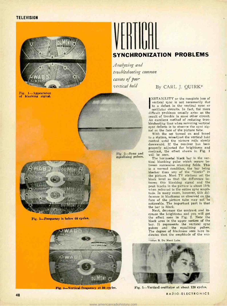
TELEVISION
L SYNCHRONIZATION PROBLEMS
Analyzing and
troubleshooting common
causes of poor
vertical hold By CARL J. QUIRK* Fig. 1- Appearance of blanking signal.
Fig. 2 -Sync and equalizing pulses.
Fig. 3- Frequency is below 60 cycles.
48
Fig. 4- Vertical frequency at 30 cycle;.
NSTABILITY or the complete loss of vertical sync is not necessarily due to a defect in the vertical sync or oscillator circuits. In fact, the more
difficult problems usually arise as the result of trouble in some other circuit. An excellent method of reducing trou- bleshooting time when servicing vertical sync defects is to observe the sync sig- nal on the face of the picture tube.
With the set turned on and tuned to a station, misadjust the vertical hold control until the picture rolls slowly downward. If the receiver has been properly adjusted for brightness and contrast, the effect shown in Fig. t will be seen.
The horizontal black bar is the ver- tical blanking pulse which occurs be- tween successive scanning fields. This is a normal condition, the bar being blacker than any of the "blacks" in the picture. Most TV stations set the black level so that the difference be- tween this blanking signal and the peak blacks in the picture is about 15% when referred to the entire sync ampli- tude. In many cases, however, this dif- ference in blackness as observed on the face of the picture tube may not be noticeable. The important part is that the bar is black.
Next, decrease the contrast and in- crease the brightness and you will get the effect seen in Fig. 2. Note the black area in the upper section of the bar. It represents the vertical sync pulses and the equalizing pulses. The degree of blackness seen here in- dicates that the amplitude of the ver-
*Allen B. Du Mont Labs.
Fig. 5- Vertical oscillator at about 120 cycles.
RADIO -ELECTRONICS
www.americanradiohistory.com
tical pulses is adequate. Since the sync signals are referred to as "blacker than black," it becomes obvious that, if the amplitude of these sync signals is normal, they should be blacker than the blanking pulse.
Since the sync signals must pass through all the picture circuits, it is possible that these circuits might dis- criminate against these signals in one way or another, causing faulty sync. However, this check (observing the sync signal on the screen) provides a quick and easy way of establishing whether the sync signal, as fed to the sync circuits, is adequate. It might be a little difficult at first thought to con- sider a pulse amplitude in terms of blackness on the face of the tube. How- ever, a little experience in observing this signal under various conditions of trouble will provide a very valuable troubleshooting tool.
Get "feel" of vertical hold Another important check point for
running down a bad case of vertical sync trouble is the vertical hold con- trol. Get the "feel" of the hold control! This might seem like a rather large order since the technician is called upon to service many makes and models. However, a few basic principles con- cerning the vertical hold control should be kept in mind.
For example, a receiver with a large - amplitude sync pulse available will also have a wide range of adjustment over which the set will remain in sync. Furthermore, a set with a high- ampli- tude sync pulse will "snap" into sync as the vertical hold control is adjusted. Sets with a lower -amplitude sync signal have a much narrower range of the control over which the set will remain in sync and will normally not "snap" into sync. In either case the set in question may be perfectly normal, and this is one thing that the service tech- nician will have to get experience with. A good method of gaining it is for the technicians to check the "feel" of the hold control on every set he services even though the trouble is not a vertical condition.
Several years ago I discussed vertical hold difficulty with a technician who had been having trouble with sync noise immunity. His problem concerned a sync circuit that was stable enough of itself, but when a burst of noise appeared the vertical sync would be lost. To overcome this he used a large capacitor (0.1 µf) across the output of the integrator circuit. This in effect bypassed to ground the noise pulses which were giving trouble. It also sub- stantially reduced the amplitude of the sync signal. With this modification, the range of the hold control had become extremely small, almost to the point of being critical. Once set, it would re- main very steady. According to him, this was a complete cure. However, the hold control was located on the back of the set, which would have made cus- tomer adjustment difficult.
MARCH, 1956
In addition to the sync pulses on the screen and the feel of the vertical hold control, the service technician will find another observation helpful under cer- tain conditions of vertical sync trouble.
As the vertical hold control is rotated in one direction, the picture will roll downward. When it is rotated in the other direction, the picture looks like Fig. 3 - several pictures appear to be partially superimposed. If the vertical hold control has sufficient range, it is possible to get two separate pictures (Fig. 4). In such case, the vertical fre- quency is running at 30 cycles. As the picture rolls downward, the vertical frequency is above 60 cycles. Again, if the control has adequate range, it is possible to run the frequency of the vertical oscillator up to 120 cycles. Fig. 5 shows the effect that would be seen under this condition.
Summing up this information we can conclude that, if the picture rolls down- ward, the vertical frequency is above 60 cycles; if the picture shows the effect in Fig. 3 or Fig. 4, the frequency is below 60 cycles.
Now that we are familiar with sev- eral checkpoints and a few simple tests, let's go about our business of cleaning up some of the vertical problems apt to present trouble.
Vertical sync due to ghosting A customer complained that on one
channel the picture rolled badly. The service technician verified this com- plaint - the remaining channels were rock solid. He concluded that the tubes in the receiver were all O.K. His next thought was to establish whether there was any particular reason why this one channel should have poor sync.
To do this he looked at the sync in- formation on the face of the picture tube. The picture on this channel was not as good as that on the other chan- nels. He noticed a ghost of negative polarity (that is, white objects ap- peared as black in the ghost region and vice versa). He did not concern himself with this detail too much and he then misadjusted the vertical hold control to get a good look at the sync. At first look, the blanking signal seemed normal. But when he adjusted the brightness and contrast controls to get a better look at the sync, instead of seeing the clean -cut black display that represents sync and equalizing infor- mation, he saw the ghost of the sync signal cancelling the sync information, since the reflection was negative. So here was the trouble - the ghost was so located that it not only affected the picture but, since it was negative, it cancelled the sync. Thus the difficulty with the one "rolling channel." The trouble was eliminated when the tech- nician modified the antenna position so that this ghost effect was removed.
Loss due to compression This condition will appear similar to
that caused by ghosting. The customer may complain that only one channel
TELEVISION
rolls. In this case, however, it is much more likely that two or more channels are rolling. Make the necessary adjust- ments to the set for a look at what the vertical pulse looks like in black -and- white as it were. Fig. 6 shows the ver- tical sync signal seriously compressed.
In this case, the channel that was affected had just increased its power, thereby resulting in sync compression in the front end of the receiver. A printed - circuit attenuator was used to attenuate the signal relieving this condition. In some cases, it is possible to correct this trouble by adjusting the a.g.c. con- trol, provided of course that the re- ceiver has such a control. It is also possible that sync compression can take place somewhere in the i.f.'s, the video amplifier or even in the sync circuits. This should not be too difficult to deter- mine: during overload, when the sync pulse is compressed and vertical syn- chronization is lost, other effects are seen. For example, one of the first effects of overload is audio buzz, and the picture may be lacking in its range of shading. If the compression is tak- ing place somewhere in the set, it should not be too difficult to analyze with an oscilloscope.
A crystal probe is necessary when exploring the i.f.'s for possible com- pression. After the video detector, of course, the scope may be used direct. The usual procedure is to examine the sync waveform at the input and output of each circuit involved. Fig. 7 shows what should be seen when everything is operating normally. Improper volt- ages, especially in the grid circuit, will produce sync compression.
Various degrees of compression can cause trouble. In one case the trouble appeared as an intermittent vertical and was due to an open screen bypass capacitor at the video amplifier tube. The capacitor was a 10 -pf unit. The scope revealed the vertical serrated pulse to be greatly depressed. Inci- dentally, most popular -priced scopes dis- criminate against this ii orizontal sync signal because of inadequate frequency response, with the result that when everything is normal the waveform of the sync signal as viewed in the video circuits appears as shown in Fig. 7. Note that the vertical pulse interval is apparently of higher amplitude than the horizontal. If an oscilloscope having an extended response were used, both would be of equal amplitude. There- fore, if with a lower- response scope both amplitudes are the same, the ver- tical region is probably being com- pressed. Whether sync is being affected enough to make a difference in per- formance will depend upon the set In question.
Improper sync due to hum This trouble could have been a dilly
had not the technician been curious about every little thing he saw in a pic- ture. Let's see how it paid off.
The customer phoned the technician and said that his set would be O.K. for
49
www.americanradiohistory.com

TELEVISION
Fig. 6 (Left) -A compressed vertical pulse. Fig. 7- (Below) Normal appearance of waveform.
a while, then the picture would roll a few times, stop, be O.K. for a while longer and repeat the cycle.
The technician examined the sync as it appeared on the face of the pic- ture tube and found it to be normal. He then checked the "feel" of the hold control - also normal. While examining what was happening as the set went out of sync, he noticed a slight ripple in the picture. Since this ripple resem- bled a sine wave if the picture were turned on its side, he concluded that a 60 -cycle signal was getting into the sync circuits. He further noticed, how- ever, that as the positive half -cycle of this ripple got to the bottom of the picture - the region of the vertical sync - the picture would take its sev- eral rolls and then recover again. By the time that the next positive half - cycle got to the bottom of the picture the effect would be repeated. The tech- nician concluded that this 60 -cycle rip- ple was causing the trouble. He also knew that the most common way a 60- cycle sine -wave signal gets into a set is through heater -cathode leakage in a tube. By substitution, it was found that the trouble was just that - heater -cath- ode leakage in the second i.f. tube.
Tubes that have a cathode resistance to ground will produce this trouble. Obviously, if the cathode is grounded, heater -cathode leakage will not have this effect. If the set is in the shop, the stage can quickly be identified by shorting the cathode of each of the possible tubes to ground. When the hum disappears as the short is made, you have located the culprit. This condition happens fairly often, so watch for the symptoms. And if you haven't run into it, you no doubt will sooner or later.
50
Vertical drift Here is trouble that turns a tech-
nician's hair gray. What usually hap- pens is this: The customer is sitting back in his easy chair enjoying his favorite program when slowly the pic- ture starts to roll downward. He fidgets in his chair, waiting for the picture to settle down, but it doesn't. Reluctantly, he hoists himself out of his favorite spot and lumbers over to the set to adjust the vertical hold. This done, he returns to pipe and popcorn.
A little later, 1 minute, maybe 5 minutes, the above series of events is repeated. Our customer is getting a little peeved. The third time it happens he cannot get it to stop rolling. This is where you -the technician -come in.
How do you go about running down such a trouble? You and I would prob- ably change the vertical oscillator tube. Perhaps the trouble would be elim- inated. At least you think it is because you watch the set for an hour and it doesn't roll. However, about a week later, you get a call from your customer and he is not happy. It's rolling again, he says, why don't you fix it right? Back you go, to try again.
Let's see which of our checks might pay off in a spot like this. The symp- toms here are definitely different than they were for the case of the tube with the heater -cathode leakage. In that trouble the set would correct itself. What about the sync information on the face of the tube? You would not likely see much there, but there is always a possibility that something un- usual might come up and would be visible. How about the "feel" of the hold control? Perhaps, but not too likely
for these symptoms, especially if the set always goes out in the same (fre- quency) direction.
This specific problem has been en- countered by a number of set manu- facturers who used a 6BL7 as the ver- tical oscillator and output tube. A few years ago this was popular, at least until everyone got into trouble with the tube.
At that time, technicians were re- placing the tube only to have the con- dition recur. It was found that if the filament power was reduced slightly, this condition would be corrected in most cases. The only difficulty was that the picture would come to full vertical size rather slowly. However, since it was during the normal warmup time of the set, it was not too important. The filament power was reduced by a resistor (1 -1.5 ohms, 4 -5 watts) in series with the filament of the tube.
Du Mont got around this problem by using a special adapter containing the resistor. The adapter consisted of an octal tube base with an octal socket inserted in its top with the correspond- ing pins wired through, except for the filament pins which had the resistor in series. Some time later the 6BL7 was improved, obviating the use of the adapter. If the trouble is not a tube, it is most likely a part of the vertical oscillator circuit. Thus, if the frequency drifts up, some part is changing value so that the frequency will run high. That is, some frequency- determining re- sistor or capacitor has decreased in value. It follows, therefore, that if the drift is downward in frequency, it is due to a component that has increased in value.
On occasion, a technician will replace a part only to find that the trouble still persists or exists in a slightly different form. This may be due to a component correctly color- coded, but actually not close to its supposed value.
Unstable vertical sync The customer complained that the
picture rolled constantly. Investigation revealed that while it was possible to adjust the vertical sync so that the picture would lock, the hold was ex- tremely "loose" and the hold control was very critical. This set used a block- ing oscillator which derived its pulse from an integrator coupled to the grid circuit of the oscillator through a wind- ing on the blocking oscillator trans- former. From the feel of the hold con- trol the amplitude of the sync pulse was very low. A quick look at the ver- tical signal on the face of the tube revealed everything to be normal. So, the fault was laid to the vertical sync circuits (the oscillator was O.K. since adjustment of the hold control would provide the frequency range considered normal for this set) . This receiver used an integrator composed of individual capacitors and resistors. The trouble in this case was traced to a leaky capac- itor in the integrator that was bleeding most of the pulse to ground. END
RADIO -ELECTRONICS
www.americanradiohistory.com

HEN hum can be seen on the screen as well as heard from the speaker, the service tech- nician will usually find it
a
FROM RATIO DEI
' VOLUME
À AI 150
135V
LINE TO OTHER CKTS
I2CA5 SOUND OUTPUT
7
v2 5AM8 3RD IF AMPL
Fig. 1 -Audio output tube as voltage divider resistor in Admiral 17KP3 set.
18K FROM IST VIDEO AMR PLATE
.011 TO SYNC SEEP
_ v2 6U8 NOISE CANCEL
18K 8 FROM VIDEO DIT
047 ÿ 1.5 MEG
FROM HORIZ MULT
.01
8CD6 -G HORIZ OUTPUT
471(
500K NOISE CANCEL
Fig. 2- Horizontal output and noise- cancellation stage in Stromberg 624.
MARCH, 1956
VERT 05C TRANS
FROM VERT INTEGRATOR
.004
u
6K6 -GT VERT OUTPUT
3 18OV
-I00V
CI .I
5
2.2MEG
-100V
C2 84
8
.05 8.2K
,11
t 22041 R3 1 R C4 T K
+ I
C3 50 t-IOOV
LINEARITY 5K
2 SMEG
HEIGHT
R2N 56K
TELEVISION
TO VERT DEFL COILS
i0K 275V
Fig. 3- Vertical sweep circuit in the RCA 8TS30 television receiver.
easier to concentrate on the video sym -- toni. With only the audio effect, he has to determine whether the trouble is hum or buzz (troubleshooting procedure differs for the two).
Hum generall; has a smooth sound; it consists of a sine -wave heater or power- supply ripple of 60 or 120 cycles. Being sinusoidal, very little harmonic distortion is produced. The 60 -cycle hum is generally a product of heater -cath- ode leakage in a tube; 120 -cycle hum indicates such trouble as faulty filtering in the B supply.
Buzz has a raspy sound. It is most often produced by harmonic -rich square waves such as the vertical sync and blanking pulses. Other common sources are low- frequency video signals and vertical deflection voltages in a set. The horizontal sweep circuits seldom cause interference because the 15,750 -cycle signal falls beyond the response range of television audio amplifiers.
Drawing a still finer line, we should distinguish between picture or video buzz and sync buzz. Picture buzz is by far the more common of the two. In addition, it is easy to spot -it changes in tone and amplitude with any major change in the televised scene, such as produced when switching cameras or breaking into a commercial. Sync buzz, produced by coupling between the audio section and the vertical sweep and de- flection circuits, does not vary with changes in video content. We will cover the various causes of buzz at a later date. Now let's concern ourselves with audible hum.
Again we must distinguish between terms : power -supply hum and modula- tion hum. Power -supply hum can be heard at all times regardless of whether a signal is being received; modulation hum is produced only when tùned to an active channel.
After it has been determined that the trouble is power -supply hum, the first important check is to see if the hum in- tensity can be varied with the volume control. If it can, the defect is almost always before this point. If varying the volume control has no effect on the hum, it is a fairly safe guess that the trouble lies after the control. When hum can
be controlled, replace the audio demodu- lator and all other tubes between this and the sound takeoff point.
Where the volume control has no effect on hum level, try substituting new tubes in all circuits between the control and the loudspeaker. If this clears up the trouble, heater -cathode leakage was probably the defect. If tubes are not causing hum, a process of circuit elimi- nation can be used.
If removing the audio output tube eliminates the hum, replace the output tube and remove the tube preceding it (generally the first audio amplifier). If hum remains, carefully check the filter capacitors in the B -plus line to the audio output tube and check the output tube grid circuit. This can be done with a scope or headphones plus blocking ca- pacitor.
If removing the first audio tube also removes hum, check the grid and plate circuits of that stage. A quick check of the grid circuit consists of simply grounding it to chassis. If a B -minus bus is used, short the grid to this point. If shorting removes the hum, the trouble lies between this grid circuit and the volume control -check all ca- pacitors. (In shorting grids to ground, be on the lookout for audio tubes also used for voltage dropping. See Fig. 1. The grid may be at about 120 volts.)
Once a circuit has been found to be the source of trouble, make the follow- ing additional checks: See that all shielded wire is properly grounded, dress all unshielded wiring and com- ponents away from ac power lines and power -supply circuitry. Where audio and ac wiring must cross paths, do so at right angles. Be sure sockets are thoroughly grounded.
If confusion exists between hum and buzz, eliminate possible sources of buzz by removing the vertical and horizontal oscillator and output tubes. For further insurance remove the final sound if amplifier tube. In some cases where hum is introduced into the grid of the first audio amplifier, the volume control can vary its intensity, giving the effect that it is being introduced before the control -watch for this.
In sets with series -string heaters
51
www.americanradiohistory.com

TELEVISION
tubes may still be removed by replacing them with inoperative units (all pins clipped except the heaters).
Modulation hum
This effect is produced by hum in the rf and if amplifiers and exists only when receiving a signal. It is caused by heater cathode leakage or B- supply ripple in the plate and screen circuits. It generally appears as amplitude modu- lation on the if carrier and would thus be more noticeable on the picture -tube screen, the ratio detector being fairly effective in guarding against AM. Be- cause of this, tunable hum is found in split -sound receivers where maximum AM rejection takes place when the sound if is exactly the same as the cen- ter frequency of the sound detector. In intercarrier sets there is no tunable modulation hum, the 4.5 -me signal being constant. In any case, maximum pro- tection against modulation hum is care- ful alignment of the sound detector.
The above rules are general and the technician must be on the lookout for misleading variations. For instance, a set having heater cathode leakage in one of its if amplifiers may produce hum only on weak stations. This could pose a time -consuming problem in which the technician will eventually discover that strong signals produce a large agc volt- age that is applied to the defective tube. This greatly lowers its gain and the modulation hum produced by that stage is negligible. On weak stations the hum rides through. But this is what makes servicing so interesting.
High -voltage doubler A Sylvania 1 -512 chassis has been
giving more than its share of trouble. The general symptoms are a loss in high voltage and brightness. The circuitry around the high -voltage power supply has been gone over with a fine -tooth comb and, if anything, everything checks too good. I measure about 15,000 volts at the picture tube which is lower than it should be (19 -23 kv). However, the horizontal output, damper and high - voltage tubes have been changed with no improvement. I suspect that the horizontal output transformer may be defective. -C. C., Saco, Me.
Of course, if every component associ- ated with the sweep and high -voltage circuitry has been checked and all test good, it is logical to suspect the fly- back transformer. However, voltage doublers of this type have a character- istic trouble that should be checked carefully. Between the filament of the input 1B3 -GT and the plate of the out- put 1B3 -GT are connected three 1- megohm resistors.
Supplying a 27GP4 which requires 21,000 volts for normal operation, the resistors and capacitors in this circuit are under severe operating conditions and breakdowns under load are com- mon. Most often the 1- megohm resistors change value and cause a surprising loss in high voltage. Thus, replace the
52
three resistors with good -quality 2 -watt units -this is most likely the trouble.
Negative Picture
A Stromberg- Carlson model 624 has come in with a strange set of symptoms. So many things check wrong that it seems as if many components are de- fective. However, the customer states that the set played perfectly until everything went wrong at once. The picture has a negative or engraved ef- fect; it is badly distorted and sync is highly critical. The same effect can be produced by advancing the noise can- cellation control under normal condi- tions.
The agc voltage is very low and may be causing overload. I have carefully gone over the keyed agc circuit but it appears to be in order. The plate pulse is only 200 volts or so which is probably lower than it should be. The noise can- cellation circuit has no effect and the grid voltage on the horizontal output tube is very low. M. R., Wheeling, W. Va.
There are a few highly significant clues that you have uncovered. The low voltage on the plate of the keyed age tube accounts for the low age voltage. The pulse at the plate of this tube should be approximately 800 volts. Thus, the very low age voltage is per- mitting excessive rf or if amplification, causing video overload and the engraved effect.
Pursuing this further, the lack of negative voltage on the grid of the horizontal output tube accounts for the low voltage on the plate of the keyed agc tube. This is substantiated by the fact that the picture appears the same as when the noise cancellation control (Fig. 2) is fully advanced. The final clue is the normal operation of the hori- zontal multivibrator circuit.
The trouble lies in the cathode circuit of the horizontal output tube. Replace both cathode resistors. However, most likely the defective component is an open 5 -sf 50 -volt cathode bypass capaci- tor. With this capacitor open, the nega- tive voltage disappears and the grid of the noise cancellation tube, normally biased about 7 volts negative, is at ground potential. The tube conducts heavily, fully clipping the sync and pro- ducing a distorted and critically syn- chronized picture.
Poor height and linearity A real old -timer came in the shop in
NEXT MONTH An Important Item
for every TV Technician
TUNABLE TRAPS in
COLOR RECEIVERS By Maff Mandl
Watch for It!
the form of an RCA 8TS30. The set must be over 8 years old and has under- gone much servicing. The present trouble is insufficient height and poor linearity. I cannot be sure that there are two separate problems, since a com- mon trouble could be causing both symptoms.
The wiring in this set is pretty much messed up but it seems to be correct. I have checked the vertical oscillator and output tubes, and some of the more likely components but have drawn a blank. P. T., Orlando, Fla.
It is very possible that on an old set such as this the trouble is being caused by the general deterioration of several components. However, some are more likely suspects than others. For height, check capacitors Cl and C2 (Fig. 3) by direct replacement -they may be only slightly leaky. Check resistors R1 and R2 for off -values. Because of the age of the set, try to maintain 10'7, tolerances. Resistor R3 has also proved troublesome through the years. Filter capacitors G%
and C4 should definitely be replaced if even remotely suspected.
Several of these components also af- fect vertical linearity, primarily capaci- tors C2, C3 and C4. An important com- ponent involved in linearity is resistor R4. This certainly should be replaced. If the above checks fail, it would be wise to replace the vertical output transformer before going on. Several voltages are indicated in the diagram. See that your measurements are within 10% of them. If appreciably lower, check the low- voltage power supply rec- tifier tubes and filter capacitors.
Horizontal pull
In a,Crosley series G Super V chassis I have run into a case of severe pulling on the right side about half -way down the screen. I have the manufacturer's schematic and service notes and have checked everything possible. All wave- forms seem perfect and all voltages are almost exactly as stated on the sche- matic. I have gone over the entire hori- zontal circuit with a vtvm and scope with no results. -A. L., Detroit, Mich.
The number of possible causes of pull- ing are far too great to list here. How- ever since you have made such an ap- parently exhaustive search, it is very likely that the trouble is one common to these Crosley chassis. The pulling takes the form of a triangular notch in the area you described. It appears to be due to core saturation of the horizontal out- put transformer because increasing the air gap clears up the defect.
Examine the air gap carefully. In some case there is excessive tape there which can be removed -one layer at a time. Other times, you may be able to place a few pieces of plastic tape be- tween the pole pieces. In either case, be careful not to make the air gap too wide or the decrease in horizontal pulling will be accompanied by a decrease in width. END
RADIO -ELECTRONICS
www.americanradiohistory.com

AUDIO -HIGH FIDELITY
Unit provides triode, pentode
and Ultra - Linear operation
Top and bottom views of amplifier chassis. Selector switch is at right.
4110.,
THERE has always been an argu- ment among audio fans concerning the relative merits of various types of output tube operation. Some will
settle for nothing but a triode, others are equally certain that the more effi- cient pentode is the best choice. A relatively new, but equally avid group, holds that Ultra- Linear operation is best since it has the power advantage of the pentode along with the character- istic low distortion of a triode.
This amplifier solves the touchy problem with the addition of a two -pole three -position switch. Its purpose is to select any one of the three output tube connections. A constructor can build the amplifier without the switch and use his pet connection or add the switch and amuse himself by choosing the output stage which suits his mood. The switch can also be used to confuse purist friends who believe in only one type of output stage since the audible differ- ence in performance at the three posi- tions is very small.
If the only difference between this amplifier and others was the addition of a single switch, there would be noth- ing remarkable about it. Actually, very careful thought went into the design of
MARCH. 1956
AMPLIFIER By ROBERT SHARPE
each circuit in this amplifier and the following list of features is offered as proof :
1. Response flat from 10 to 100,000 cycles.
2. Hum and noise more than 80 db below maximum output.
3. About 0.3 -volt input required for maximum output.
4. Maximum power output of 6, 12 and 13 watts for 1% distortion (Fig. 1) on triode, Ultra- Linear and pentode connection.
5. Less than 1 -db variation in over- all gain when switching from triode to pentode operation.
6. Only four matched parts needed for accurate signal balance at the grids of the output tubes.
I am dismayed by some of the trends in recent amplifier designs. A typical design uses a monstrous output trans- former flanked by a pair of overworked 6L6's, a 40 -pound transmitter -sized power supply, a half -dozen mystic adjustments, a couple of voltage ampli- fiers and 20-30 db of negative feedback to cover up the design blunders. Don't think that the home constructor is the only one guilty of questionable design. A well known manufacturer operates
a 12AX7 tube, which has a maximum plate voltage rating of 300, with 484.
I am not satisfied with this type of design, but prefer to construct a neat, compact, reliable, high -quality and moderately priced amplifier which can be simply placed in operation and then forgotten. Ten watts of audio power output from 10 to 100,000 cycles with less than 1% distortion is adequate - I am sure -for even the critical listener. Furthermore, it can be achieved with standard parts, conventional circuitry and conservative operation of all parts.
One best circuit design does not exist. Mai.y good ones have been made. The circuit described in this article (Fig. 2) has been used in two amplifiers to date
A
SIM I
3
,II%J sra 2 4 6 6
PONER OUTPUT (WATTS)
Fig. 1- Harmonic distortion vs output.
53
www.americanradiohistory.com

AUDIO -HIGH FIDELITY
and has proven its merits. So that you may see what decisions were involved in the design, a step -by -step outline is presented in approximately the sequence followed.
Output stage The 5881's in the output stage have
a maximum plate dissipation of 23 watts each and yet are small. In the interest of reliability all of the "high - power" components such as transform- ers and tubes are operated at about 70% of their maximum rating. This called for a plate input to the two 5881's of about 30 watts.
After following a ring of interlock- ing decisions for a few minutes, I decided that 300 volts at 100 ma would provide the desired 30 watts with the most efficient use of power supply parts. A standard power transformer, rated at 750 volts at 150 ma and working into a choke -input filter, supplies a well -filtered 300 volts with excellent regulation. The choice depended upon maintaining class -A operation of the output tubes along with the use of standard power supply components. Parts which are run too close to rat- ings are unreliable ; using them far under their ratings is uneconomical as well as doing little to improve reli- ability.
With pentode operation of the output tubes (the 5881 is normally referred to as a beam power tube, but it has five electrodes and could be called a pen- tode), a maximum power output of 10 to 15 watts could be expected. A Peer- less S -226Q output transformer seemed to be the logical choice from a consider- ation of ratings, quality, cost and size. Its 20 -watt rating is adequate, it is very compact and its response flat ±1 db from 10 to 100,000 cycles. Although the secondary can be arranged to match loads of 2, 4, 8 and 16 ohms, high - quality speakers are normally 8 or 16 ohms. The connections were modified from the manufacturer's instruction sheet so that 8- or 16 -ohm speakers could be used without any wiring changes in the amplifier. A switch in the screen leads of the output tubes makes the change between triode, Ultra - Linear and pentode.
Cathode- follower driver The 12AU7 cathode -follower driver
has very low output impedance, hence
54
Top and bottom view of the power supply chassis. Note the tubular
rectifiers.
its high -frequency response is good. At the operating conditions selected for this tube, it has an output impedance of something over 300 ohms. Estimating the input capacitance of one output tube at 50 µµf (triode connection, when it is the largest), the high- frequency response is calculated to be less than 3 db down at 1 mc. Capacitive loading on the previous stage is also very low because the input capacitance of cath- ode followers is inherently low (about 5 µµf for this tube).
Low- impedance output is desirable for another reason. It permits an in- crease in the amplifier's output by
hPPf
driving the output tubes into grid cur- rent. The improvement in power capabilities is evident if the 6 -watt rating of this amplifier on triode connection is compared with the value of 4 watts listed in most tube manuals.
Low -distortion drive into grid cur- rent requires direct coupling 'to the output tubes. With it, return to normal conditions is instantaneous after a sig- nal peak has drawn grid current. With R -C coupling, grid current would rapid- ly charge the coupling capacitor. The charge, slowly leaking off through the high- resistance grid return, would pro- duce a signal not related to the signal
180K 33K #t 2W
I2AU7 5881(2)
12AX7 I
T I2AV7
1 130V 3
295V
V2 -a
OV
V3-a
-25V
V4
PEERLESS 5-2260
4 o, 6
L 2
4V
BALANCE i0,lww
B2 K
z
4
3 39K 10nWW
s BIAS
2
V3-b 5V
V2-b VS
130V
808 2
6
280V
10K 2w
4.78 300V
20 450V 2
QMATCHED T0 5X OR BETTER *IAATCHEDTO IX OR BETTER
Fig 2- Schematic diagram of amplifier.
A " ----
I 300V/ROMA GND
o--
-150V IRMA REGULATED
8n
SIRS
Ft
16n
6.3VAC / 2.7A
Switch selects output tube operation.
RADIO -ELECTRONICS
www.americanradiohistory.com

peak which caused the grid current. This is truly distortion -a very dis- agreeable type.
R -C coupling to the cathode -follower type driver prevents dc drift in the bias and balance adjustments for the output tubes. To prevent the distor- tion just mentioned, in the grid circuit of the cathode follower, a low -mu tube is used. There is a safety margin of about 10 volts between grid- current flow in the output tubes and in the drivers when a 12AU7 is used. A 12BH7 would have been somewhat better but is more expensive. It can be sub- stituted directly into the circuit if desired.
Direct coupling is obtained by ground- ing the cathode resistors of the output tubes and returning the cathode resis- tors of the driver to a negative 150 - volt supply. This -150 -volt supply is also used for a previous stage. The direct coupling produces a simplified balance and bias circuit for the out- put tubes. Low- wattage carbon pots are used in the grid circuit of the driver and the resulting adjustment is smooth and relatively permanent.
Adjustment is simplified by ground- ing the cathodes of the output tubes permanently through a pair of matched 10 -ohm resistors. Connect a meter on a 3- volt -or -lower scale between the cathodes of the output tubes and set the balance control for zero reading. With the meter from a cathode to ground, set bias for 0.5 volt. A recheck of balance completes the adjustment.
Parts values were chosen so that the output tubes could not be damaged by misadjustment of the bias control. The range of the balance control is sufficient for good tubes. If balance cannot be reached with the control, it is a sign that one or both of the output tubes is unsatisfactory.
As the circuit stands, removing the 12AU7 or failure of its heater will not cause any damage. If the cathode follower had not been R- C- coupled to the preceding stage, results would have been very different. While failure or removal of the cathode follower would not cause any harm, removing the previous stage would raise the grid of the cathode follower toward B plus and cause severe overload of the out- put tubes and power supply.
The cathode follower is essentially free from drift because of the large amount of inherent feedback. But the stage preceding it is likely to drift 10 to 20 volts during its normal life and this amount of signal, direct -coupled to the output tubes, would present a serious drift problem.
Phase inverters That's right, this amplifier has two
phase inverters. The first one is a 12AX7 in the common seesaw connec- tion and need not use precision compo- nents. The second is a 12AV7 with a long -tailed connection and has accu- rately matched plate loads. While its chief function is that of a push -pull
MARCH, 1956
amplifier, its constants are chosen to improve the phase- inverting action of the first tube.
Using standard resistors, the first inverter shouldn't have over 10% un- balance. After passing through the 12AV7 stage, the outputs should be matched within 0.5 %. Because of the large amount of feedback in the cathode - follower driver, the signal should reach the grids of the output tubes with less than 1% unbalance. The important feature here is that since the phase - inverting action is essentially inde- pendent of tubes, unbalance of less than 2% can be maintained at the out- put tubes for the life of the amplifier - without any adjustment.
The importance of having accurately balanced signals at the grids of the output tubes should not be underesti- mated. An unbalance of 20% can in- crease the distortion generated in the output stage by several times. Measure- ment on a push -pull 6V6 amplifier with- out feedback showed that a 20% un- balance in output grid drive increased the distortion by 2.5 times. As for distortion, the unbalance would essen- tially nullify the effect of 8 db of negative feedback.
Widest possible use of a single part value has been made in this amplifier. This policy makes it simple to select a matched pair. For example, plate loads on both the 12AX7 and 12AV7 are 180,000 ohms. Only the plate loads for the 12AV7 need matching and the best matched pair can be selected from the four resistors. Even if the unused resistors are not needed for immediate use, lots of 5 or 10 can usually be pur- chased at a reduced rate and pairs selected with an ohmmeter. This way you have a matched pair and some extras at about the cost of a commer- cially matched pair. If carbon resistors
Parts list for amplifier section Resistors: 1 -4,700, 3- 10,000, I- 15,000, 1- 33,000, 1- 39,000, 7- 680,000 ohms (two pairs matched to 5% or better), 1/2 watt; 2 -10 ohms (matched to 1% or better), 1/2 watt, wirewound; 1- 150,000, 2 -1,200 ohms (wirewound), I watt; 1- 10,000, 2- 47,000 (matched to 5% or better), 1- 82,000, 4- 180,000 ohms (two matched to 1% or better), 2 watts; 1- 10,000, 1- 20,000 ohms, potentiometers. Capacitors: 1 -50, I -75 µµf, mica or disc ceramic, 500 volts; 3-0.1, 2 -0.5 µf, 600 volts, metallized paper (Aerovox P82 or equivalent); I -20-20 pi, electrolytiic, 450 volts. Miscell : I- output transformer, primary im- pedance 6,600 ohms ct, secondary 4, 8, 12, 16 ohms (Peerless S -226 -Q or equivalent; 1-12AU7, I- 12AV7, I- 12AX7, 2- 5881's; 3-9 -pin miniature, 2 -octal sockets; I -2 -pole 3- position switch; 1-4 x 7 x 12 -inch chassis (Flexumount or equivalent); I- length of 6- conductor cable; I-6- contact plub (Cinch -Jones P- 306 -CCT or equivalent).
Parts list for power supply section Transformers and chokes: I -power transformer, 750 volts ct @ 150 ma, 5 volts @ 3 amps, 6.3 volts @ 4.5 amps (Stancor PC -8411 or equivalent); !- power transformer, 250 volts @ 25 ma, 6.3 volts @ I ma (Stancor PS -8416 or equivalent); I -choke, 7 henries @ 150 ma, 200 ohms (Stancor C -1710 or equivalent); 1-choke, 3 henries @ 150 ma, 90 ohms (Stancor C -2309 or equivalent). Miscall : I- 2,000, I- 3,000, 1 -4,000 ohms, 4- watts, wirewound, resistors; I -30 -30 µf, 350 volts, electrolytic; I -40-40 µf, 450 volts, electrolytic; I- 5114 -GA, I-0A2; I- octal, I -7 -pin miniature, sockets; 4 -20 -ma selenium rectifiers, miniature (Federal 1159 or equivalent); I-4 x 7 x 12 -inch chassis Fleximount or equivalent) I-6- contact socket Cinch -Jones S- 306 -A8 or equivalent); 1 -2 -amp fuse
and holder; I -line cord and plug.
AUDIO -HIGH FIDELITY
are used, it is wise to use wattage ratings much higher than the power actually dissipated to minimize the resistance change which accompanies temperature change.
Feedback is taken from the trans- former secondary to the cathode of the input stage. The compensating net- works used were calculated from data measured without feedback but were touched up slightly to provide the best square -wave response on the pentode position, where ringing was a little troublesome. No ringing was noticed with triode or Ultra- Linear connection of the output tubes.
Power supply Although a 5U4 -GA rectifier is
specified in the parts list, a somewhat higher -priced tube, the 5V4 -G, would be easier on the output tubes since its cathode type construction delays the B -plus voltage until they have warmed up.
2A
117SAC
750V T 5U4-GA 714 /150MA 3H/ I50MA
8 = 300v
63V/4.5A
20MA SELRECT(4)
0A2 x21V4W 36/4W 415/4W
40
450V
Fir g0
3- Schematic of power supply.
The negative 150 -volt supply (Fig. 3) must come on before plate voltage is applied to the output tubes since it supplies their . bias. Thus, a bridge selenium rectifier is used. A pseudo choke -input filter, 150 -volt miniature VR tube and power transformer, com- plete the parts list. The 0A2 voltage regulator fires within 2 seconds after power is turned on and the positive supply follows by about 10 seconds.
The amplifier and power supply were constructed in a pair of 4 x 7 x 12 -inch Fleximount cases. Adequate ventilation is essential to reliable operation and a pattern of holes drilled in the covers suffices.
Standard construction practices such as twisting ac leads, careful placement of parts and shielding input and output from each other should be used. A 6- conductor cable and a pair of Jones connectors facilitates power connec- tions between the two units. END
(Note that Mr. Sharpe has designed his amplifier for best operation in the pentode connection. By using higher plate voltage -easily obtained by using capacitor input instead of choke input in the power supply -and by adjusting output plate loads and grid bias, the characteristic can be changed to opti- mum for triode or Ultra- Linear opera- tion.- Editor)
55
www.americanradiohistory.com
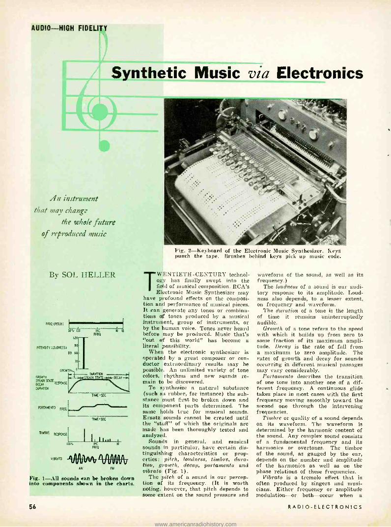
AUDIO -HIGH FIDELITY
Synthetic Music via Electronics
/In instrument
that may change
tue whole future of reproduced music
By SOL HELLER
REQ (Mtn 30'U 100
120 -
DJiFJüiTY(1O0Y.IESS) 90
GROWTH
STEADY STATE
DECAY RE-
DURATION
D8 60
30
0 GROWT
SE
PORTAMENTO EREO
TIMBRE RESPRüE
VIBRATO
p 15
MOTION 71 5TA DECAY -a.
TIME -SEC
100
TIME -SEC
I hii r,c ro
FREQ
VUUVvV AK
IIfllt V
FM
Fig. i -A1Il sounds can be broken down into components shown in the charts.
56
Fig. 2- Keyboard of the Electronic Music Synthesizer. Keys punch the tape. Brushes behind keys pick up music code.
TW;ENTIETH-CENTURY technol- ogy has finally swept into the field of musical composition. RCA's Electronic Music Synthesizer may
have profound effects on the composi- tion and performance of musical pieces. It can generate any tones or combina- tions of tones produced by a musical instrument, group of instruments, or by the human voice. Tones never heard before may be produced. Music that's "out of this world" has become a literal possibility.
When the electronic synthesizer is operated by a great composer or con- ductor extraordinary results may be possible. An unlimited variety of tone colors, rhythms and new sounds re- main to be discovered.
To synthesize a natural substance (such as rubber, for instance) the sub- stance must first be broken down and its component parts determined. The same holds true for musical sounds. Ersatz sounds cannot be created until the "stuff" of which the originals are made has been thoroughly tested and analyzed.
Sounds in general, and musical sounds in particular, have certain dis- tinguishing characteristics or prop- erties: pitch, loudness, timbre, dura- tion, growth, decay, portamento and vibrato (Fig. 1) .
The pitch of a sound is our percep- tion of its frequency. (It is worth noting, however, that pitch depends to some extent on the sound pressure and
waveform of the sound, as well as its frequency.)
The loudness of a sound is our audi- tory response to its amplitude. Loud- ness also depends, to a lesser extent, on frequency and waveform.
The duration of a tone is the length of time it remains uninterruptedly audible.
Growth of a tone refers to the speed with which it builds up from zero to some fraction of its maximum ampli- tude. Decay is the rate of fall from a maximum to zero amplitude. The rates of growth and decay for sounds occurring in different musical passages may vary considerably.
Portamento describes the transition of one tone into another one of a dif- ferent frequency. A continuous glide takes place in most cases with the first frequency moving smoothly toward the second one through the intervening frequencies.
Timbre or quality of a sound depends on its waveform. The waveform is determined by the harmonic content of the sound. Any complex sound consists of a fundamental frequency and its harmonics or overtones. The timbre of the sound, as gauged by the ear, depends on the number and amplitude of the harmonics as well as on the phase relations of these frequencies.
Vibrato is a tremolo effect that is often produced by singers and musi- cians. Either frequency or amplitude modulation -or both -occur when a
RADIO -ELECTRONICS
www.americanradiohistory.com

vibrato effect is introduced. Vibrato gives music a slightly quavery effect that adds warmth and beauty to a tone and enhances its emotional intensity. Timbre sometimes varies at the same time as well. Many instruments are capable of producing such an effect.
A final characteristic (of musical sounds) that is more intangible than the others is irregular deviation. This is a property that relates to the way the sounds are grouped and prevents the music from sounding mechanical.
How it works The synthesizer is capable of elec-
tronically reproducing all the char-
brush positioned just behind the keys. The coded information punched into the paper is picked up by the brush and transferred to the appropriate circuits.
The synthesizer produces one sound at a time -i.e., only single tones, such as those produced by one key of a piano or one string of a violin. To create the effect of an orchestra, the sounds made by individual instruments must first be separately formed by the synthesizer, then combined in a record- ing setup. The system employed is made up of a lateral cutter and a con- ventional 33 i- r.p.m. turntable. The turntable is coupled to the drive mech- anism of the paper- coding unit to
Fig. 3 -The recording system. Six pickups on upper record pick up and mix signals to be combined into a single recording on the lower disc.
acteristics just described and can thus generate any desired musical tone as well as any combination of tones. It is operated from a simple 36 -key key- board (see Fig. 2). Depressing the keys produces a punched paper record that controls the output of the system. The keys are colored and are arranged in groups to simplify their identification and operation. Each group controls one sound characteristic.
The 36 keys are divided into two basic sets of 18 each. In each set, 4 keys regulate note selection, 3 determine choice of octave, 4 regulate timbre, 3 control the growth, duration and de- cay characteristic and 4 affect the volume.
Two sets of keys are used because the synthesizer has two coding chan- nels. (Information on the punched paper record is in the form of a musical code. The information runs in sequence along a channel.) While one channel is operating and producing a tone, the other is being set up to produce a dif- ferent one. Another advantage pro- vided by a two -channel coding system is that one channel can begin to play a tone before the other has stopped playing the preceding one.
As each key on the keyboard is touched, a hole is punched in the me- chanically driven paper tape. The punched paper record passes at a speed of up to 5 inches per second under a
synchronize the two operations. A 16 -inch disc record is used. The
record has room for six 3- minute re- cordings, each of which represents a different single -tone series of notes. When the six recordings have been completed, they are combined into one. Six reproducing heads simultaneously play back all the single -tone series of notes (see Fig. 3) at the same time that a single head on another disc makes one recording of the combined sounds. Using such a combination process, any number of single tones may be mixed to produce the effect of var- ious combinations of instruments.
This system of individually recording a series of single tones permits the operator to work on one instrumental effect at a time, changing it over and over until he is satisfied with the way it sounds.
TUNING FORK UNIT
LU L
6J7
AUDIO -HIGH FIDELITY
The synthesizer circuitry This falls into the following basic
groups: A frequency generator, consisting of
12 electrically driven tuning forks. The forks form part of an electronic oscillator (see Fig. 4). Oscillator signal voltage flowing through coil Ll drives the tuning fork. The fork vibrates at the desired frequency and its tines cause a voltage to be induced into L2 and fed to the 6J7 grid. The frequency of this voltage is the same as that of the oscillation in the fork, which is, in turn, equal to the desired oscillator frequency.
The tuning forks create tones whose frequency range is the same as that of an octave on the piano. A schematic of the frequency -selecting system used for one octave is shown in Fig. 5. A binary coding system, using a relay tree, permits the selection of any of 12 frequencies through the use of only 4 keys.
A random -noise generator using a hot -cathode gas triode imitates the sounds produced by drums, maracas and other instruments. When the noise - producing circuits are worked through narrow -band filters, weird and unusual sounds can be produced.
An octave -selection system increases the frequency range of the instrument, so it covers the standard piano key- board and extends beyond it on either side. The octave system is made up of three circuits capable of providing any one of eight octave ranges. The dif- ferent octaves are obtained by the division or multiplication of the fre- quencies generated by the tuning forks.
Growth and decay circuits control the rate at which a tone reaches max- imum intensity, then diminishes from this peak. This characteristic varies in different instruments. For a plucked or struck string instrument, such as a guitar, the growth or buildup time is relatively short; in the case of a pipe organ, on the other hand, it is rela- tively long. Decay characteristics vary in a similar fashion.
Three circuits in the synthesizer provide eight different growth and decay characteristics. This is a number greater than conventional musical in- struments are capable of providing.
Portamento, as pointed out earlier, refers to the smooth way in which musical tones change in frequency. The transition is usually a gliding rather than an abrupt one. A single
65N7-GT
Fig. 4 -The tuning -fork oscillator.
ouTPUT
i l ¡
B+
Li is the driver; L2 controls frequency.
MARCH, 1956 57
www.americanradiohistory.com

AUDIO -HIGH FIDELITY
I~ !
( NOISE =-! EMI
N
< O B3
I es =--) , Gg
I D6--1 ¢ ó D6
c7 L...-- 1
s I
F6 - o
Fig. 5 - Frequency- selective system for one octave. Four re- lays select 12 notes.
ó TO Pe
BRUSHES
OUTPUT
L
RELAYS
PAPER RECORD
DRUM
OCTAVER
RELAY l TREE
11111111 BRUSHES
FREU
SOURCE DRUM
FREO
GLIDER
RELAY TREE
GROWTH DECAY AND
DURATION CONI
t CODED PAPER
RECORD
OCTAVER - aw = W¢ - ¢ r
smooth glide is characteristic of some instruments (such as the trombone or violin). In others, the transition is made in a series of successive approxi- mations. The instrument provides either type of portamento.
Basically, the portamento circuit con- sists of a specially designed oscillator that adjusts itself to changes in the frequency of the (musical) signal applied to it. When the input signal changes from one frequency to another in an abrupt or discontinuous manner (as when the operator depresses first one frequency key, then another), the output of the oscillator changes in fre- quency, shifting from the first to the second frequency smoothly or continu- ously and introducing glide effect.
Timbre differentiates the musical sounds produced by one instrument from those of another. The harmonics associated with the fundamental fre- quencies generated are responsible for the timbre of an instrument. A choice of 16 different timbres is provided in through 4 circuits.
The sine -wave signals generated by
58
RELAY TREE
FRED GLIDER
RELAY TREE
o
z
CHANNEL I
H P L P
FILTERS
1-0
o
10
-20
-30
40 100", 200 440 8 IKC
FRED
Fig. 6- Harmonics of 440 -cycle sawtooth. Harmonics extend to infinity with ever -decreasing amplitudes.
2 4 8 10
VOL CONT
Fig. 7 -A block diagram of the RCA Electronic Music Synthesizer.
LOW FRED MOD
RESONATOR
CHAINS
TIMBRE
COAT
RELAY TREE
I` TURNTABLE
RELAY TREE
CUTTER
MOTOR
AMPL
DRIVING CABLE
GROWTH DECAY AND DURATION
CONT
H P LP
FILTERS
VOL CONT
LOW FRED MOD
CHANNEL 2
the tuning -fork oscillators are converted into square waves of the same funda- mental frequency by two tubes in the frequency -multiplier section. Two other tubes change the square wave into a sawtooth one. Now, a sawtooth signal contains harmonics extending to infinity (see Fig. 6) . Frequency- discriminating systems select any desired grouping of harmonics, thus permitting the timbres of various musical instruments to be accurately simulated.
These frequency- discriminating sys- tems are made up of a combined high - and low -pass filter system whose cutoff is variable and a chain of amplifiers (resonator chains in Fig. 7) tuned to different frequencies. The setup per- mits timbre to be changed during the sounding of a single tone.
Vibrato was previously defined as a frequency or amplitude modulation of certain tones. The modulation fre- quency is generally 7 cycles. A low - frequency modulator in the synthesizer injects this vibrator or tremolo quality.
A volume control system made up of four circuits varies the sound output
RESONATOR
CHAINS TIMBRE CONTROt
between 0 and 120 db in a series of 15 voltage steps. Changes in volume may be made during the generation of a single tone or even between tones. The synthesizer's volume control sys- tem also controls the overall volume.
One advantage the music synthesizer has over conventional instruments is its elimination of various undesired sounds. Sensitive listeners may be annoyed by the noise of guitar strings being plucked or of piano hammers striking the strings, possibly rattling the mechanism as well. Most instru- ments produce such extraneous noise in varying amounts.
Some day, perhaps, anyone who wants to compose music or conduct an orchestra, but isn't in the mood to de- vote possibly 20 -odd years to mastering the skills involved, may be able to gratify his wish by operating a music synthesizer. It's something to look for- ward to-the joy of composing a violin concerto without knowing a note of music, or conducting the same piece without an orchestra. Frankly, I can hardly wait. . . . END
RADIO -ELECTRONICS
www.americanradiohistory.com

TRANSISTORIZED
AMPLIFIER
for
INTERFLEX
TUNER
Unit provides class -B push-pull audio output
By DR. WILLIAM H. GRACE, JR.
IN compliance with numerous requests from builders of the "Transistorized Interflex Receiver" which appeared in the August, 1955, issue of RADIO-
ELECTRONICS, I am pleased to describe the final stage of class -B push -pull audio amplification that was used for PM speaker operation with the Interflex tuner. It is an elementary push -pull affair with a minimum of components and a relatively low battery drain.
No detailed measurements were made as to the exact db gain or the precise output in milliwatts but the resultant signal is of good quality, unusual clarity and sufficient volume for enjoyable listening even in a large living room. Classed only as a medium -power am- plifier, its overall frequency response
a and total volume compare favorably with much more complicated equipment in the same location.
In receivers employing the Interflex principle developed in 1925 by Hugo Gernsback, a crystal detector or diode was connected directly in the grid cir- cuit of a triode and produced a good - quality signal plus substantial audio amplification. I found the same effect could be achieved if a suitable tran- sistor was substituted for the tube and the crystal diode was inserted directly in the base circuit of the transistor. It is by this very arrangement that it becomes feasible to couple the tuner output immediately into a push -pull stage without using a separate driver stage.
MARCH, 1956
AUDIO -HIGH FIDELITY
This system gives enough volume to activate standard PM type speakers - loud enough to cause a neighbor to complain. Several sizes and makes were tested. In areas where there are no powerful locals an additional driver stage can be incorporated without difficulty. In the New York City vicinity the additional stage was definitely un- necessary.
The circuit (see diagram) is orthodox. It represents about the simplest type of transistor amplifier circuitry possible. No particular transistor experience is needed to assemble this circuit; nothing could be more fundamental.
Equipment and wiring Two transformers are used. One as
a driver couples into the push -pull- connected transistors; the other as an output matching device couples directly into the voice coil of the speaker. Fortunately, it is not necessary to pur- chase expensive subminiature transistor transformers because there is ample room on the supporting panel to employ slightly larger and much less costly miniature types as the Argonne models (obtainable through Lafayette Radio). Transformer T1 is an Argonne AR -109 and T2 an Argonne AR -119 which appear to be well suited for use with transistors. Handy mounting brackets on the transformers permit easy attach- ment to the panel by bolts or rivets.
Any fairly matched pair of junction type transistors may be used with this
Rear view of the amplifier shows all major components mounted on board.
circuit if their specifications are similar or close to the type and make of the ones I used. These happened to be Raytheon CK722 (photo shows RR106's used in later experimenting) because they were in stock at the time the original amplifier was assembled. They are p -n -p types and the circuit diagram shows the correct battery polarity for this type of transistor. A pair of n -p -n junction transistors may be used if the battery polarity is reversed.
The subject of proper polarity often confuses the transistor neophyte yet it is simple to understand. For either n -p -n or p -n -p types merely see that the collector is connected to the battery terminal which corresponds to the middle letter of the transistor. If the middle letter is p, the positive battery terminal connects to the collector ; if it is n, the collector is to the negative battery terminal -you can't go wrong!
The mounting panel (see photos) has a number of machine screws or bolts extending through it for supporting certain components, making connections through the panel, etc. Brass eyelets or rivets would do as well but, in this case, the bolts were available. The transistors are soldered to the heads of six bolts which are seen in a vertical line just to the right (rear view of panel) of T1 which is mounted to the panel by two similar brass bolts. Thus, sockets are eliminated for the tran- sistors.
The objection to the use of sockets
59
www.americanradiohistory.com

AUDIO -HIGH FIDELITY
Mou-Iting board re- moved shows minor components and the underside wiring.
is twofold: they are an additional expense; they can develop troubles hard to locate by making poor contact with the small- diameter leads of the tran- sistors. The wire leads from the tran- sistors should not be cut short before soldering and they must be held with pliers to act as a heat sink so the heat will not be conducted up the lead and perhaps seriously damage the element. It is a very wise rule to use no more heat in soldering than is absolutely necessary to produce a sound electrical joint whenever transistor leads are soldered.
Two fixed capacitors are needed. They may be either paper or mica types as they operate at low voltages. Capacitor Cl has a value of 30 µµf and serves as a bypass unit. It was included during the experimental stage of the amplifier because a high -pitched whistle was heard. This was quickly eliminated by inserting the small capacitor. If the constructor finds no whistle present, this item may be omitted. Capacitor C2 can be of any value between .02 and .05 µf; it goes from collector to collector.
Two s/z -watt resistors furnish proper bias and are soldered directly into the wiring on the reverse side of the panel (see photo). Resistor RI is rated at 100 ohms and R2 at 2,700 ohms. The measured battery drain averaged 3.6 ma at zero signal and 10 -14.5 ma at normal operating level for the pair of transistors.
For those who wish to experiment,
60
the resistor values may be altered plus or minus within reasonable limits. The total battery drain can be lessened or increased by changes in the bias. The idea is the same as with tubes operating at various degrees -of bias but the values used here seemed a good compromise and worked effectively.
The power supply A dc voltage of 4.5 is furnished by
the three dry cells and applied to the collector circuit. The small cells are
70 CI
IH7ERELEk RCVR
Schematic diagram of the push -pull audio amplifier for the Interflex tuner.
Parts for loferiez amplifier I -I00. I -2,700 ohms, I/2 watt resistors; 1 -30 uuf, I- .02 .O5 µµf, capacitors; 2- matched transistors; CK722's, RRIO6's, 2N107's, 2N35's, etc. (observe whether n -p -n or p- n -p-see text); I- driver trans- former (primary impedance 10,000 ohms, secondary impedance 2,000 ohms center -tapped; primary re- sistance SOO ohms, secondary resistance 50 ohms) (Argonne AR -109 or equivalent); I- output trans- former (primary impedance 500 ohms center -tapped, secondary impedance 3.2 ohms; primary resistance 20 ohms, secondary resistance 0.3 ohm) (Argonne AR -119 or equivalent); I- loudspeaker 3 to 5 inches;
I-s eaker cabinet; 3- penlight cells; I- battery holder; I- mounting board; I-spot switch.
mounted in a convenient and compact battery holder. ( The photo shows holder for four cells. The unit works well on three, but four cells may be used with slightly greater output.) Cells are quickly inserted into the cliplike holder and it is a simple matter to replace them when the occasion demands. The battery holder provides a practical method of making electrical connections to the cells without soldering directly to the cell terminals. Obtainable from the same source as the transformers, these holders come in large sizes as well and will take flashlight -size dry cells if larger units are favored. The two lugs above the battery support leads to the power switch mounted on the side of the speaker housing. The center lugs go to the voice coil of the speaker and the two left -hand (rear view) lugs are the input terminals from the tuner.
Some speaker tests During the testing period several
makes and sizes of PM speakers were hooked to the amplifier. The sizes ranged from 3- to 12 -inch diameter speakers and results were as expected. The smallest speaker attenuated the low notes; the largest one was too bulky to house so a 5 -inch size was finally selected. (When the 12 -inch speaker was tried with proper baffle the tone was realistic to a degree surprising for such modestly powered equipment.) The speaker cabinet measures 7 inches across the rear so the panel was cut 7 by 3 inches wide. But these dimen- sions should be altered to suit the size housing used by the builder.
The power switch is on the left side of the cabinet (rear view) and is needed because a separate power supply is used to furnish the do to the push -pull stage rather than taking it from the same battery used for the Interflex tuner. A separate battery was decided upon to eliminate the filter system with its attendant electrolytic capacitors, etc., which would be necessary with a push -pull stage powered by the same source as the tuner. Furthermore, separate battery supplies will last longer than a single source.
A few bolts, nuts; lugs, insulating spaghetti lengths and connecting wire are all that are required to complete the assembly of the amplifier. After wiring, it is a very sound practice to check and recheck all connections for accuracy and good electrical conduc- tivity. Do this before the battery switch is turned to the on position.
One closing word of caution: Make sure you have marked the proper bat- tery polarity on the battery holder so that when it does become necessary to replace the dry cells you will know exactly how to insert them. If you fail to mark the holder, now, you can easily forget the correct polarity at a later date.
The above amplifier gave me a lot of pleasure both for its quality and the fun of building it-may it do the same for you. Happy listening! END
RADIO -ELECTRONICS
www.americanradiohistory.com

FOR GOLDEN EARS The Concertone 20/20 recorder;
Recoton- Goldring pickup car-
tridge; record destaticizers
and cleaners
By MONITOR
AUDIO -HIGH FIDELITY
ONLY
Rpretty RESPONSE from 20 to 20,000
cycles is a pr bi g order in a tape recorder regardless of price. When a manufacturer
claims it in a job which sells for less than $500 (less cases), many people are naturally rather skeptical. The answer to the first question most read- ers will ask is given in the Concertone 20/20 response (Fig. 1). This was taken by feeding a metered audio generator into the recorder at 20 db below the so-called normal level (0 VU) and measuring the output of the tape, on subsequent playback, with a vtvm. The -20 -db level is the proper point for measuring tape- recorder frequency response. A recorder flat at this level will produce flat recordings even when set to record peaks at zero level be- cause the peak power in music is pro- duced by frequencies between 50 and 1,000 cycles. Measuring a tape recorder at 0 VU will saturate the equalizers and tapes at high frequencies and pro- duce a sloping response beyond about 5,000 cycles.
The response at 71/2 ips is flat within 1 db from 100 to 15,000 cycles; at 15 ips there is a slow rise between 2,000 and 15,000 but the response at 20,000 cycles is exactly the same level as at 1,000. The rise at 15 ips is the result of the equalizers in the 20/20 being adjustable for a flat response at either 7% or 15 ips; the one tested was adjusted at 7% and this produced a slight boost at 15 ips. The slope below 100 cycles is probably deliberate and to minimize wow, flutter and especially head magnetization from transient switching thumps. However, record- ings show no lack of bass either with
lo + o
Is I
s IPS
201 so I00 500 II
FRED
CONfERTOtE 2020 RECORDER,TWRi IRISH FERRO-SHEEN SMOOCH TAPE
RECORDED AT -20VU LEVEL
5 lo
Fig. 1- Response of Concertone 20/20.
MARCH, 1956
microphone or when dubbing from radio or disc.
The claimed distortion at the so- called normal operating level (0 VU) is 2% harmonic. My measurement gave me 2.2 %. However, my meter is a null type unit and its readings always include a certain amount of noise and hum. The noise ratio is specified to be 55 db and again my measurements indicated that the figure is conservative if anything. Flutter and wow were completely inaudible throughout the period during which I used the sample, even when considerable bass boost was applied in playback. All in all these are top -notch figures. The 20/20 differs from the Concertone Broadcast model BR -1 (aside from some $100 in cost) in having slightly less expensive motors, a less elaborate amplifier, higher dis- tortion and more slope below 50 cycles.
As for operating flexibility and con- venience, the 20/20 will meet all profes- sional standards and needs. It accepts reels up to 101,E inches without need for any extensions or accessories. It is simple to thread and the controls are nicely interlocked and arranged to pro- vide about as foolproof operation as I can imagine. Only one precaution is necessary: the rewind and fast for- ward are very fast (1 minute for a 10% -inch reel). It works very nicely when the same -sized reel or hub is used on both spindles. But if two different - sized reels are used, the rewind can accelerate to a terrific speed and can break tapes when brought to a sudden stop. Care is necessary with unequal reels during rewind and fast forward.
The provisions for locating cue point and for editing are the best I have ever come across at any price. With a little experience the veriest amateur should have no trouble even with such bits of subtle editing as cutting out a super - flous "s" at the end of a word or a short click or pop.
The amplifier has two input channels, one for a high- impedance mike (low - impedance transformer available as an
Recoton -Goldring pickup cartridge.
extra to plug into prewired socket) and another for a high -level radio or line channel. Both channels have individual level controls and the two can be mixed any time. The output is from a cathode follower and there are two jacks which can be used simultaneously -one on the back for permanent connection and one on the panel for monitoring headphones or a temporary output. A fader permits monitoring either input or tape output. The meter can also monitor either input or tape output, but a clever provision (meter switch in "record" position) makes it possible for the meter to monitor the tape output continuously while the headphones monitor either the input or the tape for comparison of quality, etc.
Another handy feature useful in home installations as well as for broad- cast is that the 20/20 can be tied into a line or a hi -fi system so that the line goes to the recorder and the output of the recorder goes to the other side of the line or to the amplifier in a hi -fi system. When the on-off switch on the 20/20 is turned on, the line is opened and the recorder inserted in it; in the off position, the line is closed to bypass the recorder. Thus the 20/20 can be installed easily in even the simplest hi -fi system -between FM tuner and control unit, for example, but will be drawing current only when actually recording.
All the controls have been well thought out and well placed and no special habit is needed to operate them. With only 10 minutes of experience when assembling the system, I took it with me to a band festival and made 5 hours of recordings without the slightest difficulty.
The 20/20 is by no means as portable as the single -case, 25 -pound Ampex 600. However, it can be put into two avail- able cases (along with a playback amplifier available as an extra). The
61
www.americanradiohistory.com

AUDIO -HIGH FIDELITY
cases have plenty of room to take also a microphone, extension cords and several reels of tape. Though this out- fit is pretty bulky and weighs well over 50 pounds, it isn't hard to carry in a car and is convenient to set up for operation. When a single recorder must do for both studio and portable work, this is an excellent combination for recording of the very highest quality.
The 20/20 has provisions to accom- modate five heads but comes normally with three. The cheapest model has double -track heads. The model I tested is the TWR -1 which has single -track record and erase heads but a double - track playback head. For me this is the ideal combination for it permits professional -quality, single -track re- cording and playing back double - track recordings made on other re- corders or prerecorded commercially. (The quality on 71,E -ips prerecorded tapes is exceedingly good.) A wide variety of heads provides just about any combination for recording or play- ing back single- or double- track, monaural, binaural or all, etc. Those who have special needs should obtain complete specifications. The 20/20 is also available with 71h- and 3% -ips speeds.
The 20/20 has all the professional type adjustments for bias, equalization, head alignment, etc. Incidentally, the meter can read the bias and be adjusted to give a 100% reading for the bias suitable for any tape. Adjustment is so simple that the supercritical can adjust the bias for different types and brands of tape in a minute or so. Construction is very fine and sturdy. Maintenance is very simple. The 20/20 can be tpounted in standard racks or in custom cabinets, vertically or hori- zontally.
Recoton-Goldring cartridge One of the things audiophiles have
prayed for is a good $10 pickup car- tridge with a response to 15,000 cycles or beyond. The Recoton -Goldring (made in England by Goldring and distributed in the U. S. by Recoton ) sells for just under $10 (audiophile net). The curves of Fig. 2 were taken with the un- equalized cartridge fed directly into an ac vtvm. The 78 -rpm curve was taken with a Cook series -10 test record and the 33 rpm with a Cook series 10LP.
The 78 -rpm needle has a serious peak at 12 kc, probably due to coupling of needle and record groove. Though the recommended load is 47,000 ohms, the actual load used accidentally was 33,000 ohms -which indicates that the load is not critical. The average output was 12 mv on LP and 25 mv on 78 rpm, or about 5 db higher than that of the G -E. The curves were recorded with a pres- sure of just over 5 grams and this gave good tracking on the first four bands of the Dubbings D -100 record. The IM distortion with the same Cook records was just a little higher than the lowest I have so far recorded. The tracking was not optimum because, when mount-
62
ed in an arm which provides proper tracking for the G -E or Pickering, the Recoton -Goldring has about 1/z inch less overhang. Presumably, reposition- ing the arm to provide optimum tracking would result in even better performance and, particularly, lower distortion.
There was no discernible hum at normal levels. Needle chatter is very low. The listening quality is thor- oughly first class on LP discs and astonishingly low in scratch on old shellac 78's even when they are played back with a flat treble.
I0 +
DB 0
a koDB 25M
20b
IO
DBeO
e
100 iKC
rREO
1B RPM coos 14°10
10 20
ODB=I2MV
20% IDO IML
FRED
33 RPM COOK 10 LP
q 20
Fig. 2- Unequalized response of Reco- ton cartridge feeding an audio vtvm.
The cartridge is of the turnover variable -reluctance type with two en- tirely independent and nonreacting needles which, incidentally, can be changed simply. The cartridge mounts with 1,ßz -inch centers in all standard arms capable of taking the G -E. But, as I point out above, the needle will be farther back and hence tracking will not be optimum although the perform- ance with such a tracking error is excellent. The cartridge is also avail- able, at higher prices, with either one or two diamond needles.
Record destaticizers and cleaners Modern plastic records are highly
susceptible to acquiring an electrostatic charge which is expressed in the form of pops and crackles in playback and which also attracts dusts and dirt and thus contributes to wear. Various means are available to neutralize this charge or to clean the record. To test the effectiveness of destaticizing I worked out the following test: I tore a small piece of newsprint into the smallest particles I could manage and scattered them on a portion of a table- top; the test record was rubbed briskly with a silk cloth to impart a high charge; the charge was verified by holding the record just above the bits of paper -the charge attracted them, making them stand on end and, in some instances, jump a gap of as much as V4 inch; the record was then treated as recommended by the manufacturer; the record was once more tested for paper attraction.
Walco Stati -Clean is a liquid in an aerosol bomb type can. The manufac-
turer recommends spraying the record with two bursts and then wiping with a soft cloth. I thought the product was easier to apply uniformly by spray- ing the piece of cloth with a burst or two and then wiping the record. In either case Stati -Clean is completely effective in neutralizing the static charge. The manufacturer claims that the effect continues for as long as 6 ' months. I can verify that the record does remain neutral for 2 months.
Quiet is another liquid application which, however, contains also a cleaning agent and some sort of fatty lubricant. The manufacturer claims that it will destaticize records, loosen imbedded dirt so that it will be plowed up by the needle, lubricate the grooves to reduce friction between needle and groove and thus reduce wear and noise. Quiet is applied with a cellulose- sponge appli- cator supplied with the liquid. It destaticized the records for the 2 months of the test.
It unquestionably cleans the records. The dirt plowed up by the needle fouls the needle and it has to be brushed off - with a brush supplied. The first play- back after application will sometimes foul the needle so completely that track- ing will cease. But very noisy old shellac records treated once and played back twice subsequently provided much more pleasant reproduction. I had no way of verifying the effectiveness of the lubrication. If records are kept in albums between plays the lubricant does not seem to accelerate fouling.
The above preparations are inexpen- sive and most convenient to use. But those who want to roll their own can obtain effective destaticizing and clean- ing by mixing the liquid detergent Joy with 10 parts of water in any conven- ient bottle. It can be applied to the records with a soft cloth, a bit of cellulose sponge or a piece of chamois. As a matter of fact, for destaticizing and removing surface lint and dust, a bit of chamois wetted with plain water and wrung out until it is merely moist, is fully effective.
A related problem often a great nuisance is that of lint and dust accumulating on the needle of the pickup and fouling it and the gap. The Kral Rec -O -Clean is a large flat camel -hair brush which resembles the chip- chasers used in disc recording. It is fastened to the turntable top with a pressure- sensitive adhesive disc and is adaptable to just about any size or height of turntable.
The gadget is simple and fairly con- venient to use. It handles the problem nicely. The brush is too soft to do any damage. So far as I could determine any tendency for the constant rubbing to build up a static charge is so slow that the increase in frequency of destaticizing is insignificant. Cleaning and destaticizing records once in a while with one of the liquids and then using Rec -O -Clean regularly seems to minimize record troubles. END
RADIO -ELECTRONICS
www.americanradiohistory.com

- TUBE ADVERTISING
-SOME REACTIONS
Below are some excerpts from the many
messages received after our announcement
(see letter at right and page 57 of our
January issue) of strict copy rules for mail -order tuse advertising. These rules were adopted to protect readers & advertisers
TELEGRAM HARVEY GERNSBACK, PRESIDENT, RADIO -ELECTRONICS
CONGRATULATIONS ON BOLD STAND ON ADVERTISING OF TUBES IN RADIO -
ELECTRONICS. MEMBERS OF FEDERATION OF RADIO AND TV SERVICE ASSOCIA-
TIONS, PENNSYLVANIA, PLEDGE TO DESTROY DEFECTIVE TUBES. FURTHER IMPROVE-
MENT IN MAGAZINE, ELIMINATE NET PRICES.
B. A. BREGENZER, PRESIDENT, FRSAP.
SIMPSON ELECTRIC CO.
I note your announcement of policy whereby rebranded or used electron tubes will no longer be advertised in your magazine. I wish to ... add my applause to that of the majority of TV servicemen who have complained bitterly against the rebranded tube racket. We are all benefited by your courageous stand.
Undoubtedly, your new policy will cost you some advertising revenue, but I am confident that in the long -term pull, you will more than recoup any temporary loss.
R. G. MIDDLETON Chief Field Engineer
BARRY ELECTRONICS
We applaud your courage in taking a positive stand against any dealer in the electron tube industry who engages in unscrupulous practices to the detri- ment of your readership and the in- dustry.
This company has long been a pre - ponent of selling 100 cents' worth of honest value with every dollar's worth of tubes sold, and it has paid off in customer confidence and repeat sales.
MARCH, 1956
Your new advertising regulations have long been standard practice with this company. May we refer you to our current ad in RADIO- ELECTRONICS and other publications in the electronics field?
B. N. GENSLER President
ALLIED RADIO CORP.
All of us here want to congratulate you on this new policy, which can only strengthen your publication with read- ers and give greater value to adver- tisers.
ALEX BRODSKY General Marketing Manager
ELECTRO- VOICE. INC.
We have just read your announce- ment of the policing of your ads on radio tube offerings. This is certainly a fine effort and we know it will redound to the success of RADIO -ELECTRONICS in the long run.
A like statement, or declaration of policy, to advertisers who abuse the name "high fidelity" would set bells ringing in wild acclaim from over 100
true high -fidelity manufacturers we know of! HOWARD SOUTHER
Marketing Director
INTERNATIONAL RESISTANCE CO.
I received your note of Dec. 6 advis- ing us of your new policy and I heartily concur. I don't believe that any maga- zine can carry water on both shoulders. As soon as this situation is cleared up, the industry can go forward.
H. A. EHLE Executive Vice President
GENERAL ELECTRIC CO.
I appreciate your Dec. 6 letter and the announcement which will appear in the January RADIO -ELECTRONICS con- cerning advertising policy for mail - order receiving tubes.
Your action should benefit reader and advertiser alike. You deserve hearty congratulations for such forth- right action to insure that products advertised in RADIO -ELECTRONICS are properly represented.
GRADY L. ROARK Manager -Tube Sales
ACRO PRODUCTS CO.
The new advertising policy . in your publication deserves a vote of thanks from every business man. It took great courage to make the first step in the direction that I hope will be followed by others in the advertising industry.
JACK SNYDERMAN Sales Manager
END
63
www.americanradiohistory.com

TEST INSTRUMENTS
INTERMITTENT SET TESTER
Panel view of the intermittent tester.
RADIOS which cut off or drop in volume periodically are one of the service technician's worst head- aches. This intermittent checker
(see diagram) is designed to simplify servicing such sets. It consists of three units on one chassis:
1. A self- contained oscillator to sup- ply a constant signal to the set so that the bench signal generator will not be tied up.
2. An output warning device consist- ing of a rectifier, relay and bell to in- dicate when the set cuts off. The speaker voice coil can be disconnected so that the technician does not have to keep one ear cocked or be bothered by the noise and can carry on with other work.
1629 (4 ) OSC 270v4f
5 --f
AVC
3
6
50Y6 -GT 50b' RI 3
+ O Bfsov
270K
100K .
AUDIO
.002
470K
11011P11
.004
ANT COIL
117VAC
50vú -6T
1225
1629141
©SEE TEXT
OUTPUT .5/600V
PLATE
SEL REGT
IOK
SI
HTRS
BELL
22K X
2w
A1 10K/2W
Schematic of set tester - instrument operates from an isolation transformer.
64
Side view shows components layout.
3. Four electron -ray indicators, cou- pled to the receiver local oscillator, a.v.c. and first and second audio grids or plates, assist in isolating the fault. For instance, if the second audio indi- cator shows no signal, the fault is in that circuit. Similarly if the first and second eyes are open, the fault follows the second detector. No a.v.c. indication means the i.f. or r.f. end is dead. The oscillator "eye" open indicates a dead oscillator. (Connecting a test lead to the oscillator grid will detune it to some extent so that compensation will have to be made.)
Series 150 -ma tubes were used to eliminate a filament transformer. How- ever 6.3 -volt tubes could be used as well with a suitable power transformer. Cir- cuit values and plate voltage of the 1629 tubes were chosen for maximum sensi- tivity so that the signal level in the set under test would not have to be run too high. A transformer is used to keep the chassis isolated from the line. Since the plate current of the 1629 tubes is small (under 1 ma) a junkbox push -pull audio input transformer can be used and the filter resistor R1 selected to provide the required 150 volts.
The relay (surplus) is a sensitive 5,000 -ohm normally closed type requir- ing from 2 to 3 ma to open. It is coupled to the plate of the receiver output tube through a 0.5 -µf capacitor. A standard 65 -ma selenium rectifier connected across the relay changes the audio signal to d.c. The other side connects to the receiver ground. The set tester is isolated from the tester chassis so that it will not be hot for a.c. d.c. sets.
A terrific time saver, tester
monitors several circuits
simultaneously
By JOHN A. DEWAR
The relay can be used to turn on a light or any other signaling device. In this instrument a buzzer was tried but it set up sufficient r.f. noise to jar the et under test back into operation. The
bell is a home -made affair using a small magnetic speaker unit. The hammer from an old alarm clock is soldered to the armature and the clock also supplied the bell. The unit is run from the a.c. line through a 10,000 -ohm dropping resistor and, since there is no make - and -break contact, no interference is produced. Switch S1 shuts the bell off after warning of a cutoff.
The self -contained oscillator is a sim- ple tickler feedback type using a broad- cast antenna coil and capacitor. The 10,000 -ohm potentiometer controls the intensity of oscillation so that for maxi- mum sensitivity the output can be ad- justed to a point just beyond where the relay closes. The a.c. on the plate sup- plies the modulation. Varying the plate voltage varies the oscillator frequency slightly so that it will be necessary to
Parts for set fester Resistors: I -47,000, 1- 100,000, I- 150,000, 1- 270,000, I- 470,000 ohms, 3-I megohm, '/2 wall; I- 10,000, I- 22,000 ohms, 2 watts; I- 10,000 -ohm potentiometer; I -RI (see text). Capacitors: 2 -270 µµf, 1 -.002, 1 -.004, I -.01 if, 400 volts; 1-0.5 µf, 600 volts; 1-8 pf, 150 volts, electrolytic; 1 -365 µµf, variable, broadcast type. Miscell 4- 1629's and sockets; 1-50Y6 and socket; I -12 15 and socket; 1- antenna coil, broad- cast type; I- selenium rectifier, 130 volts, 65 ma; I- relay, 5,000 ohms, normally closed, sensitive (see text); I -bell; 2- s.p.s.t. switches; I- transformer, 1:1 isolation type (see text); I- chassis; 1 -front panel; 3- knobs; I- tuning dial; 6 -test leads; I -line cord.
readjust the tuning capacitor. The a.c. section of the oscillator is not connected to the chassis, isolating it from the line. Sufficient signal is fed into the receiver through the other leads so that no di- rect connection is needed.
The 1629 electron -ray tubes are used because they are available very cheaply from surplus. However their 6 -volt equivalent, the 6E5, could be used with a filament transformer. One or two more 1629's could be added to the tester for additional audio checks by substi- tuting a 35Z6 half -wave rectifier for the 50Y6. END
RADIO -ELECTRONICS
www.americanradiohistory.com

eah k FOR THE EN IR ELECTRONICS INDUSTWY
more t' an 65 top
quali models to hoose
from i cludi ch
outs a ding
kit
as
AMATEUR
RADIO
RADIO & TV
SERVICEMEN
THE
WORLD'S LEADING MANUFACTURER
OF ELECTRONIC
KITS ...
INDUSTRIAL
LABORATORIES
V -7A VACUUM TUBE VOLTMETER: Easily the world's largest selling VTVM. Features peak -to -peak scales -etched metal circuit board -1% precision resistors -full wave rectifier and AC input circuit -reads rms and peak -to -peak AC, DC, and ohms.
0 -10 LABORATORY TYPE OSCILLOSCOPE: The world's largest selling oscilloscope kit, and the most successful oscilloscope in history. Designed especially for color and black -and- white TV service work. Its 5 megacycle bandwidth and new 500 Kc sweep generator readily qualify it for laboratory applications. Features easy -to- assemble etched metal cir- cuit board construction.
WA -P2 HIGH FIDELITY PREAMPLIFIER: This is the world's larg- est selling hi fi preamplifier kit. Features complete equal- ization, 5 separate switch -selected inputs with individual pre -set level controls, beautiful modern appearance, high - quality components.
HIGH FIDELITY AMPLIFIERS: Five Heathkit Models to choose from at prices ranging from $16.95 to $59.75. Power output range from 7 to 25 watts.
DX-1 00 TRANSMITTER: A 100 watt phone and CW ham trans- mitter, offering the greatest dollar value available in the ham radio field today.
Greatest Dollar Value Through Factory -To -You Selling!
ONLY CAN GIVE YOU ALL OF THESE DISTINCTIVE ADVANTAGES!
The Most Complete Construction Manuals for Easy Assembly.
Originality of Design -Developed Through Pioneering in the Kit Instrument Field.
Greatest Dollar Value -Finest Quality with Real Economy.
Direct Contact with Manufacturer -Lower Price, Guaranteed Performance.
Etched Metal, Prewired Circuit Boards -Save Construction Time, Improve Performance.
High Quality Standard Components for Long -Life Service.
HEATH COMPANY A Subsidiary BENTON HARBOR 20, MICHIGAN of Daystrom, Inc.
MARCH, 1956 65
www.americanradiohistory.com

there is no substitute for
HEATHKIT QUALITY
YOU GET MORE: All first -run, top quality parts -the latest in electronic design- complete and corn -
MODEL prehensive step -by -step assembly instructions with 0 -10 large pictorial diagrams and assembly drawings.
Proven performance through the production of thousands of kits.
o 77CalGG ETCHED CIRCUIT COLOR -TV
5" OSCILLOSCOPE KIT This deluxe quality oscilloscope has proven itself through thousands of operating hours in service shops and labors-. tories. Features the best in components -and the best in circuit design.
Features amplifier response to 5 Mc for color TV work, and employs the radically new sweep circuit to provide stable operation up to 500,000 cps. In addition, etched metal, pre -wired circuit boards cut assembly time almost in half, and permit a level of circuit stability never before achieved in an oscilloscope of this type.
Vertical amplifiers flat within +2 db -5 db from 2 cps to 5 Mc, down only 11/2 db at 3.58 Mc. Vertical sensitivity is 0.025 volts, (rms) per inch at 1 Kc. 11 tube circuit employs a 5UP1 CRT.
Plastic molded capacitors used for coupling and bypass - preformed and cabled wiring harness provided.
Features built -in peak -to -peak cali- brating source -retrace blanking ampli- fier -push -pull amplifiers and step -at- tenuated input.
MODEL 0 -10
$6950 Shpg. Wt. 21 Lbs.
oT7 L1Q ETCHED CIRCUIT
5" OSCILLOSCOPE KIT This is a general purpose oscilloscope for the more usual applications in the service shop or lab, yet is comparable to scopes costing many dollars more.
Features full size 5" CRT (5BP1), built -in peak -to -peak voltage calibration -3 step input attenuator -phasing con- trol- push -pull deflection amplifiers -and etched metal pre - wired circuit boards.
Vertical channel flat within ±3 db from 2 cps to 200 Kc, with 0.09 V. rms /inch, peak -to -peak sen- sitivity at 1 Kc. Sweep circuit from 20 cps to 100,000 cps. A scope you will be
' proud to own and use.
MODEL 0M-1
$4950 Shpg. Wt. 21 Lbs.
'e 5
i0,0 ̀: 4 1
77Gc2'GIGfi LOW CAPACITY
PROBE KIT Scope investigation of circuits encountered in TV re- quires the use of special low capacity probe to prevent loss of gain, circuit loading, or distortion. This probe features a variable capacitor to provide NO. 342 correct instrument impedance matching. $350 Also the ratio of attenuation can be con- i trolled. Shpg. Wt. 1 Lb.
o7 eeZ Q ETCHED CIRCUIT
SCOPE DEMODULATOR PROBE KIT Extend the usefulness of your Oscilloscope by observing modulation envelope of R.F. or I.F. carriers found in TV and radio receivers. Functions like NO. 337 -C AM detector to pass only modulation of $350 signal and not signal itself. Applied 'volt- age limits are 30 V. RMS and 500 V. DC. Shpg. wt. .1 Lb.
© 77 aQ ETCHED CIRCUIT
3" OSCILLOSCOPE KIT This compact little oscilloscope measures only 91/2" H. x 61/2" W. x 113/4" D., and weighs only 11 lbs! Easily em- ployed for home service calls, for work in the field or is just the ticket for use in the ham shack or home work- shop. Incorporates many of the features of the Model 0M -1, but yet is smaller in physical size for portability.
Employing etched circuit boards, the Model OL -1 fea- tures vertical response within ± 3 db from 2 cps to 200 Kc. Vertical sensitivity is 0.25 V. RMS /inch peak -to- peak, and sweep generator operates from 20 cps to 100,000 cps. Provision for r.f. connection to deflection plates for modulation monitoring, and incorpo- MODEL 01 -1 rates many features not expected at $2950 this price level. 8 -tube circuit features a type 3GP1 Cathode Ray Tube. Shpg. Wt. 14 Lbs.
HEATH COMPANY of A
Daysomylnc, BENTON HARBOR 20, MICHIGAN
66 RADIO -ELECTRONICS
www.americanradiohistory.com
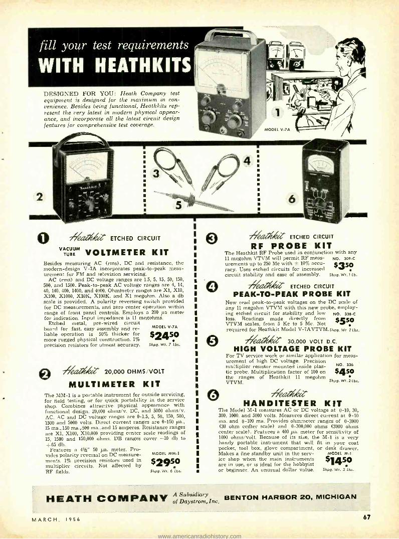
fill your test requirements
WITH HEATHKITS
DESIGNED FOR YOU: Heath Company test equipment is designed for the maximum in con- venience. Besides being functional, Heathkits rep- resent the very latest in modern physical appear- ance, and incorporate all the latest circuit design features for comprehensive test coverage.
o 77Iea G ETCHED CIRCUIT
VACUUM VOLTMETER KIT Besides measuring AC (rms), DC and resistance, the modern- design V -7A incorporates peak -to -peak meas- urement for FM and television servicing.
AC (rms) and DC voltage ranges are 1.5, 5, 15, 50, 150,
500, and 1500. Peak -to -peak AC voltage ranges are 4, 14, 40, 140, 400, 1900, and 4000. Ohmmeter ranges are Xl, X10, X100, X1000, X10K, X100K, and Xl megohm. Also a db scale is provided. A polarity reversing switch provided for DC measurements, and zero center operation within range of front panel controls. Employs a 200 pa meter for indication. Input impedance is 11 megohms.
Etched metal, pre -wired circuit board for fast, easy assembly and re- liable operation is 50% thicker for more rugged physical construction. 1% precision resistors for utmost accuracy.
MODEL V -7A
$2450 Shp9. Wt. 7 Lbs.
eTI Zil 20,000 OHMS /VOLT
MULTIMETER KIT The MM -1 is a portable instrument for outside servicing, for field testing, or for quick portability in the service shop. Combines attractive physical appearance with functional design. 20,000 ohms /v. DC, and 5000 ohms /v. AC. AC and DC voltage ranges are 0 -1.5, 5, 50, 150, 500,
1500 and 5000 volts. Direct current ranges are 0 -150 pa., 15 ma., 150 ma.,.500 ma., and 15 amperes. Resistance ranges are Xl, X100, X10,000 providing center scale readings of 15, 1500 and 150,000 ohms. DB ranges cover -10 db to +65 db.
Features a 41/2' 50 pa. meter. Pro- vides polarity reversal on DC measure- ments. 1% precision resistors used in $2950 multiplier circuits. Not affected by i RF fields. Shp9. Wt. 6 Lbs.
MODEL MM -1
e 77 iQ- ETCHED CIRCUIT
RF PROBE KIT The Heathkit RF Probe used in conjunction with any 11 megohm VTVM will permit RF meas- NO. 309 -C
urements up to 250 Mc with ± 10% accu- $350 racy. Uses etched circuits for increased circuit stability and ease of assembly. Shp9. wt. 1 Lb.
o 77 WI ETCHED CIRCUIT
PEAK -TO -PEAK PROBE KIT Now read peak -to -peak voltages on the DC scale of any 11 megohm VTVM with this new probe, employ- ing etched circuit for stability and low NO. 338-C loss. Readings made directly from $550 VTVM scales, from 5 Kc to 5 Mc. Not required for Heathkit Model V- 7AVTVM.shp9 Wt. 2 Lbs.
© T7/eaa, 30,000 VOLT D.C.
HIGH VOLTAGE PROBE KIT For TV service work or similar application for meas- urement of high DC voltage. Precision multiplier resistor mounted inside plas- tic probe. Multiplication factor of 100 on the ranges of Heathkit 11 megohm VTVM. Shp9. Wt. 2 Lbs.
NO. 336
5450
o ireaafrQ- HANDITESTER KIT
The Model M -1 measures AC or DC voltage at 0 -10, 30, 300, 1000, and 5000 volts. Measures direct current at 0 -10 ma. and 0 -100 ma. Provides ohmmeter ranges of 0 -3000 (30 ohm cerlter scale) and 0- 300,000 ohms (3000 ohms center scale). Features a 400 pa. meter for sensitivity of 1000 ohms /volt. Because of its size, the M -1 is a very handy portable instrument that will fit in your coat pocket, tool box, glove compartment, or desk drawer. Makes a fine standby unit in the serv- MODEL M -1
ice shop when the main instruments $1450 are in use, or is ideal for the hobbyist or beginner. An unusual dollar value. Shp9. Wt. 3 Lbs.
HEATH COMPANY A subsidiary BENTON HARBOR 20, MICHIGAN of Daystrom, Inc.
MARCH, 1956 67
www.americanradiohistory.com

68
7Veaellie TV ALIGNMENT
GENERATOR
KIT
4
I 1
1
1
1
1
1
1
I I
1
HEATH COMPANY A SUBSIDIARY OF DAYSTROM INC
The Model TS -4 features a controllable inductor for all -electronic sweep, improved oscillator and automatic gain circuitry, high RF output, center sweep operation, and improved linearity. It sets a new high standard for sweep generator operation, and is absolutely essential for the up -to- date service shop doing FM, black -and- white TV, and color TV work.
Voltage regulation and effective AGC action insure flat output over a wide fre- quency range. Electronic sweep insures complete absence of mechanical vibration. Sweep deviation controllable from 0 up to 40 Mc, depending upon base frequency. Effective two -way blanking.
Fundamental output from 3.6 Mc to 220 Mc in 4 bands. Crystal marker provides markers at 4.5 Mc and multiples thereof. Crystal MODEL TS-4
included with kit. Variable marker covers from 19 Mc to $4950 60 Mc on fundamentals, and up to 180 Mc on harmonics. Provision for external marker. Shpg. WI. 16 Lbs.
O 7rflG LINEARITY PATTERN
o
GENERATOR KIT The new- design Model LP -1 produces vertical or horizontal bar pat- terns, a cross -hatch pattern, or white dots on the screen of the TV set under test. No internal connections required. Special clip is attached to the TV antenna terminals. Instant selection of the pattern desired for adjustment of vertical and horizontal linearity, picture size, aspect ratio, and focus. Dot pattern presentation is a must for color convergence adjustments on color TV sets. MODEL LP -1
Extended operating range covers all television chan - $2250 nels from 2 to 13. Produces 6 to 12 vertical bars or 4 to 7 horizontal bars. Shpg wl. 7 Lbl.
77 LABORATORY
GENERATOR KIT The Heathkit Model LG -1 Laboratory Generator is a high- accuracy signal source for applications where metered performance is essential It covers from 100 Kc to 30 Mc on fundamentals in 5 bands. Modu- lation is at 400 cycles, and modulation is variable from 0-50%. RF output from 100,000 pv. to 1 pv. 200 pa. meter reads the RF output in microvolts, or percentage of modulation. Fixed step and variable output attenuation provided. MODEL LG -1
Features voltage regulation, and double copper plated $3950 shielding for stability. Provision for external modula- tion. Coaxial output cable (50 ohms). Shpg. WI. 16 Lbs.
© 77ea4O G CATHODE RAY
TUBE CHECKER KIT This new -design instrument holds the key to rapid and complete picture tube testing, either in the set, on the work -bench, or in the carton. Tests for shorts, leakage, and emission. Features Shadow - graph test (a spot of light on the screen) to indicate whether the tube is capable of functioning.
The Model CC -1 tests all electromagnetic deflection picture tubes normally encountered in television servicing. Supplies all- operating voltages to the tube under test, and indicates the condition of the tube on a large "GOOD -BAD" scale. Features spring loaded test switches for operator protection.
The CC -1 is housed in an attractive portable case and is light in weight - ideal for outside service calls.
O 71/e de DIRECT READING
MODEL CC -1
$225,0 Shpg. Wt. 10 Lbs.
CAPACITY METER KIT Not only is this instrument popular in the service shop, but it has found extensive application in industrial situations. Ideal for quality control work, production line checking, or for matching pairs.
Features direct reading linear scales from 100 mmf to .1 mfd full scale. Necessary only to connect a capacitor of unknown value to the insulated binding posts, select the correct range, MODEL CM -1
and read the meter. The CM -1 is not susceptible to $2950 hand capacity, and has a residual capacity of less than i 1 mmf. Shpg. WI. 7 Lbs.
BENTON HARBOR 20, MICHIGAN RADIO- ELECTRONICS
www.americanradiohistory.com

MODEL SG -8 Shpg. Wt. 8 Lbs.
51950
This is one of the biggest signal generator bar- gains available today. The tried and proven Model SG -8 offers all of the outstanding fea- tures required for a basic service instrument. High quality components and outstanding per- formance.
The SG -8 covers 160 Kc to 110 Mc on funda- mentals in 5 bands, and calibrated harmonics extend its usefulness up to 220 Mc. The output signal is modulated at 400 cps, and the RF output is in excess of 100,000 uv. Output con- trolled by both a continuously variable and a fixed step attenuator. Also, audio output may be obtained for amplifier testing. Don't let the
low price deceive you. This is a professional type service instrument to fulfill the signal source requirements in the service lab.
O 77GllAti'!G ... IMPEDANCE BRIDGE KIT The IB -2 features built -in adjustable phase shift oscillator and amplifier, and has panel provisions for external generator. Measures resistance, capaci- tance, inductance, dissipation factors of condensers, and storage factor of inductance.
D, Q, and DQ functions combined in one control. 1/2% resistors and 1/2%
silver -mica capacitors especially selected for this instru- MODEL 1a -2 ment. A 100 -0 -100 microammeter provides null indications. $5950 Two -section CRL dial provides 10 separate "units" with an accuracy of .5 %. Fractions of units read on variable control. shpg. Wt. 12 Lbs.
© 77L, "Q" METER KIT The Heathkit Model QM -1 will measure the Q of inductances and the RF resistance and distributed capacity of coils. Employs a 41/2" 50 microampere meter for directtindication. Will test at frequencies of 150 Kc to 18 Mc in 4
ranges. Measures capacity from 40 mmf to 450 mmf within ± 3 mmf. Indis- pensible for coil winding and determining unknown condenser values. A worthwhile addition to your laboratory at an outstandingly MODEL OM-1 low price. Useful for checking wave traps, chokes, peaking $4450 coils, etc, Laboratory facilities are now available to the service shop and home lab. Shpg. WI. ¡4 Lbs.
Q 77 6- 12 VOLT
BATTERY ELIMINATOR KIT This modern battery eliminator will supply 6 or 12 volt output for ordinary I automobile radios as well as 12 volts for the new models in the latest model I cars. Output voltage is variable from 0 -8 volts DC, or 0 -16 volts DC. Will deliver up to 15 amperes at 6 volts, or up to 7 amperes at 12 volts. Two 10,000 microfarad filter capacitors insure smooth DC output. MODEL 8E -4 Two panel meters monitor output voltage and current. Will double as a battery charger. Definitely required for auto- mobile radio service work. Shpg. WI. 17 Lbs.
Q 77LL DECADE RESISTANCE KIT Twenty 1% precision resistors provide resistance from 1 to MODEL DR -1
99,999 ohms in 1 ohm steps. Indispensible around service shop laboratory, ham shack, or home workshop. Well worth $1950 the extremely low Heathkit price. Shpg. WI. 4 Lbs.
-7Veaaia" SIGNAL
GENERATOR KIT
© / /ea tià" VIBRATOR TESTER KIT Tests vibrators for proper starting and indicates the quality of the output on a large "GOOD -BAD" scale. Checks both interrupter MODEL VT -1
and self- rectifier types in 5 different sockets. Operates from $1450 any battery eliminator delivering variable voltage from 4
to 6 volts DC at 4 amps. Ideal companion to the Model BE -4. Shpg. WI. 6 Lbs.
Q 77GLLQ- DECADE CONDENSER KIT Provides capacity values from 100 mmf to 0.111 mfd in steps of 100 mmf. ± 1% precision silver -mica condensers used. High quality MODEL DC-1 ceramic switches for reduced leakage. Polished birch cab- inet. Extremely valuable in all electronic activity. 6
Shpg. WI. 3 Lbs.
BENTON HARBOR 20, MICHIGAN MARCH, 1956
1
HEATH COMPANY A SU3SID1'ARY OF JAYS7ROn.1 INC.
69
www.americanradiohistory.com

70
e TUBE CHECKER KIT
I
2
I
I
I I I
I I 1
I
HEATH COMPANY A SUBSIDIARY OF DAYSTROM INC
OThe Heathkit Model TC -2 is an emission type tube tester that repre- sents a tremendous saving over the price of a comparable unit from any other source. At only $29.50, you can have a tube tester of your own, even
if you are an experimenter, or only do part time service work. Extremely popular with radio servicemen, it uses a 41/2" meter with 3 -color meter face for simple "GOOD -BAD" indications that the customer can understand. Will test all tubes commonly encountered in radio and TV service work.
Ten 3- position lever switches for "open" or "short" tests on each tube ele- ment. Neon bulb indicates filament continuity or short between tube elements. Line adjust control provided. The roll chart is illuminated.
Sockets provided for 4, 5, 6, and 7 -pin, octal, and loctal tubes, 7 and 9 pin miniature tubes, and the 5 pin Hytron tubes. Blank space provided for future socket addition. Tests tubes for opens, and shorts, and for quality on the basis of total emission. 14 different filament voltage values provided.
MODEL TC -2
$2950 Shpg. Ws. 12 Lbs.
o 77Glia4Z PORTABLE TUBE CHECKER KIT The Model TC -2P is identical to the Model TC -2 except that it is housed in a rugged carrying case. This strikingly attractive and practical two -tone case is finished in proxylin impregnated fabric. The cover is de- MODEL TC-2P tachable, and the hardware is brass plated. This case imparts a real professional appearance to the instrument. Ideal for 50 home service calls, or any portable application. Shpg. Wt. 15 Lbs.
© 7/7/e LLG TV PICTURE TUBE TEST ADAPTER The Heathkit TV picture tube test adapter is designed for use with the Model TC -2 Tube Checker. Test picture tubes -for emission, shorts, and thereby determine tube quality. Consists of 12 -pin TV tube socket, 4 ft. cable, octal connector, and necessary technical data. (Not a kit.)
MODEL 355
$450 Shpg. Wt. 7 Lb.
O/ ClGI.fL . . .
CONDENSER CHECKER KIT Use this Condenser Checker to quickly and accurately measure those un- known condenser and resistor values. All readings taken directly from the calibrated panel scales without any involved calculation. Capacity measure- ments in four ranges from .00001 to 1000 mfds. Checks paper, mica, ceramic and electrolytic condensers. A power factor control is available for accurate indi- cation of electrolytic condenser efficiency. Leakage test switch -selection of five polarizing voltages, 25 volts to 450 volts DC to indicate condenser operating quality under actual load conditions. Spring- return test switch automatically discharges condenser under test and eliminates shock hazard to the operator.
Resistance measurements can be made in the range from 100 ohms to 5 meg- ohms. Here again, all values are read directly on the calibrated scales. Increased sensitivity coupled with an electron beam null indicator in- creases overall instrument usefulness. MODEL C-3
For safety of operation, the circuit is entirely transformer $1950 operated. An outstanding low kit price for this surprisingly accurate instrument. Shpg. Wt. 7 Lbs.
© 77L il. VISUAL -AURAL
SIGNAL TRACER KIT This signal tracer is extremely valuable in servicing AM, FM, and TV receivers, especially when it comes to isolating trouble to a particular stage of the circuit under test.
This visual -aural tracer features a high gain RF input channel to permit signal tracing from the receiver antenna input clear through all RF, IF, de- tector, and audio stages to the speaker. Separate low -gain channel provided for audio circuit exploration. Both visual and aural indication by means of a speaker or headphone, and electron beam "eye" tube as a level indicator. Also incorporates a noise locater circuit for DC noise checks, and a built -in cali- brated wattmeter (30 -500 watts). Panel terminals provided for "patching" output transformer or speaker into external MODEL T -3 circuit for test purposes. Designed especially for the radio l235 and TV serviceman. Cabinet size: 91/2" wide x 6112" high x 5" iii deep. A real test equipment bargain. Shpg. WI. 9 Lbs.
> BENTON HARBOR 20, MICHIGAN RADIO -ELECTRONICS
www.americanradiohistory.com

5hpg. Wt. 73 Lbs. $4950
Used with a sine wave generator, the Model HD -1 will check the harmonic distortion out- put of audio amplifiers under a variety of conditions. Reads distortion directly on the meter as a percentage of the input signal. Operates between 20 and 20,000 cps. High impedance VTVM circuit for initial reference settings and final distortion readings. Ranges are 0 -1, 3, 10, and 30 volts full scale. 1% pre- cision resistors. Distortion scales are 0 -1, 3, 10, 30 and 100% full scale. Requires only .3 volt input for distortion test.
0 77Cl GL AUDIO ANALYZER KIT This instrument consists of an audio wattmeter, an AC VTVM, and a complete IM analyzer, all in one compact unit.
Use the VTVM to measure noise, frequency response, output gain, power supply ripple, etc. Use the wattmeter for measurement of power output. Internal loads provided for 4, 8, 16, or 600 ohms. VTVM also calibrated for DBM units. High or low impedance IM measurements made with built -in 6KC and 60 cps generators. VTVM ranges are .01, to 300 volts in 10 steps. Wattmeter ranges are .15 mw. to 150 w. in 7 steps. IM scales are 1% to 100% in 5 steps.
MODEL AA -1
$5950 Shpg. Wt. 13 Lbs.
4/eat/tier HARMONIC
DISTORTION METER KIT
7reataWZ AUDIO GENERATOR KIT This new Heathkit Model features step- tuning from 10 cps to 100 Kc with three rotary switches that provide two significant figures and multiplier. Less than .1% distortion. Frequency accurate to within ± 5 %.
Output monitored on a large 41/2" meter that reads voltage or db. Both variable and step -type attenuation provided. Meter reads zero -to- maximum at each attenuator position. Output ranges (and therefore meter ranges) are 0 -.003, .01, .03, .1, .3, 1, 3, 10 volts. Step - tuning provides rapid positive selection of the desired fre- quency, and allows accurate return to any given frequency. Shpg. Wt. 8 Lbs. e 79eaAatid. AUDIO OSCILLATOR KIT
(SINE WAVE - SQUARE WAVE)
The Model AO -1 features sine wave or square wave coverage from 20- 20,000 cps in 3 ranges. It is an instrument specifically designed to completely fulfill the needs of the serviceman and high fidelity enthusiast. Offers high level output across the entire frequency range, low distortion and low impedance output. Features a thermistor in the second amplifier stage to maintain essentially flat output through the entire fre- quency range. Produces an excellent sine wave for audio testing, or will produce good, clean, square waves with a rise time of only 2 microseconds. .
7 /&z% s.
G RESISTANCE
SUBSTITUTION BOX KIT ... Provides switch selection of 36 RTMA 1 watt standard 1% resistors ranging from 15 ohms to 10 megohms. Numerous applications in radio and TV work, and essential in the developmental laboratory.
/ 77 etli Z" AC VACUUM TUBE
VOLTMETER KIT... The Heathkit AC VTVM features high impedance, wide frequency range, very high sensitivity, and extremely wide voltage range. Will accurately measure a voltage as small as 1 mv. at high impedance. Excellent for sensitive AC measurements required by laboratories, audio enthusiasts and experimenters. Frequency response is substantially flat from 10 cps to 50 Kc. Ranges are .01, .03, .1, .3, 1, 3, 10, 30, 100,
and 300 v. RMS. Total db range -52 to + 52 db. Input impedance 1 megohm at 1 Kc.
/ hGG CONDENSER
SUBSTITUTION BOX KIT ...
MODEL AG -9
$3450
o
o
O
MODEL AO -1
$2450 Shpg. Wt. 10 Lbs.
MODEL ES -1
$550 Shpg. Wt. 2 Lbs.
MODEL AV -2
$2950 Shpg. Wt. 5 Lbs.
Very popular companion to Heathkit RS -1. Individual selec- tion of 18 RTMA standard condenser values from .0001 mfd to .22 mfd. Includes 18" flexible leads with alligator clips.
MODEL CS -1
Shpg.
$550 Wtbs.
' I 1
I I
1
1
1
1
1 1
I I
3
(3 r-c`--
H E AT H COMPANY
1
1
1
I 1
I
1
1
BENTON HARBOR 20, MICHIGAN <
MARCH, 1956
A SUBSIDIARY OF DAY.STROM INC.
71
www.americanradiohistory.com

72
HEATHKIT HAM GEAR for high quality at moderate cost
E
I
MODEL
1
DX-100
DOLLAR VALUE: You get more for your Heathkit dollar because your labor is used to build the kit instead of paying for someone else's. Also, the middleman's margin of profit is elim- inated when you deal directly with the manu- facturer.
O 7V i DX -100 PHONE & CW TRANSMITTER KIT
The reception given this amateur transmitter has been tremendous. Reports from radio amateurs using the DX -100 are enthusiastic in praising its performance and the high quality of the components used in its assembly. Actual "on the air" results reflect the careful design that went into its development.
The DX -100 features a built -in VFO, modulator, and power supplies, and is completely bandswitching for phone or CW operation on 160, 80, 40, 20, 15, 11, and 10 meters. All parts necessary for construction are supplied in the kit, including tubes, cabinet, and detailed step -by -step instruc- tions. Easy to build, and a genuine pleasure to operate.
Employs push -pull 1625's modulating parallel 6146's for RF output in excess of 100 watts on phone and 120 watts on CW. May be excited from the built -in VFO or from crystals (crystals not included with kit). Features five - point TVI suppression: (1) pi network interstage coupling to reduce harmonic transfer to the final stage; (2) pi net- work output coupling; (3) extensive shielding; (4) all in- coming and outgoing circuits filtered; (5) inter -locking cabinet seams to eliminate radiation except through the coaxial output connector. Pi network output coupling will match 50 to 600 ohm non -reactive load. Illuminated VFO dial and meter face. Remote control socket provided.
The chassis is made of extra -strong 1116 gauge copper - plated steel. It employs potted transformers, ceramic switch and variable capacitor insulation, solid silver loading switch terminals, and high -grade well -rated components through- out. Features a pre -formed wiring harness, and all coils are pre -wound.
High -gain speech amplifier for dynamic or crystal micro- phones, and restricted speech range for increased intelli- gence. Plenty of audio power reserve. Measures 207/x" W. x 133/4" H. x 16" D. Schematic diagram and complete technical specifications on request.
MODEL DX-100
$18950 Shpg. Wt. 120 Lbs.
Shipped Motor Freight Unless Otherwise Specified $50.00 Deposit Required on C.O.D. Orders
o VFO KIT The Model VF -1 covers 160- 80- 40- 20 -15 -11 and 10 meters with three basic oscillator frequencies. Better than 10 -volt average RF output on fundamentals. Features illuminated and pre -calibrated dial scale. Cable and plug provided to fit crystal socket of any modern transmitter.
Enjoy the convenience and flexibility of VFO operation at no more than the price of crystals. May be powered from plug on the Heathkit Model AT -1 MODEL VF -1 transmitter, or supplied with power from most transmitters. Measures: 7" H. x 51950 63Y W. x 7" D. Shpg. Wr tbs. e 771 CW AMATEUR
TRANSMITTER KIT The Model AT -1 is an ideal novice transmitter, and may be used to excite a higher power rig later on.
This CW transmitter is complete with its own power supply, and covers 80, 40, 20, 15, 11, and 10 meters. Features single -knob bandswitching, and panel meter indicates grid or plate current for the final amplifier. Designed for crystal operation or external VFO. Crystal not included in kit. Incorporates such features as key click filter, line filter, copper -plated chassis, pre -wound coils, 52 ohm coaxial out- put, and high quality components throughout. Instruction book simplifies assembly. Employs a 6AG7 oscillator, 6L6 final amplifier. Operates up to 35 $295° watts plate power input. Shpg. Wt. 15 Lbs.
ANTENNA COUPLER KIT The Model AC -1 will properly match your low power trans- mitter to an end -fed long wire antenna. Also attenuates signals above 36 Mc, reducing TVI. 52 ohm coax. input-. power up to 75 watts -10 through 80 meters -tapped induc- tor and variable condenser -neon RF in- dicator- copper plated chassis and high quality components. Ideal for use with Heathkit AT -1 Transmitter.
MODEL AT -1
MODEL AC -1
$14 Shpg. Wt. 4 Lbs.
HEATH COMPANY A Subsidiary BENTON HARBOR 20, MICHIGAN of Daystrom, Inc.
RADIO -ELECTRONICS
www.americanradiohistory.com

MODERN DESIGN: You can be sure of getting all the latest and most desirable design features when you buy Heathkits. Advanced- design is a minimum standard for new Heathkit models.
O4/eae IG COMMUNICATIONS -TYPE
ALL BAND RECEIVER KIT The new Model AR -3 features improved IF and RF performance, along with better image rejection on all bands. Completely new chassis layout for easier as- sembly, even for the beginner
Covers 550 Kc to 30 Mc in four bands. Provides sharp tuning and good sensitivity over the entire range. Features a transformer -type power supply -electrical bandspread- separate RF and AF gain controls -antenna trimmer -noise limiter- AGC -BFO- headphone jacks - 51/2" PM speaker and illuminated tun- ing dial. CABINET: Fabric covered cabinet with aluminum panel as shown. Part No. 91- 15, shipping weight 5 lbs. $4.50.
MODEL AR -3
$Z795 Shpg. Wt. 12 Lbs.
(Less Cabinet)
"Q" MULTIPLIER KIT Here is the Heathkit Q Multiplier you hams have been asking for. A tremendous help on the phone and CW bands when the QRM is heavy. Provides an effective Q of approximately 4,000 for extremely sharp "peak" or "null." Use it to "peak" the desired signal or to "null" an undesired signal, or heterodyne. Tunes to any signal within the IF band -pass of your receiver. Also provides "broad peak" for conditions where extreme selectivity is not required.
Operates with any receiver having an IF frequency between 450 and 460 Kc. Will not function with AC -DC type receivers. Requires 6.3 volts AC at 300 ma. and 150 to 250 VDC at 2 ma. Derives operating power from your receiver. Uses a 12AX7 tube, and special High -Q shielded coils. Simple to connect with the cable and plugs supplied. Measures only 4- 11 /16 "H.x7% "W.x41/e "D. A really valuable addition to the receiving equipment in your ham shack.
MODEL OF -1
$995 Shpg. Wt. 3 Lbs.
I I I I I
I I
I I I I I
I I I I
I
© /¿ VARIABLE VOLTAGE
REGULATED POWER SUPPY KIT Provides well filtered DC output, variable from zero to 500
volts at no load and regulated for stability. Will supply up to 10 ma. at 450 VDC, and up to 130 ma. at 200 VDC. Voltage or current monitored on front panel meter. Also provides 6.3
VAC at 4A. for filament. Filament voltage isolated from and both isolated from ground. Invaluable around the ham shack for supplying operating potentials to
MODEL PS -3 experimental circuits. Use in all types of re- search $3550 and development laboratories as a temporary power supply, and to determine de- sign requirements for ultimate power supply. Shpg. Wt. 17 lbs.
Q 7//eLG ANTENNA
IMPEDANCE METER KIT Use in conjunction with a signal source for measuring antenna impedance, line matching, adjustment of beam and mobile antennas, etc. Will double as a phone monitor or relative field strength indicator. 100 pa. meter employed. Covers the range from 0 -600 ohms. An instrument of many uses for the amateur. Shpg. Wt. 21b.
MODEL AM -1
$1450
Q /ea GRID DIP METER KIT This is an extremely valuable tool for accomplishing literally hundreds of jobs on all types of equipment. Covering from 2 Mc to 250 Mc, the GD -1B is compact and can be operated with one hand. Uses a 500 pa. meter for indi-
MODEL GD-il cation, with a sensitivity control and head- phone jack. Includes prewound coils and rack. $1950 Indispensable instrument for hams, engineers, or servicemen. Shpg. Wt. 4 lbs.
Subsidiary si HEATH COMPANY A Subd A Subs vm, Inc. BENTON HARBOR 20, MICHIGAN of
MARCH, 1956 73
www.americanradiohistory.com

74
-#eardez PROVIDE THE
"CONSTRUCTIVE" APPROACH TO
HIGH- FIDELITY
3
EASY TO BUILD: The assembly instruc- tions supplied with Heathkits are so complete and detailed that anyone can assemble the kits without difficulty. Plenty of pictorial diagrams and step -by step in- structions. Information on resistor color codes, soldering, use of tools, etc. Build -it- yourself with confidence!
7 eat ADVANCED- DESIGN HIGH FIDELITY AMPLIFIER KIT
The 25 Watt Model W -5 is one of the most outstanding high fidelity amplifiers available today -at any price. Incorporates the very latest design features to achieve true "presence" for the super- critical listener. Features a new -design Peerless output transformer, and KT66 output tubes handle power peaks up to 42 watts. The unique "tweeter- saver" suppresses high frequency oscillation. A new type balancing circuit results in closer "dynamic" balance between output tubes. Features improved phase shift characteristics and frequency response, with reduced IM and harmonic distortion. Color styling harmonizes with the Heathkit WA -P2 Preamplifier and the FM -3 Tuner. Frequency response -within ± 1 db from 5 cps to 160 Kc at 1 watt. Harmonic distortion only 1% at 25 watts, 20- 20,000 cps. IM distortion only 1% at 20 watts, using 60 and 3,000 cps. Output impedance 4, 8, or 16 ohms. Hum and noise -99 db below rated output. Uses two 12AU7's, two KT66's and a 5R4GY. KIT COMBINATIONS: W -5M Amplifier Kit: Consists of main amplifier and power supply, all on one chassis. Complete with all neces- sary parts, tubes, and comprehensive manual. Shpg. Wt. 31 lbs. Express only. W -5 Combination Amplifier Kit: Consists of W -5M Amplifier Kit listed above plus Heathkit Model WA -P2 Preamplifier Kit. Complete with all necessary parts, tubes, and construction manuals. Shpg. Wt. 38 lbs. Ex- press only.
© 7711G DUAL- CHASSIS WILLIAMSON TYPE
HEATH COMPANY A SUBSIDIARY OF DAYSFROM INC.
$597s
$7950
HIGH AMPLIFIER KIT F
This is a very popular high fidelity amplifier kit that features dual -chassis type construction. The resulting physical dimensions offer an additional margin of flexibility in installation. It features the famous Acrosound TO -300 "ultra- linear" output transformer, and has a frequency response within - 1 db from 6 cps to 150 Kc at 1 watt. Harmonic distortion only 1% at 21 watts. IM distortion at 20 watts only 1.3': at 60 and 3,000 cps. Rated power output is 20 watts. Output im- pedance 4, 8. or 16 ohms. Hum and noise -88 db below 20 watts. Uses two 6SN7's, two 5881's, and a 5V4G. KIT COMBINATIONS: W -3M: Consists of main amplifier and power supply for separate chassis construction. Includes all tubes and com-
polnents necessary for assembly. Shpg. Wt. 29 lbs., Express
Y. W -3: Consists of W -3M Kit listed above plus Heathkit Model WA -P2 Preamplifier described on opposite page. Shpg. Wt. 37 lbs., Express only.
$4197s
$695? © 7 ea.A6 SINGLE- CHASSIS WILLIAMSON TYPE
HIGH FIDELITY AMPLIFIER KIT
This is the lowest priced Williamson type amplifier ever offered in kit form, and yet it retains all the usual features of the Williamson type circuit. Main amplifier and power supply combined on one chassis, and uses a new -design Chicago output transformer. Frequency response- within ± 1 db from 10 cps to 100 Kc at 1 watt. Harmonic distortion only 1.5% at 20 watts. IM distortion at rated out- put, 2.7'':, at 60 and 3,000 cps. Rated power output is 20 watts. Output impedance 4, 8, or 16 ohms. Hum and noise -95 db below 20 watts. Uses two 6SN7's, two 5881's, and one 5V4G.
Instructions are so complete that the kit may be assembled successfully even by a beginner in electronics. KIT COMBINATIONS: W -4AM: Consists of main amplifier and power supply for single chassis construction. Includes all tubes and com- ponents necessary for assembly. Shpg. Wt. 28 lbs. Express only. W -4A: Consists of W -4AM Kit listed above plus Heathkit Model WA -P2 Preamplifier described on opposite page. Shpg. Wt. 35 lbs. Express only.
$397.5 $595°
BENTON HARBOR 20, MICHIGAN RADIO -ELECTRONICS
www.americanradiohistory.com

ATTRACTIVELY STYLED: Heathkit high fidelity instruments are not only func- tional, but are most attractive in physical design. Such units as the preamplifier and the W -5 main amplifier are designed for beauty as well as performance. They blend with any room decor and are the kind of in- struments you will be proud to own.
O 79601111% HIGH FIDELITY
PREAMPLIFIER KIT This outstanding preamplifier is designed specifically for use with the Heathkit Williamson type amplifiers. It completely fulfills the requirements for remote control, compensation and preamplification, and exceeds even the most rigorous specifications for high fidelity performance.
Features five separate switch -selected input channels (2 low level and 3 high level) , each with its own input control. Full record equalization with four -position turnover control and four- position rolloff control.
Output jack for tape recorder - separate bass control with 18 db boost and 12 db cut at 50 cps. - treble control offering 15 db boost and 20 db cut at 15,000 cps - special hum control to insure minimum hum level - and many other desirable features. Overall frequency response (with controls set to "flat" position) is within 1 db from 25 cps to 30,000 cps. Will do justice to the finest available program sources. Beautiful satin -gold fiinish.
Power requirements from the Heathkit Williamson type MODEL WA -P2
high fidelity amplifier - 6.3 VAC at 1 amp., and 300 VDC at $' 975 10 Ma. Uses two 12AX7's and one 12AU7. Shpg. Wt. 7 Lbs.
© 77 20 -WATT HIGH FIDELITY
AMPLIFIER KIT This Heathkit Model offers you the least expensive route to high fidelity performance. Frequency response is ± 1 db from 20- 20,000 cps. Features full 20 watt output using push -pull 6L6's, and incorporates separate bass and treble tone controls. Preamplifier and main amplifier are built on the same chassis. Four switch- selected compensated inputs and separate bass and treble tone controls provide all necessary functions at minimum in- vestment. Features miniature tube types for low hum and noise.
Uses 12AX7, two 12AU7's, two 6L6G's and a 5V4G. A most interesting "build -it- yourself" project, and an excellent hi -fi amplifier
MODEL A -9B for home use. Well suited, also, for public address applica- tions because of its high power output and high quality audio reproduction. Another Heathkit "best -buy" for you! Shpg. Wt. 23 tbs.
711 7 -WATT AMPLIFIER KIT
The redesigned Model A -7D features a new type output transformer for tapped screen operation, and provides improved sensitivity, reduced distor- tion, and increased power output.
The full 7 -watt output of the Model A -7D is more than adequate for nor- mal home installations. Frequency characteristics are ± 11/2 db from 20 to 20,000 cps. Potted output and power transformers employed. Push -pull output - detailed construction manual - top quality parts
MODEL A -7D - high quality audio without great expense. Output trans- $' 695 former tapped at 4, 8, and 16 ohms. Bass and treble tone
controls provided on the front chassis apron. Shpg. Wt. ió Lbs.
Model A -7E: Provides a preamplifier stage with two switch -selected inputs and RIAA compensation for variable reluctance or low level cartridges. Preamplifier built on same chassis as main amplifier. Model
A -7E. Shipping weight 10 lbs. $18.50.
BENTON HARBOR 20, MICHIGAN MARCH, 1956
-edrity THE VERY BEST IN AUDIO WITH
"BUILD -IT- YOURSELF"
HEATHKITS
HEATH COMPANY A SUBSID6ARY OF DAYSTROM INC.
75
www.americanradiohistory.com

HEATHKIT HIGH -FIDELITY
FM TUNER KIT
MODEL FM -3
5í,P9. Wt. $2450 7 lbs.
( with cabinet )
The new Heathkit Model FM -3 features tremendous circuit improvements and brand new physical design. Sensitivity is better than 10 uv. for 20 db of quieting, and it employs a completely modern tube line -up for high gain and stable operation. Incorporates its own power supply, and has pro- vision for low -level or high -level output at low impedance.
The attractive Model FM -3 matches the WA -P2 Pre- amplifier in color, styling, and physical size.
Incorporates automatic gain control, a highly stabilized oscillator, and illuminated tuning dial. Educational treat- ment of construction manual simplifies assembly for the newcomer to electronics. IF and ratio transformers are pre - aligned, and the front -end tuning unit is pre -assembled and aligned. Uses 6BQ7A as a cascode type RF stage, 6U8 oscil- lator- mixer, two 6CB6's as IF amplifiers, a 6AL5 ratio de- tector, a 6C4 audio amplifier, and 6X4 rectifier.
FetUi-es Brand New, Modern FM Circuit Using Latest Type Miniature Tubes. Low -Noise Cascode RF Stage -Two IF's -Ratio Detector -Stage of Audio. Extremely Good Sensitivity and Band -Pass for Outstand- ing Performance. Strikingly Attractive Satin -Gold Finish to Match Heath - kit Model WA -P2 Preamplifier. Compact Physical Dimensions for Most Pleasing Appear- ance and Increased Circuit Efficiency.
HEATHKIT BROADCAST -BAND RECEIVER KIT Build your own radio receiver with con- fidence, even if you are a beginner. Com- plete instructions supplied.
Features transformer -type power sup- ply, high -gain miniature tubes, built -in antenna, 5t /z" speaker, and planetary tuning from 550 Kc to 1500 Kc. Adapt- able for use as AM Tuner and phono amplifier. Educational treatment of the construction manual helps the beginner learn about radio circuits and parts as he builds. CABINET: Fabric covered plywood cabi- net with aluminum panel as shown. Part 91 -9, Shpg. Wt. 5 lbs., $4.50.
MODEL BR -2
e $17 SP CaLbiss net
Shpg. Wt. 10 lbs.
Are you on our mailing list? If not -how about sending us your name?
JL:1::
Phone \ WALNUT 5-1175
ORDE R BLANK from SHIP VIA
Pane Post
Express
Freight
Best Way
PA NY
of paystrom, Inc. ASubsidlary RBOR 20, BENTON
HA MICHIGAN -
(PLEASE PRINT)
QUANTITY ITEM MODEL NO. PRICE
I
Enclosed find
ON PARCEL
NOTE: ALL PRICES SUBJECT TO CHANGE WITHOUT NOTICE.
( ) check ( ) money order for Please ship C.O.D. ( ) postage enclosed for pounds.
On Express orders do not include Transportation charges -they will be collected by the express agency at time of delivery.
POST ORDERS include postage for weight shown. ORDERS FROM CANADA and APO's must include full remittance.
HEATH COMPANY A SDabstrom BENTON HARBOR 20, MICHIGAN of aystoInc. 76 RADIO -ELECTRONICS
www.americanradiohistory.com

TEST INSTRUMENTS
SOb1ETHING NEW
in HIGH-VOLTAGE SUPPLIES
Auxiliary supply
develops 9-18-kv output
for use in TV
receiver servicing
By VAL SANFORD and LEIGHTON BURNHAM
DURING the past few years various trade magazines have described make -it- yourself TV high -voltage supplies. The ap-
pearance of these articles indicates in- terest in auxiliary high -voltage sources external to the TV chassis.
Not so very long ago the authors needed a compact, stable high -voltage supply and decided to build several
6BQ6 -GT
VI FEEDBACK CONF
CI.001/IKY
/3W H
HORIZ BLOCKING TRANS
PRI
COT SOCKET
I0 IST ANODE (G2 )
.25/600
SECII b
P
g
II q k,
K
SOOp t20 KV
PRI ill >20V INSULATION
gI V4 Y3-GT p (CDEO
NWOT USE) II
R4 501<4.2W 8H NT 6H I
BRIGHTNESS
VOLTAGE
Front -panel view of the instrument.
models. The most promising of the published designs were constructed and tested.
We found they all contained dis- advantages which made them imprac- tical for television use; they either generated insufficient voltage for the larger picture tubes or their regula- tion was so poor that, when connected to a picture tube, increasing brightness
500ppt1120KV V2,V31ñ2-B
V2 C2 (5'470K/IW) v3
R5 2.5MEG
501VIw
00I(/2W
I1K CATH
2. CONTROL GRID (GI)
rÒ 0'4 100M + -t 40 eiOV
_:,'---BRKMNE55 CONI
,HTR
SHIELD OR CHASSIS
I CERAMIC I FE/EDT0ROUGH
IME6 %IW if,/ l TO 2ND CRT
Y ANODE CaT50q,pf/20KV i 11C)USSLSGND
,
700V CT/100MA
elm WW15V/2A A
-------------___ IINAC
-J
A
Fig. 1- Schematic diagram of complete supply high voltage can be varied.
MARCH, 1956
reduced the terminal voltage to zero. What was needed was a voltage
source with an output stable under normal load conditions and capable of being varied from 10-20 kv to ac- commodate different -size picture tubes. Aside from the high- and low- voltage rectifiers, only one other tube could be used in generating this voltage since the entire instrument was to be en- closed in a small vtvm case and space was at a premium. We decided that only an oscillator amplifier combina- tion would do the job: provide sufficient isolation between the oscillator and external load and maintain the re- quired regulation.
The result of much experiment ap- pears in Fig. 1. This version satisfies all the original specifications: it is small, oscillator and amplifier being contained in one tube; it is stable - does not produce blooming; it is ver- satile- output voltage is variable, from 9 -18 kv. In addition, all other volt- ages necessary for kinescope operation are supplied to a universal picture - tube socket. The brightness control has a 0 -70 -volt range. The unit is relatively inexpensive.
Circuit operation Except for the plate circuit, the
6BQ6 -GT operates as a conventional horizontal blocking oscillator. Similar
77
www.americanradiohistory.com

TEST INSTRUMENTS
to pentagrid converter action, the screen grid serves as the plate of the oscillator. When the unit is turned on, control grid bias is zero and the B plus on the screen (acting as a plate) causes the tube to conduct. An expanding magnetic field is built up around the blocking oscillator transformer due to the screen current flowing in the pri- mary winding. This expanding field induces a positive voltage in the sec- ondary winding, making the control grid positive and charging Cl (two .001 -µf capacitors in series). The tube conducts heavily, more screen current flows and a greater positive voltage is applied to the control grid.
Finally, the tube reaches saturation. The magnetic field stops growing and the positive voltage on the secondary falls off, cutting the tube off through the grid -leak bias resulting from the charge on Cl.
The current now ceases in the pri- mary winding, the magnetic field collapses and a high negative voltage is applied to the control grid. Slowly the charge on Cl leaks off through Rl. When the discharge curve passes the cutoff axis, conduction begins and the cycle is repeated.
The control grid of V1 is held below cutoff most of the time- depending on the time constant of Cl Rl -going positive and conducting heavily for a small portion of its duty cycle. Since the control grid governs not only the screen current (oscillator plate cur- rent) but the plate current of V1, heavy plate current will flow through the primary of the flyback transformer during each positive excursion of Vl's control grid. When the control grid again goes into cutoff, the current through this winding abruptly ceases. This causes its surrounding magnetic field to collapse and induces a high, positive pulse voltage which shock - excites the flyback transformer. The positive pulse is stepped up by the secondary winding and is applied to the voltage doubler circuit.
To make the output voltage variable, potentiometer R4 was added in the screen circuit. It has a pronounced effect on the gain of Vl. To maintain the most effective oscillator feedback at different values of screen voltage, unbypassed 10,000 -ohm potentiometer R2 was inserted between the screen and the primary of the blocking oscillator transformer. This acts as a degenera- tive device, limiting the pulse current in the primary and, consequently, the feedback voltage applied to the control grid.
A well -insulated horizontal blocking oscillator transformer is used, since it must withstand voltages well above normal. Grid leak resistor Rl was chosen by experiment to obtain a fre- quency at which maximum voltage out- put and stability occurs -about 15,000 cycles. Some difficulty was encountered in choosing the grid leak capacitor. Due to the high feedback pulse, two .001 -µf 1,000 -volt ceramic capacitors
78
Pr-V1r7T9Zrvf n ' 3,
Fig. 2 -Rear view shows plastic cover over the voltage- doubler assembly.
CORONA RING ¡ V2 SOCKET
V2 SOCKET MOUNTS HERE
Fig. 3 -The high -voltage compartment.
Rear view of the high- voltage supply.
were used in series. Units of smaller voltage rating would immediately break down.
An rf power dissipation greater than 1 watt (depending on frequency) was found in Rl; therefore a 2 -watt resistor was used. The flyback transformer need not be anything special. An auto - transformer type was used only be- cause it was cheapest. Where there is a choice of several B -plus taps on the flyback transformer, the one producing the highest output voltage should be used. The deflection -coil windings are
not used and should be properly taped. The two 1X2 -B rectifier tubes are
used in a voltage -doubler circuit. A pulse appears at the high side of the flyback transformer and is applied to the plate of V2, causing it to conduct and charge C3 to full peak voltage. Between successive pulses the charge on C3 leaks off through R5, charging C2 in the polarity indicated. After several pulses C2 becomes fully charged to the peak value of the pulse (assume :t kv). The 9 -kv charge on C2 now adds to the 9 -kv pulse from the trans-
RADIO -ELECTRONICS
www.americanradiohistory.com

TEST INSTRUMENTS
former, presenting a potential of 18 kv to the plate of V3. That tube now conducts and charges its cathode capacitor to 18 kv. The actual output voltage depends upon the load (which limits the extent to which C2, C3 and C4 will charge) and the amplitude of the applied pulse.
Resistor R5 consists of five 470,000 - ohm, 1 -watt resistors in series, en- closed in spaghetti tubing. Unless an expensive high -voltage bleeder resistor is available, it is not advisable to use anything but this series combination as the voltage rating of each resistor should not be exceeded.
Current -limiting resistor R6 was in- serted to reduce shock hazard and the possibility of damaging the rectifier tubes by accidentally shorting the high -voltage cable to ground.
The instrument was designed to supply all picture -tube voltages except the vertical and horizontal sweep - their use is optional. Voltage for the brightness control is supplied by poten- tiometer R3 which is part of a voltage divider across the low- voltage power supply. The center arm is connected to the kinescope cathode and acts as a brightness control. The control grid is grounded and the first anode goes directly to B plus.
Construction Only readily available items were
used in making this instrument. Parts . location is not critical but great care must be taken with the high -voltage compartment. Arcing is always a major obstacle in the development of com- pact high -voltage devices. It is over- come in this unit by making a poly- ethylene cover (Fig. 2) that encloses the entire high -voltage doubler circuit. The ends of a rectangular plastic sheet are heated with a soldering iron until they reach a semimolten state and are then pressed together to form a cyl- inder. The elliptical end piece is heated and inserted in the same way. The finished cover should fit snugly around the entire voltage -doubler assembly. As an added precaution, all wires and connections in that vicinity should be sprayed with three or four coats of high -voltage insulation spray. The problem of component overheating is solved by drilling ventilation holes in both sides of the case.
As can be seen from Fig. 3, the high - voltage unit is mounted on the front panel. The flyback is stripped of its terminal board and all leads are at- tached to a small terminal strip. Heavy spaghetti tubing surrounds the high - voltage lead from the flyback as well as the high -voltage bleeder string. The two 1X2 -B filament wires, which have 20-kv insulation, each make one turn around the core of the flyback. The corona ring is soldered to one side of each filament line.
Select the ceramic feedthrough insu- lator carefully. If it is not of over- lapped construction (such as ICA No. 2306), it will probably arc to the case.
FOR BLACK AND
WHITE
another installation ...
nn Me beam ! with oIRAOIE
APPER A job well done! You can guarantee the very best reception for
the customer, and there'll be no costly call-backs or complaints, when you install come of the Taco family of Trapper antennas.
The Trappers will outperform and outlast all the other antennas in the neighborhood.
SUPER TRAPPER
Working elemen s
-24 high band and 7 low band.
Gail- up to 12 DB on high band and
9 DB on low band.
TRAPPER ROYAL
Working elements -15 high band and
5 low band. Gain up to 11 DB on
high bend and 71/2 DB on low band.
TRAPPER Working elements
-15 high band and 5 low band,
Gain up ro 10DBon }ugh bond and
7 DB on low bond.
TRAPPER JR. Working elements
-7 high band and 3 low band.
Gain up ,o S DB on high band and
31/2 DB on low band.
TECHNICAL APPLIANCE CORPORATION SHERBURNE, N. Y. In Cc nada. Hackbusch Electronics: Toronto 4, Ont.
MARCH, 1956 79
www.americanradiohistory.com
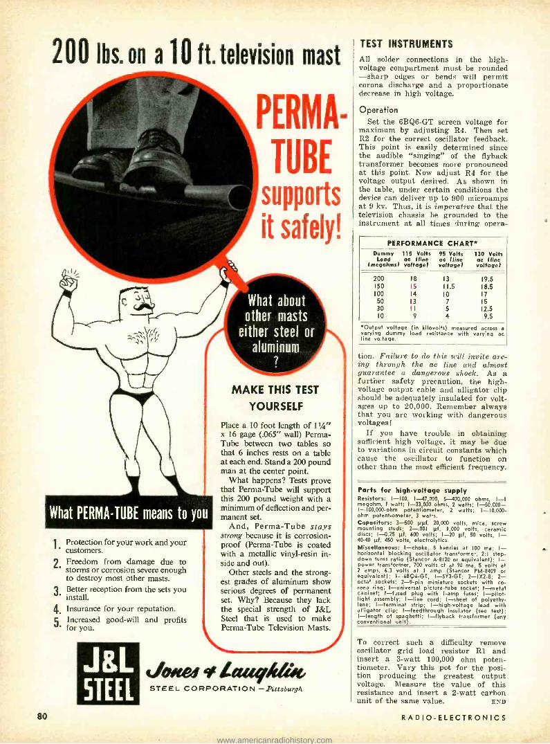
20016s. on a 10 lt.televisiou mast
PERMA-
TUBE supports
it safely!
What about other masts
either steel or
aluminum 7
80
1.
2.
3.
4. 5.
Protection for your work and your customers. Freedom from damage due to storms or corrosion severe enough to destroy most other masts. Better reception from the sets you install. Insurance for your reputation. Increased good -will and profits for you.
JaL STEEL
MAKE THIS TEST
YOURSELF
Place a 10 foot length of 11/" x 16 gage (.065" wall) Penna- Tube between two tables so that 6 inches rests on a table at each end. Stand a 200 pound man at the center point.
What happens? Tests prove that Perma -Tube will support this 200 pound weight with a minimum of deflection and per- manent set.
And, Perma -Tube stays strong because it is corrosion - proof (Perma -Tube is coated with a metallic vinyl -resin in- side and out).
Other steels and the strong- est grades of aluminum show serious degrees of permanent set. Why? Because they lack the special strength of J &L Steel that is used to make Perma -Tube Television Masts.
Jotiew Lau011ot STEEL CORPORATION - Pittsburgh
TEST INSTRUMENTS
All solder connections in the high - voltage compartment must be rounded -sharp edges or bends will permit corona discharge and a proportionate decrease in high voltage.
Operation Set the 6BQ6 -GT screen voltage for
maximum by adjusting R4. Then set R2 for the correct oscillator feedback. This point is easily determined since the audible "singing" of the flyback transformer becomes more pronounced at this point. Now adjust R4 for the voltage output desired. As shown in the table, under certain conditions the device can deliver up to 900 microamps at 9 kv. Thus, it is imperative that the television chassis be grounded to the instrument at all times during opera-
PERFORMANCE CHART* Dummy
Load (megohms)
115 Volts ac (line voltage)
95 Volts oc (line voltage)
130 Volts ac (line voltage)
200 18 13 19.5 150 15 11.5 18.5 100 14 10 17
50 13 7 15 30 11 5 12.5 10 9 4 9.5
*Output voltage (in kilovolts) measured across a varying dummy load resistance with varying ac line voltage.
tion. Failure to do this will invite arc- ing through the ac line and almost guarantee a dangerous shock. As a further safety precaution, the high - voltage output cable and alligator clip should be adequately insulated for volt- ages up to 20,000. Remember always that you are working with dangerous voltages!
If you have trouble in obtaining sufficient high voltage, it may be due to variations in circuit constants which cause the oscillator to function on other than the most efficient frequency.
Parts for high -voltage supply Resistors: 1 -100, 1- 47,000, 5 -470,000 ohms, I -I megohm, I watt; 1-33000 ohms, 2 watts; 1- 50,000- I- 100,000 -ohm potentiometer, 2 watts; 1- 10,000.. ohm potentiometer, 3 watts. Capacitors: 3-500 µµf, 20,000 volts, mica, screw mounting studs; 2 -.001 pf, 1,000 volts, ceramic discs; 1 -0.25 µf, 600 volts; I -20 sf, 50 volts, I- 40-40 µf, 450 volts, electrolytics. Miscell I- choke, 8 henries at 100 ma; (- horizontal blocking oscillator transformer, 2:1 step - down turns ratio (Stancor A -8120 or equivalent); 1- power transformer, 700 volts et at 90 ma, 5 volts at 2 amps, 6.3 volts at 1 amp (Stancor PM -8409 or equivalent); 1- 6B96 -GT, I- 5Y3 -GT; 2- 1X2 -B; 2- octal sockets; 2 -9 -pin miniature sockets with co- rona ring; I- universal picture -tube socket; I -metal cabinet; I -fused plug with I -amp fuses; I- pilot- light assembly; I -line cord; I -sheet of polyethy- lene; 1- terminal strip; I- high -voltage lead with alligator clip; I- feedthrough insulator (see text); I- length of spaghetti; I- flyback transformer (any conventional unit).
To correct such a difficulty remove oscillator grid load resistor Rl and insert a 3 -watt 100,000 ohm poten- tiometer. Vary this pot for the posi- tion producing the greatest output voltage. Measure the value of this resistance and insert a 2 -watt carbon unit of the same value. END
RADIO -ELECTRONICS
www.americanradiohistory.com

New
The model 500 Dyna - Quik tube tester.
N the days before TV, a tube tester was usually taken on service calls. Now many technicians feel that a tube tester requires too much time to
set up. With as many as 10 switches and controls to set for each tube, the better part of an hour may be consumed in checking all the tubes suspected of causing a particular trouble in a TV set -particularly in the older ones with around 30 tubes. Several manufacturers have developed new types of tube testers designed specifically to reduce the time required to check a tube.
In a conventional tester, much of the time is consumed in setting up the bank of 10 or so switches that connect the various socket terminals to the required points in the test circuit. The new testers eliminate this by using separate sockets wired to conform to almost any setup available with the usual free - point selector bank.
ASD TV -20 tester The American Scientific Development
Co.'s model TV -20 (see photo) is not designed to replace conventional tube testers. It is a special -purpose instru- ment designed for testing approxi- mately 250 TV receiving type tubes - including the new 600 -ma varieties. It eliminates the roll chart and time - consuming setups by using 20 sockets with the types of tubes tested in them printed directly on the panel. Wherever possible the tube groupings have been arranged so all horizontal output tubes are tested in one socket, high -voltage rectifiers in another and so on. There are only two adjustable controls -a heater -voltage selector switch and a resistive load control.
The TV -20 is available in portable and bench or panel models for the technician and in counter and self - service types that allow the customer to check his own tubes. Self- service testers are now found in many super- markets and auto supply, drug and hardware stores in suburban areas where the do- it- yourself fad is wide- spread.
The diagram in Fig. 1 shows the cir- cuit of the TV -20 with sockets elimi- nated for simplicity. The test circuit treats the tube under test as an ac rectifier with a meter measuring the do output. The meter is calibrated BAD-
MARCH, 1956
TEST INSTRUMENTS
Analysis of the ASD Tl' -20 and Dyna -Quik model S00
TUBE TESTERS By ROBERT F. SCOTT
TECHNICAL EDITOR
? -Goon with a 0 -100 scale for comparing the quality of tubes of the same type.
Dual tubes such as the 6AL5 and 12AT7 are checked in a single operation by connecting them in series as in Fig. 2. If one section of the tube is weak, the meter will read accordingly even if the other half is perfect. The .01 -µf capacitor across the lower section of the tube causes heater cathode leakage in the upper half to show up in the short test.
Shorts within a tube are located by connecting the cathode and plate to one side of a 145 -volt source and the grid or grids and one side of the heater to the other side of the 145 -volt supply
LINE
®NE-51 .01 :-- 1.2 MEG
through a .01 -µf capacitor and a neon lamp shunted by 1.2 megohms.
The setup for testing pentodes is shown in Fig. 3. Heater -to- cathode, cathode - to - grid and screen - to - plate shorts or leakage will complete the ac circuit and light the NE -51 neon lamp when the pushbutton switch is pressed. The lamp goes out if the tube is free of shorts. A gassy tube passes high leakage current and will also cause the lamp to remain on when the switch is pressed. The indicator glows when leakage resistance or the short re- sistance is less than 1.5 megohms. By making the short -test sensitivity high, it is easy to detect tubes that can cause
0-IMA 5K
UDAD
12011. 55 CALIB
FLOATING CAIN
IBn
IN1r- - 163
.0I
NTR 5IN HTR
CATHODES
k-HTR
PLATES
1B3-GT CAP
Fig. 1- Simplified schematic diagram of the model TV -20 tube tester.
The model TV -20 tele- vision tube tester.
81
www.americanradiohistory.com

10014
TEST INSTRUMENTS
Fig. 2- Circuit checks dual tubes. trouble in dc restorer, age, afc and sync circuits.
In later models of the TV -20, heater continuity in tubes not listed on the panel can be checked by plugging the tube into one of four specified sockets and turning the selector switch to OFF. The heater is good if the lamp stays on and bad if it goes out.
Dyna -Quik model 500 A product of the B & K Manufactur-
ing Co., this tube tester is similar in appearance (see photo) to the TV -20 and other testers designed for speedy testing. It is a dynamic mutual -con- ductance tester with tube quality shown on REPLACE- ?-GOOD and 0- 6,000- and 0- 18,000 -micromho scales. An added feature of this instrument is the life
r-- - _
2A
05%
1.2 MEG
NE -51
HEATER LINE
Fig. 3- Circuit for testing pentodes. test that enables the technician to spot tubes that are usable at the time of testing but whose mutual conductance is gradually dropping and will soon reach the point where a callback will be necessary. It has 30 sockets and HEATER, TEST and SENSITIVITY controls.
The 100 most popular tube types are listed on the panel. Each of these and the correct setting for the sensitivity control are listed next to the socket designated for the test. The setting of the heater -voltage selector is determined by the first number (3, 6, 12, etc.) in the tube type.
Only the most commonly used tube of a given type is listed next to a socket but an asterisk next to the tube listing shows that equivalent types with dif- ferent heater voltages can be tested in the same socket when the heater voltage is adjusted accordingly. For example, only the 6AL5 is listed on the panel but
an asterisk before it shows that 3AL5's and 12AL5's can be tested when the filament selector switch is set to 3 or 12, respectively.
Approximately 200 additional tube types can be tested in the Dyna -Quik 500. These, along with those listed on the panel, are listed on a chart inside the top cover. This chart also lists the socket number, heater voltage, sensi- tivity- control settings for GOOD -? -RE- PLACE and direct transconductance measurements and the standard mutual conductance for each tube.
Dyna -Quick circuit The diagram of the model 500 is
shown in Fig. 4. Sockets have been left out for simplicity. The usual manual line -voltage adjustment has been elimi- nated and replaced by automatic line - voltage compensation. A voltage- sensi- tive bridge consisting of two No. 44 pilot lamps and two 16 -ohm resistors is connected across a 6.3 -volt heater winding. This bridge monitors the line voltage and automatically adjusts the sensitivity of the mutual- conductance bridge to compensate for line -voltage variations.
The TEST switch is a lever type with positions marked SHORT, GM, LIFE and
DIODE PLATE
C Ó
1K
Ó fiTSENHmSI¡
5oA
I 12 43 44
S3-b
250pf/6V t
I
Y2 1 ---_
IBOK 1
1
32 h 6AT6
2
6
HT S5.6ME6
' AR
`4 Ss
O
w o
35.
25 o
D o
12o
To - o
6o HEATER VOLTAGE
6AX5
v
HTR
2 )
r SOMA RER
+
S3-e
20/2S0V-gr h 3
1 0--- 1 4
I o
'100o.
R°44
IIWRT 53i oIJFE
$GAS
240A.
1 I S3 o ló - 1
3
4
RER PLATE
12K
2W
IK
IOMEG
5615
IK
470K
1 12 I3 } f 1 j
3 -J
11
II
PLATE 10
SCREEN
CONNECTIONS
TO SOCKET PANEL
HIGH BIAS O
MEDIUM BIAS©
LOW BIAS 0 HIGH SIG Q
HTR
HTR
ALL S3 SWITCH SECTIONS GANGED
Fig. 4- Simplified schematic diagram of the model 500 Dyna -Quik tube tester.
82 RADIO -ELECTRONICS
IL
www.americanradiohistory.com

TEST INSTRUMENTS
GAS (grid emission), respectively. All tubes are checked first with the switch in the SHORT position. In this test, a short or leakage up to 1 megohm be- tween heater and cathode, grid and cathode, grid and plate or screen grid and plate will cause the NE -51 neon in- dicator to light.
If the tube is not shorted, the switch is then thrown to GM for a qualitative test. With the sensitivity control set as indicated by the number on the panel or in the good -replace column on the chart in the cover, the meter will in- dicate on the GOOD - ?- REPLACE scale.
If the exact mutual conductance of the tube is desired, the sensitivity con- trol is set as indicated in the true g., column of the chart. The 0- 6,000 -micro- mho scale on the meter is printed in black; the 0- 18,000- micromho scale in red. The sensitivity -control settings in the true gm column are printed in red or black to indicate the meter scale to be used.
Mt 9+
Fig. 5- Measuring gm of dual tubes.
Mutual conductance is the ratio of a small change in plate current to the small change in grid voltage causing it (with all other voltages remaining con- stant), or
eo,2
eiPi+e pz
Ai, oe
The amplification available from a tube is the product of g,,, and the load re- sistance. Mutual conductance is found by inserting the tube in a sensitive bridge circuit, applying a small ac volt- age to its grid and measuring the re- sulting alternating plate current.
The mutual conductance of dual triodes and dual pentodes is measured with the halves in parallel as in Fig. 5. If the ac signal voltage is applied to the grids in parallel, the meter meas- ures the sum of the plate currents and the gm is equal to
Olp, + lns AeR
If the mutual conductance of either section of the tube is low, the meter reads low.
Life test Manufacturers have found that prob-
able remaining tube life can be esti-
TUBE UNDER TEST
5.6 MEG
NEL BIAS SUPPLY
Fig. 6 -Grid emission
MARCH, I956
...the most
Complète Line of VOM's Select the one that fits your needs!
MODEL
260 world's most I
popular; Over half a million Model 260's have been told to date! 20,000 Ohms per volt. You'll find it wherever quick, accurate, elec- trical checks are needed. It's so
handy, so dependable, so sensi- bly priced! Ask your jobber. Price, including Adjust -A -Vue Handle, only ... $38.95 Carrying Cases from $6.75
MODEL 262 MODEL 269 100,000
Ohms
per volt!
the new VOM with a 7 meter 20,000 Ohms per volt DC and 5,000 Ohms per volt AC sensitivity ... 33 ranges ... compact 7" case with Adjust - A -Vue Handle $59.50 Carrying Case $ 9.95
NEW!
Most sensitive VOM available! A Volt- Ohm- Microam- meter with a big 7" meter in a com- pact 7" case ... 33 ranges ... Adjust - A -Vue Handle ... price complete
Carrying Case
$88.00 $ 995
MIDGETESTER Model 355 -New shirt -pocket size Volt -Ohmmeter $29.95
MODEL 240 -Small VOM; 14 ranges; up to 3000 volts AC er DC $26.35 MODEL 230 -Small VOM; 12 ranges; up to 1000 volts AC or DC $24.95 ROTO RANGER Model 221 -25 Separate meters at turn of a sw tch $75.00
LABORATORY STANDARD -For instrument calibration. Price on application.
O
ELECTRIC COMPANY
World's Largest Manufacturer of Electronic Test Equipment
5200 W. KINZIE ST., CHICAGO 44. ILL. EStebrook 9 -1121 In Canada: BACH -SIMPSON, LTD., LONDON, ONTARIO
83
www.americanradiohistory.com

It's a real sweetheart THE NAUTILUS ANTENNA by TENNA IS THE MOST BEAUTIFUL, BEST LOVED OF ALL
STREAMLINED AUTO ANTENNAS.
CAR OWNERS LOVE IT! Car owners love it for its beautiful tear -drop mounting base that so perfectly matches the streamlined beauty of modern cars. They love its lustrous chrome finish and its sturdy, rigid construction.
DEALERS LOVE IT! Dealers love it because it sells on sight, because it is fully adjustable 0 -25° angle to fit any mounting location and is specially adapted for crown fenders, because it mounts either front or rear and assures quick turn over.
SERVICEMEN LOVE IT! Servicemen love it because it is quickly, easily mounted from the outside and without the use of any special tools and gadgets.
Model NT -3 Model NT3 -15 with 4' lead with 15' lead
for front mounting for rear mounting
MADE AND GUARANTEED BY
THE WORLD'S LARGEST MAKER
OF AUTOMOBILE ANTENNAS
MODEL NT -3
'/Itit+tiiiht,,i.et 7580 GARFIELD BLVD. CLEVELAND 25, OHIO
84
TEST INSTRUMENTS
mated reasonably by testing with the heater voltage reduced 10 -15%. Under these conditions, there may be a sharp drop in g.,. This indicates that the space charge has dropped to the point where the tube will have little remaining life. The instruction manual does not indi- cate the percentage of change in g,n that is considered pertinent for a given tube type but no doubt this can be de- termined reasonably by experimenting with tubes that give different readings On the GOOD - ?- REPLACE scale.
Grid- emission (gas) tests When a tube is being made or when
it is improperly operated, some of the cathode coating material may evaporate and deposit on the grid. When the tube warms up, this material emits electrons that flow from grid to plate, through the power supply and grid resistor, back to the grid. This grid current flow is in the direction that tends to reduce the nor- mal grid bias and make the grid more positive with respect to the cathode.
If there is a small amount of gas in the tube, electrons from the cathode will strike the gas molecules and knock off one or more electrons, converting the molecules to positive ions. Some of the ions may then strike the grid and take on an electron and become a gas molecule again. When this molecule again becomes ionized by striking elec- trons from the cathode, the electron from the grid is released to flow to the plate. This process continues and re- sults in gas current that tends to drive the grid positive in the same manner as grid emission due to contamination.
Grid emission and gas oppose the normal grid bias and usually cause plate saturation, resulting in clipping and overloading.
When a tube is tested for grid con- tamination or gas, normal plate voltage is applied but its grid is biased to cut- off so no plate current flows. This bias is applied through a 10- megohm resistor that also connects to the grid of the 6AT6 dc amplifier in the tester. Under these conditions, the 6AT6 is also cut off and the meter in its plate circuit does not deflect. (See Fig. 6.)
However, if the tube being tested has a contaminated cathode or is gassy, cur- rent flows from grid to plate and then back to the grid through the power supply and the 10- megohm resistor. This current flow develops a voltage that opposes the cutoff bias and causes the meter to deflect. This test indicates grid current as low as 2 µa. END
RADIO -ELECTRONICS
www.americanradiohistory.com

a
ALLI ED knight -kits FINEST ELECTRONIC EQUIPMENT IN LOW -COST KIT FORM
YOU SAVE MORE BEC
LOW COST -huge buying power and DIRECT SALE pass big-
gest savings on to you. You do the easy assembly and your
built -up instrument is equal in appearance and performance
to equipment selling for several times the KNIGHT -KIT price.
ADVANCED DESIGN- months of research, development
and field p
testing erfo ance,premium quality rt l parts are supplied throughout
PRINTED CIRCUITS
Model F -144
$6900
knight -kit WIDE -BAND
5" OSCILLOSCOPE KIT
Wide -band 5" Oscilloscope equal or superior
$6.90 down, to commercially -wired 'scopes costing sev- eral times the price. Vertical response from
12 months to 5 cycles to 5 mc-ideal for the professional pay balance laboratory, for color TV servicing, and high
frequency applications. Response -1 db at 3.58 mc; -3 db at 5 mc. Two printed circuit boards and laced wiring harness reduce assembly time. Has very wide sweep range -from 15 to 600,000 cps. Locks in frequencies as high as 9 mc. High vertical sensitivity of 25 rms milli- volts /inch. Input capacitance 36 mmf. Outstanding fea- tures: cathode -follower vertical and horizontal inputs; 1400 volts at 2nd anode provides high -intensity trace; push -pull vertical and horizontal amplifiers; positive and negative locking; faithful square wave response; frequency -com- pensated input attenuator; Z -axis input for intensity modu- lation; one volt peak -to -peak calibrating voltage; internal astigmatism control; blanking circuit to eliminate retrace lines; DC positioning control. Complete with all tubes and parts, ready for easy assembly. Handsome professional case finished in blue, with gray control panel. Shpg. wt., 40 lbs. Model F -144. 5' Oscilloscope Kit. Net only Model F -148. Demodulator Probe. Net $3.45 Model F -147. Low Capacity Probe. 12 mmf. Net $3.45
$69.00
ALSO AVAILABLE: Refer to your 324 -page 1956
Allied Catalog for dozens of other KNIGHT-KIT
values, including 20,000 Ohms /Volt \IOM, Signal
Generator, Audio Generator, Resistor -Capacitor
Tester, Signal Tracer, Resistance and Capacitance
Substitution Boxes. Additional altest instrument ent k is
appear on the next page, Hobbyist, Ham and Hi -Fi KNIGHT -KITS-
AUSE YOU BUY DIRECT
EASIEST ASSEMBLY -all chassis and panels are punched
for accurate assembly; all parts are fully identified. Instruction
manuals are a marvel diagrams featuring
nd "Spotlight" pnd-Chek"
For assembly, "King-Size"
pictorials. For easy assembly you need only a soldering iron,
pliers and screwdriver. ALLIED -the reliable name in EleCtrOniCS-
gives you the through the economies a of DIRECT SELLING
knight -kit PRINTED CIRCUIT VTVM KIT
Model F -125 New, extremely stable, highly accurate VTVM. Greatly sim-
i. $2495 plified
wiring- entire chassis is a printed circuit board. Fea- tures maximum convenience in arrangement of scales and con-
trols. With peak -to -peak scale for FM and TV work. Ranges: AC peak -to -peak volts, 0- 4- 14 -40- 140 -400 -1400 -4000; AC rms volts and DC volts, 0- 1.5- 5 -15 -50 -150- 500 -1500; ohms, 0 -1000, 10K, 100K; 1 -10- 100 -1000 megs; db scale, -10 to +5. Response, 30 cps to 3 mc. Uses low- leakage switches and 1% precision resistors. Balanced- bridge, push -pull circuit permits switching to any range without adjusting zero set. 4 %' meter,
200 microamp movement. Polarity reversing switch. Input resist- ance, 11 megs. Complete kit, ready to assemble. Shpg. wt., 6 lbs.
$24.95 Model F -125. Printed Circuit VTVM Kit. Net only Model F -126. Hi- Voltage Probe; extends DC range to 50,000 Volts. Net $4.75
Model F -127. Hi- Frequency Probe; extends AC range to 250 mc. Net $3.45
knight -kit TUBE TESTER KIT
An Outstanding Value Model F -143
Counter Model
$297s Portable
Model
Expertly designed, up -to -date, ideal for the laboratory or service shop. Remarkably low priced, yet it offers high accuracy, top versa- tility and convenience. Illuminated roll chart lists over 700 tube types. Features provision for testing 600 -ma tubes; roll -chart in- cludes data for all popular series -string types. Tests 4, 5, 6 and 7 -pin large, regular and miniature types, octals, loctals, 9 -pin mini- atures and pilot lamps. Tests for open, short, leakage, heater con- tinuity and quality (by amount of cathode emission). 06" square meter with clear "GOOD -?- REPLACE" scale. With line- voltage indicator and line -adjust control. Choice of 14 filament voltages from .63 to 117 volts. Blank socket for future type tubes. Universal - type selector switches for any combination of pin connections. Single -unit, 10 -lever function switch simplifies assembly. Complete kit, ready for easy assembly. Shpg. wt., 14 lbs. Model F -143. Counter Model Tube Tester Kit. Net only . $ 29.75 Model F -142. As above, but with carrying case. Net only . $34.75 Model F -141. TV Picture Tube Adapter for above. Net only . $3.75
EASY PAYMENT TERMS: If your total kit order comes to over $45,
take advantage of
our liberal application ral
Time aym
nt Plan -only 10% down, 12 full
months to pay.
Order from ALLI E D RADIO loo N. WESTERN AVE., CHICAGO 80, ILLINOIS
SEE FOLLOWING PAGES
MARCH, 1 9 5 6 85
www.americanradiohistory.com

Knight -Kit IN- CIRCUIT
CAPACITOR CHECKER KIT
SAVE UP TO
70% Model F -119
$1165
SUPER -VALUE
FAMOUS knight -kits FOR HOBBYISTS
"SPACE- SPANNER" RECEIVER KIT
Tests capacitors while they are still wired in the circuit! Saves time and trouble. Just press a button and the "magic eye" instantly shows opens and shorts. Checks practically any by- pass, blocking, coupling and filter capacitors for opens or shorts. Tests for opens can be made on any capacitor of 20 mmf or greater, even when capacitor is in parallel with resist- ance as low as 50 ohms. Tests for opens on any capacitor up to 2000 mfd, even when shunted by as low as 20 ohms. Housed in pro- fessionally styled case, sturdy steel in blue wrinkle finish with gray control panel. Com- plete kit, ready for easy assembly. Shpg. wt., 5 lbs. Model F -119. Capacitor Checker Kit. $11.65 Net only
Knight -Kit VOM KIT
1000 Ohms /Volt
Model F -128
$145
Exceptional accuracy and versatility at amaz- ing low cost. Ideal for service shop, lab and Amateur use. Uses 4 " meter (400 microamp movement) with separate scales for AC volt- age and current, DC voltage and current, deci- bels and resistance. 38 ranges include: AC, DC and Output volts, 0- 1- 5- 10 -50- 100 -500 -5000 (1000 ohms /volt sensitivity); Resistance, 0- 1000 -100,000 ohms and 0 -1 meg.; Current, AC or DC, 0 -1 -10 -100 ma and 0 -1 amps; Deci- bels, -20 to +69 in 6 ranges. Uses 1% preci- sion resistors. 3- position function switch and 12- position range switch. Complete kit with bakelite case, battery and test leads. Shpg.
.wt., 23. lbs. Model F -128. 1,000 ohms /volt VOM Kit. Net only $14.25
EASY PAYMENT TERMS: If your total kit order comes to over $45, take advantage of our liberal Time Payment Plan -only 10% down, 12 full months to pay. Write for application form.
Mode! S -243 Featuring Bandswitching for Thrilling Short
Wove and Broadcast Reception. All -new 2-
5 band receiver -easy to build -a great value! Pulls in thrilling short wave in- cluding amateur, aircraft, police and
marine radio (6 to 17 mc), and standard broadcast. Features special highly sensitive regenerative cir-
cuit. Has 4" PM speaker and beam -power output tube for plenty of volume. Kit includes calibrated panel, punched chassis, all parts and tubes, detailed instructions (less wire and solder). 7 x 10% x 6 "; for
110 -120 v. 50 -60 cycles AC or DC. Shpg. wt., 4 % lbs.
Model S -243. "Space- Spanner" Kit. Net Only (less cabinet )
$139
GEIGER COUNTER KIT Super- sensitive Uranium Locator and Radio-
activity Detector. Get started in uranium prospecting now with this extremely sen- sitive instrument- comparable to costly equipment, yet easy to build at only a
fraction of the price. Just turn it on, flip the high -voltage switch and listen to the clicks in the headphone when you hit a radioactive source. Uses low -cost long -life batteries. Kit includes all parts, tubes, carrying case with shoulder strap, 22%y and 1% v. batteries, head- phone, AEC prospecting booklet, radioactive sample and complete assembly instructions. Shpg. 23. lbs. 15.95 Model S -242. Geiger Counter Kit. Net only... $
$13.95 S -247. Matching cabinet for above $2.85
Model S -242
$1595
FAMOUS 10 -IN -1 LAB KIT Model S -265 Build Any One of 10 Fascinating Projects.
Instructive and fun to build. Construct
$1245 a sensitive Broadcast Receiver; Ampli- fier (for phono or mike); Wireless Phono Oscillator; Home "Broadcast Station";
Code Practice Oscillator; Capacity -Operated Relay or any one of four other fascinating projects. Kit in- cludes mounting board, special "safety designed" low voltage power transformer, tubes, all parts, microphone, 12 -page builder's manual (less wire and solder). For 110 -120 v. 50 -60 cycles AC. Shpg. wt., 10 lbs. Model S -265. "10 -in -1" Kit. Net only
PORTABLE RADIO KIT Powerful 3 -Way Operation. Top - quality, Model S -730
portable AM receiver for AC, DC or bat- tery operation. Tunes full broadcast band, 535 -1650 kc. Features sensitive superhetcircuit; 5 "PM dynamicspeaker; built -in loop -stick antenna; automatic volume con- trol; handsome carrying case. Complete with all parts, tubes and easy-to-follow instructions (less wire, sol- der and batteries). For 11.0 -120 v., 50 -60 cycle AC, DC, or batteries. Shpg. wt., 6 lbs. 18. $ Model S -730. Portable Radio Kit. Net only . .75
5 S-651. Battery Kit for above. Net $
ModelS -765 TRANSISTOR RADIO KIT
Printed Wiring -Works From Flashlight Cell. Experiment with the marvel of transistors in this printed- circuit radio. No tubes -no crystal! Small enough to fit in the palm of the hand -yet it provides powerful reception over the com- plete AM broadcast band. Operates from single flashlight cell. For use with headphones. Printed circuit eliminates wiring -just assemble and solder a few connections! Sup- plied complete with all parts, hardware, battery, and easy - to -follow instructions. Less solder, antenna and headphone. Shpg. wt., 8 oz. Model S -765. Transistor Radio Kit. Net only
$1875
$12.45
$395
BUY WITH CONFIDENCE BUILD WITH CONFIDENCE
Premium Quality Components
Crystal -Clear Instruction Manuals
"Step- and -Chek" Building Method
Advanced Electronic Design
Precision Quality Performance Professional Streamlined Styling
BUY DIRECT YOU SAVE MORE YOU GET MORE FOR YOUR KIT DOLLAR
$3.95
RECEIVER KIT ACCESSORIES
J-149. 4000 ohm extra -sensitive double headset. $1.9B
Net c -100. Antenna kit for use with all Knight-Kit receivers. Net
All Prices Net F.O.B. Chicago
Order from ALLIED RADIO 100 N. WESTERN AVE., CHICAGO 80, ILL.
86 RADIO -ELECTRONICS
www.americanradiohistory.com

Easiest -to- Build Electronic Equipment in Kit Form
BUILD- YOUR -OWN HIGH FIDELITY knight -kits
BVY DiRECT
AND purr,
knight -kit BASIC 25 -WATT LINEAR -DELUXE
HI -FI AMPLIFIER KIT
Model S -755
knight -kit 50 WATT CW TRANSMITTER KIT
Model SX -255
$4250
Built -in Pi -Type Antenna Coupler Check the features packed into this new transmitter kit and you'll see why it's one of the greatest Amateur values ever offered. Compact and versatile, it is the perfect low -power rig for the beginning Novice or sea-
soned veteran. Features: 50 watts input to 807 final; high -efficiency 6AG7 modified- Pierce oscillator takes crystal or VFO without circuit changes; bandswitching coverage of 80, 40, 20, 15, 11 -10 meters; pi- section an- tenna output matches line impedances from 50 to 1200 ohms -permits use with any type of antenna. Crisp, clean, cathode keying of oscillator and final. Power take -off plug supplies filament and B -plus voltages for other equipment. Copper- finished chassis and cabinet interior, filtering, shielding, bypassing, and coaxial SO- 239 antenna connector provide excellent TVI suppres- sion. Meter reads either plate or grid current of final. Jacks for VFO, crystal, and key. Supplied with all parts, tubes and step -by -step instructions. Less crystal and key. Size, 8'r1'6 x 111/4 x 841". For 110 -120 volts, 50 -60 cycle AC. Shpg. wt., 18 lbs. SX- 255. 50 -Watt Transmitter Kit. Net $42.50
knight -kit SELF - POWERED
VFO KIT
Model S -725
52750 *Complete with built -in power supply! Careful design and voltage regulation assure high stability. Excellent oscillator keying characteristic for fast break -in with- out clicks or chirps. Full TVI suppression. Has plenty of bandspread: separate calibrated scales for 80, 40, 20, 15,11 and 10 meters; vernier drive mechanism. 2- chassis construction keeps heat from frequency determining circuits. Output cable plugs into crystal socket of trans- mitter. Output on 80 and 40 meters. With Spot -Off- Transmit switch for "no swish" tuning. Extra switch contacts for operating relays and other equipment.
0 Complete kit for easy assembly. Shpg. wt., 8 lbs. $2.50 Model S -725. Self- Powered VFO Kit. Net... .
knight -kit CODE PRACTICE OSCILLATOR KIT
Model 5 -239
95 Transistorized-
$ Powered by Flash-
light Battery
An ideal new code practice oscillator. Uses transistor circuit. Extremely low current consumption- powered by single penlight battery. Provides crisp, clear tone (400 to 600 cps). Has input jack for earphone; screw - type terminal strip for key. In compact bakelite case (2% x 3% x 1 Ç) with anodized aluminum panel. Com- plete with all parts, battery and easy -to- follow in- structions. Shpg. wt., 1 lb. $4.95 Model S -239. Code Practice Oscillator Kit .... $4.95
Custom Quality Printed Circuit Wiring Williamson -type Circuit Chrome -Plated Chassis
Designed to satisfy the most critical listener. Intended for use with tuners incorporating built -in preamp or with separate preamp. Uses latest Williamson -type circuit. Has potted, matched transformers. Output: Maximum, 45 watts; rated, 25 watts. Frequency response: ± 0.5 db, 10 to 120,000 cps, measured at 20 watts. Harmonic distortion is only 0.15% right up to 30 watts. Intermodulation is only 0.27% at 17 watts and only 1% at 20 watts, using 60 cps and 7 kc, 1:4 ratio. Hum level is 85 db below rated output. Output impedance, 4, 8, 16 ohms. Uses two 12AU7's, two 5881's, and a 5V4. Printed circuit is utilized in voltage amplifier and phase inverter stages. Has output tube balancing control, variable damping control, and on- off switch. Handsome chrome -plated chassis, 14" x 9" x 2 ". Overall height, 7 ". Complete with all parts, tubes and construction manual (less wire and solder). Shpg. wt., 27 lbs.
5t1 Model S -755. Basic 25 watt Hi -Fi Linear -Deluxe Amplifier Kit. Net Model S -706. Knight Preamplifier- Equalizer. Ideal for use with above amplifier. Provides 5
selectable inputs. Completely wired -ready to use. Net $36.95
knight -kit 10 -WATT HI -FI AMPLIFIER KIT Model S -234 Famous for wide re-
2 spouse and smooth re- production at low cost.
$ Only 0.5 volt drives am- plifier to full output. Re-
sponse: ± 1 db, 30- 20,000 cps at 10 watts. Harmonic distortion less than 0.5% at 10 watts. Intermodulation is less than 1.5% at full output. Controls: On- off -volume, bass, treble. Input for crystal phono or tuner. Chassis punched to take preamp kit for magnetic cartridges. Matches 8 ohm speakers. Shpg. wt., 14 lbs. Complete kit (less wire and solder). $20.95 Model S -234. Amplifier Kit. Net. Model S -235. Preamp Kit for above. Net $2.75
1 1 1 1 1
ORDER TODAY MARCH, 1956
20 -WATT HI -FI AMPLIFIER KIT Model S -750 True hi -fi for less! Re-
sponse, ± 1 db, 20 to 20,000 cps at 20 watts. Distortion, 1 %p at 20 watts. Hum and noise
level: Tuner input, 90 db below 20 watts; magnetic phono, 72 db below 20 watts. Sensitivity: Tuner input, 0.6 volt for 20 watts output; magnetic phono, .007 volts. 4 inputs: Magnetic phono, microphone, crystal phono or recorder, and tuner. Con- trols: Bass, Treble, Volume, Selector with compensation positions for 78 and LP records. Chrome -plated chassis. Wt., 23 lbs. Complete kit (less wire and solder). Model S -750. 20 -Watt Hi -Fi $34.%5 Amplifier Kit. Net
53475
CCALLIED RADIO IM E atQ11 & frW 4
¡ attab k Soma,
Allied Radio Corp., Dept. 2 -C -6,
100 N. Western Ave., Chicago 80, III.
Ship me the following KNIGHT -KITS:
Quantity
OUR
35TH YEAR
Description Model No. Price
$ enclosed. For parcel post include postage (express is shipped collect).
Send FREE 324 -Page ALLIED Catalog listing the complete Knight -Kit line.
Name
Address
City Zone State tl tlS- tltltltl- olos nil 87
1 1 1 1 1 1 1
1
www.americanradiohistory.com
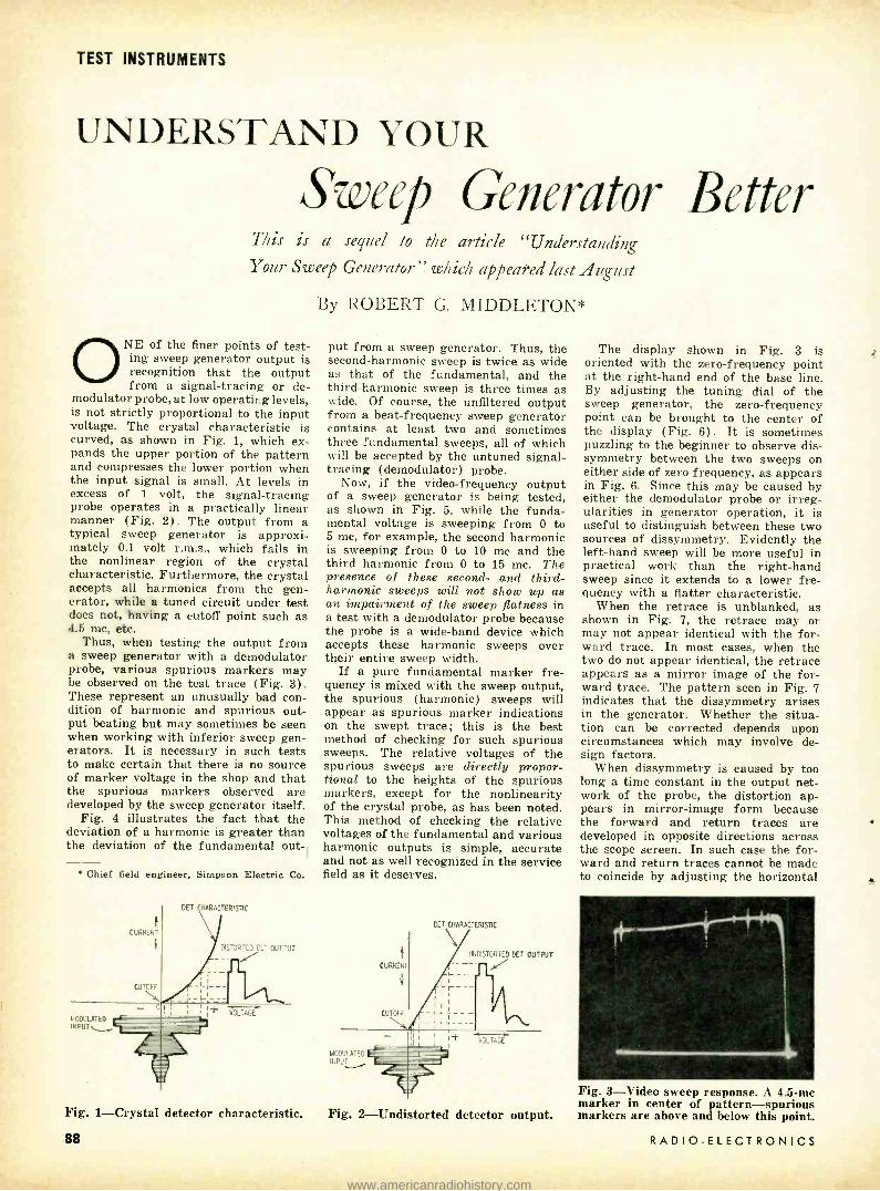
TEST INSTRUMENTS
UNDERSTAND YOUR
Sweep Generator Better This is a sequel to the article "Understanding Your Sweep Generator" which appeared last August
ONE of the finer points of test- ing sweep generator output is recognition that the output from a signal- tracing or de-
modulator probe, at low operating levels, is not strictly proportional to the input voltage. The crystal characteristic is curved, as shown in Fig. 1, which ex- pands the upper portion of the pattern and compresses the lower portion when the input signal is small. At levels in excess of 1 volt, the signal- tracing probe operates in a practically linear manner (Fig. 2). The output from a typical sweep generator is approxi- mately 0.1 volt r.m.s., which falls in the nonlinear region of the crystal characteristic. Furthermore, the crystal accepts all harmonics from the gen- erator, while a tuned circuit under test does not, having a cutoff point such as 4.5 mc, etc.
Thus, when testing the output from a sweep generator with a demodulator probe, various spurious markers may be observed on the test trace (Fig. 3). These represent an unusually bad con- dition of harmonic and spurious out- put beating but may sometimes be seen when working with inferior sweep gen- erators. It is necessary in such tests to make certain that there is no source of marker voltage in the shop and that the spurious markers observed are developed by the sweep generator itself.
Fig. 4 illustrates the fact that the deviation of a harmonic is greater than the deviation of the fundamental out
r
Chief field engineer. Simpson Electric Co.
MODULATED INPUT`S
CURRENT
CUTOFF
- o
DET CHARACTERISTIC
DISTORTED DET OUTPUT
-I-i- - -
I___
VOLTAGE
Fig. 1- Crystal detector characteristic.
88
By ROBERT G. MIDDLETON*
put from a sweep generator. Thus, the second -harmonic sweep is twice as wide as that of the fundamental, and the third -harmonic sweep is three times as wide. Of course, the unfiltered output from a beat -frequency sweep generator contains at least two and sometimes three fundamental sweeps, all of which will be accepted by the untuned signal - tracing (demodulator) probe.
Now, if the video -frequency output of a sweep generator is being tested, as shown in Fig. 5, while the funda- mental voltage is sweeping from 0 to 5 mc, for example, the second harmonic is sweeping from 0 to 10 mc and the third harmonic from 0 to 15 mc. The presence of these second- and third - harmonic sweeps will not show up as an impairment of the sweep flatness in a test with a demodulator probe because the probe is a wide -band device which accepts these harmonic sweeps over their entire sweep width.
If a pure fundamental marker fre- quency is mixed with the sweep output, the spurious (harmonic) sweeps will appear as spurious marker indications on the swept trace; this is the best method of checking for such spurious sweeps. The relative voltages of the spurious sweeps are directly propor- tional to the heights of the spurious markers, except for the nonlinearity of the crystal probe, as has been noted. This method of checking the relative voltages of the fundamental and various harmonic outputs is simple, accurate and not as well recognized in the service field as it deserves.
MOD7LATED R:PU
CURRENT
1
CUTOFF
DE1CHAR ACTERISTIC
UNDISTORTED DOT OUTPUT
_j*y___ _ --
Fig. 2- Undistorted detector output.
The display shown in Fig. 3 is oriented with the zero -frequency point at the right -hand end of the base line. By adjusting the tuning dial of the sweep generator, the zero -frequency point can be brought to the center of the display (Fig. 6). It is sometimes puzzling to the beginner to observe dis- symmetry between the two sweeps on either side of zero frequency, as appears in Fig. 6. Since this may be caused by either the demodulator probe or irreg- ularities in generator operation, it is useful to distinguish between these two sources of dissymmetry. Evidently the left -hand sweep will be more useful in practical work than the right -hand sweep since it extends to a lower fre- quency with a flatter characteristic.
When the retrace is unblanked, as shown in Fig. '7, the retrace may or may not appear identical with the for- ward trace. In most cases, when the two do not appear identical, the retrace appears as a mirror image of the for- ward trace. The pattern seen in Fig. 7 indicates that the dissymmetry arises in the generator. Whether the situa- tion can be corrected depends upon circumstances which may involve de- sign factors.
When dissymmetry is caused by too long a time constant in the output net- work of the probe, the distortion ap- pears in mirror -image form because the forward and return traces are developed in opposite directions across the scope screen. In such case the for- ward and return traces cannot be made to coincide by adjusting the horizontal
Fig. 3 -Video sweep response. A 4.5 -mc marker in center of pattern -spurious markers are above and below this point.
RADIO -ELECTRONICS
4
www.americanradiohistory.com

90
80
r0
60
rREQ-MC
50
RD HARMONIC OF SWEEP GEN
40
30
20
2ND HARMONIC OF SWEEP GEN
0
UNDAMENTAL OUTPUT F SWEE GEN
2 4 E 10 12
0E016710N OF FUNDAMENTAL WC 1
Fig. 4- Relation of harmonic deviations.
sweep phasing control of the scope. A further check can be made to corrob- orate this conclusion by advancing and backing off on the setting of the sweep generator attenuator. If the distortion pattern changes with the attenuator setting, it is conclusive that the fault lies in the generator.
If the sweep -width control of the generator is now set for a small sweep width, the detail of the generator out- put in the vicinity of zero frequency becomes evident (Fig. 8). Note the extent of the locking region, since it is this region that determines the lower limit of frequency output from the generator. The extent of pulling and locking is determined by the residual coupling between the fixed and swept oscillators in the beat -frequency gen- erator.
Fig. 9 shows the basic arrangement in a beat -frequency sweep generator and indicates the residual coupling be- tween the two oscillators as stray capacitance C. The two oscillators pull before they lock, and in this pulling region they move off normal frequency, approaching a frequency intermediate
_ OUTPUT CABLE
SWEEP GEN
SIG TRACING FROBE
Fig. 5- Checking generator output for flatness -ground lead must be short.
Fig. 6 -The zero -frequency point is brought to center of the sweep trace.
MARCH, 1956
DYNA-QU /K soó DYNAMIC MUTUAL CONDUCTANCE TUBE TESTER
Tests over 95% OF ALL POPULAR TV TUBES' -IN SECONDS
You can cut servicing time -eliminate repeat calls -make more on -the -spot tube sales -give a better service guarantee -make new profits in minutes with DYNA -QUIK. This top quality, low cost, portable dynamic mutual conductance tube tester enables any serviceman to locate weak and inoperative tubes quickly and easily with laboratory accuracy right in the home.
DYNA -QUIK creates greater customer confidence because your customer sees for himself the true tube condition on "Good -Bad" scale. In just a few minutes you can check all the tubes in a TV set for shorts, grid emission, gas content, leakage, dynamic mutual conductance and life expectancy under the dynamic heavily loaded conditions that are the actual operating conditions of the set. Used in the shop or in the home -DYNA -QUIK will make money for you every day!
Fast -a complete tube test In as little as 12 seconds.
Easy -one swat :h tests everything. No roll chart -no multiple switching.
Accurate -large 4'/,- plastic meter has two scales calibrated 0.8,000 and 0- 18,000 micromhos.
Always L p to date -test procedure Instructions for new tubes supplied by factory at regular intervals.
Automatic line compensation -special bridge continuously monitors line voltage.
7 -pin and 9 -pir straighteners mounted on panel.
Portable- luggage style carrying case with removable slip- hinged cover.
Lightweight -15''% x 14% x 5% in. Weighs only 12 lbs.
Includlne new 600 nmil serles tubes.
Send for article on "Profitable TV Servicing In the Home" and Bulletin 500 -E
Also makers of the famous CRT 400
B & K MANUFACTURING CO. 3726 N. Southport Ave. Chicago 13, Illinois
89
www.americanradiohistory.com

TEST INSTRUMENTS
Fig. 7- Unblanking the retrace in Fig. 6 shows dissymmetry in the generator.
YOU NEED THESE FEATURES:
555A QOM
Meter Movement Protection up to 500 times overload is provided by a rectifier network.
The 555A Measures: AC Current, DC Current, AC Voltage, DC Voltage, Output, Resistance
43 Unduplicated Ranges
Separate Range and Function Switches
Double Magnetic Shielding
3% DC, 4% AC Permanent Accuracy
Easy to Read, Four Color Scales 4 7/8" long
Metal Case with Die Cast Bezel 67/8" x 4 %" x 27/8"
Sensitivity: 20,000 Ohms /Volt DC, 2000 Ohms /Volt AC
Complete with Probes and $4450 Batteries at your Parts Distributor
PHAOSTRON INSTRUMENT AND ELECTRONIC COMPANY
151 Pasadena Avenue, South Pasadena, California
90
Fig. 8- Reducing sweep width shows de- tails of zero -frequency point in Fig. 7.
between the normal frequencies. In this pulling region, the output becomes badly distorted, generating an exces- sive number of harmonics; the output becomes attenuated. And finally, as the operating frequencies of the oscil- lators approach the locking region, the two oscillators suddenly "seize" the same frequency and the output drops to zero until the swept oscillator again moves out of the locking range.
Because the output from a beat - frequency generator such as shown in Fig. 9 contains a sum as well as a difference beat, it is apparent that the test shown in Fig. 5 is not entirely valid unless a suitable low -pass filter is used in the output system of the sweep generator. The low -pass filter should have a characteristic impedance equal to that of the output cable to avoid disturbance of the cable imped- ance. The cutoff frequency of the filter should be chosen to pass the difference - frequency band of the generator, but to suppress the sum -frequency band.
VIDEO SWEEP OUTPUT
Fig. 9- Diagram shows basic arrange- ment for a beat -frequency sweep gen-
erator.
For technicians who like to build their own equipment, details of low -pass filter construction may be found in publications such as the ARRL Hand- book, and in most books on circuit theory. END
RADIO -ELECTRONICS
www.americanradiohistory.com

f
p TED C0101101.11.
)) ) ) )
SOUNp.pCTlVp`
)11,4)
Sensitive device
can be used to
actuate and control
electronic equipment
By RICHARD J. SANDRETTO
OU ACTIVATED controller can be used to switch a paging system on automatically at the first word of an announcement
and off again at the end, to give an auxiliary alarm for deaf people when the telephone rings or to give an alarm when the baby starts crying. Such a device can also be used to operate an unattended tape recorder so that in- frequently occurring sounds or radio transmissions can be recorded without having the recorder run continuously. Other uses include automatically in- creasing the volume of a radio or TV set so that a program can be heard above occasional loud outside noises and functioning as an automatic talk listen switch on radiotelephone and intercom systems.
In some instances it might be desired that a sound switch be set off by sounds of one particular narrow range of fre- quencies but be unaffected by other sounds. This type of sound switch is called a tone -operated relay.
Two very versatile and unique sound switches are described in this article. Each uses an 0A4 -G thyratron tube for economy of operation, simplicity and dependability. The two -tube model has much greater sensitivity than the single -tube design. Both have been
MARCH, 1956
FILAMENT RESISTOR
IU4
ELECTRONICS
INPUT TRANS
SENSITIVITY ADJ
carefully planned to be easily adaptable to almost any special situation.
Circuit description The circuit of a basic 0A4 -G sound
switch is shown in Fig. 1. The tube initially does not conduct although filter capacitor C is kept charged to the peak value of the line voltage by the selenium rectifier. Tube conduction, and conse- quent closing of the plate relay, will occur only if a sufficiently high voltage is placed on the starter anode of the tube. Voltage- dividing potentiometer R permits adjustment of this voltage to a value slightly lower than that neces- sary to start tube conduction.
Sounds reaching the carbon micro- phone cause corresponding voltage variations across the input transformer primary. The transformer steps up each variation and adds it to the pre - adjusted dc potential already on the 0A4 starter anode. The tube will fire if the total voltage is high enough.
Once the tube has fired it continues to conduct and the relay remains closed. Resetting requires momentarily break- ing any part of the tube conduction circuit. Such a unit would be useless for most applications because it can respond only once and then has to be manually reset. This circuit is excel-
View shows the top - mounted components.
lent nevertheless for lock -in operation. Fig. 2 gives the circuit of a unit
which, once set off, holds the relay armature in for a predetermined period and then automatically resets itself, ready for instant use again.
The circuit operates like that of Fig. 1 except that the closing of the relay disconnects one side of the power line and shunts R4 across the tube. This causes C to discharge through the relay coil and R4. The relay remains closed until the current through its coil drops to a value too low to hold the armature in. The relay then opens and resets the unit.
The selenium rectifier is protected from overloads by R2 which limits the current surge at the reset moment.
- an MY PLATE RELAY
65MA SEL RER
1- Diagram of basic controller. Relay locks in when tube is fired.
91
www.americanradiohistory.com

ELECTRONICS
PLATE RELAY C2 SEL RECT
The circuit of Fig. 2 will operate with- out it but it could not be omitted in Fig. 3. Here, an unlimited current surge will produce interference which will cause immediate refiring.
Three factors govern the relay hold - in period with any given relay. The most obvious is that increased capac- itances of C give increased periods. Similarly, lower capacitances give shorter periods.
Second, if a greater period is needed than can be conveniently obtained with increased filter capacitance, R3 (Fig. 2) can be added to the circuit. Its value is chosen by experiment. When the unit is fired, this resistor allows some current to flow into C from the power line, but not enough to replenish com- pletely the energy being drawn by the relay circuit. The capacitor charge lasts longer because of this aid. C should have a relatively high capacitance for stability. The circuit shows RS and its chosen value for the author's particular unit. For applications not requiring an extended hold -in period this resist- ance is omitted.
The third method to lengthen the hold -in period further is the addition of R4. This too is chosen by experi- ment. If not needed, its connection points are shorted. It will add only slightly to the period.
Fig. 3 shows the resulting combina- tion when a stage of high -gain audio
THIS SECTION FOR CONTROLLED CKT
R2- 47n /IW - i e
111000 100MA SEL REGT
+ 80 450V
5K-PDT
RI
500K
MIKETO GRID INPUT TRA S
1.5-7.5V
92
CARBON MIKE
Underchassis compon- ents of controller.
amplification is added to the circuit of Fig. 2. Greatly increased sensitivity is achieved and careful design has main- tained the features of simplicity and economy of operation.
In this circuit the 1U4 miniature pentode acts as a variable resistance, forming one leg of a voltage- dividing circuit. The other leg is formed by Rl and R5. Resistor R5 is protection against accidentally placing a damaging voltage on the 1U4 plate and 0A4 -G grid when Rl is adjusted.
The 1U4 conducts current steadily unless an audio signal reaches the micro- phone. The voltage between its cathode (filament) and plate is relatively low after Rl has been properly adjusted. The 0A4 -G starter anode is at this same potential and will not fire until the voltage increases to approximately 90. Ac signals from the input trans- former cause the potential on the 1U4 grid to fluctuate. During the periods that the grid becomes negative the plate current decreases, causing an increase in plate voltage. This increase may be sufficient to fire the 0A4 -G, depending on the setting of R1 and the microphone signal strength.
The 1U4 filament is continuously supplied with filtered do from the power line. The unit's total power consump- tion could be reduced from about 10 to approximately 2 watts, and R7 and
Left -Fig. 2- Automatic re- setting circuit.
Right -Fig. 3 -Circuit of Fig. 2 with a stage of ampli- fication added
to it.
I00MA SEL RECT
Cl could be omitted if the filament were supplied by a 2 -volt radio storage cell. A 15 -ohm 1h -watt resistor would be needed in series with the tube fila- ment which is rated at 1.4 volts. The same storage cell could also supply carbon microphone current.
Construction The photographs show a Fig. 3 type
unit. Minor wiring changes and re- moval of the 1U4 convert this unit to the single -tube operation of Fig. 2.
The component values, except for R3 and R4, are not in the least critical. These resistors are omitted unless an extended relay hold -in period is needed and then are chosen experimentally for each particular unit. The values shown serve only as rough guides. Caution: Do not make R3 so low that line -voltage variations appreciably change period length and possibly cause relay lock -in.
When a short period is wanted, the value of C2 (C in Fig. 2) is lowered. The period cannot be determined be- forehand because of the possible varia- tions in components that can be used. Here are some rough guides to go by: For a very brief period try 10 µf for C2 and omit R3 and R4. A 5- second period will require about 80 µf and also R4. A 9- second period will require about 120 /If and both R3 and R4. Greater periods than this can also be obtained.
It is a good precaution to make the grid leads, especially that of the 1U4, short and shielded to minimize hum and other interference pickup.
The relay must have the contact arrangement needed for the external control circuit in addition to spdt con- tacts for circuit resetting. I used a 5,000 -ohm Guardian series 200 dpdt unit which was made more sensitive by stretching the armature spring slightly. A 2,500 -, 5,000- or 10,000 -ohm dpdt Potter & Brumfield type LM -11 relay would work well also.
The input transformer can be any low - to high- impedance unit designed for matching carbon or dynamic micro- phones or PM speakers to input grids.
A 1C21 thyratron tube can be direct- ly substituted for the 0A4. The 1C21 is 1% inches shorter than the 0A4 and is slightly more sensitive.
Light lowers the breakdown voltage
TOR CONTROLLED CKT 4 +
R7 CI
20 150V
117VAC 3w R6
C3
.05
270K C2 + 115 15K/I 80 450V R4
RI 10K/2W
SENSmvITY OK SEE
DPDT RY
R3
1000
47n/Iw IU4
600V 7
6 INPUT TRANS
PM SPKR
SEE TEILT
RADIO -ELECTRONICS
www.americanradiohistory.com
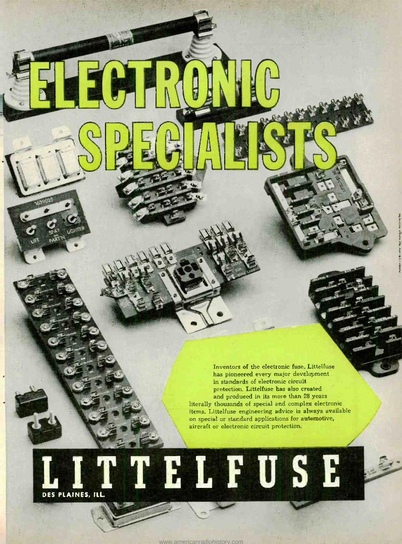
r;4- _._
11171, ti vs.\,1.` v*':1\
s
Inventors of the electronic fuse, Littelfuse has pioneered every major development in standards of electronic circuit protection. Littelfuse has also created and produced in its more than 28 years
literally thousands of special and complex electronic items. Littelfuse engineering advice is always available on special or standard applications for automotive, aircraft or electronic circuit protection.
LITTELFUSE DES PLAINES, ILL.
r!,
www.americanradiohistory.com

...another
MALLORY service -engineered
product
There's extra life in this NEW MALLORY Vibrator
Contact "bounce" and chatter are eliminated in this latest Mallory self - rectifying vibrator. New dual spring design is the reason. This construc- tion gives clean make - and -break, and provides dynamically balanced self alignment.
COUNT ON THEM FOR LONGER LIFE,
and freedom from occasional early failure ... for extra service without extra cost.
COUNT ON MALLORY, leader in vibrator progress, for con- tinued improvements in performance of all types of vibrators.
Your local Mallory distributor is stocked with the new vibrators, in both shunt drive (shown here) and separate drive models. Order from him now ... and make these your standard replacement for all commercial jobs needing self -rectifying units.
MALLORY P.R. MALLORY & co. Inc.'
P. R. MALLORY & CO. Inc., INDIANAPOLIS 6, INDIANA
Capacitors Controls Vibrators Switches Resistors Rectifier%
Power Supplies Filters Mercury Batteries
94
ELECTRONICS
characteristics of these tubes; a bright light may cause the controller to fire falsely. Therefore, the 0A4 -G should be shielded from outside light. This can be done by enclosing it in a case, painting the bulb black or using a tube shield. The manufacturer paints the 1C21 bulb black; a glow discharge in- side this tube could not be used for visual indication unless part of the paint were scraped away.
When the Fig. 3 type is plugged into the power line, it will immediately fire. This is due to a high -voltage drop across the 1U4 because it is not yet conducting.
All units are adjusted by slowly turning sensitivity control Rl until the unit fires. Then the control is backed up slightly until the unit no longer fires without activation. Sensitivity can be decreased by backing up this control further.
A telephone type carbon microphone unit gave excellent results. They are sometimes obtainable on the surplus market for less than a dollar.
CONTROLLER RCVR
INPUT TRANS 10N TRANS
u u
FROM
OUTPUT STAGE
RCVR SPNR
Fig. 4- Diagram shows controlling sig- nal taken from radio or amplifier.
The sensitivity obtained with a car- bon microphone depends to a large extent on its battery voltage. Ordi- narily this should be between 1.5 -7.5 volts. Use the lowest voltage that still gives the needed sensitivity. Additional voltage only wastes battery power and may ruin the microphone. The unit of Fig. 3 is highly sensitive and when used with a carbon microphone even 1.5 volts will be more than needed for some applications. A series -connected resistor should then be tried to see whether current consumption can be further lowered. Dry cells, storage batteries or low- voltage power supplies can be used to furnish the current.
Parts list for Fig. 3 controller Resistors: 1- 100,000 (see text), 1- 270,000 ohms, 1/2 watt; l-47, 1- 15,000 ohms, I watt; I- 10,000 ohms (see text), 2 watts; 1 -3,000 ohms, 10 watts; 1- 100,000 ohms, potentiometer. Miscellaneous: I- 100 -ma selenium rectifier; I- 05 -af 600 -volt capacitor; I -20 -uf 150 -volt capacitor;
I -80-µf 450 -volt capacitor; I -IU4 and socket; I- 0A4-G and socket; I-dpdt plate relay, approxi- mately 5,000 ohms (Guardian 200 series, Potter & Brumfield model LMII or equivalent); I -input transformer for matching low impedance to grid; I- 6- terminal barrier strip; I- carbon microphone and battery, or PM speaker; I- chassis; I- shield for 0A4-G; I -knob.
However, if a low -voltage power supply is used, it must be well filtered.
A PM speaker connected directly across the input transformer primary, as in Fig. 3, can be used for a micro- phone. Then a power- consuming micro- phone current supply is unnecessary because the speaker generates voltages when audio signals reach it. Sensitivity
RADIO -ELECTRONICS
www.americanradiohistory.com

ELECTRONICS
is much lower than it is with a carbon microphone, yet it is more than needed for many applications when used with the more sensitive controller of Fig. 3.
Use speakers with heavy Alnico mag- nets and large diaphragms which are more sensitive than those with lighter magnets or smaller diaphragms.
For situations such as recording intermittent radio announcements the controlling signal is taken directly from the low- impedance output of a radio or amplifier (Fig. 4). The poten- tiometer is used to reduce high noise level which might otherwise cause the controller to fire falsely. It also acts as a second sensitivity control.
ÌÑPUT CKT
CONTROLLER INPUT TRANS
j"
L
C CAN BE PLACED HERE INSTEAD
FROM
STAGE
RCVRSPKR
Fig. 5- Adding interference filter.
When connected to a receiver the controller can be adjusted to respond to a CW signal, voice, code or music on a continuous carrier. Any "click" sounds heard in the receiver loud- speaker may also activate the con- troller if it is adjusted to respond to a weak signal. Fig. 5 shows a filter that can be used to reduce the effect of clicks. Here, too, values of L and C may be selected experimentally.
Special connections It may sometimes be necessary to
use the same microphone for sound switch operation as for the input of an amplifier such as a paging system or intercom. Fig. 6 shows a method that
TO INPUT
CKT
CONTROLLER INPUT TRANS
iN
1.5-9V
I
CARBON MIKE
AMPL INPUT TRANS
GPoD
B-
Fig. 6- Single microphone serves con- troller and amplifier or intercom.
works well with battery, ac dc or ac type amplifiers. The amplifier input transformer isolates the units. Its pri- mary impedance will reduce circuit sensitivity slightly, but the battery voltage can be raised to compensate.
Any other method that does not isolate the units will result in a high hum level, possible short circuits and shock hazard unless the amplifier ground and sound -switch B minus are permanently connected to the same side of the power line.
When the controller is used with a microphone, it will be more sensitive to a narrow band of frequencies or to some particular types of sounds. This selective response characteristic seems to be caused by microphone resonances and sometimes varies considerably with different microphones. END
MARCH, 1956
. another
MALLORY ser' ice-engineered
product
..f
Your best choice in wire-wound resistors
Whenever you replace a wire -wound bleeder, load resistor or voltage
divider, you can make the job sure by using Mallory vitreous enamel resistors. From the inside out, they're built for real stability and long service.
Low temperature coefficient wire is space wound on a high quality stea- tite core, and is protected by a special non -porous, non -alkaline
enamel coating that protects perma- nently against moisture and cor- rosion. A special design of the terminal bands assures fool -proof connection.
Mallory wire -wounds run cool, for they are conservatively rated under actual inside- chassis service. Your
Mallory distributor carries them in a complete range of resistance values ... in the popular 10 -watt size illus- trated, and in 5, 20, 50, 100 and
200 -watt ratings. See him today!
C.apacitcrs Controls lñbrators Switches Resistors Rectifiers PDwer Supplies Filters
Me -cury Batteries
MALLORY P.R. MALLORY A CO. Inc.
P. R. MALLORY L CO. Inc., INDIANAPOLIS. 6, INDIANA
95
www.americanradiohistory.com
MR. SERVICE DEALER! INVEST IN .. .
YOUR FUTURE IN COLOR TV SERVICE
AND EQUIP YOUR SHOP FREE. DURING THE FABULOUS
PHILCO SHARE afetf PROFIT DIVIDEND OPPORTUNITY
That's right! This is the year to equip for color and by con- centrating your radio and TV Parts and Accessory purchases on Philco, you can earn FREE Philco color and B/W Test Equipment and Parts and Accessory Dividends ... all at no extra cost! SHARE and PROFIT dividends go to work for you immediately ... building EXTRA 100 c profits because they cost you nothing. Sell them for full profit or put them to work in your own shop. Make your business prosper like never before! Now is the time to equip yourself for color servicing ... FREE. See your Philco Distributor for details.
NO LIMIT TO WHAT YOU CAN EARN Order your Parts and Accessories, then pick the dividends you need. Stock up on genuine Philco Parts and Accessories and earn the dividends of your choice through valuable SHARE and PROFIT stamps you receive with each pur- chase. SHARE and PROFIT stamps are redeemable at your Philco Distributor's for the dividends of your choice.
PHILCO PUTS YOU IN THE COLOR SERVICE BUSINESS WITH ONE COMPACT INSTRUMENT
PHILCO UNIVERSAL COLOR BAR AND DOT BAR GENERATOR Model 7100
It's new ... highly efficient ... designed to color reproduction and make accurate con - provide the widest possible variety of funs- vergence adjustments in any color receiver tions in the minimum amount of space. made. In conjunction with your present PHILCO MODEL 7100 can be used to corn- monochrome equipment, it gives you com- pletely trouble -shoot circuits associated with plete color service facilities!
PLUS OTHER VALUABLE FREE DIVIDENDS LIKE THESE Store Aids and Fixtures Dealer Store Identification Signs
Your Choice of Parts and Accessories 6 HP Lauson Outboard Motor
PHILCO TUBES IMPROVE THE
PERFORMANCE OF ANT TV OR
RADIO RECEIVER
PHILCO CORPORATION ACCESSORY DIVISION PHILADELPHIA 34, PA.
96 RADIO-ELECTRONICS
www.americanradiohistory.com

P O R T A B L E
A I
COUNTER Part II -Probe construction and assembly; adjusting and operating
the counter
By JAMES W. BRAY
THE probe assembly for the photo- tube is shown in Fig. 1 and the photographs. It was made for a previous model and is unnecessarily
elaborate for use here. Considerable machine work is necessary and the job was turned over to a local machinist.
The main probe housing is 2 x 5% inches, including the threaded portion. It may be cut from a 2 x 6 -inch length of brass tubing (latrine flush connector available from any plumbing firm). The threaded portion of the main probe housing consists of the end section from a 100 -ampere fuse cartridge and is sol- dered to the inside of the housing.
The crystal housing is constructed from 1%-inch thin brass tubing with an aluminum or thin brass end piece sol- dered on. At the other end of the 1 5/16 - inch length of tubing is a retaining lip made from the same material as the end piece. The lip is soldered to the edge of the tubing and made to fit inside the knurled cap from the fuse cartridge. The cap fits tightly over the hat -shaped crystal housing and holds it securely. Fig. 2 shows the internal layout of the probe. A simpler unit, shown in Fig. 3, can be constructed more easily with tools usually found in the home work- shop. Either probe simply forms a housing for the crystal, phototube and associated voltage divider and capac- itors. Lighttight construction is a must;
D C-a C G b
SOLDER TO INSIDE OF HOUSING
THREADED PORTION
A -AWN PROBE HOUSING; A -, -SLOT FORC(MX LEADS I,B "XIYI6; A- b- MOUNTING HOLES FOR COVER(3) (2/56TAP) B- TIGHT -FITTINGCOVER(BRASS) ;MOUNTING HOLESTO MATCH A -b C- XTALHOUSING: C-a-ENDPIECE; C- b-RETAINING LIP D- KNURLED CAP I/2 "WIDE(THREADED INSIDE TD FIT PROBE HOUSING)
E- SPRINGS ;E -a-SPRING MDUNTINGS(SEE TEXT)
SIDE VIEW - ASSEMBLED PROBE
Fig. 1 -Probe assembly for phototube.
MARCH, 1956
ELECTRONICS
extraneous light must not reach the phototube! Black Scotch tape is useful for closing light leaks.
A piece of flexible Mumetal shield- ing should be wrapped around the phototube in direct contact with the glass envelope. It can be held in place by wrapping tightly with the above - mentioned tape. This shielding counter- acts the effects of the Earth's magnetic field. If Mumetal is not available, a steel shell of some sort might be used.
After the shield is attached, the tube is fitted into the probe housing with a thickness of sponge rubber between. This will keep the tube and crystal in place. The probe with the screw -cap end was designed to allow quick inspection of the crystal and phototube. However, performance will be just as good with the simpler housing of Fig. 3.
The phototube socket is fitted with a terminal strip (see photo) for con- nection to the coax cables. The strip is separated from the socket by 3/16 - inch spacers s/4 inch long to allow space for mounting the 22- megohm voltage - dividing resistors Rl and the capacitors Cl (see Part I). The spring contacts supplied with the duodecal socket are reshaped at the connection end to allow them to pass through small holes drilled
SPONGE RUBBER UMETAL SHIELD SPACERS TERM STRIP
' END
COVER
6199 xrAL ? SPRINGS L-..iiaar'
SILICONE COUPLING FLUID SOCKET TAGE DIVIDER CRI-CI)
Fig. 2- Cross -sectional view of probe. SPONGE RUBBER
LIGHTWEIGHT ALUMINUM -ANY CONVENIENT SIZE SPRING LIGHTPROOF SHIELD SPRINGS OMITTED
END
COUPLING FLUID
ALUMINUM OR THIN BRASS XTAL CUP
FASTENED TO TUBE ASSEMBLY WITH
SCOTCH BLACK TAPE
Fig. 3- Diagram of a simplified probe.
SELF -TAPPING SCREWS
in back of each socket pin (see photo). In this manner, a lug from each pin con- tact extends through a hole to the back of the socket at which point connection is made. The resistors and capacitors are soldered directly to these lugs.
On top of the terminal strip are two short sections of spacer material which engage the two springs that in turn maintain a slight pressure against the phototube to assure good contact be- tween tube and crystal. Two more sim- ilar spacers are bolted to the end cap of the probe assembly to hold the other end of the springs. Select a spring which will not put too much pressure against the tube, damaging the tube or crystal.
Crystals are available in various sizes and the sensitivity of the instrument is directly related to the crystal size. In this counter a 1 x 1 -inch crystal was used. Crystals as small as % x 1 inch can be purchased, but the 1 x 1 -inch size is recommended. This crystal will give very good performance from a plane at low altitudes and the % x f- inch unit will give good sensitivity for foot -prospecting.
Scintillation crystals are very fragile and should not be subjected to shocks (either physical or erratic temperature change). When ordering, be sure to specify that it is to be used in a portable device with a 6199 tube and the manu- facturer will supply the most rugged.
The probe is connected to the sub - panel with two lengths of RG 58 /U or 59/U coax. These contain the signal from the phototube anode, and high voltage to the probe. The plug is an Amphenol MC3M with all brass fittings removed so that it will fit into the space between the panels. The receptacle, a type PC3F, is mounted on the subpanel.
Probe modification After this counter was completed, an
arrangement came to mind which would greatly increase the usefulness of the instrument. For certain types of sur-
(Continued on page 100)
97
www.americanradiohistory.com
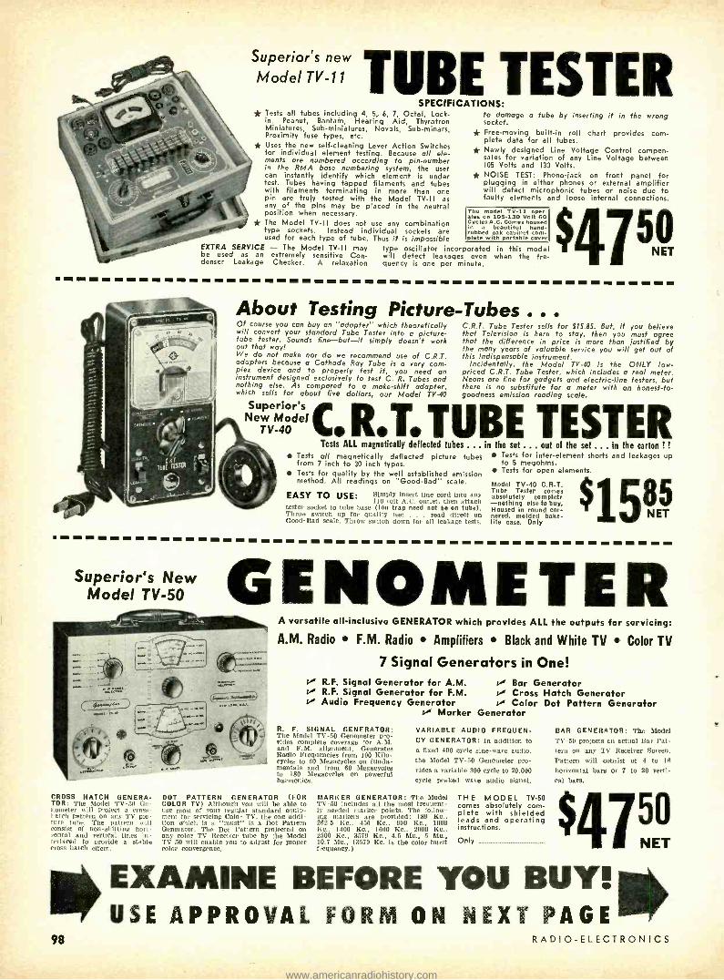
Superior's new
Model TV -11 TUBE TESTER SPECIFICATIONS: * Tests all tubes including 4, 5, 6, 7, Octal, Lock -
in, Peanut, Bantam, Hearing Aid, Thyratron Miniatures, Sub -miniatures, Novels, Sub -minars, Proximity fuse types, etc. * Uses the new self -cleaning Lever Action Switches for individual element testing. Because all ele- ments are numbered according to pin- number in the RMA base numbering system, the user can instantly identify which element is under test. Tubes having tapped filaments and tubes with filaments terminating in more than one pin are truly tested with the Model TV -II as any of the pins may be placed in the neutral position when necessary. * The Model TV-II does not use any combination type sockets. Instead individual sockets are used for each type of tube. Thus it is impossible
to damage a tube by inserting it in the wrong socket.
* Free -moving built -in roll chart provides com- plete data for all tubes.
* Newly designed Line Voltage Control compen- sates for variation of any Line Voltage between 105 Volts and 130 Volts.
* NOISE TEST: Phono -jack on front panel for plugging in either phones or external amplifier will detect microphonic tubes or noise due to faulty elements and loose internal connections.
The model TV -11 oper- ates on 103 -130 Volt 60 Cycles Cycles A.C. Comes housed in a beautiful hand - rubbed oak cabinet com- plete with portable cover
EXTRA SERVICE - The Model TV -II may type oscillator incorporated in this model be used as an extremely sensitive Con- will detect leakages even when the fre- denser Leakage Checker. A relaxation quency is one per minute.
50 N ET
About Testing Picture -Tubes ... Of course you can buy an "adapter" which theoretically will convert your standard Tube Tester into a picture - tube fester. Sounds fine -but -it simply doesn't work out that way! We do not make nor do we recommend use of C.R.T. adapters because a Cathode Ray Tube is a very com- plex device and to properly test it, you need an instrument designed exclusively to test C. R. Tubes and nothing else. As compared to a make -shift adapter, which sells for about five dollars, our Model TV -40
Superior's New Model
TV -40
C.R.T. Tube Tester sells for $15.85. But, If you believe that Television is here fo stay, then you must agree that the difference in price is more than justified by the many years of valuable service you will get out of this indispensable instrument.
Incidentally, the Model TV -40 is the ONLY low - priced C.R.T. Tube Tester, which includes a real meter. Neons are fine for gadgets and electric -line testers, but there is no substitute for a meter with an honest -to- goodness emission reading scale.
.T.TUBE TESTER Tests ALL magnetically deflected tubes ... in the set ... out of the set ... in the carton ! !
Tests all magnetically deflected picture tubes Tests for inter -element shorts and leakages up from 7 inch to 30 inch types. to 5 megohms. Tests for quality by the well established emission Tests for open elements. method. All readings on "Good -Bad" scale
EASY TO USE: Simply insert line cord into any 110 volt A.C. outlet, then attach
tester socket to tube base (Ion trap need not be on tube). Throw switch up for quality test . read direct on Good -Bad scale, Throw switch down for all leakage tests.
Model TV -40 C.R.T. Tube Tester comes absolutely complete -nothing elseto buy. Housed In round cor- nered, molded Bake- lite case. Only 1585
Superior's New GENOMETER Model TV -50
CROSS HATCH GENERA- TOR: The Model TV -50 Ge- nometer will project a cross- ! Itch p*ttem on any TV pie - ture tube. The pattern will consist of non -shifting Mini. minas and vertical lines in- terlaced to provide a stable cross -hatch effect.
98
A versatile all- inclusive GENERATOR which provides ALL the outputs for servicing:
A.M. Radio F.M. Radio Amplifiers Black and White TV Color TV
7 Signal Generators in One! R.F. Signal Generator for A.M. Bar Generator R.F. Signal Generator for F.M. Cross Hatch Generator Audio Frequency Generator Color Dot Pattern Generator
Marker Generator
R. F. SIGNAL GENERATOR: The Model TV -50 Genometer pro- vides complete coverage for A.M. and F.M. alignment. Generates Radio Frequencies from 100 Kilo- cycles to 60 Megacycles on funda- mentals and from 60 Megacycles to 180 Megacycles on powerful harmonica.
BOT PATTERN GENERATOR (FOR COLOR TV) Although you will be able to use most of your regular standard equip- ment for servicing Color TV, the one addi- tion which is a "must" is a Dot Pattern Generator. The Dot Pattern projected on any color TV Receiver tube by the Model TV -50 will enable you to adjust for proper color convergence,
VARIABLE AUDIO FREQUEN- CY GENERATOR: In addition to a fixed 400 cycle sine -wave audio, the Model TV -50 Genometer pro- vides a variable 300 cycle to 20,000 cycle peaked wave audio signal.
MARKER GENERATOR: The Model TV -50 includes all the most frequent- ly needed marker points. The follow- ing markers are provided: 189 Ko., 262.5 Kr., 456 Kc., 600 Kc., 1000 Kr., 1400 Kc., 1600 Kc., 2000 Kc., 2500 Kc., 3579 Kc., 4.5 Mc., 5 Mo., 10.7 Mc., (3579 Kc. is the color burst frequency.)
THE MODEL TV -50 comes absolutely com- plete with shielded leads and operating instructions.
Only
BAR GENERATOR: The Model TV -50 projects an actual Bar Pat- tern on any TV Receiver Screen. Pattern will consist of 4 to 16
horizontal bars or 7 to 20 verti- cal bars.
4l5ó EXAMINE BEFORE YOU WW1& USE APPROVAL FORM ON NEXT PAGE Illmr
RADIO -ELECTRONICS
w
www.americanradiohistory.com

Superior's new Model 670 -A SUPER METER
A COMBINATION VOLT -OHM MILLIAMMETER PLUS
CAPACITY REACTANCE INDUCTANCE
AND DECIBEL MEASUREMENTS
SPECIFICATIONS:
D.C. VOLTS: 0 to 7.5/15/75/150/750 /1,500/7,500 Volts
A.C. VOLTS: 0 to 15/30/150/300/1,500 /3,000 Volts
OUTPUT VOLTS: 0 to 15/30/150/300/1,500 /3,000 Volts
D.C. CURRENT: 0 to 1.5/15/150 Ma. 0 to 1.5/15 Amperes
RESISTANCE: 0 to 1,000 /100,000 Ohms 0 to 10 Megohms
CAPACITY: .001 to I Mfd. 1 to 50 Mfd. (Good -Bad scale for checking quality of electrolytic condensers)
REACTANCE: 50 to 2,500 Ohms, 2,500 Ohms to 2.5 Megohms
INDUCTANCE: .15 to 7 Henries 7 to 7,000 Henries
DECIBELS: -6 to +18, +14 to +38, +34 to +58
ADDED FEATURE:
Built -in ISOLATION TRANSFORMER reduces possibility of burning out meter through misuse.
The Model 670 -A comes housed in a rugged crackle - finished steel cabinet com- plete with test leads and oper- ating instruc- tions.
40 NET
Superiors New Model TV -12
TRANS -CONDUCTANCE TUBE TESTER
TESTING TUBES * Employs improved TRANS -CONDUCTANCE circuit. An in -phase signal is impressed on the input section
of a tube and the resultant plate current change is measured. This provides the most suitable method of simulating the manner in which tubes
actually operate in Radio & TV receivers, ampli- fiers and other circuits. Amplification factor, plate resistance and cathode emission are al correlated in one meter reading.
* NEW LINE VOLTAGE ADJUSTING SYS- TEM. A tapped transformer makes it pos- sible to compensate for line voltage varia-
tions to a tolerance of better than 2 %.
* SAFETY BUTTON -protects both the tube under test and the instrument meter agains-
damage due to overload or other form of im- proper switching.
* NEWLY DESIGNED FIVE POSITION LEVER SWITCH ASSEMBLY. Permits application of sep- arate voltages as required for both plate and grid of tube under test, resulting in improved Trans -Conductance circuit. ALSO TESTS TRANSISTORS
TESTING TRANSISTORS A transistor can be safely and adequately tested only under dynamic conditions. The Model TV -12 will test all transistors in that approved manner, and quality is read di- rectly on a special "transistor only" meter scale.
The Model TV -12 will accommodate all transistors including NPN's, PNP's, Photo and Tetrodes, whether made of Germanium or Silicon, either point contact or ¡unction contact types.
Model TV -12 housed in hand- some rugged portable cabinet sells for only
SHIPPED ON APPROVAL NO MONEY WITH ORDER -NO C.O.D.
Try any of the instruments on
this or on the `acing page for
10 days before you buy. If
completely satisfied then send
down payment and pay balance
as indicated on coupon. No
Interest or Finance Charges
Added! If not completely satis-
fied return unit to us, no ex-
planation necessary.
MARCH, V956
MOSS ELECTRONIC DISTRIBUTING CO., INC.
Dept. D -215, 3849 Tenth Ave., New York 34, N. Y.
Please send me the units checked. 1 agree to pay down payment within to days and to pay the monthly balance as shown. It is understood there will be no finance. interest or any other charges, provided I send my monthly payments when due. It is further understood that should I fail to make payment when due, the full unpaid balance shall become immediately due and payable.
Model 670 -A Total Price $28.40 $7.40 within 10 days. Balance $3.50 monthly for 6 months
Model TV11 Total Price $47.50 511.50 within 10 days. Balance $6.00 monthly for 6 months.
Name.
Address...---
ID Model TV -40 Total Price $15.85 $3.85 within 10 days Balance $4.00 monthly for 3 months.
Model TV50 Total Price 547.50 511.50 within 10 days. Balance $6.00 monthly for 6 months.
None. State
i Model TV -12 Total Price 572.50 522.50 within 10 days. Balance $10.00 monthly for 5 months.
99
www.americanradiohistory.com

t
MERIT, first in exact and universal replacement transformers, yokes, coils -the only manufacturer of transformers, yokes and coils who has complete pro- duction facilities for all parts sold under their brand name.
ELECTRONICS
HOV -42 FOR EXACT REPLACE- MENT IN CBS -COLUMBIA.
Another in the complete MERIT line of exact and universal replacements -the only single source for all your transformer and coil requirements.
Merit MERIT COIL & TRANSFORMER COMPANY
4427 NORTH CLARK STREET CHICAGO 40, ILLINOIS
100
veys it is desirable to have a separate probe, small and mobile to allow its use in out -of- the -way corners and crevices. The counter described here can have this advantage in addition to its self - contained one -piece feature. The only changes necessary are:
1. Make the probe cable long enough to reach well away from the main case; 3 to 4 feet should be the maximum.
2. In place of the probe clamp de- scribed below, make one from spring material shaped like a large fuse clip. Install it on a block to bring it high enough to hold the probe firmly in the mounting blocks described below.
3. Reroute the cable to front of case and eliminate cable clamps so that the cable can be disconnected easily.
OEI ERIOR AI
PROOF dee
"The ONLY sl aas el-
oPent in 10 Years line
Permaline ELIMINATES
RAPID
DETERIORATION
Phototube socket arrangement.
4. Obtain one of the waterproof snap covers of the type used with weather- proof outdoor electrical outlets. Mount this so that it will cover a ,i-inch or larger hole cut in the front of the case near the top. To use the probe outside the case, simply unclip it, remove the coax plug and rethread the cable through the hole in the case.
Installing the probe The probe is mounted in the case on
two Bakelite blocks, made by sawing out curved portions slightly larger than the contour of the probe. Cement thin pieces of sponge rubber on top surfaces. Drill and tap the bottom for mounting.
With the blocks mounted in the case, put the probe in place and bend a piece of 1/2- inch -wide aluminum strap over the probe (see photo). Cut the strap to size, allowing space on each end for mounting, and attach a piece of thin sponge rubber to the underside. Mount one end of the strap rigidly with a screw passing through the bottom of the box. Fasten the other end of the strap with a knurled nut on a longer screw passed through the bottom.
A round piece of sponge rubber is cut and cemented to the inside of the box opposite the crystal end of the probe to cushion it in case the strap comes loose. No opening was made in the case for rays to enter since the aluminum case caused little or no attenuation.
C:0 - t9 ri
because it's guaranteed up to
25 years to: - Resist salt spray and salt air
Resist fumes from chemical plants and oil refineries
Resist severe low temperatures
Resist sunlight and ultra- violet light
Resist deterioration for countless other reasons
PERMALINE TV TRANSMISSION LINE reduces servicemen nuisance calls; means happier customers; provides better signals because of longer life.
Available at leading distributors!
WIRE & SUPPLY CO. 2850 Irving Park Road Chicago 18, III.
RADIO -ELECTRONICS
www.americanradiohistory.com
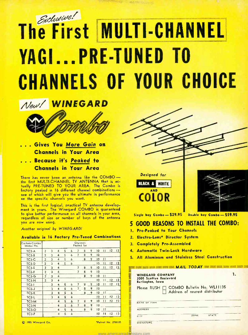
The First MULTI- CHANNEL
YAG1...PRE-TUNED TO
CHANNELS OF YOUR CHOICE
Nee/,/ WINEGARD
. . Gives You More Gain on
Channels in Your Area
e e . Because it's Peaked to Channels in Your Area
There has never been an antenna like the COMBO - the first MULTI -CHANNEL TV ANTENNA that k ac- tually PRE -TUNED TO YOUR AREA. The Combo is
factory peaked in 16 different channel combinations - one of which will give ycu the ultimate in performance on the specific channels you want.
This is the first logical, practical TV antenna develop- ment in years. The Winegard COMBO is guaranteed to give better performance on all channels in your area, regardless of size or number of bays o= the antenna you are now using.
Another original by WINEGARD!
Available in 16 Factory Pre -Tuned Combinations Custom-Combo
Model No. Channels
Peaked for
TC3-A 2 3 4 5 6 7 8 9 10 II 12 13
TC3-B 2 3 4 5 6 7 8 9 10
TC3-C 2 3 4 5 6 8 9 10 II TC3-D 2 3 4 5 6 10 II 12 13
TC3-E 2 3 4 7 8 9 10 II 12 13
TC3-F 2 3 4 7 8 9 10
TC3-G 2 3 4 8 9 10 II TC3-H 2 3 4 10 II 12 13
TC3-I 3 4 5 6 7 8 9 10 II 12 13
TC3-J 3 4 5 6 7 8 9 10
TC3-K 3 4 5 6 8 9 10 II TC3-L 3 4 5 6 10 II 12 13
TC3-M 4 5 6 7 8 9 10 II 12 13
TC3-N 4 5 6 7 8 9 10
TC3-O 4 5 6 8 9 10 II TC3-P 4 5 6 10 11 12 13
® 1955 Winega d Co. Patent No. 2700105
Designed for
BLACK & WHITE
COLOR
Single bay Combo - $29.95 Double bay Combo - $59.95
5 GOOD REASONS TO INSTALL THE COMBO: 1. Pre- Peaked to Your Channels
2. Electro -Lens* Director System
3. Completely Pre -Assembled
4. Automatic Twin -Lock Hardware
5. All Aluminum and Stainless Steel Construction
MAIL TODAY
WINEGARD COMPANY 3000 Scotten Boulevard Burlington, Iowa
Please RUSH COMBO Bulletin No. WLII135 Address of nearest distributor
1.
NAME OF FIRM
ADDRESS
CITY ZONE STATE
SIGNATURE
www.americanradiohistory.com
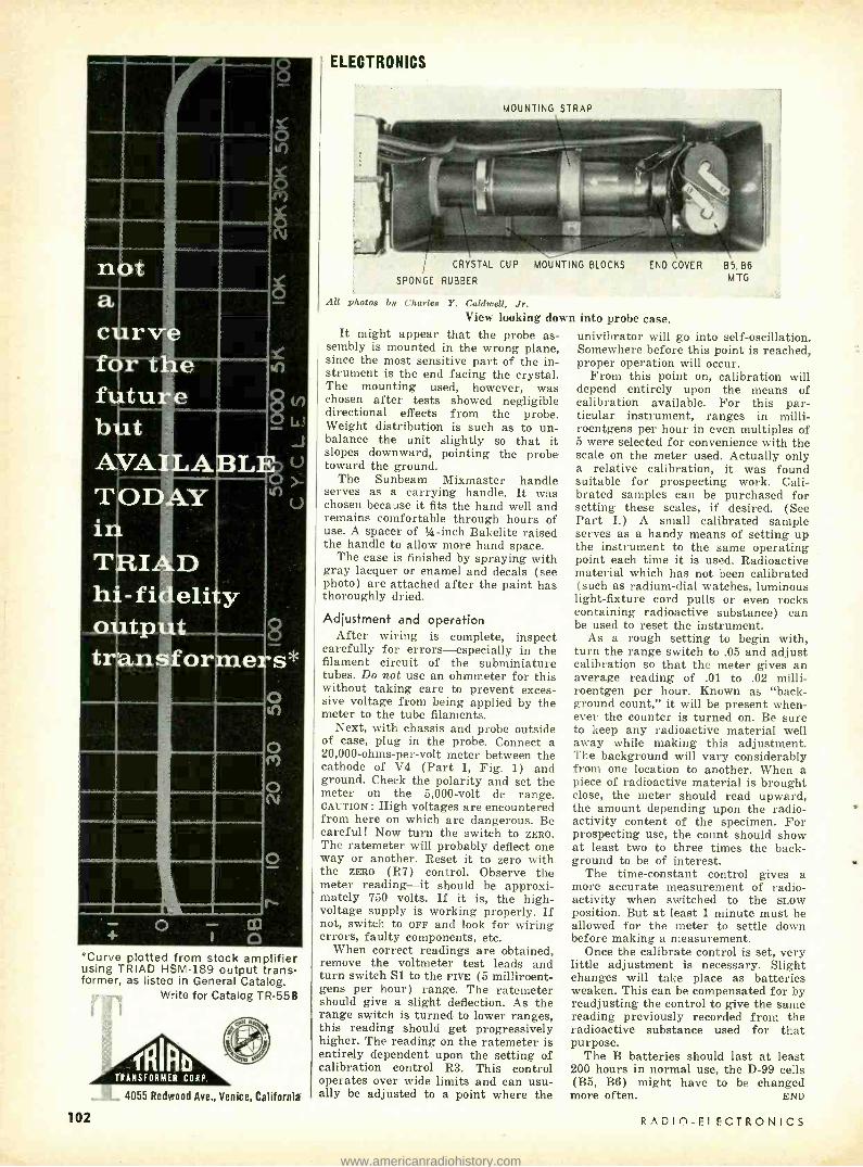
*Curve plotted from stock amplifier using TRIAD HSM -189 output trans- former, as listed in General Catalog.
Write for Catalog TR -558
4055 Redwood Ave., Venice, California
ELECTRONICS
MOUNTING STRAP
CRYSTAL CUP MOUNTING BLOCKS
SPONGE RUBBER
END COVER
All photos by Charles Y. Caldwell, Jr. View looking down into probe case.
It might appear that the probe as- sembly is mounted in the wrong plane, since the most sensitive part of the in- strument is the end facing the crystal. The mounting used, however, was chosen after tests showed negligible directional effects from the probe. Weight distribution is such as to un- balance the unit slightly so that it slopes downward, pointing the probe toward the ground.
The Sunbeam Mixmaster handle serves as a carrying handle. It was chosen because it fits the hand well and remains comfortable through hours of use. A spacer of h -inch Bakelite raised the handle to allow more hand space.
The case is finished by spraying with gray lacquer or enamel and decals (see photo) are attached after the paint has thoroughly dried.
Adjustment and operation After wiring is complete, inspect
carefully for errors -especially in the filament circuit of the subminiature tubes. Do not use an ohmmeter for this without taking care to prevent exces- sive voltage from being applied by the meter to the tube filaments.
Next, with chassis and probe outside of case, plug in the probe. Connect a 20,000- ohms -per -volt meter between the cathode of V4 (Part I, Fig. 1) and ground. Check the polarity and set the meter on the 5,000 -volt do range. CAUTION: High voltages are encountered from here on which are dangerous. Be careful! Now turn the switch to ZERO. The ratemeter will probably deflect one way or another. Reset it to zero with the ZERO (R7) control. Observe the meter reading -it should be approxi- mately 750 volts. If it is, the high - voltage supply is working properly. If not, switch to OFF and look for wiring errors, faulty components, etc.
When correct readings are obtained, remove the voltmeter test leads and turn switch S1 to the FIVE (5 milliroent- gens per hour) range. The ratemeter should give a slight deflection. As the range switch is turned to lower ranges, this reading should get progressively higher. The reading on the ratemeter is entirely dependent upon the setting of calibration control R3. This control operates over wide limits and can usu- ally be adjusted to a point where the
8 5, 86 M TG
univibrator will go into self -oscillation. Somewhere before this point is reached, proper operation will occur.
From this point on, calibration will depend entirely upon the means of calibration available. For this par- ticular instrument, ranges in milli - roentgens per hour in even multiples of 5 were selected for convenience with the scale on the meter used. Actually only a relative calibration, it was found suitable for prospecting work. Cali- brated samples can be purchased for setting these scales, if desired. ( See Part I.) A small calibrated sample serves as a handy means of setting up the instrument to the same operating point each time it is used. Radioactive material which has not been calibrated (such as radium -dial watches, luminous light- fixture cord pulls or even rocks containing radioactive substance) can be used to reset the instrument.
As a rough setting to begin with, turn the range switch to .05 and adjust calibration so that the meter gives an average reading of .01 to .02 milli - roentgen per hour. Known as "back- ground count," it will be present when- ever the counter is turned on. Be sure to keep any radioactive material well away while making this adjustment. The background will vary considerably from one location to another. When a piece of radioactive material is brought close, the meter should read upward, the amount depending upon the radio- activity content of the specimen. For prospecting use, the count should show at least two to three times the back- ground to be of interest.
The time -constant control gives a more accurate measurement of radio- activity when switched to the now position. But at least 1 minute must be allowed for the meter to settle down before making a measurement.
Once the calibrate control is set, very little adjustment is necessary. Slight changes will take place as batteries weaken. This can be compensated for by readjusting the control to give the same reading previously recorded from the radioactive substance used for that purpose.
The B batteries should last at least 200 hours in normal use, the D -99 cells (B5, B6) might have to be changed more often. END
102 RADIO- ELECTRONICS
www.americanradiohistory.com

Prepare for a Good Paying Job -Or Your Own Business
Learn PRACTICAL RADIO -Tr" h
of equipmast 1 seed you while you *coin w th me ... for valuable
riece .. .
I Will Train You at Home In
RADIO-TELEVISION On Liberal No Obligation Plan!"
is I the new Sprayberry Traini tension receiver, tuilt end lest
sections or greatest intrust"
lue
now offer this fins moceen ox score to help you lean pact
Television servicing.
You will build this powerful sho wave and broadcast superhet ra .
receiver for valuable shop inslr lion practice.
. (tJ
- pxx.x.r±4
New Equipment! New Lessons! Enlarged
Course! The true facts are yours in my
big new catalog ... YOURS FREE ... JUST MAIL COUPON!
I can train and prepare you in as little as
10 months to step into the big opportunity Radio -Television service field. Train without signing a binding contract . .. without obli- gating yourself to pay any regular monthly Frank L. Sprayberry
amounts. You train entirely at home in spare President, Sprayberry
hours ... you train as fast or as slowly as Academy of Radio
you wish. You'll have your choice of THREE SPRAYBERRY TRAINING PLANS ... planned for both beginners as well as the more experienced man. Get the true facts about the finest most modern Radio- Training avail-
able today ... just mail the coupon for my big new 56 page fact -filled
catalog plus sample lesson -both FREE.
Train the Practical Way -with Actual Radio -Television Equipment
My students do better because I train both the mind and the hands. Sprayberry
Training is offered in 25 individual training units, each includes a practice giving
kit of parts and equipment ... all yours to keep. You will gain priceless practical
experience building the specially engineered Sprayberry Television Training Re-
ceiver, Two -Band Radio Set, Signal Generator, Audio Tester and the new Spray -
berry 18 range Multi- Tester, plus other test units. You will have a complete set
of Radio -TV test equipment to start your own shop. My lessons are regularly
revised and every important new development is covered. My students are corn-
pletely trained Radio- Television Service Technicians.
NEWEST
DEVELOPMENTS
Your training covers U H F, Color
Television, F M, Oscilloscope
Servicing, High Fidelity Sound
and Transistors,
See for Yourself. .. Make Your Own Decision
...Mail Coupon Today!
The coupon below brings you my big new catalog plus an actual sample Sprayberry Lesson. I invite you to read
the facts ... to see that I actually illustrate every item
I include in my training. With the facts in your hands,
you will be able to decide. No salesman will call on you.
The coupon places you under no obligation. Mail it now,
today, and get ready for your place in Radio -Television.
SPRAYBERRY ACADEMY OF RADIO 111 North Canal Street, Dept. 20 -Jr Chicago 6, Illinois
Mail This Coupon For Free Facts and Sample Lesson
you but parry Tesler ..1 g range
Nilltamnete readings outpue met« and condenser
and resists substCetios selector.
In addition to mocern lesson training, I also give you plenty of home practice on actual Radio -Television equipment ... yet. will build and use the units shown here plus many more. Al this equipment is yours to
keep ... keep everything You need to sat up your shop.
MARCH, 1956
SPRAYBERRY ACADEMY OF RADIO Dept. 20-J, 111 N. Canal St.. Chicago 6, III.
Please rush all information on your ALL -NEW Radio -Tele-
vision Training Plan. I understand this does not obligate ene
and that no salesman will call upon me. Include New Cata-
log and Sample Lesson FREE.
Name Age
Address
City Zone State
103
www.americanradiohistory.com

ELECTRONICS
ONE of the most fascinating branches of electronics is that of counters and computers. Devices of this type, with
their phenomenal speed and accuracy, appear to the layman to be somewhat of a near -miracle. To describe some of the more advanced computers as "electronic brains" is not too far from the truth -such equipment, in their special use, simulate functions of the human brain very closely.
The basic "cell" of nuSt conventional counters and computers is the vacuum tube, usually working in what are known as binary units, or "bits." The reason for this choice of units is that a single tube can be relied upon only to indicate one of two states: when it is conductive (passing cathode cur- rent) ; when it is nonconductive (be- yond grid cutoff). It would be im- practicable to expect a tube to cope reliably with three states such as: off (past grid cutoff) ; half -on (low cathode current); fully on (high cathode cur- rent). Tube spread and deterioration could cause the half -on and fully on states to lie too close together after a period of use, and there would be a risk of misinterpretation.
A tube capable of counting in 10's or decades would overcome this trouble. This type of tube exists, a typical one being the EIT made by Mullard in England. This tube may be used in cascade with others with the result
Fig. 1- Internal construction of EIT.
104
Elcciromc
mounter Tithe fl special type of C -R tube, the EIT can count in tens
By J. R. DAVIES
that when one tube has reached what would otherwise be "10" it triggers the next tube in the circuit and slips back itself to zero. Thus, a group of three tubes can be used to count to 999: the first tube counts digits and triggers the second tube at every decade; the second tube counts in 10's and similarly triggers the third tube which counts in 100's.
To add to its versatility, each of the EIT tubes not only counts but also indicates its number on an easily read built -in fluorescent screen. The photo shows the tube and its indicating screen. The top counting speed is 30 kc.
Construction and circuitry The internal construction of the EIT
is shown in Fig. 1. Fig. 2 illustrates a typical circuit.
In Fig. 1 the cathode emits an elec- tron stream which passes through grid G1 and the beam -forming electrodes B1, B2. The stream next passes through G2 and, being at B -plus potential, is accelerated. Leaving G2 the electron stream is in the form of a thin ribbon - shaped beam, the major width of the ribbon being at right angles to the sur- face of the paper.
The beam now travels through de- flector plates D1, D2 to G4. However, G4 is perforated and the narrow beam is not wide enough to pass through more than one of its 10 apertures be- fore it reaches segmented plate A2. This plate has apertures also and the beam has to pass through one of these before it finally strikes fluorescent con- ductive target T. The apertures in A2 are staggered alternately, thus allow- ing the fluorescent indications on the target to be similarly staggered for well spaced out readings. In addition, A2 is sectionalized, preventing the beam from spreading too widely after it has passed through the particular aperture it has chosen in G4.
Due to the narrowness of the beam, once it has settled at a particular aper- ture in G4, it remains locked there until some external force is applied to move it elsewhere. Deflector plates D1 and D2 are arranged so that they pro-
vide this beam -moving force in a hori- zontal plane relative to the surface of the paper in Fig. 1. Plate D2 has a positive potential higher than that on Dl. Thus the beam is attracted, when the tube is first switched on, to the furthermost right -hand aperture of G4. This position corresponds to 0 on the fluorescent target.
Fig. 2- Schematic of a typical cir- cuit in which the EIT may be used.
When a positive counting pulse of the correct shape (provided by a suit- able input filter) is injected into the circuit of Fig. 2 at A, D1 becomes momentarily more positive than D2 causing the beam to move to the left. However, the shape of the pulse is such that the beam moves only one step (or one aperture in G4) whereupon it then stops and becomes locked in its new position. Successive pulses cause the beam to move to successive aper- tures. On the arrival of the tenth pulse, the beam passes from the tenth aper- ture of G4 and strikes Al. Current is drawn by this plate, causing a nega- tive pulse to appear at point B (Fig. 2). This negative pulse triggers an external circuit which does two things: it applies a reset pulse to the tube so that it may return to zero; it passes a counting pulse to the next decade -counting tube along the line.
The reset pulse consists of a nega- tive pulse injected at C and causes Gl to go negative, whereupon the tube cuts off altogether. When the negative pulse at G1 ceases, the counting cycle starts up all over again with the electron beam of the tube passing through the furthermost right -hand aperture in G4.
The tube is then ready to count another decade. END
RADIO -ELECTRONICS
www.americanradiohistory.com

NEW CHASSIS PUNCHES
j A complete line of precision punches,
featuring Walsco-Pioneer "Taper Wedge'
design to speed more accurate hole
punching... any size, any shape. NEW TEKNI-LABELS A complete line of handy title and design
decals for speedy labeling of
electronic equipment.
NEW PHONO-RECORDER
DRIVES & BELTS
the first, complete line of vital replacements for all major phonographs
and tape recorders. Packaged in
convenient kits or sold separately.
000 CHEMICALS A complete line of chemical specialties, including cements, solvents, and contact
cleaners in bottles and handy spray cans.
HARDWARE & SERVICE AIDS
A complete line of essential small component hardware, packaged in
reusable plastic boxes Dial cord, feedthru bushing, and other valuable
vice aids.
If it makes serve
faster, easier,
more profitable... you'll find it in the
COMPLETED LINE
.::...... .M..::r 1 :::, /111111111 ;...,.; ::::::; MIMI I...r,IIII "NM AM/ ELECTRONICS CORPORATION
3602 Crenshaw Blvd.
Los Angeles 16, Calif. ALIGNMENT TOOLS
A complete line of tools for every
servicing job
www.americanradiohistory.com

NOW! PASS
FCC LICENSE
EXAMS! easier . e e faster!
Train for
Radio -TV's
best pay
jobs!
Answers
almost 2200
typical F C C
examination
questions!
A complete guide for getting
your license as a commercial operator in
RADIO OR TELEVISION
STATIONS
SHIP OR MARINE RADIO
AIR LINE RADIO COMMUNICATIONS,
etc.
Here, at last, is a low- priced, easy - to- understand book that gets right
down to brass tacks in helping you get your com- mercial radio operator license and any one of the many big -pay jobs for which it qualifies you!
LICENSE MANUAL FOR RADIO OPERA- TORS by J. Richard John- son (W2BDL) is a com- plete guide to FCC License Examination subjects. Best of all, it's written so you can easily understand and remember it. It states the questions . . . then gives you clear, concise answers.
This book covers ALL eight examination elements, not just some of them. Brings you full details of the latest communications laws . .. and all other per- tinent data from electrical fundamentals to television and related subjects.
Whether you plan to take the Federal Communications Commission examination for either your Ist. 2nd or 3rd class 'phone or telegraph license, this big book will guide you ALL of the way!
EXTRA "BONUS" ! At not one cent of extra cost you also get a 32 -page Supple- ment. This brings all parts of Johnson's LICENSE MANUAL FOR RADIO OPERATORS fully up to the minute as regards the recent changes in Examina- tion Elements I and 2. Many people are not even aware that these changes exist!
10 -DAY FREE EXAMINATION Dept. RE 36. RINEHART & CO., INC. 232 Madison Ave., New York I8, N. Y. 1
Send Johnson's LICENSE MANUAL FOR RADIO I OPERATORS (including the new 32 -page supplement en Element, 1 and 2) for 10 -day FREE EXAMINA- I TION, If I decide to keep them, I will promptly ,end you 55.00 (plus a few cents postage) in full payment. 1 Otherwise I will return book postpaid and owe you nothing.
Name
Address
City, Zone, state ,,UTBrns U.S.A. -Prre $5.50 rash with order. Money bark if
book ,. .et. nevi ,, Irr vs
Rinehart Books are sold by leading book stores
106
1
1
I
I
MISCELLANY
THE FUND REACHES $11,874.73
the `2nd' trip up
Costs you!
RECENTLY the Help- Freddie -Walk Fund received some wonderful news
from Herschel Thomason, service tech- nician of Magnolia, Ark., and father of 7- year -old Freddie.
As most of our readers know, Freddie was born without arms or legs. Some time ago, he was fitted with legs and has learned to walk and run almost as well as normal children. Just a few months ago, his father writes, he re- ceived his right arm, a mechanical ar- rangement fitted to his shoulder and manipulated by moving his shoulder up and down. Already Freddie has learned to feed himself and pick up and hold various items, including a glass, with his split utility hook. Freddie's progress has amazed everyone, but he was so anxious to get his arm and so deter- mined that he would use it well that he has been able to cover a great deal of ground in a short time.
When Freddie received his arm, he was also fitted with a new pair of legs, which meant learning to balance him- self and walk all over again. Changes in the mechanical appliances upon which he depends must be made regularly, and although at present Freddie is not as tall as the average 7- year -old, it is hoped that in the near future he will reach his "normal growth."
Needless to say, such changes are horribly expensive ... and Freddie still has to be fitted with another arm. Dur- ing the past years, our readers have been extremely generous -the Fund has turned over to Freddie's parents almost $12,000 -but we ask you to be even more generous in 1956, so Freddie's progress will not be held up because of lack of funds. His parents are doing all they can, not only financially, but in giving to Freddie love, encouragement, faith and determination.
Any contribution you might be able to make will be acknowledged and sincere- ly appreciated, no matter how large or small it may be. Make out all checks, money orders, etc., to Herschel Thoma- son. Send all contributions to:
Help- Freddie -Walk Fund c/o RADIO -ELECTRONICS Magazine 25 West Broadway New York 7, N.Y. RADIO -ELECTRONICS Contributions as of Oct. 10, 1955 $11,214.23 FAMILY CIRCLE Contributions 602.50 Anonymous, Waterbury, Conn 10.00 Jack Farrance, Falls Church, Va 3.00 Thomas Jaski, San Mateo, Calif 10.00 Mary Krull Passaic, N. J 10.00 C. R. Mitchell, Newark, Ohio 2.00 Margaret Morrissey, Worcester, Mass 6.00 M. Moses, Portsmouth, Ohio 5.00 Mr. & Mrs. Alois Pommer, Allentown, Pa 5.00 M. Rosenburg, River Vale, Westwood, N. J. 2.00 Ed. Thornborrow, Great Falls, Mont 5.00
TOTAL CONTRIBUTIONS as of Jan. IO, 1956 $11,874.73
too Antenna Call -Backs due to broken leads
With
the mosley
` Y -T Y' TV installation profits vanish when you're called back to repair a wind - whipped lead -in connection!
Protect those profits - and your reputation - by using the Mosley "Y -TY" on each antenna you in- stall.
A sturdy clamping member locks around the complete line ... takes the strain off the fragile copper strands! The plated brass connect- ing straps bend and twist to fit any antenna type.
Antenna Terminal Connector No. 263, List Price $ .80
You make More Installation Profits ...when you use Premium Quality
MOSLEY TV ACCESSORIES
At Radio and Television Parts Distributors, Coast -to- Coast.
Mcir/eq &ectelut. .944 8622 51. CHARLES ROCK ROAD, ST LOUIS t4, MISSOURI
Si vous lisez le francais technique, vous devez lire
ELECTRONIQUE INDUSTRIELLE
la grande revue francaise de technique moderne Specimen gratuit sur demande
EDITIONS RADIO 9, rue Jacob - Paris 6° - France
RADIO -ELECTRONICS
www.americanradiohistory.com

sells your service while he sells CBS Tubes*
`Mln ofork, Guaranteed by w,
Good Housekeeping
omen, oos'
*On the CBS Television Network.
"This portion of the Garry Moore Show
is brought to you in behalf of radio and television service -dealers who use
and recommend CBS Tubes. cThat's the way you're introduced.
Later, I focus right on you - like this:
... television sets require trained
service -dealers to keep them in good
condition. And believe me, a qualified
service -dealer is a trained technician.
He has spent a lot of time and effort
studying electronics, and a substantial
amount of money for technical equipment"
"See how CBS -HYTRON works side by side
with you. The easy way for you to cash
in is to use and recommend CBS Tubes.
Because I keep reminding my listeners there are no better tubes made than CBS Tubes - and they have the Good Housekeeping Guaranty Seal."
You'll build profitable customer confidence
and sales when you recommend CBS Tubes ... the tubes with the Good Housekeeping Guaranty Seal.
Garry Moore
famous CBS Television Star
CBS- HYTRON, Danvers, Massachusetts . . . A DIVISION OF COLUMBIA BROADCASTING SYSTEM, INC.
107 MARCH, 1956
www.americanradiohistory.com

fliland "[GOLDEN SERIES" HIGH FIDELITY
HF155 etc FM-AM HI-FI TUNER
Here is quality FM (response ± 0.5 db, 20 to 20,000 cps) and improved AM, both most perfectly realized for finest reception in a unit only 4" high -at a very reasonable price. Outstanding fea- tures: Sensitivity, FM -3 microvolts for 20 db of quieting; AM -5 microvolts for 1.5 volts output; separate RF stage on FM and AM; discriminator with dual limiters; cathode follower with 2 outputs; AFC; flywheel tuning, FM di -pole antenna, etc.
NEW! HI -FI SOUND FOR TV! Now, make your TV sound "come alive ". Just plug the new RAULAND TV55 Tuner into the unit above and enjoy TV sound through your hi -fi system. Exclusive with RAULAND. See it- 'hear it soon.
( 20 -WATT HI -FI AMPLIFIER
Designed for those who appreciate the finest in Hi -Fi reproduction -the very best for less. Features: Full 20 watts output; response, ± 0.5 db, 20 to 40,000 cps; 6 response curves (compen- sation for all record types); 5 inputs for complete hi -fi versatility; separate bass, treble controls; contour and volume controls; variable damping control; rumble filter, plus many other deluxe features. In compact cabinet, 4" high.
HANDSOME "SPACE- SAVER" DESIGN RAULAND matching "Space- Saver" units are decorator -styled in smart char- coal black with marbleized gold finish, control panels in soft brushed brass. No cabinets required -fit beautifully any- where. (Extension shafts available for behind -panel mount.)
Hear these RAULAND Hi -Fi
units at your dealer's, or write
for full details
RAULAND -BORG CORPORATION 3515 W. Addison St., Dept. A, Chicago 18, III.
108
MISCELLANY
ELECTRONIC TERMS, OUR ABBREVIATIONS
A NUMBER of our readers have pointed out that "Our Abbrevia-
tions of Electronic Terms" (page 138, January, 1956) was useful chiefly to the person who wished to find the abbreviation for a certain term. But because the items were indexed by terms, the person who found an un- known abbreviation was often at a loss. The letter E, for example, might stand for emitter, in which case the reader would find it without difficulty. But it might also stand for voltage and he would not be likely to look for an E among the V's.
We have therefore prepared this revision of the January list indexed according to abbreviations. This repre- sents the forms consistently used in our magazine. As pointed out in the January issue, many of these are abbreviated in art work only and are usually spelled out in the text. Periods are omitted except where the omission would cause confusion. Abbreviations in lower -case letters are so printed in text -are capitalized in artwork. Those printed in capitals are capitalized in both text and artwork.
ABBREVIATION ELECTRONIC TERM no ACC ADJ of etc of choke AFT agc AM amp AMPL ANT ape ATTEN AUTOTRANS avc AWG b or base BATT BC! hto
BTO c (of transistors) C. CAP CALIB oath (K on tube
diagrams) CATH FOLL CH (or CHOKE) CHAN CHG CKT CKT BRKR coax COM CON D CONN CONI CONV CONVTR counter and C -R CRO CW db dc dec DC REST DEFL DEMOD DET df DI ELEC DISCH DISCRIM dpdt dost doe DYN dx e E E (sometimes V in
transistor dia-
ELEC ms)
ELECT emf
EQUIV ERASE HD ERP EXT
alternating current automatic chroma control adjacent audio frequency automatic frequency control audio -frequency choke audio -frequency transformer automatic gain control amplitude modulation ampere(s) amplifier antenna automatic phase control attenuator autotransformer automatic volume control American wire gauge base (of transistors) battery broadcast interference beat frequency oscillator Barkhausen oscillation blocking tube oscillator collector capacitor (capacitance) calibrate cathode
cathode follower choke channel charge circuit circuit breaker coaxial common conductor connection control convergence converter counter electromotive torce cathode -ray (tube. etc.) cathode -ray oscilloscope continuous wave decibel direct current double cotton covered (wire) direct current restorer deflection demodulator detector direction finder dielectric discharge discriminator double pole double throw double pole single throw double silk covered (wire) dynamic distance emitter (transistor) potential
voltage electrio electrode electromotive force enamelled (wire) equivalent erase head effective radiated power external or extension
MICRONS PUTS AN END TO ALL
LINE VOLTAGE HEADACHES Insure lull s .e, s:rength and sync of TV pic- ture when low line voltage shrinks or weak- ens picture. Ill units have baked wrinkle fin- ish, but t -in i.0 receptacles and 6 line cord.
NEW! LVS 153 LINE VOLTAGE STABI LIZER A popularly priced, qual- ity automatic voltage reg- ulator. Stabilizes line for TV, radio or industrial use where load is con- stant. Input may vary be- tween 95-130 volts, nom - leal output voltage regu- lated ±3%. One model covers 125 to 300 watt range. Built -in automatic relay turns stabilizer on with equipment. Wave - shape is free from distor- tions and frequency sen- sitivity of resonant type regulators. size: 1O "x5 "x81/ " high Weight: 10 lbs. List Price: 29.95 DEALER NET: 17.95
NEW! LVB -350 METERED VARIABLE VOLTAGE ADJUSTER Constant duty unit used as step -up or step -down. Automatically operated - turns on and off with set. Easily adjusted by man- sally turning 7- position rotary switch until built- in voltmeter reads 115 volts output. Has input switch positions for 90 thru 130 volts. Watts: 350 Weight: 7 lbs. Size: 7 "x31/4 "x37 /a" high Mounting Centers:
5 "x21/= List Price: 24.75
DEALER NET: 14.85 LVB -117 LINE
VOLTAGE BOOSTER Multi tap selector switch restores line voltages of 90 thru 135 volts to 117 volts output. Calibrated neon indicator permits exact voltage adjustment. Automatically operated- turns on and off with set. Overload fuse protects against unsafe line in- creases. Watts: 350 Weight: 4 lbs. Size, 41/a "x31/4 "x37 /a"
high Mounting Centers:
2 3/16 "x21/2" List Price: 17.95 DEALER NET: 10.80
LVB "Jr." UP -DOWN VOLTAGE BOOSTER
Reliable, budget - priced unit, Single switch pro- vides 10 volt boost or drop or straight- through line. Watts: 350 Weight: 3 lbs. Size: 27/8".31/4"a37/8"
high Mounting Centers:
1 11/16".21/2" List Price: 6.75 DEALER NET: 4.05
PICTURE TUBE REJUVENATOR Boosts CRT brightness. Units are resin treated; new design insures cool and buzz - free operation; 8 oz.
List Price 148B: Parallel sets, 6 leads $2.00 it49C: Parallel sets, 5 leads $1.50 ti SOD: Series sets, 6 leads $1.75 tt51E: Parallel, isolation, 6 leads$2.25 cí52 : Parallel, 2 -step boost,
6 leads $3.75 S153 : Universal, isolation &
boost $4.25
All the above units are available for im- mediate de'ivery at your local distributor
fflIcRoTRan® !n Transformer Division. Crest Laboratories, Inc.
Rockaway Beach 93, New York
RADIO- ELECTRONICS
www.americanradiohistory.com

Tt-e QUALITY! BEAUTY! PRECISION!
tiompson Products
Supertor For accuracy, dependabillity, and ease of control, the new Elec-
tronic Automatic Superotor is years ahead of any other antenna
rotator on the market. Electronic VP* Tuning, completely silent oper-
ation, and smooth, even rotation combine to bring you instantly,
automatically, the finest TV picture you've ever enjoyed. :.. Vernier Precision
OTHER THOMPSON PRODUCTS ELECTRONIC AFFILIATES
Bell Sound Systems Doge Television Ramo- Wooldridge Corp,
Pacific Semi -Conductors, Inc.
MARCH, 1 9S6
INTERCHANGEABLE ROTATORS
Famous Superotor models "100" and "500" have both been designed for automatic operation.
ELECTRONICS DIVISION elhomCpSOn Products, Inc.
2196 CLARKWOOD ROAD CLEVELAND 3, OHIO Available in Canada thru Atlas Radio Corp., Ltd., 50 Wirgold Ave., Toronto
109
www.americanradiohistory.com

C -D's CUB BEST -BAR NONE
MOLDED TUBULAR
CAPACITORS
The C -D "Cub" capacitor has proven itself the best on the market today -by out -lasting, out- perform- ing, out -selling any other replace- ment capacitor for radio or TV. For consistent high quality -always rely on C -D, the only tubulars with the built -in extras required in servicing sets today. That's why distributors who know, carry the complete Cornell -Dubilier line. Special! "Cub -Kit" with bonus plastic service dispenser. Ask your C -D Distributor. He's listed in your local Classified Tele- phone Directory.
There are more C -D capacitors in use today than any other make
ORNELL- DUBILIER CAPACITORS PLANTS IN SOUTH PLAINFIELD, N. J.; NEW BEDFORD, WORCESTER AND CAMBRIDGE, MASS.; PROVIDENCE AND HOPE VALLEY. R. I.; INDIANAPOLIS. IND.; SANFORD AND FUOUAY SPRINGS, N. C.; SUBSIDIARY: THE RADIART CORPORATION CLEVELAND, O.
ATTENTION! SCHOOLS, HOBBYISTS, RADIO TECHNICIANS!
CATHODE RAY SCOPE TUBE 3API, made by famous tube
maker - Jan type! Electro- static focus and deflection. Medium 7 pin base Indivi-
dually cartoned. Packed for export. Regular net $15.75.
790 ea. Lots of
Je indivd. pacCed
4 to a carton (7 lbs. to cart. Of 4)
SINGLE 991C EA. Orders
Under $5. 50c Handling
Charge
Tel TUBE CO.
WOOD UTILITY CHEST tool kit tube caddy toy chest photographic equipment
et hobby material
Sturdy, all purpose case 201/4 "x91 /2 "x71/4 ", 2 locks and clasp. No nails, all countersunk screws. Approx. shipping weight II lbs. Req. $14.46.
B © 0
1.95 RT- 24 /APX -2 IFF EQUIPMENT
44 tube transceiver with usa- ble parts. tube sockets, relays, coax fittings, condensers, re- sistors, etc. 24 volt Blower motor, 24v gear train motor. Power transformer 400 to 2400 cycles. Original govt. Cost $750.00. Less tubes (Shp. wt.
45 $595 Complete with 44
tubes $17.95 each. ea.
SEND FOR 115 COIT ST., IRVINGTON II, N. J.
110
FREE TUBE CATALOG NOW! Over 400 High Quality Tube Types and Many Parts Specials. Write RE -3.
MISCELLANY (Continued)
ABBREVIATION F (f in combina-
tion) f. FREQ FIL (F in tube
diagrams) FM FOLL G (in tube dia-
grams) GCA GDO GEN GND h HD hf HORIZ HTR (H)
If ILS 1M IN INV ips K kc kw L L If LIN LIM It Rf Rh
RRf µsec M ma max me moo mh mike MIN MOD MULT MVD NBFM NE NEG NET n -p -n
OSC OUT P PA PERM phone(s) nix PL PM PM p-n-p
POS POT PP PPI pnv preamp art PRI Q QUAD R RCDG RCDR RECT REG regen rf RFC RFT rms Ry S sec SEC SEL (RECT) SEP SG SIG spdt SPKR 50st soc SW SWR sync T TELEG TERM tote TRANS t rf TVI uhf
V va vac, vile VAR VC VERT VFO vhf VIB VOL VOM vswr vtvnl VU w X xtal Z
ELECTRONIC TERM
farad(s)
frequency
filament frequency modulation follower Ong)
grid ground controlled approach grid dip oscillator generator ground henry head high frequency horizontal heater current intermediate frequency instrument landing system inter mods lation input Inverter inches per second thousand kilocycle kilowatt inductor coil low frequency linearity limiter micro- (one -millionth) microfarads microhenry(ies) micromicrofarad (s) microseconds meter milliampere(s) maximum megacycles) menohm millihenry(ies) microphone minimum modulation (modulator) multiplier m u ltivi brator narrow -hand FM neon negative, network nepative- positive- negative
(eransistors) oseil Istor output plats prb!ic address permanent telephone picture (TV) pilot lamp permanent mannet (speaker) phase modulation postive- negative- positive
(transistors) positive potentiometer peak -to -peak plan position indicator (radar) Pulses per second preamplifier pulse repetition frequency primary reactance -resistance ratio quadrature resistance (resistor) recording recorder rectifier regulator regeneration radio frequency radio -frequency choke radio -frequency transformer root mean square relay switch single cotton covered (wire) secondary selenium (rectifier) separator screen grid signal single pole double throw speaker single pole single throw single silk covered (wire) shortwave standing wave ratio synchronization trimmer telegraph terminal tuned plate tuned grid transformer tuned radio frequency television interference ultra high frequency volt(s) tube, transistor volt -ampere volts ac, de variable voice coil vertical variable frequency oscillator very high frequency vibrator volume volt -ohmmeter voltage standing wave ratio vacuum -tube voltmeter volume unit(s) watt(s) reactance crystal impedance -END-
RADIO -ELECTRONICS
www.americanradiohistory.com

geared fo your needs!
RTV matched
components by
CLAROSTAT
CLAROSTAT RTV re3lacemen-. con:ro
for radio and television Eire
matched to the original components, Both
electrically and mechanically.
No fuss; ne bother just 3u11 out tie old
control , install the CLAROSTAT RTV control
called for, and the job is co-npleted.
Ask your distributor for complete details ou
CLAROSTAT products gearec to pui seeds.
CLAROSTAT MFG. CO., INC., DOVER, NEW HAMPSHIRE to Cancdc: Canadian Marconi Co., Ltd., Toronto, Ont.
MARCH, 1956 111
www.americanradiohistory.com

MAKE MORE MONEY ON SERVICE!
TELEVISION RADIO ELECTRONIC
iii
Ñ ill,
6,00 1
I. m
eel f \.
ONLY $12 FOR THE COMPLETE TRAINING you Save $12.2
Learn to handle ANY job easier, better and lots FASTER this modern professional way!
THESE two big, fact -packed Ghirardi training books make it easy for you to become expert on all types of home radio and television receiver service -at absolute minimum cost!
Ask the men who already have good -pay jobs 1
They'll tell you that Ghirardi training is the finest - AT ANY PRICE - because it is so outstandingly complete, and be- cause it makes even
Radio and Television Receiver
CIRCUITRY AND OPERATION
By Ghirardi and Johnson 669 pages, 417 helpful illustrations; Price $6.50
Radio and Television Receiver
TROUBLESHOOTING AND REPAIR
By Ghirardi and Johnson 822 pages, 417 clear
illustrations; Price $6.75
SPECIAL money- saving OFFER!
the toughest subjects so easy to understand. Each of these two books is entirely new, com-
pletely modern in every respect -NOT a re -hash of old, outmoded material. Together, they form a complete service library written so you can easily understand every word -and designed to serve either as a complete training course or as a handy reference for experienced servicemen who want to look up puzzling jobs or develop new and faster methods.
Learn all about Circuits ... AND WATCH SERVICE "HEADACHES" DISAPPEAR
Years of experience plus hun- dreds of talks with service techni- cians proved to Mr. Ghirardi the need for a book that got right down to earth in explaining the basic circuits and operation of modern radio and television re- ceivers. Radio & Television Re- ceiver Circuitry and Operation is the result. Backed by what you can learn from it, you'll find that 9 out of 10 service jobs are tre- mendously simplified. You'll work faster with less testing -and make more money in the bargain! Guesswork is eliminated.
Starting with AM and FM proc-
esses and characteristics, the book progresses to a complete under- standing of basic circuits, how they operate, how to recognize them quickly and what is likely to go wrong with them. By making it easy for you to understand each circuit and its relation to other cir- cuits, the book helps you go right to the seat of trouble in far less time. You'll know what different trouble symptoms mean - and you'll know how to repair troubles lots faster and more efficiently.
Sold separately for $6.50. Try it for 10 days on our FREE exam- ination offer.
Complete Training in MODERN PROFESSIONAL SERVICE METHODS
This big book makes the tough
4 service jobs easy, makes the easy ones a cinch!
Actually, Radio & Television Re- ceiver TROUBLESHOOTING AND REPAIR is a complete guide to modern professional methods.
First you get a full analysis of com- ponents, their functions, their troubles and their remedies. Next you learn modern troubleshooting methods from "static" tests to dynamic signal tracing and injection techniques. You learn basic procedures and how to Interpret performance data. Four big chapters show how to realign Television, FM and AM receivers in less time. You'll learn how a glance at a TV set may quickly tell you what is wrong. Special hard - to -flx service, problems are explained. Puzzling "intermittent" troubles and their remedies are clearly outlined. Step -by -step service procedure charts p - - = = = - =====
Dept. II E.36, RINEH ART & CO., INC. 232 Madison Ave., New York 16, N.Y.
Send books below for 10 -day FREE EXAMINATION. In 10 days. I will either remit price as Indicated (plus a few cents postage) or return books postpaid and owe you nothing.
demonstrate many operations almost st a glance. In short, from the simplest troubles to the most difficult ones, nothing has been omitted- nothing has been condensed. Everything is carefully explained -and the entire book Is fully indexed so you can find exactly what you want in a Jiffy.
Read it 10 days FREE! See for your- self how this great book can pave your way to bigger pay. Sold separately for $6.75. Save money by ordering special combination offer.
Check here to order books singly: Radio E TV Receiver p Radio Si TV Receiver CIRCUITRY & OPERATION TROUBLESHOOTING Si REPAIR
(Price $6.50 separately) (Price $6.75 separately) Check here for MONEY SAVING COMBINATION ... SAVE $1.251
Both of the above big books at the special price of only $12.00 for the two. (Regular price $13.25 -you save $1.25.) Payable at the rate of $3 after 10 days if you decide to keep hooks and $3 a month thereafter until the total of $12 plus postage has been paid.
Name
Address
City. Zone. State Save $1.25 by ordering OUTSIDE U.S.A -$7 25 for TROUBLESHOOTING & REPAIR book: $7.00 both of the above big for CIRCUITRY & OPERATION; $13.00 for both books. Cash with order books. Make your service only. Money refunded if you return books in 10 days.
library complete! 11.1mmmammma ===== = = = m = = = = = = = RINEHART BOOKS ARE SOLD BY LEADING BOOK STORES
112
MAGNETIC RECORDING SYSTEM
Patent No. 2,713,676 Howard M. Fleming, Jr., Orange, N. J. (Assigned
to Monroe Calculating Machine Co.) In most computers, a magnetic tape or drum
is used to store or "memorize" data. Much time may be saved if it is possible to record data on one channel while an adjacent channel is being played back for other data. Ordinarily this creates interference because the flux field of the recording head is strong and affects the playback head. Here is an effective method for cancelling this reaction.
The diagram shows recording and playback
PLAYBACK AMPL__ y WTPIlr
TO RECORD
A11PL
RECORDING HEAD
heads, both contacting the same magnetic drum D. The signal from the recording circuit arrives at tube V via two different paths. One is through A and the phase shifter to the cathode. The other is through the flux field generated by the recording head. This is picked up and fed to the grid. When these signals are identical, V has no output. They can be made equal by adjusting arm A and the phase of the shifter. After these adjustments are correctly made. the playback circuit is free from interference.
Playback is not affected. The reproduced signal is fed to the grid only and is amplified as usual.
SPOT -WOBBLER Patent No. 2,722,627
Michael T. Pappas, Ardaley, and George W. King, Pleasantville, N. Y. (Assigned to General Precision
Laboratory, inc.) TV spot- wobblers have been mentioned in
this magazine on several occasions. They are used to modulate the horizontal lines scanned on a picture tube. Ordinarily these lines are straight, therefore noticeable and often dis- tracting. When modulation or wobbling is applied, the lines are broken up or take on a wavy character which is less annoying to viewers.
The triode is an ultra -audio oscillator which needs an untapped coil as tank circuit. This is provided by the spot -wobbler (L) yoke itself. A frequency near 10 me is chosen for the wobble frequency. Note that L is connected to
RFC
RADIO -ELECTRONICS
a
www.americanradiohistory.com

-one co e ensive line for virtually all replacement requirements!
RADIO CORPORATION Of A MERI CA ELECTRONIC COMPONENTS HARRISON. N. J.
MARCH, 1956
Now, RCA offers you a top - grade line of selenium recti- fiers for general replacement use in TV, radio receivers, and phonographs. Advanced design, select raw materials, and superior workmanship give you a dependable line of selenium rectifiers for virtu- ally all service jobs.
Advanced Design for Dependable Performance and Long Life
Note the wide -open plate spacing for elimination of solid center "hot spot." De- sign utilizes corrugated spacers for excellent heat dissi- pation and rigid construction for rugged service.
NEW- smaller size ... for any given current, they are smaller than other types.
NEW- quicker installation . . .
integral mounting stud.
NEW- wide -open design ... insures maximum heat dissipation, cooler operation ... no center "hot spots."
NEW -rigid construction . . . for rugged service.
RCA SELENIUM RECTIFIERS -a com- prehensive line -for consistently good performance, easier installa- tion, longer life and customer satis- faction. ORDER FROM YOUR RCA DISTRIBUTOR TODAY!
WIDE SELECTION OF 12 TYPES
Max. Output ma
Max. Input volts
RCA
Type
65 130 205G1 75 130 200G1
100 130 206G1 150 130 201G1 200 130 207G1 250 130 208G1 300 130 202G1 350 130 209G1 400 130 203G1 500 130 204G1 400* 130 210G1 500* 130 211G1
*Special thin types for use where available space will not permit the use of type 203G1 or 204G1.
113
www.americanradiohistory.com

don't rebuild the
set to fit the
transformer
use a transformer that fits the set... a
STANCOR
exact replacement TRANSFORMER
FREESTANCOR TV Transformer Catalog and Replacement Guide listing replacement data on virtu- ally all TV sets in use today, with hundreds of VERIFIED exact replace- ment applications.
EXPORT SALES: Roburn Agencies, Inc. 431 Greenwich Street New York 13, N. Y.
When you install a STANCOR
exact replacement TV trans- former, all you'll need is a soldering iron and a screw- driver, and perhaps a wire cutter . . . because STANCOR transformers are VERIFIED exact replacements . . . designed from the original manufac- turers specifications and tested by actual installation and operation in the recommended chassis.
CHICAGO STANDARD
TRANSFORMER CORPORATION
3592 Elston Avenue Chicago 18, Illinois
Mao
0 T Ä C 2 E Ó o ß, t o r 3 V - ß 3= n Ù ` 4 u 3 ú
I Y x g O O2 Ñ d
114
EASTER SEALS 0190,4 r.
7 1956
HELP CHIPPER] CHIEDHEH
PATENTS (Continued) the tube through a shielded cable for minimum pickup and radiation.
The insert shows how a typical yoke is made of two sections, each of two turns. It is placed over the neck of the picture tube.
DRIVING ALARM Patent No. 2,726,380
Hugo Amilio Campisi, Belmont, Calif. This unusual pair of spectacles warns the
driver of a vehicle when he is becoming too drowsy to operate his car safely. A beam of light is focused from each bow of the frame onto the nosepiece. The light follows a path just in front of the eyes so that, when the eyelids close, the eyelashes interrupt the beam and prevent it from falling onto a photocell mounted on the nosepiece. Thus if the driver's eyes close. even for a short interval, an alarm
PHOTOCELLS
LIGHT SOURCES
sounds to waken him immediately. The figure shows the general appearance of the spectacles.
The photocell output is amplified and fed to a bistable multivibrator. This circuit has two stable states. Normally, when the driver's eyes are open, its first tube is conducting. The second tube (which feeds into a relay) is blocked. The relay is inoperative during this time. When the driver closes his eyes, photocell output disappears and the multivibrator goes into its other stable state. The second tube begins to conduct and the relay is energized. This sounds an alarm - which may be a buzzer or other device - to waken the driver at once.
TRANSISTORIZED REGULATOR
Patent No. 2,716,729 William Shockley, Madison, N. J. (Assigned to
Bell Telephone Labs, Inc.) Tubes are often used as voltage regulators.
Here a transistor is used to regulate current. The circuit requires a junction transistor and a junction diode. A constant current flows through the load.
The diode is biased in the blocked direction within its Zener or breakdown region. In this region a diode exhibits unusual characteristics including negative resistance. Also the diode voltage remains nearly independent of the cur-
rent flowing through it. Therefore, in the diagram shown, the emitter -to -base bias on the transistor remains constant.
R controls the value of regulated current since it determines emitter flow. END
"I can't find any 60 C- Y -C -L -E listed in here."
RADIO -ELECTRONICS
www.americanradiohistory.com

NOW.. . theA/I-purpose 'Sçope%Y WESTON
44
04
v BAL.
V a4V0
200 xw , ca W
cALIS
-o0 SOO
io
Weston Model 983 Oscilloscope
WAVEFORM ANALYSIS
Response curves accurately displayed. Ideal for use with Weston intensity marker display. A fast, retrace sweep circuit with cathode follower output prevents pattern distort,on,
SQUARE WAVE RESPONSE
Overshoct is only 2 to 5 °ó. R`.se Time
is 0.1 Microsecond. Square wave de- picted 250 kc,
PHASE MEASUREMENTS Model 983 is a high gain, wideband Oscilloscope designed to accurately reproduce waveforms comprising a wide band of frequencies. High sen- sitivity of 15 millivolts per inch RMS makes this "scope ideal for - SETTING RESONANT TRAPS ... SIGNAL TRACING IN LOW LEVEL STAGES ... AS A GENERAL NULL INDICATOR ... for PHASE CHARACTERISTIC MEASUREMENT IN INDUSTRIAL APPLICATIONS... and for SWEEP FREQUENCY VISUAL ANALYSIS.
The 'scope contains identical vertical and horizontal push -pull amplifiers with a choice of AC or DC coupling without affecting either sensitivity or band width. Both amplifiers have compensated step attenuators and cathode follower input. It has excellent square wave reproduction with overshoot of only 2 to 5 %, with a rise time of 0.1 microsecond. The 'scope response is essentially flat throughout the specified range of 4.5 mc and is usable to 6 mc.
The unit has provisions for internal calibration, internal phased sine wave, and Z -axis intensity modulation. Reversal of polarity of both horizon- tal and vertical signals is easily accomplished by means of toggle switching. Tube replacements are non critical, and etched circuitry facilitates quick and rapid maintenance.
The Model 983 Oscilloscope is now available through local distributors. For complete literature write WESTON Electrical Instrument Corporation, 614 Frelinghuysen Avenue, Newark 5, New Jersey. A subsidiary of Day - strom, Incorporated.
WESTON 1fp MARCH, 1956
Phase shift between horizontal- verti- cal amplifiers, 0 -500 kc -0', to 1 mc
within 2'; by internal adjustment with gain controls at max 0` phase shift possible on any specific fre- quency to 6 mc.
RESPONSE CHARACTERISTIC
Note flatness throughout specified range; to 3.6 mc down 1.5 db, at 4.5 mc down 3 db, at 6 me down 6 db.
115
www.americanradiohistory.com

BUILD 16 RECEIVER, TRANSMITTER, CODE OSCILLATOR, SIGNAL TRACER, SIGNAL INJECTOR CIRCUITS AT HOME
only $19.95 complete With the New Deluxe 1956 PROGRESSIVE RADIO "EDU -KIT"
Professional Wiring on Punched Metal Chassis
PLUS Printed Circuit Construction
No Knowledge of Radio Necessary No Additional Parts Needed Excellent Background for TV
Learn High Fidelity Used in 79 Countries School Inquiries Invited Learn Practical Radio Theory and Construction
Reg. U.S. Pat. OR.
Pend.
FREE RADIO and TELEVISION SERVICING LITERATURE ON REQUEST (See Coupon Below)
WHAT THE ttEDU -KIT" OFFERS YOU Our Kit i designed to provide a fundamental background in radio. with
the basic facts of Radio Theory and Construction Practice expressed simply and clearly. You will gain a knowledge of basic Radio Principles involved in Radio Reception. Radio Transmission and Audio Amplification.
You will learn how to ;density Radio Symbols and Diagrams; how to build hadios. using regular radio circuit schematics; how to mount various radio ts; par hew to ire and solder in professional manner. You will learn proper chassis layout. You will learn Printed Circuity. You will learn how to service and trouble -shoot radios. You will learn code, You will receive training for F.C.C. Novice Li . You will learn Nigh Fidelity. In brief, you will receive practical basic education in Radio. worth many times the small price you pay
THE KIT FOR EVERYONE The Progressive Radio 'Edu -Kit" was specifically prepared for any person who has desire to learn Radio. The Kit has been used e cessfully by young d Old in all parts of the world. It i not necessary that you have even the slightest background in science or radio. The Progressive Rodo 'EduKit" is sed by many Sadie Schools and Clubs
in this country and abroad. It i used by Armed Forces Personnel and Vet- erans throughout the orld for training and rehabilitation. The Progressive Radio Eau -Kit" requires no instructor. All instructions
are included. All parts are individually boxed. and identified by name. illustra- tion and diagram. Every step in building these sets is carefully explained.
"LEARN BY DOING " -PROGRESSIVE TEACHING METHOD The Progressive Radio "Edu -Kit" comes complete with instructions. These instructions are arranged in clear. simple and progressive manner. The the. ory of Radio Transmission, Radio Reception. Audio Amplification and servicing
by Signal Tracing is clearly explained. Every part is identified by illustration and diagram. You will learn the function and theory of every part used.
The Progressive Radio [du -Kit' uses the principle of Learn by Doing.' Therefore you ill build radio circuits. perform jobs, and conduct experiments to illustrate the principles which you learn. These circuits are designed in a modern manner, according to the best Principles of present -day educational Practice. You begin by building a simple radio. The next set that you build is slightly more advanced. Gradually in a progressive m you will find yourself constructing still more advanced multi -tube radio sets and doing work like a professional Radio Technician. Altogether you will build Receiver. Transmitter. Code Oscillator. Signal T . Signal Injector Circuits -1e in all. These sets operate on 105 -125 V. AC /DC. For use in Foreign Countries having 210.250 Volt Source. an Adaptor for 210 -250 V. AC /DC is available.
THE PROGRESSIVE RADIO "EDU -KIT" IS COMPLETE You will r every part necessary to build 15 different radio ircuits. Our ^[duKas contain all tubes. tube sockets. chassis, variable. electrolytic. and paper condensers. resistors, tie strips, coils hardware tubing. Instruction Man-
Cuals, Printed Circuit chassis, Printed Circuit tube sockets and hardware, Printed ircuit Instruction Manual. etc. Selenium rectification is used throughout. Every part that you need is included. These parts are individually packaged. to that you can easily identify every item. A soldering iron is included. as well as an Electrical and Radio Tester. Complete. easy-to-follow instructions e provided. All parts are guaranteed brand new. carefully selected and matched. In addition the Edu -Kit" now contains lessons for servicing with the Progressive Signal Tracer and Signal Injector. F.C.C. Instructions, quiues. Nigh Fidelity Instructions. The Progressive Radio ''Edu -Kit" is practical home radio Course at a rock bottom price.
TROUBLE -SHOOTING LESSONS Trouble- shooting and servicing are included. You will be taught to recog
Se and repair troubles. You will build and learn to operate professional ignal Tracer and Signal Injector. You will receive an Electrical and Radio T , and learn to use it for radio repairs. While you are learning in this practical way. you will be able to do many repair job for your neighbors and friends, and charge fees which ill far exceed the cost of the Edu- Kit." You can learn radio quickly and easily and have others pay for it. Our Consul- tation Service will help you with any technical problems which you may have.
PRINTED CIRCUITRY Now Included You build s Printed Circuit Signal injector. a Servicing Imt rumen[ thin ti,Il detect many Radio and TV troubles. A )'rhino) circuit is it special Insulated chassis on which has been deposited a conducting ma-
which takes the ploee of wiring. Var- ioue parts are plugged in and soldered to terminals. Title new prise, .v is ilnsv popular in commercial rildio.. 'i't. In. ri a_ aide, etc.
FREE EXTRAS RADIO & ELECTRICAL TESTER ELECTRIC SOLDERING IRON TESTER INSTRUCTION MANUAL CONSULTATION SERVICE
HIGH FIDELITY GUIDE QUIZZES TELEVISION BOOK
30 -DAY UNCONDITIONAL MONEY -BACK GUARANTEE - -- -MAIL TODAY -ORDER SHIPPED SAME DAY RECEIVED - -- Send "Edu -Kit" Postpaid. I enclose full payment of $19.95.
D Send "Edu -Kit" C.O.D. I will pay $19.95 plus postage. Send me FREE additional information describing "Edu -Kit." Include FREE valuable Radio and TV Servicing Literature. No obligation.
(Outside U.S.A. -No C.O.D.'.. Send check on U.S. bank or Internt'I M.O. "Edu -Kit" for 105 -125 V. AC /DC $20.95; 210.250 V. AC /DC 523.45.1
Name
Address
116
PROGRESSIVE "EDU- KITS" INC. 497 Union Ave.. Room II IC. Progressive Bldg., Brooklyn II. N.Y.
new
Devices
ANTENNA, Super Fan, heavy - duty fan head of high- impact polystyrene combined with heavy -gauge aluminum. Ele- ments snap out and lock into
place automatically. No hard- ware, tools or tightening neces- sary. Elements reinforced with 1/4-inch diameter external alu- minum sleeves 31,4 inches long. Series 313A of seamless tubing in 1 -, 2- and 4 -bay arrays; series 713A with butted tubing elements in 1- and 2 -bay arrays. -Channel Master Corp., Ellen - ville, N.Y.
TOWER, No. 40, heavy -duty radio communication and micro- wave type. Self- supporting to 66 feet; to 300 feet when guyed.
_AL 18 -inch equilateral design with steel cross -bracing; electrically welded. -Rohn Mfg. Co., 116 Limestone, Bellevue, Peoria, Ill.
HI -FI CABINETS. Model 65 ac- commodates radio tuner, ampli- fier, record changer or player, manual player or professional turntable, tape recorder and speaker or speaker system.
Model 65 D: phonograph record or tape storage in lieu of speak- er compartment. Adjustable - shelf storage section finished inside. Combination of hinged and sliding doors. Hand -rubbed mahogany, walnut and korina (blond mahogany), and black lacquer.- Cabinart, 99 N. 11th St., Brooklyn 11, N.Y.
EXTENDED RANGE HI - FI SPEAKER, Stentorian model H.F. 1214. Cambric cone con- struction for good low- frequency response. Six stabilizing discs of long -staple fiber impregnated into front of cone for smooth re- sponse in mid -register from 1,000 to 3,000 cycles. Large mag- net system for good response
over entire range. Bass reson- ance, 39 cycles; overall response 25 to 14,000 cycles; power rating, 15 watts; 5 -lb 8 -oz Alco- max 3 -inch magnet; 14,000 gauss, 11/2-inch diameter voice coil; impedance 15 ohms. -Beam Instruments Corp., 350 Fifth Ave., New York, N.Y.
HI -FI AMPLIFIER, EICO HF20, 20 -watt Ultra- Linear Wil- liamson type. Kit or factory - wired. Preamplifier with 5 posi- tions of feedback equalization. Variable turnover feedback tone controls. Separate panel level control. Full adjustable Fletch- er - Munson loudness compen- sation. Rated power 20 watts (34 -watt peak). Power response: (20 watts) ±0.5 db from 20 to 20,000 cycles, ±1,5 db from 10 to 40,000. Frequency response:
(1/2 watt) ±0.5 db 13 to 35,000 cycles, ±1.5 db 7 to 50,000. IM distortion (60 cycles and 6 kc, 4:1, 20 watts.) 1.3 %; mid -band harmonic distortion 0.3 %; max- imum harmonic distortion (be- tween 20 and 20,000 cycles at 1 db below 20 watts) 1 %. Speaker taps 4, 8, and 16 ohms. -Electronic Instrument Co., Inc., 84 Withers St., Brooklyn 11, N.Y.
RADIO -ELECTRONICS
www.americanradiohistory.com

TRIO d7//i highest performance ever achieved
Now, the tests of TRIO engineers have been con- firmed unanimously by scores of unsolicited reports from the field. Distributors, dealers and thousands of consumers have verified these tests, proving it's the best antenna ever designed. The ZEPHYR ROYAL's performance on ALL CHANNELS, 2 thru 13, is
nothing short of miraculous, thanks to its revolution- ary new VYING DIPOLE PRINCIPLE and STAG-
in a TV antenna
MODEL Z -1
CHANNELS 2 thru 13
r
COMPACT STREAMLINED POWERFUL
MODEL ZR -1 PATENT NO. 2,703,840
SUPERIOR IN design
workmanship performance
GER- TUNING developed and introduced by TRIO engineers. It is pre -assembled -uses Instalok Clamps; fiberglass insulators and riveted construction, is light- weight, yet extremely rugged. For these reasons the ZEPHYR ROYAL is America's new favorite -the No. 1 Antenna -electrically and mechanically -and one bay does it!
Watujactieszar es«vaw GRIGGSVILLE, ILLINOIS
TRIc5,9/4/. more performance per dollar than any other antenna!
The TRIO ZEPHYR is the popular choice when the extra features of the ZEPHYR ROY- AL are not required. Using two of the revolu- tionary new wing dipoles, the ZEPHYR will
outperform any other antenna in its price range on the market. Needless to say -the ZEPHYR uses the same superior construction features found in the ZEPHYR ROYAL. For its size and weight, its performance also is nothing short of miraculous!
COPYRIGHT 1955 -TIRIO MANUFACTURING COMPANY
Export Sakes Div.: Scheel International, Inc., 4237 N. Lincoln Ave., Chicago, U.S.A. Cable Address: Harscheel
LEADER IN ANTENNA DEVELOPMENT'
MARCH, 1956 117
www.americanradiohistory.com

NEW DEVICES
HIGH - POWER AMPLIFIER, model 275, delivers 75 watts continuously, peaks up to 150 watts. Rated at 65 watts with IM distortion less than 0.5% (any combination of frequencies within audio spectrum). 12% x 7 x 7 inches, weighs 32 lbs. Damping control adjustable from 0.1 to 10. Primary taps
for any line voltage from 105 to 125. Adjustments for dynamic balance of 6550's bias and dc plate current balance. Output impedances: 4, 8, 16 ohms. Input signal for full rated output, 0.8 volts -Fairchild Recording Equipment Co., 154 St. & 7 Ave., W hitestone, N.Y. HI -FI AM -FM RADIO TUNER, ST -4, with electronic eye. Elec- trically matched for plug -in use with home- assembled music sys- tems. Extended frequency range
20- 15,000 cycles. Audio output 1.5 volts. 6% x 14% x 12%
inches. Only two controls, re- quires only one cutout for tuning dial and controls. - Radio Corp. of America, The- atre & Sound Products Dept., Camden, N. J. HI -FI ENSEMBLE, Golden En- semble HF535, combines AM- FM tuner, preamp and 12 -watt amplifier. Separate FM and AM front ends. FM section: tuned rf stage, discriminator with dual limiters, afc with defeat on function switch, drift- compen- sated circuits, 300 -ohm balanced antenna input, dipole antenna supplied; AM section: tuned rf stage, ferrite loop, input for magnetic or ceramic pickup with RIAA response curve, separate bass and treble tone controls, choice of regular volume con- trol or loudness control. FM sensitivity, 3µv for 20 db of quieting, 5µv for 30 db. AM sen- sitivity, 5µv for 0.5 -watt output. Frequency response: FM -±0.5 db, 20- 20,000 cycles; AM - ±3.0
db, 20 -5,000 cycles; phono-±" 0.5 db, 20 to 20,000 cycles. Har- monic distortion: radio input less than 2 %; phono input less than 0.7%. Tone controls: bass - +16 to -16 db at 40 cycles; treble - +16 db to -16 db at 10,000 cycles. TV control posi- tion intended for use with Rau - land TV55 TV sound tuner. - Rauland -Borg Corp., 3515 W. Addison St., Chicago 18, Ill.
SPEAKER ENCLOSURE, Cata- lina. Fully expanding rear -horn loading with all front radia- tion. Houses single 15 -inch
speaker or two speakers. Three - way systems also accommo- dated. Blond, walnut or ma- hogany; choice of beige, bronze or random -gold grille cloths. 30 x 36 x 20 inches. -Stephens Mfg. Corp., 8538 Warner Dr., Culver City, Calif.
TRANSISTOR KIT, No. 2, for all radio receivers. Includes
one converter- oscillator tran- sistor, two intermediate -fre-
(Continued)
quency transistors and three audio transistors packaged in functional Lucite box. -Gen- eral Transistor Corp., 95 -18 Sutphin Blvd., Jamaica 35, N. Y.
Q MULTIPLIER KIT, Heathkit, for phone and dx bands when QRM is heavy. Effective Q of ap- proximately 4,000 for extremely sharp peak or null. Peaks de- sired signal or nulls undesired signal or heterodynes. Tunes to any signal within if bandpass.
Broad peak for conditions where extreme selectivity not required.
Operates with receivers hav- ing if between 450 and 460 kc. Not usable with ac -dc receiv- ers. Requires 6.3 volts ac at 300 ma; 150 -250 volts at 2 ma. Op- erating power from receiver. Uses 12AX7 tube, high -Q shield coils. Connecting cable and plugs. 4 11/6 x 7% x 4% inches. Heath Co., Benton Harbor, Mich.
VACUUM -TUBE COMPUTER, quick -way tube pin locator and identifier.
Tube -number dial automatic-
what you want..
when you want it
with an
HERE'S WHAT YOU 63 High Stability ERIE Disc or Tubular Ceramicons
O18 Popular Values
OHandy, Convenient 18 Section Plastic Storage Case
OExceptional Value
HERE'S WHAT YOU SAVE REGULAR PRICE
63 Piece ERIE Ceramicon Assortment $15.00 18 Section Plastic Case 1.75
Total Value $16.75 YOU PAY $10.65 YOU SAVE $ 6.10
ERIE Disc and Ceramicon Service Kits are also available
ORDER NOW From Your
ERIE
DISTRIBUTOR
ERIE ELECTRONICS DISTRIBUTOR DIVISION ERIE RESISTOR CORPORATION
Main Offices : ERIE, PA. F000r ERIE, PA. LONDON, ENGLAND TRENTON, ONTARIO
118
Grommes BEST BUY IN HI -FI
55 -C 12 -Watt Amplifier
Grommes hi -fi amplifiers, avail- able separate or as a complete system with FM -AM tuner, record changer and speaker. Output: 12 watts. IM distortion -1 %. Re- sponse ± 0.5 DB, 15 to 30,000 CPS. Built in preamplifier with sepa- rate roll -off and turnover controls. Calibrated bass and treble controls.
GROMMES Division of PRECISION ELECTRONICS
9101 -RE, King Ave., Franklin Park, Ill.
RADIO -ELECTRONICS
www.americanradiohistory.com

how long would it take you to solve this service problem?
SYMPTOM: Loss of horizontal hold. Hold
control will not pull the pic-
ture into synchronization. Sound is normal.
There's no telling how long it might take to solve this
problem with hit -or -miss methods -it's been known to take hours. With a
PHOTOFACT Folder by your side, the job takes just minutes. Here's why:
RLC1
IDEO IMP vil 6A15
ORO PIC
60O6Grl
MORI? OUTPUT
HOMI Mull
oosf
HOMO MULI
1365N7GTA
NORn. DRI
ieo
255V 300V
.l,rY crv 'AM 2[I,MLU ii. Lrlll JlclV LO-c1 C75 .0047 400 RCP10M4472M SI4700 D6-473 C76 .047 200 RCP10M2473M BPD-05 DF-50 C77 4700 500 47X543 1464-0047 C78' 390 500 RCM20B3913 1469-00039 D6-391 C79 .1 400 RCP10M4104M P488N-1 DF-10, C80 330 '500 47X570 14406_00075 1140_771
MONEY BACK GUARANTEE!
Got a tough repair? Try this -at Howard W. Sams' own risk: see your Parts Distributor and buy the proper PHOTOFACT Folder Set covering the re- ceiver. Then use it on the actual repair. if PHOTO - FACT doesn't save you time, doesn't make the job easier and more profitable for you, Howard W. Sams wants you to return the complete Folder Set direct to him and he'll refund your purchase price promptly. GET THE PROOF FOR YOURSELF - TRY PHOTOFACT NOW!
MARCH, 1956
In just seconds, you locate the tubes most likely to cause this symptom by referring to the Tube Placement Chart* and Tube Failure Check Chart* you'll always find in the same place in each PHOTOFACT Folder.
In this case the trouble wasn't caused by tube failure, so...
In just seconds you refer to the Horizontal Circuit on the Standard Notation Schematic* featured exclusively in all PHOTOFACT Folders. Circuits are always laid out in the same uniform manner. The Horizontal Circuit is always located in the lower center of the schematic. In a matter of minutes you check waveforms and voltages- they're right on the schematic. And in those same few minutes you find the answer to the problem in this case history. The waveform at W17 and the voltage reading at Pin 4 show a leaky coupling capacitor C78. Yes, you have your answer in just minutes!
And PHOTOFACT, through its accurate Parts Listings *, instantly gives you a choice of the proper replacement required to accom- plish the repair. You save even more time!
From start to finish, you solve your service problems in just minutes...you service more sets and earn more daily
with PHOTOFACT by your side!
free I.
Send for Sams' INDEX TO PHOTOFACT FOLDERS - your guide to virtually any receiver model ever to come into your shop; helps you locate the proper PHOTO - FACT Folder you need to solve any service problem on any model. You'll want this valuable reference guide. Send coupon now.
*One of 32 features found exclusively In PHOTOFACT -the world's finest service data
HOWARD W. SAMS & CO., INC.
Howard W. Sams & Co., Inc. 2205 E. 46th St., Indianapolis 5, Ind.
Send FREE Index to PHOTOFACT Folders I am a Service Technician
Name
Address
City Zone State
119
www.americanradiohistory.com

THE FIRST LOW PRICED 7" COLOR SCOPE
300K $94.95 300W $199.50
LOW PRICED 5" SCOPE 315K 49.95 315W $84.95
LOWEST PRICED
909K WIRED 41/2" VT $25
98 909W $37.50
THE FIRST AND ONLY 8t/2" COLOR SCOPE
308K $129.50 308W $229.50
THE FAMOUS MODEL ##111 111K $69.95 111W $139.95
voloorgig
OR at least the serviceman's confidence in tube testers. LOOK at the FACTS -A serviceman trusts his VTVM (like the Precise 9071 or 909); his signal generator (like the Precise 610 or 630 or 635); his oscilloscopes (like the famous 300 or 308 or 315).
BUT . . . HE DOES NOT TRUST HIS TUBE TESTER (UNLESS IT'S A PRECISE 111).
For the serviceman's sake, WHY?
Precise engineers recognize him as a logical, intelligent fellow. They knew he had good reasons and they looked into the matter with him in mind. Our electronic sleuths found that some manufacturers used an Em (emission) test, some a Gm (mutual transconductance), some a so- called combination, and some a sort of OUIJA board. Some manufactured tube testers that were fast -some slow -some tied almost all the elements together. In some you could cut off pins and the tube merrily read "good." Some didn't even connect all the pins. NO wonder our serviceman's confidence was being murdered!
What then has Precise done to prevent this mayhem. We went directly to the tube manufacturers before offering the serviceman a tube tester. We found out how the tube manufacturer gets the kind of check a serviceman wants ... a 100% test! We wanted to offer a tube tester that simulates operating conditions in a set. WE HAVE DONE THIS. We added a lot of other requirements ... A SHORT CHECK, GAS CHECK, Gm, Em, LIFE, FILAMENT CURRENT for 600 mil tubes, BIAS, NOISE and other checks.
RESULT, a tube tester with built in confidence ... you can even see the tube characteristic curve on an oscilloscope. What's more you can operate this tube tester as simply as the ordinary testers. The Precise 111 has about the same number of controls ... Remember! it uses rotary switches instead of lever type, because the rotary gives over twice the protection against becoming obsolete. Furthermore, several tests are listed for each tube (an Em and a Gm) with the 100% test starred. NOW YOU CAN TEST YOUR TUBES COMPLETELY. SEE YOUR LOCAL DISTRIBUTOR FOR PROOF OF WHAT WE OFFER -OR WRITE US FOR DOCUMENTARY RESULTS OF AN INDEPENDENT SCIENTIFIC SURVEY.
RF -AF -BAR GENERATOR with pre -assembled* head
630K $33.95 630KA* $38.95 630W $53.95
Prices slightly higher in the West. Prices and' specifications subject to change without notice.
SEE US AT THE IRE SHOW THE FINEST VOLT, REG, 7" VTVM KIT
9071K $35.95 9071W $49.95
LOW PRICED RF SIGNAL GENERATOR "BEST BUY" IN GEN. FIELD
610K $23.95 6101(A pre -assembled head $28.95 610W $39.95
UNIV. AF, SINE, SO, & PULSE GEN. 635K $33.50 635W $52.50
SEE THE MANY MORE PRECISE INSTRUMENTS AND PROBES AT YOUR JOBBER TODAY!
THE FINEST KIT AND WIRED TEST EQUIPMENT WRITE FOR CATALOG RE 3.6
DEVELOPMENT CORP. OCEANSIDE, NEW YORK, U.S.A.
www.americanradiohistory.com

NEW DEVICES
ally selects all pin locations at once. Covers receiving tubes
-I-
used in radio. TV, amateur radio, hi -fi amplifiers, counters, etc. New tube log also on com- puter face.- Airport Television & Radio Co., 188 Airport Rd., Reno, Nev.
RF SIGNAL GENERATOR, I'.MC model 501, for AM, FM or TV- -color and monochrome servicing. Factory -wired or easy -to- assemble kit form. 6. band frequency range: 115 kc to 110 me on fundamentals; to 220 me on first harmonic. Mod- ulated or unmodulated rf out- put controlled by fine and
1
coarse 3 -step attenuator with fixed output of 72 ohms at each step. 400 -cycle sine -wave mod- ulation, rf output to 100,000 pv. frequency accuracy of
provision for audio out- put to test amplifiers. Electron- ic Measurements Corp., 280 La- fayette St., New York 12, N. Y.
PORTABLE LABORATORY INSTRUMENTS, self- contained, ready -to -use, in 38 standard ranges with rated accuracy of either 0.5% or 1% of full -scale deflection. Overload network protects meter up to 500 times full - scale value for short periods.
Multirange portable instru- ments provide up to six ranges with multiplier switch. Switch (lamps meter movement in transit position, giving addi-
tional protection during stor- age and transit.
Leather carrying case, cali- bration chart, probes, metal cases, double magnetic shield- ing. mirrored scales and double probe outlets. -Phaostron In- strument & Electronic Co., 151 Pasadena .Ave.. S. Pasadena, rainproofing. -LMB, 1011 Ven- Calif. ice Blvd., Los Angeles 15. END
All specifications given on these pages are from manufacturers' dato.
(Continued)
MULTIMETER, model TV -80 Allneter, all- purpose 20,000 ohms per volt. Recessed 6½- inch 40 -pamp meter with mir- rored scale, rf signal tracer and audio signal tracer.
8 dc voltage ranges (20,000 ohms per volt): 0-15, 75, 150, 300, 750, 1,500, 7,500, 30,000; 7 ac voltage ranges (5,000 ohms
I .
j
; ! * -ia
per volt): 0-15, 75, 150, 300, 750, 1,500, 7,500; 3 resistance ranges: 0- 2,000, 200,000 ohms, 20 megohms, 2 capacitance ranges; .00025 -0.3pf .05 -30 pi, 5 dc current ranges; 0-75 pamp; 0-7.5, 75, 750 ma; 0-15 amps; 3 decibel ranges, -6 +18, 14 -38, 34 -58. Superior In- strument Co., 2435 White Plains Rd., New York 67, N. Y.
FLYBACK TRANSFORMERS. HVO -50 and Hl'O -52. HVO -50 exact replacement for Trav- ler parts TV -X- 104 -TV -X -114.
HVO -52 (illustrated) exact replacement part for Halli- crafters, Coronado, Silvertone
v and Truetone parts numbers 55C133, 55C143 and 55C155. Merit Coil & Transformer Corp., 4427 N. Clark St., Chi- cago 40, Ill. TUBULAR PI FILTERS, Qui - etone. Wide range of attenua- tion characteristics and con- tainer shapes, sizes, terminals and terminal arrangements. High insertion -loss values for suppression of radio noise. Current ratings from 0.1 -50
amps. Voltages: 28, 50, 100, 300 and 500 dc; 115 and 125 ac. Frequencies 60, 400 and 1,000 cycles. Slotted -hole mounting prevents filter unit from turn- ing and jogging loose. -Cor- nell Dubilier Electric Corp., S. Plainfield, N. J. BOX CHASSIS, Flangelock, dustproof, 100% shielded, mois- tureproof. 33 sizes for outdoor applications. Can be sealed for
MARCH, 1956
LEARN MORE ! EARN ITH H. G. CISIN'S TV SERVICE
ORE BOOKS
FAMOUS 1956 TV CONSULTANT! NEW! Easy wax to solve toughest TV troubles. Ne" rapid meth, ds of penpoineh'. faults. New alignm,nt meth. -1, shown by pictures. diagrmi'., and t as)' to follow direction,. TV CONSULTANT tells exactly WHAT TO DO and HOW TO DO IT. UHF section Inelud.-
Installation apd servicing. Lists instruments
e.led for servicing COLOR TV. P100(10al punters on 104. of TV Test Instruments. 3111) PIx. raster and sound symp-
bran,. Detailed directions ten WHERE and HOW to and faulty parts. Over 135 RAPID CHECKS Inrludine , picture tube a - .I. Over 125 1U11-'!
ave.f °rms. 4110.la Patterns snow Mg arme. teats -males TV servicc pleasure. NO MATH. No THEORY - NO FORMULAS -- Just practical servicing info, matb.n n.tering all tyres 0,
TV Serviceman's Silent Partner -No. L1 S2
SHOOT TV & RADIO TROUBLE FAST
In, latest edition of 11. I.. Cisin's world fa-
n Rapid TV Trouble Shooting Method has been enlarge.. revised and brought up to date. F.,nlbles you b' locate faults in n. 1- break log time. regardless of make or nu del. Includes section on RAPID TROU- BLE SHOOTING of AC- Dc RADIO SETS and - miring ..f PRINTED CIRCUITS.
QUICKEST TV TROUBLE SHOOTER -No. T2 51.50
TV TUBE LOCATOR TROUBLE INDICAT ING TUBE LOCA- TION GUIDES .
300(1 moat m,puiar models. Admiral to Zenith. Shows PIK tubes used In each model. Covers prod. nets or over 110 different TV mann tuners. Over 135 common TV troubles Are listed ith x- elicit dirartlons for locating defective tubes which can ,
ul.h tann.
SPEED SERVICING -No.
PIX GUIDE Sect. I Is a lull) illus. trated Guide to oft -re- curring picture fault,. Causes and cures ex- plained. CmdTighted Illustrated CHART Lelia where troubles start in tYplcal TV set. Illustrations show resulting aul'y TV pictures.
Sect. 2 explains hundreds of TV terms in nontechnical lan- guage.
PIX SHOW FAULTS -No. G1 ..S1
K1....S1
TV DOCTOR
Remedy IV ',ti- ldes: Useful lí,b About TV Sets: gas,- Trouble Checks: UHF Servicing: An- tenna Know -How: Servie) lg flints: Col.N TV: Troubles Due to Defective Tubes: How to Read Schematic Dia- grams. Practical hints for prosper-
TV ,. r, i'en.en.
BEGINNER'S BESE BUY - No, D5 S1
RCA TV TUBE LOCATION GUIDES
1947-1955 Models Conta.I -
Tube .. - .. UaeR Emetic, . . ..I. Is and also a
FITS ALL TUBE CADDIES - No. Al S1
TV TROUBLE TRACER t:nth )01. has different [ROUBLE INRI CATING hundreds ndreds f n a poI TV
LOCATION models. s.. Ea. .
has over TO Illustr. A Guides. 40 must . s.nlmon pix troubles illustrated. Vol. 1 (No. TT1) older models Vol. 2 (NO. TT2) IV52.105:1 .
Vol. 3 (No. TT3) 1053 -1054 Vol (No. TT4) 1!i i I- 11155 II.
EACH VOL. 50c
TV & RADIO TUBE
SUBSTITUTION GUIDE
1st section mites tube re- Placements for TV sets. radio's and other electron- ic devices. all FIT seem SOCKET. A WITHOUT CHANGES IN WIRING. 211d section TV PIC- TURE TUBE rat,, many d tr. '.1111 my sir
SUBSTITUTE WITH CERTAINTY - No. Si ...50c
ABC of COLOR TV
H. O. C lsin's remelkable new hook takes the mystery out m Color TV. All ex- planations in easily understandable lan- guage. Fully Illustrated. (`osors basin color principles. Color transpdssion & reception. the color signal, color tubes will help you cask in on this rapidly expanding new ((ht. COLOR TV SIMPLIFIED-
No. RI Sl
FREE TV & RADIO TUBE SUBSTITJTION GUIDE with every purchase of S5 or over
FREE TV & RADIO TUBE SUBSTITUTION GUIDE plus TV TROUBLE TRACER. Vol. 4
wtih every purchase of $8 or over
r If jobber is out of stock send coupon to: H. G. CISIN, Dept. E -38, Amagansett, N Y.
Enclosed find S RUSH POSTPAID following books Ll -S2 D5 -S1 TT3 -50e order ss Or over IN-
O Al -S1 T2 -51.50 Q TT4 -50c 0 CLUDE
FREE Si K1 -S1 TT1 -50c RI-SI Order SA or over
SEND BOTH FREE Gl -S1 TT2 -50c S1 -50e Bonns
Name
Address
1
city zone.... State I. - - - - am - - 1RR - - am - am 11m am - am M - - - - BJ1
121
www.americanradiohistory.com

AN0 TV Serviceman can afford
be Without this new time.save °
r
Thousands in use
With excellent
results!
The Best Possible Picture Tube Tester is to Substitute Another CRT!
0 Determines immediately whether trouble is in picture tube or chassis - without guesswork! Takes only 60 seconds to hook -up!
0 Exclusive insulation -piercing clips eliminate need ill a a a a a it for variety of deflection yokes, connectors, etc. a I Ideal for use in shop - just connect to receiver. a In compact, corn- a pletely enclosed a The new Sel -Son CRT Substituter now makes it pos- unit, with conven-
sible for servicemen on calls to see at a glance a lent carrying handle whether trouble is in television tube or chassis, with- N out removing the tube, yoke, focus arrangement or a 4495 ion trap from set. Once the service technician has a 4495 solution to the problem, it is a simple matter to re- a
complete
Also in kit form, less tube
move only the chassis, without disturbing the picture tube and components in the cabinet. In his shop he can connect the receiver to the CRT Substituter and
operate it on his bench or shelf.
Available from your parts jobber or write 12595
DARBY, PA. One of America's
leading sources for Television Picture Tubes
122
EASTER SEALS
if 0 t'ttilipc
1 1956 11
EEP CRIPPLED MORE
Technicians'
1 sews TV TECHNICIANS' WEEK
The second annual National Televi- sion Servicemen's Week, an RCA pro- motion designed to improve the rela- tions and tighten the contacts between the TV service dealer and his public, gets under way March 5. The "Week" is registered with the United States Chamber of Commerce and is being publicized with an unprecedented amount of effort -window and truck stickers, window displays and news- paper, direct mail and television and radio advertising. A booklet What's Your Television I.Q.? and a safety - glass cleaning cloth -designed to be given away by the service dealer to his customers -are featured.
A TV Service Plaque (see photo), with a figure somewhat reminiscent of that used last year, will be supplied by
CODE OF ETHICS
I RCA distributors to active participants in the Week. It carries the following Code of Ethics: We are pledged to:
Use top quality products Provide prompt service Charge fair prices Perform only authorized work Employ only qualified technicians Use reliable test equipment Honor parts warranties Advertise truthfully Itemize all bills Protect customers' property
An identification card, as well as the window display plaque, is offered tech- nicians who subscribe to the Code of Ethics.
214ordatoe+ra
tbsmoaaurr+ M1mÁ.paryt,mxx -CAe,JF, p`n Mbn ml, eitt.x"ssn.m1
I.ylg'attiA.aarodinMrw.
iyncrta tot wd-v Moms. ro,.w.m
..d.e.». o-an110,
t«atx nt t,i. . nwect na=e.ts v.+rm
NO LICENSE IN COLUMBUS Sixty -three TV and radio technicians
of Columbus, Ga., expressed disap- proval of an ordinance proposed by the city to regulate the business of repair- ing and distributing radio and televi- sion sets and other electronic devices. The city was represented by the assist- ant city manager and the city attorney.
RADIO -ELECTRONICS
www.americanradiohistory.com
ALLIANCE TENNA -ROTOR MODEL T -10 -with Tessa - Teller pointer. Gives constant and immedi- ate readings. Highly accurate. Most modern styling. Fingertip elec- trical control. $29.95
ALLIANCE TENNA -ROTOR
MODEL U-83- Deluxe Model. Points antenna directly, positively, instantly to target station. The on.y fully automatic rotator! Just
set it and forge' it! $ 39.95
You profit mostCoasf to -Coast
4rom ALLIANCE 'v
POWER- PACKED PROMIJlION -r
ALLIANCE TENNA -ROTOR MODEL K -22 - Economy Model. Same quality, pre - cision manufacture. Neat, compact, fully guaranteed. $19.95
Another Outstanding
Profit -Maker!
Alliance
LIFT - GARAGE DOOR
-DOR OPERATOR
Radio -controlled (from car dash)
automatic garage door operator -opens, closes, locks door, turns
lights on and off. Factory -
assembled for easy installation. Customers gleam when you tell them the low price! Models from
$79.95 up.
MARCH, 1956
30,000,000 "home demonstrations" on TV week after
week ... seven years of continuous Alliance TV adver-
tising! That's solid backing for you which no other TV
accessory has even approached.
And that's not all ... Alliance magazine and news-
paper advertising and point -or -sale displays provide
added impact.
Millions KNOW about Alliance ... more USERS have
Alliance Tenna- Rotor.® You can't miss with the "leader "!
a ilia TENNA ROTOR
(TV ANTENNA RDTATCtR!
THE ALLIANCE MFG. COMPANY, INC. Alliance, Ohio IN CANADA -ALLIANCE MOTORS, SCHELL AVENUE, TORONTO 10
123
www.americanradiohistory.com

-Hoff tkfwt .n b ' (t...
ta,, aiECHMASTER Kit! gei
you'll enjoy building a Tech -Master Kit almost as much as you'll enjoy using the finished product.
Simple, step -by -step pictorial diagrams guide your every move right down to the last detail. Your feeling of pride and accomplishment will be well justified when you plug in the last tube and put your unit to its initial test. Then you will definitely agree, as do thousands of others, that when you build with Tech -Master, you build the best.
HI -FI FM TUNER
Self- contained power supply Tuning range 87-109 Mc 200Kc IF bandwidth Grounded -grid RF stage AFC with front -control cutoff Micro - vernier tuning No -drift ratio detector 4 uv sensitivity for 20 db quieting Standard de- emphasis network .8 volt RMS cathode-follower output 3.2 volt RMS high- impedance output
300 ohm input impedance Switch -controlled AC receptacle for auxiliary equipment.
WILLIAMSON TYPE
20 -WATT AMPLIFIER
Frequency response flat and smooth thru entire audi- ble range Less than .0025 distortion at normal listening levels Excellent transient characteristics.
Model FM -18, complete with punched chassis, tubes, Model TM -15A, complete with tubes - sockets, and hardware (less wire and solder) $29.50 terminal strips, and connectors mounted............$49.95
Self- Powered PREAMPLIFIER EQUALIZER
Cathode- follower output Loudness- compensating control Input selector 4 input channels
Independent bass and treble boost and attenu- ation 5- position equalization control AC receptacle for auxiliary equipment Self- contained power supply. Model TM -165P, complete with matching odd escutcheon. $24.50
630 -TYPE TV KIT Advanced Cascade turret AFC horizontal sync.
3 -stage sync. amplifier, clipper and separator 4 -stage stagger -tuned video IF Adjacent-
channel trop 2 -stage video amplifier Direct - coupled keyed AGC circuit 5 microvolt sensi tivity For 21" to 27" (90 °) picture tube. Model 630 -9, complete with all components, brackets, speaker, and tubes (less kine, wire and solder). .§159.50
:The quality and performance of Tech - Master kits reflect the combination of long experience, skilled engineering, and painstak- ing craftsmanship, which has made Tech - Master the foremost name in Custom Tele- vision. This is your assurance of the uniform excellence of every Tech -Master product.
Television Radio Audio
124
PREAMPLIFIER
with Cathode Follower Output
4 input channels Separate bass and treble controls 3- position equalizer AC outlet for auxiliary equipment Powered by main amplifier. Model TM -17P, complete ................... ......._.................$19.95
TV
CRAFT KIT
Super -selective 12- channel turret tuner IF sec- tion completely wired and aligned 9 microvolt sensitivity 3 -stage stagger -tuned IF AGC
Syncro -guide AFC with horizontal hold Cer. omit core horizontal output xmfr with beam power amplifier. For L.V. electrostatic kines 17 " -21 ". Model 5516W, complete with tubes, hardware, and brackets (less kine, wire, and solder)..._ .............$94.50
Zeitexe SUPERHET
AC -DC RADIO
Broadcast Bond - 550 -1720 KC Super -sensitive circuit with built -in loop antenna AVC 5 tubes. Model 3851C, complete with tubes and handsome bakelite cabinet (less wire and solder) ...............$19.95
Write for latest catalog of complete Tech- Master line
TECH -MASTER CORPORATION 75 Front Street, Brooklyn 1, N. Y.
TECHNICIANS' NEWS (Continued)
The meeting was a result of an earlier one in which the local Radio & Television Dealers Association had asked the City Commission to enact an ordinance similar to that in effect in St. Paul, Minn., where service shops and technicians are licensed and certain minimum requirements for a TV -radio repair business are set up. No infor- mation is as yet available on the differ- ence between this proposal and that made by the city authorities.
NEW ASSOCIATION PLANNED Representatives of local and state
associations met in Chicago Jan. 15 to discuss how the national objectives of their associations could best be accom- plished. They represented associations whose membership voted against ac- cepting the proposals brought back by their delegates from the meeting held in Indianapolis Oct. 9 last.
The meeting decided to ask the advice and opinions of all known electronic service associations relative to the character and structure of an organiza- tion that would be truly democratic and would give electronic service techni- cians representation on a national level, thus gaining cooperation and recogni- tion from distributors and manufactur- ers.
To obtain this information, and look- ing forward to the formal organization of a suitable association, a steering committee was elected consisting of :
Forrest Baker, Texas Electronic As- sociation, temporary president;
Bert Bregenzer, Federation of Tele- vision -Radio Service Associations of Pennsylvania, temporary vice presi- dent;
Murray Barlowe, Radio & TV Guild of Long Island (N. Y.), temporary treasurer;
Howard Wolfson, Associated Radio & TV Servicemen, Chicago, temporary secretary.
Four subcommittees were formed to handle publicity, finance, objectives and fact -finding questionnaires.
ARTSNY SUBDIVIDES The Associated Radio & Television
Service Technicians of New York (City) has created individual borough chapters for Manhattan, Bronx, Brook- lyn and Queens. The recent announce- ment to this effect formalized a plan under which experimental steps had already been taken. The borough chap- ters will elect their own officers and ex- ercise local autonomy while working within the framework of the present organization's constitution.
The 1956 agenda calls for a service clinic in each of the boroughs. The latest clinic to open its doors is held at 401 East 74th St., Manhattan, and holds sessions on the first and third Mondays of each month from 8 to 11 p.m. The Brooklyn clinic, 220 Knicker- bocker Ave., is maintaining its regular Wednesday night schedule.
Recently elected officers for the main organization are Peter La Presti, presi-
RADIO -ELECTRONICS
F
www.americanradiohistory.com

REGAL RADIOS T beseReady toApl g °nand plays U LESS THAN 1/2 LIST PRICE Model #471 5 Tubes Model #271 5 Tubes
List slashed S25.50 fo
S11.97 List slashed S 4.32 530.95 fo
3 -Way Portable =1877
List slashed S
16 QQ
536.95 to
Also the REGAL 3 -WAY 4!-.P175 Round -The -World PORTABLE
Receives all Domestic & Foreign Stations; Power- ful 6 -Tube Superheterodyne in a handsome Brown Alligator Grain finish with 6' slide -in whip antenna. 39.74
List $84.00 slashed to
Colors on #471, 271 and 1877 are Walnut, Ivory, Ebony and Maroon. In event we cannot supply specified color, we will send next available color.
Catalog showing all Model REGAL RADIOS, on request.
r CUSTOM -BUILT CABINETS M FACTORY YOU
/Smid yin°i"s 5+.06. i :l SUPER DE LUXE
31 -TUBE
#630 TV CHASSIS
#630 SUPER DELUXE 31 -TUBE TV KIT OPERATES 16" to 21" PICTURE TUBES Engineered in strict adherence to the genuine RCA a.B30 pins added features FULL 4MC BANDWIDTN CAS - CODE TUNER COSINE DEFLECTION YOKE LARG- ER POWER TRANSFORMER KEYED AGC 12" SPEAKER CONDENSERS and RESISTORS at rated Capacities and tolerances. You receive a COMPLETE SET of PARTS and TUBES. everything needed 1s in- cluded (less CRT & wire). All I.F. Coils and Trans- formers are factory pre -aligned and tuned. You will enjoy building it with "LIFE -SIZE easy to follow step -by -step ASSEMBLING INSTRUCTIONS" included with each KIT.
Slashed to $9999 Similar KIT for 24" or 27" CRT S o,3g
slashed to
#630 SUPER TV CHASSIS LICENSED UNDER RCA PATENTS
COMPLETE READY TO PLUG IN AND PLAY Similar in features to the 16" to 21" TV KIT above.
Slashed to $142.27 CRT) J
c #630 B TECHMASTER COMPLETE LINE AT SPECIAL PRICES
Catalog mailed on request I r-PULSE KEYED AGC KIT --
Finest, most accurate and the easiest Kit to install in any make TV RECEIVER including ti a No. 630. Improves performance and insures a steady picture on all channels.
COMPLETE SET OF PARTS ` 15eledi O 6AU6 tube & Instructions 52'99 /
FLYBACK TRANSFORMER - This is the most t r: ill,' new sensation in Flyback Transformers. It is s i m i l a r to the popular No. X -053 and goes up as hielt s 16KV. With it You receive
C instructions and schematic
diagrams that apply to improve practically $ all makes of TV Receivers
DEFLECTION YOKE (COSINE latest achievement in the 70° type. with com-
ete wired network. Will add new life to any TV t. in brilliance. clarity and sweep. This is the me type we supply with our Kits. with
$4.92 you receive easy -to- follow instructions d diagrams
18KV FLYBACK TRANSF. refs new Flyback Transformer now ,Hakes 90° conversions easy on any make TV Set. Customers report excellence on 24" and 27" TV sets built or converted with this Transformer.
95.24 Instructions and schematic diagrams included
(-COSCOSINE DEFLECTION YOKE NEW 90` TYPE. with complete wired network. It solves all problems formerly ought for. in 90 Yokes. for undistorted clear pictures and ease of
INE
sweep. Instructions ang schematic 4 5
tt overall
sweep. included for and, replacing y
and converting
3 LEADING 1956 STYLES in genuine Mahogany or walnut (blond 10% extra)
Ready drilled for any It 630 TV chassis and cutout for any 16 ". 17 ". 19 ". 20" or 21" picture tube at no extras in price Also supplied with undrilled knob panel for any other TV set EVERYTHING NECESSARY for an easy p feet chassis and CRT assent. bly to included Each cabinet is delivered complete as pictured with mask. safety glass. mounting brackets. backbard. back. cup. hardware and assembling instructions
Each cabinet Is .shipped in an air coati- toned carton from FACTORY to YOU!
GEM $35.91
GEM also
available for
24" or 27" picture tube
$59.54
WESTCHESTER $8830
MAN- HATTAN
also available
for 24" or 27"
Picture tube
$79.22
MANHATTAN $53.43
(- DUMONT OR THOMAS PICTURE TUBES BRAND NEW in Factory Sealed Cartons- With a Full Year Guarantee
17ff_178P4A$22.66 1
21 En4B$32.21 I 24lumÇni¢$48.99 27Q 27EP=A$74.31
(-21" TV CONVERSION KIT- Th Convert any Size, any Make TV RECEIVER to oper- ate the 21" or ANY 70° PICTURE TUBE
COMPLETE SET OF ESSENTIAL PARTS Includes matched set of Todd 70 COSINE DEFLECTION YOKE and TODD HV FLYBACK TRANSFORMER, FOCALIZER, 20KV FILTER, DRIVE TRIMMER, LINEARITY COIL, CONDENSERS, RESISTORS.
List Price $33.50
Your ti 0.97 ¡irce.. -YY Ines. CONVERSION MANUAL with
step- byStep Instruetionaó Diagrams/
x-27" TV CONVERSION KIT-, Convert any Size, any Make TV RECEIVER to oper- ate the 27" or ANY 90° PICTURE TUBE
COMPLETE SET OF ESSENTIAL PARTS includes matched set of Todd 90° COSINE DEFLECTION YOKE and TODD 18KV FLYBACK TRANSFORMER, 30KV FILTER, 6AX4 TUBE, YOKE BRACKETS, WIDTH CONTROL, CONDENSERS. RESISTORS.
List Price 539.75
Your $1 5.98 Price... I Incl. CONVERSION MANUAL with
Step -by -Step Instructions 6. Diagrams, Illustrations for mounting- TV Sets flush with wall ex- tending into garage, closet or wall recess included.
/UNIVERSAL MOUNTING BRACKETSI Complete -
Including band that holds
picture tube Fits All 12° /s" to 21" pitture tubes
,i,s4." ° ,0 r ' /
Cor better all around performance Complete with tubes Brooks CASCODE S15.97 MANUAL with step-by-step instructions and J arl extra parte needed-
STANDARD CASCODE TUNER
TUBULAR CONDENSERS-85°C 7'0P QUALITY-Equally as ;, oud fur TV or Radio Work. Example of value we offer . . . .047 -600v liste at 36c
.005-400v .... 4c
.01 -400v .... 5c
.02 --400v .... 5c
.047-400v .... 7c
.1 --400v .... 9c .25 -400v ....12c .005 --600v .... 7c .01 -600v .... 8c .02 -600v .... 8c
.047 -600v .... 9e
.1 -600v ....12e
.25 -600v ....14e
.001 -1000v ...11e
.01 -1C00v ...14e .035 -1000v ...16e .05 -1C00v ...18e .1 -1000v ...22c .5 -4COv ....28c
CARBON RESISTORS Regular factory stock in. Stackpole. I.R.C. Speer. Order
toleranee. Deduct 10 0 on lots of 1
the desired 100 or over.
V2 WATT, 5% 5c 10% 4c 20 %....3e 1 WATT, 5 %....6c I0 % 5e 20% 4e 2 WATT, 5 %....9e I0%....7e 20 % Sc
ELECTROLYTIC CONDENSERS -85 c 40/10/80 mfd-450/450/150v $1.37 40/40/10 mfd--450/450/450v 1.49 80/50 mfd-450/50v 1.49 40/10/10 mfd-450/450/350v 1.37 20/80 mfd-450/350v 1.49 250/1000 mfd-10/6v .93
20 mfd-150v ..27c 8 mfd450v .. .26c 20/30 mfd-150v.38c II
- 20 mfd-450v ..42c
50/30 mfd-150v.39c 30 mfd-450v . .49c
MICA & CERAMIC CONDENSERS Values up to 85c each
5. 10. 51. 56. 82. 100, 120. 150, 220,
5 270, 330. 390. 470, 510, 680, 1000. 1200, C
1500, 3900. 6800 MMF Your choice eaenl /
BROOKS RADIO & TV CORP,84 Vesey St., Dept. A, New York 1,N.11E0and07259
MARCH, 1956 125
www.americanradiohistory.com
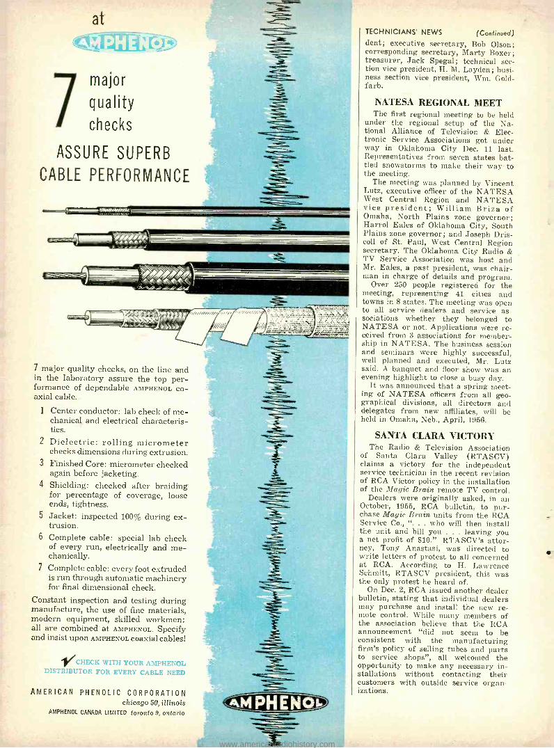
7 major
quality
checks
ASSURE SUPERB
CABLE PERFORMANCE
*0%14 Gi-/-!ilr.l!!iL
7 major quality checks, on the line and in the laboratory assure the top per- formance of dependable AMPHENOL co- axial cable.
1 Center conductor: lab check of me- chanical and electrical characteris- tics.
2 Dielectric: rolling micrometer checks dimensions during extrusion.
3 Finished Core: micrometer checked again before jacketing.
4 Shielding: checked after braiding for percentage of coverage, loose ends, tightness.
5 Jacket: inspected 1005, during ex- trusion.
6 Complete cable: special lab check of every run, electrically and me- chanically.
7 Complete cable: every foot extruded is run through automatic machinery for final dimensional check.
Constant inspection and testing during manufacture, the use of fine materials, modern equipment, skilled workmen: all are combined at AMPHENOL. Specify and insist upon AMPHENOL coaxial cables!
CHECK WITH YOUR AMPHENOL DISTRIBUTOR FOR EVERY CABLE NEED
AMERICAN PHENOLIC CORPORATION chicago 50, illinois
AMPHENOL CANADA LIMITED toronto 9, ontario
TECHNICIANS' NEWS (Continued) dent; executive secretary, Bob Olson; corresponding secretary, Marty Boxer; treasurer, Jack Spegal; technical sec- tion vice president, H. M. Layden ; busi- ness section vice president, Wm. Gold- farb.
NATESA REGIONAL MEET The first regional meeting to be held
under the regional setup of the Na- tional Alliance of Television & Elec- tronic Service Associations got under way in Oklahoma City Dec. 11 last. Representatives from seven states bat- tled snowstorms to make their way to the meeting.
The meeting was planned by Vincent Lutz, executive officer of the NATE SA West Central Region and NATE SA vice president; William Briza of Omaha, North Plains zone governor; Harrol Eales of Oklahoma City, South Plains zone governor; and Joseph Dris- coll of St. Paul, West Central Region secretary. The Oklahoma City Radio & TV Service Association was host and Mr. Eales, a past president, was chair- man in charge of details and program.
Over 250 people registered for the meeting, representing 41 cities and towns in 8 states. The meeting was open to all service dealers and service as- sociations whether they belonged to NATESA or not. Applications were re- ceived from 3 associations for member- ship in NATESA. The business session and seminars were highly successful, well planned and executed, Mr. Lutz said. A banquet and floor show was an evening highlight to close a busy day.
It was announced that a spring meet- ing of NATESA officers from all geo- graphical divisions, all directors and delegates from new affiliates, will be held in Omaha, Neb., April, 1956.
SANTA CLARA VICTORY The Radio & Television Association
of Santa Clara Valley (RTASCV) claims a victory for the independent service technician in the recent revision of RCA Victor policy in the installation of the Magic Brain remote TV control.
Dealers were originally asked, in an October, 1955, RCA bulletin, to pur- chase Magic Brain units from the RCA Service Co., ". . who will then install the unit and bill you . . . leaving you a net profit of $10." RTASCV's attor- ney, Tony Anastasi, was directed to write letters of protest to all concerned at RCA. According to H. Lawrence Schmitt, RTASCV president, this was the only protest he heard of.
On Dec. 2, RCA issued another dealer bulletin, stating that individual dealers may purchase and install the new re- mote control. While many members of the association believe that the RCA announcement "did not seem to be consistent with the manufacturing firm's policy of selling tubes and parts to service shops ", all welcomed the opportunity to make any necessary in- stallations without contacting their customers with outside service organ- izations.
www.americanradiohistory.com

COMPRESSED GLASS SEALE) TYPES -Packet in light -as -air Styrofoam which holds axial type leads straight ... keeps shipping cost! down. Capacitors are easily removed from
packing to be fed to automatic fabricating machines.
Specially packaged capacitors speed
automated chassis assembly New methods of packaging capacitors for automatic machine assembly of printed electronic circuits have been developed by the Sangamo Electric Company. With this special packaging, there's no need for time -consuming straightening of wire leads or checking if close tolerances between leads have been maintained throughout shipping and handling. This special packing makes it easy to remove Sangamo Capacitors from their containers in uniform rows, with wire leads always straight.
Here are a few examples of Sangamo packaging. Sangamo will be glad to discuss special packaging to fit your particular requirements. Write to the factory today.
SANGAMO ELECTRIC COMPANY Marion, Illinois
WIRE LEAD MICA CAPACITORS - Packaged to keep pre- trimmed leads straight in transit. Taped for ease of handling and feed- ing through magazine of auto- matic machines.
SILVERED MICA BUTTON
CAPACITORS -Fixed in cardboard squares and boxed. Users like them because they may be easily stored and they provide quick identification of inventory. Color code does not chip off and ter- minals are kept from bending by this special packaging.
+-- 04.4344
r`{r ae `+... ..,s` s44 . ....
MAP a -,.,.
'-'1.r**o'"-y.w Mts s.,.
+e Fzk4 J
triet{14 444'4 4044 44
Are4144wF A
QrA
t4$-'YRDnrsrr^r. As 4i
PLUG -IN PAPER TUBULARS - Attached to glass !', ",,, tape, uniform rows of these Type 36 paper tubulars can
be lifted from the card and fed to assembly Imachines.
Close tolerances between leads are maintained through- out shipping in spite of rough handling. Similiarly -pock-
aged standard paper tubulars,, shown in the foreground. are also available. scas -i
www.americanradiohistory.com

Slender, modern dynamic at a fraction of the price you expect
ANOTHER TURNER
ER MpDEI, 51
1RN D
MICROPHONE VALUE
POR BROADCAST,
, PA
Response: 55 (ID for qulcklec wired
r high
or low
Coble: 20 ft. 3-conductor
shielded Imp do °ta gshieldis
with plug finish. Can't re-
black-sat swings CpSe'flect
light. hinged
coupler ondard hió0. arc. 5
Mounting: ou^ /e," }n reod. ludion
5 - 2T
clean-cut QúicklY nà or 6
c
;''iceeoonde koto floor sto
use. % .00 d use. ou51 han E:
1.151 Modcl B`desk. stop : 57.54
match ¡n9
THE
TURNER COMPANY
933 17th St. NE, Cedar Rapids, Iowa
Canada: Canadian Marconi Co., Toronto, Ont. & Branches
Export: Ad Auriema, Inc., 89 Broad St., New York 4, N. Y.
Get more out of your job -or hobby with Gernsback Library Books
Look for this new revolving counter rack at your dis-
tributors. TRANSISTORS
Transistors - Theory and Practice -No. 51. For the practical man -theory and applica- tions in circuits. 144 Pages. $2.00
Now -a complete library of low- and save costly mistakes which cost books to help you get ahead may be worth hundreds of Bol- in your ¡ob or get more from tars to you. Pick out the books your hobby. These complete, you need -if your distributor easy -to -read books will give you doesn't have them, send in the new ideas, show you short cuts, coupon below today.
SERVICING AND TEST INSTRUMENTS NEW! The V.T.V.M. $2.50. Hard cover Radio & TV Test In- -No. 57. How to $4.00 struments - No. 49. use the V.T.V.M. The Oscilloscope - Details on how to to best advantage. No. 52. How to get build 22 test instru- 224 Pages. Paper more out of your cover $2.50. Hard scope. e. New uses. cover edition $4.60 192 Pages. Paper
cover $2.25. Hard cover $4.00
Sweep and Marker Generators -No. 55. 224 Pages. Paper TV Repair Tech - Cover $2.50. Hard niques - No. 50. cover edition $4.60 Hints by the experts
can save you hours Probes -No. 54. 224 of servicing time. Pages. Paper cover 128 Pages. $1.50
ments for modern servicing. 128 Pages. $1.50
Television Technotes -No. 46. Causes, symptoms and cures of over 600 actual troubles. Cuts trou- bleshooting time to the bone. 128 Pages. $1.50
AUDIO -HIGH FIDELITY NEW! Basic Audio High- Fidelity - De- High- Fidelity Tech - Course - No. 66. sign, Construction, niques -No. 42. A Audio fundamentals Measurements -No. humorous but prac- from theory of sound 48. How to achieve tical guide to get - to advanced tech- top performance. ting more out of niques. 224 Pages. Amplifier construc- your hi -fi system. Paper cover $2.75. tion. 128 Pages. $1.50 112 Pages. $1.00 Hard cover $5.00
See your distributor - or mail this coupon
GERNSBACK LIBRARY, INC. Dept. 36 25 West Broadway New York 7. N.Y. Enclosed is my remittance of S Please send me the following books postpaid Prices 10% higher in Canada
39 42 43 44 45 46 0 4 0 4 0 4 O 5 0 5 52 53 54 55 57 66
Hard cover editions by mail only. 52M 54M 55H 57M Cl 66H
Name (Please print clearly)
Street
City State
RADIO -CONTROL Radio -Control Hand -
book-No. 53. A com- plete, practical guide on how to build R/C systems. 192 Pages. $2.25 Model Control by Radio -No.43. Theory of R/C and practical sugges- tions on building units. 112 Pages. $1.00
FUNDAMENTALS Basic Radio Course - No. 44. Easy -reading but thorough book on fundamentals from Ohm's Law to circuit analysis. Hard cover. 176 Pages. $2.25 Radio Tube Fundamen- tals-No. 45. How and why tubes work as they do. 96 Pages. $1.00
MISCELLANEOUS Radio & TV Hints- Practical Disc Record - No. 47. 300 hints, kinks ing -No. 39. How to and short cuts. 112 make disc recordings. Pages. $1.00 96 Pages. 75c
128
TECHNICIANS' NEWS (Continued)
TUBE DISCOUNTS DISCUSSED The evils of selling tubes at a dis-
count by the independent service tech- nician formed the subject of lively debate at the January meeting of the Radio -Television Guild of Long Island (N.Y.).
The feeling of a large part of the meeting was expressed by Bob Hender- son of Baldwin, L. I., who stated, "If the service industry is forced to dis- count tubes, the dealer will have to raise labor charges on servicing. Serv- ice charges are inadequate now and tubes are helping to level off the inade- quacy of these rates." Later, he pointed out that service technicians should never "get into combat with discount houses. To do so we would have to lower our standards of servicing... .
Another point of view, presented by Robert Larsen of Windsor TV Service, Rosedale, was that a more realistic list price should be determined as a means of cutting the advantage the discount houses, farmers' markets, drug and hardware stores now have. For instance, if tubes were sold at 40 %® off list, one that now lists at $2 would sell for $1.20 and would cost the service dealer 80 cents. In other lines such a markup would be considered excellent.
Guild president Murray Barlow -ex- pressing not his own opinions but quoting arguments that had been pre- sented to him, and referring particu- larly to the automatic tube venders that are becoming common in the area -stated:
"... If tubes were available to con- sumers locally at 40% off list, the drug stores, hardware stores and supermar- kets would have to drop their prices to meet competition. This would take that beautiful 150% profit that we have created for these operators to split be- tween themselves and the stores and chop it down to 50 %.
"After deducting the cost of amortiz- ing the tube testers, the losses due to pilferage, etc., there would hardly be enough left over after the split to cover the shipping."
NONAFFILIATION VOTED The new California State Electronics
Association went on record at its Janu- ary board of directors' meeting against affiliation with any national associa- tion now in the field.
The association is concerned primar- ily with state -wide public relations functions, relationship with dealers and manufacturers and state legislation affecting the radio -TV industry.
ARTSD ELECTS The new president of the Associated
l'tadio- Television Service Dealers of Columbus, Ohio, appointed 12 commit- tees, ranging from advertising to a TESA (Ohio) delegate. The 1956 officers are: Jim Cumbow, president; Harry Walcutt, vice president; Bob Hawthorne, treasurer; Jack Voigt, secretary. A five -man board of direc- tors -plus one jobber representative on the board -was also elected. END
RADIO -ELECTRONICS
r
www.americanradiohistory.com

new Tubes &
Transistors
2N139, 2N 140
RCA has announced two new tran- sistors, the 2N139 and 2N140, intended for intermediate- frequency amplifier and converter service, respectively, in transistorized portable and automobile radio receivers. Both transistors are hermetically sealed and are of the germanium -alloy, p -n -p junction type.
The 2N139 (see photo) designed especially for 455 -kc applications, can provide a power gain of 30 db at 455 kc in suitable common -emitter circuits (see diagram). It has excellent sta- bility, low collector cutoff current, is only 0.26 inch in diameter and has a seated height of 0.495 inch.
2 -20ppf
k
2N140 220144f
12-229p0
L_
OSC COIL 1 c>
ANT COIL ,3.9K O P ( lo-1o6pyf
11T r.1
; ' 2-2010f
T 221015
IOK
2B3 -GT A new high -voltage rectifier tube,
the 2B3 -GT, has been announced by G -E. Intended for use in television receivers in place of the popular 1B3- GT, the tube can be operated directly from a flyback transformer without a filament dropping resistor. The 2B3- GT (see photo) has a filament rating of 1.75 volts at 250 ma as compared with the 1B3 -GT rating of 1.25 volts at 200 ma. Other ratings and pin connections remain the same as those
2B3 -GT
620n 90pp1 2N139
.51 3391d
C 220ppf
B r 220ppf
J
The 2N140 is mechanically like the 2N139 but has characteristics which especially meet the requirements of converter and mixer -oscillator applica- tions in the standard AM broadcast band. In typical operation in a common - emitter circuit (see diagram) the 2N140 features a conversion power gain of 27 db at 1 mc. The circuit is sufficiently stable to permit changing transistors without readjusting the oscillator.
Maximum ratings for the 2N139 and 2N140 are : collector voltage, -16; collector current, -15 ma; collector dissipation, 35 mw; emitter voltage, -12, emitter current, 15 ma.
MARCH, 1956
l0VALUE TO MATCH OSC COIL
TO 2ND DET
2NI39 & 2N140
BASE- BOTTOM VIEW
BASE COLLECTOR
9V
EMITTER
of the 1B3 -GT. The new high -voltage rectifier should give longer tube life and reduce television set manufacturing costs.
6CS5, 12CS5
Designed for use in low- voltage audio applications, the 6CS5 and 12CS5, de- veloped by CBS -Hytron, are minia- turized beam pentodes with the same power- handling capability and electrical characteristics as the 6W6 -GT. The tubes fulfill the demand for high audio - power output with low supply voltages and may be used in printed- circuit radio and television receivers. The tubes are nine -pin units with the 12CS5 de-
NOW- - - model SX -100 Selectable side band receiver
BUILT TO THE SPECIFICATIONS NF
1,000,000 FIELD EXPERTS
See it at your Jobber -only $295.00
Model SX -I00. Amateur Net $295.00 Matching R -46B Speaker $17.95
Frequency Range 538kc- 1580kc 1720kc -34mc
Hallicrafters 22 years of production know -how, the
engineering experience of developing over 100 dif-
ferent major receiver designs, plus the advice of
over 1,000,000 field experts operating Hallicrafters
receivers all are combined to bring you this out-
standing new receiver -the SX -100! Hallicrafters
alone, long recognized as the leading designer and
manufacturer of quality communications equip-
ment, can offer you the dependability and perform-
ance of this great new SX -100 at the amazingly low
price of just $295.00
Look at these features you enjoy with the SX -100
... before, they were available only on receivers
costing a great deal more!
1. SELECTABLE SIDE BAND OPERATION.
2. "TEE- NOTCH" FILTER -This new development provides a stable non -regenerative system for the rejection of unwanted hetrodyne. The "Tee - Notch" also produces an effective steepening of
the already excellent 50 K.C. i.f. pass band (made
famous in the SX -96) and further increases the
effectiveness of the advanced exalted carrier type reception.
3. NOTCH DEPTH CONTROL for maximum null adjustment.
4. ANTENNA TRIMMER. 5. PLUG IN LABORATORY TYPE EVACUATED 100
KC QUARTZ CRYSTAL CALIBRATOR -included in price.
6. LOGGING DIALS FOR BOTH TUNING CON-
TROLS. 7. FULL PRECISION GEAR DRIVE DIAL SYSTEM.
8. SECOND CONVERSION OSCILLATOR CRYSTAL
CONTROLLED -greater stability through crystal control and additional temperature compensa- tion of high frequency oscillator circuits.
CONTROLS
Pitch Control Reception Standby Phone Jack Response control (upper and lower side band selector) Antenna Trimmer Notch Frequency Notch depth Calibrator on /off Sensitivity Band Selector Volume Tuning AVC on /off Noise limiter on /off Bandspread Selectivity
allicrafters CHICAGO 24, ILLINOIS
129
www.americanradiohistory.com

Engineering Writing
at HUGHES
An engineering writer is that rare combination of a man so technically informed that he knows every detail of a given piece of equipment -and also is able to present a clear, concise, written description of its operation and performance.
Engineering writers at Hughes Research and Development Labo- ratories are as important to the team effort on any project as the engineers with whom they work in close cooperation. This is because the handbooks and other material created by engineering writers are products -just as are antennas, modulators, syn- chronizers and other electronic items.
The writers' products include Hughes equipment operating instructions; pilot and radar operator instruction manuals; serv- ice instruction books; test equipment use and service manuals; illustrated parts catalogues. Tape recorders are a time- and effort - saving tool in this work.
Evening classes are available nearby at the University of Cali- fornia, Los Angeles, and the University of Southern California, for engineering writers desiring to advance their knowledge of the electronics arts.
130
FOR INFORMATION CONCERNING AVAILABLE POSITIONS WRITE:
Scientific Staff
Relations HUGHES
RESEARCH AND DEVELOPMENT LABORATORIES
Culver City, Los Angeles County, California
Photo, above: Engineering writer working with Hughes engineers on a design phase of the Hughes Falcon air -to- airguided missile.
NEW TUBES AND TRANSISTORS (Continued)
signed for 600 -ma series- string opera- tion.
6DQ6, I2DQ6 An addition to their line of 600 -ma
controlled -warmup tubes has been an- nounced by G -E with the introduction of the 12DQ6. The 6 -volt version is the 6DQ6. The tubes (see photo) are de- signed for horizontal- deflection ampli-
Left- 12DQ6, Right -6DQ6 fier service. They have extremely high perveance, permitting the design of a high -efficiency 90 °- deflection system. The 6DQ6 and 12DQ6 are rated at a peak plate pulse of 6,000 volts and a plate dissipation of 15 watts.
The 6DQ6 heater is rated at 6.3 volts and 1.2 amperes; the 12DQ6 at 12.6 volts and a heater current of 600 milli- amperes.
6842 A seven -pin miniature tube with an
overall height of 21/4 inches, the 6842 is designed for use in regulated power supplies or voltage amplifier circuits operating at plate potentials of 300 volts to 4 kv. This National Union tube is useful as a shunt regulator or
z
tn
in a series regulator circuit in equip- ment that requires a stabilized voltage independent of line -voltage and load - current variations. The 6842 (see photo) can provide up to 10 -ma average plate current and dissipate approx- imately 8 watts.
The low capacitances, high gain and high voltage ratings of the 6842 make the tube well suited for applications in television receiver and oscilloscope sweep circuits employing electrostatic deflection. END
RADIO -ELECTRONICS
www.americanradiohistory.com

There's more than Financial: ward
ofilered at univae
Yes, at
These are permanent non -
travel positions.
Full salary while you re-
ceive excellent training on
complex computer circuits.
Excellent hospitalization
and insurance plans paid
by company.
Regular merit reviews guarantee recognition for
outstanding performance.
MARCH, 1956
legIngt -1&111.541-C- 11VI0ney talks-and it is certainly an important consideration to all
of us. Other things count too -such as the challenge and the future of a job.
Univac® offers permanent, secure, and rewarding positions to
FIELD LOCATION ENGINEERS with a college degree in a scientific or engi-
neering field and experience in electronics. Extensive electronic
background may substitute for some college. Many opportunities
for rapid advancement.
FIELD LOCATION TECHNICIANS Technical school background and prefer-
ably some experience in electronics. These positions can lead to
full engineering responsibility.
These are assignments with Univac installations - Univac I, Univac Scientific and File Computer.
Send complete resume to
lite.,,sngi s..,,. M//id Tiix+rt DIVISION OF SPERRY RAND CORPORATION
AT ANY ONE OF THESE THREE PLANT LOCATIONS
MR. D. A. BOWDOIN Dept. M -10
2300 W. Allegheny Ave. Philadelphia, Pa.
MR. KURT PINKE Dept. M -10
1902 W. Minnehaha Ave. St. Paul W4, Minn.
MR. FRANK KING Dept. M -10
Wilson Avenue South Norwalk, Conn.
131
www.americanradiohistory.com

TH\NEW Y EW
14th EDITION i
The very latest publi- 9\
cation of the world famous Radio Handbook with ... ALL NEW EQUIPMENT SHOWN! A wealth of valuable reference work will be found in these profusely illustrated and diagrammed 768 pages.
Chapter after chapter of necessary, vital informa- tion for every practical radioman, technician, ad- vanced amateur, engineer and operator.
Just look at these chapter titles! Mobile Equipment Amplitude Modulation D -C & A -C Circuits Receiving Equipment Transmitter Design TV & BC Interference
Introduction Oscilloscopes Power Supplies Test Equipment Transmitter Keying Special V.T. Circuits V T Principles Workshop Practices Receiver Fundamentals Semi- Conductors Transmitter Constr. Antennas, H -F, V -H -F, V T Amplifiers R -F V.T. Amplifiers U -H -F & Beams FM Transmission S.S.B. Transmission Speech & AM Equipment
Radiation, Propagation & Transmission Lines
Exciters & Low Power H -F Ampls.
R -F Energy Generation
$7,50 in U.S.A. (plus sales tax)
BUY FROM YOUR FAVORITE DISTRIBUTOR at above price or add 10 °o on direct mail orders to:
EDITORS and ENGINEERS, Ltd. S U M M E R L A N D 3 . C A L I F O R N I A
BOOKSTORES. ORDER FROM BAKER '& TAYLOR CO., HILLSIDE. N.J.
132
11
HELP CRIPPLED CHILDREN
new Records
Note: Records below are 12 -inch LP and play back with RIAA curve unless otherwise indicated.
TCHAIKOVSKY : 1812 Overture Capriccio Italien
RIMSKY-KORSAKOV: Capriccio Espagnol Russian Easter Overture Vienna State Opera Orchestra
conducted by Mario Rossi. Vanguard SRV -101
This Vanguard entry into the demonstration record sweepstakes is disarming in its lack of pretension. No percussion bands, no frequency - range sweeps, no commentary, indeed no expla- nations except the usual musical notes on the jacket. Just four complete samples of Vanguard recordings from the series made by the Vienna State Opera Orchestra under Mario Rossi. The music includes some of the most brilliant hi -fi warhorses, from a deep gutty bass to tinkling traps and triangles, and is distinguished for the exceptional clarity, definition, cleanness and faithfulness to tone.
Each is spectacular in its own way. Moreover, although it sounds best on the best systems, it will sound impressively good on average and middling systems for Vanguard includes nothing that would really floor today's good average system - like the big drum in the Egyptian March of its Strauss record Vienna Bon -Bons. In fact, the inherent high quality will make up for many system deficiencies. Still, there are tremendous clean climaxes, big transients in attacks, sharp cutoffs to test decay, ahnost fear- ful concatenations of the full armory of the big orchestra to try definition. Here is material for testing almost any audio quality.
SMETANA: The Moldau ENESCO: Rumanian Rhapsody KODALY: Dances of Gelanta DVORAK: Scherzo Capriccioso, Opus 66
Bamberg Symphony conducted by Jonel Perlea
Vox PL -9500 For those who object to "hi -fi jinks" here is
a demonstration record that will prove that high fidelity is worth while. Four of the most popular pieces of program music based on national folk airs are played with vivacity, inter- preted with proper faithfulness to the com- posers' ideas and intentions and brilliantly re- corded. There are almost no high -highs but the rest of the spectrum is smooth. The bass is not overwhelming but well defined and with no boom. There is a nice big -hall liveness capable of yielding a very high degree of presence in a good living room. Especially in the Rumanian Rhapsody, there are lovely woodwinds, singly and in choirs. The overall effect has brillance but is mellow throughout and guaranteed not to hurt anyone's ears short of eardrum -bursting loudness.
SURINACH, Carlos: Ritmo Jondo Three Berber Songs Tientos (Essays) Various chamber ensembles
conducted by the composer MGM E -3268
A brief version of Ritmo Jondo is found on MGM's E -3155 Spanish and Latin American Music which I liked so much. Here it is in full
RADIO -ELECTRONICS
www.americanradiohistory.com

Nol
IMPIO
Filament
CHECKER
on
cads
S Pins 1812
of Pic lohe y3r1.e1
DEALER tJ.T *MORE
iead $2.95 V E R O AT I L E
LOWER
COMPLETELY NEW COST
Automatically check; ALL TU3ES includ ng locals and pix tube.
Continuity and voltage teste -no switctes, merely plug in test leads.
Ask your Jobber to see the New Senso Cheerer.
SERVICE I
INSTRUMENTS CO. I ADDISON, ILLINOIS I
1 " ADDISON INDUSTRIAL DISTRICT" I
ARKAY MODEL Pif -3
Amazing Miniature Radia
featuring a iuperhatercdyne 'circuit and hearing aid type ear piece, this radio kit, which has set the =ndustry talking,
receives the full AM band. 3 tune circuit brings in all stations clear as a bell and its plastic case measures only 51/4" x 3' /n" x 1" as small as a
pocket book.
ARKAY MODEL M -853
Measures AC -DC voltages from 0 to 2500 volts in 5 ranges and DC current ranges from 0 to 250 MA in 2 ranges. This accurate easily read pocket instrument is versatile and highly stable. A must far every repair purpose. ;9.95
size 31/a "x4 "x1.3/4
1Z.95
OTHER KITS
IN THE ARKAY LINE
Television Kits Testing Equipment Phonographs
Audio Amplifiers .Geiger Counters Experimenters Equipment Radios V,s,t your local distributor for these wonderful kits and write today for the specai FREE Radio Kits Catalogue and list of dealers Your copy will be sent by retun mail with no obligation Wy,te ta
Radio Kits Inc., Dept. R 2
120 Cedar Street New York
MARCH, 1956
NEW RECORDS (Continued)
and even more impressive in the novelty of the musical effects and its value for demonstration and testing. Fine kettle drums, xylophone, a notably fine bassoon, hand clapping, a fas- cinatingly complex rhythm and music which verges on the edge of dissonance but is always interesting - provided the playback system con- tributes no distortion.
This Tientos again is superior to that on Capitol's P -8309 with harp instead of harpichord, very fine kettle drums plus a very fine English horn. The Berber Songs are brand -new to LP and share the same novelty of tonalities and present the woodwinds especially with beautiful faithfulness of tone. The bass in the Ritmo Jondo and Tientos is tops for dullness ; all three selections have sharp attacks and excellent transients. If you don't mind modern music with a Spanish flavor -and that kind is perhaps the easiest of all to take -you'll find this one of the best test records available.
PROKOFIEFF: Prodigal Son (Complete ballet music) New York City Ballet Orchestra
conducted by Leon Barzin Vox PI 9310
The New York City Ballet Orchestra con- tinues to give Vox some of the grandest sound being recorded today. On the finest single - channel systems this is capable of providing an illusion of presence worthy of comparison with stereo sound but without its distractions. The big -hall liveness is just right when played at a moderately loud level to take the living room into the auditorium. The drums and basses are excellent and the lesser instruments are plainly heard without seeming to step out of the orchestra into the listener's lap. The fortissimos are clean and brilliant. The horns are especially good. A good example of modern recording at its best and without hi -fi jinks. One of Pro- kofieff's best ballets, this is easy to take without the dancers.
Concertos Under the Stars Leonard Pennario, piano Hollywood Bowl Symphony
conducted by Carmen Dragon Capitol P -8326
Another contribution by Capitol to the library of "popular" symphonic music played with suf- ficient verve and color to appeal to the casual music listener and excellently recorded. Here are seven "concerto arrangements" including the Warsaw Concerto, Swedish Rhapsody, Cornish Rhapsody, Adagio from the Moonlight Sonata, Liebestraum, Prelude in C Sharp Minor and the more obscure Scherzo from Concerto Symphonique by Litolff. Pennario plays them with less boredom than in previous potpourris and the overall sound is capable of being spec- tacular on good hi -fi systems, though not in the same class as the Vanguard or Vox above. Don't play this for real long hairs ; but the man in the street should love it.
Sounds of the American Southwest Folkways FPX -122
Sounds of Sea Animals Vol. II Folkways FPX -125
Sounds of Carnival Folkways FPX -126
Sounds of Medicine: Operation Body Sounds
Folkways FPX -127 I don't know how many of you have discovered
as I have that one of the most entertaining uses for a high -fidelity system is that of presenting a "concert" of various noises. Here are a few more records suitable for an "evening at the audiophiles home."
Sounds of Carnival is fairly routine. One side is all calliope music and reasonably faithful to the wheezing, hay -wired sample in use by the American Royal Shows; but one or two bands is a plenty. The other side offers various barkers and assorted carnival and crowd noises. Un- fortunately this is too amateurish a recording job; and I presume will be most useful to radio and TV- stations for sound effects.
Sounds of the American Southwest is loaded with rattlesnakes (at least a half -dozen vari- eties) plus various birds, toads, beetles, wild-
there alte
new CGMJ WQIJS
to add a
RC -54 Record Changer
to your HIGH FIDELITY
SYSTEM
Write for details - today
/ I a I
Dc
ROCKBAR CORPORATION 215 East 37th St., New York 16, N.Y.
Please send me complete informa- tion about the **two new pre-wired and pre- mounted Collaro RC -54 units designed for ready use.
Name ......_.....
Address .
I I 1
1
City Zone State { a
a I
133
www.americanradiohistory.com

let 114115
be your guide
twis
IIEROUON B
C
W
ti D
E
G
H
1
ELECTROLYTIC CAPACITOR
REPLACEMENT
GUIDE ADMIRAI
to ZENITH
K
M
N
o
roar Atroro, nt.eator
R
s
u
V
w
DISTI IUTOII DIVISION Á55
AEIOvOx COE,OEATION NEW SWORD, MASS
net
HERE IT IS!
A complete, up -to -date replacement guide for all electrolytic capacitors used in TV sets. Saves time, labor,
money, on your service calls. In all
cases, this Guide recommends only
ONE unit replacement for any
given Manufacturer's Part No.
-not TWO units to replace ONE.
Ask your distributor for your copy. Or send 25c directly to...
AEROVOX CORPORATION
DISTRIBUTOR SALES DIVISION NEW BEDFORD, MASS.
In Conado AEROVOX CANADA LTD., Hamilton, Ont. Export: Ad Auriemo, Inc., 89 Brood St., New York, N. Y
Coble. Aariemo, N. Y.
134
NEW RECORDS
cats, etc. The portable recorder used did not do them as complete justice as a hi -fi man would like, but the rattlesnakes are natural enough to frighten if you've ever heard one.
The operation in Sounds of Medicine is fairly hair -raising in its verisimilitude, but the prize of this disc are the bands on the other side of normal and abnormal heartbeats, respiration and bowel noises. The normal heartbeat has some awesome transients and the respiration obviously contains high -high components re- sembling white noise.
One side of Sounds of Sea Animals covers the field of natural undersea noises in a fast once- over-lightly ; the other side covers in detail the fascinating case of porpoise sounds which, the evidence suggests, are a type of pulse -time modulated sound ranging. Particularly novel for test purposes is the track giving porpoise clicks at 1 /64th of natural speed and frequency, followed by echoes from the surface and bottom. The pulses are genuine transients, the echoes are faint ; it takes a good system to hear them clearly and sharply.
Jimmy Durante in Person MGM E -3256
Nothing of hi -fi interest here that I can find but anybody who has ever liked Durante should welcome this opportunity to get on one disc all his classic songs, including my own favorite, The Lost Chord and 11 others.
BEETHOVEN: Violin Concerto in D Major Nathan Milstein, violin william Steinberg and the
Pittsburgh Symphony Capitol P-8313
Milstein and the Pittsburgh Symphony give one of the greatest of all violin concertos a very worthy performance. Some audiophiles may recall that this is the concerto which gives the kettle drums a real workout and the juxtaposi- tion of the drums and the fiddle is often very interesting particularly for checking inter - modulation distortion.
(Continued)
Milstein s violin is its usual, almost incredibly, sweet self and his playing is characteristically unforced, the high notes especially being pure and right on the head. The Pittsburgh Symphony which on some of its discs suffers from the acoustics of the Mosque in which it plays, here is really impressive. Many audiophiles will espe- cially like the deep bass and in those portions where it underlies the fiddle it provides a fine measure of IM distortion. Those who insist on fine sound as well as fine performance will, I think, agree that this is the version for them. The first movement is exceptionally good.
SAINT -SAENS: Cello Concerto No. 1 in A minor
LALO: Cello Concerto in D minor Andre Navarra, cello Orchestra of Paris Opera conducted
by Emanuel Young Capitol P -8318
This very faithful rendition of the cello pro- vides a lovely middle bass that will give an impressive demonstration of bass quality on small speaker systems that cut off somewhere above 50 cycles. There is also, however, an excellent choir of double basses offering contrast between the two instruments which will be most obvious on systems with a wide bass range. These are two of the most melodic and interesting major works for the cello. The re- cording is very fine and clean and the bass definition is exceptionally good.
Holiday in Cuba Don Marino Barreto, Jr. and his
Cuban Orchestra Vox VX -25020
Except that, like many other popular records, it is slightly overcut in spots, here is a first - class popular demonstration record with plenty of jingling highs of all kinds, a very notably dull, deep bass and plenty of brass. END
Names and addresses of manufacturers of records mentioned in this column may be ob- tained by writing Records, RADIO -ELECTRONICS, 25 West Broadway, New York 7. N.Y.
TELCO TELEVISION HARDWARE AT YOUR DISTRIBUTOR
WRITE for your TELCO Catalog or ask your supplier. FREE'
TELCO CHIMNEY QUICK MOUNT
One -piece style for fast installing.
N o. 8005
TELCO DELUXE CHIMNEY MOUNT
All aluminum, with stainless strap.
No. 8001
TELCO TV STAND -OFF Wood -screw type, 31 long.
No 8027
TELCO DUPLEX STAND -OFF
Infine wood -screw type. 7!. No. 8225
TELCO UNIVERSAL LIGHTNING ARRESTOR
UL- approved; for all lead -ins.
No. 8642
TELCO TELEVISION ROLL -AROUND
Fits under most sets for easy moving.
No. 8957
TELCO UHF -VHF LIGHTNING ARRESTOR
UL- approved; 300- & 450 -Ohm lines.
N o. 8640
TELCO RATCHET TYPE CHIMNEY MOUNT For masts to 134" dia.;
fast, sure. No. 9218
TELCO NO-GUY ROOF MOUNT
Cast iron base; 1%" dia. masts.
N o. 9060
TELCO HEAVY DUTY RIDGE MOUNT
For flat or any -angle roof; I%" mast. NO. 8630
TELCO TUBE CHECKER Series filament and
continuity tests. N o. 9270
TELCO TV LEAD -IN TUBE Universal style, up to 14' wall.
No. 8958
TELEVISION HARDWARE MFG. CO. Division of General Cement Mfg. Co. 910 Taylor Avenue Rockford, Illinois
RADIO -ELECTRONICS
www.americanradiohistory.com

SELLU(G OUT REGARDLESS OF COST.
Prices Reduced Up to 80%
1 COMPLETE STOCK OF NATIONALLY ADVERTISED RADIO & TELEVISION TESTING INSTRUMENTS, PARTS AND ELECTRICAL APPLIANCES TO BE SOLD
This is the opportunity of a lifetime! Below mentioned units are not kits, but all factory wired and brand new. Some models have been discontinued by the manufacturer, but every one is factory sealed and carries a one year factory guarantee. Satisfaction as money refunded within 10 days.
Model 999 Combination TEST CRAFT F. M.. A. M. and Television
SIGNAL ModelMuRitester ality
GENERATOR AC and DC Voltage Ranges: 0- 5/15/150/-
s,yy- f- A.C. operated, generates 1500/3000 Volts. DC R.F. frequencies from 150 Current Ranges: 0 -5 /50 kc. to 50 mc. Positive ac- tion attenuator provides ma. 0 -I.5 Amps. Re-
.`r. effective output control sistance Ranges: 0 -100 ohms. 0 -100 K.
at all times. R.F. is obtainable sep- Complete with batteries, instructions: A arately or modulated by the Audio
$1950 Size:6 "x3/2 "x2" $9$5 Frequency. Complete with test leads, Reg. $16.85 now only VVV
instructions. Reg. $39.50; now only
TEST CRAFT Model TC -75
Combination Test Speaker
and Signal Tracer
plus speaker sub- stitution
plus resistor tester plus field substitutur Plus condenser tester plus voice coil substitu- plus output indicator tion Complete with full instructions $2450 Reg. $39.50 now only
Famous -Make
OHMMETER Has a double range of 0 -10 and 0.1000 ohms for ac- curate measurement of low resistance. Widely used for production testing. armature and field resistances of small motors relay and coil testing transformer wind- ing tests, etc. Complete with test leads. instructions, leather case.
Reg. $36.50 $1495 now only
SUPREME Model 543 -S
Multimefer I% WIRE WOUND
PRECISION RESISTORS
D.C. Volt Ranges: 0 -150- 300 D.C. Ma: 0- 60 -120- 300 -600. AC Volt Ranges: 0 -150 -300. Ohm Ranges: 0 -1000 /100,000. Complete with instructions.
Reg. $24.50 $995 now only
SUPERIOR METROPOLITAN GENERAL ELECTRONICS
REINER ELECTRONICS.... RADIO CITY PRODUCTS..
SHALLCROSS GRUEN WESTON TRIPLETT MARION
ACRO GRAF -O -TON E
MELODISC
HOLYOKE
DUOSONIC
MAGUIRE TELE -TONE MOTOROLA
STANDARD PHILCO GENERAL ELECTRIC ADMIRAL PHILCO GENERAL ELECTRIC ADMIRAL REVERE GENERAL ELECTRIC ROLAND CUCKOO CLOCK
GLO
BROIL -QUICK CHEF
CAPITOL
All prices are f.o.b. New
Dealers Selling -Out Net Price Price
Model 660 -A Signal Generator $ 42.50 $ 29.50 " III Quality Multitester 21.50 9.95 " 200, AM -FM & Television
Signal Generator, AC operated 39.50 24.50 " 333, DC Volt- Ohm -Milliammeter 26.95 9.95 " 668 Electronic Multitester 74.50 39.50 " 665 AC -DC Volt -Ohm Capacity, VTVM 95.40 49.50 " 630 Wheatstone Resistance Bridge 145.00 75.00
21/2" DC, D'Arsonval Type, I Milliammeter, Meter., 9.95 2.95 Model 507, F.S. I, 2 Milliam. Meter 12.95 3.95 331 -JP 30 Amperes, Meter 12.95 4.95 3" D'Arsonval Type, I Milliam. with calibrated
Volt -Ohm Current Scale, Meter 12.95 3.95 Radio & Phonograph Chassis Cradles 6.95 2.95 8" Glass Recording Discs, sold only in
cartons of 24 discs .75 each .15 12" Metal Recording Discs, sold only in
cartons of 50 discs 1.50 each .30 180 Ohm resistance line cords, 6 foot with plug 1.25 each .35 Electrical Iron Cords, 6 foot with plug .95 each .25 Extension line cords, 9 foot with plug .75 each .30 Extension line cords, 12 foot with plug .95 each .40 No. 22, stranded, tinned, copper push -back
wire, on 500" spools 5.75 ea. spool 2.50 MODEL CAPRI, 3 speed recordplayers, with life
time needle, plastic case, speaker and amplifier Reduced to 16.95 each Automatic Recordchanger Reduced to 9.95 each
Table Radio, all colors Reduced to 9.95 each Table Radio, 5 tubes, all colors Reduced to 12.95 each Clock Radios, all colors Reduced to 18.95 each Portable Radios, 3 Way Reduced to 14.95 each Table Radios, all colors 5 tubes Reduced to 17.95 each Portable Radios, 3 Way 5 tubes Reduced to 24.95 each Portable Radios, 3 Way 5 tubes Reduced to 24.95 each Portable Radios, 3 Way 5 tubes Reduced to 24.95 each Clock Radios, 5 tubes Reduced to 24.95 each
Clock Radios, 5 tubes Reduced to 24.95 each Whistling Tea Kettles Reduced to 2.95 each Automatic Irons Reduced to 7.95 each Table Radios, all colors 5 tubes Reduced to 12.95 each Genuine, imported Black Forest, hand -carved,
cuckoos every 15 minutes Reduced to 4.95 each Electronic, oscillating massager with infra-
red heat combined Reduced to 3.95 each Fully automatic rotisserie and broiler combination,
7 way, with time clock, 3 heat element, double powered Reduced to 24.50 each
Infra -red heat, automatic broiler Reduced to 9.95 each
York, 20% deposit with order, balance C.O.D., or full remittance with order.
QUANTITIES ARE LIMITED. WRITE, PHONE OR WIRE FOR IMMEDIATE DELIVERY.
METROPOLITAN ELECTRONICS & INSTRUMENT CO. 106 Fifth Ave., New York II, N.Y. Telephone: Oregon 5 -1707 Cable Address: METRONICS
SUPERIOR Model PB -100
Volt -Ohm- Milliammeter
Measures DC Volt- ages to 2500 Volts, AC Voltages to 1000 Volts, Resist- ance to I Megohm,
Output Volts to 1000 Volts, DC Current to 2.5 Amperes, Decibels to plus 55 D.B. Push Button Operation. Complete
$1 ¿ 00 with instructions and test leads. Reg. $28.40 now only
Reg. $29.25
SUPERIOR Model 1553
Volt -Ohm- Milliammeter
Meets U.S. Army re- quirements for accu- racy and durability. Measures AC Volt- ages: 0- 7.5/15/150/- 750. D.C. Voltages: 0 to 2.5/15/150/750. D.C. Current: 0 to 7.5/75 ma. Resist- ance: 0 to 5,000/500.- 000 Ohms. Complete with leather case, in- structions.
now only $1450
SUPERIOR 5,000 ohms per Volt,
Volt -Ohm- Milliammeter
D.C. Voltages to 1500 Volts. A.C.
Voltages to 1500 Volts. Resistance to 2 Meg - ohms, Output Volts to 1500 Volts, D.C. Cur- rent to 150 Ma., Decibels to plus 58 D.B. Complete with in- structions and test leads. Y Reg. 527.65 now only
TEST CRAFT Model TC -50
TUBE AND SET TESTER Test all tubes up to date, ïncl. 4, 5. 6. 7L, octals, loctals, television, magic eye. thyrators single end- ed floating filament. mercury vapor, new miniatures. etc. Mul- timeter Specifications:
AC and DC Voltage Ranges: 0 -1. 100 -1000 -5000, DC Carrent Ranges: 0.10 -100 -1 Amp. Low Res. Range: 0- 10,000 Ohms, Medium Re. Range: 0- 100Á00 Ohms High Res. Range: 0.1 megohm. Com- plete with test leads and instruc- tions. Reg. $49.50 now only
$2950
MARCH, 1956 135
www.americanradiohistory.com

THE BOOK YOU NEED
TO PRICE WITH SPEED... for profit
quick check for 60,000 prices
Profit -making time -money -phone call- saver. 200 pocket -sized pages. Replacement parts listed by manu- facturer, product and part number. up -to -date charging information Completely revised 4 times a year.
TV -RADIO SERVICE
1 GUIDE TO
RESALE PRICES
a( TUBES
BATTERIES ANTENNAS ANO COMPONENT
SERVICE PARIS
COVERS ALL
SERVICE ITEMS IN
THE ELECTRONIC INDUSTRY
VOL . I -NO 1
OCTOBER 1955
~` ++ -RAD/0 i SERVICE SI
OFFICIAL ORDER BOOK
and the perfect partner ... DAVE RICE'S OFFICIAL TV -RADIO SERVICE ORDER BOOK For TV, Radio, Phono or Hi -Fi service. provides separate listings for: Picture tubes, receiving tubes, parts and components, serial numbers, labor and state and local taxes. 51/2"X8% " -50 sets of triplicate orders -carbons bound in.
at parts distributors or send check to
ELECTRONIC PUBLISHING CO., INC. 180 NORTH WACKER DRIVE CHICAGO 6, ILLINOIS
DIGEST: $2.50 per copy. ORDER BOOK: $.75 each or $6.50 per dustproof box of 10.
136
radio- electronic
Circuits
SYNCHRODYNE TUNER Since publishing the article on a syn-
chrodyne receiver (April, 1951) we have received periodic requests for ad- ditional circuits and references. The diagram shows the circuit of a simple
u ,ANT COIL SIG AMPLITUDE
l íisl 1 o -+a
LIO¡ , 1T T
1 '
, r- i
L
OK
1 I
8.15 SIG CATH POLL
.1
constants selected so the circuit is un- stable and locks in easily with the external sync signal.
A tertiary winding (L4) on the oscil- lator transformer applies an oscillator
MODULATOR
=,I
GERMANIUM DIODES 33K r4.1K .01
33K a7Kc
.I 1w 47K
,I
8SN7-GT5I2AU7 SY NC CATH FOLL
.T
VI-a OSC VI-b
y
I SYNC CONT
SK ,I 7n
I R 1 I L---------- OK
012 L4
O O O
c L3
I0016,
1+
AF OUTPUT..
'SHIELD
synchrodyne type local- station AM tuner designed for the experimenter by G. A. French and described in The Radio Constructor (London, England).
Basically, the synchrodyne is a super - het with an i.f. of zero. The oscillator is synchronized and locked in on the frequency of the incoming signal so the difference frequency is zero. The oscil- lator signal beats with the sidebands of the broadcast signal and produces a.f. signals identical to those modulating the transmitter.
Signals from the antenna are coupled to L1 and the desired station is tuned in by the trimmer capacitors selected by Si. The tuned circuit is heavily loaded by the 10,000 -ohm control so its response is broad -a requirement for good synchrodyne operation. A portion of the incoming signal, tapped off the control and fed through the 6J5 cathode follower, is applied to one set of termi- nals of a diode type balanced modulator circuit.
The incoming signal is also fed to the grid of V1 -a, the sync cathode fol- lower. The output of V1-a is then in- jected into the cathode circuit of the oscillator to synchronize it with the desired carrier frequency. Vl -b is a conventional tuned -grid oscillator with
voltage of approximately 1 to the re- maining terminals of the balanced modulator.
Switch tuning eliminates tracking problems. Only two sets of tuning capacitors are shown. Others can be added. Li is a standard broadcast an- tenna coil. You can use one with a sep- arate primary instead of a tap. A good outside antenna is recommended for this circuit.
The oscillator coil is a broadcast type r.f. coil with the primary used for L2 and the secondary for L3. L4 is an added winding with enough turns to develop about 1 volt across the modu- lator.
To adjust the receiver, tune the input circuit to a strong local station. A simple r.f. signal tracer will be useful in this operation. Set the signal ampli- tude control to maximum and the sync control to minimum. Temporarily short out the 47 -ohm oscillator cathode re- sistor and adjust the oscillator trimmer until a beat note is heard. Remove the short from the resistor and adjust the sync control until the oscillator just locks in and the modulation signal is heard clearly. Now, adjust the signal amplitude control and antenna tuning capacitor for best results.
SIMPLE METRONOME Most metronome circuits require an tube a.c. -d.c. radio. The metronome
amplifier, power supply and speaker. circuit is shown in the diagram. The This one uses those of a typical five- only new parts needed are shown in
RADIO -ELECTRONICS
www.americanradiohistory.com

RADIO -ELECTRONIC CIRCUITS (Continued)
heavy lines. The rest of the circuit is a part of the receiver.
The circuit is basically a relaxation oscillator. Cl charges through R1 and R2. When the voltage across Cl reaches the striking potential of the neon lamp, it breaks down and feeds a pulse to the grid of the audio output tube through C2. This produces a loud click in the speaker. The repetition rate of the click
MEG IMEG
RI----- a2---
FROM AUDIO
VOLTAGE AMPL
B -BUS
OR CHASSIS
CI
NE-25 50L8-GT OREOUIV
AF AWL
C2
.001
IIF TO SPMR
B+
depends on the setting of Rl. The greater its resistance, the slower the click tempo.
When using the metronome, warm up the radio and then tune it to a dead spot on the dial. Turn Rl clockwise to close SW and start the metronome.
Assembly and construction are sim- ple. Drill a hole in the side of the re- ceiver cabinet and mount Rl and then mount the neon lamp and remaining parts under the chassis among the other parts of the receiver. Rl may be cali- brated by counting the number of clicks per minute and recording them on a small cardboard dial under the control knob. -Jess Jacobson
VOICE- POWERED RADIOTELEPHONE
A transistorized voice -powered radio transmitter that would make a nice companion piece for the Transistor- ized Wrist Radio (RADIO -ELECTRONICS, March, 1954) has been developed at the Signal Corps Engineering Labora- tories in Fort Monmouth, N. J. The unit is built into a telephone handset (see photo) and is designed along the lines of the basic circuit shown in the
ti diagram.
The microphone is a moving -coil or armature type, transformer- coupled to the tuned -base tuned -collector type rf oscillator. Operating voltage for the transistor is developed by rectifying the of signal at the secondary of the
MARCH, 1956
MY PROFITS JUST BEGIN
WITH THE INSTALLATION
I-
JERROLD MASTER TV SYSTEMS
Smart service technicians and dealers realize that the profit they make on the sale and installation of a Jerrold Master TV System is only the beginning! For the sharp, snow -free pictures delivered by a Jerrold system is their key to mass receiver orders ... more receiver servicing jobs ... more frequent Master TV installations as other businessmen become Jerrold- conscious.
Cash -in on the growing demand for Jerrold Master TV Systems in motels, apartments, clubs, and small hotels. With a Jerrold sys-
tem there are no installation headaches ... no guesswork about profits. Every installation step is figured out for you in advance.
Discover how easy it is to get beautiful, snow -free pictures at 5,
10, 20, or more receivers from a single antenna -even in ultra - fringe areas. Send 25c today for the big illustration- packed book-
let, "INSTALLATION MADE EASY." It shows how to profit- ably sell, estimate costs, install, and service any TV System.
JERROLD . . . the complete Master TV Line.
Sold by leading distributors.
De- Snower® pre -amplifiers UHF Master Converters Distribution Amplifiers Line Splitters Line Tap Impedance Matchers
Solderless Coaxial Connectors
Interference Traps
Attenuator Pads
JERROLD ELECTRONICS CORP. 2216 Chestnut Street, Philadelphia 3, Pa.
In Canada: JERROLD ELECTRONICS (Canada) Ltd.
50 Wingold Ave., Toronto 10, Ontario
137
www.americanradiohistory.com

UNIVERSAL TV ... Famous for 25 Years Thousands of Successful Grads
ELECTRONICS -the world's GREAT- EST new industry is years ahead of its manpower supply. ELECTRONICS JOBS ARE SEEKING TRAINED TECH- NICIANS, an acute shortage of which
exists today. Big companies are actually pirating men from one another because there aren't enough trained electronics experts to go around to fill the many jobs.
Wide Scope Electronics Course at UNIVERSAL: Embraces Radio, Monochrome -Television, Color TV, Industrial Electronics, Industrial Television, Atom - electronics and Automation. Automation, a terrific new field, embraced at UTS.
25 Years EXCLUSIVELY in Electronics: For a quarter of a century UNIVERSAL TV has been training and placing grad technicians in fascinating big -pay lobs from coast to coast. You can start earn- ing as much as $150 per week; no limit as time goes on, or you can open your own business.
UNIVERSAL not a Johnny -come lately school: Not a home study or correspondence training, but a "genuine" old established resident school staffed by expert instructors and headed by America's first TV broadcasters. Costs so little to prepare yourself for life. Many middle age trainees attend; go into successful business. No previous experience needed. Approved for vets and non -vets. a WRITE FOR Send coupon for FREE BOOK on TV & electronic opportunities.
l-- -FILL OUT COUPON- - I UNIVERSAL TV SCHOOL
1222R Admiral Boulevard, Kansas City, Missouri I PLEASE SEND ME INFORMATION FREE. Age_ II Name
I Address
I City State Check here if Korean Veteran
..I
VIDEO PROBE
METER! a professional instrument designed for testing a T.Y.
ABOVE and BELOW chassis!
THE VIDEO PROBE METER!
Saves TWO HOURS PER DAY when used in shop for
under chassis work.
With the attachable pick -up lool,(where sufficient signal is available) the Probe Meter can detect and indicate radiation of signal thru I.F. and video amp tubes. (Simply slide loop over tube being tested.) Where internally shielded tubes are encountered, remove tube and insert probe tip into grid pin of socket. Indicates gain per stage.
an Can accurately trace
to pale the following
Video. Sync.,
tuner nix tube) R.F.. I.F., audio Video. Sync., local Sign Hz. oeg Drive. audio output. sound I.F. (Signal tracing radios.)
EXCELLENT FOR TRACING AND COMPARING r_ COLOR T.V. CIRCUITS.
ADDITIONAL FEATURES Voltmeter, 0.500V. D.C., 20,000 Ohms /volt.
Fully Guaranteed If your dealer cannot supply you, order direct full purcnase price refunded if not satisfied. DEALERS & REPS. INQUIRIES WILL RECEIVE
IMMEDIATE ATTENTION.
Research Inventions & Manufacturing Co. 617 F St., N. W., Washington 1, D. C.
Dealers Nef Price
$31.50
terrific TV antenna values at Concord
8- element VEE -D -X "long john" yogi
OP O
$795 net
Reg. $18.50
Mor °4t
LOTS OF 3 $7.49 ea.
A. High front -to -back ratio provides high gain for fringe areas. Full 6 mc. band width. Rugged boom bracing for extra strength. Chan. 9, 9, 10; Specify Chan.. Wt. 6 lbs.......... .Stock #99- T -DLI.
10- element VEE -D -X
broad -band yogi
B. 2 Antennas cover all VHF channels. High front -to -back ratios. Pre -assembled for easy in- stallation. Chan. 2-6 Wt. 15 lbs. Stock 3r99TX26, Reg. $41 Net $10.95 Stock #99TX713, wt. 9 lbs., Reg. $20; Net $8.95
4 -bay VEE -D -X colinear array $650 net Reg. $26
C. Broad -band array has attached phasing harness, center terminals for line. Hardware cadmium -plated. Chan. 8, 9, 10, 11, 12, 13. Specify Chan. Wt. 41/4 lbs. Stock #99TVOCA.
10- element DELCO Yagi
Reg. $35 $750 net Lots of 3 - $6.95 ea.
D. Inline design with wide element (heavy gauge all- aluminum) spacing for extra -high front -to- back ratio. Twin V- braced crossbar for strength. Chan. 5 & 6. Specify Chan.. Stock #99TBD610.
UHF bowtie & reflector by NEPCO
$265 net
Reg. $6.95
LOTS OF 3 $2.49 ea.
E. For mast mount. High gain & directivity on all UHF bands. Hardware and outfit weather- resistant. Wt. 3 lbs. Stock #T- BTR -1X.
Money -back guarantee. $5 minimum orders. FOB NYC. 25% deposit on COD's.
send for FREE catalog Concord Radio, Dept. 11118, 45-A Warren St.. N.Y. 7
Please send me items on attached clipping. I'm not on your list. Send Bargain Catalogs. Send special TV Accessories Close -out List.
name
address
city zone state check enc. M.O. enclosed Dlgby 9-1132
138
RADIO -ELECTRONIC CIRCUITS (Continued)
transformer. The antenna may be a quarter -wavelength dipole. END
Rabic' TIjírtp =Jibe pearo ago In Gernsback Publications
HUGO GERNSBACK, Founder Modern Electrics _ 1908 Wireless Association of America 1908 Electrical Experimenter 1913 Radio News .. ............. 1919 Science & Invention _._.._..........- ...1920 Television 1927 Radio -Craft 1929 Short -Wave Craft 1930 Television News 1931
Some larger libraries still have copies of ELECTRICAL EXPERIMENTER on file for interested readers.
In March, 1922, Science and Invention (formerly Electrical Experimenter)
Steel Wire Records Heart Beats. How to Build a Radiotrola by H. Gerns-
back and R. E. Lacault. Radiophoning to and from Trains. Radio Gives Telephone Secrecy. Sun Dust Bars Radio. Radio for the Beginner, by Armstrong
Perry. Installment I. American Amateurs Heard in Europe.
o ar-:73
SALER,vO
o
"Ile comes along with me on color calls -I'm color blind."
RADIO -ELECTRONICS
www.americanradiohistory.com
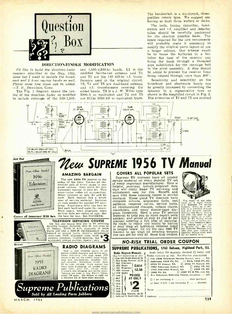
DIRECTION- FINDER MODIFICATION I'd Pike to build the direction -finder
receiver described in the May, 1955, issue but I want to include the broad- cast and 2-4 -mc marine bands as well. Please show how these can be added. -T. B., Danielson, Conn.
The Fig. 1 diagram shows the tun- ing of the direction finder as modified to include coverage of the 540 -1,500-
Just Out
; ° T3
01 .p I
SI-a
¡ l
and 1,500 -4,500 -kc bands. L1 is the modified ferrite -rod antenna and T1 and T2 are the 140 -425 -kc r.f. trans- formers used in the original circuit. T3, T4 and T5 are dual -band antenna and r.f. transformers covering the added bands. T3 is a J. W. Miller type 3996 -A or equivalent and T4 and T5 are Miller 3996 -RF or equivalent types.
i ---- -- 7 ---T1------- --- i IU4
i 1ST RF AMR.
i1
I oo
ÿfT 2ND RF AMPL o I t
1 - ..
T4 y l
I SI-d 1 04. 15 7 ° T °' I r '
Si
140- _ ¡
4251(C 540- ! 6
1500KC SI-6 1500- 450p1{L r
/
1
SI 0
á 0
T3- MILLER 3996A ANT COILS
T4,ß, - 1,1ILLER 3996 RF COILS
( /Fr,» -
1956 ___-------- Televisü» ii
Covers all important 1956 Sets
`,365Vyr
The bandswitch is a six -circuit, three - position rotary type. We suggest one having at least three wafers or decks.
The coils, tuning capacitor, hand - switch and r.f. amplifier and detector tubes should be carefully positioned for the shortest possible leads. The space required for the new components will probably make it necessary to modify the original parts layout or use a larger cabinet. One scheme would be to house the batteries in a box below the base of the receiver and bring the leads through a threaded pipe substituted for the carriage bolt in the pivot assembly. A stop should be added to prevent the receiver from being rotated through more than 360 °.
Sensitivity and selectivity on the broadcast and shortwave bands can be greatly increased by converting the detector to a regenerative type as shown in the simplified circuit in Fig. 2. The primaries of T2 and T5 are omitted
T2 L
1
TS 1 250yyf TO DU GRID d .o I F 51-e i p I o o I O
T
1
I
a I o
I SI f 1 T t ' c' 3.3MEG
T
I
I
! J
Fi1.1
+090v
o1.5V- 1
I
SUPREME 1956 TV Manual AMAZING BARGAIN
The new 1956 TV manual is the scoop of the year. Covers all im- portant sets of every make in one giant volume. Your price for this mammoth manual is only $3. This super -value defies all competition. Other volumes at only $3 and $2 each. Each manual has a whole year of service material. Includes all data needed for quicker TV serv- icing. Practically tells you how to find each fault and make the repair. More pages, more diagrams, more service data per dollar of cost. Get the best for less. Get SUPREME.
TELEVISION SERVICING COURSE Let this new course help you in TV servicing.
Amazing bargain, complete, only $3, full price for all lessons. Giant in size, mammoth In scope, topics just like a $200.00 correspondence course. Lessons on picture faults, circuits, adjustments,
short -cuts, UHF, alignment facts, hints, st antenna problems, trouble -shooting, test equipment, picture analysis. Special, only
Newest RADIO DIAGRAMS Ilere is your complete source of all
needed RADIO diagrams and service data. Covers everything from most recent 1955 radios to pre -war old -timers; home radios, auto sets, combinations, changers, FM, and portables. Sensational values. Only $2 for most volumes. Every manual has extra large schematics, all needed align- ment facts, parts lists, voltage values, trimmers, dial stringing, and helpful hints. Volumes are large in size, 81/2x11 inches, about 190 pages. See coupon at right for a complete fiat of these radio manuals.
Supreme Publications Sold by All Leading Parts Jobbers
MARCH 1956
COVERS ALL POPULAR SETS Supreme TV manuals have all needed
service material on every popular TV set of every important manufacturer. Here is helpful, practical, factory- prepared data that will really make TV servicing and adjustment easy for you. Benefit and save with these amazing values in service manuals. These giant TV manuals have complete circuits, alignment facts, test patterns, response curves, service hints, all recommended changes, voltage charts, waveforms, and many double -page dia- gram blueprints. Here is your TV service material to help you do more expert work quicker; and priced at only $3 and $2 per manual covering a full year of material. Be ready to repair any model by having in your shop all television volumes listed in coupon below. Or try the new 1956 TV manual to see what an amazing bargain you can get for only $3. Send trial coupon.
The repair of any tele- vision set is really simple with Supreme TV service manuals. Every set is cov- ered in a practical manner that will simplify trouble- shooting and repair. This is the help you need to find toughc't faults in a jiffy. Each $3 TV volume curers a whole year of scnice ma- terial. New Television Serv- icing Course will aid you in learning TV. Be wise, buy Supreme Manuals only once each year instead of spending dollars evei9 week for not needed data.
NO -RISK TRIAL ORDER COUPON
SUPREME PUBLICATIONS, 1760 Balsam, Highland Park, ILL.
Radio Diagram Manuals (See full description at left)
New 1955 Radio Manual,$2 1954 Radio Manual, $2.50 1953 Diagrams 1952 Radio ( EACH 1951 Diagrams
CI 1950 Manual $250 1949 Radio 1948 ; PRICED 1947;j AT ONLY
7 1946 ç ` 1942f 1941 o
D 1940 E 1939 m EACH 1926 -1938 Manual, $2.50
a Radio and TV Master Index, 256
Rush today TV manuals checked below and Radio manuals at left. Satisfaction guaranteed.
New 1956 Television Service Manual, only. ...$3. Additional 1955 TV, $3. Early 1955 TV, $3. 1954 TV Manual, $3. 1953 TV Manual, $3. 1952 Television Manual, $3. 1951 TV, $3. 1950 Television Manual, $3. 1949 TV, $3. 1948 TV, $3. 1947 TV & FM, only $2. New Television Servicing Course, complete.... $3.
I am enclosing $ Send postpaid.
Send C.O.D. I am enclosing $ deposit.
Name:
Address: 139
www.americanradiohistory.com

One Focalizer for all picture tubes.. ..
i.
QUAM QF -4 UNIVERSAL
FOCALIZER UNIT
....
FREE! Catalog 78, listing complete specifications of the QUAM OF-4 Universal Focalizer Unit.
New ceramic magnets and extended focusing range eliminate the need for more than one model ... yet provide maximum resolution with minimum spot size.
Installs in minutes, adjusts in seconds.
The QF -4 has a newly designed "quick- setting" picture centering lock and is supplied with a soft aluminum blank mounting bracket that is easily drilled to fit any mounting arrangement.
LIST PRICE $4.25
QUAM- NICHOLS COMPANY 234 East Marquette Road Chicago 37, Illinois
NEW! For the First Time! eNtC %ESr
A q oNDEsERS IN THE SET! RSA E1'.
CAPACITES''' Quickly, . lcct[rately checks:
PAPER, MICA, CERAMIC CAPACITORS
ICS itoi)
CONTINUITY
4g FLASHBULBS Cp## SATISFACTION
GUARANTEED OR RETURN WITHIN
.. TEN DAYS FOR REFUND
CAPACITEST, d.7. pé ment is a new, compact checker that does a giant job to save you time and money. It will check condensers at 150 Volts, which is approximately the working voltage in a radio or TV set. Meters will not give this type of heck since the sunned voltagKe is 20 Volts or less. Avoid call -backs by using CAPACITEST. Accurately, quickly, it shows open,
4x4"22"-lightweight, intermittent
for capacitors and
tool leaky electrolytics.
B . It
AC /DC VOLTAGES
5995 postpaid ?Pr? Net ready for operation
NOT A KIT FREESpecial Introdaetory Offer for limited tame only: Set of test !cads Free with each CAPACITEST.
Order direct from manufacturer -Include $3 deposit with C.O.O.'s. Save PP 6 COD fees, send $9.95 IS we'll pay postage.
The B a r j a y Co. 145 West 40 Street New York 18, N.Y.
OPPORTUNITY ADLETS Rates -45e per word (including name, address and initials) Minimum ad 10 words. Cash must accom- pany all ads except those placed by accredited agen- cies. Discount, 10% for 12 consecutive issues. Mis- leading or objectionable ads not accepted. Copy for May issue must reach us before March 15, 1956.
RADIO -ELECTRONICS, 25 W. Broadway, New York 7, N. Y.
BUY SURPLUS. RADIOS, receivers, electronic equip nient. Direct from Government. List $1.00. BOX 1842M Hartford 1, Conn.
SPEAKER RECONINO: Guaranteed workmanship. C &M Recone Co., 255 Tioga St.. Trenton 9. N.J.
WANTED Electronics Technicians to qualify for "Engi- neering Degrees" by comprehensive examination. Excel- lent employment opportunities waiting. C1IAMWELL INSTITUTE. 11E -7, Adams, Masa.
TELEVISION Tuner Repairs. DAN'S Television Labora- tory. 9 West 183rd St.. N.Y. 53, N.Y.
RULE OTHERS WITH THOUGHTS. (Full course.) $2. Delmar Wisdom, 846 -S5. Sunnyside. Chicago 40.
DIAGRAMS FOR REPAIRING RADIOS $1.00. Televi- sion $2.00. Give Make. Model. Diagram Service. Box 672 -RE. Hartford 1. Conn.
FAMOUS Make T.V. Trade -in Sets. 10 "- $16.95: 12 " -17 "-- $19.95 up. Complete Listing. ELECTRONIC WOULD, 237 -RE, Sunrise Highway, Rockville Center. L.L. N.Y,
HIGH FIDELITY mail orders shipped prepaid and in- sured. Distributors of Fisher. Pilot, Harmon. Kardon, H. H. Scott, Intereleetronics, Garrard. Micracord, Rex. Itek- O -Kut, Fairchild, Pickering. Electro Voice, Stephens, Wharfdsle, Bozak, Reeves. Crestwood. Pentron and Columbia Tape Recorders. All Labels LP Records. Sealed -20% Off List. 3 Speed, Dual Tuck English Tape Deck with 3 Motors- 30 -15,000 cps. Best Buy At $79.50. Free Data. Write Today. FIDELITY UNLIMITED 63 -03 39th Avenue, Woodside 77. N.Y.
U.S. CIVIL SERVICE TESTS! Training until appointed. Men- Women, 18 -55. Start high as $350.00 month. litany jobs open. Qualify NOW! Get FREE 36 -page illustrated book showing salaries, requirements, sample tests. WRITE: Franklin Institute, Dept. N -54. Rochester, N.Y.
TUBES -TV. RADIO, TRANSMITTING. AND SPECIAL PURPOSE TYPES IIOUGHT, SOLD AND EX- CHANGED. Send details to R. E. Gensler W2LNI, 51.2 Broadway, N.Y. 12. N.Y.
PRINTED CIRCUITS- Construct your own. Special con- ductor cement $3.95 2 oz. bottle. Order from GEORGE. Rt. 1 -69 Hubert. Dallas, Tex.
I'OCKET Rubber Stamp, plastic case, self inking, $1.00 air mailed postpaid, HADFIELD STAMPS. Dept. 11E. 205 W. Crosstimbers, Houston 18, Texas.
ALL MAKES OF ELECTRICAL INSTRUMENTS AND TESTING equipment repaired. Write for free catalogue on new and used instruments at a savings. Hazelton In- strument Co., 128 Liberty Street. New York, N.Y.
TELEVISION SETS $14 up. JONES RADIO. 1115 Rambler. Pottstown. Pa.
TAPE RECORDERS. tapes; Wholesale prices. KARSTAN. 215 E. 88 St., New York 28, N.Y.
THOUSANDS of dollars may be buried in your inven- tion. Send name on postcard and learn how we contract on cash or royalties. KESSLER Corporation, Dept. 173. Fremont, Ohio.
WANTED: AN /APR 4, other, "APR. ", "TS ", "IE -". ARC -1, ARC -3, ART -13, BC -345. etc. Microwave Equip- ment. Everything Surplus. Special tubes. Tee Manuals. Lab Quality Eouipment, Meters. Fast Action, Fair Treat- ment, Top Dollar! Llttell, Fairhills Box 26, Dayton 9. Ohio.
BUY WHOLESALE 25 000 Items. Catalog 25o, Mat- thews, 1472 -P6, Broadway, N.Y.C. 36.
DIAGRAMS: Professional Model Timers, Counters, In- tercoms, Organs, etc. $1.00 each. List free. Parks, 101 S.E. 57th, Portland 15, Oregon..
PRINTING -Letterheads, 63% envelopes, statements. 250 for $2.50, Postpaid. POOR BOY RE, Box 1055. Little Rock, Ark.
RADIO. RADAR. TELEVISION Instruction leading to Licenses. Port Arthur (Texas) College.
FOREIGN jobs list. Technicians needed. $1. RATITE. Box 173, New Orleans 3, La.
REMAILS 25c. Imported Dutch viewcards 6 for $1.00. SCHAUT, 619 Kamms. Mishawaka. Indiana.
WANTED -"Electrical Experimenter Magazine ", May, June. August, September, October, November, Decem- ber. 1913; January. April. July 1914; January, February 1915; "Radio News ", August, October, 1921; April, May 1922; July 1923. "Amateurs Radio Handbook," Volume 3; Volume 4. Joseph J. Simpson, 85 -39 152nd Street. Jamaica 32, N.Y.
TV FM ANTENNAS. ALL TYPES. Mounts, accessories. Lowest prices. Wholesale Supply Co., Lunenburg 2, Mass.
140 RADIO -ELECTRONICS
www.americanradiohistory.com

QUESTION BOX (Continued)
for simplicity. Ticklers L5 and L6 are wound at the ground ends of L3 and IA, respectively, to provide the neces- sary feedback. L5 and L6 are approx- imately 16 and 10 turns, respectively,
of No. 30 enameled wire closewound at the ground ends of L3 and L4. Adjust the number of turns so the circuit starts to oscillate with 30 to 50 volts on the screen grid. Regenera- tion is controlled by the sensitivity control.
TRANSISTORIZED WAVEMETER
I am experimenting with transistor- ized oscillators and transmitters and have difficulty in adjusting the circuits for maximum performance because the power output his too low to operate a wavemeter. The S meter on my receiver is not sensitive enough to respond to such minute changes in output. Is there any type of amplified wavemeter or similar rf output indicator that I can
. BAP BA 2
use? I want to use it on the broadcast and lower -frequency amateur bands. - J. K., Flushing, N. Y.
Here is the circuit of a transistorized wavemeter described in The Philips Experimenter, a series of data sheets and application notes distributed by Philips Electrical Industries of New Zealand.
The input transistor, the one coupled to the tuned circuit, is connected in a common (grounded) collector circuit. The 22,000 -ohm resistor in the base return biases this transistor close to cutoff. The output signal is taken off the emitter, which is direct -coupled to the second (output or meter- amplifier) transistor, connected in a common - emitter arrangement.
Since the emitter circuits of the two transistors are in series, the second is likewise biased close to cutoff and the current through the meter is small. Both transistors are powered by BAl.
MARCH, 1956
$23.50 g ..°'°°' sturdy metal .' cabinet
Suggested net price
t tititi ol repeement dual,00ntr
the fright
... not if you have a
Centralab Fastatch FR -22A Kit
Always handy, right at your fingertips - the dual - concentric replacements you need 80% of the time, for all popular TV, radio, and auto sets.
*Each control is factory assembled, tested, and guaranteed.
*Kit contains 22 control units, 4 Fastatch switches, 2 auto adapter bushings.
*Ask your Centralab distributor to tell you more. Or send coupon for bulletin 42 -223.
ab e
A DIVISION OF GLOBE -UNION INC. 922C East Keefe Avenue, Milwaukee 1, Wisconsin
Send me Fastatch bulletin 42 -223
Company
Address................-.................._.__............................... ............................... ._ ___
City ....................._.......-...........-......_.._.__._.......Zone .............State _...._..._....... -........_
B5614 t B- 'is- s_r 141
www.americanradiohistory.com

QUESTION BOX (Continued)
a flusters. I
f ' ¡1 Standing. current thrniao -h th O EA
e
bucked out by a reverse current from BA2 through the 2,200 -ohm resistor and the ZERO control.
When an rf signal is induced in the tuned circuit, the base and emitter of the input transistor act as a diode detector connected to conduct only on negative half -cycles. The two tran- sistors conduct and the collector cur- rent of the output stage is read on the 500 -pa meter.
Coil L and tuning capacitor C are selected to cover the desired frequency range. The input impedance of the input stage (about 20,000 ohms) is high enough to provide good selectivity if the tap is placed well down toward the ground end of the coil.
TV SET TO SCOPE? I have an old 12 -inch TV set that
I want to convert to an oscilloscope. Do you have a set of general conver- sion details or a diagram that I can use ? -H. T. T., Bronx, N. Y.
We assume that your set has a C -R tube requiring electromagnetic deflec- tion. If this is the case, conversion to an oscilloscope is not practical. In a TV set, the vertical and horizontal deflection circuits operate on fixed fre- quencies of 60 and 15,750 cycles, respectively. The output transformers and deflection -yoke windings are de- signed to operate best at these fre- quencies.
An oscilloscope uses a single -line type display rather than a modulated raster as does a TV set. The vertical amplifier in a scope is designed to pass a wide band of frequencies -often ranging from near dc to 4 me or higher. The horizontal deflection cir- cuit is fed by a variable- frequency oscillator and passes signals ranging from around 30 cycles to 100 kc or so. Because of the differences in the fre- quencies fed to the deflection circuits in TV sets and general -purpose and servicing type scopes, oscilloscopes use C -R tubes requiring electrostatic deflec- tion.
We recommend that you start from scratch and construct a scope. END
errrrra
write for Stanley's complete tube and parts catalog.
UTAH 12" COAXIAL
SPEAKER 12 woofer. 31 "s" Tweeter, ideal for any
ststom in allatio. $50 L st Price á2S.
DUMONT & RCA licensed CATHODE RAY TUBES
ALL BRAND NEW. ONE YEAR GUARANTEE Discounts for the quantity purchaser!
List Our Price Type 10BP4 .__.._.. 519 25 . S1 t.' 9
12QP4 524.25 S13 95 12LP4 524 25 SI 91 148P4 522.50 S15 9'1
16AP4 S34.25 519.99 16EP4 £34 25 S21.75 16FP4 á33.25 S18.75 16S P4 S'3.25 520.99 16HP4 S28.35 $18.99 161P4 27.95 . S19.00 I6KP4 528.35 S17.99 16LP4 511.50 S17.99 I6RP1 '2.00. S17 09 17BP4 S32.00 S19.00 I7HP4 st/.00 $19.03 17LP4 534.00 S18 00 19AP4 S39.75 S23.00 20CP4 c39.00 924.00 21AP4 S39.75. $22.03 21EP4 S39.75 . S24.00 21FP4 S39.00 .. .__._ . S24.00
POCKET SIZE I TRANSISTOR RADIO
Plays anywhere: works on e850 flashlight batteries. Complete ready to use.
FREE COUPONS
with ese q' order. Send for free pre - mium catalog order now . get these valuablo cou- pons.
Electric Tester e luIPPad with genuine neon glow lamp. Tent 100,1- from 00 to 500 volts. AC or DC. With ever, S:1 or more or- dered.
Req. $4.95 5 pc. SYLVANIA REPAIR KIT
lne. flashlight head. Ph tll i -
and fiat head -'ca'Iria -. alignment tool and rase. with .a every order of $25 or
TERMS: 25% deposit required on all orders. bal- ance COD. Save COD charges send full remittance plus postage with order. All unused money refunded with order. NO MINIMUM ORDER. SUBJECT TO PRIOR SALE.
142
"Sorry Henry. Univac doesn't give you a `yes' answer."
tanley ELECTRONics
MAIN AVENUE PASSAIC N. J.
eReOrv 1-249e Dept. RE3
EASY TO LEARN CODE It 1s easy to learn or Increase speed with an Inatructograph Code Teach- er. Affords the quickest and most practical method yet developed. For beginners or advanced students. Available tapes from beginner's al- phabet to typical messages on all subjects. Speed range 5 to 40 WPM. Always ready -no QRM.
ENDORSED BY THOUSANDS! The Inetructograph Code Teacher literally takes the Place of on oPer- ator- inetruetrr and enables anyone to learn and master code without fur. ther assistance. Thousands of successful operators have
Wr"acquired e todayh forendco convenient with t rentalnaandc purchase Dane.
INSTRUCTOGRAPH COMPANY 4701 Sheridan Rd.. Dept. RC, Chicago 40. III.
RADIO -ELECTRONICS
www.americanradiohistory.com
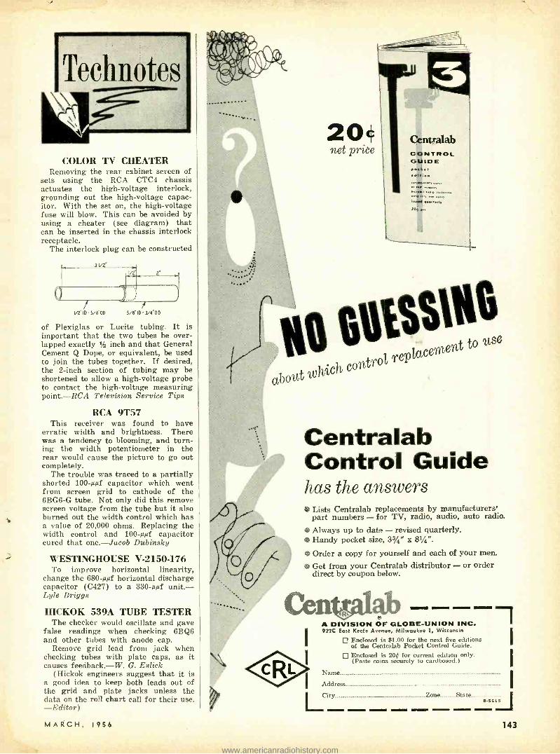
COLOR TV CHEATER Removing the rear cabinet screen of
sets using the RCA CTC4 chassis actuates the high -voltage interlock, grounding out the high -voltage capac- itor. With the set on, the high -voltage fuse will blow. This can be avoided by using a cheater (see diagram) that can be inserted in the chassis interlock receptacle.
The interlock plug can be constructed
1/2"ID5/EbD 5/(ID-3/4"OD
of Plexiglas or Lucite tubing. It is important that the two tubes be over- lapped exactly 3h inch and that General Cement Q Dope, or equivalent, be used to join the tubes together. If desired, the 2 -inch section of tubing may be shortened to allow a high -voltage probe to contact the high- voltage measuring point. -RCA Television Service Tips
RCA 9T57 This receiver was found to have
erratic width and brightness. There was a tendency to blooming, and turn- ing the width potentiometer in the rear would cause the picture to go out completely.
The trouble was traced to a partially shorted 100 -µµf capacitor which went from screen grid to cathode of the 6BG6 -G tube. Not only did this remove screen voltage from the tube but it also burned out the width control which has a value of 20,000 ohms. Replacing the width control and 100 -ppf capacitor cured that one. -Jacob Dubinsky
WESTINGHOUSE V- 2150 -176 To improve horizontal linearity,
change the 680 -µpf horizontal discharge capacitor (C427) to a 330 -µµf unit. - Lyle Briggs
HICKOK 539A TUBE TESTER The checker would oscillate and gave
false readings when checking 6BQ6 and other tubes with anode cap.
Remove grid lead from jack when checking tubes with plate caps, as it causes feedback. -W. G. Eslick
(Hickok engineers suggest that it is a good idea to keep both leads out of the grid and plate jacks unless the data on the roll chart call for their use. -Editor)
MARCH, 1956
20 'net prit'e
Centxalab CONTROL GUIDE p..ket
20e ..,
115 S00% replacement
to se
t control
aboca
Centralab Control Guide has the answers ! Lists Centralab replacements by manufacturers'
part numbers - for TV, radio, audio, auto radio.
0 Always up to date -- revised quarterly. ® Handy pocket size, 3%" x 81/4 ".
Order a copy for yourself and each of your men.
0 Get from your Centralab distributor - or order direct by coupon below.
e A DIVISION OF GLOBE -UNION INC. 922C East Keefe Avenue, Milwaukee 1, Wisconsin
Enclosed is $1.00 for the next five editions of the Centralab Pocket Control Guide.
Enclosed is 20¢ for current edition only. (Paste coins securely to cardboard.)
mel
I
I Name.. ... ......._ ............................................_......................................... .............................__
Address............_...._...__.._._ .............._........................................................ ...............................
LCity ....._......_. .. _ Zone State
B
143
www.americanradiohistory.com

CAN YOU THINK FASTER THAN THIS MACHINE?
Control Panel of GENIAC set up to do a problem In check valve research.
Be careful before you answer- GENIAC the first electrical brain construction kit is equipped to play tic -tac -toe, cipher and encipher codes, convert from binary to decimal, reason (in syllogisms) as well as add, subtract, multiply and divide. Specific problems in a variety of fields- actuarial, policy claim settlement, physics, etc., can be set up and solved with the components. Connections are solderless and are completely explained with templates in the manual. This covers 33 circuits and shows how new ones can be designed,
expe ience: one kit iusergwroteu "this thus kit has opened up a new world of thinking to me." You actually see how computing, problem solving, and game play (Tic-tac -toe, nim. etc.) can be analyzed with Boolean Algebra and the algebraic solutions transformed directly into circuit dia- grams. You create from over 400 specially designed and manufactured components a machine that solves problem. faster than you can express them. Schools and colleges, teachers of science or math, en. gineering, philosophy or psychology will find these excel. lent demonstrators of circuitry, solutions in symbolic logic, theory of numbers, cybernetics, and automation. Note: Teachers take advantage of our 10% discount to educational institutions and for group purchases.
four hundred ycomponents and parts, fully illustrated man- ual and wiring diagrams. We guarantee that if you do not want to keep GENIAC after one week you can return it for full refund plus shipping costs. MAIL THIS COUPON
SCIENCE KITS, Dept. RE-34, Oliver Garfield Co. 126 Lexington Ave., N.Y. 16, N.Y. Please send me:
1 GENIAC Electric Brain Construction Kit and Manual. $19.95 (East of Mississippi) 320.95 (Elsewhere In United States) $21.95 (Outside the United States)
Returnable in seven days for full refund if not satisfied. I enclose $ in full payment. My name and address are attached.
ADAPTER Write for Bull. 3548
TYPE 7B $2.25 TYPE 8B $2.50
TYPE 9B $2.75 (ILLUSTRATED)
plus shipping chgs. Min. size for use in crowded spaces RETMA color coded terminals Uses (All above chassis)
1. Modify circuits for max. performance and testing without soldering or unsoldering. 2. Break into any circuit for trouble shooting. 3. Measure voltage, resistance and current in con- junction with standard instruments.
1
A. L. PRODUCTS CO., INC. L -- .311 Hickory St., Kearny, N.J. - --J Watch for April
RADIO- ELECTRONICS
On Sale March 22
NOW IN STOCK at NIDISCO
L7E/COL COLOR
& MONOCHROME Laboratory &
TV SERVICE 5 -MC SCOPE
713 Newark Av. ,Jersey C
53 State St.,ltackensack, N.J: 294 Passaic St., Passaic. N. J.
658 Anderson Ar.,Cliftside,N.J. 126 S. Warren St. ,Trenton \.J.
NEW
e = Q ir _4). ;fit #460
KIT $79.95 Factory Wired $129.50
TELCO VHF -UHF ANTENNAS
Cover the Mass Market -109 Styles Available For Every TV Installation
WRITE for your TELCO Catalog or ask your supplier. FREE!
TELCO RANGER CONICAL A -100
TELCO GOLDEN HALO A -9000
TELCO X -BACK CONICAL A -160
TELCO ROTO -INDOOR A- 8160 -TP
.e."'
TELCO GOLDEN V A-8125
TELCO FLYING V A -260
TELCO GLOBE -TENNA A -9265
TELCO SKY -WING TELCO GOLDEN VAGI TELCO DELUXE TELCO CORNER A -300 A -320 BOW -TIE A -8965 REFLECTOR A -8984
TELCO ELECTRONICS MFG. CO. Division of General Cement Mfg. Co. 910 Taylor Avenue Rockford, Illinois
144
TECHNOTES (Continued)
STROMBERG 16 SERIES This series is fairly easy to work on
in comparison with other Stromberg- Carlson models. With some modifica- tions the 16 is similar to the TC -125 and 116 series. In cases of no agc or poor sync, check R11, R92, R91 and R115 (see diagram) for changed values. If the peak -to -peak voltage at the 6AU6 agc keyer plate is less than 150,
6AC7 B
FROM 75 PH 1201t.
VIDEO
5W,
VIDEO AMPL
.05 8.2K
+ 10 400pH
3 45- pH
TO FIX
- IOK Cl 2.2K 2W
RIIS 2W
R© iPtá 470ppf
RII 22n Ci 2
CONTRAST
6AU6 soc 5
R9
8+
2.7K 2W
B+
TO FLYBACK TRANS
475
0 MANUFACTURER'S CODE
B+
change the horizontal output trans- former if everything eise checks OK. To prevent picture blooming when the brightness control is advanced, replace R39, R66, R75, the bleeder string in the high -voltage cage with three 680,- 000 -ohm 2,000 -volt resistors in series. R70, a 220,000 -ohm resistor in series with the brightness control also causes blooming. Replace the 12AU7 vertical output tube with a 12BH7 if it is difficult to obtain height. Horizontal - oscillator instability is usually caused by the 6SN7 horizontal oscillator resis- tors (R54 -5,600 ohms, R58- 270,000 ohms) changing value or loss of Q in the ringing coil. -Wilbur J. Hantz
TURRET TUNERS It was noted that after the standard
job on turret tuners with dirty contacts (clean and apply the usual contact lube) was performed, the set would require the same job in six months or less.
Applying a very small daub of petro- leum jelly (Vaseline) with the tip of a toothpick (so as not to smear grease over the tuner strip) the job will stand up a year or more. Elmer Woods
RCA TV FUSE FAILURE An 0.3- ampere 250 -volt fuse with
wire leads (stock No. 78214) is now used in many RCA models. It should be replaced only with a fuse of the same rating.
When fuses blow out, examine the glass body interior to determine the cause. Where a small segment of the fuse link has melted, a defect in the horizontal deflection circuit is indicated. Check the horizontal output and damper tubes and watch for a possible inter- mittent resistor or capacitor in these circuits.
Failures where the fuse link has vaporized against the glass fuse body
RADIO -ELECTRONICS
i
www.americanradiohistory.com

STAN-BURN
E CATHODE RAY TUBE SPECIALS I I ONE YEAR GUARANTEE I
STAN- STAN -1 G.E. Type BURN G.E. Type BURN
$13.25 _. 108P4 ......$10.20 $31.25....17GP4 $20.75 I 18.00 _. IOFP4 14.00 32.25 I9AP4A .... 22.50 16.25 ... I2LP4A 13.95 27.40....20CP4 18.95 1
12QP4 10.50 33.00 ...21ÁP4 22.25 28.95 12 U P4 14.50 27.40....21 E P4 20.15 I 18.15 14CP4 13.40 33.25....21 MP4 23.50
15DP4 14.50 90.75 ...24AP4 49.00 1 31.25.._16AP4A .... 16.00 DUMONT TUBES 26.25 ... I6KP4 15.75 I2QP4A $23.75 1 31.25....16 G P4 18.50 15 D P4 26.55 29.00__I6LP4 15.25 I6DP4A 31.00 I 29.00.. ..16 W P4 15.25 16 F P4 22.50... I7BP4 15.75 17KP4
26 25.001
28.15 ...17CP4 19.50 19AP4A /B 33.25 21KP4 . 38.50 I
PRICES SUBJECT TO CHANGE WITHOUT NOTICE
I
I
I
I I
I
I I I I
I
1 $20 WORTH OF ELECTRONIC PARTS IN GRAB -BAG consisting of: Porcelain sockets, coils. speaker. trans Formers, resistors. condensers. etc. ONLY
(Plus 50e possta69e8) I
NEW G.E. PHONO CARTRIDGES G.E. Original Boxed
RPXO50A .001 and .003 (SS) S 6.78 RPX052A Golden Treasure (DS) 19.38 RPX053A Golden Treasure (DD) 28.08 I RPX040A .003 Single (5) 5.09 RPX041A .001 Single (S) 5.09 1 RPJO10A Dual (S) .001 and .003 .............. 1.92 RPJ012A Dual (D) .000 and .003 18.43 RPJ013A Dual (D5) .001 and .003 10.66 I RPJ010 or RPJ3D Single (D) 9.69 RPJO15 or RPJ03S Single (S) 1.29 I Replacement styli for RPX040 & 041 only. RPJ001 or RPJ005 Single (S) G.E 1.29 I RPJO03 or RPJ004 Single (D) 9.69
VM 3 SPEED HI -FI CHANGER -Model 950 with Ronette I Sonotone or Astatie flieover cartridge -BRAND NEW ORIGINAL CARTONS $21.49 I WEBSTER Model 140-3 -SPEED Automatic with I Ronette Sonotone or Asiatic flip -over car- tridge $22.49
RC54 Collaro -less cartridge $34.95 RC54 Collate with Ronette flip -over cartridge 37.95 I with G.E. plug in RPX05O 39.95 with G.E. plug in RPX052. 59.95 I
HALLICRAFTERS TV Model 17TS700M -Table Model -Dealers net $88.95 I Model 21T5460M -Table Model- Dealers net 129.46 I
ANTENNA ACCESSORIES P -800 JFD DOUBLE V" ant., box of 10 ea $ 1.39 FLASH- DOUBLE "V" lightning arrest.
1 Box of 12 ea 2.09 REGO- DYNAMIC BALL, SW /TYPE INDOOR
Ant. ea 2.69 I RMS -SW TYPE INDOOR Ant. List 9.95 ea 2.19 10' ALUMICOTE MASTS ea 1.19 I 5' SWEDGED MASTS ea .69 10 ELEMENT CONICAL ea 2.19 ZIP 5 JFD 10 ELEMENT CONICAL.... ea 2.39 I ZIP 2 JFD 8 ELEMENT CONICAL ea 2.19 SPICO S -8 INDOOR RABBIT EARS Ant ea .99 I JFD TA141 INDOOR RABBIT EARS Ant ea 1.19 JFD TA144 INDOOR RABBIT EARS Ant ea 1.29 1 55 MILL 300 OHM WIRE -1000 Feet 8.95 BO MIL 300 OHM WIRE -1000 Feet 12.49 100 MIL 300 OHM WIRE -1000 Feet 13.99 I
ATTENTION! Domestic and Foreign Auto Radio Dealers. Jobbers and Automobile Agencies. Our Auto Radio dept. can now supply you with CUS- TOM FIT MOTOROLA RADIOS. These radios are :,dapted by skilled machinists to fit exactly the same as factory Installed sets, without using complicated and unsightly panels. Send for samples to convince ourself. MONEY BACK GUARANTEE. All Models arc
Ì'US1I- BUTTON. PLYMOUTH '55.'56553.00 DODGE '55 -'56 54.00 OLDSMOBILE
'55 -'56 59.00 FORD '56 only 55.00 BUICK 'S5 -'56 66.00 Other modela available -
rite for prices. Our DELCO and GM dept. with your AUTO RADIO el
DISAPPEARING ANTENNA 53.35
3 SECTION COWL ANTENNA 2.19
12 VOLT 3 & 4 prong Universal vib 1.49
6 VOLT 4 Prong Universal vib 1.19
(Quantity users-write for quotations) rill be glad to supply you ctronie needs.
DEALERS: Write for low cost prices and catalogs On '58 models-HALLICRAFTERS. CRESCENT. FAN - NON, SONORA, WILCOX -GAY, TECHMASTER. G.E.. WESTINGHOUSE. TUNG -SOL. DeWALD, MAJESTIC. GRUNDIG, CAPEHART, DELCO, GEN. MOTORS. Address all inquiries to Dept. RE -3.
Our High Fidelity department will promptly quote on any item in the Hi -Fi held. Send us your list for our lowest quotations. We invite export inquiries and offers. Our export de- partment will give special attention to expediting foreign orders at minimum imum commissions. We are authorized distributors for United Motors. all Delco and Gen. Motors Auto Radio parts in stock. We also carry a complete line of popular makes of Radio Tubes at 50/10 discount. Also many other special purpose and transmitting types, and all elec- tronic parts and equipment at lowest prices. Send us a list of your requirements for prompt quotations. Terms: 20% with order. Balance C.O.D. All prices F.O.B., NEW YORK Warehouse. Minimum order $5.00. Write for our latest price list and Hi -Fi Catalog RE -3.
STAN -BURN RADIO and ELECTRONICS CO.
558 (ONEY ISLAND AVE. B'KLYN 18, N. Y.
MARCH, 1956
TEC H N OT ES (Continued)
can be due to an intermittent short in the 6ÁQ5 vertical output tube. In some cases this is caused by a momentary flashover that clears itself. -RCA Radio Phono Television Service Tips
TUNER INTERMITTENT FROM SOLDER BLOB
The photograph shows a part of a turret type tuner oscillator channel strip which caused an intermittent with some headaches. The trouble would occur only on rather hot days after considerable warmup of the set. A new channel strip was installed by the serv- iceman who brought the old one back
SDLDER EXCESS
to the shop for inspection. The solder blob shown in the picture was the only thing that seemed unusual about the coil strip so the turns were pried apart a little. The strip was then installed in a set and has been operating daily for months. James A. McRoberts
RCA T -120, T -121 Poor horizontal sync stability in
several of these sets was caused by a 150,000 -ohm grid resistor in the hori- zontal output stage.
Howard Sams' schematic shows a 1- meg resistor and for the KCS34C chassis a 470,000 -ohm resistor. The 470,000 resistor gives the best results. If the picture is narrow after chang- ing to 470,000 ohms try several 6SN7- GT horizontal oscillator tubes. Choose one that gives more than normal drive, first making sure the 5U4 -G and 6BG6- G are OK. Then align the horizontal oscillator. For the waveform adjust- ment connect a 15 -µµf capacitor (ceramic or mica) in series with the test lead. This is very important on scopes that don't have a cathode fol- lower input. -G. P. Oberto END
N -FM TUNER
4299.
NIGH I1DEWY
'.395
"Where's your low- fidelity depart- ment?"
HERE'S EVERYTHING YOU NEED TO KNOW ABOUT
OSCILLOSCOPES!
10511°4
MODERN
4111, lsid° AN tHE1R
U,.<
Service any Radio -TV ever built EASIER-BETTER-FASTER
Oscilloscopes are gold mines for serv- icemen who learn to use them fast and accurately -and here, in a completely re- vised 2nd edition, is THE book that really shows you how.
In plain, easily understood language, MODERN OSCIL- LOSCOPES AND THEIR USES teaches you just when, where and exactly how to use your oscilloscope. You learn how to handle tough jobs easier and faster than you may have dreamed. Every detail is clearly explained -from mak- ing connections to adjusting circuit corn- ... even in atomic ponents and setting oscilloscope controls.
Equally important, you learn to analyze patterns accurately in far less time. Almost 400 illustrations including dozens of pattern photos make things doubly clear.
'SCOPES ARE "GOLD MINES" when you learn to use them fully! This big book is more widely used than
any other of its type- because it gets right down to "brass tacks." No involved math- ematics. No complicated discussions. You learn exactly what the oscilloscope is and exactly how to use it on all types of AM, FM and television service (including color) -from locating troubles in a jiffy to handling tough realignment jobs.
Send coupon for 10 -day free trial.
PRACTICE 10 DAYS FREE! r Dept. RE -36, RINEHART & CO., Inc.,
332 Madison Ave., New York 16, N. Y. Send new Stud edition of 370 -page MODERN OSCILLO- SCOPES AND THEIR USES for 1O -day FREE EXAM- INATION. If book is what I want. I will then send You $6.50 promptly in full Payment. If not. I will return book postpaid In good condition and owe YOU nothing.
New ! Enlarged
2nd EDITION ..Contains latest data
on 'scopes and their uses.
MORE THAN 30 EXTRA PICTURES
plus 50 additional pages include newest
details on using mod-
ern oscilloscopes in
color TV, industrial electronics
energy work!
Name
Address
City, Zone. State OUTSIDE U.S.A. -Price $7.00. cash only. Money back Lif you return book in 10 davo.
Rinehart Buoks Are Sold by Leading Book Stores
145
www.americanradiohistory.com

HERSHEL SPECIALS
All New MYSTERY PACKAGE \ i /p of ELECTRONIC PARTS
,. i r Wn, 540.00 It's the surprise //w_ of your
tlso/ BEANO MEW 4.1.2'
/rise p,
_ ©. ® ' S39S Tova.alsgr:io. 1
% w;. w, Thom., etc.
% /I / ?,tl. ,t 701ós
`
n n Irates n sou
on
liiht. Ager Assembly ,dt Its
d 'M 9Yo. I Sim ilu to Parts Nit has fuses. vibrator,
Z3
Li
any
01y
Entra Instruction
* BRAND NEW
Electronic
PHOTO _I FLASH
, sso,Ib t. loo Watt
12 24 VDC. with Ignition
inc e strobe n IuÓee .10 /t.
433 11.1073. 4330.) Extra
1013 bulb. manual.
ARC -5 TRANSMITTER \
COMMAND
©5695 0 © 0e
gs 0 M 7 te 9l MC. Brand Neri in Carrons.
OIL
`moi
1- 1M New eau,,.
CONDENSER
$165 2 MFD. 3000 VDC. Pyranol Oil W,Mount-
/d. g 3000V DC.
removed from 4 ,a4 x 21/2,, V
tI I. Hottest Bey in t
with iebes.
e Country GE Pyranol Oil
CONDENSER 12 MF D. 330 VAC. 60
from S PHOTO ELECTRIC CELL e.,,. NEW
uaOAan,
n
954CE1t sound
useful I07tor. openneng garage doors d Alarm
Systems,
vt12T'z RCA Transformer Transformer
II P.P. SLOPS 25
IIEJ I
WA LTf órì. so0o in
ri tput SEC. SOO ohms,
4.95 s2 goo is te nms
- estons 15.000 cr. Cat.
ALL -PURPOSE FIL TRANSFORMER
Aw PRI. 117 v. 60 c7C. see.
t ° i G. r sta
'3; r. *''''''':
OBRAND
Ni Gain Dynamic Mike Kit Traansforme
Ta $195 taie Mike. Idi al for Hams,
AtoF,n0 NEW 495 Equip. CPS
rDD ág80 ñed.
SWING CHOKE 20-711 530 T
VARIABLE TRANSFORME'
moi 495 I KW ANT. CHANGEOVER
t t no VAC RELAY
~ I T / Am. 50.eo
Bee 80 If 5995
i IS Amp . . Ste. 2500 Volt
( b7.
r gip. DuaeeMd
1
Issvi - U.T.C.
TERMS: ALLIGATOR CLIP
ö1.Ftno t t. with 25[C
lade lug! Ideal 118IL test clip. TL.137.
Cash with order or 25% DOWN -BALANCE C.O,D.
ALL PRICES NIT F.O.B. DETROIT MINIMUM ORDER 52.00
H 5249
ER!Hio. E, TY ler 8-9400
GRAND RIVER Detroit 8, Michigan
EXtE SPÉp E V - tHE-jj'l
e. Fi-aaalitYó éseké ' i F
C tn 4".a
e ian
s Y DSB
C t either SOeayco h5t ar
............... ..
a:
CERO 63 G ILROY AVE. UNIONDALE. L.I. N.Y.
April RADIO -ELECTRONICS On Sale March 22
NOROIC, CUSTOM RADIOS FOR
1952 TO 56 FORDS Ito SUPERHETERODYNE BIG 6 x 9 INCH SPEAKER LOW BATTERY 90 90 DRAIN EASY INSTALLATION $38
PERMEABILITY TUNER WRITE FOR LITERATURE
NORDIC RADIO COMPANY BOX 582EVANSTON, ILL.
146
try
This one
SPEAKER REPAIRS When the voice -coil lead on a speaker
breaks close to the cone at a point that cannot be reached from the rear with a soldering iron, cut a V (not a tri- angle) in the cone over the spot where the lead is to be soldered.
Bend the point of the V outward and insert the soldering iron into the open- ing to make the repair. Bend the V- flap back, match the edges and apply cone cement to form a solid seam over the cut. If you are careful, the repair can be made without noticeably chang- ing the speaker's response. -Stanley Clark
TIMING SERVICE JOBS Most service technicians time the
labor on a service job by noting the time as the job is started and com- pleted. However, in some cases, there are many unavoidable interruptions and the job cannot be timed accurately. If interruptions cannot be avoided, try timing with a small self- starting elec- tric clock.
Set the clock to 12 and turn it on when starting a job. Turn it off when interrupted and on again when work is resumed. When the job is completed, the clock will record the total time consumed. -A. von Zook
PANEL PROTECTION An instrument panel and its decal or
silk- screened markings are easily de- faced by pointer type indicator dials. A sheet of clear plastic placed between the pointer and panel protects against scratches and preserves the original finish and markings. Two small 4 -36
screws are usually sufficient for mount- ing the plastic sheet. -Edwin Bohr
(Small control knobs without skirts also permit the fingertips to mar the panel finish and markings. Circular plastic discs cemented to the back of the knobs or fastened to the panel will eliminate this trouble. Editor)
Joe Servicem an
says:
"You can't 0.4 get somethin'
for nothin', especially Quality and Reliability
QUIETROL E TRADE MARK REG. V.S. PAT. OFF.
the original lubricant and cleaner for quiet- ing noisy controls and switches, costs little more than the cheapest imitations, but the name assures you are getting the best. INSIST ON QUIETROLE
THE CHOICE OF BETTER SERVICE DEALERS
"EVERYWHERE"
V
LUBRICANT
®A Ct[aN[e I- oaf1"Z$
: manufactured by
QUIETROLE COMPANY
Spartanburg, South Carolina
ask the " Man -on- the -Roof" why he prefers
TWO TO A SET
RATCHET TYPE CHIMNEY MOUNT
Model RT (Galt'. Banding) Model RT -ST (Stainless Banding)
FASTEST, SIMPLEST, MOST CONVENIENT EVER MANUFACTURED
Mounts in 2 simple steps- Complete- ly factory assembled with no eye- bolts, banding clips, nuts, etc., to handle. Furnished with flat -lay, non coiling banding, heavy gauge, em- bossed, welded steel construction. Forged, heat treated Alum. ratchets.
Write For Our Latest Catalog
SOUTH RIVER METAL PRODUCTS CO., INC.
South River, New Jersey
pioneer & outstanding producer of finest line of antenna mounts
RADIO -ELECTRONICS
www.americanradiohistory.com

TRY THIS ONE
1/2"
`O
we X I/16 "ALUMINUM HOLDING STRIP
FIN. ..
O
PWR TRANS
MOUNT
I "XI "ANGLE STRIPS (2) LENGTH AS READ
RECT TUBE
SOGMET MOUNT
MINIMUM LENGTH AS PER TEXT
SHADED AREAS CUT
OUT AS READ
CHOKE
MOUNT
O' /
FILTER CAP
MOUNT
FINAL SAW LINE
1 /2 "X I/16"ALUMINUM HOLDING STRIP
Fq.l
(Continued)
NOVEL CHASSIS CONSTRUCTION
I recently needed a narrow, odd -sized chassis for a small power supply. Un- able to purchase the size I wanted, I
improvised an extremely neat assembly out of two 1 x 1 x 1/32 -inch aluminum angles as shown in Fig. 1 (left).
The width can be varied according to the need and other combinations can be worked out using larger angles. The center slot is not unsightly and provides good ventilation. The alu- minum strips at the ends can be re-
WASHER d WOOD SCREW CHASSIS
Fig.2
WOOD BASE
moved after the components have been bolted in place. The chassis can then be sawed to minimum length. The chassis can be mounted on a wooden base with a wood screw and washer as in Fig. 2. -Alan M. Palmer
INSTALLING TV ANTENNAS An ordinary galvanized iron bucket
and a hank of 1/4 -inch sash cord or clothesline come in handy when install-
THE NEWEST!
K -3 CORNER SPEAKER CABINET KIT
kitform of the original corner speaker horn
... one of 39 new units! CC //
slightly higher west and south $54 Write for Complete 36 pages of radio furnitur Catalog for the hi .h Oddity ho
e kifs and speakers me music system.
99 North 11th Street, Brooklyn 11, N. Y.
largest manufacturer of cabinets and kits for hi fi o division or G d H Wood Products Co. Inc.
T w
You CAN QUICKty'
BE DOING INTERESTING
PROFITABLE WORK
LIKE ¡IRS
The future is YOURS in TELEVISION! A fabulous field -good pay -fascinating work -a prosperous future in a good job, or independence in your own business!
Coyne brings you MODERN -QUALITY Television Home Train- ing; training designed to meet Coyne standards at truly lowest cost -you pay for training only -no costly "put together kits." Not an old Radio Course with Television "tacked on." Here is MODERN TELEVISION TRAINING including Radio, UHF and Color TV.
No Radio background or previous experience needed. Personal guidance by Coyne Staff. Practical Job Guides to show you how to do actual servicing jobs -make money early in course. Free Life-
time Employment Service to Graduates. B. W. COOKE,
Presüdent
A TECHNICAL TRADE INSTITUTE OPERATED NOT FOR PROFIT
500 S. Paulina Street, Chicago 12, Dept. 36HT4
MARCH. 1956
r B!!
ú.! Coyne -the Institution behind this train- ing ... the foment, oldest, beat equipped residential sch ool of its kind. Pounded 1888.
Send eaaraa 104 q/aee Booh and full details, including easy Payment Plan. No obligation, no salesman will call.
FCOYNE Television Home Training Division 500 S. Paulina St., Chicago 12, Ill. Dept. 36 -HT4 Send Free Book and details on how I can get Coyne Quality Television Home Training at low cost and easy terms.
Name
Address
City State
147
www.americanradiohistory.com
THE MUSICAL MASTERPIECE SOCIETY INVITES YOU TO ACCEPT / /I®
II/
y
dll
4,s'''"etherlands Philharmonic Orchestra and Chorus Under the Baton of Walter Goehr A!! Three Symphonies Complete To The Last Note! The Most
Astounding Record Offer Ever Made I
PRE BEETHOVEN'S SYMPHONY
(The Chorale) phis Beethoven's 1sT god 8TB Symphonies
O demonstrate the amazing value, the magnif- icent artistry of the Society's recordings take this majestic new album of BEETHOVEN'S NINTH ... plus Beethoven's 1st and 8th sym- phonies-as a FREE GIFT! No obligation to buy
another record ever. We simply want to introduce you to the enjoyment awaiting you in all the new releases listed below. Great masterpieces per- formed by world renowned artists and orchestras
. reproduced on high -fidelity discs encompass- ing the entire range of human hearing.
1 THE MUSICAL MASTERPIECE SOCIETY. Dept. 52 -3 43 W. 61st St.. New York 23. N. Y. Rush my FREE GIFT album of Beethoven's 9th, 1st and 8th symphonies. Also deliver for a 5 day free home trial the long- playing selections I have NOT crossed off at the right, about one a month. I will be billed only for those I keep - at only $1.65 plus shipping, per long -playing disc. I may re- turn any recording, and pay nothing. I may cancel my Trial Membership at any time. Free Gift is mine to keep in any case.
Name
Addree8
Litt' Zone.. State
Save Over 40% off usual cost When you send for your FREE GIFT Recordings, you also become eligible to audition FREE any or all of these 30 additional discs at the rate of two a month. Pay only $1.65, plus shipping, for each you keep. Pay nothing for those you don't want after 5 day trial. FREE GIFT is yours in any case. Mail coupon now!
Just Imagine the Fabulous Record Collection - You Can Build From This List!
(Cross out only those you do want to audition Free) I. DVORAK: Symph. No. 5 2. TCHAIKOVSKY: Violin Con. 3. MOZART: Plano Con. No. 24 4. BACH: Magnificat in D 5. BEETHOVEN: "Emperor" Concerto 8. BIZET: Symph. in C 7. VIVALDI: Four Seasons 8. SCHUMANN: Piano Concerto 9. HAYDN: Trumpet- Concerto, and Flute - Concerto 10. SCHU- BERT: "Trout" Quintet 11. MOZART: "Jupiter" and 17th Symph. 12. CHOPIN: Piano Con. No. 1 13. BACH: Violin Con. No. 2 14. RIMSKY -KORSAKOFF: Capriccio Espagnol; Mussorgsky: Intro. to "Khovantchina" 15. DEBUSSY: Quartet in G; and Sonata for Cello and Piano I8. BEETHOVEN: Appasslonata" and "Moonlight" Sonatas 17. BRUCH: Violin
Concerto; PAGANINI: La Campanella 18. MOZART: Clarinet Quin. in A 19. SAINTSAENS: Violin Concerto No. S 20. MOZART: Symph. Nos. 40 & 34 21. GOLDMARK: Rustle Symph. 22. BEETHOVEN: Symph. No. 7 23. CHOPIN: Sonata No. 2 24. HAYDN: "Surprise" and "Military" Symphe. 25. FRANCK: Symph. in D 26. STRAVINSKY: Firebird, and Piano Con. 27. SCHUBERT: Symph. No. 3 28. PROKO- FIEFF: Violin Con. No. 1 and Piano Con. No. 1 29. MEN - DELSSOHN: "Scotch" Symph. 30. DVORAK: "American" Quar. J
148
TV TOWERS Safe Long Lasting Easy to Install
JONTZ
Sell the line that is , . "Really Built" to do the job.
AVAILABLE at better jobbers . .
EVERYWHERE
Carry and sell the line that is really built to do the job. JONTZ TOWERS hove every. thing . . fine 14 gauge tubular steel; simplicity of erecting; easier to climb; guarantee maximum safety; self-supporting; withstand wind load up to 100 m.p.h.
MANUFACTURED BY
JONTZ MANUFACTURING CO. 1101 East McKinley, Mishawaka, Indiana
TRY THIS ONE (Continued) ing TV or FM antennas on a roof. In the bucket I keep two end wrenches, a hammer, oil can, sandpaper, a paper bag of assorted nuts and bolts, pliers, screwdriver, cutters and other tools I may need. Stick one end of the mast
in the bucket and throw a couple of half- hitches of line around the other end. Carry the line to the roof and haul away. See drawing. It's easy to hoist antennas in cartons this way too.
Always keep your tools in the bucket. It is easy to lose them if you lay them on a roof. Frank W. Dresser END
CORRECTION In his article "Transistor Demodu-
lator Probe" in the September issue, Mr. Davidson inadvertently showed the 1N34 detector diode in a series type detector circuit that will not work because there is no d.c. return to the input side of the diode.
Correct this error by shunting the 1N34 directly across the 1,000 -ohm resistor with its cathode terminal connected to the ground line.
We thank L. D. Oder, of New London, Conn., for spotting and reporting this error.
The photos in Figs. 5 and 6 of Middle - ton's article "Again -the Matrix" in the November issue were transposed. The captions are correct as printed. This obvious error was spotted by Ed Zreet, of KTBC -TV, Austin, Tex.
RADIO -ELECTRONICS
www.americanradiohistory.com

William J. Hal- ligan, Sr., founder of Hallicrafters Co., Chicago, was re- elected chairman of the board and elected president to succeed Raymond W. Durst, who withdrew from an active managerial position because of personal interests. Durst will con- tinue as a member of the board of directors.
William J. Halligan, Jr. was elected vice president -sales. He has been man- ager of shortwave communications sales and a director. Robert F. Halligan, director of operations for the past two years, was also elected a vice president.
Clifford W. Perk- ins, chief comp- troller of both Walter L. Schott Co. and Walsco Electronics Corp., Los Angeles, will assume additional duties as secre- tary- treasurer of
the Walter L. Schott Co. and secretary of Walsco Electronics.
Irving I. Ser, as- sistant sales man- ager in charge of original equipment sales for Astron Corp., East New- ark, N. J., was pro- moted to the posi- tion of company sales manager.
J. W. (Jack) Merritt was promoted to sales manager of the new Photofact Division of Howard W. Sams & Co., Indianapolis. He joined the company in 1948 and has since served in various sales capacities. Other appointments in line with the company's expansion plans include W. W. (Bill) Hensler, tech- nical editor of the PF Reporter, to sales manager of the Book Division; J. H. (Joe) Morin, sales manager of the PF Reporter, sales manager of the new Magazine Division; W. D. (Bill) Ren- ner, Jr., one of the original 12 who started in the company's Engineering Department, to head the Educational Division; Joseph O. (Joe) Goetz of the sales staff in charge of the Customer Service Division; A. E. (Archie) Cut - shall, production manager, advertising
MARCH, 1956
u turomic CHICAGO 8, ILL.
World's most progressive probe manufacturer announces two more important new probes for your V.O.M. Provide more uses for your V.O.M. than ever before.
NEW!
NEW!
WORLD'S FIRST
WORLD'S FIRST
TYPE 263 Polarity Reversing Probe -Gives you finger -tip control of polarity. Saves time and annoyance. Use with any V.O.M.
Net $6.95 TYPE 264 Range -Splitter Probe -Converts the 250 volt d.c. range to a 500 volt range at the flip of a switch. Use with any 20,000 ohms -per -volt V.O.M. having a 250 volt range and a 50 volt range.
Net $9.95 TYPE 261 High -Ohms Probe -Gives you an additional Rx100,000 ohms range on your V.O.M. Used with the most popular types of 20,000 ohms- per -volt V.O.M.s having an Rx10,000 ohms range, with 12 ohms center scale indication. Measure high resistance leakage.
Net $9.95 TYPE 262 Signal- Tracing Probe Converts your V.O.M. into a signal tracer. Check signal voltages in horizontal and vertical sync and sweep circuits, high frequency and I.F. circuits. Use with any 20,000 ohms -per -volt V.O.M.
Only $9.95 net Probes are gold -plated, with high grade components throughout. Complete, with full operating instructions. Nothing else to buy. Satisfaction Guaranteed. Rep. inquiries invited.
Order your FUTURAMIC probes from: '
U. S. RADIO & TELEVISION SUPPLIES, INC.
6346 SOUTH ASHLAND AVENUE CHICAGO 36. ILLINOIS
N
find your way fo the trouble with a arurdmic probe
EBEABROKER PAYS BIG! SEND FOR FREE, BIG, ILLUS TRATED CATALOG NOW! Graduates report making substantial incomes. Start and run your own business quickly. Men. women of all ages. learn easily Course covers Sales. Property Management. Appraising, Loans. Mortgages. and related subjects. STUDY AT HOME Or in class- room,- in leading cities. Diploma awarded.. Write TODAY for free book! No obligation.
Approved for World War II and Korean Veterans WEAVER SCHOOL OF REAL. ESTATE (Est. 195e) 2022L Grand Kansas City, Missouri
Please send me the following Y.O.M. probes: Type 261 High Ohms Probe, $9.95 Type 262 Signal Tracing Probe, $9.95 Type 263 Polarity- Reversing Probe, $6.95 Type 264 Range Splitter Probe, $9.95
I am enclosing $I down for each probe ordered. Upon delivery, I will pay postman balance, plus postage.
Name (please Print)
Address
City State
E TEST aoid REPAIR PICTURE TUBES "Right on the Job"
CENTURY'S CRT
TESTIVATOR BUILD YOUR OWN JENSEN HI -FI SPEAKER SYSTEM SEND FOR NEW BOOK TODAY! Save money ... build your choice of 18 different hi -fi speaker systems with 8 new 2 -way and 3 -way Jensen speaker kits. 36- Page Manual 1060 given complete instruc- tions for building enclosures, selecting your Jensen speaker kit and assembling. Send 50c in coin today/ JENSEN MFG.CO.Dept. H 6601 S. Laramle,Chicago 38
do you want to learn TV servicing? Just master the first few chapters of
ELEMENTS OF
TV SERVICING by ABRAHAM MARCUS and
SAMUEL GENDLER
And you are ready for business! Written in the same clear. easy -to- understand style that sold over a snit- Ilan copies of MARCUS' famous ELEMENTS OF RADIO. Chapters 3 to 5 cover servicing in the field -servicing that takes care of over 80% of all service calls. Chapters 6 to 14 cover bench servicing which accounts for the remainder of the service calls. Chapters 15 to 17 cover the theory and servicing procedures for color television.
THE ONLY BOOK THAT GIVES FULL DETAILS OF THE NEW RCA 28 -TUBE COLOR TV
CIRCUIT 587 pages fully illustrated in black- and -white and in
color
Published by Prentice -Hall. Get your copy today!
NVcw Profits! More Sales! Saves Tithe! Saves
Trouble!
With Model 303 CRT TESTIVATOR you can repair picture tubes right in the net in
103 matter of minutes The TESTIVATOR tells you INSTANTLY
what the trouble is and THEN FIXES IT!
IT TESTS: leakage between elements s Open elements Probable useful life of the tube.
IT REPAIRS: Activates the CRT cathode by removing surface nation
Restores emission giving life to weak and dim tubes Clears inter -element shorts and leakage.
So easy to use . you just plug in, attach the TESTIVATOR socket to the base of the CRT and
accurate, the accurate, easy -to -read indicators tell you what you must (Complete cables and instructions included.)
FREE BONUS: Order now and receive a handy. valuable booklet listing radio
and TV tubes (incl. CRT's) which can be substituted with NO WIRING CHANGES. Another profit maker for you.
10 -Day Free Trial -Money Back Guaranteed
- -- -NOW! PAY AS YOU EARN--- - CENTURY ELECTRONICS CO., Dept. RE -3 111 Roosevelt Ave., Mineola, N.Y. Et Enclosed is $5.00 down payment. Please send me
Model 103 CRT TESTIVATOR. After 10 days, if not completely satisfied. I will return it for a complete refund -Or I will send 55.00 a month until the full price of $14.95 plus postage is paid.
Name
Address
City State
this AOrdeSNIPPIN we CHARGES! Enclose
shipping costs 5 catsh
same refund privileges.
149
www.americanradiohistory.com

0G -C RADIO- TELEVISION PRODUCTS AT YOUR DISTRIBUTOR
WRITE for your G -C Catalog or ask your supplier. FREE!
G -C TEST SOCKET ADAPTER KIT
Complete, for all tests. No. 9250
G -C 300 -OHM LINE TOOL
Slot, strip, cut twin leads No. 9220
G -C VINYLITE CEMENT Great adhesion; many uses;
2 oz. No. 58 -2
G -C DUAL SHEET METAL PUNCH
Two punches-7," x
No. 9260
G -C RADIO -TV SERVICE CEMENT High grade adhesive.
No. 30 -2
G -C DUAL TUBE PIN STRAIGHTENER
For both 7 and 9 pin tubes. No. 9092
G -C SPRA -KLEEN Contact Cleaner
No. 8666
G -C TV CHASSIS SUPPORTS
Tilt chassis safely. No. 9176
G -C ECONOMY TEST LEADS
Tenite 5" prods, 50" leads. No. 9190
G -C ALIGNMENT KIT Roll case and 9 matched
alignment tools. No. 5023
GENERAL CEMENT MFG. CO.
G -C K -27 PRINT -KOTE Pressure spray silicone resin.
No. 14 -6
910 Taylor Avenue
G -C SPRAY DE -OX -ID Cleaner for radio,
TV controls. No. 19 -6
Rockford, Illinois
WHEN A FINGER TIP WILL DO THE JOB FOR YOU...,
How many times have you had to lift and turn a big chassis in order to get the light correctly focused so that you could make a
solder connection...or look for a broken lead? All this extra work can now be eliminated if you put a LUXO LAMP above your bench.
LIGHTWEIGHT AND PORTABLE... YET SO STURDY! The remarkable LUXO LAMP directs all the light where you want it. With just the touch of a finger, you can raise, lower, turn or tilt it to any angle ... get just the desired focus, direction and intensity of light. Comfortable to work under, too, because it eliminates reflections and disturbing shadows ... and provides glare -free illumination.
INSPECT THE LUXO LAMP AT YOUR JOBBER TODAY! See for yourself why LUXO Is the ideal lamp for your service bench,
Approved by UNDERWRITERS LABORATORIE
INC.
150
LUXO LAMP CORPORATION TUCKAHOE, N.Y. SAN FRANCISCO, CAL. MONTREAL, QUEBEC
PEOPLE (Continued)
manager. The photo shows, left to right: W. D. Renner, W. W. Hensler, A. E. Cutshall, Joseph O. Goetz, J. W. Merritt and J. H. Morin.
Charles T. Gab - riele joined Tel - rex, Inc., Asbury Park, N. J., in the position of adver- tising and public relations manager. He came to the company from Thomas A. Edison, C. T. Gabriele Inc.
A. Batcheller
Arthur Batchel- ler retired as en- gineer in charge of the Second Radio District of the Federal Communi- cation Commission after 38 years of service. He joined the Department of
Commerce Radio Division in 1917.
Obituary Kenneth Kistler, traffic manager of
Allen B. Du Mont Labs., Clifton, N. J., suddenly at his home in Fairlawn, N. J., at the age of 39.
Personnel Notes ... Harold Metz was appointed direc- tor of personnel and organization de- velopment for RCA. He had been di- rector of personnel. Arnold K. Weber, director of organization development, was named director of manufacturing.
Thomas H. Moss, active with the Turner Co., Cedar Rapids, Iowa, for a number of years, was appointed jobber sales manager according to an an- nouncement by Renald P. Evans, presi- dent of the firm. H. M. Murdock con- tinues as general sales manager.
... Helen Staniland Quam, distribu- tor sales manager of Quam- Nichols Co., Chicago, resigned as treasurer of the Association of Electronic Parts & Equipment Manufacturers because of the pressure of company business. She retires from the post after 20 years' service.
. Paul F. Leopold was appointed sales manager of the Home Instrument Division of Crescent Industries, Chi- cago. He had been assistant sales man- ager.
... Glenn Hall was promoted to ad- vertising manager of Clarostat Manu- facturing Co., Dover, N. H. He was
RADIO-ELECTRONICS
www.americanradiohistory.com

SENSATIONAL ... is the word for the Miller #595 NEGATIVE MUTUAL
COUPLED BROADCAST BAND -PASS DIODE TUNER
Only 4 x 7 x 3 %2 " Deep
The most amazing High Fidelity Broadcast tuner ever
offered to music lovers anywhere. High Fidelity fans will be pleasantly surprised with the tonal quality, selectivity, and sensitivity of this marvelous tuner. The frequency response is limited only by the audio system used. Freq. Range 540 KC to 1700 KC.
A beautiful Black or Ivory bakelite cabinet houses the
tuner with a Richlow brass etched panel for the
escutcheon. Both combine to complement any decor.
Like all Miller products this #S95 tuner is guaranteed
to perform to your satisfaction. Buy from your Radio and
TV Ports Distributor, or High Fidelity Dealer.
#595 Tuner net price only $19.50 plus excise lox.
SEE YOUR DISTRIBUTOR FOR LITERATURE OR WRITE DIRECT
J. W. MILLER COMPANY 5917 S. MAIN ST., LOS ANGELES 3, CALIF.
LEARN TV the T ractical way --
BUILDdeveat TRANSVISION
TV KIT *THIS MODEST INVESTMENT gets you started on a most fas- cinating project - assembling the new "E" type Transvision TV Kit in easy stages. For S15 you get PACKAGE #1 (standard first package for all new "E" kits). This package gives you the BASIC CHASSIS and required first -stage TV COMPONENTS, with complete instructions. When ready, you order the next stage (pkg. #2), etc.
PROFIT 3 WAYS:
QT Learn TV
Clove up to S0%
p Prepare for COLOR TV
Shows 8 Ono TV kits: EXCLUSIVE: Only Transvision TV Kits are adaptable to UHF. Ideal for FRINGE AREAS. No Previous Technical Knowledge required. Write now!
TRANSVISION NEW ROCHELLE, N. Y.
. MAIL THIS COUPON TODAY . -- TRANSVISIOFT, INC., NEW ROCHELLE, N. Y. Cepl. RE-3
I I'm enclosing S deposit. Send standard kit
PACKAGE .1, with all Instruction Material. Balance C.O.D.
I ID Send FREE copy of your new TV ICI Catalog.
1 Nome
I Address
City State
1
1
MARCH, 1956
PEOPLE (Continued)
formerly a technical writer with the company and set up its replacement television program. George H. Immen joined the company as applications en- gineer. He has held various electronic engineering and sales positions during the past 25 years.
... Irwin Goldman was appointed manager of technical planning for the Research Laboratories of Sylvania Electric Products. Prior to this ap- pointment he headed the technical serv- ices of Sylvania's Physics Laboratory. Dr. Edwin G. Schneider, former man- ager of Sylvania's Missile Systems Laboratory, was named chief engineer of the Electronic Systems Division.
. Abe Kosakowsky joined Pyramid Electric Co., North Bergen, N. J., as sales service engineer in the Jobber Division. He comes to the company from Steelman Radio & Phonograph Co.
Russell Jornd, chief engineer in charge of tool processing for Littelfuse, Des Plaines, Ill., was promoted to direc- tor of engineering; John Marquis, chief electrical engineer, to chief engineer of circuit breaker and thermo devices; Art Steele, fuse engineer, to chief en- gineer in charge of fuses, and Leon Uhl, research engineer, to chief re- search engineer.
... Peter Schnipper, assistant quality - control supervisor of Triad Trans- former Corp., Venice, Calif., was pro- moted to manager, quality control de- partment.
Dause L. Bibby joined Daystrom Inc., Elizabeth, N. J., as executive vice president. He had been vice president of International Business Machines.
Niles P. Gowell was appointed chief engineer of the Raytheon Manu- facturing Co.'s Receiving Tube Divi- sion, Waltham, Mass. He formerly headed its Quality Control and Appli- cations Engineering Departments. John M. Palmer was appointed manager of manufacturing for the Receiving Tube Division. He has had more than 20 years experience in tube manufacturing and was most recently with Lansdale Tube Co.
... Stanley F. Patten was elected treasurer of Allen B. Du Mont Labs., Clifton, N. J., in addition to his duties as vice president and a director. He succeeds Paul Raibourn who continues as a director of the corporation. Nich- olas De Falco, assistant general quality - control manager of Allen B. Du Mont Labs., was promoted to general quality control manager.
Thomas P. Walker, vice president of Triad Transformer Corp., is to head the Los Angeles Council of the West Coast Electronic Manufacturers Asso- ciation. END
Lektron's SPRING
DOLLAR SALE! PLUS -ANY ITEM IN THIS AD FREE
WITH EVERY $10 ORDER!
El 12 AC -DC LINE CORDS. POSJ type. 2 rond. #18
stranded. Rubber Jacket w /m,dded plug. Wt. 1 $
+ Ib. Reg. $2.50 D 5 ROLLS TAPE. Guar-
anteed fresh. Cellophane wrapped. Friction. plastic. rubber. Wt. 1 lb. .$1. Reg. $2.50 D 90 MINIATURE BULBS.
Asstd. standard screw & bayonet types. 1.1 thru 6 V. Wt. 1/2 lb. $1 Reg. $4.00 D 100 STEATITE COIL
FORMS. Builders' spe- cial! Many sizes. styles. Some worth $2 ea. Plus 30 asstd. iron slugs FREE. $1 Wt. 2 Ohs. Reg. $15 D 125 CARBON RESIS-
TORS. 30 values; 100 ohms to I meg. tin. 1/2, 1
& 2 Uninsulated. Wt. $1 1 lb. Reg. $21
10 VOLUME CONTROLS. Asstd. values for radio.
TV. lab. 10 ohms to meg. Wt. 2 Reg. $9.00
13 -PC TWIST DRILL KIT. 1/16 thru 1/4" to
St 1/4" chuck. Fine tempered steel. Plastic case. Wt. $1 1 lb. Reg. $3.00 D G -E PRE -AMP KIT,
Chassis. condensers, re- sistors. wire. socket. sche- matic. Uses 6SC7 (comes less tube). Wt. 1 lb. $ Reg. $4.50
150 RADIO PARTS! Large amt. of coils. ce-
ramics. paper. moulded & condensers. resistors. $1 Wt. 1 Ib. Reg. $30 D 25 TUBE SOCKETS.
4 to 14 pins. subminia- tures. miniatures. Metal, octal. 15 types. Mica & ceramic. tool Wt. 1 lb. $1 Reg. $9 O 3 LOS. HOOKUP WIRE.
Repeating a sellout! Hundreds of pre -cut lengths in asstd. sizes. colors. Stranded. lengths up to $1 18" Reg. $9 D 00 MICA CONDENSERS.
Postage stamp types. 25 values: .00001 to .01 mf. Many silver. 5
r " too! $1
Wt. t/z lb. Reg.
D 20 POWER RESISTORS. Wirewound. candohm &
tnbular.20 values to 10.000 ohms: 5 to 50 w. Wt. 1 $1 lb. Reg. 512.00
60 CARBON RESIS- TORS, insulated. 35
values: 15 ohms to 10 megs; 1/2, 1 & 2 w. Ma i' ß 1 & 5'o Wt. 1/z lb. $ Reg. $18
50 CERAMIC CONDENS- ERS. Cartwheel. disc.
button. standoff & tubular types. 25 values: 5 mmf to 01mf. Duals, too! Wt. 1/2 lb. Reg. $18
8 -PC POCKET TOOL CHEST. 2 Phillips. 2
screwdrivers. chisel, awl, tackllfter. plastic handle. 1 Wt. 1 lb. $3.50 value $
D 10 ELECTROLYTICS. FP & tubular. 8 to 1000
mf up to 450 V. Multiple sections. too. Some $2.50 each! Wt. 2 lbs. $1 Reg. $18 D so INDUCTORS. Wide
variety -slug- tuned: RF. ant.. peaking coils: RF & mtg. chokes. Shoo musts
Wt. 1 lb. $1 Reg. 521
50 KNOBS, instrument, radio. TV & appliance
types: knurled. skirted. push -on. pointer types. Some 50e ea. Wt. 1 lb. $1 Reg. $12 D 3 SELENIUM RECTI-
FIERS. One each 24 VDC
1 .5A: 12 VDC @ .25A: one meter or instru- ment type. Wt. 1 lb. $1 Reg. $15
80 TUBULAR CON. DENSERS. 30 different
values: .00035 to 1 mf. to 1600 V, Oils & Mouideds, tool Wt. 2 lbs. $1 Reg. $l0
1000 PCS. SPAGHETTI. Asstd. sizes, colors. in-
sulation. Lengths to 4 ". Builders' te! Wt. t.O $1 lb. Reg. ST
O 8 -PC NUTDRIVER KIT. Plastic handle. 3/10.
7/32. 1/4, 5/16, 11/32, a/s. 7/16" steel socket
in plastic case. Cl $ Wt. 1/2 lb. 53.50 value
D 4 POPULAR DIODES. Exclusive! One each:
1N21. 1N22. 1N23. 1N34A in poly bag. t Reg. $11 i
40 MOULDED CAPACI- TORS. .001 to .25 mf
to 1000 V. Asst. values. makers. Wt. 2 lbs. $1 Reg. $14
2000 PCS. HARDWARE. Screws. washers, lugs,
grommets, tc. Wt. 3 ;1 lbs. Reg. $11
6O TERM, STRIPS. BOARDS. Wide variety.
1 to 12 solder lug points, binding posts,
WL too.
1 guild-
Reg. 56.OÓ $1
D TEN CHASSIS! Scoop!! 2 to 6 tube -tor Pre -
amps. amplifiers. power supplies. Wt. 3 lbs. G Reg. $9.00 '+
15 ROTARY SWITCHES. Experimenters. tel Varied asst. single & dual gangs. Wt. 2 lbs. $1 Reg. $17
10 PANEL SWITCHES. Asstd. micro, toggle.
push: mobile types. too! Some worth 52. Wt. 1 ti1 lb. Reg. 512 D 15 PRECISION RESIS.
TORS. UP to 100 mega. Asstd. values, Infra, wat- tage. Some 1/2 c. included! Wt. 1 /alb. $1 Reg, $24
THIS MONTH'S SPECIALS! FIVE IF TRANSFORMERS, 455 KCS. $1 I1:0. $1.111 each FIVE FULL WAVE RECTIFIERS. 12 VDC @ 250 $1 10 SLUG -TUNED COILS, 1000 DtCS. $1 Reg. 69c each SIX 100 MEG 5% PRECISION RESISTORS. $1 Reg. $1.00 each 0 -60 MINUTE TIMER, BELL ALARM. $1 Reg. $5.00 each 5 XMTG. CHOKES, 250 MICROHENRIES $1 Reg. $1.50 each 10 XMTG. CONDENSERS. .01 -600, low loss type $1 Reg. $2.00 each 15 ERIE VARIABLES, 8 -SO MMF. $1 Reg. 89e each 2 DeJUR PRECISION POTS. 20.000 ohm. 6 watts $1 THREE 200 MA CHOKES. 2 Henries. $1 Reg. $1.50 each TWO 4 MF, 600 V OIL CONDENSERS. $1 Reg, $4.50 each 1 PR. 5" re- cutting DIAGONAL PLIERS. $1 Reg. $2.00 3 VARIABLES, DUAL GANG, 3.15 mmf. $1 Rog. $1,40 each
FREE -BIG BARGAIN BULLETIN
Check items wanted. Return entire ad with HOW TO'cheek or MO. Incl. sufficient postage, .... ORDER returned. C.O.D. orders, 25% down. Rated.
Net 30 days. RE -3
Name
Street
City Zone State
Enclosed S for kits, S for Postage.
(Please PRINT)
LEKTRON SPECIALTIES 28 Gardener Street Chelsea 50, Mass.
Visit Our Showroom at 131 Everett Ave., Chelsea
151
www.americanradiohistory.com

NO FREE GIFTS! NO ^DUPONS! EXCEPT THE
LOWEST TUBE PRICES rBRAND NEW
famous make
PICTURE
TUBES DUMONT and RCA
licensed
One Year Guarantee
In original factory sealed carton
PRescott 3 -0330
NO REPLACEMENT DUD Type
10BP4A 12LP4A 16AP4A 16RP4 16WP4A 17BP4A 19AP4 20CP4 21ALP4A 21AUP4A 21 EP4A 21FP4
List Price 19.25 24.25 44.75 36.75 41.50 32.00 39.75 39.00 46.00 46.00 39.00 39.75
REQUIRED! T. M. Price
11.95 14.99 19.99 17.95 18.00 19.00 23.00 24.00 24.00 24.00 24.00 24.00
F.O.B. Passaic, N.J. . Subject to prior sale. Write for complete tube listing. Including Special Purpose cnd Transmitter tubes.
TUBE MART The Lokpet Bldg. Passaic, N. J.
DISCOUNT
HOUSE
TAPE RECORDERS Tapes- Accessories
Nationally Advertised Brands UNUSUAL VALUES
Send for Free Catalog
DRESSNER Box 136RE, Peter Stvant Sta.,
New York 9, uyN. es
Y.
MERI TAPE Low Cost. High Quality Record- lfig Tap boxes or ln r cans.
m WH GET up To
40% OFF
LESALE: Service at Nane,
'MME NrntNANOnf rga + Start a Buying
Seenowt. 4Er 64. spt_r AND CUENTS uD ro Opt. LEss o o REG Doro SALES EASW. AS CAN UK S,rfAelE 00Sí STU MANE Fai CAMM S. Aut C Wbwgs NtifA.W7hMYtelatixM'
American Buyers Service FREE:
Mba DEPT. RE. HERTEL STATION BUFFALO, NEW YORK
6 -VOLT BATTERY SOLDERING IRON AND WELDER U.S. Army release. Brand New -Never Used. Fully Guaranteed. This soldering iron can be used to solder or weld when connected to any six -volt storage battery. Uses approximately 200 to 300 watts. The high intensity arc created between the metal to be soldered and the carbon electrode (carbons supplied free with iron) can be used to heat tin or aluminum solder. Suitable also for light brazing and spot welding. Arc can be used
APPROX 200 TO
300 WATTS
ITEM NO. 126 UNUSUAL BUY
for melting metals, cutting holes and soldering seams in chassis. Also useful for ana- lyzing metals and minerals.
Battery soldering iron out- fit includes 2 carbons, 3
heavy duty spring clips, 2
pieces 5 ft. heavy duty wire cable. (Battery not included.) Ideal for use where current is not available. Ship wt. 4 lbs. $1.95
P.P. á Halo. Chgs. 50e)
VARIABLE SPEED UNIVERSAL MOTOR FOR 110 VOLTS. A.C. OR D.C. Used, but in excellent condition. Special lever control permits varia- ble speeds up to 3000 r.p.m., 1/4" shaft extends from both sides of
motor. Measures 71/1 x 31/4" diam. overall Shp. Wt. 03/4 lbs. ITEM NO. 127 Your Price $2.45
PP. & Hdlg. Chgs. 75c
(P.P. a Hdlg. Chgs. 51.25)
WATTHOUR METER Leading makes - reconditioned. Ideal for trailer parks. 100 -I10 volts, 60 cycles, 2 -wire A.C. 5 amp. Heavy metal case 81/2" x 61/4' x 5 ". Easy to install. Ship. wt. 14 lbs. ITEM NO. 33 $4.50
AMAZING BLACK LIGHT 250 -watt ultra -violet light source. Makes fluorescent articles glow in the dark. Fits any lamp socket. For experimenting, entertaining, unusual lighting effects. Ship. wt. 2 lbs. $2.45 ITEM NO. 87
(P. P. & Hdlo. Chns. 35c1
POWERFUL ALL PURPOSE MOTOR Sturdy shaded pole A.C. induc- tion motor. 15 watts, 3000 rpm. 3 "x2 "x13/ "; 4 mounting studs; ) /e" shaft, 3/16" diameter; 110- 120 volts, 50 -60 cycles. A.C. only. ITEM NO. 147 $2.45 UNUSUAL BUY
(P.P. L. Hdlg, Chgs. 35c)
250 POWER TELESCOPE LENS KIT Make your own high powered 6 ft. telescope! Kit contains 2" diam., 75" focal length, ground and polished objective lens and necessary eye pieces. Magnifies 50x to 250x. Full instructions. ITEM NO. 123 $2.95 (Shp. Chgs. 10c)
BLAK -RAY SELF -FILTERING ULTRA -VIOLET LAMP
B LAK -RAY 4 -watt lamp. model X-4. with U -V tube. Lamp has a wave -length of 3654 to 4000 angstrom units. Some of the substances made to fluoresce are certain
nods, oils, minerals, ilk - stone, cloth, paints, plastics. yarn, drugs, crayons, etc. Self- filtering and harmless. Equipped with aluminum reflector. 110 volt 50 -60 cycle A.C. 2000 to 3000 hours of service. Approved
by Underwriters has a built -in transformer. 1 ITEM NO. 125
Shp. Chgs. 80o) $16. 7s 5
HUDSON SPECIALTIES CO. 25 West Broadway, Dept. RE -356 New York 7, N. Y. I am enclosing full remittance for Items circled below. (Be sure to Include shipping charges.) OR, my deposit of 8 Ship balance C.O.D. MINIMUM C.O.D. ORDER $5 00. C.O.D. ORDERS ACCEPTED ONLY WITH 204/. DE- POSIT. INCLUDE SHIPPING CHARGES. 87 147 33 126 123 125 127
Name Please Print Clearly
Address
City lone State
Z
152
Business I .. r u'Al
Merchandising and Promotion CBS -Hytron, Danvers, Mass.,
launched an advertising and merchan- dising campaign to promote its Silver Vision TV picture tube. It will be ad- vertised on the Garry Moore TV Show over the CBS network and in national magazines. The chief appeal will be made to women because a recent survey indicated to the company that it is the housewife who makes most of the calls for TV service.
Columbia Wire & Supply Co., Chi-
'i na aiiircll for 25 years
against deterioration
íwl, jagna
wr swa ....
cago, designed a display card which shows actual samples of its TV trans- mission line.
ORRadio Industries, Opelika, Ala., doubled its mid -winter advertising pro- gram for its Irish Brand recording tape during January and February. During the winter quarter 39 ads in 23 national publications are scheduled.
Weller Electric Corp., Easton, Pa., is promoting its soldering kit to high - fidelity fans with a specially designed
display card. The photo shows Albert N. Kass of Radio Electric Service Co. of Penna., Philadelphia, displaying the kit.
RADIO -ELECTRONICS
www.americanradiohistory.com

BUSINESS (Continued)
General Electric Tube Department, Schenectady, N. Y., developed a method
Mskorr.OPr7lpFD lnSLs
ffltliiiiisi of visual tube inventory control by which the service technician can ob- serve his tube requirements at a glance. The new See -Lect -A -Tube method fea- tures a dispenser unit which holds 250 tubes compactly.
Tescon TV Product.. Inc., Springfield
Gardens, N. Y., is now imprinting dis- tributors' names on its antenna car- tridge.
Kay -Townes Antenna Co., Rome, Ga., announced the winners of its $12,000 Golden Harvest contest for distributor managers, distributor salesmen and dealers: Mrs. Louise Teague (Teague Radio -TV Supply, Blytheville, Ark.),
first prize a 1956 Cadillac; Reg Holland (Yancey Co., Savannah, Ga.), top sales- man prize of $3,500 Series E bond, George S. Spann (Spann Hardware Co., Dothan, Ala.), first dealer prize of a $1,000 Series E bond. Photo shows C. J. Harshbarger, Kay- Townes sales manager (extreme left) with the com- mittee who drew the winners.
Dale Products, Inc., Columbus, Neb., is now packaging its Dalohm type RS miniature power resistors and type DC deposited- carbon resistors in a handy new strip package holding 20 resistors.
MARCH, 1956
from the VOICE OF AUTHORITY IN SWEEPS...
FREE RAM BOOK SHOWS HOW!
Typical latest field- proven servicing data you'll find in your RAM
RAM Electronics Sales Co., Dept. C -3 Irvington, New York
Send me FREE 1956 RAM "PIX -A- FAULTS" BOOK.
Name
Firm
Street
City Zone State
FAULT -Picture compression and stretching.
CAUSE -Capacitance value of boost capacitor (connected to linearity coil) too low.
FAULT - Trapezoidal pattern. FAULT - Split picture.
CAUSE - Reversed AGC wind CAUSE - Short m hbntoital ,ng of H. Output Trans.
winding of Yoke. former; insufficient ACC
voltage or reversed Polarity.
For over 10 years, RAM hos specialized and pioneered in sweeps exclu-
sively. RAM designs them. makes them, counsels TV set manufacturers
on them, field- services them, educates Servicemen on them - leads the
industry.
No one but RAM can bring you such proven data - as shown here and
in the RAM Manual. In manufacturing know -how and field experience,
you can depend on RAM for .. .
THE VOICE OF AUTHORITY IN SWEEPS
Scnd coupon today - get the BEST information from the FORE-
MOST manufacturer now!
R AM ELECTRONICS SALES CO. Irvington, N. Y.
Canadian Sales Division: Telequipment Mfg. Co., Ltd., Ontario
Export Dept: Doge Corp., 219 E. 44 St., New York, N. Y.
s ,
TERADO
-f ecfric rau CONVERTERS
JUST PLUG INTO CIGAR LIGHTER
ON DASH
AND YOU CAN USE
"101" USES -No need to leave appliances for work or pleas- ure behind. Take them along. Use them on business trips, camping, at the cabin, hunting, etc. Just plug Tray- Electric into cigar lighter on dash. Plug appliances intc Trav- Electric. That is all!
6 MODELS -for both 6 and 12 volt batteries. All models change battery current to 110 volt A.C. 60 cycle, some as at home. Sizes 2" x 2" x 31/2" to 4" x 5" x 6 ". Capacities: 10 to 125 watts. Fully guaranteed. List
prices: from only 511.95 to $54,95.
See your Jobber Salesman, or write for name of nearest
Jobber.
Electric Sharer
Radio Lights
Small Electric
Drill
Small Soldering _
Iron
Test Equipment
i
Dictating Machine Heating Pad Phonograph Hand Yac.
TERADO COMPANY Mfrs. of Electronic Equipment Since1927
1057 Raymond Ave.. St. Paul 14, Minn.
In Canada write Atlas Rodio Corp., Ltd.
50 Wingold Ave Toronto 28. Ont. Export Soles Division: Scheel Internotionol, Inc., 4237 N. Lincoln Ave., Chicogc 18, Ill., U. S. A. -Cable Address- Harscheel
153
www.americanradiohistory.com

NOW! Step ahead faster
- as an
INDUSTRIAL
ELECTRONICS
TECHNICIAN
Turn your experience into a
big, new better- paying career! Day by day industrial plants are adding more electronic devices -for sorting, counting, checking almost any control job you can name. Cash in on industry's great need for men who can keep these devices in top working order. Make more money, feel more secure, doing work that is second nature to you. With what you already know about electronics you have a long head start in a field just beginning to boom. GET INTO IT RIGHT NOW with the help of
PRACTICAL INDUSTRIAL ELECTRONICS LIBRARY
No lone; scssions on math or theory! These 4 prac- tical volumes show you how to keep the plant's electronic equipment working - . how to lo- cate and correct tube and circuit troubles . how to install, service, and maintain even brand new equipment without being stumped by new circuits. FREE TRIAL -EASY TERMS!
4 volumes (1390 PP.. 1050 illus.): Chute's Electronics
in Industry Miller's Mainte-
ance Manual of Electronic Con- trol
MaHrkus & Zo andbook fIn-
dustrial Electron- ics Circuits
Henney & Fahne- stock's Electron Tubes in Indus- try
McGraw -Hill Book Co., Dept. RE -3 321 W. 41st St.. N.Y.C. 36 lend me the Practical Industrial Electronics Library for 10days' examination on approval. In 10 days I
ill nd $2.50. then $4.00 a month until $22.50 is paid. (A ` aving of $3.50 under the regular price
of $26.00.1 Otherwise I will return books postpaid. (Print)
Name
Address
City ....... . .... . .... Zone State Cenmany
Position For price and terms outside U.S. write
McGraw -Hill Int'l.. N.Y.C.
RE-3
THE BIG BOYS KNOW -. YOUR BUSINESS REALLY BEGINS TO PAY OFF WHEN YOU START SELL- ING WALCO NEEDLES! r
FOR FREE
ILLUSTRATION OF LILY, WRITE Dept. RE -3
e `Ir TRADE NAME OF
ELECTROVOX CO., INC. 60 Franklin St., East Orange, N. J.
NOW IN STOCK at R.PD. orthurnagel, inc. NEW E /CO 't Chi ago 15. Illinois
COLOR 8 MONOCHROME
Laboratory 8 TV SERVICE 5 -MC SCOPE
KIT $79.95 Factory Wired $129.50
Lo 20 th, Uea. sc4u i 44. w. TO THE DEALER -SERVICEMAN, EXPERI-
MENTER, INDUSTRIALIST AND AMATEUR!
FREE 1956 CATALOG lam Packed With Bargains - Everything in Radio, TV and Hi -Fi - Over 15,000 Top -Quality Items.
WORLD RADIO LABORATORIES "The World's Most Personalized Electronic Supply House!"
1
Featuring: * Only 10% Down Payment * Better Than Ever Trade -Ins * Personalized Service * Up to 50% Savings on Recond. Eqpt.
1956-- I
WORLD RADIO LABORATORIES RE -3 3415 W. Broadway Council Bluffs, Iowa PLEASE RUSH ME:
FREE 1956 CATALOG LATEST RECONDITIONED EQPT. LIST
AND INFORMATION ON THE WRL TRANSMITTERS
NAME:
ADDRESS CITY Cr STATE: J
BUSINESS (Continued) Production and Sales
RETMA reported the production of 7,151,895 TV sets and 13,108,365 radios, for the first 11 months of 1955 com- pared with 6,513,292 TV sets and 9,138,955 radios for the 1954 period.
RETMA announced that 9,992,769 TV picture tubes worth $191,474,413 were sold by manufacturers during the first 11 months of 1955 compared with 8,904,106 tubes valued at $185,554,432 for the comparable 1954 period. The association also noted the factory sale of 441,753,000 receiving tubes for the first 11 months of 1955 compared to 347,180,000 for the same period in 1954.
New Plants and Expansions Philco Corp., Philadelphia, acquired
a new 100,000- square -foot plant in Spring City, Pa., which will be devoted exclusively to the production of tran- sistors, diodes and other semiconduc- tors.
Howard W. Sams & Co., Indianapolis, Ind., plans to add a new 18,000- square- foot wing to its plant which was com- pleted 18 months ago.
C. P- Clare & Co., Chicago, opened a new production unit at Fairview, N. C.
American Electronics Inc. opened a marketing division in Los Angeles.
Mergers Sarkes Tarzian acquired the entire
facilities of the Silicon Corp. of Amer- ica. It will move the company's pro- duction facilities to Bloomington, Ind. Silicon Corp. will be operated as part of the Rectifier Division. Key personnel of Silicon Corp. have transferred to the new division in Bloomington.
Cannon Electric Co., Los Angeles, purchased the facilities, assets and in- ventory of the Diamond Manufacturing Co. of Wakefield, Mass. which will now operate as the Diamond Division of Cannon Electric. The transaction did not include plant building or liabilities.
Tricraft Products Co., Chicago an- tenna manufacturer, has been acquired by Frank J. Klancnik, president of Hi -Lo TV Antenna Corp. also of Chi- cago. The companies will be operated as separate corporations.
Penn -Texas Corp. has purchased the business and all the assets of Halli- crafters Corp., Chicago, which it will operate as a subsidiary under present management.
Business Briefs ... General Electric Tube Depart- ment's general manager, J. M. Lang, stated that Americans would spend $300 million to replace picture tubes in 6,000,000 TV sets in 1956 and would replace more than 150,000,000 smaller vacuum tubes during the year. He noted that the average picture -tube life is about four years.
Channel Master Corp., Ellenville, N. Y., and JFD Manufacturing Co., Brooklyn, N. Y., have settled their dif- ferences and agreed to license each other under their patents. END
154 RADIO -ELECTRONICS
www.americanradiohistory.com

DON'T SMASH RECEIVING TUBES
...SAVE 'EM
WITH
NEWEST ELECTRONIC
SENSATION !
LEÇTRON -Or VAC
This is an entirely new method of renewing cathode ray and receiving
type tubes for television, radio and other electronic circuits...
the only known instrument on the market that will reactivate BOTH
TV picture tubes and receiving type radio and TV tubes.
CATHODE RAY AND RECEIVING TUBE REACTIVATOR
Distributors' Inquiries Invited
WRITE FOR THIS
DEALER
SALES KIT MAKE BIG
HI -FI PROFITS Sell the finest HI -FI Ulits for custom build-
ing or in BEAUTIFUL -ABINETS ...Sell BE-
LOW REGULAR WHOLESALE PRICES w th fill dealer mark -up and Irith price protection.
TRANSVISION WE Equipment is
SOLD THRU SELEC-ED DISTRIBUTORS
TRANSVISION, INC., MEW ROCHELLE. N. Y.
In Canada: 1338 Queen St. W., Toronto 3, Ont.
TRANSVISION, INC., New Rochelle, N.Y. Rush FREE Dealer SALES KIT on HI -FI and name of nearest distributor.
Name
Address
City
MARCH, 1956
State
PERFORMANCE TESTED AND PROVED BY
University Lab Tests
Major TV Manu- facturer Police Mobile Communications Large Service Organizations Industrial Users
Ask your distributor or write
ELECTRON -O -VAC CORP. 4620 Leary Way Seattle 7, Washington
ATLAS Cobra -Jectors wide angle dispersion indestructible fiber -glass all- weather construction
CJ -30
Net $24.00
Weatherproof universal lime transforme $5.1C Net
CJ -14
Net $16.80
Designed for wide angle coverage, paging, high efficiency intercom, sensitive talk -back. Tops in arti:vlation. Convenient omni- dire:c- tional moulting bracket. In appeararce, they're "beauts ".
SPECIFICATIONS
Input pwr (cont.) Input imp. Response (cps) Dispersion Bell Size Over -al length
C1-30
15 w 4 or 8A 250-9,000 120° x 60° 14" x 6" 14"
C1-14
5w 4,8or45tl 400-10,000 120° x 60' 91/2" x 5172- 81/2'
Amazing ''power packages" -use the Cobra- Jectars for the "lough" jobs.
WRITE FOR COMPLETE CATALOG
ATLAS SOUND CORP. 11 Conoda Atlas Rodio Corp., Ltd , Toronto, Ont.
..:k. %1
amazing TRANS- ATOMIC
T lt.t: SI TOlt It A1110 KIT S8.95 ';i`;te
List
WORKS LIKE MAGIC . . . indoors, outdoors, anywhere! So small, fits in
your palm, pocket or purse. Economical too .. works for months on IOc bat- teries. Features genuine Germanium Transistor, Germanium Diode, Slide Rule Dial for precision tuning, world famous Loopstick antenna for sensa-
tional reception. Comes pre -punched, complete with instructions . only a
screwdriver is needed for quick, easy
assembly. THIS IS A "HOT" ITEM and supply may be limited ... so get your order in today!
Alit
Grayburne VARI- LOOPSTICK
LIST g1' °°
World's most sensitive, compact radio antenna. Replaces inefficient loops pulls in stations strong and clear. DON'T ACCEPT IMITATIONS! Ask for VARI- LOOPSTICr( by name.
NEW Homogenized
"Q -V"
95 "Q net
(Giant 3 oz. bottle with applicator)
QUIET CONTROLS OC QUIET CONTACTS
CLEANS and PRESERVES . . . eliminates noise . retards corrosion. NONE BETTER
ANYWHERE!
NEW Superei
MOM FILIA- COUPLER
1 Coupler does $2.49
2 jobs List
SUPEREX COMBINES 2 NECESSARY ITEMS for homes with two TV sets. 2 -set coupler elimi- nates second antenna . . built -in High -pass filter insures perfect reception. Don't accept orai nary couplers . . insist on double- action FILTA- COUPLER.
7 LOOPSTICK King Size LOOPSTICK that outperforms all others! List
$2.25
"Q" up to 425 . .
amazing reception Like adding another stage of IF
MEETS THE MOST SEVERE REQUIREMENTS!
successor to Grayburne
ilPeria 4 Radford PL, Yonkers, NY
155
www.americanradiohistory.com

BA's NEW 1956
" FREE CATALOG
1164
PAGE
MADE FOR
MINIATURES! XCELITE
TRANSVERSE CUTTERS
For flush cutoff work in miniature and sub -miniature sets!
Thin nose - small, tough end nippers!
Gets in where other pliers can't go!
Also available chrome plated!
Drop forged strength!
LOOK! NO HANDS! Spring return allows cutting with thumb and one finger in tight
places where your hand won't go.
HAVE YOUR SUPPLIER show you the wide line of XCELITE special - purpose pliers.
COMPLETE GUIDE TO EVERYTHIN IN RADIOTV, ELECTRONICS
10015 OF BRAND NEW
ITEMS LISTED HERE FOR THE
VERY FIRST TI E
INCLUDES 23 PAGES
OF AMAZING BARGAINS, NOT FOUND IN ANY OTHER CATALOG
I 1
I I
I
SEND
FOR IT
TODAY!
BURSTEIN- APPLEBEE CO. Dept. S. 1012 -14 McGee St., Kansas City 6, Mo.
CI Send Free B -A Catalog No. 661.
NAME
ADDRESS
CITY STATE
1
1
1
I
XCELITE INCORPORATED Dept. J
Orchard Park, N.Y. In Canada -
Charles W. Pointai Lfd. 6 Alcina Ave., Toronto, Onf,
Watch for the April RADIO- ELECTRONICS
On sale MARCH 22
ELECTRONICS Prepare for un- ENGINEERING DEGREE limited oppor- tunities
e
IN 27 MONTHS trmitlFS oP the Electronic Age! Earn your B.S. degree in 27 months at Indiana Technical College. Intensive, specialized course. Comprehensive training in math and electrical engineering. advanced radio theory and design. television, electronics. Modern laboratories. Low rate. Also B.S. DEGREE IN 27 MONTHS in Aeronautical. Chemical. Civil. Electrical and Mechanical Engineering. G.I. approved. Enter March. June, September. December. Earn part of your expenses in hart Wayne while studying. Write for catalog.
INDIANA TECHNICAL COLLEGE 1736 E. Washington Blvd.. Fort Wayne 2. Ind. Please send me free information on B.S. ENGINEERING DEGREE IN 27 MONTHS as checked.
Electronics Chemical Aeronautical Civil Mechanical Electrical
Name
Address ..,
156
A Superior High Fidelity PRE -AMP from DYNAMO
20 through 20,000 CPS Signal ¡re 3MV - 100 CPS Signal out: 10V 115 Volts. 50-60 cycles. 5 watts.
Play the new pre- recorded tapes with sparkling new fidelity. 60 db. signal -to -noise ratio on NARTB play- back characteristic. Designed for connecting into home music systems. Use with variable reluctance phonograph cartridges.
Equalization control can be adjusted to match char- acteristics of high fidelity sound systems.
Dist. in Canada by Musimart of Canada, 901 Bleury St, Montreal
Write: DYNAMU,Maleo Bldg., Minneapolis, Minn.
technical
Literature
1956 CATALOG Allied's new 1956 Catalog No. 150
lists over 26,000 items in 324 pages. Data on high -fidelity components, in- cluding 34 complete hi -fi systems; tele- vision chassis, boosters, rotators and u.h.f. converters; table model and port- able phonographs; professional and home recording equipment; PA ampli- fiers and complete systems; amateur receivers, transmitters and other gear; industrial v.h.f. radio and radiotele- phone equipment are contained in 128 pages.
Other listings cover a wide selection of kits and supplies, books, manuals, diagrams, tools and hardware, plus additional radio, television and indus- trial electronics items.
Allied Radio Corp., 100 N. Western Ave., Chicago 80, Ill.
Any or all of these catalogs, bulletins, or periodicals are available to you on request direct to the manufacturers, whose addresses are listed at the end of each item. Use your letter - head-do not use postcards. To facilitate iden- tification, mention the issue and page of RADIO - ELECTRONICS on which the item appears. UNLESS OTHERWISE STATED, ALL ITEMS ARE GRATIS. ALL LITERATURE OFFERS ARE VOID AFTER SIX MONTHS.
TUBE DATA SERVICE An automatic roll -chart and tube -
data service is being made available to all owners of Precision tube testers. The new service is intended to keep owners abreast of the newest tube releases and free them from the necessity of writing the company when they require testing data on new tubes. The service will in- clude a minimum of two new roll charts plus other test data mailings annually.I
Full -year subscription, $2. Precision Apparatus Co., Attention Tube Test Data Dept., 70 -31 84 St. Glendale 27, N. Y.
DEPOSITED "CARBON PRECISTORSrr Bulletin B -4a contains 4 pages of
comprehensive data on tests, applica- tions, specifications, tolerance, ranges, performance and dimensions on depos- ited carbon Precistors. Charts and graphs are also included.
International Resistance Co., 401 N. Broad St., Philadelphia -8, Pa.
TV PICTURE TUBES Sylvania's 24 -page booklet Charac-
teristics of Sylvania Television Picture Tubes lists picture and other cathode - ray tubes including those of all domestic manufacturers as well as several foreign types. Tubes are divided into two groups -those with magnetic de- flection and those with electrostatic.
RADIO- ELECTRONICS
www.americanradiohistory.com

LMB BOX CHASSIS
Flangelocking Precision Engineered
65 sizes and shapes for the laboratory,
manufacturer, Industrial. experimenter, builder, and general applications where metal boxes are required. Stocked by all electronic and geophysical distributors. Send for free catalog.
Interlocking
L M B 1011 Venice Blvd. Los Angeles 15, Calif.
50 -30 MC POLICE BAN D
Frequency to your
$ exact specification.
Write for Free Catalog
4, ELECTRONIC PRODUCTS //// 20 Glenwood PI. Cincinnati 17, 0.
INVENTORS Send for
PATENT INFORMATION Book and
INVENTORS RECORD without obligation
GUSTAVE MILLER RE -36 WARNER BUILDING
WASHINGTON 4, D. C.
REGISTERED PATENT
ATTORNEY ASSOCIATE EXAMINER U.S. PAT. 0 F F.1922-1929
Patent Attorney & Advisor U.S. Navy Dept. 1930 -1947
PATENT LAWYER
Please Mention
RADIO -ELECTRONICS When writing advertisers
DON'T THROW
OLD RADIOS AWAY!
Here's the data you need to fix old sets FAST -good as new
Just look up the how- to -do -it data on that old radio you want to fix!
Four times out of 5, this giant, 31/2- pound, 744 -page Ghirardi RADIO TROUBLESHOOTER'S HANDBOOK gives exactly the information you need to fix it in a
jiffy. Tells what is likely to be causing the trouble . shows how to fix it. No useless testing. No wasted
time. Handbook covers common troubles and their remedies in practically every radio receiver model made by 202 manufacturers between 1925 and 1942. Using it, even beginners can easily fix old sets which might otherwise be thrown away because service information is lacking. With simple repairs, most of these old sets can be made to operate perfectly for years to come.
THE ONLY GUIDE OF ITS KIND! Cuts service time in half !
Included are common trouble symptoms and their rem- edies for over 4,800 models of old home. auto radios and record changers. Airline, Apex. Arvin, Atwater Kent, Belmont, Bosch. Brunswick, Clarion, Crosley, Emerson, Fads,. G -F. Kolster, Majestic. Motorola. l'hilco. t'ilot. RCA, Silvertone, Spartan, Stromberg and dozens more. Gives how- to -do -it clata on SPECIFIC jobs -NOT gen- eral theory. Includes hundreds of pages of tube and component data, service short cuts, etc., no longer avail- able from any other source still in print. ,...TRY IT 10 DAYS ... at our risk!,..
Dept. RE -36, RINEHART & CO., inc. 232 Madison Ave.. New York 16. N. Y.
Send Ghirardi's RADIO TROUBLESHOOTER'S HANDBOOK for 10 -day free examination. If I decide to keep hook, I will then remit the full price of only $6.50 plus a few cents postage. Otherwise, I will return book postpaid and awe you nothing.
NAME
ADDRESS
CITY, ZONE, STATE Outside U. S.A.-Price $7.50. cash only. Sam.. return nrisiteae
Rinehart Books are sold by leading book atores
MARCH, 1956
TECHNICAL LITERATURE (Continued)
Within these groups the tubes are listed numerically and alphabetically. The im- portant electrical and screen character- istics and mechanical dimensions are shown for each tube. The character- istics and typical uses of standard phosphors are presented in table form.
Sylvania Central Advertising Distri- bution Dept., 1100 Main St., Buffalo 9, N. Y.
SPEAKERS AND HORNS Bulletin B -1 describes model 375 com-
pression driver type loudspeaker. Bul- letin B -2 describes the model 537 -500 horn and lens assembly featuring the Koustical lens. Model 537 -508 horn and lens assembly is detailed in Bulletin B -3 and model 537 -512 in Bulletin B -4.
James B. Lansing Sound, Inc., 2439 Fletcher Dr., Los Angeles 39, Calif.
CONNECTORS Deutsch's AN connector chart con-
tains a section on how to select the right AN connector, which includes number of contacts, contact size, voltage rating, creepage distance and spacing informa- tion. It tells how to specify the complete connector assembly covering special in- sert insulation materials and shell fin- ishes. It also contains shell dimensions, availability check list and shell data and code of contact sizes of AN con- nectors.
Available to interested parties from Deutsch Co., 7000 Avalon Blvd., Los Angeles, Calif.; Attention R. H. Cum- in.
1956 CATALOG EICO's 1956 catalog describes 54
models of professional electronic test instruments in both kit and factory - wired form. Features, applications and specifications for each model, including kit and factory -wired prices, are given in the 12 -page catalog. It includes such units as oscilloscopes, vtvm's, multi - meters, signal and sweep generators, tube testers, signal tracers, resistance and capacitance boxes, accessory probes and hi -fi amplifiers.
EICO, 84 Withers St., Brooklyn 11, N. Y.
SELENIUM RECTIFIERS Specifications and replacement re-
quirements for all radio and TV sets using selenium rectifiers are listed in a pocket -sized 28 -page selenium rectifier replacement guide Bulletin 213. It con- tains a cross -reference of Radio Re- ceptor rectifiers and competitive types.
Dept. E., Semiconductor Div., Radio Receptor Co., Inc., 251 W. 19 St., New York 11, N. Y.
HEATH KITS The Heathkits for 1956 Catalog con-
tains specifications, features, descrip- tive material as well as illustrations and schematics of test equipment, high - fidelity amplifiers and preamplifiers, amateur gear and speaker- system kits. The new Heath analog computer kit is also described.
Heath Co., Benton Harbor, Mich. END
WRITE FOR OUR BARGAIN "TABOGRAM" A Free Bonus with Every Order
"TABTRON"
,o v
to order. SPECIFY. Stk No T28VSA T28V12A T28V24At T28V30At
HI CURRENT PWR SUPPLY ONE YEAR GUARANTEE
Variable 0- 28VDC. Completely Built. Inclal Full Wave Selenium Rectifier. Transformer. Varian. Volt & Anti, Meters. Switch. Terminals & Fuse. In
3
duty Steel Cabinet. 1 I5V /80cy Input or 220t and 3 phut,
Cont. Rating W- Meters 0 -28 VDC S Amp S 50 0.28 VDC at 12 Amp $125 0 -28 VDC at 24 Amp $155 0.28 VDC at 50 Amp $285
NEW "TABTRON" SELENIUM BRIDGE
Gtd RECTIFIERS One Yr FOLLOWING LIST. FULL WAVE BRIDGE
Corr, 18/14 36/28 52/42 130/100 Cont. Volts Volta Volts Volts Sr SAMP $1.40 $2.30 $3.70 $7.40 2AMP 2.00 2.95 5.30 10.25 3AMP 2.90 4.10 5.75 12.70 1 4AMP 3.50 6.40 11.25 25.00 RAMP 3.95 7.70 12.75 29.65 0
I OA M P 5.85 11.35 19.40 41.25 12AMP 7.20 14.25 22.00 43.85
NEW IMPORTED "TAB" POCKET AC -DC Mulfifesfer
1000 Ohms Per Volt Model ACc Hi-accuracy
Volts: 5precision VOM.
. & DC VOlts: O. 5. 25. 25, 1000 V. DCMA: O. 1, 10, 100 ;VIA. OHMS: 0, 10. 100 K. Size 11/4 'D. 45/s "L, lusa "W. Test leads.
(plus 400 ship in U.S.A )
SPECIAL $7.75
:a fir ID 'I11
ai e h7
'
tha than 20 lite
'MUG
NEW "TAB" MINIATURE 0-1 MAllamp
Jeweled dble visa ns. Readable long
Biased. .Rugged. well Rear cased. Front Sq. le R4az
mtg. NOT
4 NOT SU RPRUS. Special
2/57. MFG RS WRITE for DISC.
METER Better íe" scale.
damped, Round
bake- Round foc"
screws 185: _
h $3.85; O ...
TUBES None
No Electrical 024 .45 1AX2 .95 153 .60 1R5 .50 1T4 .50 1U5 .45 1X2 .85 3V4 .75 5U4 .45 SV4 1.28 5Y3 .65 8AC7 .65 BAGS .45 OAKS .60 BALS .40 6Aß5 .45 CATS .40 BAU4 .95 BAUS 1.10
.45
New and Rewashed
or Mechanical 6AVS .80 6AV6 .45 6AX4 .80 88X5 .75 BBAG ,45 6B05 .60 6B56 .45 61313111}} 1.24 6131(7A 1.11 CHILI .90 ORNE 1.19 6Bß8 .90 6BQ7A 1.30 6C4 .35 6CB6 .50 6CD6 1.08 (MFG 1.25 BCL6 1.65 BJS .40 B16 .45
WARRANTY Unused or Rebranded
Rejects 61(6 .45 128X7 .55 654 .45 12886 .50 6SA7 .50 128E6 .65 65J7 .65 128117 .65 651(7 .50 12BY7 ,97 6SL7 .55 12SA7 .64 6SN7 .55 1251(7 .45 65117 .55 125N7 .56 6T4 1.15 12547 .50 6T8 .75 25Bß6 .90 6V6 .55 25L6 .42 6W4 .35 25W4 1.03 6X4 .40 35L6 .69 8X5 .45 35W4 .50 6X8 .85í35Z5 .45 12AT6 .40 5065 .70 12AT7 .65 5005 .52 12AÚ6 .41 50L6 .55 I2AU7 .50 75 .85 12AX4 1.29 83V 1.22
NEW 15" HI -Fl SPEAKERS SOLD ON MONEY BACK GUARANTEE Latest Design, Biggest 4 Best Ticowi
DG Magnet Assembly Wgt. lit tbs.. 8 Ohms V.C. Rated 25 to 50 watts. TRI -AXIAL 15" (20- 20.000 cyl)..._$89 DUAL -CONE 15" (20- 14,000 cy).._$69 WOOFER 15" (20 -4,000 cy) 559
"TAB" HI FI SPEAKERS Inbuilt network. 2 wires needed for HF / & LF Response Famous H1 Fi migra. Model P2SCO 15" Coaxial PM & 5" Tweeter I 1 25 Watt /20 -17500 cycles $19.50 Model P12C0 12" Coaxial PM & 31/x" 11 ',"
Tweeter 12W/45 -15KC Cy $12.75 V Model PeCO 8" Coaxial PM & 2Úa" Tweeter 8 Watt /70 -15KC $7.75 t
FINEST HI -F1 RECORDING TAPE 71/2" Reel -1200 Ft. Per Reel
:t. ' t $ $ $ Back Guarantee 7'rç ¡: Precision Coated & Slit. Gtd Splice
i 1 Free. Quality Controlled. Plastic Base. Gtd Constant Output. Freq. 71/2 IPS
40.15KC, Oxide Wnd In @ $1.68 ea; 3 e 51.62 ea; 12 @ $1.55 ea; 24 e $1.45 ea; 72 @ $1.35 ea.
NEW GE PHONO CARTRIDGES Original
.001 Boxed, S S Back Gtd
RPXOSCA. & re3 (SS) 19.98 RPX053A. Golden Treasure (DS) $19.98 RPX053A Golsen Treasure (DU) $28.98
Replacement Needles ''TETRAD" Diamondf RPJO13A Dual IDS) .001 & .003 "TETRAD "t- .- .$1D.99 RPJOID or RPJO3D Single (D) "TETRAD "t $9.99 RPJOIS or RPJO3S Single (S) $1.35 RPJO03 or RPJOO4 Single (D) "TETRAD' $9.99 MG or 78 Single (D) TETRAD "t $9.89
NEW "TABLITE" ELECTRONIC Flash Kit 400 II
Compact Camera size case ti5'e" H/rt 5 f 23/4" Dpth, 5" Wdth. Uses New lo-cost
Flash circuit Wee per flash. 1000 to l200 flashes per set of Batteries. Color number
+ 40. Flash Pan 200. Recycles 2 seeds. Simplified Kit (child can build) LESS BATTERIES e $29 95, Set
Two (2) 240V Batteries e 510 ))of
Flash Lamp Gun, Holder 6 10" Wide Range Re-
Photoflash Cond- 525MFD /450V /53W, Seed, New flector @ $3.49; With DX Flash Lamp $13.49
to leakage. Famous mfr $8; 2/515
NEW PROFESSIONAL "TABLITE" Flash Kif 1000 II
Includes Four 525MFD/450V Flash Condensers. Oper- ates AC & BATTERIES. Guide number Color 200; Fast Pan + 500. LESS BATTERIES @ $44.98. SET BATTERIES XTRA @ $10
5 B" TERMS: Money Back Gtd (cost of mdse only) $5 min order F.O.B. N.Y.C. Add shpg charges or for C.O.D. 25% Dep. Tubes gtd, sia R -Exp Only. Prices shown subject to change.
111 LIBERTY ST., N.Y. 6, N.Y. RECTOR 2-6245 DEPT. 3146-CABLE "TABPARTS"
157
www.americanradiohistory.com

6/ 12 -volt DC Power Supply... operates all 6 & 12 -volt auto radios Same price range as Kits!
Heavy duty control transformer offers better regulation and withstands over- loads for long service. Electro appli- cation of larger selenium rectifiers, combined with EPL patented conduction cooling increases rectifier power rating at lowest operating cost. Rugged, high quality construction, superior filtering, wide application. $3995
Only Electro offers actual proof with performance charts
DC Output Voltage
Amperage Output % AC Ripple Continuous Intermittent
0 -8 0 -10 20 5
0 -16 0 -10 20 5
Model ' NF" DC Power Supply 0 -28 volts up to 15 amperes Less than 1% ripple at top load. Intermit- tent loads up to 25 amperes. Acclaimed in industry for its unmatched perform- ance and construction at this $ 9500 price. Certified performance.
SEND TODAY FOR
DETAILED BULLETINS! II 1-55
ELECTRO PRODUCTS LABORATORIES
I 4501 -RE N. Ravenswood Ave., Chicago 40, III.
IRush bulletin on
Electro "D -612" O Electro Model "NF"
I NAMP
I COMPANY_
I ADDRESS
CITY L. 158
I
I
I
I 7ONE_STATE
PRINCIPLES OF COMMUNICATION SYSTEMS, by W. D. Hershberger. Prentice -Hall, Inc., New York, N. Y. 51/2 x 8 inches, 253 pages. $6.65
This book describes systems rather than actual equipment. It emphasizes the capacity to transmit, store and re- ceive information, as well as limiting factors. Many interesting subjects not usually encountered in radio texts are found here. Math is at undergrad level.
Special attention is given to the binary number system, noise and its measurement, modulation (and demod- ulation), characteristics of radio waves. A chapter on Fourier series and the Fourier integral shows effective meth- ods for studying the square -wave and other basic signals. The author dis- cusses af, radar and TV systems, show- ing how certain factors control the rate at which information flows.
The human factor is not ignored. Music and articulation tests and their results are given in Chapter 8. IQ MODERN OSCILLOSCOPES AND THEIR USES, by Jacob H. Ruiter, Jr. (revised edition). Rinehart & Co., Inc., 232 Madison Ave., New York 16, N. Y. 53/4 x 9 inches, 346 pages. $6.50
Going far beyond the usual book on this subject, this covers not only align- ment and testing of radio-TV receivers (and in great detail) but shows how to make a host of other electronic measurements as well. The treatment is clear at all times. Step -by -step pro- cedures are accompanied by diagrams and scope patterns.
From early Crookes and Braun be- ginnings, the book moves rapidly to our modern -day tube. First a general background is provided on deflection, acceleration, focus, attenuation, time - base generation, etc. Then the author goes into greater detail, discussing each circuit and control separately.
The heaviest chapters are those de- voted to alignment and servicing of AM, FM and TV receivers and trans- mitters. The step -by -step treatment throughout is such that even a beginner cannot get lost.
Aside from radio-TV, the author shows other applications for the scope. They include time measurement, null indication, potentiometer test for noise, frequency runs on amplifiers. Every- where we find scope patterns of actual measurements and diagrams.
The uses of a scope in teaching (cir- cuit demonstrations) occupies an entire chapter. The same holds for various methods for photographing from a scope screen. IQ
5MC Band -
Width
<' -- 10 MV
per
inch
PRECISION PRESENTS
ES-550 THE NEW MODEL High Sensitivity, Wide Band
5" OSCILLOSCOPE
For laboratory, industrial and technician. A rug- ged, dependable instrument for broad coverage of modern electronic oscillograph applications, INCLUDING COLOR TV. High sensitivity PLUS single, overall wide -band frequency response, and many other special performance features - at most sensible price.
* Push -Pull, Wide -Band Vertical Amplifier: 10 MV /inch sensitivity. 2 Megohms, 22 mmfd. One DB from 10 cps. to 3.5 MC -3 DB at 5 MC.
* Direct Reading, Peak to Peak Voltage Calibrator
* Vertical Pattern Reversal Switching Facility * Push -Pull, Wide -Range Horizontal Amplifier:
100 MV /inch sensitivity. 2 Megohms, 25 mmfd. One DB from 10 cps. to 1.0 MC -3DB at 2 MC.
* Linear, Multi- vibrator Sweep Circuit: 10 cycles to 100 KC. Amplified sweep retrace blanking.
* Amplified Auto -Sync Circuit
* Four Way Sync. Selector Switch provides for internal Negative, Internal Positive, External and Line Synchronization.
* "Zrr Axis Input for blanking, timing, marking. * Built -in 60 cps Phasing and Blanking Controls. * All 4 Deflection Plates Available directly
(at rear), with full beam centering facilities. * Tube Complement: 12AV7 "V" Cathode
Follower -Ampi. 6U8 "V" Ampl. -Phase Splitter. Two 6CL6 Push -Pull "V" Drivers. 6U8 "H" Cath- ode Follower -Ampl. 6C4 "H" Phase Splitter. Two 12BH7 Push -Pull "H" Drivers. 12AV7 Linear - Sweep. 6BH6 Auto -Sync. Ampl. 12AU7 Sweep Retrace Blanking Ampl. 0A2 Voltage Regula- tor. 5V4 Low Voltage Rect. Two 1V2 High Volt- age Rect. 5CP1 /A CR Tube.
* High Contrast, Filter Type, Calibrating Screen
* Fully Licensed under AT &T and RCA patents. Model ES -550 Deluxe: (Illustrated) In custom -
styled, blue -grey ripple finished steel cabinet; 2 color satin -brushed aluminum panel and con- trasting dark blue control knobs. Case Dimen- sions 81/4 x 141/2 X 181/2 Inches. Complete with all tubes, including 5CP1 /A CR tube. Compre- hensive Instruction Manual.
Net Price $235.00 Model ES -550 Standard: Electrically Identical to
above but in standard black cabinet with black anodized aluminum panel. Case Dimensions 81lä x 14112 x 181/2 inches. Complete as above.
Net Price: $230.00
PRECISION Test Equipment is avail- able and on display at leading elec- tronic parts distributors. Write directly to factory for new 1955 catalog.
PJ?ECISIO/VApparatus Company, Ina. 70 -31 84th Street, Glendale 27, L. I., N. Y.
E,port: 458 Broadway, New York 13, U. S. A. Canada: Atlas Radio Corp., Ltd., 50 Wìngold Are., Toronto 10
RADIO -ELECTRONICS
www.americanradiohistory.com
Be one of the few experts on Audio and Hi -Fi ... . Hobbyist or Technician ... MASTER ALL THE TRICKS
THE EASY, TIME and MONEY -SAVING WAY!
No more guesswork . . no more frantic searching through musty dusty files and magazines to solve a ticklish problem . no more expensive mistakes. Now, for the first time, you will know just what's right or wrong with any Hi -Fi system . how audio circuits work . . . . how to use them properly . . . .
how to tell which parts work best in which system! You will have at YOUR fingertips all the inside dope on tape recording, turntables, pickups, amplifiers, speakers, enclosures! Yes, you will actually have the world's top experts working for YOU .... helping to build, repair, maintain and service any Audio or Hi -Fi system.
THE GERNSBACK AUDIO AND HIGH -FIDELITY LIBRARY is the FIRST and ONLY COMPLETE library of practical, detailed Audio and Hi -Fi know - how ever assembled. Written by the fore- most authorities in the field, all of the 9
handsomely bound books in the Library will give you complete diagrams -the latest tips and inside dope written in down -to- earth, easy to understand language.
AND YOU CAN SAVE 25% If you buy each of these 9 books individually as they are published, you will pay $5.00 each .... but by becoming a member of the GERNSBACK AUDIO AND HIGH- FIDELI- TY LIBRARY PLAN YOU CAN SAVE 25 %.
Here Is How the Library Plan Works (1) You will receive the very latest book by mail every three months as it comes
off the press. Examine it IN YOUR OWN HOME FOR 10 FULL DAYS AT OUR RISK! If you don't like, return it.
(2) You only have to agree to take four of the nine Hi -Fi books to get each one at the special low member's price of only $3.75 per copy -you can save $11.25 on the whole library!
THE FIRST BOOK IS READY NOW! BASIC AUDIO COURSE, by Donald Carl Hoefler, well -known RCA recording en- gineer, gives you all the lowdown on what audio systems must do- covers such vital subjects as: audio -frequency amplifiers, principles of audio -amplifier de- sign, push -pull amplification, inverse feedback, volume compression, power sup- plies for audio systems. This important basic book tells you about the Forms of Sound, the Characteristics of Music, the Physics of Music and so much more it's impossible to list all the topics. Then .... the additional books you will get as they are published include: High Quality Audio; Maintaining High Fidelity Equipment; The Golden Ear; Audio Hints; Constructing Audio Amplifiers; The Audio Designer's Guide Book; Loud- speakers and Speaker Systems; Loud- speaker Enclosures.
FILL OUT THIS NO -RISK COUPON
TODAY! All you have to do is fill out this coupon and mail it today. Just check the box that suits you best. Don't delay! Get your copy of BASIC AUDIO COURSE for a FREE home exami- nation now!
MARCH, 1956
ENO RISK COUPON.
GERNSBACK LIBRARY, INC. Dept. 356, 25 West Broadway, New York 7, N. Y.
Enroll me now as a member of the GERNSBACK AUDIO AND HIGH -FIDELITY LIBRARY. Send me postpaid, for free examination, the deluxe,hard- cover edition of BASIC AUDIO COURSE. If satisfied I agree to remit the special member's price of $3.75 and will take at least 3 more books as published. I
tHIGH- FIDELITY LIBRARY. Send f AUDIO infor-
mation. mation.
NAME
STREET
CITY STATE
please print
GET INTO ONE OF THESE GREATER OPPORTUNITY FIELDS
Eiectrîcìty or Radio- Television TRAIN IN THE GREAT SHOPS OF
EOLDEST, BEST EQUIPPED
SCHOOL OF ITS KIND IN U. S.4 Prepare for your future NOW. Get prac-
tical training in TELEVISION - RADIO - ELECTRICITY- ELECTRONICS -all vital in Industry. Prepare now for a better job that also offers a real future in the years ahead. Learn on real equipment at Coyne -no advanced education or previous experience needed Approved for Veterans- finance plan---en- roll now, pay most of tuition later. Part time em- ployment service while training if needed.
FREE BOOK Clip coupon for Big Free Illustrated Book. No Salesman will call. Act NOW .
B. W.CODKE, ED f0899
President
A TECHNICAL TRA D INSTITUTE
OPERATED
SOO S. PAULINA, CHICAGO. Dept. 36 -81 H
i 4
ELECTRICITY TELEVISION RADIO REFRIGERATION ELECTRONICS"
B. W. COOKS, Pros. COYNE ELECTRICAL School I
500 S. Paulina St., Chicago 12,111. Dept. 36-81N
Send FREE BOOK and details on: I
I RADIO- TELEVISION ELECTRICITY
NAME I
I ADDRESS
I CITY STATE a-
"Now the next time I come into your store perhaps you'll stock
JENSEN NEEDLES, eh?"
159
www.americanradiohistory.com

ULTRA -LINEAR
BEST FOR EL- 34/6CA7 AND 6550 OUTPUT TUBES A perfect match is assured with the 1.0-3 30* transformer. Percentage of screen winding is chosen according to Mullard recommendation for operation of the EL -34 tube. Screen and plate winding sections are interleaved and tightly cou- pled for maximum power output over the greatest bandwidth.
Acrosound output transformers with Acro developed Ultra- Linear amplifiers assure the finest sound. Lows are more articu- late, transient qualities of highs are pre- served and reproduced with sparkling realism. Details and catalog upon request.
*Patented
ACRO PRODUCTS COMPANY 369 SHURS LANE, PHILADELPHIA 28, PA.
ATV E RADIO s SERVICE LIBRARY
TELLS HOW TO ANSWER RADIO T.V.QUESTIONS
HERE IS LATE INFORMATION IN A HANDY FORM FOR TELEVISION AND RADIO REPAIRMEN, SERVICEMEN AND STUDENTS
AUDELS T.V. RADIO SERVICE LIBRARY - Highly Endorsed - Over 1500 Pages -1048 Illustrations & Diagrams. 1001 Important Facts & Figures on Modern Television. Radio, Electronic Devices at your finger ends.
INCLUDES TRANSISTORS & Transistor Circuits, Record Changers, Rectifiers, P.A. Systems, Tape Recorders, Pho- nograph Pick -ups, F.M., Auto Radio; Radio Compass, Short Wave, Radar, etc.
ASK TO SEE IT! IT WILL PAY TO KNOW -
The Basic Principles -Con- struction- Installation -Oper- ation- Repairs- Trouble Shoot- ing. Shows How to get Sharp, Clear T.V. Pictures. Install Aerials -How to Test. Ex- plains Color Systems, Methods of Conversion, Terms, etc. In- cludes Ultra High Frequency -Valuable for Quick Ready Reference and Home Study.
Get this Information for Yourself.
7 DAY TEST -PAY ONLY $1 A Month MAIL ORDER------ ---
A U DEL Publishers, 49 W.23 St. N.Y.IO, N.Y. Mail AUDELS T. V. RADIO SERVICE LIBRARY i2 Volumes) $6 on 7 days free trial. It O. R. I will remit $1 in 7 days and SI monthly 101111 $6 is paid. Otherwise I will return them.
Name
Address
Occupation
Employed by
160
EE
BOOKS (Continued)
THE FABULOUS PHONOGRAPH, by Roland Gelatt. J. B. Lippincott Co., 521 Fifth Ave., New York, N. Y. 51/2 x 81/2 inches, 320 pages. $4.95.
The author's musical background causes him to record the phonograph's development in terms of the records it played and the . artists who could be persuaded to perform for it. We are led through the period of scratchy zinc discs to the engraved wax disc, the shellac record and so to ffrr and mod- ern microgrooves.
The historical value of the book is weakened by a lofty disregard of the cylinder phonograph. The first decade of the century is represented as a struggle between the Victor Talking Machine Co. and Columbia, though (to this reviewer's memory at least) the Edison phonograph held an important if not dominant position through most of that period, and even Columbia made cylinder records till 1912.
The treatment of Edison, in fact, verges on open hostility. He is virtu- ally accused of forgery in the first chapter and the same feeling continues to page 250, where he is described as "deserting his invention after years of bumbling mismanagement." Yet the author's passion for facts compels him to refer -often almost in asides -to Edison's introduction of the diamond stylus, microgroove cylinders and im- proved surface materials, resulting in "a standard of sound reproduction far above the general level achieved by pre -World War I recording techniques."
There is a meticulous and enthusias- tic history of the Victor, and an ex- cellent account of the near -eclipse of the phonograph during the rising years of radio. Among the other interesting points brought out, most striking is that the two most important advances in phonography came from outside the entertainment record industry. Bell Labs developed the electrical transcrip- tion process in 1924 (inventing the orthophonic horn as a byproduct) and full- frequency range recording was de- veloped by the British Decca Co. under the sponsorship of the British Ad- miralty as a means of distinguishing between the sounds of British and Ger- man submarines. FS ELECTRONICS, by Thomas Benjamin Brown. John Wiley & Sons, Inc., New York, N. Y. 6 x 9 inches, 545 pages. $7.50.
This practical text on tubes and tube circuits is the result of many years of study and teaching. Special attention is given to graphical analysis.
Vacuum tubes are covered in the first part of the book, gas types following. Lab and demonstration experiments are given to accompany the text so that the reader may prove the theory and equa- tions and become more familiar with the principles.
The many diagrams show circuits for measuring tube constants, various am- plifiers, oscillators, modulators, etc. so that the reader can set up the proper equipment for the experiments. END
SCHOOL
PREPARE FOR A GOOD JOB! BROADCAST ENGINEER ELECTRONICS
RADIO SERVICING
Television Servicing (Approved for Veterans)
SEND FOR FREE LITERATURE BALTIMORE TECHNICAL INSTITUTE
1425 EUTAW PLACE, BALTIMORE 17, MD.
,f+SENDING ¿s Citior,yntEIVING:1,ZNLO
Be a "key" man. Learn how to send and receive messages In code by telegraph and radio. Commerce needs thousands of men for Jobs. Good pay, adventure. In- teresting teresting ork. Learn at borne quickly through famous Candler System. pixel. Sty for canes. Write for` FREE BOOR.
rotai LI CANDLER SYSTEM CO.
Dept. 3.C. Bos Denver 1,Colo..U.S.A.
TV REPAIRMEN I EARN TOP MONEY!
IN JUST 12 MONTHS, COM- 1
PLETE TV SERVICE TRAINING, A INCLUDING COLOR TV. Stream-
lined course gives you all essentials for a good job as service technician. Graduates in great demand; lobs are plentiful in this growing field. Other elec- tronic courses in radio operation and maintenance. Day or evening classes. Opportunity for employment in local industry. Approved for Korean veterans.
Write for Catalog 111 Today
INDIANAPOLIS ELECTRONIC SCHOOL 312 E. Washington, Indianapolis 4, Indiana
RADIO -TV ELECTRONICS CREI graduates in big demand. ECPf)- Accredited Technical Institute Curricula. New classes start monthly. Free placement service for grads, Courses: Radio Engineer. ing, Broadcast or TV Engineering: TV. FM. AM Servicing: resident studies leading to "Associate in Applied Science" degree. Write for free catalog. Approved for veta.
CAPITOL RADIO ENGINEERING INSTITUTE Dept. RE. 3224 -16th St., N.W., Washington 10. D.C.
,,/ I
NE BE
U BY QUALITY
QUAI -KITS!
W SE
Advanced 7 tube circuit provides full sensitivity and selectivity giving this AM -FM tuner exceptional hi -fi reception. Armstrong FM circuit with limiter, Foster -Seeley Discrimina- tor. 20- 20,000 cps re- sponse. Full AFC control - no drift.
Complete 6 tube -10 watt amplifier. Push -pull beam power output, built -in pre - amp. 5 position selector
$28.95 switch, 3 position record equalization, LP, RIM, Fur. Response V2 db. 20- 20,000 cps. Output 10 watts at less than 2% IM.
,Low noise level and har. monic distortion.
$28.50 Cover and legs optional at extra cost.
Write today for more detailed information and a list of dealers in your locality carrying time remarkable units.
Quality- Electronics 319 Church Street New York 13, N. Y,
RADIO -ELECTRONICS
www.americanradiohistory.com

Your choice of school
DIRECTORY
LEARN TV 'At the most practical school in the west'
Work on late model sets -using modern equipment and service techniques: under qualifled technician instructors. Short resident and correspondence courses -no unnecessary math or theory -also UHF and Color TV.
APPROVED FOR VETERANS ... day and nite classes. Write for free literature. Dept. IA for residence -Dept. lAC for correspondence.
4570 Firestone Blvd. South Gate, California V. S. I. TELEVISION 5('11110I.
ELECTRONICS CAREER OPPORTUNITIES
Now you can choose a state -chartered, non- profit technical institute for professional train- ing on vocational and engineering technician levels. Intensive one & two year courses.
MAXIMUM TRAINING AT MINIMUM COST Prepare for top -paying positions as Electronic Technician, Laboratory Technician, Engineer- ing Assistant, Radio -Television Service Tech- nician, Engineering Technician and others. SEND FOR FREE ILLUSTRATED BOOKLET R -3
WESTERN ELECTRONICS INSTITUTE APPROVED FOR VETERANS
5119 -21 Sunset Blvd. Hollywood 27, Calif.
11 RCA INSTITUTES, INC. A service of Radio Corporation of America
350 West 4th St.. New York 14. N. Y.
OFFERS COURSES IN ALL TECHNICAL PHASES OF
RADIO, TELEVISION, ELECTRONICS Approved for Veterans
Write Dept. RE -56 for Catalog
4 GET INTO
ELECTRONICS You can enter this uncrowded, inter- esting field. Defense expansion. new developments demand trained special- ists. Study all phases radio & elec- tronics theory and practice: TV: FM; broadcasting: servicing; aviation, ma- rine. police radio. 18 -month course. Graduates in demand by major com- panies. H.S. or equivalent required. Begin January. March. June, Septem- ber. Campus life. Write for catalog.
VALPARAISO TECHNICAL INSTITUTE Dept. C Valparaiso, Indiana
Get Your F.C.C. LICENSE Quickly!
Guaranteed preparation, in a MINIMUM OF TIME. for F.C.C. commercial operator examinations. Our highly specialized
resident Ls in by correspondence. or
in WASHINGTON, D.C. and HOLLYWOOD, CALIF. Write for our free booklet with complete details.
GRANTHAM School of Electronics Desk 4 -C, 821 19th Street N.W., Washington 6. D.C.
ELECTRONICS Prepare for un- ENGINEERING DEGREE limited oppor- tunities in elee- IN 27 MONTHS Ironies! B.S. de- gree in 27 months. Intensive. specialized courses. Math, electrical engineering. TV, advanced radio theory ,Sr de- sign. Mod. labs. Low tuition. Self -help. Also Aeronautical. Chemical. l'i -il. Elect Deal, :Mechanical Engineering. G.I. approved. hour ]Jar.. Juno. Sept.. Dee., Catalog.
INDIANA TECHNICAL COLLEGE 1536 E. Washington Blvd., Fort Wayne 2, Ind.
MARCH, 1956
wanted career men Train for a career instead of a job.
Demand for our graduates exceeds supply. Effective placement. Modest costs. Small classes. Well -equipped labs. Beautiful campus. Approved for Vets. Enter March, June, Sept., Jan.
BACH. SCI. DEGREE IN 27 MONTHS Complete Radio Eng. courses . , TV, UHF, FM, Electronics. Also Mech., Civil, Elec., Chem., Aero. Eng. 36 -month B.S. in Bus. Adm. (teen. Bus., Acctg., Motor Transport Mgt.) . capable
students faster. Prep courses. Write Jean McCarthy, Dir. Adm., for catalog and "Your Career in Engineering & Com- merce."
2436 College Avenue, Angola, Indiana
EARN MORE MONEY - BE A PROFESSIONAL
TELEVISION SERVICE
TECHNICIAN GET COWN -TO -EARTH PRACTICAL TV TRAINING WITH WTI EXPERTS FOR THE TOP PAYING $5,000-
510,000 PER YEAR JOBS.
UHF -COLOR -VHF Master the latest, up -to- SEND FOR
the -minute TV and Color FREE TV developments QUICKLY. BOOK TODAY!
WESTERN TV offers real experience on live equipment In our BIG SHOPS AND LABORATORIES in the shortest practical time under expert Instructors. Graduates are In big demand because they have the "field expe- rience" necessary for Immediate "bench" or super- visory positions. You learn every phase of Radio and TV servicing (AM, FM, VHF, UHF). WTI men win fast promotion ... can demand better pay ... develop highly profitable businesses of their own with the latest and most PRACTICAL PERSONALIZED TRAINING BEHIND THEM. You concentrate all your time on being a PROFESSIONAL TV SERVICE TECHNICIAN - non- essential math and engineering theory omitted. YOU
CAN EARN WHILE YOU LEARN. Special Finance Plan.
APPROVED FOR VETERANS. Find out how you can get into the TOP PAY GROUP - Send for this fact -packed book NOW!
WESTERN TELEVISION INSTITUTE
America's Leading Television
Servicing School
I Western Television Institute Dept. E -356 341 W. 18th St., Los Angeles 15, Calif. Without obligation, please send FREE booklet. (No salesman will call.)
NAI
ADDRESS
LCITY
fully Illustrated
AGE
70NE_STATE
is highly important to your career in
INDUSTRIAL ELECTRONICS
RADIO
TELEVISION
Become an ELECTRICAL ENGINEER or an ENGINEERING TECHNICIAN at
MSOE in Milwaukee Choose from courses in: ELECTRICAL ENGINEERING Bachitr of Science degree in 36 to 42 months with a major in electronics or electrical power.
ELECTRICAL TECHNOLOGY Engineering Technician certificate in 12 months in electronics, radio, or electrical power; Associate in Applied Science degree in 18 months in radio and television.
TECHNICAL SERVICE Service certificate in 6 months in electric- ity; in 12 months in radio and television.
MSOE - located in Milwaukee, one of America's largest indus- trial centers - is a national leader in electronics instruction - with complete facilities, including the latest laboratory equipment, visual aid theater, amateur radio transmitter - offers 93 subjects in electrical engineering, electronics, radio, television, electrical power, and electricity.
Advisory committee of lead- ing industrialists. Courses approved for veterans. Over 50,000 former students. Excellent placement record-
TERMS OPEN APRIL. JULY. SEPTEMBER. JANUARY
Choose wisely - your future depends on it. Write for more information today!
MILWAUKEE SCHOOL OF ENGINEERING! Dept. RE -356, 1025 N. Milwaukee St. Milwaukee 1, Wisconsin
Send FREE career booklets on: Electrical Engineering Radio-Television
Iam interested in. ............................_......... ............................... (Name of course)
Name_. ..__. ...__...__._....._.___......... ._ .Age .- ...._............__
Address.__ __......_......__........_..._..._.. ..._..._...._...._...._..__....
If veteran, give discharge date.._......__.._.......... ils -31
161
www.americanradiohistory.com

441. Only the 5 TOP QUALITY brands of
STANDARD
BRAND TUBES AT SENSIBLE PRICES! Individually boxed First quality only
Brand New Standard RTMA guarantee No private brands No rejects No rebrands or rewashed bargains
Frees Newest handy a r -mail order form for your pop ing e Lists over 400
- popular teplazement types. WRITE FOR YOUR FREE COPY TODAY!
Lists ALL popular TV & radio types. Makes mail -ordering a real pleasure. All tube orders over S25.00 (with remittance) postpaid.
SPECIALe PURPOSE TUBES Write for our complete listing on Transmitting, Indus- trial, Special- Purpose Tubes. and Crystal Diodes. We STOCK over 1000 types at excellent prices.
EQUIPMENT SPECIALS! New & used at bargain prices. Subject to prior sale. All items guaranteed to be as advertised. MICROVOLT SIG. GEN, Hickock 292X, L.N $115.00 BINARY SCALER. GE 2145N1A3. W/5963 New 11.00 1 "t OSCILLOSCOPE. Millen 90901. W /1CP1,
29.50 LM -1S NAVY FREQ. METER W /orig. book,
tax, pow- supply 4 instruction book L.N. 150.00 RESISTOR- CONDENSER ANALYZER, Sprague
model TO -3. L.N 39.95 TV CALIBRATOR, RCA model WR -39C. L.N 175.00 MARKER GENERATOR, xtal ealib. RCA model
WR -89A. L.N. 175.00 MULTI -SIGNAL TRACER, Eico model 145.
wired and tested. L.N 19.95 LAB. POWER SUPPLY, Electro "Bi ". See.
6vDC @ 1 -25 A. Esc 49.50 KAY MEGA -MARKER SR., 13 channel xtal
freq. TV marker. vy gd 80.00 5" OSCILLOSCOPE. G.E. Model CRO.5A, L.N 125.00 TV CALIBRATOR, RCA model WR -39A, Ens 149.50 3" OSCILLOSCOPE, Supreme model 546. Exc 24.95 SNOOPERSCOPE TUBES. CR1 -143 or 147- New 3.50 INFRA -RED FILTER for above. New 1.50 115 V. SELENIUM RECTIFIERti%2' amp.
above)
wave bridge type, Sarkes- Tareian. New 3.00 SELSYN MOTORS. 115 volt, 60 cycle, each 9.75
2 COLOR TUBE CARTONS Keeps your tube stock neat, New safety partition prevents tube breakage. Distinctively lithograph- ed in glossy red and black. The most distinctive tube carton avail- able today. Minimum quantity: 100 of any one size. Write for case lot prices.
SIZE FOR TUBE PER 100 Miniature BALM. etc $1.00 OT 6SN7. etc 1.25 Large GT 153. etc 1.50 Large G 5U4G, etc 2.00
WHITE GLOSSY BOXES Completely blank. No printing or color. Otherwise same as above. Same high quality, same low prices. Specify "white" when or- dering.
TUBE STACKERS White glossy ly. Ministacker holds 10 Min,. tube cartons: "GT" stacker holds 10 "GT" Cartons.
SIZE 100 Ministaeker
PER $1.50
GT 2.00
STANDARD
BRAND
DIRECTRON SELENIUM RECTIFIERS Full Wave Bridge Type
Max. Amps.
18VAC 14VDC
36VAC 28VDC
54VAC 42VDC
72VAC 58VDC
130VAC 100VDC
1 $1.35 $2.35 $3.75 $4.50 $7.45 2 2.00 2.75 5.35 5.90 9.15 21/2/3 4
2.98 3.50
4.15 6.45
5.85 11.35
7.85 14.35
12.75 21.75
6 10
4.00 5.90
7.75 11.45
12.85 19.50
17.30 24.80
29.75 41.35
12 20
7.25 13.05
14.35 25.05
22.10 37.25
29.75 48.75
44.25 78.50
24 30
14.25 17.95
28.75 34.35
44.50 58.50
57.85 71.00
81.00 109.00
36 22.45 42.35 65.00 86.95 134.00 Al 29.50 34.35 105.45 115.75 174.00
We build other Selenium Rectifiers. Transformers and Chokes to your specifications. B uy from the Direct Source for Quick Delivery.
-NEW RECTIFIER TRANSFORMERS - 1 Amp $ 5.75 2 Amps 5 Amps
12 Amps 24 Amps 30 Amps 50 Amps
100 Amps
Pri: 115V, 80 cycles input SEC: 9, 12, 18, 24, and 36 volts. Continuous
7.85 16.00 35.00 45.00 57.00
108.00
NEW RECTIFIER CHOKES - Continuous Ratings
1 Amp .1 Hy 1.5 ohm 2 Amps .04 Hy .9 ohm S Amps .07 Hy........ .6 ohm
12 Amps .01 Hy .1 ohm 24 Amps .004 Hy .025 ohm 50 Amps .005 Hy .01 ohm
$ 4.95 5.95 7.50
14.00 29.00 54.00
-FILTER CAPACITORS - Capacity W. Voltage Each 500 MFD 50 V, .85
1000 MFD 15 V. .35
WRITE FOR "BARRY'S GREEN SHEET" OF BARGAINS. ISSUED MONTHLY. FREEI
BARRY ELECTRONICS
CORP. Dept. RE
512 Broadway - N.Y. 12, N.Y. Phone: WAlker 5 -7000
162
ADVERTISING INDEX
Radio -Electronics does not assume responsibility for any errors appearing in the
Acro Products Co 160 Aerovox Co 134 A. L. Products Co 144 Alliance Mfg. Co 123 Allied Radio Corp 15, 85 -87 American Buyers Service 152 American Phenolic Corp 126 Arkay Radio Kits, Inc 133 Astron Corp 28 Atlas Sound Corp 155 Audel Publishers, Inc 160
B & K Mfg., Co 89 Barjay Co 140 Barry Electronics 162 Bell Telephone Labs 30 Boland & Boyce, Inc 27 Book -of- the -Month Club, Inc 13 Brooks Radio & Television Corp 125 Burstein -Applebee Co 156
CBS -Hytron 107 Cabinart 147 Capitol Radio Engineering Institute..19 -20 Centralab Div. of Globe Union 141,143 Century Electronics 149 Channel Master Corp 16 -17 Chicago Standard Transformer Co 114 Cisin (H. G.) 121 Clarostat Mfg. Co 111 Cleveland Institute
of Radio Electronics 9 Columbia Wire & Supply Co 100 Concord Radio 138 Cornell Dubilier Electric Corp 22, 110 Coyne Electrical & Television
School 25, 147, 158
DeRo Electronics 146 DeVry Technical Institute 7 Dressner 152 DuMont Labs.
(Allen B.) Inside Front Cover Dynamu Magnetronics Corp 156
Editions Radio 106 Editors & Engineers 132 Electro Products Labs 158 Electro- Voice, Inc Inside Back Cover Electron -O -Vac Corp 155 Electronic Instrument Corp.
(EICO) 31,32 Electronic Publishing Co 136 Erie Resistor Corp 118
Garfield (Oliver) Co 141 General Cement Mfg. Co 134, 144, 150 General Industries Co 10 Gernsback Library, Inc 128, 158 Grommes 118
Hallicrafters Co 129 Heath Co 65 -76 Hershel Radio 146 Hudson Specialties Co 152 Hughes Research & Development Labs _130
Indiana Technical College 156 Instructograph Co 142 International Business Machines 164
Jensen Industries 158 Jensen Manufacturing Co 149 Jerrold Electronics Corp 137 Jones & Laughlin Steel Corp 80 Jontz Manufacturing Co 148
Kuhn Electronic Products 157
Lafayette Radio 163 Lektron Specialties 151 Littelfuse, Inc 93 LMB 157 Luxor Lamp Co 150
Mallory' (P. R.) & Co., Inc 94, 95 McGraw -Hill Book Co 154 Merit Coil & Transformer Co 100 Metropolitan Electronics &
Instrument Co 135 Microtran 108 Miller (Gustave) 157 Miller (J. W.) Co 150 Mosley Electronics 106 Moss Electronics Distributing 98 -99 Musical Masterpiece Society 148 National Radio Institute 3,11
index below.
National Schools 5 Nidisco 144 Nordic Radio Co 146
Opportunity Adlets 140
Perma -Power Co 142 Phaostron Co 90 Philco Corp 96 Pickering & Co., Inc 12 Precise Development Corp 120 Precision Apparatus Co., Inc 158 Precision Electronics 118 Prentice -Hall, Inc 149 Progressive Edu -Kits, Inc 116
Quality Electronics 160 Quam- Nichols 140 Quietrole Co 146
RCA Institutes, Inc 23 Rad -Tel Tube Co 110 Radiart Corp 22 Radio Corporation of America
(Components Div.) 113 Radio Corporation of America
(Tube Dept.) Back Cover Radio Television Training Association.. 29 Ram Electronic Sales 153 Rauland -Borg Corp 108 Raytheon Manufacturing Co 24 Remington -Rand Univac 131 Research & Inventions Manufacturing 138 Rider (John F.) Inc 21 Rhinehart Books, Inc 106, 112, 145, 157 Rockbar 133 Rohn Manufacturing Co 26 RPD Arthur Nagel, Inc 154
Sams (Howard W.) & Co., Inc 18, 119 Sangamo Electric Co. 127 School Directory 160 -161 Sel -Son Electronic Tube Corp 122 Service Instruments Co 133 Shure Brothers, Inc 8 Simpson Electric Co 83 Sonotone Corp 14 South River Metal Products Co 146 Sprague Products Co 114,122,132 Sprayberry Academy of Radio 103 Stan -Burn Radio & Electronics 145 Stanley Electronics Corp 142 Superex Electronics 155 Supreme Publications 139
"TAB" 157 Techmaster Corp 124 Technical Appliance Co 79 Telco Electronics Mfg. Co 144 Television Hardware Mfg. Co 134 Tenna Manfacturing Co 84 Terado Co 153 Thompson Products Co 109 Transvision, Inc 150, 155 Triad Transformer Corp 102 Trio Manufacturing Co 117 Tube Mart 152 Tung -Sol Electric Co 6 Turner Co 138
Universal Television School 142 U. S. Radio & Television
Supplies, Inc 149
Walco Products, Inc 154 Walsco Electronic Sales 105 Weaver School of Real Estate 149 Weston Electrical Instrument Co 115 Winegard Co 101 World Radio Labs 154
Xcelite Inc 156
SCHOOL DIRECTORY PAGES 160 -161 Baltimore Technical Institute Candler System Co. Capitol Radio Engineering Institute Grantham School Indiana Technical College Indianapolis Electronic School Milwaukee School of Engineering RCA Institutes, Inc. Tri -State College Valparaiso Technical Institute V.S.I. Television School Western Electronic Institute Western Television Institute
RADIO -ELECTRONICS
www.americanradiohistory.com

FLIE1 &PYET? F CATALOG Ca`.atat 1055
132 PAGE ELECTRONIC
CATALOG Packed with the largest selection of Electronic, Radio and T.V. Parts, and equipment, PA, Hi-Fi systems, tubes, an- tennas, Transistor Kits, parts and components,. Test Equip- ment, new built your own kits, took, books, Microscope, drafting equipment, Binoculars, Telescopes AI II Radio, TV and Ham supplies - ALL AT GREAT SAVINGS - For the economy minded servicemen, dealer;, engineer and tech- nician. CHUCK FULL OF BUYS! SEND FOR YOUR FREE
COPY TO -DAY.
ust a few of Lafayette's Values Packed Into a 21 /a "x'31/2"xl ea" plastic case. This Two Transistor plus c tal diode radio kit offers many surprises, utilizing a regener- ative detector circuit with transformer coupled audio stage. gives you high gain and excel- lent selectivity. Pulla In distant stations with ease with more than ample earphone volume. Kit comes complete with two transistors .
crystal diode. loopstick. Argonne transistor audio transformer. resistors. condensers. Dias. tic case, etc. Including schematic and in. structlons. KT.66A Complete Kit less earphones. 11.60 Net M6.260 New Super Power Dynamic
Earphone. ideal for Translator Circuit Imp. 8000 ohm, D.C
65 2000 ohm
HIGH SENSITIVITY 20,000 OHM PER VOLT DC
10,000 OHM PER VOLT AC MULTITESTER
HIGH- FIDELITY TURNOVER CARTRIDGE 40 -14000 CYCLE NEVER BEFORE AT SUCH A PRICE!
Lafayette brings you one of the fitt- est high- fidelity turnover cartridges, AT AN UNBELIEVABLE PRICE! Frequency response from 40- 14000 cycles } 2 db. Has 2 sapphire styli to play all speeds. Needle pressure only 5 grams on LP cond 12 -15 grams 78. Output is volts. .Complete
.5 with turnover mechanism
and knob, fits Webster, Garrad, VM, Collaro and tone arms of leading
Reg. Puke manufacturera of record changers and players. PK -79 ................Singly, Each 2.75
In lots of 3, Each 2.50
SLIM HIGH OUTPUT DYNAMIC MICROPHONE
35 ua 3" METER SILVER CONTACT SELECTOR SWITCH 1"/. RECISION RESISTOR
LOOK AT THESE FULL SCALE RANGES! D.C. VOLTS: 0.6; 0 -30; 0 -120; 0 -600; 0.1200; 0.6000 Volts -A.C. VOLTS: O -6; 0.30; 0 -120; 0 -600; 0.1200 Volts- IRESISTAMCE: 0.10K; 0.100K; 0.1 Meg; 0 -10 Megohms -D.C. CURRENT: 0 -60 MIcroamp; 0.6; 0.60; 0.600 Mllllarnps- DECIBEL: -20 t. +17 db (0 db - 0.774V)-CAPACITY: 0001 - .01; .005 .15 mfd-INDUCTANCE: 20. 2000 millihenry- OUTPUT RANGES: 0.6; 0.30; 0 -120; 0.600; 0-1200 Volts
The new Lafayette high sensitivity Multitester Is a ,Complete instrument (not a kit). In addition to Its unusual sensitivity of 20,000 OHMS PER VOLT ON D.C. AND 10,000 OHMS PER VOLT ON A.C., and the extraordi. nary number and scope of its ranges, it is packed with features that would make it cost as least twice as much If made in this country. Uses 1% precision resistors, silver contacts on selector switch, 35 ua 3" meter. Size: 6V4" x 41/4" x 21/2 ". Complete with batteries and leads. Shipping weight 41/2 lbs. RW -30A Singly. Each 19.95
In lots of 3. each 19.25
The fit - Ft Piano- Sptent Bud. The Yean
8 WATT PUSH -PULL AMPLIFIER WITH PREAMP FOR G.E. RELUCTANCE CARTRIDGE
RPX-050A
This High -Fidelity 8 -.aatt amplifier offers superb reproduction at a lower than ever price. Frequency response ±1 db at 30 - t 20,000 cacha. Push -pull output for minimum distortion at normal level - only 1% at full 8 watts output. Noise level SO db below rated output. Separate bass and treble controls - 15 db bass toast and treble attenuation. Self con- tained pre -amplifier designed for use with variable reluctance and mag- netic type cartridges ,crystal cartridges cannot be used). Tubes: 1.85(7, 1- 6SL',GT, 2- 6V8GT, :8X5GT. Output impedance 4.8 and 18 ohm. Size 9" x 7" x 5i / ", For 110.125 Volt 60 cycle mC operation.
NET 22.50 LA21 Shpg. wt. 10 lbs.
Reg. Price Net 9.95 A pencil -slim design, high output PA Dynamic Microphone of exceptional quality, at a price that is 1/S of the price of any comparable microphone on the market today. Very smooth response, 60- 10,000 cycles. Omnidirectional, tiltable bead. Switch on side gives choice of either high im- pedance (50,000 ohms) or low impedance (250 ohms). Instantly removable bracket per-
mits use either on stand or as hand mike. Fea- tures exceptional mechanical strength. Cast case with satin chrome finish, 5/e "-27 thread. Acous- tically- treated grille head, 8" long; 11/4" barrel diameter. Shipping weight 2 lbs. 9 PA-29 In lots
ingly, Each 9.95
TRANSISTOR CHECKER KIT
G.E. 12" tl i
Collars A0-54
AUTOMATIC HI -FI COMBINATION SYSTEM WITH G.E. 12" 25 WATT SPEAKER
The watt push -pull
9141 mpRfter
system The ltest Including
Collaroa 2.54LIntermix F3 speed changer, with the G.E. RPX -050A Turnover cartridge and O.E. 12^ HI.Pl 25 watt PM speá,ter complete system. SY 20 NET69.S0
LAFAYETTE TIME + 1/2 TAPE
1800 FT. - 7 INCH REEL
Checks Shorts, Leakage, and Gain A must" for servicemen, experimenters and engineers. Tests both PNP and NPN type transistors. Gives 2 separate checks; first GOODBAD check for shorts and leakage. and second for GAIN. Gray hammertone case 51/4" x 3" x 21 /a " Kit includes case, meter, all parts with full assembly and operating Instruc- tions. Simple to build. Fast, accurate. Slips. wt. 3 lbs. KT -86 Kit 7.95
NEW POCKET AC -DC VOM MULTITESTER
2,000 ohm per Volt on AC & DC
Completely wired - Not a kit Accurate VOM with a sensitivity of 2000 ohms per volt on both AC and DC. Single se- lector switch. 3" 160 amp. meter. Scales: DC Volta: 0.10 -50 -500 -1000; AC Volts: 0 -10 -50 -500 -1000; Ohms: 0 -10K, 0 -1 Meg; DC Current: 500 ua and 500 ma; Decibel: -20 to +22, +20 to 36; Capacity: 250 mmf to .2 mfd and .005 to 1 mfd. Heavy plastic panel, metal bottom. 41/4" x 31/2" x 1% ". With batteries and test leads. Shpg. wt. 4 lbs. RW -27A ........ .7.95
TRANSISTOR 455 KC I.F.
Specially designed for transistor
s" circuits, Ws" high.
lots of 10. each 79* Single. Each 89
TRAN ISTOR
LOOP ANTENNA
Fixed inductance tapped to match 600 ohm input. Cov- ers 540 -1650 kc with 365 mmf variable cond. also 9/16 x 41/4" MS -166 Net 1.25
singly
$2. 45 Each, I.irt. of 10
CRYSTAL MICROPHONE
COMPARE IT WITH ANY MIKE AT 2 to 3 TIMES THE PRICE
A quality crystal Microphone for PA systems. house recorders. etc. Frequency response 30 to 10.000 cycles. Output level -32 db. Pro- vides ample output for use with low gain amplifiers. Complete with .5ít. ofbBhielded Cable. Shpg. Wt..
PA -24- In lots of 3,each .. 3.95 aingl'. each 4.26
REMOTE CONTROL
FOR SILENT
TV VIEWING
For Hard -of- Hearing For Lafe Listening
One or two people can both are or hear the program with the loud speaker cut -off. The hard -of- hearing can listen to radio or TV without turning the volume so high that others can't stand the noise. Comes complete with miniature piton and 20 ft. of cable. Shpg. wt. 3 lbs. MS -125
AN ENTIRE SYMPHONY ON ONE REEL OF TAPE! NO MORE ANNOYING INTERRUPTIONS!
Lafayette did it again! New plastic base. TIME + 1/z FldelltY Recording Ta e at an amaaingly law
pr Me! Over It /a hrs. of Playa g time on a slsnle tel nt 7t /a" per second on dust track recording. 1t 3aí" per second you get 3 hours and 12 minutes. The same quality that has made the Lafayette Standard Tape the at 7t/ 'S
outstanding per o Vi sec d assures
value. cycle you of the finest profession-
al quality high fidelity rerardings. A true Lafayette value backed up with our Money Back Guarantee. You be the judge -try 1tí
LAFAYETTE TIME -i- I/2 TAPE L0t0 of Emh $2.45
1800 FT. - 7 INCH REEL singly. Each $2.59
`BUILD
COMPLETE 8
YOUR OWN
TRANSISTOR
RADIOS
Net 6.50
MARCH, 1956
PAGE BROCHURE
Q (?R g M I 542 I Forahint) NEw4RK,N.1. 24 Central Are
100 SIXTH AVE. ÑINFIRD.r.l. L19west2ndSl.
NEW YORK, N.Y. ROSTON,K155. 11Ofs eslSt.
Include postoge with order.
Send FREE 132-Page Lafayette Catalog
Name
Address
City Zonr-State__
163
www.americanradiohistory.com

Your prospects and the world's largest computer
164
As a technician at IBM, your prospects are virtually unlimited. You work with the world's largest computer. You can assume engineering responsibility with greater job satisfaction.
Do you possess at least a 2 -year technical school background emphasizing electronics ? Then you're eligible for an experience money can't buy. After advanced computer training ( up to 9 months with pay ) at IBM's Kingston, N. Y. school, you'll take an active part in the fastest -growing program in the electronics industry. You'll learn the latest computing and calculating techniques ... use the finest test equipment. You'll work in computer input -output functions, and you'll become familiar with the largest computer in the world. In this unique, long -range project, you can learn the duties of an engineer. Merit alone will govern your progress. The future looks good at IBM, long an outstanding leader in its field.
Write to N. O. Heyer, Room 3103, International Business Machines Corp., Kingston, New York.
Customer Engineers: opportunities are also available, locally, for technicians to service IBM machines, after training with pay. Contact your nearest IBM office.
IBM producer of electronic data processing machines, electric accounting machines, electric typewriters, and electronic time equipment.
RADIO -ELECTRONICS
1
www.americanradiohistory.com

Your next step to
Model A20CL Music Control Center and 20 -watt Power Amplifier. Features unique, exclusive 'Pres- ence" control. Response 20- 20,000 cps. -}1. _1 db
at rated 20 watts, 40 watts peak. Controls include Playing Selector, Loudness, Bass, Treble, Vclurre and Power, Phono -Selector. Power Amplifier ut lues Circlotron Circuit and Variable Damping Coatrel. Low -boy style. Net $124.E0
Model A15CL Music Control Center and 15 -watt Power Amplifier. Similar to Model A20CL above ex-
cept Power Output 15 watts rated, 30 watts peak.
Controls include Power, Bass, Treble, Volume, Play-
ing Selector and Phono- Selector. Net, $99.50
Model PC/ Music Control Center. Serves as control for line amplifiers. Has self -contained, shielded, low -noise power supply. Features exclusive E -V
"Presence" control. Other controls include Playing Selector, Loudness, Bass, Treble, Volume, Power and Phono -Selector. Net, $99.50
Model PC2 Music Control Center. Serves as control for line amplifiers. Controls include Playing Selec- tor, Bass, Treble, Phono -Selector, Volume and Power. Self- contained, shielded, low -noise power supply.
Net, $67.00
Model A15 Circlotron Amplifier. Power output: 15
watts rated, 30 watts on peak. Response: i- .5 db
20- 50,000 cps. Net, $69.50
Model A20 Circlotron Amplifier. Power Output: 20
watts rated, 40 watts on peak. Response: ± .5 db
20- 60,000 cps. Net, $85.00
Model A30 Circlotron Amplifier. Power Output: 30 Response: -* .5 db
Net, $108.00
Power Output: 50 Response: ± .5 db
Net, $169.80
. Power Output 100 Response: ± .5 db
Net, $261.00
of the Rockies.
watts rated, 60 watts on peak. 20- 75,000 cps.
Model A50 Circlotron Amplifier. watts rated, 100 watts on peak. 20- 75,000 cps.
Model A100 Circlotron Amplifier watts rated, 200 watts on peak. 20- 50,000 cps.
Prices slightly higher west
Featuring the new, vital PRESENCE CONTROL
With the thrilling new PRESENCE CONTFOL, you take the leader s baton
and conduct the orchestra to suit your on listening pleasure in the
ELECTRO -VOICE MUSIC CONTROL CENTER. Balances vocals to orchestra
and room acoustics fcr true high fidelity. Just like the network and
recording studios, the PRESENCE CONTROL gives mid -range program
equalization never before available in home systems. Low -boy styling is
skillfully blended with mocha, satin brown, and brushed brass trim for a
beautiful appearance that matches blonde or mahogany cabinets.
With ELECTRO -VOICE CIRCLOTRON AMPLIFIERS, you come closer than
ever to perfection in high- fidelity reproduction. The famous Circlotron
Circuit provides unity coupling between output tubes; eliminates
switching transients and removes DC from output transformer. The
exclusive Variable Damping Control greatly reduces loudspeaker
low -frequency distortion and voice -coil override. Permits matching
amplifier, speaker and enclosure to room...for the closest approach to
reality of reproduction.
See your E -V High Fidelity Distributor or write for Bulletin 222
CffiCZ Producers of famous E -V High -Fidelity
Speaker Enclosures and Systems
ELECTRO- VOICE, INC. BUCHANAN, MICHIGAN www.americanradiohistory.com

Advanced engineering ,
and precision manufacture
build
into RCA , ( RECEIVING TUBES
-
A receiving tube that delivers, and keeps on delivering at maximum performance levels doesn't just happen - it has to be made to happen! Stringent quality control checks govern each part and each process in the manufacture of all RCA Receiving Tubes. Take the RCA -6AU6, for instance: The control grid is silver -
minimize grid emission and to give low contact ,. w ̀ potential; care - interface; the
trode leak - each tube
on RCA. only.
plated to fully processed cathode materials minimize leakage and mica support is specially treated to insure low inter -elec- age; result -Long Life! To insure noise -free performance - is "receiver- tested." Avoid costly callbacks - standardize Tell your distributor to fill your tube order with RCA Tubes
Ri
RECEIVING TUBES RADIO CORPORATION OF AMERICA
www.americanradiohistory.com