Practical-Television-1958-10.pdf - World Radio History
60
EDITOR:RICAMM iTh tra irONTENTS - -- TV AT THE SHOW SERVICING TELEVISION RECEIVERS TV FAULTS : CAUSES & CURE READERS' TV PROBLEMS SOLVED TELENEWS, ETC. ETC. www.americanradiohistory.com
-
Upload
khangminh22 -
Category
Documents
-
view
0 -
download
0
Transcript of Practical-Television-1958-10.pdf - World Radio History

EDITOR:RICAMM
iTh tra
irONTENTS - -- TV AT THE SHOW
SERVICING TELEVISION
RECEIVERS
TV FAULTS : CAUSES &
CURE
READERS' TV PROBLEMS
SOLVED
TELENEWS, ETC. ETC.
www.americanradiohistory.com

r
PRACTICAL TELEVISION October, 1958
Build y our overt Aerials... 47 7/OM('
AERIAL FITTINGS FOR BAND III, BAND I & RADIO I" . N1. Useful formulm
and hints for constructing your own aerial Quickly and cheaply. Catalogue Illustrating
our increased range of Diecast Alloy Fittings, including Band Band III to I Mast Couplers, Reflector
and Director Rod Holders Insulators (both " Inline " and H " types), Masthead Fit- ti Masts and Elements, Chimney
for the etc. Send 1'- in stamps above to : --
MARLBOROUGH, WILTS. Phone : 657/8
,qDcoLP\ (Regd. Trade Ma.k
SOLDERING EQUIPMENT
THE INSTRUMENTS CREATED FOR THE DISCRIMINATING
USER.
British & Foreign Pats., Regd. Designs, etc.
ILLUSTRATED Protective Shield
(Cat. No. 68) Instrument 1," Bit
(Cat. No. 70)
The ideal combina- tion for transistor and other' intricate
work.
Apply direct for catalogues :- ADCOLA PRODUCTS LTD.,
GAUDEN RD.,
CLAPHAM HIGH ST.,
LONDON, S.W.4. Telephones MACaula/ 4272 and -3101
TI_V11ON Tut3rs
WE OFFER
MULLARD - COSSOR - EMITRON Etc., From Stock
12" TUBES - >£6 Re 12" tubes, please confirm before placing order.
14" MULLARD TUBES f6 (Or equivalent)
14' MAZDA TUBES £6 10.
17" TUBES - - L7 10. Please add 12/6 Carriage and Insurance.
12" tubes guaranteed for 3 months ;
14" & 17 ", 6 months
MARSHALLS for TELEVISION 131 St. Ann's Road, Tottenham,
London, N.I5. Callers welcome. STAmford Hill 3267
www.americanradiohistory.com
October, 1958 M PRACTICAL TELEVISION 109
HIS MA$TEI{$ VOICE MARCONIPHONE
COLUMBIA
40011ce NEW PRACTICAL WAY
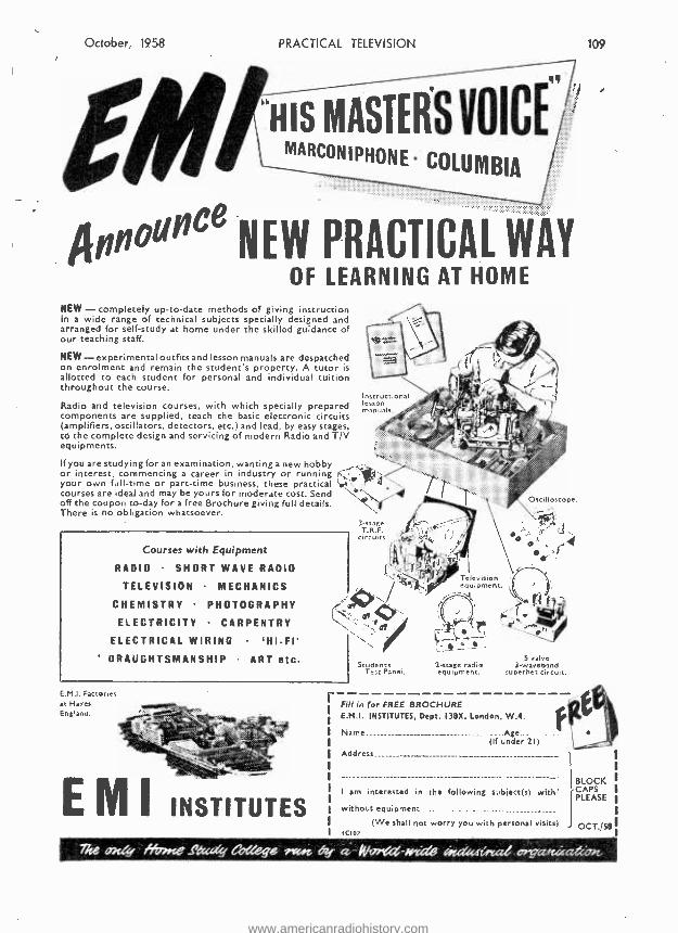
OF LEARNING AT HOME NEW - completely up -to -date methods of giving instruction In a wide range of technical subjects specially designed and arranged for self -study at home under the skilled guidance of our teaching staff.
NEW - experimental outfits and lesson manuals are despatched on enrolment and remain the student's property. A tutor is allotted to each student for personal and individual tuition throughout the course.
Radio and television courses, with which specially prepared components are supplied, teach the basic electronic circuits (amplifiers, oscillators, detectors. etc.) and lead, by easy stages, to the complete design and servicing of modern Radio and T/V equipments.
If you are studying for an examination, wanting a new hobby or interest, commencing a career in industry or running your own full -time or part -time business, these practical courses are ideal and may be yours for moderate cost. Send off the coupon to -day for a free Brochure giving full details. There is no obligation whatsoever.
Courses with Equipment
RADIO SHORT WAVE RADIO
TELEVISION MECHANICS
CHEMISTRY PHOTOGRAPHY
ELECTRICITY CARPENTRY
ELECTRICAL WIRING 'HI-FI' DRAUGHTSMANSHIP ART etc.
Instructional lesson manuals.
Oscilloscope.
',r . rr rJ
í. Teles equivipmion ent. ;I
motif
E.M.I. Factories at Hayes England.
EMI INSTITUTES
Students Test Panel.
2 -estate me
randio quipt. S valve
3. waveband superhet circuit.
Fill in for FREE BROCHURE E.M.I. INSTITUTES. Dept. 138g, London, W.4.
Name._........._. .:_._...._._......._._...__ .... ..........._......... __.....Age.. (lf under 21
Address
1 am interested in the following subject(s) with¡
without equipment ___ ..................................... ._..........:..............._..
(We shall not worry you with personal visits)
1 BLOCK CAPS PLEASE
OCT. 58
The oxly ffv»ge _ready College 'von 6y a 11/nr(,d-Aoéd6 4cdu4ísy.aG oráarsúezelvn
www.americanradiohistory.com
110
SUPER EMISSION
Pi;ACTICAL TELEVISION
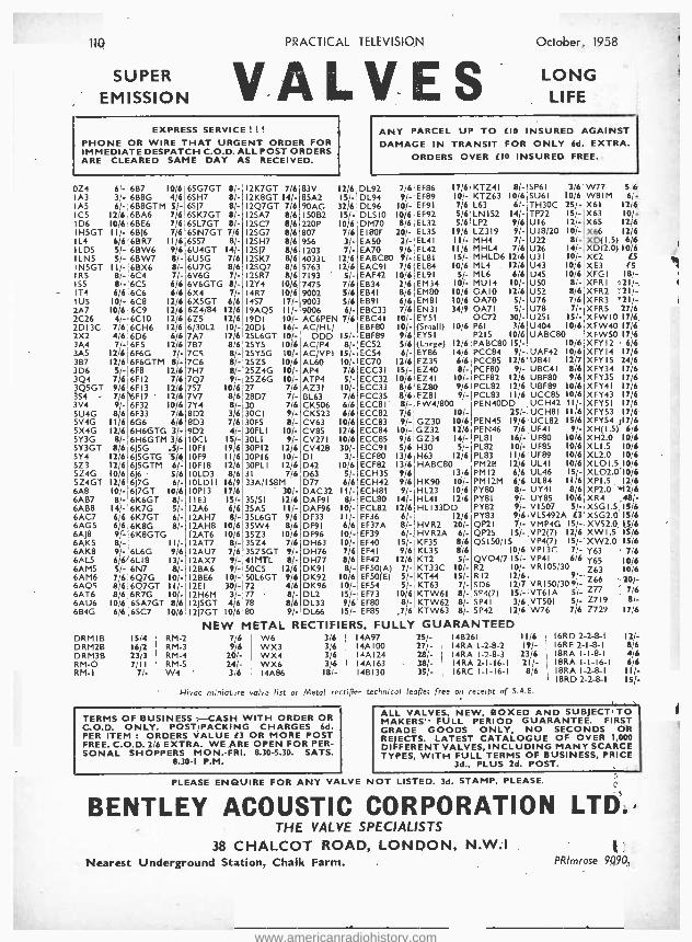
VALVES EXPRESS SERVICE ! .
PHONE OR WIRE THAT URGENT ORDER FOR IMMEDIATE DESPATCH C.O.D. ALL POST ORDERS ARE CLEARED SAME DAY AS RECEIVED.
October 1938
LONG LIFE
ANY PARCEL UP TO E10 INSURED AGAINST DAMAGE IN TRANSIT FOR ONLY 6d. EXTRA.
ORDERS OVER E10 INSURED FREE.
OZ4 6 - 6B7 10/6 6SG7GT 8/- I2K7GT 7/6 83V 2 6 DL92 7i6 EF86 17/6 KTZ4I 8/- SPEI 3/6 W77 5 6
IA3 3 - 6B8G 4/6 6SH7 e/- I2K8GT I4/- 85A2 IS - DL94 9/- EF89 10/- KTZ63 10/6 SU6I 10/6 WBIM 6 -
IA5 6 - 6B8GTM 5/- 6SJ7 II- I2Q7GT 7/6 90AG 2 6 DL96 10/- EF9I 7/6'1.63 61- TH30C 25/- X6I 12 6
IC5 12,6 68A6 7/6 6SK7GT 8/- 12SA7 8/6 150B2 15'- DLSIO 10/6 EF92 5/6',LN152 14/- TP22 15/- X63 10 -
ID6 10/6',6BE6 7/6 6SL7GT 8/- 125C7 8/6 220P 0 6 DM70 8/6 E132 5/6!LP2 9/6 U16 Ill- X65 12,6 IH5GT 11/-16BJ6 7/6 6SN7GT 7/6 12SG7 8/6 807 7 6.EI80F 20/- EL3S 19/6',LZ319 9/- U18/20 10/- X66 12,6 IL4 6/616BR7 1116 6557 8/- 12SH7 8/6 956 31- EA50 2/- EL4I 111- MH4 7/- U22 8/- XD( I.5) 6-6 ILDS S'-6BW6 9/6 6U4GT 14/- 12517 8/6 1203 7/- EA70 9/6 EL42 I1/6'MHL4 7/6 U26 14/- XD(2.0) 10,6
ILN5 O - 6BW7 8/- 6U5G 7/6 I2SK7 8/6 4033L 12/6 EABC80 9/- EL81 15/- MHLD6 12/6 U31 10/- XE2 E5
IN5GT II- 6BX6 8/- 6U7G 8/6 12SQ7 8/6 5763 12/6 EAC91 7/6 EL84 10/6 ML4 . 12/6 U43 10/6 XE3 fS IRS 8 -'6C4 7/- 6V6G 7/- 12SR7 8/6 7193 S/- EAF42 10/6 EL9I 5/- ML6 6/6 U45 10/6 XFGI 18 -
1S5 8 - 6C5 6/6 6V6GTG t/- 12Y4 1016 7475 7/6 EB34 2/6 EM34 10/-,MU14 10/- USO 8/- XFRI 21 - IT4 6/6 6C6 6/6 6X4 7/- 14R7 10/6 9002 5/6 EB4I 8/6 EM80 10/6IOA10 12/6 U52 8/6 XFR2 .21,- 1 U 10/- 6C8 12/6 6X5GT 6/6 1457 I7/- 9003 5/6 EB91 6/6 EM81 10/6';OA70 S/- U76 7/6 XFR3 '21/- 2A7 00/6 6C9 12/6 6Z4/84 12/6 19AQ5 III- 9006 6/- EBC33 7/6 EN31 34/91OA71 5/- U78 7/- XFR5 27/6 2C26 4/- 6C10 12/6 6Z5 12/6 19DI I0/- ACEPEN 7 6 EBC41 10/- EY51 '0072 30/- U251 IS!- XFWIO 17/6. 2D13C 7/6 6CH6 12/6 6/30L2 I0/- 20D1 16/- AC/HL/ EBF80 10/- (Small) 10/6,P61 3/6 U404 10/6 XFW40 17/6 2X2 416 6D6 6/6 7A7 12/6 25L6GT 10/- DDD I5,- EBF89 9/6 EY51 P215 10/6 UABC80 XFW50 176 3A4 7 - 6E5 12/6 7B7 816 25Y5 10/6 AC/P4 8- EC52 5/6 (Large) I2/6IPABC80 IS/- 10/6 XFY12 6/6 3A5 12 6 6F6G 7/- 7CS 8/- 25Y5G 10/- AC/VPI 15 - EC54 6/. EY86 14/6,PCC84 9/- UAF42 10/6 XFY14 17/6 3B7 12 6 6F6GTM 8/- 7C6 8/- 2575 10/6 ALSO 10 - EC70 12/6 EZ35 6/6 PCC85 12/6 UB41 12/7 XFYI5 24/6 3D6 5 - 6F8 12/6 7H7 8/- 25Z4G I0/- AP4 7 6 ECC3I IS/- EZ40 8/- PCF80 9/- UBC41 8/6 XFY34 17/6 3Q4 7 6 6F12 7/6 7Q7 9/- 25Z6G 10/- ATP4 Sj- ECC32 10/6 E74 10/- PCF82 12/6 U8F80 9/6 XFY35 17/6 3Q5GT 9-6 6F13 12/6 757 10/6 27 7/6 AZ31 I0/- ECC33 8/6'EZ80 9'6 PCL82 12/6 UBF89 10/6 XFY4I 17/6 3S4 - 7;6 6F17 '" 12/6 7V7 8/6 28D7 7/- BL63 7/6 ECC35 816 EZ8I 9 - PCL83 11/6 UCC85 10/6 XFY43 17/6 3V4 9/-!6F32 10/6 7Y4 8/- 30 7/6 CK506 6/6 ECC81 8;- FW4/800 PEN4ODD UCH42 II/- XFY5I 17/6 5U4G 8/6 6F33 7/18D2 3/6 30C1 9/- CK523 6/6 ECC82 7;6 I0/- 25/- UCH81 I1/6 XFY53 17/6' 5V4G 11/6 6G6 6/6 8D3 7/6 30F5 8/- CV63 10/6 ECC83 9/- GZ30 10/6 PEN45 19/6 UCL82 15/6 XFY54 17/6 5X4G 12/6 6H6GTG 3/- 9D2 4/- 30FL1 10/- CV85 12/6 ECC84 I01- GZ32 12/6 PEN46 7/6 UF41 9/- XH(l.5) 616
5Y3G 8/- 6H6GTM 3/6 IOCI IS//- 30L1 9/- CV271 10/6 ECC85 9¡6 GZ34 14/-'PL81 I6/- UF80 10/6 XH2.0 10/6 SY3GT 8/6 6J5G 2S/- IOFI 19/6 30P12 12/6 CV428 30/. ECC9I 5/6 H30 S/- PL82 10/- UF85 10/6 XLI.5 10/6 5Y4 12/6 6J5GTG 5/6 I0F9 11/6 30PI6 10/- DI 3/- ECF80 13/6 H63 12/6 PL83 I1/6 UF89 10/6 XL2.0 10/6 5Z3 12/6 6JSGTM 6/- I0FI8 12/6 30PL1 12/6 D42 10/6 ECF82 13/6 HABC80 PM2B 12/6 UL4I 10/6 XLOI.5 10/6 5Z4G 10/6 6J6 5/6 IOLD3 8/6 31 7/6 D63 5/- ECH35 9/6 13/6 PM 12 6/6 UL46 15/- XLO2.0"10/6 5Z4GT 12/6 6J7G 6/- IOLDI 116/9 33A/158M D77 6/6 ECH42 9/6 HK90 I0/- PM12M 6/6 UL84 11/6 XPI.5. 12/6 6A8 IOi- 6I7GT 10/6 I0P13 17/6 - 30/- DAC32 I I/- ECH8I 9/. HL23 10/6 PY80 8/- UY4I 8/6 XP2.0 M2/6 6AB7 8'-'6K6GT 8/- 11E3 15/- 35/51 12/6 DAF9I 8/- ECL80 14/- HL4I 12/6 PYBI 9/. UY85 10/6 XR4 .48/- 6AB8 14'-'6K7G S/- I2A6 6/6 35A5 IU- DAF96 10/- ECL82 12/6 HL133DD PY82 9/- V1S07 51- XSGI.S,IS/6 6AC7 6:6 6K7GT 6/- I2AH7 8/- 35L6GT 9/6 DF33 11/- EF36 6/- 12/6 PY83 9/6 VLS492A É3 XSG2.O-15/6 6AG5 6'6 6K8G 8/- I2AH8 10/6 35W4 8/6 DF9I 6/6 EF37A 8/. HVR2 20/- QP21 7/- VMP4G 15/- XVS2.0, IS/6 6AJ8 9- 6K8GTG 12AT6 10/6 35Z3 10/6 DF96 10/- EF39 6/-. HVR2A 6/- QP25 1S/- VP2(7) 12/6 XW1.5 IS/6 6AK5 8 - 11/- 12AT7 8/- 35Z4 7/6 DH63 10/. EF40 15/- KF35 8/6 QS 150/15 VP4(7) 15/. XW2.0 IS/6 6AK8 9 - 6L6G 9/6 12AU7 7/6 35Z5GT 9/- DH76 7/6 EF4I 9/6 KL35 8/6 10/6 VPI3C: 7/- Y63 ' 7/5 6AL5 6 6 6L18 13/- 12AX7 9/- 41MTL 8/- DH77 8/6 EF42 12/6 KT2 5/- QVO4/71S/- VP4I 6/6 Y65 10/6 6AM5 S - 6N7 8/-'12BA6 9/. SOCS 12/6 DK9I 8/- EF50(A) 7/- KT33C 10/- R2 10/- VRI05/30 Z63 10/6 6AM6 76 6Q7G 10/- 120E6 10/- 50L6GT 9/6 DK92 10/6 EF50(E) 5/- KT44 IS/- R12 12/6 9,'- 766 .
241/_ 6AQS 8 6.6Q7GT II/- 12E1 30/- 72 4/6 DK96 10/- EF54 5/- KT63 7/- SD6 12/7 VRI50/309/- 6AT6 8 6 6R7G I0/- 12H6M 3/- 77 8/- DL2 15/- EF73 10/6 KTW6I 8/- SP4(7) 15/- VT61A S/- Z77 7/6
6AU6 10 6 6SA7GT 8/6 12)5GT 4/678 8/6 DL33 9/6 EF80 8/- KTW62 8/- SP41 3/6 VT501 5/- Z719 ' 8/- 6B4G 6 6 6SC7 10/6 12J7GT 10/6 80 9/- DL66 IS/- EF85 ,7/6 KTW63 8/- SP42 12/6 W76 7/6 7729 17/6
NEW METAL RECTIFIERS, FULLY GUARANTEED DRMIB 15 4 RM-2 7/6 W6 3/6 I 14A97 2Si- 148261 11/6 6RD 2-2-8-1 12/- DRM2B 16,2 RM-3 9/6 I WX3 3/6 14A100 271- 14RA I-2-8-2 19/- 6RE 2-I-8-I 8/6 DRM3B 23.3 RM-4 20/- WX4 3/6 14A124 28;- , I4RA 1-2-8-3 23/6 BRA I-I-8-1 4/6 RM-0 7 I I RM-5 24/- WX6 3/6 1 I4AI63 38/- I4RA 2-I-16-I 21/- 8RA I-1=16-1 6/6 RM-I 7 - W4 3/6 I 14A86 18/- I 148130 35/- I6RC I-I-16-1 816 BRA I-2-8-I 11/-
BRD 2-2$I ISf- Hivac miniature valve list or Metal rectifier technicol leaflet free o. rerPipt of S.A.E.
TERMS OF BUSINESS : -CASH WITH ORDER OR C.O.D. ONLY. POST PACKING CHARGES 6d. PER ITEM ORDERS VALUE E3 OR MORE POST FREE. C.O.D. 2 6 EXTRA. WE ARE OPEN FOR PER- SONAL SHOPPERS MON. -FRI. 8.30 -5.30. SATS.
8.30 -I P.M.
ALL VALVES, NEW, BOXED AND SUBJECT TO MAKERS' FULL PERIOD GUARANTEE. FIRST GRADE GOODS ONLY, NO SECONDS OR REJECTS. LATEST CATALOGUE OF OVER 1,000 DIFFERENT VALVES, INCLUDING MANY SCARCE TYPES, WITH FULL TERMS OF BUSINESS, PRICE
3d., PLUS 2d. POST.
PLEASE ENQUIRE FOR ANY VALVE NOT LISTED. 3d. STAMP, PLEASE.
BENTLEY ACOUSTIC CORPORATION LTD. THE VALVE SPECIALISTS
38 CHALCOT ROAD, LONDON, N.W.I Nearest Underground Station, Chalk Farm. PRlmrose 90tiO.
1
www.americanradiohistory.com

October, 1958 PRACTICAL TELEVIS JN
. .
..... , i's/,ii: iei.:.:...... --.... -ì,,'f.%f.'1.C::Y.:%' :-ti -r.ï :7:4.?'I.:eg :::.x:: : :vii::{:
REBUILT TUBES MULLARD AND
MAZDA GUARANTEED SIX MONTHS 7 days delivery time as from receiving order.
I tin. 14ín. 17ín. 2lin.
Plus 12/6 P.P. & ins.
AS A RESULT OF PURCHASE TAX REGULA- TIONS WE CAN CNLY REBUILD YOUR CWN TUBE. THESE SHOULD BE SENT Via BRITISH
ROAD SaRV K ES (PARCELS) LTD.
£8 0 0 £18 O 0 C12 0 0 C14 f) O
We have a number of good reclaimed Tubes at ¿5.0.0 incl. 12ín. All sizes. Guaranteed
3 months. P.P. & ins. 12/6.
Brayhead Converters ¿6.10.0 inc.
Call, write or phone.
ST. MARY'S ELECTRONICS 18, PR. ED STREET, LONDON, W.2.
(Ambassador 9795)
SUPER -VISION LIMITED EVERY ITEM BRAND NLW AND GUARANTEED AT
LOW PRICES
Enamelled Copper Wire 12 to 45 SWG from 11¡6lb. Also available in smaller quantities.
Valve Holders Int. Octal, 4d. each. B7G, 4d. each. E9A. 6d. each. CER. B9A with screen, 1/9 each.
Condensers 2 to 100 pF., Sd. each. 220 -5,000 pF., 7d. each. .01 to .I,
Rd. each.
Coil Formers and S x t x I r .3 dia. with iron dust core, 2/- each.
Ix tic 21 .3 dia. with two iron dust cores, 3/- each.
Resistances Carbon. 10 to 5 M. f W., 3d. each. ... W.. 4d. each. I W., 6d. each. 2 W., I/- each. Wire Wound. 2,200 5 M. 1 W., 1/3 each. 5, IO and 20 ohms, IO W., 1/6 each. 5, 10, 50 and ICO ohms, 20 W., 3 +- each.
Variable T/V type pots 3 K., 5 K., 25 K. and 1 M., 2/6 each.
Egen Slider type 3 K., 5 K. and 25 K., 1/9 each.
Volume Controls .5M., 2/9 each. .5 M. with DPS Switch, 4/3 each.
Eleptrolytics 60/100 mfd.. 5/6 each. 32 -1 -32 f- 16 mfd. 350 v., 3/6 each. 40 +40 mfd., 450 v., 3,'6 each. Clips 3d. each. 50 mfd. 12 v. 3d. each.
Auto, Transformers '5 W. to 1,000 W. from 11.10.0 to £9.0.0.
send for list, price 3d.
SUPER -VISION LIMITED 136 HIGH ST. TrDDINGTON, MIOD X. KIt:R-ton 4393.
lit
COMPLETELY BUILT 8 WATT AMPLIFIER. A.C. Mains 150'250 v. Size 101 in. x 6iin. x 21ín. Incorporat- ing 6 valves. H.F. pen., 2 triodes, 2 output pens., and rectifier. For use with all makes and types of pick -up and mike. Negative feed- back. Two inputs, mike and gram, and controls for same. Separate controls for Bass and Treble lift. For use with ti Std. or L.P. records, musical
71,4 instruments such as Guitars.
y. s etc. Complete with Bin. speaker and ready N.9.6 for use.
Plus P. &
SIGNAL GENERATORS £6.19.6 or 25 - deposit and G
monthly payments of 21/6. P. & P. 5/- extra. Coverage 100 Ke /.s -100 Me /r on funda- mentals and 100 Mc;s to 200 Mel+ on harmonies. Metal case loin. x 6fin. x 54in., grey hammer finish. Incorporating three miniature valves and Metal Rectifier. A.C. Mains 200/250. Internal Modulation of 400 c.p.S. to a depth of 30 °. : modulated or unmodulated R.F., output continuously variable. 100 4111111-volts,
C.W. and mod. switch. variable A.F. output. Incorporating magic -eye as output indicator. Accuracy plus or minus 2...
54.19.6 or 25'- deposit and 4
monthly payments of 21,6. P. & P. 5- extra. Covcrage 120 Kc's-84 Mc/s. Metal case loin. x Olin. x 4410. Size of scale, 6!.in. x 3 ;in., 2 valves and rec titer, A.C. mains 230 -250 v. Internal modulation of 4to c.p.s. to a depth of 30 °,., modulated or unmodulated R.F. out- put continuously variable 100 milli- volts. C.W. and mod. switch, variable A.F. output and moving coil output melt r. Grey hammer finished case and white renel. Accuracy plus or minus 2
SIGNAL & PATTERN > -,r- GENERATOR
-,.
25'- deposit plus P. & P. 5'- and 6 monthly payments of 21/6. Cash £6.19.8 plus P. & ii
P. 5/ -. Coverage 7.6 Mc /s -210 ,. ,
Mc /s in five bands, all on fundamentals, slow -motion tuning, audio output, 8 vertical and horizontal bars, logging scale. In grey hammer finished case with carryio.; handle. Accuracy -1 A.C. mains 200-250 v.
AC /DC POCKET MULTI -METER KIT Comprising lin. moving coil meter scale calibrated in AC'DC volts, ohms and milll -amps. Voltage range ACIDC 0-50, 0- 100, 0 -250, 0 -500, milli -amps 0 -10, 0 -100. Ohms range 0- 10,000. Front panel, range switch. wire -wound pot (for ohms zero setting), toggle switch, resistors and rectifier. Basic movement 2 mA. In grey hammer finished case.
19/6 P. & P. 1/6. Point to point wiring diagram l' -, free with kit.
13 CHANNEL TUNER I.F. 11 -13 Mc s. Complete with PCF80 & PCF84. These hate
been removed 19 / 6 Plus P. & P. <rom chassis. 26.
Built and tested 7/6 extra.
RADIO & T.Y. COMPONENTS (Acton) LTD. 23, HIGH STREET, ACTON, LONDON, W.3
All enquiries S.A.E. GOODS NOT DESPATCHED OUTSIDE U.K.
www.americanradiohistory.com

112 PRACTICAL TELEVISION October, 1958
3® 30® EEEEEEE3 B33® 03E3El303Eídi® hE0303®® S! fflffl® E3E303® ffli333®9Bg3i80303®KüB®®BüEES®E3®i80323®E m®E983fflffl®a3
FE Wireless Set 19 -30/- EB EE
E3 ffl
ffl ES
ffl ®Transmitter receiver contains £20-
£30 worth of spare parts. Complete and in good condition less valves
® and meter. Price 30:- plus 5. -.
E Small Clock Movement 7 day mechanism beau t i f u l l
EE made and ® :..... fully jew- E3 .s-. elled, few
only sale ® }a °2" j?+. price 12,6
plus I6 E3 l' each. IS
ig Simplex Transistor Kit EE Makes ideal bed - EE room radio, uses ® one transistor El
and one crystal III` diode. Complete
M less case Dye. case ® 5,- extra, post l'6.
EE Mains Isolation Transformer
03 ES
EE EE
ffl ffl
ffl '/' Makes servicing
safe. Input tan- g300-150 v.. output tapped 200 -
250 v. Rated at 500 watts. inter- 141 mittent rating 2000. watts. Screens Fe for suppressing mains interference. E/ Size 141e. x bin. x Bin.. weight
401bs. Price £5/12:6. Carriage 7,6 it (up to 250 miles).
EsCar Starter Charger Kit tu All parts to build 6- and 12 -volt ® charger which can be connected to
a " flat "to and will enable the car to be started instantly. Mains transformer ... ... 22'6
E3 5 -amp. rectifier ... ... 17 6 ® Regulator Stud Switch ... 3(6 ® Resistance Wire ... ... 2/- ® Resistance Former ... ... 216
Mains on/off Switch .`,t'
0-5 amp. Moving Coil Meter ... 12!6 lid Construction Data ...... 1 6 ® Or if bought all together price
is .. ... ® plus 36 post and packing. ES
ffl ES
03 EE
EB
EN
Variable Rheostat Heavy duty slider -(resistor rated at
amps. Basic re- sistance Is .4 ohms. Can he re- wired to suit individual
requirements. Ideal for dimmer circuit, etc. Price 8 :3, post 3.6.
LE Suppressor Condenser ES
,Stop E3
your drill or he
Eá3 appliances interfering with your or
03 your
Simple instructions given m 1 :6 each, 12i- dozen.
Latest A V O Process Timer for 15/- Can be yours for only 10'- deposit and 19 payments of
10'- weekly. Like all AVO meters it is a very fine instru- ment: it has a sensitivity of 10,000 ohms per volt and 19 most useful ranges a s follows - D.C. volts
0 -1,000 (seven ranges), A.C. volts 0 -1,000 (five ranges). D.C. current 0 -1 amp. (5 ranges), resistance 0-2 mess. (2 ranges) (complete with test leads). Immediate delivery. Cash price 59.10.0. FREE GIFT. -All purchasers will receive Range Extender scale and data which add: capacity 0 -1 mid, in two ranges. Inductance 0 -100 henrys, etc. etc.
Testmeter
MUITiMiNOR
THERMOSTATS Æ 2;tn. x lin. x llin. high. Useful for the control of +f appliances such as con- vectors. gluepots, vulcani- sers, hot plates, 'etc. Adjustable to operate over temperature range 50 -550 deg. F., fitted with heavy silver contacts. 8'6. Other types : 11 amp., 3/6; 5 amp., 8 /8: 2 amp. QMB. 5/8: 15 amp. OMB, 15/ -: 15 amp, encased wall mounting type, 29/6.
-N,- ó o ó`
Instantus z. > \
1.,;`:`:'.::.::-
. : 4 '
ß
\
Make a time delay switch - to work off mains (A.C. or D.C.). all the parts (less case). Price 15/ -, post and ins. 2i6.
Heater
Introducfno ... THE INDUCTOR 80 80 w 5ft. fluorescent fitting with a 5 year guarantee -uses the latest type of impregnated induction (choke) control gear -absolutely quiet in opera- tion -all steel batten type construction stove enamelled white -suitable for direct mounting or for suspending. Undoubtedly the most modern fitting available will last a lifetime and will save its oust in lamps and electricity in about 12 months. Two models available -Type A, fixed voltage suitable for 200 -240 v. price 39,6. Type B. Variable voltage suitable for 200 -250 v., price 45' -, carriage and insurance up to 150 miles 5'6: up to 250 miles 7'6. Tubes, latest type which give more light for same electricity, daylight or natural to your choice, 14/6 each -no extra carriage if ordered with fitting.
LIO FOR AN IDEA With the equipment described below you can see bu cannot be seen in the dark. It has many obvious uses driving in the fog, -bird and animal watching, ra catching, watching for intruders, etc.. but we believe it has many novel uses and we invite readers sugges Lions, in fact for the best novel use suggested we wil give a prize of £10. If you have an Idea, send it in Closing date October 31st.
Comprises : 2lnlra ited Radiators. adjustable ouwis(- lars, power pack for 6 or 12 volts, control units and inter- connection cables. Original cost probably around £100. Unused and in perfect order -£10, car- riage and insurance 10 / -, or 10.- deposit and 21 weekly payments of 10' -.
SUPER SENSITIVE (2,000 O.P.V.) MULTIMETER KIT
17 ranges including D.C. volts to 1.000 v, A.C. volts to 1,000 v.. D.C. milliamps to 500 ohms to 2 meg.. capacity and inductance. All the essential parts, including metal case, selected resistors, wire for shunts. selected switches. calibrated scale and instructions, 326. piss 2'6 post and ins.
Convector heater Made from heavy gauge sheet steel (galvanised). For greenhouse, workshop, aviary, etc. 500 watt. 51.12.8: 1,000 watt, 52.10.0. 1,000 watt with wired but separate thermostat, £3.17.8. 2K watt free standing or wall mount- ing. 53.19.6: 2K watt with built -in thermostat, £4.19.6. Carriage and insurance 5'- per heater. ALL ARE GUARANTEED FOR 5 YEARS.
Making a Solder Gun
A 7- second sol- der gun of the type costing £3-£4 was des-
cribed in Practical Mechanics ". Only two essential parts are required -(a) the transformer and (b)
the push switch. These we can supply at 1316, plus 2/- post. The rest of the parts you will have in your own ' junk " box. Copy of the article concerned given free with the kit.
if w _-_
STOP PRESS Long, Medium and
Short Wave Coil Pack An exceptionally well made coil pack which covers the standard long. medium and short wave bands for 465 Kc. T.F. complete with diagram of connections, 14/6 plus 116 post- age and insurance -limited quantity only. SO More T.V. Service Sheets. -Readers already posseysinc our service sheets numbers 1 -100 will be glad to know that 101- 150 are now ready, price 10 - post free. Install 2 -way Switches. Our outfit comprises : 30 yd multicore cable, two 2-war switches, two wood blocks. Full instructions. 9/6 each. post and insurance 2(6.
THE TRANSISTOR 8.
A superb little portable reiceiver which is also loud enough and sensi- tive enough to be a car radio. All parts, prepared chassis. 8 selected transistors. 7in. x 41n. elliptical speaker and handsome carrying case -supplied for 511.10.0 or WI -de- posit and 24 weekly payments of 10 /-
®E3Eá3®®EE®®EÓ®®E3®E3®®®®EEfflE3EEEEEBE3E31EEi®®ES®&EB®®®03E3E3®ESES®®®EB®K1®E3®®&fflHi03®E3®®E3®ES®E
www.americanradiohistory.com

r
October, 1958 PRACTICAL TELEVISION 113
EBEBsmE®®83ffi®mayRa®®FP®®fB®63®a®;,c®®®®®E003®IB®®®®Eí1®IE®BIBIPFBM®`BEB ffl03IMS171MM&®®®®®® Band III Converter Build this 17in. T.V. in - \ EB
Ela
EB
EZi
EB
ES
EB
® Eli EB
EB
ÉB
Eíi
EB EB
EB
Ea
Efl EB
m EB
EE3
F8 EB
EB
EB
83 es ® EB
Ea ® EB
® FB
Suitable Wales, Lon- don. Mid - lands,North, Scotland, etc. All the parts fnclud- ing 2 EF80 valves, coils fine tuner, contrast control, con- 12- channel turret tuner. densers, and resistors. (Metal case Multivibrator time, bases. available as an extra.) Price only 19'6, plus 26 post and insurance. Ferrox cube E.H.T. and scan coils. Data free with parts or available separately, 1/6. The building cost (less tube) is only £29.10.0, plus Please send two more le/f.c, the one yos10- carriage and insurance. Or £5 down and 28 sent last week is performing magnifi- weekly payments of £1. All parts guaranteed rently, twelve months.
this sort letter every you
receive Full information nod data free with part. or day of
t the week, so if you have hest- 1 .
tated because you thought our kits available separately. price 3'6. too cheap you need hesitate no longer.
an evening Undoubtedly the most up-to -date televisor for the home constructor. You can build it in an evening and the set when finished will he equal to a factory made equivalent.
All miniature valves, and metal rectifier.
All -Mains Amplifier
Powerful three -valve mains ampli- fier ideal for dances, parties, etc. Complete less chassis. cabinet and speaker (available if required) - As supplied by National Health. data 118 (free with parts). Price, completely overhauled and in 19'8. plus 2/6 post and insurance. good working order with six
months' guarantee. Only 52.15.0 plus 2/6 post and ins. Complete with earphone and new ear plug but not batteries. these can be supplied as an extra for 5/- per set. Instruction. showing how to convert to pocket radio available free if rruursted.
Medresco Hearing Aid
Now 2 Models Turret Tuner Brand new stock, not sur- plus. with coils for Band I and III complete with valves. Model I I.F. out- put 33/33 Mc /s. Series heaters Model 2 I.F. out- put 16/19 Mc /s. Parallel heaters. With instruc- tions and circuit dia- gram. 79/6. With knobs 316 extra. post and in- surance 2 s
.
The Skysearcher This is a 2 -valve plus -metal receiver set useful as an educational set for beginners, also makes a fine second set for the bedroom. workshop. etc. All parts, less cabine 1. chassis and speaker. 19/6. Post and ins.. 2B. Data free with parts or available separately, 1'6. 3 -valve battery version also available at the same price. A.C. /D.C. Multimeter Kit
Ranges: D.C. volts 0 -5, 0-50, 0 -100. 0 -500. 0 -I.000 A.C. volts 0 -5, 0-50, 0-100, 0 -500,
0-1.000. D.C. milliamps 0-5, 0 -100. 0-500. Ohms 0- 59,000 with internal batteries. 0- 500,000 with ex- ternal batteries. Measures A.C./ D.C. volts. D.C. current and
ohms. All the essential parts includ- ing metal case, tin. moving coil meter, selected resistors, wire for shunts. range selector, switches. calibrated scale and full instructions, price 198, plus 2'6 post and insur- ance.
This Month's Snip Sornweave
This really lovely loud- speaker fabric
e offer at half price. namely 7/6 per yd., 48" wide. This is also very suit- able for cover- ing plain 6 wooden cases EB for portables. EB
EB
83 Yaxley Switches EB
133 3 -pole, 2 -way 1/3 12 -pole, 2 -way 1/8 Ea 3 -pole, 3 -way 1/6 EB 9 -pole. 3 -way 2'- 2 -pole. 9 -way 2,- 6 -pole, 4 -way 218 e 4 -pole, 5 -way 2/8 03 2 -pole, 6 -way 2/6
EB 1 -pole, 7 -way EB 1 -pole, 12-way 2/6 EB 6- position shorting switch 211- EB Double -pole mains switch for EE attaching to Yaxley switches 116 EB Discount of 10 " allowed where a
dozen of one type ordered. Special EB quotes 144 or over. EB
Ganged Pots for Stereo, & etc. f
Made by Morganite. these are a first /'l EB class control, unfor- tunately only linear types are AA Eli available, in - p
EB the following - '- EB
values : 5K +5K, 50K s EB +50K. 100K +1001C. _ - EB I Meg. /-) Meg., 2 03 Meg.-d2 Meg. All in original cartons price 3/- each, special quotes for quantities.
83
STOP PRESS ! ES
83 8 Watt Stereo Amplifier.-Com- plete with valves, ready to work,
EB £8 plus 708 carriage & insurance. it
Short Wave Communications Receiver R.208. Only £6.19.6. 10/- Deposit
This is a super short -wave receiver covering 5 -33 metres (10-60 Mc/s). Uses 6 valves. Has R.F. stage. 2 LF. stages, B.F.O., etc. Muirasad instrument drive. two internal power packs, mains and battery vibrator pack. Complete with own P.M. speaker. Provision for phones and speaker muting. Complete in metal transit case : size approx. 24 x 18 x 12in.: weight 70Ib. Suitable A.C. mains 100 -250 and 6 volt battery. In perfect condition. practically unused. Tested before despatch and guaranteed. Handbook free with each. Price 58.19.6. carriage and insurance 15 / -. Or 10'- deposit plus 15 - carriage and ins., then 15 weekly payments of 10, each.
ELECTRONIC PRECISION EQUIPMENT, LTDm Post orders are dealt with from Eastbourne, so tor prompt attention pleas*
EB 50 More T.V. Service Sheets post your orders to 66, Grove Road, Eastbourne, marked Department b. Readers already pessessico nur 42-46, Windmill 11111,
68. Grove Road, 29, Stroud Green Rd., 266, London Road, Hi service sheets numbers 1 -100 will h,- Ruislip, Middx. Finsbury Park, N.4. Croydon. glad to know that 101 -150 are now Phone: RUISLIP 5780 Eastbourne, Sussex. Phone: ARChway 1049 Phone: CRO 6558 ready, price 10 / -, post free. I
Half day, Wednesday. Half day. Saturday. Half day, Thursday. Half day, Wednesday. iE13033ÊBEBEB8393 EBEBEBB3MEfEPEBMl3383 3EBEBEBEl3EB® EB® EBE9E3MMEBER13838® EBEBEBEíMM133IBEBEBEBEBEB ®E8®19E8EPEBMEBEBEB ®
www.americanradiohistory.com

114 PRACTICAL TELEVISION
BRM,aR 618 The Brimar 6T8 is a triple -diode triode in which one diode has a separate cathode. The triode 5
section has a high amplification factor making the valve suitable for use in AM /FM receivers in . the demodulation and first stage audio circuits. 4
The diodes may be used in series shunt limiter g circuits, for example, in the audio sections of
television and ó communica- < tions receivers, followed again by the triode, section for A.F. amplification. N±ar Equivalents o EABC80 DH7I9
6ÁK8
October, 1958
11111111n1111 111111tie111111u111111111111111111n11 1111E11111111r11111111111111111111 BRIMAR 6T8. 11111111 1111r4
1111111111 r41111 11111111111111111111/I1111 1111ri1111111111 11111111.1111111111111111111/A811 I111111I1
411111111r/111111111111 ï EEEEEEEE:::E:EE:a:::e.-:::::::::'n° ' : :C:C::E::E:r`D:E::::::E:"::::: 11 1111A I äEEEEE::EEE
;:EEE; : EEE:,Qs
°E;EEE: EEE::EEE:EEE EEEEEE°rY11iúiiiEi.iiiéiiïiE ÌiEli'i' r/ :ED::° OC Ä%CC ? i11n11tal%1f'11/2111rMEW/MUMS 111111111511114 111111.I11i 11r51111111111r ,111111 r MLti' An11G 11.11 NW' %111111ti" i._ EzNs>v
100 200 ANODE VOLTAGE -Va
300 400
Typical Triode Operating Characteristics as an R.C. coupled
Anode Supply Voltage Anode Load Resistor Grid Resistor ... ... Cathode Bias Resistor ... Peak Output Voltage Stage Gain (for 24 V peak to peak output Distortion (for 24 V peak to peak output) ,
Keep this for further reference or write to for a data sheet.
the
500
amplifier. 250 250 volts 0.25 0.25'megohm 1.0 10 megohms 3 0 kilohms 43 40 volts 42 42 1 5% Publicity Department
5%c7lic/O/'l/ %'/PphOiJeS and Cab/c5 Limited FOOTSCRAY S!DCUP KENT Footscray 3333
2 1 RANGES
YOUR VERY OWN
TEST SET NOW
It's as simple m this. Sou iu,t send 47 6 deposit to have one of the newly stylised M.I.P. Multi -Range Series ICO Test Sets posted to you almost by return of post. Balance is
payable over 6 months at £1.16.0 per month. Cash price is £ 12.7.6. Post coupon row for full details.
covering
10 -1,000 d.c. volts 10 -1,000 a.c. volts 100 Microamps to 500 Milliamps d.c. 100 Microamps a.c.
0 to 1 Megohm 0 to 10,000 ohms
There is also the SERIES 90 MULTI -RANGE TEST SET, having 19 SELF- CONTAINED ranges a.c. /d.c. volts up to 1,000 ¿r., d.c. current up to 500 mA., a/c current up to 200,íA., resistance 0- 200,000 O.
Deposit 35/- and six monthly pcyments of 28 /I0. (Cash price E9.15.O.)
GD.22
MULTI -RANGE TEST SET- SERIES IOO
MEASURING INSTRUMENTS (PULLIN) LTD. Electrin Works, Winchester St., Acton, London, W.3
Please send illustrated leaflet of the Series 100 Test Set with details of new easy payments scheme
Ditto Series 90 *Please indicate instrument requited.
NAME
ADDRESS D.10 58j
www.americanradiohistory.com

. 1111IIIIIIIIIII
Tp
r ë
Vol. 9 No. 99
C
v 1111111
11
& TELEVISION TIMES Editor : F. J. CAMM
11
EVERY MONTH
üF Editorial and Advertisement Offices :
PRACTICAL TELEVISION George Newnes. Ltd.. Tower House. Southampton Street, Strand, W.C.2
© George Newnes Ltd., 1958.
i
ï
Phone : Temple Bar 4363. Telegrams : Newnes, Rand. London. Registered at the G.P.O. for trans- mission by Canadian Magazine Post.
SUBSCRIPTION RATES including postage for one year
Inland - - 19s. per annum Abroad - - 17s. 6d. per annum Canada - - - 16s. per annum
CONTENTS: Page
Televiews ... 115 Band Ill Doubly Arras
Aerial More About Shared Aerials 118 An Improved Video Ampli-
fier I20 Servicing Television Re-
ceivers Television Troubles... .. .
Telenews Analysing and Servicing TV
Receivers ... 130 Home Constructed Television
Receiver 136 TV at the National Radio
116
123 125 128
Underneath the Dipole ... Correspondence ... Your Problems Soiled ...
140 147 151 155
The Editor will be pleased to consider articles of a practical 'nature suitable for publication in" Practical Television." Such articles should be written on one side of the paper only, and should con- tain the name and address of the sender. Whilst the Editor does not hold himself responsible for manuscripts, every effort will be made to return then: if a stamped and addressed envelope is enclosed. All correspondence intended for the Editor should be addressed to : The Editor. " Practical Television," George Newnes, Ltd., Tower House, Southampton Street, Strand. W.C.2.
Owing to the rapid progress in the design of radio and television apparatus and to our efforts to keep our readers in touch with the latest developments. we give no warranty that apparatus described in our columns is not the subject of letters patent.
Copyright in all drawings, photo- graphs and articles published in "Practical Television" is specifically reserved throughout the countries signatory to the Berne Convention and the U.S.A. Reproductions or imitations of any of these are therefore expressly forbidden. }'
OCTOBER, 1958
TELE VIEWS THE RADIO SHOW
S far as television is concerned, there were no surprises, and beyond minor improvements and reduction in size and prices, 1959 receivers are as they were. One firm
showed a push- button receiver covering all 13 channels with instantaneous channel choice. On another receiver, the push button controls definition. The wide- angled tubes have enabled designers to make their receivers shallower, without the unsightly protrusion at the back of the set. Self -contained portables were also shown by two makers. Although 21 in. and 24in. receivers were available, the 17in. tube models still remain the most popular. Most of the TV receivers made use of printed circuits in some part of the circuit and transistors, of course, were much in evidence. One manufacturer showed red and green lighting on the switch to distinguish hetween BBC and ITV. channels. There was also shown a unit -constructed TV.
Stereophonic sound really stole the show and it is a marked improvement on the older system, a special Audio Hall being set aside for demonstration, particularly of stereophonic gramo- phone records. Of 160 exhibitors, at this 25th Silver Jubilee Exhibition only 36 manufacture radio and TV receivers. Many receivers were equipped for reception of V.H.F. /F.M. sound broadcasting. Some receivers were fitted with the new electro- static focus tube with a deflection angle of 110 deg., but most tubes had the 90 deg. deflection angle. Several manufacturers listed legs for fitting to table models as an optional extra. A number of exhibitors showed loft aerials of an improved form. They can easily be fixed and permit tilting, rolling, and turning for anti- ghosting. It was noteworthy that colour television demonstrations dropped out of the show.
" A BEGINNER'S GUIDE TO TELEVISION"
THERE has been a huge demand for " A Beginner's Guide to Television " (7s. 6d.) or 8s. 3d. by post, and as with the
companion volume, " Beginner's Guide to Radio," the edition will soon be exhausted. It is necessary therefore to order now to secure a copy.
1.
l..
q
TV SPREADS OVER THE WORLD
THE annual production of television receivers in Australia at present is 310,000, and receivers go from the dealers into
the home as fast as they are delivered. Retailers have negligible stock. Other countries not at present equipped with TV have laid plans to develop such a service and soon there will be world -wide coverage, and further possibilities for B.B.C. pro- grammes are augmented by Continental TV linkages. -F. J. C.
Our next issue, dated November, will be published on October 22nd
www.americanradiohistory.com
116 PRACTICAL TELEVISION Ölober, 1958
Band III Double Array Aerial THIS ARTICLE DESCRIBES A CONNECTOR BOX By M. S. Ford
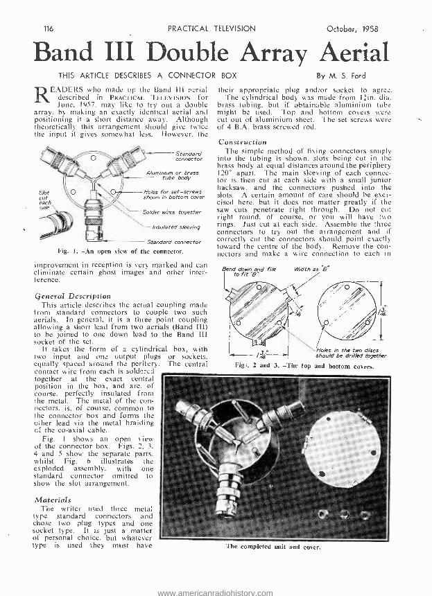
READERS who made up the Band III aerial described in PRACTICAL TELEVISION for June, 1957. may like to try out a double
array, by making an exactly identical aerial and positioning it a short distance away. Although theoretically this arrangement should give twice the input it gives somewhat less. However. the
Slot cut each side
Standard connector
Aluminium or brass tube body
Ho /es for set -screws shown in bottom cover
Solder wires together
Insulated sleeving
Standard connector
Fig. 1. -An open view of the connector.
improvement in reception is very marked and can eliminate certain ghost images and other inter- ference.
General Description This article describes the actual coupling made
from standard connectors to couple two such aerials. In general, it is a three point coupling allowing a short lead from two aerials (Band III) to be joined to one down lead to the Band III socket of the set.
It takes the form of a cylindrical box, with two input and one. output plugs or sockets. equally spaced around the perifery. The central contact wire from each is soldc :c_l together alt the exact central position in the box, and are, of course, perfectly insulated from the metal. The metal of the con - nectors, is, of course, common to the connector box and forms the other lead via the metal braiding cf the co -axial cable.
Fig. 1 shows an open view of the connector box. Figs. 2. 3, 4 and 5 show the separate parts, whilst Fig. 6 illustrates the exploded assembly. with one standard connector omitted . to show the slot arrangement.
Materials The writer used three metal
type standard connectors and chose two plug types and one socket type. It is just a matter of personal choice, but whatever type is used they must have
their appropriate plug and /or socket to agree. The cylindrical body was made from lain. dia.
brass tubing, but if obtainable aluminium tube might be used. Top and bottom covers were cut out of aluminium sheet. The set screws were of 4 B.A. brass screwed rod.
Construction The simple method of fixing connectors snugly
into the tubing is shown. slots being cut in the brass body at equal distances around the periphery 120° apart. The main sleeving of each connec- tor is then cut at each side with a small junior hacksaw, and the connectors pushed into the slots. A certain amount of care should be exer- cised here, but it does not matter greatly if the saw cuts penetrate right through. Do not cut right round, of course, or you will have two rings. Just cut at each side. Assemble the three connectors to try out the arrangement and if correctly cut the connectors should point exactly toward the centre of the body. Remove the con- nectors and make a wire connection to each in
Bend down and file Width as B4
Fig ;.
Holes in the two discs should be drilled together
2 and 3. -The top and bottom covers.
The completed unit and corer.
www.americanradiohistory.com

October, 1958 PRACIILAL TELEVISION 117
Showing tubular body with one slot partly finished. Lug is bent until fractured off and bottom of slot rounded by file
/4.
Figs. 4 and 5. -The tubular body and set screw.
the usual way, each being soldered and protrud- ing about lin. Push in each connector and slip on short lengths of plastic sleeving. Join the wires at the exact centre and solder together. Fit the top and bottom covers by the lengths of screwed rod. It will be noted that the top cover has lug pieces. These not only close the small gaps left, but also completely locks the three connectors and forms quite a rigid job. Although short, the wiring inside the box must be stranded. as contained in the Band III type co -axial cable and soldering is, of course, most important. The dimension "B" (width of slot) has been omitted as the standard connector varies just slightly in different makes. A pair of callipers would be useful to measure the sleeve diameters.
Method of Cutting Tube Fig. 7 shows a simple method of cutting tubing
to give an even cut right round. A line is scratched by a scriber against a paper strip of known machined edge.
Fig. '8 shows diagrammatically the arrangement in use. The short cable lengths from each array should be identical in length. Again the dimen- sion marked " A " has been omitted, but one
f` Array No l I Array No 2
Coaxial cable to connector box must Le cf equal
/rns the
Connector Box
Coaxial lead to Band lit socket of Receiver
Scriber
Paper strip Simple method of markng tube for even cut
Figs. 7 and 8 -(Below) I hm to cut the tubing. (Above) Showing diagrammatic :ilh the arrangement in use.
wavelength, i.e., 531ín. for channel 9, is suggested as quite convenient in most lofts. Experiment is quite possible, of course, indoors.
The short saw cuts seen in the lugs of the top cover were found to make bending down of these lugs easier, and retains as far as possible the circular form of the cover. It is a good plan to drill the holes in the top and bottom covers together, clamping the discs in a vice.
atn - -Top fixing nuts
++ - - Top cover
Hs -{
Bottom cover with brass screwed rod acting as set-
Fig. 6. -An connector
screws
exploded assembly, with one standard omitted to show the slot arrangement.
Aerials Finally, a word about the two aerials. These
should agree. of course, exactly, and should be mounted at same heights. A slight variation in alignment one from the other can be experimented with to give interference free reception as far as is practicable.
GOOD COMPANIONS !
A Beginner's Guide to Television By F. J. Camm
A Complete Course in 15 Lessons (with Dictionary of Technical Terms) I 28 Pages -61 Illustrations
7/6, by post 2/4 AND
A Beginner's Guide to Radio By F. J. Camm
A Complete Course in 27 Lessons. 160 Pages -100 Illustrations
7/6, by post 8/4 from
The Book Publisher, George Newnes Ltd., Tower House, Southampton Street, Strand, London, W.C.2
3
www.americanradiohistory.com
118 PRACTICAL TELEVISION October, 1958
More About Shared Aerials
This estate of 73 dwellings is supplied with BBC and ITV television signals from a common aerial system,
seen ringed in the photograph.
THE value for the " star " network resistors must be chosen to suit the coaxial cable employed and the number of outlets
required. Since the cable impedance is usually the same all the way round, the resistors should have like value, which can be discovered very quickly from the following expres- sion: R = Z (n - 1/n + 1). where Z is the character- istic impedance of the cable and n is the number of outlets. Thus, for a two -outlet network using standard 72 ohm feeder. the resistors must each be 24 ohms.
Unfortunately, however. there is a price to be paid for this maintenance of matching, and that is the input to each receiver is less than the aerial signal by 20 log n db. This means that with a two -outlet system the signal at each set is half that at the aerial. with a three -outlet system the signal at each set is a third of that at the aerial
250NÚ.
Band .1 Amplifier
( +21.5db)
PROBLEMS WHICH ARISE WHEN SEVERAL RECEIVERS OPERATE
FROM THE SAME AERIAL
by S. J. Jackson
and so on as the number of outlets is increased. All is well in an area of high signal strength,
where it matters little if the signal is divided among the outlets in this fashion, but in fringe areas there is a call for amplifiers to make good the network losses. Then. of course, there is the loss in the cable itself to be considered.
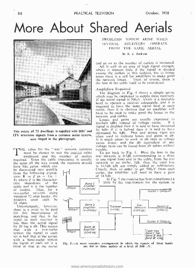
Amplifiers Required The diagram in Fig. 4 shows a simple set -up
which may be employed to supply three receivers. It the aerial signal is 5000/. which is a desirable level to operate a receiver adequately, and it is
required to have the same signal level at each outlet. then it is obvious that an amplifier will have to be used to make good the losses in the network and cables.
Losses and gains are usually expressed in decibels (db) instead of voltage ratios. If a signal is doubled then it is said to have increased by 6db; if it is halved then it is said to have decreased by 6db. Plus and minus signs are often used to indicate losses and gains in db. It is much easier to work in db than in voltage ratios direct, and the db equivalent of any voltage ratio can be found from db tables without trouble.
To get back to Fig. 4. Here the loss in the star network is 0.5db (corresponding to a three to one signal loss) and in the cable, from the star network to an outlet, 5db. thus, the total loss is 14.5db (db are simply added or subtracted). Clearly, then. in order to get 500pV from each outlet, the amplifier will need to have a gain of 14.5db.
In Fig. 5 the exercise has been complicated a little by the requirement for the system to
/OOONt<
Band II Amplifier ( +/z sae)
500 /iV.
Band Ill Amp lifier (20.5 db)
Trip exer ( -/ db)
Outlet ! (500/ v)
Star Network (9.5db)
Outlet 2 (500/i k)
Outlet 3 (500,u1..
Cable /oss Band 1 5db Band II 8db Band III /0db
Fig. 5. -A more complex arrangement in which the signals of three bands are fed to three outlets at a level of 500 µV.
www.americanradiohistory.com

October, 1958 PRACTICAL
carry signals in Bands I. Il and III. The aerial signals are also different, as would be expected, but in spite of this and the fact that the attenuation value of the cables differs over the three bands. it is a relatively simple matter to secure 500pV of signal on each band at the three outlets by adjusting the gain of the amplifiers accordingly.
¡d n cable
Fig. 6.- Method of tapping main cable for sub-
scribers feeds.
Outlet feed
In this system it will be seen that a triplexer is used to combine the outputs into a common feeder.,
On Band 1 there is only 250AV of signal, which is 6db below the required 500µV to start with; there is ldb of loss in the triplexer and 5db in the cable at Band I frequencies. Plus the 9.5db loss presented by the star network, the amplifier is required to raise the signal by 21.5db (equal to the sum of all the losses).
On Band II the aerial signal is 6db up on 500 AV. Thus, the gain required for the Band II amplifier is found by subtracting 6db from the sum of the losses; it will be observed in this case that the cable losses are 8db, becoming greater as the frequency rises. On Band III the aerial signal is the same as required at the outlets, so it is a matter of adding up all the losses, including the 10db cable losses. and arranging the amplifier to have equivalent gain.
Amplifiers There are on the market amplifiers which are
highly suitable for this kind of work, which can. for example, be rigged up in the roof -space below the aerial system and energised continuously from the mains supply. The power requirements are quite modest .. and. provided due consideration is
H
fl
Band I Amplifier
31.
Band II Amplifier
Band III Amplifier
Trip exer
TELEVISION 119
given to the ventilation. there is little danger of overheating. Nevertheless. the amplifiers should be lightly fused and adequately earthed. The author has under his control aerial amplifiers which have been running continuously for three years without component failure of any kind! Indeed it would appear that the valves and components live
Cable loss lOdb
Loss due to taps 3db
Terminating resistor
20 db ta attenuation 500,0!
Outlets
Fig. 7. -A simple signal distribution system.
longer when the equipment is permanently energised than when it is intermittently switched on and off.
Some amplifiers feature pre -set gain controls which can_ be adjusted to provide a balance of signal at the outlets. but in cases where such a facility is not available. fixed or variable attenu- ators can be introduced at the outlets of the amplifiers to serve the same purpose.
There is another method of tapping the required level of signal at various points along a main cable feed for subscribers' outlets. as shown in Fig. 6. Here the signal in the main cable is at fairly high level since it is obtained from the output of a distribution amplifier, and it is extracted by breaking into the cable as shown, but instead of the feed cable being con- nected directly into the main cable, it is isolated by means of resistor Rl, while a second resistor R2 server to load the end of the outlet feed cable to avoid standing waves and stub effects.
In effect. the resistors form a potential divider across the main cable at the point of entry, and the signal level fed into the feed cable is dependent on the ratio of the resistors. The
(Continued on page 122.)
Outlets Fig. 8. -A more advanced three -band signal distribution system.
www.americanradiohistory.com

PRACTICAL TELEVISION October, 1958
An Improved Video Amplifier THIS ARTICLE DEALS WITH THE PRINCIPAL FACTORS INVOLVED
By S. D. R. Bowman
THE video frequency amplifier is without doubt the most critical circuit in a receiver from the design aspect, apart perhaps from
the timebases. In this stage a great deal can be lost and, what is perhaps worse, much can actually be introduced to spoil a picture. Commercial design is fair, but a number of the cheaper receivers display faults which the home designer can, for a little trouble. avoid altogether.
idea that the larger the number of stages the more opportunity for correction.
Theoretical Details It is not proposed to go into the theoretical
details of the design, but the reader may care to be reminded of the principal factors involved. In the first place, all amplifying devices possess self- capacitance, partly in the valves themselves and partly in the circuit. While at low frequen- cies this is insignificant, at high frequencies this capacitance causes two adverse effects -loss of amplification due to the familiar " by- passing " effect, and change of phase. In audio -frequency amplifiers the latter is of minor significance, but in video amplifiers it becomes a great nuisance. For these reasons it is essential for the circuits to possess intrisically low impedance, and this limits severely the load resistance which can be employed; this in turn reduces stage gain.
By putting inductance in the circuit, the capacitance can be " tuned out," thus enabling the load resistance to be increased, giving higher gain -and, incidentally, much improving the amplification characteristics at high frequencies. The size of the induc'ances used has to be calculated with care, otherwise more harm than good can result. Overshoot can occur quite readily. By this is meant that if a square wave is applied to the input, the output voltage shows a momentary jump above its final value. This will cause a light band on the left -hand side of a white object on the cathode -ray tube screen. " Undershoot " can similarly occur, resulting in a darker edge to a dark object. While this is sometimes done deliberately to improve the
Fig. 1.- Showing the circuit diagram.
The characteristics of a perfect V.F. amplifier are, briefly, as follow:
(a) Linear amplification of frequencies from zero to 3 Mc /sec. (or whatever upper limit is nominally imposed on transmissions).
(b) Zero phase shift of all frequencies amplified. (c) Zero rise time to an input voltage " step " --
i.e., to a square wave, with zero " overshoot." The amplifier here described represents an
approximation to the ideal. and its gain is such that it may be found a better alternative. in fringe areas, to the use of an extra I.F. or R.F. stage.
The Circuit Diagram Fig. 1 shows the circuit diagram. It is a two -
stage amplifier of fairly conventional design. with negative feedback. This may cause some eyebrows to be raised; as is well known. the larger the number of stages of video amplification the more the possible sources of loss in performance. However, the writer met this challenge with the lhe ideo amplifier.
www.americanradiohistory.com

October, 1958 PRACTICAL
Overshoot
Slope shows finite rate of rise
Full line shows -
output waveform
Dotted line shows input square wave Infinitely fast rise)
Undershoot
Time in microseconds
Fig. 2. -The " overshoot " and " undershoot."
apparent "resolution " of a picture it is actually a source of degradation of detail, and it should be minimised. Fig. 2 shows overshoot and undershoot.
Both shunt and series inductances are used in the present circuit. and their proportions are such that overshoot has been made negligible (a little under 2 per cent.).
The chief requirement is. however, a very fast rise of output voltage when a square -wave input occurs. This also affects the calculation of the compensating inductances, and when compromis- ing between linear amplification up to high frequencies and fast rise it is better to let the
LIST OF COMPONENTS R1 -3.8 K. C3- See text. R2 -100 ti. C4- See text. R3-2.2 K. C5 -1 mfd. (physicall), R4-3.3 K., k watt. small). R5 -5.6 K., 1 watt. C6 -16 mfd. elec. R6-1 M. L1 -65 pH. R7 -1.2 K., 3 watt. L2 -37 pH. R8 -1.5 K., 3 watt. L3 -130 pH. R9 -100 D. L4-56 pH. C1 -16 mfd. elec. VI -6AM6. C2 -220 pF. V2 -6CH6.
linearity take second place. For British trans- missions a maximum rise time (from 10 per cent. to 90 per cent. of final output voltage) of 0.1 microseconds or a little more is essential if all fine detail is to be displayed on the tube face. In this circuit the rise time is 0.038 microseconds -well under the maximum allowable.
Low -frequency Response Low- frequency response is also important, and
in this connection the chief difficulty is the avòidance of "sag " when a low- frequency pulse is applied to the input. Fig. 3 shows the effect.
' This is due to couplings having too low a time- constant (t = C.R.) so allowing " leakage " during the pulse. Grid couplings, cathode screen and anbde decouplings, can all give rise to this undesired effect. In the amplifier just described. grid coupling has a time -constant of 1 second,
TELEVISION 121
which enables a complete frame scan to be achieved without noticeable sag. In anode and screen circuits, it is impracticable to achieve a time -constant as long as this. With resistors of low enough value to give high enough screen and anode voltages, decoupling capacitors would have to be impossibly large. Compensation by R3. Cl and R7. C6 has, therefore, been introduced and it is important that the circuit values given are adhered tò quite closely. With this arrange- ment, the sag is ?educed to negligible proportions and in fact amounts to only 1.7 per cent. The difficulty about sag due to the cathode bias resistor -condenser combination is avoided by omitting the bias condenser altogether. (The 220 pf condenser across VI cathode resistor is for frequency compensation purposes only, And
LIST FOR COIL CONSTRUCTION L1 -140 turns No. 40 gauge wire enam., on former
0.3 in. dia. V.H.F. (purple coded) dust core fully inserted.
L2 -Same as above without dust core. L3- Wearite M.W. oscillator coil (P.0.2), with
small winding removed completely and d the turns taken off the other.
L4 -80 turns No. 36 gauge enam. wire- Aladdin former .4 in. dia. with iron dust core.
does not count in low- fr.;uency considerations.) The negative feedback so resulting is actually beneficial rather than otherwise, although, of course. gain is considerably reduced.
In order to seduce phase change still further and to level out the frequency response over a wide spectrum, a little negative feedback is added from the output anode to input grid -note, of course, that the cathode bias resistor of VI is part of the V I grid circuit. This feedback is D.C. coupled -a real necessity here -and the amount possible is limited by the inherent characteristics of V 1. The network R5. R2 would have to be changed if any valve but one having the D.C. cathode current of a 6AM6 were used. The resulting gain of the whole amplifier is thus about 100 -six to ten times that usually obtained in a single -stage amplifier -and therefore needs less than a volt input to modulate a C.R.T. fully.
ó
o
/nput souare wave
i t Sag
-.---output waveform
Time in milliseconds
Fig. 3. -" Sag " at L.F.
www.americanradiohistory.com

122 PRACTICAL TELEVISION
3 4 5 6 7
Frequency in Mc4 per second
Fig. 4. -The frequency response curve.
Frequency Response Fig. 4 gives the frequency response curve, and
it will be seen that the whole range of British TV frequencies can be dealt with easily. Fig. 5 is a curve which shows the rise time actually achieved with this amplifier. Again, overshoot is very small and the rise time well within what is allowable.
Construction The construction and layout presents no
special difficulties, except the avoidance of stray capacitance. It should be remembered that unwanted feedback can occur, and screening of each stage is indicated.
C3 should be a total of 3 pf including " strays." If L2 is wound according to the table its self capacitance will be 1.2 pf, and the rest can be m^d up by normal circuit capacitance. It is,
October, 1958
therefore, not a physical component. C4 is a trimmer; for the valves specified it is 4.7 pf, but if others are used it may well be advisable to make it 0 -10 pf variable and to adjust it for minimum overshoot with a test -card on the screen of the C.R.T.
The circuit is intended to work into about 10 pf. This represents a reasonble value for an average cathode -ray tube, but best results are had by setting up the circuit, with tube in position, as follows:
Alignment With signal generator set to 4.6 Mc /sec.,
apply about .3 volts to VI grid. Temporarily short -circuit R8 and, with a valve -voltmeter connected to V2 anode through a 2 pf con- denser, adjust the core of L4 for maximum response. If a maxi- mum cannot be found screw the core right home : the circuit is evidently of lower capacitance than designed for, and no ill results will occur if then used as it stands. Remove the short - circuit on R8 and the amplifier is ready for use. Fig. 5.- Amplifier rise time.
I/O
100
90
80
70
60
50
40
30
20
10
Time in milli- microsecs.
SHARED AERIALS (Continued from page 119).
approximate degree of attenuation in db given by the network can be expressed as 20 log (2R1 /R2).
The diagram in Fig. 7. shows a main cable on which six taps are made along its length and which is loaded at the far end by a resistor equal to the cable's characteristic impedance. In order to secure a good figure of isolation between outlet feeds and the main line, and to avoid interaction between outlets, the attenuation given by the tapping network at the far end of the main line should not be less than about 15db. Each tapping network has a slight loading effect on the main line, and thus tends to increase the line attenuation, but this is usually little more than about 0.5db per tap. With six taps, there- fore, the 3db loss should be added to the 10db cable loss and the 20db attenuation of the end tapping network, giving a total loss of 33db, which has to be made up by the amplifier if a signal of equal level to that at the aerial is to be obtained at the far outlet. If required, the attenuation of the other taps cart be arranged to increase progressively towards the amplifier to obtain a constant 500AV signal at each outlet.
The diagram in Fig. 8 shows this kind of distribution network can be extended to cater for all channels and a greater number of outlets.
Additional amplifiers can be introduced to extend the coverage with little difficulty.
The photograph shows an estate of some 73 dwellings which is supplied with both BBC and ITV television signals from the common aerial system seen mounted on the wall of one of the houses. This system, which is in a fringe
area and uses Spencer West distribution amplifiers, has now been in operation for nearly three years with excellent results.
In conclusion, it should be made clear that a Post Office Relay Licence is usually required to operate a large shared aerial system of this nature, but this may not be necessary if just a few neighbours get together to share a common aerial as a means of reducing expense and preserving the amenities.
PRACTICAL TELEVISION CIRCUITS
288 pages, 156 illustrations I5 /- net or 15/6 by post, from
GEO. NEWNES, LTD., Tower House, Southampton Street, Strand, W.C.2.
www.americanradiohistory.com

October, 1958 PRACTICAL TELEVISION 123
THIS range of receivers includes the following models. TV53 and TV56 are table models with 14in. and 17in. tubes respectively, the
T57 and TUG58 are 17in. consoles and the TUG 59 and T59 are 21in. consoles. A further model. the TV62, is similar but features a 14in. electrostatic tube and thus the setting -up procedure is somewhat different. The TV53 uses an MW36 -24 tube. the TV 56, T57 and TUG58 use an MW43 -64 (later models MW43 -69). the T59 and TUG69 d c
No. 41. -THE BUSH TV53 SERIES
By L. Lawry -Johns
MW53 -20. The TV62 has an AW36 -21. The following range of receivers were also on similar lines with detail differences and these were the TV63. TV66 and TUG68. Therefore these notes may be used in conjunction with quite a com- prehensive range of receivers with the reservation that the TV53 is the main subject. From a study of readers' letters received, it would appear that the pre -set controls present some difficulty as the purpose of these is not fully understood. We do not refer to the controls located under the front flap as these are clearly labelled. The pre -set capacitor TC2 is the line drive which should not require adjustment and this really applies to all the controls located at the rear end on the chassis. However, for those not in possession of a service sheet the following. extracted from the setting -up procedure as recommended by Bush. will be of assistance. Set all controls for a normal picture, using a standard test pattern, and connect an AVO model 7. range 100mA., O.C.. between the H.T. line and the anode of the
9
mF á á2 J TO
r1ECENEN ó UNIT
Circuit of the Power Pick
+ www.americanradiohistory.com

124. PRACTICAL
efficiency diode y17, PY81. Adjust the drive -trimmer TC2, located in underside .of main deck, for a deflection of 60mA.. D.C.; this will corres- pond to a current of approximately 95mA., D.C., in the cathode of V15, PL81 line amplifier. Re- adjust focus lever if necessary. Adjust anti - ring trimmer TC3 (located on deflector coil assembly) for minimum waviness on line scan, left -hand edge of raster. Adjust line linearity coil L5 (located on deflector coil assembly) by sliding magnet in clip until a position is fbund at which optimum line linearity is achieved.
The focus unit uses two coaxially mounted Magnadur ring magnets, arranged with their magnetic fields in opposition; control of the focus is obtained by varying the distance between the magnets. Adjustment is by means of a lever on the left of the focus housing.
Centring of the Picture Set the width and height controls so that the
raster edges are within the mask. Adjustment of the lever at rear of the focus unit and project- ing to the left achieves a vertical shift (if the lever is moved in a horizontal direction) or a
horizontal shift (if moved in a vertical direction). This means that the whole raster is moved either sideways or up and down to present the picture centrally on the screen.
To square the picture in the mask (if the nicture it tilted) adjust the scan coils by rotation
TELEVISION October, _1958
on he tube nee. until the edes of the raster ari parallel to the sides of the mask. The adjustment is made by releasing the knurled screw, located on the underside of the scan coil assembly (deflection coils), and rotating the complete assembly until the raster is square in the mask. Re- tighten the knurled clamping screw.
The frame form control TCI must be adjusted for the best overall linearity. This means that the scanning lines should be as evenly spaced as possible at the top, centre and bottom of the raster..
Two picture width adjustments are provided. A variable resistor VR5 is located under the flap and a stepped adjustment" is located on the rear of the line output transformer T4. To adjust for correct width, set the variable control VR5 for a picture which just extends beyond the edges of the mask. If VR5 does not provide sufficient adjustment, alter position of the plug on the " stepped adjustment " and reset VR5.
The Tuner Unit These receivers do not employ a turret tuner
of the conventional type. The channel selector and tuning control consists of a click -stop mechanism and cam which adjusts the separately ganged core assemblies to the channel required. The tine tuning control moves the entire channel selector assembly.
(To he continued)
INPUT FROM
SOUND STRIP o
loo /OOpF
PF
b
d
/Mn VAN-
TCt FRAME FORM
.Á6M11
HEIGHT
/ v hBMO
VII V/lB PCL83
SYNC. V128 fV/3A %2ECC83 CPCLaT
4 7 PF
Sync and frame amplitude circuit.
www.americanradiohistory.com

October; ;958 PRACTICAL TELEVISION 125
TELEVISION TROUDL Their Symptoms and How They May be Cured -3
By G. THIS month we turn our attention to the
popular range of Bush receivers and deal with the many symptoms which result
from faults in the timebase and synchronisation circuits. It is intended to pursue the general pattern of presentation as was described in the first and second articles of this series.
TV22 and TUG24 (Early Versions) Irregular Pairing and Trembling of the Scan-
ning Lines. -This symptom is very disturbing and due to its rather intermittent nature often proves somewhat of a problem to locate and cure. The frame timebasc circuit employs an ECL80 valve, which is situated on the main chassis directly behind the mains dropper resistor in the near left -hand corner when viewing from the rear of the cabinet. The complete circuit. including the frame sync filter section. is given in Fig. 1.
It often happens that - when this symptom occurs the ECL80 valve itself is suspected of being " noisy " and, indeed, when it is tapped with the handle of a screwdriver the symptom is invariably created. This, of course, leads to the replacement of the valve, which may appear to have cured the trouble. However, after a short while the symptom may reappear, and still can be promoted by tapping the replacement valve. In a lot of cases the real trouble is caused by an intermittent fault developing in the 250 pF capacitor connected between the slider of the frame linearity control and chassis -marked Cl in Fig.l.
It is worth noting that new and good condition ECL80 valves in this section of the .
circuit. seem to exhibit the symptom of loose electrodes when subjected to consider- able vibration, though there are times when the valve itself is. in fact, responsible. 002
Impaired Frame Hold *00/ 002 A similar symptom is pF H-F
caused by intermittent opera- tion of the frame coupling capacitor (C2 in Fig. H. In this case, however, the height of the picture is affected slightly in a random manner. Applying pressure with a finger to the subject capacitor often proves this trouble conclusively.
In most cases this
H.r+
ro Sync. separator
J. King symptom is caused by trouble in a component associated with the frame sync feed and pulse shaping circuits. If the frame tends to Dock lightly within the range of the hold control, the type W6 rectifier should immediately be suspected. If a replacement is not at hand for a substitution test, an idea of whether or not the trouble is in this component can be gleaned by placing a short -circuit across it. This should be done purely as a test and not as a permanent feature, for although a strong lock will be secured by this action in the event of the rectifier being defective, the excellent interlace perform- ance of this model will be destroyed.
A critical frame hold symptom sometimes occurs as the result of open -circuit of the frame hold control itself. When this fault exists the control appears to suffer from hand- capacity effects. and the speed of the generator can be altered by bringing the hand in contact with the control panel.
Other causes of the symptom are: (a) open - circuit frame sync coupling capacitor (C3 in Fig. 11; (b) open- circuit or alteration in value of the components associated with the pulse shaping diode (W6) and (c) shorting turns or high resis.-
ro boosted HT (S on Fig, 2),
/MC) T' . NF 250pF
Fig. 1. -The Bush TV22 aeries frame time base circuit.
www.americanradiohistory.com

126 PRACTICAL
tance windings of the frame blocking oscillator transformer (T1).
If the hold control appears to be right out of balance, and the picture seems as though it would lock if the control could be rotated past its stop, attention should be given to the resistors asso- ciated with the control circuit. These are of fairly high value and have a tendency to rise in value above tolerance and cause the trouble. Capacitors C4 and CS should also be checked for value in persistent cases of the symptom. There is also the possibility of a drift in characteristics of the ECL80 valve, but a substitution test quickly proves this possibility.
Frame Non -linearity Cramping at the bottom of the picture is a
fair indication that the ECL80 is in need of replacement. The i megohm resistor in series with the frame linearity control may rise in
TELEVISION October, 1958
circuits was destroyed, as was also their balance. The tag strip was replaced along with the capa- citor and the fault was completely remedied.
Frame on Sound While this symptom, which takes the form of
a rough buzzing on the sound channel, the pitch of which alters as the frame hold control is rotated. has no direct association as a frame fatilt symptom, it is included because it is caused' by a frame timebase fault.
It occurred on a Model TV24, which uses a common panel for the frame hold and volume controls. It was eventually found that there existed an unusual form of coupling between the two controls, and this was promoted by the hold control being open- circuit at one end of its track. The curious thing about this was that the frame hold control operated pretty well normally, as did the volume control. However, replacing the
HT /
To S nc. sepa tor
250 pF
820 KO
C e
7.74 800 pF
/8V
C2 3OOpF
ECLBo V2a /
68 KO
50Kr) Line Hold
CS 0/,uF
280 V
lKC2
TC PL38 V3 -
470KC2
.7.1g3 r, 2A/F l Line 8; 2 Linear/ty p pF
280V u i .
Metros //
T
R/ 22KO
V4 EY5/
Fig. 2. -The Bush TV22 series line timebase circuit.
value and put the point of optimum linearity outside the range of the linearity control. A leak in the coupling capacitor C2 also plays havoc with the linearity.
Another cause of poor linearity, which is rarely ever considered, is leakage between the contacts on tag strips and valve holders. During the course of investigating a very bad frame linearity fault on a TV22, it was noticed that some of the electrolyte had leaked from the 60 +250 mF elec- trolytic smoothing capacitor which is mounted above the frame output transformer and had fallen between adjacent contacts on the tag strip which is mounted on the transformer. As this strip carries various resistors associated with the frame timebase, the insulation between the
to- To CP,Tube final Anode
To Cp. Tube first An, ..-/e
Chassis
control cured the unwanted coupling without any trouble.
It is worth mentioning that a symptom of this nature is invariably caused by a defective decoupling component either in the frame time - base or sound A.F. stages.
EHT Failure This, of course, results in a blank screen.
though the sound is normal. The presence of EHT can be established by using a screwdriver with an adequately insulated handle and holding the blade close to the EHT connector on the tube. EHT is revealed by a series of thin sparks jumping between the two points; a,,more vigorous discharge can be evoked by holding
www.americanradiohistory.com

Oc ober: - 1958 PRACTICAL TELEVISION 127
the blade in contact with the metal tube support. If EHT is lacking at this point, a test of a similar kind can be made at the anode of the EY5 EHT rectifier, but this time a connection should not' be made between the screwdriver blade and chassis. If only a minute spark can be drawn from this paint. or if it is totally dead the trouble lies in the line timebase circuit, which are given in Fig. 2. If a healthy spark can be drawn from the anode. but not at the heater or EHT connector, then the EY5I should be replaced.
A frequent cause of line timebase failure is shorting turns in the line output transformer (T3). but before contemplating its replacement a series of tests should be made in the associated circuits. On a number of occasions the 470 pF waveform correction capacitor (CI in Fig. 2) has been known to develop a slight leak and load the circuit so much that it fails to produce EHT. When this fault occurs there is no glow from the heater of the EYS1 valve. though a faint 10 kc /s whistle, which alters slightly in pitch as the line hold control is rotated, can usually be heard from the line output transformer.
As will be seen from Fig. 1 the line timebase uses two valves, which are coupled and caused to oscillate by way of the output transformer and the 300 pF capacitor C2. Thus. failure of C2 represents another possible cause of the symptom. In this case, however, the stages will be com- pletely dead from the point of view of oscillation: there will be no line whistle and the PL38 valve will rise to a high temperature owing to lack of bias. which is normally produced by the drive signal.
A short -circuit in the 2 mF electrolytic capa- citor (C3) connected in the cathode circuit of VSa (efficiency diode) also destroys the EHT by promoting failure of the timebase. A clue in this connection is given by measuring the voltage either at the cathode of VSa or the screen of the line amplifier V3 when, instead of its normal 280 volts, it will be in the region of 180 volts.
Other causes of the symptom are: (a) poor insulation of the " drive " compression trimmer (C4); (b) poor insulation of C2 resulting in the grid of V2a going positive; (c) low emission of V2a or V3; (d) failure of VSa; (e) open -circuit or short -circuit of the coupling capacitor CS and (f) shorting turns in the line output transformer.
In the case of a suspect line output trans- former, a substitution check is the most conclu- sive and satisfying, but in the event of a replace- ment transformer not being available tests of winding continuity and resistance sometimes assist in establishing a definite fault, but it should be remembered that a short between adjacent turns will prevent operation of the circuit though will not show up in terms of a resistance test. However, as a guide to readers the approximate resistance values to be expected across the various windings on the transformer are given below: section A, 7.5 ohms; section B, 30 ohms; section C, 800 ohms; section D, 14.2 ohms; section E. 1.3 ohms; section F, 1.5 ohms. Poor Line Linearity
This symptom is not very common on the model under discussion, but if it does occur and
the line timebase valves are in good order, attention should be directed to the series - connected resistor capacitor across a section of the width coil (C6 and RI in Fig. 2). Low H.T. voltage also causes the trouble, since then a too far advanced setting on the width control is demanded in order to secure adequate line ampli- tude -check the PZ30 valve.
Failing Line Scan This often happens. and while the picture may
appear perfectly normal at first, as the set warms up the picture will suddenly fade out, starting with a collapse of width and fading eventually to a dim pillar of light before disappearing com- pletely. The trouble is caused by a fracture in the cathode circuit in the P7_,30 valve (section V5a). There is continuity when the valve is cool. but as it warms up and the electrodes expand a break occurs in the circuit.
(To be rout: :rued )
More Vidicons in Use THE conversion of variations in light over a
picture area into equivalent proportions of electrical signal information -an essential process in any television service -is carried out by two principal methods. photoemissivity and photo- conductivity. An example of the former is._ of course, the Iconoscope or one of its variations while in the latter class we have the Vidicon.. Generally speaking the first named device, in which a concentrated beam of electrons striking a photoemissive surface brings about a release of free electrons from it, is much more sensitive, but of late, particularly in America. more television stations have been uting. Vidicon equipment.
Glass Face at End of Tube At the end of the Vidicon tube is a glass face
backed by a transparent conductive coating which is again backed by a photoconductive target. II has the advantage of signal storage in addition to being cheaper than its photoemissive counter- part. It has a very good signal to noise ratio, but at low levels of light intensity a Vidicon has been rather insensitive.
The new tubes, which are now available, show a considerable improvement in this connection. with the result that even for live television broad- casts Vidicon camera chains are now being employed. This is quite apart from its use in telecine equipment and industrial camera devices.
JUIN THE PRACTICAL CROUP Edited by F. J. CAMM
PRACTICAL WIRELESS ... PRACTICAL TELEVISION 1/3 PRACTICAL HOUSEHOLDER ... 1/3
PRACTICAL MECHANICS 1/3 PRACTICAL MOTORIST & MOTOR
CYCLIST 1/3 They ore oll published monthly
www.americanradiohistory.com

128 TELEViSION TIMES October, 1958
Television Receiving Licences THE following statement shows
the approximate number of Television Receiving Licences in force at the end of July, 1958, in respect of receiving stations situ- ated within the various Postal Regions of England, Wales, Scot- land and Northern Ireland.
Region London Postal ... ... Home Counties Midland North Eastern ... ... North Western ... ... South Western ... ... ... Wales and Border Counties ...
Total England and Wales Scotland ... Northern Ireland ...
Grand Total ...
Total 1,597,023 1,026,530 1,328,431 1,337,250 1,160, 704
648,431 479,675
7,578,044 627,454 89,411
8,294,909
Increase in Power at Blacn- piwyf TV Station ON August 8th the power of
the BBC television station at Blaen- plwyf, near Aber- ystwyth, was doubled; the station was opened in April 1957 with an effective radiated power of 1 kilowatt and this will now be increased to 2 kilowatts. This increase in power should im- prove reception, particularly in the fringe areas. It will not, however, materially increase the area served by the station, which extends around Cardigan Bay from Pwllheli in the north to Aberporth in the south.
ITV for the South TOP 1TV programmes are now
being transmitted to southern England to a population of approximately 2; million. These are the shows with the highest viewing ratings, produced, filmed or bought from abroad by the four major TV contractors. They are beamed by the new independent TV st at ion.
Southern Television, over 3,500 square miles in a rough D -shape from Weymouth to Brighton and northwards to Newbury.
Television for Miners MINERS in the Norgrad coal-
field, in Hungary, have decided to build a television booster station at Salgotarjan. The TV mast will be sited on top of a 492ft. hill, and will enable viewers to watch pro- grammes within I2'2 miles radius.
100,000 Saw Southern TV Exhibitions
WELL over 100.000 people v Y have been introduced to
independent television and Southern Television through a series of exhibitions arranged by Southern TV.
Centrepiece of the exhibitions was the new station's outside broadcasting unit transmitting on a closed circuit to TV sets on the stands of retailers taking part.
Standardising Video Tape Practice
IN answer to the rising need for standardisation of video
tape recording practices in the television industries, Mr. Axel G Jensen, Bell Telephone Labs, engineering vice -president of the Society of Motion Picture and Television Engineers. has announced the formation of a Video Tape Recording Engineer- ing Committee, by the society.
The official scope of the com- mittee, which will be chaired by Mr. Howard A. Chinn. CBS Television, will be " to propose standards and good engineering
practices for the construction, operation and measurement of video tape recording and repro- ducing equipment and for those video tape or other characteris- tics which affect performance and interchangeability."
Items to be Standardised Initially, the committee plans
to consider standardisation of the following: tape (dimensions and identification), tape reels (hub and flange), tape tracks (locations, video -, audio -, con- trol-, and cue -tracks), recorded signal electrical characteristics (video, audio, control and cue), tape leaders, methods of mea- surement. terminology and tape splicing.
New Features New features include an
image orbiting device which is designed to prevent " stick- ing " on static pictures (thereby prolonging the useful life of the pick -up tube) and a new picture and waveform monitor with 14in. picture and 5in. waveform tubes. The camera control and power supply are arranged for rack or mobile mounting. and the control panel contains no valves whatsoever.
Temporary Stations in Orkney and Caithness
THE BBC is building a com- bined television and V.H.F.
sound broadcasting station in Orkney, and another near Wick: the latter is to fulfil the dual purpose of relaying the signals to the Orkney station and pro- viding a service for listeners and viewers in Caithness. When they are in their final form these stations will carry the BBC tele- vision service and the three
www.americanradiohistory.com

October, 1956
sound programmes to almost the whole of the Orkney Islands and Caithness, with a total population coverage of some 43.000. In order to provide a television service before the constructional work on the per- manent stations can be com- pleted, it has been decided to provide temporary installations both in Orkney and at Wick. which it is hoped to complete early in the new year. Since the temporary aerials at these sta- tions will be lower and less effective than the permanent aerials, the coverage in the temporary condition will be restricted to the immediate neighbourhood of Kirkwall and Wick respectively. Skeleton Slat Aerial OPTICESSORY PRODUCTS.
Treharris, Glam. state that they can supply a Skeleton Slot Aerial, similar to that described in the May issue. at 28s., carr. free.
It is supplied folded flat. though completely assembled. the user having cnly to swivel the arm at 90 deg. to frame and tighten two screws. Both ends of the arm are shaped to suit the frame, thus giving a deadlock location.
Tested against a normal five element the S.S. had a slightly higher gain with good band- width and better Band I rejection.
Light and robust, it is ideal for use outdoors, being easily fixed to any wall or chimney. quickly and permanently, or with the universal clamp, to any lin. to tin. diameter mast.
Due to its size it can be used anywhere indoors, even " hidden " under the TV table, or in a cupboard. New TV Camera
MARCONI'S latest design of television camera channel
is currently undergoing opera- tional trials with the British Broadcasting Corporation at their Riverside Studios. Fifteen of these camera channels were recently ordered by the BBC for their new White City Television Centre, and the Australian Broadcasting Commission have also ordered eight for their new television studios at Brisbane and Hobart. This new image orthicon camera channel. known as the Mark IV, is equally suit-
TELEVISION TIMES 129
Showing the Mark IV in use on "The Skylarks" set at the BBC's Riverside Studios.
able for outside broadcast and studio work. This design has been derived from the highly successful Mark Ill channel which pioneered the use of the 41in. image orthicon pick -up tube and which has been adopted by the BBC. the I.T.A. pro- gramme contractors and tele- vision authorities throughout the world. The Mark IV camera, which weighs less than 100lb., allows full advantage to be taken of the technical superi- ority of the 4fin. tube, at a weight comparing favourably with cameras designed specifi- cally to take only the 3in. tube. It can, of course. be easily adapted for use with the smaller tube.
New TV Link for Orkneys THE BBC has recently placed
a contract with E.M.I. Electronics Ltd., for a temporary microwave radio link to serve the new transmitting station in the Orkneys so as to bring tele- vision to people living in the Kirkwall area nearly a year sooner than would otherwise have been possible. The link will relay the BBC's programmes from a site near Wick to the new broadcasting station at Nether Button in the Orkneys. This station is due to be brought into service in a temporary con- dition early in 1959 and will eventually carry a full V.H.F. sound and television service.
The television link will operate
in the 7,000 Mc /s band. It i. designed for unattended opera- tion and will comprise duplicate channels working into common aerial systems. A passive reflector system will be used at the receiving end of the link at Nether Button Provision will be made for remote control over a separate radio link for change- over from one channel to the other.
E.M.I. Awarded Contract for Temporary Link EARLIER this year E.M.I. was
awarded a contract for a similar temporary link installa- tion as mentioned above to relay television programmes to the BBC's new transmitting station at Peterborough. This station is due to be completed early in 1959.
A "Special Form" Tube IT is amazing to see the strides
which have been made to reduce the length of cathode -ray tubes used in television receivers. It was not long ago that boxed - in projections at the back of the cabinet to protect the cathode end of the tube, were more the rule than the exception. Develop- ments in wide angle deflection have been rapid, however, and the latest has been made manifest in a briefcase portable television set which makes use of a 17in. diameter tube made by Philco. This is called a " Special Form " and is just over 101in. long !
www.americanradiohistory.com

130
A NEW SERIES
PRACTICAL TELEVISION October, 1958
Analysing and Servicing TV Receivers
THE amplified R.F. signal appearing across the tuned anode coil is capacitively coupled to the oscillator coil L2 (Fig.
6). The signal is then fed to the control grid of V2 through the ccupling capacitor. (24. V2 is a self oscillating frequency changer employing the usual Colpitts oscillator. C3 is the oscillator trimmer while Cl is a mica capacitor. C2 is a ceramic with a negative temperature co- efficient. Temperature within the cabinet and of surrounding components may affect the oscillator frequency causing drift. Capacitors are particu- larly affected by heat changes. Heat will increase the value of Cl while it will decrease C2 by a similar amcunt. ,this helps to cancel out any
RF
C/ c'/ C3
Ne. 2. -The Mixer Oscillator Stage
By "Diadem" overall change in capacity in the oscillator circuit due to heat, as any drifting will be very noticeable in the sound channel.
Cl and C2 have other uses besides frequency stabilising, by altering their value various fre- quencies can be covered which would otherwise be outside the range of the oscillator, and they also help to make the adjustment of the oscillator trimmer less critical.
The circuit shown in Fig. 7 works in a similar manner to Fig. 6 except a separate oscillator is used giving greater gain in the mixer stage, the gain from a single valve frequency changer being practically nil. The pentode is Strapped as a triode. The total capacity of the oscillator coup- ling condenser is split into two halves. C5 and C6. C5 is mica, C6 is ceramic. These two capa- citors have a similar stabilising influence to Cl and C2 in Fig. 6, but they don't have the same function of course. C5 and C6 can be likened to C4 in Fig. 6. The output from the oscillator is taken through C8 and fed into the mixer grid.
Fig. 8 is another type 'of frequency changer using a single valve. This is not the self oscillating type as in Fig. 6. The oscillator being formed by the control and screen grids and the reaction
(Continued on page 133)
V2 Osr-
Mixér EF8O
rf Figs. 6 and 7.- (Left) A self- oscillating frequency changer. (Right) This circuit works in a similar manner as
Fig. 6, except that a separate oscillator is used.
www.americanradiohistory.com
TRANSFORMER A COIL WINDING CAPACITY AVAILABLE FOR PROTOTYPES S SMALL R UNS. I
Ociober, 1958 PRACTICAL TELEVISION 131
L Our specialist buying knowledge and reputation SPEEDY MAIL ensure a square deal ... and enable us to ORDER SERVICE
offer the best for your money!
!_
EE
0,44149, Suitable for London, Midland, North, Scottish, Welsh and I.o.W. 1TA Transmissions
BAND 3 T/V CONVERTER -I80 Mc /s -205 Mc /s
Mk. 2 Model as illustrated. Latest Casccde circuit using ECC84 and'EF80 valves giving improved sensitivity (-I- 18db) over standard circuits. Built -in Power supply AC 200 -250 v. Dimensions only 61in. x 3in. Ht. 4in. Simple and easy to fit -only external plug -in connections, wired, aligned and tested ready for use. State Channel required. Guar. Bargain Offer -good results or full refund,
VOLUME CONTROLS I 10,000 ultras-2 Megohs. All! long spindles, Mon
goalie Midget type. 11- diameter. (Mar. 1 year. Log. or Linear Ratine. Less Bw. 3/.. D.P. Sw. 9/9. RESISTORS. -Full range, 10 ohms -10 Megohms. 20% i w. 3d., f w. Bd., 1 w. 6d 2 w. 9d. 10% Hi -Stab, I w. 5d.. } w. 7d. i. 1 w. 9d. 1% Hi- Stab., } w. 1/8 (10 ohms -100 ohms, 21-).
COLLARO TAPE TRANSCRIPTOR 16k. IV This latest tape deck featured as an advertising offer. Limited stocks. New and sealed In Mnlra. cartons. Bargain. 22 goy. Post Free. RECORDING TAPE. -],200 ft. on 7 in. Plastic reel. 88 type. Hi Quality Product. Bach boxed. 2218.
ALL -WAVE RADIOGRAM CHASSIS 3 WAVEBANDS 5 VALVES 8.W. 10 m.-50 m. LATEST MIDGET M.W. 200 m.-SIX' m. B V A L W. 800 m. -2,001' m. SERIES Brand new and guar. A.C. 200;250 c., 4 pos. W/C aw. Short- Medium -Long-Gram. P.U. socket. High Q dust porc colle. Latest circuit technique, delayed AVC and neg. feedback. 0/P 4 watts. Chassis size 17} x 61 x 25 in. Dial 10in. s 41in. Hor. or Vert. station names. Walnut or Ivory knobs to choice. Aligned and calibrated ready for use. Sensitivity and Quality at Low Coat. Chassis isolated from mains. BARGAIN
v, Carr. and ins., 4!S. PRICE 2 Gm°. 8 or 10 in, speakers to match. 20,'- and 25'-. 7 Valve De Luse, push -pull EL41 version, 7 watt output, with H /Duty 0/p Trans, 212.10.0. Carr. & ins., 51 -
RECORD PLAYER BARGAINS 4 sp. BEH (TUO), 92/8, 4 sp. COLLABO JUNIOR. 24.10.0. 4 sp. GARRARD (4 8.P.), 87,15.0. Carr. & loo. 3 /0. AUTO ORANGERS. -4 sp. ESE (UAS), 57.19.6. 4 ap. COLLABO. 27.19.8. 4 sp. GARRARD (RC120 /4H0(, 210.5.0. Carr. & ins.. 416. All above unite are latest models and are fitted with modem styled )'weight Xtal. P.U. with turnover head and twin sapphire etvtii. AT.1, BRAND NEW BOXED AND GUAR.
only £3.19.6. Carr. & Pack. 2/6. Band 1
Band 3 c/o Switch and BBC aerial socket, fitted and wired to convertor, 8/- extra. CONN ERTER ACCESSORIES Band 1 -Bard 3 Cross -over Unit, 7;6. Var. Alternators (db- 3Edb., 7/6. BBC Pattern Filter 8/6. Band 3 Aerials- outside Single Dirole with 4 yds. co -ax., etc., 13/9. 3 Element Beam, 27/6. 5 Element, 35/ -, etc.
C.R.T. Heater Isolation Transformers
New improved types -mains prim. 200 /250 y. tapped.
All isolation Transformers a supplied with alternative ,o Mod, pla.
a
. and play 50% I oust t::ps, at no extra charge
2V. 20 type 12 6 (l'. ,t P. 1/61 ti.3W. .liA 12'6 .,
12 6 ,. l:tV. 3A 12 6
Other collagen in course of prodnrlloo. Small size and to terminated for easy fitting.
JASON P.M. TUNER UNIT 87 -105 Yole. 11e.fgner Approved Kit of parts to build this modern highly s, ea.fnl unit, drilled cha.sis and etto, type dial
Falsetto, Coils, cans, and all quality components,
etc., for only 6 gag., frost free. Bet of 4 spec. EF9I'r or equiv. valves, 001 -, post free. Illustrated hand- book with full details., 21- poet f,ee, FREE WITH KIT. 48 hr, alignment service, 7/6 plus 2/- P. & P
loWED VA L VE S GUARANTEED. 1R5,1T4 7/6 DF96 91- EF4I 185, 1B4 7/6 DK96 9/- EF8(t 384, 3V4 8/- DL96 91- EF86 5Z4 9/6 35L6 1018 EFI11 6AT6 8/S EABC86 9l0 EL41 6K7 S/0 EB91 8/8 EL84 6E8 8/0 EBC41 10/5 EM85 6Q7 8/5 ECM/ 9/0 E151 68N7 8/6 ECC84 12/6 E186 6V6 7/0 ECF80 1210 EZ40 6%4 7/0 ECF82 1218 EZ80 6X5 7/6 ECH42 10/6 E7.81 7C5 9/. ECM' 1016 MU14 714 8/0 ECL80 16/0 PCC84 DAF06 9/- ECL82 1810 PC'F80
10;6 PCF82 1910 1016 PCL83 1BIp 16'S PL81 1410
8'0 PLB'l 10/- 1016 PL83 11/0 11/6 PY80 9/6 11/0 PY81 9/6 1216 P182 6 14/5 PY83 1 /8
816 Ui- 8/8 81S U25 12/6 0/6 UCH42 10/6 616 UF41 10/-
10/5 UL41 10/6 10/0 ÚY41 8/8
SPECIAL PRICE PER SET 1E5, 1T4, 185, 184 or 784, or 3V4 ... DK96, DF96, DAF96, DL96 6K8, 6117, 6Q7, 6V6, 5Z4 or 6 %5...
2716 551- 15l-
RECONDITIONED TV TUBES Re- vacuumed and re- activated. Guar. 6 months. 12io. Dollard, Mazda, etc. 26.10.0 (as available). 14ín. Mollard, Mazda (Rect.), 27.0.0. 17in. ?dullard, Mazda (Reef.), 88.10.0.
Carr. and ins., 126. AND NOW -NEW HEATER, CATHODE and GUN ASSEMBLIES FITTED TO YOUR OWN TUBER.- Reeonditioned virtually as new. Only
estro. Uncon. guaranteed. 7 days delivery.
ELECTROLYTES ALL TYPES NEW STOCK Tubular Wire Ends 32+321360 v. B.E.C. 6 e
v., 50/12 v. 110 Can Types, Clips 3d. a. 25J50 v. T.C.C. 2,'- . 8 /5lOt v. Dub. 31- 50/50 v., 4/500 v. 2/- 848/450 v. T.C.C. 418 100/25 v., 2/450 v. 2I- 8 +l6'450 v. Hunts 51- 8 -450 v. T.C.C. 211 16 +10.450 v. T.C.C. 6;6 8 +8/4511 v. B.E.C. 4;5 32/350 v. B.E.C 4. -
8 +11íi450 r. T.CA'. 5- 32 +32/275 v. Hunts 94 161450 v. B.E.C. 1,1 32 +32/460 v. T.C.C. 818 16 500 v. Dab. 4/- 2501350 N. B.E.C. 8,8 I6+16/45Ov.T.C.C.5 /8 60350 r. T.C.C. 6 5 32/350 v. B.E.C. 4/- 60 +100 /350v.B.E.C. 116 321500 N. Ltb. 5/- 60+ 250,275v.B.E.C. 12.8 50+ 50r350v.B.E.C.6ß 100+200;276v.B.E.C.12 6
RECORD PLAYER CABINETS
Contemporary style, resins. covered cabinet in lawn and brown with cream Interior. Size 183 x 134 x ht. 011o., fitted with all accessories, including speaker balle board and plastic fret. Space available for all modem amplifiers and aulochangera, etc. Usent record player mounting board 14 x 17in. supplied,
Cabinet Pries, 13. 3. 6. Carr. and Iue., 3,6.
2 -VALVE AMPLIFIER Mk. I 200,.'250 v. A.C. Modem circuit with High Cain EL84 output and double wound Mains Transformer, variable tone and volume control., wired and tested with bin. Speaker and 0/P Trans. complete with knob. and drilled ready to fit Baffle Boanl in above cabinet. Only 23.12.6. Carr. & Pack, 2;6.
2 -VALVE AMPLIFIER Mk. 2 200/250 v. A.C. Specification as above but a higher fidelity and greater output (approx. 3 watts) is obtained by using latest Twin Stage Triode -pentode Valve ECL62 and negative feedback Tone Control. Complete wired and tested as above 23.19.6. Carr. at Pack. 2;6. SPEAKER' FRET.- Expanded Bronze a nod bed metal 8 x sin., 2/3: 12 x sin., 3 -: 12 .x. l2in., 4;C:
Regret only Bullard and Mazda types et present. 12 x 16ín., 6' -: 24 s lttiu.. 9' -, etc. Can. & Ins. 12/0. As used in our own Workshops. TYGAN FRET (Murphy pattern) 12ín. s LSiu., 2; -;
112 s 18ín., 3, -: 12 s 24iu., 4 -, etc,
Listed a
hove are only a few Henna from o r
very large stock. Send 3d. stamp today for Complete Bargain List.
Terms : C.W.O. sr C.O.D. Kindly soste cheques, P.0g, etc., payable to T.R.5. Port/Parting up to }Ib. 7d.,111, 1,1, 618. lati, 5Ib. 2; -, 101b. l,'9. Hours : 9 a.m. -6 p.m. I p.m. Wed. Open all day Saturday.
RADIO COMPONENT SPECIALISTS (Est. 1946)
70 BRIGSTOCK ROAD, THORNTON HEATH, SURREY (TUO 2188)
SO yards Thornton Heath Station. Buses : 130A, 133, 159, 166 and 190
www.americanradiohistory.com

132 PRACTICAL TELEVISION
PREMIER RADIO CO.
October, 1958
(Regd.) B. H. MORRIS & CO. (RADIO) LTD.
207, EDGWARE ROAD, LONDON, W.2. 23, TOTTENHAM COURT ROAD, LONDON, W.1. Telephone : AMBassador 4033. PADdington 3271 /2. Telephone : MUSeu.m 3451.
The "Petite" PORTABLE May Be Built For
£7.7.0 plus 3- p. 6 p. * Size only Bin. x
Bin. x 41ín. Batteries Extra.
HT 10/- (Type B126) or equivalent. LT 1/6 (Type
AD35) or equi- valent.
Battery Elimin- ator now
available for 37'6.
8 -WATT AMPLIFIER This design includes 5 miniature Valves of the latest types, an Ultralinear Output Transformer suitable for Speakers of 3 and 15 ohms and a very attractive Perspex front panel with gold lettering, complete set of parcs, £8.8.0. Built and Tested EI0.19.6. Pontage & Packing 5/- extra.
Read what a customer says about the MAYFAIR Televisor
"1 am writing to tell you that this set is a complete success, it is
all you ciaim for it -Plus. Some 40 miles from the station
a picture was obtained with a shore length of flex, while a somewhat crude loft aerial produces results which astound my neighbours with their expen- sive factory -made secs.
"Construction was begun in some trepidation, the groan- ers implying that this was a
somewhat risky operation to undertake, that the picture received would be an inch wide stripe on the screen, that the coils would be out of line, etc. You can imagine my delight when I switched on for the first time to find all the controls performed their various functions exactly -on sound and vision. This achievement on your part and mine gives added pleasure to viewing. Congratulations on an excellent circuit and kit."
MAY BE ¢3'D s 7 a I I Plus cost of C.R.T. BUILT FOR L ..77 Send for Inst. Book 3/6.
B.S.R. TU8
3 -speed record player L3.19.6, plus
2/6 postage and
packing.
PLEASE ADDRESS ALL MAIL ORDER ENQUIRIES TO Dept. (PT3), 207 EDGWARE RD , LONDON, W.2
VALVES ti..",r r,.' All Guaranteed New and Boxed
1.4 v. midget, 1R5, 185, 1T4, 3S4, 3Q4, 3V4, DAF01, DF91, DK91, DL92, DL94 ; ANY 4 for 27/8.
T 131- GT 7/- 18 11'- É8(S) 7P6 1Áî 9/6 6X4DF91 1- F '6
3H5GT 11'- 6X5GT 96 DF9S 8'8 EF88 14'- PY82 1N5GT 11/- 7136 12/6 DH76 716 EF91 6'9 PY83 IRS Si- 7B7 SI- DH77 713 EF92 5 6 PZ30 IS1 101- 7C5 81- DK32 19'6 EL33 16 9 R19 1S5 716 7C3 8,1- DK91 8'- EL3B 22 8 SP41 3T4 7'- 7H7 81- DK92 8'6 EL41 9 6 SP51 1U5 8,6 7S7 9/- 03(93 8'6 EL42 11 6 1.123
3A5 1016 7Y4 81- DUO 9'- ELM 8 9 U50 3Q4 8/8 12AH8 91- DL33 131- EM80 9 6,1152 3S4 3S4 738 12AT7 8'- DL92 7'6 EM81 10'- U76 3V4 816 12AU7 7'- DIPI 8'8 EY51 11 6 U78 5114G 7'- 12AX7 8 - OLIO 8'8 EY86 12 6 UABC80 9;- 5V4G 1119 12BA6 8 6 EABC80 719 E7,10 7 9 UAF42 9'8 5Y3GT 7'6 12K7GT 7 6 EAF42 916 EZ41 10 3 iIBC41 816 5Z4G 9/6 12K8GT 12 6 EBP1 5/6 EZBO 6 6I UBF80 9i6 6A1.5 516 12Q7GT "6 EBC33 7i6 EZ81 9 - UCC84 18'- 6AM5 51- 14S7 15 6 EBC41 9 8 FW4150010 6 UCC85 91- 6AM6 619 19AQ5 7 6 EBF80 8 9 0232 11 - UCF80 19/6 6AQ5 7'6 25A6G 11 6 ECC81 8 - -iT33C S 6 JCH42 9'9 BATE 7/3 25L6GT 8 6 7- KT63 6 6 UC1181 9'6 69A6 7/8 25Z4G fi 6' ECC83 8-
NU34 9 UF41 1816 -
66E6 7i- 7i- 25Z6GT 9 -'ECC84 9 6 -
65H6 9'- 35L6GT 9 6 ECC85 9 6 Nil S 6 UF42 151- 813J6 7'- 35Z4GT 7 6 ECF80 10i6PCC84 9 - UF89 9'- 658,7 10'8 35Z5GT 9 6 ECM 111-iPCF80 9 -IUL41 9'3 6BW6 8'3 50CD6G 24 6 ECH21 1619' PCF82 10 - UE,44 22'6 6BW7 7'6 5 LBGT 8 6 ECH35 101- PCL82 10 - UL84 8/6 6CD6G 28'9 AZ31 11 6 ECH42 91- PCL83 116'URIC 9'8 6F6G 6'8 B36 15 6 ECH81 $1- PENA4 11 - UY21 151- 6K7G 4 6 0I,33 16 9 F.CL80 1119 PEN36C 9 6 UY41 816 8K7GT 8 - D77 56 ECL82 11/9 PEN46 6 - UY85 7/6 6K8G 7'9 DAC32 11 - EF37A 8,'6 PL3B 22$ VP4B 916 6Q7GT 86 DAF91 8 EF39 61- PLS1 15'- VP41 816 6SL7GT 7'- DAF96 8 6IEF41 906 W76 7/6 66N7GT 716 DCC90 10;8,EF42 1116 PL83 10(6 W77 5/6 6U4GT . 11'- Postage 6d. per valve extra. 277 lg
9 6V6G 7,'- Any Parcel Tnsured Against Damage in Transit 6d. extra.
8'-
818 8'6
18- 13q
36 76 7'8
READERS RADIO 24, COLBERG PLACE, STAMFORD HILL,
LONDON, N.16 STA 4587
T.V. TUBES ALL MAKES, MOST SIZES, ¿5.0.0 EACH, PLUS POSTAGE
AND INSURANCE 15 / , GUARANTEED THREE MONTHS
12in. MAZDA 6 weeks delivery
GOVERNMENT SURPLUS & MANUFACTURERS CLEARANCE
I.T.A. AERIALS. NEW AND BOXED. 3 ELEMENT, 22/6. 5 ELEMENT, 27/6. CO -AX CABLE, 6d. per yd. AIR SPACED, 9d.
METERS. MOVING COIL 2)in. DIAM. 50 Micro -amp, £2.10.0 I00 Micro -amp, E2.5.0. 100 milliamp, 12/6. 0 -50 amp A.C., 4}in. diam., 25/ -.
NIFE CELLS. 3 x 2.4 x lin., unused, 5/- each. 50/- doz. INERT CELLS. L4 v., 2/- each. 18/- doz. RELAYS. High speed. 1,003 +1,093 ohms. Plat. cont., 7/6.
P.O. 3,033 type, 20,003 ohm coil 4 -pole c,'o, 20/- each. 6,500 ohm coil, 2 make 2 break, 11/6.
TORCH BULBS. Ever Ready 2.5 v. and 3.5 v., 16/- per 100. 9/. per 50.
HEADPHONES. Moving iron, low impedance, 6, -. High, 9/ -. Balanced armature, low, I3 / -. High, I5 / -. Moving coil, low only, IO /- per pair.
VALVES. All valves tested before despatch on MULLARD'S latest ELECTRONIC TESTER. 3A4 6/- 6FI 7/6 6V6 7/- EB9I 5/6 5005 I0/- 6)5 6/- 6X4 7/- ECH42 9/- 5Z4 9/6 6J6 6/- 6X5 7/- EF36 6/- 6AB8 10/- 6)7 8/- 12AHB 10/- EF37A 9/- 6AG5 5/- 6K7 4/6 I2AT7 7/6 EF39 6/- 6AL5 5/6 6L6 7/- 12AU7 8/6 EF80 9/- 6AM6 7/6 65C7 4/6 12AX7 8/6 EF9I 7/6. 6AQS 7/6 6S)7 6/- 12BH7 EF92 6AU6 7j 6SK7 5/- 12SH7
_10/- 6/6 DAF96 Ì
6BE 9/6 6BW6 8/6 6S L7 7/- I2SJ7 7/6 DK96 9/6 6C4 6/- 6SN7 8l- 12SK7 6/- DL9S 9/6
HUGGETT'S LIMITED 2/4, Pawsons Road, West Croydon.
www.americanradiohistory.com

October, 1958 PRACTICAL TELEVISION 133
is only one of many types that can be used. The cathode circuit rejector mentioned in the forthcoming faults section as upsetting the stability of the stage if incorrectly adjusted is shown in Fig. 12.
The I.F. amplifier shown in Fig. 11 works in a similar manner to Fig. 10 except the I.F. coils L6 and L7 are of the single wound stagger tuned type which are much simpler for the amateur to design and align. But simplicity always has its snags. In this case it is the time constant developed by Cl and R4. In resistance capacity coupled circuits such as this a heavy burst of in'erferencc will charge CI and cause grid blocking until the extra bias has leaked away. thus cutting down the stage gain to a low level. In bad cases the picture may be blacked out altogether for a few seconds. A stagger tuned circuit of this type does not normally re- quire damping resistors across the coils and the value of the anode resistor in the previous stage can be slightly increased, which also reduces the damping effect giving higher gain to the stage.
The bandwidth is preserved by tuning two of the I.F. coils slightly to either side of the correct frequency and the third coil tuned to the
C9 i frequency. This gives an overall pass -band of the required width. It should be remembered that too much staggering will reduce the overall gain. In fringe areas the coils can be peaked up a little to give a restricted bandwidth of 2 Mc /s, this will give greater gain per stage. But even greater gain can be obtained from a correctly designed and aligned I.F. transformer.
Fig. 8. - Another type of frequency changer using a
single valve.
To RF Anode
ii
Sound
Vision LF
Osc.-Mixer EF80
V2
11. 5 os ab. i 7 :t :
r
coupling between them being across the common impedance C10. The oscillator trimmer is C9. The amplified output from the R.F. stage is com- bined with the oscillator voltage in V2 which produces the separate sound and vision inter- mediate frequencies at the anode of V2.
Fig. 9 is a modern version of Fig. 7, the pen- tode section being the mixer and the triode section the oscillator. Automatic mixing of oscillator and signal frequencies does not take place in this valve as it does with the triode hexode where' an internal connection is extended from the oscillator grid into the mixer section. The triode pentode is two separate valves in one envelope and therefore either an inductive or capacitive coupling is necessary between the two sections. The capacitor coupling seems the most popular and this is carried out by a very small value. usually about 2 P.F. by CI1. The oscillator trimmer being C12.
The I.F. Amplifier The R.F. and I.F. circuits must be designed to
give a substantially flat response of 3.5 Mc /s where only the lower sideband is used. The I.F. usually chosen lies between 10 Mc /s and 38 Mc /s.
The vision signal appearing across the I.F. bandpass transformer L1/2 is fed to the I.F. amplifier V2 control grid, the amplified signal appears across L4/5 and is then passed to the diode detector. RI and R2 in Fig. 10 are damping resistors shunted across the primary and secondary I.F. coils to main- tain the required bandwidth necessary for good picture definition. The contrast control R3 operates the same as the gain control in the R.F. stages which has already been explained. Breakthrough of sound on vision is prevented by the sound I.F. rejector coil L3. This rejector
The Detector -video Amplifier and Noise Limiter Stages Fig. 13. -The vision signal from the final I.F.
stage LI is passed to the detector anode VIA. The positive going video signal developed across RI is fed to the grid of the video amplifier V2. The Output from the amplifier is negative going on signal and is therefore suitable for feeding direct to the tube cathode. The sync pulse is always the reverse of the vision signal and is therefore positive going.
Fig. 9. -This is a modern version of Fig. 7.
www.americanradiohistory.com

134 PRACTICAL TELEVISION
Contrast Fig. 10. -1.F. amplifier circuit.
The video frequency correcting circuit com- prises of R2 and the choke L2, L3, and the damp- ing resistor R3 prevents L3 from ringing at certain frequencies.
VIB is the interference limiter, bursts of inter- ference send the cathode negative causing the valve to conduct, and this shorts out the video output momentarily through CI to chassis, the voltage on the anode of V 1B is varied by the limiter control R4 and the setting of this adjusts the level at which the valve conducts. The brilli- ance control network is also part of the potential divider feeding VIB, variation of the brilliance control will also affect the voltage on the limiter anode. VIB must be a low impedance type of valve otherwise it will not form an effective shunt during conduction.
Fig. 14. -As it will be immediately noticed that the two diodes and the input and output phase symbols to V4 are in reverse to those in Fig. 13, the cathode bias resistor is considerably lower in value. All this is neces- sary when the vision signal is fed to the tube grid. The output of V4 must be posi- tive going on signal and the sync pulse is therefore nega- tive going. The coil L4 is a filter coil to prevent voltages at intermediate frequencies from being fed into the video amplifier from the detector stage, the coil also provides a measure of compensation at the higher end of the video frequency band. The coil with the input capacitance of V4 resonates at about 4 Me /s.
To /st. if Amp. Anode
October, 1958
R5 is a damping resistor to prevent ring- ing. R6 is the diode load, its value is lower than the resistor in a similar position in the sound detector circuit. A low value of about 5K is necessary when the valve has to deal with frequencies of several megacycles per second in order to maintain the required frequency response. Now we have arrived at the detector a word or two about phasing may be helpful to the reader.
Phasing commences at the vision rectifier V3A. Notice should be taken of this valve to see which way round it is connected. If, for instance, this detector was reversed and the output from V4 was taken to the tube grid as shown, the vision signal would have the wrong polarity, and the picture would be the same as viewing a photo- graphic negative. The sync pulses feeding the line and frame generators would also receive synchronising pulses of incorrect polarity and difficulty may be experienced in holding the picture steady. Further diagrams of correct phasing will be seen in the tube and time -base sections. This is one reason why it is not wise for the newcomer to TV to mix circuits, but to stick to a published design unless they have suffi- cient knowledge to take the polarity problems into consideration. Other examples which may confuse beginners are that in some receivers two video amplifying stages may be used, this means the polarity will again be reversed, the above remark does not apply to two video output valves in parallel. The same phase reversal takes place when a sync separator is followed by a sync amplifier or triode line and frame clippers are used prior to the generators, also when a phase splitter or cathode follower is used to feed the picture signal to the tube, at its anode will appear sync pulses of reversed polarity to those at its grid.
In Fig. 14 a positive going sync pulse could be taken from the cathode of V4 if required, or a negative going pulse from V2 cathode in Fig. 13, these connections will depend on the type of timcbase in use.
H.T.+
Oetecfor
H.T.-F
L6 Vis /on
H.T. -l-
Contrast Figs. 11 and 12.- (Left) Another I.F. amplifier. i Right I l he cathode circuit rejector
www.americanradiohistory.com

October, 1958
HT Line
Vis ion+:
PRACTICAL TELEVISION 135
misalignment of one or more coils in the vision strip, this causes the sync pulse to fire the line oscillator out of step. Try staggering the tuning; check the video out- put valve and its components. If the fault still persists and picture definition is good, check the input condenser to the sync control grid and all the sync components (see sync faults).
=s9; Black after White or Reverse.- Misalignment fault again. Poor H.F. response. Check the damping resistors across the coils for high resistance or open circuit, examine the video amplifier and its components.
Plastic Effect. -Caused by poor L.F. response; align the tuned circuits; check the de- coupling capacitors, the coil damping resistors and video correction chokes.
Smearing. -The faults on 25c,n C/
Brilliance smearing given in an earlier paragrazh should not be con- fused with smearing due to leakages across electrodes in also the damping resistors
circuits for 0/C or high Fig. 13.- Germanium crystals can be used in place of
the diodes.
In place of the diodes in Figs. 13 and 14 some designers prefer to use germanium crystals, but the ultimate results are the same. These are shown by the dotted lines.
Faults Affecting the Vision Strip Sound on Vision. -Bars on picture, with tremb-
ling picture varying with sound intensity. A strong signal can cause overloading, attenuate the signal at the aerial or reduce contrast or gain con- trol. tune oscillator to max. sound; also check for incorrect setting of the sound rejectors and for microphonic valve.
Ragged Verticals does not always originate in the sync stage, but may be weak signal. in vision strip if accompanied by snow (grain specks on picture); also check aerial.
Loss of Highlights (Whites). -Check interfer- ence limiter for faulty components and tube for low emission, if the whites are clipped as though the vision interference limiter is at max.. the fault may only be instability; check the decoupling condensers in the strip or if excessive contrast Check Det., Video Amp., and EHT.
Smearing, Flaring or Right- handed Overshoot. Can be due to L.F. phase distortion; check the I.F. alignment and the crystal detector; check the black and white rectangle on top of the test card. Bad low frequency response can also be caused by faulty decoupling condensers especially the ones in the video amplifier, and check the voltage in this stage.
Pulling on Whites or Stepped Verticals. -Check the H.F. response. The fault is usually caused by
the C.R.T.; check across the tuned resistance.
Uncontrollable Brilliance. -This can be caused through other than tube defects or brilliance network faults. Check the video out- put stage components and valve and also the vision noise limiter.
(To be continued)
Tube Grid, Vision
Vision
Fig. 14. -If required the posit've going sync pulse can be taken from the cathode of B4.
www.americanradiohistory.com
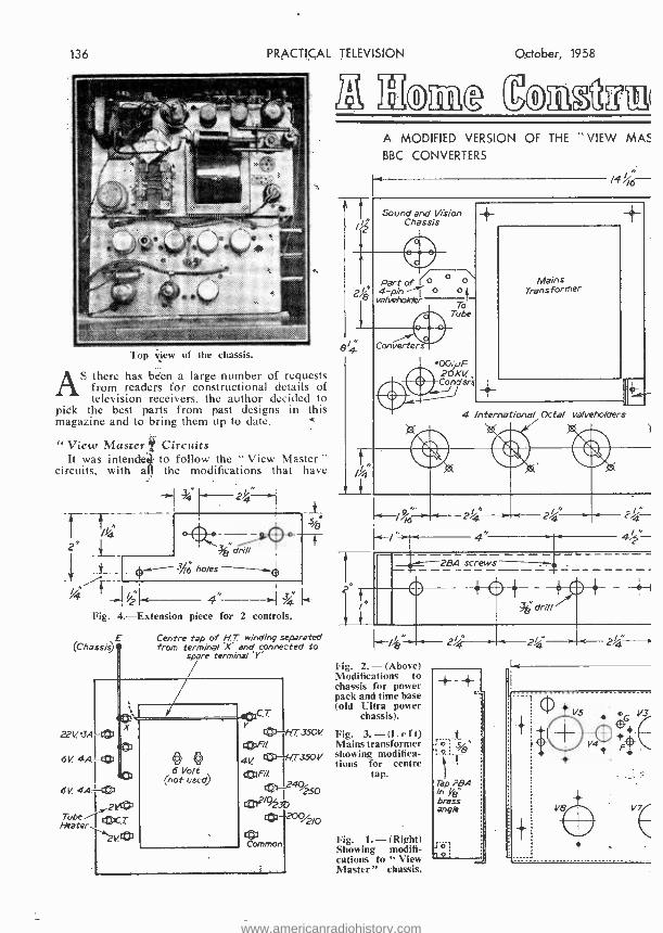
PRACTICAL TELEVISION
x
Top view of the chassis.
AS there has been a large number of requests from readers for constructional details of television receivers, the author decided to
pick the best parts from past designs in thi, . magazine and to bring them up to date.
"View Master Circuits. It was intende to follow the "View Master
circuits, with a the modifications that have
4 2' L drill
J V, ho/es
I
4" -4a Fig. 4.- Extension piece for 2 controls.
(Chassis) E Centre tap of H.T. winding separated from terminal 'X' and connected to
spare terminal 'Y'
22V. 3A -t©
6V. 4.01,-0
6V 4A -tom 2!4*
Tobe --17:03c3.- C Heater 1
VtO
350V
October, 1958
3Icml TaimIgn A MODIFIED VERSION OF THE VIEW MAS
BBC CONVERTERS
A Sound and Vision
Y Chassis
Part of ( o é" 4-pin- o o
vale ehoktr
8/4. Converters
Tol Tube
Mains Transformer
I T 1
4 International Octal valveholders
)
24._
4`
2a /
screws - rt o +o f
B drill
% 4g=
I" 24.
Fig. 2. - (Above) Modifications to chassis for power pack and time base (old Ultra power
chassis).
Fig. 3.- (Left) Mains transformer showing modifica- tions for centre
tap.
Fig. 1.- (Right) Showing modifi- cations to " View Master" chassis.
24 2% -1
www.americanradiohistory.com
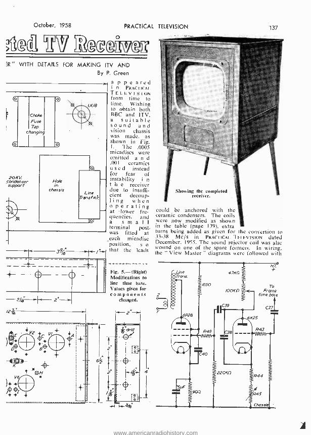
October, 1958
Mgx
PRACTICAL TELEVISION
ER" WITH DETAILS FOR MAKING ITV AND By P. Green
appeared i n PRACTICAL TELEVISION from time to time. Wishing to obtain both BBC and ITV, a suitable sound and vision chassis was made, as shown in Fig. 1. The .0005 micadiscs were omitted a n d .001 ceramics used instead for fear of instability i n t h e receiver due to insuffi- cient decoup- ling when o p e r a t i n g at lower fre- quencies, and a s m a l l
terminal post, was fitted at each micadisc position, s o that the leads
Choke
Fuse Tap
changing
20KV condenser suppor t
Fig. 5.- (Right) Modifications to line time base. Values given for components
changed.
137
Showing the completed receiver.
could be anchored with the ceramic condensers. The coils were now modified as shown in the table (page 139), extra turns being added as given for the conversion to 33 -38 Mc /s in PRACTICAL TELEVISION dated December, 1955. The sound rejector coil was also wound on one of the spare formers. In wiring, the " View Master" diagrams were followed with
To Frame
time base
www.americanradiohistory.com

138 PRACTICAL TELEVISION
56
61(25
PS
P59
T To
Line time
-base
Chassis
Fig. 6.- Modifications to frame time base. Values given for components changed.
the exception of the above modifications. The 22 volt negative bias to valve 6D2 is carried via the 5 -pin plug. The lead to the time bases from
Sides
October, 1958
this valve is a separate wire through a single point plug. This is near the valve and allows the chassis to be separated. Power Pack and Time Bases
For the power pack and time bases an old Ultra chassis was now modified as shown in Fig. 2. As there is no centre tap available from the H.T. windings of the mains trans- former. this wire had to be separated from the thick bus wire connected to the chassis. It was taken to a spare terminal on the side panel as shown in Fig. 3 and diagrams of connections in Fig. 8. The cathode heater short trans- former can be seen in the photograph of the chassis, mounted near the on /off switch. Three sockets were now fitted, each one to supply a different point, viz., sound and vision chassis, converters, and the tube. A control panel was made and fitted to the rear of the chassis; it contained six controls and an on /off switch (Figs. 4 and 7).,
ITV Converter Diagrams are shown in Figs. 5 and 6 which differ
5f/
/yß
69A 2 P/u9
/ +4-
I 1 -¢ -+-
L___L_Z=_..--.._-.._-.-. 1
.-.-t o / 51/ .," /4 5// _I
4,----884 for coils
oil d /e.
Coil
o
This /billing to suit / -SpF trimmer condenser
s
Material: %2 Brass sheet
/" 76 rivet of corners
Fig. 9. -138C converter drilling as viewed from top. ITV converter drilling, but 2 -B9A valves. Omit cbil drilling X unless extra gain is required (see P.T. June, 1956).
www.americanradiohistory.com

October, 1958
P64 P65 25011 SKI]
Bottom T® .!
These four controls
adjust Frame
PRACTICAL TELEVISION
Omit COIL WINDING DATA P46
P45 R59 it IODAT) Min 2.5K0 10K11 /ma) Switch
''Top Tgand 1 Sync. Linearity
Rep /aces P6O -P6/ Fig. 7. -The control panel.
H.T.t
loon
To UU8 Plates
loon
Mains Tronsfmi Chossis
--245Y bias to 602 valve
Fig. 8.- (Above) Modifications for 2.5 v. bias to 6D2 valve. Fig. 10.- (Right) Diagram of ITV converter.
All .001 condensers ceramic.
/Sn
from the " View Master," as they include modifica- tions that have appeared in PRACTICAL TELEVISION at various times. On page 136 is shown the top view of the chassis. Unfortunately, at this period much time was wasted on tuners and certain published diagrams of converters which proved unsatisfactory. It was, therefore, decided to make an ITV converter as near as possible to the one published in the October, 1955. issue. It was an out- standing success. Fig. 9 shows the chassis and Fig. 10 the circuit of the ITV converter. Two identical chassis were made and the coils wound on standard 5 /160n. formers with O.B.A. slugs, The number of turns for the coils is shown in the tables.
BBC Converter The BBC converter will
be shown next month. It wilk be noted that in this converter a 6F12 valve was
T Heater r choke
VI
PCC84
139
Coil ITV Converter
LI, L2
L3 L4 L5 L6
Heater choke
2T. 26 s.w.g. S.C. cop. wire. 4T. 22 bare cop, wire.
4T. 18 S.w.g. en. cop. wire. 2T. 18 s.w.g. en. cop. wire. 12T & 2T. 28 s.w.g. S.C. cop. wire. 41T. 22 s.w.g. bare tin cop. wire. 12T. On hin. former. 22 en. cop. wire.
Coil ¡ BBC Converter
LI, L2 L3A L3B L4 L5
Heater choke
2T & 13T. 28 s.w.g. S.C. cop. wire. IOT. 28 s.w.g. S.C. cop. wire. 12T. 28 s.w.g. S.C. cop. wire. 14 & 2T. 28 s.w.g. S.C. cop. wire. 6T. 22 s.w.g. bare tin cop. wire. 12T. on *in. former. 22 en. cop. wire.
Note. -All coils on std. 5;'16in. dia. 0 B.A. slug former . except coil L3 and choke.
used in the first stage, but it was found there was not enough gain and a further coil had to be added, similar to the description given in the June. 1956, issue. It would appear that botti converters should be constructed on the same lines, both using the PCF80 and PCC84 vahr;.
(To be continued)
1°G.al MIMEO
LS
/9OV.Hr
ï
Output
u.
Co-mtiol socket
v2 PCF8O
9 L6i - ,
LI
www.americanradiohistory.com

140 PRACTICAL TELEVISION
The Bush 14in. push- button transportable model.
LAST year portability was the main feature in television design and although a number of portable receivers were again in evidence
at the show. this year the emphasis was on television receivers equipped with V.H.F. /F.M. radio. and the use of printed circuits.
Purely as a novelty was a 29 transistor portable television receiver with an 81in. tube which operated from an 18 volt battery. It was shown working on the Vidor stand but is not available to the public as it was an experimental model Vidor have been working on for the past 18 months.
The Ferguson "400 " series television receivers incorporated many new technical features, among them "Sequential Auto -Gain." which enables the best possible signal -to -noise ratio to be achieved combined with very good cross modulation characteristics. Another exclusive feature is a
Resonant Spot Limiter " which results in inter- ference pulses (e.g., car ignition) appearing only as a grey dull spot instead of a bright white spot. Other technical features are "Stabilised EHT." "Frame Flyback Suppression." " Optimised D.C. Components." " Anti -drift Line Synchronisation " and " Positive Interlaced Circuit."
Large Picture Area Ferguson showed a number of table models
with either 17in. or 21in. electrostatically focused aluminised 90 deg. deflection angle tubes, and " push through " presentation affords the largest possible picture area. Two models were equipped with V.H.F. /F.M. radio. The V.H.F. radio unit is entirely separate from the television circuit. Two other models had a sync -cancelled A.G.C. system with gated amplifier which gives a true black -level control over a wide range of signals and minimises re- adjustment when switching from one channel to another. A pre -set "local /distant " control enables the receiver to be adjusted upon installation for the best possible signal -to -noise
O::tober, 1958
TN AT THE MA11ONAL
RADIO SHOV'/ The Trend in Dekggn a This Year's Exhibition
ratio. The flywheel line synchronisation uses a sinusoidal oscillator -an exclusive feature of Ferguson receivers.
All the models are convertible, matching legs being available for the. 17in. models as an optional extra at two guineas and matching stands for the 21in, models at three guineas.
Printed Circuits H.M.V. " New Highlight " receivers featured
an electrostatically -focused 90 deg. deflection tube and a new type of tuner. Coils for all 13 channels are incorporated and a "slot " front facing speaker is fitted. Printed wiring is used for the sound and vision I.F. amplifiers and for the line output stages. An important feature in these new television models is the speaker, which occupies a relatively small space. The new -type multi -coil radial turret tuner has an exclusive colour -coded illuminator, showing green for BBC and red for ITV.
New is the resonant spot limiter for neutralising interference and automatic sensitivity compensa- tion for best possible signal -to -noise ratio.
The above firm also showed a 17in. table model which included a self -contained radio unit to receive V.H.F. sound programmes. The fringe area models incorporated keyed automatic gain control to minimise output variation over a wide range of signal input, thus reducing the effect of fading due to weather and other conditions.
Dynatron offered many outstanding features in
Marconiphone Model VT157, which is a 17ín. A.C. D.C. table receiver for normal reception areas.
www.americanradiohistory.com

October, 1958 PRACTICAL
their receivers. They included aluminised tubes. automatic control of picture and sound and a highly efficient turret tuner. A wide choice of cabinet styles. for both console and table models, are available to suit varying tastes in furnishings.
A highlight of the Cossor exhibit was a new printed circuit television receiver of " unit con - st ction " design. The receiver is composed of srate printed circuit boards which simplify ser*icing to a considerable degree. The 17in. 90 deg. aluminised tube is push through mounted
tk%
TELEVISION 3.141
or fringe form. A standard model is also available incorporating V.H.F. radio.
Another push- button model was exhibited by Bush and is dealt with later.
Murphy Range Murphy showed a universal television receiver
incorporating V.H.F. /F.M. radio which is identical externally with the now familiar V310 and retains all the features of that receiver. The
(Left) Another attractive trans- portable is the Ekco 14in. re- ceiver incorpor- ating VHF radio (Right) The Argosy Model 17 F41 for fringe
reception.
which means that maximum picture area is 'obtained as no part of the screen is masked.
A 21in. table model incorporated automatic picture control and syncrolock celf- centering flywheel synchronisation to ensure a rock -steady picture. Also with a 21in. tube was a receiver specially designed for operation in Band I or Band III fringe areas. Universal models were also seen.
Another fringe area model with a 17in. aluminised electrostatic tube with direct synchro- nisation. automatic picture control, frame flyback
exclusive Murphy feature of easy operation on television with no fine tuner has been maintained. the special tuner provided serving for the selection of V.H.F. programmes only. The vision side of this receiver is also identical with the V310 but the sound channel has an innovation in that a double superheterodyne circuit is used. By per- mitting a low final I.F. this results in selectivity
Two other attrac- tive receivers are (Left) the Pye SP17 and (Right) the Invicta Model
F.237.
ssion and automatic sound noise limiter own by Argosy.
Push - button Model .
A push -button, high definition 17in. table model was shown by Pye. which, by pushing a button the highest possible definition picture auto - mafihally appears. The set is available in standard
on V.H.F. reception similar to that of a normal radio set.
The turret is provided with a special pair of coil biscuits to cover all BBC stations in the F.M. band. When these are brought into position a cam, fitted to the turret control shaft, operates the multi -pole changeover switch. . Thus in changing over to V.H.F. the timebase valve heaters are switched off, as also are the tube heaters. In order to keep the heater current constant, an extra resistor is switched into circuit.
www.americanradiohistory.com

142 PRACTICAL
This resistor is located adjacent to the other heater droppers.
A Varite thermistor is provided within the switched heater chain to prevent current surges from damaging valves or tube. The H.T. con- nections to the timebase circuits are also broken and a ballast resistor is substituted to prevent the H.T. line from rising and causing valves and components to over -run. The vision I.F. ampli- fier is also muted to protect the video stage and tube. As the cascode and common I.F. valves are used both on television and F.M., they are switched to maximum gain for F.M. reception.
Ekco had three new 17in. receivers incorpora- ting a channel selector on which the BBC and ITV stations are side by side. One of these models was suitable for the fringe area.
Unique Test Method In the R.G.D. television range pride of place
was occupied by the Deep Seventeen. A unique feature of this set is the fact that it begins its
TELEVISION October, 1958
Kolster- Brandes featured a 17in. lightweight portable TV, the Royal Star. It weighs only 381b. and is available with a telescopic aerial, which is not required in all areas, and is there- fore optional. The specification includes 14 valves. 3 germanium diodes, 90 deg. self -focus tube, miniature 13 channel tuner, printed circuits and wide range A.G.C. circuits. It measures 16in. X 16in. X 161in.
24in. Model Large size pictures are provided by a 21 in.
Console and a Consolette. Both of these models are available with V.N.F. /F.M. if desired. The range of receivers has also been increased with a 17in. fringe model. The 24in. Regina Consolette provides one of the largest direct viewing pictures in Great Britain.
A 17in. screen receiver incorporating printed circuit design was shown by Spencer -West as standard and fringe models. Another receiver incorporated a vertically- mounted chassis with
(Left) The R. G. D. fringe area model the Deep Seventeen. (Above) The K.B. 17M. transportable model. (Right) The Ferguson 17in. Stan-
dard Consolette receiver.
v:orking life. fully operational, while still travel- ling along the factory conveyor line. Taking current from a live rail, it is subjected to a series of transmission tests, the results of which are computed electronically. R.G.D. engineers claim that their test methods, even at peak pro- duction, give a quality graph which is constant to within 3 per cent.
Bush exhibited a large number of receivers, the highlight of which was the Twin Set, which has a separate V.H.F. circuit and is for fringe area reception.
The first television receiver with push- button instantaneous switching from BBC to ITV and vice versa without further adjustment was the Bush I4in, transportable model. It covers all thirteen channels, but only four buttons are fitted, two for adjusting to any two channels on the BBC hand (Band I- channels 1 to 5) and the other two channels on the ITV band (Band III -- channels 6 to 13).
printed circuit, hinged for complete accessibility for servicing, at the same time leaving all hand controls in the mounted position for operation enabling testing to be carried out under ideal conditions.
Television Cameras A novelty on the Peto Scott stand was a studio
and an industrial television camera shown in con- junction with their 14in. and two 17in. television receivers, the latter having automatic self -locking synchronisation circuits to prevent line tearing. frame flyback suppression and regulated EHT. The studio camera was British built and the industrial camera is suitable for 405 and 625 line transmission.
Masteradio showed receivers with 17in.. 21in. and 24in. tubes. Features of the sets was a new type of elliptical speaker facing front, improved automatic picture control, a new automatic focus- ing system giving freedom from focus and ion
www.americanradiohistory.com

October, 1958 PRACTICAL TELEVISION t1ß.3
trap adjustments and electrostatic focusing cathode ray tubes.
A number of sets from 14in. to 21in.. including fringe models. were shown by Invicta Radio.
TVIRadiogram 'Where living room space is a problem, this
was overcome by Ferranti who introduced a TV/ radiogram. Combined in this receiver were a 17in. television set. V.H.F. /F.M. radio and a record player.
A new 21in. receiver introduced by G.E.C. incorporated V.H.F. /F.M. radio and twin loud- speakers. Printed circuit technique was used in some of their designs.
Each of the new range of television receivers
date type for every purpose. Three of these valves. the 6/30L2. the 30FLI, and the 30PLI possess identical characteristics in the triode sections, allowing an unusual flexibility in con- structional layout.
The Mullard stand also showed new develop- ments in cathode ray tubes and valves. A giant wire model of a valve was seen, the main features of which were highlighted and emphasised by explanatory captions.
Aerials and Components Combined arrays for covering BBC and ITV
reception were to be seen on J -Beam Aerials stand. To these can be added attachments for V.H.F. radio if required. Prominent among
(Left) The Spencer -West Model 174. (Right) The Labgear pic- ture equaliser.
by McMichael used printed circuits and had V.H.F /F.M. 'radio. Two of their sets had multiple- speaker systems.
On the Pam stand was a transportable 17in. receiver capable of receiving V.H.F. /F.M. broad- casts.
Features of the Philco range was 17in. receivers with variable interference suppressors and V.H.F./ F.M.
The .advantages of indirect viewing shown by the' Valradio 48in. large screen projection receiver is the absolute absence of flicker and the photographic quality of the life -size 48in. picture.
Cathode Ray Tubes One of the interesting features of the Siemens
Edison Swan stand was the presentation of new developments in tube design.
Examples included the new 21 in. electrostatic focus tube with a deflection angle of 110 deg. Another 21in. tube was the C.R.M. 212 90 deg. magnetic focus. The 17in. range was represented by tivo new electrostatic focus tubes: the first again had a deflection angle of 110 deg., and with it was the new C.M.E. 1702 -a 90 deg. deflection tube with a maximum overall length nt 15in. In addition, two new 14in. electrostatic focus tubes were seen: the C.M.E. 1402. which has a 90 deg. angle of deflection, and another tube which has appeared recently, the C.M.E. 141. with a 70 deg. deflection angle.
Foi- the television receiver, a complete first preference range of 0.3 amp. heater current type Valves was being displayed, providing an up -to-
these were the long and medium range folding double beam arrays being basically a two element Band T with a double four slot beam Band III for medium range, and a three element Band I with a double four slot beam Band III for long range. The skeleton slot principle is not only used to give optimum gain and bandwidth on Band M. but the matching properties on the skeleton slot are utilised to enhance the Band I
(Left) The Antiference, Ltd., Vantenna all -land room aerial. (Right) The Aerialite Aermatch 3 tnin -bard
model 840,'T.
www.americanradiohistory.com
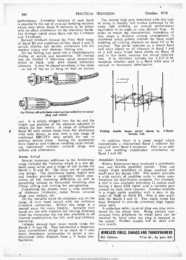
1Á,1 PRACTICAL
performance; Complete isolation of each band is ensured by the use of co -axial isolating sections which even allow Band lI elements to be added with no effect whatsoever on the television bands. For stronger signal areas there was the Unibeam and Twinbeam.
Burwell products showed the View Well range of Band III and combined aerials, Band I and II aerials. dipoles, loft aerials, conversion kits for stacked arrays and chimney lashing kits.
On the Belling Lee stand was a comprehensive display of aerials and accessories. Of interest was the Golden V television aerial attractively styled in black, with gold plated telescopic elements. It may be placed anywhere in the room -on top of the set or hung on wall or picture
TELEVISION October, 1958
The normal high gain associated with this type of array is thereby still further enhanced by an extra 3dB yielding an overall performance equivalent to an eight or nine element Yagi. In order to match the characteristic impedance of free space a skeleton conical arrangement is employed which greatly extends the band width enabling all existing channels on Band III to be covered. The aerial operates as a broad band half wave dipole on all channels in Band I and as a full wave broad band dipole on Band Il and in this latter instance has mixed polarisa- tion. It is, therefore. suitable for V.H.F. /F.M. reception whether used in a Band I /III area of vertical or horizontal polarisation.
x\\\V1\tltlllllll
The Wolsey all- polythene construction solderless co -axial plug and socket.
rail. It is simply plugged into the set and the length and position of the elements adjusted to obtain the best results. A range of collapsible Band III attic aerials made from flat aluminium strip were shown, as also were a new range of combined BBC /ITV attic aerials for use in primary service areas. Among the accessories were diplexer and triplexer coupling units includ- ing waterproof versions. co -axial plugs and sockets and attenuators.
Room Aerial Several important additions to the Antiference
range included the Vantenna which is a new all - band room aerial and a range of loft aerials for Bands I, II and III. The latter are of complete new design. The mast /boom clamp, angled arm and bracket provide a versatility which: over- comes all loft mounting difficulties as well as permitting vertical or horizontal mounting plus tilting, rolling and turning for anti -ghosting.
Completing the display were a wide selection of diplexers. triplexers,_ outlet boxes, co -axial plugs and sockets, etc.
On the Aerialite stand the emphasis was on the range of twin band aerials with the exclusive Crosslink connection. Within this range is a
special array for every locality. Aerialite twin bands are not only supplied for varying distances from' the transmitter but are also available in all channel combinations for loft, wall and chimney mounting.
Labgear showed their space match range for Bands I, II and III. This represented a departure from conventional design in as much as it uses space impedance termination to secure a uni- directional polar diagram from a V beam con- figuration.
Folding double beam aerial shown by J -Beam Aerials, Ltd.
In addition there is a super model which incorporates a channelised Band I reflector for areas of poor Band I reception. This is an add - on unit enabling independent orientation on Band I and III.
Amplifier System Wolsey Electronics have produced a completely
new and flexible amplifier system. They can supply single amplifiers of large. medium and small gain for Bands IjIII. The system provides a wide variety of amplifier units in many com- binations for distribution purposes. For example, a unit is now available providing 12 outlets each having a Band I /III signal with a variable gain control on each input channel. Another example is a single outlet amplifier with a gain in the order of 50dB on Band III. This is also avail- able for Bands I and II. The whole range has been designed to provide extremely high signal/ noise ratio.
A solderless safety co -axial plug was also intro- duced by the above firm. Being entirely con- structed from polythene no metal parts can be touched by hand when the plug is inserted in the socket. Further models will be dealt with next month.
WIRELESS COILS, CHOKES AND TRANSFORMERS
8th Edition. Price 6/ -, by post 6 9.
www.americanradiohistory.com

Oclobor, 1958 PRACTICAL TELEVISION '1(45
WONDERFUL OFFER OF A.M. -F.M. CHASSIS AT £14 (P. & P. 10 / -) Why buy a F.M. Tuner at the same price? Tapped input 203-225 v. and 226 -250 v. A.C. ONLY. Chassis size 15" x 6f" x 51-' high. New manufacture. Dial 141" x 4" in gold, red and deep brown. Pick -up, Extension speaker, Ae., E. and Dipole sockets. Five "piano" push buttons -OFF, L.W., M.W., F.M. and Gram. Aligned and tested. With all valves.
/s. Vales E1Z.0800
0 rech. CÑ81,
0E-F500 ,
MA.
ECC85. Speaker & Cabinet to fit, polished, with back, 70/ -. x 6' ELLIPTICAL SPEAKER 20/ -. ` -Y TERMS :- (Chassis) £5 down + carr. and 5 Monthly Pay- ments of 33 -, or with Cabinet and Speaker £6 down+carr.and 6 Monthly Payments of £2. BEST VALUE FOR MONEY
IN CONVERTERS I.T.A. high gain converter. ALL 0: CHANNELS ALL AREAS- IIi' ALL SETS. (For twin feeder input use a matching transformer at 5/- extra.) Direct switching (I.T.A. to B.B.C.) ; internal power pack ; valves PCF80 and PCC84 ;
£5.50
P. & P moulded cabinet 81" x 4" x 6 ". 3/ No alteration to your set ; fitted in 10 mins. 12 months' guarantee. Terms -see below.
CYLDON 16 Mc /s and 19 Mc /s TUR- RET TUNER with two sets coils (state B.B.C. & I.T.A. channels). Extra pairs of coils, 5/- pr. With knobs. ONLY 77/6 (216 post). Brand new in original carton. Valves PCC84 and PCF80 included.
GRAMOPHONE AMPLIFIER .vith 5in. SPEAKER
WHY PAY MORE 9 ONLY 60/- (POST 3/ -)
On Fabric- covered Baffle 12:}" x 5 ". Mains and Output Transformers. Metal Rectifier. ECL82 Valve. Tone and Volume Controls. On -off switch. Plenty of Volume. Fully Guaranteed. Two Knobs supplied. Ready to play. BATTERY ELIMINATOR. Converts your Battery Set to Mains. For 4 Low Consumption Valves (DK96 range). 90 v. 15 mA. and 1.4 v. 250 mA., 42/6 (2/6 post). 200 -250 v. A.C. Size 5g," x 3/" x 2'. I.T.A. AERIALS clipping to existing mast I -2" dia. 3- element, 27/- ; 5 -el., 35/- ; 9 -el., 55/- ; Loft mountg. 3 -el., 20/- ; 5 -el., 27/6 ; Combined single B.B.C. and 5 -el. I.T.Á., 75/- with chimney lashings ; Co -axial cable semi -airspaced, 8d. yd. or 20 yds., 12/6 ; aerial and cable prices carr. pd.
SEND 6d. FOR CATALOGUE
THE BRAYHEAD TURRET TUNER. £7.7.0, post Complete with booklet and fitting instructions. State set and model no. when order- ing.
free.
INCREMENTAL TUR- RET TUNER by famous manufacturer for 35 Mc /s only ; with knobs. Valves PCC84 and PCF80. ONLY 77/6 post free or without valves, 60/ -.
A NEW LINE FOR US
Electric shaver by Swiss precision watchmakers. As good as anything on the market and better than most. Rotary cutters with trimmer (patented) for sides and mous- tache. Make shaving a pleasure. 12 mths. guarantee. Proved in the difficult Ameri- can market. A.C. and D.C'. mains. Two types (A) 220- 240 v., £7.17.6 in Gold Filled Red Box ; (B) 110 v. and 200- 250 v. in Presentation Case.
free trials as they work f rrstOti ¡both post paid. No
PERSPEX UNSCRATCHED, post 2/- each size, 6 post free ; sizes in ins. 14 x 11 x 3/16 clear, 5'- ; 12 x 91) s 5 clear, 4'- ; 16 x 14 x 3 /16 clear, 7,'- ; 15 x 12 x tinted, 6' -. LX. -W,D. PERISCOPES, size loin x 6in.. 7 6 (p. and p. 2 6). I:LECTROLYTÌCS 200- 200 -200 mf. 275 v.. 7'0 (post 16). 200 -100 mf. 275 v., 4/6 (post l / -) ; many others. BATTERY CHARGER. 1 amp. 6 v. and 12 v., £2, post paid. Posted Orders to Camberley, please. Delivery by return. Terms :- One -third down and balance plus 7/6 in four equal monthly payments. Postage with down payment. (C.O.D. 2/- extra.) These terms are applicable to all items except A.M. - F.M. chassis.
GLADSTONE RADIO 82B, High Street, Camberley, Surrey, and 3, Church Road, Redfield, Bristol. Tel. : ç t 207.
www.americanradiohistory.com

146 PRACTICAL TELEVISION October, 1958
MAINS TRANSFORMERS A new range of mains transformers for many post -war receivers. Mains input 20Q- 230 -250 volts List No. Output Price MTD /1 210-0-210 v.. 80 m.a.,
6.3 V., 3.5 a. MTDl2 230-0-230 v., 80 ma., 1íT['3 250-0-250 V., 80 MA.,
MTD'4 280.0 -260 v., 80 m.a..
MT,MR 240 v., 70 ma., 6.3 v., 3 a. HEATER TRANSFOR MERS Primary 220 -240 volts. 2 v., 1 a.... 2e., 3a. ... ... 4 v.. 11 a. ... 4 v.. 3 a.... ... 5 v.. 2 a .... ... ... ... 6.3 v., 1 a. 6.3 v.. 11 a. ... ... ... 6.3 v.. 3 a. ... ... ... 12 v.. P a. .. ... ... METAL RE(TII'IERS 12 v.. a. ... ... ...
250 v., 75m.a.... ... 300 v., 60 m.a. ... ... ... Full Wave :
8. ... ... ... 12 2
v., Iaa. ... ... ...
32- 32i-
32'-
ALPHA RADIO SUPPLY CO.
VALVES GUARANTEED ALL TESTED
BEFORE DISPATCH
DAF96 10'6 ' KT33C 10 - 3V4 DF96 10/6 KT66 15 - 5U4
8'3 DK96 10'8 KTW61 5Y3GT ... 516 DL96 1016 1478 1 5Z4 ... 10- EBC33 718 OZ4 ... lOr_ EBC41 l0í- PCC84 1 6A7 13 /-
5!8 EBFBO 1018 PCF80 1 SALO 8/8 ... 6/9 ECC84 104 PL81 1 6AM6 91- ... 10'- ECC65 9'6 PL82 6F60 7/8
ECH35 10'6 PX25 1 6F13 141-
each ECH42 10/6 PY80 9 - 6F15 14'- ECH81 11.'- PY81 10 6K7G 5!- ... L8 ECLßO 1318 PY82 9 - 6KBG 8'8 ... 519 EF39 716 PEN4VA 15'- 6L6G 9'- 6'6 EF40 14'6 PEN25 5 - 6Q70 W- ... 6'6 EF41 9/9 PENA4 15 - BSN7 7'8
... 5'3 EF50 4/- SP41 3 - 6SL7 8/- EF41 918 SP81 3 - 6U4 14'-
91- EF42 141- TP25 2710 6V6G 7l- v.. ... ... ... .. 15'6 EF80 9'- U14 8 6 6V6GT 7 %8 Lectrona ... ... ... ... 1718 LINE OUTPUT TRANSFORMERS EF86 1418 1125 14 6 6X50 7/- 61 Units by Plessey ... ... 1ßl8 Type No. Used in Model No's. Price EL41 11 /- UCH92 10 6 12AT7 91- 8" Units by Goodmans ....1918 LO4 Pye V4- V7- VT4 -VT1. EL42 12 /- UL41 10 - 12ÁU7 81- PAM 908- 909 -952 -953 - EL84 10/6 VU3I 8 9 12AX7 9r_ 10 Units by Elac, Plessey ... 2518 958, Invicta 118 -119- EM80 018 ICS 12 8 2SÁ6 1118 6 x 4' Units by Plessey ... 1918 120 .. ... 55'2 EY51 13 /8 1115 10 8 25L6 10' 7" x 4" Units by Goodmans ... 19'6
L013 Regentone 1íG 12/5 ... 81'11 EY8S 13/8 1145 10 6 25Y5 111_ 7" x 5" Units by Goodmans ... 10 6
L017 Alba T372, T472, T372B. EZ40 91- 1R5 3 35Lß 918 8 x 5" Units by Goodmans ... 25 6 T392. T992 - 9812B. EZ80 8!9 1S5 ';.,111. 35Z4 8 ;_ 10 x 6" Units by Plessey ... ... 25'6 TR9872, U1253 . 43'2 GZ32 12 /- 1T4 42 81- Our 1958/9 Catalogue is available-
L024 Cossor927 -932 -929 56'8 IIL23DD 8'8 334 8'- 80 8/6 send li- In stamps for tour ropy- " T.V. Faults," by N StRvens -a quick reference fault guide, giving more than 80 faults with test procedure. 54 post free. TER MS : Cash with order or C.O.D. Postage and Packing charges extra, as follows : Order value 10/- add 1 I : 20 - add 1/9 ;
40:- add 2,6 ; £5 add 36. Minimum C.O.D. Fee and Postage 3' -. For full terms of busine =s see tnstde cover of our catalogue. Personal Shoppers 9 a.m. to 5 p.m. Monday to Friday. Saturday 10 a.m. to 1 p.m.
103 LEEDS TERRACE, WINTOUN STREET, LEEDS, 7.
9/- 81- 8'-
11 /-
811 1 51 15TORS CZi ... 3.11
CZ3_ ... ... 1/8
CZ6 ... .. 3/6 CHASSIS Aluminium Undrilled with Reinforced Corners. Available in the following sizes :
each each 6" x 4" 24" ... 4/6 12' x 8" x 21" ... 8/8 8' x 6. 24" ... 613 14' x 3" x 21" ... 6/- 10'x7'x21' ... 7/3 14'x 9'x 21' ... 12/- 12 "x3"x21" ... 5,9 16'x6'21- ... 8/8 12'x5'x21° .. 6/9 16 "x10'x21'... 14/- All are four -sided ideal for radio re- ceivers- amplifiers -power packs. etc. HARDWARE Brass nuts 2BA, 7/8 4BA, 3 .'- 6BA, 2 8BA, 2/- Brass Bolts (Round Headed) 2BAx f -.3/9 4BA x f ", - 6BA x 1'. 2/6 2BA x r. 4/8 4BA x 1 ". 3'9 6BA x 1 ", 2/9 2BA x 1', 4/9 4BA x 1 q'8 6BA x 41-
8BA xi-. 3/6 LOUDSPEAKER UNITS
All Brand New Note Special Prices All Permanent Magnet 3 ohms Impedance.
each 5' Units by Plessey, Goodmans,
CZBA ... . . 218 CZ9A 2/8
118 CZ11 ... ... 4/- CZ12 ... ... 5/8
AN ELECTRONIC ORGAN FOR THE
HOME CONSTRUCTOR
By Alan Douglas, M.I.R.E., Here is a do- it- yourself book which gives straightforward instructions for building an inexpensive electronic organ. Compact and easily transportable, the instrument has been specially designed for amateur use in chu rch, hall or home. Detailed step -by -step instructions are given, as well as .a complete list of materials and their suppliers.
Illustrated with photographs an4 diagrams. From booksellers, 15/- net.
PITMAN Parker St., Kingsway, London, W.C.2
BAND III CONVERTOR for ANY SET in ANY AREA This unit has been widely used since I.T.A. Transmissions began to convert all types of sets, Superhet and T.R.F., to receive on Band Ill.
Unlike many other convertors this unit is small enough to be fitted inside your cabinet, enabling the job to appear finished and perfectly safe for all to use.
The wiring is simple to follow, and alignment is not difficult. * IT will convert any set, any age, T.R.F. or Superhet. * IT includes station switching. * IT provides pre -set contrast balancing. * IT uses only one aerial input for both bands * IT provides manual tuning on Band Ill. * IT is totally screened. * IT completely rejects unwanted signals. * IT requires no additional power supply where either 6.3 v.
or .3 amp. heater line is available.
CONVERTOR wired and aligned with fitting instructions ... ... ... ... ... L3 IO 6
KIT complete in every detail, less knobs ... ... E2 10 6 1 0
CIRCUIT and instructions in detail (free with kit) 1 6 KITS made up by customers checked and aligned,
including post ... ... ... ... ... 12 6
When ordering please state present B.B.C. Station and I.T.A. Orders over f2 post free.
C. &. G. KITS 285, LOWER ADDISCOMBE ROAD, ADDISCOMBE, CROYDON, SURREY
Phone : ADDiscombe 5262
www.americanradiohistory.com

October, 1958
Manchester Progress BOTH Granada and ABC -TV
are spending a lot of money on improvements at their Manchester Studios. Having got their new large and well - fitted stage into operation, Granada have now branched out into extensions of ancillary premises and plant. There will be a special sound effects studio for all types of pro- grammes, music and tape recording libraries, an Ampex record i ng department for magnetic recording of pictures. together with new wardrobe, make - up and dressing - room facilities. This is a practical indication of the success of com- mercial television in the North- ern area. excerpts only of which are seen in the South frcm time to time. A small point which puzzles some of my friends in Lancashire is the Granada Network's habit of omit- ting the National Anthem at the end of the programmes. I feel this must be an oversight. as occurred at the start of BBC television after the war. I admit that I may not always look and listen to the National Anthem at the end of television on BBC or I.T.A.. but I would feel very offended if it wasn't there. As far as I know, all other television organisations in this county. always end their programmes with the National Anthem.
I.T.A. Extensions IT.A. programme companies
are now making a reason- able profit, commensurate with their early losses, as one executive put it. And as those initial losses went into millions. the returns must now be highl satisfactory, to say the least. At any rate, nearly all the area stations are expanding rapidl and now spending quite a lot of money on new equipment and
-facilities. Apart from the
PRACTICAL TELEVISION 147
UNDERNEATH THE DIPOi) A MONTHLY COMMENTARY
By Iconos extensions already mentioned at Granada's Manchester Television Centre, their London Chelsea television theatre is being refitted with new permanent control rooms, additional lighting by Mole - Richardson, improved lighting control equipment by Strand Electric and new 44in. Image Orthicon cameras by Marconi. Associated Rediffusion are planning large studio extensions at Wembley. includ- ing a huge studio stage. which will probably be the largest television stage in Europe. Scottish Television are also spending a lot of money on new lighting equipment and expand- ing their facilities. Southern Television, having converted the Plaza Cinema. Southampton, into a compact yet very complete television centre, are arranging for Post Office lines to London for reverse network operation. This will not come into opera- tion immediately, and the opening all -star programme, together with a weekly mystery serial will be sent to London via a number of. temporary micro- wave link "hops." When I called at the studio recently, some of this equipment, supplied by E.M.I. was just arriving. Most of the television equipment at Southampton will be provided by E.M.I., though a flying -spot
telecine apparatus will be sup- plied by Cintel.
East- Anglia THE changed financial climate
of independent television operation has also put a different aspect on the planning of future studios in the smaller areas yet unoccupied. East Anglia. for instance, with an T.T.A. trans- mitter at Mendlesham. Suffolk, will be served by the Anglia studios, Norwich. This will be quite an elaborate set -up in the large Agricultural Hall building in the centre of that city, formerly used for circuses. exhibitions and agricultural shows. This is an 80- year -old building, slightly reminiscent of a small Alexandra Palace, which is ideally suited for conversion into two quite large television stages, with plenty of space for ancillary offices, dressing -rooms and workshops. I understand that the Mendlesham aerial will be highly directional. radiating most of its power in a north- westerly direction, and will be mounted on one of the highest television masts in Europe- 1 ,000ft. high.
Regional Tastes BOTH BBC and I.T.A. cater 1 to some extent for local
Showing the imposing building of the Agricultural Hall at Norwich.
www.americanradiohistory.com
tastes. I.T.A. companies take the majority of the programmes from the I.T.A. Network, but these are varied with - a few local programmes, together with films specially obtained and run on the local telecine equipment. Local programmes are especially popular in Scotland and Wales, some of them obtaining quite high ratings from the public opinion polls- T.A.M. and Niel- sen. I would expect that a strong regional flavour will also be appreciated when the South Western area I.T.A. transmitters start operating for Devon and Cornwall. Cornish viewers in particular appreciate a local flavour to their entertainment. BBC regional studios in Man- chester, Birmingham, Glasgow and Cardiff make frequent con- tributions to the BBC pro- grammes, and to these will shortly be added a studio at Southampton.
Automation
THE keynote of most of the new equipment coming
along for television studios is automation -or, at least, semi- automation. When the BBC re- opened the Riverside Studios, Hammersmith. a year or so ago. with two large stages and a very elaborate lighting equipment, it was considered to be the most up-to -date television studio in the world. It still is one of the best from the facilities point of view, but several further developments in lighting and lighting control have been made as a result of experiences there. Both Mole -Richardson and U.E.C. have produced new types of lightweight spotlights, the focus and other adjustments on which can be made with " lamp- lighter " poles, manipulated by an electrician on the studio floor. This avoids lowering the lamp for adjustment or the use of ladders or steps to reach the lamp. Telescopic and lazytongs types of lamp support are now in general use, various types of runners are installed for moving lamps from one part of the stage to another in the shortest pos- sible time and with the minimum of labour. Strand Electric have also improved their elaborate organ console remote lighting control, and various new types of memory devices have been
PRACTICAL TELEVISION
devised for " punching up " lighting arrangements for differ- ent stage settings in advance, with their dimmers pre -set to give the best results as deter- mined at rehearsals. Mole - Richardson have also produced a new lightweight general pur- pose lamp. which can be readily converted from a flood to a spot- light. Many of these devices are in the course of being installed at BBC and I.T.A. studios and will improve the general quality of the picture. Operation of the lighting is then in the hands of one man. who should be well versed in the art of portrait photography.
A High Density IN the United States, an
investigation carried out by an advertising research body, has brought to light the amazing fact that 84 per cent. of the homes in that country have television installed. The actual figures are 50,540.000 homes and 42,400.00 with TV. This repre- sents a substantial increase over the survey carried out two years ago, when the respective figures were 48.800,000 homes and 15.500,000 with television, a percentage of 72.8.
Colour TV Demonstrated in Poland DURING the course of the
recent Polish International Trade Fair in Posnan. colour television was demonstrated by the Radio Corporation of America. This is said to be the first time such a show has been organised behind the Iron Curtain. All the programmes were originated in a specially erected studio inside the American Pavilion and were
October, 1958
watched by visitors on a number of R.C.A. colour TV receivers.
Television in China USING a 625 line standard,
the first television station in China has been opened, in Peiping. During the course of 'the next year a second station is to be established in Canton.
Hong Kong Vision Service
IN May 1957, the first public television service to be
operated in any British Colony was opened by the Governor on behalf of Rediffusion. This was an additional service to the relaying of sound programmes in the three main Chinese dialects which had been functioning for some years. The rapid growth of this combined service has necessitated the provision of plans for a new nine storey building and it is anticipated that this will be ready for occupation next year.
Creating a TV Commercial ADETAILED presentation showing the creation of a
TV commercial was the theme of the display by the five agencies of The Advertising Service Guild at the first Euro- pean Television Exhibition at Park Lane House, London, W.1, from May 19th to 24th.
A huge wall display, 27ft. X 9ft. in the form of a progress chart, simplified by colour and illustrated by photographs. traced the creation of a TV com mercial from the first contact with the client and product re- search to the final transmission -arid subsequent audience inquiry. Separate panels also illustrate the work in television of each agency.
PRACTICAL - WIRELESS CHIEF CONTENTS OF OCTOBER ISSUE
NOW ON SALE, 1/3.
A 3- TRANSISTOR 200 mW AMPLIFIER A HIGH QUALITY RECORD PLAYER
CAR RADIO INTERFERENCE SUPPRESSION BEGINNER'S CONSTRUCTIONAL COURSE
SERVICING PRINTED CIRCUITS A TOP -BAND TRANSMITTER
A TRAWLER AND MEDIUM WAVEBAND DIRECTIONAL RECEIVER
www.americanradiohistory.com

October, 1958 PRACTICAL TELEVISION 141
Technical Training
in Radio, Television
and Electronics
Engineering with
'Cs
The dec s'nn 's yours. To be a saccess in your chosen career ; to qualify f o r the highest paid job .. .
to control a profitable business of your own. Ics home -study courses put your plans on a practical basis ; teach you theory and practice ; give you the knowledge and experience to take you, at your own pace, to the top.
Choose the RIGHT course :
RADIO AND TELEVISION ENGINEERING : RADIO AND TV SERVICING : RADIO SERVICE AND SALES : ELECTRONICS : VHF 'FM ENGINEERING
Ics provides thorough coaching for professional examinations :
A.M. BRIT. I.R:E., City and Guilds Telecommunications, Radio Servicing ; Radio Amateurs P.M.G. Cert. (Marine).
LEARN AS YOU BUILD Practical Radio Courses
Gain a sound up- to- professional standards knowledge of Radio and Television as you build YOUR OWN 4 -valve T.R.F. and a 5 -valve superhet radio receiver Signal Generator and High -quality Multi - tester. At the end of the course you have three pieces of permanent and practical equipment and a fund of personal knowledge and skill. Ics Practical Radio courses open a new world to the keen Radio amateur.
THERE ARE ICS COURSES TO MEET YOUR NEEDS AT EVERY STAGE OF YOUR CAREER FILL IN AND POST THIS COUPON TODAY.
you will receive the FREE 6o page ICS Prospectus listing examinations and Ics technical courses in radio, television and electronics PLUS details of over 15o specialised subjects.
P
Other ICS courses include : AGRICULTURE, HORTI- CULTURE, ARCHITECTURE. WOODWORKING. SALES- MANSHIP AND SALES MANAGEMENT. ART. PHOTOGRAPHY. MECHANI- CAL ENGINEERING. MOTOR ENGINEERING. FIRE ENGINEERING. CHEMICAL ENGINEERING. Etc., etc. A WHOLE WORLD OF SKILL AND KNOWLEDGE FOR THE KEEN STUDENT.
INTERNATIONAL CORRESPONDENCE SCHOOLS (DEPT. 172 S), 71 KINGSWAY, LONDON, WC2
PLEASE SEND EPEE BOOK ON
` .4.0E
ADDRESS
OCCUPATION AGF 10.313
é
www.americanradiohistory.com

150 PRACTICAL TELEVISION October, 1958
RADIO SUPPLY CO. (LEEDS) (opposite
Post 'leans C.N'.0. or C.O.D. NO C.0.0. I. under £1. Postage 1/9 extra under M. 2 9 under £5. Open lo callers 9 a.m. lo 5.30 p.m. Sato. until 1 p.m. S.A.E. with
enquiries, please. Full list 6d. ; Trade list 5d. R.S.C. TRANSFORMERS
Fu10 Guarani ecd Interleaved and impregnated.
Primaries 200 -230 -250 v. 50 c /s screened TOP SHROUDED DROP THROUGH 260-0-260v 70 ma. 6.3v 2 a, 5v 2 a ...16:9 350.0-350v 80 ma, 6.3v 2 a. 5v 2 a ...18x9 250-0-250v 100 ma, 6.3v 4 a. 5v 3 a ...23/9 350-0-350v 100 ma. 6.3v 4 a. 5v 3 a ...2319 350 -0-í50v 150 ma. 6.3v 4 a 5v 3 a ...29/9 FULLY SHROUDED UPRIGHT 250 -0-250 v S) ma, 6.3 v 2 a, 5 v 2 a
Midget type 21- 3.3In.... .. ... 17/9 250 -0-250v 100 ma, 6.3v 4 a, 5v 3 a ...26'9 250-0-250 v 100 ma. 6.3 v 6 a, 5 v 3 a
for R1355 Conversion ... ... 31/- 300 -0- 300v 100 ma, 6.3v 4 a, 5v3 a ...23./9 350- 0 -350v 100 ma, 6.3v 4 a, 5 v 3 a -.23/9 350 -0-350v 150 ma. 6.3v 4 a, 5v 3 a ...33/9 425 -0-425 v 200 ma, 6.3 v 4 a, C.T. 6.3 v
4 a. C. T. 5 v 3a ... ... ... ... 49; 9 FILAMENT TRANSFORMERS All with 300 -250 v 50 cis Primaries : 6.3 v 1.5 a, 5'9 1 6.3 v 2 a, 7/ 6 : 0 -4-6.3 v 2 a. 79 :
12v la, 7/11:6.3v3a,8'11:6.3v6a,179. CHARGER TRANSFORMERS 200 -250 v 0-9 -15 v 1; a, 11'9: 0-9 -15 v 3 a. 16 9: 0-9-15 v 5 a. 19'9 : 0-9 -15 v 6 a. 22/9. OUTPUT TRANSFORMERS Standard Pentode 5,000 to 3 ohms ... 4/9 Small Pentode 5,000 to 3 ohms ... 3x9 SMOOTHING CHOKES 100 ma 10 250 ohms ... ... ... 819 80 ma 10 h 35Q.phms ... ... 5'6 60 ma10h400 ohms ... ...4111 SELENIUM METAL RECTIFIERS 250 v 250 ma. 119 : 120 v 40 ma. 3'9 :
6/12 v 1 a F.W., 4'11 : 240 v 50 ma, 411 6/12v2a F.W.. 8,9 :6'12v4a. 149 :250v 80 ma. 7/9 : 6,12 v 6 a F.W., 19.9: 6/12 v 10 a, 25 9 : 6 12 v 15 a. 35'9 ;24 v 2 a, 14 9. CO- AXIAL, CABLE ;in. 75 ohms 14'36 .. ... Sd. 3d. Twin -,greened Feeder ... -1111. ni.
BATTERY SET CONVERTER KIT All parts for converting any normal type of Battery Receiver to A.C. mains 200 -250 v 50c /s. Supplies 120 v, 90 v or 60 v at 40 ma. fully smoothed and fully smoothed L.T. of 2 v at 0.4 a to 1 a. Price including Mr- cult 49/9. Or ready for use, 9/9 extra. ALL DRY RECEIVER BATTERY ELIMINATOR KIT. -All parts for the construction of a unit (metal -case 51- 41 -2in.) to supply Battery Portable receivers requiring 90 v and 1.5 v. Fully smoothed. From 200 -250 v 50 c's mains. Price, Inc. point -to -point wiring dia- grams. 89/9. Or ready for use, 46,9. EX -GOVT. DOUBLE WOUND STEP UP /STEP DOWN TRANSFORMERS 10-0- 100 -200-220 -240 v to 5-0-75 -115 -135 v or REVERSE. 80 -100 watts. Only 12,9. plus 29 post. 10-0- 100 -200 -220 -240 v to 9 -0- 110.122 -136-149 v or Reverse. 200 watts. 359, plus 7/6 carr. Both 50 c.o.s. EX-GOVT. ('ASES. Well ventilated, black crackle finished, undrilled cover. Size 14 x 10 x 80n. high. IDEAL FOR BATTERY CHARGER OR INSTRUMENT CASE. OR COVER COULD BE USED FOR AMPLIFIER. Only 9'9, plus 2,9 postage. Size 131 x 81 x 611n. with undrilled perfor- ated cover finished stoved grey enamel. 7 9, plus 2'9 post. -
EX-GOVT. VALVES (NEW )
1R5 7'9 6K7G 3'9 DF96 9/9 1T4 i g 6(470 9'11 EBC33 8,'9 155 7x8 6$5GT 7,9 EB91 8/9 3S4 8.19 6SN7G1' 89 ECC91 4'8 5Y3G 719 6L6G 11/9 EF91 8.9 5U40 8/9 (3,15G SG 419
807 ^¡8 E1.32 3 9 12A6 79 EL91 59 6K8G 9/9 -25Z4G 9l9 FW4/500 8 9 6SJ7GT 6/9 MG 7/9 3574 8:9 KT61 7 9
61l5G 3/9 Df84 . 49 KT66 119 6J6 4'9 BATfi 79 SP81 2.9
LTD., Dept. N, MAUDE ST. parish church school), LEEDS 2.
EX -GOVT. MAINS TRANSF. Removed from Now ex -Govt. units.
Primary 0 -200 -130 -250 v. Secs 275-0 -275 v 100 ma, 6.3 v 7 a, 5 v 3a 21/9
All 200 -250 v 50 c/s input. 230.0-230v80ma, 12.6v1.5a, 5v2a ... 11'9 250-0-250 v 150 ma, 5 v 3 a ,. ... 16' 9 350-0-050v160 ma, 6.3v5a,5v3a ...279 400-0-400v250 ma. 5v2a,5v2a ...18'9 455-0-3av150 ma, 6.3v5a,6.3v1a;299 450-0-450 v 250 ma. 6.3 v3 a, 6.3 v 1 a, 5v6a . ... ... ... ...49'9 12.5v3a,5v3a ... ... ... ...129 EX-GOVT. SMOOTHING CHOKES- 80 ma 10 h 150 ohms .. ... ...3/11 100 ma 5 h 100 ohms Tropicalised ... 3111 100 ma 8-10 h 100 ohms l'armeko ... 6/- 120 ma 12 h 100 ohms . ... ... 9/9 150 ma 6-10 h 150 ohms. Trop.... ... 6/9 150 ma 10 h 150 ohms ... ... ...11/9 250 ma 20 h 200 ohms ... ... ... 19'9 200ma3h100 ohms ... ... ... 9'9
F,LF,('TROLYTIC'S (NEW) Tubular Can Type
8 mfd 450 v 1'9 6-8 mfd 450 v. 2'11 16 mfd 450 v 2 9 8-16 mfd 450 v 3/11 8-16 mfd 500 r 4 11 16-16 mfd 450 v 4;11 25 mfd 25 v 1 3 32-32 mfd 350 v 4/9 50 mfd 12 v 1:3 3E-32 mfd 450 v 5/9 50 mfd 50 v 1:9 350 mfd 450 v 5/9 100 mfd 25 v °. 3 100-100 mfd 350 v 5/9 3,000 mfd 6 v 3 9 100-200 mfd 275 v 6.000 mid 6 v 3 11 6111 BATTERY l'IIA RG ERS. -For mains 200 -250 v 50 e s. Output for charging 6 v or 12 v at 1 amp. In strong metal case. Only 27.9. Above can also be used for electric. train power supply. D.C. SUPPLY KIT. -Suitable for Elec- tric Trans. Consists of mains trans. 200-250 v 50 c.o.s. A.C. 12 v 1 a Selenium F.W. Bridge Rectifier. 2 Fuseholders. 2 Fuses. Change Direction Switch. Variable Speed Regulate,. Partially 09/9 drilled Steel Ca-e. and Circuit.
NEW -MAX ELECTRONICS
LTD. For London's Finest Bargains in electronics, television and radio
equipment. 500 REPOSSESSED AND SHOP SOILED T.V. SETS IN STOCK. ALSO LARGE SELECTION OF TAPE RECORDERS
ALL GUARANTEED.
T.V. TUBES RECLAIMED & GUARANTEED
loin. and 12ín., £6: 14ín.. £5 : 15jn. and 17ín. 27.10.0.
BRAND NEW FULLY GUARANTEED 14ín. M.W. 36 -24 tubes. 218.10.0. 17ín. M.W. 43-64 tubes. 217.10.0. P.P. & Insurance on all tubes, 15' -. BRAND NEW T12.91 12ín. flat face 2 volt filament. Ferranti tube with replace Brimar- Mazda- G.E.C. 12in. tubes. Price 210.10.0. Guaranteed 6 months. Also Ferranti 9in. T9/3 brand new 4 volt filament will replace G.E.C., Mazda or Brimar. 27.0.0. SPECIAL OFFER. The Schmidt T.V. projection optical box for 22ín. picture back projection including focus and frame coils. less tube. Original price £30. Our price including P. & P.. 25.10. A full range of F.M. and A.M. Tuners. Hi -Fi and stereophonic amplifiers. record players. record changers, A.M. and F.M. Radiogram chassis. All types and makes of test Instruments. shavers. typewriters, radios (battery and tran- sistors). SPECIAL OFFER. 1.200ft. recording tape on 7ín. reels, well -known make - list price, 35 -. Our price 22.6 or 6 for 120' -. Orders and Callers to :
NEW -MAX ELECTRONICS LTD. 220 Edgware (toad. London. 15.2
l'SI) 5607
11/111/N LINE OUTPUT
TRANSFORMERS Ae y
replacement or rewind. Send .
us your faulty one and we will be pleased to quote and save you money.
^
AUDIO LTD. Tower Road, London, N.W.10 r e_
OPPORTUNITIES IN I
TE LEYISION 148 pages
car'è / Television offers unlimited scope to the technically qualified. Details of the easiest way to study for A.M.Brit.I.R.E., R.T.E.B. Cert., City and Guilds, Television, Television Servicing, Sound Filrn. Projection, Radio Diploma Courses, etc., are given in our 148 -page Handbook " ENGINEER- ING OPPORTUNITIES" which also explains the benefits of our Appoint- ments Dept.
We Guarantee " NO PASS -NO FEE " If you are earning less than £20 a week you must read this enlightening book.
Send for your copy NOW -FREE and without obligation.
WRITE TO-DAY !
Brilisi lastitota af Easlaeenar Acóaaloae 237. College Home. 29-31. Wrirát's Lase.
Kensington, W.b. IET
www.americanradiohistory.com

October, 1958 PRACTICAL TELEVISION 151
CORRESPONDE1 lCP - . . ...... i.:..: ïilld///lI//I/YiJJiYf "r,"7!/H.UIHHIGfI!!/.Wli//uriï//JfH///!!.W!!A'ifi,
ENGLISH ELECTRIC TV DEFECT SIR, -I wish to thank you and express my
appreciation for your reply to my query regarding a fault in an English Electric TV set, and also to let you know that your diagnosis was correct.
One of the .001 mfd high voltage capacitors was leaking, and after this was replaced the set is once again working satisfactorily.
It may interest you to know that the leaking capacitor was detected with the aid of a 250 volt D.C. supply, taken from the A.C. mains via a metal rectifier, and a neon -lamp rigged up on the lines of the Condenser Condition Tester described in the February, 1958, issue of Practial Wireless. This has proved to me the value of this instrument, and I shall certainly be making this up in the near future.
Many thanks for two very valuable journals - PRACTICAL TELEVISION and Practical Wireless. - W. A. THOMAS (Enfield).
The Editor does not necessarily agree with the opinions expressed by his correspon- dents. All letters most be accompanied by the name and address of the sender (rot necessarily for publication).
minutes as the makers seem to think. -E. RAKEHURST (Hendon, N.W.4).
PAM 13 CHANNEL TV ADAPTOR SIR,- Reading G. Parkinson's query regarding
the Pam 13 Channel TV adaptor, and your reply (August issue), has prompted me to write this letter. I purchased one of these adaptors to convert my receiver, a Cossor 12in. table model No. 932.
The way in which I have achieved this con- version despite the difference in frequencies, will, I hope, be of interest to your readers, some of whom have, no doubt, purchased this adaptor.
By the simple expedient of connecting a 10 pF mica condenser across the aerial, R.F. and
SPECIAL NOTE +
Will readers please note that we are unable to supply Service Sheets or Circuits of ex- I
government apparatus, or of proprietary i makes of commercial receivers. We regret 1
that we are also unable to publish letters from i readers seeking a source of supply of such apparatus.
+
TROUBLE WITH PROJECTION RECEIVER
SIR, -With regard to " D.F." in the August issue of PRACTICAL TELEVISION. The trouble
indicated with the Philips 1400A is clearly indicative of the C.R.T. grid being driven too far positive. It is common practice with projection receivers to connect the negative end of the brilliance control network to a negative supply; the tube is, therefore, biased beyond cut -off at all settings of the control. The tube is brought within its grid base by a positive potential derived, via the protection circuits, from the timebase output stages. Failure of either scan, therefore, blacks out the tuba.
I suggest that " D.F.'s " negative supply has failed and so the tube grid is driven positive. Connection of resistance, small compared with the brilliance control network (usually a few megohms), between grid and earth will reduce this positive voltage but is extremely unwise as the benefits of the protection circuits are lost. Any- one who has seen a projection tube on which a scan has failed and the protection circuits not operated will appreciate the folly of this. The correct course is to restore the negative supply to the brilliance control. -J. C. NELSON (Leeds, 16).
EXPERIENCES WITH MURPHY V310
S iR;note the letter in August issue, from I O. W. Warner (Morecambe) regarding
Murphy V310. I have the same model, new last October, the picture on both stations is very good,, but the test cards are the same as described by your correspondent. More information could be tgiven by the makers on how to tune up from zero-; the dealers do not run after you every five
oscillator coils I have brought the tunable fre- quency of the input stages within the band of adaptor o u t p u t frequency.
The success of this method makes me think that other receivers could be likewise modified.
Naturally. for different sets different values of condenser will be needed but the values quoted were sufficient for my purposes.
The results obtained are good as the extra noise that is present is far offset by the increase of signal.
I might add that this locality is known as a black spot for TV reception but my results are obtained with a simple H mounted below roof height. -E. M. STONER (Bath).
THE QUAD AERIAL SIR,-1 should like to report on the Quad aerial
described in your June issue. I have tried this out in the Furness peninsular, in a location which is average for the district and the results are nothing short of amazing. I supported the aerial, in the loft, by laths nailed to rafters and floor joists, with cross -laths lashed to them. A good signal was obtained using the aerial element only, but was improved by addition of the reflector. But the interesting point is that the same aerial suits ITV perfectly also, stations are, Holme Moss and Bolton -Channels 2 and 9, but I also received sound on Channels 5 and 8. The aerial has 5ft. sides and the reflector, 2ft. behind, has 5ft. Sin. sides. I intend trying the effect of a director of 4ft. 9in. sides, 2ft. in front of the aerial. This is not required here, but should prove interesting. -F. GATES (Ulverston).
SERVICE DATA SIR, -I also support the suggestion that space
should be devoted to requests for service data. Manufacturers should really not presume that all their customers are nitwits and unable to service receivers themselves. Some of us know
www.americanradiohistory.com
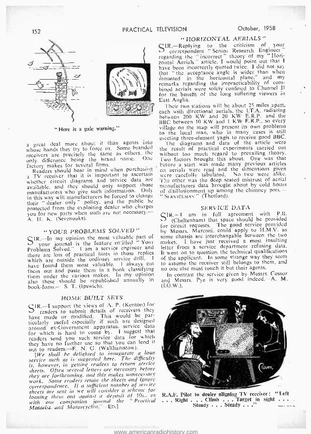
152 PRACTICAL TELEVISION October, 1958
" HORIZONTAL AERIALS "
SIR,- Replying to the criticism of your correspondent " Senior Research Engineer"
regarding the " incorrect " theory of my ` Hori- zontal Aerials " article, I would point out that I have been incorrectly quoted twice. I did not say that " the acceptance angle is wider than when mounted in the horizontal plane," and my remarks regarding the impracticability of com- bined aerials were solely confined to Channel II for the benefit of the long suffering viewers in East Anglia.
Their two stations will be about 25 miles apart, each with directional aerials, the I.T.A. radiating between 200 KW and 20 KW E.R.P. and the BBC between 10 KW and 1 KW E.R.P., so every village on the map will present its own problems to the local man, who in many cases is still erecting three -element yagis to receive good BBC.
The diagrams and data of the article were the result of practical experiments carried out without too much regard to prevailing theory. Two factors brought this about. One was that before a start was made many previous articles on aerials were read and the dimensions given were carefully tabulated. No two were alike. T!)e other was the deep seated mistrust of aerial manufacturers data brought about by cold hours of disillusionment up among the chimney pots.- " SERVICEMAN " (Thetford).
"Here is a gale warning."
a great deal more about it than agents into whose hands they try to force us. Some branded receivers are precisely the same as others. the
only difference being the brand name`. One factory makes for several firms.
Readers should bear in mind when purchasing a TV receiver that it is important to ascertain whether circuit diagrams and service data are
available, and they should only support those manufacturers who give such information. Only in this way will manufacturers be forced to change their " dealer only " policy. and the public be
protected from the exploiting dealer who charges you for new parts when such are not necessary. - A. H. K. (Sevenoaks).
" YOUR PROBLEMS SOLVED" SIR. -In my opinion the most valuable part of
- your journal is the feature entitled " Your Problems Solved." I am a service engineer and
there are lots of practical hints in those replies which are outside the ordinary service drill. I
have found them most valuable. I always cut them out and paste them in a book classifying them under the various makes. In my opinion also these should be republished annually in
book -form.- S. T. (Ipswich).
HOME BUILT SETS SIR. -I support the views of A. P. (Kenton) for
readers to submit details of receivers they have made or modified. This would be par- ticularly useful especially if such are designed around ex- Government apparatus. service data for which is hard to come by. I suggest that readers send you such service data for which they have no further use so that you can lend it
out to readers. -E. N. G. (Walthamstow). [We shall he delighted to inaugurate a loan
service such as is suggested here. The difficulty is, however, in getting readers to return service sheets. Often several letters are necessary before they are forthcoming, and this makes unnecessary work. Some readers retain the sheets and ignore correspondence. If a sufficient number of service sheets are sent in we will consider a scheme for loaning them out against a deposit of 10s.. as with our companion journal the Practical 14010.48s- and Motorcyclist." -En.]
SERVICE DATA SIR, -I am in full agreement with P.B.
(Cheltenham) that space should be provided for circuit requests. The good service provided by Messrs. Marconi, could apply to H.M.V. as some chassis are interchangable between the two makes. I have just received a most insulting letter from a service department refusing data. It went on to question the technical qualifications of the applicant. In some strange way they seem to assume the receiver still belongs to them, and no one else must touch it but their agents.
In contrast the service given by Messrs. Cossor and Messrs. Pye is very good indeed. -A. M. (I.O.W.).
R.A.F. Pilot to dealer aligning TV receiver: "Left ... Right . . Climb . Target in sight .. . Steady . . Steady ..."
www.americanradiohistory.com
October, 1958 PRACTICAL TELEVISION 153
Everything for the T.V. & Radio Enthusiast
I7in. T.V. CHASSIS, TUBE & SPEAKER, 419.19.6.
171n. Rectangular Tube on modified chassis. Supplied as single -channel chassis covering B.B.C. channels 1 -5 or incor- porating Turret Tuner which can be added as an extra, at our special price to chassis purchasers. 50/ -, giving choice of any 2 channels (B.B.C. and I.T.A.). Extra channels can be supplied at 7/6 each. Chassis size : 121n. x 141ín. x llin. Less valves. Similar chassis were
because of their stability and reliability. y. With Tube and Speaker £19.19.6. With all valves. 825.19.6. Complete and working Tur- ret Tuner, £28.9.6. 12 months' guarantee on the tube. 3 months' guarantee on the valves and chassis. Ins. Carr. (incl. tube) 25. -. Complete and working Turret Tuner, £28.9.8. 12 months' guarantee on the tube, 3 months' guarantee on the valves and chassis. Ins. Carr. (incl. tube) 25 -.
PLESSEY SOUND & VISION STRIP, 25/6. Superhet. Tested. I.F.'s 10.5 Mc, s sound. 15 Mc, s vision. 8 valve basis (6 -0F1's and 2 -6D2's not included). Size 81tin. x Sin. x 41in. high. Post and packing 2/6. The Turret Tuner plugs directly into this chassis. SOUND & VISION STRIP, 10iß. Superhet. Complete vision strip. Less valves. Not tested. Drawings free. Postage 2.6. POWER PACK & AMPLIFIER, 19/6. Output stage 8V6 with O.P. trans. Smoothed H.T. 350 v. 250 mA., 6.3 v. at 5 A, 22 v. at .3 A 6.3 v. at 4 A centre tapped. Less valves. Free drawings. Ins. Carr. 5,6. POWER PACK & AMPLIFIER. 19'6. Output stage PEN 45, O.P. trans. choke. Smoothed H.T. 325 v. at 250 mA., 4 v. at 5 A, 6.3 v. at 5 A, 4 v. at 5 A centre tapped. Less valves. Carr. 5 6. CHASSIS, 1.- each. 6 or 8 valve. Latest type midget valve design for A.M. or F.M. Brand new cadmium plated. Size 121in. X 7í1n. x 21in. Post 1 9. 4 for 4 -. n'c -t 3 -. 12 for 10 / -, Carr. 51 -.
SUPER CHASSIS, 99/6.
5 valve superhet chassis including Bin. P.M. speaker and valves. Four control knobs (tone, volume, tuning, wehange switch). Four w bands with position for gram. P.U. and extension speaker, A.C. Ins. carr., 5,'6.
ELECTRIC CONVECTOR HEATER, 99/6. A.C. D.C. Switched for 1 or 2 kw. Illuminated grille, size 26ín. x 18ín. x 711n, deep. Ins. carr. 10/6. INSULATING TAPE, 1/6. Finest quality. 75in. x lin. wide. Post 9d. GANG CONDENSERS, 1'9. 2 and 3 gang .0005 p8'. Standard. Salvaged. Tested. P. & P. 1 3.
BEAUTIFUL EXTENSION SPEAKERS, 29/9. Fitttidd with 6ín. P.M. speaker W.B. or Gorlßmans of the highest quality. Standard ma ing to any.. receiver. (2-5 ohms. tiw .h and flex included. Unrepeatable at this price. Money back if not completely
Stied. Inc. care. 3 4.
STEREOPHONIC SOUND !
extra speaker, v: ill now be required. 81,í;'.M. SPF.AKEIty, 9;9- With O.P. transformer fitted. 10' -. P,,,tage 219. 6'in, P.M. SPEAKER, 12'6. Postage 2.9.
TERMS AVAILABLE
Liverpool St. to Manor Park
Mins.
REGETTERED IMPROVED VACUUM T.V. TUBES.
I7in. 47.I0.0. 14ín. 45.10.0.
12 MONTHS' GUARANTEE.
6 months' full replacement,6 months' progressive. Made possible by the high quality of our tubes. Ins. Carr. 15/6. 9in.. l0in.. 14in., 15ín, and 161n. round tubes. Our special offer of these sines, £5. 12ín. T.V. TUBES, £6. Three months' guarantee on round tubes, Ins. Carr. 15/6. 14in. RECTANGULAR TA'. TUBF,.S with burns, 30' -. Ideal as a standby or testing. Carriage 10.-.
EXPRESS DESPATCH SERVICE Phone to confirm tube in stock. Send Telegraph Money Order. On receipt of same, tube despatched Passenger Train same day.
TRANSFORMERS MAINS 5 amp., 4 v at4 amp.,
t 6 amp., ext a wf ding for 2 v. or 4 v. tubes. Primary 200 -250 v., 50 cycles. Post and Packing 3 9. MAINS POWER TRANS. 350 -0-350 v..12/9. 250 mA. 6 v. heater at 5 amp., 4 v. at 5 amp., 4 v. centre tapped. Dropthrough type. Prim, 200 -250 v. (41ín. x 5fn. x 5in.). Post 3/0.
MAINS TRANS., 3/9. 350- 0 -350 v. 80 mA., 4 v., 4 v. heaters. 250 -250 v. prim. Post 2/3. MAINS TRANS., 5/9. 280-0 -290 v, 30 mA., 6 v. 4 v. heaters. 200 -250 v. prim. Post 2/3. O,P. TRANS.. 1 3. Standard size, 2 -5 ohms, Post 1,' -. 20 for £1. Post 5 /6. MAINS TRANSFORMERS, 12,9. 42.5 v. 3(e) mA. Single secondary 6.3 v. at 12 amp., 6.3 v. at 0.6 amp., 200.250 v. screened primary. Post and Packing 3'6.
SOLO SOLDERING TOOL, 12/6. 110 v. or 6 v. i special adaptor for 200; 240 v., 10 /- extra). Automatic solder feed, including a 201t. reel of ERSIN 60/40 solder and spare parts. It is a tool for electronic soldering or car wiring. Revolutionary in design. Instantly ready for use and cannot burn. In light metal case with full instructions for use. Post 2 9.
`' ... _, HOME RADIO, 79/6.
Five -valve (octal) superhet, 3 waveband receiver. Can be adapted for your gram., p.u, at a little extra cost. Two A.C. /D.C. sizes : 911n. x 18)1n. x 11 iin., 911n. x 205 in. x 121n. Wooden cabinets. Ins. Carr. 4,6. Please state mains and size when ordering.
NEW BAKELITE CABINETS, 9/9. Attractive style. Size 12in. x 7in. x 51in. Ideal for small receivers, convertors, etc., P. & P. 2'6.
AMPLIFIERS 159/6. Ill -Fl AT LOW COST I Valve line up 6CK5 (V.2), 6CK5 (V.3), ECC91 (VIA, V1B). VIA as amplifier, V1B as resistance, capacity coupled phase splitter. V2, V3 in push -pull as the output stage, giving up to 10 watts of audio. Negative feedback to the first stage. Three controls, volume control with mains switch, bass and treble. Hygrade output transformer outputs of 3, 7.5, 15 ohms. Size 121 x 71 x 211n. Carr. Ins. 4/6.
Send for free catalogue to:
DUKE & CO. OPEN SATURDAY ALL DAY
10 (Dept. E.10), 621/3, Romford Road, Manor Park, E.12 CLOSED THURSDAY
Telephone ILF. 6001/3 I p.m.
www.americanradiohistory.com

TAT Pre -Amp., 45 Mc's Pre -amp unit with 2- VR91.(slight modifica-
I tion necessary), 12 6.
134 PRACTICAL TELEVISION
fdEW BOXED VALVES ! - EQUIVALENT TO FOLLOWING TYPES
70 60 GU50 MX40 VP4 7-pin AC SC:VM 1130 PEN4VA VP4B AC'PF.N MSPEN 5-pin PEN36C VMS4 AC'VP15-pin MSPEN 7-pin PP35 VMP4G AC VP1 7-pin MVSPEN 5-pin SP4 5-pin W42 AC'VP2 MVSPEN7-pin SP4 7-pin 1D5 AC,HLDD MVSPENB S4VB 7D5 Cl'1C MHD4 TDD4 DOTO MKT4 URIC 7D6 FOI MS9B VP4 5-pin 41MPG
10/ each
A SELECTION FROM OUR LARGE RANGE: 1TPI 4!- 1102 316 1T4 8'- 6SJ7 76 AZal 12'6 K'r2 51- 1R5 8 -- 6Q7 10'- D12 5'- MUl4 8,6 1S5 8 - 6J6 6 - Db170 91- OZ4 7- 1S4 8 - 6BX6 9- DK11 10 - PX25 12/8 3S4 8 - 6SK7 7'6 FASO EB34
2.- 3'6
PX25A TDD2A
1276 8/6.
3V4 5174
9 - 86
6V8G 7S7
7/6 9'-
EB9l 7 '6 VR105 /30 816 5Z4 10- 12A6 76 EF50 4 - VR65 41- 6AM6 7 6 12AT7 9 - ECC61 9 - XH(1.5 v.) 4/- 6AL5 7 6 25A6 10 - ECL80 12'6 XP (2 v,) 4/- 6SN7 7 6 43 10.- EF92 17- Y63 8/8 6SK7 7 6 5OL6GT 10'- O.'ll9 17x6 Z77 76 6JSM 5- 607 716
SEND FOR OUR FREE COMPLETE VALVE LIST
TRANSISTORS (PNP) 4:IREEN. YELLOW Audio Frequency. Amp. 7/6. %YIIITF.SPO'r 2.5 Me /s R.F. and I.F. Amp.. 15' -. it 1:11 YELLOW 1.5 to 8 Mcis R.F. and I.F. Amp., 15 -.
COMPLETE RANGE OF MAZDA TRANSISTORS IN STOCK
Build yourself a miniature Transistor receiver. Send S.A.E. for all Lists and circuits available.
NIORT -«'AVE RECEIVER, 10-60 Mc/s (5 -30 Metres)
itGCISI''l'10\ .GI 1'11'1: 208
It
k .
Complete with 6 valves, 2- 6K /C, 2 -EF39. 6Q70 and 6V6G. Intern,' mains power pack and 6 v. vibrator pack. Built -in 64" speaker. Muirhead slow -motion drive. B.F.O. and R.F. stage. Provision for 'Phones and Muting and 600 ohms. Combined Input 100 /250 v. A.C. or 6 v. D.C. All sets in new condition and air tested. I.F. Frequency 2 Mc.s. f6/19/6 Carr. 151/i.
BE PREPARED TO LISTEN TO TIC:" SATELLITES
PYE 45 Mc /s STRIP TYPE 3583 Complete with 10- EF50's, EB34 and EA50 valves. Unit is in new condition. ABSOLUTE BARGAIN I
Including modification data. 39 / 6
R.F. UNITS Type 25 Switched Tuning 20 to 30 Mc's. Unit includes 35P61's. 10' carriage 2,6. Circuits available. Type 20. Variable Tuning from 50 to 65 Mc's. Including 2- EF54's and EC52. 251 -. carriage 2.6. . Circuits available.
QUARTZ CRYSTALS IN STOCK Frequency ranges from 100 kc /s to 36.7 Me, s. Send for free list.
IF IT IS NOT ADVERTISED WE MAY STILL HAVE IT. OPEN MONDAY to SAT. 9-6. THURS. 1 o'clock.
HENRY'S RADIO LTD. 5 HARROW ROAD, EDGWARE ROAD, LONDON, W.2
TEL.: PADDINGTON 1903 -9
October, 1958
8e pia mop ill-F1 -with an
entirely
NEa7 raalzc
units
and
cabinets! Imr.rine the pleasure of having this magnificent Hi -Fl
equipment in its beautiful contemporary style furniture for your home . and experiencing an entirely new realism In sound reproduction. Yet the Emistructor HI -Fi will ease you money aal give you all the extra fun and satisfaction of building It yourself - and being able to service and maintain it afterwards. Special instruction manuals guide you at each stage and teach you all about the equipment in simple terms as you build. No skill or experience is needed -only a few simple tools.
Emistructor equipment is made to the highest quality standards and is a product of E.M.I. Institutes Ltd. -part of a Company world famous for sound recording and reproducing equipment.
There is a wide variety of equipment and cabinets at different price levels to suit individual tastes and requirements. The range varies from a complete III -FI installation with separate speaker enclosures to a simple all -in -one compact system for those with more modest requirements. All equipment is suitable for stereo or non -stereo reproduction of records. Full details and complete specifications will be sent with our free Brochure.
EMISTRUCTOR Dept. H.F. 138, 43, Grove Park Road, London, W.4
Associated with one of the World's largest recording organisations comprising -
"HIS MASTER'S VOICE" CAPITOL COLUMBIA MGM etc. oCT /sa 1C137
'TUBES REBUIIT1 SEND YOUR DUD
MULLARD AND MAZDA TUBES TO US FOR REBUILDING
Via B.R.S. (Parcels) Ltd., or BRITISH RAILWAYS.
MULL'ARD - 12" £7.10 Enlitron, Cossor & Cathodeon 16" & 17" £10.10 MAZDA 14" £8.10 15" & 17" £10.10
14"
21" 21"
£8.10
£12.10 £12.10
TERMS TO TRADE Carriage and Insurance 15/- eac5 tube.
FULLY GUARANTEED SIC MONTHS
LINE OUTPUT TRANSFORMERS AND DEFLECTOR COILS
Most types can be supplied. State set make, model number and part required. S.A.E. please.
IBRAYHEAD TURRET CONVERTERSI
Foremost in performance. With Instruction book- let, £6.19.6. Plug -in Adapter if needed 7/6. P. & p. 2/6. State set, model number and channels
required. Terms C.W.O. or pro forma
PRIME ELECTRICS (Dept W/2) 36, QUEENSDALE ROAD, LONDON, W.11. (Near Shepherds Bush Central Line.) Phone - PARk 1131.
CALLERS : 10.30 -3 MON: SAT. Closed WED.
www.americanradiohistory.com
Ocloóer 1958 PRACTICAL TELEVISION 155
middle, other times middle of picture lighter than top and bottom. The picture also is too con- trasting but when contrast is turned down the picture breaks up eventually after the verticals have become was When brilliance is turned down the parts of picture which are dark go black and only the lighter part of the picture is left. The fine tuning control is very sensitive ; any slight movement and the picture breaks up.
1 ani fairly sure it is not the tube because when the aerial is disconnected or when the channel selector on tuner is turned to a not used position the screen is illuminated uniformly and brilliance control reduces illumination. Sound is all right, but a very slight hum is heard which changes very slightly when vertical hold is revolved through its entire travel. When width control was operated to reduce width of picture the left - hand side of front of picture was an uneven edge. -C. Nutall (Mon.).
ó M11 411 _.; . t //// CG G NIP'.I. - --I
Whilst we are always pleased to assist readers with their technical difficulties, we regret that we are unable to supply diagrams or provide instructions for modifying surplus equipment. We cannot supply alternative details for constructional articles which appear in these pages. WE CANNOT UNDERTAKE TO ANSWER QUERIES OVER THE TELEPHONE. The coupon from p. /56 must be attached to all Queries, and if a postal reply is required a stamped and addressed envelope must be enclosed.
PYE V4 My set is fitted with the makers' tuner unit.
Once the set has warmed up the picture takes a saw -tooth effect which appears to ripple from the bottom upwards. -R. Carslaw (Glasgow).
We suggest you check the ECL80 line oscillator which is in front of the " black box." Another possible cause is a faulty EY51 inside the " black box," and if this is the case reducing the bright- ness will reduce the amount of " saw -toothing."
ALBA 17in. T304, T494 I converted the set with one of the two models
of turret tuner as advertised in " Practical Tele- vision." It worked well until recently, when I found out that the sound on ITV had fallen off considerably. Previous to this the sound or volume was equal to the BBC. I still have good sound from the BBC, but not quite so good on ITV (Wenvoe). If I retard the contrast control sound diminishes even more.
The set has recently been serviced with a L/O transformer and two new rectifier valves (PY82). Could you give me any advice as to where the trouble is likely to be ? -B. Green (Llanelly).
From the description given it is difficult for us to say whether the drop in ITV volume is due I terioration in the receiver sound valve stages o hethcr it is due to tuning drift in the tuner unit;,,af the latter provides maximum sound with the fine tuner midway, it may be assumed that it is the receiver which is at fault and the V9-V10 (EF80). VI I (EB9I) and V12 (PL82) sound valves shot:4d be tested. If these are in order, check the core trimming of the sound I.F. coils and the 2S 'mfd. capacitor associated with the PL82 cathode circuit.
1hUSH TV63 The receiver is a Bush TV63, tuned to Sutton
ColdfMMld (no I.T.A. aerial although 12 channel tune)) in set). Trouble is uneven illumination of picture ; sometimes top and bottom lighter than
The symptoms indicate a defective PCF80 video amplifier- cathode follower. If replacement of this valve does not cure all the fault symptoms. we would suggest you replace also the line oscil- lator ECC82.
INVICTA 126 After my Invicta 126 has been on some time
the picture breaks up and the only way to get it back is by letting it cool off. The line oscillator PCF80 has already been changed six times. After this it will be all right for a week. There is a pre- set condenser with a fixed one across it, but all adjustment has gone. I have tried new ones, but only get multiple pictures and shortened scan. The value of the two condensers pre -set is 250 pF and fixed 910 pF. Changing these and keep- ing them away from heat makes no difference. - W. Kingliorn (Peterborough).
The symptoms - described may be due to a defective PL81, the screen dropping resistor of this valve. a defective metrosil associated with the cathode circuit of the PCF80 or a defective 25 mfd. capacitor (there are two), again associated with the cathode circuit.
PHILIPS lSOOA The grid of test card " C " is received on above
set with the left -hand side much smaller than the right. Two squares normal to 12 small, horizon- tally. This is not noticeable on the other pro- gramme. Lately a black border on the left side has cut short the picture. 1 have been able to keep a full size picture- by adjustment to tube magnet and variable controls at set face. I appear to be at the end of this latter adjustment hori- zontally though picture is fairly good and steady. Apart from valves could you advise which condenser /resistor or both to test ? I have not been able to secure a circuit or data sheet. - T. W. Carr (Hull).
We would advise you to have the inner of the two PZ30 valves tested. This, if failing, would account for the poor width on the left -hand side. Also, have the UL44 line output valve tested and check the resistors and capacitors associated with this and the UY41.
www.americanradiohistory.com
156 PRACTICAL
We have dealt with the 1800A receiver in a past issue of PRACTICAL TELEVISION, namely the September. 1955. issue.
PHILIPS 1446U I have a Philips 1446U set which at present
has no coils in the tuner for Channel 11. If 1 fit
these coils is there any other adjustment necessary to the set ? -1.. Coombs (Andover).
If a correct pair of Channel 11 coil biscuits is obtained and fitted, there may not be any need to carry out any further adjustments. How- ever. you may find it necessary to remove the small stop screw (which prevents the turret from rotating fully) from the rear of the tuner unit if this has not already been done, and it may be necessary to .,insert an insulated trimming tool into the hole in the front of the tuner unit to adjust the core of the new oscillator coil if the fine tuner does not produce maximum sound at. or about. its mid- position.
The sensitivity control should. of course, be well advanced.
K. -B. KF60 I noticed my EHT rectifier was running low
on emission so I replaced it. On completion of doing the necessary soldering I switched on and found it wouldn't light. I have checked the line output transformer and find I get a spark from the anode connection of R12. 1 get a slight spark from the H.H.K. of same, does this suggest the L.O.T. is gone, or is there a condenser causing the trouble ? -J. O'Donnell (Glasgow).
You should check the setting of the horizontal linearity control. Then have the 8D3, 6CD6G. and 6U4GT valves tested.
If in order. check the 16 mfd. wired from pin 3
of the 6CD6G to chassis. Then ensure that the resistor wired between the O.T. windings (on the transformer) is 15 kilohm. Check .1 mfd. capaci- tors associated with the 6U4GT.
FERRANTI 17T3 My trouble is fuses blowing. First time H.T.
fuse 1 amp. went I hadn't a 1 amp., so used 1.5 amp. When I switched on again mains fuse 2
amp. went. I have tested (with Avo 7) all condensers, etc.,
and have had rectifier valve tested, but cannot find anything wrong.
One peculiarity of set has been that on switch- ing off a small bright spot remains on centre of tube. This can be removed only by turning dawn brightness control.
I should be much obliged if you would suggest the way to find cause of blown fuses. -C. W. Richards (Madeley).
You should first replace the PZ30 valve. This may have been tested, but it still remains by far the most likely suspect.
If the fuses still continue to blow, however. we will assist you further if you will let us know the period of time which elapses between switch-
TELEVISION October, 1958
ing on the set and the fuses blowing and any other signs you may have observed as they blow. The residual spot which remains when the receiver is turned off is quite normal.
K.B. "QUEEN" HV40 The picture is brilliant and clear, but high-
lights in it are accompanied by horizontal shadows both sides of the highlights.
The fault appears at its simplest and most obvious forms in captions. Thus a caption con- sisting of three lines of simple lettering, white on black, will appear as though the lettering is set on bands darker than the normal background.
The effect is also to be seen in, say, a close -up of a man with white hair. From the top of the picture to a horizontal line touching the top of the head the black level is lighter than below that horizontal line.
In intervals between "shots" short lines are evident thus:
They are evenly spaced. There are reserves of contrast and brightness
and definition is good. -A. S. Maultby (Ilford). We would advise you to check the resistors
associated with the 6AL5 detector and the 6AM6 video amplifier. The 6.8 kilohm anode load of the video amplifier is likely to have changed value, the 15 kilohm resistor (across the video grid coil) may be open circuit or the video ampli- fier cathode (pin 2) components may be at fault.
DEFIANT 14in. I live in a black spot and do not get a good
picture on I.T.A. Would a booster on I.T.A. improve my picture ? -I. Jones (Holyhead).
We would say that in a situation like yours the use of a Band III preamplifier would be definitely advantageous. It would " load up" the A.G.C. circuit and enable a picture to be held under varying conditions even if an amount of " snow " is the price of such amplification. In all cases, however. every effort should be made to secure better reception by means of a highly efficient aerial rather than a preamplifier. As intimated above. the latter does tend to introduce valve noise which appears as background " snow or mush on the picture.
BUSH TV24 Lour blurping noises on sound occur; these are
intermittent and sometimes cut the speech out. -J. Houlihan (Norwich).
The noises referred to are often due to a defer- tive PL33 sound output valve. If this is not responsible, check the volume control wiring for poor connections.
Ì t
I QIIER IES ('O -UPON 1
I This coupon is available until OCTOBER 21st, 1958, and I
must accompany all Queries sent in accord with the I
notice on page 155.
PRACTICAL TELEVISION, OCTOBER, 1958
Published on the 22nd of each month by GEORGE NEWNES, LIMITED. Tower House, Southampton Street, Strand, London, W.C.2, and
printed in England by W. SPEAIGHT & SONS. Euhoor Street, London. W.10. Sole Agents for Australia and New Zealand : GORDON A
GOTCH (A /Inla Inland 9s.. Abroad 175. 6d.d(Canaada116s.)
CENTRAL at the General Post Office forithe Canadian Maggazine Post for one year
www.americanradiohistory.com

Ociober, 1958
MAKER'S SURPLUS COMPONENT BARGAINS
WIDE :NGLE 38 Line E.H.T. Trans. Ferros-
cube core. 9 -16 kV. ........ 25'- Scanning Coils. Low imp line and frame
Ferrox -cube cored Scanning Coils and Line Output Trans., 10 -15 kV. EY51 winding Line Trans. with circuit dia., pair Frame Output Transformer 66 Scanning Coils. Low imp. line and frame 17.6 Frame or line block osc Transformer 4'8 Focus Magnets Ferrox -core 19.6
P.M. Focus Magnets, Iron Cored 19 6
Duomag Focalisers 22 6 300 m'a Smoothing Chokes 15.-
STANDARD 35 tout. Line Output Transformers
8.9 kV. E.H.T. and 6.3 v. winding. Ferrox -cube 19'6
Scanning Coils. -Low imp line and frame 12/6 Ditto, by Igranic 14/9
Frame or line blocking oscillator Transformer 4 6 Frame Output Transformer 7 6
Focus Magnets :
Without Vernier 12 6 With Vernier 17 6
200 m'a Smoothing Choke, 10 6
PRACTICAL TELEVISION
THE "STIRLING " BAND III CONVERTER
AVAILABLE ON CREDIT SALES TERMS
CASH PRICE
6GNS. Post paid
or 2I /- deposit and 5 monthly payments of 21/- This very efficient CONVERTER employing R.F. amplifier ECC85 and metal rectifier is TUNABLE OVER ALL 13 CHANNELS and incorporates its own power supply for 200 -250 v. A.C. mains. Can be fixed to rear of sec or used as separate unit. Metal brown crackle finish case : 4in. wide, 7in. deep, tin, high.
157
SPECIAL OFFER OF SOLDERING IRONS SOLON, ex- Govt., new and unused. Pencil bit, 65 watts, 220 -250 v. A.C. /D.C. List 27/6. Lasky's 16/6 Price Post 1/6. Spare Bits, If- each. Spare Element (state voltage), 5/9.
SPEAKER BARGAIN Special Purchase of Plessey P.M. Speakers, 5in. round or 7in. x 4in.
elliptical. Lasky's Price 14/6 Post 1/6.
TURRET TUNERS. All types in stock - Cyldon, Brayhead, Telenge, Valradio. Describe your sec and we will quote you. Prices from 79/6.
C. R. TUBES, new, unused. 14 ", LI4.19.6. 17 ", £16.19.6. 12', E8.19.6. 9', E5.17.6. Carr. & ins. 22 6.
MAIL ORDERS TO .HARROW ROAD, PLEASE L_1SKY'S (HARROW RI).) LTD,
42, TOTTENHAM COURT ROAD, W.1. Telephone : MUSeu.m 2605.
370, HARROW ROAD, PADDINGTON, W'.9. LADbroke 4075 and CUNningham 1979.
Open all day SATURDAY. Half day Thursday.
COLLARO 4 -SPD. MIXER AUTO -CHANGERS RC. 456, incorporates auto and manual control. Complete with Studio crystal P.U. and sapphire stylus. List £13/171 -. £%.19.6 Lasky's Price
Post 3/6.
Collard RC: 457 or "Continental," £8.19.6. Post 3/6.
B.S.R., type UA8, 4 -spd., with latest B.S.R. ful -fi P.U., £6.19.6. Post 5' -.
RST MA H. ORDER nIP.Vt'rYENT
211 Stry autan, Road, Mitcham, Surrey. Al.). 1 %I,5 I;ì LISTED ARE NEW S'i'O( h.
Term. C.W. I. or C.O.D. Postage 3d. per saisi'. MIT('I1AM 6201.
AZ31 10/6 B65 8/8 DAC32 9/9 DAF91 9/-
DD 1Ó18 DF33 9/9 DF91 8/6 DF96 8/9 DH719 9/6 DK91 9/- DK96 9/6 DL33 9/9 DL92 81- DL96 8/9 EABC80
6 EAF421ö8 EB91 5/9 EBC41 9/3 EBF80 9/8 EBF89 9/8 EC9CC1 8/9 ÉCC81 8/6 F:CC82 9!- FyCC83 9/- hCC84 10 ̀ - ECC85 10/6 ECF80
cCF8212,8 12/6
ECH35
ECH42 12/6
ECH81 9/8 ECL82
Er37A13/8
En) 10/3 EF41 9/6
EF42 12/- EF50 (A)
EF80 818 EF85 7/6 EF86 12/- EF89 10/- EF91 8/ß ÉF95 14/- EL42 10/- EL84 9/- EL90 8/6 EM80 10/- EM81 11 6 EY81 10/- EY84 13/- EY91 9+- EZ35 8'6 EZ40 8/- E241 10/6 EZ80 8/- EZ81 8/- FC2 14/6 FC4 23/8 FC13 14/6 FC13C 19/8 GZ32 11/6 H30 4/9 H63 10/- HBC90 8/- HL92 11%8 HL133D
KT33C11 6
KT66 12 6 16 6
LZ319 12 6 MKT9/5 ) (or 7) 21'- ML4 128 MSP4 15 - MU14 10'- MX40 15'-
N142 9 6 N153 11 3 N154 11 3 N727 8 6 PCC84 9 - PCF80
PCF8212t8 11'6
PCL82
PCL831218
PENA42/8 11/6
PEN4VA
PL36 15f 8 PL82 10 - PL83 11'6 PY80 8 3 PY81 9 6 PY82 8 8 PY83 8 6 R10 22- R19 19 - SP41 3 6 SP61 3 6 TDD4 15 - TP22 12 6 U142 8,6 U147 9/9 U153 9/6 UABC80
UAF9210/- 10/-
UBC41 8/8 UBF80 9/6 UCH42
10'- UCH81
10/6
UCL83 6J7GT
UF41 19//-- 6K7 4 6 UF89 101- 6K7GT 10 - UL41 9/6 6K8GT
ÚÚ8 23/6 6L1 176 ÚY41 7/6 6L6G 7 6 ÚY85 8/- 6LI8 12 6 VP4B 17/6 6119 21 - W81M 8/6 6N7G, /GT W142 9/- W719 8/6 6SL7GT8 W727 X78 19/- 6SN7GT
7'6 X79' 11/9 Z21 10 /6 6X5GT 8 6 6 Z77 10/6 7S7 12 6 Z152 8/6 7Y4 7 6 Z719 8/6 8D3 8 6 ÌR5 9/- 1OLD11 5Y3GT 8/6 14 9 5Z4G 10 /- 12AH8 10 - 6A8GT 12ÁT6 8 9
15/ b 0/-
9 12AÚ7 99 6AM6 9/- 12AX7 9 - 6AN5 5/- 12BA6 8.9 6AQ5 7/6 12BE6 93 6ßA6 8/8 12BH7 10 - 6BE6 8/3 12J7G /GT 6BJ8 6ßR7 12//-- 12K7GT
U
6BW7 98 12K8GT08 6BX6 8 6 12 3 6CD6G 12Q7 8 6
- 12Q7GT
6F1 19/8 35Z4GT8 6
6FÌ3 18/6 50L6GT8 6
6J5G 6/6 10 _
Quotations given for any types not Isted, Obsolete and old types a speciality. Send for lists
AEVACOUMED T.V. TUBES SIX MONTHS' STRAIGHT GUARANTEE
Mullard in. £
4 MW 36-22 5 4 MW 36-24 5 4 MW 36-44 5 4 AW 36-21 5 6 MW 41-1 7 7 MW 43-43 7 7 MW 43-64 7 7 MW 43-69 7
21 MW 53-20 10 21 MW 53-80 10
Cossor 14 17 17
14I K 17I K I72 K
5
7 7
I. 10 10
IO 10 o
IO 10
10
10
10
IO 0 IO 0 IO 0
in.
21
21
14
14
17 17
17
Mazda
4 CRM 141 4 CRM 142 4 CRM 143 5 CRM 153 7 CRM 171 7 CRM 172
CRM 211 CRM 212
Brimar C 146M C 14FM C17BM C 17FM CI7JM
£
5 5 5
6 7 7
10 10
5
5 7 7 7
s. d,
10 O
IO 0 10 0 10 0 IO 0 IO 0 10 0 10 0
10 0 10 0 IO 0 10 0 10 0
14 in. Marconi. Emitron, 17 in. Marconi, Emitron,
Ferranti, G.E.C. LS IO O. Ferranti, G.E.C. E7 10 O.
Carriage and Insurance 12/6 (U.K.). Cash with order. Personal Callers Welcome.
VIDIO REPLACEMENT CO. HALES ST., DEPTFORD HIGH ST., LONDON, S.E.8
Telephone : TIDEWAY 4506
www.americanradiohistory.com
158 Practical Television Classified Advertisements October, 1958
SETS & COMPONENTS
MAINS FROM 12V. CAR BATTERY. - American Dynamotor Unit, runs 200/ 250 AC /DC radios, televisions, tape recorders, etc., from 12v. car battery, continuous duty, perfect, cost £25, 80 / -; s.a.e. full details. SCIENTIFIC PRODUCTS, Cleveleys, Lancs.
T.V. TUBES as new, revacuumed; all makes; 6 months'. straight guar- antee; 14in. £5 /101 -, 17in. £7/101 -; carriage and insurance 12/6 U.K. Free delivery greater London. VIDIO REPLACEMENT CO., Hales St.. Deptford High St., London, S.E.8. (Tideway 4506.)
MAKE YOUR AERIALS with our fully machined parts. Examples :
Band 1. " H," complete with lashings. for £31101 5 Element, Band 3, with folded dipole, mast and clamp for 45/ -. Get further details from our illustrated lists and data on all aerials, sent for 1/- P.O. (Trade supplied.) SKYLINE WORKS. Burn - sall Rd., Coventry. (Tel.: 60418.)
ASSIST -U- AERIAL KITS, containing insulator and cap for lin. boom, hp. elements. '20 lin, plugs. 2 lin. end plugs, 2 tin. grommets, suitable for construction of Band II or Band III Aerials, 6/0 complete. Send P.O. with order. ROBERT MOSS, LTD., 35, Banbury Rd., Kidlington, Oxford. Trade inquiries invited.
T.V. TUBES 14in. Rectangular types. £4.0.0. 14in. Round types. £8.10.0. 15in. CRM 153, 24.0.0. 17m. types. 85.0.0. Picture tested and guaranteed 3 months. A few 14ín. and 17in. for testing or boosting at 25. -- each. All carriage paid. Your own tube reconditioned at 4/- per inch. return carriage paid, 48 hour service. S.A.E. all enquiries please.
MIDLAND TIDES LIMITED 37,G 00000 St., Manchester, 1. Central 0432.
CATHODE RAY TUBES used but in good working order, with three months' written guarantee. 12in, to 17in. Mazda. Mullard and Equivalent types only. at £4110/ -, plus 12/6 for carriage and insurance. En- quiries and orders to BHP DISTRI- BUTORS (LONDON) LTD.. 379, Staines Rd.. Hounslow, Middlesex. (Tel.: HOU 5144.) Our terms are c.w.o. or c.o.d.
UNREPEATABLE OFFER. -12ín., 5- channel T.V., £15; 14in., £22; good working order. C. EDWARDS, 1070. Harrow Rd., London. N.W.10. (Phone: LADbroke 1734.1
CATHODE RAY TUBES, ex- chassis, picture- tested, 3 months' guarantee. Mullard. Mazda, Brimar, etc., 9ín., 12in., 14ií1.. 15in.. £3/10/ -; 17in.. £4; carriage and insurance, 15/ -. Minia- ture Valves, 10/- dozen. S.C.L., 77, Cranleigh Rd., Bournemouth.
T.V. TUBES 14ín. Rectangular types. £4; 141n. Round types, £3.10. 15ín. CRM 153, £4; 171n. Types. £5. Picture tested and guaranteed 3 months. A few 14in. and 17in, for testing or boosting at 251- each. All carriage paid. Your own tube reconditioned at 41- per inch, return carriage paid, 48 hour service. S.A.E. all enquiries please.
S. BRADLEY 6, Station A , Waterloo, Huddersfield.
RATES : 4/- per line or part thereof, average five words to line, minimum 2 lines. `Box No. 11- extra. Advertisements must be prepaid and addressed to Advertisement Manager, ' Practical Television," Tower House, Southampton St., Strand, London, W.C.2.
SETS & COMPONENTS continued
CALLING CENTRAI. SOUTHERN REGION t Convert NOW. It's simple with the BRAYHEAD TURRET TUNER. In stock for ANY AREA. State Channels, set make and model No. 26.19.6. post/ins., 2'5. The RADAR RELOVOLTER measures E.H.T. 3-30 kV 23.17.6. post /ins. 2/6. Line and Frame ose. and O.P. transformers for 500 sets. EXACT REPLACEMENTS. State make and number with enquiry (3d. stamp).
WESTWAY RADIO 5, N'e.lssard R'ap, Harrow, Middx.
TELEVISIONS, Bin. models, £7/101-; 12m. models, £13/10/ -; 12in. 5 -Chan- nel models, £19/101- each; all work- ing; carriage paid. Send for list. TOMLINS, 127. Brockley Rise, Forest Hill. S.E.28. (FOR 5497.)
TELEVISION BARGAINS. -12in. from £9, 14in. from £18; 17in. from £25. TYLER TELEVISION. 63, Lee High Rd.. Lewisham, S.E.13. (Lee 5979.)
12 MONTHS' GUARANTEE! The very best reconditioned c.r.t. ever offered. 12in. £9, 14in. £10. 15in. and 17in. £12/101 -, 21in. £16; carriage and insurance 22/6. S.C.L., 77, Cranleigh Road, Bournemouth.
LINE OUTPUT and Blocking Ose. Transformers, Scan Coils, etc., for all models. For engineers, techni- cians and serious amateurs, codtpre- hensive professional trade television and radio engineers' Trimmer Tool Kit. £51216; c.w.o. S.A.E. all en- quiries. L. BRENNER, 23, Meadway Close, Barnet, Herts.
TELEVISIONS FROM £5. Radios from £2, all working. Tubes, Valves, Components, cheap (callers only). J. PALMER, 32, Neasden Lane, N.W.10.
CHANNEL 11 OFFER. -5 Element folded Dipole array with mast and universal clip for fixing to any size Band 1 aerial mast. 39/6. Trade rates 6 or more. Post paid. All types of Aerials and Machined Parts available. Send 1/- P.O. only for details and technical data for " Do it Yourself." SKYLINE WORKS, Burnsall Rd., Coventry.
TELEVISIONS, London only. 12ín.. Ñ10; 5- channel, 12ín., £14; 14ín.. £18; 17ín., £27; 13- channel, 12ín.. £20; 14ín., £25; 17in., £35. (Callers only.) JOHN GILBERT TELE- VISION, 1B, Shepherds Bush Rd., London, W.6. (SHE 8441.)
YOURT.V. TUBE RECONDITIONED AT 4/- PER INCH
(Sole Patent Rights, D.H.P. System) -OR SUPPLIED ALREADY
RECONDITIONED FROM OUR STOCK WITH ONE YEAR'S GUARANTEE. Also Reclaimed Tubes in all sizes from £3. Television Sets from £`s and Valves and
Spares from the year dot. Write for Details and Free Lists to :
LES. HOWE & SONS, LTD. (Dept. M.O.), 5, Auckland ('lose, Tilbury, Essex.
SETS & COMPONENTS continuei
TELEVISION TUBES FACTORY reconditioned T,V. pictur'e. ubes. SIX months' guarantee.
£ s. d. 12ín. MW3I -74, CRMI23, etc.... 7 0 0 14ín. MW36 -24, AW36 -21, etc.... 7 15 0 17in. MW43 -64, MW43 -80, etc.... 9 15 0 21 in. MW53 -20, MW53 -20, etc.... 13 10 0
CATHODE -RAY TUBE SERVICE 35, Broomwood Road, St. Paul's Cray
Orpington 21285
NEW MAZDA CRM171 17in., c.r.t.. manufacturers' guarantee unwritten. £15, carriage paid. New Aerialite 2 -stage Band III Pre -amplifier. £4. 77. Cranleigh Road. Bournemouth.
METAL RECTIFIERS H.W. 270v., 80 mA., 5/6; 350v., 80 mA.. 6/0; 600v., 30 mA., 6 /-; 1kV., 30 mA., 7/6: 500v., 30 mA.. 4/6; 240V., 100 mA.. 4 /-; Bridge: 12v., 4 A., 218; 12v., 1.5 A., 716; metertype 5 mA.. 5/6; 120v., 1 A., 30 / -. List and enquiries: S.A.E. please! Ternis c.w.o. Postage extra. Immediate despatch. W. A. BENSON, (P.T.). 136, Rathbone Road, Liverpool, 15.
TELEVISION BARGAINS. - Huge quantity of Televisions offered at absolutely rock bottom prices. 9ín,. £41101 -; 12in., £101101 -; 5 Channel, 12in., £13/10/ -; 14 -15ín. from £18; 17in. from £24. Also latest 17in. and 21in. Receivers. prices on request. All above in good working order. Non working : 9in., £2; 12in.. £4. Please add £1 carriage. Also quan- tity of Spares, including Scan Coils and Line Transformers. Callers welcome: trade supplied. GRAIN- GERS, 21, Kenwyn Ave., Blackpool, Lancs.
COMPONENTS, Valves, Tubes, etc. Write or phone for free list. ARION TELEVISION, 4. Maxted Rd.. Peck- ham, S.E.15. (New Cross 7152.)
RECLAIMED TUBES, 12in., 14ín., 17in., all at £5 each, guaranteed; 100 (5 channel) T.V. Ekco 161. Ferguson 988, £15 each. C. EDWARDS. 1070, Harrow Rd. (Phone: LADbroke 1734.)
TELEVISIONS ? Not working sets from: 9in., £2; 12in.. £3/101 -; 14in.. £10. Working sets: 9in., £5;12ín... £9; 14in., £15. (Trade enquiries in- vited.) RELYON RADIO, 439, Katherine Rd., London, E.7, (Tel.: GRA 1820.)
TELEVISION SPARES for 9ín., 10in., and 12in. T.V.s Valves, Components. Brayhead I.T.V. Converters. £4 /18l -: s.a.e. LONDON TELEVISION. 4. Henderson Rd., Eastney, Portsmouth. Hants.
RF27 or 26. 18' -; 25 or 24. 1íJ -; brand new. post 3.3. E.W.S. CO., CO,
Church Rd.. Moselcç. Birmingham.
TELEVISION CATHODE RAY TUBES Reconditioned and Guaranteed 6 months.
14' round Mazdas- E5.0.0. 15" round Mazdas -86.0.0. 17" rect. Mazdas- (6.0.0.
Carriage and Insurance, 10/ -, Cash with orders to "TELESPEED," Dept. 2 /B, 6, Clemente Street, Coventry.
Tel. 41062.
www.americanradiohistory.com

October, 1958 Practical Television Classified Advertisements 159.
SETS & COMPONENTS continued
Save 30% on all outdoor aerials and fittings. Example: Double Five Array costs only 70/ -. Self -contained Band III Pre- ampli- fiers only 60 / -. Converters 80 /- complete. Fringe Area Super Low -loss Co- axial. 1/4 yard. Reconditioned T.V. Tubes. 6 months' guarantee, 12' & 14" 110 / -, 17' 150/ , 21" 210 / -. C.W.O., carriage 101- extra. Tubes delivered in 24 hours all parts U.K, S.A.E.
OR FULL LISTS. G. A. STRANGE
North W'raxall, Nr. ('hippenham, Wilts. Tel.: Marshfield 238.
AUCTIONS
EVERY TRLRISDAY AT lla.m. Sales by pris ate treaty-.
DAILY £-5.30. SATS. 9.5 p.m. Over 500 TVs from £3 working, 10/- not. Radios, grams, washing machines, fridges,
vacuum cleaners, typewriters.
EASTERN AUCTION MART Whitehorse Lane, Stepney, London, E.1
FOR SALE MAINS RADIO IN YOUR CAR, com- plete unit runs 2001250 AC. DC radio, television, tape recorders, etc., from 12V. battery, perfect, cost £25. 80 /;
N PRODUCTS, Cleveleys, Lancs. ENTIFIC
HOW TO USE EX -GOV. LENSES and Prisms. Nos. 1 and 2, 2/8 ea. Vertical Enlarger Plans for 35mm. to 21in. sq., 3/0 ea. Optical Condensers and Achromatic Lens to suit, 33/ -. Lists. S.A.E. H. W. ENGLISH, Ray- leigh Rd., Hutton, Essex.
VALVE CARTONS at keen prices. Send 1/- for samples and list. J. & A. BOXMAKERS, 75a. Godwin St.. Bradford, 1.
AMAZING OFFER. -Originally £40/ £100 each. Ekco, Pye, H.M.V., Marconi, Philips, Murphy, etc., 9 /l0in. Televisions, complete, not working, 50 /- each; carriage paid; immediate dispatch, 12ín. £5/5/ -; 15in., £9; Philips 17in. Projection Televisions, £8/15/. TOMLINS, 127, Brockley Rise, London, S.E.23.
TELEVISION BARGAINS. 12ín., O.K., £10; 14in. and 17in. cheap 'for cash. New sets at bargain price. T.V., SUPPLIES. 1. High St., Chal- Vey'. (Tel.: Slough 21860.1
CO -AXIAL CABLE, unbeatable offer. ed. a yard air spaced. TELEVISION TABLES cancelled order. 20" x 20 ", 18" legs, 4- quartered veneering, venggred both sides, in medium oak, walnut and supele. Unrepeatable offer while stocks last. 39/ -, carriage 3/6.
MARSHALLS FOR
TELEVISION 131, ST. ANN'S ROAD,
s TOTTENHAM, N.15. Phone : STArnford Hill 3267.
FOR SALE continued
SECONDHAND TELEVISIONS. 9in. to 21in.; all makes; faulty and worsting. WILKINSON'S, 146a, Goldhawk Rd., Shepherds Bush, 4379.
SUPERTONIC SUNLAMPS, listed £7/10/ -, 80 / -. S.A.E. SCIENTIFIC PRODUCTS CO., Cleveleys, Lancs.
EFFICIENT AERIALS, test, com- pare with latest aerial current meter. HOBLEY, 109, The Drive, Wellingborough.
PRACTICAL AERIALS. outdoor Band III folded dipole, fitted insulato'. reflector, 3 directors, ;':fn. dia. alloy, belts, assemble to your own boom, alloy, wood, etc. Send 19!- P.O. S.A.E. queries. 165, Beoley Rd.. Red - ditch. Worcs.
100 BAYS of brand new adjustable steel Sheaving, 72in. high x 34ín, wide x 12ín. deep, stove enamelled. dark green; sent unassembled, 6 -shelf bay, £31151 -; sample delivered free; quan- tity discounts. N. C. BROWN, LTD., Eagle Steelworks, Heywood, Lancs. (Tel.: 69018.)
USEFUL SPARES INSULATED TAPE. 1r6. Finest quality in sealed metal container. 75ft. x iiv. wide. Postage on 1 tin, 9d. Postage on 6 tins, SOLDER REELS. 1;8. 20ft. on plastic spools 60-40 3 core ERSIN. Postage 9d. VALVE SCREENING CANS, 1'- doz. Iatest midget type. Aluminium. 21n. high x tin. dia. Postage on 1 doz.. ed. DUKE & CO. (DEPT. E.101. 621/2. Itomford Road, Manor Park, F.12. Tel.: 1LF. 6901 -3.
WANTED
ALL TYPES OF VALVES WANTED, PL81, ECL80. EY51, U25. PCF80, PZ30, U801, etc.. etc. Best cash price by return. STAN WILLETTS, 43, Spon Lane, West Bromwich, Stafß.
Tel.: WES 2392.1
NEW VALVES WANTED. EY51, PL81, ECL80, and similar types. R.H.S.. 155, Swan Arcade, Bradford, I, Yorks.
IMPORTANT. -All types new B.V.A. Valves wanted. Same day payment. ROBERT, 414, Whitefoot Lane, Brom- ley, Kent.
SERVICE SHEETS
SERVICE SHEETS for sale and hire. Radio /T.V.; s.a.e. enquiries. J. PALMER, 32, Neasden Lane, N.W.10.
SERVICE MANUALS /SHEETS Tel/ Radio for hire. Sale and wanted. Mixed Manuals and Sheets. 12 for 10/ -; s.a.e. enquiries. W. J. GILBERT (P.T.), 24, Frithville Gdns., London, W.12.
ENGINEER has complete range Radio /T.V. Service Sheets, 4/. each; s.a.e. State Model No. required; c.w.o. L. BRENNER, 23, Meadway Close, Barnet, Herts.
EDUCATIONAL
FREE 1 Brochure giving details of Home Study Training in Radio, Tele- vision and all branches of Elec- tronics. Courses for the Hobby Enthusiast or for those aitping at the A.M.Brit.I.R.E., City and Guilds. R.T.E.B. and other Professional examinations, Train with college operated by Britain's largest Elec- tronics organisation. Moderate fees. Write to E.M.I. INSTITUTES, Dept. Pr28, London, W.4.
STUDY RADIO, TELEVISION AND ELECTRONICS with the world's largest home study organisation - I.C.S. Courses for the enthusiast and for those seeking examination qualification. Brit. I.R E., City and Guilds, R.T.E.B., etc. Build your own equipment with Practical Radio Course. Write to -day for free book: INTERNATIONAL CORRESPON- DENCE SCHOOLS 71, Kingsway. (Dept. 516), London, W.C.2.
BUILD YOUR OWN TiV and learn about its operation, maintenance and servicing. Qualified engineer -tutor available while you are learning and building. Free Brochure from E.M.I. INSTITUTES, Dept. PT58, London, W.4, 'Associated with H.M.V.)
INCORPORATED Practical Radio Engineers home study courses of radio and - T.V. engineering are recognised by the trade as outstand- ing and authoritative. Moderate fees to a limited number of students only. Syllabus of Instructional Text is free. " The Practical Radio Engineer," journal, sample copy 21 -, 6,000 Align- ment Peaks for Superhets, 5/9. Membership and Entry Conditions booklet, 1 /, all post free from the SECRETARY, I.P.R.E., 20, Fairfield Road, London, N 8.
LEARN IT as you do it -we provide practical equipment combined with instruction in Radio, Television, Electricity, Mechanics, Chemistry. Photography, etc. Write for full details to E.M.I. INSTITUTES, Dept. PT47, London, W.4.
II+ EXAMINATION Write for FREE 24 -page GUIDE
and Test stating age of child to The Registrar (Dept. M.7),
MERCER'S CORRESPONDENCE COLLEGE, 69 Wimpole Street, London, W.I.
PROPERTY
BERRYLANDS (Surbiton). Adjoin- ing station in a fully built -up area, parade of spacious .shops with 2 floor upper parts just constructed. To be let or sold. Trades already reserved Grocer and Provision Merchant, Greengrocer, Ladies' Outer- and Underwear, Shoe Repairer, Tobac- conist and Confectioner, Dyers and Cleaners, Retail Builders' Merchant and Pet Shop. Full details: MESSRS. WHIDDINGTON, Chartered Surveyors, 133, High Street, Ted - dington. (KINgston 1216/- 7/6,2
www.americanradiohistory.com
îb0 PRACTICAL TELEVISION
IS YOUR T.V. TUBE DIMMING ?
YOU CAN EXTEND THE LIFE OF THAT TUBE AND IMPROVE THE PICTURE
Pat. pending. Reg. design.
PRICE
TYPE SERIES For 6.3 volts, .3 amp. 12.6
volts, .3 amp. All tube sizes. Duodecal base.
NO SOLDERING NO WIRING JUST PLUG IN IT'S AUTOMATIC IT'S GUARANTEED
30'- Package & Postage 1/6.
(Postal Orders. C.W.O. C.O.D.)
Sinclair Electronics introduces the first series wired plug in boosterunit,for all universal TVsets, using Mazda & Mullard Tubes & equivalents, operating off A.C. mains. Any voltage. For A.C. TV sets only (A.C. parallel types can be supplied). If not satisfied money refunded within 7 days.
SINCLAIR ELECTRONICS, 247, BRICK LANE, LONDON, E.2.
Phone : SHO 7424
October, 1958
SOMETHING NEW ! ! A PRE -AMP FOR BOTH I.T.V. AND B.B.C.
Following the success achieved by our Band III
Pre -amp, we introduce a combined unit designad to overcome the difficulties experienced in situations where reception of both I.T.V. and B.B.C. is extremely poor.
Units now available :- "DUAL BAND" * Co -ax Inputs for Bands
I and III. * I.T.V- amplified. * B.B.C. -amplified. * Single Output to Receiver.
Price (9.10.0 C.W.O. or C.O.D.
"SINGLE BAND" * Co -ax Inputs for Bands I and III. * I.T.V.- amplified. * B.B.C. -Diplexed. * Single Output to Receiver. Price f6 -6 -8, C.W.O.
or C.O.D. Please state channels required.
Both Units have a high signal to noise ratio, and will produce excellent results in localities where the signal is normally unusable.
Units have Built -in Power Packs 200 -50 v. A.C. Dimensions : 6 x 4 x 2} in. (Fly Lead, 3/6 extra).
cíAIUVISIOw" (Electronic Equipment Manufacturers)
14 BOULTON RD., SOUTHSEA, HANTS.
59 Gns.-` 17'
A full specification I7in. Tele-
vision Receiver to Spencer -
West standards now available
at your Dealers. Remarkable
performance and priced at 59
Gns. only, complete.
For Leaflet apply to :-
SPENCER-WEST LTD. Quay Works, Great Yarmouth
Norfolk
Phones : Works 4794 ; Sales 3009
Grams: Spencer -West, Great Yarmouth
1 A BEGINNER'S GUIDE TO TELEVISION
1 A Series of lessons on persistence of
1 vision and scanning ; the cathode -ray tube and timebase ; interlacing ; the aerial ; the T.V. camera ; scanning sys- tems ; colour and stereoscopic tele- vision, technical terms, etc. 61 illus- trations 7/6 by F.J. Camm. Postage 6d.
PRACTICAL TELEVISION CIR- CUITS. By F. J. Camm, 15 / -. Postage 9d.
TELEVISION SERVICING. By G. N. Patchett. Vol. I, Vol. ?, 51- ea. Postage 4d. ea.
BEGINNER'S GUIDE TO RADIO. By F. I. Camm, 7/6. Postage 6d
IMPROVE YOUR RECEPTION. By J. Gara and L. Stanley, 5 / , Postage 6d.
TELEVISION ENGINEERING VOL. IV. By S. W. Amos and D. C. Birkinshaw, 35/-. "Postage 1/2.
RAPID T.V. REPAIR. By G. W. Heath, 23/ , Postage 1 / -.
RADIO VALVE DATA. 6th Ed. Cam. " WW ", 5 / -. Postage 9d.
THE MODERN BOOK CO. BRITAIN'S LARGEST STOCKISTS
of British and American Technical Books
19 -23 PRAED STREET, LONDON, W2. Complete catalogue 6d.
Phone : PADdington 4185. Open 6 days 9 -6 p.m. .
fri e, i.ion Aerial'.. Band III 3- element 21 E 5- element. 37.8: B- element, 57 6. B.B.C. Single Dipole, 32/8 : H. '74 6
X " 7418. We carry large stocks of good aerials. Sand B.A.E. with your requirements and we will reply by return. Air- Spaeed Coaxial ('able, 9d. por yd. 70'- per 103 yds. Crossover Boxes, 12 -. Coaxial Plugs, 1' -. Coaxial Soekets, 1' -. ton -Trapp Magnets, 51 -. Television 'fables. 8216. Electrolytic Condensers, 64 +120 mid., 0-. 100+200 mfd., 1018. 100 mfd.. 88. 13 mid., 3' -. 8 -8 mid.. 216. 8 mid., 19. Speakers, 5in.. 19'8. 6ín., 18 6- 8in., 22 8. 12ín.. 28/8. 7 x 4ín.. 1816. 9 x 5in., 2'3'8. Guaranteed Brand New Stock. Ideetrie Blankets, Single Size, 8718. Double Size, 8716. 13.S.R. 4 -speed Record Changer., £7.12.8, plus 3'6 carriage.
Guaranteed Valves PCL83 UCL83 3C4 12'8
15 /- 5Y3 1016 UCC8415.'- 5U4 1011 UCC8515/- 5V4 10'6 UL41 11'- 5Z4 10/8 ÚL44 21/6 6A7 178 UL46 18/8 8AQ5 816 UL84 11/- 6BA6 8,8 ÚF89 12/8 6BG6G UY85 8/6 1A7 18/8 6CD6G
17' 6
lA5 318 22.16 1N5 13/8 6F6 8/8
PL/6 18 61HI -í 13/8 6V6GT 9/6 PCC84 105 13/8 6L6G 17/8
15 - 11.1,3 3/8 6Q7 12/6 MUJ 3 12 6 2A3 15 /- 6S57 8/- UBC41 8'8 2A5 1818 2574 10/6 UCH42 9 6 2B7 16'6 2574 10 /8 UBF80 2X2 318 35Z4 106
10 6 3A4 15'- 807 8/8 18- UCL8215 -3A5 18/8 16Z 5'-
NAIL ORDER ONLY -NO CALLERS Terms: C.W.O. or C.O.D. Minimum C.O.D. charge 3 6. Postage and packing'per valve. 6d. Other items, under - £2 1/9 : £5, 2; -. Aerial- 3 - carriage.
ELECTRO- SERVICES & Co. 221 BATTERSEA PARK ROAD, LONDON, S.W.11, MAC 8155
AZ1 12/- AZ31 121- CBL1 18'8 CBL31
17/8 ^L33 14/8 CY31 1218 DDT4 18/8 EBL31
1318 EBC33
14/6 EF85 9;8 EF86 11/8 EL33 14/8 GZ32 15/- F.CL82
15/- EL38 21/8 PCL82
PL33 15'- PL38 21,8 PY31 17 8 PY32 17 6 PZ30 17 8 PCFBO
7 PY81 12 8 PY82 8 8 PY83 10 6 PL81 15 6
www.americanradiohistory.com

October, 1958 PRACTICAL TELEVISION
alfrnd 1/41/f1EIWEN 4" WOAlrEN
Industry and Commerce offer their best posts to those with the qualifications- appointments that will bring personal satisfaction, good money, status and security. As part of a modern industrial organisation, we have skilled knowledge of what is required and the best means of training personnel for present day and future requirements. We specialise also in teaching for hobbies, new interests or part -time occupations in any of the subjects listed here. Write to us to -day for further information. There is no obligation of any kind.
161
PERSONAL & INDIVIDUAL TRAINING IN - Accountancy Draughtsmanship Mathematics Advertising Economics M.C.A. Licences Aeronautical Eng. Electrical Eng. Mechanical Eng. A.R.B. Licences Electrical Instal. Metallurgy Art (Fashion. Illus- Electronics Motor Eng. tracing, Humorous) Electronic Painting & Automobile Eng. Draughtsmanship Decorating Banking Eng. Drawing Photography Book -keeping Export P.M.G. Certs. Building Gen. Cert. of Police Business Education Production Eng.
Production Planning
Radar Radio Radio Amateur
(C &G) Licence Radio Engineering Radio & Tele-
vision Se ic ing Refrigeration
Management Heat & Vent. Eng. Carpentry 'Hi -Fi' Equipment Chemistry High Speed City & Guilds Exams Oil Engines Civil Service Industrial Admin. Commercial Jig & Tool Design
Subjects Journalism Commercial Art Languages Computers Management Customs Officer Maintenance Eng.
Sales Management Sanitary
Engineering Salesmanship Secretaryship Servo Mechanisms Shorthand & Typing Short Story Writing Short Wave Radio Sound Recording Telecomm uni-
cations Television Time & Motion
Study Tracing Transistors Welding Workshop Practice Works M'gement etc., etc.
Also courses for GENERAL CERTIFICATE OF EDUCATION, A.M.I.H. &V.E., A.M.S.E.,
s
M.Brit.I.R.E., A.M.i.Mech. E., A.M.I.E.D., A.M.I.M.1., A.F.R.Ae.S., A.M.I.P.E., A.M.I.I.A., A.C.C.A., A.C.I.S., A.C.C.S., A.C.W.A., City& Guilds Exams.. R.T.E.B. Servdcing Certificates, R.S.A. Certs., etc., etc. Moderate fees.
The E.M.I. Factories at Hayes, England.
The only Home Study College
operated by a world -wide
manufacturing organisation
INSTITUTES
Courses with PRACTICAL EQUIPMENT
in RADIO TELEVISION MECHANICS
www.americanradiohistory.com

162 PRACTICAL TELEVISION
I. F. STRIPS -POWER PACKS SOUND & VISION STRIPS, 10'6.8 het. '\ 'rakes G EI JI, Af'+,.J^I_' 1 1 9
Post Not . I . lye
tested. Poet 2 tì. l,.¡ .. Vahes 62'- extra. SOUND & VISION STRIP. PLESBEY, 256. N het. Takeo 4.- -' 6 691, 2 6119 (valve, extra). Not tested. I.F.a 10.5 1Ic c sound. 15 Me n vision. Bargain. Poet 2,6.
TIMEBA9E, less valves. FREE
remitting not( drawing. Post
Boxed 4111 Ii.A11 3 6,6516 6137 6,84(1 6.912 6FI-t 6111111 6J5M 6SJ71f 67'611 61`2. 1
6.S A'v1 651:7 6S1:7 411_ 4 n:: 902 i
111'::: 1246 12A1'7 12Rt:d 12K7 121:1
VALVES Guaranteed 9 357.4 8 9,EF4OREU R1,37 1 9
93:51R 89, 5 9 896 9 63SPT 2 9. E980 8,9 (4 21uVPT 5 9 1i985 8 9
97)9:1 a9 E991 79 '9 AR6(2\'I 1 9: El`W2 3 9 '9 ARP3.5 3 9,EL84 10.9 9 CV1083 3
E2411 8 9 '9 OH76 8 99N'4, 300 .9 UK98 8 9: 104 81)960 59KTW61 54 9'EA60 19.KTW63 89 9,hABC409'6,Rdí 34 9 EAP4'L 8 9è1:145
99 9 EB34 1 9 g 996 59PEK46 6:9 9 E13132 6 9 PER220A 9'99041 89, 3.9 9ECH4'- 8
iPMR1r2 1.9 8.9
ÿ1:F:i7 4'9P9"LS 39 9,t:939 89PY81 89 9'E950 29,P81 99
l'-2 l' F41
C-ül VR65 VT:ï' VT501 VN-3G TT1l W76 W8I Z77
69 109 89 -9 89 69 69 69 19 89 89 39 î9
trb TYI'/1s 18 39 42 3 9 ^- 3 9 7Á 3 9 11u! 39 25R1S 3 9 6A7 3 9 77 3 9.
EY51 VALVES, 8 9. Es- equipment. Teats 1. Post nul.
FOCUS MAGNET, 99. 35 mm. Permanent magnet type. Salvage, Plessey. Pont 1,9.
FLAC FOCUS MAGNET, 5 9. 17 -30 mu. Per- manent magnet. Salvage. Post 1 II,
FRAME OUTPUT TRANSFORMERS, 3: 9. TO mat lilt low impedance lima. Post I 3.
FLAC FOCUS MAGNET. 12 9. Brand new. 55
Post 1 9.
VISCONAL CONDENSERS, SR. .1 at 7 KV. working and .1101 at 12.5 KV. Post Gd.
RECTIFIERS.2 9. 23(1 v. 16(1 mA. Full or halt -wave. Salvage. Post 1 3.
INSULATING TAPE, 1.6. 73 ft. c 1. in. wide. Pont 9d
SOLDER REELS. 1 8. Ii0 -40 Lenin :1 core. 20ft. ou
plastie spool. Post 8d.
HEADPHONES, 3 P. Marconi. New. 60 ohms. Very sensitive. Post 1 -. Less leads.
VOLUME CONTROLS, 1 9. I megohm. Mese, boxed. Long spindle. Post I -.
VOLUME CONTROLS. l'3. 2081 D. Unused. short spindle. Carbon. Post 1; -.
VOLUME CONTROLS, £ te ken from working chassis.
N ohm'. anti tone Post 1 9.
GANGED CONDENSERS. 1 9. 9 and 3 -gang 0.0003. Std. sise. Salvage. 11ní 1 3.
I.F. TRANSFORMERS, 1'. pair. 460 ke'a. Tested. Post 9d. TRIMMERS, 54. 3 -30 p9., 5'. duz. Pool o0 1, 4d.
dur... 1
CAR AERIALS. 6 9. Plated. Whip a1 lean. r. Oui,. lung. Collapsing to llin. One -hole lining. Post 1 -.
CO-AE. CABLE. 66. yen]. Oural tptality. Cut lo
any length. Post on 2() yds., 1 6. 45,- pur 100 y,l,. Post 3 6.
COIL PACKS. 3.9. 1: -gang. Also 11Clnaed ire psirl.F. trans., 465 he n and 2-gang, condenser. Post 2 .1.
TRANSFORMERS MAINS POWER TRANSFORMER, 15 9. 35040-:9a; v. 0.-in n,A. 6 n. 11 A., 1 t. 5 A., 4 r. 2 A. Isolated. Post 3 9.
MAINS POWER TRANSFORMER, 99. 350-0 3:0 .
2.50 InA., 6.3 v., i A., 6.3 v. 4 A., 262 v. 0.3 A. and 4 1
centre tapped. Post 3P. EY51 TRANSFORMER (Heater) 1 -1 ratio. Suitable 0.3 v. lobeo as isolation trans., 5,9. Post 1;9.
P. P. COMPONENTS LTD.(Dept. 1'8)
219 ILFORD LANE, ILFORD, ESSEX. Phone: ILF 0295
Send :4. stamp for FREE Calalogve.
T1M Snap -action
Appliance Connector TEST BENCH MODEL
Equipment under test connected to mains without plugs or screw terminals. Safe.
positive grip contact is made and unmade in an instant. A low- priced workshop time saver for both amateurs and manu- facturers. With colour coded Mycalex insulated terminals and on and off switch.
Stove enamelled, Price, 35/ -each.
MYCALEX & T 1 M LIMITED,
ASHCROFT ROAD, CIRENCESTER, GLOS
Telephone : Cirencester 400.
from one source Denco, Repanco, J.B., T.C.C., Woden, Elac,
McMurdo, Radiospares, Eddystone, Elstone,
Bulgin, Belling & Lee, Hunts, Sorad, Acos,
Brown, Mullard, Igranic, Cossor,Taylor, Avo, Henley, E.M.I., etc.
Orders dealt with day received
56 page illustrated catalogue No. I1, with 108 photographic illustrations and over 2,000 new guaranteed lines by leading makers. 9d. post free.
SOUTHERN RADIO and ELECTRICAL SUPPLIES SORAD WORKS . REDLYNCH
SALISBURY . WILTS
TRANSFORMERS ?
CONTACT jforit5t FIRST! Rewinding and manufacture of all types for Television, Radio and Electronic
Application. FORREST (TRANSFORMERS) LTD.,
Shirley, Solihull, Warwickshire. Phone : SRI. 2483. Est. 34 years.
RES/CAP. BRIDGE p. "/- .
Checks all types of resistors and condensers.
Easy to Build Up Easy to Use READY CALIBRATED
Stamp for details of this and other kits.
RADIO MAIL (Dept. VF) Raleigh Mews, Raleigh Street, Nottingham
October, 195R
AT LAST! A REAL I.T.V.
CONVERSION SERVICE
WE OFFER A COMPLETE AFTER -SALES SERVICE WITH ALL I.T.V. EQUIPMENT SOLD
BY US.
Your problems settled by return mail. Whether novice or expert, let our extensive I.T.V. experience ensure your success.
PRE -AMPS I.T.V. SIGNAL ROOSTER AT
37,6 COMPLETE SMALL. Fits rncatly in cabinet corner. EFFICIENT. Simple tut clever circuitry giving pentode gain and triode noise level. EASIFIX. One -hole fixing to cabinet fillet. Plug -in feeder steals power from main T.V.
STATE CHANNELS, SET MAKE AND MODEL WITH ORDER.
Standard pattern suits most T.V.s using EF80 valves.
CONVERTERS
THE FAMOUS BRAYHEAD TURRET TUNER AT
L6.19.6 COMPLETE.
EASIFIX. Over 600 model converted by simple plug -in technique. SPECIAL OFFER. We can supply a modified version of our standard I.T.V. booster as an
add -on fitment, thus improving I.T.V. performance.
Special at 25/- extra. STATE CHANNELS, SET MAKE
AND MODEL WITH ORDER.
AERIALS OUR 5- ELEMENT ADD -ON
I.T.V. AERIAL 39 ¡6 COMPLETE
with Universal Clamp and Stand -off Arm.
Diplexers and Low -Loss Cable to order. State your needs or ASK OUR ADVICE with order.
WILSON 48, CATHAY, BRISTOL, I
(Phone BRISTOL 26242) -
Mail Order only. Terms :
Postage 1/6, above f2 free except aerials 2/6. .>
i
www.americanradiohistory.com

Odober," 1953 PRACTICAL TELEVISION 63
UNE OUTPUT PUT
TRANSFORMERS
Most types available. State Make and Model Number
of Receiver when ordering.
S.A.E. please with all enquiries.
HOWORTH 51 POLLARD LANE, BRADFORD, 2, YORKS
Tel. 37030
Selling fast ... F. J, Camm's A IIIH :G INNER, 'S GI'IDE
TO TELER'ISION Covers persistence of vision and scanning ;
the cathode -ray tube and timebase ; inter- lacing ; the aerial ; the TV camera ; scan- ning systems ; colour and stereoscopic television. etc. 81 illustrations. From all booksellers or Be. 3d., by post from 7s. 6d. GEORGE NEIVNES LTD.. Tower
Rouse, Southampton .Street, W.C.2.
COVENTRY RADIO Audio & Component Specialists Est. 1925 189 -191, Dunstable Rd., Luton, Beds. HI -F1 EQUIPMENT CABINETS IN
STOCK Record Housing : Nordik Range in
Oak, Walnut, Mahogany. Speaker Enclosure ... .., [5.17.6 Equipment Cabinet [5.19.6 Record Cabinet (150 records) [4.17.6
,Continental Bench ... ... 14.17.6 Polenaise Hi -Fi Cabinet 419.19.0 W.B. Prelude Speaker Cabinet íl1.11.0 W.B. Prelude Equipment Cabinet
[13.13.0 W.B. Prelude Corner Speaker
í10.1a0 abinet W.B. Table Equipment Cabinet W.B. Senior Hi -Fi Console ... W.B. Junior Hi -Fi Console .., W.B. Junior Base Reflex ... W.B. Standard Base Reflex W.B. Senior Base Reflex Corner
19.19.6 E16.16.0 £12.12.0 O. 9.0
£10.10.0 111.11.0
B.K. AUDIO PLAN ILK. Speaker Cabinet ... £16.19.6 B.K. Equipment Cabinet ... ¿17.19.6 B.K. Record Cabinet . .. 116.16.0 AK. Continental Bench 48in.... 17. 7.0
K. Continental Bench 72in.... 113.13.0 B.K. Set 4 Legs tilt & glide feet E2. 2.0 B.K. Set 4 Legs Plain Ebonised 19.6 SOUTHDOWN Hi -Fi Cabinet
129.10.0 R.G.A. Lowboy Cabinet ., £18.10.0 HEALS Chairside for Quad ... ¿29.15.0 HEALS Chairside E37. 0.0 BREARCLIFFE Equip. Cab. 130. 9.0 BREARCLIFFE Equip. Cab. £22. 1.0 ARMSTRONG Equipment Cabinet
134.19.0 Leaflets available on request.
FIRST -CLASS TELEVISION and RADIO COURSES .
GET A CERTIFICATE! After brief, intensely interesting study -undertaken at home in your spare time -YOU can secure your pro - fessional qualification or learn Servicing
- and Theory. Let us show you how !
FREE GUIDE The New Free Guide contains 132 pages of information of the greatest importance to those seeking such success compelling qualifications as A.M.Brit.I.R.E., City and Guilds Final Radio, P.M.G. Radio Amateurs' Exams., Gen, Cert. of Educ., London B.Sc. (Eng.), A.M.I.P.E A.M.I.Mech.E., Draughtsmanship (ail branches), etc., together with particulars of
our remarkable Guarantee of SUCCESS OR NO FEE Write now for your copy of this invaluable publication, It may well prove to be the turning point in your
career. .FOUNDED 1115 -OVER
150,000 SUCCESSES NATIONAL INSTITUTE OP
ENGINEERING (Dept 462), 140, HOLBORN.
LONDON, E.C.I.
11.11.C.-I.T.V.-E.M. AERIALS B.B.C. (Band IL- Teles- copic loft, 19/8. External S; D, 23,6. "X" Chimney unit, 75, -. 1.T.( (Band 3k-3-ele- ment loft array. 24/- 5- element, 3218. Wall mounting. 3-element, 33/9 : 5- element, 41..3. Combined B.B.C. -1 I.T.V. Loft 1.3 element. 4113: 1-i -5 element. 48,9. Wall mounting. 1 3 element. BBelling
1,5 '' Golden V
t" room
aerial, 421 -. Antiference "V," 25/ -. F.H. (Band 21.-Loft "H," 28/- ; 3 -ele- ment. 5218. 8 /Dloft, 126. External SID, 28+3. State channel when ordering. C.W.O. or C.O.D. P.1" Z6. Coaxial cable, 8d. yd. Coaxial plugs, 12. Send 3d. stamps for lists. K.V.A. r I.E('TROXI( ,kept. T.P.), 38. (.o,i-1 one Road, I.,nlex, Surrey
CONVERT YOUR
PRE -1954 ULTRA TO I.T.V.
Specially designed to give the best, clearest ITV reproduction on Ultra sets.
"Fixes permanently by means of clamps, or stands beside the set. Neat ' flick of a switch ' programme selector. £9 - 9 -0 (incl. PT)
Inquire from your Ultra Dealer, or send money order or post card for further details to Dept. 1, Ultra Electric Ltd., Western Avenue, 1V'.3. -
EDDY'S (Nam.) tirD. DEPT. P.T.
172, ALFRETON ROAD, NOTTINGHAM.
ACOS CRYSTAL MIKES. Fztellent for Tape Recorders, Baby Alarms, Amplifiers, etc. Our Price 29/11. List Price 50/ -, Plus 3/- Post and Packing. Brand New and Boxed. MIDGET BATTERY ELIMINATORS. To convert all types battery portables to mains operation, 57/6 each, 2/6 Post, etc. Size 3.7 in. x 2.5 in. x 1.8 in. Smaller than H,T. battery alone. (Please state make and model No.) Brand New and Boxed. ACOS CRYSTAL TURNOVER PICK- UPS (2 Sapphire stylii), 29/11, 216 extra Post, etc. Brand New. and Boxed. B.S.R. MONARCH 4 -SPEED AUTO- MATIC CHANGERS. Complete with High Fidelity turnover head type H.G.P.37 -I. Capacity of 10 records, plays 12 in., 10 in., 7 in. intermixed in any order. 78, 45, 33, 16 r.p.m. For A.C. Mains 100 -250 volts, 16.19.6. Brand New with full instrucnbns. Post, etc., 5/ -. ACOS CRYSTAL MIKE INSERTS, 4111 each. High Quality. Can be used for Tape Recorders, Baby Alarms, Musical Instruments, etc. Post and Packing 8d. extra. Brand New and Boxed. THROAT MIKES, 1/- each, Post etc., 6d. extra. Can be uied for electrifying musi- cal instruments, etc. GERMAN" IM DIODES, 1/- each, 10/- doz. Yost, etc., 4d. extra. MORSE TAPPERS. Plated contacts, Adiustable Gap, ,Heavy Duty, Good quality. Special Price, 3/6, Post, etc., 9d. each.
ALL NEW AND GUARANTEED 1 1D 10/ 25L6G 9/11 EF91 7/6 IRS 7/6 25Z4G 9/11 EL41 10'6 IT4 6/6 35A5 10/6 EL42 10/6 3Q5GT 9/6 35L6GT9/II EL9I S/- 5U4G 6/6 35W4 7/6 EY86 14/6 SY3G 8/- 3523 13/6 EZ80 8/3 5Z4G 9/- 35Z4G 7/6 EZ81 9/11 SZ4M 10/- 807(8) 3/9 GZ32 12/6 6B8G 2/II 807(USA) KT33C 8/6 6F1 13/II 5/6 KT66 15 /- 6F13 12/6 954 1/6 -L63 6/- 6J5G 2/11 955 3/11 PCC84 9/- 6K7G 2/11 956 2/11 PCF80 12/6 6K8G 7/6 AZI 12/11 PCF82 12/6 6L6G 6/11 AZ3I 12/11 PCL83 15/6 6L18 12/6 CY3I 12/II PL36 15 /- 6Q7G 8/6 DAF96 9/6 PL38 19/6 65K7GT 6/- DF96 9/6 PL81 16/- 6SN7GT 5/9 DH77 7/II PL82 9/6 6V6G 5 /11 DL96 9/6 PL83 10/6 6X4 6/- DM70 7 /II PY80 8/3 6X5GT 6/6 EB91 5/11 PY81 8/6 7C6 8/- EBC4I 9/11 PY82 0/6 7H7 8/- EBF80 9/11 TDD4 12/6 757 9/11 ECC81 e/- UAF42 10/6 7Y4 7/11 ECC82 8/- UF4I ß/- 10F9 10/6 ECC83 8/11 UF42 14/6 12AH7 7/6 ECC84 8/11 UL41 9/6 121(7 7/6 ECC85 8/11 UL84 9/6 12SH7 5/6 ECL80 1316 UY4I 716 125J7 7/6 Ef40 13/11 UY85 8/11 12SK7 - 7/6 EF41 9/6 VT52 2/11 1457 15/6 EF42 12/6 Z63 18/6
25A6G 12/11 EF80 8 -- 766 8/6
GUARANTEED NEW AND SURPLUS VALVES
All tested before despatch. C.W.O. or C.O.D. only.
Postage and Packing 6d. per valve extra. Over £3 Free,
S.A.E. with enquiries. Any parcel insured against damage in transit for only 6d. extra per order. All uninsured parcels at customer's risk.
www.americanradiohistory.com

164 PRACTICAL TELEVISION October, 1958
AN ESSENTIAL PIECE OF EQUIPMENT " FOR
RADIO & TV ENGINEERS Technicians and Keen Amateurs
This new 2nd Edition provides in compact form all the information required by those engaged in design, maintenance, technical sales, operation and servicing of modern radio and TV transmitting and receiving equipment. It supplies the practical data, formula, calculations and information you need, and which is often not obtain- able without recourse to numerous references. For the technician and executive -to -be it is indispensable.
CRAMMED WITH FACTS, FIGURES AND DATA
WRITTEN BY 41 SPECIALISTS
Formula & Calculations. Electron Optics & Colour TV. Materials. Studios & Equipment planning, lighting, camera tubes, etc. Broad- casting Transmitters & Power Plant. Communication Transmitters- design, components, marine, ground -to -air, mobile, international call signs, etc. Amateur Radio Equipment- licences, frequencies, H -F transmitter and receiver design, etc. R.F. Transmission Lines. Wave - guides. Broadcasting Receivers -design, developments, V.H.F., etc. TV Receiver Design -frequency conversion, channel selection, V.H.F. Converters, colour TV, etc. Commercial H.F. Radio Links. Broad - Band Radio Systems. Navigation & Radar. Aero Equipment. Industrial TV Aerials - vertical rod- inverted L- loop- aerials, V.H.F. --band III, car aerials, fundamentals, fringe equipment, etc. Transistors. Crystal Diodes. Resistors. Capacitors. Inductors & Transformers. Microphones. Loudspeakers. Interference -causes, etc. Recording. Gramophone Mechanisms. Batteries & Conversion Equipment -dry, storage, charger, vibrators, etc. Measuring & Test Equipment. Radio & TV Installation & Servicing -equipment, alignment, precautions, fault-finding, etc. Projection TV- tubes, adjustment, theatre, etc. Quartz Oscillators & Frequency Allocations.
Units & Symbols. etc., etc.
BROADCASTING COMMUNICATIONS NAVIGATION SERVICING
STUDY IT -TEST IT IN YOUR OWN HOME
WITHOUT COST OR
OBLIGATION
1,800 pages of technical data to meet your everyday needs. 46 main sections, written and compiled by leading authorities. 2,000 diagrams, tables, standard formula, calcu- lations, measurements. 3,260 cross - referenced index entries enabling wanted information to be found in an instant.
POST TO-DAY We cannot list above more than a small fraction of its invaluable contents -seize this opportunity to examine it freely in your own home. A " must " for the radio enthusiast.
1
Post coupon in 2d. unsealed envelope.
To : George Newnes, Ltd.. 15 -17 Long Acre. London, W.C.99. Please send me Newnes RADIO AND TELEVISION ENGINEERS' REFERENCE BOOK without obligation to purchase. I will either return the works within eight days or I will send the first payment of 7s. 6d. eight days after delivery, and then seven monthly subscriptions of 10s. until the sum of 77 6 has been paid. Cash price within eight days is 72' -.
Name
Address rlci(On here ipptiobte
ftou.seOWNER
Occupation 1 mtanhotder
Living with Parents
Your Signature RB I3 Longing Address (Or your parent's signature if under 21) te
www.americanradiohistory.com

October, 1958 PRACTICAL TELEVISION
YOUR OWN TELEVISION TUBE RE -BUILT THE FOLLOWING TYPES AND SIZES ONLY
MULLARD . . 12in. £7-10-0. 14in. £8-10-0. OR EQUIVALENTS
COSSOR-EMITRON-CATHODEON 17i n. £10-10-0. 21 i n. L12-10-0.
48 Hr. SERVICE All Tubes plus I0,- carriage and insurance.
SIX MONTHS' GUARANTEE Terms to the Trade.
OWING TO PURCHASE TAX REGULATIONS WE CAN ONLY RE -BUILD YOUR OWN TUBE. THESE CAN BE SENT TO US BY BRITISH ROAD
SERVICES (Parcels) LTD., CARRIAGE FORWARD.
TERMS, CASH WITH ORDER or C.O.D.
RE -VIEW (LONDON) LTD. 81, HIGH STREET . . MERTON S.W.I9
Telephone : CHERRYWOOD 3255
THE LABGEAR BAND III PRE -AMPLIFIER
Model E.5044. E6.15.0 for Channels 8 -9 -10. Model E.5044'Á. E6.15.0 for Channels 9- 10 -11.
* High gain I5db.
* Low Noise Level.
* Self- contained Power Unit. * Broad Bandwidth 3.5 Mc!s at 1.5 db. * Easy to fit. * Small Physical Size. * Automatically switched ON /OFF by receiver.
* Will work with any T.V. Receiver capable of reception on Band III. * Single -stage of Cascode. * 75 ohm input and output. * Power consumption only 10 watt.
OBTAINABLE FROM LEADING RETAILERS OR IN CASE OF DIFFICULTY WRITE TO :- LABGEAR LTD. WILLOW PLACE, CAMBRIDGE
Tel. : 2494.
www.americanradiohistory.com

iv PRACTICAL TELEVISION
C.R.T. ISOLATION TRANSFORMER Tree A. low leakage win.linga Optional _.- 1111 .-,6" boost u ;ondar>'.
. r 4 y or 4i.:1 V. or 111.s V. or 13.3. c , V. V. ,it. primaries . 12 6.
Type Multi 4p11pnl 1, 4, ,i.:t, ut tolls. Bot.t , an,I
Trpr C. L,,, ap:wily transformer for 1 voll .... . - i:,Pout emitision. Slain. Primary.
_,-3 volt. at _ n np.. 17 6.
TRIMMERS. Ceramic. ;,o, pf.. 9d.: lo, pf.. 1 3 I 250 pf.. 1 6 : 1pì 750 Pi.. 1 9.
RESISTORS. Preferred values. Pi ohm, to Ill u ,
w .,4d.; 1 w.,4d.: I w .60.: Il w..8d.: 2 1 -. HIGH STABILITY. 1 51.. 1"... 2 -. Preferred .ante..
if to IO Wren. nit fo... . I1111 O O Bd. ate WIRE -WOUND RESISTORS 11 3
,net 25 ohm. -I , 0 ohnra l'6 1 ,011 (2 I , .,loll 541.111. ..Roll x.. 1'9; In w.. 23.
126 PURETONE RECORDING TAPE 1,200 U. on standard 7 Metal reels. Spar- Reels 7" plastic. 4 - : 7' metal, 2'3. SUPERIOR 1,200 R. Plastic Tape on 7' Plastic Reels, Quality Guaranteed, 21 -.
S.F. TRANSFORMERS. ...F11r,t..,.p',.4-p111i-; 8 tl t CHOKEi I:p-n. II. 1 \.. 5
1.. 10 6: lu fl. I:111 111k., 14 -.
I.4a 10 II
MAINS TRANSFORMERS STANDARD. -an.1i :!:,0, 111 1., . lapped
4 Ite. i lhrr 6.3 , , 5 . or I t, 22 6 : r ,. .
l i f t o :50.301 ... . ... 226 MINIATURE. 2on r n. 5., 6.:1 r. 1 a. 10 8 MIDGET. ..roi v. 4l u. L. 6.:: ._ . ... 15 6 SMALL.'_ - ,I.. 176 STANDARD. .2.511.o.-25o. '.-. to 5, 6.3 Y.
HEATER TRANS. 200 230 y. IL:; v. I 1 amP. 7 8 Oitlo, tapprd n 0. 1, n.., 1., If amp.. 98 Iitto. S,,. 6.3 V. atop. ... ... 106
ALADDIN FORMERS and rtir,', Ilia. 9d.: 41r,.. l0d. n. FORMERS 5937 8 and Cans TV1 2- n. '.I. x
moil s ..I. s Iiri.. 2 - ,'ir., with soin TYANA. - Midget soldering Ir,m. 2011 220 t nr
.. 18 9. Solon Instrument Iron, 24 -. MAINS DROPPERS. x I lin. Ado. Flidrn,
ohms, 4 3. 41.2 amp., 1,000 city... 4 9. LINE CORD .6 :o.ro.. 611 0110r Pe, foot, .2 s 11, 10
lire . ed. per P.m, r
: ay, 7d. mir fl.
l ir LOUDSPEAKER P.M. 3 OHM. 2 . A: ., 17 6.
l ' l e . : , r . 39 6. 7i . c 4in. l. :o,almari+. 21 -. i 01- 18 6. 1, i, It k A.. 30' -.
M.L. 2. 51, roil. tapped 0.1.. tra11nf.. 24 6. 5 ohm Plessey 10 wt. 12in. with Tweeter, 97 6.
CRYSTAL DIODE 34:.4'.. 2 -. GEX34, 4 -. HIGII RESISTANCE PHONES'. 4.0.. oho,. 18'6 Pr. RIVE TRANSF. 50 : 1.3'9 ea.: I llo : 1, coiled. 10 6. SWITCH CLEANER Fluid =.Inirt...pow. 43 tin. TWIN GANG TUNING CONDENSERS. 1115 pt.
lint. x l'in. x I;tn..10 Standard .. ' o 11.9 -: L,.. lrimuu'r..6 -. midget, 7 8.
6! :.AKLR FRET. I:xp:mded Metal s.Irrr, . 'h.
GOLD CLOTH. 171t. s 2.on., 6'- :75m. s::a1rn.. 10'-. Tygaa ItI /m. wide, 10'-ft. I 20. wide.5 -tt.
All Boxed VALVES 90-day Guarantee.
1.. 866KS 88 E51fI'SU 11 'an 8 8'61:i 10'8 108 12 6 8 8 , ; \ 71t 7 8 1 : 1 1 ' , I 88111 R21 7:6 3 6 647 10 8 It11, ::. 8 8 MI-11 108 8 616,17 î 6 I:Br-11 10 8 1,11 6 6 886H.f7\I 106 1!I:1,0 108 128
i 8 8,''S V 8 6 I:I, '. I 12 8 VI 1, 11'8 8'8r,561i ..81:1'F" 118 Pr 4'" 118
10861,:1.1' 561;,.I's./ 11 81n 118 886\I 781:1-I1p' 1081'1:\''.-, 86 58,;1--' 76I:r-I.-_' 12 1'Lv" 10 8
IIOi 781_'v; 781:r::a 78P\.o 108 ItIfll 10 8 1^_.IIiS 1 6 1i1'11 30 6 l'1+I 10'8 '.\I ri 10812 A'l'7 6I:F.-.o 56l'S." 10 8
1 \5,- S 6 I"11-7 Bh:l'xo 108`1"II 56 ii. 108 12 .\Y7 6 h:l".I 8'6 I
III'11 10.8 781211W; 1 81:I^a_' 56 HP110'8 7 6 I2K7 61:I.:r' 561 108 38111,y7 81-:1.s1 10 61'IJI 108 88151:6 Br;Vl 128154I 108 76:;n'/.I 81!7.p' 1061 :'"f 108 88 s 1 6 4:Zo' 9 8 11:1;,-, 88 6 8 U74 6 1:ZI 11 8 5111,o 8'6
L. 5.8 EA.,n 6 El 1, 16 \7" 108
FINEST VALUE
1953 RADIOGRAM CHASSIS THREE WAVEBANDS FIVE VALVES .`{ \\ . I. \ -I III I.I. 1 I: I M\\ " 1 1 1 1 . 1 P 1 1. 1 'Il. I lu II.
1.1.11, I./.Io. h
S.I' .111 +h.1r1-11,.1i1 I.nr I.5`.1 11.1 \..._altrr r'110,1, 4.2 r 1 h:1.-i- 1.: ... f:l:l.- .linl
,tJ`.i11. horli..11t.1 1a1 nilnhle. " l'il.,l Í,at,., 1',..1r h,r,l.`. Illalnnt nr Ivory. Itg11..I ..1 r,LI, l.r.,.,1. I.oh,terl l'hnxsi,.
£9-10 r .1.t. .0 III,. 4 6.
: Dep. 25.5.0 :o..l IiV1' monthly of £1, MATCHED SPEAKERS FOR ABOVE CHASSIS,
,.. 17 8 : loin., 25 -: 11iu., 30 -,
EXCEPTIONAL OPPORTUNITY
COLLARO 4.564 l -,pel 9lngle Itreor,l Player. including henry weight Turntable and light- weight $4111Ii, 41 I`lek -.tarp. 1r,toalop fitted.
OUR PRICE 6 gns. fare. 4..
GARRARD 4 -SPEED - SINGLE RECORD PLAYER 48P.
PERFECTION I
Designed to play 18, 33, 45, 78 r.p.m. Records 7in., 10in., 12in. Lightweight Xtal pick-up. GCE turnover head. two separate sapphire style.
OUR PRICE £8,0,0 each. Post Free.
COLLARO HIGH- FIDELITY AUTOCHANGER
Miser Model RC458 4- SPEEDS 10 RECORDS With Studio "0" pick -up
BRAND NEW IN MAKER'S BOXES OUR PRICE £8.5.0, pool
BUILD THIS REPRODUCER BARGAIN SINGLE PLAYER KIT
Ready for immediate assembly. 4 -speed (bilnrr, e' Junior 1'110 £4 12 6
Handsome e . 17!. I::!. -in. £2 5 0
Ready- h,lilt 1` :l.plitier with two valve. and lo.l.prakrr £3 12 8
or £9.15.0 complete kit post free. 23.5.0 extra with Cnrrar.l Model 4SI'.
ALUMINWM CHASSIS. td ..nc,ir. m,dri I it I With 4 abler, riveted corner: and fattier, ris1,1: holes, 211n. ai,lr.. 7 s tin.. 4 8: !' x 7 0 .. 5 0:
Y.
1
II 7111., 6 9; 11 c .. 8 6: 14 I fin . 10 6: 13 s 141n., 12'6; Is 5 16 x ..Ito.. 18 6.
GOLTOP TRANSISTORS Pr.ah,et of l'ye. I.r.l., ' nmbridge 1.....Idelr
.lion Audio V.510 15a. 15 -. C.I', cr. WI. 24 -.
HANDY VOLT METERS. o -_.. V. R d I, -1:.11 x.. D.4'. wílh le.la :nnl Ira, her ear. 9 8.
CRYSTAL MIKE INSERT Iro Am, praei =ion engineered. Siir' only ¡in, s 1 I6in., 6 6.
ACOS CRYSTAL HAND MIKE, e,nuplete. 25 - HI -GAIN BAND 3 PRE -AMP KIT. f r.. .0.. eirciiit with valve 4:101'81. Price 298. 15 Oh Cower Park. 496. Inal rurt ion, only 16.
Band I tenrvmn came prier..
October, 1958
COSSO: COMPANION SUPERHET MODEL 527 X FOR ALL-DRY
BATTERY OPERATION v,55.1 11.6 to 4:1 more, ..\\.'
12
.' metre, Sir"diolll Isi r..
I, o-tre-
5 nn All-w . `igi,ing "Oil-, ide erptir r three . i1ard.. alrakrr
Thr cabinet C
maroon awl Lrigwirh gold Irimndng.. al 1 !". IFIi. DA F96. 111.96 1 II .T. v. LT. 1.5
+I%I:'.' x 41111. .dI OUR DL C O 11i,ltt,-n 18 8 r .1.1
PRICE 30 V 1,1II e i 1r
Volume Controls 80 COAX
r.n. 11n1-_ I11..Ir.in.i1,1,.,1. In, I
3 - 4 9 1t'1.IIiI1. C
Linear or Log 'l'r.oik.. :\ -I'o'.1. /ô yd.
OAX PLUGS... 1 DOUBLE SOCKET ... 13 OCKETS 1 OUTLET BOXES ... 46
BALANCED TWIN FEEDER yd. 8d. ,c o1 0 oh.. DITTO SCREENED per yd. 18. .d.i l...rp WIRE -WOUND POTS. 3 WATT. Pr. Mill. 'r.\'. Type. All r : . Ines '21 oho.. to :t i K., 3 - -n K.. 4 -. n' ,r1..n..u. K. t., m.. 3 -.) WIRE -WOUND 4 WATT. Pot, _tin. .,.11.
oho ..i h., 5 fou K.. 86. CONDENSERS. New > ,,,'k. 001 mol. 7 CS'. 'l'.t'!'.. 5 8: Imp., 011 kV.. 9 6 Ito pl. to 5110 pf. Micas, 8d.: 'l'nh..l :.t .. v. Toul I., of ofd., 9d.: .P2.. I . 1 -; . 21 , 1 6 : - v . 1.9 ; . 1 350 v., 9d. ;
v .1 1 9 1 .I ..i'L, roil11x, 3 6, CERAMIC CONOS. :p .i pl. to vo told.. 10d. SILVER MICA CONDENSERS. 1 1 1 - . 5 M. to 3011
pf., 1 - 1 pi. t..: . pi.. 1 3. 1'lo.r ,,detainee I -
1 pr.) I.F. t.. Jlrff Apr.. 1 6. Win I' 511 pF. to a l , OF.. 1 9 : I , , lull ;IF. to :,, . , p1'., 2 -.
I.F. TRANSFORMERS 7/6 pair. 485 Kc e Slug tuning Miniature Can. 21 in. s lin. s lin. High Q and good bandwidth. By Pye Radio. Data sheet supplied.
Wearite M800 I.F. 485 Kc s. 12 6 per pair. Wearite 550 I.F. 965 Kr e, 12 6 per pair.
NEW ELECTROLYTICS. FAMOUS MAKES TUBULAR
i
TUBULAR CAN TYPES ., .2- 1111..2.5 - r 2- 16-11 56
,, 23 nr46 16 Ii 13ív 56 I I.., -. 2 - I , 1. 14 :a. 151i L. v 5 8
l i m o 5.23 6- V. 46 . 2 9 CAN TYPES ..t l: li v. 6'6
n. I n:.38 rlip. 39. nv r.4 - I; :.stn v. 4 - .. 111 v. 11 8 lr,,o. 58 _ - 4- 11
r .1'9 64 d:oi v. 5 8 loo 200 2,5 r.12ß . t . 2 - .d m l " .. 3 - Item 1. n. '. c.
2- s..11 I ,115- 86 SENTERCEL RECTIFIERS. E.H.T. TYPE FLY- BACK VOLTAGE. ICI 25 2 CC., 5 -: Ka 40 3
k s . 7 K a J. : :.: I: \ .. 7 6: R3 311 4 kV., 8 -; K:i 10u r kS-.. 14 6, I.1' -. Voltage, ;00., of above. MAINS TYPE SELENIUM v. S.7 mA., 7 6, CONTACT COOLED sin r.:,o nr A.. 716; 60 mA., 8,6; - .. 5.. 9 8 11I; 5I -'' - 27 8. COILS We:n1 :. -" It ' Iype. 3 - ",eh. Oamnr Midget
1 -Id. .I.. -, ecre 11111 11 4 -. All ',mgrs. TELETRON. 1.. n II. I.' T. I:. F.. wlrh mac lion. 36. FERRITE ROD AERIALS. 51.55'., 8 9: M. 0 L., 12 6. T.R.F. COILS 1 II I, 7 - l' in, H.F. 4'HOK Es, 2 6. FERRITE ROD 7111. t 2 6.
JASON F.M. TUNER COIL SET, 28, -. H.F. .ol, a rinl e.ril, , eil lnln coil, two LP. tram. Ia 7 11e - Rion, Ir1eetor and beater choke.
ail I ....i 1 , 1 1 1 6 1 .. a 6A516. 2 -.
COMPLETE JASON F.M. KIT WITH VALVES, £8.15.0. fringe area kit. 22 8 taste . MOLLARD 3 -3 AMPLIFIER READY BUILT :p :u.e lower i r 'l'nner, enc.. £7.17.6.
FULL WAVE BRIDGE SELENIUM RECTIFIE or 17 r. II atop.. 8 5; 2 5.. 11:3.4 a.. 178.
HARGER TRANSFORMERS. Tapped input -tit' shamming a l 2 r 12 v . I f mps.. 15 6.
a x17 6 : 1 ngx a
.'p 22 6. I'ircuit included. I VALVE nod' T.V. TUBE equivalent hooka, 5 -.
TOGGLE SWITCHES. S. l'.2. -. D.P.3 6, D.I'.D,T.4, -, ,
WAVECHANGE SWITCHES I,. I -wap
' r I.p spin.lie ...... 6 6
' I - 2-a0 il'` _ , pet .pirrIle 2 8 li v, 1 I lI II p.:i- r Iing spindle 3 6
I`pm t,. I p. 1`'' , Ion apind le 38 VALVEHOLDERS. Pan. lot. wet., 4d. EF. -d,, E.\ñu, 6d. It I2 5. T'il'l', 1 3. 4:5g. and Amer. 4, i, li .7 nml '.. pm. 1 -. MOULDED MAZDA and Int. Oct 8d R7u, Bs S. B.SI;, PO 5, 9d, 11711 with eat, 1 O.
Vt'1197, 2 6, BOA. with O a , 2 6. CERAMIC ERSo. USI,, ISUA, Int. Oct., 1 -. It IS. with can , 1.9.
NEW AND ENLARGED SHOWROOMS NOW OPEN. H.P. AVAILABLE OUR WRITTEN GUARANTEE WITH EVERY PURCHASE. Please address all Mail Orders correctly as telow.
RADIO COMPONENT SPECIALISTS 'OPEN p.m.)
Tel, THO 1665. Buses 133 or 68 pass door. 48 -hour postal service. P. & P. I / -, over L2 host free. (Export Extra) C.O.D. Service 1/6.
,
www.americanradiohistory.com