1954 Television - World Radio History
195
Most Often - Needed 1954 VOLUME TV -8 Television Servicing Information VOLUME TV -8 PRICE $3 Compiled by M. N. BEITMAN SUPREME PUBLICATIONS
-
Upload
khangminh22 -
Category
Documents
-
view
0 -
download
0
Transcript of 1954 Television - World Radio History

Most Often - Needed
1954VOLUME TV -8
TelevisionServicing Information
VOLUME TV -8
PRICE$3
Compiled by
M. N. BEITMAN
SUPREME PUBLICATIONS

Most - Often - Needed
1954Volume TV -8
TelevisionServicing Information
Compiled by
M. N. BEITMAN
4791..m I 11 F
I PR ',CU,: T /
Fb 4,r
Supreme Publications

MOST -OFTEN -NEEDED 1954 TELEVISION SERVICING INFORMATION
2
FOREWORD
This new 1954 Television Servicing Informationmanual is the eighth volume of the Supreme Publica-tions TV series. As in previous volumes, we havetried to include in this new manual circuit diagramsand all essential service facts on every popular TVset made during the past year. Factory prepared andchecked material was used in every case where it wasavailable. We believe that each manufacturer knowsits sets best and can prepare the most accurate andeasiest to apply service material on the very sets theyengineered, built, and distributed. The kind receptiongiven by servicemen to previous volumes of this seriesencourages us to believe that our selection and edit-ing of factory material incorporated in these manualsmeets with your needs and approval.
The data on 1954 TV models included in this newSUPREME manual brings exciting news of recent tech-nical developments that will prove of great interest toyou and will be the help you need when these sets arein your shop for service.
The list of Contents is given on pages 3 and 4,while a complete Index by manufacturers and model(or chassis) numbers begins on page 191. Refer tothis list and index to find the TV material you need.
Our sincere thanks and appreciation is extendedto all manufacturers through whose cooperation it waspossible to present technical information on the setsof their make.
M. N. BeitmanFebruary 1954Highland Park, Illinois
Copyright 1954, by Supreme Publications.
All rights reserved. This book, or partsthereof, must not be reproduced in anyform without permission of the publisher.

MOST -OFTEN -NEEDED 1954 TELEVISION SERVICING INFORMATION
TABLE OF CONTENTSAdmiral Corporation
Chassis 22F2, 22G2, 22M2, 22N2, 22P2, and 22R2 5 to 14Chassis 19J1, 19L1, 19P1, 19S1, 19A2, 19B2, 19D2, 19E2 . 15 to 18
(For list of models using these chassis see pages 5 and 15)Arvin Industries, Inc.
Chassis TE 358-1, TE 359, TE 363-1, TE 364, used in Models9210, 9212, 9216, 9218, 9219, 9240 (with suffix letters) 19 to 22
Crosley Corp.Chassis 405, 405-1, 410, 410-1, and similar Chassis 402, 402-1
403, 403-1, 404, 404-1 :for list of models see page 23) . . 23 to 30Allen B. Du Mont Laboratories, Inc.
Chassis RA -306, RA -307 31 to 36Emerson Radio and Phonograph Corp.
Chassis 120185B, 120190D, 120191D, 120192B, 120192D . . . 37 to 44Chassis 120174B, 120180D, 120193B, 120198D are similar.(See page 37 for complete list of models using these chassis)
Chassis 120182D, 120195D, 120196B, 120197B, 120197D, used inModels 741F, 757D, 781A, 781B, 784E, 784G, and 785K . 45 to 46
General Electric Co.Models 21C225, 21C333, 21T7, 21T8, 21T20, 21T21, Chassis EE 47 to 52
The Hallicrafters Co.Chassis A1400D, B1400D, C1400D, D1400D (Models listed on 53) 53 to 58
Hoffman Radio Corp.Chassis 300-17, Models 7M140, 7B141, and Chassis 300-21, used
in Models 21M143, 21B 144, 21P145, 21M317, 21B318,21M718, 21B719, 21P720 59 to 62
Motorola, Inc.Chassis TS -602, TS -602Y, (see page 63 for list of models) 63 to 68Chassis TS -292, VTS-292, WTS-292, with various suffix letters 69 to 71
(For list of models using these chassis, see page 69)Chassis TS -402, TS -502, (see page 72 for list of models) 72 to 76
Muntz TV, Inc.Chassis 17B1, 17B2, 17B3, 17B4, 17B5, 17B6, and 37A2 77 to 82
(Models using these chassis are listed on page 77)Olympic Radio & Television, Inc.
Chassis TM -17, TN -21, TNA-21 (see page 83 for list of models) 83 to 84Packard -Bell Co.
Chassis Type 2040 (See page 85 for complete list of models) . . 85 to 86
Philco CorporationRF Chassis R-181 and Deflection Chassis D-181 87 to 97RF Chassis R-191 and Deflection Chassis D-191 98 to 104RF Chassis R-201 and Deflection Chassis D-201 105 to 110
(For list of models using these chassis see first pages of text) 3

MOST -OFTEN -NEEDED 1954 TELEVISION SERVICING INFORMATION
4
TABLE OF CONTENTS (Coed.)
R. C. A. VictorModels 21T356U, 21T363, -U, 21T364, -U, 21T365, -U, 21T372, -U,
21T373, -U, 21T374, -U, 21T375, -U, Chassis KCS-83, -B, -E,and similar Models 21S354, -U, 21S362, -U, KCS-83C, -D 111 to 114
Models 17S349, 17S350, -U, 17S351, -U, 17T352U, 17S360, -U,17T361, -U, using Chassis KCS-78F, -78H, -78J, andModels 17T301, -U, 17T302, -U, 17T310, -U, ChassisKCS-78, -78B, and Models 21T303, -U, 21T313, -U,21T314, -U, 21T315, -U, 21T316, -U, 21T322, -U, 21T323,- U, 21T324, -U, using Chassis KCS-82 and KCS-82B . . 115 to 120
Models 21D305, -U, 21D317, -U, 21D326, -U, 21D327, -U,21D328, -U, 21D329, -U, 21D330, -U, Chassis KCS-81,-81B, Models 21D358, -U, 21D368, -U, 21D376, -U,21D377, -U, 21D378, -U, 21D379, -U, 21D380, -U,Chassis KCS-81F, -81J, and Models 21D346, -U, -81D, -E 121 to 126
Raytheon Manufacturing Co.21T8 Chassis, Models UM -2133A, UM -2134A, UM -2135A,24T2 Chassis, Models UC-2403A to UC-2406A
Sentinel Radio Corporation
etc.127 to 134
Models 500, 510, 511, 512, 513, 515, 532, 542, 552, 554, etc. 135 to 138
Sparks-Withington Co. (Sparton)Chassis 21S173A, 21S214, 24U174, 24U213, 24U214 . 139 to 142
(See page 139 for a complete list of models)
Stewart -Warner ElectricModels 21C-9300, 21T-9300, with various suffix letters 143 to 152
Stromberg-Carlson CompanySeries 621A, 622, 624, and 625 153 to 158
Sylvania Electric Products, Inc.Chassis 1-514, 1-520, Models 105-14, 120-20, 300, 320, etc. 159 to 163Chassis 1-518, Models 175-18, 372, 373, 375, 376, 377 . . 164 to 168
Westinghouse Electric Corp.Chassis V-2240-1, V-2240-2, V-2243-1, V-2247-1, V-2249-1,
and V-2250-1, (for list of models see page 169) . . . 169 to 175Chassis V-2227-1, V-2227-2, Models H -736T17, H-738T17,etc. 176 to 177
Western Auto Supply Co. (Truetone)Models 2D1330A, 2D1331A, 2D1336A, 2D1345A, 2D2334A . . 178 to 180
Zenith Radio Corp.Chassis 19L25, 19L26, 19L27, 19L28, 21L21, 22L20
(See page 188 for a complete list of models) 181 to 190
Index 191-192

MOST -OFTEN -NEEDED 1954 TELEVISION SERVICING INFORMATION
Admiral22F2, 22G2, 22M2, 22N2, 22P2 and 22R2 CHASSIS
MODEL IDENTIFICATION CHARTMODEL NUMBERS
Model numbers may hovesuffix letter "N"
TVChassis
PictureTube
VHFTuner
UHF RecordTuner Changer Radio
ToneControl
122DX12
122UDX12
222DX15B, 222DX16B,222DX17B
22F2 21ZP4A 94D61-1 ......22G2 21ZP4A 94D61-1 A3969 or
A4000
22M2 21EP4A 94D61-1
Yes
Yes
Yes
222UDX15, 22211X16, A3969 or22N2 2IEP4A 94D61-1222UDX17 A4000 Yes
222DX27B 22M2 21EP4A 94D61 -I Yes
322DX16A 22P2 2IEP4A 94D61.1 RC600 Built -1n AM Yes
322UDX16 22R2 2IEP4A 94D61.1 A3969 orA4000 RC600 Built -In AM Yes
All these chassis have the same basic television circuitry and are similar toearlier Chassis 22C2, 22E2, covered in 1953 manual. For alignment informationon all of these sets please refer to Supreme Publications Volume TV -7, Most -Often -Needed 1953 Television Servicing Information manual, pages 13 to 15, inclusive.
The circuit for 22G2 and 22N2 chassis is printed on pages 10-11. These areall channel VHF and UHF sets. Chassis 22R2 is used in a combination set and issimilar to 22G2, 22N2, except for a built-in AM radio, record changer, and thenecessary switching network. On pages 12-13 is the circuit for 22P2 combinationwhich uses a similar radio and switching arrangement. Chassis 22F2 and 22M2are straight television sets that correspond to the TV circuitry of 22P2 chassis.
BUILT-IN VHF AND UHF TELEVISIONANTENNAS
VHF -UHF receivers using the All -Channel UHF tunerare equipped with separate VHF and UHF built-in an-tennas which may eliminate the need for either indooror outdoor antennas if the receiver is in. a "normal sig-nal" area. The VHF built-in antenna is connected to thetwo lower terminals; the UHF built-in antenna is con-nected to the two upper terminals.
CONNECTING EXTERNAL ANTENNAS
A combination VHF -UHF antenna or a separate VHFand UHF antenna system can be used with these re-ceivers. For best results in weak signal areas, we recom-mend the use of separate VHF and UHF antennas andtransmission lines.
If separate VHF and UHF external antennas areused, connect the VHF antenna lead-in to the lower an-tenna terminals and the UHF antenna lead-in to theupper antenna terminals.
I f a combination VHF -UHF antenna is used, thefollowing connections should be made:
1. Connect a 31/4 inch stub of 300 ohm transmission line(shorted on one end to the upper left terminal andthe lower left terminal, as shown in the figure below.
TO COMBINATION VHF -UHF ANTENNA
31/4" t31/4"SHORTED END
UHFANTENNA
TERMINALS SHORTED END
VHF
300 OHM TRANSMISSION LINE
Figure 21. Antenna Connections when CombinationVHF -UHF Antenna is Used.
2. Connect a similar stub to the other two terminals,upper right and lower right.
3. Connect the combination antenna lead-in wire to theupper two terminals.

MOST -OFTEN -NEEDED 1954 TELEVISION SERVICING INFORMATION
ADMIRAL Chassis 22F2, 22G2, 22M2, 22N2, 22P2, and 22R2, continued.
SERVICE ADJUSTMENTS
6
For best results, all checks or adjustments should be made using a transmitted televisiontest pattern. A mirror placed in front of the picture tube screen will be of help in observ-ing the picture while making adjustments at the rear of the chassis. Removing the TV backdisconnects the line cord; use a separate line cord (part number 89A22-1) when servicing.
1. ADJUSTING CHANNEL SLUGSIndividual channel slug adjustment of every
receiver should be checked upon installation orservicing. I f this adjustment is properly made,it is possible to tune from one station to anotherby merely turning the CHANNEL control. Withcorrect slug channel adjustment, best picture and satis-factory sound will be located at the approximate center(half rotation) of the range of the Tuning control.
Channel slug adjustment can be made without remov-ing the chassis from the cabinet. Adjust as follows:
a. Turn the set on and allow 15 minutes to warm up.b. Set the CHANNEL knob for a station; set other con-
trols for normal picture and sound.
c. Set TUNING control at center of its range by rotatingit approximately half -way.
d. Remove the CHANNEL and TUNING knobs.
e. Insert a 1/8" blade, NON-METALLIC tool in thehole adjacent to the channel tuning shaft (see illus-tration). Since some channel slugs may be "hollowedout" for hex drive, the screwdriver slot will exist ononly the outer edge of the slug. A narrow, worn orexcessively sharp blade will cause the adjustment toolto slip out of the drive slot in the slug. For eachchannel in operation, carefully adjust the channelslug for best picture with clear detail. (Note thatthis may not be the point at which the sound isloudest.) Be sure that the Tuning control is set atthe center of its range before adjusting each channelslug. Generally, only slight rotation of the slug willbe required; turning the slug in too far will causeit to fall into the coil. (If the slug falls into thecoil, remove the chassis from the cabinet and re-move the coil. Move the retaining spring aside,lightly tap the open end of the coil until the slugslips out. Replace slug and reset retaining spring.)
TORE VERTICAL RORIEORTAL:::Z
0.T.,..
\CHANNEL TUNINC
SLUC ADJUSTMENT
Control Panel in 22F2 and 22M2 Sets.Channel Knob Removed.
CHANNEL TUNING
SLUG ADJUSTMENT
Control Panel in 22P2 Sets. Channel Knob Removed.
2. ADJUSTING THE ION TRAPTo prolong the life of the picture tube, it is
important that this adjustment be made upon in-stallation, after adjusting the picture positioninglever, or after repositioning the focus coil.
Set the BRIGHTNESS control I at front of set) fornormal brightness.
Position the ion trap on the picture tube close to thebase. Starting from this point, very carefully move theion trap forward or backward and at the same time,rotate it slightly in either direction until maximumbrightness is produced.
Reset the BRIGHTNESS control for normal brightness.Adjust the FOCUS control (at front of set) for goodfocus. Readjust the ion trap for maximum brightness.
Note that there may be two locations where the bright-est picture can be produced. The second ion trap loca-tion, which is further away from the tube base, shouldnot be used or tube damage will result.
Important: If the corners of the picture are shaded,be sure the ion trap has been properly adjusted. Do notsacrifice picture brightness when adjusting the ion trapto remove shaded corners. To eliminate shaded corners,see paragraph 5 "Picture Centering".
3. ADJUSTING DX RANGE FINDERThis control is at the rear of the set, near the right side.
This control is used to improve TV reception in fringeareas and in ores. where there is interference.
PICTURE POSIEONING LEVER.
MOVES SIDEMAIS OR
UP AND 0019
H
FOCUS COIL
ION TRAP
FUSE
WID!-
VEH I
HORIZ.LIN.
HORIZ. DRIVE
DJG
.HONGINPUTJACK
PHONOMOTOR
SOCKET
"P. ked,- RANGE FINDER
Pr HEIGHT\HORIZ LOCK
Chassis View Showing Adjustment Locations.

MOST -OFTEN -NEEDED 1954 TELEVISION SERVICING INFORMATION
ADMIRAL Chassis 22F2, 22G2, 22M2,The DX RANGE FINDER should be at the "0" posi-
tion, if satisfactory pictures can be obtained by using theoperating controls on the front of the set.
Where the TV signal strength is weak, the picture canoften be improved by turning the DX RANGE FINDERpart way to the right or, if necessary, all the way to "300".
White flashes across the picture can sometimes beminimized by careful adjustment of the DX RANGEFINDER.
Caution: If the DX RANGE FINDER is turned toofar to the right for a strong signal, the picture may dis-appear completely.
If the signal strength changes, it may be desirable tochange the setting of the DX RANGE FINDER; however,it is generally possible to set it at a single compromiseposition which gives reasonable reception for the differ.ent signal strengths.
It is important to keep the DX RANGE FINDER set-ting as low as possible consistent with satisfactory pic-tures.
4. ADJUSTING PICTURE TILTIf the picture is
tilted, loosen thewing screw "H" onthe deflection yokecoil "F" and slightlyrotate the yoke un-til the picture isstraight. Beforetightening the wingscrew, be sure thatthe yoke is movedas far forward aspossible, otherwisecorners of the picture may
Picture Tilted; AdjustDeflection Yoke Coil.
become shaded.
5. PICTURE CENTERINGIf the picture is
off center, it can becentered by usingthe picture position.ing lever, and whennecessary, reposi-tioning the focuscoil around the pic-ture tube neck. Fol-low the instructionsgiven below. Notethat the picturepositioning lever'can be moved sideways, or up and down.
a. Adjust ion trap as instructed on preceding page.
b. Slightly loosen the screw "A" which locks the picturepositioning lever to the focus coil, and adjust thelever (sideways, or up and down) for correct picturecentering.
Picture Not Centered; AdjustPicture Positioning Lever.
22N2, 22P2, and 22R2, continued.c. Readjust the ion trap.
Difficulty in Centering the Picture
a. Adjust ion trap as instructed on preceding page.
b. Slightly loosen the two screws "B" which hold thefocus coil to the yoke bracket. Center focus coilaround the tube neck; tighten screws.
c. Loosen the screw "A" and center the picture with thepicture positioning lever. If the picture cannot 'becentered with the lever, it may be necessary to locatethe focus coil slightly off center and then center thepicture with the picture positioning lever.
d. Readjust the ion trap.
Difficulty in Eliminating Shaded Corners
a. Loosen screws "G", then move the yoke supportbracket forward until rubber grommet "E" is firmlyagainst the flare of the picture tube.
b. Move the deflection yoke coil "F" as far forward aspossible. In some cases, it may be necessary to loosenthe two screws "D", move the bracket up or down,and then move the deflection yoke coil as far forwardas possible.
c. Adjust preceding page.
6 HEIGHT AND VERTICAL LINEARITYADJUSTMENT
If the picture is of incorrect height (vertical size), ad-just the HEIGHT control. This adjustment may affectthe vertical linearity of the picture. If necessary, al-ternately adjust the VERT. LIN. control and HEIGHTcontrol. Note that the upper portion of the picture is
Incorrect Height; Alternately AdjustHEIGHT and VERT. LIN. Controls.
affected mostly bythe Vertical Linear-ity control; the low-er portion by theHeight control.
If the large circlein the test patternappears cramped orflattened at top orbottom (non-linearvertically), correctby alternately ad-justing the VERT.LIN. control and the
Top or Bottom of PictureCramped or Flattened; Adjust
VERT. LIN. and HEIGHT.
HEIGHT control. 7

MOST -OFTEN -NEEDED 1954 TELEVISION SERVICING INFORMATION
ADMIRAL Chassis 22F2,
7. WIDTH ADJUSTMENTIf the picture is too wide or too narrow, slide the
WIDTH adjustment to the left or to the right until thepicture just fills the picture tube screen.
8. HORIZONTAL LINEARITY ADJUSTMENTIf the large circle
in the center of thetest pattern has acramped appearanceat either side (non-linear horizontallyslide the HORIZ.LIN. adjustmentto the left or rightas required. Notethat the HorizontalDrive and the Widthadjustments also af-fect linearity. Be sure that these adjustments are set cor-rectly when making the horizontal linearity adjustment.
Side of Picture Cramped orFlattened; Adjust HORIZ. LIN.
a HORIZONTAL OSCILLATOR AND HORIZONTAL DRIVE ADJUSTMENTA receiver which requires horizontal oscillator
or horizontal drive adjustment can be correctedonly by following in exact detail the step-by-stepprocedure given here.NOTE: If HORIZ. DRIVE adjustment is not prop-erly made, it may be difficult to obtain sufficientpicture width and brightness.
Check to see if the HORIZONTAL control (on frontpanel) keeps the picture in "horizontal sync" throughhalf of its range so that the picture does not "break up"when switching channels. Note: Since there is someinteraction between the HORIZ. LOCK adjustment andthe HORIZ. DRIVE control, adjustment of these controlsare combined in one procedure.
If the picture will not stay in "horizontal sync"through half of the range of the HORIZONTAL control(on front panel), it will be necessary to make HORIZ.LOCK and HORIZ.DRIVE adjustments.However, beforemaking these adjust.ments, be sure thatthe picture can bemade to remain sta-tionary up and down(sync vertically) aslack of both verticaland horizontal syncis an indication oftrouble in the synccircuits such as a deicctive tube or other component.
Make the HORIZ. LOCK and HORIZ. DRIVE ad-justments exactly as follows:
8
Picture Out of Horizontal Sync.
g.
22G2, 22M2, 22N2, 22P2, and 22R2, continued.a. Allow the receiver to warm up for a few minutes.
Tune in the station, set the BRIGHTNESS control ata lower than average setting. Turn PICTURE con-trol fully to the left. Important: Before proceeding,be sure that the DX Range Finder control (AGC) isadjusted according to the instructions given in thismanual.
Turn the HORIZONTAL control (front panel) com-pletely to the left. Turn the HORIZ. DRIVE controlfully to the right.
Turn the HORIZ. LOCK adjustment to the right untilthe picture falls out of sync. If the picture cannot bemade to fall out of sync, momentarily interrupt thesignal by switching the CHANNEL control off chan-nel and then back on.
With the picture out of sync, turn the HORIZ. LOCKadjustment slowly to the left until the picture justfalls in sync.Turn the CHAN-NEL control toan unused chan-nel. If a whitevertical line ( s)appears near thecenter of thescreen, slowlyturn the HORIZ.DRIVE controlto the left untilthe line(s) justdisappears.
b.
c.
d.
e.
Vertical Line;Adjust HORIZ. DRIVE.
f. If, in step "e", the HORIZ. DRIVE control requiredreadjustment, tune in a station and repeat steps "c"and "d" to be sure of proper Horizontal Oscillatoradjustment.Adjustment should now be satisfactory. However,check adjustment by slowly rotating the HORIZON-TAL control in either direction while interrupting thetelevision signal by switching the CHANNEL controloff channel and then back on. The picture shouldautomatically fall in sync through at least half ofthe range of the HORIZONTAL control. If necessary,repeat the above step.
h. Do not use the HORIZ. DRIVE control to obtain cor-rect width or linearity. If necessary, make Widthand Horizontal Linearity adjustments.
ADJUSTING CURVATURE CORRECTINGMAGNETS IN SETS USING 21 EP4A
(21") PICTURE TUBE
If either side of the picture has excessive curvature(pin cushion effect) or if corners of the picture are bentinwardly, this can be minimized by adjustment of thecorrecting magnets shown in the chassis illustration.Either side of the picture can be adjusted individuallyby using the magnet on that side of the picture tube. Apicture or test pattern having straight vertical lines
near the sides can be used for making adjustment.

MOST -OFTEN -NEEDED 1954 TELEVISION SERVICING INFORMATION
ADMIRAL Chassis 22F2, 22G2, 22M2, 22N2, 22P2, and 22R2, continued.
TROUBLE CHARTPicture Raster Sound Checks and Suggested Tube Changes
None. None. None. Is set plugged in?Line cord loose.Change tube V501.
None,weak, orintermittent.
None,insufficient brightness,or intermittent.
OK. Fuse (if it is necessary to replace fuse, alsoreplace tube V408).Change tubes V406, V405, V407, V408,V305.Adjust ion trap per paragraph 2.Replace picture tube.
None,weak, orintermittent.
OK. None,distorted,weak, orintermittent.
Cheek antenna connections.Changes tubes VI01, V102, V301, V302,V303, V304, V305, V307. See paragraphs 1and 3.
None,weak, orintermittent.
OK. OK. Change tubes V305, V304, V303, V101,V102, V301, V302, and V307. See para-graph 3.Replace picture tube.
OK. OK. None, weak,distorted, orintermittent.
Insufficient brightness. Insufficient brightness. OK.
See paragraph IChanges tubes V202, V201, V203, V204 andV304.Check speaker connections.See paragraph 2.Changes tubes V305 and V407.Replace picture tube.
Picture expands when pic-ture control is advanced.
May have insufficientbrightness.
OK. Change tube V407.
Insufficient width. Insufficient width. OK. See paragraphs 7, 8, and 9.Change tubes V406, V405, V501 and V408.
Insufficient height. Insufficient height. OK. See paragraph 6.Change tubes V402, V401, and V501.
Bright, horizontal lineacross center of screen.
Bright, horizontal lineacross center of screen.
OK. Change tubes V402 and V401.
Horizontal lines move up-ward when volume con-trol is advanced.
OK. OK. See paragraph I.Change tubes V102, V101, V301, V302,V303, and V304.
Will not hold sync ver-tically, or horizontally.
OK. OK. Change tubes V403, V401, and V101. Afterchanging each tube, adjust the vertical -holdcontrol, and make the adjustments in para-graph 9.
Holds sync vertically, butnot horizontally.
OK. OK. Change tubes V404, V405, V406, V305,V101, V301, V302, and V403. After chang-ing each tube, make the adjustments in para-graph 9.
Holds sync horizontally,but rolls vertically.
OK. OK. Change tubes V401 and V403.
Picture curves (bends). OK. OK. See paragraph 9.Change tubes V404, V405, V406, V305,V101, V301, V302, and V403.
Poor horizontal linearity. OK. OK. See paragraphs 7, 8, and 9.Change tubes V406, V4.05, and V408.
Poor vertical linearity.
Tilted.
OK. OK. See paragraph 6.Change tubes V402 and V40I.
Tilted. OK. See paragraph 4.
Off center or shadedcorners.
Off center or shadedcorners.
OK. See paragraph 5.
Vertical lines or jaggededges, poor horizontallinearity.
Jagged edges. OK. See paragraph 9.Change tubes V408, V406, and V405.
Wide, black horizontalbar across picture.
Wide, black horizontalbar across raster.
OK. Change tube V305.

MOST -OFTEN -NEEDED 1954 TELEVISION SERVICING INFORMATION
Admiral Corporation Schematic
Block Diagram of UHF Tuner Circuit: The blockdiagram of the circuit functions ( figure 29) will aid inunderstanding the operation of the UHF tuner. Theprinciple employed is that of a single conversion stageand can be compared to a simple superheterodyne radioreceiver. The incoming signal is applied to a tuned pre -selector stage and then coupled to the input of a mixerstage. In the mixer, the signal is beat with signal fromthe local oscillator, thus producing a beat of the desiredfrequency. In this case, the oscillator operates below thefrequency of the incoming UHF signal and produces abeat which is the difference between the two frequencies.The preselector bandwidth is such that the usable beatfrequency extends from 76 to 88 MC, which is within thefrequency range of Channel 5 or 6.
UHF TUNER A4000
MO HO VII 111.
MIF ANT.
NI 4141PILOT LIMIT
/00 Y
SI AIM /0'MY 1.05/1701
143.04,
0 0C
6663821
If
CIA 013
64144UMf 13101
VI
gt, III! 14S1NIX41 KIN
II00 f4n
CiplO0
RIB/ C011etl/NBMW C111111 of s"°I? SWF, st
L
4
10
UHF TUNER 44000
10
I L2
_ClI 4-3-,40.
II
Z IA
ZIB
ZIC
6AF4VIII OSC.
V2
CO
500
TI
for 22G2 and 22N2 Television Chassis.
ANTENNA
UHFPIESELECTOR
40014C T0190 NC6AM4UHF VHF FRED.
MIXER OF CHANNEL5 OR $
6AF4UHF LOCAL OSC.
510MC TO II5MC
Figure 29. Block Diagram of UHF Tuner Circuit.
UHF Preselector Circuit: The UHF signal is coupledto the first tuned line of the preselector circuit by a coup-ling loop CL1. The loop is center -tapped in order to pro-vide a balanced 300 ohm input. The signal from Z1A istransferred to the second tuned line Z1B by means of
VHF TUNER 94D61 -I
1341
ira
NMI( 1 WITCO SETTIIC SELECTS 4611 08
COILS LIM 1 L102 TOR 0116601. 1E011E1.
/ , 1102
414
1350
IS %[
6BZ7VHF AMP
V101
CII5
T.0014111
1551
T 401
106 AlC125
I
-N
T11
it'114624le
1.1 ma.(1
110201
1101
2201
1104MO1
_016X,
L1026
6J6VHF MIXER
V1024
dD1J,I`N" 12
17;tio1105 C
JI 101 .5-3
1114
1.2
one -$.1r FiL"'
-I- C103 IT 'N.A.,5 VHF 054
110214
TO
11035.3 MC
1203
1/2 12AT 71ST. SOUND IF
V3045
21311400114f
10301 120
rC551_1_ -14535.2r .011
10.001 13%
L3, 13121
!WO6% NC Y Y IR
6C1ST
ol
RED4341
IILLIOt i on I//NF1401
1402 140 6404JA
221 MOO MO 0441 OSOw
0401 C402 I0403 TEEL0
502 1.005 T.005 MU1404121E0
2401VEIT
1/26SWICTyou 004.
T401 1401114E0
VEIT 4010
6S4YEA 041406
3402IWO
0405
. T40
Mn101
1404 S% ITC10E6
.... COM
Tuts% Vag,c-141
201M0
14012.5 MC
ti MOT
VEIT LII
1410
500
411
20
MIT
1403AvEITIC1LDR MDT
41.4.TOME
454VEll Ililt
LIIIII UM3403 56120
12AU7 -SYNC. ST1I C
SO 1401 NT 4420
1414
2.2400 2.2 KC
110441,MLT
hi 11111
1/2 6SN
SZ4`64:1
-1(1, W
_0110
1416
/ _0101
NO
1ME.
12
1421
IONIC
-40F
If
14231000
0412
14242200
R415
1200 20
RAMV2 VI

MOST -OFTEN -NEEDED 1954 TELEVISION SERVICING INFORMATIONcoupling loop CL2. Since maximum coupling is at thepoint of current maximum, a loop of constant size at thispoint will have a degree of coupling which will vary withfrequency. To provide the most uniform coupling overthe entire tunable range, the loop is placed as close aspossible to the point of current maximum.
Coupling from the second tuned line Z1B to the cath-ode of the 6AM4 mixer tube, VI is provided by couplingloop CL3. Tuning capacitors TC2 and TC3 are connectedto the end of the line and add capacity to it. This effec-tively lengthens the line. The two lines are tracked fromChannel 14 to Channel 83.
An equivalent circuit of the tuned line preselector isshown in figure 31. Note that parallel resonant circuits
10210.001 - /I
L202
221
1201
1701
1511C
6AU6110.50010 11
v201
1202Ill
112012,3 1.5 NC
OS 17203
10005%
6AL5RATIO OET.
1101 v202
or
r
1205qt
201
1201 CO
C20SOO5lit
42012222 1 lowie- cr, RMIA
1111[C
0204MVO
0200
1125124
)I.,-
have been substituted for the tuned lines. Z1A can beconsidered as a tuned primary and Z1B a tuned second-ary. CLI is the UHF antenna coupling and CL2 is thelink coupling between the two tuned circuits.
Z1A
I CLI
ANTENNA IINPUT ,
IrJ
CL2
Z I BrCL3 I
I (
I 4i121,- T
L _J
TO MIXERINPUT
RI
Figure 31. Equivalent Circuit of Preeelector.
6AV6 6V6cT50010 IRI SOUND 0111101
*203 v201'sr r=it
,C212
5 .11.6 12I1110
1701
CVO rout4
30 T ARC
1223
15
011112111E4
0211
005
MI
1213535
e 02151
eeec
_
1202 44200 3202
1301-1302 fillmicurfm, 1201- 1303 -L309if/LACE Es Stir Illf len; ,...4'S!! 1.40 SIMI II iyoz____6AC5 oR 91vo6666 6AU6 !--2,210. IF 3 ID IF
T303233IN
V302 *303 c- -- -,.,F. AW IMF 1,
1302J an 223 NC I
130461
-4130T
530
13151
1000
3021
006
13011
0304
310
/ 55 7
1311ISO
15I
L303;4
j401111
-1-1/212ATT
VIDEO DETV3046-srl
1311MOO
:L302
1315
1115%
wristMOISI
6AU6
101110 01100
4 SY 601.61_ \v3VIDEO 05 111P
01100E11021 ff1312_
033
_0022 .6110.1 1334
Oa,
',NG. cat Ina..T TT
NY
1132
4100
1551 f 152701
011*1113,0:11 2,
too 'a
L303
111
-C$20
.005
121141
C2I31
10 NEN
L
101
1111
-
nzlllq1
1101331. 20
C 11
NM
2202I $11321 1.10,
T 5""(1325
1 11140 2
IL 304 firer1316 0332
_5 ItW031011 1%
0125 1In ''132/IralC315
13110 1001 ISM
11711191153 1000
---o-r51150 I
_3_
1215.NVY
1 6AG5I V303
010 11
MINE laf VS1.101fisW IOW SKr!!
/5000f 1 RENOVIt 1500 1111/17
451l
2101, ISO
011
13110
1014151
2IEP4A
v2IZP4A306111 2262
211P48II 22022
in Mil 0011011i1 5 11
6AL51152 On16 051
50404
.940
61112/
MI 'PA"1121
:XL-t-
xota,iIP IN\
HY1A_8112 .../\...)\_.
F=
,21141.2
5.401NOW.10Cl
1450470 20
"6SNTCTv4 05
/544Kea
at
1411
540004e
41
0411
tit cog CITE
EC 3,, 011
L105
C103
.001
4102
L104
410112101
04202:LejiL4,`, -1110 0
5 ..-...C4j0550 C421 0430
11
5 s t[1413 1431
nr 11201416
1452 4454
i500 1001
113166,44.41.1
NO , 0141 ICC 01140
410
Clil100 1.306
0
61106cTNOW 001101
v406
JOr
C42
(Conn4111
C311
00 050
MI 4501
5
03031
.001
4302
104047IN
221 1111
li
?Ns
Ef 0O 0
42)
4303 4301 4202 4201 4307 43-01 441 MOS
'1115411015%
C311
104031120110
1250 ICI
20
2'.
1101404 470
awl" KfritiStif If ?WI
45/
0411 .041017
cas
L.40{4ovum
`T7 1456AX4CT 10"
DOM L - -v408
twrL403
001107% 45401
311111FUSE
O 0 0 0 0 0o o 0 t(3 0 0
5011NSW
I B3CT 441110P Sit 0,14N V RECTIFIER Iffitif avow
V407Conu 91110
T4036
12Puiii20 10 31.,
10 a
Sr ACTELL011
T501
5U4c
v5011E1,
hror,*
sofFOC* COL ISOF
C431 1404 1E1
1 1E0:-. 011101 MO 5K1
251.t ° 130n In1112 ILIN 1110 CifOr9r t
113111 150 121 n S. i 2..4C1
CUM FIGS C102 3towel so en
una-r
O 0 0 0 ft 0O 0 0 0 0 0= =
4103 4203 1102 4441 1101 4201 1401
Refer to notes on page 14.
1142220
44501
IITEILOCI 44502
_J
EN 8501270I!
11

MOST -OFTEN -NEEDED 1954 TELEVISION SERVICING INFORMATION
Admiral Corporation Schematic for 22P2 Television and Radio Chassis.
SCHEMATIC NOTESRun numbers are rubber stamped at the rear of the chassis.Numerical symbols C), ®, C), etc. indicate run numbers for all 22 series chassis.
g0, (:), etc. indicate alignment points and alignment connections.
TV TUNER 94D61 -I
011-1 411E111
1141
100E7 511201 5E1E116 SELECTS PAII Of
COILS 1101 1 1102 101 CKIJIIEL DESIRED.
1350
15 IR
6BZ71ST.4 21111 117 INV
1E0
3101 C404
.0047
_1402 10403 7(5501
5 7.005 °1"J
1152PvW.-
1.5 EC
140
1551-5.-tE 6-5
S7034 S70313
5703C S703D
6J6
S703
If MIXER11024.0-4. 100
!Sr LIp9 C!:2
010711 i12
IS
R1:1 L1031106
1
821 25.3 IC
0111101
I torclose
IF OSC- v10213
11011511
L203
(47(111141114.
slL704 'T- 5 V70i toot 2
T701
1/2 12 AT 71ST. 50010 IE
13040
-..' 120
'I. CH: 1 - iesE C2134 .28
L3:, 1.312 iLi3S,3 1501s.,..1535 ,2225 1.21
5.41 V V 'ICPI.
_J
ME 1102
6C1361ST IFV301
ED
5721
331
6BE6COOT RIR
L202
120'1-162.E12.
111E1
1307110
T301-1302
T3014.3v
2
4504000
6AU6210 5000 II
v201
T4 SIC
12031001
PI KS NI Mfcn7 111fICI1ICIIISWW1. prs SIN 1111 all IIINCI SIMI If Ifill
6CB624D. IFV302
-L- 100
C0
25
1F 21011
6
2
0.12113,081
03014 3021
I( II0015 0015
1501065%
730222.310
...'1<1.111301rE11
( 1/2 6 SN 7CTVERT. 05C.14014
0404
?07.74T
14012.51E6
(1647
6S4VEIT 011101
v402f
20sF0
0438
1451 3472100
I 2 7a. SE°
3 TOPPERv403
6551' CPC 9 f 111,7
022g6
51.1 *11 67445 2.2 KC
1411
561 21AAA"
1420331 21
101 I - 40,4E11 501117
r
.4"..."..*"."'" 257 r"."..--11"..."..1:0711.
-;v115011± ,11:
1 _
44 I \\ 354
1/2 6SNICTMC INV
V4014
144 5
-001
5121NN1.2410
1115
'3:0;
12
1412 .al
rot
If
41231000
01,1
1121 f .001
7200
6A L5 '6SN1c%R12 PVC DISC MOIL 050
1404 7 011 v4051100IP
4105
5439 0464.1 510 747
140! If40410 14!LOCI ISO
45015 211

133911
MOST -OFTEN -NEEDED 1954 TELEVISION SERVICING INFORMATION
6BA6If kwV702 no
PICTURE TUBE REPLACEMENTPicture tube replacement for the 22 series receivers is
similar to that of other chassis using a rectangular. .glasspicture tube. The 21ZP4A is not interchangeable withthe 21EP4A because of cabinet differences. Instructionsfor adjusting curvature correcting magnets used with21EP4A (21" cylindrical faced) picture tube is given.
ty1703150
vat' 1101
231II
0307
T -°°0
1766
oat
6AL5111310 DS T.
v202
5306101
1715
IT*7 LI
1702
1109T.II'"5300 56
120
0205 4
500
Ill
09 y02064610
M704 Q m7u2 M706110110
NO TON
5102 PNO 01 -OFF
6AV6SOUND AMP
V203
VOLUME
C 1221 .0
C309.61
1201 cola
11frrio
7191210
005,
223EL
1021
11210 j.011101 to 5
6V6sTSOUND OUTPUT
0204 110010250
3
or irsroo 0214
d" .0047
, nplr
41.11?13A
130 VD
BLUE
7201-7303-L309
;5 OR ,(0)' C3 6
AU6ID. IF T303
23.5 NC303 - - - -2
5/JOY
IJOY
1312
C3031
L30
TAOS
70112.2204 I
I/212AT 7VIDEO DE E.V3046
- SY
,11311
1/00
L30
315.71
_LC3226.1
L3084.5 MC
ovAA- 4 - 577110112
MOP
6AU6 4.5410 P 6CL6V 307
VIDEOGATED ACC Van
6
C316
DI INICEFIIDE1
JOY 1342_700
5 IC
II
1333$ .001
15015
0321 1311
.4T
1532Moo
011.
2-9
1331OJ
210/
1316 $lo a5
000
White Flashes. Across Picture (22F2, 22M2 and22P2 chassis): In weak signal, high noise level areas,white flashes across the picture can sometimes be mini-mized by careful adjustment of the DX Range Finder con-trol. Caution: turning the DX Range Finder control toofar to the right for a strong signal may cause the pictureto disappear completely.
Refer to notes on page 14.
IAD Ty
6703E
64203
2 M201 M202
13E0111(0
02131
10 100
903
L 30 3
!PO_ !III
1320
.003
.-2a-C3074T :ow
coos!T
11521]111
11_304 -
11111 111111111111 III
EST.
I1324 #3072701(
1325
16E0 c
1215
470 2W
ACTORE /WE YOLIARESTARIM FROM TORE SOCKET
(SOCREI REMOVER Mir Wt. I
to
4SOY
1346 0332L _J 6200 .1
0310
1339III
13224700
211
03071
Bo 11311
11323_E71
151 t
11129niC5151701,
0309 2
110190110.
0420
2% 56" -330 C121 1131
H01 "1143/YIC
11136
006
,s3,) 1141 1501
5100 -DRIVE
307
042
10511
68Q6sT60111, OUTPUT
0406
11141
12
0425 .00
140 AI
IT 8200
135411015%
11319
549.44.3000 III
13131 1006
V306 21 E P44
250 ATONE rOLTAGE11.5 IV
111614111155
11326V,
1001
50- 4
VENT.
6AG5
YELLOW
5,
1E03131E5U4c1
1341
0331 .1,2 4250 IOW
1C4072011121113
A0i
3
2
740414434 7
110011110 If WEI1B3cr
X. V. RECTIFIER
//OS 11 I Of NW 2 0407
MOO V
1101112
C.11170It 2-1- MOON POIKFOlf 1114SIRSC
C0110111, MEL
RED
aR CREEN
3.4 25,!mar
Re ;RED1000 V3_-22 0111
402WIDTH
CONTROL
31
411
6AX4GT 'm
-1140313
DUPER Lv408
1445
I 110113.DEE YOKE
20 TO 31_,TOTAL
14116
131
IJOY COS
If-C127 047
.047
HOY
L403A0110.LIN. 64401
5703A
\RAO
TV
Focus COIL
L404RED 00000 TELLOI
34110 2 0 V FASF
04010-.610 MDT
1152 WI
FOC25 C432 n1030701-k--"WO 1111
350
V501
oorde
CHENS.JV N
1501
2701//7 AO
TOO
5501
S703C a DP110
IAD
TV
M501
INTERLOCKM502
M7013PILOT 1.161T fIffi vans .44
PP OW64707
40 DIAL L1011
© 00702
O 0V701
v402
0 eV408
V204
4-C-6 :.145 OTC"
0403
0 0 00306
0406
c CS>1,5
203
° 0303 3 0011
0 0 0V304
V202
V307
1130
306
0119,
13

MOST -OFTEN -NEEDED 1954 TELEVISION SERVICING INFORMATION
Admiral Chassis 22F2, 22M2, 22P2, continued.
WAVEFORM DATA(Waveforms given on schematic)
Waveforms taken with CONTRAST control set fully to the right, all other controls set fornormal picture (in sync). Warning: Incorrect adjustment of the DX Range Findercontrol will cause waveform distortion.
Waveforms at .video and sync stages obtained with transmitted signal input to receiver.The oscilloscope sweep is adjusted for 30 cycles (which is one-half of the vertical
frequency), or for 7875 cycles (which is one-half of the horizontal frequency) so that twopulses appear on the screen.
The peak -to -peak voltage readings shown are subject to some variations due to responseof the oscilloscope and parts tolerances.
CAUTIONPulsed high voltage is present on the caps of V406, V407 and pin 3 of V408. Do not
make direct connection to these points with ordinary test equipment. Waveform and peak -to -peak voltage at pin 3 of V408 taken, using an oscilloscope with a capacitive voltagedivider probe. Waveform at pin 3 of V408 can be taken by clipping or twisting the leadfrom the oscilloscope high side over the insulation on the cap lead. When taking thewaveform this way, the shape of the waveform will be the same but the peak -to -peak voltagewill be much lower, depending upon the degree of coupling.
VOLTAGE DATA(Voltages given on schematic)
TV voltage taken with function switch on "TV" position. CONTRAST control turnedfully clockwise. CHANNEL control set on an unused channel. Other front controlsset at approximately half rotation. Vert. Lin. and Height set at approximately halfrotation. DX Range Finder control set fully to the left (at "0" position). TV antennadisconnected from set with terminals shorted.
Radio voltages V701 and V702 taken with function switch on "Rad" position; voltagesmeasured from underside of tube sockets. When measured from top of tube sockets (withtube removed), B plus voltage at pins 5 and 6 of V701 and V702 will be approximately275 volts.
B plus voltages at V203 and V204, will be slightly higher when set is switched to "Rad"position. Voltages marked with an asterisk will vary widely with control setting.
Line voltage 117 volts AC. Voltages measured with a vacuum tube voltmeter between tube socket terminals and
chassis, unless otherwise indicated. Voltages at V306 measured from top of socket with tube removed. Voltages at V101 and V102 (TV Tuner) are measured with tube in socket. Use an
adapter or lift tube out of socket just high enough to allow a needle point probe tocontact tube pins.
CAUTIONPulsed high voltages are present on the cap of V406, pin 3 of V408 and on the filament
terminals and cap of the 1B3GT tube. NO ATTEMPT SHOULD BE MADE TO TAKEMEASUREMENTS FROM THESE POINTS WITHOUT SUITABLE TEST EQUIPMENT.
Picture tube 2nd anode voltage can be measured from the 2nd anode connector andshould be taken only with a high voltage instrument such as a kilovoltmeter or VTVM witha high voltage probe. 2nd anode voltage is approximately 17.5 KV. Proper filament voltagecheck of the 1B3GT tube may be made by observing filament brilliancy as compared withthat obtained with a 1.5 volt dry cell battery.
POOR UHF RECEPTION DUE TO IMPROPERANTENNA LEAD DRESS
Poor UHF reception in All -Channel VHF -UHF re-ceivers, may be caused by the UHF antenna lead from
14
DRESS UHF ANTENNA LEAD AWAYFROM ALL METAL AS FAR AS POSSIBLE
REMOVE BRACKET (IF USED)
UHFANTENNATERMINALS
VHFANTENNATERMINALS
Side View of VHF -UHF Chassis ShowingVIIF and UHF Antenna Leads.
L
PICTURE TUBE
V306 SOUND AMR
RATIO 121:73DET.
1ST
\V '-' LV204
OSCA,MIXER VERT
,II, 2!D VIDEO DET. 2ND V/03\
V
V201102 V301 ,E, IF SOUND IF ,----. /----N
VIDESILIND IF
RF AMP. \\ OUTPUT
VERT. OSC. 6
STAG' V305 /INV 8403
'-' AMP. /OUTPUT
-1
/SOND
1-,
V101 \
.//1401 SYNC. SE P./'EQ=I
oRECT. V40o ...,
,HOR. SYNC. ,-,DISC y307(
"---' & CLIPPER
1401 DAMPER "v \
'----`.1 V404 ACC
1
/ RECTIFIER
\-.."V.06 I
HORIZ. i
OSC.
0 NOR IZ. /-;j (-I
OUTPUT 8405\...."
3/LAMP 250 V. FUSE
Top View of 22F2 and 22M2 Chassis.
V102
OSC. MIXER
V101
RI AMP \-1
j CONV. IF AMP
; V101 V102 SOUND AMP........ ----PICTURE TUBE
RATIO V203DET.
.....1S T V
IF 2ND306 VIDEO DET moo /3RD U 1ST SOUND IF ,---,
Vp..j .,---,"---' IF IF SOUND IFV204
OVERT.
V30 V303 V304 viDE0.1°J'SOUNDOUTPUT
1401 SYNC SEP/ ru...ff:1
V402
it° 1403
& CLIPPER
110fi SYNC./ RECTIFIER
DAMPER V301:
V408 AGC
8406HORIZ. /Th()SC
OUTPU81,4p. 05
e 0
Top View of 22P2 Chassis. (V701 and V702 areaccessible from underside of chassis.)
the UHF antenna terminals to the UHF tuner being closeto or touching the metal brackets of the rear picture tubemount. This lead is purposely long and acts to present ahigh shunt impedance at the mean frequencies of thelower and higher VHF channels.
Remove the back cover of the cabinet and check thislead to be sure it is not close to any metal and straightenit out if it is looped or doubled up. While the back is offthe cabinet and after the antenna lead has been checked,check the lead from UHF antenna terminals at the pointwhere it is soldered to the side of the UHF tuner; seeillustration above. Remove the metal bracket (if used)that covers the UHF antenna connections. This bracketwas used on the production line and is not required afterthe set is installed in the cabinet.
REPLACING FUSE M401The horizontal output circuit of these receivers is pro-
tected by fuse M401 ( 3/8 amp., 250 volts). This fuse islocated at the side of the high voltage compartment.

MOST -OFTEN -NEEDED 1954 TELEVISION SERVICING INFORMATION
Admiral19J1, 19L1, 19P1, 1951, 19A2, 1962, 19D2 and 19E2 CHASSIS
Used in Models 121UDX12, 221UDX16L, 221UDX17L, 321UDX15L, 321UDX16L,TU1811, TU1812, TU1822, TU2212, C2215, CU2215, T2215, TU2215, C2216,CU2216, H2216, HU2216, K2216, KU2216, T2216, TU2216, C2217, CU2217,H2217, HU2217, K2217, KU2217, T2217, TU2217, T2218, TU2218, TU2222,TU2226, C2236, CU2236, C2237, CU2237.
For alignment of these sets please refer to pages 6 to 9 in Supreme PublicationsVolume TV -7, 1953 Television Servicing Information manual. The circuit printedon pages 16-17 of this manual is exact for Chassis 19J1, 19L1. The other chassisare very similar and this material may be used for servicing these additional sets.
INDIVIDUAL VHF CHANNEL SLUGADJUSTMENT
Individual VHF channel slug adjustment ofevery receiver should be checked upon installationor servicing. If this adjustment is properly made,it is possible to tune from one VHF station toan other by merely turning the LOW -CHANNELselector. With correct channel slug adjustment, bestpicture and satisfactory sound will be located at the ap-proximate center (half rotation) of the range of the FineTuning tab.
VHF channel slug adjustment can be made without re-moving the chassis from the cabinet. Adjust as follows:a. Turn the set on and allow 15 minutes to warm up.b. Turn HIGH -CHANNEL selector completely to the
right until the pilot light goes out and the letters"VHF" are at the top of the knob.
c. Set the LOW -CHANNEL selector for a station; setother controls for normal picture and sound.
d. Set the FINE TUNING tab (low -channel) at centerof its range by rotating it approximately half -way.
UHF TUNER SLUG
mown.o.'ONE
VHF CHANNEL SLUG
Control Panel in 19)1 and 19L1 Sets;Knobs Removed.
UHF TUNER SLUG
....- .1.... ,...---e-3 .
.ft
VHF CHANNEL SLUG
Control Panel in 19P1 Sets; Knobs Removed.
e. Remove the CHANNEL knobs and FINE TUNINGtab.
f. Insert a 1/8" blade, non-metallic tool in the hole ad-jacent to the channel tuning shaft (see illustrationsbelow). For each VHF channel in operation, care-fully adjust the channel slug for best picture with
at which the sound is loudest.) Be sure that the FineTuning tab is set at the center of its range before ad-justing each channel slug. Caution: Only slight rota-tion of the slug will be required.
UHF TUNER SLUG ADJUSTMENT
The UHF tuner slugI mixer output network ) is set atthe factory and should generally never require readjust.ment in the field. However, if UHF reception is weaki picture has excessive snow). reception can be improvedby readjusting the UHF tuner slug. This adjustment islocated below the VHF channel slug adjustment. It canbe reached after removing the CHANNEL knobs andFINE TUNING tab (low -channel).
UFIF tuner slug adjustment can be made without re-moving the chassis from the cabinet. Adjust as follows:a. Set the LOW -CHANNEL selector knob to either Chan-
nel 5 or 6 (whichever does not have a TV station).b. Set the FINE TUNING tab at the center of its range
by rotating it approximately half -way.c. Tune in UHF station for best picture.d. Remove the CHANNEL knobs and FINE TUNING
tab.e. Insert a 1/8 inch blade, non-metallic tool through the
tuner shaft hole in the knob panel until the alignmenttool engages the adjustment screw just below the VHFchannel slug adjustment hole. Carefully adjust theslug for best picture with clear detail. Only slight ad-justment in either direction will be required.
15

MOST -OFTEN -NEEDED 1954 TELEVISION SERVICING INFORMATION
ADMIRAL 19J1, 19L1, 19P1, etc. , continued
0UHF TUNER A4000 VHF TUNER 94D46-3
65110 -IN VHF ANT
0
6U1 1 -IN UHF ANT.
0
MI #47PILOT LICHT
/00
S/ SHOP /1/10/1 503/1101
114
300 5%\
R6
65K2
0 09 ok
f oh of oL
In
90
TURRET SNITCH SETTiliC SELECTS PAIR OF
COILS L101 6 L102 FOR CHANNEL DESIRED
6BZ7VHF RF AMP
I. L1 01A
10
L101 B,
7
1101
151
ZIB
6AM4UHF MIXER
VI
SEE Tall 14510/40.411 ill
ci_A1100CU.1100
7 8Ir L L
RI
400
.665
I Fa_500
1R314
Self, CONNECT/0Nroom 01111101 82
MI 300113 62005%
6AF4UHF OSC.
V2
9
L L4
R446Vs/VV.
10
C9
500
L6
cd L5
L 10 6TOO
V101N...
/300'
COIN
6102 -IC1014711 3-9
_LC1162800
65039000 5%
511
All
530 Y6
4C104
CII9 = 5-3
15 C120
47
8110 R103..Aw---vvvv----49
02!1001 1001_ RillA. I 1601
BOTTOM VIEW BOTTOM VIEW
OF OF
T301 13024 3 4
ENAMELED HIRES
1A,J 2 TERMINALS 314 I 2Of T301
1303
V 11 LI024I PI C105
05 7'1 3 4f
F
L 10 2 B
R104
1500
i`g
L 10 2C 1.'1
BLUE
R-3Y :05
4
2
10:%#
J5 Vs
R3ip
6J6VHF MIXER
v1024
L109 CiI2
171-'000,-4-Hifi0106
i/00 56.8 -
-.5-36106
2201I
I_ 71 1
= I, 1
COON
Ij0 -55r ; /5I Ri07C109 \-1
1015
VHF OSCvi020
TWINcoo
C503WHITE
RIO
15
V leCI141104i
8103
1200
ED
L20.4.511C
L10323.14C
Ci12103
LuC
330
V30i
V302
V303
V304
V203
V202
V204
V201
0115
BLACK 100
L307
- 000L105 Ciil
1401L104
COOT
I"'
V102
6102 V1011.901 6627
V402
WAR?
O ® 1...ii
eVI 1
61HF 1
1E1
0 0
UHF TUNER 44000
16
ZIA
ZIB
ZIC
6AM4VI
66502
44501
INTERLOC
l/OP 40
6AF4V2
7501-
I
i I
V40i
V305
V306
V406
V404
V4031 GREEN 3Y4C
01 5U4GRECTIFIER
VELLON 5Y4t
1710610I RED 4
1_
I:1 - RED
Li_ J 1/0Y ICRED- YELLOW
45012704IW
Slop
133315 MEC
3.3 MEC
201 VERT.
2011101a1
0480MORI'.LOCI
RANCE
10 Y HMI
10V
VERT. 11111
I
10 SPEAKER FIELDJUMPER IN ,---000, 3 16.SY
SPEAKER PLUG 65A20
... CEOs, 0502 ..TEC21301 (C409876000 IOMFD
Schematic for 19J1 and 19L1 VHF -UHF Television Chassis.
68
1420
35°K CHI;
WI< 14212011 52
5°
14213301

MOST -OFTEN -NEEDED 1954 TELEVISION SERVICING INFORMATION
See page 18 for notes applicable to this schematic diagram.
6AL5RATIO 0E1V202
OY
470214
.0012"I
112015
IMEC
6AV6SOUND AMP.
V203/JOY
Or
- C21150
1773/3.,4N470
VANS sof, fit wifeIFS All OCT 0ff0 /0
111/4
6AS5SOUND OUTPUT
V204
E 20232 -31m
- "5 I °NIP! I 2/A75
2,4421I; =11- "111121,01,lj
0213
P
4700 44'4 910
ZIP14.04 J
5%5%
1$224471
/S 0100 /I/11/J 10450/5
102i4 7
7 1101'
tsar
0215
10Imp
TO 0501
Of 504 L
Admiral
4203SPEAKER
4214 101101 V1E11200 Of SOCKET
1201
101 41E1 00
MAC 1202
03031
fr 2.2
030415
L3012MC1 25
05351000
6C86250 IFV302
----- "orT301 or 5_25.340 r
11306 4 tie6
220 : I: 0311
2r H---1- /Y001 7 1531
41
$1309$1000
/JOY
1511
108
5%
1/2 608300 IF
130223.110,
133
C30111
C319 004
1512
1000
V303A
smor
i.rorOY 3
7 303 03102NC5 5
6A15VIDEO LIET &ACC
v304-.SY
OY
3Y
11716
3311/Y
0315I 1 C309
100 143C3011
11
20
- 0040314330
1331 --AAAY
5110
541.61,6
7'
11311 0 O.
4101
C3Ii C312
t315 , 001NEC
X
RANDCE
FINOtly
02131 17131 02)30
20400 6000 491100
1=3-62-1-foov-F
45114700 I C313
53195600
1520L303 MEC
e 3146 I
1
13044 SIC
65Y 65VNORI2. \ma) 0110.
111111111111111111
6 C 86 n Iso-511vIDEO AMP. '
V305 3C34
I100, 331 J
L30671/001 41324
10131Ii
521
MOM1000
CONT AST
IA-r-44
VER0
101'
433K322
.22
03265.41It
1 4327211
13301101
1331 1001
COUPLATE IBS -12
11110X140 56
\' IC315 f,11529T ISO
2.211E1
1/2 12AU7SYNC CLIPPER
1403 V4018 11401
C401
21
H 1E11011 11D
I 1200 1200 .0041aII kuf04 C405
v30344T1 2
1
JOYYaw"00 C405- 005-r-1, CNEE1
150,0412
-co
4021,
_ _L2ILEC
1410i-JOY
101
5%-1(
14042 1141
30 0 NO112.
3011E41.
11,,.11111111111111111111.
T I/2 6SN7sTOL NORIZ. OSC.
1405INK
It
04022221
14
1401
1204 VEIT.
COUPLATE 6301 II
1/26U8
(
0406T401 VERT. OSC.
1411
13140
4102.4010
1404 -4--C A /51 401112.
A F
710111242 1401.01425 16is/v. A/vvv.
0416III 501 221
T OS
-for
C415
022
1421ANNA. -
1501
V40394 ap) T404- - - - -WIZ.0
I 111 Ca, L401
0011 ` - i35A. 610
95,1 MU. 104111.07- 10-160
- OKA_ Kill.-C419 DRIVE
6501101112.
4421446A,
1431-,/vvv1701
0420
120
0430 1432vvvv. 4VVY
1501 121
...LC407041
'r(07.1.0105
[R413
INK
4 14
2 IIEG
741041
6 -VENT
-'I,
1434
.1
6S4VENT OUTPUT
V402Jr ?WY
1413 9 1000,,'NEC
-C3i7
T °'1337
4500 SW
__LI...1000V VERT
1402ILuE
C40 11001E0
OMC4102011E9H7,,
8411 1411 3000
120 V(11 Liu
Ill i9LIII
uTELL01 I
VENTICAk
5 7403a,RED
5 Of4 7...
56011006 6
_
11
zR
1405
4
1B3crINN VOL1ACE RECT
V405
6806sTNORILOUTPUT
V404
1435IT
041
11436
52
A411120021
I JOY
2 0111171
C011ECTS TOPIN 6 Of 0405
1442 7 2
r 1445 7'32100
04271.01
54441421561 T.011.
CLOY
21WP4
2IZPIA
V306
_1_
50vKit
210 4110000011101
15111
4.7w CORONA 5 1E10
6AX46T KEA_
CAMPERC425V4061 41
1440
3000tsar 5
L 40211014
4434 1435 'RITEAAA,-1200 1000 042421
-0423 .047
T"104401 3/1 AIIP. 2500 fuSE
L403NOW. LIN.
T40313, 4011201101
DE f 701120 TO 31,101AL
0421
)1114170 25004
NON1L
.1
C401/01 Stf 14Yf10111 111.4111011 11(4511/11
17

MOST -OFTEN -NEEDED 1954 TELEVISION SERVICING INFORMATION
ADMIRAL 19J1, 19L1, 19P1, 19S1, 19A2, 19B2, 19D2, and 19E2, continued.
SCHEMATIC NOTESRun numbers are rubber stamped at the rear of the chassis.Numerical symbols 0, (D, ®, etc. on schematic indicate a production change covered
by a run number.
g, ®, 0, etc. indicate alignment points and alignment connections.IMPORTANT: Before making waveform and voltage measurements, tee instructions below.
WAVEFORM DATA(Waveforms and Voltages given on schematic)
Waveforms taken with CONTRAST control set fully to the right, all "'for controls set fornormal picture (in sync). DX Range Finder control set fully to the left I at "0" position).Warning: Incorrect adjustment of the DX Range Finder control will cause waveformdistortion.
Waveforms at video and sync stages obtained with transmitted signal input to receiver.Waveform at pins 1 and 4 of V403 and terminal "C" (2) of T404 taken with a 10 mmfd.
condenser connected in series with the oscilloscope high side.The oscilloscope sweep is adjusted for 30 cycles (which is one-half of the vertical
frequency), or for 7875 cycles (which is one-half of the horizontal frequency) so that twopulses appear on the screen.
The peak -to -peak voltage readings shown are subject to some variations due to responseof the oscilloscope and parts tolerances.
Caution: Pulsed high voltages are present on the caps of V404 and V405 and at pin 3 ofV406. Do not make direct connection to these points with ordinary test equipment. Wave-form and peakto-peak voltage taken at pin 3 of V406, using an oscilloscope with a capacitive voltage divider probe. Waveform at V406 can also be taken by clipping or twisting thelead from the oscilloscope high side over the insulation on the lead connecting to pin 3.When taking the waveform this way, the shape of waveform will be the same but the peak -to -peak voltage will be much lower, depending upon the degree of coupling.
TV VOLTAGE DATA
CONTRAST control turned fully clockwise. LOW -CHANNEL SELECTOR set on anunused VHF channel. HIGH -CHANNEL SELECTOR in the "VHF" position. Otherfront controls set at approximately half rotation. Vert. Lin. and Height set at approxi-mately half rotation. DX Range Finder control set fully to the left tat "0" position).
VHF antenna disconnected from set with terminals shorted. Voltages marked with an asterisk (*) will vary widely with control setting. Line voltage 117 volts AC. Voltages measured with a vacuum -tube voltmeter between tube socket terminals and
chassis, unless otherwise indicated. Voltages at V101 and V102 IN HF Tuner) are measured with tube in socket. Use an
adapter or lift tube out of socket just high enough to allow a needle point probe tocontact tube pins.Voltages at pins 1 and 8 of V101 (6BZ7) must be taken as described above or no voltagereading will be obtained.
Voltages at V306 measured from top of socket with tube removed. B+ voltage at terminal "a" of VIIFUFIF switch S1 of UHF tuner A4000 taken with
switch in UHF position.CAUTION
Pulsed high voltages are present on the cap of V404, pin 3 of 406 and on the filamentterminals and cap of the 1B3GT tube. NO ATTEN1PT SHOULD BE NIADE TO TAKEMEASUREMENTS FROM THESE POINTS WITHOUT SUITABLE TEST EQUIPMENT.
Picture tulle 2nd anode voltage can be measured from the 2nd anode connector andshould be taken only with a high voltage instrument such as a kilovoltmeter or a vacuum -tube voltmeter with a high voltage probe. 2nd anode voltage is approximately 15 K\.Proper filament voltage check of the 1B3GT tube may be made by observing filament brilli-ancy as compared with that obtained with a 1.5 volt dry cell battery.
18 Illustration of VHF -UHF Switch Si.
(VI ) 011MIXER
® 00F OSC
V102 vwft0S0 &MIXER
V101
VHF AMP
-1 1-
NV RECT
540
PICTURE TUNE
5306SOUND AMP V203
RI110 DE T 5292
SOUND If AMP
1ST If \ 21111! /DE*CCY7°1
V301 V302 v33 5304
VFRI
DOTC4-(
SYNC SIP VIDEO AMP
CLIP
0=03/8 AY/250 VISE
I DAMPER
5404
NOVOUTPUT NOR.050
CONTROL
SOWOUTPUT
RECTIFIER
Top View of Chassis.
PICTURE POSITIONING LEVER
MOVES SIDEWAYS ORUP AND DOWN
ION TRAP
FOCUS
ADJUSTMENT
UHF ANT.
TERMINALS
VHF ANT
TERMINALS
WIDTH
VERT. LIN.
HORIZ. LIN.
HORIZ. DRIVE
HORIZ. LOCK RANCE 0HORIZ. FRED. HEIGHT FUSE
HORIZONTAL CONTROL
ON FRONT PANEL
DX RANGE FINDER
Rear View of VHF -UHF Chassis ShowingAntenna Terminals and Adjustment Locations.
FULLY CLOCKWISE
3 TURNS
Drive Cord Stringing for UHF Tuner A4000.

MOST -OFTEN -NEEDED 1954 TELEVISION SERVICING INFORMATIONA
/Arvin TE 358-1, TE 359, TE 363-1, TE 364The chassis listed above are almost identical except for type of tuner
and size of picture tube. The circuit diagram on the next two pages, over,is exact for TE 363-1. To the time of publication these chassis were usedin television models listed below.
Models 9210, 9212, 9216, 9218, 9219, 9240 (with various suffix letters)
PARTS LISTSchematicLocation
Part SchematicNo. Description Location
PartNo. Description
Sche ma HcLocation
PartNo.
CAPACITORS RESISTORS 22381-561
C202 40355-1 Disc. 2.2 uuf, 5%, 500V. P -I00 R426 41050 1100 ohm, 5%. 22W22381-10224123-560
C204CZI7
41077-1 Disc. 2.7 uuf 0.5 uuf, P -I0020290-390 Mica. 39 uuf, 10%
R4098217,323,
379
22381-12222382-122
1200 ohm, 10%. 1/2W1200ohm, 5%, 1/2W
T202T203
4117141172
C407C414C410C408C409
20290-101 Mica. 100 uuf, 10%40538 Disc. 130 uuf, 5 KV.20290-27I Mica. 270 viol, 10%20331-331 Mica. 330 uuf, 5%, 500V.20290-331 Mica. 330 uuf, 10%
R429R427R221R218R430
25467-15223970-1822381-22222382-27220070-332
1500 ohm, 5%, 2W2000 ohm. 10%, SW2200 ohm, 10%, I/2W2700 ohm, 5%, 1/2W3300 ohm, 10%, IW
T204,205T206T301T402T401
411734117422446-14092641024
0416C205,208
24994 Hi Volt 500 nut. 20 KV. 8202,32141052-1 Disc. 560 mil R219
22381-47241075-602
4700 ohm, 10%, I/2W6000 ohm. 5%, 4W
T102L201
24776-541176
215,211C201, 203.
R5623074 Disc. .001 of, G.M.V. 20070-472 4700 ohm, 10%, IW T101
T3024117741023-1
206,207, R104 20070-682 6800 ohm, 10%, IW T201 41175209,210, 0211 22382-682 6800 ohm. 5%, 1/2W
212,213, R203 22382-822 8200 ohm, 5%, 1/2W
214,214, 0413 22381-822 8200 ohm, 10%, 1/2W
717R408 20070-822 8200 ohm, 10%, IW 41129-1
0111,308 40054-102 Disc. .001 uf. 20% R330 22382-822 8200 ohm. 5%, 1/2W
307.105 R431,432 25467-103 10K. 5%, 2W41129-3
C405 40108-102 Disc. Heavy Duty. .001 Ind. 1000V. R311 22381-103 10K, 10%, 1/2W
0110C406
40054-332 Disc. .0033 uf, 20% R310R301
20433-392 Mica. 3900 uuf, 5%, Giese B.22381-12322382-123
I2K, 10%, 1/2W12K, 5%, 1/2W 41129-2
C301R5540053-472 Disc. .0047 of. G. M. V. 25467-133 13K, 5%, 2W 41129-4
0302.401, R22440054-472 Disc. .0047 of, 20% 22381-153 15K, 10%, 1/2W
109CI12
0214
40108-472 Disc. Heavy Duty .0047 of. 1000V. R417,41822381-18320302-183
181., 10%, 1/2W18K, 10%, 2W 40935-3
C3 1 20324-472 .0047 uf, 600V. MM. Oil Imp. R303 22382-223 22K, 5%, 1/2W 40935-2R406Molded Paper 20302-223 22K, 10%, 2W
C101.102,103,104,
40053-103 Disc. .01 of, G.M.V. ::(317,, 316 22382-27322383-303
27K, 5%, 1/2W3034, 5%, 1W 40935-4
106.108, 852,53,54 25467-363 36K,45%, 2W40934-3
C4I7,418 41135-103 Disc. Heavy Duty, .01 of, 1500V. R106 22381-393 39K, 10%, 1/2W
C404.304 830525455-103 .01 uf, 20%, 200V. P.T. 22382-393 39K, 5%, 1/2W 40934-20319 25455-223 .022 uf, 20%, 200V. P.T. R308, 313, 22381-473 47K, 10%, I/2W 40934-4C412,419, 25462-104 I uf. 20%, 400V. 319 40933
51 R304 22382-473 47K, 5%, 1/2W 409320413.415 20457-473 .047 of, 10%, 600V. P. T. 8109 20061-473 47K, 20%, 1/2W 24699-70311 25461-473 . 047 of, 20%, 600V. P. T. R302 22382-563 56K. 5%, 1/2W 24973C402,219 25455-473 .047 of. 20%, 200V. P.T. R306 22382-823 82K, 5%, 1/2W 24944-4C312, 25461-104 .800.20%, 600V. P.T. 8110 22381-823 82K, 10%, 1/2W 24947C50 25455-104 .1 uf, 20%, 200V. P. T. 0410 22382-913 91K. 5%, 1/2W 40670-1C107,313 25462-224 .22 of. 20%, 400V. R225 22381-104 100K. 10%, 1/2W 25519C306 25455-474 .47 uf. 20%. 200V. P. T. R401; 402 22382-104 100K, 5%. 1/2W 23538C314 25461-474 .47 of, 20%, 600V. P.T. R412 22381-124 120K, 10%. 1/2W 19579C6 41534 Elect. 2 of, 150V. R317.222 22381-154 150K, 10%, 1/2W 25267-12C7 25453 Elect. 4 uf, 150V. R42, 20061-224 220K, 20%, 1/2W 40663C5 40002 Elect. 5 uf. 250V. R108 22381-334 330K, 10%, 1/2W 25471C4 41429 Elect. 10 uf, 350V. R309 22382-394 390K, 5%, 1/2W 40959Cl 22422-20 Elect. 30-400V, 60-20 350V.100 -50V. R318 22381-394 390K, 10%. I/2W 40512C3 22422-22 Elect. 30 of, 400V. R334,325, 22381-474 470K. 10%, 1/2W
25095C2CP-I
22422-21 Elect. 60-40-350V, 50 -400V.20 -25V.24166 Couplet.
4148404,314, 22382-135 1 meg 10%, 1/2W 25265-1
0411 24528 Trimmer 40-370 uuf 328 19351
RESISTORS R326 22382-135 1.3 meg, 5%, 1/2W24911-825662-3
A312 22381-155 1.5 meg, 10%. 1/2W 41123-2R420 20209-39 3.9 ohm. 10%, 1/2W, W -W 25511-10419 20308-100 10 ohm. 10%, 1/2W, W -W R331 22381-225 2.2 meg, 10%. I/2W 41464R50 22381-220 22 ohm, 10%, 1/2W 8403 22381-475 4.7 meg. 10%. 1/2W RI11,223 22464-50R415 20061-470 47 olun20%, 1/2W R107 20061-106 10 meg, 20%, 1/2W SW -38208,204, 22382-470 47 ohm, 5%, 1/2W RZZO 22464-52
212 COILS, CHOKES at TRANSFORMERS R333 22464-41R101 22381-680 68 ohm, 10%, 1/2W L403 41020 Coil, Width Control 8327 22464-580113 20070-181 180 ohm, 10%, IW L101 40937 Coil, Quadrature R4Il 22464-538215 22381-181 180 ohm. 10%, 1/2W L202 25468-18 Coil. Peaking 93 UH on 6800 ohm R112, SW- I 22464-568332 20103-471 470 ohm. 20%, IW 1.206 25468-16 Coil, Peaking 500 UH on 101.1 R329 22464-438416R428R105R3228205,206,
23970-16 220 ohm, 10%, SW23970-27 400 ohm, 10%, 5W22382-681 680 ohm, 5%, 1/2W22382-821 820 ohm, 5%, 1/2W22381-102 1000 ohm, 10%. 1/2W
1.203L204L207L4021.401
25468-1525460-1925468-2025468-1023449
Coil, Peaking 500 on DummyCoil, Peaking 185 UH on 8200 ohmCoil, Peaking 215 UH on 8.21Coil, Peaking 93 UPCoil, Horizontal C.c.
0315R103
22464-57410384107241073
207,210, L205 25609 Coil. Video Trap SW -2 41039213.216 L404 40533 Coil, Horizontal Linearity 40991-2
8434 20070-102 1000 ohm. 10%, 1W L406 40925-1 Choke. Filter 24458-3PSI 20061-102 1000 ohm, 20%, 1/2W 1,405 23095 Choke, FilamentR320 22382-112 1100 ohm, 5%, 1/2W 24807 Coil, Deflection Yoke
Description
0335,336, Resistor 560 ohm 10%R337, Resistor 1000 ohm, 10%,C315. Capacitor Disc. 56 uuf, 10",
Transformer, let Piz I.F, Amoy (MI)Transformer, let Pia I. F. Assy (M2)Transformer, 2nd 16 3rd 1.F. AileyTransformer, 4th Pia I, F, Assy.Transformer, Vert. Osc. AssyTransformer, PowerTransformer. Pori.. Output Assy.Transforrner, Audio OutputTransformer. Sound Take OffTransformer, let Sound 1. F.Choke, Vertical Output Assy.Transformer, Converter
MISCELLANEOUS
Door, Control 2 Escutcheon As.),(9210, 18, 19CM UHF)Door, Control& Escutcheon Assy(9210, 16, 18C9 UHF)Door, Control 0 Escutcheon Assy(9212CFP UHF)Door, Control & Escutcheon Assy(9212MEA UHF)Knob, Channel Indicator(9210, 16, 18, 19CM CB UHF)Knob. Channel Indicator(9212CFP UHF)Knob. Channel Indicator(92I2MEA UHF)Knob. Volume (9210, 16, 18, 19 -
CM CB UHF)Knob. Volume (92I2CFP UHF)Knob. Volume (9212MEA UHF)Knob, Fine TuningKnob, BrightnessKnob, Behind Control DoorRail, Top RetainerRail, Bottom RetainerGlass. SafetyMask, PlasticSpeakerPlug, SpeakerSocket, SpeakerTuner Assy. (Dual)Fuse, High VoltageCap, Tube Top (6CD6G)Plug. Interlock Assy.Socket I. Corona Ring Aef. 11133GT1UHF IndicatorPanel Light Socket AssyDial Light Bulb.Socket, Kinescope Assy.Trap, IonConnector, Anode Assy.Cover. Hi Volt Top & Rear Assy.41 Mc.Control, Volume, Brightness
Control, ContrastControl, Vertical LinearityControl, Vertical HoldControl, Horizontal HoldControl, Tone-Phono-TV SwitchControl, HeightControl, Elect. StabiliserControl, BuzzShaft, Control ContrastCoupling, Contrite! ControlSwitch, Local DistanceControl, Magnetic FocusAntenna Loop Assy.
19

MOST -OFTEN -NEEDED 1954 TELEVISION SERVICING INFORMATION
Arvin television CHASSIS TE 363-1
20
AGC
L
DIAL LIGHT
R5022
UHF -VHF TUNER
YELLOW
L 23014700
HEATER
BROWN GREEN RED
SW -2 = R306DIST) LOCAL 82K
SU B -t""5 8371
I2K
R30,,
R30221
R304471(
FWHITE
13+ GRAY8+2505 B+145V 13+ 85V 240V 1
1
-I R56ORANGE
R511000
C50.1
R52-53-544700
OAPMVP
R5513K2W
36K 2W
C51
T201
:3311
7202 7203V4 PICTURE i 2' 1--=-- - - -1 =---,
,,cov co.,-1 -c../..44-rbi5 6GE16 2
2 1 -01V
cig1.3
MAX A"-5 VOLTS
V9AGO
23024700
C67.2 MFD
R33639K
C30
6AU6 R 47K308
2
R20447
8202 82034700
R2011000
TPP
15,750+
8200
2.7
0
$9.8
RaD5
47E0
C3351--560
R2061000
13 12
4
L_ _I
82071000
T145
5750-7
C2061000
R31110K
6 +290V
5v
R30727X
3901(
LQJ
C30401
R312
MEGmEG
WO=+30V68E6
- R3I347K 8317 VI/A Zfq1C7TER
1508+130V
6SN 7GTA
IMEGF34
-01V TO***-0.6V R3I8
8316 390K27K
25V
0305.1
X R315
t Z5MEG
ELECTRONICSTABILIZER
*a190
575 VPPI.0
.47
1451
30V
5
+34V
O
t
R820322
22K
.00228200
15-100478200
I -.)R3231_200
I. RESISTANCES ARE. SHOWN IN OHMS; x =1000. MEG ,C00.0002 CAPACITANCE ,ALUES LESS THAN (11 ARE IN MFD ANI) MORE
THAN IN MMF D UNLESS OTHERWISE NOTED3 COIL RESILIANCE VALUES LESS THAN GI OHM ARE NOT SHOWN4 ARROWS AT CONTROLS INDICATE CLOCKWISE ROTATION5 DC VOLIAGES ARE READ WITH VOLTC,HMYST ANTENNA
TERMINALS SHORTED, LINE VOLTAGE 117 VAC . 60 CYCLES '1,6 RESISTANCE vALUES SHOWN ARE WITH FART OUT OF CHASSIS7 ALL WAVEEURAIS ME PEAK TO PEAK VOLTAGE NORMAL PICTURE
ALL CONTROLS SET FOR NORMAL PICTURE BEFORESIGNAL WAS REMOVED FROM ANTENNA TERMINALS
***DEPENDS UPON SETTING OF ELECTRONIC STABILIZER
TE 363-1 differs from TE 363 as follows:
R328, 1.5 meg changed to 1.0 meg. R339, 1200 ohm added.
C319, .022 of added. C314, .1 of changed to .47 uf.
.001
5.,IS. /So,
-- C3013.001 2405
.001
VI/8 OSCILLATORo
90/K.BLUE +170V
`:18r5;
50- 1301
GREEN
§: \
pairi RED
R326I 3 MEG
R328410
II R327 \ MEG
-4-*
2 0 MEG
VERTICALHOLD
R329 ,25MEG
8:r5
HEI
VI5 HOR1ZD1SCR
6AL5i4OiKOK
0101.1111Y4°4OI
R402 +6.6V1006
8404I MEG
R4C6VK2W
R4034.7 MEG
C401.0047 T 0402
.047
V/4 HORIZ OSCILLATOR
OV TO+2 V
10 ONNORMALPICTURE
L401
0406.0039
4071CO
408330
1
6SN7UTA9V
-13V
15A-X
+10VHORIZ
8409 8410LOCK
1200 91KR4088200IN
HOliaHOLD

MOST -OFTEN -NEEDED 1954 TELEVISION SERVICING INFORMATION
Service data on Arvin Chassis TE 358-1, TE 359, TE 363-1, TE 364, continued.
.,,, INTERCARRIER SOUNDr I SOUND AMPLIFIER V2 LIMITER -DETECTOR+1+170V68N6
OV
0102
0101 I .01
.01
SECONDVSPIL TUNE IF
+120V T204 i) vGCB&
X < R2I0[003
T 101-
so 34 4 OV
PHONO
11102 SW- I Blobo
SW- I.
Tv
[L4
THIRDV6 PICTURE I F
+120V T2056G B6
.3-;;;+120V: o
0 TO +5v
1500- BUZZ _ 11100
- CCNTROC 418W00
FOURTHV7 PICTURE I F+130V
Alignment information on the next page.
SECONDDETECTOR
1206 INS 4
10003611
000100031 0- J
w AUDIOAl OUTPUT+24 V
1MEGII C-371
RIII
T102
VOLUMETRCL
= 020 -I-5- .8v
0II0 20 MFD3300
181212 MEG
TONECONTROL
R I131130
IW
L334
L. 118 AMPLIFIERVIDEO 000 6.
6G L6+40v
L203SWUM1041
R2171200
- 0 216= 1000
82003-
47
L205114.5 MCSTRAP
C217 cownosr1_39 coNT4oL
11220
R22111219 2200
... --4-/ _L ft
X145 I _l_ 0^ - 1 I 9 5 I 1 ,,:fi---10iCVN7R02E)C1'..,._
_ 1 1 145 1o
SYNC GATE 141.4 3 M..BRIGHT NESS LAS VOUJME )
(SAME SHAFT I
VIDEO TO SYNC B AGC_
+I8v R223.1 ,
I T. R2 24 038 R5011
GT302
T .0.43.1511
TVPHONO 5"T YELLOW .0-- f I"'
"ell -1111'-'.,.,,,,,. I. .19 SW -1D--)
0218
vagmcp-s 6AH4GT OWE
II FED-HV YOKE , R225C4T
i i_ 225A "II e ID 5.9. 10011\ 10-0-4 PLUG 4 0315-11RED C3I8 YELLOWC312 I
R3376 ''
1000 i'-'
T +20V TCH-35V 2 I :''R331 II
2.2 8 GREEN )MEG ,,-- V0321 , 14 II;;; xBROWN ,
441 ELACK GREEN o1
I C31 7 I
)66-6
CI 03R333 C313 snr'cl- 6' °:
L _ J i000000 WHITE WHIT OV , 2
+950VK/
-L- VERTICALUNEAFITY GRE E N 1
t -R3391200
+450V
C319
12751
.022 o
19.730^- -
DO NOTME /Gun(
vi5.0Faz L oo2
1 /11
PUTOurow)93UH
I/50 I
-I-15.3
G410 \ R4152TO 47
Pr
4'340 701 HOR I ZDRIVE
9+24V
..LF1416
OYFD
6 BO6GT
= 13001
161,7 11418KIK 18K2w 2W
V16HI- VRE CT
HCRIZ LINEARITY I ITV60
FED
T402 YELLOW -GREEN
POWER6
FEDRECTIFIER
114.0
1- 320
W95J4G
R426110022W
CANDOHM
000
ACK - 0 13Vil,
120, _LC 2C I
40 WD
21EP48
0422 8423 R424220K 22011 220K
w 2W 2W1-4° 850
135v ON STRONG SIGNAL.1900 cr. NO SIGNAL.
MINERALS BE93E SUPPLY VOLTAGESINDICATE NUMBER OF THOSE SUPPLYPOM TS ON SCHEMATIC.
8434030I W
CSICFD
LC 2 A
somPo
R430 -3- 00 TUNER3300 _t_ .11W =
I WRFE)
2
2
21

VH
F A
NT
EN
NA
TE
RM
INA
LS
UH
F A
NT
EN
NA
TE
RM
INA
LSX
UR
F M
OD
ELS
ON
LY
\F
OC
US
/\N
NC
)//
HO
P L
OC
K
BU
ZZ
CO
NT
RO
L
VE
RT
. LIN
EA
RIT
Y
O
HO
R D
RIV
E
HE
IGH
T
PH
ON
O
TU
RN
RIG
HT
TO
INC
RE
AS
ES
TA
BIL
ITY
ELE
CT
RC
NIC
ST
AB
ILIZ
ER
HO
R. L
INE
AR
ITY
A C
PO
WE
R
SP
EA
KE
RS
OC
KE
T
WID
TH
UH
F M
OD
ELS
ON
LY
UH
F O
SC
RE
AR
PA
NE
L C
ON
TR
OLS
----
----
----
----
V 2
0P
ICT
UR
E
TU
BE
VE
RT
OU
T
SY
NC
SP
LIT
VE
RT
OS
C
IS
T P
. IF
SO
UN
D O
UT
PO
WE
R
TR
AN
S
IJD
I
SO
UN
DLI
M D
ET
L201
AS
G
NO
R O
SC
Vi4
6SN
7G
TA
.
DA
MP
ER
AG
C
MO
R O
UT
H V
RE
CT
ST
AG
GE
R -
TU
NE
D I.
J. A
LIG
NM
EN
T P
RO
CE
DU
RE
1.S
et tu
ner
to c
hann
el 9
-10
or II
.2.
Pul
l AG
C tu
be V
9 m
t.1.
Con
nect
-2.
5 vo
lt. D
ia. f
rom
'sec
tion
P30
4 an
d R
303
to g
roun
d w
ith tr
iple
pas
ser
..itc
h in
Sub
urba
n po
sitio
n.4.
Con
nect
VIV
A(
act..
R21
16 1
1211
1.Is
olat
e V
TV
M w
ith 1
8X r
esie
tor.
U..
-5V
sca
le.
5.C
onne
ct R
F s
igna
l gen
erat
or to
ung
roun
ded
mis
er tu
be .W
ild I.
.. fli
t min
er tu
be .W
ild u
ntil
It le
Rut
tutg
ound
od.
6.G
ood
R. F
. gro
undi
ng b
etw
een
TV
rec
eive
r on
tea
and
ten
quip
men
t is
nec
----
- y.
A m
etal
eur
fac
Muc
h to
psh
ould
be
used
to in
sure
pro
per
RF
gro
undi
ng.
ST
EP
FR
EQ
UE
NC
YA
DJU
ST
ME
NT
INS
TR
UC
TIO
NS
I. 2. 3. 4. 5. 6. 7. 8. 9.
10.
39.7
5 m
e
41.2
5 m
c
47.2
5 m
c
43.2
mc
UH
F -
VH
F42
.8 In
c V
HF
45.2
mc
VH
F -
VH
F45
.0 m
c V
HF
44 m
e
42.2
mc
40.3
mc
45.2
mc
43 r
oc
Top
T20
1 fo
r m
in.
Bot
tom
T20
2 fo
r m
in.
Bot
tom
T20
3 fo
r m
in.
Tun
er c
oil f
or m
ax.
Bot
tom
T20
1 fo
r m
en.
Top
T20
2 fo
r nu
n.
Top
T20
3 fo
r m
an.
Bot
tom
T20
4 fo
r m
an
Bot
tom
220
5 fo
r m
ax.
Bot
tom
T20
6 fo
r m
ax.
Out
er p
..k
Out
er p
eak
Not
e: T
urn
botto
m T
201
com
plet
ely
out b
efor
em
aldn
g M
i. ad
just
men
t.
Out
er p
eak
Out
er p
eak
-rec
heck
sto
ps 6
and
]
Rec
heck
Mop
e 8-
9 en
d 10
OV
ER
ALL
SW
EE
P C
HE
CK
I.C
onne
ct R
F s
igna
l gen
erat
or to
cha
mis
nea
r V
4 fo
r m
arke
r ge
nera
tor.
Pus
h M
ield
dea
n on
mis
er M
M.
2.C
onne
ct o
ecill
osco
pe a
ct..
R2I
7 It
R21
8.Is
olat
e om
illoe
com
lead
with
300
vat
to g
roun
d en
d 10
Kre
sist
or In
eer
is.
To
clue
ing
3.In
crea
se b
ias
to -
3.5
volt.
....
4,5,
...ity
_Lcg
reg_
4.C
onne
ct s
wee
p ge
nera
tor
to a
nten
na te
rmin
als.
Adj
uNt m
imes
gen
erat
or k
tune
r to
cha
suso
l 10.
;300
nut
CU
RV
E41
.
12.
25
AD
JUS
TM
EN
TIN
ST
RU
CT
ION
S
TZ
05
T20
6
1105
pos
ition
. 45.
75 m
arke
r45.
75
T20
6 ad
juet
s til
tof
turv
e
Not
e: U
dos
ired
curv
y ca
nnot
be
obta
ined
, alig
ht a
djus
tmen
t of H
IM,
coil
and
botto
m T
201
may
be s
ec..-
.- y
.
SO
UN
D A
ND
4.5
MC
TR
AP
ALI
GN
ME
NT
Tun
e in
ava
ilabl
e T
V s
tatio
n an
d ro
de..
sign
al Im
o se
t unt
il hi
m I.
hea
rd w
ith m
ond.
.T
hi c
an b
e do
ne b
yin
sert
ing
an a
ttenu
ator
in th
e es
tera
se fo
od -
le o
r by
roo
my.
' ant
enna
lea4
.1a
from
the
sot a
nd s
tray
foot
ling
in s
igna
l by
plac
ing
lead
-in in
---
-- p
roxi
mity
of t
he m
t.
Set
bus
s co
ntro
l in
the
mid
dle
of it
. ran
ge.
Adj
ust t
abs
off c
oil L
201,
top
and
botto
m T
101,
Qua
drat
ure
cell
(L10
1) a
nd b
uss
cont
rol f
or c
lean
est s
ound
and
min
imum
haz
e.If
any
adju
stm
ent c
ause
s h1
to d
isap
pear
redu
ce e
igru
l int
o se
t unt
il hi
m r
eapp
ear.
and
con
tinue
with
adj
ustm
ents
.
Not
e:If
diffi
culty
is m
icou
nter
ed e
ither
in r
educ
ing
sign
al m
dfic
ient
ly o
r ad
jum
men
ts M
ing
very
bro
ad. T
Mfo
llow
ing
proc
eedu
r m
ay b
e m
od.
ST
EP
EQ
UIP
ME
NT
CO
NN
EC
TIO
NF
RE
QU
EN
CY
AD
JUS
TM
EN
TIN
ST
RU
CT
ION
S
I.D
et. j
ig
Inpu
t of j
ig to
pin
2 of
V2
Kee
p bu
d be
twee
n 15
Kre
sist
or a
nd p
in 2
sho
rtm
pos
sibl
e
2.V
TV
Mou
t pm
of j
igT
une
in a
vaila
ble
chan
nel
L201
-T
101
(top
and
botto
m)
for
aux.
Adj
ust 1
.201
on
inne
r pe
ak
rem
rem
ove
jigS
am*
Qua
drat
ure
coil
(L10
1) fo
r m
an.
soun
d
cont
ra in
Set
buz
z c
of H
s ra
nge
befo
re .d
tine
L101
Sam
eB
uzz
cont
rol f
orm
inim
um b
uss
Cor
rect
adj
uotn
utd
ol b
uss
cont
rol i
s ap
prox
. mid
dle
of B
e ra
ng*
5.D
ot. j
ig
San
cti=
1.2
05an
d 1.
206
Con
nect
VT
VM
to s
ops
of A
t
6.R
F s
igna
lge
nera
tor
Pia
9 (
V8)
. 5 m
cT
une
.S e
nc tr
ap(1
.205
) fo
r m
inim
um
Det
ecto
r K
eV
TV
M
G w
oad

MOST -OFTEN -NEEDED 1954 TELEVISION SERVICING INFORMATION
CROSLEY
A UHF Converter with a
CHASSIS 405Models:
F-21TOMH F-21COMH F-21CDMHF-21TOBH F-21 COBH F-21CDBH
CHASSIS 405-1Models:
F-21TOMU F-21COMU F-21 CDMUF-21TOBU F-21COBU F-21CDBU
continuous tuner that covers the seventyto 83) is included in the 405-1 and 410-1 chassis.
(70) UHF
CHASSIS 410Models:
F-17TOMH F-17COMHF-17TOBH F-17COBH
CHASSIS 410-1Models:
F-17TOMU F-17COMUF-17TOBU F-17COBU
television channels (14
The material on the next eight pages is exact for models listed above.The sets listed below use chassis which are very similar to the ones co-vered and, therefore, this material can be used as an aid in servicingthese additional sets. The main differences are in AGC circuit, tubesused in sync clipper and amplifier, and type of VHF tuner.
CHASSIS 402Models:
F-17TOLHF-17TOLBH
CHASSIS 402-1Models:
F-17TOLUF-17TOLBU
WOO01050
10151
LIPEL0 0 0 0 0pc
3.4.4SOCKER
001911.0. ECT
101 t9 P152
pcwi cr.
Kowa noRa01.1/15/3 CA10100[
caroPcs0 05,4' r,.3 09 of, 1.100, .34
v- I.6 10139
wwc.0455
0
C-0102
09,091 .4
Ec
061300AA0061016
59Loc. own,.
311166.10R156 SW402
Kw. CA,
10162
51155 5P-4 TP-5
nR
114C CLA.CA
0'277'r
10e L70
cow
(71LE.10Tr
1.01.
RA313
E.
T 101
e 1
AMOS
q v101 PI*
wW4
.
3(53 P0110100
.00( nhow
VISC3.1
TOP VIEW 405-1, 410-1 CHASSIS(Tube and Alignment Locations)
CHASSIS 403Models:
F-21TOLHF-21TOLBH
CHASSIS 403-1Models:
F-21TOLUF-21TOLBU
-i39.K
- A.
LCCAL VERYOS, SW oN
05sc
0SCOR.
00C
01\006
P102ECK
E QE f uIE
COL
P101 1.10:11
wmf
Ars AJMER
CHASSIS 404Models:
F-21COLH F-21 CDLHF-21 COLBH F-21CDLBH
CHASSIS 404-1Models:
F-21COLU F-21CDLUF-21 COLBU F-21 CDLBU
`""°T"00,33
SNEAKER
LI°
0
lea
T002
W I I
RATIO
ARA CT !CAT',
0UOKIAmPucER
r.060 rah
1 4;
6'7Cr'41152
40
C..6f0T30CR
405 Akr,.10.99,3
S1101
1
s l
4-j
73 ,,0 TACK
SE ac,T.0R
VENTPICED
P179
( v,15 .0.0000.OSC,A004
506219Ni. POAll000RER Off RR
P154
C 169
510 101
R 3 3 1
erwcw0PESS
1016394COAT.%
BOTTOM VIEW 405-1, 410-1 CHASSIS(Tube Socket and Alignment Locations)
esoT
-0II OftVOLubit
23

24
MOST -OFTEN -NEEDED 1954 TELEVISION SERVICING INFORMATION
CROSLEY (Continued) I. F. ALIGNMENT
All lead connections from the signal generator and wobbulator must be shielded. Keep the exposed ends and ground leads asshort as possible (about one inch). Always locate the ground lead connections as close as possible to their respective "hot"leads in the television receiver chassis. The wobbulator, signal generator output, and contrast control must be kept lowenough to prevent overloading the television receiver circuits.
1. TO CHECK I. F. ALIGNMENT ON OSCILLOSCOPE.
a. Lift the shield of the Oscillator -Mixer tube V2 suf-ficiently to clear the socket ground clips. Connectsweep signal generator "hot" lead to the ungroundedtube shield and generator ground lead to the tunerchassis.
b. Connect high side of oscilloscope to high side of con-trast control, and the low side to chassis.
c. Apply -3.0 volts D. C. bias to I. F. Bias line(seesketch "Variable Bias Control"). Contrast controlshould be set in the maximum counter -clockwiseposition.
20.5 MC 21.9MC.
I 1
I
82.4%
NOMINAL OVERALL I. F. RESPONSE CURVENOTE: Response as Seen by Means of Sweep Generator.
d. With the generator sweep set at zero, connect anelectronic voltmeter between top of detector loadand chassis. Adjust the output of the generator toobtain a reading of 2 volts D. C. on the meter.
e. Set generator to sweep from 20 mc. to 32 mc.
f . Connect marker- generator to sweep generator out-put leads and adjust to provide markers that appearin the curve. See nominal response curve.
g. Observe curve and position of markers (see nominalresponse curve). Slight deviation in shape from thenominal response curve is permissible, but if anygreat deviation is noted, it will be necessary to re-align the I. F. Amplifier.
2. ALIGNMENT, I. F. & TUNER ASSEMBLY(with electronic voltmeter):
a. Connect -3.5 volts D. C. bias supply to I. F. Biasline.
b. Connect signal generator "hot" lead through a 1000mmf. capacitor to TP-1 (wire protruding from tunerclosest to the oscillator mixer tube V2) and theground lead to the R. F. tuner case.
c. Connect high side of Electronic Voltmeter to top ofdetector load resistor, R116, and low side to chassis;zero the meter.
d. Set signal generator to 24.4 mc. and adjust top ofT101 for maximum D. C. meter indication on volt-meter. Adjust the signal generator amplitude tomake this peak indication 2 volts. D. C., approxi-mately.
e. Set signal generator to 22.9 mc. and adjust top ofL103 for maximum D. C. meter indication, limitingmeter deflection to 2 volts D. C. by adjusting inputof attenuator.
f. Set the signal generator to 21.9 mc. and adjust bot-tom of L103 for minimum D. C. meter deflection.Input should be high enough to permit a definite nullto be observed on meter.
g. Repeat steps "e" and "f".
h. Set signal generator to 25.5 mc. and adjust top ofL102 for maximum meter deflection, limiting meterdeflection to 2 volts D. C. by adjusting input attenu-ator.
I -F Bias Line
To minus (-) of 4 1/2 v. Battery -#
and plus (+) of 4 1/2 V.Battery
5000 Ohm Control only, Part No. 144260
VARIABLE BIAS CONTROL ASSEMBLY
i. Connect a 100 ohm resistor in series with a 1000mmf capacitor across L101. With signal generatorat 25.5 mc., adjust converter output, L10 of R.F.Tuner, for maximum meter deflection, but limit out-put of generator so this reading does not exceed2 volts D.C. Remove the 100 ohm resistor and the1000 mmf., capacitor.
1 Reset signal generator to 27.9 mc. and adjust thebottom of L101 for minimum D. C. meter deflection.Signal generator amplitude must be sufficiently highto produce a definite null.
k. Set signal generator to 24.4 mc. Connect the 100ohm resistor and the 1000 mmf. series capacitorfrom TP-2 (wire protruding from the tuner throughthe insulated eyelet closest to L10) on the R. F.Tuner to the tuner case and adjust L101 for maxi-mum D. C. meter indication, adjusting amplitude ofsignal generator to make this maximum indicationapproximately 2 volts D.C. Remove the 100 ohm re-sistor and the 1000 mmf capacitor.
1. Repeat steps "j" and "k".
m. Check sensitivity. The input, to obtain 2 volts D. C.output with zero bias, should not exceed 650 micro-volts at 24.4 mc. with generator properly terminatedand generator fed into grid of first I. F. Amplifier.
n. Remove the signal generator and electronic volt-meter.
o. Note: When aligning bottom of L103 and bottom ofL101 the first null obtained when running the coreinto the trap winding from the Tinnerman Clip endof the trap winding is the proper alignment null.

MOST -OFTEN -NEEDED 1954 TELEVISION SERVICING INFORMATION
CROSLEY Chassis 405, 410, etc.
SOUND
1. Connect crystal controlled 4.5 mc. 400 cycle amptitudemodulated signal, modulated 30% or greater, betweengrid of video amplifier and chassis.
2. Connect high side of scope through detector probe tothe junction of R132 & C121 (picture tube cathode).Connect low side of scope to chassis. Adjust 4.5 mc.trap, L111, for minimum 400 cycle deflection on scope.
3. Connect electronic voltmeter to lug 2 of ratio detector,V107, and adjust 4.5 mc. sound take -off (L115) and bot-tom of ratio transformer (T102) for peak reading on
Alignment Continued
ALIGNMENT
voltmeter. Adjust input to make this peak reading 4volts.
4. Adjust input to obtain 12 volts output. Transfer elec-tronic voltmeter to junction of R135 and R136 (refer toSchematic Wiring Diagram). Adjust top of T102 forzero balance on electronic voltmeter.
5. Recheck steps 2, 3 and 4 above.
6. Remove input signal, scope and electronic voltmeter.
HORIZONTAL HOLD ADJUSTMENT
1. Tune in a local television signal and adjust contrastcontrol for normal picture.
2. Connect electronic voltmeter between TP-3 (green lead)and chassis.
3. Short TP-5 (red lead) to chassis and adjust electronicvoltmeter to zero.
4. Remove short from TP-5. Do not change zero on elec-tronic voltmeter.
5. Connect a 0.1 mfd. 600 volt capacitor between TP-4(orange lead) and chassis.
A
Vu1/2 1111107 ADO /A0. 61127
R. F. AMP.
VI/In 61107,6 00 740.6.11,1,2
r T.17
CI?
AOC.WHITE
500
VHF TUNER
sso I- -1
S
1500
cool I 'e
writ 64 R FILACX BLUE6.3v 250v
S1
6. Adjust Horizontal Hold control for zero reading on themeter.
7. Remove the 0.1 mfd. capacitor from TP-4 and chassis.Do not disturb setting of horizontal hold control.
8. Adjust Horizontal Stabilizer coil (L117) for zero readingon the meter.
9. Remove electronic voltmeter from TP-3.
10. Check horizontal pull -in range. The pull -in rangeshould be approximately 50° of the control's rotation.
SCHEMATIC
IP.0
V26J6
MIXER 05C.5
C20
LIP
RIO15.1
1900
04 MIXERRED i3OV
TP20
Ce
T6.0
L.011
RII
1511
C14
I
C15
,20
25

MOST -OFTEN -NEEDED 1954 TELEVISION SERVICING INFORMATION
CI
LI
L
0.68 02 0.6e
R
L5 470611111
CROSLEY Chassis 405, 410, etc.(Continued)
NOTES
I BOTTOM VIEW OF TUBE SOCKETS.2. VOLTAGES MEASURED WITH AN ELEC-
TRONIC VOLTMETER CONNECTED FROMSOCKET LUG TO CHASSIS WITH THEFUNCTION SWITCH IN 'UHF" POSITION.
3*, AC. VOLTAGES.NC= NO CONNECTION.
4 OSCILLATOR SOCKET VOLTAGE VARIESWITH FREQUENCY, OTHER VOLTAGES 10%.
5. LINE VOLTAGES, I17v,606 MINIMUM CRYSTAL CURRENT FOR PROPER
OPERATION OF THE OSCILL ATOP, 300,uo
UHF SOCKET VOLTAGE CHART
L6
-41-f 0 0 0 0.182,"
L 9DOID.i45/)
2 2cRi CI4 L 10 paIT
2-7
TO TOTO 6.3V. TO II01
4250V. AC. 1103 1102
SW IFRONT
R IO 330
LI
J 68
NOTES
KI0002 ALL CAPACITANCE VALUES IN MMF. AND ALL
RESISTANCE IN OHMS UNLESS OTHERWISE NOTED
3 ALL SECTIONS OF SWITCH sw I ARE VEWED FROM
THE SHAFT END.
STUD
26REAR
PLACEMENT OF DIAL DRIVE CORD
FRONT
FRONT
4 TURNSREAR
MAX CLOCKWISE ROTATIONAGAINST STOP
FRONT
MIDDLE
PULLEY
t
jVHFROTATESONE POLE
(SHOWN IN UHF POSITION)
C11
47 OT
SWITCH ARM 8 CAM MUST BE SET SO THATPOSITIVE SWITCHING OF ALL POLES WILLOCCUR IN LAST 71/2 ROTATION OF TUNERSHAFT
R882
68Z7 8 6I-EAMPL.
UHF CONVERTER SCHEMATIC
3
CII
470
11O
R7470K
CI7
11500
TI
El1470

MOST -OFTEN -NEEDED 1954 TELEVISION SERVICING INFORMATION
CROSLEY Chassis 405, 410, etc.(Material continued)
NOISE GATE CONTROL:
This control makes it possible to obtain improved picturestability in the presence of electrical interference (noise).When the control is turned completely counter -clockwise,its effect is minimized. Adjust the control by turning itclockwise until the picture is stable. If the control is ad-justed on a signal of one strength, it may require readjust-ing when a signal of a different strength is received.
L_
R101
4700
101
470
C102
470
11102
470
vRF RE TUNER
SEE SLNEMAT, ON ADJACENT PAGE
L101
_RED16.411
R.DE
MOTE
21 MC
0024 4 NC
VHF OSCILLATOR ADJUSTMENT:
A turret type VHF tuner is used on this receiver, and thereis an oscillator adjustment for each channel. When the re-ceiver is installed, the oscillator should be adjusted foreach channel on which a station is operating in the area.Set the Channel Switch to the channel that is to be adjusted.Turn the Fine Tuning control to the center of its range.The oscillator trimmer screw is directly to the right of thetuner shaft, and is accessible through a hole in the front ofthe chassis after the two VHF tuning knobs have been re-moved. Use a non-metalic screw driver and adjust theoscillator trimmer screw until the proper tuning point is inthe center of the fine tuning range.
v1016C86
1ST VIDEOIf.
$106
21_104 RR:6
ORANGEGREEN
1192
396R10647 .001MFD
R107
CI05
25 5.1C_L102
026066
2610.VIDEOI F ern
.R109
.1000
gill 1 1 "1468 1001,aFD
- )R112 0109 Rila50
21.9 MCL103
110 61
0106
g11
22 1W
11113
5111
6
p COO
MED
8.2
R03.220
VHF
UHF RF TUNER
OHIO OH AO, -1.410 -I CHASSIS ONLY
SEE SCHENHor ON ADJACENT PAGE
- L2.
-34'4
,----- SEE NOTE 10
R16512
R 0
C 101
SEE NOTE 9
61674706
Ri67
COOS
a D
5. 101OFF- ON SWITCHON vOLuNE CONTROL
56101
SR
amea
C1400± 0140
T40160TOO WO
T 07
00000 -Son
049AA.±.200 RFD
I
5
27

MOST -OFTEN -NEEDED 1954 TELEVISION SERVICING INFORMATION
CROSLEY Chassis 405, 405-1, 410, 410-1Part of this circuit diagram is shown onthe preceding page. This division is madefor printing convenience only and is notpresent physically.
V 036086
3RD VIDEO Vi®
1.4
3'4S
I, 24 amc
IF,,,?! tl10 10112
o L105
0 %Tr41041
0110 150
MFD
tails _CPI1000 .0012
MFD.
0441118L106 L107
804A 59A0113
R1165.64
L108
TELLOMWm, F
82284
4
70-7-MED
4117
474
V1046J6
ACC AMP L
DEFLECTION YOKE AND BRACKET:
The DEFLECTION YOKE BRACKET should be positionedas far forward as possible so that the rubber cushion on thefront of the bracket rests on the flare of the tube.
The DEFLECTION YOKE should be positioned as far for-ward as possible on the picture tube neck and rotated to theleft or right as required to make the picture parallel withrespect to the top and bottom of window frame.
SO
82RII9 Cu'
1F11233904ImEG
M'F'D
t?17'ID
8124I KEG
- -R190
01181 W
yV
L GREEN,
33
LII2L110 OT.
6A46e z4
'15/56` 000
410E0 AMP
6 6TESEI
3 5119
T: W6.F 0
3
R1254-ON CONTRAST
illCOST
= 1
614N tWIRT
R130
334
R.316,28 ---6.84 8214
66
aq L114
a)b.oasa.U)
O
a)
0t1.0
s-
"04-1
U)
O
81443904
818611204 V105
6CS6STK
CLIPPER
8142NOISE
f GATEr 10MEG
C131L 01.MED. 8146 8148
6132t.8MEG 2.24
t,(0MFD
41066J5SYNC
OUTPUT
Ov. P -P
8152DES LEVEL
414924
'euzi
R1502.24
CI50
000
10 133
0047MFD
8151 R153
224 104
0134I7MFD
8154VERTMOLD
MEG
3504 3STOP
6135
5 MEG
17 p- P
01MPS
;Al(DISTANCE
LOCAL
SW 102
01404
-1.10 MFD
SO SO dALIt3103
0000
27611GREEN
0173_
T0012_LIAM
rri
006 MFD.00VI
V 1130V2 12847VERTOSC
RISK611825
MEGSTOP
0137
0138
VI138112 12847
FD047 VERT QUTRVT
7fppp0. GAEL
1 PLO
8157MVO4.74
R159 01411750 2
VERT T°°'L. MFOCOST -18'
C IrCR.605 64 I3061F0
=
c.?JI*2091rD
8174AVIV1504
R189we3.34
01156HIV
C156 In 6547CT
-I-4104.OSC
75 ,.61+20041
4170. 6153221s y,DC154
i7 v
TP-3
OD
iu73 AN
R172 "MEG MI4.71MEG
C 159
1471 0
;.1a DE2;
KOoOTP 5
4115 8152 66416T/ 320404 OSC
C1601
390 Lilic
, #812I:0 1 7:0 I
R 175 cisoiC-.-,Tn. tt"TiC° I
L11780R681811.12ATON
01498.
)151,00
IT
#179.0ft .3.0
1704
76
60
75v P -P
41166806GT
KM OUTPUT
1.4541
5162
mFOT.05
4183
Note: for minor circuit changes see page 30.28

MOST -OFTEN -NEEDED 1954 TELEVISION SERVICING INFORMATION
35
r 108
SCHEMATIC WIRING DIAGRAM - CHASSIS 405, 405-1, 410 & 410-1
CAUTION: One side of the chassis is connected to the power line. Therefore, test equipment should not be connected to thereceiver unless an isolation transformer is used between the power line and the receiver. DO NOT GROUND THERECEIVER CHASSIS UNLESS AN ISOLATION TRANSFORMER IS USED.
R 172.100K
VI0/361.06
5 MC AMP
2
C1249
I
R158820K
--J
81852.2
R1621.50
P1171E13 GTHp RECT
C16320
T 02
270
Ri25ANEG
VOL CONT.
V107
RATIORATIO DE T
C144111-11:1'5A, 0
2SOK3
016
TONELINT
8196LVOV470K
RR IMO
0165
v 112606
AUDIO OUTPUT
3.
ROE T IOU
11201IL 1o7
offo :0RED 0
8137
RI3633K
C126 01291
DOS I°°'k1FD = UFO 1
L1166
7
C
al oL _J
10166 WO'
mi.,: SEE NOTE'S
LIIBNIA
71
00102
iPar
YELLOW
PICTURE TUBEvilB
405.05-1104101
1 2
; 1 88 ._____SEE NOTE *12
470K
1:22rEr.' - NOTE40
:..---410EroMM*2-
R140
FOCUSCOST.
2124212.2018128P17104
181395MEGBRIGHTNESSCONT.
RI933906
BOOK4
X
SPEAKER USED ONSP 0 IT TABLE MODELSSP 02SP .03
2, r.BLP MODELSOPEN CONSOLE MODELS
sP 101 CONSOLE MODELS wow DOORS
1
VHFR.F. TUNER ;
t` eeeYC168
-
7101
S
.?. I
T
T
Az!VAT
NOTES:
1. ALL VOLTAGES MEASURED WITH AN ELECTRONIC VOLTMETERCONNECTED FROM SOCKET LUG TO CHASSIS.
2. SUPPLY VOLTAGE 117 VOLTS 60 CYCLE AC.3. K.10004. ALL CAPACITANCE VALUES IN MMF. AND ALL RESISTANCE VALUES
IN OHMS UNLESS OTHERWISE NOTED.5. R140 FOCUS CONTROL 1.5 MEGOHM - USED ON 410 & 410-1 CHASSIS.8. JUMPER IS REMOVED BETWEEN TERMINALS 3 AND 4 ON T108 AND
R184 IS SUBSTITUTED ON 405 & 405-1 CHASSIS.7. 1-104 IS USED ON 405 & 410 CHASSIS.IL ON 405 & 405-1 CHASSIS, C165 IS REPLACED BY C166 0 L118.9. 1-101, 1-102, 1-103 USED ON 405-1 & 410-1 CHASSIS.
10. R165 USED ON 405-1 St 410-1 CHASSIS.11. R166 USED ON 405 4 410 CHASSIS. 2912. R188 USED ON 410, 410-1 CHASSIS ONLY.

MOST -OFTEN -NEEDED 1954 TELEVISION SERVICING INFORMATION
CROSLEY, Continued.
CIRCUIT CHANGESON CHASSIS 405, 405-1, 410, & 410-1*
Tho circuit shown in Fig. 1 appears only on those chassis bearing code letter "A". The circuit change, as shown in the com-plete schematic, was made in later production sets (Code B, etc.) to improve the contrast ratio.
Fig. 2 shows two capacitors (.005 mfd) that appear in chassis coded with the letter "A". These capacitors were found un-necessary and are not used in with later code letters.
The circuits in Fig. 3 & 4 are found only in the chassis coded A and B. The changes to the circuits shown on the completeschematic were production changes only, not design improvements.
Chassis 405, 405-1, 410, & 410-1 (Code B or later) have a provision for greater heat dissipation in the screen circuit of the6BQ6. This is accomplished in two ways: (1) Part No. 156911-1 resistor is used for R183, for under test, this resistorshows more than its rated 2 watt heat dissipation ability. (2) Two resistors are used in place of one and are wired inparallel; one is a 33,000 ohm, 10%, 1 w. resistor (Part No. 39374-131), and the other is a 15,000 ohm, 10%, 2 w. resistor(Part No. 39374-215).
NOTE: In early production sets, R125B (Contrast Control) had a resistance of 1500 ohms. To reduce the total resistance,a shunt was added by wiring a 3300 ohm, 10%, 1/2 w. resistor (Part Number 39374-31) from terminal 1 to terminal 3 of thecontrol. in later sets, R125B has a resistance of 1000 ohms.
Code A
sane
SOP. P P
RI88
470K
7 I
3J.:* 2
R1401.5MEGFOCUSCONT.
`TO DEFLECTIONCOILS
Fig. 1
1
SEE NOT E#12
NOTE'S I
Codes A & B
Code A_ _ _ _ _
C143
VIII C1456C4 01
AUDIO AMP MFD
3
R1632505TONECCNT
Fig. 3
Codes A & Br
RI6433K
1 V1138i/2 12E047VERT UTPUT
RI57AMM4.7K
41.1111,
1118.5121
GE12.70
R159750VERTLIN.CONT.
005MFD. j_
T0141
3
2
51606.8K
V1126W6
AUDIO OUTPUT
7
CI42
-20MFD
C I 40C
BONED
R189SW.27K -1-
_ _ _ _ _ _ ------Fig. 4
Fig. 2* In early production, when a change was made to one of the above chassis, it was made to all of them; similarly, the same
30"de
letter was assigned to all chassis incorporating the same changes.

MOST -OFTEN -NEEDED 1954 TELEVISION SERVICING INFORMATION
MALLEN B. DU MONT LABORATORIES, INC
RA -306, 307 CHASSISService material on these chassis is printed below and through page 36.For convenience in printing, the circuit diagram is divided and printedon page 33 and across pages 34-35. This separation is not present inthe physical sense in the actual chassis.
CC,...57CON,RetSHAFT
5215
LaHEARITT
UNDERCHASSIS VOLTAGE POINTS
=0=. 1STL210 V.I.F.
6
2204.06
J204
0202
,C11.1EL I -,Cr '1
AC:155y ASA "O.
OrE 1217 IS IS D iN Re 30eAND 02,9,220 N RA 507
OSC.MIXER R -F AMP
45V
105
-u-
3RD VIDEOV.1. F. DET.
2202 2203
-LRA.INAL BOARDS AREN....CRED AS SHORN SEL,ro
5 2
SOUNDI.F.
Lwe
1.3 7 .5P204 IOZT"aN/' 1ST SYNC
CLIPPER OP206
2ND SYNCCLIPPER
es,ss .
7..
1-1 r-1 r-1
POWER04 RECTIFIER
5:s22 -OT
O5
xAs
0A:
POWER A POWERRECTIFIER RECTIFIER
T204
VERT OSC.
VERT. DEFLAMP
.0 n,ANOR.
DE T.PHASE 57"
GC.5A0007 AMP.
GALSVAA
RATIODET.
1ST r"AUDIO
AMPe.
2NDAUDIO AMP
5 55y II125
8300RF AGCDELAv
1-1
ATES'T'4111
P203 s0,9:,
2.0v
NOR. .550
OSC.k
Ad
?A/5
NOR.DEFL.AMP.
A2,0r IUSt we PROSE,
DAMPER
31

MOST -OFTEN -NEEDED 1954 TELEVISION SERVICING INFORMATION
3
DuMont Chassis RA -306/307, continued
(See page 36 for Alignment Test Points location drawing)
VIDEO IF ALIGNMENT RA -306/307Place STATION SELECTOR between channels to disable oscillator. Remove the Horizontal Deflec-tion Amplifier, V214, and Damper, V215. Connect a short length of wire to pin 5 of V102 (seefigure 1). Use the lowest VTVM range for all steps.
StepSignal Generator Output
IndicatorConnect to Adjust
Frequency Connect to
1
44.0 MCNo
Sweep
Pin 5,V102
0rrvm
P206(Pin 2, V204)
Z203 for maximum reading.Set signal generator output to maintain
reading on lowest range of VTVM.IVTVM
242.35 MC
NoSweep
As Above0 VTV MAs Above
Z202 for maximum reading.2VTVM
As AboveVTVM Z201 for maximum reading.3
44.85 MCNo
Sweep
As Above
0 3VTVM
4
43.5 MCCenterFreq.10 MC
deviation
As Above
4Oscilio-graph
throughrrAL
Pin 5, V201C202 for 41.25 MC trap.
Mixer plate coil (L109) and 42 2595 75
MC
Z204 (top) for 45.75 MC "7
marker. Z204 (bottom) for 55%
42.25 MC marker. L210 _ --for 47.25 MC trap. 41 35 47.25
MC MC
4XTAL
54.5 MC400 CPS
AM
P206(Pin 2.V204)
Oslo-graph
throughXTAL
Junction ofR217, R220,and C216. L207 for minimum reading.
5XTAL
SOUND IF ALIGNMENT
64.5 MC1 MC
Sweep
P206(Pin 2.V204)
0Oscillo-graph
throXTAL
Pin 5, V2094.5MC
L208 and Z205 (bottom)for waveform.6XTAL
7 As AboveAs Above
0 Oscillo-graph
DIRECT
P205(Junction of
C241 & C242) 2205 (top) for 4 5MC
waveform.7DIR
ALTERNATE SOUND IF ALIGNMENT - USING TV SIGNAL
6TV Signal, Telesetmust be tuned for
best picture.VTVM
Pin 5, V209 L208 and Z205 (bottom)for maximum reading.6VTVM
7
II
As Above VTVM
P205(Junction of
C241 & C242) Z205 (top) for null point.
7VTVM

MOST -OFTEN -NEEDED 1954 TELEVISION SERVICING INFORMATION
or -
1.°°:;
/204
P104n 11
122411
02025-3Lnyr
- 41.2550SOUNDTRAP
P201
V
Ac
40 MC7- 040r- -
R.F. AMP.VIOIA1,2 68117
GREENOR
WHITE
R.F. AMP0'12 1 V1018600 I 1,2 6E167
(17
-
V101
oocg
0104;Our
5%
PO
C 106800
0702UU,
5%
V102
1ST. VIDEO I.F.V2016036
2204TOP SLUG45754,C
Z204 10238 L210BOY. 27472550SLUG 0UEADJ.42.25 SOUND
MC TRAP
0.C277
-1247V
AGCDIODESV21033,2 6876
5201
830722K 0306 0204
42" 680UPC
,40v
R10482065%
C ,05 I
TL)2£
1C10847
±PP,10%
RIGSI MEG5%
CIO000
51
11706470
1
MIXERV102A
6J6
0123L51.8/4
5%
RIOT10K
Co09147 puo-
- IQ%
LOOKPOINT
C1104108
80612127
1-FINE
1-13
I TUNING
/C1 wur
5v
IF AMP STRIP IN UHF POSITIONBLUE RED
L107
05
410
w Ts
90V LIO8L109
45.75 MC0 p6 /-
Co I 4bo 0113
LTIfi II2L/0E-
10%w0w0% - 800
R109ICY
02.2
IW
A2"V
020144.8500
0267220K
83003 MEG.1/4 W
0s5LCa.LAAcTJ.
.1."'::#: O uu, di, '#OSC.I._ _ CON /
5,1__r
1 E81031 0680 , UP,
,
I 4 TUNER 89 012 901 NAS -C"
8750
RN/ _ 1'2 60600
" '4'4?,
Mix
-VI0213
STRIP IN UN, POSITION:_r_1'Z'''
40 MC --TUNER 89 012 911 HAS 40 MC
0210T5000120E
2ND. VIDEO I.F.V2026CBID
R204 0206111 470"
20% 20%
R242 270v3.3V -3.30 3.9 MEG.
146 A 012 AGC 5%DELAY
BL TEL
fi 1201DIAL LIGHT
T204
03064706
GRN.
I35V
CI ;276 -VWtOj!), 270"
220242 351AC
R2972771 2W
TO 1219AT v 048 R292AAT v205
POWERRECTIFIER
V2I7SU4G
285V
6 3v ACGRN. I
1101.6.3V AC
SRN. "''''
V219 6 V220 001USED IN MODEL RA307
851218
45"C2940 T 02946
C 20
POWERRECT.V2I95T3-GT
TO T204RED
(1)
POWERRECT.V220
503 -UT
TO T204RED
(i)
270 vA
262v
0
285VAC
23"COAXIALCABLE
21OOT
3RD.VIDEO I.F.V2036CB6
O P204AGC TESTPOINT -70
DU MONT
Part of circuitdiagram shownon pages 34-35.Correspondingpoints connecttogether as isexplained.
To point "A" of circuiton pages 34-35.
VIDEO DET.V221
6C4
220344MC
02081500006
V20t0 0
0229__5000 _G.0212
15KC
R27739005%
ROOK
5%
10 C2R4A
TO T204YELLOW
4 C222 R223
1.022476
.°C'v MP 0205'0% .22
200v
R30621K
....
D
V202
0L221
2.70
TO #268,0211AT V2t4
R289331120%
-I3VC213
1'3?
TEL
L202 L204/3" 1.8"IC2,31 IC24
,-- 1.111e ,- up,0% 0%
V2030 0
AGC AMPV2186AU6
L222
0261100
021500i
TO T2C4
0
2 OV
A
270V
V221
17L5206:
BRO.
02123.38
1203
VIOLET
0 0L223
TO JUNCTIONL206,L 207,0291
AT 9204
150
038V
,5000IO5V
1BOV
0 0R225688
IT/
#224396
0303100K- 30%
- DUM0/0 TOR2709 IACCI
33

MOST -OFTEN -NEEDED 1954 TELEVISION SERVICING INFORMATION
Allen B. Du Mont(Continued)
RA -306, 307
Part of this circuitdiagram is shownon page 33. Thisdivision is made forprinting convenienceand is not presentphysically in theactual chassis.
To point "A" ofcircuit on page 33.
A A
0231.
asyyF
it 206.5mC2." -
SOUND I.F.V2086AL/6
130V
2200
O 0 yr
C233R216 0 .01
478 0 0 2.2v -C2345u00,01's
\ VIDEO AMP.V204I2BY7
P206VIDEO
TEST POINT
USE OF SYMBOLSSolid symbol indicates source of voltage.Open symbol indicates point to which voltage isapplied.Solid bar indicates an adjustable control.
60,1
e75v ftDIAL STRINGINGFINISH
START
UHF PULLEY SHAFTAT FULL CW
START Al POINT
PULLEYSHAFT
2 TURNS
TUNER SHAFTDIAL STRING LINED IN DRUM
RA -307 CHASSIS
3420
2 TURNS
LENGTH OF DIAL STRING
R246 C23222 .01
1450
02 00 00060
L -
R24618 205.
$350
60,1
.A.1,1J-90c
000--1209VIOLET
82148.28
021747 our
0%LOOT
1754
02928
400 VV
82198.28
TOJUNCTION
8211,R 296,8297NEAR V202
60'1
R218
T
R228338
8229560
82310219 58.022 1ST SYNC600V CLIPPER
VR239 2052208 68E6
35vTO50v
R2302.2
EG.
4 MC 'g8^1
TO R244AT V218
5 C C2I9
1206WHITE
R2217K
10*
270V
A i558 R256IMIG.
MEG4V
A',7,0
CA 20%BRIGHTNESS
I0%
RATIO DET.V209UALS
82171208
"1C220 0291 C2$6
IS 158 .1
OUT.I
20% 400CONTRAST
82451.58
2205
BRN
S202Tv PHONO
9 B
0252 .P C241228
C236 #205 .102 TO660 SOUND - 5202-I1101 NoLL TEST MP
T
0
C.R.T.V401
170P4 2IFP4A
TO P202
BLUE zioA
0 -R 220 o2708
R290AI mEG.30%
VOLUME
ltP
024C.01200'
10112
R2i5128
1010223
200V
9202
70 PHONO
.r 40
430vB BOOST
O
131_6
RED
C289RN. .1
200V
8259I MEG.20%
60,1
R268
37V 3S6 9226
250006
TO55V
C224
2004
0221022
400V
R227 R232MEG.226
20%
6.5
8,350 Sv 270v
R292A Ci A5 MEG.V4V/AUTOMATICPICTURE SYNC CLIPPER WAVEFORMS TAKEN *ITN
STABILIZER R292A IN FULL COUNTER CLOCKWISE POSITION
TO JUNCTIONR2II,R296.0297
NEAR V202
2/0V
A
60%
82908 000240
ISRC
COBB.01
6004
R260100K
2ND SYNCCLIPPER
V206AI/2 I2AT7
R2341.26
5v
MP
0225.001600
R233680"
59.
MP
C228.0033
R2416808
R236 R240100K 4.7
MEG.
R255690,,
5%
C226.0016004
1554
HOR. PHASEDETECTOR
V2076AL5

MOST -OFTEN -NEEDED 1954 TELEVISION SERVICING INFORMATION
AUDIOMPtIOA6476
550
pmsi
C2ac0?
2928mEG48
TONE
2552400
WITH 9242 REMOVED05C4 DISABLED
6-5V
2ND. AUDIOAMP.V2I1
6576 CT
FV
VERT. OSC.V2068/2 12AT 7
7)201
RI RZ R3220 9 20 11.20
2
2,65 4TC%
5
1W_
/ __.31v
--r-
, \L 1 /
6257002240000%
R293.4141E0.
20% 4/4t0vERT. HOLD
P203AFCTESTPOIHT
0.C2671-.055
200v
HOR.05C.V2I36587
02704700 uor
5%
4500
4274900K
C2660022400r0%
0262
6000MP
4 0260.047205 R27340%0 o I MEG. 6000
650
0276B.205%
0 240y
826400K
L215HOR STAB
4, C269 0271
--18, 3,0
10
0009
-5020 %
0279180
R2982704
09200
20
9 5v
02938SOK 30%
i/45/HOP. HOLD
A
0272191,5%
0 2943 MEG.
30% I/46VERT SIZE
B. Ov135 BOOST
O
C27500476000
yr.
102820%6.205%
0274390LIU!
635
028469."20%
024368K
02742.2
MEG.20%
THE SPEAKER ASS, MUST BE..060(CTIO TO SEPvIGE Toils CHAt,SIE
R269470
50v
0275 -74920,,
ivy
8295SK 20%
VERT. LIM.
4704.41.1F
VERT. DEFL.AMP.V212654
450C
HOP. DEFL.AMP.V2I4
41306-67450v WSE HV PROBE)
60%
GREEN
NOTES1. All waveforms and voltages were taken under
operating conditions. The receiver was tunedto an average strength TV signal, the Contrastcontrol rotated fully clockwise and the Du -monitor control (aqc) was adjusted for -7volts at P204 the agc test point.
2. Voltages ± 20% of those shown are normal.3. All resistors are 10%, one-half watt, unless
otherwise indicated.4. W.W. indicates wire wound resistor.5. All capacitors are 20%. 500V, unless otherwise
indicated.6. All capacitors are ceramic, unless indicated as
follows:M-mica, P-Paper, ±-electrolytic
MP-Molded Paper7. GI Tuner 89 012 901 is used in RA -306 chassis
stamped G. GI Tuner 89 012 911 and filterN202 are used with UHF tuner 89 013 291 inRA -307 chassis stamped G. Chassis usingStandard Coil tuner 89 012 971 are stamped S.
8. The Tone Control R292B and the Phono-TVSwitch 5202 were installed in chassis begin-ning with serial numbers 3069001 and 3072338.
' i 500SOV
TO C2110AT v404
18 T201
OR286
ISK
20%
C2794300
2(4" 84 BOOST
O
0P404
1286
720
515 7
04800-00
0203 R2664700 .2 MEG.20% 20%
R2956.8MEG.1/26
G2
530
2
8299750 -42 -
led
REAR 0221TO 299
v PHON 7 15500 -1S202
0$
TO
S202-9
2700 F2014/4 AMP.
0244 HOP LIR2/7.
40280
0'
,0% 2000
028147)
0 0DAMPER o6AX4-GT 4800V215
IUSE MVPROBE1
0217--- 000 / 03-"-
270v
02975000I 40<
SEMI -POLARIZED
A270811'
("0292.0336000QR.
TO 0296AT/207
TO C24547 0248
z2 a
0:0
02500002KV
02873,31,2w
G29540 4300
350V 90 80061
0248
02
4000 5126
LAMEEEEE MON
rola
melt 20m14,
C40175 in.' IE
5%400r
I VERTICAL
H.V.RECTFIER
V216183-G7
L219
0902Kr.
504
1
35

MOST -OFTEN -NEEDED 1954 TELEVISION SERVICING INFORMATIONDU MONT(C ontinued)
MIXER PLATE COIL LI09ON TOP OF TUNER
4XTAL
L2I01ST
V.I.F.V2016086
Z204 2201
Figure I
OSC.MIXER R-F AMP.
V102 VIOI6.16 6BKT
2NDV.I.F.V2026CB6
2202
3RDV.I.F.V2036CB6
Z203
P204
VIDEODET.vast604
ALIGNMENTTEST POINTS
SOUNDLE22061114U6
1ST SYNC VIDEOCLIPPER P2060 AMR209 V204
4E1E6 12477
2ND SYNCCLIPPER
V20612ATT
VERT.OSC.
2203VHF
ANTENNA
R.F. AMP.V101-131/2 6607
ANTENNASTRIP
- 1R.F. AMP.V101 -A
1/2 6807
1001
300^ 10INPUT
.102
L
360114800//LW
R108156
R10947620%
WHITE
ARC
TUNER 89 012 971USED ALTERNATELY WITH TUNER 89 012 901.
MIXERSTRIP MIXER220V VI02-A
1/2 6./6
3031
CUI1.5
UAW
LIOT
1300
01203-9UUf
120V
01093 111.1(
RICH3303
010468Tuuf
01022206
L116800UlJf
C1035-3
1.11./f
R105470,,20%
IS 1103
L104 31
L109
0110ICIUUf
10% NPO105 20
&Br
N750
h_L-
Viol -
BLUE - COO
WHITE000l/Uf
6.
C119FINE TUNING
00011 Ur
LIO6 LIDS
C1158001 [a_1.111f
SLACKWHITE
HEATER6.30
9031 a?), /
01076.8Uf5%
NPO
0110 Rio4.7N 15N
20%
VV\
OSC.V102 -B1/2 6J6
V102
TIOI
C722Ianuur
13,,COAXIAL
CH7BOO
REDWHITE
DR
TO210E0 LP
6XTAL6VTVM
RATIODET.2202111AL5
I
onoalo-0
1STAUDIOAMR
V210IAT6
2NDAUDIO AMP.
VIII4W6 OT
n

MOST -OFTEN -NEEDED 1954 TELEVISION SERVICING INFORMATION
EllierS011 reaorkModel Numbers
TVChassis
TubeSize
TVTuner
760D, 762D 120191-D 17LP4470696
760H 120190-D (GLASS-RECT.)732G, 742E 120185-B 21MP4
767A, 771A, 773A 120192-B (METAL-RECT.) 470696
771D 120192-D 21YP4(GLASS-RECT.) 470696
The service material on the next eight pages is exact for models usingchassis as listed above. This material is also applicable to the followingadditional models:
Models 752A, 755A, 784A, use Chassis 120174B, and Models 768A,772A, 774A, use Chassis 120193B, which are almost identical to Chassis120185B, with the main differences in the use of individual VHF and UHFtuners, and placement of 5U4G rectifier tubes.
Models 753D, 761C, use Chassis 120180D,and Models 753F, 785C,785E, use Chassis 120198D, which are almost identical to Chassis 120191Ddescribed in this manual; the main difference is in type of tuners used.
TUBE TROUBLE ANALYSIS CHART FOR CHASSIS 120185-B, 120190-D, 120191-D and 120192-B, D
SYMPTOM CHECK
Weak or no sound nor video (picture), raster normal V-22, V-23, V-1, V-2, V-3, V-4, *Weak or no sound video and raster normal
(a) Volume control setting effects strength of sound or hum V-6, V-7, V-8, V-9(b) Volume control setting does not effect strength of sound or hum V-9, V-10
Weak or no video - Sound and raster normal V-5, V-24Sound and roster normal. Picture takes more than a couple of minutesto come to full contrast, starts out silvery. In time picture may alwaysbe negative in appearance V-24Poor or no horizontal nor vertical sync - sound and video normal(contrast control makes video darker or lighter) V-11, V-17Poor or no horizontal nor vertical sync - Video weak or distorted, rasternormal - sound may or may not be normal V-22, V-23, V-1, V-2, V-3, V-4Poor or no horizontal sync - raster normal and sound normal(picture locks in vertically) V-11, V-12, V-13, V-17Poor or no vertical sync - raster normal and sound normal(picture locks in horizontally) V-il, V-17, V-18Horizontal line (no vertical sweep) - sound normal V-18, V-19Insufficient horizontal size, sound and video normal V-14, V-16, V-20. V-21Insufficient vertical size, or white horizontal bar in picture,horizontal size OK V-19No sound, no raster - tubes lit Fuse, V-20, V-21No sound, no roster - tubes not lit Plug connection in wall socket,
ON -OFF switch, line cord.
By raster we mean the illuminated scanning lines.*Another very common fault is a shorted or open circuit antenna connection to set. 37

MOST -OFTEN -NEEDED 1954 TELEVISION SERVICING INFORMATIONEMERSON Chassis 120185B, 120190D, 120191D, 120192B, -D, continued
ALIGNMENTSTANDARD
ALIGNMENT
SIGNAL GEN.
(SUPPLIES COUPLE IN A MANNER TWAT WILL
MARKER SIGNAL) PROVIDE JUST ENOUGH MARKERTO BE DISCERNABLE WITHOUT
a. Equipment Required - A sweep generator, (10 MC.sweep with center frequency of 44 MC. plus allnecessary R.F. sweep frequencies as listed in R.F.
TOGROUND,111CHASSIS
AFFECTING THE OBSERVED RESPONSE
ISO /..--..,I I riTable), accurate marker generator, oscilloscope
and V.T.V.M. are required for alignment. Themarker generator must supply frequencies of 4.5MC., 40 to 48 MC. and 50 to 216 MC.
b. Alignment Points - The location of all I.F. trans -
SWEEP GENERATOR
WITH 50 OHM
OUTPUT
50 .A.
V H F.ANTENNA
TERMINALS
formers, Tuned Circuits, and trimmers shown in 120
Figure 14.
TV R.F. & MIXER ALIGNMENT
Connect 3 volt bias battery to both I .F . and R.F.AGC. circuits, positive terminal to chassis, nega-five terminal to *junction of R-19, C-19, C-18.Add a jumper wire from this junction to junctionof R-10, R-16, C-8 so that the bias battery is alsoopplied to I.F. AGC.
eillNOTE. SWEEP GENERATOR
WITH 500 OHMOUTPUT CONNECTDIRECTLY TO ANT.TERMINALS.
Figure 10. GENERATOR CONNECTIONS FOR TELEVISIONR.F. CHANNEL ALIGNMENT.
SWEEP & MARKERGENERATOR
MARKER GEN. OSCILLOSCOPE MISCELLANEOUS TRIMMER TYPE OF ADJUSTMENT
CONNECTIONSFREQ.RANGE
FREQ.CONNECTIONS INSTRUCTIONS OR SLUG AND OUTPUT INDICATION
Connect asshown in Fig. 10and adjustsweep controls
Channel#12
209.75 MC.Sound Carrier
205.25 MC.
Vert. input ofscope through10K resistor totest point on
Set Channel Selector to #12
NOTE
Keep output of R.F. Marker
C-2R.F. Amp.
InPatTrimmer
Adjust Trimmers C-2, C-5 and C-6to obtain response shown in Fig. I I
IMPORTANT: When adjustingtrimmers C-2, C-5 and C-6 it will
for width sothat completechannel re-
207 MC.CenterFreq.
Pix Carrier tuner Fig. 14Low side tochassis
Generator at a level thatprovides a readable markerbut does not distort the
C-1I.F. Trap
be noted that the band pass char -acteristic can be broadened bysacrificing amplitude. It is unde-
spouse may beobserved asshown in Fig. 11
curve that is being observedon the scope.
C-5R.F. PlateTrimmer
sirable to overly broaden thecurve as that would result in aloss of sensitivity.
C-6MixerGrid
Trimmer
C-1 should normally be set at maxi -mum capacity (screw all the way in)unless interference is encountered.(See note below)
#13213 MC.
*215.75 MC.**211.25 MC.
Set Channel Selector to #13(See Note Above)
The r -f band pass characteristic of the othertelevision channels should now be checkedwithout disturbing the settings of trimmersC-2, C-5 C-6. Adjust the -f
#11201 MC.
*203.75 MC.**199.25 MC.
Set Channel Selector to #11(See Note Above)
and r sweep gen-erator and marker generator for operation onthe other television channels, observing posi-
#10195 MC.
*197.75 MC.**193.25 MC.
Set Channel Selector to #10(See Note Above)
tion of both the sound carrier and picture car -tier markers.
/9 *191.75 MC. Set Channel Selector to #9189 MC. "187.25 MC. (See Note Above) / \
#8183 MC.
185.75 MC."181:25 MC.
Set Channel Selector to #8(See Note Above) 2
1
SameOS
/7177 MC.
*179.75 MC.**175.25 MC.
Sameas
Above
Set Channel Selector to #7(See Note Above)
E 50
r
Above#6 87.75 MC. Set Channel Selector to #6 t .
85 MC. ** 83.25 MC. (See Note Above) ** \\.e.
/579 MC.
* 81.75 MC.' 77.25 MC.
Set Channel Selector to 05(See Note Above)
\"" i.7:::i.7:0727:.. ::..!=,:=0.
#469 MC.
* 71.75 MC. 67.25 MC.
Set Channel Selector to #4(See Note Above)
Figure 11-- TUNER RESPONSE CURVESHOWING BAND-PASS LIMITS.
#363 AMC.
65.75 MC." 61.25 MC.
Set Channel Selector to #3(See Note Above)
The response for all channels should meet withthe requirements of Fig.11. To do so it may be
to by slightly changing#257 MC.
* 59.75 MC.*" 55.25 MC.
Set Channel Selector to 02(See Note Above)
necessary compromisethe initial channel #12 adjustments of C-2,C-5 and C-6 while switched to channel whichdoes not conform.
Sound Carrier Marker NOTE: C-1 IS AN I.F. TRAP AND CAN BE ADJUSTED IN THE FIELD TO REDUCE ANY INTERFERENCE WHICH
"Picture Carrier Marker MAY AFFECT CHANNEL #2 FROM A NEARBY TRANSMITTER OPERATING IN THE 40 MC. BAND.
38

MOST -OFTEN -NEEDED 1954 TELEVISION SERVICING INFORMATION
EMERSON Chassis 120185B, 120190D, 120191D, 120192B, -D, continued
I.F. ALIGNMENT
1) Tune receiver to unused Channel 10 or 12.
2) Connect 3 volt bias battery with negative terminal to I.F. AGC. (Junction R-10, C-8, R-16) positiveterminal to chassis.
3) Connect D.C. V. T. V.M. to video test point (see location in Fig. 13 and 14).
4) Connect terminated marker generator to floating shield of converter tube V-23 6J6. (Shield raisedslightly so that it does not make contact with chassis). Use unmoduloted marker. See Fig. 13.
MARKERGENERATOR ADJUST PROCEDURE
45.75 MC.Unmodulated T-4
43.2 MC.Unmodulated T-3 Peak for maximum response. Adjust output of signal generator so that
maximum response does not produce more than -2V. D.C. on V.T.V.M.42.0 MC.
Unmodulated T-2
45.0 MC.Unmodulated
L-3T-1
41.25 MC.Unmodulated L-2 Adjust trap for minimum response. Increase output from signal generator so that a
true minimum position can be found.
5) Connect vertical input of an oscilloscope instead of V.T.V.M. to video test point with vertical scopegain set at, or near, maximum. (Horizontal scope sweep set at 400 cycles).
MARKERGENERATOR ADJUST PROCEDURE
47.25 MC.400 CyclesAmp. Mod.
L-1 With signal generator set at maximum output, adjust L-1 for minimum vertical re -sponse on scope.
6) Now that all the I.F. coils and transformers have been set, the overall response can be observed andadjusted if necessary.
SIGNAL GENERATOR INPUT
FREQUENCY MEASURINGADJUSTINSTRUMENT PROCEDURE
CONNECTIONSWEEP MARKER
Connect terminatedsweep and markeras shown in Fig .13.
Centerfrequency44 MC.10 MC.Sweep
45.75 MC. Scopeconnectedto Video
TestPoint
T-4 If 45.75 MC. doesn't lie from 60 to70% down adjust T-4 (see fig 12) fortolerances. *
Providing overall curve is within tolerances as shown below, no further adjustments are needed. If bond width ortilt is not as specified, repeat entire alignment procedure. If still out then a slight retouching is permissible.TRAPS L-1 and L-2 MUST BE ADJUSTED AS INDICATED ABOVE. DO NOT RE -ADJUST WHILE OBSERV-ING OVERALL I.F. RESPONSE CURVE.
*KEEP OUTPUT SIGNAL GENERATOR AS LOW AS POSSIBLE WHEN OBSERVING THE OVERALL I.F. SHAPE SINCETUBE OVERLOAD MIGHT RESULT AND THE RESPONSE WILL APPEAR INCORRECTLY FLAT AND WIDE.
mo.-- PERMISIBLE TILT
't 20% EITHER WAY
20%MAX.
41.25 MC.
.....60%i
45.7514- 3.5 TO 4 MC. --01
TO 70% NOTE: It may be impossible toobserve the 47.25 MC. markerwith the average service equip-ment due to the high attenuation
MC. of trap L-1 (adjacent sound).
47.25 MC. ADJACENTSOUND
Figure 12. OVERALL I.F. RESPONSE CURVE 39

MOST -OFTEN -NEEDED 1954 TELEVISION SERVICING INFORMATIONEMERSON Chassis 120185B, 120190D, 120191D, 120192B, -D, continued
SCOPE
ERT HOE
TOSWEEP
GENERATORCONNECT IN
PLACE OF V TV.MWHEN NEEDED.
TOMARKEN
FLOATING SHIELD TOMARKER
TOSWEEP
FLOATING SHIELD
VIDEOTESTPOINT
T-5SOUND
TAKE OFFT NA N WORM E
Figure 13. CONNECTIONS FOR I.F. ALIGNMENT.
All instrument leads should be dressed as directed and as short as possible to preventinteraction between input and output leads. Failure to do this may result in an un-stable response indication.
NOTE: It is important that the output cable of the sweep and marker generator be properlyterminated in their characteristic impedance which is usually from 50 to 75 ohms.If this termination has not been built into the end of the cable by the instrumentmanufacturer then a resistor of the proper value (characteristic impedance) shouldbe connected across the output of each generator cable as shown above.
40
A2 -A 13ACCESSIBLETHRU HOLE IIN TUNERCHASSIS
C-3FINE
TUNING
TEST POINT
T-45.0 MC
T- 242.0 MC.BOT TOM
FRONT OF CHASSIS
L-3 45.0 MC. TOP OR BOTTOM
L -I ADJACENT SOUND TRAP47.25 MC. TOP OR BOTTOM
L-2 SOUND CARRIER TRAP41.25 MC. TOP OR BOTTOM
T- 343.2 MC.
C -I I F TRAP ADJUST- BOTTOMMENT TUNED IN FIELD TOREDUCE INTERFERENCE ONCHANNEL 2 DUE TO NEARBYTRANSMITTERS BROADCASTINGIN THE I.F. RANGE. IF NOINTERFERENCE IS PRESENTTURN SCREW ALL THE WAY IN.
T-445.75 MC.BOTTOM
VIDEOTESTPOINT
T- 54.5 MC
TOP ORBOTTOM
TOP ANDBOTTOM
4.51.- 7MC.TOP ANDBOTTOM
SECONDARYON TOP FORTPART NO.708018 AND708151.
4.1-5 I 11 2C
T-6 TRAP4.5 MC. BT OCTOP
BOTTOM
Figure 14 - LOCATION OF ALIGNMENT POINTS (TOP VIEW)

MOST -OFTEN -NEEDED 1954 TELEVISION SERVICING INFORMATION
EMERSON Chassis 120185B, 120190D, 120191D, 120192B, -D, continued
R.F. OSCILLATOR ALIGNMENT (V. H.F. )
1. Connect marker and sweep generator as shown in Figure10, low side to chassis.
2. Connect scope to video test point (see location Fig.13 and 14).
3. Connect 3 volt bias battery as described under R.F. Alignment
4. Before undertaking oscillator alignment be sure I.F. circuits are correctly aligned for band pass characteristic and trapsettings.
5. During oscillator alignment, it is necessary to set the fine tuning control so that the tooth on the fine turning cam pointsdownward.
MARKERSIGNAL SWEEP MISCELLANEOUS TRIMMER TYPE OF ADJUSTMENT
GENERATOR GENERATOR INSTRUCTIONS OR AND OUTPUT INDICATIONFREQUENCY FREQUENCY SLUG
Be sure that fine tuning control hasbeen properly positioned (tooth on thecam pointing down)
NOTE
NOTE: Before making the following adjustment,advance the vertical gain control on the scope inorder to magnify the sound trap portion of the re -sponse curve.
Channel#12
Center
During this step and thru-out all suc-seeding steps it is necessary to:
Adjust
Then, use a non-metallic screwdriver to adjustchannel #12 oscillator slug (accessible thru holeon front of r -f tuner unit) and shift response curve
'209.75 MC.*205.25 MC.
Frequency207 MC.
10 MC.Sweep
1. Keep output of sweep generator at alevel that does not allow the readingon a VTVM to exceed minus 1 voltwhen connected across video detectorload at minimum sweep width.
2. Keep output of standard signal gen-erator at a level that provides areadable marker but does not distortthe curve that is being observed onthe scope.
SlugA-12
so that sound carrier marker is located at theposition indicated below.
Now reduce gain control setting of scope to re -store pattern to normal amplitude and observeposition of picture carrier marker. This markershould appear on the high frequency side of thecharacteristic curve. The amplitude of the pic-ture carrier should be between 60 and 70% downfrom peak response.
215.75 MC. Channel #13 Set Channel Selector to #13 Adjust the r -f sweep generator and marker generator for op -"211.25 MC. 213 MC. (See note above) eration on other television channels; set marker generator to
203.75 MC.**199.25
Channel #11201 MC.
Set Channel Selector to #11 sound carrier frequency. After setting Channel Selector to cor-responding channel, adjust oscillator slug thru hole on front ofMC. (See note above) r -f tuner unit. (A-2 to A-13)
*197.75 MC.**193.25 MC.
Channel #10195 MC.
Set Channel Selector to #10(See note above) This permits response curve to be shifted so that sound carrier
marker will appear at the position indicated below.*191.75 MC. Channel #9 Set Channel Selector to #9
**187.25 MC. 189 MC. (See note above)
185.75 MC. Channel #8 Set Channel Selector to #8
60 TO*181.25 MC. 183 MC. (See note above)
*179.75 MC. Channel #7 Set Channel Selector to #7 70%**175.25 MC. 177 MC. (See note above)
PI X 1. F.--+-45.75 MC. 87.75 MC. Channel #6 Set Channel Selector to #6
** 83.25 MC. 85 MC. (See note above) SOUND I. F.* 81.75 MC. Channel #5 Set Channel Selector to 05
* 77.25 MC. 79 MC. (See note above)
71.75 MC. Channel #4 Set Channel Selector to #441.25 MC.
** 67.25 MC. 69 MC. (See note above)
65.75 MC. Channel #3 Set Channel Selector to #3 TYPICAL OVERALL RESPONSE CURVE
* 61.25 MC. 63 MC. (See note above) NOTE: Make sure that cam on fine tuning control shaft re- 59.75 MC. Channel 02 Set Channel Selector to #2 mains properly positioned during this step (tooth on the cam
** 55.25 MC. 57 MC. (See note above) pointing downward).
NOTE: If on unsatisfactory overall response is obtained for a particular channel, observe R -F amp. and Mixerresponse curve for that channel (as described in R -F Amp. and Mixer Alignment Table). If characteristic curvedoes not conform reasonably well within the typical curve shown in Figure 11, then do the following things:
1. Check method of connecting scope, voltmeter and generator leads to eliminate possible distortion ofobserved response, or:
2. Attempt to obtain a better compromise for R.F. response on all channels by realigning R -F Amp. andMixer circuits, or:
3. Try replacing Antenna, R -F and Oscillator coils for the particular channel.
'Sound Carrier Marker**Picture Carrier Marker
R.F. OSCILLATOR ALIGNMENT PROCEDURE 41

MOST -OFTEN -NEEDED 1954 TELEVISION SERVICING INFORMATION
SOUND
42
EMERSON Chassis 120185B, 120190D, 120191D, 120192B, -D, continued
ALIGNMENT
(A) USING 4.5 mc UNMODULATED SIGNAL (B) USING TRANSMITTED TV AIR SIGNALGENERATOR
1) Connect antenna and tune to a good on the air1) Short pin #1 of V-3 to Chassis with short jumper TV station.
wire. 2) Adjust fine tuning control for best picture.2) Keep output of signal generator low so as to 3) Adjust antenna coupling for moderate signal so
provide a sharp meter indication with adjust- as to provide a sharp meter indication with ad-ment of transformers. justment of transformers.
4) Meter reading may pulsate due to changes insignal strength; do not confuse with a peakadjustment.
STEPSIGNAL GENERATOR INPUT MEASURING
INSTRUMENTADJUST PROCEDURE
CONNECTION FREQUENCY
1
Maker Gen, through.01 MF to Pin 7 ofV-4 low side tochassis.
- or -Connect antenna andtune in a good trans-mitted TV. signal(any channel)
4.5 MC(Unmodulated)
- or -
A good on theair TV. channel
Connect D.C. V.T.V.M.(negative scale) through10K Resistor to Junctionof C-30, R-35, R-36 -low side to chassis.
T-5Topor
Bottom
T-6Top andBottom
Peak for maximum voltage. Adjustoutput of signal generator to produceabout a one volt D.C. rise onmeter (1 volt above noise* voltage)
If T.V. signal is used adjust ant.coupling to receiver to produceabout the same voltage rise.
2 Same as
above.
Same
a s
a b o v e.
Connect V.T.V.M.through 10K Resistor toJunction of R-44, C-34- low side to chassis.
T-7Top andBottom(Dis-crimi-nator)
A) Detune Discriminator secondary1-7 (Top Pt. #708018, 708151;Bottom Pt. #708017) for maxi -mum negative meter reading.
B) Adjust primary T-7 for maximumnegative meter reading.
C) Readjust Discriminator secondary(towards original setting) forzero D.C. reading on V.T.V.M.
D) Check Audio, if distorted repeatsteps A - C.
Theshort
4.5 MC
1.
2.3.
4.
ingduced.too
REPAIR
tionbroken
replacingoriginal
noise voltage is measured under no signal conditions (antenna terminals shorted directly at tuner by means of ajumper wire; or disconnect 4,5 MC. generator if procedure (A) above is followed.)
VIDEO TRAP ALIGNMENT 1l..-12)
Connect crystal controlled 4.5 mc. signal generator through a .01 mf. condenser to the grid of the video ampli-fier tube (Pin 1 of V-5, 6CB6) low side to chassis.Set contrast control for maximum contrast (fully clockwise).Connect a V.T. V. M. (D.C. scale) through an R.F. probe to the cathode of the picture tube (Pin 11, yellow lead)low side to chassis.Adjust the 4.5 mc. trap L-12 for minimum reading on the V.T.V.M.
If a crystal controlled generator is not available the video trap can be adjusted in the field by setting the fine tun-control for maximum 4.5 mc. in picture and adjusting the 4.5 mc. trap (L-12) until this 4.5 mc. beat note is re-
Be sure that video ringing is not introduced from this adjustment since this indicates the trap was aligned atlow a frequency.
OF TUNER
The majority of tuner troubles which are not due to defective tubes con usually be detected by a physical examina-of the tuner (turret removed), such as burnt resistors, broken parts, bent or dirty contact fingers, cold solder joints,
socket pins, etc.It should always be borne in mind that a burnt resistor is usually the result of a shorted condenser or tube.The part numbers of items which are not generally commercially available are given on the tuner schematic. When
parts, leads should be kept as short as possible and components replaced in the same position as theparts.

MOST -OFTEN -NEEDED 1954 TELEVISION SERVICING INFORMATION
EMERSON Chassis 120185B, 120190D, 120191D, 120192B, -D, continued
ROTEBELOW
POWERTRANSFORMER
TELEVISION TUBEI7LP4 - 100190-D2IMP4-1201135-11
VVt V-3
SOUND 1. .
1STAUDIO OUTPUT
v1I NOM LE 31111.V4I.P. VIVIET.
,......-N .-- ......... , ...... e
NO. AMR
INDICATES GAPS BETWEEN PINS I IOR 9) ON IMMATURESOtKETS. THIS SHOULD ASSIST YOU IS INSERTING THESETUBES WHERE A SOCKET IS OBSTRUCTED FROM VIEW
V-7SOUND i qT AU010
Lodmit
FUSE
1 v-i
oesLEGTwl; ram
AMPLIFIER 0v-i SYNC.
SNC.SEPARATOR v- IT
6 NOISE INVERTERYNC.CLAN*
ITORiZ PHASEOCT 110R1ESYNC PHASE
INVERTER
HOME 8851CONTSOL GT
GRID
HOME VEST OSCNYSE
GT
OvoYMIT
tONNECTION
IXIA - 110190-0X-3 1-1 1136T-120166-0
NOTBELOW
ANTENNACONNECTION
V.2VAC&
MIXER
V-72
917AIWA136E7
LvRECT
LV SECT
NOTE. THE RF AMP. TUBE PRESENTLY USED IS A SCOT. IN THE FUTURE 6B07 , 6807A OR A Sea T MAYBE USED. THESE THREE TUBES ARE INTERCHANGEABLE, BUT DUE TO POSSIBLE VARIATIONS ININTERELECTRODE CAPACITIES, SEVERAL TUBES MAY HAVE TO BE TRIED FOR BEST RESULTS.
Figure 15 - TUBE LOCATION DIAGRAMCHASSIS 120185-B, 120190-D
ANT. INPUTBAL.300 4L
ACC 0
+ 225 V 0
+ ISO V.0
6.3 V.
TELEVISION TUBE
I7LP4 -120191.1)SIMP4 - 120192 B
V-1 VE1ST 0NONO, viols
1STSOU ND.,
v-6
V-3 V43Noyo I VIO DEE
16C861
DEFLECTIONTONE
v.7SOUND
LASTER
v-17SYNC CLASPSNOSE p/vEATEA
NONE Ps.2ASE DET.00 SINGPHASE INVERTER
HONZ OSCOUTPUT
*NONE AsAsE NORIZCONTROL
11X21 12019I-0 00'0B 367 -120192-6
* THE PHASE COIL SIDE OF THE 4 LUGTERMINAL STRIP ALWAYS HAS TWO WIRESCONNECTED TO IT, THE OTHER SIDE HASONLY THE ONE CONTROL GRID WIRE.
Figure 16 - TUBE LOCATION DIAGRAMCHASSIS 120191-D, 120192-B, D
//1 IT
81 /""1
960631Ce / 1/2 V-22
6807
C -9 133
I -. I, . .
L-4:1 . i:
,,,,-:
. -....--, R.4wo x
L__J
5-4 a6C3:26L -S - 960635
, E I
9-3 8-, 1C-15330K *OK
c_. 19.'3%r
!SEEN
BLUE
C -10000
960131
L-
RED
SLACK
TUNER
C -11r000
F00-13
C121000
COILS FOR CHANNEL DESIRED
II F AMP 191301341/2 V-22 C-5
6607 ro 5 3
R - To
-7
I
L-9
CI610
PO960636
960136%'/ I
9606571
FINETUNING
I.
0-10
C-3
C -II TO COS PT NOS 960407
L-8
ION
L.
icnIcoLLAToR11/2 V-23I CIS
C-19IWOOssoi3s
Li- II1 c
- -I
NOTES- 3, L 10 AND L11
ARE MOUNTED . INDIVIOULCHANNEL ITN /PS ON TURRETSNITCH POINTS Ant 7NNEITED
THE ORDEN OE THEIR RESPECTIVELOCTIOH 'RON T. SEAN ENSOf UNES
- ALRESISTANCE VALUES REPS CAPACITANCE VALUES
NNE UNLESS OTMERVISEINGICATE0
IS SONE TUNERS960136 THIS ETO OF c-eiL-Ic /coNNEcTED TO Pint
NS UN 4144.
S60633L -13Of
T - 1 VIDEOWIRER
1/2 V-236.16
91
960634C-60.6-3r
R-10K
R-9210K
TEST POINT
AY -A13
c-ze isL960659
960139.E.C-230000 I
PART NO. 470696 MECHANICAL PARTS CAN BE ORDERED BY NAMINGPARTS FUNCTION AND NOTING THE TUNER PT. NO.
1OUTPUT
R-1115 K
Figure 17 - SCHEMATIC DIAGRAM OF TURRET TYPE TUNER USED ON CHASSIS 120185-B, 120190-D, 120191-D AND 120192-B, D
43

1111
1111
1111
1111
1I
ON
-VO
LD. C
NT
.0t
1/2
5-2
e JS
VH
F T
UN
ER 1-
1
FR
ON
T C
ON
TR
OLS
V-2
2 M
T
/V
-23
11J6
OM
M
IXE
Rso
NoN
sjs
rer.
741..
114.
4.0
RA
U
'-II
so c
V-2
0V
-2I
5U44
5044 '1
2
P-5
N C
-1 1
-...
. .
C D
NO
TS
X00
¢7.
1 N
AT
.
1ST
VID
EO
V 6C66
ST
AT
.@ S
ELE
CT
OR
-4.;r
0r I
01.
..°1*
,7.C
.-4.
411,
0SC
IliD
;70.
4
AN
40 .7
11.
NC
CZ
PZ
,v-
ID
70C
u
ISA
U6
sous
6ALS
'AV
G6,
1 G
T
i"4-1
41 -
.N
.,,./
W.
C .6
4.0
011
C .
EN
D V
10.0
/MI
V-1
260
66
OW
AN
DM
INN
UII
10
N.,.
...,7
7.
VIN
O A
C *
mos
.V
-1D
INO
SA
CS
ND
V-3
6C11
600
0 s
11V
j.
'111
00 I
A11
1111
0'i
NO
20 T
O in
tD
OC
1011
0100
,111
110
.11
1111
DI
1
Cre
711
CP
S
ON
q. V 5
6C66
C
RE
AR
00
0o
0
1:1
?
0-2
8-2
0
CO
NT
RO
LSF
OR
CH
AS
SIS
120
165-
8, 1
2019
0-D
1201
91-0
912
0192
43,D
SP
-1
EM
ER
SON
FIG
UR
E (
8S
CH
EM
AT
IC D
IAG
RA
MC
HA
SS
IS12
0185
-8,1
2019
0-0,
1201
91-D
, 120
192-
B,D
So
IN
V10
V.
1/2
V-1
162A
UT
T
MC
NN
W.
1SO
V
V-1
76!P
AU
?
'AN
41.1
101/
it2A
Vu
I 7
c
'X'X
1.1,
142
0.00
1000
1, *
V-
SO 1
11
firl
d11
C-
C00
CC
'SA
C? =
INN
0.2
.704
1sV
-122
,5-
1211
i
'111
1,11
,1,
Li'.
,1
1114
1111
C r
tt"
C T
S.0
0.1
0
C -
SS
0011
nOoT
n4O
ul,A
L
,sV
-I4
5605
67
1:0
I.k CI
KN
../N
OLL
AN
AV
- D
i66
1CT
IST
;+-b
.247
.11,
41-7
,a-
-
C-7
1N
7
Ow
0:.1
TN
LA
<,
so
V-
IS51
(867
voT
0101
110
1,10
.B
IS
DE
N S
IDE
CO
N11
10L
-D
e
47 NO
NT
IDD
IC
OT
Nt
.
Vi
v-$5 X
2
V-1
5IR
S G
T e
IND
SC
NT
IOL
oA
WL
200'
CX
'A tE
PIC
TU
RE
TO
RE
0-24
100K
TA
.2LE
AD
.1.5
K
NC
I.
L''''
..1
"gr
10-
6
2tP4
551%
,.
201
CH
AS
SIS
,041
10 0
,130
100
2-6
_2-
52-
5
m0.
020T
AL
SO
CK
ET
. 5,
11,4
11,1
;WM
. id
0.1
MO
N 0
'DO
SD
.tv
04.1
.-,7
;---
--7-
LO
fK
O.4
0002
202
000.
402
Tra
"

MOST -OFTEN -NEEDED 1954 TELEVISION SERVICING INFORMATION
Emmon readikx,Model Numbers TV
ChassisTubeSize
TVTuner
741F, 757D 120182-017LP4(GLASS
- RECT.) VHF - 470696781A, 781B 120196-8
21MP4(METAL
- RECT.)
784E 120197-B21MP4
(METAL - RECT.)VHF - 470712UHF - 470729784G 120197-D 21YP4
(GLASS - RECT.)
785K 120195-D17LP4(GLASS
- RECT.)
For circuit diagram see the next page, over. Alignment procedure for thesesets is the same as for earlier sets covered in the 1953 Television Manual,and you are referred to pages 50 to 54 of this volume (TV -7) for alignmentinformation.
BRIEF CIRCUIT DESCRIPTION
The above chassis incorporate a 40 mc I.F. intercarrier system. The 4.5 mc intercarrier sound signal which isdeveloped in the video detector is fed back to the grid of V-2 where it is amplified along with the regular, video endaudio I.F. signals are then fed to the sound limiter (V-6). This system is known as "sound reflex" and is ac-complished by incorporating two resonant circuits in the plate and two resonant circuits in the grid of V-2. Oneset of plate and grid circuits resonates at the 40 mc video I.F. frequencies and the other set at the intercarriersound frequency (4. 5 mc). C-7 resonates with the secondary of T-5 to form the 4.5 mc grid resonant circuit of V-2.
To operate the R.F. amplifier at maximum gain at low signal levels delayed A.G. C. is applied to the tuner.
The output of the video amplifier (V-5, 6CB6) not only drives the cathode of the picture tube but also feeds thecomposite video signal to the grid circuit of the sync separator tube (1/2 V-8, 12AX7). Since the polarity of thevideo signal is such that the sync tips drive`the grid of V-5 in a negative direction strong noise pulses of greateramplitude than the sync will drive the grid to cutoff and will, therefore, be clipped in the plate circuit of this tube.This effect greatly improves sync stability in electrically noisy weak signal areas.
ALIGNMENT OF MIRACLE PICTURE LOCK(Horizontal Oscillator and A. F. C. )
This can be accomplished without removing chassis from cabinet.1- Tune set to a channel known to be good.2- Short phasing coil by using a clip lead across phasing coil terminal strip located on top of chassis next to
horizontal oscillator tube.3- Rotate horizontal hold control fully clockwise.4- Starting with horizontal frequency slug all the way out, rotate in until picture just locks into sync. (Turn slug
in 1/2 turn more).5- Adjust horizontal size if necessary; if picture falls out of sync. repeat Step 4.6- Adjust centering so that right hand edge of picture is visible while facing front of set (see Figure #1).7- Decrease contrast and turn up brightness while viewing a good picture so that the horizontal blanking porch is
visible (see Figure #1) on right hand side of picture.8- Remove the short across the phasing coil. If the picture falls out of horizontal sync. adjust the phasing coil
to re -sync. the picture and then carefully continue to adjust the phasing coil so that the start of the horizontalsync. pulse is just visible at the end of the front blanking porch. (see Figure #2). It should be noticed that thesync. pulse is darker than the front blanking porch but not quite as dark as the unlit portion of the picture tube.
FIGURE I
ENO OF PICTUREDETAIL
BLANKING FRONTPORCH ---40SYNC- PULSE JUSTSTARTS TO SHOW
UNLIT TUBE
FIGURE 2 45

mT
O G
OM
M Z
OIN
Am
NoL
vm
Qom
,`
1Zr
MIA
S i-MM
INN
ICT
OM
. S
ME
AR
. MA
IM*
uGM
LNIM
LIN
N
re.
ON
-711
15" al
V.1
5ol
-N le M
IAM
I,vk
lil.B
12P
b10
011
OR
ME
TM
ES
I L_
NE
M N
MI F
US
Sn
JS
W 3
.17,
=w
, roi
4.4
==.
MO
MO
IST
.
InV
-111
646
VT
v T
UN
ER
ITT
47011E
1113
-0,
Pel
IT N
a S
PO
ON
711
1-0.
1114
1
TI
I
V-
IS 6
1107
R.E
AM
RV
- If
LK 0
601
MIX
ER
MM
I AM
1ST
rIII
SO
V-1
SC
SI
L-3
MODELS - 741F. 747D
CHASSIS - 120162-0
MODELS - 781A. 7818
CHASSIS - 120196-6
MODEL - 764E
CHASSIS - 120197-8
MODEL - 76411
CHASSIS - 120197-0
MODEL - 7555
CHASSIS - 120195-0
In=
V-2
OC
AS 50
r.11
0V
ST
K M
IMO
SA
1/2
V -
S12
AX
7
CO
MM
MA
TS
LIS
TC
ON
TR
OLS
CO
MIE
NS
IN
.141
1iii
thE
. D
IER
OT
ES
AY
,
CO
MM
IS R
Ism
RE
SIS
TO
RS
114.
4.A
01
NA
L LI
OM
MT
000
EM
ER
SO
N R
AD
IO A
ND
PH
ON
OG
RA
PH
CO
RP
V-6
6.61
16
.4:
IM
V-3
SC
SI
7-6
DIM
ILE
INA
TO
RV
-7S
ALT
MO
M M
C D
ET
EC
TO
RV
-4 G
ALS
."3
VII
IMP
"
I/UT
-S12
AX
7
II.'
......
.1.4
.H
OR
IMN
ITA
L ..1
IC
OM
ELM
OS
CIL
LAT
OR
.In
V -
III2
AU
71/
2 V
-11
12A
U7
I
IMR
E M
S V
DU
AS
CO
NT
RO
L T
EM
IN M
TIA
LLE
I
I1=
r I I
PII:
Cf Z
S":
1:.
I
11
i-__
I,m
sem
mC
ON
TR
OL
TO
M1/
2 V
-II
1111
176T
VE
ST
ICA
L 05
CLa
la V
-IC
I 12A
U?
..,.
c..
cg1
a..:1
.
.
,- T
-1
H
i
NO
MIO
NT
AL
OS
CIL
LAT
OR
:r
CO
MM
A
3P-1
/wow
IMO
IXIN
WIt
NM
1/-1
1
SV
SS
T
XI
0-5
SC
SI
rogr
: eag
ra ;M
inR
. N
IT a
men
=M
N M
eT
O .
ME
SE
IM*1
1.4.
0" a
ti/P
#1.1
61.1
INIT
TE
D.M
N.
TO
EIL
ION
IST
S.A
rIT
ICI
SE
RI
UT
MIT
K61
37III
NIT
-IO
1201
82-D
I201
95 -
D A
I201
97 -
BA
Q
I201
97 -
DA
1201
96-B
Ini
tial
PIC
TU
RE
TU
BE
V-2
112
0113
2-D
- 1
7LP
412
0195
-0 -
17L
P4
1201
96 -
B -
2 I
MP
412
0197
-5 -
21
MP
412
0197
0 -
2 I Y
P4
UN
TIR
ING
RE
NT
10, T
RA
ON
TH
E C
HA
SM
S O
ME
N
W=
4:0,
114.
U4C
FCC
PTA
"IM
O P
on M
OM
'Rui
n.
CHASSIS NO.120182 -El

MOST -OFTEN -NEEDED 1954 TELEVISION SERVICING INFORMATION
GENERAL ELECTRICTELEVISION RECEIVERS
MODELS 21T7 & 21T8
This material is exact for Models 21T7 and 21T8. Models 21C225 to 21C333,21T20, and 21T21, are similar, but waveform voltages may differ somewhat.
TROUBLE SHOOTINGIn many cases a circuit difficulty may be localized by observing the picture or test pattern and by noting the presence or absence of
sound. In general, the tubes in defective circuits should be checked first since this check does not take much time and the probability offailure is higher in tubes than in components. When substituting tubes in r -f or video i-f circuits, the original tube should be replaced inthe socket if it is found to be satisfactory.
General Service InformationI. CRIDCAL. LEAD DRESS
To prevent the effects of undesired 4.5 me harmonic radiation,it is essential that all audio and video i-f components be replacedin exactly the same position they occupied when they were wiredin at the factory. All r -f, video and sync carrying leads should bemade as short as possible. Check lead dress of picture tube anodelead to prevent high -voltage arc -over.
2. NOISE INVERTER CHECK
A simple oscillographic check may be performed which willdisplay the operation of the noise inverter. The procedure isbased upon noise pulse inversion in the absence of signal.
1. Turn on receiver. Set channel selector switch to an un-occupied channel.
2. Connect oscilloscope to Junction of C303 and C304.3. Bias off the noise inverter (V115B) by connecting a 100,000 -
ohm resistor between its pin No. 3 and +250 volts.4. Supply a moderate -amplitude noise signal to the antenna
input terminals. A suitable noise source would be an electricshaver or similar "spark" type noise generator.
5. Observe positive polarity of noise pulses on oscilloscope.Removal of the temporarily added 100,000 -ohm resistor shouldcause the noise signal to reverse itself and hence become negativein polarity.
3. KEYER TUBE CHECKThe proper operation of the AGC Keyer tube VIO8B may be
checked by shorting pins 2 and 7 and observing the AGC voltage.This voltage should reach a value of 40 volts as measured at theAGC terminal of the R -F Tuner (see Fig. 19).
SYMPTOM CHECK FOR
DEFECTS OF THE SYNC SECTIONA. Weak or no horizontal sync; vertical
sync, picture and sound satisfactory1. Sync amplitude at input to discriminator tube, V119A2. Bias and plate voltage on control tube, V119B3. Sine -wave oscillator components, L351, C361, C357, R358 and R3594. Leaky or shorted capacitors, C354 and C3555. Waveform feedback components, C364, R365, R366 and C365
B. Weak or no composite sync, otherwisepicture and sound normal
C. No vertical sync, horizontal sync satis-factory
1. Defective coupling capacitor C303 or C304 to clipper tube2. Incorrect value of plate resistor, R312 of clipper tube, V116A3. Insufficient amplitude of composite signal applied to sync amplifier from video
detector; check video detector circuit
1. Sync pulse at input of vert. oscillator, check integrator plate P3012. Vert. oscillator frequency, if far off from 60 cps, check vert. oscillator components
such as C311 and R3173. Leakage in feedback capacitor, C315
D. Picture displaced to left, right edgewavy
1. Open or low value of capacitor, C304
E. Horizontal sync out, bright bar or barsin picture
1. Shorted, open or leaky capacitor, C3602. Improper value resistor, R361
F. "Gear Tooth" effect 1. Open or low value capacity of C3562. Open or high resistance of R357
DEFECTS OF THE VERTICAL DEFLECTION CIRCUITA. Poor vertical linearity, inadequate
height1. Low emission of sweep output tube, V1182. Improper grid input "drive" voltage at V1183. Defective sweep output transformer T3014. Low B+ voltage to sweep output tube V1185. Low value of cathode capacitor, C402C
B. Inadequate picture height 1. Rise in resistance value of vert. oscillator plate resistor, R319 or R3742. Leakage in capacitor C3123. Incorrect value of plate, or grid voltages on output tube, V1184. Low value capacitor in cathode of vert. output tube, C402C (This usually results
in poor linearity)5. Weak vertical deflection tube, V117 or V118
C. No vertical deflection 1. Open vertical deflection coils, D3012. Defective sweep output transformer, T3013. Shorted capacitor C312, C3144. Poor contacts in yoke plug
Continued onpages 48 to 52. 47

MOST -OFTEN -NEEDED 1954 TELEVISION SERVICING INFORMATION
AGC
GENERAL ELECTRIC Models 21T7 & 21T8
OUTPUT CIRCA T5Of R F TUNER
F1/V103B2 12427 6CONV
7t
TERMINAL BOAR
240V
cisa75
L152380MCTRAP
140V
TESTPOINT
+260VVII3C
4 6T8AGC
DELAYDIODE
R3083. 3MEG
C305 -0.152MF
C1531_22
C306 _C-02MF
UHF,POWER
J402
117V60.,, 6.3VAC
R45220K
1401
1402
1403YOKE PLUGINTERLOCK
BLARED' F4014
LACKR406220K
2W 2W
- .S21 GREEN
48
L1534225MCTRAP
R336VVN180K
C 3192IMF
C3204IMF
+270V
VIII6CB6
AUDIO 1-F AMP190V
VII26406
LIMITER
VII3AT202 1/2 618
- RATIO DET 1 RATIO DETTRANS lc
I A
I 1.11 TOTAL
5000 f yyy R203 47K 100R201 4700C202 R221 R206180 1300 IW 100K 470K
4-2600 TEST POINT
SEL W. -T.-260VC2085000
SOUND TAKE -OFF 4.5MC
TESTPOINTII
V1046406
I ST. VIDEO I -F155V
600V
4fet B1/2 EUEIKEYERA
L40i4H
1_74,F,= a
C4014 700 5600
-;43F C 4018,r o,330V
VI255U4G
2 4 RECTIFIERRED TEL.
VII. 4
GReEnEL
VI 245U4G
RECTIFIER
VI056406
2 NO.VIDEO I -F
060 L3V
B- OO
R 53
t 22K
0156330
. RISK336K
C157
VII5BI 2 12477 TEST IX V2N0'2ISAET7
VI 6AVII5A
INVERTER 0303 0304R304
0. C302 r
2L, pi 2,4EXR7
L57.17-il, 4R73F-0-64.6v
.0033 R3I3 R3I9 R315 1.IF
7 33KP301
...) :c3202K8 8200 8200 I 2
gi 39MF
.047MF 1
1 1W530v2 _.-3c3.52V2 4 470KC310
: 3 - 8316
R3I7 4IM
8319 5321 04:1214F3::: 'IRA Iv wEGF -44 M r "
6R803°K7
3
R312
a I? 2 V__ 47K
82K
.7IAEG EG 390
* 1 i
I
**R301
.--
74-..
47K
,_2W
KIE A
60 8318 481932EG0 HE iGHT-VLE:R5:42W 2K4-- 60V 1731+240V1 VERT.
HOLD
V1066406
3 RD. VIDEO I -F150V
5 TI53
V1076CB6
4 TH. VIDEO I -F
R210
TESTPOINT
SfaV11313
I/4 6T8AU010 AMP
C2I3 C 15
C2MICF)10Mf '
50v
.01MF
VOLUME .L13
R3:73 54)-kv".'h
I
K F8220
CONTROL
I 470K
BOOK
VIDEOr_DEJECTOR ASSEMBLY
C152 (TOP) TRAll41.25 MC
68CI67
LI67 Y151311!1464 Ci66
LI56310.LI 68
5 44mN 1
TESTPOINT
33C
65V L201
7 R2I4470K
.1-P)+240V
V 1 01/2
ST. VIC
H 9I00L 160
TRAP IC17
1.1"
6.VFF
C316 83
.003910
..s30,03
) +260V
+240VC4034 HEAD END
+140VHEAD END
V119A1/2 12407
ORZ. PHASE.DETC35I -7VA-It
R354 C3532 4. 68 K
R351
560K
R352 C354__
15VIOOH 3300 T.
R356ANA220K
RE FIL.
01 13 Vi 14 7 V 16 9 0115 0II9 0I20 V1124 viz, 26T85 6V6 24X74 5 4
12477 24074
12407 64065 6CD6
1V109 3 V1239 VIII V110 VIIB2 V10896405 64647 12BH74521EP48i2 644407 608
UHF FIL
0106 36406
4
V105 Vi04641.154 64064
R360100K
0359
L163 01781 LI65C177 1.40 800 1.406 CI79800I8100800
C361 688
500HOR. HOLD
T VII7A VII7B.5V 1/2 28H7
iVERT. OSC.I/O I28H7VERE OSC.
C3I5 C313
0312 mEGIMF+260 \
** **
VI20A1/2 12407HORZ.05C.
33K.1
R365 R3664VslY, 4VsN,6800 T 6800
11 03641470
VI2013 VI211/2 12407 6006OR 4:1417 C366 HORZ OUTPUT
-25
765
300
NOTE RESISTANCE VALUES IN OHMSCAPACITANCE VALUES IN MIAFDUNLESS OTHERWISE NOTED.
0377.05MFm
C4031
25V
C37'..051
8321
33K 8372 8Crx
NESS76
CONRi
Fig. 31. Schematic Diagram with Waves

MOST -OFTEN -NEEDED 1954 TELEVISION SERVICING INFORMATION
VI 146V6GT4) OUTPUT
NOTE
* SCOPE SYNCED AT 172 VERT FREOUENcy
KR SCOPE SYNCED AT la NONZ FREOuENcy
DISCONNECT INTEGRATOR OUTPUT TO 51176SO THAT VERT OSCILLATOR DOES NOT
LS INFLUENCE PULSE
VOLTAGE MEASUREMENTS ARE IN RESPECTTO ChLASSIS WITH A 24000111 VOLTMETER, WITH CONTROLS SET FOR NORMAL
C.038 a OPERATION 743 SIGNAL APPLIED
A MEASURED win4 vIVAI.Wa.ED LETTERS REFER TO TERMINAL
OF TEST PORT COMMA
+260V . VARIES MTN CONTRAST CONTROL SETTING
161 V1096A05
kJ, 2 PRIVIDEO AMR
I/89
4.36 170Rill
40006 crc
5V
Z2
c 80P00
CONTRAST
RIBS
8172
33K073 1.155
Niel.IMF
13
L164201.1.
TESTPONT
R173MEG1
VI1021E P46
PICTURE TUBE
20-120V
R175
4174200K
T7
22K294
RI86
47K
OM 22K
+260V
250V +
oc*J.....R176 -100K
/ BRIGHTNESS8176 GANGED WITH
P0Slit7ifiROVEIER
T301
R326150
1 2
I D351
i OREENI NOR.TOKE
of
D301 I
VERT.YOKE
30
4R327
I I 2200
G)L-- -400
4
C372
rh.FR3773.9 MEG.
R3782.2611CG OR MEG1 550y
6330
8329 160002201 cult
.ONIF
T 328
V1168I/2 1261(7NORZ. BL.
R376
3311
20V
R375-4v4v4.
MEG
T351
YOKE CONN.I8LACKI
25MF
2600V 36V
II 111111111 11111
5
L354100en
NOR.LIP.1-353
11+ 80057
2
VI236A1C4GT
DAMPER
C376
800
1402
C370
V122183-GT
RECTIFIER
4.6052.50
'oltagos
Wiring Diagram for T152
.53
-=TSA'
LL,46(;" 7.06"5nd
403.94=1224¢=1C61.35.3. DT cx
Wiring Diagram for T153
T 52
Ratio Detector Wiring
i3Y11..
GENERAL ELECTRIC
5 .0.2 54066 A ...04 NNT 1.6 POSITIONGAPSIB3r2.. RF
V101
6A$4In RF4 .00
01C.T5
p T.0
.
00E
.0E474
4.5 me Interstag Transformer Wiring
L.
.4 0.
.1
512050,NO3
C131
4p op
VI02
60
41 .24
d.
1" `'c',.!,";
eso V103605C
A ." (142 AT 7v
1:
50
2
.6
iH
4.30
V433 41:4
4,1Js V10313
CON V(1,012 AT 7
25,Cl.gr52e,
PONT
1,12'0x
-31XX3
C42
LILT.8411
0122400
ACC
CO..,
GAOTERM 404415
160,501.1viern
Fig. 29. R -F Tuner, Schematic Diagram
240VOC 14pVDt
_J
Video Defector Wiring Diagram
1 c5.1 Pawl -
109fil--- 1-i472f;
icr..-,
col
MI4 40,..,4 3
NO CHNGE/ ,,URAL II
55
e 2
TUBE1
EP49PI X
473: .,3,0,..7..G3 III.'eLOAC4H'"GANGEI--4( B
.0p3d I 9 0 3.0 c_r 3 3CIAOP -II
r,_0 .00 Tad
5 1T 11011 161tV
PV
MS.
.+ .0 .500 74 . .
T
4.2605. NEAT DISEN STAGE 0366OTDC.NCE)4---1
.0047
Revised Video Amp. andBrightness Control circuits.
4366
4760
6216CD6
R3(15100v1.055
C300
m. 4186IT 4,2
T 352
INC El
21PAEG
1BRIGHTNESS
439024,1W
0.13 260V
EG
12391226,212
49

MOST -OFTEN -NEEDED 1954 TELEVISION SERVICING INFORMATION
GENERAL ELECTRIC 1100 B. 240V Ell AGC
C410RECEIVER ALIGNMENT iai l al 137(Cont'd)EH- TO
AUDIO I -F ALIGNMENTNOTES:
1. Tune in a television signal. This will provide a 4.5 mc sig-nal source for audio alignment. Keep the Volume control turneddown unless the speaker is connected.
II
1
R -F
INPUT WAFER
OSOL.
Fig. 19. R -F Tuner Terminal Board
2. Figure 21 shows a simple resistor network needed for thealignment of T202 secondary. These two 100K resistors shouldbe chosen as accurately as possible, for equal resistance. Be sureto remove these resistors after completing the alignment. Alignas follows:
L106 T100 V101 0102 1106 V103 T202
ADJUST FORMAXIMUM =DEFLECTION
+ METER20,000OHMS/VOLTAPPROX.ma= , NPUT ST R -F 280 R -F
TRANSFCONY OSC
1 - 10-15VOLTSr -V112
_ -1 -2-V113AI 6T 8
II. 6AU6 I 3
2TUNING
41. CONTROLcll.
...i I I
I
1I 1 R208, I 22K
Ca09-
-/VskA",I
C2I0 I
IOMF f."40. '-' Ir 41
k1
1
500050V 1
' It* CHANNELSWITCH
460
OP
--
1
I
e-- -.I
1.0 I0 TEMPO ARY ADDEDBALANCED 100K
0I -.
I
L _ _ _ _J
1- -1 C213TO VOL. i R210
RESISTORS FOR T202TOP -CORE ALIGNMENT
`HAND-P1CK" RESISTORSWITHIN 5% OF EACHOTHER.CONTR.111
C100 C106 cioa 22K ADJUST FOR ZERO
CHANNEL 13 CHANNEL 13 TEST CHANNEL 13.OIMF
C2I2 C2IiVOLTS
011ST R -F PLATESTEP 1
2ND R -F GRIDSTEP 2
POINTY 2ND R -F PLATESTEP 1
. 0 04 1 .0 01 IC124J 31MF T TEST POINTrnF
-:-- ....- 3DE METERFig. 1$. R -F Tuner Adjustment, Top View 20000, OHMS/VOLT
Fig. 21. Audio IF Meter Connections SET ON LOWEST RANGE
AUDIO I -F ALIGNMENT CHART
STEP CONNECT VTVM OR20,000 OHMS/VOLTMETER
ADJUST METERINDICATION
REMARKS
1 To test point VI and chassis. L157 and T201 (top and bottomcores). Adjust for maximum
deflection.Voltage to be read is negativewith respect to chassis.
2 V113A, pin 2 and chassis. T202 primary (bottom core).
3 Test Point VII and center oftwo 100K resistors. See Fig.21.
T202 secondary (top core). Adjust for zero voltsd -c output.
Repeat steps 1, 2 and 3 to assureproper final adjustment.
L106 TRAP ADJUSTMENT
ALIGNMENT OF L106 1-F TRAP 2.The trap, L106 (Fig. 18) i's incorporated in the r -f tuner to same
remove or attenuate any interfering frequency in the i-f range. eratorThe trap should be aligned by tuning for minimum i-f channel ferenceinterference pattern on the screen. If the interference is inter- at themittent and the interfering frequency is known, L106 may alsobe aligned by the use of a calibrated signal generator. 3.
of 300NOTES: antenna
1. Connect 3 volts bias from the AGC line on the r -f tuner(see Fig. 19) to chassis with the positive terminal of the battery 4.connected to chassis. channel
L106 ALIGNMENT CHART
Use an accurate marker generator to furnish a signal of thefrequency as the interfering frequency and a sweep gen-with its center frequency set approximately at the inter -frequency. Connect the scope to view the response curve
output of the video detector.
Use the GE -ST -8A balanced adapter and a 3 -foot piece-ohm transmission line to couple the r -f sweep to the
terminals of the receiver.
Be sure not to tune the trap so that it will attenuateNo. 2.
MarkerFrequency
Sweep Frequenciesand Input Point
Observe ResponseCurve at
Channel SwitchSetting Adjust
Interference frequency
5 040 to 50 mc to antennaterminals
Test Point IV 2 Core of L106 for minimumamplitude of curve at marker

MOST -OFTEN -NEEDED 1954 TELEVISION SERVICING INFORMATIONRECEIVER ALIGNMENT (Cont'd)
ST- 5AMARKERGEN.
ST -4ASWEEPGEN.
00 00
SWEEP OUTPUTTO MARKER
I -FFILTER
OUTPUT TO VERT.OF SCOPE
HOR. SWEEP VOLTAGETO SCOPE
RESPONSEUNSHIELDED PAIR
FROM RECEIVER
ATTENUATOR
Fig. 15. I -F Sweep Equipment Connection Diagram
VIDEO I -F ALIGNMENTIntroduction:
The following alignment data is divided into two separateprocedures. Because of the extremely high adjacent channel trapattenuation, the conventional method of sweep observation ofthese traps becomes difficult.
The second portion of this procedure involves the shaping ofthe i-f response curve in the conventional manner by the applica-tion of a sweep generator signal. During this procedure, observethe usual precautions regarding warm-up time, equipment cablelead dress and generator output cable termination, see Fig. 15.
ALIGNMENTIn many cases, the technician will have a suitable AM signalgenerator available. It should cover the range of 37 to 48 mega-cycles at fundamental frequency, with available internal 400 -cycle modulation. When this type of signal is used, the trapsshould be adjusted for minimum 400 -cycle signal as observedon the oscilloscope.
Owners of General Electric sweep alignment equipment mayobtain the required amplitude -modulated carrier frequencies bya simple manipulation of the equipment controls as noted below.
Those technicians who do not have either of the above equip-ment available are advised to omit the trap alignment procedure.With the exception of the video amplifier 4.5 mc trap L160, thetraps will not become seriously mis-aligned due to tube changes.The above -mentioned 4.5 mc trap may be sweep -aligned, ifdesired, in which case a 4.5 mc sweep signal should be used instep 2, of trap alignment chart.ObtainIng AM Output from G -E Sweep Equipment
The General Electric ST -4A Sweep Generator will provide 60 -cycle square -wave amplitude -modulated signal. To obtain thissignal proceed as follows:
Fig. 22. Tube and Trimmer Locations
1. Turn the sweep generator sweep width control fully counter-clockwise. This will provide a steady (zero sweep) carrier.
2. Turn the sweep generator blanking switch "on." This willsquare -wave -modulate the carrier at a 60 -cycle rate.
3. The next step is to calibrate the frequency of this AMcarrier.
a. Turn the marker generator "on" and set the dial to thedesired frequency (4.5 mc, 38.0 mc, 41.25 mc or 47.25 mc).
b. Slowly tune the sweep generator through the desiredfrequency. As the desired frequency is approached, a strong beatsignal will be observed on the oscilloscope. At exact resonance,a zero beat condition will be noticed, on each side of which willappear a beat pattern. Minor sweep generator back -and -forthfrequency drift may be noted. However, this drift is insignificantand may be disregarded.
c. Turn off the marker output.4. Apply this AM signal according to the instructions in the
chart on page 5Z.5. The signal observed on the oscilloscope appears as two
parallel lines. When the traps are properly tuned the distancebetween these lines will be at a minimum. NOTE: It may benecessary to use full output of the sweep generator and nearmaximum oscilloscope gain to observe proper trap tuning.
ALIGNMENT NOTES:
1. Remove V121 plate cap. Temporarily connect a 2500 -ohm,25 -watt resistor from B+ 260 V to Chassis.
2. Remove tube VII5 from its socket.3. Turn the Volume control to minimum and the Picture
Contrast control to maximum. Turn the Brightness control fullycounterclockwise.
4. Set Channel Selector tochannel 11 position. Set the FineTuning control to its maximumcounterclockwise position.
5. Connect oscilloscope to testpoint V (picture tube grid).
6. Allow receiver and testequipment to warm up for 15minutes. Refer to Fig. 22 foralignment adjustments location.
TESTPOINT.
I -16
R FTIMER
207 AOC
.-4
1401
VI095
RITZ
CI7 3
R171 RI7
TO VERTICL
,MPUT Of SCOPE
Fig. 23. Detector Network
TEST TESTPf T NT
TESTPOINTI
TESTPONT
TEST POINT XI
%re) 70 0
0o °TESTo 4-PONT o
TESTPONTII
TEST PORITY
NOTE: OMfiVZ:111.1"IIO
Fig. 27. Test Point Diagram
TESTPOINT
PIN 2OF VII0
51

MOST -OFTEN -NEEDED 1954 TELEVISION SERVICING INFORMATION
GENERAL ELECTRIC RECEIVER ALIGNMENT (Cont'd)
TRAP ALIGNMENT CHART
STEP AM-GENERATORINPUT POINT
AM-GENERATORFREQUENCY
ADJUST FORMINIMUM OUTPUT
L151
REMARKS
1
Through .001 mf capacitor to junc-tion of R166 and L154; connectgenerator cable shield to receiverchassis (see figure below)
41.25 mc
May require maximum oscilloscope ver-tical gain.
47.25 mc- -
L153
38.0 mc L152
2 Test Point IV (Diode Load) (seefigure below)
4.5 mc L160Connect detector network between oscil-loscope input and receiver test point Vas shown in Fig. 23. Remove V107 dur-ing this step.
Trap AlignmentStep
IC
TESTPOINT
L154
1 RI66
10
V104 5
I
7 Trap AlignmentStep 2
aiso
-=
0 VIDEODET. ASS'Y
-I- 1
Y151LI56 J_ Gt6 8
0I66- 1 L168 L159
__JTEST - I-15 8
POINT
IVR163
=
GEN.
.00IMF
GENERAL:-Now that the traps have been I -F SYSTEM SWEEP ALIGNMENT
set at their proper frequenciesthe i-f curve may be shaped. VIII. Connect positive lead of
battery to chassis.NOTES:- 4. Calibrate the vertical gain
1. Turn Picture Contrast con- of the oscilloscope to provide atrol to minimum. 2 -inch deflection with applied
2. Connect oscilloscope to test signal, 1% volts peak -to -peak.point III (junction of R164 and 5. Note that the following procedure uses 45.0 mc as the 100%R165). reference point. Maintain the sweep generator output so that
3. Apply a negative 414 -volt the baseline -to -45.0 mc marker amplitude equals 2 inches. Alignbattery bias voltage to test point as indicated in the alignment chart below.
I -F ALIGNMENT CHART
STEP CONNECT SWEEPGENERATOR
ADJUST DESIRED RESPONSE REMARKS
1
Into Test Point II andchassis through .001 mf ca-pacitor. Center sweep fre-quency approx. 44.0 mc.Sweep width approx. 10 mc.
T151 for proper 42.0 mcresponse.T153 for proper 45.75 mcresponse.T152 as L167 for zero "tilt"and maximum gain without"saddle -back."
41.25 MC
Make indicated adjustments toobtain maximum gain con -sistent with proper curve. Cor-ners of curve peak must showslight rounding. Peak of curvemay extend 10 % (max.) beyond
mc marker.
v42 MC 40%
55% 45.75 MC
42.5 MC 85x 45 MC- 100%45.0
2
Into Test Point I and chassisthrough .001 mf capacitor.Center sweep frequencyapprox. 44.0 mc. Sweep widthapprox. 10 mc.
L154 and T105 (R -F Tuner)for maximum gain and propermarker position.
41.25 MC
Obtain maximum gain andproper marker positions. Peakof curve should extend 15%beyond 45.0 mc marker, withslight rounding.
42 MC 35%43% 45.75 MG
42.5 MC 80%45 MC -100%
3 Into R -F Tuner inputthrough balanced adapterand 300 -ohm pad and line.Sweep channels 2-13. Sweepwidth approx. 10 mc.
C108 (R -F Tuner) Align for zero "tilt" on ch. 10. Check chs. 7--I3 and makefurther compromise adjustment so that each channel willhave no more than 20% "tilt" with the Fine Tuning ad -justed to provide the proper sound and picture i-f markers.
4L124 86 L127 (R -F Tuner)
Align for zero "tilt" on channels 3 and 5. Check chs. 2-6 andmake further compromise adjustment, so that each channelwill have no more than t 20% "tilt" with the Fine Tuningadjusted to provide the proper sound and picture i-f markers.52

MOST -OFTEN -NEEDED 1954 TELEVISION SERVICING INFORMATION
A1400D21"
UHF/VHF
hallicraftersB1400D
21"VHF
C1400D24" or 27"UHF/VHF
D1400D24" or 27"
VHF
CHASSIS IDENTIFICATIONThe first two digits of the model number indicates the picture tube size while the last letter indicates the cabinetfinish. A mahogany cabinet has an M suffix while a blonde cabinet has a B suffix.
CHASSIS NO. MODELS CHASSIS MAY BE USED IN
A1400D 21K201B, 21K211M, 21K221B, 21K231M
B1400D 21K200B, 21K210M, 21K220B, 21K230M
C1400D 24K241M, 24K241B, 27K251M, 27K251B
D1400D 24K240M, 24K240B, 27K250M, 27K250B
The circuit of B1400D chassis is printed on pages 54-55. Chassis A1400Dalso uses a 21" picture tube and is practically the same as the B1400D exceptthat provisions are included for UHF reception. Chassis C1400D and D1400Duse either 24" or 27" picture tubes and are very similar to 21" chassis. TheI.F. chassis are practically identical and the circuit differences will be foundin the deflection circuits where circuit changes were required in order to obtainhigher deflection voltages for the 24 and 27 -inch picture tubes and also a highersecond anode voltage. The alignment information applies to all 1400D chassis.This service material is continued through page 58.
POWER SUPPLY & I. F. CHASSIS - The Hallicrafters 1400D series television chassis are composed of twobasic chassis which are bolted together by means of a single bracket in the rear and the dial support bracket in thefront. One chassis contains the VHF tuner, the UHF tuner and cascode i-f amplifier if the chassis has UHF provisions,all four i-f stages and the video detector, sound i-f amplifiers, ratio detector and two audio stages, AGC tube, videoamplifier, and sync clipper stage. This chassis will be referred to in this service manual as the I.F. CHASSIS.
The other chassis contains two rectifiers in a transformer type power supply for both chassis. Two 5U4G tubes areused in a full wave rectifier circuit. This chassis also contains an additional stage of sync clipping, the vertical oscil-lator and output stages, horizontal AFC tube, horizontal oscillator and output stages, damper tube, and high voltagerectifier. This chassis will be referred to in this service manual as the POWER SUPPLY CHASSIS.
The two chassis are connected together electrically by a nine pin plug and socket, a three pin plug and socket, and asingle shielded plug and socket. The nine pin plug and socket is used primarily for supplying the I.F. CHASSIS with150, 270, heater and bootstrap voltages. One pin is used for feeding the brightness and the retrace blanking voltagesto the grid of the picture tube and one is used for feeding the sync signal from the sync clipper stage in the i-f chassisto the sync clipper stage in the power supply chassis. The three pin plug and socket is used for feeding the outputfrom the ratio detector to the volume control, which is mounted in the power supply chassis, and then back to the audioamplifier stages in the i-f chassis. The single shielded plug is used to feed the pulse from the horizontal output trans-former to the plate circuit of the AGC tube.
53

MOST -OFTEN -NEEDED 1954 TELEVISION SERVICING INFORMATION
HALLICRAFTERS 1400 Series
NOTES
I CAPACITOR TALLIES ARE IN NSF AND HAVE 500V RATINGUNLESS OTHERWISE SPECIFIED.
2 RESISTOR VALUES ARE IN OHMS AND HAVE 1,2 WATTRATING UNLESS OTHERWISE SPECIFIED.
3 273 VOLT SY LEADS SHOWN IN HEAVY SOLID LINES.
150 VOLT SA LEADS SHOWN IN HEAVY BROKEN LINES.11.=11.
5. 00 NOT MEASURE VOLTAGE ON PLATE OF V317. PEASVOLTAGES PRESENT RAT DAMAGE TEST EQUIPMENT.
VHF
21" CHASSIS
B1400D
RUN 1
"TTP-
k
"
aaa
150V
GC
1oo
L102
VRNaces
1ST IF AMP fr) 1103
0104 000
Ca1
RHO ATAMO
If
j.011 L104 -so.45
mos
= Ives110 .
CL106
AHT
V102 I6C815
.0 IF AMP
O 00
T 410.IaY
1000
A..roo
OHO000
37. TAM.OI.
wow,. 6.3 V AC
um... 0100
II 1:4
1- 35_
I J1.11..!:
L
54
.
III
roodtoo
DIAL "pLAMP
CONTROL
DIAL
15101
S 30IOFF -ON
1.1c
a aro0004
03156SN7GT
SONG CLIPPER& VERT 05C.
0301
"131110.000
TI010.000
RT OSC.7302
.200
A34* Too ASA
VERT ICAHOLD
MI1
1
MOOD gift11311 od.*too I 0014
MOO4001
31.11
000,000 3C3111
0313 UN. 111411
1 Vog9-1 "XIII. . ./ SO '47
STOP ...0 14" ....
MS.,
ii.t__.CC00.13133
4001= IEIGHT
P: I 11"".3.11300
n..07,1C/1.
11110 To
LNEARITY'
- .
41=1O
11110
40041
V101 v101 VII
3 I 13Al
VOLUMEs CONTROL
s"II
V 314634
VERT OUTPUT
MAO
AWL
OL
I 411Too341
-L M.
E.
80305__$
PL301
T30103205044
LV RECT.
F
1132151.AG
4 ...V RECT
Ana11300s "VA
301 Y.es.0.0.000" _
CbY 430"40 PO SO 1010
0.00010
EAU ER -
L301 A
-TSA400vWA i
304 00,000
S3012`
CT TO ------ 1144 Mire*

5
MOST -OFTEN -NEEDED 1954 TELEVISION SERVICING INFORMATION
VIIISAVE
AUDIO AMP. 5RF DELAYEDAGC DIODE
,ft7.50
NCA
30
C.02000
=RIR/
5 1 NM
VII 26605
.0010 OUTPUT
F PC -80A.3
10,000
HALLICRAFTERS 1400 Series, continued
C.OS 1610 RIGS
1100W 10.0.0 TONE1( nx.. CONTROL
612.0 ci20 10195 20 INFO
R3v 4003
PM 1
1103 500 0.103SPEAKER TO
PL 102
01036CB6
3RD IF AMP L108
1.1000 RI.
0 0
V1046.6
4TH IF AMP
1101
1064VIDEO
DETECTOR
C.611.1
J01D000
Lt09
-jL112
/OM
:go
,y,15,000
LI11
4.5 MCD
TRAPLIN
4000
0--
MIS 5 C210.000 60
R1303000133
10 w
v1051213T1
VIDEO AMP
L201N0812. VERT
10
1Y1
L113 .00
.000 0 A
- C12.6-220,000
CONTRAST 'F 010R 5
I CONTROL
00 .00 6.000 TARSI
8003 --015RFC
0123^ ss
xx2-1-m 15:g1 0000". R.6
.005 1111,0
6003
0104 0108
_(\ 5
L 18 -
V109 0112
fCVII 2 V107
4,1 3
0105
000RFC
1000- 0111 ONIS
1000
50301
VION6606
KEYED AGO
50 302BOTTOM
VIEW
6.3V -TOPly TUBE
v222
V316651101
HOR11. 05C.
V312600601
HORIZ. OUTPUT
=m/mtwomt6tSctv
C5R1 C320 1C32R R532. 11..'I100,..... 1000 67000
t .562 T1.,000 J_ 2003
100
70'0'200
HORIzHOLD
TOf-XtZ
L302HOR1205C.
C 321.001.0
.600V
R337.0,000 cx,:t,
C33230 HORIZ60 DRIVE
80 TO 350R5311.000
1151100
R3.06110,000
WO5560,000
-10129 0130
INTO WOSOte 2003
RI633.000
PL OS
SO 305
V222ply TUBE
PL104
50 304
R142 0355100 51.11.SW 503
V318W4
DAMPER
L 306RFC
303Holy 12
L (REPRO,
L305
(I(6003
fi033,
"60:7
0304
V/ 102
R35166,000
V319H RECT
I B3
T 304
-5 5

MOST -OFTEN -NEEDED 1954 TELEVISION SERVICING INFORMATIONHALLICRAFTERS 1400 Series, continued
HORIZONTAL OSCILLATOR ADJUSTMENT
1. Turn the channel selector to the strongest station that can be received and tune it for the best possible picture.
2. Connect the d.c. test probe of a zero center scale vacuum tube voltmeter to test point (V-315 pin 1).
3. Set the horizontal hold control (R-334) in the center of the range over which it may be rotated.
4. Adjust the horizontal oscillator coil (L-302) adjustment screw until the picture is in sync and a zero d.c. voltage isindicated by the vacuum tube voltmeter.
CHANNEL VHF FINE TUNINGSELECTOR UHF TUNING
II
PIX CONTRASTGUARD
AGC TONE
f f r®6J6
TERM.00 CXER
6BZ7RE AMP
® ®VHF TUNER
BRIGHTNESS
VERTHOLD =Cc
PIX TUBESOCKET 06AU6
KEYED AGC
L105 (TOP)L102 47.25MC
6CB6ISTIF
6405AUDIOOUTPUT
L1036CB62ND IF
06AV6
01ST AUDIO
CPSPEAKER/ 6AL5SOCKET RATIO DET
56
T0
4.5e1
L106 L104(BOTTOM)41.25 MC
L107
6BE6SYNC
CLIPPER
0
HORIZ.HOLD
AGCLEAD
(6CS6)R134
Lsc?
0L108 12BY7
6CB66 VIDEO
3RD IFAMP
TI03
LII6
04.5MC
6CB6'-4TH IF
0
X 101
6AU61ST
SOUND IF
TIOI
6AU62ND
SOUND IF
The UHF tuner
HEIGHT VERT.LIN.
OFF -ONVOLUME
P1101S0301
6S4
6SN7VERT. OSC.
VERTOUTPUT
PLIO203025U4
LV. RECT
0R302
S03046407
HORIZ AFC
L302 HORIZ OSC
6SN7 PLIO5HORIZ OSC
L301
POWERTRANS
T 301
1 B3GTHV RECT
6B06
HORIZOUTPUT
SO 305
6W4
DAMPER
T 304
11
S0303 L 303DRIVE WIDTH ( LOWER ) HORIZ LIN.C332 ( UPPER)
U I
and cascode amplifier will be found only in combination VHF/UHF chassis.
Fig. 617A. Alignment Adjustment Points for all 1400D Chassis

MOST -OFTEN -NEEDED 1954 TELEVISION SERVICING INFORMATIONHALLICRAFTERS 1400 Series, continued
4.5 MC TRAP ADJUSTMENT & FM SOUND CHANNEL ALIGNMENT
EQUIPMENT REQUIRED
1. Signal generator capable of delivering approximatelya 1 volt unmodulated signal between 4 and 5megacycles.
2. Vacuum tube voltmeter (VTVM).
3. Test circuit shown in Fig. 616A.
PROCEDURE
47 MMFCONNECT TO MICA
PIN NO. II OF 41---)PICTURE TUBE
100,0001/2 W.
I MEG
1/2 W.
GND.
CONNECT HIGH SIDE
OF VTVM HERE.
GROUND LEADOF VTVM
Fig. 616A. Test Circuit for Trap Adjustment
1. Disconnect the. 1N64 video detector diode from terminal 0 in the top of T-101. CAUTION - Crystal diodes arevery easily damaged by excessive heat. .Hold the lead between the diode and the terminal with a pair of pliers tohelp dissipate heat when removing the solder connection to terminal
2. Connect the hot lead from the signal generator to terminal from which the diode was disconnected. A 3300 ohmresistor should be connected in series with the generator lead and terminal . Set the generator to 4.5 MC.
3. Connect the detector circuit shown in Fig. 616A. to pin 11 (yellow wire) of the picture tube.
4. Adjust the generator output (unmodulated) to give a 1 volt reading on the VTVM.
5. Adjust the 4.5 MC trap (L-111) in the video amplifier grid circuit for a minimum VTVM reading. Use the settingnearest the outer limit of the adjusting screw. Increase the output of the generator as required to maintain ausable VTVM reading.
6. Remove the detector circuit and connect the VTVM to terminal OG (V-110 plate pin 2).
7. Adjust L-116 and the bottom core of T-102 at 4.5 MC for a maximum VTVM reading.
8. Connect the VTVM to test terminal OH shown in the schematic diagram. Adjust the secondary of T-102 (top core)at 4.5 MC for the zero reading which occurs between the positive and negative peaks. If the zero reading occursat more than one setting, use the position nearest the top limit of the core.
9. Shift the signal generator an equal amount on either side of 4.5 MC and touch up the primary of T-102 (bottomcore) for approximately equal peaks. Use just enough signal output to obtain one volt peaks for best results.
Fig. 618A. Response between V-102 & X-101
42 45 44 .5 44
9181168
Fig. 618D. Response Between VHF Tuner & V-101
4243 44. 45
Fig. 6188. Overall i.F Response Curve
5 44
Fig. 618C. Response Between V.101 6 V-102
57

MOST -OFTEN -NEEDED 1954 TELEVISION SERVICING INFORMATION
HALLICRAFTERS 1400 Series, continued
I -F AMPLIFIER ALIGNMENT FOR 1400D CHASSIS
EQUIPMENT REQUIRED
Sweep Generator RCA type WR-59B or equiv.
Marker Generator RCA type WR-39C TelevisionCalibrator or equivalent.
Oscilloscope RCA type WO -56A or equiv.
VTVM RCA type WV -97A vacuum tubevoltmeter or equiv.
Detector Circuit Shown in Fig. 619A.
Bias Source 3 volt battery or equiv.
PROCEDURE
VAGIrr r 11r.10At vit
ArAVOIAL OVA./<TOM, TO OVIALOSGOIS
Fig. 619A. Detector Circuit
1. Connect the hot lead from the sweep generator to point ® (grid of the second i-f amplifier, V-102) through a.005 mfd. capacitor. Connect the ground lead from the generator to the receiver chassis.
2. Connect the vertical input terminal on the oscilloscope through a 47,000 ohm 1/2 watt resistor to point Uin thevideo detector circuit.
3. Connect the oscilloscope terminals on the sweep generator to the horizontal input of the oscilloscope and adjustthe gain for the desired test pattern width.
4. Connect the negative side of the 3 volt bias supply to the AGC bus at point through a 1000 ohm isolatingresistor. Connect the positive side of the bias supply to the receiver chassis.
5. Adjust T-101, L-108, and L-107 (See Fig. 617A) until the pattern shown in Fig. 618A is obtained. A markergenerator loosely coupled to the hot lead from the sweep generator may be used to locate the 50% points whichshould fall at 41 MC and 46 MC as shown. Adjust for maximum gain and a flat topped response with the 41 and46 MC points down 50% on the skirt of the response curve. Keep the output of the generators low so as to preventoverloading of the i-f system of the receiver.
6. Disconnect the sweep and marker generators from point ® and reconnect to point OD (V-101 grid pin 1).
7. Connect the hot lead for the vertical amplifier in the oscilloscope to point (V-102 grid pin 1) through thedetector circuit shown in Fig. 619A.
8. Adjust L-103, L-104, L-105, and L-306 for the response curve shown in Fig. 618C. The 41.25 MC and 47.25 MCsound traps, L-104 and L-105, must be carefully adjusted for a minimum response on the exact frequenciesspecified.
9. Disconnect the detector circuit and oscilloscope lead from test point and reconnect to test point 0
10. Raise the shield for the oscillator mixer tube in the VHF tuner above the ground clips that hold it in place andconnect the hot lead from the signal generator to it. Loosely couple the hot lead from the marker generator tothe sweep generator lead.
11. Adjust L-9 (in the VHF tuner) and L-102 for the response curve shown in Fig. 618D.
12. Repeat steps 6 and 2 which will give an overall response curve.
13. Touch-up the adjustments for L-107, L-108, and T-101 for a flat topped response curve with maximum gain andthe band width shown in Fig. 618B. L-107 will have more effect on the high frequency side of the response curveand L-108 will have more effect on the low side. Transformer T-101 should be adjusted to control the tilt of thetop portion of the curve. DO NOT change the settings of L-103, L-104, L-105, and L-106. Their adjustment wascompleted in step 8.
58

MOST -OFTEN -NEEDED 1954 TELEVISION SERVICING INFORMATION
111110 111SERVICE DATA
TELEVISION CHASSIS
300-17 & 300-21
anCHASSIS 300-17
MODELS 7M140, 7B141
CHASSIS 300-21MODELS 21M143, 21B144, 21P145, 21M317,
2113318, 21M718, 2113719, 21P720Chassis incorporating the "All -Wave Tuner" can be identified bya "U" following the model number. (Example 7M140U)
The 300 chassis and its complete model assemblyis designed to facilitate receiver servicing. The chassisis mounted in a horizontal position within the cabinet.It is held in position within the cabinet by four boltswhich thread into four mounting brackets located atthe corners of the chassis. The four bolts are insertedfrom below the mounting shelf in the cabinet. Removalof the backboard exposes the top of the chassis. Theremoval of two screws from the bottom rear of the highvoltage cage allows the back and top of the cage to berotated away for servicing inside of the cage. Thebottom of the chassis is made accessible by removingthe bottom cover board which is held in place by severalwood screws.
,a. XI=a al al'f' o
TMma cogra Tao a Tem
1114MOPIVT 0.,
MO1111,
-.f.....
.....c ....... 416i KZ Oa Mrt r7
Nir,..,...,,,,,.. t . ..t.-- az,.....c No NI
Dm",F2
sla
ALr a
ma, Oa a gam. //00-MMa 00 300- Fr
0,..,Canar
,..,
MAC OR
Figure 3. Top View Parts Layout
SIGNALGENERATOR
0.005 of
) H -TO GRID
Figure 4. Signal Generator Isolation
VOLTMETER10K
0- W\C-..- TO OUTPUTO TO GROUND
Figure 5. Voltmeter Isolation
Figure 6. Detector Network
Figure 7. Oscilloscope Isolation
MX LIMIT ONTILT
MX LIMIT ON 10% LIMIT ONDIP ROUNDED CORNERS
mm3.6 mot
50%__ 50%DOWN DOWN
42 I 45.75mc I mc
FREQUENCY, mc
Figure 8. Picture I -F Response Curve
Circuit diagram is on the next two pages.Alignment continued on the page following. 59

*260
8201IK
C201
.006
.01
60
MOST -OFTEN -NEEDED 1954 TELEVISION SERVICING INFORMATION
HOFFMAN Chassis 300-17 & 300-21
ANT. INPUT 11-300 OHMS
C22
68
CS.001
COIL TURRETPRI C. ANT R.F PRI
1 079:16", T24 'Th'17C2I
R. _
I:C2336
R215
6
R41801(
8 F-C4GrL Re 120
1006
3..
47
C3001
II760-
BLK
CW4C
IS
AGO
122 V8 AMP
RED-YEL
2.0
92
a 5
1
1jis
R3
C7001
C IC.001Ailar
L5 T L6
FIL
Effo.:B6
IM PICTI.9 1.F.
R 2061.201 43 MC
I R20376
C202.001
OK
C 203C2001
R40IA
47
SEC
5
6V I:MIXER-OSC
R 9L7 4.711
C 1147
15K
R S2206
2
C125-3
6
OSC
15
O
Z201CHANNEL ; Aung:1-13_j
L945 MC
3 5 ,1.171.1E
TUNING
C13.001
RIO10 K
22621'
CIS.001
1511
C20*"."82
39.
Cv2-Q06 CB 6
2nd PICTURE 1 F
140
RED
Figure 2. Ion Trap PositionV 101
6 AU 6SOUND I F
R 202150
45 MC
0101
L10 T"
6211,
-2 X .0,
C 1071
GB 63rd PICTURE I F
C 20645.61C 24
C 20647 820
L 202
C 211
R209470
C 209820
24L 203'31.25 MC
11
T47
42.75 MC _C 212.001
10
IS K 6213001 ISO
3
YEL
06.3 V, I AWR.YEL 7 W
XH
GRN In06.3 V,I2A. Y OaGRN
X801
*i+
R
IC 801140 MF
C1302X802 MF
A.
3 V58AV01
BL yr°
0
COLOR C00
WH _ WmTEBL BLUEGRN GREENTEL YELLOWOR MANX
BR BROWNELK BLACKGT __GRAY
2604
;IC 803 TUBE DROP,ZOO MF ( 6W6 )
A 150 VC 804
-200 MF
t..,
° 11121k
v501A 12 AU 7
IL SYNC. SEPARATOR
+260 H 39
502F 12_,AU72Nd SOS SEPARATOR
K3 K
R5042.2 6
65052.26
2
1)501611
R5071.86
9308390
1AvEFORMS NOTESH INMATES SCOPE FREQUENCY THESE NuM0ERS REFER TO THE Lp3ST NumBERINL.FOUR, TO HORIZONTAL SWEEPERICH/ENO - - -v tNOICTfS SCOPE FREDIANCT ----- WILD WASHED LLNE AROUND V NUMBER INDICATESEOVAL TO vERTICAL SNEER EXTERNAL TUBE SHIELD
BUS VOLTAGES ARE RIR II, V LINE ZERO S.GRAL 0 VOLTS AG C
III"AV"E'WPFL:TAI:TI:Et 70 PE.NORMAL CON,. SETTINGS EXCEPT MAX CONTRST .0 MIN BRiGHTNESS
VOlTGE vAL.S Cf wAvEFoRms DENOTES Sir, 8 S301 ARE GANGED TOGETHER .0 ARE SHowN IN NORmALOBTAINED w,TH NORMAL SE TTiNGS
a PIN 9 IS INTERNAL SHIELD.ROWS ON POTENTIOMETERS INDICATE CLOCKWISE ROTATIONINPUT .0 WIG LIME VOLTAGEALL CAPACITIES SHOWN DECIMAL ERACTKINS AKRCTARADS .Ad WHOLE
NUMBERS MICRO MICRO !RAMIS UNLESS OTNERIMSE NOTED
LI le
V701 t+6AL5HORIZONTAL
PHASEDETECTOR
C7011181
0703
9703470 K
C 7040047
0705047
Figure 13. Schematic Diagram for Chassis 300
+ 260
1182
V7036SN7G'
HORIZONTAL OSC
114:

MOST -OFTEN -NEEDED 1954 TELEVISION SERVICING INFORMATIONThe source of protection which is provided in the
chassis is the (usable resistor, 8801. The entirereceiver is protected against overloading due to shortcircuiting that results in excessive input current beingdrawn by the selenium rectifiers. 1(801 will open cir-cuits on several times normal load.
V 102
64L5RATIO DET
LvIck416AL5
VIDEO DETECTOR
C 709470
;Z 0I'
06 CO610R 001
V4
L203 I
_IQ n ,050L _J
Ram6W4GTDAMPER
V 1056 AV 6
£0010 AMPLIFIER
+ 150V JOI
I2 BY 7VIDEO MAIALIFER
11)L
31171 kn.5
L. J
_LC 606
HOFFMAN Chassis 300-17 & 300-21
V1046W6GT
114713 OUTPUT
+260 CIII01
VERTICALCARY
ISO
J 1420
64031311
6404_47T
V706 NI
R.V. RIPTIER
260
V 502
21`0.4AI7HP4A
I 93
61

MOST -OFTEN -NEEDED 1954 TELEVISION SERVICING INFORMATION
HOFFMAN Chassis 300-17 & 300-21, continued
6
ALIGNMENT
Before alignment is begun, tune the tuner off -channelby turning the tuner CHANNEL SELECTOR shaft so thatthe detent roller rests on one of the high points of thedrum disc. Bias pin 1 of V704 with -60 volts, in orderto eliminate spurious signals and possibility of highvoltage shock hazard, or remove high voltage tube.
TV ALIGNMENT PROCEDURE
STEPNO.
SIGNALGENERATORFREQUENCY,
MC
CONNECTSIGNAL
TOOUTPUT
INDICATOR ADJUST INSTRUCTIONSSPECIAL CONNECTIONS
AND SETTINGS
SOUND I -F AND RATIO DETECTOR
1 4.5CW
Pin 2of
V301
Meter acrosspin 7 of V102and ground.
T101 Pri.(bottom)
L101
Tune for maxi-mum reading onmeter
Signal level should be lowenough to obtain approxi-mately 4 to 7 volts onmeter. Use isolation net-works shown in Figures 4and 5.
2 4.5CW
ft Meter acrossground andjunction of R105and C108.
T101 Sec.(top)
Tune for zerometer reading;use same sig-nal level as instep 1.
Repeat tuning of T101 pri-mary and secondary untiladjustments do not change.
TRAPS AND PICTURE I -F
3 4.5CW
Pin 2of
V301
Meter connectedthrough detectornetwork to picturetube cathode lead.
L302 Tune for mini-mum readingon meter.
Detector and isolating net-works shown in Figures 4and 6.
4
5
6
7
41.25CW
43.75CW
42.75CW
45.4CW
Mixer grid
II
II
Mixer grid
Voltmeter acrossR215.
II
"
If
Top ofL203
L204
L203
L202
Tune for min-imum readingon meter.
Tune for maxi-mum.
II
Tune for maxi-mum readingon meter.
Apply -3V bias to AGC bus.See text for connection tomixer grid. Use isolatingresistor between negativevoltmeter lead and R213.Keep generator output low.Either bias V704 with A-60volts or remove tube. SetCONTRAST control formaximum contrast. Adjustsignal level throughout I -Falignment so that a 1 voltDC output is maintainedacross R215.
8 43CW
ft L9 Tune for mini-mum readingon meter.
9 43CW
., L201 Tune for maxi-mum.
10 45CW
,, ,, L9 Tune for maxi-mum.
11 Repeat steps 4 through 10 until adjustments do not change.
12 Approximately43.5 with 10-mc sweep.Marker re-quired.
Mixer grid High gain scopeacross R215
AdjustL202,L203 andL204 ifnecessary,
Set 45.75 mcmarker at 50%point with L202.Eliminate tiltwith L204.
See Figure 7 for isolationnetwork. Use markers todetermine bandpass be -tween picture carrier and50% point on opposite skirt.Bandpass should be between3.4 mc and 3.6 mc. AdjustL9 and L201 only when ab-solutely necessary.

MOST -OFTEN -NEEDED 1954 TELEVISION SERVICING INFORMATION
HIGH VOLTAGE--- CONNECTOR
YOKEADJUSTMENT
THUMBNUT
FOCUS COIL POSITIONADJUSTMENT STUD
( DNE ON EACH END)
' -41111e--.- ION TRAP4D
- . ....,, IlD 41 MI 4 gip,
0 . '""Vi! FOCUS COIL.lb .". ECCENTRIC'- '`= ADJUSTMENT STUD
.ONE ON EACH SIDE)
PICTURECENTERING
LEVER
FUSES - B+ and initial surge; 5 ohm special resistorFilament - fusing wire; 1" of #26 copper wire
POWER SUPPLY - 117 volts, 60 cycles, AC only
There is a dual control on the right and a triple controlon the left of the receiver's front panel. Supplementarycontrols are located behind a door in the center of the frontpanel. See Figure 1 for control functions.
CHASSIS
TS -602TS -602 Y
MODELS
24K1Y248124K1BY24K1B24K2Y24K224K2BY24K2B24K3Y24K324K3WY24K3W2782
Service materialbelow and on thenext five pages.
NOTE: The ion trap is accessible without removingthe cabinet back. The picture tube rear cover is hinged atthe top and can be opened by pulling on bottom edge to ex -
1. Place the magnet on the neck of the tube sositioned over the slash in the gun structure.the separation between grids #1 and #2.
2. Set the brightness control at low intensity.
3. Move the magnet a short distance forward and back-ward, at the same time rotating it to obtain the brightestraster:
4. Keep brightness at low intensity until the ion trap isproperly set. NOTE: A few precautions to keep in mindwhile adjusting the ion trap are:
a. If the magnet has to be moved more than 1/2" for-ward from the slash, the ion trap is probably weak andshould be replaced.
b. Never correct for a shadowed raster with the iontrap if such correction results in decreased brightness.The ion trap is always adjusted for maximum brightnessand, if shadows occur at this setting, they should be elirre3Mated by adjusting the focus coil or adjusting the yoke.

MOST -OFTEN -NEEDED 1954 TELEVISION SERVICING INFORMATION
MOTOROLA, INC.
2411 SERIES 24E2 SERIES
2413 SERIES
27E2 SERIES 2713 SERIES
01--"""'"AI- 300 Om
At us
C2
So
to
Mores
TELEVISION CHASSIS TS -602
o
Mt *AK **415411..1, Kos worm A v vs. II000 INDICAICO GYMS.
Loot 03.1. voL vs ELE1
3. movE. CON10CII1 Mon SC14 se LOCAL POW., .111.1AL 1.1.11L 11.10S . ALL C01011104. S .11,10L OPERA,. POSIT.
022.3 *no SE 2 2.433 Of .11123AS
0.0 OA Ow. 1.00EL OSGL LOSCOPE
ALL Oil. CONTROLS 00121. OPERMINS POUT.
SE SPEcoOPOOKVEr.0 0C...02ARASSI wCESS
We/W.10FISSASTORS 1.0cA2E 0 04/3. a COO 0100
DC PROSE 220K 100MMF SAW,0111111.001
or. C.% 00.Kw VOL 0.1
71;1 D
1134220K
FIGURE 19. CRYSTAL DETECTOR CONNECTIONS
64
4. 5 MC TRAP ALIGNMENT
Equipment Required:
/VA
8527R. .1
SO ..
1000
RE
of
SO
cm
xv ca
S
v /2 Sue1 OSC.2
1000
CIO
%OR O
.0
2211
.3COH
S. 3
El
RN
47014 ii
200 NV
C113
AM Signal Generator: Accurately calibrated at 4.5 mcDC Meter: Low range electronic voltmeter
Procedure:
1. Connect the signal generator to top of the 4700 ohm de-tector load resistor R-46.
via12 AU? I 2/220 AU,
AK WIT
11,
Oro
100
V?:WOO
r SE Aw G*
21011-SR
t
A V
SCSI
4130SIRIC
.SEP
.1% 1 ISNH
C
30011RIC
011/
SO.7010
Ant**
2. Set the contrast control for maximum gain (fully clock-wise).
3. Connect the voltmeter and a crystal detector, as shownin Figure 19, between the cathode of the picture tube (yellowlead) and chassis,.
4. With the signal generator accurately set at 4.5 mc andmaximum output, adjust the trap L-32 for a null or mini-mum reading on the voltmeter.

MOST -OFTEN -NEEDED 1954 TELEVISION SERVICING INFORMATION
AU62.0 AUDIO
-7"
RIO
AL5RATIO DV
WOOA62
A65
V9
68,61ST 4.0 AMP IS
RF AMP
vn6V6GT
0010 OUTPvl
100V
4'00
O 114 '41
1,=°,3r
aleT. IAOT .A1
7:1- 4110
SPA, PLUG1PM VICAI
ATO (C50
11,
10
IPA
122,VAXO
2,101/
C
0 *A
L33
/EST RECER71110, 0E40 it C
LOCALl LAWMAN
RS4
./AU?1ST SYNC SFR
1ST A.0 IF
API
Jr.
Oa
Thllui
v
1/2 604761.0. ...St Dv.
3.10_10EMI
NWe-G--A01
WIG
651,176Tr0.1 OSC
elmcAwsL SAA
TF7.
16CAMASLIAS
L SAC
oroFt OEFL
380
24CPAA240/0427E P4*
R,CI'VRE
I vELfear
'AG
00K 1
ME6RISS R134
I 1,
CSG
r106'
O 0
1C0
6G060PRA OUTPUT A Mv 401
SIWVAr
3,5C103
YALC
714:41
1,7
-I-
r .- I(
70: T122
OSSIRM
T104
00600
I6361v;ECT
'AGOG'mot
121
CAUTION: AOT AT TEMPT v0 TAU RE AOMGATW OA SCOPE RE01.5 TW 6004G
e l ATE ma °ADM. v. E0o1PME A 1
S P
WAS
IA
A 04
PICTURE TUBE REMOVAL
I. Remove the mounting board containing the chassis andpicture tube from the cabinet by removing the screws hold-ing the board to the cabinet.
2. Remove the picture tube socket, ion trap, and high volt-age lead.
3. Loosen the tie rod nuts.
4. Remove the strap retaining screws which hold the pic-ture tube to the front picture tube support bracket.
5. Remove the picture tube with band, and place face up inunused tube carton.
6. Loosen the band clamping nuts and remove band fromold tube. DO NOT BEND OR KINK BAND. 65

MOST -OFTEN -NEEDED 1954 TELEVISION SERVICING INFORMATION
Motorola Chassis TS -602
GENERAL
ALIGNMENT
The chassis should be mounted on angle iron bracketsso that all connections and adjustments are readily acces-sible.
Since the power cord circuit is broken by the interlockwhen the cabinet back is removed, it is necessary to obtainan extra power cord with the female interlock receptacle inorder to make a power connection to the receiver. OrderMotorola Part No. 30B470756.
It is important that an isolation transformer be used be-tween the receiver and line when any test equipment is at-tached to the chassis. Due to the full -wave rectifier, thereis always a potential difference between the chassis andearth. This precaution is especially important if groundedtest equipment is used. NEVER GROUND THE RECEIVERCHASSIS DURING TESTING OPERATIONS OR INSTALLA-TION UNLESS AN ISOLATION TRANSFORMER IS USED.
For all of the following procedures, the line voltagemust be set at 117 volts. If necessary, a variac should beused to obtain the proper line voltage.
ORDER OF ALIGNMENT
A complete receiver alignment can be most convenientlyperformed in the following order:
1. IF I Mixer Transformers
2. Oscillator & RF Sections
3. IF Trap
4. 4. 5 Megacycle Trap
5. Audio Take -Off Interstage Coil and Ratio Detector
IF AMPLIFIER ALIGNMENT
Equipment Required:
IF Sweep Generator meeting the following requirements:
C6
6615154
TB
BOTTOM VIEWOF CHASSIS
1T3
L37
®1
L36
L32
J5
66 J6
(Continued)
1. 38 to 50 mc approximately 12 mc sweep width.
Z. Output constant and adjustable to at least 0.1 volt max-imum.
3. Accurately calibrated, adjustable markers
Cathode Ray Oscilloscope - Preferably one with a calibratedattenuator.
AM Signal Generator - Adjustable Output
NOTE: If there are no built-in markers in the sweep gen-erator, loosely couple the output of an accurately calibratedAM signal generator to the IF strip. At all times, keep themarker output low enough to prevent the markers from dis-torting the response curve.
If a wide band scope is used, the markers will be moredistinct if a capacitor of 100 to 1000 mmf is placed acrossthe scope input. Use the smallest size possible, since toolarge a capacitor will affect the shape of the curve.
NOTE: Caution should be observed that all coils are tunedwith slugs tuned away from the center of the coil.
Keep the signal input low, to prevent flattening thetop of the curve, due to limiting in the video orscope amplifiers.
The dressing of plate and grid components in the IFcircuit affects tuning. Do not move indiscriminately.
Procedure:
I. Remove the horizontal output tube V-17 to eliminate RFinterference in the oscilloscope. Place a 2500 ohm 25W re-sistor from B to chassis to normalize the bus voltages.
2. By means of an external battery, apply a voltage to theIF AGC like, so that a negative 3V bias appears at pin 1 ofthe test receptacle.
3. Attach a scope to pin 3 (video detector output) of the test
J1ANTENNA
RECEPTACLE
J2@
El)0610
0519
V2i- 0621
125 T52 ;3) 5.171
L26
0113
T13
TOP VIEW OFCHASSIS
T6Lee
(v s, J7
C6)
(0_32
LM
V13
®L34
(V7)
QD
VW
79VIO
630
ve
FIGURE 7. ALIGNMENT ADJUSTMENT LOCATIONS

MOST -OFTEN -NEEDED 1954 TELEVISION SERVICING INFORMATION
Motorola Chassis TS -602,
receptacle (J-6) and chassis. If a stronger output is re-quired, connect the oscilloscope between the picture tubecathode (yellow lead) and chassis. The curve seen at thispoint will be opposite in polarity to that seen at the detectorload.
4. Turn AREA SELECTOR SWITCH (S-2, Figure 2) toLOCAL position. Set channel selector switch to channel 13.Set contrast control to minimum.
5. Detune the oscillator by placing a 470 mmf capacitorfrom the channel 13 coil to chassis.
6. Using leads as short as possible, connect the sweep gen-erator through a 1000 mmf capacitor to test receptacle(J-7). feeding into the grid of the third IF tube (V-5, seeFigure 7). (Do not use the loose or "spraying" method ofcoupling. ) Set the generator center frequency to 44 mega-cycles with a sweep deviation of 12 megacycles.
7. Connect an AC voltmeter to the high side of detectorload resistor (R-46) and chassis. Adjust sweep output togive 3 volts AC at the detector load.
8. Tune the primary and secondary of the 3rd IF trans-former (T-7) to place a 45.75 mc marker on the high sideof the response curve approximately 5 to 10% down frommaximum response and a 42.25 mc marker on the low sideof the response curve approximately 5 to 10% down frommaximum response. See Figure 8.
5-10%
Alignment Information, continued.
42.25 MC 45.75 MC
FIGURE 8. 3RD IF RESPONSE CURVE
9. Move the sweep generator and capacitor to test recep-tacle (J-5, see Figure 7) feeding into the grid of the 1st IFstage. Set the sweep generator to 45.75 mc and adjust the1st IF transformer T-5 to place the 45.75 mc marker 30%down from maximum response on the high side of the curve.See Figure 9. The resonance point of the IF coils and thetraps will be found at two settings of the core. The correctsetting is the one with the cores at the outer end of the wind-ing (toward the top).
10. Set the sweep generator to 42.25 mc and adjust the 2ndIF transformer T-6 to place the 42.25 mc marker 30% downfrom maximum response on the low side of the curve. SeeFigure 9. The resonance point of the IF coils and the trapswill be found at two settings of the co. -e. The correct set-ting is the one with the cores at the outer end of the winding(toward the top).
1l. Set the sweep generator to 47.25 mc. Adjust the trap
L-27, which is located at the top of the 1st IF transformer.until the marker is at maximum attenuation on the curve.See Figure 9. Make sure the core is toward the outside ofthe trap winding (toward the top).
12. Set the sweep generator to 41.25 mc. Adjust the trapL-28, which is located at the top of the 2nd IF transformer,until the marker is at maximum attenuation on the curve.See Figure 9. Make sure the core is toward the outside ofthe trap winding (toward the top).
41.25 MC 4 7. 2 5 MC
42.25 MC 45.75 MC
1,0 4 TILT ALLOWED
FIGURE 9. OVERALL IF RESPONSE CURVE
13. Apply the sweep generator and capacitor to the testreceptacle J -3, which feeds into the grid of the mixer. SeeFigure 7.
14. Adjust the mixer coils L-25 di L-26 to the response andmarkers shown in Figure 10. The mixer coils should betuned so the slugs are toward the outside of the coils (towardthe chassis). L-25 affects the high side of the curve, whileL-26 affects the tilt.
41.25 MC30-34DB 38-40DB
47.25 MC
FIGURE 10. MIXER RESPONSE CURVE
NOTE: It is important that the 41.25 mc and the 47.25 mccarrie-s be attenuated as much as shown in Figure 10. Tocalculate, connect an AM generator directly to the mixergrid (pin 2 of V-2) and a VTVM across the detector load re-sistor R-46. Take voltage readings at 41.25 mc, 44 mc.and 47.25 mc and divide per following formula:
voltage reading at 41.25 mcvoltage reading at 44 mc
voltage reading at 47.25 mcvoltage reading at 44 mc
between 40 and 70
75 or better
67

MOST -OFTEN -NEEDED 1954 TELEVISION SERVICING INFORMATION
Motorola Chassis TS -602, continued
BANDWIDTH
The IF bandwidth may be checked with an AM signalgenerator, if desired. Connect the generator, through a1000 mmf capacitor, directly into the grid of the mixer tube(pin Z of V-2) and an electronic voltmeter across the videodetector load resistor R-46. Set the generator to 44 mc andadjust its output for a I volt reading on the meter. Doublethe output of the generator. Tune to both sides of 44 mc andnote the frequencies at which the meter again reads 1 volt.These frequencies indicate the 6 db bandwidth. By watchingthe meter while tuning slowly through the band, any seriouspeaks or holes in the response curve can be detected.
REGENERATIONAfter the mixer and IF stages have been aligned, a check
for regeneration in the IF strip should be made as follows:
1. Detune the oscillator by placing a 470 mmf capacitorfrom channel 13 coil to ground.2. Remove the bias and observe the response curve on thescope as taken between the picture tube cathode (yellow lead)and chassis. The bandwidth may change with the bias re-moved, but should not change more than 0.3 mc. If thebandwidth does change more than 0.3 mc, check the cathoderesistors or change tubes.3. Set the contrast control at maximum gain.4. Decrease the generator input until the output signalshows a marked decrease.5. Any regeneration present will be indicated by sharppeaks on the overall response curve.
TT37UHF TUNER I!!!F!IIII--"1 1_jHF,SCALE
VIEW OF UHF TUNER INSTALLEDIN "Y" SERIES CHASSIS
68
MIXER SENSITIVITY MEASUREMENTS
1. Connect an AM signal generator set at 44 me directlyinto the grid of the mixer tube (pin Z of V-2) through a ca-pacitor of 1000 mmf.
2. Remove battery bias from the AGC line.
3. The 470 mf capacitor should be left on from the channel13 coil to ground to detune the oscillator.
4. Connect the electronic voltmeter across the video de-tector load resistor R-46. Turn contrast control to maxi-mum.
5. Turn area selector switch to fringe position (fully clock-wise).
6. The signal required to produce 1 volt DC above noisevoltage at the detector should be less than 90 microvolts.
IF SENSITIVITY MEASUREMENT
I. Move the generator to test receptacle J-5, feeding intothe grid of the 1st IF tube V-3.
2. Connect the electronic voltmeter across the video de-tector load resistor R-46 (4700 ohms).
3. The sensitivity at 44 mc for 1 volt DC at the detectorshould be at least 600 microvolts.
VIVTT42Y
TVHFER
6BZ7RF-AMP
V 20PICTURE TUBE
TUBE KEYING INDICATED BY6U8V2r. MIXER-OSC
V3 V41ST IF 2ND IF
©3RD IF
6CB6
12BY7VIDEO AMP
12SYNC AMID a1ST AUDIO IF OV14
V5
6AV6AF AMP a
RF-AGC-CL AMPVI3
6B X7VERT
OUTPUT
V9
VIO6V6GTAUDIO
OUTPUT
V8
(5VT RATIO6AU60 DET2ND AUDIO
6SN7GT IFHORIZ
PHASE DET 81VERT OSC
V6
6C S6SYNC SEP 813V15NOISE GATE
12AGCAU7
O 6SN7GTHORIZ
VII OSC
V12
VI9
1B3GTHV RECT
6CD6V16 HORIZ 6AU4OUTPUT a DAMPING
HV GEN DIODE
VIT VI8
TUBE LOCATION

MOST -OFTEN -NEEDED 1954 TELEVISION SERVICING INFORMATION
MotorolaSee the next two pages for complete circuit
Complete service material on ChassisTS -292A is in Volume TV -7, 1953 TVmanual, pages 91 to 98. The produc-tion changes after TS -292B-04 areprinted below and the differences ofother chassis are also explained.
CHASSIS DESCRIPTIONThe basic chassis is TS -292. Suffixes (B-04, C-01,
etc.) to this basic number indicate production changes.Prefixes (WTS and VTS) indicate only mechanical differ-ences between chassis. A "Y" suffix designates a chassiscontaining a factory -installed UHF tuner.
CHASSIS WTS-292 SERIES
Same as chassis TS -292 with corresponding suffix, ex-cept for different picture tube front support brackets, madenecessary by a thicker safety glass window in some cabi-nets (e. g. , chassis WTS-292B-04 is electrically the sameas TS -292B-04). Chassis WTS-292 uses the TT -44 CascodeVHF tuning unit.
CHASSIS TS -292Y, WTS-292Y, VTS-292Y SERIES
Chassis model numbers with a "Y" suffix (TS -29213Y -04,WTS-292CY-02. etc.) indicate that the chassis contain fac-tory -installed UHF tuners. Chassis TS -292Y and WTS -292Yuse the TT -52M UHF tuning unit, and chassis VTS-292Yuses the TT -60M UHF tuning unit.
MODELS
21C1BD21C1BDY21C1BY21C1D21C1DY21C1Y21F2F21F2FB
diagram of basic chassis. 21F 2FBY21F 2FY21F 2Y21F 3BD21F3BDY21F 3BY21F 3D21F 3DY21F 3Y21K 4AY21K 4BD21K 4BDY21K 4BY21K 4C21K 4CB21K4CBY21K 4CW21K 4CW Y21K 4CY21K4D21K4DY21K4WD
CHASSIS
TS -292B-04WTS-292B-04VTS-29 ZB-0 S
THRIITS -292C-03
WTS-292C-03VTS-292C-03
TS -29 ZAY SERW TS-292BY SERVTS-292BY SER
THRIITS-292CY-03
WTS-292CY-03VTS-292CY-03
CHASSIS VTS-292 SERIES
21K 4W DY21K 4W Y21K 4Y21K SBD21K SBDY21K SB Y21K SD21K SDY21K SY21K 6D21K6DY21K6Y21K7D21K7DY21K7Y21K921K9Y21K1021K1OB21K1OBY21K10Y21K1121K11B21K11BY21K11Y21T 4ACY21T721T7B21T7BY21T7Y
Electrically, the same as chassis TS -292 with corre-sponding suffix (e.g.. chassis VTS-292B-05 ts the same asTS -292B-05). Mechanically, the picture tube rear tilt brackethas been removed, and the VTS-292 picture tube front sup-port brackets are different from the TS -292 brackets be-cause of a different type window and mask in some cabinets.Chassis VTS-292 uses the TT -45 Cascode VHF tuning unitand a new volume control, both with longer shafts than thetuner and volume control on the TS -292 chassis.
PRODUCTION CHANGESChassisCoding Changes
TS -29213 -04WTS -292B -04
TS -292B -05WTS -292B -05VTS -292B -05
TS -292B -06WTS - 292B -06VTS -292B -06
TS -292C -00WTS-292C-00VTS -292C -00
Fusing wire (F-1) added to filament cir-cuit. R-84 (470) added to screen circuit of6BC)6GT, to reduce barkhausen oscillation.
R-82 (4700) changed to 6800 ohms to reducehorizontal over -drive and fold -over.
R-62 (3300) changed to 1800 ohms and R-63(1800) changed to 3300 ohms, to increaseblanking pulse at the grid of the picturetube. (This change did not occur in somechassis until "C-0 l". )
NOTE. Chassis marked "C-00" do not in-corporate the change above in "B -06". Com -pensating coil L-16 and 4.5 me trap L-17interchanged, to improve video response.
"Framelock" circuit added, as listedbelow, to improve vertical sync under noiseconditions:
ChassisCoding Changes
TS -292C -01WTS -292C -01VTS -292C -01
TS -292C -02WTS -292C -02VTS -292C -02
TS -292C-03WTS -292C-03VTS -292C -03
C-103(33), C-104(22), R-96 (1000), andL-27 added to 3rd IF stage.
C-28 (1500) changed to 1000 mmfC-105 (470) and R-97 (15K) added to
video amplifier stage.C-63 (22) removed from 1st clipper.
These chassis incorporate all changes listedunder "B-06" and "C-00".
R-53 (680K) changed to 1 meg, to improveinterlace.
C-75 (5000 mmf, 2000V) added from picturetube focusing anode (blue lead) to chassis,and C-73 (5000 mmf) changed to capacitorwith 2000V rating, to prevent high voltageflash -over within the picture tube and the69vertical output tube, respectively.

MOST -OFTEN -NEEDED 1954 TELEVISION SERVICING INFORMATION I
v,SAM
Fa MYERMOTOROLA, INC. CHASSIS TS -292C-00MOT Tom TEN OF CLASS.,
NOTES
MN WI" KISUlleiglIrft. MK INN VTVW IRON POINT VIOLATED TO CLASNINS
2 LIE LOLTAISE 07 VOLTS
1 ANTENNA TASCONTECTED 0111 IN LOCAL POSITION.]
CIONNIL SELECTOR SOTO. 001 GNARL IMP 011 ALTOSLESS Took 1 VOLT NOM AT Po NO. OF TEST TEMPT
S CON GOO ROI CLOCALISE POW TOOL
6 ALL OTRIN CONTROLS S ISIS. OPERA, INN POSIT*.T oats WITH SET TOGS OP CONTROLS
WAVVVRAISS,
E COLLO 0 ON NOON, LOLL 041 OSCILLOSCOPE.
COM CONTROL SET FOR SONO. OF 410 P TO P AT
PLATE OF vOCO AMP TOPE
S. ALL OTHER COOT ROL S M NININAL OPEESTINE POSTS 611066T HT SEN TIM INENOLLD TO CLIMATE MI TEAM
O UTWORE MC IRON SOOT LION CORNS ALL IIMITORIDS,E RUPT THOSE IRON MASI OCT TOINOION YORIZ OLIO
LI
LIE
LID
LIG
Lie
LA
OECEPTACLE 220CI
PLANTENNA
PLUG
01
ONMLINE
ANTENNAINPUT
70
RED
T2
TI
EC 2P 61'
V I 11/107/16027 1N 2050 comm.)OF AIAP
VIA
220C3
470 170IT TO
LA
L3
150
13
Is o
C
OF TUNER TT -44
CST
5S, 2 iR R7
, sOr
TOssi 51.5
LZE110-.,
. LTC
V-/.
VII Tog
120 k a a1 r LTD
LOC II 55 / m LTG
LEO LS / cs-s.L7O
MOO 3.[AS ' 1900I v3LTA
i:rc . vson - yIs
1±500
4700 =C/R2
3JV CII
1500
CIT
02A
1/ 2- 6U8as(
GE
-,-"v co L.I
50 0
ci.
RE195 TS -5 r17 1=
OK FINEToo 1121..16
IS
11,7Tow
1500
vre1/2-6(15 0 GtoestTom
A4C0
POW
SID
4.,
-190
L9C0-.4
LSOo-2 .L911
0300At
MCI500_1_
CIO
I Y
1000012
RI
C20
5000
Co
T3
v36056
HST
150V
THANNEL SELECTORSOTO.
NOTE CNA/NEL SE LTC TON SOTO]WAN ill 4040 EL NO 1 POSTON
sVf
Ress3TORS 5411(0 IN 0416111. 5.1000 COOCAPACITORS INMATE] II INCRONICROFARADS UNLESS°TORNIO SPICE 1E0 INNEN MCAT DWOOF SRAos TN ET AK CENALL COO TONAL AL ORMICA T 'MTS. (LEP T ION soLvE LOON IN RiosCOX , 500. S 41000, TRILH ART TK ODL OEPAPER T YET AND PIE NERO O NOIRE MCAT TO
000 11NNG CORES
SMITE.ToNOCA
7_5
t 020
4700
C62
.6-MSS._ISSY
Xs.' ( !FC95A
2001Mf
C39151 5 MEG
151
120'2700144
052
ILO
wo.TEL2
700
C17
tiY
V12
6SN7GT1ST D 250 CLIPPERS
012A47;000
WI,C65
053220094
1
NOW
120
220
"'ASO I
*TOOTCOD

I MOST -OFTEN -NEEDED 1944 TELEVISION SERVICING INFORMATIONVII V9
6AU6 GALSFM LOWER RATIO OCT
5000 100 5000
ob 04S s$20 03
, T4,E,T6Ittis7C6CB62ND AMP
i351,
0019
13
(I)
15CONNECTIONS
CHASSIS
t1.9 MC TRAP
30
C30
.05V
R:0
000
000
C
000
C52 330p-A40,4-1445
VIDAlit -581470T
5000 va 15T AUDIO AMP
470
CST
C5734LL
.Vs 2.26C86 c Sr
3RD IF AMPNOV
J4TEST
RECEPTACLE1007 TOM VIEW)
1.5 MEGMAPR25
J6UHF RECEPT(TOP VIEW(
100882.
2.2MEGNkmR26
LI4PUR DDT
'6110'
C35 -.AW-
7,
0200
vti6W 66T
41100 OUTPUTMOr
PLOUHF PLUG(PIN VIEW)
V6
6AH6VIOE0 AMPMir
2500
CONTRASTR3IA
S2AREA SELECTOR
SWITCH1500401 M SUBURBAN POSIT0IN RED T(L)
J7 PLOSPQR RECEPT SPIER PLUG
II 1713. VIE81 IP* VIEW)
LIT4.5 MC L16
GIN/ DOT111111-
30 10 0
87P CVI R34
Wft
BRED
5 OHTLID
(DOLED
.0,
DEL
1200R36
4,2L--;cioT >R97
t AK.
ERED '1600T
39001137
DLRDOT
10000CA_
C42
390%LOCAL r Nw
- SUBURBAN 30001R33
'FRINGECI C401
Sry
-1-LornILA
005 MEC70
10,000
VERT e65HOLD
VISA1/ 2 - 121111(7
\-1.5VVERT BLOCS OSC
NM /91ve
1500 i500AMP WIPP
07:1; C62#75 R76
C601
-/FP
aHlts_.
4.7 ENG
R14 IIY
, c+1,
ror
toyL.
1000C71
\ \/TI e
V14
6SN7GTHORIZ OSC
/7/
3300863
5 MEG861
STOOP
STOP
01381/2-1261(7
VERT OUTPUTNoy.
(13V
ART LIM713
\N\
4700 30 DM 10 MFR65 3904k74
893
TIO
LSli '""SRN
o
GV7 LVERT
TSOHMS
(EDT -404-11L0,
GRA
L 220
L220
400011
VI56B06GT
H0192 OUTPUT NV GEN
CAUTION' DD MOT ATTEMPT VOLTAGEREADIMISS ON THE 411134T On SCOPE READINGSON THE 400.110T PLATE WITH ORDINARY
VI66AX4GTDAMPING
DIODE
fogy9 VIA
CST
ID
390
86F177 4o
STOP
470DIFF II/.4011.1232
C1151 OSC
112008711
Sly
NOM'HOLD
ROO
r 5000
6001 COO
C137
12, KR0003301
62 1.1211 3
P-71) .1 MFCOST Case
470
RED.YEL2
4700
Ras wo,
C9I
HOR11SIZE
REDD
V le
21F P4PICTURE TUBE
ORM
O TEL
PSDD
MAP1002R95
S MEG
SPIGOTNE
SS
NOR
0
STOP
FOCUSR611
1.5 MEG
VI]193GT
HV RECT
Til
.7\(.0- 807
-S
Til CONNECTIONS
L22C L22D100(2 REELII-
86 Conn 71

MOST -OFTEN -NEEDED 1954 TELEVISION SERVICING INFORMATION
MotorolaRECEIVER MODEL BREAKDOWN CHART
Model Cabinet Description
TVChassis
Used-- 1
17K17 Console, red-brn mahogany TS -402Y17K17 Console, red-brn mahogany TS -402Y17KI7B Console, limed oak TS -402YI7K1713 Console, limed oak TS -402Y17T15A Table, red-brn mahogany; plastic VTS-402YI 7T 15A Table, red-brn mahogany; plastic VTS-402Y17T15AE Table, ebony plastic VTS-402Y17T15AE Table, ebony plastic VTS-40ZY17T16 Table, red-brn mahogany TS -402YI7T16 Table, red-brn mahogany TS -402Y17T1613 Table, limed oak TS -402Y17T16B Table, limed oak TS -402Y21C2 Table, red-brn mahogany: with de-
tachable, console -height legsTS -502
Y21C2 Table, red-brn mahogany: with de-tachable, console -height legs
TS -502Y
21C213 Table, limed oak: with detachable,console -height legs
TS -502
Y21C2B Table, limed oak: with detachable,console -height legs
TS -502Y
21F5 Combination, red-brn mahogany TS -502Y21F5 Combination, red-brn mahogany TS -502Y21F5B Combination, limed oak TS -502YZ1F5B Combination, limed oak TS -502Y21K12A Console, red-brn mahogany WTS-502Y21K12A Console, red-brn mahogany WTS-502Y21K12AB Console, limed oak WTS-502Y21KI2AB Console, limed oak WTS-502Y21K1ZWA Console, walnut WTS-502Y21K12WA Console, walnut WTS-502Y21K13 Console, red-brn mahogany TS -502Y21K13 Console, red-brn mahogany- TS -502Y21K13B Console, limed oak TS -502Y21KI3B Console, limed oak TS -502Y211(14 Console, red-brn mahogany TS -502Y21K14 Console, red-brn mahogany TS -502Y211(1413 Console, limed oak TS -502Y21K14B Console, limed oak TS -502Y211(15 Console, walnut TS -502Y21KI5 Console, walnut TS -502Y21KI6 Console, birch TS -502YZIK16 Console, birch TS -502Y21K16W Console, walnut TS -502Y21K16N1 Console, walnut TS -502Y211(17 Console, birch: with iron stand TS -502Y21K17 Console, birch: with iron stand TS -502Y21 T8A Table, red-brn mahogany; plastic TTS-502Y21T8A Table, red-brn mahogany; plastic TTS-502Y21T8AE Table, ebony plastic TTS-502Y2I T8AE Table, ebony plastic TTS-502Y21T11 Table, red-brn mahogany; metal VTS-502Y2ITII Table, red-brn mahogany; metal VTS-502Y21T11B Table, blonde; metal VTS-502Y2 IT 118 Table, blonde; metal VTS-502Y21T1IW Table, walnut: metal VTS-502YZITIIW Table, walnut: metal VTS-502Y
72
CHASSIS
TS -402 SERTS -502 SER
ALIGNMENTIF AMPLIFIER ALIGNMENT
Equipment Required:
IF Sweep Generator meeting the following requirements:
1. 38 to 50 mc, approximately 10 mc sweep width
2. Output constant and adjustable to at least 0.1 volt max-imum.
3. Accurately calibr.ated, adjustable markers
Cathode Ray Oscilloscope -Preferably one with a calibratedattenuator.
AM Signal Generator - Adjustable Output
NOTE: If there are no built-in markers in the sweep gen-erator, loosely couple the output of an accurately calibratedAM signal generator to the IF strip. At all times, keep themarker output low enough to prevent the marker from dis-torting the response curve.
If a wide band scope is used, the marker will be moredistinct if a capacitor of 100 to 1000 mmf is placed acrossthe scope input. Use the smallest size possible, since toolarge a value will affect the shape of the curve.
If necessary, use a variac to obtain input of 117 volts.
NOTE: Keep the signal input between 3 and 5 volts peak -topeak, at the detectors to prevent overloading of theIF or scope amplifiers.
To check for crystal overloading an AM signal gen-erator, set at 44 mc and fed into the first IF grid,should be used. With the AGC shorted to ground,the output at the detector load R-46 should be atleast 13V DC before limiting occurs or increasingthe input gives no corresponding increase in output.
The dressing of plate and grid components in the IFcircuit affects tuning. Do not move indiscriminately.
The resonance point of the IF coils and the trap canbe found at two settings of the core. Be sure thatthe coils are tuned with the cores away from thecenter of the coil form so as not to affect the cou-pling between the coil and the trap windings.
Procedure:
1. Turn the AREA SELECTOR switch to LOCAL position.2. By means of an external battery, apply a negative 3 voltbias, through a decoupling resistor of 47K ohms, to theAGC line, which is connected to pin 1 of the test receptacleJ-7. See Figure 5 for receptacle location. Check to makesure that bias is still 3 volts after sweep is applied.3. Turn tuner to channel 13.
4. Stop oscillator by shorting grid (pin 9) of V-2 to groundwith a short lead.
Circuit diagram on pages 74-75,alignment continued on page 73.

MOST -OFTEN -NEEDED 1954 TELEVISION SERVICING INFORMATIONMOTOROLA Chassis TS -402, TS -502,
ro n
BOTTOM VIEW OF CHASSIS
continued.
C11
J3
L15--- (D --1C 23
TOP VIEW OF CHASSIS
0J2
©J6
L21 C)
0 L33©
C)TESTRECEPT
0T4
S®C66
L29
HORIZOSC
FIGURE 5. ALIGNMENT ADJUSTMENT LOCATIONS
5. Using leads as short as possible, connect the sweep gen-erator, through a 1000 mmf capacitor, to test receptacle5-6 feeding into the grid of 1st IF tube V-3. See Figure 5.(Do not use the loose or "spraying" method of coupling.)Set the generator center frequency to 44 mc, with a sweepdeviation of 10 mc.,
6. Through a 47K ohm decoupling resistor, connect the (xi -cilloscope across the video detector load resistor R-46(4700) which may be reached from pin 3 of test receptacleJ-7.
7. Adjust trap L-23 (top slug of the 2nd IF transformerT-2) so the trap suck -out falls on the 41.25 mc marker.The sweep generator input should be adjusted to a level suf-ficient to clearly define the trap.
8. Adjust trap L-22 (top slug of theist IF transformer T-1)so the trap suck -out falls on the 47.25 mc marker. Tem-porarily removing the AGC -3 volt bias may define the trapsuck -out to a greater degree).
9. Tune the 1st IF transformer, T-1, to place a 45. 75 memarker on the high side of the response curve 40% downfrom maximum response. At the same time, adjust T-3 toprovide a flat top or symmetrical response curve. Tuning
the two transformers together will make for proper markerplacement and "jacking" action of T-3. See Figure 6.
41.25 MC
42.25 MC
45.75MC
50%
I
47.25 MC
40 %
IF RESPONSE CURVE
FIGURE 6. OVERALL IF RESPONSE CURVE
Alignment continued on page 76. 73

MOST -OFTEN -NEEDED 1954 TELEVISION SERVICING INFORMATION
MOTOROLA, INC.
TELEVISION CHASSIS TS -402, 502
i7 vOLTS60 CYCLESIAC ONLY)
TUNERIREAR VIEWI
IlL.FrOR
TUNER
FETYOFF -011 SWITCH
INTERLACE ION VOL CONTI
7.5
TO RIOT
RED
T9 12507312661
14- - - - -TO
Eb
filMBL
BOOST2
SLU
R107
O
68Z7 OR 6807ARF AMP LII
IS
L9
(WW1,
5
LID
NOTES
VOLTAGE MEASUREMENTS
I MADE WITH VTVN FROM POINT INDICATED TO CHASSISLINE VOLTAGE II/VAC
3 ANTENNA DISCONNECTED IS! IN LOCAL POSITIONICHANNEL SELECTOR SWITCH ON CHANNEL WHICH DEVELOPSLESS THAN I VOLT NOISE AT PIN NO5 OF TEST RECEPT
5 CONTRAST CONTROL MAXIMUM CLOCKWISE POSITION6 ALL OTHER CONTROLS IN NORMAL OPERATING POSITIONS 01 VARIES WITH SETTING OP CONTROLS.
WAVEFORMS
I OBSERVED ON DUMONT MODEL 241 OSCILLOSCOPE2 CONTRAST CONTROL SET FOR SIGNAL OF ASV 11 TO PAT
PLATE OF VIDEO AMP TUNE3 ALL OTHER CONTROL IN NORMAL OPERATING POSITION4 6110653 HV GEN TUBE REMOVED TO ELIMINATE NV PULSE
INTERFERENCE FROM SCOPE WHEN OBSERVING ALL WAVEFORMS.EXCEPT THOSE FROM PHASE OCT THROUGH HOME CIRCUITGENERAL
RESISTORS INDICATED IN °HULK 1000 OHMSCAPACITORS INDICATED IN MICROMICROFARADS UNLESSOTHERWISE SPECIFIED. WHEN INDICATED IN miCRON.CRO.FARADS THEY ARE CERAMIC DISC. TUBULAR, OR MICATOPES, EXCEPT FOR VALUES SHOWN IN RTMA COOE,SUCH AS 47,000, WHICH ARE THE MOLDED PAPERTYPE AND PREFERRED WHERE INDICATED
OAF TUNER
5.
2,u1
No
C12
IC
L 12A
L126
3300' L12CR6
LIZO
LIU
To
1000R6
L12f
000
JO
1500
1500
TIE
22
CI6
V26I/2-6UB
MIXER
130v
3 351, _C2I
'BOO
1.5V
HY
C25
4A
LIB
L14C
L140
LINE
4C2615
2A
I/2 -6U8DISC
15001C20
000
012
014
_10 POO
EziTT
S E
'TX
COT
6AU6FM 06,E
TESTRECEPT
6000
R31
+3
6GB.1ST IF
5
470
T''
470
C42
155V
10,000
CZO
150,2_
CT15001 10,000
TCI
B UHF T puff.?
StCHANNEL SELECTOR
SWITCH
NOTE CHANNEL SELF TOR SNITCH SHOWNIN CNNNEL NO2 POSITION.
v5iTTCR2
CR3
N
2000269 Y
100.6IF
C116 --
T9 CONNECTIONS IN TS.402 SERIES. CHASSISNOTE.- TS -.102 SERIES CHASSIS MEASURED
VOLTAGES WILL BE APPROX 513 LOWERI THAN S11051. ON THE MAGI.
IOpTYf
ISMEG
Fl
26i111)
2M01(__,
C"
27
BV
MOO IOV
NOR.,
T -NV
V12
6SN7GT1ST 8 NO CLIPPERS
51,
47000
C67
ION
4700 4700 10,000
COr C90
OV
10
220R25
2700ARVR.
V:;'6)
11:;r12
470
C97
470
C911 100R9
1000
HOW
v106
470
CT
LAO000`-P0
30XSTOP
I/2-6SN7GTPHASE ET
001
1000
0100
.ti
R94
/553,

MOST -OFTEN -NEEDED 1954 TELEVISION SERVICING INFORMATION
ye6AU6
Fr ;Joint
it;
v96AL5
RATIO MT6 0 le
S6 Ow
C 4T
415reA
11111
vOLumE
CT,
Re5
MOTOROLA Chassis TS -402, TS -502viCAT
l/26SN7GT
T ALCM AMP
cov;it
- -130
.04.2C791 I
.00CNO
1200A66
067TON
003 1W
cnN..330 %
6W6GTAuoto
OUTPUT 0710
155V
e04
sv
elz
GOT
RED
200
00311 -
P12sPA PLGG1Po v,Ew;
rI Ln 22.
1T1 52 -Z4
f0.. 1
. 3301436B
L -r. _ _ _; 3i
0_
C46
,000r ,0001;35
5 IfC ST
v6C B6
2ND IF 10.1.
3 v
560(; ENT
S2AREA SELECTOR
SWITCHMAR VIEW)
5.008. IALOCPOSITION)
1,Lz5 21
cIT
1000
42R
1.5
120
vs6CB6
300 IF AMP
2
500
51
PO
00MSU
LE
i000412
CRI
C54
Cam
II
2,000
R
10.000 10002_ 2001F
COT CUT C0441". -
V6
I 2BY 7010E0 AMP opy
He
4a2.
IF AGC
c55
0:
IOW*RT
1500
CONTRAST446
viDEC1DETECTOR 'Tr
Of
TEST incEPT(SOTTO.; VIEW)
L29/130
CST
1750
Id_o4
C54611000
3000053
220
no755V
rROY
TS
' CN
OR
VISA
woo sLoo, oscvin1
1/2 -210,1ram vv. OUTPUT543w
-.1"°°°100 2 is
-C93 SOLORe
0-6, An/30V-- STOP
2 .M07000_ -
6e1 VE11T
1!UN LIN
1/2 -12BHT
c.01-
0,
oESDO
:31V_)A.001I/OF MO lir
019 -R94
0
C102
0104
Pt V
I IC105
vt65N7GToNT12 OSC
390
35y
100
C107
137 - 210C;L: o0R12
OS TEST-cra4 RECEPT
5014
22l0fgHOL
STOP
0200 t097 5r
CI I 3!RON
IV)
CO
6110
CIOO
0104
CIlO
VIS
6806GTRORIE OUTPUT
or GEM
2
33001 a6905
135OEFUECTIOR TONE
CAUTION: DO LIDO Arno, vOLTAGERANKS ON THE 10361 0R SCOPE READIROSON THE 600661 PLATE WITH 00001415EquOVERT
vi664X4GTDANAING
005130
ISO
7011 C51 NOTE pot NO 6 Of INCOME TUNE
MAT NE CONNECT 0 AT ANT 04TOE FOLLOWING POINTSeconsnop ItcoASsiS
0010 6
vie PICTURE TIMITS- 502 21 FPO/1TS -502 21FP44
WTS - 502 215P4TS -402 17LP4
VTS-402 ITLP4
RH 5000RH
BRIOITNESS
vITIBSGT
RECT
TO
1.6
11100nTRA4
I5 3NY 0,rs-4orSt4arsIA SKY INTO -502SERIES
R106ION T5-502 SERIES 0.01.01
I 75

MOST -OFTEN -NEEDED 1954 TELEVISION SERVICING INFORMATIONMOTOROLA, continued.
10. Tune the 2nd IF transformer, T-2, to place a 42. 25mc marker on the low side of the response curve 50% downfrom maximum response. At the same time, adjust T-3 toprovide a flat top or symmetrical response curve as in step9. See Figure 6.
11. Move the generator and capacitor to test receptacleJ-3. See Figure 5.
12. Tune the convertor coils L-15 and L-21 together sothat the bandpass appears as in Figure 7. L-15 positionsthe curve and L -2l levels it.
This is a double -tuned bottom coupled circuit. L-15 andL-21 should be tuned simultaneously so that the convertorresponse is centered over the IF response.
BANDWIDTH
The IF bandwidth may be checked with an AM signalgenerator if desired. Connect the generator, through a1000 mmf capacitor, to test receptacle J-3 in the grid cir-cuit of the mixer tube, V-2, and an electronic voltmeteracross the video detector load resistor R-46 (4700). Apply3 volt bias as in 2nd step of IF procedure. Short out R-10(4700), set the generator frequency to 44.00 mc, and adjustits output for a 1 volt reading on the meter. Double the out-put of the generator. Tune to both sides of 44 mc and notethe frequencies at which the meter again reads 1 volt. Thesefrequencies indicate the 6db bandwidth points and should beeven with the low marker between 42.1 and 42.25 and thehigh marker between 45.3 and 45.75. By watching the meterwhile tuning slowly through the band, any serious peaks orholes in the response curve can be detected.
REGENERATION
After the mixer and IF stages have been aligned, a checkfor regeneration in the IF strip should be made as follows:
1. Remove the battery bias and observe the response curve.The bandwidth may change with the bias removed, but should
41.25 MC 47.25 MC
42.25 MC
5 0-60 %
45.25MC
50-60%
76
10% VALLEYPERM I SSABLE
MIXER RESPONSE CURVE
FIGURE 7. MIXER RESPONSE CURVE
not change more than 0.2 mc. If the bandwidth does changemore than 0.2 mc, check the cathode resistors, bypass ca-pacitors, and tubes.
2. Any regeneration present will be indicated by sharppeaks on the overall response curve.
NOTE: The oscillator should be stopped, as described,during this procedure.
CAUTION: Do not inject too much marker signal.
AUDIO TAKE -OFF, INTERSTAGE COIL,& RADIO DETECTOR ALIGNMENT
Refer to Figure 5 for location of adjustments.
1. If possible, it is desirable to align the audio sectionfrom an actual station signal, since the 4.5 mc alignmentwill be exact. To permit operation below the limiting levelof the audio drive tube, for sharp alignment, the fine tun-ing should be turned off the station slightly so that there isbetween 6 and 8V as measured from plus side of C -56B andchassis.
2. If a signal generator is used, tune it accurately to 4.5mc, and adjust the output to approximately 5,000 micro-volts. Connect the high side of the signal generator to pin 3of test receptacle J-7 and the low side to chassis. The fol-lowing steps apply whether the station signal or signal gen-erator is used.
3. From positive side of electrolytic capacitor C -56B (10mf) through a 10K ohm decoupling resistor, connect anelectronic voltmeter to chassis.
4. Tune audio take -off coil L-33 for maximum reading onmeter.
5. Tune interstage trimmer C-66 for maximum reading onmeter.
NOTE: As adjustments are brought to resonance, it is ad-visable to reduce the signal generator output to preventoverloading.
6. Tune ratio detector T-4 primary (top core) for maxi-mum reading on meter.
NOTE: Both the primary and secondary of the ratio detec-tor transformer have two tuning points. Only one, with thecores at the outer end of the windings, is the proper point.
7. Connect a matched pair of 100K resistors across theratio detector load R-62.
8. Connect the ground side of meter to the mid -point of the100K resistors and the high side to the output of the de -emphasis network (junction of R-63 (33K) and C-74 (1000mmf).
9. Adjust T-4 secondary (bottom core) for zero responseon the lowest scale of the meter. Be sure the slug is tunedto the outside of the transformer winding. This correspondsto the cross -over point of the FM detector curve. If de-sired, the symmetry of the curve may be checked by tuningthe signal generator 25 Kc above and below 4. 5 mc andnoting the plus and minus voltage produced, reversing themeter connections, as necessary. For proper balance ofthe ratio detector system, the voltages in each directionshould be approximately equal. If not, check the tuning ofL-33, C-66, and both the primary and secondary of T-4,the ratio detector transformer. If necessary, replace theratio detector tube V-9.
10. Repeat steps 4 through 9 for maximum accuracy.

MOST -OFTEN -NEEDED 1954 TELEVISION SERVICING INFORMATION
Ilkautz,TV,,cMaterial on models listed at leftpresented on the next six pages.
BENEATH CHASSIS
POINTC o
-{ .0
TRANS.T6
0
Figure No. 6 Figure No. 6A
CHECKING NEED FOR HORIZONTALOSC. ADJUSTMENT
MODELSMODEL
NO.CHASSIS
NO.PICTURE
TUBECABINET
STYLE
2053-A 17B1 or 17B2 20" Rect. Consolette2054-A 17B1 or 17B2 20" Rect. Console Comb.2055-A 17B1 or 17B2 20" Rect. Table Model Leatherette2055-B 17B2 20" Rect. Table Model Leatherette2056-A 17B1 or 17B2 20" Rect. Consolette W Doors2457-A 17B3 or 17B4 24" Round Consolette With Doors2158-A 17B5 or 17B6 21" Rect. Consolette With Doors2159-A 17B5 or 17B6 21" Rect. Consolette
2162-A 17B5 or 17B6 21" Rect. Table Model
2461-A 17B3 or 17B4 24" Round Consolette
317T2 37A2 17BP4A Table Leatherette
321T1 17B2 21WP4 Table Masonite
321T2 17B2 21WP4 I Table Leatherette
Rotate the horizontal hold control (found beneaththe Muntz nameplate) fully counter -clockwise. Thepicture should remain in horizontal sync. Rotatethe control fully clockwise and the picture shouldfall out of sync showing one vertical black blank-ing bar near the center of the picture. If the horizon-tal oscillator does not fill the above requirements, thecircuit needs readjusting and can usually be donein the customer's home by readjustment of theHorz. Range Trimmer, the top Horz. Slug, the Horz.Drive and the Horz. Hold control until settings arefound that fulfill the above procedure. If these con-ditions cannot be obtained, the bottom slug of T-6under the chassis probably requires adjustment.Then follow the procedure listed under "CompleteAlignment of Horizontal Oscillator." For a stablesetting of the Horz. Hold Control, turn the controlfully clockwise. The picture should slip out of syncby one vertical black blanking bar. Now movethe control counter -clockwise until picture locksinto sync. Final setting of this control should be20 degrees counter -clockwise from where the picturepulls into sync.
COMPLETE ALIGNMENT OF HORIZONTALOSCILLATOR (A. F. C.)
(a) Tune in a known good signal (test pattern wherepossible) and adjust the contrast control wellbelow an over -contrast condition.
(b) Turn both Horz. Osc. slugs out of coil canNo. LO -0039 (T-6) as far as possible.Caution: For manufacturing convenience bothof the oscillator adjustments are within the canNo. LO -0039. If the Horz. Osc. slugs are turnedtoo far in, a coupled condition is reached whichis undesirable.
(c) Place jumper wire between terminals C and Dof T-6.
(d) Preset Horz. Range Trimmer 1/4 turn out fromfull "in" position. Turn Horz. Hold control fullyclockwise. Through adjustment of top slug ofT-6 cause the picture to sync. Readjust Horz.Range Trimmer slightly in order to sync picture.
(e) With picture in sync., check picture width andlinearity adjusting Horz. Drive and Linearitycontrols if necessary until a normal picture isobtained.
(f) Remove jumper between terminals C and D ofT-6. Picture should remain in sync. If it does not,re -adjust Horz. Range Trimmer or top slug of T-6.IMPORTANT: The Oscilloscope used in thefollowing adjustment must have a flat verticalamplifier response up to 500 K. C. or better ora false waveform will result. A scope withpoor vertical response will show a perfect wave-form as shown in Figure 6A but when checkedagainst a good wide band oscilloscope, thewaveform will be found to have considerabletilt. This is highly undesirable because the bot-tom core is not adjusted properly, although weare led to believe it is.
(g) Connect scope having a 10 mmf. condenser inseries with the vertical lead to point C Fig. 6.
Adjust bottom slug of T-6 until the broad andsharp peaks are of equal height (Fig. 6A) keep:ing picture in sync at all times. If picture goesout of sync at any time repeat procedure understep No. f. If the picture still goes out of sync.,there is a defect in the Horz. control and A.F.C.circuit. Try a new 6SN7 tube before checkingfurther.
The above adjustment is very important to cor-rect circuit operation. If the broad peak is lowerthan the sharp peak the noise immunity becomespoor, hence the osc. is not stabilized as wellresulting in greater drift. If the broad peak ishigher than the sharp peak, the oscillator be-comes over -stabilized and double triggering canoccur when the hold control approaches fullclockwise position. REMOVE SCOPE.
(h) Set the Horz. Hold control to extreme clockwiseposition and adjust top slug of T-6 for onevertical blanking bar. Rotate Horz. Hold controlfully counter -clockwise. Picture shouldremain in sync. 77

MOST -OFTEN -NEEDED 1954 TELEVISION SERVICING INFORMATION
ALIGNMENT INSTRUCTIONS MUNTZ TV, continuedAvoid excessive signal input when using V.T.V.M. as alignment indicator. Use lowest scale on V.T.V.M. and just enough signal from thegenerator to override the noise level at all times. Run coil slugs at points A, B, C, and D in Figure 7 down all the way before proceeding.A 22,000 ohm isolation resistor, for scope or V.T.V.M., is provided beneath the chassis terminating at Point "E" Figure 7.
VIDEO I. F. ALIGNMENT CHART
STEPNO.
SIGNALGENERATORFREQUENCY
SIGNALGENERATORFREQUENCY CHANNEL
CORRECTV.T.V.M.
FIGURENO. 7
ADJUST REMARKS
01 High side thru 24.25 2 or 13 D.C. C (Z-9) Short Antenna Connections. To avoid distortion#2
.001to ungrounded tube 22.5 2 or 13 Probe A (L-5) which may be caused by AGC action keep the
#3 shield floating over 22.5 2 or 13 To Test D (Z-6) attenuator of the signal generator to a minimum
#4converter tube (V-2).Low side to chassis 25. 2 or 13
PointB (Z-4)
just enough to override noise level voltages.Adjust for maximum.
#5 Repeat above operations in sequence until no fur her improvement can be made. Be very particular about the last adjustmentmade at 25 M.C.
PrecautionsWhencurveAlwaysthe scope.
OVERALL VIDEO I. F. RESPONSE EMPLOYING I. F. CURVEto be observed before making the following adjustments:
observing the television receiver band pass characteristics on the scope, it is extremely important to avoid distortion of the responsewhich would occur when using a large signal input from the sweep and marker generators.
set the generator attenuator below the point where its output voltage starts to alter the shape of the response curve shown onThis applies to both sweep and marker generators.
STEPNO.
SWEEP GENERATORCOUPLING
SWEEPGENERATORFREQUENCY
MARKERGENERATORFREQUENCY CHANNEL
CONNECTSCOPE
FIGURENO. 7
TOUCH UP REMARKS
#6High side thru .005 to un-grounded tube shield float-tng over converter tube(V-2). Low side to chassis.
23 M.C.(10 M.C.Sweep)
20.6 M.C.22.6 M.C.C.
M.C.24.3
25.1 M.C.
or 13 PointE
ABCD
Short Antenna Connections.Check response curve toFig. 8 and touch up wherenecessary.
DISCRIMINATOR AND SOUND I. F. ALIGNMENTEQUIPMENT: A.M. Generator and V.T.V.M. indicator.Connect two matched 100K ohm resistors in series from Pin #2 of the 6T8 to chassis ground. Fig. 9.
STEPNO.
SIGNALGENERATOR
COUPLING
SIGNALGENERATORFREQUENCY CHANNEL
CONNECTV.T.V.M.
FIGURENO. 7
ADJUST REMARKS
#7
High side thru .1blocking condenserto side of Xtal (Y-1).Low side to chassis
4.5 M.C.(unmod) Max.Signal outputof generator
2.or 13 Pin #2 of 6T8 and chassis ground F, H
Turn picture control (contrast) allthe way counter -clockwise. Adjustfor maximum reading. Use non -metallic screw driver.
#8 Same as Step #7 4.5 M.C.(unmod) 2 or 13
Move neg. lead of V.T.V.M. topoint T, pos. lead to Point 5. Besure V. T. V. M. case is notgrounded during this adjustment.
The correct setting is whenV.T.V.M. Pointer is at zero "crossover point." Use non-metallicscrew driver.
DISCRIMINATOR AND SOUND I. F. SWEEP ALIGNMENT
STEPNO.
SWEEPGENERATORCOUPLING
SWEEPGENERATORFREQUENCY
MARKERGENERATORFREQUENCY CHANNEL
CONNECTSCOPE
FIGURENO. 7
ADJUST REMARKS
#7Alternate
High side thru .1
to side of Xtal.Low side to chassis
C.4.5 M.C.(100 K.C.Sweep)
. 5
MC. 2 or 13Pin #2 of 6T8and Chassis
Ground
F, HRefer toFig. 10
Same as Step #7. Remove C-22gnd. lead. Adjust for maximumsymmetrical output wave form.Solder C-22 gnd. lead whenfinished.
#8Alternate
Same as Step #7(alternate)
4.5 M.C.000 K.C.Sweep)
4.5M.C.each2 or 13
Move Vert. Scopeinput lead topoint T in Fig.7. Neg. scopelead to gnd.
GRefer toFig. 11
When finished the correct set -ting is when the "S" curve asshown on scope is symmetrical
side of base line and 4.5M.C. marker in center of "S"curve.
PIN 2OF 6T8 1
1
i 100K :
208 S ti - 4 6.11K 1 ILIMITS
4,
100K I
i
I
\5014 1l -A
YELLOW
I% -
4 25...MAi5% LEAD
- 4 75,..0
1-Z2.. a.31COK zzo OHMS
T
4 51201000 470 CENTER ERE()
myNM
FI78 Figure No. 8 = Figure No. 9 Figure No. 10

MOST -OFTEN -NEEDED 1954 TELEVISION SERVICING INFORMATIONMUNTZ TV, continued
R. F. ALIGNMENTRemove 1st I.F. Amplifier tube V7 before making adjustments L, I, M.
STEPNo.
DUMMYANTENNA
SWEEPGENERATORCOUPLING
MASTEROSC.(MC)
MARKERGEN.
FREQ. (MC) CHANNELCONNECT
SCOPE
FIGURENo. 7
ADJUST REMARKS
#9Two 120 ohmcarbon res.
Across ant.term. with 120in(10ohms eachlead.
207.50
MCsweep)
205.25209.75 12
R.F. Test Point N,Figure No. 7
PointsL, J, M
Adjust to response curveFigure No. 12 with mark -ers as shown.
213.50211. 25215.75 13
201.50199.2511203.75
195.50193.2510197.75
189.50187.259191.75
Across ant183.50
181.258185.75
#10 Two 120 ohmcarbon res.
term. with 120ohms in each 177.50
175.25179.75
7R.F. Test Point N.Figure No. 7
Check all channels to seethaf they have not beenseriously affected.
lead. 85.50 8325.
87.756
79.5077. 2581.75
5
69.5067.25471.75
63.50 61.25365.75
57.5055.25259.75
OSCILLATOR ALIGNMENT
Restoreof thevidualIt shouldchannel.
Connect14. Connect
1st I.F. tube V7 to its socket. If the oscillator seems to be off frequency approximately the same amount for a majoritychannels, it is possible to correct them in one step, using adjustment K Figure No. 7. Before adjusting K move each indi-channel oscillator slug (they are reached through a hole at the right of the channel switch shaft), and observe the curve.
be noted that adjustment K is an all -channel oscillator circuit adjustment and should not be adjusted for any individual
the output of Model 7008 (Philco) to the antenna terminals of the receiver through a matching network; see Figure No.the oscilloscope input through the scope input leads to point E Figure No. 7. Set the FUNCTION switch to AM RF.
STEPNo.
DUMMYANTENNA
SWEEPGENERATOR
COUPLING
MASTEROSC.(MC)
MARKERGEN.
FREQ. (MC) CHANNELCONNECT
SCOPEADJUST
OSC. SLUG REMARKS
#11See FigureNo. 12
Across ant. ter-urinals with match-ing network. SeeFigure No. 12.
(Use Table in aboveR.F. Alignment Chart)
Point E,Figure No. 7 13 to 2 incl.
Adjust to place the soundmarker as per Figure No.13. The Video markershould fall about 50°c.
L K
A
O9M
4 5,... -.'-'----CREONTE,f
NOT TOED
MC AT 6.98
45 mCK- 70 --.,1
B4 4sAc ......,---
Ci?C PI.
Figure No. 11 Figure No. 12
E - 1--#-------...
DETECTORALIGN. TIE 9 D
F 4.5- k- MC.
POINT " BENEATHCHASSIS ' SOUND PHIL CO _,.. 106= re
AN
G -ABOVE'CHASSIS
LIU ITS MARKER DUMMY
C,ND
%C6
..
TEN
4.5 MC. m150
NA
I
?TRAP
H ABOVEOR
BENEATHCHASSIS
VIDEOMARKER
AN' MATCHING NET'VVORK
---' Figure No. 14ALIGNMENT POINTS 79Figure No. 7
TOP VIEW Figure No. 13

MOST -OFTEN -NEEDED 1954 TELEVISION SERVICING INFORMATION!
This circuit is exact for Chassis17B2 above Serial No. 369500,17B6 above Serial No. 361950,other chassis are very similar.
BACK OF CABINET0
O 0 0O 00
O 00
0
0
PICTURECENTERINGLEVER
0
BEAM CENTERINGYOKE COIL CONTROL.
TOP VIEW- C.R.T. ADJUSTMENTSRUBBER CUSHION TUBE BASE
VERT DEFLECTIONYOKE ADJ. Q ION TRAP
FOCALIZER UNIT
FOCUS ADJ.
4 C.R.T. CUSHION 0 FOCAL! ZER CENTADJ. BOLTS ADJUSTMENT ARM
OE ADJ.-HOR. PLANEFOCALIZER
80
8AU6SOUND U.
V3
Z310110 DETMON
R. F. TUNER
1+A. C C. HMI 11.0.1
In -I11 ill KU I%101111 I
T4
BA*(0 DIFLIV101 111/
V: 6BL7GT0(11 001710
VISA
+2101.1000
6T8E.M. DR A 151. WM
V4
1+1111211
6W6GTAUDIO 00711
VS
II in in12
.1451
6 C B61ST If IMP
V7
*36-,V A.-110
1782 chassis above Serial No. 3695001786 chassis above Serial No. 361950 "

MOST -OFTEN -NEEDED 1954 TELEVISION SERVICING INFORMATIONL.51
3.2^ VOICE CO4
1rf
011.
Z40
CS'0401
474
No
6AL161116.4 1111
V8
C37
5041
L3131 015
4. 511 1 o RI -rzi;c51A d;c26.
6AU65101f 1111
V9
440
5U4GL V RECT
V6
520016.4
T 450,
C4'tiv OltOIL _ 135
4/1
.1453 1453
CSIT.22-7001
133
1201 1E1E510171011611
111
134
221
T2
111
042LbS 67
000
5C B6315E0 1113
VIO
51 MI M.0011101 -
5.04.
6/1-1111
114
1161
:50
50171451
531
5 11
1456 42103
51
L S2
4505
Ji
VIVO
0.1 47
4404
ASS
of
C44
I P70
s./1135
1300
1140 111.
1001
litivatzTV21(P4Ar 2IEP4A20GP4A et 201-IP4A
mustvol
TO 111"-L
1451201
1450.
044
510
151 1151_.. 160 I- ila 501 77 017-11
1
401.1
054.047
4403
6SN7GT11 4/C1 IOC
V13
C55 C56
022- NWIOC V
162 051
a-V."4H4J1 .47
N2/00.-
S 06511'E 1 1504
.054 is70.
/05/4 14-111
NI 1141
161
T6
161
MU
44)
1561T 11
062
11
1110
4757.
C63
11020 C64MI
114".AT/
T7 175
183GT04 UV
V15
301171 417
LI6101 Men
0,11:000000s-.*NIT
0-
347101.-{2T3114 10111/ 4144
52405c647 0017
061
T160r.153
6W4GT01/4/11
V16
177
11 10Wr17RIin CU
" , 2111___I
0511 IV 011 4144111 VII 15111103400 1001$ 111E5
*Mt
IOTES
PONsmarms sr NW/ In
1- uevren MX MOWNoaft III Wen MN311/1....f15 MalVUILC1MS MI/ INN. /At
.1-4N00I111 MN! IA11N$Aff MINNOW MUSS17,(11/50111
81

MOST -OFTEN -NEEDED 1954 TELEVISION SERVICING INFORMATION
82
MUNTZ TV Chassis 17B1, 17B2, 17B3, 17B4, 17B5, 17B6, 37A2, continued
TUBE LAYOUT AND SIGNAL PATH CHART
12, CIO
0 6AU6 * 13AU6Z5 Z4
v io2
6C136%, 6AU6
12AT7
Ts11)
VERT BLOCKING OS . 1 I
° af38:
TRANSFORMER 0CIRCUIT LEGEND ,
R.F.SIGNAL ------I. F. COMPOSITE SIGNAL -VIDEO WITH SYNC PULSES 000 o 0004.5 MC TRAP SIGNAL - - - -HOR Z. DEF LC. CURRENT - - -
e.
AUDIO - SIGNALA .0 C VOLTAGE - I.- 0
**.
VER. AND NOR Z. PULSES --VERTICAL PULSES GO 0
HORZONTAL PULSES 86,6189,98898-,
BRILLIANCE VERT. HOLD HOR HOLD(R42) (RS3) (R59)
n
KINESCOPEV17
(0 T-4 .7..
6BL7GT
ANTENNA
ITERM. STRIP
0 OORi s.
TBI
SPEAKER
R48
° 0 0P"
6SN7GT
T 6
G -TOPF -ROT.
I B 3 GT
VOLUME(1416 A)
CONTRAST(R 168)
H.V. TRANS.T7
'FUSE (5.0 A:4.3-8LO
o 7
6I306GT 6W4GTHOAHC2SC
:N -DEFLECTION YOKE COIL----0- 0 0-0 0-1.-o °A'P
-*-FOCALI ZER -USED WITH ELECTROMAGNETICFOCUS KINESCOPE ONLY
Y-1....FOCUS ADJUSTMENT
VERT. LINEARITY VERT SIZE
PSI
rt}._ioN TRAP
INTERLOCKSI
R76
FOCUS
USED WITH ELECTROSTATIC FOCUSKINESCOPE ONLY.
NOR. RA NGE/-1-10R. DRIVE
C59A C59 B
NOR. LINEARITYCONTROL COIL
L 16
°.0T1 a)
X23a) o _2
°1:1
$12 (I)
Q)
z E-o 0.1n
uCL
:I1
CI a)
01::n .-(1) o
-6'0 wo
0o .>ba)
(te
a)-0 ;1
(1)
a) 0.g .0
Q)
TJCD z:0 to tY1
2 a oFo
gs 3 bi-;.4 a) a)
711 .4 -x
-.5 70
0 (1)Ts 0 -0
tj -X 'CI^. a) 0 0
E-.0 0

MOST -OFTEN -NEEDED 1954 TELEVISION SERVICING INFORMATION
OLYMPIC RADIO & TELEVISION INC.Chassis TN -21, used in Models 21065, 21068, 21C72, 21C73, 21D60, 21D64, 21K61,21K62, 21K63B, 21T58, 21T69, 21T70, and 21T74, is covered by diagrams belowand on page 84. Chassis TM -17, used in Models 17C57, 17K55, 17T56, uses 17HP4picture tube, but is very similar to TN chassis. TV section of the combination setTNA-21, Model 21K101, is also similar.
rm
2
2
PICTURECONTROL
OFF -ON SWITCHAND SOUNDVOLUME CONTROL
RECTANGULARKMESCOPE TUBE
2IZ21:4A
/I rtlell POSTS
OYU,. 11/ T104.5 011,4101145'Min. .1 NTS O. 11.1 le IGOILII "C.
Stilt,fillet OM
CHANNEL SELECTORSWITCH
FINE TUNINGCONTROL
6BK 7.. 6807VI
I PSIPSTISIO
6J6V2
R F ORO CONVERTER
C304.5 5 NV
12 CHANNEL R. F. TUNER
L301411.$111C ram!
',.IN;;;.
VERT.OSCTRANS
sec L4 ANicUNDERSIDE OFCHASSIS
IIII'
LIT WIDTH
JeuI YOKE
FOCUSCOIL
POWERTRANSFORMER
PICTURE ION TRAPCENTERINGLEVER (BEAM RENDER)
.4/SPEAKER CABLE
LINE CORDINTERLOCKMOUNTED TOMASONITECABINET BACK
LW HORIZONTALFREQUENCY
LIT HORIZONTAL PHASEUNDERSIDE OF CHASSIS
L 10 AS.N.
SHIELD
L9 21.5.C.L2 1.5 AK. UNDERSIDEACC SOUND OF CHASSIS
L6 27 75 in TRAPL/3 23.0 ax.
ADJACENT Pix IFSOUND TRAP
VIDEO IFANN./NA
FILAMENTS
0 to .44C4 0 CO 0
to0 0 Cd I -
cc, fa. fa.VI CI) 8'a)
Po E row+tkoca
2 -Ers
4-,CO C.) ;
a) ajCV E
,Tt>
It" 0- U 0(1)
+0
Yz PL,clRi Ys
Ii..16/ OMIT rilar.511
IL + R46+520V.
+155V.
mX IA so.
POST

MOST -OFTEN -NEEDED 1954 TELEVISION SERVICING INFORMATION
OLYMPIC TN -21 CHASSIS21' TN MODELS: 21158, 21D60, 21K61, 21K62, 2186313, 21D64, 21665, 21668, 21169, 21770, 21672, 21C73 9 21774
6U8 LI L2 6 A U6smc v3
le SOW. IA SOUND I TM.1.0.1M SOUM I
L3 L4 6AL5
RAT 10 DETECTOR
4,2
L 11111074-
6AV6V D
AUDIO AINALIIN
CIO
45V
21111 10411.
630
6W61431V.
AviNo ov..4
AL Ni WPM
itAgriCOS
N.I011.110T
AIM 'x-41V49)
6686 L5vt
1 roc
2.
IA!,Tomo
X 0 X
63fa:0144 e.
t
Unin y
-A.
6666 L7 6C86 L8 L955
5. e I no ros..61. Tear
OLE
6U8(%t) L12VI
viovo racrEcron .50. zet"' L it
I I
.tfrif 1 X
3 +155V.
EOM
84
+14 S V
cal DMA.CROWS KS RCS
6AC7 L14 LviOLO 4..T.66,1
114
TAM
:14LI 3SOON
MITA DOT.
°480
14W
12AU7SYNC v4VOR CA !MEP
12AU7VAC AMA NOISE CLIPPER
L, T.... 0e4 ..n. 'A twasso
nierc" 0000000000 . et Te.samma
Teovas TITUS. SO olagol. g 61.am TN BOMMIN CON.. WY
',40je AO V1114"14.1 14411 al gsre,r1 _
6SN7/GTguys... cow... OS COO off 6 6" ' "" :LA
V la "1r r:g."1:11g wt. To am ms oos am V6voneastrat OSVggs,00 .... ,Tre.01,.. SUMS
Ryar...°
L16
groMoT t. 04
11n nu
C41
mn
+ 320V
.:12;H;
Mg.ono eon
geTh'insg%
rin ;6', 61
*
rm.. nogg.. V 14es. woo 1..1...., DEVIL. OWL TOR
10A. 1SLIZA
tv"A").
163/DTV1S
1.61 KS? 44( RtnrxR
&MNOS V
+320V +155V.
+360V.
+360V.
ICTANGLILMI2IZP4A
5NINVICOM
ISM
O 15KV.
...Mt I:MOTION CO
+ 550V +360V.
6W4/GT
11.06
To cf. 1.0.
Part of circuit diagram is printed on page 83, and points 1, 2, 3, X, Y, andB+ voltages 360, 320, 155, connect to correspondingly marked points.
I5KV.
Y13 11. V. -IN1475CAS SO v ...CPS SOS
IOUTPUT ASV 1ST SIT 111
SO CP.
11111 .1160.0,06 0.G 00000
7/v1S - PITI
30 G1 4000 7 070 Cry 10S T.T. CPS 105070,1 CPS 1010

MOST -OFTEN -NEEDED 1954 TELEVISION SERVICING INFORMATION
9aelaimi ffeaCHASSIS TYPE 2040 is a 20 tube TV chassis whichmounts a 21 inch electrostatic focus picture tube on ellmodels except the 17 inch table model. It features a Local -Distance switch located on the rear chassis apron to insureoptimum performance in either fringe or metropolitanareas. This chassis is used on the following models:(VHF Tuner; (VHF -UHF Tuner)
2041 2141 Table Model, 21 inch2042 2142 Standard Console, 21 inch2043 2143 De Luxe Console, 21 inch2044 2144 Table Model, 17 inch
Complete circuit diagram is printedon the next page, over.
ALIGNMENT PROCEDURECHASSIS 2040
PICTURE I -F ALIGNMENT:
1. Connect a vacuum tube voltmeter between point "A"and ground.
2. Loosely couple signal generator to mixer tube in
tuner.
StepSig. Gen.Freqncy. Adjust For
3. 45.50 Mc. S-15 MAXIMUM(mixer I -F in tuner)
4. 45.50 Mc. S-6 MAXIMUM5. 41.80 Mc. S-5 MAXIMUM6. 43.30 Mc. S-8 MAXIMUM7. 44.50 Mc. S-10 MAXIMUM8. 39.75 Mc. S-4 and 5-9 Minimum9. 47.25 Mc. 5-3 and S-7 Minimum
REPEAT STEPS 3 THROUGH 9
10. Connect oscilloscope to point "B", using a 22,000ohm isolating resistor in series with the scope probe.Connect an electrolytic capacitor. 5 mfd., 50 volt,between point "A" and ground, the negative peadto point "A".
11. Connect sweep generator to antenna terminalsthrough an impedance matching network. (Antennaterminals 300 ohms balanced.)
12. Rotate tuner to channel 3, and set sweep generatorto center frequency of channel, (63 Mc.). With asweep width of 10 Mc., adjust generator output todevelop approximately 2 volts of A. G. C.
13. With signal generator loosely coupled to convertertube, adjust output to provide the markers shown onthe response curve, Fig. 1. Check the position of themarkers one at a time.
14. Observe the waveform obtained on the oscilloscopeand compare it with the waveform shown in Fig. 1.
If the spot frequency alignment has been carefully
done. the comparison will be favorable. However,slight retouching of the I -F adjustments may be re-quired. It should not be necessary to change any ad-justment appreciably. The markers should be locatedas follows:
The 47.25 Mc. and the 39.75 Mc. at minimumresponse. (These markers will be at too low alevel to show on scope.)The 45.75 Mc. marker at 50% response.The 43.30 Mc. marker at 95% response.The 45.00 Mc. marker at 97% response.The 41.25 Mc. marker at 8% response.
IMPORTANT: The 45.00 Mc. marker must not exceed97% response on channel 3 or picturemay smear on higher channels.
ALIGNMENT OF 4.5 Mc. TRAP:1. Connect signal generator between point "B" and
ground through a .001 mfd isolating capacitor.2. Turn contrast control to maximum.3. Connect a R -F vacuum tube voltmeter to point "C".
If an R -F VTVM is not available, connect a germani-um diode crystal in series with the positive probe of aconventional VTVM.
4. Set signal generator to 4.50 Mc:, exactly, with theoutput at one volt or more.
5. Adjust trap, 5-11, for minimum VTVM reading
NOTE: If signal generator is not capable of one volt out-put, it will be necessary to adjust the trap by visual means.To do this, observe the picture and adjust the trap to elimi-nate the 4.5 Mc. beat.
SOUND I -F AND RATIO DETECTOR ALIGNMENT:
1. Connect signal generator between point "B" andground
2. Connect VTVM between point "D" and ground.3. With generator frequency at 4.50 Mc., adjust 5-12
and S-1 for MAXIMUM output.4. Connect VTVM between points "E" and "F".5. Adjust Ratio Detector secondary, S-2, for zero be-
tween positive and negative peaks.
47.25 MC.
FiCTURECARRIER 1 50 %45.75 MC.
SOUNDCARRIER 4425 MC. 39.75 MC.
43.3MC.45.0 MC.
Fig. 1. I -F Response Curve, Chassis 2040 es

FR
ON
T E
NO
SE
E F
RO
NT
EN
D S
CH
EM
AT
ICS
TU
NE
R N
O. /
0534
- V
.N.R
V-
Isv-
50T
ON
ER
NO
. 105
35-V
.14K
eco
exV
-I9
V-2
0V
-2/
TE
ST
Ecl
air
CL
5-15
AD
JUS
TM
EN
T J
0-2
4725
3575
MC
.M
C.
MM3-
3i5
-.
C/t
-04
Cl.
470.
4..C
CA
A44
c/T
OR
US
ED
ON
LY W
/TN
NO
/053
5pe
ovrE
vo.
V-9
1ZA
U7
SY
NC
SE
P /
/NV
565
£39
R40
225
-`11
-*M
r+24
/r-
34
zo'c
$22
524
22/..
514
C24
pirE
eRA
TO
XN
ET
WO
RK
J R6/
ISM
Ru
344
sift.9.41-
RE
355
05
V./
6AU
6S
OU
ND
-I -
A-
+17
314
r
465,
44C
.
Cl/3
.0 AW
LL-
5847
.25M
C
V-2
-115
-2R
AT
IO D
ET
EC
TO
Rp
6AL5
AS
V.'0
.5V
/
V-
GC
BS
2NA
GY
.V1-
56C
B6
3m M
X/ -
F
R20
3500
ggs
C44
SM
A50
X
V-3
6AV
6I.-
Az/
0/0
5677
R7A
220
.02
500.
5V
OL.
o
.003
64C
C6
1-1
522
/20
0-10
V,/
6AL5
L-43
6SN
7-6T
C57
.4.5
. C.
.5-4
3N
O51
2. 0
50/5
007
0001
R50
raov
229
v54
d6-
41Y
v'/0
57
C30
54,
000
38
4/4
C26
546
/SO
O33
00 TggfR65 t
567
374
£64
V N
OLO
565
/005
C40
.410
0445
50V
L .0
05_
J
*365
V
568
55V
G/N
.V
-14
/Z81
17la
er 0
3C0,
./TR
V7
HA
45/
2200
Re
47M
. C/6
.05
496
fit.4
524
3300 C36
.05
4,5
WID
TH
RIO
2205
C9
.02
LOC
AL
Oar
1,-/
56A
X4
DA
MP
ER
V 8
MA
4/ 7
0. 5
..W
OC
-0
/83-
67"
'eV
RIC
,'
037
.500
205v
.-a.
V-4
6A-6
-Gr
AU
DIO
our
eur
o 1.
/9o
270
A4
.0E
40V
.3
CK
7-00
5
8
c45
2544
FZ
..2
50
C23 ./
V
553
.560
W.
/m .4
/
e_er
pvSM.
v-17
5U4-
6R
EC
T
V-
/8 P
ICT
UR
E 7
-c/8
E04
0050
5 20
4/ -
2042
- 2
043
AN
D 2
/4/ -
242
- 2
/4.9
LLS
E/ Y
R4
RE
CT
AN
GU
LAR
704
., v0
47..4
05E
LEC
TR
OS
TA
TIC
AX
VS
.
4600
205
2044
AN
D 2
/44
use
/7h'
P4//7
Ric
te/7
.122
T7
L.0
ELE
CT
RO
ST
AT
IC Ii
2Cvs
...E
TD
V NO
RA
NT
ER
.
t.R.3
FO
CU
S3,
44.
FO
R37
470K
CA
D/O
M"
-T45
00
NO
TE
vOtT
A6E
5M
EA
SU
RE
D 7
0 05
0.4v
0-0/
0 51
6144
4-co
vrap
sr A
T-
- O
TH
ER
CO
NT
RO
LSsy
s_or
52-
7- F
C44
eas
r P
ICT
UR
E (
rpm
Etc
,-8/
8A",
)/1
70 C
ow L
INE
ALL
px.
TE
TE
-mrs
ro,
r-E
XC
EP
T-
AS
IND
ICA
TE
D.
T54
45 v
4C
PAC
KA
RD
-BE
LL
CO
CH
,455
/S T
YPE
204
0
75I0
70
1/0,
20 V
AC
60..
044,

MOST -OFTEN -NEEDED 1954 TELEVISION SERVICING INFORMATION
PHILCO
R -F CHASSIS R-181 AND
DEFLECTION CHASSIS D-181
R -F Chassis R -181U incorporatesa UHF tuner for UHF reception,and is used in UHF models.
For a complete list of models using these chassis, see listing on page 96.(This material is printed through the courtesy of the Philco Corp.)
CIRCUIT DESCRIPTION
Philco "B line", Code 130 Television Receivers usetwo chassis-r-f chassis R-181, containing the r -f, video,audio, and sync circuits, and deflection chassis D-181,containing the power and deflection circuits. Sincethese chassis are not isolated from the 60 -cycle powerline, all protruding shafts and mounting feet areinsulated from the chassis.
CAUTION: See A -C LINE ISOLATION.A separate subchassis contains the r -f amplifier. the
oscillator, and the mixer. The r -f amplifier uses a6BZ7 tube, VI. The oscillator and mixer each useone half of a 12AZ7 tube, V2. The output of themixer is fed to a three -stage, stagger -tuned, i-f ampli-fier system employing three 6CB6 tubes. A type1N64 crystal diode is used for the video detector,the output of which is amplified by a single -stagevideo amplifier utilizing a type 12BY7 tube, V6. Theconnections at the detector are such as to produce acomposite video signal with negative -going syncpulses. The signal, which is subjected to a 180 -degreephase shift through the video amplifier, is applied tothe cathode of the picture tube; therefore, the syncpulses at this point are positive -going. The grid ofthe picture tube is returned to ground through a re-sistor (R309). A blanking pulse, taken from the ver-tical output stage, is applied across R309, for sup-pression of the vertical retrace.
Sound i.f. (intercarrier) is obtained by utilizing thebeat frequency produced when the 26.6 -me. videocarrier and the 22.1-mc. sound carrier are mixed in thevideo detector. The 4.5-mc. beat frequency is thedifference between 26.6 mc. and 22.1 mc., and con-tains the FM sound signal. This 4.5 -me. signal con-tains only a negligible amount of video amplitudemodulation, provided that the amplitude of the 22.1-mc. signal is considerably lower than that of the 26.6-mc. signal. The proper relationship between the twocarriers is established during the alignment of the re-ceiver.
The oscillator is tuned primarily to obtain the bestpicture, since the 4.5 -me. relationship always existsbetween the two carriers. The 4.5-mc. sound i.f.(intercarrier), which is taken from the plate circuitof the video amplifier, is passed through a 4.5 -me.sound i-f stage using a 6AU6 tube, V7, and is thenapplied to the FM detector, which utilizes two diodesections of a 6T8 tube, V8A. The triode section of the6T8, V8B, is used as the first audio amplifier. Thepower amplifier uses a 6K6GT tube, V9.
A portion of the video signal appearing at the gridof the video amplifier is applied to the pentode sec-tion of a 6U8 tube which operates as a sync ampli-fier, V10A. The output of this stage is composite videowith positive -going sync, and is applied to grid 3 (pin7) of the 6BE6 sync separator, V11. Since grid -leakbias is used on grid 3, the tips of the sync pulses areclamped to zero, and the video components swingin a negative direction from zero. Because of thecut-off characteristics of grid 3, the video componentsare eliminated, and only negative -going sync pulsesappear in the plate circuit of the sync separator. Atthe same time, however, a signal is taken from thevideo detector and applied to grid 1 (pin 1) of the6BE6 tube. This grid is returned to B plus, and thebias is maintained close to zero, because of a smallgrid -current flow. Since the signal applied to grid 1is composite video with negative -going sync, anynoise modulation present in the signal appears in theform of sharp spikes, driving in a negative direction.The circuit constants are chosen to allow grid 1 to cutoff plate current whenever the signal goes more neg-ative than the sync pulses. A series grid -limiting re-sistor (R614) is also incorporated, to prevent the videocomponents from appearing in the plate circuit ofthe sync separator. A -G -C voltage is also developedin the sync separator circuit in the following manner:On tips of the sync pulses, grid 3 (pin 7) of the6BE6 tube draws current, which flows downward
(Continued on the next 10 pages) 87

MOST -OFTEN -NEEDED 1954 TELEVISION SERVICING INFORMATION
PHILCO CHASSIS TYPES R-181, D-181
through the network composed of R609, R610, R611,L214, and R211, causing capacitors C604, C602, andC603 to assume negative charges that are propor-tional to the amount of peak signal applied to grid3. The tuner a -g -c voltage is delayed by means of aresistor divider network, which applies a small pos-itive voltage to the tuner a -g -c circuit. This positivevoltage prevents a -g -c action from lowering the tunergain on weak signals. To prevent the delay voltagefrom driving the tuner a -g -c voltage positive on weaksignals, a diode clamp (part of V8B) is connectedacross C602.
The negative -going sync pulses appearing in theplate circuit of the sync separator are fed to thesync inverter stage, VlOB (triode section of the 6U8tube). This stage acts as a phase-splitter circuit; pos-itive sync pulses appear in the plate circuit, and neg-ative sync pulses are taken from the cathode. Bothpositive and negative sync pulses are fed throughthe interchassis cable into the deflection chassis.
Proper triggering of the vertical oscillator requiresnegative synchronizing pulses. The vertical sync sig-nal is separated from the horizontal sync signal bythe integrator circuit, and is fed to the grid of thevertical oscilator (V12), a cathode -coupled multivi-brator. The output of the vertical oscillator is ampli-fied by a type 12B4 tube, V13, which is employed asthe vertical output amplifier. The output of the ampli-fier is applied to the vertical -deflection coils throughthe vertical -output transformer.
The horizontal sweep circuits require both positiveand negative sync pulses. The phase-comparer circuituses a 6AL5 tube, V14. Positive sync pulses are ap-plied to the plate of V14A, and negative sync pulsesare applied to the cathode of V14B. A saw -tooth volt-age is fed to the plate of V14B and to the cathodeof V14A, for comparison of the sync and horizontalsweep voltages. When the saw -tooth and sync signalsare exactly in phase, no voltage is developed acrossR800, but when the two signals are out of phase,either a positive or a negative voltage is developed,depending upon whether the horizontal -oscillatorfrequency is lower or higher than the sync -pulsefrequency, The grid circuit of the horizontal oscil-lator, a 12AU7 (V15) cathode -coupled multivibrator,is connected to R800 through a filter network; whenthe voltage at this point goes in a positive direction,the frequency of the horizontal oscillator is increased,and when the voltage swings negative, the frequencyof the oscillator is decreased. In this manner thefrequency of the horizontal oscillator is controlledover the lock -in range of the circuit. The horizontal -oscillator hold control (R812) adjusts the horizontal -oscillator frequency so that it is within the controlrange of the phase comparer. The output of the
88
horizontal oscillator is fed to the horizontal outputamplifier, which makes use of a 6BQ6GT tube, V16.The screen voltage for the horizontal amplifier is
supplied from a voltage -divider network. R816, R817,(the WIDTH control), R818, R307 (the BRIGHTNESScontrol), and R311 are parts of this divider. R817 variesthe voltage applied to the screen, thus adjusting forproper picture width. Adjusting R307 for brightnessvaries the bias on the picture tube. The change inbias causes a change in beam current, and wouldtend to result in a change in picture width and var-iation in the second -anode voltage. However, whenthe control arm of the BRIGHTNESS control, R307,is moved toward ground, less of the control is shuntedby the 22K resistor, R311, and the total resistance ofthe voltage divider is increased. This increase in re-sistance results in a decrease in the current throughthe divider, and the screen voltage on the horizontalamplifier is increased proportionally, thus compen-sating automatically for the increase in beam currentin the picture tube. The horizontal amplifier feeds thedeflection coils through the horizontal output trans-former. A 6AX4GT tube, V17, is used as the hori-zontal damper.
The second -anode voltage for the picture tube issupplied by one 1B3GT high -voltage rectifier tube,V18. The B plus voltage for the receiver is suppliedby two selenium rectifiers, CR100 and CR101, in afull -wave, voltage -doubler circuit, operating directlyfrom the power line. Bias voltage is obtained fromacross a filter choke, L405, which is in series with thenegative side of the B plus supply. The B plus boostvoltage, derived from the horizontal damper circuit,supplies higher B plus voltage to the vertical oscillatorand the first anode of the picture tube. Filament volt-age lor all the tubes except the high -voltage rectifieris supplied by a step-down transformer. Filament volt-age for the high -voltage rectifier is supplied by awinding on the horizontal output transformer.
IMPORTANTA -C LINE ISOLATION
CAUTION: One side of the a -c line isconnected to the chassis through C101and L405. The other side of the a -c lineis connected to the chassis through R100,F100, CR100, and C103, in series. Ground-ing the chassis will result in a short circuitacross one or the other of these twobranches in the voltage -doubler circuit.During servicing and alignment it is de-sirable that an a -c line isolation trans-former capable of handling at least 225watts (Philco Part No. 45-9600) be used.Failure to use an isolation transformer willgreatly increase the shock hazard, andmay result in damage to the test equip-ment or receiver, or both.

MOST -OFTEN -NEEDED 1954 TELEVISION SERVICING INFORMATION
PHILCO CHASSIS TYPES R-181, D-181
HORIZONTAL -OSCILLATORADJUSTMENT
To adjust the horizontal -oscillator circuit, tune ina station and proceed as follows:
1. Reduce the width of the picture until approxi-mately 1 inch of blank screen appears at the right-hand and left-hand sides of the picture.
2. Increase the BRIGHTNESS control setting un-til the blanking becomes visible. This will appear asa dark vertical bar on each side of the picture.
3. Connect a .1-4. condenser from the test point,adjacent to TC800, to ground. (The plate side of thehorizontal ringing coil, L800, is connected to thetest point.)
4. Set the HORIZONTAL HOLD control to theapproximate center of its mechanical rotation.
5. Adjust the HORIZ. HOLD CENTERING con-trol until equal portions of the blanking bar appearon both sides of the picture.
6. Remove the .1-p.f. condenser from the test point.7. Adjust the horizontal ringing coil, L800, until
equal portions of the blanking bar again appear onboth sides of the picture.
8. Rotate the HORIZONTAL HOLD controlthrough its range. The picture should fall out ofsync on both sides of the center of its rotation. If thepicture does not fall out of sync on both sides, re-adjust the HORIZ. HOLD CENTERING control.
9. Rotate the HORIZONTAL HOLD controlthrough its range, and observe the number of di-agonal blanking bars that appear just before the pic-ture pulls into sync. The pull -in should occur withfrom 1 to 2 diagonal bars when the sync position isapproached from either direction. If proper pull -inis not obtained, repeat the above procedure.
VIDEO -DETECTORPEAKING -COIL ADJUSTMENT
The video -detector peaking coil, L214, is adjustedat the factory for proper transient response of thevideo circuit. Ordinarily, this coil will require nofurther adjustment by the serviceman. On any stationwhere excessive overshoot or excessive smear is pres-ent, a slight adjustment of L214 may improve thepicture quality on that station; however, this adjust-ment may sacrifice the quality on other channels. IfL214 is replaced in servicing, adjustment will be re-quired.
Before adjusting L214, check the tuner alignmentand i-f alignment. (Never adjust L214 until the align-ment of the receiver is correct.) Then tune in a stationand adjust L214 until there are no trailing whites orsmear in the picture. Turning TC206 clockwise re-duces trailing whites and overshoot; turning TC206counterclockwise reduces picture smear and increasestrailing whites. The proper position is the point whereno smear or trailing whites appear in the picture.
TELEVISION ALIGNMENTGENERAL
The alignment consists of tuning each i-f coil to agiven frequency, using an AM signal, and then feed-ing in a sweep signal at the antenna terminals andtouching up the adjustments to obtain the desiredpass band.
The over-all response curve (r -f, i-f) of the circuitsfrom the antenna terminals to the video detector,after the i-f stages have been aligned, should appearessentially the same, regardless of the channel undertest. If not, the tuner should be aligned.
106
SIGNAL. GENERATOROUTPUT
(75 OHMS)106 OHMS
OHMS
300 TOOHMS ANTENNA
INPUT
ISO OHMS
Figure 1. Antenna -Input Matching Network
SOLDERED
3C OR RECT
ORIENTATION
TOSCOPE
22 00OHMS
PART NO66-222E1340
PLUG PART NO27-4765-3
GND
TERMINAL STRIP
2200 OHM RESISTORINSULATED WITH SPAGHETTI
SHIELD PART NO 56-562 9rA3
SOLDERED
SHE LL PART NO 515-1148-1
PLUG PART NO 27 -4765-3
PART OF POTENTIOMETER
- 75v- BATTERY
SHORT-CIRCUIT 10,000 OHM POT E NT IOMET ER
PROTECTIONPART NO. 45-5010
RESISTOR
Figure 2. Video I -F Alignment Jig
TELEVISION TUNER ALIGNMENT
After the tuner is serviced, or if an i-f alignmentis required, the tuner alignment should be checkedby observing the tuner response curve, as given underBandpass Alignment. If the response curve does notfall within the limits shown in figure 5, the tunershould be realigned. If realignment is necessary, usethe procedure given below.
Since the frequency of the local oscillator affectsthe tuner response, the local -oscillator alignmentshould be made first.
89

MOST -OFTEN -NEEDED 1954 TELEVISION SERVICING INFORMATION
PHILC 0
CHASSIS TYPES R-181, D-181
PLUG PL400HERE
40))
4
TO J400
VTVM OR20,000 -OHMS -PER -VOLT
VOLTMETER
Oscillator AlignmentGeneralTuning cores are provided in the oscillator coils at
channels 13, 11, 9, 7, 6, and 4. By adjusting thesetuning cores, all channels may be placed on fre-quency. This procedure should be carried out with thehighest -frequency channel first, since the alignmentof each channel affects the alignment of all the chan-nels below it in frequency. The channel adjustmentsare so arranged that, with one exception, each ad-justment corrects the tuning of more than one chan-nel. The coverage of the various adjustments is asfollows:
GND
SOCKET (BOTTOM VIEW)PART NO. 27-6214
TO OSCILLOSCOPE
PLUG PART NQ27-4785-3
Figure 3.
ChannelAdjustment
Channels CorrectedBy Adjustment
13
11
97
64
13 and 1211 and 109 and 87 only6 and 5
4, 3, and 2
The FINE TUNING cam should be preset for alladjustments by placing the stop on the FINE TUN-ING cam between the Channel 7 and 8 holes on thefront plate of the tuner. See figure 4.
90
52 TC512
GI
0508
0512
V2125Z7MIXER
OSC
6827RF *MK
IC 513
0
TC504 TC502 TC500
(§)
TC505 TC503 TC501
Figure 4. Televis'on Tuner,Showing Locations of Adjustments
1/4"4-40NUTS AND BOLTS
METAL BRACKETSSOLDERED TO
SHIELD
MINIATURE SHIELDPART NO.
56-5629FA3
SHELLPART N0.56 -1146-I
VOLTM TERSOCKET
PART NO. 27-6214NOTE: CONNECTIONSINSULATED WITHSPAGHETTI
SOLDERED
OSCILLOSCOPE
TERMINAL STRIP
I/4" HOLE
SOLDERED
PLUGPART NO. 27-4785-3
Sound I -F Alignment Jig
CORRECTORIENTATION
Procedure Using Signal GeneratorAn r -f signal (unmodulated), at the oscillator
frequency, is fed into the antenna input from an AMsignal generator, and the oscillator tuning cores areadjusted for zero beat. The r -f signal frequencyshould be accurately determined. It is preferable thatthe signal be taken from a crystal -controlled source;if this is not available, the signal generator may becalibrated against the television station.
1. Connect the hot lead of the oscilloscope to themixer plate test point, G2, through a 1000 -ohm re-sistor, and connect the ground lead of the oscillo-scope to the chassis, near the test point. (High oscil-loscope gain may be necessary to obtain a visual beat.In this instance, base -line hum may be ignored.)
2. Connect the AM (marker) generator to the 300-
ohm antenna -input terminals. For this purpose theantenna -input matching network is not required.
3. Disconnect the white (a -g -c) lead from the tuner,and connect it to the negative terminal of a 1% -voltbattery. Ground the positive terminal. If regenerationis observed, the bias may be increased to 4 or 5 volts,to reduce the regeneration.
4. Mechanically preset the fine-tuning cam asshown in figure 4.
5. Feed in an r -f signal (unmodulated), at the oscil-lator frequency for Channel 13, with the CHANNELSELECTOR set for Channel 13.
6. Adjust the Channel 13 tuning core (see figure 4).7. Reset the signal -generator frequency and the
CHANNEL SELECTOR, and adjust the tuning coresfor Channels 11 and 9, respectively.
8. Repeat steps 5, 6 and 7 until Channels 13, 11,and 9 are within plus or minus 500 kc. of the cor-rect frequency.
9. Feed in r -f (unmodulated) signals, at the oscil-lator frequencies for Channels 7, 6, and 4, consecu-tively (see NOTE below), and adjust the respectivetuning cores (see figure 4).
NOTE: The exact position of the FINETUNING cam should be marked whenChannel 4 is correctly aligned. This po-sition is to be used in step 4 of the i-falignment procedure.

MOST -OFTEN -NEEDED 1954 TELEVISION SERVICING INFORMATION
PHILCO CHASSIS TYPES R-181, D-181
Procedure Using Station SignalThe following simplified procedure may be used
to align the oscillator when the television i-f align-ment is satisfactory and a station signal is available:
1. Mechanically preset the FINE TUNING camto the center of its range (see figure 4).
2. Tune in the highest -frequency channel to bereceived.
3. Adjust the tuning core for that channel, or thenext highest channel, for the best picture; that is,
starting with sound in the picture, turn the tuningcore until the sound disappears. Repeat for eachchannel received in the area.
Bandpass AlignmentGeneralThe bandpass alignment consists of aligning the
tuner at Channels 13 and 6, and then making it trackdown to Channels 7 and 2, respectively.
During the alignment, a fixed bias of 1% volts isapplied to the r -f amplifier tube.
An FM (sweep) signal is applied to the antenna -input circuit, and an oscilloscope is connected to themixer plate circuit. The, oscilloscope gain should beas high as possible, consistent with hum level and"bounce" conditions. Hum conditions will cause dis-tortion of the time base and response. Bounce con-ditions, which are caused by poor line regulation,will cause the response and time base to jump upand down. The use of too high an oscilloscope gainaggravates these conditions, whereas the use of toolow a gain necessitates increasing the generator out-put to a point where the tuner may be overloaded.Overload may be checked by changing the generatoroutput while observing the shape of the responsecurve; any change in the shape of the curve indicatesoverload, in which case a lower generator outputand higher oscilloscope gain must be used. The tunercoupling link should be disconnected from the i-f sec-tion and a 40- to 70 -ohm resistor connected acrossthe open end of the link, to eliminate the absorptioneffect of this coil on the response curve.
1. Disconnect the white (a -g -c) lead from the tuner,and connect it to the negative terminal of a 1% -voltbattery. Ground the positive terminal.
2. Disconnect the tuner link at terminal boardB11-5 and B11-7 (see figure 36), and connect a 40- to70 -ohm carbon resistor to the two leads of the link.
3. Connect a 1000 -ohm resistor in series with thehot lead of the oscilloscope. Connect the other end ofthe resistor to the mixer plate test point, G2, andconnect the ground lead of the oscilloscope to thechassis, near the test point.
4. Connect the FM (sweep) generator to the 300 -ohm antenna -input terminals through an antenna -in-put matching network. See figure 1.
0tn2 50
012 70
100fefe
II MC MAX4.5 MC MIN
CHANNEL CARRIERSMUST LIE BETWEENTHESE LIMITS
RESPONSE MUSTFALL INSIDE SHADEDARE A
Figure 5. Television TunerResponse Curve, Showing Bandpass Limits
Procedure1. Set the CHANNEL SELECTOR and FM
(sweep) generator to Channel 13 (213 mc.): Adjustthe generator for sufficient sweep to show the com-plete response curve.
2. Establish the channel limits (see figureusing the marker (AM r -f) signal generator to pro-duce marker pips on the response curve. (Set themarker generator first to 210 mc., then to 216 mc.)The curve should be reasonably flat between thelimits shown in figure 5.
3. Adjust TC502 and TC504 (figure 4) for a sym-metrical, approximately centered pass band. Set themarker generator to 213 mc. Detune TC504 counter-clockwise until a single peak appears. Adjust TC502until the peak falls on the 213-mc. marker. It maybe necessary to increase the output of the generatorduring this adjustment. Then adjust TC500 for max-imum curve height and symmetry of the single peak.The antenna circuit is now tuned for the high -frequency channels.
4. Readjust TC502 and TC504 for a symmetricalresponse, centered about 213 mc., and falling withinthe limits shown in figure 5.
5. Set the CHANNEL SELECTOR and FM gen-erator to Channel 7 (177 mc.).
6. Establish the channel limits by using the markergenerator to produce marker pips on the responsecurve. (Set the generator first to 174 mc., then to180 mc.). The curve should be reasonably flat be-tween the limits.
7. On Channel 7, note the response curve, with re-spect to tilt and center frequency. The curve shouldbe centered in the pass band, and should be sym-metrical.
91

MOST -OFTEN -NEEDED 1954 TELEVISION SERVICING INFORMATIONPHILCO
0
50
70
100
FREQ
N
DESIRED \ CENTERFREQUENCY
17 9 MC
I
I 77 MCCENTER
FREQUENCY
14-- CARRIERS
ACTUAL
A
ORIGINAL
Figure 6. Television Tuner Response
8. If the curve is not symmetrical, and appearsunbalanced, as shown in figure 6, leave the generatorand tuner set to Channel 7, and adjust C508 andC512 (see figure 4) to obtain a response curve whichis the mirror image (tilt in the opposite direction) ofthe original. This is a form of overcompensation, toallow for the effect of Channel 13 adjustment onChannel 7. For example, if the Channel 7 responseappears as in figure 6A, then the trimmer should beadjusted to obtain the response shown in figure 6B.
9. Reset the CHANNEL SELECTOR and gen-erators to Channel 13. Readjust TC502 and TC504for a symmetrical and centered pass band. See step 4.
10. Set the CHANNEL SELECTOR and gener-ators to Channel 7, and check the response for centerfrequency and symmetry. Repeat steps 8 and 9 asmany times as necessary to obtain the most sym-metrical and centered response curves on Channels13 and 7. Channels 7 through 13 are now correctlyaligned.
11. Set the CHANNEL SELECTOR and sweepgenerator to Channel 6 (85 mc.).
12. Establish the channel limits, using the markergenerator to produce marker pips on the responsecurve. (Set the generator first to 82 mc., then to 88 mc.)
13. Adjust TC503 and TC505 for a symmetrical,approximately centered pass band. Set the markergenerator to 85 mc. Detune TC505 counterclockwiseuntil a single peak appears.
CAUTION: Do not turn TC505 exces-sively, or it will fall out of the coil.
92
0
50ACTUAL
70
100
FREQ
CENTERFREQUENCY
175 MC
177 MCCENTER
FREQUENCY
/DESIRED
B
COMPENSATED
Curve, Showing Tracking Compensation
Adjust TC503 until the peak falls on the 85 -me.marker. It may be necessary to increase the outputof the generator during this adjustment. Then adjustTC501 for maximum curve height and symmetry ofthe single peak. The antenna circuit is now tunedfor Channels 2 through 6. To prevent overloading,the output of the generator should be reduced afterthis adjustment is completed.
14. Readjust TC503 and TC505 for a symmetricalresponse, centered about 85 mc.VIDEO I -F ALIGNMENTPreliminary
Before proceeding with the alignment or makingan alignment check, observe the following prelim-inary instructions:
1. Preset the CONTRAST and BRIGHTNESS con-trols to the maximum counterclockwise position.
2. Preset the CHANNEL SELECTOR to Channel 4.3. Insert the video i-f alignment jig into J200.4. Connect the oscilloscope to the 2200 -ohm re-
sistor from the video i-f alignment jig. Connect theground lead of the oscilloscope to the ground leadof the jig.
5. Connect a 3 -volt bias battery to the video i-falignment jig, with the negative terminal of the bat-tery to the bias lead of the jig, and the positiveterminal to the ground lead.
6. Connect the AM generator to the mixer testpoint, G-1, through a mixer jig, and adjust the gen-erator for approximately 30 percent modulation at400 cycles. Adjust the output of the generator dur-ing alignment, to keep the output at the second de-tector below .6 volt, peak to peak.

MOST -OFTEN -NEEDED 1954 TELEVISION SERVICING INFORMATION
PHILCO CHASSIS TYPES R-181, D-181
VIDEO OUT
®TC206
VIDEO TESTAND FRINGESWITCH SOCKET
1ST VIF
TC 20125.71AC
0206C502C415
4.51ACTOP
IC 402
SIF
V 96K5GT
AUDIO OUT
T400AUDIO OUTPUT
t. TRANS.
TC512
©241.4CG2
&CONTRASTBRIGHTNESS
VOLUMECONTROLSOCKET
AGC CLAMP
J401SPEAKERSOCKET
RF AMPLecsoe
®C542
OSC-MIXER
Figure 7. R -F Chassis R-181, Top View, ShowingLocations of Adjustments
Procedure1. Tune the AM generator to 28.1 mc., and adjust
TC200 (see figure 7) for minimum output, as ob-served on the oscilloscope.
2. Tune the AM generator to 22.1 mc., and adjustTC203 for minimum output, as observed on theoscilloscope.
NOTE: In steps 1 and 2 it is necessaryto keep the generator output sufficientlyhigh that a null indication may be ob-served on the oscilloscope; however,avoid overloading of the receiver by ex-cessive signal.
O
50
100
k
o MC
)1 Jri
66 68.567.25 70.25VIDEO 50%
CARRIER CHECK POINTFREQUENCY IN MC
71
Figure 8. Over-all R -F, I -F ResponseCurve, Showing Tolerance Limits
3. Tune the AM generator to the frequencies indi-cated below, and adjust the tuning cores for max-imum output.
a. 24.0 mc., adjust TC512.b. 25.7 mc., adjust TC201.c. 23.6 mc., adjust TC202.d. 26.4 mc., adjust TC204.e. 24.5 mc., adjust TC205.
4. Connect the sweep generator and r -f markergenerator to the antenna terminals through a match-ing jig. (If a separate oscilloscope is used, connectthe sweep output of the generator to the horizontalinput of the oscilloscope.) Set the CHANNEL SE-LECTOR to Channel 4, and tune the sweep gen-erator for output on Channel 4. After the equip-ment is properly connected, adjust the FINE TUN-ING control to the mark previously made (see NOTEunder Oscillator Alignment).
5. If the response curve does not fall within thelimits shown in figure 8, the adjustment of the tun-ing cores may be touched up slightly while observ-ing the response curve with the sweep generator. Donot touch the setting of TC200 and TC203. To ad-just the curve, adjust TC201 and TC204 for propervideo carrier level. The top of the curve may beleveled by adjusting TC205, and the low -frequency
93

MOST -OFTEN -NEEDED 1954 TELEVISION SERVICING INFORMATION
PHILCO CHASSIS TYPES R-181, D-1811N34
CRYSTAL.PART NO.54-6001
220U. U.FPART NO.
62-122001001
Circuit diagrams on TO 100,000 OHMS j470 Li Ll. F 100,000 OHMS
the next three pages. OSCILLOSCOPE PART NO.66-4108340
TPART NO.62-147001001
PART NO.66-4108340
INPUT
OND.4
side of the curve may be adjusted by adjustingTC202. By means of these adjustments the responsecurve should be brought within the limits shown infigure 8.
CAUTION: Do not turn any of the tun-ing cores excessively. To retouch, onlyturn the tuning cores slightly. This cautionapplies particularly to TC202.
SOUND I -F ALIGNMENT1. Remove the 1st v-i-f tube, and connect a v.t.v.m.
or a 20,000 -ohms -per -volt voltmeter to the sound i-falignment jig. Adjust the VOLUME control for mod-erate speaker output.
2. Feed in an accurately calibrated 4.5-mc. AMsignal through the 2200 -ohm resistor in the video i-falignment jig, to pin 2 of J200.
3. Tune TC400, TC401, and TC402 for maximumindications on the meter. The point of maximummeter indication for TC402 should also be the pointof minimum speaker output.
4. Tune TC402 for minimum speaker output.5. Connect an r -f probe or crystal detector to the
cathode (pin 11) of the picture tube. See NOTE below.6. Tune TC300 for minimum indication on oscil-
loscope. (If a crystal detector is not available, TC300may be adjusted for minimum beat pattern, as ob-served on the picture tube, with a station picturepresent.)
7. Replace the 1st v-i-f tube. Tune in a station anduse the speaker output as an indication.
8. Turn the FINE TUNING control clockwise toobtain a slightly fuzzy picture.
94
Figure 9. Wiring Diagram of Crystal Detector
9. Tune TC402 for minimum AM (noise) output.NOTE: The R -F Probe, Part No. 76-3595,is used as a detector of the 4.5-mc. signal,and the oscilloscope is used as an indi-cating device. An alternate crystal de-tector may be made up as shown in fig-ure 9.
010MORI/ NCLO 07011
OITCRIN4 VCI, LIN
V17GAX4GTDAMPER
JI01CHASSIS
CONNECTINGPOWER
SOCKET
J600DEFLECTION
SOCKET
V16513060T
HOR12OUTPUT
V1512 AU?
HOR12 05C
V14RALS
PHASECOMP
V I 2I 2 OH
VERT 05C
V131264VERT
OUTPUT
Deflection Chassis D-181, Run 4 (First Production), Base Layout
00

MOST -OFTEN -NEEDED 1954 TELEVISION SERVICING INFORMATION
PHILCO CHASSIS TYPES R-181, D-181
SECTION 7- VERT SWEEP
0700.0111ER.
V2 I
VI2AMP75V
8700ION
4702 /03
8200 8200
07010221 ''.0O2202
INF Tili-7 =
8704IS OR
tt_TO20v
:703 -25V
5V
1200710%
R707
HERDHOLD
V128V2 VA/
R1065105%
R7052200
(704
I0531.17
C106
4115
$80V0120V
04
R 7086200
2.5ME0 ,HERAT,
0200 V13VERT
OUTPUT
IV -15V2.7
R /IL2.2
MEG
BLUE
42250
3
0*
5
_L1C708
.1 U
41104_
; 584120 7 Ie VE
0R
GIN. 1.1118EG
:4704
C 709R. 015W,
R 7161007
R717
1600SW
17700
o BLit 1000
FINN
1800
- C I0, PIN21001(;
R711/21115
25:1000
YS
R719 251000 01015
!,1
.1=I
VERTVORE
IJ000P36 10
44.2,?.%4
R720 0711
SECTION 8-HORIZ SWEEP
R 8032700
C101
.000
r R802100
V144V2 6AL 5
014PHASE COMP
TC6 00
L600 44 INI IC30.80
MN
FUT®R807
ISO
015021000
I25V81104
47 MEG
0800476E6
C800_ . ROW10 OR
03vi
V148I/2 6415 4
2
8805
0804
0.07
R8084000
IC607710%
VI5110RIZ 050
V154I2AU
IC
C6061
T3008.
VI5BI/2 12 AU I
._,ovTO-I5V
0009
390
6806 6.5V 48061200 580
0805
NORIZ HOLDCENTERING
7810250*
1000
R111
357W
8812508
-27V 04.Re47
137V0110.005
1,1-*
11041233010
Cell
11881 4
590
07.
8815imEG
V166130661"HOR1Z
OUTPUT
140V
7 2
Z
38165000SW
C812
1R817OWENl251 -2I0
R8101.12R
C813 R8 9611R
01,11 7
1800A
TOLI01. } VI8RFC AT.
15
82039720
4
2
-0-,111 I s-0--804
RFC
PINT v,
087368
21110
6821 I PIN 3 "0
;00
270 J800
I 00 57 :It:ir(1514
T D.v
3
L1502
22,09195
Lp12:13
OHAIS
PIN 8 TA
.111-00
VI7DAMPER641461
0305RFC
E1
ROWYORE
30991
A Z
5
230V
350V..
10
20
30
50
60
70
90
600
110
4.
lOy
FlOiNEATER 7100
FUSE
R101
20-07'24COPPER WIRE
4700CR100 104 5300 MA FUSE IOW
67046230V
CI001
300V I 50V0101
V*1(1201101500
AIN 011101300 NA
013E0E114331350CRIT JI01
11102
I MEG
cro21Jur T
11104E60 CYCLES
I
5100
2100
SECTION I -POWER SUPPLY
TO
7800
0
11103
4,1
I8V111360
NVREV
2
NOTES
7E50100 VALUES ARE IN 01045 10%,1/2 WAT T, A NDCONDENSER VALUES MEIN 010,1030 UNLESSOTHERWISE INDICATED.
6100 0045 ®-L255 THAN ONE OHMVOLTAGES MEASURED WITH A 20000-0004S-PIR-vOLT METER.SIGNAL PAINS ARE SHOWN 80 HEAVY CONNECTING
LINES.ARROW ON CONTROL ARM INOKATES ARM1/00E4(81 MEN CON7R01. 0 ROUTED CLOOMSE.I VOLTAGE VARIES WITH NORit NOW AND MORIZ HOLDCENTERING CONTROL SETTINGS.ft VOLTAGE vARIES1017N VERT 14:110
CONTROL SETTING
TO ANODE OfRI' CRT
0 C_)"1V16
VW
U
Deflection Chassis D-181, Run 4 (First Production), Schematic Diagram
95

MOST -OFTEN -NEEDED 1954 TELEVISION SERVICING INFORMATION
PHILCO CHASSIS TYPES R-181, D-181
List of Models18B300018BU300018B300118BU300118B310018B3100HM18B3100L18BU310018BU3100HM18BU3100L22B400022BU400022B410022B4100L22B U410022BU4100L22B430122B430322BU4303Models with theletters "BU"use ChassisR -181U for UHFreception.
96
0500 TAPERED LINE ASSEMBLY
8500 C500 I.500
1mEG
JO` PimBALANCED
INPUT
C503220
R 500
502
C502
110 V
SECTION 5- RF
0510
15061000
Vt
6/!1R505
2 2MEG 4 5
TESTPOSITGI
*-2VV2
%LT
V2AWEER
4/212021
V2BOSC
1/212421
530
145 V
170 V
RFC RFC
C1VmitTE
mwC506,s0 4112 214fG
10507 11504 C:3200011 (3_
MOO
7. BROWNTO TERFER NaIN SECTION 6
V212AZ)
4`45
74'
T
1CM
(SU
2.2
*-6.6 V
1529
TC500
TEST POINT62
C511.7".4FORR TO
3 IT SECTOR
R5427%
1562
m 41.10.Gt MEASURED 4114 45000 0.114 ISOLATINGRESISTOR IN SERIES Wan mETER PROBE.
* * CPIS ARE SHOWN Nam WAFER SWITCHES mlCHANNEL 13 POSITION. IOW SWITCHING ANDCOIL INTOMAATKIN REFER TO TUNER SCHEMATIC.
112 V
C201I.
C202
Ies°,1200
SECTION 2-IF
V3ICA
1ST a
.5 Vilo
1204:
1c204115V
m.11.21017. 22
TC203
1;;2311500
R201
41
V4NC 6
2ND Al
4°05 107 V,
0203Isx
C20111000
7
3
112V 1.Td04
R200
220
L207
CO 200.64 1211
V5 win DOT 40uN6106
310 a 1202 2 AIS
105V
2V,0208 12J9!1500 -1A 270
4
Eta L2.0
110V
0211
1500 104200 TO000 OH
1214220
1206
0 1 0 .1-4,1RFC 0
1212Rum
1213
3 300
01010 TE5' AN1011.4E SWITCI
TC 206 SOCKET
1211
1100
1700
R212twt..AttAte.-
3908
1202NH,
330IN
120125006.2W
C 208 A
NOTESRESISTOR VALUES ARE IN OHMS 1102,1/2 WATT.AND CONDENSERARE IN VOLT, 600v UNLESS OTHERWISE INDICATE°.041000 OHMS &LESS THAN ONE OHM.
VARIES WITH CONTRAST CONTROL SETTING.Ai VARIES WITH BRIGHTNESS CONTROL SETTING.SIGNAL PATHS ARE' SHOWN 81 HEAVY CONNECTING LINES.ALL VOLTAGE READINGS TAKEN WITH NO SIGNAL INPUT.
5200FRINGE -FOCAL SWITCH
R -F Chassis R-181, Run 15 (First Production), Schematic Diagram

MOST -OFTEN -NEEDED 1954 TELEVISION SERVICING INFORMATION
PHILCO CHASSIS TYPES R-181, D-181
V750146
SO
4002 2
IA
VOW(CONTROL
3006(0.,16 51E51
V8Ala 670
5010 DETEGIOR
C410
--
R402 401
2,0 225404 41.r.407 401.SO T soo
J400
DIOT
8404
335
V8B1/2 611157 W310
6600
8407 84042708 4105
4404RFC
SECTION 4-SOUND
V91116647
AUTO 007867
200 V
17V
409'270
C414
1600 omys6000V
leo V
R410
4703
, 415100 T.
7400
2401SPEAKERSIX,(1
(LOU. 01E0
14050,061
600,413I.
SECTION 3-VIDEO
13404740
V6RID OUTPUT
1284,
150 V TOCool 4200 V 2200 ,k60id
-
41003301
116
>4,3"
0 8-10 I 0102 k
IF 1
no
1130T
7000
CONTRAST
66
*85 V TO120V
;6<302our
-7
11304
a 305190015
e 6D -tooux
3061705
(303
15-1
11307
1006 781113ol18[55
G304 8711
(306
DT
113064708
VI9y 94
,R2 104
FRONT69ND
10 05050.0
TO 150x1 70115480554 WM,
11
V TO '
74 V 8,1; "23051000
63044701,
4310106
C307
IE -4
320 m5
RS 58544(6
10. Jut
01.1.;
81 406
RED
-
tiZ'34:7,4.0 607366, 444N1.,
VIOA, 2 NI
51.4 AMP
.0107 1110,
3300
11627
011(6
10401144C
1030
8647
12011
6044601JXp
030
11607
1601
$2208 VII
71602
4108C604
331.17 119 8410 116.0220,4708 --'or
(6033SUFT
761E6
64117308
68(6sr. SIP
22 V
20 V
Ile10649
10376SX
VIOB2 648
5,4( 1.0
(60
C606 .04T.1,11
0
6611 7 4,218 C601
T 33 660314
116,6 0610 9V6505 2,00
..=
210 V
6620
Z.
4605.Onsf
SECTION 6-SYNC
4105
-1.-c
1. _1.--2
350V I 3
4
9V
21 0 V
6.7 VA
230 V !
J2000 0V4 V5 \it0 0
V9
C> -f
-16 V!_P.1!1
O
J400V8 0
97

MOST -OFTEN -NEEDED 1954 TELEVISION SERVICING INFORMATION
PHILCO
R -F CHASSIS R-191 AND
DEFLECTION CHASSIS D-191
R -F Chassis R-194 and Deflection Chassis D-194 used in combinationsets, are similar to units R-191 and D-191, described on pages 98 to 104,inclusive. Chassis R -191U incorporates a UHF tuner to provide UHF re-ception. Chassis R -192U uses a different VHF tuner and a UHF tuner unit.A complete list of models using these chassis is given on page 102.
Philco "B" line, Code 140, Television Receiversuse two chassis-the r -f chassis R-191, containing ther -f, video, audio, and sync circuits, and deflectionchassis D-191, containing the power and deflectioncircuits. Since these chassis are not isolated fromthe 60 -cycle power line, all protruding shafts andmounting feet are insulated from the chassis.
HORIZONTAL -OSCILLATORADJUSTMENT
To adjust the horizontal -oscillator circuit, tune ina station and proceed as follows:
1. Reduce the width of the picture until approxi-mately 1 inch of blank screen appears at the right-hand and left-hand sides of the picture.
2. Increase the BRIGHTNESS control setting un-til the blanking becomes visible. This will appearas a dark vertical bar on each side of the picture.
3. Connect a .1 p.f. condenser from the test point,adjacent to TC800, to ground. (The plate side of thehorizontal ringing coil, L800, is connected to the testpoint.)
4. Set the HORIZONTAL HOLD control to theapproximate center of its mechanical rotation.
5. Adjust the HORIZ HOLD CENTERING con-trol until equal portions of the blanking bar appearon both sides of the picture.
6. Remove the .1-4. condenser from the test point.7. Adjust the horizontal ringing coil, L800, until
equal portions of the blanking bar again appear onboth sides of the picture.
8. Rotate the HORIZONTAL HOLD controlthrough its range. The picture should fall out ofsync on both sides of the center of its rotation. If
98
the picture does not fall out of sync on both sides,readjust the HORIZ HOLD CENTERING control.
9. Rotate the HORIZONTAL HOLD controlthrough its range, and observe the number of diag-onal blanking bars that appear just before the picturepulls into sync. The pull -in should occur with from1 to 2 diagonal bars when the sync position is ap-proached from either direction. If proper pull -in isnot obtained, repeat the above procedure.
VIDEO PEAKING -COIL ADJUSTMENTThe video peaking coil, L303, is adjusted at the
factory for proper transient response of the videocircuits. Ordinarily, this coil will require no furtheradjustment by the serviceman. On any station whereexcessive overshoot or excessive smear is present, aslight adjustment of L303 may improve the picturequality on that station; however, this adjustment maysacrifice the quality on other channels. If L303 is re-placed in servicing, adjustment will be required.
Before adjusting L303, check the tuner alignmentand i-f alignment. (Never adjust L303 until the align-ment of the receiver is correct.) Then tune in a sta-tion and adjust L303 until there are no trailing whitesor smear in the picture. Turning TC301 clockwisereduces trailing whites and overshoot; turning TC301counterclockwise reduces picture smear and increasestrailing whites. The proper position is the pointwhere no smear or trailing whites appear in thepicture.
The above procedure for adjustment of TC301 ap-plies to a particular station exhibiting smear or over-shoot. After TC301 is adjusted, reception on all theother stations should be checked, to make certainthat the adjustment has not impaired the picturequality.

MOST -OFTEN -NEEDED 1954 TELEVISION SERVICING INFORMATION
PHILCO R -191 and D-191, continued
VIDEO I -F ALIGNMENTPreliminary
Before proceeding with the i-f alignment or makingan alignment check, observe the following prelim-inary instructions:
1. Preset the CONTRAST and BRIGHTNESS con-trols to the maximum counterclockwise position.
2. Preset the CHANNEL SELECTOR to Channel 4.
3. Insert the video i-f alignment jig (figure 2) intoJ200.
4. Connect the oscilloscope to the 15,000 -ohm re-sistor from the video i-f alignment jig. Connect theground lead of the oscilloscope to the ground leadfrom the adapter.
5. 'A ith a voltmeter connected across the pointsshown in figure 2, set the potentiometer to furnish-6 volts of bias.
6. Connect the AM generator to the mixer testpoint, GI, through a mixer jig (described in step 4of procedure given below ), and adjust the generatorfor approximately 30 percent modulation with 400cycles. Adjust the output of the generator during thealignment to keep the output at the second detectorbelow .6 N olt, peak to peak.
Procedure
1. Preset condenser C526 for minimum capacitance(turn screw counterclockwise).
2. Tune the AM generator to 47.25 mc., and adjustC200 for minimum output, as observed on the oscillo-scope. See figure 7.
NOTE: It is necessary to keep the generatoroutput sufficiently high that a null indica-tion may be observed on the oscilloscope;however, avoid overloading of the receiverby excessive signal.
3. Tune the AM generator to the frequencies indi-cated below, and adjust the trimmers for maximumoutput, as observed on the oscilloscope.
a.b.c.
d.e.
45.7 mc.-adjust C52642.6 mc.--adjust C20245.0 mc.--adjust C20643.2 mc. -adjust C21044.3 mc.-adjust C212
4. Connect the sweep generator and r -f marker gen-erator to the antenna terminals through a matchingjig. (If a separate oscilloscope is used, connect thesweep output of the generator to the horizontal inputof the oscilloscope.) Set the CHANNEL SELECTOR
IOR
BIAS (NEG)
SWITCH
SIG GEN CONNECTIONFOR S -I -F ALIGNMENT
BIAS (POS) TO OSCILLOSCOPE
SCOPE GROUND
MINIATURE TUBE SHIELD
1500 UUFPART NO. 62-215001001
SHELLPART Na 56-1146-1
uto5
SIG GEN CONNECTIONFOR S -1--f ALIGNMENT
156,1/2 WATTPART NO.6 6- 3158340
2200, 1/2 WATTPART Na 66-2228340
106,1/2 WATTPART NO.66-3108340
SOLDERED TO SHELL
5 PIN PLUGPART NO. 27-4765-3
Figure 2. Video I -F Alignment Jig
PLUG PL400HERE
Crril4 SOCKET (BOTTOM VIEW)
OND 1111
NO. 27-6214
20,000-CHWS-PER-VOLT
111711liTVM OR
TO OSCILLOSCOPE
410VOLTMETER
TO .1400
PLUG PART NO.27-4765-3
t#4.4-40NUTS AND BOLTS
METAL BRACKETSSOLDERED TO
SHIELD
MINIATURE SHIELDPART NO.
56-5629FA3
SHELLPART NO. 56-1146-1
PLUGPART NO.27-4765-3
VOLTM TER
GND
SOETPART NQCK 27-6214
NOTE: CONNECTIONSINSULATED WITHSPAGHETTI
SOLDERED
OSCILLOSCOPE
TERMINAL STRIP
I4 MOLE
SOLDEREDCORRECT
ORIENTATION
Figure 3. Sound I -F Alignment Jig 99

MOST -OFTEN -NEEDED 1954 TELEVISION SERVICING INFORMATION
PHILCO R-191 and D-191, continued
SYNC SEP
J200
VIDEOTEST
C2I244.3 MC
VID OUT
TC400
4 5MC ®TC300
MIN
V:0 AMPL
3RD VIF-WO C2i0
43.2 MC
C206 2ND VIF45.0 MC
iST VIP
C20242.6 MC
C20047.25 MC
CONTRAST
BRIGHTNESS
TC301
AUDIO OUT
4 5 MCTOP
TC402
BOTTOMTC 401 RATIO DET4.5MC 1ST AUDIO
TUNERAGC DELAY
VOLUMECONTROLSOCKET
J401SPEAKERSOCKET
1400AUDIO OUTPUT
TRANS
Figure 7. R -F Chassis R-191, Top View,Locations of Adjustments
to Channel 4, and tune the ,weep generator for out-put on Channel 4. Tune the r -f marker generator tothe video carrier frequency of Channel 4 (67.25 mc.),and tune the i-f marker generator (capacitively cou-pled to the mixer grid) to 45.75 mc. Note two markergenerators are used for this procedure. The r -fmarker generator is connected to the antenna ter-minals, while the i-f marker generator is coupledcapacitively to the mixer grid test point, Gl. A jigconstructed from a piece of fiber tubing, with:1'16 -inch inside diameter, and a brass machine screwwhich fits tightly into the tubing, is used to couplethe generator capacitively to the test point. The
screw is adjusted so that its tip clears the test point
Showing
1001)Y approximately IA; 4 inch. The output cable of the
marker generator is connected to the head of thebrass screw in the jig and to the chassis near the mixertube. Both marker generators should be adjustedfor the minimum output required to make the mark-ers barely visible. Failure to observe this precaution,or the use of excessive output from the sweep gen-erator, will cause misleading results. After the equip-ment is properly connected, adjust the FINE TUN-ING control for zero beat of the two markers, asobserved on the oscilloscope. When zero beat is ob-tained, remove the i-f marker.
5. If the response curve does not fall within thelimits shown in figure 8, the adjustment of the trim-mers may be touched up slightly, while observingthe response curve. Do not retouch the setting ofC202 at this point. To adjust the curve, first adjustC206 and C212, alternately, until maximum improve-ment has been obtained. C212 affects the tilt of thecurve, and C206 affects the dip of the curve. AfterC212 and C206 have been adjusted, adjust C210 forproper slope at the 42.5-mc. side of the curve, then ad-just C526 for proper level at the video carrier fre-quency (45.75 mc.). After these adjustments havebeen made, if the response curve still does not fallwithin the limits shown in figure 8, a slight readjust-ment of C202 is permissible.
CAUTION: Do not turn any of the trim-mers excessively. To retouch, turn the trim-mers only slightly.
SOUND ALIGNMENT
1. Remove the 1st v-i-f tube, and connect av.t.v.m. or a 20,000 -ohms -per -volt voltmeter to thesound i-f alignment jig ( figure 3). Adjust the VOL-UME control for moderate speaker output.
2. Feed in an accurately calibrated 4.5-mc. AMsignal, through the 2200 -ohm resistor in the video i-falignment jig, to pin 2 of J200.
3. Tune TC400, TC401, and TC402 for maximumindications on the meter. The point of maximummeter indication for TC402 should also be the pointof minimum speaker output.
4. Tune TC402 for minimum speaker output.5. Connect an r -f probe or crystal detector to the
grid (pin 2) of the picture tube. See NOTE below.
6. Tune TC300 for minimum indication on oscillo-scope. (If a crystal detector is not available, TC300may be adjusted for minimum beat pattern, as ob-served on the picture tube, with a station picturepresent.)
7. Replace the 1st v-i-f tube. Tune in a station,using the speaker output as an indication of correcttuning.

MOST -OFTEN -NEEDED 1954 TELEVISION SERVICING INFORMATION
PHILCO R-191 and D-191, continued
0
50
100
I-F FREQUENCY IN MC45.75 42.5
VIDEO CARRIER CHECK POINT47 46 45 44 43 42 41
N
F
xr`
66 67 66 69 70 71 7267 25 70.5
VIDEO CARRIER CHECK POINT
R-F FREQUENCY IN MC --n.
Figure 8. Over -All, R -F, I -F Response Curve,Showing Tolerance Limits
Sync Separator Plate,Pin 5
26 volts, 15,750 c.p.s.
Phase Comparer,Pins 5 and 7
8 volts, 15,750 c.o.s.
416
TOOSCILLOSCOPE
-ND.*
11434CRYSTALPART NO54-6001
22OULLPPART NO
62-122001001
100,000 OHMSPART NO66-4108340
ATOLLUFTPART NO62-141001001
100,000 OHMSPART NO INPUT66-4108340
Figure 9. Wiring Diagram of Crystal Detector
8. Turn the FINE TUNING control clockwise toobtain a slightly fuzzy picture.
9. Tune TC402 for minimum AM (noise) output.
NOTE: The R -F Probe, Part No. 76-3595,is used as a detector of the 4.5-mc. signal,and the oscilloscope is used as an indicatingdevice. An alternate crystal detector may bemade up as shown in figure 9.
OSCILLOSCOPE WAVEFORM PATTERNS
These waveforms were taken with the receiver ad-justed for an approximate peak -to -peak output of 2volts at the video detector. The voltages given withthe waveforms are approximate peak -to -peak values.The frequencies shown are those of the waveforms-not the sweep rate of the oscilloscope.
Vertical -Oscillator Plate,Pin 6
260 volts, 60 c.p.s.
Horizontal Oscillator,Junction of L800 and R806
34 volts, 15,750 cp.:. 101

MOST -OFTEN -NEEDED 1954 TELEVISION SERVICING INFORMATION
PHILCO Circuit Diagram of R -F Chassis R-191
Models usingR-191, R -191U,R -192U, R-194,R -194U, D-191,and D-194.
18B300218B U300218B310218B3102L18BU310218BU3102L18B340818BU340822B400222B4002L22BU400222B400422BU400422B410222B4102L22BU410222BU4102L22B410622BU410622B4109HM22BU4109HM22B415022B430222BU430222B430422BU430422B430622B4306L22BU430622BU4306L22B4307HM22BU4307HM22B4400W22BU4400W22B440222BU440224B600224B610424B6104L
102
SECTION 5-RF
ROOT LSOO
LS270 TRAP
CS02
FY TRAP
GITEST
PONT
TESTPOINT
C1CPL 5006
SIR COILS SHOWN f4 SAIPUFIED FORM. FOR COILAND SWITCHING DETAILS REFER 10 TUNER SCHONAT'C D,AGRAL.
CAT AC
P1201
SECTION 2-IF
RAPS
200 L201 I:1202
200 L203
1201
L200
V3acre
TOT WATOOT
C202
C206
= 1204 1.7L203
C20
R200
C203="" ---aR203/1C20-71-147 V°
MOOTMOO
NOTES
0.2143
COD
imp
RESISTOR MLLES APE N 01.11,1/2 WATT, Alp CONDENSER MLLES AREIN our ICO MASS OTSWAVOSE INDICAMO,20000 (SS THAN ONE OHMVOLTAGES WEASLRED MTN A 20000 0111,13 -1111 -VOLT METER WITH NOSIGNAL 1111T
V42k0 rd
RFC
1111--L206
5204
220
C2094
7292
IC204
3.301
2
10
1200:
Hw C211
0200 T RHO
63
1000
L206
1121)1 2
4300
RipEAR
V5SCSI
SRI) RIO
4
CAIN C2s7
252T-0
R209
1F2t.220
L201
02117.56C
44E214Rr 1500
CD2 COHi44
HID DOT
T203
LOTS ITL210 OW]
L2123001145
63
,2:10
42
2200VIDEO TESTD.DO 4E141
SIGNAL PATHS ARE SHOWN IT HEART CONNECTING LINES.
ARNOW ON CONTROL ARM INDICATES ARIA 1014414ENT WHEN CONTROL IS ROTATED CLOCKWISE.
}VOLTAGE *RIES WITH BRIGHTNESS CONTROL SETTING
}}VOLTAGE VARIES WITH CONTRAST CONTROL SETTING.
Figure 34. R -F Chassis R-191, Schematic Diagram

MOST -OFTEN -NEEDED 1954 TELEVISION SERVICING INFORMATION
PHILCO Circuit Diagram of R -F Chassis R-191
SECTION 4 -SOUND
TC CC
401 L400 ,3g
V864116
1ST SIB
4
I-I C404
L 01
47VTC 401
47V
R401c4.1 R402
3300
V9A1/2 618
RATIO DETECTOR
7400
T '
201C.410 ';',7,?,5
C406 0407 wi C40871500
C409
8403 R404
270 226
2400VOLUME CONTROL
SOCKET LLUG VIEW)
11408
106
64102700
940310 610
1
140610 MEG 5%
6407
186-2W
V981/2 6015 VIO
1ST AUDIO TUNER MGTAGE DELAY AUDIO OUTPUT
6411
2106
150 V
R4I
KV,84124706
4413390
IW
680010004
500 OHMS T400
C412 2 4 OV 3
J401SPEAKERSOCKET
LW VIEW)
4 260V
SECTION 3 -VIDEO
C300
.047 ME
L301250 UN5 OHMS
6800
4700 2301R1 MEG 2706 ,QV
R302
C304 T015V5
R306
8305
5600C304
100
R347
m4 C305047MF
V7VIDEO OUTPUT
6605 C306
171114
211 P4A
I40a,TO
250V-15V
R30815206
R301 5 MEG
R 3
30001061
260Ver
2500CONTRAST
"0TO
I5V
047141
IC 301130360-240 11 II
5 OHMS
R3124706
V19PICTURE TUbE
FRONT BAND
R3134706
L30,1.4011H
120 CAWS
4:3070111f
LOW
30V 2TO BPI=75V "
R314
1806
CAE
8316
ww C308IMF
II
SI 1
C4440111F
VOLUMECONTROL
PLUGPC 400
PRONGVIEW
C4IT.01+I1 1
I I
T
174I4..3
92MEG
.1:114 T ROL_
6415666 0415446
C41601 TO 05 41F 44,4
400Vi
C600 00
22066'SOK
R605 66045208 6800
1W
1961156806
VII6C56 18V
SYNC SE_P.T.v 33V"°' R604 6 HIP
4700 216 `1 4608
27602 4 3 C60606
733
C6021. n
.151.1FT
EG
17603
6206
7.047µHLC603 8604
6606
601.k.)5,
0812406
446 C607
SECTION 6 -SYNC
.04711F
86076,4262W
BRIGHTNESS
CONTRAST
13:31036
420V
2 V
H
0
12
-16V
PLIO1
103

MOST -OFTEN -NEEDED 1954 TELEVISION SERVICING INFORMATION
PHILCO Deflection Chassis D-191
SECTION 6 -SYNC
VI2A 200V
SPLIT TER
C60941
O57I 04O0612
11200 2200
3
961310K
06143900
SECTION 7-VERT SWEEP
070,0226
(700 0101
RIO?
r^Sr''.1"14
TO202V
350OHMS 191-27701
8703 TO22011 -36V
47004700
C702C701 033
12200
61042900
VERT HOLD
C703m.V1213 111511FT112 12447VERT 05.4.706
3300
6v R7 7
ROSS87052.5M00
1000 HEIGHT
1Mr
07106600
COOS
I('UP
R7 8SAN
VERT LIN
8703ILIEG
87112.2MEG
4506/051,0
VI34294VERT
OUTPUT,
-22V
BLUE
4205V
0712
T701
lLiACK
.1-330OHMS
RED
ton 1.72,3
222
2109 I
.02211F 1
VS
07141000
C7077.0470F
"2',`,73,7
-T3000
1700
L701
25OHMS
BOO VERT 706 40 MN j
PIN 100J130
SECTION 8-HORIZ SWEEP
111'iOo'°O `1igo°
VI4A1/2 5AL5
PHASE COMP
86011000
9801
LOGO 01----1 T...,C615A3Lrii: COON43 2200 30070
2801TEST
TC 800
POINT
68065K
1
0603
soct--- 170V
8804,7
06004., MEG
4 7 MEG
COOS
8131347011
II.5VTO
601-16V
7.5V 31°
_L1--11:00° VISA 0669
1/2 12A111 5686802 1/0012 OSC1000
VI4BTAO
PHASE COMP
8603
150
0502
C914
2000
6610140012
OSCTREK2506
CS09
50RODS410
I65VC808390
VI5B1/2 12AUT1101112 OSC
RollSOK
8612 8822
NOW
0615
DO NOTMEASURE
VI66006GTOUTPUT
-38V
"145VTO
160VFe,
4.
000
WIDTH881612 SK
26
Cell
:R1114 .1001103I MEG
Tmu8
68185000SW
000 A
13
kVcsc
O 0BO 0®0 Cy
DEFLECTION SOCKETLUG 01E1V
J000
.T4
T2
T7sC-
TI
R621210
1603RFC
0 5 1 s--0-21100
P7 YI
it920009 Y2
A Y7
2800
P82600
C 131124C/1127.47uF
39 396IW
VI760640TDAMPER
L601220005
110172
YOKE090
L802220905
7
0 5 01111Leo4 2 V
10
4
O
SECTION I -POWER SUPPLY
25V
-15V
CR100350 MA
F1000100 10 A
7101
0+ (103
T 100Y
0100120011509
406
0101
IMP C6 Mt
350 51.4 0700
90
11
O
12SV
FL ANENTFUSE
-I6V
2101INTERCHASSIS
SOCKET
2101
LUG VIEW
BAN e SRI
3.7.5BLK WHITE
0101IMEG C102
.470F -47-
NOTES
RESISTOR VALUES ARE IN 0000.1/2 WATTS .10% AND CONDENSERVALUES ARE Al 0610 5000 UNLESS OTHERWISE INDICATED.0.1000 ®*LC S5 THAN I OHM.VOLTAGES MEASURED WITH A 20,000 OHMS -PER -VOLT METER WITH NO SIGNAL INPUT.
SIGNAL PATHS ARE SHOWN BY HEAVY CONNECTING LINES.9406000 ON CONTROL ARM INDICATES ARM MOVEMENT WHEN CONTROL IS ROTATED CLOCKWISE1 VOLTAGE VARIES WITH WRIT HOLD AND HORIZ HOLD CENTERING CONTROL SETTINGS.AVOLTAGE *RIES WITH BRIGHTNESS CONTROL SETTING.171001TA6E VARIES WITH VERT HOLD CONTROL SETTING.
5100
2100 11100
77TH ACAO CYCLES
V18IROCT
RECT
TO NV ANODE
2
0 UG
R102
4.1
114
A
TO 00I613016ON T800
8706
cD,
VO ULU -4.1 tt,HOR12 NOLOERT HOLD
104 Figure 35. Deflection Chassis D-191, Schematic Diagram

MOST -OFTEN -NEEDED 1954 TELEVISION SERVICING INFORMATION
PHILCO
R -F CHASSIS R-201
DEFLECTION CHASSIS D-201
R -F Chassis R-202 and R-204, andDeflection Chassis D-202 and D-204,are used in combination sets, and aresimilar to R -F Chassis R-201 andDeflection Chassis D-201 describedon pages 105 to 110, inclusive.
List of models using these chassis isprinted on page 109.
TOP VIEWOF PLUG
10K
Figure 2.
TOP VIEW
10,000
PART NO66-3108340
R310,000
PART NO.66-3108340
BIAS -14V
C+
SCOPEGROUND
G BIAS -14 V
TO OSCILLOSCOPE
C+
SCOPEGROUND
VIDEO 1-F ALIGNMENT Preliminary
1. Preset the CONTRAST and BRIGHTNESScontrols to the maximum counterclockwise position.
2. Preset the CHANNEL SELECTOR to Chan-nel 4.
3. Insert the video i-f alignment jig into J200.
4. Connect the oscilloscope to the 15,000 -ohm re-sistor from the video i-f alignment jig. Connect theground lead of the oscilloscope to the ground leadfrom the adapter.
5. With a voltmeter connected across the pointsshown in figure 2, set the potentiometer to furnish-14 volts of bi.
6. Connect the AM generator to the mixer testpoint, Gl, through a mixer jig, and adjust the gen-erator for approximately 30 percent modulation at400 cycles. Adjust the output of the generator duringthe alignment to keep the output at the second de-tector below .6 volt, peak to peak.
1.-C BIAS -14V
1114 1 5 2 3
SOLDEREDTO SHELL
1500 111.1F
PART NO. 62-215001001
TO OSCILLOSCOPE
15K,I/2 WATT/PART NO.66-315834 0
Video I -F Alignment Jig
SHELL PART NO56-1146-1
Fla
LEAD ne
PART NO66-2228340
CI1500PART NO.62-215001001
USE ONLY FORALIGNMENT OF4.5 MC SOUNDTRAP ITC 301 I
TO SIGNAL GENOR SCOPE
(SHORT LEAD) BLAS +
TO SIGNAL GENOR SCOPE
BIAS -14 V
LEAD "A'
TO SIGNAL GENOR SCOPE
SOLDER TO SHELL
(SHORT LEAD) BIAS+
TO SIGNAL GENOR SCOPE
PLUG PARTNO 27-4785-3
Figure 3. Sound I -F Input Alignment Jig
10K, 1/2 WATTPART NO.66-3108340MINIATURETUBE SHIELDPART NO. 56-5629FA3
SHELLPART NO. 56-1146-I
5 PIN PLUGPART NO. 27-4785-3
TO FMTESTPOINTJ400
CORRECTORIENTATION
I-10 00
0453
1/4" 4-40NUTS AND BOLTS
METAL BRACKETSSOLDERED TO
SHIELD
LEAD 4" LONG
MINIATURE SHIELDPART NO
56-5629FA3
SHELLPART NO 56-1146-I
PLUGPART NO 27-4785-3
SOCKET (TOP VIEW)PART NO 27-6214
1R26001111R2120,000
Op,PLUG(TOP VIEW)
PART NO 27-4785-3
SOCKETPART NO 27-6214
VOLTMETER
GND
SOLDERED
VOLTMETER
TERMINAL STRIP
I/4' HOLE
SOLDERED
NOTE CONNECTIONSINSULATED WITHSPAGHETTI.
Figure 4. Sound I -F Output Alignment Jig 105

MOST -OFTEN -NEEDED 1954 TELEVISION SERVICING INFORMATIONPHILCO R-201 and D-201, continued
NOTE: If the i-f shield has been removedfor repairs, it must be replaced before pro-ceeding with the alignment.
Procedure
1. Tune the AM generator to 47.25 mc., and adjustC201 for minimum output, as observed on theoscilloscope.
12AU7DATED LEY
W NOISE INVTC301
RueVID PAWLSYNC SEP
000.
J200VIDEO AGCTEST JACK
seas1ST SIF
e TC300
0`41:.
0Tcrot
TCP1E401
111SOT TOMTC400
soros4Th VIF
Ts=
6C563R0 VIP
C21045.7 NC
GAUD2ND SIF
ogTC303 J401
TOL CONTSOCKET
TOPTC403
1
-LEES.SOT TOC
Tc402 0 611RATIO DE/'
Fm TEST 1ST AUDIOPOINT TUNER AGC(NATIO DELAY
GET)
6V6GTAUDIO OUT
AU050 OUT TRANS7400
0000
0203
4I.251/1C
606 c.2ND VIF e
c422%6 ® 47.1Satc
YG
6C/161ST VIF
C2048
.7510C
RN!
coos
J201UHF ANO
PILOT LIGHTSOCKET
.1402SPEAKERSOCKET
GAUDAGC GATE
J500 613Z740 YORF AMPLPoPuT
MAIOC5137 CD
eIC512
OGI
MISPOINT
CSI442.7 54C
8
12AZ7OSC MIX
CONTRAST
11RiONTRESS
106 Figure 8. R -F Chassniss 41)tf -201, 11sTopenVtsiew,Locatio
2. Tune the AM generator to 41.25 me., and adjustC203 for minimum output, as observed on theoscilloscope.
3. Tune the AM generator to the frequencies indi-cated below, and adjust the trimmers (see figure 8)for maximum output.
a.b.c.
d.
e.
f.
42.7 mc.-adjust C51444.75 mc.-adjust C20445.7 mc.-adjust C21044.4 mc.-adjust C21543.0 mc.-adjust C21842.0 mc.-adjust C206
4. Increase the bias (by means of the poten-tiometer) until the scope presentation of step f,above, is reduced to 50 percent of its previous ampli-tude, and retouch C206 for maximum indication onthe oscilloscope.
5. Connect the 'sweep generator and r -f markergenerator to the antenna terminals through a match:ing jig. (If a separate oscilloscope is used, connectthe sweep output of the generator to the horizontalinput of the oscilloscope.) Set the CHANNEL SE-LECTOR to Channel 4, and tune the sweep gen-erator for output on Channel 4. Tune the r -f markergenerator for the video carrier frequency of Channel4 (67.25 mc.), and tune the i-f marker generator(connected through jig to mixer grid) to 45.75 mc.Note that two marker generators are used for thisprocedure. The r -f marker generator is connected tothe antenna terminals, while the i-f marker generatoris connected capacitively to the mixer grid test point,Gl. A jig constructed from a piece of fiber tubing,with 3/ inch inside diameter, and a brass machinescrew which fits tightly into the tubing, is used toconnect the generator capacitively to the test point.The screw is adjusted so that it clears the test pointby approximately 1A4 inch. The output cable ofthe marker generator is connected to the head of thebrass screw in the jig and to chassis near the mixertube. Both marker generators should he adjustedfor the minimum output required to make the mark-ers barely visible. Failure to observe this precaution,or the use of excessive output from the sweep gen-erator, will cause misleading results. After the equip-ment is properly connected, adjust the FINE TUN-ING control for zero -beat of the two markers, asobserved on the oscilloscope. When zero beat is ob-tained, remove the i-f marker.
6. If the response curve does not fall within thelimits, as shown in figure 9, the adjustment of thetrimmers may be touched up slightly, while observ-ing the response curve. Do not retouch the settinga C201, 203, or C206. To adjust the curve, firstadjust C215 and C218 alternately until maximum im-provement has been obtained. C215 affects the tilt

MOST -OFTEN -NEEDED 1954 TELEVISION SERVICING INFORMATIONPHILCO Chassis R-201 and D-201, continued
I -F FREQUENCY IN MC45 75
VIDEO CARRER47 46 45 44 43 42 41
0
25-
100A
66 67 68 69 702567.
VIDEO CARRER 50% CHEC71.0K rOINTR -F FREQUENCY IN MC
72
Figure 9. Over-all R -F, I -F Response Curve
of the curve, and C218 affects the dip of the curve.After C215 and C218 have been adjusted, adjust C514for proper slope at the 42.25-mc. side of the curve,and then adjust C204 and C210 for proper level atthe video carrier frequency (45.75 mc.).
CAUTION: Do not turn any of the trim-mers excessively. To retouch, only turn thetrimmers slightly.
SOUND I -F ALIGNMENT
The sound i-f system may be aligned by the use ofa station signal or an accurately calibrated signal gen-erator, for the signal source. If the station signal isused, tune the FINE TUNING control for the bestpicture, regardless of sound. It will be necessary toreduce the signal input to the receiver, so that the d -coutput at the sound detector, as measured with theaid of the sound i-f output alignment jig (betweenpoint "B" and ground), is kept below 5 volts, maxi-mum, and preferably below 3 volts. To establish thislevel in strong signal areas, it may be necessary toshort the antenna terminals and to apply bias to thea -g -c circuit. The signal input to the receiver may beadjusted by varying the length of the shorting lead.
The bias may be applied to the a -g -c circuit by meansof the jig shown in figure 3. The sound i-f outputalignment jig shown in figure 4 should be used forconvenient connection of the meter to the sound -detector output.
When a signal generator is used, bias should be ap-plied to the a -g -c circuit, to avoid any possibility ofregeneration, using the sound i-f input alignment jig(figure 3). In addition, the first video i-f tube shouldbe removed, to aid in the reduction of circuit noisesfrom the i-f system.
1. Connect the generator through the 2200 -ohm re-sistor, in the sound i-f input alignment jig, to pin 2of )200. The generator should be adjusted for un-modulated output at 4.5 mc.
2. Insert the sound i-f output alignment jig intothe volume -control socket (J401), and insert thevolume -control plug (PL401) into the top of the jig.Connect the clip lead to the FM test point (J400) ;connect a 20,000 -ohms -per -volt voltmeter betweenpoint "B" and the ground lug of the jig, with thenegative lead of the meter going to point "B."
3. Adjust TC300, TC400, TC401, and TC402 formaximum output, as indicated on the meter. If theoutput exceeds 5 volts, reduce the signal input to thereceiver.
4. Shift the positive lead of the meter to point"C" on the sound i-f output alignment jig, and adjust'PC403 for zero crossover. Zero crossover is indicatedby a zero indication on the meter. When TC403 isturned in one direction from this zero point, the meterwill swing positive; turning TC403 in the oppositedirection will cause a negative swing. (To aid inreading a positive and negative swing on the meter,set the pointer, by means of its zero -adjustmentscrew, to a convenient calibration mark on the scale,before connecting the meter to the circuit.)
5. Replace the first video i-f tube, and tune in astation on the receiver. Turn the FINE TUNINGcontrol to obtain a slightly fuzzy picture, and retouchTC403 for minimum AM (noise), using the speakeroutput as an indication.
ADJUSTMENT OF 4.5 -MC. TRAP
1. Tune in a strong station signal.2. Turn the FINE TUNING control in the clock-
wise direction until a fine beat pattern appears in thepicture.
3. Adjust TC301 until the beat disappears or is ata minimum. When correctly adjusted, the screw willbe out from the chassis approximately % inch.
4. If more than one station is available, check thesetting of TC301 on all stations. 107

MOST -OFTEN -NEEDED 1954 TELEVISION SERVICING INFORMATION
PHILCO Circuit Diagram of R -F Chassis R-201
108
SECTION 5-RF
151,1 0501
505 L503
E TIE =To.$
1502
cso2
2500TTRAP
TARRED LINE ASSEMBLY
10500E)
NKRCOUPLING
LB%
TUNER LINKTEST LUG
(ON 813)
LSOI
TC501506
40110MUM
300 COINBALANCED
INPUT
(2 05500E00
1200
(200
47.25440 41.25 MCTRAP TRAP
C205
C506
9650
IIOV25 V 0,04
VI6601
RI ASPI
0505S mEG
6050001F)
*5500 D(K0
5/55000161
j4d,
V3IV OW6(66
201
t'SI I %--
L217RFC
C510
o 59 UNE
C509 050101 LIF 1510E6
161500C (F0
V42ND VW
6056
6221±CND C212NO
5TEST 2511 MI
PCNNT 220 - L334
RI 25VIW 1(-12
2BV,/2 12AZ/
CISC
_L 1 _C52439
150
6 503620
60550060
SECTION 2 -IF
Figure 40. R -F Chassis R-201, Schematic Diagram
WS 50061R0
V5300 00
6066
1202 5203
0205220
8223416
C213
1200021206
050
1.209 RFC600
22° 111224:6207
ifILF T
OF LINK
1C 12 ism055000 tr,
625500 A (RI
V6AN YU
6066
L2.2000
0021
62124
R212 2
10 3 4 62
10
J201Ulf APO
PILOT LIGHTSOCKET
1204
v125 V
54.WF
1
CO2000111 DET
0.64
40
C223 IC22121IF FIN 600 P1201 PL201
OPTGSAL PILOT LI4I1T CONMLTRNS

MOST -OFTEN -NEEDED 1954 TELEVISION SERVICING INFORMATION
PHILCO Circuit Diagram of R -F Chassis R-201
V9
(404101. T_1 f
0.403
1
111
AL [4021500
VIO
73V
50.,
1111-4 0 l
75 V1.-61*
24,4
VI1AR400 0(710101
1/2418
1518
1406
L4o3
1.04
-4087
3400
1409
1408
SECTION 4-SOUND
V B,51 .41010 .0Tu. 44( (4,A1
2 818
0405340 11[
008110LstC4Er
1LU4 81010
0.117
(415 or,6000 <
V1200010 003951
646311
TC300
800061100
6 01.5
V 7A ciVAD ,9
616160.0
2302
95 VIO IC 0100
TR/1
108 V
1(111
V8.0E0 00191
6,5*170 VTO
(v, 250 V041113
1100
0101
13054700
9102oA
110%
2N1111400.41/5
SECTION 3-VIDEO
01,
1131
2408170(
31781.
0<
,514
zzP
110810155
V 22MiuRE TURI
11114 OA 212944CA 21E941
22
050
WI MAIMAl I
L406 P1102
60 OARS
[ wt[I1C*,
CATE Put SE106
(vioNG MR)
1216418
601
1180
1219
1708
...C225
81
V 146000 Er
2.1
0600 (600Oluf
1607 16021100 418
0601 .ft0,,
11413
WISE Nv
1/2 12Aul
160122
ufb
[602ipf
1034
SECTION 6-SYNC Y.(75/3P
,7
[603
11(4100
6 4.634 V
OS8
1100.0 160122011582 4118 0
008
[604
470
1601
61N
RHO
2714EG
25 V
400 V
613
16,47*
0
(>91 (-31
14
RAS25V
06
9E41185 61
250 V.
4445 VTO - 1E714CE 5.81 G0
q
00 V -17 V
401(3RE swop ..243 043 0. 0461 "2 NIT I. 680 C04DEN$E1 PUM..1.45 645 IN al/r 1.004 06 (SS 0114138f 1101C4ft01,004 le,(33 1080 O.( 006A/L0101133 YE1IIAL501111),ft
IREC98 80 *(0
00 08.43 K111 4118WI.110 SIGE,91.81(.*AL 1400,051044 OI Nu31 CP.[C,,<, L.N(5
.14122.03140t151CgrIAT.C.1E0S1St" '°"." 4OLTAGE ARIES R. CONTRAST LoTROL 51.17316
001160( rAtES 41111 11110/04E55 :JOWL SEM,*011408 4048010 *018 610000 046 135157011 INHMS Ram iEfER PROOE
List of Modelsusing ChassisR-201, D-201,R-202, D-202,R-204, D-204.
18B310418BU310422B400822BU400822B410822BU410822B411022B4110L22BU411022BU4110L22B430822BU430822B440422B440522B440622B4406L
109

MOST -OFTEN -NEEDED 1954 TELEVISION SERVICING INFORMATION
PHILCO Circuit Diagram of Deflection Chassis D-201
1614
11CP
VISAPHASEyuirf
L401
fMina
116,1
1141S
r--
4 lovR614
AS5
0
2200 _L
0017 MIS221 IVO
ow
.00,20T
SECTION 6SYNC
0.105
022C /0322111
1102
t f t122V
TO1 POO 158V
DDa 4,2-t't
NRCTOO revt° -23 V03310 TO -29 V
HOLD
5111
el
00 OANS
V1513
0.714 RIW1000 1101
2520(0277
cm, ow1:04/NT TONAL
105WOO
11042 2 kiE6
KILT LW
I6V92,1
LI
71
A000Pll
I
1112
VI6,204 T101 1/00 1
I'40144
vEOT OUTI 6 LwS
NED
RH
H1 0 Al
1 40A-11715
IMO
15V
moo -----I.. C101
7MOW-
SECTION 7VERT SWEEP
VI7A624
*00.54 COMP
10041111:01111
WON
CPC'
DOW/
011004 7 REG
VI78IMO
di(CNN
*125 VTO
(bn 130VLiNE KG
01007 l
*5.6VI TO 6.4 V
VISA .zoo2 IZANT
HON 050
105 T
SECTION 8HORIZONTAL SWEEP
000JO -10111,
200 0005*TC100
1111
COOS
22C0 !ION = row111001ort
*I35V-300 TOit 165 VV
42 sr-10VTO-13 V
'TSIKLRING2
/1111
DOA
HAL00.0
CI,S6 Mot
V1813vtu.,toe 050.
CPU 0017
OILLT 47'11
61044/00
11111
414E0
2 1) 000
'" 5a P. -x21E62.00 SCOW
wE
V19NOW 11101 110/OutOu70111 T3 2 0 OWS
0 0115--DO NUREOT
MEAS
1115
WAN
4201100
4:140TOV
160V
009 Te00
TO
ROW
300,14
Ica. I ria.01052 mus
25
20
Tr
ij
r V206414GDARREN e
E. _J.
11121211
5I.*
L104WC -
2 (INNS
0 OrwAS
cm0.572
100v
54010°
250V
(005212
ay,1.1?0
OHL 450o,
00V
20
1
I
So- 21V
4
-17VTIC
FUSE
50V5.
47.4so
caws
7100
PLO) AM
C--oho-111100
1102Vvvv,
20012005 .24 riRL
* 80V TO 150V
132
SON
F100 WOO
250V FLIThcrIP--"":E""--
E
oICHI
IICALF- v
60P 1
110 0000
-17 V
(103 RN IMFNW vew 0 - ISC1501'
,- 3000
CO
-4*0101MOM
INTIK005510SOW/
(3))°
T'D
Co,
(1111,
P31
LPG FEW
V21
77CT
1503
4 1
TD Is,NCO
NOTES
0454010$ VALuES ARE IN MINS, 170%,I/2 Mil, Ale 0004)(05011 VALUES AREW 00004, 411170, UNLESS OTHERWISEwerCATE01.1000 OHIO OvLESS THAN ONE omag300.10025024500(0 WITH A 20,000
ONEAS11(115111XT 10111 WIT, NO 5163020.NOWTSIGNAL PATHS ARE SHOWN W HEAVY
015 CONNECTING LINES.ARNOW 011(01.010E AR11 NeKATES
ARP movEMENT WHEN COMTWX 15ROTATED (LOOMIS(r vOLTAGE WRNS WITH HOWE 0010Are HOCE HOLD CENTERING CONTROLSET Tireor vOLIAGE PARKS WITS 11141111405CONTROL 51111414.1/1 VOLTAGE WRNS 1/7111 411 HOLDCONTROL SETTING
V16
TOW
0010014 UNOME NOAD
1011 HOLD
SECT ION I
POWERSUPPLY
110 Figure 41. Deflection Chassis D-201, Schematic Diagram

MOST -OFTEN -NEEDED 1954 TELEVISION SERVICING INFORMATION
RCAVICTORTELEVISION RECEIVERS - MODELS
21-T-356 U, 214-363, 214-363 U,214-364, 21-T-364 U, 21-T-365,
214-365 U, 21-T-372, 21-T-372 U,
21-T-373, 214-373 U, 214-374,21-T-374 U, 214-375, 214-375 U
Chassis Nos. KCS83, KCS83B or KCS83E
The circuit on the next two pages,over, is exact for Chassis KCS-83Bused in "U" models. KCS-83E usedin 21T356U is identical but employs21EP4A picture tube. Other modelsuse Chassis KCS-83 which is prac-tically identical to KCS-83B but hasKRK-29 tuner unit for VHF only.
Chassis KCS-83C used in Models21S354 and 21S362 with tuner KRK-29,and Chassis KCS-83D used in Models21S354U and 21S362U with tunersKRK-29A and KRK-27 (UHF), arevery similar to chassis listed above.ION TRAP MAGNET ADJUSTMENT.-Set the ion trap
magnet approximately in the position shown in Figure 2. Start-ing from this position immediately adjust the magnet by movingit forward or backward at the same time rotating it slightlyaround the neck of the kinescope for the brightest raster onthe screen. Reduce the brightness control setting until theraster is slightly above average brilliance. Turn the focuscontrol (shown in Figure 2) until the line structure of theraster is clearly visible. Readjust the ion trap magnet formaximum raster brilliance. The final touches of this adjust.ment should be made with the brightness control at the maxi-mum clockwise position with which good line focus can bemaintained.
DEFLECTION YOKEADJUSTMENT
FOCUS MAGNETMOUNTING SCREW
KINESCOPESOCKET
ION TRAPMAGNET
FOCUSCONTROL
CENTERINGADJUSTMENTWING NUT
CENTERINGADJUSTMENT
LEVER
PIN -CUSHIONCORRECTION MAGNET
(WITH GLASSSINE ONLY)
Figure 2-Yoke and Focus Magnet Adjustments
DEFLECTION YOKE ADJUSTMENT.-If the lines ofthe roster are not horizontal or squared with the picture mask,rotate the deflection yoke until this condition is obtained.Tighten the knurled yoke adjustment nuts.
PICTURE ADJUSTMENTS. -It will now be necessary toobtain a test pattern picture in order to make further adjustments.
If the receiver is overloading, turn R154 on the rear apron(see Figure 3) counter -clockwise until the set operates nor-mally and the picture can be synced.
If the Horizontal Oscillator and AGC System are operatingproperly, it should be possible to sync the picture at this point.However, if the AGC control is misadjusted, and the receiveris overloading, it may be impossible to sync the picture.
CHECK OF HORIZONTAL OSCILLATOR ALIGN-MENT.-Turn the horizontal hold control to the extremecounter -clockwise position. The picture should remain inhorizontal sync. Momentarily remove the signal by switchingoff channel then back. Normally the picture will be out of sync.Turn the control clockwise slowly. The number of diagonalblack bars will be gradually reduced and when only 2 or 3bars sloping downward to the left are obtained, the picture willpull into sync upon slight additional clockwise rotation of thecontrol. Pull -in should occur before the control has beenturned 120 degrees from the extreme counter -clockwise posi-tion. The picture should remain in sync for approximately 90degrees of additional clockwise rotation of the control. At theextreme clockwise position, the picture should remain in syncand should not show a black bar in the picture.
ALIGNMENT OF HORIZONTAL OSCILLATOR. -Ifin the above check the receiver failed to hold sync with thehold control at the extreme counter -clockwise position or failedto hold sync over 90 degrees of clockwise rotation of the con-trol from the pull -in point, it will be necessary to make thefollowing adjustments.
Horizontal Frequency Adjustment.-Turn the horizontalhold control to the extreme clockwise position. Tune in atelevisicn station and adjust the T114 horizontal frequencyadjustment at the rear of the chassis until the picture is justout of snync and the horizontal blanking appears as a verticalor diagonal black bar in the raster. Then turn the T114 coreuntil the bar moves out of the picture leaving it in sync.
Horizontal Locking Range Adjustment.-Set the hori-zontal hold control to the full counter -clockwise position.Momentarily remove the signal by switching off channel thenback. The picture may remain in sync. If so turn the T114 rearcore slightly and momentarily switch off channel. Repeat untilthe picture falls out of sync with the diagonal lines slopingdown to the left. Slowly turn the horizontal hold controlclockwise and note the least number of diagonal bars ob-tained just before the picture pulls into sync.
If more than 3 bars are present just before the picture pullsinto sync, adjust the horizontal locking range trimmer C174Aslightly clockwise. If less than 2 bars are present, adjustC174A slightly counter -clockwise. Turn the horizontal holdcontrol counter -clockwise, momentarily remove the signal andrecheck the number of bars present at the pull -in point. Repeatthis procedure until 2 or 3 bars are present.
Repeat the adjustments under "Horizontal Frequency Ad-justment" and "Horizontal Locking Range Adjustment" untilthe conditions specified under each are fulfilled. When thehorizontal hold operates as outlined under "Check of Horizon-tal Oscillator Alignment" the oscillator is properly adjusted.
KRK29TUNERUNIT
TI14HORIZONTALOSCILLATORFRED AC,
CITAAHORIZ
LOCKINGRANGE
C,746HORIZDRIVE
figure 3-Rear Chassis Adjustments 111

VHF I
CHANNELS' E3.6
VHF I
CHANNELSIC7 -10 I
INCL. L
VHFCHANNELS'',IS D
INCLL
MOST -OFTEN -NEEDED 1954 TELEVISION SERVICING INFORMATIONRCA -Victor CIRCUIT SCHEMATIC DIAGRAM, KCS83B (KCS83E with 21EP4A
21-T-356 U, 21-T-363, 21-T-363 U,
21-T-364, 21-T-364 U, 21-T-365,
21-T-365 U, 21-T-372, 21-T-372 U,
21-T-373, 21-T-373 U, 21-T-374,
21-T-374 U, 21-T-375, 21-T-375 U
VHF [CHANNELS
2-4 'AINCL. I
LI -2
.0 HousiNG65
75
The schematic is shown in the latestcondition at the time of printing.
All resistance values in ohms. K = 1000.
Direction of arrows at controls indicatesclockwise rotation.
TUNER UNIT KRK- 12 A
UHF r 516
CHANNELS! E14-52INCL.
L2-93 y.
L .1,r 1C._._._ - 7
UHFCHANNELS]
53-83 IFINCL. I
L
R18 R1910014 C
OVERNETWORK
R38.2
MEG
R6100KOSCVOLT
COSTS
R5120K
112
P301
-1 ANT.TERM.BOARD
R8NI 470/4
R78.2 C22 R9 C20
H5511000 120 11000
C15
L7
C 164-4043.5 MC.I -F TRAP
ADJ.
7
C4saoi 120
-111.R 11
2.470K I L6
C70.5-3
aa
LS
10
9 01011
MISER
C 1122
C80.5-3
UNF OSC.INJ_ ADJ.
RI647
VI
680.7A -R -F AMPL.
2
J
VS6 I3Q7A
F AMPL
v46S4.VOLTAGECONTROL
R17100
**** I C43I470
L12
IB20
C1056
LeII MUM
C191000
cs0.5-3 I
12 13
FINETUNiN
13
'13271C3 C12
22 /. 11000 2
I 6V2
6AF4OSC
L9
R14 T2 I 112$000 10KI -F PLATE
TRANS ,r T Di
1.011 10K 8 1:I
r -
TII -F GRIDTRANS
ORANGE'DOT 0
C 21
-
RIO00
L t000
TEST PT
L
SHIELD
4
L IS
V2
C 2311000.1.
R131000
L II
C241000
W103
Kinescope)
All capacitance values less than 1 in FMand above 1 in MMF unless otherwisenoted.
All voltages measured with "VoltOhmyst"and with no signal input. Voltages shouldhold within ±20% with 117 v. a -c supply.
OV.
V101
GA U61111, SC411401-1
7
T101SOUND 1-11.
TRANS.4.9 MC.
010322
:ittf:41124,1_ C A
R101 CIOIA C1011I.01
.01
R105100 0
155 V.
R1031000V./1,
R133470
V102
6AUS2110. SOUNt
P AMP{,.
+205,
4 3
C 104.0,
8 1063300
+270V.R -F A. G.0
ing
T vi/via
3 C251 54%4 Or 5 S 4L 14 10001C 26 Tl000 TW6
If NOTEWHEN USING CROSS -OVER NETWORK; CONNECT UHF AND VHF
ANTENNA TRANSMISSION LINES TO RESPECTIVE TERMINALS.WHEN CROSS -OVER NETWORK IS NOT USEDI DISCONNECT W301
AND CONNECT UHF, VHF 09 COMBINATION UHF- VHF ANTENNATRANSMISSION LINE TO ANTENNA TERMINAL BOARD.
TIO4Isl. PIK.I -F TRANS.
A
TS -7° 0123T 15 8
C125470
RII9 R1211.5 MEG.. 3800
IC121 C124tit5 MF10.22
R120180K
+270V.
Vt0.3
6CF 61ST PM1-F AMPL.
.033.5V
11,M Tc2-1S
12656
710620 9. PIES.
43TRANS
43 MC
r>7.D
01271470
Rt271000
1_119
C
=1212833 JO
0107 T 107
6CF 6 3°°'2110. DIR. LF TRANSI -F PAWL. 49'5"C'
Rt56
'TIT!
Rag$ vgA-I
L 101
T .C177
C1420.47 T
R14915054
R14543K
t -FAGC
R1241.5MEG.
C 143220
VIIIB12AU7
A G -C R ISOAMPL. 47K
.0.3VC145 RISS
68KR15710K
494.5. 7.105 V
C146 R1534 y 5 .001 3.9.56. 2
515247014
- CI24A10 MF
8151390 K
31154500 KAGCCONTR
R156650 1(
12AUv:AciNOR. SYNC c 14 VERT 5SEPARATOR 270 SEP"'
RI61 C150 3 el270K
'T42'.E. 1
C 149330
691 I3 O90 VAZ
C147.0039
+270 V.
RIGS1.2
MEG.
4270V.
C 1201470 I
R19675K
NOR. HOLDR197 cONTR 51952214 681(
2
+270V.C173 0178.001 1.047
C 174 AC176
10.160/NOR.
LOCKINGRANGE C175.11 R930
12
v114.
6SN7-GTNOR. SWEEP OSC
AND CONTR.
170V.
-17.5 V
NO1051
s +179Y
81V4*
C 177O. I
:290K RrN4.12729
-5.5VC ISO0.47 -)90908
C18I330
R1933301.
M.5199 SR2o15014 1I.8MEG.
+270V..

MOST -OFTEN -NEEDED 1954 TELEVISION SERVICING INFORMATIONSTATION SELECTOR
CANE TUNING
KRK29 R -F Oscillator
Adjustments y
TO REMOVE ESCUTCHEON, SLIDE -- OSCILLATOR ADJUSTMENT /500156 CLIP TO LEFT - - FOR CHANNEL NUMBER
..."Tio2 V1OS
RATto OE T 6A L5 6AV6 6K6 -6TTRANS RATIO 0111 1ST AUDIO AUDIO
4.5 MC DETECTOR .0047 AMPL. OUTPUT
1,1 4 15 --412.20
70V.
Vi015
,C B6RD NA
AMPL
TrOa4.1.N PI%
TRANS44 5 MC
C
R134A7K
R 2612KW.
j 470
R 133.9 MEG
RIGS22 K
-C153
C ISA
C134
RIT 21.5 MEGVERT 3HOLD 2 al/ 3
CONTR 3.5 MEGNEG.,
C183 CONTR
CII 3z .01 -0.63v
RI128I MEGVOL RIII
CONTR
0113)12K
.J101P110110INPUT
O
C1161.01
3 19aV
0114 >4700 ul
8y 9
!,11_6.1AC117B
.001257
.--AT 20 MF270 ; 3300
Tg7,
Clla
T103AUDIOOuTPUTTRANS.
131 -J --
m I.002T I
A RID
C119820 MF
+2701/
L 104V5MC 6 X"°8A
L105C137 250 MU I, 12AU7
villA
TRAP VIDEO 47,.047OUTPUT
°RN- ORN CI38 VIDEOAMPL 005
01353900 C135 ci
47
L103250 mul.1GRN
n215
65147- GTvERT SWEEP
OSC DISCO
82070 6800 c 1E18
.039
4 "r" I C169R202 LIES C187 R206 03947K .0012 0.27 C190 L110
270 1.5 00-11
5 255
F 101 g i.LICr;r LINE0.25 AMP F =Lll,
8208270 K
R137 8130
.270V
L106250 0
470 K
R1405600 R1124
10KPIX
CONTR
RI4 4180
01136K6-GT
P176 C163 C167 12180 VERT. SWEEP22K .015 .022 22K OUTPUT
FR-)C11 6l
1.00 27
R175 VIES8177470K
C160 01781.0, 390K
C0:58
L 109WIDTH
SR
225v.
CHANNELVINDICATOR
APERTURE
OSCILLATORADJUSTMENT
(ALL CHANNELS)
00((: %\)
j0
4.4-04
CHANNELINDKATORAPERTURE
KRKI2A Oscillator AdjustmentP -M -
5PEAKER
rUNCTION SW. Slot FRONT ANDREAR VIEWED FROM FRONT WITHCONTROL SHAFT IN MAX COUNTERCLOCKWISE POSITION (P05.NO. I)
P05 I - TV MIN HIGHS2- TV NORMAL.3 - TV MIN. LOWS.4- P0050 MIN. 1416855 - PkoH0 NORMAL6 - PH0NO. MIN LOWS.
LICEISO MU -11
131.0 cw0.1
L107SOO. MU11GRRA(HT
C1390027
R1427500
+270V.
0146 C I24C1500 T 30 MF
AT R106
+270V
220K
0. 145200
00186T/1E55CONTR
7- 112VERT SWEEPOUTPUT TR
FEILU
C164.022
8-411311, 0182
4701< _
R185
1B3-GTM' V RECT
+130000
DEFLECTION YOKE1 RED
11(192 VERT COILS I
66 1..113 L114
MOOR213 GRN
211 8212560 560 YES
P102 -IPIN VIE
BLK- RED
RIBS3300
0168047 R189
IS K
V118
21AP 4(METAL)
oR
, 21 EP4ALn (GLASS)
KINESCOPE
CHANNELLAMP
.1.7-aLnai
-C169
VII9 v120
5U4 -G 5Y3-GTRECT RECT
T 1155152
Circuit SchematicDiagram, KCSH3B, KCS83E
JI02 -FSEAR VIEW
411 +270VC U9A C II7A
1301.1F 100 MFSUPPLY 1150.6o.
SUPPLY
See over foralignment facts.
113

MOST -OFTEN -NEEDED 1954 TELEVISION SERVICING INFORMATION
RCA -Victor (Continued) 21-T-363 to 21-T-375 incl.ALIGNMENT PROCEDURE 21 -T -356U to 21 -T -375U incl.
PICTURE I -F TRANSFORMER ADJUSTMENTS. -Models 21-T-363 to 21-T-375 incl.
Connect the i-f signal generator across the link circuit onterminals A and B of T104.
Connect the "VoltOhmyst" to the junction of R123 and C142.Turn the AGC control fully clockwise.
Obtain two 7.5 volt batteries capable of withstanding appre-ciable current drain and connect the ends of a 1,000 ohmpotentiometer across each. Connect the battery positiveterminal of one to the chassis and the potentiometer arm tothe junction of R123 and C142. The second battery will beused later.
Set the bias to produce approximately -5.0 volt of bias atthe junction of R123 and C142.
Connect the "VoltOhmyst" to junction of R135 and L102 andto ground.
Set the VHF signal generator to each of the following fre-quencies and peak the specified adjustment for maximumindication on the "VoltOhmyst". During alignment, reduce theinput signal if necessary in order to produce 3.0 volts of d -cat R123 and L102 with -5.0 volts of i-f bias at the junction ofR123 and C142.
44.5 mc T10845.5 mc T10743.0 mc. T106
Set the VHF signal generator to the following frequency andadjust the picture i-f trap for minimum d -c output at 8135,L102. Use sufficient signal input to produce 3.0 volts of d -con the meter when the adjustment is made.
47.25 mc.. L118
Models 21 -T -356U to 21 -T -375U inclConnect the "VoltOhmyst" to the junction of R123 and C142.Turn the AGC control fully clockwise.Obtain a 7.5 of withstanding appre-
ciable current drain and connect the ends of a 1,000 ohmpotentiometer across it. Connect the battery positive terminalto chassis and the potentiometer arm to the junction R123 andC142. Adjust the potentiometer for -5.0 volts indication onthe "VoltOhmyst".
Connect the "VoltOhmyst" to the junction of R135 and L102and to ground.
Connect the output of the signal generator to the frontterminal of the crystal mixer in series with a 1500 mmf.ceramic capacitor.
Set the VHF generator to each of the following frequenciesand with a thin fiber screwdriver tune the specified adjustmentfor maximum indication on the "VoltOhmyst". In each in-stance the generator should be checked against a crystalcalibrator to insure that the generator is on frequency.
During alignment, reduce the input signal if necessary inorder to produce 3.0 volts of d -c at R135 and L102 with -5.0volts of i-f bias at the junction of R123 and C142.
44.5 mc. . .T10845.5 mc T10743.0 mc. . T106
0110 UNDI r
TRANS.
T 1010
4.5 MC
114
RATIOOCT.
TRANS.Ttoa
04.5 MC.
DAL 5RATIOOET.
V10
RATIO DET.TRANS.
T102e
4. SMC
SOUND IFTRANS.
[4.5M -C]
TIO1
T 1064-4.5 MC
L 104
4.5 MC TRAP
VE AM
35°.IF
TRANS.
Set the signal generator to the following frequency andadjust the picture i-f trap for minimum d -c output at junction ofR135 and L102. Use sufficient signal input to produce 3.0 voltsof d -c on the meter when adjustment is made.
47.25 mc. L118
RATIO DETECTOR ALIGNMENT. -Set the signal gen-erator at 4.5 mc. and connect it to the first sound i-f grid,pin 1 of V101.
As an alternate source of signal, the RCA WR39B orWR39C calibrator may be employed. In such a case, con-nect the calibrator to the grid of the third pix i-f amplifier,pin 1 of V108.
Set the frequency of the calibrator to 45.75 mc. (pix carrier)and modulate with 4.5 mc. crystal. The 4.5 mc. signalwill be picked off at L103 and amplified through the soundi-f amplifier.
Connect the "VoltOhmyst" to pin 2 of V103.Tune the ratio detector primary, T102 top core for maximum
d -c output on the "VoltOhmyst". Adjust the signal level fromthe signal generator for 6 volts on the "VoltOhmyst" whenfinally peaked. This is approximately the operating level ofthe ratio detector for average signals.
Connect the "VoltOhmyst" to the junction of R108 and C109.Tune the ratio detector secondary T102 bottom core for zero
d -c on the "VoltOhmyst".
Repeat adjustments of T102 top for maximum d -c at pin 2of V103 and T102 bottom for zero d -c at the junction of R108and C109. Make the final adjustments with the signal inputlevel adjusted to produce 6 volts d -c on the "VoltOhmyst" atpin 2 of V103.
SOUND I -F ALIGNMENT. -Connect the signal gener-ator to the first sound i-f amplifier grid, pin 1 of V101.
As an alternate source of signal, the RCA WR39B orWR39C calibrator may be employed as above.
Connect the "VoltOhmyst" to pin 2 of V103.Tune the T101 top core for maximum d -c on the "Volt-
Ohmyst".
The output from the signal generator should be set toproduce approximately 6.0 volts on the "VoltOhmyst" whenthe final touches on the above adjustment are made.
4.5 MC. TRAP ADJUSTMENT. -Connect the signalgenerator in series with a 100 ohm resistor to pin 2 of V109.Set the generator to 4.5 mc. and modulate it 30% with 400cycles. Set the output to approximately 0.5 volt.
Short the third pix i-f grid to ground, pin 1, V108, to preventnoise from masking the output indication.
Connect the crystal diode probe of an oscilloscope to theplate of the viedo amplifier, pin 9 of V110.
Adjust the core of L104 for minimum output on the oscillo-scope.
Remove the short from pin 1, V108 to ground.
T 10743.5 MC
pixIF
TRANS.
T10643.0 MC
PIXIF
TRANS.
T104 L10647.25MC
@IsT PIX IF
GRIDTRAP
Top Chassis Adjustments
RISS
R 172
R IS!
T V- PNONOTONE SWITCH
NORHOLD
VERT.HOLD
VERT.LIN .

ION TRAP MAGNET ADJUSTMENT. -Set the ion trapmagnet approximately in the position shown in figure 2.
Starting from this position immediately adjust the magnet bymoving it forward or backward at the same time rotating itslightly around the neck of the kinescope for the brightestraster on the screen. Reduce the brightness control settinguntil the raster is slightly above average brilliance. Turn thefocus control (shown in figure 2) until the line structure ofthe raster is clearly visible. Readjust the ion trap magnet formaximum raster brilliance.
KINESCOPESOCKET
ION TRAPMAGNET
FOCUS MAGNETMOUNTING SCREW
FOCUS -CONTROL
CENTERINGADJUSTMENT-LCCK SCREW
DEFLECTIONYOKE
ADJUSTMENT
KINE
DEFLECTION KINEYOKE CUSHION
S
CENTERINGAaJUSTMEN
LEVER
Figure 2 -Yoke and Focus Magnet Adjustments
MOST -OFTEN -NEEDED 1954 TELEVISION SERVICING INFORMATION
RCAVI CTORModels 17S349, 17S350, 17S351, 17S360, 17T361, use Chassis KCS-78F
that has its exact circuit printed on the next two pages, over. Models 17S350U,
17S351U, 17S360U, use Chassis KCS-78H which is practically identical to theKCS-78F, but employs VHF tuner unit KRK-29A and UHF tuner KRK-27, topermit reception of any UHF channels. Models 17T352U and 17T361U useChassis KCS-78J which is also almost identical to KCS-78F, but uses a com-bination VHF and UHF tuner unit KRK-12B.
Models 17T301, 17T302, 17T310, use Chassis KCS-78 with tuner KRK-11Bfor VHF reception, and Models 17T301U, 17T302U, 17T310U, use ChassisKCS-78B with tuner KRK-12 to provide both VHF and UHF reception. Thesechassis KCS-78 and KCS-78B use a circuit similar to KCS-78F shown on thenext two pages, but differ in tuner type and in that some other (but technicallysimilar) types of tubes are employed in some of the sections. The use of thesedifferent tubes will change some of the voltage values shown in the diagram.
Models 21T303, 21T313, 21T314, 21T315, 21T316, 21T322, 21T323,21T324, use Chassis KCS-82 employing tuner KRK-11B and 21AP4 picturetube, but otherwise practically identical to the circuit of KCS-78F shownon the next two pages. Models 21T303U, 21T313U, 21T314U, 21T315U,21T316U, 21T322U, 21T323U, 21T324U, use Chassis KCS-82B which usestuner KRK-12 to provide VHF and UHF reception, but otherwise is thesame as KCS-82, and therefore is practically identical to KCS-78F.
The alignment information and service notes below and on the next fivepages are applicable to all these chassis. Notice that parts of the alignmentprocedure differ for VHF and VHF -UHF models and are so marked.
CHECK OF HORIZONTAL OSCILLATOR ALIGNMENT. -Turn the horizontal hold control to the extreme counter -clock-wise position. The picture should remain in horizontal sync.Momentarily remove the signal by switching off channel thenback. Normally the picture will be out of sync. Turn the con-trol clockwise slowly. The number of diagonal black bars willbe gradually reduced and when only 2 or 3 bars slopingdownward to the left are obtained, the picture will pull intosync upon slight additional clockwise rotation of the control.Pull -in should occur before the control has been turned 120degrees from the extreme counter -clockwise position. Thepicture should remain in sync for approximately 90 degreesof additional clockwise rotation of the control. At the extremeclockwise position, the picture should remain in sync andshould not show a black bar in the picture.
KRK29TUNERUNIT
5101PHONOSWITCH
J101PHONOINPUT
R134AOC
CONTROL
T114HORIZONTALOSCILLATORFRED ADJ.
01746HORIV3NTAL
DRIVE
Figure 3 -Rear Chassis Adjustments
LIIIHORIZONTALLINEARITYCONTROL
L109WIDTH
CONTROL
1115

MOST -OFTEN -NEEDED 1954 TELEVISION SERVICING INFORMATION
L61
J2I -K L9
INPUTir
Schematic Diagram Chassis KCS-78F
ANT. MATCHING UNITr25 L4 LI _F -M I -F
TRAP TRAP TRAPC2
9
C13270
126
325 11
124
1.23
122121
10
Tc S'AA SI-B1000 REAR
loon. II
TP.1 (:) loe
C4 C3 CI TI33 27 L3 L2t18 ANT
TRAN,17
SI-E SI-EI REAR FRONT 13
7.32
10. 5 13,
23
I
S
6
ANTI'S3000BAL
JI-FREAR PINVIEW VIEW
TO ANT
720 COA
P113-14PINVIEW
TUNER UNITKRK-29
R -F AMPL.
i06c.878: 0 a 0
T470
vI AAA
I6130.7A C35
33
1.27 R336 0
ITT.1R00
CL33" 000" C17
32 2.2 -rtr _,
3 Ilee2 124
128 c la _ F712 t°°° T R04 nos
0L29 -150 C34
1 7 S , 470 19K
7e 131 1-71 -
L32
C 230.68MMF
3*
31-C St- CREAR FRONT
143 759 TP-2 136
S1-13
C32 FRONT
,oz sC51.!3.3 L424,41. LAI
L4 416 39
T 136 C21-1
t 0.8-3r
IS
5 157
B Ti16
1.56'I
51- AFRONT
6X8OSC. B MIXER
i4.5V
C 20 --1000;
Iri
C 2611 10
4150 C241. RI2151 10 100K
CHANNEL SELECTOR SWirm SiFRONT AND REAR SECTIONS VIEWEDFROM FRONT AND SHOWN INCHANNEL N0.2 POSITION.
0015 014----4 470
C181000F
OTR. 3
-IC 25:0.8-3
152153
COLOR CODES MOULDED PAPER CAPACITORS
116
MULTIPLIER
DIGITS TOLERANCE
VOLTAGERATING
11111111OUTER FOIL END
DUALITY I MULTIPLIERTOLERANCE
MULTIPLIER
DIGITS TOLERANCE
VOLTAGERATING
111111111OUTER FOIL END
(MAY BE ON EITHER END) (MAY BE ON EITHER END
RATING ARROW
OUTE.
TOLERANCEFOIL ENO
DIGITS MULTIPLIER
RMA COLOR CODE, FIXED MICA CAPACITORSWHITE INDICATES RMA STDBLACK INDICATES JAN STD
(1)
DIGITS
OVA ITT I MULTIPLIERTOLERANCE
WRITE INDICATES RMA STDBLACK INDICATES JAN STD
DIGITS
65Egg
'47ID4
0
4270V.
T104.1ST PI K
TRANSF
VIIIA12AU7
AMPLA-G-C R 1 4 9
7K0,
C145.4 22
--)1C146 R152.001 3.91465
V.%
tolGA U61ST SOUND
AMPL
T sot50uN 0 I -F
TRANS4.4 MC
+I nOV.Sig 2 1 t cg3
O n
vlo66CF61ST PINt -F AMPL
RI27 .T.C1281000 1_470
C 143 I0.47
R148 .4.150 K
35 v
615168K
0 1203300
+270v.
2.0 PIO
RS45 MC
I-F8147 A. G C43K
+270V.
R 158 77+
6 1041000At'y
01026AU6260. SOUND
AMPL
V107
6C F 6200 PIPI -F AMPL
7102RATIO 0
TRANS4.5 MC
51 +1050.
+115 V.
IF
C194E..01 I f R217
10K
+270V.
T 1073RD. P,NI -P TRANS45.5 MCB C
1' MEG'
v108
6C1363RD PIN
AMPL.
130V
5, R162 v109 BI AU / 22K 12AU 7LNOR. SYNC C149 VERT SYNCSEPARATOR 270 SEPARATOR
.259 v
126410 MF
6159470K
AA.R155390 K
+118v 8R154500 NA GCCONTR
R160 .71C 147680K 31.0039
+270V.
R20075 N
0012 O0201 CONTHRLD 419922K 68H,
3 ..-- I
T272700 C/6 160v
.001 1 :.047 .- 16 V
C 174 A C g87 '93'.3051,
10-160
LOCKING 1.NOR
RANGE - C35T.f V,;(1
11.1
0163 C 151270K 0.1
01
1150 01
3301'159 ( 01648200{ 2.2
MEG
vIt46SN7- GTNOR SWEEP OSC
AND CONTR.
R iGS47K
+270V.
61684700
= 0142.022
T114 4( a 2o7NOR. SWEEP y ezo,OSC TRANS
270V
ft
000Di
t 0206j 4715
All resistance values in ohms. K 1000.
All capacitance values less than 1 inMF and above 1 in MMF unless other-wise noted.

MOST -OFTEN -NEEDED 1954 TELEVISION SERVICING INFORMATION
V1036A L5
RATIODETECTOR
Em IC1061
470109
0.47
0V
M.R 10547
NI OpRIK
TRANS4.5 KC
C
1,4,77,0_
103
R137MEG1.9
RIO710K
RTOB10K
v109 A
-12AU7 1 -*22ND P. 36 K
°ET 000- 077
CIO'3
.004-7
RII0 AI MEGVOL
COO
CIRCUIT SCHEMATIC DIAGRAM KCS78F
v !OA
GAV61ST AUDIO
AmPL
3 cmi -0.8V
t R1094 1I3,MEG j 4 3 4708R'
12K .001
.flACY116C
"In -4- "j v I C114
I -II-. :R1141 560 ... 20 EiFI°33 --,31-.
v1056K6 -6T
AUDIOOUTPUT
R 1408200
T 103AUDIO
OUTPUTTRANS.
BLU -1
011811 IC
A RED __J I
C1 520MF
{ 5775 1800
42705.
R1441571
PICTURECONTROL
L1061000MUL4ELK -81.6
.2705.
V112 A
t47GTSTNC
OUTPUT
.580
RI70:.2 MEG
R209
C 174810 IGO
stDRIVE
-ifc 185.0012
01AMP
R171 215622 K .001w. r ,-..-
R173
C1551 III72 3900.0082 18K
C160 -
0115
613136-6TNOR. SWEEP
OUTPUT
RI741.2 MEG
VERT.MOLD
COSTS
R2116800I7SVc1800.7
YC189
3109WIDTK.022 c Tzt
-C41 Iao V '1701571 (R21 6W4
0-GT0.27 I K100 C 19i iTO DAMPER
270 1.5 MU.
VI12 B
6SN7-GTvERT SKrEEP 5178 RI79 C164 C166
OSC 4 DISCO 150K 100K .0015 .022
750.t..." A. if
,R tailIc157C *2T390 1.0047 i 56".001.I I
R175 CIGIi EC 1801 5n.1 5 MEG o 0200 ..14,18
R18951-8f7g'14C I
2.00221 8200
R1/63 MEG
NE IGNTCOKER
R177270K 0.1 +270V.
4280V11 CIII
LINE.CORER
07736 K6-GTVERT. SWEEP
OUTPUT
3 5250V
-10V
61841.2
MEG
vliG1B3 -6T
V RECT413 0005
DERL YOKE
+159
1112192 PERT COILS91 L113 Li14.
R2161000
L107 0171220NuR 0.1WOE 'NOT
R192
A R 146 2207027K
91452200
1861000VERTLINECONTR
R187390
Y.R 790220K
*27" 12 110 IS200K
BRiGHTNSCONTR.
1000.
11
T112= CC19VERT SWEEP
OUTPUTR188
rii.CUTRANS-
Vi 3' 3300
i . , .047 RI89 ? . 01681.0. I C 1
L ..._15K .7, .0047
P. NNE.
_J 8L NE0
J1020REAR vl w
All voltages measured with "VoltOhmyst"and With no signal input. Voltages shouldhold within +20% with 117 v. a -c supply.
Direction of arrows at controls indicatesclockwise rotation.
P. N1SPEAKER
17C P4(METAL)
OR
170.P4(GLASS)
KINESCOPE
CN MARNE LD. LAMP
BRN_L
5119 VI20
5U4 -G 5Y3-GTSECT RECT. Ils 5102r
CIIEAMEO I
4.270vSUPPLY
RN- RED.
csY
tx- vE3 _
ELK.N
0773Ot
81.K
821910013
5103INTERLOCK
IIS V 60.0SUPPLY
Schematic DiagramKCS78F
Additional servicematerial on the nextthree pages.
117

MOST -OFTEN -NEEDED 1954 TELEVISION SERVICING INFORMATION
RCA -Victor Chassis KCS-78, KCS-78B, KCS-78F, KCS-78H, and KCS-78J
ALIGNMENT PROCEDURE
PICTURE I -F TRANSFORMER ADJUSTMENTS. -VHF Models
Connect the i-f signal generator across the link circuiton terminals A and B of T104.
Connect the "VoltOhmyst" to the junction of R147 and R148and to ground.
Obtain a 7.5 volt battery capable of withstanding appre-ciable current drain and connect the ends of a 1,000 ohmpotentiometer across it. Connect the battery positive terminalto chassis and the potentiometer arm to the junction of R147and R148.
Set the bias to produce approximately -5.0 volt of bias atthe junction of R147 and R148.
Connect the "VoltOhmyst" to the juncture of R138 and L105and to ground.
Set the VHF signal generator to each of the followingfrequencies and peak the specified adjustment for maximumindication on the "VoltOhmyst". During alignment, reducethe input signal if necessary in order to produce 3.0 volts ofd -c at R138, L105 with minus 5.0 volts of i-f bias at the junc-tion of R147 and R148.
94.5 mc. T10845.5 mc. 110743.0 mc. ....T106
Set the VHF signal generator to the following frequencyand adjust the picture i-f trap for minimum d -c output atR138, L105. Use sufficient signal input to produce 3.0 volts ofd -c on the meter when the adjustment is made.
47.25 mc. 1104 top coreVHF -UHF Models
Connect the "VoltOhmyst" to the junction of R147 andR148 and to ground.
Turn the AGC control fully clockwise.Obtain a 7.5 volt battery capable of withstanding appre-
ciable current drain and connect the ends of a 1,000 ohmpotentiometer across it. Connect the battery positive terminalto chassis and the potentiometer arm to the junction R147and R148. Adjust the potentiometer for -5.0 volts indicationon the "VoltOhmyst".
Connect the "VoltOhmyst" to the junction of R138 and L105and to ground.
Connect the output of the signal generator to the front ter-minal of the crystal mixer in series with a 1500 mmf ceramiccapacitor.
Set the VHF generator to each of the following frequenciesand with a thin fiber screwdriver tune the specified adjust-ment for maximum indication on the "VoltOhmyst". In eachinstance the generator should be checked against a crystalcalibrator to insure that the generator is on frequency.
During alignment, reduce the input signal if necessaryin order to produce 3.0 volts of d -c at R138, L105 with -5.0volts of i-f bias at the junction of R147 and R148.
44.5 mc. T10845.5 mc. . T10743.0 mc. 1106
Set the signal generator to the following frequency andadjust the picture i-f trap for minimum d -c output at R138,L105. Use sufficient signal input to produce 3.0 volts of d -c onthe meter when the adjustment is made.
47.25 mc. . 1104 top core
SWEEP ALIGNMENT OF PIX I -F. -VHF Models
To align T2 and T104, connect the sweep generator to themixer grid test point TP2, in series with a 1500 mmf ceramiccapacitor. Use the shortest leads possible, with not more thanone inch of unshielded lead at the end of the sweep cable.Connect the sweep ground lead to the r -f unit outer shield.
Set the channel selector switch to channel 4.Clip 330 ohm resistors across terminals A and B of T107
and T108.
118
Preset C119 to minimum capacity.Adjust the bias box potentiometer to obtain -5.0 volts of
bias as measured by a "VoltOhmyst" at the junction of R147and R148. Set the AGC control fully clockwise.
Connect a 180 ohm composition resistor from pin 5 of V106to terminal A of T106. Connect the oscilloscope diode probe topin 5 of V106 and to ground.
Couple the signal generator loosely to the diode probe inorder to obtain markers.
Adjust T2 (top) and T104 (bottom) for maximum gain andwith 45.75 mc. at 70% of maximum response.
Set the sweep output to give 0.3 volt peak -to -peak on theoscilloscope when making the final touch on the above ad-justment.
Adjust C119 until 42.5 mc. is at 70% response with respectto the low frequency shoulder of the curve as shown in Fig-ure 22.
Disconnect the diode probe, the 180 ohm and two 330 ohmresistors.
Connect the oscilloscope to the junction of R138 and L105.Leave the sweep generator connected to the mixer grid
test point TP2 with the shortest leads possible.Adjust the output of the sweep generator to obtain 3.0
volts peak -to -peak on the oscilloscope.Couple the signal generator loosely to the grid of the first
pix i-f amplifier. Adjust the output of the signal generatorto produce small markers on the response curve.
Retouch T106, T107 and T108 to obtain the response shownin figure 23.
VHF -UHF ModelsTo align the crystal mixer plate circuit, T2 and T104 con-
nect the VHF sweep generator to the front terminal of the1N82 crystal holder in series with a 1500 mmf ceramic capaci-tor. Use the shortest leads possible, grounding the sweepgenerator to the tuner case.
Clip 330 ohm resistors across terminals A and B of 1107 andT108.
Set the channel selector to channel 5.Connect a 180 ohm composition resistor from pin 5 of V106
to terminal A of T106. Connect the oscilloscope diode probeto pin 5 of V106 and to ground.
Couple the signal generator loosely to the diode probe inorder to obtain markers.
The shunt trimmer C119 across terminals A and B of T104is variable and is provided as a bandwidth adjustment. Presetthe shunt trimmer to minimum capacity. Adjust T2 (top)and 1104 (bottom) for maximum gain at 43.5 mc. and with45.75 mc. at 70% of maximum response.
Adjust T1 for maximum gain. Readjust T2 and T104 if neces-sary to obtain proper wave shape, see Fig. 13.
Disconnect the diode probe, the 180 ohm and the two330 ohm resistors.
Connect the oscilloscope to the junction of R138 and L105.Adjust the bias potentiometer to obtain -5.0 volts of
bias as measured by a "VoltOhmyst" at the junction of R147and R148.
Leave the sweep generator connected to the front terminalof the 1N82 crystal holder with the shortest leads possibleand with not more than one inch of unshielded lead at theend of the sweep cable. If these precautions are not observed,the receiver may be unstable and the response curvesobtained may be unreliable.
Adjust the output of the sweep generator to obtain 3.0to 5.0 volts peak -to -peak on the oscilloscope.
Couple the signal generator loosely to the grid of the firstpix i-f amplifier. Adjust the output of the signal generator toproduce small markers on the response curve.
Retouch T106, T107 and T108 to obtain the response shownin Figure 14.
Remove the oscilloscope, sweep and signal generatorconnections.

MOST -OFTEN -NEEDED 1954 TELEVISION SERVICING INFORMATION
RCA -Victor Chassis KCS-78, -78B, -78F, -78H, -78J, continued
ALIGNMENT PROCEDURE
RATIO DETECTOR ALIGNMENT.-Set the signal gener-ator at 4.5 mc. and connect it to the first sound i-f grid,pin 1 of V101.
As an alternate source of signal, the RCA WR39B orWR39C calibrator may be employed. In such a case, connectthe calibrator to the grid of the third pix i-f amplifier, pin1 of V108.
Set the frequency of the calibrator to 45.75 mc. (pixcarrier) and modulate with 4.5 mc. crystal. The 4.5 mc.signal will be picked off at L104 and amplified through thesound i-f amplifier.
Connect the "VoltOhmyst" to pin 2 of V103.Tune the ratio detector primary, T102 top core for maximum
d -c output on the "VoltOhmyst." Adjust the signal level fromthe signal generator for 6 volts on the "VoltOhmyst" whenfinally peaked. This is approximately the operating level ofthe ratio detector for average signals.
Connect the "VoltOhmyst" to the junction of R106 and C108.Tune the ratio detector secondary T102 bottom core for zero
d -c on the "VoltOhmyst."Repeat adjustments of T102 top for maximum d -c at pin 2
of V103 and T102 bottom for zero d -c at the junction of R106and C108. Make the final adjustments with the signal inputlevel adjusted to produce 6 volts d -c on the "VoltOhmyst" atpin 2 of V103.
SOUND I -F ALIGNMENT.-Connect the signal genera-tor to the first sound i-f amplifier grid, pin 1 of V101.
As an alternate source of signal, the RCA WR39B orWR39C calibrator may be employed as above.
Figure 20 Figure 21Connect the "VoltOhmyst- to pin 2 of V103. Sound /F Ratio Det.Tune the T101 top core for maximum d -c on the "Volt- Response Response
Ohmyst."The output from the signal generator should be set to
produce approximately 6.0 volts on the "VoltOhmyst" whenthe final touches on the above adjustment are made.
4.5 MC. TRAP ADJUSTMENT.-Connect the signal gener-ator in series with a 1,000 ohm resistor to pin 2 of V109. Setthe generator to 4.5 mc. and modulate it 30% with 400 cycles.Set the output to approximately 0.5 volts.
Short the third pix i-f grid to ground, pin 1, V108, to preventnoise from masking the output indication.
Connect the crystal diode probe of an oscilloscope to theplate of the video amplifier, pin 6 of V110.
Adjust the core of L105 for minimum output on the oscil-loscope.
Remove the short from pin 1, V108 to ground.As an alternate method, this step may be omitted at this
point in the alignment procedure and the adjustment made"on the air" after the alignment is completed.
If this is done, tune in a station and observe the picture onthe kinescope. If no 4.5 mc. beat is present in the picture, whenthe fine tuning control is set for proper oscillator -frequency,then L105 requires no adjustment. If a 4.5 mc. beat is present,turn the fine tuning control slightly clockwise so as to exagger-ate the beat and then adjust L105 for minimum beat.
AGC CONTROL ADJUSTMENT.-Disconnect all test equip-ment except the oscilloscope which should be connected topin 6 of V110.
Connect an antenna to the receiver antenna terminals.
Turn the AGC control fully counter -clockwise.
Tune in a strong signal and adjust the oscilloscope to seethe video waveform.
Turn the AGC control clockwise until the tips of sync beginto be compressed, then counter -clockwise until no compres-sion is obtained.
Figure 13KRK12B T2
and T104Response
^,C
Figure 22KRK29 T2 and T104
Response
C
Figure 14Over -al!
I -F Responsewith KRK12B
4.5 MCti
Figure 23Over-all I -F Response
with KRK29
INCORRECT
CORP ECT
Figure 24-Horizontal Oscillator Wave Forms
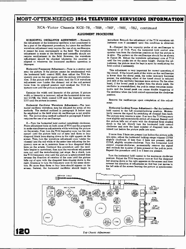
MOST -OFTEN -NEEDED 1954 TELEVISION SERVICING INFORMATION
RCA -Victor Chassis KCS-78, -78B, -78F, -
ALIGNMENT PROCEDURE
HORIZONTAL OSCILLATOR ADJUSTMENT. - Normallythe adjustment of the horizontal oscillator is not considered tobe a part of the alignment procedure, but since the oscillatorwaveform adjustment may require the use of an oscilloscope,it cannot be done conveniently in the field. The waveformadjustment is made at the factory and normally should notrequire readjustment in the field. However, the waveformadjustment should be checked whenever the receiver isaligned or whenever the horizontal oscillator operation isimproper.
Horizontal Frequency Adjustment.-Tune in a station andsync the picture. If the picture cannot be synchronized withthe horizontal hold control R200, then adjust the T114 fre-quency core on the rear apron until the picture will synchro-nize. If the picture still will not sync, turn the T114 waveformadjustment core (under the chassis) out of the coil severalturns from its original position and readjust the T114 fre-quency core until the picture is synchronized.
Examine the width and linearity of the picture. If picturewidth or linearity is incorrect, adjust the horizontal drive con-trol C174B, the width control L109 and the linearity controlLi 11 until the picture is correct.
Horizontal Oscillator Waveform Adjustment.-The hori-zontal oscillator waveform may be adjusted by either of twomethods. The method outlined in paragraph A below maybe employed in the field when an oscilloscope is not availa-ble. The service shop method outlined in paragraph B belowrequires the use of an oscilloscope.
A.-Turn the horizontal hold control completely clockwise.Place adjustment tools on both cores of T114 and be preparedto make simultaneous adjustments while watching the pictureon the screen. First, turn the T114 frequency core (on the rearapron) until the picture falls out of sync and three or fourdiagonal black bars sloping down to the right appear on thescreen. Then, turn the waveform adjustment core (under thechassis) into the coil while at the same time adjusting the fre-quency core so as to maintain three or four diagonal blackbars on the screen. Continue this procedure until the oscil-lator begins to motorboat, then turn the waveform adjustmentcore out until the motorboating just stops. As a check, turnthe T114 frequency core until the picture is synchronized thenreverse the direction of rotation of the core until the picturefalls out of sync with the diagonal bars sloping down to theright. Continue to turn the frequency core in the same direc-tion. No more than three or four bars should appear on thescreen. Instead, the horizontal oscillator should begin to
SPEAKER CABLE
120
78H, -78J, continued
motorboat. Retouch the adjustment of the T114 waveform ad-justment core if necessary until this condition is obtained.
B.-Connect the low capacity probe of an oscilloscope toterminal C of T114. Turn the horizontal hold control one -
quarter turn from the clockwise position so that the picture isin sync. The pattern on the oscilloscope should be as shownin Figure 24. Adjust the waveform adjustment core of T114until the two peaks are at the same height. During this ad-justment, the picture must be kept in sync by readjusting thehold control if necessary.
This adjustment is very important for correct operation,ofthe circuit. If the broad peak of the wave on the oscilloscopeis lower than the sharp peak, the noise immunity becomespoorer, the stabilizing elf 3ct of the tuned circuit is reducedand drift of the oscillator becomes more serious. On the otherhand, if the broad peak is higher than the sharp peak, theoscillator is overstabilized, the pull -in range becomes inade-quate and the broad peak can cause double triggering ofthe oscillator when the hold control approaches the clockwiseposition.
Remove the oscilloscope upon completion of this adjust-ment.
Horizontal Locking Range Adjustment.-Set the horizontalhold control to the full counterclockwise position. Momen-tarily remove the signal by switching off channel then back.The picture may remain in sync. If so turn the TI14 frequencycore slightly and momentarily switch off channel. Repeat untilthe picture falls out of sync with the diagonal lines slopingdown to the left. Slowly turn the horizontal hold controlclockwise and note the least number of diagonal bars ob-tained just before the picture pulls into sync.
If more than 3 bars are present just before the picture pullsinto sync, adjust the horizontal locking range trimmer C174Aslightly clockwise. If less than 2 bars are present, adjustC174A, slightly counter -clockwise. Turn the horizontal holdcontrol counter -clockwise, momentarily remove the signaland recheck the number of bars present at the pull -in point.Repeat this procedure until 2 or 3 bars are present.
Turn the horizontal hold control to the maximum clockwiseposition. Adjust the T114 frequency core so that the diagonalbar sloping down to the right appears on the screen and thenreverse the direction of adjustment so that bar just moves tothe left side of the screen leaving the picture in synchroniza-tion.
Top Chassis Adjustments
2174VERT HOLDCONTROL
0.176HEIGHTCONTROL
RIB6VERT SINCONTROL
R200NOR HOLDCONTROL

MOST -OFTEN -NEEDED 1954 TELEVISION SERVICING INFORMATION
RCAVICTORModels 21D358U, 21D368U, 21D376U, 21D377U, 21D378U, 21D379U, 21D380U,
use Chassis KCS-81J that has its exact circuit printed on the next two pages, over.Models 21D358, 21D368, 21D376, 21D377, 21D378, 21D379, 21D380, use ChassisKCS-81F which is practically identical to the KCS-81J, but is intended for VHFreception only and uses tuner unit KRK-29.
Models 21D305, 21D317, 21D326, 21D327, 21D328, 21D329, 21D330, useChassis KCS-81 with tuner unit KRK-11B for VHF reception only, while Models21D305U, 21D317U, 21D326U, 21D327U, 21D328U, 21D329U, 21D330U, employChassis KCS-81B which has tuner unit KRK-12 for both VHF and UHF reception.Outside of different tuners, these chassis are practically the same as KCS-81Jand the circuit of this chassis on the next two pages should be used for these addi-tional models.
Model 21D346 uses Chassis KCS-81D with tuner unit KRK-22A for VHF re-ception only, and Model 21D346U uses Chassis KCS-81E with tuner unit KRK-12for reception of both VHF and UHF. Both of these chassis are used in combina-tion sets with separate radio chassis, audio amplifier, and record changer. Out-side of tuner differences and provisions for switching and connecting the radiochassis which has the audio output tube and speaker, these chassis are very si-milar to other chassis covered by service material on this and the next five pages.
WIDTH. DRIVE AND HORIZONTAL LINEARITY ADJUST-MENTS. - Adjustment of the horizontal drive control affects thehigh voltage applied to the kinescope. In order to obtain thehighest possible voltage hence the brightest and best focusedpicture, adjust horizontal drive trimmer C186B for maximumdrive (minimum capacity) consistent with a linear raster. Com-pression of the raster due to excessive drive can be seen as awhite vertical bar or bars in the right half of the picture.Besides compression caused by excessive drive, another itemto watch for is the change in linearity at the extreme left withchanges of brightness control setting. By proper adjustment ofthe linearity coil, the changes in linearity with changes inbrightness can be made negligible. In general, to achieve thiscondition, the linearity coil should be set slightly on the highinductance side (core slightly clockwise) of the optimum position.
Preset the following adjustments as directed:A.-Place the width plug P103 in the minimum width posi-
tion (top).B.-Set the width control coil L109 in approximately mid.
position.
C.-Set the linearity control coil L111 near minimum in-ductance (counter -clockwise).
D.-Set the drive capacitor C186B in the maximum diive posi-tion (counter -clockwise).
If the raster is cramped or shows compression bars on theright half of the picture turn C186B clockwise until this con-dition is just eliminated.
Adjust the linearity control coil L111 clockwise until bestlinearity and maximum deflection or best compromise are ob-tained, then turn one quarter turn clockwise from this position.
Retouch the drive trimmer C186B if necessary to obtain bestlinearity and maximum width.
Check the horizontal linearity at various settings of thebrightness control R114A. There should be no compression ofthe right half and no appreciable change of linearity espe-cially at the extreme left of the picture. If objectionable changedoes occur, turn linearity coil L111 slightly clockwise andrepeat the test.
Adjust the width control L109 to fill the mask.If the line voltage is low and it becomes impossible to fill
the mask, remove the width plug P103 to the bottom position.
HEIGHT AND VERTICAL LINEARITY ADJUSTMENTS.-Adjust the height control (R190 behind front control panel) untilthe picture fills the mask vertically. Adjust vertical linearity(R197 behind front control panel), until the test pattern is sym-metrical from top to bottom. Adjustment of either control willrequire a readjustment of the other.
ION TRAP MAGNET ADJUSTMENT. - Set the ion trap mag-net approximately in the position shown in Figure 2. Startingfrom this position immediately adjust the magnet by moving itforward or backward at the same time rotating it slightlyaround the neck of the kinescope for the brightest raster on thescreen. Reduce the brightness control setting until the rasteris slightly above average brilliance. Turn the focus control(shown in Figure 2) until the line structure of the raster isclearly visible. Readjust the ion trap magnet for maximumraster brilliance. The final touches of this adjustment shouldbe made with the brightness control at the maximum clockwiseposition with which good line focus can be maintained.
DEFLECTION YOKEADJUSTMENT
FOCUS MAGNETMOUNTING SCREW
KINESCOPESOCKET
ION TRAPMAGNET
FOCUSCONTROL
CENTERINGADJUSTMENTWING NUT
CENTERINGADJUSTMENT
LEVER
Figure 2-Yoke and Focus Magnet Adjustments 121

MOST -OFTEN -NEEDED 1954 TELEVISION SERVICING INFORMATION
VHF 1
CHANNELSIA2-4L
,NCL
VHFCHANNELSIts5 -6
INCL.L
VHFrICHANNELS IC
7-10 I
INCH
ICCS8IJ CIRCUIT SCHEMATIC DIAGRAM
T6
The schematic is shown in the latestcondition at the time of printing.
All resistance values in ohms. K = 1000.
All capacitance values less than 1 inMF and above 1 in MMF unless otherwisenoted.
Direction of arrows at controls indicatesclockwise rotation.
TUNER UNIT KRK-12 Es
*0 00 MOUSING
T4
r T3VHF I
1 -13INCL.
L
UHF I
CHANNELS 1 e,4-52INCL
L
r -UHF
CHANNE LS. F
INCL I
L
56
10011
4
LI L2
2-F
C 29 LL
3
C256
OON C5
3057
P301I
R302150K
%1 §TEL.16301 - 'BOARD1306
1502
1301
LvNF .JCROSS-OVERNETWORK
R3a.zMEG
A
C
C IC4.40
49510C.I.F TRAP
ADJ.
Cs0.5-3
8
1.16
0-3
6 7
1
1
10 II X12 13
CR
MIXER R"t
`2V
CBas -3
C9 10.5-3 I
11
-1F2unF OSC
Ti'012
IJ
F NE 9107
VI
66027A _CIOR -F AMPL 56
2
CA =R26130I 120
TI
fPOC;K L6
V36BG7A
AMPL
470
R75.2y C22 R9 C20MEG1000 ,20 1000
C113220
R4270K
R6
CONTR
1001C
VOLT,05C, 2
122
R17100
IC43I 470
CH
11
8Plum
C191000
RI41000
OI
C2'23
1C322K T1003 2
v26AF4osc
T2
SNIELD_Jr -TI
PF GRIDTRANS
CRAW!! fra:
L9
12
101
W104
AGC THRESHOLD CONTROL.
To check the adjustment of the AGC Threshold Control, tunein a strong signal and sync the picture. Momentarily removethe signal by switching off channel and then back. If the pic-ture reappears immediately, the receiver is not over -loadingdue to improper setting of 8180. If the picture requires anappreciable portion of a second to reappear, or bends exces-sively, R180 should be readjusted.
Turn R180 fully counter -clockwise. The raster may be bentslightly. This should be disregarded. Turn R180 clockwise untilthere is a very, very slight bend or change of bend in thepicture. Then turn R180 counter -clockwise just sufficiently toremove this bend or change of bend.
If the signal is weak, the above method may not work asit may be impossible to get the picture to bend. In this case,turn R180 clockwise until the snow in the picture becomesmore pronounced, then counter -clockwise until the best signalto noise ratio is obtained.
5.70
_1.2V
V 101
6AU61ST SOUNDI -F AMPL
5 41460. 950211
1230.
CIOIA RIOT
R -FA C
7101SOUND I -F
TRANS.4.5 MC.
C 04 RIO3
61022
47K
0102
6AU2NO, SOUNDI -F AMPL.
V
MARMON SW. 5101 FRONTAND REAR VIEWED FROM FRONT, "25,.125V WITH CONTROL SHAFT IN MAK.COUNTER -CLOCKWISE POSTRo. 1)
P03. I - TV. AIIN,HIGHs.2 - TV. NORMAL.3- TV, MIN LOWS.4 - PNONo, MIN HIGNS5- P0000. NORMAL6- PH000. MIN. LOWS.
TIO2RATIO CRT
TRANS.4.5 MC.
ov
12104COO
E
RIOT47
3101 I.FRONT
V106T104
1ST MN1ST. P1XIF TRANS. I -F AMPL
M?85 V.
C.39.25CCi2520
A fl CI Ov.
Roo 3 61251000 75600 y
C1266124/00 loo
Vir:t wooR12933K
T105 6CB601077106
ND. PM I -FPLATE TRANS.TAM GRID TRANS.1 200.. P1X
i1 FA ern, UM V.1 %it: 1: CZI . S
__II RI50 c.,,_ 11 _14700 IS :: 8
4700 I± ___S J L S_ JC 130i 4.'1% 11 ;P
1-
C214 Vg r,;,,;f4 I -F BIAS
R13233K
R13456
0131000
LI1
C241000
C2164,1000
1100T PT
C 2311070.1.
6S4111,55 voLTAGE
CONTROL
0.4664..0 V2
115C251000.1.
C26 T110o0
T1 5
V3 vI .44 4 S
2
27011
3C27; .00
11. NOTE:WHEN USING CROSS -OVER NETWORK, CONNECT UHF AND VHF
ANTENNA TRANSMISSION LINES TO RESPECTIVE TERMINALS.WREN CROSSOVER NETWORK IS HOT USED, DISCONNECTA w 3ot
AND CONNECT HOP, VHF OR COMBINATION uNF- VHF e NN ATRAN514166101. LINE TO ANTENNA TERMINAL BOARD
C129 6167 1-11,20% S C 23r0.22 821 2250. 4700?
r{ -- - ;.,:: --4.10 it VII!4" 12AU7
0254270K AGC MT SYNC CIS)CR145RECT. SERAR, .033
o V. V. 1
co I a RI73R229 R163 6166 CI- 39K10K 270 0 100K ..°"
C757TCM'''W'-i10.22 IC.22
0. 166MEG
+350 V.
R170V 4.7
mE6137V. 02700.
3
RI696800
ST.
1'1073RD PIX.I -F TRANS41.8 MC.
C
ISV.Can CO784700 4700
3351,5 51000
1101
C 1364700-J
V .225 V.
R161MEG.
5
V I12
12A U 7N01L.9YNC SYNC
MIAMI AMPI-1.65. 27!
8171 R1742700 27K
8178 032"27K,
'047 c159 .0.68
rj501:IFF5X177I
C213
/47015
.1R1G8
3.9 14E6
6 160200KAGC 0350 V.C09756mm.m
R1792200
270-1 -
6176 41/6,00 v
+150V. R210750
6212 1.1 C06,1010oNTR 620939K 56K
0111610-140KOR17
LOCION61.RANGE
MO0
c82
R205330
6206820 5
VII$65N7-GTHOME SWEEP05C. f CrT5:
.047 _28V.
0108.047
6208 C18968K .0221
R20718 OK
C1910 47
R2I I3900
R21310
TI 1440617 OSC.
TRANS(75, -1
1 C5540! .001
C192:270
R21482 K C193
.01-VW*R2I539K
C
V114
6C D6 -GKOMI, SWEEPOUTPUT
621647 30V
CMGSR217 110-160 7
I ME6.4 r. "R17.0193 .7.
.0013
64163V.0767.047
II
5#91;,If V.197T R22100112166431(
1722.1:S4
F t-0 25 AMP.

MOST -OFTEN -NEEDED 1954 TELEVISION SERVICING INFORMATION
Rah2300
RATIO oarBALANCE
TO REMOVE ESCUTCHEON, SLIDESPRING CLIP TO LEFT
C 1l2.0047
- OSCILLATOR ADJUSTMENT- FOR CHANNEL NUM(SER
Figure 4-KRK29 R -F Oscillator Adjustments
V1OA
6AV61ST. AUDIO
AMPL.
vms6A05AUDIOOUTPUT
TiO3AUDIOOUTPUTTRANS.
et- -GTRANS.
RI1S 6II9 C1200 C120B330 T20,330 10 mE T 351410
35.106
6I. PIK.AMPL.
615910K
1106ATM PertI -F TRANS45.5 MC.
C139A C139
160v.
0109 T1096CBG STN. PM. 1-F L1024.3.7 MC.4TH. PIA. TR
A66
i-F AMPL F - -(TOP) 0,I2) ,...... .'. 1
154v.7 4141
N 1010
C 401-:8,424700T 5155
vii3A65N7-GT
VERT SYNC170 R23331 220K AWL
1350.,86
'55 3233511
C166
:.0040 270120-6 1851600
01370.165I3752
ICI220
P103WIDTHLINK
0 032 4103 vine
6W4 -6TDAMPER345V
L 110LS hion.SRN -UN
WIDTHII 52gat.
C140151_4700 I+137v.
014114700
C14(
C144 -
15((00,
R14.76600 .01 I
CHECK OF R -F OSCILLATOR ADJUSTMENTSModels 21-D-358 to 21-D-380 incl. with KRK29 Tuner
Tune in all available stations to see if the receiver r -f oscillator is adjusted to the proper frequency on all channels. If ad-justments are required, these should be made by the methodoutlined in the alignment procedure on page 11. The adjust-ments for channels 2 through 12 are available from the frontof the cabinet by removing the station selector escutcheon asshown in Figure 4. Adjustment for channel 13 is on top of thechassis.
Models 21 -D -358U to 21 -D -380U incl. with KRK128 TunerTune in all available UHF and VHF stations to see if the
receiver r -f oscillator is adjusted to the proper frequency on allchannels. Set the fine tuning control to the center of its range.Adjust the oscillator core for each channel to obtain maximumaudio output without distortion. The location of the adjustmentis the same for all channels (see Figure 5).
P -MSPEAKER
All voltages measured with "Volt-Ohmyst" and with no signal input. Volt-ages should hold within ±20% with 117v. a -c supply.
Tin°SOUND 1103TAKE.REF 72 00.11TRANS. OR -RED
.01 .270V
225V.143
5K
1.104RIAS SOO4706 1.6.1.14
6P4-61
011313 V i 14
65N7 -6T GA asKRT 03C
470K .0047,,,,sc,., C176 OUTPUT206V. 0.22 uTRIBS C171 ,
C173I
6164 CI66 C149 0.147081100 1100"Ric,091I7.30 . Tii i
8187100 K 8 OK 137 V. vERTHOLD
CoNTR
15K 1184 5
V
R239 05CVERT
VR236 'MEG
T115H -v TRANS.
IC leoX399 e R225
Z I 1.3
33
2
RI902.5 MEG.- HEIGHTCONTR.
V 117
1133-GTH -V RECT.
C201Soo
.345L112
1.5202631 SRN
Linn163615 LIN
0 200150
+350V.
C178022
c,71 R14910 1 3300
II I
4.5 MC. RISO3900
33 C T.0062
424700
Tis2VERTICALOUTPUTTRANS
VOLSLU
y) GE
N 4200
41971500
NN vERT.
ILINEARITYCONTR
P.024,DE FL YOKE PIN VIEW
gr COPSD
56
INDICATORCHANNEL
LAMP
V 110
6CL6VIDEOAMPL
6 01300 C150 C15147 470600.
LI06500muin
ORN.014
Lio54.5 MC.TRAP
130J-VEL
OSCILLATORADJUSTMENT
(ALL CHANNELS)
CHANNELIP-INDICATOR
APERTURE
CHANNEINDICATORAPERTURE
Figure 5-KRK12B Oscillator Adjustment
R1551511
3 PICTURECONTR.
L107180 Hu-. C153
"'"L 0.22 RI611- 1000
2 R158 R15922K 1501(
8159675015'08 R,S
IOK 4011
02250.02250. *1378201 C1833300 0.1
4
1015200 20011K2
R 14 A
C2060.22T 6203
12,50.100K
4,32VL is
OR
GLASS
ETAL
3500. 02700. 2250. 41600. 01370. +125 V.
J102 FTERM. VIEW
EE -47381 -o
Rat" R22.2g, 612g7 Pt 70002807
C149 c1leAc149 C1201)15 B C ^1014F.
10 MET 250F IOMF
L 117FILTER
CHOKE
REETIF IRS
5103INTERLOCK
C149A 70 MECileA 35 MP
C1200-35 AnE.VI21
0185 0184.01 .01
115V. 60,SUPPLY
A
1
J
Continued on thenext three pages.
CircuitSchematicDiagram,KCS811
123

MOST -OFTEN -NEEDED 1954 TELEVISION SERVICING INFORMATION
RCA -Victor Chassis KCS-81, -81B, -81D, -81E,-81F, -81J, continued
ALIGNMENT PROCEDURE
PICTURE I -F TRAP ADJUSTMENT. - Connect the i-f signalgenerator across the link circuit on terminals A and B of T104.
Connect the "VoltOhmyst" to the junction of RI33 and C133B.Obtain two 7.5 volt batteries capable of withstanding ap-
preciable current drain and connect the ends of a 1,000 ohmpotentiometer across each. Connect the positive terminal of onebattery to chassis and the potentiometer arm to the junction ofR133 and C133B.
Set the bias to produce approximately -1.0 volt of bias atthe junction of R133 and C133B.
Connect the "VoltOhmyst" to pin 9 of V110, the 6CL6 videoamplifier.
Set the signal generator to each of the following frequenciesand adjust the corresponding circuit for minimum d -c outputat pin 9 of VI10. Use sufficient signal input to produce 1.0 voltof d -c on the meter when the final adjustment is made.
39.25 mc. T104 top core41.25 mc. T105 bottom core47.25 mc. T106 bottom core
PICTURE TRANSFORMER ADJUSTMENTS. -VHF Models
Set the signal generator to each of the following frequenciesand peak the specified adjustment for maximum indication onthe "VoltOhmyst." During alignment, reduce the input signalif necessary in order to produce 1.0 volt of d -c at pin 9 of V110with -1.0 volt of i-f bias at the junction of 11133 and C133B.
43.7 mc. T10945.5 mc. T10841.8 mc. T107
To align T105 and T106, connect the sweep generator to thefirst picture i-f grid, pin 1 of V106 through a 1,000 mmf. ceramiccapacitor. Shunt R137, R141 and terminals "A" and "F" ofT109 with 330 ohm composition resistors. Set the i-f bias to-1.0 volt at the junction of R133 and C133B.
Connect the oscilloscope to pin 9 of V110.Adjust T105 and T106 top cores for maximum gain and curve
shape as shown in Figure 22. For final adjustment set the out-put of the sweep generator to produce 0.5 volt peak -to -peak atthe oscilloscope terminals.
To align T2 and T104. connect the sweep generator to themixer grid test point TP2. Use the shortest leads possible, withnot more than one inch of unshielded lead at the end of thesweep cable.
Adjust C121 until 41.25 mc. is at 85% response with respectto the low frequency shoulder at approximately 41.9 mc. asshown in Figure 23.
Disconnect the diode probe, the 180 ohm and three 330 ohmresistors.
VHF -UHF ModelsSet the signal generator to each of the following frequencies
and peak the specified adjustment for maximum indication onthe "VoltOhmyst." During alignment, reduce the input signalif necessary in order to produce 1.0 volt of d -c at pin 9 ofV110 with -1.0 volt of i-f bias at the junction of 11133 andC133B.
43.7 mc T10945.5 mc. T10841.8 mc. T107
To align T105 and T106, connect the sweep generator tothe first picture i-f grid, pin 1 of V106 through a 1,000 mmf.ceramic capacitor. Shunt 11137, R141 and terminals "A" and"F" of T109 with 330 ohm composition resistors. Set the i-f
bias to -1.0 volt at the junction of R133 and C133B.
Connect the oscilloscope to pin 9 of V110, the 6CL6 videoamplifier.
124
Adjust T105 and T106 top cores for maximum gain andcurve shape as shown in Figure 22. For final adjustment setthe output of the VHF sweep generator to produce 0.5 voltpeak -to -peak at the oscilloscope terminals.
To align the crystal mixer and T2 and T104. connect theVHF sweep generator to the front terminal of the 1N82 crystalholder in series with a 1,500 mmf. ceramic capacitor. Use theshortest leads possible, grounding the sweep generator to thetuner case.
Set the channel selector to channel 5.
Connect a 180 ohm composition resistor between terminal"B" of T105 and the junction of R131 and C133A.
Connect the oscilloscope diode probe to terminal "B" of T105and ground. Couple the signal generator loosely to the diodeprobe in order to obtain markers.
The shunt trimmer C121 across terminals "A" and "B" of T104is variable and is provided as a bandwidth adjustment. Presetthe shunt trimmer to minimum capacity. Adjust T2 (top) andT104 (bottom) for maximum gain at 43.5 mc. and with 45.75mc. at 70% of maximum response.
Adjust the shunt trimmer C121 until 41.25 mc. is at 85%response with respect to the low frequency shoulder at ap-proximately 41.9 mc. as shown in Figure 13. Adjust T1 for
41.9 MC.
41.25 MC857. -45.75 MC
75%
42.25 MC85%
Figure 13-T2 andT104 Response with
KRK12B
Figure 20 -Sound I -FResponse
41.9 14C
41.25 MC785%
45.75 MC.50./.
46.5MG.5%
Figure 14 -Over-allI -F Response with
KRK12B
4.5 MCL.4
Figure 21 -Ratio Det.Response
42.25 MC
42.0t, T1'
IC:15.75MC AT90
4654.20*-
41 25 MC4725MC
Figure 22-T105 and T106
Response
45 MC85%
70% 45.75 MC50%
Figure 23-T2 and T104
Response with KRK29
40.5 MC5%
Figure 24 -Over -all I -F
Response with KRK29

MOST -OFTEN -NEEDED 1954 TELEVISION SERVICING INFORMATION
RCA -Victor Chassis KCS-81, -81B, -81D, -81E, -81F, -81J, continued
ALIGNMENT
maximum gain. Readjust T2 and 1104 if necessary to obtainproper wave shape, see Figure 13.
Disconnect the diode probe. the 180 ohm and the three 330ohm resistors.
SWEEP ALIGNMENT OF PICTURE I-F.-Connect the oscilloscope to pin 9 of V110.
Adjust the bias potentiometer to obtain -6.0 volts of biasas measured by a "VoltOhmyst" at the junction of R133 andC133B.
Leave the sweep generator connected to the mixer grid testpoint TP2 on KRK29 Tuner or to the front terminal of the1N82 crystal holder on KRK128 Tuner. Use the shortest leadspossible with not more than one inch of unshielded lead at theend of the sweep cable. If these precautions are not observed.the receiver may be unstable and the response curves obtainedmay be unreliable.
TO ANT TERMINALS
PROCEDURE
Adjust the output of the sweep generator to obtain 3.0 voltspeak -to -peak on the oscilloscope.
Couple the signal generator loosely to the grid of the firstpix i4 amplifier. Adjust the output of the signal generator toproduce small markers on the response curve.
Retouch 1108 and 1109 to obtain the response shown in Fig-ure 14. Do not adjust 1107 unless absolutely necessary. If 1107is adjusted too low in frequency it will raise the level of the41.25 mc. sound i-f carrier and may create interference in thepicture. It will also cause poor adjacent channel picture rejec-tion. If 1107 is tuned too high in frequency, the level of the41.25 mc. sound i-f carrier will be too low and may producenoisy sound in weak signal areas.
Remove the oscilloscope, sweep and signal generator con-nections.
SPEAKER CABLE
T1ANT MATCHING
TRANS.
YE6XIS
OSC'AMER
TZMISERTRANS.
RATIO OCT.TRANS.
TIOZ
0.1 MC
11101
SOUNDIF
ORATH, OETSALAMI
12447
vERT SYNC SE SAG C
Soo,Tv 'oft( -PHONO
SWITCH
CRTvERT
HOLDCONTROL
1RI
HEIGHTCONTROL
RISTCERT LIPCONTROL
AM NOLO
521 PIE I.FTRANS
TIO9
43/MC
SOUND TAKE -OFFTRANS
SCV 0
L6
I01.
0
T1041Ale IX
TRANS45.5MC
T107SSE FIR IF
TRANS41.5 MC
O
ESE Pox
TRANS
FIX rFPLATETRANS
IQ PIE I.FGRID
TRANS
T106)"IS MC
TIOS0
4110AC
TIOR0
31.1114
All CHANNELSELECTORSWITCH\=VIII 112__i\
TAILCONTROL
ROESBLEEDER
viSS 'GTER SYNC
HAPR WIRTOSC
TEENS
Lon"FILTERCHOKE
510.Tv-ToNE-
:Vitt
Melt
MIRO
REI
R HITVERTHOLD
OW ROL
RIE014116HT
CONTROL
RIS7VERT LitCONTROL
/1R210
HOE HOLDCORTNOL
Figure 26-Top Chassis Adjustments (KRK29 Tuner Shown)
Ed PIE rF
GRIDTRANS.
ISO 01111-F
TRANS.
Y106
47.1551C,
TIOS
41.25510
To0,N TEARSF
TIOSRUNE IF
TIOS
';V,d
Figure 27-Bottom Chassis Adjustments
SOUND 14TRANS
sPENER CORD
RATIOPET
T101
CS MC
0RATIODR/
ONCE
125

MOST -OFTEN -NEEDED 1954 TELEVISION SERVICING INFORMATION
RCA -Victor Chassis KCS-81, -81B, -81D, -81E, -81F, -81J, continued
ALIGNMENT PROCEDURE
RATIO DETECTOR ALIGNMENT. - In order to obtain goodratio detector alignment an AM modulated signal generatorthat is exceptionally free from FM modulation must be em-ployed. Set the signal generator at 4.5 mc. and connect it tothe second sound i-f grid, pin 1 of V102. Set the generator for30% 400 cycle modulation.
As an alternate source of signal, the RCA WR39B or WR39Ccalibrator may be employed. If used, connect it to the grid ofthe 4th pix i-f amplifier, pin 1, V109. Set the frequency of thecalibrator to 45.75 (pix carrier) and modulate with 4.5 mc.crystal. Also turn on the internal AM audio modulation. The4.5 mc. signal will be picked off at T110A and amplifiedthrough the sound i-f amplifier.
Connect the "VoltOhmyst" to the junction of R111 and C111.
Connect the oscilloscope across the speaker voice coil andturn the volume control for maximum output.
Tune the ratio detector primary, T102 top core for maximumDC output on the "VoltOhmyst." Adjust the signal level fromthe signal generator for -10 volts on the "VoltOhmyst" whenfinally peaked. This is approximately the operating level ofthe ratio detector for average signals.
Connect the "VoltOhmyst" to the junction of R110 and C110.
Adjust the T102 bottom core for zero d -c on the meter. Then,turn the core to the nearest minimum AM output on theoscilloscope.
Repeat adjustments of T102 top for maximum DC and T102bottom for minimum output on the oscilloscope making finaladjustment with the 4.5 mc. input level adjusted to produce 10volts d -c on the "VoltOhmyst" at the junction of R111 and C111.
Connect the "VoltOhmyst" to the junction of R110 and C110and note the amount of d -c present. If this voltage exceeds+1.5 volts, adjust R108 by turning it in until zero d -c is ob-tained. Readjust the T102 bottom core for minimum output onthe oscilloscope. Repeat adjustments of R108 and T102 bottomcore until the voltage at R110 and C110 is less than ±1.5volts when T102 bottom core is set for minimum output on theoscilloscope.
Connect the "VoltOhmyst" to the junction of R111 and C111and repeak T102 top core for maximum d -c on the meter andagain reset the generator so as to have -10 volts on the meter.
Repeat the adjustments in the above two paragraphs untilthe voltage at R110 and C110 is less than ±1.5 volts when theT102 top core is set for maximum d -c at the junction of R111and C111 and the T102 bottom core is set for minimum indica-tion on the oscilloscope.
SOUND I -F ALIGNMENT. - Connect the sweep generator tothe first sound i-f amplifier grid, pin 1 of V101. Adjust thegenerator for a sweep width of 1 mc. at a center frequency of4.5 mc.
Insert a 4.5 mc. marker signal from the signal generator intothe first sound i-f grid. With the WR39B or WR39C calibratorsthe 4.5 mc. crystal signal may be obtained at the R -F outterminal by turning the variable osc. switch off, the calibrateswitch to 4.5 mc. and the volume control with mod. off.
Connect the oscilloscope in series with a 10,000 ohm resistorto terminal A of T101.
Adjust T101 top and bottom cores for maximum gain andsymmetry about the 4.5 mc. marker on the i-f response. Thepattern obtained should be similar to that shown in Figure 20.
The output level from the sweep should be set to produceapproximately 2.0 volt peak -to -peak at terminal A of T101 whenthe final touches on the above adjustment are made. It is neces-sary that the sweep output voltage should not exceed thespecified values otherwise the response curve will be broad-ened, permitting slight misadjustment to pass unnoticed andpossibly causing distortion on weak signals.
126
Connect the oscilloscope to the junction of R110 and C110and check the linearity of the response. The pattern obtainedshould be similar to that shown in Figure 21.
SOUND TAKE -OFF ALIGNMENT. - Connect the 4.5 mc. gen-erator in series with a 1,000 ohm resistor to terminal "C" ofTI10. The input signal should be approximately 0.5 volt.
Short the fourth pix i-f grid to ground, pin 1, V109, to preventnoise from masking the output indication.
As an alternate source of signal the RCA WR39B or WR39Ccalibrator may be used. In such a case, disregard the abovetwo paragraphs. Connect calibrator across link circuit, T104A, B, and modulate 45.75 with 4.5 mc. crystal.
Connect the crystal diode probe of a "VoltOhmyst" to theplate of the video amplifier, pin 6 of V110.
Adjust the core of T110 for minimum output on the meter.
Remove the short from pin 1 V109 to ground, if used.
HORIZONTAL OSCILLATOR ADJUSTMENT. - Normally theadjustment of the horizontal oscillator is not considered to be apart of the alignment procedure, but since the oscillator wave-form adjustment may require the use of an oscilloscope, it cannot be done conveniently in the field. The waveform adjust-ment is made at the factory and normally should not requirereadjustment in the field. However, the waveform adjustmentshould be checked whenever the receiver is aligned or when-ever the horizontal oscillator operation is improper.
Horizontal Frequency AdJustment.- Tune in a station andsync the picture. If the picture cannot be synchronized with thehorizontal hold control R210, then adjust the T114 frequencycore on the rear apron until the picture will synchronize. If thepicture still will not sync, turn the T114 waveform adjustmentcore (under the chassis) out of the coil several turns from itsoriginal position and readjust the T114 frequency core until thepicture is synchronized.
Examine the width and linearity of the picture. If picturewidth or linearity is incorrect, adjust the horizontal drive con-trol C I86B, the width control L109 and the linearity control L111until the picture is correct.
Horizontal Locking Range AdJustment.- Set the horizontalhold control to the full counter -clockwise position. Momentarilyremove the signal by switching off channel then back. The pic-ture may remain in sync. If so turn the T114 frequency coreslightly and momentarily switch off channel. Repeat until thepicture falls out of sync with the diagonal lines sloping downto the left. Slowly turn the horizontal hold control clockwise andnote the least number of diagonal bars obtained just before thepicture pulls into sync.
If more than 3 bars are present just before the picture pullsinto sync, adjust the horizontal locking range trimmer C186Aslightly clockwise. If less than 2 bars are present, adjust C186Aslightly counter -clockwise. Turn the horizontal hold controlcounter -clockwise, momentarily remove the signal and recheckthe number of bars present at the pull -in point. Repeat thisprocedure until 2 or 3 bars are present.
Turn the horizontal hold control to the maximum clockwiseposition. Adjust the T114 frequency core so that the diagonalbar sloping down to the right appears on the screen and thenreverse the direction of adjustment so that bar just moves offthe screen leaving the picture in synchronization.
SENSITIVITY CHECK. -A comparative sensitivity check canbe made by operating the receiver on a weak signal from atelevision station and comparing the picture and sound ob-tained to that obtained on other receivers under the same con-ditions.

MOST -OFTEN -NEEDED 1954 TELEVISION SERVICING INFORMATION
RAYTHEON,RAYTHEON MANUFACTURING COMPANY
TELEVISION AND RADIO DIVISION
21T8 CHASSISMODELS UM -2133A, UM -2134A, UM -2135A, UM -2136A, UC-2139A,
UC-2141A, UC-2142A, UC-2144A and UC-2145A
24T2 CHASSISMODELS UC-2403A, UC-2404A, UC-2405A, and UC-2406A
T 301BOTTOM 43.7 MC
L323ATOP 41.4 MC
L 323BBOTTOM 45. 15 MC
L319TOP or BOTTOM 4 2.1 MC
L3 12TOP or BOTTOM 42.and46.MC
L3I4TOP or BOTTOM 47.25MC
L31 3TOP or BOTTOM 41. 25MC
TOP or BOTTOM 42.and46. MCLI1 T200,4
TOP 42.0 and 456
UHFTUNER
TUNERDRIVE ASSY
LI112
OP'
VHFTUNER
T 300ATOP 41.4 MC
IF ALIGNMENTBOTTOM 42.0 and 484.-6 MC INPUT "B"
T 00B
* MARKER FREQUENCIES
VIDEO TRAP COIL (L403) ADJUSTMENT
(a) Tune in station.(b) Adjust tuner until sound bars just appear.(c) Turn L-403 Slug all the way out (counter -clockwise).(d) Turn the slug in (clockwise) until the horizontal
scanning lines are smooth and continuous.
IF ALIGNMENTINPUT "A"
Circuit diagram forChassis 21T8 is onpages 130-131, andthe circuit diagramfor Chassis 24T2 ison pages 132-133.Alignment facts forall models are printedon pages 127 to 129,and page 134.
ALIGNMENT PLUG
For ease of alignment and to reduce the possibility ofregeneration, it is suggested that a simple generatoralignment plug be made and used during the alignment.
127

MOST -OFTEN -NEEDED 1954 TELEVISION SERVICING INFORMATIONRaytheon Manufacturing Company, Chassis 21T8 and 24T2, continued
VIDEO IF ALIGNMENTNOTE: (a) Preheat the unit for at least five minutes.
(b) Set VHF tuner to approximately Channel 7.(c) Use 10K ohm resistor (isolation) in series with VTVM and scope for the following steps.
1213
Ste -No.
SignalGenerator
Freq. (mc.)
SweepGeneratorFreq (mc.)
SignalInputPoint
OutputPoint
Remarks Adjust Response
1 43.7IF Alignment
Input "Ai.VTVM at IF
DetectorOutput
Adjust generator foroutput of approx. 2 volts
DC on VTVMT-301
MaximumReading
41.4IF Alignment.,Aii
VTVM at IFDetectorOutput
Adjust generator foroutput of approx. 2 volts
DC on VTVM
L -323A(Top)*
MinimumReading
45.15IF Alignmenti.AiiInput
VTVM at IFDetectorOutput
Adjust generator foroutput of approx. 2 volts
DC on VTVM
L -323B(Bottom)*
MaximumReading
42.1IF Alignment
Input "A"VTVM at IF
DetectorOutput
Adjust generator foroutput of approx. 2 volts
DC on VTVML-319
MaximumReading
41.25IF Alignment
Input "A"VTVM at IF
DetectorOutput
Adjust generator foroutput of approx. 2 volts
DC on VTVM
L-313(Bottom)
MinimumReading
47.25IF Alignment
Input "A"VTVM at IF
DetectorOutput
Adjust generator foroutput of approx. 2 volts
DC on VTVM
L-314(Bottom)
MinimumReading
41.4IF Alignment
Input "A"VTVM at IF
DetectorOutput
Adjust generator foroutput of approx. 2 volts
DC on VTVM
T -300A(Top)*
MinimumReading
8Remove VTVM from IF Detector output and substitute an oscilloscope in its place. Calibrate scope for sensi-tivity of one volt per inch.
42.046.0
40IF Alignment
Input "B"Scope at IF
DetectorAdjust wave form for
approx. 20 divisions on
L-311 (Bottom)1-312 (Bottom)
Adjust foriamplitude
properdwwildth
456AK10 42.045.6
40IF Alignment
Input "A"
1
Scope at IFDetectorOutput
Adjust wave form forapprox. 20 divisions oscope with sweep Ben.
T-200T6-33000513 (Bottom)*
Adjust for maximumamplitude with
proper bandwidth
* NOTE: Two Peaks can be obtained. Use Peak with core furthest out of coil form.
SOUND IF ALIGNMENTNOTE: Short antenna to ground.
StepNo.
SignalGeneratorFreq. (mc.)
SweepGeneratorFreq (mc.)
SignalInputPoint
OutputPoint
Remarks Adjust Response
1 4.5IF Detector
Output
VTVMacrossC-416
T400 Primary(Bottom of can)
MaximumReading on
V.T.V.M.
2 4.5 IF DetectorOutput
ScopeacrossC-416
Sweep approx. ± 100 KC.Adjust for maximum
Linearity
T400 Secondary(Top of can)
3 4.5IF Detector
Output
ScopeacrossC-416
Sweep approx. ± 100 KC.Adjust for symmetry
of peaks
T400 Primary(Bottom of can)

MOST -OFTEN -NEEDED 1954 TELEVISION SERVICING INFORMATIONRaytheon Manufacturing Company, Chassis 21T8 and 24T2, continued
VHF TUNER ALIGNMENTNOTE: IF amplifier must be aligned before tuner adjustments are
made. Also Low Band of Ti.ner must be aligned before High Band.
1. Preset trimmer screws as shown in Figure 5.2. Preset coil cores as following:
(A) With Band Sw. in Low Band pos., set treadle bar to fop of stroke (Cores furthest out of coil)(B) Adjust Cores: L200, L201, L205, L236, L209, L210 to 1-1/2" from cores to end of coil form.(C) Adjust Core: L213, L214 to 1-5/8" from cores to end of coil form. (See Figure 6.)
C217HI BAND MIXER ---FE
C230LOW BAND OSC. - I 16.1
C231HI BAND OSC. -
IF ALIGNMENT1NPUTW
G213LOW BAND MIXER 14
C2I1HI BAND RF
C208LOW BAND R F -1116
0204LOW BAND ANT -
C205HI BAND ANT
Note 1: From bottom of treadle bar 13/4" to top of tuner chassis.Note 2: From bottom of treadle bar 11/8" to top of tuner chassis.Note 3: From bottom of treadle bar 5/8" to top of tuner chassis.Note 4: From bottom of treadle bar 7/8" to top of tuner chassis.
6U8
Alignment tableis on page 134.
REAR CAM
BOTTO COVER
FILAMENT
B+240V
FIGURE 6. BOTTOM VHF TUNER VIEW
AGO
RF TEST POINT
6BZ7
ANTENNA INPUT
THE DIMENSIONS SHOWN AREAPPROX. FROM THE SHOULDEROF SCREW HEAD TO CHASSIS.
FIGURE 5. TOP VHF TUNER VIEW
21%L2I4 L210- L209
LL206 205
L200
SWITCH PLATETENSION SPRING
L201
FRONT CAM
SET SCREWS
COUPLING ARM
LINK
LINK SPRING
129

MOST -OFTEN -NEEDED 1954 TELEVISION SERVICING INFORMATION
Raytheon Chassis 2 1T 8
UHFANTENNATERMINAL
AUTOMATICSWITCHING DEVICE VWT %EWA
INAL
03001000
:210 00
I
1MM
C
0100100
64E
5300
$200
L 2441 L
I35V
C101
47011UHF
JUMPER
L5O6i
1.305_
CAVITY CAVITY
T100 C10
OSCCAVITY
, ,,,,F6AFILtcro4
N82 RI02CRYSTAL 56
I
PIT
L102
C104
20
0102
100
L10412A010510001
01071000
5670-
V OSC. GRDCHECK POiN
F107
Olt1111
) 0 0?' 7
rioe- 160622
220 5.100
BOV - L105Ri05
R 106
56
0-46CB6list IF I
IF AUGMENTT3420 13 1 ±..t?
122K M' I I , I
TM° " ciroir 1 , ! AH7::A,31 IA ,
I
I
7."..1i21 1
1
IrT3008 'I
I _ ..i._T=O 4 1000 344...C315
__ _ 0 0 0 7 0 V
nIIE ......
0.1 0
22 09 7.1000
CRYSTAL CI104 CI1OB Ulf POACHPONT 1000 71000 PLUG
re,s2300
.1011.1.
0 0
V 2C2 613Z720
9 EgffigC2O
20
202200
IOK
°
105
R202
5201
Lp 00L206
L206
10
T1206
C211
=
Ci
0213
FI,:'FtYPAtu'
V-36U8
VHF Cow
UHIF05 4'+14.C219
L209
L210,t
C
L2071000
0216
C217
200C220
L2
C22I
30
70V
0007
R204224
2-
22CK
0'
10
8209 C22210K 11000
oo
7=10
ck4-41,G
A
C 5 C
L 2 I 5
2117
5203
6
0218
It9 REI TEST
POINT
4506 2.2 18 L2 42200
JY°2j2°41226
L21
22=
:188
ALIGNMENTINPUT -=Er -
.IV
C307R304 1-50001000 _L
9* .,Mt -.:F-
I -"t- TY 22112W 2W
400 L30716
AG 2.o.0 La,_2,-r-irsFL
I
0231
00>C232
R420
11000
-2V
150V
3K2
C
L
i6.807000;
14HOCPOYIKETE8 1 -5T4 -s362.2o
C3091_5_000 R305
22K
R311471(
V-5
6C8CEE
IF
II
L2
R310
1000 0320,000Iii
5000 =
L3
AGC
C310 C3II50001 5000 165
-T EscV
L316
V4fnn.240 U
24
R404
V-8
3v 68E68403 ZylSMiffi-6 OK
+240V
R4001M
C400...22MFT
8402!NI
R401
A
>'GO12RCE
it,14
R40547K
33V
*1Rep747K2W
8406 8-6V15K
F FO/C13
2VPP
yC 406
64616
1400
4011
IOCK < T 4
AC INPUT115 VOLTS60 CYCL
LW
600
...C4011I0
+240V
ON -OFF SWITCHON VOLUME
CONTROL T404GREEN
SAFETYINTER-LOC
130
63VAC
BLACK GREEN
SELENIUM
91A RECTIFIERS
R446 + K
RESISTOR 258g6TYPE FUSE FILAMENTS
0447150
5 25C0-14
2505v -o
J
-,1
0Cr
V-12 V-14_ 6AL5 25C5
leUte0 DETI
R42347
24
iC4115
IDIMF
AYY 1C1iF
75VA-
0417 R427
I -1 1311111.1
V-13
6AV6COKEEI C418
0I1E
7°00
214'1 4429470K
1401
05V
SW- F,200A
,5V RED
05VR430,1.C414L1
12° 10 MF1W T50
BLUE
0414020W4300V
VSLTAEGIT +-1C428 1C429SOURCE 100mF71COMF
8++240VSOURCE
10wL4042200
F 150V 1500_E-4/ 0'0000'
255V 70 R448
C402C + 4,01001E 100300VO L
=-
65+1VSOURCE
411
ittiPM11SPEAKER R43I
3.9
C421*47 PILOT LIGHT .22e41
+240V
R43222M
V
0
(p o
433*OK
471
I 1\1"qL-CC431 V-17
6AL5V.14.1-7'FL
7
R4 C4,12.2M' ;
R47,10V
68IC438
MF.0022
R4521506 1113m7F
4470K
C 4 35- 680
0443 4458
R4
,6806
15011 IOU459
1:173.811' 1W in MP .1
0 0
130AL405
Ld-hata
ce 40
111
V2
103
vv
+2400
5
4
+2400
H V POWERSOCKET
6 70039MF
C41204
330
8V
I-- -.AN.C436 P435220 68011
0 03 2
-302-5V
50
2200 r
41911F10jLOR141'.1:
Y
7
FA
H V POWER
IPLUG
7
V
1161111
050
4t

MOST -OFTEN -NEEDED 1954 TELE
L31865 '
r L323
-160V qTrL32I
2.2A
V -7
RIK CK-706CRYSTAL
16 n
A
IFDETECTOR OUTPUT
-DwER.UG
¢1 03
5V
25C5$2400
L328410v622A
8325
R4171000 ION TRAP
MAGNET V-1021YP4
GATHCOERAY
TUBE
100K
R437 R48 114163M 1800 3300
V HOLD
R438 84393-314 100K
I 8435
100K
04T4047MF.
I- 12AUT oVriPV o c
.0047MF
460V
500K
250E
350-4150 .BLUE 1403
g64 R443EO`180 K
OCZVERTICAL YOKE
1501170
1
V-19BLUE 1500 RED
C 502
0503_3.5014F
450V
IB3
05062MF
450 486 -r --Me470
#444 #446
I
65A\-L1--U8L111../
14CRIZONEBLISOCKET
6
HORIZONTALYOKE PLUG
A-6
VISION SERVICING INFORMATION
Raytheon Manufacturing Co.Circuit Diagram Chassis 21T8
8I2KF IIPIC°0VtgAZIgET1S!EDZMI1CFRLL74EFEINDICATED. C DEFTErMCRO-ARAD.
anCEECE==FIESISTOR WATTAGE IS REPRESENTED IN 1/2 WATT UN-TED. (K DENOTES U 1.000 8 DENOTES 51,000,000.
17 WALL SWITCHES ARE SHOWN IN THE POSITION FOR VHF
IlgiNIREITIIE VOLTAGE READINGS INDICATED AT THE VARIOUS TUBEWERE MEASURED WITH A 20,000 OHM PER VOLT VOLTMETER,
NORVAL OPERATION, NO SIGNAL INPUT AND LINE VOLTAGE AT 115v AC WHERE401411IOL SETTINGS AFFECT VOLTAGE READINGS THE MINIMUM AND MAXIMUM.BE POICATED (SEE WARNING BELOW
(31233ETEE=HISH VOLTAGE ON PLATE CAPS OF THE 183 HIGH VOLTAGEPECTWIER AND 25936 HORIZONTAL RASE AMPLIFIER CO NOT MEASURE THIS
M R CRT 2nd ANODE VOLTAGE WITH H V PROBE- THE DC RESISTANCE READING INDICATED NEAR THE
COILS HAVE BEEN TAKEN WITH AN OHMMETER DIRECTLYACROSS THE COIL BEING MEASURED COILS SHOWN WITHOUT A RESISTANCEREADING HAVE A DC RESISTANCE OF LESS THAN ONE OHM A TOLERANCEIF ":10 IS PERMISSIBLE .00 NOT MEASURE WITH SET TURNED ON
HE WAVE FORMS ILLUSTRATED ARE EXACT COPIES OF'HAT SHOWN A LABORATORY OSCILLOSCOPE THE WAVE FORMS WERE'AKER UNDER NORMAL OPERATING CONDITIONS, WITH A TRANSMITTED SIGNALAND THE PICTURE IN SYNC AT ALL TIMES WITH EACH WAVE FORM IS THE'EAR -TO -PEAK VOLTAGE AND A HORIZONTAL OR A VERTICAL NOTATIONREPRESENTING VERTICAL IGO CYCLES) OR HORIZONTAL (15,750 CYCLES)SCOPE FREO THE WAVE FORM ANO PEAK -TO -PEAK VOLTAGE READINGSMAT VANS SOMEWHAT DEPENDING ON THE STRENGTH OF THE SIGNAL, THEPICTURE INFORMATION BEING TRANSMITTED AND THE ADJUSTMENT OF THEVARIOUS CCEITROLS WHEN CHEOGNG WAVE FORMS.CONPECT THE GROUNDLEAD FROM THE OSCALOSCCPE 10 THE CHASSIS AND THE HOT LEAD TO THE
BY THE ARROW I SEE WARNING BELOW)BEFORE REPLACING TUBES THE CABINET BACK MAT
-IRST BE REMOVED. REMOVING THE CABINET BACK DISENGAGES THE SAFETYNTERUXA AND REMOVES THE POWER TO THE RECEIVER DO NOT TAKERWITH CR ATTEMPT TO DEFEAT THE PLMPOSE OF THE SAFETY INTERLOCK, ASSEVERE SHOCK MAY RESULT DO NOT REMOVE TUBES WHILE THE RECEIVER
4AS LOADING OR COMPOST MAUR( MAY RESULT=162 DUE TO LARGE SURFACE AND EXTREME HIGH VACUUM, CARE SHOULD BE USED WHEN HANDLING THE CHASSIS
OUTSIDE THE CARNET DO NOT SUBJECT THE TUBE TO EXCESSIVE PRESSUREOR RCOGR HANDLING AS AN IMPLOSION MAY RESULT CAUSING SERIOUS
R1.904AL
POSIT). .T
WARNINGAT ALL TIMES DURING OPERATION THE CHASSIS IS AT 125 VEG.T5 OC
POTENTIAL ABOVE GROUND AND IT ALSO MAT BE AT THE LINE VOLTAGEPOTENTIAL DEPENDING ON HOW THE LINE CORD PLUG IS INSERTED RITAPOWER RECEPTACLE
EXTREME CAUTION MUST BE OBSERVED WHEN WAXING WITH THECHASSIS OUTSIDE THE CABINET AND WHEN POWER IS APPLIED TO THERECEIVER WITH THE CABINET BACK REMOVED SEVERE- SMOCK MAY RESULTFROM CONTACT WITH CHASSIS.
AN ISOLATION TRANSFORMER BETWEEN THE LINE CORD PLUG ANDPOWER RECEPTACLE MUST BE USED WHEN SERVICE IS REQUIRED. THIS RE-MOVES AC LINE SHOCK HAZARDS OAMAGE TO THE RECEIVER AND TESTEOU,PEMENT MAY RESULT WITHOUT THE USE OF AN ISOLATION TRANS-FORMER
PLOTLIGHT
0.16654V -I3
GAVG
V -H1
2506v12
6 Ala
GCBV-4
S
v-5SCSIV -SBUS
5'07V-8
6C64
noA
uHF 00A1 K SIZEHT SOCKET CORTREK
V -II
'AUG
V-865E6
v-17BALD
V92505
v -ISI2AU7
V -I915806
v-206AX4V-21183
v-7GCBS
V-16AF4
H.
O N -OFF NCHOLD BRIGHT VOLUME PICTURE STASY BIL V HOLD
131

MOST -OFTEN -NEEDED 1954 TELEVISION SERVICING INFORMATION
Raytheon Chassis 24T2
fuw6VATORflRE MIXER OSC
CAVITY CAVITY V0-1 CAVITY
C100 1N82 6102100 CRYSTAL 56
UHFANTENNATERMINAL
VHF ANTENNATERMINAL
r -
2;82
03001000
0101
MEDD
C301
300 1 82 5300
i1I302CCO
301 IC30
C 4 2 L303
L302
C2
1)
1000
es'
3200
1.
2 05
0
C202
L202
02063
-1
8100470K
UHFJUMPER
II,I
- T100
L101
FI
P101
IS
LI
0104
oCIO
1
G1026
100
1104
C105 -IC/00
000
01070.4
56
R105
2
U 0
fR 200
R232
5201
03 5
1206
C21
205
208 IC22910
C2095 C213
INPUTAI
120701
4209
1210
T1000C214
0215 4 6D1000
_C216
C232
C2i
V - 3
6U8VHF CONVUHF F AMP
C21968
C22I10002
" R20422K
R20522CH
Olt607 Win
op 0OSC. GR D
DECK POINT
P104 R10622
220 S 1001105
G101880
%8
009000
1106
CRYSTAL 01104 01013 = OFF POWERCHECK POINT 000 71030 PLUG L
T200
R209 _022210) 11000
0R2
500
1 VHF OSC 1
40.C218
RE1_ TEST7 FONT
2200
10o z
627,5 C, 6
22 IP,
1213
C2271000
204T cii
c
e
hi1000
L215
TM'5203I
1214
0231
1,000
O67
11_4
6C86( IA IF
AGNMEN250
12
0_ IDEUT.V TPOTT_
1-300112
5C3,31 1
1307
L309
6
IFALIGNMENT
INPUT"Er
0307moo -re000000
314
V- s
6CB6I2ndIFI
IRA
831197K
R3I2R3+100
8,33,10 1000T1661. C320..
IF50004 =
68
9701
L
C3I4 C3155 T 7
R30682 0316 317
66°T5C°°T
UHF POWERSOCKET
It
C310-.. C311
5000M 50001 L3
L31
F POWEFPLUG
C319
16907
13 6AU6[AUDIO IF AMPI
T400
40V0416
2.o
0415
2
6AL5=
E=1
6AV6 Fit; T:IMFIAUDIO AMP I
02 1 R424. 0414 47R4I9 zo- 25
V C4I8 22113 .11:
L404
C409
8200R4
R418
-2W
5C°'423 I5000T 120 8 i 221 - -
7 'T- .F. -1.q0VC9i -3
/7-1#417 C408 5GGO100K T 47
2
5400A
= -4- 1N P U II's', i -PH \ R421
C410 R920 CO:I'. 42IMF 470% 022MET,
ON -OFF SWITCH 7 7ON VOLUME CONTROL 1905 L406
_7F.LtOW _105.5_
1+124 C240galt150V 15001-
.-- -75. r
3.151 3SAFETY
INTER -LOCK
YELLOW_j
I SELENIUM
63VRECTIFIERS
L_AC E j R956
0AC INPUT 1 A 11
1
RESISTORTYPE FUSE
115 VOLTS FILAMENT VOLTAGE60 CYCLES SOURCE -P-- R457
0_ 0tO on.0 0
' 5 V AC +3200
Oov..,9
40V
0
-5Y3V RE
63V AC
132
gt00
C41941107511
R1142
NOLUMEI
7
00
oOrb" 0
R426 FC92F 10
01 M
A
3009&)26'IRVC
.-.,SOURCE
+125V
19954008
I` oTVC440- i50 MEPH
15ONF71.50y ,Lo,
15005 L407 L408
25V
5
1111 1111364 36o.C401EL0 6401(,_.3OMFT 601.17-300 V 3COV
124,025GD6
ENTS
659
I5W35 5 4
2
.6.1-2 00SOURCE
0422.0114F
2
R927470K
V- 14
50Rte !AUDIO OUC5TPUTI
340100v T
GIME -C4231
200IL
110 V
8431471(
7V
R450: 64I9812.9 mICAAF
" 6 V
150 VSOURCE
C4422214F
2200IOW
7;1-m
PMSPEAKER
47 PILOTLIGHT
3VR400 840247K IOU
vR4015:2 2M
49 V-86BE6
SNYG CLIPPE-R0 i 0
R4.3nV
iSK
0
0 0
5100
kW
10041006
Sv
R406156
+2204
.5.
22K
5
6AU6GC AM
0+
1500
200v
C900
476
47KR939 C427_0424
'NF
SR4375606
Uono00.0A
A X+220V
'e"
BOOST
6AV6(SYNC AMP
4.4C428.47MF
1 MF'R436
i, R43.31.18
C426 3
450V -+220
V
ol
1/1".-221(
C44322 - v-206AL5
AFC DISCR
1P459
400IOW
J
0 0
0
84631506
C444 #4682121t:IPA
1409IH HOLD1
OM AF
101
R461
I 1
4809
30'0v 51 II
R4606445 150K P-21680 12AU7
1114g, 0
462M
ov
O .. .a.. 0 0
R46956001W
1600
'4158
464 R4650721970K 681( MF
14,8 71-4671.00
04947 8466220 IN
2
0Io
R471H HOLD]
50K
94733j
R970220
y" A
1380
0-
6
220V
4$t13..)
rF R500 C50
-- 5600 27C
P*4= 3
C5075000
PSII 5C
C 02OAF
IGHT PLUG

319
230
MOST -OFTEN -NEEDED 1954 TELEVISION SERVICING INFORMATION
Raytheon Manufacturing Co.Circuit Diagram Chassis 24T2
C32215
0324p000
IFECTOR OUTPUT
V-6
36
R31647
V-9
6AH6V
L321
L322 500C3370III s-o-Hlt-i_
2OL400 C40
41 M IMFR409 R4I0
V- 7 VC -2
L32 3
327 831827 22K
L3238R317 <,
471u: I
R3191000
C3295000
1304
R323
5600 L3284104A
L325 22KR321
;hcars V 1W
CST1
-V 220v >11-1 .8V11- EI DEFLECTION
-I- j_C402 tR4I2 R4i4YOKE
I20/ov I R44,ET,.. ca,k560047K -I- 006 OV- ma y
-- 2w R413 2i0V-F1407 IRRIGHTNER
[PICTURE] L403 5006 C40675° 1-2200 --0405 547MF
413 p1 TO47MF
10A 380VL401
ION TRAPMAGNET
0-17
6 6BF672E I V OSC
V HOLD]3M -
-4-17"25CD6
IM Fixst
36C504 A
068V-23
12.AX4ID AUK RI
.-13415COK
2,3 V
-
CENTERINGMAGNET
34
43 1 NF047 OUTPU
8415 84163300 1800
4604 BLUE T403V-18
,htF
R44O;nip,
IV SIZEI 72750K
R44822M
C43620 MF- 4504
VERTICAL YOKELOW
REEDSOCKET PLUG
R4 BOOST
R449 C401SOURCE 4804
330K 60W -it 845250V j_ 1000
BOOSTSOURCE 4804
1900
V-24
I B3Ill V RECTI
SIZE I
40V
15,276
HORIZONTAL YOKEPLUG
CAPACITORS /CAPACITOR VALLES ARE REPRESENTED IN MICRO -MICROFPRAD (mMF) UNLESS OTHERWISE INDICATED .MF. DENOTES MICRO.FARAD
)RESISTORS WATTAGE IS REPRESENTED IN I/2 WATT UN-LESS OTHERWISEOTHERWISE INDICATED 3C. DENOTES X WOO 8 'le DENOTES KI,000.000WITCIrn ]ALL SWITCHES ARE SHOWN IN THE POSITION FOR UHF
OPERATICIZTHE VOLTAGE READINGS INDICATED AT THE VARIOUS TUBE
SOOTET PINS WERE MEASURED WITH A 20000 AIM PER VOLT VOLTMETER,NORMAL OPERATION, NO SIGNAL INPUT AND LINE VOLTAGE AT 115V AC WHEREOCNTRCL SETTINGS AFFECT VOLTAGE READINGS THE MINIMUM AND MAXIMUMARE INMATE°WARN9IG PLJH1GH VOLTAGE ON ATE CAPS Of THE 183 HIGH VOLTAGERECTIFIER AND 25C06 HORIZONTAL PULSE AmP,TFIER DO NOT MEASURE THIS
rgIsATAGSDC RESISTANCE ITHE DC RESISTANCEHy ADING INDICATED NEAR THETRANSFORMERS AND COILS HAVE BEEN TAKEN WITH AN OHMMETER DIRECT LYACROSS THE COIL BEING MEASURED COILS SHOWN WITHOUT A RESISTANCEREADING HAVE ADC RESISTANCE OF LESS THAN ONE OHM A TOLERANCEOF T OR -5 N. IS PE RMISSIBL E
I RFPLACiliG_TUBE-1 BE FORE REP ACING TUBES THE CABINET BACK mustFIRST BE REMOVED REMOVING THE CABINET GAGA DISENGAGES THE SAFETYINTERLOCK AND REMOVES THE POWER TO THE RECEIVER DO NOT TAMPERWITH OR ATTEMPT TO DEFEAT THE PURPOSE OF THE SAFETY INTERLCCK, ASSEVERE SHOCK MAY RESULT DO NOT REMOVE TUBES WHILE THE RECEIVERIS IN OPERATION AS OVERLOADING OR COMPONET FAILURE MAY RESULT
I PTCTURF TURF HAPOLfaCd DUE TO LARGE SURFACE AND EXTREME 4101 vaCmtmtOF THE PICTURE TuBE, CARE SHOULD BE USED WHEN HANDLING THE CHASSISOUTSIDE THE CABINET DO NOT SUBJECT THE TUBE TO EXCESSIVE PRESSOROR ROUGH HANDLING AS AN IMPLUSION KAY RESULT CAUSING SERIOUSPERSONAL INJURY
WARNINGAT ALL TIMES DURING OPERATION THE CHASSIS IS AT 125 VOLTS DC
POTENTIAL ABOVE GROUND AND IT ALSO MAY BE AT THE LINE VOLTAGEPOTENTIAL DEPENDING ON HOW THE LINE CORD PLUG IS INSERTED IN THEPOWER RECEPTACLE
EXTREME CAUTION MUST BE OBSERVED WHEN WORKING WITH THECHASSIS OUTSIDE THE CABINET AND WHEN POWER IS APPLIED TO THERECEIVER WITH THE CABINET HACK REMOVED SEVERE SROGN MAY RESULTFROM CONTACT WITH CHASSIS
AN ISOLATION TRANSFORMER BETWEEN THE LINE CORD PLUG ANDPOWER RECEPTACLE MUST BE USED WHEN SERVICE IS REQUIRED THIS RE-MOVES ALL SHOCK HAZARDS AND IS THE ONLY SAFEGUARD DAMAGE TOTHE RECEIVER ANC TEST EGUIPENENT MAY RESULT WITHOUT THE USE CSAN ISOLATION TRANSFORMER
SODS `
V-136AVG
V-96C86
V 56CB6
V-19/5Y3
V-3/RUB
V2/6:-Z67/
6CB6
0-12GALS 6AU6
CONTROL
V -I560U6
V I 4 V 'O V ',and V 23 I NANANIS In VRIES
V -H
!GREG
vAl6
V-96AH6V
_ v 2112 AU7
V-206AL5
V-2225CD6
V-24I B3
NVX34
6vGB76
6A F4
V SIZE TUNING V SIZE
0/ 0 0
PH. TV
I{ HOLD TONE
0 0
ON OFFVOWME
PICTURE
0
BRIGHT
V HOLD
YOKE WING NUT
DEFLECTION YOKE
ADJUSTING SCREW
ION TRAP MAGNET
ANTI PIN CUSHIONMAGNETS
CENTERING MAGNET 133
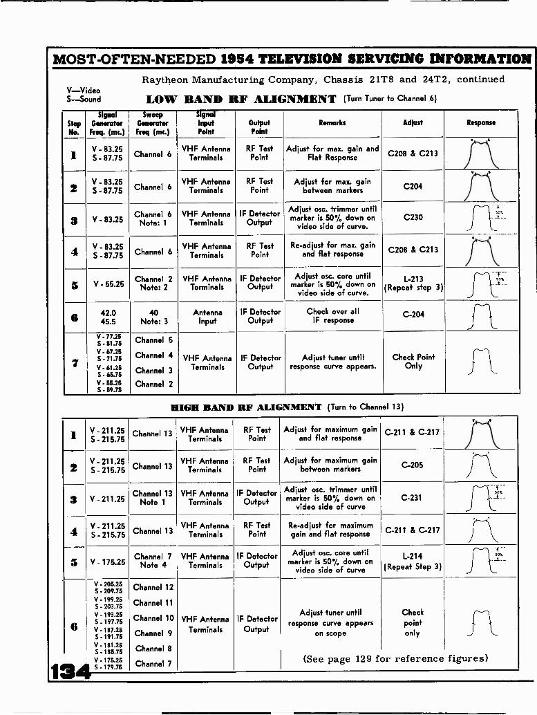
MOST -OFTEN -NEEDED 1954 TELEVISION SERVICING INFORMATIONRaytheon Manufacturing Company, Chassis 21T8 and 24T2, continued
LOW BAND RF ALIGNMENT (Turn Tuner to Channel 6)
1
V -VideoS -Sound
StepNo.
SignalGeneratorFreq. (mc.)
SweepGeneratorFreq (mc.)
SignalInputPoint
OutputPoint
Remarks Adjust Response
I V - 83.25S - 87.75 Channel 6
VHF AntennaTerminals
RF TestPoint
Adjust for max. gain andFlat Response C208 & C213
2V - 83.25S - 87.75 Channel 6
Channel 6Note: 1
VHF AntennaTerminals
VHF AntennaTerminals
RF TestPoint
Adjust for max. gainbetween markers C204
3
4
V - 83.25
V - 83.25S - 87.75
IF DetectorOutput
Adjust osc. trimmer untilmarker is 50% down on
video side of curve.C230
-T--
J t:"-
Channel 6VHF Antenna
TerminalsRF Test
PointRe -adjust for max. gain
and flat response C208 & C213
5 V - 55.25Channel 2
Note: 2VHF Antenna
TerminalsIF Detector
OutputAdjust osc. core until
marker is 50% down onvideo side of curve.
L-213(Repeat step 3)
_..
6 42.045.5
40Note: 3
AntennaInput
IF DetectorOutput
Check over allIF response
C-204
TA_
7
V - 77.25S - 81.75V - 67.25S - 71.75
V - 61.25S - 65.75V - 55.25S - 59.75
Channel 5
Channel 4
Channel 3
Channel 2
VHF AntennaTerminals
IF DetectorOutput
Adjust tuner untilresponse curve appears.
Check PointOnly
HIGH BAND RF ALIGNMENT (Turn to Channel 13)
.' V - 211.25S - 215.75
Channel 13 VHF AntennaTerminals
RF TestPoint
Adjust for maximum gainand flat response
C-211 & C-217
ZV - 211.25S - 215.75 Channel 13
VHF AntennaTerminals
RF TestPoint
Adjust for maximum gainbetween markers C-205
3 V . 211.25Channel 13
Note 1VHF Antenna
TerminalsIF Detector
Output
Adjust osc. trimmer untilmarker is 50% down on
video side of curveC-231
50%_t__
A
`-V. 211.25VS - 215.75 Channel 13
VHF AntennaTerminals
RF TestPoint
Re -adjust for maximumgain and flat response C-211 & C-217
5 V V. 175.25Channel 7
Note 4VHF Antenna
TerminalsIF Detector
Output
Adjust osc. core untilmarker is 50% down on
video side of curve
L-214(Repeat Step 3)
T -_51--
110%
response
p2A
V - 205.25S 209.75V - 199.25S - 203.75V - 193.255.197.75V -197.25S - 191.75V - 181.25S - 185.75
V - 175.25s _ 179.75
Channel 12
Channel 11
Channel 10
Channel 9
Channel 8
Channel 7
VHF AntennaTerminals
IF DetectorOutput
Adjust tuner untilcurve appears
on scope
(See page 129 for
Checkpointonly
reference
1
figures)

MOST -OFTEN -NEEDED 1954 TELEVISION SERVICING INFORMATION
SENTINEL RADIO CORPORATION
MODELS 500, 510, 511, 512, 513, and 515.Models 532, 542. 552, 554, 562, 564, are similar to these sets in most respects.
VIDEO AMP,
STEP -3 SmC TRAPT-6
6SN7GTNORrZ
05C
3RD VIDEO I F 1ST VIDEO 1 r2.D VIDEO r
STEPS 300 410E0 IF7. 3.0MC
T.
STEP -7 2ND VIDEO 1 FT-3 45.4 MC
S'TEPI- SOUNDTARE OF COIL
T
4 5 NC SOUNDIr
6SN> GTAUDIO P
NONIZ AFCOMTROL
STEP 2 TH1111 47,000 0411RESISTOR, CONNECT vOLTMETERTO JUNCTION Or c. R-30
FOR R F ALIGNMENT ADJUSTC -S, 0-7, ARO C-12SEE STEPS 11 AND 0.
FOR R F ALIGNMENT SEE STEPSit OSCILLOSCOPE CONNECTION
ADJUST 0-111 TO ELIMINATE 40 AICLOCAL INTERFERENCE NOT USED
IN MODELS WITH UHF TUNERS.
HSTEP .0 PART OF 1ST VIDEO HSTEP N PART OF 1ST 410E0 I
I F T-2 43.7S NC T-0 44.4 MC
RATIO DET
ST P 2 SECONDARY OF-RATIO DETECTOR T.0
45 MC
STEP, TN.° IO CONNECTOOLTMETER TO JUNCTION OFR.37 ANO L.T. NOTE 3CONNECT OSCILLOSCOPE TOJUNCTION OF ROT ANT L -T.
STEPS THRU 12CONNECT3 DOLTS BUS TO JUNCTIONOF R.37 C -NI POSITIVESOX Of TTENT ToGROUNO.
L.I3
STEP 3 CONNECT SIGNAL CENCNATOR-,INITy .0CP WO CORD TO CATNOOE
OF PICTURE TUNE. IELLOIN LEA01
r-
rS1,CTI 0,,14.11.10,10 DETECTORT MC
T.0
STEP ,R P PANT Or2. 4.0.E0 1.1. T.3AT SS MC
7-13
STEP I 3 TINIV A T,000 ONSIRESISTOR, CONNECT VOLTMETERACROSS C.23.
/Th
FIG. 4
0
FIG. 5
41.25 MC
42.25 MC7.5 DB OR 80%
DOWN
STEPS I 2 CONNECT SIGNAL A tttttt OATNitu 001 MED. COMO TO JUNCTION OF
/ ANO LI3.
6BQ7A OR 6BZ7
r!!'T-ITRLP71
Circuit diagramand alignment onthe next 3 pages.
R F AMP
---
47.25 MC
45.75 MC
5D8 OR 45%DOWN
OVERALL RESPONSE CURVE
FIG. 2
PICTURE SOUND
P F OSC STRIP 1000 WOr I
14 I ---Y. 0 r ENC2E MITER 1.r. 120 NSW
.,
...I. 6I 1 6J6
:.i
i
I050 -MISER
2
T.. C-2
Ls c'I.
At WOE.c- oT-
3
§SQ
FIG. 3
.1100 Nor C -20A I
-1600 AIME C-202 1
3800 1,1 0-200 1T
90%
c
-335

MOST -OFTEN -NEEDED 1954 TELEVISION SERVICING INFORMATION
a)
cda.to00
r-4
a)
zO
UGr
U
O
O
6CB6is, VIDEO
6CB62.0 VIDEO Ir
6CL6VIDEO AMP.
6CB63.. VIDEO IF
5mmX
E 6
VIDEO If TRANS. T-5
INFO
14
!Id 5.tiL.
SEE NOTE
R F CHOKE
LITE CORTE
0a+ 4b.0
3..-0 - 4.
0 SU)
a)s.4
O
O
a)
OU
En
O
v -I
U)
a'
0
136
PHASE SPUTTER
SENTINEL RADIO CORP
Circuit Diagram forModels 500, 510, 511,512, 513, and 515.
R-82 \Mow850,000.,vERT. HOLD
STOP AT 3508
.005 MF
5v\\ 950
12BH7VERT. OSC
OUTPUT
9
0-.3 T50"..VERT, LIM.
IR-195 MFG.,-
VERT. SIZE
6BQ6GTHORIZ OUTPUT
6W4GTHOR1Z DAMPER
T. ,
50 Yi 10 MF,
FILTIIPC82

IMOST -OFTEN -NEEDED 1954 TELEVISION SERVICING INFORMATION
o
6AU65MC SOUND I.F
3
ifs
8T°
SO
O
2
6AL5RATIO OET
RATIO DE T COILT-8 + -23
10 Mr
70.w.
5;
66N7GTAUDIO AMP
3
10 Iur
IC-26
332100n. °°5 Nil/ MEG,.N 30 c-tounic CON T. Ir
6111300.n.
6W6GTAUDIO OUTPUT
SEE NOTE 2
O PIA, SPEAKERSP-
5017
R-311
2650
005 MF
100n.MAYA7
000.n. 2 2 NEG.:,
91 90
1B3GTH V RECT
MORI2. OUTPUTTRANS T -ti
22n.wvensNA
Mr 0-66
LOCALITY ADJSWITCH
swI
0
WEAK SICMEDIUM SIGSTRONG SIG
4
8
I00 O0. 2541'
2 0 6
G-72
R-7.
I MFG-,FOCUS CON T.
DEFLECTION TONET-12
I
ENT ONTOU'BANS T -I39,
120,
R ;78
R-7/
5IYF 60 tIF,
C 1113
5U4GRECTIFIER
L
FILTERCHOKE
00000'4
TO ...GT
-
100 1F 0 Mr 0r r n ro!C...
NOTES
s MODELS 500, 510, & 520 130 NOT HAVE MI, IT E CONTROL-MI-LITE CONTROL CIRCUIT ENCLOSED NT DOTTED ONESIS OMITTED.
2 MODELS SOO, 510, 13 520 DO NOT HAVE TONE CONTROL.TONE CONTROL CIRCUIT ENCLOSED I3, DOTTED LINESIS OMITTED AND CONDENSER C-30 IS CHANGED TO A.01 mr 400V.
3. R-43 (not shown) a 22,000 ohmres. added from junction ofC-31 a .005 MFD. cond. andlocality adjuster switch lead totuner AGC.
Alignment informationcontinued on next page.
137

MOST -OFTEN -NEEDED 1954 TELEVISION SERVICING INFORMATION
13
SENTINEL RATIO DETECTOR AND SOUND ALIGNMENT
StepNo.
Connect SignalG for to
Sig. Gen.Freq.
Connect Voltmeter to Miscell s Instructions Adjust
I In series with .001 Mfd.Cond. to junction ofC-97 and L -I3 terminal3 of 4th I.F. See fig. 5
4.5 MC. In series with 47,000 ohm res. acrossC-23 a 10 Mfd. cond. See fig. 5
Maintain reading on 10 volt scalecontrast at maximum.
Remove 3rd video IF tube 6CB6.
T-7 (top) and T-8(bottom) for max.
reading.See fig. 4 & 5
2 In series with .001 Mfd.Cond. to junction ofC-97 and L -I3 terminal3 of 4th I.F. See fig. 5
4.5 MC. In series with 47,000 ohm res. tojunction of R-30 and C-44.
See fig. 5
Maintain reading on 10 volt scalecontrast at maximum.
Remove 3rd video IF tube 6CB6.
T -B (lop) for zeroreading.See fig. 4
3 In series with .001 Mfd.Cond. to cathode ofpicture tube yellow
ad Sea fie 5
4.5 MC. In series with 47,00 ohm res. acrossC-23 a 10 Mfd. cond. See fig. 5
Maintain reading onlow volt scale.
Remove 3rd video IF tube 6CB6.
T-6 (top) for mini-mum reading.
See fig. 4
PICTURE I -F ALIGNMENT
4 Ungrounded convertertube (6J6) shield
44.0 MC. In series with 47,000 ohm res. tojunction of R-37 and L-7. See fig. 5
Tuner on channel 3, 3 volts biasacross C -5I positive side toground. Locality switch in strong
position. See fig. 5
1-5 (top) formaximum reading.
See fig. 4
5 Ungrounded convertertube (6J6) shield
43.0 MC. In series with 47,000 ohm res. tojunction of R-37 and L-7. See fig. 5
Tuner on channel 3, 3 volts biasacross C-51 positive side toground. Locality switch in strong
position. See fig. 5
1-4 (top) formaximum reading.
See fig. 4
6
7
Ungrounded convertertube (6J6) shield
Ungrounded convertertube (6J6) shield
41.25 MC.
45.4 MC.
In series with 47,000 ohm res. tojunction of R-37 and L-7. See fig. 5
Tuner on channel 3, 3 volts biasacross C -5I positive side toground. Locality switch in strong
position. See fig. 5Repeat Steps 5 & 6
T-4 (bottom) forminimum reading.
See fig. 5
In series with 47,000 ohm res. tojunction of R-37 and L-7. See fig. 5
Tuner on channel 3, 3 volts biasacross C -5I positive side toground. Locality switch in strong
position. See fig. 5
T-3 (top) formaximum reading.
See fig. 4
8 Ungrounded convertertube (6J6) shield
47.25 MC. In series with 47,000 ohm res. tojunction of R-37 and L-7. See fig. 5
Tuner on channel 3, 3 volts biasacross C-51 positive side toground. Locality switch in strong
position. See fig. 5Repeat Steps 7 & 8
1-3 (bottom) forminimum reading.
See fig. 5
9
10
Ungrounded convertertube (6J6) shield
44.6 MC. In series with 47,000 ohm res. tojunction of R-37 and L-7. See fig. 5
NOTE: Detune 1-2 by turning slugout as far as possible.
Tuner on channel 3, 3 volts biasacross C-51 positive side toground. Locality switch in strong
position. See fig. 5
T -I (top) formaximum reading.
See fig. 4
Ungrounded convertertube (6J6) shield
45.75MC. In series with 47,000 ohm res. tojunction of R-37 and L-7. See fig. 5
Tuner on channel 3, 3 volts biasacross C -5I positive side toground. Locality switch in strong
position. See fig. 5
1-2 (top) formaximum reading.
See fig. 4
NOTE I: For minimum buzz always adjust T-8 (top) with the sound carrier of a TV station.NOTE 2: Alternate 4.5 MC. trap alignment: Adjust 1-6 (top) for minimum 4.5 MC. beat on picture with a strong station signal.NOTE 3: For visual check of IF response curve (see fig. 2) connect signal and sweep generator to ungrounded converter tube shield (6J6).
Connect oscilloscope in series with 47,000 ohm resistor to junction of R-37 and L-7.
TUNER R.F. ALIGNMENT
StepNo.
C t MarkerGenerator to
MarkerGen. Freq.
C c t SweepGen. to
SweepGen. Chan.
ConnectOscilloscope to
Miscell s
ConnectionsAdjust
I I Loosely couple to 205.25 MC. 300 ohm an- 12 Lead extending from Tuner on channel 12 C-3, C7 and C-12 forsweep gen. leads, and
209.75 MC.tennis terminals. top of tuner. See fig. 4 3 volt bias to junc-
tion of C-51 localityswitch in strong
position.
max. response havinglinear peaks with pic-ture and sound mark -ere at 90°A, maximumresponse. See fig. 3
12 OBSERVE RESPONSE CURVE FOR ALL CHANNELS USING CORRECT FREQUENCIES AND CHANNELS.A SLIGHT COMPROMISE SHOULD BE MADE WITH C-3, C-7 and C -I2 IF MARKERS ARE BELOW 70%.
NOTE 5: FOR RF OSCILLATOR ALIGNMENT, SET FINE TUNING CONTROL IN CENTER POSITION. ADJUST INDIVIDUAL CHANNEL
TRIMMERS FOR BEST PICTURE DETAIL WITH THE PATTERNS OF A TV STATION.
tiE 6: C -I8 (See fig. 4) part of a 40 MC. tuned trap need only be adjusted when local interferences from 40 thru 45 MC. affect thepicture. Adjust C-18 for minimum 40 MC. beat on picture with a station signal. Not used in Models with UHF Tuner.

MOST -OFTEN -NEEDED 1954 TELEVISION SERVICING INFORMATION
SPARTON TELEVISIONDIVISION OF
THE SARKS-WITHINGTON COMPANY -JACKSON, MICHIGAN
Chassis 21S173A, used in Models 58112 and 5811421S214, used in Models 31322, 32324, 35342, 35343, 11322A,
11324A, 15312A, and 15314A24U174, used in Models 58112 and 5811424U213, used in Models 20312, 20313, 21322, 2132424U214, used in Models 21322A, 33322, 34324, 36342,
36343, 50312, and 50314.The chassis listed above are practically identical except for minor
circuit differences, different size and type of picture tubes, and the in-corpotation of the Kingston UHF converter. The circuit diagram on thenext two pages (over) is exact for Chassis 24U214.
MISCELLANEOUS SERVICE HINTS
Horizontal Drive Adjustments:
With 125V.A.C. line adjust vertical deflection for 10% over -scan with bestlinearity then adjust horizontal linearity control for best linearity and followwith adjustment of horizontal width control for maximum width. Adjusthorizontal hold control to its maximum counter -clockwise position. De-crease horizontal drive control resistance until the compression near thecenter of the picture disappears. Reset horizontal hold control to its mid -position.
With 117 A.C. line volts, the cathode current of the 6BQ6 must not ex-ceed 110 Ma. with zero beam current.
Horizontal Oscillator Adjustment:
With 117 A.C. line volts and the horizontal hold control set at the mid -pointof its range, adjust L-36 for synchronization with approx. zero volts fromPin 41 of V-17 to ground as measured with a vacuum tube or other high im-pedance voltmeter.
Adjustment of Anti -Pin Cushion Corrector Magnets:
These magnets are mounted on the deflection coil mounting bracket and canbe moved in and out by first loosening the mounting screws. Under certainconditions it may be necessary to form, or bend the flexible arms whichsupport the magnets. The above adjustment is made at the factory and shouldnot require re -adjustment unless the original position of the magnets is accidentlydisturbed. Adjustment can be made in the following manner:
1. With the size controls reduce the size of the raster until the sides arevisible.
2. Adjust the corrector magnets for straightest possible raster edges.Restore the picture to normal size.
Misadjustment of the corrector magnets may cause barreling, keystoningand/or poor linearity. 139

MOST -OFTEN -NEEDED 1954 TELEVISION SERVICING INFORMATION
TOP VIEW
HOR1Z OUTPU
Olk
eve 21.
11.1.WER SL. LOCW1,01,
BOTTOM VIEW
573G7 5U4G
,4!trt4: 4 01-;1,
CATS
..... R3.
3.1
65N700
POWER RAYS
650600
8SNI7. PALS
O
6V6GT
646G1
VOLTAGE TEST SPECIFICATIONS:1. All Voltages & Current measured with VHF - UHF Switch in S(:S position.2. Channel Switch Position - Channel 2-3. Line Voltage - 117 Volts A.C. No signal input applied to set.4. Brightness & Contrast Control Position - Muimum Clockwise.5. Horizontal & Vertical Hold Control Positions - Set correct position to lock In6. Width Control Position - Set for normal slae.7. Vertical Size & Linearity Control Position - Set for normal size beet linearity.6. Focus Control Position - Properly focused.S. Volume Control & Tone Control Position - Maximum Counter -Clockwise.10. Instrument (Meter) Used - (VTVM) Vacuum Tube Volt Meter.
. Unless otherwise designated all voltages measured in respect to Chassis Ground.
140
SPARTON TELEVISION SCHEMAT IC DIAGRAMCHASSIS TYPE 24U214- MODELS 2I322A , 33322 , 34324 , 36342 , 36343,
50312 1 50314
CCIAITIOL
Ra100KAAM
VI61397R.F. AMP
OSCILLATORLIME
5Y361
INTERLOCK
117 V.00 44
f?1 tiug;(314( TO CI
TO
wTO PRO
PLACIS TO MLATLRS
V26J 6J 6
OSC &MIXER
V24
V.H.F. TUNER
L-10
L -II210 1111C
fiche
U. H. F. CONV.
L -I30
8221
220 2205e Ch)
41200.
11
II
C136
V61°K- IC IAla e
aVAAAr I %.
piLo r wwL1GMT
-0 0
POWER SUPPLY
r, ri 1 F Ekt-tutiv=":1;:: elL iu6E6. __i I I
II I L __LII I
v.I I 4 4 I 43 PA
I I I I4
I I I
I
TObvI I
SaoI
I I
I
I
II
I
NomTO. points indicated by the letters A,B,C,D,E,F, 6 G are Ihe alignmenttest points referred to In the alignment procedure.(Al Pb. 5 of Vi (13115) osc. L Mixer Tube.
Apply signals tare for spot I.F. Alignment or I.F. Sweep(1) Apply eiMus 3 volts thrcugh 11011 Ohms to test terminal, located Stamen
the tubes on top of R.F. Tuner. Glee Suggested .put adapter./(C) Diode Load Resistor
Road D.C. output More for mica I.F. AlignmentCanned Prone Pen for visual I.F. Alignment.
ID) Cathode of Picture tubeRead A.C. output here for °vet, it mensal.,Read 4.5 Mc o.put here for overall oe.itivity.
(El Ratio Detector OutputRead D.C. here for alignment of sound tame -off Ira, Meer-A.13e sound.
IF) Ratio Detector Balanced outputRead D.C. here for a iignernent of egeondary of ratio del. trans.
(GI A.G.C. lineApply 4.5 volts bias here for visual check of I.F. or 0.9.11 ebb willoscope.

MOST -OFTEN -NEEDED 1954 TELEVISION SERVICING INFORMATION
1
J LV3
6CB6Ru 1ST IFAMP
R14391, RIe
R154 C2411( 5. 55
VIDEO I.F.
V96AU6
4 5 MC SOUND I FL25
SOUND I.F.
4.51.1CT-1- -
R52C52 160
V4 VS6CB6 6CB6
2ND. I.F.AMP 3RD. I.F. AMP
%29
-_-_ .__ ==:;?,-1 l'gr, hi,4000. C73
Rea
2701k
VI3 R71
6AU6SYNC. STRIPPER II -1(c
4--- 120v5
D.C.RESTORER 150
P1)32 254,
VERT. DEFL. SYSTEM
V166ALS
HORIZ. PHASE DET.
14/CA5 IR
C114
'S Zfor1005
tc
79215
4B470TASE!TIER
2W1211
8123-.0NYVv
L -I526014C
100.125V Ov.
VIO6AL5
RATIO DET.
.657 I3300vOLUIME
V66ALS
VIDEO DET.
4840
C S9
VII6AT6
AUDIO AMP.
V126V60T
Go FwR AMP
130v Rv.62
11--vWV11.1--R3/C41 1215
L-i-A 200.139 L-16
R31
VITONTRAST
R4733015
MANI
T-2OUTPUT TRANS.
GREEN
ELI -0
2500
220 v
SPEAXERPC 173000-41 10'PC63000-43 6.
310 VOLTS
V62IEP4A
PICTURE TUBE12 5.0.
2ND UrOOE
0 ORANGE
1005C42
4,1
11001.1
IF-- X!*;
VI4A VIS1200. 65N707 6V60TP -P
RED VERT. OSC.& DISC.,,:0,,,, VERT. OUTPUT vERT ONTRUT mmmmm
400v swE T-3
1 0du . .1. .00v.is EC 0
3e5 17.x15 a 215 4.75 ..---. 175v 7.011 10011R7S RSO Rai C77 yEu_01.4 f GNAT...: el D C Pi
P e Cjgm CD L -30ATcAte, Tuac ,:33. FIELD BLOCKING
05C T14.43. 0 2 291400 450..
Go Of"i., VERT.w YOKE.cool'. cu.,
P3 a3Rfl COIL ..,
611 TR 1004 i ES 560vERT.001.0 OON SCOV. SOV. 41.1 1CP SOS P-0
I= I. 69e.25 5,..'GRI-t14. EN elR
2'531:;
vERT. LIN ;OA
4' 3
VERTSIZE ft 0 5.0171 01.x00 2 R
2 T .y.- - == :.-
500. HORIZ. VI9P -P AIJTOT RANSFORMER I B.3 eT
vie T-5Ull H.V. RECT.
HORIZ. DEFL. SYSTEM
TOP GAP470R90
1750
DO NOT mEASU
va3 4
VT VS V12 V17 v-10 1-I
43CI
12 3 3 4 SrA4 2 7I
I
TATER HOOKUP 013,, I II
I
500' 3100
20 vTO 2ND. ANODE
101
3156---NVVVY.-41 V.
11104400
8101
56vP -P
Ad, Vrnent Csni OkIness.
om In I he, eNseclk,Reel L. -cults
INTERLOCK
HS. HOP 1015
OSC DRIVE
0 # QO 0 0VERT HEIGH- wiDTHLIN.
CHASSIS BACK VIEW
ERTr AL
HORIZONTAL S.N-OPF-
CHASSIS FRONT VIEW
T
AS
( TINE TUNING
CHANNELINDICATOR 141

1.11
1: V
HF
R.F
. AN
D M
IXE
R A
LIG
NM
EN
T
4la
1.Se
t sta
tion
sele
ctor
to C
hann
el 1
2.
rol
2. C
onne
ct o
scill
osco
pe th
roug
h 10
,000
ohm
s to
test
poi
nt T
(W
ire
loop
on
top
of tu
ner.
)
3.Fo
r ne
gativ
e bi
as c
onne
ct -
3 vo
lts D
C to
A.G
.C. l
ead
(whi
te c
over
ed w
ire)
fro
m tu
ner.
4. F
eed
swee
p ge
nera
tor
into
ant
enna
term
inal
s, s
wee
ping
Cha
nnel
12.
5. A
djus
t C3,
C6
and
C13
(up
righ
t scr
ews
on to
p of
tune
r) f
or f
lat t
op r
espo
nse
curv
e an
d
max
imum
gai
n. C
heck
mar
kers
on
all c
hann
els.
SPA
RT
ON
Alig
nmen
t Inf
orm
atio
n, c
ontin
ued.
VH
F O
SCIL
LA
TO
R A
LIG
NM
EN
T
1.T
urn
on s
et a
nd s
elec
t cha
nnel
to b
e vi
ewed
.
2. C
ente
r fi
ne tu
ning
con
trol
.
3.Pl
ace
a no
n in
duct
ive
scre
wdr
iver
thro
ugh
open
ing,
and
adj
ust o
scill
ator
coi
l for
bes
t
pict
ure
and
soun
d.
4. R
epea
t thi
s ad
just
men
t for
eac
h ch
anne
l tha
t can
be
view
ed in
the
area
.
X 0 02 li. 0 11 til Z
VIS
UA
L A
LIG
NM
EN
T C
HE
CK
USI
NG
SW
EE
P G
EN
ER
AT
OR
,M
AR
KE
R G
EN
ER
AT
OR
, AN
D O
SCIL
LO
SCO
PE.
A.
Adj
ust a
ll co
ntro
ls to
nor
mal
ope
ratin
g po
sitio
n. C
onne
ct th
e sw
eep
gene
rato
r to
the
grid
of V
2 (p
oint
A.)
Con
nect
a 4
.5 v
olt b
ias
batte
ry b
etw
een
poin
t G a
nd g
roun
d. (
Posi
tive
term
inal
of
batte
ry to
cha
ssis
gro
und.
)
B.
Con
nect
the
osci
llosc
ope
acro
ss R
32 (
poin
t C)
by m
eans
of
the
shie
lded
cab
le a
nd f
ilter
syst
em s
how
n be
low
.
I MG
M tll LM
',
00
el
AL
IGN
ME
NT
PR
OC
ED
UR
E U
NM
OD
UL
AT
ED
(C
W)
GE
NE
RA
TO
R M
ET
HO
DSt
ep O
ne:
SOU
ND
TR
AP
AL
IGN
ME
NT
A.
Adj
ust a
ll co
ntro
ls to
nor
mal
ope
ratin
g po
sitio
n. C
onne
ct th
e R
.F. S
igna
l Gen
erat
or to
the
grid
of
V-2
(Po
int A
.)I.
F. in
put a
dapt
er, a
s sh
own
belo
w,
R. F
. Gen
erat
or50
/Coa
x..,
500
UM
FT
oof
V2
0
Out
put
--
- -
- -
- -
It--
---.
.gr
idPo
int (
A)
50.n
.n
To
chas
sis
grou
nd
Oscilloscope
47K
r-
To Font (C)
Igh
..3
.7==7
3 vo
lt bi
as-
batte
ry
220
_J -
r_
Ii
Shielded Cable
II 1
50 uuf.
To
grou
nd
tri el L
ill
ligVert.
K
B.
Con
nect
VT
VM
acr
oss
R92
(Po
int C
.) U
se lo
w v
olts
D. C
. Sca
le.
C.
Con
nect
a 4
.5 v
olt b
ias
batte
ry b
etw
een
Poin
t G a
nd g
roun
d. (
Posi
tive
term
inal
of
batte
ryto
cha
ssis
gro
und.
)D
.Se
t R.F
. Tun
er to
cha
nnel
whi
ch g
ives
min
imum
indi
catio
n on
vol
tmet
er.
E.
Adj
ust L
12 f
or m
inim
um in
dica
tion
on v
oltm
eter
at t
he s
peci
fied
fre
quen
cy
L12
=21
.75
mc
Step
Tw
o: P
DC
IF
AL
IGN
ME
NT
Adj
ust L
11, L
19, L
14, L
15, f
or m
axim
um in
dica
tion
on v
oltm
eter
at t
he s
peci
fied
freq
uenc
y:
L11
22.5
mc
L19
25.0
mc
L14
23.8
mc
L15
28.0
mc
Step
Thr
ee: S
OU
ND
IF
AL
IGN
ME
NT
A.
Con
nect
the
R.F
. Sig
nal G
ener
ator
to P
oint
C.
B.
Inje
ct th
e 4.
5 m
c si
gnal
. (Fr
eque
ncy
accu
racy
impo
rtan
t.)C
.C
onne
ct V
TV
M f
rom
Poi
nt E
to g
roun
d. U
se -
10
volt
DC
Sca
le.
D.
Adj
ust L
25 a
nd T
1 pr
imar
y fo
r m
axim
um in
dica
tion
on v
oltm
eter
.E
.C
onne
ct V
TV
M f
rom
Poi
nt F
to g
roun
d. U
se lo
wes
t D. C
. Sca
le. A
djus
t sec
onda
ry o
f T
1fo
r ze
ro o
utpu
t, as
indi
cate
d by
vol
tmet
er. N
ote!
It is
pos
sibl
e to
pro
duce
a p
ositi
ve o
rne
gativ
e vo
ltage
indi
cate
d by
var
ying
this
adj
ustm
ent.
The
poi
nt w
here
the
volta
ge s
win
gsfr
om p
ositi
ve to
neg
ativ
e is
zer
o ou
tput
and
indi
cate
s co
rrec
t alig
nmen
t.( I
f R
atio
Det
ecto
r is
seri
ousl
y m
isal
igne
d re
peat
alig
nmen
t of
prim
ary
and
seco
ndar
y un
til n
o im
prov
emen
tca
n be
mad
e.)
F.C
onne
ct V
TV
M w
ith d
etec
tor
prob
e fr
om P
oint
D to
gro
und.
Use
low
est D
C S
cale
.G
.A
djus
t L19
for
min
imum
indi
catio
n on
vol
tmet
er.
i,Pi fIl
11
C.
Adj
ust t
he R
. F. s
wee
p ge
nera
tor
so th
at it
sw
eeps
D.
Adj
ust t
he o
scill
osco
pe s
o th
at th
e I.
F. r
espo
nse
whe
re r
otat
ion
of F
ine
Tun
ing
does
not
cha
nge
E.
Inje
ct p
rope
r m
arke
r si
gnal
s as
rec
omm
ende
d
gene
rato
r us
ed.
F.O
bser
ve th
e ba
nd w
idth
, rel
ativ
e po
sitio
n of
the
over
all
I.F.
resp
onse
cur
ve.
If n
eces
sary
, slig
htly
I.F.
coi
ls L
11, L
13, L
14, L
15, u
ntil
the
pict
ure
.T
he s
olid
cur
ve d
epic
ts th
e id
eal I
.F. r
espo
nse
perm
issa
ble
vari
atio
ns.
24 Mc.
from
app
roxi
mat
ely
20 to
30
mc.
is v
isib
le.
(Set
tune
r to
cha
nnel
obse
rved
res
pons
e.)
by m
anuf
actu
rer
of R
.F. s
wee
p
pict
ure
carr
ier,
and
fla
tnes
s of
the
vary
the
tuni
ng o
f th
e pi
ctur
e
I.F.
res
pons
e sh
own
is o
btai
ned.
whi
le th
e do
tted
curv
es s
how
25.5 Mc.
4:0 z el el
tdA
.
lig imi
CI PI X CI
ilm8 X o
vi 0
23.25 Mc.
26.25 Mc.
DP
84 11 0 X

MOST -OFTEN -NEEDED 1954 TELEVISION SERVICING INFORMATION
STEWART-WARDERTELEVISION RECEIVER MODELS
21T -9300A, 21T-9300AA, 21T -9300B, 21T -9300D,
21C -9300E, 21C -9300F, 21C-930OG, 21T -9300H,
21T-9300HA, 21C -9300K, 21C-9300KB, 21C-9300L,
21C-9300LB, 21C. -9300M, 21C-9300MB, 21C-930OP,
21T -9300R, 21T-9300RB, 21T -9300S & 21T-9300T.Series 9300 service material applicable to the above listed models is presentedon pages 143 to 152 inclusive. The main circuit diagram is on pages 144-145.Models 24C-9360, 24C-9370, 27C-9310, 27C-9350, use very similar circuits.
400
COLUE-W.17(
RBLACK -WOW(
BRED-WHaf
WIWE
AORE(M-W.M
BOTTOM VIEW OF CHASSIS SHOWINGCONNECTIONS TO RF TUNER UNIT
air
6607m 6607A m 6817 ^--TFMW
VII
DIAGRAM FOR 521068 RF TUNER
L KJ H GF EDCBA521068 R.F. TUNER UNIT
(SHOWN WITH SIDE SHIELD REMOVED)vm
616
MIRES - OSC
424 427
1.04. at."7"'?04
143

MOST -OFTEN -NEEDED 1954 TELEVISION SERVICING INFORMATION
STEWART-WARNER 21C-9300 E, F, G, K, KB, L, LB, M, MB & PMODELS 21T-9300 A, AA, B, D, H, HA, R, RB, S & T
1st & 2nd 3rdI.F. Coil I.F. Coil520977 520979 Oa, H
DENriPij'ATiON WENT 'YELLOW
AT ON '-`"98FWJ,C,
OSCILLOGRAMS
All oscillograms taken with groundlead of 'Scope connected to receiverchassis and controls set for normalreception. Power Booster control ad-justed to give 50 volts peak to peakat cathode of picture tube. Oscillo-scope vertical amplifier response wasflat to within 20% at 2 MC.
Number appearing to the left of oscil-logram specifies setting of horizontalsweep frequency control on 'Scope.
330
01
6C86ist I F AM"
JO
A
00 1?!,
rI6C86
*vitt AMP
33
"IS
OV
o
6C86As I.F.ALP.
ml, 2
0
17
5U46
..e.
33646 86
444 v 31
os
A 6
68E6 VIAGATED SYNC '/2126'/2126011 2,,SEPARATOR SYNC. AMP
1°3
3
11
:41
u
VOLTAGE MEASUREMENTSAll voltages measured with a 20,000 Ohm per volt meterwith the receiver connected to a 117 volt 60 cycle powersupply.Tuner set to an inactive channel with antenna terminalsshorted and connected to ground.Controls set for normal reception - Power Booster controlcompletely counterclockwise.Voltages marked with an asterisk (*) will vary widely withcontrol settings.
PRODUCTION CHANGES - ContinuedLETTERDESIGNATION
144
DESCRIPTION OF CHANGE
The following changes were incorporated to improve the video response.1. Change peaking coil 51 in plate circuit of tube V4 (Video Amp.) from
part 520984 to 520689.2. Change resistor 52 in parallel with peaking coil 51 from 15,000 Ohms
to 12,000 Ohms.3. Change peaking coil 53 in plate circuit of tube V4 (Video Amp.) from
part 520986 to part 509342.4. Change resistor 54 in plate circuit of tube V4 (Video Amp.) from 3900
Ohms to 2200 Ohms.5. Change resistor 55 in plate circuit of tube V4 (Video Amp.) from 1500
Ohms to 1800 Ohms.
1/13
6686SOUND I F AMP
LIMITER.
3
1_ _
l's
VII A
1/2618'SOUND DISCRIMINATOR
SOUND AMP
133 v

9 5,
--I P"1G n4 111..P
so 52'.L;
VII
'/,618
G C CLAMP
54
MOST -OFTEN -NEEDED 1954 TELEVISION SERVICING INFORMATION
1
5=
NJ'
Vi6SNIGT
NOW A I C
Stewart -Warner Series 21C9300 and 21T9300 Receivers
12617.VITRO AV/P
AllY26900
HDRI/BLOCAING 26OSCILLATOR
VIS
6A05
SUING OUTPUT
Is,
95
6AWAm-kcc
RR
Is 2
110
6606 CT
HORIZONTAL
SCANNING OUTPUT
. VG.
HOLD.ToIRS
!fr.'189*
CLTRIa
12.6.
69
15000 16(55
2164NPICTURE TUN
-11;;
VAT umuMGT HOPI/IONIC w.oTH
NEGINRWM DAMPINGWWIER
V /9
1/212807'WART BLOCKING
OSCILLATOR
RIG
6AH4G7VERTICAL
SCANNING OUTPUT
iiIOU00044g
flA'KAL 004 44(5.0..
s
145

MOST -OFTEN -NEEDED 1954 TELEVISION SERVICING INFORMATION
Stewart -Warner Television ReceiversSeries 21C9300 and 21T9300, continued
PRODUCTION CHANGESThe following tabulation furnishes complete details on changes which occurred duringproduction. The receivers incorporating these changes ore identified by coding stampedsurface of chassis. The coding consists of one or more letters following the word SESERIES B, SERIES AC, etc., and corresponds to similarly lettered changes shown below.incorporate only that change indicated by letter designation; i.e., chassis stamped "SEdoes not include changes "A" or "C" or "13".
The circuit shown on this page appliesto "SERIES ABCDEFGHJKLMPORST" chassis.
A letter following the component circuit diagram number thus -201 0, indicates that thisparticular item was affected by a circuit change. The letter corresponds to the series code letterlisted in the production change column, from which complete change information can beobtained.
LETTERDESIGNATION
DESCRIPTION OF CHANGE
UNCODED INITIAL PRODUCTIONThe following change was incorporated to maintain a better balance offilament voltage on the tubes connected across the 12.6 volt transformerfilament winding in the event of tube failure or removal from the socket.1. The center tap of the 12.6 filament winding on power transformer 76
is connected to ground through the common red and yellow lead. Trans-formers not having this modification have a red identification dot onthe bottom side.
The following changes were incorporated to improve focus at high bright-ness levels.1. Change resistor 63, connected from one end of the Brightness control
from 15,000 Ohms to 22,000 Ohms.2. Disconnect pin 6 of picture tube, V17, from the 270 volt supply and
connect to chassis ground.3. Disconnect phono terminal of switch 66A from the 320 volt supply and
connect to the 120 volt supply.
"C" The following changes were incorporated to increase horizontal sync. stabilityon strong signal levels.1. Change connection of condenser 107 (100 Mmfd.) in grid circuit of V8A
(Horiz. A.F.C.) from junction of resistors 105 and 106 to the plate(pin 6) of V7A (12AT7-Sync. Amplifier).
2. Change resistor 124 in plate circuit of V8A (Horiz. A.F.C.) from 100,000Ohms to 120,000 Ohms.
3. Change resistor 97 in grid circuit of V6 (Gated Sync. Separator) from1.2 Meg. to 820,000 Ohms.tv, The following changes were incorporated to extend range of width control.
1. Change resistor 84 at output of V12 (Rectifier) from 100 Ohms to 50Ohms.
2. Add resistor 138 (47,000 Ohms) in parallel with resistor 139 (12,000Ohms) located in screen circuit of V9 (Horiz. Scanning Output).
O'F''
The following change was incorporated to facilitate production techniques.1. Two interconnecting sockets and plugs were added in the chassis.The following change was incorporated tominimize the possigni774c717777horizontal holding action when changing channels.1. Add condenser 45 (5000 Mmfd.) between resistor 44 (47,000 Ohms) and
pin 1 of tube V6 (Gated Sync. Separator). NOTE When undertakingthis modification be sure that the SERIES "C" is also incorporated.
The following changes were incorporated to minimize hum and buzz in audiosystem.1. Add resistor 92 (1500 Ohms) and resistor 93 (15,000 Ohms) in series
between the 120 volt supply and the 270 volt supply. The junction ofthese two resistors, 92 and 93, provides the 135 volt supply.
2. Relocate condenser 85C (40 Mfd.) from the 270 volt supply to the 135volt supply and add condenser 91 (4 Mfd.) to the 270 volt supply inthe position formerly occupied by condenser 85C.
3. Disconnect pins 2 and 7 of tube V5 (Keyer-A.G.C.) from the 120 voltsupply and connect to the 135 volt supply.
4. Disconnect resistor 97 (820,000 Ohms) in grid circuit of V6 (Gated Sync.Separator) from the 120 volt supply and connect to the 135 volt supply.
5. Disconnect resistor 104 (1 Meg.) in grid circuit of V7A (12AT7-Sync.Amplifier) from the 120 volt supply and connect to the 135 volt supply.
6. Disconnect pin 8, cathode of V7A (12AT7-Sync. Amplifier) from the 120volt supply and connect to the 135 volt supply.
7. Disconnect pin 6, screen, of tube V5 (Keyer-A.G.C.) from the 270 voltsupply and connect to the 285 volt supply.
8. Remove resistor 105 (3300 Ohms) in plate circuit of tube V7A (12AT7-Sync. Amplifier) and change resistor 106 from 3300 Ohms to 6800 Ohms.
The following changes were incorporated to meet an U.L. requirement.1. Add resistor 145 (1 Meg.) in high voltage supply to the picture tube.
This resistor is located in the shield of the 1B3GT socket.The following changes were incorporated to reduce the amount of undesiredvideo signal present in the sync. puke.1. Change resistor 100 in plate circuit of V6 (Gated Sync. Separator) from
330,000 Ohms to 220,000 Ohms.2. Change resistor 102 in plate circuit of V6 (Gated Sync. Separator) from
12,000 Ohms to 6800 Ohms."G. The following change was incorporated to improve the shape of the sync.
pulse.1. Change resistor 102, in plate circuit of V6 (Gated Sync. Separator), to
18,000 Ohms. Chassis that have the letter "F" in the series designationwere produced with a 6800 Ohm resistor. Chassis that do not have theletter "F" in the series designation were produced with a 12,000 Ohmresistor.
,,w, TFe following change was incorporated to minimize horizontal oscillator driftthus improving Horizontal Hold action:1. Change condenser 131 in plate circuit of V8B (Horz. Blocking Osc.) from a
ceramic type, 820 Mmfd. ±10%, 400 volt to a mica type, 820 Mmfd.±5%, 500 volt.
Ili II
146The following changes were incorporated to provide for the use of analternate type tube.1. Change V7A (Sync. Amp.) and V78 (Vert. Blocking Oscillator) from a
type 12107 to a type 12AU7 tube.Change condenser 71 in grid circuit of tube V17 from 5000Mmfd. to 03 Mfd.
receiveron rear
RIES, asChassis
IES BE"
LETTERDESIGNATION
DESCRIPTION OF CHANGE
"K" The following changes were incorpo-rated to provide for the use of analternate type tube.1. Change V4 (Video Amp.) from a
type 6CL6 to a type 12BY7 tube.2. The circuit for tube V4-6CL6 (Video
Amp.) is shown at the right:
14
6CL6VIDEO A.
"L" The following change was incorporated to improve focus.1. Disconnect pin 6, focusing grid of V17 (Picture tube), from ground and
connect to 270 volt supply.
The following changes were incorporated to meet on U.L. requirement.1. Remove condensers 73 and 74 (.01 Mfd.) from each leg of the A.C. input.2. Add resistor 201 (150,000 Ohms) to the switch leg of the A.C. input.Chassis having this change do not incorporate o Phono Switch (66-A, B) nor aPhono Input Socket.
"P" The following changes were incorporated to improve the picture quality.1. Change resistor 30 in plate circuit of tube V2 (2nd I.F.) from 15,000
Ohms to 5600 Ohms.2. Alignment frequencies of the I.F. system are as follows:
Converter Plate coil: 23.5 Mc. 2nd I.F. coil: 25.9 Mc.1st I.F. coil: 23.5 Mc. 3rd I.F. coil: 25.9 Mc.
The following changes were incorporated to extend the useful range of theHorizontal Hold control.1. Change Horizontal Range 108-A control in the grid circuit of V8A (Hori-
zontal A.F.C.) from a variable condenser (10-160 Mmfd.) to a fixed con-denser 218 (47 Mmfd.).
2. Change resistor 113 in grid circuit of tube V8A 'Horizontal A.F.C.) from150,000 Ohms to 220,000 Ohms.
3. Change resistor 114 in grid circuit of tube V8A (Horizontal A.F.C.) from330,000 Ohms to 1 Meg.
4. Add resistor 212 (150,000 Ohms) from the junction of condenser 109 (47Mmfd.) and resistor 114 (1 Meg.) to chassis ground.
5. Remove resistor 133 (10,000 Ohms) in grid circuit of tube V9 (HorizontalScanning Output) and replace with condenser 133 (270 Mmfd.).
6. Change resistor 97 in grid circuit of tube V6 (Gated Sync. Separator) from820,000 Ohms to 1.5 Meg.
7. The plate load resistor of tube V7A (Sync. Amp.) differs with variousseries type chassis. Before undertaking the change listed below, checkthe series type chassis and incorporate only the applicable portion.a. On chassis that incorporate a letter "1" in the series designation,
change resistor 106 from 10,000 Ohms to 4700 Ohms and odd resistor105 (4700 Ohms) in series with resistor 106 and plate of tube V7A.Resistor 182 (18,000 Ohms) remains connected to the plate of tubeV7A-12AU7 while condenser 107 (100 Mmfd.) is reconnected to thejunction of resistors 105 and 106.
b. On chassis that incorporate a letter "f" but does not include the letter"1" in the series designation, change resistor 106 from 6800 Ohms to3300 Ohms and add resistor 105 (3300 Ohms) in series with resistor106 and plate of tube V7A. Resistor 182 (18,000 Ohms) remains con-nected to the plate of tube V7A-12AT7 while condenser 107 (100Mmfd.) is still connected to the junction of resistor 105 and 106.
C. On chassis that do not incorporate letters "F" and "1" this step (#7)need not be undertaken when incorporating the "0" change.
In addition to the above changes the Syncroguide transformer must be re-adjusted in accordance with the procedure (for a Series "0" chassis) givenin the service data section of the manual.The following changes were incorporated to improve the blanking duringhorizontal retrace interval.1. Add resistor 213 (150,000 Ohms) between cathode of tube V9 (Horizontal
Scanning Output) and the grid circuit of tube V17 (Picture Tube).2. Add resistor 214 (1 Meg.) between pin 1 of the horizontal output trans-
former and grid circuit of tube V17 (Picture Tube).3. Add resistor 215 (56,000 Ohms) from the junction of resistors 213 and 214
to chassis ground.4. Add condenser 216 (100 Mmfd.) from the junction of resistors 213 and 214
to the grid of tube V17 (Picture Tube).The following change was incorporated to reduce illumination of picture tubewith minimum setting of the Brightness Control.1. Change resistor 68 in the brightness circuit from 470,000 Ohms to 330,000
Ohms.The following change was incorporated to prevent the A.G.C. voltage fromgoing positive.I. Add V14B (6T8-A.G.C. Clamp) by connecting diode plate pin 6 of
tube V14 -6T8 to A.G.C. system.
"R" The following change was incorporated to minimize frequency drift in thesyncroguide circuit.1. Change condenser 130 from a .01 Mfd. to a .01 Mfd. (Special charac-
teristic) Stewart -Warner part 512311 only.
"5" The following changes were incorpor-ated to improve the useful range ofthe Power Booster control.7. Change connection of Brightness
control 67A associated circuit fromcathode of tube V17 (Picture tube)to grid of the some tube. TheBrightness circuit for chassis thatdo not incorporate the letter "5"is shown at the right:
2. Add resistor 219 (470,000 Ohms)in parallel with condenser 62 (.1Mfd.) located in cathode circuitof tube V17 (Picture tube).
3. Change resistor 70 in plate circuitof tube V7B (Vert. Blocking Osc.) from 100,000 Ohms to 47,000 Ohmsand add condenser 210 (.1 Mfd.) in series with resistor 70. Connectother end of condenser 210 to the junction of condenser 190 (.047 Mfd.)and resistor 191 (8200 Ohms).

MOST -OFTEN -NEEDED 1954 TELEVISION SERVICING INFORMATIONStewart -Warner Series 21C9300 and 21T9300 Receivers, continued
ALIGNMENT PROCEDUREThe receiver chassis must be removed from the cabinet in order to ac-complish alignment of all tuned circuits.
Alignment of oll RF and IF tuned circuits in this receiver may be ac-complished by utilizing the procedures described in the following charts.
These procedures should preferably be applied in the order in which theyare presented. Alignment of Sound Channel of IF Channel may be ac-complished individually if desired.
The RF Amplifier and Mixer alignment may also be occomolished inde-pendent of Sound or IF Channel alignment, but oscillator calibration canonly be done after IF Channel has been correctly aligned.
CAUTION
The picture tube is highly evacuated andif broken fragments will be violently ex-pelled. Handle with care. Avoid contactwith metal shell of picture tube as this ispart of the high voltage circuit.
INSTRUMENTS: The following instruments will be required as signalsources and output indicators during the alignment process. Since accuratealignment of a television receiver is heavily dependent upon the perform-ance of your instruments, it is imperative that they meet the essentialspecifications described here.
SOUND CHANNEL
1. STANDARD SIGNAL GENERATOR to provide unmodulated (pureRF) signals at the following frequencies. Maximum output on allranges should be at least .1 volt with provision for attenuation asdesired. This instrument must have good frequency stability and beaccurately calibrated.
a. IF Frequencies:4.5 Mc. Sound Channel21.5 Mc. to 26.6 Mc. IF Channel
b. RF frequencies:54 to 88 Mc.174 to 216 Mc.
2. VACUUM TUBE VOLTMETER. The lowest voltage range of this in-strument should preferably permit a 1.0 volt reading to be indicatedat not less than one third of full scale deflection.
3. RF SWEEP GENERATOR to provide frequency modulated signal forobserving the over-all bandpass characteristic and RF Channel align-ment at the following frequencies:
20 to 30 Mc. with 10 Mc. sweep width.54 to 88 Mc. with 10 Mc. sweep width.174 to 216 Mc. with 10 Mc. sweep width.
4 CATHODE RAY OSCILLOSCOPE, preferably a unit with verticalamplifier having wide range frequency response and low capacitypick-up probe. This instrument is used for observing the over-all band-pass characteristic and for RF Channel alignment.
ALIGNMENT PROCEDURE1. Short antenna terminals together with a jumper wire.2. Set receiver Channel Selector to any inactive television channel and
Power Booster control to its maximum counter -clockwise position; othercontrols may be left at any desired setting.
3. A small screwdriver (preferably non-metallic) con be used for align-
ment of Sound IF. The blade of this tool will fit the slot in the core
of the transformer.
STANDARD SIGNALGENERATOR VTVM
CONNECTIONSMISCELLANEOUSINSTRUCTIONS
TRIMMEROR SLUG
TYPE OF ADJUSTMENTAND OUTPUT INDICATIONCONNEC-
TIONS FREQUENCY
Connect as shownin Fig. 1.
4.5 MC.unrnodulated
IMPORTANTThis signal mustbe accurate with-in 1/4 of 1F`io of4.5 Mc. Checkgenerator calibra-ciao against acrystal controlledsignal source by"zero beating"(heterodyning)with harmonicsof the crystal fro.quency.
Connect as shown inFig. 2.
1 Set Power Booster control to its maxi-mum clockwise position.
2. A special detector must be utilized whenaligning the 4.5 Mc. Sound Trcp Coil.This unit can be constructed in ac -cordance with the information con -rained in Fig. 3. If a VTVM containinga high frequency A.C. probe is avail-able, this probe can be utilized inplace of the crystal detector shown inFig. 2
3. During this adjustment only, removeone of the three 6CB6 IF amplifiertubes (V1, V2 or V3). This will preventnoise in the RF stages from effectingthe voltage reading while adjusting thesound trap.
# 14.5 MC Sound
Trap(See Fig. 10)
Adjust for minimum readingon VTVM.
Same asabove
Same asabove. Connect as shown in
Fig. 4.
A "swishing" sound may be heard in thespeaker during Sound Channel Alignment.This spurious oscillation is caused by hori-zontol sweep voltage being picked up inthe audio system thru stray coupling ofinstrument leads; it should be disregardedas it will have no effect on alignment ofthe sound channel.
Di#i2minatorscrSecondary
(See Fig. 10)
Adjust for maximum readingon VTVM.
#3Discriminator
Primary(See Fig. 11)
ax imuAdjust for m m readingon VTVM.
ndSou4 IFTransformer(See Fig. 10)
Adjust for maximum readingon VTVM.
Same asabove.
Some asabove.
Connect as elsown inFig. 5,
To obtain zero balance of the discriminatorcircuit, two 68,000 ohm resistors will berequired. These resistors must be matchedso that their respective resistances donot differ by more than 1%-the accu-racy of the total resistance is not critical.Connect the two resistors in series frompin 2 of the 6T8 tube to chassis groundas shown in Fig. 5.
#2Discriminator
Secondary(See Fig. 10)
Note that as slug #2 is rotated,a point will be found where thevoltmeter will swing rather sharp..Iv from a positive to a negativeregding or vice versa. The cor.rest setting of slug #2 is obtainedwhen the meter reads zero asthe slug is moved thru this point.
Replace the type 6CB6 tube previously removed in the above procedure and turn set on. Tune 'n to a local channel and should there be anamount of "Intercarrier Buzz" refer to procedure on adjoining page to remove this aforementioned fault.

MOST -OFTEN -NEEDED 1954 TELEVISION SERVICING INFORMATION
Stewart -Warner Series 21C9300 and 21T9300 Receivers, continued
INSTRUMENT CONNECTIONS FOR SOUND CHANNEL ALIGNMENT
STANDARD
SIGNAL GEN.
SET TO 4.5 MC.
NO MODULATION
PURE R.F. 1000MM F.
GROUND TORECEIVER CHASSIS
V4
VI4
VICKOANW 616
46
PCABOOSTER
(Refer to circuit diagram page for tube typeand pin connections.)
FIG. 1
Generator Connectionsfor Sound Channel and 4.5 Mc. Sound Trap
Alignment
VI/
2IMP4MIME TUDI
CRYSTALDETECTOR
V.T.V.M.
+GROUND TO I 1RECEIVER CHASSIS
FIG. 2Crystal Detector and VTVM Connections
for 4.5 Mc. Sound TrapAlignment
148
100MMF. 47K
FIG. 3Circuit Diagram for
Crystal Detector shown in Fig. 2
SOUND DISCRIMINATORSOUND AMP
Ise
O
USE 10,000 OHMISOLATING RESISTOR
IN SERIES WITHMETER PROBE
GROUND TOFIG. 4 RECEIVER CHASSIS
VTVM Connectionsfor Sound IF Alignment
V14
618SOUNC DISCRIMINATOR
SOUND AWP
'6
01V
5
3
USE 10,000 OHMISOLATING RESISTOR
IN SERIES WITHMETER PROBE
66K
66K
FIG. 5VTVM Connections
for Sound DiscriminatorAlignment
REDUCTION OF INTERCARRIER BUZZUnder actual reception conditions slight "dynamic" unbalance of the dis-criminator secondary can emphasize intercarrier buzz due to incompleteamplitude modulation rejection. Therefore it is vitally important to obtainan accurate setting of the discriminator secondary slug under these con-ditions.
Disconnect all instruments (Fe sure that I.F. tube removed for the adjust-ment of Sound Trap has been replaced) and then connect an antenna tothe receiver to obtain program reception from a local station. If inter -carrier buzz is prominent, a slight readjustment of the discriminatorsecondary slug (#2) should be made to obtain the "dip" point for thebuzzing sound. Note that program sound will be clear and free fromdistortion at this point. Buzz should now be at an acceptable minimumif station transmission is not at fault.

MOST -OFTEN -NEEDED 1954 TELEVISION SERVICING INFORMATIONStewart -Warner IF CHANNEL ALIGNMENT PROCEDURE (Continued)
1. A special aligning tool designed to fit the stems on adjustable cares ofthe IF coils (see points 5, 6, 7 and 8 in Fig. 10) is available and maybe obtained from Stewart -Warner by requesting IF Alignment Tool#507479.
2. Turn receiver Channel Selector to television channel #12 and shortantenna terminals together with a jumper wire.
3. Connect a 3 volt battery to the receiver AGC system so that negativeterminal of battery connects to the AGC line and positive terminal ofbarery connects to receiver chassis. See Fig. 11 for convenient point ofconnection.
A. If the IF channel is badly misaligned and two or more immediately ad-joining IF stages are tuned to the same frequency, oscillation may oc-cur. Such oscillation shows up as an excessive voltage across thevideo detector load, circuit reference number 42 and 43, and is indi-cated by the VTVM that is connected to this point during alignment.It should be noted that voltage due to IF oscillation is unaffected by
strength of signal from the generator.
Where IF oscillation is encountered, it is generally possible to correctthe condition by detuning the IF coils in different directions. If thatdoes not have the desired effect, increase fixed bias on AGC line byusing a 41/2 volt battery instead of the 3 volt battery referred to ininstruction #3. After stopping the oscillation in this manner it willthen be possible to align all IF stages using the following procedure,however, the AGC bias battery must be changed back to 3 volts whenusing the oscilloscope to observe band pass characteristics. Once allstages have been aligned using the 41/2 volt bias, the IF channelshould be stable with reduced bias.
5. In order to eliminate the possibility of spurious oscillations, it is de.sirable to render the RF oscillator inoperative. This may be readilyaccomplished by insulating oscillator terminals of tuner. Remove tunerbottom shield and place a piece of transparent cellulose tape on thefirst two contacts (from front) of drum assembly. Use any inoperativechannel and rotate drum to this insulated position.
STANDARD SIGNALGENERATOR
SWEEP GENERATOR VTVMCONNEC-
TIONS
'SCOPECONNEC-
TIONS
MI SCELLANEOUSINSTRUCTIONS
TRIMMEROR SLUG
TYPE OF ADJUST-MfNT AND OUTPUT
INDICATIONCONNEC-TIONS FREQUENCY CONNEC-
TIONSFREQ.
Connect asshown in
23.4 MC.OR
Below
Connect as
Fig. 9.
Be sure that 'RF os-cillator has beenrendered inopera-
#5 atthethee head of thischart.
#5Converter
latecoil
(See Fig. 10)
Adjust for maximumreading on VTVM.
Some asabove.
24.2 MC.OR
23.5 MC.See Note "P"
Below
Not used. Sam. asabove. Not used. Same as
above.
#61st I.F.
(See Fig. 10)
Adjust for maximumreading on VTVM.
Same asabove. OR
25.9 MC.Se. Note "P"
Not used. Same asabove. Not used. Same as
above.#7
2nd I.F.(See Fig. 10)
Adjust for maximumreading on VTVM.
Same asabove.
25.4 MC.OR
25.9 MC.See Not* "P"
Not used.Same asabove. Not used. Same as
above.
# 83rd I.F.
(See Fig. 10)
Adjust for maximumreading on VTVM.r
Connect asshown inFig. 8.
26.6OR
26 MC.Se Note "F"
Below
Connect asshown in
Fig. 8.
25 MC.swooping-±- 5 Mc.
Same asabove.
Connect asshown in Fig. 9
IMPORTANT:
1. Adjust output at.tnuator onsweep generatorso that readingon VTVM Is ap-proximately one-half volt.
2. S e t attenuatoron standard sig-nal generator sothat marker sig-nal does net dig-tort the patternon the oscilla-scope.
3. B. sure that a3 volt battery Isconnected to AGCline as specifiedin instruction #3at the head ofthis chart. Do notuse a battery ofany other volt-age.
The I.F. bandpassby the useshould comparepicture carrierthat incorporateat rear ofamplitude
2 0 -,-
4 0 --
60
80-100-X ,
Should thiments, therepeated,of the markerformer slugsfrequencies.
characteristic can now be observedof a 'scope. Its general shape and contour
with the curve shown in Fig. 6. Themarker (26.6 Mc. or 26 Mc. on Chassis
a letter "P" in the series designationchassis) should appear at the 50% 1±10%)position of the curve as shown in Fig. 6.
EACH DIVISION= I MC.
SOUNDMARKER
-
observationcomplete
exercisinggenerator
for
I I I I f I I +-l
SOX
PICTUREMARKER
I . F.
RESPONSEFIG. 6 CURVEfail to meet the above require -
I.F. alignment procedure must begreater care in frequency setting
and adjusting the I.F. trans-maximum output at the prescribed
Some asabove.
22.1OR
21.5 MC.See Note "P"
Below
Same asabove.
Same asabove.
some asabove.
Same asabove.
Same a sabove.
The sound carrier marker (22.1 Mc. or 21.5 Mc. onchassis that incorporate a letter "P" in the series &silo -nation at rear of chassis) can be observed by the useof a 'scope and should be compared with that shownin Fig. 6. Increase the vertical gain control on 'scopein order to magnify the sound portion of the responsecurve. This marker should appear at the position indi-cated in fig. 6. Should the sound marker not be prop -erly positioned, check the setting of the picture carriermarker as indicated in the previous step.
NOTE "P": On chassis which have a letter "P" in the SERIES designation on rear o chassis, the converter Plate and 1st I.F. coils mustbe aligned to 23.5 Mc. and the 2nd I.F. and 3rd I.F. coils must be aligned to 25.9 Mc. The carrier markers on this seriestype chassis are: picture carrier 26 Mc., sound carrier 21.5 Mc. 149

RA SE TUBESH ELD TOISOLATE ITFROM BASE
FIG. 7Generator Connections
for IF Channel Alignment
MOST -OFTEN -NEEDED 1954 TELEVISION SERVICING INFORMATIONStewart -Warner Series 21C9300 and 21T9300 Receivers, continued
INSTRUMENT CONNECTIONS FOR IF CHANNEL ALIGNMENT
SOLDER PIGTAILFOR GENERATOR
CONNECTION
GROUND TOTUNER FRAME
STANDARD
SIGNAL GEN.(SUPPLIES
MARKER SIGNAL)
GROUND TORECEIVERCHASSIS
SOLDER PIGTAIL FORGENERATOR CONNECTION
RAISE TUBESHIELD TOISOLATE IT
FROM BASE
ROUND TOTUNER FRAME
FIG. 8Generator Connections
for IF Channel Alignment
S
3
43
PLACE 1000 MMFDCONDENSER ACROSS
'SCOPE TERMINALSAS AN R.F. FILTER
GROUND TORECEIVERCHASSIS
USE 10,000 OHMISOLATING RESISTOR
IN SERIES WITH METERAND OSCILLOSCOPE PROBES
FIG. 9
1 5 0 VTVMfoarndIF Oscilloscope Connections
SAXER ONIO
AI ANDKATI TANANA
Af AMPONO /NYASA
ANDSEE CANNFOR TRIO
'11".AillrOA FINO
3. I MISIC CASON10A MO
SOUND Ir ANNIS NC.
SOUND TRAPINC
ION
FIG. 10Top View of Chassis
FIG. 11Bottom View of Chassis

MOST -OFTEN -NEEDED 1954 TELEVISION SERVICING INFORMATIONStewart -Warner Series 21C9300 and 21T9300 Receivers, continued
RF CHANNEL ALIGNMENT PROCEDURE1. CAUTION: The shell of the picture tube has a high voltage potential,
approximately 14,000 volts, and contact should be avoided. As theadjustment screws are in relatively close proximity to this shell, somemeans of insulation from accidental contact should be provided.
2. Connect a 3 volt battery to the receiver AGC system so that negativeterminal o' battery connects to AGC line and positive terminal of bat-tery connects to receiver chassis. (See Fig. 11 for convenient pointof connection.)
STANDARD SIGNALGENERATOR
SWEEP GENERATOR VTVMCONNEC-MISCELLANEOUS
TIONS
SCOPECONNEC-
TIONS INSTRUCTIONSTRIMMEROR SLUG
TYPE Of ADJUST-MENT AND OUTPUT
INDICATIONCONNEC-TIONS FREQUENCY
CONNEC-TIONS FREQ.
RF AMPLIFIER AND MIXER ALIGNMENT
Connect asshown inFig_ 12.
209.75 MC.Sound Carrier205.25 MC.
Picture Carri-er Marker.
Connect asshown Fig.12 a nodd setcontrols forsweep widthof 10 Mc. ont e I e v i -
s i o n channelspecified inthe next col-umn.
CHANNEL1:12 Not used.
Connect asshown inFig. 13.
forSet Chan
#12.ne Selec-
to44-9it -
mixer Grid,(See Fig. 19)
"4"''(10RF A ma.
Plate,:See Fig. 19)
44' 1 I-,RF Amp.
(See Fig. 19)
Adjust these trimmers to obtain proper-ly shaped RF band pass characteristic asshown in Fig. 16. Use Mixer Grid trim -mer #9, and RF Amplifier Plate trimmer#10 to obtain correct amplitude of char -acteristic in vicinity of picture and soundcarrier markers. Then adjust RF Amp.Grid trimmer #11 t equalizeo o verallamplitude. Repeat adjustment of trim -risers to be sure correct response hasbeen obtained.
IMPORTANT: When adjusting trimmers#9, 10 and 11 it will be noted that theband pass characteristic con be broad -ened by sacrificing amplitude. It is un-desirable to overly broaden the curve asthat would result in a loss of sensitivity.
IMPORTANT(Keep output of
(standard s i n a Iggenerator a1 a levelthat prov desareadable m ark e rbut does not distortthe curve that is be-ing observed on thescope.
Same asabove
'
The bandpasscharac-teristic foreach of theSUCCes-sive channelsshould nowbe observedindivid-ually. For fre-quency settingof marker sig-sots see tablein Fig. 15.
Same asabove.
Set sweepgener-a t o r toc h a n -
net fire-q u e n -cies beingobserved.
Not used. Same asabove.characteristicSet channel selectorto channel beingobserved.
The RF band pass characteristic of the other televisionchannels should now be checked without disturbing thesettings of trimmers #9, 10 and 11. Adjust the RFsweep generator and marker generator for operation onthe other television channels, observing position of boththe sound carrier and picture carrier mark ers. Band pass
of these channels should conform close tothe RF response curve in Fig. 16. If necessary, a com-promise may be obtained to compensate for large varia-tions in channel response by returning to channel #12and making slight changes in the settings of trimmers#9, 10 and 11.
OSCILLATOR ALIGNMENT1. IMPORTANT: Before undertaking oscillator alignment be sure IF 3. During this step and thru-out all succeeding steps it is necessary to:
circuits are correctly aligned for band pass characteristic illustrated keep output of sweep generator at a level that does not allow readingin Fig. 6. on VTVM to exceed one-half volt.
2. During oscillator alignment, it is necessary to set the Fine Tuning 4. Keep output of standard signal generator at a level that provides acontrol so that the tooth on the fiber fine tuning cam points downward readable marker but does not distort the curve that is being observed(correct position for this control is shown in Fig. 18). on the 'scope.
Connect asshown inFig. 12.
209.75 MC.Sound Carrier
Marker.
205.25 MC.Picture Carri-er Marker.
Connect asshown in Fig.12 a n d setcontrols forsweep widthof 10 Mc. ont e I e v i -
s i o n channelspecified inthe next col-umn.
CHANNEL#12
Connect asshown inFig. 14.
Connect asshown inFig. 13.
Set ChannelSelector to
#12
Be sure that gener-ator's output doesnot exceed volt egspecified it instr uc -tions #3 and 4above.
Using a non-metallic screwdriver to adjust channel .#12oscillator slug (accessible thru hole on front of RFTuner Unit-see Fig. 181 shift response curve so thatpicture carrier marker is located at the position indicatedin Fig: 17.
NOTE: Before making the following adjustment, ad -vance the vertical gain control on the 'scope in order tomagnify the sound portion of the response curve.
Observe position of sound carrier marker (see Fig. 17).
Same asabove.
The bandpasscharac-teristic foreach of theswiss-rive channelsshould nowbe observedindivid-wally. For fre-quency settingof marker sig-nals see tablein Fig. 15.
Some asabove.
Set sweepgener-ator toc h a n -
nil fire-q u e n -
cies beingobserved.
Same asabove.
Some asabove
(
Set channel selectorto channel beingobserved.
Adjust the RF sweep generator and marker generatorfor operation on the other television channels; set mark-er generator to sound carrier frequency. After settingChannel Selector to corresponding channel, adjust ascii-lator slug thru hole on front of RF Tuner Unit (see Fig.18). This permits response curve to be shifted so thatpicture and sound carrier markers will appear at theposition indicated in Fig. 17. The picture carrier markerfor the corresponding channel should thenappear atthe 50°,(,, amplitude position on the opposite side of theband pass characteristic curve.
NOTE: Make sure that cam on fine tuning control shaftremains properly positioned during this step (tooth onthe cam pointing downward-see Fig. 18).
If an oscil ator slug "fal s into" its coi form during adjustment, remove the slug move toward the end so that its threads will be engaged by thethe Channel Coil from he turret assembly and lift the Slug Retaining Slug Retaining Spring when that spring is returned to its normal position.Spring aside. By tapping the coil form it should be possible to make (See Fig. 20.)
If an unsatisfactory overall response is obtained for a particular shown in Fig. 16, then, (1) attempt to obtain a better compromise for RFchannel, observe RF Amp. and Mixer response curve for that channel. response on all channels by realigning RF Amp. and Mixer circuits, or (2)If characteristic does not conform reasonably well within the typical curve try replacing Antenna, RF and Oscillator coils for the particular channels.

MOST -OFTEN -NEEDED 1954 TELEVISION SERVICING INFORMATIONStewart -Warner Series 21C9300 and 21T9300 Receivers, continued
INSTRUMENT CONNECTIONS FOR R.F. CHANNEL ALIGNMENT
STANDARD
SIGNAL GEN.
(SUPPLIESMARKER SIGNAL)
SWEEP GENERATOR
WITH SO OHM
UNBALANCED
OUTPUT CABLE
COUPLE LOOSELY - DO NOT MAKEELECTRICAL CONTACT-MERELY TWISTINSULATED WIRES TO FORM TWO TURNS.
120-rt.
FIG. 12Generator Connections
for RF Channel Alignment
USE 10,000 OHMISOLATING RESISTOR
IN SERIES WITHOSCILLOSCOPE PROBE
GROUNDTO
RECEIVERCHASSIS
ANTENNATERMINALS
PLACE 1000 MMF. CONDENSER ACROSS SCOPE TERMINALSAS AN R.F. FILTER
FIG. 13Oscilloscope Connections
for RF Amp. and Mixer Alignment
GROUND TORECEIVERCHASSIS
152
PLACE 1000 MMFDCONDENSER ACROSS'SCOPE TERMINALSAS AN R.F. FILTER
GROUND TORECEIVERCHASSIS
USE 10,000 OHMISOLATING RESISTOR
IN SERIES WITH METERAND OSCILLOSCOPE PROBES
FIG. 14VTVM and Oscilloscope Connections
for Oscillator Alignment
CHANNELNUMBER
PICTURE CARRIER SOUND CARRIERMARKER FREQ. MARKER FREQ.
13 211.25 MC. 215.75 MC.
12 205.25 MC. 209.75 MC.
11 199.25 MC. 203.75 MC.
10 193.25 MC. 197.75 MC.
9 187.25 MC. 191.75 MC.
8 181.25 MC. 185.75 MC.
7 175.25 MC. 179.75 MC.
6 83.25 MC. 87.75 MC.
5 77.25 MC. 81.75 MC.
4 67.25 MC. 71.75 MC.
3 61.25 MC. 65.75 MC.
2 55.25 MC. 59.75 MC.
FIG. 16
FINE TUNING SHAFT
CHANNEL SELECTOR SHAFT
FINE TUNING CAMThis cam must be setto position shown when
adiusting oscillator slug.
...CR 01,0TRIL461,11
PL
RI AMPGPiO IfliuKP
Fig. 15
EACH DIVISION...I MC.
20- 1
SO% SOUND4O- MARKER
60 -PICTUREMARKER80- TYPICAL
OVERALL100 - RESPONSE
Y. CURVE
FIG. 18Front View ofRF Tuner Unit
ffinwitip
FIG. 17
MIXER GRID TRIMMER
OSCILLATOR COIL TUNINGSLUG FOR CHANNEL IN USE
Slugs for coils of other channels
become accessible thrusame opening as ChannelSelector(and Tuner Turret)is rotated.
CONv[Plf.
SEE np"ran ,Rt0
FIG. 19Trimmer Location of
R.F. Tuner

MOST -OFTEN -NEEDED 1954 TELEVISION SERVICING INFORMATION
STROMBERG-CARLSON 622 SERIES 624 SERIES TELEVISION
The illustration on this page of chassis top and rear panel is exact for622 Series and is similar in appearance to 624 Series. In following align-ment information on page 158, which is applicable to both 622 and 624, re-ference may be made to this view. Tube voltage chart for 622 Series is onpage 154, and the circuit diagram for 622 Series on page 155. The circuitdiagram for 624 Series is printed separately on pages 156-157, since it isdifferent in some important respects from the 622.
FRONT
L-4
eLr401V.H.F OSC.EIMI ER
OL-30 I
,ct.FAtjt
wiL-201
CONV.scc.39.7 M.c.TRAP
1st VI D.LK AMP.
T7 1stVIDEOI.F
OUTPUT T8 HORIZ.AIRC.4125
RATIO DETECTOR PHASE DET.
47.25 A .8.C.DE LAY DIODETRAP 1st AUDIO AMP
U.H.F OSC.
LI 7
YOKE SOCKET
HORIZ.OSC.
T- 8
2nd[T. S VIDEO
INPUTRATIO
.
2nd VIDEO I.F.AMP.
3rdVIDEOI.F.
T -I0
PHASE INVERTER2nd SYNC.CUPPER
RATIO DETECTORDRIVER
Toy
2nd AUDIOI. F.
KEYED A.G.C.
1st AUDIO I.F. El 2nd VIDEO3rd VID.I.F AMP. NOISE CANCELLATION Atka
T -I I
21 FP4-AKINESCOPE
V 15
DAMPER
4th L7,21 V -I3 L-27VIDEO AUDIO MO 6U8 WV 4.5I.F. 1,F, )4.C.TRAP
1/4 AMP. FUSE
E M-2
H.V.RECTIFIER
AUDIOOUTPUT
HORIZ.AMP.
VERTICALOSC.
VERTICALOUTPUT
POWERRECTIFIER
SPKR. SOCKET
POWERRECTIFIER
SIMILAR RECEIVERSSeries 621A is similar to 622,but uses a different type tuner.Series 625 and 625RP are alsosimilar to 622. Series 624RPis similar to 624 Series.
HORIZ. PHI)"FRED.FREQ. SWITCH
eL-28 TV
PHONOINPUT
REAR
1st VIDEO1st SYNC.CLIPPER
LINEFIDE
R-255 %...)) L-30 R228 R2320 0 0 M-4 8 0 0
NOISE HORIZ. HORIZ. HORIZ. VERT. VERTCANCELLATION LIN. DRIVE SIZE SIZE LIN.
R-261 L-29
153

MOST -OFTEN -NEEDED 1954 TELEVISION SERVICING INFORMATION
Stromberg-Carlson 622 Series Tube Voltage Chart
TUBE VOLTAGE CHART1. Measurements are made at 1 1 7 Volts line using vacuum tube voltmeter. All voltages are D.C. and are
positive with respect to chassis ground except where noted.2. Contrast and brightness controls set for normal picture. (Strong signal area).
PIN 1 PIN 2 PIN 3 PIN 4 PIN 5 PIN 6 PIN 7 PIN 8 PIN 9
ACV-10 6C86 1st VIDEO -3.66 .09 Fil. 6.3 134 144 Gnd.
AC ACV-11 6CB6 2nd VIDEO -3.46 .08 6.3 6.3 125 144 Gnd.
AC ACV-12 6CB6 3rd VIDEO 0 1.28 6.3 6.3 110 128 Gnd.
V-13 6U8 1st SYNC. CLIPP AC AC1st VIDEO AMP 43.2 -1.32 104 6.3 6.3 129 Gnd. Gnd.
ACV-14 6W6 2nd VIDEO AMP 9.8 6.3 274 146 9.26 528 Gnd. 25
V-15 KINESCOPE SOCKET. Gnd. 313 474 RF 522 Gnd. 468 465
AC ACV-16 6U8 1st AUDIO 128 0 141 6.3 6.3 140 .78 -.56 -21.2
AC ACV-17 6AU6 DRIVER -11.3 Gnd. 6.3 6.3 107 113 Gnd.
AC ACV-18 6T8 RATIO DET -15.8 -37.4 -2.46 6.3 6.3 -3.7 Gnd. -.76 64.4
ACV-19 6V6 AUDIO OUTPUT NC Gnd. 234 257 .05 NC 6.3 12
V-20 6AU6 A.G.0 134 144 144 144 -37 316 144
V-21 12AU7 PHASE INV AC AC2nd SYNC. CLIPPER 41.8 Gnd. 15.6 6.3 6.3 116 13.4 20.6 Gnd.
ACV-22 6C4 VER. OSC NC NC Gnd. 6.3 128 -28.5 0
ACV-23 6S4 VER. OUTPUT NC 23.2 NC 0 6.3 .11 NC NC 458
ACV-24 6AL5 PHASE DET 0 0 Gnd. 6.3 14.8 NC -13.6
ACV-25 65N7 HOR. OSC -14.6 156 11.6 1.64 264 11.6 6.3 Gnd.
ACV-26 611Q6 HOR. AMP 161 Gnd. NC 159 -25.4 -25.4 6.3 10
ACV-27 6AX4 DAMPER NC NC 565 NC 316 563 6.3 Gnd.
V-29 5U4 L.V. RECTIFIER NC 335 NC Plate NC Plate NC 335
V-30 5U4 L.V. RECTIFIER NC 335 NC Plate NC Plate NC 335
AC T.B.17227 Terminal V.H.F. TUNER 137 152 6.3 -.98 NC 0 0 0 0
154

MOST -OFTEN -NEEDED 1954 TELEVISION SERVICING INFORMATION
STROMBERG -CARLSON 622 SERIES TELEVISION RECEIVER
ie ti
ii ri !, z.Aph.
111Wdi
1(10. it h.,
v. a, . !1-1.--i. i fill i dI..*
- r^..._)±,-"-'`AA'-'-v'Al 'Lt50
11 tiv,,,
ilF4,;i>th 70-'ill iL
Lit -1111-t
-s
I dNI
it
N
vn
aid
"
it
5.3
Alid: 1....41114
1(-0
4;1
II 1:
r. IA it
Th
T6,-P""
T
-1TI1-MW
K-*
t-
;r_JAA4;
tv
;Hifi17.
MI553 5111
I= 0
! 35
4
1
feu
ai
15
Al:
1
1
El
NI
V0;1
"t.
N
8
i;IHTirs'
NI
155

MOST -OFTEN -NEEDED 1854 TELEVISION SERVICING INFORMATION I
6807R F AMP
C-10
C -R10001AMFC-111/-4
2°H1-MF
r--;*;
0000V2
-1114".! C"" 6J6MIXER OSC.
R-2
47K
R95K
220
7-c di
1-12
L-13
C-20-13001/61F
SHIELDEDCABLE
IF 06 PUT -
L -14 0300MMF
-.iC -I9
C-14
5 PANE
I 10 MNIF10
FINE 1 C-13TUNING C 1510140
F
C53-9
MAW
C13-01401 -01±1 B -C1
L MMF MMF MM
R-647K
"`IeooMMF
AGC T FIL 8+ fir-MXT6iWHITE BLACK BLUE V RED 130 V -150V
L -I0
C-21
11
21
CONVERTERSEC 1-6
3975508E1765TRAP
4
KX1324F
6CB6i ST VCE0 IF AMP FjOMMF
OUTPUT T-7 H01ST VIDEOIFt-,
0000
16 fa00
2 HI-,;IMF "
41.25NCSE P28Aa
-C-105 R-MYS SHIELD 1
6CB624K 2ND VIDEO F AMP 3RD VIDEO IF
2
056
.";
L102
L103 .1
0-10712MMF 7 4104
R-1102214
-- 1210-r 50.1
C-104T150050
ACC 7150 7
1500MMF
110
°ManTRAP
12R-1 21200
3R0 VIDEVIF
YF j_C
31011
H47.2006
C-200T 22 MF ,R6,5,73 `41,.°4
P-301 p.302
22K 2W 226 2W
047
C-134
R-1351M
15.75KC
C -I35 100MMF
R -I36
I ST SYNC CLIPPER
1/2 6U8V -I3-13
R-1313
680C-210
MF
15.75KE4T- " 34:1*
150KR-210
2ND SYNC CLIPPER
1/2 12AU7V -21-A
(L_MV 100133V1575 KC 60-
r- '
C-220
.0C221L17
a,C-221
C04)10
re 14 0222
BLOCKINGTRANS. C-223
T-18.0IMF
r1;500IM
60- R-2254
VERTICAL OSC.
6C4V-22
g1YELLOW
8206R-224
VERTHOLD
STROMBERG - CARLSON624 SERIES TELEVISION
156
1170AC60
N 422610K
C-224
22 MF
01 MFC-211
2241,1
226R-215
2.20 V1
R-213
PHASE INVERTER
1/2 12AU7V-21-13
R-200
O
TWISTEDPAIR 005
ME
X 0,103KEYED AGC
6AU6V-20
v -I6 -A
1/2 6U61ST AUDIO IF AMP
310
140LThrir\105V
,
IMF
30
6MR-228
0613 MF
C-225
VERTSIZE
1NTERLOCX o
C-293MF
VERT OUTPUT AMP
6BL7 GTV-23
C-291-6LT 10061F
R-232VERTICALLINEARITY
T-21POWER
TRANS
00611-249
BL
.65
M4 13LK5 AMP
U FUSE
TO OFF -ONSWITCH
RED
00 5
g.14
S RED
617 VI 60^
BLUE I
VERT 1,
CUTPUT 3,0'sTRANS.
T-19
GREEN
RED
.1_ 20 MFC -291-D
v. RECT504011-30
YEL
L.V. REC.
5U4G0.29
YI TWISTEDPAIR
V2
80 2WR-233
(ME
C-23,
1575 KCj:Li1;4rv.001MF1- _L C-241
1\1,\..4,157560 \ .15.75001-
100K C-242
470KR-242
947
C-240 If.' - 26V, .00IMF15.75 KC
PHASE DETECTOR
6AL50-24
R-251 501IyVY
B710142 HMO
8 2W
68 2W 7310
R-303R-290
40ML-T' 2.2KC -290A
1500
405EtiC-29
R-152ION
IMF

MOST -OFTEN -NEEDED 1954 TELEVISION SERVICING INFORMATION
1 'wt.ttitycco:.,31
-gflF1I 5MMF
r 4-_,.o L-22
r1 21
L - ... 81.1(
R -I22MOO
VI
22KR-131
IRK
R.11 T1575 KC
00
NOISE C.ANCAMP
1/2 6U8v-16-8
78 IOU
2K8-132
1-26
1.-25
0
00
Stromberg-Carlson 624 Series DiagramIS 750C
0-140
1ST 010E0 AMP
1/2 6U8V-13.4
ei;
T -I55.Faig._IF_c,t
0-17033 WE
MF
60SW
y1 TV-17
6AU6RATIO
OCT DRIVER
.018
0-171
VV`158
10 Mf
RATIODETECTOR
T-16
220
01010 OUTPUT
6W6 GT
8-14300
0 `o0O
R-141-4
21C 7wR-144 L- 27
TRAP
01 MF
0-142
CONTRASTI
:.-1042 ±C
CONTROL
00:1;
R -I45
Ri841014
RATO Due AGO DELAY
6T80.18
0161FC-184
C-1131A05 MF
R185
005
LAM
8-14622 K
R.050IM
-T-1850PIT V_LMAX
15.7580
24CP4A/24 TP4CRT0-15
GREEN
RED
175 v
ORANGE
YELLOW
BROWN
X X
TWISTED PAIR
VOL CONT.r -R-113.3.1%+2506
100K
R-14 -8BRIGHTNESS
CONTRA_
--------------
g R. 57
TV330K
1
-182 8-M2C-183
1.00331AF
H. V. POWER SUPPLY BOTTOM COVER
1-
2054706
8-256
t_40K R.255Vt.:ma DRIVE 2701mAF i25 v
G234_A_
15.75 KC
DI niF
7 0 0.26210K1.257 47K
R-260
390MMF0.255
68
27K IRR-204
HOW. OUTPUT AMP
6C06 0V-26
500KR-261
NOSE GANG.CONTROL
El. DAMPER
-22mF6AX4 GTse C-262 0-278.265 r.
4
- 8A7w
261 100101_514F 0-1.277
L-29HOR12
LIN. CONTROL
T 20HORIZOuTIT oTRAM
: 363"
DAMPER 7.6AX4 GT g I5.
v-31
rl
2 2,8L-33
270
0H v REGT
1183 30 KV
V-28 *
7
047 MF8 3^
047MFC -27I
206
R-275
R-502 10 59 w
FUSE 220KI/4 AMP 0.273
205101 2206.a94 .01 8.274
10. 27580 /46.0
R-2704 7K 2W
476 2wR -27I
8-2 22W0
IIORIZ SIZE , SA.CANTROL
TOOTH1aTRAM
OCTALSOCKET
------------ -
11.854700
R-19268
-000181
8-190470K
R-183-8500K
0294-
0-186LT'40MF
R-194
I' OW480IOW
T 17
ROW
8-1931250SW
DEFECTION YOKE L-32
0.276 0.277
OCTALDEFLECTIONPLuG
RED AR
276120
1.500R -a78
RED(SMALL)
Taw
gM'CO'TZLN
-
NOTE ARROW ON POTENTIOMETERSINDICATE CLOCKWISE ROTATIONS
157
R -i912702W

MOST -OFTEN -NEEDED 1954 TELEVISION SERVICING INFORMATION
Stromberg-Carlson 622 and 624 Series Alignment ProcedureApply A.G.C. bias of approximately -2 V to A.G.C. Line (across C-202). Maintain the output level of thesweep generator such that the second detector output is 2 volts peak to peak. Scope Cal. 1-V per inch.
NOTE -USE A NON-METALLIC ALIGNING TOOL AND LIGHT PRESSURE ON ALL SLUGS.
Signal Generator Oscilloscope orConnection VTVM Connection Adjustments
1. Output of 40mc. Sweep Genera- Input of scope to grid of 1. Adjust top and bottom of T-11
---s\for to grid of 3rd I.F. Tube, pin Video Amplifier, pin 2 of for marker positions as shown1 of 6CB6 V-12 thru 100 MMF 6U8 V-13 thru 47K ohm on curve Figure 1.isolating capacitor. isolating resistor.
5.,4 :',
FIG. 1
41.9,
2. Output of 40mc. Sweep Genera- Same as Step #1. 1. Adjust top and bottom of T-10for to grid of 2nd I.F. Tube, pin for marker positions as shown on1 of 6CB6 V-11 thru 100 MMF curve Figure 2.isolating capacitor.
..
FIG. 2
3. Output of 40mc. Sweep Genera- Same as Step #1. 1. Adjust top of T-9 for markerfor to grid of 1st I.F. Tube, pin 1 position of 47.25mc.of 6CB6 V-10 thru 100 MMF 2. Adjust bottom of 1-9 for markerisolating capacitor.
positions at 41.25mc.
3. Adjust bottom of T-6 for marker 4, 7, ,
position at 39.75mc. \_..-) '4. Adjust bottom of 1-7 and T-8 to
produce curve as shown on Fig-ure 3.
FIG. 3
4. Raise converter tube shield from Same as Step #1. 1. Adjust top of 1-6 and L-4 onground and connect output of tuner (L-14 on standard coil40mc. sweep generator to the tuner) assembly to produce a
)
shield. curve as shown on Figure 4. 4
5. Connect a 400 cycle modulated Connect 2-100 resistors 1. Adjust L-21, T-15 and bottom FIG. 44.5mc. signal to the junction of in series from plate of slug of T-16 for maximum indi-Video detector M-13 and C-130. ratio detector pin 2 of cation.Adjust generator output to a V-18, 618 to ground. Con -level to indicate 1.5 Volts on nett VTVM from junctionVTVM. of the 2-100K resistors to
ground.
6. Same as Step #5. Connect - VTVM ground 1. Adjust the secondary (Top slug)lead to the junction of of T-16 for zero volts betweenthe 2-100K resistors (see the positive and negative ex -5 above). Connect VTVM cursions. (Increase Generator out-D.C. lead to the junction put for good deflection).of C-183 and R-182.
Alternate Trap AlignmentIF THIS METHOD IS USED, IT SHOULD BE PERFORMED BEFORE THE I.F. CURVE ALIGNMENT
Signal Generator Oscilloscope orConnection VTVM Connection Adjustments
1. Connect a modulated (400 cycle) Same as Step #1. 1. Adjust bottom of T-6 for mini-39.75mc. signal to grid, pin 1 mum response on scope.of the 1st video I.F. Tube -V-10:
2. Connect a modulated (400 cycle) Same as Step #1. 1. Adjust bottom of 1-9 for mini-41.25mc. signal to the grid, pin 1 mum response on scope.of 1st video I.F. Tube 6CB6-V-10.
3. Connect a modulated (400 cycle) Same as Step #1. 1. Adjust top of T-9 for minimum47.25mc. signal to grid, pin 1 response on scope.of 1st video I.F. Tube 6CB6-158 V-10.

MOST -OFTEN -NEEDED 1954 TELEVISION SERVICING INFORMATION
SYLVANIATELEVISION
MASK PICTURE weeHOLODOWN STRAP
PIN CUSHIONCORRECTOR MAGNET
1-514 CHASSIS
YOKE MOUNTINGWINO NUT
SYLVANIA ELECTRIC PRODUCTS INC.
CHASSIS 1-514-1, -3, -41-520-1, -3, -4, -7, -8
MODELS ALL 105-14, 300 SERIESALL 120-20, 320, 325, 326 SERIES
FOCUS MAGNETADJUSTMENT
SCREW
CENTERINGADJUSTMENT
SHAFT
PICTURETUBE
SOCKET
ION TRAP MAGNETAPPROAIMATELYFROM FRONT OF PICTURE
TUNE BASE
REAR TUBEMOUNTINGROO NUT
REAR TUNE MOUNTINGBRACKET
REAR TUNE MOUNTINGBRACKET SCREW
PICTURE TUBE
Picture Tube ReplacementAlignment of the mask and picture tube should not benecessary after normal servicing of the chassis.However, if tube support members have been dis-turbed during picture tube replacement, observe thefollowing procedure. See Picture Tube Installationillustrations.1. Position tube with face tilted forward about 3 de-
grees with brackets in approximately normal po-sition, Tighten the following just enough to per-mit further adjustment in cabinet.(a) Tube holddown strap mounting nuts (21" chas-
sis only).(b) Holddown strap rod or rod nuts.(c) Rear tube mounting rod nut.(d) Yoke mounting wing nuts.(e) Rear tube mounting bracket screws if pre-
viously loosened.
HaloLight Tube Replacement1. Remove chassis from cabinet.2. Unfasten the nuts that hold the bezel assembly
to the cabinet and remove assembly.3. Lay bezel assembly face down on a surface that
will not scratch bezel.4. Remove clamps holding light shield and mask to
bezel.5. Remove HaloLight plug, and transformer and con-
trol assembly.
WOOD BLOCK IN CABINETJ PAGER
ASNER
OD SCREW
MOUNTING STUD, NUT, WASHER AND BRACKET
IN CUSTNONCORRECTOR MAGNET
PTC.TuRE TUBE NOLDOOWN STRAP
TIGHTEN TUBE NOLDOOWN STRAPROO NO'
HOLDDOWN STRAP ROO
INSTALLATION
6.
7.
8.
9.
10.
PICTURE TUBEcnoualomc SPIONG
1-520 CHASSIS
YOKE MOUNTiNG*FRG NUT
CENTERINGADJuST AO NT SNAT T
FOG, MAGNETADJUSTMENT SCREW
PICTURE TUBESOCITET
iON TRAP MAGNETPANOTTATATE LT la 'FROM
FRONT OF PICTURE TUBE BASE
REAR TUBEMOUNTING ROD NUT
RAF. HANDLE
REAR TUBEMOUNTING BRACKET
REAR TUBE MOUNTINGBRACKET SCREW
Remove retaining channels and lift HaloLightshield from assembly.Remove tape holding HaloLight tube mounting clipsand leads to shield.Remove vinyl tubing from ends of tube and care-fully lift tube from shield.Unsolder leads from tube.To replace tube, follow the foregoing steps inreverse order. It is important that all tape re-moved from assembly be replaced to minimizedust collection on picture tube face.
RETAINING CHANNEL
EE
CLAMPS-
%Wool
BEZEL-
-
//CLAMPS
HALOLIGHTTUBE
LIGHT SHIELD
CLAMP
MOUNTINGSTUD
hoc`
RETAININGCHANNEL
LIGHTDSHIEL
MASK
POTu13
BEZEL
HALOLIGHT TUBE REMOVAL 159

MOST -OFTEN -NEEDED 1954 TELEVISION SERVICING INFORMATION
SYLVANIA Chassis 1-514 and 1-520, continued
VIDEOIFI
4.5MC TRAP AND SOUND ALIGNMENTPREALIGNMENT INSTRUCTIONS READ CAREFULLYBEFORE ATTEMPTING ALIGNMENT.
Lay chassis on side with H. V. supply down for under-chassis adjustments.
Ground all test equipment unless otherwise stated.
Keep detector leads short.
Use proper non-metallic alignment tools for powderediron cores with hex holes or slots. Metallic screwdrivers may be used for cores adjusted by brass screws.
Receiver should warm up for approximately 15 minutes
VIDEO IF ALIGNMENT
before alignment.
During Video IF Alignment, when indicated, raise shieldon Oscillator/Mixer tube so ground contact is broken.
Set Fringe (AGC) switch to maximum counterclockwiseposition on 1-514-3, 1-514-4, 1-520-3, 1-520-4 and1-520-8 chassis.
STEPSIGNAL GENERATOR
Connection Freq.SWEEP GENERATOR
Connection Freq.VTVM
CONNECTIONOSCILLOSCOPE
CONNECTION ADJUSTOUTPUTREADING COMMENTS
I. To raised tube shieldon Osc. /Mix. tube.
39.75MC
Across diode loadresistor R147 -4.7K.
L54(Top Core)
Min. Set VHF tuner to free channel. Apply -3V%between C130 - 22 Mfd. and chassis. Usesufficient output for satisfactory reading.
2.
CHASSIS 1-514-1, 1-520-1- - -Loosely couple markerto Looker Point "B" onVHF tuner.
AND-42.1 &45.75
MC
1-520-7 ONLY:_ _ _ _Looker Point "B" onVHF tuner.
_43.25
MC10 MCSweep
- -- - - - -Pin 5 of 1st VideoIF Amp. thru de-tector circuit.
- -L54 (Bot.Core); T2(VHF tuner)
- - -Responsecurve shownin Fig. A.
Remove AGC voltage. Disconnect T55 pri-many lead from pin 5 of VI - 6CB6; con -nect 330 Ohm resistor in its place (fromR128 - 1K to pin 5 of VI). LowerOsc. /Mix. tube shield to normal position.On chassis 1-514-1 and 1-520-1 and -7,set VHF tuner to any free high channel;on chassis 1-514-3, 1-514-4, 1-520-3,1-520-4 and 1-520-8, set VHF tuner be -tween any two channels. L53 controlswidth of curve on 1-514-3, 1-514-4,1-520-3, 1-520-4 and 1-520-8 chassis.
CHASSIS 1-514-3, 1-519-4,
Loosely couple markerto pin 5, 676 thru holein VHF tuner.
1-520-3,
42.1 &45.75MC
1-520-4, 1-520
Pin 5, 676 thru holein VHF tuner.
8 ONLY:-43.25
MC10 MCSweep
- - - - -Pin 5 of 1st VideoIF Amp. thru de-tector circuit.
- - -L54 (Bot.Core); L8(VHF tuner);L53
- - -Responsecurve shownin Fig. C.
3. Repeat step 2 until curve is flat with 42.1 MC and 45.75 MC markers on corners. REMOVE 330 OHM RESISTOR AND RECONNECT T55 before proceeding with step 4
4. To raised tube shieldon Osc. /Mix. tube.
41.25MC
Acrossresistor
diode loadR147 -4.7K.
L55 4thVideo IFtrap.
Min.Set VHF tuner to free channel. Apply -3V.between C130 - .22 Mfd. and chassis. Usesufficient output for satisfactory reading.
5. Same as 4 47.25 Same as 4 T56 Min. Same as 4MC
_(Top Core)
6. Same as 4 41.25 Same as 4 T55 Min. Same as 4MC (Top Core)
7. Same as 4 44.0 Same as 4 T58 Max. Same as 4. Reduce signal generator outputMC
_to keep VTVM reading between 1 and 2 volts.
8. Same as 4 42.0 Same as 4 T57 Max. Same as 7MC
_9. Same as 4 45.2 Same as 4 T56 Max. Same as 7
MC_
(Bot. Core)
10. Same as 4 43.2 Same as 4 T55 Max. Same as 7MC
-(Bot. Core)
11. Repeat steps 4 to 6 Inclusive.
12. Loosely couple mar-ker to raised tubeshield on Osc. /Mixer.
41.25MC
42.1MC
45.75MC
47.25MC
To raised tube shieldon Osc. /Mixer tube. 43.25
MC10 MCSweep
- Across diode load re-sistor R147 - 4.7Kwith 33K resistor inseries with hot scopelead.
T58T57T56
(Bot. Core)T55
(Bot. Core)
ResponseCurveshown inFig.B
Same as 4. Use low signal input and highscope gain. Retouch T58, T57, T56 andT55 adjustments slightly to obtain responsecurve shown.
100x EXTERNALT ,.. 7 . ifika RESISTORS
VTVZZOK0-1 L541901.)
T2(TUNER)45.75
45.0 MC. RESPONSE.100%
L53 L5411301.)
6 100 /.4 f 1N34 :0* . SCOPE
INPUT . 120 K 1N60"-.001CRYSTAL
42.11MC.
L54(TOP)
MC. PIK42.1 MG 45,75MC.
42.1MC. L13(TUNER)45.75 MC.
L54fTCP)
3M250V.0PflE
3915MC
SOUND41.25 47.25MC. PAC,5
1-52(1-3,TO 002
mg GROUND LEAD5 5103
SOUND DISCRIMINATORALIGNMENT SETUP
(NOT NECESSARY IF SHIELDED LEADUSED ON SCOPE)
VIDEO IF DETECTOR CIRCUIT
1-514-1, 1-520-1, 1-520-7FIGURE A FIGURE B
VIDEO IF RESPONSE CURVES
1_514_3, 1-514-4,1-52.15-4,1:520-8
FIGURE C
4.5MC TRAP ALIGNMENT
STEPSIGNAL GENERATOR
Connection Freq.VTVM CONNECTIONS
RF Probe Ground Lead ADJUSTOUTPUTREADING COMMENTS
Video1. To Pin 2 of 12BY7
Amplifier.4.5 MC RF Probe connected to
Cathode (Pin 11) ofPicture Tube.
To chassis. 1.61 Min. Short Pin 1 of V4-6CB6 4th Video IF Amplifier to Chassis.

MOST -OFTEN -NEEDED 1954 TELEVISION SERVICING INFORMATION
SYLVANIA Chassis 1-514 and 1-520, continuedSOUND ALIGNMENT
STEPSIGNAL GENERATOR
CONNECTIONVTVM CONNECTIONS
DC Probe Ground Lead ADJUSTOUTPUTREADING COMMENTS
1. 45 MC and 4.5 MC generators eachconnected through a 1000 ohm resistorto pin 1 of VI -13C136 1st video IFAmplifier
or45 MC generator with 4.5 MC mar-ker (preferably crystal controlled)through 1000 ohm resistor to pin 1of V1.
To pin 5 of v7-6AL5. To pin T of V7 . T52 Sec. (Top Core)T52 Pri. (Rot. Core)L62
Max..
Set tuner to free channel with minimum interference.
2. Same as 1To junction of twomatched 100K resis-tors connected in series across R104.
Thru 100K re-sistor to ter-urinal 5 of 752.
T52 Sec. (Top Core) Zero Use lowest meter scale set to zero center. At correctsetting, a slight turn of core will give either a positiveor negative reading.
3. Remove test equipment and resistors.
ALTERNATE SOUND ALIGNMENT
STEP SIGNAL SOURCEVTVM CONNECTIONS
DC ProbeI
Ground Lead ADJUSTOUTPUTREADING COMMENTS
1. Connect a good antenna installation to the receiver.
2. Strong station To pin 5 of V7-6AL5. To pin 7 of 117-6AL5. T52 Pri. (Bot. Core)L62
Max. Repeat all adjustments until maximum is reached.
3. Strong station Thru 100K resistor toterminal 5 of T52.
To junction of twomatched 100K resis-tors connected inseries across R104.
T52 Sec. (Top Core) Zero Use lowest meter scale set to zero center. At correctsetting, a slight turn of core will give either a positiveor negative reading.
4. Remove test equipment and resistors.
irillosalso,1.csipA215 Ac4*Ci 33R1., di Ct77 v",,223 Ri56'"iiiiir R225. 8224Cil2a
CI35A (1C134 0214 HEIGHTC 356 ®Ri4=
136 R'37<ipCi75A R229
UHF TUNER
c1376C136 Ri40
I 71;6i42120CR:8
C2i2I-
II. R227 R219
L55
Ri 42C
:.,0139
4 4C Ai11C2i0f,
%
C140 RiOiy59
8220
L58 ,RI4 Ilo "0,4,
IC207,C206
R149 Ern
C209.R 216CONTRAST Ci41
1 R146 R147II%
...R217MI 4. ss R148
L57
CI46 IlD
R 214
111 00IAC200..,.....R100 44.-0 4.-* R215CI42 /*Ai RI54
CI02, C103CI04,11103
anDC203
R101 GIOIA C100 e .53 % ..i. Lse
C201R201R203, 202 ID R20
BOTTOM LAYOUT
C106
%
am
ciole .0 t,R10 LED 40 L60
R208inn2 Dm 0113 = R205-
mIn
R150R8151 Ile"
53
R204
8200
RI52 C254
RI06 =C256
(I 01 47 C252c c 7 ED8121
)FRINGE(AOC)il :-.-.J.R2t0 R209L::,
. T53!
R114
8104NM
C105
Nj.
1,- =R1158257
R206 2253 Al.111251
Vei,R252IL._
C204 P212 R207 Rage' R255_414, 20501111
8254t
OmR222
'---11
-LC107C106 R256
R25,(7111 R213R2Il
C251
0'>R107 arn n C258 0206
R262 L50 R261C255
C25048 C111 WIA R 10 9 SYNC
SAL
R112 C257HOR.
C259 R263 HOLD
C109R2%50
ON -OFF 1
.SWITCH
3 R108 RIII Albi 111C26I C260
OR.T
CHOC (5§).R260 III R267 DRIVE
RIOSVOLUME
Qq,coos '40
C110A ' RII0 L70 0265iti)L72 R2. 41'16 #"...
R155BRIGHTNESS iltr-
R113
R265262R266 161

UN
now
,14
IIT
25
SYL
VA
NIA
EL
EC
TR
IC P
RO
DU
CT
S C
hass
is 1
-514
and
1-5
20 C
ircu
it D
iagr
am
SA
ND
PA
SS
IE A
DJU
ST
ME
NT
SL5
4111
10T
TO
R C
OR
E/
L53
L. (
TU
NE
R)
2516
C T
ON
G S
WE
EP
VH
F T
IME
RIG
.I.I
LE
CIIII
4°1
2 2R
1100
9A5S
if A
DJU
ST
ME
NT
SLS
4 M
OT
TO
.. C
OR
EI
T2
(TU
NE
R)
3 25
1K O
RO
SW
EE
P
V12
VI
vi6C
4 R
AM
O6C
.6E
OM
AC
M
75L5
OC
KC
ITY
C17
11
ooI
OW
00
vzo
acT
UR
EU
BE
8201
EN
-NW
416.
MO
O
L54
FR
ING
E M
GC
ISW
ITC
HN
MF
OR
AG
E P
OS
TO
N)
zn
:
GZ
! TA
SA
120
V WO
AN
Lto
C25
0[S
YN
C II
ALA
NC
IRG
I70
-70/
Nd
le*
R25
022
4
- r
SC
HE
MA
TIC
DIA
GR
AM
FO
R 1
-514
& 1
-520
TV
CH
AS
SIS
"tax
onD
OT
UA
MIC
NOTESti,
trvr
rOR
IM10
. 111
0,0A
. OK
11,.
rIr
'Av1
73 Z
ratV
8.10
7112
3101
- N
YT
SPE
IL: /
2:13
TM
E
-""
ndr"
rtA
:a1%
":11
" R
K/
coul
ason
s Y
AL
E. 0
1.1.
112
1- 1
:011
1.1
CO
NST
AO
L S
AT
tO M
AII
NK
R.
C00
47
0,33
-1,
541
0 0
1
V3
T5?
6CB
63T
LR V
IDE
OA
/AP
IMI:
OR
R/
100A
4osT
ipat
7" v
X;
2110
v?
FM
a
6Ay6
6AL5
1.T
S2
RA
,0 D
E T
!OS ov
/
002
1-17
'04
41-
-11
V.
INI0
5
viD
EO
47.
/A
AI
6C86
tF
44W
Ri4
3T
S.
DE
TE
CT
OR
W-W
r-III
.60.
. - -
- -
fflor
fi 'I
--1
561
1"
cAt.
ts.,
W0
II',
...C
HI)
-.-
I
::IZ
:F.1
'''''';
I'1
140-
-- -
-i
-0 i
I02
2250
0lO
OK
1.25
)
KIN
IOU
6SN
7GT
/A14
NO
R 0
5C
1125
6W
. 7
4E4
8252
0047
R25
54K
C2S
6
0047
Tac
a. °
sc.
aa.s
... 3
.3S
ICR
I MO
V1.
1.25
.G
.?:
N-T
.50
.
-r29
00E
RE
IM02
900
.262
255
6AH
4GT
VE
RT
OU
TP
UT
TO
P ila
r
CI'
C10
710
04/0
,
RIO
.IS
ME
G
NO
EL
MO
IL
L.4
L65
0I
ISA
232
Nut
VW
,
L6?
L_ NO
R
0259
8264
-co
,I0
0,1
70.1
fA
O ,,
L.
1131
1D
RIV
E
iNT
TT
0254
1126
1C
GI
LS
N7G
T/A
11-1
1--"
AN
-4-0
--ip
-vm
om
6E0
12M
EA
SUR
ED
AG
IN A
N E
LEC
TR
OS
TA
TIC
OR
ZE
RO
CU
RR
EN
T M
ET
ER
AN
D A
T L
INE
VO
LTA
E M
ET
ER
RE
AD
IO
F II
/ VO
LTD
S. U
ND
ER
WN
W O
HS
OF
NO
RM
AL
SU
N..
AN
NO
BR
IGH
TN
ES
S
$B
RIG
HT
NE
SS C
ON
TR
OL
AT
MA
XIM
UM
.P
ICT
UR
E C
ON
TR
AS
T C
ON
TR
OL
AT
NIN
INU
N.
FRINGE rE
4t1
.0.1
17aC
M,4
1111
:N.X
.IM
UM
CO
UA
NIG
H P
EA
K V
OLT
AG
E O
f SH
OR
T D
UR
AT
ION
(A
PP
RO
X. s
pa, v
)M
AT
DA
MA
GE
ME
TE
R U
SE
D F
OR
TH
IS M
EA
SU
RE
ME
NT
.
+01
4NP
EA
K V
OLT
AG
E M
OR
E T
HA
N 1
,000
VO
LTS
)V
OLT
AG
E S
OV
ICE
S A
RE
RE
IGA
TE
° G
I EN
CIR
CLE
D S
YM
BO
LS; C
OA
RE
SP
ON
OM
G S
YM
BO
LS W
ITH
OU
T C
IRC
LES
IND
ICA
TE
VO
LTA
GE
TIE
PO
INT
S.
Vs1
:.*Z
.,;;!°
.tcA
,Tja
Di M
iTT
RA
LET
" A
AT
T Z
2P4,
2711
.U.T
.Ics'
st A
TE
LtA
ftV g
rafa
'"ccl
asta
LcT
sEIT
Igo:
17.5
4,4s
711s
." II
T V
OLT
AV
ER
AG
E V
OLT
AG
ES
AN
O C
C, R
ES
ST
AN
CE
S A
RE
IND
ICA
TE
D. R
ES
IST
AN
CE
OF
TA
PP
ED
CO
ILS
IS f0
01 E
NT
IRE
RIN
GIN
G. C
OIL
RE
SIS
TA
NC
E IS
NO
T S
HO
WN
VIN
EIM
RE
AD
ING
SA
RE
WO
SM
ALL
OR
WID
ELY
VA
RIA
BLE
.A
PR
ON
S A
T C
ON
TR
OLS
WE
NC
AT
E C
LOC
KW
ISE
RO
TA
TIO
N O
F C
ON
TR
OLS
.
m
®35
0v C
264
10p
6Y6G
OV
IRU
T
NC
RO
uTO
u
za
140A
C11
100
47
Rom
omax
Maw
r.M
ON
O..
1111
3.1
0E2
40.
01
C26
70
gO
igL
70:0
1
6A%
401
DA
MPE
R
TO
oF
US
E
1.90
v
CA
UT
ION
NO
TIC
ET
HE
HIG
H V
OLT
AG
E L
EA
D T
O T
HE
PIC
TU
RE
TU
BE
HA
SA
PO
TE
NT
IAL
OF
IIS
O00
VO
LTS
. PR
EC
AU
TIO
NS
SH
OU
LD B
E O
BS
ER
VE
D W
HE
N T
HE
CH
AS
SIS
ISR
EM
OV
ED
FR
OM
TH
E C
AB
INE
T F
OR
SE
RV
ICE
PU
RP
CG
ISD
O N
OT
OP
ER
AT
E T
HE
RE
CE
IVE
R W
ITH
TH
E N
.V.
CO
VE
R R
EM
OV
ED
.
ALW
AY
S U
SE
SA
FE
TY
GO
GG
LES
AN
D G
LOV
ES
IF IT
ISN
EC
ES
SA
RY
TO
RE
MO
VE
TH
E P
ICT
UR
E T
HE
.

MOST -OFTEN -NEEDED 1954 TELEVISION SERVICING INFORMATIONcau HANGkS VARIATIONS
a a. a3 a ts. ,CHASSIS 4 :,,, '" N. ~rye e, ,,, 4,,,,?
... ., .., ..., , ..... 4
DESCRIPTION OF CHANGE
COl I. P. COl I. P. I. P. I. P. I. P. I. P.Hor. Osc. socket and Audio Out-put transformer relocated.R269 - 1 K and C267 - . 1 Mfd.added to H. V. assembly (Initialchange).
CO2 I. P. CO2 COl I. P. CO1 I. P. I. P.
R269 - 1 K and C267 - . 1 Mid.added to H. V. assembly (Revisedproduction).
CO3 I. P. CO3 CO2 I. P. CO2 COl COl
C206 - .0033 Mid, changed to0047 Mfd. (1-514 only)
C04 C04 _ _C261 - 10 Mfd. removed. C04 I. P. C04 CO3 I. P. CO3 CO2 CO2
R22IVERTHOLD
R226VERT.LIN.
HEIGHT
FRINGE 1,0(AGM
L7IHOR.SIZE
R259NOR.
HOLD
C260NOR.
DRIVE
CHASSIS PICTURE TUBE TUNERSVHF UHF
1-514-I 17YP4(Cyl. ) S. T.1-514-3 17YP4(Cyl. ) G. I.1-514-4 17YP4(Cyl. ) G. I. G. I.
1-520-1 212P4A(Spher. ) S. T.1-520-3 21ZP4A(Spher. ) G.I.1-520-4 21ZP4A(Spher. ) G.I. G.I.1-520-7 21EP4A (Cyl.) S. T.1-520-8 21EP4A (Cyl. G.I. G. I.
HALOLIGHT MODELS
NoNoNo
105-14; 300Same as 1-514-1.105-14; 300 ("U" Models)
NoNoNoYesYes
120-20; 320; 325Same as 1-520-1.120-20; 325 ("U" Models)326326 ("U" Models)
S. T. - Sarkes - Tarzian tuner.G.I. - General Instrument tuner."U" Models - All -channel models designated BU, MU, etc.Cyl. - Cylindrical faced; Spher. - Spherical faced.I. P - Change incorporated in initial production.
17N6AH4GT
OUTPUT
VI2
6C4VERT. OSC.
VIO
12AU7SYNC. SEPSVIIC.AMP
6AL5NOR. PHASEDETECTOR
t-113
1 /4AMPFUSE
CI75)CI751
(;;-\12BY7VIDEO
AMPLIFIER
I2AU7NOISE
INVERTER
V166BQ6GT
Now OUTPUT
T61
isn
VII
I B3GTN.V. RECT.
6 A X4 TDAMPER
v
6CB6r VIDEOIF AMP
V26CB62ND VIDEO
IF AMP
V36686
30 VIDEOIF AMR
V46CB6
4 DI VIDEOIF AMP.
O
SYLVANIA ELECTRICService Data, continued
TOP LAYOUT
1N105VIDEO
DETECTOR
O
V76 AL5
RATIODETECTOR
V66AU6SOUND IFAMP
6S N7GT ANOR. OSC.
VS
6AV61ST AFAMP
V96Y66
A F OUTPUT
VHF CHANNELSELECTOR
4 FINE TUNINGAND UHF CHANNEL
SELECTOR
GI49CONTRAST
R155BRIGHTNESS
163

MOST -OFTEN -NEEDED 1954 TELEVISION SERVICING INFORMATION
SYLVANIATELEVISION
CHASSIS 1-518-1, -2, -3
MODELS ALL 175-18, 372,
373, 375,376, 377 SERIES
(Pages 164 to 168)
Note 1: The terms "Hori-zontal,"or "Vertical,"refer tothe oscilloscope sweepemployed.
Note 2: All waveforms aretaken with the oscilloscopehorizontal sweep directionfrom left to right and with
414
SYLVANIA ELECTRIC PRODUCTS INC.WOOD BLOCK IN CABINET
MASK
upward deflection corre-sponding to positivepolarity.
Note 3: In some instancesthe waveforms obtainedwill not be identical withthose shown, due to theelectrical characteristics of
ViriNrctilo
*12BY7 (V7) Video Am- "12BY7 (V7) Video Am-plifier Control Grid (Pin plifier Control Grid (Pin2) 3.5 Volts (PP) Vertical 2) 3.5 Volts (PP) Hori-
zontal
41- -AL
.I40: Now
*12BY7 (V7) Video Am-plifier Plate (Pin 7) 75Volts (PP) Vertical
164
*12BY7 (V7) Video Am-plifier Plate (Pin 7) 75Volts (PP) Horizontal
6C4 (V 16) Vertical Oscil-lator Plate (Pin 1) 180Volts (PP) Vertical
J
6AH4GT (V17) VerticalOutput Grid (Pin 1) 85Volts (PP) Vertical
SPACERWASHER
WOOD SCREW
MOUNTING STUD, NUT, WASHER AND BRACKET
PICTURE TUBE HOLDDOWN STRAP
TIGHTEN TUBE NOLODOWN STRAPROO Nut
HOLODOWN STRAP ROO
PICTURE TUBEGROUNDING SPRING
PICTURE TUBE INSTALLATION
the oscilloscope used.Note 4: All waveforms aremeasured with respect tochassis unless otherwiseindicated.Note 5: Have Picture(Con-trast)control at maximum.
12AX7 (V14) Hor. Sync 12AX7 (V14) Hor. SyncSeparator and AGC Recti- Separator and AGC Recti-fier Cathode (Pin 3) 6 fier Plate (Pin 1.,) 45 VoltsVolts (PPG Vertical (PP) Vertical
12AX7 (V14) Hor. Sync 12AX7 (V14) Hor. SyncSeparator and AGC Recti- Separator and AGC Rect.-fier Cathode (Pin 3) 4.0 fier Plate (Pin 1) 45 VoltsVolts (PP) Horizontal (PP) Horizontal
6AH4GT (VI7) VerticalOutput Plate (Pin 5) 700Volts (PP) Vertical
Vertical Deflection Coils(Test Point 1) 70 Volts(PP) Vertical
6AL5 (V18) HorizontalDiscriminator Plate(Pin 2) 55 Volts (PP)Horizontal
6AL5 (V18) HorizontalDiscriminator Plate(Pin 7) 55 Volts (PP)Horizontal
PIN CUSHIONCORRECTOR MAGNET
YOKE MOUNTINGWING NUT
CENTERINGADJUSTMENT SHAFT
FOCUS MAGNETADJUSTMENT SCREW
PICTURE TORESOCKET
ION TRAP MAGNETAPPROXIMATELY 1/2"FROMFRONT OF PICTURE TOOL BASE
REAR TUBEMOUNTING ROD HUT
RAYING HANDLE
REAR TUBEMOUNTING BRACKET
REAR TUBE MOUNTINGBRACKET SCREW
*The peak to peak (PP)voltages of these wave-forms are dependent on thedepth of modulation of thetransmitted signal; voltagesshown are obtained whenmodulation is approxi-mately 90 percent.
12AX7 (V14) Sync Sepa-rator Plate ( Pin 6) 40Volts (PP) Vertical
12AU7 (V15) Sync Am-plifier and Clipper Plate(Pin 1) 90 Volts (PP)Vertical
NV\
12A1.77 )V15) SPILL Am-plifier and Clipper Plate(Pin 1) 80 Volts (PP)Horizontal
6C4 (V16) Vertical Oscil-lator Grid (Pin 6) 180Volts (PP) Vertical
6CB6 (VI9) Horizontal 12131-17 (V20) HorizontalControl Plate (Pin 5) 70 Discharge Plate (Pin 6)Volts (PP) Horizontal 85 Volts (PP) Horizontal
12BH7 (V20) HorizontalOscillator Plate (Pin80 Volts (PP) Horizontal
AGC Winding of Hori-zontal Output Transformer(Point X to Ground) 300Volts (PP) Horizontal

SYL
VA
NIA
EL
EC
TR
IC P
RO
DU
CT
S C
ircu
it D
iagr
am
Cha
ssis
1-5
18-1
, -2,
-3,
Mod
els
All
175-
18, 3
72, 3
73, 3
75, 3
76, 3
77
CA
UT
ION
NO
TIC
ET
IC 0
020
VC
S.T
AG
E L
EA
D T
O T
ot P
ICT
UR
E T
ulle
NA
S P
OT
EN
TIA
LO
F IT
,__
_00040
1n. P
IRE
CA
UT
ION
S SI
CV
LO
if M
CR
AE
) vo
IEN
TIC
Gm
AG
GIS
IS R
Em
OV
ED
FR
OM
TIC
CA
BIN
ET
FO
P S
ER
VIC
EPU
RPO
SES.
00 N
OT
OPE
RA
TE
TH
E R
EC
EIV
ER
WIT
H T
OE
00
CO
VE
R R
OW
ED
*LA
WS
USE
WE
TS
GO
GG
LE
S A
NO
GIM
ES
K M
IS
NE
CE
SSA
R1
TO
RIM
/ TIC
PIC
TU
RE
TU
BE
.
O I
NA
SIN
IE0
0101
4 A
N E
i.EC
TR
OST
TPC
OP
IN
CIu
M C
ows.
,14
1.0
KA
N v
OL
TA
St O
F ..7
0E
t.E
NE
TE
R N
O A
T L
rIV
6020
2003
V w
ow.
IMPI
O.0
1. O
KR
1011
spo
ov is
mK
AT
A*1
710
RE
AO
K O
F 07
VO
LT
S.W
.. M
ET
ER
uSE
G. F
OR
7...
UN
DE
R 0
0.10
.11.
00
*004
2. B
AN
AL
OR
loos
css
com
voL
otSu
alm
EN
TA
RO
..NW
AT
NA
AN
tura
m A
66
r v.
. a I
MA
IO/W
O C
O01
6230
<03
2 M
GM
K. v
OL
TA
GE
K.S
.ToN
010.
TH
AN
1,0
00 v
0,11
166
2 63
64,2
0T
.RIC
LE
0 PA
MPA
03.
1.07
.0...
..CO
E V
O.,1
141
Wet
611
1rO
ZA
SOK
0 K
1 C
RA
SS...
ASS
OT
HE
RW
ISE
11.
100G
AT
EG
I, 0
G T
AK
EN
AT
t0,0
00 O
K. K
R L
IM,
EC
AT
100
OH
MS
KR
vO
LT
ME
ASU
RE
ME
NT
CO
RO
T...
WIL
ES*
OT
HC
KN
SE 1
.1.1
0 SO
UR
CE
HT
VO
LT
SO G
VO
.E. A
RM
.. IN
SCO
NN
EC
TE
D w
ITH
SH1.
1. H
AM
A F
IGN
OE
GO
TT
TT
TT
AT
0.0
.0. M
TIO
RT
.S$
111.
1011
.01O
W -
OT
HE
R G
ON
TIN
N.S
AT
001
0....
. 1.0
.10.
111.
AV
ER
MIC
VO
LT
ASC
S IN
TO
CO
IL 0
0001
.010
00D
I4T
E0
RE
SIST
RC
IE O
F T
AK
EO
G00
., IS
FO
R 0
40.
0000
x1[.
Gdl
RE
NsT
AN
CE
000
SHO
WN
WH
ER
E R
EA
DIN
GS
APE
700
WA
LL
OR
111
150
.010
01.1
ON
O. A
T C
ON
TR
O.S
0.0
6110
2 0.
00,6
62
Ism
iNha
s H
Alu
tarm
INT
SIS
OIN
CA
I O
MN
I56
4L
AM
AG
A,
AST
SC O
NG
ME
%s
Eve
ttf:':
or..
We
'CA
MO
MC
O.
of=
5F5
6
Mg
:..-
''fU
=1
GC
RE
MO
., A
NN
' eFEM
1I ,.
0 t
r2
7 iM
i ,r
1
,aco
ir...
'"-,
-X -
*4tr
?
, sta
..Il
l.h
..._.
J°
w R
Ov.
i S e
n, ,A
,
144
rN
SAv.
.
2i 10
00' L
ee e
acrl
aw 1
,...,
SUG
GSU
46 ..
1.3.
, 17.
.
..L--
303
;O
O.
, /6
GK
C.
.:24141MM
:,:F
R =
0.:.-
wig
2 SO
v ®0
w
ovom
0(77
Swot
.oo
5
0) UI
ssoF
f:1`0
.) 0007
Gv4
211
aIV
5. ?
16v,
OS
541
36v2
0qv
?
as
Vas
664
0V
a66
70.
v
6AU
6SO
.. 7
6GU
G
r1.
10F.
EN
O
GA
LS
1100
Oaf
OF
FS C
omm
os-
. _ _
SPi,e
af,
co.,
..,,
.N
Go.
006
F":
To'
---,
,,-,-
__"3
-77
607'
. ';''
O;
--it-
--1C
rili
I
1'
."4:
;10
il;1
.21
6,y 7
LL
:
11, .
GG
GP.
03,F
WV
n010
411
I 12
1.
0:(0
1:
GA
VE
Tor
ct4.
2.'"
7C H
v..h
KO
.0;
4?'
"Z14
7rx
'si.u
,c.
o..0
Cw
izS2
TA
NC
I.70
2
11G
1. O
K11
ST. A
m
11.
A R
CO
.,
T50
.
GA
LS
NO
R M
ICR
R2S
3
C
1.
id!!
1..,l
uras
so2u
NII
lox
6V6G
TA
r 01
014.
0
,0,
,,T
ST
vK2I
EN
IAPI
CT
UR
E T
U.
CO
O.0
00v
el C
r I-
0 'A
1.2
2
i55s
,OW
610
0F 1
2807
461;
31
c16
cr55
.FF
57O
lcN
OR
aw
l26
2G
OT
T.
NO
N
01:1
0b1.
-To
C
IIO
uTFu
0012
00.
4,ar
rav
ree
m
ER
. 1
11
alb
-
VI;
42v
ia
_oi
0vG
I..
41.2
11,K
ovC
.Ms
rroT
ero,
von
AsN
2060
. 3I6
ovila
,117=WranlY
E T
n 'att .S
0231
10
60. S
IJA
am
0v
ar,
aa20
0234
ISD
N

....
VID
EO
IF, 4
.5M
C T
RA
P A
ND
SO
UN
D A
LIG
NM
EN
TP
RO
CE
DU
RE
Sin
PRE
AL
IGN
ME
NT
IN
STR
UC
TIO
NS
-R
EA
D C
AR
EFU
LL
Y3.
Whe
n co
nstr
uctin
gde
tect
orci
rcui
tke
ep le
ads
shor
t.5.
Allo
w r
ecei
ver
to w
arm
up
for
appr
oxim
atel
y 15
min
utes
0)B
EFO
RE
AT
TE
MPT
ING
AL
IGN
ME
NT
.be
fore
pro
ceed
ing
with
alig
nmen
t.4.
Use
pro
per
insu
late
d al
ignm
ent t
ools
for
pow
dere
d ir
on1.
Lay
cha
ssis
onsi
defo
run
der
chas
sis
adju
stm
ents
.co
res
with
hex
hol
es o
r sl
ots
and
met
allic
scr
ew d
rive
rsN
OT
E:
Dur
ing
Vid
eo I
F A
lignm
ent,
whe
n in
dica
ted,
rais
efo
r th
ose
core
s ad
just
ed b
y br
ass
scre
ws.
shie
ld o
n O
scill
ator
-M
ixer
tube
so
that
gro
und
cont
act i
s2.
Gro
und
all
test
equi
pmen
tun
less
oth
erw
ise
stat
ed.
brok
en.
w l' rV
IDE
O IF
ALI
GN
ME
NT
.c
Z 0 CO H e 0 ili y tvi
STE
PSI
GN
AL
GE
NE
RA
TO
RC
onne
ctio
nFr
eq.
SWE
EP
GE
NE
RA
TO
RC
onne
ctio
nFr
eq.
VT
VM
CO
NN
EC
TIO
NO
SCIL
LO
SCO
PEC
ON
NE
CT
ION
AD
JUST
OU
TPU
TR
EA
DIN
GC
OM
ME
NT
SZ 1-
4Z a
1.T
o ra
ised
tube
shi
eld
on O
sc. -
Mix
er39
.75
MC
Acr
oss
Dio
de L
oad
Res
. R15
2 3.
3KL
53(T
op C
ore)
Min
.Se
t Tun
er to
fre
e ch
anne
l.A
pply
-12
V.
betw
een
junc
tion
of R
137
and
C13
1 an
d()
Z tl__
__ch
assi
s.U
se s
uffi
cien
t out
put f
or s
atis
-fa
ctor
y re
adin
gs.
Ptr
i
2.L
oose
ly c
oupl
e m
arke
rto
con
trol
gri
d (p
in 5
) of
45.7
5M
CT
hrou
gh H
ole
in tu
ner
cove
r to
Pin
5 o
f 6J
643
.25
MC
Plat
ePi
n 5
ofV
3 6C
B6
thro
ugh
L59
(Sot
. Cor
e),
Res
pons
eC
urve
Rem
ove
AG
C v
olta
ge. D
isco
nnec
t T55
pri
-m
ary
from
pin
5 o
f V
3 6C
B6;
con
nect
a 3
30
cn U)
CO
r
ej trj
616
Osc
. -M
ixer
thro
ugh
hole
in T
uner
Cov
er.
42.1 MC
10 M
CSw
eep
Det
ecto
r C
ircu
it.Se
e"C
omm
ents
"L
8 (T
uner
),L
54sh
own
in F
ig. A
ohm
res
isto
r in
its
plac
e. L
ower
Osc
. -M
ix-
er tu
be s
hiel
d. S
et V
HF
tune
r be
twee
n an
ytw
o ch
anne
ls. L
54 c
ontr
ols
wid
th o
f cu
rve.
o- i
31-,
Rep
eat s
tep
2 ad
just
men
ts u
ntil
curv
eis
fla
t with
42.
1 M
C a
nd 4
5.75
MC
mar
kers
on
corn
ers.
RE
MO
VE
330
OH
M R
ESI
STO
R A
ND
RE
CO
NN
EC
TT
55 b
efor
e pr
ocee
ding
with
ste
p 4.
tit 1
h"t ,,4.
To
rais
ed tu
be s
hiel
don
Osc
. - M
i-te
r41
.25
MC
Acr
oss
Dio
de L
oad
Res
. R15
2 3.
3KL
554t
hM
in.
Set T
uner
to f
ree
chan
nel.
App
ly -
12 V
.be
twee
nP1
37C
131
,-,
-11
:11
Vid
eoIF
trap
.ju
nctio
n of
and
and
chas
sis.
Use
suf
fici
ent o
utpu
t for
satis
fact
ory
read
ings
.i N,
14 til,
S.Sa
me
as 4
47.2
5Sa
me
ae 4
T56
Min
.Sa
me
as 4
Irli
MC
(Top
Cor
e)W
8.Sa
me
as 4
41.2
5ga
me
as 4
T55
Min
.Sa
me
as 4
'.A
tliul
roi
MC
(Top
Cor
e)Fe U
)7.
Sam
e as
444
.*0
Sam
e as
4T
58M
ax.
Sam
e as
4.
Red
uce
Sig.
Gen
. out
put t
o ke
ep4-
,:-.4
*
MC
VT
VM
rea
ding
bet
wee
n 1
and
2 V
olts
.al
l
8.Sa
me
as 4
42.0
Sam
e as
4T
57M
ax.
Sam
e as
7(9
ZM
CP,
-M
a.,
9.Sa
me
as 4
45.2
T56
Max
.Sa
me
as 7
IVM
C(S
ot.
Cor
e)50
-hX
10.
Sam
e as
443
.2T
55M
ax.
Sam
e as
79S
4M
C(S
ot. C
ore)
161
11.
Rep
eat s
teps
4 to
8 in
clus
ive.
9) ,-,-
bill
12.
Loo
sely
cou
ple
mar
-ke
r to
rai
sed
tube
shie
ld o
n O
sc -
Mix
er
41.2
5M
C42
.1
To
rais
ed tu
be s
hiel
don
Osc
. -M
ixer
43.2
5M
C10
MC
Acr
oss
Dio
de L
oad
Res
.R
152
3.3K
with
33K
resi
stor
in s
erie
s w
ith
T58
T57
T56
Res
pons
eC
urve
show
n
Sam
e as
4.
Use
low
sig
nal i
nput
and
hig
hsc
ope
gain
.
(5 ..Z C)
ei 84M
C45
.75
MC
47.2
5M
C
Swee
pho
t sco
pe le
ad.
(Bot
. Cor
e)T
55(B
ot. C
ore)
in F
ig. B
0
'0Z 8i
(5
4.5M
C T
RA
P A
LIG
NM
EN
TC
LPi
STE
PSI
GN
AL
GE
NE
RA
TO
RC
onne
ctio
nFr
eq.
VT
VM
CO
NN
EC
TIO
NS
RF
Prob
eG
roun
d L
ead
AD
JUST
OU
TPU
TR
EA
DIN
GC
OM
ME
NT
S
Dill
Oil
Fle
1.T
o Pi
n 2
of 1
2BY
7V
ideo
Am
plif
ier
4. 5
MC
RF
Prob
e co
nnec
ted
toC
atho
de (
Pin
11)
ofPi
ctur
e T
ube
To
chas
sis
L61
MM
.Sh
ort P
in 1
of
V6
6CB
6 4t
h V
ideo
IF
Am
plif
ier
to C
hass
is0

220K
45.0
L53(
8011
0---
110
00//
f:N
34I
roA
SP
ON
SE
0..5
442
.1M
CLB
ITU
NE
RI
45.7
5MC
L53(
TO
TI
OR
'
SC
OP
EIN
PU
TI2
0K31
60-'
.001
AL
PO
I42
.IMC
45.7
5MC
En
i'
CA q
39.7
5M
C
FIG
UR
E A
(NO
T N
EC
ES
SA
RY
IF S
HIE
LDE
D L
EA
DIS
US
ED
ON
SC
OP
E 1
VID
EO
IF D
ET
EC
TO
R C
IRC
UIT
SO
LIN
O70
%41
.25M
C50
.4 4
7.25
MC
FIG
UR
E B
L <0 ill
ZS
OU
ND
ALI
GN
ME
NT
ti ZS
TE
PS
IGN
AL
GE
NE
RA
TO
RC
ON
NE
CT
ION
VT
VM
CO
NN
EC
TIO
NS
DC
Pro
beG
roun
d Le
adA
DJU
ST
OU
TP
UT
RE
AD
ING
CO
MM
EN
TS
133
. Zi.
45 M
C a
nd 4
.5 M
C g
ener
ator
s ea
chco
nnec
ted
thro
ugh
a 10
00 o
hm r
esis
tor
to p
in 1
of V
3 6C
1313
1st
Vid
eo IF
Am
plifi
eror
45 M
C g
ener
ator
with
4. 5
MC
mar
-ke
r (p
refe
rabl
y cr
ysta
l con
trol
led)
1000
ohm
res
isto
r to
pin
Iof
V3.
To
pin
7 of
VIO
6A
L5T
o pi
n 5
of V
IO6A
L5.
T52
Sec
. (T
op C
ore)
T52
Pri.
(Bot
. Cor
e)L8
2
Max
.S
et tu
ner
to fr
ee c
hann
el w
ith m
inim
um in
terf
eren
ce.
on CO
MM
U),
... "1 CT i
CO
1.-+
trj tii tv tri el rt
hrou
gh
mip
2.S
ame
as 1
To
junc
tion
of tw
om
atch
ed 1
00K
re-
sist
ors
conn
ecte
dIn
ser
ies
acro
ssR
110.
To
pin
1 of
de -
emph
asis
plat
e th
roug
h10
0K r
esis
tor
T52
Sec
. (T
op C
ore)
Zer
oU
se lo
wes
t met
er s
cale
set
to z
ero
cent
er.
At c
orre
ctse
tting
, a s
light
turn
of c
ore
will
giv
e ei
ther
a p
ositi
veor
neg
ativ
e re
adin
g.N i
113
46 Ili tri
3.R
emov
e te
st e
quip
men
t and
res
isto
rs.
...
IL"
VII
ALT
ER
NA
TE
SO
UN
D A
LIG
NM
EN
T..-
.o'
q4 N
sS
TE
PS
IGN
AL
SO
UR
CE
VT
VM
CO
NN
EC
TIO
NS
DC
Pro
beI
Gro
und
Lead
AD
JUS
TO
UT
PU
TR
EA
DIN
GC
OM
ME
NT
S5 (1
)
gii
umI.
Con
nect
a g
ood
ante
nna
inst
alla
tion
to th
e re
ceiv
er.
0 ,-,-
0 Z2.
Str
ong
stat
ion
To
pin
7 of
V10
6A
L5T
o pi
n 5
of V
IO 6
AL5
T52
Pri.
(B
ot. C
ore)
L82
Max
.R
epea
t all
adju
stm
ents
unt
il m
axim
um is
rea
ched
.1-
4
RI 0
finV
ITo
3.S
tron
g st
atio
nT
o te
rmin
al 5
of T
52ju
nctio
n of
two
100K
res
isto
rs in
serie
s fr
om p
in 5
to p
in 7
of V
106A
L5.
T52
Sec
. (T
op C
ore)
Zer
oU
se lo
wes
t met
er s
cale
set
to z
ero
cent
er.
At c
orre
ctse
tting
, a s
light
turn
of c
ore
will
giv
e ei
ther
a p
ositi
veor
neg
ativ
e re
adin
g.S
D I. 0
0 4 F4
4.R
emov
e te
st e
quip
men
t and
res
isto
rs.
0 -el 8.
4
(-) 0
3 T
urns
(F
irst l
oop
from
VH
FZ
pulle
y to
war
d fr
ont o
f cha
ssis
),..
,'""
.U
HF
Pul
ley
Hub
,...
VH
F P
ulle
y(T
)
Eye
let
Thi
s si
de o
f loo
p fo
rms
3 tu
rns
CL.
Z CI
18 /13 0
over
hub
.,,,
.4".
.?
Not
e op
enin
gsO
in P
ulle
ys m
ust -
1---
w.
face
eac
h ot
her.
CO
..--
I I/4
"-.
-1
Ove
rall
leng
th o
f dia
l str
ing
=36
''
UH
F/V
HF
DIA
L C
OR
D S
TR
ING
ING
ING
II WI 0 z

MOST -OFTEN -NEEDED 1954 TELEVISION SERVICING INFORMATIONSYLVANIA Chassis 1-518-1, -2, -3, Service Information, Continued.
REIT
MOLDVERT
RUTVE RT ELIN
1223MEI6NT
RISSPICTURE
(CONTRAST)
ICIVERT SCAN
vus
12AU7 12AX7 I2BY7SYNC SEP.0 VIDEOSYNC.EN;
NOISE SATE ADC RECT. AMPLIFIER
CLIPPER
11102ABC 6AU6 6AL5
A6C NORAMP DISC*
NORHOLD
LSB
SIZEMOR
ROSSNOR.
DRIVE
168
V3
6CB6ITT VIDEO
F AMP
VI
2ap6CB6VIDEOIF AMP.
VSO 6C863RD VIDEO
IF AMP
C.)vs
6CB6VIDEO
IF AMP
(c7ii\12BH7 6CB6MOR.OSC NOR
NC/N.016CW CONTROL
T63NOR. SCAN
3 2
NOR. YOKECONNECTOR
SOCKET
921
6B06GTMON OUTPUT
BOTTOM LAYOUT
R10980RiCHTNESS
Roo9AVOLUME
ON -OFFSWITCH
/7 923I B3GT
II V RECT
2:81f°
t1111011"0114
NMI C
CA
(I -sue -2)
UHF/VHFSWITCH
0-311-21
9106AL5
RATIODETECTOR
SPEAKERSOCKET
129/19231
680(7(1-311.1,«2)
V26J6
osc MIXER
TOP LAYOUT
arl:ZI 5230AM
COST RED
0261
1126.1
KITS
SO 8179
CI77
1116R209
R260 R IS
111E -71.1-=-J R2700262 11264
CIO
1201 CMRITT 1221
FIZI)
VHF CHANNELSELECTOR
FINE TUNINGEl UHF CHANNEL
SELECTOR 11-515.2)
VOLUME
711113 F1-1
BRIONTNESS
C200,0 205,02071121,1, AZ IS,R2 IA
FF72AGC7).
HOWHOLD
R263HOPDRIVE

MOST -OFTEN -NEEDED 1954 TELEVISION SERVICING INFORMATION
WestinghouseModels H -765T17, H -766T17,
Models H -770T21, H -771T21,H -776T21, H -786K21,
TELEVISION
H -810T17, Chassis V-2240-1, V-2240-2, and
E -772K21, H -773K21, H -774K21, H -775K21,H -787K21, using Chassis V-2243-1.
MODELS CONTAINING ALL -CHANNEL UHF TUNERSWhen the letter "U" appears in the model number, it indicates that the receiver contains an all -channel UHF tuner in addition to its VHF facilities. For example, Model H-770TU21 is the same asModel H -770T21 except that an all -channel UHF tuner has been added to it.
The service material and alignment information presented on pages 169 to 171,applies to all models listed above. Separate circuit diagrams for Chassis V-2240-1and -2 (pages 172-173), and for Chassis V-2243-1 (on pages 174-175), are printedsince these diagrams differ in some respects. Refer to correct material.
The following additional Models H -782K21, H -783K21, H -784K21, H -785K21,H -791K21, H -792K21, using Chassis V-2247-1, and Models H -788C21, H -789C21,H -790C21, H -794C21, using Chassis V-2249-1, are similar to Chassis V-2243-1,and differ mainly in the Sound I.F. and Audio sections. Models H -795T27, H -815T24,and H -817K24, using Chassis V-2250-1, are also similar to V-2243-1, with the maindifferences in the Power and Sweep sections.
PICTURE
OPT -ON -VOLUME
LOCI. HOLD
VERT. MOLD
BRIGHTNESS
PILOT LAMP
PINE TUNING
CHANNEL SELECTOR
BELT TIGHT NCR -5
7641.6--;KLIF0
',RGC
N WitAFC
6t3
LPOWER TRANS.
6454GT112,
SAWYER
2
L400RINGING/3,6 COIL A2AT7\
SING 0 SWIG cotoraxsc
(6006
0L302
(AM 2INBOARD
FUSE
Jf NTNOSE GLIM>,
L202
1®.
SPAR{
L 201
B $51 ASOUNO
Y1010 TEST
CRYSTALVIDFODCT
SPACE FORuNF TUNERMOUNTING
FIG. 5 - TOP VIEW OF CHASSIS
L303
IONIC LIN
117,A -C
1
. FOCUS
yE HT I. IN
YOutri INNCORM/06
AG CCONTROL
169

MOST -OFTEN -NEEDED 1954 TELEVISION SERVICING INFORMATION
170
Westinghouse Electric, Television Chassis V-2240-1, V-2240-2, V-2243-1ALIGNMENT CHARTS
COMMON I -F SECTION
Rotate the channel selector to channel 13.
Connect the oscilloscope to the video test terminal, point "B"through the decoupling network shown in Fig. 2.
Connect a 9 volt bias battery to the AGC line, point "A''
Couple the Ts- ker generator output to the sweep generator out-put. In the steps that follow, use the marker to check the responsecurve at the frequencies indicated on Fig, 6.
StepAlignment
Signal Remarks Adjust -1. Remove the 6BZ7 R -F amplifier tube
2. 44 mc. sweep to3rd I -F grid
Connect detuning clipsto lst & 2nd I -F plates
Pri. of T302 for max. re -sponse and sec. of T302for symmetrical curveshown in Fig. 6A
3. 47.25 mc. ampli-tude modulatedto 1st I -F grid
Use sufficient signalto produce sine waveresponse on oscillo-scope
L302 for min. response
4. 44 mc. sweep to2nd 1-F grid
Connect detuning clipto 1st 1-F plate
Pri, of T301 for max. re -sponse and sec. of T301for symmetrical curveshown in Fig. 6B
5. 44 mc. sweep to1st I -F grid
Detune L103 before ad-justing T300
Pri. of T300 for max. re -sponse and sec. of T300for symmetrical curve
6. 44 mc. sweep to1st I -F grid
L103 for "suck -out" at44 mc. (center of curve).See Fig. 6C
7. Replace the 6BZ- R -F amplifier tube
8. 213 mc. sweep toantenna term-inals throughnetwork
Fine tuning set to mid-range
L300 for symmetricalcurve and L301 for min.41.25 mc. marker am -plitude. See Fig. 6D
4.5 MC. TRAPConnect the signal generator to pin #3 or #7 of the 6BK5 video amplifier (point "B") through
a .001 mfd capacitor.
A
B
C
D
47.25Mc 45.0mc 43.0Mc 41.25Mc45.75Mc 44014c 42.25Mc1
1 '
47,2514c 45.OMc 45.0M 41.25Mc45.75Mc 44 ONG 42:25Mc
FIG. 6 - RESPONSE CURVESAT VARIOUS STAGES OF
ALIGNMENT
StepSignal Gen.Frequency VTVM Connections Remarks Adjust -
1. 4.5 mc.unmodulated
R -F probe to point "C",and common lead to
chassis
Use strong signal from gen-erator
L303 for minimum voltage
CRT CUSHION
DEFLECTION TONE API
LP. R DONN MAW* AOL.
ION TRAP MAGNET
ALINADAG GROLPCNG SPRING
MACK 8ACK 8 LATERAL CUIP.O. ADA
CENTERING MAGNETS A111
FIG. 1 - CRT ADJUSTMENTS
1
OSCILLOSCOPE
CAPACITOR
RESISTORTK
CHASSIS POI*30R7GROUND VIDEO AMP.
1____ TO SWEEPGENERATOR
FIG. 2 - OSCILLOSCOPE CONNECTIONS

MOST -OFTEN -NEEDED 1954 TELEVISION SERVICING INFORMATION
Westinghouse Electric, Television ChassisAlignment Information, continued.
The sound system can be aligned using eitherlocally generated signals or a received TV signal.Since the latter method does not require signalgenerating equipment, it will be described first andwill be followed by the procedure using locallygenerated signals.
To use an "air" TV signal for alignment:1. Tune the receiver to a TV station and con-
nect an attenuator between the receiver and theantenna so that the strength of the signal can bevaried from weak to strong.
2. Set the quieting control (R202) locatedon the back of the chassis approximately to itsmid -position.
3. Adjust the 4.5 mc. IF slug (L200) formaximum program sound. If peaks occur at twodifferent positions of the slug, use the peak thatoccurs when the slug is farthest counterclockwise.Reduce the signal to its lowest usable level andrecheck the adjustments.
4. Apply a strong signal to the receiver, andadjust the quadrature coil (L202) for maximumprogram sound. If peaks occur at two differentpositions that are widely separated, use the onethat occurs with the slug farthest counterclock-wise. If two peaks occur within a narrow range ofadjustment, sufficient signal is not being appliedto the receiver or the quieting control is not setat the desired position.
5. Apply a very weak signal that allowsnoise to be heard and adjust the quieting control(R202) for minimum noise. The position at which
V-2240-1, V-2240-2, and V-2243-1Sound Section.
the noise is minimized depends on the strengthof the signal; therefore, the weakest usable sta-tion in the area should be used for this adjust-ment. This, control determines the AM rejectioncharacteristics of the sound system, and itscorrect setting is normally about mid -position.Do not leave the quieting control set at its max-imum counterclockwise position.
To use locally generated signals for align-ment:
1. Connect an oscilloscope or an AC volt-meter across the volume control for use as anindicator.
2. Apply a 4.5 me. FM signal (deviationapproximately 7.5 kc.) to pin #3 or #7 of the 6BK5video amplifier.
3. Using the lowest signal level that willproduce an indication, adjust L200 for maximumoutput.
4. Using a strong signal, adjust L202 formaximum output.
5. Apply a 4.5 mc. AM signal (modulatedapproximately 30 percent) to pin #3 or #7 of the6BK5 video amplifier.
6. Beginning with a very low signal level, in-crease the generator output, while rotating thequieting control back and forth, until the signallevel is such that the AM output across the volumecontrol dips to zero with a rise on each side asthe quieting control is rotated. Set the quietingcontrol for zero output at this signal level.
CHASSIS REMOVAL
To avoid scratching or chipping the cathoderay tube, the speaker and baffle should he removedbefore attempting to remove the chassis from the
cabinet. To release the speaker and baffle fromthe cabinet, remove the four No. 6 Phillips -headscrews from the top of the cabinet.
CRITICAL LEAD DRESS
All leads located near the horizontal multi -vibrator trimmer capacitor, C430, must be dressedaway from the capacitor and close to the chassis.
All resistors rated above one watt must hedressed away from each other and clear of othercomponents and wires.
REFLECTION
Light reflection from the pilot lamp can appearon the lower right hand corner of the CRT unlesspreventive measures are taken. To eliminate thereflection, a piece of electrical tape (1" x 6") isapplied to the edge of the lower right corner of
Video peaking coils should be dressed awayfrom the chassis and clear of adjacent parts.
All leads in the high voltage unit must bedressed away from the high voltage transformerto prevent arcing.
Keep all leads in the I -F and video circuitsas short as possible.
ELIMINATION
the CRT face.When replacing a CRT, the electrical tape
must be applied to the new tube in the samemanner as it was applied to the old tube.
171

Inpr
oduc
tion,
any
or
all
of th
e fo
llow
ing
chan
ges
may
be
inco
rpor
ated
in V
-224
0-1
chas
sis.
R45
0 is
cha
nged
fro
m 6
.8K
to 1
2K to
pre
-ve
nt h
oriz
onta
l ove
rdri
ve.
A c
onde
nser
C44
7, 4
7mm
f. is
add
ed b
e-tw
een
the
plat
e (p
in 5
) of
the
6AU
6 sy
nc s
epar
ator
and
grou
nd.
R3I
6 is
incr
ease
d to
270
K a
nd R
332
to12
0K to
pre
vent
pic
ture
str
eaki
ng,
R.2 A
O
(i)
flrn
a a cz
I
Fila
men
t cho
ke L
505
part
'JV
-488
6-2
has
been
add
ed in
ser
ies
with
the
fila
men
t(p
in 3
) of
the
6BN
6. A
12K
res
isto
r ha
s be
en in
sert
ed b
e-tw
een
R20
3, 4
70 o
hms
and
C21
1, .0
2 m
fd.
C41
9 is
cha
nged
fro
m 1
00 m
mf.
to 1
50 m
mf.
8. C
302,
1.5
mm
f. h
as b
een
chan
ged
to 2
.2m
mf.
toin
crea
se s
ound
atte
nuat
ion.
With
this
chan
ge C
301,
3.3
mm
f., i
s un
nece
ssar
y an
d ha
sbe
en r
emov
ed.
HO
P ^4
,P^
-
;A
a x0
C

MOST -OFTEN -NEEDED 1954 TELEVISION SERVICING INFORMATION
MODEL H -765T17 H -766T17 H -810T17
SECTION 2 SOUND I -F and AUDIO
643700711306470
630270
16! F ARE5 95V
16
4"4"-,
v 3,
aT = L302
4)4, X11
C3036810/0
1800
5304101
25 6305 IC 3061004 ^800
MIFF
C307=.005
&LIU254 IF 101
4 309i
16/95V 31
1_
C3Il47 AINF
2 b3o 08 "-68 MMF
0309_
6CB63!t if AAP.
SECTION 3 VIDEO
6E11,46FM DEL 5203
T 3014210V 470ZZ61.00C21021 c.026
C2122 7
.02
L30550 oh
4207276
C47`09OR AI&
VIDEO DET
lion-I
3,43
1
MMFI-_S 183117 7 IK 3
53122.2X
L306250KA
6E(5AUDIO OUTPUT
3-7
RRO6 500Kv1.11.16 a -COBSCONTROL
T200OUTPUT
TRANS.
2209
5v 111
661(5VIDEOAMP.
100
64014.74 12AU7
KEYED AGC 11C403
NOISE CLIPPE
C400
2202
120vCICH100
5402100K
540482K
O C7
1406
5405626
150V
C4022.05
0 CAL
65400OCISTANT
6406476
07
IM
SOYP.P
ri8'87(
3V P -P270kC404
5AU627047SYNC. SEP NtIoc 1; .
30 vP -P
R461 C407476 1
I/2128H7
VERT. DISCHARGE
85v MP
50 to i5OVftC4I0.02
Oto45Vtt
47441231061
R4221006-w
R429)I ,-c00 4,1,2zsii
C412 4424.007 7I.SM
641127145/408M 6806431
7:18 64:0119
6420
1Y425225I
CONTROL
42K
//80V RP
C321
C214.005
R2147,10
.005=
1404
C31833miof
03194314
15KPICTURECONTROL
1/212E17VERT, OUTPUT
.0C4131 414-01
320 to 4209
L30150068
RN2.7
2.R32.11
I:see*
522 C323'005 .25
2211 632, 100K
CON13FIIGHROLT7ESST
0320 032236WAF
R3I5150 lc
4316220K
609 P.P
0415 3Q02 peR
liOro125/19
2
410V
166V17LP4C. K.T.
ition, 256
.4010
8430 58VERT. LIN,CONTROL
J 7400
CTNIZIT.
C416
44335.66
77V P P
5401°EFL. YOKE_p5460
6341011
6AL5HORIZ. AFC
6437
4/1 20.1 P.P
R444106
RINGING 1-C428L400 'NA.509 P.P COIL T.'
--t1/41?, AA tv -I-C427 I i Dv P -P
T,347,;F'°"---
"--... 5443/ /C420 0422 \ 22Kmmf VW 5,::1
12AU727K
NORIZ. MULTItoo 390
5438
0121
04392206
6448106
_LC433T.25
844936K
005 5
R440 C4244706 T.01
8445
140V6 c429 ,,,,C430 R450
071 61=5LP80 6.811
11447e;r140611. , 0
10V P -P CONTROL
820 C431
0432390
.1106.F8152470K
6B06GT1402e. OUTPUT
C434.01
Rit
54554, 2.2X
4 145V
_C436v 1.1
6453 -C43533 .1
183GTV.V. RECT.
SECTION 4 SWEEPI.C 7T.2g
845616
C44116007 MMF
C41691_30
8435iSK
436336
C4 I
.06 .25411 11
VERT.
1vwHORI
Ra1
.1
58 C444390 51 1111/1f
4457 I
330K
/
I L 402139
I WIDTH L401J4
I I 60812. LIN.
) /-C442.04
6AUGT64X4GTDAMPER
173

MOST -OFTEN -NEEDED 1954 TELEVISION SERVICING INFORMATION
Westinghouse MODELS H -786K21 H -787K21TELEVISION (MAHOGANY) (BLOND)
174
CHASSIS ASSEMBLY V-2243-1613z47roRLpsgiA
v) If
W
3 9K
FACTCRYTENTrOINT
TOP
6 _city.405 Fi .(1)
-= 005
R7EFIN.
111:
UHF REAR
511
OF.4-- FRONT
WAFER
TOP
uHF4 2INBOARD
N32250
BOTTOMVIEW
VALUES OF ALL CAPACITORS IN RF TUNERARE SHOWN IN NMF,
SECTION I R -F470
R331 8323I.9K 3.3K
CIOE
L.TERN 1-405
II0V
0300005
0300
0301 C302
TnU 1.5F MMF
R328IOK
.021R325
I . 5M v., -
R324 13(2218M 7, .01
C30368
MMFL
R327 SOONAGO
CONTROL83263,04
C324"17 .005
vviErilliTuT sZaTuta. 64116 601(5 6C86 6G86 6CB6 21YP4NOISE CLIPPER SYNC AMP. SYNC SEP. AUDIO OUTPUT I 11 IF 2 tio 51/I2 F CRT
-
4/V 4 4A 4/13 33/1(iv 3/)..:$ 5A.4
6.3V7
6.3v
- soo0506 0507MT .003- 0504 WR 0 MMF roeTUNER 6AS4GT OR
2 6SN7GT 68N6 641 120Y7 680661 64x4G1 64116 610.VEFTT. MULTI. FM PET. SOUND IF VIDEO AMP HORIZ . OUTPUT TAMPER KEYED AGC HORIZ. AFC844313^4 5 7/)/2
0508-IT .005
* 47PILOT LAMP 24117
HORIZ. MULTI4/\&\5
CHASSIS ASSEMBLY V-2243.1
117 V
NOTES'A.0
I. VOLTAGES WILL VARY WITH CONTROL SETTINGQUIETING CONTROLPICTURE CONTROL
41,vERT HOLD CONTROLvERT LIN. CONTROL
PEAK .TO.PEAK WAVEFORMS WERE TAKEN WITH THE PICTURE CONTROL SET FOR SIGNAL OF 60V. AT THE CATHODE OF C.R.T.ALL OTHER CONTROLS SET FOR NORMAL PICTURE.
3. PARTS TOLERANCE AND RESPONSE OF TEST EQUIPMENT NAY CAUSE SOME VARIATIONS OF THE PEAK -.TO-PEAK VOLTAGEREADINGS.
4. D -C VOLTAGES MEASURED FROM CHASSIS GROUND USING A 20,000 OHM/ VOLT METER AND NO SIGNAL INPUT. RE nOiNGS SHOULDBE AS SHOWN ± 20 PER CENT.
5. ALL CAPACITANCE VALUES IN MFO AND AU. RESISTANCE VALUES IN OHMS UNLESS OTHERWISE SPECIFIED.
1500L.V
POWER TRANS.
7We."06.3V54Q
L.V.U RECT.
R501 L500330V GO = 300V
C90EA 'F6-6
-Th 40 11 40
5,4G--
L.V. RECT.
KEYED 400
5
11011
BOY!
0435 R4524.7DOS 8453
K
SW 500OFF -ON
SECTION 5 POWER and FILAMENTS

12ALTSYNC CONTROL
SYNC AMP.
MOST -OFTEN -NEEDED 1954 TELEVISION SERVICING INFORMATION
H -770T21 H-7721(21(MAHOGANY) (MAHOGANY)
H -771T21 H-7731(21(BLOND) (BLOND)
H-7741(21 Westinghouse(MAHOGANY)
H-7751(21 H -776T21TELEVISION
(BLOND) (MAHOGANY)
L 200
SECTION 2 SOUND I -F and AUDIO
C20:150UM!
6A06 Xpg,1ST SOoNn II AMP
-I- NI* .01! 470
./V
6200110
62004.7MMF
6204.002 I
1 0202 -T
L201
62011.24
C207-r .005
6200 7
47MMF 2
' L003350011
czoe7 .005
6202 500QUIETINGCONTROL
68)(5AUDIO OUTPUT
zeov0210 6211
.0O2/37T..T.02
R207 e-- 5V
G212±-ws.'"130 6v 6
116 50.01 10VOLUME
060203 62138
CONTROL 1130ff- 20
2052
R20474
2702
7200OUTPUTTRANS.
.0020135
66261.1a
+0216A30
- C309 0305.005 470
6C662 KO iF AMP. r
8303 76
0305800iKeF
R330'OK
6 329100K
1.39.P -P
302
6325SOOMMI'
C306 - 21k363
MW Tr BOO
10307mmF
6VP -P
C32/3 8308.47 MMF 470
63064
6066
'06VC31_I_800MMF
CRYSTALC4706-IN64
OR 14160
-1.3cPri3RD IF AMP r L32-0-1
5
Id 11 C312 C313 C3i4 L305
=10:146.3.3 12 MMF
I , 31 9t_ )C3II -1- -
8307 T600150 _ MMF
SECTION 3 VIDEO
VIDEOTEST
POINT
`11
R311126
83103.36C315T
631210
17313 1.51$PICTURECONTROL
3009
11E228309 VIDEO AMP220 #21710 2906 qr
Pemntr
C316V1.18:___ MMF
0318Hov
So
7V
6519 R3I5.005 3 96
J_
L303 L307 a (509614088 .
KO V.P-1
_.111g8?1 C,301°+
B11319 10O6RIGNTNESS
CONTROL
11514 rm V
C321_
6
5059
R32I ONFOCUS
CONTROL
505V
211_2L1C.R.T.
\\S13.5116
186
R4492206
1448 64001308 2704 7
64012.28
64024.74
0401270 MMF
C400 #404.01 4708
8403It 4704
i2 126H7NOISE CPPER
...LI....0 *AV
405 'l,, 1C402
4.74 (C4 34 2.26 .5 4114F270
GA110 R,LCISYNC SCR
3V
21L-IV. P -P
8406471,
16VP -P
278
#4106.86
2400
.01 224 8.24 8.24
28 .002 .005 005
#447 644011450 476 .1
IM
-P
3
6517qlVERT. MULTI.
P
2445OK
844447
165C1P -P 1.26_-E7
VERT. OUTPUT114171000
0407
to 2 5211-0406
.01
6418 2506HEIGHT'CONTROL
845606
?cr'4,&11,.,
#414 7506VERT. NOLOCONTROL
R2.281
8419 -
39811(
1
-"It15 to 306
T_ ISO
*422 54 VERT. LK
CONTROL
006 #41505 6.81
ftRI63.3K
7400- VERT..; OUTPUT 538.
TRANS. P I.
+C4IlB10
8424 041013te476 30
R41237.56
#458 #4571006 338
2401DEFL.yoKE
rm5;4:00 R34,11,
NO1112ICIL390 51 11111F
426IM
601.5HORI Z. AFC
7
0412150
M.° 53V. P.P. \\\
0429 C28100 390 R438MMF PAW 1811
1f -4-I(
L400RINGINGCOIL
11130 '1
226R42927K
843147K
-n_C419
64,83900
1F
12 AU 7HORIZ MULTI
160V
1109. RP
04156445 .005
MR42722011
_Tig 6414- #4128 - 6416P.IF .01 06 Z.01
7 7
FLP
C4i7
4F2
09. P -P
1256 60420
1444F
R43270
R432 R434 606820 NOR HOLDCONTROL7
R437276
1494: r
A 3
0424, .25 #443
,
#4436 ', T 61306GT 8'2156 ,
100611. OUTPUT
104256421 j_.01
/Am,5-80 6R435
6.13K o 30440 5
0423390
T MMF0422 7 6441 026
.1 ..p 33../ 0.P
14N 34
4 135V
61271
F400
:
1/4014RN. tsoy
1401
G4302 500MMF
SECTION 4 SWEEP10437 #455T.25 16
I LV;I WIDTH 8920
0441 +a,10°5 L401
7
C432 043306 .25
175:0
-NOR12.
_0431'
6 AS4 GTORvahz
175

MOST -OFTEN -NEEDED 1954 TELEVISION SERVICING INFORMATION
Weslinghowe electric Corporation
Models H -736T17 and H -738T17Chassis Assembly V-2227-1
Model H -739T17, H-739TU17Chassis V-2227-2, is similarbut uses RF tuner with UHFattachment provision, and theH-739TU17 contains a built-in UHF tuner. Other circuitdifferences are:C301 changed to 3.3 mmf.A .005 mfd. capacitoradded between #3 of thetuner and ground.A 2200 -ohm resistor isadded between 100 of tithe tuner and the 280volt B+ line.
NOTES:
AMT
10
Although this circuit differs in important respectsfrom the sets covered in last year's volume, thealignment information given on page 184, VolumeTV -7, 1953 Television Manual, applies exactly tothis additional chassis, V-2227-1.
6005R.F. AMP
2.2K
1800
'V.V.470 '005
1470
14
L ALL `MATCH WAFERS VIEWED FROM THE FRONT ON CHANNEL 13.2.11. FRONT OF WAFER.' 8" REAR OF WAFER.3. MJIMiLDS ON WAFER SHOW CHANNEL POSITIONS.4. VALUES OF ALL CAPACITORS IN RF TUNER IN IMF
In the later production of Models H -736T17 and H -738T17, the following production changes were incor-porated.
IMPROVED HORIZONTAL AFC. To increase the lock -in range of the horizontal oscillator, the horizontal multi -vibrator trimmer, C457, was changed from 5-40 mmf to5-80 mmf and R435 was changed from 125,000 ohms to60,000 ohms.
VERTICAL MULTIVIBRATOR CIRCUIT. C407, .002mfd and C408, .002 mfd (series connected) were removedand replaced with a single .001 mfd., 1000 volt capacitordesignated C407.
IMPROVED TONE COMPENSATION. C208 has beenchanged from .01 mfd to .02 mfd. R207 has been changedfrom 10,000 ohms to 27,000 ohms.
PICTURE DISTORTION. Picture distortion whichappears as a vertical wiggle from the top to the bottom ofthe picture can be caused by AC ripple in the B-, appliedto the plates of the horizontal multivibrator tube. Thiscondition is corrected by changing C466 to .25 mfd andR441 to 10,000 ohms.
6BQ6GT PLATE CURRENT REDUCTION. To reducethe plate current of the 6BQ6GT horizontal output tubeand thus prolong its life, R499 was increased to 39,000ohms.
176
OK
SECTION I RF
Alos.
!62\*.-±"'
800
r1800
7 7.
RIVETED
C445.25
CHASSIS NO. V 2227-I
1300
HON A.F.C.
P47IN
UV, PP 15,7501. R475
\ 220K
C455.005
:A=12AU7HCR MV.
11W PP
8433820
HIV. PP 15,750
10322
LKWA.G.C.NOISE CLIPPER
325
LOCAL "4°1114491
MST A 474
R403 11.2K
2 C65: 100 MMFC.62- ,00
"F 745304993MIIT
SECTION 4 SWEE

MOST -OFTEN -NEEDED 1954 TELEVISION SERVICING INFORMATION
Westinghouse H -736T17 H-738117TELEVISION
CHASSIS ASSEMBLY V-2227-1SECTION 2 SOUND IF AND AUDIO
C2013.3-
0223
"F
6806FM OCT.
2
-LR201 500QUIETINGCONTROL
62434TO
_L 0202 005 02071
_L005 0202
220
1-F CHASSIS
L204 I C215
3621030.
C222.02
6207IOU R208 500.
C2078 VOLME-CARTTROL
5219120
6E165
480.0 OUTPUT2400
3V
0225120
T202
L
-1- C220
SPEAKER
6
AMP
1306
C3C4 I
800MMF
03351 Qat 0310DOS 1. 2 NO. IF AMP.
T302
11
63067
0303 V7 105,1800 tr.
MTAF
_0320 2 80 -IMF
63134/0
§.21§6_1? IF AMR
aLQ§,orbVIDEO OCT.
4 5.3104 .310 L302 R342100W, I K
4 1303 71,--.1-10J,% ' i irroo,---vv,___i ' -,-- is 7-- I
./.z We , _I_ COZ9
5 ,,;,.5., ,47.
2
; c, -eTs 1 '114 F t-4 /.. .24
- t;111312'
IlL -I 41C306 7-- - ISO
I cCs.: C 308 .
I. 800 - T.. 1600 ---NPIFWF-
03172,21
L502504
5005VIDEO 010
L303 L30714..6
SECTION 3 VIDEO
6TF -;;/;4325
1148;1 T
013ADT343. 71
;1;161Tt00570401_ _1 2.8.6
343
R3623 C.3,5 3007ROL 4
-304 .1
5 5M
032K20
021.3,1
1-1
,:.113
WII 102 640826V 0-1, 6010
Oa;ft6A116 1001(SYNC. 5E1
C4032706162
11409270.
6 30
R42V
2.6457
SWEEPCHASSIS
1405181(
5411
Rg./11
L:_c--Li 96V
6015.1
12BH7VERT.
DISCHARGE
134V. 64. 6015.., C410 -(6; P -P 60114 /
1413(006
1428 vERT HOLD
61119 5.0091810.
1201,17
E4.9 6417 0407 CP. ART OUTPUT.02 1003 002
64554700
144133IOU
04
W1974/.
°°' TC440 -L. C4C13 ;99011,:;,;;;TRE.10.;;QUTPUT""0, RAL8
6.
1
5851/
),;(1;71.7 T;; 4 6
042836
L.R42.1 ,-.HT004
+ tidkc;
Ws 43 VLA..3) ' . --411;7_1;_4;44:_'
ti 7/ ;;; ;;!-;;;Z1.... 37-1R 4 R 11.,
6----"SAN-6<' HEIGHT 046per
---"W3'39
oz
P CO,
;COKE2402
27
6441216
0423
I
04992.2.
891.242
?AI
4VD5 6156
8 0 10429I
- - - 73300-NAY
Ranb 042321
844431402 330.
6
1
CATSM
C431'500WWF
C,T.C.14
416
6A646TDAMPER
2808
POwE6TRANS
301-- "SW 507
ON. OFT SWITCHI
II es; - 6. 3 V
0504rr
0,1.
ddddl
R5012206
5046L.V. RECT.
L.54.21
40 11-/-0502T L301 - 40= A
R50250
300v
SECTION 5 POWER
NOTES:I ALL CAPACITANCE VALUES IN 4WD AND ALL RESISTANCE VALUES IN OHMS UNLESS
oTHER78SE SPECIFIED.2.19 EARLT PRODUCTION CHsSis A FEW COMPONENTS WERE OF SLTGHTLT DifiERENT
VALUE THAN SHOWN. REPLACEMENT PARTS SHOULD BE OF VALUES SHOWN.
3 VOLTAGES MEASURED FROM CHASSIS GROUND USING A 20,000 OW/VOLT METERLINE VOLTAGE 117 VAC, ALL CONTROLS SET AT MIDRANGE AND WO SIGNAL 1.6.17.HEADINGS SNOUT/ BE 43 SHOWN 220%.
1. FARTS TOLERANCE AND 623606SE OP TEST EOUIRAENT MAT CAUSE SOWE VARIATIONSOF THE PEA. TO -PEAK VOLTAGE READINGS. 177

MOST -OFTEN -NEEDED 1954 TELEVISION SERVICING INFORMATION
WESTERN AUTO SUPPLY COMPANY
63
270
VHF ANT.
R-382C-26
R5
1000MEG.
R 3975 MEGSYNC.STABILITY
ALL RESISTANCE VALUESIN OHMS.
ALL CAPACITANCE VALUESLESS THAN 1.0 IN MF. ANDABOVE 1.0 IN LAF.. UNLESSOTHERWISE NOTED.
COIL RESISTANCE VALUESLESS THAN 1.0 OHM ARENOT SHOWN.
V -I6CB6
1ST P/X I -F
63 V0C
VHF I zsoLTUNER
Additional informationon page 180.
178
f1101,
C-281000
R-78100 6
6CB6
16
I 1000
C-21.61000
cano,22.
V -S 8I2AT7
PHASE SPLITTER
R-422216
C.29 C -30A1000 20 A4F. -
V -IS6AL5
PHASE DE T.
11-80 C-601006 7.01
R-79 R -8I4.7 MEG. 4709
MODEL 2D1331A 2D1345A 2D2334AModels No. 2D1330A and 2D1336A use almostthe identical circuit.
V-2 T-2 V-36CB6 2ND P/X 6C86
2ND P/X I -F t -f COIL 3RD P/X /-F
OVV210 R-29
W1000 150
R 464 R 46B R -46C2 2 K 8268213 1
R-82 R-83276 6.86
L- 14HORIZ.FREQ.
R-51I MEG
VERT.HOLD
1000 1 1000
9-30 9-3:1003= 2.7 MEG
4.00 THRESHO:GOM,OCC
R108V -B 2.5 MEG.
6SN7-GTAVERT. OSC. s vERr. OUTPUT
C-34 3
T-4VERTOSC.
0 300V
V- 66SN7-GTA
NOR Z. OSC.
TC-64.047
33 2.26R-86R-85
630.22
1.8 MEG
R-88 C-66
R 57-- 2.2 MEG
9-494VERT.L/N.
R-551 8A.AEG.
R-532.2 MEG.
R-52 R-5418013 2.5 MEG
HEIGHTCONTROL
R 89 R 90
150 K NOR/Z. DRIVE 47 lc
3001,
C-67 C-681 C-691430"- 3307 200
R91.5 K
T-3RD P/X
I -F COIL
L-3
C-8311000 C 19
7
V-46A
3.
1000=
*F1 321 330
9.33....4';n
V-06AU6A.G. C.
R 59 .1 C-70
V-176BQ6-GT
NOR/Z. OUTPUT
R-92 R-93 C -7I *fi 95 C-725.66 4709 5 MET 100 .047
R9450 6NOR/Z.HOLD
K-96 C-73126 1000
300
10
C.

MOST -OFTEN -NEEDED 1954 TELEVISION SERVICING INFORMATION
V -4.46AL5
P/X DET.
C85
WESTERN AUTO (Truetone) Models 2D1331A and 2D2334A (2D1336A is similar)
651.47-GTA-Vert. Osc. Plat*125V P -P 60 C.P.S.
V-3.11-R707 12AT7/ 226 1ST
RV/DEO
L-5 I 21, 11
60 ±T2! --rI I L-9
TI.5 AIME I
C-9 80 MU .1
R-11
5.6 K
L-6 L-7 Cd0500141/
MC. 5 360
TRAP ---
6.1004 7 K
L- 836 MUM
1.1.1M111.-V-6
6AH6VIDEO OUTPUT
C11__-047
R -I21.5 K
R-2033 6
6AU6 A.G.C.450V P -P 15,750 C.P.S.
L1 I
I 140-M0M.R-16 L- I I4.7K
CO -.112
6 .1/50 V
R-13 N R-14I MEG. 100
R-22CONTRAST 1.5K
'5° V CONT
R 212 2 K
R-24100K
ISO MU. H.
65N7-Hor. Osc. Plate50V P -P 15,750 C.P.S.
11-113
100 K R-19I MEG.
2
CI3 047
R-26 0.1C -I5
.150 VR-25
500 KBRIGHTNESSCONTROL
V-2/2IMP4
V-4 a6AL5
o. C. RESTORER
15 NV
Continued onpage 180.
v -/o6AU6
/ST AUDIO -F
V-//6AU6
2ND AUDIO /-F
T - 7SOUND RATIO
DET. TRANS.----1 7- - /3-1
:-42 IR60,.- / ! T-6 !
1
1,-- e---..
1 1001....1 ; 'SOUND
I ,-, ,- I I -F I I_ ,I
i .1-7: L' TRANSL-13 jai
0 UND -e-1-45 .I.C-46 5000
1I 6
15616 ._,/wA,__ ., Ill 5000R 63° R-65 1C-49
IKE-OFF7IL R-61 000
- - -
R-63336.
R-64100K
150 V
V -IS6AL5
RAT/0 DET.6AV6
/ ST AUDIO AMP
TONECONTROL
R-72I MEG.
C;51270 686
C 53 68 KR-70 .0047T
C-54 R -7I.0047 I I MEG.
VOLUMECONTROL
V-/46AQ5
AUDIO OUTPUT
C0157- -11FJ
I7
I 9-75A 14-7584706 4706
CI__ _Et J CO
R-76330
194146 IC.o17
T-8AUDIO OUTPUT
TRANS.
C-591.0047.4 -
.Tx- tR77I K
C-56 1R-73.01
10 MEG. .290V
T-9NORIZ. OUTPUT SH. V TRANS., - -
I <
liE 1.(S. , R-975
17,I a, 1 v -i8.:g I 6AX4-GT
I:1- 'il DAMPER21'23
'741
I
fr-"-
WIDTHD.
0
L-15
CONTRotic 85
-
e I
1-*
C-740.1
L- I 6 0300NORIZ. LIN.CONTROL
I-C -75
56
L- I 7 I 76NOR/Z.T°15DEFLECT/ON
R-991 MEG
V-20 Al V-225U4 -G
L.Y.RECT.
4
2
I0 RV
°IB3-GT 1.150 0250V 4,100V
N. V. RECT.R-IO2 R -I03 L- 18 F -I
1.5 K 330 "5FILTER
R -I01 CHOKE
.047 50018 Ic-BO ,1C -15B
60MF. 30 MF. 80 MEC-77 C-78
R -I09100 K
C-79 B80 ME
T -10POWER TRANS6E0 r
(11
a arift
4J 4
OR
C -8I C-82.01
re-Rcix,
179

MOST -OFTEN -NEEDED 1954 TELEVISION SERVICING INFORMATION
WESTERN AUTO SUPPLY COMPANYModels 2D1331A, 2D1345A, 2D2334A (2D1336A is similar) continued from pp 178-179
FRONT APRON
--1--CONvERTER GRID ADJ C-209
R -f TEST PO -NT
CONVERTER COL AD,' L-59t51 .0C
TR PL ATE AC, C-206
TT ANTENNA ANof C-201
T- I1ST P!R If
13 r
6C86
T-22 ND P,R
15 0 WC
L-13SOUNDTARE -OFFCOIL
5 wC
SOUND TRAPzr /
ALIGNMENT PROCEDURE
T-7SOaNDRATIO DETTRAMSsecukoAPZERO CENTER 5 .MC
°SOUND i-F TRANS
5 MC
L-7TRAP
5 04C
A. Unmodulated R -F signal into Converter Grid by meansof tube shield insulated from base. VTVM with filterin lead of 22 K ohms and 5000 mmf connected to pic.det. load resistor, (R-100) 4700 ohms, in series withpeaking coil (L-6) from Pin 7 of 6AL5. Input signallevel should be such that output is less than 2 voltsDC. Apply -4.5V battery bias on AGC line.
FREQUENCY ADJUST
1. 25.2 MC
2. 23.1 MC
3. 25.9 MC
4. 24.1 MC
5. 21.7 MC
B.
18
Converter plate coil on top oftuner for maximum dc at picturedetector.
let picture I -F coil (T-1) formaximum dc at picture detector.2nd picture I -F coil (T-2) formaximum dc at picture detector.
3rd picture I -F coil (T-3 belowchassis) for maximum dc at pic-ture detector.3rd picture I -F trap (T-3 in canabove chassis) for minimum dcat picture detector.
I -F Sweep Generator into converter grid by means oftube shield insulated from base.Connect oscilloscope across R-100 (in place of VTVM).Apply -4.5V bias (DC) to AGC line (battery).Tuner should be switched to dead channel so as notto cause interference.Observe overall I -F response, which should be asshown above: A slight touch-up may be required. Atno time should the trap coil be re -adjusted, nor shouldit be necessary to turn any of the picture I -F coilsmore than 1/2 turn of the slug. The following com-ments are suggestions only:
1. The height of the 26.2 MC marker is controlled bythe 25.2 MC (Converter Plate Coil on tuner) andthe 25.9 MC (2nd P.I.F.) coils.
2. The uniformity of response (flatness across topand position of 23.5 MC) marker is controlled forthe most part by the 24.1 MC third picture I -F coil.
3. The 23.0 MC marker position is controlled by thefirst picture I -F (23.1 MC coil). However, it is not
padvisable to change the setting of the coil, due toits effect on sound rejection.
T-7SOUND RATIODET TRANS
PR/ 4 5 MC.
T-6SOUND I -FTRANS.45 MC
FRONT APRON
T-33 RD PIX I -F24 1 MC.
Bottom Chassis Video and Audio I -F Adjustments
VIDEO
With 4.5 MC unmoduloted signal from a high impedancesource, (10,000 ohms in series with the generator) intoplate of the picture detector tube (Pin 7-6AL5) andVTVM on picture tube grid, tune 4.5 MC trap (L-7 Top)for minimum response. 0-10 V AC scale. Thisadjustment can also be made while observing a picturefrom a station. Tune trap for least 4.5 MC beat in pic-ture.
22.K
vrvm
0 VTVM Connections
23.5 25.25
23.0 26.2
21.7 2710
Overall Response Curve
AUDIO I -F
50 %
1. With signal generator set to 4.5 MC and dc VTVM con-nected to junction of R-62 and C-46, adjust soundtake -off coil (L-13 Top) and sound I -F transformerslugs (T-6 Top & Bottom) for maximum.
2. With VTVM connected to pin 7 of V-12 (6AL5) adjustthe ratio detector primary (T-7 Bottom) for maximum.
3. With VTVM connected to junction of R-66, R-69 andC-50, adjust ratio detector secondary (T-7 Top) forcross over (zero voltage) on lowest scale.NOTE-- If no signal generator is available, the pro-cedure above may be followed by tuning in a stationand using the 4.5 MC beat between picture and soundcarrier.

MOST -OFTEN -NEEDED 1954 TELEVISION SERVICING INFORMATION
gfri/ TH 1954 "L" SERIES
ALTERNATE FOCUSING& CENTERING UNIT
FOCUS
HORIZONTAL DRIVE-,
-4-4))
BEAMBENDER
CHASSIS 19L25 -191.26 -I9L27 -19L28 -21L21 -221.20
154 FRINGE LOCK
REMOTE CONTROLAC SOCKET
AC. INTERLOCK
-1(39 BUZZ CONTROL
MAGNETIC CENTERING El FOCUS- WIDTH (USED IM SOME MODELS)
- HORIZONTALLINEARIT
PICTURE CENTERING !ADJUSTMENT
AC INTERLOCK2 P CTURE CEN-TERING ADJUST PHONEVISION SOCKET A C,MENTS WIDTH
HORIZONTALLINEARITY
FUSE ---__
PHONEVISIONCONNECTION POINT
k,CRRECTOR MAGNET
TONE REGISTERCONNECTORRISER m SONE MOD -CSI
SPEAKER COMPENSATION -
JUMPER WIRE
A FC TEST POINT(V T VOLTMETER
CONNECTION)
VOLUME CONTROLON-OFF SWITCH
TONE REGISTERCONTROL (USED IN SOME otoo(151
HORIZONTAL HOLDHEIGHT CONTROL --
BRIGHTNESS--I
BEAMJ1 BENDER
'BEAMBENDER
-FOCUS
VIDEO OUTPUT!TEST POINT
FRINGELOCK
-rflc
c
'-PICTURE CEN-TERING AD-JUSTMENTON YOKE 0COVER
SCIEET REGIS-TER CONNECTOR
(USED IN SOME MODELS)
DEFLECTIONYOKE ADJUSTMEN
17LP4 T4 4TH21YP4 IF TRANS
:NE.4 21 EP4B2IEP4A ASSEM a TAL
DET.
%...VIDEO DET. TEST POINT "D.
(SCOPE CONNECTION)
L23 OUADRATURE COILT3 3RD I.F TRANS.
LII 39 75MC TRAP-ADJ.CHANNEL PICTURE
T2 2NC I.F TRANS.LI2 4725 NC TRAP-ADJCHANNEL SOUNDL13 41.25 MC ASSOCIATEDSOUND TRAP COIL
TI 1ST LF TRANS
BULL'S EYE ADJUSTMENT
I.F OUTPUT JACK
LIO OSC. IND TUNING
-ANTENNA TERMINALS
!-L6 CONV. GRID IND. TUNINGr7EST POINT *A"( I.F SWEEP GEN. INJECTION)
R39 BUZZ CONTROL
0/ LB CONV PLATE TUNING'TEST POINT "H"(SCOPE CONNECTION FOR
RF BANO PASS OBSERVATION I
C9 CONV GRID CAP TUNING
L7 MUTUAL INDUCTANCE TRIMMER
L5 R -F PLATE IND TUNING
C7 R F PLATE CAP TUNINGLI9 SOUND TAKE -OFF COIL
- C3 R.E. GRID TUNING
CORRECTOR MAGNETL22 INTERCARRIER COIL
FOCUS SELECTOR TERMINALSTRIP (USED IN SOME MODELS)
* TEST POINTS USED INPRODUCTION
CHANNEL SELECTOR
PILOT LIGHT CONNECTOR
SCREEN REGISTER CONTROLtuseo IS SOME moo(10
FINE TUNINGA.G.C. DELAY CONTROL
--CONTRAST CONTROLVERTICAL LINEARITY
VERTICAL RANGE I I VERTICAL HOLD(USED IN SOME MORELS)
Fig. 1 Representative Chassis Layout "L" Models.
Continued on pages182 to 190, inclusive.
181

MOST -OFTEN -NEEDED 1954 TELEVISION SERVICING INFORMATIONZenith "L" Series, continued
INTRODUCTION
The 19L25, 19L26, 19L27, 19L28, 21L21 and 22L20chassis described in this manual are basically alike.Alignment and adjustment procedures are identical.The slight differences which exist are as follows:
19L25: This chassis utilizes a 17 inch rectangularpicture tube and is the basic chassis.
19L26: This chassis is the same as the 19L25 withoutthe screen and tone register controls.
19L27: This is the 19L25 chasSis with a 21 inch picturetube.
19L28: This is the 19L26 chassis with a 21" picturetube.
21L21: This chassis is the same as the basic 19L25chassis except for the 21 inch picture tube and theaddition of a 5U4G low voltage rectifier and a 1X2Atube in the high voltage circuit. The 1X2A is used inconjunction with the 1B3GT rectifier to boost thepicture tube second anode voltage to 18.5 Kv. Thischassis uses a 6CD6 in the horizontal output circuit.PM focusing and centering is utilized.
22L20: This chassis is similar to the 21L21 chassisbut has a separate power supply and utilizes eitherthe 24 or 27 inch picture tube. The 12AX7 used as thevertical oscillator in all other "L" chassis is used in theinterlace circuit of this chassis. This circuit is design-ed to utilize the actual vertical pulse for triggering,rather than depending on the voltage build-up acrossan intergrating network. In this circuit the first ofthe six serration of the vertical pulse is differentiated,clipped by the 12AX7 (used as a diode) and applied to the6SN7GT vertical oscillator. By using the actual pulsefor triggering, the time relationship between alternatefields remains constant and positive interlacing results.This chassis utilizes the 6AV5GT vertical output and the6AS4GT damper.
All models have provisions for reception of the newUltra High Frequency stations by the simple additionof UHF strips as required.
THE FRINGE LOCK CIRCUITThe fringe lock is a newly developed circuit, utilizinga 6BE6 heptode, which can be adjusted to assure syncstability over the wide range of noise and signal levelsencountered in different areas. In this circuit the out-put of the crystal detector, approximately -3 voltspeak to peak, is fed to grid #1 of the 6BE6. The samesignal, after it has been inverted and amplified toapproximately 40 volts peak to peak by the first videoamplifier, is applied to grid #3 which in this circuitis the signal grid. The fringe lock control is used topre-set the bias on grid #1 so that the normal 3 voltsignal allows proper sync clipping action, i.e. the sync
182
pulses, which have been stripped from the compositevideo signal appearing at grid #3, will appear at theplate. If a noise pulse drives grid #1 beyond the 2 voltlevel, plate current cutoff occurs and the noise pulsecannot get through to falsely trigger the sweep oscil-lators. On rare occasions, a strong noise pulse mayoccur at the time of the sync pulse and the tube like-wise will cut off, however, the flywheel action of thesweep oscillators will maintain sync during this briefperiod. The entire fringe lock system is based on thefact that the loss of an occasional sync pulse is to bepreferred over having a noise pulse get through tofalsely trigger the sweep oscillator.
FRINGE LOCK ADJUSTMENT1. Turn the fringe lock control fully clockwise andthen back it off approximately 1/4 turn. Adjust thevertical and horizontal hold controls and check opera-tion of the receiver to see that it syncs normally whenthe turret is switched from channel to channel.
2. If the picture jitters or shows evidence of delay,tearing, split phase, etc., back down the fringe lockcontrol further, a few degrees at a time, each time re-adjusting the hold controls and switching from channelto channel until normal sync action is obtained. It willbe found that under normal signal conditions, thecorrect adjustment will be near the counterclockwiseposition of the control.
3. In fringe and noisy areas, the best adjustment willbe found at or near the maximum clockwise positionof the control, however, do not automatically turn thefringe lock fully clockwise in fringe areas as has beendone on previous models. Always follow the procedureoutlined.
CENTERING ADJUSTMENTIn the 19L series, the centering assembly is built into.the yoke housing. This assembly is made up of twomagnetic rings which can be rotated by means of tabs.Centering is accomplished by gradually rotating the tabswith respect to each other then rotating both tabs simul-taneously until the picture is centered.
In the 21L and 22L series, PM focusing and centering isutilized. The top screwdriver adjustment on the center-ing assembly is used to move the picture up or downand the bottom adjustment for side to side movement.The center adjustment is for focusing.
In some 21L and 22L receivers, a single centering leveris used for both vertical and horizontal centering. Theup down movement of this lever moves the picturehorizontally while a left -right movement moves thepicture vertically. A screwdriver adjustment is pro-vided for focusing.
AFC ADJUSTMENTThe AFC adjustment can effectively be made by set-ting the horizontal hold control L26 to a positionwhere it is virtually impossible to "throw" the re-ceiver out of horizontal sync when switching fromchannel to channel.

MOST -OFTEN -NEEDED 1954 TELEVISION SERVICING INFORMATION
BULLS EYE TUNER ADJUSTMENTSTo adjust the receiver for bulls -eye tuning, set thefine tuning control to its approximate center positionas shown in Fig 2 . Without further adjustment ofthe fine tuning control insert a 68-21 alignment wrenchinto the tuner (See Fig.11) and adjust each operatingchannel to resonance. It will be noted that tuning toone side of resonance results in a faded, washed-outpicture with the spacing between the wedge linesfogged and tuning in the opposite direction causes thespaces between the lines to clear up. However, goingbeyond this point causes the picture to take on a"wormy" appearance from sound getting into thepicture. Correct adjustment is obtained by tuningto the "wormy" picture and then backing the controloff slightly until the picture clears up.
Fig. 11 Bulls -eye Tuning Adjustment.
REMOVING TURRET TUNER1. Pull out the power and IF connector cables anddisconnect the antenna transmission line.
2. Look through the U shaped openingin the top of the tuner and rotate the fine tuning controluntil the allen head set screw (or paint mark on sometuners) is straight up.
3. Loosen (do not remove) the hex head set screwin the turret dial cord pulley assembly.
4. Slide the pulley towards the front of the chassisuntil it clears the fine tuning shaft.
5. Remove the four hex nuts and gently pull the tunerassembly straight out of its case.
REMOVING CHANNEL STRIPS1. To insure proper indexing, carefully note thechannel to which the receiver is tuned so that thetuner drum can be rotated back to this channel be-fore the unit is reassembled.
Zenith "L" Series, continued
2. Rotate the turret drum until the strip to be re-moved is readily accessible.
3. Insert a small screwdriver in the slot (See Fig.13).Push in the direction of arrow until the channel stripclears the drum slot then lift straight out in directionof screwdriver shaft. Some strips have a round holeinstead of a slot and a pointed tool is used in place ofthe screwdriver.
CAUTION: TO AVOID DAMAGE TO CHANNEL STRIPS,DO NOT USE PRYING ACTION IN REMOVING STRIPS.
Fig. 13 Removing Channel Strips.
REMOVING TURRET DRUM ASSEMBLY1. Use long nose pliers and remove the two turretshaft tension springs from the front and rear of thetuner assembly. Unsolder and slide the bronze turretshaft grounding springs out of their slots at the frontand rear of the tuner.
2. With a pair of long nose pliers, grasp the firstturn of the spiral index spring and lift spring offits hook. This takes pressure off the detent armand may cause the roller to fall out and become lost.
3. Slide the drum out of its slot. Reverse this pro-cedure to re -assemble the tuner.
Some of the component parts in the tuner cannot be re-placed without removing the fine tuning control andbracket assembly. This bracket can be removed asfollows:1. Unsolder the fine tuning capacitor lead.2. Loosen the Allen head set screw on the fine tuningshaft collar and remove fine tuning shaft.3. Remove the self tapping screw from the center topof the tuning capacitor mounting bracket, loosen thethree remaining screws and remove the bracket.
183

MOST -OFTEN -NEEDED 1954 TELEVISION SERVICING INFORMATION
Zenith "L" Series, continued
DOUBLE DELAYED GATED AGCIn order to obtain the best possible performance infringe and weak signal areas, it is important that theapplication of AGC voltage to the 6BK7A RF tube bewithheld until the signal level reaches approximately500 microvolts at the antenna input. The noise figureof the tuner will be optimized only under this condi-tion of no AGC voltage. To accomplish this, thecathode of the 6CB6 1st IF tube is approximately8 volts positive by virtue of the drop through thecathode resistor of the 6CB6 3rd IF. This voltageplus the voltage which results from current flowthrough the tube makes the grid of the 6CB6 1st IFapproximately 9.3 volts negative with respect to itscathode. It should be noted here that the bias voltagefor the 3rd IF is obtained across the 100 ohm portionof the cathode resistor only. The voltage at thejunction of the two resistors varies from 8 volts withno signal to 4 volts with strong signals. The 2nd IFtube is in series with the 1st IF tube and any changesin the plate current of the 1st IF tube will also changethe 2nd IF tube thus the 2nd IF tube is also controlledindirectly by the AGC.
Under weak signal conditions, the output of the AGCtube at point "E" is approximately 8 volts positive.This positive voltage however, does not reach thegrid of the 6BK7A because of the 2.2 megohm resistor.Actually the grid of this tube is slightly negativebecause of contact potential developed as a result ofthe high resistance in its grid circuit (2.2 megohms).The 8 volts positive voltage however, is applied tothe grid of the 6CB6 1st IF but because the cathodeis 9.3 volts positive the grid is actually 1.3 voltsnegative with respect to its cathode and AGC controlof the IF results under weak signal conditions.
When the receiver is used with normal signals, thesignal voltage applied to the grid of the AGC tubewill increase and as a result the output of the AGCtube will become 4 to 5 volts negative. This negativevoltage will be applied to the 6BK7A through the 2.2megohm resistor thus both the RF and IF stages willthen be controlled by the AGC.
With the application of a negative AGC voltage to the6BK7A tube under normal signal conditions, the noisefigure of the tuner will not be optimized as under weaksignal conditions, however, this is not a considerationwith normal signal levels.
AGC ADJUSTMENTS
IMPORTANT: 1HE AGC CONTROL CANNOT BE USEDIN ANY WAY TO IMPROVE THE RECEIVER SENSITI-VITY. The sole function of this control is to set thelevel applied to the video amplifier (12BY7) tube so thatthe output of this tube is approximately 100 volts peak(100% modulated video signal) for application to thepicture tube cathode.
184
The adjustment can also be made by connecting a cali-brated oscilloscope through a 10K isolation resistor, totest point "D" (See Fig.16) and, while receiving thestrongest TV signal adjust the AGC delay control for 2.5volts (2.75V on 19L26 and 28 models) peak output.Satisfactory adjustment can also be made by observingthe picture and slowly turning the AGC delay controlfrom its maximum clockwise position, counterclock-wise until a point is reached where the picture dis-torts and buzz is heard in the sound. The controlshould then be turned slowly clockwise and set at apoint comfortably below this level of intercarrierbuzz, picture distortion and improper sync.
CAUTION: Misadjustment of the AGC delay controlcan result in a washed-out picture, distorted picture,buzz in sound OR COMPLETE LOSS OF PICTUREAND SOUND.
ALIGNMENT
TO RECEIVER ANTENNA TERMINALS
MODIFIED 5-15369MATCHING TRANSFORMER
HOOKED ENDFOR CONNECTINGTO VARIOUS GRIDS
470 MMFD.CERAMICCAPACITOR
5611.1/2 W 5%CARBONRESISTOR
GROUND DIRECTLYTO CHASSIS. DO NOTUSE LEADS.
SWEEP GENERATOROUTPUT CABLE
Fig. 15 IF-RF Alignment Fixtures
A suitable sweep generator in conjunction with anaccurate marker must be used for alignment work.It is very important to have the sweep generator out-put cable properly terminated and to check whetheror not its attenuator is reactive. If the attenuator isreactive or if the output cable is improperly ter-minated, correct alignment cannot be made since thedegree of attenuation then may change the shape aswell as the amplitude of the response curve. Theposition of the attenuator should only vary the ampli-tude and not the shape of the response curve.
VIDEO IF ALIGNMENT1. Connect the negative lead of a 2 volt battery supplyto terminal "E" (Fig.36 ) and the positive lead tochassis. The bias supply should be made variable sothat it can be varied from negative 3 volts to positive3 volts. Keep the supply leads short.
2. Connect the calibrated oscilloscope through a10,000 ohm isolation resistor between terminal "D"and chassis. The sweep generator input to the re-ceiver should be adjusted for 3 volts peak to peakdetector output. Do not exceed this output levelduring any of the adjustments.

MOST -OFTEN -NEEDED 1954 TELEVISION SERVICING INFORMATION
T4 4th IFAND CRYSTAL
LI3-4 25MC TRA.
LI2-47 75mC TRAP
LI I-39.75MC TRAP
Zenith "L" Series, continued
REMOVE TwO MOUNTING SCREWSAND LAY TUNER ON ITS SIDE.
TUBES AND ADJUSTMENT SLUGSARE THEN READILY ACCESSIBLE.
ON THOSE MODELS WHICH DO NOTHAVE 41.25MC STAMPED ON THECAN. LI I AND 1.13 ARE REVERSED
IF Alignment Guide.
3. Feed the output from the sweep generator throughthe special termination unit shown in Fig. 15 to point"C" (Pin 1 of 6CB6, 3rd IF). Adjust the generatoruntil a pattern similar to Fig. 17 is obtained.
4. Set the Marker Generator to 45.75 Mc and alter-nately adjust the top and bottom slugs of the 4thIF transformer for maximum gain with the 41.25 Mcand 45.75 Mc markers positioned as shown in fig. 17
Fig. 17 4th IF Response.
If the correct response curve cannot be obtained inthis step, check the position of the two slugs to seethat they are entering their respective coils from theopposite ends of the coil form. The position of theslugs near the center of the coils may change thecoefficient of coupling, making correct alignmentdifficult if not impossible.
4
5. Connect the sweep generator cable to terminal"A" (Mixer Grid). In this step it may be necessaryto temporarily reduce the bias to zero or even to goto a slightly positive voltage in order to see the highlyattenuated trap slots with the oscilloscope vertical gainnear maximum.
6. Adjust the 47.25 Mc, 41.25 Mc and 39.75 Mc trapsfor minimum marker amplitude (See Fig.I8 . It canbe seen that maximum oscilloscope gain has been usedand as a result the top of the response curve has been"run off" the oscilloscope screen in order to see a"blow-up" of the trap slots.
7. Readjust the bias to -2 volts and set the oscilloscopevertical gain to the calibrated position. Adjust thesweep generator for a 3 volt peak to peak output fromthe video detector.
Fig. 18 Exploded View of Trap. 185

MOST -OFTEN -NEEDED 1954 TELEVISION SERVICING INFORMATION
Zenith "L" Series, continued
Fig. 19 Overall IF Response.
8. With the test equipment set up as in Step 7, alter-nately adjust the 2nd IF, 3rd IF, 1st IF and the conver-ter plate coil until an overall response curve similar toFigl9is obtained. It will be found that the 2nd IF affectsthe low side (42.75 Mc) and the 3rd IF the high sideof the response curve. If the proper response curvecannot be obtained by an alternate adjustment of theabove trimmers, it may be necessary to retouch the4th IF transformer.
SOUND ALIGNMENTProper alignment of the 4.5 Mc intercarrier soundchannel can only be obtained if the signal to the re-ceiver antenna terminals is reduced to a level belowthe limiting point of the 6BN6 Gated Beam Detector.This level can be easily identified by the "hiss" whichthen accompanies the sound.
Various methods may be used to reduce the signallevel, however, it is recommended that a step atten-
Cot scoorTION
AAAAAAA SLUG
1411-121
Watt 11,0osc L L A Tom SLUG
CS
C
12454ItSSOtor um, CC.
0fir,letalke .0Y.60o" .0 IT scaJtt-.0ttr,
tr.05Skits?St -5
00../ G. sir DISC car 5000U1
wIT saw G. DISC CAIO 100D-1001000 5000
CI Nrs. Tot ho WINCISCI
CI
cIScot
4.06 NILX[1.1
MILL..1.nom.n4400.0000 6 IT CAN 5000StelDitt.tatt
47,5 N W EEN .06,/MO0LOLD 111.110 50.
StttOs 000 tOtMs °mu 0.4 ve w
N3NA
11
41.160663- A055.11511
3500 (11011 ror1/2 W SoO
Ts on ION oft wONM DS Ir
1. ONW 103.111 ut
SISIO
11,111211,01
Sl-I1411
0 0.1 WA oft wONSI 10% 011N
St 0050 100. 01
LIL
t:LS
t;LS010
S-1541)t0.4.DO..A10-4 fa5-1055520-4"IDS.>
0-000023.1.6.
FINAL ANT LIAO 4555,4,NT ruk.ND COILO 10.1 TUNING COIL.CODILINO COILOSC. Tow. COIL
iII 5,00.9 PINTO. CO, A5501
co, 05550r owiltToo-rILN <Aim). COILPINTO. .LOTS COIL 55504stuTIAL,Z.N4 co, .5.
186
cAScoos PLATS c0,1551w
I/
T0 DoorTJWI.T
swproo us,Wow,. str.C.T
t",°.14,Itra
I 6I.F.
L10
uator similar to the S-17203 unit be used for mostsatisfactory results. To prevent leakage, certainprecautions must be taken when connections are made.Use as short a lead as possible between the atten-uator and receiver antenna terminals and approxi-mately 6 feet of 300 ohm shielded line between theantenna transmission line and the attenuator. Theshield from the transmission line should be connectedto the attenuator and the attenuator itself grounded
to the TV chassis under test.
After the connections have been made, proceed asfollows:
1. Tune in a tone modulated TV signal and adjust thestep attenuator until the signal is reduced to a levelwhere "hiss" is heard with the sound.
2. Adjust the sound take -off coil L19 (top and bottomslugs), intercarrier coil L22, quadrature coil L23and buzz control R39 for the cleanest sound andminimum buzz. It must be remembered that any ofthese adjustments may cause the "hiss" to disappearand further reduction of the signal will be necessaryso that the "hiss" does not disappear during alignment.
If intercarrier buzz is in evidence, after all normalsound adjustments have been made, the cause may beattributed to one or more of the following:
1. Improper adjustment of the AGC delay control.
2. Defective 6AU6 sound limiter.
3. Extremely high signal levels which require atten-uation in the antenna circuit.
4. Transmitter over modulation.
L
6AU6AMPL.
IstNL ir- dc
111
C 44444 L ssAcrtT
L 7
Cl
6AF4OSC.
-/T_Nlt
Schematic Diagram 5-19670 Continuous Tuner.
LT
Too .00\eV,
.?'s Doff
NODSTONO
1.11.0T"t050IT
ot-oss

111
Lao
L30
111
:AB
LE
AN
TE
NN
A
C 8
940
MIA
F5% 5% 4 M
MF
1.31
C89
4016
.4F
5%
1.31
5% 40 m
hoC
89
111
111
V2
6U8
OS
C M
IXE
R
VI
6BK
7AR
F
VIS
6B06
GT
OR
660
6GH
OR
IZ O
UT
V6
1291
'7V
IDE
O A
MP
V14
6SN
7GT
1114
1MIS
CV
968
65S
OU
ND
OU
T
6AV
1073
GT
HO
RIZ
CO
NT
RO
L
V5
6C13
63R
D I
F
V4
6CB
62N
D IF
V3
6CB
61S
TI
F
V7
6AU
6S
OU
ND
LI
V8
6BN
6A
UD
IO D
ET
V19
I7 L
P4
PIX V12
6AH
4GT
VE
RT
OU
T
vi7
6A X
4GT
DA
MP
ER
VIO
1245
7A
G C
. VE
RT
VII
6BE
6S
YN
C C
LIP
O0
O0
0
V
O 0
O0
Ocz
470
MM
F
0 0 0 O 0
O 0
O 0
2 0
0
8.2
PL
I
L30
CI
400
MM
F F
TG
M V LI
C6
800
MM
F
L2
3L3 CS
100
UH
F
C4 II
01C
3R
2 5-
647
661
64F
2 2
MM
FV
IA5%
1/2
68 R. F
. 470
10%
CI 40
0F
T D
EN
OT
ES
FE
ED
UH
FT
HR
OU
GH
TY
PE
OF
F
CE
RA
MIC
CO
ND
EN
SE
RG
M V
02-5
%,H
8%4
WO
.0
-at
lyZ
u^t A
NT
EN
NA
R F
GR
ID
0 I5
V W
HE
NT
UN
ED
TO
UN
E C
HA
NN
EL
5830
OS
CIL
LAT
OR
FE
ED
FO
RU
HF
R4
R F
PLA
TE
226
VIB
1/2
6 B
KT
AR
. F.
,
RE
MO
TE
CO
NT
RO
L.S
OC
KE
T
LC
680
0IO
WG
MV
L4 20,
R7
476
10%
wV
AR
IR
3i
2206
400
1R
614
64F
R5
FT
GM
VIR
K00
67
1100
10k
44.
MM
FF
T G
MV
SW
ITC
H O
NV
OLU
ME
CO
NT
RO
L.
117
VA
C
9
Ingr
rit,1
0CONVERTER
CIO
C8
GR
IDT
19M
MF
Ii
2 1/
2%
SU
E
100
,L7
V 2
A
MMCII
11/2
6U
8Fss
, lot .
.M
IXE
RL6
i15-
7 2
3.1
.16i
F
98 470
220
CI 40
0 M
MF
FT
GM
v
-4.IV
WIT
HR
EC
EIV
ER
TU
NE
DT
O C
HA
NN
EL
2-2
6V
WIT
HR
EC
EIV
ER
TU
NE
DT
O C
HA
NN
EL
13
C9 .7 -
3.0
MM
F V18
R34
5 U
4G10
0618
L.V
.R
ED
EC
T.
SLA
TE
/ B
RN
475
AM
PS
QR
N5,
01 A
MP
S7
400
MM
EF
T GM
V
R6
1006
10%
RIO 26
.10
%
II i -s
0I
i04
CO
- ,a
o.41
o. t
...m
a'.0
ccs'
-'co
o-
.1co ,_
,Iv
CD
0'1
3".
.1cs
1ts
.),-
-
0z0
(1)
00 .-
-«,
t--,
r -T
CO
I-4
I-4
1-3
't,U
1011
)o
escr
cl1-
,-.-
t\Dr)
U3
,72
()c;
o.,
coca
.-/
00co O
crs
o"c
0<
"0
0' 0
111:
1)N
co
(Dp
on,-
.,-
,-
`<rj
)i7
.0
't's
,...o
Cl-
C)
,-,
ti.,
(-r-
Z4'
ncl
0 P 0
"- O° 0
CO
'cn
,-.
(D°I
I
T9
CD
,..1
a27
50111
6-N
L -,
-1C
7380
LP, C
OLD
Pao
v0
- ,
",40
0 M
si F
D
1410
MM
F0.
5 M
MF
RI2 22
6
13 FIN
ET
IJN
IC
ON
TR
N
lh ,,
- 4
.10,
AU
ui: t
JO
SC
ILLA
TO
R
NR
CI2
LIO
55 M
MF
0.5
MM
Fv2
81/
2 6U
8O
SC
.
4M
MI
±5
MA
W
R1
106
10%
13ev
WIT
H R
EC
EIV
ER
TU
NE
DT
O C
HA
NN
EL
240
0 W
ITH
RE
CE
.VE
R T
UN
ED
TO
CH
AN
NE
L I!
I? O
Vv0
TH
RE
CE
IVE
R T
UN
ED
TO
CH
AN
NE
L 2
[21
0 V
WIT
HR
UIN
ER
TU
NE
DT
O C
HA
NN
EL
13
_25.
50 W
ITH
RE
CE
IVE
R T
UN
ED
TO
CN
AN
NE
L224
0 V
WIT
HR
EC
EIV
ER
TU
NE
DT
O C
NA
NN
E I.
I
1.
O*1
0ul
P0
PE
nm
CD
073
AD
41=
180
MF
D40
0 V

MOST -OFTEN -NEEDED 1954 TELEVISION SERVICING INFORMATION
ZENITH 1954 "L" SeriesSchematic 19L25 & 19L27
Some of the models listedbelow use these chassis,and others use 19L26,19L28, 21L21, 22L20.See page 182 forchassis differences.
co
I=,LL.1
04
5 . 3 iC.)
2001
"4-4
C3550MMF
-4"411
-o :1
3
bA
0O
GD
a)
O
a)
O
IV7
6AU6SOUND LIM.
TI
t
L_
V3 V56CB6 6CB61ST I.F. 3RD I.F
CI5 - C661 Ci7470 7 6MMF MMF MMF
a Jf
8^L24
-I 5V
63733010%
CI
001
R6006
7t
L22
I I
a 361
60V L10MMF'InJ
R3BiOOK10%
ce
MMF
L12 L25
24
536
22 MEG
125V
5
929Ri4
%1056
RI368
2
V46CB62ND I.F.
SSA.470
1439
2039
R29106 1310%r -t
L_
4.
CI9
ye68N6
SOUND DISC.7 R40
6606
R39600BUZZCONTROL
39
5
65V
C3726 01M
84133
001 CI9001
ANC21 AAC19C2 330M1AFT 00147 10%
040
80MMF.1.7C3,1Fibt
10% *1
C39
047
R33220K10%
RI9
i 1206 10%AmAcig R19
I00110%120A /I494.
C22470 MAW10%
V96BK5
03I SOUND OUT.
01
1K
09
6
2396
4.9
11-1 45 5006VOL Callailv
+ 250 V
R2222010%
5
2
60
1316
CIS
T70IAMF
R22Re470 1.001c:g
2201 10%
-1- 250 V
GO
0%,
o40
:011147.10K'ADDED FORIRACHO TV'COMB! T1ONSONLY
T20
C73 CO30 MFD
Pf411;1-1400 V
40 MFD25 1.
R4B47010%
VIOA1/2 I2AX7
A.G.C.
SPi84910011
R302.7610%
C23
4AG C
DELAYCONTROL
T4
24
MM
811062610%
R747610%
C44 R54002 75
MEGFRINLOC
031101
4
MODEL
L1812E or RL1820E or R
188
I 3A1/2
V6A07GT
A.F.C.
C5256MMF10% c53 R72
6=F
T,439
2
0
gr;
3
R72I MEG10%
C54 =
VI4A
S
3B1/2Vt6A07GT
HORIZ. wr, C57CONTROL ei-a1
R751/2 65N7G
10%R72 R66 04 t
I MEG10%
R6447K10%
Abo 055
10%
C56
10%
100
3.7V 6
C54
R7347010%
L26HORIZ
HOLD
R74
106
C33
OSC
1500 MMFR4
226C59
1100 MMF10%
431.79
C60
001
MO
R76150610%
599 I
RI476
VI4B1/2 6SN7GT
HORIZ.2 DISCH.
C62 R66
2- 70 - MMF10%
`6B0 R634706
10%
R5230%
)
NOC63RIZDRIVETRIM.
VI 56 BQ6GT OF
H01-35V
L1846E or RL2229E or RL2235E or RL2236E or RL2258E or RL2259E or R
L2260RL2261E or HL2262CL2262RL2266RL2267E or H
L2270L2281 or EL2281RL2285RL2287RL2291E
L2571RL2572RL2573EL2574RL2575EL2592R
4 309
C64
04 1:rR77 <IBK10%
200 MAQIN.D
L2593HL2876EL2876RL2878RL2879EL2894HU

MOST -OFTEN -NEEDED 1954 TELEVISION SERVICING INFORMATION
V612 BYT
VIDEO AMP.41.C30
33 MMFLI9 10"
R15 L20
R2833610%
R302.7610%
P2910610%
C82
0033
C3247AINF10%
R3IK
R6 '0iOOK10%
E8
R32156
NTRASNTROLT
R33
220K 10%
36
0 5
R33220K10% R35
R34TOOK
200K
°
10
V1921YP4..I 7LP4
P I X
6
4-5654
.003310%
ZENITH 1954 "L" Series
Schematic Diagram 19L25 & 19L27 Chassis.
TO H V
FOCUSADJUSTMENT
385V
VII6B E6
SYNC. CLIP234
5R5i
68060%
2159
EXENoiNo.ON FRINGE10( SITT1
i555 MEG
10%
VIOB1/2 I2AX7
R57 A-, C45 VERT. OSC.
33610%
2,011F-.
1
75MEGPOT
VERTICALSIZE
R6100610%
VI 26A H4GT
VE RT. OUT.
145
833.
220610%
=C48C85 001
033 100610% 10%
R6515610%
j 756
HOL 14760%4.4RI.C67' C47
33 220F0MM10%
4-250 V
RIRC4600110%
0%
C50
R66
100
R678 MEG
10%
82i5vR691500VERTLINEAR-
ITY
R971005%0
C28DD100 MFD50 v
LT6
C5I
T7
6010%
R76
10%
2
C2840MFD400 V
230V
R7I68010%
VERTDEFLEC-TIONCOILS
R 7e213k
46GT14
L37jI DTW
:ONTROL
10%
WHITE
4- 385 V
VI6I B3GT
H. V.RECT.
C28AD y.
4759
.14 RV TO 2NDANODE PI5 TUBE
T7
YELLOW
WHITEVRED
.05 c72.01
la%1. SLACK
C6I1-1=-0;00.5'
L 28 HORIZ, LIN.
V17 TcxL36 6AX4GT
DAMPER5 2499
450v
C
POWER SUPPLY110 Volts - 60 Cycles AC
19L Series 185 Watts21L Series 225 Watts22L Series 255 Watts
C6615107,
R81336
FINISHE - BlondeR - MahoganyH - CherryC - Copper Tone
* NOTE ON MODEL 19L28 CHASSIS645 63-2777 BECOMES R9663- 2838 VI9 17LP4 BECOMES2IYP4
NOTESALL VOLTAGES MEASURED FROM CHASSIS TO POINTS INDICATED.ALL VOLTAGES ARE DC UNLESS OTHERWISE SPECIFIEDALL DC VOLTAGES TO BE MEASURED WITH VACUUM TUBE VOLT-
METER HAVING II MEGOHM INPUT RESISTANCE.ALL VOLTAGE MEASUREMENTS TO BE MADE WITH NO SIGNAL
PRESENT NORMAL SETTING OF CONTROLS 8, CHANNEL SELEC-TOR SET TO 2 UNLESS OTHERWISE SPECIFIED
ALL CONDENSER VALUES IN MICROFARADS UNLESS OTHERWISESPECIFIED
ALL RESISTORS 20% TOLERANCE UNLESS OTHERWISE SPECIFIED.ALL CONDENSER CAPACITY TOLERANCE !.20% UNLESS OTHERWISE
SPECIFIEDRESISTANCE MEASUREMENTS SHOWN WITH COILS DISCONNECTED
FROM CIRCUITCOIL RESISTANCES NOT GIVEN ARE UNDER ONE OHMCATHODE RAY TUBE 2ND ANODE VOLTAGE TO BE MEASURED WITH
ELECTROSTATIC OR 20K MIN OHM PER VOLT HIGH VOLTAGEMETER.
ARROWS ON POTENTIOMETERS INDICATE CLOCKWISE ROTATION.
ALIGNMENT
O POINTS CIRCLED ALPHABETS INDICATE ALIGNMENT ANDTEST POINTS
Mahog. 189

MOST -OFTEN -NEEDED 1954 TELEVISION SERVICING INFORMATION
ZENITH 1954 "L" Series, continued
190
AUDIODET.
V3
6CB6) 1ST. I.F.
OSC.
.V4
16C136;2ND I.F.
V5 ';3RDt6CB6;
.... ........
VI9I7LP4 OR 2IYP4
PICTURE TUBE
(FRINGE LOCKGATE ).
VII 4%
6BE6** ..
SYN
*
VAMIDEP PIN*I I
VERTICAL CIRCUIT .4. ««..HORIZONTAL CIRCUIT
Signal Path Chart
AFFECTS PICTUREAND SOUND
GI E.
I2AX7 SOUND OUT-%iyag.. PUTVERT -1°
OUT.
TOVERT.YOKE
TO HORI Z. YOKE DISCHARGE
DAMPER
LOW VOLTAGERECTIFIER
SOUND CIRCUITCOMPOSITE VIDEO*******
Signal Path Chart 19L Series Receivers.
This signal path chart can be used for quickly isolating theparticular section of the receiver where trouble is suspected.As an example, if the set under test has video but no sound, thechart will indicate that the sound signal alone is handled by V8and V9, and so the trouble must lie in one of these sections.The AGC tube (V10A) affacts both picture and sound. In usingthis chart reference should be made to the main circuit shownon pages 187 and 188-189.

MOST -OFTEN -NEEDED 1954 TELEVISION SERVICING INFORMATION
IndexAdmiral Corp.19A2 1519B219D219E219J119L119P1195122F222G222M222N222P222R2121UDX12122DX12122UDX12221UDX16L221UDX17L222DX15B222DX16B222DX17B222DX27B2220DX15222UDX16222UDX17321UDX15L3210DX16L322DX16A3220DX16TU1811TU1812TU1822TU2212C2215CU2215T2215TU2215C2216CO2216H2216H02216K2216KU2216T2216TU2216C2217CO2217H2217H02217K2217KU2217T2217TU2217T2218TU2218702222T02226C2236CO2236C2237CO2237
15151515151515555
55
5
155
5
151555
55
55
5
151555
1515151515151515151515151515151515151515151515151515151515151515
Arvin Industries.7E358-1 19TE359 19TE363-1 19
Under each manufacturer's name are listed that make chassisand models in numerical order, at left. The corresponding pagenumber at right of each listing refers to the first page of each sec-tion dealing with such material.
Arvin (cont.)TE364921092129216921892199240
19191919191919
Crosley Corp.F-17COBH 23F-17COBU 23F-17COMHF-17COMUF-17TOBHF-17TOBUF-17TOLBHF-17TOLBUF-17TOLHF-17TOLUF-17TOMHF-17TOMUF-21CDBHF-21CDBUF-21CDIMHF-21CDLBUF-21CDLHF-21CDLUF-21CDMHF-21CDMUF-21COBHF-21COBUF-21COLBHF-21COLBUF-21COLHF-21COLUF-21COMHF-21COMUF-21TOBHF-21TOBUF-21TOLBHF-21TOLBUF-21TOLHF-21TOLUF-21TOMHF-21TOMU402, 402-1403, 403-1404, 404-1405, 405-1410, 410-1
232323232323232323232323232323232323232323232323232323232323232323232323232323
Du Mont Labs,RA -306 31RA -307 31
Emerson Radio732G 37741F742E757D760D,762D7 67A771A,773A781A, 781B784E, 784G785K
453745
760H 373737
7710 3737454545
Emerson (cont.)120182D 45120185B 37120190D 37120191D 37120192B 37120192D 37120195D 45120196B 45120197B 45120197D 45
General -ElectricEE21C22521C33321T721T821T2021T21
Hallicrafters21K200B21K201B21K210M215211M215220B21K221B21K230M21K231M24K240B,-M24K241B,-M27K250B,-M27K251B,-MA1400D81400DC14000D1400D
Hoffman7B1417M140215144,-021B318, -U218719,-U21M143, -U21M317,-021M317,-021M718,-021P145, -U21P720, -U300-17300-21
47474747474747
53535353535353535353535353535353
59595959595959595959595959
Motorola, Inc.17517,-B 7217T15A,-AE 7217T16, -B 72Y17K17,-B 72Y17T15A,-AE 72Y17T16,-B 7221C1BD, 6921C1BDY 6921C1BY,-D 6921C1DY,-Y 69
21C2, -B 7221F2F,-FB 6921F2FBY 69
Motorola (cont.)21F2FY,-Y 6921F3BD 6921F3BDY21F3BY,-D21F3DY,-Y21F5. -B21K4AY,-BD21K4BDY21K4BY,-C21K4CB21K4CBY21K4CW21K4CWY21K4CY,-D21K4DY,-WD21K4WDY21K4WY,-Y21K5BD21K5BDY21K5BY,-D21K5DY,-Y21K6D,-DY21K6Y21K7D,-DY21K7Y21K9, -Y21K1021K10B,-BY21K10Y21511, -B21K11BY,-Y21K12A,-AB21K12WA2151321514, -B2151521516, -W2151721T4ACY21T7, -B21T7BY,-Y21T8A,-AE21T11, -B21T11WY21C2,-BY21F5, -BY21K12AY21K12ABY21K12WAY21K13,-BY21K14,-BY21K15Y21K16,-WY21K17Y21T8A,-AEY21T11,-BY21T11W2451, -B2452, -B2453, -WY24K1,-BY24K2,-BY24K3,-W2752, -B27K3Y27K2,-BY27K3
696969726969696969696969696969696969696969
6969696969696969727272727272726969697272727272727272727272727272727263636363636363636363
MotorolaTS-292AYTS -292BTS -292CTS-292CYTS -292YVTS-292BVTS-292BYVTS-292CVTS-292CYVTS-292YWTS-292WTS-292B,-BYWTS-292C,-CYWTS-292YTS -402TS -402YVTS-402, -YTS -502TS -502YTTS-502,-YVTS-502,-YWTS-502,-YTS -602TS -602Y
Muntz TV178117B2171017B417B517B637A2317T2321T1321T22053-A2054-A2055 -A, -B2056-A2158-A2159-A2162-A2457-A2461-A
(c ont .)
696969696969696969696969696972727272727272726363
77777777777777777777777777777777777777
Olympic Radio17C57 8317555 83175101 8317T56 83TM -17 8321065 8321068 8321C72 8321C73 8321060 8321064 8321561 8321562 8321K63B 83
21T58 8321T69 8321T70 8321T74 83TN -21 83TNA-21 83
191

MOST -OFTEN -NEEDED 1954 TELEVISION SERVICING INFORMATION
Packard -Bell Philco, (cont.) Itytheon Stewart -Warner + Westinghouse ++2040 85 R -191U 98 21T8 127 21T -9300R 143 H-784KU21 1692041 85 R -192U 98 24T2 127 21T-9300RB 143 H -785K21 1692042 85 D-194 98 UM -2133A 127 21T -9300S 143 H-785KU21 1692043 85 R-194 98 UM -2134A 127 21T -9300T 143 H -786K21 1692044 85 R -194U 102 UM -2135A 127 24C-9360 143 H-786KU21 1692141 85 D-201 105 UM -2136A 127 24C-9370 143 H -787K21 1692142 85 R-201 105 UM -2139A 127 27C-9310 143 H-787KU21 1692143,2144 85 D-202 105 UM -2141A 127 27C-9350 143 H -788C21 169
R-202 105 UM -2142A 127 H-788CU21 169Philco Corp. D-204 105 UM -2144A 127 Stromberg- H -789C21 16918B3000 96 R-204 105 UM -2145A 127 Carlson H-789CU21 169188133000 96 UC-2403A 127 621A 153 H -790C21 1691883001 96 RCA Victor UC-2404A 127 622 153 H-790CU21 169188173001 96 17S349 115 UC-2405A 127 624, -RP 153 H -791K21 16918B3002 102 178350,-U 115 UC-2406A 127 625, -RP 153 H-791KU21 169188133002 102 178351,-U 115 H -792K21 16918B3100188113100
9696
178352U178360,-U
115115
Sentinel Radio Sylvania Elect. H-792KU21H -794C21
169169500 135 1-514-1 159
18B3102 102 178361,-U 115 510 135 1-514-3 159 H-794CU21 16918811310218B3104188113104188340818811340822B4000
10210910910210296
17T301, -U17T302, -U17T310, -U21D305, -U21D317, -U21D326, -U
115115115121121121
511512513515532542
135135135135135135
1-514-4 1591-518-1 1641-518-2 1641-518-3 1641-520-1 159& -3,-4,-7,-8
H -795T27H-795TU27H -810T17H-810TU17H -815T24H-815TU24
169169169169169169
228114000 96 21D327, -U 121 552, 554 135 105-14 159 H -817K24 16922B4002 102 21D328, -U 121 562, 564 135 120-20 159 H-817KU24 169228114002 102 21D329, -U 121 175-18 164 V-2240-1 16922B4004 102 21D330, -U 121 Spar ton 300 159 V-2240-2 169228174004 102 21D358, -U 121 139 320 159 V-2243-1 16921S173A2284008 109 21D368, -U 121 21S214 139 325 159 V-2247-1 169225U400822B4100
10996
21D376, -U21D377, -U
121121
24U17424U213
139139
326 159372 164
V-2249-1V-2250-1
169169
22BU4100 96 21D378, -U 121 139 373 16422B4102 102 21D379, -U 121 11322A 139 375 164 Zenith Radio228114102 102 21D380, -U 121 11324A 139 376 164 L Series 18122B4106 102 218354,-U 111 15312A 139 377 164 19L25 181228114106 102 218362,-U 111 15314A 139 19L26 1812284108 109 21T303, -U 115 20312 139 True tone, 19L27 181228114108 109 21T313, -U 115 20313 139 Western Auto 19L28 18122B4109HM 102 21T314, -U 115 21322, -A 139 21L21 1812D1330A 178228114109HM 102 21T315, -U 115 21324 139 2D1331A 178 22L20 18122B4110 109 21T316, -U 115 31322 139 2D1336A 178 L1812E,-R 1882280411022B41502284301
10910296
21T322, -U21T323, -U21T324, -U
115115115
323243332234324
139139139
2D1345A 1782D1352A see 1432D1353A see 143
L1820E,-RL1846E,-RL2229E,-R
188188188
22B4302 102 21T356U 111 35342 139 2D2334A 178 L2235E,-R 18822811430222B43032281143032284304223U430422B4306
1029696102102102
21T363, -U21T364, -U21T365, -U21T372, -U21T373, -U21T374, -U
111111111111111111
353433634236343503125031458112
139139139139139139
WestinghouseL2236E,-RL2258E,-RL2259E,-RL2260RL2261E,-HL2262C,-R
188188188188188188
H -765T17 169H-765TU17 169H -766T17 169H-766TU17 169
228174306 102 21T375, -U 111 58114 139 H -770T21 169 L2266R 1882284307HM 102 KCS-78 115 H-770TU21 169 L2267E,-H 18822BU4307HM 102 KCS-78B 115 Stewart -Warner H -771T21 169 L2270 18822B4308 109 KCS-78F 115 21C -9300E 143 H-771TU21 169 L2281, -E 188228114308 109 KCS-78H 115 21C -9300F 143 H -772K21 169 L2281R 1882284400W 102 KCS-78J 115 21C -9300G 143 H-772KU21 169 L2285R 188228114400W 102 KCS-81 121 21C -9300K 143 H -773K21 169 L2287R 18822B4402 102 KCS-81B 121 21C-9300KB 143 H-773KU21 169 L2291E 18822BU4402 102 KCS-81D 121 21C -9300L 143 H -774K21 169 L2571R 18822B4404 109 KCS-81E 121 21C-9300LB 143 H-774KU21 169 L2572R 18822B4405 109 KCS-81F 121 21C -9300M 143 H -775K21 169 L2573E 18822B4406 109 KCS-81J 121 21C-9300MB 143 H-775KU21 169 L2574R 18824B6002 102 KCS-82 115 21C -9300P 143 H -776T21 169 L2575E 18824B6104 102 KCS-82B 115 21T -9300A 143 H-776TU21 169 L2592R 188D-181 87 KCS-83 111 21T-9300AA 143 H -782K21 169 L2593H 188R-181 87 KCS-83B 111 21T -9300B 143 H-782KU21 169 L2876E,-R 188R -181U 87 KCS-83C 111 21T -9300D 143 H -783K21 169 L2878R 188D-191 98 KCS-83D 111 21T -9300H 143 H-783KU21 169 L2879E 188R-191 98 KCS-83E 111 21T-9300HA 143 H -784K21 169 L2894HU 188
192

+
.,._'&,.. ' t,,.1-1,-.- - , - t..°` ''',,!,ft,:02..kr-.--.: :-.--,-..--- c-
, .,-.:_ _-,-
A

Another
Supreme Publications
Service Manual
Supreme Publications are Available at All Leading Parts Jobbers