technical regulat ions - WMO Library - World Meteorological ...
112
W O R L D M E T E O R O L O G I C A L O R G A N I Z A T I O N TECHNICAL REGULAT I O N S VOLUME III Hydrology 2006 edition Basic Documents No. 2 Secretariat of the World Meteorological Organization – Geneva – Switzerland 2006 WMO-No. 49
-
Upload
khangminh22 -
Category
Documents
-
view
0 -
download
0
Transcript of technical regulat ions - WMO Library - World Meteorological ...

W O R L D M E T E O R O L O G I C A L O R G A N I Z A T I O N
TECHNICAL REGULAT I O N S
VOLUME III
Hydrology
2006 edition
Basic Documents No. 2
Secretariat of the World Meteorological Organization – Geneva – Switzerland
2006
WMO-No. 49

2006 edition
© 2006, World Meteorological Organization
ISBN 92-63-15049-4
NOTE
The designations employed and the presentation of material in this publication do not imply the expression of any opinionwhatsoever on the part of the Secretariat of the World Meteorological Organization concerning the legal status of anycountry, territory, city or area or of its authorities, or concerning the delimitation of its frontiers or boundaries.

TABLE FOR NOTING SUPPLEMENTS
2006 edition
1
2
3
4
5
6
7
8
9
10
11
12
13
14
15
16
17
18
19
20
SUPPLEMENT
Inserted
datebyNo. Date

EDITORIAL NOTE
The following typographical practice has been followed:
Standard practices and procedures have been printed in semi-bold roman
Recommended practices and procedures have been printed in light face roman. (Definitions appear in bigger type.)
Notes have been printed in smaller type, light face roman, and preceded by the indication: NOTE.
2006 edition

2006 edition
1. The WMO Technical Regulations (WMO-No. 49) arepresented in three volumes:
Volume I — General meteorological standards and recom-mended practices
Volume II — Meteorological service for international airnavigation
Volume III — Hydrology.
Purpose of the Technical Regulations2. The Technical Regulations of the Wo r l dM e t e o rological Organization are determined by Congress inaccordance with Article 8(d) of the Convention.
3. These Regulations are designed:
(a) To facilitate cooperation in meteorology and hydro l o g ybetween Members;
(b) To meet, in the most effective manner, specific needsin the various fields of application of meteoro l o g yand hydrology in the international sphere; and
(c) To ensure adequate uniformity and standardization inthe practices and pro c e d u res employed in achieving(a) and (b) above.
Types of Regulations and notes4. The Technical Regulations comprise s t a n d a rd p r a c-tices and pro c e d u res and re c o m m e n d e d practices andprocedures.
5. The definitions of these two types of Regulations areas follows:
The standard practices and procedures:
(a) Shall be the practices and pro c e d u res which it is n e c e s-s a ry that Members follow or implement; and there f o re
(b) Shall have the status of re q u i rements in a technicalresolution in respect of which Article 9(b) of theConvention is applicable; and
(c) Shall invariably be distinguished by the use of the term s h a l l in the English text, and by suitable equiva-lent terms in the Arabic, Chinese, French, Spanish andRussian texts.
The recommended practices and procedures:
(a) Shall be the practices and pro c e d u res which it is d e s i r-a b l e that Members follow or implement; and there f o re
(b) Shall have the status of recommendations to Members,to which Article 9(b) of the Convention shall not beapplied;
(c) Shall be distinguished by the use of the term s h o u l d i nthe English text (except where otherwise provided bydecision of Congress) and by suitable equivalent terms inthe Arabic, Chinese, French, Russian and Spanish texts.
6 . In accordance with the above definitions,Members shall do their utmost to implement the s t a n d a rdpractices and pro c e d u res. In accordance with Article 9(b) ofthe Convention and in conformity with the provisions ofRegulation 127 of the General Regulations, Members shallf o rmally notify the Secre t a ry-General, in writing, of theirintention to apply the s t a n d a rd practices and pro c e d u res ofthe Technical Regulations, except those for which they havelodged a specific deviation. Members shall also inform theS e c re t a ry-General, at least three months in advance, of anychange in the degree of their implementation of a st a n d a rdpractice or pro c e d u re as previously notified and the eff e c t i v edate of the change.
7 . Members are urged to comply with re c o m-m e n d e d practices and pro c e d u res, but it is not necessary tonotify the Secre t a ry-General of non-observance except withrespect to those contained in subsection C.3.1.
8 . In order to clarify the status of the variousRegulations, the standard practices and pro c e d u res are distin-guished from the recommended practices and pro c e d u res bya diff e rence in typographical practice, as indicated in theeditorial note.
9 . C e rtain notes (preceded by the indication NOTE)a re included in the Technical Regulations for explanatorypurposes; they may, for instance, refer to relevant WMOguides and WMO publications of factual information. Thesenotes do not have the status of Technical Regulations. (TheWMO guides describe practices, pro c e d u res and specificationswhich Members are i n v i t e d to follow or implement in estab-lishing and conducting their arrangements in compliancewith the Technical Regulations and in developing meteoro l o g-ical and hydrological services in their respective countries.)
Status of annexes and appendices10. WMO publications (other than the Te c h n i c a lRegulations (Volumes I to III)) which contain re g u l a t o ry
INTRODUCTION
material having the status of the Technical Regulations area n n e x e s to the Technical Regulations. These annexes,normally also called manuals, are established by decision ofC o n g ress and are intended to facilitate the application ofTechnical Regulations to specific fields. In principle, annexesmay contain both standard and recommended practicesand procedures.
11. Texts called a p p e n d i c e s appearing in theTechnical Regulations or in an annex to the Te c h n i c a lRegulations have the same status as the Regulations towhich they refer.
Updating of the Technical Regulationsand their annexes12. The Technical Regulations are updated, as neces-s a ry, in the light of developments in meteorology andh y d rology and meteorological and hydrological techniquesand in the applications of meteoro l o g y. Certain principlesp reviously agreed upon by Congress and applied in theselection of material for inclusion in the Te c h n i c a lRegulations are re p roduced below. These principles pro v i d eguidance for constituent bodies, in particular technicalcommissions, when dealing with matters pertaining to theTechnical Regulations:
(a) Technical commissions should not recommend that aRegulation be a s t a n d a rdpractice unless it is support e dby a strong majority;
(b) Technical Regulations should contain appro p r i a t einstructions to Members regarding implementation ofthe provision in question;
(c) No major changes should be made in the Te c h n i c a lRegulations without consulting the appropriate techni-cal commissions;
(d) Any amendments proposed to these Te c h n i c a lRegulations submitted by Members or by constituentbodies should be communicated to all Members at leastt h ree months before they are submitted to Congre s s .
13. Amendments to the Technical Regulations — asa rule — are approved by Congress.
14. If a recommendation for an amendment is madeby a session of the appropriate technical commission and ifthe new regulation needs to be implemented before thetime of next Congress, the Executive Council may, on behalfof the Organization, approve the amendment in accord a n c ewith Article 14(c) of the Convention. Amendments toa n n e x e s to the Technical Regulations proposed by thea p p ropriate technical commissions are normally appro v e dby the Executive Council.
15. If a recommendation for an amendment is madeby the appropriate technical commission and the imple-mentation of the new regulation is urgent, the President ofthe Organization may, on behalf of the Executive Council,take action as provided by Regulation 9(5) of the GeneralRegulations.
16. As far as the publication of updated material inWMO-No. 49 is concerned, new editions of Volumes I andIII are normally issued after each session of Congress (i.e.f o u r-yearly). The material in Volume II is pre p a red by theWorld Meteorological Organization and the Intern a t i o n a lCivil Aviation Organization working in close cooperation, ina c c o rdance with the Working Arrangements agreed bythese Organizations; this also applies to the issuing of neweditions of Volume II. In the period between the publicationof two subsequent editions, the Technical Regulations arekept up to date by means of supplements, as necessary.
Technical Regulations for Hydrology17. Volume III of the Technical Regulations presentsrecommended practices and pro c e d u res in hydro l o g y.Some of the regulations contained in Volume I meet therequirements of hydrology. In such cases the relevant textshave been reproduced herein.
18. This volume includes an annex entitledHydrological instruments and methods of observation.
2006 edition
TECHNICAL REGULATIONS — VOLUME III — HYDROLOGYvi

Page
Definitions ................................................................................................................................... ix
SECTION D — HYDROLOGYD.1 HYDROLOGICAL INFORMATION AND WARNINGS
[D.1.1] Chapter D.1.1 — Hydrological observing networks and stations ............................ D.1.1 – 1
[D.1.1.] 1 Classification of hydrological observing stations........................................................... D.1.1 – 1[D.1.1.] 2 Networks of hydrological observing stations................................................................ D.1.1 – 1[D.1.1.] 3 Location of hydrological observing stations ................................................................. D.1.1 – 2[D.1.1.] 4 Identification of hydrological observing stations .......................................................... D.1.1 – 2[D.1.1.] 5 Information relating to hydrological observing stations................................................ D.1.1 – 2[D.1.1.] 6 Supervision of hydrological observing stations............................................................. D.1.1 – 3[D.1.1.] 7 Hydrological observing system .................................................................................... D.1.1 – 3[D.1.1.] 8 The functions and responsibilities of National Hydrological Services............................. D.1.1 – 3
[D.1.2] Chapter D.1.2 — Hydrological observations............................................................. D.1.2 – 1
[D.1.2.] 1 Composition of observations ....................................................................................... D.1.2 – 1[D.1.2.] 2 Observing and reporting programme for hydrological observing stations.................... D.1.2 – 1[D.1.2.] 3 Equipment and methods of observation ...................................................................... D.1.2 – 2[D.1.2.] 4 Collection, processing and publication of hydrological data ........................................ D.1.2 – 3[D.1.2.] 5 Safety procedures ........................................................................................................ D.1.2 – 4
Appendix — Symbols and units ............................................................................................................. D.1.2 – 5
[D.1.3] Chapter D.1.3 — Hydrological forecasts and warnings............................................ D.1.3 – 1
[D.1.3.] 1 General ....................................................................................................................... D.1.3 – 1[D.1.3.] 2 Organization of the service .......................................................................................... D.1.3 – 1[D.1.3.] 3 Forecasting and warning programme.......................................................................... D.1.3 – 1
[D.1.4] Chapter D.1.4 — Hydrological data transmission ...................................................... D.1.4 – 1
[D.1.4.] 1 General ....................................................................................................................... D.1.4 – 1[D.1.4.] 2 System and plan for data transmission......................................................................... D.1.4 – 1[D.1.4.] 3 Organization of data transmission ............................................................................... D.1.4 – 1
[D.1.5] Chapter D.1.5 — Water quality monitoring.............................................................. D.1.5 – 1
[D.1.5.] 1 General ....................................................................................................................... D.1.5 – 1[D.1.5.] 2 Monitoring programme............................................................................................... D.1.5 – 1[D.1.5.] 3 Monitoring objectives.................................................................................................. D.1.5 – 1[D.1.5.] 4 Network design........................................................................................................... D.1.5 – 1[D.1.5.] 5 Water quality parameters............................................................................................. D.1.5 – 1[D.1.5.] 6 Collection of water samples ......................................................................................... D.1.5 – 1[D.1.5.] 7 Field safety .................................................................................................................. D.1.5 – 2
2006 edition
CONTENTS

Page
D.2 METEOROLOGICAL SERVICES FOR HYDROLOGY
[D.2.] 1 General D.2 – 1[D.2.] 2 Meteorological observations for hydrological purposes D.2 – 1[D.2.] 3 Meteorological forecasts and warnings for hydrological purposes D.2 – 1[D.2.] 4 Publication and dissemination of climatological data for hydrological purposes D.2 – 2
Appendix — Climatological statistics D.2 – 3
D.3 HYDROLOGICAL BIBLIOGRAPHY AND PUBLICATIONS
[D.3.] 1 Hydrological documents and abstracts D.3 – 1
Appendix — Universal Decimal Classification for Hydrology................................................................... D.3 – 3
Annex — Hydrological instruments and methods of observation............................................................ III-An. – 1Definitions ................................................................................................................... III-An. – 3I — Calibration of current meters in straight open tanks ........................................ III-An. – 7II — Water-level measuring devices......................................................................... III-An. – 11III — Direct depth sounding and suspension equipment.......................................... III-An. – 17IV — Rotating element type current meters ............................................................. III-An. – 21V — Precalibrated weirs for the determination of discharge .................................... III-An. – 23VI — Establishment and operation of a hydrometric station ..................................... III-An. – 25VII — Determination of the stage-discharge relation ................................................. III-An. – 37VIII — Estimation of uncertainty of discharge measurements ..................................... III-An. – 41IX — Flow measurement using flumes ..................................................................... III-An. – 45X — Dilution methods for measurement of flow ..................................................... III-An. – 49XI — Echo sounders for water depth measurements ................................................ III-An. – 51XII — Discharge measurements by the moving-boat method ................................... III-An. – 53XIII — Water quality monitoring ................................................................................ III-An. – 55
2006 edition
TECHNICAL REGULATIONS — VOLUME III — HYDROLOGYviii

Introductory note. The following terms, when used in Volume III ofthe Technical Regulations, have the meanings given below. Some ofthese terms have already been defined in Volume I or in the M a n u a lon the Global Observing System (WMO-No. 544), which constitutesAnnex V to the WMO Technical Regulations, but it was considereddesirable, for the convenience of the re a d e r, to repeat the defini-tions in this volume. These terms are identified by an asterisk.
A l a rm level. Water level (stage) at, or approaching, floodlevel which is considered to be dangerous and at whichwarnings should be commenced.
* A l t i t u d e. The vertical distance of a level, a point, or anobject considered as a point, measured from mean sea-level.
A q u i f e r. Porous water-bearing formation capable of yieldingexploitable quantities of water.
*Automatic station. A station at which instruments makeand either transmit or re c o rd observations automatically, theconversion to code form, if re q u i red, being made eitherdirectly or at an editing station.
Catchment are a. An area having a common outlet for itssurface runoff.
*Climatological station. A station from which climatologicaldata are obtained.
Climatological station for hydrological purposes. A climato-logical station set up in a drainage basin specifically toaugment the existing climatological network in order tomeet hydrological requirements.
*Climatological station for specific purposes. A climatologi-cal station established for the observation of a specificelement or elements.
D i s c h a rg e. The volume of water flowing through a cro s s -section in a unit time.
Drainage basin. (See Catchment area)
Drainage flood. A flood which results from rainwater pond-ing at or near the point where it falls because it is fallingfaster than the drainage system (natural or man-made) cancarry it away.
*Elevation. The vertical distance of a point or level on or aff i x -ed to the surface of the Earth, measured from mean sea level.
E s t u a ry. That generally broad portion of a river near itsoutlet, upstream of which stages are a function of thedischarge from upstream, downstream of which they are afunction of tides and surges of the water body into which itflows.
Flash flood. Flood of short duration with a relatively highpeak discharge in which the time interval between theo b s e rvable causative event and the flood is less than four tosix hours.
Flooded are a. Area covered by water when stre a m f l o wexceeds the carrying capacity of the channel or as a conse-quence of damming the channel downstream.
Forecast (warning) lead time. Interval of time between theissuing of a forecast (warning) and the expected occurre n c eof the forecast element.
F o recast updating. Adjustment of forecasts of events as newinformation becomes available.
F o recast verification. Determination of the accuracy of theforecasts through the statistical analysis of forecast errors.
Gauge datum. The vertical distance of the zero of a gaugereferred to a certain datum level.
G roundwater level. Elevation, at a certain location and time,of the phreatic or the piezometric surface of an aquifer.
G roundwater station. A station at which data on gro u n d -water are obtained on one or more of the followingelements: water level, water temperature and other physicaland chemical pro p e rties of water and rate and volume ofabstraction and/or recharge.
H y d ro g r a p h. Graph showing the variation with time of water stage, discharge or velocity, or some other hydro-logical characteristic.
H y d rological advisory. Information on an expected hydro-logical phenomenon which is considered to be potentiallydangerous.
Hydrological drought. A period of abnormally dry weathersufficiently prolonged to give rise to a shortage of water asevidenced by below normal streamflow and lake levelsand/or the depletion of soil moisture and a lowering ofgroundwater levels.
H y d rological fore c a s t. A statement of expected hydro l o g i c a lconditions for a specified period and for a specified locality.
2006 edition
DEFINITIONS

2006 edition
H y d rological observ a t i o n. The direct measurement or evalu-ation of one or more hydrological elements, such as stage,discharge, water temperature, etc.
Hydrological observing station. A place where hydrologicalo b s e rvations or climatological observations for hydro l o g i c a lpurposes are made.
H y d rological station for specific purposes. A hydro l o g i c a lstation established for the observation of a specific element orelements, for the investigation of hydrological phenomena.
H y d rological warn i n g. Emergency information on anexpected hydrological phenomenon which is considered tobe dangerous.
H y d rometric station. A station at which data on water inrivers, lakes or re s e rvoirs are obtained on one or more of thefollowing elements: stage, stre a m f l o w, sediment transportand deposition, water temperature and other physical pro p-e rties of water, characteristics of ice cover and chemicalproperties of water.
Ice forecast. A statement of expected ice phenomena for aspecified period and for a specified locality.
L a rge river. A river with a mean annual discharge at themouth exceeding 2 000 m/s3 or with a drainage basinexceeding 500 000 km2.
Lateral inflow. Inflow of water to a river, lake or re s e rv o i ralong any reach from the part of the catchment adjacent tothe reach.
L o n g - t e rm hydrological fore c a s t. Forecast of the future valueof an element of the regime of a water body for a periodextending beyond 10 days from the issue of the forecast.
Major river. A river with a mean annual discharge at themouth exceeding 100 m/s3 or with a drainage basinexceeding 100 000 km2.
M e d i u m - t e rm hydrological fore c a s t. Forecast of the futurevalue of an element of the regime of a water body for aperiod ending between 2 and 10 days from the issue of theforecast.
* M e t e o rological forecast (Fore c a s t ). A statement of expectedm e t e o rological conditions for a specified time or period,and for a specified area or portion of air space.
* M e t e o rological observation (Observ a t i o n ). The evaluationor measurement of one or more meteorological elements.
* O rd i n a ry climatological station. A climatological station atwhich observations are made at least once daily, includingdaily readings of extreme temperature and of amount ofprecipitation.
* P recipitation station. A station at which observations ofprecipitation only are made.
Precision of observation or of reading. The smallest unit ofdivision on a scale of measurement to which a reading ispossible either directly or by estimation.
*Principal climatological station. A climatological station atwhich hourly readings are taken, or at which observ a t i o n sa re made at least three times daily in addition to hourlytabulation from autographic records.
Principal hydrometric station. A hydrometric station atwhich one or a number of elements, taking into account thesignificance of such elements in relation to the physical envi-ronment, are observed for a period of many years. Thestation is usually equipped with recording instruments.
Rating curv e. A curve showing the relation between stageand discharge of a stream at a hydrometric station.
* R e f e rence climatological station. A climatological stationthe data of which are intended for the purpose of determ i n-ing climatic trends. This re q u i res long periods (not less than30 years) of homogeneous re c o rds, where man-made envi-ronmental changes have been and/or are expected toremain at a minimum. Ideally the re c o rds should be of suff i-cient length to enable the identification of secular changesof climate.
Seasonal hydrological forecast. Forecast of the future valueof an element of the regime of a water body for a season(usually covering a period of several months or more).
S e c o n d a ry hydrometric station. A hydrometric station whichis established only for a limited number of years to supple-ment the basic network of principal hydrometric stations.
S h o rt - t e rm hydrological fore c a s t. Forecast of the future valueof an element of the regime of a water body for a periodending up to two days from the issue of the forecast.
Snow course. A line laid out and permanently marked, alongwhich the snow is sampled, or its depth measured, ata p p ropriate times at stations separated by definite distances.
Snow cover. Snow accumulated on the ground.
Snow depth. The vertical distance between the surface of asnow layer and the ground, the layer being assumed to beevenly spread over the ground which it covers.
S t a g e. The vertical distance of the water surface of a stre a m ,lake, or reservoir relative to a gauge datum.
Storm surge. The difference between the actual water levelunder the influence of a meteorological disturbance and thelevel which would have occurred in the absence of themeteorological disturbance.
Streamflow. The volume of water flowing through an openchannel.
U n c e rt a i n t y. The interval within which the true value of aquantity can be expected to lie with a stated probability.
Water balance. An inventory of water based on the principlethat during a certain time interval, the total water gain to agiven catchment area or body of water must equal the totalwater loss plus the net change in storage in the catchment.
Water equivalent of snow cover. Ve rtical depth of a waterlayer which would be obtained by melting a snow cover.
Water supply forecast. A statement of the expected volumeof available water with associated time distribution andp robabilities, whenever feasible for a specified period andfor a specified area.
Wind daily run. The distance represented by integration ofthe wind speed over 24 hours measured at the point ofobservation.
TECHNICAL REGULATIONS — VOLUME III — HYDROLOGYx

2006 edition
SECTION D
HYDROLOGY
D.1 — HYDROLOGICAL INFORMATION AND WARNINGS
Chapter D.1.1 — Hydrological observing networks and stations
Chapter D.1.2 — Hydrological observations
Chapter D.1.3 — Hydrological forecasts and warnings
Chapter D.1.4 — Hydrological data transmission
Chapter D.1.5 — Water quality monitoring
D.2 — METEOROLOGICAL SERVICES FOR HYDROLOGY
D.3 — HYDROLOGICAL BIBLIOGRAPHY AND PUBLICATIONS


[D.1.1.] 1
Classification of hydrological observingstations[D.1.1.] 1.1
Hydrological observing stations should be classified as:
(a) Hydrometric stations;
(b) Groundwater stations;
(c) Climatological stations and precipitation stations forhydrological purposes;
(d) Hydrological stations for specific purposes.
NOTE: Any station may fall under more than one of the abovecategories.
[D.1.1.] 1.2
Climatological stations for hydrological purposes should beclassified as:
(a) Reference climatological station;
(b) Principal climatological station;
(c) Ordinary climatological station;
(d) Climatological station for specific purposes.
NOTES:
(a) The definitions of stations listed above will be found under“Climatological station” in the Appendix of Volume I of theManual on the Global Observing System (WMO-No. 544) .
(b) Any station may fall under more than one of the abovecategories.
[D.1.1.] 1.3
H y d rological stations for specific purposes should includethose stations the data of which are necessary or used forpurposes such as:
(a) D e t e rmination of the water balance of catchments,lakes, reservoirs or glaciers;
(b) M e a s u rement of waves and currents on lakes andre s e rv o i r s ;
(c) Measurement of evaporation and evapotranspiration;
(d) Measurement of soil moisture;
(e) D e t e rmination of the physical and chemical pro p e rt i e sof water.
NOTE: A hydrological station for specific purposes may serve morethan one of the above purposes.
[D.1.1.] 2
Networks of hydrological observingstationsNOTE: Detailed guidance on design of networks including density
is given in the Guide to Hydrological Practices ( W M O -No. 168).
[D.1.1.] 2.1
Each Member should establish in its terr i t o ry a network ofhydrological observing stations.
NOTE: The design of hydrometric networks may be based on theconcept of principal and secondary stations.
[D.1.1.] 2.2
The density of the network of hydrological observ i n gstations should be adequate to permit the assessment, to anaccuracy consistent with its purpose, of the elements of thehydrological cycle and other hydrological characteristics ofany region.
[D.1.1.] 2.3
In planning networks of hydrological observing stations,account should be taken of the re q u i rements of global orregional studies or programmes. In this re g a rd all rivers withmean annual discharges at the mouth greater than1 0 0 m / s3 or catchment areas greater than 100 000 km2
should be gauged.
[D.1.1.] 2.4
In planning networks of hydrological observing stations fori n t e rnational drainage basins, account should be taken ofthe requirements of the various Members concerned.
2006 edition
D.1 — HYDROLOGICAL INFORMATION AND WARNINGS
CHAPTER D.1.1HYDROLOGICAL OBSERVING NETWORKS AND STATIONS

[D.1.1.] 2.5
Observations of snow depth and water equivalent of snowcover should be made at a selection of climatologicalstations for hydrological purposes.
[D.1.1.] 3
Location of hydrological observingstations
[D.1.1.] 3.1
Each station should be located at a site which perm i t sc o rrect exposure and functioning of the instruments ands a t i s f a c t o ry instrumental and non-instrumental observ a t i o n s .
[D.1.1.] 3.2
Each hydrometric and groundwater station should belocated at a place and under an arrangement which willp rovide for the continued operation of the station for atleast 10 years, unless it serves a specific purpose which justi-fies its functioning for a shorter period.
[D.1.1.] 3.3
Climatological stations for hydrological purposes should belocated as recommended in 2.8.5, 2.8.6 and 2.8.7 of Part IIIof Volume I of the Manual on the Global Observing System(WMO-No. 544).
NOTE: For convenience, 2.8.5, 2.8.6 and 2.8.7 of Part III ofVolume I of the Manual on the Global Observing System aregiven below.*
[D.1.1.] 3.4
Each hydrological station for a specific purpose should belocated at a place and under an arrangement which wouldp rovide for its proper operation for the re q u i red period oftime.
[D.1.1.] 4
Identification of hydrological observingstationsA hydrological observing station should be identified by itsname and geographical coordinates and, where applicable,by the name of the river and major river basin, lake, reser-voir or aquifer on or in which it is situated.
NOTE: The system of station index numbers for hydrological observ-ing stations as used in the WMO international h y d rological codes is given in Annex II to the Te c h n i c a lRegulations (Manual on Codes (WMO-No. 306), Volume I.1).
[D.1.1.] 5
Information relating to hydrologicalobserving stations
[D.1.1.] 5.1
Each Member should maintain an up-to-date dire c t o ry of itsh y d rometric and groundwater stations and hydro l o g i c a lstations for specific purposes. The dire c t o ry should containthe following information for each station, where applicable:
(a) Name of river basin, name of river, lake re s e rvoir ora q u i f e r, name of station and its geographical coord i n a t e s ;
(b) Elevation of re f e rence datum of water-level observ a-tions and/or elevation of the station and the geodeticsystem of reference;
(c) Elevation of the surface of the ground at the well usedfor groundwater measurement;
(d) Type of station (stream gauging, lake gauging,g roundwater observations, soil moisture, pre c i p i t a t i o n ,snow, evaporation, sediment and chemical quality);
(e) Elements observed;
(f) I n s t ruments, observing programme, and time of observation;
(g) Area of the catchment above the station in km2;
(h) I n f o rmation on artificial control and regulation of stre a m-flow or water level and on conditions relating to ice;
(i) A station history containing dates of beginning, closingor interruption of records, changes in the name of thestation, changes in instrumentation or observ i n gp rogramme, changes in the units of re c o rding andi n f o rmation on water abstractions, re c h a rges andre t u rns excluded or included in the observations as thecase may be;
(j) The name of the operating and supervising organiza-tion or institution;
(k) I n f o rmation on characteristics of the catchment org roundwater basin, including elevation, topography,g e o l o g y, hydro g e o l o g y, vegetation, urban develop-ment and principal water re s o u rces and drainagedevelopment, as applicable.
[D.1.1.] 5.2
The information relating to climatological stations for hydro-logical purposes should be maintained in the manner
2006 edition
TECHNICAL REGULATIONS — VOLUME III — HYDROLOGYD.1.1 – 2
* 2.8 Climatological stations
2.8.5 Each climatological station should be located at a placeand under an arrangement that will provide for the continuedoperation of the station for at least ten years, and for the exposureto remain unchanged over a long period, unless it serves a specialpurpose that justifies its functioning for a shorter period.
2.8.6 Each re f e rence climatological station should be sited withan adequate and unchanged exposure where the observations canbe made in re p resentative conditions. The surroundings of thestation should not alter in time to such an extent as to affect thehomogeneity of the series of observations.
2.8.7 The data relating to the elevation of a climatologicalstation should be specified at least to the nearest five metre s ,except that for a station with a barometer the elevation should bespecified to the nearest metre.
described in 2.8.4 of Part III of Volume I of the Manual onthe Global Observing System (WMO-No. 544).
NOTE: For convenience, 2.8.4 of Part III of Volume I of the M a n u a lon the Global Observing System is given below.*
[D.1.1.] 6
Supervision of hydrological observingstations
[D.1.1.] 6.1
Each Member should arrange for its hydrometric andg roundwater stations to be inspected at least once every sixmonths to ensure the correct functioning of instru m e n t sand the maintenance of a high standard of observations. Atleast once annually, the gauge datum of a hydro m e t r i cstation and of a groundwater station should be checked.
NOTE: These inspections are independent of routine inspectionand maintenance of instruments and stations essential toefficient day-to-day working.
[D.1.1.] 6.2
The inspection of climatological stations for hydro l o g i c a lpurposes should be arranged in the manner described in3.1.9 of Part III of Volume I of the Manual on the GlobalObserving System (WMO-No. 544).
NOTE: For convenience, 3.1.9 of Part III of Volume I of the M a n u a lon the Global Observing System is given below.**
[D.1.1.] 6.3
The inspection of hydrological stations for special purposesshould be arranged to meet the re q u i rements of specific investigations.
[D.1.1.] 7
Hydrological observing system
[D.1.1.] 7.1
A hydrological observing system should include networks of hydrological observing stations, observers, observ i n gdevices, observation methods, pro c e d u res and comm-u n i c a t i o n s links. It should provide hydrological observ a t i o n saccording to a given plan.
[D.1.1.] 7.2
The plan of hydrological observations should generallyinclude all major components of the hydrological waterbalance pertinent to both quantity and quality (includingriver bed surveys and sediment transport measurement).
[D.1.1.] 7.3
Each Member should establish and operate a hydro l o g i c a lobserving system according to the national requirements.
[D.1.1.] 7.4
The hydrological observing system should be reviewed andrevised as needed.
[D.1.1.] 8
The functions and responsibilities ofNational Hydrological Services
[D.1.1.] 8.1
General
Each Member should ensure that there exists a nationalcapacity to acquire, store and disseminate the water- re l a t e ddata and information required for sustainable developmentand management of its water re s o u rces, and for the mitiga-tion of water-related hazards.
N O T E : Detailed guidance on the acquisition of water- related dataand hydrological information is provided in the Guide toH y d rological Practices ( W M O - N o . 1 6 8 ) .
[D.1.1.] 8.2
Organization
A rrangements should be made appropriate to the Member’ssystem of government, socio-economic and geographic characteristics, to ensure efficient and effective coord i n a t i o nand communication amongst the providers and users ofw a t e r- related data and hydrological information. Whereseveral agencies and/or levels of government have separateresponsibility for providing or using information, theirresponsibilities and relationships should be clearly establishedand their eff o rts coordinated using appropriate administrativeand legal arr a n g e m e n t s .
N O T E : Examples of methods for organizing the acquisition of water-related data and hydrological information are provided in theCasebook of Examples of Organization and Operation ofH y d rological Serv i c e s (WMO-No. 461) and in The Legal Basisand Role of Hydrological Services (WMO/TD-No. 602).
2006 edition
HYDROLOGICAL OBSERVING NETWORKS AND STATIONS D.1.1 – 3
* 2.8 Climatological stations
2.8.4 Each Member should maintain an up-to-date dire c t o ry ofthe climatological stations in its terr i t o ry, giving the following infor-mation, often referred to as metadata, for each station:(a) Name and geographical coordinates;(b) Elevation of station;(c) A brief description of the local topography;(d) Category of station and details of observing programmes;(e) E x p o s u re of instruments, including height above ground of
thermometers, raingauges and anemometers;(f) A station history (dates of beginning of re c o rds, changes of site,
closure or interruption of records, changes in the name of thestation and important changes in the observing programme);
(g) The name of the supervising organization or institution;(h) The datum level to which atmospheric pre s s u re data of the
station refer.
** 3.1.9 Principal climatological stations should be inspected atleast once every year; ord i n a ry climatological and pre c i p i t a t i o nstations should be inspected at least once every three years. If poss-ible, relevant inspections should occasionally be carried out duringthe winter season.

[D.1.1.] 8.3
Functions
In general, the routine functions of National Hydro l o g i c a lServices should include:
(a) Coordinating the agencies which have responsibilitiesfor acquiring and/or using water- related data andhydrological information;
(b) Establishing the re q u i rements of existing or possiblef u t u re users of water- related data and hydro l o g i c a li n f o rmation, including the re q u i rements of other org a-nizations that are collecting environmental andenvironmental-impact data in relation to land use andclimate change;
(c) Defining the standards (accuracy, precision, timeliness,a c c e s s i b i l i t y, etc.) of the data which are implied bythose requirements;
(d) Designing, establishing and operating hydro m e t r i cnetworks to measure the various types of datare q u i red. Both “use-specific” and “basic” networksmay be needed, which may be complementary oreven overlapping, and which should be integrated;
(e) Evaluating the adequacy of the existing network toe n s u re that the data and information collected meetthe requirements of the users;
(f) Establishing a quality assurance programme includings t a ff qualifications, training and development, docu-mentation of data collection and analysis methods andp ro c e d u res, pro c u rement and calibration of instru m e n-tation, and review and approval of reports;
(g) Developing methods for extrapolating data from sites atwhich measurements have been made to points orregions for which they are intended to be re p re s e n t a t i v e ;
(h) Collecting data, and maintaining quality control of thedata collection process by inspection of both fieldinstallations and field practice;
(i) Assembling water-related data and hydrological infor-mation generated by non-governmental, intern a t i o n a land private sector organizations, and ensuring theirfuture accessibility;
(j) Transmitting, processing and archiving data, and main-taining control of the quality and security of thearchived data;
(k) Making the data accessible to users, when, whereand in the form they re q u i re. For example this mayi n c l u d e:(i) The dissemination of hydrological forecasts and
warnings;(ii) The publication of yearbooks of basic data, in
paper, microfiche or computer-compatible form;(iii) The preparation of reports on water resources, in
which data are comprehensively analysed. Thismay include media such as hydrological atlases ordatabases in geographical information systems;
(iv) I n f o rmative or educational material for use by thegeneral public, the news media or schools;
(v) Design information;(vi) S u p p o rting global data centres, intern a t i o n a l
programmes and projects;
(l) I n f o rming potential users of the information that is availableto them, and assisting them to make the best use of it;
(m) Adapting or developing new methods and technology,related to:(i) Network design;(ii) Instrumentation and methods of observation;(iii) Data transmission and processing;(iv) Hydrological forecasting;(v) Data analysis, interpretation and presentation;
(n) C a rrying out re s e a rch into hydrological and re l a t e dp rocesses, in order to assist the user in interpreting andunderstanding the data;
(o) Securing qualified staff and providing staff training anddevelopment;
(p) Collaborating with agencies which acquire water-related or other relevant information, such as waterquantity and quality, sediment, hydrogeological, wateruse, topographic and land use, or meteoro l o g i c a linformation;
(q) P a rticipating with foreign water-sector agencies ininternational programmes and projects;
(r) F u rnishing hydrological information for inclusion incountries’ periodic re p o rts on the state of theenvironment;
(s) U n d e rtaking water re s o u rces assessment studies fordevelopment purposes;
(t) P a rticipating in the planning, development andmanagement of water resources projects.
2006 edition
TECHNICAL REGULATIONS — VOLUME III — HYDROLOGYD.1.1 – 4
2006 edition
CHAPTER D.1.2HYDROLOGICAL OBSERVATIONS
[D.1.2.] 1
Composition of observations
[D.1.2.] 1.1
At a hydrometric station, observations should be made ofsome or all of the following elements:
(a) River, lake or reservoir stage;
(b) Streamflow;
(c) Sediment transport and/or deposition;
(d) Te m p e r a t u re and other physical pro p e rties of the waterof a river, lake or reservoir;
(e) Characteristics and extent of ice cover on rivers, lakesand reservoirs;
(f) Chemical and biological pro p e rties of the water of ariver, lake or reservoir.
[D.1.2.] 1.2
At a climatological station for hydrological purposes, obser-vations should be made of one or more of the elementsn e c e s s a ry for the quantitative estimation of the atmosphericphases of the hydrological cycle, as follows:
(a) Precipitation:(i) Amount;(ii) Time of occurrence;(iii) Form (e.g. rain, snow, sleet);(iv) Character (continuous, intermittent, scattere d
showers, etc.);(v) Intensity;
(b) Air temperature (including extreme temperatures);
(c) Air humidity;
(d) Wind — speed and direction (10-minute wind average);
— daily run;
(e) Amount and type of cloud;
(f) Snow cover:(i) Snow depth;(ii) Density;(iii) Water equivalent;
(g) Evaporation (measured with evaporation pan);
(h) Solar radiation;
(i) Sunshine;
(j) Soil temperature;
(k) Atmospheric pressure;
(l) Soil moisture.
[D.1.2.] 1.3
At groundwater stations, observations should be made ofone or more of the following elements:
(a) Water level;
(b) Te m p e r a t u re and other physical pro p e rties of the water;
(c) Chemical properties;
(d) Rate and volume of abstraction or recharge.
[D.1.2.] 1.4
At hydrological stations for specific purposes, observationsshould be made of those elements which are appropriate tothe purpose of the station (see [D.1.1.] 1.3) and mayinclude some of those elements which are listed in[D.1.2.] 1.1 and [D.1.2.] 1.2.
[D.1.2.] 2
Observing and reporting programme forhydrological observing stationsNOTE: In addition to the regulations in this section, detailed guid-
ance on observing programmes is given in the Guide toHydrological Practices (WMO-No. 168).
[D.1.2.] 2.1
W h e re automatic registration is not available, observations ofelements for hydrological purposes should be made at re g u-lar intervals which are appropriate for the elements andp u r p o s e s .
[D.1.2.] 2.2
U n i f o rmity in time of observations should generally beobserved within a catchment area.

[D.1.2.] 2.3
For rivers under flood conditions or where there are variablec o n t rols, special measurements should be made at interv a l sfrequent enough to define the hydrograph.
[D.1.2.] 2.4
The re p o rting interval of river, lake and re s e rvoir stagesshould be prescribed to meet the intended operational use.
[D.1.2.] 2.5
When sudden and dangerous increases in river levels occur,o b s e rvations should be made and re p o rted as soon as poss-ible without re g a rd to the usual time of observation, tomeet the intended operational use.
[D.1.2.] 2.6
The observing and re p o rting programme of climatologicalstations for hydrological purposes should be carried out asdescribed in 2.8.12, 2.8.13 and 2.8.14 of Part III of Volume I ofthe Manual on the Global Observing System (WMO-No. 544).
NOTE: For convenience 2.8.12, 2.8.13 and 2.8.14 of Part III ofVolume I of the Manual on the Global Observing System aregiven below.*
[D.1.2.] 2.7
Hydrological information for international purposes shouldbe open text or in the appropriate code forms on the basesof bilateral or multilateral agreement.
NOTE: The regulation governing exchanges in international code (Technical Regulations, Volume I (1988 edition), [A.2.3.] 1.1.1) is given below.**
[D.1.2.] 3
Equipment and methods of observationNOTE: In addition to the regulations in this section, detailed guid-
ance about equipment and methods of observation is g i v e nin the Guide to Hydrological Practices (WMO-No. 168).
[D.1.2.] 3.1
Each Member should equip its stations with properly cali-brated instruments and should arrange for these stations tofollow adequate observational and measuring techniques toe n s u re that the measurements and observations of the various hydrological elements are accurate enough to meetthe needs of hydrology.
[D.1.2.] 3.1.1
Specifications of facilities, equipment and procedure to beused for the calibration of current meters should be as spec-ified in the annex, section I — Calibration of current metersin straight open tanks.
[D.1.2.] 3.1.2
Devices for measurement of water levels should conform tothe specifications given in the annex, section II — Wa t e r-level measuring devices.
[D.1.2.] 3.1.3
Equipment for measurement of depth of water and for suspending current meters and sediment samplers shouldc o n f o rm to the specifications given in the annex, section III— Direct depth sounding and suspension equipment andsection XI — Echo sounders for water depth measure m e n t s .
[D.1.2.] 3.1.4
Operational re q u i rements, construction, calibration andmaintenance of rotating element current meters should be asspecified in the annex, section IV — Rotating element typec u rrent meters.
[D.1.2.] 3.1.5
Functional requirements for the measurement of dischargeusing weirs should be as specified in the annex, section V —Precalibrated weirs for the determination of discharge.
[D.1.2.] 3.1.6
Functional requirements for the measurement of dischargeusing flumes should be as specified in the annex, section IX— Flow measurement using flumes.
[D.1.2.] 3.1.7
Conditions and re q u i rements for the use of dilution methods for measurement of discharge in open channelsshould be as specified in the annex, section X — Dilutionmethods for measurement of flow.
[D.1.2.] 3.1.8
Equipment and functional re q u i rements for the use of themoving-boat method for discharge measurement should beas specified in the annex, section XII — Discharge measure-ments by the moving-boat method.
TECHNICAL REGULATIONS — VOLUME III — HYDROLOGYD.1.2 – 2
* 2.8. Climatological observations
2.8.12 Each Member should arrange that observations at anyclimatological station be made at fixed hours, according to eitherUniversal Time Coordinated (UTC) or Local Mean Time, whichremain unchanged throughout the year.
2.8.13 When two or more observations are made at a climato-logical station, they should be arranged at times that reflect thesignificant diurnal variations of the climatic elements.
2.8.14 When changes are made in a network of the times ofclimatological observations, simultaneous observations should bec a rried out at a skeleton network of re p resentative stations for aperiod covering the major climatic seasons of the area at the oldtimes of observation and at the new ones.
** [A.2.3.] 1.1.1
Coded information exchanged for international purposes shall bein the appropriate international code forms, specified in Annex I I(Manual on Codes (Publication No. 306), Volume I).
NOTE: Coded information exclusively for exchange betweenone Member and another may be in other forms bybilateral agre e m e n t .
2006 edition

[D.1.2.] 3.2
Each Member should have access to a sediment laboratorywhich is equipped for two principal functions:
(a) The determination of suspended-sediment concentra-tions of samples collected from streams;
(b) The determination of the particle size distribution ofsuspended sediment, stream-bed material and re s e r-voir deposits.
[D.1.2.] 3.3
The method for measuring discharge at a new site shouldbe selected on the basis of the streamflow characteristics atthe site determined from water-velocity observations atvarious verticals in a cross-section and depths at eachvertical.
[D.1.2.] 3.3.1
The establishment and operation of a hydrometric stationfor measuring discharge should conform to the specifica-tions given in the annex, section VI — Establishment andoperation of a hydrometric station.
[D.1.2.] 3.4
The number of discharge measurements at a stre a mgauging station should be adequate to define the ratingcurve for the station at all times.
[D.1.2.] 3.4.1
Methods of determining the stage-discharge relation (ratingc u rve) for a station should be as specified in the annex,section VII — Determination of the stage-discharge re l a t i o n .
[D.1.2.] 3.5
U n c e rtainty in the observation of water levels of rivers, estu-aries, lakes, reservoirs and groundwater should not exceed:
(a) In general, 10 mm at the 95 per cent confidence level;
(b) Under difficult conditions, 20 mm at the 95 per centconfidence level.
[D.1.2.] 3.6
River discharges should be measured to an accuracy commen-surate with flow and local conditions. Percentage uncert a i n t yof the discharge measurement should not exceed:
(a) In general, 5 per cent at the 95 per cent confidence level;
(b) Under difficult conditions, 10 per cent at the 95 percent confidence level.
[D.1.2.] 3.7
The method of evaluating the uncertainty in discharg em e a s u rements should conform to the specifications given inthe annex, section VIII — Estimation of uncertainty ofdischarge measurements.
[D.1.2.] 3.8
U n c e rtainty in temperature observations in rivers, lakes,reservoirs and groundwater should not exceed:
(a) In general, 0.1°C at the 95 per cent confidence level;
(b) Under difficult conditions, 0.5°C at the 95 per centconfidence level.
[D.1.2.] 3.9
Observations made at climatological stations for hydrologi-cal purposes should meet the accuracy re q u i rements whichare generally associated with those types of observations.
NOTE: Detailed guidance about instruments and methods ofobservation for climatological stations is given in the Guideto Meteorological Instruments and Methods of Observ a t i o n(WMO-No. 8).
[D.1.2.] 3.10
M e a s u rements of the depth and water equivalent of thesnow cover should be made in permanently marked are a sor snow courses where snow surveys are taken every year.Those areas or snow courses should be located to provide areliable index of the water equivalent of the snow coverover a great part of a river basin.
[D.1.2.] 3.11
Suspended-sediment samples should be taken in such amanner as to yield concentrations truly re p resentative of themean suspended-sediment concentration for the entirecross-section of the stream.
[D.1.2.] 4
Collection, processing and publication ofhydrological dataNOTE: Detailed guidance re g a rding the collection, processing and
publication of hydrological data is given in the Guide toHydrological Practices (WMO-No. 168).
[D.1.2.] 4.1
Each Member should collect and pre s e rve its hydrological re c o rd s .
[D.1.2.] 4.2
Each Member should make the necessary arrangements tofacilitate the retrieval and analysis of its hydrological data byautomatic data-processing equipment.
[D.1.2.] 4.3
Each Member should maintain in its archives an up-to-dateinventory of the hydrological data available in its territory.
[D.1.2.] 4.4
The time units used in processing hydrological data for inter-national exchange should be selected from the following:
(a) The Gregorian calendar year;
(b) The months of this calendar;
(c) The mean solar day, from midnight to midnight,according to the zonal time, when the data permit;
(d) Other periods by mutual agreement in the case ofi n t e rnational drainage basins or in the case of drainagebasins in the same type of region.
2006 edition
HYDROLOGICAL OBSERVATIONS D.1.2 – 3

[D.1.2.] 4.5
Sums or averages of all or most of the following data from aselection of hydrometric and groundwater stations shouldbe computed for each month and for the year:
(a) River, lake, reservoir stages or groundwater levels;
(b) Streamflow;
(c) Sediment transport;
(d) Water temperature;
(e) Chemical properties of water.
[D.1.2.] 4.6
For selected hydrometric stations the following characteris-tics for each year should be processed:
(a) Maximum instantaneous and minimum daily meanvalues of water stages and streamflow;
(b) Statistical frequency of mean daily water stages and/ormean daily discharges;
(c) Mean weekly suspended-sediment discharges;
(d) M e a s u red values of the concentration of chemicalconstituents in streams.
[D.1.2.] 4.7
For selected groundwater stations the following characteris-tics for each year should be processed:
(a) Maximum and minimum values of water levels;
(b) Statistical frequency of mean daily water levels;
(c) M e a s u red values of the concentration of chemicalconstituents in the water.
[D.1.2.] 4.8
Members should compute long-term annual and monthlyaverages of some elements for selected hydrological observ-ing stations within their terr i t o ry where there are at least 10 years of continuous records.
[D.1.2.] 4.9
Each Member should ensure the annual publication ofhydrological data in an appropriate form.
NOTE: Monthly re p o rts plus an annual summary may constitute anannual report.
[D.1.2.] 4.9.1
In the case where a station falls under two or more cate-gories (refer to note under [D.1.1.] 1.1), selected data fro msuch stations should be published under each appro p r i a t ecategory.
[D.1.2.] 4.9.2
The information contained in the annual publicationsshould consist of:
(a) A list for each hydrometric and groundwater stationgiving, where applicable:
(i) Name of river, lake, reservoir or aquifer, name ofstation and geographical coordinates;
( i i ) Elevation of re f e rence datum for observations inm e t re s ;
(iii) Area of the catchment above the station in km2;(iv) C a t e g o ry of station and details of observ i n g
programme, including observation times;(v) Instrumentation;(vi) Period of record;(vii) I n f o rmation on principal upstream diversions and
artificial controls;
(b) A number of tables containing hydrological data andtheir statistical characteristics, where applicable.
[D.1.2.] 4.9.3
Whenever long-term averages are published, the period towhich they refer should be indicated.
[D.1.2.] 4.9.4
If the main language of a publication is not English, Fre n c h ,Russian or Spanish, all headings of tables should be in oneof these official languages or in internationally re c o g n i z e dsymbols or letters (key illustrative tables may be sufficient).
NOTE: Although Arabic and Chinese are official languages ofWMO, Congress has not yet approved their use in allaspects of the work of WMO.
[D.1.2.] 4.10
Except where WMO practices indicate otherwise, Membersshould use the International System of Units (SI units), as defined by the International Organization forS t a n d a rdization (ISO), in scientific publications and otherscientific documents.
NOTE: Guidance on the use of these units is given in theI n t e rnational Meteorological Ta b l e s (WMO-No. 188) and inISO Standards Handbook 2, Units of Measurement, 1979.
[D.1.2.] 4.10.1
Recommended symbols and units used for hydro l o g i c a lpurposes should be as given in the appendix.
[D.1.2.] 5
Safety procedures
[D.1.2.] 5.1
Each Member shall ensure that proper safety pro c e d u re sa re specified, documented and utilized in all its operations.
[D.1.2.] 5.2
A handbook for national safety pro c e d u res shall be estab-lished which stresses precautions and practices specific tothe conditions in the country concerned. These pro c e-d u res must also satisfy all of the re q u i rements of thec o u n t ry including legal, health and safety codes.
NOTE: In addition to the regulations in this section, countries arere f e rred to the Guide to Hydrological Practices ( W M O -No. 168), fifth edition, which contains detailed guidance onsafety procedures.
2006 edition
TECHNICAL REGULATIONS — VOLUME III — HYDROLOGYD.1.2 – 4

2006 edition
APPENDIX (See [D.1.2.] 4.10.1)
SYMBOLS AND UNITS
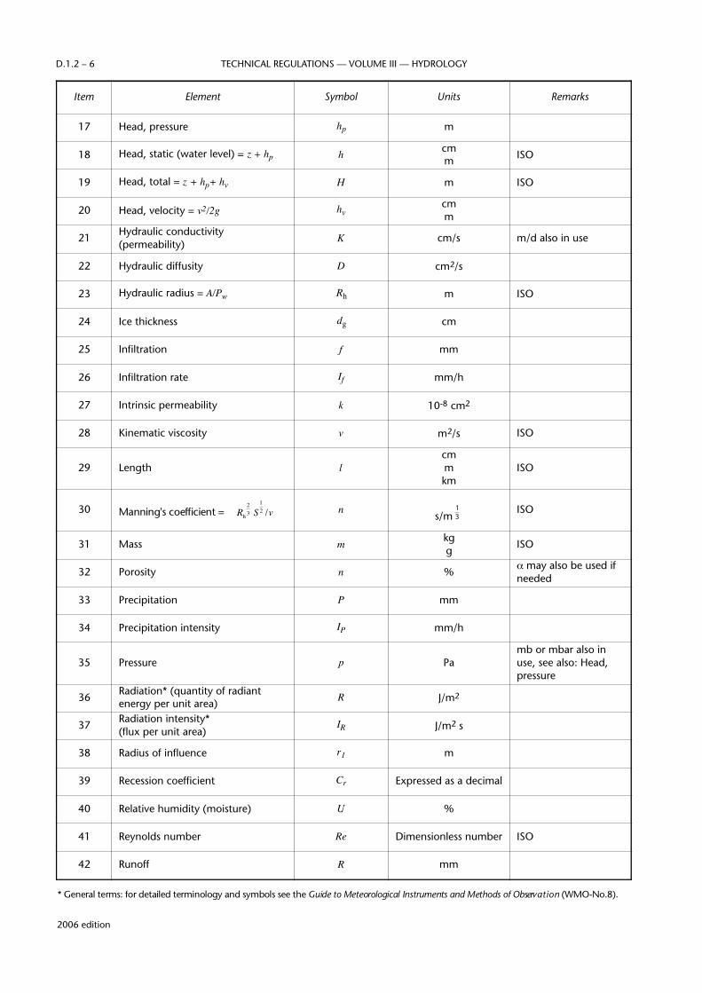
NOTE: W h e re international symbols exist these have been used where appropriate and are indicted as ISO in the last column (see Table 1.4 for modifiers of symbols).
Table 1.1Recommended symbols and units
Item Element Symbol Units Remarks
1 Acceleration due to gravity g m/s2 ISO
2 Albedo r Expressed as a decimal
3 Area (cross-sectional) (drainage basin) A m2
km2
ISOISOha also in use
4 Chemical quality mg/l (for dilute solutions)ppm also in use
5 Chézy coefficient
€
v / RhS( )12
C m /s ISO
6 Conveyance K m3/s ISO
7 Degree day D Degree day
8 Density p kg m-3 ISO
9 Depth, diameter, thickness d mcm ISO
10
Discharge(river flow)(wells)(unit area Q/A, or partial)
QQwe
q
m3/sl/sm3/s km2
l/s km2
ISO
ISO
11 Drawdown s mcm
12 Dynamic viscosity (absolute) η Pa s
13 Evaporation E mm
14 Evapotranspiration ET mm
15 Froude number Fr Dimensionless number ISO
16 Head, elevation z m ISO
€
12
2006 edition
TECHNICAL REGULATIONS — VOLUME III — HYDROLOGYD.1.2 – 6
Item Element Symbol Units Remarks
17 Head, pressure hp m
18 Head, static (water level) = z + hp h cmm ISO
19 Head, total = z + hp+ hv H m ISO
20 Head, velocity = v2/2g hvcmm
21 Hydraulic conductivity (permeability) K cm/s m/d also in use
22 Hydraulic diffusity D cm2/s
23 Hydraulic radius = A/Pw Rh m ISO
24 Ice thickness dg cm
25 Infiltration f mm
26 Infiltration rate If mm/h
27 Intrinsic permeability k 10-8 cm2
28 Kinematic viscosity v m2/s ISO
29 Length lcmmkm
ISO
30 Manning's coefficient =
€
Rh
23 S
12 /v n
s/m
€
13
ISO
31 Mass m kgg ISO
32 Porosity n % α may also be used ifneeded
33 Precipitation P mm
34 Precipitation intensity IP mm/h
35 Pressure p Pamb or mbar also inuse, see also: Head,pressure
36 Radiation* (quantity of radiantenergy per unit area) R J/m2
37 Radiation intensity* (flux per unit area)
IR J/m2 s
38 Radius of influence r1 m
39 Recession coefficient Cr Expressed as a decimal
40 Relative humidity (moisture) U %
41 Reynolds number Re Dimensionless number ISO
42 Runoff R mm
* General terms: for detailed terminology and symbols see the Guide to Meteorological Instruments and Methods of Observ a t i o n ( W M O - N o . 8 ) .

2006 edition
HYDROLOGICAL OBSERVATIONS D.1.2 – 7
Item Element Symbol Units Remarks
43 Sediment concentration cs kg/m3 ppm also in use
44 Sediment discharge Qs t/d
45 Shear stress τ Pa ISO
46 Slope (hydraulic, basin) S Dimensionlessnumber ISO
47 Snow cover An %
48 Snow depth dn cm
49 Snowmelt M mm n o rmally expressed asdaily
50 Soil moisture Us % volume % mass also in use
51 Soil moisture deficiency Us′ mm
52 Specific capacity = Qwe/m Cs m2/s
53 Specific conductance ℵ µS/cm at θ = 25°C
54 Specific yield YsExpressed as a
decimal
55 Storage S m3
56 Storage coefficient (groundwater) CsExpressed as a
decimal
57 Sunshine n/N Expressed as adecimal
actual (n)/possible (N) hours
58 Surface tension σ N/m ISO
59 Temperature θ °C ISOt also in use
60 Total dissolved solids md mg/l (for dilute solutions)ppm also in use
61 Transmissivity T m2/d
62 Vapour pressure e Pa mb or mbar also in use
63 Velocity (water) v m/s ISO
64 Volume V m3 ISO
65 Water equivalent of snow wn mm
66 Weber number We Dimensionlessnumber
67 Wetted perimeter Pw m
68 Width (cross-section, basin) b mkm ISO
69 Wind speed u m/s km/h, kn (or kt) also in use

2006 edition
TECHNICAL REGULATIONS — VOLUME III — HYDROLOGYD.1.2 – 8
Table 1.2Miscellaneous symbols
Table 1.3Units used in Table 1.1
Item Element Symbol Remarks
1 concentration c ISO
2 coefficient (in general) C ISO
3 difference Δ ISO, values expressed in same units
4 inflow I
5 lag time Δ t various units
6 load L
7 number of (or rank) m ISO
8 outflow O
9 recharge f (see Infiltration in Table 1.1)
10 total number N
Item Unit Symbol Remarks
1 centimetre cm ISO
2 day d ISO
3 degree Celsius °C ISO
4 gram g ISO
5 hectare ha
6 hour h ISO
7 joule J ISO
8 kilogramme kg ISO
9 kilometre km ISO
10 knot kn, kt
11 litre l ISO
12 metre m ISO
13 microsiemens µS
14 millibar mb, mbar ISO
15 milligram mg ISO
16 millimetre mm ISO
17 minute min ISO
18 newton N ISO
19 parts per million ppm
20 pascal Pa ISO
21 percentage %
22 second s ISO
23 tonne (metric ton) t ISO
24 year a ISO
2006 edition
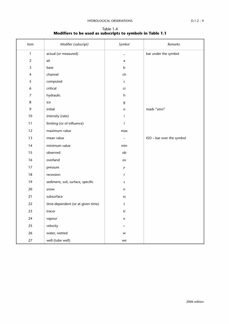
HYDROLOGICAL OBSERVATIONS D.1.2 – 9
Table 1.4Modifiers to be used as subscripts to symbols in Table 1.1
Item Modifier (subscript) Symbol Remarks
1 actual (or measured) – bar under the symbol
2 air a
3 base b
4 channel ch
5 computed c
6 critical cr
7 hydraulic h
8 ice g
9 initial o reads “zero”
10 intensity (rate) i
11 limiting (or of influence) l
12 maximum value max
13 mean value – ISO – bar over the symbol
14 minimum value min
15 observed ob
16 overland ov
17 pressure p
18 recession r
19 sediment, soil, surface, specific s
20 snow n
21 subsurface ss
22 time-dependent (or at given time) t
23 tracer tr
24 vapour e
25 velocity v
26 water, wetted w
27 well (tube well) we


CHAPTER D.1.3HYDROLOGICAL FORECASTS AND WARNINGS
[D.1.3.] 1
GeneralEach Member should ensure that hydrological forecasts andw a rnings are issued for protection from hazardous hydro-logical conditions and for purposes of water managementoperations.
N O T E : Detailed guidance re g a rding the principles and practice ofh y d rological forecasting is given in the Guide to Hydro l o g i c a lP r a c t i c e s (WMO-No. 168), fifth edition, Part E .
[D.1.3.] 2
Organization of the serviceThe hydrological forecasting service should be organized insuch a way that efficient coordination and communication,including data collection and exchange of hydrological data,is ensured between all its departments and centres andbetween the forecasting service and those responsible for thep rovision of meteorological data and forecasts. Where theya re separate organizations, the division of responsibility andauthority between the Hydrological Service and theM e t e o rological Service should be clearly defined.
NOTE: Detailed information on hydrological forecasting services isgiven in the Guide to Hydrological Practices (WMO-No. 168),fifth edition, 41.4.
[D.1.3.] 3
Forecasting and warning programme
[D.1.3.] 3.1
Types of forecasts, warnings and advisories tobe issued
[D.1.3.] 3.1.1
H y d rological forecasts should be classified according to fore-cast periods as (see definitions):
(a) Short-term hydrological forecasts (up to 2 days);
(b) Medium-term hydrological forecast (2 to 10 days);
(c) Long-term hydrological forecast (more than 10 days);
(d) Seasonal hydrological forecast (several months).
[D.1.3.] 3.1.2
The basic hydrological elements for which forecasts shouldbe issued are as follows:
(a) Water levels (river/lake stage) for specified times; alsovelocity and discharge where needed for navigation,water supply and/or other requirements;
(b) In flood periods, the times when water level risesabove the alarm level, the peak stage (velocity and/ordischarge) and its time of occurrence;
(c) Ice conditions on rivers, lakes and reservoirs;
(d) Volume and time distribution of ru n o ff for variousperiods of time (periods of high and low flows, month,season, year) and whenever feasible, associatedprobabilities;
(e) A b n o rmally low stages or discharges (dro u g h tconditions);
(f) S t o rm surges and wave heights in estuaries, coastalzones, large lakes and reservoirs;
(g) Selected water quality parameters.
NOTE: See the Guide to Hydrological Practices (WMO-No. 168), fifthedition, 41.2.
[D.1.3.] 3.1.3
H y d rological information should be issued on a routine basisas follows:
(a) I n f o rmation re g a rding the actual hydrological situation(including, as appropriate, stages discharges and waterquality parameters for rivers, estuaries, coastal zones, lakesand re s e rvoirs; ice conditions; groundwater levels; soilm o i s t u re; precipitation; water equivalent of snow cover);
(b) Assessment of conditions which are conducive to highlevels and runoff;
(c) Assessment of conditions which may be indicative offuture drought conditions.
[D.1.3.] 3.2
Data requirements
Networks should be designed taking into account thespecial needs of hydrological forecasts. Each membershould arrange for the timely collection and distribution of
2006 edition

the data re q u i red for the preparation of the forecasts andadvisories indicated in [D.1.3.] 3.1.
[D.1.3.] 3.2.1
Collection and transmission of data
The precision and frequency of measurement of hydrologi-cal data should be as tabulated in the Guide to HydrologicalPractices (WMO-No. 168), fifth edition, Part E.
NOTES:
(a) See also D.1.1, D.1.2 and D.1.4.
(b) H y d rological forecasting has special network and data collec-tion re q u i rements. Detailed guidance on data collection andtransmission is given in the Guide to Hydrological Practices(WMO-No. 168), fifth edition, Part C, and in the H O M SR e f e rence Manual, Sections E and F.
[D.1.3.] 3.2.2
Meteorological data
Desirable precision of observation and frequency ofmeasurement of meteorological data for hydrological fore-casting purposes should be as indicated in [D.2.] 2.3.
[D.1.3.] 3.2.2.1
Precipitation data and quantitative precipitationforecasts (QPF)
The hydrological forecaster should be supplied with QPFs on aregular basis and these should be frequently updated duringflood situations. The meteorological forecaster making the QPFshould have available all current precipitation observ a t i o n sincluding those made primarily for hydrological purposes.
[D.1.3.] 3.2.2.2
Meteorological observational and forecast dataother than precipitation
The following types of meteorological information, data andf o recasts should be made available at standard times to thehydrological forecaster:
(a) Temperature, including:(i) Current data;(ii) Forecasts of abrupt and sizeable changes;(iii) Forecasts of unusually high or low temperatures;
(b) Wind, including:(I) Current data;(ii) Forecast of unusually high winds;(iii) When hydrologically significant, forecast of abru p t
changes in wind direction;
(c) M e t e o rological data related to evapotranspirationcomputations:(i) Solar radiation or per cent sunshine;(ii) Dew point temperature or relative humidity;(iii) Observed pan evaporation.
[D.1.3.] 3.3
Selection of techniques
In selecting a forecasting technique, the hydrological fore-casting service should take into account the forecast needs,
the resources available and, among others, the experienceobtained through investigations and intercomparison oftechniques conducted during the last two decades.
NOTE: I n f o rmation on the relative capabilities and re s o u rc e sre q u i rements of hydrological models is given in the Guide toH y d rological Practices (WMO-No. 168), fifth edition, 33.2,Chapter 34, 39.1, 39.2, 39.3 and Chapter 43, inI n t e rcomparison of conceptual models used in operationalh y d rological fore c a s t i n g (WMO-No. 429), I n t e rcomparison ofmodels of snowmelt ru n o ff (WMO-No. 646) and in theHOMS Reference Manual, Sections J and K.
[D.1.3.] 3.4
Administrative considerations
[D.1.3.] 3.4.1
Use of QPF in hydrological forecasting
[D.1.3.] 3.4.1.1
H y d rological forecasting should be based on whatevercombination of observed and forecast rainfall provides themost timely and accurate forecast.
[D.1.3.] 3.4.1.2
The decision to use QPF in a hydrological forecast should bean operational decision based on the following hydro l o g i c a linformation relative to the forecast event:
(a) The probable error in the QPF as re g a rds volume, loca-tion and timing;
(b) How such errors propagate through the hydro l o g i c a lf o recasting technique and affect the accuracy of thehydrological forecast;
(c) How the user of the forecast is affected by vary i n gf o recast lead time and by varying levels of fore c a s ta c c u r a c y.
[D.1.3.] 3.4.2
Forecast adjustment
H y d rological forecast updating should be perf o rmed in such amanner as to make full use of the fore c a s t e r ’s knowledge andjudgement. Where available, automated adjustment tech-niques should be used to aid the forecast adjustment pro c e s s .
N O T E : I n f o rmation on forecast adjustment techniques is given in theGuide to Hydrological Practices (WMO-No. 168), fifth edition,43.10 and in the HOMS Reference Manual, Section J.
[D.1.3.] 3.4.3
Uncertainty in hydrological forecasts
The hydrological forecasting service should establish adminis-trative regulations concerning the manner in whichh y d rological forecasts, and their probable errors, aree x p ressed. The service should also undertake whatever educa-tional activities are needed to assure that the forecast userunderstands not only the forecast, but also its probable erro r.
2006 edition
TECHNICAL REGULATIONS — VOLUME III — HYDROLOGYD.1.3 – 2
[D.1.3.] 3.5
Flash floods and storm surges
In areas where flash floods or storm surges are a problem,the hydrological forecasting service should concentrate onp roviding whatever automation and administrative pro c e-dures are needed to accomplish:
(a) Rapid transmission of field observations to the fore c a s toffice;
(b) Rapid computation of the forecast;
(c) Rapid transmission of the forecast to the ultimate user.
The service should provide generalized flash flood or storms u rge warnings without delaying to pre p a re refined, site-specific forecasts.
[D.1.3.] 3.6
Drainage flooding
In areas where drainage flooding and lateral inflow occur,the rainfall intensity which is likely to cause problems shouldbe ascertained. Wa rnings should be issued when such inten-sities are being experienced or are considered to beimminent. The hydrological forecasting service shoulda s s u re that all concerned, including the users, understandthe diff e rence between drainage flooding and floodingcaused by rivers and storm surges.
[D.1.3.] 3.7
Dam breaks
The hydrological forecasting service should conduct as u rvey of dams in its area. For those dams whose failurewould cause extensive property damage and/or loss of life,advance computation should be made of the downstreamflood profile and the alarm levels based on various types ofassumed failures including the worst possible case. Theseshould be available for immediate use in the event of afailure.
N O T E : Technical information re g a rding the routing of h y d rographs resulting from dam failure are given in theGuide to Hydrological Practices (WMO-No. 168), fifthedition, 44.33 and in the HOMS Reference Manual,Sections J and K.
[D.1.3.] 3.8
Estuaries and coastal zones
W h e re the land area adjacent to an estuary or a coast issubject to damage by flooding or where extreme stagesand/or discharges in an estuary affect navigation activities,f o recasts of stages and/or discharges in the estuary should bei s s u e d .
N O T E : I n f o rmation on the technical aspects of estuary fore c a s t-ing is given in the Guide to Hydrological Practices(WMO-No. 168), fifth edition, 43.8 and 44.4. A serv i c efaced with an estuary problem and not having there s o u rces to apply a dynamic routing pro c e d u re to it mayobtain adequate results by using an empirical graphicalrelationship involving upstream discharge, open seas u rge and estuary stage.
[D.1.3.] 3.9
Low flow forecasts
[D.1.3.] 3.9.1
Water supply forecasts
W h e re needed, long-term (usually monthly or seasonal)forecasts of the flow of rivers should be made to enable thee fficient operation of water supply systems. Usually, suchf o recasts will need to take account of future weather andt h e re f o re, in general, they should be given in pro b a b i l i s t i cterms.
NOTES:
(a) I n f o rmation on techniques used for making water supplyf o recasts is given in the Guide to Hydrological Practices(WMO-No. 168), fifth edition, 44.5.
(b) Techniques for water supply forecasts, using stochasticinputs to continuous streamflow models or pro b a b i l i s t i canalyses of model output based on historical data, arec o v e red in the Guide to Hydrological Practices ( W M O -No. 168), fifth edition, 43.11 and 44.5.
[D.1.3.] 3.9.2
Drought forecasts
The hydrological forecasting service should re m a i nconstantly alert for conditions which may indicate the onsetof a period of hydrological drought and should release itsassessment of the situation on a regular basis.
NOTE: See the Guide to Hydrological Practices (WMO-No. 168), fifthedition, 35.4 and 35.5.
[D.1.3.] 3.10
Cold region phenomena
[D.1.3.] 3.10.1
Snow
NOTE: See the Guide to Hydrological Practices (WMO-No. 168), fifthedition, Chapter 45 for snowmelt forecasts and 42.6.2 forremote sensing
(a) In areas where precipitation may fall as either snow orrain, re p o rting pro c e d u res should assure that the char-acter of precipitation as well as its amount are re p o rt e dto the forecaster.
(b) In accessible portions of river basins, snow surv e y sshould be made as often as necessary to maintain acontinuing quantitative assessment of the snow coversituation.
[D.1.3.] 3.10.2
Ice forecasts
NOTE: See the Guide to Hydrological Practices (WMO-No. 168), fifthedition, Chapter 46.
The hydrological forecasting service should determine whichriver reaches are prone to the formation of ice and ice jams.During cold weather, such areas should be re c o n n o i t re d
2006 edition
HYDROLOGICAL FORECASTS AND WARNINGS D.1.3 – 3

2006 edition
TECHNICAL REGULATIONS — VOLUME III — HYDROLOGYD.1.3 – 4
re g u l a r l y. The expected effects of ice jams on water levelsshould also be assessed.
[D.1.3.] 3.11
Forecast dissemination
The hydrological forecasting service should be concern e dnot only with preparing the forecasts and warnings, but alsowith their dissemination to the ultimate users and theirp resentation in a form understandable to them. Speciale m e rgency plans for informing the public and variousresponsible bodies should be developed.
NOTE: A discussion of dissemination methods and considerations isgiven in the Guide to Hydrological Practices (WMO-No. 168),fifth edition, 41.5.
[D.1.3.] 3.12
Forecast evaluation/verification
The hydrological forecasting service should constantlymonitor the quality of its output. Such monitoring shouldlay emphasis on the values of the forecasts to potential usersand hence the evaluation should be based on their accuracy
and timeliness, as well as the responsiveness of the userswhen forecasts and warnings are issued.
NOTE: I n f o rmation on operational forecast verification is given inthe Guide to Hydrological Practices (WMO-No. 168), fifthedition, 41.3 and 41.3.1.
[D.1.3.] 3.13
User education
The value of hydrological forecasts and warnings, in partic-ular flood forecasts, depends upon the degree ofunderstanding and the response of the recipients. To ensurethe correct response to flood forecasts, particularly flashfloods, a continuing public education programme should beestablished to cover the interpretation of flood forecasts andthe appropriate action to be taken.
[D.1.3.] 3.14
International basins
The exchange of hydrological forecasts and warnings on international basins should be organized on the basis ofbilateral or multilateral agreement (see note to [D.1.2.] 2.7).
CHAPTER D.1.4HYDROLOGICAL DATA TRANSMISSION
[D.1.4.] 1
General
[D.1.4.] 1.1
Each Member should ensure the transmission of hydrologi-cal observations necessary to meet national requirements.
[D.1.4.] 1.2
Transmission facilities should be organized for the inter-national exchange of hydrological data, forecasts andwarnings on the basis of bilateral or multilateral agreement(see note to [D.1.2.] 2.7).
[D.1.4.] 1.2.1
The Global Telecommunication System (GTS) of the Wo r l dWeather Watch (WWW) should be used for intern a t i o n a lexchange of hydrological data, where practical and economical.
N O T E : A l t e rnative systems may be more appropriate for the trans-mission of hydrological data not re q u i red in real time.
[D.1.4.] 2
System and plan for data transmission[D.1.4.] 2.1
A data transmission system should include communicationsfacilities to transmit, relay and collect data from a hydro l o g i c a lo b s e rving system and to distribute processed data to users.
[D.1.4.] 2.2
A hydrological data transmission plan should include pro v i-sion for sensor interfacing, communications equipment, dataf o rmatting, operating personnel and operation pro c e d u re s .
[D.1.4.] 2.2.1
The hydrological data transmission plan should be re v i e w e dand revised, as needed.
[D.1.4.] 3
Organization of data transmission
[D.1.4.] 3.1
Each Member should ensure that national hydrological datatransmission facilities meet both national needs and inter-national requirements agreed upon on the basis of bilateralor multilateral agreement.
[D.1.4.] 3.2
Each Member should ensure that the technical characteris-tics and operational methods are compatible with regionaltelecommunication networks and associated plans.
[D.1.4.] 3.3
Each Member should ensure the collection of hydrologicaland related meteorological observational data from its ownt e rr i t o ry and ensure reception of such data from one orm o re other Members, if re q u i red, on the basis of bilateral ormultilateral agreement.
[D.1.4.] 3.4
Each Member should ensure distribution of data and re s u l t-ing processed information to its users and, if re q u i red, toother Members, on the basis of bilateral or multilateralagreement.
[D.1.4.] 3.5
Each Member should, according to:
(a) National needs, establish a communication linkbetween its Hydrological Service(s) and the NationalMeteorological Centre (NMC);
(b) I n t e rnational needs for exchange, establish a comm-unication link through the NMC in order to use the GTS.
2006 edition


[D.1.5.] 1
GeneralEach Member should establish a water quality monitoringprogramme according to its national requirements.
NOTE: Detailed guidance on the establishment of a water qualitymonitoring programme is provided in section XIII of theannex and in the Manual on Water Quality Monitoring(WMO-No. 680).
[D.1.5.] 2
Monitoring programmeThe water quality monitoring programme should consist of anumber of interrelated components:
(a) Water quality legislation and policies;
(b) Programme objectives;
(c) Programme design;
(d) Field activities;
(e) Laboratory activities;
(f) Data management;
(g) Data analysis;
(h) Quality assurance programme;
(i) Interpretation and report generation;
(j) Information utilization and decision-making.
[D.1.5.] 3
Monitoring objectivesThe objectives of a water quality monitoring pro g r a m m eshould be stated in terms of the “products” which theprogramme will deliver and should be directly linked to theresponsibilities in the current legislation, policies and prior-ities as well as to the existing infrastructure and resources.
[D.1.5.] 4
Network designNOTE: Water quality monitoring can be adequately accomplished
through the operation of a network of strategically locatedlong-term stations (basic network) supplemented as neces-sary by periodic short-term surveys of intermediate stations
( s e c o n d a ry network) including the monitoring of accidentalpollution of water bodies.
The network design shall be based on the monitoringobjectives of the programme and shall be coord i n a t e dwith the existing hydrological network.
[D.1.5.] 5
Water quality parameters
[D.1.5.] 5.1
The selection of water quality parameters to be monitored inrivers, lakes/re s e rvoirs and groundwaters should be based onprevious pilot studies. The basic parameters are listed in thetable in section XIII of the annex.
[D.1.5.] 5.2
Special precautions should be taken to pre s e rve the integrityof samples during storage and transportation for laboratoryanalysis.
NOTE: The quality of certain parameters including electricalc o n d u c t i v i t y, pH, dissolved oxygen, temperature, colour,turbidity and transparency may change during storage andshould be measured in situ or in the field as soon as possibleafter sampling.
[D.1.5.] 6
Collection of water samples
[D.1.5.] 6.1
The type of surface water sample to be collected should bedetermined by:
(a) The objectives of the programme, including the para-meters of interest and the precision and accuracy needed;
(b) The characteristics of the system being studied, includingthe flow regime, tributaries, groundwater infiltration,homogeneity of the water body, climatic conditions,a n t h ropogenic inputs, and the aquatic life pre s e n t .
NOTES:
(a) Three types of water samples are defined: grab or discrete;depth integrated grab; and composite.
CHAPTER D.1.5WATER QUALITY MONITORING
2006 edition
2006 edition
TECHNICAL REGULATIONS — VOLUME III — HYDROLOGYD.1.5 – 2
(b) General sampling guidelines are given in section XIII, XIII-3.2 of the annex.
[D.1.5.] 6.2
Groundwater samples should be taken from pumped wellsor from flowing artesian wells. In open wells or in casesw h e re samples are re q u i red from specific depths, smalldiameter grab samplers should be used.
[D.1.5.] 6.3
When collecting samples for radioactivity measure m e n t sp recautions should be taken to avoid absorption on thewalls of the container or on suspended matter.
NOTE: Acceptable container materials include polypro p y l e n e ,polyethylene or teflon.
[D.1.5.] 6.4
Sampling for biological analysis re q u i res specific samplersand pro c e d u res and should follow the re c o m m e n d a t i o n sgiven in section XIII, XIII-4.3 of the annex.
[D.1.5.] 6.5
Guidelines on the collection of samples for atmosphericdeposition measurement are given in section XIII, XIII-4.4 ofthe annex.
[D.1.5.] 6.6
Guidelines on the collection of samples for sedimentm e a s u rement are given in the Manual on SedimentManagement and Measurement (WMO-No. 948).
[D.1.5.] 6.7
For sampling sites located on a non-homogeneous reach ofa river or stream, samples should be collected on a cro s s -section of the channel at a specified number of horizontalpoints and depths.
[D.1.5.] 6.8
The frequency of sampling should be based on the varia-bility of the data, the concentrations to be measured andthe changes to be detected.
[D.1.5.] 7
Field safetyField personnel should be trained to recognize potentialh a z a rdous situations and to take measures necessary tominimize hazards.
NOTE: A p a rt from physical hazards, the water being sampled maycontain chemical and/or biological substances which may beh a rmful and contact with the skin should be avoided. Specialp recautions will be re q u i red in the handling of sewerage andindustrial eff l u e n t s .
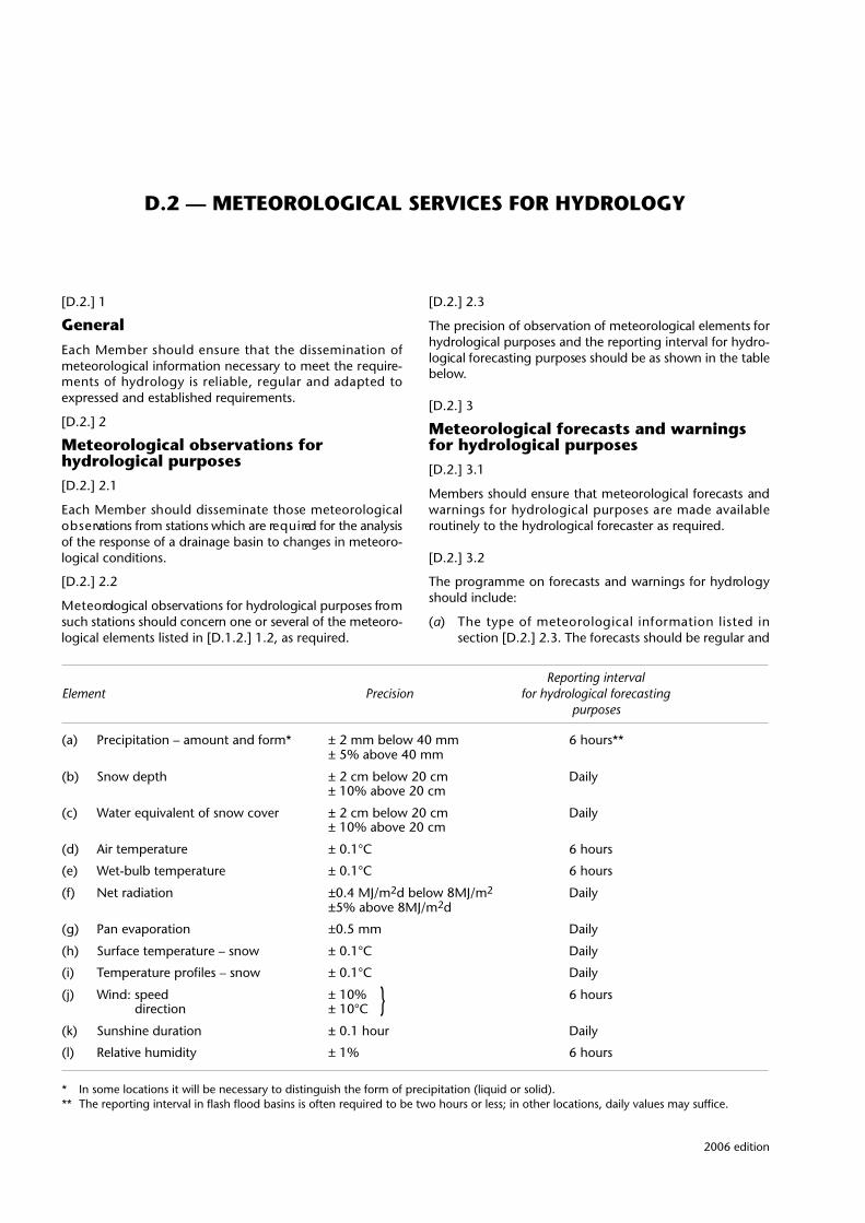
2006 edition
Reporting intervalElement Precision for hydrological forecasting
purposes
(a) Precipitation – amount and form* ± 2 mm below 40 mm 6 hours**± 5% above 40 mm
(b) Snow depth ± 2 cm below 20 cm Daily± 10% above 20 cm
(c) Water equivalent of snow cover ± 2 cm below 20 cm Daily± 10% above 20 cm
(d) Air temperature ± 0.1°C 6 hours
(e) Wet-bulb temperature ± 0.1°C 6 hours
(f) Net radiation ±0.4 MJ/m2d below 8MJ/m2 Daily±5% above 8MJ/m2d
(g) Pan evaporation ±0.5 mm Daily
(h) Surface temperature – snow ± 0.1°C Daily
(i) Temperature profiles – snow ± 0.1°C Daily
(j) Wind: speed ± 10% 6 hoursdirection ± 10°C
(k) Sunshine duration ± 0.1 hour Daily
(l) Relative humidity ± 1% 6 hours
* In some locations it will be necessary to distinguish the form of precipitation (liquid or solid).** The reporting interval in flash flood basins is often required to be two hours or less; in other locations, daily values may suffice.
}
D.2 — METEOROLOGICAL SERVICES FOR HYDROLOGY
[D.2.] 1
GeneralEach Member should ensure that the dissemination ofmeteorological information necessary to meet the require-ments of hydrology is reliable, regular and adapted toexpressed and established requirements.
[D.2.] 2
Meteorological observations for hydrological purposes[D.2.] 2.1
Each Member should disseminate those meteoro l o g i c a lo b s e rvations from stations which are re q u i red for the analysisof the response of a drainage basin to changes in meteoro-logical conditions.
[D.2.] 2.2
M e t e o rological observations for hydrological purposes fro msuch stations should concern one or several of the meteoro-logical elements listed in [D.1.2.] 1.2, as required.
[D.2.] 2.3
The precision of observation of meteorological elements forhydrological purposes and the reporting interval for hydro-logical forecasting purposes should be as shown in the tablebelow.
[D.2.] 3
Meteorological forecasts and warningsfor hydrological purposes[D.2.] 3.1
Members should ensure that meteorological forecasts andw a rnings for hydrological purposes are made availableroutinely to the hydrological forecaster as required.
[D.2.] 3.2
The programme on forecasts and warnings for hydro l o g yshould include:
(a) The type of meteorological information listed insection [D.2.] 2.3. The forecasts should be regular and
2006 edition
TECHNICAL REGULATIONS — VOLUME III — HYDROLOGYD.2 – 2
detailed, specifying to the greatest possible extent localand regional variations;
(b) The following forecasts:(i) Quantitative precipitation forecasts (QPF) for
periods of up to 72 hours;(ii) Air temperature, humidity, dew point, wind and
sky conditions for up to five days;(iii) Wind speed and directions for 24 hours or more;
(c) Wa rnings of hazardous weather conditions, part i c u l a r l yin the following cases:(i) Heavy precipitation (amount and intensity);(ii) Sudden and persistent changes in temperature to
above or below freezing;(iii) Strong winds.
[D.2.] 4
Publication and dissemination ofclimatological data for hydrologicalpurposes[D.2.] 4.1
Each Member should publish annually its climatologicaldata for hydrological purposes in addition to thosepublished as climatological data.
[D.2.] 4.2
The publication of climatological data for hydro l o g i c a lpurposes should conform with [B.1.] 4.1.1, [B.1.] 5.2.2,
[B.1.] 5.2.3 and [B.1.] 5.2.4 of the Technical Regulations,c o n c e rning the publication of climatological data, except thatthese data should be grouped according to main drainage basins.
NOTE: For convenience [B.1.] 4.1.1, [B.1.] 5.2.2, [B.1.] 5.2.3 and[B.1.] 5.2.4 are given in the appendix.
[D.2.] 4.3
Climatological data published or disseminated for hydro l o g-ical purposes should include frequencies, sums or averages,whichever applicable, of the following elements and fortime units as indicated in [B.1.] 4.1.1, [B.1.] 4.2.1 and [B.1.]4.2.2 of the Technical Regulations:
(a) Air temperature;
(b) Relative humidity;
(c) Wind speed and direction;
(d) Precipitation (amount and intensity);
(e) Solar radiation;
(f) Snow cover;
(g) Pan evaporation;
(h) Wet-bulb temperature;
(i) Sunshine duration.
NOTE: For convenience [B.1.] 4.1.1, [B.1.] 4.2.1 and [B.1.] 4.2.2are given in the appendix.

APPENDIX(See [D.2.] 4.2 and 4.3)
CLIMATOLOGICAL STATISTICSThis is reproduced from Volume I, Chapter [B.1.].
2006 edition
[B.1.] 4.1
Time units
[B.1.] 4.1.1
The time units used in processing climatological data shouldbe selected from the following:
(a) The Gregorian calendar year;
(b) The months of this calendar;
(c) The mean solar day, from midnight to midnight,according to the zonal time or the mean solar time ofthe station, when the climatological data permit.
[B.1.] 4.2
Climatological frequencies, sums andaverages
[B.1.] 4.2.1
F requencies, sums or averages, whichever applicable, of theobservations of a meteorological element at a fixed time ofthe day or of extreme values for the day should becomputed, either for individual time units or for a sequenceof re c u rring time units (e.g. ten successive Januaries, etc.)using international time designation.
[B.1.] 4.2.2
Frequencies, sums or averages, whichever applicable, of allor most of the following data from a selection of climato-logical stations should be computed for each month:
(a) Atmospheric pre s s u re at fixed times at the re f e re n c elevel appropriate to the station, as indicated in [B.1.]5.2.2.2 (b) ;
(b) Air temperature at fixed times;
(c) Daily air temperature extremes;
(d) Relative humidity at fixed times;
(e) Vapour pressure at fixed times;
(f) Wind speed at fixed times, and for fixed periods;
(g) Wind direction at fixed times;
(h) Cloud amount at fixed times;
(i) Amounts of precipitation for fixed periods;
(j) Duration of bright sunshine for fixed periods.
[B.1.] 5.2.2
The general information contained in annual climatologicalreports should consist of:
[B.1.] 5.2.2.1
A statement giving:
(a) The standards of time used;
(b) The types of instrument used;
(c) The methods of applying corrections;
(d) The methods in which conventional means arecomputed;
(e) The times at which extreme temperatures are read.
[B.1.] 5.2.2.2
A list for each station giving:
(a) Name and geographical coordinates;
(b) The altitude of the re f e rence levels for station pre s s u re ;
(c) The heights of the thermometer bulb, the anemometerhead and the rim of the raingauge above ground level.
NOTE: Model tables for climatological summaries are given in theGuide to Climatological Practices (WMO-No. 100).
[B.1.] 5.2.3
If the main language of a publication is not English, Fre n c h ,Russian or Spanish, all headings of tables should be in oneof these official languages, or in internationally recognizedsymbols or letters.
NOTE: Although Arabic and Chinese are official languages ofWMO, Congress has not yet approved their use in allaspects of the work of WMO.
[B.1.] 5.2.4
Each Member should publish or make available on a nationaland a regional basis at least the following radiation data:
2006 edition
TECHNICAL REGULATIONS — VOLUME III — HYDROLOGYD.2 – 4
(a) For principal radiation stations, hourly totals of globalsolar radiation and of sky radiation [see Te c h n i c a lRegulations, Volume I, [B.1.] 5.2.4 (a)];
(b) For ord i n a ry radiation stations, daily totals of globalsolar radiation [see Technical Regulations, Volume I,[B.1.] 5.2.4 (b)].

D.3 — HYDROLOGICAL BIBLIOGRAPHY AND PUBLICATIONS
2006 edition
[D.3.] 1
Hydrological documents and abstracts
[D.3.] 1.1
General form of hydrological documents and abstracts
[D.3.] 1.1.1
O fficial publications which give the results of studies inh y d rology and which may be distributed intern a t i o n a l l yshould include an abstract in at least one of the followingo fficial languages: English, French, Russian or Spanish.
NOTE: Although Arabic and Chinese are official languages of WMO,C o n g ress has not yet approved their use in all aspects of thework of WMO.
[D.3.] 1.1.2
The International Organization for Standardization (ISO)system of Cyrillic transliteration should be used in allh y d rological documents and publications for intern a t i o n a lu s e .
[D.3.] 1.1.3
Films, perforated or not, used for making microfilm copies ofh y d rological documents should have a width of 16, 35 or 70 m m .
[D.3.] 1.2
Classification of hydrological documents and abstracts
O fficial hydrological documents, abstracts and bibliographiesintended for international dissemination should be classified inc o n f o rmity with and should bear the relevant number of theUniversal Decimal Classification (UDC), Section 556, as given inthe appendix.
[D.3.] 1.3
Preparation of catalogues of hydrological documents
[D.3.] 1.3.1
The catalogue cards pre p a red by Members and intended fori n t e rnational dissemination should contain the relevant UDCnumbers of the hydrological documents, books, pamphlets andperiodicals to which the cards pert a i n .
[D.3.] 1.3.2
Catalogue cards pre p a red by members for books, pamphletsand periodicals should contain the following information: theUDC indexes, the name or names of the author(s), the title andits translation where applicable, the name of the editor, thenumber of the edition, the volume number or year of publica-tion or of reprinting (in the case of a series of periodicals), thefascicle or issue number, place of publication, publisher and dateof publication, the number of volumes of a single work, form a t ,pagination of the book or article, illustrations and plates, collec-tion or series to which the work belongs, a note on the existenceof an author’s abstract, if any, and any amplification of the title.

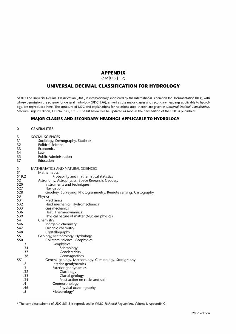
2006 edition
APPENDIX(See [D.3.] 1.2)
UNIVERSAL DECIMAL CLASSIFICATION FOR HYDROLOGY
NOTE: The Universal Decimal Classification (UDC) is internationally sponsored by the International Federation for Documentation (RID), withwhose permission the scheme for general hydrology (UDC 556), as well as the major classes and secondary headings applicable to hydrol-ogy, are reproduced here. The structure of UDC and explanations for notations used therein are given in Universal Decimal Classification,Medium English Edition, FID No. 571, 1985. The list below will be updated as soon as the new edition of the UDC is published.
MAJOR CLASSES AND SECONDARY HEADINGS APPLICABLE TO HYDROLOGY
0 GENERALITIES
3 SOCIAL SCIENCES31 Sociology. Demography. Statistics32 Political Science33 Economics34 Law35 Public Administration37 Education
5 MATHEMATICS AND NATURAL SCIENCES51 Mathematics519.2 Probability and mathematical statistics52 Astronomy. Astrophysics. Space Research. Geodesy520 Instruments and techniques527 Navigation528 Geodesy. Surveying. Photogrammetry. Remote sensing. Cartography53 Physics531 Mechanics532 Fluid mechanics, Hydromechanics533 Gas mechanics536 Heat. Thermodynamics539 Physical nature of matter (Nuclear physics)54 Chemistry546 Inorganic chemistry547 Organic chemistry548 Crystallography55 Geology, Meteorology. Hydrology550 Collateral science. Geophysics
.3 Geophysics
.34 Seismology
.37 Geoelectricity
.38 Geomagnetism551 General geology. Meteorology. Climatology. Stratigraphy
.2 Interior geodynamics
.3 Exterior geodynamics
.32 Glaciology
.33 Glacial geology
.34 Frost action on rocks and soil
.4 Geomorphology
.46 Physical oceanography
.5 Meteorology*
* The complete scheme of UDC 551.5 is reproduced in WMO Technical Regulations, Volume I, Appendix C.

.7 Historical geology. Stratigraphy
.8 Paleography552 Petrology. Petrography553 Economic geology. Mineral deposits556 Hydrosphere. Water (in general). General hydrology
.1 Hydrological cycle, properties and conditions. Global water balance
.3 Groundwater hydrology. Geohydrology. Hydrogeology
.5 Surface water hydrology. Land hydrology56 Paleontology57 Biology58 Botany59 Zoology
6 APPLIED SCIENCES. MEDICINE. TECHNOLOGY61 Medical Sciences62 Engineering621 Mechanical and electrical engineering
.22 Water power. Utilization of hydraulic energy
.3 Electrical engineering
.39 Telecommunication623 Military and naval engineering624 Civil engineering625 Railway, highway engineering626 Hydraulic engineering627 River and harbour engineering628 Public health engineering629 Transport engineering63 Agriculture and Related Sciences and Techniques630 Forestry633 Field crops and their production634 Horticulture generally635 Garden plants. Gardening636 Animal husbandry639 Game and fish management65 Management. Administration. Organization68 Specialized trades, etc.681.2 Instrument making, Instrumentation
.3 Data processing equipment
.5 Automatic control engineering69 Building
7 ARTS. SPORTS71 Physical Planning. Landscape, etc.72 Architecture77 Photography79 Entertainment. Games. Sports
8 LANGUAGES AND LITERATURE
9 GEOGRAPHY. BIOGRAPHY. HISTORY91 Geography929 Biography93/99 History
SECTION 556 – HYDROSPHERE. WATER (IN GENERAL)
556 HYDROSPHERE. WATER (IN GENERAL). GENERAL HYDROLOGYComprehensive works on surface waters and groundwater→532 Fluid mechanics. Hydraulics
551.4 Geomorphological aspects551.46 Oceanographic aspects621.6 Fluid storage and distribution (engineering)66/627 Hydraulic construction works. Waterways, etc.628.1/3 Water supply, drainage, and waste disposal
556.01 Theory. Principles of research and investigation.011 Theoretical principles.012 Research, methodology, requirements, etc..013 Theoretical investigation: use of models, etc. Cf. 556.072 Models.014 Experimental (laboratory and field) investigation
2006 edition
TECHNICAL REGULATIONS — VOLUME III — HYDROLOGYD.3 – 4

556.02 Practical work: organization, programmes, projects, etc.Details of organization :061...Organization and management techniques by :65....
.023 Laboratories and laboratory work
.024 Stations and field work generally
.025 Services and networks, including network design
.028 Representative and experimental basins556.04 Observation(s), data and records
.042 Observation methods
.043 Data handling: collection, processing, and dissemination
.044 Data, observational data (on specific hydrological phenomena)
.045 Records
.047 Hydrological analyses
.048 Hydrological computation. Coefficients, etc.556.06 Hydrological forecasting and forecasts
“32” Seasonal(1/9) Regional
556.07 Equipment, installations and apparatus for hydrological work.072 Models, analogies, etc. Subdivide as 53.072.078 Special apparatus and equipment for study of hydrological phenomena, e.g. 556.132.8.078
Evaporation pans556.08 Measurement: principles and instruments. Subdivide as 53.08, e.g.
.082 Principles of measurement and of measuring instruments
.084 Instruments: design, construction, and components
.085 Indicators, Scales, etc.
.088 Measurement errors, correction, and evaluation
556.1 HYDROLOGICAL CYCLE, PROPERTIES AND CONDITIONS. GLOBAL WATER BALANCE556.11 Water properties
.113 Physical properties of water.2 Further details: 53....3 Turbidity.4 Colour
.114 Chemical properties of waterFurther details: 54..., e.g.:541.132 Electrolytic dissociation and pH (H-ion concentration):543.242 Oxidation-reduction analysis. Redox potential:543.319 Alkalinity
.2 Dissolved gases
.3 Hardness of water
.4 Taste and odour
.42 Taste of water
.44 Odour of water
.5 Salinity
.6 Element and inorganic content (of water)Subdivide as 546, e.g.
.6.027 Isotope content (generally)
.611*3 Tritium (3H) content
.679 Radioactive elements (generally)Cf. 556.388; 556.535.8; 556.555.8
.7 Organic chemical contentSubdivide as 547... (or :547)
.115 Biological and microbiological properties of waterFurther details: 57/59, e.g.:579.8 Bacteria, micro-organisms:582 Plants, flora:592/599 Animals, fauna
556.12 Precipitation: rainfall, snow, etc. (as element in the hydrological cycle)→ 551.57 Aqueous vapour, precipitation, and hydrometeors (meteorology)“32” Seasonal variations“45” Annual variations(1/9) Geographical, areal distribution
.04 Observations, data and records, e.g. snow and glacier melt rates.121 Amount and duration of precipitation
.2 Mean or average
.3 Maximum
.4 Minimum
.6 Intensity
.7 Duration
2006 edition
HYDROLOGICAL BIBLIOGRAPHY AND PUBLICATIONS D.3 – 5

.8 Relation between duration and intensity.123 Rainfall. Subdivide as 556.121 and use “32” and “45” for seasonal and annual variations .124 Snow and ice. Snowpack. Glacier
→ 551.32/.34.1 Amount and duration. Subdivide as 556.121.2 Snow cover: distribution and water equivalent.3 Melting of snow: rate, relationships, etc..4 Melting of glaciers
556.13 Evaporation, evapotranspiration and transpiration (in the hydrological cycle). Cf. 551.571/.574.131 Total evaporation. Evapotranspiration
.1 Computation and determination: methods and equipment
.11 Water balance methods
.112 Evaporimetry and evaporimeters
.114 Lysimetry and lysimeters
.116 Soil-moisture and groundwater level variations
.12 Energy balance methods
.13 Vapour flux, turbulent diffusion
.14 Moisture advection
.18 Empirical formula methods of computation
.2 Amounts of total evaporation
.3 Condensation of the Earth’s surface
.5 Evaporation control → 556.18.132 Evaporation
.2 Evaporation from water bodies
.28 Evaporation from ponds
.4 Evaporation from snow and ice former number: 556.134
.6 Evaporation from land (solid, fields, forests) former number: 556.133
.8 Pan evaporation556.14 Infiltration (as element in the hydrological cycle)
.142 Soil moisture → 631.432 (Agriculture)
.143 Groundwater storage → 556.32 (Vertical distribution)556.15 Water storage (as element in the hydrological cycle)
.152 Surface detention
.153 Channel (and bank) storage.5 Bank storage
.155 Lake and reservoir storage → 627.81 Dams
.157 Valley storage556.16 Runoff
“32” Seasonal“45” Annual
.01 Theory of runoff
.044 Depth, runoff depth
.045 Streamflow records
.047 Hydrographs, unit hydrographs
.048 Computation and coefficients
.06 Forecasting, forecasts.161 Rainfall–runoff relation. Runoff factors.162 Distribution (and frequency). Use “32”, “45” and (1/9).164 Surface runoff. Overland flow.165 Normal runoff and its computation.166 Maximum runoff. Floods and flood runoff
→ 627.51“321” Spring (snow-melt)“324” Winter
.2 Storm floods
.4 Flash floods.167 Minimum runoff. Base flow. Dry-weather flow
.2 Base flow
.6 Drying-up, drought.168 Underground runoff → 556.332.2 Aquifers
556.18 Water management. Applied hydrology. Human control of hydrological conditionsDivide by: 626/627, :628..., :631.6..., etc.
.182 Conjunctive use of surface and groundwater resources
556.3 GROUNDWATER HYDROLOGY. GEOHYDROLOGY. HYDROGEOLOGY
→ 550.8 Geological exploration methods, prospecting551.44 Speleology, subterranean waters, etc.
.01 Theory of groundwater, principles of investigation and research
2006 edition
TECHNICAL REGULATIONS — VOLUME III — HYDROLOGYD.3 – 6

.02 Practical work organization: projects, laboratories, stations, services, and networks
.04 Observation(s), data, and records
.06 Forecasting and forecasts
.07 Equipment, apparatus, models, etc.
.08 Measurement: principles and instruments556.31 Properties of groundwater. Subdivide as 556.11, e.g.
.313 Physical properties: temperature, colour, turbidity, etc.
.314 Chemical and physio-chemical properties: hardness, taste and odour, salinity, chemical content
.315 Biological and microbiological properties: bacteria, plants, animals556.32 Subterranean (underground) water: vertical distribution
.322 Zone of aeration. Suspended water. Vadose water.2 Soil water.4 Pellicular and gravitational water.6 Capillary water
.324 Zone of saturation. Groundwater (in restricted sense)556.33 Aquifers. Water-bearing strata
.332 Unconfined (phreatic) aquifers.2 Storage capacity: inflow and outflow.4 Permeability of rock formations.04 Observations and tests, data, records, analyses.042 Pumping tests.048 Storage coefficient. Specific yield.41 Impermeable, not containing water. Aquifuges.42 Impermeable, containing water. Aquicludes.43 Slowly permeable water-bearing strata.44 Easily permeable water-bearing strata.46 Karst formations → 551.435.8 Geomorphology of karst.5 Water table. Phreatic surface.52 Fluctuations (or water table)
“32” Seasonal fluctuations:551.466.7 Tides:550.348 Seismic disturbances, tremors, earthquakes:551.54 Atmospheric pressure effects:556.53 Rivers and streams (as fluctuation factors)
.6 Recharge
.62 Natural recharge and its sources:556.12 Precipitation, rainfall, etc.:556.168 Underground runoff:556.55 Lakes and reservoirs
.625 Juvenile water
.629 Other sources of natural recharge
.63 Artificial recharge and its methods → 628.112.2/.3
.632 Pits and shafts
.633 Spreading
.634 Injection wells
.636 Induced recharge
.639 Other methods of artificial recharge
.7 Seawater intrusion → 556.388 Pollution
.72 Freshwater–saltwater interface
.78 Methods of prevention (of seawater intrusion).334 Confined (artesian) aquifers
Subdivide as 556.332 where applicable, adding:.3 Compressibility.5 Piezometric surface
.336 Perched aquifers. Subdivide as 556.332 where applicable556.34 Groundwater flow. Well hydraulics
→ 532.5 Hydrodynamics, fluid flow628.112 Wells (water supply)
.042 Observation wells.342 Flow rate. Velocity. Gradient
.2 Darcy’s law→ 532.546 Flow in porous media
.343 Flow to wells. Drawdown.2 Radial flow.22 Steady flow.24 Non-steady flow.3 Partially penetrating wells.4 Interference of wells.5 Well losses
556.36 Springs Cf. 556.182 → 628.112.1 Catchment
2006 edition
HYDROLOGICAL BIBLIOGRAPHY AND PUBLICATIONS D.3 – 7

.362 Depression springs
.363 Contact springs
.364 Artesian springs
.366 Fracture springs
.367 Intermittent springs
.368 Volcanic springs→ 553.7 Mineral springs
556.38 Groundwater basins. Groundwater managementCf. 556.182 Conjunctive use of groundwater and surface water
.02 Practical work organization: projects, networks, etc..382 Safe yield.383 Overdraft.388 Pollution (of groundwater). Protective measures
→ 556.332.7 Sea-water intrusion504.43 Groundwater environment
.2 Protection of intake areas and sources
.4 Protection of springs and wells556.5 SURFACE WATER HYDROLOGY. LAND HYDROLOGY
→ 551.435 Geomorphology of surface waters.01 Theory, principles of investigation and research.02 Practical work organization: stations, networks, etc..028 Representative and experimental basins.04 Observations(s), data and records.06 Forecasting and forecasts.07 Equipment, apparatus, models.072 Models. Subdivide as 53.072.08 Measurement: principles and instruments. Subdivide as 53.08
556.51 Drainage or catchment areas, basins. River basins. Watersheds (Amer.)→ 551.435.164 Geomorphology: catchment basins
.028 Representative and experimental basins.512 Water balance of drainage basins.513 Area of drainage basins.514 Shape of drainage basins.515 Slope of drainage basins.516 Stream density
556.52 River systems. Potamology (general description).522 Classification. Order of stream.523 Large streams.524 Tributaries
556.53 Rivers, streams and canals.531 Water properties (in rivers). Subdivide as 556.11, e.g.
.3 Physical properties: temperature, turbidity, colour
.4 Chemical properties, incl. hardness, taste, and odour
.5 Biological and microbiological properties.532 Water balance (of perennial streams)
:556.16 Runoff.535 River regimes
.2 Level
.3 Discharge
.4 Thermal regime
.5 Ice regime → 551.326.83 Ice on streams
.6 Sediment transport → 532.584 Hydrodynamics
.8 Pollution (of rivers) → 504.453 Fluvial environment, rivers, streams.536 Hydraulics, hydrodynamics of rivers and streams
Fluvial hydraulics → 532.5 Hydrodynamics.2 Currents, river currents.3 Waves.5 Wind influences Cf. 551.556.8 (Meteorology)
.537 Channel and bank formation (only hydrological aspects)→ 551.435.1 Geomorphology of rivers
627.4 River training.538 Intermittent or ephemeral streams
.1/7 Subdivide as 556.531/.537 where applicable556.54 River mouths. Estuaries. Deltas. Subdivide as 556.53 where applicable
→ 551.435.126 Geomorphology of deltas→ 551.468.6Estuaries. Exchange of sweet and sea water
.541 Water properties in river mouths and estuaries. Subdivide as 556.11
.542 Water balance (in river mouths and estuaries)
.545 Estuarine regimes, pollution. Problems of exchange between fresh and saline water, mixing, resulting in brackish water
2006 edition
TECHNICAL REGULATIONS — VOLUME III — HYDROLOGYD.3 – 8

→ 504.454 Fluvio-marine environment. River mouths.Estuaries
.546 Estuarine hydraulics and hydrodynamics556.55 Lakes, reservoirs and ponds. Limnology
→ 551.435.38 Geomorphology of lake basins(211) Polar(212) Temperate(213) Tropical and subtropical
.551 Water properties in lakes, reservoirs, and ponds. Subdivide as 556.11
.552 Water balance of lakes
.555 Lake regimes.2 Level.3 Inflow and outflow.4 Thermal regime. Thermal stratification.41 Epilmnion.42 Metalimnion. Thermocline.43 Hypolimnion.5 Ice regimes → 551.326.85 Ice on lakes.6 Sedimentation and silting (in lakes).7 Chemical stratification.8 Pollution of lakes
→ 504.455 Freshwater environment, lakes, reservoirs and ponds.556 Hydraulics, hydrodynamics of lakes
→ 532.5 Hydrodynamics.2 Currents.3 Waves.4 Seiches.5 Wind influences. Wind set-up
Cf. 551.556.8 (Meteorology).557 Lake shores and their alteration
→ 551.435.3 Geomorphology of lakes627.8 Dams
556.56 Swamps and marshes:626.86 Drainage of swamps→ 551.435.1 Geomorphology of swamps
.561 Water properties in swamps. Subdivide as 556.11
.562 Water balance of swamps
.565 Swamp regimes. Pollution, etc. → Freshwater environment, swamps
.566 Hydraulics, hydrodynamics of swamps→ 532.5 Hydrodynamics
2006 edition
HYDROLOGICAL BIBLIOGRAPHY AND PUBLICATIONS D.3 – 9

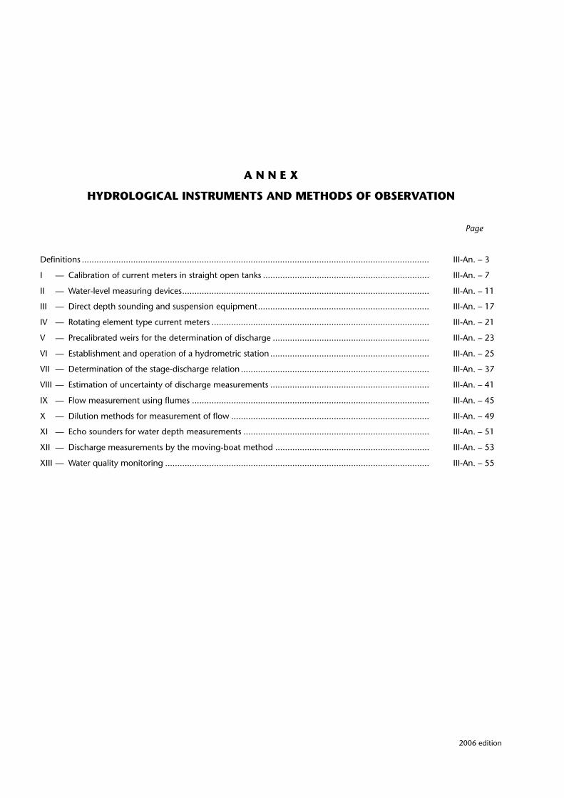
A N N E X
HYDROLOGICAL INSTRUMENTS AND METHODS OF OBSERVATION
Page
Definitions .............................................................................................................................................. III-An. – 3
I — Calibration of current meters in straight open tanks .................................................................... III-An. – 7
II — Water-level measuring devices..................................................................................................... III-An. – 11
III — Direct depth sounding and suspension equipment...................................................................... III-An. – 17
IV — Rotating element type current meters ......................................................................................... III-An. – 21
V — Precalibrated weirs for the determination of discharge ................................................................ III-An. – 23
VI — Establishment and operation of a hydrometric station ................................................................. III-An. – 25
VII — Determination of the stage-discharge relation ............................................................................. III-An. – 37
VIII — Estimation of uncertainty of discharge measurements ................................................................. III-An. – 41
IX — Flow measurement using flumes ................................................................................................. III-An. – 45
X — Dilution methods for measurement of flow ................................................................................. III-An. – 49
XI — Echo sounders for water depth measurements ............................................................................ III-An. – 51
XII — Discharge measurements by the moving-boat method ............................................................... III-An. – 53
XIII — Water quality monitoring ............................................................................................................ III-An. – 55
2006 edition

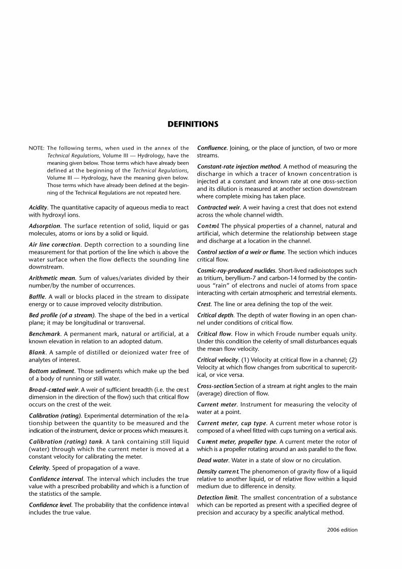
2006 edition
DEFINITIONS
NOTE: The following terms, when used in the annex of theTechnical Regulations, Volume III — Hydro l o g y, have themeaning given below. Those terms which have already beendefined at the beginning of the Technical Regulations,Volume III — Hydro l o g y, have the meaning given below.Those terms which have already been defined at the begin-ning of the Technical Regulations are not repeated here.
A c i d i t y. The quantitative capacity of aqueous media to re a c twith hydroxyl ions.
A d s o r p t i o n. The surface retention of solid, liquid or gasmolecules, atoms or ions by a solid or liquid.
Air line corre c t i o n. Depth correction to a sounding linemeasurement for that portion of the line which is above thewater surface when the flow deflects the sounding linedownstream.
Arithmetic mean. Sum of values/variates divided by theirnumber/by the number of occurrences.
B a ff l e. A wall or blocks placed in the stream to dissipateenergy or to cause improved velocity distribution.
Bed profile (of a stream). The shape of the bed in a verticalplane; it may be longitudinal or transversal.
B e n c h m a r k. A permanent mark, natural or artificial, at aknown elevation in relation to an adopted datum.
B l a n k. A sample of distilled or deionized water free ofanalytes of interest.
Bottom sediment. Those sediments which make up the bedof a body of running or still water.
B ro a d - c rested weir. A weir of sufficient breadth (i.e. the cre s tdimension in the direction of the flow) such that critical flowoccurs on the crest of the weir.
Calibration (rating). Experimental determination of the re l a-tionship between the quantity to be measured and theindication of the instrument, device or process which measures it.
Calibration (rating) tank. A tank containing still liquid(water) through which the current meter is moved at aconstant velocity for calibrating the meter.
Celerity. Speed of propagation of a wave.
Confidence interv a l. The interval which includes the tru evalue with a prescribed probability and which is a function ofthe statistics of the sample.
Confidence level. The probability that the confidence interv a lincludes the true value.
Confluence. Joining, or the place of junction, of two or morestreams.
Constant-rate injection method. A method of measuring thed i s c h a rge in which a tracer of known concentration isinjected at a constant and known rate at one cro s s - s e c t i o nand its dilution is measured at another section downstreamwhere complete mixing has taken place.
Contracted weir. A weir having a crest that does not extendacross the whole channel width.
C o n t ro l. The physical pro p e rties of a channel, natural anda rtificial, which determine the relationship between stageand discharge at a location in the channel.
C o n t rol section of a weir or flume. The section which inducescritical flow.
C o s m i c - r a y - p roduced nuclides. Short-lived radioisotopes suchas tritium, beryllium-7 and carbon-14 formed by the contin-uous “rain” of electrons and nuclei of atoms from spaceinteracting with certain atmospheric and terrestrial elements.
Crest. The line or area defining the top of the weir.
Critical depth. The depth of water flowing in an open chan-nel under conditions of critical flow.
Critical flow. Flow in which Froude number equals unity.Under this condition the celerity of small disturbances equalsthe mean flow velocity.
Critical velocity. (1) Velocity at critical flow in a channel; (2)Velocity at which flow changes from subcritical to supercrit-ical, or vice versa.
C ro s s - s e c t i o n. Section of a stream at right angles to the main(average) direction of flow.
C u rrent meter. Instrument for measuring the velocity ofwater at a point.
C u rrent meter, cup type. A current meter whose rotor iscomposed of a wheel fitted with cups turning on a vertical axis.
C u rrent meter, propeller type. A current meter the rotor ofwhich is a propeller rotating around an axis parallel to the flow.
Dead water. Water in a state of slow or no circulation.
Density curre n t. The phenomenon of gravity flow of a liquidrelative to another liquid, or of relative flow within a liquidmedium due to difference in density.
Detection limit. The smallest concentration of a substancewhich can be reported as present with a specified degree ofprecision and accuracy by a specific analytical method.

Dilution method. A method of determining the discharge ofa stream by measuring the degree of dilution by the flowingwater of an added tracer solution.
Double float. A body of slightly negative buoyancy whichmoves with the stream at a known depth and whose posi-tion is indicated by a small surface float from which it issuspended.
D r a g. Force exerted by a flowing fluid, e.g. water, on anobject placed in or adjacent to the fluid, projected in thedirection of flow.
D rowned (submerged) weir. A weir in which the upstre a mwater level is affected by the downstream water level.
Duplicate samples. Obtained by dividing one sample intotwo or more identical subsamples.
Echo sounder. An instrument using the reflection of anacoustic signal from the bed to determine the depth.
Error. The difference between the result of a measurementand the true value of the quantity measured.
NOTE: This term is also used for the difference between the resultof a measurement and the best approximation of the truevalue (rather than of the true value itself). The best appro x-imation may be a mean of several or of manymeasurements.
F a l l. Diff e rence in elevation of water surface between twopoints of a stream at a given time.
F i l t r a t i o n. The process of passing a liquid through a filteringmedium for removal of suspended or colloidal matter.
F l o a t. Any natural or artificial body which is supported andp a rtly or fully immersed in water, its vertical motion indicatingthe changes in water level or its horizontal movement indicat-ing the velocity of water at the surface or at various depths.
Float gauge. A gauge consisting essentially of a float whichrides on the water surface and rises or falls with it, its move-ment being transmitted to a re c o rding or indicating device.
Flood plain. Adjoining nearly level land at the bottom of thevalley of a stream flooded only when the stre a m f l o wexceeds the water carrying capacity of the channel.
Flume. An artificial channel with clearly specified shape anddimensions which may be used for measurement of flow.
F roude number. A dimensionless number expressing theratio of inertia forces to gravity forces:
v = velocity of flow
g = acceleration of gravity
d = average depth of flow
G e o c h e m i s t ry. A science that deals with the chemical compo-sition of and chemical changes in the crust of the eart h .
Grab sample. A sample taken at a selected location, depthand time.
Head over (on) the weir. The elevation of the water abovethe lowest point of the crest, measured at a point upstre a m .
(The point of measurement depends on the type of weirused.)
Height of weir. The height from the upstream-bed to thelowest point of the crest.
H e r b i c i d e. A chemical agent that destroys specific vegetation.
Homogeneous. Uniform in composition.
H y s t e resis (in stage-discharge re l a t i o n ). The variability of thes t a g e - d i s c h a rge relation at a gauging station subject to vari-able slope where, for the same gauge height, the discharg eon the rising stage is diff e rent from that on the falling stage.
Injection cro s s - s e c t i o n. The cross-section on a stream atwhich a tracer solution is injected into the flow of water forthe purpose of measuring the discharge.
In situ measure m e n t s. Measurements made directly in thewater body.
Integration (pulse or gulp injection) method. A method ofmeasuring the discharge in which a known quantity of atracer is injected over a short time at one cross-section andits dilution is measured at another cross-section downstre a mw h e re complete mixing has taken place, over a period suff i-cient to allow all the tracer to pass that cross-section so thatthe concentration/time relationship of the tracer during thesampling time can be determined.
Invert. Lowest part of the cross-section of a channel.
K e m m e rer sampler. A messenger-operated vertical pointsampler for water-suspended sediment.
Macrophytes. Large plants.
Measuring (throated, standing-water) flume. A flume withside contractions and/or bottom contractions within whichthe flow changes from subcritical to supercritical, thed i s c h a rge being determined by the cross-sectional area andvelocity of flow at critical depth within the throat.
Measuring re a c h. A reach of open channel selected formeasurement of discharge.
Mixing length. The minimum length of travel of a tracerafter which good mixing is obtained.
Modular (free) flow. A flow which is not influenced by thelevel of water downstream of a measuring device.
Moving-boat method. A method of measuring discharg efrom a boat by traversing the stream along the measuringsection whilst continuously measuring velocity, depth anddistance travelled.
Multiple sampler. An instrument permitting the collection ofseveral water-suspended sediment samples of equal ordifferent volumes at each site, simultaneously.
Nappe. The sheet of water flowing over the crest of a wall,dam, or weir erected across a stream having an upper and alower surface.
N o rmal distribution (Gaussian distribution). A mathematicallydefined, symmetrical, bell-shaped, continuous distribution,traditionally assumed to re p resent random erro r s .
N o t c h. A thin-plate weir of any defined shape pro d u c i n gside contractions.
2006 edition
TECHNICAL REGULATIONS — VOLUME III — HYDROLOGYIII-An. – 4
€
Fr =ν
g ⋅ d
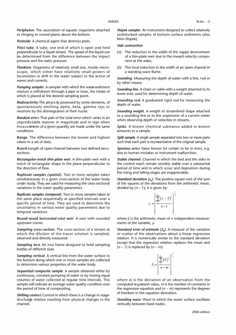
P e r i p h y t o n. The association of aquatic organisms attachedor clinging to rooted plants above the bottom.
Pesticide. A chemical agent that destroys pests.
Pitot tube. A tube, one end of which is open and heldperpendicular to a liquid stream. The speed of the liquid canbe determined from the diff e rence between the impactpressure and the static pressure.
Plankton. Organisms of relatively small size, mostly micro-scopic, which either have relatively small powers oflocomotion or drift in the water subject to the action ofwaves and currents.
Pumping sampler. A sampler with which the water- s e d i m e n tmixture is withdrawn through a pipe or hose, the intake ofwhich is placed at the desired sampling point.
R a d i o a c t i v i t y. The pro p e rty possessed by some elements, ofspontaneously emitting alpha, beta, gamma rays orneutrons by the disintegration of their nuclei.
Random erro r. That part of the total error which varies in anu n p redictable manner in magnitude and in sign whenm e a s u rements of a given quantity are made under the sameconditions.
R a n g e. The diff e rence between the lowest and highestvalues in a set of data.
R e a c h. Length of open channel between two defined cro s s -sections.
Rectangular-notch thin-plate weir. A thin-plate weir with anotch of rectangular shape in the plane perpendicular tothe direction of flow.
Replicate samples (spatial). Two or more samples takensimultaneously in a given cross-section of the water bodyunder study. They are used for measuring the cro s s - s e c t i o n a lvariations in the water quality parameters.
Replicate samples (temporal). Two or more samples taken atthe same place sequentially at specified intervals over aspecific period of time. They are used to determine theu n c e rtainty in various water quality parameters due totemporal variations.
Round-nosed horizontal-crest weir. A weir with ro u n d e dupstream corner.
Sampling cro s s - s e c t i o n. The cross-section of a stream atwhich the dilution of the tracer solution is sampled,observed and directly measured.
Sampling iro n. An iron frame designed to hold samplingbottles of different sizes.
Sampling vertical. A vertical line from the water surface tothe bottom along which one or more samples are collectedto determine various properties of the water body.
Sequential composite sample. A sample obtained either by continuous, constant pumping of water or by mixing equalvolumes of water collected at regular time intervals. Thissample will indicate an average water quality condition overthe period of time of compositing.
Shifting contro l. Control in which there is a change in stage-d i s c h a rge relation resulting from physical changes in thechannel.
Shipek sampler. An instrument designed to collect re l a t i v e l yundisturbed samples of bottom surface sediments (alsoM i n i - S h i p e k ) .
Side contraction.
(a) The reduction in the width of the nappe downstreamof a thin-plate weir due to the inward velocity compo-nent at the sides;
(b) The local reduction in the width of an open channel ina standing wave flume.
Sounding. Measuring the depth of water with a line, rod orby other means.
Sounding line. A chain or cable with a weight attached to itslower end, used for determining depth of water.
Sounding ro d. A graduated rigid rod for measuring thedepth of water.
Sounding weight. A weight of streamlined shape attachedto a sounding line or to the suspension of a current meterwhen observing depth or velocities in streams.
S p i k e. A known chemical substance added in knownamounts to a sample.
Split sample. A single sample separated into two or more part ssuch that each part is re p resentative of the original sample.
Spurious erro r. Value known for certain to be in erro r, e.g.due to human mistakes or instrument malfunction.
Stable channel. Channel in which the bed and the sides inthe control reach remain sensibly stable over a substantialperiod of time and in which scour and deposition duringthe rising and falling stages are inappreciable.
S t a n d a rd deviation (sy). The positive square root of the sumof the squares of the deviations from the arithmetic mean,divided by (n – 1); it is given by:
where –y is the arithmetic mean of n independent measure-ments of the variable, y.
Standard error of estimate (Se). A measure of the variationor scatter of the observations about a linear re g ression relation. It is numerically similar to the standard deviationexcept that the re g ression relation replaces the mean and(n – 1) is replaced by (n – m):
w h e re di is the deviation of an observation from thecomputed re g ression value, m is the number of constants inthe regression equation and (n – m) represents the degreesof freedom in the equation derivation.
Standing wave. Wave in which the water surface oscillatesvertically between fixed nodes.
€
Se=
di( )21
n
∑n − m
12
2006 edition
ANNEX III-An. – 5
€
sy =
yi − y ( )21
n
∑n −1
12

Stilling well. A well connected with the stream in such a way asto permit the measurement of the stage in relatively still water.
Subcritical flow. The flow in which the Froude number isless than unity and surface small disturbances will travelupstream and downstream.
S u b s i d e n c e. Lowering in elevation of a considerable area ofland surface, due to the removal of liquid or solid underlyingmaterial or removal of soluble material by means of water.
S u b s u rface float. A float with its greatest drag below thesurface for measuring subsurface velocities.
Supercritical flow. The flow in which the Froude number isg reater than unity and small surface disturbances will traveldownstream.
Surface float. A float with its greatest drag near the surfacefor measuring surface velocities.
Suspension cable. The wire from which the current meter issuspended and possibly incorporating an electrical insulatedcore.
Systematic error. That part of the error which either:
(a) Remains constant in the course of a number ofmeasurements of a given quantity;
(b) Varies according to a definite law when the conditionschange.
Te f l o n. Polytetrafluoroethylene, a man-made plastic materiali n e rt to most chemicals or reagents except molten alkalimetals. It is used for laboratory and field equipment.
Thin-plate weir. A weir constructed of a vertical thin-platewith a thin crest shaped in such a manner that the nappesprings clear of the crest.
T h ro a t. The minimum cross-sectional area within a flume. Itmay have any shape, e.g. re c t a n g u l a r, trapezoidal, U or anyother.
Ti d e. Periodic rise and fall of water in the seas or in larg elakes due principally to the gravitational attraction of themoon and the sun.
To l e r a n c e. The permissible variation of the specified value ofa quantity.
Tr a c e r. A substance or material, commonly an ion,compound or radionuclide introduced into a flow system tofollow the behaviour of some component of that system; itis necessary for the tracer, which can be observed, tobehave in exactly the same fashion as the component to befollowed, whose behaviour cannot easily be observed.
Tr a n s d u c e r. A device which responds to a phenomenon andp roduces a signal which is a function of one or more charac-teristics of the phenomenon.
Tr i a n g u l a r-notch (V-notch) thin-plate weir. A thin-plate weirwith two edges symmetrically inclined to the vertical tof o rm a triangular notch in the plane perpendicular to thedirection of the flow.
Tr i a n g u l a r- p rofile (Crump) weir. A bro a d - c rested weirhaving a triangular profile in a vertical direction in the dire c-tion of flow.
NOTE: This should not be confused with a triangular thin-plate weir.
True value. The value which is assumed to characterize aquantity in the conditions which exist at the moment whenthat quantity is observed (or is the subject of a determina-tion). It is an ideal value which could be known only if allcauses of error were eliminated.
U n c e rt a i n t y. The interval within which the true value of aquantity can be expected to lie with a stated probability.
Undercurrent. (See Density current)
Unstable channel. (See Stable channel)
Van Dorn sample. A messenger-operated water-suspendedsediment point sampler used to collect samples at a speci-fied depth. The long axis of the cylinder can be lowere deither horizontally or vertically.
Velocity rod; rod float. A floating rod weighted at the baseso that it travels in an almost vertical position; the immersedportion may be adjustable.
Viscosity. P ro p e rty of a fluid to resist shearing in the pre s e n c eof velocity gradients. It is usually expressed as a coeff i c i e n t .
Wading ro d. A light, hand-held rigid rod graduated forsounding the depth and positioning the current meter formeasuring the velocity in shallow streams suitable forwading.
NOTE: This may be used from boats or ice cover at shallow depth.
Water quality criteria. Scientific information, e.g. concentra-t i o n - e ffect data, used to recommend water quality objectives.
Water quality objective. A concentration or a narrative state-ment describing the water body, which, when met, willprotect the intended uses of the water.
Weighted mean. The arithmetic mean of a series of results ofm e a s u rements calculated as the sum of the observ a t i o n s ,each one being multiplied by the corresponding norm a l i z e dweight (the sum of the weights being unity).
We i r. An overflow stru c t u re which may be used for contro l l i n gu p s t ream water level or for measuring discharge or for both.
Wet line corre c t i o n. Depth correction to a sounding linem e a s u rement for that portion of the line which is below thewater surface when the flow deflects the sounding linedownstream.
2006 edition
TECHNICAL REGULATIONS — VOLUME III — HYDROLOGYIII-An. – 6
I – CALIBRATION OF CURRENT METERS IN STRAIGHT OPEN TANKS(See [D.1.2.] 3.1.1)
2006 edition
I-1 Scope and field of applicationNOTE: The material in this section of the annex is based on ISO
3455 (1976) entitled “Liquid flow measurements in openchannels — Calibration of rotating-element current metersin straight open tanks”.
This section specifies the procedure to be used for the cali-bration of current meters in order to conform to there q u i rements of Technical Regulation [D.I.2.] 3.1 and tomeet the re q u i rements for accuracy of measurement of riverd i s c h a rge indicated in Technical Regulation [D.1.2.] 3.6. Italso specifies the type of tank and equipment to be used andthe method of presenting the results.
NOTE: Detailed guidance on calibration of current meters is givenin the Guide to Hydrological Practices ( W M O-N o . 168) and inthe Manual on Stream Gauging (WMO-No. 519).
I-2 Principle of calibration procedureThe current meter should be drawn through clean still waterin a straight tank of uniform cross-section at a number ofu n i f o rm velocities. Measurements should be made of thespeed of the towing carriage and of the rate of revolution ofthe rotor of the current meter. The two sets of values shouldbe related by equation(s) of which the limits of applicationshould be stated.
I-3 Design criteria for calibrationstations
I-3.1 Dimensions of the calibration tank
NOTE: The dimensions of the tank and the number and the re l a t i v epositions of current meters in the tank cross-section mayaffect the test results.
I-3.1.1 Length
(a) The total length of a calibration tank should be consid-ered as comprising accelerating, stabilizing, measuringand braking sections.
(b) The length of the accelerating and braking sectionsshould be compatible with the design of the carr i a g eand the maximum speed at which the current meter isto be towed in the tank. The length re q u i red for thebraking section is governed by safety requirements.
(c) The length of the measuring section should be suchthat the calibration erro r, which is composed of inaccu-racies in the measurement of time, distance covere d ,and rate of revolution of the rotor, should not exceedthe desired tolerance at any velocity.
Example: If times both for distance covered by the carr i a g eand for the revolutions counted are measured toan uncertainty of 0.01 s in order to limit the erro rin time measurement to 0.1 per cent at the 95 per cent confidence level, the duration of thetest should be at least 10 s at maximum speed; ifthe maximum speed is 6 m/s then the measuringsection of the tank would be 60 m long; the totallength of the tank would there f o re be about1 0 0 m of which about 20 m would be foracceleration and stabilizing and 20 m for braking.
NOTE: Detailed descriptions of several tanks are given in theManual on Stream Gauging (WMO-No. 519).
I-3.2 Rating carriage
I-3.2.1 In order that the current meter can be movedt h rough the water at constant and accurately measure dspeeds, the current meter should be suspended from acarriage running on rails or a track.
I-3.2.2 The rails or track should be accurately alignedwith the longitudinal axis of the tank and the plane of therails should be parallel to the surface of the water in the tank.
I-3.2.3 The wheels of the carriage should be free ofi rregularities to eliminate irregular motion of the carr i a g eand transmission of vibrations to the current meters whichcould disturb the rating.
NOTE: Two types of carriage are in common usage, namely:
(a) The towed carriage which is moved along the rails by acable driven from a constant-speed motor standing apartf rom the moving carriage. The towed carriage may belightly constructed with the consequent advantage of highacceleration and quick braking, but the elasticity of thetowing cable may cause irregularities in the movement ofthe carriage;
(b) The self-propelled carriage which is moved along the rails byan internally mounted motor. The self-propelled carriage willbe heavier in construction as it also carries the driving motor.

This results in greater inertia of the carriage and assists insmoothing out the running irregularities of the carriage.
I-3.3 Measuring equipment
NOTE: The calibration of a current meter re q u i res the simultaneousmeasurement of the following three quantities:
(a) The distance covered by the carriage;
(b) The number of pulses delivered by the current meter;
(c) The time.
The towing speed is calculated from the simultaneous measure-ments of distance and time and the rate of revolution of the rotor isobtained by simultaneous measurement of the number of pulsesand time.
I-3.3.1 Distance
The uncertainty in the distance measurement should notexceed 0.1 per cent at the 95 per cent confidence level.
NOTE: Two of the most common methods are:
(a) The establishment of markers at regular intervals along thelength of the calibration tank which actuate mechanical oroptical pulse transmitters fitted to the carriage;
(b) The use of measuring wheels with mechanical or photo-electric pulse transmitters which are drawn along the trackby the carriage.
I-3.3.2 Time
The measurement of time should be accurate to within 0.1 per cent at the 95 per cent confidence level.
NOTE: Two of the most common timing methods in use are:
(a) A clock giving a contact pulse every one or several seconds.These time pulses are usually re c o rded on a graph ormagnetic tape together with the pulses of the ro t a t i n gelement of the current meter and the distances travelled. Thetime corresponding to an integral number of pulses from themeter is usually determined by interpolation of the time pulse;
(b) E l e c t ronic clocks, capable of measuring fractions of asecond, which time and display a preset number of distanceintervals and a corresponding number of pulses.
I-3.3.3 Current-meter pulses
(a) The uncertainty in the measurement of rotor re v o l u-tions should not exceed 0.1 per cent at the 95 per centconfidence level. The pulses from the current metershould be counted or recorded.
(b) In determining the number of rotor revolutions in agiven time, measurement should be made betweenidentical points on the current-meter pulse.
(c) When a re c o rding is made, the speed of the re c o rd i n gmedia should be adjustable so that the interval betweenthe current-meter pulse re c o rdings can be madecompatible with the speed re c o rdings of the carr i a g eand the re q u i red accuracy of the measure m e n t .
I-3.4 Ancillary equipment
In order to increase the efficiency of a current meter calibra-tion station, several items of ancillary equipment should beprovided:
(a) Filtering, dosing and scum-removing equipment formaintaining clear water;
(b) Stilling devices to reduce the reflection of disturbancesin the water by the end walls of the tank;
(c) Means for checking that a cable-suspended meter isproperly aligned at the start of a run;
(d) A thermometer to indicate the temperature of thewater in the tank.
NOTE: M e a s u rement of temperature of the water in the tank isneeded to determine the existence of density currents inthe tank and to compute the viscosity of the lubricants usedin the current meter being rated.
I-4 Calibration procedure
I-4.1 Instructions for calibration
The instructions for calibration should include:
(a) The limits of calibration speeds;
(b) Details of the means of suspension and weights;
(c) For current meters with oil-filled systems, specificationsof the oil used;
(d) I n f o rmation concerning the desired calibration docu-ments (equations, calibration diagrams or tables, andunits in which the results are to be expressed);
(e) Any particular re q u i rements, such as calibration “asreceived” and “after repair”.
I-4.2 Suspension of the current meter
I-4.2.1 B e f o re the current meter is immersed in water, itshould be checked for cleanliness, lubrication and mechan-ical and electrical functioning.
I-4.2.2 The suspension of the current meter shouldusually be the same as that used during field measure m e n t .
I-4.2.3 The current meter should be placed at a depthbelow the surface of the water so that surface influence isnegligible.
NOTES:
(a) For a propeller-type current meter, a depth (water level toro t a ry axis) twice the diameter of the ro t a ry element isgenerally sufficient.
(b) A cup-type current meter should be immersed to a depth ofat least 0.3 m or one-and-a-half times the height of therotor, whichever is greater.
I-4.2.4 When several current meters are calibrated atthe same time, care should be taken to ensure that there isno mutual interference.
2006 edition
TECHNICAL REGULATIONS — VOLUME III — HYDROLOGYIII-An. – 8

I-4.2.5 A ro d - s u p p o rted current meter should be rigidlyattached to the rod so that it is aligned in the direction oftravel.
I-4.2.6 A cable-suspended current meter should bealigned in the direction of travel at the start of each run.
I-4.2.7 If the meter is of the type which is capable ofswivelling in a vertical and/or horizontal plane, its balanceshould be checked and, if necessary, adjusted so that it ishorizontal and perpendicular to the cross-section beforecalibration tests are started.
I-4.3 Performance of calibration
I-4.3.1 Minimum response speed
The minimum response speed should be determined bygradually increasing the carriage velocity from zero until therotating element revolves at a constant angular velocity.
I-4.3.2 Number of calibration points
M e a s u rements should be carried out from the minimumresponse speed at a sufficient number of towing velocitiesto enable the calibration of the current meter to be definedaccurately.
NOTE: It will generally be necessary to carry out tests at closervelocity intervals at the lower end of the range because thel a rgest errors, expressed as percentages, usually occur inthis range.
I-4.3.3 Stilling time
The water in the tank should be relatively still before eachtest run and the waiting period should be chosen so thatresidual velocities are negligible compared with the nexttest velocity.
NOTE: The time needed for the water to still depends on thedimensions of the tank, the type of damping device, thep revious test velocity, the size and shape of the curre n tmeters and of the immersed portion of the suspensionequipment.
I-5 Presentation of results
I-5.1 Calibration diagrams
The calibration points should be entered in a graphic systemwith the velocity v as the ordinate and the rate of re v o l u t i o nof the rotor n as the abscissa.
I-5.2 Calibration equations
The calibration form should indicate the equation(s) of thestraight line(s) with which the calibration curve ro u g h l y
coincides, specifying for each value of n the interval towhich it is applicable, as follows:
(a) v = a + bn
where:
v is the velocity, in metres per second; n is the number or revolutions of the rotor per second;a and b are constants determined for each equation;
or
(b)
when it is convenient to show the time t corresponding toN total rotor revolutions.
I-5.3 Calibration tables
The relation between v and n should be presented in tabularform.
NOTE: The velocity can be given for every 0.01 rev s-1 or for inte-gral numbers of revolutions in a pre d e t e rmined timei n t e rval or corresponding to a pre d e t e rmined number ofrevolutions.
I-5.4 Calibration documents
In addition to the elements mentioned in 1-5.1, I-5.2 and I-5.3, the calibration form should include the followinginformation:
(a) The name and address of the rating station;
(b) The date of calibration;
(c) The calibration number;
(d) The make and type of current meter;
(e) The serial number of the current meter and of eachrotor;
(f) Details of the suspension used and weights;
(g) The position of the current meter in the cross-sectionof the tank;
(h) A statement of the minimum speed of response;
(i) The limits of calibration;
(j) Any remarks such as “as received” rating or statementsof any modifications made to the current meter, suchas the fitting of spare parts;
(k) The water temperature during calibration;
(l) The viscosity of the bearing oil;
(m) A statement concerning the accuracy of the ratingequation, which should include an assessment of theaccuracy of the basic calibration technique;
(n) The signature of a responsible member of the staff atthe calibration station.
2006 edition
ANNEX III-An. – 9
€
v = a + b Nt


II – WATER-LEVEL MEASURING DEVICES(See [D.1.2.] 3.1.2)
II-1 Scope and field of applicationNOTES:
(a) The material in this section of the annex is based on ISO4373 (1995) entitled “Measurement of liquid flow in openchannels — Water-level measuring devices”.
(b) Detailed guidance on water-level measuring devices is givenin the Guide to Hydrological Practices ( W M O-N o . 168) and inthe Manual on Stream Gauging (WMO-No. 519).
This section specifies the functional requirements of:
(a) A stilling well with intake pipes for float-operated water-level recorders;
(b) Stage sensing devices;
(c) Water-level recording devices;
in order to conform with the re q u i rements of Te c h n i c a lRegulation [D.1.2.] 3.1 and to meet the re q u i rements foraccuracy of measurement of stages and groundwater levelsindicated in Technical Regulation [D.1.2.] 3.5.
II-2 Stilling well and intakes
II-2.1 Stilling well
NOTE: The function of the stilling well is:
(a) To accommodate the instrument and protect the floatsystem;
(b) To provide within the well an accurate presentation of thewater level in the river;
(c) To damp out oscillations of the water surface.
I I - 2 . 1 . 1 The well may be placed in the stream bank or inthe channel but should not be located in the channel whereflow conditions would lead to separation and stagnatione ff e c t s .
I I - 2 . 1 . 2 The well should not interf e re with the flow patternin the approach channel and, if set in relation to a control, itshould be placed in the pool formed by the control butu p s t ream from the area of drawdown at the contro l .
II-2.1.3 The well should be firmly founded when placedin the bank and firmly anchored when standing in thestream so that it should remain stable at all times.
II-2.1.4 The well and all construction joints of well andintake pipes should be watertight so that water can enter orleave only by the intake itself.
II-2.1.5 The well should be vertical and have suff i c i e n theight and depth to allow the float to travel freely the fullrange of possible water levels.
I I - 2 . 1 . 6 The dimensions of the well should be such as toallow unrestricted operation of all equipment installed in it.Clearance between walls and float should be at least 75 mmand, where two or more floats are used within the well, clear-ance between them should be at least 150 mm. In silt-ladenrivers the well should be large enough to be entered and cleaned.
II-2.1.7 When placed in the bank of the stream, the still-ing well should have a watertight bottom to pre v e n tseepage into or leakage out of the chamber.
II-2.1.8 In wells with a watertight bottom, the bottom ofthe well should be at least 300 mm below the invert of thelowest intake to provide space for sediment storage and toavoid the danger of the float grounding at times of low flow.
II-2.1.9 In cold climates the well should be pro t e c t e df rom the formation of ice by the use of well covers, sub-floors, heaters, or oil on the water surface. When oil is used,the oil surface will stand higher than the water level in thestream and a correction is required.
II-2.2 Intakes
NOTE: The functions of the intakes to the stilling well are:
(a) To allow water to enter or leave the stilling well so that thewater in the well is maintained at approximately the sameelevation as that in the stream under all conditions of flow;
(b) To limit lag and oscillating effects within the stilling well.
Intakes may take the form of a pipe connecting the well tothe river when the well is set back into the bank or a series ofholes or slots cut into the well itself when it is set dire c t l yinto the river. In rivers with a high silt content a well set inthe stream may have a hopper-shaped bottom to serve as anintake and also as a means of self-cleansing. Two or moreintakes may be installed, at different levels, to ensure opera-tion of the system if one intake becomes blocked.
II-2.2.1 The dimensions of the intakes should be larg eenough to allow the water level in the well to follow the riseand fall of the river stage without appreciable delay.
2006 edition

II-2.2.2 The dimensions of the intakes should be smallenough to damp oscillations caused by wave action or surg e s .
NOTE: These are conflicting re q u i rements and a suitable balanceshould be achieved. As a general guide the total c ross-sectional area of the intakes should not be less thanone per cent of the cross-sectional area of the well.
II-2.2.3 For a stilling well set into a bank the invert of thelowest intake should be at least 150 mm below the lowestanticipated stage and should enter the stilling well at least300 mm above the well bottom. In cold climates this intakeshould be below the frost line.
II-2.2.4 Intake pipes should be laid at a constant gradi-ent and on a suitable foundation which will not subside.
I I - 2 . 2 . 5 The intake should be so oriented in the stre a mthat it will sense the true water level. When velocities inthe stream at the point of measurement are suff i c i e n t l yl a rge that the dynamic pre s s u re is of sensible magnitude,the intake should incorporate a static pre s s u re device.
II-2.2.6 Intake pipes more than 20 m long should be provided with an intermediate manhole fitted with inter-nal baffles to act as a silt trap and provide access forcleaning.
II-2.2.7 Means of cleaning the intakes should bep rovided, either by a flushing system where water underseveral metres of head can be applied to the stilling wellend of the intake by pumping water through the intake orby hand cleaning with rods.
I I - 2 . 2 . 8 W h e re velocity past the river end of the intakeis high, drawdown of the water level should be reduced byattaching a capped and perforated static tube to the riverend of the intake and extending it horizontallyd o w n s t re a m .
II-3 Stage sensing devices
II-3.1 Gauge datum
NOTE: The gauge datum may be a recognized datum, such asmean sea level, or an arbitrary datum plane selected for theconvenience of using gauge readings of relatively low, butpositive, numbers.
II-3.1.1 If an arbitrary datum plane is used, it should bere f e rred to a benchmark of known elevation above sea levelby accurate levelling.
II-3.1.2 The zero of the gauge should be correlated witha national datum through a station benchmark.
II-3.1-3 The station benchmark should be set in a posi-tion offering maximum security against disturbance. Itshould be securely fixed in a concrete block or similarmounting that extends below the ground surface to a levelfree from disturbance, such as frost or hill creep.
II-4 Vertical and inclined staff gaugesNOTE: Such gauges comprise a scale marked on or attached to a
suitable surface.
II-4.1 Functional requirements
These gauges should meet the following functionalrequirements:
(a) They should be accurate and clearly marked;
(b) They should be durable and easy to maintain;
(c) They should be simple to install and use.
II-4.2 Material
The material of which a gauge is constructed should bedurable and should have a low coefficient of expansion.
II-4.3 Graduation
II-4.3.1 Graduations should be clearly and permanentlymarked. The numerals should be distinct and placed in sucha way that there is no possibility of any ambiguity.
II-4.3.2 Gauge plates should be manufactured in suit-able lengths with the face of the scale not less than 50 mmin width.
I I - 4 . 3 . 3 The markings of the subdivisions should have ap recision of ± 0.5 mm, and the cumulative error in lengthshould not exceed 0.1 per cent or 0.5 mm, whichever is gre a t e r.
II-4.4 Installation and use
II-4.4.1 General
(a) The gauge should preferable be placed near the bank sothat a direct reading of water level may be made.
(b) The gauge should be located as close as possible to themeasuring section without affecting the flow condi-tions at this point.
(c) It should be readily and conveniently accessible so thatthe observer may make readings as near as possible toeye level.
II-4.4.2 Vertical gauges
The gauge board or backing plate should be secure l yfastened to the surface of a wall or to piles having a verticalface parallel to the direction of flow.
II-4.4.3 Stepped gauges
W h e re the range of water levels exceeds the capacity of asingle vertical gauge, additional sections may be installed onthe line of the cross-section normal to the direction of flow.
(a) Stepped gauges should be installed at such intervals asto ensure the measurement of water level at all stages.
(b) The scales on the series of stepped gauges should havean adequate overlap.
II-4.4.4 Inclined gauges
An inclined gauge should be installed in such a manner as tofollow closely the contour of the river bank and should be cali-brated in situ by precise levelling from the station benchmark.
2006 edition
TECHNICAL REGULATIONS — VOLUME III — HYDROLOGYIII-An. – 12
II-5 Needle gaugesA needle water-level gauge consists of a point and somemeans of determining its exact vertical position relative to adatum. The two types of needle gauge are:
(a) The point gauge, whose tip approaches the fre esurface from above;
(b) The hook gauge, which is hook-shaped, and whose tipis immersed and approaches the free surface fro mbelow.
The vertical position may be determined by a graduatedscale, a tape with some vernier arrangement, or a digitalindicator.
II-5.1 Functional requirements
(a) A needle gauge installation should permit measure-ment of stage to be made at all levels from below thelowest to above the highest level anticipated.
(b) There should be good illumination of the place wherethe tip meets the free liquid surface.
(c) The tip should be tapered to a point having an includedangle of approximately 60° and the point should berounded to a radius of approximately 0.25 m m .
II-5.2 Material
A needle gauge and auxiliary parts should be madethroughout of durable corrosion-resistant materials.
II-5.3 Graduation
The graduation of a hook or point gauge should be inmillimetres and should be clearly and accurately marked.
II-5.4 Installation and use
(a) A needle should be mounted over an open watersurface at the edge of a stream if conditions permit. Ifthis is not practicable because of turbulence, winde ffect or inaccessibility, a stilling bay or stilling wellshould be installed.
(b) The location of the needle gauge should be as close aspossible to the measuring section.
(c) W h e re more than one datum plate or bracket isprovided at different levels, or where a stepped gaugeis used, all should lie on a single cross-section normalto the direction of flow in the stream. If this is not prac-ticable and it is necessary to stagger the points, allshould lie within a distance of one metre on either sideof the cross-section.
(d) Datum plates and brackets should be mounted on asecure foundation which extends below the frost line.
(e) The elevation of the datum plates, with re f e rence towhich the level of the free surface is determ i n e d ,should be established with great care. The tolerance
on the transfer of level from the station benchmark toeach datum plate should not exceed ± 1.0 mm.
II-6 Float gaugesNOTE: The float gauge is used to measure stage usually inside
a stilling well. A typical float gauge consists of a float operating in a stilling well, a graduated steel tape, a counterweight, a pulley and a pointer.
II-6.1 Functional requirements
(a) A float gauge installation should permit measurementof stage to be made at all levels from the lowest to thehighest level anticipated.
(b) The float should be made of durable corro s i o n - re s i s t a n tand antifouling material. It should be leakproof andfunction in a truly vertical direction.
(c) The float should float properly and the tape or wireshould be free of twists or kinks.
(d) A means should be provided for readily checking thefloat gauge readings with the actual stream stage.
II-6.2 Graduation
The graduations of a float gauge should be in millimetre sand should be clearly and accurately marked.
II-7 Wire-weight gaugesN O T E : A typical wire-weight gauge consists of a drum wound with a
single layer of cable, a bronze weight attached to the end of thecable, a graduated disc and a counter, all housed within ap rotective housing. The wire-weight gauge is used as an outsidere f e rence gauge where other outside gauges are difficult tomaintain. The wire-weight gauge is normally mounted wheret h e re is a bridge or other stru c t u re over the water.
II-7.1 Functional requirements
A wire-weight gauge should permit measurement of stagethroughout the range of levels anticipated.
II-7.2 Material
A wire-weight gauge should be made throughout ofdurable corrosion-resistant materials.
II-7.3 Graduation
The graduations of a wire-weight gauge should be inmillimetres.
II-7.4 Installation and use
(a) The gauge should not be installed in a location wherethe water surface is disturbed by turbulence, windeffects or afflux.
(b) The elevation of a wire-weight gauge should be veri-fied frequently to ensure reliability of stageobservations.
2006 edition
ANNEX III-An. – 13
II-8 Pressure gaugesN O T E : P re s s u re gauges are frequently used at sites where it would be
too expensive to install stilling wells. A widely used method ofmeasuring water level is to measure the height of a column ofwater with respect to some datum plane. This can be accom-plished indirectly by sensing the water pre s s u re at a fixed pointbelow the water surface and then utilizing the hydrostatic principle that the pre s s u re of a liquid is pro p o rtional to thedepth. The most successful and widely used method of trans-mitting the pre s s u re is the gas-purge technique.
II-8.1 Gas-purge (bubbler) technique
(a) An adequate supply of gas or compressed air shouldbe provided. The supply should have a delivery pre s s u rein excess of the range to be measured.
(b) A pre s s u re - reducing valve should be provided so thata pre s s u re safely in excess of that of the maximumrange can be set. A flow control valve and some formof visual flow rate indicator should be installed sothat the discharge of gas supplied to the system canbe properly adjusted. The pre s s u re should be set top revent water from entering the tube, even underthe most rapid rates of change expected.
(c) I n c o rrect readings due to the friction of the gas movingthrough the tube should be minimized.
(d) The tubing should be installed with a continuousdownslope to the orifice.
II-8.2 Water density compensation
Since the density of the water which the sensor is tomeasure will vary with temperature and also with chemicaland silt content, either automatic or manual means ofcompensating for these changes should be provided.
II-8.3 Changes in gas weight
If the gas technique is used to transmit pressure, provisionsshould be made for compensating for changes in thedensity of the gas with temperature and pressure.
II-8.4 Range
The range of the instrument should be adequate to accom-modate the anticipated range in water level.
II-8.5 Response
The response of the instrument should be sufficiently rapidto follow any expected rate of change in water level.
II-9 Recording devices
II-9.1 Mechanical recorders
II-9.1.1 Driving torque
NOTE: In the re c o rding devices, the angular movement of theinput shaft is transformed by mechanical linkage into move-ment of the stylus of an analogue re c o rder or into thecoding mechanism of a digital re c o rd e r. If the friction is
high, i.e. the driving torque re q u i red to position the re c o rd-ing element is high, then there is an appreciable time lagfollowing a water-level change.
(a) The driving torque should be sufficient to overcome thefriction generated by mechanical linkages.
(b) The friction should be as low as feasible and should notexceed 7 mN.m.
II-9.1.2 Hysteresis (lost motion)H y s t e resis should be kept to a minimum and should notexceed 3 mm.
NOTE: If the input shaft is rotated in one direction until the stylusfollows and then the direction of rotation reversed, the totalh y s t e resis is the amount of motion re q u i red to cause thestylus to follow in the reversed direction.
II-9.1.3 Timing mechanism(a) The clock mechanism which rotates the chart plate
should be of high quality, sturdy and reliable andshould be protected from dirt, corrosion and insects byits housing.
(b) The uncertainty in the time measurement or the clock-work should not exceed ± 30 s/d average over a periodof at least 30 days.
(c) A movement adjustment should be provided to perm i tregulation within the accuracy requirements set forthin (b).
II-9.1.4 Paper (chart or tape)The paper used should remain stable within relatively closetolerance throughout the range of temperature and humid-ity conditions expected.
II-9.1.5 StylusIf a pen is used, the pen and ink should be such that aneasily readable trace is produced without blotting. If a pencilis used, it should be of proper hardness to produce a read-able trace.
II-9.1.6 Errors
The sources of errors when using a recording device are asfollows:
(a) Friction in the driving mechanism;
(b) Hysteresis in the driving mechanism;
(c) Line shift, caused by change in depth of flotation ofthe float when the stage changes rapidly and with itthe weight of the float line changes;
(d) Expansion and contraction of paper;
(e) A m b i g u i t y, if the stage is between digits (in digitalrecorders).
In digital re c o rders, if the stage is between digits, there c o rder should be forced to the nearest digit before thetape is punched in order to prevent ambiguity.
2006 edition
TECHNICAL REGULATIONS — VOLUME III — HYDROLOGYIII-An. – 14
II-9.1.7 Environmental requirements
The re c o rder should operate satisfactorily over the pre v a i l i n granges of ambient temperature and relative humidity.
II-9.1.8 Material
All parts of the re c o rder should be manufactured of materialswhich will resist corrosion under conditions of field usage.
II-9.1.9 Housing
The recorder should be housed in a drip-proof, dust-proof,w e a t h e r- resistant case. The case should contain a windowso that visual inspection of the re c o rd can be made withoutopening the case.
II-9.1.10 Levelling of the input shaft
Means of horizontal levelling of the input shaft should beprovided.
II-9.1.11 Operational manual
A general operational manual should be provided with suchdescriptions and diagrams as necessary for proper operationand maintenance of the recorder.
II-9.2 Pressure-actuated recorders
II-9.2.1 Pressure range
(a) The pressure range of the recorder should be selectedto encompass the expected total range of the pre s s u reof the water. Allowance should be made for anye x t reme condition to avoid damage to the pre s s u re -sensing element.
(b) The mechanical and pre s s u re-sensing elements shouldbe of high quality, both in material and workmanshipto minimize hysteresis.
(c) A means should be incorporated in the re c o rder foradjusting for altitude.
II-9.2.2 Timing mechanism
As in II-9.1.3 above.
II-9.2.3 Paper (chart or tape)
As in II-9.1.4 above.
II-9.2.4 Stylus
As in II-9.1.5 above.
II-9.2.5 Environmental requirementsThe re c o rder should operate satisfactorily over the pre v a i l i n granges of ambient temperature, relative humidity and atmo-spheric pressure.
II-9.2.6 MaterialAs in II-9.1.8 above.
II-9.2.7 HousingAs in II-9.1.9 above.
II-9.2.8 Operational manualAs in II-9.1.11 above.
II-9.3 Electronic recorders
II-9.3.1 AccuracyThe uncertainty in the re c o rds of the electronic re c o rd e rshould not exceed 0.5 per cent of its full scale reading.
II-9.3.2 ReadabilityThe overall movement of the operating mechanism (stylus)should be adequate to allow resolution of the smallest incre-ment. The width of the chart paper should be at least equalto the stylus movement.
II-9.3.3 StabilityA recorder used for the recording of water level should bestable within ± 2 readability divisions over a 30-day period.
NOTE: The stability of the re c o rder is its ability to maintain the samereading within a given tolerance for the same input signal.
II-9.3.4 Timing mechanismAs in II-9.1.3 above.
II-9.3.5 PaperPaper of only the best quality and with an accurate scaleprinting should be used.
II-9.3.6 StylusAs in II-9.1.5 above.
II-9.3.7 Environmental requirementsAs in II-9.1.7 above.
II-9.3.8 MaterialThe re c o rder should be constructed of materials and housedin a manner as to function satisfactorily under conditions offield usage for prolonged periods of time.
II-9.3.9 HousingAs in II-9.1.9 above.
II-9.3.10 Operational manual
As in II-9.1.11 above.
2006 edition
ANNEX III-An. – 15

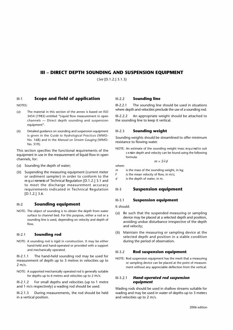
III – DIRECT DEPTH SOUNDING AND SUSPENSION EQUIPMENT(See [D.1.2.] 3.1.3)
III-1 Scope and field of applicationNOTES:
(a) The material in this section of the annex is based on ISO3454 (1983) entitled “Liquid flow measurement in openchannels — Direct depth sounding and suspension equipment”.
(b) Detailed guidance on sounding and suspension equipmentis given in the Guide to Hydrological Practices ( W M O -No. 168) and in the Manual on Stream Gauging ( W M O -No. 519).
This section specifies the functional re q u i rements of theequipment in use in the measurement of liquid flow in openchannels, for:
(a) Sounding the depth of water;
(b) Suspending the measuring equipment (current meteror sediment sampler) in order to conform to there q u i rements of Technical Regulation [D.1.2.] 3.1 andto meet the discharge measurement accuracyre q u i rements indicated in Technical Regulation[D.1.2.] 3.6.
III-2 Sounding equipmentNOTE: The object of sounding is to obtain the depth from water
surface to channel bed. For this purpose, either a rod or asounding line is used, depending on velocity and depth offlow.
III-2.1 Sounding rod
NOTE: A sounding rod is rigid in construction. It may be eitherhand-held and hand-operated or provided with a supportand mechanically operated.
III-2.1.1 The hand-held sounding rod may be used form e a s u rement of depth up to 3 metres in velocities up to 2 m/s.
NOTE: A supported mechanically operated rod is generally suitablefor depths up to 6 metres and velocities up to 2 m/s.
III-2.1.2 For small depths and velocities (up to 1 metreand 1 m/s respectively) a wading rod should be used.
III-2.1.3 During measurements, the rod should be heldin a vertical position.
III-2.2 Sounding line
I I I - 2 . 2 . 1 The sounding line should be used in situationsw h e re depth and velocities preclude the use of a sounding ro d .
III-2.2.2 An appropriate weight should be attached tothe sounding line to keep it vertical.
III-2.3 Sounding weight
Sounding weights should be streamlined to offer minimumresistance to flowing water.
NOTE: An estimate of the sounding weight mass re q u i red to suitc e rtain depth and velocity can be found using the followingformula:
m = 5 –v dwhere:m is the mass of the sounding weight, in kg;–v is the mean velocity of flow, in m/s;d is the depth of water, in m.
III-3 Suspension equipment
III-3.1 Suspension equipment
It should:
(a) Be such that the suspended measuring or samplingdevice may be placed at a selected depth and position,avoiding undue disturbance irrespective of the depthand velocity;
(b) Maintain the measuring or sampling device at theselected depth and position in a stable conditionduring the period of observation.
III-3.2 Rod suspension equipment
NOTE: Rod suspension equipment has the merit that a measuringor sampling device can be placed at the point of measure-ment without any appreciable deflection from the vertical.
III-3.2.1 Hand-operated rod suspension equipment
Wading rods should be used in shallow streams suitable forwading and may be used in water of depths up to 3 metre sand velocities up to 2 m/s.
2006 edition
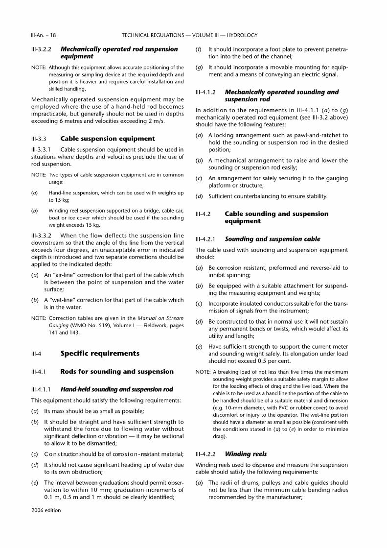
III-3.2.2 Mechanically operated rod suspension equipment
NOTE: Although this equipment allows accurate positioning of themeasuring or sampling device at the re q u i red depth andposition it is heavier and re q u i res careful installation andskilled handling.
Mechanically operated suspension equipment may beemployed where the use of a hand-held rod becomesimpracticable, but generally should not be used in depthsexceeding 6 metres and velocities exceeding 2 m/s.
III-3.3 Cable suspension equipment
Ill-3.3.1 Cable suspension equipment should be used insituations where depths and velocities preclude the use ofrod suspension.
NOTE: Two types of cable suspension equipment are in commonusage:
(a) Hand-line suspension, which can be used with weights upto 15 kg;
(b) Winding reel suspension supported on a bridge, cable car,boat or ice cover which should be used if the soundingweight exceeds 15 kg.
III-3.3.2 When the flow deflects the suspension linedownstream so that the angle of the line from the verticalexceeds four degrees, an unacceptable error in indicateddepth is introduced and two separate corrections should beapplied to the indicated depth:
(a) An “air-line” correction for that part of the cable whichis between the point of suspension and the watersurface;
(b) A “wet-line” correction for that part of the cable whichis in the water.
NOTE: C o rrection tables are given in the Manual on Stre a mG a u g i n g (WMO-No. 519), Volume I — Fieldwork, pages141 and 143.
III-4 Specific requirements
III-4.1 Rods for sounding and suspension
I I I - 4 . 1 . 1 Hand-held sounding and suspension ro d
This equipment should satisfy the following requirements:
(a) Its mass should be as small as possible;
(b) It should be straight and have sufficient strength towithstand the force due to flowing water withoutsignificant deflection or vibration — it may be sectionalto allow it to be dismantled;
(c) C o n s t ruction should be of corro s i o n - resistant material;
(d) It should not cause significant heading up of water dueto its own obstruction;
(e) The interval between graduations should permit obser-vation to within 10 mm; graduation increments of0.1 m, 0.5 m and 1 m should be clearly identified;
(f) It should incorporate a foot plate to prevent penetra-tion into the bed of the channel;
(g) It should incorporate a movable mounting for equip-ment and a means of conveying an electric signal.
III-4.1.2 Mechanically operated sounding and suspension rod
In addition to the re q u i rements in III-4.1.1 (a) to (g)mechanically operated rod equipment (see III-3.2 above)should have the following features:
(a) A locking arrangement such as pawl-and-ratchet tohold the sounding or suspension rod in the desire dposition;
(b) A mechanical arrangement to raise and lower thesounding or suspension rod easily;
(c) An arrangement for safely securing it to the gaugingplatform or structure;
(d) Sufficient counterbalancing to ensure stability.
III-4.2 Cable sounding and suspension equipment
III-4.2.1 Sounding and suspension cable
The cable used with sounding and suspension equipmentshould:
(a) Be corrosion resistant, pre f o rmed and reverse-laid toinhibit spinning;
(b) Be equipped with a suitable attachment for suspend-ing the measuring equipment and weights;
(c) Incorporate insulated conductors suitable for the trans-mission of signals from the instrument;
(d) Be constructed to that in normal use it will not sustainany permanent bends or twists, which would affect itsutility and length;
(e) Have sufficient strength to support the current meterand sounding weight safely. Its elongation under loadshould not exceed 0.5 per cent.
NOTE: A breaking load of not less than five times the maximumsounding weight provides a suitable safety margin to allowfor the loading effects of drag and the live load. Where thecable is to be used as a hand line the portion of the cable tobe handled should be of a suitable material and dimension(e.g. 10-mm diameter, with PVC or rubber cover) to avoidd i s c o m f o rt or injury to the operator. The wet-line port i o nshould have a diameter as small as possible (consistent withthe conditions stated in (a) to (e) in order to minimizedrag).
III-4.2.2 Winding reels
Winding reels used to dispense and measure the suspensioncable should satisfy the following requirements:
(a) The radii of drums, pulleys and cable guides shouldnot be less than the minimum cable bending radiusrecommended by the manufacturer;
2006 edition
TECHNICAL REGULATIONS — VOLUME III — HYDROLOGYIII-An. – 18
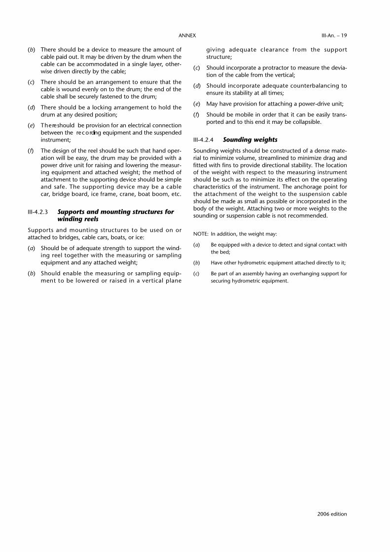
(b) T h e re should be a device to measure the amount ofcable paid out. It may be driven by the drum when thecable can be accommodated in a single layer, other-wise driven directly by the cable;
(c) T h e re should be an arrangement to ensure that thecable is wound evenly on to the drum; the end of thecable shall be securely fastened to the drum;
(d) T h e re should be a locking arrangement to hold thedrum at any desired position;
(e) T h e re should be provision for an electrical connectionbetween the re c o rding equipment and the suspendedinstrument;
(f) The design of the reel should be such that hand oper-ation will be easy, the drum may be provided with apower drive unit for raising and lowering the measur-ing equipment and attached weight; the method ofattachment to the supporting device should be simpleand safe. The supporting device may be a cable c a r, bridge board, ice frame, crane, boat boom, etc.
III-4.2.3 Supports and mounting structures for winding reels
S u p p o rts and mounting stru c t u res to be used on orattached to bridges, cable cars, boats, or ice:
(a) Should be of adequate strength to support the wind-ing reel together with the measuring or samplingequipment and any attached weight;
(b) Should enable the measuring or sampling equip-ment to be lowered or raised in a vertical plane
giving adequate clearance from the support s t ru c t u re ;
(c) Should incorporate a protractor to measure the devia-tion of the cable from the vertical;
(d) Should incorporate adequate counterbalancing toensure its stability at all times;
(e) May have provision for attaching a power-drive unit;
(f) Should be mobile in order that it can be easily trans-ported and to this end it may be collapsible.
III-4.2.4 Sounding weights
Sounding weights should be constructed of a dense mate-rial to minimize volume, streamlined to minimize drag andfitted with fins to provide directional stability. The locationof the weight with respect to the measuring instru m e n tshould be such as to minimize its effect on the operatingcharacteristics of the instrument. The anchorage point forthe attachment of the weight to the suspension cableshould be made as small as possible or incorporated in thebody of the weight. Attaching two or more weights to thesounding or suspension cable is not recommended.
NOTE: In addition, the weight may:
(a) Be equipped with a device to detect and signal contact withthe bed;
(b) Have other hydrometric equipment attached directly to it;
(c) Be part of an assembly having an overhanging support forsecuring hydrometric equipment.
2006 edition
ANNEX III-An. – 19


IV – ROTATING ELEMENT TYPE CURRENT METERS(See [D.1.2.] 3.1.4)
2006 edition
IV-1 Scope and field of applicationNOTES:
(a) The material in this section of the annex is based on ISO2537 (1988) entitled “Liquid flow measurement in openchannels — Rotating element current meters”.
(b) Detailed guidance on current meters is given in the Guideto Hydrological Practices (WMO-No. 168) and in the M a n u a lon Stream Gauging (WMO-No. 519).
This section specifies the operational re q u i re m e n t s ,c o n s t ruction, calibration and maintenance of ro t a t i n gelement current meters in order to conform to the require-ments of Technical Regulation [D.I.2.] 3.1.4.
IV-2 Operational requirementsNOTE: C u rrent meters of conventional construction are intended
to operate in a horizontal or near horizontal position.Current meters designed to operate in other positions arenot covered by this section.
IV-2.1 The equipment should maintain alignment withthe flow in such a way that the rotating element respondsto flow movement as intended. If a pivoted suspension isincorporated within the current meter, it should permit fre e-dom in the vertical plane to ensure correct alignment withthe liquid flow.
IV-2.2 The current meter should offer minimum resis-tance to the force of the current.
IV-2.3 The rotating element of the current metershould be such that, when driven by the fluid, it rotates atan angular velocity which has a known relation to the veloc-ity of the flow within the calibrated velocity range stated bythe manufacturer or rating laboratory.
IV-2.4 The meter should respond rapidly and consis-tently to changes in velocity; the manufacturer should statethe expected response rates.
IV-2.5 Unless indicated otherwise, the current metershould be suitable for use in silty and/or saline waters.
IV-3 Constructional featuresIV-3.1 The propellers should be made from a materialwhich will not allow them to be easily distorted or bent.
IV-3.2 The resisting torque of the bearings should be assmall as possible and should be constant during use.Bearings should be lubricated as stated by the manufacture r.P rovision should be made to keep silt and water from thebearings except as re q u i red for water-lubricated bearings.
I V- 3 . 3 The revolutions of the rotor should, by meansof mechanical contracts or by means of magnetic, opticalor other devices, give a clear and positive signal at allvelocities within the effective range of the meter. If electri-cal connections are used, they should be appro p r i a t e l yw a t e r p ro o f e d .
IV-3.4 M a n u f a c t u rers should stipulate the maximumconductivity of water in which the meter can be used.
IV-3.5 For the measurement of low velocities, it shouldbe possible to choose the frequency of signals transmittedby the counting mechanism in such a way as to reduce to aminimum the errors entailed in measurements of norm a lduration.
IV-3.6 For the measurement of high velocities, if thefrequency of the signals is such that they can no longer becounted or indicated properly, a device that will detect allinput signals at these high velocities should be provided.
IV-3.7 S p a re parts should be fully interchangeable so asto have uniform functional characteristics and should causeless than 2 per cent divergence from the calibration.
IV-3.8 Current meters should be constructed of corro-sion-resistant materials throughout or of materials that aree ffectively protected against corrosion encountered in natu-ral waters. The meter should be of sufficiently ru g g e dc o n s t ruction to maintain calibration under conditionsnormally encountered.
IV-4 CalibrationIV-4.1 All calibrations should conform to the re q u i re-ments set out in section I of this annex.
IV-4.2 When current meters are calibrated, either indi-vidually or by groups, a calibration document as specified insection I, I-5.4 of this annex should be furnished with eachmeter.
IV-4.3 G roup ratings should be based on the calibra-tion of a group of current meters of uniform manufacture.The sample calibrated should be adequate in number and

should comprise, if possible, both new current meters andwell-maintained used current meters.
IV-4.4 If group ratings are used, the calibration ofmeters should be periodically checked to ensure that theycontinue to operate within the expected tolerances.
IV-4.5 Individually calibrated current meters should be recalibrated on a routine basis at yearly intervals or after300 hours of use, whichever is the shorter.
IV-4.6 A p a rt from the regulations above, a curre n tmeter should be recalibrated whenever its perf o rmance issuspect.
IV-4.7 For the reliability of the calibration, the ratingl a b o r a t o ry should state tolerance limits at the 95 per centconfidence level at velocities of 0.15, 0.25 and 0.50 m/s anda b o v e .
IV-4.8 As a check for goodness of fit of the calibrationcurve, the manufacturer or rating laboratories should statethe standard error of the data for the lower and upper limitsof calibration, and for at least two intermediate points. Thes t a n d a rd error should be stated as a percentage of the meanvelocity class and should be related to the 95 per cent confi-dence limits.
IV-5 MaintenanceNOTE: In general, under conditions of normal operation, the user
should follow recommended check procedures before andafter each discharge measurement, as laid down in themanufacturer’s operations and servicing manual.
IV-5.1 The meter should be examined, before and aftereach discharge measurement, for worn or damaged bear-ings, proper shaft alignment, correct operation of contactpoints and deformation of the yoke or cup-wheel in the caseof cup-type meters, or of the propeller in the case ofpropeller-type meters.
IV-5.2 For inspection, it should be possible to dismantleand reassemble the current-meter assembly in the field,
without specialized workshop facilities and by personnelwithout specialist training. The tools which are required toc a rry out this operation should be supplied as standardaccessories.
IV-5.3 B e f o re use, the meter should be tested forc o rrect operation by the signal test. By turning the ro t o rs l o w l y, the number of rotations should be compared withthe number of pulses received. For current meters with agenerator, it should be checked that the output varies withrotor speed.
IV-5.4 The condition of the current meter should bed e t e rmined by the spin test, both before and after beingused for a discharge measurement.
NOTE: The spin test is perf o rmed as follows: Place the meter in then o rmal operating position, with the rotor protected from airc u rrent; spin the rotor by hand; as it nears its stoppingpoint, observe its motion carefully to see whether the stopis abrupt or gradual. If the stop is abrupt, the cause shouldbe found and corrected before the meter is used.
IV-5.5 The manufacturer should specify the duration ofspin which should be expected for any particular type ofcurrent meter.
IV-5.6 The duration of the spin should be timed andnoted, and compared with the minimum duration specifiedfor the current meter.
IV-5.7 After each discharge measurement, or moref requently for extended measurements, all bearing surf a c e sshould be thoroughly cleaned and, where appro p r i a t e ,lubricated. The oil used should have the same specificationsas recommended by the manufacturer.
IV-5.8 A suitable protective case for transport and stor-age should be provided for the current meter, the spareparts and the maintenance tools.
IV-5.9 A comprehensive operational and serv i c i n gmanual should be supplied with each instrument. It shouldpresent full instructions and be illustrated where necessary.
2006 edition
TECHNICAL REGULATIONS — VOLUME III — HYDROLOGYIII-An. – 22

V – PRECALIBRATED WEIRS FOR THE DETERMINATION OF DISCHARGE(See [D.1.2.] 3 1.5)
2006 edition
V-1 Scope and field of applicationNOTES:
(a) The material in this section of the annex is based on ISO1438-1 (1998) entitled “Water flow measurement in openchannels using weirs and Venturi flumes — Part 1: Thin-plateweirs”, ISO 3846 (1989) entitled “Liquid flow measure m e n tin open channels by weirs and flumes — Rectangular bro a d -c rested weirs”, ISO 4360 (1984) entitled “Liquid flowm e a s u rement in open channels by weirs and flumes —Tr i a n g u l a r- p rofile weirs”, ISO 4374 (1990) entitled “Liquidflow measurement in open channels — Round-nose horizon-tal bro a d - c rested weirs” and ISO 4377 (2002) entitled“ H y d rometric determinations — Flow measurement in openchannels using stru c t u res — Flat-V weirs”.
(b) Details of relevant discharge equations are given in theabove ISO Standards. Further guidance on the determina-tion of discharge is given in the Guide to Hydro l o g i c a lPractices (WMO-No. 168) and the Manual on Stre a mGauging (WMO-No. 519).
This section specifies the functional re q u i rements for themeasurement of discharge using:
(a) Thin-plate weirs;
(b) Rectangular broad-crested weirs;
(c) Triangular-profile weirs;
(d) Round-nose horizontal-crest weirs;
(e) Flat-V weirs;
to conform with the re q u i rements of Technical Regulation[D.1.2.] 3.1.5.
V-2 Selection of siteV-2.1 The weir should be located in a straight reach ofchannel and local obstructions, changes in roughness, orunevenness of the bed should be avoided.
V-2.2 A pre l i m i n a ry survey should be made of theproposed site as set out in section VI, VI-4.15.
V-2.3 The site selected should comply, in so far poss-ible, with the re q u i rements specified in VI-3.2 in general,and VI-4.16 in particular, of section VI.
V-3 Installation conditionsThe complete measuring installation should consist of ana p p roach channel, a measuring stru c t u re and a down-stream channel.
V-3.1 Approach channel
V-3.1.1 The flow in the approach channel should besmooth and free from disturbances and should have as evenas possible a velocity distribution over the cro s s - s e c t i o n .L a rge rocks and boulders should be cleared from the bed ofthe approach section. A standing wave should not occurupstream of the structure within a distance of 30 times themaximum head.
V- 3 . 1 . 2 The cross-section should be uniform and thea p p roach channel should be straight for a length equal toat least five times the water surface width at maximumf l o w.
V-3.1.3 W h e re the entry to the approach channel ist h rough a bend, discharged into the channel through aconduit or smaller cross-section, or at an angle, the straighta p p roach channel should be long enough to achieve aneven velocity distribution.
V-3.1.4 W h e re baffles are used in an artificial channel,free of debris or matter carried in suspension, there shouldbe no baffle nearer to the point of measurement than 10 times the maximum head to be measured.
V-3.2 Measuring structure
V-3.2.1 The weir stru c t u re should be rigid and water-tight, capable of withstanding floodflow conditions, andshould be at right angles to the direction of flow.
V-3.2.2 In the case of a thin-plate weir, the wall onwhich it is built should be free from projections, and itsupstream face should not protrude beyond the face of thew e i r. On the downstream side, the stru c t u re should be suchthat it does not interfere with the aeration of the nappe.
V-3.2.3 The ground on which the stru c t u re is to befounded should be impermeable or sealed by gro u t i n g ,piling or other means.

V-3.3 Downstream of the structure
For weirs designed for free-flow conditions, any accumula-tion of debris in the channel downstream of the structure,which might raise the water level sufficiently to drown thestructure, should be removed.
V-4 Measurement of headThe head upstream of the weir should be measured by ana p p ropriate water-level measuring device as described insection II of this annex.
V-5 MaintenanceV-5.1 The approach channel should be kept clean andfree from silt and vegetation for at least the distance speci-fied in V-3.1.2 above.
V-5.2 The float well and the entry from the approachchannel should be kept clean and free from deposits.
V-5.3 The weir stru c t u re should be kept clean fro mclinging debris.
2006 edition
TECHNICAL REGULATIONS — VOLUME III — HYDROLOGYIII-An. – 24

VI – ESTABLISHMENT AND OPERATION OF A HYDROMETRIC STATION(See [D.1.2.] 3.3.1)
2006 edition
VI-1 Scope and field of applicationNOTES:
(a) The material in this section of the annex is based on ISO1100-1 (1996) entitled “Measurement of liquid flow in openchannels — Part I: Establishment and operation of a gaugingstation” and on ISO 748 (1997) entitled “Measurement ofliquid flow in open channels — Ve l o c i t y - a rea methods”.
(b) Detailed guidance on establishment and operation of ah y d rometric station is given in the Guide to Hydro l o g i c a lPractices (WMO-No. 168) and in the Manual on Stre a mGauging (WMO-No. 519).
This section specifies the re q u i rements in the establishmentand operation of a hydrometric station for the measure m e n tof stage or discharge, or both, in order to conform to there q u i rements of Technical Regulation [D.1.2.] 3.3 and tomeet the re q u i rements for accuracy of measurement indi-cated in Technical Regulations [D.1.2.] 3.5 and [D.1 2.] 3.6.
VI-2 Water-Ievel (stage) gauging station
VI-2.1 Preliminary survey
A pre l i m i n a ry survey should be made of the physical andhydraulic features of the proposed site to ensure that itc o n f o rms to the re q u i rements necessary for the measure-ment of water level as specified in section II — Water-levelmeasuring devices.
VI-2.2 Selection of site
VI-2.2.1 The site selected for stage observation should beg o v e rned by the purpose for which the re c o rds arecollected, the accessibility of the site and the availability ofan observer if the gauge is non-recording.
VI-2.2.2 Gauges on large bodies of water should belocated so as to reduce the fetch of strong winds which maycause misleading data.
VI-2.2.3 Hydraulic conditions should be given impor-tance in site selection on channels, particularly where waterlevels are used to compute discharge records.
VI-2.3 Design and construction
A water-level gauging station should consist essentially of are f e rence gauge or gauges. When a continuous re c o rd ofstage is required a water-level recorder should be installedin addition to the reference gauge.
NOTE: Specifications of various types of water-level measuringdevices, their installation and use are given in section II ofthis annex.
VI-3 Station for the measurement of discharge; individual m e a s u re m e n t s
NOTE: The methods which follow are most suitable for a singlemeasurement, a limited number of measurements or infre-quent measurements of discharge, but where no continuousrecord of discharge is desired.
VI-3.1 Velocity-area methods and principle of method
The velocity and area of cross-section of flow in an openchannel are measured and from these is obtained thedischarge.
VI-3.2 Selection of site
VI-3.2.1 A p p roximate measurements of widths, depthsand velocities should be made in a pre l i m i n a ry survey toinvestigate the suitability of a site. These measure m e n t sshould be used as a guide to ensure that both longitudinaland transverse bed profiles and the velocity distribution areacceptable for the purpose of discharge measurement.
VI-3.2.2 At the site selected it should be possible tom e a s u re the whole range of discharges and all types of flowwhich may be encountered or which it is re q u i red to measure .
VI-3.2.3 The site selected should comply, as far as poss-ible, with the following requirements:
(a) The channel at the measuring site should be straightand of uniform cross-section and slope. If the length ofthe straight channel is restricted, the straight lengthu p s t ream of the measuring section should be twicethat downstream;
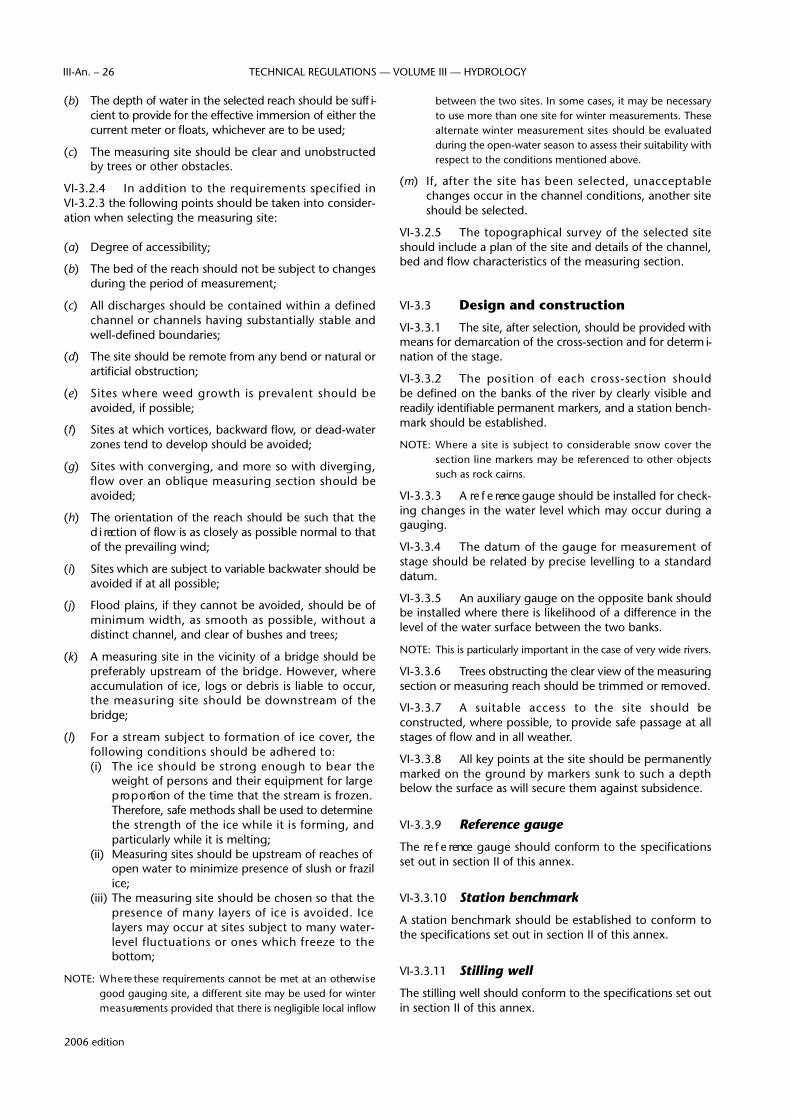
(b) The depth of water in the selected reach should be suff i-cient to provide for the effective immersion of either thec u rrent meter or floats, whichever are to be used;
(c) The measuring site should be clear and unobstructedby trees or other obstacles.
VI-3.2.4 In addition to the re q u i rements specified in VI-3.2.3 the following points should be taken into consider-ation when selecting the measuring site:
(a) Degree of accessibility;
(b) The bed of the reach should not be subject to changesduring the period of measurement;
(c) All discharges should be contained within a definedchannel or channels having substantially stable andwell-defined boundaries;
(d) The site should be remote from any bend or natural orartificial obstruction;
(e) Sites where weed growth is prevalent should beavoided, if possible;
(f) Sites at which vortices, backward flow, or dead-waterzones tend to develop should be avoided;
(g) Sites with converging, and more so with diverg i n g ,flow over an oblique measuring section should beavoided;
(h) The orientation of the reach should be such that thed i rection of flow is as closely as possible normal to thatof the prevailing wind;
(i) Sites which are subject to variable backwater should beavoided if at all possible;
(j) Flood plains, if they cannot be avoided, should be ofminimum width, as smooth as possible, without adistinct channel, and clear of bushes and trees;
(k) A measuring site in the vicinity of a bridge should bep referably upstream of the bridge. However, whereaccumulation of ice, logs or debris is liable to occur,the measuring site should be downstream of thebridge;
(l) For a stream subject to formation of ice cover, thefollowing conditions should be adhered to:(i) The ice should be strong enough to bear the
weight of persons and their equipment for larg ep ro p o rtion of the time that the stream is fro z e n .T h e re f o re, safe methods shall be used to determ i n ethe strength of the ice while it is forming, andparticularly while it is melting;
( i i ) Measuring sites should be upstream of reaches ofopen water to minimize presence of slush or frazilice;
(iii) The measuring site should be chosen so that thep resence of many layers of ice is avoided. Icelayers may occur at sites subject to many water-level fluctuations or ones which freeze to thebottom;
NOTE: W h e re these re q u i rements cannot be met at an otherw i s egood gauging site, a different site may be used for winterm e a s u rements provided that there is negligible local inflow
between the two sites. In some cases, it may be necessaryto use more than one site for winter measurements. Thesea l t e rnate winter measurement sites should be evaluatedduring the open-water season to assess their suitability withrespect to the conditions mentioned above.
(m) If, after the site has been selected, unacceptablechanges occur in the channel conditions, another siteshould be selected.
VI-3.2.5 The topographical survey of the selected siteshould include a plan of the site and details of the channel,bed and flow characteristics of the measuring section.
VI-3.3 Design and construction
VI-3.3.1 The site, after selection, should be provided withmeans for demarcation of the cross-section and for determ i-nation of the stage.
VI-3.3.2 The position of each cross-section should be defined on the banks of the river by clearly visible andreadily identifiable permanent markers, and a station bench-mark should be established.
NOTE: W h e re a site is subject to considerable snow cover thesection line markers may be re f e renced to other objectssuch as rock cairns.
VI-3.3.3 A re f e rence gauge should be installed for check-ing changes in the water level which may occur during agauging.
V I - 3 . 3 . 4 The datum of the gauge for measurement ofstage should be related by precise levelling to a standardd a t u m .
VI-3.3.5 An auxiliary gauge on the opposite bank shouldbe installed where there is likelihood of a difference in thelevel of the water surface between the two banks.
NOTE: This is particularly important in the case of very wide rivers.
V I - 3 . 3 . 6 Trees obstructing the clear view of the measuringsection or measuring reach should be trimmed or re m o v e d .
VI-3.3.7 A suitable access to the site should beconstructed, where possible, to provide safe passage at allstages of flow and in all weather.
VI-3.3.8 All key points at the site should be permanentlymarked on the ground by markers sunk to such a depthbelow the surface as will secure them against subsidence.
VI-3.3.9 Reference gauge
The re f e rence gauge should conform to the specificationsset out in section II of this annex.
V I - 3 . 3 . 1 0 Station benchmark
A station benchmark should be established to conform tothe specifications set out in section II of this annex.
V I - 3 . 3 . 1 1 Stilling well
The stilling well should conform to the specifications set outin section II of this annex.
2006 edition
TECHNICAL REGULATIONS — VOLUME III — HYDROLOGYIII-An. – 26
VI-3.3.12 Water-level recorder
The water-level re c o rder should conform to the specifica-tions set out in section II of this annex.
VI-3.3.13 Sounding and suspension equipment
Suspension equipment of the current meter should conformto the specifications set out in section II of this annex.
VI-3.4 Definitive survey
VI-3.4.1 After the gauging station has been constructed,a definitive survey should be made.
VI-3.4.2 For discharge measuring stations, a standardp rofile of the measuring cross-section should be drawn,indicating the position of the cross-section markers. Thep rofile should be checked frequently and revised if neces-s a ry. A copy of the standard profile (most recent re v i s i o n )should be kept in the instrument house at all times.
V I - 3 . 4 . 3 For float-gauging stations, a standard plan shouldbe pre p a red on which the lines of the selected float runs andthe release points for floats should be indicated. A copy ofthis plan should be kept in the instrument house at all times.
VI-3.4.4 The definitive surv e y, repeated as re q u i red at notless than annual intervals, should include the accurate deter-mination of the elevations and the relative positions of allthe station installations and any other key point or signifi-cant feature of the site.
VI-3.5 Measurement of cross-sectional area
VI-3.5.1 Measurement of width
VI-3.5.1.1 The width of the channel and the widths of theindividual segments should be measured from or to a fixedreference point which should be in the same vertical planeas the cross-section.
V I - 3 . 5 . 1 . 2 W h e re the width of the channel permits, orwhen the surface is covered by ice, the width should bem e a s u red by direct means, for example by a steel tape orsuitably marked wire, care being taken to apply the neces-s a ry corrections. The intervals between the verticals, i.e. thewidths of the segments, should be similarly measured.
NOTE: The corrections which may be necessary are:
(a) C o rrection for sag;
(b) Correction for pull;
(c) Correction for slope;
(d) Correction for temperature.
VI-3.5.1.3 W h e re the channel is too wide for the abovemethods of measurement, the distance should be deter-mined by optical or electrical distance meters, or by one ofthe common surveying methods.
NOTE: The common surveying methods are:
(a) Angular method;
(b) Linear method;
(c) Pivot-point method.
VI-3.5.1.4 The uncertainty in the measurement of widthshould not exceed 0.5 per cent of the true value.
VI-3.5.1.5 The distance between successive cro s s - s e c t i o n sused for the measurement of velocity by floats should bed e t e rmined by methods similar to those described aboveand to a similar degree of accuracy.
VI-3.5.2 Measurement of depth
VI-3.5.2.1 M e a s u rement of depth should be made at inter-vals close enough to define the cross-sectional pro f i l ea c c u r a t e l y. In general, the intervals should not be gre a t e rthan 1/15 of the total width in the case of regular bedprofiles and 1/20 in the case of irregular bed profiles.
NOTE: For small channels with a regular bed profile, the number ofintervals may be reduced.
VI-3.5.2.2 The depth should be measured employingeither sounding rods or sounding lines or other suitabledevices as specified in section III of this annex.
NOTE: Where the channel is of sufficient depth, an echo soundermay be used. If the velocity is high, it is preferable to use anecho sounder or other device which will not re q u i re larg ecorrections.
VI-3.5.2.3 When a sounding rod or sounding line is used,at least two readings should be taken at each point and themean value adopted for calculations, unless the diff e re n c ebetween the two values is more than 5 per cent in whichcase two further readings should be taken.
VI-3.5.2.4 When an echo sounder is used, the average ofseveral readings should always be taken at each point andfrequent calibrations of the instrument should be made.
VI-3.5.2.5 When depths are determined by soundingsre f e rred to the water surface, frequent readings of the waterlevel should be made on the re f e rence gauge to ensure thatall measurements may be corrected to the same plane.
V I - 3 . 5 . 2 . 6 When, during the measurement of discharg e ,the bed profile changes appre c i a b l y, depth measure m e n t sshould be carried out by taking one depth reading at eachpoint at the beginning and one at the end of the velocitym e a s u rement at each vertical, and the mean value ofthese two measurements should be taken as the eff e c t i v ed e p t h .
NOTE: Inaccuracies in soundings are likely to occur due to theconditions below:
(a) The deviation from the vertical of the sounding rod or line,p a rticularly in deep water. A sounding line may deviate fro mthe vertical owing to the force exerted by the stream on theline itself and on the sounding weight. The amount of devi-ation (drift) may be minimized by using a fine wire line(2.5-mm diameter or less) and a streamlined weight.C o rrections to the indicated depth should be applied tocompensate for the deviation;
(b) The penetration of the bed by the sounding weight or ro d .This difficulty may be alleviated by fitting a base plate;
(c) The presence of boulders or large stones. The influence ofthese may be reduced by taking a number of soundings;
2006 edition
ANNEX III-An. – 27

(d) When an echo sounder is used, the presence of softdeposits may give rise to a double echo. The upper echowill normally give the effective depth but further investiga-tions would be required. This difficulty may be eliminatedby using an echo sounder whose operating frequency is200 kHz or higher.
VI-3.5.2.7 When an ice cover exists, the effective depthshould be computed, i.e. the depth of water beneath theice cover.
NOTE: The total depth is measured at holes cut in the ice using anice chisel, chain saw or ice drill and then the distance fromthe water surface to the bottom of the ice layer is measure dusing an L-shaped scale or similar device. The eff e c t i v edepth is computed by subtracting these two values.
VI-3.5.2.8 The uncertainty in the profile should not exceed± 2 per cent or 0.1 m throughout the range of depths,whichever is greater.
VI-3.6 Measurement of velocity
VI-3.6.1 Measurement by current meter
VI-3.6.1.1
(a) The current meter should be held in the desired posi-tion in each vertical by means of a wading rod in thecase of shallow channels, or by suspending it from acable or rod from a bridge, trolley or boat in the caseof deeper channels.
(b) When a boat is used, the current meter should be heldso that it is not affected by disturbances of flow causedby the boat.
(c) After the current meter has been placed at the selectedpoint in the vertical, it should be permitted to becomeadjusted to the flow before the readings are started.
NOTE: The meter used to measure the streamflow may be a rotat-ing element current meter, an ultrasonic (acoustic) currentm e t e r, an electromagnetic current meter, a pendulumc u rrent meter, a pitot tube or any other suitable measuringinstrument.
VI-3.6.1.2 At least 20 verticals should be used and thed i s c h a rge in any one segment should not exceed 10 percent of the total.
VI-3.6.1.3
(a) The velocity at each selected point should be observ e dby exposing the current meter for a minimum of 30 seconds.
(b) Where the velocity is subject to large periodic pulstions, the exposure time should be increasedaccordingly.
VI-3.6.1.4 The horizontal axis of the current meter shouldnot be situated at a distance less than one-and-a-half timesthe rotor height from the water surface, nor should it be ata distance less than three times the rotor height from thebottom of the channel. Furthermore, no part of the metershould break the surface of the water.
VI-3.6.1.5 The current meter should be removed from thewater for examination when passing from one vertical to another.
V I - 3 . 6 . 1 . 6 When velocity observations are made from icec o v e r, the meter should be exposed to air temperature sfor as short a time as possible in order to prevent form a-tion of ice on moving parts. If ice does form, the metershould be soaked for a few minutes before commencingthe count.
VI-3.6.1.7 If oblique flow is unavoidable, the angle of thed i rection of the flow to the perpendicular to the cro s s -section should be measured and the measured velocitycorrected.
NOTE: If the measured angle to the perpendicular is γ, then vcorrected = vmeasured cos γ
Vl-3.6.1.8 The mean velocity of the water in each vert i-cal should be determined by one of the standardm e t h o d s .
NOTE: The standard methods are:
(a) Velocity-distribution method;
(b) Reduced-point methods:(i) Two-point method (measurement at 0.2 and at 0.8
of the depth below surface);(ii) One-point method (measurement at 0.6 of the depth
below surface);
(c) Integration method;
(d) Other methods:( i ) Six-point method (measurement at 0.2, 0.4, 0.6
and 0.8 of the depth below surface and as near asp o s s i b l e below surface and above bottom);
(ii) Five-point method (measurement at 0.2, 0.6 and 0.8of the depth below surface and as near as possibleb e l o w s u rface and above bottom);
(iii) T h ree-point method (measurement at 0.2, 0.6 and0.8 of the depth below surface);
(iv) A l t e rnative one-point method (measurement at 0.5of the depth below surf a c e ) ;
(v) S u rface one-point method (measurement at one pointjust below surface).
VI-3.6.2 Measurement by floats
NOTE: Floats should only be used when it is impossible toemploy a current meter because of excessive velocities ordepths, because of the presence of material in suspen-sion, or where velocities are too low for current meterm e a s u re m e n t .
VI-3.6.2.1 Selection of cross-sections
(a) T h ree cross-sections should be selected along thereach of the channel, at the beginning, midway and atthe end of the reach.
(b) The cross-sections should be far enough apart that thetime of float movement from one cross-section to thenext can be measured accurately.
NOTE: A minimum duration of float movement of 20 seconds isrecommended.
2006 edition
TECHNICAL REGULATIONS — VOLUME III — HYDROLOGYIII-An. – 28

VI-3.6.2.2 Measuring procedure
(a) The float should be released far enough above theupper cross-section to attain a constant velocity beforereaching this cross-section.
(b) The time at which the float passes each of the thre ecross-sections should be noted.
(c) This pro c e d u re should be repeated with the floats atvarious distances from the bank of the river.
(d) The width of the channel should be divided intosegments of equal width or of approximately equaldischarge.
(e) The number of segments should not be less than thre e ,but where possible a minimum of five should be used.
NOTE: Types of floats used are surface floats, double floats, subsurface floats and velocity rods (float rods).
(f) Surface floats should be used when their movement isnot likely to be affected by winds.
(g) The length of the subsurface float should be approxi-mately equal to the water depth, but the float shouldin no case touch the bottom.
(h) The velocity rod should be at least 0.95 of the depth ofthe channel but should not touch the bottom.
VI-3.6.2.3 Evaluation of velocity
(a) The float velocity should be determined by dividingthe distance between the cross-sections by the timetaken by the float to travel this distance.
(b) Several values of the float velocity should be taken andthe mean of these values should be multiplied by thea p p ropriate coefficient to obtain the mean watervelocity.
(c) The coefficient derived from current-meter measure-ments at the site at a stage as near as possible to thatduring the float measurement should be used forconverting the float velocity to mean velocity.
NOTE: The following coefficients are given as general guidance:
(a) 0.84 to 0.90 for surface floats, the higher values for smooth beds;
(b) 1.0 for double floats at 0.6 of the depth and 0.96 at 0.5 of thed e p t h ;
(c) 0.8 to 1.0 for subsurface floats and velocity ro d s .
Vl-3.7 Dilution-gauging methods
NOTE: Principle of method
A tracer liquid is injected into a stream and at a point further down-s t ream, where turbulence has mixed the tracer uniformly thro u g h o u tthe cross-section, the water is sampled. The change in concen-tration between the solution injected and the water at the samplingstation is a measure of the discharge. The tracer may be injectedgradually (constant rate method) or suddenly (gulp, pulse or integ-ration method) and may be chemical, radioactive or a fluorescent dye.
VI-3.8 Preliminary survey
A pre l i m i n a ry survey should be carried out to determine thehydraulic and mixing characteristics of the site.
VI-3.9 Selection of site
VI-3.9.1 At the site selected it should be possible tomeasure the whole range of discharge and all types of flowwhich may be encountered or which it is re q u i red tomeasure.
VI-3.9.2 There should be no loss or gain of water in themeasuring reach.
Vl-3.9.3 The length of the reach should be sufficient sothat the solution injected at its beginning will be uniformlydiluted throughout the sampling cross-section.
NOTE: It is desirable that the distance between the injection andsampling sections be as short as possible.
Vl-3.9.4 A reach should be chosen in which the river is asn a rrow and as turbulent as possible, free of dead-waterzones, with numerous transverse currents. Grassy and vege-tation-grown zones, as well as separation zones of the riverinto arms, should be avoided.
NOTE: For determination of suitability and length of a measuringreach, a concentrated solution of dye fluorescein may beinjected for a relatively short time at a point on the poten-tial injection section. Study of the diffusion of the solutionwill show whether there are any dead zones and whatshould be the minimum distance between the injection andsampling cross-sections.
VI-3.10 Design and construction
VI-3.10.1 The gauging station should consist of a measur-ing reach and a reference gauge.
VI-3.10.2 A station benchmark should be established toc o n f o rm to the specifications given in section II of thisannex.
VI-3.10.3 The re f e rence gauge should conform to thespecifications given in section II of this annex.
VI-3.10.4 The design and construction of the stilling wellshould conform to the specifications given in section II ofthis annex.
VI-3.11 Slope area method
NOTE: Principle of method
The water- s u rface slope and the mean area of cross-section of thechannel are measured in a selected reach which is as straight andu n i f o rm as possible. Assuming a coefficient of roughness, the meanvelocity is computed using a flow formula relating velocity, ro u g h -ness, hydraulic mean radius and slope. The discharge is then thep roduct of mean velocity and mean area of cross-section of flow.
VI-3.12 Preliminary survey
A pre l i m i n a ry survey should be made to ensure that thephysical and hydraulic features of the proposed site areacceptable for the purpose of discharge measurement.
2006 edition
ANNEX III-An. – 29

VI-3.13 Selection of site
VI-3.13.1 The river should be fairly straight and uniform insection, free from obstructions and vegetation, show nop ro g ressive tendency to scour or accrete, and be free of thebackwater effect of tributaries, downstream stru c t u re s(dams, bridges), or tides.
VI-3.13.2 The length of the reach should be such that thed i ff e rence in water levels is not less than 10 times the uncer-tainty in the difference in water levels.
VI-3.13.3 The flow should be contained within definedboundaries.
VI-3.13.4 The topographical survey should include a planof the site, a longitudinal section of the channel from apoint downstream of the control to the upstream limit ofthe reach, plus details of the channel, bed and flow characteristics.
VI-3.14 Design and construction
VI-3.14 1 The gauging station should consist of a naturalor artificial measuring section and two reference gauges.
VI-3.14.2 The positions of the cross-sections should bemarked on the banks and the sections surveyed at intervalsand after floods.
VI-3.14.3 A suitable access to the site should beconstructed, where possible, to provide safe passage at allstages of flow and in all weather.
VI-3.14.4 All key points at the site should be permanentlymarked on the ground by markers sunk to such a depthbelow the surface as will ensure them against movement.
VI-3.15 Definite survey
VI-3.15.1 After the gauging station has been constructed adefinitive survey should be made.
VI-3.15.2 The gauges should be precisely levelled and thelevels related to a common datum.
VI-3.15.3 The distance between the gauges should beaccurately measured.
VI-4 Station for the measurement of discharge; regular measurements
NOTE: The methods which follow are most suitable for re l a t i v e l yf requent measurements often made over a relatively longperiod and where a continuous re c o rd of discharge isdesired.
VI-4.1 Stage-discharge station
NOTE: Principle of method.
In a stable channel with satisfactory downstream control of waterlevel there may be a unique relation between stage and discharge.In such channels it is expedient to establish the relation betweenstage and discharge and thereafter to deduce the discharge fro mmeasurements of stage only. The station may be calibrated by thevelocity-area method using current meters, a moving boat, floats,or by dilution gauging methods.
VI-4.2 Preliminary survey
VI-4.2.1 A preliminary survey should be made to ensurethat the physical and hydraulic features of the proposed sitec o n f o rm to the re q u i rements for the method selected tomeasure discharge for the calibration of the station.
VI-4.2.2 The proposed site should be in a stable stre t c hof river and free from standing waves at high flow, weedgrowth and adverse ice conditions.
VI-4.3 Selection of site
VI-4.3.1 At the site selected it should be possible tom e a s u re the whole range of discharges and all types of flowwhich may be encountered or which it is re q u i red tomeasure.
V I - 4 . 3 . 2 The site should be sensitive to the extent that asignificant change in discharge, even for the lowestd i s c h a rges, should be accompanied by a significantchange in stage. The sensitivity of the station should bes u fficient for the purpose for which the measurements arere q u i re d .
VI-4.3.3 Sites where weed growth is prevalent should beavoided if possible.
VI-4.3.4 T h e re should be no vortices, dead water orother abnormalities in flow.
VI-4.3.5 Sites where poor ice conditions are pre v a l e n tshould be avoided if possible.
VI-4.3.6 Access to the site should be feasible under mostconditions.
VI-4.3.7 The detailed topographical survey of the siteshould be made as specified under VI-3.1, VI-3.7 and VI-3.11 above, according to the method selected formeasurement.
VI-4.4 Design and construction
VI-4.4.1 The gauging station should consist of one orm o re natural or artificial measuring sections and a re f e re n c egauge.
NOTE: N o rmally a water-level re c o rder is installed to produce acontinuous record of stage. It may be desirable to establishgauges at both banks, particularly when there is anyevidence of difference in water level between the banks.
VI-4.4.2 The positions of each cross-section should be defined on the banks of the river by clearly visible andreadily identifiable permanent markers, and a station bench-mark should be established.
VI-4.4.3 If a control regulates the stage at low discharg e sat the gauging section, it should be situated at the down-stream end of the reach and any measuring section shouldbe sufficiently remote from it to avoid any distortion of flowwhich might occur in the vicinity.
VI-4.4.4 W h e re the main re q u i rements necessary for asuitable gauging site, as specified, do not exist conditionsshould be improved, if possible, as follows:
(a) C o n s t ructing flood banks to confine the flow in adefined floodway;
2006 edition
TECHNICAL REGULATIONS — VOLUME III — HYDROLOGYIII-An. – 30

(b) Trimming the bank to a regular line and a stable slopeand removing from the bed any large stones or boul-ders to eliminate local eddies;
(c) Protecting unstable banks upstream and downstreamof a measuring section for a distance equal to at leastone quarter of the bankfull width of the channel ineach direction. In the case of float gauging the wholeof the measuring reach should be protected;
(d) Introducing an artificial control to improve the stage-d i s c h a rge relation (sensitivity) or to create conditions inthe measuring section for instruments to be eff e c t i v e l yused.
NOTE: An artificial control is a simple stru c t u re built in a channel. Itmay be a low dam or a contraction which is seldomdesigned to function as a control throughout the entirerange of stage. It is not practicable in large alluvial rivers.
VI-4.4.5 The re f e rence gauge and water-level re c o rd e rshould be located as close as possible to the measuringsection and if floats are used to measure the velocities, there f e rence gauge and water-level re c o rder should be locatednear the midpoint of the measuring reach.
VI-4.4.6 A suitable access to the site should beconstructed, where possible, to provide safe passage at allstages of flow and in all weather.
VI-4.4.7 All key points at the site should be permanentlymarked on the ground by markers sunk to such a depthbelow the surface as will secure them against movement.
VI-4.4.8 The re f e rence gauge should conform to thespecifications given in section II of this annex.
VI-4.4.9 The stilling well should conform to the specifica-tions given in section II of this annex.
V I - 4 . 4 . 1 0 The water-level recorder should conform to thespecifications given in section II of this annex.
VI-4.5 Definitive survey
(a) The definitive surv e y, repeated as re q u i red at not morethan annual intervals, should include the accurated e t e rmination of the elevations and the relative posi-tions of all the station installations and any other keypoints or significant features of the site. In case ofstations affected by hysteresis, the rise and fall shouldbe calibrated separately by discharge measurements, ifthe rate of rise (fall) is quite similar for all events.
(b) Bed profiles should be checked after a flood.
VI-4.6 Operation of station
VI-4.6.1 W h e re a station is fitted only with a re f e re n c egauge or re f e rence gauges and no water-level re c o rd e r, thelocal observer should be re q u i red to furnish readings atspecified intervals of all the gauges in his or her care.
NOTE: P referably the readings should be made at fixed hours. Thei n t e rvals between the readings should be determined bythe rate at which the water level at the site usually changes,but arrangements should be made to have additional re a d-ings when the water level is changing more rapidly than
usual. It is essential that the gauge observer re c o rds theexact time of each gauge observation.
VI-4.6.2 When a station is fitted with a re c o rd e r, visits bythe observer should be made regularly to verify that therecorder is operating satisfactorily.
VI-4.6.3 E v e ry gauging station should be inspectedwhenever any incident which might affect its accuracy isnotified by the local observer.
VI-4.6.4 All re c o rders and re c o rder clocks should becleaned and lubricated in accordance with the manufactur-ers’ instructions or as indicated by experience underprevailing operating conditions.
VI-4.6.5 The elevation of all key points which weres u rveyed in the definitive survey should be checked by re f e r-ence to the station benchmark at least annually or followingany flood when equipment might have been damaged bydebris or by ice. At the same time any vertical gauge shouldbe tested for verticality.
V I - 4 . 7 S l o p e - s t a g e - d i s c h a rge or fall-discharg e
NOTE: Principle of method
In a stable channel with a varying downstream control of waterlevel, when there is no unique relation between stage andd i s c h a rge, there may be a relation between the water- s u rface slope,stage and discharge. In such channels it is expedient to measureboth water- s u rface slope and water level from which the discharg eis deduced. The station may be calibrated by the velocity-are amethod or by dilution-gauging methods.
VI-4.8 Preliminary survey
See VI-4.2 above.
VI-4.9 Selection of site
V I - 4 . 9 . 1 At the site selected it should be possible tom e a s u re the whole range of discharges and all types of flowwhich may be encountered or which it is re q u i red to measure .
VI-4.9.2 At any gauging station with twin gauges, thesite should be sensitive such that a significant change ind i s c h a rge, even for the lowest discharges, should be accom-panied by a significant change in stage at the gaugesand/or fall between the two gauges. The sensitivity of thestation should be sufficient for the purpose for which themeasurements are required.
VI-4.9.3 Sites where weed growth is prevalent should beavoided if possible.
VI-4.9.4 T h e re should be no vortices, dead water orother abnormalities in flow.
VI-4.9.5 Sites where poor ice conditions are pre v a l e n tshould be avoided if possible.
VI-4.9.6 Access to the site should be feasible under mostconditions.
VI-4.10 Survey
See VI-4.3.7 above.
2006 edition
ANNEX III-An. – 31

VI-4.11 Design and construction
VI-4.11.1 The gauging station should consist of one orm o re natural or artificial measuring sections and two water-level gauges, one of which is the reference gauge.
NOTE: Wa t e r-level re c o rders may be installed to produce a contin-uous re c o rd of stage and fall. It may be desirable toestablish gauges at both banks, particularly when there isany evidence of diff e rence in water level between thebanks.
VI-4.11.2 The positions of each cross-section should bedefined on the banks of the river by clearly visible and re a d-ily identifiable permanent markers and a station benchmarkshould be established.
VI-4.11.3 The length of the reach should be sufficient tomake any observational error negligible relative to the fall ofwater level between the two gauges.
VI-4.11.4 If a control regulates the stage at low discharg e sat the gauging sections, it should be situated at the down-s t ream end of the reach, and any measuring section shouldbe sufficiently remote from it to avoid any distortion of flowwhich might occur in that vicinity.
VI-4.11.5 The re f e rence gauge and water-level re c o rd e rshould be located as close as possible to the measuringsections and, if floats are used to measure the velocities, there f e rence gauge and water-level re c o rder should be locatednear the midpoint of the measuring reach.
VI-4.11.6 W h e re the main re q u i rements necessary for asuitable gauging site, as specified, do not exist conditionsshould be improved, if possible, as described in VI-4.4.4.
VI-4.11.7 W h e re not already existing, suitable access tothe site should be constructed, if possible, to provide safepassage at all stages of flow and in all weather.
VI-4.11.8 All key points at the site should be permanentlymarked on the ground by markers sunk to such a depthbelow the surface as will secure them against movement.
VI-4.11.9 The re f e rence gauge should conform to thespecifications given in section II of this annex.
VI-4.11.10 The stilling wells should conform to the specifi-cations given in section II of this annex.
VI-4.11.11 The water-level re c o rders should conform to thespecifications given in section II of this annex.
VI-4.12 Definitive survey
VI-4.12.1 The definitive surv e y, repeated as re q u i red at notm o re than annual intervals, should include the accurated e t e rmination of the elevations and the relative positions ofall the station installations and any other key points orsignificant features of the site.
VI-4.12.2 Bed profiles should be checked after a flood.
VI-4.13 Operation of station
See VI-4.6 above.
VI-4.14 Notches, weirs and flumes
NOTE: Principle of method
A relation between head and discharge is established usually in thel a b o r a t o ry and this relation is applied to the field installation. Am e a s u rement of head only is there f o re re q u i red at the gaugingstation and this value is inserted in the appropriate formula to obtaina value of discharge. The particular formula and conditions of appli-cation governing each measuring stru c t u re are specified in theManual on Stream Gauging (WMO-No. 519). Whenever possible thef o rmula should be verified in the field by discharge measure m e n t s .
VI-4.15 Preliminary survey
A pre l i m i n a ry survey should be made of the physical andhydraulic features of the proposed site to check that itc o n f o rms (or may be constructed or modified so as toc o n f o rm) to the re q u i rements necessary for the measure-ment of discharge by the structure.
VI-4.16 Selection of site
VI-4.16.1 P a rticular attention should be paid to the following features in selecting the site:
(a) The adequacy of the length of channel of regular cro s s -section available (see note after VI-4.16.3);
(b) The uniformity of the existing distribution;
(c) The avoidance of a steep channel (Froude numbershould not exceed about 0.5);
(d) The effects of any increased upstream water levels dueto the measuring structure;
(e) The conditions downstream including such influencesas tides, confluences with other streams, sluice gates,mill dams and other controlling features such asseasonal weed growth) which might cause drowning;
(f) The impermeability of the ground on which the struc-t u re is to be founded and the necessity for piling,grouting or other means of controlling seepage;
(g) The necessity for flood banks to confine the maximumdischarge to the channel;
(h) The stability of the banks and the necessity for trim-ming and/or revetment;
(i) Uniformity of section of the approach channel.
VI-4.16.2 The stru c t u re should be so designed that itcannot become drowned under specified operating conditions.
VI-4.16.3 The flow in the approach channel should have asymmetrical velocity distribution.
NOTE: This can most readily be ensured by providing a longstraight approach channel of uniform cross-section. Alength of approach channel five times the water surf a c ewidth at maximum flow will usually suffice, provided theflow does not enter the approach channel with high veloc-ity via a sharp bend or angled sluice gate.
2006 edition
TECHNICAL REGULATIONS — VOLUME III — HYDROLOGYIII-An. – 32
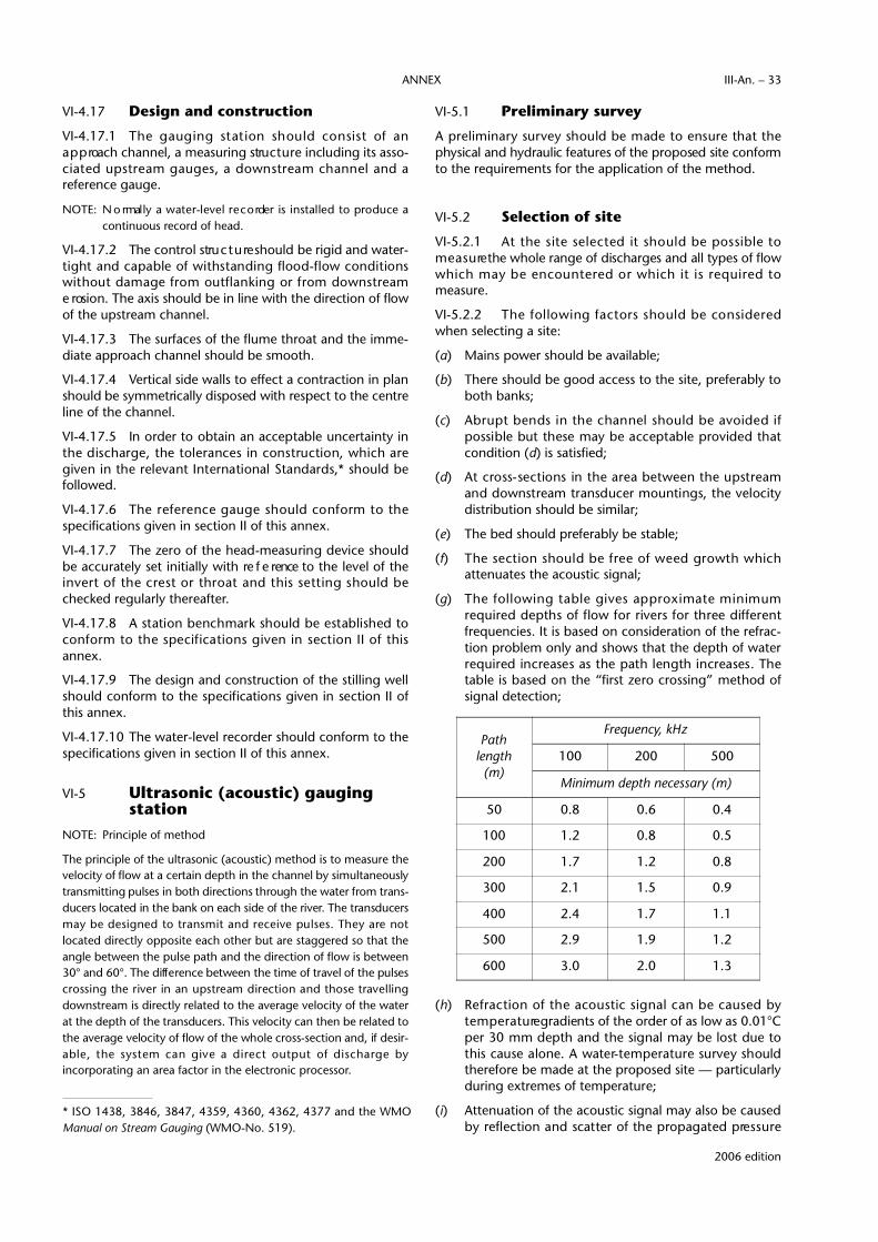
VI-4.17 Design and construction
VI-4.17.1 The gauging station should consist of ana p p roach channel, a measuring stru c t u re including its asso-ciated upstream gauges, a downstream channel and areference gauge.
NOTE: N o rmally a water-level re c o rder is installed to produce acontinuous record of head.
VI-4.17.2 The control stru c t u re should be rigid and water-tight and capable of withstanding flood-flow conditionswithout damage from outflanking or from downstre a me rosion. The axis should be in line with the direction of flowof the upstream channel.
VI-4.17.3 The surfaces of the flume throat and the imme-diate approach channel should be smooth.
VI-4.17.4 Vertical side walls to effect a contraction in planshould be symmetrically disposed with respect to the centreline of the channel.
VI-4.17.5 In order to obtain an acceptable uncertainty inthe discharge, the tolerances in construction, which aregiven in the relevant International Standards,* should befollowed.
VI-4.17.6 The re f e rence gauge should conform to thespecifications given in section II of this annex.
VI-4.17.7 The zero of the head-measuring device shouldbe accurately set initially with re f e rence to the level of thei n v e rt of the crest or throat and this setting should bechecked regularly thereafter.
VI-4.17.8 A station benchmark should be established toc o n f o rm to the specifications given in section II of thisannex.
VI-4.17.9 The design and construction of the stilling wellshould conform to the specifications given in section II ofthis annex.
VI-4.17.10 The water-level recorder should conform to thespecifications given in section II of this annex.
VI-5 Ultrasonic (acoustic) gauging station
NOTE: Principle of method
The principle of the ultrasonic (acoustic) method is to measure thevelocity of flow at a certain depth in the channel by simultaneouslytransmitting pulses in both directions through the water from trans-ducers located in the bank on each side of the river. The transducersmay be designed to transmit and receive pulses. They are notlocated directly opposite each other but are staggered so that theangle between the pulse path and the direction of flow is between30° and 60°. The diff e rence between the time of travel of the pulsesc rossing the river in an upstream direction and those travellingdownstream is directly related to the average velocity of the waterat the depth of the transducers. This velocity can then be related tothe average velocity of flow of the whole cross-section and, if desir-able, the system can give a direct output of discharge byincorporating an area factor in the electronic processor.
VI-5.1 Preliminary survey
A pre l i m i n a ry survey should be made to ensure that thephysical and hydraulic features of the proposed site conformto the requirements for the application of the method.
VI-5.2 Selection of site
VI-5.2.1 At the site selected it should be possible tom e a s u re the whole range of discharges and all types of flowwhich may be encountered or which it is re q u i red tomeasure.
VI-5.2.2 The following factors should be considere dwhen selecting a site:
(a) Mains power should be available;
(b) There should be good access to the site, preferably toboth banks;
(c) A b rupt bends in the channel should be avoided ifpossible but these may be acceptable provided thatcondition (d) is satisfied;
(d) At cross-sections in the area between the upstre a mand downstream transducer mountings, the velocitydistribution should be similar;
(e) The bed should preferably be stable;
(f) The section should be free of weed growth whichattenuates the acoustic signal;
(g) The following table gives approximate minimumre q u i red depths of flow for rivers for three diff e re n tfrequencies. It is based on consideration of the refrac-tion problem only and shows that the depth of waterre q u i red increases as the path length increases. Thetable is based on the “first zero crossing” method ofsignal detection;
(h) Refraction of the acoustic signal can be caused byt e m p e r a t u re gradients of the order of as low as 0.01°Cper 30 mm depth and the signal may be lost due tothis cause alone. A water- t e m p e r a t u re survey shouldtherefore be made at the proposed site — particularlyduring extremes of temperature;
(i) Attenuation of the acoustic signal may also be causedby reflection and scatter of the propagated pre s s u re
Path length
(m)
Frequency, kHz
100 200 500
Minimum depth necessary (m)
50 0.8 0.6 0.4
100 1.2 0.8 0.5
200 1.7 1.2 0.8
300 2.1 1.5 0.9
400 2.4 1.7 1.1
500 2.9 1.9 1.2
600 3.0 2.0 1.3
2006 edition
ANNEX III-An. – 33
* ISO 1438, 3846, 3847, 4359, 4360, 4362, 4377 and the WMOManual on Stream Gauging (WMO-No. 519).
wave from entrained air bubbles. Sites immediatelyd o w n s t ream of dams, weirs or waterfalls should there-fore be avoided;
(j) Suspended solids may have a significant effect on thesignal attenuation, caused by both reflection and scat-ter from sediment particles suspended in the stre a m .G e n e r a l l y, sections having concentrations of over 1000 mg/I for significant periods of time should beavoided. Due regard should be given to the operatingf requency used, the size of sediment, distribution,water temperature and length of acoustic path.
VI-5.3 Design and construction
VI-5.3.1 The gauging station should consist of:
(a) (i) One or more pairs of transducers installed on each bank and fixed permanently in position; or
(ii) One or more pairs of transducers installed oneach bank and having the facility of movement inthe vertical or on an incline;
(b) An electronic console containing an electronic dataprocessor and a data recorder;
(c) A water-level re c o rder interfaced with the electro n i cdata processor where an output of stage or dischargeor both is required;
(d) An arm o u red cable, to transmit the signals from thetransducers and the water-level re c o rder (where part ofthe system), normally installed in the bed;
(e) A reference gauge.
VI-5.3.2 A detailed level survey should be made of thebed and banks extending for one river width upstream ofthe proposed upstream transducer mounting and one riverwidth below the downstream transducer mounting. Ifn e c e s s a ry, improvement of the bed and banks should beundertaken.
VI-5.3.3 When the positions of the transducer mountingshave been decided, the angle between the mountingsshould be carefully surveyed for ultimate wiring into theelectronic processor.
NOTE: The output from an ultrasonic station may be recorded inany one of the following modes:
(a) Path velocity (or an index whlch is numerically pro p o rt i o n a lto the path velocity);
(b) Path velocity and stage;
(c) Discharge and stage;
(d) Velocity and discharge;
(e) Velocity, discharge and stage.
If stage is not included in the mode, it should be re c o rded sepa-rately by water-level re c o rder for subsequent off-site pro c e s s i n g .
When operating in the discharge mode a manual facility should bep rovided in the electronic processor to make any adjustment neces-sary for a change in bed level.
VI-5.3.4 A reference gauge should conform to the speci-fications given in section II of this annex.
V I - 5 . 3 . 5 A station benchmark should be established toc o n f o rm to the specifications given in section II of this annex.
VI-5.3.6 The design and construction of the stilling well,if used, should conform to the specifications given in section II of this annex.
VI-5.3.7 The water-level recorder should conform to thespecifications given in section II of this annex.
VI-6 Compilation of recordsVI-6.1 All field data should be examined critically andp romptly with the objective of uncovering any anomalieswhich may exist.
VI-6.2 Where recorders are installed, readings of waterlevels from instrument charts or tapes should be taken atsuch intervals as may be necessary to define the hydro g r a p ha d e q u a t e l y. The conversion from water level to discharg eshould be made for each water level, making all necessarycorrections.
VI-6.3 The extrapolation of discharges from ratingc u rves should be avoided, if possible. Discharges derived byextrapolation should be distinguished from those derived byinterpolation. (Methods for extrapolation are detailed in theManual on Stream Gauging (WMO-No. 519), Volume II —Computation of Discharge, pages 16 to 26.)
NOTE: A re c o rd may be considered a standard re c o rd provided thesum of the estimated quantities does not exceed 5 per centof the total runoff for the year.
VI-6.4 Annotations of the re c o rd should indicate anyday on which the flow suffered interference through weedgrowth, ice or flood debris.
VI-7 Measurement of discharge under ice conditions
VI-7.1 Design and construction
VI-7.2 Stilling well
The stilling well and inlet pipes should be constructed insuch a manner that the system will remain operationalduring extended periods of freezing temperatures.
VI-7.3 The pneumatic recorder
VI-7.3.1 The orifice from which the compressed gasdischarges into the stream should be mounted at an eleva-tion below that of the bottom of the ice sheet which wouldnormally form at the gauging station.
VI-7.3.2 The orifice should be located away from loca-tions where anchor ice will form, such as above rapids, toprevent it being blocked up.
VI-7.3.3 W h e re the possibility of the orifice becomingf rozen in the ice exists, the gas-feed pre s s u re should be
2006 edition
TECHNICAL REGULATIONS — VOLUME III — HYDROLOGYIII-An. – 34

reduced to a value less than the pressure equivalent of thefull-scale range of the instrument.
VI-7.3.4 The line to the orifice should be buried in thebank to a depth sufficient to prevent damage from ice scourduring the freshet.
V I - 7 . 3 . 5 W h e re necessary, the instrumentation shouldbe heated to the minimum operating temperature statedby the manufacturer if uninterrupted operation is re q u i re d .
N O T E S :
(a) The mercury used in some instruments solidifies at approx-imately -40°C.
(b) B a t t e ry power supplies may be waterproofed and placed inthe stream to obtain satisfactory perf o rmance duringextremely low temperatures.
VI-7.4 Notches, weirs and flumes
VI-7.4.1 W h e re necessary and feasible, notches, weirsand flumes should be heated during the freezing period toe n s u re that the head-discharge relation is applicable duringthe winter.
VI-7.4.2 The elevation of the stru c t u re should be checkedduring or after the ice period to ensure the stru c t u re has notheaved due to freezing of the soil.
2006 edition
ANNEX III-An. – 35


VII – DETERMINATION OF THE STAGE-DISCHARGE RELATION(See [D.1.2.] 3.4.1)
2006 edition
VII-1 Scope and field of applicationNOTES:
(a) The material in this section of the annex is based on ISO1100-2 (1998 and 2000) entitled “Liquid flow measure-ment in open channels — Part 2: Determination of thestage-discharge relation”.
(b) Detailed guidance on the determination of the stage-d i s c h a rge relation and of the uncertainties involved is givenin the Manual on Stream Gauging (WMO-No. 519).
This section specifies the methods of determining the stage-d i s c h a rge relation at a gauging station for stable andunstable channels, including those subject to ice conditionsas well as an analysis of the uncertainties involved in thep reparation and use of the relation. The specifications aredesigned to conform to the re q u i rements of Te c h n i c a lRegulation [D.1.2.] 3.1 and to meet the re q u i rements foraccuracy as indicated in Technical Regulation [D.1.2.] 3.6.
VII-2 Calibration of a gauging station
VII-2.1 General
An established stage-discharge relation should be continu-ously reviewed so as to ensure its validity is maintained andto redetermine the relation when it is shown to have beensignificantly altered by any changes which have occurred.
NOTE: Since a river is continuously in course of development, itscharacteristics are subject to changes which may affect thecalibration These changes may take place gradually as aresult of slow processes of erosion or accretion or they mayoccur suddenly as a consequence of alterations in the chan-nel. In addition, temporary changes may be caused by thegrowth and decay of aquatic weeds, by the formation andbreakup of ice cover or by the deposition of debris.
VII-2.2 Stable stage-discharge relation
NOTES:
(a) The simplest expression of the stage-discharge relation is aplot on coordinate graph paper with discharges plotted asabscissae against corresponding stages as ordinates. Sinced i s c h a rge often ranges over several orders of magnitude, itis sometimes more convenient to plot the relation on singleor double logarithmically divided paper. The stage used in
plotting should be the weighted mean stage during thedischarge measurement.
(b) Computation of mean stage of a discharge measurement isdescribed in the Manual on Stream Gauging ( W M O -No. 519), Volume I — Fieldwork, pages 147 to 150.
V I I - 2 . 2 . 1 A smooth curve should be drawn by eye thro u g hthe array of data points to detect points which may be e rro n e o u s .
VII-2.2.2 The rating curve should be defined by a suff i-cient number of measurements suitably distributedthroughout the entire range of water levels.
V I I - 2 . 2 . 3 The rating curve should be examined for hystere-sis. Where possible the measurements should have beenmade at steady stage but, if not, those taken at rising orfalling stages should be indicated by distinguishing symbols.
VII-2.2.4 The equation for the rating curve should beobtained, or the curve may be treated as a purely graphicrecord.
NOTE: If the zero of the gauge corresponds to zero discharge thes t a g e - d i s c h a rge relation at a station may often be expre s s e dby an equation of the form Q = Chβ ( w h e re Q is thed i s c h a rge, h is the gauge height and C and β a re coeff i-cients) over the entire range of water levels, or more oftenby two or more similar equations, each relating to a port i o nof the range. If the zero of the gauge does not correspondto zero discharge a correction “a” should be applied to hresulting in the equation:
Q = C (h + a)β
The quantity a may be determined from the level on thec o n t rol section in relation to zero flow. Altern a t i v e l y, theconstant a may be determined by trial and error while plot-ting Q (either on ordinary or on logarithmic scale), versus h + a (on logarithmic scale). The value of a which gives thebest straight alignment of the data points may be consid-ered as the best value of a.
VIl-2.3 Unstable stage-discharge relation
VIl-2.3.1 General
Smooth rating curves should be drawn for those periodswhen little or no shift is apparent.
NOTE: In unstable channels the channel geometry and frictionproperties — and hence the control characteristics — varyas a function of time and so does the stage-discharge rela-tion at any given point in the channel. Such variations incontrol are evident particularly during and after flood peri-ods, under ice conditions and during periods of weedg rowth and decay. In such cases, all discharges measure da re plotted against their corresponding stages and eachpoint labelled by date order.
VIl-2.3.2 Shifting controls
NOTE: The term “shifting control” refers to that condition wherethe stage-discharge relations do not remain permanent butv a ry from time to time, either gradually or abru p t l y,because of changes in the physical features forming thecontrol for the station. If discharge measurements indicatethat the stage-discharge relation has changed from a pre -vious direction, one may use shifting-control corre c t i o n s(addition or subtraction from the gauge height) in ord e rthat the effective gauge height corresponds to themeasured discharge and rating curve.
VII-2.3.3 Shifting control due to ice conditions
VII-2.3.3.1 Discharge measurements and ice thickness
(a) Discharge measurements should be made before andafter the formation of the ice cover to determine theinitial decrease in discharge, at appropriate intervals todefine the flow recession under the ice cover, andb e f o re and after the ice breakup to determine whenthe open-water stage-discharge relation becomesagain applicable.
(b) Ice thickness should be measured every time adischarge measurement is made.
VII-2.3.3.2 Computation of daily discharge
Daily mean discharges should be computed by means of astandard method.
NOTE: The most common standard methods are:
(a) Using effective gauge heights and the open-water stage-discharge relation;
(b) D i rect interpolation between measured values of discharg e ;
(c) Using the recession equation, particularly in larger streamshaving significant lake storage;
(d) Using a winter rating curve, in particular if the ice re g i m eappears to be consistent from winter to winter.
VII-2.3.4 Evaluation involving surface slope (fall)
NOTE: For gauge sites affected by variable backwater and subjectto hysteresis due to changing discharge when the hydraulicslope is very mild, the evaluation of discharge requires theuse of the fall between two re f e rence gauges located withinthe reach as an additional parameter. The plotting of thestage-discharge observations with the value of fall markedat each observation will reveal whether the relationship isaffected by variable slope at all stages or only when the fallis smaller than a particular value.
VII-2.3.4.1 If the discharge is affected by the fall at allstages, the constant-fall method should be applied whenevaluating the stage-discharge relation.
VII-2.3.4.2 If the discharge is affected by the fall only whenthe fall is smaller than a particular value, the norm a l - f a l lmethod should be applied when evaluating the stage-discharge relation.
NOTE: Methods for evaluating stage-discharge relations, usingslope as a parameter, are described in the Manual on Stre a mG a u g i n g (WMO-No. 519), Volume II — Computation ofdischarge, Chapter 2 and ISO 1100-2, Annex C.
VII-2.4 Extrapolation of the rating curve
VII-2.4.1 A rating curve preferably should not be appliedoutside the range of observations upon which it is based.
VII-2.4.2 When extrapolation is necessary, the re s u l t sobtained should be checked by more than one method.
VII-2.5 Rating table
A rating table can be prepared from the rating curve(s) orf rom the equation(s) of the curve(s), showing thedischarges corresponding to stages in ascending order andat intervals suited to the desired degree of interpolation.
VII-3 Methods of testing stage-discharge curves
The rating curves should be tested for bias and goodness of fit.
NOTE: Methods of testing are given in the Manual on Stre a mG a u g i n g (WMO-No. 519), Volume II — Computation ofdischarge, Chapter 2 and ISO 1100-2, Annex A.
VII-4 U n c e rtainty in the stage-discharg erelation and in mean discharg e s
VII-4.1 Statistical analysis of the stage-discharge relation
VII-4.1.1 The stage-discharge relation should be moreaccurate than any of the individual gaugings.
VII-4.1.2 The uncertainty in the stage-discharge re l a t i o nshould be expressed as Em r, which is the confidence interv a l ,at the 95 per cent level, as a percentage of the discharg ecalculated from the stage-discharge relation at each stage.
VII-4.1.3 If the stage-discharge relation contains one orm o re break points, Em r should be calculated for each range.
VII-4.1.4 At least 20 observations should be available ineach range before a statistically acceptable estimate can bemade of Emr.
NOTE: The pro c e d u re to evaluate the uncertainty in the stage-discharge relation Q = C (h + a)β is as follows:*
2006 edition
TECHNICAL REGULATIONS — VOLUME III — HYDROLOGYIII-An. – 38
*An example calculation for uncertainty in the stage-discharge re l a-tion is given in the Manual on Stream Gauging (WMO-No. 519),Volume II, Chapter I, pages 28 to 33.

(a) The standard error of estimate is calculated for the logarith-mic relation according to:
in which:Se (In Q) is the standard error of estimate of In Q, expressed in
absolute terms;N is the number of discharge measurements;S(x) is the standard deviation of x;β is the exponent of the stage-discharge relation;(h + a) is the stage.
(b) The uncertainty Emr is obtained by the formula:
in which:t should be taken as Student’s t at the 95 per cent confidence
level; Emr is expressed as percentage of discharge..
(c) The uncertainty in stage is computed as:
where:E(h + a) is the uncertainty in stage (or head);(h + a) is the stage (or head) (metres);E’g is the random uncertainty in the re c o rded value of stage (or
head) (metres) (recommended value for punched taperecorder = ± 3 mm; for chart recorder = ± 5 mm);
E’z is the random uncertainty in the gauge zero (metres) (recommended value = ± 3 mm).
VII-4.2 Uncertainty In the mean discharges
VII-4 2.1 The daily mean discharge should be calculatedby taking the average of the observations of discharg eduring the 24-hour period.
NOTE: The pro c e d u re to evaluate the uncertainty in the daily meandischarge is as follows:
(a) For a velocity-area station:
in which:Edm is the uncertainty in the daily mean discharge;Emr is the uncertainty in the stage-discharge relation;Eh + a is the uncertainty in the measurement of stage;Qh a re the values of discharges used to calculate the daily
d i s c h a rg e s ;β is the exponent of the stage-discharge relation.
(b) For a measuring structure:
in which Ec is the uncertainty in the coefficient of discharge.
VII-4.2.2 For monthly mean discharge:
in which:Emm is the uncertainty in the monthly mean discharg e ;Qdm is the daily mean discharge.
VII-4.2.3 For annual discharge:
in which:Ea is the uncertainty in the annual discharge;Qmm is the monthly mean discharge.
€
Se In Q( ) = ±N −1N − 2
S2 In Q( )−β 2 S 2 In h + a( )( )[ ]
1 2
2006 edition
ANNEX III-An. – 39
€
E dm = ±Emr2 + β 2 Eh +a
2( )1 2
Qh∑Qh∑
€
E h +a( ) = ±100h + a( )
′ E g2 + ′ E z
2( )1/ 2
€
Ea = ±Emm Qmm∑∑ Qmm
€
Emm = ±EdmQdm∑
Qdm∑€
Edm = ±Ec2 + β 2 Eh +a
2( )1 2
Qh∑∑ Qh
€
E mr = ± tSe In Q( ) 1/N +In h + a( )− In h + a( )[ ]
2
In h + a( ) − In h + a( )[ ]2∑
1 2


VIII – ESTIMATION OF UNCERTAINTY OF DISCHARGE MEASUREMENTS(See [D.1.2.] 3 7.1)
2006 edition
VIII-1 Scope and field of applicationNOTES:
(a) The material in this section of the annex is based on ISO5168 (2005) entitled “Measurement of fluid flow —P ro c e d u res for the evaluation of uncert a i n t i e s . ”
(b) Detailed guidance on the estimation of uncertainty ofd i s c h a rge measurements is given in the Manual on Stre a mG a u g i n g (WMO-No. 519), Volumes I and II.
This section describes the calculations which should beperformed in order to arrive at a statistical estimate of thei n t e rval within which the true discharge may be expected tolie, given a single discharge measurement, in order tosupport Technical Regulation [D.1.2.] 3.6.
VIII-2 General principlesNOTE: It is physically impossible to effect a measurement without
e rro r. However, it is usually possible to assign an interv a la round the measurement, called the confidence interval,
within which the true value can be expected to lie with a prescribed pro b a b i l i t y, called the confidence level. There isa close relationship between the confidence level and theconfidence interval such that the higher the level, the widerthe interval. In this section, the 95 per cent confidence levelis used.
VIII-3 Nature of errorsVIII-3.1 Classification of errors
E rrors should be classified into the following three gro u p s(see the figure below):
(a) Spurious errors;
(b) Random errors;
(c) Systematic errors.
VIII-3.1.1 Spurious errors
Spurious errors should be eliminated by discarding themeasurement.

NOTE: In order to identify spurious errors, a statistical “outlier” test,such as the one described in Annex A of ISO 5168, may beapplied as a rejection criterion.
VIII-3.1.2 Random errors
The uncertainty associated with random errors at the 95 percent confidence level should be calculated as:
(a) 1.960σY in case of a large number of measurements;
(b) tσY in case of a small number of measurements;
σY is the true standard deviation, estimated by the standarddeviation sy of the measurements of the variable Y; t being avalue of Student’s t d i s t r i b u t i o n .
NOTES:
(a) Random errors are caused by numerous, small, indepen-dent influences. When measuring a certain quantityre p e a t e d l y, under equal conditions, the data points deviatefrom the mean in accordance with the law of chance, suchthat their distribution can be assumed to be normal. For asmall sample of data points, the normal distribution shouldbe replaced by the Student’s t distribution. Tables of the t distribution can be found in most handbooks on statistics.
(b) The random error in the result of a measurement can bereduced by making repeated measurements of the variableand using the arithmetic mean value, since the standarddeviation of n independent measurements is √n t i m e ssmaller than the standard deviation of the individualmeasurement.
VIII-3.1.3 Systematic errors
Vlll-3.1.3.1 Minimizing uncertainties in systematic errors
The uncertainty associated with systematic errors should beminimized by one of the following methods:
(a) By changing equipment or conditions of measure m e n t ;
(b) By subjective judgement.
NOTE: Systematic errors are those errors which cannot be re d u c e dby increasing the number of measurements if the equip-ment and conditions of measurement remain unchanged.
Vlll-3.1.3.2 Correction for systematic errors
If the systematic error has a unique, known value, this valueshould be added to (or subtracted from) the result of themeasurement and the uncertainty in the measurement dueto this source should be taken as zero.
Vlll-3.2 Numerical values of uncertainties
NOTE: Recommended values of component uncertainties for use inthe computation of overall uncertainty in discharg em e a s u rement may be found in the Manual on Stre a mGauging (WMO-No. 519), Volume I, sections 5.8 and 7.9.
VIII-4 Combination of errorsIf a quantity Q is a function of several measured quantities x,y, z , the error eQ in Q due to errors ex, ey, ez, in x, y, z,respectively, should be evaluated by the equation:
H o w e v e r, the term s etc. are covariancet e rms and their sum is considered negligible whenc o m p a red with the squared terms since they contain quan-tities which are as equally likely to be positive or negative.Therefore, the error eQ may be approximated by a simpli-fied equation:
EXAMPLE:* Uncertainty in velocity-area method
The channel cross-section under consideration is dividedinto segments by m verticals. The width, depth and meanvelocity associated with the i t h v e rtical are denoted by bi , diand –vi respectively. Then the computed discharge is:
in which the factor Fm a p p roaches 1 when the number ofv e rticals m i n c reases. In actual calculations it is assumed thatm is sufficiently large to make Fm ≈ 1.
Random uncertainty
I n t roducing the notation EF m = (eF m) /Fm for the re l a t i v eu n c e rtainty due to the limited number of verticals (Ebi)r =( ebi)r/bi for the relative random uncertainty in bi, etc., then the total relative random uncertainty in the dischargemeasurement can be expressed by:
In the derivation, the following simplifying assumptionshave been made: the segment discharges bi, di,
–vi a re nearlyequal and the uncertainties (Ebi)r , (Edi)r and (E_
vi)r , are nearlyequal for all i’s and have the values (Eb)r , (Ed)r and (E_
v )rrespectively. (E_
v )r can be broken down further into:
in which:(Ep)r is the percentage uncertainty due to the limited
n u m b e r of points in the vertical;(Ec)r is the percentage uncertainty of the current meter
r a t i n g
€
EQ( )r
2≈ eFm( )2 +
1m
E b( )r
2+ Ed( )r
2+ E
ν( )r
2[ ]
€
Q = Fm bi di v i( )i=1
m
∑
€
eQ( )2
=∂Q∂x
ex
2
+∂Q∂y
ey
2
+∂Q∂z
ez
2
2006 edition
TECHNICAL REGULATIONS — VOLUME III — HYDROLOGYIII-An. – 42
*A numerical example is given in ISO 5168, Section two, pages 21and 22.
€
Eν( )r
2= E p( )r
2+ E c( )r
2+ E e( )r
2
€
eQ( )2
=∂Q∂x
ex
2
+∂Q∂y
ey
2
+∂Q∂z
ez
2
+∂Q∂x
⋅∂Q∂y
ex ⋅ ey +∂Q∂x
⋅∂Q∂z
ex ⋅ ey + ...
€
∂Q∂x
⋅∂Q∂y
ex ⋅ ey

(Ee)r is the percentage uncertainty due to pulsations off l o w.
Systematic uncertainty
The equation for calculating the overall perc e n t a g esystematic uncertainty is:
in which:(Eb)s is the percentage systematic uncertainty in the instru-
ment measuring width; (Ed)s is the percentage systematic uncertainty in the instru-
ment measuring depth; (Ec)s is the percentage systematic uncertainty in the
current meter rating tank.
The overall uncertainty in a single discharge measure m e n t(random and systematic uncertainties together) is then:
VIII-5 Reporting of discharge measurements
A discharge measurement should be reported in one of thefollowing forms:
(a) Uncertainties expressed in absolute terms
(i) Discharge Q = . . . . . . . . .
Random uncertainty (er)95 = . . . . . . . . .
Systematic uncertainty es = . . . . . . . . .
(ii) Discharge Q = . . . . . . . . .
(Overall) uncertainty = . . . . . . . . .
Random uncertainty (er)95 = . . . . . . . . .
(b) Uncertainties expressed in percentage terms
(i) Discharge Q = . . . . . . . . .
Random uncertainty (Er)95 = . . . . . . .%
Systematic uncertainty Es = . . . . . . .%
(ii) Discharge Q = . . . . . . . . .
(Overall) uncertainty = . . . . . . .%
Random uncertainty (Er)95 = . . . . . . .%
2006 edition
ANNEX III-An. – 43
€
er( ) 952+es
2
€
Er( )952
+ Es2
€
EQ = EQ( )r
2+ EQ( )s
2[ ]1/2
€
EQ( )s
2= Eb( )s
2+ Ed( )s
2+ Ec( )s
2


IX — FLOW MEASUREMENT USING FLUMES(See [D.1.2.] 3.1.6)
2006 edition
IX-1 Scope and field of applicationNOTES:
(a) The material in this section of the annex is based on ISO4359 (1999) entitled “Liquid flow measurements in openchannels — Rectangular, trapezoidal and U-shaped flumes”.
(b) Guidance on the determination of discharge is given in theGuide to Hydrological Practices (WMO-No. 168), the M a n u a lon Stream Gauging (WMO-No. 519) and in Use of Weirs andFlumes in Stream Gauging (WMO-No. 280).
This section specifies the functional re q u i rements formeasurement of discharge using:
(a) Rectangular-throated flumes;
(b) Trapezoidal-throated flumes;
to conform to the re q u i rements of Technical Regulations[D.1.2.] 3.1 and 3.6. U-throated, i.e. ro u n d - b o t t o m e d ,flumes are seldom used for streamflow measure m e n t s ,hence are not described in this section.
IX-2 Selection of type of flumeIX-2.1 The type of flume should be selected on thebasis of such factors as the range of discharge to bem e a s u red, the accuracy re q u i red, the head available andwhether or not the flow carries sediment.
IX-2.2 The re c t a n g u l a r- t h roated flume, if necessarywith a hump in the bed, should be used to measured i s c h a rge in channels with relatively small variation in flow.
IX-2.3 The trapezoidal-throated flume should be usedw h e re a wide range of discharge is to be measured withconsistent accuracy and submergence is to be avoided.
IX-3 Selection of siteThe guidelines for selection of the site should conform tothe specifications set out in section VI, VI-3.2 in general andVI-4.16 in particular, of this annex.
IX-4 Installation conditionsIX-4.1 The complete measuring installation shouldconsist of an approach channel, a flume stru c t u re and adownstream channel.
IX-4.2 The length of approach channel should be atleast five times the water-surface width at maximum flow.
IX-4.3 If the width of the lined approach to the flumet h roat is less than the width of the channel, a contraction inplan should be provided.
IX-4.4 Flow conditions in the approach channel shouldbe as specified in section V, V-3.1 of this annex.
IX-5 Flume structureIX-5.1 The stru c t u re should be rigid and watert i g h tand capable of withstanding flood-flow conditions withoutdamage from outflanking or downstream erosion.
IX-5.2 The centre line of the throat should be in linewith the centre line of the approach channel.
IX-5.3 Subcritical flow should exist in the flumeapproach.
IX-5.4 The dimensions and height of the flume shouldbe such that it will not be submerged and the downstreamwater level will not affect the discharge.
IX-5.5 The surface of the flume should be smooth( c o n c rete, galvanized steel or other non-corrodible material).
IX-5.6 If the stream-bed downstream of the stru c t u re ise rodible, the bed should be lined in order to avoid excessivescouring and thus avoid accumulation of bed materialwhich may raise the water level sufficiently to drown thestructure.
IX-6 MaintenanceThe stru c t u re should be maintained in the manner specifiedin section V, V-5 of this annex.
IX-7 Measurement of headIX-7.1 The head upstream of the flume throat shouldbe measured by an appropriate water-level measuringdevice as described in section II of this annex.
IX-7.2 The head-measuring section should be locatedat a distance of between three and four times maximumhead upstream of the leading edge of the entrancetransition.

IX-8 Rectangular-throated flumeThere are three types of rectangular-throated flumes:
(a) With side contractions only;
(b) With bottom contraction (hump) only;
(c) With both side and bottom contractions.
The type to be used depends on downstream conditions atvarious rates of flow, the maximum rate of flow, the perm i s-sible head loss and the limitations of the ratio of the head tothe throat width, and whether or not the stream carr i e ssediment.
IX-8.1 The following limits of application should beobserved:
(a) The lower limit of the head should not be less than0.05 m or 5 per cent of the length of the thro a t ,whichever is the greater;
(b) The upper limit of the ratio of the areas of the throatand the approach channel should not exceed 0.7;
(c) The width of the throat should be not less than0.10 m;
(d) The ratio of the head to the throat width should notexceed 3;
(e) The head should not exceed 2 m;
(f) The ratio of the head to the length of the throat shouldnot exceed 0.50; for maximum head the ratio may beallowed to rise to 0.67, resulting in an additionaluncertainty of 2 per cent;
(g) To ensure modular (free) flow conditions the dimen-sions of the flume should be such that the total headupstream is at least 1.25 times that downstream at allrates of flow.
IX-8.2 Computation of the stage-discharge relationship
IX-8.2.1 The stage-discharge relation for a part i c u l a rflume should be obtained by considering a series of valuesof water levels (heads) and computing the corre s p o n d i n gdischarges using the discharge equation:
Q = (2/3)3/2 (g)1/2 Cv Cd bh3/2
where:Cv is a coefficient allowing for the effect of appro a c h
velocity on the measured head upstream of the thro a t ;Cd is a coefficient allowing for the boundary effect on the
m e a s u red values of b and h, including the effect of headlosses (coefficient of discharg e ) ;
b is the width of the flume throat;h is the head measured on the flume gauge.
The coefficients Cv and Cd are obtained from ready-madetables and diagrams which are given in the Manual onStream Gauging (WMO-No. 519).
IX-8.2.2 The equation should always be checked againsta few direct measurements obtained by other means (e.g.c u rrent meter). If the discharge values obtained from theequation deviate from the corresponding measure d
discharge values, the coefficients of the equation should beadjusted accord i n g l y. The acceptable deviation may be esti-mated as indicated in section VIII, VIII-3 of this annex.
IX-9 Trapezoidal-throated flumeNOTE: Tr a p e z o i d a l - t h roated flumes may be designed to cope with
many diff e rent flow conditions, and the optimum thro a tg e o m e t ry (i.e. bed width and side slopes) will depend onthe range of flow to be measured and on the characteristicsof the stream or channel in which it is to be installed.
IX-9.1 The following limits of application should beo b s e rv e d :
(a) The lower limit of the head should not be less than0.05 m or 5 per cent of the length of the thro a t ,whichever is the greater;
(b) The ratio of areas of the approach channel and thet h roat should be such that the Froude number, Fr, inthe approach channel does not exceed 0.5 at anyd i s c h a rge; in some situations (for example whencoarse sediment would deposit in the approach chan-nel), Fr should be allowed to rise to 0.6, resulting in anadditional uncertainty of 2 per cent for 5 < Fr < 6;
(c) The bed width of the throat should be not less than0.10 m;
(d) The bed should not exceed 2 m;
(e) At all elevations, the width between the throat wallsshould be less than the width between the appro a c hchannel walls at the same elevation;
(f) The ratio of the head to the length of the throat shouldnot exceed 0.50; for maximum head the ratio may beallowed to rise to 0.67, resulting in an additionaluncertainty of 2 per cent;
(g) To ensure modular (free) flow conditions at variousthroat expansions the dimensions of the flume shouldbe such that the minimum ratio of the total headupstream to that downstream should be as follows:(i) 1.10 for 1 in 20 each side;(ii) 1.20 for 1 in 10 each side;(iii) 1.25 for 1 in 6 each side;(iv) 1.35 for 1 in 3 each side.
IX-9.2 Computation of the stage-discharge relationship
NOTE: The discharge equation for the trapezoidal flume isexpressed as follows:
Q = (2/3)3/2 (g)1/2 Cv Cs Cd bh3/2
where:Cv is a coefficient allowing for the effect of approach velocity
on the measured head upstream of the throat;Cs is a coefficient which takes into account the non-re c t a n g u l a r
flow section;Cd is a coefficient allowing for the boundary effect on the
m e a s u red values of b and h, including the effect of headlosses (coefficient of discharg e ) ;
b is the width of the flume throat at the bed;h is the head measured on the flume gauge.
2006 edition
TECHNICAL REGULATIONS — VOLUME III — HYDROLOGYIII-An. – 46
The direct application of this equation is not very convenientbecause the gauged head is different from the total head. A theo-retical calibration for a range of discharge in one computation usinga technique of successive approximation is there f o re re c o m-mended.
IX-10 Uncertainty of measurementThe overall uncertainty of measurement should be esti-mated according to section VIII of this annex. The followingfactors should be taken into account:
(a) The standard of construction and the finish of theflume surf a c e ;
(b) The uncertainty of the formula for the coefficient ford i s c h a rg e ;
(c) The uncertainty of the velocity of approach coeff i c i e n t ;
(d) A correct application of the installation re q u i re m e n t s ;
(e) The uncertainty of measurement of the geometry ofthe flume;
(f) The uncertainty of the measured head.
2006 edition
ANNEX III-An. – 47

X — DILUTION METHODS FOR MEASUREMENT OF FLOW(See [D.1.2.] 3.1.7)
2006 edition
X-1 Scope and field of applicationNOTES:
(a) The material in this section of the annex is based on ISO9555-1 (1994) entitled “Measurement of liquid flow in openchannels — Tracer dilution methods for the measurement ofsteady flow — Part 1: General”, ISO 9555-2 (1992) entitled“ M e a s u rement of liquid flow in open channels — Tracer dilu-tion methods for the measurement of steady flow — Part 2:Radioactive tracers”, ISO 9555-3 (1992) entitled“ M e a s u rement of liquid flow in open channels — Tracer dilu-tion methods for the measurement of steady flow — Part 3:Chemical tracers” and ISO 9555-4 (1992) entitled“ M e a s u rement of liquid flow in open channels — Tracer dilu-tion methods for the measurement of steady flow — Part 4:F l u o rescent tracers”.
(b) Detailed guidance on dilution methods is given in theGuide to Hydrological Practices (WMO-No. 168).
This section specifies the conditions and re q u i rements forthe use of dilution methods for measurement of dischargein open channels, to meet the re q u i rements of Te c h n i c a lRegulations [D.1.2.] 3.1 and 3.6.
X-2 Principle of methodNOTES:
(a) A tracer liquid is injected into a stream and a sample(s) ofwater is (are) taken at a point downstream, where the tracerhas been mixed uniformly throughout the cross-section. The dilution of the tracer is a measure of discharg e .
(b) The method is particularly suitable for measurement ofd i s c h a rges in turbulent streams where other methods donot apply.
At the sampling cross-section of the stream the tracer- w a t e rmixture must be absolutely complete and uniform.
X-3 Characteristics of injected tracerNOTE: The tracer may be a chemical or a fluorescent dye or a
radioactive isotope and may be injected gradually(constant-rate method) or suddenly (gulp, pulse or integra-tion method).
X-3.1 The tracer should comply with the followingrequirements. It should:
(a) Dissolve readily in water at ordinary temperatures;
(b) Not react with water, matter carried in solution andsuspension, material which forms the channel orsampling systems or containers used in the analysis ofthe samples;
(c) Only exist in the stream water at background levelswhich are known, relatively low and preferably stablewith time;
(d) Not be retained by sediments, plants or organisms, bys t ream-bed material or by containers and samplingsystems used;
(e) Be stable under environmental influences such assunlight and pH changes in the measuring reach;
(f) Not have any harmful effects on human and aquaticlife in the concentrations used;
(g) Be measurable with precision at concentrationscompatible with the accuracy desired and with thequantity of tracer it is convenient to inject;
(h) Be low in cost.
X-3.2 The handling of radioactive tracers and their usemust conform with the regulations or decreed safety laws ofthe country concerned.
NOTE: Detailed guidance on this question is given in the IAEAGuide to safe handling of radioisotopes in hydro l o g y, Safety Series No. 20.
X-4 The measuring reachX-4.1 A measuring reach should be as narrow andturbulent as possible, free of dead-water zones and withnumerous transverse currents. Reaches with much aquaticgrowth and braided streams should be avoided.
X-4.2 The length of the measuring reach should be asshort as possible but sufficient to assure a uniform dilutionof the tracer at the sampling cross-section.
NOTES:
(a) A first test of the suitability and length of the measuringreach can be made by injecting a concentrated solution of as t rong dye, such as fluorescein, at the potential injectionc ross-section. A visual study of the diffusion of the dye willshow whether there are any dead zones and what should be
the minimum distance between the injection and samplingc ro s s - s e c t i o n s .
(b) The mixing length, being a function of discharge, may beadequate for a moderate discharge but insufficient at loweror higher discharges.
X-4.3 There should be no loss or gain of water in themeasuring reach.
NOTES:
(a) M e a s u rements can be made in case of inflow (tributaries orsprings) into the measuring reach provided mixing iscomplete at the measuring cross-section. The measured flowthen includes the inflow.
(b) M e a s u rements can be made if there is a loss in the measur-ing reach, provided that mixing is complete before the loss.The measured flow is then the flow upstream of the leakageand not at the sampling section.
X-5 SamplingN O T E : Sampling and monitoring of a tracer at the measuring cro s s -
section can be done by discrete samples analysed in al a b o r a t o ry or in situ by detection probes: conductivity or ion-detection electrodes for chemical tracers, fluorimeters for dyetracers and scintillation detectors for radioactive tracers.
X-5.1 Constant-rate injection method
X-5.1.1 The tracer solution should be pre p a red in aseparate tank with water from the stream to be measure dand should be as homogeneous as possible.
X-5.1.2 This solution should be injected at a constantand measured rate of flow.
X-5.1.3 The measurement of injection rate should bemade with a precision compatible with the required overallprecision of discharge measurement.
X-5.1.4 The duration of injection should be such that asteady concentration regime is established in the measuringcross-section for a sufficient length of time, generally 10 to15 minutes.
NOTE: The re q u i red duration generally varies directly with thelength of the reach and the extent of the dead-water zones,and inversely to the mean velocity of the water.
X-5.1.5 Samples for determination of tracer concentra-tions should be taken:
(a) Upstream of the point of injection:
(b) Of the tracer solution to be injected;
(c) In the measurement cross-section before the injectionand when the concentration has attained a steadyvalue, by continuous re c o rding or by discre t esampling.
X-5.2 Integration method
X-5.2.1 The appropriate quantity of concentrated tracersolution should be diluted with water from the stream in theinjection vessel, and the exact volume of the solution shouldbe known.
X-5.2.2 The injection should be made by pouring thecontents of the container into the channel at the head ofthe measuring reach; the container should be rapidly rinsedwith stream water and the washings transferred into thechannel.
X-5.2.3 Samples should be taken:
(a) U p s t ream of the injection cross-section before andafter the injection;
(b) Of the injection solution;
(c) In the measuring cross-section before, during and afterpassage of the tracer either by continuous monitoringor by discrete sampling.
2006 edition
TECHNICAL REGULATIONS — VOLUME III — HYDROLOGYIII-An. – 50
XI — ECHO SOUNDERS FOR WATER DEPTH MEASUREMENTS
(See [D.1.2.] 3.1.3)
2006 edition
XI-1 Scope and field of applicationNOTE: The material in this section of the annex is based on ISO
4366 (1979) entitled “Echo sounders for water depthmeasurements”.
This section provides information on the principles of oper-ation, selection criteria, perf o rmance and use of echosounders for measurement of water depths to conform withthe requirements of Technical Regulation [D.1.2.] 3.1.
XI-2 PrincipleNOTE: An echo sounder indicates the depth of water by measur-
ing the time diff e rential between the transmission of anacoustic pulse and the reception of the echo from thestream-bed. Depth is determined from the equation:
where:d is the distance from the transducer to the stre a m - b e d ;t is the travel time of the acoustic energ y ;c is the velocity of sound in water.
N o n - re c o rding echo sounders indicate depth by a small flash-ing light on a depth scale; the analogue echo sounder gives acontinuous trace of the stream-bed on a chart while in thedigital echo sounder the instant depth appears on a display.
XI-3 Criteria for selectionX I - 3 . 1 An echo sounder whose operating frequency is200 kHz or higher should be selected because it betterdiscriminates abrupt changes in the stream-bed, and itsbeam is reflected from unconsolidated bed material insteadof penetrating it.
XI-3.2 The beam width of the echo sounder transducershould be narrow (less than 10°) in order to detect clearlya b rupt changes and steep inclinations in the stre a m - b e d ,and also to save battery power.
XI-3.3 When selecting echo sounders, the user shouldalso consider the following:
(a) The range of depths to be measured;
(b) The anticipated nature of the stream-bed;
(c) W h e re possible, the anticipated nature and the extentof suspended and other matter affecting the velocityof sound in water;
(d) The desired accuracy of depth determination;
(e) The minimum depth to which the echo sounder willrespond and the smallest interval which may be reador recorded;
(f) The anticipated accuracy of depth determ i n a t i o nhaving re g a rd to the following:(i) Installation of the equipment with full and
adequately illustrated instru c t i o n s ;(ii) Operational pro c e d u re ;(iii) Maintenance ro u t i n e s ;(iv) Special re q u i rements for control of equipment
environment.
XI-3.4 In addition to the general features as given insection III of this annex, echo sounders should have thefollowing other feature s :
(a) A sensitivity control to adjust the signal for changes inwater conditions and depth;
(b) A control to correct for changes in the velocity ofsound in water;
(c) A clear and distinct display for the digital echo sounderwhich should be equipped with a shroud so that thedigits can be read even in strong sunlight;
(d) For analogue echo sounders (see also section XII,XII-4.1 of this annex):(i) A re c o rder unit with a sufficiently wide chart so
that the desired readability can be achieved;(ii) Two or more selectable chart speeds so that the
trace can be produced at a speed most suited forthe application;
(iii) Indicator of “zero” or the initial point of signaltransmission on the recorder;
€
d =tc2
(iv) A mark switch so that the operator can insert areference mark on the chart record.
XI-4 CalibrationXI-4.1 The echo sounder should be calibrated on site inorder to produce accurate measurements.
XI-4.2 When accurate depth measurements are to bemade, the sounder should be calibrated at least daily andm o re frequently if there are suspected changes in the waterdensity or elasticity.
NOTE: The standard calibration method is to adjust the echo sounderto read a known depth corre c t l y. This is usually accomplished bysuspending on chains or cable a metal plate at a known depthbelow the transducer, ensuring that, the flat surface of the plate is parallel with the face of the transducer.
XI-5 PrecautionEcho sounders should be used with caution where thesuspended-sediment concentration is high because one cannotbe sure that the re t u rn signal received is from the bed. This alsoapplies where the amount of entrained air is high, such asd o w n s t ream of chutes, spillways or hydroelectric plants.
2006 edition
TECHNICAL REGULATIONS — VOLUME III — HYDROLOGYIII-An. – 52

XII — DISCHARGE MEASUREMENTS BY THE MOVING-BOAT METHOD(See [D.1.2.] 3.1.8)
2006 edition
XII-1 Scope and field of applicationNOTES:
(a) The material in this section of the annex is based on ISO4369 (1979) entitled “Measurement of liquid flow in openchannels — Moving-boat method”.
(b) Detailed explanation and guidance on the perf o rm a n c eand computation of a discharge measurement by themoving-boat method are given in the Guide to Hydro l o g i c a lP r a c t i c e s (WMO-No. 168) and in the Manual on Stre a mGauging (WMO-No. 519).
XII-2 GeneralNOTES:
(a) The moving-boat is essentially a velocity-area method ofd e t e rmining discharge. The stream is traversed alonga preselected path normal to the flow. During the traversethe following data are collected:(i) An echo sounder re c o rds the geometry of the cro s s -
section (see section XI of this annex);(ii) A continuously operating current meter measures the
combined stream and boat velocities;(iii) At intervals, the angle between the current meter,
which aligns itself in a direction parallel to the move-ment of the water past it, and the preselected pathis observ e d ;
(iv) A l t e rnatively to (iii), the distance from the boat to afixed point on the bank and the corresponding timea re measured at interv a l s .
(b) Where practicable, readings of all the required parametersare automatically and simultaneously recorded.
(c) There are two methods of calculating the stream velocity.Method 1 uses the data under (ii) and (iii), while method 2makes use of the data under (ii) and (iv). In practice thetwo methods are often combined.
XII-3 MeasurementXII-3.1 To compensate for minor deviations of thed i rection of flow or the deviations between the boat pathand the cross-section, an equal number of runs should bemade in both directions.
XII-3.2 The method should normally be used on widerivers only, i.e. rivers more than 300 m wide and at least2 m deep.
XII-3.3 If automatic and simultaneous readings of allrequired parameters are not recorded, readings should bemade at 30 to 40 points in the cross-section for each run,depending on the width of the river. There should never befewer than 25 readings.
XII-3.4 The minimum speed of the boat should be ofthe same order as the velocity of the stream.
XII-3.5 The stream should not have underc u rrents, ascan be the case in tidal flow.
XII-4 EquipmentNOTE: The following specialized instrumentation is re q u i red for
the moving-boat method:
(a) Strip chart (analogue) echo sounder;
(b) Modified propeller-type current meter;
(c) Pulse-rate indicator with counter and display unit;
(d) Vane and angle indicator;
(e) Optical or electronic range finder;
(f) Boat with outboard engine.
XII-4.1 The echo sounder should be portable, of highquality and should have a resolution of at least 0.10 maccurate to 1 per cent of full operating range. It shouldc o n f o rm to the specifications given in section XI of thisannex.
XII-4.2 The current meter should be equipped with acomponent pro p e l l e r. It should be adapted for mountingon the leading edge of the vane or for suspending on acable from the boat.
NOTE: When applying method 2, the angle between the cro s s -section and the current meter axis is not needed. Thus, thec u rrent meter may be suspended on a cable from the boat.The suspension equipment should conform to specifica-tions given in section III of this annex.
XII-4.3 The revolutions of the current meter should bedisplayed on a counter or converted to a velocity display.The counting unit should have provision to preset the

number of pulses. An audible signal should be generatedwhen the preset number is reached and the echo sounderstrip chart should be automatically marked. The countershould automatically reset itself before repeating theprocess.
XII-4.4 A vane assembly with angle indication mecha-nism should be mounted on the bow of the boat. The anglebetween the direction of the vane and the course of theboat (i.e. the cross-section line) should be indicated on adial which should be calibrated in degrees from 0° to 90° onboth sides of its index point. The vane with current metershould be mounted so that they extend 0.9 to 1.2 m belowthe water surface, depending on the depth of the river.
XII-4.5 The distance from each observation point (vert i-cal) to a fixed position on the river bank should bem e a s u red by an optical or electronic range finder. Therange finder should have a relay connection with the echosounder so that at each observation point a line markingcan be triggered on the strip chart, automatically or byhand.
XII-4.6 The boat and the outboard engine should bematched. The boat should be stable and easily manoeu-vrable, and it should be suited to the local river conditions.
XII-5 Measuring siteXII-5.1 The criteria for the selection of the measuringsite should conform with the specifications given in sectionVI, VI-3.2 of this annex, as applicable.
X I I - 5 . 2 The path selected for the boat to traverse theriver should be as nearly perpendicular to the flow dire c t i o nas possible. This path should be marked on each bank by apair of clearly visible range markers placed in line with thep a t h .
NOTE: Spacing between the two markers on each bank is depen-dent upon the length of the traverse. Approximately 30 mof spacing is required for each 300 m of path length.
XII-5.3 A n c h o red floats to mark the beginning andending points of the traverse should be placed in the stre a m12 to 15 m from each shore along the selected path.
XII-6 The crewThere should be two or three experienced crew members,depending on the level of automatic recording equipment,when making a moving-boat discharge measure m e n t .N o rm a l l y, they include a boat operator, an angle or distanceo b s e rver and a notekeeper. The notekeeper should be theperson in charge of the measurement.
XII-7 Computation of dischargeXII-7.1 The discharge should be computed as specifiedin the Manual on Stream Gauging (WMO-No. 519).
XII-7.2 The average cross-section coefficient used toadjust the computed discharge should be calculated from afew re p resentative vertical-velocity curves taken across themeasuring cross-section.
2006 edition
TECHNICAL REGULATIONS — VOLUME III — HYDROLOGYIII-An. – 54
XIII — WATER QUALITY MONITORING(See [D.1.5.] 1)
2006 edition
XIII-1 Monitoring objectivesXIII-1.1 A water quality monitoring programme shouldclearly define the objectives of the programme.
XIII-1.2 The objectives should be based on existinglegislation and/or policy directives; on national, re g i o n a land organizational priorities; and on a reasonable assess-ment of available re s o u rces (human, financial and material).
XIII-1.3 The objectives should be, as far as possible,p roduct oriented, i.e. should have an identifiable output,such as interpretative re p o rt, water quality standards orpollution control measures.
XIII-1.4 The objectives should specify time limits. Theycan be long or short term. Long-term objectives are usuallyachieved by establishing a network in which samples arecollected at regular intervals, e.g. monthly, bimonthly ors e a s o n a l l y, over a long period of time, i.e. of at least 10 years. Short - t e rm objectives are usually achieved byconducting special intensive studies characterized byfrequent sampling over short periods of time.
XIII-1.5 Possible long-term objectives are to:
(a) I n c rease knowledge of existing water quality condi-tions and understanding of the aquatic environment;
(b) Determine the availability of water quantity and qual-i t y, i.e. a quantity-quality inventory of water re s o u rc e s ;
(c) P rovide information on the past, present and futureeffects of significant natural and anthropogenic activi-ties on the aquatic environment, including waterp rojects such as dams, diversions, stream enlarg e m e n t ,massive irrigation projects and aquifer flooding, andagricultural, industrial and urban developments;
(d) Monitor pollution systems, such as industrialcomplexes, urban areas, mineralized water and seawater, to safeguard water supplies;
(e) Assess the effectiveness of pollution control measures;
(f) Detect trends in water quality to provide an earlywarning system.
XIII-1.6 Possible short-term objectives are:
(a) Identification of problem areas;
(b) Identification of sources of pollutants and their loads;
(c) D e t e rmination of compliance with regulations andstandards;
(d) Monitoring of interjurisdictional water quality;
(e) Research on processes and pathways.
XIII-2 Network designXIII-2.1 The network design should be based on themonitoring objectives. It consists of:
(a) Selection of sampling sites;
(b) Selection of physical, chemical and biological para-meters to be measured in situ, in the field and in thelaboratory;
(c) Selection of media (i.e. water, sediment, biota) andtype of samples (e.g. grab, integrated, composite) tobe collected for analysis;
(d) Determination of sampling frequency;
(e) D e t e rmination of sampling collection, pre s e rv a t i o n ,t r a n s p o rt, analytical and data heading methodologies;
(f) Determination of quality assurance protocols for field,laboratory, and data storage and retrieval activities;
(g) D e t e rmination of analysis re q u i rements and selectionof methods;
(h) Determination of requirements and selection of inter-pretation products, e.g. reports, fact sheets, models.
XIII-2.2 Selection of sampling sites
XIII-2.2.1 The selection of sampling sites should followf rom the objectives established for the monitoringprogramme.
NOTES:
(a) If the purpose of the monitoring programme is to monitorthe quality of drinking water supplies, then the sampling willconcentrate on the proximity of the intake for the watert reatment plants. If the purpose is to establish the effects oflong-range transport of airborne pollutants (LRTAP), the siteswill be located in areas remote from anthropogenic activities.If the objective is to enforce or monitor compliance withc e rtain regulations or laws, then the protocols specified inthe legislation should be followed.

(b) For selection of sampling sites for monitoring long-rangetransport of airborne pollutants see XIII-4.4 below.
XIII-2.2.2 Other factors which should be considered inestablishing a water quality sampling site are:
(a) Accessibility and safety of the site;
(b) Availability of other measurements at the site, e.g. riverdischarge or precipitation quantity and quality (espe-cially when studying LRTAP effects);
(c) D e g ree of cooperation from other agencies if thiscooperation is significant for the programme, e.g. willp rovide samples or measurements impossible to obtainotherwise, or will reduce the overall costs;
(d) Costs of sampling, and costs and time for sampletransport to the laboratory;
(e) Availability of prior water-quality data;
(f) Land use;
(g) Location of inputs (point and non-point sources) inrelation to the water bodies being studied.
XIII-2.3 Selection of water quality parameters
XIII-2.3.1 Water quality parameters can be classified bytheir nature as:
(a) Physical pro p e rties, e.g. temperature, colour, turbidity,electrical conductivity;
(b) Inorganic chemical components, e.g.:– gases — O2, NH3;– major ions — Cl–, SO2–, HCO3– , CO2–, Na+, M g2+, Ca2+;– nutrients — N and P compounds;– trace metals — e.g. Cd2+, Pb2+, Zn2+;– general measurements, e.g. alkalinity, pH, total
dissolved solids;
(c) Organic substances, e.g.:– pesticides, herbicides;– polyaromatic hydrocarbons (PAHs);– polychlorinated biphenyls (PCBs);– phenols, chlorinated phenols;– volatile organic compounds (VOCs);
(d) Biological components, e.g.:– microbiological — coliforms;– plankton, chlorophyll, biomass;– fish.
XIII-2.3.2 The basic water quality parameters which shouldbe monitored are listed in the table below. Water qualityparameters to be measured in a monitoring pro g r a m m eshould be based on:
(a) Objectives of the programme;
(b) Costs of sample collection and analysis;
(c) R e s o u rces available (e.g. money, personnel, field equip-ment and instrumentation, laboratory facilities);
(d) Methods available for sample collection, preservation,quality assurance and analysis;
(e) Existing knowledge of water quality of the waterbodies under study, such as their chemical composi-tion or any relationships between variables;
(f) Geochemistry of the region under study;
(g) Land use;
(h) Production or use of chemicals in the region;
(i) Physical, chemical and biological nature of inputs tothe water bodies.
XIII-2.4 Media selection
XIII-2.4.1 The objectives of the programme are the mainfactors in deciding what materials, e.g. water, suspendedsediment, bottom sediment or biota, should be collected forphysical, chemical and biological analysis.
NOTE: If the objective of the programme is to monitor the qualityof drinking water supplies, then the water column shouldbe sampled. If the objective is to find out what chemicalsa re present in a given aquatic system, then all media, i.e.w a t e r, suspended and bottom sediments and biota, shouldbe sampled, as some substances can be detected only insome media.
XIII-2.4.2 Other factors which should be considered indeciding which media to sample are the availability of:
(a) Sampling methods and equipment;
(b) Analytical methods for particular media compatiblewith the objectives of the programme.
XIII-2.5 Determination of sampling frequency
XIII-2.5.1 Sampling frequency depends on:
(a) The purpose of the network (e.g. the type and magni-tude of change to be detected);
(b) The range of the measured variables;
(c) The time variability of the parameters of interest;
(d) The availability of re s o u rces for sample collection,p re s e rvation, transport to the laboratory, sample analysis, data storage and retrieval, quality assuranceand data interpretation.
NOTE: If the purpose of the network is to determine the average( y e a r l y, monthly, weekly, ...) value of a parameter with stan-d a rd deviation S and an error E at a degree of cert a i n t y,statistical considerations re q u i re the number of (yearly,monthly, weekly, ...) samples to be:
w h e re t/ 2 is the Student’s t constant (see also the Manual onWater Quality Monitoring (WMO-No. 680), section 2.4).
XIII-2.5.2 The time variability of water quality parameterscan be determined by:
(a) Using existing water-quality data; or
(b) C a rrying out a pre l i m i n a ry (pilot) sampling pro g r a m m e .
2006 edition
TECHNICAL REGULATIONS — VOLUME III — HYDROLOGYIII-An. – 56
€
m ≥t / 2⋅S
2
E
4 3
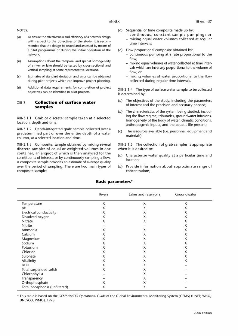
NOTES:
(a) To ensure the effectiveness and efficiency of a network designwith respect to the objectives of the study, it is re c o m-mended that the design be tested and assessed by means ofa pilot programme or during the initial operation of then e t w o r k .
(b) Assumptions about the temporal and spatial homogeneityof a river or lake should be tested by cross-sectional andvertical sampling at some representative locations.
(c) Estimates of standard deviation and error can be obtainedduring pilot projects which can improve project planning.
(d) Additional data re q u i rements for completion of pro j e c tobjectives can be identified in pilot projects.
XIII-3 Collection of surface watersamples
XIII-3.1.1 Grab or discrete: sample taken at a selectedlocation, depth and time.
XIII-3.1.2 Depth-integrated grab: sample collected over ap re d e t e rmined part or over the entire depth of a watercolumn, at a selected location and time.
XIII-3.1.3 Composite: sample obtained by mixing severald i s c rete samples of equal or weighted volumes in onec o n t a i n e r, an aliquot of which is then analysed for theconstituents of interest, or by continuously sampling a flow.A composite sample provides an estimate of average qualityover the period of sampling. There are two main types ofcomposite sample:
(a) Sequential or time composite made up by:– cont inuous , constant sample pumping; or– mixing equal water volumes collected at re g u l a r
time intervals;
(b) Flow proportional composite obtained by:– continuous pumping at a rate pro p o rtional to the
flow;– mixing equal volumes of water collected at time inter-
vals which are inversely pro p o rtional to the volume offlow; or
– mixing volumes of water pro p o rtional to the flowcollected during regular time intervals.
XIII-3.1.4 The type of surface water sample to be collectedis determined by:
(a) The objectives of the study, including the parametersof interest and the precision and accuracy needed;
(b) The characteristics of the system being studied, includ-ing the flow regime, tributaries, groundwater infusions,homogeneity of the body of water, climatic conditions,anthropogenic inputs, and the aquatic life present;
(c) The re s o u rces available (i.e. personnel, equipment andmaterials).
XIII-3.1.5 The collection of grab samples is appro p r i a t ewhen it is desired to:
(a) Characterize water quality at a particular time andlocation;
(b) P rovide information about approximate range ofconcentrations;
2006 edition
ANNEX III-An. – 57
Rivers Lakes and reservoirs Groundwater
Temperature X X XpH X X XElectrical conductivity X X XDissolved oxygen X X XNitrate X X XNitrite – – XAmmonia X X XCalcium X X XMagnesium X X XSodium X X XPotassium X X XChloride X X XSulphate X X XAlkalinity X X XBOD X X –Total suspended solids X X –Chlorophyll a – X –Transparency – X –Orthophosphate X X –Total phosphorus (unfiltered) X X –
* This table is based on the G E M S / WATER Operational Guide of the Global Environmental Monitoring System (GEMS) (UNEP, WHO,UNESCO, WMO), 1978.
Basic parameters*
(c) Allow collection of variable sample volumes;
(d) Deal with a stream which does not flow continuously;or
(e) Detect changes of water quality based on re l a t i v e l yshort time intervals.
NOTES:
(a) For sampling sites located in a homogeneous reach of a riveror stream, the collection of depth-integrated samples in asingle vertical may be adequate. For small streams, a grabsample taken at the centroid of flow is usually adequate.
(b) For sampling sites located in a non-homogeneous reach ofa river or stream, it is necessary to sample the channel cro s s -section at a number of points and depths. The number andtype of samples taken will depend on the width, depth,d i s c h a rge, amount of suspended sediment, and aquatic lifep resent. Generally, the more points sampled in the cro s s -section, the more re p resentative the composite sample willbe. Ten verticals are recommended although three to fivea re sometimes sufficient, and fewer are necessary forn a rrow and shallow streams. The location of the vert i c a l scan be determined by:
– The EWI (equal-width increment) method — vert i c a l sspaced at equal intervals across the stream; or
– The EDI (equal-discharge increment) method — thec ross-section is divided into segments of equal discharg e .This method re q u i res detailed knowledge of the stre a mflow distribution in the cross-section.
XIII-3.2 General sampling guidelines
XIII-3.2.1 The sample collector should be pre p a red for themethods required by different sampling sites and the timeof the year, e.g.:
(a) Shallow water and deep water;
(b) Sampling from boats, bridges, aircraft, or from streambanks and wharves;
(c) Special conditions such as flooding, snow cover, or icecover.
XIII-3.2.2 L a rge non-homogeneous particles such as leavesand detritus should not be included in the sample.
XIII-3.2.3 Samples from a river should be taken facingupstream.
NOTE: This enables the collector to see whether any floating debrisis coming downstream. It also avoids contamination fro moil, paint chips or other dirt from the sampling site.
XIII-3.2.4 A sufficient amount of water, sediment or biotashould be collected to permit replicate analyses and qualityc o n t rol testing, if re q u i red. If not otherwise specified, therequired amount is a summation of the quantities requiredfor analysis of all the parameters of interest.
XIII-3.2.5 Accurate re c o rds of the sampling conditionsshould be maintained, including possible sources of interf e r-ence, atmospheric conditions and a description of anyunusual observations at the location.
XIII-3.3 Field sampling equipment
XIII-3.3.1 Grab water samples should be taken with arecognized sampler.
NOTES: Examples of suitable samplers are:
(a) Sampling iron with an appropriate bottle;
(b) Van Dorn bottle;
(c) Kemmerer bottle;
(d) Pump-type sampler;
(e) Multiple sampler.
A solvent-cleaned bottle opened just below the surface can be used.
X I I I - 3 . 3 . 2 Depth-integrated samples should be obtained by:
(a) Filling a bottle at a constant rate while moving it vert i-cally at a constant rate, such that the bottle is just filledat the end of the vertical motion; or
(b) Lowering a flexible plastic tube weighted at the bottomend to the desired depth, closing the upper end, raisingit and draining the contents into a sample container.
XIII-3.3.3 Composite samples should be obtained by:
(a) Mixing several grab samples; or
(b) Pumping of water over a period of time.
XIII-3.3.4 Automatic samplers should be used to collecteither grab or composite samples at predetermined times,p re d e t e rmined time intervals, or at a given rate of flow intothe sampling bottle.
XIII-3.4 Preparation for field trips
Thorough preparation should be made before setting forthon a field trip. This includes:
(a) Specific instructions on sampling procedures;
(b) Preparation of an itinerary according to the samplingschedule;
(c) Preparation of lists of equipment and materials;
(d) Ensuring that all sample bottles have been cleaned inaccordance with standard procedures;
(e) Ensuring that the chemical reagents and standard shave been provided by the laboratory;
(f) Preparation of a checklist.
NOTES:
(a) The number and size of containers needed are determ i n e dby the number of parameters to be analysed, the samplevolumes prescribed by the laboratory, and the number ofduplicate and triplicate analyses re q u i red by quality assurance.
(b) The type of containers used depends on the parameterbeing measured. Polyethylene containers are the mosteconomical. Glass, Teflon, or special containers are used for
2006 edition
TECHNICAL REGULATIONS — VOLUME III — HYDROLOGYIII-An. – 58
v e ry sensitive parameters such as dissolved oxygen or highlyreducing interstitial water.
(c) A well-pre p a red checklist ensures that nothing is forg o t t e n .It should include items such as: checking and calibration ofi n s t ruments; supplies of sample containers; filters; icechests; supplies of reagents for pre s e rvation; field analysisand standardization; maps; station descriptions; containerlabels and station re p o rting forms; manuals; tools; spareparts; safety equipment; first aid kit.
XIII-3.5 Field measured parameters
XIII-3.5.1 Rapidly changing parameters should bem e a s u red in the field. These include temperature, colour,transparency, turbidity, pH, dissolved oxygen, and conduc-tivity, and, in the case of groundwater, redox potential.
XIII-3.5.2 Because field measurements involve electricalmeters, titrations and optical comparisons, field personnelshould be trained to maintain such apparatus and to use itexactly and re p roducibly as specified in the Manual onWater Quality Monitoring (WMO-No. 680).
XIII-3.5.3 C a reful cleaning of containers and apparatus,appropriate to each kind of analysis, is essential for reliable analytical results, together with avoidance of contaminationsuch as dust, dirt, smoke, fumes, fingers and grease whilesamples are being taken and handled.
XIII-3.5.4 In no case should a value of zero be re c o rded foran analytical result; if the value obtained is below themethod detection limit, it should be recorded as “less than(state the method detection limit)”.
XIII-3.6 Recording of field data
XIII-3.6.1 An accurate record should be made of the loca-tion at which each sample was taken and of any specialconditions prevailing at the time of sampling.
XIII-3.6.2 When a sampling station is established its loca-tion should be adequately described.
NOTE: In addition to recording its geographical coordinates (lati-tude and longitude, grid re f e rence, Universal Tr a n s v e r s eM e rc a t o r, etc.), it should be located by means of a larg e -scale map of the area, a detailed sketch of the locale, andm e a s u red distances from nearby landmarks and perm a n e n treference points. The registered description should includenatural and man-made conditions which may have a bear-ing on water quality.
XIII-3.6.3 Station numbers or codes should be establishedfor ease of reference to station locations on sample labels.
XIII-3.6.4 A field sheet of observations should be pre p a re d ,including location, date, time, measurements made, andnotes of any conditions which may make a diff e rence ini n t e r p reting the data, such as weather, dead fish, algalg rowth, ice breakup and water flow data. The field sheetshould also show which methods of analysis have beenused, field calibrations of instruments including make andmodel number, sampling apparatus used and pro c e d u re s ,and specifics of quality control.
XIII-4 Water quality sample collection and storage
XIII-4.1 Types of samples
XIII-4.1.1 The types of samples considered in XIII-4 are:
(a) S u rface water samples, for physico-chemical analysis(see XIII-3 for sampling methods);
(b) Samples for biological analysis;
(c) Samples of atmospheric deposition for chemicalanalysis;
(d) Samples of suspended or bottom sediment;
(e) Groundwater samples.
XIII-4.2 Field filtration and preservation
XIII-4.2.1 To distinguish between concentrations ofcomponents dissolved in the water and of componentsp resent in or adsorbed on suspended particulate matter,samples with turbidity greater than three should be filteredin the field. Particular attention should be given to fieldfiltration to avoid contamination of the sample.
XIII-4.2.2 The choice of appropriate containers is veryi m p o rtant in pre s e rving the integrity of samples.Consideration should be given to:
(a) Leaching of container material by the sample, e.g.o rganic compounds from plastic, sodium or other ionsfrom glass;
(b) Sorption of substances from the sample onto containerwalls, e.g. trace metals, especially radioactive species,by glass, and organic substances by plastic;
(c) Direct reaction of the sample with the container, e.g.fluoride and glass;
(d) Bacteriostatic effects of metals and rubber.
XIII-4.2.3 For a number of parameters, samples should bep re s e rved for the trip to the laboratory by chemical addi-tions, such as acidification, by refrigeration, by sequesteringof metal ions, by staining of some organisms, and in somecases by freezing.
XIII-4.3 Biological samples
XIII-4.3.1 M i c robiological samples should be collected insterile, autoclavable non-toxic bottles.
XIII-4.3.2 Samples which cannot be analysed immediatelyshould be stored in the dark in melting ice to minimizemultiplication and die-off of the micro-organisms.
XIII-4.3.3 M a c robiota re q u i re specific sampling devices,depending on the types of organisms, and on whether theyare in the water column or in the sediment:
(a) Fish — actively with seines, trawls, electro - f i s h i n g ,chemicals, and hook and line, or passively with netsand traps;
(b) M a c ro i n v e rtebrates — with nets, multiple-platesamplers and basket samplers;
2006 edition
ANNEX III-An. – 59

(c) Plankton — with surface water samplers, or speciallydesigned equipment such as Juday traps or metere dnylon nets;
(d) Periphyton — with anchored or floating slides;
(e) M a c rophytes — with rakes, dredges, cutting knives onpoles, grapples, or in some case with the aid of self-contained underwater breathing apparatus;
(f) Bottom dwellers — see XIII-4.5.
XIII-4.4 Samples of atmospheric deposition
XIII-4.4.1 Site selection for sampling for monitoring thelong-range transport of airborne pollutants should considerthe direction and distance of transport controlled by short-t e rm weather conditions and by long-term climate. Forl a rge areal scale monitoring, sites should be rural andremote, with no continuous sources of pollution within 50 km in the direction from which the prevalent wind orig-inates, and 30 km in all other directions.
XIII-4.4.2 Local site-selection criteria should include:
(a) No moving sources of pollution such as traffic within 1 000 m of the site;
(b) No surface storage of agricultural products, fuels orother foreign materials within 1000 m of the site;
(c) Installation on flat, undisturbed land, preferably grass-c o v e red, with no wind-activatable sources of pollutionnearby such as ploughed fields, unpaved roads, ornatural or man-made sources of turbulence and eddycurrents;
(d) No objects such as trees or stru c t u res taller than thesampler closer than 5 m;
(e) No object within a distance of 2.5 times the height bywhich the object extends above the sampler. Part i c u l a rattention should be given to overhead wires used aspower source for automatic collectors;
(f) If a generator is used for power, location of the exhaustshould be as far as possible downwind from thecollector;
(g) Collector intake should be at least 1 m above theg round cover to minimize collection of coarse materialand splashes.
XIII-4.4.3 Types of atmospheric deposition which shouldbe sampled are rain, snow and dry deposition. Dry deposi-tion should be collected between wet and fro z e nprecipitation events such as rainfall and snowstorms.
XIII-4.4.4 Automated two-bucket samplers should be used.
NOTES:
(a) These samplers collect dry deposition in one bucket with thesecond bucket covered and have a sensor which detects ap recipitation event and shifts the cover from the second tothe first bucket during the event.
(b) The minimum rainfall, r in mm, which can be analysed asan event for a given collector system with a collectingsurface area a (in m2) can be calculated from:
where:d is the detection limit of the instrument used for analysis,
in nanograms (ng);c is the expected concentration in the rain, ice or snow fall, in ng/l;i is the injection factor, i.e. the fraction of the total sample
injected in the instrument for analysis. For example, if thetotal volume of the sample after concentration is 100 mland 20 ml is injected in the gas chromatograph, say, theni = 20/100. If the sample is analysed by atomic absorptionby aspiration from the 100 ml sample, then i = 1.
XIII-4.5 Sampling of sediment
NOTES:
(a) Detailed guidance on sediment sampling is given in theManual on Operational Methods for the Measurement ofSediment Tr a n s p o rt (WMO-No. 686).
(b) Sediment can be classified as:(i) Suspended material — material maintained in the
water column above the bed;(ii) Bed-load or traction-load — material found in almost
constant contact with the river bed, but moved alongby the flow;
(iii) Deposited material — material allowed to settle out bya decrease in water energ y, characteristically fine onlake bottoms and more heterogeneous on river beds.
(c) Where suspended sediment concentrations are high, grabor depth-integrating water samplers may be adequate.H o w e v e r, to obtain a sample of 5 g, it may be necessary tot reat thousands of litres, necessitating pumping systems,p referably with a continuous flow centrifuge to avoid labo-rious filtration procedures.
Bottom sediments are conveniently sampled by use of ad redge such as the Shipek sampler or the Birg e - E k m a nd redge, although gravity or piston core samplers should beused where less disturbed samples are re q u i red. If the inter-stitial water is anoxic, to undertake any study it should bepreserved under an inert atmosphere.
XIII-4.6 Groundwater
X I I I - 4 . 6 . 1 In addition to the station information re q u i red underXIII-3.6, the well used should be further described by pro v i d i n g :
(a) The aquifers tapped;
(b) The well depth, size, type of casing, and location andtype of perforations in the casing;
(c) A survey including the elevation of the land surf a c e ;
(d) A diagram and photograph of the well, showing accessto it and the measuring point;
€
r =d
a c i
2006 edition
TECHNICAL REGULATIONS — VOLUME III — HYDROLOGYIII-An. – 60

(e) The local name of the well, and its owner’s name;
(f) The use of the well.
XIII-4.6.2 The water level should be measured, usingeither a weighted steel measuring tape rubbed at the lowerend with blue carpenter’s chalk to show the water level, or atape detecting the water level by its electrical conductivity,or a bubbling air line converting the pre s s u re re q u i red forbubbling into the depth of submersion to be subtractedf rom the total length of the line. Recording devices employ-ing floats, electrical devices and pre s s u re gauges can beused to monitor changes in water levels.
XIII-4.6.3 Samples should be taken from pumping wells orf rom capped artesian wells. In open wells and wheresamples from specific depths are re q u i red grab samplers, ofsmall external diameter for narrow well casings, should beused.
XIII-4.6.4 Soil water samples from above the water tableshould be taken by driving tubes with a porous region nearthe bottom into the soil, or by embedding porous ceramiccups in the ground supplied with vacuum lines.
XIII-4.7 Samples for radioactivitymeasurement
XIII-4.7.1 P recautions should be taken to avoid adsorptionon the walls of the container or on suspended matter.
NOTE: Acceptable container materials include polypro p y l e n e ,polyethylene or Teflon.
XIII-4.7.2 To keep metals in solution and minimize theiradsorption, hydrochloric or nitric acid, 2 ml/l of sample,should be added.
XIII-4.8 Shipping of samples
When shipping samples to the laboratory for analysis, eachsample should be labelled with full information on thestation, date, time, parameters to be analysed, methods ofp re s e rvation if any, and the identity of the collector,together with an optional narrative description to identifyany special circumstances affecting the interpretation of thedata.
NOTE: Depending on local rules of evidence, any sample whichmay form part of the evidence in legal proceedings may re q u i re the maintenance of a verifiable chain of custodythrough all persons having custody of the sample from thecollector to the analyst.
XIII-5 Quality assurance
XIII-5.1 Generalities
NOTES:
(a) Quality assurance consists of quality control, the overallsystem of guidelines and pro c e d u res designed to control the
quality of the product, and quality assessment, the overall system of activities which ensure that quality contro lis being effectively perf o rm e d .
(b) Analytical methods can be classified as:(i) P r i m a ry methods, suitable for establishing the analytical
data for standard re f e rence material; exacting, time-consuming and requiring a high degree of skill;
( i i ) Routine methods, suitable for day-to-day use withn u m e rous samples, for good precision and accuracy.
(c) Accuracy of routine methods can be checked by the use ofsamples of known concentration, such as standard re f e r-ence materials, and by the addition of known amounts of“spikes” to the sample being analysed.
XIII-5.1.1 The quality assurance programme shall includedocumentation of field and laboratory protocols.
NOTES:
(a) Quality of analytical results is defined by their precision, am e a s u re of the closeness of agreement between data gener-ated by replicate measurements, and accuracy, the degree ofa g reement of the data with the “true value”.
(b) The precision measures the variability of the method re s u l t -ing from random errors, and is generally re p o rted as thes t a n d a rd deviation or the relative standard deviation of aseries of replicate analyses.
(c) Accuracy is usually expressed in the form of % erro r, i.e.100 times the diff e rence between the mean value obtainedand the true value, divided by the true value.
(d) The accuracy of a method can be determined by analysings t a n d a rd re f e rence materials or by the addition of knownamounts of “spikes”, analysing them, and determining the% re c o v e ry. This measures the capability of the method torecover known amounts of material added to a sample.
XIII-5.1.2 For each method and for each instrument in alaboratory the following values should be determined:
(a) I n s t rument detection limit — the lowest concentrationof analyte that an instrument can detect whichis statistically diff e rent from the instrumental background noise;
(b) Method detection limit — the lowest concentrationthat a method can reliably detect which is statistic a l l yd i ff e rent from the value obtained from a blank, e . g .distilled water, carried through the same m e t h o d ;
(c) Practical detection limit — the lowest concentrationthat a method can reliably detect in a real sample-matrix which is statistically diff e rent from a blankc a rried through the method on the same sample-matrix;
(d) Limit of quantitation — a value of a sufficient number o fs t a n d a rd deviations, usually above the average v a l u eof the blank, that not only indicates the pre s e n c e of theanalyte detected, but is also a useful value for theconcentration determined.
2006 edition
ANNEX III-An. – 61

NOTES:
(a) Sampler blanks — samples consisting of ultra-pure distilledwater poured into or permitted to pass through the samplerand run through the rest of the field and analytical pro c e s s ,including field pre s e rvation and transportation to the laboratory.
(b) Bottle blanks — samples pre p a red from ultra-pure water ora solvent placed in randomly selected sample containersand run through the analytical process to ensure that nocontamination is introduced through the bottle-washingprocess.
(c) Field blanks — samples prepared as the bottle blanks, butalso adding the chemicals re q u i red to pre s e rve the sampleuntil it is analysed. These samples detect any contaminationdue to the chemical preservation of samples.
(d) Filter blanks — samples pre p a red from ultra-pure waterwhich was passed through the field filtering apparatus.These samples are used to detect contamination occurr i n gduring field filtration.
(e) Duplicate samples (splits) — subsamples obtained by divid-ing a sample in two or more parts.
(f) Replicate samples (temporal) — samples taken at the samelocation at specified, usually short, time intervals.
(g) Spiked samples (standard additions) — split samples spikedwith several diff e rent levels of the parameters of interest, todetect the introduction of systematic errors or bias into theanalytical method.
XIII-5.2 Quality assessment reports
XIII-5.2.1 Quality assessment re p o rts should be re q u i re df rom each level of laboratory supervision, from benchanalyst to section head.
XIII-5.2.2 The bench analyst should report:
(a) The variability of data for blanks and standards;
(b) The precision and accuracy of groups of tests;
(c) The number and type of quality control analyseswhose results deviated by more than a pre s e tamount, e.g. two standard deviations, from the tru evalues;
(d) Other information relevant to quality control, suchas: variation in standard solutions, reagents found tobe substandard, methods used in housecleaning,samples with incorrect or inadequate inform a t i o n ,f requency of instrument calibration.
XIII-5.2.3 L a b o r a t o ry supervisors should re p o rt, appro -priate to the supervisory level:
(a) Frequency of user/client complaints;
(b) Training sessions attended by staff;
(c) Analytical audits and checks of data against historicalvalues;
(d) I n t e r l a b o r a t o ry quality control studies in which thelaboratory participated;
(e) New analytical pro c e d u res introduced or modified;
(f) Overall precision and accuracy of group results;
(g) Other information relevant to quality control, such as:incidence of instrumental breakdown, frequency ofdata verification.
XIII-5.3 Data recording
XIII-5.3.1 In no case should a value of zero be re c o rded foran analytical result.
NOTE: If the value obtained is below the method detection limit, itshould be re c o rded as such, e.g.”less than [state themethod detection limit]”.
XIII-5.3.2 Values below the practical detection limit or thelimit of quantitation should be so identified, in the lattercase normally by enclosing the data in parentheses.
XIII-5.3.3 Quantitative data should be accompanied bym e a s u res of precision and accuracy where available, and byexpected reliability such as the confidence interval.
NOTE: A confidence interval is a statistically-derived estimate thatthe true value lies in a given percentage of determinationsbetween the stated upper and lower limits about thesample mean value as determined.
XIII-6 Field safety
XIII-6.1 Training
XIII-6.1.1 Field personnel should receive the necessarytraining to become knowledgeable of the hazards they maye n c o u n t e r, to recognize potential hazardous situations, andto take measures to minimize hazards.
XIII-6.1.2 Training should include water safety, field firstaid, wilderness survival and basic methods for re p a i r i n gtransportation vehicles.
XIII-6.1.3 Field offices should maintain a current list of re l e-vant safety courses available from government or private agencies, together with a re c o rd of courses taken by theirpersonnel.
XIII-6.1.4 Periodic re f resher courses should be org a n i z e d .
XIII-6.2 General practices
XIII-6.2.1 All employees should be aware of, and adhereto, safety procedures promulgated by their governments.
XIII-6.2.2 Field staff should be provided with availablei n f o rmation on the characteristics of water bodies to bestudied and weather forecasts for the area.
XIII-6.2.3 Sampling should not be carried out if abnormalweather or water conditions prevail which are considered tobe hazardous to the safety or the health of staff members orlikely to damage equipment.
XIII-6.2.4 Field parties should leave accurate samplingschedules and expected itineraries in the field office.
2006 edition
TECHNICAL REGULATIONS — VOLUME III — HYDROLOGYIII-An. – 62

XIII-6.3 Safety precautions when sampling
XIII-6.3.1 Each type of sampling site re q u i res its own set ofsafety precautions. Field personnel should consider:
(a) Highway bridges — the need for warning lights,signs, fluorescent clothing, flags on equipmentsuspension lines, presence of power lines;
(b) Railway bridges — knowledge of train schedules,have equipment that can be moved quickly;
(c) Wading — be aware of insecure banks, slipperyrocks, fast-flowing water, have available rod forp robing depths, flotation device (e.g. life jacket),safety line attached to a rigid mooring, knowledgeof quicksand pro c e d u res, have change of clothingto avoid wet clothing hypotherm i a ;
(d) Boats — need for compliance with local small vesselregulations, avoidance of busy navigation lanes, at leasttwo persons present, auxiliary power for emerg e n c i e s ,extra fuel and spare parts, no overloading, flotationdevices, clothing to avoid sunstroke or wet clothingh y p o t h e rmia, avoid floating or submerged debris.
X I I I - 6 . 3 . 2 Field personnel should be trained to re c o g n i z e p o-tential hazardous situations and to take necessary measures tominimize hazards. In addition to physical sitehazards, waterbeing sampled may contain chemical and/or biologicalsubstances which may be harmful and contact with the skinshould be avoided. Special precautions will be re q u i red in thehandling of sewerage and industrial eff l u e n t s .
X I I I - 6 . 4 Handling chemicals and equipment
X I I I - 6 . 4 . 1 Acids and bases should be stored and handledwith care, and never pipetted orally. Safety glasses should bew o rn at all times when handling acids and bases. Spills shouldbe cleaned up immediately by flushing with large quantities ofwater or neutralization; gloves and an apron should beincluded for such clean-up operations.
X I I I - 6 . 4 . 2 Inhalation of vapours or direct contact with skin,eyes and clothing should be avoided. Skin which has been incontact with an acid or base should be washed immediatelywith plenty of water, followed by washing with soap or swab-bing gently with a neutralizing solution.
X I I I - 6 . 4 . 3 Chemicals in eyes must be flushed immediatelywith water, having the eyelids held open if necessary. All eyeinjuries should receive professional treatment as soon as possible.
X I I I - 6 . 4 . 4 Use of mercuric chloride (corrosive sublimate)should be avoided unless absolutely necessary. If it is used,operators should have specific hazards training and all merc u ryresidues should be re c o v e re d .
X I I I - 6 . 4 . 5 Work pro c e d u res should be designed to minimizethe electrocution hazards of working with electrical equipmentin or near water. Electrical equipment should never be dire c t l yw i red to power lines without plugs or switches for quick andeasy disconnection.
X I I I - 6 . 4 . 6 Self-contained underwater breathing appara-tus (scuba gear) or other diving gear should always bechecked before use to ensure re l i a b i l i t y.
2006 edition
ANNEX III-An. – 63