TECHNICAL MANUAL PowerTech Plus™ 4.5L & 6.8L Diesel ...
742
PowerTech 4.5L & 6.8L PowerTech Plus 4.5L & 6.8L Diesel Engines Base Engine TECHNICAL MANUAL PowerTech Plus 4.5L & 6.8L Diesel Engines— Base Engine CTM104 27JAN06 (ENGLISH) For complete service information also see: POWERTECH Diesel Engines—Mechanical Fuel Systems ......................... CTM207 POWERTECH Diesel Engines—Level 4 Electronic Fuel Systems with Bosch VP44 Pump ............................... CTM170 POWERTECH Diesel Engines—Level 12 Electronic Fuel Systems with Stanadyne DE10 Pump .......................... CTM331 POWERTECHDiesel Engines—Level 1 Electronic Fuel Systems with Delphi/Lucas DP201 Pump ......................... CTM284 POWERTECH Diesel Engines—Level 11 Electronic Fuel Systems with Denso HPCR ............................... CTM220 POWERTECH Diesel Engines and PowerTech Plus—Level 14 Electronic Fuel Systems with Denso HPCR.............. CTM320 Alternators and Starter Motors ........... CTM77 OEM Engine Accessories ...... CTM67 (English Only) John Deere Power Systems LITHO IN U.S.A.
-
Upload
khangminh22 -
Category
Documents
-
view
0 -
download
0
Transcript of TECHNICAL MANUAL PowerTech Plus™ 4.5L & 6.8L Diesel ...
PowerTech 4.5L &6.8L
PowerTech Plus 4.5L& 6.8L
Diesel EnginesBase Engine
TECHNICAL MANUALPowerTech Plus 4.5L & 6.8LDiesel Engines— Base Engine
CTM104 27JAN06 (ENGLISH)
For complete service information also see:
POWERTECH Diesel Engines—MechanicalFuel Systems . . . . . . . . . . . . . . . . . . . . . . . . . CTM207POWERTECH Diesel Engines—Level 4Electronic Fuel Systems with Bosch VP44Pump . . . . . . . . . . . . . . . . . . . . . . . . . . . . . . . CTM170POWERTECH Diesel Engines—Level 12Electronic Fuel Systems with StanadyneDE10 Pump . . . . . . . . . . . . . . . . . . . . . . . . . . CTM331POWERTECHDiesel Engines—Level 1Electronic Fuel Systems with Delphi/LucasDP201 Pump . . . . . . . . . . . . . . . . . . . . . . . . . CTM284POWERTECH Diesel Engines—Level 11Electronic Fuel Systems with DensoHPCR . . . . . . . . . . . . . . . . . . . . . . . . . . . . . . . CTM220POWERTECH Diesel Engines andPowerTech Plus—Level 14 Electronic FuelSystems with Denso HPCR. . . . . . . . . . . . . . CTM320Alternators and Starter Motors. . . . . . . . . . . CTM77OEM Engine Accessories . . . . . . CTM67 (English Only)
John Deere Power Systems
LITHO IN U.S.A.
Introduction
DPSG,OUO1004,2767 –19–27SEP05–1/1
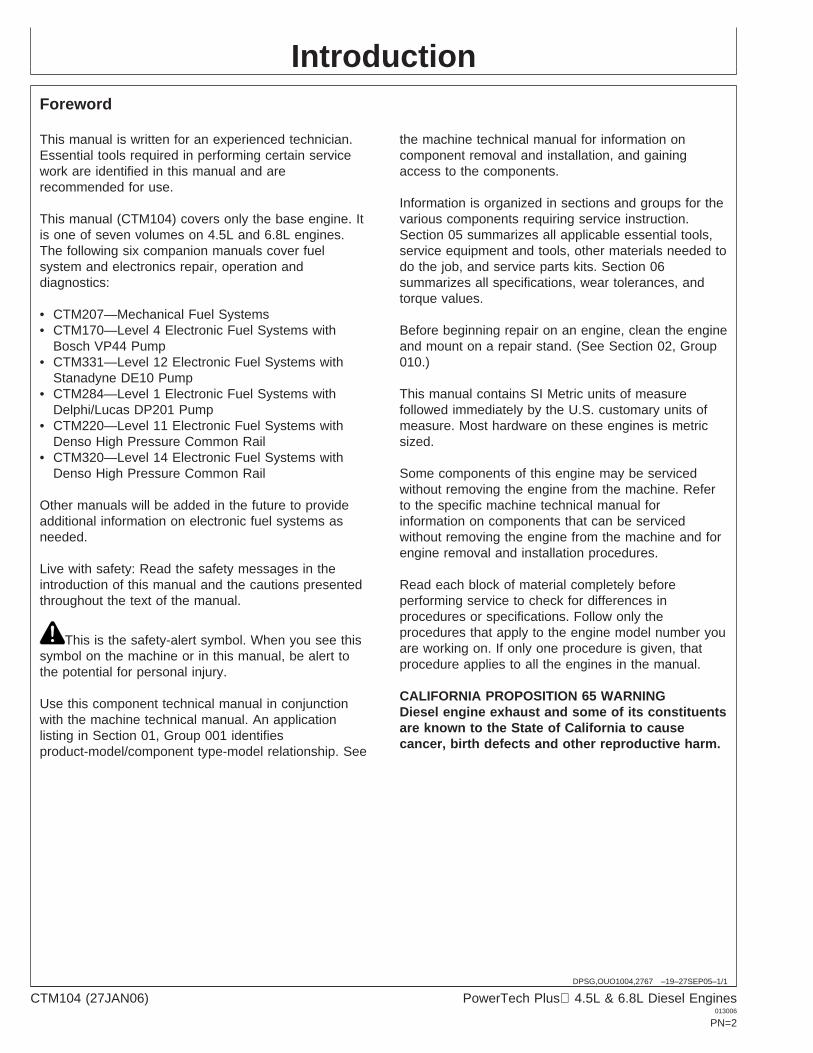
Foreword
This manual is written for an experienced technician.Essential tools required in performing certain servicework are identified in this manual and arerecommended for use.
This manual (CTM104) covers only the base engine. Itis one of seven volumes on 4.5L and 6.8L engines.The following six companion manuals cover fuelsystem and electronics repair, operation anddiagnostics:
• CTM207—Mechanical Fuel Systems• CTM170—Level 4 Electronic Fuel Systems with
Bosch VP44 Pump• CTM331—Level 12 Electronic Fuel Systems with
Stanadyne DE10 Pump• CTM284—Level 1 Electronic Fuel Systems with
Delphi/Lucas DP201 Pump• CTM220—Level 11 Electronic Fuel Systems with
Denso High Pressure Common Rail• CTM320—Level 14 Electronic Fuel Systems with
Denso High Pressure Common Rail
Other manuals will be added in the future to provideadditional information on electronic fuel systems asneeded.
Live with safety: Read the safety messages in theintroduction of this manual and the cautions presentedthroughout the text of the manual.
This is the safety-alert symbol. When you see thissymbol on the machine or in this manual, be alert tothe potential for personal injury.
Use this component technical manual in conjunctionwith the machine technical manual. An applicationlisting in Section 01, Group 001 identifiesproduct-model/component type-model relationship. See
the machine technical manual for information oncomponent removal and installation, and gainingaccess to the components.
Information is organized in sections and groups for thevarious components requiring service instruction.Section 05 summarizes all applicable essential tools,service equipment and tools, other materials needed todo the job, and service parts kits. Section 06summarizes all specifications, wear tolerances, andtorque values.
Before beginning repair on an engine, clean the engineand mount on a repair stand. (See Section 02, Group010.)
This manual contains SI Metric units of measurefollowed immediately by the U.S. customary units ofmeasure. Most hardware on these engines is metricsized.
Some components of this engine may be servicedwithout removing the engine from the machine. Referto the specific machine technical manual forinformation on components that can be servicedwithout removing the engine from the machine and forengine removal and installation procedures.
Read each block of material completely beforeperforming service to check for differences inprocedures or specifications. Follow only theprocedures that apply to the engine model number youare working on. If only one procedure is given, thatprocedure applies to all the engines in the manual.
CALIFORNIA PROPOSITION 65 WARNINGDiesel engine exhaust and some of its constituentsare known to the State of California to causecancer, birth defects and other reproductive harm.
CTM104 (27JAN06) PowerTech Plus 4.5L & 6.8L Diesel Engines013006
PN=2
Introduction
OUO1080,000023A –19–12JUN02–1/2
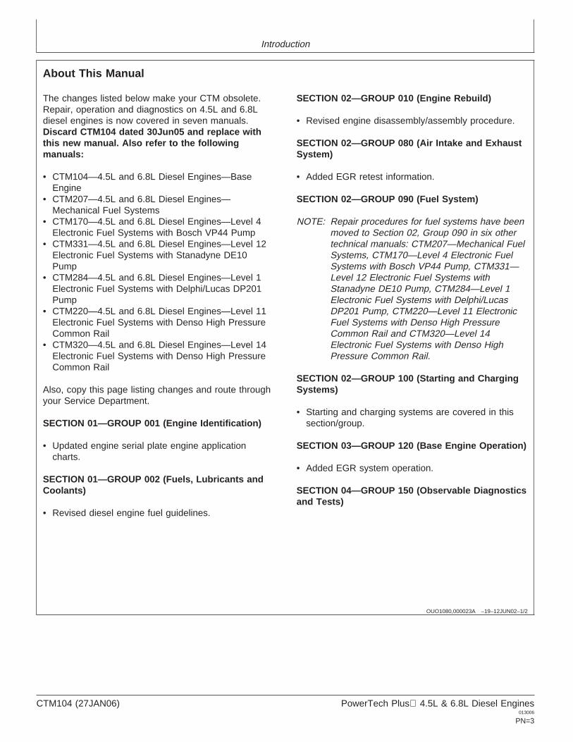
About This Manual
The changes listed below make your CTM obsolete.Repair, operation and diagnostics on 4.5L and 6.8Ldiesel engines is now covered in seven manuals.Discard CTM104 dated 30Jun05 and replace withthis new manual. Also refer to the followingmanuals:
• CTM104—4.5L and 6.8L Diesel Engines—BaseEngine
• CTM207—4.5L and 6.8L Diesel Engines—Mechanical Fuel Systems
• CTM170—4.5L and 6.8L Diesel Engines—Level 4Electronic Fuel Systems with Bosch VP44 Pump
• CTM331—4.5L and 6.8L Diesel Engines—Level 12Electronic Fuel Systems with Stanadyne DE10Pump
• CTM284—4.5L and 6.8L Diesel Engines—Level 1Electronic Fuel Systems with Delphi/Lucas DP201Pump
• CTM220—4.5L and 6.8L Diesel Engines—Level 11Electronic Fuel Systems with Denso High PressureCommon Rail
• CTM320—4.5L and 6.8L Diesel Engines—Level 14Electronic Fuel Systems with Denso High PressureCommon Rail
Also, copy this page listing changes and route throughyour Service Department.
SECTION 01—GROUP 001 (Engine Identification)
• Updated engine serial plate engine applicationcharts.
SECTION 01—GROUP 002 (Fuels, Lubricants andCoolants)
• Revised diesel engine fuel guidelines.
SECTION 02—GROUP 010 (Engine Rebuild)
• Revised engine disassembly/assembly procedure.
SECTION 02—GROUP 080 (Air Intake and ExhaustSystem)
• Added EGR retest information.
SECTION 02—GROUP 090 (Fuel System)
NOTE: Repair procedures for fuel systems have beenmoved to Section 02, Group 090 in six othertechnical manuals: CTM207—Mechanical FuelSystems, CTM170—Level 4 Electronic FuelSystems with Bosch VP44 Pump, CTM331—Level 12 Electronic Fuel Systems withStanadyne DE10 Pump, CTM284—Level 1Electronic Fuel Systems with Delphi/LucasDP201 Pump, CTM220—Level 11 ElectronicFuel Systems with Denso High PressureCommon Rail and CTM320—Level 14Electronic Fuel Systems with Denso HighPressure Common Rail.
SECTION 02—GROUP 100 (Starting and ChargingSystems)
• Starting and charging systems are covered in thissection/group.
SECTION 03—GROUP 120 (Base Engine Operation)
• Added EGR system operation.
SECTION 04—GROUP 150 (Observable Diagnosticsand Tests)
CTM104 (27JAN06) PowerTech Plus 4.5L & 6.8L Diesel Engines013006
PN=3
Introduction
OUO1080,000023A –19–12JUN02–2/2
NOTE: Fuel system testing and diagnostics has beenmoved to Section 04, Group 150 in five othertechnical manuals: CTM207—Mechanical FuelSystems, CTM170—Level 4 Electronic FuelSystems with Bosch VP44 Pump, CTM331—Level 12 Electronic Fuel Systems withStanadyne DE10 Pump, CTM284—Level 1Electronic Fuel Systems with Delphi/LucasDP201 Pump, CTM220—Level 11 ElectronicFuel Systems with Denso High PressureCommon Rail and CTM320—Level 14Electronic Fuel Systems with Denso HighPressure Common Rail.
SECTION 5 (Tools and Other Materials)
• All essential tools, service tools, dealer fabricatedtools and other materials listed throughout thismanual are consolidated in this section for ease ofreference.
SECTION 6 (Specifications)
• All repair, test and diagnostic specifications listedthroughout this manual are consolidated in thissection for ease of reference.
CTM104 (27JAN06) PowerTech Plus 4.5L & 6.8L Diesel Engines013006
PN=4
Introduction
DPSG,OUO1004,129 –19–15MAY02–1/1
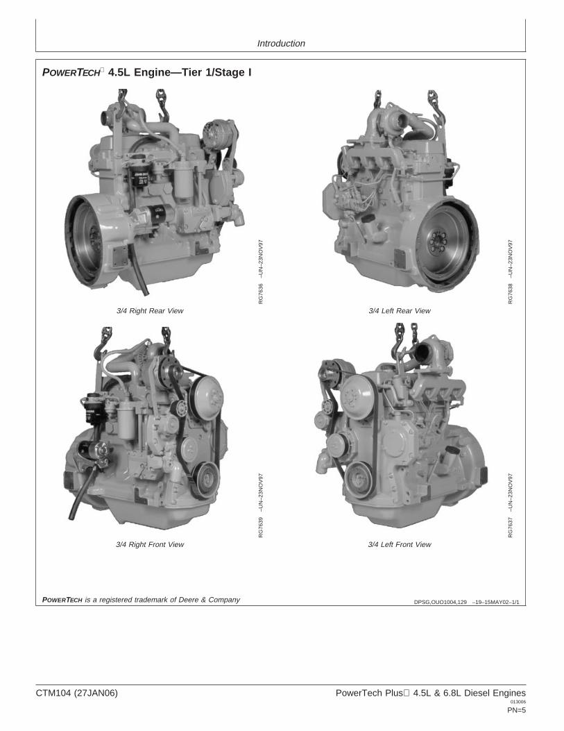
POWERTECH 4.5L Engine—Tier 1/Stage I
RG
7636
–UN
–23N
OV
97
3/4 Right Rear View
RG
7638
–UN
–23N
OV
97
3/4 Left Rear View
RG
7639
–UN
–23N
OV
97
3/4 Right Front View
RG
7637
–UN
–23N
OV
97
3/4 Left Front View
POWERTECH is a registered trademark of Deere & Company
CTM104 (27JAN06) PowerTech Plus 4.5L & 6.8L Diesel Engines013006
PN=5
Introduction
OUO1080,0000238 –19–03JUN04–1/1
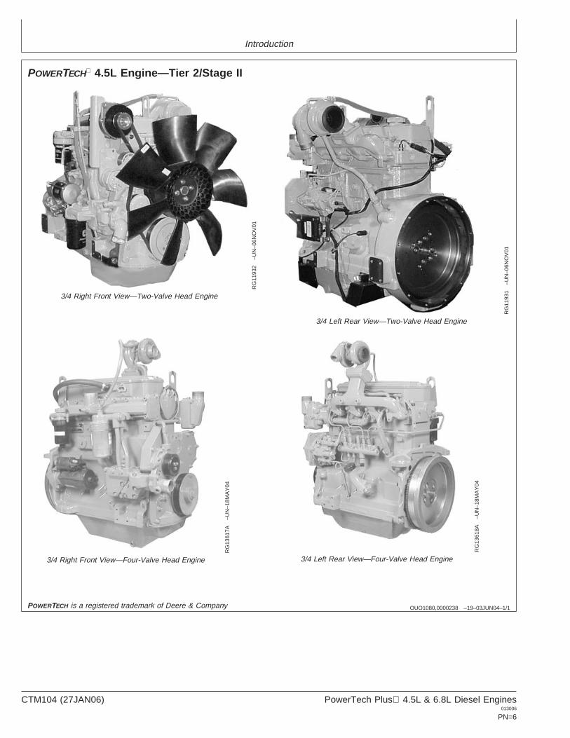
POWERTECH 4.5L Engine—Tier 2/Stage II
RG
1193
2–U
N–0
6NO
V01
3/4 Right Front View—Two-Valve Head Engine
RG
1193
1–U
N–0
6NO
V01
3/4 Left Rear View—Two-Valve Head Engine
RG
1361
7A–U
N–1
8MA
Y04
3/4 Right Front View—Four-Valve Head Engine
RG
1361
8A–U
N–1
8MA
Y04
3/4 Left Rear View—Four-Valve Head Engine
POWERTECH is a registered trademark of Deere & Company
CTM104 (27JAN06) PowerTech Plus 4.5L & 6.8L Diesel Engines013006
PN=6
Introduction
DPSG,OUO1004,130 –19–15MAY02–1/1
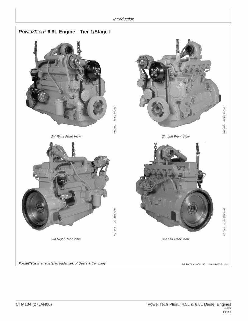
POWERTECH 6.8L Engine—Tier 1/Stage I
RG
7641
–UN
–23N
OV
97
3/4 Right Front View
RG
7640
–UN
–23N
OV
97
3/4 Left Front View
RG
7643
–UN
–23N
OV
97
3/4 Right Rear View
RG
7642
–UN
–23N
OV
97
3/4 Left Rear View
POWERTECH is a registered trademark of Deere & Company
CTM104 (27JAN06) PowerTech Plus 4.5L & 6.8L Diesel Engines013006
PN=7
Introduction
OUO1080,0000239 –19–06JUN02–1/1
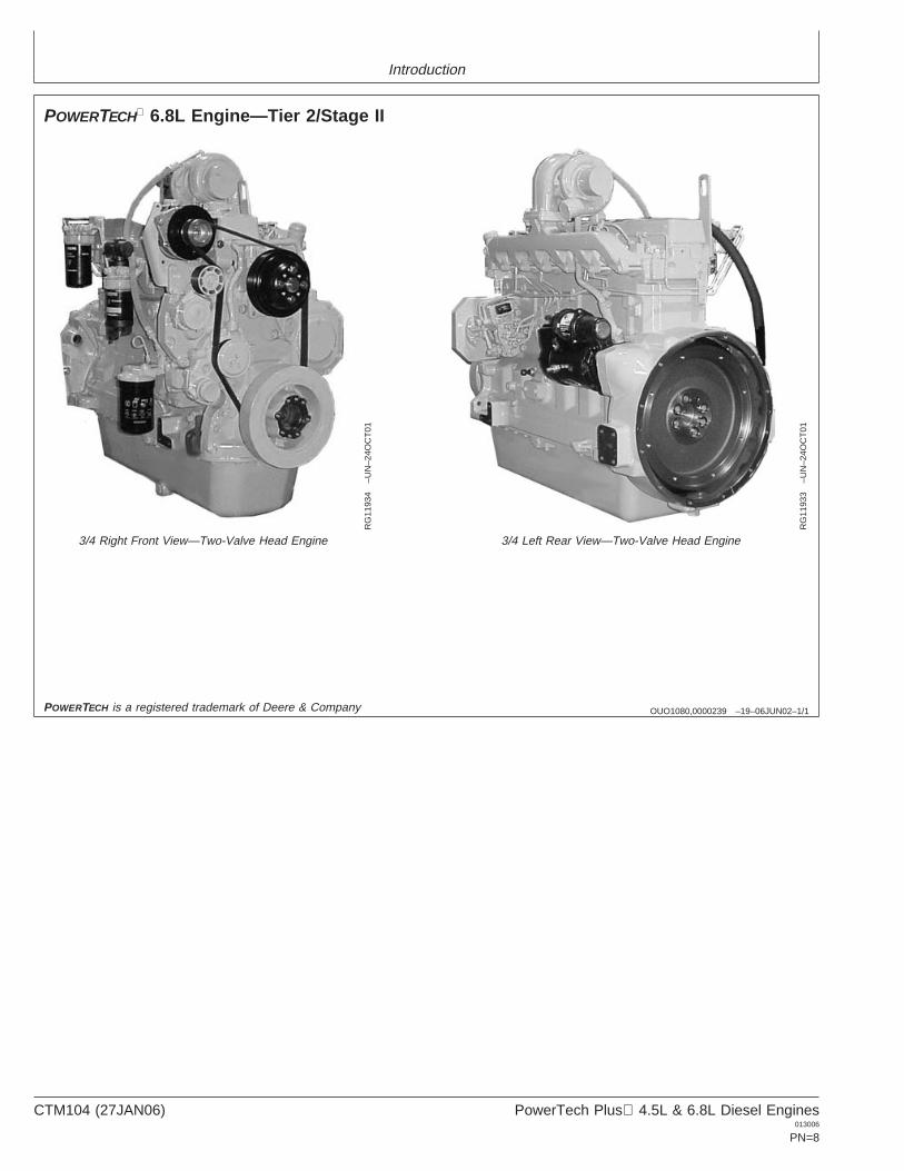
POWERTECH 6.8L Engine—Tier 2/Stage II
RG
1193
4–U
N–2
4OC
T01
3/4 Right Front View—Two-Valve Head Engine
RG
1193
3–U
N–2
4OC
T01
3/4 Left Rear View—Two-Valve Head Engine
POWERTECH is a registered trademark of Deere & Company
CTM104 (27JAN06) PowerTech Plus 4.5L & 6.8L Diesel Engines013006
PN=8
Introduction
OUO1083,00005FC –19–21OCT05–1/1
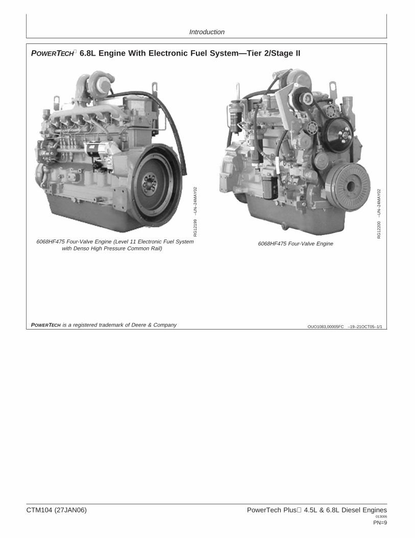
POWERTECH 6.8L Engine With Electronic Fuel System—Tier 2/Stage II
RG
1219
9–U
N–2
4MA
Y02
6068HF475 Four-Valve Engine (Level 11 Electronic Fuel Systemwith Denso High Pressure Common Rail)
RG
1220
0–U
N–2
4MA
Y02
6068HF475 Four-Valve Engine
POWERTECH is a registered trademark of Deere & Company
CTM104 (27JAN06) PowerTech Plus 4.5L & 6.8L Diesel Engines013006
PN=9
Introduction
OUO1083,00005FC –19–17DEC03–1/1
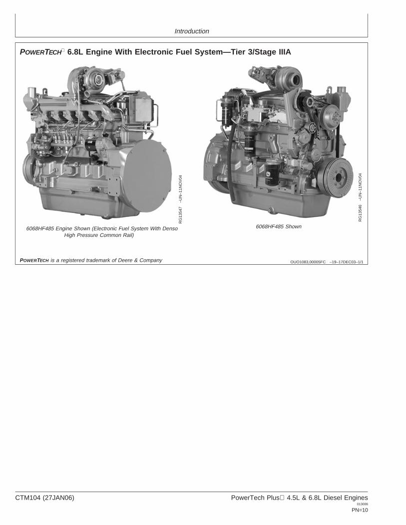
POWERTECH 6.8L Engine With Electronic Fuel System—Tier 3/Stage IIIA
RG
1354
7–U
N–1
1NO
V04
6068HF485 Engine Shown (Electronic Fuel System With DensoHigh Pressure Common Rail)
RG
1354
6–U
N–1
1NO
V04
6068HF485 Shown
POWERTECH is a registered trademark of Deere & Company
CTM104 (27JAN06) PowerTech Plus 4.5L & 6.8L Diesel Engines013006
PN=10
Contents01
SECTION 01—General InformationGroup 000—SafetyGroup 001—Engine Identification and Application
ChartsGroup 002—Fuels, Lubricants and Coolants
02
SECTION 02—Repair and AdjustmentsGroup 010—Engine RebuildGroup 020—Cylinder Head and Valves (Two-Valve
Head Engines)Group 021—Cylinder Head and Valves (Four-Valve
Head Engines)Group 030—Cylinder Block, Liners, Pistons and
RodsGroup 040—Crankshaft, Main Bearings and
Flywheel
03
Group 050—Camshaft, Balancer Shafts and TimingGear Train
Group 060—Lubrication SystemGroup 070—Cooling SystemGroup 080—Air Intake and Exhaust SystemGroup 090—Fuel SystemGroup 100—Starting and Charging Systems
SECTION 03—Theory of OperationGroup 120—Base Engine Operation
04
SECTION 04—DiagnosticsGroup 150—Observable Diagnostics and Tests
SECTION 05—Tools and Other MaterialsGroup 170—Repair Tools and Other MaterialsGroup 180—Diagnostic Service ToolsGroup 190—Dealer Fabricated Service Tools
SECTION 06—SpecificationsGroup 200—Repair and General OEM
Specifications
05
Group 210—Diagnostic Specifications
All information, illustrations and specifications in this manual are based onthe latest information available at the time of publication. The right isreserved to make changes at any time without notice.
06
COPYRIGHT 2006DEERE & COMPANY
Moline, IllinoisAll rights reserved
A John Deere ILLUSTRUCTION ManualPrevious Editions
Copyright 1996, 1998, 2000, 2002, 2004, 2005
INDX
CTM104 (27JAN06) i PowerTech Plus 4.5L & 6.8L Diesel Engines013006
PN=1
Contents
01
02
03
04
05
06
INDX
CTM104 (27JAN06) ii PowerTech Plus 4.5L & 6.8L Diesel Engines013006
PN=2
01
Section 01General Information
Contents
Page
Group 000—Safety . . . . . . . . . . . . . . . . . . . .01-000-1
Group 001—Engine Identification and ApplicationCharts
Engine Serial Number Plate Information . . . . .01-001-1OEM Engine Option Code Label . . . . . . . . . . .01-001-3Information Relative to Emissions
Regulations . . . . . . . . . . . . . . . . . . . . . . . . .01-001-3Engine Application Charts . . . . . . . . . . . . . . . .01-001-4
Group 002—Fuels, Lubricants and CoolantsDiesel Fuel . . . . . . . . . . . . . . . . . . . . . . . . . . .01-002-1Bio-Diesel Fuel . . . . . . . . . . . . . . . . . . . . . . . .01-002-2Lubricity of Diesel Fuel . . . . . . . . . . . . . . . . . .01-002-3Testing Diesel Fuel . . . . . . . . . . . . . . . . . . . . .01-002-3Diesel Engine Break-In Oil . . . . . . . . . . . . . . .01-002-4Diesel Engine Oil—Non-Certified and Tier 1
Certified Engines . . . . . . . . . . . . . . . . . . . . .01-002-5Diesel Engine Oil—Tier 2/Stage II
Certified Engines . . . . . . . . . . . . . . . . . . . . .01-002-6Diesel Engine Oil —Tier 3/Stage IIIA Certified
Engines . . . . . . . . . . . . . . . . . . . . . . . . . . . .01-002-7OILSCAN, OILSCAN Plus,
COOLSCAN and COOLSCAN PLUS . . .01-002-8Oil Filters. . . . . . . . . . . . . . . . . . . . . . . . . . . . .01-002-8Grease . . . . . . . . . . . . . . . . . . . . . . . . . . . . . .01-002-9Diesel Engine Coolant. . . . . . . . . . . . . . . . . .01-002-10Additional Information About Diesel
Engine Coolants and Supplemental CoolantAdditives . . . . . . . . . . . . . . . . . . . . . . . . . .01-002-12
Testing Diesel Engine Coolant . . . . . . . . . . .01-002-13Supplemental Coolant Additives . . . . . . . . . .01-002-14Operating in Warm Temperature Climates . .01-002-14Flush and Service Cooling System . . . . . . . .01-002-15Disposing of Coolant . . . . . . . . . . . . . . . . . . .01-002-16
CTM104 (27JAN06) 01-1 PowerTech Plus 4.5L & 6.8L Diesel Engines013006
PN=1
Contents
01
CTM104 (27JAN06) 01-2 PowerTech Plus 4.5L & 6.8L Diesel Engines013006
PN=2
Group 000Safety
010001
DX,FLAME –19–29SEP98–1/1
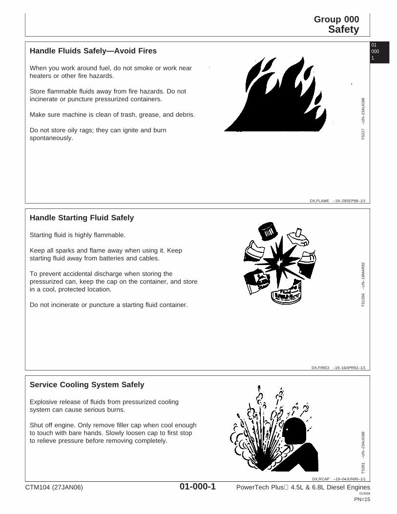
Handle Fluids Safely—Avoid Fires
TS
227
–UN
–23A
UG
88
When you work around fuel, do not smoke or work nearheaters or other fire hazards.
Store flammable fluids away from fire hazards. Do notincinerate or puncture pressurized containers.
Make sure machine is clean of trash, grease, and debris.
Do not store oily rags; they can ignite and burnspontaneously.
DX,FIRE3 –19–16APR92–1/1
Handle Starting Fluid Safely
TS
1356
–UN
–18M
AR
92
Starting fluid is highly flammable.
Keep all sparks and flame away when using it. Keepstarting fluid away from batteries and cables.
To prevent accidental discharge when storing thepressurized can, keep the cap on the container, and storein a cool, protected location.
Do not incinerate or puncture a starting fluid container.
DX,RCAP –19–04JUN90–1/1
Service Cooling System Safely
TS
281
–UN
–23A
UG
88
Explosive release of fluids from pressurized coolingsystem can cause serious burns.
Shut off engine. Only remove filler cap when cool enoughto touch with bare hands. Slowly loosen cap to first stopto relieve pressure before removing completely.
CTM104 (27JAN06) 01-000-1 PowerTech Plus 4.5L & 6.8L Diesel Engines013006
PN=15
Safety
01000
2
OUO1083,00005FE –19–17DEC03–1/1
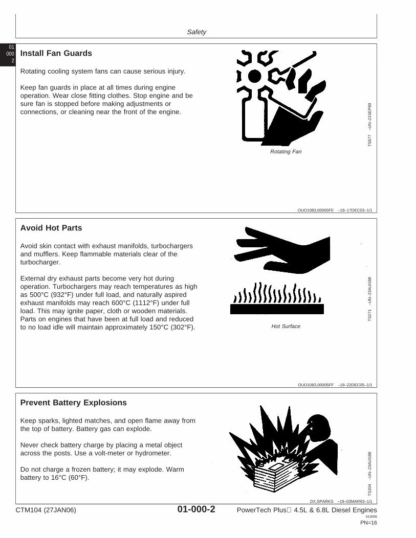
Install Fan Guards
TS
677
–UN
–21S
EP
89
Rotating Fan
Rotating cooling system fans can cause serious injury.
Keep fan guards in place at all times during engineoperation. Wear close fitting clothes. Stop engine and besure fan is stopped before making adjustments orconnections, or cleaning near the front of the engine.
OUO1083,00005FF –19–22DEC05–1/1
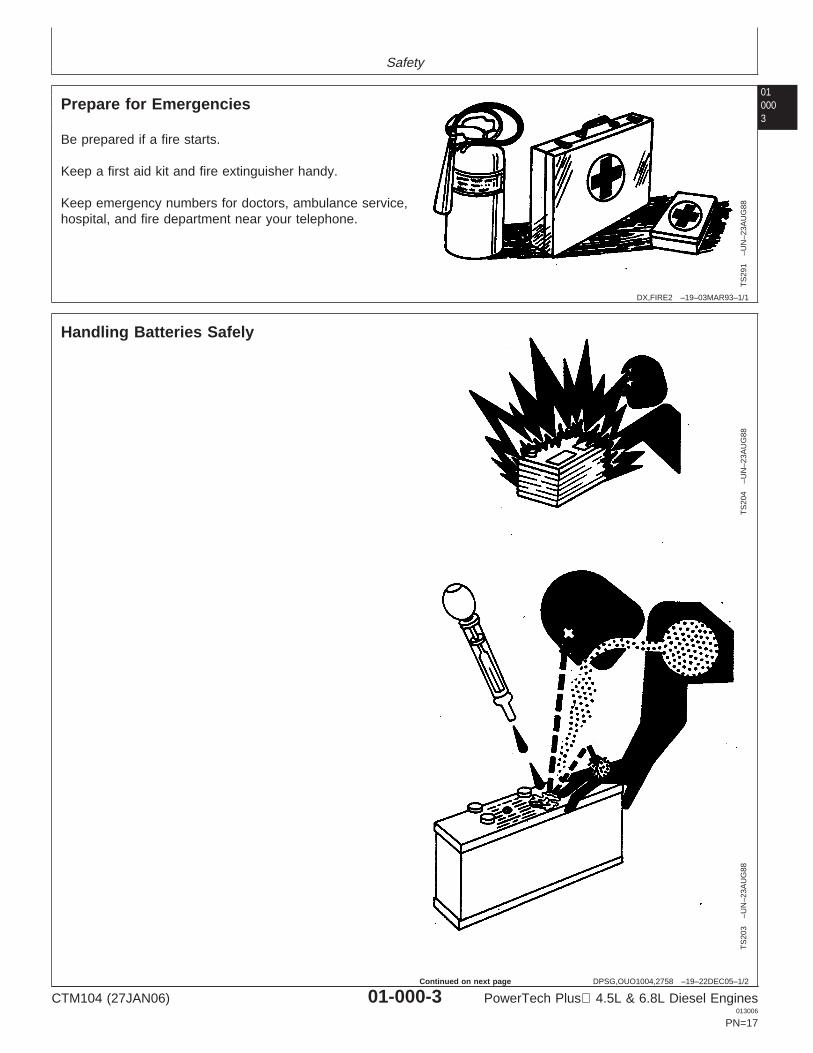
Avoid Hot Parts
TS
271
–UN
–23A
UG
88
Hot Surface
Avoid skin contact with exhaust manifolds, turbochargersand mufflers. Keep flammable materials clear of theturbocharger.
External dry exhaust parts become very hot duringoperation. Turbochargers may reach temperatures as highas 500°C (932°F) under full load, and naturally aspiredexhaust manifolds may reach 600°C (1112°F) under fullload. This may ignite paper, cloth or wooden materials.Parts on engines that have been at full load and reducedto no load idle will maintain approximately 150°C (302°F).
DX,SPARKS –19–03MAR93–1/1
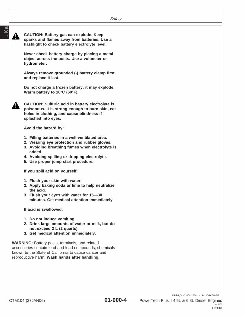
Prevent Battery Explosions
TS
204
–UN
–23A
UG
88
Keep sparks, lighted matches, and open flame away fromthe top of battery. Battery gas can explode.
Never check battery charge by placing a metal objectacross the posts. Use a volt-meter or hydrometer.
Do not charge a frozen battery; it may explode. Warmbattery to 16°C (60°F).
CTM104 (27JAN06) 01-000-2 PowerTech Plus 4.5L & 6.8L Diesel Engines013006
PN=16
Safety
010003
DX,FIRE2 –19–03MAR93–1/1
Prepare for Emergencies
TS
291
–UN
–23A
UG
88
Be prepared if a fire starts.
Keep a first aid kit and fire extinguisher handy.
Keep emergency numbers for doctors, ambulance service,hospital, and fire department near your telephone.
DPSG,OUO1004,2758 –19–22DEC05–1/2
Handling Batteries Safely
TS
204
–UN
–23A
UG
88T
S20
3–U
N–2
3AU
G88
CTM104 (27JAN06) 01-000-3 PowerTech Plus 4.5L & 6.8L Diesel Engines013006
PN=17
Continued on next page
Safety
01000
4
DPSG,OUO1004,2758 –19–22DEC05–2/2
CAUTION: Battery gas can explode. Keepsparks and flames away from batteries. Use aflashlight to check battery electrolyte level.
Never check battery charge by placing a metalobject across the posts. Use a voltmeter orhydrometer.
Always remove grounded (-) battery clamp firstand replace it last.
Do not charge a frozen battery; it may explode.Warm battery to 16°C (60°F).
CAUTION: Sulfuric acid in battery electrolyte ispoisonous. It is strong enough to burn skin, eatholes in clothing, and cause blindness ifsplashed into eyes.
Avoid the hazard by:
1. Filling batteries in a well-ventilated area.2. Wearing eye protection and rubber gloves.3. Avoiding breathing fumes when electrolyte is
added.4. Avoiding spilling or dripping electrolyte.5. Use proper jump start procedure.
If you spill acid on yourself:
1. Flush your skin with water.2. Apply baking soda or lime to help neutralize
the acid.3. Flush your eyes with water for 15—30
minutes. Get medical attention immediately.
If acid is swallowed:
1. Do not induce vomiting.2. Drink large amounts of water or milk, but do
not exceed 2 L (2 quarts).3. Get medical attention immediately.
WARNING: Battery posts, terminals, and relatedaccessories contain lead and lead compounds, chemicalsknown to the State of California to cause cancer andreproductive harm. Wash hands after handling.
CTM104 (27JAN06) 01-000-4 PowerTech Plus 4.5L & 6.8L Diesel Engines013006
PN=18
Safety
010005
DX,FLUID –19–03MAR93–1/1
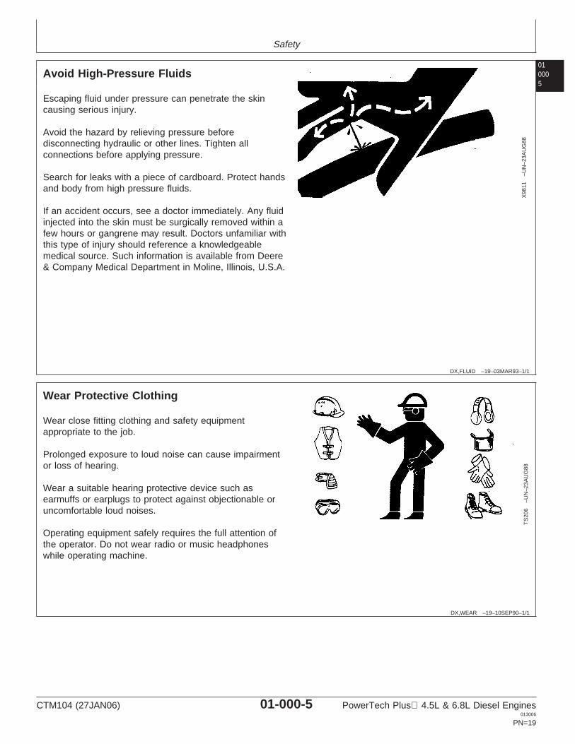
Avoid High-Pressure Fluids
X98
11–U
N–2
3AU
G88
Escaping fluid under pressure can penetrate the skincausing serious injury.
Avoid the hazard by relieving pressure beforedisconnecting hydraulic or other lines. Tighten allconnections before applying pressure.
Search for leaks with a piece of cardboard. Protect handsand body from high pressure fluids.
If an accident occurs, see a doctor immediately. Any fluidinjected into the skin must be surgically removed within afew hours or gangrene may result. Doctors unfamiliar withthis type of injury should reference a knowledgeablemedical source. Such information is available from Deere& Company Medical Department in Moline, Illinois, U.S.A.
DX,WEAR –19–10SEP90–1/1
Wear Protective Clothing
TS
206
–UN
–23A
UG
88
Wear close fitting clothing and safety equipmentappropriate to the job.
Prolonged exposure to loud noise can cause impairmentor loss of hearing.
Wear a suitable hearing protective device such asearmuffs or earplugs to protect against objectionable oruncomfortable loud noises.
Operating equipment safely requires the full attention ofthe operator. Do not wear radio or music headphoneswhile operating machine.
CTM104 (27JAN06) 01-000-5 PowerTech Plus 4.5L & 6.8L Diesel Engines013006
PN=19
Safety
01000
6
DX,LOOSE –19–04JUN90–1/1
Service Machines Safely
TS
228
–UN
–23A
UG
88
Tie long hair behind your head. Do not wear a necktie,scarf, loose clothing, or necklace when you work nearmachine tools or moving parts. If these items were to getcaught, severe injury could result.
Remove rings and other jewelry to prevent electricalshorts and entanglement in moving parts.
DX,AIR –19–17FEB99–1/1
Work In Ventilated Area
TS
220
–UN
–23A
UG
88
Engine exhaust fumes can cause sickness or death. If it isnecessary to run an engine in an enclosed area, removethe exhaust fumes from the area with an exhaust pipeextension.
If you do not have an exhaust pipe extension, open thedoors and get outside air into the area
DX,CLEAN –19–04JUN90–1/1
Work in Clean Area
T66
42E
J–U
N–1
8OC
T88
Before starting a job:
• Clean work area and machine.• Make sure you have all necessary tools to do your job.• Have the right parts on hand.• Read all instructions thoroughly; do not attempt
shortcuts.
CTM104 (27JAN06) 01-000-6 PowerTech Plus 4.5L & 6.8L Diesel Engines013006
PN=20
Safety
010007
DX,PAINT –19–24JUL02–1/1
Remove Paint Before Welding or Heating
TS
220
–UN
–23A
UG
88
Avoid potentially toxic fumes and dust.
Hazardous fumes can be generated when paint is heatedby welding, soldering, or using a torch.
Remove paint before heating:
• Remove paint a minimum of 100 mm (4 in.) from areato be affected by heating. If paint cannot be removed,wear an approved respirator before heating or welding.
• If you sand or grind paint, avoid breathing the dust.Wear an approved respirator.
• If you use solvent or paint stripper, remove stripper withsoap and water before welding. Remove solvent orpaint stripper containers and other flammable materialfrom area. Allow fumes to disperse at least 15 minutesbefore welding or heating.
Do not use a chlorinated solvent in areas where weldingwill take place.
Do all work in an area that is well ventilated to carry toxicfumes and dust away.
Dispose of paint and solvent properly.
DX,TORCH –19–10DEC04–1/1
Avoid Heating Near Pressurized Fluid Lines
TS
953
–UN
–15M
AY
90
Flammable spray can be generated by heating nearpressurized fluid lines, resulting in severe burns toyourself and bystanders. Do not heat by welding,soldering, or using a torch near pressurized fluid lines orother flammable materials. Pressurized lines canaccidentally burst when heat goes beyond the immediateflame area.
CTM104 (27JAN06) 01-000-7 PowerTech Plus 4.5L & 6.8L Diesel Engines013006
PN=21
Safety
01000
8
DX,LIGHT –19–04JUN90–1/1
Illuminate Work Area Safely
TS
223
–UN
–23A
UG
88
Illuminate your work area adequately but safely. Use aportable safety light for working inside or under themachine. Make sure the bulb is enclosed by a wire cage.The hot filament of an accidentally broken bulb can ignitespilled fuel or oil.
DX,LIFT –19–04JUN90–1/1
Use Proper Lifting Equipment
TS
226
–UN
–23A
UG
88
Lifting heavy components incorrectly can cause severeinjury or machine damage.
Follow recommended procedure for removal andinstallation of components in the manual.
DPSG,OUO1004,899 –19–19MAY99–1/1
Construct Dealer-Made Tools Safely
LX10
1674
9–U
N–0
1JU
L97
Construct Dealer-Made Tools Safely
Faulty or broken tools can result in serious injury. Whenconstructing tools, use proper, quality materials and goodworkmanship.
Do not weld tools unless you have the proper equipmentand experience to perform the job.
CTM104 (27JAN06) 01-000-8 PowerTech Plus 4.5L & 6.8L Diesel Engines013006
PN=22
Safety
010009
DX,SERV –19–17FEB99–1/1
Practice Safe Maintenance
TS
218
–UN
–23A
UG
88
Understand service procedure before doing work. Keeparea clean and dry.
Never lubricate, service, or adjust machine while it ismoving. Keep hands, feet , and clothing frompower-driven parts. Disengage all power and operatecontrols to relieve pressure. Lower equipment to theground. Stop the engine. Remove the key. Allow machineto cool.
Securely support any machine elements that must beraised for service work.
Keep all parts in good condition and properly installed. Fixdamage immediately. Replace worn or broken parts.Remove any buildup of grease, oil, or debris.
On self-propelled equipment, disconnect battery groundcable (-) before making adjustments on electrical systemsor welding on machine.
On towed implements, disconnect wiring harnesses fromtractor before servicing electrical system components orwelding on machine.
DX,REPAIR –19–17FEB99–1/1
Use Proper Tools
TS
779
–UN
–08N
OV
89
Use tools appropriate to the work. Makeshift tools andprocedures can create safety hazards.
Use power tools only to loosen threaded parts andfasteners.
For loosening and tightening hardware, use the correctsize tools. DO NOT use U.S. measurement tools onmetric fasteners. Avoid bodily injury caused by slippingwrenches.
Use only service parts meeting John Deere specifications.
CTM104 (27JAN06) 01-000-9 PowerTech Plus 4.5L & 6.8L Diesel Engines013006
PN=23

Safety
01000
10
DX,DRAIN –19–03MAR93–1/1
Dispose of Waste Properly
TS
1133
–UN
–26N
OV
90
Improperly disposing of waste can threaten theenvironment and ecology. Potentially harmful waste usedwith John Deere equipment include such items as oil, fuel,coolant, brake fluid, filters, and batteries.
Use leakproof containers when draining fluids. Do not usefood or beverage containers that may mislead someoneinto drinking from them.
Do not pour waste onto the ground, down a drain, or intoany water source.
Air conditioning refrigerants escaping into the air candamage the Earth’s atmosphere. Government regulationsmay require a certified air conditioning service center torecover and recycle used air conditioning refrigerants.
Inquire on the proper way to recycle or dispose of wastefrom your local environmental or recycling center, or fromyour John Deere dealer.
DX,LIVE –19–25SEP92–1/1
Live With Safety
TS
231
–19–
07O
CT
88
Before returning machine to customer, make suremachine is functioning properly, especially the safetysystems. Install all guards and shields.
CTM104 (27JAN06) 01-000-10 PowerTech Plus 4.5L & 6.8L Diesel Engines013006
PN=24
Group 001Engine Identification and Application Charts
010011
RG19661,0000005 –19–27JAN06–1/2
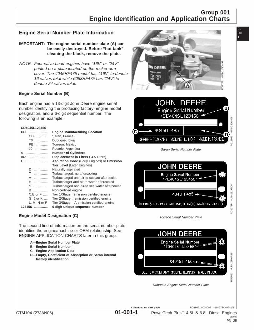
Engine Serial Number Plate Information
RG
7778
–UN
–11N
OV
97
RG
1380
6–U
N–2
3JA
N06
Saran Serial Number Plate
RG
1371
6–U
N–2
3JA
N06
Torreon Serial Number Plate
RG
9060
–UN
–16M
AR
98
Dubuque Engine Serial Number Plate
A—Engine Serial Number PlateB—Engine Serial NumberC—Engine Application DataD—Empty, Coefficient of Absorption or Saran internal
factory identification
IMPORTANT: The engine serial number plate (A) canbe easily destroyed. Before “hot tank”cleaning the block, remove the plate.
NOTE: Four-valve head engines have “16V” or “24V”printed on a plate located on the rocker armcover. The 4045HF475 model has “16V” to denote16 valves total while 6068HF475 has “24V” todenote 24 valves total.
Engine Serial Number (B)
Each engine has a 13-digit John Deere engine serialnumber identifying the producing factory, engine modeldesignation, and a 6-digit sequential number. Thefollowing is an example:
CD4045L123456CD ...................... Engine Manufacturing Location
CD ............ Saran, FranceT0 ............. Dubuque, IowaPE ............. Torreon, MexicoJ0 .............. Rosario, Argentina
4 ........................ Number of Cylinders045 .................... Displacement in Liters ( 4.5 Liters)L ........................ Aspiration Code (Early Engines) or Emission
Tier Level (Later Engines)D ............... Naturally aspiratedT ............... Turbocharged, no aftercoolingA ............... Turbocharged and air-to-coolant aftercooledH ............... Turbocharger and air-to-water aftercooledS ............... Turbocharged and air-to sea water aftercooledB ................ Non-certified engineC,E or F ..... Tier 1/Stage I emission certified engineG, J or K .... Tier 2/Stage II emission certified engineL, M, N or P Tier 3/Stage IIIA emission certified engine
123456 ............... 6-digit unique sequence number
Engine Model Designation (C)
The second line of information on the serial number plateidentifies the engine/machine or OEM relationship. SeeENGINE APPLICATION CHARTS later in this group.
CTM104 (27JAN06) 01-001-1 PowerTech Plus 4.5L & 6.8L Diesel Engines013006
PN=25
Continued on next page
Engine Identification and Application Charts
01001
2
RG19661,0000005 –19–27JAN06–2/2
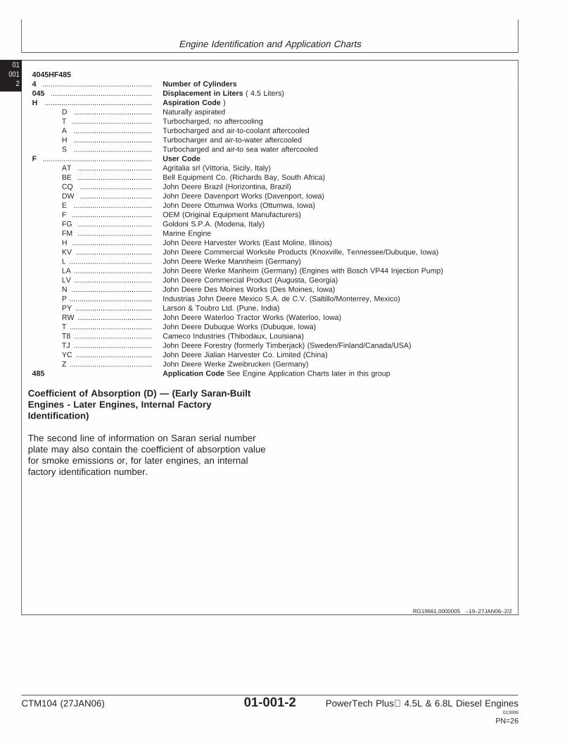
4045HF4854 ..................................................... Number of Cylinders045 ................................................. Displacement in Liters ( 4.5 Liters)H .................................................... Aspiration Code )
D ...................................... Naturally aspiratedT ....................................... Turbocharged, no aftercoolingA ...................................... Turbocharged and air-to-coolant aftercooledH ...................................... Turbocharger and air-to-water aftercooledS ...................................... Turbocharged and air-to sea water aftercooled
F ..................................................... User CodeAT .................................... Agritalia srl (Vittoria, Sicily, Italy)BE .................................... Bell Equipment Co. (Richards Bay, South Africa)CQ ................................... John Deere Brazil (Horizontina, Brazil)DW ................................... John Deere Davenport Works (Davenport, Iowa)E ...................................... John Deere Ottumwa Works (Ottumwa, Iowa)F ....................................... OEM (Original Equipment Manufacturers)FG .................................... Goldoni S.P.A. (Modena, Italy)FM .................................... Marine EngineH ....................................... John Deere Harvester Works (East Moline, Illinois)KV ..................................... John Deere Commercial Worksite Products (Knoxville, Tennessee/Dubuque, Iowa)L ........................................ John Deere Werke Mannheim (Germany)LA ...................................... John Deere Werke Manheim (Germany) (Engines with Bosch VP44 Injection Pump)LV ...................................... John Deere Commercial Product (Augusta, Georgia)N ....................................... John Deere Des Moines Works (Des Moines, Iowa)P ........................................ Industrias John Deere Mexico S.A. de C.V. (Saltillo/Monterrey, Mexico)PY ..................................... Larson & Toubro Ltd. (Pune, India)RW .................................... John Deere Waterloo Tractor Works (Waterloo, Iowa)T ........................................ John Deere Dubuque Works (Dubuque, Iowa)T8 ...................................... Cameco Industries (Thibodaux, Louisiana)TJ ...................................... John Deere Forestry (formerly Timberjack) (Sweden/Finland/Canada/USA)YC ..................................... John Deere Jialian Harvester Co. Limited (China)Z ........................................ John Deere Werke Zweibrucken (Germany)
485 Application Code See Engine Application Charts later in this group
Coefficient of Absorption (D) — (Early Saran-BuiltEngines - Later Engines, Internal FactoryIdentification)
The second line of information on Saran serial numberplate may also contain the coefficient of absorption valuefor smoke emissions or, for later engines, an internalfactory identification number.
CTM104 (27JAN06) 01-001-2 PowerTech Plus 4.5L & 6.8L Diesel Engines013006
PN=26
Engine Identification and Application Charts
010013
DPSG,OUO1004,482 –19–07NOV98–1/1
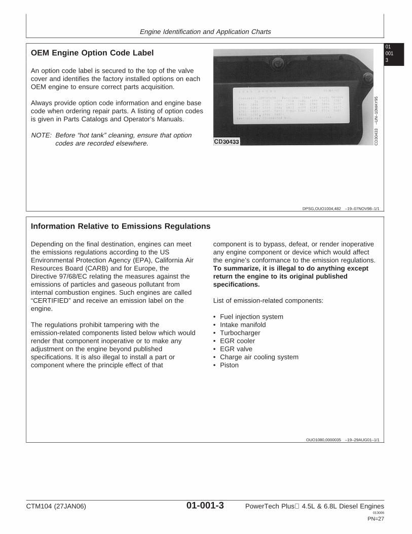
OEM Engine Option Code Label
CD
3043
3–U
N–1
0MA
Y95
An option code label is secured to the top of the valvecover and identifies the factory installed options on eachOEM engine to ensure correct parts acquisition.
Always provide option code information and engine basecode when ordering repair parts. A listing of option codesis given in Parts Catalogs and Operator’s Manuals.
NOTE: Before “hot tank” cleaning, ensure that optioncodes are recorded elsewhere.
OUO1080,0000035 –19–29AUG01–1/1
Information Relative to Emissions Regulations
Depending on the final destination, engines can meetthe emissions regulations according to the USEnvironmental Protection Agency (EPA), California AirResources Board (CARB) and for Europe, theDirective 97/68/EC relating the measures against theemissions of particles and gaseous pollutant frominternal combustion engines. Such engines are called“CERTIFIED” and receive an emission label on theengine.
The regulations prohibit tampering with theemission-related components listed below which wouldrender that component inoperative or to make anyadjustment on the engine beyond publishedspecifications. It is also illegal to install a part orcomponent where the principle effect of that
component is to bypass, defeat, or render inoperativeany engine component or device which would affectthe engine’s conformance to the emission regulations.To summarize, it is illegal to do anything exceptreturn the engine to its original publishedspecifications.
List of emission-related components:
• Fuel injection system• Intake manifold• Turbocharger• EGR cooler• EGR valve• Charge air cooling system• Piston
CTM104 (27JAN06) 01-001-3 PowerTech Plus 4.5L & 6.8L Diesel Engines013006
PN=27
Engine Identification and Application Charts
01001
4
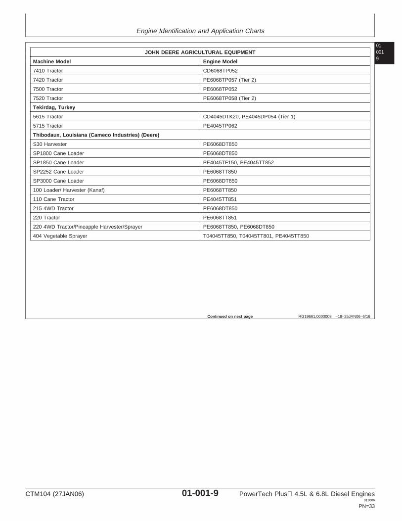
RG19661,0000008 –19–25JAN06–1/16
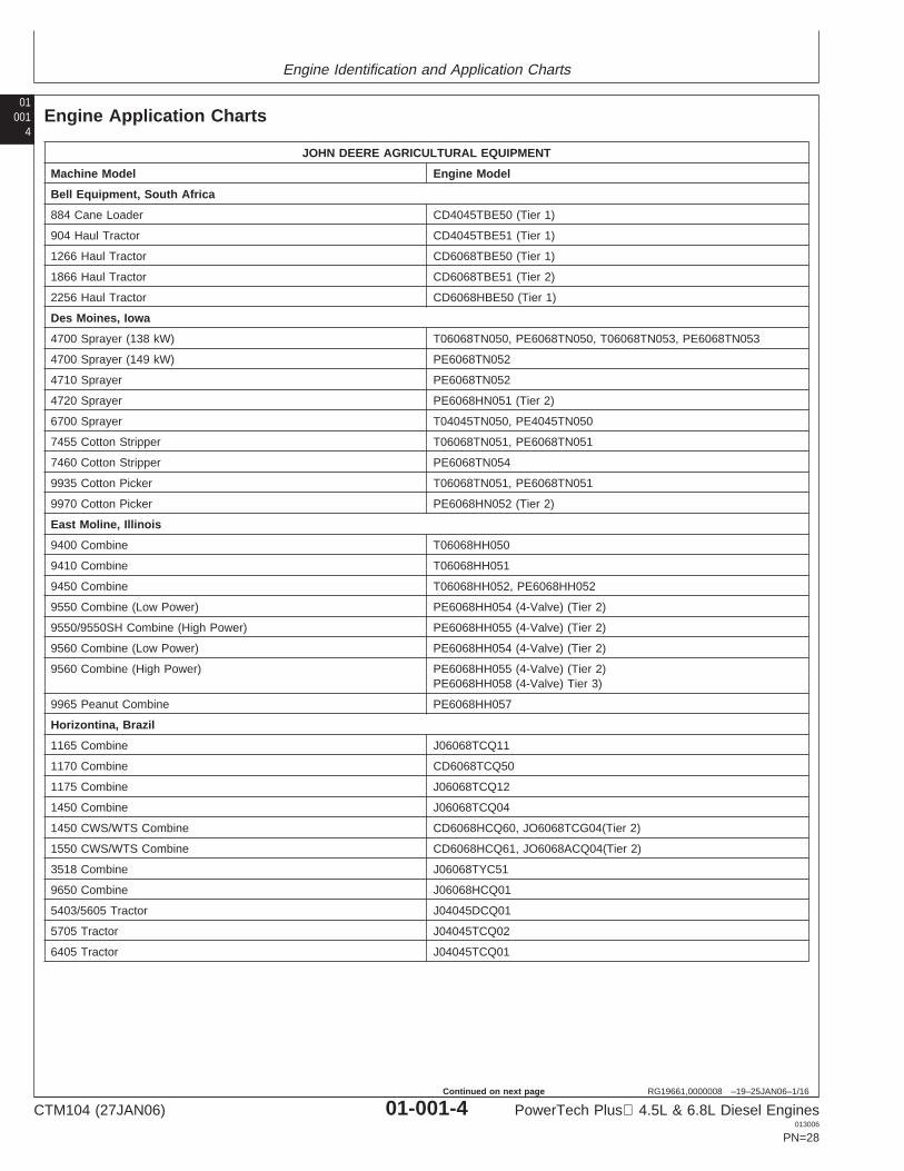
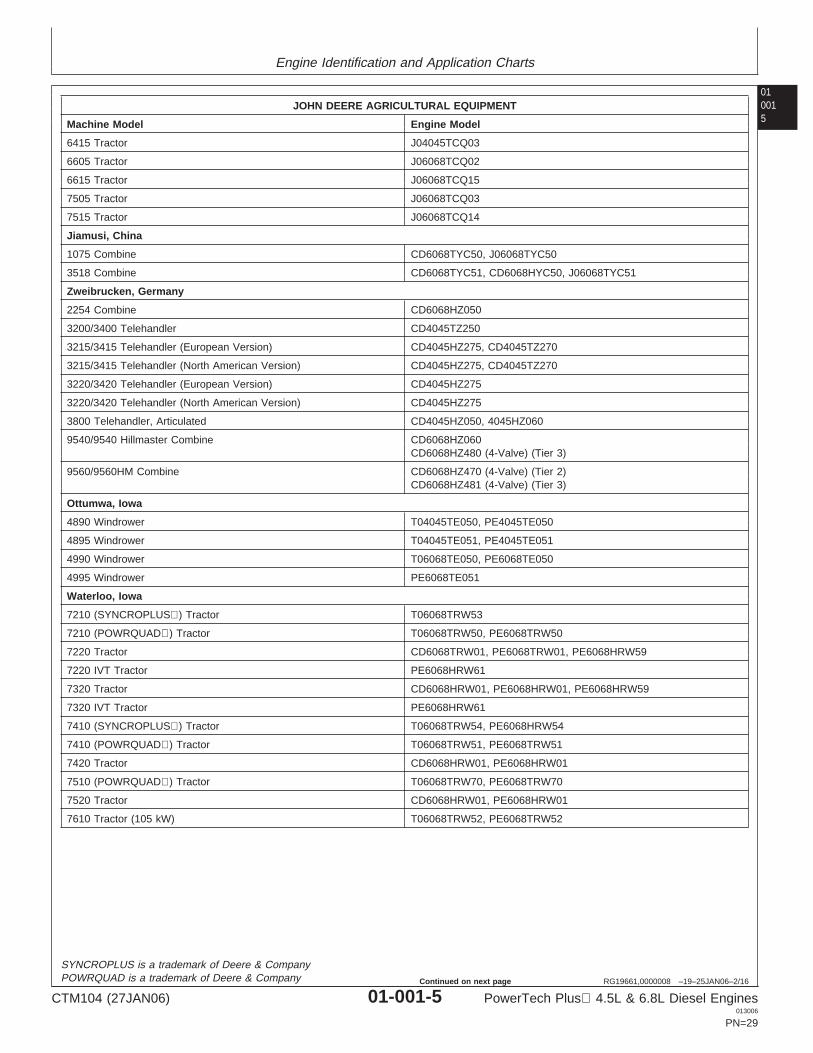
Engine Application Charts
JOHN DEERE AGRICULTURAL EQUIPMENT
Machine Model Engine Model
Bell Equipment, South Africa
884 Cane Loader CD4045TBE50 (Tier 1)
904 Haul Tractor CD4045TBE51 (Tier 1)
1266 Haul Tractor CD6068TBE50 (Tier 1)
1866 Haul Tractor CD6068TBE51 (Tier 2)
2256 Haul Tractor CD6068HBE50 (Tier 1)
Des Moines, Iowa
4700 Sprayer (138 kW) T06068TN050, PE6068TN050, T06068TN053, PE6068TN053
4700 Sprayer (149 kW) PE6068TN052
4710 Sprayer PE6068TN052
4720 Sprayer PE6068HN051 (Tier 2)
6700 Sprayer T04045TN050, PE4045TN050
7455 Cotton Stripper T06068TN051, PE6068TN051
7460 Cotton Stripper PE6068TN054
9935 Cotton Picker T06068TN051, PE6068TN051
9970 Cotton Picker PE6068HN052 (Tier 2)
East Moline, Illinois
9400 Combine T06068HH050
9410 Combine T06068HH051
9450 Combine T06068HH052, PE6068HH052
9550 Combine (Low Power) PE6068HH054 (4-Valve) (Tier 2)
9550/9550SH Combine (High Power) PE6068HH055 (4-Valve) (Tier 2)
9560 Combine (Low Power) PE6068HH054 (4-Valve) (Tier 2)
9560 Combine (High Power) PE6068HH055 (4-Valve) (Tier 2)PE6068HH058 (4-Valve) Tier 3)
9965 Peanut Combine PE6068HH057
Horizontina, Brazil
1165 Combine J06068TCQ11
1170 Combine CD6068TCQ50
1175 Combine J06068TCQ12
1450 Combine J06068TCQ04
1450 CWS/WTS Combine CD6068HCQ60, JO6068TCG04(Tier 2)
1550 CWS/WTS Combine CD6068HCQ61, JO6068ACQ04(Tier 2)
3518 Combine J06068TYC51
9650 Combine J06068HCQ01
5403/5605 Tractor J04045DCQ01
5705 Tractor J04045TCQ02
6405 Tractor J04045TCQ01
CTM104 (27JAN06) 01-001-4 PowerTech Plus 4.5L & 6.8L Diesel Engines013006
PN=28
Continued on next page
Engine Identification and Application Charts
010015
RG19661,0000008 –19–25JAN06–2/16
JOHN DEERE AGRICULTURAL EQUIPMENT
Machine Model Engine Model
6415 Tractor J04045TCQ03
6605 Tractor J06068TCQ02
6615 Tractor J06068TCQ15
7505 Tractor J06068TCQ03
7515 Tractor J06068TCQ14
Jiamusi, China
1075 Combine CD6068TYC50, J06068TYC50
3518 Combine CD6068TYC51, CD6068HYC50, J06068TYC51
Zweibrucken, Germany
2254 Combine CD6068HZ050
3200/3400 Telehandler CD4045TZ250
3215/3415 Telehandler (European Version) CD4045HZ275, CD4045TZ270
3215/3415 Telehandler (North American Version) CD4045HZ275, CD4045TZ270
3220/3420 Telehandler (European Version) CD4045HZ275
3220/3420 Telehandler (North American Version) CD4045HZ275
3800 Telehandler, Articulated CD4045HZ050, 4045HZ060
9540/9540 Hillmaster Combine CD6068HZ060CD6068HZ480 (4-Valve) (Tier 3)
9560/9560HM Combine CD6068HZ470 (4-Valve) (Tier 2)CD6068HZ481 (4-Valve) (Tier 3)
Ottumwa, Iowa
4890 Windrower T04045TE050, PE4045TE050
4895 Windrower T04045TE051, PE4045TE051
4990 Windrower T06068TE050, PE6068TE050
4995 Windrower PE6068TE051
Waterloo, Iowa
7210 (SYNCROPLUS) Tractor T06068TRW53
7210 (POWRQUAD) Tractor T06068TRW50, PE6068TRW50
7220 Tractor CD6068TRW01, PE6068TRW01, PE6068HRW59
7220 IVT Tractor PE6068HRW61
7320 Tractor CD6068HRW01, PE6068HRW01, PE6068HRW59
7320 IVT Tractor PE6068HRW61
7410 (SYNCROPLUS) Tractor T06068TRW54, PE6068HRW54
7410 (POWRQUAD) Tractor T06068TRW51, PE6068TRW51
7420 Tractor CD6068HRW01, PE6068HRW01
7510 (POWRQUAD) Tractor T06068TRW70, PE6068TRW70
7520 Tractor CD6068HRW01, PE6068HRW01
7610 Tractor (105 kW) T06068TRW52, PE6068TRW52
SYNCROPLUS is a trademark of Deere & CompanyPOWRQUAD is a trademark of Deere & Company
CTM104 (27JAN06) 01-001-5 PowerTech Plus 4.5L & 6.8L Diesel Engines013006
PN=29
Continued on next page
Engine Identification and Application Charts
01001
6
RG19661,0000008 –19–25JAN06–3/16
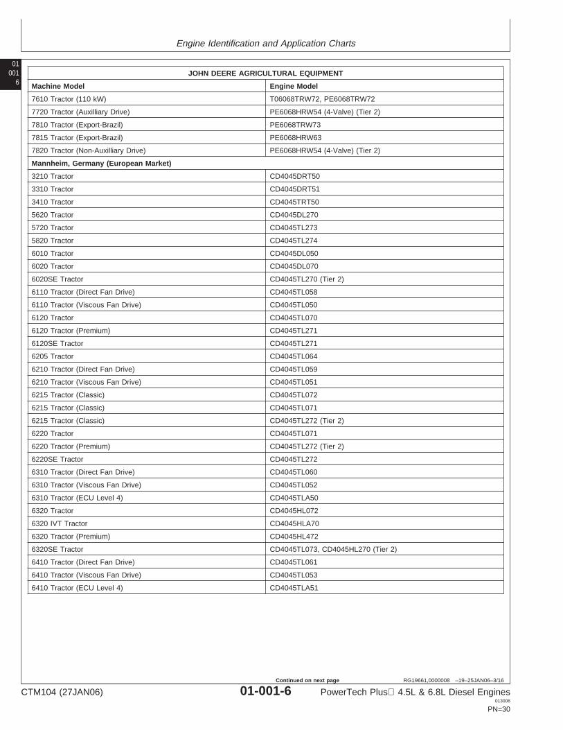
JOHN DEERE AGRICULTURAL EQUIPMENT
Machine Model Engine Model
7610 Tractor (110 kW) T06068TRW72, PE6068TRW72
7720 Tractor (Auxilliary Drive) PE6068HRW54 (4-Valve) (Tier 2)
7810 Tractor (Export-Brazil) PE6068TRW73
7815 Tractor (Export-Brazil) PE6068HRW63
7820 Tractor (Non-Auxilliary Drive) PE6068HRW54 (4-Valve) (Tier 2)
Mannheim, Germany (European Market)
3210 Tractor CD4045DRT50
3310 Tractor CD4045DRT51
3410 Tractor CD4045TRT50
5620 Tractor CD4045DL270
5720 Tractor CD4045TL273
5820 Tractor CD4045TL274
6010 Tractor CD4045DL050
6020 Tractor CD4045DL070
6020SE Tractor CD4045TL270 (Tier 2)
6110 Tractor (Direct Fan Drive) CD4045TL058
6110 Tractor (Viscous Fan Drive) CD4045TL050
6120 Tractor CD4045TL070
6120 Tractor (Premium) CD4045TL271
6120SE Tractor CD4045TL271
6205 Tractor CD4045TL064
6210 Tractor (Direct Fan Drive) CD4045TL059
6210 Tractor (Viscous Fan Drive) CD4045TL051
6215 Tractor (Classic) CD4045TL072
6215 Tractor (Classic) CD4045TL071
6215 Tractor (Classic) CD4045TL272 (Tier 2)
6220 Tractor CD4045TL071
6220 Tractor (Premium) CD4045TL272 (Tier 2)
6220SE Tractor CD4045TL272
6310 Tractor (Direct Fan Drive) CD4045TL060
6310 Tractor (Viscous Fan Drive) CD4045TL052
6310 Tractor (ECU Level 4) CD4045TLA50
6320 Tractor CD4045HL072
6320 IVT Tractor CD4045HLA70
6320 Tractor (Premium) CD4045HL472
6320SE Tractor CD4045TL073, CD4045HL270 (Tier 2)
6410 Tractor (Direct Fan Drive) CD4045TL061
6410 Tractor (Viscous Fan Drive) CD4045TL053
6410 Tractor (ECU Level 4) CD4045TLA51
CTM104 (27JAN06) 01-001-6 PowerTech Plus 4.5L & 6.8L Diesel Engines013006
PN=30
Continued on next page
Engine Identification and Application Charts
010017
RG19661,0000008 –19–25JAN06–4/16
JOHN DEERE AGRICULTURAL EQUIPMENT
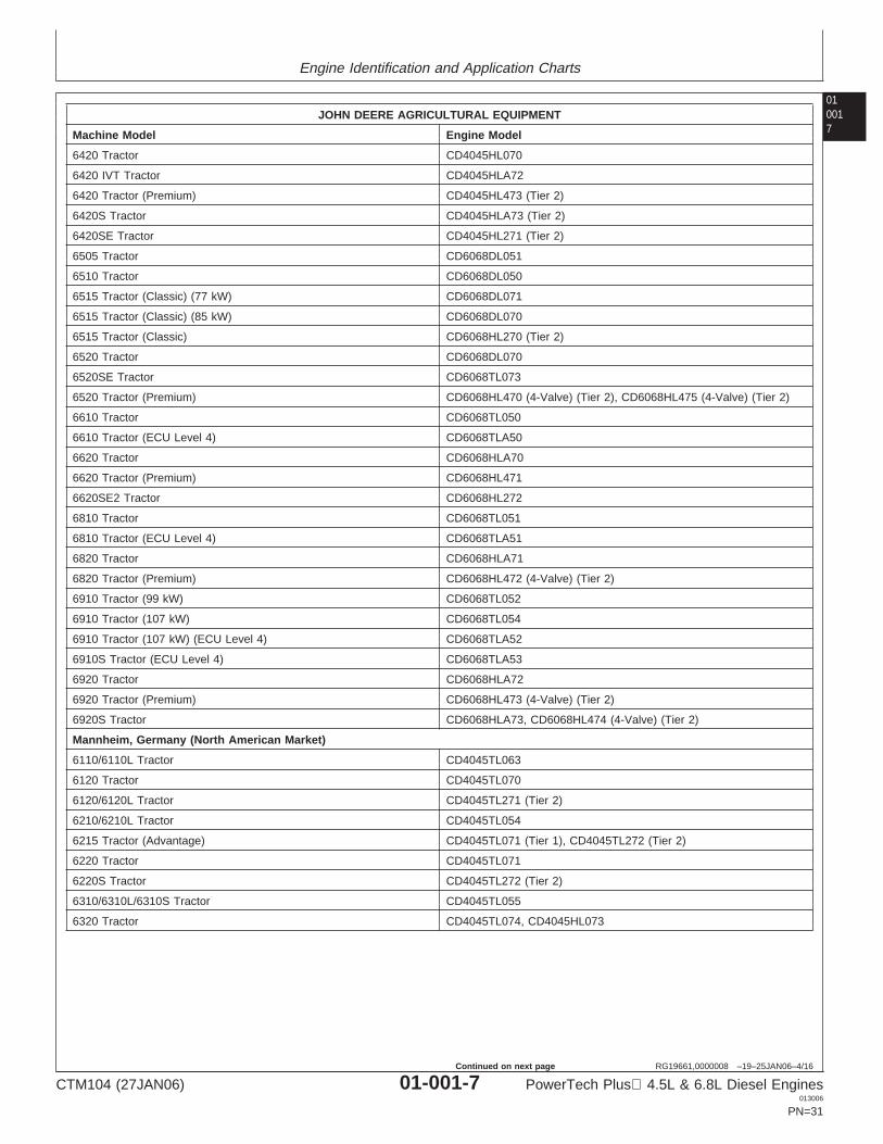
Machine Model Engine Model
6420 Tractor CD4045HL070
6420 IVT Tractor CD4045HLA72
6420 Tractor (Premium) CD4045HL473 (Tier 2)
6420S Tractor CD4045HLA73 (Tier 2)
6420SE Tractor CD4045HL271 (Tier 2)
6505 Tractor CD6068DL051
6510 Tractor CD6068DL050
6515 Tractor (Classic) (77 kW) CD6068DL071
6515 Tractor (Classic) (85 kW) CD6068DL070
6515 Tractor (Classic) CD6068HL270 (Tier 2)
6520 Tractor CD6068DL070
6520SE Tractor CD6068TL073
6520 Tractor (Premium) CD6068HL470 (4-Valve) (Tier 2), CD6068HL475 (4-Valve) (Tier 2)
6610 Tractor CD6068TL050
6610 Tractor (ECU Level 4) CD6068TLA50
6620 Tractor CD6068HLA70
6620 Tractor (Premium) CD6068HL471
6620SE2 Tractor CD6068HL272
6810 Tractor CD6068TL051
6810 Tractor (ECU Level 4) CD6068TLA51
6820 Tractor CD6068HLA71
6820 Tractor (Premium) CD6068HL472 (4-Valve) (Tier 2)
6910 Tractor (99 kW) CD6068TL052
6910 Tractor (107 kW) CD6068TL054
6910 Tractor (107 kW) (ECU Level 4) CD6068TLA52
6910S Tractor (ECU Level 4) CD6068TLA53
6920 Tractor CD6068HLA72
6920 Tractor (Premium) CD6068HL473 (4-Valve) (Tier 2)
6920S Tractor CD6068HLA73, CD6068HL474 (4-Valve) (Tier 2)
Mannheim, Germany (North American Market)
6110/6110L Tractor CD4045TL063
6120 Tractor CD4045TL070
6120/6120L Tractor CD4045TL271 (Tier 2)
6210/6210L Tractor CD4045TL054
6215 Tractor (Advantage) CD4045TL071 (Tier 1), CD4045TL272 (Tier 2)
6220 Tractor CD4045TL071
6220S Tractor CD4045TL272 (Tier 2)
6310/6310L/6310S Tractor CD4045TL055
6320 Tractor CD4045TL074, CD4045HL073
CTM104 (27JAN06) 01-001-7 PowerTech Plus 4.5L & 6.8L Diesel Engines013006
PN=31
Continued on next page
Engine Identification and Application Charts
01001
8
RG19661,0000008 –19–25JAN06–5/16
JOHN DEERE AGRICULTURAL EQUIPMENT
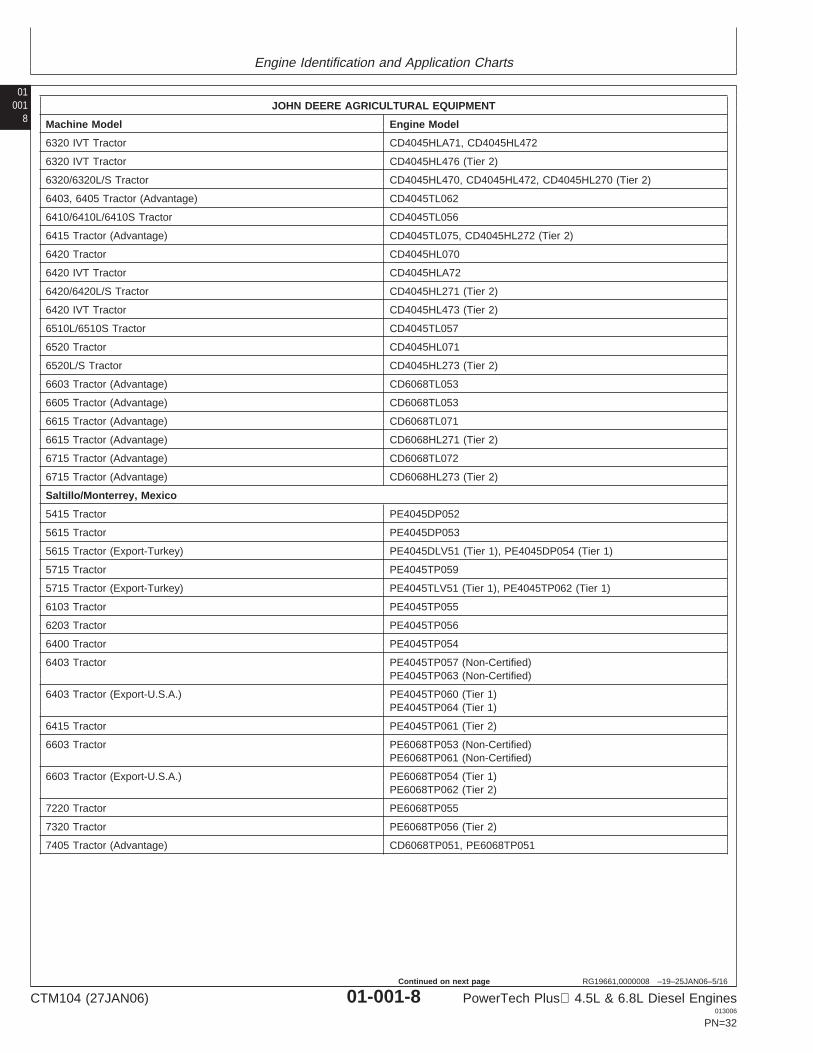
Machine Model Engine Model
6320 IVT Tractor CD4045HLA71, CD4045HL472
6320 IVT Tractor CD4045HL476 (Tier 2)
6320/6320L/S Tractor CD4045HL470, CD4045HL472, CD4045HL270 (Tier 2)
6403, 6405 Tractor (Advantage) CD4045TL062
6410/6410L/6410S Tractor CD4045TL056
6415 Tractor (Advantage) CD4045TL075, CD4045HL272 (Tier 2)
6420 Tractor CD4045HL070
6420 IVT Tractor CD4045HLA72
6420/6420L/S Tractor CD4045HL271 (Tier 2)
6420 IVT Tractor CD4045HL473 (Tier 2)
6510L/6510S Tractor CD4045TL057
6520 Tractor CD4045HL071
6520L/S Tractor CD4045HL273 (Tier 2)
6603 Tractor (Advantage) CD6068TL053
6605 Tractor (Advantage) CD6068TL053
6615 Tractor (Advantage) CD6068TL071
6615 Tractor (Advantage) CD6068HL271 (Tier 2)
6715 Tractor (Advantage) CD6068TL072
6715 Tractor (Advantage) CD6068HL273 (Tier 2)
Saltillo/Monterrey, Mexico
5415 Tractor PE4045DP052
5615 Tractor PE4045DP053
5615 Tractor (Export-Turkey) PE4045DLV51 (Tier 1), PE4045DP054 (Tier 1)
5715 Tractor PE4045TP059
5715 Tractor (Export-Turkey) PE4045TLV51 (Tier 1), PE4045TP062 (Tier 1)
6103 Tractor PE4045TP055
6203 Tractor PE4045TP056
6400 Tractor PE4045TP054
6403 Tractor PE4045TP057 (Non-Certified)PE4045TP063 (Non-Certified)
6403 Tractor (Export-U.S.A.) PE4045TP060 (Tier 1)PE4045TP064 (Tier 1)
6415 Tractor PE4045TP061 (Tier 2)
6603 Tractor PE6068TP053 (Non-Certified)PE6068TP061 (Non-Certified)
6603 Tractor (Export-U.S.A.) PE6068TP054 (Tier 1)PE6068TP062 (Tier 2)
7220 Tractor PE6068TP055
7320 Tractor PE6068TP056 (Tier 2)
7405 Tractor (Advantage) CD6068TP051, PE6068TP051
CTM104 (27JAN06) 01-001-8 PowerTech Plus 4.5L & 6.8L Diesel Engines013006
PN=32
Continued on next page
Engine Identification and Application Charts
010019
RG19661,0000008 –19–25JAN06–6/16
JOHN DEERE AGRICULTURAL EQUIPMENT
Machine Model Engine Model
7410 Tractor CD6068TP052
7420 Tractor PE6068TP057 (Tier 2)
7500 Tractor PE6068TP052
7520 Tractor PE6068TP058 (Tier 2)
Tekirdag, Turkey
5615 Tractor CD4045DTK20, PE4045DP054 (Tier 1)
5715 Tractor PE4045TP062
Thibodaux, Louisiana (Cameco Industries) (Deere)
S30 Harvester PE6068DT850
SP1800 Cane Loader PE6068DT850
SP1850 Cane Loader PE4045TF150, PE4045TT852
SP2252 Cane Loader PE6068TT850
SP3000 Cane Loader PE6068DT850
100 Loader/ Harvester (Kanaf) PE6068TT850
110 Cane Tractor PE4045TT851
215 4WD Tractor PE6068DT850
220 Tractor PE6068TT851
220 4WD Tractor/Pineapple Harvester/Sprayer PE6068TT850, PE6068DT850
404 Vegetable Sprayer T04045TT850, T04045TT801, PE4045TT850
Continued on next page
CTM104 (27JAN06) 01-001-9 PowerTech Plus 4.5L & 6.8L Diesel Engines013006
PN=33
Engine Identification and Application Charts
01001
10
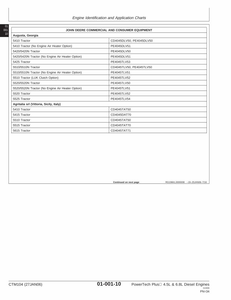
RG19661,0000008 –19–25JAN06–7/16
JOHN DEERE COMMERCIAL AND CONSUMER EQUIPMENT
Augusta, Georgia
5410 Tractor CD4045DLV50, PE4045DLV50
5410 Tractor (No Engine Air Heater Option) PE4045DLV51
5420/5420N Tractor PE4045DLV50
5420/5420N Tractor (No Engine Air Heater Option) PE4045DLV51
5425 Tractor PE4045TLV53
5510/5510N Tractor CD4045TLV50, PE4045TLV50
5510/5510N Tractor (No Engine Air Heater Option) PE4045TLV51
5510 Tractor (LUK Clutch Option) PE4045TLV52
5520/5520N Tractor PE4045TLV50
5520/5520N Tractor (No Engine Air Heater Option) PE4045TLV51
5520 Tractor PE4045TLV52
5525 Tractor PE4045TLV54
Agritalia srl (Vittoria, Sicily, Italy)
5410 Tractor CD4045TAT50
5415 Tractor CD4045DAT70
5510 Tractor CD4045TAT50
5515 Tractor CD4045TAT70
5615 Tractor CD4045TAT71
Continued on next page
CTM104 (27JAN06) 01-001-10 PowerTech Plus 4.5L & 6.8L Diesel Engines013006
PN=34
Engine Identification and Application Charts
0100111
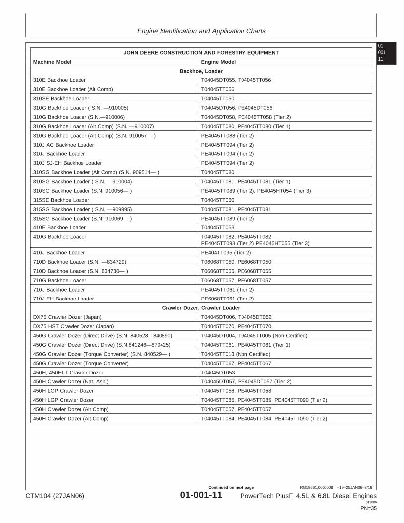
RG19661,0000008 –19–25JAN06–8/16
JOHN DEERE CONSTRUCTION AND FORESTRY EQUIPMENT
Machine Model Engine Model
Backhoe, Loader
310E Backhoe Loader T04045DT055, T04045TT056
310E Backhoe Loader (Alt Comp) T04045TT056
310SE Backhoe Loader T04045TT050
310G Backhoe Loader ( S.N. —910005) T04045DT056, PE4045DT056
310G Backhoe Loader (S.N.—910006) T04045DT058, PE4045TT058 (Tier 2)
310G Backhoe Loader (Alt Comp) (S.N. —910007) T04045TT080, PE4045TT080 (Tier 1)
310G Backhoe Loader (Alt Comp) (S.N. 910057— ) PE4045TT088 (Tier 2)
310J AC Backhoe Loader PE4045TT094 (Tier 2)
310J Backhoe Loader PE4045TT094 (Tier 2)
310J SJ-EH Backhoe Loader PE4045TT094 (Tier 2)
310SG Backhoe Loader (Alt Comp) (S.N. 909514— ) T04045TT080
310SG Backhoe Loader ( S.N. —910004) T04045TT081, PE4045TT081 (Tier 1)
310SG Backhoe Loader (S.N. 910056— ) PE4045TT089 (Tier 2), PE4045HT054 (Tier 3)
315SE Backhoe Loader T04045TT060
315SG Backhoe Loader ( S.N. —909995) T04045TT081, PE4045TT081
315SG Backhoe Loader (S.N. 910069— ) PE4045TT089 (Tier 2)
410E Backhoe Loader T04045TT053
410G Backhoe Loader T04045TT082, PE4045TT082,PE4045TT093 (Tier 2) PE4045HT055 (Tier 3)
410J Backhoe Loader PE404TT095 (Tier 2)
710D Backhoe Loader (S.N. —834729) T06068TT050, PE6068TT050
710D Backhoe Loader (S.N. 834730— ) T06068TT055, PE6068TT055
710G Backhoe Loader T06068TT057, PE6068TT057
710J Backhoe Loader PE4045TT061 (Tier 2)
710J EH Backhoe Loader PE6068TT061 (Tier 2)
Crawler Dozer, Crawler Loader
DX75 Crawler Dozer (Japan) T04045DT006, T04045DT052
DX75 HST Crawler Dozer (Japan) T04045TT070, PE4045TT070
450G Crawler Dozer (Direct Drive) (S.N. 840528—840890) T04045DT004, T04045TT005 (Non Certified)
450G Crawler Dozer (Direct Drive) (S.N.841246—879425) T04045TT061, PE4045TT061 (Tier 1)
450G Crawler Dozer (Torque Converter) (S.N. 840529— ) T04045TT013 (Non Certified)
450G Crawler Dozer (Torque Converter) T04045TT067, PE4045TT067
450H, 450HLT Crawler Dozer T04045DT053
450H Crawler Dozer (Nat. Asp.) T04045DT057, PE4045DT057 (Tier 2)
450H LGP Crawler Dozer T04045TT058, PE4045TT058
450H LGP Crawler Dozer T04045TT085, PE4045TT085, PE4045TT090 (Tier 2)
450H Crawler Dozer (Alt Comp) T04045TT057, PE4045TT057
450H Crawler Dozer (Alt Comp) T04045TT084, PE4045TT084, PE4045TT090 (Tier 2)
CTM104 (27JAN06) 01-001-11 PowerTech Plus 4.5L & 6.8L Diesel Engines013006
PN=35
Continued on next page
Engine Identification and Application Charts
01001
12
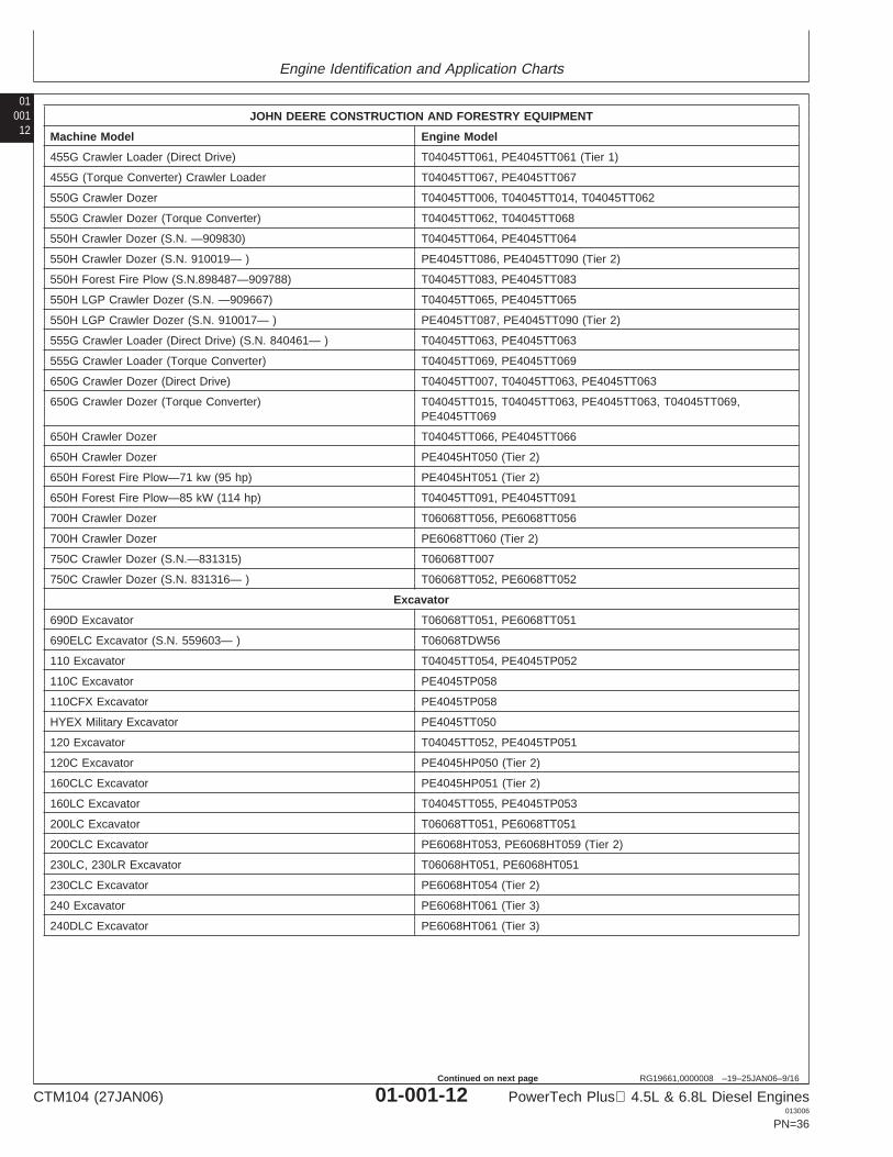
RG19661,0000008 –19–25JAN06–9/16
JOHN DEERE CONSTRUCTION AND FORESTRY EQUIPMENT
Machine Model Engine Model
455G Crawler Loader (Direct Drive) T04045TT061, PE4045TT061 (Tier 1)
455G (Torque Converter) Crawler Loader T04045TT067, PE4045TT067
550G Crawler Dozer T04045TT006, T04045TT014, T04045TT062
550G Crawler Dozer (Torque Converter) T04045TT062, T04045TT068
550H Crawler Dozer (S.N. —909830) T04045TT064, PE4045TT064
550H Crawler Dozer (S.N. 910019— ) PE4045TT086, PE4045TT090 (Tier 2)
550H Forest Fire Plow (S.N.898487—909788) T04045TT083, PE4045TT083
550H LGP Crawler Dozer (S.N. —909667) T04045TT065, PE4045TT065
550H LGP Crawler Dozer (S.N. 910017— ) PE4045TT087, PE4045TT090 (Tier 2)
555G Crawler Loader (Direct Drive) (S.N. 840461— ) T04045TT063, PE4045TT063
555G Crawler Loader (Torque Converter) T04045TT069, PE4045TT069
650G Crawler Dozer (Direct Drive) T04045TT007, T04045TT063, PE4045TT063
650G Crawler Dozer (Torque Converter) T04045TT015, T04045TT063, PE4045TT063, T04045TT069,PE4045TT069
650H Crawler Dozer T04045TT066, PE4045TT066
650H Crawler Dozer PE4045HT050 (Tier 2)
650H Forest Fire Plow—71 kw (95 hp) PE4045HT051 (Tier 2)
650H Forest Fire Plow—85 kW (114 hp) T04045TT091, PE4045TT091
700H Crawler Dozer T06068TT056, PE6068TT056
700H Crawler Dozer PE6068TT060 (Tier 2)
750C Crawler Dozer (S.N.—831315) T06068TT007
750C Crawler Dozer (S.N. 831316— ) T06068TT052, PE6068TT052
Excavator
690D Excavator T06068TT051, PE6068TT051
690ELC Excavator (S.N. 559603— ) T06068TDW56
110 Excavator T04045TT054, PE4045TP052
110C Excavator PE4045TP058
110CFX Excavator PE4045TP058
HYEX Military Excavator PE4045TT050
120 Excavator T04045TT052, PE4045TP051
120C Excavator PE4045HP050 (Tier 2)
160CLC Excavator PE4045HP051 (Tier 2)
160LC Excavator T04045TT055, PE4045TP053
200LC Excavator T06068TT051, PE6068TT051
200CLC Excavator PE6068HT053, PE6068HT059 (Tier 2)
230LC, 230LR Excavator T06068HT051, PE6068HT051
230CLC Excavator PE6068HT054 (Tier 2)
240 Excavator PE6068HT061 (Tier 3)
240DLC Excavator PE6068HT061 (Tier 3)
CTM104 (27JAN06) 01-001-12 PowerTech Plus 4.5L & 6.8L Diesel Engines013006
PN=36
Continued on next page
Engine Identification and Application Charts
0100113
RG19661,0000008 –19–25JAN06–10/16
JOHN DEERE CONSTRUCTION AND FORESTRY EQUIPMENT
Machine Model Engine Model
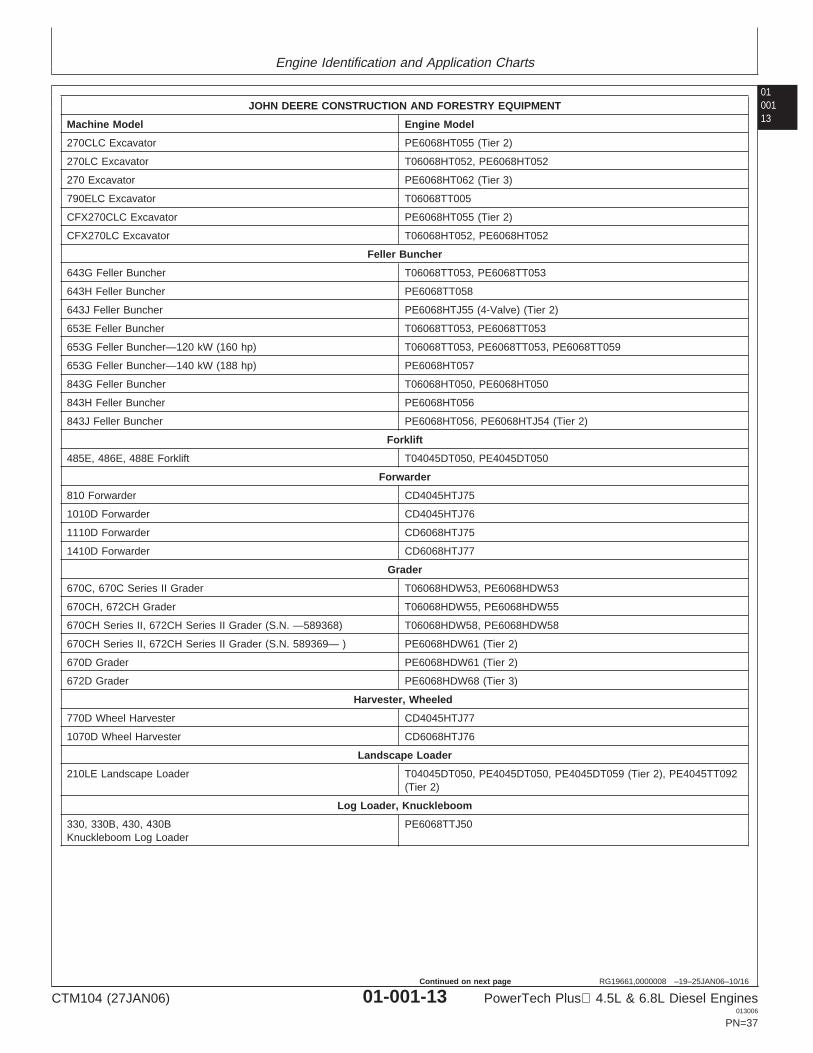
270CLC Excavator PE6068HT055 (Tier 2)
270LC Excavator T06068HT052, PE6068HT052
270 Excavator PE6068HT062 (Tier 3)
790ELC Excavator T06068TT005
CFX270CLC Excavator PE6068HT055 (Tier 2)
CFX270LC Excavator T06068HT052, PE6068HT052
Feller Buncher
643G Feller Buncher T06068TT053, PE6068TT053
643H Feller Buncher PE6068TT058
643J Feller Buncher PE6068HTJ55 (4-Valve) (Tier 2)
653E Feller Buncher T06068TT053, PE6068TT053
653G Feller Buncher—120 kW (160 hp) T06068TT053, PE6068TT053, PE6068TT059
653G Feller Buncher—140 kW (188 hp) PE6068HT057
843G Feller Buncher T06068HT050, PE6068HT050
843H Feller Buncher PE6068HT056
843J Feller Buncher PE6068HT056, PE6068HTJ54 (Tier 2)
Forklift
485E, 486E, 488E Forklift T04045DT050, PE4045DT050
Forwarder
810 Forwarder CD4045HTJ75
1010D Forwarder CD4045HTJ76
1110D Forwarder CD6068HTJ75
1410D Forwarder CD6068HTJ77
Grader
670C, 670C Series II Grader T06068HDW53, PE6068HDW53
670CH, 672CH Grader T06068HDW55, PE6068HDW55
670CH Series II, 672CH Series II Grader (S.N. —589368) T06068HDW58, PE6068HDW58
670CH Series II, 672CH Series II Grader (S.N. 589369— ) PE6068HDW61 (Tier 2)
670D Grader PE6068HDW61 (Tier 2)
672D Grader PE6068HDW68 (Tier 3)
Harvester, Wheeled
770D Wheel Harvester CD4045HTJ77
1070D Wheel Harvester CD6068HTJ76
Landscape Loader
210LE Landscape Loader T04045DT050, PE4045DT050, PE4045DT059 (Tier 2), PE4045TT092(Tier 2)
Log Loader, Knuckleboom
330, 330B, 430, 430B PE6068TTJ50Knuckleboom Log Loader
CTM104 (27JAN06) 01-001-13 PowerTech Plus 4.5L & 6.8L Diesel Engines013006
PN=37
Continued on next page

Engine Identification and Application Charts
01001
14
RG19661,0000008 –19–25JAN06–11/16
JOHN DEERE CONSTRUCTION AND FORESTRY EQUIPMENT
Machine Model Engine Model
335B, 335C, 435B, 435C, 437C PE6068TTJ51Knuckleboom Log Loader
Loggers
2054 Logger PE6068HT053, PE6068TT053, PE6068HT059 PE6068HT065 (Tier 2)
2554 Logger PE6068HT054, PE6068HT064 (Tier 2)
Loader, Four Wheel Drive
LX80 Loader T04045HDW51
LX100 Loader (Hitachi Construction Machine) T06068TDW53, PE6068TDW53
LX100-3 Loader (Hitachi Construction Machine) T06068TDW50, PE6068TDW50
LX120 Loader (Hitachi Construction Machine) T06068HDW52, T06068HDW70, PE6068HDW70
324H Loader CD4045DF153
344H Loader T04045TF152, PE4045TF152
344H Loader T04045TF273, CD4045TF273 (Tier 2)
TC44H Tool Carrier T04045TDW50, PE4045TDW50
444H Loader T04045TDW50, T04045HDW50, PE4045TDW50
444J Loader PE4045HDW52 (Tier 2), PE4045HDW53 (Tier 3)
TC54H Tool Carrier T06068TDW50, PE6068TDW50
544H Loader T06068TDW50, PE6068TDW50
544J Loader PE6068HDW56 (Tier 2), PE4045HDW63 (Tier 3)
TC62H Tool Carrier T06068HDW50, PE6068HDW50
624G Loader T06068TDW010
624H Loader T06068HDW50, PE6068HDW50
624J Loader PE6068HDW57 (Tier 2), PE6068HDW67 (Tier 3)
644 Loader PE6068HDW69 (Tier 3)
1204C Loader (Bell Equipment) CD4045TBE52 (Tier 2)
1706C Loader (Bell Equipment) CD6068TBE53 (Tier 1)
1806C Loader CD6068TBE52 (Tier 2)
Skid Steer Loader
JD7 Skid Steer Loader PE4045DKV50, PE4045DKV51
270 Skid Steer Loader (Auxiliary Drive) PE4045DKV50
270 Skid Steer Loader (Non-Auxiliary Drive) PE4045DKV51
280 Skid Steer Loader PE4045TKV50
Skidder
360D Skidder (Timberjack) T06068TDW54, PE6068TDW54
360D Skidder (Timberjack) (S.N. 589337— ) PE6068TDW58 (Tier 2)
460D Skidder (Direct Drive) (Timberjack) T06068TDW55, PE6068TDW55
460D Skidder (Direct Drive) (Timberjack) (S.N. 589337— ) PE6068HDW60 (Tier 2), PE6068HDW65 (Tier 3)
460D Skidder (Torque Converter) (Timberjack) (S.N. —586336) T06068TDW57, PE6068TDW57
460D Skidder (Torque Converter) (Timberjack) (S.N. 589337— ) PE6068HDW59 (Tier 2)
CTM104 (27JAN06) 01-001-14 PowerTech Plus 4.5L & 6.8L Diesel Engines013006
PN=38
Continued on next page
Engine Identification and Application Charts
0100115
RG19661,0000008 –19–25JAN06–12/16
JOHN DEERE CONSTRUCTION AND FORESTRY EQUIPMENT
Machine Model Engine Model
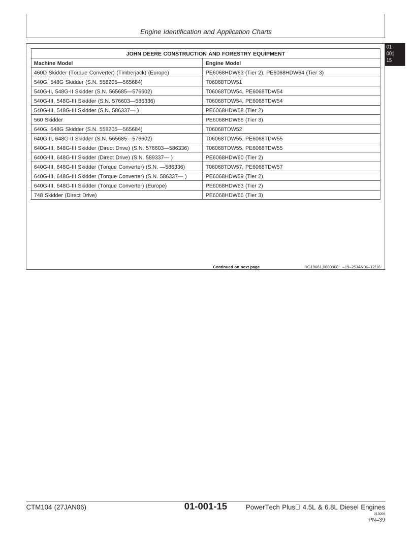
460D Skidder (Torque Converter) (Timberjack) (Europe) PE6068HDW63 (Tier 2), PE6068HDW64 (Tier 3)
540G, 548G Skidder (S.N. 558205—565684) T06068TDW51
540G-II, 548G-II Skidder (S.N. 565685—576602) T06068TDW54, PE6068TDW54
540G-III, 548G-III Skidder (S.N. 576603—586336) T06068TDW54, PE6068TDW54
540G-III, 548G-III Skidder (S.N. 586337— ) PE6068HDW58 (Tier 2)
560 Skidder PE6068HDW66 (Tier 3)
640G, 648G Skidder (S.N. 558205—565684) T06068TDW52
640G-II, 648G-II Skidder (S.N. 565685—576602) T06068TDW55, PE6068TDW55
640G-III, 648G-III Skidder (Direct Drive) (S.N. 576603—586336) T06068TDW55, PE6068TDW55
640G-III, 648G-III Skidder (Direct Drive) (S.N. 589337— ) PE6068HDW60 (Tier 2)
640G-III, 648G-III Skidder (Torque Converter) (S.N. —586336) T06068TDW57, PE6068TDW57
640G-III, 648G-III Skidder (Torque Converter) (S.N. 586337— ) PE6068HDW59 (Tier 2)
640G-III, 648G-III Skidder (Torque Converter) (Europe) PE6068HDW63 (Tier 2)
748 Skidder (Direct Drive) PE6068HDW66 (Tier 3)
Continued on next page
CTM104 (27JAN06) 01-001-15 PowerTech Plus 4.5L & 6.8L Diesel Engines013006
PN=39
Engine Identification and Application Charts
01001
16
RG19661,0000008 –19–25JAN06–13/16
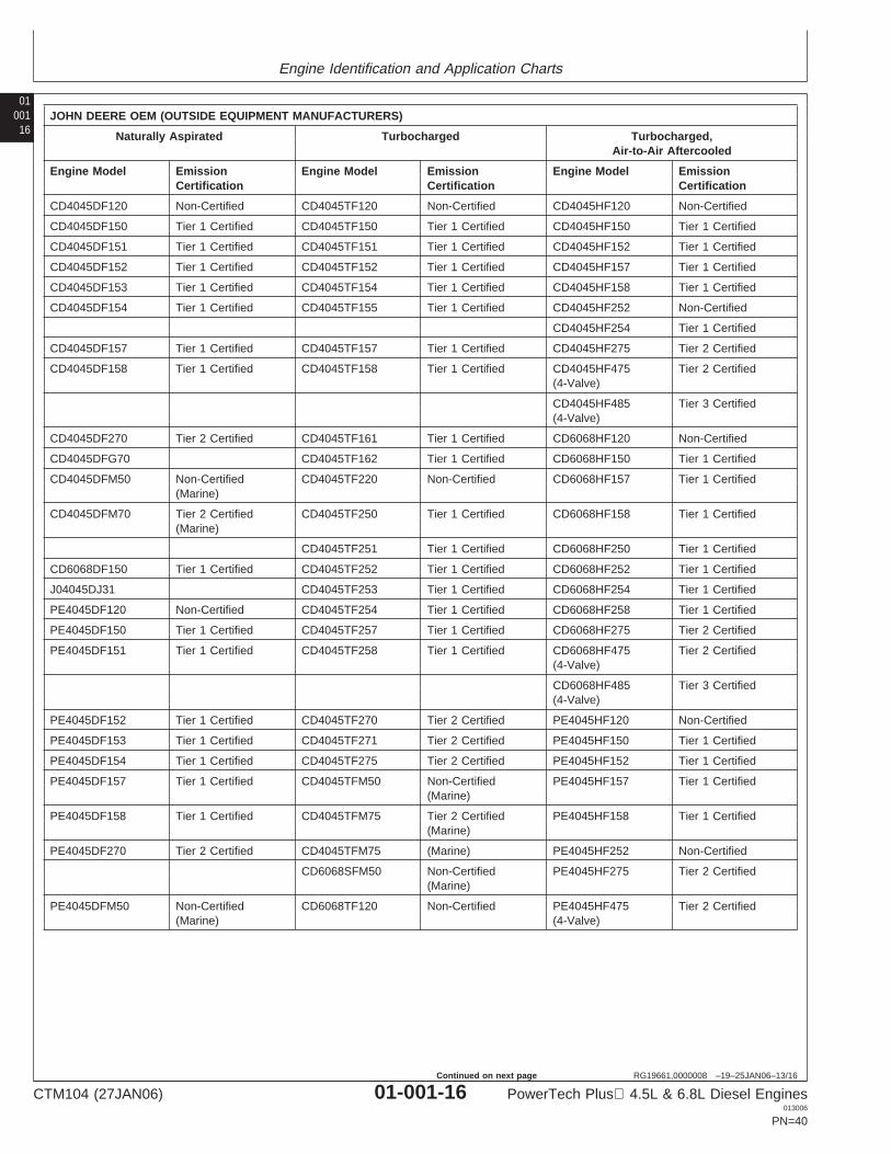
JOHN DEERE OEM (OUTSIDE EQUIPMENT MANUFACTURERS)
Naturally Aspirated Turbocharged Turbocharged,Air-to-Air Aftercooled
Engine Model Emission Engine Model Emission Engine Model EmissionCertification Certification Certification
CD4045DF120 Non-Certified CD4045TF120 Non-Certified CD4045HF120 Non-Certified
CD4045DF150 Tier 1 Certified CD4045TF150 Tier 1 Certified CD4045HF150 Tier 1 Certified
CD4045DF151 Tier 1 Certified CD4045TF151 Tier 1 Certified CD4045HF152 Tier 1 Certified
CD4045DF152 Tier 1 Certified CD4045TF152 Tier 1 Certified CD4045HF157 Tier 1 Certified
CD4045DF153 Tier 1 Certified CD4045TF154 Tier 1 Certified CD4045HF158 Tier 1 Certified
CD4045DF154 Tier 1 Certified CD4045TF155 Tier 1 Certified CD4045HF252 Non-Certified
CD4045HF254 Tier 1 Certified
CD4045DF157 Tier 1 Certified CD4045TF157 Tier 1 Certified CD4045HF275 Tier 2 Certified
CD4045DF158 Tier 1 Certified CD4045TF158 Tier 1 Certified CD4045HF475 Tier 2 Certified(4-Valve)
CD4045HF485 Tier 3 Certified(4-Valve)
CD4045DF270 Tier 2 Certified CD4045TF161 Tier 1 Certified CD6068HF120 Non-Certified
CD4045DFG70 CD4045TF162 Tier 1 Certified CD6068HF150 Tier 1 Certified
CD4045DFM50 Non-Certified CD4045TF220 Non-Certified CD6068HF157 Tier 1 Certified(Marine)
CD4045DFM70 Tier 2 Certified CD4045TF250 Tier 1 Certified CD6068HF158 Tier 1 Certified(Marine)
CD4045TF251 Tier 1 Certified CD6068HF250 Tier 1 Certified
CD6068DF150 Tier 1 Certified CD4045TF252 Tier 1 Certified CD6068HF252 Tier 1 Certified
J04045DJ31 CD4045TF253 Tier 1 Certified CD6068HF254 Tier 1 Certified
PE4045DF120 Non-Certified CD4045TF254 Tier 1 Certified CD6068HF258 Tier 1 Certified
PE4045DF150 Tier 1 Certified CD4045TF257 Tier 1 Certified CD6068HF275 Tier 2 Certified
PE4045DF151 Tier 1 Certified CD4045TF258 Tier 1 Certified CD6068HF475 Tier 2 Certified(4-Valve)
CD6068HF485 Tier 3 Certified(4-Valve)
PE4045DF152 Tier 1 Certified CD4045TF270 Tier 2 Certified PE4045HF120 Non-Certified
PE4045DF153 Tier 1 Certified CD4045TF271 Tier 2 Certified PE4045HF150 Tier 1 Certified
PE4045DF154 Tier 1 Certified CD4045TF275 Tier 2 Certified PE4045HF152 Tier 1 Certified
PE4045DF157 Tier 1 Certified CD4045TFM50 Non-Certified PE4045HF157 Tier 1 Certified(Marine)
PE4045DF158 Tier 1 Certified CD4045TFM75 Tier 2 Certified PE4045HF158 Tier 1 Certified(Marine)
PE4045DF270 Tier 2 Certified CD4045TFM75 (Marine) PE4045HF252 Non-Certified
CD6068SFM50 Non-Certified PE4045HF275 Tier 2 Certified(Marine)
PE4045DFM50 Non-Certified CD6068TF120 Non-Certified PE4045HF475 Tier 2 Certified(Marine) (4-Valve)
CTM104 (27JAN06) 01-001-16 PowerTech Plus 4.5L & 6.8L Diesel Engines013006
PN=40
Continued on next page
Engine Identification and Application Charts
0100117
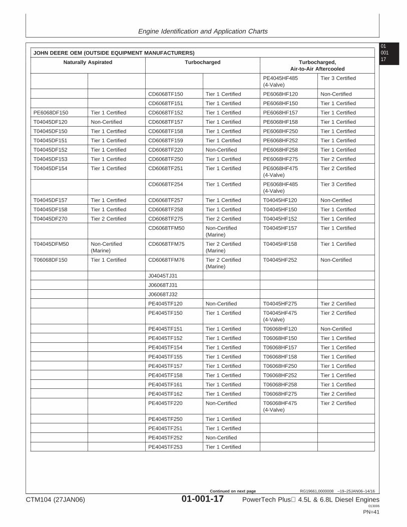
RG19661,0000008 –19–25JAN06–14/16
JOHN DEERE OEM (OUTSIDE EQUIPMENT MANUFACTURERS)
Naturally Aspirated Turbocharged Turbocharged,Air-to-Air Aftercooled
PE4045HF485 Tier 3 Certified(4-Valve)
CD6068TF150 Tier 1 Certified PE6068HF120 Non-Certified
CD6068TF151 Tier 1 Certified PE6068HF150 Tier 1 Certified
PE6068DF150 Tier 1 Certified CD6068TF152 Tier 1 Certified PE6068HF157 Tier 1 Certified
T04045DF120 Non-Certified CD6068TF157 Tier 1 Certified PE6068HF158 Tier 1 Certified
T04045DF150 Tier 1 Certified CD6068TF158 Tier 1 Certified PE6068HF250 Tier 1 Certified
T04045DF151 Tier 1 Certified CD6068TF159 Tier 1 Certified PE6068HF252 Tier 1 Certified
T04045DF152 Tier 1 Certified CD6068TF220 Non-Certified PE6068HF258 Tier 1 Certified
T04045DF153 Tier 1 Certified CD6068TF250 Tier 1 Certified PE6068HF275 Tier 2 Certified
T04045DF154 Tier 1 Certified CD6068TF251 Tier 1 Certified PE6068HF475 Tier 2 Certified(4-Valve)
CD6068TF254 Tier 1 Certified PE6068HF485 Tier 3 Certified(4-Valve)
T04045DF157 Tier 1 Certified CD6068TF257 Tier 1 Certified T04045HF120 Non-Certified
T04045DF158 Tier 1 Certified CD6068TF258 Tier 1 Certified T04045HF150 Tier 1 Certified
T04045DF270 Tier 2 Certified CD6068TF275 Tier 2 Certified T04045HF152 Tier 1 Certified
CD6068TFM50 Non-Certified T04045HF157 Tier 1 Certified(Marine)
T04045DFM50 Non-Certified CD6068TFM75 Tier 2 Certified T04045HF158 Tier 1 Certified(Marine) (Marine)
T06068DF150 Tier 1 Certified CD6068TFM76 Tier 2 Certified T04045HF252 Non-Certified(Marine)
J04045TJ31
J06068TJ31
J06068TJ32
PE4045TF120 Non-Certified T04045HF275 Tier 2 Certified
PE4045TF150 Tier 1 Certified T04045HF475 Tier 2 Certified(4-Valve)
PE4045TF151 Tier 1 Certified T06068HF120 Non-Certified
PE4045TF152 Tier 1 Certified T06068HF150 Tier 1 Certified
PE4045TF154 Tier 1 Certified T06068HF157 Tier 1 Certified
PE4045TF155 Tier 1 Certified T06068HF158 Tier 1 Certified
PE4045TF157 Tier 1 Certified T06068HF250 Tier 1 Certified
PE4045TF158 Tier 1 Certified T06068HF252 Tier 1 Certified
PE4045TF161 Tier 1 Certified T06068HF258 Tier 1 Certified
PE4045TF162 Tier 1 Certified T06068HF275 Tier 2 Certified
PE4045TF220 Non-Certified T06068HF475 Tier 2 Certified(4-Valve)
PE4045TF250 Tier 1 Certified
PE4045TF251 Tier 1 Certified
PE4045TF252 Non-Certified
PE4045TF253 Tier 1 Certified
CTM104 (27JAN06) 01-001-17 PowerTech Plus 4.5L & 6.8L Diesel Engines013006
PN=41
Continued on next page
Engine Identification and Application Charts
01001
18
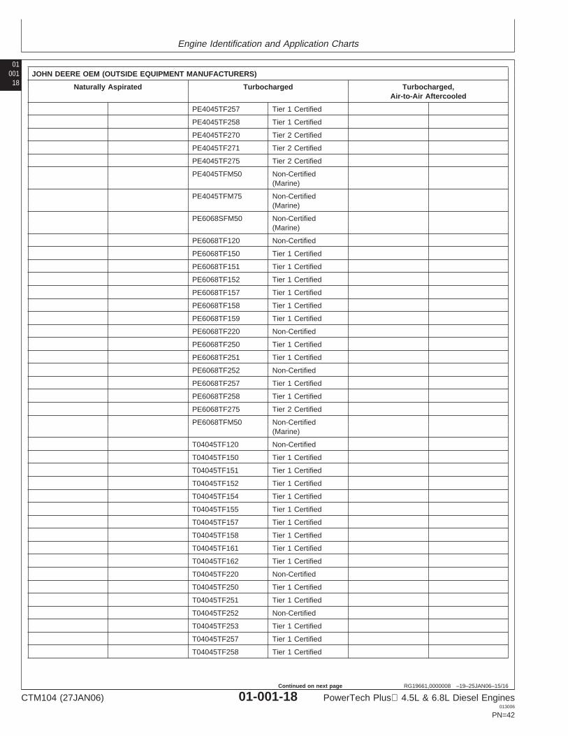
RG19661,0000008 –19–25JAN06–15/16
JOHN DEERE OEM (OUTSIDE EQUIPMENT MANUFACTURERS)
Naturally Aspirated Turbocharged Turbocharged,Air-to-Air Aftercooled
PE4045TF257 Tier 1 Certified
PE4045TF258 Tier 1 Certified
PE4045TF270 Tier 2 Certified
PE4045TF271 Tier 2 Certified
PE4045TF275 Tier 2 Certified
PE4045TFM50 Non-Certified(Marine)
PE4045TFM75 Non-Certified(Marine)
PE6068SFM50 Non-Certified(Marine)
PE6068TF120 Non-Certified
PE6068TF150 Tier 1 Certified
PE6068TF151 Tier 1 Certified
PE6068TF152 Tier 1 Certified
PE6068TF157 Tier 1 Certified
PE6068TF158 Tier 1 Certified
PE6068TF159 Tier 1 Certified
PE6068TF220 Non-Certified
PE6068TF250 Tier 1 Certified
PE6068TF251 Tier 1 Certified
PE6068TF252 Non-Certified
PE6068TF257 Tier 1 Certified
PE6068TF258 Tier 1 Certified
PE6068TF275 Tier 2 Certified
PE6068TFM50 Non-Certified(Marine)
T04045TF120 Non-Certified
T04045TF150 Tier 1 Certified
T04045TF151 Tier 1 Certified
T04045TF152 Tier 1 Certified
T04045TF154 Tier 1 Certified
T04045TF155 Tier 1 Certified
T04045TF157 Tier 1 Certified
T04045TF158 Tier 1 Certified
T04045TF161 Tier 1 Certified
T04045TF162 Tier 1 Certified
T04045TF220 Non-Certified
T04045TF250 Tier 1 Certified
T04045TF251 Tier 1 Certified
T04045TF252 Non-Certified
T04045TF253 Tier 1 Certified
T04045TF257 Tier 1 Certified
T04045TF258 Tier 1 Certified
CTM104 (27JAN06) 01-001-18 PowerTech Plus 4.5L & 6.8L Diesel Engines013006
PN=42
Continued on next page
Engine Identification and Application Charts
0100119
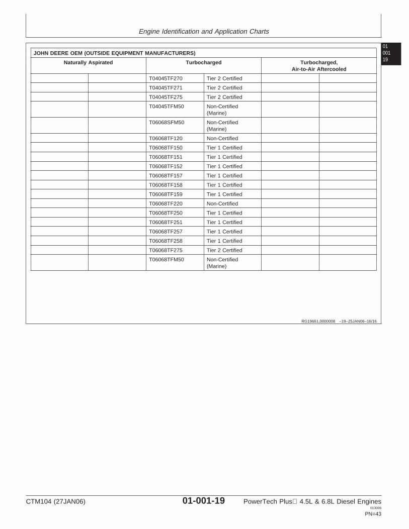
RG19661,0000008 –19–25JAN06–16/16
JOHN DEERE OEM (OUTSIDE EQUIPMENT MANUFACTURERS)
Naturally Aspirated Turbocharged Turbocharged,Air-to-Air Aftercooled
T04045TF270 Tier 2 Certified
T04045TF271 Tier 2 Certified
T04045TF275 Tier 2 Certified
T04045TFM50 Non-Certified(Marine)
T06068SFM50 Non-Certified(Marine)
T06068TF120 Non-Certified
T06068TF150 Tier 1 Certified
T06068TF151 Tier 1 Certified
T06068TF152 Tier 1 Certified
T06068TF157 Tier 1 Certified
T06068TF158 Tier 1 Certified
T06068TF159 Tier 1 Certified
T06068TF220 Non-Certified
T06068TF250 Tier 1 Certified
T06068TF251 Tier 1 Certified
T06068TF257 Tier 1 Certified
T06068TF258 Tier 1 Certified
T06068TF275 Tier 2 Certified
T06068TFM50 Non-Certified(Marine)
CTM104 (27JAN06) 01-001-19 PowerTech Plus 4.5L & 6.8L Diesel Engines013006
PN=43
Engine Identification and Application Charts
01001
20
CTM104 (27JAN06) 01-001-20 PowerTech Plus 4.5L & 6.8L Diesel Engines013006
PN=44
Group 002Fuels, Lubricants and Coolants
010021
RG19661,0000017 –19–27JUN05–1/1
Diesel Fuel
Consult your local fuel distributor for properties of thediesel fuel available in your area.
In general, diesel fuels are blended to satisfy the lowtemperature requirements of the geographical area inwhich they are marketed.
Diesel fuels specified to EN 590 or ASTM D975 arerecommended.
Required fuel properties
In all cases, the fuel shall meet the followingproperties:
Cetane number of 45 minimum. Cetane numbergreater than 50 is preferred, especially fortemperatures below -20°C (-4°F) or elevations above1500 m (5000 ft).
Cold Filter Plugging Point (CFPP) below theexpected low temperature OR Cloud Point at least5°C (9°F) below the expected low temperature.
Fuel lubricity should pass a minimum level of 3100grams as measured by ASTM D6078 or maximum
scar diameter of 0.45 mm as measured by ASTMD6079 or ISO 12156-1.
Sulfur content:
• Diesel fuel quality and fuel sulfur content mustcomply with all existing emissions regulations for thearea in which the engine operates.
• Sulfur content less than 1000 ppm (0.10%) isstrongly recommended.
• If diesel fuel with sulfur content greater than 1000ppm (0.10%) is used, crankcase oil service intervalsmay be affected.
• Diesel fuel sulfur content greater than 5000 ppm(0.50%) is NOT recommended.
• DO NOT use diesel fuel with sulfur content greaterthan 10,000 ppm (1.00%).
IMPORTANT: Do not mix used diesel engine oil orany other type of lubricating oil withdiesel fuel.
IMPORTANT: Improper fuel additive usage maycause damage on fuel injectionequipment of diesel engines.
CTM104 (27JAN06) 01-002-1 PowerTech Plus 4.5L & 6.8L Diesel Engines013006
PN=45
Fuels, Lubricants and Coolants
01002
2
DX,FUEL7 –19–14NOV05–1/1
Bio-Diesel Fuel
Consult your local fuel distributor for properties of thebio-diesel fuel available in your area.
Bio-diesel fuels may be used ONLY if the bio-dieselfuel properties meet the latest edition of ASTM D6751,EN 14214, or equivalent specification.
It is recommended to purchase bio-diesel fuel blendedwith B100 from a BQ-9000 Accredited Producer or aBQ-9000 Certified Marketer as recommended by theNational Bio-diesel Board.
The maximum allowable bio-diesel concentration is a5% blend (also known as B5) in petroleum diesel fuel.It has been found that bio-diesel fuels may improvelubricity in concentrations up to this 5% blend.
When using a blend of bio-diesel fuel, the engine oillevel must be checked daily when the air temperatureis –10°C (14°F) or lower. If oil becomes diluted withfuel, shorten oil change intervals accordingly.
IMPORTANT: Raw pressed vegetable oils are NOTacceptable for use as fuel in anyconcentration in John Deereengines.
These oils do not burn completely,and will cause engine failure by
leaving deposits on injectors and inthe combustion chamber.
A major environmental benefit of bio-diesel fuel is itsability to biodegrade. This makes proper storage andhandling of bio-diesel fuel especially important. Areasof concern include:
• Quality of new fuel• Water content of the fuel• Problems due to aging of the fuel
Potential problems resulting from deficiencies in theabove areas when using bio-diesel fuel inconcentrations above 5% may lead to the followingsymptoms:
• Power loss and deterioration of performance• Fuel leakage• Corrosion of fuel injection equipment• Coked and/or blocked injector nozzles, resulting in
engine misfire• Filter plugging• Lacquering and/or seizure of internal components• Sludge and sediments• Reduced service life of engine components
Consult your fuel supplier for additives to improvestorage and performance of bio-diesel fuels.
CTM104 (27JAN06) 01-002-2 PowerTech Plus 4.5L & 6.8L Diesel Engines013006
PN=46
Fuels, Lubricants and Coolants
010023
DX,FUEL5 –19–27OCT05–1/1
Lubricity of Diesel Fuel
Most diesel fuels manufactured in the United States,Canada, and the European Union have adequatelubricity to ensure proper operation and durability offuel injection system components. However, dieselfuels manufactured in some areas of the world maylack the necessary lubricity.
IMPORTANT: Make sure the diesel fuel used inyour machine demonstrates goodlubricity characteristics.
Fuel lubricity should pass a minimum load level of3100 grams as measured by ASTM D6078 or amaximum scar diameter of 0.45 mm as measured byASTM D6079 or ISO 12156-1.
If fuel of low or unknown lubricity is used, add JohnDeere PREMIUM DIESEL FUEL CONDITIONER (orequivalent) at the specified concentration.
DX,FUEL6 –19–14NOV05–1/1
Testing Diesel Fuel
DIESELSCAN is a John Deere fuel analysis programthat can be used to monitor the quality of your fuel. TheDIESELSCAN analysis verifies fuel type, cleanliness,water content, suitability for cold weather operation, andwhether the fuel meets specifications.
Check with your John Deere dealer for availability ofDIESELSCAN kits.
DIESELSCAN is a trademark of Deere & Company
CTM104 (27JAN06) 01-002-3 PowerTech Plus 4.5L & 6.8L Diesel Engines013006
PN=47
Fuels, Lubricants and Coolants
01002
4
DX,ENOIL4 –19–19DEC05–1/1
Diesel Engine Break-In Oil
New engines are filled at the factory with John DeereENGINE BREAK-IN OIL. During the break-in period,add John Deere ENGINE BREAK-IN OIL as needed tomaintain the specified oil level.
Change the oil and filter after the first 100 hours ofoperation of a new or rebuilt engine.
After engine overhaul, fill the engine with John DeereENGINE BREAK-IN OIL.
If John Deere ENGINE BREAK-IN OIL is not available,use a diesel engine oil meeting one of the followingduring the first 100 hours of operation:
• API Service Classification CE• API Service Classification CD• API Service Classification CC• ACEA Oil Sequence E2
• ACEA Oil Sequence E1
After the break-in period, use John Deere PLUS-50or other diesel engine oil as recommended in thismanual.
IMPORTANT: Do not use PLUS-50 oil or engineoils meeting any of the followingduring the first 100 hours ofoperation of a new or rebuilt engine:
API CI-4 PLUS API CFAPI CI-4 ACEA E7API CH-4 ACEA E6API CG-4 ACEA E5API CF-4 ACEA E4API CF-2 ACEA E3
These oils will not allow the engineto break-in properly.
PLUS-50 is a trademark of Deere & Company.
CTM104 (27JAN06) 01-002-4 PowerTech Plus 4.5L & 6.8L Diesel Engines013006
PN=48
Fuels, Lubricants and Coolants
010025
OUO1082,0000236 –19–25JAN06–1/1
Diesel Engine Oil—Non-Certified and Tier 1Certified Engines
TS
1681
–UN
–18D
EC
03
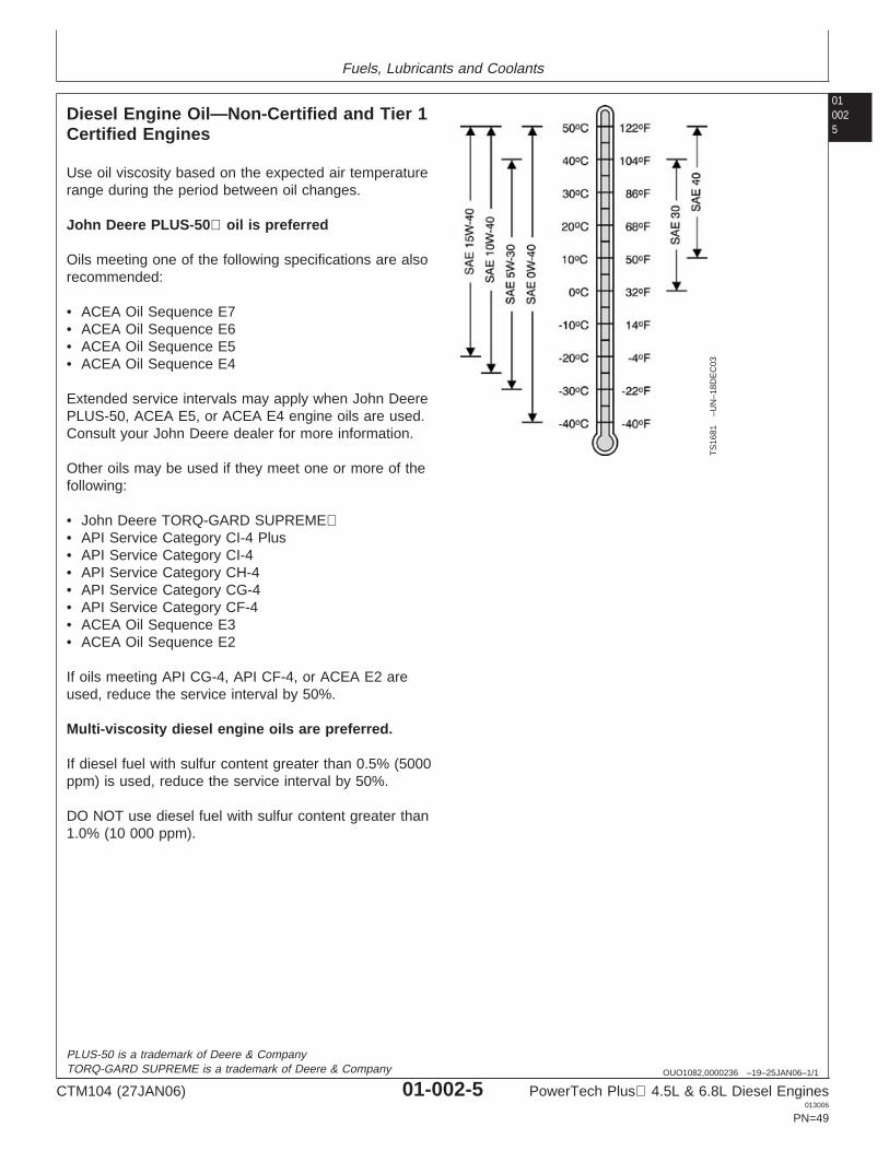
Use oil viscosity based on the expected air temperaturerange during the period between oil changes.
John Deere PLUS-50 oil is preferred
Oils meeting one of the following specifications are alsorecommended:
• ACEA Oil Sequence E7• ACEA Oil Sequence E6• ACEA Oil Sequence E5• ACEA Oil Sequence E4
Extended service intervals may apply when John DeerePLUS-50, ACEA E5, or ACEA E4 engine oils are used.Consult your John Deere dealer for more information.
Other oils may be used if they meet one or more of thefollowing:
• John Deere TORQ-GARD SUPREME• API Service Category CI-4 Plus• API Service Category CI-4• API Service Category CH-4• API Service Category CG-4• API Service Category CF-4• ACEA Oil Sequence E3• ACEA Oil Sequence E2
If oils meeting API CG-4, API CF-4, or ACEA E2 areused, reduce the service interval by 50%.
Multi-viscosity diesel engine oils are preferred.
If diesel fuel with sulfur content greater than 0.5% (5000ppm) is used, reduce the service interval by 50%.
DO NOT use diesel fuel with sulfur content greater than1.0% (10 000 ppm).
PLUS-50 is a trademark of Deere & CompanyTORQ-GARD SUPREME is a trademark of Deere & Company
CTM104 (27JAN06) 01-002-5 PowerTech Plus 4.5L & 6.8L Diesel Engines013006
PN=49
Fuels, Lubricants and Coolants
01002
6
RG19661,0000014 –19–22JUN05–1/1
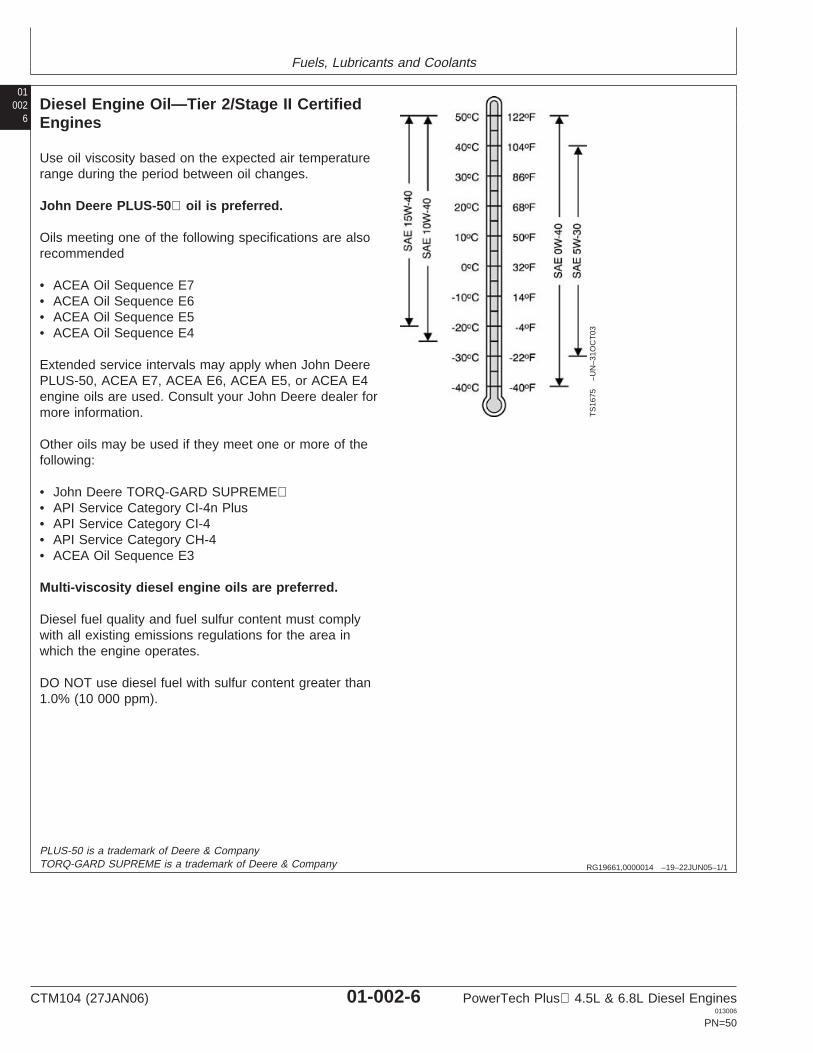
Diesel Engine Oil—Tier 2/Stage II CertifiedEngines
TS
1675
–UN
–31O
CT
03
Use oil viscosity based on the expected air temperaturerange during the period between oil changes.
John Deere PLUS-50 oil is preferred.
Oils meeting one of the following specifications are alsorecommended
• ACEA Oil Sequence E7• ACEA Oil Sequence E6• ACEA Oil Sequence E5• ACEA Oil Sequence E4
Extended service intervals may apply when John DeerePLUS-50, ACEA E7, ACEA E6, ACEA E5, or ACEA E4engine oils are used. Consult your John Deere dealer formore information.
Other oils may be used if they meet one or more of thefollowing:
• John Deere TORQ-GARD SUPREME• API Service Category CI-4n Plus• API Service Category CI-4• API Service Category CH-4• ACEA Oil Sequence E3
Multi-viscosity diesel engine oils are preferred.
Diesel fuel quality and fuel sulfur content must complywith all existing emissions regulations for the area inwhich the engine operates.
DO NOT use diesel fuel with sulfur content greater than1.0% (10 000 ppm).
PLUS-50 is a trademark of Deere & CompanyTORQ-GARD SUPREME is a trademark of Deere & Company
CTM104 (27JAN06) 01-002-6 PowerTech Plus 4.5L & 6.8L Diesel Engines013006
PN=50
Fuels, Lubricants and Coolants
010027
RG19661,0000013 –19–25JAN06–1/1
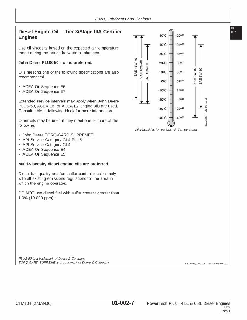
Diesel Engine Oil —Tier 3/Stage IIIA CertifiedEngines
RG
1386
5–U
N–0
8FE
B05
Oil Viscosities for Various Air Temperatures
Use oil viscosity based on the expected air temperaturerange during the period between oil changes.
John Deere PLUS-50 oil is preferred.
Oils meeting one of the following specifications are alsorecommended
• ACEA Oil Sequence E6• ACEA Oil Sequence E7
Extended service intervals may apply when John DeerePLUS-50, ACEA E6, or ACEA E7 engine oils are used.Consult table in following block for more information.
Other oils may be used if they meet one or more of thefollowing:
• John Deere TORQ-GARD SUPREME• API Service Category CI-4 PLUS• API Service Category CI-4• ACEA Oil Sequence E4• ACEA Oil Sequence E5
Multi-viscosity diesel engine oils are preferred.
Diesel fuel quality and fuel sulfur content must complywith all existing emissions regulations for the area inwhich the engine operates.
DO NOT use diesel fuel with sulfur content greater than1.0% (10 000 ppm).
PLUS-50 is a trademark of Deere & CompanyTORQ-GARD SUPREME is a trademark of Deere & Company
CTM104 (27JAN06) 01-002-7 PowerTech Plus 4.5L & 6.8L Diesel Engines013006
PN=51
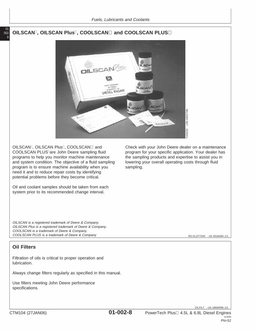
Fuels, Lubricants and Coolants
01002
8
RG,01,DT7040 –19–05JAN00–1/1
OILSCAN, OILSCAN Plus, COOLSCAN and COOLSCAN PLUS
T10
4220
–UN
–03O
CT
96
OILSCAN, OILSCAN Plus, COOLSCAN andCOOLSCAN PLUSare John Deere sampling fluidprograms to help you monitor machine maintenanceand system condition. The objective of a fluid samplingprogram is to ensure machine availability when youneed it and to reduce repair costs by identifyingpotential problems before they become critical.
Oil and coolant samples should be taken from eachsystem prior to its recommended change interval.
Check with your John Deere dealer on a maintenanceprogram for your specific application. Your dealer hasthe sampling products and expertise to assist you inlowering your overall operating costs through fluidsampling.
OILSCAN is a registered trademark of Deere & Company.OILSCAN Plus is a registered trademark of Deere & Company.COOLSCAN is a trademark of Deere & Company.COOLSCAN PLUS is a trademark of Deere & Company
DX,FILT –19–18MAR96–1/1
Oil Filters
Filtration of oils is critical to proper operation andlubrication.
Always change filters regularly as specified in this manual.
Use filters meeting John Deere performancespecifications.
CTM104 (27JAN06) 01-002-8 PowerTech Plus 4.5L & 6.8L Diesel Engines013006
PN=52
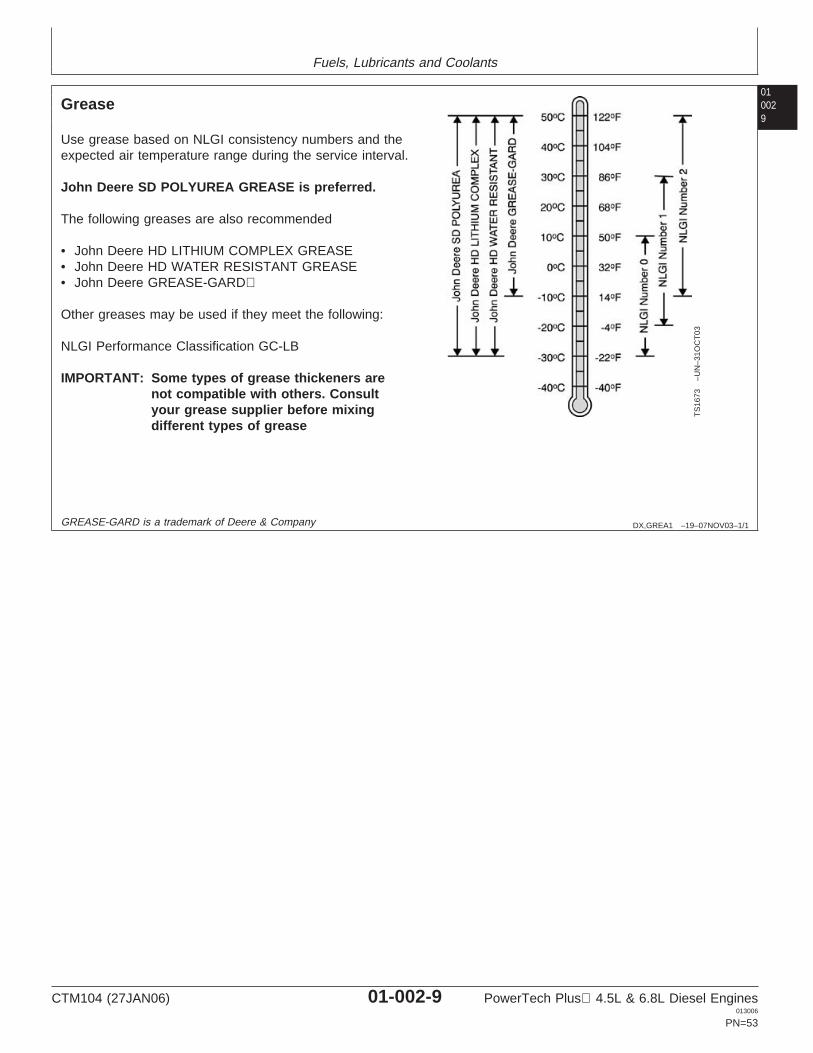
Fuels, Lubricants and Coolants
010029
DX,GREA1 –19–07NOV03–1/1
Grease
TS
1673
–UN
–31O
CT
03
Use grease based on NLGI consistency numbers and theexpected air temperature range during the service interval.
John Deere SD POLYUREA GREASE is preferred.
The following greases are also recommended
• John Deere HD LITHIUM COMPLEX GREASE• John Deere HD WATER RESISTANT GREASE• John Deere GREASE-GARD
Other greases may be used if they meet the following:
NLGI Performance Classification GC-LB
IMPORTANT: Some types of grease thickeners arenot compatible with others. Consultyour grease supplier before mixingdifferent types of grease
GREASE-GARD is a trademark of Deere & Company
CTM104 (27JAN06) 01-002-9 PowerTech Plus 4.5L & 6.8L Diesel Engines013006
PN=53
Fuels, Lubricants and Coolants
01002
10
DX,COOL3 –19–27OCT05–1/2
Diesel Engine Coolant
The engine cooling system is filled to provideyear-round protection against corrosion and cylinderliner pitting, and winter freeze protection to -37°C(-34°F). If protection at lower temperatures is required,consult your John Deere dealer for recommendations.
John Deere COOL-GARD Prediluted Coolant ispreferred for service.
John Deere COOL-GARD Prediluted Coolant isavailable in a concentration of either 50% ethyleneglycol or 55% propylene glycol.
Additional recommended coolants
The following engine coolant is also recommended:
• John Deere COOL-GARD Coolant Concentrate in a40% to 60% mixture of concentrate with qualitywater.
John Deere COOL-GARD coolants do not require useof supplemental coolant additives, except for periodicreplenishment of additives during the drain interval.
Other fully formulated coolants
Other fully formulated low silicate ethylene orpropylene glycol base coolants for heavy-duty enginesmay be used if they meet one of the followingspecifications:
• ASTM D6210 prediluted (50%) coolant• ASTM D6210 coolant concentrate in a 40% to 60%
mixture of concentrate with quality water
Coolants meeting ASTM D6210 do not require use ofsupplemental coolant additives, except for periodicreplenishment of additives during the drain interval.
Coolants requiring supplemental coolant additives
Other low silicate ethylene glycol base coolants forheavy-duty engines may also be used if they meet oneof the following specifications:
• ASTM D4985 ethylene glycol base prediluted (50%)coolant
• ASTM D4985 ethylene glycol base coolantconcentrate in a 40% to 60% mixture of concentratewith quality water
Coolants meeting ASTM D4985 require an initialcharge of supplemental coolant additives, formulatedfor protection of heavy duty diesel engines againstcorrosion and cylinder liner erosion and pitting. Theyalso require periodic replenishment of additives duringthe drain interval.
Other coolants
It is possible that neither John Deere COOL-GARD norcoolants meeting one of the coolant standards listedabove is available in the geographical area whereservice is performed. If these coolants are unavailable,use a coolant concentrate or prediluted coolant with aquality additive package that provides cylinder linercavitation protection and protects the cooling systemmetals (cast iron, aluminum alloys, and copper alloyssuch as brass) from corrosion.
The additive package must be part of one of thefollowing coolant mixtures:
• ethylene glycol or propylene glycol base prediluted(40% to 60%) coolant
• ethylene glycol or propylene glycol base coolantconcentrate in a 40% to 60% mixture of concentratewith quality water
Water quality
COOL-GARD is a trademark of Deere & Company
CTM104 (27JAN06) 01-002-10 PowerTech Plus 4.5L & 6.8L Diesel Engines013006
PN=54
Continued on next page
Fuels, Lubricants and Coolants
0100211
DX,COOL3 –19–27OCT05–2/2
Water quality is important to the performance of thecooling system. Distilled, deionized, or demineralizedwater is recommended for mixing with ethylene glycoland propylene glycol base engine coolant concentrate.
IMPORTANT: Do not use cooling system sealingadditives or antifreeze that containssealing additives.
IMPORTANT: Do not mix ethylene glycol andpropylene glycol base coolants.
CTM104 (27JAN06) 01-002-11 PowerTech Plus 4.5L & 6.8L Diesel Engines013006
PN=55
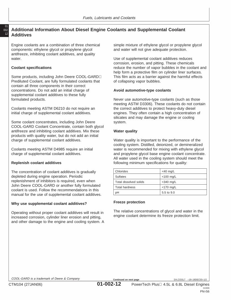
Fuels, Lubricants and Coolants
01002
12
DX,COOL7 –19–19DEC03–1/2
Additional Information About Diesel Engine Coolants and Supplemental CoolantAdditives
Engine coolants are a combination of three chemicalcomponents: ethylene glycol or propylene glycolantifreeze, inhibiting coolant additives, and qualitywater.
Coolant specifications
Some products, including John Deere COOL-GARDPrediluted Coolant, are fully formulated coolants thatcontain all three components in their correctconcentrations. Do not add an initial charge ofsupplemental coolant additives to these fullyformulated products.
Coolants meeting ASTM D6210 do not require aninitial charge of supplemental coolant additives.
Some coolant concentrates, including John DeereCOOL-GARD Coolant Concentrate, contain both glycolantifreeze and inhibiting coolant additives. Mix theseproducts with quality water, but do not add an initialcharge of supplemental coolant additives.
Coolants meeting ASTM D4985 require an initialcharge of supplemental coolant additives.
Replenish coolant additives
The concentration of coolant additives is graduallydepleted during engine operation. Periodicreplenishment of inhibitors is required, even whenJohn Deere COOL-GARD or another fully formulatedcoolant is used. Follow the recommendations in thismanual for the use of supplemental coolant additives.
Why use supplemental coolant additives?
Operating without proper coolant additives will result inincreased corrosion, cylinder liner erosion and pitting,and other damage to the engine and cooling system. A
simple mixture of ethylene glycol or propylene glycoland water will not give adequate protection.
Use of supplemental coolant additives reducescorrosion, erosion, and pitting. These chemicalsreduce the number of vapor bubbles in the coolant andhelp form a protective film on cylinder liner surfaces.This film acts as a barrier against the harmful effectsof collapsing vapor bubbles.
Avoid automotive-type coolants
Never use automotive-type coolants (such as thosemeeting ASTM D3306). These coolants do not containthe correct additives to protect heavy-duty dieselengines. They often contain a high concentration ofsilicates and may damage the engine or coolingsystem.
Water quality
Water quality is important to the performance of thecooling system. Distilled, deionized, or demineralizedwater is recommended for mixing with ethylene glycoland propylene glycol base engine coolant concentrate.All water used in the cooling system should meet thefollowing minimum specifications for quality:
Chlorides <40 mg/L
Sulfates <100 mg/L
Total dissolved solids <340 mg/L
Total hardness <170 mg/L
pH 5.5 to 9.0
Freeze protection
The relative concentrations of glycol and water in theengine coolant determine its freeze protection limit.
COOL-GARD is a trademark of Deere & Company
CTM104 (27JAN06) 01-002-12 PowerTech Plus 4.5L & 6.8L Diesel Engines013006
PN=56
Continued on next page
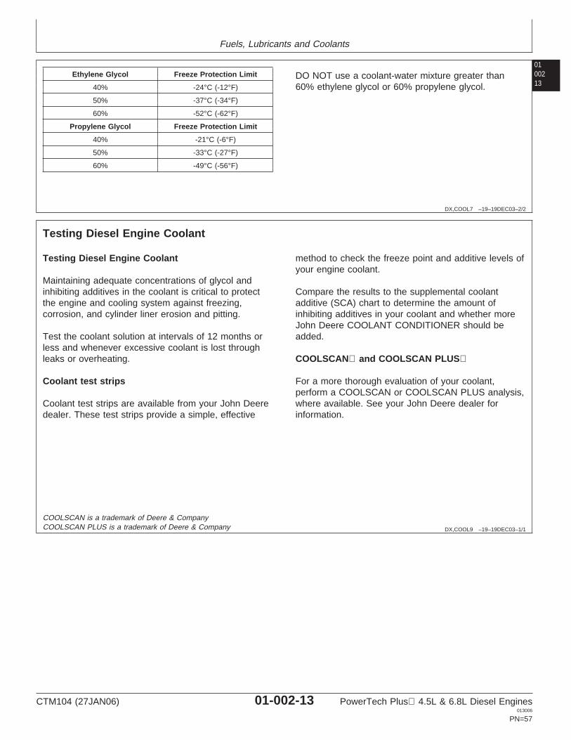
Fuels, Lubricants and Coolants
0100213
DX,COOL7 –19–19DEC03–2/2
Ethylene Glycol Freeze Protection Limit
40% -24°C (-12°F)
50% -37°C (-34°F)
60% -52°C (-62°F)
Propylene Glycol Freeze Protection Limit
40% -21°C (-6°F)
50% -33°C (-27°F)
60% -49°C (-56°F)
DO NOT use a coolant-water mixture greater than60% ethylene glycol or 60% propylene glycol.
DX,COOL9 –19–19DEC03–1/1
Testing Diesel Engine Coolant
Testing Diesel Engine Coolant
Maintaining adequate concentrations of glycol andinhibiting additives in the coolant is critical to protectthe engine and cooling system against freezing,corrosion, and cylinder liner erosion and pitting.
Test the coolant solution at intervals of 12 months orless and whenever excessive coolant is lost throughleaks or overheating.
Coolant test strips
Coolant test strips are available from your John Deeredealer. These test strips provide a simple, effective
method to check the freeze point and additive levels ofyour engine coolant.
Compare the results to the supplemental coolantadditive (SCA) chart to determine the amount ofinhibiting additives in your coolant and whether moreJohn Deere COOLANT CONDITIONER should beadded.
COOLSCAN and COOLSCAN PLUS
For a more thorough evaluation of your coolant,perform a COOLSCAN or COOLSCAN PLUS analysis,where available. See your John Deere dealer forinformation.
COOLSCAN is a trademark of Deere & CompanyCOOLSCAN PLUS is a trademark of Deere & Company
CTM104 (27JAN06) 01-002-13 PowerTech Plus 4.5L & 6.8L Diesel Engines013006
PN=57
Fuels, Lubricants and Coolants
01002
14
DX,COOL4 –19–07NOV03–1/1
Supplemental Coolant Additives
The concentration of coolant additives is graduallydepleted during engine operation. For allrecommended coolants, replenish additives betweendrain intervals by adding a supplemental coolantadditive every 12 months or as determined necessaryby coolant testing.
John Deere COOLANT CONDITIONER isrecommended as a supplemental coolant additive inJohn Deere engines.
IMPORTANT: Do not add a supplemental coolantadditive when the cooling system isdrained and refilled with JohnDeereCOOL-GARD.
If other coolants are used, consult the coolant supplierand follow the manufacturer’s recommendation for useof supplemental coolant additives.
The use of non-recommended supplemental coolantadditives may result in additive drop-out and gelationof the coolant.
Add the manufacturer’s recommended concentration ofsupplemental coolant additive. DO NOT add more thanthe recommended amount.
COOL-GARD is a trademark of Deere & Company
RG,01,DT7034 –19–29OCT97–1/1
Operating in Warm Temperature Climates
John Deere engines are designed to operate usingglycol base engine coolants.
Always use a recommended glycol base enginecoolant, even when operating in geographical areaswhere freeze protection is not required.
IMPORTANT: Water may be used as coolant inemergency situations only.
Foaming, hot surface aluminum andiron corrosion, scaling, andcavitation will occur when water isused as the coolant, even whencoolant conditioners are added.
Drain cooling system and refill withrecommended glycol base enginecoolant as soon as possible.
CTM104 (27JAN06) 01-002-14 PowerTech Plus 4.5L & 6.8L Diesel Engines013006
PN=58
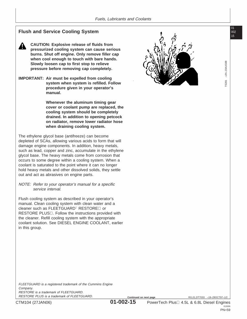
Fuels, Lubricants and Coolants
0100215
RG,01,DT7033 –19–29OCT97–1/2
Flush and Service Cooling System
TS
281
–UN
–23A
UG
88
CAUTION: Explosive release of fluids frompressurized cooling system can cause seriousburns. Shut off engine. Only remove filler capwhen cool enough to touch with bare hands.Slowly loosen cap to first stop to relievepressure before removing cap completely.
IMPORTANT: Air must be expelled from coolingsystem when system is refilled. Followprocedure given in your operator’smanual.
Whenever the aluminum timing gearcover or coolant pump are replaced, thecooling system should be completelydrained. In addition to opening petcockon radiator, remove lower radiator hosewhen draining cooling system.
The ethylene glycol base (antifreeze) can becomedepleted of SCAs, allowing various acids to form that willdamage engine components. In addition, heavy metals,such as lead, copper and zinc, accumulate in the ethyleneglycol base. The heavy metals come from corrosion thatoccurs to some degree within a cooling system. When acoolant is saturated to the point where it can no longerhold heavy metals and other dissolved solids, they settleout and act as abrasives on engine parts.
NOTE: Refer to your operator’s manual for a specificservice interval.
Flush cooling system as described in your operator’smanual. Clean cooling system with clean water and acleaner such as FLEETGUARD RESTORE orRESTORE PLUS. Follow the instructions provided withthe cleaner. Refill cooling system with the appropriatecoolant solution. See DIESEL ENGINE COOLANT, earlierin this group.
FLEETGUARD is a registered trademark of the Cummins EngineCompany.RESTORE is a trademark of FLEETGUARD.RESTORE PLUS is a trademark of FLEETGUARD.
CTM104 (27JAN06) 01-002-15 PowerTech Plus 4.5L & 6.8L Diesel Engines013006
PN=59
Continued on next page
Fuels, Lubricants and Coolants
01002
16
RG,01,DT7033 –19–29OCT97–2/2
IMPORTANT: NEVER overfill the system. Apressurized system needs space forheat expansion without overflowing atthe top of the radiator. Coolant levelshould be at bottom of radiator fillerneck.
Air must be expelled from coolingsystem when system is refilled. Loosenplug in side of thermostat housing toallow air to escape when filling system.Retighten plug when all the air hasbeen expelled.
After adding new coolant solution, run engine until itreaches operating temperature. This mixes the coolantsolution uniformly and circulates it through the entiresystem. After running engine, check coolant level andentire cooling system for leaks.
Contact your engine servicing dealer, if there are furtherquestions.
RG,01,DT7032 –19–29OCT97–1/1
Disposing of Coolant
TS
1133
–UN
–26N
OV
90
Improperly disposing of engine coolant can threaten theenvironment and ecology.
Use leakproof containers when draining fluids. Do not usefood or beverage containers that may mislead someoneinto drinking from them.
Do not pour waste onto the ground, down a drain, or intoany water source.
Inquire on the proper way to recycle or dispose of wastefrom your local environmental or recycling center, or fromyour engine servicing dealer.
CTM104 (27JAN06) 01-002-16 PowerTech Plus 4.5L & 6.8L Diesel Engines013006
PN=60
Section 02Repair and AdjustmentsContents 02
Page Page
Group 010—Engine Rebuild Knurl Valve Guides . . . . . . . . . . . . . . . . . . . .02-020-32Engine Overhaul Guidelines . . . . . . . . . . . . . .02-010-1 Clean and Inspect Valve Seats . . . . . . . . . . .02-020-32Engine Repair Stand . . . . . . . . . . . . . . . . . . . .02-010-1 Grind Valve Seats . . . . . . . . . . . . . . . . . . . . .02-020-33Engine Stand Safety Precautions . . . . . . . . . .02-010-2 Remove Valve Seat Inserts . . . . . . . . . . . . . .02-020-35Install Adapters on Engine Repair Stand. . . . .02-010-3 Measure Valve Seat Bore in CylinderEngine Lifting Procedure . . . . . . . . . . . . . . . . .02-010-4 Head . . . . . . . . . . . . . . . . . . . . . . . . . . . . .02-020-38Clean Engine . . . . . . . . . . . . . . . . . . . . . . . . .02-010-5 Install Valve Seat Inserts. . . . . . . . . . . . . . . .02-020-39Disconnect Turbocharger Oil Inlet Line . . . . . .02-010-6 Install Valves. . . . . . . . . . . . . . . . . . . . . . . . .02-020-39Mount Engine on Repair Stand . . . . . . . . . . . .02-010-7 Inspect Cylinder Head Cap Screws . . . . . . . .02-020-40Engine Mounted on Repair Stand . . . . . . . . . .02-010-8 Inspect and Clean Exhaust Manifold . . . . . . .02-020-40Engine Disassembly Sequence . . . . . . . . . . . .02-010-8 Clean and Inspect Top Deck of CylinderSealant Application Guidelines . . . . . . . . . . .02-010-12 Block . . . . . . . . . . . . . . . . . . . . . . . . . . . . .02-020-41Engine Assembly Sequence . . . . . . . . . . . . .02-010-13 Check Cylinder Liner Standout (Height AboveEngine Break-In Guidelines. . . . . . . . . . . . . .02-010-17 Block) . . . . . . . . . . . . . . . . . . . . . . . . . . . .02-020-42Perform Engine Break-In . . . . . . . . . . . . . . . .02-010-18 Install Cylinder Head . . . . . . . . . . . . . . . . . . .02-020-43
Torque-Turn Method for Proper Torque. . . . .02-020-46Install Rocker Arm Assembly. . . . . . . . . . . . .02-020-47Group 020—Cylinder Head and Valves (Two-ValveInspect and Clean Ventilator Outlet Hose . . .02-020-48Head Engines)Remove, Inspect, and Install ClosedGeneral Information. . . . . . . . . . . . . . . . . . . . .02-020-1
Crankcase Ventilation System (IfCheck and Adjust Valve Clearance . . . . . . . . .02-020-2Equipped) . . . . . . . . . . . . . . . . . . . . . . . . .02-020-49Measure Valve Lift . . . . . . . . . . . . . . . . . . . . .02-020-5
Install Rocker Arm Cover . . . . . . . . . . . . . . .02-020-50Remove Cylinder Head . . . . . . . . . . . . . . . . . .02-020-7Complete Final Assembly . . . . . . . . . . . . . . .02-020-53Disassemble and Inspect Rocker Arm Shaft
Assembly. . . . . . . . . . . . . . . . . . . . . . . . . .02-020-14Assemble Rocker Arm Assembly . . . . . . . . .02-020-15 Group 021—Cylinder Head and Valves (Four-Valve
Head Engines)Inspect, Measure, and Install Fuel SupplyPump Push Rod (If Applicable) . . . . . . . . .02-020-15 General Information. . . . . . . . . . . . . . . . . . . . .02-021-1
Check and Adjust Valve Clearance . . . . . . . . .02-021-1Inspect, Measure, and Assemble CamshaftFollowers . . . . . . . . . . . . . . . . . . . . . . . . . .02-020-17 Measure Valve Lift . . . . . . . . . . . . . . . . . . . . .02-021-5
Do Not Open High-Pressure Fuel System . . . .02-021-6Measure Valve Recess in Cylinder Head . . .02-020-19Preliminary Cylinder Head and Valve Remove Cylinder Head . . . . . . . . . . . . . . . . . .02-021-7
Inspect and Measure Valve Bridges . . . . . . .02-021-16Checks . . . . . . . . . . . . . . . . . . . . . . . . . . .02-020-20Remove Valve Assembly. . . . . . . . . . . . . . . .02-020-21 Disassemble and Inspect Rocker Arm Shaft
Assembly. . . . . . . . . . . . . . . . . . . . . . . . . .02-021-17Inspect and Measure Valve Springs . . . . . . .02-020-21Inspect Valve Rotators . . . . . . . . . . . . . . . . .02-020-22 Assemble Rocker Arm Assembly . . . . . . . . .02-021-18
Inspect, Measure, and Install Fuel SupplyClean Valves. . . . . . . . . . . . . . . . . . . . . . . . .02-020-22Inspect and Measure Valves . . . . . . . . . . . . .02-020-23 Pump Push Rod . . . . . . . . . . . . . . . . . . . .02-021-18
Inspect, Measure, and Assemble CamshaftGrind Valves . . . . . . . . . . . . . . . . . . . . . . . . .02-020-24Head Gasket Inspection and Repair Followers . . . . . . . . . . . . . . . . . . . . . . . . . .02-021-20
Measure Valve Recess in Cylinder Head . . .02-021-22Sequence . . . . . . . . . . . . . . . . . . . . . . . . .02-020-25Inspect and Clean Cylinder Head . . . . . . . . .02-020-27 Preliminary Cylinder Head and Valve
Checks . . . . . . . . . . . . . . . . . . . . . . . . . . .02-021-23Check Cylinder Head Flatness . . . . . . . . . . .02-020-28Measure Cylinder Head Thickness . . . . . . . .02-020-29 Remove Valve Assembly. . . . . . . . . . . . . . . .02-021-24
Inspect and Measure Valve Springs . . . . . . .02-021-25Clean Injection Nozzle Bores . . . . . . . . . . . .02-020-30Clean Valve Guides . . . . . . . . . . . . . . . . . . .02-020-30
Continued on next pageMeasure Valve Guides . . . . . . . . . . . . . . . . .02-020-31
CTM104 (27JAN06) 02-1 PowerTech Plus 4.5L & 6.8L Diesel Engines013006
PN=1
Contents
Page Page
Clean Valves. . . . . . . . . . . . . . . . . . . . . . . . .02-021-25 Check Piston Ring Groove Wear. . . . . . . . . .02-030-15Measure Piston Pin Bore. . . . . . . . . . . . . . . .02-030-16Inspect and Measure Valves . . . . . . . . . . . . .02-021-26
Grind Valves . . . . . . . . . . . . . . . . . . . . . . . . .02-021-27 Measure Piston Skirt . . . . . . . . . . . . . . . . . . .02-030-17Measure Piston Height . . . . . . . . . . . . . . . . .02-030-17Head Gasket Inspection and Repair
Sequence . . . . . . . . . . . . . . . . . . . . . . . . .02-021-28 Determine Piston-to-Liner Clearance. . . . . . .02-030-18Deglaze Cylinder Liners . . . . . . . . . . . . . . . .02-030-20Inspect and Clean Cylinder Head . . . . . . . . .02-021-30
02
Check Cylinder Head Flatness . . . . . . . . . . .02-021-30 Replace Piston and Liner Sets . . . . . . . . . . .02-030-20Inspect and Measure Connecting RodMeasure Cylinder Head Thickness . . . . . . . .02-021-31
Remove Fuel Injector Sleeves. . . . . . . . . . . .02-021-32 Bearings (Rods Removed from Engine). . .02-030-21Inspect and Measure Connecting RodClean Fuel Injector Bores . . . . . . . . . . . . . . .02-021-33
Install Fuel Injector Sleeves . . . . . . . . . . . . .02-021-34 Bearings (Rod and Crankshaft in Engine). . . . . . . . . . . . . . . . . . . . . . . . . . . . . . . . .02-030-22Clean Glow Plug Bores . . . . . . . . . . . . . . . . .02-021-35
Clean Valve Guides . . . . . . . . . . . . . . . . . . .02-021-35 Inspect Rod and Cap . . . . . . . . . . . . . . . . . .02-030-23Inspect Piston Pins and Bushings . . . . . . . . .02-030-25Measure Valve Guides . . . . . . . . . . . . . . . . .02-021-36
Knurl Valve Guides . . . . . . . . . . . . . . . . . . . .02-021-37 Remove Piston Pin Bushing . . . . . . . . . . . . .02-030-26Clean and Inspect Connecting Rod PinClean and Inspect Valve Seats . . . . . . . . . . .02-021-37
Grind Valve Seats . . . . . . . . . . . . . . . . . . . . .02-021-38 Bore. . . . . . . . . . . . . . . . . . . . . . . . . . . . . .02-030-28Install Piston Pin Bushing in ConnectingRemove Valve Seat Inserts . . . . . . . . . . . . . .02-021-38
Measure Valve Seat Bore in Cylinder Rod . . . . . . . . . . . . . . . . . . . . . . . . . . . . . .02-030-29Measure Rod Center-to-Center Bores . . . . . .02-030-31Head . . . . . . . . . . . . . . . . . . . . . . . . . . . . .02-021-42
Install Valve Seat Inserts. . . . . . . . . . . . . . . .02-021-43 Inspect and Clean Cylinder Block . . . . . . . . .02-030-32Clean Cylinder Liner O-Ring Bore . . . . . . . . .02-030-35Install Valves. . . . . . . . . . . . . . . . . . . . . . . . .02-021-44
Inspect Cylinder Head Cap Screws . . . . . . . .02-021-45 Measure Cylinder Block Main BearingBore. . . . . . . . . . . . . . . . . . . . . . . . . . . . . .02-030-35Inspect and Clean Exhaust Manifold . . . . . . .02-021-45
Clean and Inspect Top Deck of Cylinder Measure Camshaft Follower Machined Borein Block . . . . . . . . . . . . . . . . . . . . . . . . . . .02-030-36Block . . . . . . . . . . . . . . . . . . . . . . . . . . . . .02-021-46
Check Cylinder Liner Standout (Height Measure Camshaft Bushing Bores inBlock . . . . . . . . . . . . . . . . . . . . . . . . . . . . .02-030-36Above Block) Four-Valve Head . . . . . . . . .02-021-47
Install Cylinder Head . . . . . . . . . . . . . . . . . . .02-021-48 Measure Balancer Shaft Bushing ID in Block(4-Cylinder Engines) . . . . . . . . . . . . . . . . .02-030-38Torque-Turn Method for Proper Torque. . . . .02-021-51
Install Fuel Injectors . . . . . . . . . . . . . . . . . . .02-021-52 Measure Cylinder Liners and Block Bores. . .02-030-39Measure Liner Flange Counterbore DepthInstall Carrier Assembly . . . . . . . . . . . . . . . .02-021-53
Install Rocker Arm Assembly. . . . . . . . . . . . .02-021-54 in Block . . . . . . . . . . . . . . . . . . . . . . . . . . .02-030-40Measure Liner Flange Thickness. . . . . . . . . .02-030-40Inspect and Clean Ventilator Outlet Hose . . .02-021-56
Remove, Inspect, and Install Closed Measure Cylinder Block Top DeckFlatness. . . . . . . . . . . . . . . . . . . . . . . . . . .02-030-41Crankcase Ventilation System (If
Equipped) . . . . . . . . . . . . . . . . . . . . . . . . .02-021-57 Remove, Inspect, and Install PistonCooling Orifices . . . . . . . . . . . . . . . . . . . . .02-030-42Install Rocker Arm Cover . . . . . . . . . . . . . . .02-021-58
Complete Final Assembly . . . . . . . . . . . . . . .02-021-59 Measure Fuel Supply Pump Push RodBore and Push Rod OD. . . . . . . . . . . . . . .02-030-43
Measure and Adjust Cylinder LinerGroup 030—Cylinder Block, Liners, Pistons andRods Standout (Height Above Block) . . . . . . . . .02-030-44
Install Packing on Cylinder Liner and O-RingsConnecting Rods—General Information . . . . .02-030-1Remove Pistons and Connecting Rods . . . . . .02-030-2 in Block . . . . . . . . . . . . . . . . . . . . . . . . . . .02-030-45
Install Cylinder Liner in Block . . . . . . . . . . . .02-030-47Remove Cylinder Liners . . . . . . . . . . . . . . . . .02-030-5Complete Disassembly of Cylinder Block (If Assemble Piston and Connecting Rod . . . . .02-030-49
Install Piston Rings . . . . . . . . . . . . . . . . . . . .02-030-50Required). . . . . . . . . . . . . . . . . . . . . . . . . . .02-030-7Preliminary Liner, Piston and Rod Checks . . .02-030-8 Install Piston and Connecting Rod
Assembly. . . . . . . . . . . . . . . . . . . . . . . . . .02-030-51Disassemble Piston and Rod Assembly . . . . .02-030-9Clean Pistons . . . . . . . . . . . . . . . . . . . . . . . .02-030-10 Torque-Turn Connecting Rod Cap
Screws. . . . . . . . . . . . . . . . . . . . . . . . . . . .02-030-55Visually Inspect Pistons. . . . . . . . . . . . . . . . .02-030-11Clean Cylinder Liners . . . . . . . . . . . . . . . . . .02-030-12
Continued on next pageVisually Inspect Cylinder Liners. . . . . . . . . . .02-030-13
CTM104 (27JAN06) 02-2 PowerTech Plus 4.5L & 6.8L Diesel Engines013006
PN=2

Contents
Page Page
Check Engine Rotation for Excessive Install Main and Thrust Bearing Inserts inBlock . . . . . . . . . . . . . . . . . . . . . . . . . . . . .02-040-52Tightness. . . . . . . . . . . . . . . . . . . . . . . . . .02-030-56
Install Crankshaft . . . . . . . . . . . . . . . . . . . . .02-040-54Measure Piston Protrusion . . . . . . . . . . . . . .02-030-57 02Install Flywheel Housing . . . . . . . . . . . . . . . .02-040-57Complete Final Assembly . . . . . . . . . . . . . . .02-030-60Complete Final Assembly . . . . . . . . . . . . . . .02-040-60
Group 040—Crankshaft, Main Bearings andGroup 050—Camshaft, Balancer Shafts and TimingFlywheel
Gear TrainCrankshaft and Main Bearing FailureMeasure Valve Lift . . . . . . . . . . . . . . . . . . . . .02-050-1Analysis . . . . . . . . . . . . . . . . . . . . . . . . . . . .02-040-1Remove Timing Gear Cover . . . . . . . . . . . . . .02-050-3Inspect Vibration Damper (6.8 L Engines) . . . .02-040-2Remove and Install Camshaft BushingRemove Pulley or Vibration Damper and
with Front Plate Installed . . . . . . . . . . . . . . .02-050-6Pulley . . . . . . . . . . . . . . . . . . . . . . . . . . . . .02-040-3Remove and Install Camshaft Gear-DrivenInstall Pulley or Vibration Damper and
Auxiliary Drive . . . . . . . . . . . . . . . . . . . . . .02-050-10Pulley . . . . . . . . . . . . . . . . . . . . . . . . . . . . .02-040-5Measure Camshaft End Play. . . . . . . . . . . . .02-050-11Replace Front Crankshaft Oil Seal and WearMeasure Balancer Shaft End Play (IfSleeve . . . . . . . . . . . . . . . . . . . . . . . . . . . . .02-040-8
Equipped—4-Cylinder Engines) . . . . . . . . .02-050-11Check Crankshaft End Play . . . . . . . . . . . . .02-040-19Measure Idler Gear End Play . . . . . . . . . . . .02-050-12Inspect Flywheel . . . . . . . . . . . . . . . . . . . . . .02-040-20Measure Timing Gear Backlash . . . . . . . . . .02-050-13Check Flywheel Face Flatness . . . . . . . . . . .02-040-21Remove Camshaft. . . . . . . . . . . . . . . . . . . . .02-050-14Check Pilot Bearing Bore Concentricity . . . . .02-040-21Visually Inspect Camshaft . . . . . . . . . . . . . . .02-050-17
Remove Flywheel . . . . . . . . . . . . . . . . . . . . .02-040-22Measure Camshaft Thrust Plate Clearance
Replace Flywheel Ring Gear. . . . . . . . . . . . .02-040-23and Thickness . . . . . . . . . . . . . . . . . . . . . .02-050-17
Replace Pilot Bearing in Flywheel (IfInspect and Measure Camshaft Bushing
Equipped) . . . . . . . . . . . . . . . . . . . . . . . . .02-040-24 ID and Journal OD. . . . . . . . . . . . . . . . . . .02-050-18Replace Sleeve in Flywheel (If Equipped) . . .02-040-25 Measure Camshaft Lobe Height . . . . . . . . . .02-050-19Install Flywheel . . . . . . . . . . . . . . . . . . . . . . .02-040-26 Inspect Camshaft Gear . . . . . . . . . . . . . . . . .02-050-19Crankshaft Rear Oil Seal and Wear Sleeve Inspect Camshaft Followers . . . . . . . . . . . . .02-050-20
Handling Precautions. . . . . . . . . . . . . . . . .02-040-27 Inspect, Measure, and Install Fuel SupplyRemove Crankshaft Rear Oil Seal and Wear Pump Push Rod . . . . . . . . . . . . . . . . . . . .02-050-21
Sleeve . . . . . . . . . . . . . . . . . . . . . . . . . . . .02-040-27 Remove Balancer Shafts (If Equipped—Clean and Inspect Crankshaft Flange . . . . . .02-040-32 4-Cylinder Engines) . . . . . . . . . . . . . . . . . .02-050-22Install Crankshaft Rear Oil Seal and Wear Inspect and Measure Balancer Shaft
Sleeve . . . . . . . . . . . . . . . . . . . . . . . . . . . .02-040-32 Bushings and Journals. . . . . . . . . . . . . . . .02-050-23Remove Flywheel Housing . . . . . . . . . . . . . .02-040-38 Remove and Install Balancer ShaftRemove and Install Crankshaft Timing Wheel Bushings . . . . . . . . . . . . . . . . . . . . . . . . . .02-050-24
(Two-Valve Head Engines with VP44 or Inspect Balancer Shaft Gears and ThrustDE10 Fuel Injection Pumps and All Plates . . . . . . . . . . . . . . . . . . . . . . . . . . . .02-050-25Four-Valve Head Engines). . . . . . . . . . . . .02-040-39 Remove and Install Balancer Shaft Gears. . .02-050-26
Remove Crankshaft Main Bearings . . . . . . . .02-040-40 Remove Cylinder Block Front Plate. . . . . . . .02-050-27Check Main Bearing Oil Clearance . . . . . . . .02-040-42 Measure Idler Gear Bushing and Shaft . . . . .02-050-30Remove and Install Crankshaft Gear Remove Idler Gear Bushings . . . . . . . . . . . .02-050-31
(Crankshaft Installed in Engine) . . . . . . . . .02-040-43 Install Idler Gear Bushings . . . . . . . . . . . . . .02-050-32Remove Crankshaft. . . . . . . . . . . . . . . . . . . .02-040-45 Remove Lower and Upper Idler Shafts . . . . .02-050-33Inspect Crankshaft . . . . . . . . . . . . . . . . . . . .02-040-46 Clean and Inspect Front Plate. . . . . . . . . . . .02-050-33Measure Crankshaft Journals and Main Transfer Fuel Injection Pump Timing Mark
Bearing ID . . . . . . . . . . . . . . . . . . . . . . . . .02-040-47 onto Replacement Front PlateMeasure Main Thrust Journal Width and (Two-Valve Head Engine with Mechanical Fuel
Thrust Bearing Width . . . . . . . . . . . . . . . . .02-040-48 Injection) . . . . . . . . . . . . . . . . . . . . . . . . . .02-050-34Crankshaft Grinding Guidelines. . . . . . . . . . .02-040-49 Install Idler Shaft Spring Pins (IfCrankshaft Grinding Specifications . . . . . . . .02-040-50 Equipped) . . . . . . . . . . . . . . . . . . . . . . . . .02-050-35Measure Assembled ID of Main Bearing
Continued on next pageCaps . . . . . . . . . . . . . . . . . . . . . . . . . . . . .02-040-51
CTM104 (27JAN06) 02-3 PowerTech Plus 4.5L & 6.8L Diesel Engines013006
PN=3
Contents
Page Page
Install Upper Idler Shaft in Front Plate. . . . . .02-050-35 Remove and Install Thermostat Cover andInstall Lower Idler Shaft in Front Plate. . . . . .02-050-36 Thermostats (Tier 3) . . . . . . . . . . . . . . . . . .02-070-9Install Cylinder Block Front Plate. . . . . . . . . .02-050-37 Test Thermostat(s) . . . . . . . . . . . . . . . . . . . .02-070-10Install and Time Balancer Shafts (If Remove Coolant Pump . . . . . . . . . . . . . . . . .02-070-11
Equipped—4-Cylinder Engines) . . . . . . . . .02-050-38 Coolant Pump Assembly . . . . . . . . . . . . . . . .02-070-12Install Camshaft . . . . . . . . . . . . . . . . . . . . . .02-050-43 Disassemble Coolant Pump . . . . . . . . . . . . .02-070-13
02
Clean and Inspect Timing Gear Cover . . . . .02-050-49 Inspect, Clean, and Measure CoolantInstall Timing Gear Cover . . . . . . . . . . . . . . .02-050-50 Pump Parts . . . . . . . . . . . . . . . . . . . . . . . .02-070-14Remove and Install Magnetic Pick-Up Assemble Coolant Pump. . . . . . . . . . . . . . . .02-070-15
Sensor . . . . . . . . . . . . . . . . . . . . . . . . . . . .02-050-54 Install Coolant Pump . . . . . . . . . . . . . . . . . . .02-070-17Complete Final Assembly . . . . . . . . . . . . . . .02-050-55 Cooling System Deaeration. . . . . . . . . . . . . .02-070-19
Remove and Install Automatic (Spring) BeltTensioner . . . . . . . . . . . . . . . . . . . . . . . . .02-070-19Group 060—Lubrication System
Checking Belt Tensioner Spring Tension andGeneral Lubrication System Information . . . . .02-060-1Belt Wear. . . . . . . . . . . . . . . . . . . . . . . . . .02-070-21Remove, Inspect, and Install Oil Filter
Manual Belt Tensioner Adjustment Using BeltBase . . . . . . . . . . . . . . . . . . . . . . . . . . . . . .02-060-1Tension Gauge . . . . . . . . . . . . . . . . . . . . .02-070-23Remove, Inspect, and Install Oil Cooler . . . . .02-060-7
Manual Belt Tensioner Adjustment Using BeltRemove, Inspect, and Install Oil BypassTension Tool (Alternate Method forValve . . . . . . . . . . . . . . . . . . . . . . . . . . . . .02-060-13Engines without Auxiliary Drive.) . . . . . . . .02-070-24Remove and Install Oil Filter Bypass Valve
Inspect and Install Fan Assembly . . . . . . . . .02-070-26(Extended-Life Filter) . . . . . . . . . . . . . . . . .02-060-14Remove and Inspect Fan Drive Assembly. . .02-070-27Remove and Install Oil PressureReplace Bearings in Adjustable Fan DriveRegulating Valve . . . . . . . . . . . . . . . . . . . .02-060-14
Assembly. . . . . . . . . . . . . . . . . . . . . . . . . .02-070-28Remove and Install Oil Fill Adapter . . . . . . . .02-060-19Replace Bearings in Heavy-Duty,Remove and Install Dipstick Tube with Oil
Adjustable Fan Drive Assembly . . . . . . . . .02-070-31Pan Installed . . . . . . . . . . . . . . . . . . . . . . .02-060-21Install Fan Drive Assembly . . . . . . . . . . . . . .02-070-33Remove and Install Dipstick Tube withRemove and Install Fan Drive AssemblyFitting . . . . . . . . . . . . . . . . . . . . . . . . . . . .02-060-23
(2254 Combine) . . . . . . . . . . . . . . . . . . . . .02-070-36Remove, Inspect, and Install Oil PumpRemove and Install Coolant Heater (IfPick-Up Tube Assembly. . . . . . . . . . . . . . .02-060-24
Equipped) . . . . . . . . . . . . . . . . . . . . . . . . .02-070-37Engine Oil Pump Assembly. . . . . . . . . . . . . .02-060-24Remove and Install Cold Start AdvanceRemove Engine Oil Pump . . . . . . . . . . . . . . .02-060-25
Switch (If Equipped). . . . . . . . . . . . . . . . . .02-070-38Inspect and Measure Clearances . . . . . . . . .02-060-26Complete Oil Pump Disassembly . . . . . . . . .02-060-28Assemble Engine Oil Pump. . . . . . . . . . . . . .02-060-29 Group 080—Air Intake and Exhaust SystemInstall Engine Oil Pump. . . . . . . . . . . . . . . . .02-060-30 Extending Turbocharger Life . . . . . . . . . . . . . .02-080-1Install Oil Pan . . . . . . . . . . . . . . . . . . . . . . . .02-060-32 Remove Turbocharger. . . . . . . . . . . . . . . . . . .02-080-3
Turbocharger Failure Analysis. . . . . . . . . . . . .02-080-5Turbocharger Inspection . . . . . . . . . . . . . . . . .02-080-7Group 070—Cooling SystemPerform Radial Bearing Clearance Test . . . .02-080-14Remove Coolant Manifold/Thermostat CoverAdjust Turbocharger Wastegate Actuator (Ifand Thermostat . . . . . . . . . . . . . . . . . . . . . .02-070-1
Equipped) . . . . . . . . . . . . . . . . . . . . . . . . .02-080-16Install Coolant Manifold/Thermostat CoverRemove and Install Variable Geometryand Thermostat . . . . . . . . . . . . . . . . . . . . . .02-070-2
Turbocharger Actuator (If Equipped) . . . . .02-080-17Remove and Install CoolantRemove and Install Actuator Linkage . . . . . .02-080-19Manifold/Thermostat Cover andRepair Turbocharger . . . . . . . . . . . . . . . . . . .02-080-23Thermostat (High Flow SinglePrelube Turbocharger . . . . . . . . . . . . . . . . . .02-080-23Thermostat) . . . . . . . . . . . . . . . . . . . . . . . . .02-070-4
Remove and Install Coolant Manifold and Install Turbocharger . . . . . . . . . . . . . . . . . . .02-080-24Thermostats (Dual Thermostats) . . . . . . . . .02-070-7 Turbocharger Break-In . . . . . . . . . . . . . . . . .02-080-28
Remove and Install Coolant Manifold, Recommendations for Turbocharger Use . . .02-080-28Thermostats and Side Port (Four-Valve
Continued on next pageHead) . . . . . . . . . . . . . . . . . . . . . . . . . . . . .02-070-8
CTM104 (27JAN06) 02-4 PowerTech Plus 4.5L & 6.8L Diesel Engines013006
PN=4
Contents
Page
Remove, Inspect, and Install ExhaustManifold. . . . . . . . . . . . . . . . . . . . . . . . . . .02-080-29
Remove and Install Air-to-Air Aftercooler. . . .02-080-30 02Remove and Install EGR Exhaust Tube (Tier
3/Stage IIIA) . . . . . . . . . . . . . . . . . . . . . . .02-080-31Remove and Install EGR Coolant Inlet
Tube (Tier 3/Stage IIIA) . . . . . . . . . . . . . . .02-080-32Remove and Install EGR Cooler (Tier
3/Stage IIIA) . . . . . . . . . . . . . . . . . . . . . . .02-080-33Remove, Inspect, and Install EGR Valve (Tier
3/Stage IIIA) . . . . . . . . . . . . . . . . . . . . . . .02-080-34Remove and Install Air Intake Pipe . . . . . . . .02-080-35Remove, Inspect, and Install Intake Manifold
(Four-Valve Head) . . . . . . . . . . . . . . . . . . .02-080-36Remove, Inspect, and Install Air Inlet and
Mixing Sleeve (Tier 3/Stage IIIA) . . . . . . . .02-080-37Remove, Inspect, and Install Intake
Manifold (Tier 3/Stage IIIA) . . . . . . . . . . . .02-080-38Remove and Install Air Heater (If
Equipped) . . . . . . . . . . . . . . . . . . . . . . . . .02-080-39Remove and Install Starting Aid (If
Equipped) . . . . . . . . . . . . . . . . . . . . . . . . .02-080-40
Group 090—Fuel SystemFuel System . . . . . . . . . . . . . . . . . . . . . . . . . .02-090-1
Group 100—Starting and Charging SystemsRemove and Install Starter . . . . . . . . . . . . . . .02-100-1Remove and Install Alternator . . . . . . . . . . . . .02-100-2
CTM104 (27JAN06) 02-5 PowerTech Plus 4.5L & 6.8L Diesel Engines013006
PN=5

Contents
02
CTM104 (27JAN06) 02-6 PowerTech Plus 4.5L & 6.8L Diesel Engines013006
PN=6
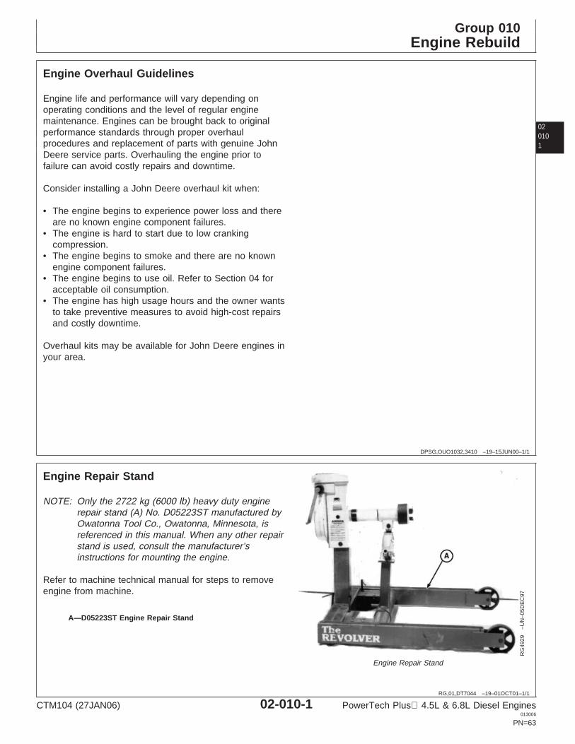
Group 010Engine Rebuild
020101
DPSG,OUO1032,3410 –19–15JUN00–1/1
Engine Overhaul Guidelines
Engine life and performance will vary depending onoperating conditions and the level of regular enginemaintenance. Engines can be brought back to originalperformance standards through proper overhaulprocedures and replacement of parts with genuine JohnDeere service parts. Overhauling the engine prior tofailure can avoid costly repairs and downtime.
Consider installing a John Deere overhaul kit when:
• The engine begins to experience power loss and thereare no known engine component failures.
• The engine is hard to start due to low crankingcompression.
• The engine begins to smoke and there are no knownengine component failures.
• The engine begins to use oil. Refer to Section 04 foracceptable oil consumption.
• The engine has high usage hours and the owner wantsto take preventive measures to avoid high-cost repairsand costly downtime.
Overhaul kits may be available for John Deere engines inyour area.
RG,01,DT7044 –19–01OCT01–1/1
Engine Repair Stand
RG
4929
–UN
–05D
EC
97
Engine Repair Stand
A—D05223ST Engine Repair Stand
NOTE: Only the 2722 kg (6000 lb) heavy duty enginerepair stand (A) No. D05223ST manufactured byOwatonna Tool Co., Owatonna, Minnesota, isreferenced in this manual. When any other repairstand is used, consult the manufacturer’sinstructions for mounting the engine.
Refer to machine technical manual for steps to removeengine from machine.
CTM104 (27JAN06) 02-010-1 PowerTech Plus 4.5L & 6.8L Diesel Engines013006
PN=63
Engine Rebuild
02010
2
RG,RG34710,45 –19–01OCT01–1/1
Engine Stand Safety Precautions
The engine repair stand should be used only byqualified service technicians familiar with thisequipment.
To maintain shear strength specifications, alloy steelClass 12.9 or SAE Grade 8 or higher cap screws mustbe used to mount adapters and engine to repair stand.Use LOCTITE 242 Thread Lock and Sealer (MediumStrength) on cap screws when installing lifting strapson engine. Tighten cap screws to specifications given.
For full thread engagement, be certain that tappedholes in adapters and engine blocks are clean and notdamaged. A thread length engagement equal to 1-1/2screw diameters minimum is required to maintainstrength requirements.
To avoid structural or personal injury, do not exceedthe maximum capacity rating of 2722 kg (6000 lb).Maximum capacity is determined with the center of theengine located not more than 330 mm (13 in.) from themounting hub surface of the engine stand.
The center of balance of an engine must be locatedwithin 51 mm (2 in.) of the engine stand rotating shaft.
Engine center of balance is generally located a fewmillimeters above the crankshaft.
To prevent possible personal injury due to engineslippage, recheck to make sure engine is solidlymounted before releasing support from engine liftingdevice.
Never permit any part of the body to be positionedunder a load being lifted or suspended. Accidentalslippage may result in personal injury.
The lifting jack is to be used when it is necessary to liftthe engine for rotation. When working on the engine,the jack should be at its lowest position to keep thecenter of gravity and the possibility of tipping low.
To prevent possible personal injury due to suddenengine movement, lower the engine by operating jackrelease valve slowly. Do not unscrew release valveknob more than two turns from its closed position.
LOCTITE is a registered trademark of Loctite Corp.
CTM104 (27JAN06) 02-010-2 PowerTech Plus 4.5L & 6.8L Diesel Engines013006
PN=64
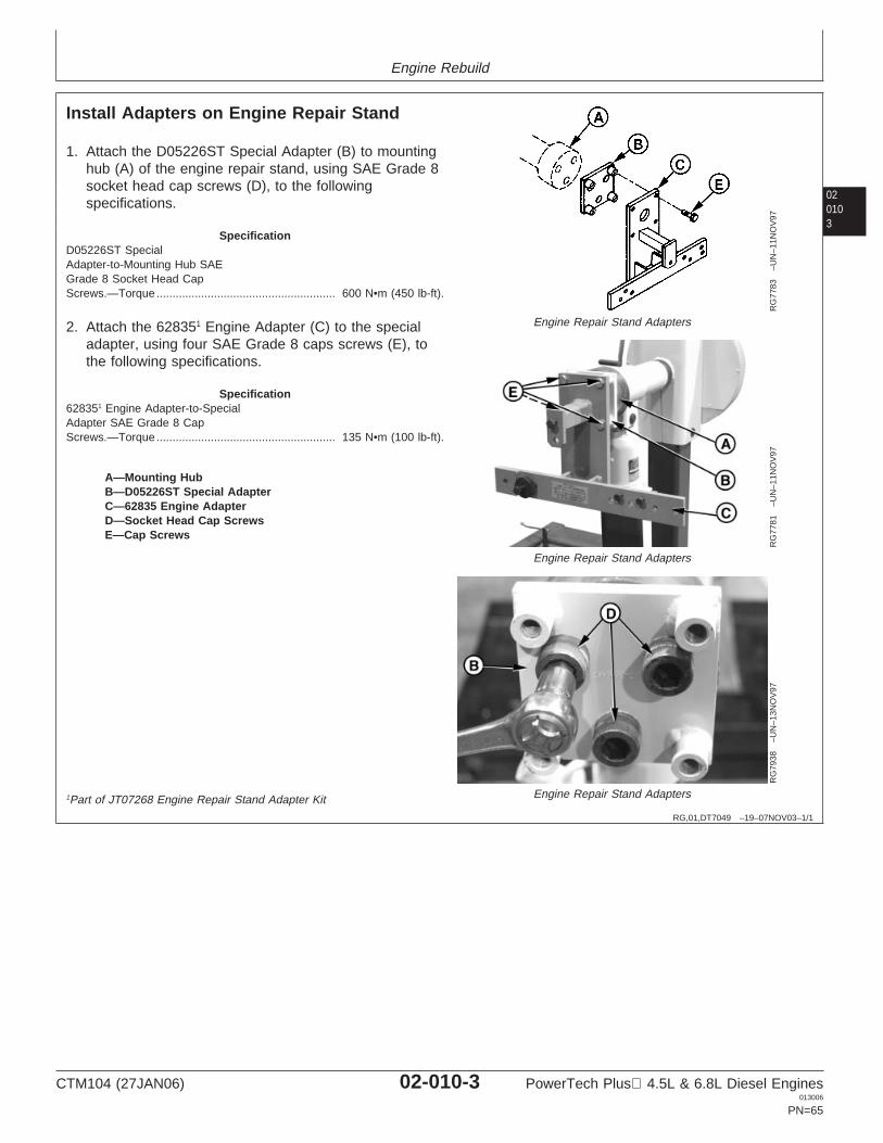
Engine Rebuild
020103
RG,01,DT7049 –19–07NOV03–1/1
Install Adapters on Engine Repair Stand
RG
7783
–UN
–11N
OV
97
Engine Repair Stand Adapters
RG
7781
–UN
–11N
OV
97
Engine Repair Stand Adapters
RG
7938
–UN
–13N
OV
97
Engine Repair Stand Adapters
A—Mounting HubB—D05226ST Special AdapterC—62835 Engine AdapterD—Socket Head Cap ScrewsE—Cap Screws
1. Attach the D05226ST Special Adapter (B) to mountinghub (A) of the engine repair stand, using SAE Grade 8socket head cap screws (D), to the followingspecifications.
SpecificationD05226ST SpecialAdapter-to-Mounting Hub SAEGrade 8 Socket Head CapScrews.—Torque 600 N•m (450 lb-ft).........................................................
2. Attach the 628351 Engine Adapter (C) to the specialadapter, using four SAE Grade 8 caps screws (E), tothe following specifications.
Specification628351 Engine Adapter-to-SpecialAdapter SAE Grade 8 CapScrews.—Torque 135 N•m (100 lb-ft).........................................................
1Part of JT07268 Engine Repair Stand Adapter Kit
CTM104 (27JAN06) 02-010-3 PowerTech Plus 4.5L & 6.8L Diesel Engines013006
PN=65
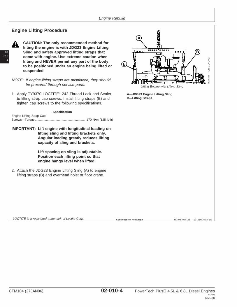
Engine Rebuild
02010
4
RG,03,JW7723 –19–21NOV03–1/2
Engine Lifting Procedure
RG
7784
–UN
–11N
OV
97
Lifting Engine with Lifting Sling
A—JDG23 Engine Lifting SlingB—Lifting Straps
CAUTION: The only recommended method forlifting the engine is with JDG23 Engine LiftingSling and safety approved lifting straps thatcome with engine. Use extreme caution whenlifting and NEVER permit any part of the bodyto be positioned under an engine being lifted orsuspended.
NOTE: If engine lifting straps are misplaced, they shouldbe procured through service parts.
1. Apply TY9370 LOCTITE 242 Thread Lock and Sealerto lifting strap cap screws. Install lifting straps (B) andtighten cap screws to the following specifications.
SpecificationEngine Lifting Strap CapScrews—Torque 170 N•m (125 lb-ft)..........................................................
IMPORTANT: Lift engine with longitudinal loading onlifting sling and lifting brackets only.Angular loading greatly reduces liftingcapacity of sling and brackets.
Lift spacing on sling is adjustable.Position each lifting point so thatengine hangs level when lifted.
2. Attach the JDG23 Engine Lifting Sling (A) to enginelifting straps (B) and overhead hoist or floor crane.
LOCTITE is a registered trademark of Loctite Corp. Continued on next page
CTM104 (27JAN06) 02-010-4 PowerTech Plus 4.5L & 6.8L Diesel Engines013006
PN=66
Engine Rebuild
020105
RG,03,JW7723 –19–21NOV03–2/2
Lifting straps are designed to lift the engine and smallaccessories, such as hydraulic pumps and aircompressors mounted to the engine auxiliary gear drive,or belt-driven components, such as air conditioningcompressors and alternators. If larger components, suchas PTOs, transmissions, generators or air compressors,are attached to other locations on the engine, the liftingstraps provided with the engine are not intended for thispurpose. Technician is responsible for providing adequatelifting devices under these situations. See machinetechnical manual for additional information on removingengine from machine.
NOTE: Use of an engine lifting sling (as shown) is theONLY APPROVED method for lifting engine.
3. Carefully lift engine and slowly lower to desiredlocation.
RG,RG34710,49 –19–07NOV03–1/1
Clean Engine
1. Cap or plug all openings (air intake, exhaust, fuel,coolant, etc.).
2. Remove electrical components (electronic controlmodule-ECM, starter, alternator, etc.). Cover electricalcomponents that are not removed (sensors, wiringharness, ECM connectors, etc.) with plastic and tapesecurely to prevent moisture damage.
IMPORTANT: Never steam clean or pour cold wateron an injection pump while it is stillwarm. To do so may cause seizure ofpump parts. Avoid fuel pumps,injectors, bearings, belts and hoses,etc.
3. Thoroughly steam clean engine.
CTM104 (27JAN06) 02-010-5 PowerTech Plus 4.5L & 6.8L Diesel Engines013006
PN=67
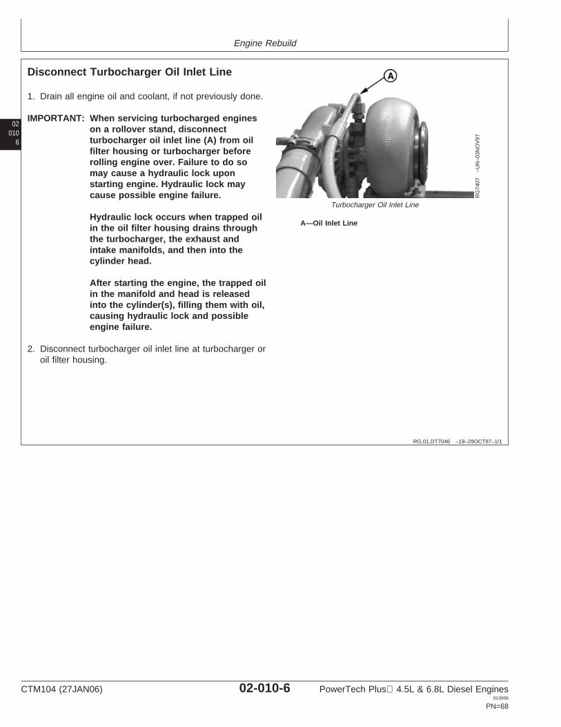
Engine Rebuild
02010
6
RG,01,DT7046 –19–29OCT97–1/1
Disconnect Turbocharger Oil Inlet Line
RG
7407
–UN
–03N
OV
97
Turbocharger Oil Inlet Line
A—Oil Inlet Line
1. Drain all engine oil and coolant, if not previously done.
IMPORTANT: When servicing turbocharged engineson a rollover stand, disconnectturbocharger oil inlet line (A) from oilfilter housing or turbocharger beforerolling engine over. Failure to do somay cause a hydraulic lock uponstarting engine. Hydraulic lock maycause possible engine failure.
Hydraulic lock occurs when trapped oilin the oil filter housing drains throughthe turbocharger, the exhaust andintake manifolds, and then into thecylinder head.
After starting the engine, the trapped oilin the manifold and head is releasedinto the cylinder(s), filling them with oil,causing hydraulic lock and possibleengine failure.
2. Disconnect turbocharger oil inlet line at turbocharger oroil filter housing.
CTM104 (27JAN06) 02-010-6 PowerTech Plus 4.5L & 6.8L Diesel Engines013006
PN=68
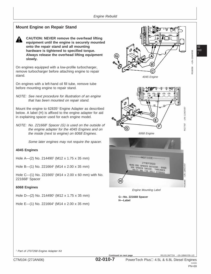
Engine Rebuild
020107
RG,03,JW7724 –19–18MAY00–1/2
Mount Engine on Repair Stand
RG
9058
–UN
–16M
AR
98
4045 Engine
RG
7787
–UN
–11N
OV
97
6068 Engine
RG
8089
–UN
–18N
OV
97
Engine Mounting Label
G—No. 221668 SpacerH—Label
CAUTION: NEVER remove the overhead liftingequipment until the engine is securely mountedonto the repair stand and all mountinghardware is tightened to specified torque.Always release the overhead lifting equipmentslowly.
On engines equipped with a low-profile turbocharger,remove turbocharger before attaching engine to repairstand.
On engines with a left-hand oil fill tube, remove tubebefore mounting engine to repair stand.
NOTE: See next procedure for illustration of an enginethat has been mounted on repair stand.
Mount the engine to 628351 Engine Adapter as describedbelow. A label (H) is affixed to the engine adapter for aidin explaining spacer used for each engine model.
NOTE: No. 2216681 Spacer (G) is used on the outside ofthe engine adapter for the 4045 Engines and onthe inside (next to engine) on 6068 Engines.
Some later engines may not require the spacer.
4045 Engines
Hole A—(2) No. 2144901 (M12 x 1.75 x 35 mm)
Hole B—(1) No. 2216641 (M14 x 2.00 x 35 mm)
Hole C—(1) No. 2216651 (M14 x 2.00 x 60 mm) with No.2216681 Spacer
6068 Engines
Hole D—(2) No. 2144901 (M12 x 1.75 x 35 mm)
Hole E—(1) No. 2216641 (M14 x 2.00 x 35 mm)
1 Part of JT07268 Engine Adapter Kit
CTM104 (27JAN06) 02-010-7 PowerTech Plus 4.5L & 6.8L Diesel Engines013006
PN=69
Continued on next page
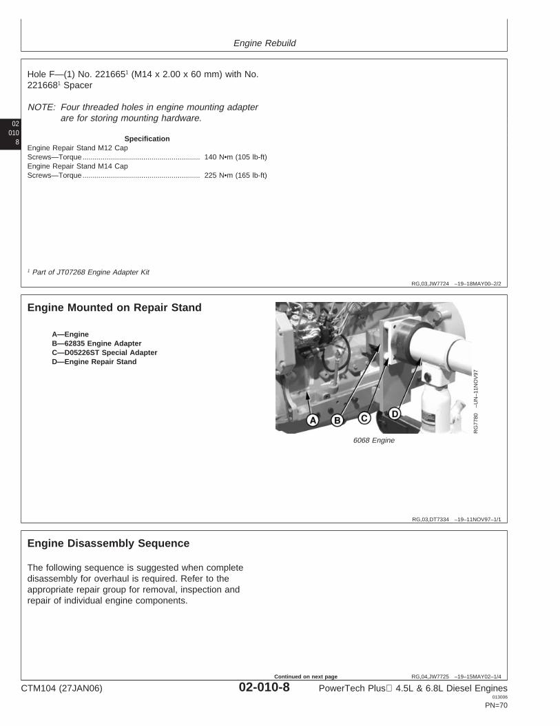
Engine Rebuild
02010
8
RG,03,JW7724 –19–18MAY00–2/2
Hole F—(1) No. 2216651 (M14 x 2.00 x 60 mm) with No.2216681 Spacer
NOTE: Four threaded holes in engine mounting adapterare for storing mounting hardware.
SpecificationEngine Repair Stand M12 CapScrews—Torque 140 N•m (105 lb-ft)..........................................................Engine Repair Stand M14 CapScrews—Torque 225 N•m (165 lb-ft)..........................................................
1 Part of JT07268 Engine Adapter Kit
RG,03,DT7334 –19–11NOV97–1/1
Engine Mounted on Repair Stand
RG
7780
–UN
–11N
OV
97
6068 Engine
A—EngineB—62835 Engine AdapterC—D05226ST Special AdapterD—Engine Repair Stand
RG,04,JW7725 –19–15MAY02–1/4
Engine Disassembly Sequence
The following sequence is suggested when completedisassembly for overhaul is required. Refer to theappropriate repair group for removal, inspection andrepair of individual engine components.
CTM104 (27JAN06) 02-010-8 PowerTech Plus 4.5L & 6.8L Diesel Engines013006
PN=70
Continued on next page
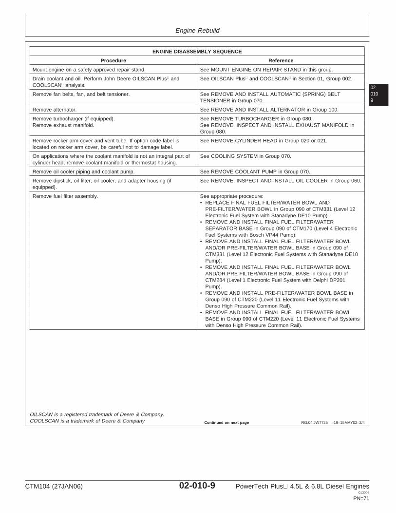
Engine Rebuild
020109
RG,04,JW7725 –19–15MAY02–2/4
ENGINE DISASSEMBLY SEQUENCE
Procedure Reference
Mount engine on a safety approved repair stand. See MOUNT ENGINE ON REPAIR STAND in this group.
Drain coolant and oil. Perform John Deere OILSCAN Plus and See OILSCAN Plus and COOLSCAN in Section 01, Group 002.COOLSCAN analysis.
Remove fan belts, fan, and belt tensioner. See REMOVE AND INSTALL AUTOMATIC (SPRING) BELTTENSIONER in Group 070.
Remove alternator. See REMOVE AND INSTALL ALTERNATOR in Group 100.
Remove turbocharger (if equipped). See REMOVE TURBOCHARGER in Group 080.Remove exhaust manifold. See REMOVE, INSPECT AND INSTALL EXHAUST MANIFOLD in
Group 080.
Remove rocker arm cover and vent tube. If option code label is See REMOVE CYLINDER HEAD in Group 020 or 021.located on rocker arm cover, be careful not to damage label.
On applications where the coolant manifold is not an integral part of See COOLING SYSTEM in Group 070.cylinder head, remove coolant manifold or thermostat housing.
Remove oil cooler piping and coolant pump. See REMOVE COOLANT PUMP in Group 070.
Remove dipstick, oil filter, oil cooler, and adapter housing (if See REMOVE, INSPECT AND INSTALL OIL COOLER in Group 060.equipped).
Remove fuel filter assembly. See appropriate procedure:• REPLACE FINAL FUEL FILTER/WATER BOWL AND
PRE-FILTER/WATER BOWL in Group 090 of CTM331 (Level 12Electronic Fuel System with Stanadyne DE10 Pump).
• REMOVE AND INSTALL FINAL FUEL FILTER/WATERSEPARATOR BASE in Group 090 of CTM170 (Level 4 ElectronicFuel Systems with Bosch VP44 Pump).
• REMOVE AND INSTALL FINAL FUEL FILTER/WATER BOWLAND/OR PRE-FILTER/WATER BOWL BASE in Group 090 ofCTM331 (Level 12 Electronic Fuel Systems with Stanadyne DE10Pump).
• REMOVE AND INSTALL FINAL FUEL FILTER/WATER BOWLAND/OR PRE-FILTER/WATER BOWL BASE in Group 090 ofCTM284 (Level 1 Electronic Fuel System with Delphi DP201Pump).
• REMOVE AND INSTALL PRE-FILTER/WATER BOWL BASE inGroup 090 of CTM220 (Level 11 Electronic Fuel Systems withDenso High Pressure Common Rail).
• REMOVE AND INSTALL FINAL FUEL FILTER/WATER BOWLBASE in Group 090 of CTM220 (Level 11 Electronic Fuel Systemswith Denso High Pressure Common Rail).
OILSCAN is a registered trademark of Deere & Company.COOLSCAN is a trademark of Deere & Company Continued on next page
CTM104 (27JAN06) 02-010-9 PowerTech Plus 4.5L & 6.8L Diesel Engines013006
PN=71
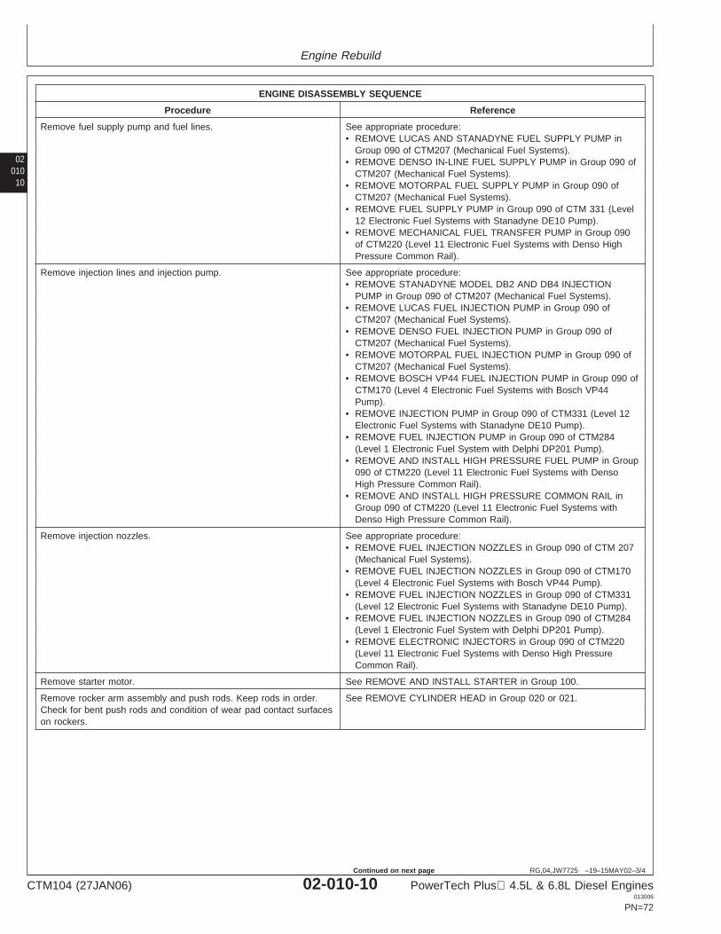
Engine Rebuild
02010
10
RG,04,JW7725 –19–15MAY02–3/4
ENGINE DISASSEMBLY SEQUENCE
Procedure Reference
Remove fuel supply pump and fuel lines. See appropriate procedure:• REMOVE LUCAS AND STANADYNE FUEL SUPPLY PUMP in
Group 090 of CTM207 (Mechanical Fuel Systems).• REMOVE DENSO IN-LINE FUEL SUPPLY PUMP in Group 090 of
CTM207 (Mechanical Fuel Systems).• REMOVE MOTORPAL FUEL SUPPLY PUMP in Group 090 of
CTM207 (Mechanical Fuel Systems).• REMOVE FUEL SUPPLY PUMP in Group 090 of CTM 331 (Level
12 Electronic Fuel Systems with Stanadyne DE10 Pump).• REMOVE MECHANICAL FUEL TRANSFER PUMP in Group 090
of CTM220 (Level 11 Electronic Fuel Systems with Denso HighPressure Common Rail).
Remove injection lines and injection pump. See appropriate procedure:• REMOVE STANADYNE MODEL DB2 AND DB4 INJECTION
PUMP in Group 090 of CTM207 (Mechanical Fuel Systems).• REMOVE LUCAS FUEL INJECTION PUMP in Group 090 of
CTM207 (Mechanical Fuel Systems).• REMOVE DENSO FUEL INJECTION PUMP in Group 090 of
CTM207 (Mechanical Fuel Systems).• REMOVE MOTORPAL FUEL INJECTION PUMP in Group 090 of
CTM207 (Mechanical Fuel Systems).• REMOVE BOSCH VP44 FUEL INJECTION PUMP in Group 090 of
CTM170 (Level 4 Electronic Fuel Systems with Bosch VP44Pump).
• REMOVE INJECTION PUMP in Group 090 of CTM331 (Level 12Electronic Fuel Systems with Stanadyne DE10 Pump).
• REMOVE FUEL INJECTION PUMP in Group 090 of CTM284(Level 1 Electronic Fuel System with Delphi DP201 Pump).
• REMOVE AND INSTALL HIGH PRESSURE FUEL PUMP in Group090 of CTM220 (Level 11 Electronic Fuel Systems with DensoHigh Pressure Common Rail).
• REMOVE AND INSTALL HIGH PRESSURE COMMON RAIL inGroup 090 of CTM220 (Level 11 Electronic Fuel Systems withDenso High Pressure Common Rail).
Remove injection nozzles. See appropriate procedure:• REMOVE FUEL INJECTION NOZZLES in Group 090 of CTM 207
(Mechanical Fuel Systems).• REMOVE FUEL INJECTION NOZZLES in Group 090 of CTM170
(Level 4 Electronic Fuel Systems with Bosch VP44 Pump).• REMOVE FUEL INJECTION NOZZLES in Group 090 of CTM331
(Level 12 Electronic Fuel Systems with Stanadyne DE10 Pump).• REMOVE FUEL INJECTION NOZZLES in Group 090 of CTM284
(Level 1 Electronic Fuel System with Delphi DP201 Pump).• REMOVE ELECTRONIC INJECTORS in Group 090 of CTM220
(Level 11 Electronic Fuel Systems with Denso High PressureCommon Rail).
Remove starter motor. See REMOVE AND INSTALL STARTER in Group 100.
Remove rocker arm assembly and push rods. Keep rods in order. See REMOVE CYLINDER HEAD in Group 020 or 021.Check for bent push rods and condition of wear pad contact surfaceson rockers.
CTM104 (27JAN06) 02-010-10 PowerTech Plus 4.5L & 6.8L Diesel Engines013006
PN=72
Continued on next page
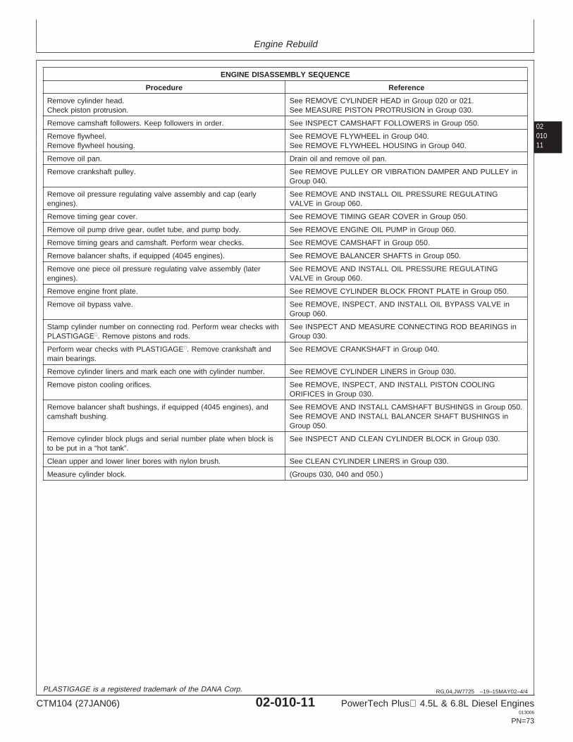
Engine Rebuild
0201011
RG,04,JW7725 –19–15MAY02–4/4
ENGINE DISASSEMBLY SEQUENCE
Procedure Reference
Remove cylinder head. See REMOVE CYLINDER HEAD in Group 020 or 021.Check piston protrusion. See MEASURE PISTON PROTRUSION in Group 030.
Remove camshaft followers. Keep followers in order. See INSPECT CAMSHAFT FOLLOWERS in Group 050.
Remove flywheel. See REMOVE FLYWHEEL in Group 040.Remove flywheel housing. See REMOVE FLYWHEEL HOUSING in Group 040.
Remove oil pan. Drain oil and remove oil pan.
Remove crankshaft pulley. See REMOVE PULLEY OR VIBRATION DAMPER AND PULLEY inGroup 040.
Remove oil pressure regulating valve assembly and cap (early See REMOVE AND INSTALL OIL PRESSURE REGULATINGengines). VALVE in Group 060.
Remove timing gear cover. See REMOVE TIMING GEAR COVER in Group 050.
Remove oil pump drive gear, outlet tube, and pump body. See REMOVE ENGINE OIL PUMP in Group 060.
Remove timing gears and camshaft. Perform wear checks. See REMOVE CAMSHAFT in Group 050.
Remove balancer shafts, if equipped (4045 engines). See REMOVE BALANCER SHAFTS in Group 050.
Remove one piece oil pressure regulating valve assembly (later See REMOVE AND INSTALL OIL PRESSURE REGULATINGengines). VALVE in Group 060.
Remove engine front plate. See REMOVE CYLINDER BLOCK FRONT PLATE in Group 050.
Remove oil bypass valve. See REMOVE, INSPECT, AND INSTALL OIL BYPASS VALVE inGroup 060.
Stamp cylinder number on connecting rod. Perform wear checks with See INSPECT AND MEASURE CONNECTING ROD BEARINGS inPLASTIGAGE. Remove pistons and rods. Group 030.
Perform wear checks with PLASTIGAGE. Remove crankshaft and See REMOVE CRANKSHAFT in Group 040.main bearings.
Remove cylinder liners and mark each one with cylinder number. See REMOVE CYLINDER LINERS in Group 030.
Remove piston cooling orifices. See REMOVE, INSPECT, AND INSTALL PISTON COOLINGORIFICES in Group 030.
Remove balancer shaft bushings, if equipped (4045 engines), and See REMOVE AND INSTALL CAMSHAFT BUSHINGS in Group 050.camshaft bushing. See REMOVE AND INSTALL BALANCER SHAFT BUSHINGS in
Group 050.
Remove cylinder block plugs and serial number plate when block is See INSPECT AND CLEAN CYLINDER BLOCK in Group 030.to be put in a “hot tank”.
Clean upper and lower liner bores with nylon brush. See CLEAN CYLINDER LINERS in Group 030.
Measure cylinder block. (Groups 030, 040 and 050.)
PLASTIGAGE is a registered trademark of the DANA Corp.
CTM104 (27JAN06) 02-010-11 PowerTech Plus 4.5L & 6.8L Diesel Engines013006
PN=73
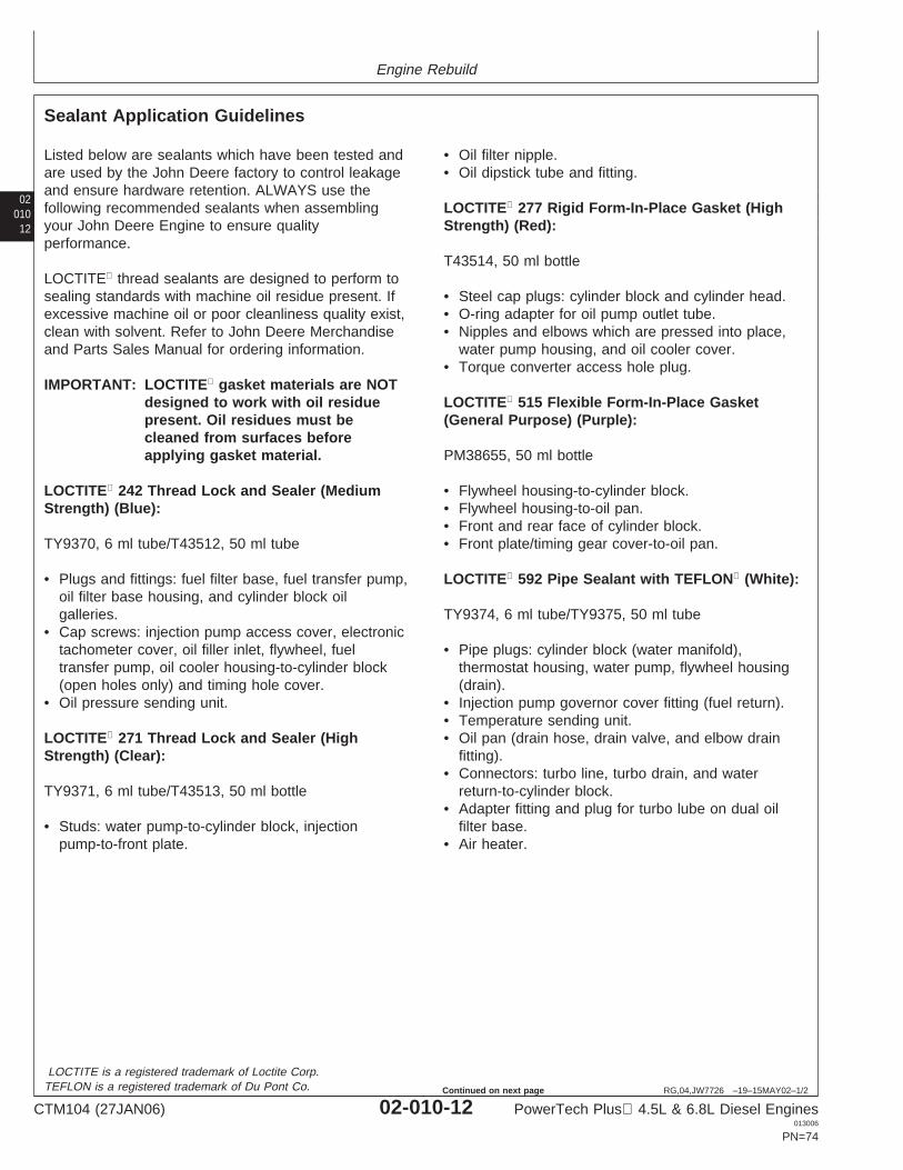
Engine Rebuild
02010
12
RG,04,JW7726 –19–15MAY02–1/2
Sealant Application Guidelines
Listed below are sealants which have been tested andare used by the John Deere factory to control leakageand ensure hardware retention. ALWAYS use thefollowing recommended sealants when assemblingyour John Deere Engine to ensure qualityperformance.
LOCTITE thread sealants are designed to perform tosealing standards with machine oil residue present. Ifexcessive machine oil or poor cleanliness quality exist,clean with solvent. Refer to John Deere Merchandiseand Parts Sales Manual for ordering information.
IMPORTANT: LOCTITE gasket materials are NOTdesigned to work with oil residuepresent. Oil residues must becleaned from surfaces beforeapplying gasket material.
LOCTITE 242 Thread Lock and Sealer (MediumStrength) (Blue):
TY9370, 6 ml tube/T43512, 50 ml tube
• Plugs and fittings: fuel filter base, fuel transfer pump,oil filter base housing, and cylinder block oilgalleries.
• Cap screws: injection pump access cover, electronictachometer cover, oil filler inlet, flywheel, fueltransfer pump, oil cooler housing-to-cylinder block(open holes only) and timing hole cover.
• Oil pressure sending unit.
LOCTITE 271 Thread Lock and Sealer (HighStrength) (Clear):
TY9371, 6 ml tube/T43513, 50 ml bottle
• Studs: water pump-to-cylinder block, injectionpump-to-front plate.
• Oil filter nipple.• Oil dipstick tube and fitting.
LOCTITE 277 Rigid Form-In-Place Gasket (HighStrength) (Red):
T43514, 50 ml bottle
• Steel cap plugs: cylinder block and cylinder head.• O-ring adapter for oil pump outlet tube.• Nipples and elbows which are pressed into place,
water pump housing, and oil cooler cover.• Torque converter access hole plug.
LOCTITE 515 Flexible Form-In-Place Gasket(General Purpose) (Purple):
PM38655, 50 ml bottle
• Flywheel housing-to-cylinder block.• Flywheel housing-to-oil pan.• Front and rear face of cylinder block.• Front plate/timing gear cover-to-oil pan.
LOCTITE 592 Pipe Sealant with TEFLON (White):
TY9374, 6 ml tube/TY9375, 50 ml tube
• Pipe plugs: cylinder block (water manifold),thermostat housing, water pump, flywheel housing(drain).
• Injection pump governor cover fitting (fuel return).• Temperature sending unit.• Oil pan (drain hose, drain valve, and elbow drain
fitting).• Connectors: turbo line, turbo drain, and water
return-to-cylinder block.• Adapter fitting and plug for turbo lube on dual oil
filter base.• Air heater.
LOCTITE is a registered trademark of Loctite Corp.TEFLON is a registered trademark of Du Pont Co.
CTM104 (27JAN06) 02-010-12 PowerTech Plus 4.5L & 6.8L Diesel Engines013006
PN=74
Continued on next page
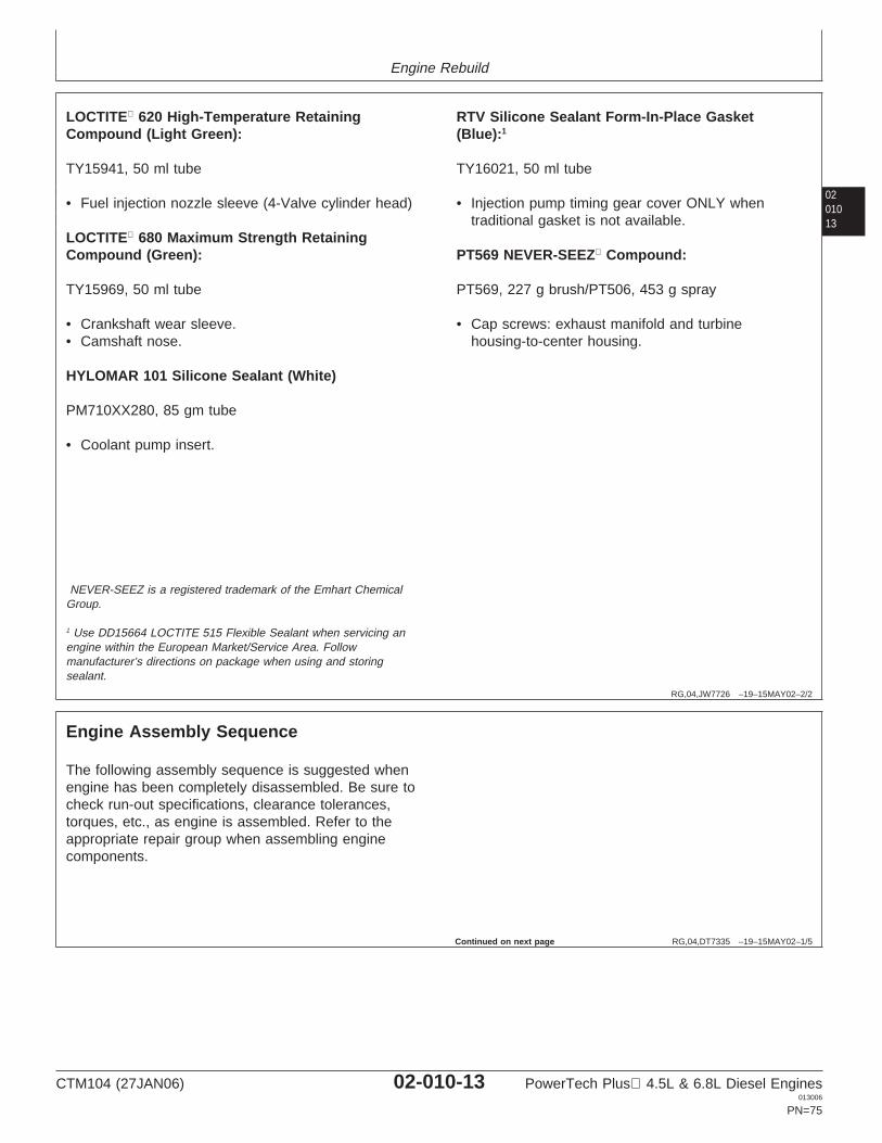
Engine Rebuild
0201013
RG,04,JW7726 –19–15MAY02–2/2
LOCTITE 620 High-Temperature RetainingCompound (Light Green):
TY15941, 50 ml tube
• Fuel injection nozzle sleeve (4-Valve cylinder head)
LOCTITE 680 Maximum Strength RetainingCompound (Green):
TY15969, 50 ml tube
• Crankshaft wear sleeve.• Camshaft nose.
HYLOMAR 101 Silicone Sealant (White)
PM710XX280, 85 gm tube
• Coolant pump insert.
RTV Silicone Sealant Form-In-Place Gasket(Blue):1
TY16021, 50 ml tube
• Injection pump timing gear cover ONLY whentraditional gasket is not available.
PT569 NEVER-SEEZ Compound:
PT569, 227 g brush/PT506, 453 g spray
• Cap screws: exhaust manifold and turbinehousing-to-center housing.
NEVER-SEEZ is a registered trademark of the Emhart ChemicalGroup.
1 Use DD15664 LOCTITE 515 Flexible Sealant when servicing anengine within the European Market/Service Area. Followmanufacturer’s directions on package when using and storingsealant.
RG,04,DT7335 –19–15MAY02–1/5
Engine Assembly Sequence
The following assembly sequence is suggested whenengine has been completely disassembled. Be sure tocheck run-out specifications, clearance tolerances,torques, etc., as engine is assembled. Refer to theappropriate repair group when assembling enginecomponents.
Continued on next page
CTM104 (27JAN06) 02-010-13 PowerTech Plus 4.5L & 6.8L Diesel Engines013006
PN=75
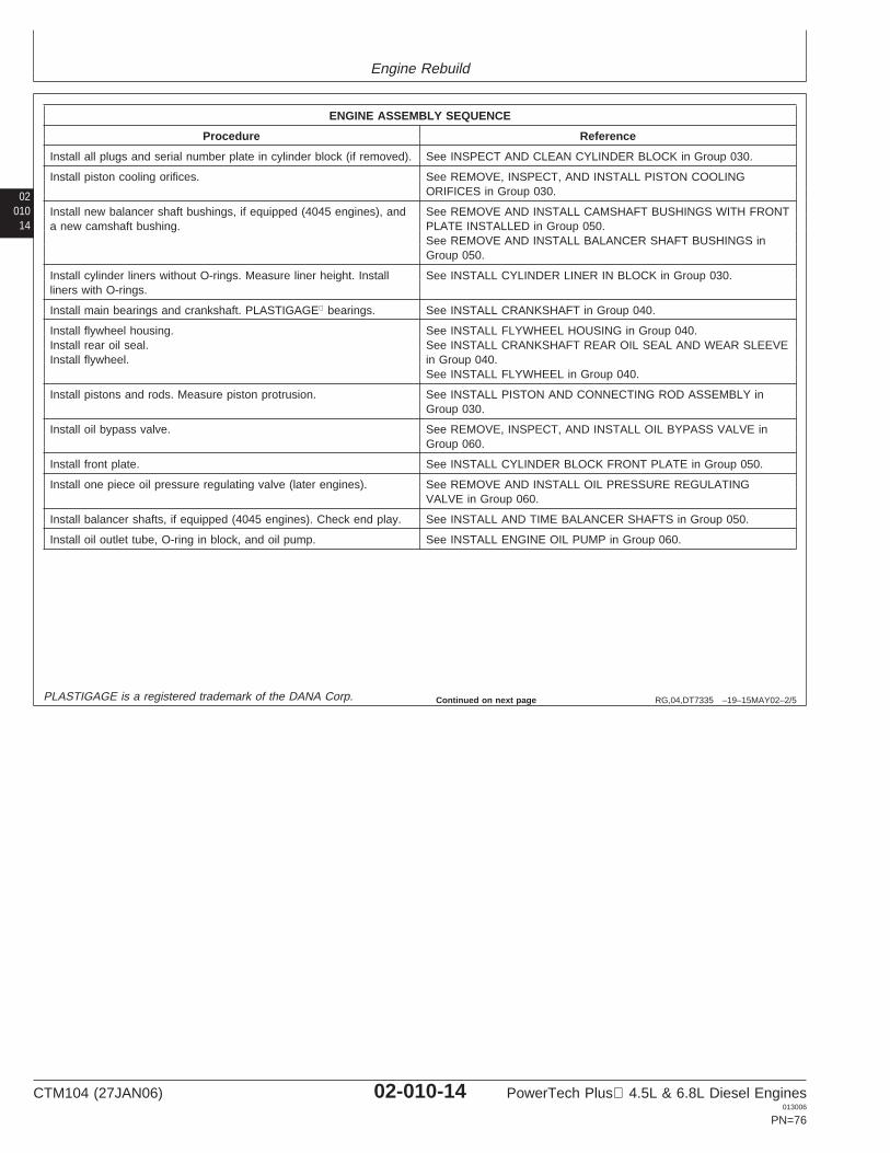
Engine Rebuild
02010
14
RG,04,DT7335 –19–15MAY02–2/5
ENGINE ASSEMBLY SEQUENCE
Procedure Reference
Install all plugs and serial number plate in cylinder block (if removed). See INSPECT AND CLEAN CYLINDER BLOCK in Group 030.
Install piston cooling orifices. See REMOVE, INSPECT, AND INSTALL PISTON COOLINGORIFICES in Group 030.
Install new balancer shaft bushings, if equipped (4045 engines), and See REMOVE AND INSTALL CAMSHAFT BUSHINGS WITH FRONTa new camshaft bushing. PLATE INSTALLED in Group 050.
See REMOVE AND INSTALL BALANCER SHAFT BUSHINGS inGroup 050.
Install cylinder liners without O-rings. Measure liner height. Install See INSTALL CYLINDER LINER IN BLOCK in Group 030.liners with O-rings.
Install main bearings and crankshaft. PLASTIGAGE bearings. See INSTALL CRANKSHAFT in Group 040.
Install flywheel housing. See INSTALL FLYWHEEL HOUSING in Group 040.Install rear oil seal. See INSTALL CRANKSHAFT REAR OIL SEAL AND WEAR SLEEVEInstall flywheel. in Group 040.
See INSTALL FLYWHEEL in Group 040.
Install pistons and rods. Measure piston protrusion. See INSTALL PISTON AND CONNECTING ROD ASSEMBLY inGroup 030.
Install oil bypass valve. See REMOVE, INSPECT, AND INSTALL OIL BYPASS VALVE inGroup 060.
Install front plate. See INSTALL CYLINDER BLOCK FRONT PLATE in Group 050.
Install one piece oil pressure regulating valve (later engines). See REMOVE AND INSTALL OIL PRESSURE REGULATINGVALVE in Group 060.
Install balancer shafts, if equipped (4045 engines). Check end play. See INSTALL AND TIME BALANCER SHAFTS in Group 050.
Install oil outlet tube, O-ring in block, and oil pump. See INSTALL ENGINE OIL PUMP in Group 060.
PLASTIGAGE is a registered trademark of the DANA Corp. Continued on next page
CTM104 (27JAN06) 02-010-14 PowerTech Plus 4.5L & 6.8L Diesel Engines013006
PN=76
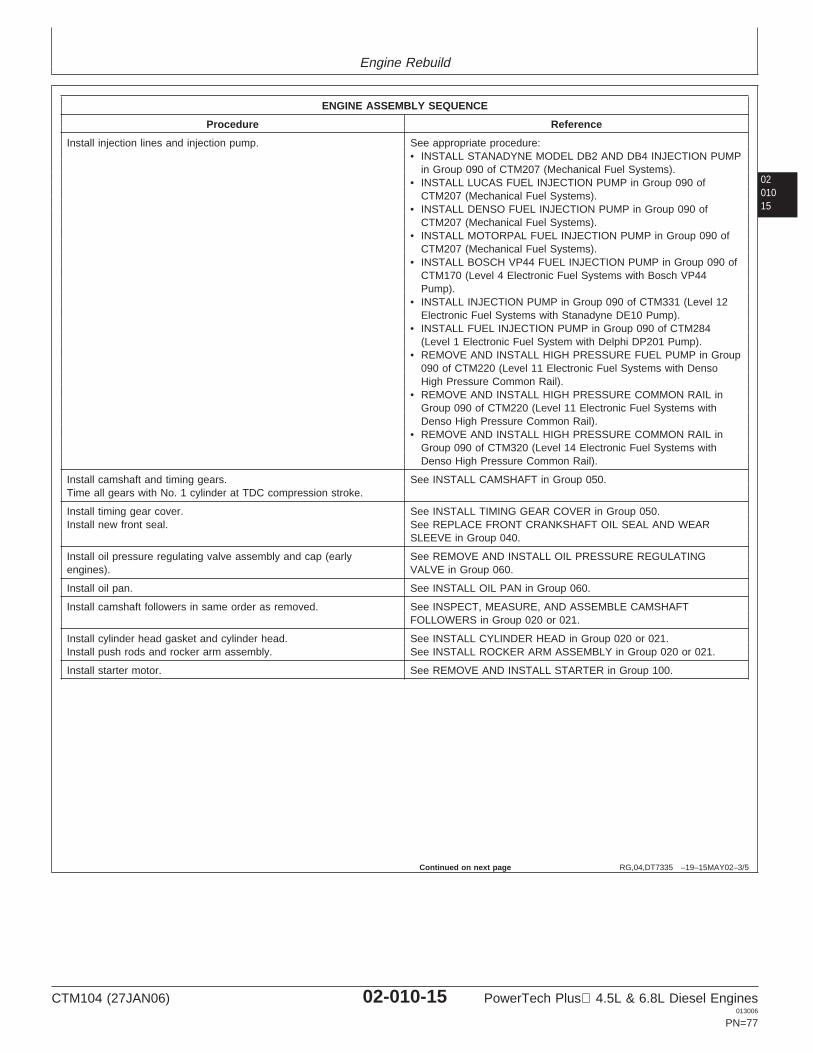
Engine Rebuild
0201015
RG,04,DT7335 –19–15MAY02–3/5
ENGINE ASSEMBLY SEQUENCE
Procedure Reference
Install injection lines and injection pump. See appropriate procedure:• INSTALL STANADYNE MODEL DB2 AND DB4 INJECTION PUMP
in Group 090 of CTM207 (Mechanical Fuel Systems).• INSTALL LUCAS FUEL INJECTION PUMP in Group 090 of
CTM207 (Mechanical Fuel Systems).• INSTALL DENSO FUEL INJECTION PUMP in Group 090 of
CTM207 (Mechanical Fuel Systems).• INSTALL MOTORPAL FUEL INJECTION PUMP in Group 090 of
CTM207 (Mechanical Fuel Systems).• INSTALL BOSCH VP44 FUEL INJECTION PUMP in Group 090 of
CTM170 (Level 4 Electronic Fuel Systems with Bosch VP44Pump).
• INSTALL INJECTION PUMP in Group 090 of CTM331 (Level 12Electronic Fuel Systems with Stanadyne DE10 Pump).
• INSTALL FUEL INJECTION PUMP in Group 090 of CTM284(Level 1 Electronic Fuel System with Delphi DP201 Pump).
• REMOVE AND INSTALL HIGH PRESSURE FUEL PUMP in Group090 of CTM220 (Level 11 Electronic Fuel Systems with DensoHigh Pressure Common Rail).
• REMOVE AND INSTALL HIGH PRESSURE COMMON RAIL inGroup 090 of CTM220 (Level 11 Electronic Fuel Systems withDenso High Pressure Common Rail).
• REMOVE AND INSTALL HIGH PRESSURE COMMON RAIL inGroup 090 of CTM320 (Level 14 Electronic Fuel Systems withDenso High Pressure Common Rail).
Install camshaft and timing gears. See INSTALL CAMSHAFT in Group 050.Time all gears with No. 1 cylinder at TDC compression stroke.
Install timing gear cover. See INSTALL TIMING GEAR COVER in Group 050.Install new front seal. See REPLACE FRONT CRANKSHAFT OIL SEAL AND WEAR
SLEEVE in Group 040.
Install oil pressure regulating valve assembly and cap (early See REMOVE AND INSTALL OIL PRESSURE REGULATINGengines). VALVE in Group 060.
Install oil pan. See INSTALL OIL PAN in Group 060.
Install camshaft followers in same order as removed. See INSPECT, MEASURE, AND ASSEMBLE CAMSHAFTFOLLOWERS in Group 020 or 021.
Install cylinder head gasket and cylinder head. See INSTALL CYLINDER HEAD in Group 020 or 021.Install push rods and rocker arm assembly. See INSTALL ROCKER ARM ASSEMBLY in Group 020 or 021.
Install starter motor. See REMOVE AND INSTALL STARTER in Group 100.
Continued on next page
CTM104 (27JAN06) 02-010-15 PowerTech Plus 4.5L & 6.8L Diesel Engines013006
PN=77
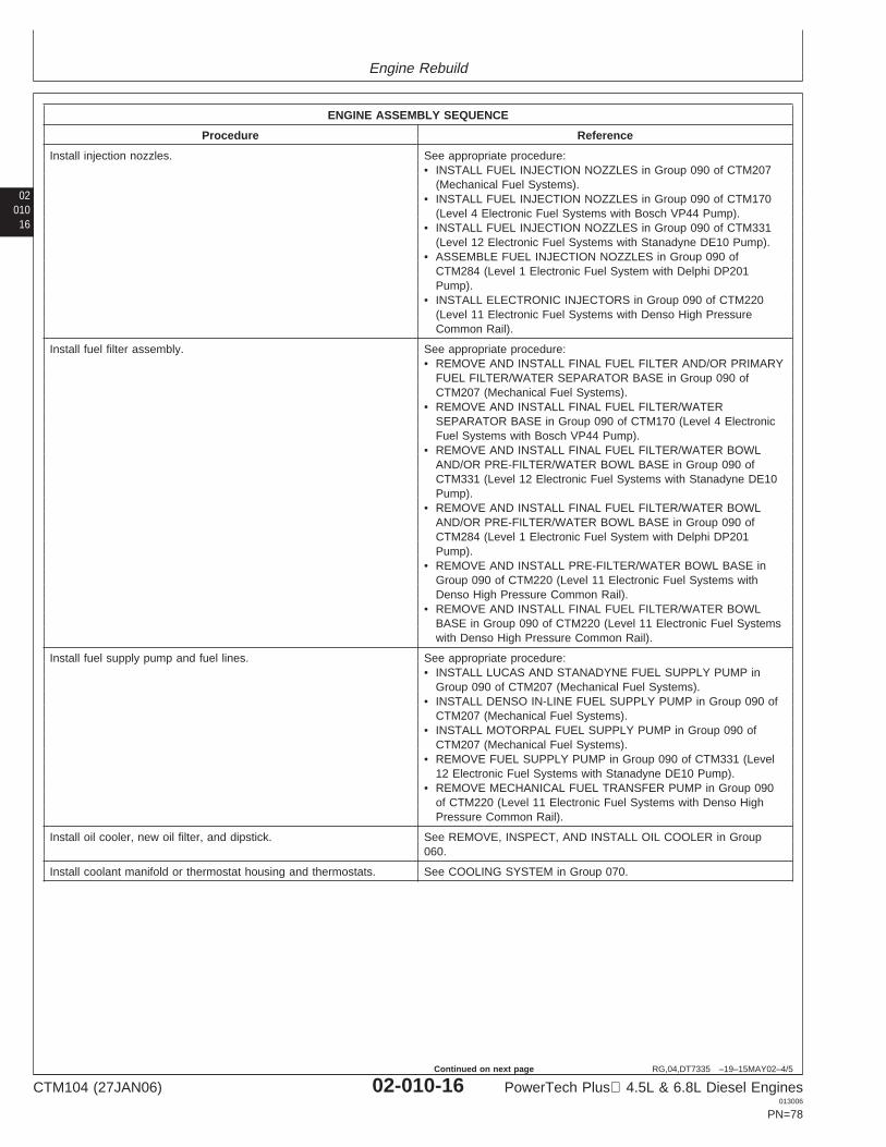
Engine Rebuild
02010
16
RG,04,DT7335 –19–15MAY02–4/5
ENGINE ASSEMBLY SEQUENCE
Procedure Reference
Install injection nozzles. See appropriate procedure:• INSTALL FUEL INJECTION NOZZLES in Group 090 of CTM207
(Mechanical Fuel Systems).• INSTALL FUEL INJECTION NOZZLES in Group 090 of CTM170
(Level 4 Electronic Fuel Systems with Bosch VP44 Pump).• INSTALL FUEL INJECTION NOZZLES in Group 090 of CTM331
(Level 12 Electronic Fuel Systems with Stanadyne DE10 Pump).• ASSEMBLE FUEL INJECTION NOZZLES in Group 090 of
CTM284 (Level 1 Electronic Fuel System with Delphi DP201Pump).
• INSTALL ELECTRONIC INJECTORS in Group 090 of CTM220(Level 11 Electronic Fuel Systems with Denso High PressureCommon Rail).
Install fuel filter assembly. See appropriate procedure:• REMOVE AND INSTALL FINAL FUEL FILTER AND/OR PRIMARY
FUEL FILTER/WATER SEPARATOR BASE in Group 090 ofCTM207 (Mechanical Fuel Systems).
• REMOVE AND INSTALL FINAL FUEL FILTER/WATERSEPARATOR BASE in Group 090 of CTM170 (Level 4 ElectronicFuel Systems with Bosch VP44 Pump).
• REMOVE AND INSTALL FINAL FUEL FILTER/WATER BOWLAND/OR PRE-FILTER/WATER BOWL BASE in Group 090 ofCTM331 (Level 12 Electronic Fuel Systems with Stanadyne DE10Pump).
• REMOVE AND INSTALL FINAL FUEL FILTER/WATER BOWLAND/OR PRE-FILTER/WATER BOWL BASE in Group 090 ofCTM284 (Level 1 Electronic Fuel System with Delphi DP201Pump).
• REMOVE AND INSTALL PRE-FILTER/WATER BOWL BASE inGroup 090 of CTM220 (Level 11 Electronic Fuel Systems withDenso High Pressure Common Rail).
• REMOVE AND INSTALL FINAL FUEL FILTER/WATER BOWLBASE in Group 090 of CTM220 (Level 11 Electronic Fuel Systemswith Denso High Pressure Common Rail).
Install fuel supply pump and fuel lines. See appropriate procedure:• INSTALL LUCAS AND STANADYNE FUEL SUPPLY PUMP in
Group 090 of CTM207 (Mechanical Fuel Systems).• INSTALL DENSO IN-LINE FUEL SUPPLY PUMP in Group 090 of
CTM207 (Mechanical Fuel Systems).• INSTALL MOTORPAL FUEL SUPPLY PUMP in Group 090 of
CTM207 (Mechanical Fuel Systems).• REMOVE FUEL SUPPLY PUMP in Group 090 of CTM331 (Level
12 Electronic Fuel Systems with Stanadyne DE10 Pump).• REMOVE MECHANICAL FUEL TRANSFER PUMP in Group 090
of CTM220 (Level 11 Electronic Fuel Systems with Denso HighPressure Common Rail).
Install oil cooler, new oil filter, and dipstick. See REMOVE, INSPECT, AND INSTALL OIL COOLER in Group060.
Install coolant manifold or thermostat housing and thermostats. See COOLING SYSTEM in Group 070.
CTM104 (27JAN06) 02-010-16 PowerTech Plus 4.5L & 6.8L Diesel Engines013006
PN=78
Continued on next page
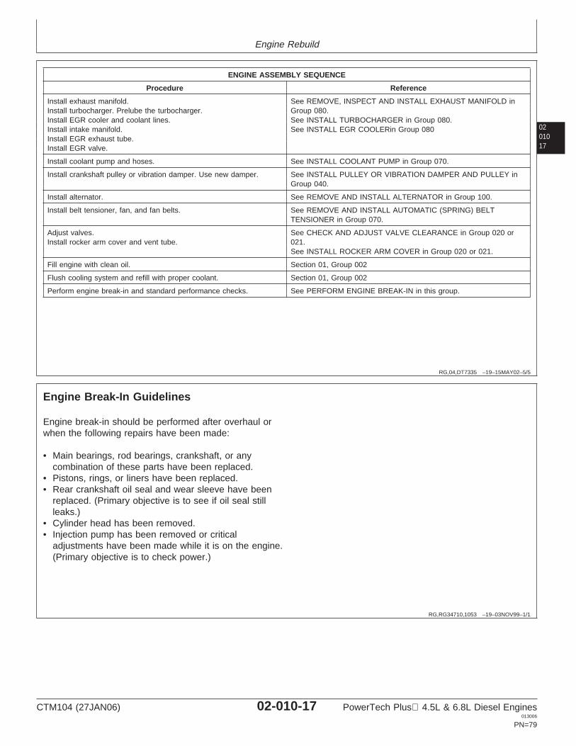
Engine Rebuild
0201017
RG,04,DT7335 –19–15MAY02–5/5
ENGINE ASSEMBLY SEQUENCE
Procedure Reference
Install exhaust manifold. See REMOVE, INSPECT AND INSTALL EXHAUST MANIFOLD inInstall turbocharger. Prelube the turbocharger. Group 080.Install EGR cooler and coolant lines. See INSTALL TURBOCHARGER in Group 080.Install intake manifold. See INSTALL EGR COOLERin Group 080Install EGR exhaust tube.Install EGR valve.
Install coolant pump and hoses. See INSTALL COOLANT PUMP in Group 070.
Install crankshaft pulley or vibration damper. Use new damper. See INSTALL PULLEY OR VIBRATION DAMPER AND PULLEY inGroup 040.
Install alternator. See REMOVE AND INSTALL ALTERNATOR in Group 100.
Install belt tensioner, fan, and fan belts. See REMOVE AND INSTALL AUTOMATIC (SPRING) BELTTENSIONER in Group 070.
Adjust valves. See CHECK AND ADJUST VALVE CLEARANCE in Group 020 orInstall rocker arm cover and vent tube. 021.
See INSTALL ROCKER ARM COVER in Group 020 or 021.
Fill engine with clean oil. Section 01, Group 002
Flush cooling system and refill with proper coolant. Section 01, Group 002
Perform engine break-in and standard performance checks. See PERFORM ENGINE BREAK-IN in this group.
RG,RG34710,1053 –19–03NOV99–1/1
Engine Break-In Guidelines
Engine break-in should be performed after overhaul orwhen the following repairs have been made:
• Main bearings, rod bearings, crankshaft, or anycombination of these parts have been replaced.
• Pistons, rings, or liners have been replaced.• Rear crankshaft oil seal and wear sleeve have been
replaced. (Primary objective is to see if oil seal stillleaks.)
• Cylinder head has been removed.• Injection pump has been removed or critical
adjustments have been made while it is on the engine.(Primary objective is to check power.)
CTM104 (27JAN06) 02-010-17 PowerTech Plus 4.5L & 6.8L Diesel Engines013006
PN=79
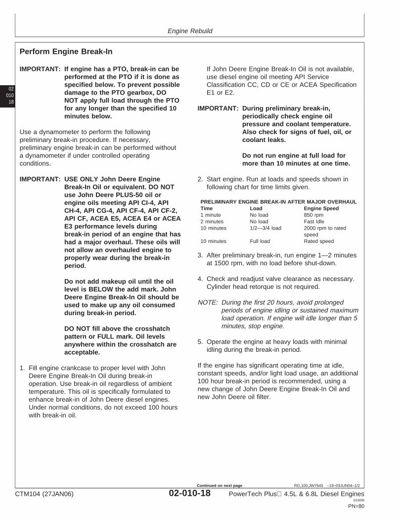
Engine Rebuild
02010
18
RG,100,JW7645 –19–03JUN04–1/2
Perform Engine Break-In
IMPORTANT: If engine has a PTO, break-in can beperformed at the PTO if it is done asspecified below. To prevent possibledamage to the PTO gearbox, DONOT apply full load through the PTOfor any longer than the specified 10minutes below.
Use a dynamometer to perform the followingpreliminary break-in procedure. If necessary,preliminary engine break-in can be performed withouta dynamometer if under controlled operatingconditions.
IMPORTANT: USE ONLY John Deere EngineBreak-In Oil or equivalent. DO NOTuse John Deere PLUS-50 oil orengine oils meeting API CI-4, APICH-4, API CG-4, API CF-4, API CF-2,API CF, ACEA E5, ACEA E4 or ACEAE3 performance levels duringbreak-in period of an engine that hashad a major overhaul. These oils willnot allow an overhauled engine toproperly wear during the break-inperiod.
Do not add makeup oil until the oillevel is BELOW the add mark. JohnDeere Engine Break-In Oil should beused to make up any oil consumedduring break-in period.
DO NOT fill above the crosshatchpattern or FULL mark. Oil levelsanywhere within the crosshatch areacceptable.
1. Fill engine crankcase to proper level with JohnDeere Engine Break-In Oil during break-inoperation. Use break-in oil regardless of ambienttemperature. This oil is specifically formulated toenhance break-in of John Deere diesel engines.Under normal conditions, do not exceed 100 hourswith break-in oil.
If John Deere Engine Break-In Oil is not available,use diesel engine oil meeting API ServiceClassification CC, CD or CE or ACEA SpecificationE1 or E2.
IMPORTANT: During preliminary break-in,periodically check engine oilpressure and coolant temperature.Also check for signs of fuel, oil, orcoolant leaks.
Do not run engine at full load formore than 10 minutes at one time.
2. Start engine. Run at loads and speeds shown infollowing chart for time limits given.
PRELIMINARY ENGINE BREAK-IN AFTER MAJOR OVERHAULTime Load Engine Speed1 minute No load 850 rpm2 minutes No load Fast Idle10 minutes 1/2—3/4 load 2000 rpm to rated
speed10 minutes Full load Rated speed
3. After preliminary break-in, run engine 1—2 minutesat 1500 rpm, with no load before shut-down.
4. Check and readjust valve clearance as necessary.Cylinder head retorque is not required.
NOTE: During the first 20 hours, avoid prolongedperiods of engine idling or sustained maximumload operation. If engine will idle longer than 5minutes, stop engine.
5. Operate the engine at heavy loads with minimalidling during the break-in period.
If the engine has significant operating time at idle,constant speeds, and/or light load usage, an additional100 hour break-in period is recommended, using anew change of John Deere Engine Break-In Oil andnew John Deere oil filter.
CTM104 (27JAN06) 02-010-18 PowerTech Plus 4.5L & 6.8L Diesel Engines013006
PN=80
Continued on next page
Engine Rebuild
0201019
RG,100,JW7645 –19–03JUN04–2/2
Check engine oil level more frequently during enginebreak-in period. As a general rule, makeup oil shouldnot need to be added during 100-hour break-in period.However, if makeup oil is required in the first 100-hourbreak-in, an additional 100-hour break-in period isrequired. Use a new change of John Deere EngineBreak-In Oil and a new John Deere oil filter.
After 100 hours maximum, drain break-in oil andchange oil filter. Fill crankcase with John DeerePLUS-50 or TORQ-GARD SUPREME or otherheavy-duty diesel engine oil within the same service
classification as recommended in this manual. SeeDIESEL ENGINE OIL—NON-CERTIFIED AND TIER 1CERTIFIED ENGINES or DIESEL ENGINE OIL—TIER2 ENGINES in Section 01, Group 002, Fuels,Lubricants, and Coolants.
NOTE: Some increase in oil consumption may beexpected when low viscosity oils are used.Check oil levels more frequently.
If air temperature is below —10°C (14°F), usean engine block heater.
PLUS-50 is a registered trademark of Deere & Company.TORQ-GARD SUPREME is a registered trademark of Deere &Company.
CTM104 (27JAN06) 02-010-19 PowerTech Plus 4.5L & 6.8L Diesel Engines013006
PN=81

Engine Rebuild
02010
20
CTM104 (27JAN06) 02-010-20 PowerTech Plus 4.5L & 6.8L Diesel Engines013006
PN=82
Group 020Cylinder Head and Valves (Two-Valve Head Engines)
02020
OUO1089,0000236 –19–12JUN02–1/1
General Information
NOTE: Engines with four-valve head design are coveredin Group 021.
1
CTM104 (27JAN06) 02-020-1 PowerTech Plus 4.5L & 6.8L Diesel Engines013006
PN=83
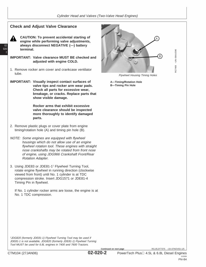
Cylinder Head and Valves (Two-Valve Head Engines)
02020
2
RG,05,DT7375 –19–07NOV03–1/5
Check and Adjust Valve Clearance
RG
7408
–UN
–06A
UG
96
Flywheel Housing Timing Holes
A—Timing/Rotation HoleB—Timing Pin Hole
CAUTION: To prevent accidental starting ofengine while performing valve adjustments,always disconnect NEGATIVE (—) batteryterminal.
IMPORTANT: Valve clearance MUST BE checked andadjusted with engine COLD.
1. Remove rocker arm cover and crankcase ventilatortube.
IMPORTANT: Visually inspect contact surfaces ofvalve tips and rocker arm wear pads.Check all parts for excessive wear,breakage, or cracks. Replace parts thatshow visible damage.
Rocker arms that exhibit excessivevalve clearance should be inspectedmore thoroughly to identify damagedparts.
2. Remove plastic plugs or cover plate from enginetiming/rotation hole (A) and timing pin hole (B).
NOTE: Some engines are equipped with flywheelhousings which do not allow use of an engineflywheel rotation tool. These engines with straightnose crankshafts may be rotated from front noseof engine, using JDG966 Crankshaft Front/RearRotation Adapter.
3. Using JDE83 or JDE81-11 Flywheel Turning Tool,rotate engine flywheel in running direction (clockwiseviewed from front) until No. 1 cylinder is at TDCcompression stroke. Insert JDG1571 or JDE81-4Timing Pin in flywheel.
If No. 1 cylinder rocker arms are loose, the engine is atNo. 1 TDC compression.
1JDG820 (formerly JDE81-1) Flywheel Turning Tool may be used ifJDE81-1 is not available, JDG820 (formerly JDE81-1) Flywheel TurningTool MUST be used for 6.8L engines in 7400 and 7600 Tractors.
CTM104 (27JAN06) 02-020-2 PowerTech Plus 4.5L & 6.8L Diesel Engines013006
PN=84
Continued on next page
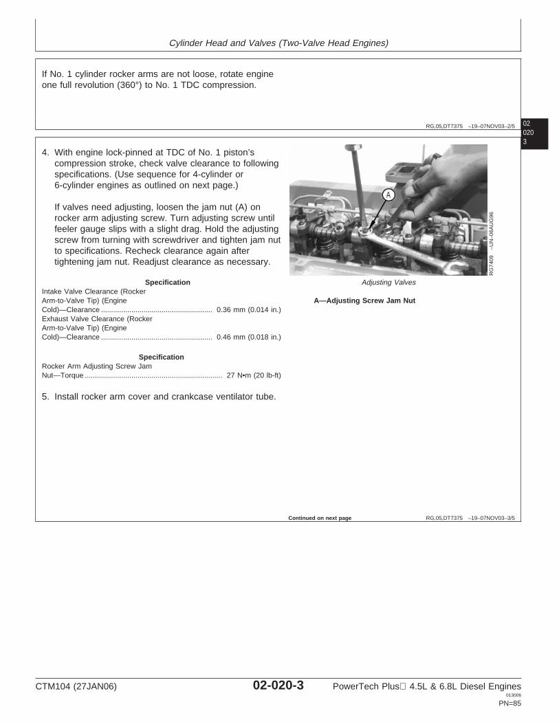
Cylinder Head and Valves (Two-Valve Head Engines)
02020
RG,05,DT7375 –19–07NOV03–2/5
If No. 1 cylinder rocker arms are not loose, rotate engineone full revolution (360°) to No. 1 TDC compression.
3
RG,05,DT7375 –19–07NOV03–3/5
RG
7409
–UN
–06A
UG
96
Adjusting Valves
A—Adjusting Screw Jam Nut
4. With engine lock-pinned at TDC of No. 1 piston’scompression stroke, check valve clearance to followingspecifications. (Use sequence for 4-cylinder or6-cylinder engines as outlined on next page.)
If valves need adjusting, loosen the jam nut (A) onrocker arm adjusting screw. Turn adjusting screw untilfeeler gauge slips with a slight drag. Hold the adjustingscrew from turning with screwdriver and tighten jam nutto specifications. Recheck clearance again aftertightening jam nut. Readjust clearance as necessary.
SpecificationIntake Valve Clearance (RockerArm-to-Valve Tip) (EngineCold)—Clearance 0.36 mm (0.014 in.).......................................................Exhaust Valve Clearance (RockerArm-to-Valve Tip) (EngineCold)—Clearance 0.46 mm (0.018 in.).......................................................
SpecificationRocker Arm Adjusting Screw JamNut—Torque 27 N•m (20 lb-ft)....................................................................
5. Install rocker arm cover and crankcase ventilator tube.
Continued on next page
CTM104 (27JAN06) 02-020-3 PowerTech Plus 4.5L & 6.8L Diesel Engines013006
PN=85
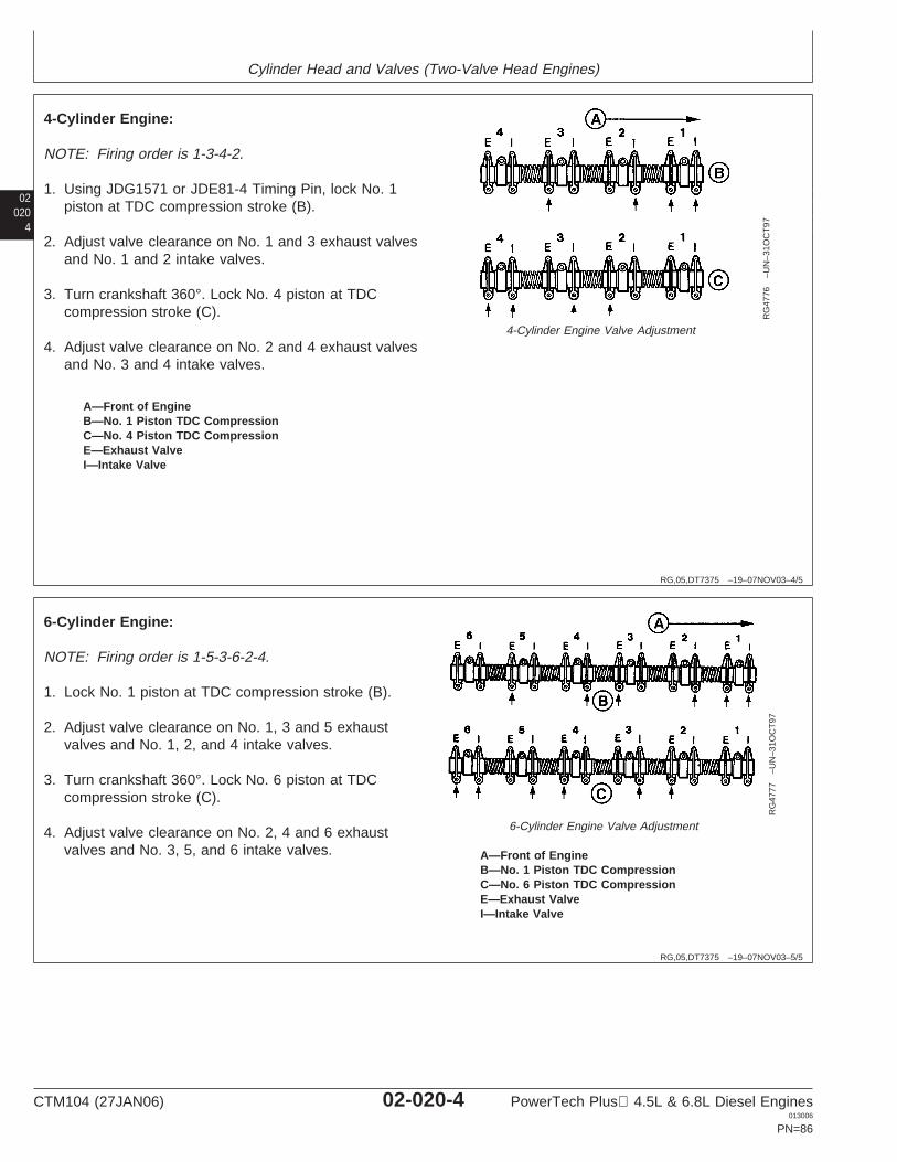
Cylinder Head and Valves (Two-Valve Head Engines)
02020
4
RG,05,DT7375 –19–07NOV03–4/5
RG
4776
–UN
–31O
CT
97
4-Cylinder Engine Valve Adjustment
A—Front of EngineB—No. 1 Piston TDC CompressionC—No. 4 Piston TDC CompressionE—Exhaust ValveI—Intake Valve
4-Cylinder Engine:
NOTE: Firing order is 1-3-4-2.
1. Using JDG1571 or JDE81-4 Timing Pin, lock No. 1piston at TDC compression stroke (B).
2. Adjust valve clearance on No. 1 and 3 exhaust valvesand No. 1 and 2 intake valves.
3. Turn crankshaft 360°. Lock No. 4 piston at TDCcompression stroke (C).
4. Adjust valve clearance on No. 2 and 4 exhaust valvesand No. 3 and 4 intake valves.
RG,05,DT7375 –19–07NOV03–5/5
RG
4777
–UN
–31O
CT
97
6-Cylinder Engine Valve Adjustment
A—Front of EngineB—No. 1 Piston TDC CompressionC—No. 6 Piston TDC CompressionE—Exhaust ValveI—Intake Valve
6-Cylinder Engine:
NOTE: Firing order is 1-5-3-6-2-4.
1. Lock No. 1 piston at TDC compression stroke (B).
2. Adjust valve clearance on No. 1, 3 and 5 exhaustvalves and No. 1, 2, and 4 intake valves.
3. Turn crankshaft 360°. Lock No. 6 piston at TDCcompression stroke (C).
4. Adjust valve clearance on No. 2, 4 and 6 exhaustvalves and No. 3, 5, and 6 intake valves.
CTM104 (27JAN06) 02-020-4 PowerTech Plus 4.5L & 6.8L Diesel Engines013006
PN=86
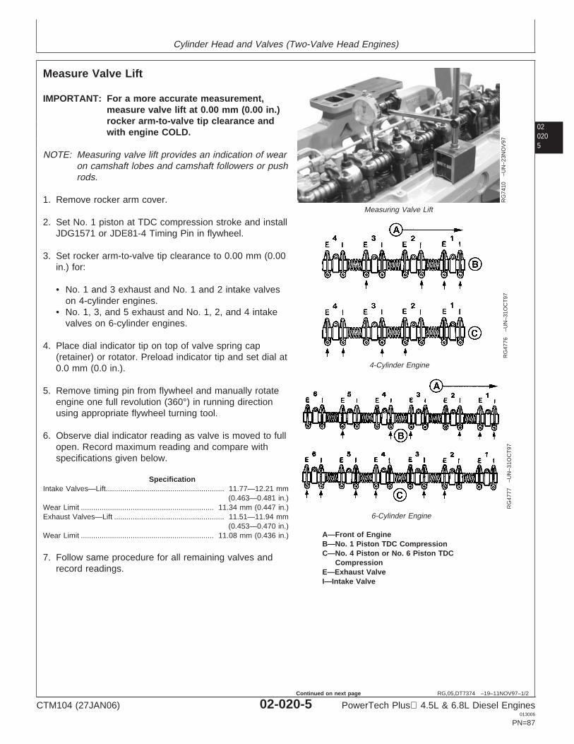
Cylinder Head and Valves (Two-Valve Head Engines)
020205
RG,05,DT7374 –19–11NOV97–1/2
Measure Valve Lift
RG
7410
–UN
–23N
OV
97
Measuring Valve Lift
RG
4776
–UN
–31O
CT
97
4-Cylinder Engine
RG
4777
–UN
–31O
CT
976-Cylinder Engine
A—Front of EngineB—No. 1 Piston TDC CompressionC—No. 4 Piston or No. 6 Piston TDC
CompressionE—Exhaust ValveI—Intake Valve
IMPORTANT: For a more accurate measurement,measure valve lift at 0.00 mm (0.00 in.)rocker arm-to-valve tip clearance andwith engine COLD.
NOTE: Measuring valve lift provides an indication of wearon camshaft lobes and camshaft followers or pushrods.
1. Remove rocker arm cover.
2. Set No. 1 piston at TDC compression stroke and installJDG1571 or JDE81-4 Timing Pin in flywheel.
3. Set rocker arm-to-valve tip clearance to 0.00 mm (0.00in.) for:
• No. 1 and 3 exhaust and No. 1 and 2 intake valveson 4-cylinder engines.
• No. 1, 3, and 5 exhaust and No. 1, 2, and 4 intakevalves on 6-cylinder engines.
4. Place dial indicator tip on top of valve spring cap(retainer) or rotator. Preload indicator tip and set dial at0.0 mm (0.0 in.).
5. Remove timing pin from flywheel and manually rotateengine one full revolution (360°) in running directionusing appropriate flywheel turning tool.
6. Observe dial indicator reading as valve is moved to fullopen. Record maximum reading and compare withspecifications given below.
SpecificationIntake Valves—Lift 11.77—12.21 mm
(0.463—0.481 in.).........................................................
Wear Limit 11.34 mm (0.447 in.)................................................................Exhaust Valves—Lift 11.51—11.94 mm
(0.453—0.470 in.).....................................................
Wear Limit 11.08 mm (0.436 in.)................................................................
7. Follow same procedure for all remaining valves andrecord readings.
CTM104 (27JAN06) 02-020-5 PowerTech Plus 4.5L & 6.8L Diesel Engines013006
PN=87
Continued on next page
Cylinder Head and Valves (Two-Valve Head Engines)
02020
6
RG,05,DT7374 –19–11NOV97–2/2
If valve lift on all valves is within specifications, adjustvalve lash to specified clearance. (See CHECK ANDADJUST VALVE CLEARANCE earlier in this group.)
If valve lift on one or more valves is not withinspecification, remove and inspect entire valve train andcamshaft.
8. Rotate engine one full revolution (360°). Lock engineat:
• TDC No. 4 compression stroke for 4-cylinderengines.
• TDC No. 6 compression stroke for 6-cylinderengines.
9. Set rocker arm-to-valve tip clearance to 0.0 mm (0.0in.) for:
• No. 2 and 4 exhaust and No. 3 and 4 intake valveson 4-cylinder engines.
• No. 2, 4, and 6 exhaust and No. 3, 5, and 6 intakevalves on 6-cylinder engines.
10. Repeat steps 4—7.
CTM104 (27JAN06) 02-020-6 PowerTech Plus 4.5L & 6.8L Diesel Engines013006
PN=88

Cylinder Head and Valves (Two-Valve Head Engines)
020207
RG,05,DT7373 –19–07NOV03–1/12
Remove Cylinder Head
In some applications, it may be necessary to removeengine from machine to service cylinder head. Refer toyour Machine Technical Manual for engine removalprocedure.
CAUTION: After operating engine, allow exhaustsystem to cool before working on engine.
Do NOT drain coolant until the coolanttemperature is below operating temperature.Remove radiator filler cap only when the cap iscool enough to touch with bare hands. Slowlyloosen cap to first stop to relieve pressurebefore removing completely.
1. Drain engine oil and coolant.
NOTE: On engines equipped with a low-profileturbocharger, remove turbocharger beforeattaching engine to repair stand.
2. Remove air inlet elbow. (See REMOVE AND INSTALLAIR INTAKE PIPE in Group 080.)
Continued on next page
CTM104 (27JAN06) 02-020-7 PowerTech Plus 4.5L & 6.8L Diesel Engines013006
PN=89
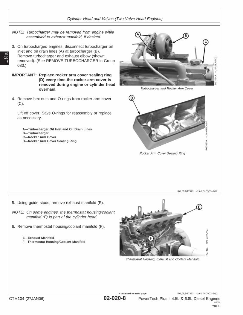
Cylinder Head and Valves (Two-Valve Head Engines)
02020
8
RG,05,DT7373 –19–07NOV03–2/12
RG
7454
A–U
N–2
1JU
N02
Turbocharger and Rocker Arm Cover
RG
7450
A–U
N–0
4NO
V97
Rocker Arm Cover Sealing Ring
A—Turbocharger Oil Inlet and Oil Drain LinesB—TurbochargerC—Rocker Arm CoverD—Rocker Arm Cover Sealing Ring
NOTE: Turbocharger may be removed from engine whileassembled to exhaust manifold, if desired.
3. On turbocharged engines, disconnect turbocharger oilinlet and oil drain lines (A) at turbocharger (B).Remove turbocharger and exhaust elbow (shownremoved). (See REMOVE TURBOCHARGER in Group080.)
IMPORTANT: Replace rocker arm cover sealing ring(D) every time the rocker arm cover isremoved during engine or cylinder headoverhaul.
4. Remove hex nuts and O-rings from rocker arm cover(C).
Lift off cover. Save O-rings for reassembly or replaceas necessary.
RG,05,DT7373 –19–07NOV03–3/12
RG
7411
–UN
–03N
OV
97
Thermostat Housing, Exhaust and Coolant Manifold
E—Exhaust ManifoldF—Thermostat Housing/Coolant Manifold
5. Using guide studs, remove exhaust manifold (E).
NOTE: On some engines, the thermostat housing/coolantmanifold (F) is part of the cylinder head.
6. Remove thermostat housing/coolant manifold (F).
CTM104 (27JAN06) 02-020-8 PowerTech Plus 4.5L & 6.8L Diesel Engines013006
PN=90
Continued on next page
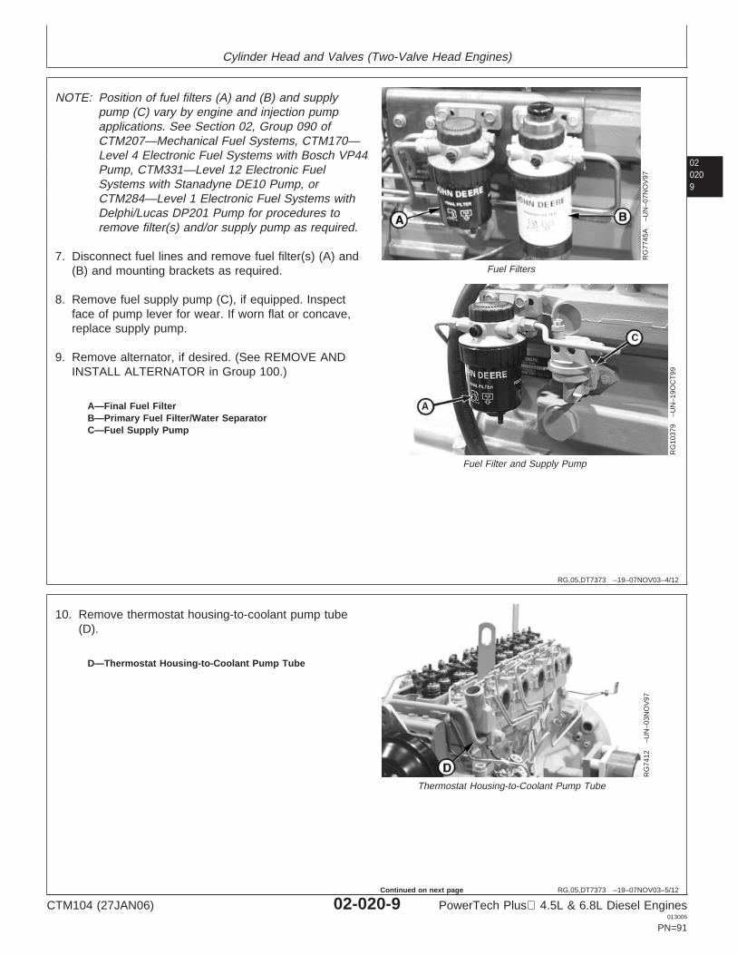
Cylinder Head and Valves (Two-Valve Head Engines)
020209
RG,05,DT7373 –19–07NOV03–4/12
RG
7745
A–U
N–0
7NO
V97
Fuel Filters
RG
1037
9–U
N–1
9OC
T99
Fuel Filter and Supply Pump
A—Final Fuel FilterB—Primary Fuel Filter/Water SeparatorC—Fuel Supply Pump
NOTE: Position of fuel filters (A) and (B) and supplypump (C) vary by engine and injection pumpapplications. See Section 02, Group 090 ofCTM207—Mechanical Fuel Systems, CTM170—Level 4 Electronic Fuel Systems with Bosch VP44Pump, CTM331—Level 12 Electronic FuelSystems with Stanadyne DE10 Pump, orCTM284—Level 1 Electronic Fuel Systems withDelphi/Lucas DP201 Pump for procedures toremove filter(s) and/or supply pump as required.
7. Disconnect fuel lines and remove fuel filter(s) (A) and(B) and mounting brackets as required.
8. Remove fuel supply pump (C), if equipped. Inspectface of pump lever for wear. If worn flat or concave,replace supply pump.
9. Remove alternator, if desired. (See REMOVE ANDINSTALL ALTERNATOR in Group 100.)
RG,05,DT7373 –19–07NOV03–5/12
RG
7412
–UN
–03N
OV
97
Thermostat Housing-to-Coolant Pump Tube
D—Thermostat Housing-to-Coolant Pump Tube
10. Remove thermostat housing-to-coolant pump tube(D).
CTM104 (27JAN06) 02-020-9 PowerTech Plus 4.5L & 6.8L Diesel Engines013006
PN=91
Continued on next page
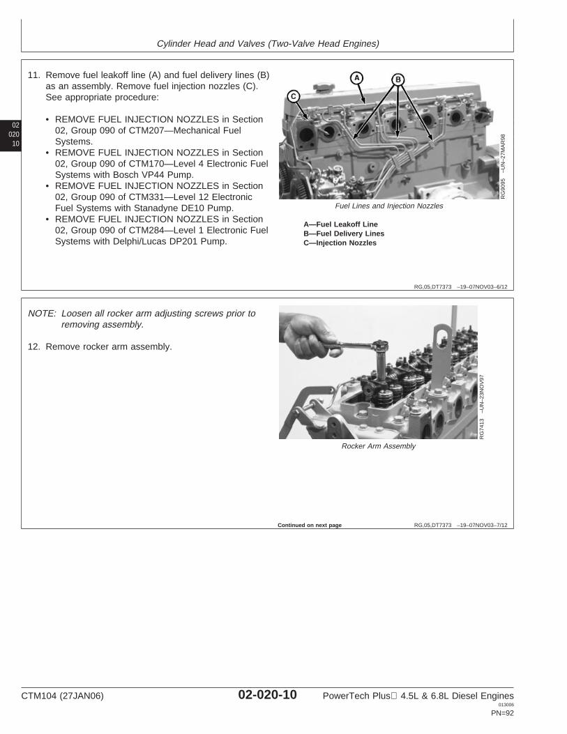
Cylinder Head and Valves (Two-Valve Head Engines)
02020
10
RG,05,DT7373 –19–07NOV03–6/12
RG
9095
–UN
–27M
AR
98
Fuel Lines and Injection Nozzles
A—Fuel Leakoff LineB—Fuel Delivery LinesC—Injection Nozzles
11. Remove fuel leakoff line (A) and fuel delivery lines (B)as an assembly. Remove fuel injection nozzles (C).See appropriate procedure:
• REMOVE FUEL INJECTION NOZZLES in Section02, Group 090 of CTM207—Mechanical FuelSystems.
• REMOVE FUEL INJECTION NOZZLES in Section02, Group 090 of CTM170—Level 4 Electronic FuelSystems with Bosch VP44 Pump.
• REMOVE FUEL INJECTION NOZZLES in Section02, Group 090 of CTM331—Level 12 ElectronicFuel Systems with Stanadyne DE10 Pump.
• REMOVE FUEL INJECTION NOZZLES in Section02, Group 090 of CTM284—Level 1 Electronic FuelSystems with Delphi/Lucas DP201 Pump.
RG,05,DT7373 –19–07NOV03–7/12
RG
7413
–UN
–23N
OV
97
Rocker Arm Assembly
NOTE: Loosen all rocker arm adjusting screws prior toremoving assembly.
12. Remove rocker arm assembly.
Continued on next page
CTM104 (27JAN06) 02-020-10 PowerTech Plus 4.5L & 6.8L Diesel Engines013006
PN=92
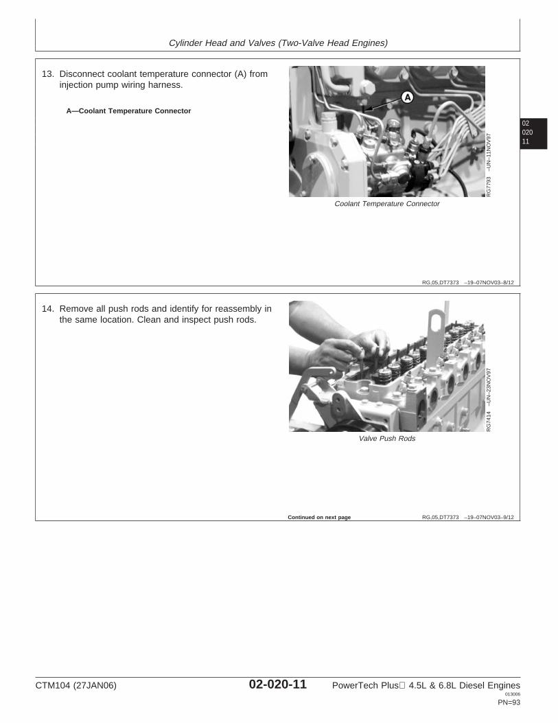
Cylinder Head and Valves (Two-Valve Head Engines)
0202011
RG,05,DT7373 –19–07NOV03–8/12
RG
7793
–UN
–11N
OV
97
Coolant Temperature Connector
A—Coolant Temperature Connector
13. Disconnect coolant temperature connector (A) frominjection pump wiring harness.
RG,05,DT7373 –19–07NOV03–9/12
RG
7414
–UN
–23N
OV
97
Valve Push Rods
14. Remove all push rods and identify for reassembly inthe same location. Clean and inspect push rods.
Continued on next page
CTM104 (27JAN06) 02-020-11 PowerTech Plus 4.5L & 6.8L Diesel Engines013006
PN=93
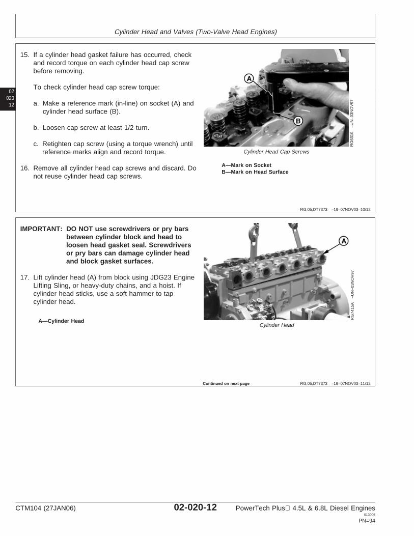
Cylinder Head and Valves (Two-Valve Head Engines)
02020
12
RG,05,DT7373 –19–07NOV03–10/12
RG
6310
–UN
–03N
OV
97
Cylinder Head Cap Screws
A—Mark on SocketB—Mark on Head Surface
15. If a cylinder head gasket failure has occurred, checkand record torque on each cylinder head cap screwbefore removing.
To check cylinder head cap screw torque:
a. Make a reference mark (in-line) on socket (A) andcylinder head surface (B).
b. Loosen cap screw at least 1/2 turn.
c. Retighten cap screw (using a torque wrench) untilreference marks align and record torque.
16. Remove all cylinder head cap screws and discard. Donot reuse cylinder head cap screws.
RG,05,DT7373 –19–07NOV03–11/12
RG
7415
A–U
N–0
3NO
V97
Cylinder HeadA—Cylinder Head
IMPORTANT: DO NOT use screwdrivers or pry barsbetween cylinder block and head toloosen head gasket seal. Screwdriversor pry bars can damage cylinder headand block gasket surfaces.
17. Lift cylinder head (A) from block using JDG23 EngineLifting Sling, or heavy-duty chains, and a hoist. Ifcylinder head sticks, use a soft hammer to tapcylinder head.
Continued on next page
CTM104 (27JAN06) 02-020-12 PowerTech Plus 4.5L & 6.8L Diesel Engines013006
PN=94
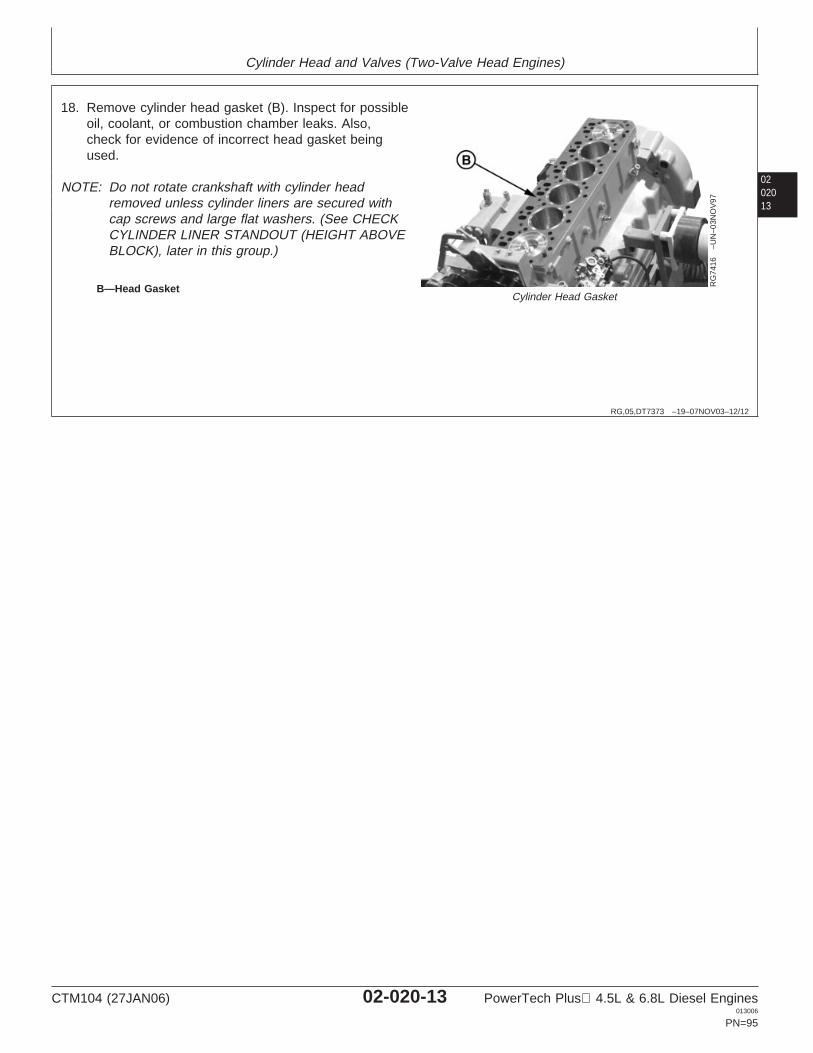
Cylinder Head and Valves (Two-Valve Head Engines)
0202013
RG,05,DT7373 –19–07NOV03–12/12
RG
7416
–UN
–03N
OV
97
Cylinder Head GasketB—Head Gasket
18. Remove cylinder head gasket (B). Inspect for possibleoil, coolant, or combustion chamber leaks. Also,check for evidence of incorrect head gasket beingused.
NOTE: Do not rotate crankshaft with cylinder headremoved unless cylinder liners are secured withcap screws and large flat washers. (See CHECKCYLINDER LINER STANDOUT (HEIGHT ABOVEBLOCK), later in this group.)
CTM104 (27JAN06) 02-020-13 PowerTech Plus 4.5L & 6.8L Diesel Engines013006
PN=95
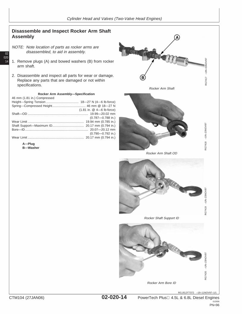
Cylinder Head and Valves (Two-Valve Head Engines)
02020
14
RG,05,DT7372 –19–11NOV97–1/1
Disassemble and Inspect Rocker Arm ShaftAssembly
RG
7417
–UN
–03N
OV
97
Rocker Arm Shaft
RG
7418
–UN
–23N
OV
97
Rocker Arm Shaft OD
RG
7419
–UN
–23N
OV
97
Rocker Shaft Support ID
RG
7420
–UN
–23N
OV
97
Rocker Arm Bore ID
A—PlugB—Washer
NOTE: Note location of parts as rocker arms aredisassembled, to aid in assembly.
1. Remove plugs (A) and bowed washers (B) from rockerarm shaft.
2. Disassemble and inspect all parts for wear or damage.Replace any parts that are damaged or not withinspecifications.
Rocker Arm Assembly—Specification46 mm (1.81 in.) CompressedHeight—Spring Tension 18—27 N (4—6 lb-force).....................................Spring—Compressed Height 46 mm @ 18—27 N
(1.81 in. @ 4—6 lb-force)......................................
Shaft—OD 19.99—20.02 mm(0.787—0.788 in.)
.....................................................................
Wear Limit 19.94 mm (0.785 in.)................................................................Shaft Support—Maximum ID 20.17 mm (0.794 in.)....................................Bore—ID 20.07—20.12 mm
(0.790—0.792 in.)........................................................................
Wear Limit 20.17 mm (0.794 in.)................................................................
CTM104 (27JAN06) 02-020-14 PowerTech Plus 4.5L & 6.8L Diesel Engines013006
PN=96
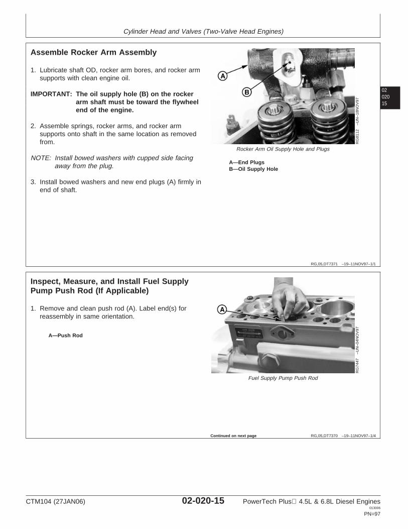
Cylinder Head and Valves (Two-Valve Head Engines)
0202015
RG,05,DT7371 –19–11NOV97–1/1
Assemble Rocker Arm Assembly
RG
8112
–UN
–18N
OV
97
Rocker Arm Oil Supply Hole and Plugs
A—End PlugsB—Oil Supply Hole
1. Lubricate shaft OD, rocker arm bores, and rocker armsupports with clean engine oil.
IMPORTANT: The oil supply hole (B) on the rockerarm shaft must be toward the flywheelend of the engine.
2. Assemble springs, rocker arms, and rocker armsupports onto shaft in the same location as removedfrom.
NOTE: Install bowed washers with cupped side facingaway from the plug.
3. Install bowed washers and new end plugs (A) firmly inend of shaft.
RG,05,DT7370 –19–11NOV97–1/4
Inspect, Measure, and Install Fuel SupplyPump Push Rod (If Applicable)
RG
7447
–UN
–04N
OV
97
Fuel Supply Pump Push Rod
A—Push Rod
1. Remove and clean push rod (A). Label end(s) forreassembly in same orientation.
Continued on next page
CTM104 (27JAN06) 02-020-15 PowerTech Plus 4.5L & 6.8L Diesel Engines013006
PN=97
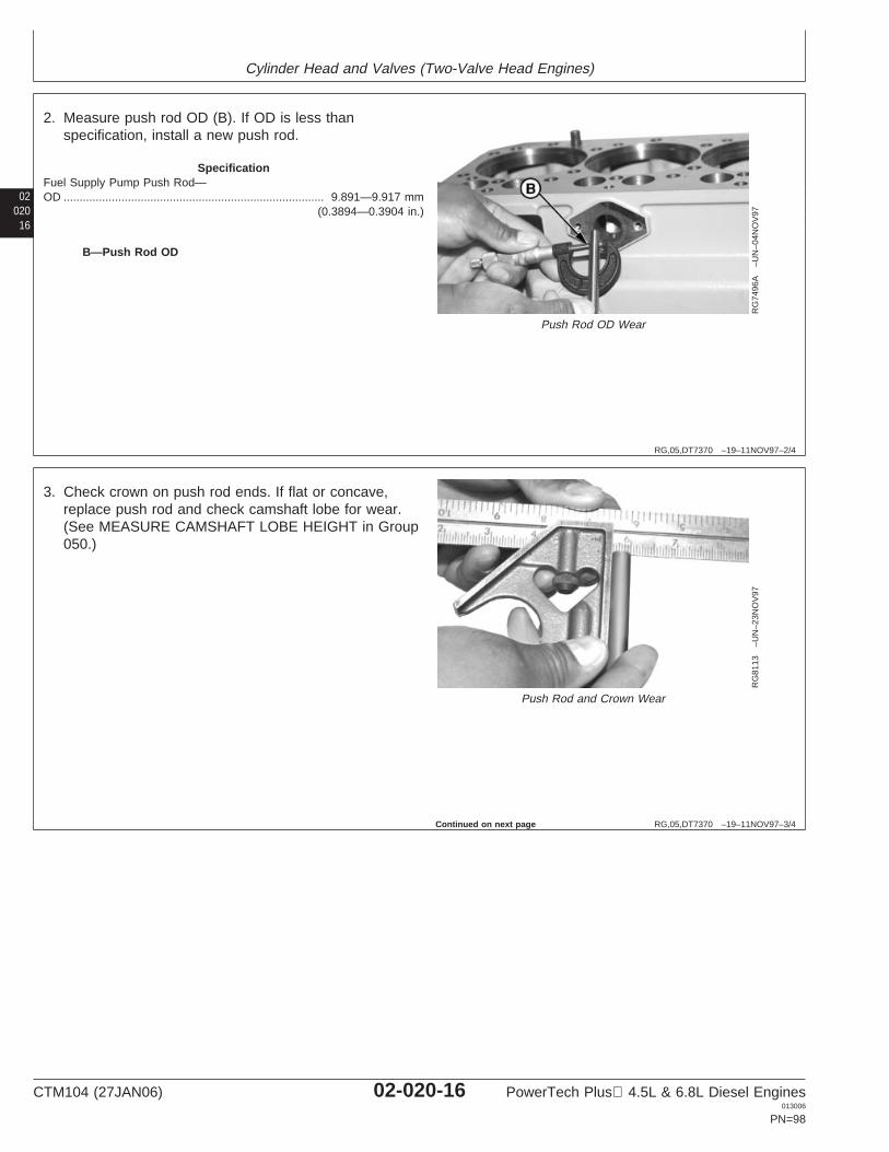
Cylinder Head and Valves (Two-Valve Head Engines)
02020
16
RG,05,DT7370 –19–11NOV97–2/4
RG
7496
A–U
N–0
4NO
V97
Push Rod OD Wear
B—Push Rod OD
2. Measure push rod OD (B). If OD is less thanspecification, install a new push rod.
SpecificationFuel Supply Pump Push Rod—OD 9.891—9.917 mm
(0.3894—0.3904 in.).................................................................................
RG,05,DT7370 –19–11NOV97–3/4
RG
8113
–UN
–23N
OV
97
Push Rod and Crown Wear
3. Check crown on push rod ends. If flat or concave,replace push rod and check camshaft lobe for wear.(See MEASURE CAMSHAFT LOBE HEIGHT in Group050.)
Continued on next page
CTM104 (27JAN06) 02-020-16 PowerTech Plus 4.5L & 6.8L Diesel Engines013006
PN=98
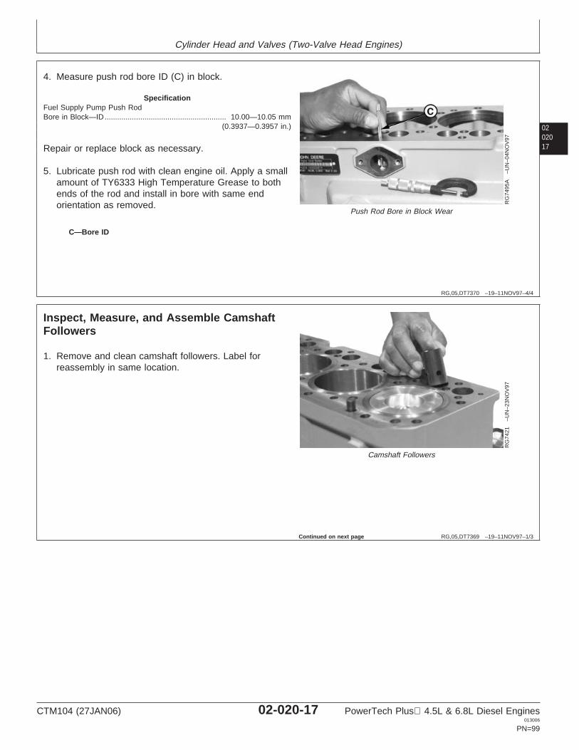
Cylinder Head and Valves (Two-Valve Head Engines)
0202017
RG,05,DT7370 –19–11NOV97–4/4
RG
7495
A–U
N–0
4NO
V97
Push Rod Bore in Block Wear
C—Bore ID
4. Measure push rod bore ID (C) in block.
SpecificationFuel Supply Pump Push RodBore in Block—ID 10.00—10.05 mm
(0.3937—0.3957 in.)..........................................................
Repair or replace block as necessary.
5. Lubricate push rod with clean engine oil. Apply a smallamount of TY6333 High Temperature Grease to bothends of the rod and install in bore with same endorientation as removed.
RG,05,DT7369 –19–11NOV97–1/3
Inspect, Measure, and Assemble CamshaftFollowers
RG
7421
–UN
–23N
OV
97
Camshaft Followers
1. Remove and clean camshaft followers. Label forreassembly in same location.
Continued on next page
CTM104 (27JAN06) 02-020-17 PowerTech Plus 4.5L & 6.8L Diesel Engines013006
PN=99
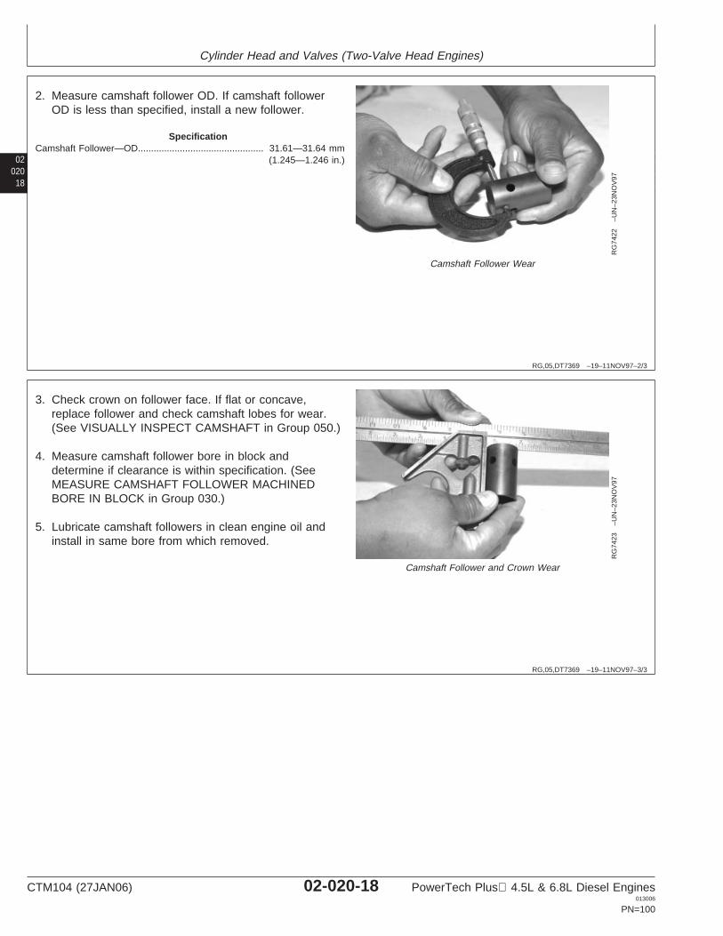
Cylinder Head and Valves (Two-Valve Head Engines)
02020
18
RG,05,DT7369 –19–11NOV97–2/3
RG
7422
–UN
–23N
OV
97
Camshaft Follower Wear
2. Measure camshaft follower OD. If camshaft followerOD is less than specified, install a new follower.
SpecificationCamshaft Follower—OD 31.61—31.64 mm
(1.245—1.246 in.)................................................
RG,05,DT7369 –19–11NOV97–3/3
RG
7423
–UN
–23N
OV
97
Camshaft Follower and Crown Wear
3. Check crown on follower face. If flat or concave,replace follower and check camshaft lobes for wear.(See VISUALLY INSPECT CAMSHAFT in Group 050.)
4. Measure camshaft follower bore in block anddetermine if clearance is within specification. (SeeMEASURE CAMSHAFT FOLLOWER MACHINEDBORE IN BLOCK in Group 030.)
5. Lubricate camshaft followers in clean engine oil andinstall in same bore from which removed.
CTM104 (27JAN06) 02-020-18 PowerTech Plus 4.5L & 6.8L Diesel Engines013006
PN=100
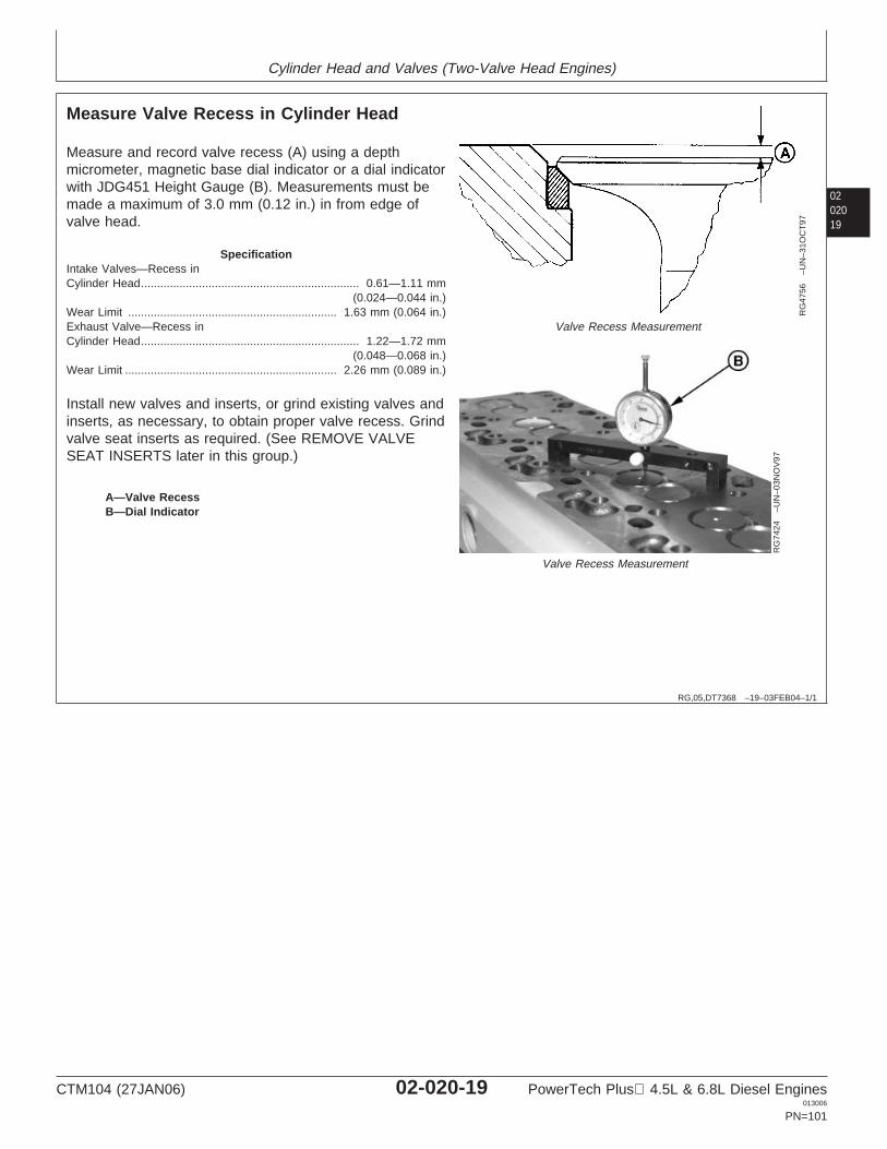
Cylinder Head and Valves (Two-Valve Head Engines)
0202019
RG,05,DT7368 –19–03FEB04–1/1
Measure Valve Recess in Cylinder Head
RG
4756
–UN
–31O
CT
97
Valve Recess Measurement
RG
7424
–UN
–03N
OV
97
Valve Recess Measurement
A—Valve RecessB—Dial Indicator
Measure and record valve recess (A) using a depthmicrometer, magnetic base dial indicator or a dial indicatorwith JDG451 Height Gauge (B). Measurements must bemade a maximum of 3.0 mm (0.12 in.) in from edge ofvalve head.
SpecificationIntake Valves—Recess inCylinder Head 0.61—1.11 mm
(0.024—0.044 in.)....................................................................
Wear Limit 1.63 mm (0.064 in.).................................................................Exhaust Valve—Recess inCylinder Head 1.22—1.72 mm
(0.048—0.068 in.)....................................................................
Wear Limit 2.26 mm (0.089 in.)..................................................................
Install new valves and inserts, or grind existing valves andinserts, as necessary, to obtain proper valve recess. Grindvalve seat inserts as required. (See REMOVE VALVESEAT INSERTS later in this group.)
CTM104 (27JAN06) 02-020-19 PowerTech Plus 4.5L & 6.8L Diesel Engines013006
PN=101
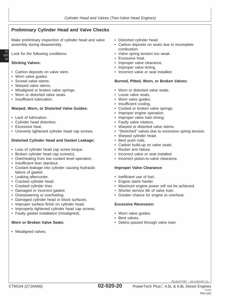
Cylinder Head and Valves (Two-Valve Head Engines)
02020
20
RG,05,DT7367 –19–11NOV97–1/1
Preliminary Cylinder Head and Valve Checks
Make preliminary inspection of cylinder head and valveassembly during disassembly.
Look for the following conditions:
Sticking Valves:
• Carbon deposits on valve stem.• Worn valve guides.• Scored valve stems.• Warped valve stems.• Misaligned or broken valve springs.• Worn or distorted valve seats.• Insufficient lubrication.
Warped, Worn, or Distorted Valve Guides:
• Lack of lubrication.• Cylinder head distortion.• Excessive heat.• Unevenly tightened cylinder head cap screws.
Distorted Cylinder Head and Gasket Leakage:
• Loss of cylinder head cap screw torque.• Broken cylinder head cap screw(s).• Overheating from low coolant level operation.• Insufficient liner standout.• Coolant leakage into cylinder causing hydraulic
failure of gasket.• Leaking aftercooler.• Cracked cylinder head.• Cracked cylinder liner.• Damaged or incorrect gasket.• Overpowering or overfueling.• Damaged cylinder head or block surfaces.• Improper surface finish on cylinder head.• Improperly tightened cylinder head cap screws.• Faulty gasket installation (misaligned).
Worn or Broken Valve Seats:
• Misaligned valves.
• Distorted cylinder head.• Carbon deposits on seats due to incomplete
combustion.• Valve spring tension too weak.• Excessive heat.• Improper valve clearance.• Improper valve timing.• Incorrect valve or seat installed.
Burned, Pitted, Worn, or Broken Valves:
• Worn or distorted valve seats.• Loose valve seats.• Worn valve guides.• Insufficient cooling.• Cocked or broken valve springs.• Improper engine operation.• Improper valve train timing.• Faulty valve rotators.• Warped or distorted valve stems.• “Stretched” valves due to excessive spring tension.• Warped cylinder head.• Bent push rods.• Carbon build-up on valve seats.• Rocker arm failure.• Incorrect valve or seat installed.• Incorrect piston-to-valve clearance.
Improper Valve Clearance:
• Inefficient use of fuel.• Engine starts harder.• Maximum engine power will not be achieved.• Shorter service life of valve train.• Greater chance for engine to overheat.
Excessive Recession:
• Worn valve guides.• Bent valves.• Debris passed through valve train.
CTM104 (27JAN06) 02-020-20 PowerTech Plus 4.5L & 6.8L Diesel Engines013006
PN=102
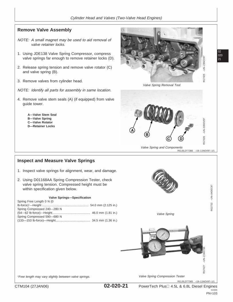
Cylinder Head and Valves (Two-Valve Head Engines)
0202021
RG,05,DT7366 –19–11NOV97–1/1
Remove Valve Assembly
RG
7425
–UN
–23N
OV
97
Valve Spring Removal Tool
RG
7426
–UN
–03N
OV
97
Valve Spring and Components
A—Valve Stem SealB—Valve SpringC—Valve RotatorD—Retainer Locks
NOTE: A small magnet may be used to aid removal ofvalve retainer locks.
1. Using JDE138 Valve Spring Compressor, compressvalve springs far enough to remove retainer locks (D).
2. Release spring tension and remove valve rotator (C)and valve spring (B).
3. Remove valves from cylinder head.
NOTE: Identify all parts for assembly in same location.
4. Remove valve stem seals (A) (if equipped) from valveguide tower.
RG,05,DT7365 –19–11NOV97–1/1
Inspect and Measure Valve Springs
RG
2732
–UN
–04D
EC
97Valve Spring
RG
7427
–UN
–21M
AY
98
Valve Spring Compression Tester
1. Inspect valve springs for alignment, wear, and damage.
2. Using D01168AA Spring Compression Tester, checkvalve spring tension. Compressed height must bewithin specification given below.
Valve Springs—SpecificationSpring Free Length 0 N (0lb-force)1—Height 54.0 mm (2.125 in.).......................................................Spring Compressed 240—280 N(54—62 lb-force)—Height 46.0 mm (1.81 in.).............................................Spring Compressed 590—680 N(133—153 lb-force)—Height 34.5 mm (1.36 in.).........................................
1Free length may vary slightly between valve springs.
CTM104 (27JAN06) 02-020-21 PowerTech Plus 4.5L & 6.8L Diesel Engines013006
PN=103
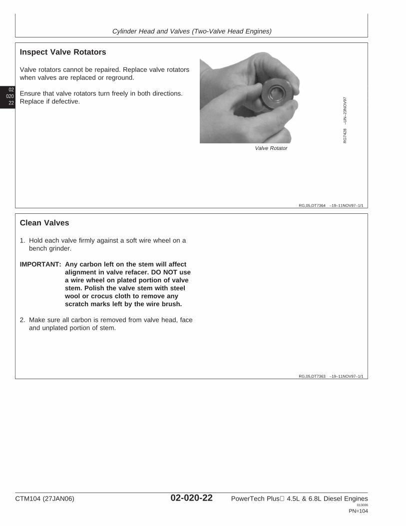
Cylinder Head and Valves (Two-Valve Head Engines)
02020
22
RG,05,DT7364 –19–11NOV97–1/1
Inspect Valve Rotators
RG
7428
–UN
–23N
OV
97
Valve Rotator
Valve rotators cannot be repaired. Replace valve rotatorswhen valves are replaced or reground.
Ensure that valve rotators turn freely in both directions.Replace if defective.
RG,05,DT7363 –19–11NOV97–1/1
Clean Valves
1. Hold each valve firmly against a soft wire wheel on abench grinder.
IMPORTANT: Any carbon left on the stem will affectalignment in valve refacer. DO NOT usea wire wheel on plated portion of valvestem. Polish the valve stem with steelwool or crocus cloth to remove anyscratch marks left by the wire brush.
2. Make sure all carbon is removed from valve head, faceand unplated portion of stem.
CTM104 (27JAN06) 02-020-22 PowerTech Plus 4.5L & 6.8L Diesel Engines013006
PN=104
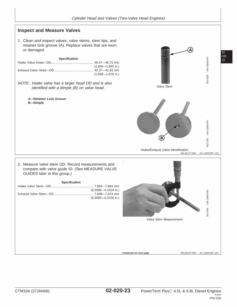
Cylinder Head and Valves (Two-Valve Head Engines)
0202023
RG,05,DT7362 –19–11NOV97–1/3
Inspect and Measure Valves
RG
7429
–UN
–03N
OV
97
Valve Stem
RG
7759
–UN
–10N
OV
97
Intake/Exhaust Valve Identification
A—Retainer Lock GrooveB—Dimple
1. Clean and inspect valves, valve stems, stem tips, andretainer lock groove (A). Replace valves that are wornor damaged.
SpecificationIntake Valve Head—OD 46.47—46.73 mm
(1.830—1.840 in.)................................................
Exhaust Valve Head—OD 42.37—42.63 mm(1.668—1.678 in.)
.............................................
NOTE: Intake valve has a larger head OD and is alsoidentified with a dimple (B) on valve head.
RG,05,DT7362 –19–11NOV97–2/3
RG
7430
–UN
–23N
OV
97
Valve Stem Measurement
2. Measure valve stem OD. Record measurements andcompare with valve guide ID. (See MEASURE VALVEGUIDES later in this group.)
SpecificationIntake Valve Stem—OD 7.864—7.884 mm
(0.3096—0.3104 in.)................................................
Exhaust Valve Stem—OD 7.848—7.874 mm(0.3090—0.3100 in.)
.............................................
Continued on next page
CTM104 (27JAN06) 02-020-23 PowerTech Plus 4.5L & 6.8L Diesel Engines013006
PN=105
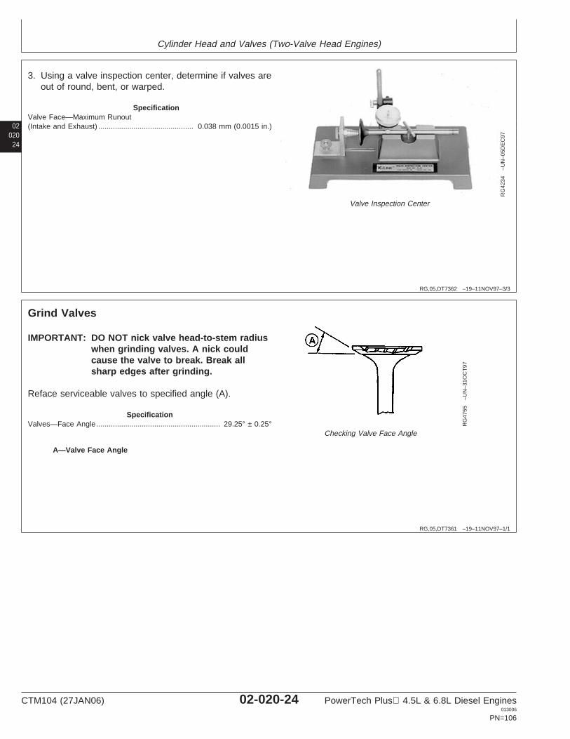
Cylinder Head and Valves (Two-Valve Head Engines)
02020
24
RG,05,DT7362 –19–11NOV97–3/3
RG
4234
–UN
–05D
EC
97
Valve Inspection Center
3. Using a valve inspection center, determine if valves areout of round, bent, or warped.
SpecificationValve Face—Maximum Runout(Intake and Exhaust) 0.038 mm (0.0015 in.)..............................................
RG,05,DT7361 –19–11NOV97–1/1
Grind Valves
RG
4755
–UN
–31O
CT
97
Checking Valve Face Angle
A—Valve Face Angle
IMPORTANT: DO NOT nick valve head-to-stem radiuswhen grinding valves. A nick couldcause the valve to break. Break allsharp edges after grinding.
Reface serviceable valves to specified angle (A).
SpecificationValves—Face Angle 29.25° ± 0.25°............................................................
CTM104 (27JAN06) 02-020-24 PowerTech Plus 4.5L & 6.8L Diesel Engines013006
PN=106
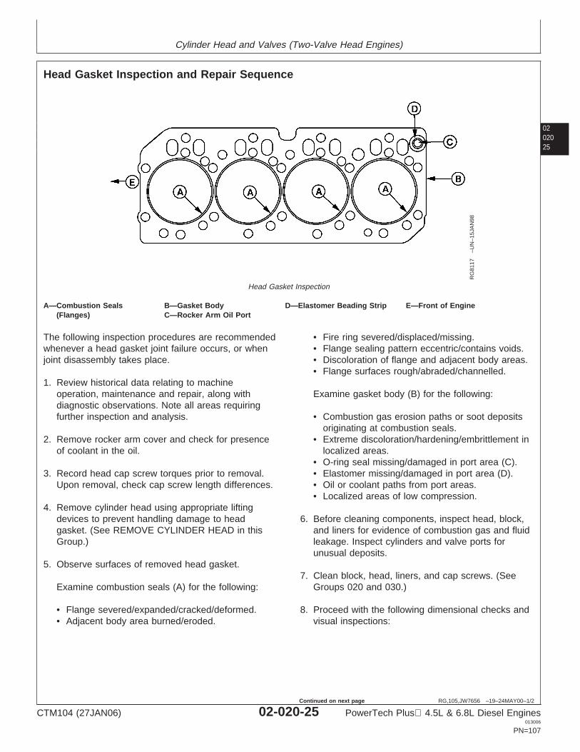
Cylinder Head and Valves (Two-Valve Head Engines)
0202025
RG,105,JW7656 –19–24MAY00–1/2
Head Gasket Inspection and Repair Sequence
RG
8117
–UN
–15J
AN
98
Head Gasket Inspection
A—Combustion Seals B—Gasket Body D—Elastomer Beading Strip E—Front of Engine(Flanges) C—Rocker Arm Oil Port
The following inspection procedures are recommendedwhenever a head gasket joint failure occurs, or whenjoint disassembly takes place.
1. Review historical data relating to machineoperation, maintenance and repair, along withdiagnostic observations. Note all areas requiringfurther inspection and analysis.
2. Remove rocker arm cover and check for presenceof coolant in the oil.
3. Record head cap screw torques prior to removal.Upon removal, check cap screw length differences.
4. Remove cylinder head using appropriate liftingdevices to prevent handling damage to headgasket. (See REMOVE CYLINDER HEAD in thisGroup.)
5. Observe surfaces of removed head gasket.
Examine combustion seals (A) for the following:
• Flange severed/expanded/cracked/deformed.• Adjacent body area burned/eroded.
• Fire ring severed/displaced/missing.• Flange sealing pattern eccentric/contains voids.• Discoloration of flange and adjacent body areas.• Flange surfaces rough/abraded/channelled.
Examine gasket body (B) for the following:
• Combustion gas erosion paths or soot depositsoriginating at combustion seals.
• Extreme discoloration/hardening/embrittlement inlocalized areas.
• O-ring seal missing/damaged in port area (C).• Elastomer missing/damaged in port area (D).• Oil or coolant paths from port areas.• Localized areas of low compression.
6. Before cleaning components, inspect head, block,and liners for evidence of combustion gas and fluidleakage. Inspect cylinders and valve ports forunusual deposits.
7. Clean block, head, liners, and cap screws. (SeeGroups 020 and 030.)
8. Proceed with the following dimensional checks andvisual inspections:
CTM104 (27JAN06) 02-020-25 PowerTech Plus 4.5L & 6.8L Diesel Engines013006
PN=107
Continued on next page
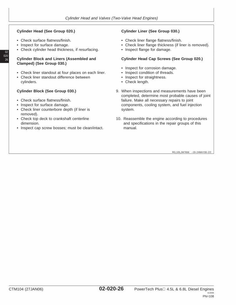
Cylinder Head and Valves (Two-Valve Head Engines)
02020
26
RG,105,JW7656 –19–24MAY00–2/2
Cylinder Head (See Group 020.)
• Check surface flatness/finish.• Inspect for surface damage.• Check cylinder head thickness, if resurfacing.
Cylinder Block and Liners (Assembled andClamped) (See Group 030.)
• Check liner standout at four places on each liner.• Check liner standout difference between
cylinders.
Cylinder Block (See Group 030.)
• Check surface flatness/finish.• Inspect for surface damage.• Check liner counterbore depth (if liner is
removed).• Check top deck to crankshaft centerline
dimension.• Inspect cap screw bosses; must be clean/intact.
Cylinder Liner (See Group 030.)
• Check liner flange flatness/finish.• Check liner flange thickness (if liner is removed).• Inspect flange for damage.
Cylinder Head Cap Screws (See Group 020.)
• Inspect for corrosion damage.• Inspect condition of threads.• Inspect for straightness.• Check length.
9. When inspections and measurements have beencompleted, determine most probable causes of jointfailure. Make all necessary repairs to jointcomponents, cooling system, and fuel injectionsystem.
10. Reassemble the engine according to proceduresand specifications in the repair groups of thismanual.
CTM104 (27JAN06) 02-020-26 PowerTech Plus 4.5L & 6.8L Diesel Engines013006
PN=108
Cylinder Head and Valves (Two-Valve Head Engines)
0202027
RG,05,DT7360 –19–25NOV03–1/1
Inspect and Clean Cylinder Head
1. Inspect combustion face for evidence of physicaldamage, oil or coolant leakage, or gasket failure priorto cleaning the cylinder head. Repair or replacecylinder head if there is evidence of physical damage,such as cracking, abrasion, distortion, or valve seat“torching”. Inspect all cylinder head passages forrestrictions.
2. Scrape gasket material, oil, carbon, and rust fromhead. Use a powered wire brush to clean sealingsurfaces.
IMPORTANT: Be sure to remove all plugs beforecleaning head, as parts can bedamaged or destroyed by hot tanksolutions.
3. Clean cylinder head in a chemical hot tank, or withsolvent and a brush.
4. Dry with compressed air and blow out all passages.
IMPORTANT: Plug in intake located below air inletmay have originally used liquid sealeronly. When reinstalling plug, it musthave an o-ring seal installed. See partscatalog for proper seal.
5. Perform all component cleaning and inspection beforeinstalling new plugs in cylinder head.
CTM104 (27JAN06) 02-020-27 PowerTech Plus 4.5L & 6.8L Diesel Engines013006
PN=109
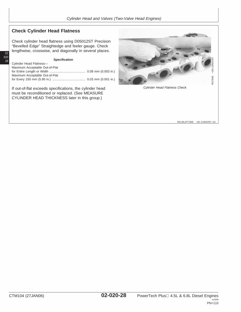
Cylinder Head and Valves (Two-Valve Head Engines)
02020
28
RG,05,DT7359 –19–11NOV97–1/1
Check Cylinder Head Flatness
RG
7645
–UN
–23N
OV
97
Cylinder Head Flatness Check
Check cylinder head flatness using D05012ST Precision“Bevelled Edge” Straightedge and feeler gauge. Checklengthwise, crosswise, and diagonally in several places.
SpecificationCylinder Head Flatness—Maximum Acceptable Out-of-Flatfor Entire Length or Width 0.08 mm (0.003 in.).........................................Maximum Acceptable Out-of-Flatfor Every 150 mm (5.90 in.) 0.03 mm (0.001 in.)......................................
If out-of-flat exceeds specifications, the cylinder headmust be reconditioned or replaced. (See MEASURECYLINDER HEAD THICKNESS later in this group.)
CTM104 (27JAN06) 02-020-28 PowerTech Plus 4.5L & 6.8L Diesel Engines013006
PN=110
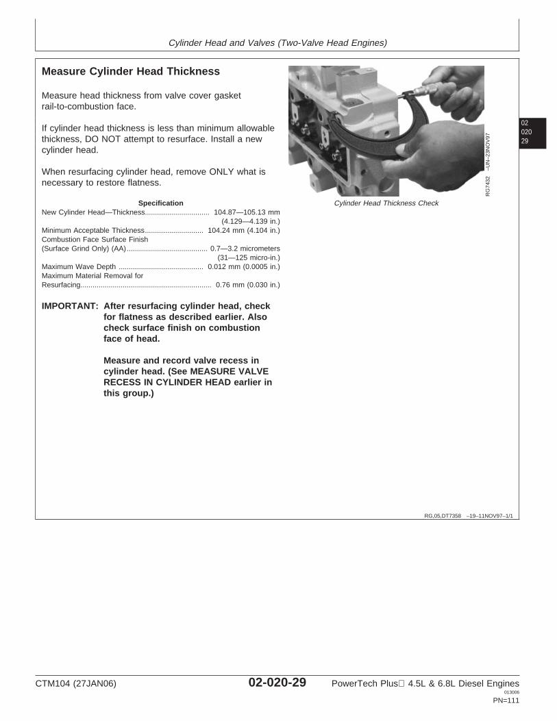
Cylinder Head and Valves (Two-Valve Head Engines)
0202029
RG,05,DT7358 –19–11NOV97–1/1
Measure Cylinder Head Thickness
RG
7432
–UN
–23N
OV
97
Cylinder Head Thickness Check
Measure head thickness from valve cover gasketrail-to-combustion face.
If cylinder head thickness is less than minimum allowablethickness, DO NOT attempt to resurface. Install a newcylinder head.
When resurfacing cylinder head, remove ONLY what isnecessary to restore flatness.
SpecificationNew Cylinder Head—Thickness 104.87—105.13 mm
(4.129—4.139 in.)................................
Minimum Acceptable Thickness 104.24 mm (4.104 in.).............................Combustion Face Surface Finish(Surface Grind Only) (AA) 0.7—3.2 micrometers
(31—125 micro-in.)........................................
Maximum Wave Depth 0.012 mm (0.0005 in.)..........................................Maximum Material Removal forResurfacing 0.76 mm (0.030 in.).................................................................
IMPORTANT: After resurfacing cylinder head, checkfor flatness as described earlier. Alsocheck surface finish on combustionface of head.
Measure and record valve recess incylinder head. (See MEASURE VALVERECESS IN CYLINDER HEAD earlier inthis group.)
CTM104 (27JAN06) 02-020-29 PowerTech Plus 4.5L & 6.8L Diesel Engines013006
PN=111
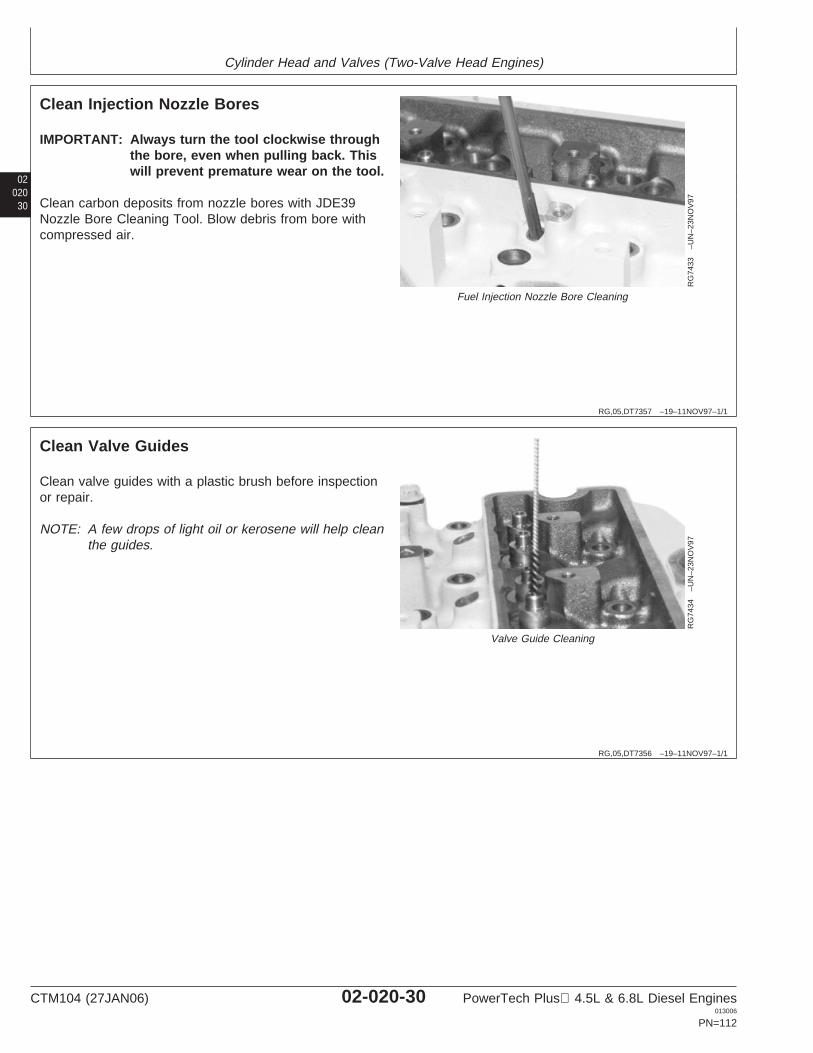
Cylinder Head and Valves (Two-Valve Head Engines)
02020
30
RG,05,DT7357 –19–11NOV97–1/1
Clean Injection Nozzle Bores
RG
7433
–UN
–23N
OV
97
Fuel Injection Nozzle Bore Cleaning
IMPORTANT: Always turn the tool clockwise throughthe bore, even when pulling back. Thiswill prevent premature wear on the tool.
Clean carbon deposits from nozzle bores with JDE39Nozzle Bore Cleaning Tool. Blow debris from bore withcompressed air.
RG,05,DT7356 –19–11NOV97–1/1
Clean Valve Guides
RG
7434
–UN
–23N
OV
97
Valve Guide Cleaning
Clean valve guides with a plastic brush before inspectionor repair.
NOTE: A few drops of light oil or kerosene will help cleanthe guides.
CTM104 (27JAN06) 02-020-30 PowerTech Plus 4.5L & 6.8L Diesel Engines013006
PN=112
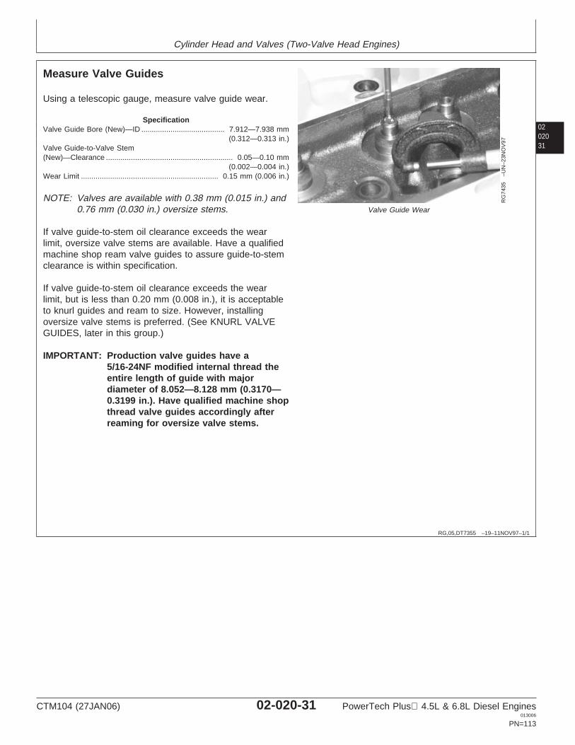
Cylinder Head and Valves (Two-Valve Head Engines)
0202031
RG,05,DT7355 –19–11NOV97–1/1
Measure Valve Guides
RG
7435
–UN
–23N
OV
97
Valve Guide Wear
Using a telescopic gauge, measure valve guide wear.
SpecificationValve Guide Bore (New)—ID 7.912—7.938 mm
(0.312—0.313 in.)........................................
Valve Guide-to-Valve Stem(New)—Clearance 0.05—0.10 mm
(0.002—0.004 in.).............................................................
Wear Limit 0.15 mm (0.006 in.)..................................................................
NOTE: Valves are available with 0.38 mm (0.015 in.) and0.76 mm (0.030 in.) oversize stems.
If valve guide-to-stem oil clearance exceeds the wearlimit, oversize valve stems are available. Have a qualifiedmachine shop ream valve guides to assure guide-to-stemclearance is within specification.
If valve guide-to-stem oil clearance exceeds the wearlimit, but is less than 0.20 mm (0.008 in.), it is acceptableto knurl guides and ream to size. However, installingoversize valve stems is preferred. (See KNURL VALVEGUIDES, later in this group.)
IMPORTANT: Production valve guides have a5/16-24NF modified internal thread theentire length of guide with majordiameter of 8.052—8.128 mm (0.3170—0.3199 in.). Have qualified machine shopthread valve guides accordingly afterreaming for oversize valve stems.
CTM104 (27JAN06) 02-020-31 PowerTech Plus 4.5L & 6.8L Diesel Engines013006
PN=113
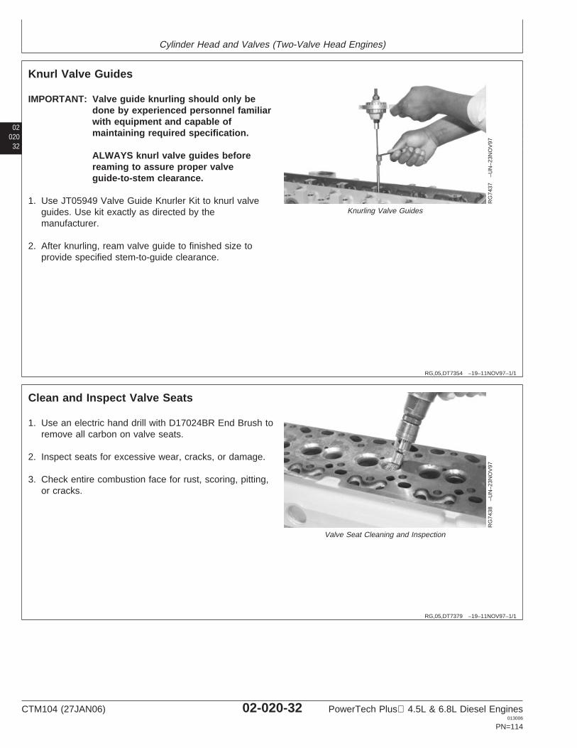
Cylinder Head and Valves (Two-Valve Head Engines)
02020
32
RG,05,DT7354 –19–11NOV97–1/1
Knurl Valve Guides
RG
7437
–UN
–23N
OV
97
Knurling Valve Guides
IMPORTANT: Valve guide knurling should only bedone by experienced personnel familiarwith equipment and capable ofmaintaining required specification.
ALWAYS knurl valve guides beforereaming to assure proper valveguide-to-stem clearance.
1. Use JT05949 Valve Guide Knurler Kit to knurl valveguides. Use kit exactly as directed by themanufacturer.
2. After knurling, ream valve guide to finished size toprovide specified stem-to-guide clearance.
RG,05,DT7379 –19–11NOV97–1/1
Clean and Inspect Valve Seats
RG
7438
–UN
–23N
OV
97
Valve Seat Cleaning and Inspection
1. Use an electric hand drill with D17024BR End Brush toremove all carbon on valve seats.
2. Inspect seats for excessive wear, cracks, or damage.
3. Check entire combustion face for rust, scoring, pitting,or cracks.
CTM104 (27JAN06) 02-020-32 PowerTech Plus 4.5L & 6.8L Diesel Engines013006
PN=114
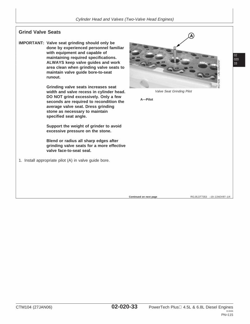
Cylinder Head and Valves (Two-Valve Head Engines)
0202033
RG,05,DT7353 –19–11NOV97–1/4
Grind Valve Seats
RG
7439
–UN
–03N
OV
97
Valve Seat Grinding Pilot
A—Pilot
IMPORTANT: Valve seat grinding should only bedone by experienced personnel familiarwith equipment and capable ofmaintaining required specifications.ALWAYS keep valve guides and workarea clean when grinding valve seats tomaintain valve guide bore-to-seatrunout.
Grinding valve seats increases seatwidth and valve recess in cylinder head.DO NOT grind excessively. Only a fewseconds are required to recondition theaverage valve seat. Dress grindingstone as necessary to maintainspecified seat angle.
Support the weight of grinder to avoidexcessive pressure on the stone.
Blend or radius all sharp edges aftergrinding valve seats for a more effectivevalve face-to-seat seal.
1. Install appropriate pilot (A) in valve guide bore.
Continued on next page
CTM104 (27JAN06) 02-020-33 PowerTech Plus 4.5L & 6.8L Diesel Engines013006
PN=115
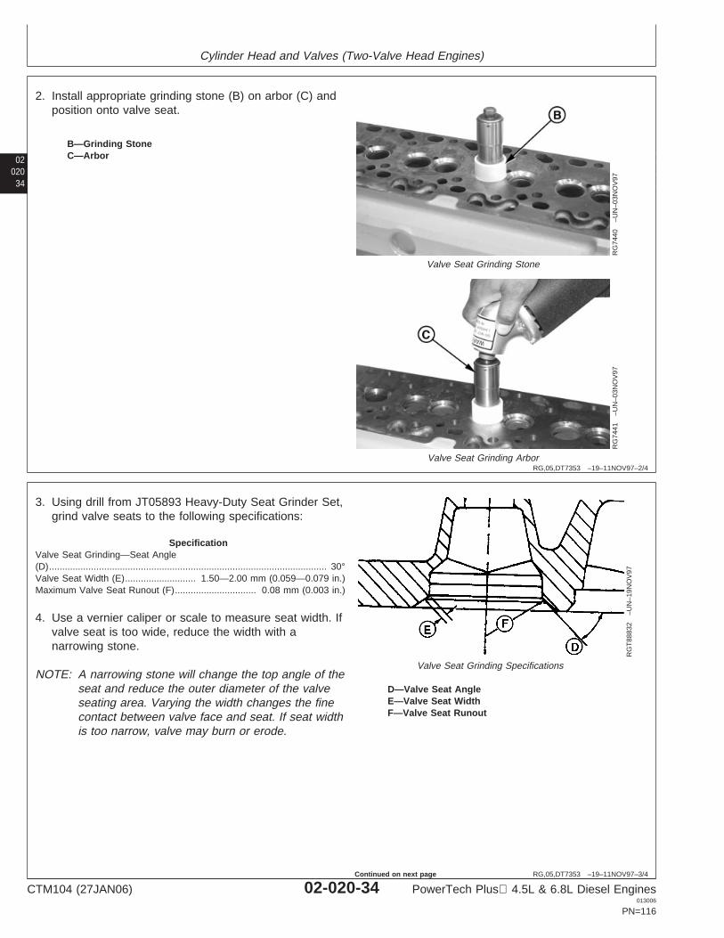
Cylinder Head and Valves (Two-Valve Head Engines)
02020
34
RG,05,DT7353 –19–11NOV97–2/4
RG
7440
–UN
–03N
OV
97
Valve Seat Grinding Stone
RG
7441
–UN
–03N
OV
97
Valve Seat Grinding Arbor
B—Grinding StoneC—Arbor
2. Install appropriate grinding stone (B) on arbor (C) andposition onto valve seat.
RG,05,DT7353 –19–11NOV97–3/4
RG
T88
832
–UN
–19N
OV
97
Valve Seat Grinding Specifications
D—Valve Seat AngleE—Valve Seat WidthF—Valve Seat Runout
3. Using drill from JT05893 Heavy-Duty Seat Grinder Set,grind valve seats to the following specifications:
SpecificationValve Seat Grinding—Seat Angle(D) 30°..........................................................................................................Valve Seat Width (E) 1.50—2.00 mm (0.059—0.079 in.)...........................Maximum Valve Seat Runout (F) 0.08 mm (0.003 in.)...............................
4. Use a vernier caliper or scale to measure seat width. Ifvalve seat is too wide, reduce the width with anarrowing stone.
NOTE: A narrowing stone will change the top angle of theseat and reduce the outer diameter of the valveseating area. Varying the width changes the finecontact between valve face and seat. If seat widthis too narrow, valve may burn or erode.
CTM104 (27JAN06) 02-020-34 PowerTech Plus 4.5L & 6.8L Diesel Engines013006
PN=116
Continued on next page
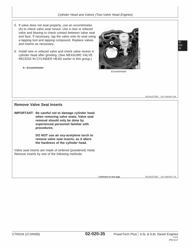
Cylinder Head and Valves (Two-Valve Head Engines)
0202035
RG,05,DT7353 –19–11NOV97–4/4
RG
6318
–UN
–03N
OV
97
Eccentrimeter
A—Eccentrimeter
5. If valve does not seat properly, use an eccentrimeter(A) to check valve seat runout. Use a new or refacedvalve and blueing to check contact between valve seatand face. If necessary, lap the valve onto its seat usinga lapping tool and lapping compound. Replace valvesand inserts as necessary.
6. Install new or refaced valve and check valve recess incylinder head after grinding. (See MEASURE VALVERECESS IN CYLINDER HEAD earlier in this group.)
RG,05,DT7352 –19–11NOV97–1/4
Remove Valve Seat Inserts
IMPORTANT: Be careful not to damage cylinder headwhen removing valve seats. Valve seatremoval should only be done byexperienced personnel familiar withprocedures.
DO NOT use an oxy-acetylene torch toremove valve seat inserts, as it altersthe hardness of the cylinder head.
Valve seat inserts are made of sintered (powdered) metal.Remove inserts by one of the following methods:
Continued on next page
CTM104 (27JAN06) 02-020-35 PowerTech Plus 4.5L & 6.8L Diesel Engines013006
PN=117
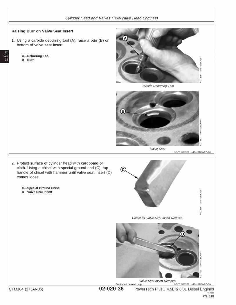
Cylinder Head and Valves (Two-Valve Head Engines)
02020
36
RG,05,DT7352 –19–11NOV97–2/4
RG
7816
–UN
–13N
OV
97
Carbide Deburring Tool
RG
7817
–UN
–13N
OV
97
Valve Seat
A—Deburring ToolB—Burr
Raising Burr on Valve Seat Insert
1. Using a carbide deburring tool (A), raise a burr (B) onbottom of valve seat insert.
RG,05,DT7352 –19–11NOV97–3/4
RG
7818
–UN
–13N
OV
97
Chisel for Valve Seat Insert Removal
RG
7760
–UN
–10N
OV
97
Valve Seat Insert Removal
C—Special Ground ChiselD—Valve Seat Insert
2. Protect surface of cylinder head with cardboard orcloth. Using a chisel with special ground end (C), taphandle of chisel with hammer until valve seat insert (D)comes loose.
CTM104 (27JAN06) 02-020-36 PowerTech Plus 4.5L & 6.8L Diesel Engines013006
PN=118
Continued on next page
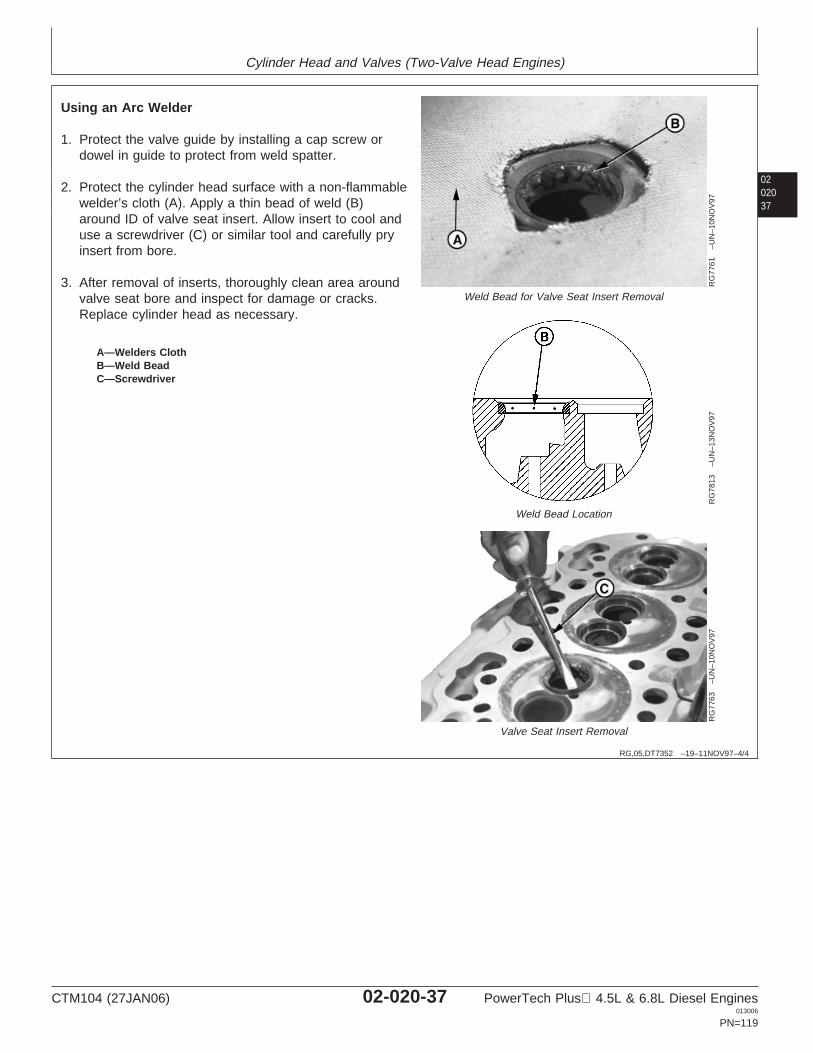
Cylinder Head and Valves (Two-Valve Head Engines)
0202037
RG,05,DT7352 –19–11NOV97–4/4
RG
7761
–UN
–10N
OV
97
Weld Bead for Valve Seat Insert Removal
RG
7813
–UN
–13N
OV
97
Weld Bead Location
RG
7763
–UN
–10N
OV
97
Valve Seat Insert Removal
A—Welders ClothB—Weld BeadC—Screwdriver
Using an Arc Welder
1. Protect the valve guide by installing a cap screw ordowel in guide to protect from weld spatter.
2. Protect the cylinder head surface with a non-flammablewelder’s cloth (A). Apply a thin bead of weld (B)around ID of valve seat insert. Allow insert to cool anduse a screwdriver (C) or similar tool and carefully pryinsert from bore.
3. After removal of inserts, thoroughly clean area aroundvalve seat bore and inspect for damage or cracks.Replace cylinder head as necessary.
CTM104 (27JAN06) 02-020-37 PowerTech Plus 4.5L & 6.8L Diesel Engines013006
PN=119

Cylinder Head and Valves (Two-Valve Head Engines)
02020
38
RG,05,DT7351 –19–11NOV97–1/1
Measure Valve Seat Bore in Cylinder Head
RG
9101
–UN
–27M
AR
98
Cylinder Head Valve Seat Bore
If bore dimensions are not within specification, machinehead to the following specifications:
Exhaust Valve Seat Insert Bore Specifications:A ................................ 42.987—43.013 mm (1.6924—1.6934 in.)B ................................ 3.82 mm (0.150 in.) ReferenceC ................................ 9.936—10.064 mm (0.3912—0.3962 in.)D ................................ 38—42°E ................................ Maximum Radius 0.5 mm (0.019 in.)
Maximum surface finish 0.00158 mmof bore “A” ................. (0.000062 in.)
Intake Valve Seat Insert Bore Specifications:A ................................ 47.104—47.130 mm (1.8545—1.8555 in.)B ................................ 3.45 mm (0.136 in.) ReferenceC ................................ 9.936—10.064 mm (0.3912—0.3962 in.)D ................................ 38—42°E ................................ Maximum Radius 0.5 mm (0.019 in.)
Maximum surface finish 0.00158 mmof bore “A” ................. (0.000062 in.)
Replacement Valve Seat Insert OD:Intake ......................... 47.155—47.181 mm (1.8565—1.8575 in.)Exhaust ...................... 43.038—43.064 mm (1.6944—1.6954 in.)
CTM104 (27JAN06) 02-020-38 PowerTech Plus 4.5L & 6.8L Diesel Engines013006
PN=120
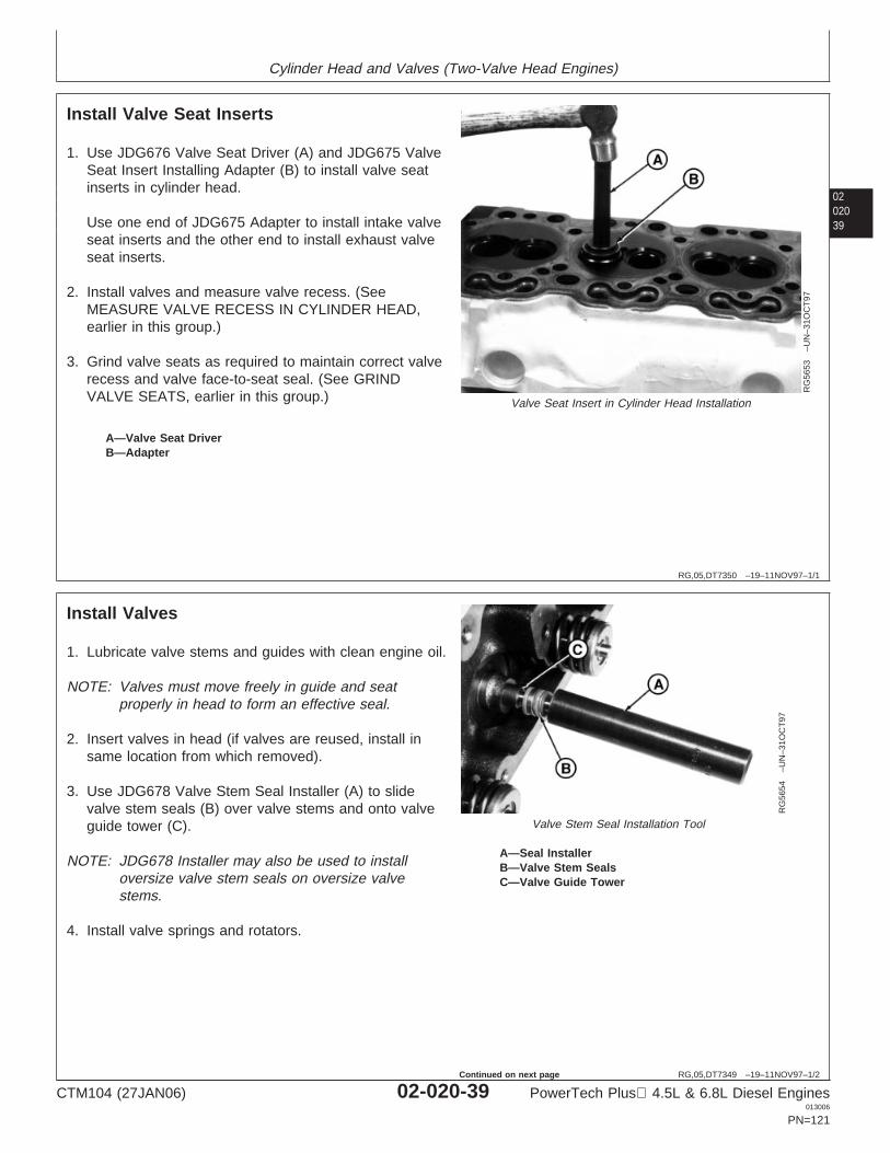
Cylinder Head and Valves (Two-Valve Head Engines)
0202039
RG,05,DT7350 –19–11NOV97–1/1
Install Valve Seat Inserts
RG
5653
–UN
–31O
CT
97
Valve Seat Insert in Cylinder Head Installation
A—Valve Seat DriverB—Adapter
1. Use JDG676 Valve Seat Driver (A) and JDG675 ValveSeat Insert Installing Adapter (B) to install valve seatinserts in cylinder head.
Use one end of JDG675 Adapter to install intake valveseat inserts and the other end to install exhaust valveseat inserts.
2. Install valves and measure valve recess. (SeeMEASURE VALVE RECESS IN CYLINDER HEAD,earlier in this group.)
3. Grind valve seats as required to maintain correct valverecess and valve face-to-seat seal. (See GRINDVALVE SEATS, earlier in this group.)
RG,05,DT7349 –19–11NOV97–1/2
Install Valves
RG
5654
–UN
–31O
CT
97
Valve Stem Seal Installation Tool
A—Seal InstallerB—Valve Stem SealsC—Valve Guide Tower
1. Lubricate valve stems and guides with clean engine oil.
NOTE: Valves must move freely in guide and seatproperly in head to form an effective seal.
2. Insert valves in head (if valves are reused, install insame location from which removed).
3. Use JDG678 Valve Stem Seal Installer (A) to slidevalve stem seals (B) over valve stems and onto valveguide tower (C).
NOTE: JDG678 Installer may also be used to installoversize valve stem seals on oversize valvestems.
4. Install valve springs and rotators.
CTM104 (27JAN06) 02-020-39 PowerTech Plus 4.5L & 6.8L Diesel Engines013006
PN=121
Continued on next page
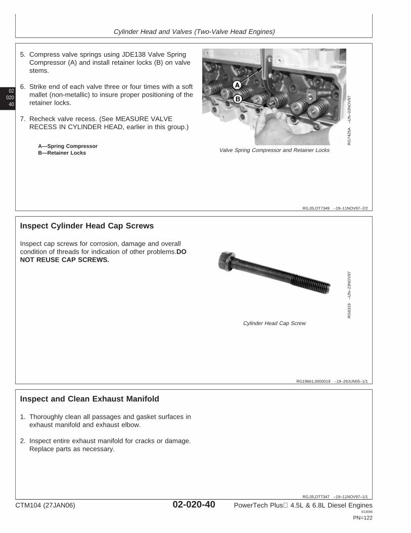
Cylinder Head and Valves (Two-Valve Head Engines)
02020
40
RG,05,DT7349 –19–11NOV97–2/2
RG
7425
A–U
N–0
3NO
V97
Valve Spring Compressor and Retainer LocksA—Spring CompressorB—Retainer Locks
5. Compress valve springs using JDE138 Valve SpringCompressor (A) and install retainer locks (B) on valvestems.
6. Strike end of each valve three or four times with a softmallet (non-metallic) to insure proper positioning of theretainer locks.
7. Recheck valve recess. (See MEASURE VALVERECESS IN CYLINDER HEAD, earlier in this group.)
RG19661,0000019 –19–29JUN05–1/1
Inspect Cylinder Head Cap Screws
RG
6319
–UN
–23N
OV
97
Cylinder Head Cap Screw
Inspect cap screws for corrosion, damage and overallcondition of threads for indication of other problems.DONOT REUSE CAP SCREWS.
RG,05,DT7347 –19–11NOV97–1/1
Inspect and Clean Exhaust Manifold
1. Thoroughly clean all passages and gasket surfaces inexhaust manifold and exhaust elbow.
2. Inspect entire exhaust manifold for cracks or damage.Replace parts as necessary.
CTM104 (27JAN06) 02-020-40 PowerTech Plus 4.5L & 6.8L Diesel Engines013006
PN=122
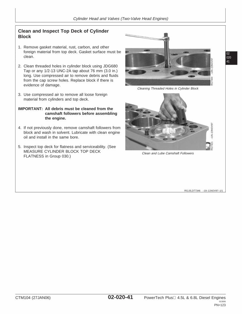
Cylinder Head and Valves (Two-Valve Head Engines)
0202041
RG,05,DT7346 –19–11NOV97–1/1
Clean and Inspect Top Deck of CylinderBlock
RG
7444
–UN
–23N
OV
97
Cleaning Threaded Holes in Cylinder Block
RG
7421
–UN
–23N
OV
97
Clean and Lube Camshaft Followers
1. Remove gasket material, rust, carbon, and otherforeign material from top deck. Gasket surface must beclean.
2. Clean threaded holes in cylinder block using JDG680Tap or any 1/2-13 UNC-2A tap about 76 mm (3.0 in.)long. Use compressed air to remove debris and fluidsfrom the cap screw holes. Replace block if there isevidence of damage.
3. Use compressed air to remove all loose foreignmaterial from cylinders and top deck.
IMPORTANT: All debris must be cleaned from thecamshaft followers before assemblingthe engine.
4. If not previously done, remove camshaft followers fromblock and wash in solvent. Lubricate with clean engineoil and install in the same bore.
5. Inspect top deck for flatness and serviceability. (SeeMEASURE CYLINDER BLOCK TOP DECKFLATNESS in Group 030.)
CTM104 (27JAN06) 02-020-41 PowerTech Plus 4.5L & 6.8L Diesel Engines013006
PN=123
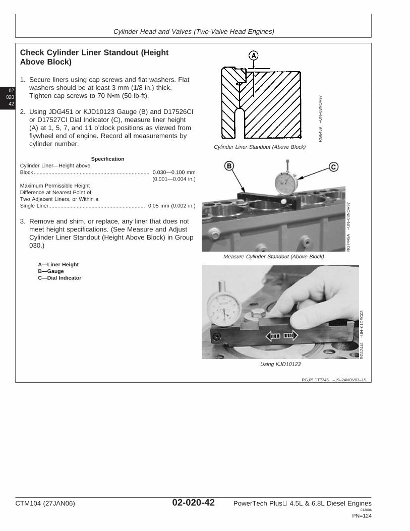
Cylinder Head and Valves (Two-Valve Head Engines)
02020
42
RG,05,DT7345 –19–24NOV03–1/1
Check Cylinder Liner Standout (HeightAbove Block)
RG
6439
–UN
–03N
OV
97
Cylinder Liner Standout (Above Block)
RG
7445
A–U
N–0
3NO
V97
Measure Cylinder Standout (Above Block)
RG
1244
1–U
N–0
1DE
C03
Using KJD10123
A—Liner HeightB—GaugeC—Dial Indicator
1. Secure liners using cap screws and flat washers. Flatwashers should be at least 3 mm (1/8 in.) thick.Tighten cap screws to 70 N•m (50 lb-ft).
2. Using JDG451 or KJD10123 Gauge (B) and D17526CIor D17527CI Dial Indicator (C), measure liner height(A) at 1, 5, 7, and 11 o’clock positions as viewed fromflywheel end of engine. Record all measurements bycylinder number.
SpecificationCylinder Liner—Height aboveBlock 0.030—0.100 mm
(0.001—0.004 in.)..............................................................................
Maximum Permissible HeightDifference at Nearest Point ofTwo Adjacent Liners, or Within aSingle Liner 0.05 mm (0.002 in.).................................................................
3. Remove and shim, or replace, any liner that does notmeet height specifications. (See Measure and AdjustCylinder Liner Standout (Height Above Block) in Group030.)
CTM104 (27JAN06) 02-020-42 PowerTech Plus 4.5L & 6.8L Diesel Engines013006
PN=124
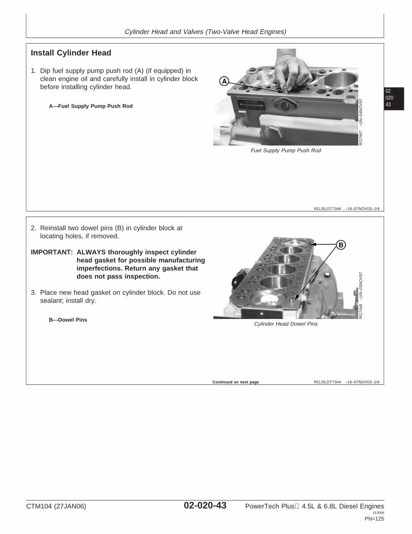
Cylinder Head and Valves (Two-Valve Head Engines)
0202043
RG,05,DT7344 –19–07NOV03–1/4
Install Cylinder Head
RG
7447
–UN
–04N
OV
97
Fuel Supply Pump Push Rod
A—Fuel Supply Pump Push Rod
1. Dip fuel supply pump push rod (A) (if equipped) inclean engine oil and carefully install in cylinder blockbefore installing cylinder head.
RG,05,DT7344 –19–07NOV03–2/4
RG
7446
–UN
–03N
OV
97
Cylinder Head Dowel PinsB—Dowel Pins
2. Reinstall two dowel pins (B) in cylinder block atlocating holes, if removed.
IMPORTANT: ALWAYS thoroughly inspect cylinderhead gasket for possible manufacturingimperfections. Return any gasket thatdoes not pass inspection.
3. Place new head gasket on cylinder block. Do not usesealant; install dry.
Continued on next page
CTM104 (27JAN06) 02-020-43 PowerTech Plus 4.5L & 6.8L Diesel Engines013006
PN=125
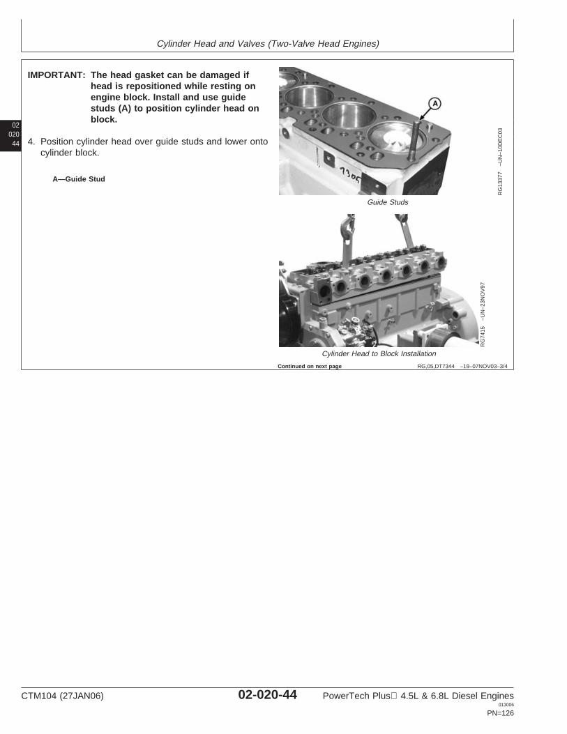
Cylinder Head and Valves (Two-Valve Head Engines)
02020
44
RG,05,DT7344 –19–07NOV03–3/4
RG
1337
7–U
N–1
0DE
C03
Guide Studs
RG
7415
–UN
–23N
OV
97
Cylinder Head to Block Installation
A—Guide Stud
IMPORTANT: The head gasket can be damaged ifhead is repositioned while resting onengine block. Install and use guidestuds (A) to position cylinder head onblock.
4. Position cylinder head over guide studs and lower ontocylinder block.
Continued on next page
CTM104 (27JAN06) 02-020-44 PowerTech Plus 4.5L & 6.8L Diesel Engines013006
PN=126
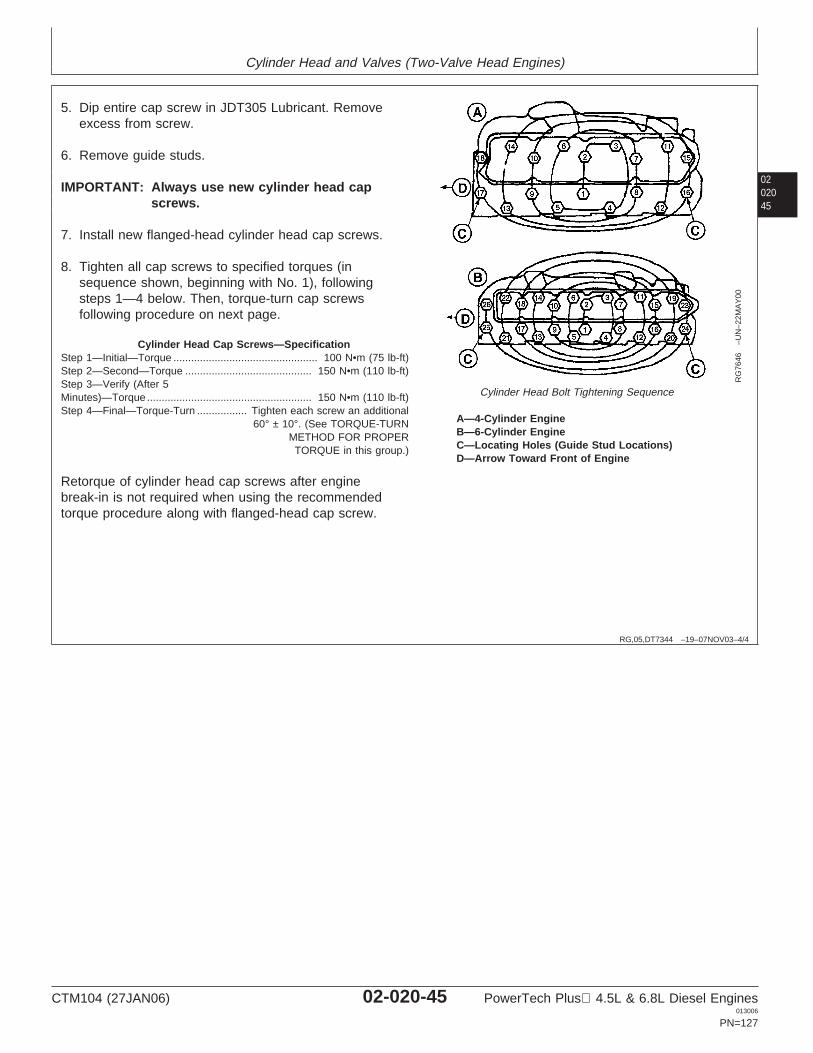
Cylinder Head and Valves (Two-Valve Head Engines)
0202045
RG,05,DT7344 –19–07NOV03–4/4
RG
7646
–UN
–22M
AY
00
Cylinder Head Bolt Tightening Sequence
A—4-Cylinder EngineB—6-Cylinder EngineC—Locating Holes (Guide Stud Locations)D—Arrow Toward Front of Engine
5. Dip entire cap screw in JDT305 Lubricant. Removeexcess from screw.
6. Remove guide studs.
IMPORTANT: Always use new cylinder head capscrews.
7. Install new flanged-head cylinder head cap screws.
8. Tighten all cap screws to specified torques (insequence shown, beginning with No. 1), followingsteps 1—4 below. Then, torque-turn cap screwsfollowing procedure on next page.
Cylinder Head Cap Screws—SpecificationStep 1—Initial—Torque 100 N•m (75 lb-ft).................................................Step 2—Second—Torque 150 N•m (110 lb-ft)...........................................Step 3—Verify (After 5Minutes)—Torque 150 N•m (110 lb-ft)........................................................Step 4—Final—Torque-Turn Tighten each screw an additional
60° ± 10°. (See TORQUE-TURNMETHOD FOR PROPERTORQUE in this group.)
.................
Retorque of cylinder head cap screws after enginebreak-in is not required when using the recommendedtorque procedure along with flanged-head cap screw.
CTM104 (27JAN06) 02-020-45 PowerTech Plus 4.5L & 6.8L Diesel Engines013006
PN=127
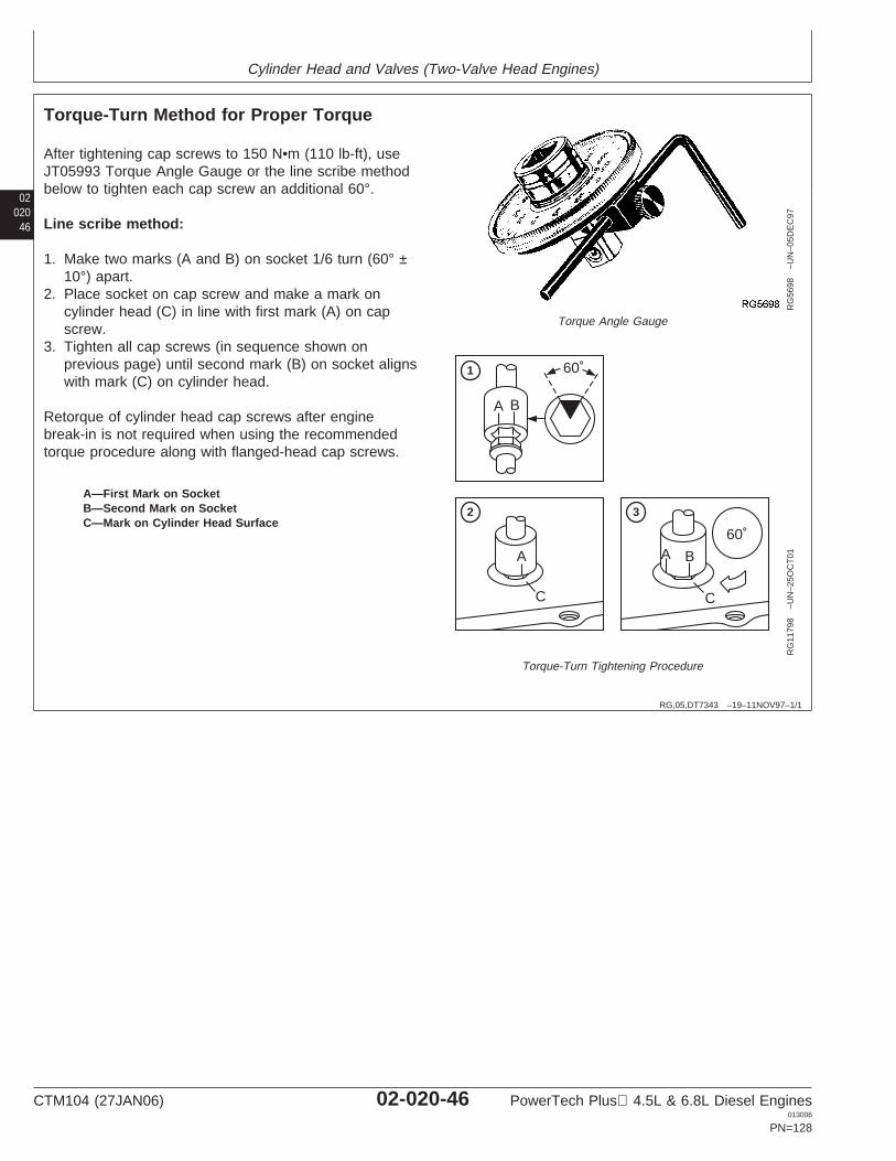
Cylinder Head and Valves (Two-Valve Head Engines)
02020
46
RG,05,DT7343 –19–11NOV97–1/1
Torque-Turn Method for Proper Torque
RG
5698
–UN
–05D
EC
97
Torque Angle Gauge
60˚
A B
BAA
C C
60˚
1
2 3
RG
1179
8–U
N–2
5OC
T01
Torque-Turn Tightening Procedure
A—First Mark on SocketB—Second Mark on SocketC—Mark on Cylinder Head Surface
After tightening cap screws to 150 N•m (110 lb-ft), useJT05993 Torque Angle Gauge or the line scribe methodbelow to tighten each cap screw an additional 60°.
Line scribe method:
1. Make two marks (A and B) on socket 1/6 turn (60° ±10°) apart.
2. Place socket on cap screw and make a mark oncylinder head (C) in line with first mark (A) on capscrew.
3. Tighten all cap screws (in sequence shown onprevious page) until second mark (B) on socket alignswith mark (C) on cylinder head.
Retorque of cylinder head cap screws after enginebreak-in is not required when using the recommendedtorque procedure along with flanged-head cap screws.
CTM104 (27JAN06) 02-020-46 PowerTech Plus 4.5L & 6.8L Diesel Engines013006
PN=128
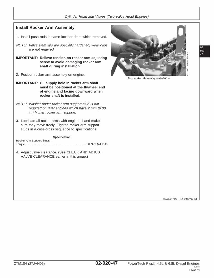
Cylinder Head and Valves (Two-Valve Head Engines)
0202047
RG,05,DT7342 –19–24NOV99–1/1
Install Rocker Arm Assembly
RG
7448
–UN
–23N
OV
97
Rocker Arm Assembly Installation
1. Install push rods in same location from which removed.
NOTE: Valve stem tips are specially hardened; wear capsare not required.
IMPORTANT: Relieve tension on rocker arm adjustingscrew to avoid damaging rocker armshaft during installation.
2. Position rocker arm assembly on engine.
IMPORTANT: Oil supply hole in rocker arm shaftmust be positioned at the flywheel endof engine and facing downward whenrocker shaft is installed.
NOTE: Washer under rocker arm support stud is notrequired on later engines which have 2 mm (0.08in.) higher rocker arm support.
3. Lubricate all rocker arms with engine oil and makesure they move freely. Tighten rocker arm supportstuds in a criss-cross sequence to specifications.
SpecificationRocker Arm Support Studs—Torque 60 N•m (44 lb-ft).............................................................................
4. Adjust valve clearance. (See CHECK AND ADJUSTVALVE CLEARANCE earlier in this group.)
CTM104 (27JAN06) 02-020-47 PowerTech Plus 4.5L & 6.8L Diesel Engines013006
PN=129
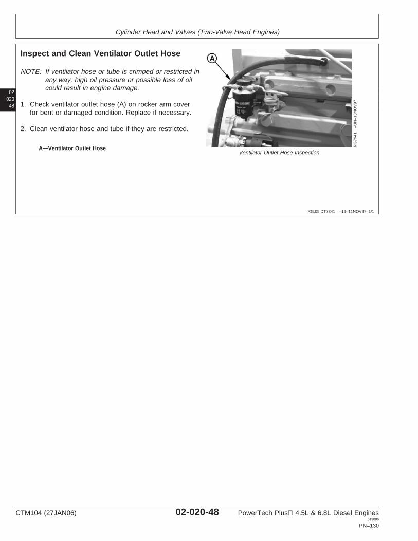
Cylinder Head and Valves (Two-Valve Head Engines)
02020
48
RG,05,DT7341 –19–11NOV97–1/1
Inspect and Clean Ventilator Outlet Hose
RG
7941
–UN
–13N
OV
97
Ventilator Outlet Hose InspectionA—Ventilator Outlet Hose
NOTE: If ventilator hose or tube is crimped or restricted inany way, high oil pressure or possible loss of oilcould result in engine damage.
1. Check ventilator outlet hose (A) on rocker arm coverfor bent or damaged condition. Replace if necessary.
2. Clean ventilator hose and tube if they are restricted.
CTM104 (27JAN06) 02-020-48 PowerTech Plus 4.5L & 6.8L Diesel Engines013006
PN=130

Cylinder Head and Valves (Two-Valve Head Engines)
0202049
OUO1083,00005FB –19–24NOV03–1/1
Remove, Inspect, and Install ClosedCrankcase Ventilation System (If Equipped)
RG
1242
6–U
N–2
0NO
V03
RG
1242
7–U
N–0
3FE
B04
A—Closed Crankcase Ventilation (CCV) ValveB—Hose, CCV Valve to Intake ManifoldC—Hose, Valve Cover to CCV ValveD—Valve Cover Vent FittingE—Intake Manifold FittingF—Cap Screw, CCV Valve to BracketG—Oil Drain HoseH—Check ValveI—Crankcase Oil Drain Tube
NOTE: CCV valve may be mounted to engine (as shown)or remotely mounted. Verify that centerline ofmounted CCV valve is between 350 mm-450 mm(13.78-17.72 in.) above centerline of crankshaft.On engines with dual dipstick option, the CCVvalve must be mounted at a minimum height of420 mm (16.54 in.). Correct the mounting locationif it is not correct.
1. Remove parts (A-H).2. Inspect hoses (C, D and G) for kinks, blockage, or
other damage.3. With check valve (H) connected to hose (G), hold hose
from end opposite check valve, letting check valvehang.
4. Pour oil into open end of hose. Oil should pass throughcheck valve before hose is full. If it does not, verify thefollowing:• Hose length is at least 275 mm (10.83 in.).• Hose is not plugged.• Check valve is installed with black end towards
crankcase.• Check valve functions correctly.
5. Verify that crankcase oil drain tube (I) is not plugged.
NOTE: CCV valve has no serviceable internal parts.
6. Inspect CCV valve (A) for cracks or other damage.7. Replace parts as necessary.8. Install parts (A—H).
CTM104 (27JAN06) 02-020-49 PowerTech Plus 4.5L & 6.8L Diesel Engines013006
PN=131
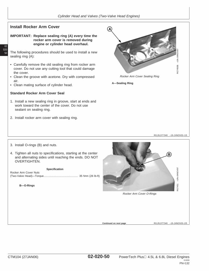
Cylinder Head and Valves (Two-Valve Head Engines)
02020
50
RG,05,DT7340 –19–24NOV03–1/5
Install Rocker Arm Cover
RG
7450
B–U
N–0
4NO
V97
Rocker Arm Cover Sealing Ring
A—Sealing Ring
IMPORTANT: Replace sealing ring (A) every time therocker arm cover is removed duringengine or cylinder head overhaul.
The following procedures should be used to install a newsealing ring (A):
• Carefully remove the old sealing ring from rocker armcover. Do not use any cutting tool that could damagethe cover.
• Clean the groove with acetone. Dry with compressedair.
• Clean mating surface of cylinder head.
Standard Rocker Arm Cover Seal
1. Install a new sealing ring in groove, start at ends andwork toward the center of the cover. Do not usesealant on sealing ring.
2. Install rocker arm cover with sealing ring.
RG,05,DT7340 –19–24NOV03–2/5
RG
7451
–UN
–04N
OV
97
Rocker Arm Cover O-Rings
B—O-Rings
3. Install O-rings (B) and nuts.
4. Tighten all nuts to specifications, starting at the centerand alternating sides until reaching the ends. DO NOTOVERTIGHTEN.
SpecificationRocker Arm Cover Nuts(Two-Valve Head)—Torque 35 N•m (26 lb-ft).............................................
Continued on next page
CTM104 (27JAN06) 02-020-50 PowerTech Plus 4.5L & 6.8L Diesel Engines013006
PN=132
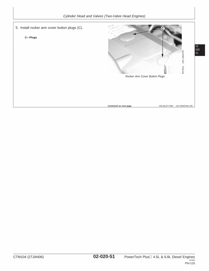
Cylinder Head and Valves (Two-Valve Head Engines)
0202051
RG,05,DT7340 –19–24NOV03–3/5
RG
7815
–UN
–13N
OV
97
Rocker Arm Cover Button Plugs
C—Plugs
5. Install rocker arm cover button plugs (C).
Continued on next page
CTM104 (27JAN06) 02-020-51 PowerTech Plus 4.5L & 6.8L Diesel Engines013006
PN=133

Cylinder Head and Valves (Two-Valve Head Engines)
02020
52
RG,05,DT7340 –19–24NOV03–4/5
RG
1243
5–U
N–0
1DE
C03
RG
1243
6–U
N–0
1DE
C03
A—Rocker Arm CoverB—GapC—Cylinder HeadD—Hold-Down StudE—Shim
Extended High Temperature Rocker Arm Cover Seal(Optional)
NOTE: Optional seal kit is available to prevent oil leakagebetween valve cover and head, in the area abovethe exhaust ports and/or directly beneath theturbo, as a result of extended high temperatureoperation.
1. Install rocker arm cover without seal. Torque covernuts to specification.
SpecificationRocker Arm Cover Nuts(Two-Valve Head)—Torque 35 N•m (26 lb-ft).............................................
2. Use a feeler gauge to measure the gap (B) betweenthe rocker arm cover (A) and the cylinder head (C).
3. Remove rocker arm cover from engine.
4. If gap (B) measured in Step 2 is less than 1.2 mm(0.047 in.), install one shim (E) onto each rocker armcover hold down stud (D).
5. If the gap measured in Step 2 is greater than 1.2 mm(0.047 in.), do not install any shims.
Continued on next page
CTM104 (27JAN06) 02-020-52 PowerTech Plus 4.5L & 6.8L Diesel Engines013006
PN=134
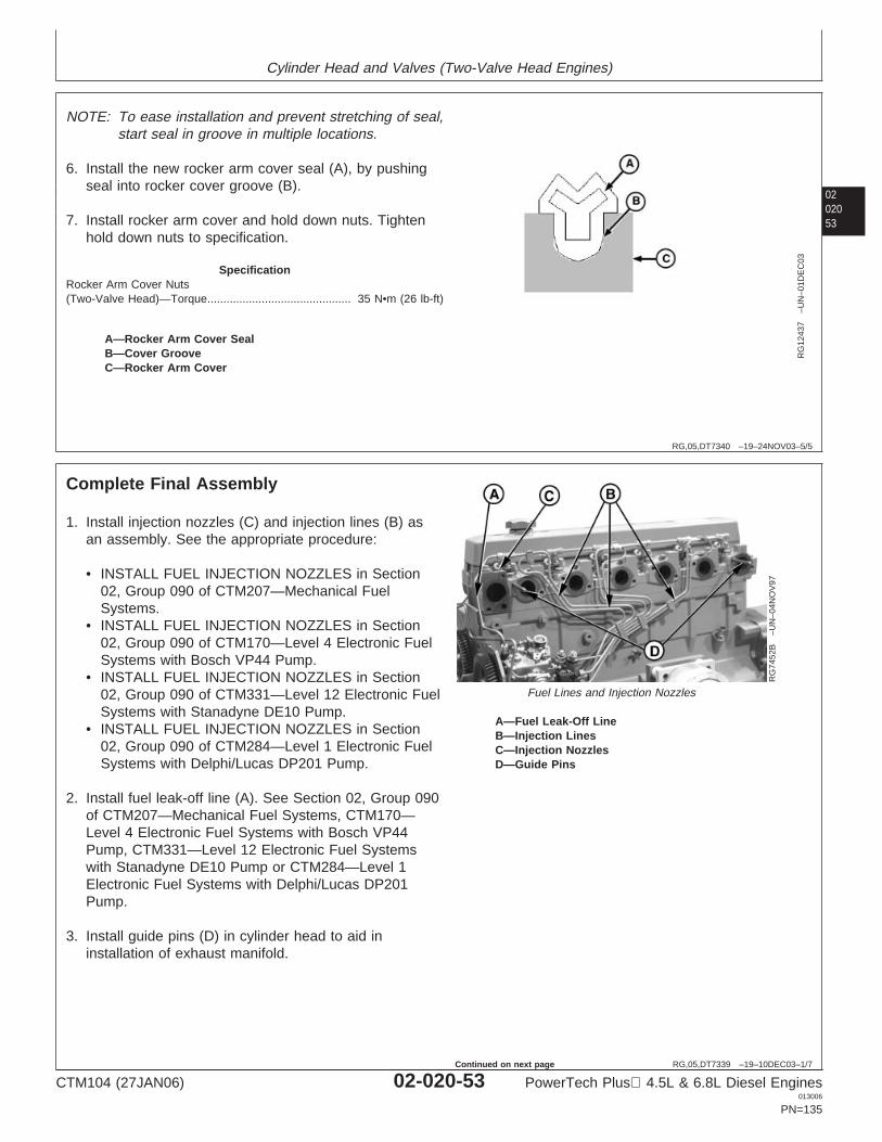
Cylinder Head and Valves (Two-Valve Head Engines)
0202053
RG,05,DT7340 –19–24NOV03–5/5
RG
1243
7–U
N–0
1DE
C03
A—Rocker Arm Cover SealB—Cover GrooveC—Rocker Arm Cover
NOTE: To ease installation and prevent stretching of seal,start seal in groove in multiple locations.
6. Install the new rocker arm cover seal (A), by pushingseal into rocker cover groove (B).
7. Install rocker arm cover and hold down nuts. Tightenhold down nuts to specification.
SpecificationRocker Arm Cover Nuts(Two-Valve Head)—Torque 35 N•m (26 lb-ft).............................................
RG,05,DT7339 –19–10DEC03–1/7
Complete Final Assembly
RG
7452
B–U
N–0
4NO
V97
Fuel Lines and Injection Nozzles
A—Fuel Leak-Off LineB—Injection LinesC—Injection NozzlesD—Guide Pins
1. Install injection nozzles (C) and injection lines (B) asan assembly. See the appropriate procedure:
• INSTALL FUEL INJECTION NOZZLES in Section02, Group 090 of CTM207—Mechanical FuelSystems.
• INSTALL FUEL INJECTION NOZZLES in Section02, Group 090 of CTM170—Level 4 Electronic FuelSystems with Bosch VP44 Pump.
• INSTALL FUEL INJECTION NOZZLES in Section02, Group 090 of CTM331—Level 12 Electronic FuelSystems with Stanadyne DE10 Pump.
• INSTALL FUEL INJECTION NOZZLES in Section02, Group 090 of CTM284—Level 1 Electronic FuelSystems with Delphi/Lucas DP201 Pump.
2. Install fuel leak-off line (A). See Section 02, Group 090of CTM207—Mechanical Fuel Systems, CTM170—Level 4 Electronic Fuel Systems with Bosch VP44Pump, CTM331—Level 12 Electronic Fuel Systemswith Stanadyne DE10 Pump or CTM284—Level 1Electronic Fuel Systems with Delphi/Lucas DP201Pump.
3. Install guide pins (D) in cylinder head to aid ininstallation of exhaust manifold.
CTM104 (27JAN06) 02-020-53 PowerTech Plus 4.5L & 6.8L Diesel Engines013006
PN=135
Continued on next page
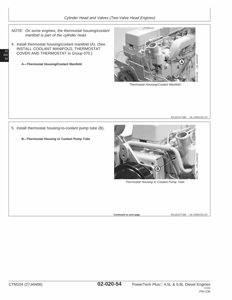
Cylinder Head and Valves (Two-Valve Head Engines)
02020
54
RG,05,DT7339 –19–10DEC03–2/7
RG
7615
A–U
N–0
6NO
V97
Thermostat Housing/Coolant Manifold
A—Thermostat Housing/Coolant Manifold
NOTE: On some engines, the thermostat housing/coolantmanifold is part of the cylinder head.
4. Install thermostat housing/coolant manifold (A). (SeeINSTALL COOLANT MANIFOLD, THERMOSTATCOVER AND THERMOSTAT in Group 070.)
RG,05,DT7339 –19–10DEC03–3/7
RG
7795
–UN
–11N
OV
97
Thermostat Housing to Coolant Pump Tube
B—Thermostat Housing to Coolant Pump Tube
5. Install thermostat housing-to-coolant pump tube (B).
Continued on next page
CTM104 (27JAN06) 02-020-54 PowerTech Plus 4.5L & 6.8L Diesel Engines013006
PN=136
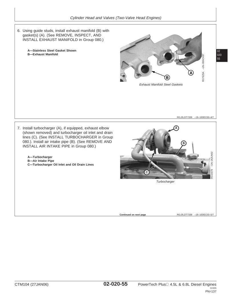
Cylinder Head and Valves (Two-Valve Head Engines)
0202055
RG,05,DT7339 –19–10DEC03–4/7
RG
7625
A–U
N–0
6NO
V97
Exhaust Manifold Steel Gaskets
A—Stainless Steel Gasket ShownB—Exhaust Manifold
6. Using guide studs, install exhaust manifold (B) withgasket(s) (A). (See REMOVE, INSPECT, ANDINSTALL EXHAUST MANIFOLD in Group 080.)
RG,05,DT7339 –19–10DEC03–5/7
RG
1037
6–U
N–2
6JU
N02
Turbocharger
A—TurbochargerB—Air Intake PipeC—Turbocharger Oil Inlet and Oil Drain Lines
7. Install turbocharger (A), if equipped, exhaust elbow(shown removed) and turbocharger oil inlet and drainlines (C). (See INSTALL TURBOCHARGER in Group080.). Install air intake pipe (B). (See REMOVE ANDINSTALL AIR INTAKE PIPE in Group 080.)
Continued on next page
CTM104 (27JAN06) 02-020-55 PowerTech Plus 4.5L & 6.8L Diesel Engines013006
PN=137
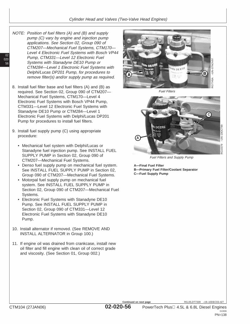
Cylinder Head and Valves (Two-Valve Head Engines)
02020
56
RG,05,DT7339 –19–10DEC03–6/7
RG
7745
A–U
N–0
7NO
V97
Fuel Filters
RG
1037
9–U
N–1
9OC
T99
Fuel Filters and Supply Pump
A—Final Fuel FilterB—Primary Fuel Filter/Coolant SeparatorC—Fuel Supply Pump
NOTE: Position of fuel filters (A) and (B) and supplypump (C) vary by engine and injection pumpapplications. See Section 02, Group 090 ofCTM207—Mechanical Fuel Systems, CTM170—Level 4 Electronic Fuel Systems with Bosch VP44Pump, CTM331—Level 12 Electronic FuelSystems with Stanadyne DE10 Pump orCTM284—Level 1 Electronic Fuel Systems withDelphi/Lucas DP201 Pump, for procedures toremove filter(s) and/or supply pump as required.
8. Install fuel filter base and fuel filters (A) and (B) asrequired. See Section 02, Group 090 of CTM207—Mechanical Fuel Systems, CTM170—Level 4Electronic Fuel Systems with Bosch VP44 Pump,CTM331—Level 12 Electronic Fuel Systems withStanadyne DE10 Pump or CTM284—Level 1Electronic Fuel Systems with Delphi/Lucas DP201Pump for procedures to install fuel filters.
9. Install fuel supply pump (C) using appropriateprocedure:
• Mechanical fuel system with Delphi/Lucas orStanadyne fuel injection pump. See INSTALL FUELSUPPLY PUMP in Section 02, Group 090 ofCTM207—Mechanical Fuel Systems.
• Denso fuel supply pump on mechanical fuel system.See INSTALL FUEL SUPPLY PUMP in Section 02,Group 090 of CTM207—Mechanical Fuel Systems.
• Motorpal fuel supply pump on mechanical fuelsystem. See INSTALL FUEL SUPPLY PUMP inSection 02, Group 090 of CTM207—Mechanical FuelSystems.
• Electronic Fuel Systems with Stanadyne DE10Pump. See INSTALL FUEL SUPPLY PUMP inSection 02, Group 090 of CTM331—Level 12Electronic Fuel Systems with Stanadyne DE10Pump.
10. Install alternator if removed. (See REMOVE ANDINSTALL ALTERNATOR in Group 100.)
11. If engine oil was drained from crankcase, install newoil filter and fill engine with clean oil of correct gradeand viscosity. (See Section 01, Group 002.)
CTM104 (27JAN06) 02-020-56 PowerTech Plus 4.5L & 6.8L Diesel Engines013006
PN=138
Continued on next page
Cylinder Head and Valves (Two-Valve Head Engines)
0202057
RG,05,DT7339 –19–10DEC03–7/7
12. Fill cooling system with clean coolant. (See Section01, Group 002.)
13. Perform engine break-in. (See PERFORM ENGINEBREAK-IN in Group 010.)
CTM104 (27JAN06) 02-020-57 PowerTech Plus 4.5L & 6.8L Diesel Engines013006
PN=139
Cylinder Head and Valves (Two-Valve Head Engines)
02020
58
CTM104 (27JAN06) 02-020-58 PowerTech Plus 4.5L & 6.8L Diesel Engines013006
PN=140
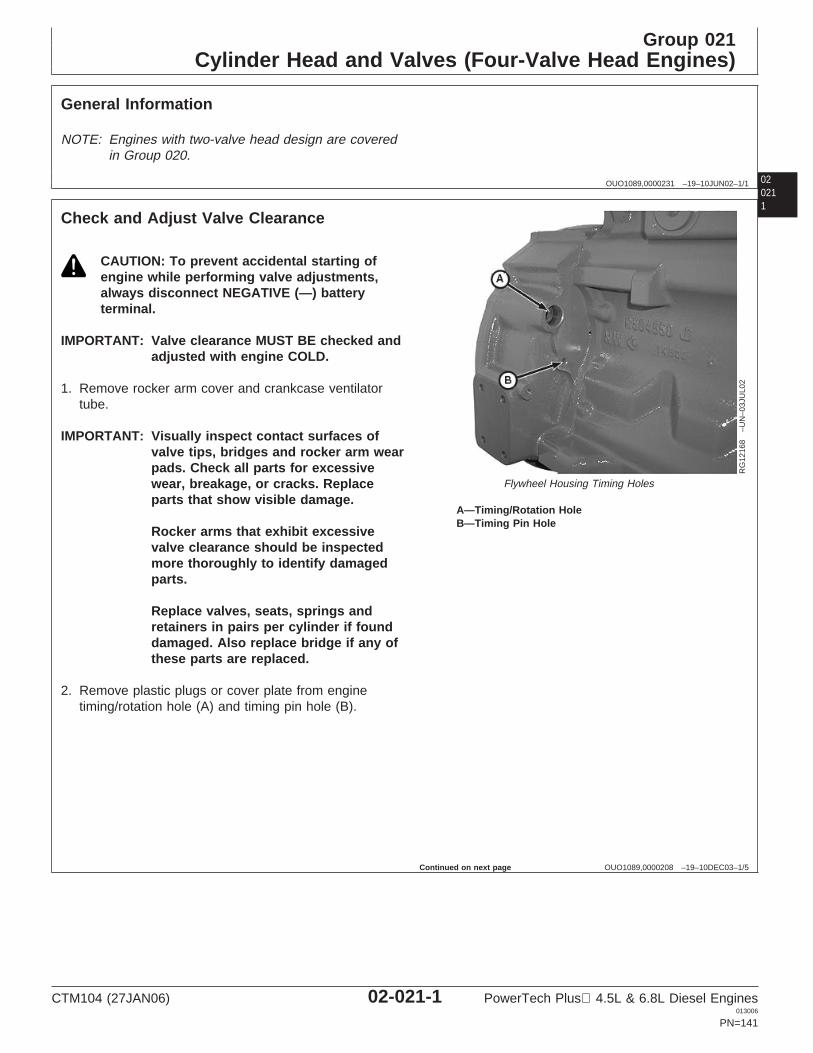
Group 021Cylinder Head and Valves (Four-Valve Head Engines)
02021
OUO1089,0000231 –19–10JUN02–1/1
General Information
NOTE: Engines with two-valve head design are coveredin Group 020.
1
OUO1089,0000208 –19–10DEC03–1/5
Check and Adjust Valve Clearance
RG
1216
8–U
N–0
3JU
L02
Flywheel Housing Timing Holes
A—Timing/Rotation HoleB—Timing Pin Hole
CAUTION: To prevent accidental starting ofengine while performing valve adjustments,always disconnect NEGATIVE (—) batteryterminal.
IMPORTANT: Valve clearance MUST BE checked andadjusted with engine COLD.
1. Remove rocker arm cover and crankcase ventilatortube.
IMPORTANT: Visually inspect contact surfaces ofvalve tips, bridges and rocker arm wearpads. Check all parts for excessivewear, breakage, or cracks. Replaceparts that show visible damage.
Rocker arms that exhibit excessivevalve clearance should be inspectedmore thoroughly to identify damagedparts.
Replace valves, seats, springs andretainers in pairs per cylinder if founddamaged. Also replace bridge if any ofthese parts are replaced.
2. Remove plastic plugs or cover plate from enginetiming/rotation hole (A) and timing pin hole (B).
Continued on next page
CTM104 (27JAN06) 02-021-1 PowerTech Plus 4.5L & 6.8L Diesel Engines013006
PN=141
Cylinder Head and Valves (Four-Valve Head Engines)
02021
2
OUO1089,0000208 –19–10DEC03–2/5
NOTE: Some engines are equipped with flywheelhousings which do not allow use of an engineflywheel rotation tool. These engines with straightnose crankshafts may be rotated from front noseof engine, using JDG966 Crankshaft Front/RearRotation Adapter.
3. Using JDE83 or JDE81-11 Flywheel Turning Tool,rotate engine flywheel in running direction (clockwiseviewed from front) until No. 1 cylinder is at TDCcompression stroke. Insert JDG1571 or JDE81-4Timing Pin in flywheel.
If No. 1 cylinder rocker arms are loose, the engine is atNo. 1 TDC compression.
If No. 1 cylinder rocker arms are not loose, rotateengine one full revolution (360°) to No. 1 TDCcompression.
1JDG820 (formerly JDE81-1) Flywheel Turning Tool may be used ifJDE81-1 is not available, JDG820 (formerly JDE81-1) Flywheel TurningTool MUST be used for 6.8L engines in 7400 and 7600 Tractors.
Continued on next page
CTM104 (27JAN06) 02-021-2 PowerTech Plus 4.5L & 6.8L Diesel Engines013006
PN=142

Cylinder Head and Valves (Four-Valve Head Engines)
020213
OUO1089,0000208 –19–10DEC03–3/5
RG
1216
9–U
N–0
3JU
L02
Adjusting Valves
A—Adjusting Screw Jam Nut
4. With engine lock-pinned at TDC of No. 1 piston’scompression stroke, check valve clearance to followingspecifications. (Use sequence for 4-cylinder or6-cylinder engines as outlined on next page.)
If valves need adjusting, loosen the jam nut (A) onrocker arm adjusting screw. Turn adjusting screw untilfeeler gauge slips with a slight drag. Hold the adjustingscrew from turning with screwdriver and tighten jam nutto specifications. Recheck clearance again aftertightening jam nut. Readjust clearance as necessary.
SpecificationIntake Valve Clearance (RockerArm-to-Bridge) (Engine Cold)—Clearance 0.36 mm (0.014 in.)...................................................................Exhaust Valve Clearance (RockerArm-to-Bridge) (Engine Cold)—Clearance 0.46 mm (0.018 in.)...................................................................Rocker Arm Adjusting Screw JamNut—Torque 27 N•m (20 lb-ft)....................................................................
5. Install rocker arm cover and crankcase ventilator tube.
OUO1089,0000208 –19–10DEC03–4/5
A
B
E I4
E3
I E2
I E1
I
E4
I E3
I E2
I E1
I
C
RG
1235
7–U
N–2
9MA
Y02
4-Cylinder Valve Adjustment
A—Front of EngineB—No. 1 Piston TDC CompressionC—No. 4 Piston TDC CompressionE—Exhaust ValveI—Intake Valve
4-Cylinder Engine:
NOTE: Firing order is 1-3-4-2.
1. Using JDG1571 or JDE81-4 Timing Pin, lock No. 1piston at TDC compression stroke (B).
2. Adjust valve clearance on No. 1 and 3 exhaust valvesand No. 1 and 2 intake valves.
3. Turn crankshaft 360°. Lock No. 4 piston at TDCcompression stroke (C).
4. Adjust valve clearance on No. 2 and 4 exhaust valvesand No. 3 and 4 intake valves.
Continued on next page
CTM104 (27JAN06) 02-021-3 PowerTech Plus 4.5L & 6.8L Diesel Engines013006
PN=143

Cylinder Head and Valves (Four-Valve Head Engines)
02021
4
OUO1089,0000208 –19–10DEC03–5/5
A
B
E6
I E5
I E4
I E3
I E2
I E1
I
E6
I E5
I E4
I E3
I E2
I E1
I
C
RG
1217
0–U
N–2
1MA
Y02
6-Cylinder Valve Adjustment
A—Front of EngineB—No. 1 Piston TDC CompressionC—No. 6 Piston TDC CompressionE—Exhaust ValveI—Intake Valve
6-Cylinder Engine:
NOTE: Firing order is 1-5-3-6-2-4.
1. Using JDG1571 or JDE81-4 Timing Pin, lock No. 1piston at TDC compression stroke (B).
2. Adjust valve clearance on No. 1, 3 and 5 exhaustvalves and No. 1, 2, and 4 intake valves.
3. Turn crankshaft 360°. Lock No. 6 piston at TDCcompression stroke (C).
4. Adjust valve clearance on No. 2, 4 and 6 exhaustvalves and No. 3, 5, and 6 intake valves.
CTM104 (27JAN06) 02-021-4 PowerTech Plus 4.5L & 6.8L Diesel Engines013006
PN=144
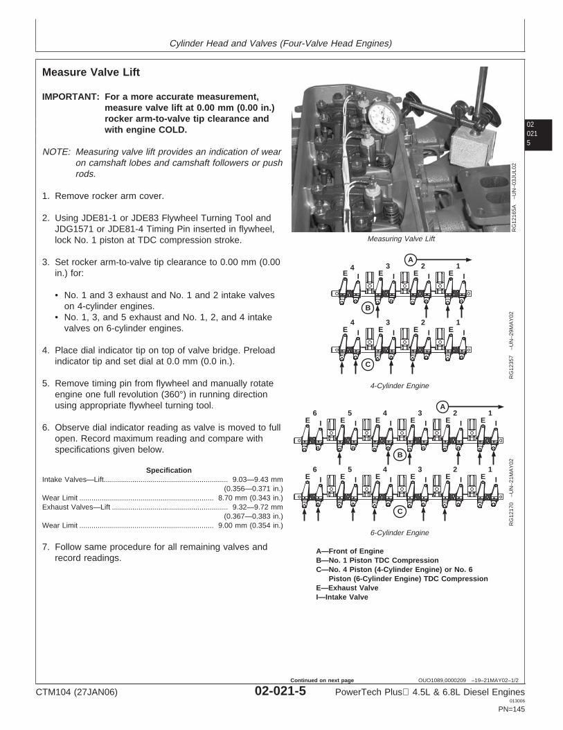
Cylinder Head and Valves (Four-Valve Head Engines)
020215
OUO1089,0000209 –19–21MAY02–1/2
Measure Valve Lift
RG
1216
5A–U
N–0
3JU
L02
Measuring Valve Lift
A
B
E I4
E3
I E2
I E1
I
E4
I E3
I E2
I E1
I
C
RG
1235
7–U
N–2
9MA
Y02
4-Cylinder Engine
A
B
E6
I E5
I E4
I E3
I E2
I E1
I
E6
I E5
I E4
I E3
I E2
I E1
I
CR
G12
170
–UN
–21M
AY
02
6-Cylinder Engine
A—Front of EngineB—No. 1 Piston TDC CompressionC—No. 4 Piston (4-Cylinder Engine) or No. 6
Piston (6-Cylinder Engine) TDC CompressionE—Exhaust ValveI—Intake Valve
IMPORTANT: For a more accurate measurement,measure valve lift at 0.00 mm (0.00 in.)rocker arm-to-valve tip clearance andwith engine COLD.
NOTE: Measuring valve lift provides an indication of wearon camshaft lobes and camshaft followers or pushrods.
1. Remove rocker arm cover.
2. Using JDE81-1 or JDE83 Flywheel Turning Tool andJDG1571 or JDE81-4 Timing Pin inserted in flywheel,lock No. 1 piston at TDC compression stroke.
3. Set rocker arm-to-valve tip clearance to 0.00 mm (0.00in.) for:
• No. 1 and 3 exhaust and No. 1 and 2 intake valveson 4-cylinder engines.
• No. 1, 3, and 5 exhaust and No. 1, 2, and 4 intakevalves on 6-cylinder engines.
4. Place dial indicator tip on top of valve bridge. Preloadindicator tip and set dial at 0.0 mm (0.0 in.).
5. Remove timing pin from flywheel and manually rotateengine one full revolution (360°) in running directionusing appropriate flywheel turning tool.
6. Observe dial indicator reading as valve is moved to fullopen. Record maximum reading and compare withspecifications given below.
SpecificationIntake Valves—Lift 9.03—9.43 mm
(0.356—0.371 in.).............................................................
Wear Limit 8.70 mm (0.343 in.)..................................................................Exhaust Valves—Lift 9.32—9.72 mm
(0.367—0.383 in.).........................................................
Wear Limit 9.00 mm (0.354 in.)..................................................................
7. Follow same procedure for all remaining valves andrecord readings.
CTM104 (27JAN06) 02-021-5 PowerTech Plus 4.5L & 6.8L Diesel Engines013006
PN=145
Continued on next page
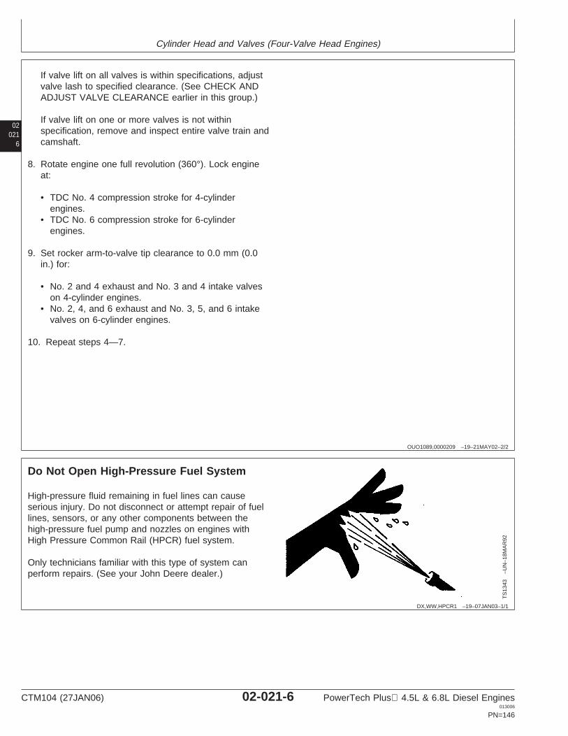
Cylinder Head and Valves (Four-Valve Head Engines)
02021
6
OUO1089,0000209 –19–21MAY02–2/2
If valve lift on all valves is within specifications, adjustvalve lash to specified clearance. (See CHECK ANDADJUST VALVE CLEARANCE earlier in this group.)
If valve lift on one or more valves is not withinspecification, remove and inspect entire valve train andcamshaft.
8. Rotate engine one full revolution (360°). Lock engineat:
• TDC No. 4 compression stroke for 4-cylinderengines.
• TDC No. 6 compression stroke for 6-cylinderengines.
9. Set rocker arm-to-valve tip clearance to 0.0 mm (0.0in.) for:
• No. 2 and 4 exhaust and No. 3 and 4 intake valveson 4-cylinder engines.
• No. 2, 4, and 6 exhaust and No. 3, 5, and 6 intakevalves on 6-cylinder engines.
10. Repeat steps 4—7.
DX,WW,HPCR1 –19–07JAN03–1/1
Do Not Open High-Pressure Fuel System
TS
1343
–UN
–18M
AR
92High-pressure fluid remaining in fuel lines can causeserious injury. Do not disconnect or attempt repair of fuellines, sensors, or any other components between thehigh-pressure fuel pump and nozzles on engines withHigh Pressure Common Rail (HPCR) fuel system.
Only technicians familiar with this type of system canperform repairs. (See your John Deere dealer.)
CTM104 (27JAN06) 02-021-6 PowerTech Plus 4.5L & 6.8L Diesel Engines013006
PN=146
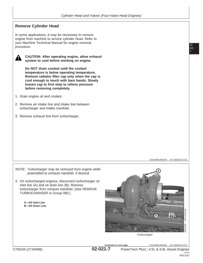
Cylinder Head and Valves (Four-Valve Head Engines)
020217
OUO1089,000020A –19–10DEC03–1/13
Remove Cylinder Head
In some applications, it may be necessary to removeengine from machine to service cylinder head. Refer toyour Machine Technical Manual for engine removalprocedure.
CAUTION: After operating engine, allow exhaustsystem to cool before working on engine.
Do NOT drain coolant until the coolanttemperature is below operating temperature.Remove radiator filler cap only when the cap iscool enough to touch with bare hands. Slowlyloosen cap to first stop to relieve pressurebefore removing completely.
1. Drain engine oil and coolant.
2. Remove air intake line and intake line betweenturbocharger and intake manifold.
3. Remove exhaust line from turbocharger.
OUO1089,000020A –19–10DEC03–2/13
RG
1216
6–U
N–0
3JU
L02
Turbocharger
A—Oil Inlet LineB—Oil Drain Line
NOTE: Turbocharger may be removed from engine whileassembled to exhaust manifold, if desired.
4. On turbocharged engines, disconnect turbocharger oilinlet line (A) and oil drain line (B). Removeturbocharger from exhaust manifold. (See REMOVETURBOCHARGER in Group 080.)
CTM104 (27JAN06) 02-021-7 PowerTech Plus 4.5L & 6.8L Diesel Engines013006
PN=147
Continued on next page
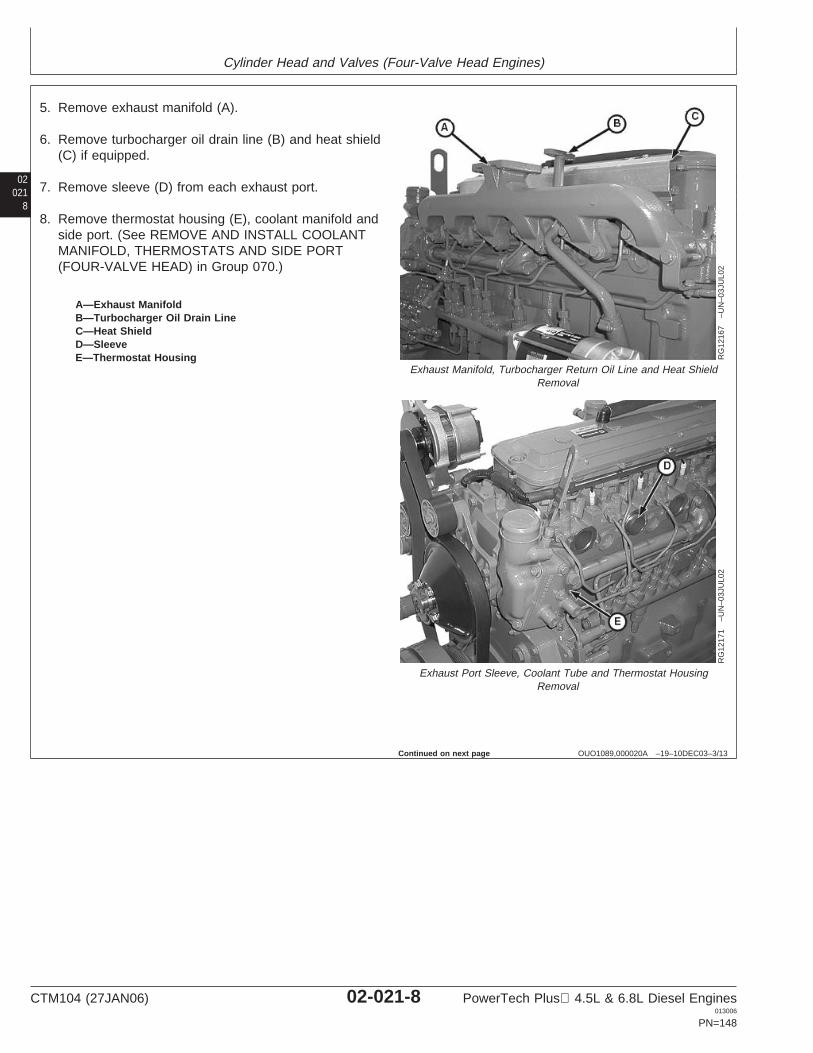
Cylinder Head and Valves (Four-Valve Head Engines)
02021
8
OUO1089,000020A –19–10DEC03–3/13
RG
1216
7–U
N–0
3JU
L02
Exhaust Manifold, Turbocharger Return Oil Line and Heat ShieldRemoval
RG
1217
1–U
N–0
3JU
L02
Exhaust Port Sleeve, Coolant Tube and Thermostat HousingRemoval
A—Exhaust ManifoldB—Turbocharger Oil Drain LineC—Heat ShieldD—SleeveE—Thermostat Housing
5. Remove exhaust manifold (A).
6. Remove turbocharger oil drain line (B) and heat shield(C) if equipped.
7. Remove sleeve (D) from each exhaust port.
8. Remove thermostat housing (E), coolant manifold andside port. (See REMOVE AND INSTALL COOLANTMANIFOLD, THERMOSTATS AND SIDE PORT(FOUR-VALVE HEAD) in Group 070.)
Continued on next page
CTM104 (27JAN06) 02-021-8 PowerTech Plus 4.5L & 6.8L Diesel Engines013006
PN=148
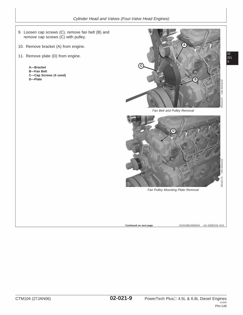
Cylinder Head and Valves (Four-Valve Head Engines)
020219
OUO1089,000020A –19–10DEC03–4/13
RG
1217
2–U
N–0
3JU
L02
Fan Belt and Pulley Removal
RG
1217
3–U
N–0
3JU
L02
Fan Pulley Mounting Plate Removal
A—BracketB—Fan BeltC—Cap Screws (4 used)D—Plate
9. Loosen cap screws (C), remove fan belt (B) andremove cap screws (C) with pulley.
10. Remove bracket (A) from engine.
11. Remove plate (D) from engine.
Continued on next page
CTM104 (27JAN06) 02-021-9 PowerTech Plus 4.5L & 6.8L Diesel Engines013006
PN=149
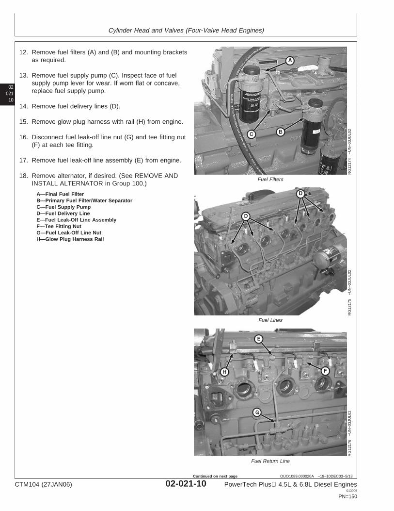
Cylinder Head and Valves (Four-Valve Head Engines)
02021
10
OUO1089,000020A –19–10DEC03–5/13
RG
1217
4–U
N–0
3JU
L02
Fuel Filters
RG
1217
5–U
N–0
3JU
L02
Fuel Lines
RG
1217
6–U
N–0
3JU
L02
Fuel Return Line
A—Final Fuel FilterB—Primary Fuel Filter/Water SeparatorC—Fuel Supply PumpD—Fuel Delivery LineE—Fuel Leak-Off Line AssemblyF—Tee Fitting NutG—Fuel Leak-Off Line NutH—Glow Plug Harness Rail
12. Remove fuel filters (A) and (B) and mounting bracketsas required.
13. Remove fuel supply pump (C). Inspect face of fuelsupply pump lever for wear. If worn flat or concave,replace fuel supply pump.
14. Remove fuel delivery lines (D).
15. Remove glow plug harness with rail (H) from engine.
16. Disconnect fuel leak-off line nut (G) and tee fitting nut(F) at each tee fitting.
17. Remove fuel leak-off line assembly (E) from engine.
18. Remove alternator, if desired. (See REMOVE ANDINSTALL ALTERNATOR in Group 100.)
CTM104 (27JAN06) 02-021-10 PowerTech Plus 4.5L & 6.8L Diesel Engines013006
PN=150
Continued on next page
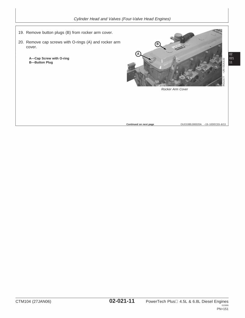
Cylinder Head and Valves (Four-Valve Head Engines)
0202111
OUO1089,000020A –19–10DEC03–6/13
RG
1217
7–U
N–0
3JU
L02
Rocker Arm Cover
A—Cap Screw with O-ringB—Button Plug
19. Remove button plugs (B) from rocker arm cover.
20. Remove cap screws with O-rings (A) and rocker armcover.
Continued on next page
CTM104 (27JAN06) 02-021-11 PowerTech Plus 4.5L & 6.8L Diesel Engines013006
PN=151
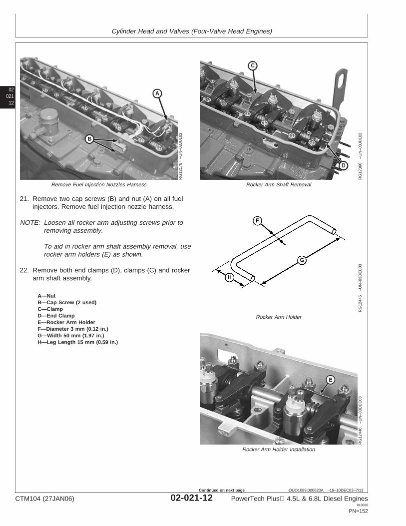
Cylinder Head and Valves (Four-Valve Head Engines)
02021
12
OUO1089,000020A –19–10DEC03–7/13
RG
1217
8–U
N–0
3JU
L02
Remove Fuel Injection Nozzles Harness
RG
1236
0–U
N–0
3JU
L02
Rocker Arm Shaft Removal
RG
1244
5–U
N–0
3DE
C03
Rocker Arm Holder
RG
1244
6–U
N–0
3DE
C03
Rocker Arm Holder Installation
A—NutB—Cap Screw (2 used)C—ClampD—End ClampE—Rocker Arm HolderF—Diameter 3 mm (0.12 in.)G—Width 50 mm (1.97 in.)H—Leg Length 15 mm (0.59 in.)
21. Remove two cap screws (B) and nut (A) on all fuelinjectors. Remove fuel injection nozzle harness.
NOTE: Loosen all rocker arm adjusting screws prior toremoving assembly.
To aid in rocker arm shaft assembly removal, userocker arm holders (E) as shown.
22. Remove both end clamps (D), clamps (C) and rockerarm shaft assembly.
CTM104 (27JAN06) 02-021-12 PowerTech Plus 4.5L & 6.8L Diesel Engines013006
PN=152
Continued on next page
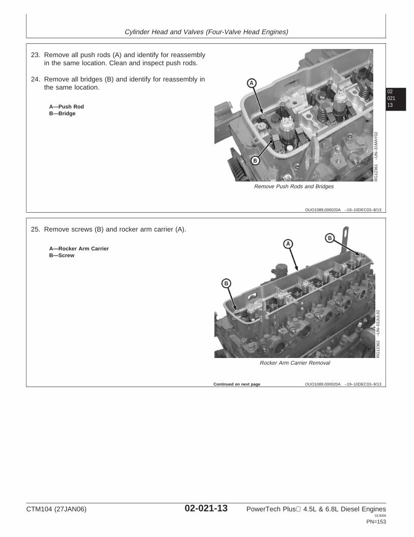
Cylinder Head and Valves (Four-Valve Head Engines)
0202113
OUO1089,000020A –19–10DEC03–8/13
RG
1236
1–U
N–3
1MA
Y02
Remove Push Rods and Bridges
A—Push RodB—Bridge
23. Remove all push rods (A) and identify for reassemblyin the same location. Clean and inspect push rods.
24. Remove all bridges (B) and identify for reassembly inthe same location.
OUO1089,000020A –19–10DEC03–9/13
RG
1236
2–U
N–0
3JU
L02
Rocker Arm Carrier Removal
A—Rocker Arm CarrierB—Screw
25. Remove screws (B) and rocker arm carrier (A).
Continued on next page
CTM104 (27JAN06) 02-021-13 PowerTech Plus 4.5L & 6.8L Diesel Engines013006
PN=153
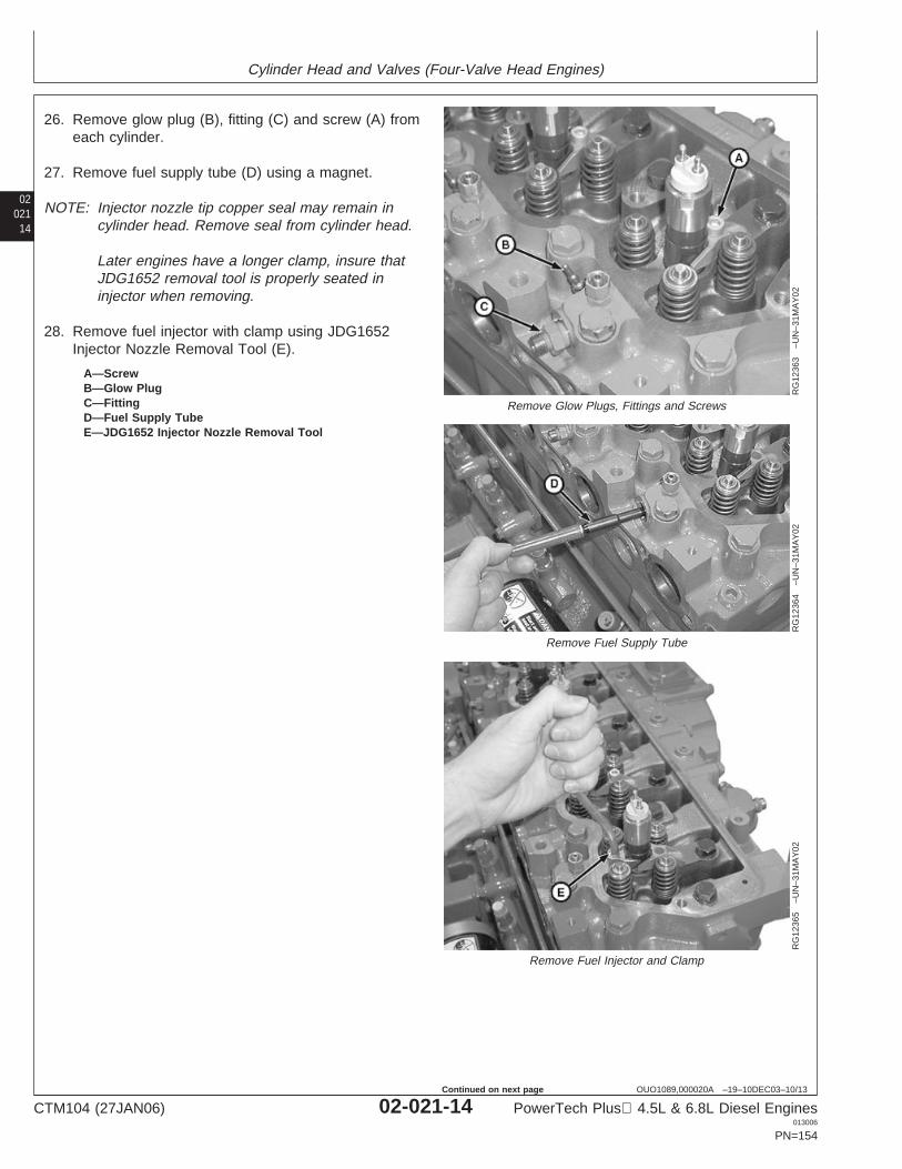
Cylinder Head and Valves (Four-Valve Head Engines)
02021
14
OUO1089,000020A –19–10DEC03–10/13
RG
1236
3–U
N–3
1MA
Y02
Remove Glow Plugs, Fittings and Screws
RG
1236
4–U
N–3
1MA
Y02
Remove Fuel Supply Tube
RG
1236
5–U
N–3
1MA
Y02
Remove Fuel Injector and Clamp
A—ScrewB—Glow PlugC—FittingD—Fuel Supply TubeE—JDG1652 Injector Nozzle Removal Tool
26. Remove glow plug (B), fitting (C) and screw (A) fromeach cylinder.
27. Remove fuel supply tube (D) using a magnet.
NOTE: Injector nozzle tip copper seal may remain incylinder head. Remove seal from cylinder head.
Later engines have a longer clamp, insure thatJDG1652 removal tool is properly seated ininjector when removing.
28. Remove fuel injector with clamp using JDG1652Injector Nozzle Removal Tool (E).
CTM104 (27JAN06) 02-021-14 PowerTech Plus 4.5L & 6.8L Diesel Engines013006
PN=154
Continued on next page
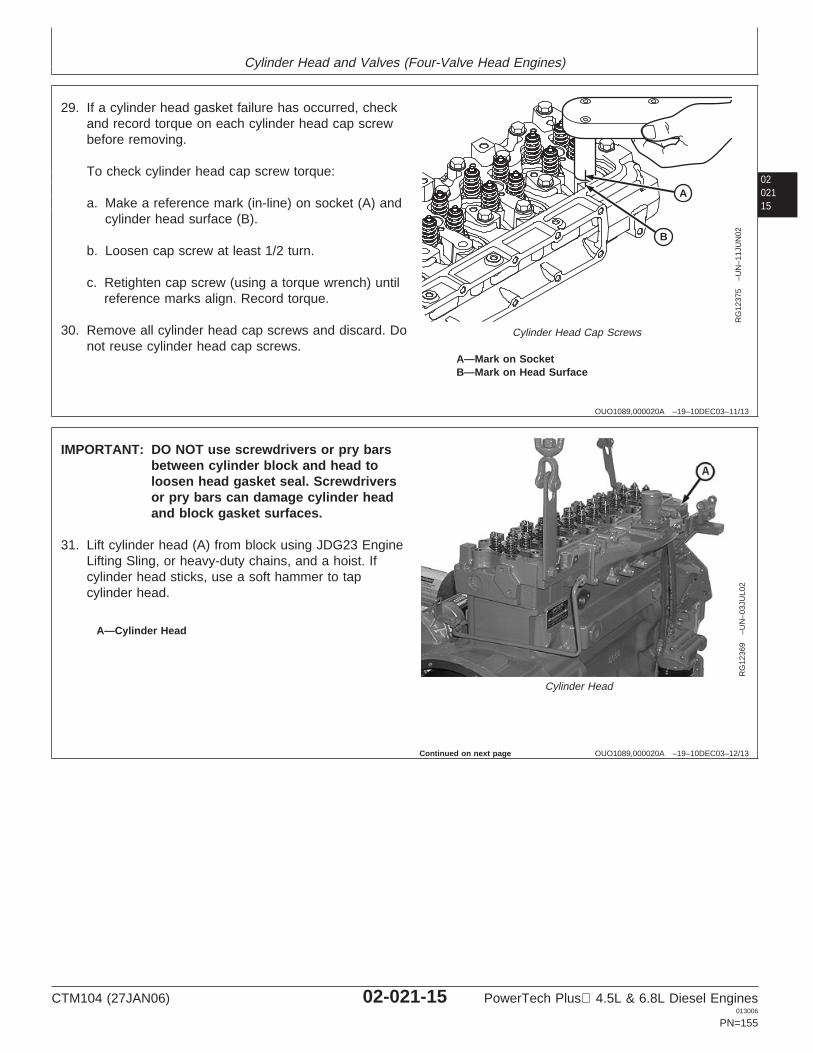
Cylinder Head and Valves (Four-Valve Head Engines)
0202115
OUO1089,000020A –19–10DEC03–11/13
B
A
RG
1237
5–U
N–1
1JU
N02
Cylinder Head Cap Screws
A—Mark on SocketB—Mark on Head Surface
29. If a cylinder head gasket failure has occurred, checkand record torque on each cylinder head cap screwbefore removing.
To check cylinder head cap screw torque:
a. Make a reference mark (in-line) on socket (A) andcylinder head surface (B).
b. Loosen cap screw at least 1/2 turn.
c. Retighten cap screw (using a torque wrench) untilreference marks align. Record torque.
30. Remove all cylinder head cap screws and discard. Donot reuse cylinder head cap screws.
OUO1089,000020A –19–10DEC03–12/13
RG
1236
9–U
N–0
3JU
L02
Cylinder Head
A—Cylinder Head
IMPORTANT: DO NOT use screwdrivers or pry barsbetween cylinder block and head toloosen head gasket seal. Screwdriversor pry bars can damage cylinder headand block gasket surfaces.
31. Lift cylinder head (A) from block using JDG23 EngineLifting Sling, or heavy-duty chains, and a hoist. Ifcylinder head sticks, use a soft hammer to tapcylinder head.
Continued on next page
CTM104 (27JAN06) 02-021-15 PowerTech Plus 4.5L & 6.8L Diesel Engines013006
PN=155
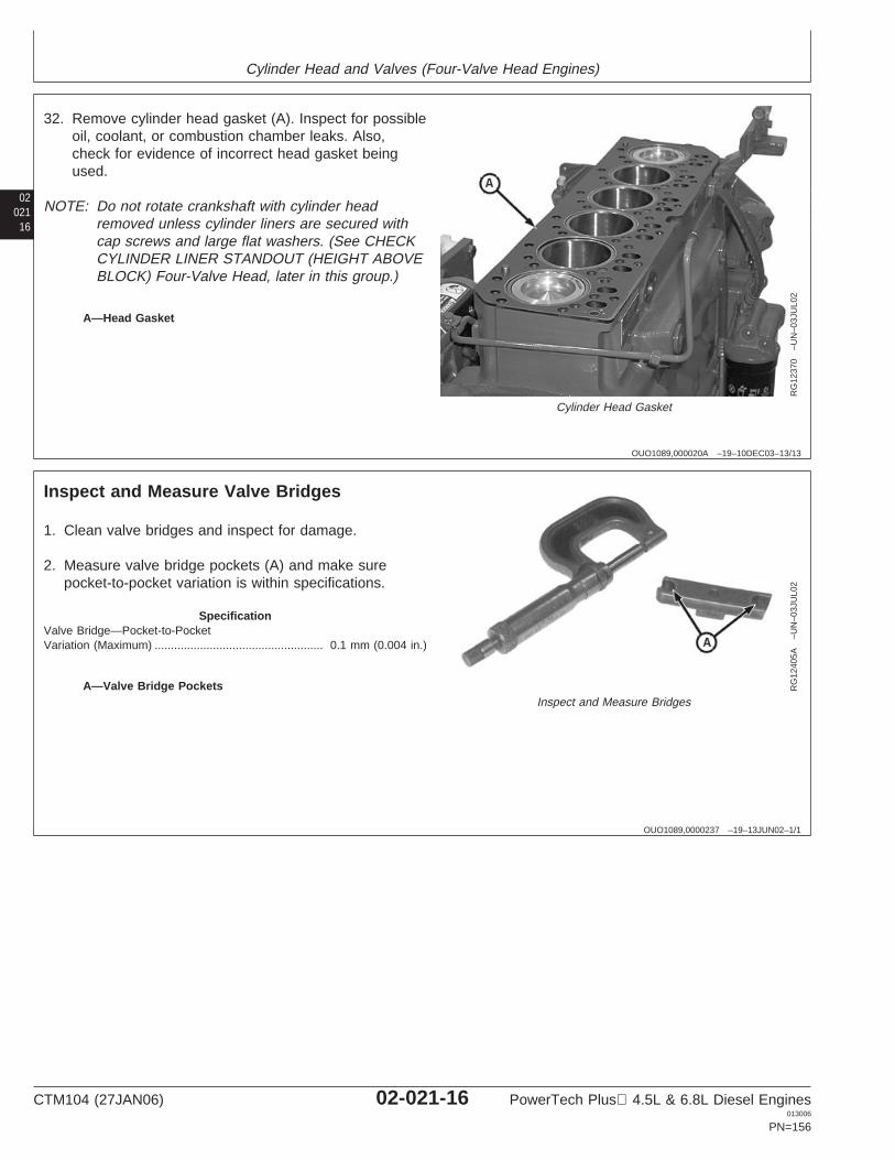
Cylinder Head and Valves (Four-Valve Head Engines)
02021
16
OUO1089,000020A –19–10DEC03–13/13
RG
1237
0–U
N–0
3JU
L02
Cylinder Head Gasket
A—Head Gasket
32. Remove cylinder head gasket (A). Inspect for possibleoil, coolant, or combustion chamber leaks. Also,check for evidence of incorrect head gasket beingused.
NOTE: Do not rotate crankshaft with cylinder headremoved unless cylinder liners are secured withcap screws and large flat washers. (See CHECKCYLINDER LINER STANDOUT (HEIGHT ABOVEBLOCK) Four-Valve Head, later in this group.)
OUO1089,0000237 –19–13JUN02–1/1
Inspect and Measure Valve Bridges
RG
1240
5A–U
N–0
3JU
L02
Inspect and Measure BridgesA—Valve Bridge Pockets
1. Clean valve bridges and inspect for damage.
2. Measure valve bridge pockets (A) and make surepocket-to-pocket variation is within specifications.
SpecificationValve Bridge—Pocket-to-PocketVariation (Maximum) 0.1 mm (0.004 in.)....................................................
CTM104 (27JAN06) 02-021-16 PowerTech Plus 4.5L & 6.8L Diesel Engines013006
PN=156
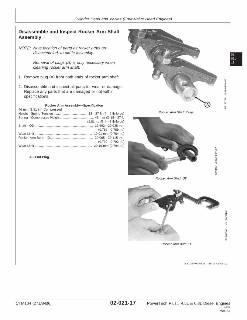
Cylinder Head and Valves (Four-Valve Head Engines)
0202117
OUO1089,000020B –19–04JUN02–1/1
Disassemble and Inspect Rocker Arm ShaftAssembly
RG
1237
2A–U
N–0
5JU
N02
Rocker Arm Shaft Plugs
RG
7418
–UN
–23N
OV
97
Rocker Arm Shaft OD
RG
1237
3A–U
N–0
5JU
N02
Rocker Arm Bore ID
A—End Plug
NOTE: Note location of parts as rocker arms aredisassembled, to aid in assembly.
Removal of plugs (A) is only necessary whencleaning rocker arm shaft.
1. Remove plug (A) from both ends of rocker arm shaft.
2. Disassemble and inspect all parts for wear or damage.Replace any parts that are damaged or not withinspecifications.
Rocker Arm Assembly—Specification46 mm (1.81 in.) CompressedHeight—Spring Tension 18—27 N (4—6 lb-force).....................................Spring—Compressed Height 46 mm @ 18—27 N
(1.81 in. @ 4—6 lb-force)......................................
Shaft—OD 19.962—20.038 mm(0.786—0.789 in.)
.................................................................
Wear Limit 19.91 mm (0.784 in.)................................................................Rocker Arm Bore—ID 20.065—20.115 mm
(0.790—0.792 in.)................................................
Wear Limit 20.16 mm (0.794 in.)................................................................
CTM104 (27JAN06) 02-021-17 PowerTech Plus 4.5L & 6.8L Diesel Engines013006
PN=157
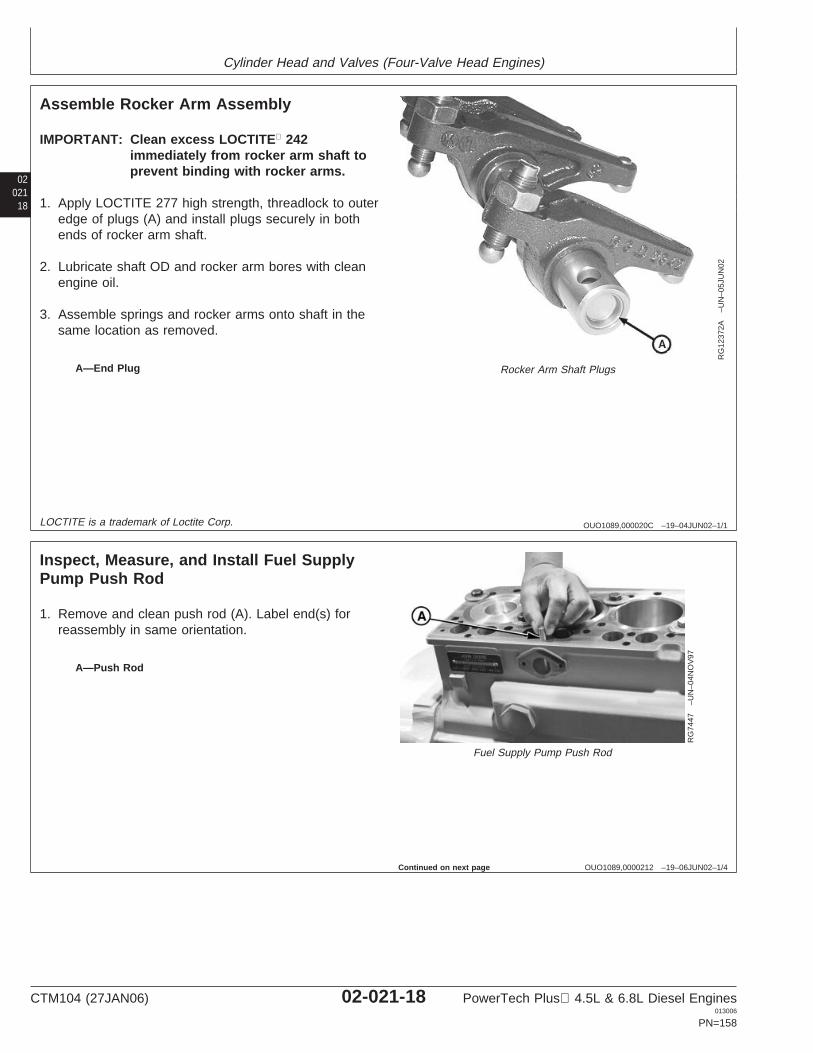
Cylinder Head and Valves (Four-Valve Head Engines)
02021
18
OUO1089,000020C –19–04JUN02–1/1
Assemble Rocker Arm Assembly
RG
1237
2A–U
N–0
5JU
N02
Rocker Arm Shaft PlugsA—End Plug
IMPORTANT: Clean excess LOCTITE 242immediately from rocker arm shaft toprevent binding with rocker arms.
1. Apply LOCTITE 277 high strength, threadlock to outeredge of plugs (A) and install plugs securely in bothends of rocker arm shaft.
2. Lubricate shaft OD and rocker arm bores with cleanengine oil.
3. Assemble springs and rocker arms onto shaft in thesame location as removed.
LOCTITE is a trademark of Loctite Corp.
OUO1089,0000212 –19–06JUN02–1/4
Inspect, Measure, and Install Fuel SupplyPump Push Rod
RG
7447
–UN
–04N
OV
97
Fuel Supply Pump Push Rod
A—Push Rod
1. Remove and clean push rod (A). Label end(s) forreassembly in same orientation.
Continued on next page
CTM104 (27JAN06) 02-021-18 PowerTech Plus 4.5L & 6.8L Diesel Engines013006
PN=158
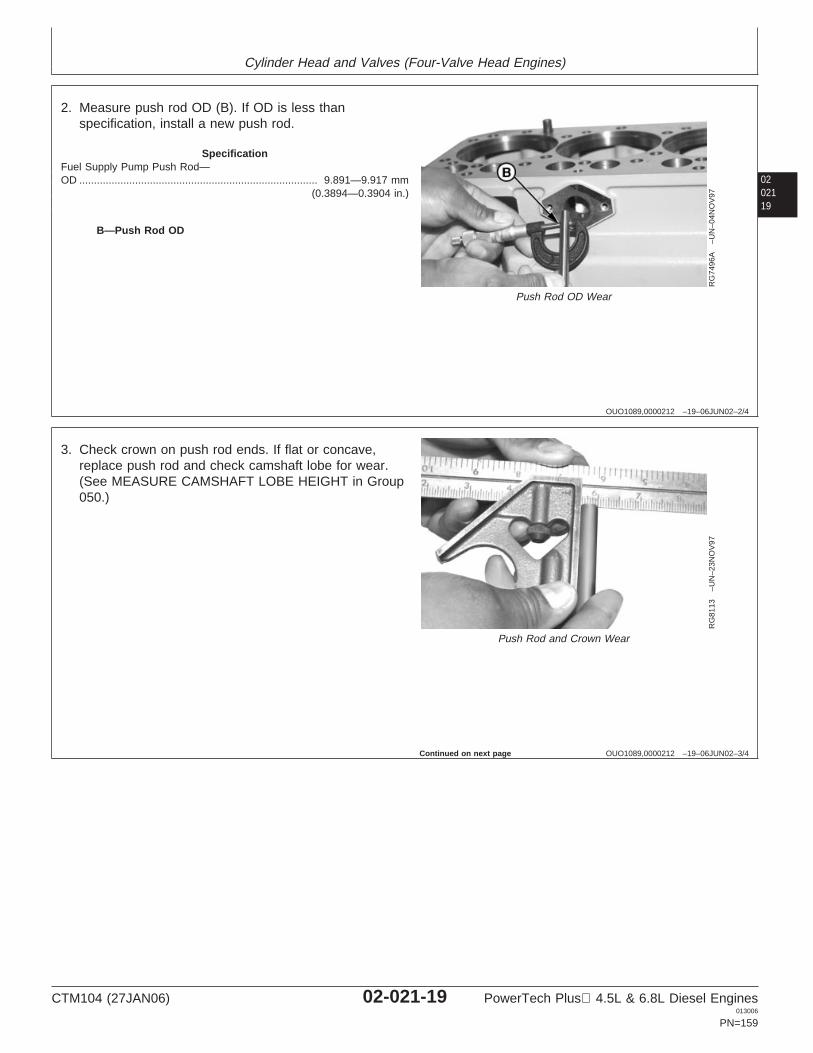
Cylinder Head and Valves (Four-Valve Head Engines)
0202119
OUO1089,0000212 –19–06JUN02–2/4
RG
7496
A–U
N–0
4NO
V97
Push Rod OD Wear
B—Push Rod OD
2. Measure push rod OD (B). If OD is less thanspecification, install a new push rod.
SpecificationFuel Supply Pump Push Rod—OD 9.891—9.917 mm
(0.3894—0.3904 in.).................................................................................
OUO1089,0000212 –19–06JUN02–3/4
RG
8113
–UN
–23N
OV
97
Push Rod and Crown Wear
3. Check crown on push rod ends. If flat or concave,replace push rod and check camshaft lobe for wear.(See MEASURE CAMSHAFT LOBE HEIGHT in Group050.)
Continued on next page
CTM104 (27JAN06) 02-021-19 PowerTech Plus 4.5L & 6.8L Diesel Engines013006
PN=159
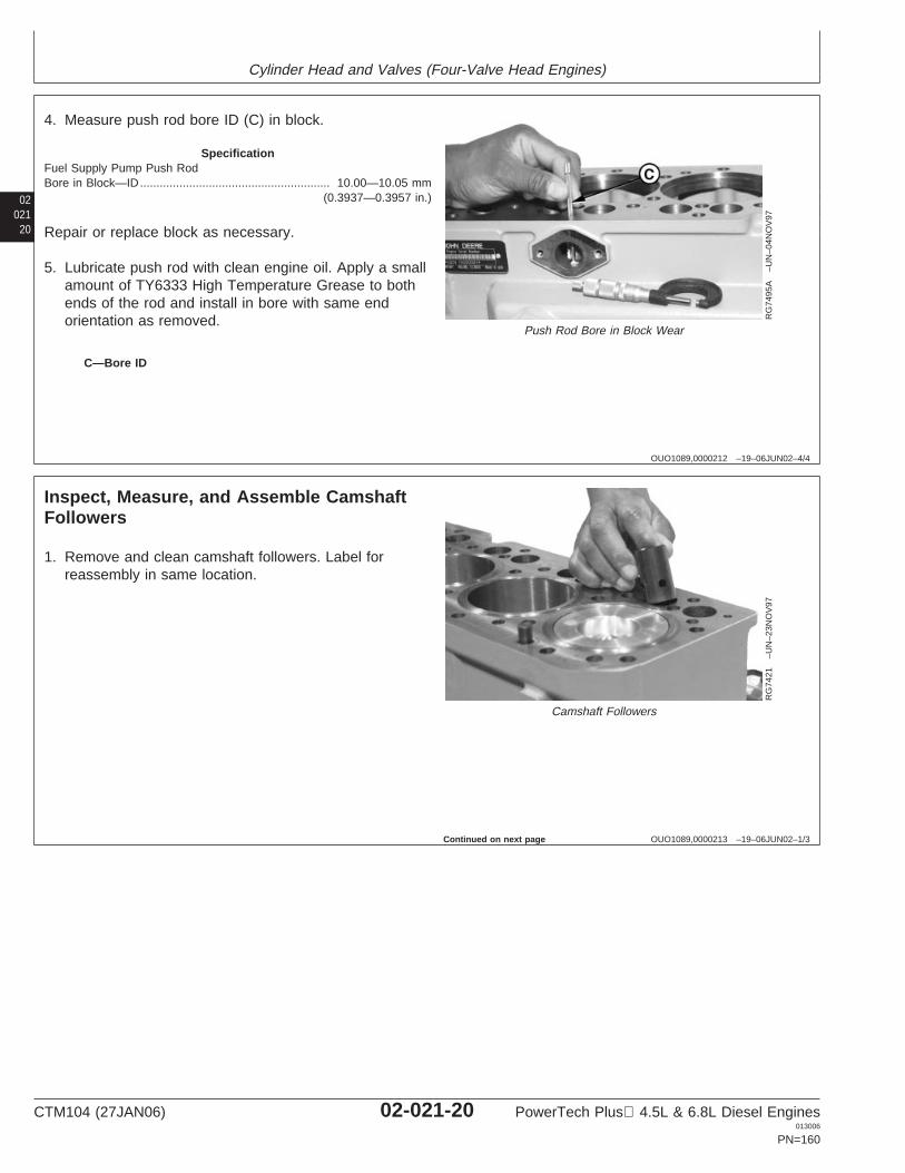
Cylinder Head and Valves (Four-Valve Head Engines)
02021
20
OUO1089,0000212 –19–06JUN02–4/4
RG
7495
A–U
N–0
4NO
V97
Push Rod Bore in Block Wear
C—Bore ID
4. Measure push rod bore ID (C) in block.
SpecificationFuel Supply Pump Push RodBore in Block—ID 10.00—10.05 mm
(0.3937—0.3957 in.)..........................................................
Repair or replace block as necessary.
5. Lubricate push rod with clean engine oil. Apply a smallamount of TY6333 High Temperature Grease to bothends of the rod and install in bore with same endorientation as removed.
OUO1089,0000213 –19–06JUN02–1/3
Inspect, Measure, and Assemble CamshaftFollowers
RG
7421
–UN
–23N
OV
97
Camshaft Followers
1. Remove and clean camshaft followers. Label forreassembly in same location.
Continued on next page
CTM104 (27JAN06) 02-021-20 PowerTech Plus 4.5L & 6.8L Diesel Engines013006
PN=160
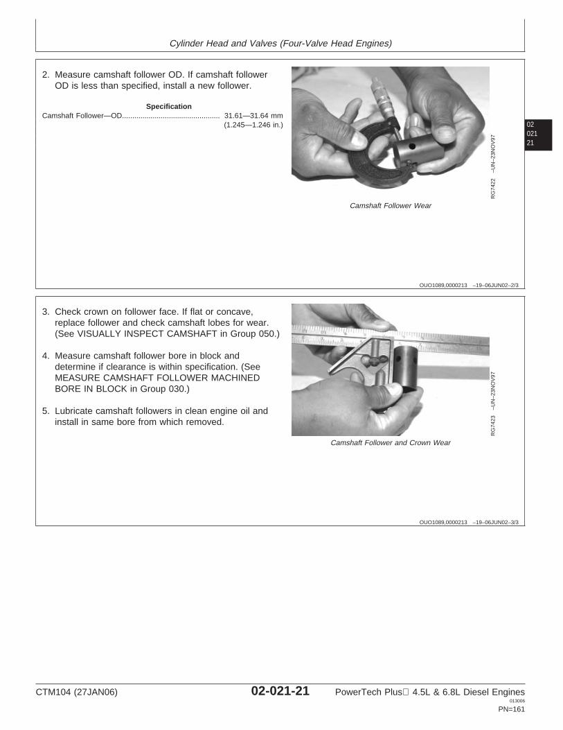
Cylinder Head and Valves (Four-Valve Head Engines)
0202121
OUO1089,0000213 –19–06JUN02–2/3
RG
7422
–UN
–23N
OV
97
Camshaft Follower Wear
2. Measure camshaft follower OD. If camshaft followerOD is less than specified, install a new follower.
SpecificationCamshaft Follower—OD 31.61—31.64 mm
(1.245—1.246 in.)................................................
OUO1089,0000213 –19–06JUN02–3/3
RG
7423
–UN
–23N
OV
97
Camshaft Follower and Crown Wear
3. Check crown on follower face. If flat or concave,replace follower and check camshaft lobes for wear.(See VISUALLY INSPECT CAMSHAFT in Group 050.)
4. Measure camshaft follower bore in block anddetermine if clearance is within specification. (SeeMEASURE CAMSHAFT FOLLOWER MACHINEDBORE IN BLOCK in Group 030.)
5. Lubricate camshaft followers in clean engine oil andinstall in same bore from which removed.
CTM104 (27JAN06) 02-021-21 PowerTech Plus 4.5L & 6.8L Diesel Engines013006
PN=161
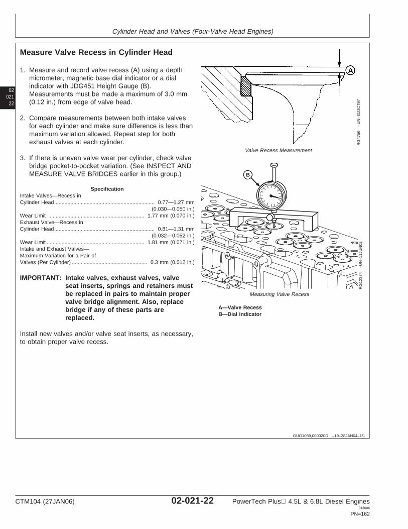
Cylinder Head and Valves (Four-Valve Head Engines)
02021
22
OUO1089,000020D –19–28JAN04–1/1
Measure Valve Recess in Cylinder Head
RG
4756
–UN
–31O
CT
97
Valve Recess Measurement
B
RG
1237
4–U
N–1
1JU
N02
Measuring Valve Recess
A—Valve RecessB—Dial Indicator
1. Measure and record valve recess (A) using a depthmicrometer, magnetic base dial indicator or a dialindicator with JDG451 Height Gauge (B).Measurements must be made a maximum of 3.0 mm(0.12 in.) from edge of valve head.
2. Compare measurements between both intake valvesfor each cylinder and make sure difference is less thanmaximum variation allowed. Repeat step for bothexhaust valves at each cylinder.
3. If there is uneven valve wear per cylinder, check valvebridge pocket-to-pocket variation. (See INSPECT ANDMEASURE VALVE BRIDGES earlier in this group.)
SpecificationIntake Valves—Recess inCylinder Head 0.77—1.27 mm
(0.030—0.050 in.)....................................................................
Wear Limit 1.77 mm (0.070 in.).................................................................Exhaust Valve—Recess inCylinder Head 0.81—1.31 mm
(0.032—0.052 in.)....................................................................
Wear Limit 1.81 mm (0.071 in.)..................................................................Intake and Exhaust Valves—Maximum Variation for a Pair ofValves (Per Cylinder) 0.3 mm (0.012 in.)...................................................
IMPORTANT: Intake valves, exhaust valves, valveseat inserts, springs and retainers mustbe replaced in pairs to maintain propervalve bridge alignment. Also, replacebridge if any of these parts arereplaced.
Install new valves and/or valve seat inserts, as necessary,to obtain proper valve recess.
CTM104 (27JAN06) 02-021-22 PowerTech Plus 4.5L & 6.8L Diesel Engines013006
PN=162
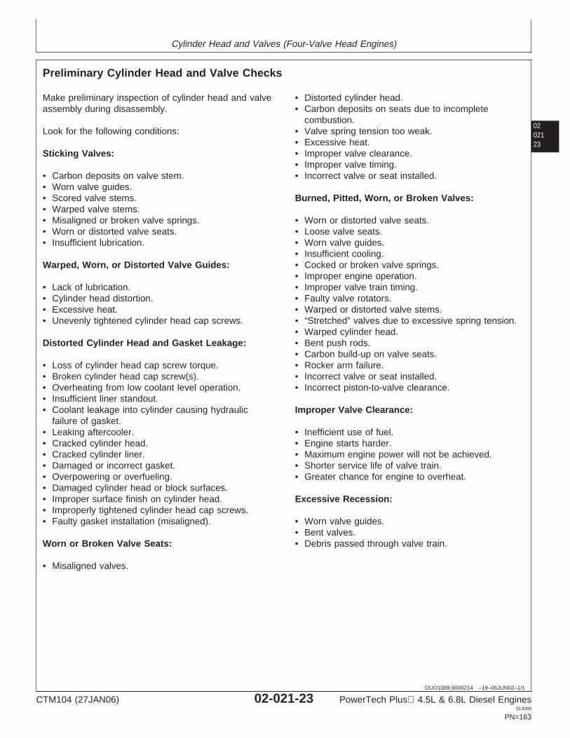
Cylinder Head and Valves (Four-Valve Head Engines)
0202123
OUO1089,0000214 –19–06JUN02–1/1
Preliminary Cylinder Head and Valve Checks
Make preliminary inspection of cylinder head and valveassembly during disassembly.
Look for the following conditions:
Sticking Valves:
• Carbon deposits on valve stem.• Worn valve guides.• Scored valve stems.• Warped valve stems.• Misaligned or broken valve springs.• Worn or distorted valve seats.• Insufficient lubrication.
Warped, Worn, or Distorted Valve Guides:
• Lack of lubrication.• Cylinder head distortion.• Excessive heat.• Unevenly tightened cylinder head cap screws.
Distorted Cylinder Head and Gasket Leakage:
• Loss of cylinder head cap screw torque.• Broken cylinder head cap screw(s).• Overheating from low coolant level operation.• Insufficient liner standout.• Coolant leakage into cylinder causing hydraulic
failure of gasket.• Leaking aftercooler.• Cracked cylinder head.• Cracked cylinder liner.• Damaged or incorrect gasket.• Overpowering or overfueling.• Damaged cylinder head or block surfaces.• Improper surface finish on cylinder head.• Improperly tightened cylinder head cap screws.• Faulty gasket installation (misaligned).
Worn or Broken Valve Seats:
• Misaligned valves.
• Distorted cylinder head.• Carbon deposits on seats due to incomplete
combustion.• Valve spring tension too weak.• Excessive heat.• Improper valve clearance.• Improper valve timing.• Incorrect valve or seat installed.
Burned, Pitted, Worn, or Broken Valves:
• Worn or distorted valve seats.• Loose valve seats.• Worn valve guides.• Insufficient cooling.• Cocked or broken valve springs.• Improper engine operation.• Improper valve train timing.• Faulty valve rotators.• Warped or distorted valve stems.• “Stretched” valves due to excessive spring tension.• Warped cylinder head.• Bent push rods.• Carbon build-up on valve seats.• Rocker arm failure.• Incorrect valve or seat installed.• Incorrect piston-to-valve clearance.
Improper Valve Clearance:
• Inefficient use of fuel.• Engine starts harder.• Maximum engine power will not be achieved.• Shorter service life of valve train.• Greater chance for engine to overheat.
Excessive Recession:
• Worn valve guides.• Bent valves.• Debris passed through valve train.
CTM104 (27JAN06) 02-021-23 PowerTech Plus 4.5L & 6.8L Diesel Engines013006
PN=163
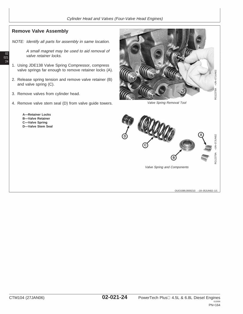
Cylinder Head and Valves (Four-Valve Head Engines)
02021
24
OUO1089,0000210 –19–05JUN02–1/1
Remove Valve Assembly
RG
1237
8A–U
N–0
7JU
N02
Valve Spring Removal Tool
RG
1237
9A–U
N–0
7JU
N02
Valve Spring and Components
A—Retainer LocksB—Valve RetainerC—Valve SpringD—Valve Stem Seal
NOTE: Identify all parts for assembly in same location.
A small magnet may be used to aid removal ofvalve retainer locks.
1. Using JDE138 Valve Spring Compressor, compressvalve springs far enough to remove retainer locks (A).
2. Release spring tension and remove valve retainer (B)and valve spring (C).
3. Remove valves from cylinder head.
4. Remove valve stem seal (D) from valve guide towers.
CTM104 (27JAN06) 02-021-24 PowerTech Plus 4.5L & 6.8L Diesel Engines013006
PN=164
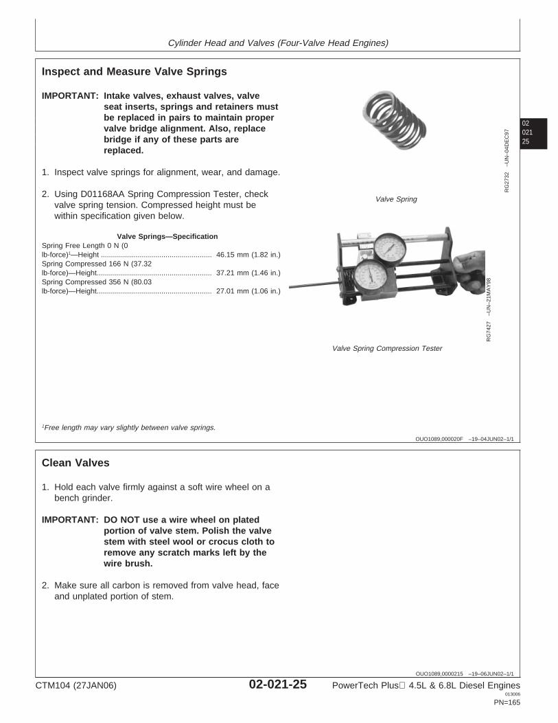
Cylinder Head and Valves (Four-Valve Head Engines)
0202125
OUO1089,000020F –19–04JUN02–1/1
Inspect and Measure Valve Springs
RG
2732
–UN
–04D
EC
97
Valve Spring
RG
7427
–UN
–21M
AY
98
Valve Spring Compression Tester
IMPORTANT: Intake valves, exhaust valves, valveseat inserts, springs and retainers mustbe replaced in pairs to maintain propervalve bridge alignment. Also, replacebridge if any of these parts arereplaced.
1. Inspect valve springs for alignment, wear, and damage.
2. Using D01168AA Spring Compression Tester, checkvalve spring tension. Compressed height must bewithin specification given below.
Valve Springs—SpecificationSpring Free Length 0 N (0lb-force)1—Height 46.15 mm (1.82 in.).......................................................Spring Compressed 166 N (37.32lb-force)—Height 37.21 mm (1.46 in.).........................................................Spring Compressed 356 N (80.03lb-force)—Height 27.01 mm (1.06 in.).........................................................
1Free length may vary slightly between valve springs.
OUO1089,0000215 –19–06JUN02–1/1
Clean Valves
1. Hold each valve firmly against a soft wire wheel on abench grinder.
IMPORTANT: DO NOT use a wire wheel on platedportion of valve stem. Polish the valvestem with steel wool or crocus cloth toremove any scratch marks left by thewire brush.
2. Make sure all carbon is removed from valve head, faceand unplated portion of stem.
CTM104 (27JAN06) 02-021-25 PowerTech Plus 4.5L & 6.8L Diesel Engines013006
PN=165
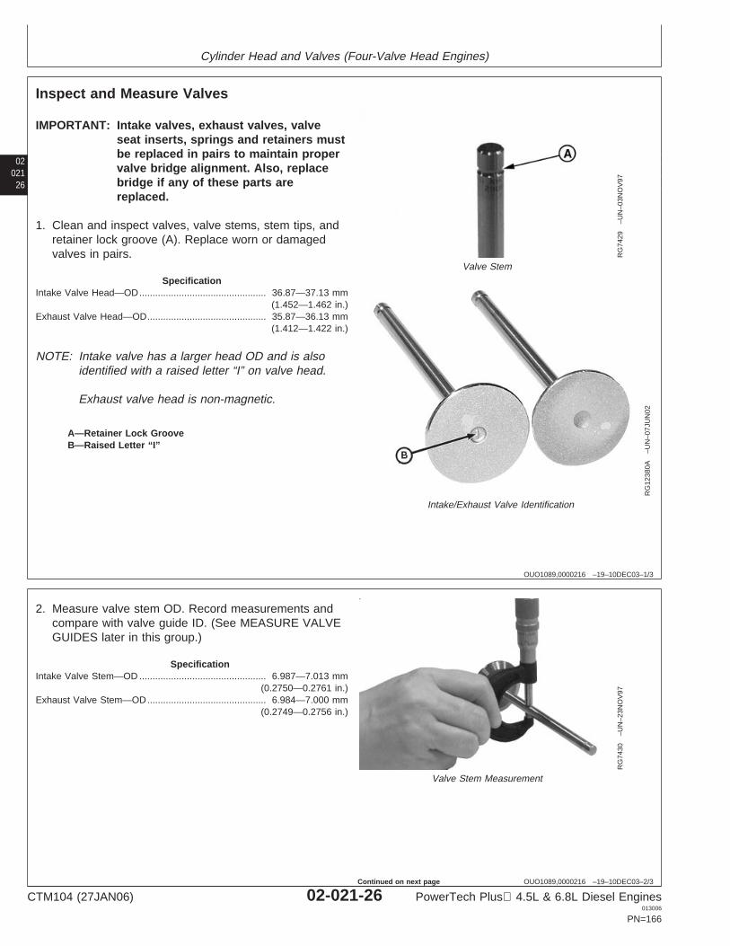
Cylinder Head and Valves (Four-Valve Head Engines)
02021
26
OUO1089,0000216 –19–10DEC03–1/3
Inspect and Measure Valves
RG
7429
–UN
–03N
OV
97
Valve Stem
RG
1238
0A–U
N–0
7JU
N02
Intake/Exhaust Valve Identification
A—Retainer Lock GrooveB—Raised Letter “I”
IMPORTANT: Intake valves, exhaust valves, valveseat inserts, springs and retainers mustbe replaced in pairs to maintain propervalve bridge alignment. Also, replacebridge if any of these parts arereplaced.
1. Clean and inspect valves, valve stems, stem tips, andretainer lock groove (A). Replace worn or damagedvalves in pairs.
SpecificationIntake Valve Head—OD 36.87—37.13 mm
(1.452—1.462 in.)................................................
Exhaust Valve Head—OD 35.87—36.13 mm(1.412—1.422 in.)
.............................................
NOTE: Intake valve has a larger head OD and is alsoidentified with a raised letter “I” on valve head.
Exhaust valve head is non-magnetic.
OUO1089,0000216 –19–10DEC03–2/3
RG
7430
–UN
–23N
OV
97
Valve Stem Measurement
2. Measure valve stem OD. Record measurements andcompare with valve guide ID. (See MEASURE VALVEGUIDES later in this group.)
SpecificationIntake Valve Stem—OD 6.987—7.013 mm
(0.2750—0.2761 in.)................................................
Exhaust Valve Stem—OD 6.984—7.000 mm(0.2749—0.2756 in.)
.............................................
CTM104 (27JAN06) 02-021-26 PowerTech Plus 4.5L & 6.8L Diesel Engines013006
PN=166
Continued on next page

Cylinder Head and Valves (Four-Valve Head Engines)
0202127
OUO1089,0000216 –19–10DEC03–3/3
RG
4234
–UN
–05D
EC
97
Valve Inspection Center
3. Using a valve inspection center, determine if valves areout of round, bent, or warped.
SpecificationValve Face—Maximum Runout(Intake and Exhaust) 0.038 mm (0.0015 in.)..............................................
OUO1089,000020E –19–04JUN02–1/1
Grind Valves
IMPORTANT: Intake valves, exhaust valves, valveseat inserts, springs and retainers mustbe replaced in pairs to maintain propervalve bridge alignment. Also, replacebridge if any of these parts arereplaced.
Do not grind valves. If valve face is warped, pitted, burnt,worn or damaged, replace intake or exhaust valves inpairs.
CTM104 (27JAN06) 02-021-27 PowerTech Plus 4.5L & 6.8L Diesel Engines013006
PN=167
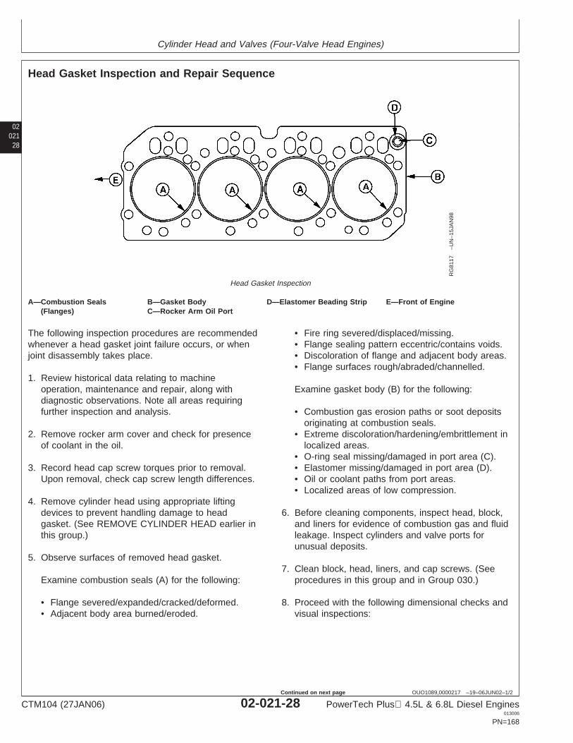
Cylinder Head and Valves (Four-Valve Head Engines)
02021
28
OUO1089,0000217 –19–06JUN02–1/2
Head Gasket Inspection and Repair Sequence
RG
8117
–UN
–15J
AN
98
Head Gasket Inspection
A—Combustion Seals B—Gasket Body D—Elastomer Beading Strip E—Front of Engine(Flanges) C—Rocker Arm Oil Port
The following inspection procedures are recommendedwhenever a head gasket joint failure occurs, or whenjoint disassembly takes place.
1. Review historical data relating to machineoperation, maintenance and repair, along withdiagnostic observations. Note all areas requiringfurther inspection and analysis.
2. Remove rocker arm cover and check for presenceof coolant in the oil.
3. Record head cap screw torques prior to removal.Upon removal, check cap screw length differences.
4. Remove cylinder head using appropriate liftingdevices to prevent handling damage to headgasket. (See REMOVE CYLINDER HEAD earlier inthis group.)
5. Observe surfaces of removed head gasket.
Examine combustion seals (A) for the following:
• Flange severed/expanded/cracked/deformed.• Adjacent body area burned/eroded.
• Fire ring severed/displaced/missing.• Flange sealing pattern eccentric/contains voids.• Discoloration of flange and adjacent body areas.• Flange surfaces rough/abraded/channelled.
Examine gasket body (B) for the following:
• Combustion gas erosion paths or soot depositsoriginating at combustion seals.
• Extreme discoloration/hardening/embrittlement inlocalized areas.
• O-ring seal missing/damaged in port area (C).• Elastomer missing/damaged in port area (D).• Oil or coolant paths from port areas.• Localized areas of low compression.
6. Before cleaning components, inspect head, block,and liners for evidence of combustion gas and fluidleakage. Inspect cylinders and valve ports forunusual deposits.
7. Clean block, head, liners, and cap screws. (Seeprocedures in this group and in Group 030.)
8. Proceed with the following dimensional checks andvisual inspections:
CTM104 (27JAN06) 02-021-28 PowerTech Plus 4.5L & 6.8L Diesel Engines013006
PN=168
Continued on next page
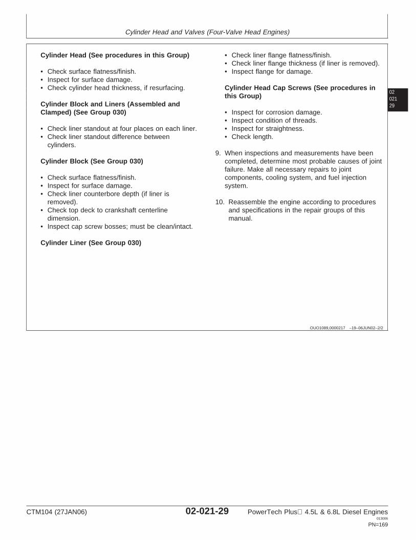
Cylinder Head and Valves (Four-Valve Head Engines)
0202129
OUO1089,0000217 –19–06JUN02–2/2
Cylinder Head (See procedures in this Group)
• Check surface flatness/finish.• Inspect for surface damage.• Check cylinder head thickness, if resurfacing.
Cylinder Block and Liners (Assembled andClamped) (See Group 030)
• Check liner standout at four places on each liner.• Check liner standout difference between
cylinders.
Cylinder Block (See Group 030)
• Check surface flatness/finish.• Inspect for surface damage.• Check liner counterbore depth (if liner is
removed).• Check top deck to crankshaft centerline
dimension.• Inspect cap screw bosses; must be clean/intact.
Cylinder Liner (See Group 030)
• Check liner flange flatness/finish.• Check liner flange thickness (if liner is removed).• Inspect flange for damage.
Cylinder Head Cap Screws (See procedures inthis Group)
• Inspect for corrosion damage.• Inspect condition of threads.• Inspect for straightness.• Check length.
9. When inspections and measurements have beencompleted, determine most probable causes of jointfailure. Make all necessary repairs to jointcomponents, cooling system, and fuel injectionsystem.
10. Reassemble the engine according to proceduresand specifications in the repair groups of thismanual.
CTM104 (27JAN06) 02-021-29 PowerTech Plus 4.5L & 6.8L Diesel Engines013006
PN=169
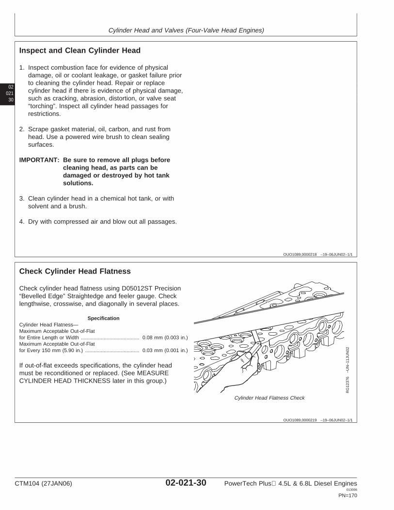
Cylinder Head and Valves (Four-Valve Head Engines)
02021
30
OUO1089,0000218 –19–06JUN02–1/1
Inspect and Clean Cylinder Head
1. Inspect combustion face for evidence of physicaldamage, oil or coolant leakage, or gasket failure priorto cleaning the cylinder head. Repair or replacecylinder head if there is evidence of physical damage,such as cracking, abrasion, distortion, or valve seat“torching”. Inspect all cylinder head passages forrestrictions.
2. Scrape gasket material, oil, carbon, and rust fromhead. Use a powered wire brush to clean sealingsurfaces.
IMPORTANT: Be sure to remove all plugs beforecleaning head, as parts can bedamaged or destroyed by hot tanksolutions.
3. Clean cylinder head in a chemical hot tank, or withsolvent and a brush.
4. Dry with compressed air and blow out all passages.
OUO1089,0000219 –19–06JUN02–1/1
Check Cylinder Head Flatness
RG
1237
6–U
N–1
1JU
N02
Cylinder Head Flatness Check
Check cylinder head flatness using D05012ST Precision“Bevelled Edge” Straightedge and feeler gauge. Checklengthwise, crosswise, and diagonally in several places.
SpecificationCylinder Head Flatness—Maximum Acceptable Out-of-Flatfor Entire Length or Width 0.08 mm (0.003 in.).........................................Maximum Acceptable Out-of-Flatfor Every 150 mm (5.90 in.) 0.03 mm (0.001 in.)......................................
If out-of-flat exceeds specifications, the cylinder headmust be reconditioned or replaced. (See MEASURECYLINDER HEAD THICKNESS later in this group.)
CTM104 (27JAN06) 02-021-30 PowerTech Plus 4.5L & 6.8L Diesel Engines013006
PN=170

Cylinder Head and Valves (Four-Valve Head Engines)
0202131
OUO1089,000021A –19–06JUN02–1/1
Measure Cylinder Head Thickness
RG
1237
7–U
N–1
1JU
N02
Cylinder Head Thickness Check
Measure head thickness from valve cover gasketrail-to-combustion face.
If cylinder head thickness is less than minimum allowablethickness, DO NOT attempt to resurface. Install a newcylinder head.
When resurfacing cylinder head, remove ONLY what isnecessary to restore flatness.
SpecificationNew Cylinder Head—Thickness 104.87—105.13 mm
(4.129—4.139 in.)................................
Minimum Acceptable Thickness 104.24 mm (4.104 in.).............................Combustion Face Surface Finish(Surface Grind Only) (AA) 0.7—3.2 micrometers
(31—125 micro-in.)........................................
Maximum Wave Depth 0.012 mm (0.0005 in.)..........................................Maximum Material Removal forResurfacing 0.76 mm (0.030 in.).................................................................
IMPORTANT: After resurfacing cylinder head, checkfor flatness as described earlier. Alsocheck surface finish on combustionface of head.
Measure and record valve recess incylinder head. (See MEASURE VALVERECESS IN CYLINDER HEAD earlier inthis group.)
CTM104 (27JAN06) 02-021-31 PowerTech Plus 4.5L & 6.8L Diesel Engines013006
PN=171
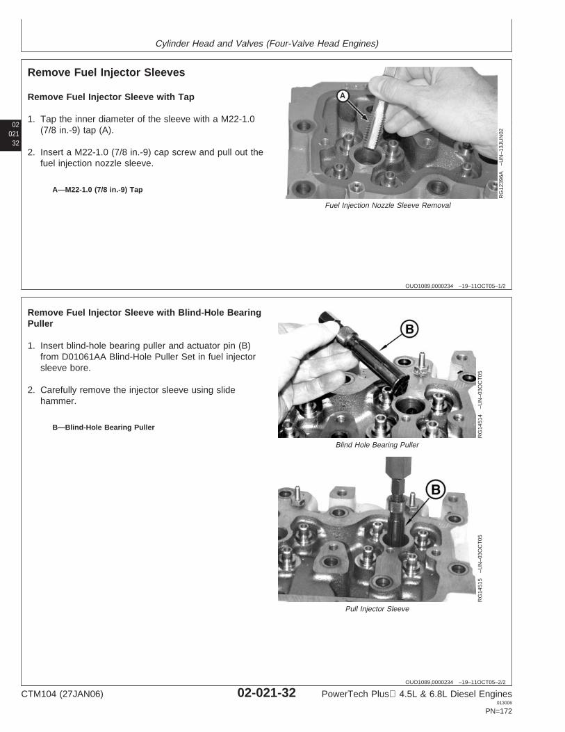
Cylinder Head and Valves (Four-Valve Head Engines)
02021
32
OUO1089,0000234 –19–11OCT05–1/2
Remove Fuel Injector Sleeves
RG
1239
6A–U
N–1
3JU
N02
Fuel Injection Nozzle Sleeve Removal
A—M22-1.0 (7/8 in.-9) Tap
Remove Fuel Injector Sleeve with Tap
1. Tap the inner diameter of the sleeve with a M22-1.0(7/8 in.-9) tap (A).
2. Insert a M22-1.0 (7/8 in.-9) cap screw and pull out thefuel injection nozzle sleeve.
OUO1089,0000234 –19–11OCT05–2/2
RG
1451
4–U
N–0
3OC
T05
Blind Hole Bearing Puller
RG
1451
5–U
N–0
3OC
T05
Pull Injector Sleeve
B—Blind-Hole Bearing Puller
Remove Fuel Injector Sleeve with Blind-Hole BearingPuller
1. Insert blind-hole bearing puller and actuator pin (B)from D01061AA Blind-Hole Puller Set in fuel injectorsleeve bore.
2. Carefully remove the injector sleeve using slidehammer.
CTM104 (27JAN06) 02-021-32 PowerTech Plus 4.5L & 6.8L Diesel Engines013006
PN=172
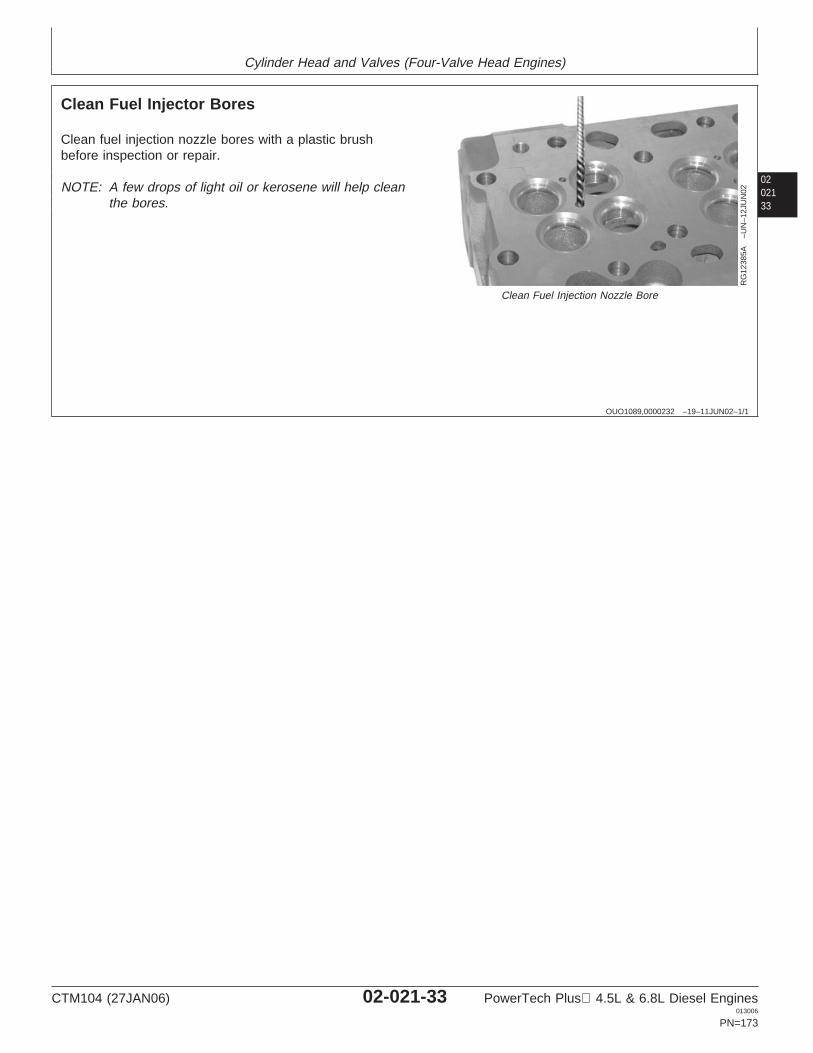
Cylinder Head and Valves (Four-Valve Head Engines)
0202133
OUO1089,0000232 –19–11JUN02–1/1
Clean Fuel Injector Bores
RG
1238
5A–U
N–1
2JU
N02
Clean Fuel Injection Nozzle Bore
Clean fuel injection nozzle bores with a plastic brushbefore inspection or repair.
NOTE: A few drops of light oil or kerosene will help cleanthe bores.
CTM104 (27JAN06) 02-021-33 PowerTech Plus 4.5L & 6.8L Diesel Engines013006
PN=173
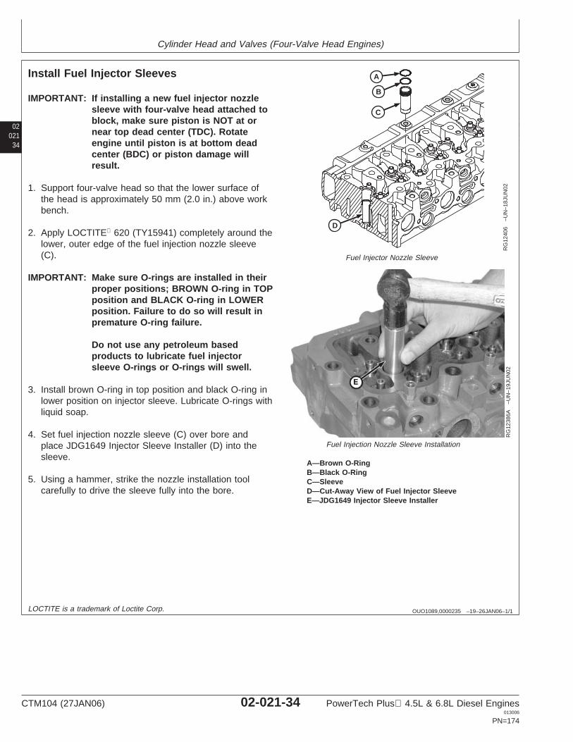
Cylinder Head and Valves (Four-Valve Head Engines)
02021
34
OUO1089,0000235 –19–26JAN06–1/1
Install Fuel Injector Sleeves
B
C
A
D
RG
1240
6–U
N–1
8JU
N02
Fuel Injector Nozzle Sleeve
RG
1238
6A–U
N–1
9JU
N02
Fuel Injection Nozzle Sleeve Installation
A—Brown O-RingB—Black O-RingC—SleeveD—Cut-Away View of Fuel Injector SleeveE—JDG1649 Injector Sleeve Installer
IMPORTANT: If installing a new fuel injector nozzlesleeve with four-valve head attached toblock, make sure piston is NOT at ornear top dead center (TDC). Rotateengine until piston is at bottom deadcenter (BDC) or piston damage willresult.
1. Support four-valve head so that the lower surface ofthe head is approximately 50 mm (2.0 in.) above workbench.
2. Apply LOCTITE 620 (TY15941) completely around thelower, outer edge of the fuel injection nozzle sleeve(C).
IMPORTANT: Make sure O-rings are installed in theirproper positions; BROWN O-ring in TOPposition and BLACK O-ring in LOWERposition. Failure to do so will result inpremature O-ring failure.
Do not use any petroleum basedproducts to lubricate fuel injectorsleeve O-rings or O-rings will swell.
3. Install brown O-ring in top position and black O-ring inlower position on injector sleeve. Lubricate O-rings withliquid soap.
4. Set fuel injection nozzle sleeve (C) over bore andplace JDG1649 Injector Sleeve Installer (D) into thesleeve.
5. Using a hammer, strike the nozzle installation toolcarefully to drive the sleeve fully into the bore.
LOCTITE is a trademark of Loctite Corp.
CTM104 (27JAN06) 02-021-34 PowerTech Plus 4.5L & 6.8L Diesel Engines013006
PN=174
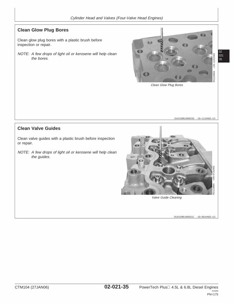
Cylinder Head and Valves (Four-Valve Head Engines)
0202135
OUO1089,0000233 –19–11JUN02–1/1
Clean Glow Plug Bores
RG
1240
0A–U
N–1
2JU
N02
Clean Glow Plug Bores
Clean glow plug bores with a plastic brush beforeinspection or repair.
NOTE: A few drops of light oil or kerosene will help cleanthe bores.
OUO1089,000021C –19–06JUN02–1/1
Clean Valve Guides
RG
1238
8A–U
N–0
7JU
N02
Valve Guide Cleaning
Clean valve guides with a plastic brush before inspectionor repair.
NOTE: A few drops of light oil or kerosene will help cleanthe guides.
CTM104 (27JAN06) 02-021-35 PowerTech Plus 4.5L & 6.8L Diesel Engines013006
PN=175
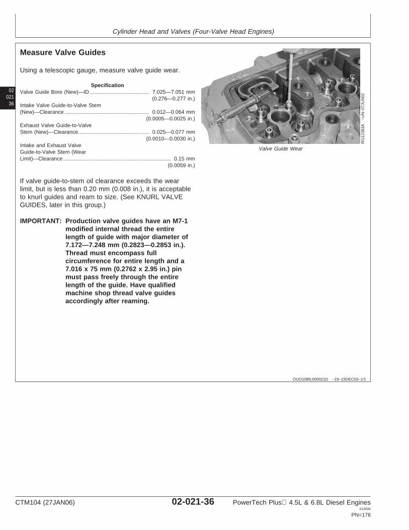
Cylinder Head and Valves (Four-Valve Head Engines)
02021
36
OUO1089,000021D –19–15DEC03–1/1
Measure Valve Guides
RG
1238
3A–U
N–0
7JU
N02
Valve Guide Wear
Using a telescopic gauge, measure valve guide wear.
SpecificationValve Guide Bore (New)—ID 7.025—7.051 mm
(0.276—0.277 in.)........................................
Intake Valve Guide-to-Valve Stem(New)—Clearance 0.012—0.064 mm
(0.0005—0.0025 in.).........................................................
Exhaust Valve Guide-to-ValveStem (New)—Clearance 0.025—0.077 mm
(0.0010—0.0030 in.)................................................
Intake and Exhaust ValveGuide-to-Valve Stem (WearLimit)—Clearance 0.15 mm
(0.0059 in.).........................................................................
If valve guide-to-stem oil clearance exceeds the wearlimit, but is less than 0.20 mm (0.008 in.), it is acceptableto knurl guides and ream to size. (See KNURL VALVEGUIDES, later in this group.)
IMPORTANT: Production valve guides have an M7-1modified internal thread the entirelength of guide with major diameter of7.172—7.248 mm (0.2823—0.2853 in.).Thread must encompass fullcircumference for entire length and a7.016 x 75 mm (0.2762 x 2.95 in.) pinmust pass freely through the entirelength of the guide. Have qualifiedmachine shop thread valve guidesaccordingly after reaming.
CTM104 (27JAN06) 02-021-36 PowerTech Plus 4.5L & 6.8L Diesel Engines013006
PN=176
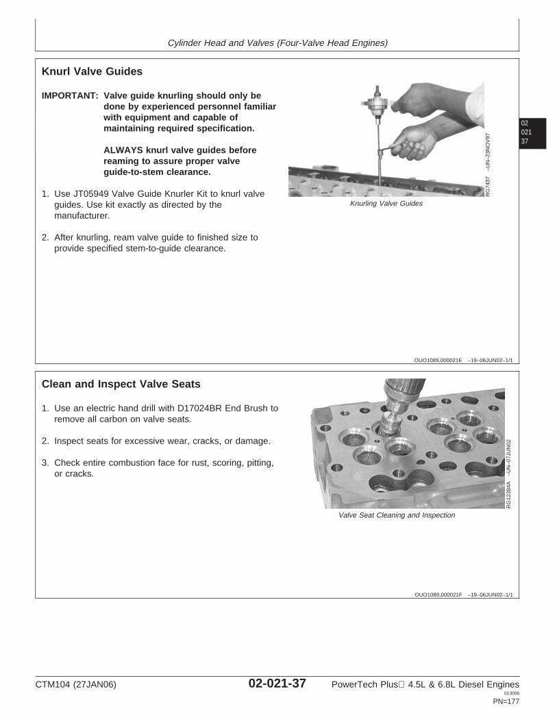
Cylinder Head and Valves (Four-Valve Head Engines)
0202137
OUO1089,000021E –19–06JUN02–1/1
Knurl Valve Guides
RG
7437
–UN
–23N
OV
97
Knurling Valve Guides
IMPORTANT: Valve guide knurling should only bedone by experienced personnel familiarwith equipment and capable ofmaintaining required specification.
ALWAYS knurl valve guides beforereaming to assure proper valveguide-to-stem clearance.
1. Use JT05949 Valve Guide Knurler Kit to knurl valveguides. Use kit exactly as directed by themanufacturer.
2. After knurling, ream valve guide to finished size toprovide specified stem-to-guide clearance.
OUO1089,000021F –19–06JUN02–1/1
Clean and Inspect Valve Seats
RG
1238
4A–U
N–0
7JU
N02
Valve Seat Cleaning and Inspection
1. Use an electric hand drill with D17024BR End Brush toremove all carbon on valve seats.
2. Inspect seats for excessive wear, cracks, or damage.
3. Check entire combustion face for rust, scoring, pitting,or cracks.
CTM104 (27JAN06) 02-021-37 PowerTech Plus 4.5L & 6.8L Diesel Engines013006
PN=177
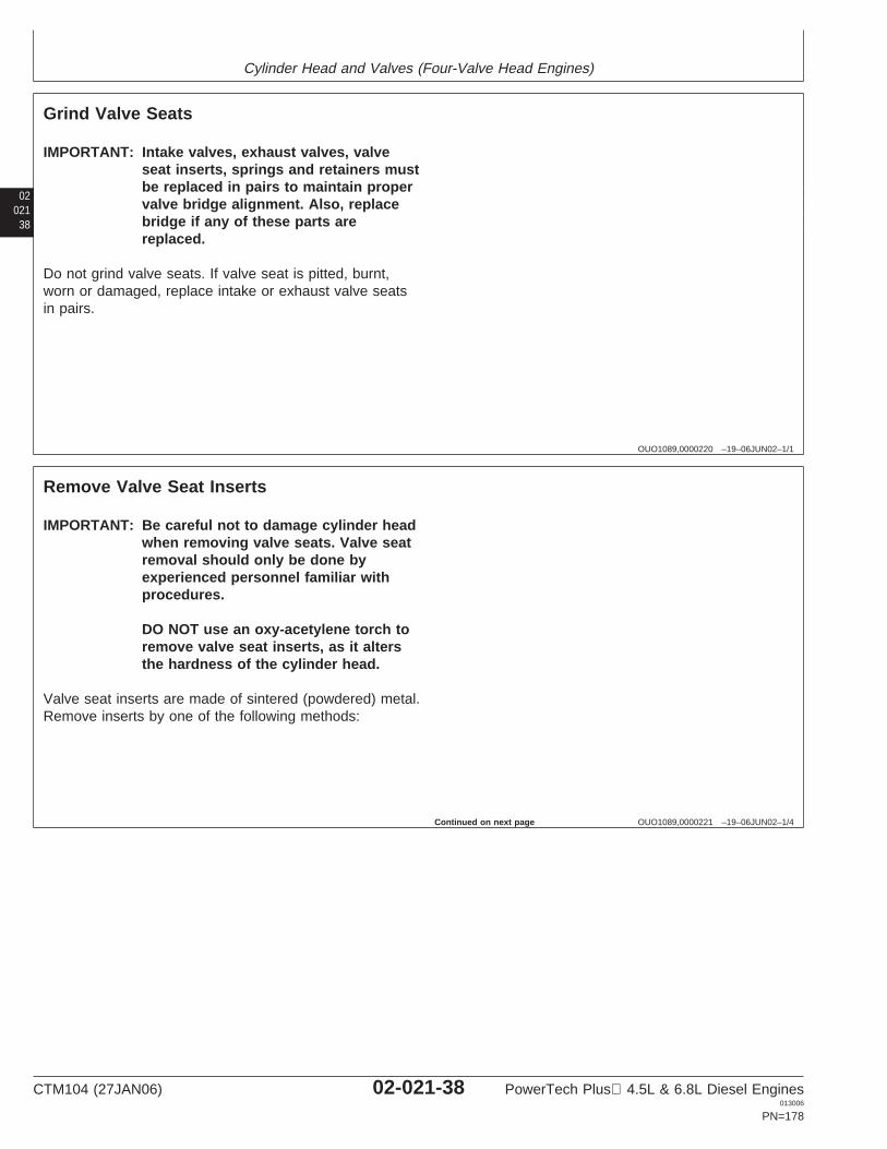
Cylinder Head and Valves (Four-Valve Head Engines)
02021
38
OUO1089,0000220 –19–06JUN02–1/1
Grind Valve Seats
IMPORTANT: Intake valves, exhaust valves, valveseat inserts, springs and retainers mustbe replaced in pairs to maintain propervalve bridge alignment. Also, replacebridge if any of these parts arereplaced.
Do not grind valve seats. If valve seat is pitted, burnt,worn or damaged, replace intake or exhaust valve seatsin pairs.
OUO1089,0000221 –19–06JUN02–1/4
Remove Valve Seat Inserts
IMPORTANT: Be careful not to damage cylinder headwhen removing valve seats. Valve seatremoval should only be done byexperienced personnel familiar withprocedures.
DO NOT use an oxy-acetylene torch toremove valve seat inserts, as it altersthe hardness of the cylinder head.
Valve seat inserts are made of sintered (powdered) metal.Remove inserts by one of the following methods:
Continued on next page
CTM104 (27JAN06) 02-021-38 PowerTech Plus 4.5L & 6.8L Diesel Engines013006
PN=178
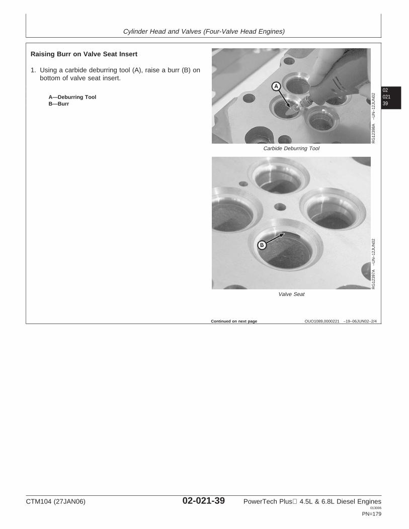
Cylinder Head and Valves (Four-Valve Head Engines)
0202139
OUO1089,0000221 –19–06JUN02–2/4
RG
1239
8A–U
N–1
2JU
N02
Carbide Deburring Tool
RG
1239
7A–U
N–1
2JU
N02
Valve Seat
A—Deburring ToolB—Burr
Raising Burr on Valve Seat Insert
1. Using a carbide deburring tool (A), raise a burr (B) onbottom of valve seat insert.
Continued on next page
CTM104 (27JAN06) 02-021-39 PowerTech Plus 4.5L & 6.8L Diesel Engines013006
PN=179
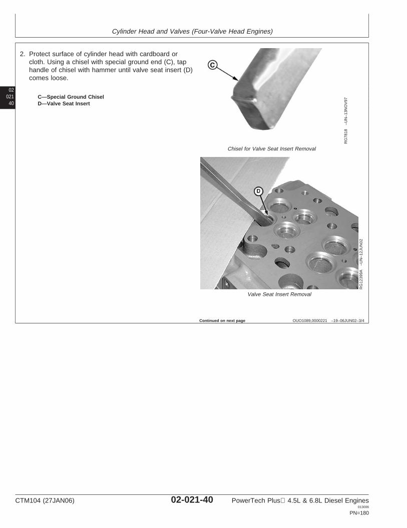
Cylinder Head and Valves (Four-Valve Head Engines)
02021
40
OUO1089,0000221 –19–06JUN02–3/4
RG
7818
–UN
–13N
OV
97
Chisel for Valve Seat Insert Removal
RG
1239
9A–U
N–1
2JU
N02
Valve Seat Insert Removal
C—Special Ground ChiselD—Valve Seat Insert
2. Protect surface of cylinder head with cardboard orcloth. Using a chisel with special ground end (C), taphandle of chisel with hammer until valve seat insert (D)comes loose.
Continued on next page
CTM104 (27JAN06) 02-021-40 PowerTech Plus 4.5L & 6.8L Diesel Engines013006
PN=180
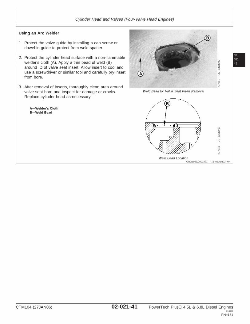
Cylinder Head and Valves (Four-Valve Head Engines)
0202141
OUO1089,0000221 –19–06JUN02–4/4
RG
7761
–UN
–10N
OV
97
Weld Bead for Valve Seat Insert Removal
RG
7813
–UN
–13N
OV
97
Weld Bead Location
A—Welder’s ClothB—Weld Bead
Using an Arc Welder
1. Protect the valve guide by installing a cap screw ordowel in guide to protect from weld spatter.
2. Protect the cylinder head surface with a non-flammablewelder’s cloth (A). Apply a thin bead of weld (B)around ID of valve seat insert. Allow insert to cool anduse a screwdriver or similar tool and carefully pry insertfrom bore.
3. After removal of inserts, thoroughly clean area aroundvalve seat bore and inspect for damage or cracks.Replace cylinder head as necessary.
CTM104 (27JAN06) 02-021-41 PowerTech Plus 4.5L & 6.8L Diesel Engines013006
PN=181
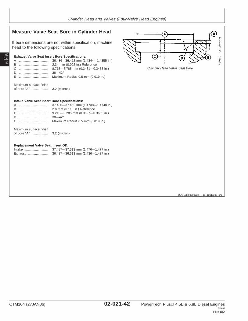
Cylinder Head and Valves (Four-Valve Head Engines)
02021
42
OUO1089,0000222 –19–10DEC03–1/1
Measure Valve Seat Bore in Cylinder Head
RG
9101
–UN
–27M
AR
98
Cylinder Head Valve Seat Bore
If bore dimensions are not within specification, machinehead to the following specifications:
Exhaust Valve Seat Insert Bore Specifications:A ................................ 36.436—36.462 mm (1.4344—1.4355 in.)B ................................ 2.34 mm (0.092 in.) ReferenceC ................................ 8.715—8.785 mm (0.3431—0.3458 in.)D ................................ 38—42°E ................................ Maximum Radius 0.5 mm (0.019 in.)
Maximum surface finishof bore “A” ................. 3.2 (micron)
Intake Valve Seat Insert Bore Specifications:A ................................ 37.436—37.462 mm (1.4738—1.4748 in.)B ................................ 2.8 mm (0.110 in.) ReferenceC ................................ 9.215—9.285 mm (0.3627—0.3655 in.)D ................................ 38—42°E ................................ Maximum Radius 0.5 mm (0.019 in.)
Maximum surface finishof bore “A” ................. 3.2 (micron)
Replacement Valve Seat Insert OD:Intake ......................... 37.487—37.513 mm (1.476—1.477 in.)Exhaust ...................... 36.487—36.513 mm (1.436—1.437 in.)
CTM104 (27JAN06) 02-021-42 PowerTech Plus 4.5L & 6.8L Diesel Engines013006
PN=182
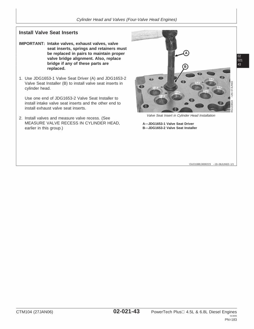
Cylinder Head and Valves (Four-Valve Head Engines)
0202143
OUO1089,0000223 –19–06JUN02–1/1
Install Valve Seat Inserts
RG
1238
1A–U
N–0
7JU
N02
Valve Seat Insert in Cylinder Head Installation
A—JDG1653-1 Valve Seat DriverB—JDG1653-2 Valve Seat Installer
IMPORTANT: Intake valves, exhaust valves, valveseat inserts, springs and retainers mustbe replaced in pairs to maintain propervalve bridge alignment. Also, replacebridge if any of these parts arereplaced.
1. Use JDG1653-1 Valve Seat Driver (A) and JDG1653-2Valve Seat Installer (B) to install valve seat inserts incylinder head.
Use one end of JDG1653-2 Valve Seat Installer toinstall intake valve seat inserts and the other end toinstall exhaust valve seat inserts.
2. Install valves and measure valve recess. (SeeMEASURE VALVE RECESS IN CYLINDER HEAD,earlier in this group.)
CTM104 (27JAN06) 02-021-43 PowerTech Plus 4.5L & 6.8L Diesel Engines013006
PN=183
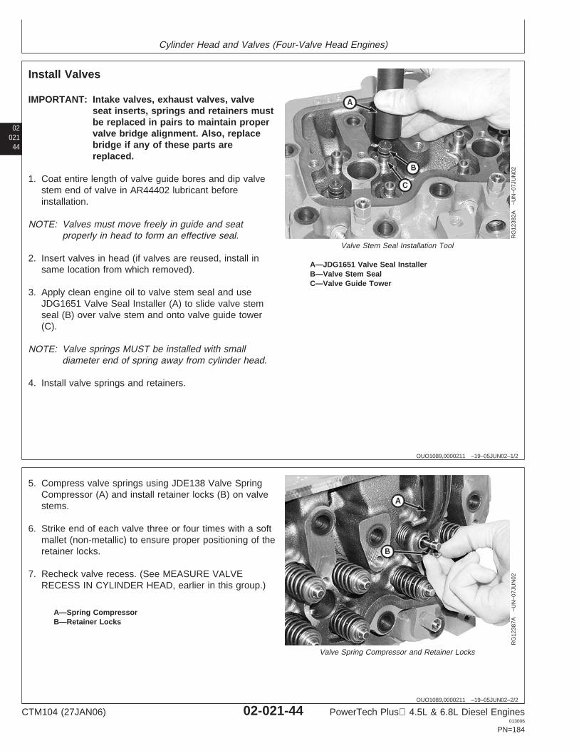
Cylinder Head and Valves (Four-Valve Head Engines)
02021
44
OUO1089,0000211 –19–05JUN02–1/2
Install Valves
RG
1238
2A–U
N–0
7JU
N02
Valve Stem Seal Installation Tool
A—JDG1651 Valve Seal InstallerB—Valve Stem SealC—Valve Guide Tower
IMPORTANT: Intake valves, exhaust valves, valveseat inserts, springs and retainers mustbe replaced in pairs to maintain propervalve bridge alignment. Also, replacebridge if any of these parts arereplaced.
1. Coat entire length of valve guide bores and dip valvestem end of valve in AR44402 lubricant beforeinstallation.
NOTE: Valves must move freely in guide and seatproperly in head to form an effective seal.
2. Insert valves in head (if valves are reused, install insame location from which removed).
3. Apply clean engine oil to valve stem seal and useJDG1651 Valve Seal Installer (A) to slide valve stemseal (B) over valve stem and onto valve guide tower(C).
NOTE: Valve springs MUST be installed with smalldiameter end of spring away from cylinder head.
4. Install valve springs and retainers.
OUO1089,0000211 –19–05JUN02–2/2
RG
1238
7A–U
N–0
7JU
N02
Valve Spring Compressor and Retainer Locks
A—Spring CompressorB—Retainer Locks
5. Compress valve springs using JDE138 Valve SpringCompressor (A) and install retainer locks (B) on valvestems.
6. Strike end of each valve three or four times with a softmallet (non-metallic) to ensure proper positioning of theretainer locks.
7. Recheck valve recess. (See MEASURE VALVERECESS IN CYLINDER HEAD, earlier in this group.)
CTM104 (27JAN06) 02-021-44 PowerTech Plus 4.5L & 6.8L Diesel Engines013006
PN=184
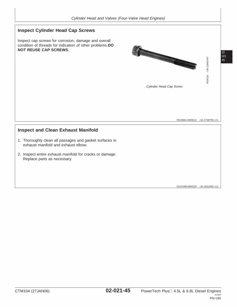
Cylinder Head and Valves (Four-Valve Head Engines)
0202145
RG19661,000001A –19–27SEP05–1/1
Inspect Cylinder Head Cap Screws
RG
6319
–UN
–23N
OV
97
Cylinder Head Cap Screw
Inspect cap screws for corrosion, damage and overallcondition of threads for indication of other problems.DONOT REUSE CAP SCREWS.
OUO1089,0000225 –19–06JUN02–1/1
Inspect and Clean Exhaust Manifold
1. Thoroughly clean all passages and gasket surfaces inexhaust manifold and exhaust elbow.
2. Inspect entire exhaust manifold for cracks or damage.Replace parts as necessary.
CTM104 (27JAN06) 02-021-45 PowerTech Plus 4.5L & 6.8L Diesel Engines013006
PN=185
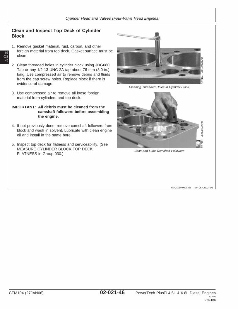
Cylinder Head and Valves (Four-Valve Head Engines)
02021
46
OUO1089,0000226 –19–06JUN02–1/1
Clean and Inspect Top Deck of CylinderBlock
RG
7444
–UN
–23N
OV
97
Cleaning Threaded Holes in Cylinder Block
RG
7421
–UN
–23N
OV
97
Clean and Lube Camshaft Followers
1. Remove gasket material, rust, carbon, and otherforeign material from top deck. Gasket surface must beclean.
2. Clean threaded holes in cylinder block using JDG680Tap or any 1/2-13 UNC-2A tap about 76 mm (3.0 in.)long. Use compressed air to remove debris and fluidsfrom the cap screw holes. Replace block if there isevidence of damage.
3. Use compressed air to remove all loose foreignmaterial from cylinders and top deck.
IMPORTANT: All debris must be cleaned from thecamshaft followers before assemblingthe engine.
4. If not previously done, remove camshaft followers fromblock and wash in solvent. Lubricate with clean engineoil and install in the same bore.
5. Inspect top deck for flatness and serviceability. (SeeMEASURE CYLINDER BLOCK TOP DECKFLATNESS in Group 030.)
CTM104 (27JAN06) 02-021-46 PowerTech Plus 4.5L & 6.8L Diesel Engines013006
PN=186
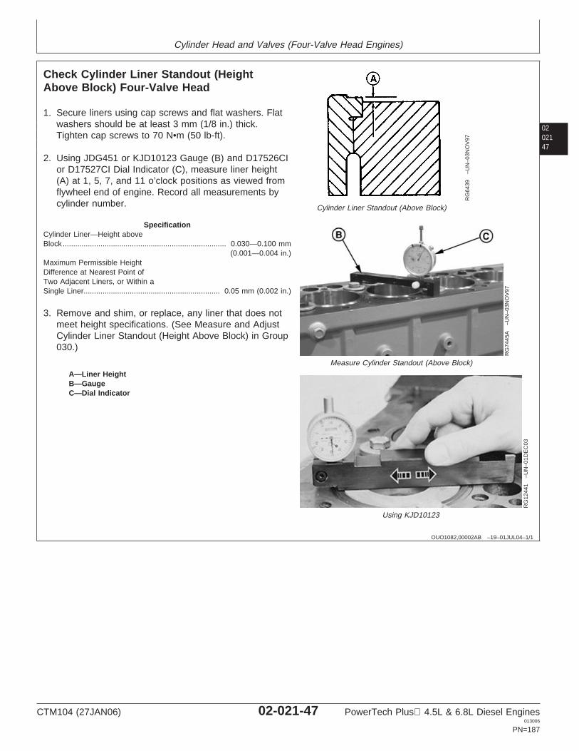
Cylinder Head and Valves (Four-Valve Head Engines)
0202147
OUO1082,00002AB –19–01JUL04–1/1
Check Cylinder Liner Standout (HeightAbove Block) Four-Valve Head
RG
6439
–UN
–03N
OV
97
Cylinder Liner Standout (Above Block)
RG
7445
A–U
N–0
3NO
V97
Measure Cylinder Standout (Above Block)
RG
1244
1–U
N–0
1DE
C03
Using KJD10123
A—Liner HeightB—GaugeC—Dial Indicator
1. Secure liners using cap screws and flat washers. Flatwashers should be at least 3 mm (1/8 in.) thick.Tighten cap screws to 70 N•m (50 lb-ft).
2. Using JDG451 or KJD10123 Gauge (B) and D17526CIor D17527CI Dial Indicator (C), measure liner height(A) at 1, 5, 7, and 11 o’clock positions as viewed fromflywheel end of engine. Record all measurements bycylinder number.
SpecificationCylinder Liner—Height aboveBlock 0.030—0.100 mm
(0.001—0.004 in.)..............................................................................
Maximum Permissible HeightDifference at Nearest Point ofTwo Adjacent Liners, or Within aSingle Liner 0.05 mm (0.002 in.).................................................................
3. Remove and shim, or replace, any liner that does notmeet height specifications. (See Measure and AdjustCylinder Liner Standout (Height Above Block) in Group030.)
CTM104 (27JAN06) 02-021-47 PowerTech Plus 4.5L & 6.8L Diesel Engines013006
PN=187
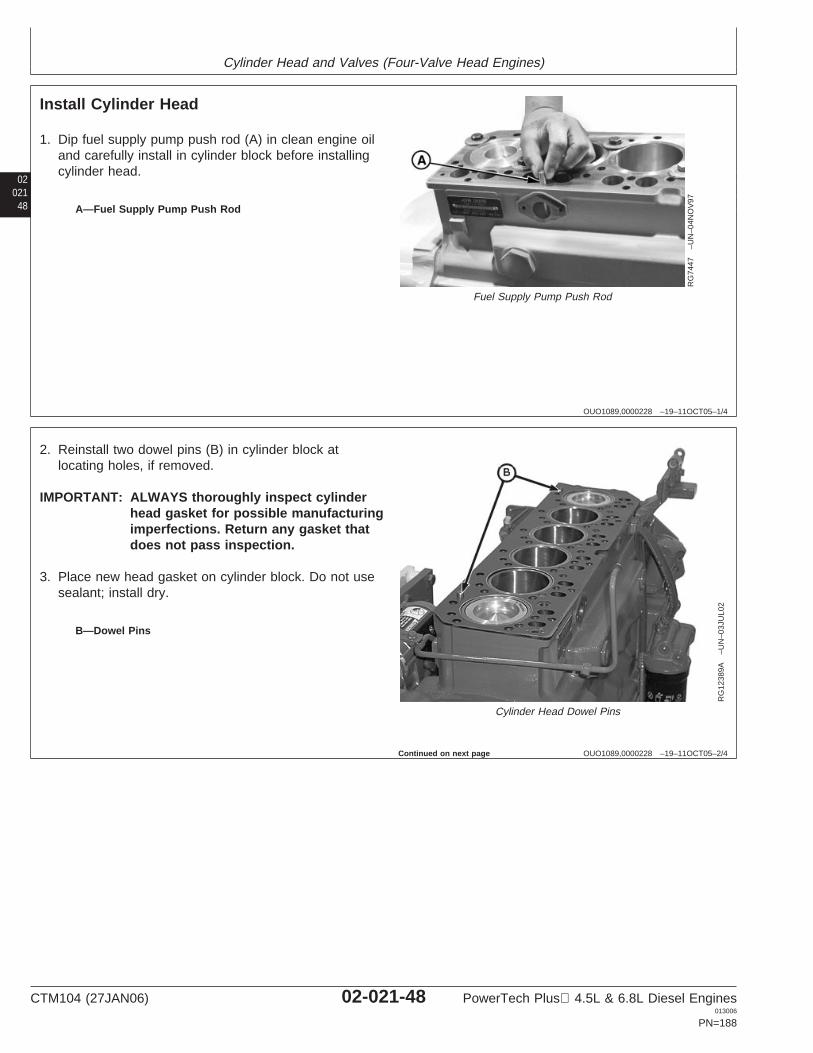
Cylinder Head and Valves (Four-Valve Head Engines)
02021
48
OUO1089,0000228 –19–11OCT05–1/4
Install Cylinder Head
RG
7447
–UN
–04N
OV
97
Fuel Supply Pump Push Rod
A—Fuel Supply Pump Push Rod
1. Dip fuel supply pump push rod (A) in clean engine oiland carefully install in cylinder block before installingcylinder head.
OUO1089,0000228 –19–11OCT05–2/4
RG
1238
9A–U
N–0
3JU
L02
Cylinder Head Dowel Pins
B—Dowel Pins
2. Reinstall two dowel pins (B) in cylinder block atlocating holes, if removed.
IMPORTANT: ALWAYS thoroughly inspect cylinderhead gasket for possible manufacturingimperfections. Return any gasket thatdoes not pass inspection.
3. Place new head gasket on cylinder block. Do not usesealant; install dry.
Continued on next page
CTM104 (27JAN06) 02-021-48 PowerTech Plus 4.5L & 6.8L Diesel Engines013006
PN=188
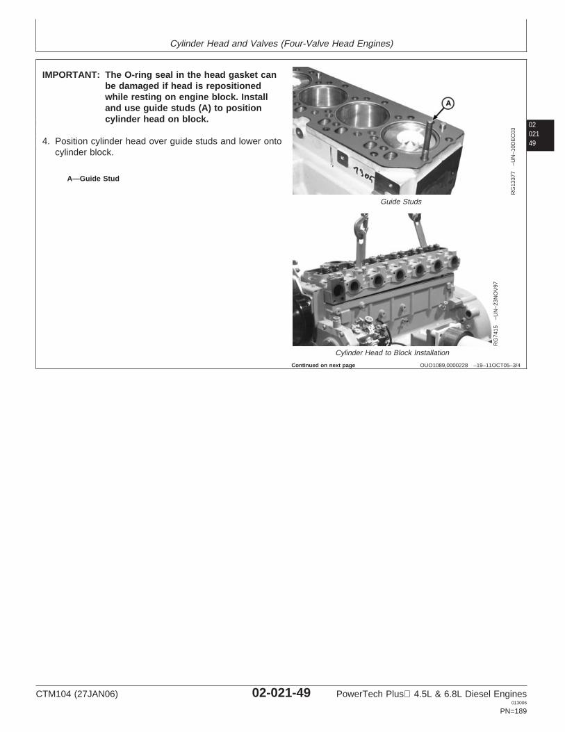
Cylinder Head and Valves (Four-Valve Head Engines)
0202149
OUO1089,0000228 –19–11OCT05–3/4
RG
1337
7–U
N–1
0DE
C03
Guide Studs
RG
7415
–UN
–23N
OV
97
Cylinder Head to Block Installation
A—Guide Stud
IMPORTANT: The O-ring seal in the head gasket canbe damaged if head is repositionedwhile resting on engine block. Installand use guide studs (A) to positioncylinder head on block.
4. Position cylinder head over guide studs and lower ontocylinder block.
Continued on next page
CTM104 (27JAN06) 02-021-49 PowerTech Plus 4.5L & 6.8L Diesel Engines013006
PN=189
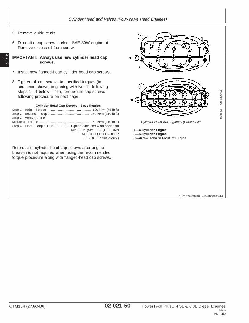
Cylinder Head and Valves (Four-Valve Head Engines)
02021
50
OUO1089,0000228 –19–11OCT05–4/4
RG
1240
1–U
N–1
2JU
N02
Cylinder Head Bolt Tightening Sequence
A—4-Cylinder EngineB—6-Cylinder EngineC—Arrow Toward Front of Engine
5. Remove guide studs.
6. Dip entire cap screw in clean SAE 30W engine oil.Remove excess oil from screw.
IMPORTANT: Always use new cylinder head capscrews.
7. Install new flanged-head cylinder head cap screws.
8. Tighten all cap screws to specified torques (insequence shown, beginning with No. 1), followingsteps 1—4 below. Then, torque-turn cap screwsfollowing procedure on next page.
Cylinder Head Cap Screws—SpecificationStep 1—Initial—Torque 100 N•m (75 lb-ft).................................................Step 2—Second—Torque 150 N•m (110 lb-ft)...........................................Step 3—Verify (After 5Minutes)—Torque 150 N•m (110 lb-ft)........................................................Step 4—Final—Torque-Turn Tighten each screw an additional
60° ± 10°. (See TORQUE-TURNMETHOD FOR PROPERTORQUE in this group.)
.................
Retorque of cylinder head cap screws after enginebreak-in is not required when using the recommendedtorque procedure along with flanged-head cap screws.
CTM104 (27JAN06) 02-021-50 PowerTech Plus 4.5L & 6.8L Diesel Engines013006
PN=190
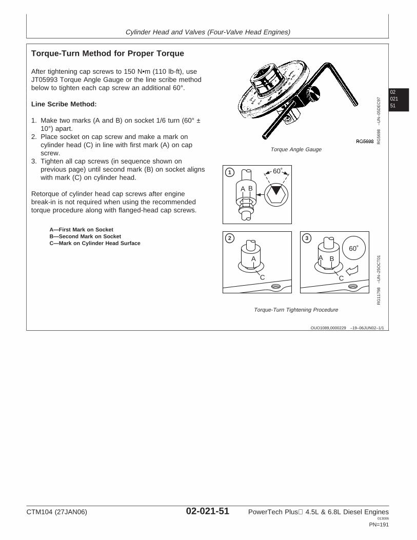
Cylinder Head and Valves (Four-Valve Head Engines)
0202151
OUO1089,0000229 –19–06JUN02–1/1
Torque-Turn Method for Proper Torque
RG
5698
–UN
–05D
EC
97
Torque Angle Gauge
60˚
A B
BAA
C C
60˚
1
2 3
RG
1179
8–U
N–2
5OC
T01
Torque-Turn Tightening Procedure
A—First Mark on SocketB—Second Mark on SocketC—Mark on Cylinder Head Surface
After tightening cap screws to 150 N•m (110 lb-ft), useJT05993 Torque Angle Gauge or the line scribe methodbelow to tighten each cap screw an additional 60°.
Line Scribe Method:
1. Make two marks (A and B) on socket 1/6 turn (60° ±10°) apart.
2. Place socket on cap screw and make a mark oncylinder head (C) in line with first mark (A) on capscrew.
3. Tighten all cap screws (in sequence shown onprevious page) until second mark (B) on socket alignswith mark (C) on cylinder head.
Retorque of cylinder head cap screws after enginebreak-in is not required when using the recommendedtorque procedure along with flanged-head cap screws.
CTM104 (27JAN06) 02-021-51 PowerTech Plus 4.5L & 6.8L Diesel Engines013006
PN=191

Cylinder Head and Valves (Four-Valve Head Engines)
02021
52
OUO1089,000022E –19–10DEC03–1/1
Install Fuel Injectors
RG
1239
1A–U
N–1
0JU
N02
Fuel Injector Inlet Port
RG
1239
0A–U
N–1
0JU
N02
Fuel Supply Tube Installation
RG
1239
2A–U
N–1
0JU
N02
Hold-Down Clamp and Fitting
A—Injector Fuel Inlet PortB—Copper WasherC—Fuel InjectorD—Injector Hold-Down ClampE—Fuel Supply TubeF—ScrewG—FittingH—Glow Plug
NOTE: Prior to installing fuel injector, ensure that usedcopper washer has been removed from bottom offuel injector sleeve.
1. Install copper washer (B) on end of fuel injector (C) tip.
2. Install fuel injector with injector hold-down clamp (D)into cylinder head. Make sure injector fuel inlet port (A)is facing fuel supply tube (E) once installed.
3. Install fuel supply tube (E) with smaller end in towardfuel injector. Turn injector by hand until tube is properlyseated in injector.
IMPORTANT: Use proper torque procedure fortightening fitting (G) and screw (F).
4. Using proper torque procedure, install fitting (G) andscrew (F). (See INSTALL ELECTRONIC INJECTORSin Section 02, Group 090 of CTM220—Level 11Electronic Fuel Systems with Denso High PressureCommon Rail.)
NOTE: When replacing glow plugs, make sure glow plugsare replaced with new ones of the same voltagerating. 24-volt glow plugs have a blue tint while12-volt glow plugs have a yellow tint.
5. Install glow plug (H) and torque to specification.
SpecificationGlow Plug—Torque 15 N•m (133 lb-in.).....................................................
6. Repeat procedure for each cylinder.
CTM104 (27JAN06) 02-021-52 PowerTech Plus 4.5L & 6.8L Diesel Engines013006
PN=192
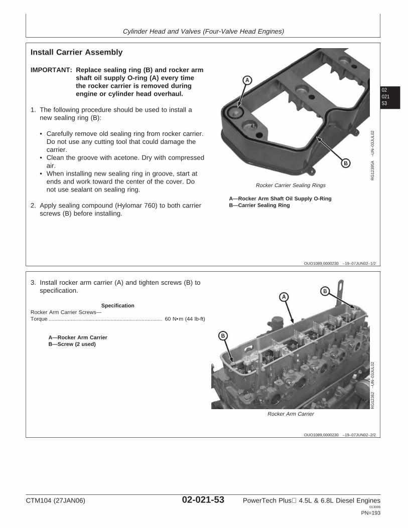
Cylinder Head and Valves (Four-Valve Head Engines)
0202153
OUO1089,0000230 –19–07JUN02–1/2
Install Carrier Assembly
RG
1239
5A–U
N–0
3JU
L02
Rocker Carrier Sealing Rings
A—Rocker Arm Shaft Oil Supply O-RingB—Carrier Sealing Ring
IMPORTANT: Replace sealing ring (B) and rocker armshaft oil supply O-ring (A) every timethe rocker carrier is removed duringengine or cylinder head overhaul.
1. The following procedure should be used to install anew sealing ring (B):
• Carefully remove old sealing ring from rocker carrier.Do not use any cutting tool that could damage thecarrier.
• Clean the groove with acetone. Dry with compressedair.
• When installing new sealing ring in groove, start atends and work toward the center of the cover. Donot use sealant on sealing ring.
2. Apply sealing compound (Hylomar 760) to both carrierscrews (B) before installing.
OUO1089,0000230 –19–07JUN02–2/2
RG
1236
2–U
N–0
3JU
L02
Rocker Arm Carrier
A—Rocker Arm CarrierB—Screw (2 used)
3. Install rocker arm carrier (A) and tighten screws (B) tospecification.
SpecificationRocker Arm Carrier Screws—Torque 60 N•m (44 lb-ft).............................................................................
CTM104 (27JAN06) 02-021-53 PowerTech Plus 4.5L & 6.8L Diesel Engines013006
PN=193
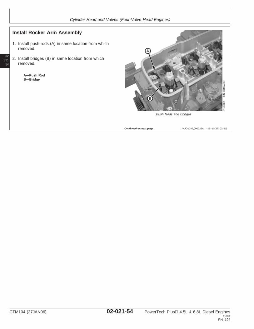
Cylinder Head and Valves (Four-Valve Head Engines)
02021
54
OUO1089,000022A –19–10DEC03–1/3
Install Rocker Arm Assembly
RG
1236
1–U
N–3
1MA
Y02
Push Rods and Bridges
A—Push RodB—Bridge
1. Install push rods (A) in same location from whichremoved.
2. Install bridges (B) in same location from whichremoved.
Continued on next page
CTM104 (27JAN06) 02-021-54 PowerTech Plus 4.5L & 6.8L Diesel Engines013006
PN=194
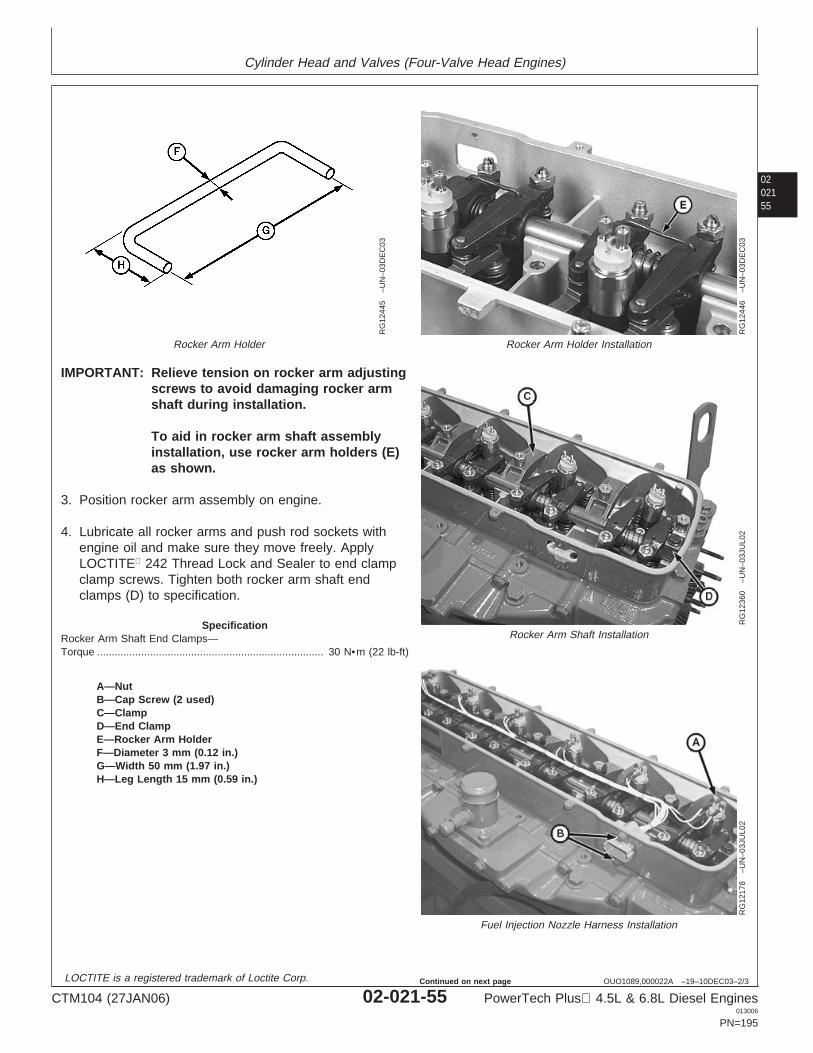
Cylinder Head and Valves (Four-Valve Head Engines)
0202155
OUO1089,000022A –19–10DEC03–2/3
RG
1244
5–U
N–0
3DE
C03
Rocker Arm Holder
RG
1244
6–U
N–0
3DE
C03
Rocker Arm Holder Installation
RG
1236
0–U
N–0
3JU
L02
Rocker Arm Shaft Installation
RG
1217
8–U
N–0
3JU
L02
Fuel Injection Nozzle Harness Installation
A—NutB—Cap Screw (2 used)C—ClampD—End ClampE—Rocker Arm HolderF—Diameter 3 mm (0.12 in.)G—Width 50 mm (1.97 in.)H—Leg Length 15 mm (0.59 in.)
IMPORTANT: Relieve tension on rocker arm adjustingscrews to avoid damaging rocker armshaft during installation.
To aid in rocker arm shaft assemblyinstallation, use rocker arm holders (E)as shown.
3. Position rocker arm assembly on engine.
4. Lubricate all rocker arms and push rod sockets withengine oil and make sure they move freely. ApplyLOCTITE 242 Thread Lock and Sealer to end clampclamp screws. Tighten both rocker arm shaft endclamps (D) to specification.
SpecificationRocker Arm Shaft End Clamps—Torque 30 N•m (22 lb-ft).............................................................................
LOCTITE is a registered trademark of Loctite Corp.
CTM104 (27JAN06) 02-021-55 PowerTech Plus 4.5L & 6.8L Diesel Engines013006
PN=195
Continued on next page
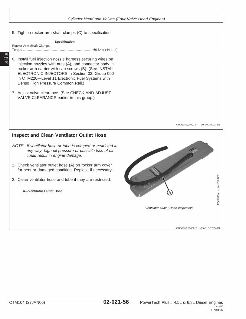
Cylinder Head and Valves (Four-Valve Head Engines)
02021
56
OUO1089,000022A –19–10DEC03–3/3
5. Tighten rocker arm shaft clamps (C) to specification.
SpecificationRocker Arm Shaft Clamps—Torque 60 N•m (44 lb-ft).............................................................................
6. Install fuel injection nozzle harness securing wires oninjection nozzles with nuts (A), and connector body inrocker arm carrier with cap screws (B). (See INSTALLELECTRONIC INJECTORS in Section 02, Group 090in CTM220—Level 11 Electronic Fuel Systems withDenso High Pressure Common Rail.)
7. Adjust valve clearance. (See CHECK AND ADJUSTVALVE CLEARANCE earlier in this group.)
OUO1089,000022B –19–11OCT05–1/1
Inspect and Clean Ventilator Outlet Hose
RG
1239
3A–U
N–1
0JU
N02
Ventilator Outlet Hose Inspection
A—Ventilator Outlet Hose
NOTE: If ventilator hose or tube is crimped or restricted inany way, high oil pressure or possible loss of oilcould result in engine damage.
1. Check ventilator outlet hose (A) on rocker arm coverfor bent or damaged condition. Replace if necessary.
2. Clean ventilator hose and tube if they are restricted.
CTM104 (27JAN06) 02-021-56 PowerTech Plus 4.5L & 6.8L Diesel Engines013006
PN=196
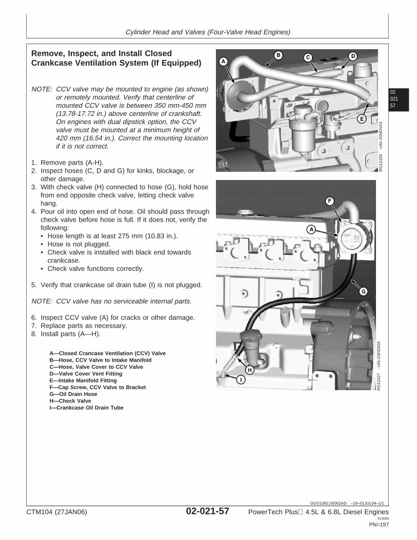
Cylinder Head and Valves (Four-Valve Head Engines)
0202157
OUO1082,00002AD –19–01JUL04–1/1
Remove, Inspect, and Install ClosedCrankcase Ventilation System (If Equipped)
RG
1242
6–U
N–2
0NO
V03
RG
1242
7–U
N–0
3FE
B04
A—Closed Crancase Ventilation (CCV) ValveB—Hose, CCV Valve to Intake ManifoldC—Hose, Valve Cover to CCV ValveD—Valve Cover Vent FittingE—Intake Manifold FittingF—Cap Screw, CCV Valve to BracketG—Oil Drain HoseH—Check ValveI—Crankcase Oil Drain Tube
NOTE: CCV valve may be mounted to engine (as shown)or remotely mounted. Verify that centerline ofmounted CCV valve is between 350 mm-450 mm(13.78-17.72 in.) above centerline of crankshaft.On engines with dual dipstick option, the CCVvalve must be mounted at a minimum height of420 mm (16.54 in.). Correct the mounting locationif it is not correct.
1. Remove parts (A-H).2. Inspect hoses (C, D and G) for kinks, blockage, or
other damage.3. With check valve (H) connected to hose (G), hold hose
from end opposite check valve, letting check valvehang.
4. Pour oil into open end of hose. Oil should pass throughcheck valve before hose is full. If it does not, verify thefollowing:• Hose length is at least 275 mm (10.83 in.).• Hose is not plugged.• Check valve is installed with black end towards
crankcase.• Check valve functions correctly.
5. Verify that crankcase oil drain tube (I) is not plugged.
NOTE: CCV valve has no serviceable internal parts.
6. Inspect CCV valve (A) for cracks or other damage.7. Replace parts as necessary.8. Install parts (A—H).
CTM104 (27JAN06) 02-021-57 PowerTech Plus 4.5L & 6.8L Diesel Engines013006
PN=197
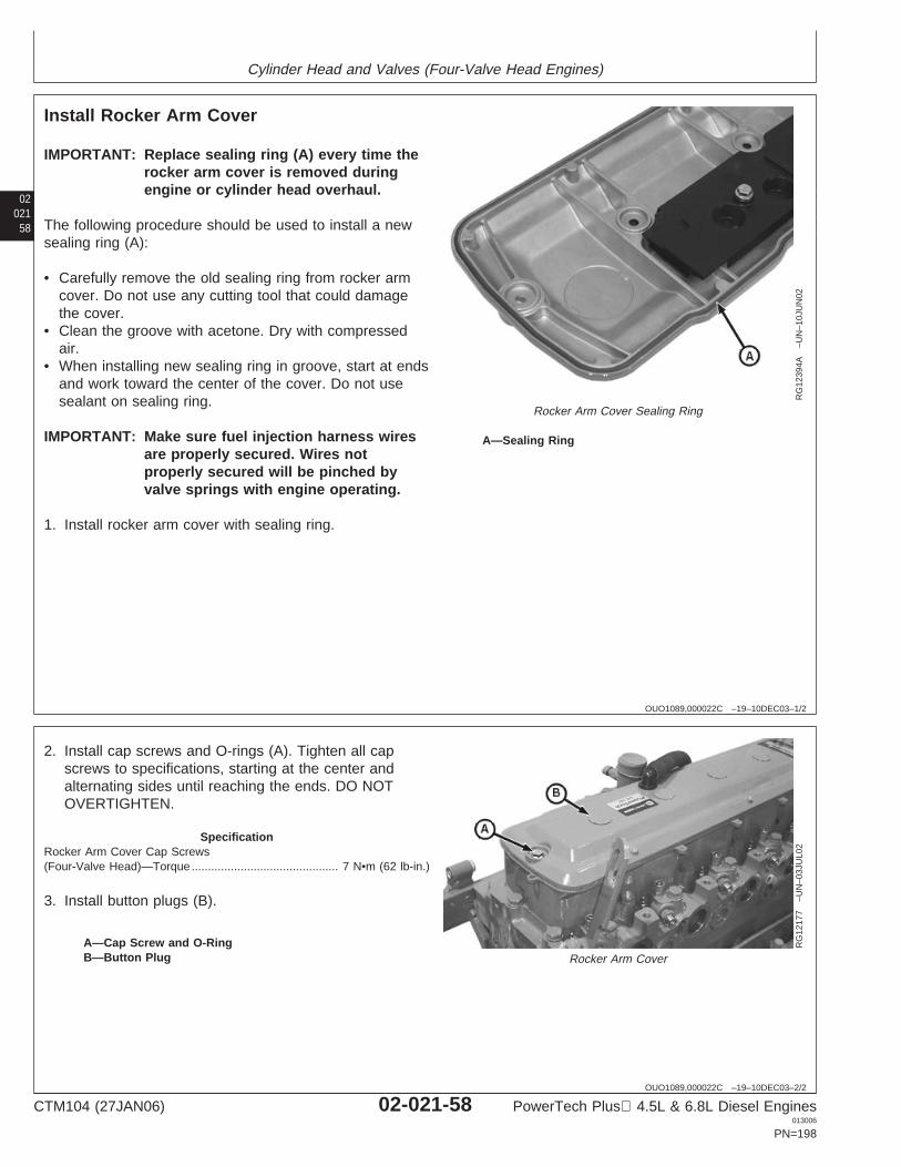
Cylinder Head and Valves (Four-Valve Head Engines)
02021
58
OUO1089,000022C –19–10DEC03–1/2
Install Rocker Arm Cover
RG
1239
4A–U
N–1
0JU
N02
Rocker Arm Cover Sealing Ring
A—Sealing Ring
IMPORTANT: Replace sealing ring (A) every time therocker arm cover is removed duringengine or cylinder head overhaul.
The following procedure should be used to install a newsealing ring (A):
• Carefully remove the old sealing ring from rocker armcover. Do not use any cutting tool that could damagethe cover.
• Clean the groove with acetone. Dry with compressedair.
• When installing new sealing ring in groove, start at endsand work toward the center of the cover. Do not usesealant on sealing ring.
IMPORTANT: Make sure fuel injection harness wiresare properly secured. Wires notproperly secured will be pinched byvalve springs with engine operating.
1. Install rocker arm cover with sealing ring.
OUO1089,000022C –19–10DEC03–2/2
RG
1217
7–U
N–0
3JU
L02
Rocker Arm CoverA—Cap Screw and O-RingB—Button Plug
2. Install cap screws and O-rings (A). Tighten all capscrews to specifications, starting at the center andalternating sides until reaching the ends. DO NOTOVERTIGHTEN.
SpecificationRocker Arm Cover Cap Screws(Four-Valve Head)—Torque 7 N•m (62 lb-in.).............................................
3. Install button plugs (B).
CTM104 (27JAN06) 02-021-58 PowerTech Plus 4.5L & 6.8L Diesel Engines013006
PN=198
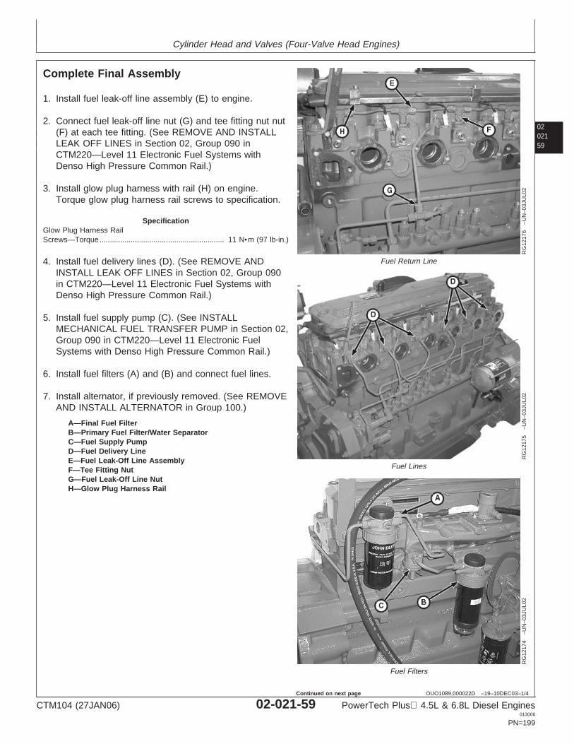
Cylinder Head and Valves (Four-Valve Head Engines)
0202159
OUO1089,000022D –19–10DEC03–1/4
Complete Final Assembly
RG
1217
6–U
N–0
3JU
L02
Fuel Return Line
RG
1217
5–U
N–0
3JU
L02
Fuel Lines
RG
1217
4–U
N–0
3JU
L02
Fuel Filters
A—Final Fuel FilterB—Primary Fuel Filter/Water SeparatorC—Fuel Supply PumpD—Fuel Delivery LineE—Fuel Leak-Off Line AssemblyF—Tee Fitting NutG—Fuel Leak-Off Line NutH—Glow Plug Harness Rail
1. Install fuel leak-off line assembly (E) to engine.
2. Connect fuel leak-off line nut (G) and tee fitting nut nut(F) at each tee fitting. (See REMOVE AND INSTALLLEAK OFF LINES in Section 02, Group 090 inCTM220—Level 11 Electronic Fuel Systems withDenso High Pressure Common Rail.)
3. Install glow plug harness with rail (H) on engine.Torque glow plug harness rail screws to specification.
SpecificationGlow Plug Harness RailScrews—Torque 11 N•m (97 lb-in.)............................................................
4. Install fuel delivery lines (D). (See REMOVE ANDINSTALL LEAK OFF LINES in Section 02, Group 090in CTM220—Level 11 Electronic Fuel Systems withDenso High Pressure Common Rail.)
5. Install fuel supply pump (C). (See INSTALLMECHANICAL FUEL TRANSFER PUMP in Section 02,Group 090 in CTM220—Level 11 Electronic FuelSystems with Denso High Pressure Common Rail.)
6. Install fuel filters (A) and (B) and connect fuel lines.
7. Install alternator, if previously removed. (See REMOVEAND INSTALL ALTERNATOR in Group 100.)
CTM104 (27JAN06) 02-021-59 PowerTech Plus 4.5L & 6.8L Diesel Engines013006
PN=199
Continued on next page
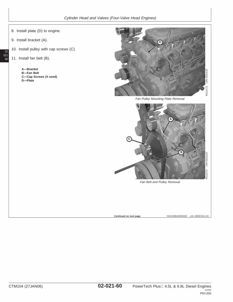
Cylinder Head and Valves (Four-Valve Head Engines)
02021
60
OUO1089,000022D –19–10DEC03–2/4
RG
1217
3–U
N–0
3JU
L02
Fan Pulley Mounting Plate Removal
RG
1217
2–U
N–0
3JU
L02
Fan Belt and Pulley Removal
A—BracketB—Fan BeltC—Cap Screws (4 used)D—Plate
8. Install plate (D) to engine.
9. Install bracket (A).
10. Install pulley with cap screws (C).
11. Install fan belt (B).
Continued on next page
CTM104 (27JAN06) 02-021-60 PowerTech Plus 4.5L & 6.8L Diesel Engines013006
PN=200
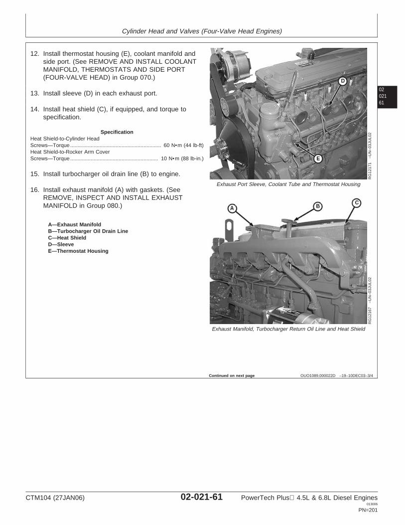
Cylinder Head and Valves (Four-Valve Head Engines)
0202161
OUO1089,000022D –19–10DEC03–3/4
RG
1217
1–U
N–0
3JU
L02
Exhaust Port Sleeve, Coolant Tube and Thermostat Housing
RG
1216
7–U
N–0
3JU
L02
Exhaust Manifold, Turbocharger Return Oil Line and Heat Shield
A—Exhaust ManifoldB—Turbocharger Oil Drain LineC—Heat ShieldD—SleeveE—Thermostat Housing
12. Install thermostat housing (E), coolant manifold andside port. (See REMOVE AND INSTALL COOLANTMANIFOLD, THERMOSTATS AND SIDE PORT(FOUR-VALVE HEAD) in Group 070.)
13. Install sleeve (D) in each exhaust port.
14. Install heat shield (C), if equipped, and torque tospecification.
SpecificationHeat Shield-to-Cylinder HeadScrews—Torque 60 N•m (44 lb-ft)..............................................................Heat Shield-to-Rocker Arm CoverScrews—Torque 10 N•m (88 lb-in.)............................................................
15. Install turbocharger oil drain line (B) to engine.
16. Install exhaust manifold (A) with gaskets. (SeeREMOVE, INSPECT AND INSTALL EXHAUSTMANIFOLD in Group 080.)
Continued on next page
CTM104 (27JAN06) 02-021-61 PowerTech Plus 4.5L & 6.8L Diesel Engines013006
PN=201
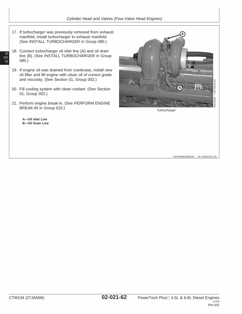
Cylinder Head and Valves (Four-Valve Head Engines)
02021
62
OUO1089,000022D –19–10DEC03–4/4
RG
1216
6–U
N–0
3JU
L02
Turbocharger
A—Oil Inlet LineB—Oil Drain Line
17. If turbocharger was previously removed from exhaustmanifold, install turbocharger to exhaust manifold.(See INSTALL TURBOCHARGER in Group 080.)
18. Connect turbocharger oil inlet line (A) and oil drainline (B). (See INSTALL TURBOCHARGER in Group080.)
19. If engine oil was drained from crankcase, install newoil filter and fill engine with clean oil of correct gradeand viscosity. (See Section 01, Group 002.)
20. Fill cooling system with clean coolant. (See Section01, Group 002.)
21. Perform engine break-in. (See PERFORM ENGINEBREAK-IN in Group 010.)
CTM104 (27JAN06) 02-021-62 PowerTech Plus 4.5L & 6.8L Diesel Engines013006
PN=202
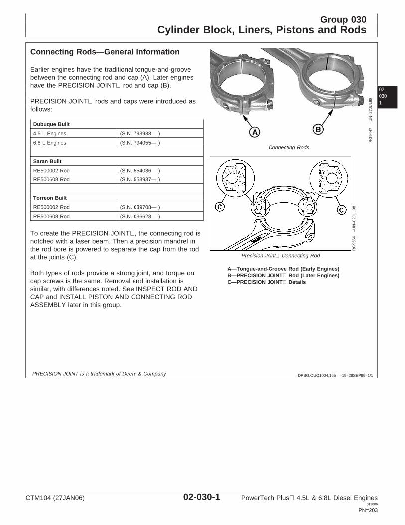
Group 030Cylinder Block, Liners, Pistons and Rods
020301
DPSG,OUO1004,165 –19–28SEP99–1/1
Connecting Rods—General Information
RG
9447
–UN
–27J
UL9
8
Connecting Rods
RG
9556
–UN
–02J
UL9
8
Precision Joint Connecting Rod
A—Tongue-and-Groove Rod (Early Engines)B—PRECISION JOINT Rod (Later Engines)C—PRECISION JOINT Details
Earlier engines have the traditional tongue-and-groovebetween the connecting rod and cap (A). Later engineshave the PRECISION JOINT rod and cap (B).
PRECISION JOINT rods and caps were introduced asfollows:
Dubuque Built
4.5 L Engines (S.N. 793938— )
6.8 L Engines (S.N. 794055— )
Saran Built
RE500002 Rod (S.N. 554036— )
RE500608 Rod (S.N. 553937— )
Torreon Built
RE500002 Rod (S.N. 039708— )
RE500608 Rod (S.N. 036628— )
To create the PRECISION JOINT, the connecting rod isnotched with a laser beam. Then a precision mandrel inthe rod bore is powered to separate the cap from the rodat the joints (C).
Both types of rods provide a strong joint, and torque oncap screws is the same. Removal and installation issimilar, with differences noted. See INSPECT ROD ANDCAP and INSTALL PISTON AND CONNECTING RODASSEMBLY later in this group.
PRECISION JOINT is a trademark of Deere & Company
CTM104 (27JAN06) 02-030-1 PowerTech Plus 4.5L & 6.8L Diesel Engines013006
PN=203
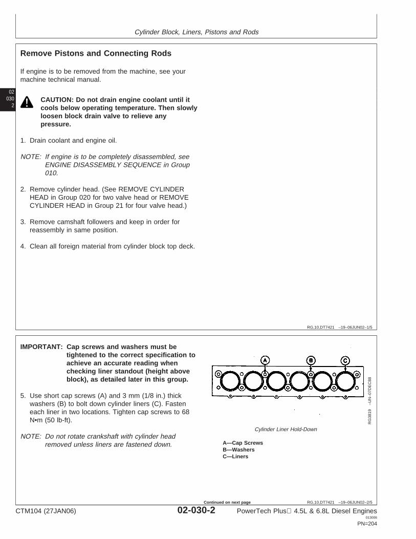
Cylinder Block, Liners, Pistons and Rods
02030
2
RG,10,DT7421 –19–06JUN02–1/5
Remove Pistons and Connecting Rods
If engine is to be removed from the machine, see yourmachine technical manual.
CAUTION: Do not drain engine coolant until itcools below operating temperature. Then slowlyloosen block drain valve to relieve anypressure.
1. Drain coolant and engine oil.
NOTE: If engine is to be completely disassembled, seeENGINE DISASSEMBLY SEQUENCE in Group010.
2. Remove cylinder head. (See REMOVE CYLINDERHEAD in Group 020 for two valve head or REMOVECYLINDER HEAD in Group 21 for four valve head.)
3. Remove camshaft followers and keep in order forreassembly in same position.
4. Clean all foreign material from cylinder block top deck.
RG,10,DT7421 –19–06JUN02–2/5
RG
3819
–UN
–07D
EC
88
Cylinder Liner Hold-Down
A—Cap ScrewsB—WashersC—Liners
IMPORTANT: Cap screws and washers must betightened to the correct specification toachieve an accurate reading whenchecking liner standout (height aboveblock), as detailed later in this group.
5. Use short cap screws (A) and 3 mm (1/8 in.) thickwashers (B) to bolt down cylinder liners (C). Fasteneach liner in two locations. Tighten cap screws to 68N•m (50 lb-ft).
NOTE: Do not rotate crankshaft with cylinder headremoved unless liners are fastened down.
CTM104 (27JAN06) 02-030-2 PowerTech Plus 4.5L & 6.8L Diesel Engines013006
PN=204
Continued on next page
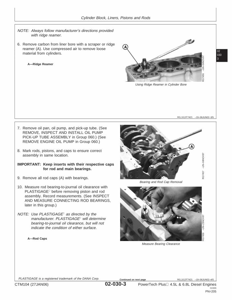
Cylinder Block, Liners, Pistons and Rods
020303
RG,10,DT7421 –19–06JUN02–3/5
RG
7455
–UN
–04N
OV
97
Using Ridge Reamer in Cylinder Bore
A—Ridge Reamer
NOTE: Always follow manufacturer’s directions providedwith ridge reamer.
6. Remove carbon from liner bore with a scraper or ridgereamer (A). Use compressed air to remove loosematerial from cylinders.
RG,10,DT7421 –19–06JUN02–4/5
RG
7457
–UN
–04N
OV
97
Bearing and Rod Cap Removal
RG
7459
–UN
–23N
OV
97
Measure Bearing Clearance
A—Rod Caps
7. Remove oil pan, oil pump, and pick-up tube. (SeeREMOVE, INSPECT AND INSTALL OIL PUMPPICK-UP TUBE ASSEMBLY in Group 060.) (SeeREMOVE ENGINE OIL PUMP in Group 060.)
8. Mark rods, pistons, and caps to ensure correctassembly in same location.
IMPORTANT: Keep inserts with their respective capsfor rod and main bearings.
9. Remove all rod caps (A) with bearings.
10. Measure rod bearing-to-journal oil clearance withPLASTIGAGE before removing piston and rodassembly. Record measurements. (See INSPECTAND MEASURE CONNECTING ROD BEARINGS,later in this group.)
NOTE: Use PLASTIGAGE as directed by themanufacturer. PLASTIGAGE will determinebearing-to-journal oil clearance, but will notindicate the condition of either surface.
PLASTIGAGE is a registered trademark of the DANA Corp.
CTM104 (27JAN06) 02-030-3 PowerTech Plus 4.5L & 6.8L Diesel Engines013006
PN=205
Continued on next page
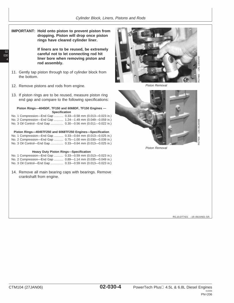
Cylinder Block, Liners, Pistons and Rods
02030
4
RG,10,DT7421 –19–06JUN02–5/5
RG
7460
–UN
–23N
OV
97
Piston Removal
RG
7934
–UN
–05J
AN
98
Piston Removal
IMPORTANT: Hold onto piston to prevent piston fromdropping. Piston will drop once pistonrings have cleared cylinder liner.
If liners are to be reused, be extremelycareful not to let connecting rod hitliner bore when removing piston androd assembly.
11. Gently tap piston through top of cylinder block fromthe bottom.
12. Remove pistons and rods from engine.
13. If piston rings are to be reused, measure piston ringend gap and compare to the following specifications:
Piston Rings—4045DF, TF150 and 6068DF, TF150 Engines —Specification
No. 1 Compression—End Gap 0.33—0.58 mm (0.013—0.023 in.)...........No. 2 Compression—End Gap 1.24—1.49 mm (0.049—0.059 in.)...........No. 3 Oil Control—End Gap 0.30—0.56 mm (0.011—0.022 in.)...............
Piston Rings—4045TF250 and 6068TF250 Engines—SpecificationNo. 1 Compression—End Gap 0.33—0.64 mm (0.013—0.025 in.)...........No. 2 Compression—End Gap 0.75—1.00 mm (0.030—0.039 in.)...........No. 3 Oil Control—End Gap 0.33—0.64 mm (0.013—0.025 in.)...............
Heavy Duty Piston Rings—SpecificationNo. 1 Compression—End Gap 0.33—0.59 mm (0.013—0.023 in.)...........No. 2 Compression—End Gap 0.89—1.14 mm (0.035—0.049 in.)...........No. 3 Oil Control—End Gap 0.33—0.59 mm (0.013—0.023 in.)...............
14. Remove all main bearing caps with bearings. Removecrankshaft from engine.
CTM104 (27JAN06) 02-030-4 PowerTech Plus 4.5L & 6.8L Diesel Engines013006
PN=206
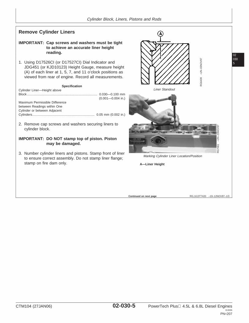
Cylinder Block, Liners, Pistons and Rods
020305
RG,10,DT7420 –19–12NOV97–1/3
Remove Cylinder Liners
RG
6439
–UN
–03N
OV
97
Liner Standout
RG
7461
–UN
–23N
OV
97
Marking Cylinder Liner Location/Position
A—Liner Height
IMPORTANT: Cap screws and washers must be tightto achieve an accurate liner heightreading.
1. Using D17526CI (or D17527CI) Dial Indicator andJDG451 (or KJD10123) Height Gauge, measure height(A) of each liner at 1, 5, 7, and 11 o’clock positions asviewed from rear of engine. Record all measurements.
SpecificationCylinder Liner—Height aboveBlock 0.030—0.100 mm
(0.001—0.004 in.)..............................................................................
Maximum Permissible Differencebetween Readings within OneCylinder or between AdjacentCylinders 0.05 mm (0.002 in.).....................................................................
2. Remove cap screws and washers securing liners tocylinder block.
IMPORTANT: DO NOT stamp top of piston. Pistonmay be damaged.
3. Number cylinder liners and pistons. Stamp front of linerto ensure correct assembly. Do not stamp liner flange;stamp on fire dam only.
Continued on next page
CTM104 (27JAN06) 02-030-5 PowerTech Plus 4.5L & 6.8L Diesel Engines013006
PN=207
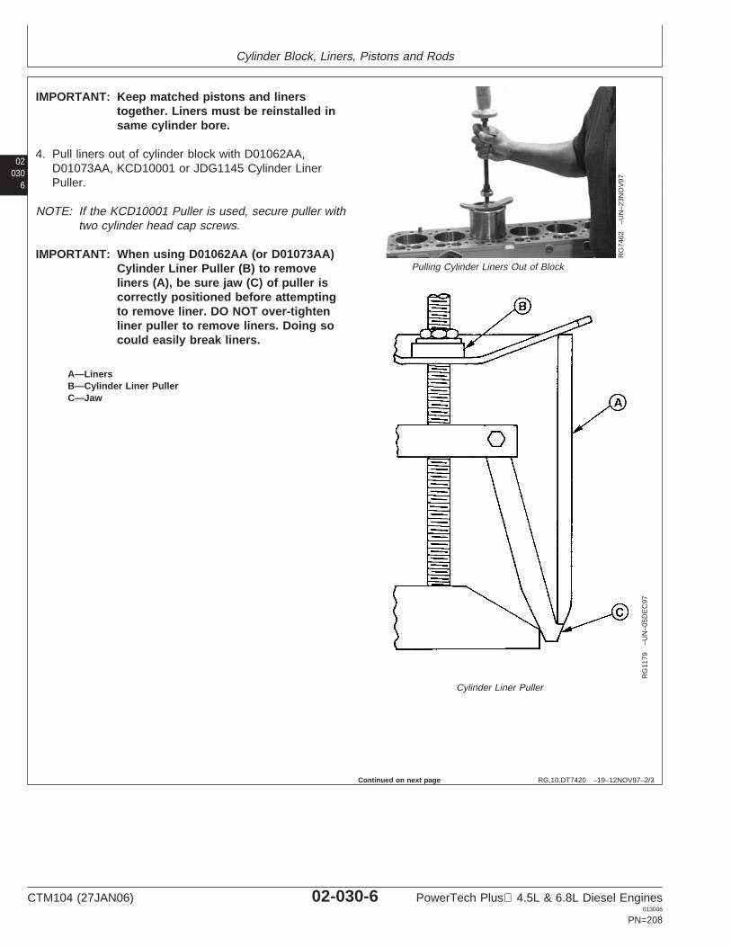
Cylinder Block, Liners, Pistons and Rods
02030
6
RG,10,DT7420 –19–12NOV97–2/3
RG
7462
–UN
–23N
OV
97
Pulling Cylinder Liners Out of Block
RG
1179
–UN
–05D
EC
97
Cylinder Liner Puller
A—LinersB—Cylinder Liner PullerC—Jaw
IMPORTANT: Keep matched pistons and linerstogether. Liners must be reinstalled insame cylinder bore.
4. Pull liners out of cylinder block with D01062AA,D01073AA, KCD10001 or JDG1145 Cylinder LinerPuller.
NOTE: If the KCD10001 Puller is used, secure puller withtwo cylinder head cap screws.
IMPORTANT: When using D01062AA (or D01073AA)Cylinder Liner Puller (B) to removeliners (A), be sure jaw (C) of puller iscorrectly positioned before attemptingto remove liner. DO NOT over-tightenliner puller to remove liners. Doing socould easily break liners.
Continued on next page
CTM104 (27JAN06) 02-030-6 PowerTech Plus 4.5L & 6.8L Diesel Engines013006
PN=208
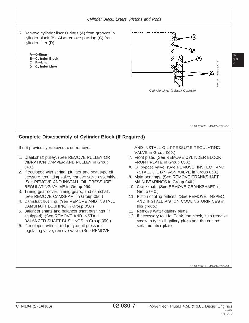
Cylinder Block, Liners, Pistons and Rods
020307
RG,10,DT7420 –19–12NOV97–3/3
RG
4745
–UN
–31O
CT
97
Cylinder Liner in Block Cutaway
A—O-RingsB—Cylinder BlockC—PackingD—Cylinder Liner
5. Remove cylinder liner O-rings (A) from grooves incylinder block (B). Also remove packing (C) fromcylinder liner (D).
RG,10,DT7419 –19–29NOV99–1/1
Complete Disassembly of Cylinder Block (If Required)
If not previously removed, also remove:
1. Crankshaft pulley. (See REMOVE PULLEY ORVIBRATION DAMPER AND PULLEY in Group040.)
2. If equipped with spring, plunger and seat type oilpressure regulating valve, remove valve assembly.(See REMOVE AND INSTALL OIL PRESSUREREGULATING VALVE in Group 060.)
3. Timing gear cover, timing gears, and camshaft.(See REMOVE CAMSHAFT in Group 050.)
4. Camshaft bushing. (See REMOVE AND INSTALLCAMSHAFT BUSHING in Group 050.)
5. Balancer shafts and balancer shaft bushings (ifequipped). (See REMOVE AND INSTALLBALANCER SHAFT BUSHINGS in Group 050.)
6. If equipped with cartridge type oil pressureregulating valve, remove valve. (See REMOVE
AND INSTALL OIL PRESSURE REGULATINGVALVE in Group 060.)
7. Front plate. (See REMOVE CYLINDER BLOCKFRONT PLATE in Group 050.)
8. Oil bypass valve. (See REMOVE, INSPECT ANDINSTALL OIL BYPASS VALVE in Group 060.)
9. Main bearings. (See REMOVE CRANKSHAFTMAIN BEARINGS in Group 040.)
10. Crankshaft. (See REMOVE CRANKSHAFT inGroup 040.)
11. Piston cooling orifices. (See REMOVE, INSPECTAND INSTALL PISTON COOLING ORIFICES inthis group.)
12. Remove water gallery plugs.13. If necessary to “Hot Tank” the block, also remove
screw-in type oil gallery plugs and the engineserial number plate.
CTM104 (27JAN06) 02-030-7 PowerTech Plus 4.5L & 6.8L Diesel Engines013006
PN=209
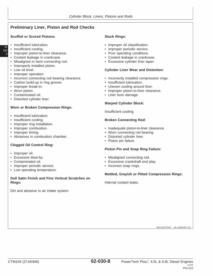
Cylinder Block, Liners, Pistons and Rods
02030
8
RG,10,DT7418 –19–12NOV97–1/1
Preliminary Liner, Piston and Rod Checks
Scuffed or Scored Pistons:
• Insufficient lubrication.• Insufficient cooling.• Improper piston-to-liner clearance.• Coolant leakage in crankcase.• Misaligned or bent connecting rod.• Improperly installed piston.• Low oil level.• Improper operation.• Incorrect connecting rod bearing clearance.• Carbon build-up in ring groove.• Improper break-in.• Worn piston.• Contaminated oil.• Distorted cylinder liner.
Worn or Broken Compression Rings:
• Insufficient lubrication.• Insufficient cooling.• Improper ring installation.• Improper combustion.• Improper timing.• Abrasives in combustion chamber.
Clogged Oil Control Ring:
• Improper oil.• Excessive blow-by.• Contaminated oil.• Improper periodic service.• Low operating temperature.
Dull Satin Finish and Fine Vertical Scratches onRings:
Dirt and abrasive in air intake system.
Stuck Rings:
• Improper oil classification.• Improper periodic service.• Poor operating conditions.• Coolant leakage in crankcase.• Excessive cylinder liner taper.
Cylinder Liner Wear and Distortion:
• Incorrectly installed compression rings.• Insufficient lubrication.• Uneven cooling around liner.• Improper piston-to-liner clearance.• Liner bore damage.
Warped Cylinder Block:
Insufficient cooling.
Broken Connecting Rod:
• Inadequate piston-to-liner clearance.• Worn connecting rod bearing.• Distorted cylinder liner.• Piston pin failure.
Piston Pin and Snap Ring Failure:
• Misaligned connecting rod.• Excessive crankshaft end play.• Incorrect snap rings.
Mottled, Grayish or Pitted Compression Rings:
Internal coolant leaks.
CTM104 (27JAN06) 02-030-8 PowerTech Plus 4.5L & 6.8L Diesel Engines013006
PN=210
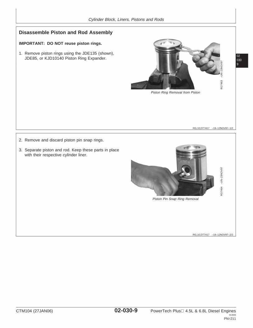
Cylinder Block, Liners, Pistons and Rods
020309
RG,10,DT7417 –19–12NOV97–1/2
Disassemble Piston and Rod Assembly
RG
7463
–UN
–23N
OV
97
Piston Ring Removal from Piston
IMPORTANT: DO NOT reuse piston rings.
1. Remove piston rings using the JDE135 (shown),JDE85, or KJD10140 Piston Ring Expander.
RG,10,DT7417 –19–12NOV97–2/2
RG
7464
–UN
–23N
OV
97
Piston Pin Snap Ring Removal
2. Remove and discard piston pin snap rings.
3. Separate piston and rod. Keep these parts in placewith their respective cylinder liner.
CTM104 (27JAN06) 02-030-9 PowerTech Plus 4.5L & 6.8L Diesel Engines013006
PN=211
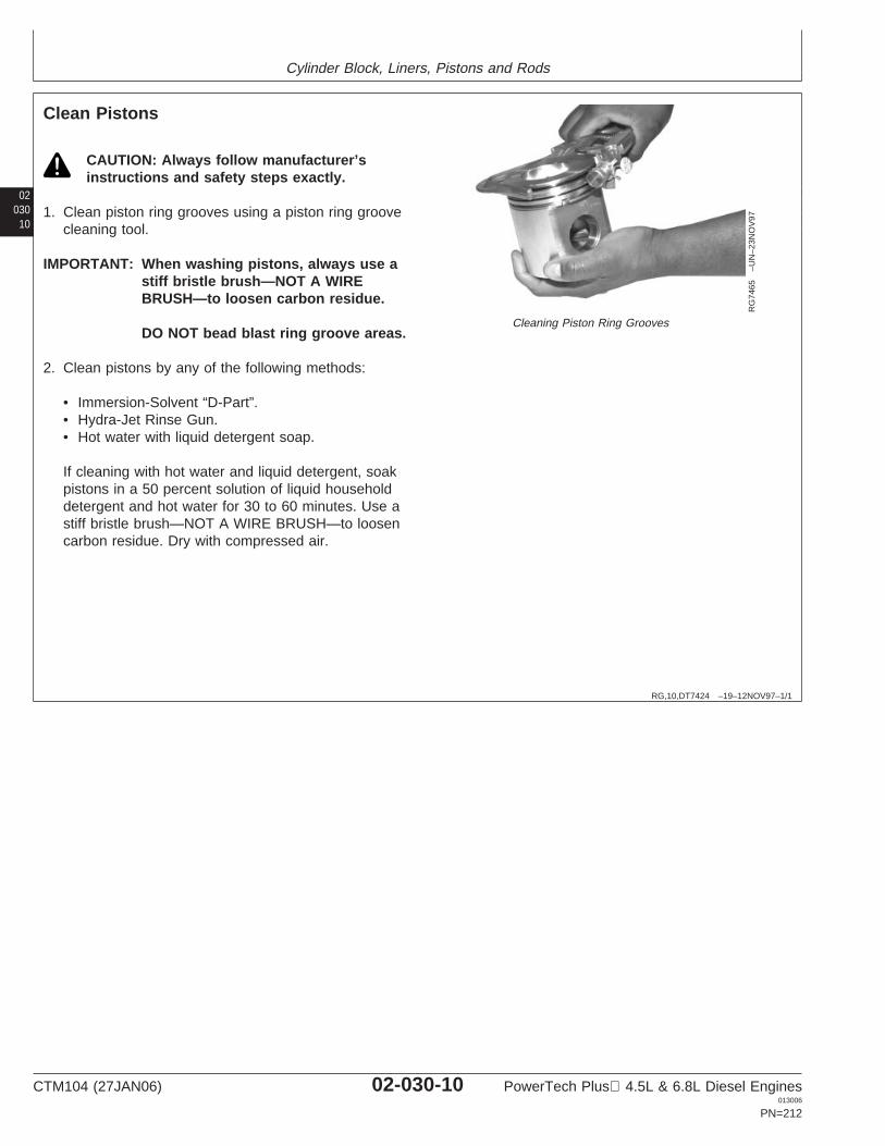
Cylinder Block, Liners, Pistons and Rods
02030
10
RG,10,DT7424 –19–12NOV97–1/1
Clean Pistons
RG
7465
–UN
–23N
OV
97
Cleaning Piston Ring Grooves
CAUTION: Always follow manufacturer’sinstructions and safety steps exactly.
1. Clean piston ring grooves using a piston ring groovecleaning tool.
IMPORTANT: When washing pistons, always use astiff bristle brush—NOT A WIREBRUSH—to loosen carbon residue.
DO NOT bead blast ring groove areas.
2. Clean pistons by any of the following methods:
• Immersion-Solvent “D-Part”.• Hydra-Jet Rinse Gun.• Hot water with liquid detergent soap.
If cleaning with hot water and liquid detergent, soakpistons in a 50 percent solution of liquid householddetergent and hot water for 30 to 60 minutes. Use astiff bristle brush—NOT A WIRE BRUSH—to loosencarbon residue. Dry with compressed air.
CTM104 (27JAN06) 02-030-10 PowerTech Plus 4.5L & 6.8L Diesel Engines013006
PN=212
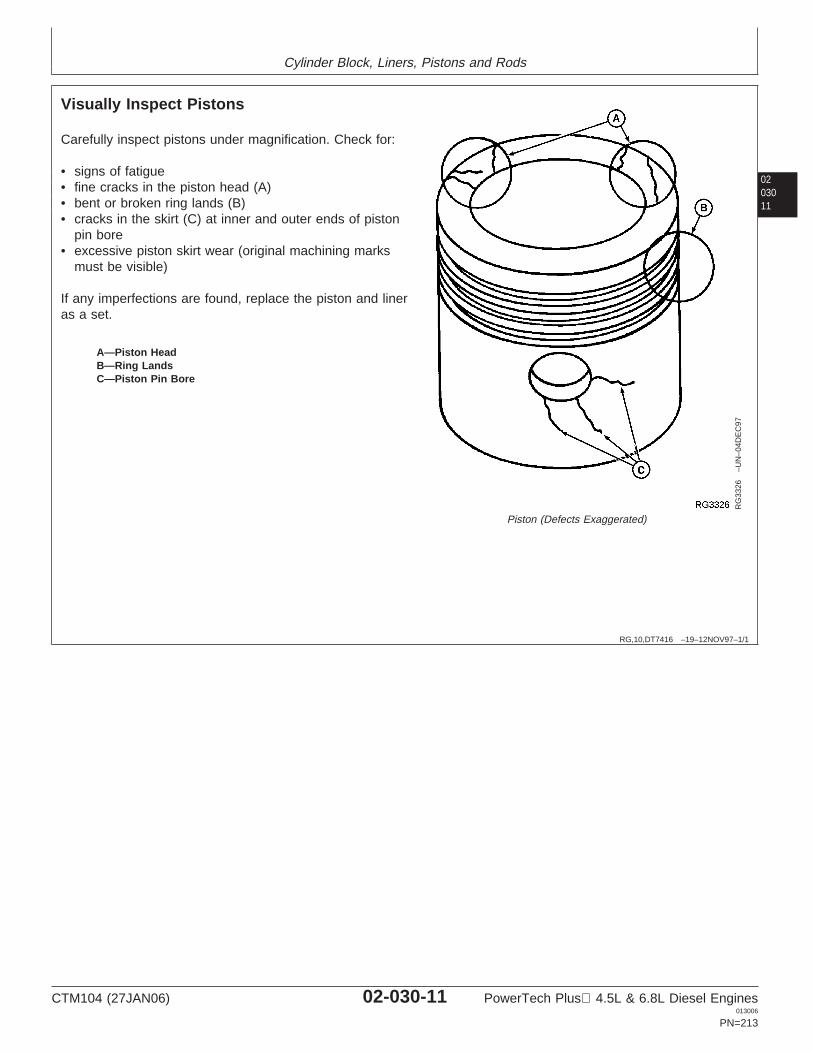
Cylinder Block, Liners, Pistons and Rods
0203011
RG,10,DT7416 –19–12NOV97–1/1
Visually Inspect Pistons
RG
3326
–UN
–04D
EC
97
Piston (Defects Exaggerated)
A—Piston HeadB—Ring LandsC—Piston Pin Bore
Carefully inspect pistons under magnification. Check for:
• signs of fatigue• fine cracks in the piston head (A)• bent or broken ring lands (B)• cracks in the skirt (C) at inner and outer ends of piston
pin bore• excessive piston skirt wear (original machining marks
must be visible)
If any imperfections are found, replace the piston and lineras a set.
CTM104 (27JAN06) 02-030-11 PowerTech Plus 4.5L & 6.8L Diesel Engines013006
PN=213
Cylinder Block, Liners, Pistons and Rods
02030
12
RG,10,DT7425 –19–12NOV97–1/1
Clean Cylinder Liners
1. Use a stiff bristle brush to remove all debris, rust, andscale from OD of liners, under liner flange, and inO-ring packing areas. Make certain there are no nicksor burrs in areas where packings will seat.
IMPORTANT: Do not use gasoline, kerosene orcommercial solvents to clean liners.Solvents will not remove all abrasivesfrom liner walls.
2. Thoroughly clean liner ID with a 50 percent solution ofhot water and liquid detergent.
3. Rinse thoroughly and wipe dry with a clean rag.
4. Swab out liner as often as necessary with clean SAE10W oil. Clean liner until a clean, white rag shows nodiscoloration.
CTM104 (27JAN06) 02-030-12 PowerTech Plus 4.5L & 6.8L Diesel Engines013006
PN=214
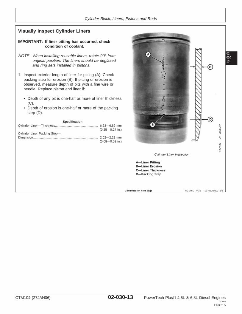
Cylinder Block, Liners, Pistons and Rods
0203013
RG,10,DT7415 –19–03JUN02–1/2
Visually Inspect Cylinder Liners
RG
4643
–UN
–05D
EC
97
Cylinder Liner Inspection
A—Liner PittingB—Liner ErosionC—Liner ThicknessD—Packing Step
IMPORTANT: If liner pitting has occurred, checkcondition of coolant.
NOTE: When installing reusable liners, rotate 90° fromoriginal position. The liners should be deglazedand ring sets installed in pistons.
1. Inspect exterior length of liner for pitting (A). Checkpacking step for erosion (B). If pitting or erosion isobserved, measure depth of pits with a fine wire orneedle. Replace piston and liner if:
• Depth of any pit is one-half or more of liner thickness(C).
• Depth of erosion is one-half or more of the packingstep (D).
SpecificationCylinder Liner—Thickness 6.23—6.89 mm
(0.25—0.27 in.).................................................
Cylinder Liner Packing Step—Dimension 2.02—2.29 mm
(0.08—0.09 in.)..........................................................................
Continued on next page
CTM104 (27JAN06) 02-030-13 PowerTech Plus 4.5L & 6.8L Diesel Engines013006
PN=215
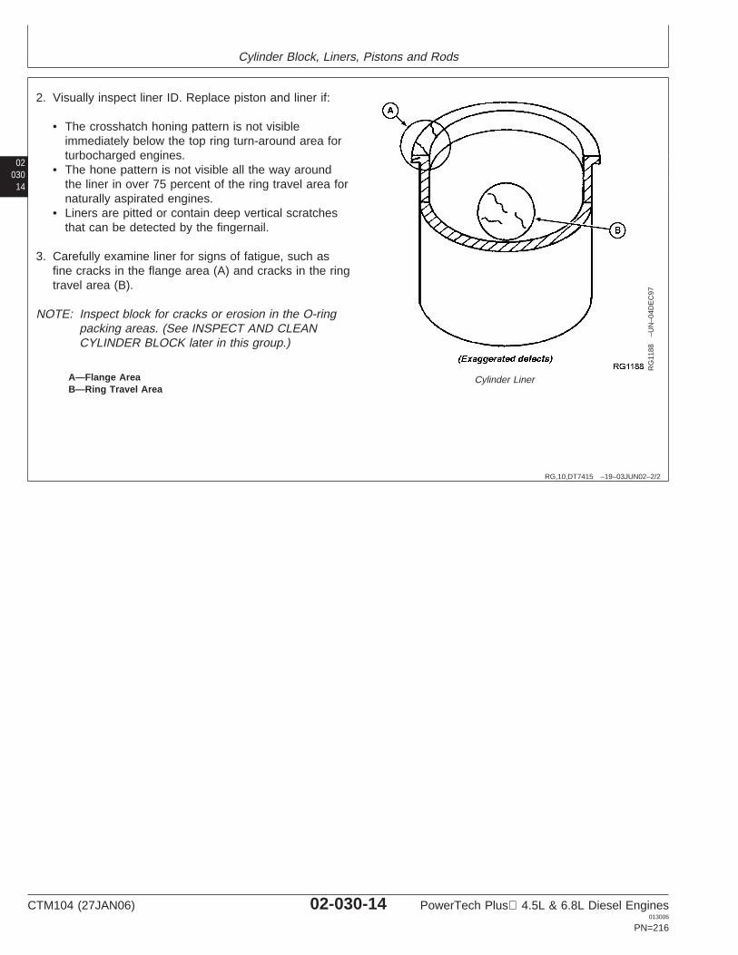
Cylinder Block, Liners, Pistons and Rods
02030
14
RG,10,DT7415 –19–03JUN02–2/2
RG
1188
–UN
–04D
EC
97
Cylinder LinerA—Flange AreaB—Ring Travel Area
2. Visually inspect liner ID. Replace piston and liner if:
• The crosshatch honing pattern is not visibleimmediately below the top ring turn-around area forturbocharged engines.
• The hone pattern is not visible all the way aroundthe liner in over 75 percent of the ring travel area fornaturally aspirated engines.
• Liners are pitted or contain deep vertical scratchesthat can be detected by the fingernail.
3. Carefully examine liner for signs of fatigue, such asfine cracks in the flange area (A) and cracks in the ringtravel area (B).
NOTE: Inspect block for cracks or erosion in the O-ringpacking areas. (See INSPECT AND CLEANCYLINDER BLOCK later in this group.)
CTM104 (27JAN06) 02-030-14 PowerTech Plus 4.5L & 6.8L Diesel Engines013006
PN=216
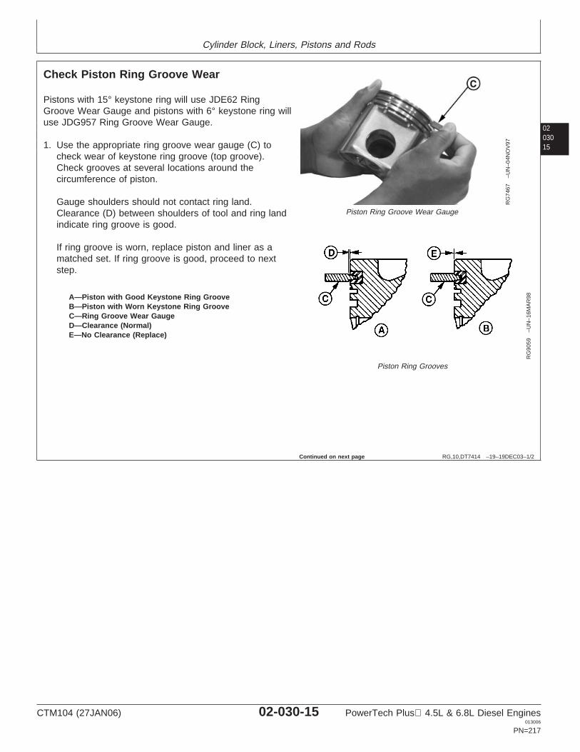
Cylinder Block, Liners, Pistons and Rods
0203015
RG,10,DT7414 –19–19DEC03–1/2
Check Piston Ring Groove Wear
RG
7467
–UN
–04N
OV
97
Piston Ring Groove Wear Gauge
RG
9059
–UN
–16M
AR
98
Piston Ring Grooves
A—Piston with Good Keystone Ring GrooveB—Piston with Worn Keystone Ring GrooveC—Ring Groove Wear GaugeD—Clearance (Normal)E—No Clearance (Replace)
Pistons with 15° keystone ring will use JDE62 RingGroove Wear Gauge and pistons with 6° keystone ring willuse JDG957 Ring Groove Wear Gauge.
1. Use the appropriate ring groove wear gauge (C) tocheck wear of keystone ring groove (top groove).Check grooves at several locations around thecircumference of piston.
Gauge shoulders should not contact ring land.Clearance (D) between shoulders of tool and ring landindicate ring groove is good.
If ring groove is worn, replace piston and liner as amatched set. If ring groove is good, proceed to nextstep.
Continued on next page
CTM104 (27JAN06) 02-030-15 PowerTech Plus 4.5L & 6.8L Diesel Engines013006
PN=217
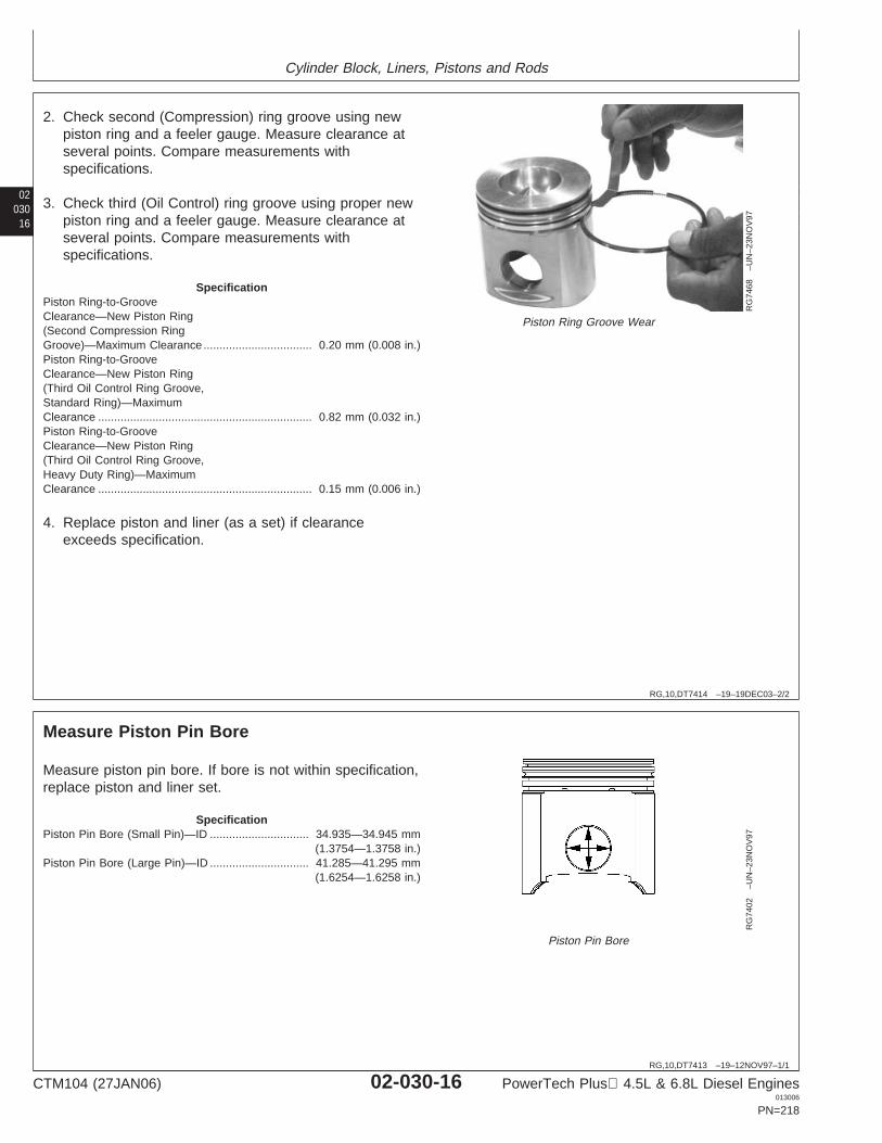
Cylinder Block, Liners, Pistons and Rods
02030
16
RG,10,DT7414 –19–19DEC03–2/2
RG
7468
–UN
–23N
OV
97
Piston Ring Groove Wear
2. Check second (Compression) ring groove using newpiston ring and a feeler gauge. Measure clearance atseveral points. Compare measurements withspecifications.
3. Check third (Oil Control) ring groove using proper newpiston ring and a feeler gauge. Measure clearance atseveral points. Compare measurements withspecifications.
SpecificationPiston Ring-to-GrooveClearance—New Piston Ring(Second Compression RingGroove)—Maximum Clearance 0.20 mm (0.008 in.)..................................Piston Ring-to-GrooveClearance—New Piston Ring(Third Oil Control Ring Groove,Standard Ring)—MaximumClearance 0.82 mm (0.032 in.)...................................................................Piston Ring-to-GrooveClearance—New Piston Ring(Third Oil Control Ring Groove,Heavy Duty Ring)—MaximumClearance 0.15 mm (0.006 in.)...................................................................
4. Replace piston and liner (as a set) if clearanceexceeds specification.
RG,10,DT7413 –19–12NOV97–1/1
Measure Piston Pin BoreR
G74
02–U
N–2
3NO
V97
Piston Pin Bore
Measure piston pin bore. If bore is not within specification,replace piston and liner set.
SpecificationPiston Pin Bore (Small Pin)—ID 34.935—34.945 mm
(1.3754—1.3758 in.)...............................
Piston Pin Bore (Large Pin)—ID 41.285—41.295 mm(1.6254—1.6258 in.)
...............................
CTM104 (27JAN06) 02-030-16 PowerTech Plus 4.5L & 6.8L Diesel Engines013006
PN=218
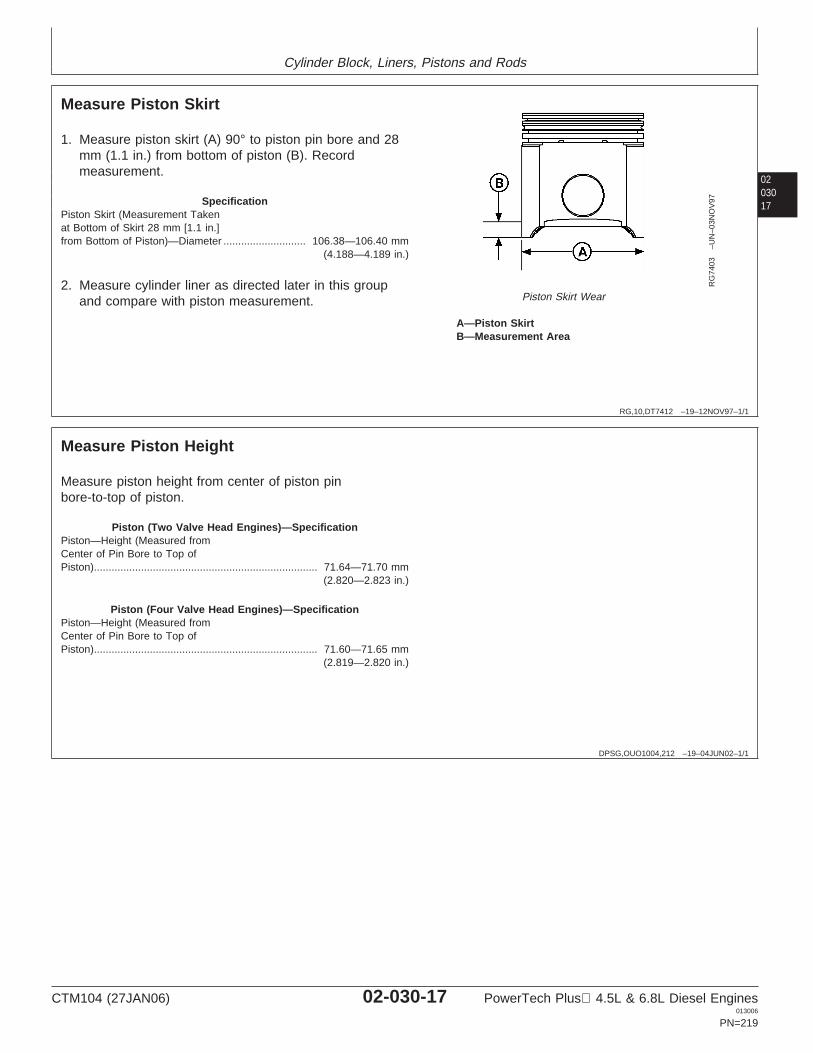
Cylinder Block, Liners, Pistons and Rods
0203017
RG,10,DT7412 –19–12NOV97–1/1
Measure Piston Skirt
RG
7403
–UN
–03N
OV
97
Piston Skirt Wear
A—Piston SkirtB—Measurement Area
1. Measure piston skirt (A) 90° to piston pin bore and 28mm (1.1 in.) from bottom of piston (B). Recordmeasurement.
SpecificationPiston Skirt (Measurement Takenat Bottom of Skirt 28 mm [1.1 in.]from Bottom of Piston)—Diameter 106.38—106.40 mm
(4.188—4.189 in.)............................
2. Measure cylinder liner as directed later in this groupand compare with piston measurement.
DPSG,OUO1004,212 –19–04JUN02–1/1
Measure Piston Height
Measure piston height from center of piston pinbore-to-top of piston.
Piston (Two Valve Head Engines)—SpecificationPiston—Height (Measured fromCenter of Pin Bore to Top ofPiston) 71.64—71.70 mm
(2.820—2.823 in.)............................................................................
Piston (Four Valve Head Engines)—SpecificationPiston—Height (Measured fromCenter of Pin Bore to Top ofPiston) 71.60—71.65 mm
(2.819—2.820 in.)............................................................................
CTM104 (27JAN06) 02-030-17 PowerTech Plus 4.5L & 6.8L Diesel Engines013006
PN=219
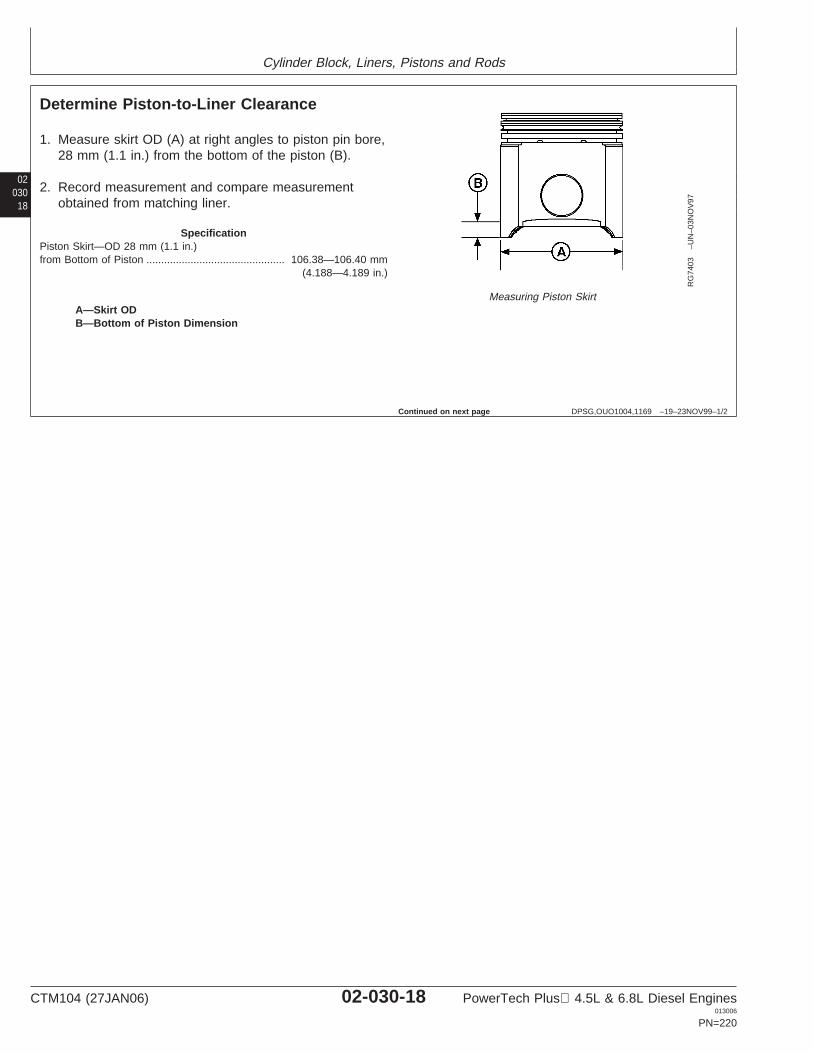
Cylinder Block, Liners, Pistons and Rods
02030
18
DPSG,OUO1004,1169 –19–23NOV99–1/2
Determine Piston-to-Liner Clearance
RG
7403
–UN
–03N
OV
97
Measuring Piston SkirtA—Skirt ODB—Bottom of Piston Dimension
1. Measure skirt OD (A) at right angles to piston pin bore,28 mm (1.1 in.) from the bottom of the piston (B).
2. Record measurement and compare measurementobtained from matching liner.
SpecificationPiston Skirt—OD 28 mm (1.1 in.)from Bottom of Piston 106.38—106.40 mm
(4.188—4.189 in.)...............................................
Continued on next page
CTM104 (27JAN06) 02-030-18 PowerTech Plus 4.5L & 6.8L Diesel Engines013006
PN=220
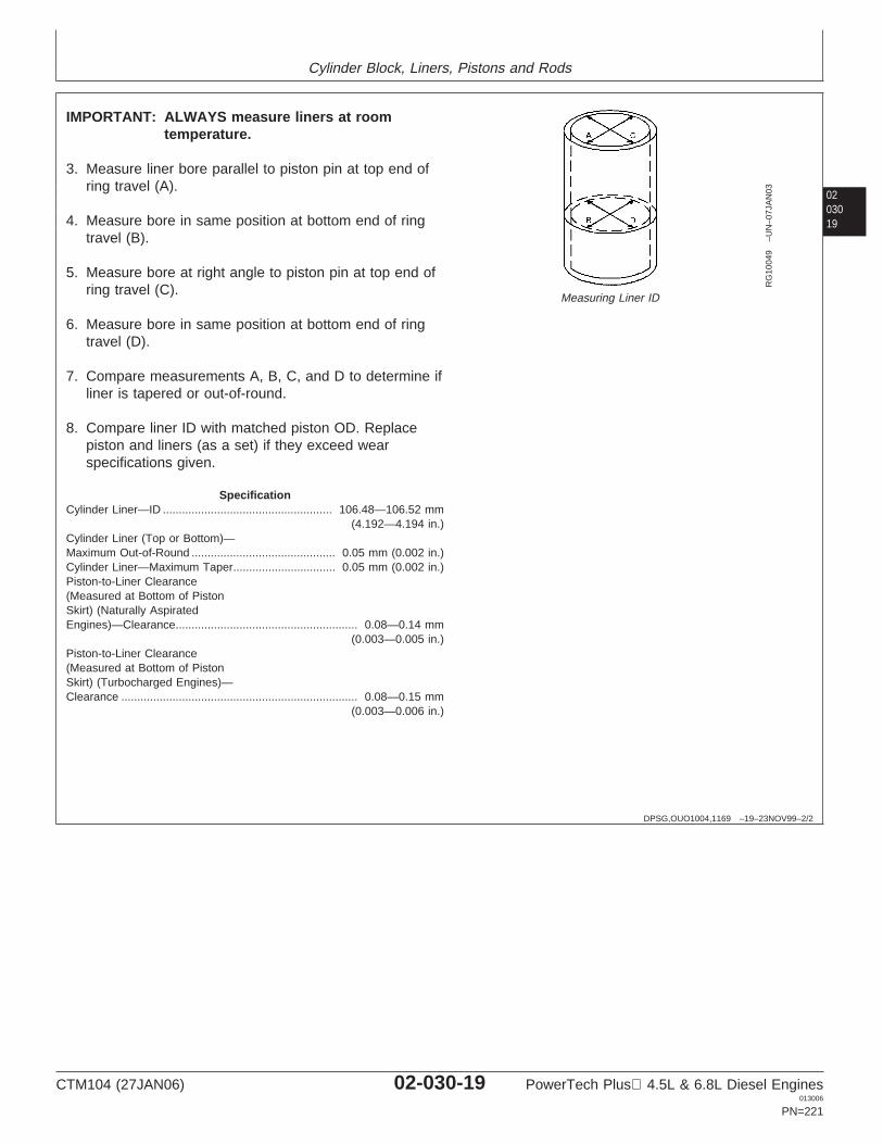
Cylinder Block, Liners, Pistons and Rods
0203019
DPSG,OUO1004,1169 –19–23NOV99–2/2
RG
1004
9–U
N–0
7JA
N03
Measuring Liner ID
IMPORTANT: ALWAYS measure liners at roomtemperature.
3. Measure liner bore parallel to piston pin at top end ofring travel (A).
4. Measure bore in same position at bottom end of ringtravel (B).
5. Measure bore at right angle to piston pin at top end ofring travel (C).
6. Measure bore in same position at bottom end of ringtravel (D).
7. Compare measurements A, B, C, and D to determine ifliner is tapered or out-of-round.
8. Compare liner ID with matched piston OD. Replacepiston and liners (as a set) if they exceed wearspecifications given.
SpecificationCylinder Liner—ID 106.48—106.52 mm
(4.192—4.194 in.).....................................................
Cylinder Liner (Top or Bottom)—Maximum Out-of-Round 0.05 mm (0.002 in.).............................................Cylinder Liner—Maximum Taper 0.05 mm (0.002 in.)................................Piston-to-Liner Clearance(Measured at Bottom of PistonSkirt) (Naturally AspiratedEngines)—Clearance 0.08—0.14 mm
(0.003—0.005 in.).........................................................
Piston-to-Liner Clearance(Measured at Bottom of PistonSkirt) (Turbocharged Engines)—Clearance 0.08—0.15 mm
(0.003—0.006 in.)..........................................................................
CTM104 (27JAN06) 02-030-19 PowerTech Plus 4.5L & 6.8L Diesel Engines013006
PN=221
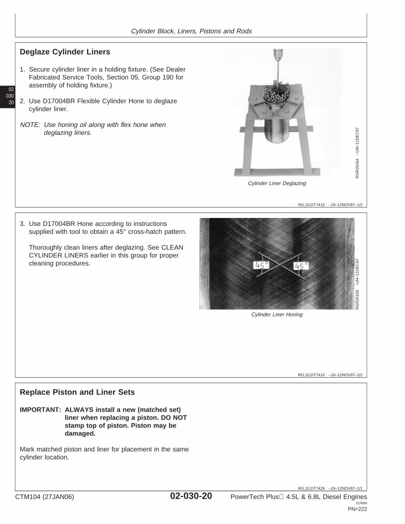
Cylinder Block, Liners, Pistons and Rods
02030
20
RG,10,DT7410 –19–12NOV97–1/2
Deglaze Cylinder Liners
RG
R26
164
–UN
–11D
EC
97
Cylinder Liner Deglazing
1. Secure cylinder liner in a holding fixture. (See DealerFabricated Service Tools, Section 05, Group 190 forassembly of holding fixture.)
2. Use D17004BR Flexible Cylinder Hone to deglazecylinder liner.
NOTE: Use honing oil along with flex hone whendeglazing liners.
RG,10,DT7410 –19–12NOV97–2/2
RG
R26
165
–UN
–11D
EC
97
Cylinder Liner Honing
3. Use D17004BR Hone according to instructionssupplied with tool to obtain a 45° cross-hatch pattern.
Thoroughly clean liners after deglazing. See CLEANCYLINDER LINERS earlier in this group for propercleaning procedures.
RG,10,DT7426 –19–12NOV97–1/1
Replace Piston and Liner Sets
IMPORTANT: ALWAYS install a new (matched set)liner when replacing a piston. DO NOTstamp top of piston. Piston may bedamaged.
Mark matched piston and liner for placement in the samecylinder location.
CTM104 (27JAN06) 02-030-20 PowerTech Plus 4.5L & 6.8L Diesel Engines013006
PN=222
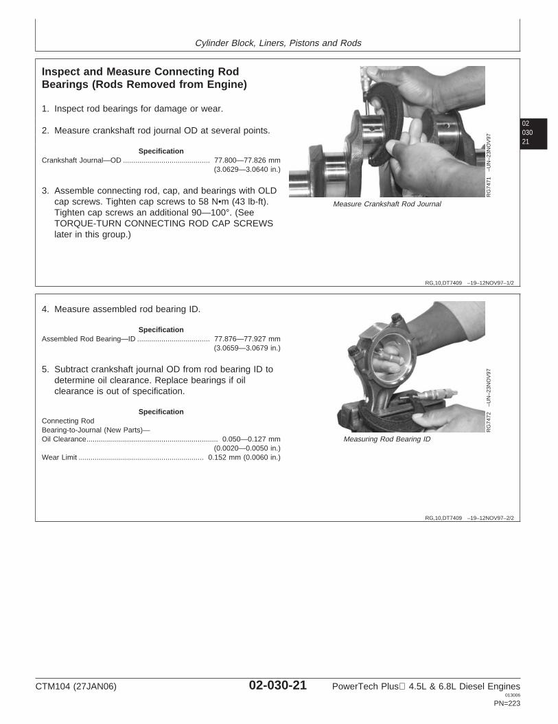
Cylinder Block, Liners, Pistons and Rods
0203021
RG,10,DT7409 –19–12NOV97–1/2
Inspect and Measure Connecting RodBearings (Rods Removed from Engine)
RG
7471
–UN
–23N
OV
97
Measure Crankshaft Rod Journal
1. Inspect rod bearings for damage or wear.
2. Measure crankshaft rod journal OD at several points.
SpecificationCrankshaft Journal—OD 77.800—77.826 mm
(3.0629—3.0640 in.)...........................................
3. Assemble connecting rod, cap, and bearings with OLDcap screws. Tighten cap screws to 58 N•m (43 lb-ft).Tighten cap screws an additional 90—100°. (SeeTORQUE-TURN CONNECTING ROD CAP SCREWSlater in this group.)
RG,10,DT7409 –19–12NOV97–2/2
RG
7472
–UN
–23N
OV
97
Measuring Rod Bearing ID
4. Measure assembled rod bearing ID.
SpecificationAssembled Rod Bearing—ID 77.876—77.927 mm
(3.0659—3.0679 in.)....................................
5. Subtract crankshaft journal OD from rod bearing ID todetermine oil clearance. Replace bearings if oilclearance is out of specification.
SpecificationConnecting RodBearing-to-Journal (New Parts)—Oil Clearance 0.050—0.127 mm
(0.0020—0.0050 in.).................................................................
Wear Limit 0.152 mm (0.0060 in.)..............................................................
CTM104 (27JAN06) 02-030-21 PowerTech Plus 4.5L & 6.8L Diesel Engines013006
PN=223
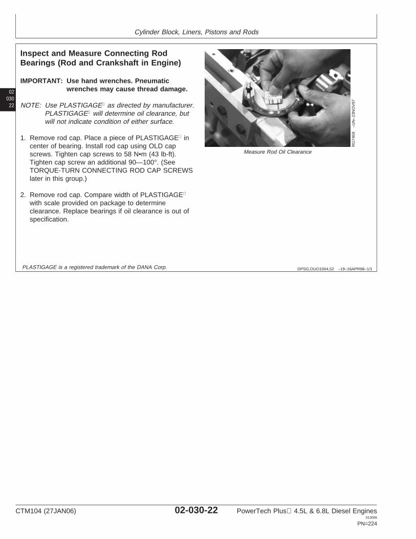
Cylinder Block, Liners, Pistons and Rods
02030
22
DPSG,OUO1004,52 –19–16APR98–1/1
Inspect and Measure Connecting RodBearings (Rod and Crankshaft in Engine)
RG
7459
–UN
–23N
OV
97
Measure Rod Oil Clearance
IMPORTANT: Use hand wrenches. Pneumaticwrenches may cause thread damage.
NOTE: Use PLASTIGAGE as directed by manufacturer.PLASTIGAGE will determine oil clearance, butwill not indicate condition of either surface.
1. Remove rod cap. Place a piece of PLASTIGAGE incenter of bearing. Install rod cap using OLD capscrews. Tighten cap screws to 58 N•m (43 lb-ft).Tighten cap screw an additional 90—100°. (SeeTORQUE-TURN CONNECTING ROD CAP SCREWSlater in this group.)
2. Remove rod cap. Compare width of PLASTIGAGE
with scale provided on package to determineclearance. Replace bearings if oil clearance is out ofspecification.
PLASTIGAGE is a registered trademark of the DANA Corp.
CTM104 (27JAN06) 02-030-22 PowerTech Plus 4.5L & 6.8L Diesel Engines013006
PN=224
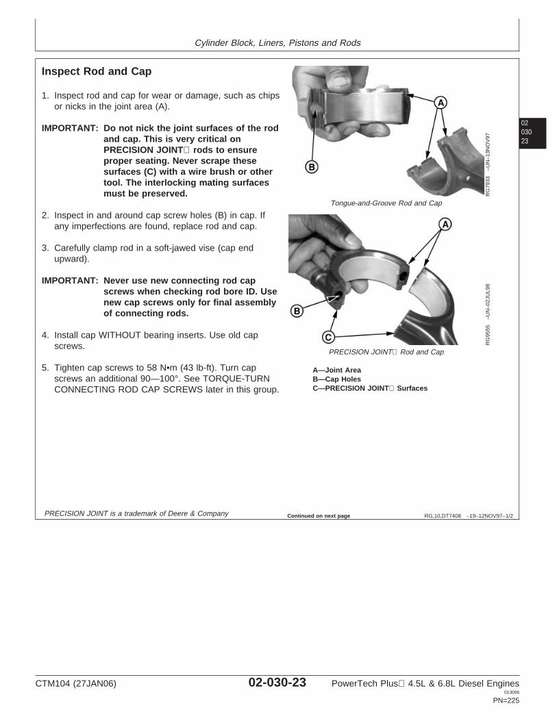
Cylinder Block, Liners, Pistons and Rods
0203023
RG,10,DT7408 –19–12NOV97–1/2
Inspect Rod and Cap
RG
7933
–UN
–13N
OV
97
Tongue-and-Groove Rod and Cap
RG
9555
–UN
–02J
UL9
8
PRECISION JOINT Rod and Cap
A—Joint AreaB—Cap HolesC—PRECISION JOINT Surfaces
1. Inspect rod and cap for wear or damage, such as chipsor nicks in the joint area (A).
IMPORTANT: Do not nick the joint surfaces of the rodand cap. This is very critical onPRECISION JOINT rods to ensureproper seating. Never scrape thesesurfaces (C) with a wire brush or othertool. The interlocking mating surfacesmust be preserved.
2. Inspect in and around cap screw holes (B) in cap. Ifany imperfections are found, replace rod and cap.
3. Carefully clamp rod in a soft-jawed vise (cap endupward).
IMPORTANT: Never use new connecting rod capscrews when checking rod bore ID. Usenew cap screws only for final assemblyof connecting rods.
4. Install cap WITHOUT bearing inserts. Use old capscrews.
5. Tighten cap screws to 58 N•m (43 lb-ft). Turn capscrews an additional 90—100°. See TORQUE-TURNCONNECTING ROD CAP SCREWS later in this group.
PRECISION JOINT is a trademark of Deere & Company Continued on next page
CTM104 (27JAN06) 02-030-23 PowerTech Plus 4.5L & 6.8L Diesel Engines013006
PN=225
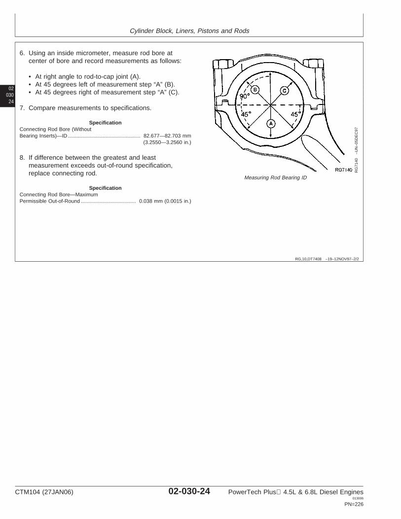
Cylinder Block, Liners, Pistons and Rods
02030
24
RG,10,DT7408 –19–12NOV97–2/2
RG
7140
–UN
–05D
EC
97
Measuring Rod Bearing ID
6. Using an inside micrometer, measure rod bore atcenter of bore and record measurements as follows:
• At right angle to rod-to-cap joint (A).• At 45 degrees left of measurement step “A” (B).• At 45 degrees right of measurement step “A” (C).
7. Compare measurements to specifications.
SpecificationConnecting Rod Bore (WithoutBearing Inserts)—ID 82.677—82.703 mm
(3.2550—3.2560 in.)..................................................
8. If difference between the greatest and leastmeasurement exceeds out-of-round specification,replace connecting rod.
SpecificationConnecting Rod Bore—MaximumPermissible Out-of-Round 0.038 mm (0.0015 in.)......................................
CTM104 (27JAN06) 02-030-24 PowerTech Plus 4.5L & 6.8L Diesel Engines013006
PN=226
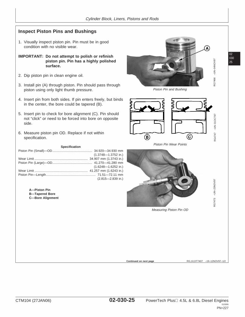
Cylinder Block, Liners, Pistons and Rods
0203025
RG,10,DT7407 –19–12NOV97–1/2
Inspect Piston Pins and Bushings
RG
7466
–UN
–04N
OV
97
Piston Pin and Bushing
RG
4747
–UN
–31O
CT
97
Piston Pin Wear Points
RG
7473
–UN
–23N
OV
97
Measuring Piston Pin OD
A—Piston PinB—Tapered BoreC—Bore Alignment
1. Visually inspect piston pin. Pin must be in goodcondition with no visible wear.
IMPORTANT: Do not attempt to polish or refinishpiston pin. Pin has a highly polishedsurface.
2. Dip piston pin in clean engine oil.
3. Install pin (A) through piston. Pin should pass throughpiston using only light thumb pressure.
4. Insert pin from both sides. If pin enters freely, but bindsin the center, the bore could be tapered (B).
5. Insert pin to check for bore alignment (C). Pin shouldnot “click” or need to be forced into bore on oppositeside.
6. Measure piston pin OD. Replace if not withinspecification.
SpecificationPiston Pin (Small)—OD 34.920—34.930 mm
(1.3748—1.3752 in.).............................................
Wear Limit 34.907 mm (1.3743 in.)............................................................Piston Pin (Large)—OD 41.270—41.280 mm
(1.6248—1.6252 in.).............................................
Wear Limit 41.257 mm (1.6243 in.)............................................................Piston Pin—Length 71.51—72.11 mm
(2.815—2.839 in.)........................................................
Continued on next page
CTM104 (27JAN06) 02-030-25 PowerTech Plus 4.5L & 6.8L Diesel Engines013006
PN=227
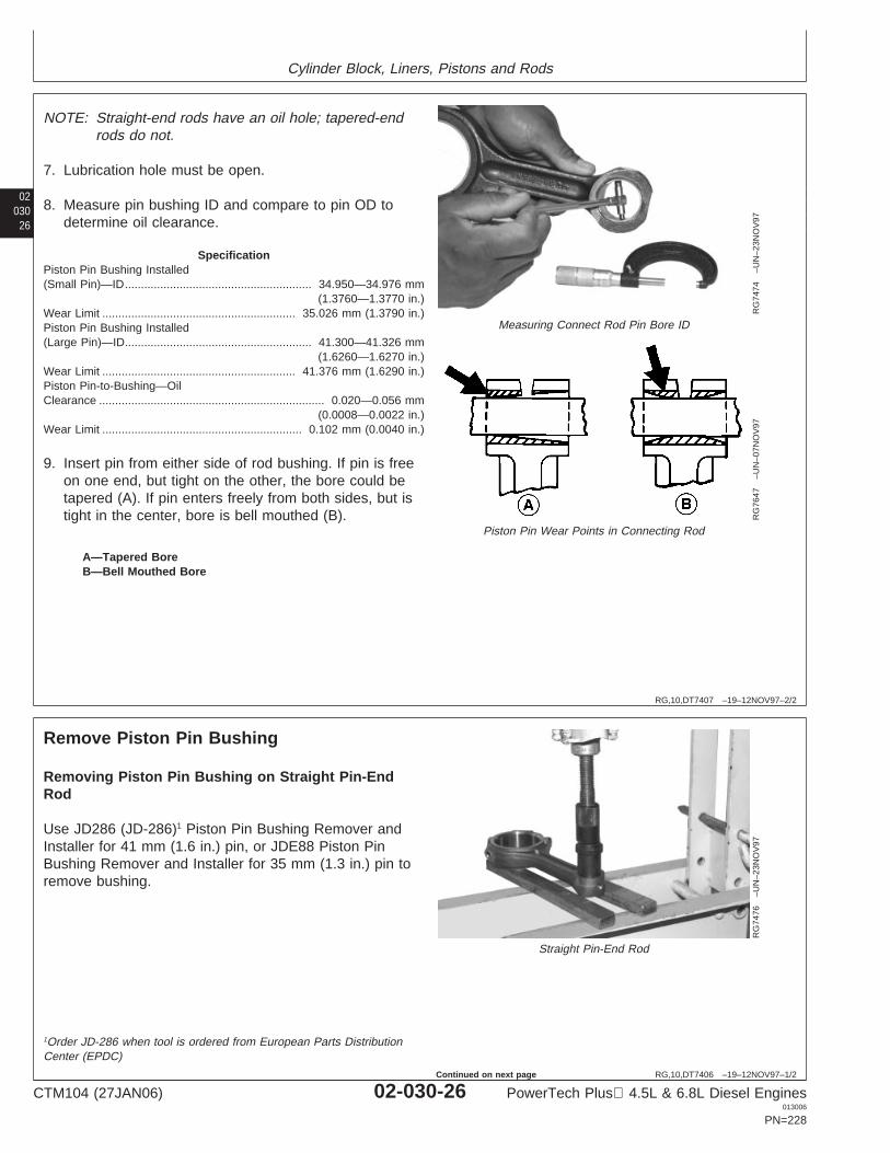
Cylinder Block, Liners, Pistons and Rods
02030
26
RG,10,DT7407 –19–12NOV97–2/2
RG
7474
–UN
–23N
OV
97
Measuring Connect Rod Pin Bore ID
RG
7647
–UN
–07N
OV
97
Piston Pin Wear Points in Connecting Rod
A—Tapered BoreB—Bell Mouthed Bore
NOTE: Straight-end rods have an oil hole; tapered-endrods do not.
7. Lubrication hole must be open.
8. Measure pin bushing ID and compare to pin OD todetermine oil clearance.
SpecificationPiston Pin Bushing Installed(Small Pin)—ID 34.950—34.976 mm
(1.3760—1.3770 in.)..........................................................
Wear Limit 35.026 mm (1.3790 in.)............................................................Piston Pin Bushing Installed(Large Pin)—ID 41.300—41.326 mm
(1.6260—1.6270 in.)..........................................................
Wear Limit 41.376 mm (1.6290 in.)............................................................Piston Pin-to-Bushing—OilClearance 0.020—0.056 mm
(0.0008—0.0022 in.)......................................................................
Wear Limit 0.102 mm (0.0040 in.)..............................................................
9. Insert pin from either side of rod bushing. If pin is freeon one end, but tight on the other, the bore could betapered (A). If pin enters freely from both sides, but istight in the center, bore is bell mouthed (B).
RG,10,DT7406 –19–12NOV97–1/2
Remove Piston Pin BushingR
G74
76–U
N–2
3NO
V97
Straight Pin-End Rod
Removing Piston Pin Bushing on Straight Pin-EndRod
Use JD286 (JD-286)1 Piston Pin Bushing Remover andInstaller for 41 mm (1.6 in.) pin, or JDE88 Piston PinBushing Remover and Installer for 35 mm (1.3 in.) pin toremove bushing.
1Order JD-286 when tool is ordered from European Parts DistributionCenter (EPDC)
CTM104 (27JAN06) 02-030-26 PowerTech Plus 4.5L & 6.8L Diesel Engines013006
PN=228
Continued on next page
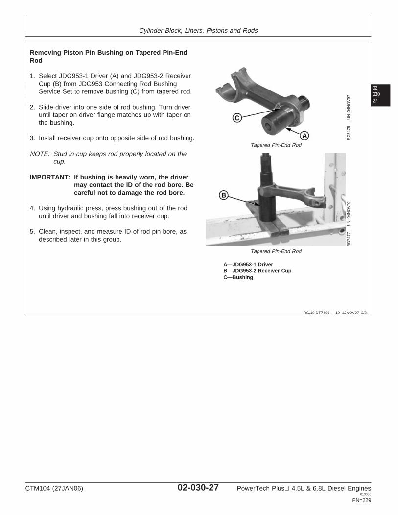
Cylinder Block, Liners, Pistons and Rods
0203027
RG,10,DT7406 –19–12NOV97–2/2
RG
7475
–UN
–04N
OV
97
Tapered Pin-End Rod
RG
7477
–UN
–04N
OV
97
Tapered Pin-End Rod
A—JDG953-1 DriverB—JDG953-2 Receiver CupC—Bushing
Removing Piston Pin Bushing on Tapered Pin-EndRod
1. Select JDG953-1 Driver (A) and JDG953-2 ReceiverCup (B) from JDG953 Connecting Rod BushingService Set to remove bushing (C) from tapered rod.
2. Slide driver into one side of rod bushing. Turn driveruntil taper on driver flange matches up with taper onthe bushing.
3. Install receiver cup onto opposite side of rod bushing.
NOTE: Stud in cup keeps rod properly located on thecup.
IMPORTANT: If bushing is heavily worn, the drivermay contact the ID of the rod bore. Becareful not to damage the rod bore.
4. Using hydraulic press, press bushing out of the roduntil driver and bushing fall into receiver cup.
5. Clean, inspect, and measure ID of rod pin bore, asdescribed later in this group.
CTM104 (27JAN06) 02-030-27 PowerTech Plus 4.5L & 6.8L Diesel Engines013006
PN=229
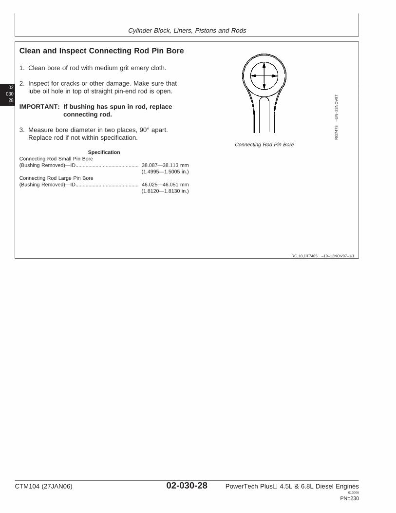
Cylinder Block, Liners, Pistons and Rods
02030
28
RG,10,DT7405 –19–12NOV97–1/1
Clean and Inspect Connecting Rod Pin Bore
RG
7478
–UN
–23N
OV
97
Connecting Rod Pin Bore
1. Clean bore of rod with medium grit emery cloth.
2. Inspect for cracks or other damage. Make sure thatlube oil hole in top of straight pin-end rod is open.
IMPORTANT: If bushing has spun in rod, replaceconnecting rod.
3. Measure bore diameter in two places, 90° apart.Replace rod if not within specification.
SpecificationConnecting Rod Small Pin Bore(Bushing Removed)—ID 38.087—38.113 mm
(1.4995—1.5005 in.)............................................
Connecting Rod Large Pin Bore(Bushing Removed)—ID 46.025—46.051 mm
(1.8120—1.8130 in.)............................................
CTM104 (27JAN06) 02-030-28 PowerTech Plus 4.5L & 6.8L Diesel Engines013006
PN=230
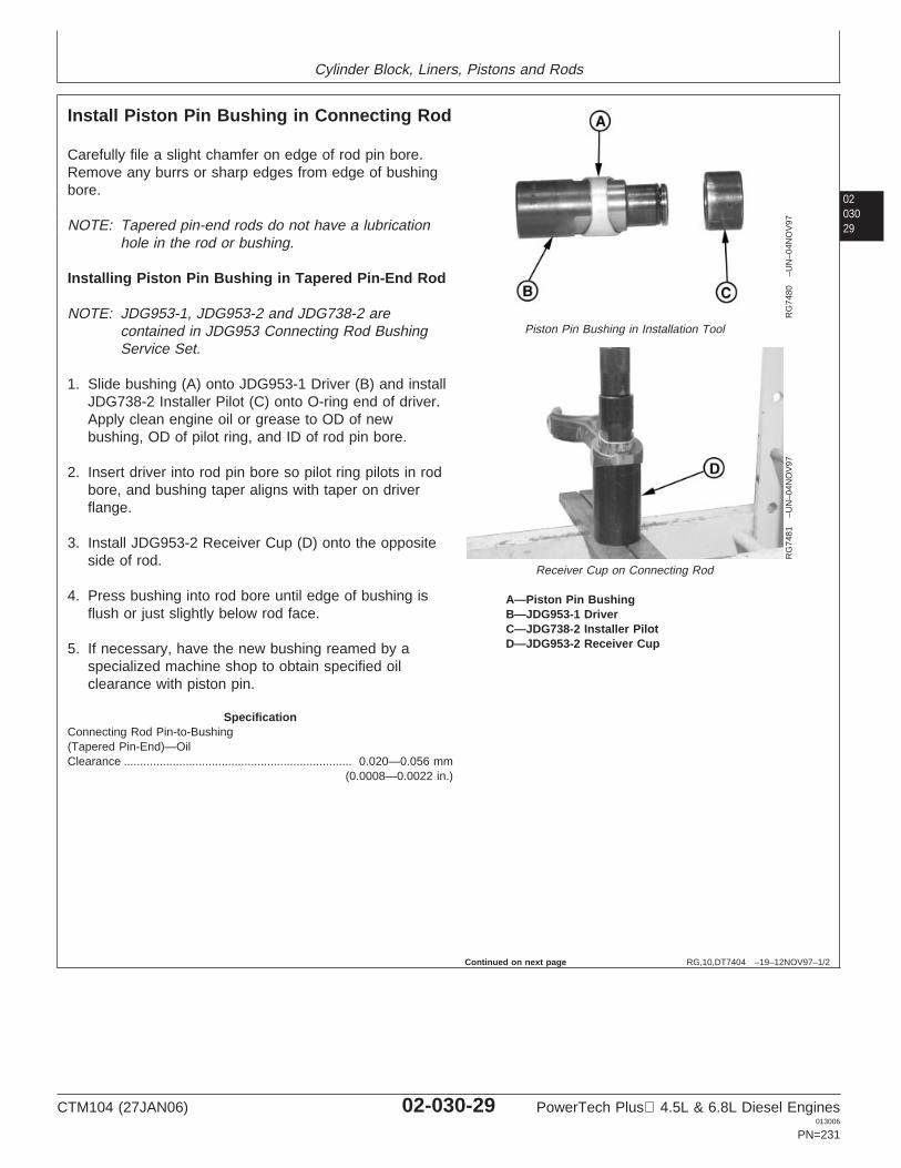
Cylinder Block, Liners, Pistons and Rods
0203029
RG,10,DT7404 –19–12NOV97–1/2
Install Piston Pin Bushing in Connecting Rod
RG
7480
–UN
–04N
OV
97
Piston Pin Bushing in Installation Tool
RG
7481
–UN
–04N
OV
97
Receiver Cup on Connecting Rod
A—Piston Pin BushingB—JDG953-1 DriverC—JDG738-2 Installer PilotD—JDG953-2 Receiver Cup
Carefully file a slight chamfer on edge of rod pin bore.Remove any burrs or sharp edges from edge of bushingbore.
NOTE: Tapered pin-end rods do not have a lubricationhole in the rod or bushing.
Installing Piston Pin Bushing in Tapered Pin-End Rod
NOTE: JDG953-1, JDG953-2 and JDG738-2 arecontained in JDG953 Connecting Rod BushingService Set.
1. Slide bushing (A) onto JDG953-1 Driver (B) and installJDG738-2 Installer Pilot (C) onto O-ring end of driver.Apply clean engine oil or grease to OD of newbushing, OD of pilot ring, and ID of rod pin bore.
2. Insert driver into rod pin bore so pilot ring pilots in rodbore, and bushing taper aligns with taper on driverflange.
3. Install JDG953-2 Receiver Cup (D) onto the oppositeside of rod.
4. Press bushing into rod bore until edge of bushing isflush or just slightly below rod face.
5. If necessary, have the new bushing reamed by aspecialized machine shop to obtain specified oilclearance with piston pin.
SpecificationConnecting Rod Pin-to-Bushing(Tapered Pin-End)—OilClearance 0.020—0.056 mm
(0.0008—0.0022 in.)......................................................................
Continued on next page
CTM104 (27JAN06) 02-030-29 PowerTech Plus 4.5L & 6.8L Diesel Engines013006
PN=231
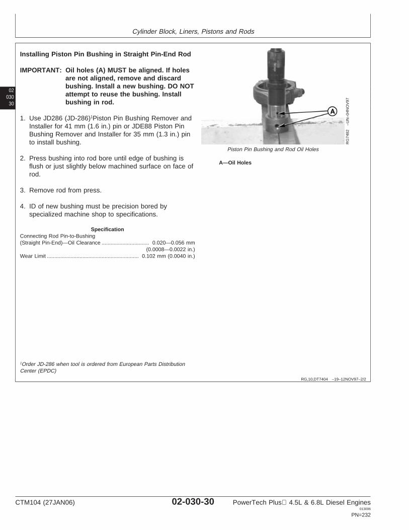
Cylinder Block, Liners, Pistons and Rods
02030
30
RG,10,DT7404 –19–12NOV97–2/2
RG
7482
–UN
–04N
OV
97
Piston Pin Bushing and Rod Oil Holes
A—Oil Holes
Installing Piston Pin Bushing in Straight Pin-End Rod
IMPORTANT: Oil holes (A) MUST be aligned. If holesare not aligned, remove and discardbushing. Install a new bushing. DO NOTattempt to reuse the bushing. Installbushing in rod.
1. Use JD286 (JD-286)1Piston Pin Bushing Remover andInstaller for 41 mm (1.6 in.) pin or JDE88 Piston PinBushing Remover and Installer for 35 mm (1.3 in.) pinto install bushing.
2. Press bushing into rod bore until edge of bushing isflush or just slightly below machined surface on face ofrod.
3. Remove rod from press.
4. ID of new bushing must be precision bored byspecialized machine shop to specifications.
SpecificationConnecting Rod Pin-to-Bushing(Straight Pin-End)—Oil Clearance 0.020—0.056 mm
(0.0008—0.0022 in.)................................
Wear Limit 0.102 mm (0.0040 in.)..............................................................
1Order JD-286 when tool is ordered from European Parts DistributionCenter (EPDC)
CTM104 (27JAN06) 02-030-30 PowerTech Plus 4.5L & 6.8L Diesel Engines013006
PN=232
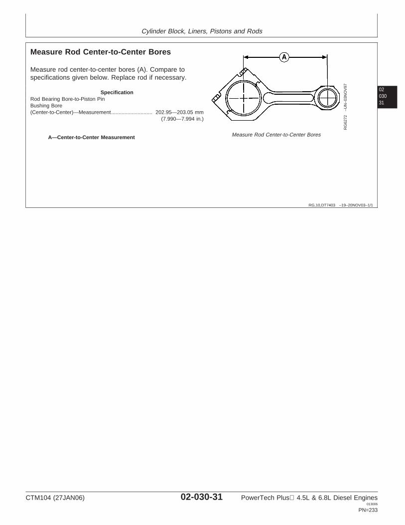
Cylinder Block, Liners, Pistons and Rods
0203031
RG,10,DT7403 –19–20NOV03–1/1
Measure Rod Center-to-Center Bores
RG
6272
–UN
–03N
OV
97
Measure Rod Center-to-Center BoresA—Center-to-Center Measurement
Measure rod center-to-center bores (A). Compare tospecifications given below. Replace rod if necessary.
SpecificationRod Bearing Bore-to-Piston PinBushing Bore(Center-to-Center)—Measurement 202.95—203.05 mm
(7.990—7.994 in.)............................
CTM104 (27JAN06) 02-030-31 PowerTech Plus 4.5L & 6.8L Diesel Engines013006
PN=233
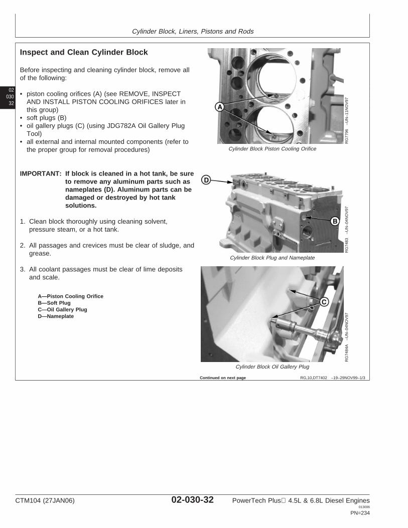
Cylinder Block, Liners, Pistons and Rods
02030
32
RG,10,DT7402 –19–29NOV99–1/3
Inspect and Clean Cylinder Block
RG
7796
–UN
–11N
OV
97
Cylinder Block Piston Cooling Orifice
RG
7483
–UN
–04N
OV
97
Cylinder Block Plug and Nameplate
RG
7484
A–U
N–0
4NO
V97
Cylinder Block Oil Gallery Plug
A—Piston Cooling OrificeB—Soft PlugC—Oil Gallery PlugD—Nameplate
Before inspecting and cleaning cylinder block, remove allof the following:
• piston cooling orifices (A) (see REMOVE, INSPECTAND INSTALL PISTON COOLING ORIFICES later inthis group)
• soft plugs (B)• oil gallery plugs (C) (using JDG782A Oil Gallery Plug
Tool)• all external and internal mounted components (refer to
the proper group for removal procedures)
IMPORTANT: If block is cleaned in a hot tank, be sureto remove any aluminum parts such asnameplates (D). Aluminum parts can bedamaged or destroyed by hot tanksolutions.
1. Clean block thoroughly using cleaning solvent,pressure steam, or a hot tank.
2. All passages and crevices must be clear of sludge, andgrease.
3. All coolant passages must be clear of lime depositsand scale.
Continued on next page
CTM104 (27JAN06) 02-030-32 PowerTech Plus 4.5L & 6.8L Diesel Engines013006
PN=234
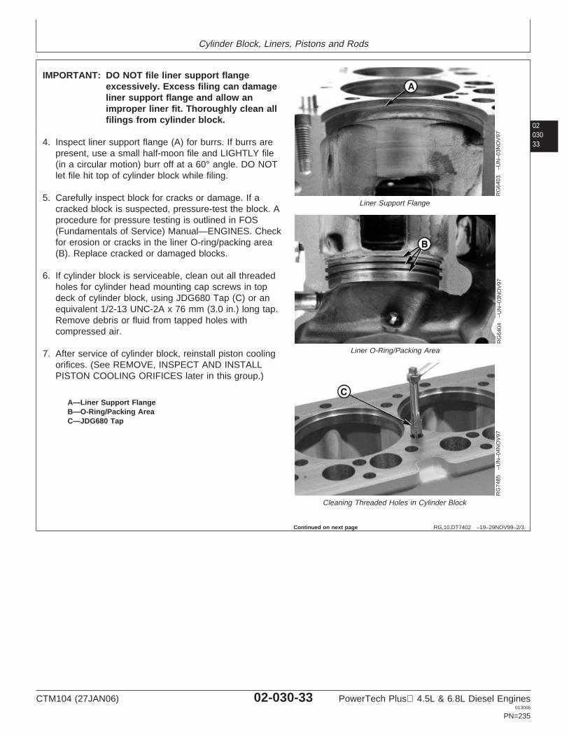
Cylinder Block, Liners, Pistons and Rods
0203033
RG,10,DT7402 –19–29NOV99–2/3
RG
6403
–UN
–03N
OV
97
Liner Support Flange
RG
6404
–UN
–03N
OV
97
Liner O-Ring/Packing Area
RG
7485
–UN
–04N
OV
97Cleaning Threaded Holes in Cylinder Block
A—Liner Support FlangeB—O-Ring/Packing AreaC—JDG680 Tap
IMPORTANT: DO NOT file liner support flangeexcessively. Excess filing can damageliner support flange and allow animproper liner fit. Thoroughly clean allfilings from cylinder block.
4. Inspect liner support flange (A) for burrs. If burrs arepresent, use a small half-moon file and LIGHTLY file(in a circular motion) burr off at a 60° angle. DO NOTlet file hit top of cylinder block while filing.
5. Carefully inspect block for cracks or damage. If acracked block is suspected, pressure-test the block. Aprocedure for pressure testing is outlined in FOS(Fundamentals of Service) Manual—ENGINES. Checkfor erosion or cracks in the liner O-ring/packing area(B). Replace cracked or damaged blocks.
6. If cylinder block is serviceable, clean out all threadedholes for cylinder head mounting cap screws in topdeck of cylinder block, using JDG680 Tap (C) or anequivalent 1/2-13 UNC-2A x 76 mm (3.0 in.) long tap.Remove debris or fluid from tapped holes withcompressed air.
7. After service of cylinder block, reinstall piston coolingorifices. (See REMOVE, INSPECT AND INSTALLPISTON COOLING ORIFICES later in this group.)
Continued on next page
CTM104 (27JAN06) 02-030-33 PowerTech Plus 4.5L & 6.8L Diesel Engines013006
PN=235
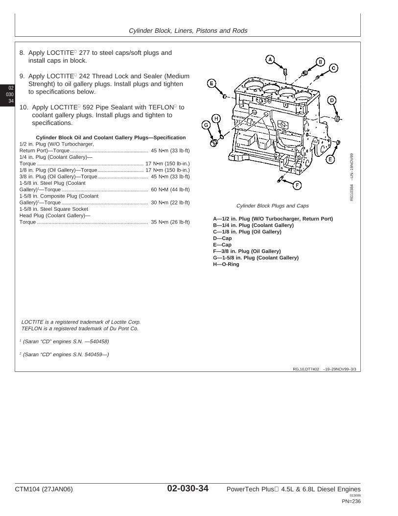
Cylinder Block, Liners, Pistons and Rods
02030
34
RG,10,DT7402 –19–29NOV99–3/3
RG
1038
4–U
N–1
9NO
V99
Cylinder Block Plugs and Caps
A—1/2 in. Plug (W/O Turbocharger, Return Port)B—1/4 in. Plug (Coolant Gallery)C—1/8 in. Plug (Oil Gallery)D—CapE—CapF—3/8 in. Plug (Oil Gallery)G—1-5/8 in. Plug (Coolant Gallery)H—O-Ring
8. Apply LOCTITE 277 to steel caps/soft plugs andinstall caps in block.
9. Apply LOCTITE 242 Thread Lock and Sealer (MediumStrenght) to oil gallery plugs. Install plugs and tightento specifications below.
10. Apply LOCTITE 592 Pipe Sealant with TEFLON tocoolant gallery plugs. Install plugs and tighten tospecifications.
Cylinder Block Oil and Coolant Gallery Plugs—Specification1/2 in. Plug (W/O Turbocharger,Return Port)—Torque 45 N•m (33 lb-ft)......................................................1/4 in. Plug (Coolant Gallery)—Torque 17 N•m (150 lb-in.)..........................................................................1/8 in. Plug (Oil Gallery)—Torque 17 N•m (150 lb-in.)................................3/8 in. Plug (Oil Gallery)—Torque 45 N•m (33 lb-ft)...................................1-5/8 in. Steel Plug (CoolantGallery)1—Torque 60 N•M (44 lb-ft)............................................................1-5/8 in. Composite Plug (CoolantGallery)2—Torque 30 N•m (22 lb-ft)............................................................1-5/8 in. Steel Square SocketHead Plug (Coolant Gallery)—Torque 35 N•m (26 lb-ft).............................................................................
LOCTITE is a registered trademark of Loctite Corp.TEFLON is a registered trademark of Du Pont Co.
1 (Saran “CD” engines S.N. —540458)
2 (Saran “CD” engines S.N. 540459—)
CTM104 (27JAN06) 02-030-34 PowerTech Plus 4.5L & 6.8L Diesel Engines013006
PN=236
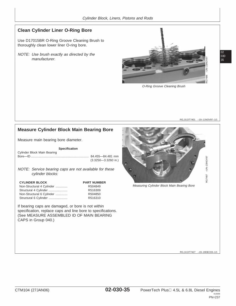
Cylinder Block, Liners, Pistons and Rods
0203035
RG,10,DT7401 –19–11NOV97–1/1
Clean Cylinder Liner O-Ring Bore
RG
7486
–UN
–23N
OV
97
O-Ring Groove Cleaning Brush
Use D17015BR O-Ring Groove Cleaning Brush tothoroughly clean lower liner O-ring bore.
NOTE: Use brush exactly as directed by themanufacturer.
RG,10,DT7427 –19–19DEC03–1/1
Measure Cylinder Block Main Bearing Bore
RG
7487
–UN
–23N
OV
97
Measuring Cylinder Block Main Bearing Bore
Measure main bearing bore diameter.
SpecificationCylinder Block Main BearingBore—ID 84.455—84.481 mm
(3.3250—3.3260 in.)....................................................................
NOTE: Service bearing caps are not available for thesecylinder blocks:
CYLINDER BLOCK PART NUMBERNon-Structural 4 Cylinder .............. R504849Structural 4 Cylinder ...................... R516309Non-Structural 6 Cylinder .............. R504850Structural 6 Cylinder ...................... R516310
If bearing caps are damaged, or bore is not withinspecification, replace caps and line bore to specifications.(See MEASURE ASSEMBLED ID OF MAIN BEARINGCAPS in Group 040.)
CTM104 (27JAN06) 02-030-35 PowerTech Plus 4.5L & 6.8L Diesel Engines013006
PN=237
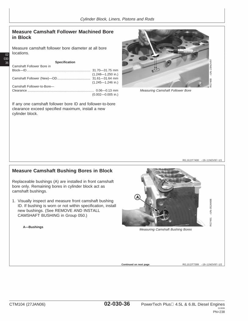
Cylinder Block, Liners, Pistons and Rods
02030
36
RG,10,DT7400 –19–11NOV97–1/1
Measure Camshaft Follower Machined Borein Block
RG
7488
–UN
–23N
OV
97
Measuring Camshaft Follower Bore
Measure camshaft follower bore diameter at all borelocations.
SpecificationCamshaft Follower Bore inBlock—ID 31.70—31.75 mm
(1.248—1.250 in.).......................................................................
Camshaft Follower (New)—OD 31.61—31.64 mm(1.245—1.246 in.)
.....................................
Camshaft Follower-to-Bore—Clearance 0.06—0.13 mm
(0.002—0.005 in.)..........................................................................
If any one camshaft follower bore ID and follower-to-boreclearance exceed specified maximum, install a newcylinder block.
RG,10,DT7399 –19–11NOV97–1/2
Measure Camshaft Bushing Bores in Block
RG
7491
–UN
–05J
AN
98
Measuring Camshaft Bushing BoresA—Bushings
Replaceable bushings (A) are installed in front camshaftbore only. Remaining bores in cylinder block act ascamshaft bushings.
1. Visually inspect and measure front camshaft bushingID. If bushing is worn or not within specification, installnew bushings. (See REMOVE AND INSTALLCAMSHAFT BUSHING in Group 050.)
Continued on next page
CTM104 (27JAN06) 02-030-36 PowerTech Plus 4.5L & 6.8L Diesel Engines013006
PN=238
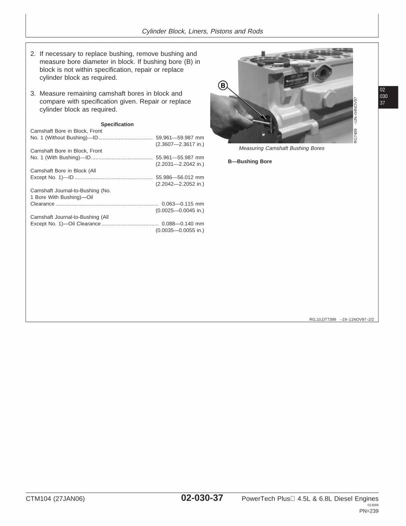
Cylinder Block, Liners, Pistons and Rods
0203037
RG,10,DT7399 –19–11NOV97–2/2
RG
7489
–UN
–04N
OV
97
Measuring Camshaft Bushing Bores
B—Bushing Bore
2. If necessary to replace bushing, remove bushing andmeasure bore diameter in block. If bushing bore (B) inblock is not within specification, repair or replacecylinder block as required.
3. Measure remaining camshaft bores in block andcompare with specification given. Repair or replacecylinder block as required.
SpecificationCamshaft Bore in Block, FrontNo. 1 (Without Bushing)—ID 59.961—59.987 mm
(2.3607—2.3617 in.).....................................
Camshaft Bore in Block, FrontNo. 1 (With Bushing)—ID 55.961—55.987 mm
(2.2031—2.2042 in.)..........................................
Camshaft Bore in Block (AllExcept No. 1)—ID 55.986—56.012 mm
(2.2042—2.2052 in.).....................................................
Camshaft Journal-to-Bushing (No.1 Bore With Bushing)—OilClearance 0.063—0.115 mm
(0.0025—0.0045 in.)......................................................................
Camshaft Journal-to-Bushing (AllExcept No. 1)—Oil Clearance 0.088—0.140 mm
(0.0035—0.0055 in.).......................................
CTM104 (27JAN06) 02-030-37 PowerTech Plus 4.5L & 6.8L Diesel Engines013006
PN=239
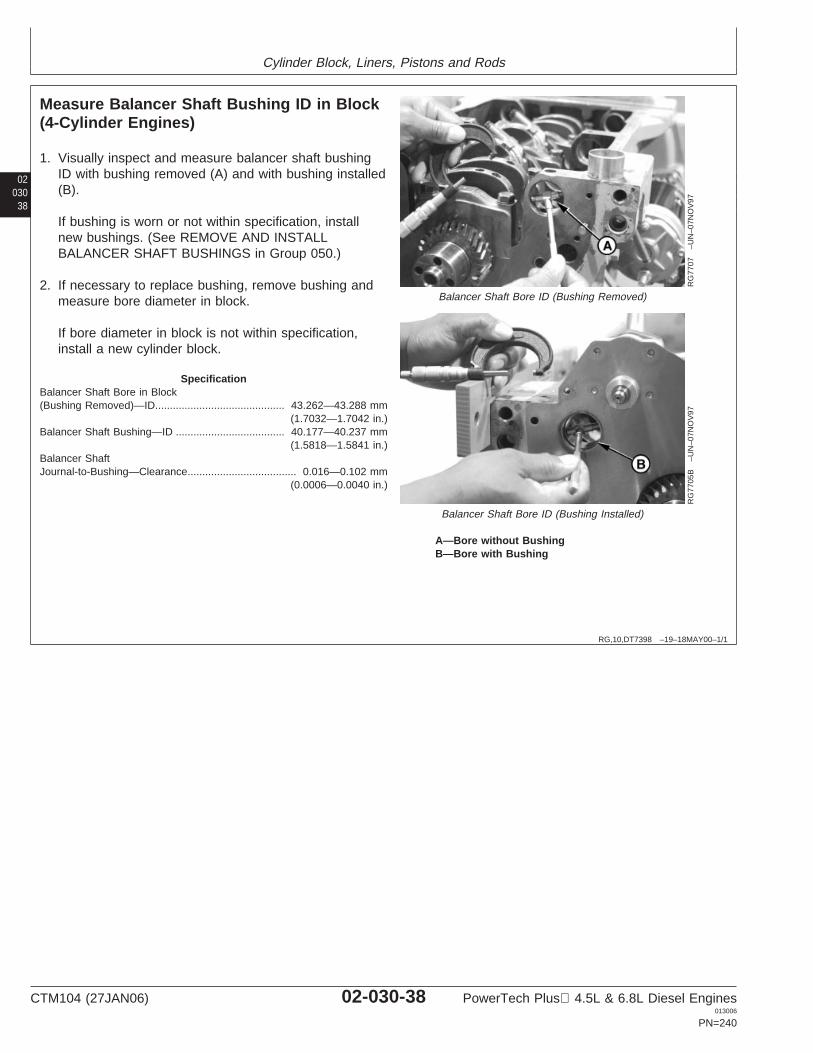
Cylinder Block, Liners, Pistons and Rods
02030
38
RG,10,DT7398 –19–18MAY00–1/1
Measure Balancer Shaft Bushing ID in Block(4-Cylinder Engines)
RG
7707
–UN
–07N
OV
97
Balancer Shaft Bore ID (Bushing Removed)
RG
7705
B–U
N–0
7NO
V97
Balancer Shaft Bore ID (Bushing Installed)
A—Bore without BushingB—Bore with Bushing
1. Visually inspect and measure balancer shaft bushingID with bushing removed (A) and with bushing installed(B).
If bushing is worn or not within specification, installnew bushings. (See REMOVE AND INSTALLBALANCER SHAFT BUSHINGS in Group 050.)
2. If necessary to replace bushing, remove bushing andmeasure bore diameter in block.
If bore diameter in block is not within specification,install a new cylinder block.
SpecificationBalancer Shaft Bore in Block(Bushing Removed)—ID 43.262—43.288 mm
(1.7032—1.7042 in.)............................................
Balancer Shaft Bushing—ID 40.177—40.237 mm(1.5818—1.5841 in.)
.....................................
Balancer ShaftJournal-to-Bushing—Clearance 0.016—0.102 mm
(0.0006—0.0040 in.).....................................
CTM104 (27JAN06) 02-030-38 PowerTech Plus 4.5L & 6.8L Diesel Engines013006
PN=240
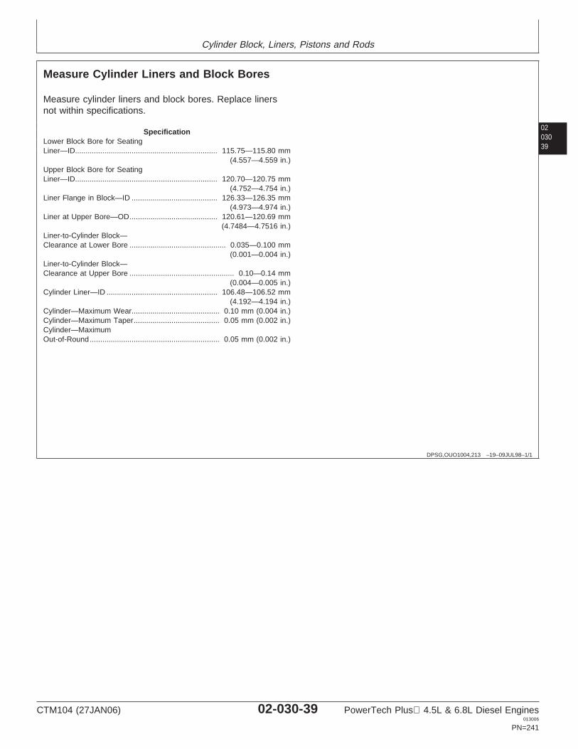
Cylinder Block, Liners, Pistons and Rods
0203039
DPSG,OUO1004,213 –19–09JUL98–1/1
Measure Cylinder Liners and Block Bores
Measure cylinder liners and block bores. Replace linersnot within specifications.
SpecificationLower Block Bore for SeatingLiner—ID 115.75—115.80 mm
(4.557—4.559 in.)....................................................................
Upper Block Bore for SeatingLiner—ID 120.70—120.75 mm
(4.752—4.754 in.)....................................................................
Liner Flange in Block—ID 126.33—126.35 mm(4.973—4.974 in.)
.........................................
Liner at Upper Bore—OD 120.61—120.69 mm(4.7484—4.7516 in.)
..........................................
Liner-to-Cylinder Block—Clearance at Lower Bore 0.035—0.100 mm
(0.001—0.004 in.)..............................................
Liner-to-Cylinder Block—Clearance at Upper Bore 0.10—0.14 mm
(0.004—0.005 in.)..................................................
Cylinder Liner—ID 106.48—106.52 mm(4.192—4.194 in.)
.....................................................
Cylinder—Maximum Wear 0.10 mm (0.004 in.)..........................................Cylinder—Maximum Taper 0.05 mm (0.002 in.).........................................Cylinder—MaximumOut-of-Round 0.05 mm (0.002 in.)..............................................................
CTM104 (27JAN06) 02-030-39 PowerTech Plus 4.5L & 6.8L Diesel Engines013006
PN=241
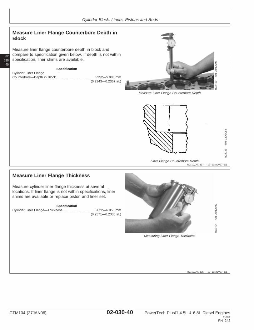
Cylinder Block, Liners, Pistons and Rods
02030
40
RG,10,DT7397 –19–11NOV97–1/1
Measure Liner Flange Counterbore Depth inBlock
RG
7490
–UN
–23N
OV
97
Measure Liner Flange Counterbore Depth
RG
4726
–UN
–13D
EC
88
Liner Flange Counterbore Depth
Measure liner flange counterbore depth in block andcompare to specification given below. If depth is not withinspecification, liner shims are available.
SpecificationCylinder Liner FlangeCounterbore—Depth in Block 5.952—5.988 mm
(0.2343—0.2357 in.)........................................
RG,10,DT7396 –19–11NOV97–1/1
Measure Liner Flange Thickness
RG
7494
–UN
–23N
OV
97
Measuring Liner Flange Thickness
Measure cylinder liner flange thickness at severallocations. If liner flange is not within specifications, linershims are available or replace piston and liner set.
SpecificationCylinder Liner Flange—Thickness 6.022—6.058 mm
(0.2371—0.2385 in.)................................
CTM104 (27JAN06) 02-030-40 PowerTech Plus 4.5L & 6.8L Diesel Engines013006
PN=242
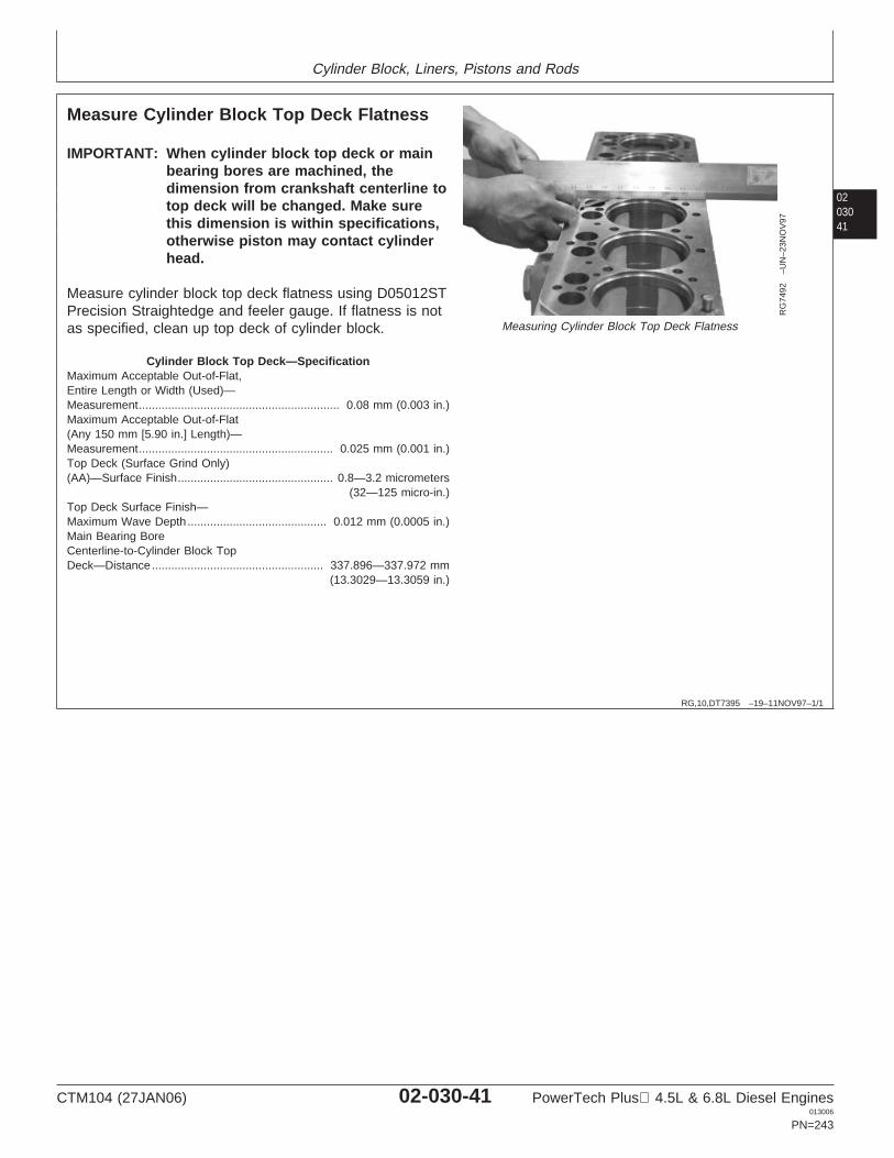
Cylinder Block, Liners, Pistons and Rods
0203041
RG,10,DT7395 –19–11NOV97–1/1
Measure Cylinder Block Top Deck Flatness
RG
7492
–UN
–23N
OV
97
Measuring Cylinder Block Top Deck Flatness
IMPORTANT: When cylinder block top deck or mainbearing bores are machined, thedimension from crankshaft centerline totop deck will be changed. Make surethis dimension is within specifications,otherwise piston may contact cylinderhead.
Measure cylinder block top deck flatness using D05012STPrecision Straightedge and feeler gauge. If flatness is notas specified, clean up top deck of cylinder block.
Cylinder Block Top Deck—SpecificationMaximum Acceptable Out-of-Flat,Entire Length or Width (Used)—Measurement 0.08 mm (0.003 in.)..............................................................Maximum Acceptable Out-of-Flat(Any 150 mm [5.90 in.] Length)—Measurement 0.025 mm (0.001 in.)............................................................Top Deck (Surface Grind Only)(AA)—Surface Finish 0.8—3.2 micrometers
(32—125 micro-in.)................................................
Top Deck Surface Finish—Maximum Wave Depth 0.012 mm (0.0005 in.)...........................................Main Bearing BoreCenterline-to-Cylinder Block TopDeck—Distance 337.896—337.972 mm
(13.3029—13.3059 in.).....................................................
CTM104 (27JAN06) 02-030-41 PowerTech Plus 4.5L & 6.8L Diesel Engines013006
PN=243
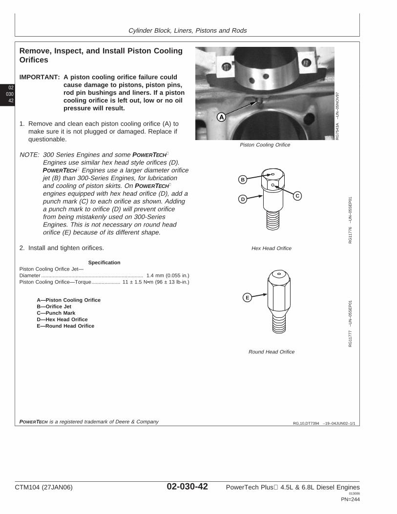
Cylinder Block, Liners, Pistons and Rods
02030
42
RG,10,DT7394 –19–04JUN02–1/1
Remove, Inspect, and Install Piston CoolingOrifices
RG
7543
A–U
N–0
5NO
V97
Piston Cooling Orifice
B
CD
RG
1177
6–U
N–0
5SE
P01
Hex Head Orifice
E
RG
1177
7–U
N–0
5SE
P01
Round Head Orifice
A—Piston Cooling OrificeB—Orifice JetC—Punch MarkD—Hex Head OrificeE—Round Head Orifice
IMPORTANT: A piston cooling orifice failure couldcause damage to pistons, piston pins,rod pin bushings and liners. If a pistoncooling orifice is left out, low or no oilpressure will result.
1. Remove and clean each piston cooling orifice (A) tomake sure it is not plugged or damaged. Replace ifquestionable.
NOTE: 300 Series Engines and some POWERTECH
Engines use similar hex head style orifices (D).POWERTECH Engines use a larger diameter orificejet (B) than 300-Series Engines, for lubricationand cooling of piston skirts. On POWERTECH
engines equipped with hex head orifice (D), add apunch mark (C) to each orifice as shown. Addinga punch mark to orifice (D) will prevent orificefrom being mistakenly used on 300-SeriesEngines. This is not necessary on round headorifice (E) because of its different shape.
2. Install and tighten orifices.
SpecificationPiston Cooling Orifice Jet—Diameter 1.4 mm (0.055 in.).......................................................................Piston Cooling Orifice—Torque 11 ± 1.5 N•m (96 ± 13 lb-in.)....................
POWERTECH is a registered trademark of Deere & Company
CTM104 (27JAN06) 02-030-42 PowerTech Plus 4.5L & 6.8L Diesel Engines013006
PN=244
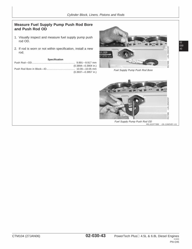
Cylinder Block, Liners, Pistons and Rods
0203043
RG,10,DT7393 –19–11NOV97–1/1
Measure Fuel Supply Pump Push Rod Boreand Push Rod OD
RG
7495
–UN
–23N
OV
97
Fuel Supply Pump Push Rod Bore
RG
7496
–UN
–26N
OV
97
Fuel Supply Pump Push Rod OD
1. Visually inspect and measure fuel supply pump pushrod OD.
2. If rod is worn or not within specification, install a newrod.
SpecificationPush Rod—OD 9.891—9.917 mm
(0.3894—0.3904 in.)..............................................................
Push Rod Bore in Block—ID 10.00—10.05 mm(0.3937—0.3957 in.)
.........................................
CTM104 (27JAN06) 02-030-43 PowerTech Plus 4.5L & 6.8L Diesel Engines013006
PN=245
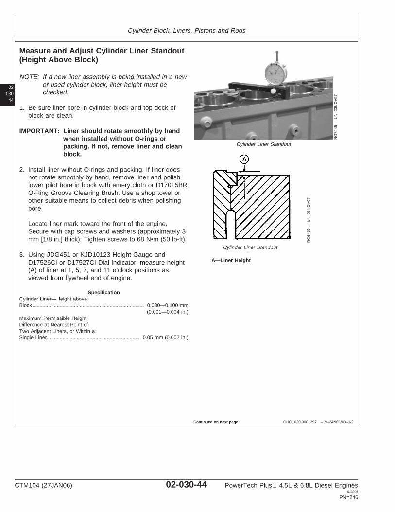
Cylinder Block, Liners, Pistons and Rods
02030
44
OUO1020,0001397 –19–24NOV03–1/2
Measure and Adjust Cylinder Liner Standout(Height Above Block)
RG
7445
–UN
–23N
OV
97
Cylinder Liner Standout
RG
6439
–UN
–03N
OV
97
Cylinder Liner Standout
A—Liner Height
NOTE: If a new liner assembly is being installed in a newor used cylinder block, liner height must bechecked.
1. Be sure liner bore in cylinder block and top deck ofblock are clean.
IMPORTANT: Liner should rotate smoothly by handwhen installed without O-rings orpacking. If not, remove liner and cleanblock.
2. Install liner without O-rings and packing. If liner doesnot rotate smoothly by hand, remove liner and polishlower pilot bore in block with emery cloth or D17015BRO-Ring Groove Cleaning Brush. Use a shop towel orother suitable means to collect debris when polishingbore.
Locate liner mark toward the front of the engine.Secure with cap screws and washers (approximately 3mm [1/8 in.] thick). Tighten screws to 68 N•m (50 lb-ft).
3. Using JDG451 or KJD10123 Height Gauge andD17526CI or D17527CI Dial Indicator, measure height(A) of liner at 1, 5, 7, and 11 o’clock positions asviewed from flywheel end of engine.
SpecificationCylinder Liner—Height aboveBlock 0.030—0.100 mm
(0.001—0.004 in.)..............................................................................
Maximum Permissible HeightDifference at Nearest Point ofTwo Adjacent Liners, or Within aSingle Liner 0.05 mm (0.002 in.).................................................................
Continued on next page
CTM104 (27JAN06) 02-030-44 PowerTech Plus 4.5L & 6.8L Diesel Engines013006
PN=246
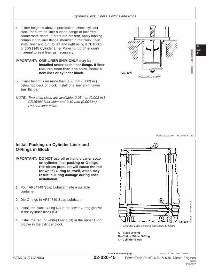
Cylinder Block, Liners, Pistons and Rods
0203045
OUO1020,0001397 –19–24NOV03–2/2
CD
3019
9–U
N–0
7MA
R95
KCD10001 Shown
4. If liner height is above specification, check cylinderblock for burrs on liner support flange or incorrectcounterbore depth. If burrs are present, apply lappingcompound to liner flange shoulder in the block, theninstall liner and turn to left and right using KCD10001or JDG1145 Cylinder Liner Puller to rub off enoughmaterial to seat liner as necessary.
IMPORTANT: ONE LINER SHIM ONLY may beinstalled under each liner flange. If linerrequires more than one shim, install anew liner or cylinder block.
5. If liner height is no more than 0.08 mm (0.003 in.)below top deck of block, install one liner shim underliner flange.
NOTE: Two shim sizes are available; 0.05 mm (0.002 in.)CD15466 liner shim and 0.10 mm (0.004 in.)R65833 liner shim.
RG,10,DT7391 –19–11NOV97–1/2
Install Packing on Cylinder Liner andO-Rings in Block
RG
3826
–UN
–04D
EC
97
Cylinder Liner Packing and Block O-Rings
A—Black O-RingB—Red or White O-RingC—Cylinder Block
IMPORTANT: DO NOT use oil or hand cleaner soapon cylinder liner packing or O-rings.Petroleum products will cause the red(or white) O-ring to swell, which mayresult in O-ring damage during linerinstallation.
1. Pour AR54749 Soap Lubricant into a suitablecontainer.
2. Dip O-rings in AR54749 Soap Lubricant.
3. Install the black O-ring (A) in the lower O-ring groovein the cylinder block (C).
4. Install the red (or white) O-ring (B) in the upper O-ringgroove in the cylinder block.
CTM104 (27JAN06) 02-030-45 PowerTech Plus 4.5L & 6.8L Diesel Engines013006
PN=247
Continued on next page
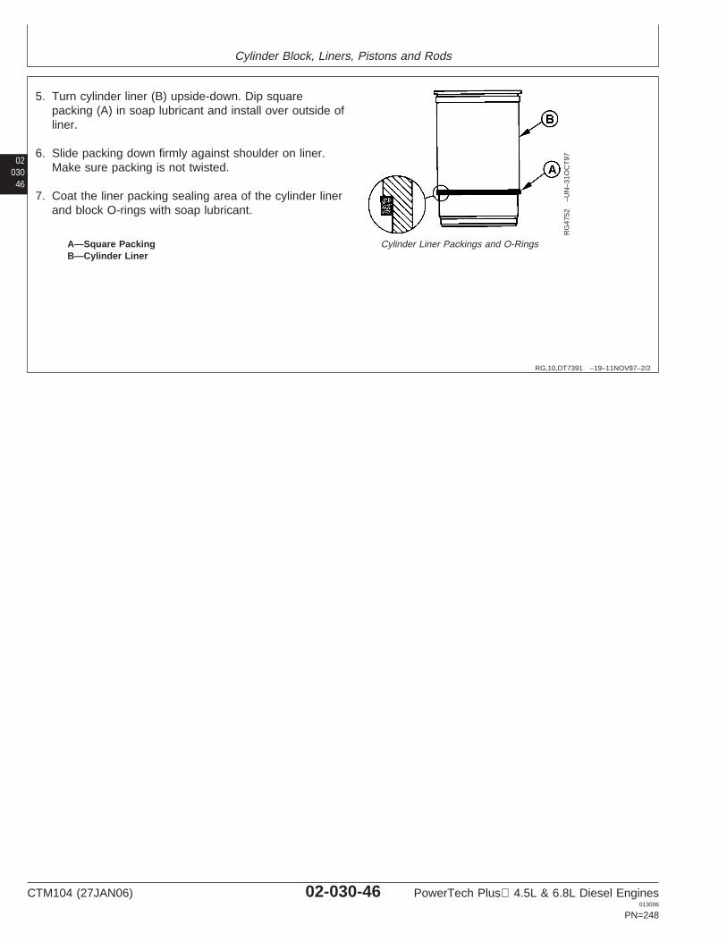
Cylinder Block, Liners, Pistons and Rods
02030
46
RG,10,DT7391 –19–11NOV97–2/2
RG
4752
–UN
–31O
CT
97
Cylinder Liner Packings and O-RingsA—Square PackingB—Cylinder Liner
5. Turn cylinder liner (B) upside-down. Dip squarepacking (A) in soap lubricant and install over outside ofliner.
6. Slide packing down firmly against shoulder on liner.Make sure packing is not twisted.
7. Coat the liner packing sealing area of the cylinder linerand block O-rings with soap lubricant.
CTM104 (27JAN06) 02-030-46 PowerTech Plus 4.5L & 6.8L Diesel Engines013006
PN=248
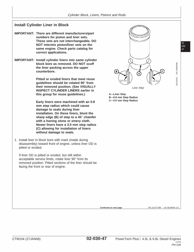
Cylinder Block, Liners, Pistons and Rods
0203047
RG,10,DT7390 –19–06JAN00–1/2
Install Cylinder Liner in Block
RG
1037
0–U
N–3
0SE
P99
Liner Step
A—Liner StepB—0.8 mm Step RadiusC—3.0 mm Step Radius
IMPORTANT: There are different manufacturers/partnumbers for piston and liner sets.These sets are not interchangeable. DONOT intermix piston/liner sets on thesame engine. Check parts catalog forcorrect applications.
IMPORTANT: Install cylinder liners into same cylinderblock bore as removed. DO NOT scuffthe liner packing across the uppercounterbore.
Pitted or eroded liners that meet reuseguidelines should be rotated 90° fromtheir removed position. (See VISUALLYINSPECT CYLINDER LINERS earlier inthis group for reuse guidelines.)
Early liners were machined with an 0.8mm step radius which could causedamage to seals during linerinstallation. On these liners, blunt thesharp edge (B) of step to a 45° chamferwith a honing stone or emery cloth.Newer liners have a 3.0 mm step radius(C) allowing for installation of linerswithout damage to seals.
1. Install liner in block bore with mark (made duringdisassembly) toward front of engine, unless liner OD ispitted or eroded.
If liner OD is pitted or eroded, but still withinacceptable service limits, rotate liner 90° from itsremoved position. Pitted sections of the liner should befacing the front or rear of engine.
Continued on next page
CTM104 (27JAN06) 02-030-47 PowerTech Plus 4.5L & 6.8L Diesel Engines013006
PN=249
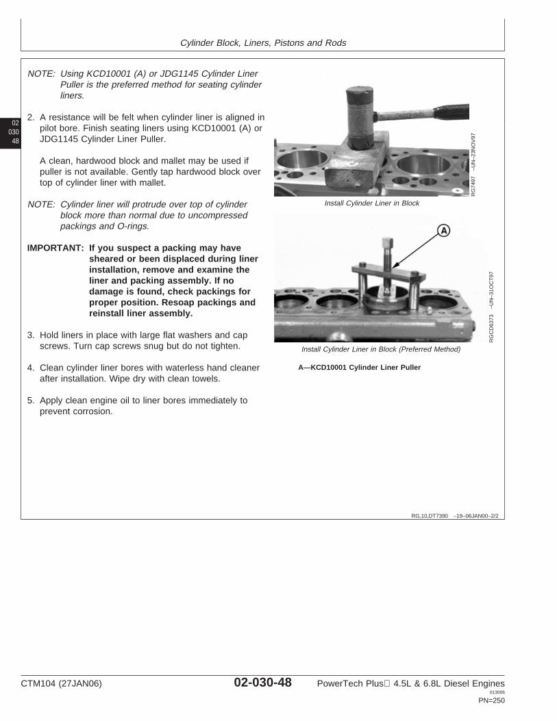
Cylinder Block, Liners, Pistons and Rods
02030
48
RG,10,DT7390 –19–06JAN00–2/2
RG
7497
–UN
–23N
OV
97
Install Cylinder Liner in Block
RG
CD
6373
–UN
–31O
CT
97
Install Cylinder Liner in Block (Preferred Method)
A—KCD10001 Cylinder Liner Puller
NOTE: Using KCD10001 (A) or JDG1145 Cylinder LinerPuller is the preferred method for seating cylinderliners.
2. A resistance will be felt when cylinder liner is aligned inpilot bore. Finish seating liners using KCD10001 (A) orJDG1145 Cylinder Liner Puller.
A clean, hardwood block and mallet may be used ifpuller is not available. Gently tap hardwood block overtop of cylinder liner with mallet.
NOTE: Cylinder liner will protrude over top of cylinderblock more than normal due to uncompressedpackings and O-rings.
IMPORTANT: If you suspect a packing may havesheared or been displaced during linerinstallation, remove and examine theliner and packing assembly. If nodamage is found, check packings forproper position. Resoap packings andreinstall liner assembly.
3. Hold liners in place with large flat washers and capscrews. Turn cap screws snug but do not tighten.
4. Clean cylinder liner bores with waterless hand cleanerafter installation. Wipe dry with clean towels.
5. Apply clean engine oil to liner bores immediately toprevent corrosion.
CTM104 (27JAN06) 02-030-48 PowerTech Plus 4.5L & 6.8L Diesel Engines013006
PN=250
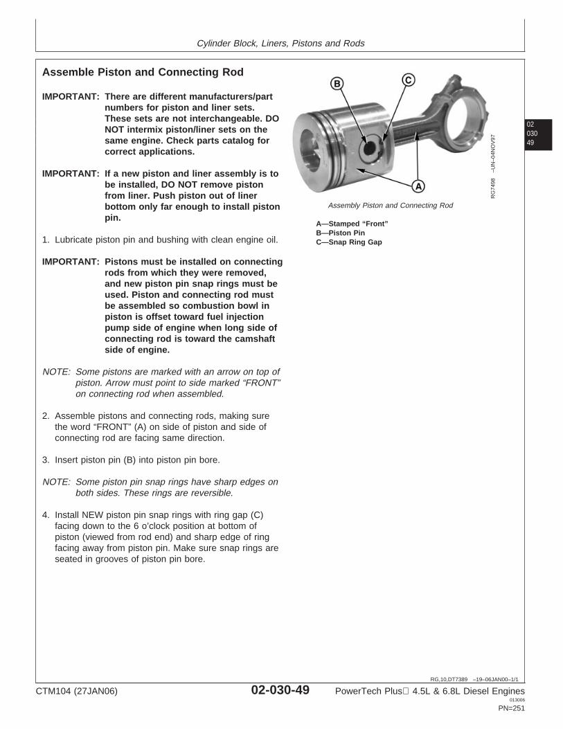
Cylinder Block, Liners, Pistons and Rods
0203049
RG,10,DT7389 –19–06JAN00–1/1
Assemble Piston and Connecting Rod
RG
7498
–UN
–04N
OV
97
Assembly Piston and Connecting Rod
A—Stamped “Front”B—Piston PinC—Snap Ring Gap
IMPORTANT: There are different manufacturers/partnumbers for piston and liner sets.These sets are not interchangeable. DONOT intermix piston/liner sets on thesame engine. Check parts catalog forcorrect applications.
IMPORTANT: If a new piston and liner assembly is tobe installed, DO NOT remove pistonfrom liner. Push piston out of linerbottom only far enough to install pistonpin.
1. Lubricate piston pin and bushing with clean engine oil.
IMPORTANT: Pistons must be installed on connectingrods from which they were removed,and new piston pin snap rings must beused. Piston and connecting rod mustbe assembled so combustion bowl inpiston is offset toward fuel injectionpump side of engine when long side ofconnecting rod is toward the camshaftside of engine.
NOTE: Some pistons are marked with an arrow on top ofpiston. Arrow must point to side marked “FRONT”on connecting rod when assembled.
2. Assemble pistons and connecting rods, making surethe word “FRONT” (A) on side of piston and side ofconnecting rod are facing same direction.
3. Insert piston pin (B) into piston pin bore.
NOTE: Some piston pin snap rings have sharp edges onboth sides. These rings are reversible.
4. Install NEW piston pin snap rings with ring gap (C)facing down to the 6 o’clock position at bottom ofpiston (viewed from rod end) and sharp edge of ringfacing away from piston pin. Make sure snap rings areseated in grooves of piston pin bore.
CTM104 (27JAN06) 02-030-49 PowerTech Plus 4.5L & 6.8L Diesel Engines013006
PN=251
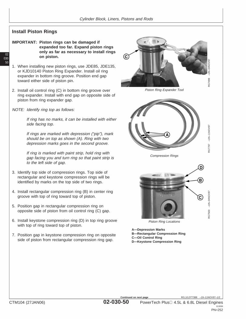
Cylinder Block, Liners, Pistons and Rods
02030
50
RG,10,DT7388 –19–11NOV97–1/2
Install Piston Rings
RG
7499
–UN
–04N
OV
97
Piston Ring Expander Tool
RG
7797
–UN
–11N
OV
97
Compression Rings
RG
7500
–UN
–04N
OV
97
Piston Ring Locations
A—Depression MarksB—Rectangular Compression RingC—Oil Control RingD—Keystone Compression Ring
IMPORTANT: Piston rings can be damaged ifexpanded too far. Expand piston ringsonly as far as necessary to install ringson piston.
1. When installing new piston rings, use JDE85, JDE135,or KJD10140 Piston Ring Expander. Install oil ringexpander in bottom ring groove. Position end gaptoward either side of piston pin.
2. Install oil control ring (C) in bottom ring groove overring expander. Install with end gap on opposite side ofpiston from ring expander gap.
NOTE: Identify ring top as follows:
If ring has no marks, it can be installed with eitherside facing top.
If rings are marked with depression (“pip”), markshould be on top as shown (A). Ring with twodepression marks goes in the second groove.
If ring is marked with paint strip, hold ring withgap facing you and turn ring so that paint strip isto the left side of gap.
3. Identify top side of compression rings. Top side ofrectangular and keystone compression rings will beidentified by marks on the top side of two rings.
4. Install rectangular compression ring (B) in center ringgroove with top of ring toward top of piston.
5. Position gap in rectangular compression ring onopposite side of piston from oil control ring (C) gap.
6. Install keystone compression ring (D) in top ring groovewith top of ring toward top of piston.
7. Position gap in keystone compression ring on oppositeside of piston from rectangular compression ring gap.
CTM104 (27JAN06) 02-030-50 PowerTech Plus 4.5L & 6.8L Diesel Engines013006
PN=252
Continued on next page
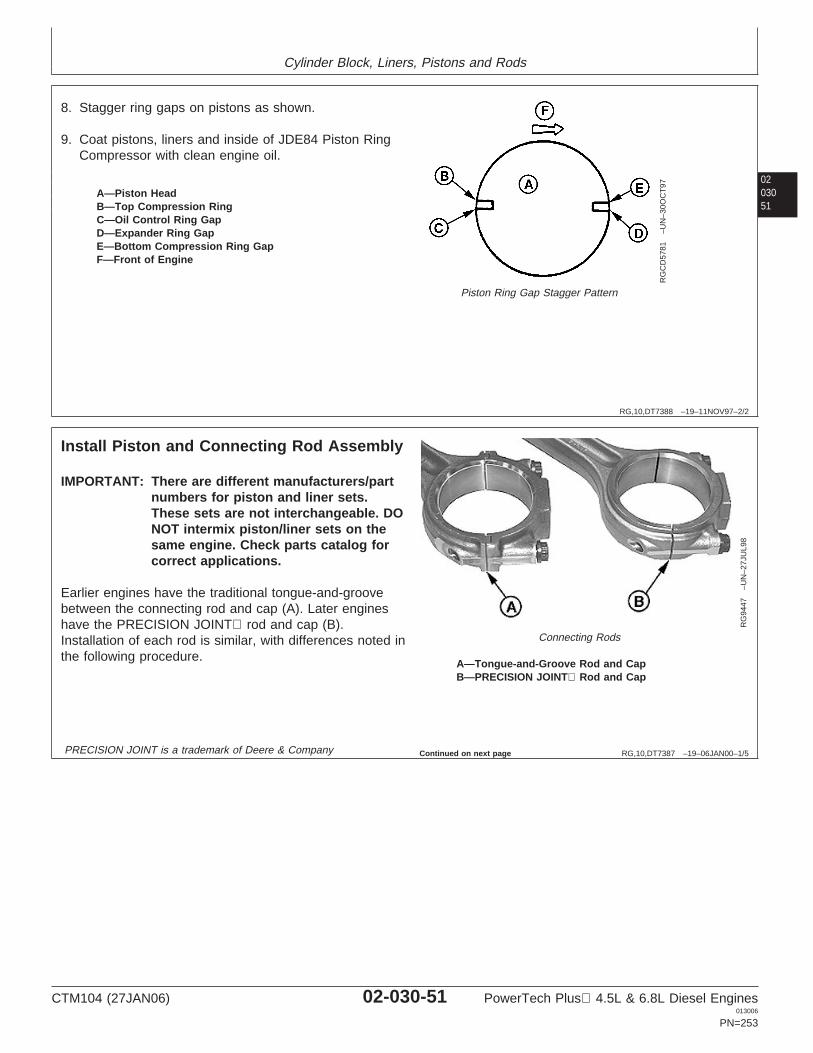
Cylinder Block, Liners, Pistons and Rods
0203051
RG,10,DT7388 –19–11NOV97–2/2
RG
CD
5781
–UN
–30O
CT
97
Piston Ring Gap Stagger Pattern
A—Piston HeadB—Top Compression RingC—Oil Control Ring GapD—Expander Ring GapE—Bottom Compression Ring GapF—Front of Engine
8. Stagger ring gaps on pistons as shown.
9. Coat pistons, liners and inside of JDE84 Piston RingCompressor with clean engine oil.
RG,10,DT7387 –19–06JAN00–1/5
Install Piston and Connecting Rod Assembly
RG
9447
–UN
–27J
UL9
8
Connecting Rods
A—Tongue-and-Groove Rod and CapB—PRECISION JOINT Rod and Cap
IMPORTANT: There are different manufacturers/partnumbers for piston and liner sets.These sets are not interchangeable. DONOT intermix piston/liner sets on thesame engine. Check parts catalog forcorrect applications.
Earlier engines have the traditional tongue-and-groovebetween the connecting rod and cap (A). Later engineshave the PRECISION JOINT rod and cap (B).Installation of each rod is similar, with differences noted inthe following procedure.
PRECISION JOINT is a trademark of Deere & Company Continued on next page
CTM104 (27JAN06) 02-030-51 PowerTech Plus 4.5L & 6.8L Diesel Engines013006
PN=253
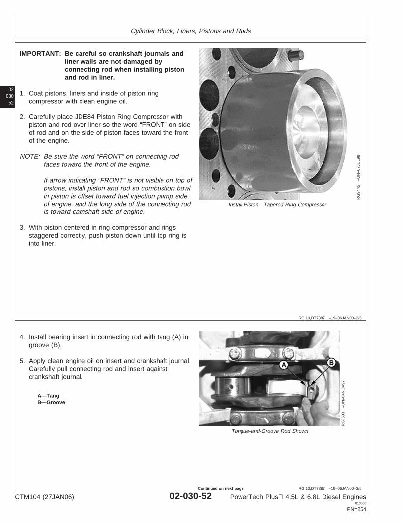
Cylinder Block, Liners, Pistons and Rods
02030
52
RG,10,DT7387 –19–06JAN00–2/5
RG
9445
–UN
–07J
UL9
8
Install Piston—Tapered Ring Compressor
IMPORTANT: Be careful so crankshaft journals andliner walls are not damaged byconnecting rod when installing pistonand rod in liner.
1. Coat pistons, liners and inside of piston ringcompressor with clean engine oil.
2. Carefully place JDE84 Piston Ring Compressor withpiston and rod over liner so the word “FRONT” on sideof rod and on the side of piston faces toward the frontof the engine.
NOTE: Be sure the word “FRONT” on connecting rodfaces toward the front of the engine.
If arrow indicating “FRONT” is not visible on top ofpistons, install piston and rod so combustion bowlin piston is offset toward fuel injection pump sideof engine, and the long side of the connecting rodis toward camshaft side of engine.
3. With piston centered in ring compressor and ringsstaggered correctly, push piston down until top ring isinto liner.
RG,10,DT7387 –19–06JAN00–3/5
RG
7503
–UN
–04N
OV
97
Tongue-and-Groove Rod Shown
A—TangB—Groove
4. Install bearing insert in connecting rod with tang (A) ingroove (B).
5. Apply clean engine oil on insert and crankshaft journal.Carefully pull connecting rod and insert againstcrankshaft journal.
CTM104 (27JAN06) 02-030-52 PowerTech Plus 4.5L & 6.8L Diesel Engines013006
PN=254
Continued on next page
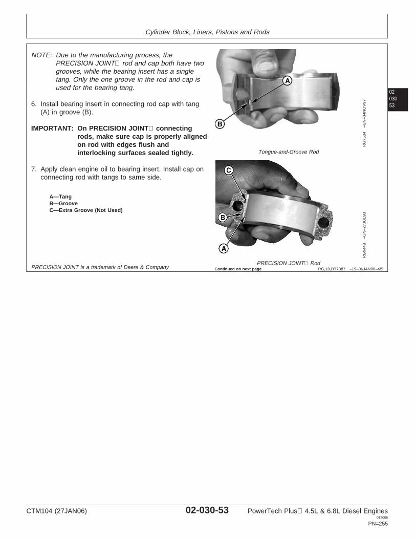
Cylinder Block, Liners, Pistons and Rods
0203053
RG,10,DT7387 –19–06JAN00–4/5
RG
7504
–UN
–04N
OV
97
Tongue-and-Groove Rod
RG
9448
–UN
–27J
UL9
8
PRECISION JOINT Rod
A—TangB—GrooveC—Extra Groove (Not Used)
NOTE: Due to the manufacturing process, thePRECISION JOINT rod and cap both have twogrooves, while the bearing insert has a singletang. Only the one groove in the rod and cap isused for the bearing tang.
6. Install bearing insert in connecting rod cap with tang(A) in groove (B).
IMPORTANT: On PRECISION JOINT connectingrods, make sure cap is properly alignedon rod with edges flush andinterlocking surfaces sealed tightly.
7. Apply clean engine oil to bearing insert. Install cap onconnecting rod with tangs to same side.
PRECISION JOINT is a trademark of Deere & Company Continued on next page
CTM104 (27JAN06) 02-030-53 PowerTech Plus 4.5L & 6.8L Diesel Engines013006
PN=255
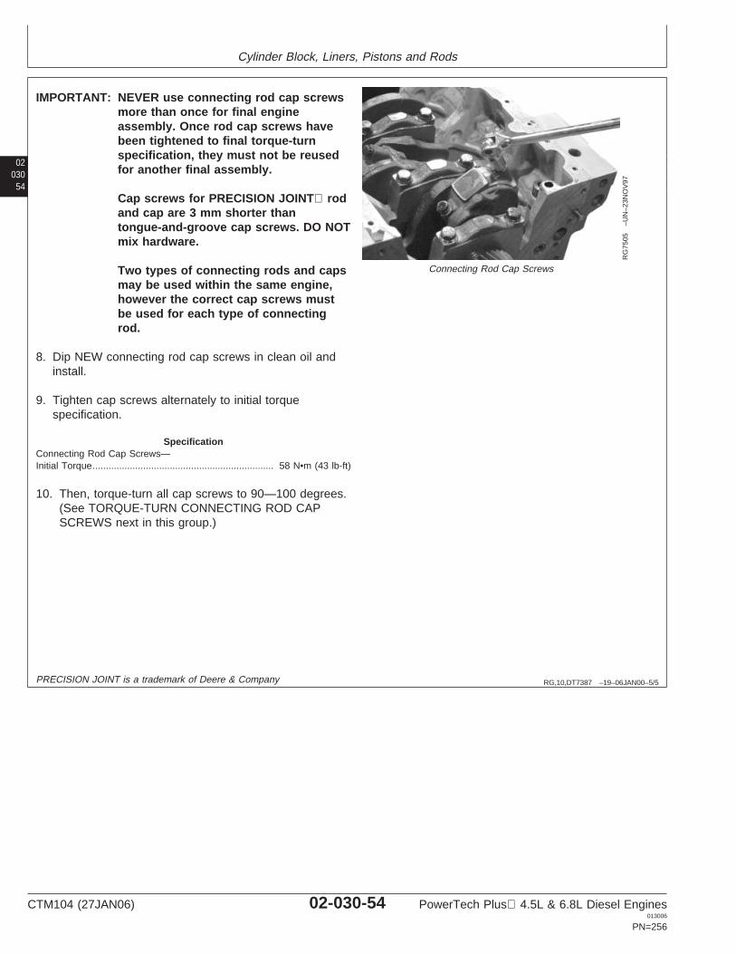
Cylinder Block, Liners, Pistons and Rods
02030
54
RG,10,DT7387 –19–06JAN00–5/5
RG
7505
–UN
–23N
OV
97
Connecting Rod Cap Screws
IMPORTANT: NEVER use connecting rod cap screwsmore than once for final engineassembly. Once rod cap screws havebeen tightened to final torque-turnspecification, they must not be reusedfor another final assembly.
Cap screws for PRECISION JOINT rodand cap are 3 mm shorter thantongue-and-groove cap screws. DO NOTmix hardware.
Two types of connecting rods and capsmay be used within the same engine,however the correct cap screws mustbe used for each type of connectingrod.
8. Dip NEW connecting rod cap screws in clean oil andinstall.
9. Tighten cap screws alternately to initial torquespecification.
SpecificationConnecting Rod Cap Screws—Initial Torque 58 N•m (43 lb-ft)....................................................................
10. Then, torque-turn all cap screws to 90—100 degrees.(See TORQUE-TURN CONNECTING ROD CAPSCREWS next in this group.)
PRECISION JOINT is a trademark of Deere & Company
CTM104 (27JAN06) 02-030-54 PowerTech Plus 4.5L & 6.8L Diesel Engines013006
PN=256
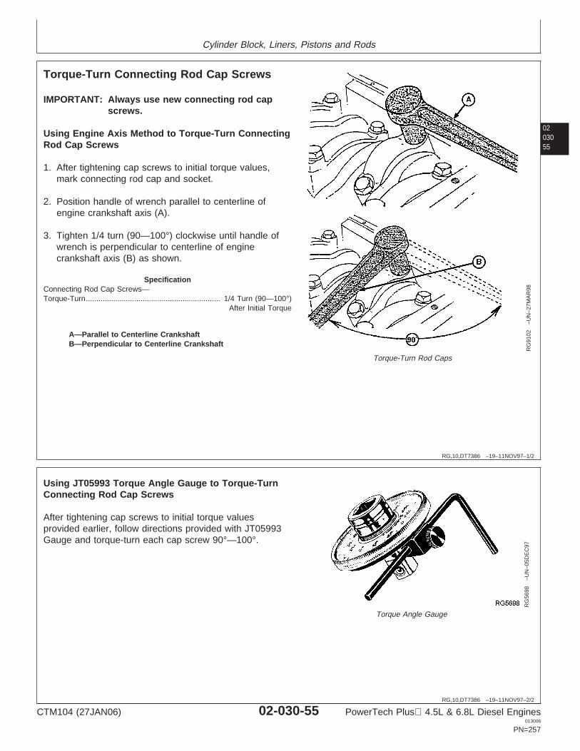
Cylinder Block, Liners, Pistons and Rods
0203055
RG,10,DT7386 –19–11NOV97–1/2
Torque-Turn Connecting Rod Cap Screws
RG
9102
–UN
–27M
AR
98
Torque-Turn Rod Caps
A—Parallel to Centerline CrankshaftB—Perpendicular to Centerline Crankshaft
IMPORTANT: Always use new connecting rod capscrews.
Using Engine Axis Method to Torque-Turn ConnectingRod Cap Screws
1. After tightening cap screws to initial torque values,mark connecting rod cap and socket.
2. Position handle of wrench parallel to centerline ofengine crankshaft axis (A).
3. Tighten 1/4 turn (90—100°) clockwise until handle ofwrench is perpendicular to centerline of enginecrankshaft axis (B) as shown.
SpecificationConnecting Rod Cap Screws—Torque-Turn 1/4 Turn (90—100°)
After Initial Torque................................................................
RG,10,DT7386 –19–11NOV97–2/2
RG
5698
–UN
–05D
EC
97
Torque Angle Gauge
Using JT05993 Torque Angle Gauge to Torque-TurnConnecting Rod Cap Screws
After tightening cap screws to initial torque valuesprovided earlier, follow directions provided with JT05993Gauge and torque-turn each cap screw 90°—100°.
CTM104 (27JAN06) 02-030-55 PowerTech Plus 4.5L & 6.8L Diesel Engines013006
PN=257
Cylinder Block, Liners, Pistons and Rods
02030
56
RG,10,DT7385 –19–11NOV97–1/1
Check Engine Rotation for ExcessiveTightness
1. Rotate crankshaft several revolutions to be sure enginerotates without excessive tightness.
2. Check liners for deep scratches caused by animproperly installed or broken piston ring.
3. Check side clearance of rods. Must have slightside-to-side movement.
CTM104 (27JAN06) 02-030-56 PowerTech Plus 4.5L & 6.8L Diesel Engines013006
PN=258
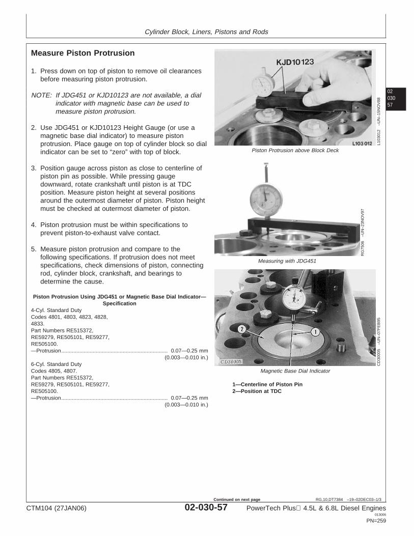
Cylinder Block, Liners, Pistons and Rods
0203057
RG,10,DT7384 –19–02DEC03–1/3
Measure Piston Protrusion
L103
012
–UN
–15N
OV
88
Piston Protrusion above Block Deck
RG
7506
–UN
–23N
OV
97
Measuring with JDG451
CD
3000
5–U
N–0
7FE
B95
Magnetic Base Dial Indicator
1—Centerline of Piston Pin2—Position at TDC
1. Press down on top of piston to remove oil clearancesbefore measuring piston protrusion.
NOTE: If JDG451 or KJD10123 are not available, a dialindicator with magnetic base can be used tomeasure piston protrusion.
2. Use JDG451 or KJD10123 Height Gauge (or use amagnetic base dial indicator) to measure pistonprotrusion. Place gauge on top of cylinder block so dialindicator can be set to “zero” with top of block.
3. Position gauge across piston as close to centerline ofpiston pin as possible. While pressing gaugedownward, rotate crankshaft until piston is at TDCposition. Measure piston height at several positionsaround the outermost diameter of piston. Piston heightmust be checked at outermost diameter of piston.
4. Piston protrusion must be within specifications toprevent piston-to-exhaust valve contact.
5. Measure piston protrusion and compare to thefollowing specifications. If protrusion does not meetspecifications, check dimensions of piston, connectingrod, cylinder block, crankshaft, and bearings todetermine the cause.
Piston Protrusion Using JDG451 or Magnetic Base Dial Indicator—Specification
4-Cyl. Standard DutyCodes 4801, 4803, 4823, 4828,4833.Part Numbers RE515372,RE59279, RE505101, RE59277,RE505100.—Protrusion 0.07—0.25 mm
(0.003—0.010 in.).......................................................................
6-Cyl. Standard DutyCodes 4805, 4807.Part Numbers RE515372,RE59279, RE505101, RE59277,RE505100.—Protrusion 0.07—0.25 mm
(0.003—0.010 in.).......................................................................
CTM104 (27JAN06) 02-030-57 PowerTech Plus 4.5L & 6.8L Diesel Engines013006
PN=259
Continued on next page
Cylinder Block, Liners, Pistons and Rods
02030
58
RG,10,DT7384 –19–02DEC03–2/3
4-Cyl. Heavy DutyCodes 4804, 4809, 4816, 4822,4825.Part Numbers RE509540,RE507758, RE55512, RE505102.—Protrusion 0.07—0.25 mm
(0.003—0.010 in.).......................................................................
6-Cyl. Heavy DutyCodes 4808, 4810, 4815, 4820,4824.Part Numbers RE509540,RE507758, RE55512, RE505102.—Protrusion 0.07—0.25 mm
(0.003—0.010 in.).......................................................................
All Four-Valve Head Engines.Part Numbers RE509540,RE507758, RE505102.—Protrusion 0.07—0.25 mm
(0.003—0.010 in.).......................................................................
Piston Protrusion Using KJD10123—Specification4-Cyl. Standard DutyCodes 4801, 4803, 4816, 4822,4825.Part Numbers RE515372,RE59279, RE505101, RE59277,RE505100.(Maximum)—Protrusion 0.21 mm
(0.008 in.)................................................................
6-Cyl. Standard DutyCodes 4805, 4807.Part Numbers RE515372,RE59279, RE505101, RE59277,RE505100.(Maximum)—Protrusion 0.21 mm
(0.008 in.)................................................................
4-Cyl. Heavy DutyCode 4804, 4809, 4816, 4822,4825.Part Numbers RE509540,RE507758, RE55512, RE505102.(Maximum)—Protrusion 0.15 mm
(0.006 in.)................................................................
Continued on next page
CTM104 (27JAN06) 02-030-58 PowerTech Plus 4.5L & 6.8L Diesel Engines013006
PN=260
Cylinder Block, Liners, Pistons and Rods
0203059
RG,10,DT7384 –19–02DEC03–3/3
6-Cyl. Heavy DutyCodes 4808, 4810, 4815, 4820,4824.Part Numbers RE509540,RE507758, RE55512, RE505102.(Maximum)—Protrusion 0.15 mm
(0.006 in.)................................................................
All Four-Valve Head Engines.Part Numbers RE509540,RE507758, RE505102.(Maximum)—Protrusion 0.15 mm
(0.006 in.)................................................................
CTM104 (27JAN06) 02-030-59 PowerTech Plus 4.5L & 6.8L Diesel Engines013006
PN=261
Cylinder Block, Liners, Pistons and Rods
02030
60
RG,10,DT7383 –19–05JUN02–1/1
Complete Final Assembly
1. Install oil pump outlet tube O-ring in cylinder block.Install oil pump and outlet tube. (See INSTALLENGINE OIL PUMP in Group 060.)
2. Install balancer shaft bushings (4-cylinder engines).(See REMOVE AND INSTALL BALANCER SHAFTBUSHINGS in Group 050.)
3. Install camshaft bushings. (See REMOVE ANDINSTALL CAMSHAFT BUSHINGS in Group 050.)
4. Install oil bypass valve (in front of block) and frontplate. (See INSTALL CYLINDER BLOCK FRONTPLATE in Group 050.)
5. Install balancer shafts (if equipped). (See INSTALLAND TIME BALANCER SHAFTS in Group 050.)
6. Install camshaft and timing gears. (See INSTALLCAMSHAFT in Group 050.)
7. If equipped with cartridge type oil pressureregulating valve, install valve. (See REMOVE ANDINSTALL OIL PRESSURE REGULATING VALVE inGroup 060.)
8. Install timing gear cover. (See INSTALL TIMINGGEAR COVER in Group 050.)
9. If equipped with spring, plunger and seat type oilpressure regulating valve, install valve assembly.(See REMOVE AND INSTALL OIL PRESSUREREGULATING VALVE in Group 060.)
10. Install oil pan. (See INSTALL OIL PAN in Group060.)
11. Install crankshaft pulley. (See INSTALL PULLEYOR VIBRATION DAMPER PULLEY in Group 040.)
12. Install camshaft followers. (See INSPECT,MEASURE AND ASSEMBLE CAMSHAFTFOLLOWERS in Group 050.)
13. Install cylinder head with new gasket. (SeeINSTALL CYLINDER HEAD in Group 020 for twovalve head or INSTALL CYLINDER HEAD inGroup 021 for four valve head.)
14. Fill engine with clean oil and proper coolant.
15. Perform engine break-in. (See PERFORMENGINE BREAK-IN in Group 010.)
CTM104 (27JAN06) 02-030-60 PowerTech Plus 4.5L & 6.8L Diesel Engines013006
PN=262
Group 040Crankshaft, Main Bearings and Flywheel
020401
RG,15,DT7461 –19–18MAY00–1/1
Crankshaft and Main Bearing Failure Analysis
Scored Main Bearing (Diagnosis Also Applies toConnecting Rod Bearing.):
• Oil starvation.• Contaminated oil.• Engine parts failure.• Excessive heat.• Poor periodic service.
Galled or “Wiped” Bearings:
• Fuel in lubricating oil (incomplete combustion).• Coolant in lubrication system (cracked block, liner
seal failure, or leaking water pump seal with pluggedhole).
• Insufficient bearing oil clearance.• Parts not lubricated prior to engine operation.• Wrong bearing size.
Inconsistent Wear Pattern:
• Misaligned or bent connecting rod.• Warped or bowed crankshaft.• Distorted cylinder block.
Broken Main Bearing Caps:
• Improper installation.• Dirt between bearing and crankshaft journal.• Low oil pressure.• Oil pump failure.
Cracked, Chipped or Broken Bearings:
• Overspeeding.• Excessive idling.• Lugging.• Excessive oil clearance.• Improper installation.
CTM104 (27JAN06) 02-040-1 PowerTech Plus 4.5L & 6.8L Diesel Engines013006
PN=263
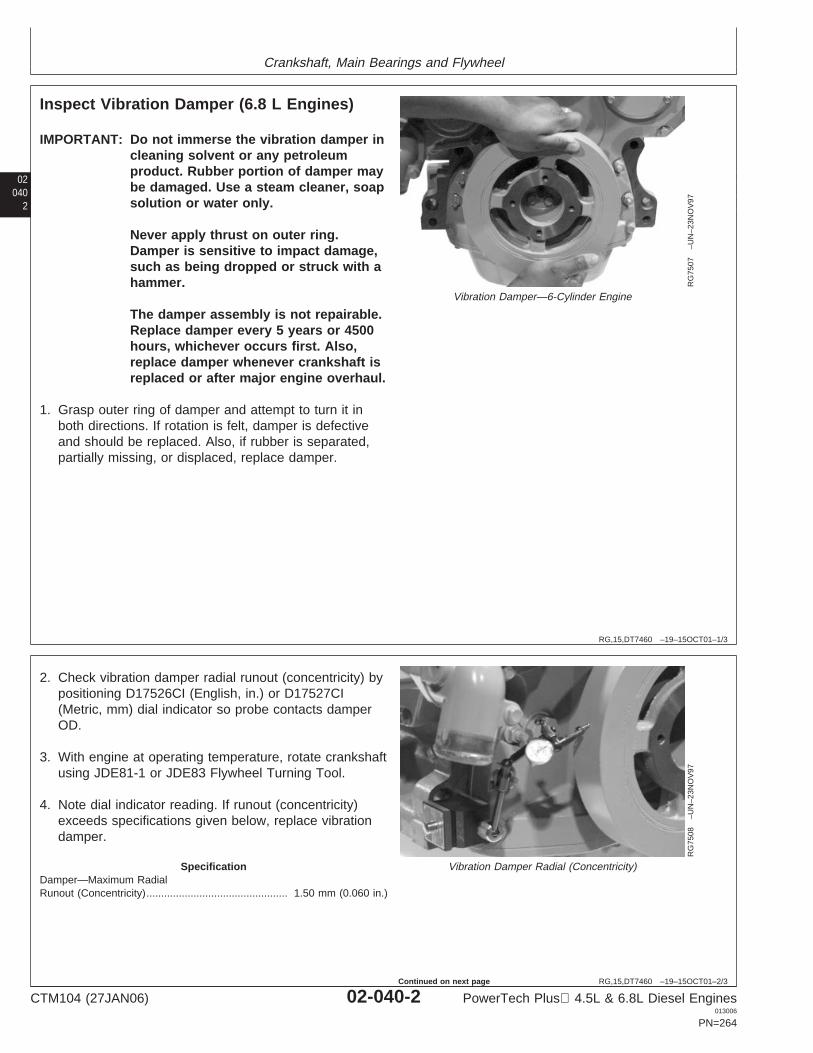
Crankshaft, Main Bearings and Flywheel
02040
2
RG,15,DT7460 –19–15OCT01–1/3
Inspect Vibration Damper (6.8 L Engines)
RG
7507
–UN
–23N
OV
97
Vibration Damper—6-Cylinder Engine
IMPORTANT: Do not immerse the vibration damper incleaning solvent or any petroleumproduct. Rubber portion of damper maybe damaged. Use a steam cleaner, soapsolution or water only.
Never apply thrust on outer ring.Damper is sensitive to impact damage,such as being dropped or struck with ahammer.
The damper assembly is not repairable.Replace damper every 5 years or 4500hours, whichever occurs first. Also,replace damper whenever crankshaft isreplaced or after major engine overhaul.
1. Grasp outer ring of damper and attempt to turn it inboth directions. If rotation is felt, damper is defectiveand should be replaced. Also, if rubber is separated,partially missing, or displaced, replace damper.
RG,15,DT7460 –19–15OCT01–2/3
RG
7508
–UN
–23N
OV
97
Vibration Damper Radial (Concentricity)
2. Check vibration damper radial runout (concentricity) bypositioning D17526CI (English, in.) or D17527CI(Metric, mm) dial indicator so probe contacts damperOD.
3. With engine at operating temperature, rotate crankshaftusing JDE81-1 or JDE83 Flywheel Turning Tool.
4. Note dial indicator reading. If runout (concentricity)exceeds specifications given below, replace vibrationdamper.
SpecificationDamper—Maximum RadialRunout (Concentricity) 1.50 mm (0.060 in.)................................................
CTM104 (27JAN06) 02-040-2 PowerTech Plus 4.5L & 6.8L Diesel Engines013006
PN=264
Continued on next page
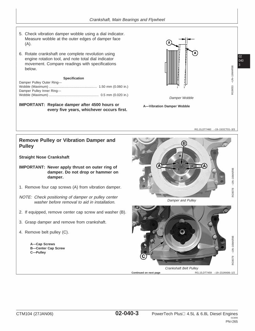
Crankshaft, Main Bearings and Flywheel
020403
RG,15,DT7460 –19–15OCT01–3/3
RG
9053
–UN
–16M
AR
98
Damper Wobble
A—Vibration Damper Wobble
5. Check vibration damper wobble using a dial indicator.Measure wobble at the outer edges of damper face(A).
6. Rotate crankshaft one complete revolution usingengine rotation tool, and note total dial indicatormovement. Compare readings with specificationsbelow.
SpecificationDamper Pulley Outer Ring—Wobble (Maximum) 1.50 mm (0.060 in.)....................................................Damper Pulley Inner Ring—Wobble (Maximum) 0.5 mm (0.020 in.)......................................................
IMPORTANT: Replace damper after 4500 hours orevery five years, whichever occurs first.
RG,15,DT7459 –19–23JAN06–1/2
Remove Pulley or Vibration Damper andPulley
RG
9078
–UN
–16M
AR
98
Damper and Pulley
RG
9079
–UN
–16M
AR
98
Crankshaft Belt Pulley
A—Cap ScrewsB—Center Cap ScrewC—Pulley
Straight Nose Crankshaft
IMPORTANT: Never apply thrust on outer ring ofdamper. Do not drop or hammer ondamper.
1. Remove four cap screws (A) from vibration damper.
NOTE: Check positioning of damper or pulley centerwasher before removal to aid in installation.
2. If equipped, remove center cap screw and washer (B).
3. Grasp damper and remove from crankshaft.
4. Remove belt pulley (C).
Continued on next page
CTM104 (27JAN06) 02-040-3 PowerTech Plus 4.5L & 6.8L Diesel Engines013006
PN=265
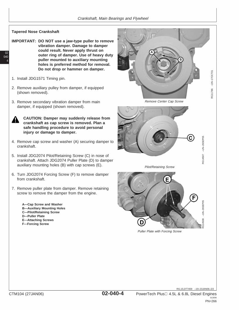
Crankshaft, Main Bearings and Flywheel
02040
4
RG,15,DT7459 –19–23JAN06–2/2
RG
1178
6–U
N–1
7OC
T01
Remove Center Cap Screw
RG
1450
7–U
N–2
6SE
P05
Pilot/Retaining Screw
RG
1450
8–U
N–2
6SE
P05
Puller Plate with Forcing Screw
A—Cap Screw and WasherB—Auxiliary Mounting HolesC—Pilot/Retaining ScrewD—Puller PlateE—Attaching ScrewsF—Forcing Screw
Tapered Nose Crankshaft
IMPORTANT: DO NOT use a jaw-type puller to removevibration damper. Damage to dampercould result. Never apply thrust onouter ring of damper. Use of heavy dutypuller mounted to auxiliary mountingholes is preferred method for removal.Do not drop or hammer on damper.
1. Install JDG1571 Timing pin.
2. Remove auxiliary pulley from damper, if equipped(shown removed).
3. Remove secondary vibration damper from maindamper, if equipped (shown removed).
CAUTION: Damper may suddenly release fromcrankshaft as cap screw is removed. Plan asafe handling procedure to avoid personalinjury or damage to damper.
4. Remove cap screw and washer (A) securing damper tocrankshaft.
5. Install JDG2074 Pilot/Retaining Screw (C) in nose ofcrankshaft. Attach JDG2074 Puller Plate (D) to damperauxiliary mounting holes (B) with cap screws (E).
6. Turn JDG2074 Forcing Screw (F) to remove damperfrom crankshaft.
7. Remove puller plate from damper. Remove retainingscrew to remove the damper from the engine.
CTM104 (27JAN06) 02-040-4 PowerTech Plus 4.5L & 6.8L Diesel Engines013006
PN=266
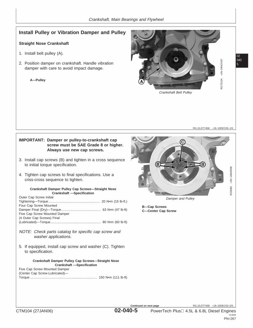
Crankshaft, Main Bearings and Flywheel
020405
RG,15,DT7458 –19–10DEC03–1/5
Install Pulley or Vibration Damper and Pulley
RG
7510
A–U
N–0
4NO
V97
Crankshaft Belt Pulley
A—Pulley
Straight Nose Crankshaft
1. Install belt pulley (A).
2. Position damper on crankshaft. Handle vibrationdamper with care to avoid impact damage.
RG,15,DT7458 –19–10DEC03–2/5
RG
9080
–UN
–16M
AR
98
Damper and Pulley
B—Cap ScrewsC—Center Cap Screw
IMPORTANT: Damper or pulley-to-crankshaft capscrew must be SAE Grade 8 or higher.Always use new cap screws.
3. Install cap screws (B) and tighten in a cross sequenceto initial torque specification.
4. Tighten cap screws to final specifications. Use acriss-cross sequence to tighten.
Crankshaft Damper Pulley Cap Screws—Straight NoseCrankshaft —Specification
Outer Cap Screw InitialTightening—Torque 20 N•m (15 lb-ft.)........................................................Four Cap Screw MountedDamper Final (Dry)—Torque 63 N•m (47 lb-ft)...........................................Five Cap Screw Mounted Damper(4 Outer Cap Screws) Final(Lubricated)—Torque 80 N•m (60 lb-ft).......................................................
NOTE: Check parts catalog for specific cap screw andwasher applications.
5. If equipped, install cap screw and washer (C). Tightento specification.
Crankshaft Damper Pulley Cap Screws—Straight NoseCrankshaft —Specification
Five Cap Screw Mounted Damper(Center Cap Screw-Lubricated)—Torque 150 N•m (111 lb-ft).........................................................................
CTM104 (27JAN06) 02-040-5 PowerTech Plus 4.5L & 6.8L Diesel Engines013006
PN=267
Continued on next page
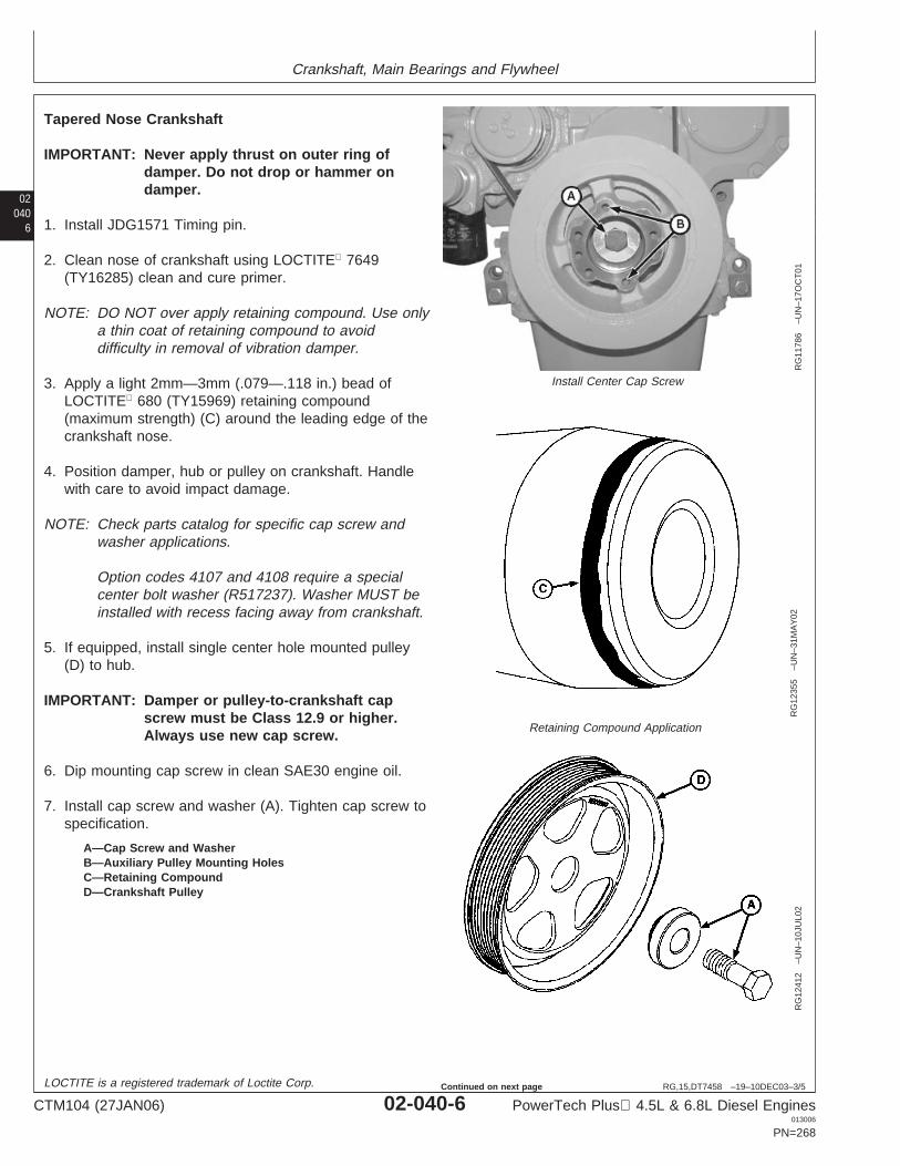
Crankshaft, Main Bearings and Flywheel
02040
6
RG,15,DT7458 –19–10DEC03–3/5
RG
1178
6–U
N–1
7OC
T01
Install Center Cap Screw
RG
1235
5–U
N–3
1MA
Y02
Retaining Compound Application
RG
1241
2–U
N–1
0JU
L02
A—Cap Screw and WasherB—Auxiliary Pulley Mounting HolesC—Retaining CompoundD—Crankshaft Pulley
Tapered Nose Crankshaft
IMPORTANT: Never apply thrust on outer ring ofdamper. Do not drop or hammer ondamper.
1. Install JDG1571 Timing pin.
2. Clean nose of crankshaft using LOCTITE 7649(TY16285) clean and cure primer.
NOTE: DO NOT over apply retaining compound. Use onlya thin coat of retaining compound to avoiddifficulty in removal of vibration damper.
3. Apply a light 2mm—3mm (.079—.118 in.) bead ofLOCTITE 680 (TY15969) retaining compound(maximum strength) (C) around the leading edge of thecrankshaft nose.
4. Position damper, hub or pulley on crankshaft. Handlewith care to avoid impact damage.
NOTE: Check parts catalog for specific cap screw andwasher applications.
Option codes 4107 and 4108 require a specialcenter bolt washer (R517237). Washer MUST beinstalled with recess facing away from crankshaft.
5. If equipped, install single center hole mounted pulley(D) to hub.
IMPORTANT: Damper or pulley-to-crankshaft capscrew must be Class 12.9 or higher.Always use new cap screw.
6. Dip mounting cap screw in clean SAE30 engine oil.
7. Install cap screw and washer (A). Tighten cap screw tospecification.
LOCTITE is a registered trademark of Loctite Corp.
CTM104 (27JAN06) 02-040-6 PowerTech Plus 4.5L & 6.8L Diesel Engines013006
PN=268
Continued on next page
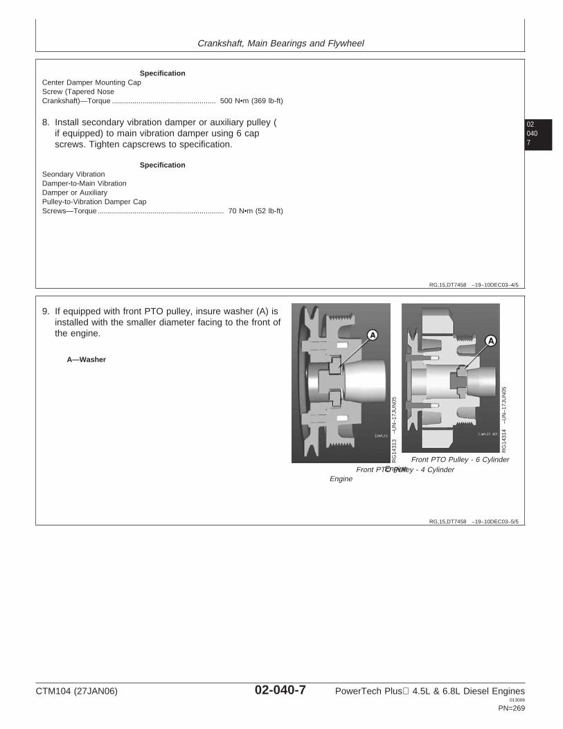
Crankshaft, Main Bearings and Flywheel
020407
RG,15,DT7458 –19–10DEC03–4/5
SpecificationCenter Damper Mounting CapScrew (Tapered NoseCrankshaft)—Torque 500 N•m (369 lb-ft)...................................................
8. Install secondary vibration damper or auxiliary pulley (if equipped) to main vibration damper using 6 capscrews. Tighten capscrews to specification.
SpecificationSeondary VibrationDamper-to-Main VibrationDamper or AuxiliaryPulley-to-Vibration Damper CapScrews—Torque 70 N•m (52 lb-ft)..............................................................
RG,15,DT7458 –19–10DEC03–5/5
RG
1431
3–U
N–1
7JU
N05
Front PTO Pulley - 4 CylinderEngine
RG
1431
4–U
N–1
7JU
N05
Front PTO Pulley - 6 CylinderEngine
A—Washer
9. If equipped with front PTO pulley, insure washer (A) isinstalled with the smaller diameter facing to the front ofthe engine.
CTM104 (27JAN06) 02-040-7 PowerTech Plus 4.5L & 6.8L Diesel Engines013006
PN=269
Crankshaft, Main Bearings and Flywheel
02040
8
RG19661,000015B –19–27JAN06–1/13
Replace Front Crankshaft Oil Seal and WearSleeve
NOTE: This procedure is for removal and installation ofthe front oil seal and wear sleeve with timing gearcover installed.
Early production engines may be equipped with atwo piece front oil seal/wear sleeve or front oilseal and no wear sleeve; however, installation ofa wear sleeve is recommended for servicewhenever a two piece front oil seal is replaced.
Later production engines may be equipped with aone piece unitized front oil seal/wear sleeve.
Two piece front oil seal/wear sleeve may bereplaced with one piece unitized front oilseal/wear sleeve. A wear sleeve is not requiredwhen installing a unitized seal.
Front Oil Seal/Wear Sleeve Installation Table
Refer to following table for proper oil seal/wear sleeveapplications and installation.
Continued on next page
CTM104 (27JAN06) 02-040-8 PowerTech Plus 4.5L & 6.8L Diesel Engines013006
PN=270
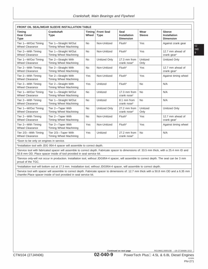
Crankshaft, Main Bearings and Flywheel
020409
RG19661,000015B –19–27JAN06–2/13
FRONT OIL SEAL/WEAR SLEEVE INSTALLATION TABLE
Timing Crankshaft Timing Front Seal Seal Wear SleeveGear Cover Type Wheel Type Installation Sleeve InstallationType Dimension Dimension
Tier 1—W/Out Timing Tier 1—Straight W/Out No Non-Unitized Flusha Yes Against crank gearWheel Clearance Timing Wheel Machining
Tier 2—With Timing Tier 1—Straight W/Out No Non-Unitized Flushb Yes 12.7 mm ahead ofWheel Clearance Timing Wheel Machining crank gearc
Tier 1—W/Out Timing Tier 2—Straight With No Unitized Only 17.3 mm from Unitized Unitized OnlyWheel Clearance Timing Wheel Machining crank nosed Only
Tier 2—With Timing Tier 2—Straight With No Non-Unitized Flushb Yes 12.7 mm ahead ofWheel Clearance Timing Wheel Machining crank gearc
Tier 2—With Timing Tier 2—Straight With Yes Non-Unitized Flushb Yes Against timing wheelWheel Clearance Timing Wheel Machining
Tier 2—With Timing Tier 2—Straight With Yes Unitized Flushb No N/AWheel Clearance Timing Wheel Machining
Tier 1—W/Out Timing Tier 1—Straight W/Out No Unitized 17.3 mm from No N/AWheel Clearance Timing Wheel Machining crank nosee
Tier 2—With Timing Tier 1—Straight W/Out No Unitized 8.1 mm from No N/AWheel Clearance Timing Wheel Machining crank noseb
Tier 1—W/Out Timing Tier 2—Taper With No Unitized Only 27.2 mm from Unitized Unitized OnlyWheel Clearance Timing Wheel Machining crank nosed Only
Tier 2—With Timing Tier 2—Taper With No Non-Unitized Flushb Yes 12.7 mm ahead ofWheel Clearance Timing Wheel Machining crank gearf
Tier 2—With Timing Tier 2—Taper With Yes Non-Unitized Flushb Yes Against timing wheelWheel Clearance Timing Wheel Machining
Tier 2/3—With Timing Tier 2/3—Taper With Yes Unitized 27.2 mm from No N/AWheel Clearance Timing Wheel Machining crank noseb
aSoon to be only on engines in service.bInstallation tool with JDG 954-4 spacer will assemble to correct depth.cService tool with fabricated spacer will assemble to correct depth. Fabricate spacer to dimensions of: 33.5 mm thick, with a 25.4 mm ID and50.8 mm OD. Place spacer inside of tool provided in seal service kit.dService only-will not occur in production. Installation tool, without JDG954-4 spacer, will assemble to correct depth. The seal can be 3 mmproud of the TGC.eInstallation tool will bottom out at 17.3 mm. Installation tool, without JDG954-4 spacer, will assemble to correct depth.fService tool with spacer will assemble to correct depth. Fabricate spacer to dimensions of: 12.7 mm thick with a 50.8 mm OD and a 6.35 mmchamfer.Place spacer inside of tool provided in seal service kit.
CTM104 (27JAN06) 02-040-9 PowerTech Plus 4.5L & 6.8L Diesel Engines013006
PN=271
Continued on next page
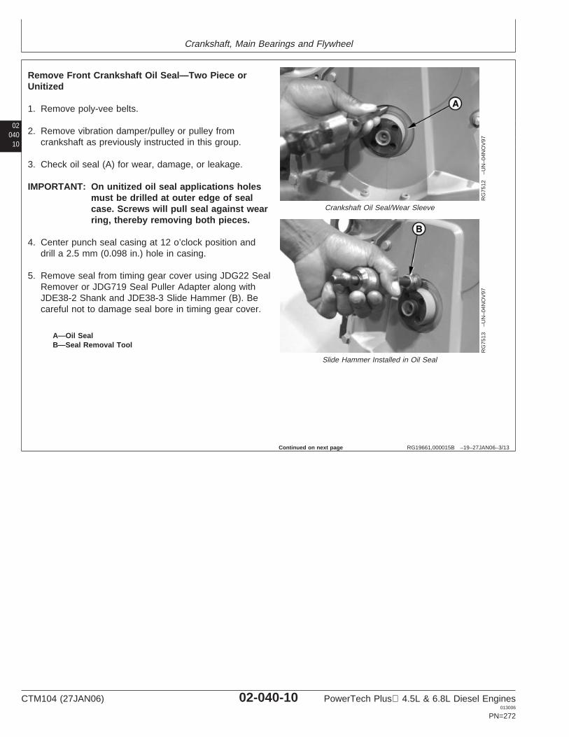
Crankshaft, Main Bearings and Flywheel
02040
10
RG19661,000015B –19–27JAN06–3/13
RG
7512
–UN
–04N
OV
97
Crankshaft Oil Seal/Wear Sleeve
RG
7513
–UN
–04N
OV
97
Slide Hammer Installed in Oil Seal
A—Oil SealB—Seal Removal Tool
Remove Front Crankshaft Oil Seal—Two Piece orUnitized
1. Remove poly-vee belts.
2. Remove vibration damper/pulley or pulley fromcrankshaft as previously instructed in this group.
3. Check oil seal (A) for wear, damage, or leakage.
IMPORTANT: On unitized oil seal applications holesmust be drilled at outer edge of sealcase. Screws will pull seal against wearring, thereby removing both pieces.
4. Center punch seal casing at 12 o’clock position anddrill a 2.5 mm (0.098 in.) hole in casing.
5. Remove seal from timing gear cover using JDG22 SealRemover or JDG719 Seal Puller Adapter along withJDE38-2 Shank and JDE38-3 Slide Hammer (B). Becareful not to damage seal bore in timing gear cover.
Continued on next page
CTM104 (27JAN06) 02-040-10 PowerTech Plus 4.5L & 6.8L Diesel Engines013006
PN=272
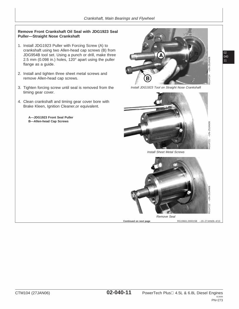
Crankshaft, Main Bearings and Flywheel
0204011
RG19661,000015B –19–27JAN06–4/13
RG
1472
4–U
N–2
5JA
N06
Install JDG1923 Tool on Straight Nose Crankshaft
RG
1472
1–U
N–2
5JA
N06
Install Sheet Metal Screws
RG
1472
2–U
N–2
5JA
N06
Remove Seal
A—JDG1923 Front Seal PullerB—Allen-head Cap Screws
Remove Front Crankshaft Oil Seal with JDG1923 SealPuller—Straight Nose Crankshaft
1. Install JDG1923 Puller with Forcing Screw (A) tocrankshaft using two Allen-head cap screws (B) fromJDG954B tool set. Using a punch or drill, make three2.5 mm (0.098 in.) holes, 120° apart using the pullerflange as a guide.
2. Install and tighten three sheet metal screws andremove Allen-head cap screws.
3. Tighten forcing screw until seal is removed from thetiming gear cover.
4. Clean crankshaft and timing gear cover bore withBrake Kleen, Ignition Cleaner,or equivalent.
Continued on next page
CTM104 (27JAN06) 02-040-11 PowerTech Plus 4.5L & 6.8L Diesel Engines013006
PN=273
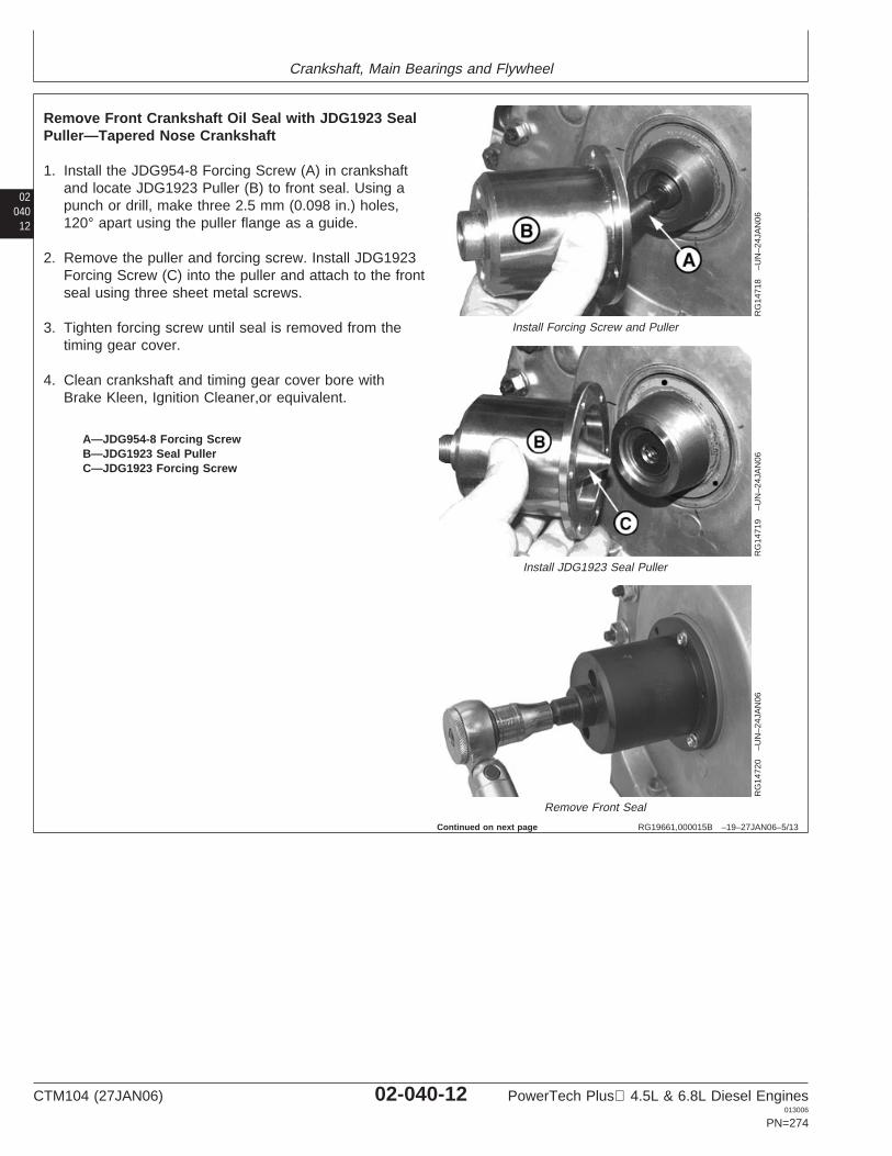
Crankshaft, Main Bearings and Flywheel
02040
12
RG19661,000015B –19–27JAN06–5/13
RG
1471
8–U
N–2
4JA
N06
Install Forcing Screw and Puller
RG
1471
9–U
N–2
4JA
N06
Install JDG1923 Seal Puller
RG
1472
0–U
N–2
4JA
N06
Remove Front Seal
A—JDG954-8 Forcing ScrewB—JDG1923 Seal PullerC—JDG1923 Forcing Screw
Remove Front Crankshaft Oil Seal with JDG1923 SealPuller—Tapered Nose Crankshaft
1. Install the JDG954-8 Forcing Screw (A) in crankshaftand locate JDG1923 Puller (B) to front seal. Using apunch or drill, make three 2.5 mm (0.098 in.) holes,120° apart using the puller flange as a guide.
2. Remove the puller and forcing screw. Install JDG1923Forcing Screw (C) into the puller and attach to the frontseal using three sheet metal screws.
3. Tighten forcing screw until seal is removed from thetiming gear cover.
4. Clean crankshaft and timing gear cover bore withBrake Kleen, Ignition Cleaner,or equivalent.
Continued on next page
CTM104 (27JAN06) 02-040-12 PowerTech Plus 4.5L & 6.8L Diesel Engines013006
PN=274
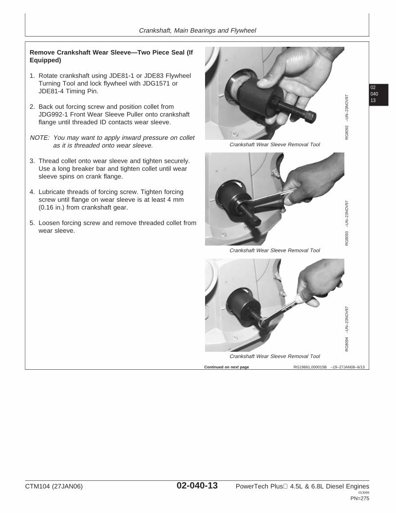
Crankshaft, Main Bearings and Flywheel
0204013
RG19661,000015B –19–27JAN06–6/13
RG
8092
–UN
–23N
OV
97
Crankshaft Wear Sleeve Removal Tool
RG
8093
–UN
–23N
OV
97
Crankshaft Wear Sleeve Removal Tool
RG
8094
–UN
–23N
OV
97
Crankshaft Wear Sleeve Removal Tool
Remove Crankshaft Wear Sleeve—Two Piece Seal (IfEquipped)
1. Rotate crankshaft using JDE81-1 or JDE83 FlywheelTurning Tool and lock flywheel with JDG1571 orJDE81-4 Timing Pin.
2. Back out forcing screw and position collet fromJDG992-1 Front Wear Sleeve Puller onto crankshaftflange until threaded ID contacts wear sleeve.
NOTE: You may want to apply inward pressure on colletas it is threaded onto wear sleeve.
3. Thread collet onto wear sleeve and tighten securely.Use a long breaker bar and tighten collet until wearsleeve spins on crank flange.
4. Lubricate threads of forcing screw. Tighten forcingscrew until flange on wear sleeve is at least 4 mm(0.16 in.) from crankshaft gear.
5. Loosen forcing screw and remove threaded collet fromwear sleeve.
Continued on next page
CTM104 (27JAN06) 02-040-13 PowerTech Plus 4.5L & 6.8L Diesel Engines013006
PN=275
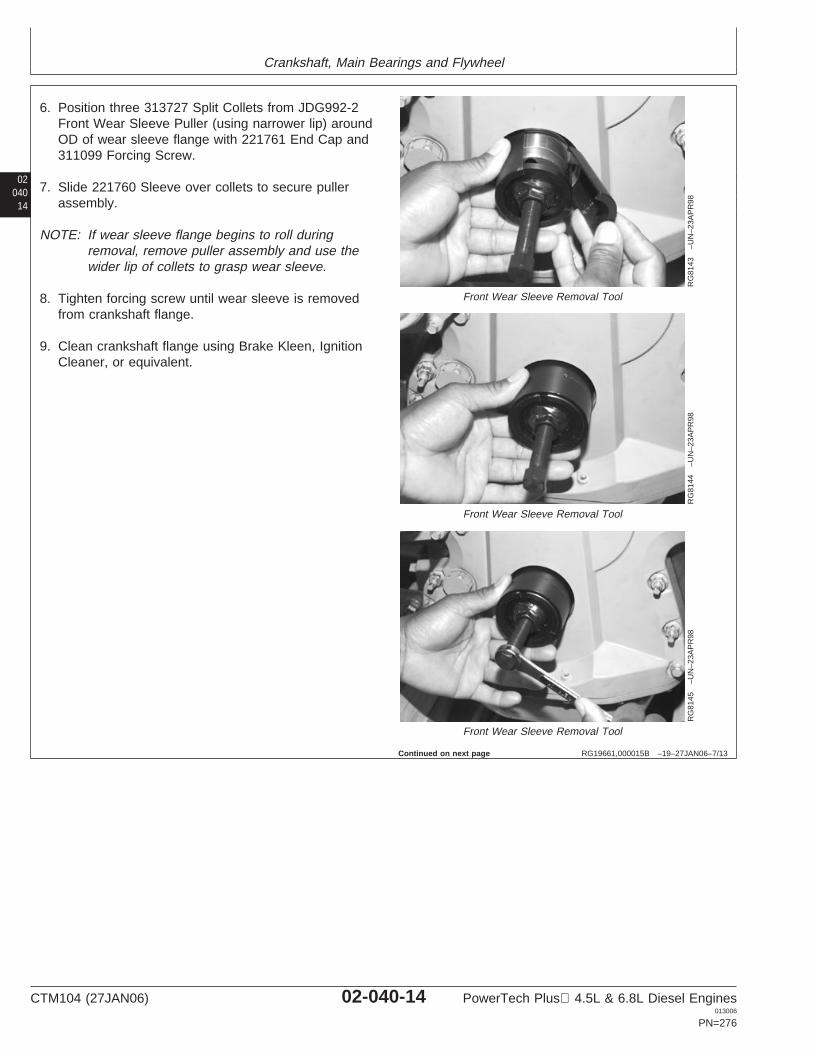
Crankshaft, Main Bearings and Flywheel
02040
14
RG19661,000015B –19–27JAN06–7/13
RG
8143
–UN
–23A
PR
98
Front Wear Sleeve Removal Tool
RG
8144
–UN
–23A
PR
98
Front Wear Sleeve Removal Tool
RG
8145
–UN
–23A
PR
98
Front Wear Sleeve Removal Tool
6. Position three 313727 Split Collets from JDG992-2Front Wear Sleeve Puller (using narrower lip) aroundOD of wear sleeve flange with 221761 End Cap and311099 Forcing Screw.
7. Slide 221760 Sleeve over collets to secure pullerassembly.
NOTE: If wear sleeve flange begins to roll duringremoval, remove puller assembly and use thewider lip of collets to grasp wear sleeve.
8. Tighten forcing screw until wear sleeve is removedfrom crankshaft flange.
9. Clean crankshaft flange using Brake Kleen, IgnitionCleaner, or equivalent.
Continued on next page
CTM104 (27JAN06) 02-040-14 PowerTech Plus 4.5L & 6.8L Diesel Engines013006
PN=276
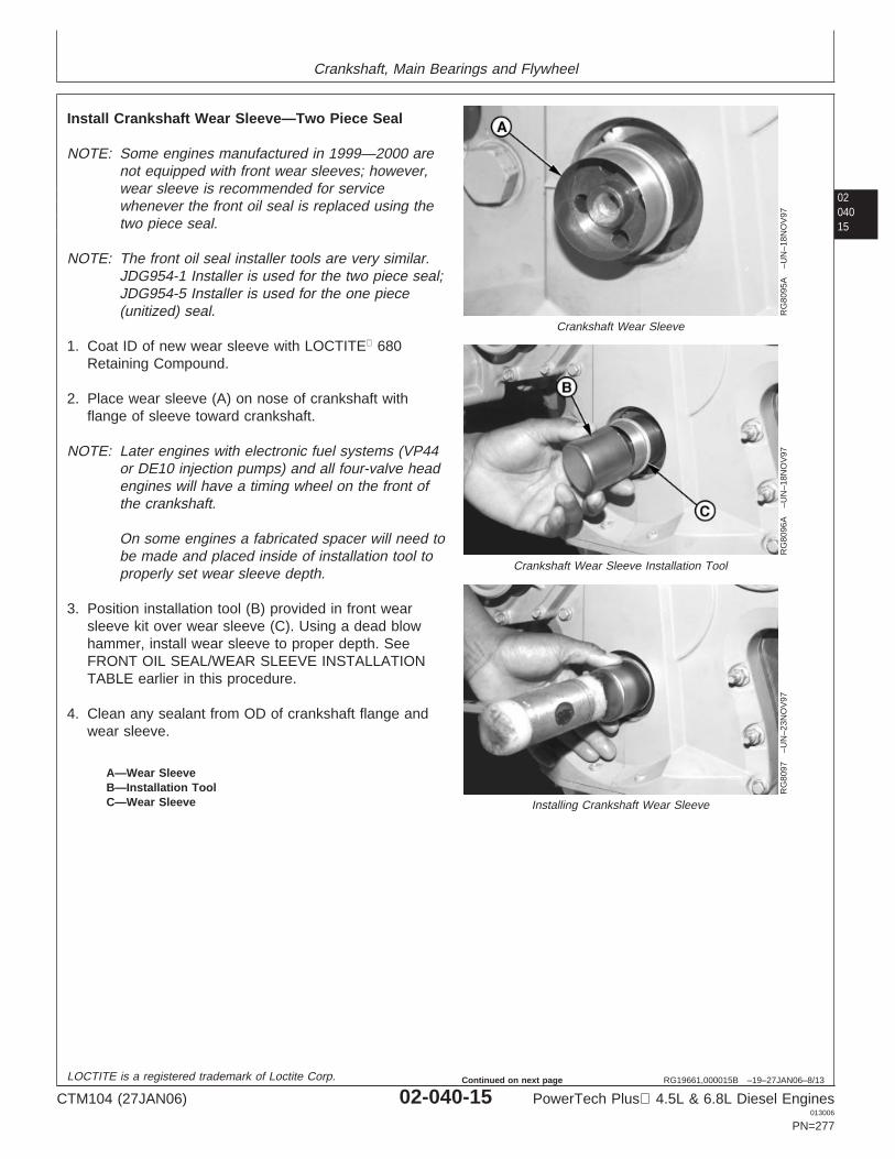
Crankshaft, Main Bearings and Flywheel
0204015
RG19661,000015B –19–27JAN06–8/13
RG
8095
A–U
N–1
8NO
V97
Crankshaft Wear Sleeve
RG
8096
A–U
N–1
8NO
V97
Crankshaft Wear Sleeve Installation Tool
RG
8097
–UN
–23N
OV
97
Installing Crankshaft Wear Sleeve
A—Wear SleeveB—Installation ToolC—Wear Sleeve
Install Crankshaft Wear Sleeve—Two Piece Seal
NOTE: Some engines manufactured in 1999—2000 arenot equipped with front wear sleeves; however,wear sleeve is recommended for servicewhenever the front oil seal is replaced using thetwo piece seal.
NOTE: The front oil seal installer tools are very similar.JDG954-1 Installer is used for the two piece seal;JDG954-5 Installer is used for the one piece(unitized) seal.
1. Coat ID of new wear sleeve with LOCTITE 680Retaining Compound.
2. Place wear sleeve (A) on nose of crankshaft withflange of sleeve toward crankshaft.
NOTE: Later engines with electronic fuel systems (VP44or DE10 injection pumps) and all four-valve headengines will have a timing wheel on the front ofthe crankshaft.
On some engines a fabricated spacer will need tobe made and placed inside of installation tool toproperly set wear sleeve depth.
3. Position installation tool (B) provided in front wearsleeve kit over wear sleeve (C). Using a dead blowhammer, install wear sleeve to proper depth. SeeFRONT OIL SEAL/WEAR SLEEVE INSTALLATIONTABLE earlier in this procedure.
4. Clean any sealant from OD of crankshaft flange andwear sleeve.
LOCTITE is a registered trademark of Loctite Corp.
CTM104 (27JAN06) 02-040-15 PowerTech Plus 4.5L & 6.8L Diesel Engines013006
PN=277
Continued on next page
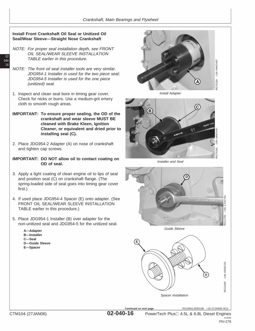
Crankshaft, Main Bearings and Flywheel
02040
16
RG19661,000015B –19–27JAN06–9/13
RG
7515
A–U
N–0
4NO
V97
Install Adapter
RG
7516
A–U
N–0
4NO
V97
Installer and Seal
RG
1179
3–U
N–1
7OC
T01
Guide Sleeve
E
A
RG
1244
9–U
N–0
4DE
C03
Spacer Installation
A—AdapterB—InstallerC—SealD—Guide SleeveE—Spacer
Install Front Crankshaft Oil Seal or Unitized OilSeal/Wear Sleeve—Straight Nose Crankshaft
NOTE: For proper seal installation depth, see FRONTOIL SEAL/WEAR SLEEVE INSTALLATIONTABLE earlier in this procedure.
NOTE: The front oil seal installer tools are very similar.JDG954-1 Installer is used for the two piece seal;JDG954-5 Installer is used for the one piece(unitized) seal.
1. Inspect and clean seal bore in timing gear cover.Check for nicks or burrs. Use a medium-grit emerycloth to smooth rough areas.
IMPORTANT: To ensure proper sealing, the OD of thecrankshaft and wear sleeve MUST BEcleaned with Brake Kleen, IgnitionCleaner, or equivalent and dried prior toinstalling seal (C).
2. Place JDG954-2 Adapter (A) on nose of crankshaftand tighten cap screws.
IMPORTANT: DO NOT allow oil to contact coating onOD of seal.
3. Apply a light coating of clean engine oil to lips of sealand position seal (C) on crankshaft flange. (Thespring-loaded side of seal goes into timing gear coverfirst.)
4. If used place JDG954-4 Spacer (E) onto adapter. (SeeFRONT OIL SEAL/WEAR SLEEVE INSTALLATIONTABLE earlier in this procedure.)
5. Place JDG954-1 Installer (B) over adapter for thenon-unitized seal and JDG954-5 for the unitized seal.
CTM104 (27JAN06) 02-040-16 PowerTech Plus 4.5L & 6.8L Diesel Engines013006
PN=278
Continued on next page
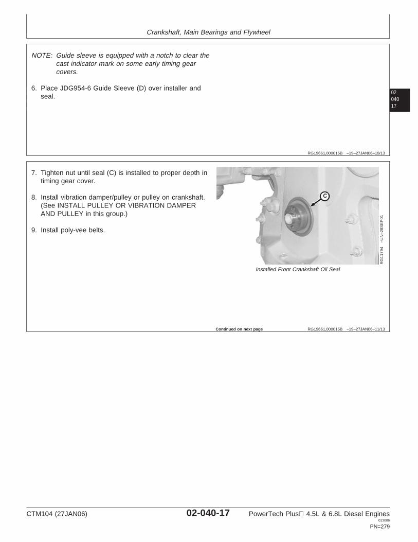
Crankshaft, Main Bearings and Flywheel
0204017
RG19661,000015B –19–27JAN06–10/13
NOTE: Guide sleeve is equipped with a notch to clear thecast indicator mark on some early timing gearcovers.
6. Place JDG954-6 Guide Sleeve (D) over installer andseal.
RG19661,000015B –19–27JAN06–11/13
RG
1179
4–U
N–2
8SE
P01
Installed Front Crankshaft Oil Seal
7. Tighten nut until seal (C) is installed to proper depth intiming gear cover.
8. Install vibration damper/pulley or pulley on crankshaft.(See INSTALL PULLEY OR VIBRATION DAMPERAND PULLEY in this group.)
9. Install poly-vee belts.
Continued on next page
CTM104 (27JAN06) 02-040-17 PowerTech Plus 4.5L & 6.8L Diesel Engines013006
PN=279
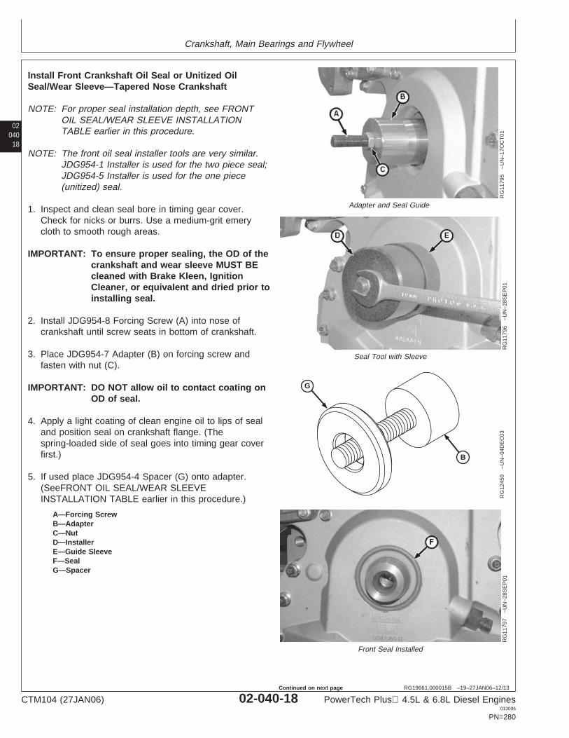
Crankshaft, Main Bearings and Flywheel
02040
18
RG19661,000015B –19–27JAN06–12/13
RG
1179
5–U
N–1
7OC
T01
Adapter and Seal Guide
RG
1179
6–U
N–2
8SE
P01
Seal Tool with Sleeve
G
B
RG
1245
0–U
N–0
4DE
C03
RG
1179
7–U
N–2
8SE
P01
Front Seal Installed
A—Forcing ScrewB—AdapterC—NutD—InstallerE—Guide SleeveF—SealG—Spacer
Install Front Crankshaft Oil Seal or Unitized OilSeal/Wear Sleeve—Tapered Nose Crankshaft
NOTE: For proper seal installation depth, see FRONTOIL SEAL/WEAR SLEEVE INSTALLATIONTABLE earlier in this procedure.
NOTE: The front oil seal installer tools are very similar.JDG954-1 Installer is used for the two piece seal;JDG954-5 Installer is used for the one piece(unitized) seal.
1. Inspect and clean seal bore in timing gear cover.Check for nicks or burrs. Use a medium-grit emerycloth to smooth rough areas.
IMPORTANT: To ensure proper sealing, the OD of thecrankshaft and wear sleeve MUST BEcleaned with Brake Kleen, IgnitionCleaner, or equivalent and dried prior toinstalling seal.
2. Install JDG954-8 Forcing Screw (A) into nose ofcrankshaft until screw seats in bottom of crankshaft.
3. Place JDG954-7 Adapter (B) on forcing screw andfasten with nut (C).
IMPORTANT: DO NOT allow oil to contact coating onOD of seal.
4. Apply a light coating of clean engine oil to lips of sealand position seal on crankshaft flange. (Thespring-loaded side of seal goes into timing gear coverfirst.)
5. If used place JDG954-4 Spacer (G) onto adapter.(SeeFRONT OIL SEAL/WEAR SLEEVEINSTALLATION TABLE earlier in this procedure.)
CTM104 (27JAN06) 02-040-18 PowerTech Plus 4.5L & 6.8L Diesel Engines013006
PN=280
Continued on next page
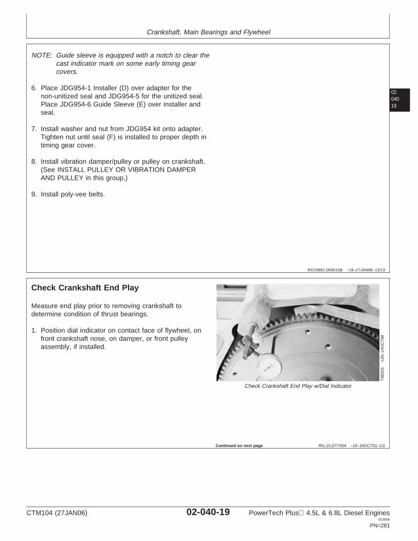
Crankshaft, Main Bearings and Flywheel
0204019
RG19661,000015B –19–27JAN06–13/13
NOTE: Guide sleeve is equipped with a notch to clear thecast indicator mark on some early timing gearcovers.
6. Place JDG954-1 Installer (D) over adapter for thenon-unitized seal and JDG954-5 for the unitized seal.Place JDG954-6 Guide Sleeve (E) over installer andseal.
7. Install washer and nut from JDG954 kit onto adapter.Tighten nut until seal (F) is installed to proper depth intiming gear cover.
8. Install vibration damper/pulley or pulley on crankshaft.(See INSTALL PULLEY OR VIBRATION DAMPERAND PULLEY in this group.)
9. Install poly-vee belts.
RG,15,DT7454 –19–15OCT01–1/2
Check Crankshaft End Play
T88
331
–UN
–14O
CT
88Check Crankshaft End Play w/Dial Indicator
Measure end play prior to removing crankshaft todetermine condition of thrust bearings.
1. Position dial indicator on contact face of flywheel, onfront crankshaft nose, on damper, or front pulleyassembly, if installed.
Continued on next page
CTM104 (27JAN06) 02-040-19 PowerTech Plus 4.5L & 6.8L Diesel Engines013006
PN=281
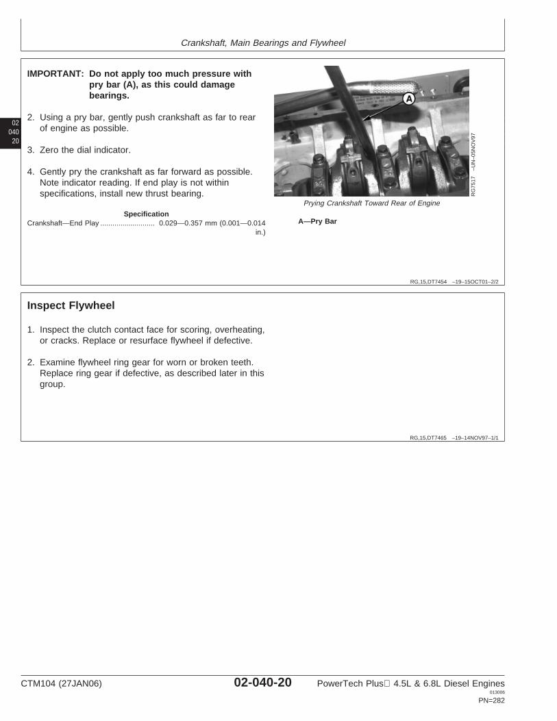
Crankshaft, Main Bearings and Flywheel
02040
20
RG,15,DT7454 –19–15OCT01–2/2
RG
7517
–UN
–05N
OV
97
Prying Crankshaft Toward Rear of Engine
A—Pry Bar
IMPORTANT: Do not apply too much pressure withpry bar (A), as this could damagebearings.
2. Using a pry bar, gently push crankshaft as far to rearof engine as possible.
3. Zero the dial indicator.
4. Gently pry the crankshaft as far forward as possible.Note indicator reading. If end play is not withinspecifications, install new thrust bearing.
SpecificationCrankshaft—End Play 0.029—0.357 mm (0.001—0.014
in.)...........................
RG,15,DT7465 –19–14NOV97–1/1
Inspect Flywheel
1. Inspect the clutch contact face for scoring, overheating,or cracks. Replace or resurface flywheel if defective.
2. Examine flywheel ring gear for worn or broken teeth.Replace ring gear if defective, as described later in thisgroup.
CTM104 (27JAN06) 02-040-20 PowerTech Plus 4.5L & 6.8L Diesel Engines013006
PN=282
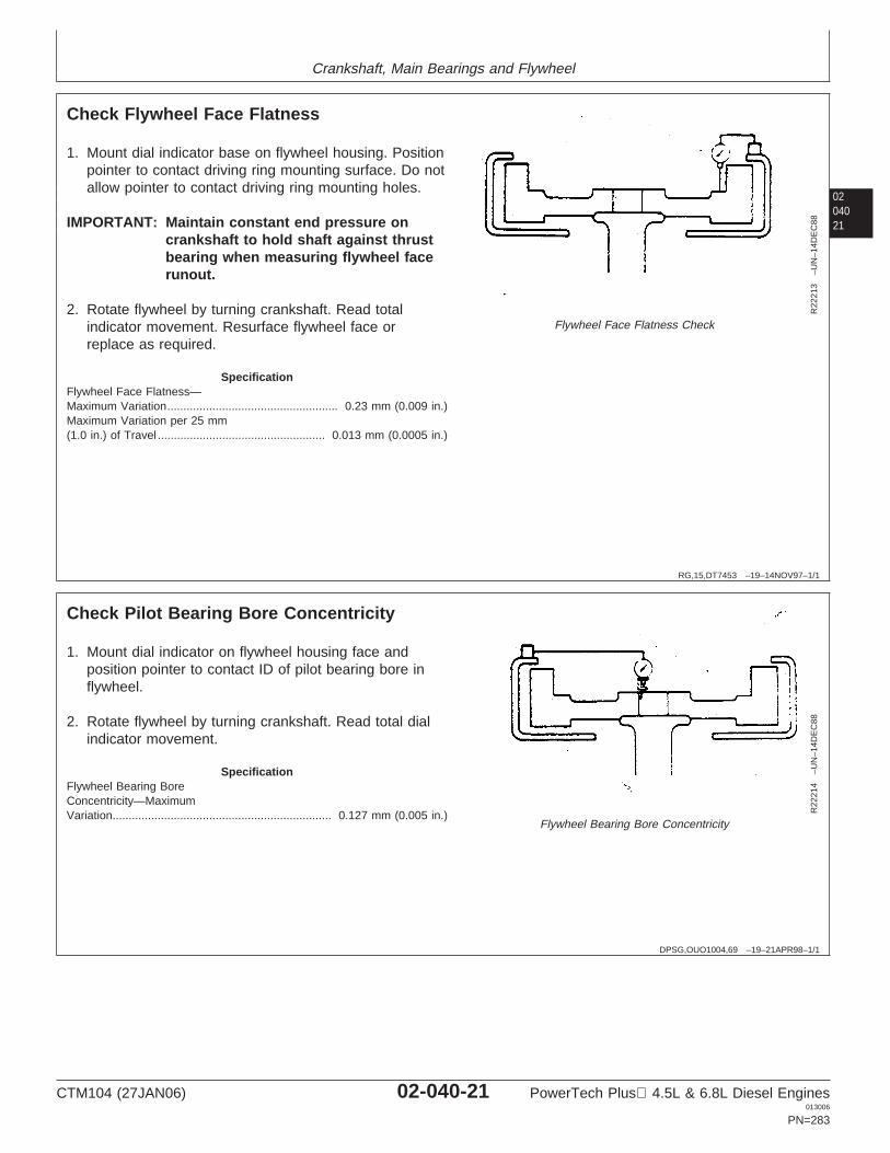
Crankshaft, Main Bearings and Flywheel
0204021
RG,15,DT7453 –19–14NOV97–1/1
Check Flywheel Face Flatness
R22
213
–UN
–14D
EC
88
Flywheel Face Flatness Check
1. Mount dial indicator base on flywheel housing. Positionpointer to contact driving ring mounting surface. Do notallow pointer to contact driving ring mounting holes.
IMPORTANT: Maintain constant end pressure oncrankshaft to hold shaft against thrustbearing when measuring flywheel facerunout.
2. Rotate flywheel by turning crankshaft. Read totalindicator movement. Resurface flywheel face orreplace as required.
SpecificationFlywheel Face Flatness—Maximum Variation 0.23 mm (0.009 in.).....................................................Maximum Variation per 25 mm(1.0 in.) of Travel 0.013 mm (0.0005 in.)....................................................
DPSG,OUO1004,69 –19–21APR98–1/1
Check Pilot Bearing Bore Concentricity
R22
214
–UN
–14D
EC
88Flywheel Bearing Bore Concentricity
1. Mount dial indicator on flywheel housing face andposition pointer to contact ID of pilot bearing bore inflywheel.
2. Rotate flywheel by turning crankshaft. Read total dialindicator movement.
SpecificationFlywheel Bearing BoreConcentricity—MaximumVariation 0.127 mm (0.005 in.)....................................................................
CTM104 (27JAN06) 02-040-21 PowerTech Plus 4.5L & 6.8L Diesel Engines013006
PN=283
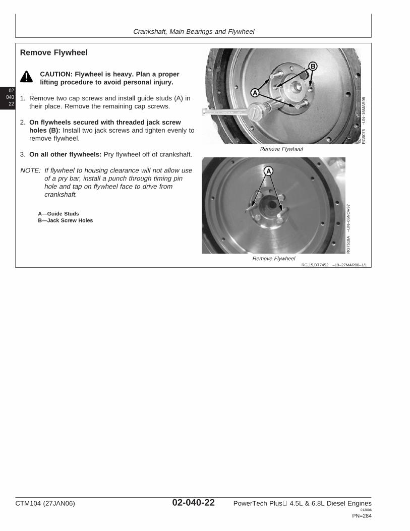
Crankshaft, Main Bearings and Flywheel
02040
22
RG,15,DT7452 –19–27MAR00–1/1
Remove Flywheel
RG
9075
–UN
–16M
AR
98
Remove Flywheel
RG
7518
A–U
N–0
5NO
V97
Remove Flywheel
A—Guide StudsB—Jack Screw Holes
CAUTION: Flywheel is heavy. Plan a properlifting procedure to avoid personal injury.
1. Remove two cap screws and install guide studs (A) intheir place. Remove the remaining cap screws.
2. On flywheels secured with threaded jack screwholes (B): Install two jack screws and tighten evenly toremove flywheel.
3. On all other flywheels: Pry flywheel off of crankshaft.
NOTE: If flywheel to housing clearance will not allow useof a pry bar, install a punch through timing pinhole and tap on flywheel face to drive fromcrankshaft.
CTM104 (27JAN06) 02-040-22 PowerTech Plus 4.5L & 6.8L Diesel Engines013006
PN=284
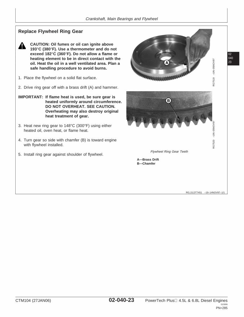
Crankshaft, Main Bearings and Flywheel
0204023
RG,15,DT7451 –19–14NOV97–1/1
Replace Flywheel Ring Gear
RG
7519
–UN
–05N
OV
97R
G75
20–U
N–0
5NO
V97
Flywheel Ring Gear Teeth
A—Brass DriftB—Chamfer
CAUTION: Oil fumes or oil can ignite above193°C (380°F). Use a thermometer and do notexceed 182°C (360°F). Do not allow a flame orheating element to be in direct contact with theoil. Heat the oil in a well ventilated area. Plan asafe handling procedure to avoid burns.
1. Place the flywheel on a solid flat surface.
2. Drive ring gear off with a brass drift (A) and hammer.
IMPORTANT: If flame heat is used, be sure gear isheated uniformly around circumference.DO NOT OVERHEAT. SEE CAUTION.Overheating may also destroy originalheat treatment of gear.
3. Heat new ring gear to 148°C (300°F) using eitherheated oil, oven heat, or flame heat.
4. Turn gear so side with chamfer (B) is toward enginewith flywheel installed.
5. Install ring gear against shoulder of flywheel.
CTM104 (27JAN06) 02-040-23 PowerTech Plus 4.5L & 6.8L Diesel Engines013006
PN=285
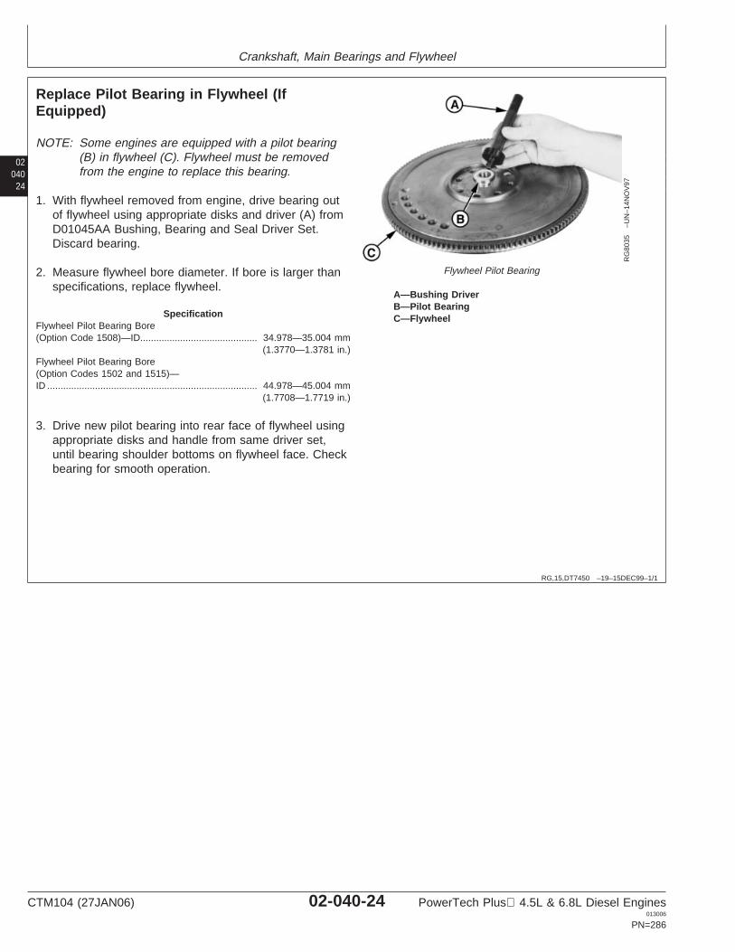
Crankshaft, Main Bearings and Flywheel
02040
24
RG,15,DT7450 –19–15DEC99–1/1
Replace Pilot Bearing in Flywheel (IfEquipped)
RG
8035
–UN
–14N
OV
97
Flywheel Pilot Bearing
A—Bushing DriverB—Pilot BearingC—Flywheel
NOTE: Some engines are equipped with a pilot bearing(B) in flywheel (C). Flywheel must be removedfrom the engine to replace this bearing.
1. With flywheel removed from engine, drive bearing outof flywheel using appropriate disks and driver (A) fromD01045AA Bushing, Bearing and Seal Driver Set.Discard bearing.
2. Measure flywheel bore diameter. If bore is larger thanspecifications, replace flywheel.
SpecificationFlywheel Pilot Bearing Bore(Option Code 1508)—ID 34.978—35.004 mm
(1.3770—1.3781 in.)............................................
Flywheel Pilot Bearing Bore(Option Codes 1502 and 1515)—ID 44.978—45.004 mm
(1.7708—1.7719 in.)...............................................................................
3. Drive new pilot bearing into rear face of flywheel usingappropriate disks and handle from same driver set,until bearing shoulder bottoms on flywheel face. Checkbearing for smooth operation.
CTM104 (27JAN06) 02-040-24 PowerTech Plus 4.5L & 6.8L Diesel Engines013006
PN=286
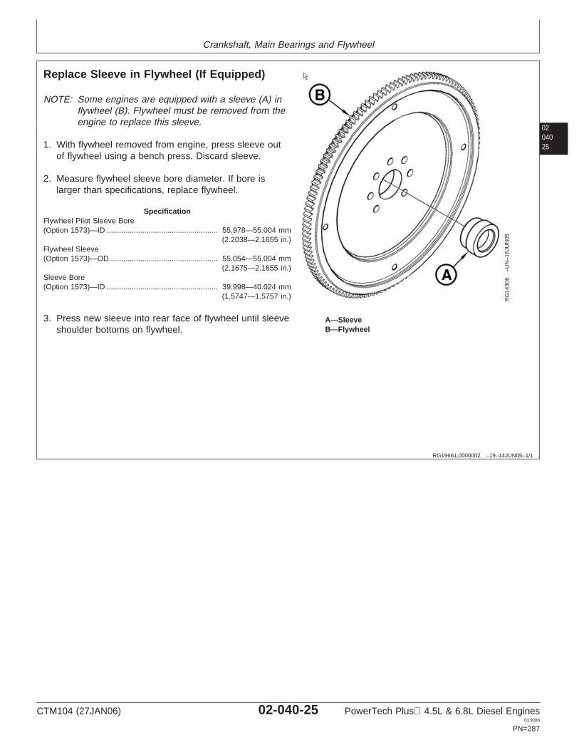
Crankshaft, Main Bearings and Flywheel
0204025
RG19661,0000002 –19–14JUN05–1/1
Replace Sleeve in Flywheel (If Equipped)
RG
1430
6–U
N–1
6JU
N05
A—SleeveB—Flywheel
NOTE: Some engines are equipped with a sleeve (A) inflywheel (B). Flywheel must be removed from theengine to replace this sleeve.
1. With flywheel removed from engine, press sleeve outof flywheel using a bench press. Discard sleeve.
2. Measure flywheel sleeve bore diameter. If bore islarger than specifications, replace flywheel.
SpecificationFlywheel Pilot Sleeve Bore(Option 1573)—ID 55.978—55.004 mm
(2.2038—2.1655 in.).....................................................
Flywheel Sleeve(Option 1573)—OD 55.054—55.004 mm
(2.1675—2.1655 in.)....................................................
Sleeve Bore(Option 1573)—ID 39.998—40.024 mm
(1.5747—1.5757 in.).....................................................
3. Press new sleeve into rear face of flywheel until sleeveshoulder bottoms on flywheel.
CTM104 (27JAN06) 02-040-25 PowerTech Plus 4.5L & 6.8L Diesel Engines013006
PN=287
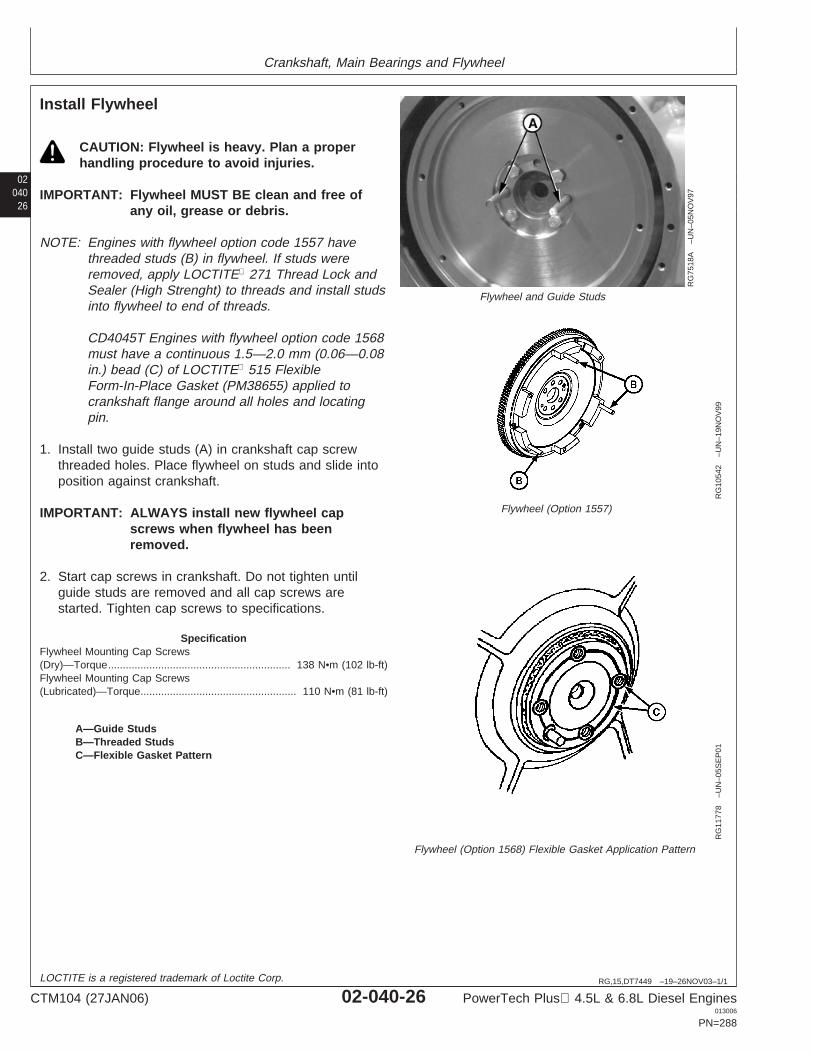
Crankshaft, Main Bearings and Flywheel
02040
26
RG,15,DT7449 –19–26NOV03–1/1
Install Flywheel
RG
7518
A–U
N–0
5NO
V97
Flywheel and Guide Studs
RG
1054
2–U
N–1
9NO
V99
Flywheel (Option 1557)
RG
1177
8–U
N–0
5SE
P01
Flywheel (Option 1568) Flexible Gasket Application Pattern
A—Guide StudsB—Threaded StudsC—Flexible Gasket Pattern
CAUTION: Flywheel is heavy. Plan a properhandling procedure to avoid injuries.
IMPORTANT: Flywheel MUST BE clean and free ofany oil, grease or debris.
NOTE: Engines with flywheel option code 1557 havethreaded studs (B) in flywheel. If studs wereremoved, apply LOCTITE 271 Thread Lock andSealer (High Strenght) to threads and install studsinto flywheel to end of threads.
CD4045T Engines with flywheel option code 1568must have a continuous 1.5—2.0 mm (0.06—0.08in.) bead (C) of LOCTITE 515 FlexibleForm-In-Place Gasket (PM38655) applied tocrankshaft flange around all holes and locatingpin.
1. Install two guide studs (A) in crankshaft cap screwthreaded holes. Place flywheel on studs and slide intoposition against crankshaft.
IMPORTANT: ALWAYS install new flywheel capscrews when flywheel has beenremoved.
2. Start cap screws in crankshaft. Do not tighten untilguide studs are removed and all cap screws arestarted. Tighten cap screws to specifications.
SpecificationFlywheel Mounting Cap Screws(Dry)—Torque 138 N•m (102 lb-ft)..............................................................Flywheel Mounting Cap Screws(Lubricated)—Torque 110 N•m (81 lb-ft).....................................................
LOCTITE is a registered trademark of Loctite Corp.
CTM104 (27JAN06) 02-040-26 PowerTech Plus 4.5L & 6.8L Diesel Engines013006
PN=288
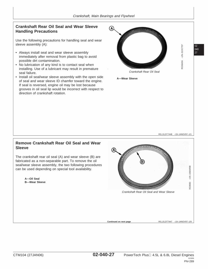
Crankshaft, Main Bearings and Flywheel
0204027
RG,15,DT7448 –19–14NOV97–1/1
Crankshaft Rear Oil Seal and Wear SleeveHandling Precautions
RG
5640
A–U
N–3
1OC
T97
Crankshaft Rear Oil Seal
A—Wear Sleeve
Use the following precautions for handling seal and wearsleeve assembly (A):
• Always install seal and wear sleeve assemblyimmediately after removal from plastic bag to avoidpossible dirt contamination.
• No lubrication of any kind is to contact seal wheninstalling. Use of a lubricant may result in prematureseal failure.
• Install oil seal/wear sleeve assembly with the open sideof seal and wear sleeve ID chamfer toward the engine.If seal is reversed, engine oil may be lost becausegrooves in oil seal lip would be incorrect with respect todirection of crankshaft rotation.
RG,15,DT7447 –19–14NOV97–1/9
Remove Crankshaft Rear Oil Seal and WearSleeve
RG
9083
–UN
–16M
AR
98Crankshaft Rear Oil Seal and Wear Sleeve
A—Oil SealB—Wear Sleeve
The crankshaft rear oil seal (A) and wear sleeve (B) arefabricated as a non-separable part. To remove the oilseal/wear sleeve assembly, the two following procedurescan be used depending on special tool availability.
Continued on next page
CTM104 (27JAN06) 02-040-27 PowerTech Plus 4.5L & 6.8L Diesel Engines013006
PN=289
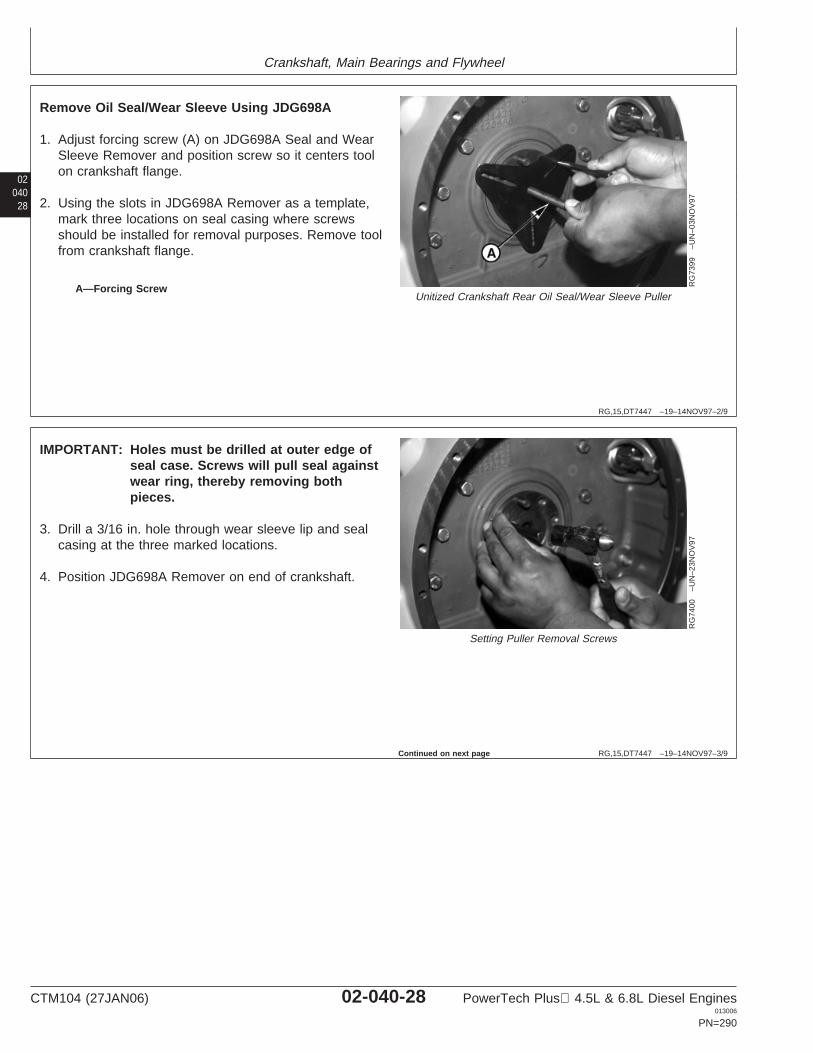
Crankshaft, Main Bearings and Flywheel
02040
28
RG,15,DT7447 –19–14NOV97–2/9
RG
7399
–UN
–03N
OV
97
Unitized Crankshaft Rear Oil Seal/Wear Sleeve PullerA—Forcing Screw
Remove Oil Seal/Wear Sleeve Using JDG698A
1. Adjust forcing screw (A) on JDG698A Seal and WearSleeve Remover and position screw so it centers toolon crankshaft flange.
2. Using the slots in JDG698A Remover as a template,mark three locations on seal casing where screwsshould be installed for removal purposes. Remove toolfrom crankshaft flange.
RG,15,DT7447 –19–14NOV97–3/9
RG
7400
–UN
–23N
OV
97
Setting Puller Removal Screws
IMPORTANT: Holes must be drilled at outer edge ofseal case. Screws will pull seal againstwear ring, thereby removing bothpieces.
3. Drill a 3/16 in. hole through wear sleeve lip and sealcasing at the three marked locations.
4. Position JDG698A Remover on end of crankshaft.
Continued on next page
CTM104 (27JAN06) 02-040-28 PowerTech Plus 4.5L & 6.8L Diesel Engines013006
PN=290
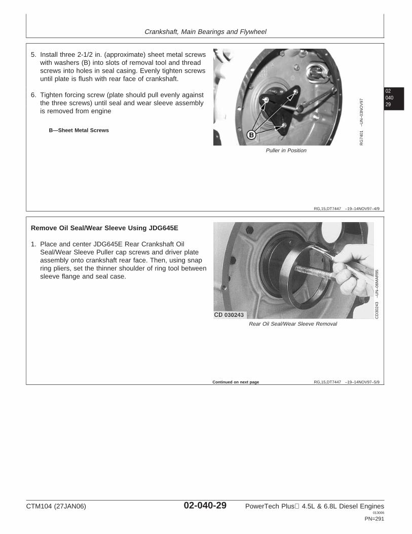
Crankshaft, Main Bearings and Flywheel
0204029
RG,15,DT7447 –19–14NOV97–4/9
RG
7401
–UN
–03N
OV
97
Puller in Position
B—Sheet Metal Screws
5. Install three 2-1/2 in. (approximate) sheet metal screwswith washers (B) into slots of removal tool and threadscrews into holes in seal casing. Evenly tighten screwsuntil plate is flush with rear face of crankshaft.
6. Tighten forcing screw (plate should pull evenly againstthe three screws) until seal and wear sleeve assemblyis removed from engine
RG,15,DT7447 –19–14NOV97–5/9C
D30
243
–UN
–06M
AR
95
Rear Oil Seal/Wear Sleeve Removal
Remove Oil Seal/Wear Sleeve Using JDG645E
1. Place and center JDG645E Rear Crankshaft OilSeal/Wear Sleeve Puller cap screws and driver plateassembly onto crankshaft rear face. Then, using snapring pliers, set the thinner shoulder of ring tool betweensleeve flange and seal case.
Continued on next page
CTM104 (27JAN06) 02-040-29 PowerTech Plus 4.5L & 6.8L Diesel Engines013006
PN=291
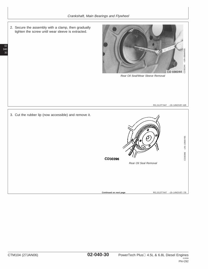
Crankshaft, Main Bearings and Flywheel
02040
30
RG,15,DT7447 –19–14NOV97–6/9
CD
3024
4–U
N–0
6MA
R95
Rear Oil Seal/Wear Sleeve Removal
2. Secure the assembly with a clamp, then graduallytighten the screw until wear sleeve is extracted.
RG,15,DT7447 –19–14NOV97–7/9
CD
3039
6–U
N–1
0MA
Y95
Rear Oil Seal Removal
3. Cut the rubber lip (now accessible) and remove it.
Continued on next page
CTM104 (27JAN06) 02-040-30 PowerTech Plus 4.5L & 6.8L Diesel Engines013006
PN=292
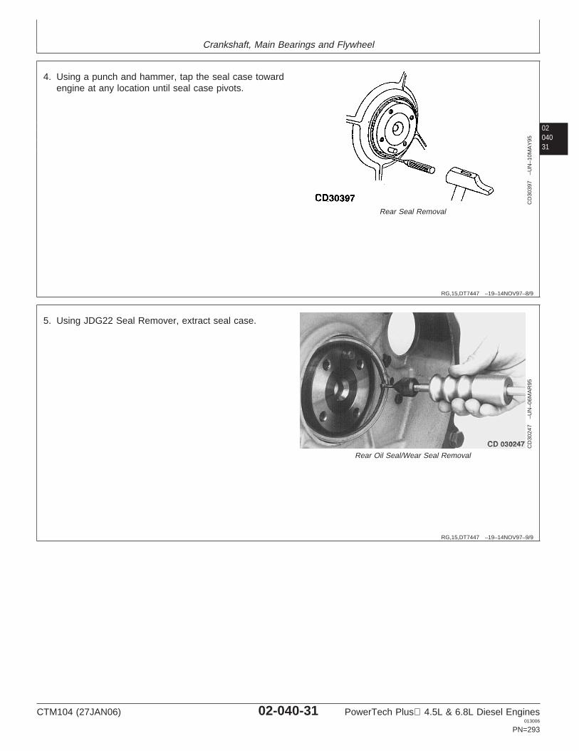
Crankshaft, Main Bearings and Flywheel
0204031
RG,15,DT7447 –19–14NOV97–8/9
CD
3039
7–U
N–1
0MA
Y95
Rear Seal Removal
4. Using a punch and hammer, tap the seal case towardengine at any location until seal case pivots.
RG,15,DT7447 –19–14NOV97–9/9C
D30
247
–UN
–06M
AR
95
Rear Oil Seal/Wear Seal Removal
5. Using JDG22 Seal Remover, extract seal case.
CTM104 (27JAN06) 02-040-31 PowerTech Plus 4.5L & 6.8L Diesel Engines013006
PN=293
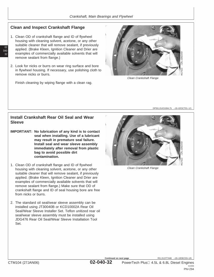
Crankshaft, Main Bearings and Flywheel
02040
32
DPSG,OUO1004,75 –19–02OCT01–1/1
Clean and Inspect Crankshaft Flange
RG
7522
–UN
–23N
OV
97
Clean Crankshaft Flange
1. Clean OD of crankshaft flange and ID of flywheelhousing with cleaning solvent, acetone, or any othersuitable cleaner that will remove sealant, if previouslyapplied. (Brake Kleen, Ignition Cleaner and Drier areexamples of commercially available solvents that willremove sealant from flange.)
2. Look for nicks or burrs on wear ring surface and borein flywheel housing. If necessary, use polishing cloth toremove nicks or burrs.
Finish cleaning by wiping flange with a clean rag.
RG,15,DT7446 –19–10DEC03–1/6
Install Crankshaft Rear Oil Seal and WearSleeve
RG
7522
–UN
–23N
OV
97
Clean Crankshaft Flange
IMPORTANT: No lubrication of any kind is to contactseal when installing. Use of a lubricantmay result in premature seal failure.Install seal and wear sleeve assemblyimmediately after removal from plasticbag to avoid possible dirtcontamination.
1. Clean OD of crankshaft flange and ID of flywheelhousing with cleaning solvent, acetone, or any othersuitable cleaner that will remove sealant, if previouslyapplied. (Brake Kleen, Ignition Cleaner and Drier areexamples of commercially available solvents that willremove sealant from flange.) Make sure that OD ofcrankshaft flange and ID of seal housing bore are freefrom nicks or burrs.
2. The standard oil seal/wear sleeve assembly can beinstalled using JT30040B or KCD10002A Rear OilSeal/Wear Sleeve Installer Set. Teflon unitized rear oilseal/wear sleeve assembly must be installed usingJDG476 Rear Oil Seal/Wear Sleeve Installation ToolSet.
CTM104 (27JAN06) 02-040-32 PowerTech Plus 4.5L & 6.8L Diesel Engines013006
PN=294
Continued on next page

Crankshaft, Main Bearings and Flywheel
0204033
RG,15,DT7446 –19–10DEC03–2/6
RG
9442
–UN
–07J
UL9
8
Rear Oil Seal/Sleeve Pilot Tool
D
C
RG
1177
9–U
N–0
6SE
P01
JT30041 Modification
A—PilotB—Cap ScrewsC—Locating BossD—Crankshaft Face JT30041 Pilot (Early Version)
Install Rear Oil Seal/Wear Sleeve Using JT30040B
NOTE: Early JT30040 Tool Set will need a modification tothe JT30041 Pilot Tool. Remove locating boss (C)flush with crankshaft face (D). Add an “A” suffix tothe JT30041 tool number. (Newer tools with “A”suffix do not need to be modified.)
1. Install JT30041A Pilot (A) from the JT30040BSeal/Wear Sleeve Installer Set on end of crankshaftusing two 38 mm (1-1/2 in.) socket-head cap screws.Tighten both cap screws until they touch base of pilot,then back them off approximately 1/2 turn.
2. Install JT30042 Driver over JT30041A Pilot until drivercross-plate bottoms on pilot. This will properly centerpilot with crankshaft flange.
NOTE: It may be necessary to lift up on pilot to installdriver to full depth over pilot and crankshaftflange.
3. Tighten two pilot socket head cap screws (B) securely.Remove driver from pilot.
Continued on next page
CTM104 (27JAN06) 02-040-33 PowerTech Plus 4.5L & 6.8L Diesel Engines013006
PN=295
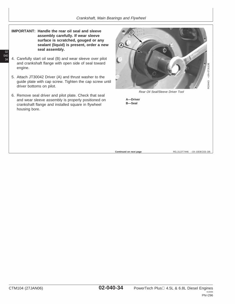
Crankshaft, Main Bearings and Flywheel
02040
34
RG,15,DT7446 –19–10DEC03–3/6
RG
9443
–UN
–07J
UL9
8
Rear Oil Seal/Sleeve Driver Tool
A—DriverB—Seal
IMPORTANT: Handle the rear oil seal and sleeveassembly carefully. If wear sleevesurface is scratched, gouged or anysealant (liquid) is present, order a newseal assembly.
4. Carefully start oil seal (B) and wear sleeve over pilotand crankshaft flange with open side of seal towardengine.
5. Attach JT30042 Driver (A) and thrust washer to theguide plate with cap screw. Tighten the cap screw untildriver bottoms on pilot.
6. Remove seal driver and pilot plate. Check that sealand wear sleeve assembly is properly positioned oncrankshaft flange and installed square in flywheelhousing bore.
Continued on next page
CTM104 (27JAN06) 02-040-34 PowerTech Plus 4.5L & 6.8L Diesel Engines013006
PN=296
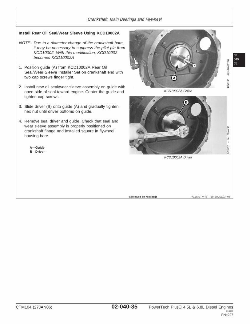
Crankshaft, Main Bearings and Flywheel
0204035
RG,15,DT7446 –19–10DEC03–4/6
RG
9136
–UN
–18M
AY
98
KCD10002A Guide
RG
9137
–UN
–18M
AY
98
KCD10002A Driver
A—GuideB—Driver
Install Rear Oil Seal/Wear Sleeve Using KCD10002A
NOTE: Due to a diameter change of the crankshaft bore,it may be necessary to suppress the pilot pin fromKCD10002. With this modification, KCD10002becomes KCD10002A
1. Position guide (A) from KCD10002A Rear OilSeal/Wear Sleeve Installer Set on crankshaft end withtwo cap screws finger tight.
2. Install new oil seal/wear sleeve assembly on guide withopen side of seal toward engine. Center the guide andtighten cap screws.
3. Slide driver (B) onto guide (A) and gradually tightenhex nut until driver bottoms on guide.
4. Remove seal driver and guide. Check that seal andwear sleeve assembly is properly positioned oncrankshaft flange and installed square in flywheelhousing bore.
Continued on next page
CTM104 (27JAN06) 02-040-35 PowerTech Plus 4.5L & 6.8L Diesel Engines013006
PN=297
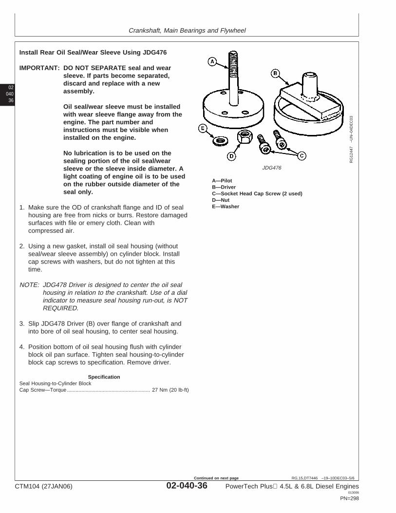
Crankshaft, Main Bearings and Flywheel
02040
36
RG,15,DT7446 –19–10DEC03–5/6
RG
1244
7–U
N–0
4DE
C03
JDG476
A—PilotB—DriverC—Socket Head Cap Screw (2 used)D—NutE—Washer
Install Rear Oil Seal/Wear Sleeve Using JDG476
IMPORTANT: DO NOT SEPARATE seal and wearsleeve. If parts become separated,discard and replace with a newassembly.
Oil seal/wear sleeve must be installedwith wear sleeve flange away from theengine. The part number andinstructions must be visible wheninstalled on the engine.
No lubrication is to be used on thesealing portion of the oil seal/wearsleeve or the sleeve inside diameter. Alight coating of engine oil is to be usedon the rubber outside diameter of theseal only.
1. Make sure the OD of crankshaft flange and ID of sealhousing are free from nicks or burrs. Restore damagedsurfaces with file or emery cloth. Clean withcompressed air.
2. Using a new gasket, install oil seal housing (withoutseal/wear sleeve assembly) on cylinder block. Installcap screws with washers, but do not tighten at thistime.
NOTE: JDG478 Driver is designed to center the oil sealhousing in relation to the crankshaft. Use of a dialindicator to measure seal housing run-out, is NOTREQUIRED.
3. Slip JDG478 Driver (B) over flange of crankshaft andinto bore of oil seal housing, to center seal housing.
4. Position bottom of oil seal housing flush with cylinderblock oil pan surface. Tighten seal housing-to-cylinderblock cap screws to specification. Remove driver.
SpecificationSeal Housing-to-Cylinder BlockCap Screw—Torque 27 Nm (20 lb-ft)..........................................................
CTM104 (27JAN06) 02-040-36 PowerTech Plus 4.5L & 6.8L Diesel Engines013006
PN=298
Continued on next page
Crankshaft, Main Bearings and Flywheel
0204037
RG,15,DT7446 –19–10DEC03–6/6
NOTE: Do NOT apply Loctite or Permatex sealant to thecrankshaft. Seal is already coated with a sealantmaterial.
5. Install JDG477 Pilot (A) on end of crankshaft. Use twosocket head screws (C) to fasten pilot to crankshaft.
IMPORTANT: Handle seal carefully. Do not allow OILto get on any part of wear sleeve O.D.or on seal. Coat RUBBER O.D. of newseal with a light coating of engine oil.Carefully start seal/wear sleeveassembly on JDG477 Pilot (open end ofseal toward engine).
Make sure that plate does not cover thetwo cap screws. Plate must bottom onface of pilot, not on cap screws. Whenthe tool bottoms, seal and wear sleevewill be correctly positioned.
6. Position JDG478 Driver over threaded stud of pilot.Install washer (E) and nut (D) on stud. Tighten nut todraw the driver “in” until it bottoms on pilot.
7. Remove JDG476 tool set from engine.
CTM104 (27JAN06) 02-040-37 PowerTech Plus 4.5L & 6.8L Diesel Engines013006
PN=299
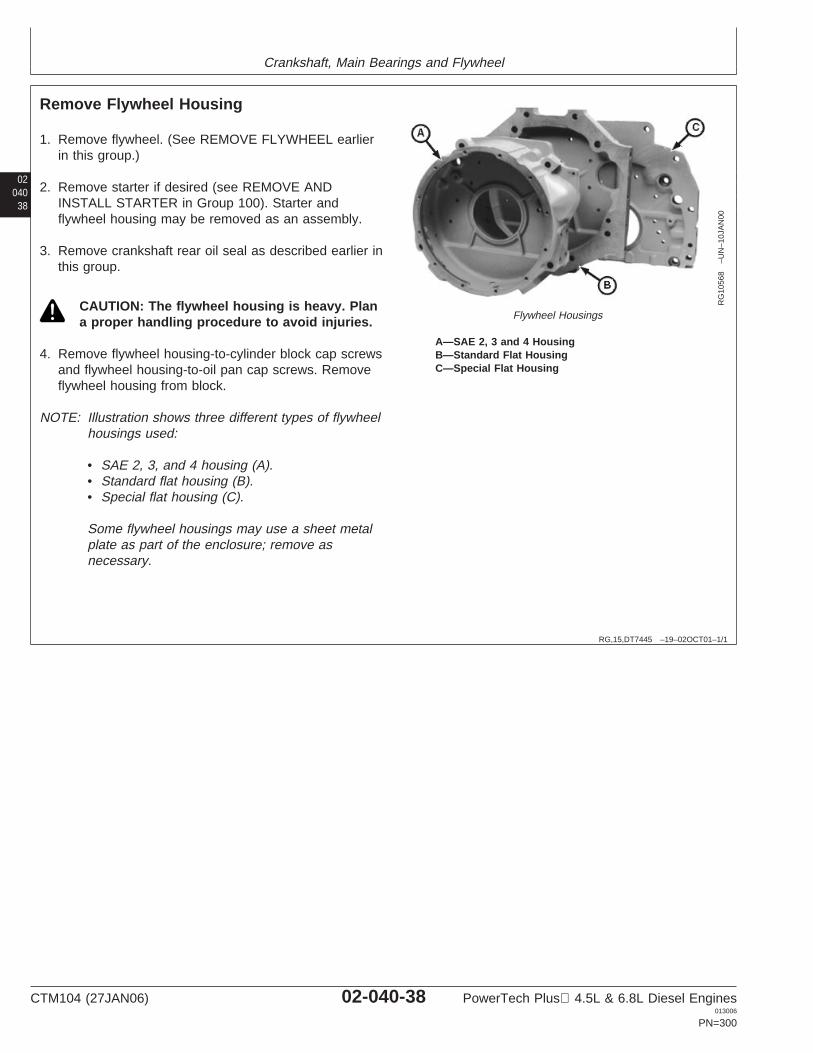
Crankshaft, Main Bearings and Flywheel
02040
38
RG,15,DT7445 –19–02OCT01–1/1
Remove Flywheel Housing
RG
1056
8–U
N–1
0JA
N00
Flywheel Housings
A—SAE 2, 3 and 4 HousingB—Standard Flat HousingC—Special Flat Housing
1. Remove flywheel. (See REMOVE FLYWHEEL earlierin this group.)
2. Remove starter if desired (see REMOVE ANDINSTALL STARTER in Group 100). Starter andflywheel housing may be removed as an assembly.
3. Remove crankshaft rear oil seal as described earlier inthis group.
CAUTION: The flywheel housing is heavy. Plana proper handling procedure to avoid injuries.
4. Remove flywheel housing-to-cylinder block cap screwsand flywheel housing-to-oil pan cap screws. Removeflywheel housing from block.
NOTE: Illustration shows three different types of flywheelhousings used:
• SAE 2, 3, and 4 housing (A).• Standard flat housing (B).• Special flat housing (C).
Some flywheel housings may use a sheet metalplate as part of the enclosure; remove asnecessary.
CTM104 (27JAN06) 02-040-38 PowerTech Plus 4.5L & 6.8L Diesel Engines013006
PN=300
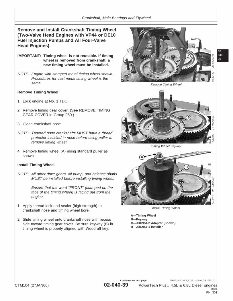
Crankshaft, Main Bearings and Flywheel
0204039
DPSG,OUO1004,1126 –19–01DEC03–1/2
Remove and Install Crankshaft Timing Wheel(Two-Valve Head Engines with VP44 or DE10Fuel Injection Pumps and All Four-ValveHead Engines)
RG
1244
2–U
N–0
2DE
C03
Remove Timing Wheel
RG
1244
3–U
N–0
2DE
C03
Timing Wheel Keyway
RG
1244
4–U
N–0
2DE
C03
Install Timing Wheel
A—Timing WheelB—KeywayC—JDG954-2 Adapter (Shown)D—JDG954-1 Installer
IMPORTANT: Timing wheel is not reusable. If timingwheel is removed from crankshaft, anew timing wheel must be installed.
NOTE: Engine with stamped metal timing wheel shown.Procedures for cast metal timing wheel is thesame.
Remove Timing Wheel
1. Lock engine at No. 1 TDC.
2. Remove timing gear cover. (See REMOVE TIMINGGEAR COVER in Group 050.)
3. Clean crankshaft nose.
NOTE: Tapered nose crankshafts MUST have a threadprotector installed in nose before using puller toremove timing wheel.
4. Remove timing wheel (A) using standard puller asshown.
Install Timing Wheel
NOTE: All other drive gears, oil pump, and balance shaftsMUST be installed before installing timing wheel.
Ensure that the word “FRONT” (stamped on theface of the timing wheel) is facing out from theengine.
1. Apply thread lock and sealer (high strength) tocrankshaft nose and timing wheel bore.
2. Slide timing wheel onto crankshaft nose with recessside toward timing gear cover. Be sure keyway (B) intiming wheel is properly aligned with Woodruff key.
CTM104 (27JAN06) 02-040-39 PowerTech Plus 4.5L & 6.8L Diesel Engines013006
PN=301
Continued on next page
Crankshaft, Main Bearings and Flywheel
02040
40
DPSG,OUO1004,1126 –19–01DEC03–2/2
3. Install tool adapter (C) into nose of crankshaft untiladapter seats in bottom of crankshaft. Use JDG954-2Adapter for straight nose crankshafts or JDG954-7 fortapered nose crankshafts.
4. Install JDG954-1 Installer (D) over adapter.
5. Tighten nut until timing wheel firmly seats against gearface.
6. Remove adapter and installer and install timing gearcover. (See INSTALL TIMING GEAR COVER in Group050.)
RG,15,DT7444 –19–14NOV97–1/3
Remove Crankshaft Main Bearings
1. Drain oil from engine crankcase and remove oil pan.
2. Remove timing gear cover. (See REMOVE TIMINGGEAR COVER in Group 050.)
3. Remove cylinder block front plate. (See REMOVECYLINDER BLOCK FRONT PLATE in Group 050.)
4. Remove flywheel housing. (See REMOVE FLYWHEELHOUSING in this group.)
5. Remove connecting rods from crankshaft. (SeeREMOVE PISTONS AND CONNECTING RODS inGroup 030.)
Continued on next page
CTM104 (27JAN06) 02-040-40 PowerTech Plus 4.5L & 6.8L Diesel Engines013006
PN=302
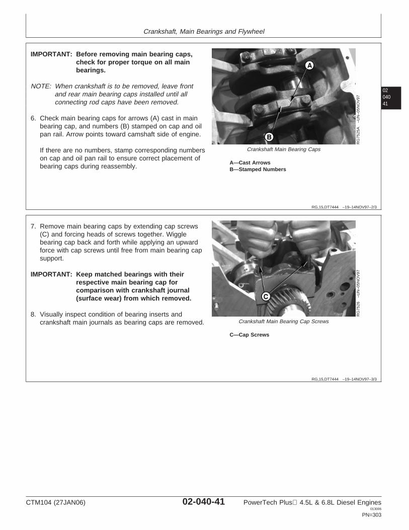
Crankshaft, Main Bearings and Flywheel
0204041
RG,15,DT7444 –19–14NOV97–2/3
RG
7525
A–U
N–0
5NO
V97
Crankshaft Main Bearing Caps
A—Cast ArrowsB—Stamped Numbers
IMPORTANT: Before removing main bearing caps,check for proper torque on all mainbearings.
NOTE: When crankshaft is to be removed, leave frontand rear main bearing caps installed until allconnecting rod caps have been removed.
6. Check main bearing caps for arrows (A) cast in mainbearing cap, and numbers (B) stamped on cap and oilpan rail. Arrow points toward camshaft side of engine.
If there are no numbers, stamp corresponding numberson cap and oil pan rail to ensure correct placement ofbearing caps during reassembly.
RG,15,DT7444 –19–14NOV97–3/3
RG
7526
–UN
–05N
OV
97
Crankshaft Main Bearing Cap Screws
C—Cap Screws
7. Remove main bearing caps by extending cap screws(C) and forcing heads of screws together. Wigglebearing cap back and forth while applying an upwardforce with cap screws until free from main bearing capsupport.
IMPORTANT: Keep matched bearings with theirrespective main bearing cap forcomparison with crankshaft journal(surface wear) from which removed.
8. Visually inspect condition of bearing inserts andcrankshaft main journals as bearing caps are removed.
CTM104 (27JAN06) 02-040-41 PowerTech Plus 4.5L & 6.8L Diesel Engines013006
PN=303
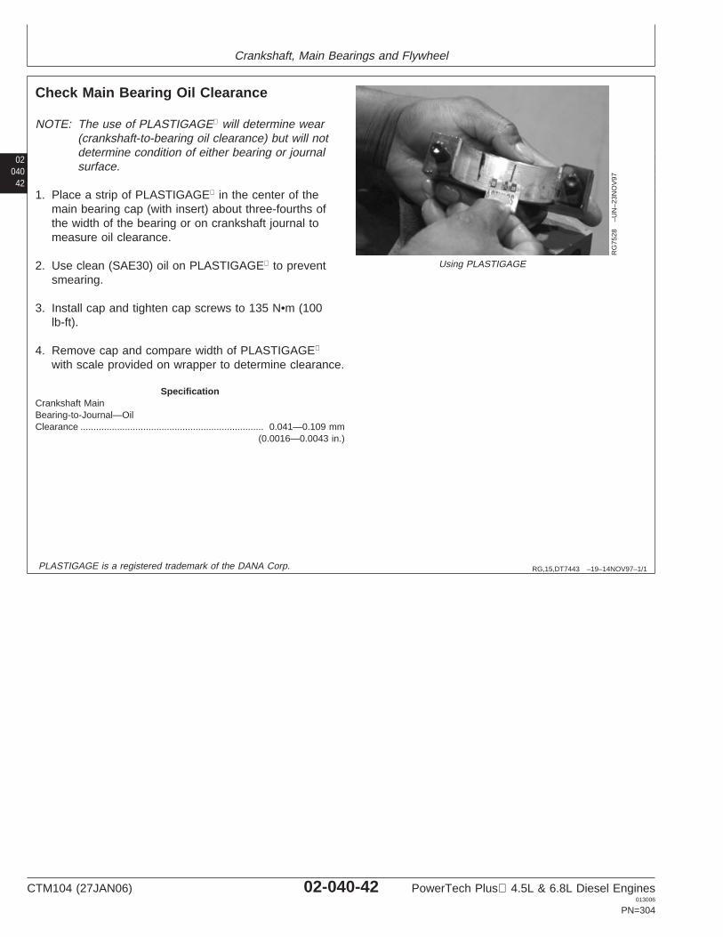
Crankshaft, Main Bearings and Flywheel
02040
42
RG,15,DT7443 –19–14NOV97–1/1
Check Main Bearing Oil Clearance
RG
7528
–UN
–23N
OV
97
Using PLASTIGAGE
NOTE: The use of PLASTIGAGE will determine wear(crankshaft-to-bearing oil clearance) but will notdetermine condition of either bearing or journalsurface.
1. Place a strip of PLASTIGAGE in the center of themain bearing cap (with insert) about three-fourths ofthe width of the bearing or on crankshaft journal tomeasure oil clearance.
2. Use clean (SAE30) oil on PLASTIGAGE to preventsmearing.
3. Install cap and tighten cap screws to 135 N•m (100lb-ft).
4. Remove cap and compare width of PLASTIGAGE
with scale provided on wrapper to determine clearance.
SpecificationCrankshaft MainBearing-to-Journal—OilClearance 0.041—0.109 mm
(0.0016—0.0043 in.)......................................................................
PLASTIGAGE is a registered trademark of the DANA Corp.
CTM104 (27JAN06) 02-040-42 PowerTech Plus 4.5L & 6.8L Diesel Engines013006
PN=304
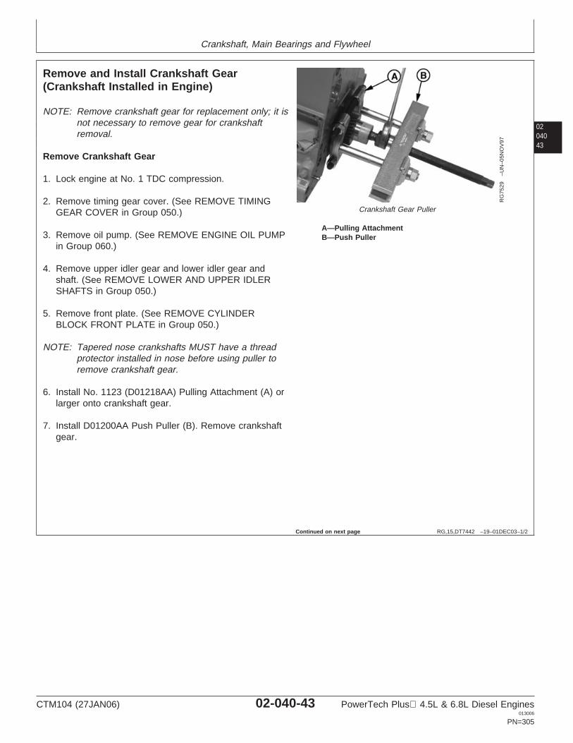
Crankshaft, Main Bearings and Flywheel
0204043
RG,15,DT7442 –19–01DEC03–1/2
Remove and Install Crankshaft Gear(Crankshaft Installed in Engine)
RG
7529
–UN
–05N
OV
97
Crankshaft Gear Puller
A—Pulling AttachmentB—Push Puller
NOTE: Remove crankshaft gear for replacement only; it isnot necessary to remove gear for crankshaftremoval.
Remove Crankshaft Gear
1. Lock engine at No. 1 TDC compression.
2. Remove timing gear cover. (See REMOVE TIMINGGEAR COVER in Group 050.)
3. Remove oil pump. (See REMOVE ENGINE OIL PUMPin Group 060.)
4. Remove upper idler gear and lower idler gear andshaft. (See REMOVE LOWER AND UPPER IDLERSHAFTS in Group 050.)
5. Remove front plate. (See REMOVE CYLINDERBLOCK FRONT PLATE in Group 050.)
NOTE: Tapered nose crankshafts MUST have a threadprotector installed in nose before using puller toremove crankshaft gear.
6. Install No. 1123 (D01218AA) Pulling Attachment (A) orlarger onto crankshaft gear.
7. Install D01200AA Push Puller (B). Remove crankshaftgear.
Continued on next page
CTM104 (27JAN06) 02-040-43 PowerTech Plus 4.5L & 6.8L Diesel Engines013006
PN=305
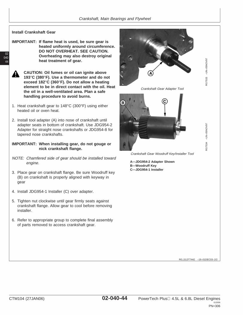
Crankshaft, Main Bearings and Flywheel
02040
44
RG,15,DT7442 –19–01DEC03–2/2
RG
7533
–UN
–05N
OV
97
Crankshaft Gear Adapter Tool
RG
7534
–UN
–05N
OV
97
Crankshaft Gear Woodruff Key/Installer Tool
A—JDG954-2 Adapter ShownB—Woodruff KeyC—JDG954-1 Installer
Install Crankshaft Gear
IMPORTANT: If flame heat is used, be sure gear isheated uniformly around circumference.DO NOT OVERHEAT. SEE CAUTION.Overheating may also destroy originalheat treatment of gear.
CAUTION: Oil fumes or oil can ignite above193°C (380°F). Use a thermometer and do notexceed 182°C (360°F). Do not allow a heatingelement to be in direct contact with the oil. Heatthe oil in a well-ventilated area. Plan a safehandling procedure to avoid burns.
1. Heat crankshaft gear to 148°C (300°F) using eitherheated oil or oven heat.
2. Install tool adapter (A) into nose of crankshaft untiladapter seats in bottom of crankshaft. Use JDG954-2Adapter for straight nose crankshafts or JDG954-8 fortapered nose crankshafts.
IMPORTANT: When installing gear, do not gouge ornick crankshaft flange.
NOTE: Chamfered side of gear should be installed towardengine.
3. Place gear on crankshaft flange. Be sure Woodruff key(B) on crankshaft is properly aligned with keyway ingear
4. Install JDG954-1 Installer (C) over adapter.
5. Tighten nut clockwise until gear firmly seats againstcrankshaft flange. Allow gear to cool before removinginstaller.
6. Refer to appropriate group to complete final assemblyof parts removed to access crankshaft gear.
CTM104 (27JAN06) 02-040-44 PowerTech Plus 4.5L & 6.8L Diesel Engines013006
PN=306
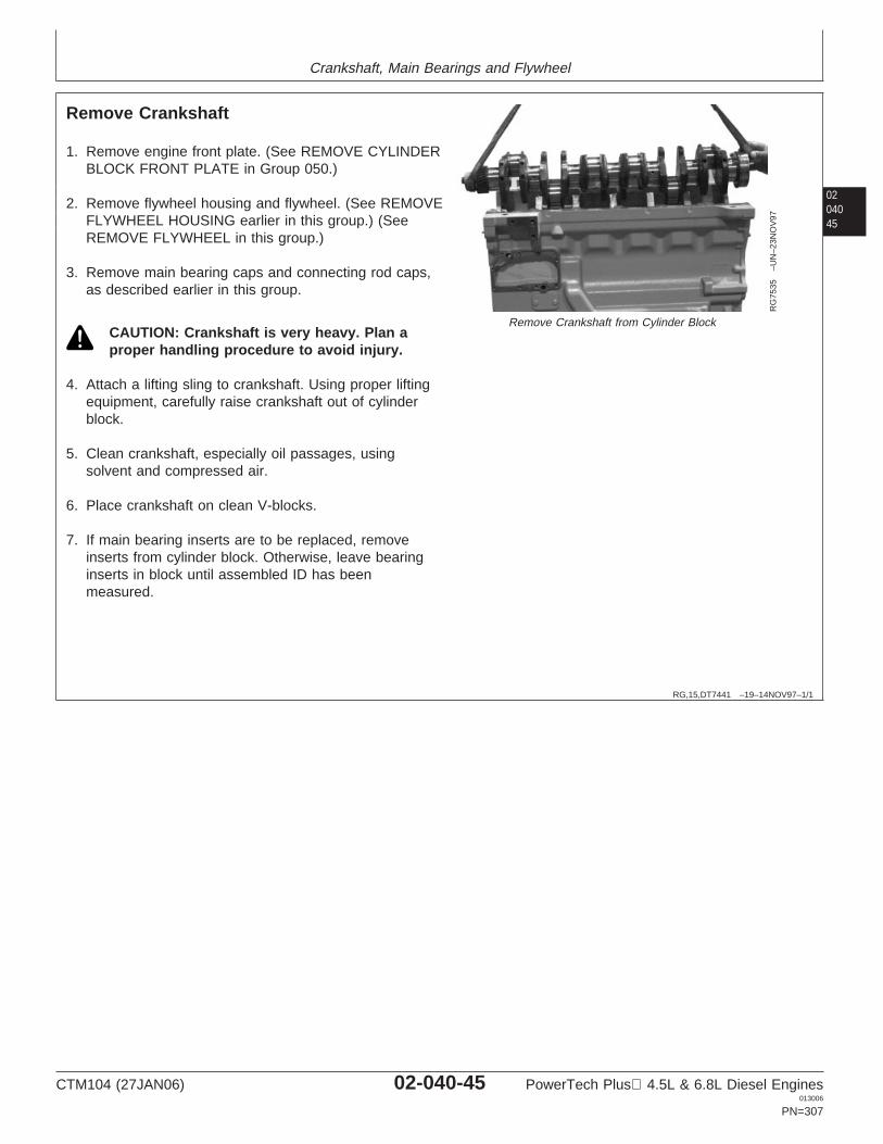
Crankshaft, Main Bearings and Flywheel
0204045
RG,15,DT7441 –19–14NOV97–1/1
Remove Crankshaft
RG
7535
–UN
–23N
OV
97
Remove Crankshaft from Cylinder Block
1. Remove engine front plate. (See REMOVE CYLINDERBLOCK FRONT PLATE in Group 050.)
2. Remove flywheel housing and flywheel. (See REMOVEFLYWHEEL HOUSING earlier in this group.) (SeeREMOVE FLYWHEEL in this group.)
3. Remove main bearing caps and connecting rod caps,as described earlier in this group.
CAUTION: Crankshaft is very heavy. Plan aproper handling procedure to avoid injury.
4. Attach a lifting sling to crankshaft. Using proper liftingequipment, carefully raise crankshaft out of cylinderblock.
5. Clean crankshaft, especially oil passages, usingsolvent and compressed air.
6. Place crankshaft on clean V-blocks.
7. If main bearing inserts are to be replaced, removeinserts from cylinder block. Otherwise, leave bearinginserts in block until assembled ID has beenmeasured.
CTM104 (27JAN06) 02-040-45 PowerTech Plus 4.5L & 6.8L Diesel Engines013006
PN=307
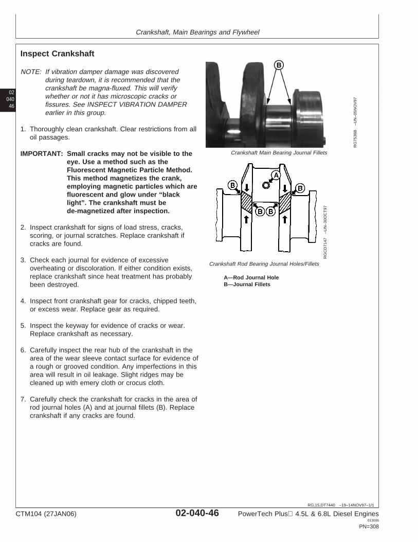
Crankshaft, Main Bearings and Flywheel
02040
46
RG,15,DT7440 –19–14NOV97–1/1
Inspect Crankshaft
RG
7536
B–U
N–0
5NO
V97
Crankshaft Main Bearing Journal Fillets
RG
CD
7147
–UN
–30O
CT
97
Crankshaft Rod Bearing Journal Holes/Fillets
A—Rod Journal HoleB—Journal Fillets
NOTE: If vibration damper damage was discoveredduring teardown, it is recommended that thecrankshaft be magna-fluxed. This will verifywhether or not it has microscopic cracks orfissures. See INSPECT VIBRATION DAMPERearlier in this group.
1. Thoroughly clean crankshaft. Clear restrictions from alloil passages.
IMPORTANT: Small cracks may not be visible to theeye. Use a method such as theFluorescent Magnetic Particle Method.This method magnetizes the crank,employing magnetic particles which arefluorescent and glow under “blacklight”. The crankshaft must bede-magnetized after inspection.
2. Inspect crankshaft for signs of load stress, cracks,scoring, or journal scratches. Replace crankshaft ifcracks are found.
3. Check each journal for evidence of excessiveoverheating or discoloration. If either condition exists,replace crankshaft since heat treatment has probablybeen destroyed.
4. Inspect front crankshaft gear for cracks, chipped teeth,or excess wear. Replace gear as required.
5. Inspect the keyway for evidence of cracks or wear.Replace crankshaft as necessary.
6. Carefully inspect the rear hub of the crankshaft in thearea of the wear sleeve contact surface for evidence ofa rough or grooved condition. Any imperfections in thisarea will result in oil leakage. Slight ridges may becleaned up with emery cloth or crocus cloth.
7. Carefully check the crankshaft for cracks in the area ofrod journal holes (A) and at journal fillets (B). Replacecrankshaft if any cracks are found.
CTM104 (27JAN06) 02-040-46 PowerTech Plus 4.5L & 6.8L Diesel Engines013006
PN=308
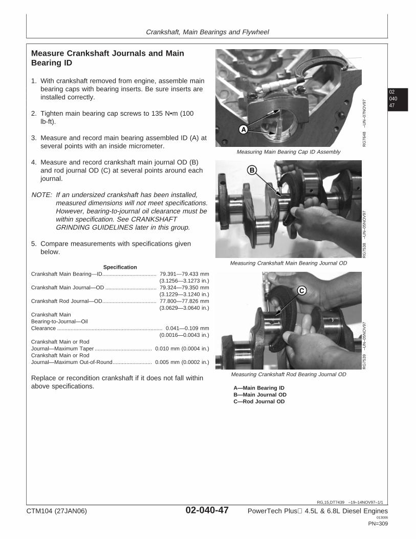
Crankshaft, Main Bearings and Flywheel
0204047
RG,15,DT7439 –19–14NOV97–1/1
Measure Crankshaft Journals and MainBearing ID
RG
7648
–UN
–07N
OV
97
Measuring Main Bearing Cap ID Assembly
RG
7538
–UN
–05N
OV
97
Measuring Crankshaft Main Bearing Journal OD
RG
7539
–UN
–05N
OV
97
Measuring Crankshaft Rod Bearing Journal OD
A—Main Bearing IDB—Main Journal ODC—Rod Journal OD
1. With crankshaft removed from engine, assemble mainbearing caps with bearing inserts. Be sure inserts areinstalled correctly.
2. Tighten main bearing cap screws to 135 N•m (100lb-ft).
3. Measure and record main bearing assembled ID (A) atseveral points with an inside micrometer.
4. Measure and record crankshaft main journal OD (B)and rod journal OD (C) at several points around eachjournal.
NOTE: If an undersized crankshaft has been installed,measured dimensions will not meet specifications.However, bearing-to-journal oil clearance must bewithin specification. See CRANKSHAFTGRINDING GUIDELINES later in this group.
5. Compare measurements with specifications givenbelow.
SpecificationCrankshaft Main Bearing—ID 79.391—79.433 mm
(3.1256—3.1273 in.)....................................
Crankshaft Main Journal—OD 79.324—79.350 mm(3.1229—3.1240 in.)
..................................
Crankshaft Rod Journal—OD 77.800—77.826 mm(3.0629—3.0640 in.)
....................................
Crankshaft MainBearing-to-Journal—OilClearance 0.041—0.109 mm
(0.0016—0.0043 in.)......................................................................
Crankshaft Main or RodJournal—Maximum Taper 0.010 mm (0.0004 in.)......................................Crankshaft Main or RodJournal—Maximum Out-of-Round 0.005 mm (0.0002 in.)..........................
Replace or recondition crankshaft if it does not fall withinabove specifications.
CTM104 (27JAN06) 02-040-47 PowerTech Plus 4.5L & 6.8L Diesel Engines013006
PN=309
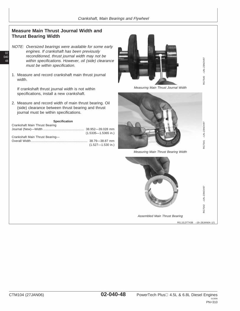
Crankshaft, Main Bearings and Flywheel
02040
48
RG,15,DT7438 –19–28JAN04–1/1
Measure Main Thrust Journal Width andThrust Bearing Width
RG
7540
–UN
–23N
OV
97
Measuring Main Thrust Journal Width
RG
7541
–UN
–23N
OV
97
Measuring Main Thrust Bearing Width
RG
7542
–UN
–23N
OV
97
Assembled Main Thrust Bearing
NOTE: Oversized bearings were available for some earlyengines. If crankshaft has been previouslyreconditioned, thrust journal width may not bewithin specifications. However, oil (side) clearancemust be within specification.
1. Measure and record crankshaft main thrust journalwidth.
If crankshaft thrust journal width is not withinspecifications, install a new crankshaft.
2. Measure and record width of main thrust bearing. Oil(side) clearance between thrust bearing and thrustjournal must be within specifications.
SpecificationCrankshaft Main Thrust BearingJournal (New)—Width 38.952—39.028 mm
(1.5335—1.5365 in.)...............................................
Crankshaft Main Thrust Bearing—Overall Width 38.79—38.87 mm
(1.527—1.530 in.).................................................................
CTM104 (27JAN06) 02-040-48 PowerTech Plus 4.5L & 6.8L Diesel Engines013006
PN=310
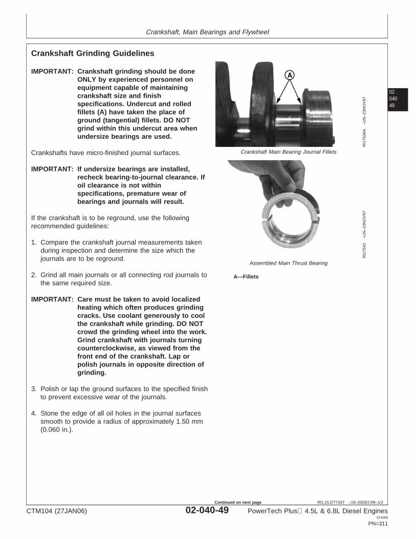
Crankshaft, Main Bearings and Flywheel
0204049
RG,15,DT7437 –19–20DEC99–1/2
Crankshaft Grinding Guidelines
RG
7536
A–U
N–2
3NO
V97
Crankshaft Main Bearing Journal Fillets
RG
7542
–UN
–23N
OV
97
Assembled Main Thrust Bearing
A—Fillets
IMPORTANT: Crankshaft grinding should be doneONLY by experienced personnel onequipment capable of maintainingcrankshaft size and finishspecifications. Undercut and rolledfillets (A) have taken the place ofground (tangential) fillets. DO NOTgrind within this undercut area whenundersize bearings are used.
Crankshafts have micro-finished journal surfaces.
IMPORTANT: If undersize bearings are installed,recheck bearing-to-journal clearance. Ifoil clearance is not withinspecifications, premature wear ofbearings and journals will result.
If the crankshaft is to be reground, use the followingrecommended guidelines:
1. Compare the crankshaft journal measurements takenduring inspection and determine the size which thejournals are to be reground.
2. Grind all main journals or all connecting rod journals tothe same required size.
IMPORTANT: Care must be taken to avoid localizedheating which often produces grindingcracks. Use coolant generously to coolthe crankshaft while grinding. DO NOTcrowd the grinding wheel into the work.Grind crankshaft with journals turningcounterclockwise, as viewed from thefront end of the crankshaft. Lap orpolish journals in opposite direction ofgrinding.
3. Polish or lap the ground surfaces to the specified finishto prevent excessive wear of the journals.
4. Stone the edge of all oil holes in the journal surfacessmooth to provide a radius of approximately 1.50 mm(0.060 in.).
CTM104 (27JAN06) 02-040-49 PowerTech Plus 4.5L & 6.8L Diesel Engines013006
PN=311
Continued on next page
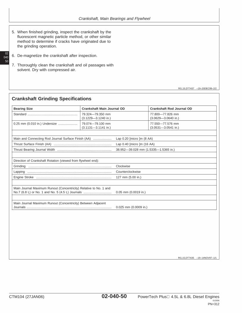
Crankshaft, Main Bearings and Flywheel
02040
50
RG,15,DT7437 –19–20DEC99–2/2
5. When finished grinding, inspect the crankshaft by thefluorescent magnetic particle method, or other similarmethod to determine if cracks have originated due tothe grinding operation.
6. De-magnetize the crankshaft after inspection.
7. Thoroughly clean the crankshaft and oil passages withsolvent. Dry with compressed air.
RG,15,DT7435 –19–14NOV97–1/1
Crankshaft Grinding Specifications
Bearing Size Crankshaft Main Journal OD Crankshaft Rod Journal OD
Standard ......................................................... 79.324—79.350 mm 77.800—77.826 mm(3.1229—3.1240 in.) (3.0629—3.0640 in.)
0.25 mm (0.010 in.) Undersize ...................... 79.074—79.100 mm 77.550—77.576 mm(3.1131—3.1141 in.) (3.0531—3.0541 in.)
Main and Connecting Rod Journal Surface Finish (AA) ..................... Lap 0.20 [micro ]m (8 AA)
Thrust Surface Finish (AA) .................................................................. Lap 0.40 [micro ]m (16 AA)
Thrust Bearing Journal Width .............................................................. 38.952—39.028 mm (1.5335—1.5365 in.)
Direction of Crankshaft Rotation (viewed from flywheel end):
Grinding ............................................................................................... Clockwise
Lapping ................................................................................................ Counterclockwise
Engine Stroke ...................................................................................... 127 mm (5.00 in.)
Main Journal Maximum Runout (Concentricity) Relative to No. 1 andNo.7 (6.8 L) or No. 1 and No. 5 (4.5 L) Journals ................................ 0.05 mm (0.0019 in.)
Main Journal Maximum Runout (Concentricity) Between AdjacentJournals ................................................................................................. 0.025 mm (0.0009 in.)
CTM104 (27JAN06) 02-040-50 PowerTech Plus 4.5L & 6.8L Diesel Engines013006
PN=312
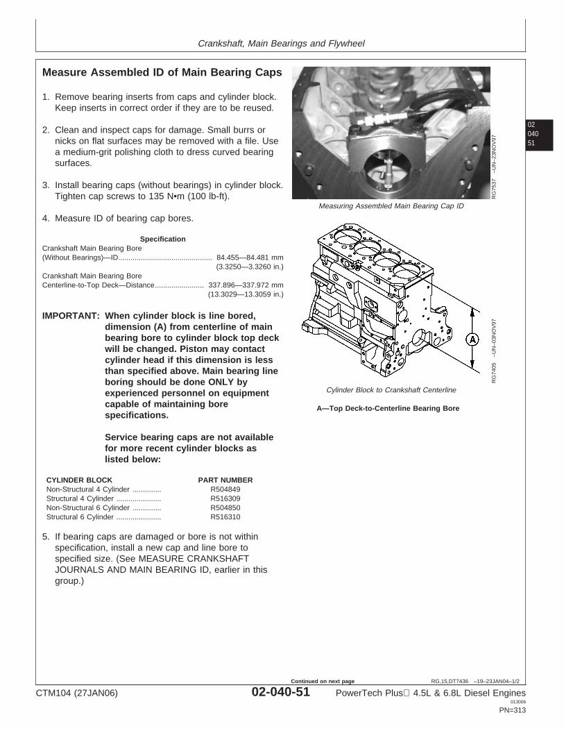
Crankshaft, Main Bearings and Flywheel
0204051
RG,15,DT7436 –19–23JAN04–1/2
Measure Assembled ID of Main Bearing Caps
RG
7537
–UN
–23N
OV
97
Measuring Assembled Main Bearing Cap ID
RG
7405
–UN
–03N
OV
97
Cylinder Block to Crankshaft Centerline
A—Top Deck-to-Centerline Bearing Bore
1. Remove bearing inserts from caps and cylinder block.Keep inserts in correct order if they are to be reused.
2. Clean and inspect caps for damage. Small burrs ornicks on flat surfaces may be removed with a file. Usea medium-grit polishing cloth to dress curved bearingsurfaces.
3. Install bearing caps (without bearings) in cylinder block.Tighten cap screws to 135 N•m (100 lb-ft).
4. Measure ID of bearing cap bores.
SpecificationCrankshaft Main Bearing Bore(Without Bearings)—ID 84.455—84.481 mm
(3.3250—3.3260 in.)..............................................
Crankshaft Main Bearing BoreCenterline-to-Top Deck—Distance 337.896—337.972 mm
(13.3029—13.3059 in.)........................
IMPORTANT: When cylinder block is line bored,dimension (A) from centerline of mainbearing bore to cylinder block top deckwill be changed. Piston may contactcylinder head if this dimension is lessthan specified above. Main bearing lineboring should be done ONLY byexperienced personnel on equipmentcapable of maintaining borespecifications.
Service bearing caps are not availablefor more recent cylinder blocks aslisted below:
CYLINDER BLOCK PART NUMBERNon-Structural 4 Cylinder .............. R504849Structural 4 Cylinder ...................... R516309Non-Structural 6 Cylinder .............. R504850Structural 6 Cylinder ...................... R516310
5. If bearing caps are damaged or bore is not withinspecification, install a new cap and line bore tospecified size. (See MEASURE CRANKSHAFTJOURNALS AND MAIN BEARING ID, earlier in thisgroup.)
CTM104 (27JAN06) 02-040-51 PowerTech Plus 4.5L & 6.8L Diesel Engines013006
PN=313
Continued on next page
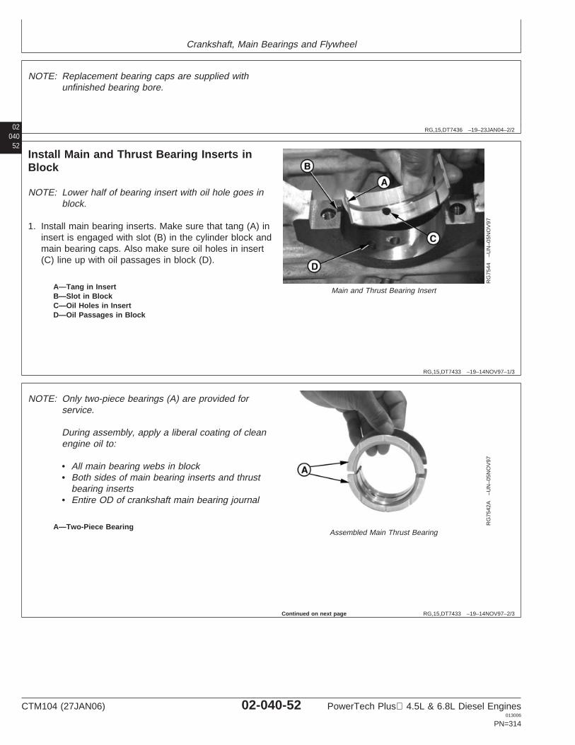
Crankshaft, Main Bearings and Flywheel
02040
RG,15,DT7436 –19–23JAN04–2/2
NOTE: Replacement bearing caps are supplied withunfinished bearing bore.
52
RG,15,DT7433 –19–14NOV97–1/3
Install Main and Thrust Bearing Inserts inBlock
RG
7544
–UN
–05N
OV
97
Main and Thrust Bearing InsertA—Tang in InsertB—Slot in BlockC—Oil Holes in InsertD—Oil Passages in Block
NOTE: Lower half of bearing insert with oil hole goes inblock.
1. Install main bearing inserts. Make sure that tang (A) ininsert is engaged with slot (B) in the cylinder block andmain bearing caps. Also make sure oil holes in insert(C) line up with oil passages in block (D).
RG,15,DT7433 –19–14NOV97–2/3
RG
7542
A–U
N–0
5NO
V97
Assembled Main Thrust BearingA—Two-Piece Bearing
NOTE: Only two-piece bearings (A) are provided forservice.
During assembly, apply a liberal coating of cleanengine oil to:
• All main bearing webs in block• Both sides of main bearing inserts and thrust
bearing inserts• Entire OD of crankshaft main bearing journal
Continued on next page
CTM104 (27JAN06) 02-040-52 PowerTech Plus 4.5L & 6.8L Diesel Engines013006
PN=314
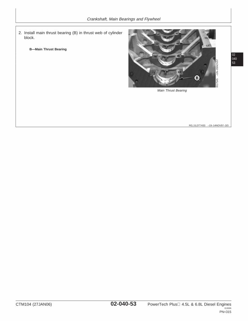
Crankshaft, Main Bearings and Flywheel
0204053
RG,15,DT7433 –19–14NOV97–3/3
RG
7545
–UN
–05N
OV
97
Main Thrust Bearing
B—Main Thrust Bearing
2. Install main thrust bearing (B) in thrust web of cylinderblock.
CTM104 (27JAN06) 02-040-53 PowerTech Plus 4.5L & 6.8L Diesel Engines013006
PN=315
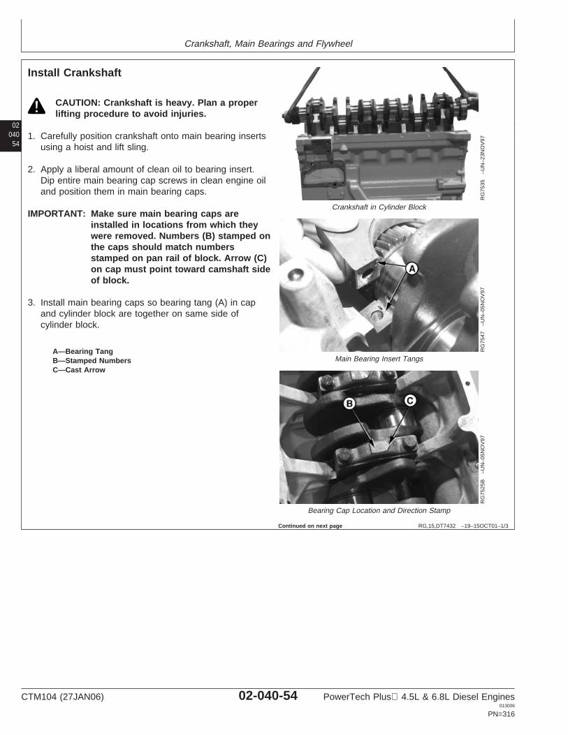
Crankshaft, Main Bearings and Flywheel
02040
54
RG,15,DT7432 –19–15OCT01–1/3
Install Crankshaft
RG
7535
–UN
–23N
OV
97
Crankshaft in Cylinder Block
RG
7547
–UN
–05N
OV
97
Main Bearing Insert Tangs
RG
7525
B–U
N–0
5NO
V97
Bearing Cap Location and Direction Stamp
A—Bearing TangB—Stamped NumbersC—Cast Arrow
CAUTION: Crankshaft is heavy. Plan a properlifting procedure to avoid injuries.
1. Carefully position crankshaft onto main bearing insertsusing a hoist and lift sling.
2. Apply a liberal amount of clean oil to bearing insert.Dip entire main bearing cap screws in clean engine oiland position them in main bearing caps.
IMPORTANT: Make sure main bearing caps areinstalled in locations from which theywere removed. Numbers (B) stamped onthe caps should match numbersstamped on pan rail of block. Arrow (C)on cap must point toward camshaft sideof block.
3. Install main bearing caps so bearing tang (A) in capand cylinder block are together on same side ofcylinder block.
Continued on next page
CTM104 (27JAN06) 02-040-54 PowerTech Plus 4.5L & 6.8L Diesel Engines013006
PN=316
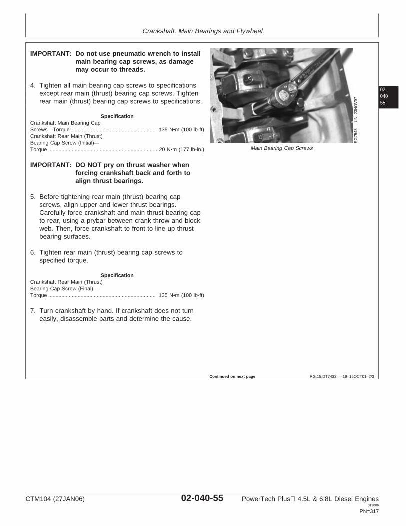
Crankshaft, Main Bearings and Flywheel
0204055
RG,15,DT7432 –19–15OCT01–2/3
RG
7548
–UN
–23N
OV
97
Main Bearing Cap Screws
IMPORTANT: Do not use pneumatic wrench to installmain bearing cap screws, as damagemay occur to threads.
4. Tighten all main bearing cap screws to specificationsexcept rear main (thrust) bearing cap screws. Tightenrear main (thrust) bearing cap screws to specifications.
SpecificationCrankshaft Main Bearing CapScrews—Torque 135 N•m (100 lb-ft)..........................................................Crankshaft Rear Main (Thrust)Bearing Cap Screw (Initial)—Torque 20 N•m (177 lb-in.)..........................................................................
IMPORTANT: DO NOT pry on thrust washer whenforcing crankshaft back and forth toalign thrust bearings.
5. Before tightening rear main (thrust) bearing capscrews, align upper and lower thrust bearings.Carefully force crankshaft and main thrust bearing capto rear, using a prybar between crank throw and blockweb. Then, force crankshaft to front to line up thrustbearing surfaces.
6. Tighten rear main (thrust) bearing cap screws tospecified torque.
SpecificationCrankshaft Rear Main (Thrust)Bearing Cap Screw (Final)—Torque 135 N•m (100 lb-ft).........................................................................
7. Turn crankshaft by hand. If crankshaft does not turneasily, disassemble parts and determine the cause.
Continued on next page
CTM104 (27JAN06) 02-040-55 PowerTech Plus 4.5L & 6.8L Diesel Engines013006
PN=317
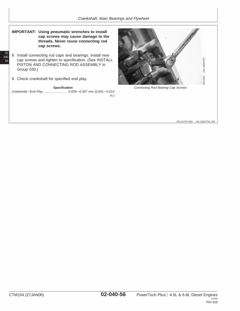
Crankshaft, Main Bearings and Flywheel
02040
56
RG,15,DT7432 –19–15OCT01–3/3
RG
7549
–UN
–23N
OV
97
Connecting Rod Bearing Cap Screws
IMPORTANT: Using pneumatic wrenches to installcap screws may cause damage to thethreads. Never reuse connecting rodcap screws.
8. Install connecting rod caps and bearings. Install newcap screws and tighten to specification. (See INSTALLPISTON AND CONNECTING ROD ASSEMBLY inGroup 030.)
9. Check crankshaft for specified end play.
SpecificationCrankshaft—End Play 0.029—0.357 mm (0.001—0.014
in.)...........................
CTM104 (27JAN06) 02-040-56 PowerTech Plus 4.5L & 6.8L Diesel Engines013006
PN=318
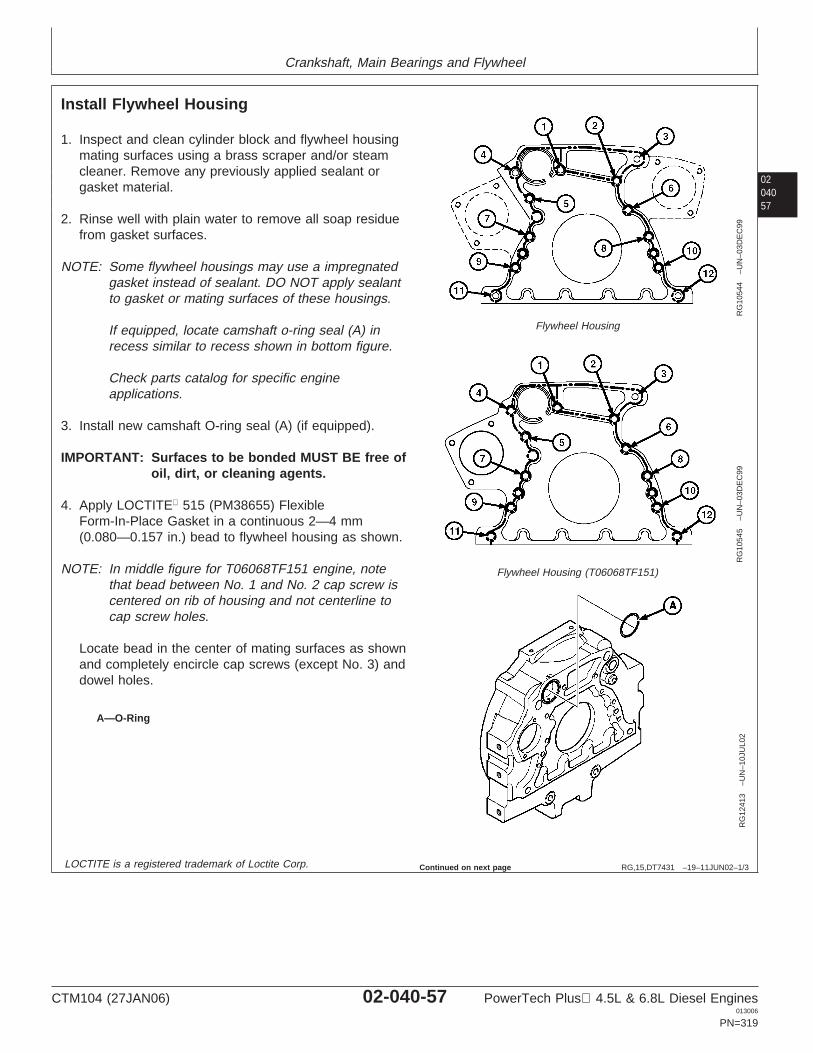
Crankshaft, Main Bearings and Flywheel
0204057
RG,15,DT7431 –19–11JUN02–1/3
Install Flywheel Housing
RG
1054
4–U
N–0
3DE
C99
Flywheel Housing
RG
1054
5–U
N–0
3DE
C99
Flywheel Housing (T06068TF151)
RG
1241
3–U
N–1
0JU
L02
A—O-Ring
1. Inspect and clean cylinder block and flywheel housingmating surfaces using a brass scraper and/or steamcleaner. Remove any previously applied sealant orgasket material.
2. Rinse well with plain water to remove all soap residuefrom gasket surfaces.
NOTE: Some flywheel housings may use a impregnatedgasket instead of sealant. DO NOT apply sealantto gasket or mating surfaces of these housings.
If equipped, locate camshaft o-ring seal (A) inrecess similar to recess shown in bottom figure.
Check parts catalog for specific engineapplications.
3. Install new camshaft O-ring seal (A) (if equipped).
IMPORTANT: Surfaces to be bonded MUST BE free ofoil, dirt, or cleaning agents.
4. Apply LOCTITE 515 (PM38655) FlexibleForm-In-Place Gasket in a continuous 2—4 mm(0.080—0.157 in.) bead to flywheel housing as shown.
NOTE: In middle figure for T06068TF151 engine, notethat bead between No. 1 and No. 2 cap screw iscentered on rib of housing and not centerline tocap screw holes.
Locate bead in the center of mating surfaces as shownand completely encircle cap screws (except No. 3) anddowel holes.
LOCTITE is a registered trademark of Loctite Corp. Continued on next page
CTM104 (27JAN06) 02-040-57 PowerTech Plus 4.5L & 6.8L Diesel Engines013006
PN=319
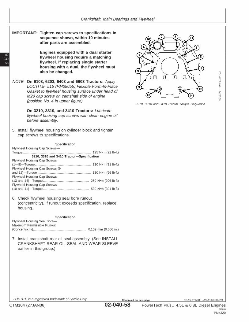
Crankshaft, Main Bearings and Flywheel
02040
58
RG,15,DT7431 –19–11JUN02–2/3
RG
1237
1–U
N–3
1MA
Y02
3210, 3310 and 3410 Tractor Torque Sequence
IMPORTANT: Tighten cap screws to specifications insequence shown, within 10 minutesafter parts are assembled.
Engines equipped with a dual starterflywheel housing require a matchingflywheel. If replacing single starterhousing with a dual, the flywheel mustalso be changed.
NOTE: On 6103, 6203, 6403 and 6603 Tractors: ApplyLOCTITE 515 (PM38655) Flexible Form-In-PlaceGasket to flywheel housing surface under head ofM20 cap screw on camshaft side of engine(position No. 4 in upper figure).
On 3210, 3310, and 3410 Tractors: Lubricateflywheel housing cap screws with clean engine oilbefore assembly.
5. Install flywheel housing on cylinder block and tightencap screws to specifications.
SpecificationFlywheel Housing Cap Screws—Torque 125 N•m (92 lb-ft)...........................................................................
3210, 3310 and 3410 Tractor—SpecificationFlywheel Housing Cap Screws(1—8)—Torque 110 N•m (81 lb-ft)..............................................................Flywheel Housing Cap Screws (9and 12)—Torque 130 N•m (96 lb-ft)...........................................................Flywheel Housing Cap Screws(13 and 14)—Torque 280 N•m (206 lb-ft)...................................................Flywheel Housing Cap Screws(10 and 11)—Torque 530 N•m (391 lb-ft)...................................................
6. Check flywheel housing seal bore runout(concentricity). If runout exceeds specification, replacehousing.
SpecificationFlywheel Housing Seal Bore—Maximum Permissible Runout(Concentricity) 0.152 mm (0.006 in.)...........................................................
7. Install crankshaft rear oil seal assembly. (See INSTALLCRANKSHAFT REAR OIL SEAL AND WEAR SLEEVEearlier in this group.)
LOCTITE is a registered trademark of Loctite Corp.
CTM104 (27JAN06) 02-040-58 PowerTech Plus 4.5L & 6.8L Diesel Engines013006
PN=320
Continued on next page

Crankshaft, Main Bearings and Flywheel
0204059
RG,15,DT7431 –19–11JUN02–3/3
8. If torque converter access hole plug was removed,apply LOCTITE 277 to plug and install.
NOTE: Some flywheel housings may use a sheet metalplate as part of the enclosure, install asnecessary.
LOCTITE is a registered trademark of Loctite Corp.
CTM104 (27JAN06) 02-040-59 PowerTech Plus 4.5L & 6.8L Diesel Engines013006
PN=321
Crankshaft, Main Bearings and Flywheel
02040
60
RG,15,DT7430 –19–19JUN02–1/1
Complete Final Assembly
Use new gaskets and O-rings during final engineassembly. Clean all engine components as necessaryprior to assembly.
1. Install oil bypass valve assembly in front face ofblock. (See REMOVE, INSPECT AND INSTALLOIL BYPASS VALVE in Group 060)
2. Install front plate. (See INSTALL CYLINDERBLOCK FRONT PLATE in Group 050.)
3. Install balancer shafts (if equipped). (See INSTALLAND TIME BALANCER SHAFTS in Group 050.)
4. Install timing gear train and camshaft. (SeeINSTALL CAMSHAFT in Group 050.)
5. Install oil pump assembly. (See INSTALL ENGINEOIL PUMP in Group 060.)
6. If equipped with cartridge type oil pressureregulating valve, install valve. (See REMOVE ANDINSTALL OIL PRESSURE REGULATING VALVE inGroup 060.)
7. Install timing gear cover gasket and timing gearcover. (See INSTALL TIMING GEAR COVER inGroup 050.)
8. If equipped with spring, plunger and seat type oilpressure regulating valve, install valve assembly.(See REMOVE AND INSTALL OIL PRESSUREREGULATING VALVE in Group 060.)
9. Install front oil seal. (See REPLACE FRONTCRANKSHAFT OIL SEAL AND WEAR SLEEVE inthis group.)
10. Install oil pan. (See INSTALL OIL PAN in Group060.)
11. Install crankshaft pulley, or vibration damper. (SeeINSTALL PULLEY OR VIBRATION DAMPER ANDPULLEY in this group.)
12. Install push rods, and rocker arm assembly. (SeeINSTALL ROCKER ARM ASSEMBLY in Group020.)
13. Install fuel supply pump. See Section 02, Group090 of CTM207 (Mechanical Fuel Systems),CTM170 (Level 4 Electronic Fuel Systems),CTM331 (Level 12 Electronic Fuel Systems),CTM284 (Level 1 Electronic Fuel Systems) orCTM220 (Level 11 Electronic Fuel Systems withDenso High Pressure Common Rail).
14. Install injection pump. See Section 02, Group 090of CTM207 (Mechanical Fuel Systems), CTM170(Level 4 Electronic Fuel Systems), CTM331 (Level12 Electronic Fuel Systems), CTM284 (Level 1Electronic Fuel Systems) or CTM220 (Level 11Electronic Fuel Systems with Denso HighPressure Common Rail).
15. Install starter motor. (See REMOVE ANDINSTALL STARTER in Group 100.)
16. Adjust valve clearance. (See CHECK ANDADJUST VALVE CLEARANCE in Group 020 fortwo-valve head engines or CHECK AND ADJUSTVALVE CLEARANCE in Group 21 for four-valvehead engines.)
17. Install and adjust poly-vee belts. (See Group 070.)
18. Fill engine with clean oil and proper coolant. (SeeSection 01, Group 002)
19. Perform engine break-in. (See PERFORMENGINE BREAK-IN in Group 010.)
CTM104 (27JAN06) 02-040-60 PowerTech Plus 4.5L & 6.8L Diesel Engines013006
PN=322
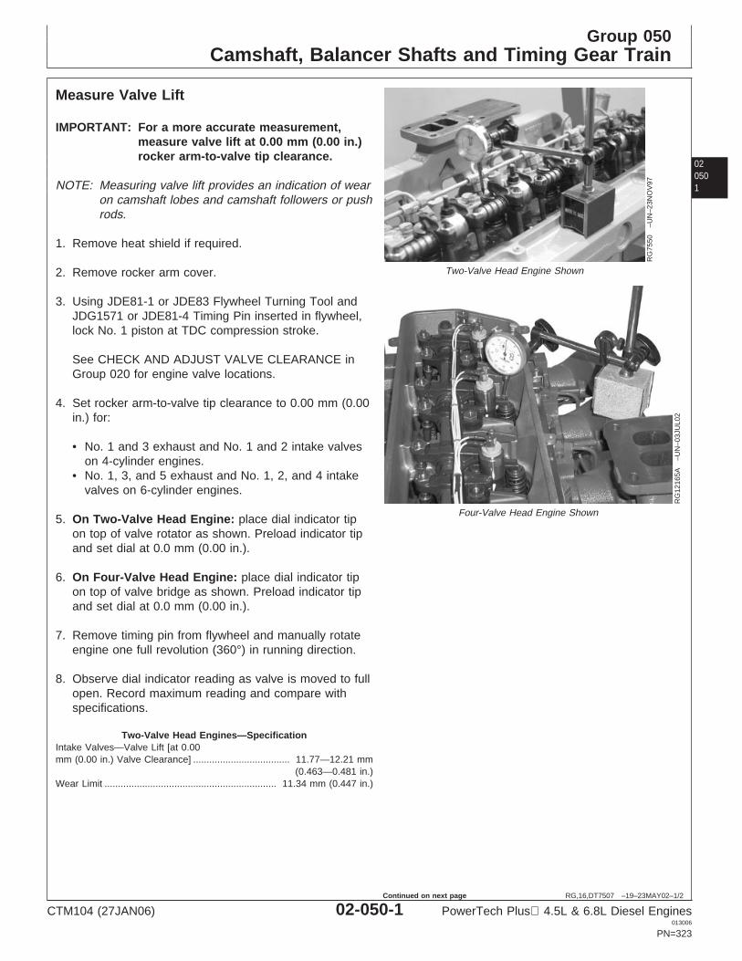
Group 050Camshaft, Balancer Shafts and Timing Gear Train
020501
RG,16,DT7507 –19–23MAY02–1/2
Measure Valve Lift
RG
7550
–UN
–23N
OV
97
Two-Valve Head Engine Shown
RG
1216
5A–U
N–0
3JU
L02
Four-Valve Head Engine Shown
IMPORTANT: For a more accurate measurement,measure valve lift at 0.00 mm (0.00 in.)rocker arm-to-valve tip clearance.
NOTE: Measuring valve lift provides an indication of wearon camshaft lobes and camshaft followers or pushrods.
1. Remove heat shield if required.
2. Remove rocker arm cover.
3. Using JDE81-1 or JDE83 Flywheel Turning Tool andJDG1571 or JDE81-4 Timing Pin inserted in flywheel,lock No. 1 piston at TDC compression stroke.
See CHECK AND ADJUST VALVE CLEARANCE inGroup 020 for engine valve locations.
4. Set rocker arm-to-valve tip clearance to 0.00 mm (0.00in.) for:
• No. 1 and 3 exhaust and No. 1 and 2 intake valveson 4-cylinder engines.
• No. 1, 3, and 5 exhaust and No. 1, 2, and 4 intakevalves on 6-cylinder engines.
5. On Two-Valve Head Engine: place dial indicator tipon top of valve rotator as shown. Preload indicator tipand set dial at 0.0 mm (0.00 in.).
6. On Four-Valve Head Engine: place dial indicator tipon top of valve bridge as shown. Preload indicator tipand set dial at 0.0 mm (0.00 in.).
7. Remove timing pin from flywheel and manually rotateengine one full revolution (360°) in running direction.
8. Observe dial indicator reading as valve is moved to fullopen. Record maximum reading and compare withspecifications.
Two-Valve Head Engines—SpecificationIntake Valves—Valve Lift [at 0.00mm (0.00 in.) Valve Clearance] 11.77—12.21 mm
(0.463—0.481 in.)....................................
Wear Limit 11.34 mm (0.447 in.)................................................................
CTM104 (27JAN06) 02-050-1 PowerTech Plus 4.5L & 6.8L Diesel Engines013006
PN=323
Continued on next page
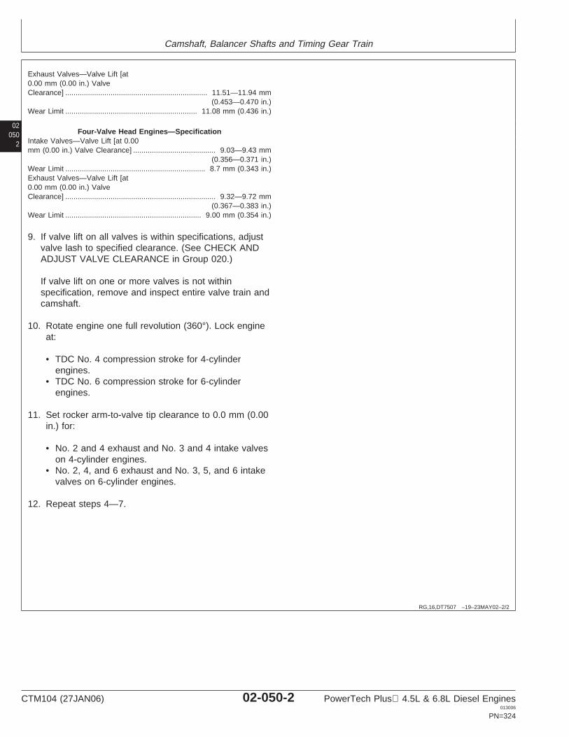
Camshaft, Balancer Shafts and Timing Gear Train
02050
2
RG,16,DT7507 –19–23MAY02–2/2
Exhaust Valves—Valve Lift [at0.00 mm (0.00 in.) ValveClearance] 11.51—11.94 mm
(0.453—0.470 in.).....................................................................
Wear Limit 11.08 mm (0.436 in.)................................................................
Four-Valve Head Engines—SpecificationIntake Valves—Valve Lift [at 0.00mm (0.00 in.) Valve Clearance] 9.03—9.43 mm
(0.356—0.371 in.)........................................
Wear Limit 8.7 mm (0.343 in.)....................................................................Exhaust Valves—Valve Lift [at0.00 mm (0.00 in.) ValveClearance] 9.32—9.72 mm
(0.367—0.383 in.).........................................................................
Wear Limit 9.00 mm (0.354 in.)..................................................................
9. If valve lift on all valves is within specifications, adjustvalve lash to specified clearance. (See CHECK ANDADJUST VALVE CLEARANCE in Group 020.)
If valve lift on one or more valves is not withinspecification, remove and inspect entire valve train andcamshaft.
10. Rotate engine one full revolution (360°). Lock engineat:
• TDC No. 4 compression stroke for 4-cylinderengines.
• TDC No. 6 compression stroke for 6-cylinderengines.
11. Set rocker arm-to-valve tip clearance to 0.0 mm (0.00in.) for:
• No. 2 and 4 exhaust and No. 3 and 4 intake valveson 4-cylinder engines.
• No. 2, 4, and 6 exhaust and No. 3, 5, and 6 intakevalves on 6-cylinder engines.
12. Repeat steps 4—7.
CTM104 (27JAN06) 02-050-2 PowerTech Plus 4.5L & 6.8L Diesel Engines013006
PN=324
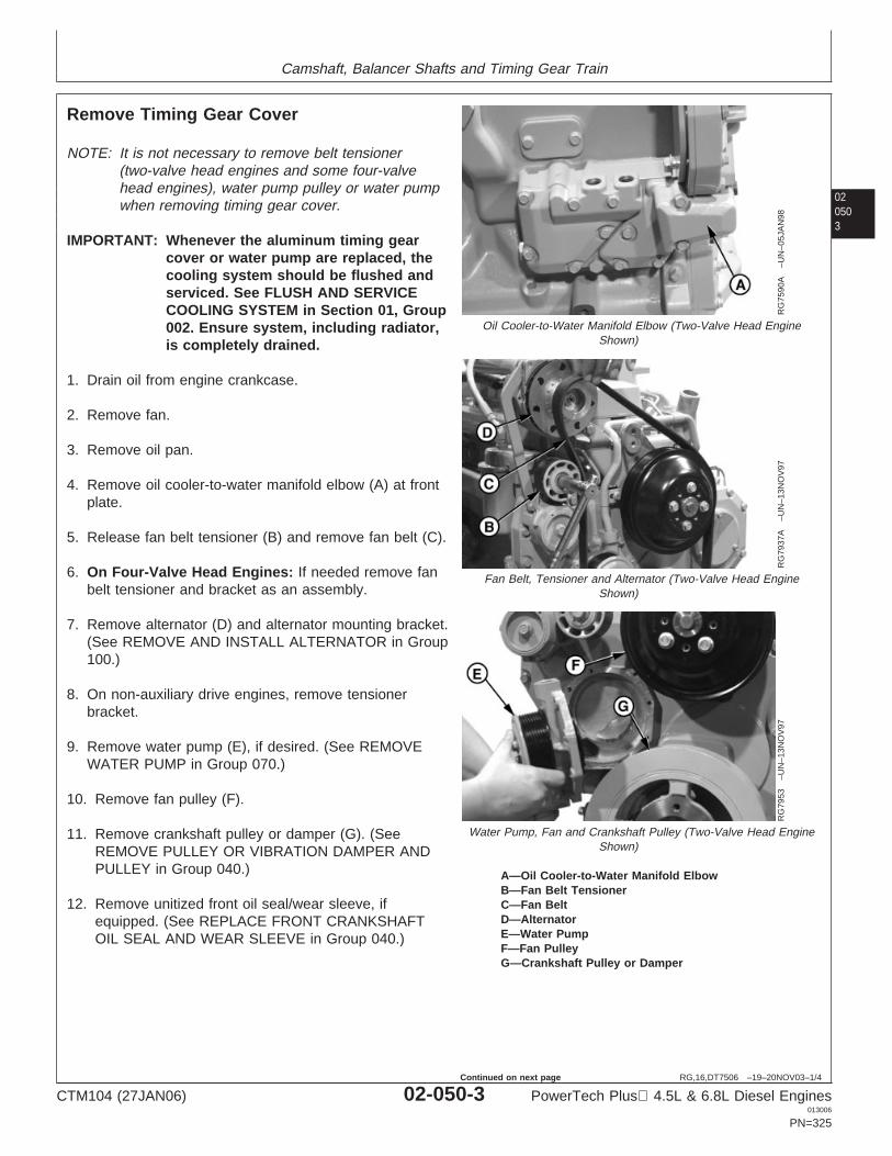
Camshaft, Balancer Shafts and Timing Gear Train
020503
RG,16,DT7506 –19–20NOV03–1/4
Remove Timing Gear Cover
RG
7590
A–U
N–0
5JA
N98
Oil Cooler-to-Water Manifold Elbow (Two-Valve Head EngineShown)
RG
7937
A–U
N–1
3NO
V97
Fan Belt, Tensioner and Alternator (Two-Valve Head EngineShown)
RG
7953
–UN
–13N
OV
97
Water Pump, Fan and Crankshaft Pulley (Two-Valve Head EngineShown)
A—Oil Cooler-to-Water Manifold ElbowB—Fan Belt TensionerC—Fan BeltD—AlternatorE—Water PumpF—Fan PulleyG—Crankshaft Pulley or Damper
NOTE: It is not necessary to remove belt tensioner(two-valve head engines and some four-valvehead engines), water pump pulley or water pumpwhen removing timing gear cover.
IMPORTANT: Whenever the aluminum timing gearcover or water pump are replaced, thecooling system should be flushed andserviced. See FLUSH AND SERVICECOOLING SYSTEM in Section 01, Group002. Ensure system, including radiator,is completely drained.
1. Drain oil from engine crankcase.
2. Remove fan.
3. Remove oil pan.
4. Remove oil cooler-to-water manifold elbow (A) at frontplate.
5. Release fan belt tensioner (B) and remove fan belt (C).
6. On Four-Valve Head Engines: If needed remove fanbelt tensioner and bracket as an assembly.
7. Remove alternator (D) and alternator mounting bracket.(See REMOVE AND INSTALL ALTERNATOR in Group100.)
8. On non-auxiliary drive engines, remove tensionerbracket.
9. Remove water pump (E), if desired. (See REMOVEWATER PUMP in Group 070.)
10. Remove fan pulley (F).
11. Remove crankshaft pulley or damper (G). (SeeREMOVE PULLEY OR VIBRATION DAMPER ANDPULLEY in Group 040.)
12. Remove unitized front oil seal/wear sleeve, ifequipped. (See REPLACE FRONT CRANKSHAFTOIL SEAL AND WEAR SLEEVE in Group 040.)
CTM104 (27JAN06) 02-050-3 PowerTech Plus 4.5L & 6.8L Diesel Engines013006
PN=325
Continued on next page
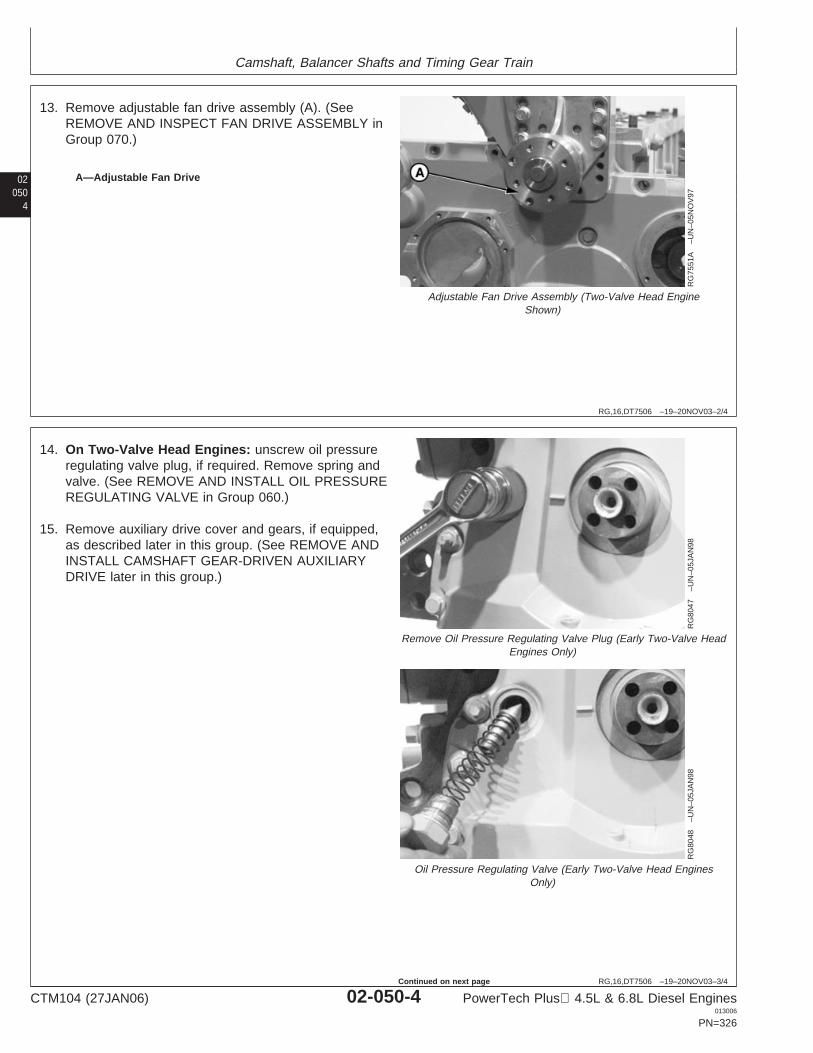
Camshaft, Balancer Shafts and Timing Gear Train
02050
4
RG,16,DT7506 –19–20NOV03–2/4
RG
7551
A–U
N–0
5NO
V97
Adjustable Fan Drive Assembly (Two-Valve Head EngineShown)
A—Adjustable Fan Drive
13. Remove adjustable fan drive assembly (A). (SeeREMOVE AND INSPECT FAN DRIVE ASSEMBLY inGroup 070.)
RG,16,DT7506 –19–20NOV03–3/4
RG
8047
–UN
–05J
AN
98
Remove Oil Pressure Regulating Valve Plug (Early Two-Valve HeadEngines Only)
RG
8048
–UN
–05J
AN
98
Oil Pressure Regulating Valve (Early Two-Valve Head EnginesOnly)
14. On Two-Valve Head Engines: unscrew oil pressureregulating valve plug, if required. Remove spring andvalve. (See REMOVE AND INSTALL OIL PRESSUREREGULATING VALVE in Group 060.)
15. Remove auxiliary drive cover and gears, if equipped,as described later in this group. (See REMOVE ANDINSTALL CAMSHAFT GEAR-DRIVEN AUXILIARYDRIVE later in this group.)
CTM104 (27JAN06) 02-050-4 PowerTech Plus 4.5L & 6.8L Diesel Engines013006
PN=326
Continued on next page
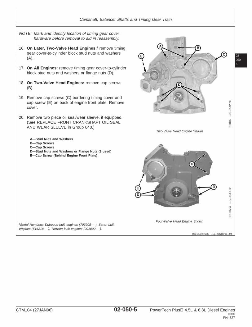
Camshaft, Balancer Shafts and Timing Gear Train
020505
RG,16,DT7506 –19–20NOV03–4/4
RG
9105
–UN
–01A
PR
98
Two-Valve Head Engine Shown
RG
1235
3A–U
N–0
3JU
L02
Four-Valve Head Engine Shown
A—Stud Nuts and WashersB—Cap ScrewsC—Cap ScrewsD—Stud Nuts and Washers or Flange Nuts (9 used)E—Cap Screw (Behind Engine Front Plate)
NOTE: Mark and identify location of timing gear coverhardware before removal to aid in reassembly.
16. On Later, Two-Valve Head Engines:1 remove timinggear cover-to-cylinder block stud nuts and washers(A).
17. On All Engines: remove timing gear cover-to-cylinderblock stud nuts and washers or flange nuts (D).
18. On Two-Valve Head Engines: remove cap screws(B).
19. Remove cap screws (C) bordering timing cover andcap screw (E) on back of engine front plate. Removecover.
20. Remove two piece oil seal/wear sleeve, if equipped.(See REPLACE FRONT CRANKSHAFT OIL SEALAND WEAR SLEEVE in Group 040.)
1Serial Numbers: Dubuque-built engines (703905— ), Saran-builtengines (516218— ), Torreon-built engines (001000— ).
CTM104 (27JAN06) 02-050-5 PowerTech Plus 4.5L & 6.8L Diesel Engines013006
PN=327
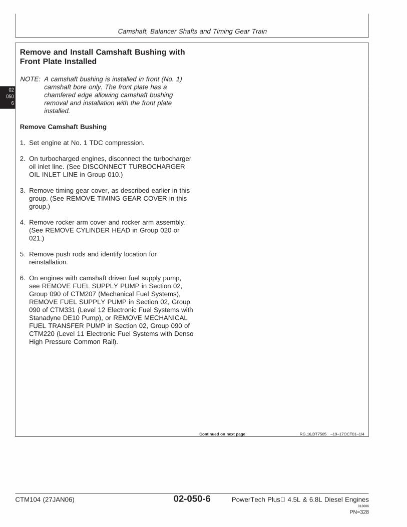
Camshaft, Balancer Shafts and Timing Gear Train
02050
6
RG,16,DT7505 –19–17OCT01–1/4
Remove and Install Camshaft Bushing withFront Plate Installed
NOTE: A camshaft bushing is installed in front (No. 1)camshaft bore only. The front plate has achamfered edge allowing camshaft bushingremoval and installation with the front plateinstalled.
Remove Camshaft Bushing
1. Set engine at No. 1 TDC compression.
2. On turbocharged engines, disconnect the turbochargeroil inlet line. (See DISCONNECT TURBOCHARGEROIL INLET LINE in Group 010.)
3. Remove timing gear cover, as described earlier in thisgroup. (See REMOVE TIMING GEAR COVER in thisgroup.)
4. Remove rocker arm cover and rocker arm assembly.(See REMOVE CYLINDER HEAD in Group 020 or021.)
5. Remove push rods and identify location forreinstallation.
6. On engines with camshaft driven fuel supply pump,see REMOVE FUEL SUPPLY PUMP in Section 02,Group 090 of CTM207 (Mechanical Fuel Systems),REMOVE FUEL SUPPLY PUMP in Section 02, Group090 of CTM331 (Level 12 Electronic Fuel Systems withStanadyne DE10 Pump), or REMOVE MECHANICALFUEL TRANSFER PUMP in Section 02, Group 090 ofCTM220 (Level 11 Electronic Fuel Systems with DensoHigh Pressure Common Rail).
Continued on next page
CTM104 (27JAN06) 02-050-6 PowerTech Plus 4.5L & 6.8L Diesel Engines013006
PN=328
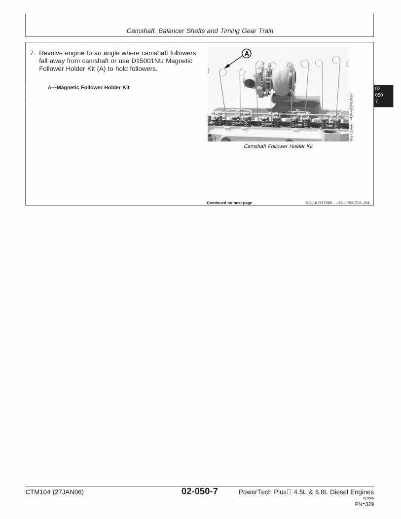
Camshaft, Balancer Shafts and Timing Gear Train
020507
RG,16,DT7505 –19–17OCT01–2/4
RG
7556
A–U
N–0
5NO
V97
Camshaft Follower Holder Kit
A—Magnetic Follower Holder Kit
7. Revolve engine to an angle where camshaft followersfall away from camshaft or use D15001NU MagneticFollower Holder Kit (A) to hold followers.
Continued on next page
CTM104 (27JAN06) 02-050-7 PowerTech Plus 4.5L & 6.8L Diesel Engines013006
PN=329
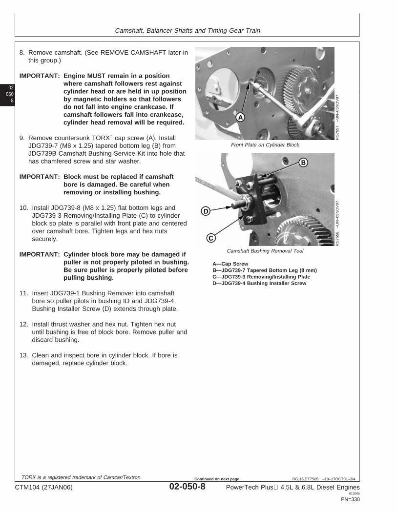
Camshaft, Balancer Shafts and Timing Gear Train
02050
8
RG,16,DT7505 –19–17OCT01–3/4
RG
7557
–UN
–05N
OV
97
Front Plate on Cylinder Block
RG
7558
–UN
–05N
OV
97
Camshaft Bushing Removal Tool
A—Cap ScrewB—JDG739-7 Tapered Bottom Leg (8 mm)C—JDG739-3 Removing/Installing PlateD—JDG739-4 Bushing Installer Screw
8. Remove camshaft. (See REMOVE CAMSHAFT later inthis group.)
IMPORTANT: Engine MUST remain in a positionwhere camshaft followers rest againstcylinder head or are held in up positionby magnetic holders so that followersdo not fall into engine crankcase. Ifcamshaft followers fall into crankcase,cylinder head removal will be required.
9. Remove countersunk TORX cap screw (A). InstallJDG739-7 (M8 x 1.25) tapered bottom leg (B) fromJDG739B Camshaft Bushing Service Kit into hole thathas chamfered screw and star washer.
IMPORTANT: Block must be replaced if camshaftbore is damaged. Be careful whenremoving or installing bushing.
10. Install JDG739-8 (M8 x 1.25) flat bottom legs andJDG739-3 Removing/Installing Plate (C) to cylinderblock so plate is parallel with front plate and centeredover camshaft bore. Tighten legs and hex nutssecurely.
IMPORTANT: Cylinder block bore may be damaged ifpuller is not properly piloted in bushing.Be sure puller is properly piloted beforepulling bushing.
11. Insert JDG739-1 Bushing Remover into camshaftbore so puller pilots in bushing ID and JDG739-4Bushing Installer Screw (D) extends through plate.
12. Install thrust washer and hex nut. Tighten hex nutuntil bushing is free of block bore. Remove puller anddiscard bushing.
13. Clean and inspect bore in cylinder block. If bore isdamaged, replace cylinder block.
TORX is a registered trademark of Camcar/Textron.
CTM104 (27JAN06) 02-050-8 PowerTech Plus 4.5L & 6.8L Diesel Engines013006
PN=330
Continued on next page
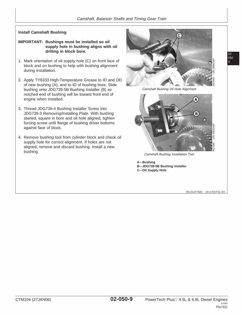
Camshaft, Balancer Shafts and Timing Gear Train
020509
RG,16,DT7505 –19–17OCT01–4/4
RG
7559
–UN
–05N
OV
97
Camshaft Bushing Oil Hole Alignment
RG
7560
–UN
–05N
OV
97
Camshaft Bushing Installation Tool
A—BushingB—JDG739-5B Bushing InstallerC—Oil Supply Hole
Install Camshaft Bushing
IMPORTANT: Bushings must be installed so oilsupply hole in bushing aligns with oildrilling in block bore.
1. Mark orientation of oil supply hole (C) on front face ofblock and on bushing to help with bushing alignmentduring installation.
2. Apply TY6333 High-Temperature Grease to ID and ODof new bushing (A), and to ID of bushing bore. Slidebushing onto JDG739-5B Bushing Installer (B) sonotched end of bushing will be toward front end ofengine when installed.
3. Thread JDG739-4 Bushing Installer Screw intoJDG739-3 Removing/Installing Plate. With bushingstarted, square in bore and oil hole aligned, tightenforcing screw until flange of bushing driver bottomsagainst face of block.
4. Remove bushing tool from cylinder block and check oilsupply hole for correct alignment. If holes are notaligned, remove and discard bushing. Install a newbushing.
CTM104 (27JAN06) 02-050-9 PowerTech Plus 4.5L & 6.8L Diesel Engines013006
PN=331
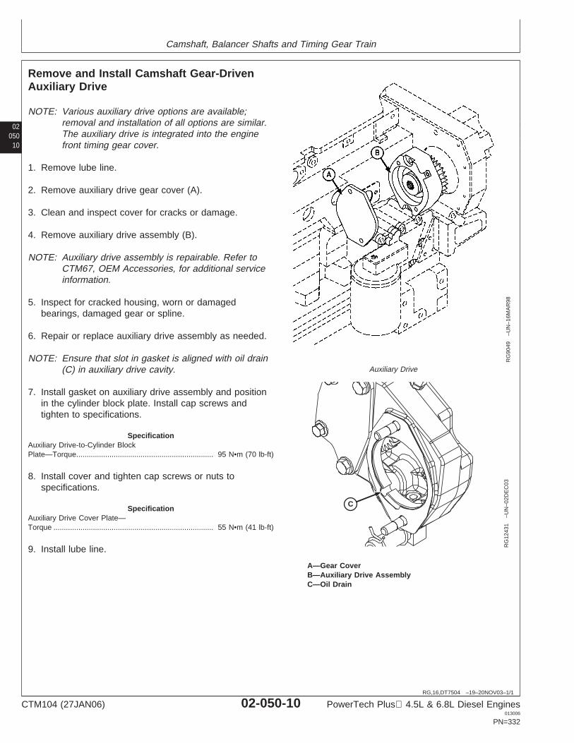
Camshaft, Balancer Shafts and Timing Gear Train
02050
10
RG,16,DT7504 –19–20NOV03–1/1
Remove and Install Camshaft Gear-DrivenAuxiliary Drive
RG
9049
–UN
–16M
AR
98
Auxiliary Drive
CR
G12
431
–UN
–02D
EC
03
A—Gear CoverB—Auxiliary Drive AssemblyC—Oil Drain
NOTE: Various auxiliary drive options are available;removal and installation of all options are similar.The auxiliary drive is integrated into the enginefront timing gear cover.
1. Remove lube line.
2. Remove auxiliary drive gear cover (A).
3. Clean and inspect cover for cracks or damage.
4. Remove auxiliary drive assembly (B).
NOTE: Auxiliary drive assembly is repairable. Refer toCTM67, OEM Accessories, for additional serviceinformation.
5. Inspect for cracked housing, worn or damagedbearings, damaged gear or spline.
6. Repair or replace auxiliary drive assembly as needed.
NOTE: Ensure that slot in gasket is aligned with oil drain(C) in auxiliary drive cavity.
7. Install gasket on auxiliary drive assembly and positionin the cylinder block plate. Install cap screws andtighten to specifications.
SpecificationAuxiliary Drive-to-Cylinder BlockPlate—Torque 95 N•m (70 lb-ft)..................................................................
8. Install cover and tighten cap screws or nuts tospecifications.
SpecificationAuxiliary Drive Cover Plate—Torque 55 N•m (41 lb-ft).............................................................................
9. Install lube line.
CTM104 (27JAN06) 02-050-10 PowerTech Plus 4.5L & 6.8L Diesel Engines013006
PN=332
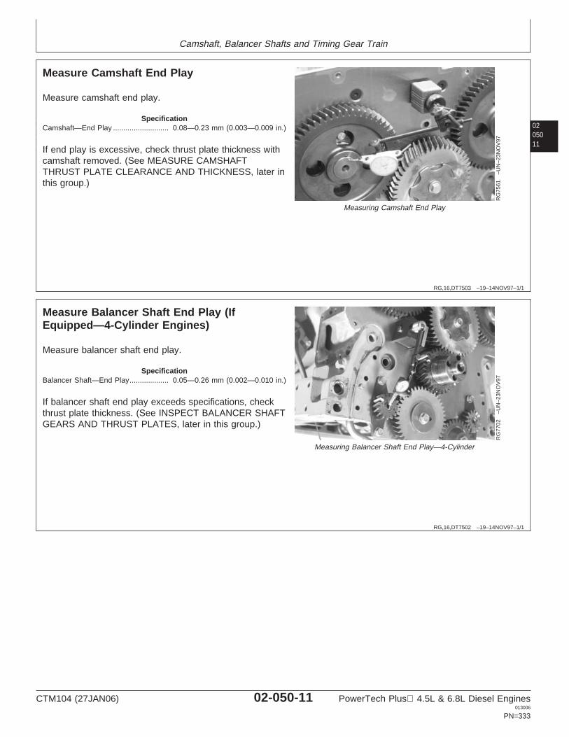
Camshaft, Balancer Shafts and Timing Gear Train
0205011
RG,16,DT7503 –19–14NOV97–1/1
Measure Camshaft End Play
RG
7561
–UN
–23N
OV
97
Measuring Camshaft End Play
Measure camshaft end play.
SpecificationCamshaft—End Play 0.08—0.23 mm (0.003—0.009 in.)...........................
If end play is excessive, check thrust plate thickness withcamshaft removed. (See MEASURE CAMSHAFTTHRUST PLATE CLEARANCE AND THICKNESS, later inthis group.)
RG,16,DT7502 –19–14NOV97–1/1
Measure Balancer Shaft End Play (IfEquipped—4-Cylinder Engines)
RG
7702
–UN
–23N
OV
97
Measuring Balancer Shaft End Play—4-Cylinder
Measure balancer shaft end play.
SpecificationBalancer Shaft—End Play 0.05—0.26 mm (0.002—0.010 in.)...................
If balancer shaft end play exceeds specifications, checkthrust plate thickness. (See INSPECT BALANCER SHAFTGEARS AND THRUST PLATES, later in this group.)
CTM104 (27JAN06) 02-050-11 PowerTech Plus 4.5L & 6.8L Diesel Engines013006
PN=333
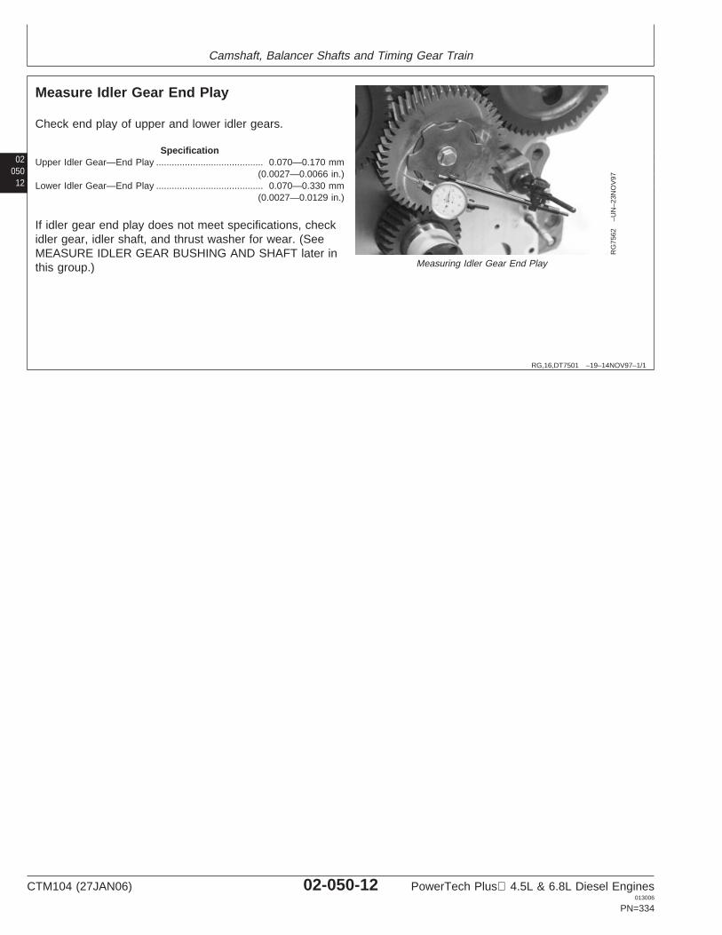
Camshaft, Balancer Shafts and Timing Gear Train
02050
12
RG,16,DT7501 –19–14NOV97–1/1
Measure Idler Gear End Play
RG
7562
–UN
–23N
OV
97
Measuring Idler Gear End Play
Check end play of upper and lower idler gears.
SpecificationUpper Idler Gear—End Play 0.070—0.170 mm
(0.0027—0.0066 in.).........................................
Lower Idler Gear—End Play 0.070—0.330 mm(0.0027—0.0129 in.)
.........................................
If idler gear end play does not meet specifications, checkidler gear, idler shaft, and thrust washer for wear. (SeeMEASURE IDLER GEAR BUSHING AND SHAFT later inthis group.)
CTM104 (27JAN06) 02-050-12 PowerTech Plus 4.5L & 6.8L Diesel Engines013006
PN=334
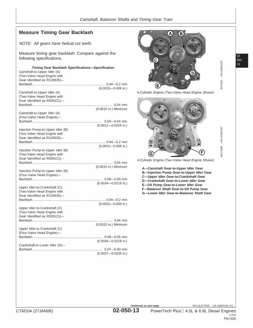
Camshaft, Balancer Shafts and Timing Gear Train
0205013
RG,16,DT7500 –19–24NOV03–1/2
Measure Timing Gear Backlash
RG
7530
–UN
–05N
OV
97
6-Cylinder Engine (Two-Valve Head Engine Shown)
RG
7703
B–U
N–0
7NO
V97
4-Cylinder Engine (Two-Valve Head Engine Shown)
A—Camshaft Gear-to-Upper Idler GearB—Injection Pump Gear-to-Upper Idler GearC—Upper Idler Gear-to-Crankshaft GearD—Crankshaft Gear-to-Lower Idler GearE—Oil Pump Gear-to-Lower Idler GearF—Balancer Shaft Gear-to-Oil Pump GearG—Lower Idler Gear-to-Balancer Shaft Gear
NOTE: All gears have helical cut teeth.
Measure timing gear backlash. Compare against thefollowing specifications.
Timing Gear Backlash Specifications—SpecificationCamshaft-to-Upper Idler (A)(Two-Valve Head Engine withGear Identified as R120635)—Backlash 0.04—0.2 mm
(0.0015—0.008 in.)...............................................................................
Camshaft-to-Upper Idler (A)(Two-Valve Head Engine withGear Identified as R505121)—Backlash 0.04 mm
(0.0015 in.) Minimum.......................................................................................
Camshaft-to-Upper Idler (A)(Four-Valve Head Engine)—Backlash 0.03—0.64 mm
(0.0011—0.0254 in.)............................................................................
Injection Pump-to-Upper Idler (B)(Two-Valve Head Engine withGear Identified as R120635)—Backlash 0.04—0.2 mm
(0.0015—0.008 in.)...............................................................................
Injection Pump-to-Upper Idler (B)(Two-Valve Head Engine withGear Identified as R505121)—Backlash 0.04 mm
(0.0015 in.) Minimum.......................................................................................
Injection Pump-to-Upper Idler (B)(Four-Valve Head Engine)—Backlash 0.09—0.55 mm
(0.0034—0.0218 in.)............................................................................
Upper Idler-to-Crankshaft (C)(Two-Valve Head Engine withGear Identified as R120635)—Backlash 0.04—0.2 mm
(0.0015—0.008 in.)...............................................................................
Upper Idler-to-Crankshaft (C)(Two-Valve Head Engine withGear Identified as R505121)—Backlash 0.04 mm
(0.0015 in.) Minimum.......................................................................................
Upper Idler-to-Crankshaft (C)(Four-Valve Head Engine)—Backlash 0.09—0.55 mm
(0.0034—0.0218 in.)............................................................................
Crankshaft-to-Lower Idler (D)—Backlash 0.07—0.60 mm
(0.0027—0.0236 in.)............................................................................
CTM104 (27JAN06) 02-050-13 PowerTech Plus 4.5L & 6.8L Diesel Engines013006
PN=335
Continued on next page
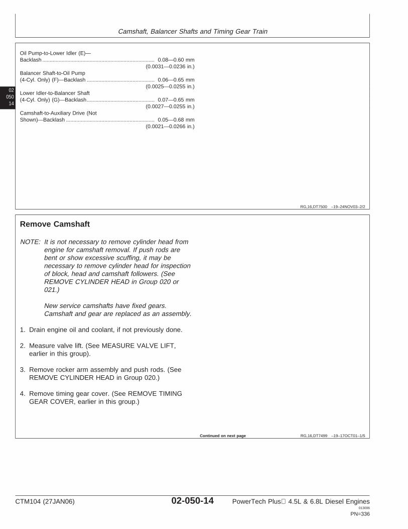
Camshaft, Balancer Shafts and Timing Gear Train
02050
14
RG,16,DT7500 –19–24NOV03–2/2
Oil Pump-to-Lower Idler (E)—Backlash 0.08—0.60 mm
(0.0031—0.0236 in.)............................................................................
Balancer Shaft-to-Oil Pump(4-Cyl. Only) (F)—Backlash 0.06—0.65 mm
(0.0025—0.0255 in.)..............................................
Lower Idler-to-Balancer Shaft(4-Cyl. Only) (G)—Backlash 0.07—0.65 mm
(0.0027—0.0255 in.)..............................................
Camshaft-to-Auxiliary Drive (NotShown)—Backlash 0.05—0.68 mm
(0.0021—0.0266 in.)............................................................
RG,16,DT7499 –19–17OCT01–1/5
Remove Camshaft
NOTE: It is not necessary to remove cylinder head fromengine for camshaft removal. If push rods arebent or show excessive scuffing, it may benecessary to remove cylinder head for inspectionof block, head and camshaft followers. (SeeREMOVE CYLINDER HEAD in Group 020 or021.)
New service camshafts have fixed gears.Camshaft and gear are replaced as an assembly.
1. Drain engine oil and coolant, if not previously done.
2. Measure valve lift. (See MEASURE VALVE LIFT,earlier in this group).
3. Remove rocker arm assembly and push rods. (SeeREMOVE CYLINDER HEAD in Group 020.)
4. Remove timing gear cover. (See REMOVE TIMINGGEAR COVER, earlier in this group.)
Continued on next page
CTM104 (27JAN06) 02-050-14 PowerTech Plus 4.5L & 6.8L Diesel Engines013006
PN=336
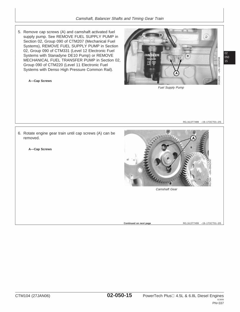
Camshaft, Balancer Shafts and Timing Gear Train
0205015
RG,16,DT7499 –19–17OCT01–2/5
RG
9050
–UN
–16M
AR
98
Fuel Supply Pump
A—Cap Screws
5. Remove cap screws (A) and camshaft activated fuelsupply pump. See REMOVE FUEL SUPPLY PUMP inSection 02, Group 090 of CTM207 (Mechanical FuelSystems), REMOVE FUEL SUPPLY PUMP in Section02, Group 090 of CTM331 (Level 12 Electronic FuelSystems with Stanadyne DE10 Pump) or REMOVEMECHANICAL FUEL TRANSFER PUMP in Section 02,Group 090 of CTM220 (Level 11 Electronic FuelSystems with Denso High Pressure Common Rail).
RG,16,DT7499 –19–17OCT01–3/5
RG
7564
–UN
–05N
OV
97
Camshaft Gear
A—Cap Screws
6. Rotate engine gear train until cap screws (A) can beremoved.
Continued on next page
CTM104 (27JAN06) 02-050-15 PowerTech Plus 4.5L & 6.8L Diesel Engines013006
PN=337
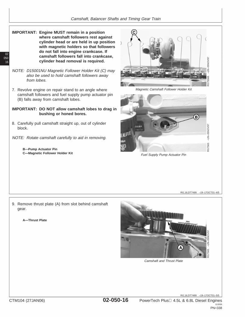
Camshaft, Balancer Shafts and Timing Gear Train
02050
16
RG,16,DT7499 –19–17OCT01–4/5
RG
7556
B–U
N–0
5NO
V97
Magnetic Camshaft Follower Holder Kit
RG
7563
–UN
–05N
OV
97
Fuel Supply Pump Actuator Pin
B—Pump Actuator PinC—Magnetic Follower Holder Kit
IMPORTANT: Engine MUST remain in a positionwhere camshaft followers rest againstcylinder head or are held in up positionwith magnetic holders so that followersdo not fall into engine crankcase. Ifcamshaft followers fall into crankcase,cylinder head removal is required.
NOTE: D15001NU Magnetic Follower Holder Kit (C) mayalso be used to hold camshaft followers awayfrom lobes.
7. Revolve engine on repair stand to an angle wherecamshaft followers and fuel supply pump actuator pin(B) falls away from camshaft lobes.
IMPORTANT: DO NOT allow camshaft lobes to drag inbushing or honed bores.
8. Carefully pull camshaft straight up, out of cylinderblock.
NOTE: Rotate camshaft carefully to aid in removing.
RG,16,DT7499 –19–17OCT01–5/5
RG
7565
–UN
–05N
OV
97
Camshaft and Thrust Plate
A—Thrust Plate
9. Remove thrust plate (A) from slot behind camshaftgear.
CTM104 (27JAN06) 02-050-16 PowerTech Plus 4.5L & 6.8L Diesel Engines013006
PN=338
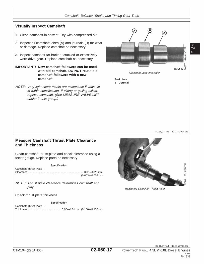
Camshaft, Balancer Shafts and Timing Gear Train
0205017
RG,16,DT7498 –19–14NOV97–1/1
Visually Inspect Camshaft
RG
3500
–UN
–03N
OV
97
Camshaft Lobe Inspection
A—LobesB—Journal
1. Clean camshaft in solvent. Dry with compressed air.
2. Inspect all camshaft lobes (A) and journals (B) for wearor damage. Replace camshaft as necessary.
3. Inspect camshaft for broken, cracked or excessivelyworn drive gear. Replace camshaft as necessary.
IMPORTANT: New camshaft followers can be usedwith old camshaft. DO NOT reuse oldcamshaft followers with a newcamshaft.
NOTE: Very light score marks are acceptable if valve liftis within specification. If pitting or galling exists,replace camshaft. (See MEASURE VALVE LIFTearlier in this group.)
RG,16,DT7514 –19–15NOV97–1/1
Measure Camshaft Thrust Plate Clearanceand Thickness
RG
7120
–UN
–23N
OV
97
Measuring Camshaft Thrust Plate
Clean camshaft thrust plate and check clearance using afeeler gauge. Replace parts as necessary.
SpecificationCamshaft Thrust Plate—Clearance 0.08—0.23 mm
(0.003—0.009 in.)..........................................................................
NOTE: Thrust plate clearance determines camshaft endplay.
Check thrust plate thickness.
SpecificationCamshaft Thrust Plate—Thickness 3.96—4.01 mm (0.156—0.158 in.).............................................
CTM104 (27JAN06) 02-050-17 PowerTech Plus 4.5L & 6.8L Diesel Engines013006
PN=339
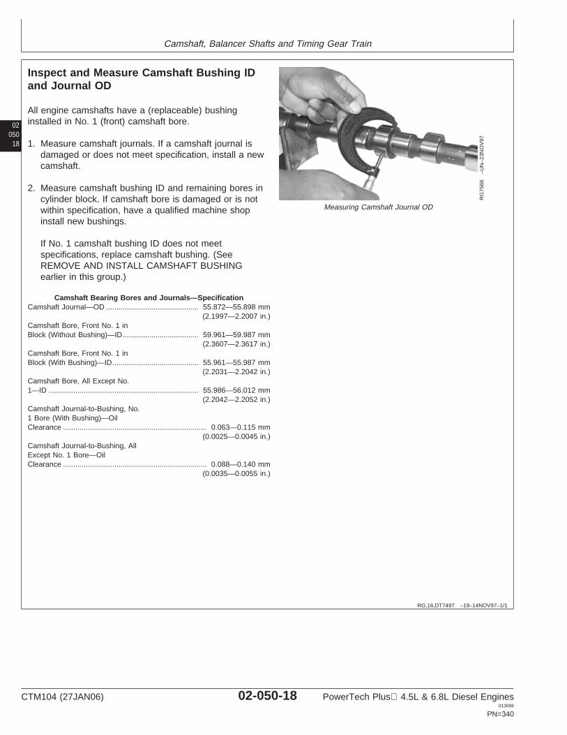
Camshaft, Balancer Shafts and Timing Gear Train
02050
18
RG,16,DT7497 –19–14NOV97–1/1
Inspect and Measure Camshaft Bushing IDand Journal OD
RG
7566
–UN
–23N
OV
97
Measuring Camshaft Journal OD
All engine camshafts have a (replaceable) bushinginstalled in No. 1 (front) camshaft bore.
1. Measure camshaft journals. If a camshaft journal isdamaged or does not meet specification, install a newcamshaft.
2. Measure camshaft bushing ID and remaining bores incylinder block. If camshaft bore is damaged or is notwithin specification, have a qualified machine shopinstall new bushings.
If No. 1 camshaft bushing ID does not meetspecifications, replace camshaft bushing. (SeeREMOVE AND INSTALL CAMSHAFT BUSHINGearlier in this group.)
Camshaft Bearing Bores and Journals—SpecificationCamshaft Journal—OD 55.872—55.898 mm
(2.1997—2.2007 in.).............................................
Camshaft Bore, Front No. 1 inBlock (Without Bushing)—ID 59.961—59.987 mm
(2.3607—2.3617 in.).....................................
Camshaft Bore, Front No. 1 inBlock (With Bushing)—ID 55.961—55.987 mm
(2.2031—2.2042 in.)..........................................
Camshaft Bore, All Except No.1—ID 55.986—56.012 mm
(2.2042—2.2052 in.).........................................................................
Camshaft Journal-to-Bushing, No.1 Bore (With Bushing)—OilClearance 0.063—0.115 mm
(0.0025—0.0045 in.)......................................................................
Camshaft Journal-to-Bushing, AllExcept No. 1 Bore—OilClearance 0.088—0.140 mm
(0.0035—0.0055 in.)......................................................................
CTM104 (27JAN06) 02-050-18 PowerTech Plus 4.5L & 6.8L Diesel Engines013006
PN=340
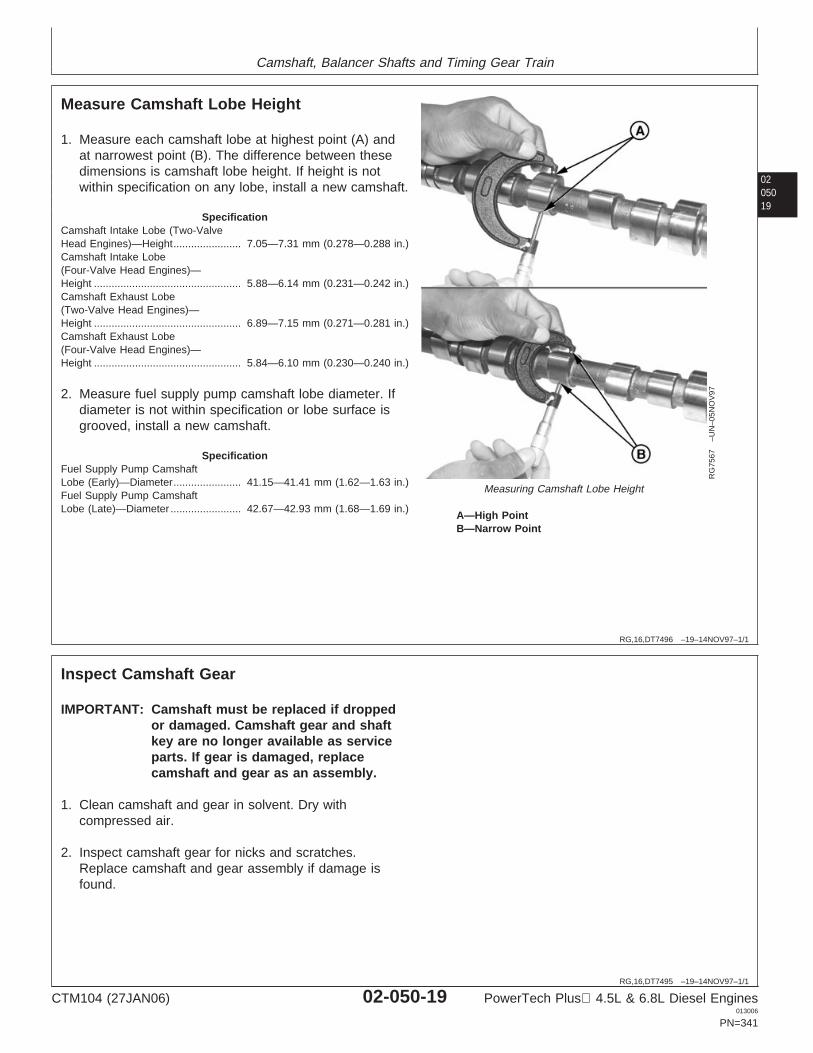
Camshaft, Balancer Shafts and Timing Gear Train
0205019
RG,16,DT7496 –19–14NOV97–1/1
Measure Camshaft Lobe Height
RG
7567
–UN
–05N
OV
97
Measuring Camshaft Lobe Height
A—High PointB—Narrow Point
1. Measure each camshaft lobe at highest point (A) andat narrowest point (B). The difference between thesedimensions is camshaft lobe height. If height is notwithin specification on any lobe, install a new camshaft.
SpecificationCamshaft Intake Lobe (Two-ValveHead Engines)—Height 7.05—7.31 mm (0.278—0.288 in.).......................Camshaft Intake Lobe(Four-Valve Head Engines)—Height 5.88—6.14 mm (0.231—0.242 in.)..................................................Camshaft Exhaust Lobe(Two-Valve Head Engines)—Height 6.89—7.15 mm (0.271—0.281 in.)..................................................Camshaft Exhaust Lobe(Four-Valve Head Engines)—Height 5.84—6.10 mm (0.230—0.240 in.)..................................................
2. Measure fuel supply pump camshaft lobe diameter. Ifdiameter is not within specification or lobe surface isgrooved, install a new camshaft.
SpecificationFuel Supply Pump CamshaftLobe (Early)—Diameter 41.15—41.41 mm (1.62—1.63 in.).......................Fuel Supply Pump CamshaftLobe (Late)—Diameter 42.67—42.93 mm (1.68—1.69 in.)........................
RG,16,DT7495 –19–14NOV97–1/1
Inspect Camshaft Gear
IMPORTANT: Camshaft must be replaced if droppedor damaged. Camshaft gear and shaftkey are no longer available as serviceparts. If gear is damaged, replacecamshaft and gear as an assembly.
1. Clean camshaft and gear in solvent. Dry withcompressed air.
2. Inspect camshaft gear for nicks and scratches.Replace camshaft and gear assembly if damage isfound.
CTM104 (27JAN06) 02-050-19 PowerTech Plus 4.5L & 6.8L Diesel Engines013006
PN=341

Camshaft, Balancer Shafts and Timing Gear Train
02050
20
RG,16,DT7494 –19–14NOV97–1/1
Inspect Camshaft Followers
RG
6324
–UN
–23N
OV
97
Camshaft Follower
NOTE: Cylinder head must be removed before camshaftfollowers can be removed from engine. (SeeREMOVE CYLINDER HEAD in Group 020 or021.)
1. Inspect followers for uneven wear or damage. Alsoinspect corresponding camshaft lobe for wear ordamage. Replace as necessary.
2. Measure follower OD and follower bore ID in cylinderblock.
SpecificationCamshaft Follower—OD 31.61—31.64 mm
(1.245—1.246 in.)................................................
Camshaft Follower Bore inBlock—ID 31.70—31.75 mm
(1.248—1.250 in.).......................................................................
Camshaft Follower-to-Bore—Clearance 0.06—0.13 mm (0.002—0.005 in.)............................................
Replace camshaft followers that are not withinspecification.
Replace cylinder block if any one camshaft follower boreis not within specification.
CTM104 (27JAN06) 02-050-20 PowerTech Plus 4.5L & 6.8L Diesel Engines013006
PN=342
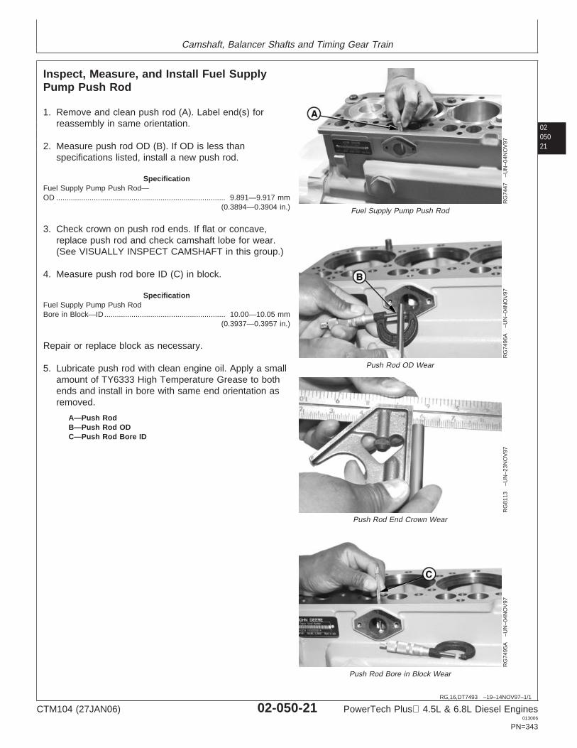
Camshaft, Balancer Shafts and Timing Gear Train
0205021
RG,16,DT7493 –19–14NOV97–1/1
Inspect, Measure, and Install Fuel SupplyPump Push Rod
RG
7447
–UN
–04N
OV
97
Fuel Supply Pump Push Rod
RG
7496
A–U
N–0
4NO
V97
Push Rod OD Wear
RG
8113
–UN
–23N
OV
97
Push Rod End Crown Wear
RG
7495
A–U
N–0
4NO
V97
Push Rod Bore in Block Wear
A—Push RodB—Push Rod ODC—Push Rod Bore ID
1. Remove and clean push rod (A). Label end(s) forreassembly in same orientation.
2. Measure push rod OD (B). If OD is less thanspecifications listed, install a new push rod.
SpecificationFuel Supply Pump Push Rod—OD 9.891—9.917 mm
(0.3894—0.3904 in.).................................................................................
3. Check crown on push rod ends. If flat or concave,replace push rod and check camshaft lobe for wear.(See VISUALLY INSPECT CAMSHAFT in this group.)
4. Measure push rod bore ID (C) in block.
SpecificationFuel Supply Pump Push RodBore in Block—ID 10.00—10.05 mm
(0.3937—0.3957 in.)..........................................................
Repair or replace block as necessary.
5. Lubricate push rod with clean engine oil. Apply a smallamount of TY6333 High Temperature Grease to bothends and install in bore with same end orientation asremoved.
CTM104 (27JAN06) 02-050-21 PowerTech Plus 4.5L & 6.8L Diesel Engines013006
PN=343
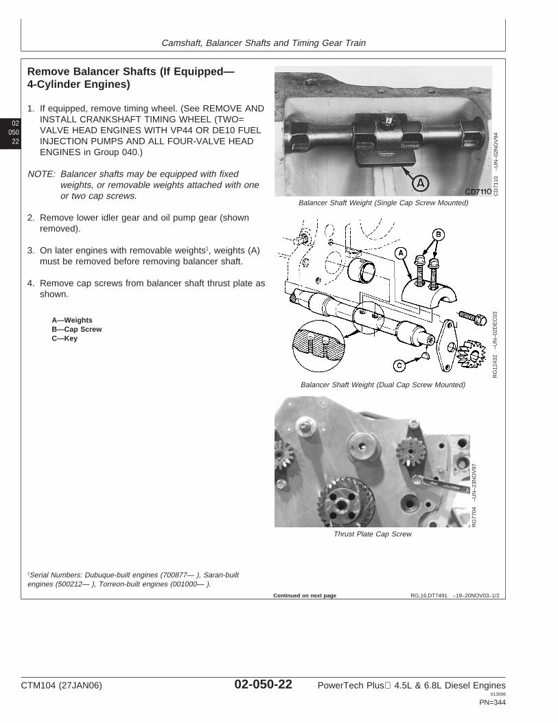
Camshaft, Balancer Shafts and Timing Gear Train
02050
22
RG,16,DT7491 –19–20NOV03–1/2
Remove Balancer Shafts (If Equipped—4-Cylinder Engines)
CD
7110
–UN
–02N
OV
94
Balancer Shaft Weight (Single Cap Screw Mounted)
RG
1243
2–U
N–0
2DE
C03
Balancer Shaft Weight (Dual Cap Screw Mounted)
RG
7704
–UN
–23N
OV
97
Thrust Plate Cap Screw
A—WeightsB—Cap ScrewC—Key
1. If equipped, remove timing wheel. (See REMOVE ANDINSTALL CRANKSHAFT TIMING WHEEL (TWO=VALVE HEAD ENGINES WITH VP44 OR DE10 FUELINJECTION PUMPS AND ALL FOUR-VALVE HEADENGINES in Group 040.)
NOTE: Balancer shafts may be equipped with fixedweights, or removable weights attached with oneor two cap screws.
2. Remove lower idler gear and oil pump gear (shownremoved).
3. On later engines with removable weights1, weights (A)must be removed before removing balancer shaft.
4. Remove cap screws from balancer shaft thrust plate asshown.
1Serial Numbers: Dubuque-built engines (700877— ), Saran-builtengines (500212— ), Torreon-built engines (001000— ).
Continued on next page
CTM104 (27JAN06) 02-050-22 PowerTech Plus 4.5L & 6.8L Diesel Engines013006
PN=344
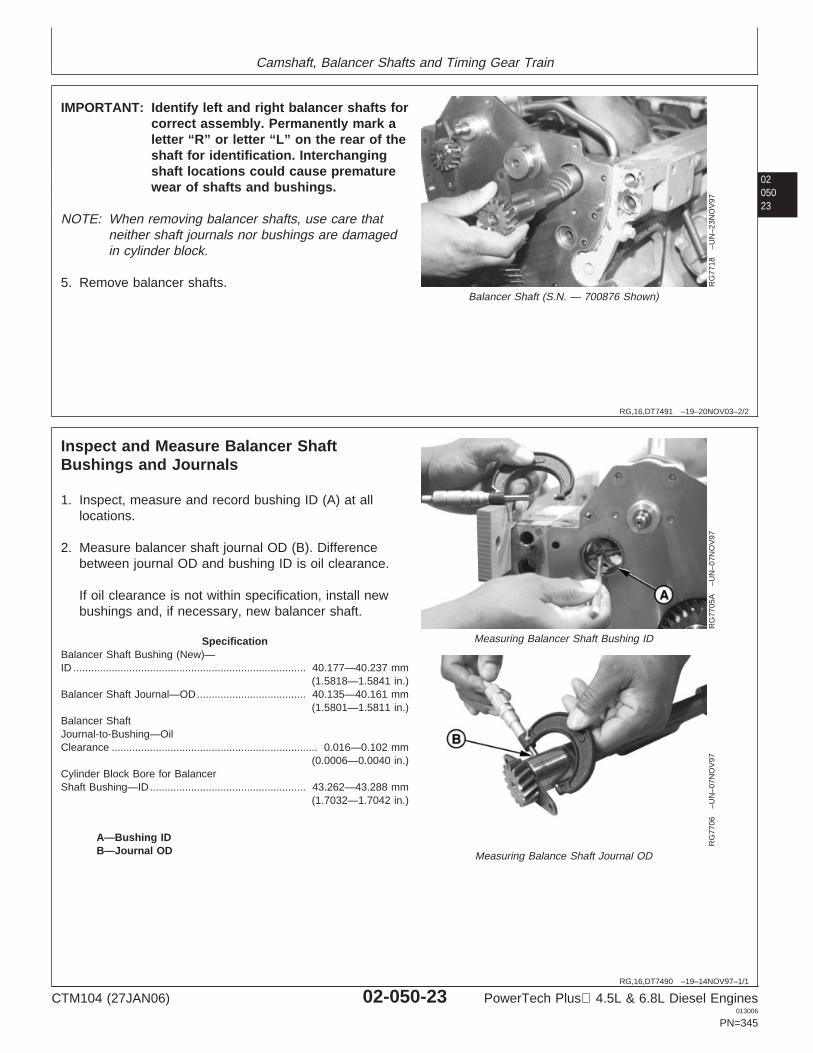
Camshaft, Balancer Shafts and Timing Gear Train
0205023
RG,16,DT7491 –19–20NOV03–2/2
RG
7718
–UN
–23N
OV
97
Balancer Shaft (S.N. — 700876 Shown)
IMPORTANT: Identify left and right balancer shafts forcorrect assembly. Permanently mark aletter “R” or letter “L” on the rear of theshaft for identification. Interchangingshaft locations could cause prematurewear of shafts and bushings.
NOTE: When removing balancer shafts, use care thatneither shaft journals nor bushings are damagedin cylinder block.
5. Remove balancer shafts.
RG,16,DT7490 –19–14NOV97–1/1
Inspect and Measure Balancer ShaftBushings and Journals
RG
7705
A–U
N–0
7NO
V97
Measuring Balancer Shaft Bushing ID
RG
7706
–UN
–07N
OV
97
Measuring Balance Shaft Journal OD
A—Bushing IDB—Journal OD
1. Inspect, measure and record bushing ID (A) at alllocations.
2. Measure balancer shaft journal OD (B). Differencebetween journal OD and bushing ID is oil clearance.
If oil clearance is not within specification, install newbushings and, if necessary, new balancer shaft.
SpecificationBalancer Shaft Bushing (New)—ID 40.177—40.237 mm
(1.5818—1.5841 in.)...............................................................................
Balancer Shaft Journal—OD 40.135—40.161 mm(1.5801—1.5811 in.)
.....................................
Balancer ShaftJournal-to-Bushing—OilClearance 0.016—0.102 mm
(0.0006—0.0040 in.)......................................................................
Cylinder Block Bore for BalancerShaft Bushing—ID 43.262—43.288 mm
(1.7032—1.7042 in.).....................................................
CTM104 (27JAN06) 02-050-23 PowerTech Plus 4.5L & 6.8L Diesel Engines013006
PN=345
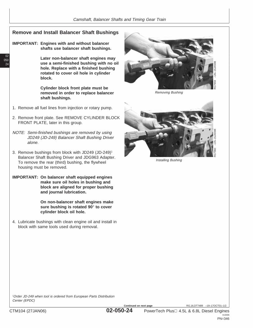
Camshaft, Balancer Shafts and Timing Gear Train
02050
24
RG,16,DT7489 –19–17OCT01–1/2
Remove and Install Balancer Shaft Bushings
RG
7959
–UN
–15J
AN
98
Removing Bushing
RG
7960
–UN
–15J
AN
98
Installing Bushing
IMPORTANT: Engines with and without balancershafts use balancer shaft bushings.
Later non-balancer shaft engines mayuse a semi-finished bushing with no oilhole. Replace with a finished bushingrotated to cover oil hole in cylinderblock.
Cylinder block front plate must beremoved in order to replace balancershaft bushings.
1. Remove all fuel lines from injection or rotary pump.
2. Remove front plate. See REMOVE CYLINDER BLOCKFRONT PLATE, later in this group.
NOTE: Semi-finished bushings are removed by usingJD249 (JD-249) Balancer Shaft Bushing Driveralone.
3. Remove bushings from block with JD249 (JD-249)1
Balancer Shaft Bushing Driver and JDG963 Adapter.To remove the rear (third) bushing, the flywheelhousing must be removed.
IMPORTANT: On balancer shaft equipped enginesmake sure oil holes in bushing andblock are aligned for proper bushingand journal lubrication.
On non-balancer shaft engines makesure bushing is rotated 90° to covercylinder block oil hole.
4. Lubricate bushings with clean engine oil and install inblock with same tools used during removal.
1Order JD-249 when tool is ordered from European Parts DistributionCenter (EPDC)
CTM104 (27JAN06) 02-050-24 PowerTech Plus 4.5L & 6.8L Diesel Engines013006
PN=346
Continued on next page

Camshaft, Balancer Shafts and Timing Gear Train
0205025
RG,16,DT7489 –19–17OCT01–2/2
5. On balancer shaft equipped engines, insert balancershaft to check for bushing-to-shaft clearance. If shaftcan be rotated by hand with a slight-to-moderate drag,adequate bushing-to-balancer shaft clearance exists. Itis not necessary to hone bushings to obtain specifiedoil clearance. Excessive clearance can result in shaftseizure.
RG,16,DT7488 –19–14NOV97–1/1
Inspect Balancer Shaft Gears and ThrustPlates
RG7708 –UN–07NOV97
Balancer Shaft Thrust Plate
A—Thrust Plate
1. Inspect for broken, cracked or excessively worn gears.
NOTE: Gear removal is required for thrust plate removal.
2. Inspect thrust plate (A) for scoring or excessive wear.
SpecificationBalancer Shaft Thrust Plate(New)—Thickness 2.97—3.02 mm (0.117—0.119 in.)...............................
CTM104 (27JAN06) 02-050-25 PowerTech Plus 4.5L & 6.8L Diesel Engines013006
PN=347
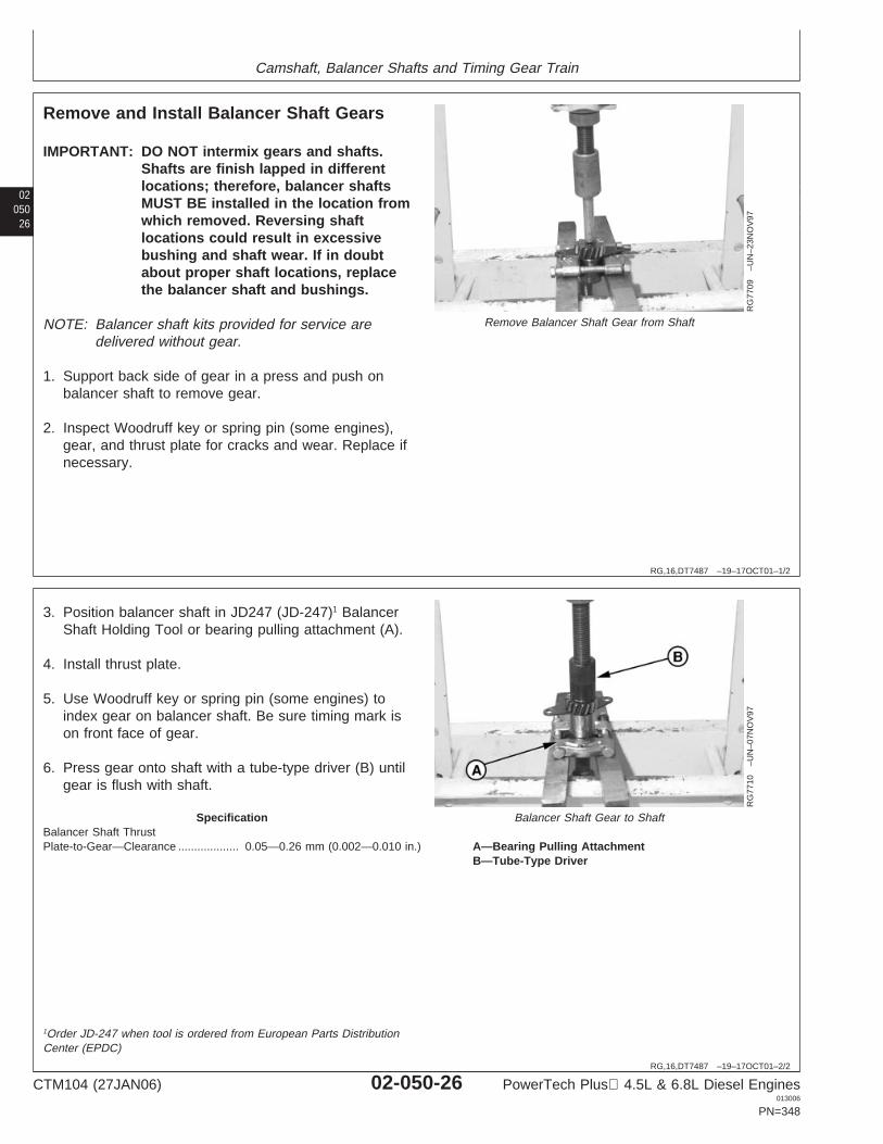
Camshaft, Balancer Shafts and Timing Gear Train
02050
26
RG,16,DT7487 –19–17OCT01–1/2
Remove and Install Balancer Shaft Gears
RG
7709
–UN
–23N
OV
97
Remove Balancer Shaft Gear from Shaft
IMPORTANT: DO NOT intermix gears and shafts.Shafts are finish lapped in differentlocations; therefore, balancer shaftsMUST BE installed in the location fromwhich removed. Reversing shaftlocations could result in excessivebushing and shaft wear. If in doubtabout proper shaft locations, replacethe balancer shaft and bushings.
NOTE: Balancer shaft kits provided for service aredelivered without gear.
1. Support back side of gear in a press and push onbalancer shaft to remove gear.
2. Inspect Woodruff key or spring pin (some engines),gear, and thrust plate for cracks and wear. Replace ifnecessary.
RG,16,DT7487 –19–17OCT01–2/2
RG
7710
–UN
–07N
OV
97
Balancer Shaft Gear to Shaft
A—Bearing Pulling AttachmentB—Tube-Type Driver
3. Position balancer shaft in JD247 (JD-247)1 BalancerShaft Holding Tool or bearing pulling attachment (A).
4. Install thrust plate.
5. Use Woodruff key or spring pin (some engines) toindex gear on balancer shaft. Be sure timing mark ison front face of gear.
6. Press gear onto shaft with a tube-type driver (B) untilgear is flush with shaft.
SpecificationBalancer Shaft ThrustPlate-to-Gear—Clearance 0.05—0.26 mm (0.002—0.010 in.)...................
1Order JD-247 when tool is ordered from European Parts DistributionCenter (EPDC)
CTM104 (27JAN06) 02-050-26 PowerTech Plus 4.5L & 6.8L Diesel Engines013006
PN=348
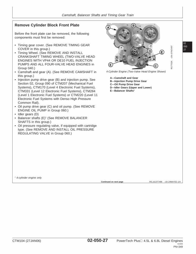
Camshaft, Balancer Shafts and Timing Gear Train
0205027
RG,16,DT7486 –19–24MAY02–1/4
Remove Cylinder Block Front Plate
RG
7703
A–U
N–0
7NO
V97
4-Cylinder Engine (Two-Valve Head Engine Shown)
A—Camshaft and GearB—Injection Pump Drive GearC—Oil Pump Drive GearD—Idler Gears (Upper and Lower)E—Balancer Shafts1
Before the front plate can be removed, the followingcomponents must first be removed:
• Timing gear cover. (See REMOVE TIMING GEARCOVER in this group.)
• Timing Wheel. (See REMOVE AND INSTALLCRANKSHAFT TIMING WHEEL (TWO-VALVE HEADENGINES WITH VP44 OR DE10 FUEL INJECTIONPUMPS AND ALL FOUR-VALVE HEAD ENGINES inGroup 040.)
• Camshaft and gear (A). (See REMOVE CAMSHAFT inthis group.)
• Injection pump drive gear (B) and injection pump. SeeSection 02, Group 090 of CTM207 (Mechanical FuelSystems), CTM170 (Level 4 Electronic Fuel Systems),CTM331 (Level 12 Electronic Fuel Systems), CTM284(Level 1 Electronic Fuel Systems) or CTM220 (Level 11Electronic Fuel Systems with Denso High PressureCommon Rail).
• Oil pump drive gear (C) and oil pump. (See REMOVEENGINE OIL PUMP in Group 060.)
• Idler gears (D)• Balancer shafts (E)1 (See REMOVE BALANCER
SHAFTS in this group.)• Oil pressure regulating valve, if equipped with cartridge
type. (See REMOVE AND INSTALL OIL PRESSUREREGULATING VALVE in Group 060.)
1 4-cylinder engine only
Continued on next page
CTM104 (27JAN06) 02-050-27 PowerTech Plus 4.5L & 6.8L Diesel Engines013006
PN=349
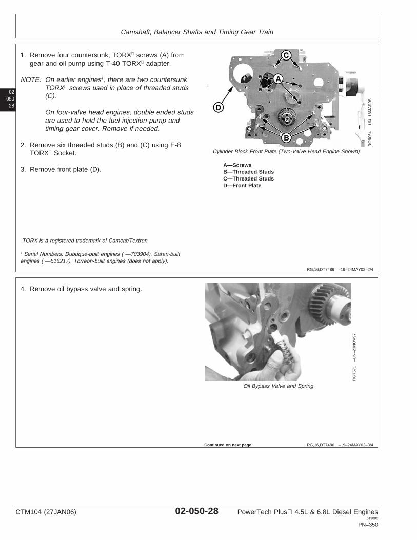
Camshaft, Balancer Shafts and Timing Gear Train
02050
28
RG,16,DT7486 –19–24MAY02–2/4
RG
9064
–UN
–16M
AR
98
Cylinder Block Front Plate (Two-Valve Head Engine Shown)
A—ScrewsB—Threaded StudsC—Threaded StudsD—Front Plate
1. Remove four countersunk, TORX screws (A) fromgear and oil pump using T-40 TORX adapter.
NOTE: On earlier engines1, there are two countersunkTORX screws used in place of threaded studs(C).
On four-valve head engines, double ended studsare used to hold the fuel injection pump andtiming gear cover. Remove if needed.
2. Remove six threaded studs (B) and (C) using E-8TORX Socket.
3. Remove front plate (D).
TORX is a registered trademark of Camcar/Textron
1 Serial Numbers: Dubuque-built engines ( —703904), Saran-builtengines ( —516217), Torreon-built engines (does not apply).
RG,16,DT7486 –19–24MAY02–3/4
RG
7571
–UN
–23N
OV
97
Oil Bypass Valve and Spring
4. Remove oil bypass valve and spring.
Continued on next page
CTM104 (27JAN06) 02-050-28 PowerTech Plus 4.5L & 6.8L Diesel Engines013006
PN=350
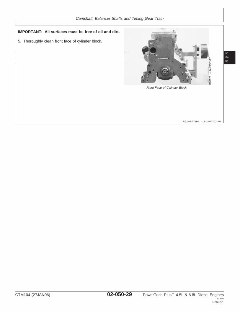
Camshaft, Balancer Shafts and Timing Gear Train
0205029
RG,16,DT7486 –19–24MAY02–4/4
RG
7572
–UN
–23N
OV
97
Front Face of Cylinder Block
IMPORTANT: All surfaces must be free of oil and dirt.
5. Thoroughly clean front face of cylinder block.
CTM104 (27JAN06) 02-050-29 PowerTech Plus 4.5L & 6.8L Diesel Engines013006
PN=351
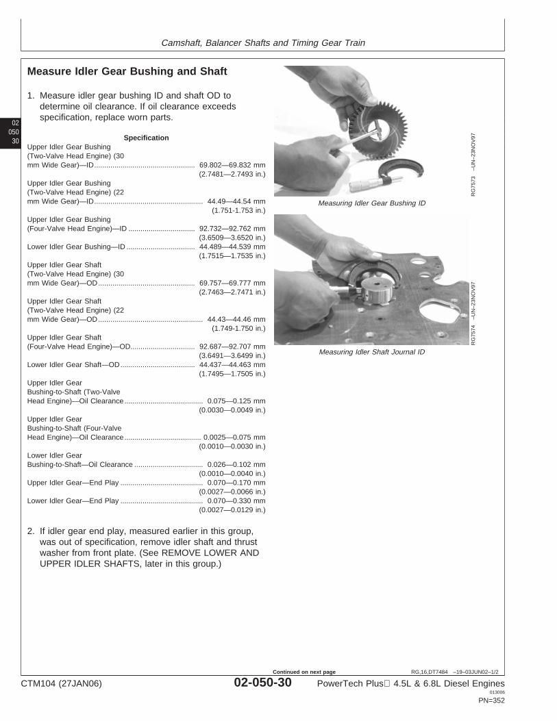
Camshaft, Balancer Shafts and Timing Gear Train
02050
30
RG,16,DT7484 –19–03JUN02–1/2
Measure Idler Gear Bushing and Shaft
RG
7573
–UN
–23N
OV
97
Measuring Idler Gear Bushing ID
RG
7574
–UN
–23N
OV
97
Measuring Idler Shaft Journal ID
1. Measure idler gear bushing ID and shaft OD todetermine oil clearance. If oil clearance exceedsspecification, replace worn parts.
SpecificationUpper Idler Gear Bushing(Two-Valve Head Engine) (30mm Wide Gear)—ID 69.802—69.832 mm
(2.7481—2.7493 in.)..................................................
Upper Idler Gear Bushing(Two-Valve Head Engine) (22mm Wide Gear)—ID 44.49—44.54 mm
(1.751-1.753 in.)......................................................
Upper Idler Gear Bushing(Four-Valve Head Engine)—ID 92.732—92.762 mm
(3.6509—3.6520 in.).................................
Lower Idler Gear Bushing—ID 44.489—44.539 mm(1.7515—1.7535 in.)
..................................
Upper Idler Gear Shaft(Two-Valve Head Engine) (30mm Wide Gear)—OD 69.757—69.777 mm
(2.7463—2.7471 in.)................................................
Upper Idler Gear Shaft(Two-Valve Head Engine) (22mm Wide Gear)—OD 44.43—44.46 mm
(1.749-1.750 in.)....................................................
Upper Idler Gear Shaft(Four-Valve Head Engine)—OD 92.687—92.707 mm
(3.6491—3.6499 in.)................................
Lower Idler Gear Shaft—OD 44.437—44.463 mm(1.7495—1.7505 in.)
.....................................
Upper Idler GearBushing-to-Shaft (Two-ValveHead Engine)—Oil Clearance 0.075—0.125 mm
(0.0030—0.0049 in.).......................................
Upper Idler GearBushing-to-Shaft (Four-ValveHead Engine)—Oil Clearance 0.0025—0.075 mm
(0.0010—0.0030 in.)......................................
Lower Idler GearBushing-to-Shaft—Oil Clearance 0.026—0.102 mm
(0.0010—0.0040 in.)..................................
Upper Idler Gear—End Play 0.070—0.170 mm(0.0027—0.0066 in.)
.........................................
Lower Idler Gear—End Play 0.070—0.330 mm(0.0027—0.0129 in.)
.........................................
2. If idler gear end play, measured earlier in this group,was out of specification, remove idler shaft and thrustwasher from front plate. (See REMOVE LOWER ANDUPPER IDLER SHAFTS, later in this group.)
CTM104 (27JAN06) 02-050-30 PowerTech Plus 4.5L & 6.8L Diesel Engines013006
PN=352
Continued on next page
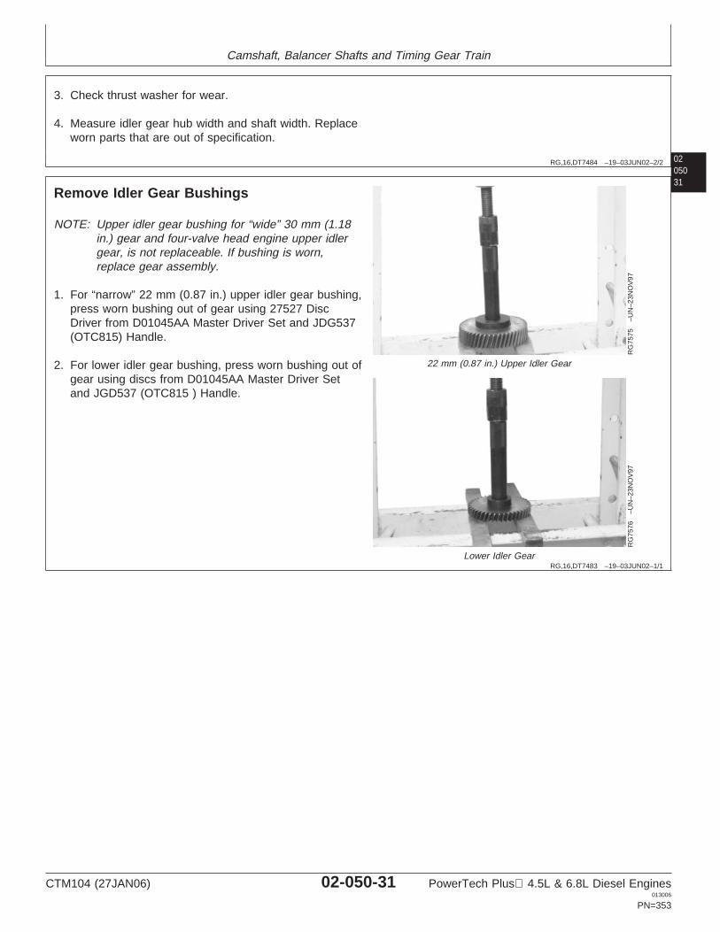
Camshaft, Balancer Shafts and Timing Gear Train
02050
RG,16,DT7484 –19–03JUN02–2/2
3. Check thrust washer for wear.
4. Measure idler gear hub width and shaft width. Replaceworn parts that are out of specification.
31
RG,16,DT7483 –19–03JUN02–1/1
Remove Idler Gear Bushings
RG
7575
–UN
–23N
OV
97
22 mm (0.87 in.) Upper Idler Gear
RG
7576
–UN
–23N
OV
97
Lower Idler Gear
NOTE: Upper idler gear bushing for “wide” 30 mm (1.18in.) gear and four-valve head engine upper idlergear, is not replaceable. If bushing is worn,replace gear assembly.
1. For “narrow” 22 mm (0.87 in.) upper idler gear bushing,press worn bushing out of gear using 27527 DiscDriver from D01045AA Master Driver Set and JDG537(OTC815) Handle.
2. For lower idler gear bushing, press worn bushing out ofgear using discs from D01045AA Master Driver Setand JGD537 (OTC815 ) Handle.
CTM104 (27JAN06) 02-050-31 PowerTech Plus 4.5L & 6.8L Diesel Engines013006
PN=353
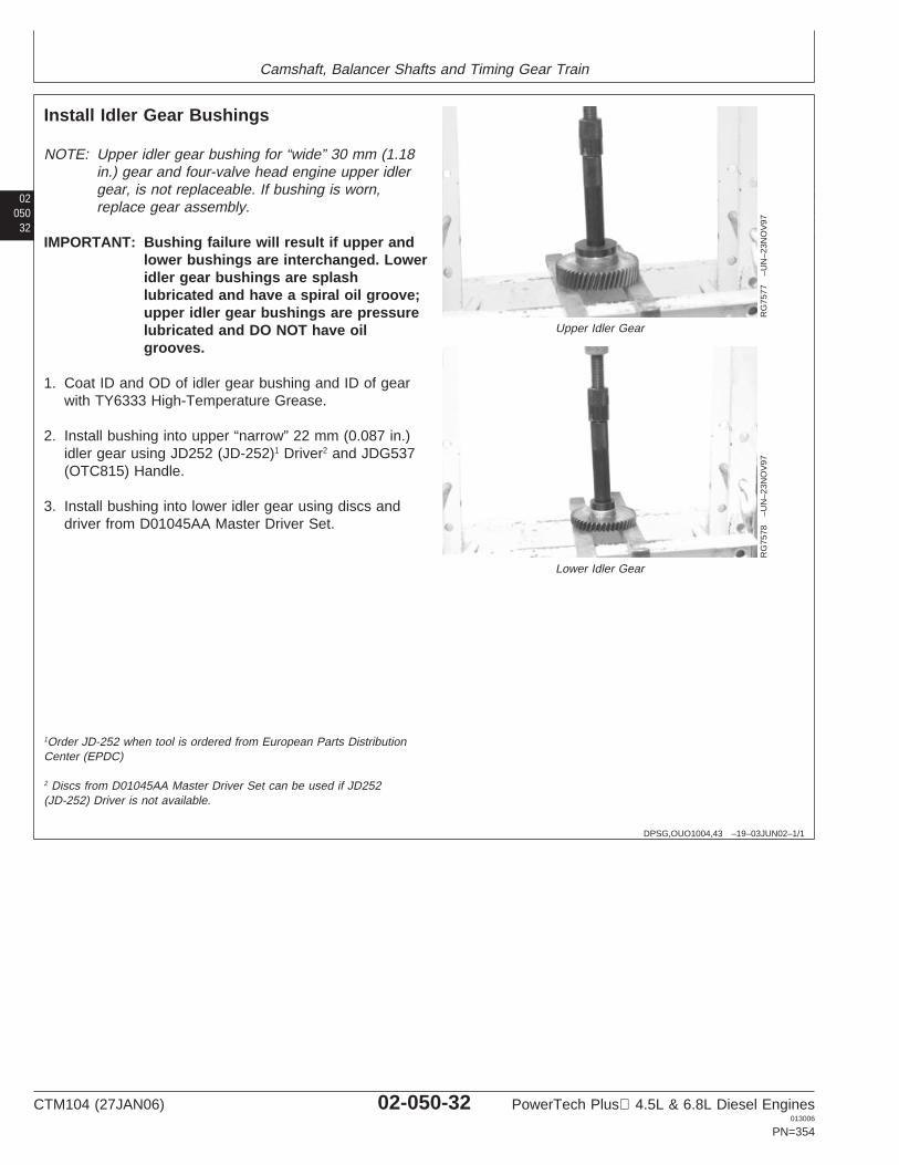
Camshaft, Balancer Shafts and Timing Gear Train
02050
32
DPSG,OUO1004,43 –19–03JUN02–1/1
Install Idler Gear Bushings
RG
7577
–UN
–23N
OV
97
Upper Idler Gear
RG
7578
–UN
–23N
OV
97
Lower Idler Gear
NOTE: Upper idler gear bushing for “wide” 30 mm (1.18in.) gear and four-valve head engine upper idlergear, is not replaceable. If bushing is worn,replace gear assembly.
IMPORTANT: Bushing failure will result if upper andlower bushings are interchanged. Loweridler gear bushings are splashlubricated and have a spiral oil groove;upper idler gear bushings are pressurelubricated and DO NOT have oilgrooves.
1. Coat ID and OD of idler gear bushing and ID of gearwith TY6333 High-Temperature Grease.
2. Install bushing into upper “narrow” 22 mm (0.087 in.)idler gear using JD252 (JD-252)1 Driver2 and JDG537(OTC815) Handle.
3. Install bushing into lower idler gear using discs anddriver from D01045AA Master Driver Set.
1Order JD-252 when tool is ordered from European Parts DistributionCenter (EPDC)
2 Discs from D01045AA Master Driver Set can be used if JD252(JD-252) Driver is not available.
CTM104 (27JAN06) 02-050-32 PowerTech Plus 4.5L & 6.8L Diesel Engines013006
PN=354
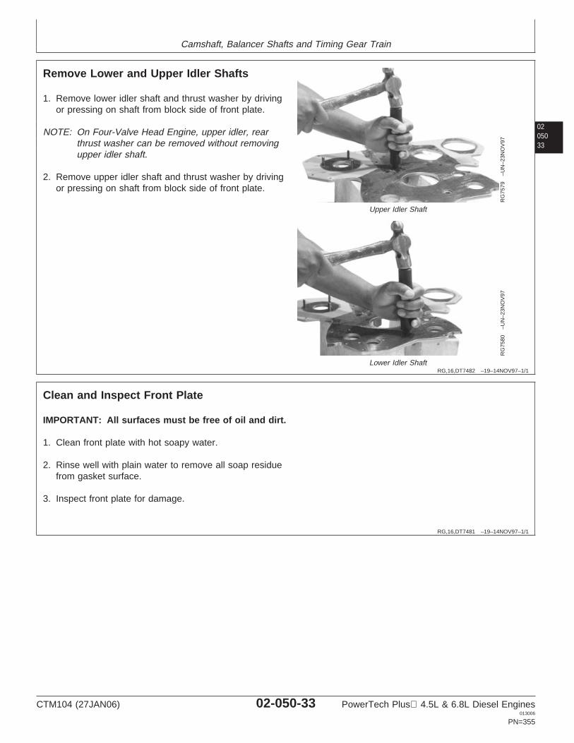
Camshaft, Balancer Shafts and Timing Gear Train
0205033
RG,16,DT7482 –19–14NOV97–1/1
Remove Lower and Upper Idler Shafts
RG
7579
–UN
–23N
OV
97
Upper Idler Shaft
RG
7580
–UN
–23N
OV
97
Lower Idler Shaft
1. Remove lower idler shaft and thrust washer by drivingor pressing on shaft from block side of front plate.
NOTE: On Four-Valve Head Engine, upper idler, rearthrust washer can be removed without removingupper idler shaft.
2. Remove upper idler shaft and thrust washer by drivingor pressing on shaft from block side of front plate.
RG,16,DT7481 –19–14NOV97–1/1
Clean and Inspect Front Plate
IMPORTANT: All surfaces must be free of oil and dirt.
1. Clean front plate with hot soapy water.
2. Rinse well with plain water to remove all soap residuefrom gasket surface.
3. Inspect front plate for damage.
CTM104 (27JAN06) 02-050-33 PowerTech Plus 4.5L & 6.8L Diesel Engines013006
PN=355
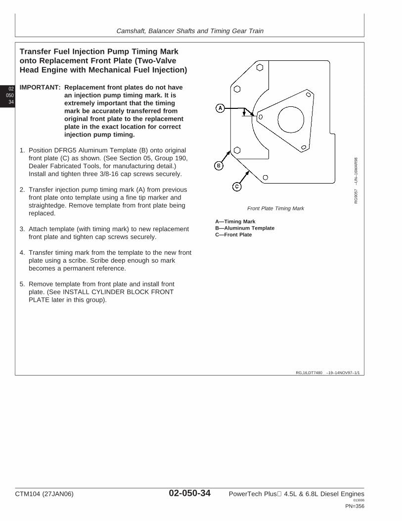
Camshaft, Balancer Shafts and Timing Gear Train
02050
34
RG,16,DT7480 –19–14NOV97–1/1
Transfer Fuel Injection Pump Timing Markonto Replacement Front Plate (Two-ValveHead Engine with Mechanical Fuel Injection)
RG
9057
–UN
–16M
AR
98
Front Plate Timing Mark
A—Timing MarkB—Aluminum TemplateC—Front Plate
IMPORTANT: Replacement front plates do not havean injection pump timing mark. It isextremely important that the timingmark be accurately transferred fromoriginal front plate to the replacementplate in the exact location for correctinjection pump timing.
1. Position DFRG5 Aluminum Template (B) onto originalfront plate (C) as shown. (See Section 05, Group 190,Dealer Fabricated Tools, for manufacturing detail.)Install and tighten three 3/8-16 cap screws securely.
2. Transfer injection pump timing mark (A) from previousfront plate onto template using a fine tip marker andstraightedge. Remove template from front plate beingreplaced.
3. Attach template (with timing mark) to new replacementfront plate and tighten cap screws securely.
4. Transfer timing mark from the template to the new frontplate using a scribe. Scribe deep enough so markbecomes a permanent reference.
5. Remove template from front plate and install frontplate. (See INSTALL CYLINDER BLOCK FRONTPLATE later in this group).
CTM104 (27JAN06) 02-050-34 PowerTech Plus 4.5L & 6.8L Diesel Engines013006
PN=356
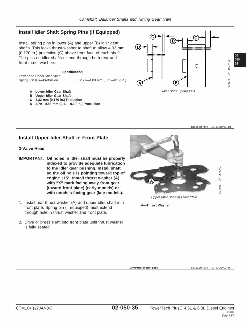
Camshaft, Balancer Shafts and Timing Gear Train
0205035
RG,16,DT7479 –19–14NOV97–1/1
Install Idler Shaft Spring Pins (If Equipped)
RG
9135
–UN
–18M
AY
98
Idler Shaft Spring PinsA—Lower Idler Gear ShaftB—Upper Idler Gear ShaftC—4.32 mm (0.170 in.) ProjectionD—2.79—4.83 mm (0.11—0.19 in.) Protrusion
Install spring pins in lower (A) and upper (B) idler gearshafts. This locks thrust washer to shaft to allow 4.32 mm(0.170 in.) projection (C) above front face of each shaft.The pins on idler shafts extend through both rear andfront thrust washers.
SpecificationLower and Upper Idler ShaftSpring Pin (D)—Protrusion 2.79—4.83 mm (0.11—0.19 in.)......................
RG,16,DT7478 –19–21NOV03–1/2
Install Upper Idler Shaft in Front Plate
RG
7581
–UN
–05N
OV
97
Upper Idler Shaft in Front Plate
A—Thrust Washer
2-Valve Head
IMPORTANT: Oil holes in idler shaft must be properlyindexed to provide adequate lubricationto the idler gear bushing. Install shaftso the oil hole is pointing toward top ofengine ±15°. Install thrust washer (A)with “X” mark facing away from gear(toward front plate) (early models) orwith notches facing gear (late models).
1. Install rear thrust washer (A) and upper idler shaft intofront plate. Spring pin (if equipped) must extendthrough hole in thrust washer and front plate.
2. Drive or press shaft into front plate until thrust washeris fully seated.
Continued on next page
CTM104 (27JAN06) 02-050-35 PowerTech Plus 4.5L & 6.8L Diesel Engines013006
PN=357
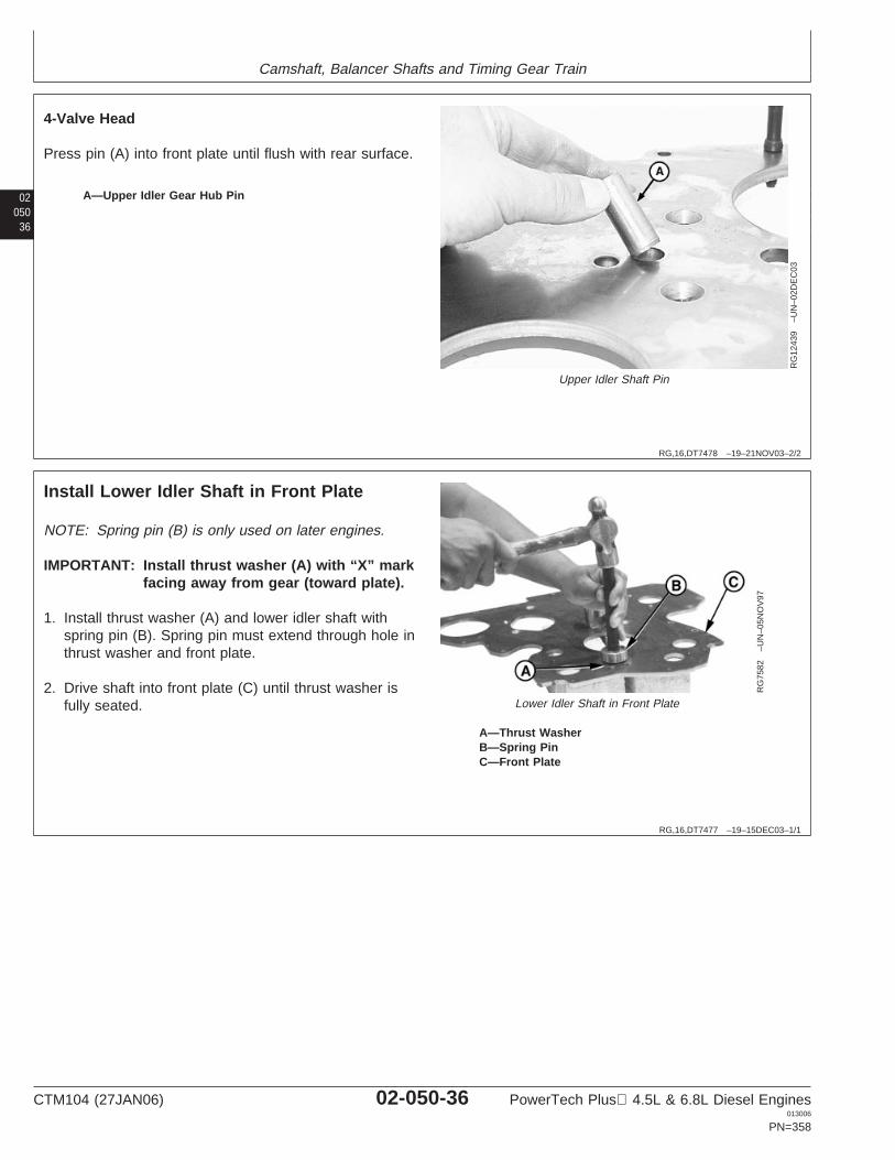
Camshaft, Balancer Shafts and Timing Gear Train
02050
36
RG,16,DT7478 –19–21NOV03–2/2
RG
1243
9–U
N–0
2DE
C03
Upper Idler Shaft Pin
A—Upper Idler Gear Hub Pin
4-Valve Head
Press pin (A) into front plate until flush with rear surface.
RG,16,DT7477 –19–15DEC03–1/1
Install Lower Idler Shaft in Front Plate
RG
7582
–UN
–05N
OV
97
Lower Idler Shaft in Front Plate
A—Thrust WasherB—Spring PinC—Front Plate
NOTE: Spring pin (B) is only used on later engines.
IMPORTANT: Install thrust washer (A) with “X” markfacing away from gear (toward plate).
1. Install thrust washer (A) and lower idler shaft withspring pin (B). Spring pin must extend through hole inthrust washer and front plate.
2. Drive shaft into front plate (C) until thrust washer isfully seated.
CTM104 (27JAN06) 02-050-36 PowerTech Plus 4.5L & 6.8L Diesel Engines013006
PN=358
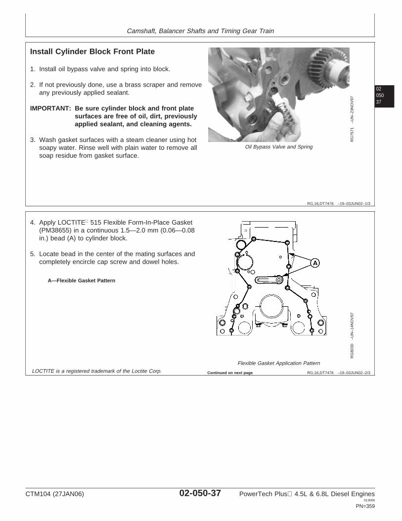
Camshaft, Balancer Shafts and Timing Gear Train
0205037
RG,16,DT7476 –19–03JUN02–1/3
Install Cylinder Block Front Plate
RG
7571
–UN
–23N
OV
97
Oil Bypass Valve and Spring
1. Install oil bypass valve and spring into block.
2. If not previously done, use a brass scraper and removeany previously applied sealant.
IMPORTANT: Be sure cylinder block and front platesurfaces are free of oil, dirt, previouslyapplied sealant, and cleaning agents.
3. Wash gasket surfaces with a steam cleaner using hotsoapy water. Rinse well with plain water to remove allsoap residue from gasket surface.
RG,16,DT7476 –19–03JUN02–2/3
RG
8030
–UN
–14N
OV
97
Flexible Gasket Application Pattern
A—Flexible Gasket Pattern
4. Apply LOCTITE 515 Flexible Form-In-Place Gasket(PM38655) in a continuous 1.5—2.0 mm (0.06—0.08in.) bead (A) to cylinder block.
5. Locate bead in the center of the mating surfaces andcompletely encircle cap screw and dowel holes.
LOCTITE is a registered trademark of the Loctite Corp. Continued on next page
CTM104 (27JAN06) 02-050-37 PowerTech Plus 4.5L & 6.8L Diesel Engines013006
PN=359
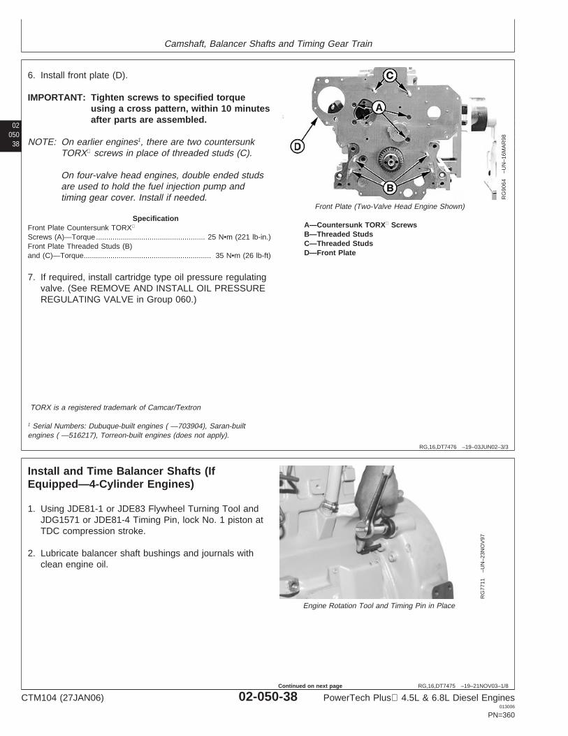
Camshaft, Balancer Shafts and Timing Gear Train
02050
38
RG,16,DT7476 –19–03JUN02–3/3
RG
9064
–UN
–16M
AR
98
Front Plate (Two-Valve Head Engine Shown)
A—Countersunk TORX ScrewsB—Threaded StudsC—Threaded StudsD—Front Plate
6. Install front plate (D).
IMPORTANT: Tighten screws to specified torqueusing a cross pattern, within 10 minutesafter parts are assembled.
NOTE: On earlier engines1, there are two countersunkTORX screws in place of threaded studs (C).
On four-valve head engines, double ended studsare used to hold the fuel injection pump andtiming gear cover. Install if needed.
SpecificationFront Plate Countersunk TORX
Screws (A)—Torque 25 N•m (221 lb-in.).....................................................Front Plate Threaded Studs (B)and (C)—Torque 35 N•m (26 lb-ft)..............................................................
7. If required, install cartridge type oil pressure regulatingvalve. (See REMOVE AND INSTALL OIL PRESSUREREGULATING VALVE in Group 060.)
TORX is a registered trademark of Camcar/Textron
1 Serial Numbers: Dubuque-built engines ( —703904), Saran-builtengines ( —516217), Torreon-built engines (does not apply).
RG,16,DT7475 –19–21NOV03–1/8
Install and Time Balancer Shafts (IfEquipped—4-Cylinder Engines)
RG
7711
–UN
–23N
OV
97
Engine Rotation Tool and Timing Pin in Place
1. Using JDE81-1 or JDE83 Flywheel Turning Tool andJDG1571 or JDE81-4 Timing Pin, lock No. 1 piston atTDC compression stroke.
2. Lubricate balancer shaft bushings and journals withclean engine oil.
CTM104 (27JAN06) 02-050-38 PowerTech Plus 4.5L & 6.8L Diesel Engines013006
PN=360
Continued on next page
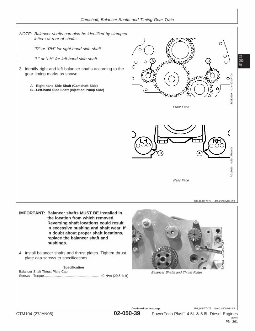
Camshaft, Balancer Shafts and Timing Gear Train
0205039
RG,16,DT7475 –19–21NOV03–2/8
RG
1361
9–U
N–1
7MA
Y04
Front Face
RG
1362
0–U
N–1
7MA
Y04
Rear Face
A—Right-hand Side Shaft (Camshaft Side)B—Left-hand Side Shaft (Injection Pump Side)
NOTE: Balancer shafts can also be identified by stampedletters at rear of shafts.
”R” or “RH” for right-hand side shaft.
”L” or “LH” for left-hand side shaft.
3. Identify right and left balancer shafts according to thegear timing marks as shown.
RG,16,DT7475 –19–21NOV03–3/8
RG
7704
–UN
–23N
OV
97
Balancer Shafts and Thrust Plates
IMPORTANT: Balancer shafts MUST BE installed inthe location from which removed.Reversing shaft locations could resultin excessive bushing and shaft wear. Ifin doubt about proper shaft locations,replace the balancer shaft andbushings.
4. Install balancer shafts and thrust plates. Tighten thrustplate cap screws to specifications.
SpecificationBalancer Shaft Thrust Plate CapScrews—Torque 40 N•m (29.5 lb-ft)...........................................................
CTM104 (27JAN06) 02-050-39 PowerTech Plus 4.5L & 6.8L Diesel Engines013006
PN=361
Continued on next page
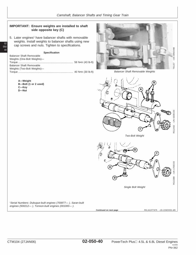
Camshaft, Balancer Shafts and Timing Gear Train
02050
40
RG,16,DT7475 –19–21NOV03–4/8
T91
157
–UN
–09N
OV
88
Balancer Shaft Removable Weights
RG
1243
2–U
N–0
2DE
C03
Two-Bolt Weight
RG
1338
8–U
N–1
7DE
C03
Single Bolt Weight
A—WeightB—Bolt (1 or 2 used)C—KeyD—Nut
IMPORTANT: Ensure weights are installed to shaftside opposite key (C)
5. Later engines1 have balancer shafts with removableweights. Install weights to balancer shafts using newcap screws and nuts. Tighten to specifications.
SpecificationBalancer Shaft RemovableWeights (One-Bolt Weights)—Torque 58 N•m (43 lb-ft).............................................................................Balancer Shaft RemovableWeights (Two-Bolt Weights)—Torque 40 N•m (30 lb-ft).............................................................................
1Serial Numbers: Dubuque-built engines (700877— ), Saran-builtengines (500212— ), Torreon-built engines (001000— ).
Continued on next page
CTM104 (27JAN06) 02-050-40 PowerTech Plus 4.5L & 6.8L Diesel Engines013006
PN=362
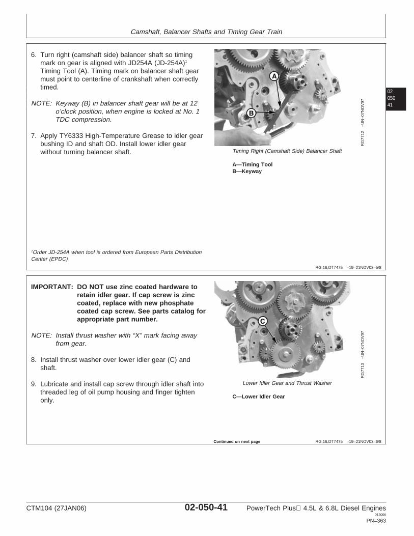
Camshaft, Balancer Shafts and Timing Gear Train
0205041
RG,16,DT7475 –19–21NOV03–5/8
RG
7712
–UN
–07N
OV
97
Timing Right (Camshaft Side) Balancer Shaft
A—Timing ToolB—Keyway
6. Turn right (camshaft side) balancer shaft so timingmark on gear is aligned with JD254A (JD-254A)1
Timing Tool (A). Timing mark on balancer shaft gearmust point to centerline of crankshaft when correctlytimed.
NOTE: Keyway (B) in balancer shaft gear will be at 12o’clock position, when engine is locked at No. 1TDC compression.
7. Apply TY6333 High-Temperature Grease to idler gearbushing ID and shaft OD. Install lower idler gearwithout turning balancer shaft.
1Order JD-254A when tool is ordered from European Parts DistributionCenter (EPDC)
RG,16,DT7475 –19–21NOV03–6/8
RG
7713
–UN
–07N
OV
97
Lower Idler Gear and Thrust Washer
C—Lower Idler Gear
IMPORTANT: DO NOT use zinc coated hardware toretain idler gear. If cap screw is zinccoated, replace with new phosphatecoated cap screw. See parts catalog forappropriate part number.
NOTE: Install thrust washer with “X” mark facing awayfrom gear.
8. Install thrust washer over lower idler gear (C) andshaft.
9. Lubricate and install cap screw through idler shaft intothreaded leg of oil pump housing and finger tightenonly.
Continued on next page
CTM104 (27JAN06) 02-050-41 PowerTech Plus 4.5L & 6.8L Diesel Engines013006
PN=363
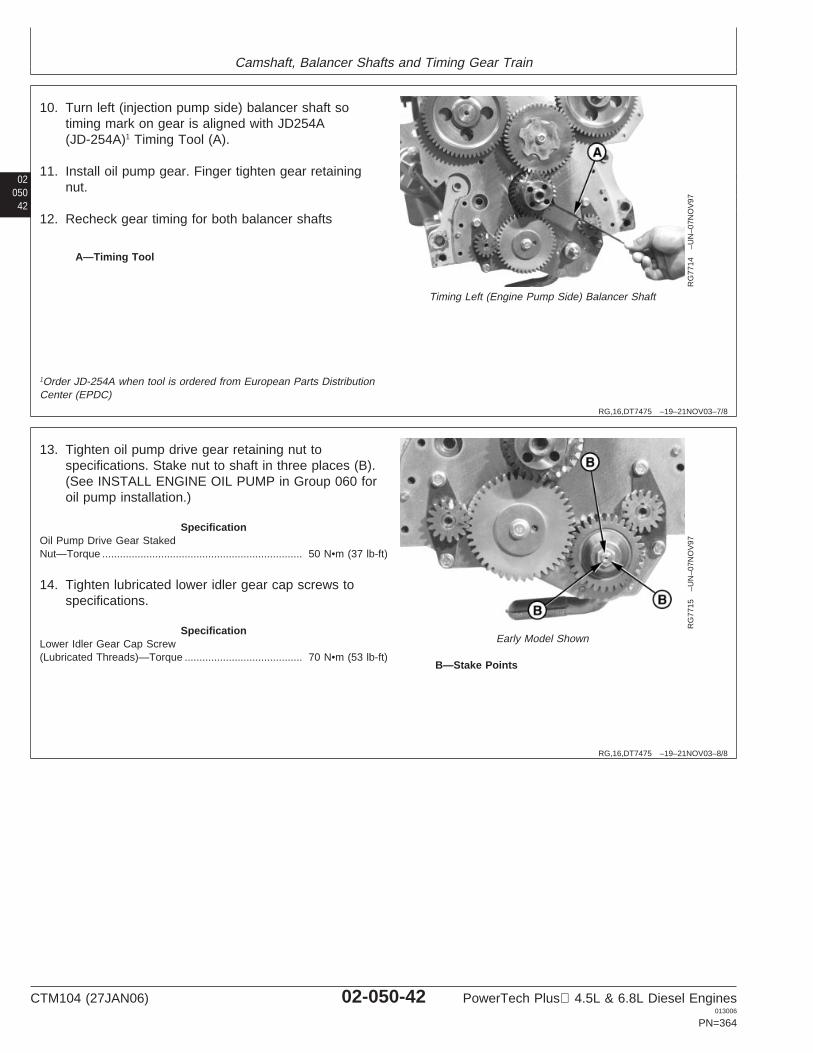
Camshaft, Balancer Shafts and Timing Gear Train
02050
42
RG,16,DT7475 –19–21NOV03–7/8
RG
7714
–UN
–07N
OV
97
Timing Left (Engine Pump Side) Balancer Shaft
A—Timing Tool
10. Turn left (injection pump side) balancer shaft sotiming mark on gear is aligned with JD254A(JD-254A)1 Timing Tool (A).
11. Install oil pump gear. Finger tighten gear retainingnut.
12. Recheck gear timing for both balancer shafts
1Order JD-254A when tool is ordered from European Parts DistributionCenter (EPDC)
RG,16,DT7475 –19–21NOV03–8/8
RG
7715
–UN
–07N
OV
97
Early Model Shown
B—Stake Points
13. Tighten oil pump drive gear retaining nut tospecifications. Stake nut to shaft in three places (B).(See INSTALL ENGINE OIL PUMP in Group 060 foroil pump installation.)
SpecificationOil Pump Drive Gear StakedNut—Torque 50 N•m (37 lb-ft)....................................................................
14. Tighten lubricated lower idler gear cap screws tospecifications.
SpecificationLower Idler Gear Cap Screw(Lubricated Threads)—Torque 70 N•m (53 lb-ft)........................................
CTM104 (27JAN06) 02-050-42 PowerTech Plus 4.5L & 6.8L Diesel Engines013006
PN=364
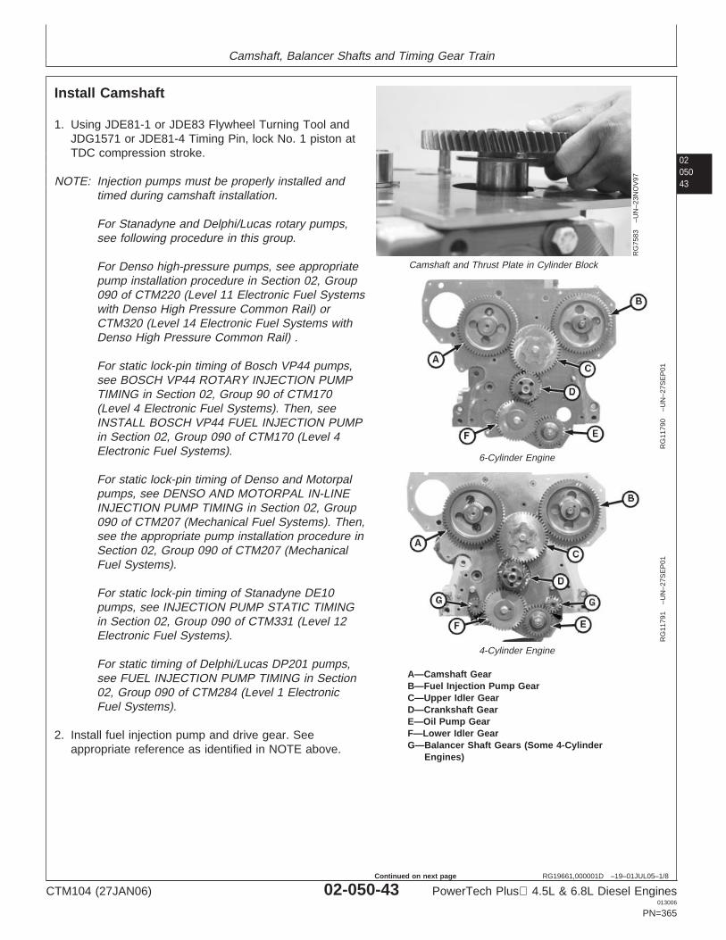
Camshaft, Balancer Shafts and Timing Gear Train
0205043
RG19661,000001D –19–01JUL05–1/8
Install Camshaft
RG
7583
–UN
–23N
OV
97
Camshaft and Thrust Plate in Cylinder Block
RG
1179
0–U
N–2
7SE
P01
6-Cylinder Engine
RG
1179
1–U
N–2
7SE
P01
4-Cylinder Engine
A—Camshaft GearB—Fuel Injection Pump GearC—Upper Idler GearD—Crankshaft GearE—Oil Pump GearF—Lower Idler GearG—Balancer Shaft Gears (Some 4-Cylinder
Engines)
1. Using JDE81-1 or JDE83 Flywheel Turning Tool andJDG1571 or JDE81-4 Timing Pin, lock No. 1 piston atTDC compression stroke.
NOTE: Injection pumps must be properly installed andtimed during camshaft installation.
For Stanadyne and Delphi/Lucas rotary pumps,see following procedure in this group.
For Denso high-pressure pumps, see appropriatepump installation procedure in Section 02, Group090 of CTM220 (Level 11 Electronic Fuel Systemswith Denso High Pressure Common Rail) orCTM320 (Level 14 Electronic Fuel Systems withDenso High Pressure Common Rail) .
For static lock-pin timing of Bosch VP44 pumps,see BOSCH VP44 ROTARY INJECTION PUMPTIMING in Section 02, Group 90 of CTM170(Level 4 Electronic Fuel Systems). Then, seeINSTALL BOSCH VP44 FUEL INJECTION PUMPin Section 02, Group 090 of CTM170 (Level 4Electronic Fuel Systems).
For static lock-pin timing of Denso and Motorpalpumps, see DENSO AND MOTORPAL IN-LINEINJECTION PUMP TIMING in Section 02, Group090 of CTM207 (Mechanical Fuel Systems). Then,see the appropriate pump installation procedure inSection 02, Group 090 of CTM207 (MechanicalFuel Systems).
For static lock-pin timing of Stanadyne DE10pumps, see INJECTION PUMP STATIC TIMINGin Section 02, Group 090 of CTM331 (Level 12Electronic Fuel Systems).
For static timing of Delphi/Lucas DP201 pumps,see FUEL INJECTION PUMP TIMING in Section02, Group 090 of CTM284 (Level 1 ElectronicFuel Systems).
2. Install fuel injection pump and drive gear. Seeappropriate reference as identified in NOTE above.
CTM104 (27JAN06) 02-050-43 PowerTech Plus 4.5L & 6.8L Diesel Engines013006
PN=365
Continued on next page
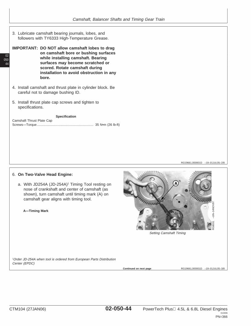
Camshaft, Balancer Shafts and Timing Gear Train
02050
44
RG19661,000001D –19–01JUL05–2/8
3. Lubricate camshaft bearing journals, lobes, andfollowers with TY6333 High-Temperature Grease.
IMPORTANT: DO NOT allow camshaft lobes to dragon camshaft bore or bushing surfaceswhile installing camshaft. Bearingsurfaces may become scratched orscored. Rotate camshaft duringinstallation to avoid obstruction in anybore.
4. Install camshaft and thrust plate in cylinder block. Becareful not to damage bushing ID.
5. Install thrust plate cap screws and tighten tospecifications.
SpecificationCamshaft Thrust Plate CapScrews—Torque 35 N•m (26 lb-ft)..............................................................
RG19661,000001D –19–01JUL05–3/8
RG
8031
–UN
–14N
OV
97
Setting Camshaft Timing
A—Timing Mark
6. On Two-Valve Head Engine:
a. With JD254A (JD-254A)1 Timing Tool resting onnose of crankshaft and center of camshaft (asshown), turn camshaft until timing mark (A) oncamshaft gear aligns with timing tool.
1Order JD-254A when tool is ordered from European Parts DistributionCenter (EPDC)
Continued on next page
CTM104 (27JAN06) 02-050-44 PowerTech Plus 4.5L & 6.8L Diesel Engines013006
PN=366

Camshaft, Balancer Shafts and Timing Gear Train
0205045
RG19661,000001D –19–01JUL05–4/8
RG
9134
–UN
–18M
AY
98
Setting Injection Pump TimingRG7939 –UN–05JAN98
JDG791A
B—Timing Mark
NOTE: Denso, Motorpal, Bosch VP44 and StanadyneDE10 injection pumps are static lock-pin timedduring installation. The following step applies toearlier Stanadyne and to all Delphi/Lucas Pumpsonly.
IMPORTANT: Use the timing mark corresponding tothe number of cylinders the engine hasthat is being timed.
b. On earlier Stanadyne and all Delphi/Lucas rotarypumps: Check injection pump gear timing withJD254A (JD-254A)1 Timing Tool resting on nose ofcrankshaft and center of injection pump shaft. Timingmark (B) on injection pump drive gear, as described intable below, must align with timing tool (as shown).
INJECTION PUMP GEAR TIMING MARKSInjection Pump Model Timing MarkDelphi/Lucas and Stanadyne 4-Cyl. Engine ........... 4Stanadyne 6-Cyl. Engine ........................................ S6Delphi/Lucas 6-Cyl. Engine .................................... L6Delphi/Lucas (1st Production 1170 Combines) ...... L6Delphi/Lucas (Early 1170 Combines) ..................... 6CDelphi/Lucas (Late 1170 Combines) ...................... 6Z
IMPORTANT: To ensure proper lubrication of newupper idler gear bushing and camshaftbushing, install new upper idler gearwith the reference number facing awayfrom engine.
c. Lubricate upper idler gear bushing ID and shaft ODwith TY6333 High-Temperature Grease. UsingJDG791A Idler Gear Installer Pilot,2 install idler gearwithout turning camshaft gear or injection pump gear.
1Order JD-254A when tool is ordered from European Parts DistributionCenter (EPDC)
2JDG791A needs to be modified to allow space for the spring pin in idlershaft.
Continued on next page
CTM104 (27JAN06) 02-050-45 PowerTech Plus 4.5L & 6.8L Diesel Engines013006
PN=367
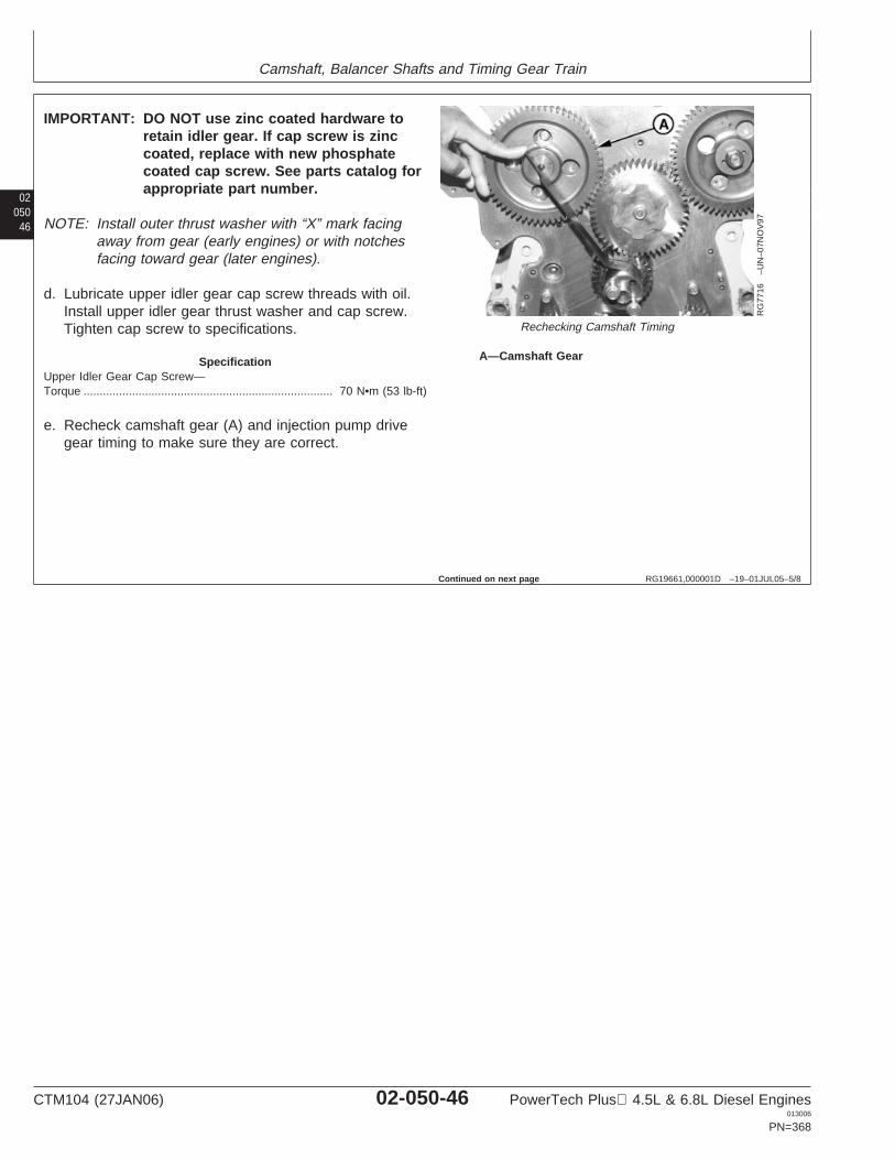
Camshaft, Balancer Shafts and Timing Gear Train
02050
46
RG19661,000001D –19–01JUL05–5/8
RG
7716
–UN
–07N
OV
97
Rechecking Camshaft Timing
A—Camshaft Gear
IMPORTANT: DO NOT use zinc coated hardware toretain idler gear. If cap screw is zinccoated, replace with new phosphatecoated cap screw. See parts catalog forappropriate part number.
NOTE: Install outer thrust washer with “X” mark facingaway from gear (early engines) or with notchesfacing toward gear (later engines).
d. Lubricate upper idler gear cap screw threads with oil.Install upper idler gear thrust washer and cap screw.Tighten cap screw to specifications.
SpecificationUpper Idler Gear Cap Screw—Torque 70 N•m (53 lb-ft).............................................................................
e. Recheck camshaft gear (A) and injection pump drivegear timing to make sure they are correct.
Continued on next page
CTM104 (27JAN06) 02-050-46 PowerTech Plus 4.5L & 6.8L Diesel Engines013006
PN=368

Camshaft, Balancer Shafts and Timing Gear Train
0205047
RG19661,000001D –19–01JUL05–6/8
RG
1244
0–U
N–0
2DE
C03
Upper Idler Gear Thrust Washer and Hub (Four-Valve HeadEngine)
F
E
D
A
RG
1243
3–U
N–0
2DE
C03
Upper Idler Gear Assembly (Four-Valve Head Engine)
G H
C
I
RG
1243
4–U
N–0
2DE
C03
Camshaft and Fuel Pump Timing (Four-Valve Head Engine)
A—Upper Idler Gear HubB—Rear Thrust WasherC—Upper Idler Gear Hub PinD—Upper Idler GearE—Front Thrust WasherF—Cap ScrewG—Camshaft Gear “V 4Valve” or “V 4” Timing MarkH—Upper Idler Gear “V 4Valve” or “V 4” Timing MarkI—Fuel Injection Pump Gear Timing Mark
7. On Four-Valve Head Engine:
NOTE: Be sure crankshaft is at TDC compression strokeand timing pin is in position (see Step 1).
a. Align the fuel injection pump gear timing mark (I) tothe twelve o’clock position.
b. Align “V 4Valve” or “V 4” timing mark (G) ofcamshaft gear with center of idler gear pin (C).
NOTE: Install inner and outer thrust washers withlubrication grooves facing toward idler gear.
c. Install rear thrust washer (B) onto pin (C) withlubrication grooves facing the idler gear.
d. Lubricate upper idler gear hub (A) ID and upperidler gear pin (C) OD with TY6333 HighTemperature Grease.
e. Lubricate upper idler gear (D) ID and upper idlergear hub (A) OD with TY6333 High TemperatureGrease. Install upper idler gear (D) onto upper idlergear hub (A).
CTM104 (27JAN06) 02-050-47 PowerTech Plus 4.5L & 6.8L Diesel Engines013006
PN=369
Continued on next page
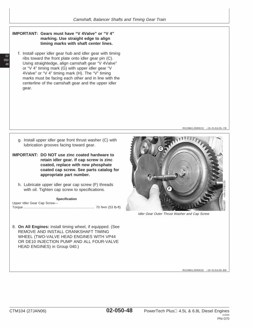
Camshaft, Balancer Shafts and Timing Gear Train
02050
48
RG19661,000001D –19–01JUL05–7/8
IMPORTANT: Gears must have “V 4Valve” or “V 4”marking. Use straight edge to aligntiming marks with shaft center lines.
f. Install upper idler gear hub and idler gear with timingribs toward the front plate onto idler gear pin (C).Using straightedge, align camshaft gear “V 4Valve”or “V 4” timing mark (G) with upper idler gear “V4Valve” or “V 4” timing mark (H). The “V” timingmarks must be facing each other and in line with thecenterline of the camshaft gear and the upper idlergear.
RG19661,000001D –19–01JUL05–8/8
RG
1338
7–U
N–1
7DE
C03
Idler Gear Outer Thrust Washer and Cap Screw
g. Install upper idler gear front thrust washer (C) withlubrication grooves facing toward gear.
IMPORTANT: DO NOT use zinc coated hardware toretain idler gear. If cap screw is zinccoated, replace with new phosphatecoated cap screw. See parts catalog forappropriate part number.
h. Lubricate upper idler gear cap screw (F) threadswith oil. Tighten cap screw to specifications.
SpecificationUpper Idler Gear Cap Screw—Torque 70 N•m (53 lb-ft).............................................................................
8. On All Engines: install timing wheel, if equipped. (SeeREMOVE AND INSTALL CRANKSHAFT TIMINGWHEEL (TWO-VALVE HEAD ENGINES WITH VP44OR DE10 INJECTION PUMP AND ALL FOUR-VALVEHEAD ENGINES) in Group 040.)
CTM104 (27JAN06) 02-050-48 PowerTech Plus 4.5L & 6.8L Diesel Engines013006
PN=370
Camshaft, Balancer Shafts and Timing Gear Train
0205049
RG,16,DT7472 –19–14NOV97–1/1
Clean and Inspect Timing Gear Cover
1. Drive crankshaft front oil seal out of cover onengines not using a unitized front seal.
2. Remove material and sealant from cylinder blockand timing gear cover gasket surfaces. Ifnecessary, remove oil filler neck and gasket andinjection pump drive gear nut cover plate andgasket.
CAUTION: Do not spin bearings when dryingwith compressed air.
3. If engine is equipped with the auxiliary drive,remove auxiliary drive as described earlier in thisgroup.
4. If engine is equipped with electronic tachometer(magnetic pick-up) sensor, remove sensor andO-ring. (See REMOVE AND INSTALL MAGNETICPICK-UP SENSOR, as described in this group.)
5. Clean timing gear cover in solvent. Dry withcompressed air.
6. Inspect cover for cracks or damage. Make sure sealbore is clean and free of nicks.
CTM104 (27JAN06) 02-050-49 PowerTech Plus 4.5L & 6.8L Diesel Engines013006
PN=371
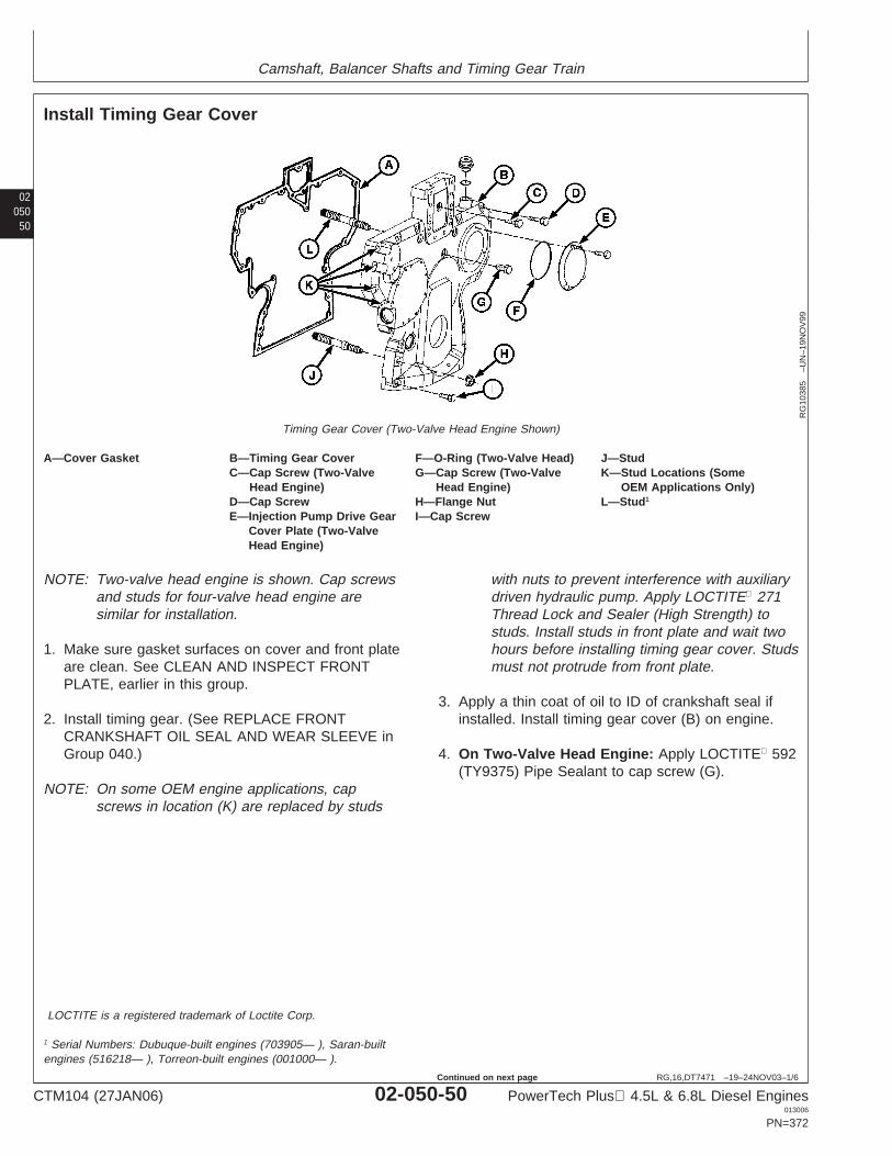
Camshaft, Balancer Shafts and Timing Gear Train
02050
50
RG,16,DT7471 –19–24NOV03–1/6
Install Timing Gear Cover
RG
1038
5–U
N–1
9NO
V99
Timing Gear Cover (Two-Valve Head Engine Shown)
A—Cover Gasket B—Timing Gear Cover F—O-Ring (Two-Valve Head) J—StudC—Cap Screw (Two-Valve G—Cap Screw (Two-Valve K—Stud Locations (Some
Head Engine) Head Engine) OEM Applications Only)D—Cap Screw H—Flange Nut L—Stud1
E—Injection Pump Drive Gear I—Cap ScrewCover Plate (Two-ValveHead Engine)
NOTE: Two-valve head engine is shown. Cap screwsand studs for four-valve head engine aresimilar for installation.
1. Make sure gasket surfaces on cover and front plateare clean. See CLEAN AND INSPECT FRONTPLATE, earlier in this group.
2. Install timing gear. (See REPLACE FRONTCRANKSHAFT OIL SEAL AND WEAR SLEEVE inGroup 040.)
NOTE: On some OEM engine applications, capscrews in location (K) are replaced by studs
with nuts to prevent interference with auxiliarydriven hydraulic pump. Apply LOCTITE 271Thread Lock and Sealer (High Strength) tostuds. Install studs in front plate and wait twohours before installing timing gear cover. Studsmust not protrude from front plate.
3. Apply a thin coat of oil to ID of crankshaft seal ifinstalled. Install timing gear cover (B) on engine.
4. On Two-Valve Head Engine: Apply LOCTITE 592(TY9375) Pipe Sealant to cap screw (G).
LOCTITE is a registered trademark of Loctite Corp.
1 Serial Numbers: Dubuque-built engines (703905— ), Saran-builtengines (516218— ), Torreon-built engines (001000— ).
CTM104 (27JAN06) 02-050-50 PowerTech Plus 4.5L & 6.8L Diesel Engines013006
PN=372
Continued on next page
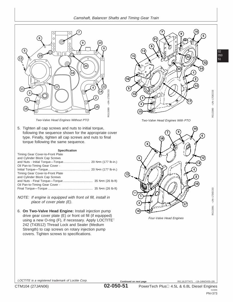
Camshaft, Balancer Shafts and Timing Gear Train
0205051
RG,16,DT7471 –19–24NOV03–2/6
7
9 10
16
1
311
8
5
13
6
12
144
2
15
17
18
19
20
RG
1338
9–U
N–1
7DE
C03
Two-Valve Head Engines Without PTO
RG
1339
0–U
N–1
7DE
C03
Two-Valve Head Engines With PTO
RG
1339
1–U
N–1
7DE
C03
Four-Valve Head Engines
5. Tighten all cap screws and nuts to initial torque,following the sequence shown for the appropriate covertype. Finally, tighten all cap screws and nuts to finaltorque following the same sequence.
SpecificationTiming Gear Cover-to-Front Plateand Cylinder Block Cap Screwsand Nuts - Initial Torque—Torque 20 N•m (177 lb-in.)................................Oil Pan-to-Timing Gear Cover -Initial Torque—Torque 20 N•m (177 lb-in.)..................................................Timing Gear Cover-to-Front Plateand Cylinder Block Cap Screwsand Nuts - Final Torque—Torque 35 N•m (26 lb-ft)...................................Oil Pan-to-Timing Gear Cover -Final Torque—Torque 35 N•m (26 lb-ft).....................................................
NOTE: If engine is equipped with front oil fill, install inplace of cover plate (E).
6. On Two-Valve Head Engine: Install injection pumpdrive gear cover plate (E) or front oil fill (if equipped)using a new O-ring (F), if necessary. Apply LOCTITE
242 (T43512) Thread Lock and Sealer (MediumStrength) to cap screws on rotary injection pumpcovers. Tighten screws to specifications.
LOCTITE is a registered trademark of Loctite Corp.
CTM104 (27JAN06) 02-050-51 PowerTech Plus 4.5L & 6.8L Diesel Engines013006
PN=373
Continued on next page
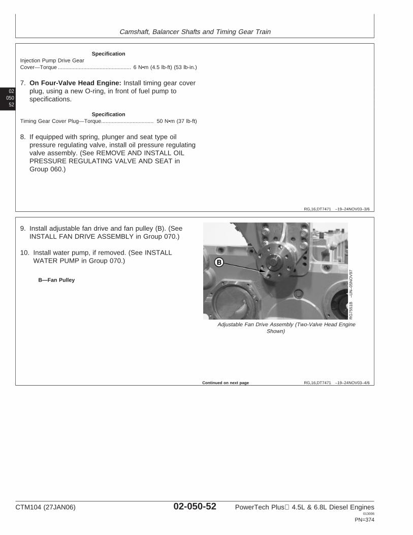
Camshaft, Balancer Shafts and Timing Gear Train
02050
52
RG,16,DT7471 –19–24NOV03–3/6
SpecificationInjection Pump Drive GearCover—Torque 6 N•m (4.5 lb-ft) (53 lb-in.).................................................
7. On Four-Valve Head Engine: Install timing gear coverplug, using a new O-ring, in front of fuel pump tospecifications.
SpecificationTiming Gear Cover Plug—Torque 50 N•m (37 lb-ft)...................................
8. If equipped with spring, plunger and seat type oilpressure regulating valve, install oil pressure regulatingvalve assembly. (See REMOVE AND INSTALL OILPRESSURE REGULATING VALVE AND SEAT inGroup 060.)
RG,16,DT7471 –19–24NOV03–4/6
RG
7551
B–U
N–0
5NO
V97
Adjustable Fan Drive Assembly (Two-Valve Head EngineShown)
B—Fan Pulley
9. Install adjustable fan drive and fan pulley (B). (SeeINSTALL FAN DRIVE ASSEMBLY in Group 070.)
10. Install water pump, if removed. (See INSTALLWATER PUMP in Group 070.)
Continued on next page
CTM104 (27JAN06) 02-050-52 PowerTech Plus 4.5L & 6.8L Diesel Engines013006
PN=374
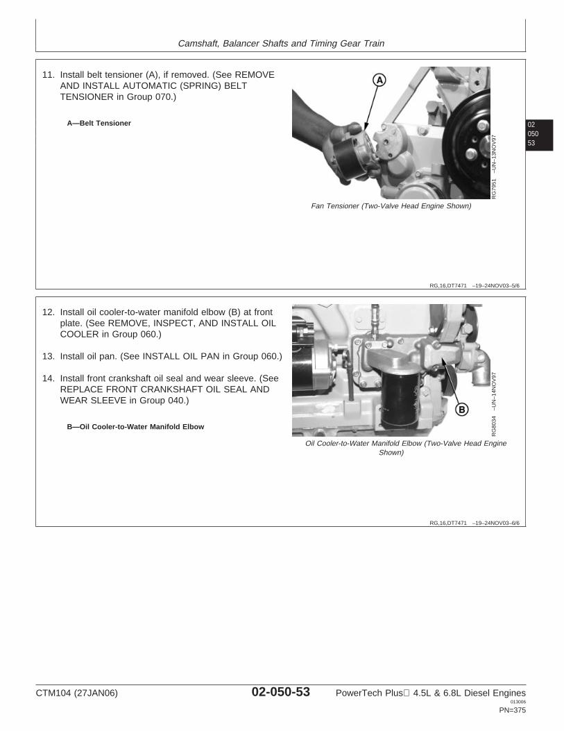
Camshaft, Balancer Shafts and Timing Gear Train
0205053
RG,16,DT7471 –19–24NOV03–5/6
RG
7951
–UN
–13N
OV
97
Fan Tensioner (Two-Valve Head Engine Shown)
A—Belt Tensioner
11. Install belt tensioner (A), if removed. (See REMOVEAND INSTALL AUTOMATIC (SPRING) BELTTENSIONER in Group 070.)
RG,16,DT7471 –19–24NOV03–6/6
RG
8034
–UN
–14N
OV
97
Oil Cooler-to-Water Manifold Elbow (Two-Valve Head EngineShown)
B—Oil Cooler-to-Water Manifold Elbow
12. Install oil cooler-to-water manifold elbow (B) at frontplate. (See REMOVE, INSPECT, AND INSTALL OILCOOLER in Group 060.)
13. Install oil pan. (See INSTALL OIL PAN in Group 060.)
14. Install front crankshaft oil seal and wear sleeve. (SeeREPLACE FRONT CRANKSHAFT OIL SEAL ANDWEAR SLEEVE in Group 040.)
CTM104 (27JAN06) 02-050-53 PowerTech Plus 4.5L & 6.8L Diesel Engines013006
PN=375
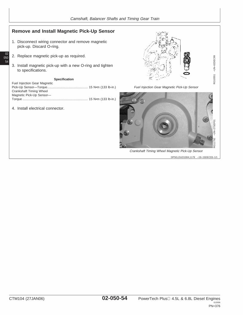
Camshaft, Balancer Shafts and Timing Gear Train
02050
54
DPSG,OUO1004,1179 –19–15DEC03–1/1
Remove and Install Magnetic Pick-Up Sensor
RG
1055
1–U
N–0
2DE
C99
Fuel Injection Gear Magnetic Pick-Up Sensor
RG
1179
2–U
N–2
7SE
P01
Crankshaft Timing Wheel Magnetic Pick-Up Sensor
1. Disconnect wiring connector and remove magneticpick-up. Discard O-ring.
2. Replace magnetic pick-up as required.
3. Install magnetic pick-up with a new O-ring and tightento specifications.
SpecificationFuel Injection Gear MagneticPick-Up Sensor—Torque 15 N•m (133 lb-in.)..............................................Crankshaft Timing WheelMagnetic Pick-Up Sensor—Torque 15 N•m (133 lb-in.)..........................................................................
4. Install electrical connector.
CTM104 (27JAN06) 02-050-54 PowerTech Plus 4.5L & 6.8L Diesel Engines013006
PN=376
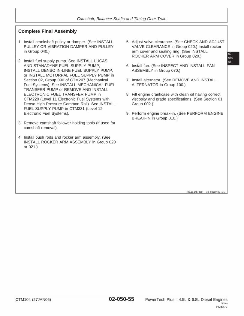
Camshaft, Balancer Shafts and Timing Gear Train
0205055
RG,16,DT7469 –19–03JUN02–1/1
Complete Final Assembly
1. Install crankshaft pulley or damper. (See INSTALLPULLEY OR VIBRATION DAMPER AND PULLEYin Group 040.)
2. Install fuel supply pump. See INSTALL LUCASAND STANADYNE FUEL SUPPLY PUMP,INSTALL DENSO IN-LINE FUEL SUPPLY PUMP,or INSTALL MOTORPAL FUEL SUPPLY PUMP inSection 02, Group 090 of CTM207 (MechanicalFuel Systems). See INSTALL MECHANICAL FUELTRANSFER PUMP or REMOVE AND INSTALLELECTRONIC FUEL TRANSFER PUMP inCTM220 (Level 11 Electronic Fuel Systems withDenso High Pressure Common Rail). See INSTALLFUEL SUPPLY PUMP in CTM331 (Level 12Electronic Fuel Systems).
3. Remove camshaft follower holding tools (if used forcamshaft removal).
4. Install push rods and rocker arm assembly. (SeeINSTALL ROCKER ARM ASSEMBLY in Group 020or 021.)
5. Adjust valve clearance. (See CHECK AND ADJUSTVALVE CLEARANCE in Group 020.) Install rockerarm cover and sealing ring. (See INSTALLROCKER ARM COVER in Group 020.)
6. Install fan. (See INSPECT AND INSTALL FANASSEMBLY in Group 070.)
7. Install alternator. (See REMOVE AND INSTALLALTERNATOR in Group 100.)
8. Fill engine crankcase with clean oil having correctviscosity and grade specifications. (See Section 01,Group 002.)
9. Perform engine break-in. (See PERFORM ENGINEBREAK-IN in Group 010.)
CTM104 (27JAN06) 02-050-55 PowerTech Plus 4.5L & 6.8L Diesel Engines013006
PN=377
Camshaft, Balancer Shafts and Timing Gear Train
02050
56
CTM104 (27JAN06) 02-050-56 PowerTech Plus 4.5L & 6.8L Diesel Engines013006
PN=378
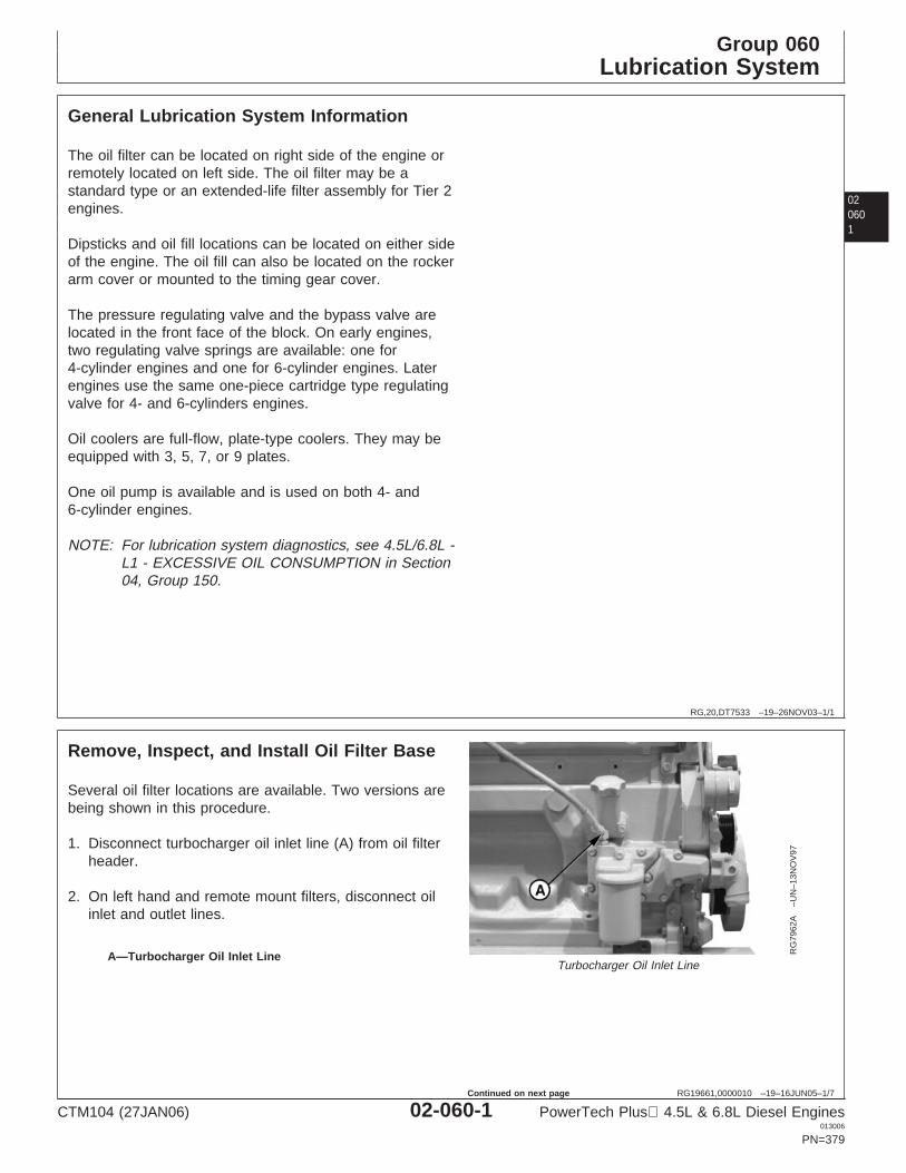
Group 060Lubrication System
020601
RG,20,DT7533 –19–26NOV03–1/1
General Lubrication System Information
The oil filter can be located on right side of the engine orremotely located on left side. The oil filter may be astandard type or an extended-life filter assembly for Tier 2engines.
Dipsticks and oil fill locations can be located on either sideof the engine. The oil fill can also be located on the rockerarm cover or mounted to the timing gear cover.
The pressure regulating valve and the bypass valve arelocated in the front face of the block. On early engines,two regulating valve springs are available: one for4-cylinder engines and one for 6-cylinder engines. Laterengines use the same one-piece cartridge type regulatingvalve for 4- and 6-cylinders engines.
Oil coolers are full-flow, plate-type coolers. They may beequipped with 3, 5, 7, or 9 plates.
One oil pump is available and is used on both 4- and6-cylinder engines.
NOTE: For lubrication system diagnostics, see 4.5L/6.8L -L1 - EXCESSIVE OIL CONSUMPTION in Section04, Group 150.
RG19661,0000010 –19–16JUN05–1/7
Remove, Inspect, and Install Oil Filter Base
RG
7962
A–U
N–1
3NO
V97
Turbocharger Oil Inlet LineA—Turbocharger Oil Inlet Line
Several oil filter locations are available. Two versions arebeing shown in this procedure.
1. Disconnect turbocharger oil inlet line (A) from oil filterheader.
2. On left hand and remote mount filters, disconnect oilinlet and outlet lines.
CTM104 (27JAN06) 02-060-1 PowerTech Plus 4.5L & 6.8L Diesel Engines013006
PN=379
Continued on next page
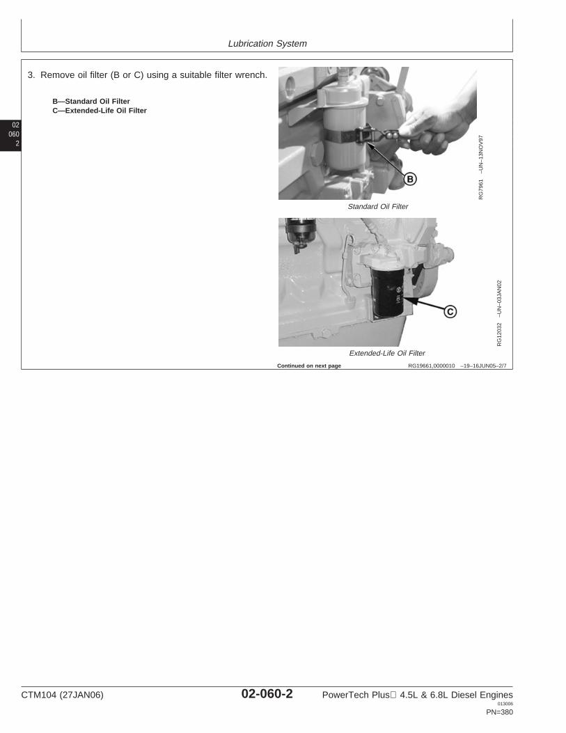
Lubrication System
02060
2
RG19661,0000010 –19–16JUN05–2/7
RG
7961
–UN
–13N
OV
97
Standard Oil Filter
RG
1203
2–U
N–0
3JA
N02
Extended-Life Oil Filter
B—Standard Oil FilterC—Extended-Life Oil Filter
3. Remove oil filter (B or C) using a suitable filter wrench.
Continued on next page
CTM104 (27JAN06) 02-060-2 PowerTech Plus 4.5L & 6.8L Diesel Engines013006
PN=380
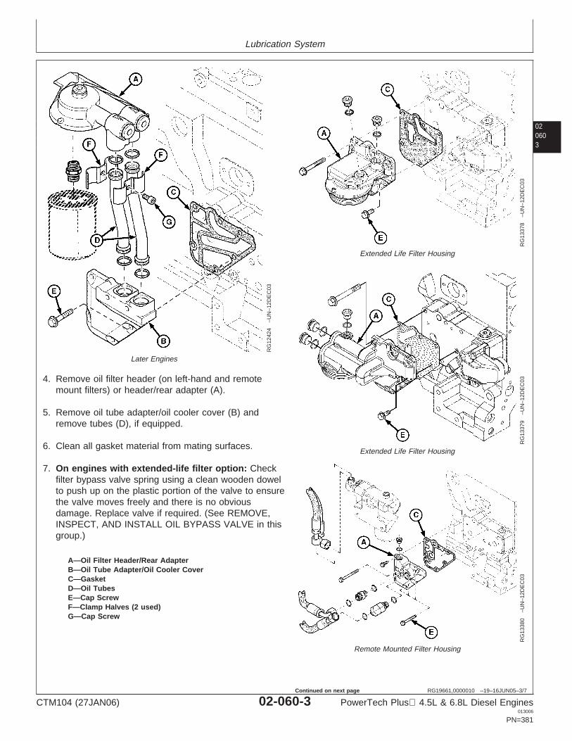
Lubrication System
020603
RG19661,0000010 –19–16JUN05–3/7
RG
1242
4–U
N–1
2DE
C03
Later Engines
RG
1337
8–U
N–1
2DE
C03
Extended Life Filter Housing
RG
1337
9–U
N–1
2DE
C03
Extended Life Filter Housing
RG
1338
0–U
N–1
2DE
C03
Remote Mounted Filter Housing
A—Oil Filter Header/Rear AdapterB—Oil Tube Adapter/Oil Cooler CoverC—GasketD—Oil TubesE—Cap ScrewF—Clamp Halves (2 used)G—Cap Screw
4. Remove oil filter header (on left-hand and remotemount filters) or header/rear adapter (A).
5. Remove oil tube adapter/oil cooler cover (B) andremove tubes (D), if equipped.
6. Clean all gasket material from mating surfaces.
7. On engines with extended-life filter option: Checkfilter bypass valve spring using a clean wooden dowelto push up on the plastic portion of the valve to ensurethe valve moves freely and there is no obviousdamage. Replace valve if required. (See REMOVE,INSPECT, AND INSTALL OIL BYPASS VALVE in thisgroup.)
CTM104 (27JAN06) 02-060-3 PowerTech Plus 4.5L & 6.8L Diesel Engines013006
PN=381
Continued on next page
Lubrication System
02060
4
RG19661,0000010 –19–16JUN05–4/7
8. Inspect all parts and replace if needed.
NOTE: On early engines, O-rings for tubes (D) areinstalled in grooves of adapter (B). Later enginesare equipped with beaded tubes (D) which retainthe O-rings. Note position on these tubes forassembly in the same position.
9. Install new gasket and O-rings (if required) and installoil filter header/rear adapter (A) or remote filter headerto bracket. Tighten cap screws to specifications.
SpecificationOil Filter Header Cap Screws(High, Front and RearMounted)—Torque 35 N•m (26 lb-ft)...........................................................Oil Filter Header-to-Bracket CapScrews (Left-Hand and RemoteMounted)—Torque 73 N•m (54 lb-ft)...........................................................
10. Using a new gasket and O-rings, install adapter (B)and tubes (D) on high, front and rear mountassemblies. Apply LOCTITE 242 Thread Lock andSealer (Medium Strength) to short cap screw (E) foropen hole in oil cooler. Tighten all cap screws tospecifications.
SpecificationOil Cooler Cover Cap Screw—Torque 35 N•m (26 lb-ft).............................................................................
11. Place clamp halves (F) on each side of the upperstraight sections of oil tubes as shown.
12. Apply LOCTITE 242 Thread Lock and Sealer(Medium Strength) to threads of cap screw (G) andtighten to specification.
SpecificationOil Line Clamp Cap Screw—Torque 10 N•m (88 lb-in.)............................................................................
13. On left hand and remote mount filters, connect oilinlet and outlet lines. Tighten line end nuts tospecifications.
LOCTITE is a registered trademark of the Loctite Corp.
CTM104 (27JAN06) 02-060-4 PowerTech Plus 4.5L & 6.8L Diesel Engines013006
PN=382
Continued on next page
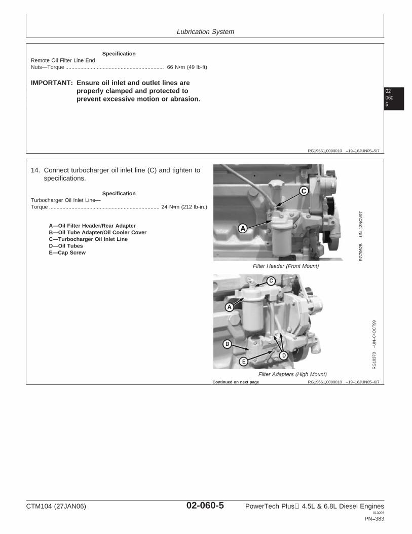
Lubrication System
020605
RG19661,0000010 –19–16JUN05–5/7
SpecificationRemote Oil Filter Line EndNuts—Torque 66 N•m (49 lb-ft)..................................................................
IMPORTANT: Ensure oil inlet and outlet lines areproperly clamped and protected toprevent excessive motion or abrasion.
RG19661,0000010 –19–16JUN05–6/7
RG
7962
B–U
N–1
3NO
V97
Filter Header (Front Mount)
RG
1037
3–U
N–0
4OC
T99
Filter Adapters (High Mount)
A—Oil Filter Header/Rear AdapterB—Oil Tube Adapter/Oil Cooler CoverC—Turbocharger Oil Inlet LineD—Oil TubesE—Cap Screw
14. Connect turbocharger oil inlet line (C) and tighten tospecifications.
SpecificationTurbocharger Oil Inlet Line—Torque 24 N•m (212 lb-in.)..........................................................................
Continued on next page
CTM104 (27JAN06) 02-060-5 PowerTech Plus 4.5L & 6.8L Diesel Engines013006
PN=383
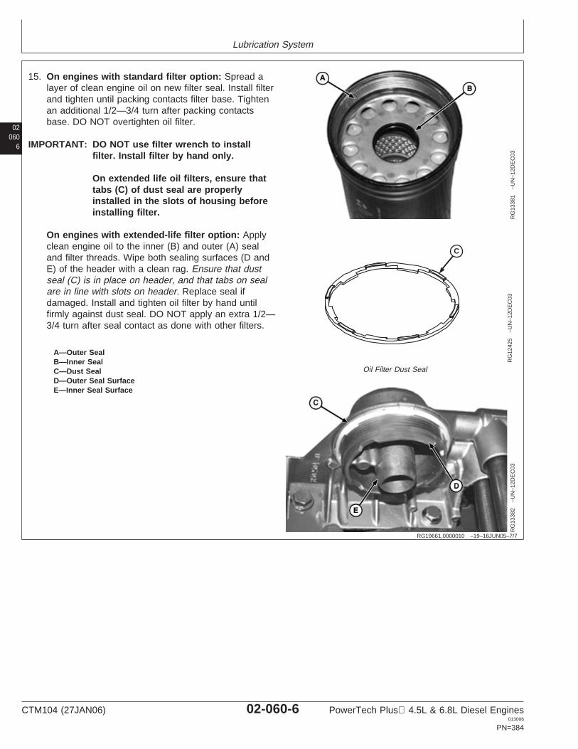
Lubrication System
02060
6
RG19661,0000010 –19–16JUN05–7/7
RG
1338
1–U
N–1
2DE
C03
C
RG
1242
5–U
N–1
2DE
C03
Oil Filter Dust Seal
RG
1338
2–U
N–1
2DE
C03
A—Outer SealB—Inner SealC—Dust SealD—Outer Seal SurfaceE—Inner Seal Surface
15. On engines with standard filter option: Spread alayer of clean engine oil on new filter seal. Install filterand tighten until packing contacts filter base. Tightenan additional 1/2—3/4 turn after packing contactsbase. DO NOT overtighten oil filter.
IMPORTANT: DO NOT use filter wrench to installfilter. Install filter by hand only.
On extended life oil filters, ensure thattabs (C) of dust seal are properlyinstalled in the slots of housing beforeinstalling filter.
On engines with extended-life filter option: Applyclean engine oil to the inner (B) and outer (A) sealand filter threads. Wipe both sealing surfaces (D andE) of the header with a clean rag. Ensure that dustseal (C) is in place on header, and that tabs on sealare in line with slots on header. Replace seal ifdamaged. Install and tighten oil filter by hand untilfirmly against dust seal. DO NOT apply an extra 1/2—3/4 turn after seal contact as done with other filters.
CTM104 (27JAN06) 02-060-6 PowerTech Plus 4.5L & 6.8L Diesel Engines013006
PN=384
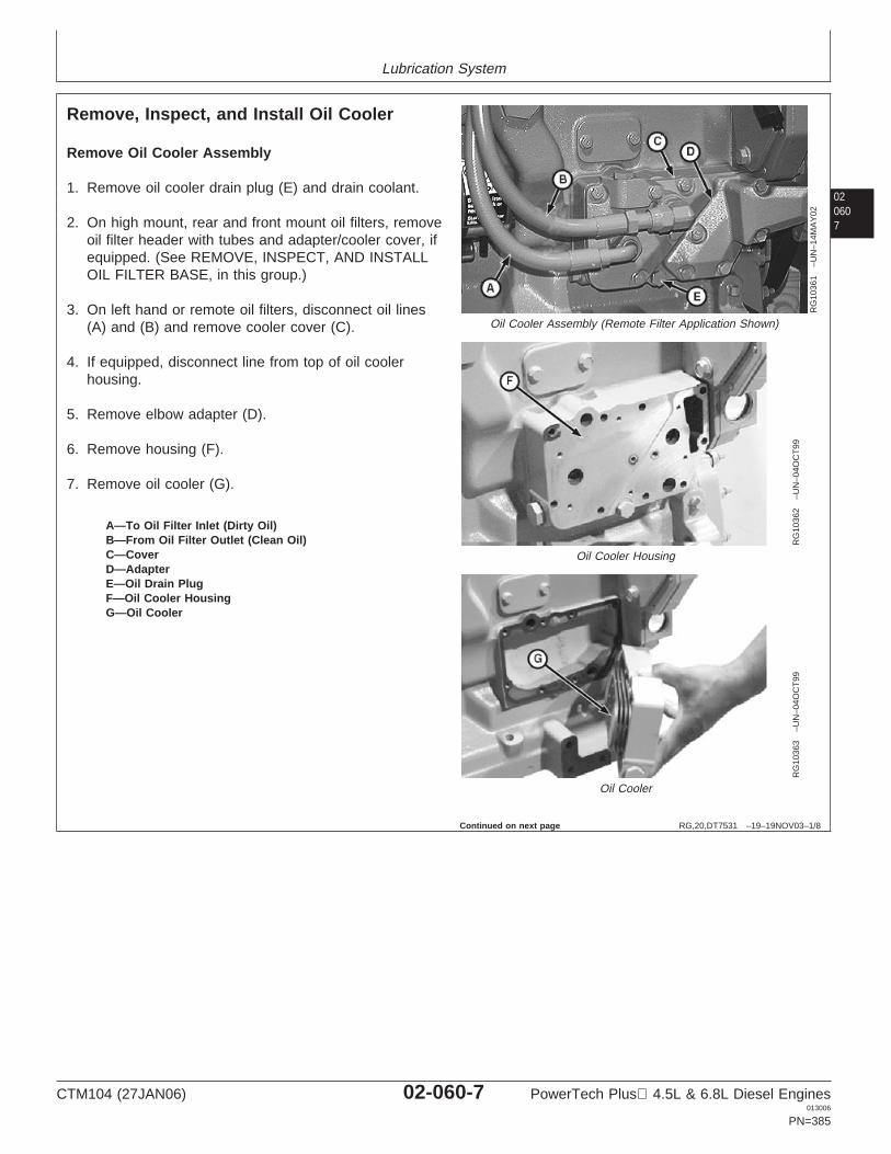
Lubrication System
020607
RG,20,DT7531 –19–19NOV03–1/8
Remove, Inspect, and Install Oil Cooler
RG
1036
1–U
N–1
4MA
Y02
Oil Cooler Assembly (Remote Filter Application Shown)
RG
1036
2–U
N–0
4OC
T99
Oil Cooler Housing
RG
1036
3–U
N–0
4OC
T99
Oil Cooler
A—To Oil Filter Inlet (Dirty Oil)B—From Oil Filter Outlet (Clean Oil)C—CoverD—AdapterE—Oil Drain PlugF—Oil Cooler HousingG—Oil Cooler
Remove Oil Cooler Assembly
1. Remove oil cooler drain plug (E) and drain coolant.
2. On high mount, rear and front mount oil filters, removeoil filter header with tubes and adapter/cooler cover, ifequipped. (See REMOVE, INSPECT, AND INSTALLOIL FILTER BASE, in this group.)
3. On left hand or remote oil filters, disconnect oil lines(A) and (B) and remove cooler cover (C).
4. If equipped, disconnect line from top of oil coolerhousing.
5. Remove elbow adapter (D).
6. Remove housing (F).
7. Remove oil cooler (G).
Continued on next page
CTM104 (27JAN06) 02-060-7 PowerTech Plus 4.5L & 6.8L Diesel Engines013006
PN=385
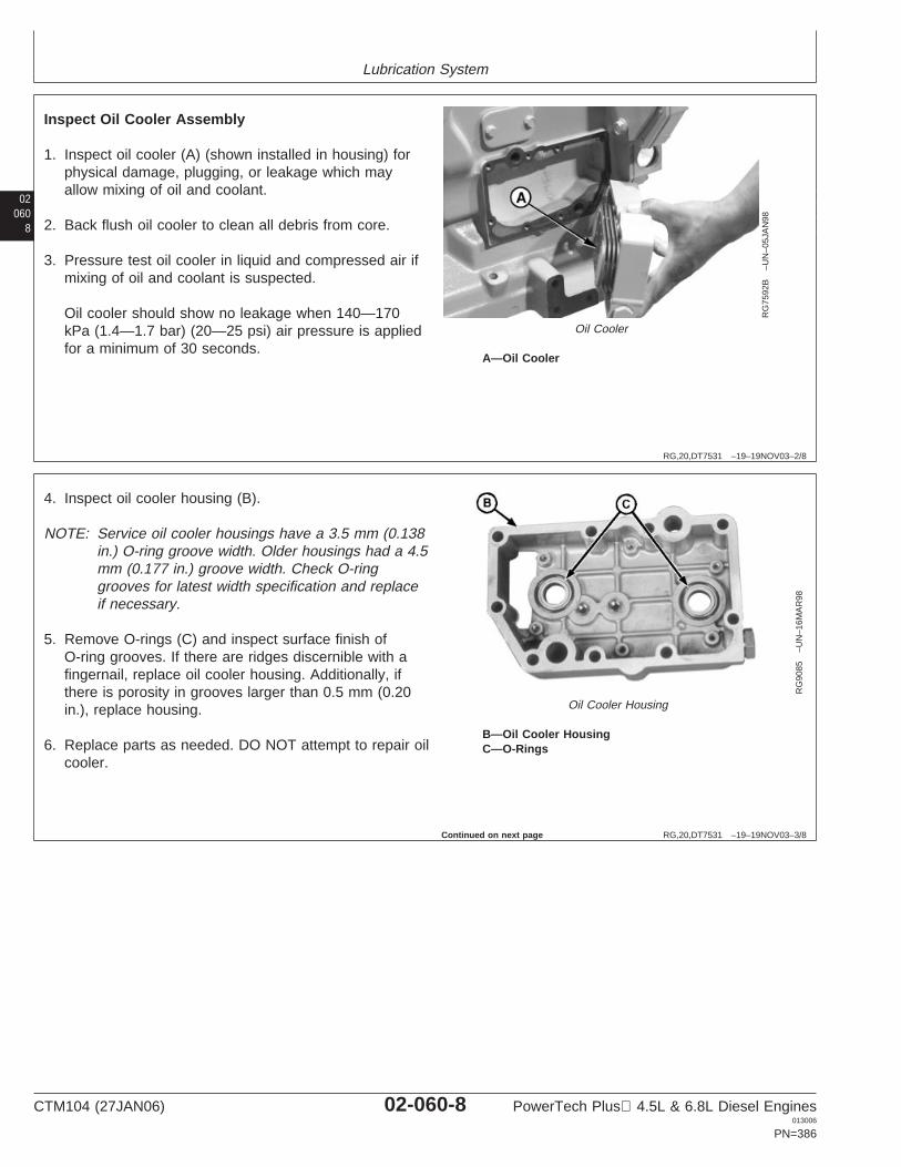
Lubrication System
02060
8
RG,20,DT7531 –19–19NOV03–2/8
RG
7592
B–U
N–0
5JA
N98
Oil Cooler
A—Oil Cooler
Inspect Oil Cooler Assembly
1. Inspect oil cooler (A) (shown installed in housing) forphysical damage, plugging, or leakage which mayallow mixing of oil and coolant.
2. Back flush oil cooler to clean all debris from core.
3. Pressure test oil cooler in liquid and compressed air ifmixing of oil and coolant is suspected.
Oil cooler should show no leakage when 140—170kPa (1.4—1.7 bar) (20—25 psi) air pressure is appliedfor a minimum of 30 seconds.
RG,20,DT7531 –19–19NOV03–3/8
RG
9085
–UN
–16M
AR
98
Oil Cooler Housing
B—Oil Cooler HousingC—O-Rings
4. Inspect oil cooler housing (B).
NOTE: Service oil cooler housings have a 3.5 mm (0.138in.) O-ring groove width. Older housings had a 4.5mm (0.177 in.) groove width. Check O-ringgrooves for latest width specification and replaceif necessary.
5. Remove O-rings (C) and inspect surface finish ofO-ring grooves. If there are ridges discernible with afingernail, replace oil cooler housing. Additionally, ifthere is porosity in grooves larger than 0.5 mm (0.20in.), replace housing.
6. Replace parts as needed. DO NOT attempt to repair oilcooler.
Continued on next page
CTM104 (27JAN06) 02-060-8 PowerTech Plus 4.5L & 6.8L Diesel Engines013006
PN=386
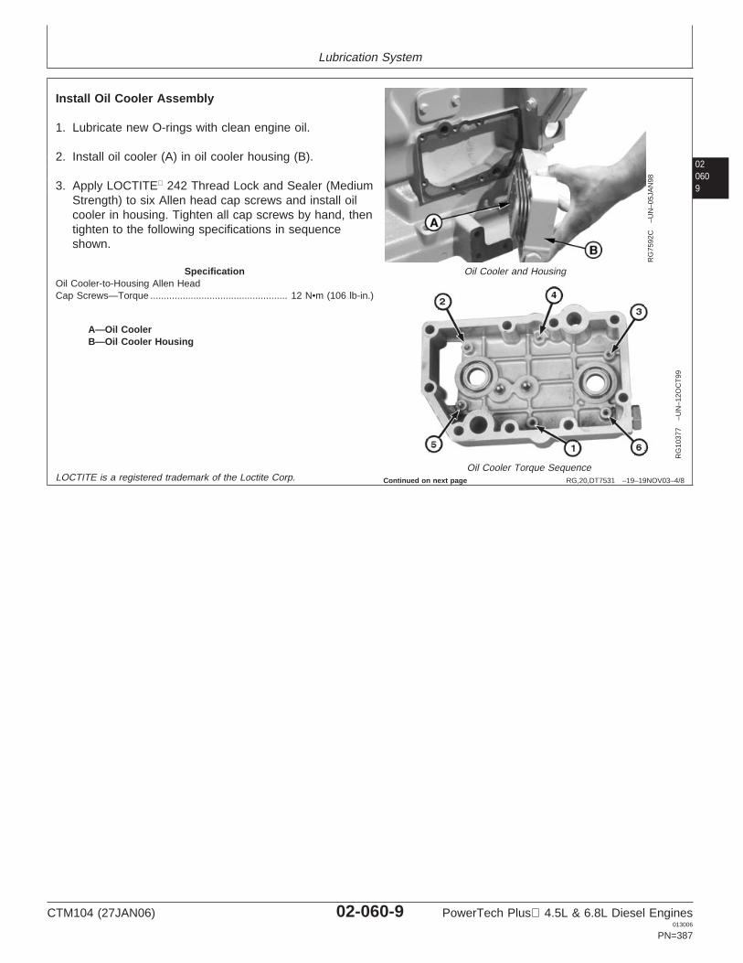
Lubrication System
020609
RG,20,DT7531 –19–19NOV03–4/8
RG
7592
C–U
N–0
5JA
N98
Oil Cooler and Housing
RG
1037
7–U
N–1
2OC
T99
Oil Cooler Torque Sequence
A—Oil CoolerB—Oil Cooler Housing
Install Oil Cooler Assembly
1. Lubricate new O-rings with clean engine oil.
2. Install oil cooler (A) in oil cooler housing (B).
3. Apply LOCTITE 242 Thread Lock and Sealer (MediumStrength) to six Allen head cap screws and install oilcooler in housing. Tighten all cap screws by hand, thentighten to the following specifications in sequenceshown.
SpecificationOil Cooler-to-Housing Allen HeadCap Screws—Torque 12 N•m (106 lb-in.)...................................................
LOCTITE is a registered trademark of the Loctite Corp. Continued on next page
CTM104 (27JAN06) 02-060-9 PowerTech Plus 4.5L & 6.8L Diesel Engines013006
PN=387
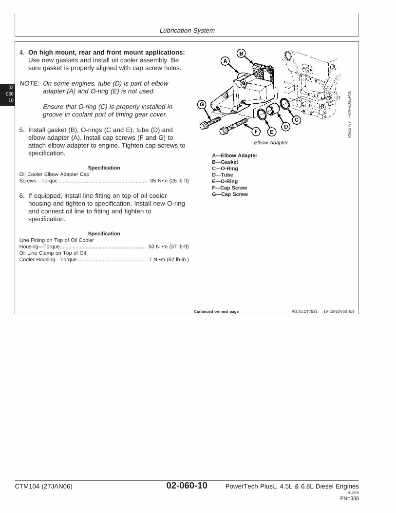
Lubrication System
02060
10
RG,20,DT7531 –19–19NOV03–5/8
RG
1178
7–U
N–2
0SE
P01
Elbow Adapter
A—Elbow AdapterB—GasketC—O-RingD—TubeE—O-RingF—Cap ScrewG—Cap Screw
4. On high mount, rear and front mount applications:Use new gaskets and install oil cooler assembly. Besure gasket is properly aligned with cap screw holes.
NOTE: On some engines, tube (D) is part of elbowadapter (A) and O-ring (E) is not used.
Ensure that O-ring (C) is properly installed ingroove in coolant port of timing gear cover.
5. Install gasket (B), O-rings (C and E), tube (D) andelbow adapter (A). Install cap screws (F and G) toattach elbow adapter to engine. Tighten cap screws tospecification.
SpecificationOil Cooler Elbow Adapter CapScrews—Torque 35 N•m (26 lb-ft)..............................................................
6. If equipped, install line fitting on top of oil coolerhousing and tighten to specification. Install new O-ringand connect oil line to fitting and tighten tospecification.
SpecificationLine Fitting on Top of Oil CoolerHousing—Torque 50 N •m (37 lb-ft)............................................................Oil Line Clamp on Top of OilCooler Housing—Torque 7 N •m (62 lb-in.)................................................
Continued on next page
CTM104 (27JAN06) 02-060-10 PowerTech Plus 4.5L & 6.8L Diesel Engines013006
PN=388
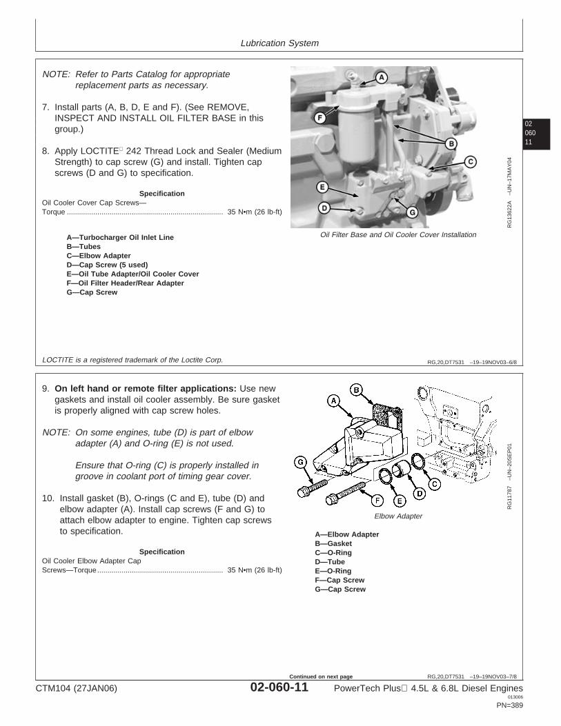
Lubrication System
0206011
RG,20,DT7531 –19–19NOV03–6/8
RG
1362
2A–U
N–1
7MA
Y04
Oil Filter Base and Oil Cooler Cover InstallationA—Turbocharger Oil Inlet LineB—TubesC—Elbow AdapterD—Cap Screw (5 used)E—Oil Tube Adapter/Oil Cooler CoverF—Oil Filter Header/Rear AdapterG—Cap Screw
NOTE: Refer to Parts Catalog for appropriatereplacement parts as necessary.
7. Install parts (A, B, D, E and F). (See REMOVE,INSPECT AND INSTALL OIL FILTER BASE in thisgroup.)
8. Apply LOCTITE 242 Thread Lock and Sealer (MediumStrength) to cap screw (G) and install. Tighten capscrews (D and G) to specification.
SpecificationOil Cooler Cover Cap Screws—Torque 35 N•m (26 lb-ft).............................................................................
LOCTITE is a registered trademark of the Loctite Corp.
RG,20,DT7531 –19–19NOV03–7/8
RG
1178
7–U
N–2
0SE
P01
Elbow Adapter
A—Elbow AdapterB—GasketC—O-RingD—TubeE—O-RingF—Cap ScrewG—Cap Screw
9. On left hand or remote filter applications: Use newgaskets and install oil cooler assembly. Be sure gasketis properly aligned with cap screw holes.
NOTE: On some engines, tube (D) is part of elbowadapter (A) and O-ring (E) is not used.
Ensure that O-ring (C) is properly installed ingroove in coolant port of timing gear cover.
10. Install gasket (B), O-rings (C and E), tube (D) andelbow adapter (A). Install cap screws (F and G) toattach elbow adapter to engine. Tighten cap screwsto specification.
SpecificationOil Cooler Elbow Adapter CapScrews—Torque 35 N•m (26 lb-ft)..............................................................
CTM104 (27JAN06) 02-060-11 PowerTech Plus 4.5L & 6.8L Diesel Engines013006
PN=389
Continued on next page
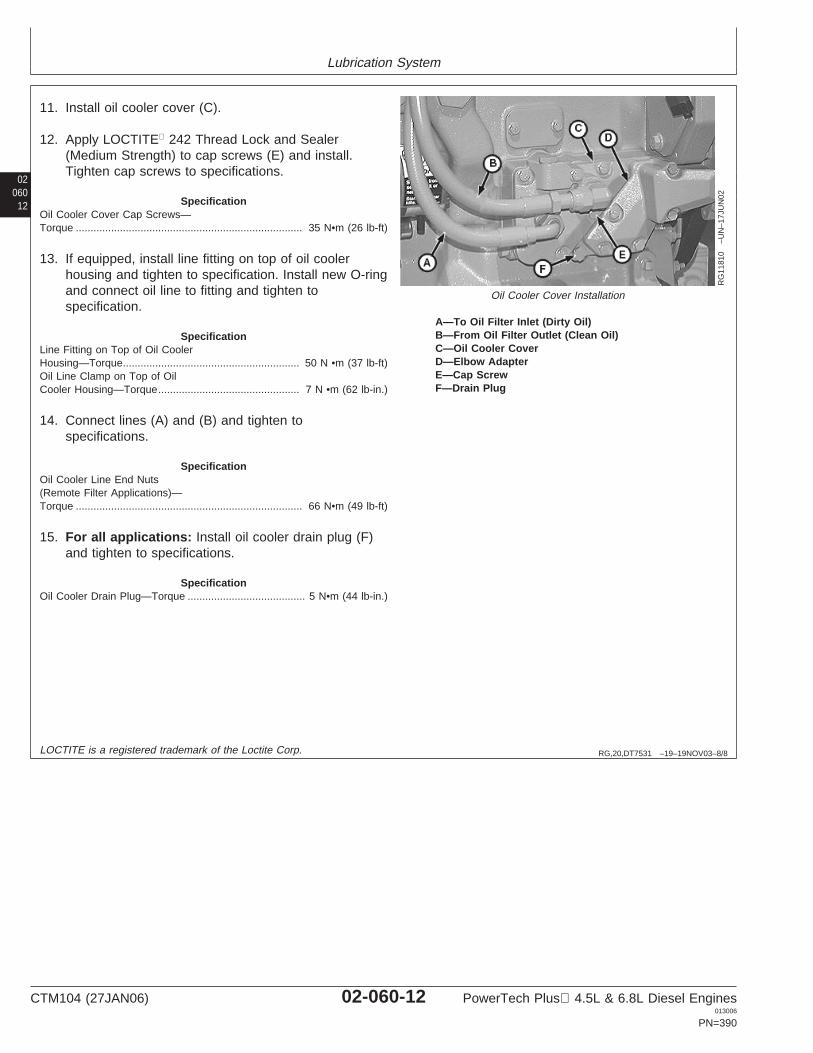
Lubrication System
02060
12
RG,20,DT7531 –19–19NOV03–8/8
RG
1181
0–U
N–1
7JU
N02
Oil Cooler Cover Installation
A—To Oil Filter Inlet (Dirty Oil)B—From Oil Filter Outlet (Clean Oil)C—Oil Cooler CoverD—Elbow AdapterE—Cap ScrewF—Drain Plug
11. Install oil cooler cover (C).
12. Apply LOCTITE 242 Thread Lock and Sealer(Medium Strength) to cap screws (E) and install.Tighten cap screws to specifications.
SpecificationOil Cooler Cover Cap Screws—Torque 35 N•m (26 lb-ft).............................................................................
13. If equipped, install line fitting on top of oil coolerhousing and tighten to specification. Install new O-ringand connect oil line to fitting and tighten tospecification.
SpecificationLine Fitting on Top of Oil CoolerHousing—Torque 50 N •m (37 lb-ft)............................................................Oil Line Clamp on Top of OilCooler Housing—Torque 7 N •m (62 lb-in.)................................................
14. Connect lines (A) and (B) and tighten tospecifications.
SpecificationOil Cooler Line End Nuts(Remote Filter Applications)—Torque 66 N•m (49 lb-ft).............................................................................
15. For all applications: Install oil cooler drain plug (F)and tighten to specifications.
SpecificationOil Cooler Drain Plug—Torque 5 N•m (44 lb-in.)........................................
LOCTITE is a registered trademark of the Loctite Corp.
CTM104 (27JAN06) 02-060-12 PowerTech Plus 4.5L & 6.8L Diesel Engines013006
PN=390
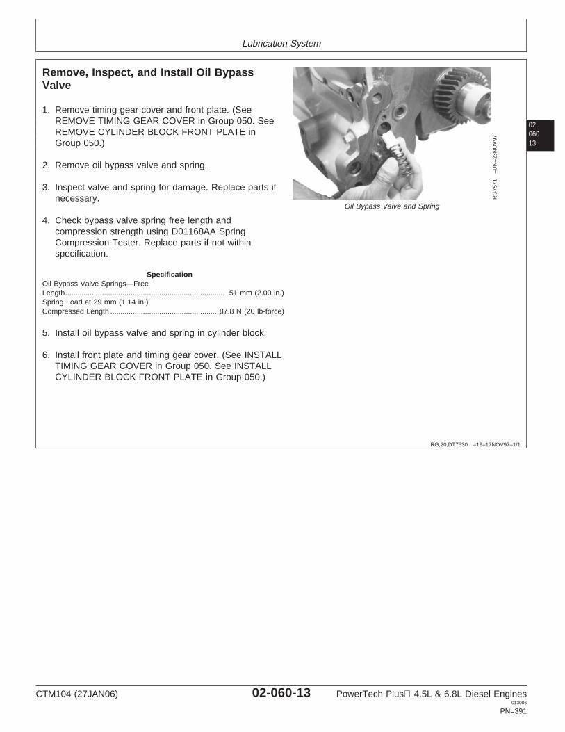
Lubrication System
0206013
RG,20,DT7530 –19–17NOV97–1/1
Remove, Inspect, and Install Oil BypassValve
RG
7571
–UN
–23N
OV
97
Oil Bypass Valve and Spring
1. Remove timing gear cover and front plate. (SeeREMOVE TIMING GEAR COVER in Group 050. SeeREMOVE CYLINDER BLOCK FRONT PLATE inGroup 050.)
2. Remove oil bypass valve and spring.
3. Inspect valve and spring for damage. Replace parts ifnecessary.
4. Check bypass valve spring free length andcompression strength using D01168AA SpringCompression Tester. Replace parts if not withinspecification.
SpecificationOil Bypass Valve Springs—FreeLength 51 mm (2.00 in.)..............................................................................Spring Load at 29 mm (1.14 in.)Compressed Length 87.8 N (20 lb-force)....................................................
5. Install oil bypass valve and spring in cylinder block.
6. Install front plate and timing gear cover. (See INSTALLTIMING GEAR COVER in Group 050. See INSTALLCYLINDER BLOCK FRONT PLATE in Group 050.)
CTM104 (27JAN06) 02-060-13 PowerTech Plus 4.5L & 6.8L Diesel Engines013006
PN=391
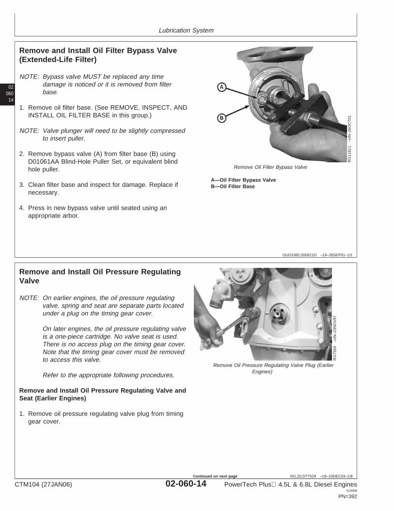
Lubrication System
02060
14
OUO1082,000021D –19–26SEP01–1/1
Remove and Install Oil Filter Bypass Valve(Extended-Life Filter)
RG
1181
1–U
N–2
6OC
T01
Remove Oil Filter Bypass Valve
A—Oil Filter Bypass ValveB—Oil Filter Base
NOTE: Bypass valve MUST be replaced any timedamage is noticed or it is removed from filterbase.
1. Remove oil filter base. (See REMOVE, INSPECT, ANDINSTALL OIL FILTER BASE in this group.)
NOTE: Valve plunger will need to be slightly compressedto insert puller.
2. Remove bypass valve (A) from filter base (B) usingD01061AA Blind-Hole Puller Set, or equivalent blindhole puller.
3. Clean filter base and inspect for damage. Replace ifnecessary.
4. Press in new bypass valve until seated using anappropriate arbor.
RG,20,DT7529 –19–10DEC03–1/8
Remove and Install Oil Pressure RegulatingValve
RG
7554
–UN
–23N
OV
97
Remove Oil Pressure Regulating Valve Plug (EarlierEngines)
NOTE: On earlier engines, the oil pressure regulatingvalve, spring and seat are separate parts locatedunder a plug on the timing gear cover.
On later engines, the oil pressure regulating valveis a one-piece cartridge. No valve seat is used.There is no access plug on the timing gear cover.Note that the timing gear cover must be removedto access this valve.
Refer to the appropriate following procedures.
Remove and Install Oil Pressure Regulating Valve andSeat (Earlier Engines)
1. Remove oil pressure regulating valve plug from timinggear cover.
CTM104 (27JAN06) 02-060-14 PowerTech Plus 4.5L & 6.8L Diesel Engines013006
PN=392
Continued on next page
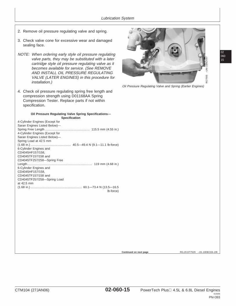
Lubrication System
0206015
RG,20,DT7529 –19–10DEC03–2/8
RG
7555
–UN
–23N
OV
97
Oil Pressure Regulating Valve and Spring (Earlier Engines)
2. Remove oil pressure regulating valve and spring.
3. Check valve cone for excessive wear and damagedsealing face.
NOTE: When ordering early style oil pressure regulatingvalve parts, they may be substituted with a latercartridge style oil pressure regulating valve as itbecomes available for service. (See REMOVEAND INSTALL OIL PRESSURE REGULATINGVALVE (LATER ENGINES) in this procedure forinstallation.)
4. Check oil pressure regulating spring free length andcompression strength using D01168AA SpringCompression Tester. Replace parts if not withinspecification.
Oil Pressure Regulating Valve Spring Specifications—Specification
4-Cylinder Engines (Except forSaran Engines Listed Below)—Spring Free Length 115.5 mm (4.55 in.)....................................................4-Cylinder Engines (Except forSaran Engines Listed Below)—Spring Load at 42.5 mm(1.68 in.) 40.5—49.4 N (9.1—11.1 lb-force)...............................................6-Cylinder Engines andCD4045HF157/158,CD4045TF157/158 andCD4045TF257/258—Spring FreeLength 119 mm (4.68 in.)............................................................................6-Cylinder Engines andCD4045HF157/158,CD4045TF157/158 andCD4045TF257/258—Spring Loadat 42.5 mm(1.68 in.) 60.1—73.4 N (13.5—16.5
lb-force)............................................................
Continued on next page
CTM104 (27JAN06) 02-060-15 PowerTech Plus 4.5L & 6.8L Diesel Engines013006
PN=393

Lubrication System
02060
16
RG,20,DT7529 –19–10DEC03–3/8
RG
7593
–UN
–05J
AN
98
Oil Pressure Regulating Valve Seat
A—JT01727 ColletB—JT01718 Slide Hammer
IMPORTANT: The valve seat is destroyed duringvalve seat removal. If the valve seat isremoved, the oil pressure regulatingvalve will need to be replaced.
5. Pull valve seat out of cylinder block with JT01727Collet (A) and JT01718 Slide Hammer (B) fromD01061AA Blind-Hole Puller Set, or equivalent.
RG,20,DT7529 –19–10DEC03–4/8
RG
7594
–UN
–23N
OV
97
Oil Pressure Regulating Valve Seat
IMPORTANT: DO NOT drive against raised inner rimof valve seat so that valve seat bore isnot damaged.
6. Drive valve seat into cylinder block with JD248A(JD-248A)1 Oil Pressure Relief Valve Bushing Driverand JDG536 (OTC813) Handle until the seat bottomsin bore.
1Order JD-248A when tool is ordered from European Parts DistributionCenter (EPDC)
Continued on next page
CTM104 (27JAN06) 02-060-16 PowerTech Plus 4.5L & 6.8L Diesel Engines013006
PN=394
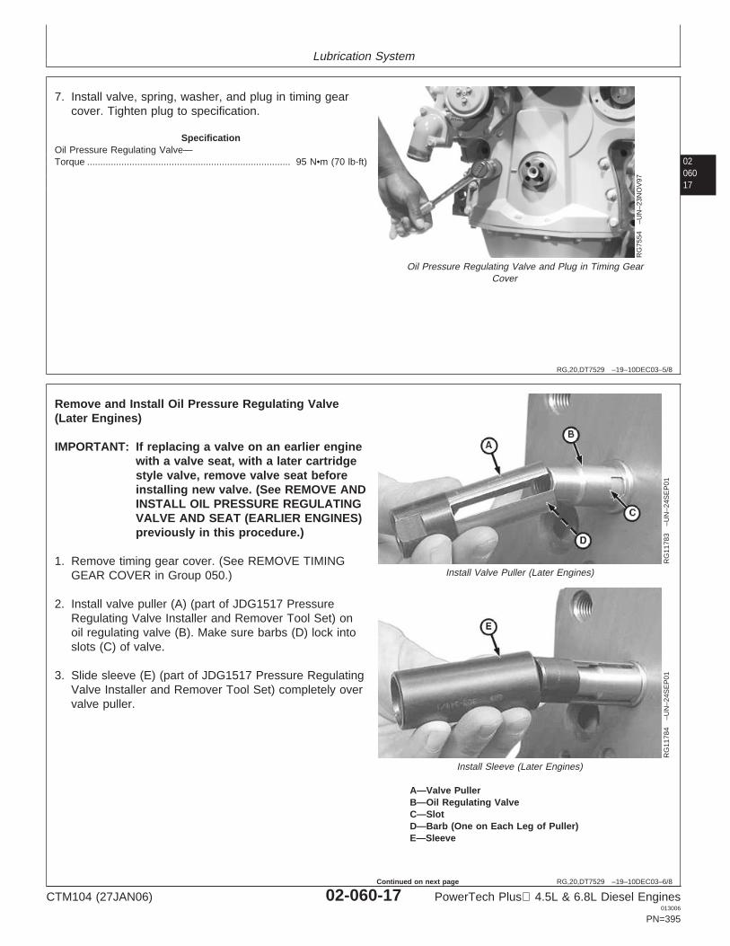
Lubrication System
0206017
RG,20,DT7529 –19–10DEC03–5/8
RG
7554
–UN
–23N
OV
97
Oil Pressure Regulating Valve and Plug in Timing GearCover
7. Install valve, spring, washer, and plug in timing gearcover. Tighten plug to specification.
SpecificationOil Pressure Regulating Valve—Torque 95 N•m (70 lb-ft).............................................................................
RG,20,DT7529 –19–10DEC03–6/8
RG
1178
3–U
N–2
4SE
P01
Install Valve Puller (Later Engines)
RG
1178
4–U
N–2
4SE
P01
Install Sleeve (Later Engines)
A—Valve PullerB—Oil Regulating ValveC—SlotD—Barb (One on Each Leg of Puller)E—Sleeve
Remove and Install Oil Pressure Regulating Valve(Later Engines)
IMPORTANT: If replacing a valve on an earlier enginewith a valve seat, with a later cartridgestyle valve, remove valve seat beforeinstalling new valve. (See REMOVE ANDINSTALL OIL PRESSURE REGULATINGVALVE AND SEAT (EARLIER ENGINES)previously in this procedure.)
1. Remove timing gear cover. (See REMOVE TIMINGGEAR COVER in Group 050.)
2. Install valve puller (A) (part of JDG1517 PressureRegulating Valve Installer and Remover Tool Set) onoil regulating valve (B). Make sure barbs (D) lock intoslots (C) of valve.
3. Slide sleeve (E) (part of JDG1517 Pressure RegulatingValve Installer and Remover Tool Set) completely overvalve puller.
CTM104 (27JAN06) 02-060-17 PowerTech Plus 4.5L & 6.8L Diesel Engines013006
PN=395
Continued on next page
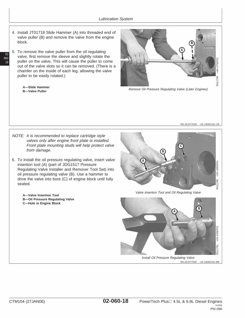
Lubrication System
02060
18
RG,20,DT7529 –19–10DEC03–7/8
RG
1178
5–U
N–2
7SE
P01
Remove Oil Pressure Regulating Valve (Later Engines)A—Slide HammerB—Valve Puller
4. Install JT01718 Slide Hammer (A) into threaded end ofvalve puller (B) and remove the valve from the engineblock.
5. To remove the valve puller from the oil regulatingvalve, first remove the sleeve and slightly rotate thepuller on the valve. This will cause the puller to comeout of the valve slots so it can be removed. (There is achamfer on the inside of each leg, allowing the valvepuller to be easily rotated.)
RG,20,DT7529 –19–10DEC03–8/8
RG
1178
0–U
N–2
4SE
P01
Valve Insertion Tool and Oil Regulating Valve
RG
1178
1–U
N–2
4SE
P01
Install Oil Pressure Regulating Valve
A—Valve Insertion ToolB—Oil Pressure Regulating ValveC—Hole in Engine Block
NOTE: It is recommended to replace cartridge stylevalves only after engine front plate is installed.Front plate mounting studs will help protect valvefrom damage.
6. To install the oil pressure regulating valve, insert valveinsertion tool (A) (part of JDG1517 PressureRegulating Valve Installer and Remover Tool Set) intooil pressure regulating valve (B). Use a hammer todrive the valve into bore (C) of engine block until fullyseated.
CTM104 (27JAN06) 02-060-18 PowerTech Plus 4.5L & 6.8L Diesel Engines013006
PN=396
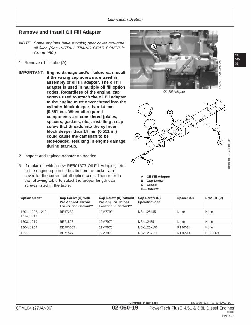
Lubrication System
0206019
RG,20,DT7528 –19–19NOV03–1/2
Remove and Install Oil Fill Adapter
RG
7964
–UN
–13N
OV
97
Oil Fill Adapter
RG
1338
3–U
N–1
2DE
C03
A—Oil Fill AdapterB—Cap ScrewC—SpacerD—Bracket
NOTE: Some engines have a timing gear cover mountedoil filler. (See INSTALL TIMING GEAR COVER inGroup 050.)
1. Remove oil fill tube (A).
IMPORTANT: Engine damage and/or failure can resultif the wrong cap screws are used inassembly of oil fill adapter. The oil filladapter is used in multiple oil fill optioncodes. Regardless of the engine, capscrews used to attach the oil fill adapterto the engine must never thread into thecylinder block deeper than 14 mm(0.551 in.). When all requiredcomponents are considered (plates,spacers, gaskets, etc.), installing a capscrew that threads into the cylinderblock deeper than 14 mm (0.551 in.)could cause the camshaft to beside-loaded, resulting in engine damageduring start-up.
2. Inspect and replace adapter as needed.
3. If replacing with a new RE501377 Oil Fill Adapter, referto the engine option code label on the rocker armcover for the correct oil fill option code. Then refer tothe following table to select the proper length capscrews listed in the table.
Option Code* Cap Screw (B) with Cap Screw (B) without Cap Screw (B) Spacer (C) Bracket (D)Pre-Applied Thread Pre-Applied Thread SpecificationsLocker and Sealant** Locker and Sealant**
1201, 1202, 1212, RE67239 19M7799 M8x1.25x45 None None1214, 1215
1203, 1210 RE71526 19M7979 M8x1.2x55 None None
1204, 1209 RE503609 19M7970 M8x1.25x100 R136514 None
1211 RE71527 19M7873 M8x1.25x110 R136514 RE70063
CTM104 (27JAN06) 02-060-19 PowerTech Plus 4.5L & 6.8L Diesel Engines013006
PN=397
Continued on next page
Lubrication System
02060
20
RG,20,DT7528 –19–19NOV03–2/2
* This option code should be used for reference only toidentify ALL parts that are needed in the oil fill adapterassembly (gaskets, spacer, mounting plate, etc.). Aspreviously stated, cap screw length should be chosento meet the 14 mm (0.551 in.) maximum threadengagement depth requirement.
** If the 19M type cap screws are used, applyLOCTITE 242 Thread Lock and Sealer (MediumStrength) to threads of cap screws to prevent oil leaks.If the RE type are used, new cap screws withpre-applied sealant must be used.
4. Using a new gasket, install oil fill adapter.
5. Tighten cap screws to specifications.
SpecificationOil Fill Tube Cap Screws—Torque 35 N•m (26 lb-ft).............................................................................
LOCTITE is a registered trademark of the Loctite Corp.
CTM104 (27JAN06) 02-060-20 PowerTech Plus 4.5L & 6.8L Diesel Engines013006
PN=398

Lubrication System
0206021
RG,20,DT7527 –19–10NOV99–1/3
Remove and Install Dipstick Tube with OilPan Installed
RG
7979
–UN
–14N
OV
97
Dipstick and Dipstick Tube
RG
7980
–UN
–14N
OV
97
Dipstick Tube Removal Tool
RG
1056
4–U
N–2
1DE
C99
A—DipstickB—Dipstick TubeC—Block Machining Height
Remove Dipstick Tube
IMPORTANT: Orientation of dipstick tube in enginevaries by application. Make index markson tube and block to ensure correctorientation when reinstalling tube.
NOTE: Saran (CD) engines for the 6010 and 6020 seriestractors use either a 71 mm or a 67.5 mm cylinderblock machining height (C) for the oil dipstick tubelocation. Service tubes and dipsticks are asfollows: R136162 Tube and AT21535 Dipstick for71 mm configuration (Engine S.N. —550948CD),or R501178 Tube and RE502740 Dipstick for 67.5mm configuration (Engine S.N. 550949CD— ).Additionally, there may be some later engines stillusing the 71 mm configuration dipstick tube with aspacer to compensate for the 67.5 mm blockmachining. For service, these should be replacedwith the 67.5 mm configuration tube and dipstick.
1. Remove dipstick (A).
2. Using JT01724 (5/16 in.) Collet, JT01720 Actuator Pin,and 1156 Slide Hammer, remove dipstick tube (B) fromblock.
Install Dipstick Tube
1. Coat end of new dipstick tube with LOCTITE 271Thread Lock and Sealer (High Strength).
LOCTITE is a registered trademark of the Loctite Corp. Continued on next page
CTM104 (27JAN06) 02-060-21 PowerTech Plus 4.5L & 6.8L Diesel Engines013006
PN=399
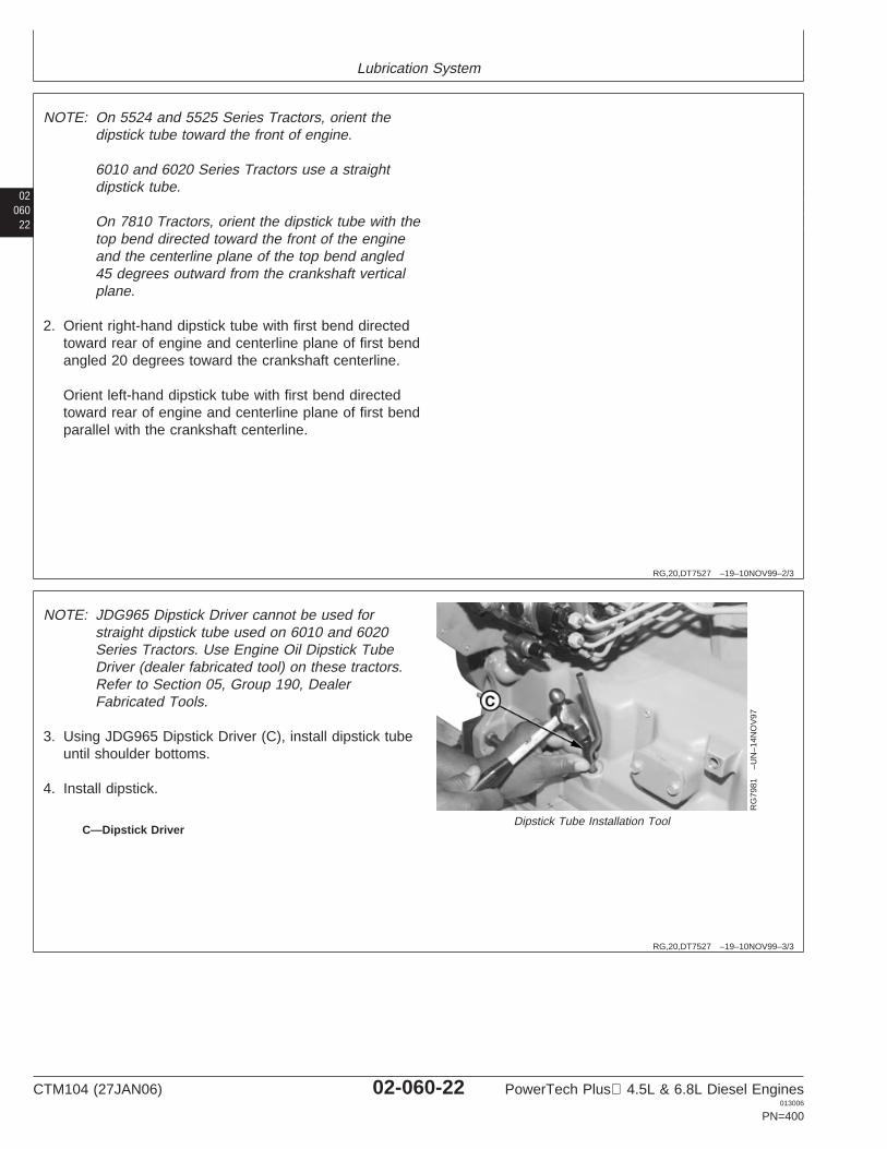
Lubrication System
02060
22
RG,20,DT7527 –19–10NOV99–2/3
NOTE: On 5524 and 5525 Series Tractors, orient thedipstick tube toward the front of engine.
6010 and 6020 Series Tractors use a straightdipstick tube.
On 7810 Tractors, orient the dipstick tube with thetop bend directed toward the front of the engineand the centerline plane of the top bend angled45 degrees outward from the crankshaft verticalplane.
2. Orient right-hand dipstick tube with first bend directedtoward rear of engine and centerline plane of first bendangled 20 degrees toward the crankshaft centerline.
Orient left-hand dipstick tube with first bend directedtoward rear of engine and centerline plane of first bendparallel with the crankshaft centerline.
RG,20,DT7527 –19–10NOV99–3/3
RG
7981
–UN
–14N
OV
97
Dipstick Tube Installation ToolC—Dipstick Driver
NOTE: JDG965 Dipstick Driver cannot be used forstraight dipstick tube used on 6010 and 6020Series Tractors. Use Engine Oil Dipstick TubeDriver (dealer fabricated tool) on these tractors.Refer to Section 05, Group 190, DealerFabricated Tools.
3. Using JDG965 Dipstick Driver (C), install dipstick tubeuntil shoulder bottoms.
4. Install dipstick.
CTM104 (27JAN06) 02-060-22 PowerTech Plus 4.5L & 6.8L Diesel Engines013006
PN=400
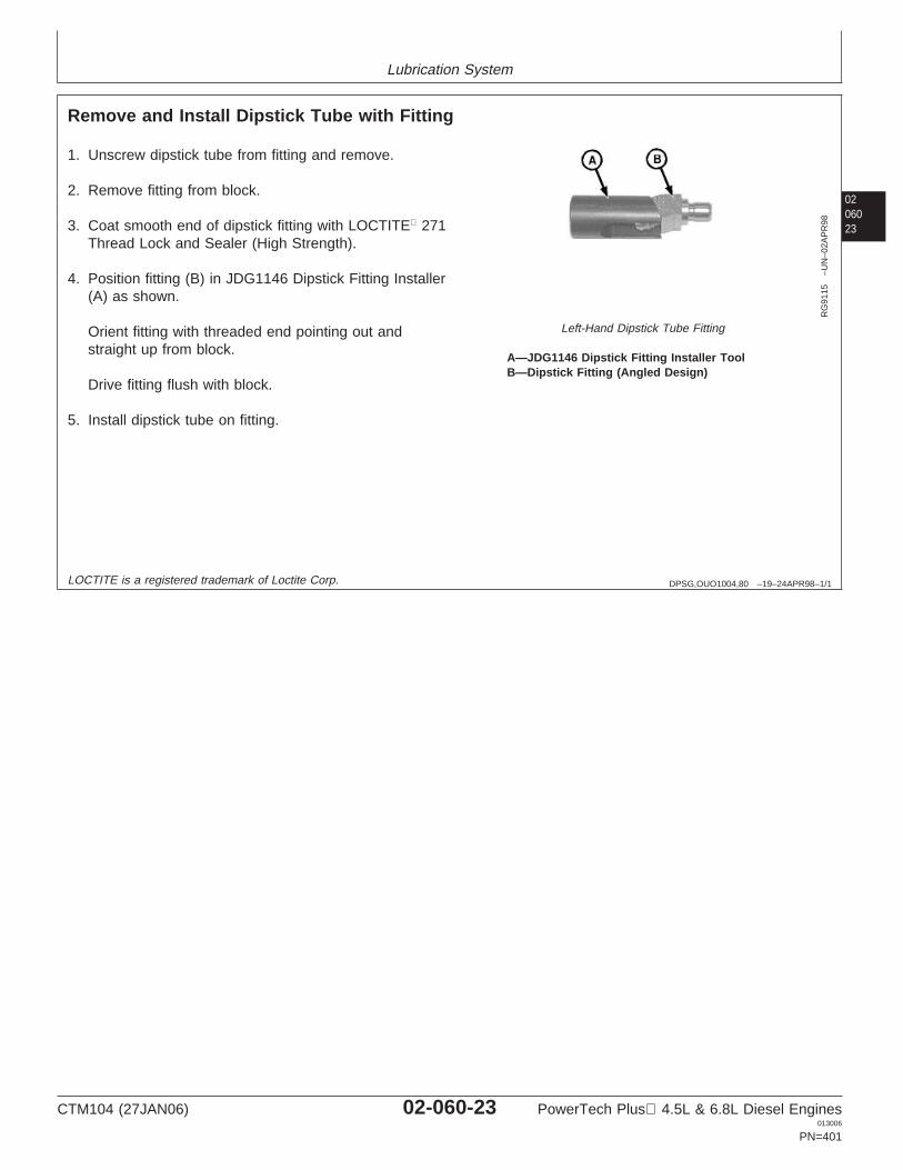
Lubrication System
0206023
DPSG,OUO1004,80 –19–24APR98–1/1
Remove and Install Dipstick Tube with Fitting
RG
9115
–UN
–02A
PR
98
Left-Hand Dipstick Tube Fitting
A—JDG1146 Dipstick Fitting Installer ToolB—Dipstick Fitting (Angled Design)
1. Unscrew dipstick tube from fitting and remove.
2. Remove fitting from block.
3. Coat smooth end of dipstick fitting with LOCTITE 271Thread Lock and Sealer (High Strength).
4. Position fitting (B) in JDG1146 Dipstick Fitting Installer(A) as shown.
Orient fitting with threaded end pointing out andstraight up from block.
Drive fitting flush with block.
5. Install dipstick tube on fitting.
LOCTITE is a registered trademark of Loctite Corp.
CTM104 (27JAN06) 02-060-23 PowerTech Plus 4.5L & 6.8L Diesel Engines013006
PN=401
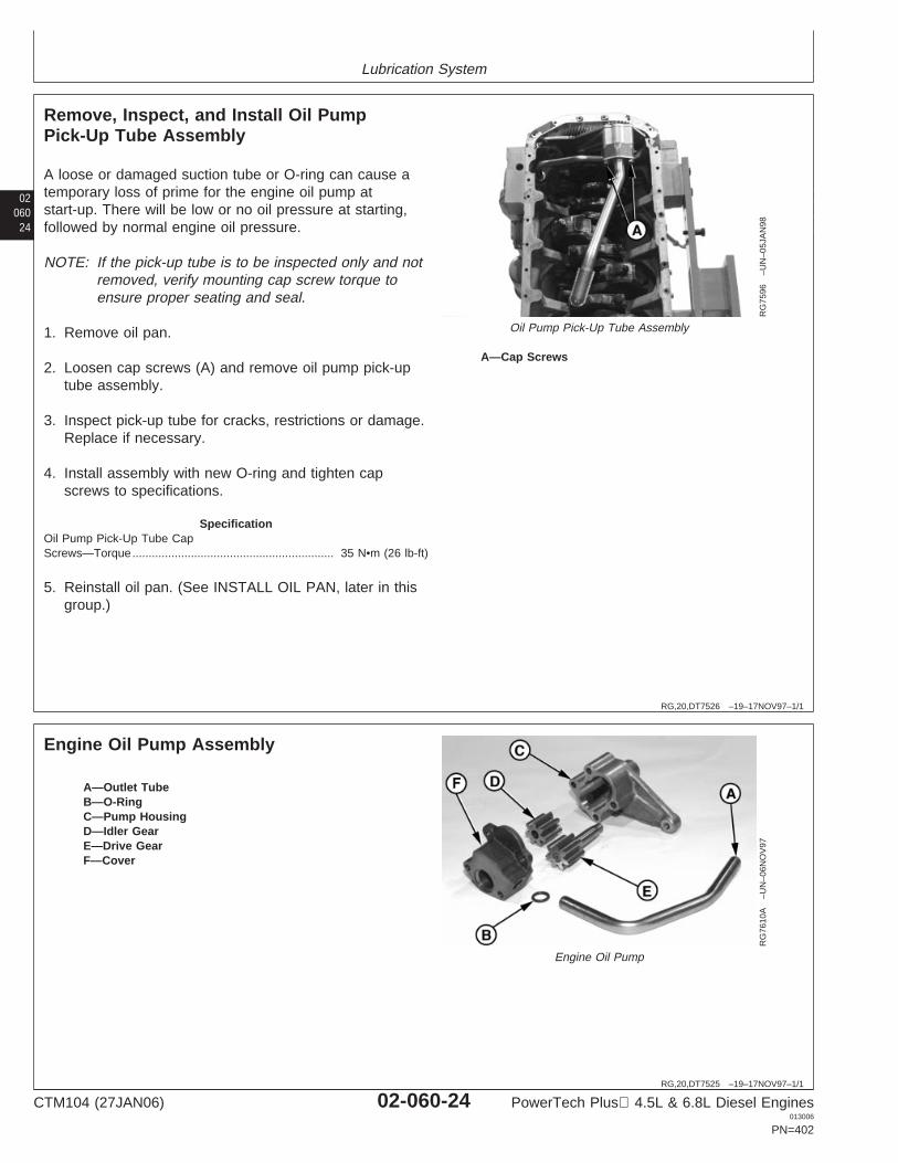
Lubrication System
02060
24
RG,20,DT7526 –19–17NOV97–1/1
Remove, Inspect, and Install Oil PumpPick-Up Tube Assembly
RG
7596
–UN
–05J
AN
98
Oil Pump Pick-Up Tube Assembly
A—Cap Screws
A loose or damaged suction tube or O-ring can cause atemporary loss of prime for the engine oil pump atstart-up. There will be low or no oil pressure at starting,followed by normal engine oil pressure.
NOTE: If the pick-up tube is to be inspected only and notremoved, verify mounting cap screw torque toensure proper seating and seal.
1. Remove oil pan.
2. Loosen cap screws (A) and remove oil pump pick-uptube assembly.
3. Inspect pick-up tube for cracks, restrictions or damage.Replace if necessary.
4. Install assembly with new O-ring and tighten capscrews to specifications.
SpecificationOil Pump Pick-Up Tube CapScrews—Torque 35 N•m (26 lb-ft)..............................................................
5. Reinstall oil pan. (See INSTALL OIL PAN, later in thisgroup.)
RG,20,DT7525 –19–17NOV97–1/1
Engine Oil Pump AssemblyR
G76
10A
–UN
–06N
OV
97
Engine Oil Pump
A—Outlet TubeB—O-RingC—Pump HousingD—Idler GearE—Drive GearF—Cover
CTM104 (27JAN06) 02-060-24 PowerTech Plus 4.5L & 6.8L Diesel Engines013006
PN=402
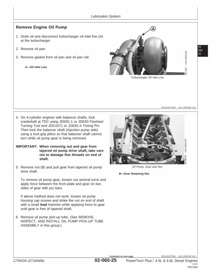
Lubrication System
0206025
RG,20,DT7524 –19–17NOV97–1/3
Remove Engine Oil Pump
RG
7407
–UN
–03N
OV
97
Turbocharger Oil Inlet Line
A—Oil Inlet Line
1. Drain oil and disconnect turbocharger oil inlet line (A)at the turbocharger.
2. Remove oil pan.
3. Remove gasket from oil pan and oil pan rail.
RG,20,DT7524 –19–17NOV97–2/3
RG
7597
B–U
N–0
6NO
V97
Oil Pump, Gear and Nut
B—Gear Retaining Nut
4. On 4-cylinder engines with balancer shafts, lockcrankshaft at TDC using JDE81-1 or JDE83 FlywheelTurning Tool and JDG1571 or JDE81-4 Timing Pin.Then lock the balancer shaft (injection pump side)using a lock-grip pliers so that balancer shaft cannotturn while oil pump gear is being removed.
IMPORTANT: When removing nut and gear fromtapered oil pump drive shaft, take carenot to damage fine threads on end ofshaft.
5. Remove nut (B) and pull gear from tapered oil pumpdrive shaft.
To remove oil pump gear, loosen nut several turns andapply force between the front plate and gear on twosides of gear with pry bars.
If above method does not work, loosen oil pumphousing cap screws and strike the nut on end of shaftwith a small lead hammer while applying force to gearuntil gear is free of tapered shaft.
6. Remove oil pump pick-up tube. (See REMOVE,INSPECT, AND INSTALL OIL PUMP PICK-UP TUBEASSEMBLY in this group.)
CTM104 (27JAN06) 02-060-25 PowerTech Plus 4.5L & 6.8L Diesel Engines013006
PN=403
Continued on next page
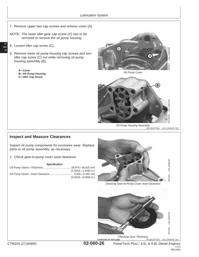
Lubrication System
02060
26
RG,20,DT7524 –19–17NOV97–3/3
RG
9077
–UN
–12M
AR
98
Oil Pump Cover
RG
7967
B–U
N–1
4NO
V97
Oil Pump Housing Assembly
A—CoverB—Oil Pump HousingC—Idler Cap Screw
7. Remove upper two cap screws and remove cover (A).
NOTE: The lower idler gear cap screw (C) has to beremoved to remove the oil pump housing.
8. Loosen idler cap screw (C).
9. Remove lower oil pump housing cap screws and turnidler cap screw (C) out while removing oil pumphousing assembly (B).
RG,20,DT7523 –19–17NOV97–1/4
Inspect and Measure Clearances
RG
7601
–UN
–23N
OV
97
Checking Gear-to-Pump Cover Axial Clearance
RG
7602
–UN
–23N
OV
97
Checking Gear Thickness
Inspect oil pump components for excessive wear. Replaceparts or oil pump assembly, as necessary.
1. Check gear-to-pump cover axial clearance.
SpecificationOil Pump Gears—Thickness 35.975—36.025 mm
(1.4163—1.4183 in.).....................................
Oil Pump Gears—Axial Clearance 0.045—0.165 mm(0.0018—0.0065 in.)
................................
CTM104 (27JAN06) 02-060-26 PowerTech Plus 4.5L & 6.8L Diesel Engines013006
PN=404
Continued on next page
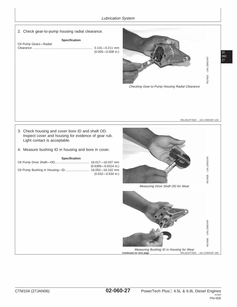
Lubrication System
0206027
RG,20,DT7523 –19–17NOV97–2/4
RG
7603
–UN
–23N
OV
97
Checking Gear-to-Pump Housing Radial Clearance
2. Check gear-to-pump housing radial clearance.
SpecificationOil Pump Gears—RadialClearance 0.131—0.211 mm
(0.005—0.008 in.)......................................................................
RG,20,DT7523 –19–17NOV97–3/4
RG
7605
–UN
–23N
OV
97
Measuring Drive Shaft OD for Wear
RG
7606
–UN
–23N
OV
97
Measuring Bushing ID in Housing for Wear
3. Check housing and cover bore ID and shaft OD.Inspect cover and housing for evidence of gear rub.Light contact is acceptable.
4. Measure bushing ID in housing and bore in cover.
SpecificationOil Pump Drive Shaft—OD 16.017—16.037 mm
(0.6306—0.6314 in.)........................................
Oil Pump Bushing in Housing—ID 16.052—16.102 mm(0.632—0.634 in.)
............................
Continued on next page
CTM104 (27JAN06) 02-060-27 PowerTech Plus 4.5L & 6.8L Diesel Engines013006
PN=405
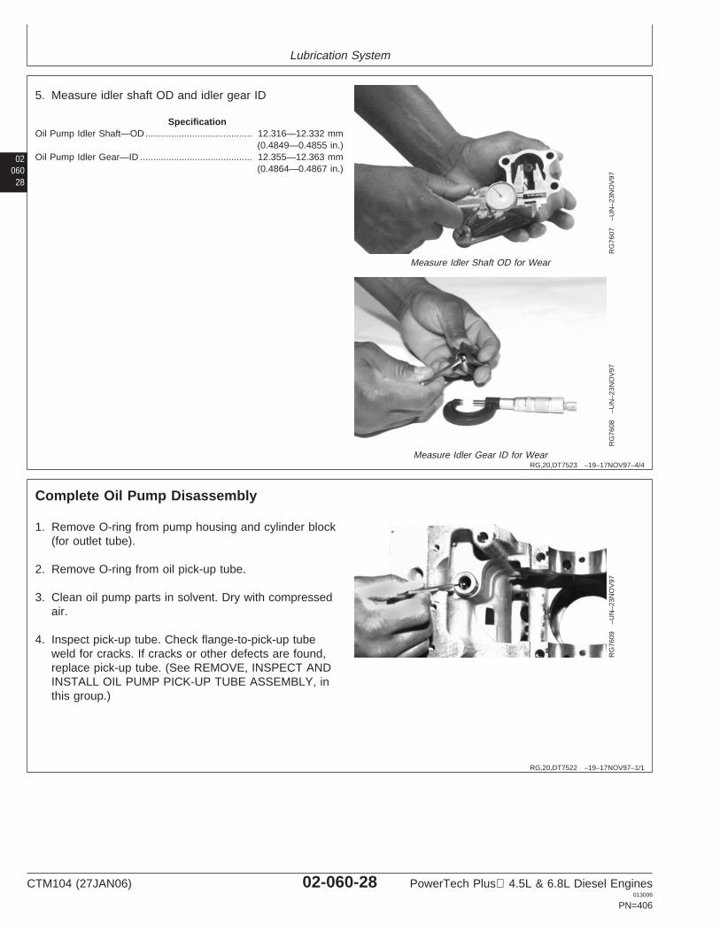
Lubrication System
02060
28
RG,20,DT7523 –19–17NOV97–4/4
RG
7607
–UN
–23N
OV
97
Measure Idler Shaft OD for Wear
RG
7608
–UN
–23N
OV
97
Measure Idler Gear ID for Wear
5. Measure idler shaft OD and idler gear ID
SpecificationOil Pump Idler Shaft—OD 12.316—12.332 mm
(0.4849—0.4855 in.).........................................
Oil Pump Idler Gear—ID 12.355—12.363 mm(0.4864—0.4867 in.)
...........................................
RG,20,DT7522 –19–17NOV97–1/1
Complete Oil Pump Disassembly
RG
7609
–UN
–23N
OV
97
1. Remove O-ring from pump housing and cylinder block(for outlet tube).
2. Remove O-ring from oil pick-up tube.
3. Clean oil pump parts in solvent. Dry with compressedair.
4. Inspect pick-up tube. Check flange-to-pick-up tubeweld for cracks. If cracks or other defects are found,replace pick-up tube. (See REMOVE, INSPECT ANDINSTALL OIL PUMP PICK-UP TUBE ASSEMBLY, inthis group.)
CTM104 (27JAN06) 02-060-28 PowerTech Plus 4.5L & 6.8L Diesel Engines013006
PN=406
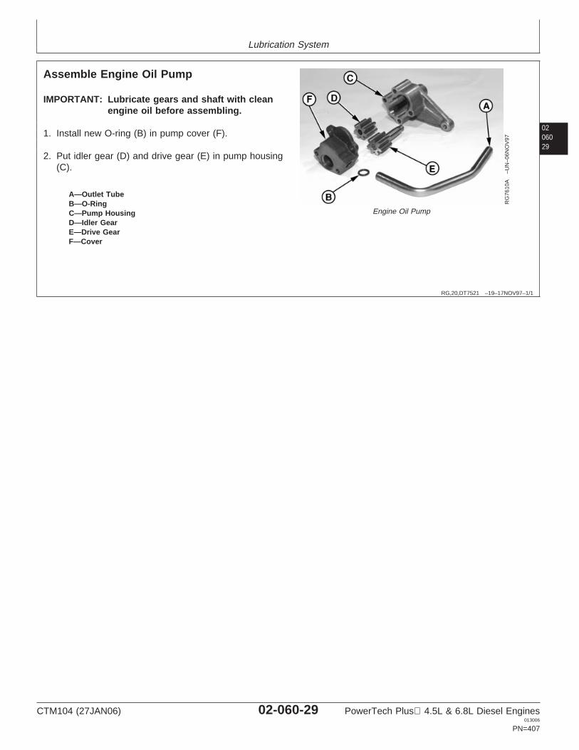
Lubrication System
0206029
RG,20,DT7521 –19–17NOV97–1/1
Assemble Engine Oil Pump
RG
7610
A–U
N–0
6NO
V97
Engine Oil Pump
A—Outlet TubeB—O-RingC—Pump HousingD—Idler GearE—Drive GearF—Cover
IMPORTANT: Lubricate gears and shaft with cleanengine oil before assembling.
1. Install new O-ring (B) in pump cover (F).
2. Put idler gear (D) and drive gear (E) in pump housing(C).
CTM104 (27JAN06) 02-060-29 PowerTech Plus 4.5L & 6.8L Diesel Engines013006
PN=407
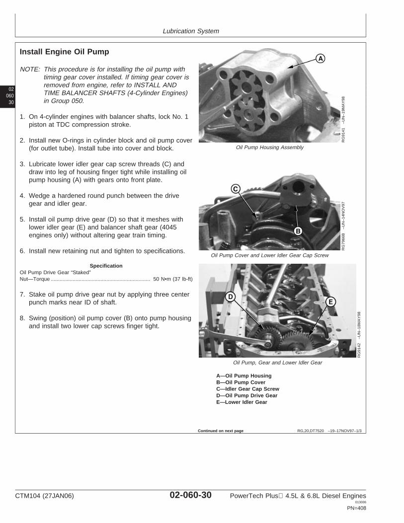
Lubrication System
02060
30
RG,20,DT7520 –19–17NOV97–1/3
Install Engine Oil Pump
RG
9141
–UN
–19M
AY
98
Oil Pump Housing Assembly
RG
7966
B–U
N–1
4NO
V97
Oil Pump Cover and Lower Idler Gear Cap Screw
RG
9142
–UN
–18M
AY
98Oil Pump, Gear and Lower Idler Gear
A—Oil Pump HousingB—Oil Pump CoverC—Idler Gear Cap ScrewD—Oil Pump Drive GearE—Lower Idler Gear
NOTE: This procedure is for installing the oil pump withtiming gear cover installed. If timing gear cover isremoved from engine, refer to INSTALL ANDTIME BALANCER SHAFTS (4-Cylinder Engines)in Group 050.
1. On 4-cylinder engines with balancer shafts, lock No. 1piston at TDC compression stroke.
2. Install new O-rings in cylinder block and oil pump cover(for outlet tube). Install tube into cover and block.
3. Lubricate lower idler gear cap screw threads (C) anddraw into leg of housing finger tight while installing oilpump housing (A) with gears onto front plate.
4. Wedge a hardened round punch between the drivegear and idler gear.
5. Install oil pump drive gear (D) so that it meshes withlower idler gear (E) and balancer shaft gear (4045engines only) without altering gear train timing.
6. Install new retaining nut and tighten to specifications.
SpecificationOil Pump Drive Gear “Staked”Nut—Torque 50 N•m (37 lb-ft)....................................................................
7. Stake oil pump drive gear nut by applying three centerpunch marks near ID of shaft.
8. Swing (position) oil pump cover (B) onto pump housingand install two lower cap screws finger tight.
Continued on next page
CTM104 (27JAN06) 02-060-30 PowerTech Plus 4.5L & 6.8L Diesel Engines013006
PN=408
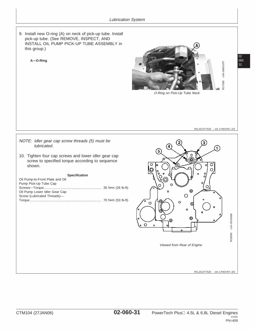
Lubrication System
0206031
RG,20,DT7520 –19–17NOV97–2/3
RG
7599
–UN
–06N
OV
97
O-Ring on Pick-Up Tube Neck
A—O-Ring
9. Install new O-ring (A) on neck of pick-up tube. Installpick-up tube. (See REMOVE, INSPECT, ANDINSTALL OIL PUMP PICK-UP TUBE ASSEMBLY inthis group.)
RG,20,DT7520 –19–17NOV97–3/3
RG
8090
–UN
–05J
AN
98
Viewed from Rear of Engine
NOTE: Idler gear cap screw threads (5) must belubricated.
10. Tighten four cap screws and lower idler gear capscrew to specified torque according to sequenceshown.
SpecificationOil Pump-to-Front Plate and OilPump Pick-Up Tube CapScrews—Torque 35 N•m (26 lb-ft)..............................................................Oil Pump Lower Idler Gear CapScrew (Lubricated Threads)—Torque 70 N•m (53 lb-ft).............................................................................
CTM104 (27JAN06) 02-060-31 PowerTech Plus 4.5L & 6.8L Diesel Engines013006
PN=409
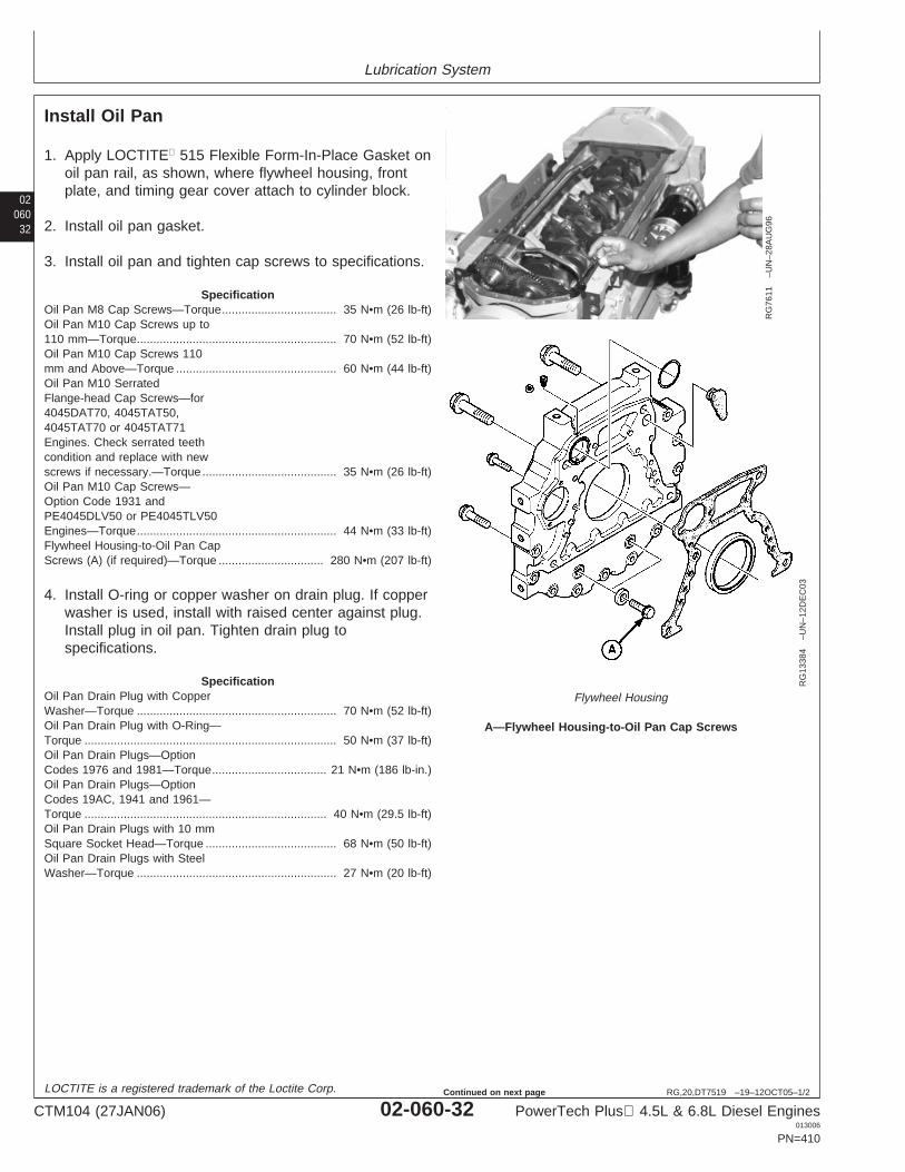
Lubrication System
02060
32
RG,20,DT7519 –19–12OCT05–1/2
Install Oil Pan
RG
7611
–UN
–28A
UG
96
RG
1338
4–U
N–1
2DE
C03
Flywheel Housing
A—Flywheel Housing-to-Oil Pan Cap Screws
1. Apply LOCTITE 515 Flexible Form-In-Place Gasket onoil pan rail, as shown, where flywheel housing, frontplate, and timing gear cover attach to cylinder block.
2. Install oil pan gasket.
3. Install oil pan and tighten cap screws to specifications.
SpecificationOil Pan M8 Cap Screws—Torque 35 N•m (26 lb-ft)...................................Oil Pan M10 Cap Screws up to110 mm—Torque 70 N•m (52 lb-ft).............................................................Oil Pan M10 Cap Screws 110mm and Above—Torque 60 N•m (44 lb-ft).................................................Oil Pan M10 SerratedFlange-head Cap Screws—for4045DAT70, 4045TAT50,4045TAT70 or 4045TAT71Engines. Check serrated teethcondition and replace with newscrews if necessary.—Torque 35 N•m (26 lb-ft).........................................Oil Pan M10 Cap Screws—Option Code 1931 andPE4045DLV50 or PE4045TLV50Engines—Torque 44 N•m (33 lb-ft).............................................................Flywheel Housing-to-Oil Pan CapScrews (A) (if required)—Torque 280 N•m (207 lb-ft)................................
4. Install O-ring or copper washer on drain plug. If copperwasher is used, install with raised center against plug.Install plug in oil pan. Tighten drain plug tospecifications.
SpecificationOil Pan Drain Plug with CopperWasher—Torque 70 N•m (52 lb-ft).............................................................Oil Pan Drain Plug with O-Ring—Torque 50 N•m (37 lb-ft).............................................................................Oil Pan Drain Plugs—OptionCodes 1976 and 1981—Torque 21 N•m (186 lb-in.)...................................Oil Pan Drain Plugs—OptionCodes 19AC, 1941 and 1961—Torque 40 N•m (29.5 lb-ft)..........................................................................Oil Pan Drain Plugs with 10 mmSquare Socket Head—Torque 68 N•m (50 lb-ft)........................................Oil Pan Drain Plugs with SteelWasher—Torque 27 N•m (20 lb-ft).............................................................
LOCTITE is a registered trademark of the Loctite Corp.
CTM104 (27JAN06) 02-060-32 PowerTech Plus 4.5L & 6.8L Diesel Engines013006
PN=410
Continued on next page
Lubrication System
0206033
RG,20,DT7519 –19–12OCT05–2/2
5. If equipped with elbow drain fittings, the threads andsealing surfaces must be free of oil film to ensure aneffective seal. Apply LOCTITE 592 Pipe Sealant withTEFLON to fitting except for the leading one to threethreads. Install and tighten fitting.
6. If equipped with side oil return ports, install port plugsand tighten to specification.
SpecificationOil Return Port Plugs—Torque 27 N•m (20 lb-ft).......................................
7. If equipped with oil level sensor, install sensor andtighten to specification.
SpecificationOil Level Sensor Cap Screws—Torque 10 N•m (88 lb-in.)............................................................................
8. Fill engine crankcase with correct grade and viscosityengine oil. See DIESEL ENGINE OIL—NON-CERTIFIED AND Tier 1 CERTIFIED ENGINES orDIESEL ENGINE OIL—Tier 2 ENGINES in Section 01,Group 002, Fuels, Lubricants, and Coolants.
LOCTITE is a registered trademark of the Loctite Corp.TEFLON is a registered trademark of the DuPont Co.
CTM104 (27JAN06) 02-060-33 PowerTech Plus 4.5L & 6.8L Diesel Engines013006
PN=411

Lubrication System
02060
34
CTM104 (27JAN06) 02-060-34 PowerTech Plus 4.5L & 6.8L Diesel Engines013006
PN=412
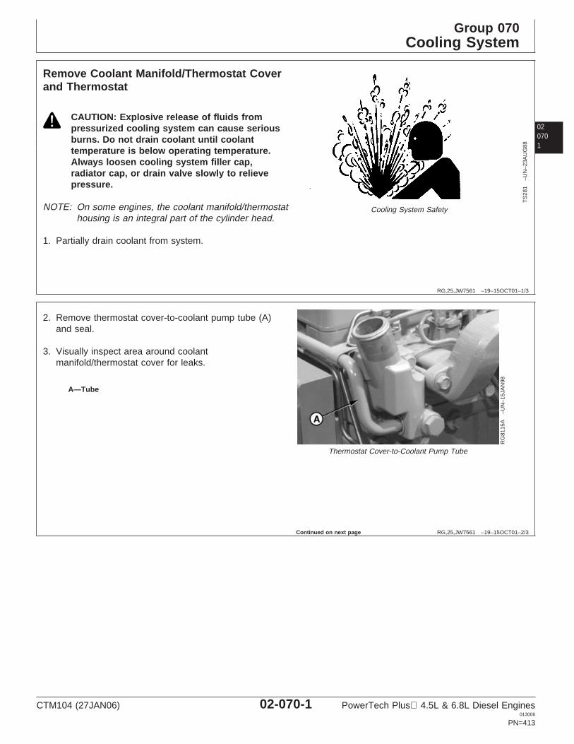
Group 070Cooling System
020701
RG,25,JW7561 –19–15OCT01–1/3
Remove Coolant Manifold/Thermostat Coverand Thermostat
TS
281
–UN
–23A
UG
88
Cooling System Safety
CAUTION: Explosive release of fluids frompressurized cooling system can cause seriousburns. Do not drain coolant until coolanttemperature is below operating temperature.Always loosen cooling system filler cap,radiator cap, or drain valve slowly to relievepressure.
NOTE: On some engines, the coolant manifold/thermostathousing is an integral part of the cylinder head.
1. Partially drain coolant from system.
RG,25,JW7561 –19–15OCT01–2/3
RG
8115
A–U
N–1
5JA
N98
Thermostat Cover-to-Coolant Pump Tube
A—Tube
2. Remove thermostat cover-to-coolant pump tube (A)and seal.
3. Visually inspect area around coolantmanifold/thermostat cover for leaks.
Continued on next page
CTM104 (27JAN06) 02-070-1 PowerTech Plus 4.5L & 6.8L Diesel Engines013006
PN=413
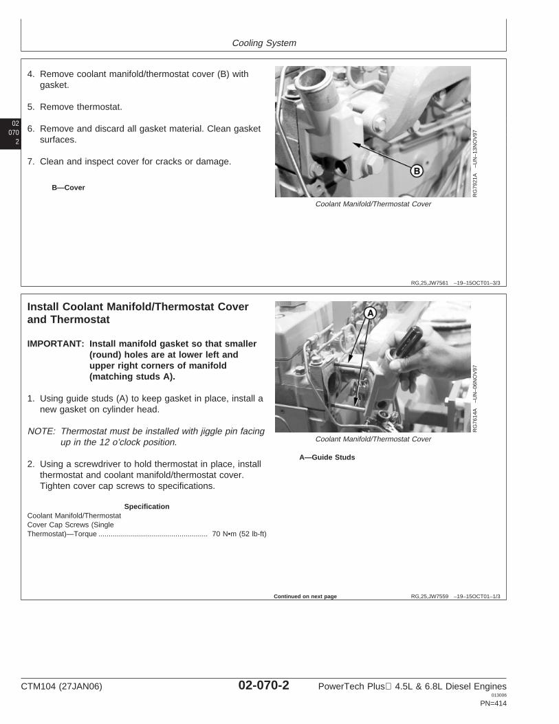
Cooling System
02070
2
RG,25,JW7561 –19–15OCT01–3/3
RG
7921
A–U
N–1
3NO
V97
Coolant Manifold/Thermostat Cover
B—Cover
4. Remove coolant manifold/thermostat cover (B) withgasket.
5. Remove thermostat.
6. Remove and discard all gasket material. Clean gasketsurfaces.
7. Clean and inspect cover for cracks or damage.
RG,25,JW7559 –19–15OCT01–1/3
Install Coolant Manifold/Thermostat Coverand Thermostat
RG
7614
A–U
N–0
6NO
V97
Coolant Manifold/Thermostat Cover
A—Guide Studs
IMPORTANT: Install manifold gasket so that smaller(round) holes are at lower left andupper right corners of manifold(matching studs A).
1. Using guide studs (A) to keep gasket in place, install anew gasket on cylinder head.
NOTE: Thermostat must be installed with jiggle pin facingup in the 12 o’clock position.
2. Using a screwdriver to hold thermostat in place, installthermostat and coolant manifold/thermostat cover.Tighten cover cap screws to specifications.
SpecificationCoolant Manifold/ThermostatCover Cap Screws (SingleThermostat)—Torque 70 N•m (52 lb-ft)......................................................
Continued on next page
CTM104 (27JAN06) 02-070-2 PowerTech Plus 4.5L & 6.8L Diesel Engines013006
PN=414
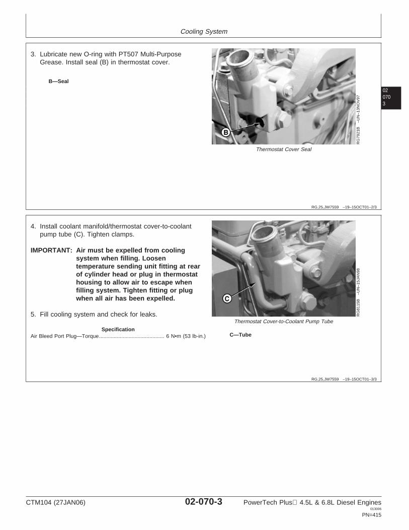
Cooling System
020703
RG,25,JW7559 –19–15OCT01–2/3
RG
7921
B–U
N–1
3NO
V97
Thermostat Cover Seal
B—Seal
3. Lubricate new O-ring with PT507 Multi-PurposeGrease. Install seal (B) in thermostat cover.
RG,25,JW7559 –19–15OCT01–3/3
RG
8115
B–U
N–1
5JA
N98
Thermostat Cover-to-Coolant Pump Tube
C—Tube
4. Install coolant manifold/thermostat cover-to-coolantpump tube (C). Tighten clamps.
IMPORTANT: Air must be expelled from coolingsystem when filling. Loosentemperature sending unit fitting at rearof cylinder head or plug in thermostathousing to allow air to escape whenfilling system. Tighten fitting or plugwhen all air has been expelled.
5. Fill cooling system and check for leaks.
SpecificationAir Bleed Port Plug—Torque 6 N•m (53 lb-in.)............................................
CTM104 (27JAN06) 02-070-3 PowerTech Plus 4.5L & 6.8L Diesel Engines013006
PN=415

Cooling System
02070
4
DPSG,OUO1004,1135 –19–15OCT01–1/3
Remove and Install CoolantManifold/Thermostat Cover and Thermostat(High Flow Single Thermostat)
TS
281
–UN
–23A
UG
88
Cooling System Safety
CAUTION: Explosive release of fluids frompressurized cooling system can cause seriousburns. Do not drain coolant until coolanttemperature is below operating temperature.Always loosen cooling system filler cap,radiator cap, or drain valve slowly to relievepressure.
1. Partially drain coolant from system.
Continued on next page
CTM104 (27JAN06) 02-070-4 PowerTech Plus 4.5L & 6.8L Diesel Engines013006
PN=416

Cooling System
020705
DPSG,OUO1004,1135 –19–15OCT01–2/3
RG
1054
3–U
N–2
9NO
V99
Coolant Manifold and Thermostat (High Flow Single Thermostat)
A—Seal F—Thermostat Cover H—Cap Screw (M10 x 70) J—SealB—Coolant Manifold G—Cap Screw (M10 x 90) Thermostat K—CoolantC—Seal Thermostat Cover-to-Coolant Manifold Manifold-to-Coolant PumpD—Thermostat Cover-to-Coolant I—Cap Screw (M10 x 25) TubeE—Jiggle Pin Manifold-to-Cylinder Head Thermostat
Cover-to-Coolant Manifold
2. Remove coolant manifold-to-coolant pump tube (K)and seal (J).
3. Visually inspect area around coolantmanifold/thermostat cover for leaks.
4. Remove cap screws (G) and remove coolantmanifold/thermostat cover assembly with gasket.
5. Remove thermostat cover (F) and thermostat (D).
6. Remove and discard all gasket material. Cleangasket surfaces.
7. Clean and inspect cover for cracks or damage.
NOTE: Thermostat must be installed with jiggle pin (E)facing up in the 12 o’clock position.
8. Install thermostat (D), cover (F) and seal (C) oncoolant manifold. Hand tighten cover cap screws(H) and (I).
9. Install coolant manifold/thermostat cover assemblyon engine using cap screws (G). Tighten all capscrews to specifications.
SpecificationThermostat Cover-to-CoolantManifold Cap Screws (H and I)(High Flow SingleThermostat)—Torque 30 N•m (22 lb-ft)................................................Coolant Manifold-to-CylinderHead Cap Screws (G) (HighFlow Single Thermostat)—Torque 35 N•m (26 lb-ft).......................................................................
10. Install new seal (J) and tube (K). Tighten tubeclamps securely.
11. Fill cooling system and check for leaks.
CTM104 (27JAN06) 02-070-5 PowerTech Plus 4.5L & 6.8L Diesel Engines013006
PN=417
Continued on next page
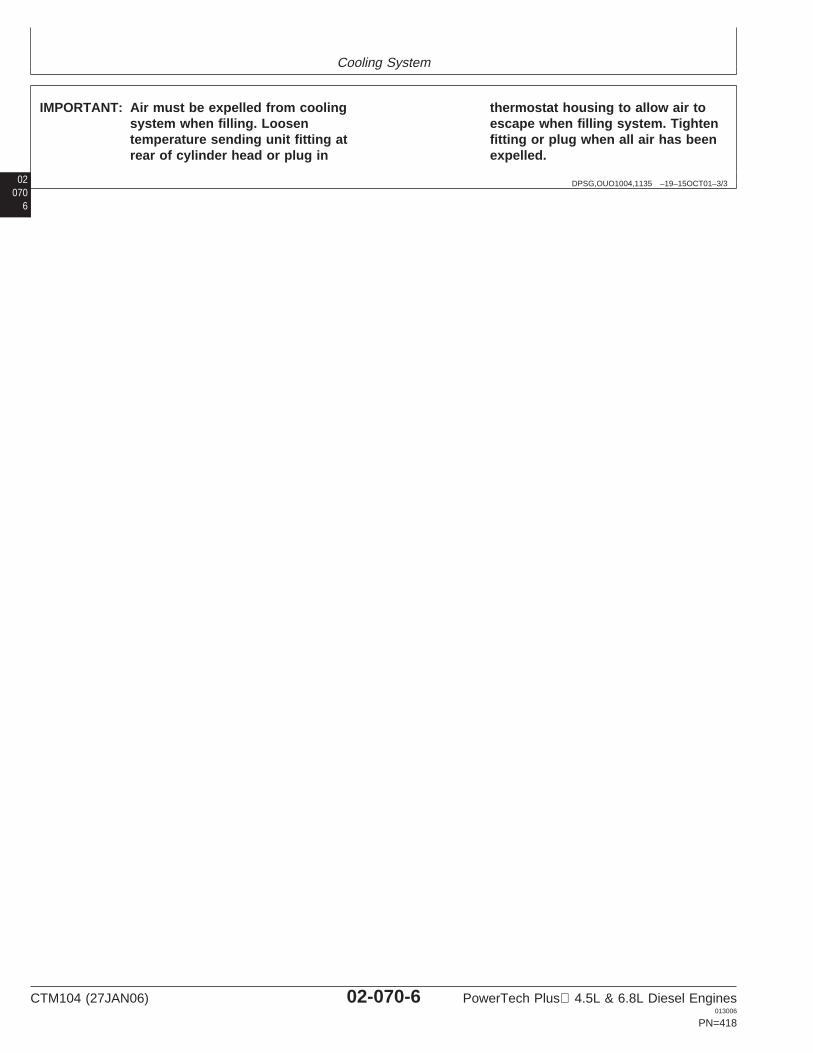
Cooling System
02070
DPSG,OUO1004,1135 –19–15OCT01–3/3
IMPORTANT: Air must be expelled from coolingsystem when filling. Loosentemperature sending unit fitting atrear of cylinder head or plug in
thermostat housing to allow air toescape when filling system. Tightenfitting or plug when all air has beenexpelled.
6
CTM104 (27JAN06) 02-070-6 PowerTech Plus 4.5L & 6.8L Diesel Engines013006
PN=418
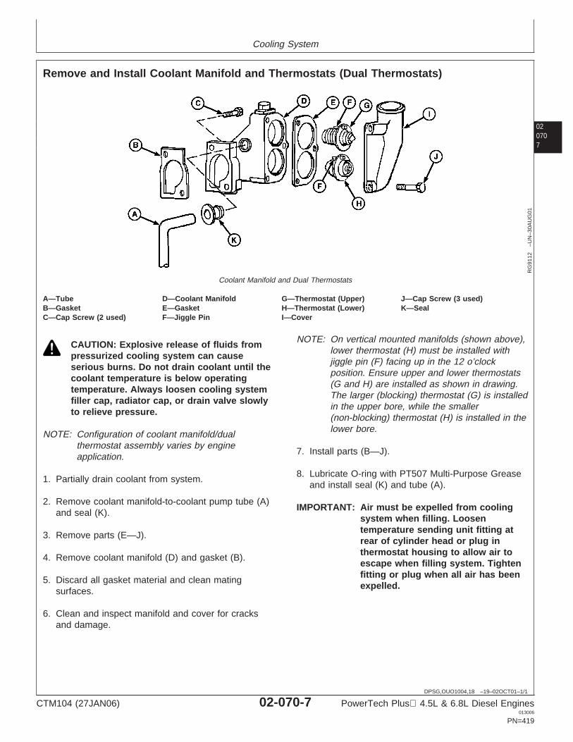
Cooling System
020707
DPSG,OUO1004,18 –19–02OCT01–1/1
Remove and Install Coolant Manifold and Thermostats (Dual Thermostats)
RG
9112
–UN
–30A
UG
01
Coolant Manifold and Dual Thermostats
A—Tube D—Coolant Manifold G—Thermostat (Upper) J—Cap Screw (3 used)B—Gasket E—Gasket H—Thermostat (Lower) K—SealC—Cap Screw (2 used) F—Jiggle Pin I—Cover
CAUTION: Explosive release of fluids frompressurized cooling system can causeserious burns. Do not drain coolant until thecoolant temperature is below operatingtemperature. Always loosen cooling systemfiller cap, radiator cap, or drain valve slowlyto relieve pressure.
NOTE: Configuration of coolant manifold/dualthermostat assembly varies by engineapplication.
1. Partially drain coolant from system.
2. Remove coolant manifold-to-coolant pump tube (A)and seal (K).
3. Remove parts (E—J).
4. Remove coolant manifold (D) and gasket (B).
5. Discard all gasket material and clean matingsurfaces.
6. Clean and inspect manifold and cover for cracksand damage.
NOTE: On vertical mounted manifolds (shown above),lower thermostat (H) must be installed withjiggle pin (F) facing up in the 12 o’clockposition. Ensure upper and lower thermostats(G and H) are installed as shown in drawing.The larger (blocking) thermostat (G) is installedin the upper bore, while the smaller(non-blocking) thermostat (H) is installed in thelower bore.
7. Install parts (B—J).
8. Lubricate O-ring with PT507 Multi-Purpose Greaseand install seal (K) and tube (A).
IMPORTANT: Air must be expelled from coolingsystem when filling. Loosentemperature sending unit fitting atrear of cylinder head or plug inthermostat housing to allow air toescape when filling system. Tightenfitting or plug when all air has beenexpelled.
CTM104 (27JAN06) 02-070-7 PowerTech Plus 4.5L & 6.8L Diesel Engines013006
PN=419
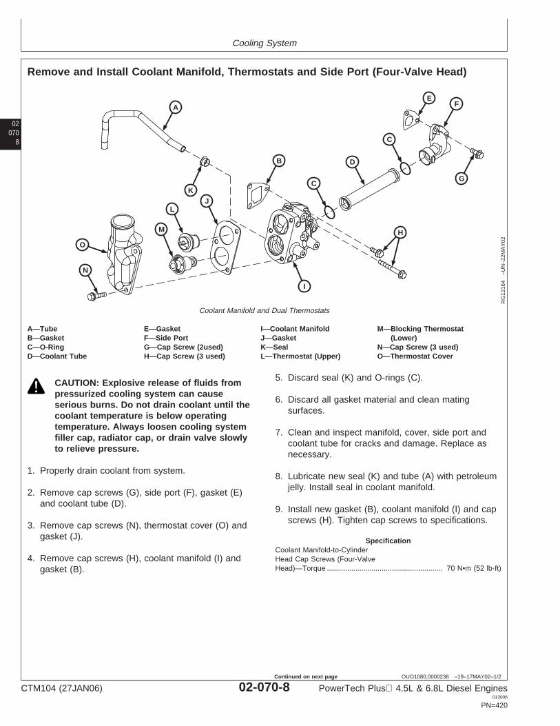
Cooling System
02070
8
OUO1080,0000236 –19–17MAY02–1/2
Remove and Install Coolant Manifold, Thermostats and Side Port (Four-Valve Head)
A
B
C
D
C
EF
G
H
I
KJ
L
M
N
O
RG
1216
4–U
N–2
2MA
Y02
Coolant Manifold and Dual Thermostats
A—Tube E—Gasket I—Coolant Manifold M—Blocking ThermostatB—Gasket F—Side Port J—Gasket (Lower)C—O-Ring G—Cap Screw (2used) K—Seal N—Cap Screw (3 used)D—Coolant Tube H—Cap Screw (3 used) L—Thermostat (Upper) O—Thermostat Cover
CAUTION: Explosive release of fluids frompressurized cooling system can causeserious burns. Do not drain coolant until thecoolant temperature is below operatingtemperature. Always loosen cooling systemfiller cap, radiator cap, or drain valve slowlyto relieve pressure.
1. Properly drain coolant from system.
2. Remove cap screws (G), side port (F), gasket (E)and coolant tube (D).
3. Remove cap screws (N), thermostat cover (O) andgasket (J).
4. Remove cap screws (H), coolant manifold (I) andgasket (B).
5. Discard seal (K) and O-rings (C).
6. Discard all gasket material and clean matingsurfaces.
7. Clean and inspect manifold, cover, side port andcoolant tube for cracks and damage. Replace asnecessary.
8. Lubricate new seal (K) and tube (A) with petroleumjelly. Install seal in coolant manifold.
9. Install new gasket (B), coolant manifold (I) and capscrews (H). Tighten cap screws to specifications.
SpecificationCoolant Manifold-to-CylinderHead Cap Screws (Four-ValveHead)—Torque 70 N•m (52 lb-ft).........................................................
CTM104 (27JAN06) 02-070-8 PowerTech Plus 4.5L & 6.8L Diesel Engines013006
PN=420
Continued on next page
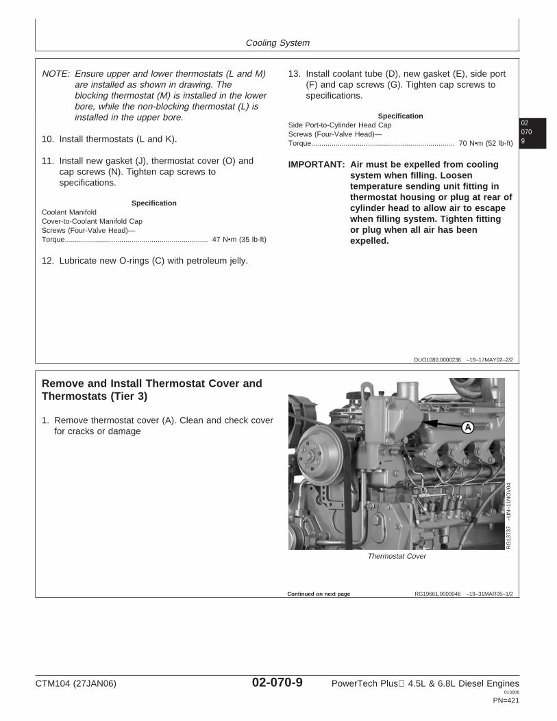
Cooling System
020709
OUO1080,0000236 –19–17MAY02–2/2
NOTE: Ensure upper and lower thermostats (L and M)are installed as shown in drawing. Theblocking thermostat (M) is installed in the lowerbore, while the non-blocking thermostat (L) isinstalled in the upper bore.
10. Install thermostats (L and K).
11. Install new gasket (J), thermostat cover (O) andcap screws (N). Tighten cap screws tospecifications.
SpecificationCoolant ManifoldCover-to-Coolant Manifold CapScrews (Four-Valve Head)—Torque 47 N•m (35 lb-ft).......................................................................
12. Lubricate new O-rings (C) with petroleum jelly.
13. Install coolant tube (D), new gasket (E), side port(F) and cap screws (G). Tighten cap screws tospecifications.
SpecificationSide Port-to-Cylinder Head CapScrews (Four-Valve Head)—Torque 70 N•m (52 lb-ft).......................................................................
IMPORTANT: Air must be expelled from coolingsystem when filling. Loosentemperature sending unit fitting inthermostat housing or plug at rear ofcylinder head to allow air to escapewhen filling system. Tighten fittingor plug when all air has beenexpelled.
RG19661,0000046 –19–31MAR05–1/2
Remove and Install Thermostat Cover andThermostats (Tier 3)
RG
1373
7–U
N–1
1NO
V04
Thermostat Cover
1. Remove thermostat cover (A). Clean and check coverfor cracks or damage
Continued on next page
CTM104 (27JAN06) 02-070-9 PowerTech Plus 4.5L & 6.8L Diesel Engines013006
PN=421
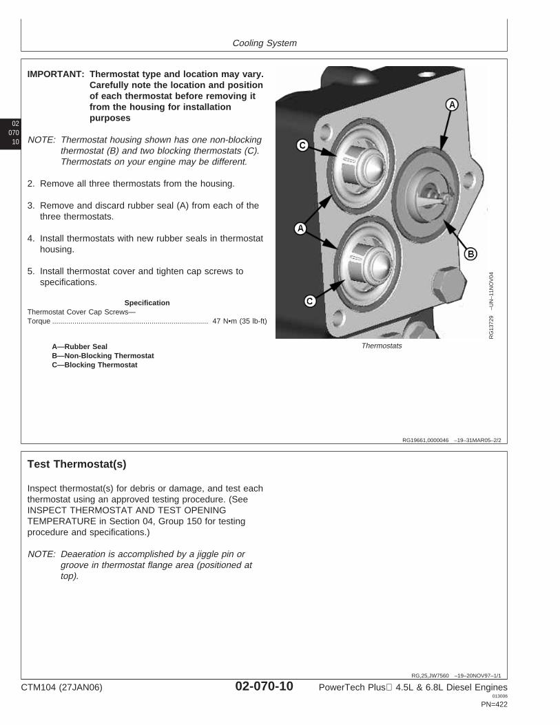
Cooling System
02070
10
RG19661,0000046 –19–31MAR05–2/2
RG
1372
9–U
N–1
1NO
V04
ThermostatsA—Rubber SealB—Non-Blocking ThermostatC—Blocking Thermostat
IMPORTANT: Thermostat type and location may vary.Carefully note the location and positionof each thermostat before removing itfrom the housing for installationpurposes
NOTE: Thermostat housing shown has one non-blockingthermostat (B) and two blocking thermostats (C).Thermostats on your engine may be different.
2. Remove all three thermostats from the housing.
3. Remove and discard rubber seal (A) from each of thethree thermostats.
4. Install thermostats with new rubber seals in thermostathousing.
5. Install thermostat cover and tighten cap screws tospecifications.
SpecificationThermostat Cover Cap Screws—Torque 47 N•m (35 lb-ft).............................................................................
RG,25,JW7560 –19–20NOV97–1/1
Test Thermostat(s)
Inspect thermostat(s) for debris or damage, and test eachthermostat using an approved testing procedure. (SeeINSPECT THERMOSTAT AND TEST OPENINGTEMPERATURE in Section 04, Group 150 for testingprocedure and specifications.)
NOTE: Deaeration is accomplished by a jiggle pin orgroove in thermostat flange area (positioned attop).
CTM104 (27JAN06) 02-070-10 PowerTech Plus 4.5L & 6.8L Diesel Engines013006
PN=422
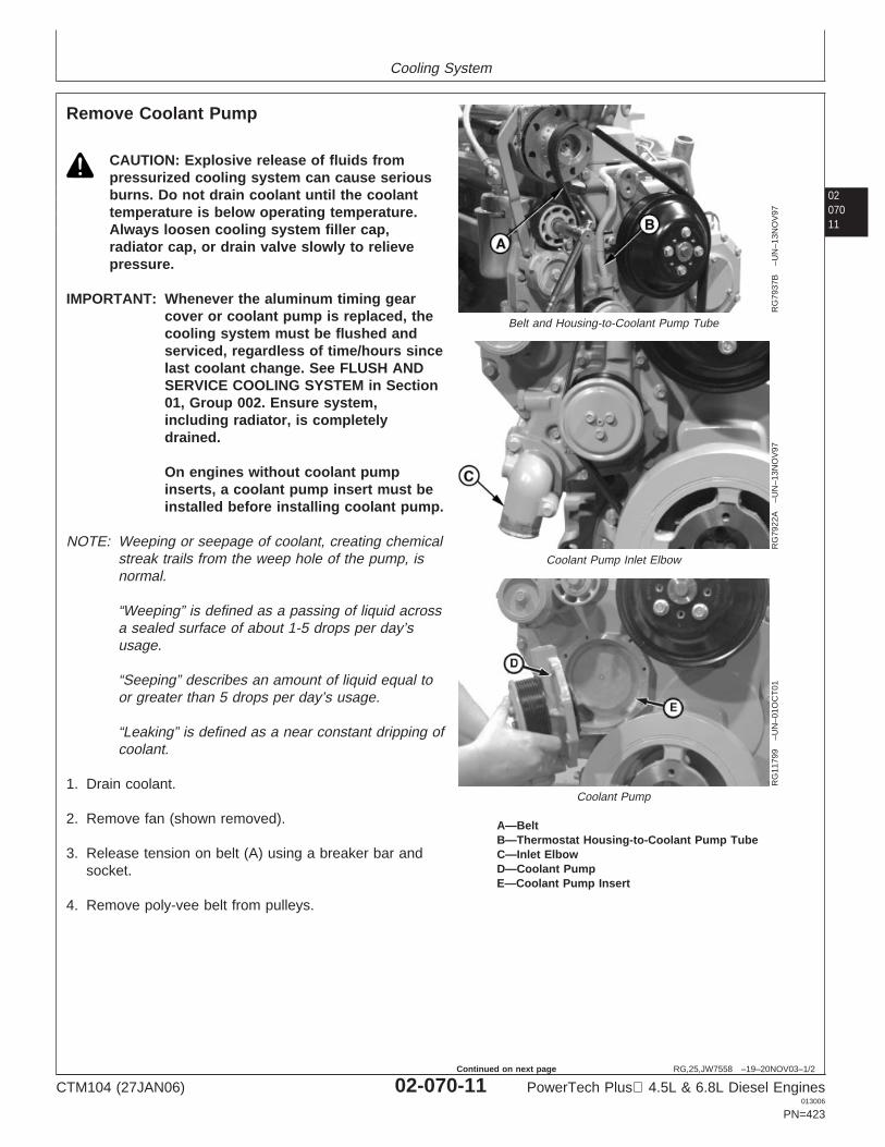
Cooling System
0207011
RG,25,JW7558 –19–20NOV03–1/2
Remove Coolant Pump
RG
7937
B–U
N–1
3NO
V97
Belt and Housing-to-Coolant Pump Tube
RG
7922
A–U
N–1
3NO
V97
Coolant Pump Inlet Elbow
RG
1179
9–U
N–0
1OC
T01
Coolant Pump
A—BeltB—Thermostat Housing-to-Coolant Pump TubeC—Inlet ElbowD—Coolant PumpE—Coolant Pump Insert
CAUTION: Explosive release of fluids frompressurized cooling system can cause seriousburns. Do not drain coolant until the coolanttemperature is below operating temperature.Always loosen cooling system filler cap,radiator cap, or drain valve slowly to relievepressure.
IMPORTANT: Whenever the aluminum timing gearcover or coolant pump is replaced, thecooling system must be flushed andserviced, regardless of time/hours sincelast coolant change. See FLUSH ANDSERVICE COOLING SYSTEM in Section01, Group 002. Ensure system,including radiator, is completelydrained.
On engines without coolant pumpinserts, a coolant pump insert must beinstalled before installing coolant pump.
NOTE: Weeping or seepage of coolant, creating chemicalstreak trails from the weep hole of the pump, isnormal.
“Weeping” is defined as a passing of liquid acrossa sealed surface of about 1-5 drops per day’susage.
“Seeping” describes an amount of liquid equal toor greater than 5 drops per day’s usage.
“Leaking” is defined as a near constant dripping ofcoolant.
1. Drain coolant.
2. Remove fan (shown removed).
3. Release tension on belt (A) using a breaker bar andsocket.
4. Remove poly-vee belt from pulleys.
CTM104 (27JAN06) 02-070-11 PowerTech Plus 4.5L & 6.8L Diesel Engines013006
PN=423
Continued on next page
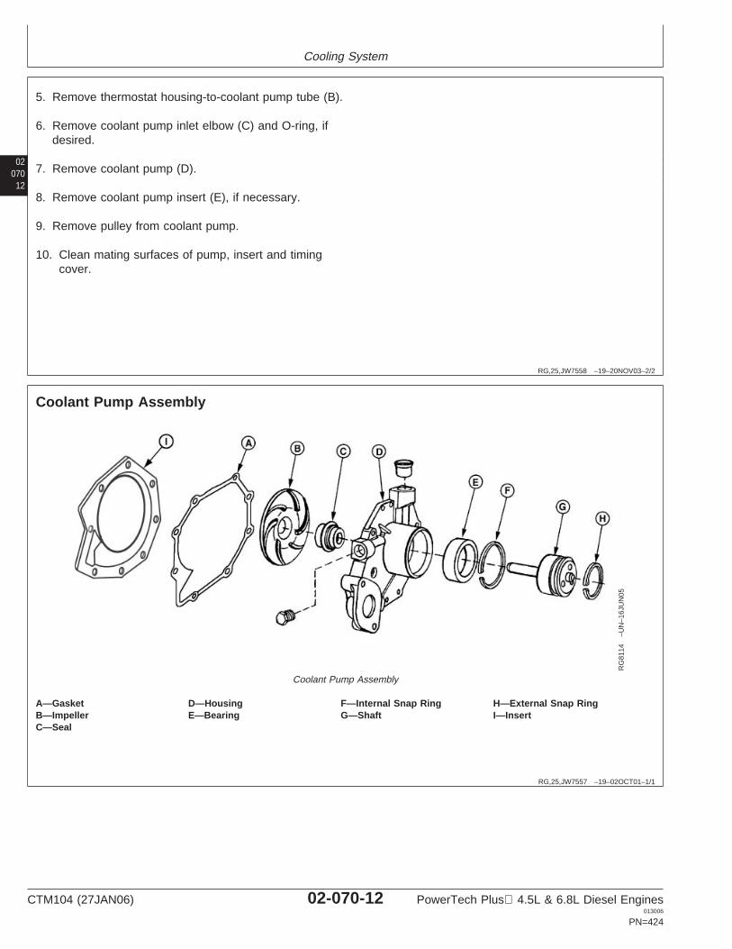
Cooling System
02070
12
RG,25,JW7558 –19–20NOV03–2/2
5. Remove thermostat housing-to-coolant pump tube (B).
6. Remove coolant pump inlet elbow (C) and O-ring, ifdesired.
7. Remove coolant pump (D).
8. Remove coolant pump insert (E), if necessary.
9. Remove pulley from coolant pump.
10. Clean mating surfaces of pump, insert and timingcover.
RG,25,JW7557 –19–02OCT01–1/1
Coolant Pump Assembly
RG
8114
–UN
–16J
UN
05
Coolant Pump Assembly
A—Gasket D—Housing F—Internal Snap Ring H—External Snap RingB—Impeller E—Bearing G—Shaft I—InsertC—Seal
CTM104 (27JAN06) 02-070-12 PowerTech Plus 4.5L & 6.8L Diesel Engines013006
PN=424

Cooling System
0207013
RG,25,JW7556 –19–02OCT01–1/1
Disassemble Coolant Pump
RG
8036
–UN
–14N
OV
97
Coolant Pump Housing Shaft and Impeller
RG
7924
–UN
–13N
OV
97
Coolant Pump Housing Seal
RG
7925
–UN
–13N
OV
97
Inner Shaft and Bearing
A—ImpellerB—SealC—Shaft
1. Using appropriate snap ring pliers, remove internalsnap ring from front bore of pump housing.
IMPORTANT: If plastic impeller breaks while pressingshaft through impeller, remove brassbushing from shaft before pressingshaft through rest of housing. Use aknife-edge puller to remove bushing.
2. Support nose of coolant pump housing and press shaftthrough impeller (A) until impeller is free from shaft andbearing/shaft assembly is removed from housing.Discard impeller.
3. Using the appropriate driver from D01045AA Bushing,Bearing and Seal Driver Set, drive or press seal (B)from pump housing.
4. Support inner bearing race and press shaft (C) out ofbearing. Discard bearing.
CTM104 (27JAN06) 02-070-13 PowerTech Plus 4.5L & 6.8L Diesel Engines013006
PN=425
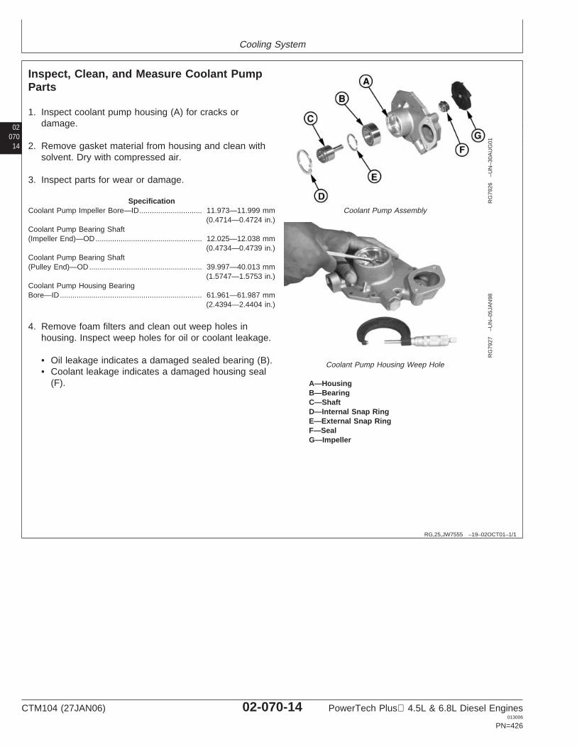
Cooling System
02070
14
RG,25,JW7555 –19–02OCT01–1/1
Inspect, Clean, and Measure Coolant PumpParts
RG
7926
–UN
–30A
UG
01
Coolant Pump Assembly
RG
7927
–UN
–05J
AN
98
Coolant Pump Housing Weep Hole
A—HousingB—BearingC—ShaftD—Internal Snap RingE—External Snap RingF—SealG—Impeller
1. Inspect coolant pump housing (A) for cracks ordamage.
2. Remove gasket material from housing and clean withsolvent. Dry with compressed air.
3. Inspect parts for wear or damage.
SpecificationCoolant Pump Impeller Bore—ID 11.973—11.999 mm
(0.4714—0.4724 in.)..............................
Coolant Pump Bearing Shaft(Impeller End)—OD 12.025—12.038 mm
(0.4734—0.4739 in.)...................................................
Coolant Pump Bearing Shaft(Pulley End)—OD 39.997—40.013 mm
(1.5747—1.5753 in.)......................................................
Coolant Pump Housing BearingBore—ID 61.961—61.987 mm
(2.4394—2.4404 in.)....................................................................
4. Remove foam filters and clean out weep holes inhousing. Inspect weep holes for oil or coolant leakage.
• Oil leakage indicates a damaged sealed bearing (B).• Coolant leakage indicates a damaged housing seal
(F).
CTM104 (27JAN06) 02-070-14 PowerTech Plus 4.5L & 6.8L Diesel Engines013006
PN=426
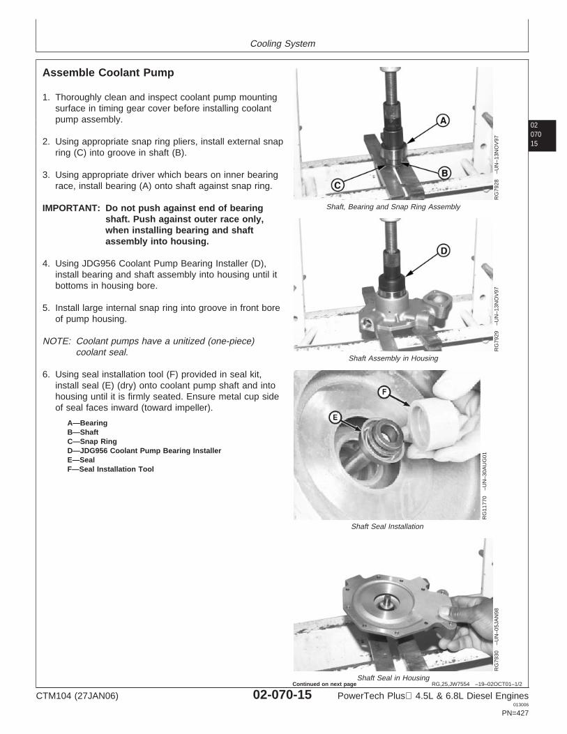
Cooling System
0207015
RG,25,JW7554 –19–02OCT01–1/2
Assemble Coolant Pump
RG
7928
–UN
–13N
OV
97
Shaft, Bearing and Snap Ring Assembly
RG
7929
–UN
–13N
OV
97
Shaft Assembly in Housing
RG
1177
0–U
N–3
0AU
G01
Shaft Seal Installation
RG
7930
–UN
–05J
AN
98
Shaft Seal in Housing
A—BearingB—ShaftC—Snap RingD—JDG956 Coolant Pump Bearing InstallerE—SealF—Seal Installation Tool
1. Thoroughly clean and inspect coolant pump mountingsurface in timing gear cover before installing coolantpump assembly.
2. Using appropriate snap ring pliers, install external snapring (C) into groove in shaft (B).
3. Using appropriate driver which bears on inner bearingrace, install bearing (A) onto shaft against snap ring.
IMPORTANT: Do not push against end of bearingshaft. Push against outer race only,when installing bearing and shaftassembly into housing.
4. Using JDG956 Coolant Pump Bearing Installer (D),install bearing and shaft assembly into housing until itbottoms in housing bore.
5. Install large internal snap ring into groove in front boreof pump housing.
NOTE: Coolant pumps have a unitized (one-piece)coolant seal.
6. Using seal installation tool (F) provided in seal kit,install seal (E) (dry) onto coolant pump shaft and intohousing until it is firmly seated. Ensure metal cup sideof seal faces inward (toward impeller).
CTM104 (27JAN06) 02-070-15 PowerTech Plus 4.5L & 6.8L Diesel Engines013006
PN=427
Continued on next page
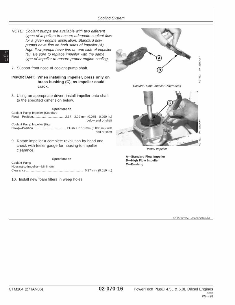
Cooling System
02070
16
RG,25,JW7554 –19–02OCT01–2/2
RG
7932
–UN
–13N
OV
97
Coolant Pump Impeller Differences
RG
7931
–UN
–13N
OV
97
Install Impeller
A—Standard Flow ImpellerB—High Flow ImpellerC—Bushing
NOTE: Coolant pumps are available with two differenttypes of impellers to ensure adequate coolant flowfor a given engine application. Standard flowpumps have fins on both sides of impeller (A).High flow pumps have fins on one side of impeller(B). Be sure to replace impeller with the sametype of impeller to ensure proper engine cooling.
7. Support front nose of coolant pump shaft.
IMPORTANT: When installing impeller, press only onbrass bushing (C), as impeller couldcrack.
8. Using an appropriate driver, install impeller onto shaftto the specified dimension below.
SpecificationCoolant Pump Impeller (StandardFlow)—Position 2.17—2.29 mm (0.085—0.090 in.)
below end of shaft....................................
Coolant Pump Impeller (HighFlow)—Position Flush ± 0.13 mm (0.005 in.) with
end of shaft.......................................
9. Rotate impeller a complete revolution by hand andcheck with feeler gauge for housing-to-impellerclearance.
SpecificationCoolant PumpHousing-to-Impeller—MinimumClearance 0.27 mm (0.010 in.)...................................................................
10. Install new foam filters in weep holes.
CTM104 (27JAN06) 02-070-16 PowerTech Plus 4.5L & 6.8L Diesel Engines013006
PN=428
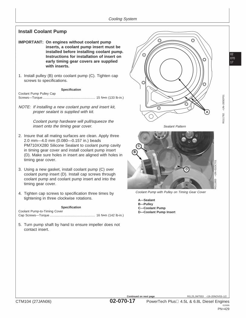
Cooling System
0207017
RG,25,JW7553 –19–20NOV03–1/2
Install Coolant Pump
A
RG
1178
2–U
N–2
8SE
P01
Sealant Pattern
RG
1180
0–U
N–0
1OC
T01
Coolant Pump with Pulley on Timing Gear Cover
A—SealantB—PulleyC—Coolant PumpD—Coolant Pump Insert
IMPORTANT: On engines without coolant pumpinserts, a coolant pump insert must beinstalled before installing coolant pump.Instructions for installation of insert onearly timing gear covers are suppliedwith inserts.
1. Install pulley (B) onto coolant pump (C). Tighten capscrews to specifications.
SpecificationCoolant Pump Pulley CapScrews—Torque 15 N•m (133 lb-in.)...........................................................
NOTE: If installing a new coolant pump and insert kit,proper sealant is supplied with kit.
Coolant pump hardware will pull/squeeze theinsert onto the timing gear cover.
2. Insure that all mating surfaces are clean. Apply three2.0 mm—4.0 mm (0.080—0.157 in.) beadsPM710XX280 Silicone Sealant to coolant pump cavityin timing gear cover and install coolant pump insert(D). Make sure holes in insert are aligned with holes intiming gear cover.
3. Using a new gasket, install coolant pump (C) overcoolant pump insert (D). Install cap screws throughcoolant pump and coolant pump insert and into thetiming gear cover.
4. Tighten cap screws to specification three times bytightening in three clockwise rotations.
SpecificationCoolant Pump-to-Timing CoverCap Screws—Torque 16 N•m (142 lb-in.)...................................................
5. Turn pump shaft by hand to ensure impeller does notcontact insert.
CTM104 (27JAN06) 02-070-17 PowerTech Plus 4.5L & 6.8L Diesel Engines013006
PN=429
Continued on next page
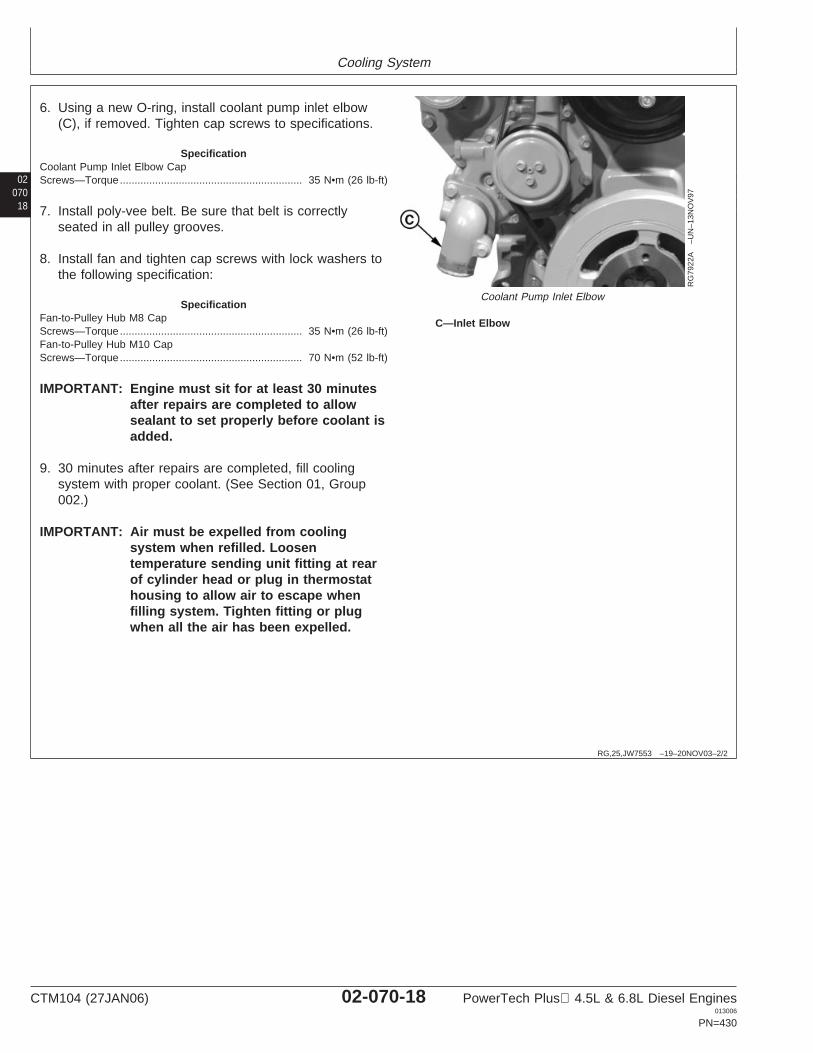
Cooling System
02070
18
RG,25,JW7553 –19–20NOV03–2/2
RG
7922
A–U
N–1
3NO
V97
Coolant Pump Inlet Elbow
C—Inlet Elbow
6. Using a new O-ring, install coolant pump inlet elbow(C), if removed. Tighten cap screws to specifications.
SpecificationCoolant Pump Inlet Elbow CapScrews—Torque 35 N•m (26 lb-ft)..............................................................
7. Install poly-vee belt. Be sure that belt is correctlyseated in all pulley grooves.
8. Install fan and tighten cap screws with lock washers tothe following specification:
SpecificationFan-to-Pulley Hub M8 CapScrews—Torque 35 N•m (26 lb-ft)..............................................................Fan-to-Pulley Hub M10 CapScrews—Torque 70 N•m (52 lb-ft)..............................................................
IMPORTANT: Engine must sit for at least 30 minutesafter repairs are completed to allowsealant to set properly before coolant isadded.
9. 30 minutes after repairs are completed, fill coolingsystem with proper coolant. (See Section 01, Group002.)
IMPORTANT: Air must be expelled from coolingsystem when refilled. Loosentemperature sending unit fitting at rearof cylinder head or plug in thermostathousing to allow air to escape whenfilling system. Tighten fitting or plugwhen all the air has been expelled.
CTM104 (27JAN06) 02-070-18 PowerTech Plus 4.5L & 6.8L Diesel Engines013006
PN=430
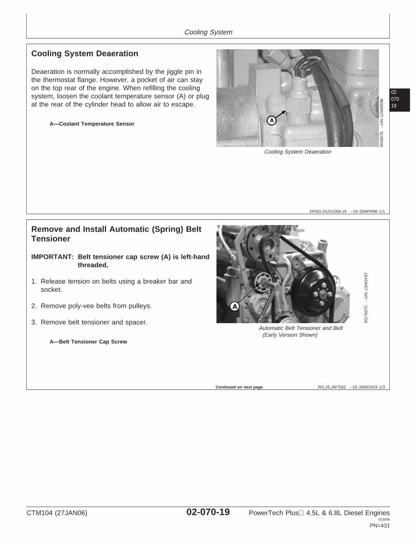
Cooling System
0207019
DPSG,OUO1004,19 –19–03APR98–1/1
Cooling System Deaeration
RG
9076
–UN
–12M
AR
98
Cooling System Deaeration
A—Coolant Temperature Sensor
Deaeration is normally accomplished by the jiggle pin inthe thermostat flange. However, a pocket of air can stayon the top rear of the engine. When refilling the coolingsystem, loosen the coolant temperature sensor (A) or plugat the rear of the cylinder head to allow air to escape.
RG,25,JW7552 –19–20NOV03–1/3
Remove and Install Automatic (Spring) BeltTensioner
RG
7937
C–U
N–1
3NO
V97
Automatic Belt Tensioner and Belt(Early Version Shown)
A—Belt Tensioner Cap Screw
IMPORTANT: Belt tensioner cap screw (A) is left-handthreaded.
1. Release tension on belts using a breaker bar andsocket.
2. Remove poly-vee belts from pulleys.
3. Remove belt tensioner and spacer.
Continued on next page
CTM104 (27JAN06) 02-070-19 PowerTech Plus 4.5L & 6.8L Diesel Engines013006
PN=431
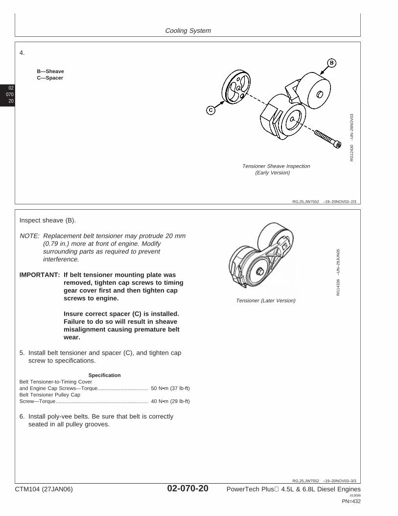
Cooling System
02070
20
RG,25,JW7552 –19–20NOV03–2/3
RG
1243
0–U
N–2
6NO
V03
Tensioner Sheave Inspection(Early Version)
B—SheaveC—Spacer
4.
RG,25,JW7552 –19–20NOV03–3/3
RG
1433
6–U
N–2
9JU
N05
Tensioner (Later Version)
Inspect sheave (B).
NOTE: Replacement belt tensioner may protrude 20 mm(0.79 in.) more at front of engine. Modifysurrounding parts as required to preventinterference.
IMPORTANT: If belt tensioner mounting plate wasremoved, tighten cap screws to timinggear cover first and then tighten capscrews to engine.
Insure correct spacer (C) is installed.Failure to do so will result in sheavemisalignment causing premature beltwear.
5. Install belt tensioner and spacer (C), and tighten capscrew to specifications.
SpecificationBelt Tensioner-to-Timing Coverand Engine Cap Screws—Torque 50 N•m (37 lb-ft)...................................Belt Tensioner Pulley CapScrew—Torque 40 N•m (29 lb-ft)................................................................
6. Install poly-vee belts. Be sure that belt is correctlyseated in all pulley grooves.
CTM104 (27JAN06) 02-070-20 PowerTech Plus 4.5L & 6.8L Diesel Engines013006
PN=432
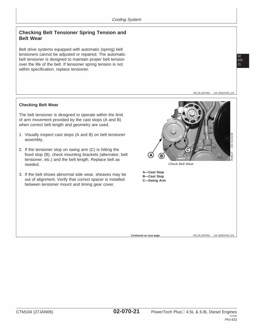
Cooling System
0207021
RG,25,JW7551 –19–20NOV03–1/3
Checking Belt Tensioner Spring Tension andBelt Wear
Belt drive systems equipped with automatic (spring) belttensioners cannot be adjusted or repaired. The automaticbelt tensioner is designed to maintain proper belt tensionover the life of the belt. If tensioner spring tension is notwithin specification, replace tensioner.
RG,25,JW7551 –19–20NOV03–2/3
RG
9127
–UN
–01J
UL9
8
Check Belt Wear
A—Cast StopB—Cast StopC—Swing Arm
Checking Belt Wear
The belt tensioner is designed to operate within the limitof arm movement provided by the cast stops (A and B)when correct belt length and geometry are used.
1. Visually inspect cast stops (A and B) on belt tensionerassembly.
2. If the tensioner stop on swing arm (C) is hitting thefixed stop (B), check mounting brackets (alternator, belttensioner, etc.) and the belt length. Replace belt asneeded.
3. If the belt shows abnormal side wear, sheaves may beout of alignment. Verify that correct spacer is installedbetween tensioner mount and timing gear cover.
Continued on next page
CTM104 (27JAN06) 02-070-21 PowerTech Plus 4.5L & 6.8L Diesel Engines013006
PN=433
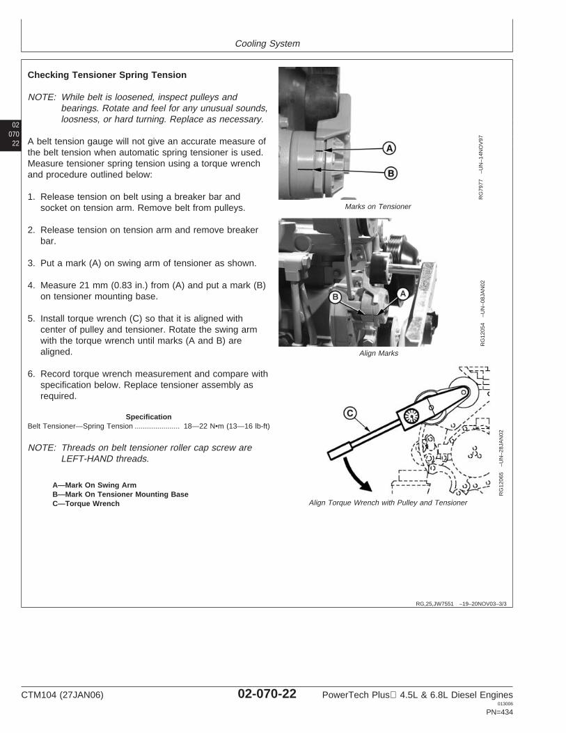
Cooling System
02070
22
RG,25,JW7551 –19–20NOV03–3/3
RG
7977
–UN
–14N
OV
97
Marks on Tensioner
RG
1205
4–U
N–0
8JA
N02
Align Marks
RG
1206
5–U
N–2
8JA
N02
Align Torque Wrench with Pulley and Tensioner
A—Mark On Swing ArmB—Mark On Tensioner Mounting BaseC—Torque Wrench
Checking Tensioner Spring Tension
NOTE: While belt is loosened, inspect pulleys andbearings. Rotate and feel for any unusual sounds,loosness, or hard turning. Replace as necessary.
A belt tension gauge will not give an accurate measure ofthe belt tension when automatic spring tensioner is used.Measure tensioner spring tension using a torque wrenchand procedure outlined below:
1. Release tension on belt using a breaker bar andsocket on tension arm. Remove belt from pulleys.
2. Release tension on tension arm and remove breakerbar.
3. Put a mark (A) on swing arm of tensioner as shown.
4. Measure 21 mm (0.83 in.) from (A) and put a mark (B)on tensioner mounting base.
5. Install torque wrench (C) so that it is aligned withcenter of pulley and tensioner. Rotate the swing armwith the torque wrench until marks (A and B) arealigned.
6. Record torque wrench measurement and compare withspecification below. Replace tensioner assembly asrequired.
SpecificationBelt Tensioner—Spring Tension 18—22 N•m (13—16 lb-ft)......................
NOTE: Threads on belt tensioner roller cap screw areLEFT-HAND threads.
CTM104 (27JAN06) 02-070-22 PowerTech Plus 4.5L & 6.8L Diesel Engines013006
PN=434
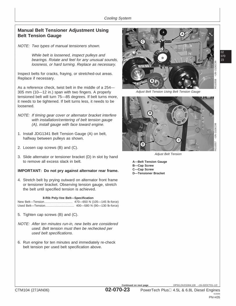
Cooling System
0207023
DPSG,OUO1004,128 –19–02OCT01–1/2
Manual Belt Tensioner Adjustment UsingBelt Tension Gauge
RG
1055
6–U
N–2
1DE
C99
Adjust Belt Tension Using Belt Tension Gauge
RG
1055
7–U
N–2
1DE
C99
Adjust Belt Tension
A—Belt Tension GaugeB—Cap ScrewC—Cap ScrewD—Tensioner Bracket
NOTE: Two types of manual tensioners shown.
While belt is loosened, inspect pulleys andbearings. Rotate and feel for any unusual sounds,loosness, or hard turning. Replace as necessary.
Inspect belts for cracks, fraying, or stretched-out areas.Replace if necessary.
As a reference check, twist belt in the middle of a 254—305 mm (10—12 in.) span with two fingers. A properlytensioned belt will turn 75—85 degrees. If belt turns more,it needs to be tightened. If belt turns less, it needs to beloosened.
NOTE: If timing gear cover or alternator bracket interferewith installation/centering of belt tension gauge(A), install gauge with face toward engine.
1. Install JDG1341 Belt Tension Gauge (A) on belt,halfway between pulleys as shown.
2. Loosen cap screws (B) and (C).
3. Slide alternator or tensioner bracket (D) in slot by handto remove all excess slack in belt.
IMPORTANT: Do not pry against alternator rear frame.
4. Stretch belt by prying outward on alternator front frameor tensioner bracket. Observing tension gauge, stretchthe belt until specified tension is achieved.
8-Rib Poly-Vee Belt—SpecificationNew Belt—Tension 470—650 N (105—145 lb-force).................................Used Belt—Tension 400—580 N (90—130 lb-force)..................................
5. Tighten cap screws (B) and (C).
NOTE: After ten minutes run-in, new belts are consideredused. Belt tension must then be rechecked perused belt specifications.
6. Run engine for ten minutes and immediately re-checkbelt tension per used belt specification above.
CTM104 (27JAN06) 02-070-23 PowerTech Plus 4.5L & 6.8L Diesel Engines013006
PN=435
Continued on next page
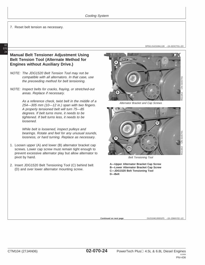
Cooling System
02070
DPSG,OUO1004,128 –19–02OCT01–2/2
7. Reset belt tension as necessary.
24
OUO1040,00001F5 –19–15MAY02–1/2
Manual Belt Tensioner Adjustment UsingBelt Tension Tool (Alternate Method forEngines without Auxiliary Drive.)
RG
1181
2–U
N–3
1OC
T01
Alternator Bracket and Cap Screws
RG
1181
3–U
N–3
1OC
T01
Belt Tensioning Tool
A—Upper Alternator Bracket Cap ScrewB—Lower Alternator Bracket Cap ScrewC—JDG1520 Belt Tensioning ToolD—Belt
NOTE: The JDG1520 Belt Tension Tool may not becompatible with all alternators. In that case, usethe preceeding method for belt tensioning.
NOTE: Inspect belts for cracks, fraying, or stretched-outareas. Replace if necessary.
As a reference check, twist belt in the middle of a254—305 mm (10—12 in.) span with two fingers.A properly tensioned belt will turn 75—85degrees. If belt turns more, it needs to betightened. If belt turns less, it needs to beloosened.
While belt is loosened, inspect pulleys andbearings. Rotate and feel for any unusual sounds,loosness, or hard turning. Replace as necessary.
1. Loosen upper (A) and lower (B) alternator bracket capscrews. Lower cap screw must remain tight enough toprevent excessive alternator play but allow alternator topivot by hand.
2. Insert JDG1520 Belt Tensioning Tool (C) behind belt(D) and over lower alternator mounting screw.
Continued on next page
CTM104 (27JAN06) 02-070-24 PowerTech Plus 4.5L & 6.8L Diesel Engines013006
PN=436
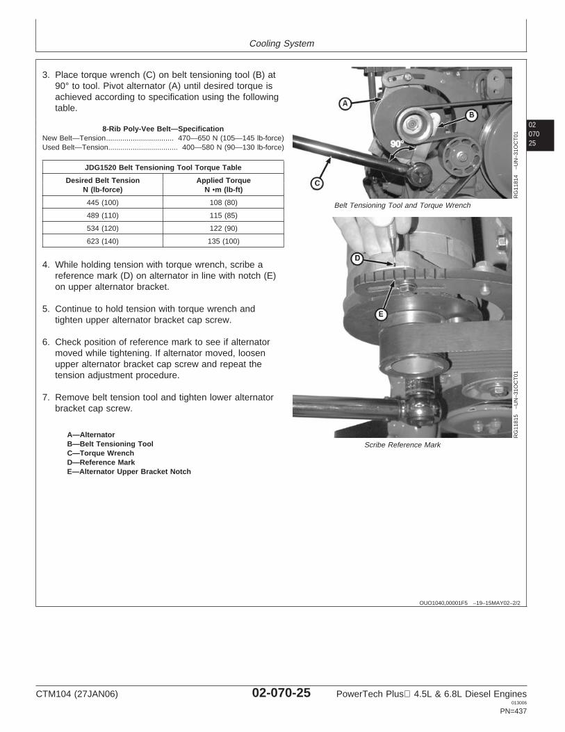
Cooling System
0207025
OUO1040,00001F5 –19–15MAY02–2/2
RG
1181
4–U
N–3
1OC
T01
Belt Tensioning Tool and Torque Wrench
RG
1181
5–U
N–3
1OC
T01
Scribe Reference MarkA—AlternatorB—Belt Tensioning ToolC—Torque WrenchD—Reference MarkE—Alternator Upper Bracket Notch
3. Place torque wrench (C) on belt tensioning tool (B) at90° to tool. Pivot alternator (A) until desired torque isachieved according to specification using the followingtable.
8-Rib Poly-Vee Belt—SpecificationNew Belt—Tension 470—650 N (105—145 lb-force).................................Used Belt—Tension 400—580 N (90—130 lb-force)..................................
JDG1520 Belt Tensioning Tool Torque Table
Desired Belt Tension Applied TorqueN (lb-force) N •m (lb-ft)
445 (100) 108 (80)
489 (110) 115 (85)
534 (120) 122 (90)
623 (140) 135 (100)
4. While holding tension with torque wrench, scribe areference mark (D) on alternator in line with notch (E)on upper alternator bracket.
5. Continue to hold tension with torque wrench andtighten upper alternator bracket cap screw.
6. Check position of reference mark to see if alternatormoved while tightening. If alternator moved, loosenupper alternator bracket cap screw and repeat thetension adjustment procedure.
7. Remove belt tension tool and tighten lower alternatorbracket cap screw.
CTM104 (27JAN06) 02-070-25 PowerTech Plus 4.5L & 6.8L Diesel Engines013006
PN=437
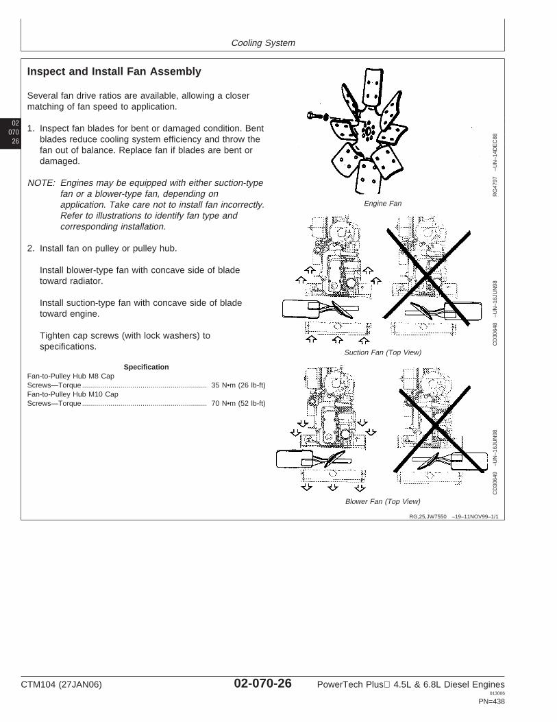
Cooling System
02070
26
RG,25,JW7550 –19–11NOV99–1/1
Inspect and Install Fan Assembly
RG
4797
–UN
–14D
EC
88
Engine Fan
CD
3064
8–U
N–1
6JU
N98
Suction Fan (Top View)
CD
3064
9–U
N–1
6JU
N98
Blower Fan (Top View)
Several fan drive ratios are available, allowing a closermatching of fan speed to application.
1. Inspect fan blades for bent or damaged condition. Bentblades reduce cooling system efficiency and throw thefan out of balance. Replace fan if blades are bent ordamaged.
NOTE: Engines may be equipped with either suction-typefan or a blower-type fan, depending onapplication. Take care not to install fan incorrectly.Refer to illustrations to identify fan type andcorresponding installation.
2. Install fan on pulley or pulley hub.
Install blower-type fan with concave side of bladetoward radiator.
Install suction-type fan with concave side of bladetoward engine.
Tighten cap screws (with lock washers) tospecifications.
SpecificationFan-to-Pulley Hub M8 CapScrews—Torque 35 N•m (26 lb-ft)..............................................................Fan-to-Pulley Hub M10 CapScrews—Torque 70 N•m (52 lb-ft)..............................................................
CTM104 (27JAN06) 02-070-26 PowerTech Plus 4.5L & 6.8L Diesel Engines013006
PN=438
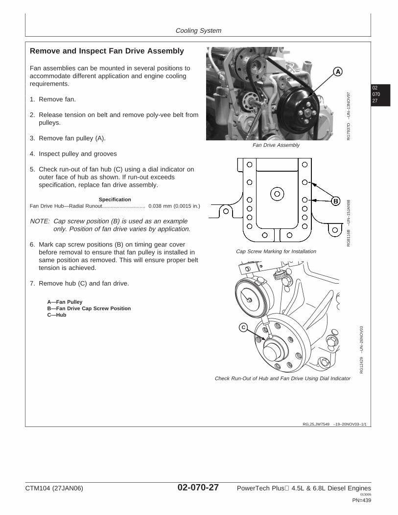
Cooling System
0207027
RG,25,JW7549 –19–20NOV03–1/1
Remove and Inspect Fan Drive Assembly
RG
7937
D–U
N–1
3NO
V97
Fan Drive Assembly
RG
8116
B–U
N–1
5JA
N98
Cap Screw Marking for Installation
C
RG
1242
9–U
N–2
6NO
V03
Check Run-Out of Hub and Fan Drive Using Dial Indicator
A—Fan PulleyB—Fan Drive Cap Screw PositionC—Hub
Fan assemblies can be mounted in several positions toaccommodate different application and engine coolingrequirements.
1. Remove fan.
2. Release tension on belt and remove poly-vee belt frompulleys.
3. Remove fan pulley (A).
4. Inspect pulley and grooves
5. Check run-out of fan hub (C) using a dial indicator onouter face of hub as shown. If run-out exceedsspecification, replace fan drive assembly.
SpecificationFan Drive Hub—Radial Runout 0.038 mm (0.0015 in.)..............................
NOTE: Cap screw position (B) is used as an exampleonly. Position of fan drive varies by application.
6. Mark cap screw positions (B) on timing gear coverbefore removal to ensure that fan pulley is installed insame position as removed. This will ensure proper belttension is achieved.
7. Remove hub (C) and fan drive.
CTM104 (27JAN06) 02-070-27 PowerTech Plus 4.5L & 6.8L Diesel Engines013006
PN=439
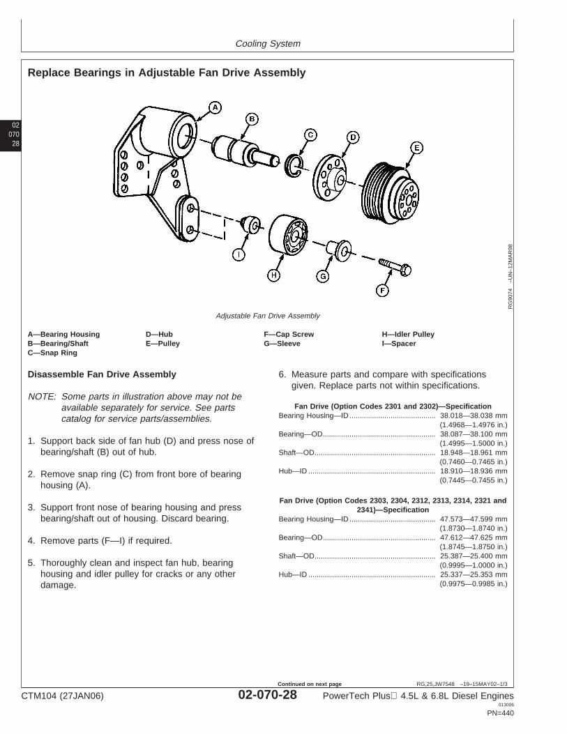
Cooling System
02070
28
RG,25,JW7548 –19–15MAY02–1/3
Replace Bearings in Adjustable Fan Drive Assembly
RG
9074
–UN
–12M
AR
98
Adjustable Fan Drive Assembly
A—Bearing Housing D—Hub F—Cap Screw H—Idler PulleyB—Bearing/Shaft E—Pulley G—Sleeve I—SpacerC—Snap Ring
Disassemble Fan Drive Assembly
NOTE: Some parts in illustration above may not beavailable separately for service. See partscatalog for service parts/assemblies.
1. Support back side of fan hub (D) and press nose ofbearing/shaft (B) out of hub.
2. Remove snap ring (C) from front bore of bearinghousing (A).
3. Support front nose of bearing housing and pressbearing/shaft out of housing. Discard bearing.
4. Remove parts (F—I) if required.
5. Thoroughly clean and inspect fan hub, bearinghousing and idler pulley for cracks or any otherdamage.
6. Measure parts and compare with specificationsgiven. Replace parts not within specifications.
Fan Drive (Option Codes 2301 and 2302)—SpecificationBearing Housing—ID 38.018—38.038 mm
(1.4968—1.4976 in.)..........................................
Bearing—OD 38.087—38.100 mm(1.4995—1.5000 in.)
.......................................................
Shaft—OD 18.948—18.961 mm(0.7460—0.7465 in.)
...........................................................
Hub—ID 18.910—18.936 mm(0.7445—0.7455 in.)
..............................................................
Fan Drive (Option Codes 2303, 2304, 2312, 2313, 2314, 2321 and2341)—Specification
Bearing Housing—ID 47.573—47.599 mm(1.8730—1.8740 in.)
..........................................
Bearing—OD 47.612—47.625 mm(1.8745—1.8750 in.)
.......................................................
Shaft—OD 25.387—25.400 mm(0.9995—1.0000 in.)
...........................................................
Hub—ID 25.337—25.353 mm(0.9975—0.9985 in.)
..............................................................
CTM104 (27JAN06) 02-070-28 PowerTech Plus 4.5L & 6.8L Diesel Engines013006
PN=440
Continued on next page
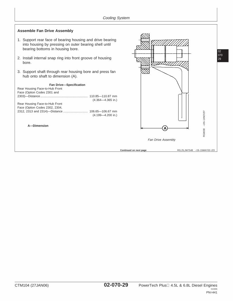
Cooling System
0207029
RG,25,JW7548 –19–15MAY02–2/3
RG
8038
–UN
–14N
OV
97
Fan Drive Assembly
A—Dimension
Assemble Fan Drive Assembly
1. Support rear face of bearing housing and drive bearinginto housing by pressing on outer bearing shell untilbearing bottoms in housing bore.
2. Install internal snap ring into front groove of housingbore.
3. Support shaft through rear housing bore and press fanhub onto shaft to dimension (A).
Fan Drive—SpecificationRear Housing Face-to-Hub FrontFace (Option Codes 2301 and2303)—Distance 110.85—110.87 mm
(4.364—4.365 in.)........................................................
Rear Housing Face-to-Hub FrontFace (Option Codes 2302, 2304,2312, 2313 and 2314)—Distance 106.65—106.67 mm
(4.199—4.200 in.).............................
Continued on next page
CTM104 (27JAN06) 02-070-29 PowerTech Plus 4.5L & 6.8L Diesel Engines013006
PN=441
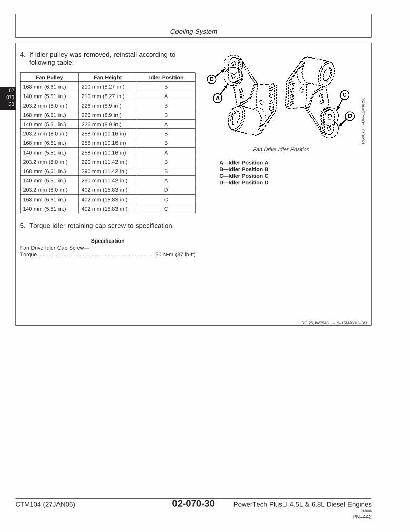
Cooling System
02070
30
RG,25,JW7548 –19–15MAY02–3/3
RG
9073
–UN
–12M
AR
98
Fan Drive Idler Position
A—Idler Position AB—Idler Position BC—Idler Position CD—Idler Position D
4. If idler pulley was removed, reinstall according tofollowing table:
Fan Pulley Fan Height Idler Position
168 mm (6.61 in.) 210 mm (8.27 in.) B
140 mm (5.51 in.) 210 mm (8.27 in.) A
203.2 mm (8.0 in.) 226 mm (8.9 in.) B
168 mm (6.61 in.) 226 mm (8.9 in.) B
140 mm (5.51 in.) 226 mm (8.9 in.) A
203.2 mm (8.0 in.) 258 mm (10.16 in) B
168 mm (6.61 in.) 258 mm (10.16 in) B
140 mm (5.51 in.) 258 mm (10.16 in) A
203.2 mm (8.0 in.) 290 mm (11.42 in.) B
168 mm (6.61 in.) 290 mm (11.42 in.) B
140 mm (5.51 in.) 290 mm (11.42 in.) A
203.2 mm (8.0 in.) 402 mm (15.83 in.) D
168 mm (6.61 in.) 402 mm (15.83 in.) C
140 mm (5.51 in.) 402 mm (15.83 in.) C
5. Torque idler retaining cap screw to specification.
SpecificationFan Drive Idler Cap Screw—Torque 50 N•m (37 lb-ft).............................................................................
CTM104 (27JAN06) 02-070-30 PowerTech Plus 4.5L & 6.8L Diesel Engines013006
PN=442
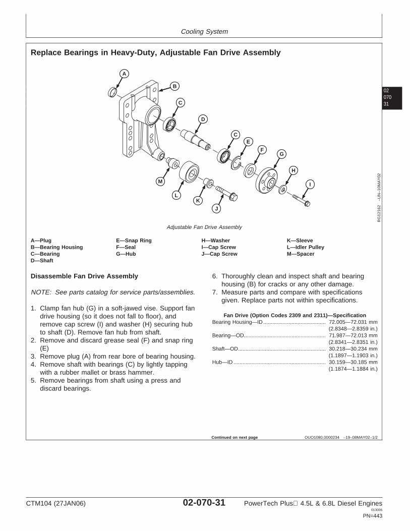
Cooling System
0207031
OUO1080,0000234 –19–08MAY02–1/2
Replace Bearings in Heavy-Duty, Adjustable Fan Drive Assembly
A
C
D
CE
FG
H
IM
L
J
K
B
RG
1216
2–U
N–1
0MA
Y02
Adjustable Fan Drive Assembly
A—Plug E—Snap Ring H—Washer K—SleeveB—Bearing Housing F—Seal I—Cap Screw L—Idler PulleyC—Bearing G—Hub J—Cap Screw M—SpacerD—Shaft
Disassemble Fan Drive Assembly
NOTE: See parts catalog for service parts/assemblies.
1. Clamp fan hub (G) in a soft-jawed vise. Support fandrive housing (so it does not fall to floor), andremove cap screw (I) and washer (H) securing hubto shaft (D). Remove fan hub from shaft.
2. Remove and discard grease seal (F) and snap ring(E)
3. Remove plug (A) from rear bore of bearing housing.4. Remove shaft with bearings (C) by lightly tapping
with a rubber mallet or brass hammer.5. Remove bearings from shaft using a press and
discard bearings.
6. Thoroughly clean and inspect shaft and bearinghousing (B) for cracks or any other damage.
7. Measure parts and compare with specificationsgiven. Replace parts not within specifications.
Fan Drive (Option Codes 2309 and 2311)—SpecificationBearing Housing—ID 72.005—72.031 mm
(2.8348—2.8359 in.)..........................................
Bearing—OD 71.987—72.013 mm(2.8341—2.8351 in.)
.......................................................
Shaft—OD 30.218—30.234 mm(1.1897—1.1903 in.)
...........................................................
Hub—ID 30.159—30.185 mm(1.1874—1.1884 in.)
..............................................................
Continued on next page
CTM104 (27JAN06) 02-070-31 PowerTech Plus 4.5L & 6.8L Diesel Engines013006
PN=443
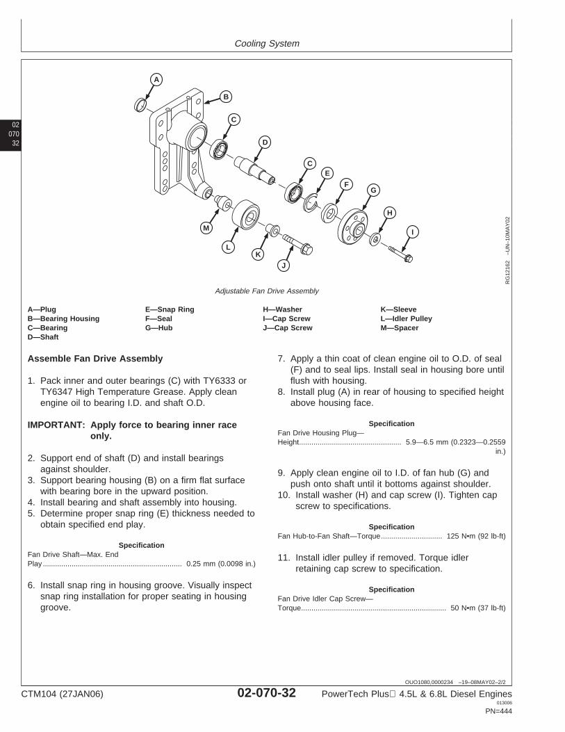
Cooling System
02070
32
OUO1080,0000234 –19–08MAY02–2/2
A
C
D
CE
FG
H
IM
L
J
K
B
RG
1216
2–U
N–1
0MA
Y02
Adjustable Fan Drive Assembly
A—Plug E—Snap Ring H—Washer K—SleeveB—Bearing Housing F—Seal I—Cap Screw L—Idler PulleyC—Bearing G—Hub J—Cap Screw M—SpacerD—Shaft
Assemble Fan Drive Assembly
1. Pack inner and outer bearings (C) with TY6333 orTY6347 High Temperature Grease. Apply cleanengine oil to bearing I.D. and shaft O.D.
IMPORTANT: Apply force to bearing inner raceonly.
2. Support end of shaft (D) and install bearingsagainst shoulder.
3. Support bearing housing (B) on a firm flat surfacewith bearing bore in the upward position.
4. Install bearing and shaft assembly into housing.5. Determine proper snap ring (E) thickness needed to
obtain specified end play.
SpecificationFan Drive Shaft—Max. EndPlay 0.25 mm (0.0098 in.)....................................................................
6. Install snap ring in housing groove. Visually inspectsnap ring installation for proper seating in housinggroove.
7. Apply a thin coat of clean engine oil to O.D. of seal(F) and to seal lips. Install seal in housing bore untilflush with housing.
8. Install plug (A) in rear of housing to specified heightabove housing face.
SpecificationFan Drive Housing Plug—Height 5.9—6.5 mm (0.2323—0.2559
in.)..................................................
9. Apply clean engine oil to I.D. of fan hub (G) andpush onto shaft until it bottoms against shoulder.
10. Install washer (H) and cap screw (I). Tighten capscrew to specifications.
SpecificationFan Hub-to-Fan Shaft—Torque 125 N•m (92 lb-ft)..............................
11. Install idler pulley if removed. Torque idlerretaining cap screw to specification.
SpecificationFan Drive Idler Cap Screw—Torque 50 N•m (37 lb-ft).......................................................................
CTM104 (27JAN06) 02-070-32 PowerTech Plus 4.5L & 6.8L Diesel Engines013006
PN=444
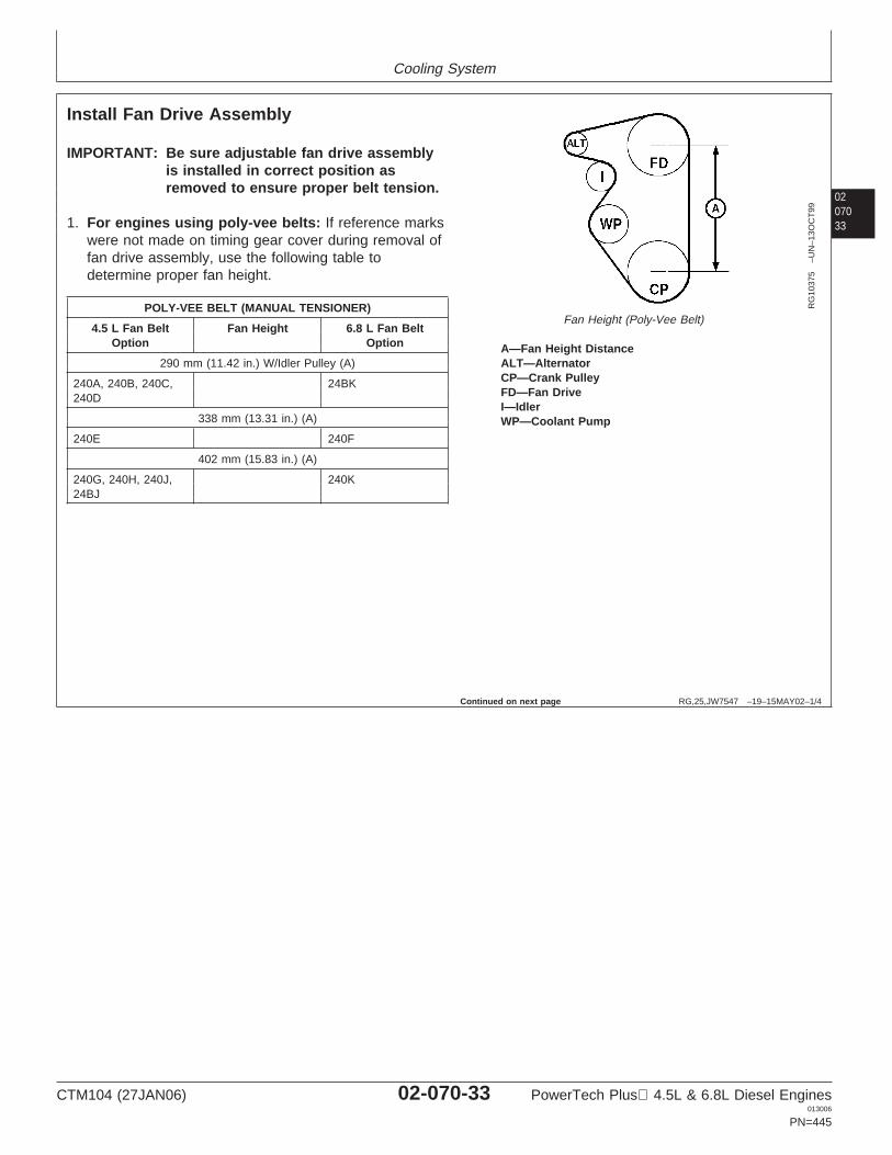
Cooling System
0207033
RG,25,JW7547 –19–15MAY02–1/4
Install Fan Drive Assembly
RG
1037
5–U
N–1
3OC
T99
Fan Height (Poly-Vee Belt)
A—Fan Height DistanceALT—AlternatorCP—Crank PulleyFD—Fan DriveI—IdlerWP—Coolant Pump
IMPORTANT: Be sure adjustable fan drive assemblyis installed in correct position asremoved to ensure proper belt tension.
1. For engines using poly-vee belts: If reference markswere not made on timing gear cover during removal offan drive assembly, use the following table todetermine proper fan height.
POLY-VEE BELT (MANUAL TENSIONER)
4.5 L Fan Belt Fan Height 6.8 L Fan BeltOption Option
290 mm (11.42 in.) W/Idler Pulley (A)
240A, 240B, 240C, 24BK240D
338 mm (13.31 in.) (A)
240E 240F
402 mm (15.83 in.) (A)
240G, 240H, 240J, 240K24BJ
Continued on next page
CTM104 (27JAN06) 02-070-33 PowerTech Plus 4.5L & 6.8L Diesel Engines013006
PN=445
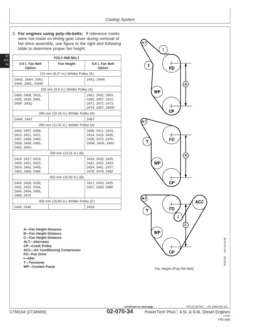
Cooling System
02070
34
RG,25,JW7547 –19–15MAY02–2/4
RG
9128
–UN
–01J
UL9
8
Fan Height (Poly-Rib Belt)
A—Fan Height DistanceB—Fan Height DistanceC—Fan Height DistanceALT—AlternatorCP—Crank PulleyACC—Air Conditioning CompressorFD—Fan DriveI—IdlerT—TensionerWP—Coolant Pump
2. For engines using poly-rib-belts: If reference markswere not made on timing gear cover during removal offan drive assembly, use figure to the right and followingtable to determine proper fan height.
POLY-RIB BELT
4.5 L Fan Belt Fan Height 6.8 L Fan BeltOption Option
210 mm (8.27 in.) W/Idler Pulley (A)
24AG, 24AH, 24AJ, 24AJ, 24AN24AK, 24AL, 24AM
226 mm (8.9 in.) W/Idler Pulley (A)
2406, 2408, 2415, 2401, 2402, 2403,2435, 2436, 2461, 2405, 2407, 2412,240P, 240Q 2471, 2472, 2473,
2474, 240T, 240W
258 mm (10.16 in.) W/Idler Pulley (A)
24AR, 24AT 24BT
290 mm (11.42 in.) W/Idler Pulley (A)
2404, 2407, 2409, 2409, 2411, 2413,2410, 2411, 2412, 2414, 2415, 2435,2437, 2439, 2440, 2438, 2475, 2476,2458, 2459, 2460, 240R, 240S, 240V2462, 240U
338 mm (13.31 in.) (B)
2416, 2417, 2419, 2416, 2418, 2420,2420, 2421, 2423, 2421, 2422, 2423,2424, 2442, 2443, 2424, 2441, 2477,2463, 2466, 2468 2478, 2479, 2482
402 mm (15.83 in.) (B)
2426, 2428, 2430, 2417, 2419, 2425,2431, 2432, 2444, 2427, 2429, 24802445, 2464, 2465,2469, 2470
402 mm (15.83 in.) W/Idler Pulley (C)
2434, 2446 2433
CTM104 (27JAN06) 02-070-34 PowerTech Plus 4.5L & 6.8L Diesel Engines013006
PN=446
Continued on next page
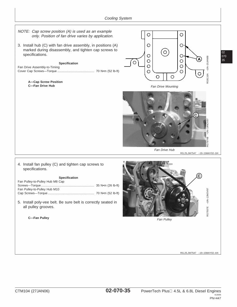
Cooling System
0207035
RG,25,JW7547 –19–15MAY02–3/4
RG
8116
A–U
N–1
5JA
N98
Fan Drive Mounting
RG
7974
B–U
N–1
4NO
V97
Fan Drive Hub
A—Cap Screw PositionC—Fan Drive Hub
NOTE: Cap screw position (A) is used as an exampleonly. Position of fan drive varies by application.
3. Install hub (C) with fan drive assembly, in positions (A)marked during disassembly, and tighten cap screws tospecifications.
SpecificationFan Drive Assembly-to-TimingCover Cap Screws—Torque 70 N•m (52 lb-ft)...........................................
RG,25,JW7547 –19–15MAY02–4/4
RG
7937
E–U
N–1
3NO
V97
Fan PulleyC—Fan Pulley
4. Install fan pulley (C) and tighten cap screws tospecifications.
SpecificationFan Pulley-to-Pulley Hub M8 CapScrews—Torque 35 N•m (26 lb-ft)..............................................................Fan Pulley-to-Pulley Hub M10Cap Screws—Torque 70 N•m (52 lb-ft)......................................................
5. Install poly-vee belt. Be sure belt is correctly seated inall pulley grooves.
CTM104 (27JAN06) 02-070-35 PowerTech Plus 4.5L & 6.8L Diesel Engines013006
PN=447
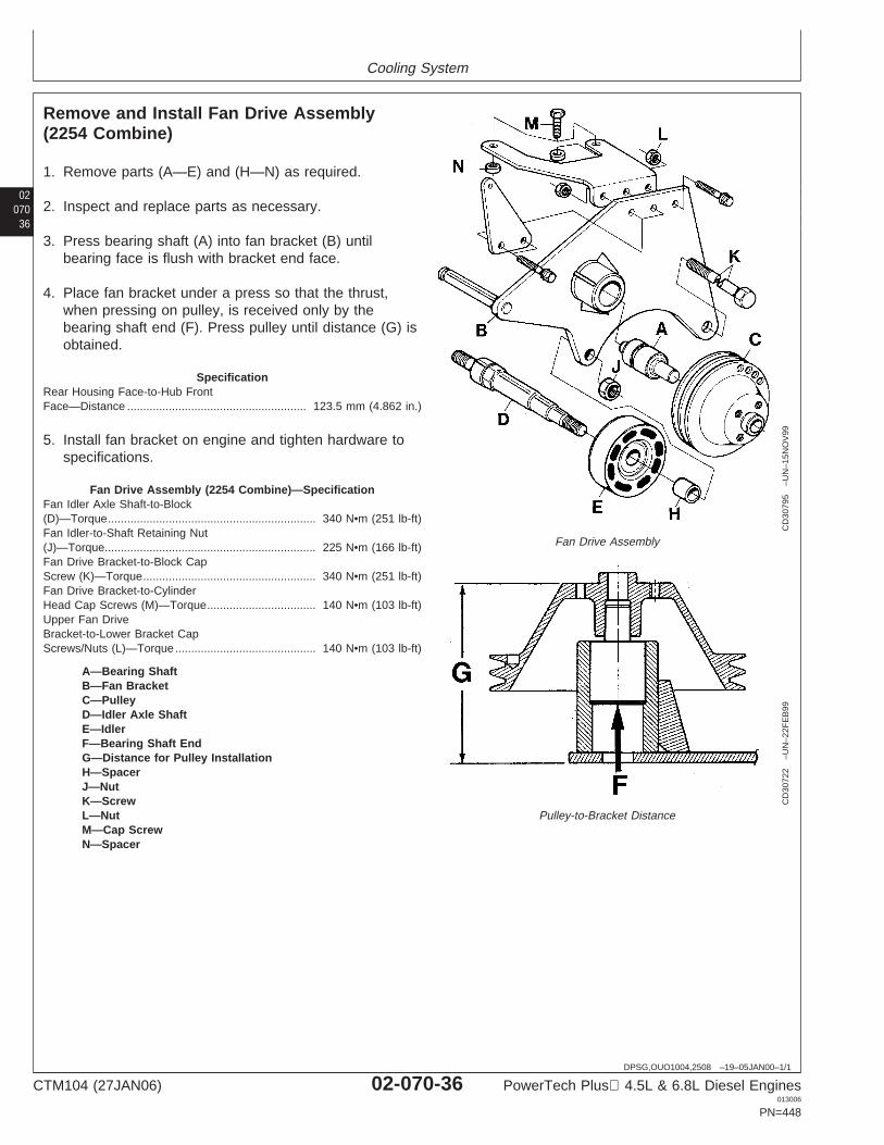
Cooling System
02070
36
DPSG,OUO1004,2508 –19–05JAN00–1/1
Remove and Install Fan Drive Assembly(2254 Combine)
CD
3079
5–U
N–1
5NO
V99
Fan Drive Assembly
CD
3072
2–U
N–2
2FE
B99
Pulley-to-Bracket Distance
A—Bearing ShaftB—Fan BracketC—PulleyD—Idler Axle ShaftE—IdlerF—Bearing Shaft EndG—Distance for Pulley InstallationH—SpacerJ—NutK—ScrewL—NutM—Cap ScrewN—Spacer
1. Remove parts (A—E) and (H—N) as required.
2. Inspect and replace parts as necessary.
3. Press bearing shaft (A) into fan bracket (B) untilbearing face is flush with bracket end face.
4. Place fan bracket under a press so that the thrust,when pressing on pulley, is received only by thebearing shaft end (F). Press pulley until distance (G) isobtained.
SpecificationRear Housing Face-to-Hub FrontFace—Distance 123.5 mm (4.862 in.)........................................................
5. Install fan bracket on engine and tighten hardware tospecifications.
Fan Drive Assembly (2254 Combine)—SpecificationFan Idler Axle Shaft-to-Block(D)—Torque 340 N•m (251 lb-ft).................................................................Fan Idler-to-Shaft Retaining Nut(J)—Torque 225 N•m (166 lb-ft)..................................................................Fan Drive Bracket-to-Block CapScrew (K)—Torque 340 N•m (251 lb-ft)......................................................Fan Drive Bracket-to-CylinderHead Cap Screws (M)—Torque 140 N•m (103 lb-ft)..................................Upper Fan DriveBracket-to-Lower Bracket CapScrews/Nuts (L)—Torque 140 N•m (103 lb-ft)............................................
CTM104 (27JAN06) 02-070-36 PowerTech Plus 4.5L & 6.8L Diesel Engines013006
PN=448
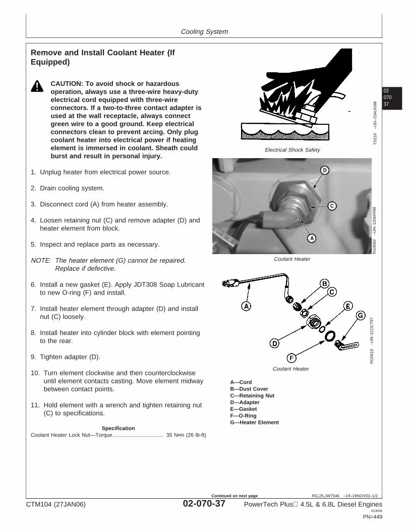
Cooling System
0207037
RG,25,JW7546 –19–19NOV03–1/2
Remove and Install Coolant Heater (IfEquipped)
TS
210
–UN
–23A
UG
88
Electrical Shock Safety
RG
9082
–UN
–12M
AR
98
Coolant Heater
RG
5619
–UN
–31O
CT
97Coolant Heater
A—CordB—Dust CoverC—Retaining NutD—AdapterE—GasketF—O-RingG—Heater Element
CAUTION: To avoid shock or hazardousoperation, always use a three-wire heavy-dutyelectrical cord equipped with three-wireconnectors. If a two-to-three contact adapter isused at the wall receptacle, always connectgreen wire to a good ground. Keep electricalconnectors clean to prevent arcing. Only plugcoolant heater into electrical power if heatingelement is immersed in coolant. Sheath couldburst and result in personal injury.
1. Unplug heater from electrical power source.
2. Drain cooling system.
3. Disconnect cord (A) from heater assembly.
4. Loosen retaining nut (C) and remove adapter (D) andheater element from block.
5. Inspect and replace parts as necessary.
NOTE: The heater element (G) cannot be repaired.Replace if defective.
6. Install a new gasket (E). Apply JDT308 Soap Lubricantto new O-ring (F) and install.
7. Install heater element through adapter (D) and installnut (C) loosely.
8. Install heater into cylinder block with element pointingto the rear.
9. Tighten adapter (D).
10. Turn element clockwise and then counterclockwiseuntil element contacts casting. Move element midwaybetween contact points.
11. Hold element with a wrench and tighten retaining nut(C) to specifications.
SpecificationCoolant Heater Lock Nut—Torque 35 N•m (26 lb-ft)..................................
CTM104 (27JAN06) 02-070-37 PowerTech Plus 4.5L & 6.8L Diesel Engines013006
PN=449
Continued on next page
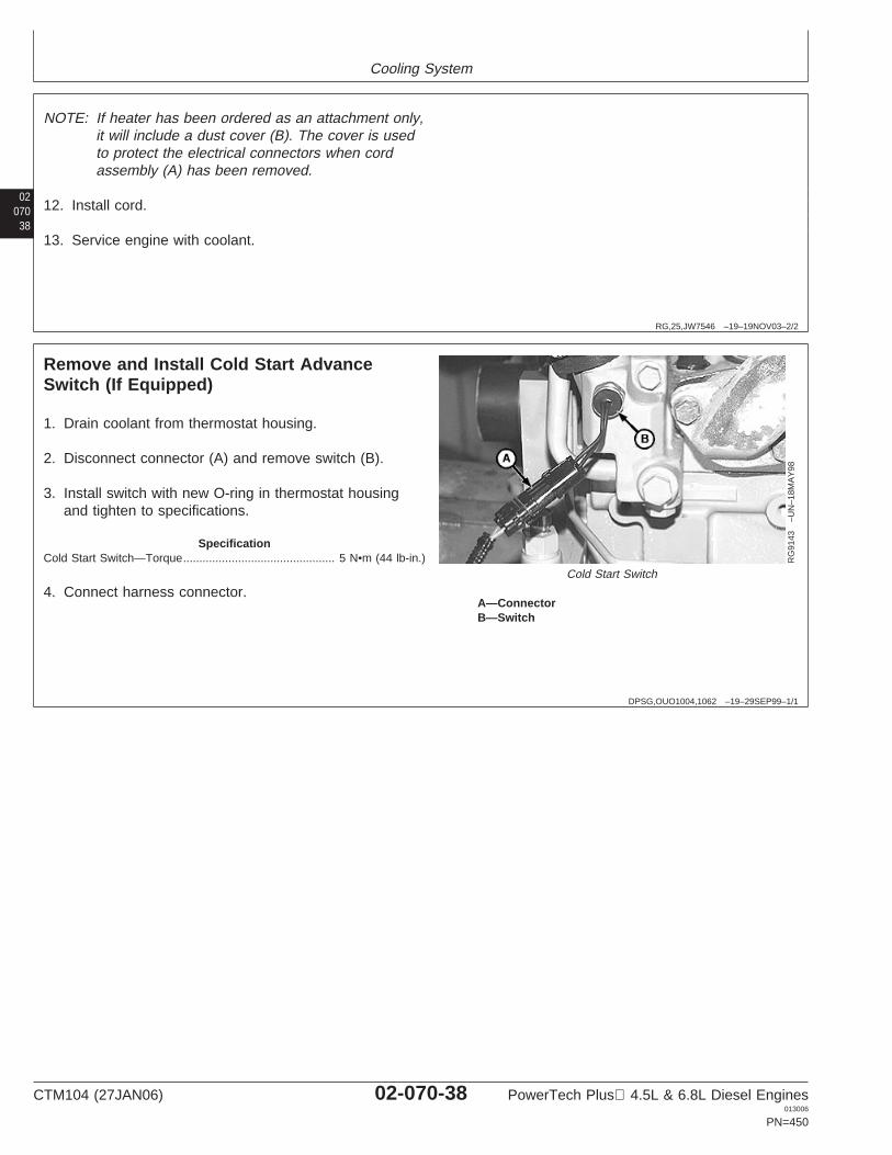
Cooling System
02070
38
RG,25,JW7546 –19–19NOV03–2/2
NOTE: If heater has been ordered as an attachment only,it will include a dust cover (B). The cover is usedto protect the electrical connectors when cordassembly (A) has been removed.
12. Install cord.
13. Service engine with coolant.
DPSG,OUO1004,1062 –19–29SEP99–1/1
Remove and Install Cold Start AdvanceSwitch (If Equipped)
RG
9143
–UN
–18M
AY
98
Cold Start Switch
A—ConnectorB—Switch
1. Drain coolant from thermostat housing.
2. Disconnect connector (A) and remove switch (B).
3. Install switch with new O-ring in thermostat housingand tighten to specifications.
SpecificationCold Start Switch—Torque 5 N•m (44 lb-in.)...............................................
4. Connect harness connector.
CTM104 (27JAN06) 02-070-38 PowerTech Plus 4.5L & 6.8L Diesel Engines013006
PN=450

Group 080Air Intake and Exhaust System
020801
RG,30,JW7583 –19–20NOV97–1/2
Extending Turbocharger Life
Turbochargers are designed to last the life of theengine, but because they operate at such high speeds(100,000 rpm or more), a moment’s carelessness cancause them to fail in seconds.
The major causes of turbocharger failures areattributed to:
• Lack of lube oil (quick starts and hot shutdowns)• Oil contamination• Ingestion of foreign objects• Restricted oil drainage• Low oil level• Operation on excessive side slopes• Abnormally high exhaust temperatures
Lack of Lube Oil
Oil not only lubricates the turbocharger’s spinning shaftand bearings, it also carries away heat. When oil flowstops or is reduced, heat is immediately transferredfrom the hot turbine wheel to the bearings, which arealso heating up because of the increased friction dueto the lack of oil. This combination causes theturbocharger shaft temperature to increase rapidly.
If oil flow does not increase and the process continues,bearings will fail. Once the bearings fail (which canhappen in just seconds), seals, shaft, turbine andcompressor wheels can also be damaged.
The principal causes of turbocharger bearinglubrication problems are low oil pressure, a bent,plugged or undersized oil lube supply line, plugged orrestricted oil galleries in the turbocharger, or impropermachine start-up and shutdown procedures.
Oil levels and pressure should always be closelymonitored and all worn hoses and lines should bereplaced. The turbocharger oil supply line should bechecked frequently to make sure it is not kinked orbent, and it should always be replaced with a line ofequal size, length and strength.
The easiest way to damage a turbocharger is throughimproper start-up and shutdown procedures. Alwaysidle the engine for at least 30 seconds (no load) afterstart-up and before shutdown. Warming the engine upbefore applying a load allows oil pressure to build upand lines to fill with oil.
Idling the engine before shutdown allows the engineand turbocharger to cool. “Hot” shutdowns can causethe turbocharger to fail because, after high-speedoperation, the turbocharger will continue to rotate longafter the engine has been shut off and oil pressure hasdropped to zero. This will cause heat to build up andpossible bearing damage. It can also cause carbonand varnish deposits to form.
Oil Contamination
A second cause of turbocharger failures iscontaminated oil. It can be caused by a worn ordamaged oil filter or not changing the lube oil atrecommended intervals. Expecting the oil filter toremove dirt, sand, metal chips, etc., from the oil beforethey reach the engine or turbocharger can be a costlymistake because contaminated oil may completelybypass the engine oil filter if the oil filter or oil cooler isclogged, if the filter element is improperly installed, orif the oil is thick during cold weather.
Four good ways of avoiding oil contamination are:
• Always inspect the engine thoroughly during majoroverhaul. Look especially for any sludge or debrisleft in lube oil galleries.
• Change lube oil at recommended intervals. Analysisof oil samples at filter change periods can helpidentify potentially harmful contaminants in the oil.
• Clean the area around the oil fill cap before addingoil.
• Use a clean container when adding oil.
CTM104 (27JAN06) 02-080-1 PowerTech Plus 4.5L & 6.8L Diesel Engines013006
PN=451
Continued on next page
Air Intake and Exhaust System
02080
2
RG,30,JW7583 –19–20NOV97–2/2
Ingestion of Foreign Objects
A third cause of turbocharger damage is the ingestionof foreign objects. Foreign objects or particles can beingested and cause damage to the turbocharger onboth compressor and turbine sides. This is easy toavoid.
On the compressor side, foreign objects usually takethe form of dust, sand, or shreds of air cleanerelement that enter through improperly installed aircleaner elements. Leaky air inlet piping (loose clampsor torn rubber joints) or torn pleats in dry-type aircleaner elements also create problems.
The result is erosion of compressor blades that cancause the delicately balanced wheel to wobble.
IMPORTANT: Whenever an internal engine failure(valve, valve seat, piston) occurs, athorough inspection of theturbocharger MUST BE performedbefore returning engine to service.
Restricted Oil Drainage
A fourth cause of turbocharger damage is restrictedlube oil drainage. The lubricating oil carries away heatgenerated by friction of the bearings and from the hotexhaust gases. If drainage back to the sump isimpeded, the bearings will overheat with damage thatwill ultimately lead to failure.
There are two primary reasons for restricted drainage.A blocked drain tube, due to either damage or a
buildup of sludged oil, or high crankcase pressure,which can be due to restricted crankcase breather orexcessive engine blow-by.
Periodically check both the turbocharger oil drain tubeand engine breather tube for damage or restriction.Correction of these conditions leads to longerturbocharger life.
Abnormally High Exhaust Temperatures
A fifth cause of turbocharger damage is abnormallyhigh exhaust temperatures. Elevated exhausttemperatures cause coking of oil which can lead tobearing failure. Extreme over-temperature operationcan cause wheel burst.
There are two basic causes of over-temperature. Thefirst is restricted air flow and the second isoverpowering the engine. In either case the engine hasmore fuel than available air for proper combustion; thisoverfueled condition leads to elevated exhausttemperatures.
Causes of restricted air flow can include damaged inletpiping, clogged air filters, excessive exhaust restriction,or operation at extreme altitudes. Overpoweringgenerally is due to improper fuel delivery or injectiontiming. If overtemperature operation has beenidentified, an inspection of the air inlet and exhaustsystems should be performed. Also, check the fueldelivery and timing.
CTM104 (27JAN06) 02-080-2 PowerTech Plus 4.5L & 6.8L Diesel Engines013006
PN=452
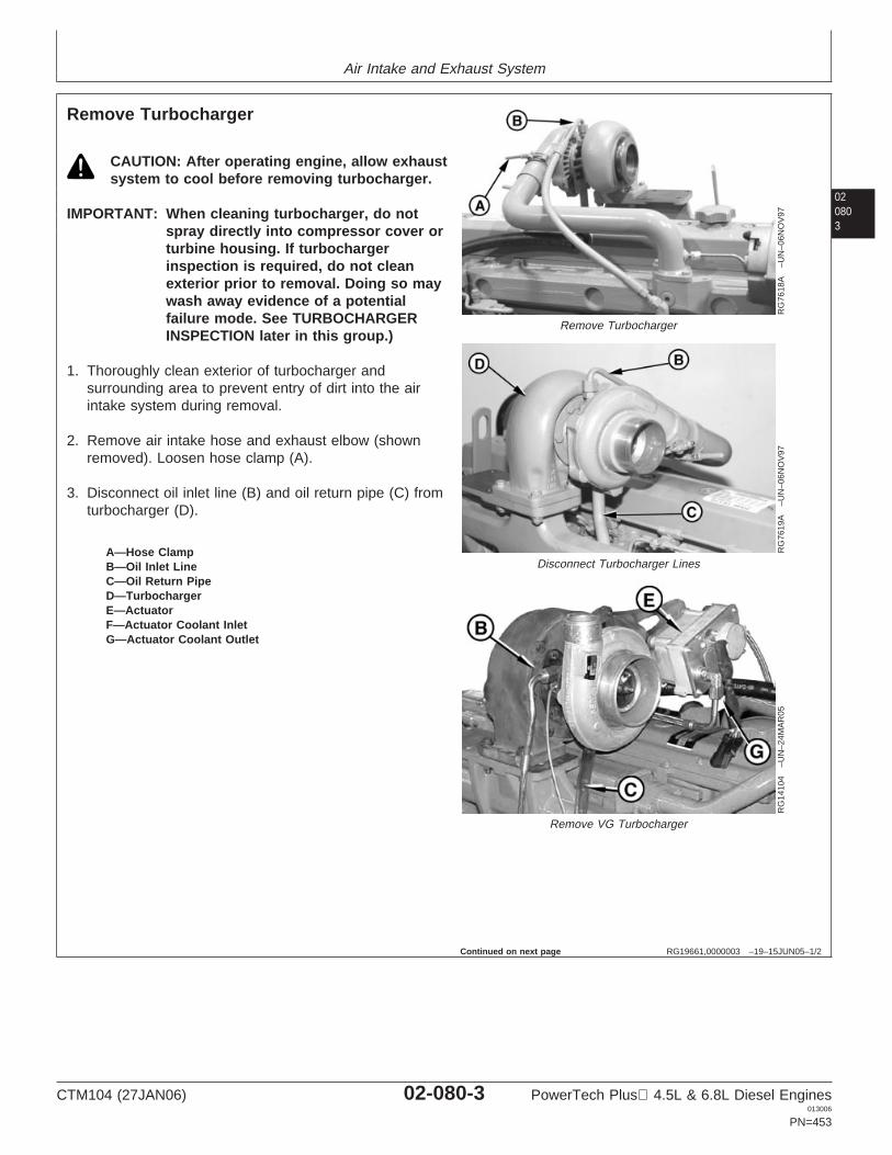
Air Intake and Exhaust System
020803
RG19661,0000003 –19–15JUN05–1/2
Remove Turbocharger
RG
7618
A–U
N–0
6NO
V97
Remove Turbocharger
RG
7619
A–U
N–0
6NO
V97
Disconnect Turbocharger Lines
RG
1410
4–U
N–2
4MA
R05
Remove VG Turbocharger
A—Hose ClampB—Oil Inlet LineC—Oil Return PipeD—TurbochargerE—ActuatorF—Actuator Coolant InletG—Actuator Coolant Outlet
CAUTION: After operating engine, allow exhaustsystem to cool before removing turbocharger.
IMPORTANT: When cleaning turbocharger, do notspray directly into compressor cover orturbine housing. If turbochargerinspection is required, do not cleanexterior prior to removal. Doing so maywash away evidence of a potentialfailure mode. See TURBOCHARGERINSPECTION later in this group.)
1. Thoroughly clean exterior of turbocharger andsurrounding area to prevent entry of dirt into the airintake system during removal.
2. Remove air intake hose and exhaust elbow (shownremoved). Loosen hose clamp (A).
3. Disconnect oil inlet line (B) and oil return pipe (C) fromturbocharger (D).
Continued on next page
CTM104 (27JAN06) 02-080-3 PowerTech Plus 4.5L & 6.8L Diesel Engines013006
PN=453
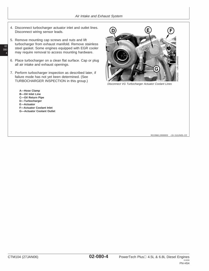
Air Intake and Exhaust System
02080
4
RG19661,0000003 –19–15JUN05–2/2
RG
1410
3–U
N–2
4MA
R05
Disconnect VG Turbocharger Actuator Coolant Lines
A—Hose ClampB—Oil Inlet LineC—Oil Return PipeD—TurbochargerE—ActuatorF—Actuator Coolant InletG—Actuator Coolant Outlet
4. Disconnect turbocharger actuator inlet and outlet lines.Disconnect wiring sensor leads.
5. Remove mounting cap screws and nuts and liftturbocharger from exhaust manifold. Remove stainlesssteel gasket. Some engines equipped with EGR coolermay require removal to access mounting hardware.
6. Place turbocharger on a clean flat surface. Cap or plugall air intake and exhaust openings.
7. Perform turbocharger inspection as described later, iffailure mode has not yet been determined. (SeeTURBOCHARGER INSPECTION in this group.)
CTM104 (27JAN06) 02-080-4 PowerTech Plus 4.5L & 6.8L Diesel Engines013006
PN=454
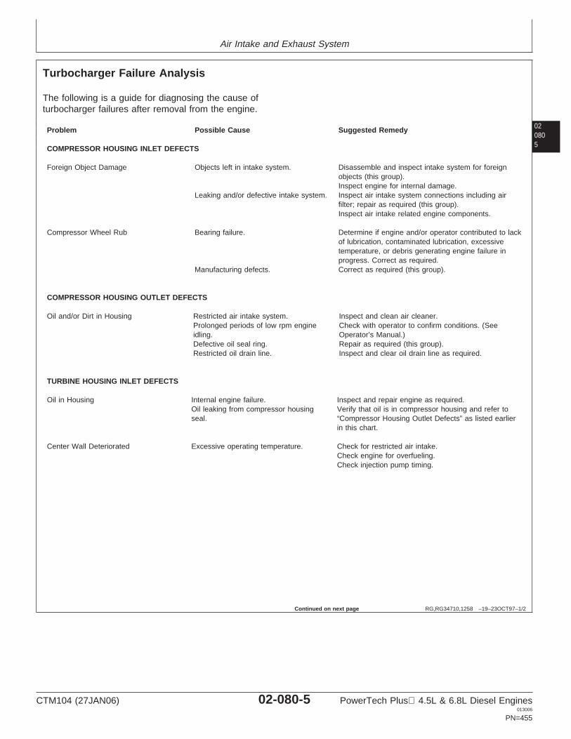
Air Intake and Exhaust System
020805
RG,RG34710,1258 –19–23OCT97–1/2
Turbocharger Failure Analysis
The following is a guide for diagnosing the cause ofturbocharger failures after removal from the engine.
Problem Possible Cause Suggested Remedy
COMPRESSOR HOUSING INLET DEFECTS
Foreign Object Damage Objects left in intake system. Disassemble and inspect intake system for foreignobjects (this group).Inspect engine for internal damage.
Leaking and/or defective intake system. Inspect air intake system connections including airfilter; repair as required (this group).Inspect air intake related engine components.
Compressor Wheel Rub Bearing failure. Determine if engine and/or operator contributed to lackof lubrication, contaminated lubrication, excessivetemperature, or debris generating engine failure inprogress. Correct as required.
Manufacturing defects. Correct as required (this group).
COMPRESSOR HOUSING OUTLET DEFECTS
Oil and/or Dirt in Housing Restricted air intake system. Inspect and clean air cleaner.Prolonged periods of low rpm engine Check with operator to confirm conditions. (Seeidling. Operator’s Manual.)Defective oil seal ring. Repair as required (this group).Restricted oil drain line. Inspect and clear oil drain line as required.
TURBINE HOUSING INLET DEFECTS
Oil in Housing Internal engine failure. Inspect and repair engine as required.Oil leaking from compressor housing Verify that oil is in compressor housing and refer toseal. “Compressor Housing Outlet Defects” as listed earlier
in this chart.
Center Wall Deteriorated Excessive operating temperature. Check for restricted air intake.Check engine for overfueling.Check injection pump timing.
Continued on next page
CTM104 (27JAN06) 02-080-5 PowerTech Plus 4.5L & 6.8L Diesel Engines013006
PN=455
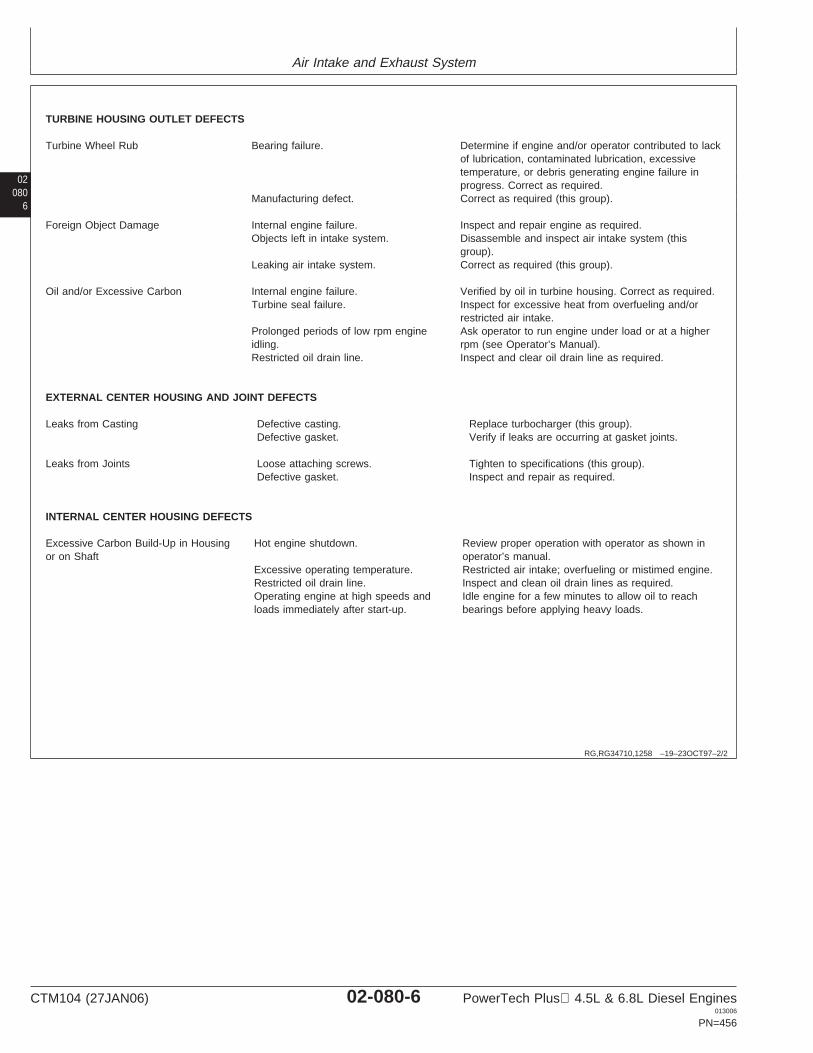
Air Intake and Exhaust System
02080
6
RG,RG34710,1258 –19–23OCT97–2/2
TURBINE HOUSING OUTLET DEFECTS
Turbine Wheel Rub Bearing failure. Determine if engine and/or operator contributed to lackof lubrication, contaminated lubrication, excessivetemperature, or debris generating engine failure inprogress. Correct as required.
Manufacturing defect. Correct as required (this group).
Foreign Object Damage Internal engine failure. Inspect and repair engine as required.Objects left in intake system. Disassemble and inspect air intake system (this
group).Leaking air intake system. Correct as required (this group).
Oil and/or Excessive Carbon Internal engine failure. Verified by oil in turbine housing. Correct as required.Turbine seal failure. Inspect for excessive heat from overfueling and/or
restricted air intake.Prolonged periods of low rpm engine Ask operator to run engine under load or at a higheridling. rpm (see Operator’s Manual).Restricted oil drain line. Inspect and clear oil drain line as required.
EXTERNAL CENTER HOUSING AND JOINT DEFECTS
Leaks from Casting Defective casting. Replace turbocharger (this group).Defective gasket. Verify if leaks are occurring at gasket joints.
Leaks from Joints Loose attaching screws. Tighten to specifications (this group).Defective gasket. Inspect and repair as required.
INTERNAL CENTER HOUSING DEFECTS
Excessive Carbon Build-Up in Housing Hot engine shutdown. Review proper operation with operator as shown inor on Shaft operator’s manual.
Excessive operating temperature. Restricted air intake; overfueling or mistimed engine.Restricted oil drain line. Inspect and clean oil drain lines as required.Operating engine at high speeds and Idle engine for a few minutes to allow oil to reachloads immediately after start-up. bearings before applying heavy loads.
CTM104 (27JAN06) 02-080-6 PowerTech Plus 4.5L & 6.8L Diesel Engines013006
PN=456
Air Intake and Exhaust System
020807
RG,30,JW7574 –19–19SEP01–1/12
Turbocharger Inspection
The following inspection procedure is recommended forsystematic failure analysis of a suspected failedturbocharger. This procedure will help to identify when aturbocharger has failed, and why it has failed, so theprimary cause of the failure can be corrected.
Proper diagnosis of a non-failed turbocharger is importantfor two reasons. First, identification of a non-failedturbocharger will lead to further investigation and repair ofthe cause of a performance complaint.
Second, proper diagnosis eliminates the unnecessaryexpense incurred when a non-failed turbocharger isreplaced.
The recommended inspection steps, which are explainedin detail on following pages, are:
• Compressor Housing Inlet and Compressor Wheel.• Compressor Housing Outlet.• Turbine Housing Inlet.• Turbine Housing Outlet and Turbine Wheel.• External Center Housing and Joints.• Perform Axial Bearing End Play Test
NOTE: To enhance the turbocharger inspection, aninspection sheet (Form No. DF-2280 availablefrom Distribution Service Center—English only)can be used that lists the inspection steps in theproper order and shows potential failure modesfor each step. Check off each step as youcomplete the inspection and record any details orproblems obtained during inspection. Retain thiswith the work order for future reference.
Continued on next page
CTM104 (27JAN06) 02-080-7 PowerTech Plus 4.5L & 6.8L Diesel Engines013006
PN=457
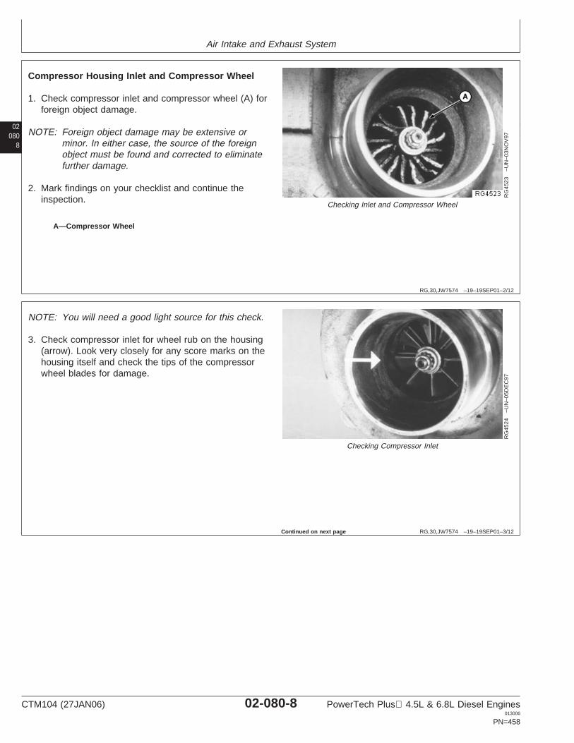
Air Intake and Exhaust System
02080
8
RG,30,JW7574 –19–19SEP01–2/12
RG
4523
–UN
–03N
OV
97
Checking Inlet and Compressor Wheel
A—Compressor Wheel
Compressor Housing Inlet and Compressor Wheel
1. Check compressor inlet and compressor wheel (A) forforeign object damage.
NOTE: Foreign object damage may be extensive orminor. In either case, the source of the foreignobject must be found and corrected to eliminatefurther damage.
2. Mark findings on your checklist and continue theinspection.
RG,30,JW7574 –19–19SEP01–3/12
RG
4524
–UN
–05D
EC
97
Checking Compressor Inlet
NOTE: You will need a good light source for this check.
3. Check compressor inlet for wheel rub on the housing(arrow). Look very closely for any score marks on thehousing itself and check the tips of the compressorwheel blades for damage.
Continued on next page
CTM104 (27JAN06) 02-080-8 PowerTech Plus 4.5L & 6.8L Diesel Engines013006
PN=458
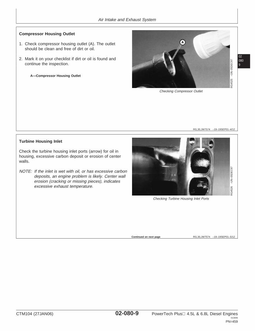
Air Intake and Exhaust System
020809
RG,30,JW7574 –19–19SEP01–4/12
RG
4525
–UN
–05D
EC
97
Checking Compressor Outlet
A—Compressor Housing Outlet
Compressor Housing Outlet
1. Check compressor housing outlet (A). The outletshould be clean and free of dirt or oil.
2. Mark it on your checklist if dirt or oil is found andcontinue the inspection.
RG,30,JW7574 –19–19SEP01–5/12
RG
4526
–UN
–05D
EC
97
Checking Turbine Housing Inlet Ports
Turbine Housing Inlet
Check the turbine housing inlet ports (arrow) for oil inhousing, excessive carbon deposit or erosion of centerwalls.
NOTE: If the inlet is wet with oil, or has excessive carbondeposits, an engine problem is likely. Center wallerosion (cracking or missing pieces), indicatesexcessive exhaust temperature.
Continued on next page
CTM104 (27JAN06) 02-080-9 PowerTech Plus 4.5L & 6.8L Diesel Engines013006
PN=459
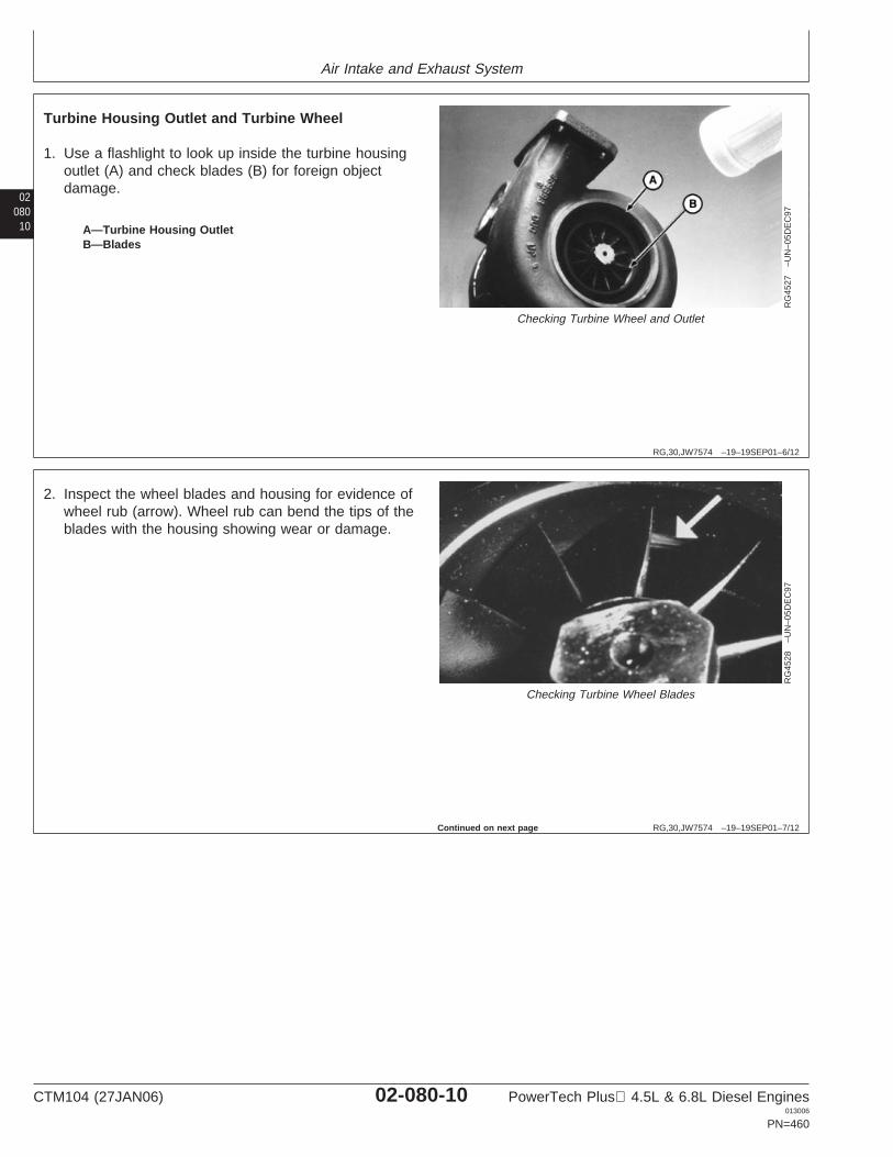
Air Intake and Exhaust System
02080
10
RG,30,JW7574 –19–19SEP01–6/12
RG
4527
–UN
–05D
EC
97
Checking Turbine Wheel and Outlet
A—Turbine Housing OutletB—Blades
Turbine Housing Outlet and Turbine Wheel
1. Use a flashlight to look up inside the turbine housingoutlet (A) and check blades (B) for foreign objectdamage.
RG,30,JW7574 –19–19SEP01–7/12
RG
4528
–UN
–05D
EC
97
Checking Turbine Wheel Blades
2. Inspect the wheel blades and housing for evidence ofwheel rub (arrow). Wheel rub can bend the tips of theblades with the housing showing wear or damage.
Continued on next page
CTM104 (27JAN06) 02-080-10 PowerTech Plus 4.5L & 6.8L Diesel Engines013006
PN=460
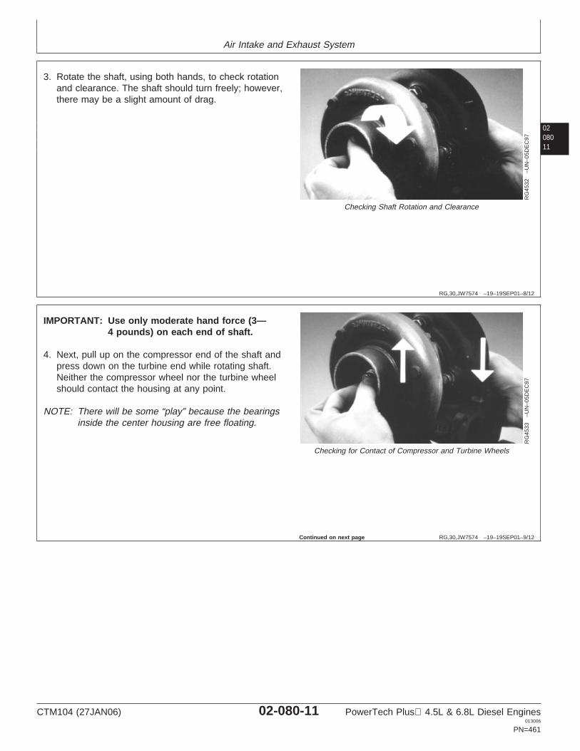
Air Intake and Exhaust System
0208011
RG,30,JW7574 –19–19SEP01–8/12
RG
4532
–UN
–05D
EC
97
Checking Shaft Rotation and Clearance
3. Rotate the shaft, using both hands, to check rotationand clearance. The shaft should turn freely; however,there may be a slight amount of drag.
RG,30,JW7574 –19–19SEP01–9/12
RG
4533
–UN
–05D
EC
97
Checking for Contact of Compressor and Turbine Wheels
IMPORTANT: Use only moderate hand force (3—4 pounds) on each end of shaft.
4. Next, pull up on the compressor end of the shaft andpress down on the turbine end while rotating shaft.Neither the compressor wheel nor the turbine wheelshould contact the housing at any point.
NOTE: There will be some “play” because the bearingsinside the center housing are free floating.
Continued on next page
CTM104 (27JAN06) 02-080-11 PowerTech Plus 4.5L & 6.8L Diesel Engines013006
PN=461
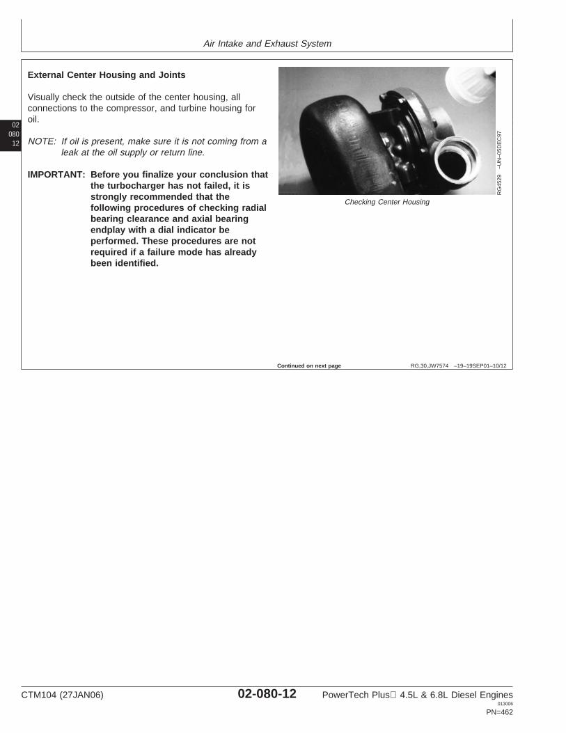
Air Intake and Exhaust System
02080
12
RG,30,JW7574 –19–19SEP01–10/12
RG
4529
–UN
–05D
EC
97
Checking Center Housing
External Center Housing and Joints
Visually check the outside of the center housing, allconnections to the compressor, and turbine housing foroil.
NOTE: If oil is present, make sure it is not coming from aleak at the oil supply or return line.
IMPORTANT: Before you finalize your conclusion thatthe turbocharger has not failed, it isstrongly recommended that thefollowing procedures of checking radialbearing clearance and axial bearingendplay with a dial indicator beperformed. These procedures are notrequired if a failure mode has alreadybeen identified.
Continued on next page
CTM104 (27JAN06) 02-080-12 PowerTech Plus 4.5L & 6.8L Diesel Engines013006
PN=462
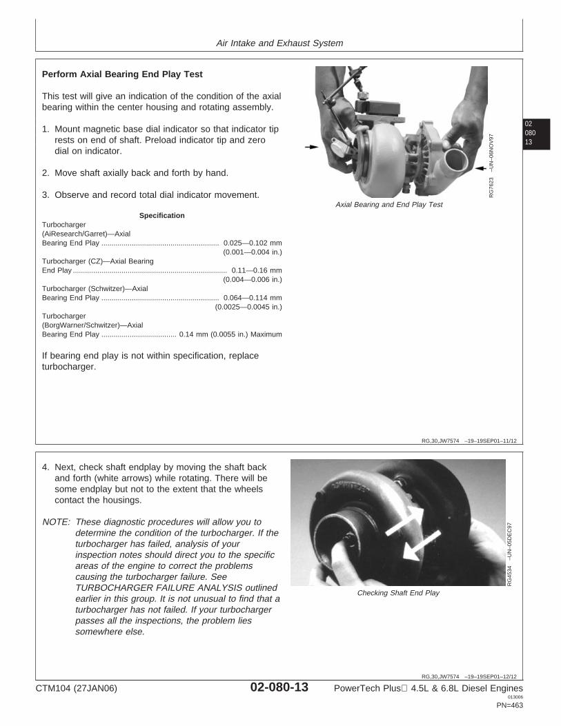
Air Intake and Exhaust System
0208013
RG,30,JW7574 –19–19SEP01–11/12
RG
7623
–UN
–06N
OV
97
Axial Bearing and End Play Test
Perform Axial Bearing End Play Test
This test will give an indication of the condition of the axialbearing within the center housing and rotating assembly.
1. Mount magnetic base dial indicator so that indicator tiprests on end of shaft. Preload indicator tip and zerodial on indicator.
2. Move shaft axially back and forth by hand.
3. Observe and record total dial indicator movement.
SpecificationTurbocharger(AiResearch/Garret)—AxialBearing End Play 0.025—0.102 mm
(0.001—0.004 in.)..........................................................
Turbocharger (CZ)—Axial BearingEnd Play 0.11—0.16 mm
(0.004—0.006 in.)............................................................................
Turbocharger (Schwitzer)—AxialBearing End Play 0.064—0.114 mm
(0.0025—0.0045 in.)..........................................................
Turbocharger(BorgWarner/Schwitzer)—AxialBearing End Play 0.14 mm (0.0055 in.) Maximum.....................................
If bearing end play is not within specification, replaceturbocharger.
RG,30,JW7574 –19–19SEP01–12/12
RG
4534
–UN
–05D
EC
97
Checking Shaft End Play
4. Next, check shaft endplay by moving the shaft backand forth (white arrows) while rotating. There will besome endplay but not to the extent that the wheelscontact the housings.
NOTE: These diagnostic procedures will allow you todetermine the condition of the turbocharger. If theturbocharger has failed, analysis of yourinspection notes should direct you to the specificareas of the engine to correct the problemscausing the turbocharger failure. SeeTURBOCHARGER FAILURE ANALYSIS outlinedearlier in this group. It is not unusual to find that aturbocharger has not failed. If your turbochargerpasses all the inspections, the problem liessomewhere else.
CTM104 (27JAN06) 02-080-13 PowerTech Plus 4.5L & 6.8L Diesel Engines013006
PN=463
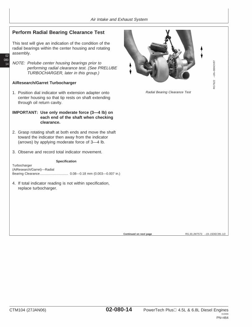
Air Intake and Exhaust System
02080
14
RG,30,JW7573 –19–15DEC99–1/2
Perform Radial Bearing Clearance Test
RG
7622
–UN
–06N
OV
97
Radial Bearing Clearance Test
This test will give an indication of the condition of theradial bearings within the center housing and rotatingassembly.
NOTE: Prelube center housing bearings prior toperforming radial clearance test. (See PRELUBETURBOCHARGER, later in this group.)
AiResearch/Garret Turbocharger
1. Position dial indicator with extension adapter ontocenter housing so that tip rests on shaft extendingthrough oil return cavity.
IMPORTANT: Use only moderate force (3—4 lb) oneach end of the shaft when checkingclearance.
2. Grasp rotating shaft at both ends and move the shafttoward the indicator then away from the indicator(arrows) by applying moderate force of 3—4 lb.
3. Observe and record total indicator movement.
SpecificationTurbocharger(AiResearch/Garret)—RadialBearing Clearance 0.08—0.18 mm (0.003—0.007 in.)...............................
4. If total indicator reading is not within specification,replace turbocharger.
Continued on next page
CTM104 (27JAN06) 02-080-14 PowerTech Plus 4.5L & 6.8L Diesel Engines013006
PN=464
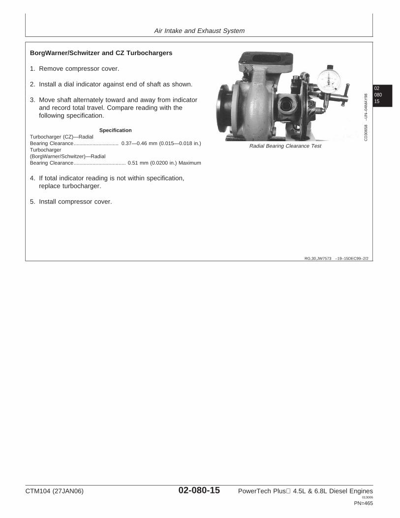
Air Intake and Exhaust System
0208015
RG,30,JW7573 –19–15DEC99–2/2
CD
3065
8–U
N–0
4MA
Y98
Radial Bearing Clearance Test
BorgWarner/Schwitzer and CZ Turbochargers
1. Remove compressor cover.
2. Install a dial indicator against end of shaft as shown.
3. Move shaft alternately toward and away from indicatorand record total travel. Compare reading with thefollowing specification.
SpecificationTurbocharger (CZ)—RadialBearing Clearance 0.37—0.46 mm (0.015—0.018 in.)...............................Turbocharger(BorgWarner/Schwitzer)—RadialBearing Clearance 0.51 mm (0.0200 in.) Maximum....................................
4. If total indicator reading is not within specification,replace turbocharger.
5. Install compressor cover.
CTM104 (27JAN06) 02-080-15 PowerTech Plus 4.5L & 6.8L Diesel Engines013006
PN=465
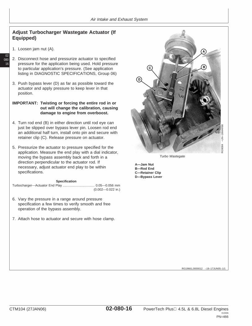
Air Intake and Exhaust System
02080
16
RG19661,0000012 –19–17JUN05–1/1
Adjust Turbocharger Wastegate Actuator (IfEquipped)
RG
9084
–UN
–16M
AR
98
Turbo Wastegate
A—Jam NutB—Rod EndC—Retainer ClipD—Bypass Lever
1. Loosen jam nut (A).
2. Disconnect hose and pressurize actuator to specifiedpressure for the application being used. Hold pressureto particular application’s pressure. (See applicationlisting in DIAGNOSTIC SPECIFICATIONS, Group 06)
3. Push bypass lever (D) as far as possible toward theactuator and apply pressure to keep lever in thatposition.
IMPORTANT: Twisting or forcing the entire rod in orout will change the calibration, causingdamage to engine from overboost.
4. Turn rod end (B) in either direction until rod eye canjust be slipped over bypass lever pin. Loosen rod endan additional half turn, install onto pin and secure withretainer clip (C). Release pressure on actuator.
5. Pressurize the actuator to pressure specified for theapplication. Measure the end play with a dial indicator,moving the bypass assembly back and forth in adirection perpendicular to the actuator rod. Ifnecessary, adjust actuator end play to be withinspecifications.
SpecificationTurbocharger—Actuator End Play 0.05—0.056 mm
(0.002—0.022 in.)...................................
6. Vary the pressure in a range around pressurespecification a few times to verify smooth and freeoperation of the bypass assembly.
7. Attach hose to actuator and secure with hose clamp.
CTM104 (27JAN06) 02-080-16 PowerTech Plus 4.5L & 6.8L Diesel Engines013006
PN=466
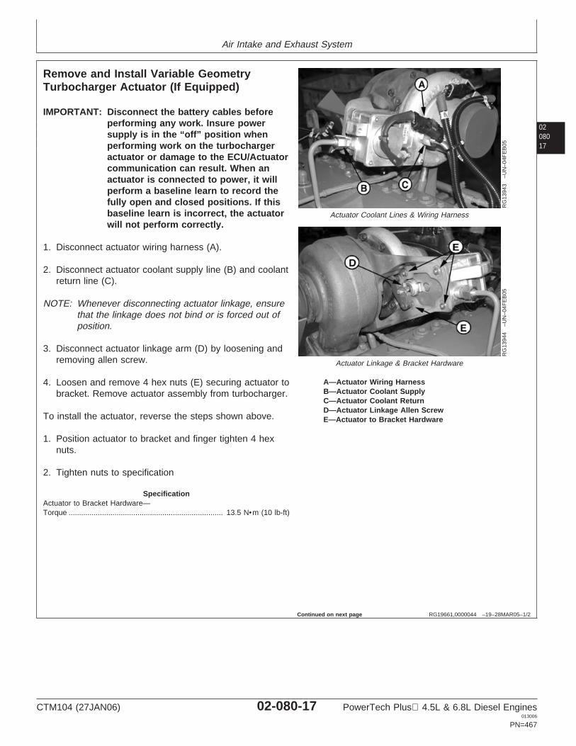
Air Intake and Exhaust System
0208017
RG19661,0000044 –19–28MAR05–1/2
Remove and Install Variable GeometryTurbocharger Actuator (If Equipped)
RG
1394
3–U
N–0
4FE
B05
Actuator Coolant Lines & Wiring Harness
RG
1394
4–U
N–0
4FE
B05
Actuator Linkage & Bracket Hardware
A—Actuator Wiring HarnessB—Actuator Coolant SupplyC—Actuator Coolant ReturnD—Actuator Linkage Allen ScrewE—Actuator to Bracket Hardware
IMPORTANT: Disconnect the battery cables beforeperforming any work. Insure powersupply is in the “off” position whenperforming work on the turbochargeractuator or damage to the ECU/Actuatorcommunication can result. When anactuator is connected to power, it willperform a baseline learn to record thefully open and closed positions. If thisbaseline learn is incorrect, the actuatorwill not perform correctly.
1. Disconnect actuator wiring harness (A).
2. Disconnect actuator coolant supply line (B) and coolantreturn line (C).
NOTE: Whenever disconnecting actuator linkage, ensurethat the linkage does not bind or is forced out ofposition.
3. Disconnect actuator linkage arm (D) by loosening andremoving allen screw.
4. Loosen and remove 4 hex nuts (E) securing actuator tobracket. Remove actuator assembly from turbocharger.
To install the actuator, reverse the steps shown above.
1. Position actuator to bracket and finger tighten 4 hexnuts.
2. Tighten nuts to specification
SpecificationActuator to Bracket Hardware—Torque 13.5 N•m (10 lb-ft)..........................................................................
Continued on next page
CTM104 (27JAN06) 02-080-17 PowerTech Plus 4.5L & 6.8L Diesel Engines013006
PN=467
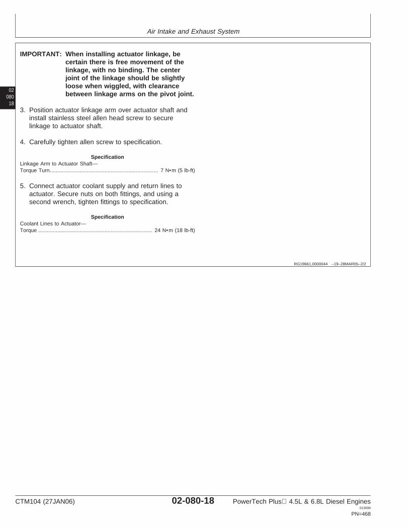
Air Intake and Exhaust System
02080
18
RG19661,0000044 –19–28MAR05–2/2
IMPORTANT: When installing actuator linkage, becertain there is free movement of thelinkage, with no binding. The centerjoint of the linkage should be slightlyloose when wiggled, with clearancebetween linkage arms on the pivot joint.
3. Position actuator linkage arm over actuator shaft andinstall stainless steel allen head screw to securelinkage to actuator shaft.
4. Carefully tighten allen screw to specification.
SpecificationLinkage Arm to Actuator Shaft—Torque Turn 7 N•m (5 lb-ft).........................................................................
5. Connect actuator coolant supply and return lines toactuator. Secure nuts on both fittings, and using asecond wrench, tighten fittings to specification.
SpecificationCoolant Lines to Actuator—Torque 24 N•m (18 lb-ft).............................................................................
CTM104 (27JAN06) 02-080-18 PowerTech Plus 4.5L & 6.8L Diesel Engines013006
PN=468
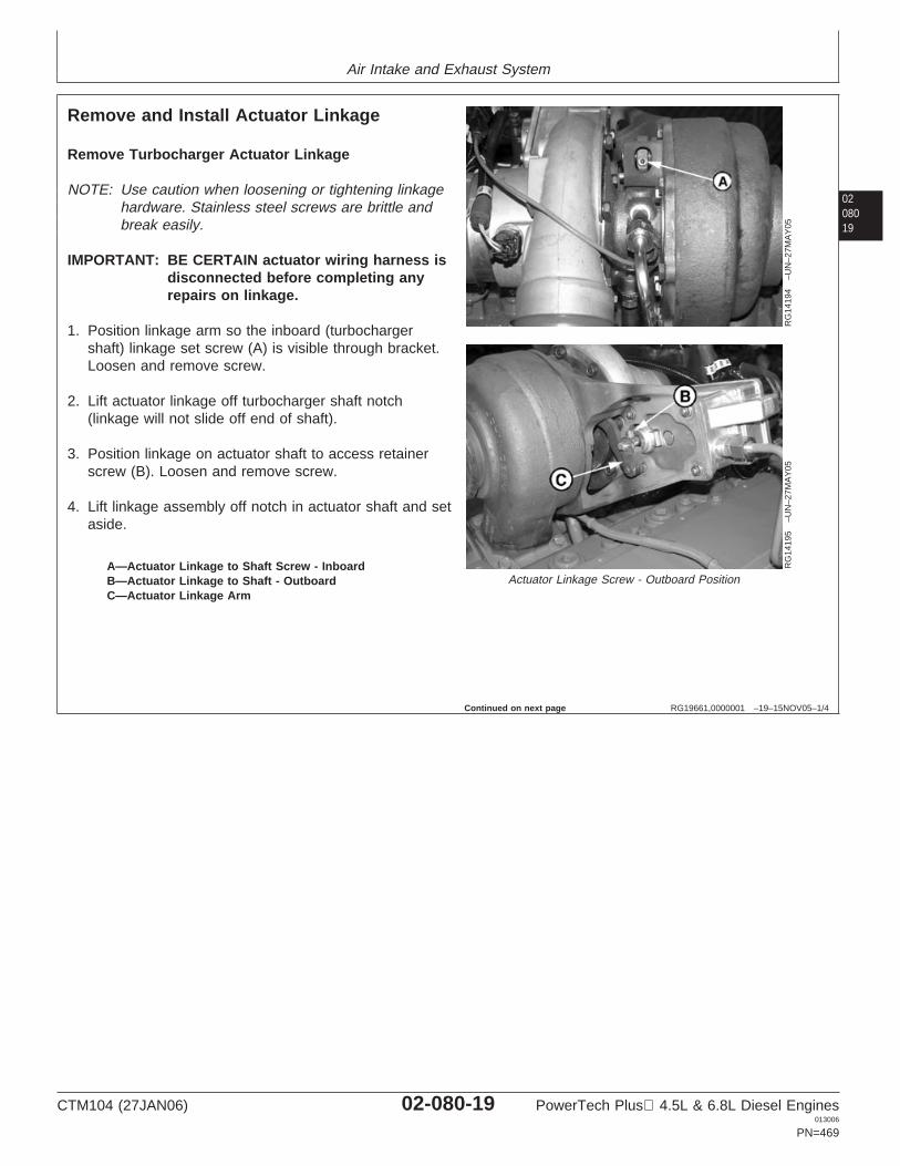
Air Intake and Exhaust System
0208019
RG19661,0000001 –19–15NOV05–1/4
Remove and Install Actuator Linkage
RG
1419
4–U
N–2
7MA
Y05
RG
1419
5–U
N–2
7MA
Y05
Actuator Linkage Screw - Outboard PositionA—Actuator Linkage to Shaft Screw - InboardB—Actuator Linkage to Shaft - OutboardC—Actuator Linkage Arm
Remove Turbocharger Actuator Linkage
NOTE: Use caution when loosening or tightening linkagehardware. Stainless steel screws are brittle andbreak easily.
IMPORTANT: BE CERTAIN actuator wiring harness isdisconnected before completing anyrepairs on linkage.
1. Position linkage arm so the inboard (turbochargershaft) linkage set screw (A) is visible through bracket.Loosen and remove screw.
2. Lift actuator linkage off turbocharger shaft notch(linkage will not slide off end of shaft).
3. Position linkage on actuator shaft to access retainerscrew (B). Loosen and remove screw.
4. Lift linkage assembly off notch in actuator shaft and setaside.
Continued on next page
CTM104 (27JAN06) 02-080-19 PowerTech Plus 4.5L & 6.8L Diesel Engines013006
PN=469
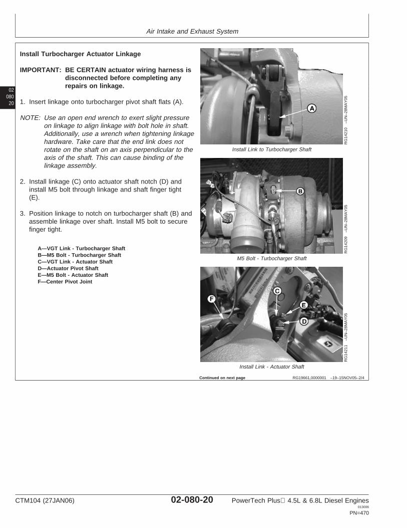
Air Intake and Exhaust System
02080
20
RG19661,0000001 –19–15NOV05–2/4
RG
1421
0–U
N–2
8MA
Y05
Install Link to Turbocharger Shaft
RG
1420
9–U
N–2
8MA
Y05
M5 Bolt - Turbocharger Shaft
RG
1421
1–U
N–2
8MA
Y05
Install Link - Actuator Shaft
A—VGT Link - Turbocharger ShaftB—M5 Bolt - Turbocharger ShaftC—VGT Link - Actuator ShaftD—Actuator Pivot ShaftE—M5 Bolt - Actuator ShaftF—Center Pivot Joint
Install Turbocharger Actuator Linkage
IMPORTANT: BE CERTAIN actuator wiring harness isdisconnected before completing anyrepairs on linkage.
1. Insert linkage onto turbocharger pivot shaft flats (A).
NOTE: Use an open end wrench to exert slight pressureon linkage to align linkage with bolt hole in shaft.Additionally, use a wrench when tightening linkagehardware. Take care that the end link does notrotate on the shaft on an axis perpendicular to theaxis of the shaft. This can cause binding of thelinkage assembly.
2. Install linkage (C) onto actuator shaft notch (D) andinstall M5 bolt through linkage and shaft finger tight(E).
3. Position linkage to notch on turbocharger shaft (B) andassemble linkage over shaft. Install M5 bolt to securefinger tight.
Continued on next page
CTM104 (27JAN06) 02-080-20 PowerTech Plus 4.5L & 6.8L Diesel Engines013006
PN=470
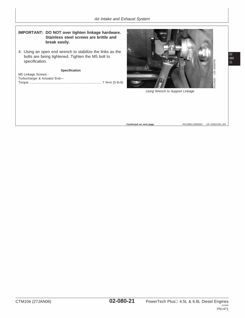
Air Intake and Exhaust System
0208021
RG19661,0000001 –19–15NOV05–3/4
RG
1452
0–U
N–3
0SE
P05
Using Wrench to Support Linkage
IMPORTANT: DO NOT over tighten linkage hardware.Stainless steel screws are brittle andbreak easily.
4. Using an open end wrench to stabilize the links as thebolts are being tightened. Tighten the M5 bolt tospecification.
SpecificationM5 Linkage Screws -Turbocharger & Actuator End—Torque 7 N•m (5 lb-ft).................................................................................
Continued on next page
CTM104 (27JAN06) 02-080-21 PowerTech Plus 4.5L & 6.8L Diesel Engines013006
PN=471
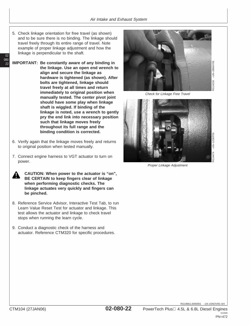
Air Intake and Exhaust System
02080
22
RG19661,0000001 –19–15NOV05–4/4
RG
1421
8–U
N–2
8MA
Y05
Check for Linkage Free Travel
RG
1447
4–U
N–1
2SE
P05
Proper Linkage Adjustment
5. Check linkage orientation for free travel (as shown)and to be sure there is no binding. The linkage shouldtravel freely through its entire range of travel. Noteexample of proper linkage adjustment and how thelinkage is perpendicular to the shaft.
IMPORTANT: Be constantly aware of any binding inthe linkage. Use an open end wrench toalign and secure the linkage ashardware is tightened (as shown). Afterbolts are tightened, linkage shouldtravel freely at all times and returnimmediately to original position whenmanually tested. The center pivot jointshould have some play when linkageshaft is wiggled. If binding of thelinkage is noted, use a wrench to gentlypry the end link into necessary positionsuch that linkage moves freelythroughout its full range and thebinding condition is corrected.
6. Verify again that the linkage moves freely and returnsto original position when tested manually.
7. Connect engine harness to VGT actuator to turn onpower.
CAUTION: When power to the actuator is “on”,BE CERTAIN to keep fingers clear of linkagewhen performing diagnostic checks. Thelinkage actuates very quickly and fingers canbe pinched.
8. Reference Service Advisor, Interactive Test Tab, to runLearn Value Reset Test for actuator and linkage. Thistest allows the actuator and linkage to check travelstops when running the learn cycle.
9. Conduct a diagnostic check of the harness andactuator. Reference CTM320 for specific procedures.
CTM104 (27JAN06) 02-080-22 PowerTech Plus 4.5L & 6.8L Diesel Engines013006
PN=472
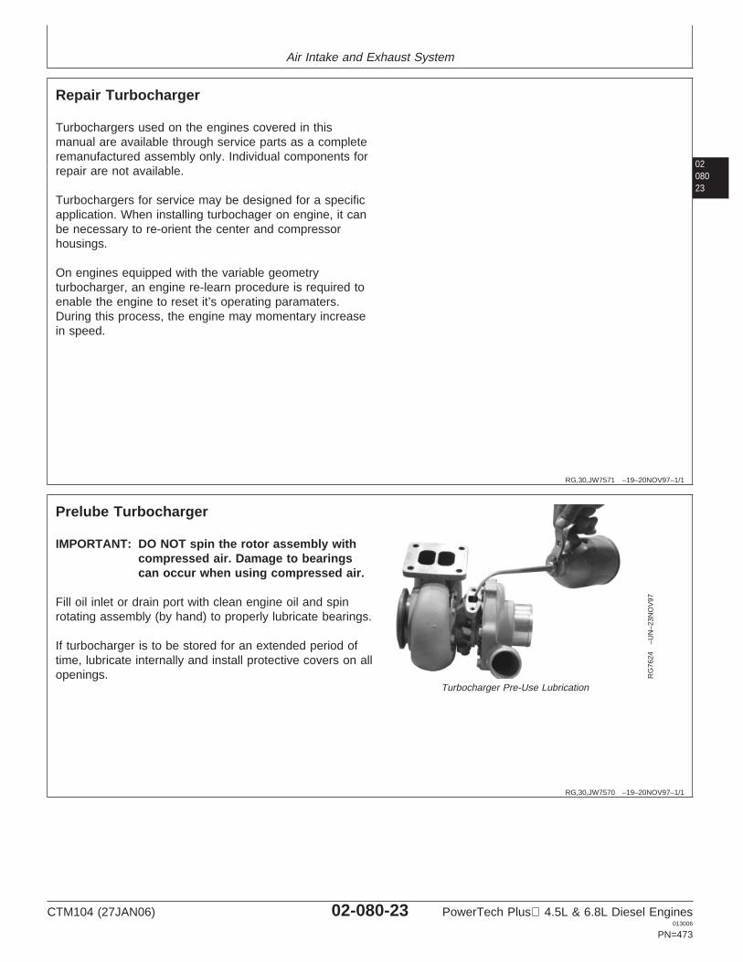
Air Intake and Exhaust System
0208023
RG,30,JW7571 –19–20NOV97–1/1
Repair Turbocharger
Turbochargers used on the engines covered in thismanual are available through service parts as a completeremanufactured assembly only. Individual components forrepair are not available.
Turbochargers for service may be designed for a specificapplication. When installing turbochager on engine, it canbe necessary to re-orient the center and compressorhousings.
On engines equipped with the variable geometryturbocharger, an engine re-learn procedure is required toenable the engine to reset it’s operating paramaters.During this process, the engine may momentary increasein speed.
RG,30,JW7570 –19–20NOV97–1/1
Prelube Turbocharger
RG
7624
–UN
–23N
OV
97
Turbocharger Pre-Use Lubrication
IMPORTANT: DO NOT spin the rotor assembly withcompressed air. Damage to bearingscan occur when using compressed air.
Fill oil inlet or drain port with clean engine oil and spinrotating assembly (by hand) to properly lubricate bearings.
If turbocharger is to be stored for an extended period oftime, lubricate internally and install protective covers on allopenings.
CTM104 (27JAN06) 02-080-23 PowerTech Plus 4.5L & 6.8L Diesel Engines013006
PN=473
Air Intake and Exhaust System
02080
24
RG19661,0000004 –19–15JUN05–1/5
Install Turbocharger
IMPORTANT: If turbocharger failed because of foreignmaterial entering the air intake system,be sure to examine the system andclean as required to prevent a repeatfailure.
If not done previously, prime (prelube) the turbochargerrotating assembly prior to mounting turbocharger onengine. Prelube center housing with clean engine oilthrough the oil drain hole. Turn rotating assembly by handto lubricate bearings.
1. Clean turbocharger-to-exhaust manifold mountingsurfaces of any debris or old gasket material.
IMPORTANT: Turbochargers can be either single ordual entry. Make sure the appropriatesingle or dual gasket is used wheninstalling turbocharger.
NOTE: Some turbochargers are installed with a liquidgasket in production. Replace with a newstainless steel gasket when servicing.
2. Position turbocharger and new stainless steel gasketonto exhaust manifold. Tighten stud nuts tospecifications.
SpecificationTurbocharger-to-Exhaust ManifoldNuts—Torque 70 N•m (52 lb-ft)..................................................................
Continued on next page
CTM104 (27JAN06) 02-080-24 PowerTech Plus 4.5L & 6.8L Diesel Engines013006
PN=474
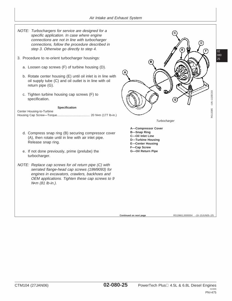
Air Intake and Exhaust System
0208025
RG19661,0000004 –19–15JUN05–2/5
RG
1338
5–U
N–1
1DE
C03
Turbocharger
A—Compressor CoverB—Snap RingC—Oil Inlet LineD—Turbine HousingE—Center HousingF—Cap ScrewG—Oil Return Pipe
NOTE: Turbochargers for service are designed for aspecific application. In case where engineconnections are not in line with turbochargerconnections, follow the procedure described instep 3. Otherwise go directly to step 4.
3. Procedure to re-orient turbocharger housings:
a. Loosen cap screws (F) of turbine housing (D).
b. Rotate center housing (E) until oil inlet is in line withoil supply tube (C) and oil outlet is in line with oilreturn pipe (G).
c. Tighten turbine housing cap screws (F) tospecification.
SpecificationCenter Housing-to-TurbineHousing Cap Screw—Torque 20 N•m (177 lb-in.).......................................
d. Compress snap ring (B) securing compressor cover(A), then rotate until in line with air inlet pipe.Release snap ring.
e. If not done previously, prime (prelube) theturbocharger.
NOTE: Replace cap screws for oil return pipe (C) withserrated flange-head cap screws (19M9093) forengines in excavators, crawlers, backhoes andOEM applications. Tighten these cap screws to 9N•m (81 lb-in.).
Continued on next page
CTM104 (27JAN06) 02-080-25 PowerTech Plus 4.5L & 6.8L Diesel Engines013006
PN=475
Air Intake and Exhaust System
02080
26
RG19661,0000004 –19–15JUN05–3/5
RG
7618
B–U
N–0
6NO
V97
Install Turbocharger
RG
7619
B–U
N–0
6NO
V97
Connect Turbocharger Lines
RG
1410
4–U
N–2
4MA
R05
Install VG Turbocharger
A—Hose ClampB—Oil Inlet LineC—Oil Return PipeD—TurbochargerE—ActuatorF—Actuator Coolant InletG—Actuator Coolant Outlet
4. Install oil return pipe (C) to turbocharger. Tighten oilreturn pipe cap screws to specifications.
SpecificationTurbocharger Oil Return PipeCap Screws—Torque 24 N•m (212 lb-in.)...................................................
5. Connect turbocharger oil inlet line (B) and tighten tospecifications.
SpecificationTurbocharger Oil Inlet Line (AtTurbocharger)—Torque 24 N•m (212 lb-in.)................................................Turbocharger Oil Inlet Line (At OilFilter Header)—Torque 24 N•m (212 lb-in.).................................................
Continued on next page
CTM104 (27JAN06) 02-080-26 PowerTech Plus 4.5L & 6.8L Diesel Engines013006
PN=476
Air Intake and Exhaust System
0208027
RG19661,0000004 –19–15JUN05–4/5
RG
1410
3–U
N–2
4MA
R05
Connect VG Turbocharger Actuator Coolant Line
A—Hose ClampB—Oil Inlet LineC—Oil Return PipeD—TurbochargerE—ActuatorF—Actuator Coolant InletG—Actuator Coolant Outlet
6. Connect turbocharger actuator inlet and outlet coolantline fittings. Connect wiring sensor leads.
7. Connect air inlet hose-to-turbocharger compressorhousing. Tighten hose clamp (A) on air inlet line tospecifications.
SpecificationTurbocharger Air Inlet HoseClamp—Torque 6 N•m (4.5 lb-ft) (53 lb-in.)................................................
IMPORTANT: Since the greatest suction force occursbetween air cleaner and turbocharger,ensure that hose connections are tightto prevent entry of dirt into system.
8. Install exhaust adapter and exhaust elbow. Tighten capscrews and clamp to specifications.
SpecificationExhaust Adapter-to-TurbochargerClamp—Torque 7.5 N•m (5.5 lb-ft) (66 lb-in.).............................................Turbocharger Exhaust Elbow—Torque 47 N•m (35 lb-ft).............................................................................
IMPORTANT: Failure to thoroughly clean all oil fromthe air-to-air aftercooler and lines willresult in an engine over speed situationupon start-up, resulting in enginedamage.
9. On engines equipped with an air-to-air aftercooler: aftera turbocharger failure, it is absolutely necessary toclean air-to-air aftercooler and lines of allcontamination, especially oil. Follow this procedure toclean air-to-air aftercooler and lines:
• Remove air-to-air aftercooler from machine. SeeRemove and Install Air-to-Air Aftercooler in thisgroup.
• Clean all oil residue from air-to-air aftercooler andlines using PMCC2638 John Deere Cooling SystemCleaner or equivalent.
• Dry the inside of air-to-air aftercooler and lines usingcompressed air.
CTM104 (27JAN06) 02-080-27 PowerTech Plus 4.5L & 6.8L Diesel Engines013006
PN=477
Continued on next page
Air Intake and Exhaust System
02080
RG19661,0000004 –19–15JUN05–5/5
IMPORTANT: Before starting engine after servicingturbocharger, run special test ”TurboLearn Value Reset Test” in ServiceAdvisor or DST.
28
RG,30,JW7568 –19–20NOV97–1/1
Turbocharger Break-In
IMPORTANT: A new or repaired turbocharger DOESNOT have an adequate oil supply forimmediate start-up of engine. Performthe steps below to prevent damage toturbocharger bearings.
1. Either push the throttle lever to the “STOP” position,hold the engine shut-off knob out, or disconnectelectrical wire from injection pump.
IMPORTANT: DO NOT crank engine longer than 30seconds at a time to avoid damage tostarter motor.
2. Crank engine over with starter motor until oil pressuregauge needle registers within the “GREEN” zone ofpressure gauge.
3. Start and run engine at low idle while checking oil inletand air piping connections for leaks.
DPSG,OUO1004,5 –19–31MAR98–1/1
Recommendations for Turbocharger Use
IMPORTANT: Should the engine stall when operatingunder load, IMMEDIATELY restart theengine to prevent overheating ofturbocharger parts.
In most cases, turbocharger damage is caused byimproper start-up and shutdown procedures. Always idlethe engine for at least 30 seconds (no load) after start-upand before shutdown.
CTM104 (27JAN06) 02-080-28 PowerTech Plus 4.5L & 6.8L Diesel Engines013006
PN=478
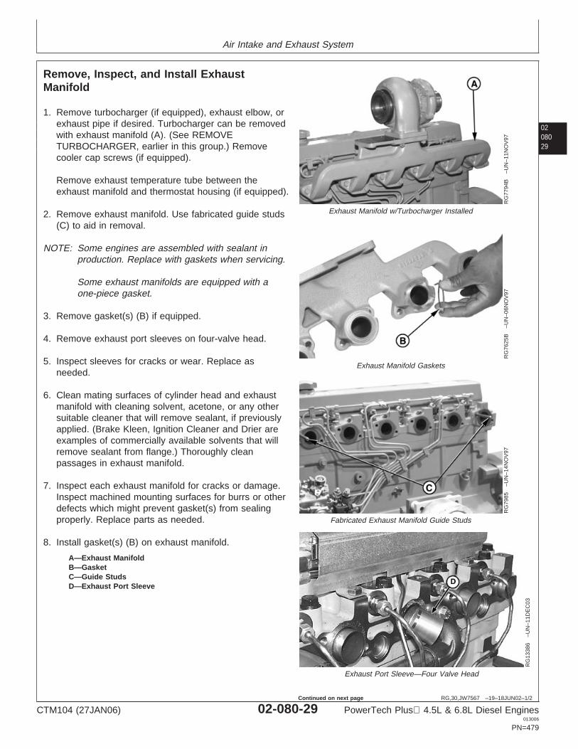
Air Intake and Exhaust System
0208029
RG,30,JW7567 –19–18JUN02–1/2
Remove, Inspect, and Install ExhaustManifold
RG
7794
B–U
N–1
1NO
V97
Exhaust Manifold w/Turbocharger Installed
RG
7625
B–U
N–0
6NO
V97
Exhaust Manifold Gaskets
RG
7985
–UN
–14N
OV
97
Fabricated Exhaust Manifold Guide StudsR
G13
386
–UN
–11D
EC
03
Exhaust Port Sleeve—Four Valve Head
A—Exhaust ManifoldB—GasketC—Guide StudsD—Exhaust Port Sleeve
1. Remove turbocharger (if equipped), exhaust elbow, orexhaust pipe if desired. Turbocharger can be removedwith exhaust manifold (A). (See REMOVETURBOCHARGER, earlier in this group.) Removecooler cap screws (if equipped).
Remove exhaust temperature tube between theexhaust manifold and thermostat housing (if equipped).
2. Remove exhaust manifold. Use fabricated guide studs(C) to aid in removal.
NOTE: Some engines are assembled with sealant inproduction. Replace with gaskets when servicing.
Some exhaust manifolds are equipped with aone-piece gasket.
3. Remove gasket(s) (B) if equipped.
4. Remove exhaust port sleeves on four-valve head.
5. Inspect sleeves for cracks or wear. Replace asneeded.
6. Clean mating surfaces of cylinder head and exhaustmanifold with cleaning solvent, acetone, or any othersuitable cleaner that will remove sealant, if previouslyapplied. (Brake Kleen, Ignition Cleaner and Drier areexamples of commercially available solvents that willremove sealant from flange.) Thoroughly cleanpassages in exhaust manifold.
7. Inspect each exhaust manifold for cracks or damage.Inspect machined mounting surfaces for burrs or otherdefects which might prevent gasket(s) from sealingproperly. Replace parts as needed.
8. Install gasket(s) (B) on exhaust manifold.
CTM104 (27JAN06) 02-080-29 PowerTech Plus 4.5L & 6.8L Diesel Engines013006
PN=479
Continued on next page
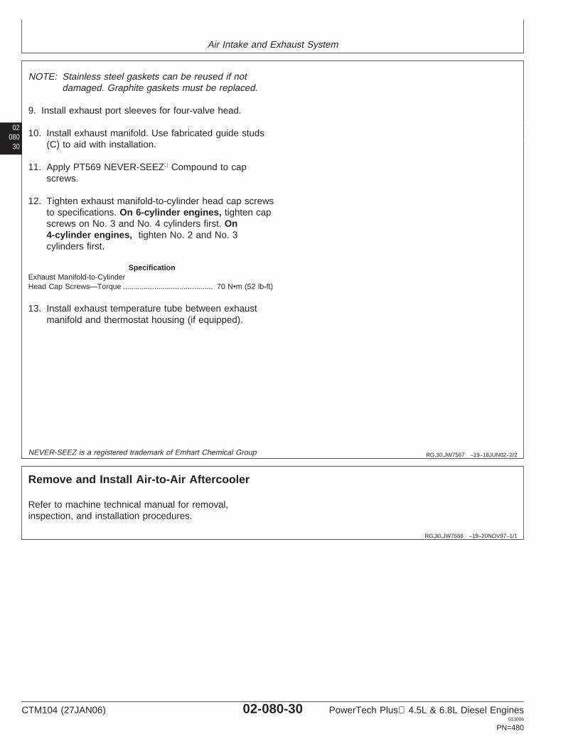
Air Intake and Exhaust System
02080
30
RG,30,JW7567 –19–18JUN02–2/2
NOTE: Stainless steel gaskets can be reused if notdamaged. Graphite gaskets must be replaced.
9. Install exhaust port sleeves for four-valve head.
10. Install exhaust manifold. Use fabricated guide studs(C) to aid with installation.
11. Apply PT569 NEVER-SEEZ Compound to capscrews.
12. Tighten exhaust manifold-to-cylinder head cap screwsto specifications. On 6-cylinder engines, tighten capscrews on No. 3 and No. 4 cylinders first. On4-cylinder engines, tighten No. 2 and No. 3cylinders first.
SpecificationExhaust Manifold-to-CylinderHead Cap Screws—Torque 70 N•m (52 lb-ft)...........................................
13. Install exhaust temperature tube between exhaustmanifold and thermostat housing (if equipped).
NEVER-SEEZ is a registered trademark of Emhart Chemical Group
RG,30,JW7566 –19–20NOV97–1/1
Remove and Install Air-to-Air Aftercooler
Refer to machine technical manual for removal,inspection, and installation procedures.
CTM104 (27JAN06) 02-080-30 PowerTech Plus 4.5L & 6.8L Diesel Engines013006
PN=480
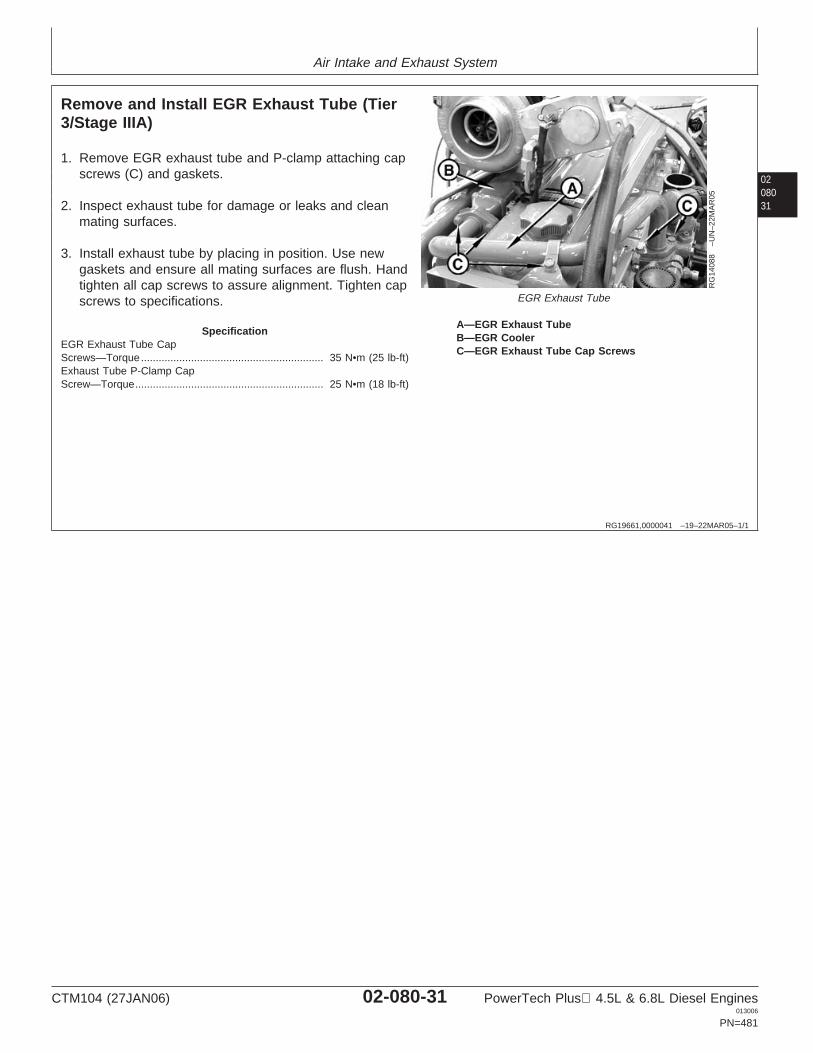
Air Intake and Exhaust System
0208031
RG19661,0000041 –19–22MAR05–1/1
Remove and Install EGR Exhaust Tube (Tier3/Stage IIIA)
RG
1408
8–U
N–2
2MA
R05
EGR Exhaust Tube
A—EGR Exhaust TubeB—EGR CoolerC—EGR Exhaust Tube Cap Screws
1. Remove EGR exhaust tube and P-clamp attaching capscrews (C) and gaskets.
2. Inspect exhaust tube for damage or leaks and cleanmating surfaces.
3. Install exhaust tube by placing in position. Use newgaskets and ensure all mating surfaces are flush. Handtighten all cap screws to assure alignment. Tighten capscrews to specifications.
SpecificationEGR Exhaust Tube CapScrews—Torque 35 N•m (25 lb-ft)..............................................................Exhaust Tube P-Clamp CapScrew—Torque 25 N•m (18 lb-ft)................................................................
CTM104 (27JAN06) 02-080-31 PowerTech Plus 4.5L & 6.8L Diesel Engines013006
PN=481
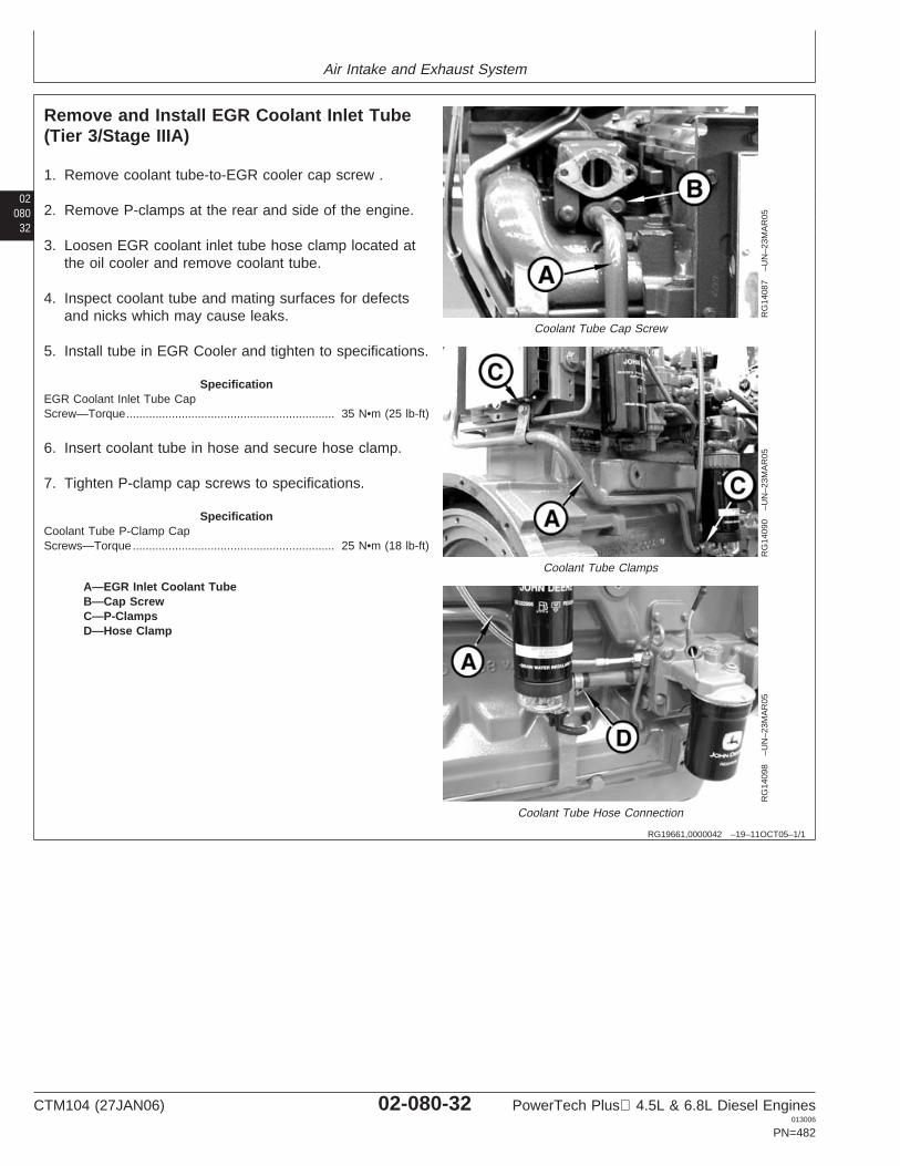
Air Intake and Exhaust System
02080
32
RG19661,0000042 –19–11OCT05–1/1
Remove and Install EGR Coolant Inlet Tube(Tier 3/Stage IIIA)
RG
1408
7–U
N–2
3MA
R05
Coolant Tube Cap Screw
RG
1409
0–U
N–2
3MA
R05
Coolant Tube Clamps
RG
1409
8–U
N–2
3MA
R05
Coolant Tube Hose Connection
A—EGR Inlet Coolant TubeB—Cap ScrewC—P-ClampsD—Hose Clamp
1. Remove coolant tube-to-EGR cooler cap screw .
2. Remove P-clamps at the rear and side of the engine.
3. Loosen EGR coolant inlet tube hose clamp located atthe oil cooler and remove coolant tube.
4. Inspect coolant tube and mating surfaces for defectsand nicks which may cause leaks.
5. Install tube in EGR Cooler and tighten to specifications.
SpecificationEGR Coolant Inlet Tube CapScrew—Torque 35 N•m (25 lb-ft)................................................................
6. Insert coolant tube in hose and secure hose clamp.
7. Tighten P-clamp cap screws to specifications.
SpecificationCoolant Tube P-Clamp CapScrews—Torque 25 N•m (18 lb-ft)..............................................................
CTM104 (27JAN06) 02-080-32 PowerTech Plus 4.5L & 6.8L Diesel Engines013006
PN=482
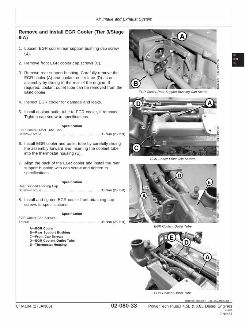
Air Intake and Exhaust System
0208033
RG19661,000003F –19–21MAR05–1/1
Remove and Install EGR Cooler (Tier 3/StageIIIA)
RG
1409
9–U
N–2
4MA
R05
EGR Cooler Rear Support Bushing Cap Screw
RG
1410
0–U
N–2
4MA
R05
EGR Cooler Front Cap Screws
RG
1410
2–U
N–2
4MA
R05
EGR Coolant Outlet Tube
RG
1410
1–U
N–2
4MA
R05
EGR Coolant Outlet Tube
A—EGR CoolerB—Rear Support BushingC—Front Cap ScrewsD—EGR Coolant Outlet TubeE—Thermostat Housing
1. Loosen EGR cooler rear support bushing cap screw(B).
2. Remove front EGR cooler cap screws (C).
3. Remove rear support bushing. Carefully remove theEGR cooler (A) and coolant outlet tube (D) as anassembly by sliding to the rear of the engine. Ifrequired, coolant outlet tube can be removed from theEGR cooler.
4. Inspect EGR cooler for damage and leaks.
5. Install coolant outlet tube to EGR cooler, if removed.Tighten cap screw to specifications.
SpecificationEGR Cooler Outlet Tube CapScrew—Torque 35 N•m (25 lb-ft)................................................................
6. Install EGR cooler and outlet tube by carefully slidingthe assembly forward and inserting the coolant tubeinto the thermostat housing (E).
7. Align the back of the EGR cooler and install the rearsupport bushing with cap screw and tighten tospecifications.
SpecificationRear Support Bushing CapScrew—Torque 35 N•m (25 lb-ft)................................................................
8. Install and tighten EGR cooler front attaching capscrews to specifications.
SpecificationEGR Cooler Cap Screws—Torque 35 N•m (25 lb-ft).............................................................................
CTM104 (27JAN06) 02-080-33 PowerTech Plus 4.5L & 6.8L Diesel Engines013006
PN=483
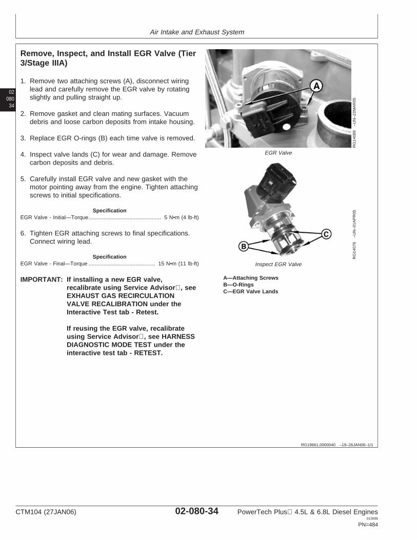
Air Intake and Exhaust System
02080
34
RG19661,0000040 –19–26JAN06–1/1
Remove, Inspect, and Install EGR Valve (Tier3/Stage IIIA)
RG
1408
9–U
N–2
2MA
R05
EGR Valve
RG
1407
6–U
N–0
1AP
R05
Inspect EGR Valve
A—Attaching ScrewsB—O-RingsC—EGR Valve Lands
1. Remove two attaching screws (A), disconnect wiringlead and carefully remove the EGR valve by rotatingslightly and pulling straight up.
2. Remove gasket and clean mating surfaces. Vacuumdebris and loose carbon deposits from intake housing.
3. Replace EGR O-rings (B) each time valve is removed.
4. Inspect valve lands (C) for wear and damage. Removecarbon deposits and debris.
5. Carefully install EGR valve and new gasket with themotor pointing away from the engine. Tighten attachingscrews to initial specifications.
SpecificationEGR Valve - Initial—Torque 5 N•m (4 lb-ft)................................................
6. Tighten EGR attaching screws to final specifications.Connect wiring lead.
SpecificationEGR Valve - Final—Torque 15 N•m (11 lb-ft)............................................
IMPORTANT: If installing a new EGR valve,recalibrate using Service Advisor, seeEXHAUST GAS RECIRCULATIONVALVE RECALIBRATION under theInteractive Test tab - Retest.
If reusing the EGR valve, recalibrateusing Service Advisor, see HARNESSDIAGNOSTIC MODE TEST under theinteractive test tab - RETEST.
CTM104 (27JAN06) 02-080-34 PowerTech Plus 4.5L & 6.8L Diesel Engines013006
PN=484
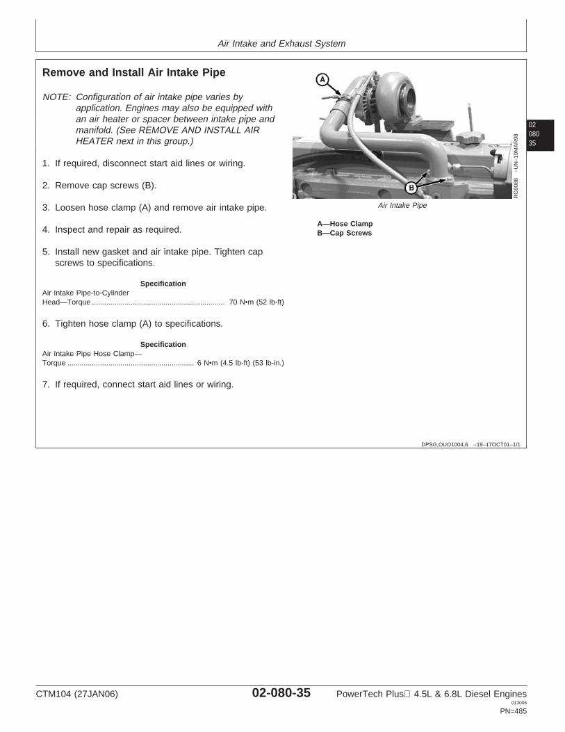
Air Intake and Exhaust System
0208035
DPSG,OUO1004,6 –19–17OCT01–1/1
Remove and Install Air Intake Pipe
RG
9088
–UN
–19M
AR
98
Air Intake Pipe
A—Hose ClampB—Cap Screws
NOTE: Configuration of air intake pipe varies byapplication. Engines may also be equipped withan air heater or spacer between intake pipe andmanifold. (See REMOVE AND INSTALL AIRHEATER next in this group.)
1. If required, disconnect start aid lines or wiring.
2. Remove cap screws (B).
3. Loosen hose clamp (A) and remove air intake pipe.
4. Inspect and repair as required.
5. Install new gasket and air intake pipe. Tighten capscrews to specifications.
SpecificationAir Intake Pipe-to-CylinderHead—Torque 70 N•m (52 lb-ft).................................................................
6. Tighten hose clamp (A) to specifications.
SpecificationAir Intake Pipe Hose Clamp—Torque 6 N•m (4.5 lb-ft) (53 lb-in.)..............................................................
7. If required, connect start aid lines or wiring.
CTM104 (27JAN06) 02-080-35 PowerTech Plus 4.5L & 6.8L Diesel Engines013006
PN=485
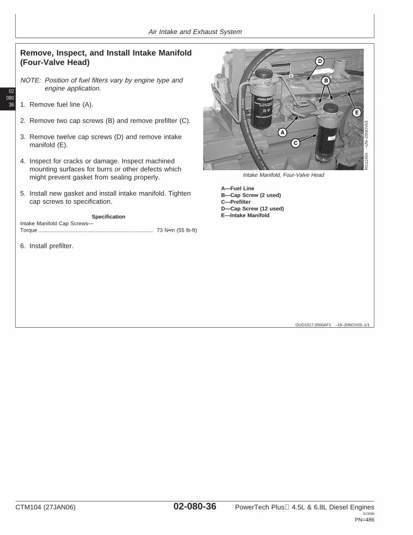
Air Intake and Exhaust System
02080
36
OUO1017,0000AF1 –19–20NOV03–1/1
Remove, Inspect, and Install Intake Manifold(Four-Valve Head)
RG
1240
4–U
N–2
5NO
V03
Intake Manifold, Four-Valve Head
A—Fuel LineB—Cap Screw (2 used)C—PrefilterD—Cap Screw (12 used)E—Intake Manifold
NOTE: Position of fuel filters vary by engine type andengine application.
1. Remove fuel line (A).
2. Remove two cap screws (B) and remove prefilter (C).
3. Remove twelve cap screws (D) and remove intakemanifold (E).
4. Inspect for cracks or damage. Inspect machinedmounting surfaces for burrs or other defects whichmight prevent gasket from sealing properly.
5. Install new gasket and install intake manifold. Tightencap screws to specification.
SpecificationIntake Manifold Cap Screws—Torque 73 N•m (55 lb-ft).............................................................................
6. Install prefilter.
CTM104 (27JAN06) 02-080-36 PowerTech Plus 4.5L & 6.8L Diesel Engines013006
PN=486
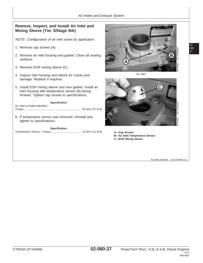
Air Intake and Exhaust System
0208037
RG19661,000003E –19–21MAR05–1/1
Remove, Inspect, and Install Air Inlet andMixing Sleeve (Tier 3/Stage IIIA)
RG
1408
3–U
N–2
1MA
R05
Air Inlet
RG
1408
4–U
N–2
1MA
R05
A—Cap ScrewsB—Air Inlet Temperature SensorC—EGR Mixing Sleeve
NOTE: Configuration of air inlet varies by application.
1. Remove cap screws (A).
2. Remove air inlet housing and gasket. Clean all sealingsurfaces.
3. Remove EGR mixing sleeve (C).
4. Inspect inlet housing and sleeve for cracks anddamage. Replace if required.
5. Install EGR mixing sleeve and new gasket. Install airinlet housing with temperature sensor (B) facingforward. Tighten cap screws to specifications.
SpecificationAir Inlet-to-Intake Manifold—Torque 50 N•m (37 lb-ft).............................................................................
6. If temperature sensor was removed, reinstall andtighten to specifications.
SpecificationTemperature Sensor—Torque 15 N•m (11 lb-ft).........................................
CTM104 (27JAN06) 02-080-37 PowerTech Plus 4.5L & 6.8L Diesel Engines013006
PN=487

Air Intake and Exhaust System
02080
38
RG19661,000003D –19–21MAR05–1/1
Remove, Inspect, and Install Intake Manifold(Tier 3/Stage IIIA)
RG
1407
9–U
N–2
1MA
R05
Intake Manifold for EGR
A—Fuel LinesB—Fuel Transfer PumpC—Fuel PrefilterD—Exhaust Tube Cap Screws (2)E—Wiring HarnessF—Cap Screws (12)G—Intake Manifold
NOTE: Position of fuel filters vary by engine type andengine application.
1. Remove fuel lines (A).
2. Remove fuel transfer pump (B).
3. Remove exhaust tube flange cap screws (D).
4. Remove wiring harness starter relay (E).
5. Remove fuel prefilter (C) and intake manifold (G) capscrews.
6. Inspect intake manifold for cracks or damage. Inspectmachined mounting surfaces for burrs or other defectswhich might prevent gasket from sealing properly.
7. Install new gasket and install intake manifold andprefilter. Tighten cap screws to specification.
SpecificationIntake Manifold Cap Screws—Torque 53 N•m (40 lb-ft).............................................................................
8. Install fuel transfer pump and fuel lines.
CTM104 (27JAN06) 02-080-38 PowerTech Plus 4.5L & 6.8L Diesel Engines013006
PN=488
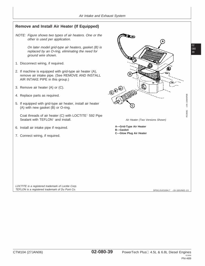
Air Intake and Exhaust System
0208039
DPSG,OUO1004,7 –19–18JUN02–1/1
Remove and Install Air Heater (If Equipped)
RG
9081
–UN
–16M
AR
98
Air Heater (Two Versions Shown)
A—Grid-Type Air HeaterB—GasketC—Glow Plug Air Heater
NOTE: Figure shows two types of air heaters. One or theother is used per application.
On later model grid-type air heaters, gasket (B) isreplaced by an O-ring, eliminating the need forground wire shown.
1. Disconnect wiring, if required.
2. If machine is equipped with grid-type air heater (A),remove air intake pipe. (See REMOVE AND INSTALLAIR INTAKE PIPE in this group.)
3. Remove air heater (A) or (C).
4. Replace parts as required.
5. If equipped with grid-type air heater, install air heater(A) with new gasket (B) or O-ring.
Coat threads of air heater (C) with LOCTITE 592 PipeSealant with TEFLON and install.
6. Install air intake pipe if required.
7. Connect wiring, if required.
LOCTITE is a registered trademark of Loctite Corp.TEFLON is a registered trademark of Du Pont Co.
CTM104 (27JAN06) 02-080-39 PowerTech Plus 4.5L & 6.8L Diesel Engines013006
PN=489
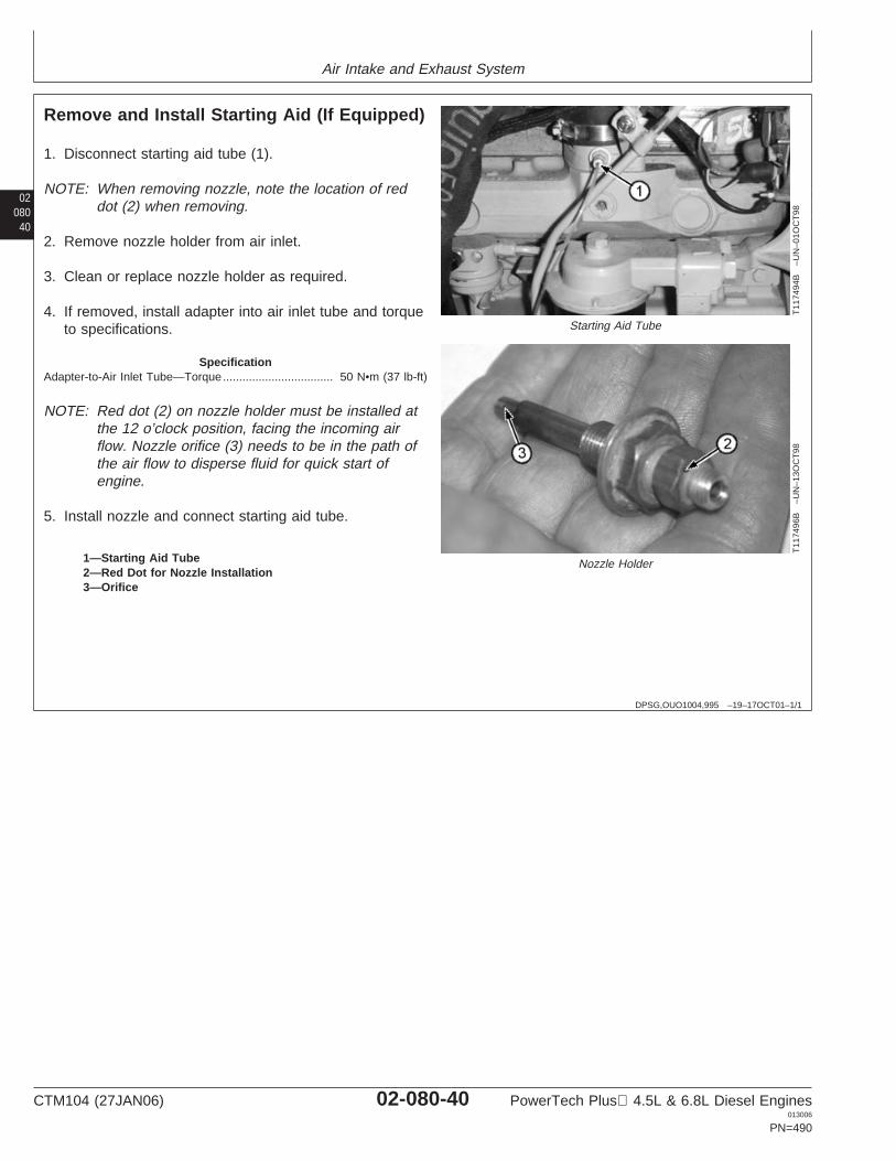
Air Intake and Exhaust System
02080
40
DPSG,OUO1004,995 –19–17OCT01–1/1
Remove and Install Starting Aid (If Equipped)
T11
7494
B–U
N–0
1OC
T98
Starting Aid Tube
T11
7496
B–U
N–1
3OC
T98
Nozzle Holder1—Starting Aid Tube2—Red Dot for Nozzle Installation3—Orifice
1. Disconnect starting aid tube (1).
NOTE: When removing nozzle, note the location of reddot (2) when removing.
2. Remove nozzle holder from air inlet.
3. Clean or replace nozzle holder as required.
4. If removed, install adapter into air inlet tube and torqueto specifications.
SpecificationAdapter-to-Air Inlet Tube—Torque 50 N•m (37 lb-ft)..................................
NOTE: Red dot (2) on nozzle holder must be installed atthe 12 o’clock position, facing the incoming airflow. Nozzle orifice (3) needs to be in the path ofthe air flow to disperse fluid for quick start ofengine.
5. Install nozzle and connect starting aid tube.
CTM104 (27JAN06) 02-080-40 PowerTech Plus 4.5L & 6.8L Diesel Engines013006
PN=490
Group 090Fuel System
020901
DPSG,OUO1004,2652 –19–29MAY02–1/1
Fuel System
NOTE: Repair, operation, diagnostics and testing of fuelsystems can be found in: CTM207—MechanicalFuel Systems, CTM170—Level 4 Electronic FuelSystems with Bosch VP44 Pump, CTM331—Level12 Electronic Fuel Systems with Stanadyne DE10Pump, CTM284—Level 1 Electronic Fuel Systemswith Delphi/Lucas DP201 Pump, CTM220—Level11 Electronic Fuel Systems with Denso HighPressure Common Rail or CTM320—Level 14Electronic Fuel Systems with Denso HighPressure Common Rail.
CTM104 (27JAN06) 02-090-1 PowerTech Plus 4.5L & 6.8L Diesel Engines013006
PN=491
Fuel System
02090
2
CTM104 (27JAN06) 02-090-2 PowerTech Plus 4.5L & 6.8L Diesel Engines013006
PN=492
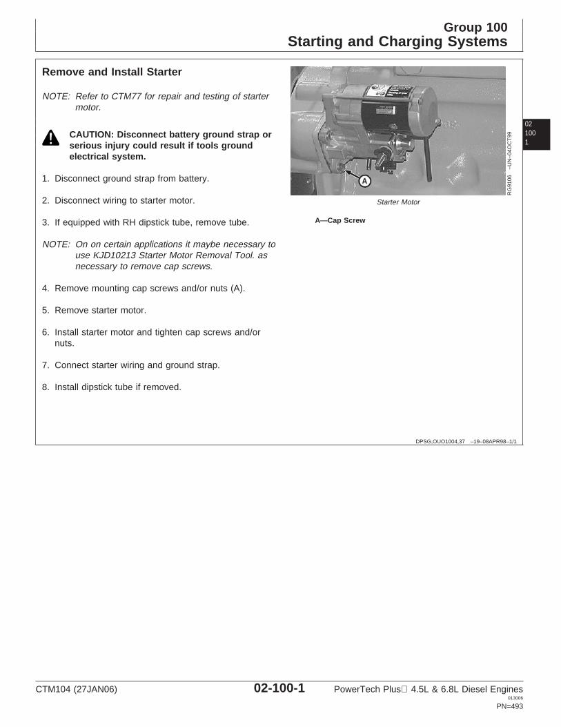
Group 100Starting and Charging Systems
021001
DPSG,OUO1004,37 –19–08APR98–1/1
Remove and Install Starter
RG
9106
–UN
–04O
CT
99
Starter Motor
A—Cap Screw
NOTE: Refer to CTM77 for repair and testing of startermotor.
CAUTION: Disconnect battery ground strap orserious injury could result if tools groundelectrical system.
1. Disconnect ground strap from battery.
2. Disconnect wiring to starter motor.
3. If equipped with RH dipstick tube, remove tube.
NOTE: On on certain applications it maybe necessary touse KJD10213 Starter Motor Removal Tool. asnecessary to remove cap screws.
4. Remove mounting cap screws and/or nuts (A).
5. Remove starter motor.
6. Install starter motor and tighten cap screws and/ornuts.
7. Connect starter wiring and ground strap.
8. Install dipstick tube if removed.
CTM104 (27JAN06) 02-100-1 PowerTech Plus 4.5L & 6.8L Diesel Engines013006
PN=493
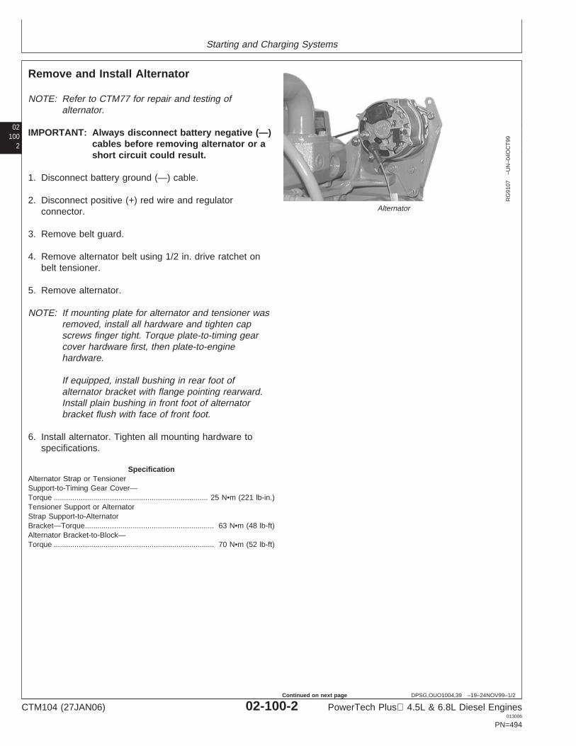
Starting and Charging Systems
02100
2
DPSG,OUO1004,39 –19–24NOV99–1/2
Remove and Install Alternator
RG
9107
–UN
–04O
CT
99
Alternator
NOTE: Refer to CTM77 for repair and testing ofalternator.
IMPORTANT: Always disconnect battery negative (—)cables before removing alternator or ashort circuit could result.
1. Disconnect battery ground (—) cable.
2. Disconnect positive (+) red wire and regulatorconnector.
3. Remove belt guard.
4. Remove alternator belt using 1/2 in. drive ratchet onbelt tensioner.
5. Remove alternator.
NOTE: If mounting plate for alternator and tensioner wasremoved, install all hardware and tighten capscrews finger tight. Torque plate-to-timing gearcover hardware first, then plate-to-enginehardware.
If equipped, install bushing in rear foot ofalternator bracket with flange pointing rearward.Install plain bushing in front foot of alternatorbracket flush with face of front foot.
6. Install alternator. Tighten all mounting hardware tospecifications.
SpecificationAlternator Strap or TensionerSupport-to-Timing Gear Cover—Torque 25 N•m (221 lb-in.)..........................................................................Tensioner Support or AlternatorStrap Support-to-AlternatorBracket—Torque 63 N•m (48 lb-ft)..............................................................Alternator Bracket-to-Block—Torque 70 N•m (52 lb-ft).............................................................................
CTM104 (27JAN06) 02-100-2 PowerTech Plus 4.5L & 6.8L Diesel Engines013006
PN=494
Continued on next page
Starting and Charging Systems
021003
DPSG,OUO1004,39 –19–24NOV99–2/2
NOTE: If engine is equipped with a manual belt tensioner,See MANUAL BELT TENSIONER ADJUSTMENTUSING BELT TENSION GAUGE in Group 070 forinstalling belt and adjusting tension duringalternator installation.
7. If removed, install alternator pulley and tighten pulleynut to specifications.
SpecificationAlternator Pulley Nut—Torque 80 N•m (60 lb-ft)........................................
8. Install alternator belt using 1/2 in. drive ratchet onautomatic belt tensioner.
9. Install belt guard.
10. Connect positive (+) red wire and regulator connector.
11. Connect battery ground (—) cable.
CTM104 (27JAN06) 02-100-3 PowerTech Plus 4.5L & 6.8L Diesel Engines013006
PN=495

Starting and Charging Systems
02100
4
CTM104 (27JAN06) 02-100-4 PowerTech Plus 4.5L & 6.8L Diesel Engines013006
PN=496
Section 03Theory of Operation
Contents
Page
Group 120—Base Engine OperationBase Engine Theory of Operation . . . . . . . . . .03-120-1 03General Engine Operation. . . . . . . . . . . . . . . .03-120-2General Engine Operation—Continued . . . . . .03-120-3Lubrication System Operation . . . . . . . . . . . . .03-120-6Cooling System Operation. . . . . . . . . . . . . . .03-120-10Head Gasket Joint Construction and
Operation. . . . . . . . . . . . . . . . . . . . . . . . . .03-120-14Air Intake and Exhaust System Operation . . .03-120-16Air Cleaner Operation . . . . . . . . . . . . . . . . . .03-120-19Turbocharger Operation . . . . . . . . . . . . . . . .03-120-20Variable Geometry Turbocharger (VGT)
Operation (Tier 3/Stage IIIA) . . . . . . . . . . .03-120-20How the Turbocharger Is Lubricated . . . . . . .03-120-21
CTM104 (27JAN06) 03-1 PowerTech Plus 4.5L & 6.8L Diesel Engines013006
PN=1
Contents
03
CTM104 (27JAN06) 03-2 PowerTech Plus 4.5L & 6.8L Diesel Engines013006
PN=2
Group 120Base Engine Operation
031201
RG19661,000000A –19–15JUN05–1/1
Base Engine Theory of Operation
NOTE: This group covers theory of operation on the baseengine only. For theory of operation onmechanical fuel systems, see CTM207(mechanical fuel systems). For theory of operationon electronic fuel systems, see CTM170 (Level 4electronic fuel systems with Bosch VP44 pump),CTM331 (Level 12 electronic fuel systems withStanadyne DE10 pump), CTM284 (Level 1electronic fuel systems with Delphi/Lucas DP201pump), CTM220 (Level 11 electronic fuel systemswith Denso high pressure common rail) orCTM320—Level 14 Electronic Fuel Systems withDenso High Pressure Common Rail .
CTM104 (27JAN06) 03-120-1 PowerTech Plus 4.5L & 6.8L Diesel Engines013006
PN=499
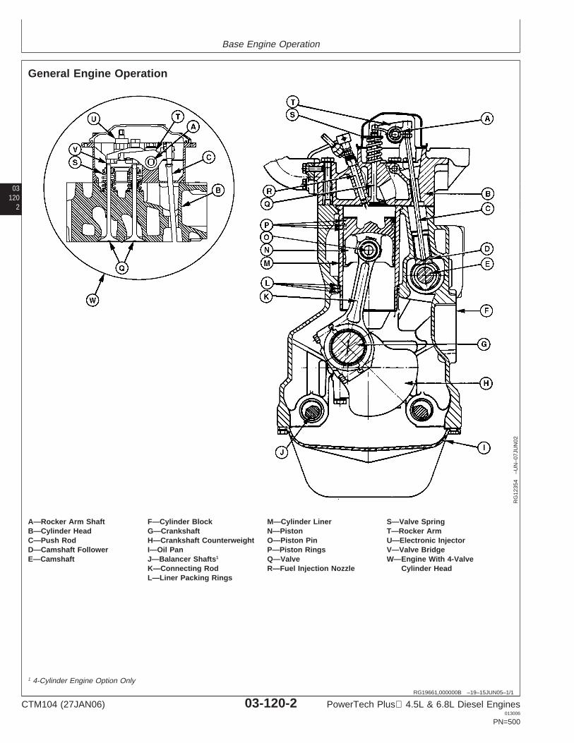
Base Engine Operation
03120
2
RG19661,000000B –19–15JUN05–1/1
General Engine Operation
RG
1235
4–U
N–0
7JU
N02
A—Rocker Arm Shaft F—Cylinder Block M—Cylinder Liner S—Valve SpringB—Cylinder Head G—Crankshaft N—Piston T—Rocker ArmC—Push Rod H—Crankshaft Counterweight O—Piston Pin U—Electronic InjectorD—Camshaft Follower I—Oil Pan P—Piston Rings V—Valve BridgeE—Camshaft J—Balancer Shafts1 Q—Valve W—Engine With 4-Valve
K—Connecting Rod R—Fuel Injection Nozzle Cylinder HeadL—Liner Packing Rings
1 4-Cylinder Engine Option Only
CTM104 (27JAN06) 03-120-2 PowerTech Plus 4.5L & 6.8L Diesel Engines013006
PN=500
Base Engine Operation
031203
RG19661,000000C –19–15JUN05–1/2
General Engine Operation—Continued
Engines are vertical, in-line, valve-in-head, 4-cycle(stroke) diesel engines.
Direct fuel injection is provided by a rotary-typeinjection pump, an in-line injection pump, or ahigh-pressure pump with common rail (4-valve headengines) and 9.5 mm injection nozzles or electronicinjectors mounted in cylinder head. The camshaft andinjection pump are timed to the crankshaft by thetiming gear train.
Some engines are equipped with a turbocharger. Theturbocharger uses energy from exhaust gases tocompress intake air and force it into the combustionchamber.
The cylinder block (F) is a one-piece casting. Theblock is available in structural and non-structuralconfigurations.
The camshaft (E) is timed to the crankshaft (G)through the timing gear train. The camshaft rotates inhoned bores in the cylinder block. All engines use abushing in No. 1 camshaft bore. The camshaft lobesdetermine the duration and lift of each valve, andoperate the fuel supply pump on rotary-type injectionpumps.
Intake and exhaust valves (Q) are operated bycamshaft followers (D), push rods (C) and rocker armassembly (T). Valve seat inserts in cylinder head areused for intake and exhaust valves.
NOTE: Engines with the four-valve head design (W)have four valves per cylinder—two intake andtwo exhaust. Each set of intake valves andexhaust valves are actuated by a single rockerarm using a valve bridge (V). (These engineshave “16V” or “24V” on their rocker arm covermedallions.)
The crankshaft (G) is a one-piece, heat-treated,nodular-iron or steel forging which operates in
replaceable two-piece main bearings. Crankshafts aredynamically balanced and are machined with undercutand rolled fillets. Two-piece main thrust bearing insertsare used to control crankshaft end play.
Cylinder liners (M) are “wet” sleeve type and areindividually replaceable. Liner packing rings (L) areused at the lower connection between cylinder blockand liners.
Pistons (N) are made of high-grade cast aluminumalloy with internal ribbing. The skirt is cam ground toallow for expansion during operation. The piston crownhas a cut-out combustion bowl with a truncated conecenter. All piston rings (P) are located above the pistonpin. Two compression rings and one oil control ring areused. The top compression ring is a keystone-shapedring, located close to the top of the piston for improvedengine performance.
The hardened, fully-floating piston pins (O) are held inplace by snap rings. Spray jets (piston cooling orifices)in cylinder block spray pressurized oil on the undersideof the piston to lubricate piston pins and cool pistons.
The forged steel connecting rods (K) have replaceablepin bushing and bearing inserts. Some connecting rodshave a tapered pin-end while others have a straightpin-end. Rods and caps have a tongue-and-groovejoint on earlier engines and a PRECISION JOINT onlater engines.
The engine is equipped with a gear-driven oil pumpand full-flow oil filter. On some engines the oil filter hasan internal bypass valve while others use a bypassvalve in the filter header. The bypass valve opens ifthe filter element becomes restricted. Engines areequipped with an oil cooler mounted on the right sideof the cylinder block. The engine is equipped with apressure regulator valve to relieve excessive pressurebuild-up in the main oil gallery, and a bypass valve toprevent oil starvation if the oil cooler and filter becomeplugged.
PRECISION JOINT is a trademark of Deere & Company
CTM104 (27JAN06) 03-120-3 PowerTech Plus 4.5L & 6.8L Diesel Engines013006
PN=501
Continued on next page
Base Engine Operation
RG19661,000000C –19–15JUN05–2/2
Balancer shafts (J) are used on some four-cylinderengines to reduce vibration. The two shafts rotate onbushings in cylinder block and are counter-rotating attwice engine speed.
The engine has a pressurized cooling system,consisting of radiator, coolant pump, multi-blade fan,and one, two or three thermostats.
03120
4
CTM104 (27JAN06) 03-120-4 PowerTech Plus 4.5L & 6.8L Diesel Engines013006
PN=502
Base Engine Operation
031205
CTM104 (27JAN06) 03-120-5 PowerTech Plus 4.5L & 6.8L Diesel Engines013006
PN=503
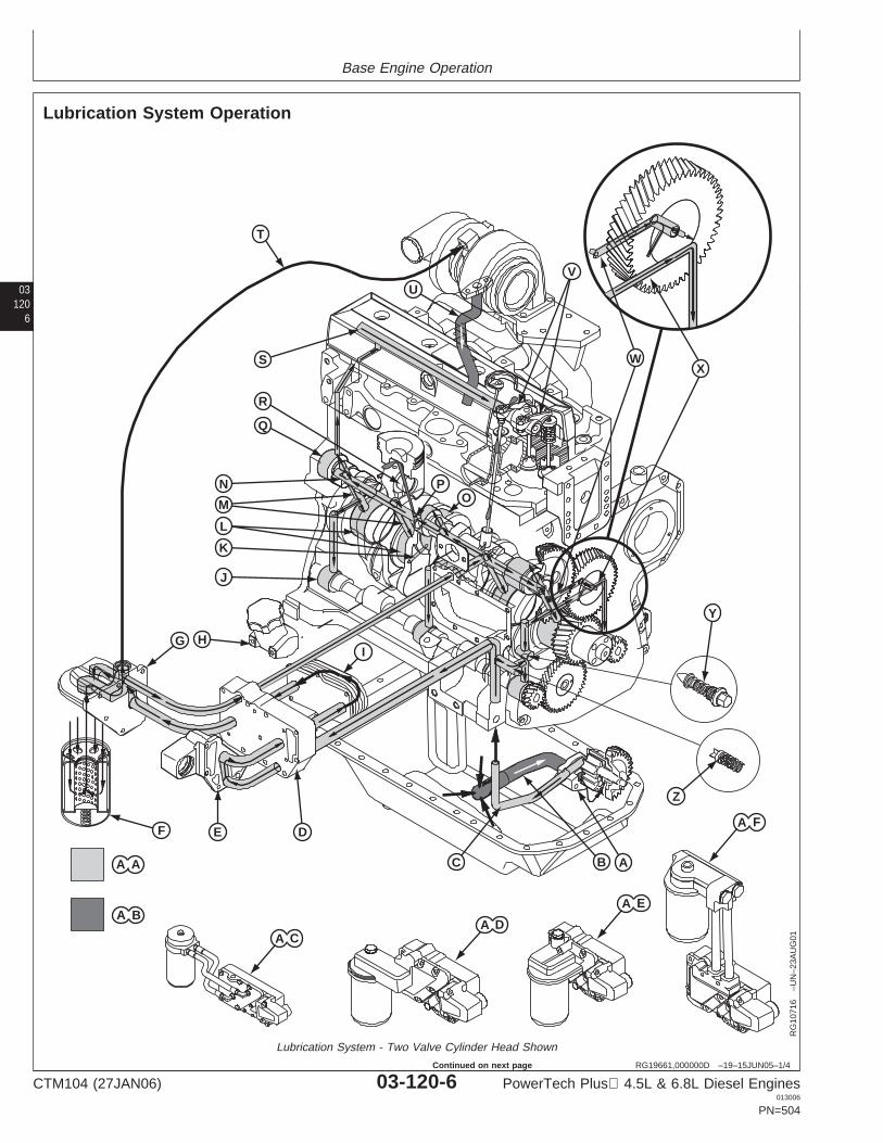
Base Engine Operation
03120
6
RG19661,000000D –19–15JUN05–1/4
Lubrication System Operation
A B
A A
U
ABC
E DF
G H
K
L
M
N
Q
R
S
T
Y
Z
I
OP
V
J
WX
A F
A E
A DA C
RG
1071
6–U
N–2
3AU
G01
Lubrication System - Two Valve Cylinder Head Shown
CTM104 (27JAN06) 03-120-6 PowerTech Plus 4.5L & 6.8L Diesel Engines013006
PN=504
Continued on next page
Base Engine Operation
031207
RG19661,000000D –19–15JUN05–2/4
A—Oil Pump J—Balancer Shaft Bushings T—Turbocharger Oil Supply AA—Pressurized OilB—Oil Suction Line K—Crankshaft Drilled Line AB—Pressure-Free OilC—Oil Outlet Tube Cross-Passages U—Turbocharger Drain Line AC—Remote Mount FilterD—Oil Cooler Housing L—Main Bearing Bushings V—Rocker Arms AssemblyE—Coolant Passage Adapter M—Oil Passages W—Machined Groove AD—Low-Mount Rear VerticalF—Oil Filter N—Main Oil Gallery X—Cross-Drillings Oil Filter AssemblyG—Oil Filter Header/Adapter1 O—Connecting Rod Bearings Y—Oil Pressure Regulating AE—Low-Mount Front VerticalH—Oil Fill Tube P—Piston Cooling Orifice Valve (Early Version Oil Filter AssemblyI—Oil Cooler Q—Camshaft Bushings Shown) AF—High-Mount Vertical Oil
R—Piston Pin and Bushing Z—Oil Bypass Valve Filter AssemblyS—Rocker Arm Shaft
1 Some oil filter headers/adapters have a built-in filter bypass valve.
Continued on next page
CTM104 (27JAN06) 03-120-7 PowerTech Plus 4.5L & 6.8L Diesel Engines013006
PN=505
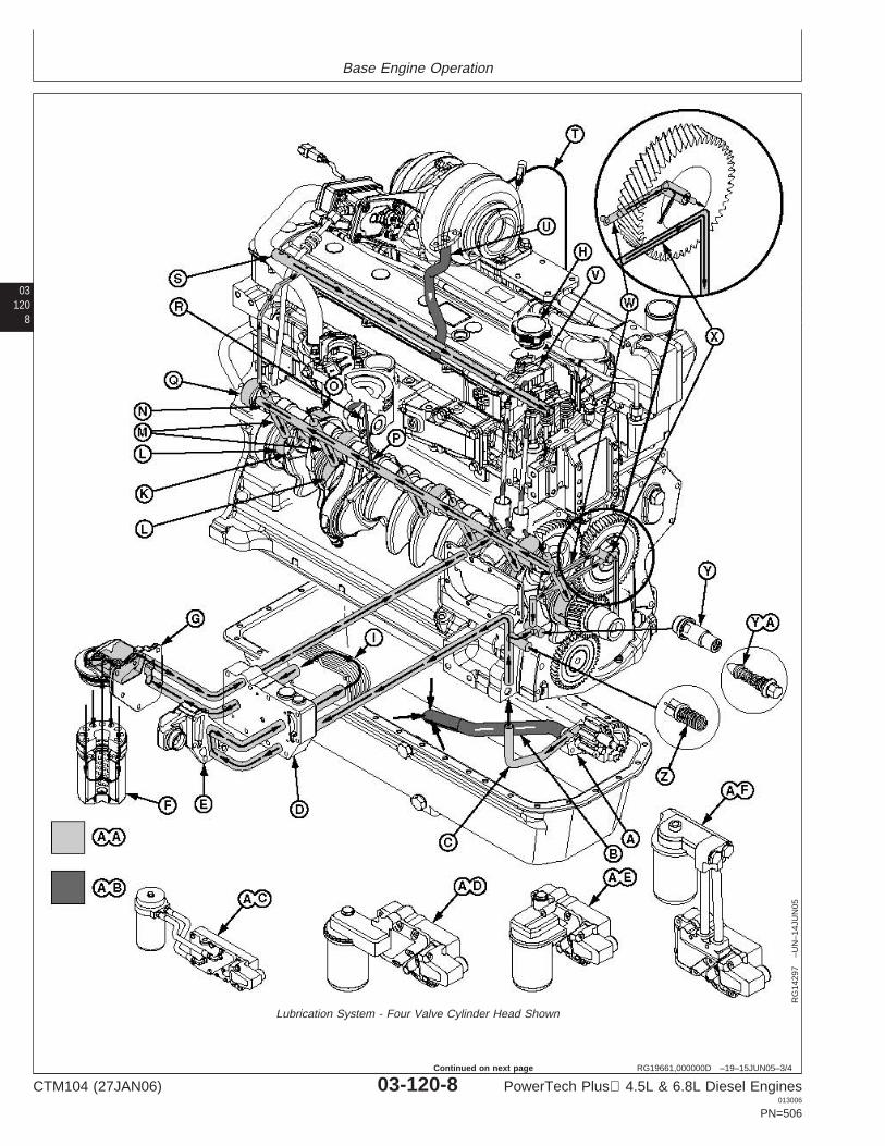
Base Engine Operation
03120
8
RG19661,000000D –19–15JUN05–3/4
RG
1429
7–U
N–1
4JU
N05
Lubrication System - Four Valve Cylinder Head Shown
CTM104 (27JAN06) 03-120-8 PowerTech Plus 4.5L & 6.8L Diesel Engines013006
PN=506
Continued on next page
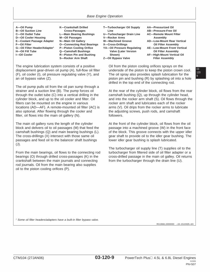
Base Engine Operation
031209
RG19661,000000D –19–15JUN05–4/4
A—Oil Pump K—Crankshaft Drilled T—Turbocharger Oil Supply AA—Pressurized OilB—Oil Suction Line Cross-Passages Line AB—Pressure-Free OilC—Oil Outlet Tube L—Main Bearing Bushings U—Turbocharger Drain Line AC—Remote Mount FilterD—Oil Cooler Housing M—Oil Passages V—Rocker Arms AssemblyE—Coolant Passage Adapter N—Main Oil Gallery W—Machined Groove AD—Low-Mount Rear VerticalF—Oil Filter O—Connecting Rod Bearings X—Cross-Drillings Oil Filter AssemblyG—Oil Filter Header/Adapter1 P—Piston Cooling Orifice YA—Oil Pressure Regulating AE—Low-Mount Front VerticalH—Oil Fill Tube Q—Camshaft Bushings Valve (Later Version Oil Filter AssemblyI—Oil Cooler R—Piston Pin and Bushing Shown) AF—High-Mount Vertical Oil
S—Rocker Arm Shaft Z—Oil Bypass Valve Filter Assembly
The engine lubrication system consists of a positivedisplacement gear-driven oil pump (A), full-flow oil filter(F), oil cooler (I), oil pressure regulating valve (Y), andan oil bypass valve (Z).
The oil pump pulls oil from the oil pan sump through astrainer and a suction line (B). The pump forces oilthrough the outlet tube (C) into a vertical drilling in thecylinder block, and up to the oil cooler and filter. Oilfilters can be mounted on the engine in variouslocations (AD—AF). A remote-mounted oil filter (AC) isalso optional. After flowing through the cooler andfilter, oil flows into the main oil gallery (N).
The main oil gallery runs the length of the cylinderblock and delivers oil to oil passages (M) that feed thecamshaft bushings (Q) and main bearing bushings (L).The cross-drillings (X) intersect with those same oilpassages and feed oil to the balancer shaft bushings(J).
From the main bearings, oil flows to the connecting rodbearings (O) through drilled cross-passages (K) in thecrankshaft between the main journals and connectingrod journals. Oil from the main bearing also suppliesoil to the piston cooling orifices (P).
Oil from the piston cooling orifices sprays on theunderside of the piston to keep the piston crown cool.The oil spray also provides splash lubrication for thepiston pin and bushing (R) by splashing oil into a holedrilled in the top end of the connecting rod.
At the rear of the cylinder block, oil flows from the rearcamshaft bushing (Q), up through the cylinder head,and into the rocker arm shaft (S). Oil flows through therocker arm shaft and lubricates each of the rockerarms (V). Oil drips from the rocker arms to lubricatethe adjusting screws, push rods, and camshaftfollowers.
At the front of the cylinder block, oil flows from the oilpassage into a machined groove (W) in the front faceof the block. This groove connects with the upper idlergear shaft to provide oil to the idler gear bushing. Thelower idler gear bushing is splash lubricated.
The turbocharger oil supply line (T) supplies oil to theturbocharger from filtered side of oil filter adapter or across-drilled passage in the main oil galley. Oil returnsfrom the turbocharger through the drain line (U).
1 Some oil filter headers/adapters have a built-in filter bypass valve.
CTM104 (27JAN06) 03-120-9 PowerTech Plus 4.5L & 6.8L Diesel Engines013006
PN=507
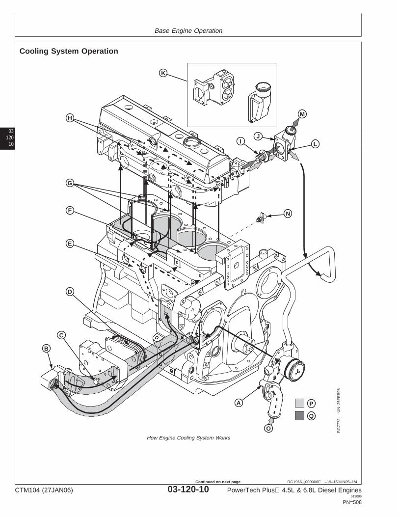
Base Engine Operation
03120
10
RG19661,000000E –19–15JUN05–1/4
Cooling System Operation
O
P
Q
H
K
IJ
L
M
N
A
B
C
D
E
F
G
RG
7772
–UN
–25F
EB
98
How Engine Cooling System Works
CTM104 (27JAN06) 03-120-10 PowerTech Plus 4.5L & 6.8L Diesel Engines013006
PN=508
Continued on next page
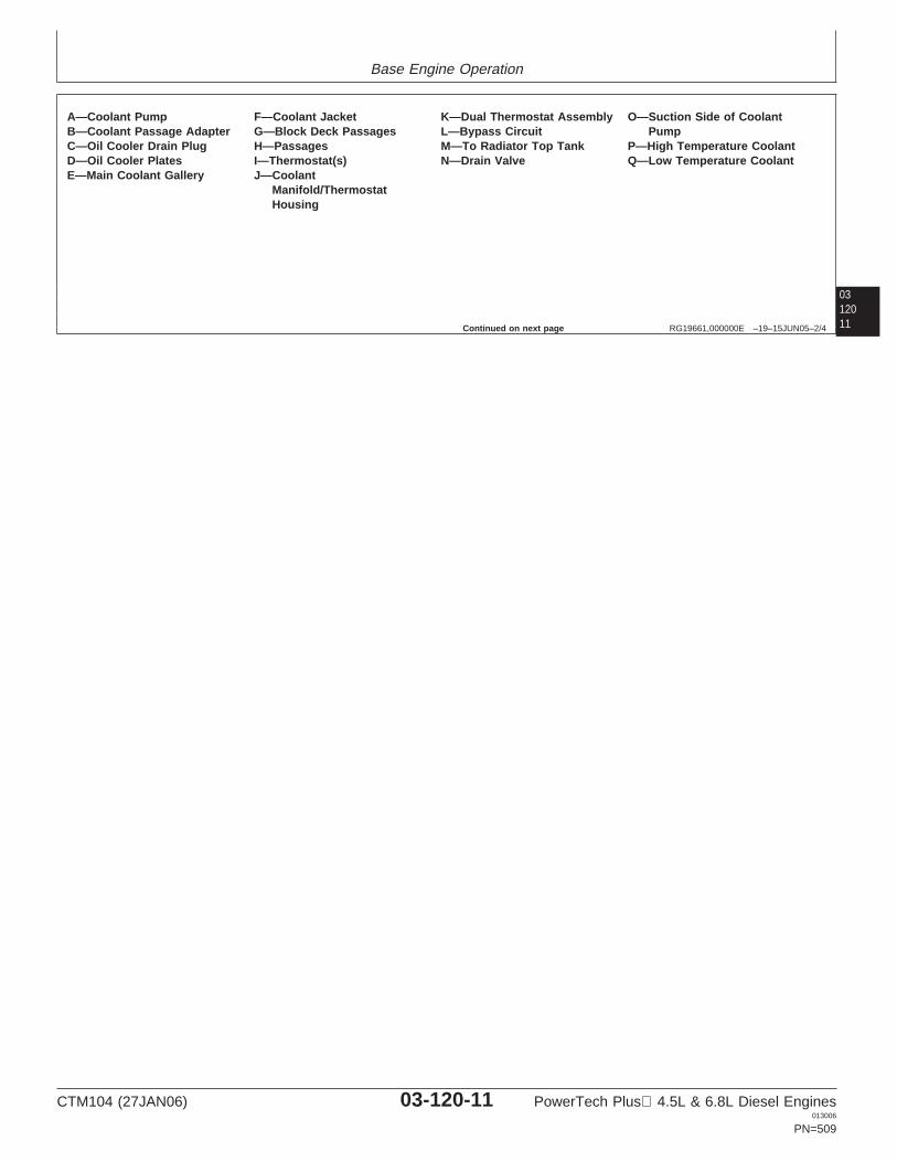
Base Engine Operation
0312011RG19661,000000E –19–15JUN05–2/4
A—Coolant Pump F—Coolant Jacket K—Dual Thermostat Assembly O—Suction Side of CoolantB—Coolant Passage Adapter G—Block Deck Passages L—Bypass Circuit PumpC—Oil Cooler Drain Plug H—Passages M—To Radiator Top Tank P—High Temperature CoolantD—Oil Cooler Plates I—Thermostat(s) N—Drain Valve Q—Low Temperature CoolantE—Main Coolant Gallery J—Coolant
Manifold/ThermostatHousing
Continued on next page
CTM104 (27JAN06) 03-120-11 PowerTech Plus 4.5L & 6.8L Diesel Engines013006
PN=509

Base Engine Operation
03120
12
RG19661,000000E –19–15JUN05–3/4
RG
1395
7–U
N–1
4JU
N05
Engine Coolant Flow with EGR Cooler(Tier 3/Stage IIIA Engines)
The cooling system includes the radiator, coolantpump (A), and thermostat(s) (I).
CTM104 (27JAN06) 03-120-12 PowerTech Plus 4.5L & 6.8L Diesel Engines013006
PN=510
Continued on next page
Base Engine Operation
0312013
RG19661,000000E –19–15JUN05–4/4
Coolant is circulated from the coolant pump into thecoolant passage adapter (B) and circulates around theoil cooler plates (D). From the oil cooler, coolant flowsinto the main coolant gallery (E). From the gallerycoolant flows into the coolant jacket (F), around thecylinder liners, up through the block deck passages(G), and into the cylinder head. In the cylinder head,the coolant flows through passages (H) around theintake and exhaust ports, valve seats, and injectionnozzles. Coolant flows toward the front end of thecylinder head and exits through the coolantmanifold/thermostat housing (J). Engines may beequipped with a dual thermostat assembly (K).
During the warm-up period, thermostat(s) (I) are closedand coolant is directed through a bypass circuit (L) intosuction side of coolant pump. The coolant continuescirculating through the cylinder block, cylinder head,and coolant pump to provide a uniform and fastwarm-up period.
Once the engine has reached operating temperature,the thermostat(s) open and allow coolant to flowthrough the upper radiator hose to the radiator top tank(M). Coolant circulates through the radiator, dissipatesheat, and then flows out of the radiator through thelower hose and into the suction side (O) of the coolantpump. Coolant continues flowing through the engineand radiator circuit until the coolant temperature dropsbelow the thermostat opening temperature.
On engines equipped with an EGR cooler, a portion ofthe coolant is circulated from the oil cooler, through theEGR cooler and back to the thermostat housing.Coolant flow is opposite exhaust gas flow and iscontrolled with a separate thermostat located in thethermostat housing. During the warm-up period, theEGR thermostat is closed and coolant circulatesthrough a bypass circuit in the thermostat housing tothe suction side of the water pump.
CTM104 (27JAN06) 03-120-13 PowerTech Plus 4.5L & 6.8L Diesel Engines013006
PN=511
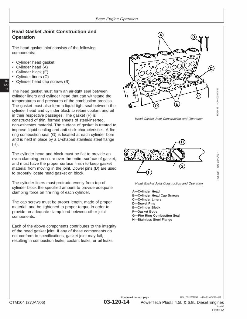
Base Engine Operation
03120
14
RG,105,JW7658 –19–21NOV97–1/2
Head Gasket Joint Construction andOperation
RG
6433
–UN
–03N
OV
97
Head Gasket Joint Construction and Operation
RG
6430
–UN
–03N
OV
97
Head Gasket Joint Construction and Operation
A—Cylinder HeadB—Cylinder Head Cap ScrewsC—Cylinder LinersD—Dowel PinsE—Cylinder BlockF—Gasket BodyG—Fire Ring Combustion SealH—Stainless Steel Flange
The head gasket joint consists of the followingcomponents:
• Cylinder head gasket• Cylinder head (A)• Cylinder block (E)• Cylinder liners (C)• Cylinder head cap screws (B)
The head gasket must form an air-tight seal betweencylinder liners and cylinder head that can withstand thetemperatures and pressures of the combustion process.The gasket must also form a liquid-tight seal between thecylinder head and cylinder block to retain coolant and oilin their respective passages. The gasket (F) isconstructed of thin, formed sheets of steel-inserted,non-asbestos material. The surface of gasket is treated toimprove liquid sealing and anti-stick characteristics. A firering combustion seal (G) is located at each cylinder boreand is held in place by a U-shaped stainless steel flange(H).
The cylinder head and block must be flat to provide aneven clamping pressure over the entire surface of gasket,and must have the proper surface finish to keep gasketmaterial from moving in the joint. Dowel pins (D) are usedto properly locate head gasket on block.
The cylinder liners must protrude evenly from top ofcylinder block the specified amount to provide adequateclamping force on fire ring of each cylinder.
The cap screws must be proper length, made of propermaterial, and be tightened to proper torque in order toprovide an adequate clamp load between other jointcomponents.
Each of the above components contributes to the integrityof the head gasket joint. If any of these components donot conform to specifications, gasket joint may fail,resulting in combustion leaks, coolant leaks, or oil leaks.
CTM104 (27JAN06) 03-120-14 PowerTech Plus 4.5L & 6.8L Diesel Engines013006
PN=512
Continued on next page
Base Engine Operation
0312015RG,105,JW7658 –19–21NOV97–2/2
Operating conditions such as coolant, oil, and combustiontemperatures, and combustion pressures can reduce theability of the head gasket joint to function properly. Failureof head gasket and mating parts may occur when coolantand oil temperatures become excessive, or whenabnormally high combustion temperatures and pressurespersist.
CTM104 (27JAN06) 03-120-15 PowerTech Plus 4.5L & 6.8L Diesel Engines013006
PN=513
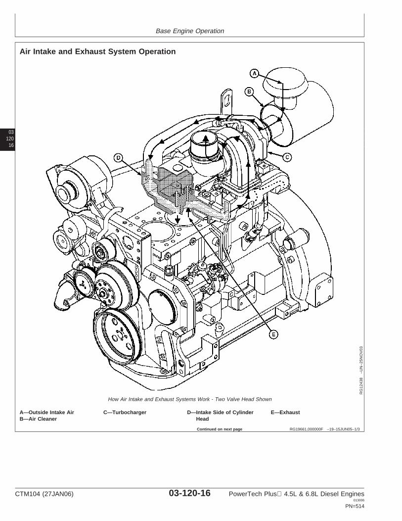
Base Engine Operation
03120
16
RG19661,000000F –19–15JUN05–1/3
Air Intake and Exhaust System Operation
RG
1243
8–U
N–2
5NO
V03
How Air Intake and Exhaust Systems Work - Two Valve Head Shown
A—Outside Intake Air C—Turbocharger D—Intake Side of Cylinder E—ExhaustB—Air Cleaner Head
Continued on next page
CTM104 (27JAN06) 03-120-16 PowerTech Plus 4.5L & 6.8L Diesel Engines013006
PN=514
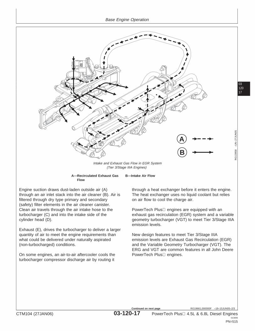
Base Engine Operation
0312017
RG19661,000000F –19–15JUN05–2/3
A
B
RG
1395
8–U
N–2
7JU
N05
Intake and Exhaust Gas Flow in EGR System(Tier 3/Stage IIIA Engines)
A—Recirculated Exhaust Gas B—Intake Air FlowFlow
Engine suction draws dust-laden outside air (A)through an air inlet stack into the air cleaner (B). Air isfiltered through dry type primary and secondary(safety) filter elements in the air cleaner canister.Clean air travels through the air intake hose to theturbocharger (C) and into the intake side of thecylinder head (D).
Exhaust (E), drives the turbocharger to deliver a largerquantity of air to meet the engine requirements thanwhat could be delivered under naturally aspirated(non-turbocharged) conditions.
On some engines, an air-to-air aftercooler cools theturbocharger compressor discharge air by routing it
through a heat exchanger before it enters the engine.The heat exchanger uses no liquid coolant but relieson air flow to cool the charge air.
PowerTech Plus engines are equipped with anexhaust gas recirculation (EGR) system and a variablegeometry turbocharger (VGT) to meet Tier 3/Stage IIIAemission levels.
New design features to meet Tier 3/Stage IIIAemission levels are Exhaust Gas Recirculation (EGR)and the Variable Geometry Turbocharger (VGT). TheERG and VGT are common features in all John DeerePowerTech Plus engines.
CTM104 (27JAN06) 03-120-17 PowerTech Plus 4.5L & 6.8L Diesel Engines013006
PN=515
Continued on next page
Base Engine Operation
03120
18
RG19661,000000F –19–15JUN05–3/3
The EGR and VGT are both performance andemission control features. The variable geometryturbocharger has adjustable vanes in the exhaustturbine housing. These vanes, controlled by acoolant-cooled electronic actuator, open and close todirect and recirculate exhaust gases. The gases thenpass through a cooler which is attached to the exhaustmanifold. The cooled exhaust gas are mixed with freshair by the EGR Valve located in the intake manifold.The Engine Control Unit (ECU) controls the quanity ofexhaust gas to be mixed with fresh intake air forcombustion. Under full load conditions as much as10—12% of the intake air is recirculated exhaustgases. The recirculation of exhaust gas allow theengine to run with higher boost pressure, increasingthe power output while reducing emissions.
TheVGT has foils or vanes located on pins on theoutside diameter of the turbine wheel. These vanesare adjustable, which allows exhaust gas pressure tobe increased or decreased based on the engine loaddemand and speed. The ECU controls an actuator thatis part of the turbocharger assembly. The actuatoradjusts the vanes to assure proper exhaust pressuresfor the correct amount of EGR and fresh air mixing.The actuator is cooled with engine coolant plumbedfrom the oil cooler housing and returned to thethermostat housing. The variable output of the VGTprovides the ability to increase low speed torque,provide a quicker transient response and increasepeak torque while improving fuel economy.
As engine speed and load demands increase, the ECUsignals the VGT actuator to close the vanes on theturbine wheel. This increases exhaust gas pressureand velocity which increases engine boost pressure.This increase in pressure limits smoke and reducesemission particles released to the atmosphere.
The EGR cooler is bolted to the exhaust manifold. Thiscooler operates much like a radiator or charge aircooler, having internal fins which allow circulation of
engine coolant to cool the exhaust gas. The cooler is acounterflow design, as engine coolant flows in theopposite direction of the exhaust gas. After enginecoolant passes through the cooler, it is returned to thethermostat housing. The exhaust gas enter the coolerat approximately 600° C (1112° F) and exit atapproximately 200° C (392° F).
The cooled exhaust gas passes through an EGR valvewhich is located in the intake manifold. The function ofthe EGR valve, controlled by the engine ECU, is to mixgiven volumes of exhaust gas with fresh intake air.The mixture of exhaust gas and fresh intake air servestwo purposes: (1) . The VGT increases engine boostas the vanes close allowing more air to be introducedinto the combustion chamber. This, in turn, allowsmore fuel to be introduced to the combustion process,increasing power output. (2). Diluting the intake air withas much as 10—12% exhaust gas (full load conditions)helps control NOX emissions released into theatmosphere after combustion.
The EGR valve is functional only when the engine isunder load and the coolant is at operating temperature.At start-up when the engine coolant is cold, and underno-load or light load conditions, the valve remainsclosed and exhaust gases exit through the muffler.When engine load and/or speed demands reach apredetermined level, the ECU signals the EGR valve toopen. The valve then mixes the proper amount ofcooled exhaust gas with cooled intake air and releasesthis mixture to the intake manifold for combustion.
The EGR valve, VGT, exhaust and intake manifoldconditions are closely monitored by sensors. Thesensors are monitored by the ECU and fault codes aregenerated if conditions exceed design guidelines.Sensors include: exhaust gas temperature, charge airtemperature, mixed air (intake air and exhaust gas)temperature, intake manifold air pressure and exhaustmanifold pressure.
CTM104 (27JAN06) 03-120-18 PowerTech Plus 4.5L & 6.8L Diesel Engines013006
PN=516
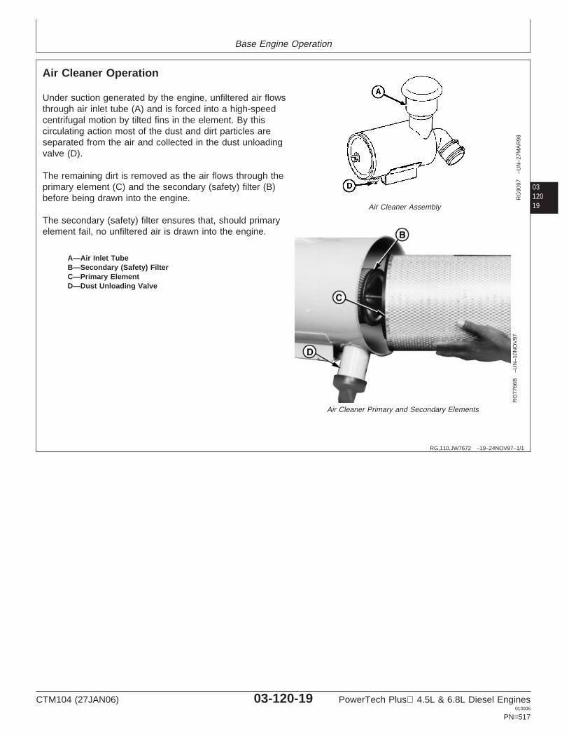
Base Engine Operation
0312019
RG,110,JW7672 –19–24NOV97–1/1
Air Cleaner Operation
RG
9097
–UN
–27M
AR
98
Air Cleaner Assembly
RG
7766
B–U
N–1
0NO
V97
Air Cleaner Primary and Secondary Elements
A—Air Inlet TubeB—Secondary (Safety) FilterC—Primary ElementD—Dust Unloading Valve
Under suction generated by the engine, unfiltered air flowsthrough air inlet tube (A) and is forced into a high-speedcentrifugal motion by tilted fins in the element. By thiscirculating action most of the dust and dirt particles areseparated from the air and collected in the dust unloadingvalve (D).
The remaining dirt is removed as the air flows through theprimary element (C) and the secondary (safety) filter (B)before being drawn into the engine.
The secondary (safety) filter ensures that, should primaryelement fail, no unfiltered air is drawn into the engine.
CTM104 (27JAN06) 03-120-19 PowerTech Plus 4.5L & 6.8L Diesel Engines013006
PN=517
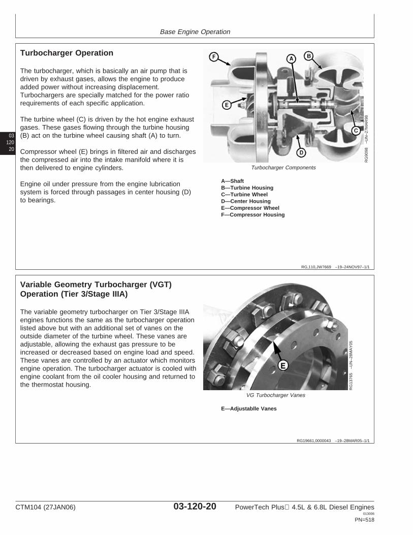
Base Engine Operation
03120
20
RG,110,JW7669 –19–24NOV97–1/1
Turbocharger Operation
RG
9098
–UN
–27M
AR
98
Turbocharger Components
A—ShaftB—Turbine HousingC—Turbine WheelD—Center HousingE—Compressor WheelF—Compressor Housing
The turbocharger, which is basically an air pump that isdriven by exhaust gases, allows the engine to produceadded power without increasing displacement.Turbochargers are specially matched for the power ratiorequirements of each specific application.
The turbine wheel (C) is driven by the hot engine exhaustgases. These gases flowing through the turbine housing(B) act on the turbine wheel causing shaft (A) to turn.
Compressor wheel (E) brings in filtered air and dischargesthe compressed air into the intake manifold where it isthen delivered to engine cylinders.
Engine oil under pressure from the engine lubricationsystem is forced through passages in center housing (D)to bearings.
RG19661,0000043 –19–28MAR05–1/1
Variable Geometry Turbocharger (VGT)Operation (Tier 3/Stage IIIA)
RG
1376
5–U
N–2
8MA
Y05
VG Turbocharger Vanes
E—Adjustablle Vanes
The variable geometry turbocharger on Tier 3/Stage IIIAengines functions the same as the turbocharger operationlisted above but with an additional set of vanes on theoutside diameter of the turbine wheel. These vanes areadjustable, allowing the exhaust gas pressure to beincreased or decreased based on engine load and speed.These vanes are controlled by an actuator which monitorsengine operation. The turbocharger actuator is cooled withengine coolant from the oil cooler housing and returned tothe thermostat housing.
CTM104 (27JAN06) 03-120-20 PowerTech Plus 4.5L & 6.8L Diesel Engines013006
PN=518
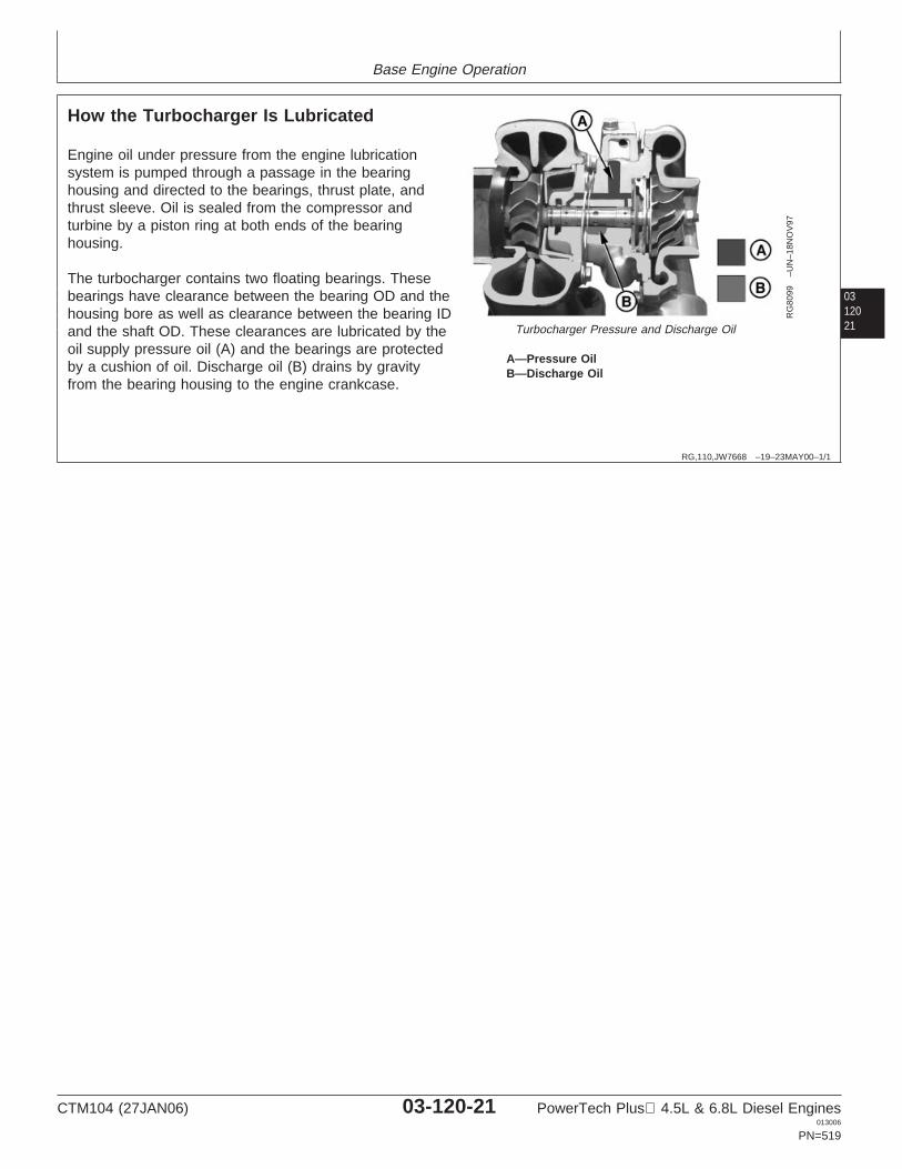
Base Engine Operation
0312021
RG,110,JW7668 –19–23MAY00–1/1
How the Turbocharger Is Lubricated
RG
8099
–UN
–18N
OV
97
Turbocharger Pressure and Discharge Oil
A—Pressure OilB—Discharge Oil
Engine oil under pressure from the engine lubricationsystem is pumped through a passage in the bearinghousing and directed to the bearings, thrust plate, andthrust sleeve. Oil is sealed from the compressor andturbine by a piston ring at both ends of the bearinghousing.
The turbocharger contains two floating bearings. Thesebearings have clearance between the bearing OD and thehousing bore as well as clearance between the bearing IDand the shaft OD. These clearances are lubricated by theoil supply pressure oil (A) and the bearings are protectedby a cushion of oil. Discharge oil (B) drains by gravityfrom the bearing housing to the engine crankcase.
CTM104 (27JAN06) 03-120-21 PowerTech Plus 4.5L & 6.8L Diesel Engines013006
PN=519
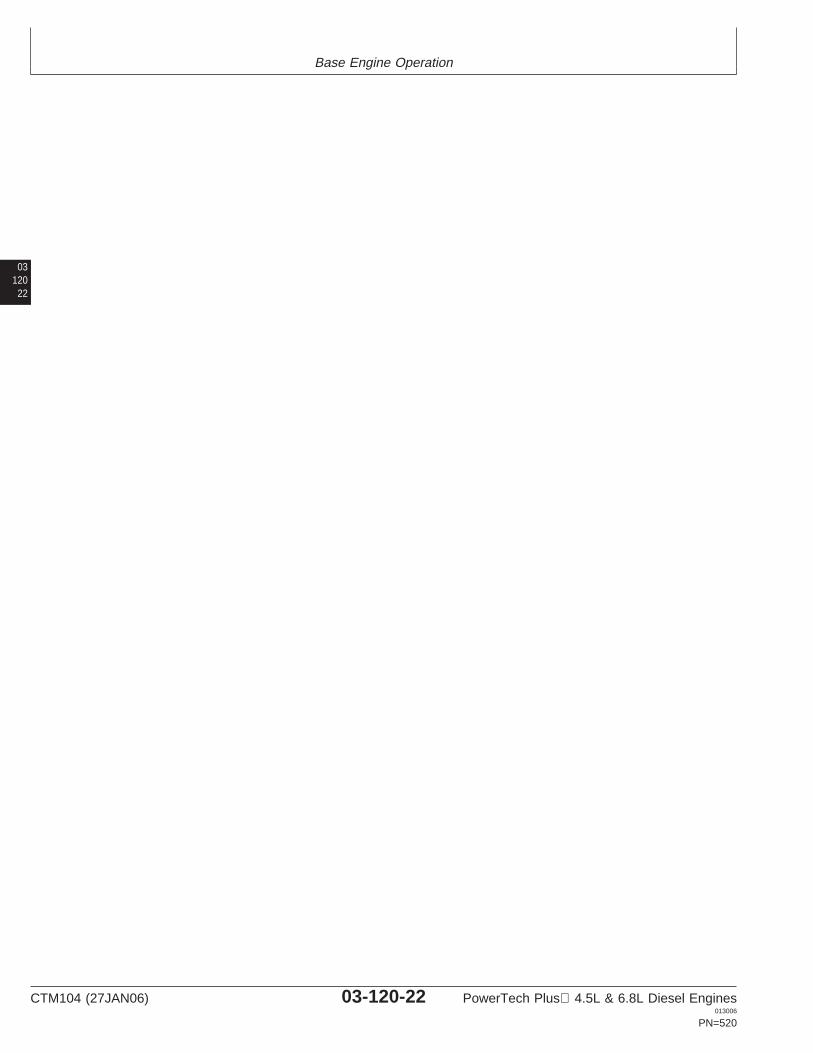
Base Engine Operation
03120
22
CTM104 (27JAN06) 03-120-22 PowerTech Plus 4.5L & 6.8L Diesel Engines013006
PN=520
Section 04Diagnostics
Contents
Page
Group 150—Observable Diagnostics and TestsAbout This Section of the Manual . . . . . . . . . .04-150-1Guideline for Acceptable Oil Consumption . . .04-150-24.5L/6.8L - L1 - Excessive Oil
Consumption . . . . . . . . . . . . . . . . . . . . . . . .04-150-24.5L/6.8L - L2 - Engine Oil Pressure Low . . . .04-150-64.5L/6.8L - L3 - Engine Oil Pressure High. . . .04-150-8
044.5L/6.8L - C1 - Engine Coolant TemperatureAbove Normal . . . . . . . . . . . . . . . . . . . . . . .04-150-9
4.5L/6.8L - C2 - Engine Coolant TemperatureBelow Normal . . . . . . . . . . . . . . . . . . . . . .04-150-10
4.5L/6.8L - C3 - Coolant in Oil or Oil inCoolant . . . . . . . . . . . . . . . . . . . . . . . . . . .04-150-10
Test Engine Compression Pressure . . . . . . .04-150-11Test Engine Cranking Speed. . . . . . . . . . . . .04-150-14Dynamometer Test . . . . . . . . . . . . . . . . . . . .04-150-15Engine Oil Consumption . . . . . . . . . . . . . . . .04-150-16Check Engine Oil Pressure . . . . . . . . . . . . . .04-150-17Check for Excessive Engine Crankcase
Pressure (Blow-By) . . . . . . . . . . . . . . . . . .04-150-19Check for Turbocharger Oil Seal Leak . . . . .04-150-20Inspect Thermostat and Test Opening
Temperature . . . . . . . . . . . . . . . . . . . . . . .04-150-21Pressure Test Cooling System and
Radiator Cap . . . . . . . . . . . . . . . . . . . . . . .04-150-22Pressure Test EGR Cooler for Air Leaks. . . .04-150-23Check for Head Gasket Failures . . . . . . . . . .04-150-24Check and Service Cooling System . . . . . . .04-150-27Check Air Intake System. . . . . . . . . . . . . . . .04-150-29Measure Intake Manifold Pressure
(Turbocharger Boost for Tier 3/Stage IIIAEngines) . . . . . . . . . . . . . . . . . . . . . . . . . .04-150-30
Measure Intake Manifold Pressure(Turbocharger Boost/Power Check) . . . . . .04-150-30
Check for Intake and ExhaustRestrictions . . . . . . . . . . . . . . . . . . . . . . . .04-150-33
Test for Intake Air Leaks . . . . . . . . . . . . . . . .04-150-34Check for Exhaust Air Leaks (Turbocharged
Engines) . . . . . . . . . . . . . . . . . . . . . . . . . .04-150-35Test Turbocharger Wastegate . . . . . . . . . . . .04-150-36Test Air Filter Restriction Indicator Switch . . .04-150-36
CTM104 (27JAN06) 04-1 PowerTech Plus 4.5L & 6.8L Diesel Engines013006
PN=1
Contents
04
CTM104 (27JAN06) 04-2 PowerTech Plus 4.5L & 6.8L Diesel Engines013006
PN=2
Group 150Observable Diagnostics and Tests
041501
DPSG,RG40854,512 –19–06MAR00–1/1
About This Section of the Manual
This section of the manual contains necessaryinformation to diagnose some base engine, alllubrication system and all cooling system problems.This section is divided into two areas: diagnosingmalfunctions and testing procedures. The diagnosingmalfunction areas are further divided into the followingheadings, containing the following symptoms:
• (L) Diagnosing Lubrication System Malfunctions:– L1 - Excessive Oil Consumption– L2 - Engine Oil Pressure Low– L3 - Engine Oil Pressure High
• (C) Diagnosing Cooling System Malfunctions:– C1 - Coolant Temperature Above Normal– C2 - Coolant Temperature Below Normal– C3 - Coolant in Oil or Oil in Coolant
Procedures for diagnosing some of the abovesymptoms are formatted such that a test or repair isrecommended, then, based on the results, another testor repair is recommended. Other symptoms areformatted in a symptom - problem - solution format. Inthese symptoms, the problems are arranged in themost likely or easiest to check first. Symptomsarranged in both formats refer to testing procedures inthe second part of this section. The second part of thissection contains the following testing procedures:
• Base Engine Testing Procedures:– Test Engine Compression Pressure– Test Engine Cranking Speed– Dynamometer Test
• Lubrications System Testing Procedures:– Engine Oil Consumption– Check Engine Oil Pressure– Check for Excessive Crankcase Pressure
(Blow-By)– Check for Turbocharger Oil Seal Leak
• Cooling System Testing Procedures:– Inspect Thermostat and Test Opening
Temperature– Pressure Test Cooling System and Radiator Cap– Check for Head Gasket Failures– Check and Service Cooling System
• Air Supply and Exhaust Systems TestingProcedures:– Check Air Intake System– Measure Intake Manifold Pressure (Turbo Boost)– Check for Intake and Exhaust Restrictions– Test for Intake Air Leaks– Check for Exhaust Leaks (Turbocharger Engines)– Test Turbocharger Wastegate– Test Air Filter Restriction Indicator Switch
CTM104 (27JAN06) 04-150-1 PowerTech Plus 4.5L & 6.8L Diesel Engines013006
PN=523
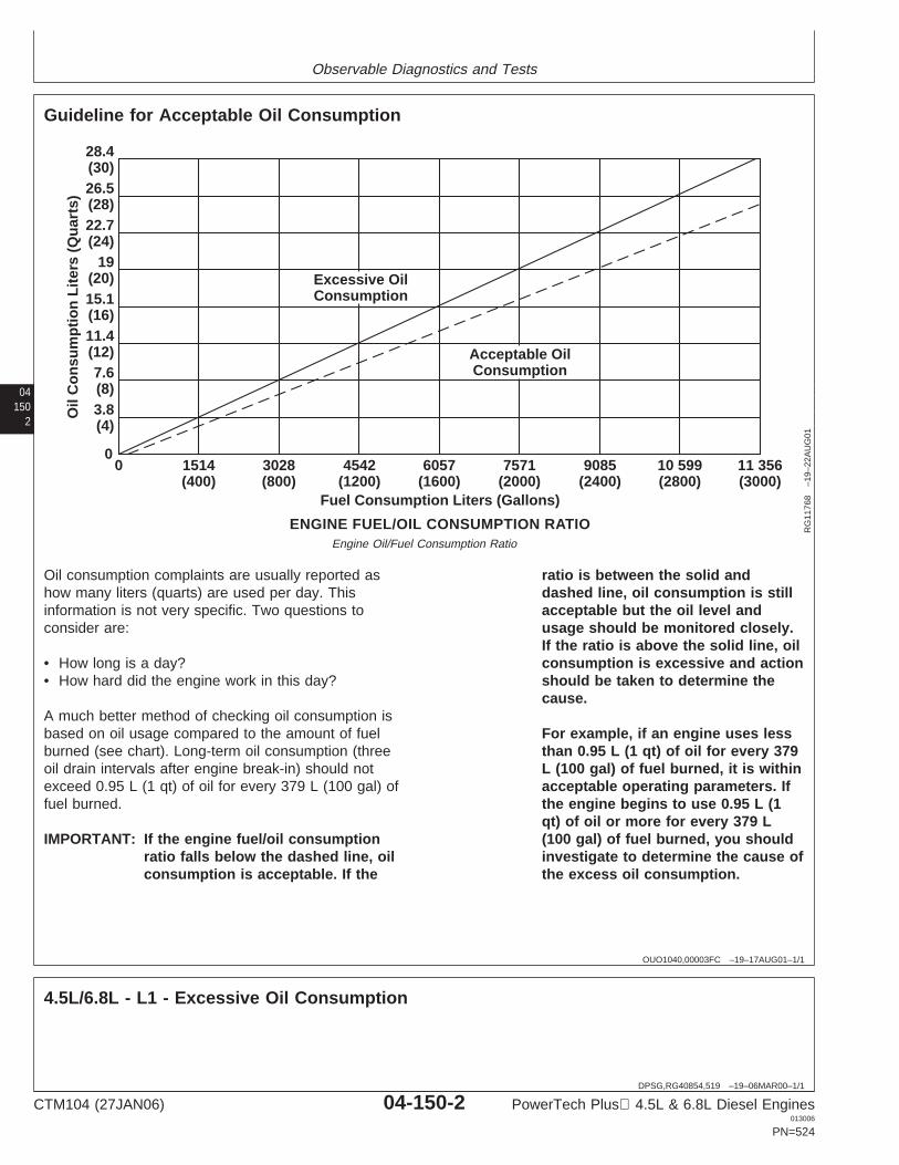
Observable Diagnostics and Tests
04150
2
OUO1040,00003FC –19–17AUG01–1/1
Guideline for Acceptable Oil Consumption
1514(400)
28.4(30)26.5(28)22.7(24)
19(20)15.1(16)11.4(12)7.6(8)3.8(4)
03028(800)
4542(1200)
6057(1600)
7571(2000)
9085(2400)
10 599(2800)
11 356(3000)
0
ENGINE FUEL/OIL CONSUMPTION RATIO
Fuel Consumption Liters (Gallons)
Oil
Con
sum
ptio
n Li
ters
(Q
uart
s)
Acceptable OilConsumption
Excessive OilConsumption
RG
1176
8–1
9–22
AU
G01
Engine Oil/Fuel Consumption Ratio
Oil consumption complaints are usually reported ashow many liters (quarts) are used per day. Thisinformation is not very specific. Two questions toconsider are:
• How long is a day?• How hard did the engine work in this day?
A much better method of checking oil consumption isbased on oil usage compared to the amount of fuelburned (see chart). Long-term oil consumption (threeoil drain intervals after engine break-in) should notexceed 0.95 L (1 qt) of oil for every 379 L (100 gal) offuel burned.
IMPORTANT: If the engine fuel/oil consumptionratio falls below the dashed line, oilconsumption is acceptable. If the
ratio is between the solid anddashed line, oil consumption is stillacceptable but the oil level andusage should be monitored closely.If the ratio is above the solid line, oilconsumption is excessive and actionshould be taken to determine thecause.
For example, if an engine uses lessthan 0.95 L (1 qt) of oil for every 379L (100 gal) of fuel burned, it is withinacceptable operating parameters. Ifthe engine begins to use 0.95 L (1qt) of oil or more for every 379 L(100 gal) of fuel burned, you shouldinvestigate to determine the cause ofthe excess oil consumption.
DPSG,RG40854,519 –19–06MAR00–1/1
4.5L/6.8L - L1 - Excessive Oil Consumption
CTM104 (27JAN06) 04-150-2 PowerTech Plus 4.5L & 6.8L Diesel Engines013006
PN=524
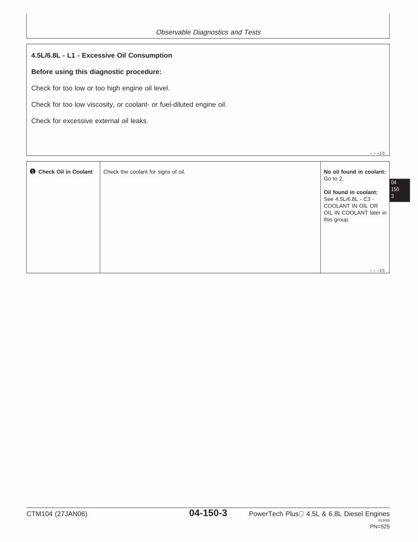
Observable Diagnostics and Tests
– – –1/1
4.5L/6.8L - L1 - Excessive Oil Consumption
Before using this diagnostic procedure:
Check for too low or too high engine oil level.
Check for too low viscosity, or coolant- or fuel-diluted engine oil.
Check for excessive external oil leaks.
041503
– – –1/1
1 Check Oil in Coolant Check the coolant for signs of oil. No oil found in coolant:Go to 2.
Oil found in coolant:See 4.5L/6.8L - C3 -COOLANT IN OIL OROIL IN COOLANT later inthis group.
CTM104 (27JAN06) 04-150-3 PowerTech Plus 4.5L & 6.8L Diesel Engines013006
PN=525
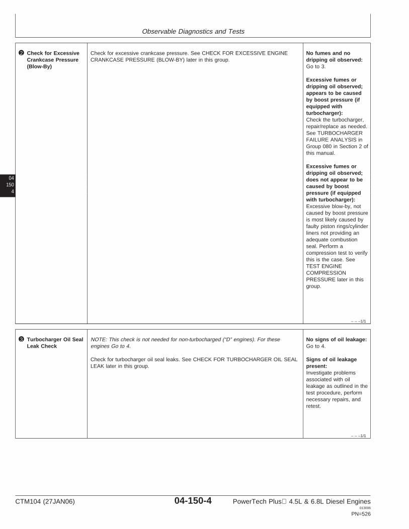
Observable Diagnostics and Tests
04150
4
– – –1/1
2 Check for ExcessiveCrankcase Pressure(Blow-By)
Check for excessive crankcase pressure. See CHECK FOR EXCESSIVE ENGINECRANKCASE PRESSURE (BLOW-BY) later in this group.
No fumes and nodripping oil observed:Go to 3.
Excessive fumes ordripping oil observed;appears to be causedby boost pressure (ifequipped withturbocharger):Check the turbocharger,repair/replace as needed.See TURBOCHARGERFAILURE ANALYSIS inGroup 080 in Section 2 ofthis manual.
Excessive fumes ordripping oil observed;does not appear to becaused by boostpressure (if equippedwith turbocharger):Excessive blow-by, notcaused by boost pressureis most likely caused byfaulty piston rings/cylinderliners not providing anadequate combustionseal. Perform acompression test to verifythis is the case. SeeTEST ENGINECOMPRESSIONPRESSURE later in thisgroup.
– – –1/1
3 Turbocharger Oil SealLeak Check
NOTE: This check is not needed for non-turbocharged (“D” engines). For theseengines Go to 4.
Check for turbocharger oil seal leaks. See CHECK FOR TURBOCHARGER OIL SEALLEAK later in this group.
No signs of oil leakage:Go to 4.
Signs of oil leakagepresent:Investigate problemsassociated with oilleakage as outlined in thetest procedure, performnecessary repairs, andretest.
CTM104 (27JAN06) 04-150-4 PowerTech Plus 4.5L & 6.8L Diesel Engines013006
PN=526
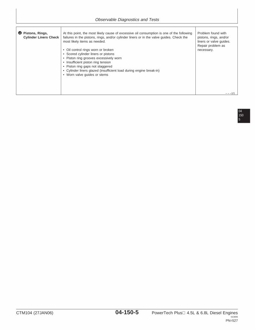
Observable Diagnostics and Tests
– – –1/1
4 Pistons, Rings,Cylinder Liners Check
At this point, the most likely cause of excessive oil consumption is one of the followingfailures in the pistons, rings, and/or cylinder liners or in the valve guides. Check themost likely items as needed.
• Oil control rings worn or broken• Scored cylinder liners or pistons• Piston ring grooves excessively worn• Insufficient piston ring tension• Piston ring gaps not staggered• Cylinder liners glazed (insufficient load during engine break-in)• Worn valve guides or stems
Problem found withpistons, rings, and/orliners or valve guides.Repair problem asnecessary.
041505
CTM104 (27JAN06) 04-150-5 PowerTech Plus 4.5L & 6.8L Diesel Engines013006
PN=527
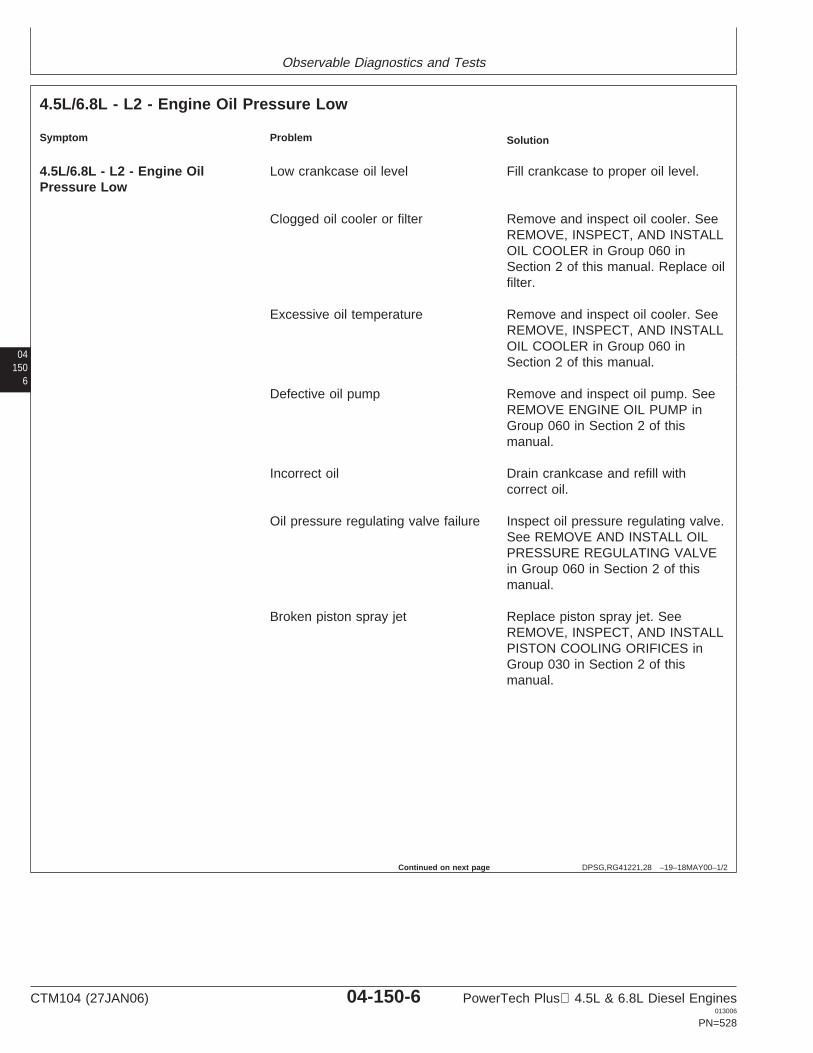
Observable Diagnostics and Tests
04150
6
DPSG,RG41221,28 –19–18MAY00–1/2
4.5L/6.8L - L2 - Engine Oil Pressure Low
Symptom Problem Solution
4.5L/6.8L - L2 - Engine Oil Low crankcase oil level Fill crankcase to proper oil level.Pressure Low
Clogged oil cooler or filter Remove and inspect oil cooler. SeeREMOVE, INSPECT, AND INSTALLOIL COOLER in Group 060 inSection 2 of this manual. Replace oilfilter.
Excessive oil temperature Remove and inspect oil cooler. SeeREMOVE, INSPECT, AND INSTALLOIL COOLER in Group 060 inSection 2 of this manual.
Defective oil pump Remove and inspect oil pump. SeeREMOVE ENGINE OIL PUMP inGroup 060 in Section 2 of thismanual.
Incorrect oil Drain crankcase and refill withcorrect oil.
Oil pressure regulating valve failure Inspect oil pressure regulating valve.See REMOVE AND INSTALL OILPRESSURE REGULATING VALVEin Group 060 in Section 2 of thismanual.
Broken piston spray jet Replace piston spray jet. SeeREMOVE, INSPECT, AND INSTALLPISTON COOLING ORIFICES inGroup 030 in Section 2 of thismanual.
Continued on next page
CTM104 (27JAN06) 04-150-6 PowerTech Plus 4.5L & 6.8L Diesel Engines013006
PN=528
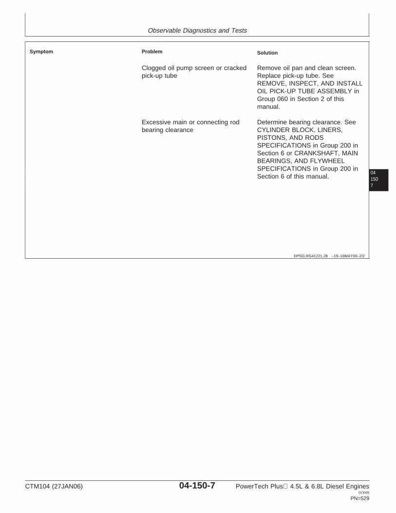
Observable Diagnostics and Tests
041507
DPSG,RG41221,28 –19–18MAY00–2/2
Symptom Problem Solution
Clogged oil pump screen or cracked Remove oil pan and clean screen.pick-up tube Replace pick-up tube. See
REMOVE, INSPECT, AND INSTALLOIL PICK-UP TUBE ASSEMBLY inGroup 060 in Section 2 of thismanual.
Excessive main or connecting rod Determine bearing clearance. Seebearing clearance CYLINDER BLOCK, LINERS,
PISTONS, AND RODSSPECIFICATIONS in Group 200 inSection 6 or CRANKSHAFT, MAINBEARINGS, AND FLYWHEELSPECIFICATIONS in Group 200 inSection 6 of this manual.
CTM104 (27JAN06) 04-150-7 PowerTech Plus 4.5L & 6.8L Diesel Engines013006
PN=529
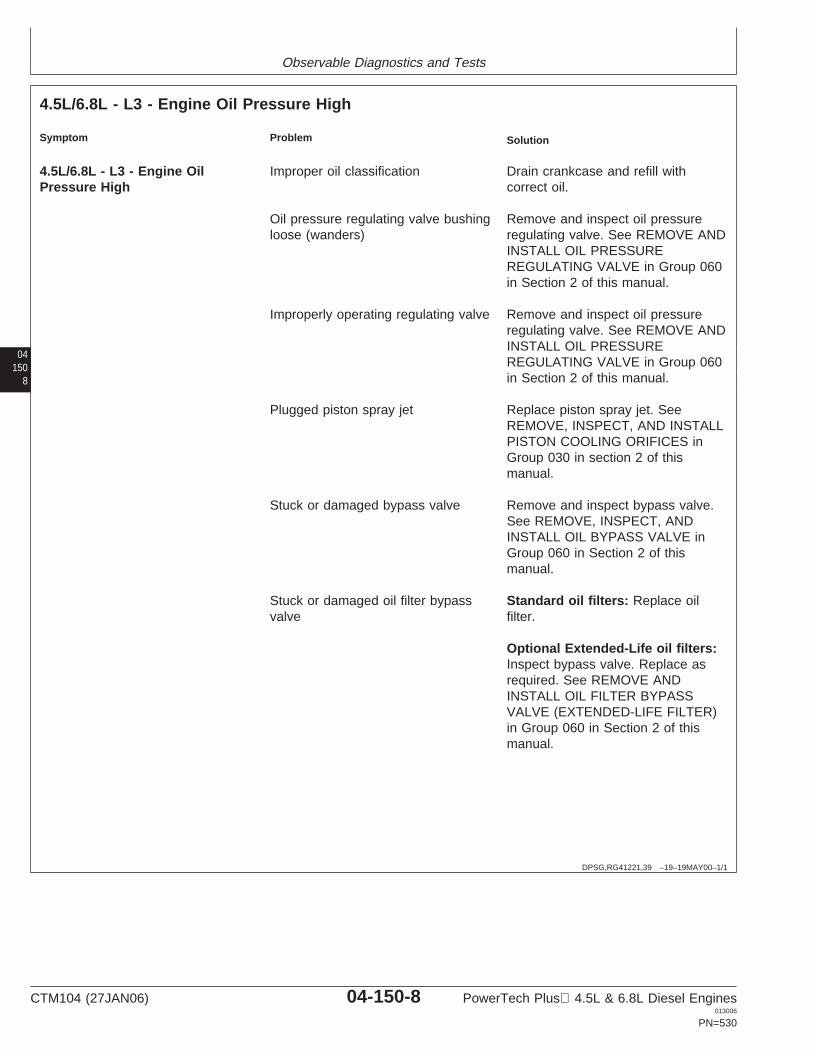
Observable Diagnostics and Tests
04150
8
DPSG,RG41221,39 –19–19MAY00–1/1
4.5L/6.8L - L3 - Engine Oil Pressure High
Symptom Problem Solution
4.5L/6.8L - L3 - Engine Oil Improper oil classification Drain crankcase and refill withPressure High correct oil.
Oil pressure regulating valve bushing Remove and inspect oil pressureloose (wanders) regulating valve. See REMOVE AND
INSTALL OIL PRESSUREREGULATING VALVE in Group 060in Section 2 of this manual.
Improperly operating regulating valve Remove and inspect oil pressureregulating valve. See REMOVE ANDINSTALL OIL PRESSUREREGULATING VALVE in Group 060in Section 2 of this manual.
Plugged piston spray jet Replace piston spray jet. SeeREMOVE, INSPECT, AND INSTALLPISTON COOLING ORIFICES inGroup 030 in section 2 of thismanual.
Stuck or damaged bypass valve Remove and inspect bypass valve.See REMOVE, INSPECT, ANDINSTALL OIL BYPASS VALVE inGroup 060 in Section 2 of thismanual.
Stuck or damaged oil filter bypass Standard oil filters: Replace oilvalve filter.
Optional Extended-Life oil filters:Inspect bypass valve. Replace asrequired. See REMOVE ANDINSTALL OIL FILTER BYPASSVALVE (EXTENDED-LIFE FILTER)in Group 060 in Section 2 of thismanual.
CTM104 (27JAN06) 04-150-8 PowerTech Plus 4.5L & 6.8L Diesel Engines013006
PN=530
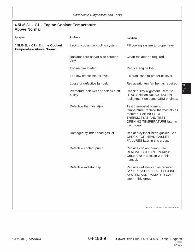
Observable Diagnostics and Tests
041509
DPSG,RG41221,40 –19–26NOV03–1/1
4.5L/6.8L - C1 - Engine Coolant TemperatureAbove Normal
Symptom Problem Solution
4.5L/6.8L - C1 - Engine Coolant Lack of coolant in cooling system Fill cooling system to proper level.Temperature Above Normal
Radiator core and/or side screens Clean radiator as required.dirty
Engine overloaded Reduce engine load.
Too low crankcase oil level Fill crankcase to proper oil level.
Loose or defective fan belt Replace/tighten fan belt as required.
Premature belt wear or belt flies off Check pulley alignment. Refer topulley DTAC Solution No. K001230 for
realignment on some OEM engines.
Defective thermostat(s) Test thermostat openingtemperature; replace thermostats asrequired. See INSPECTTHERMOSTAT AND TESTOPENING TEMPERATURE later inthis group.
Damaged cylinder head gasket Replace cylinder head gasket. SeeCHECK FOR HEAD GASKETFAILURES later in this group.
Defective coolant pump Replace coolant pump. SeeREMOVE COOLANT PUMP inGroup 070 in Section 2 of thismanual.
Defective radiator cap Replace radiator cap as required.See PRESSURE TEST COOLINGSYSTEM AND RADIATOR CAPlater in this group.
CTM104 (27JAN06) 04-150-9 PowerTech Plus 4.5L & 6.8L Diesel Engines013006
PN=531
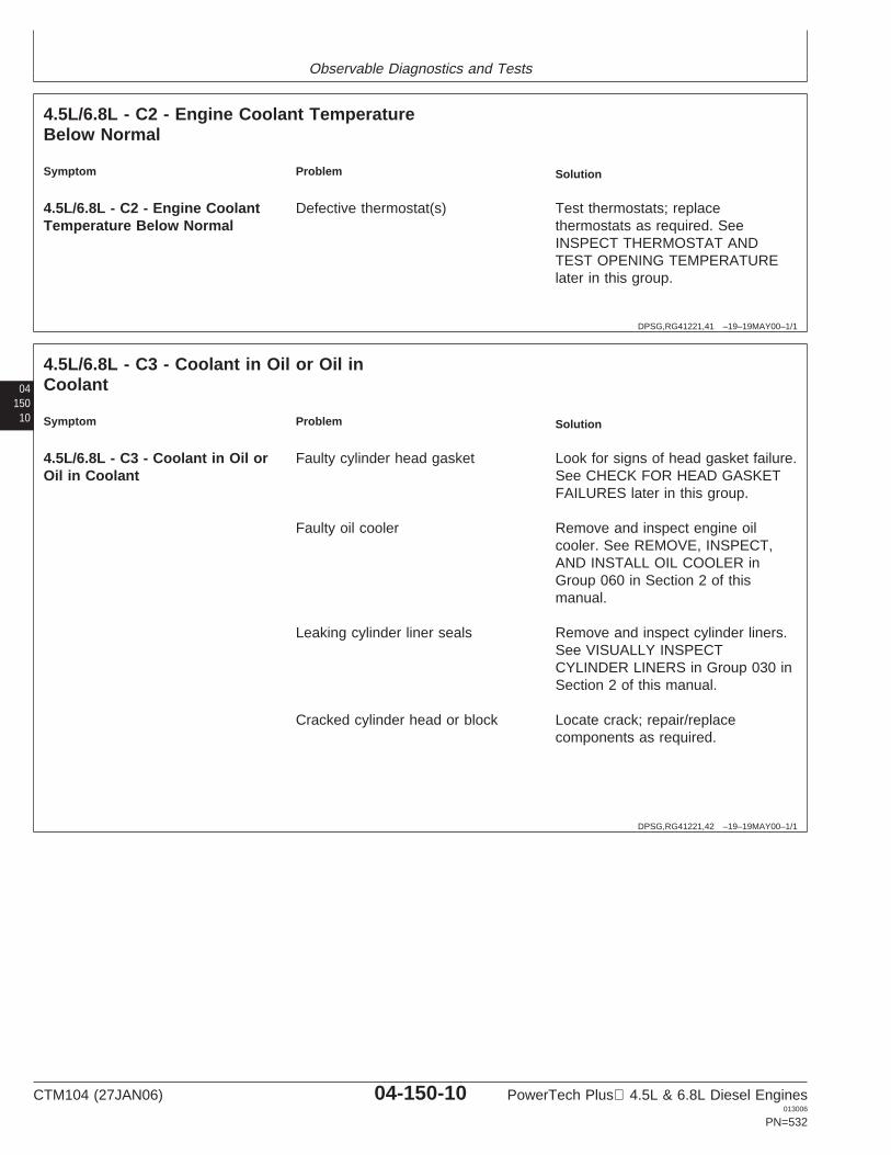
Observable Diagnostics and Tests
DPSG,RG41221,41 –19–19MAY00–1/1
4.5L/6.8L - C2 - Engine Coolant TemperatureBelow Normal
Symptom Problem Solution
4.5L/6.8L - C2 - Engine Coolant Defective thermostat(s) Test thermostats; replaceTemperature Below Normal thermostats as required. See
INSPECT THERMOSTAT ANDTEST OPENING TEMPERATURElater in this group.
04150
10
DPSG,RG41221,42 –19–19MAY00–1/1
4.5L/6.8L - C3 - Coolant in Oil or Oil inCoolant
Symptom Problem Solution
4.5L/6.8L - C3 - Coolant in Oil or Faulty cylinder head gasket Look for signs of head gasket failure.Oil in Coolant See CHECK FOR HEAD GASKET
FAILURES later in this group.
Faulty oil cooler Remove and inspect engine oilcooler. See REMOVE, INSPECT,AND INSTALL OIL COOLER inGroup 060 in Section 2 of thismanual.
Leaking cylinder liner seals Remove and inspect cylinder liners.See VISUALLY INSPECTCYLINDER LINERS in Group 030 inSection 2 of this manual.
Cracked cylinder head or block Locate crack; repair/replacecomponents as required.
CTM104 (27JAN06) 04-150-10 PowerTech Plus 4.5L & 6.8L Diesel Engines013006
PN=532
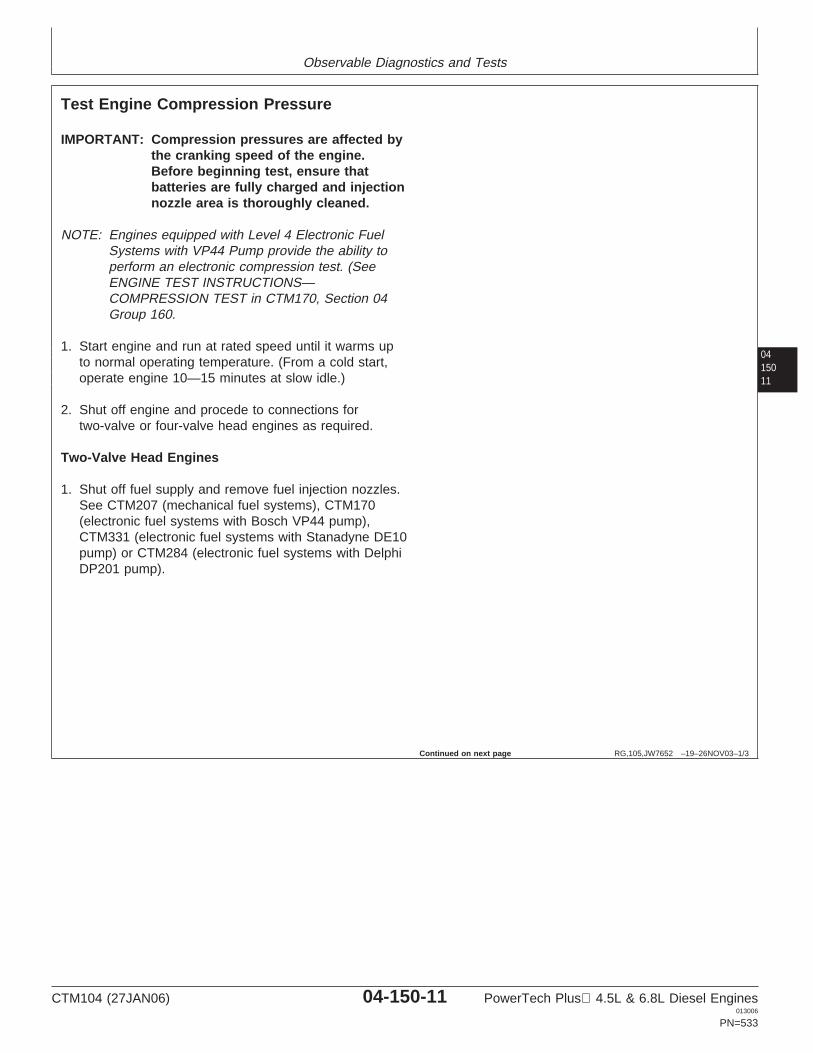
Observable Diagnostics and Tests
0415011
RG,105,JW7652 –19–26NOV03–1/3
Test Engine Compression Pressure
IMPORTANT: Compression pressures are affected bythe cranking speed of the engine.Before beginning test, ensure thatbatteries are fully charged and injectionnozzle area is thoroughly cleaned.
NOTE: Engines equipped with Level 4 Electronic FuelSystems with VP44 Pump provide the ability toperform an electronic compression test. (SeeENGINE TEST INSTRUCTIONS—COMPRESSION TEST in CTM170, Section 04Group 160.
1. Start engine and run at rated speed until it warms upto normal operating temperature. (From a cold start,operate engine 10—15 minutes at slow idle.)
2. Shut off engine and procede to connections fortwo-valve or four-valve head engines as required.
Two-Valve Head Engines
1. Shut off fuel supply and remove fuel injection nozzles.See CTM207 (mechanical fuel systems), CTM170(electronic fuel systems with Bosch VP44 pump),CTM331 (electronic fuel systems with Stanadyne DE10pump) or CTM284 (electronic fuel systems with DelphiDP201 pump).
Continued on next page
CTM104 (27JAN06) 04-150-11 PowerTech Plus 4.5L & 6.8L Diesel Engines013006
PN=533
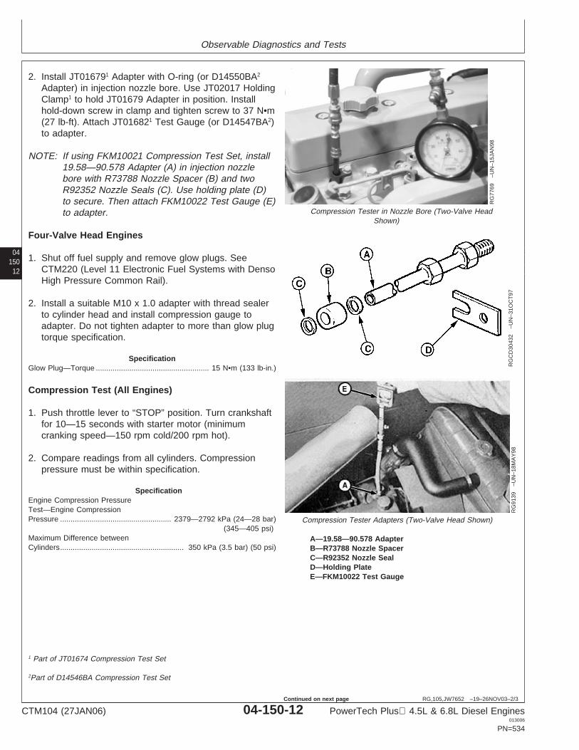
Observable Diagnostics and Tests
04150
12
RG,105,JW7652 –19–26NOV03–2/3
RG
7769
–UN
–15J
AN
98
Compression Tester in Nozzle Bore (Two-Valve HeadShown)
RG
CD
3043
2–U
N–3
1OC
T97
RG
9139
–UN
–18M
AY
98Compression Tester Adapters (Two-Valve Head Shown)
A—19.58—90.578 AdapterB—R73788 Nozzle SpacerC—R92352 Nozzle SealD—Holding PlateE—FKM10022 Test Gauge
2. Install JT016791 Adapter with O-ring (or D14550BA2
Adapter) in injection nozzle bore. Use JT02017 HoldingClamp1 to hold JT01679 Adapter in position. Installhold-down screw in clamp and tighten screw to 37 N•m(27 lb-ft). Attach JT016821 Test Gauge (or D14547BA2)to adapter.
NOTE: If using FKM10021 Compression Test Set, install19.58—90.578 Adapter (A) in injection nozzlebore with R73788 Nozzle Spacer (B) and twoR92352 Nozzle Seals (C). Use holding plate (D)to secure. Then attach FKM10022 Test Gauge (E)to adapter.
Four-Valve Head Engines
1. Shut off fuel supply and remove glow plugs. SeeCTM220 (Level 11 Electronic Fuel Systems with DensoHigh Pressure Common Rail).
2. Install a suitable M10 x 1.0 adapter with thread sealerto cylinder head and install compression gauge toadapter. Do not tighten adapter to more than glow plugtorque specification.
SpecificationGlow Plug—Torque 15 N•m (133 lb-in.)......................................................
Compression Test (All Engines)
1. Push throttle lever to “STOP” position. Turn crankshaftfor 10—15 seconds with starter motor (minimumcranking speed—150 rpm cold/200 rpm hot).
2. Compare readings from all cylinders. Compressionpressure must be within specification.
SpecificationEngine Compression PressureTest—Engine CompressionPressure 2379—2792 kPa (24—28 bar)
(345—405 psi).....................................................
Maximum Difference betweenCylinders 350 kPa (3.5 bar) (50 psi)...........................................................
1 Part of JT01674 Compression Test Set
2Part of D14546BA Compression Test Set
CTM104 (27JAN06) 04-150-12 PowerTech Plus 4.5L & 6.8L Diesel Engines013006
PN=534
Continued on next page
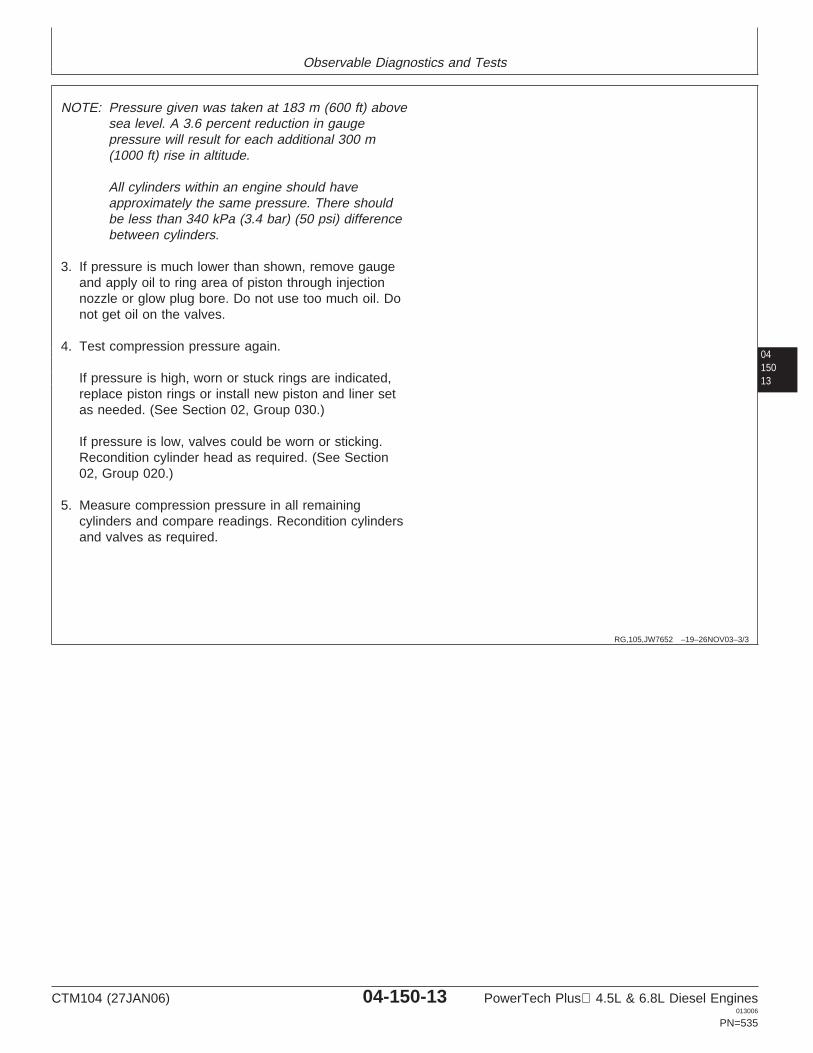
Observable Diagnostics and Tests
0415013
RG,105,JW7652 –19–26NOV03–3/3
NOTE: Pressure given was taken at 183 m (600 ft) abovesea level. A 3.6 percent reduction in gaugepressure will result for each additional 300 m(1000 ft) rise in altitude.
All cylinders within an engine should haveapproximately the same pressure. There shouldbe less than 340 kPa (3.4 bar) (50 psi) differencebetween cylinders.
3. If pressure is much lower than shown, remove gaugeand apply oil to ring area of piston through injectionnozzle or glow plug bore. Do not use too much oil. Donot get oil on the valves.
4. Test compression pressure again.
If pressure is high, worn or stuck rings are indicated,replace piston rings or install new piston and liner setas needed. (See Section 02, Group 030.)
If pressure is low, valves could be worn or sticking.Recondition cylinder head as required. (See Section02, Group 020.)
5. Measure compression pressure in all remainingcylinders and compare readings. Recondition cylindersand valves as required.
CTM104 (27JAN06) 04-150-13 PowerTech Plus 4.5L & 6.8L Diesel Engines013006
PN=535
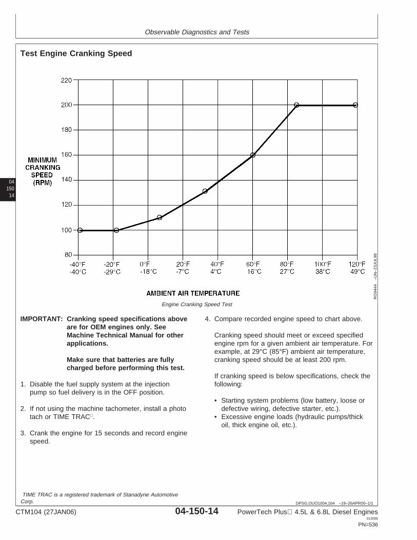
Observable Diagnostics and Tests
04150
14
DPSG,OUO1004,164 –19–26APR00–1/1
Test Engine Cranking Speed
RG
9444
–UN
–23J
UL9
8
Engine Cranking Speed Test
IMPORTANT: Cranking speed specifications aboveare for OEM engines only. SeeMachine Technical Manual for otherapplications.
Make sure that batteries are fullycharged before performing this test.
1. Disable the fuel supply system at the injectionpump so fuel delivery is in the OFF position.
2. If not using the machine tachometer, install a phototach or TIME TRAC.
3. Crank the engine for 15 seconds and record enginespeed.
4. Compare recorded engine speed to chart above.
Cranking speed should meet or exceed specifiedengine rpm for a given ambient air temperature. Forexample, at 29°C (85°F) ambient air temperature,cranking speed should be at least 200 rpm.
If cranking speed is below specifications, check thefollowing:
• Starting system problems (low battery, loose ordefective wiring, defective starter, etc.).
• Excessive engine loads (hydraulic pumps/thickoil, thick engine oil, etc.).
TIME TRAC is a registered trademark of Stanadyne AutomotiveCorp.
CTM104 (27JAN06) 04-150-14 PowerTech Plus 4.5L & 6.8L Diesel Engines013006
PN=536
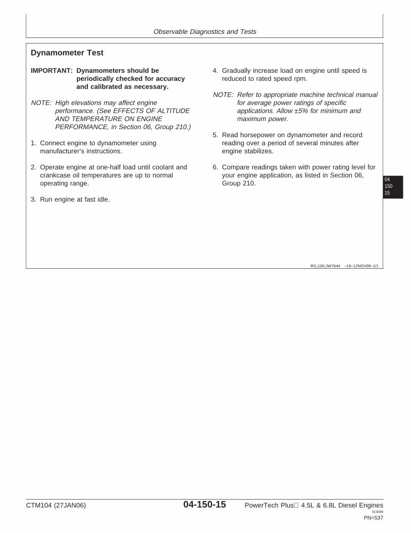
Observable Diagnostics and Tests
0415015
RG,100,JW7644 –19–12NOV99–1/1
Dynamometer Test
IMPORTANT: Dynamometers should beperiodically checked for accuracyand calibrated as necessary.
NOTE: High elevations may affect engineperformance. (See EFFECTS OF ALTITUDEAND TEMPERATURE ON ENGINEPERFORMANCE, in Section 06, Group 210.)
1. Connect engine to dynamometer usingmanufacturer’s instructions.
2. Operate engine at one-half load until coolant andcrankcase oil temperatures are up to normaloperating range.
3. Run engine at fast idle.
4. Gradually increase load on engine until speed isreduced to rated speed rpm.
NOTE: Refer to appropriate machine technical manualfor average power ratings of specificapplications. Allow ±5% for minimum andmaximum power.
5. Read horsepower on dynamometer and recordreading over a period of several minutes afterengine stabilizes.
6. Compare readings taken with power rating level foryour engine application, as listed in Section 06,Group 210.
CTM104 (27JAN06) 04-150-15 PowerTech Plus 4.5L & 6.8L Diesel Engines013006
PN=537
Observable Diagnostics and Tests
04150
16
DPSG,OUO1004,114 –19–23MAY00–1/1
Engine Oil Consumption
All engines consume some oil. The consumption ratedepends on loading, design of key parts and enginecondition. Since fuel consumption is an indicator ofoperating power levels, fuel used versus oil consumedis a critical factor in analyzing oil consumption. Oilconsumption should be measured over a 100-hourperiod.
Long-term oil consumption (three oil drain intervalsafter the engine is broken in) with consumption ratespoorer than 400:1 (100 gallons of fuel and 1 quart ofoil) indicates a need to monitor/investigate. Suggestedsteps would be:
• Check for signs of ingested dust or perform anOILSCAN test to check for silicon.
• Check for proper crankcase oil fill level.• Perform compression test to find low compression
cylinders.• Remove head and inspect for glazed or worn liners.• Inspect pistons for carbon deposits in the ring land
grooves.• Measure valve stem OD and valve guide ID to
determine clearance.
NOTE: Ring gap alignment does not identify the leaksource.
Intake valves do not have valve stem seals,and some oil deposits on the valve stem tulipare normal.
When changing to a premium oil such asTORQ-GARD SUPREME PLUS-50, little oilconsumption change is expected, although a smallpercentage of engines may experience a noticeablechange in consumption rates. This may be due to thefollowing:
• The previous oil may have left deposits on internalcomponents. Use of PLUS-50 oil will causedifferent chemical reactions in those deposits. Thetime required for the engine to regain the previousoil consumption rate will vary from one to threenormal drain intervals.
• TORQ-GARD SUPREME PLUS-50 contains ahigh-performance anti-oxidant along with otheradditives resulting in the oil remaining in thespecified viscosity grade throughout therecommended drain interval. API oil grades CD, CE,and CF-4 universal engine oils do not provide thisoxidation resistance which results in more rapidthickening. Increased oil viscosity can reduce oilconsumption.
OILSCAN is a trademark of Deere & CompanyTORQ-GARD SUPREME is a registered trademark of Deere &CompanyPLUS-50 is a registered trademark of Deere & Company
CTM104 (27JAN06) 04-150-16 PowerTech Plus 4.5L & 6.8L Diesel Engines013006
PN=538

Observable Diagnostics and Tests
0415017
RG,105,JW7651 –19–21NOV97–1/2
Check Engine Oil Pressure
RG
7484
B–U
N–0
4NO
V97
Main Oil Gallery Plug Removal Tool
A—Oil Gallery Plug
1. Remove main oil gallery plug (A) using JDG782A OilGallery Plug Tool.
Continued on next page
CTM104 (27JAN06) 04-150-17 PowerTech Plus 4.5L & 6.8L Diesel Engines013006
PN=539
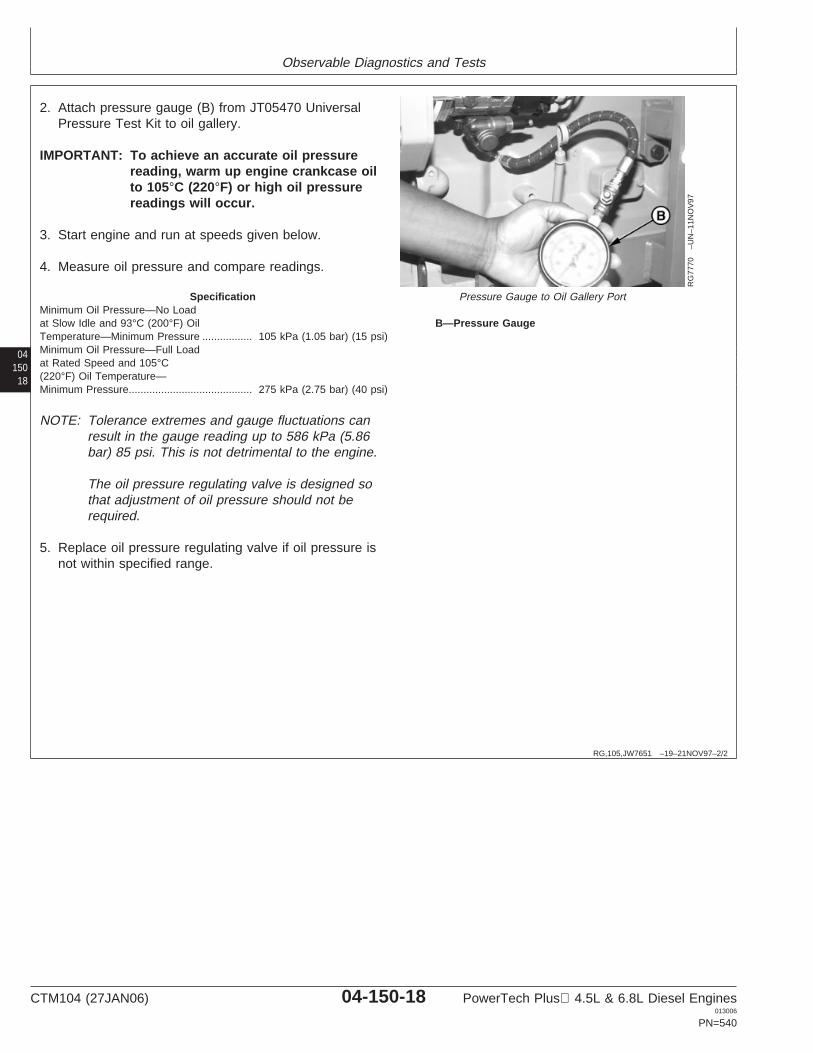
Observable Diagnostics and Tests
04150
18
RG,105,JW7651 –19–21NOV97–2/2
RG
7770
–UN
–11N
OV
97
Pressure Gauge to Oil Gallery Port
B—Pressure Gauge
2. Attach pressure gauge (B) from JT05470 UniversalPressure Test Kit to oil gallery.
IMPORTANT: To achieve an accurate oil pressurereading, warm up engine crankcase oilto 105°C (220°F) or high oil pressurereadings will occur.
3. Start engine and run at speeds given below.
4. Measure oil pressure and compare readings.
SpecificationMinimum Oil Pressure—No Loadat Slow Idle and 93°C (200°F) OilTemperature—Minimum Pressure 105 kPa (1.05 bar) (15 psi).................Minimum Oil Pressure—Full Loadat Rated Speed and 105°C(220°F) Oil Temperature—Minimum Pressure 275 kPa (2.75 bar) (40 psi)..........................................
NOTE: Tolerance extremes and gauge fluctuations canresult in the gauge reading up to 586 kPa (5.86bar) 85 psi. This is not detrimental to the engine.
The oil pressure regulating valve is designed sothat adjustment of oil pressure should not berequired.
5. Replace oil pressure regulating valve if oil pressure isnot within specified range.
CTM104 (27JAN06) 04-150-18 PowerTech Plus 4.5L & 6.8L Diesel Engines013006
PN=540

Observable Diagnostics and Tests
0415019
RG,105,JW7650 –19–21NOV97–1/1
Check for Excessive Engine CrankcasePressure (Blow-By)
RG
9568
–UN
–22J
UL9
8
Blow-By Check
A—Breather Tube
Excessive blow-by coming out of the crankcase breathertube (A) indicates that either the turbocharger (ifequipped) seals are faulty or the piston rings and cylinderliners are not adequately sealing off the combustionchamber. This is a comparative check that requires someexperience to determine when blow-by is excessive.
Run engine at high idle and check crankcase breathertube. Look for significant fumes and/or dripping oil comingout of the breather tube at fast idle, with no load.
If excessive blow-by is observed, perform the following todetermine if the turbocharger (if equipped) is causing theblow-by:
1. Remove the turbocharger oil drain line where itconnects to the engine block and run line into abucket.
2. Run engine at high idle, slightly loaded, and determineif boost pressure is forcing oil through the drain line.Check crankcase breather tube to determine if blow-byhas decreased.
3. If it appears that boost pressure is forcing oil throughthe drain line, and/or blow-by decreases with the drainline disconnected from block, replace the turbocharger,and retest.
CTM104 (27JAN06) 04-150-19 PowerTech Plus 4.5L & 6.8L Diesel Engines013006
PN=541
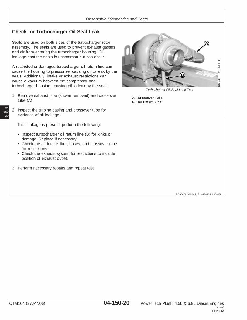
Observable Diagnostics and Tests
04150
20
DPSG,OUO1004,225 –19–10JUL98–1/1
Check for Turbocharger Oil Seal Leak
RG
9440
–UN
–23J
UL9
8
Turbocharger Oil Seal Leak Test
A—Crossover TubeB—Oil Return Line
Seals are used on both sides of the turbocharger rotorassembly. The seals are used to prevent exhaust gassesand air from entering the turbocharger housing. Oilleakage past the seals is uncommon but can occur.
A restricted or damaged turbocharger oil return line cancause the housing to pressurize, causing oil to leak by theseals. Additionally, intake or exhaust restrictions cancause a vacuum between the compressor andturbocharger housing, causing oil to leak by the seals.
1. Remove exhaust pipe (shown removed) and crossovertube (A).
2. Inspect the turbine casing and crossover tube forevidence of oil leakage.
If oil leakage is present, perform the following:
• Inspect turbocharger oil return line (B) for kinks ordamage. Replace if necessary.
• Check the air intake filter, hoses, and crossover tubefor restrictions.
• Check the exhaust system for restrictions to includeposition of exhaust outlet.
3. Perform necessary repairs and repeat test.
CTM104 (27JAN06) 04-150-20 PowerTech Plus 4.5L & 6.8L Diesel Engines013006
PN=542
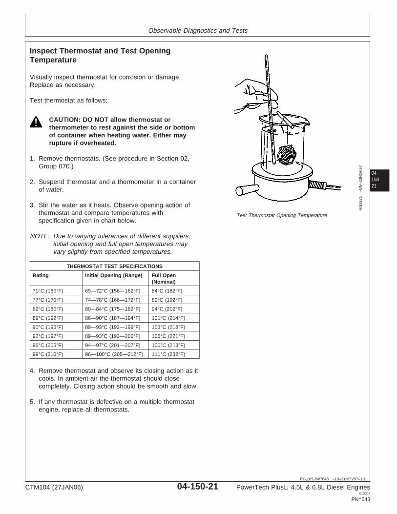
Observable Diagnostics and Tests
0415021
RG,105,JW7648 –19–21NOV97–1/1
Inspect Thermostat and Test OpeningTemperature
RG
5971
–UN
–23N
OV
97
Test Thermostat Opening Temperature
Visually inspect thermostat for corrosion or damage.Replace as necessary.
Test thermostat as follows:
CAUTION: DO NOT allow thermostat orthermometer to rest against the side or bottomof container when heating water. Either mayrupture if overheated.
1. Remove thermostats. (See procedure in Section 02,Group 070.)
2. Suspend thermostat and a thermometer in a containerof water.
3. Stir the water as it heats. Observe opening action ofthermostat and compare temperatures withspecification given in chart below.
NOTE: Due to varying tolerances of different suppliers,initial opening and full open temperatures mayvary slightly from specified temperatures.
THERMOSTAT TEST SPECIFICATIONS
Rating Initial Opening (Range) Full Open(Nominal)
71°C (160°F) 69—72°C (156—162°F) 84°C (182°F)
77°C (170°F) 74—78°C (166—172°F) 89°C (192°F)
82°C (180°F) 80—84°C (175—182°F) 94°C (202°F)
89°C (192°F) 86—90°C (187—194°F) 101°C (214°F)
90°C (195°F) 89—93°C (192—199°F) 103°C (218°F)
92°C (197°F) 89—93°C (193—200°F) 105°C (221°F)
96°C (205°F) 94—97°C (201—207°F) 100°C (213°F)
99°C (210°F) 96—100°C (205—212°F) 111°C (232°F)
4. Remove thermostat and observe its closing action as itcools. In ambient air the thermostat should closecompletely. Closing action should be smooth and slow.
5. If any thermostat is defective on a multiple thermostatengine, replace all thermostats.
CTM104 (27JAN06) 04-150-21 PowerTech Plus 4.5L & 6.8L Diesel Engines013006
PN=543
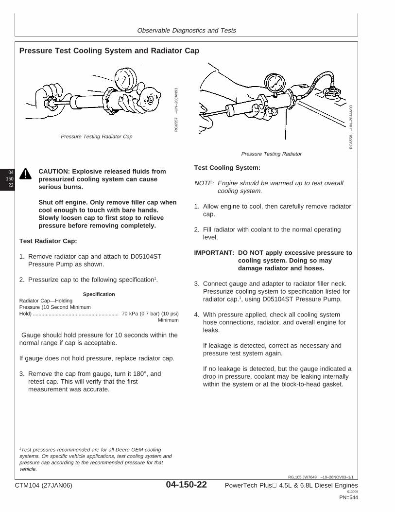
Observable Diagnostics and Tests
04150
22
RG,105,JW7649 –19–26NOV03–1/1
Pressure Test Cooling System and Radiator Cap
RG
6557
–UN
–20J
AN
93
Pressure Testing Radiator Cap
RG
6558
–UN
–20J
AN
93
Pressure Testing Radiator
CAUTION: Explosive released fluids frompressurized cooling system can causeserious burns.
Shut off engine. Only remove filler cap whencool enough to touch with bare hands.Slowly loosen cap to first stop to relievepressure before removing completely.
Test Radiator Cap:
1. Remove radiator cap and attach to D05104STPressure Pump as shown.
2. Pressurize cap to the following specification1.
SpecificationRadiator Cap—HoldingPressure (10 Second MinimumHold) 70 kPa (0.7 bar) (10 psi)
Minimum............................................................
Gauge should hold pressure for 10 seconds within thenormal range if cap is acceptable.
If gauge does not hold pressure, replace radiator cap.
3. Remove the cap from gauge, turn it 180°, andretest cap. This will verify that the firstmeasurement was accurate.
Test Cooling System:
NOTE: Engine should be warmed up to test overallcooling system.
1. Allow engine to cool, then carefully remove radiatorcap.
2. Fill radiator with coolant to the normal operatinglevel.
IMPORTANT: DO NOT apply excessive pressure tocooling system. Doing so maydamage radiator and hoses.
3. Connect gauge and adapter to radiator filler neck.Pressurize cooling system to specification listed forradiator cap.1, using D05104ST Pressure Pump.
4. With pressure applied, check all cooling systemhose connections, radiator, and overall engine forleaks.
If leakage is detected, correct as necessary andpressure test system again.
If no leakage is detected, but the gauge indicated adrop in pressure, coolant may be leaking internallywithin the system or at the block-to-head gasket.
1Test pressures recommended are for all Deere OEM coolingsystems. On specific vehicle applications, test cooling system andpressure cap according to the recommended pressure for thatvehicle.
CTM104 (27JAN06) 04-150-22 PowerTech Plus 4.5L & 6.8L Diesel Engines013006
PN=544
Observable Diagnostics and Tests
0415023
RG19661,0000015 –19–22JUN05–1/1
Pressure Test EGR Cooler for Air Leaks
NOTE: The EGR cooler can be pressure checked forleaks at a radiator shop.
1. Remove EGR cooler from engine.
2. Block off one of the coolant openings.
3. Attach shop air and regulator to the other coolantopening and submerse cooler in water.
4. Apply 248 kPa (2.5 bar) (36 psi) air pressure to coolerand watch for air bubbles indicating leaks.
If leakage is detected, replace cooler assembly.
CTM104 (27JAN06) 04-150-23 PowerTech Plus 4.5L & 6.8L Diesel Engines013006
PN=545
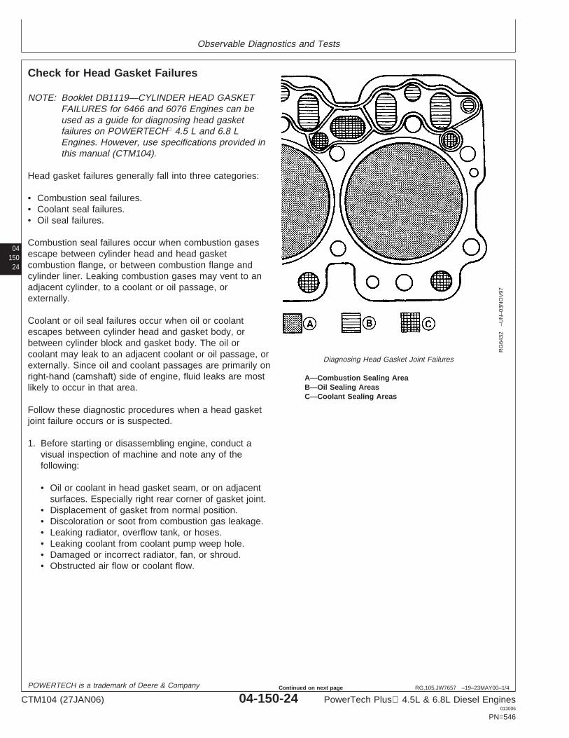
Observable Diagnostics and Tests
04150
24
RG,105,JW7657 –19–23MAY00–1/4
Check for Head Gasket Failures
RG
6432
–UN
–03N
OV
97
Diagnosing Head Gasket Joint Failures
A—Combustion Sealing AreaB—Oil Sealing AreasC—Coolant Sealing Areas
NOTE: Booklet DB1119—CYLINDER HEAD GASKETFAILURES for 6466 and 6076 Engines can beused as a guide for diagnosing head gasketfailures on POWERTECH 4.5 L and 6.8 LEngines. However, use specifications provided inthis manual (CTM104).
Head gasket failures generally fall into three categories:
• Combustion seal failures.• Coolant seal failures.• Oil seal failures.
Combustion seal failures occur when combustion gasesescape between cylinder head and head gasketcombustion flange, or between combustion flange andcylinder liner. Leaking combustion gases may vent to anadjacent cylinder, to a coolant or oil passage, orexternally.
Coolant or oil seal failures occur when oil or coolantescapes between cylinder head and gasket body, orbetween cylinder block and gasket body. The oil orcoolant may leak to an adjacent coolant or oil passage, orexternally. Since oil and coolant passages are primarily onright-hand (camshaft) side of engine, fluid leaks are mostlikely to occur in that area.
Follow these diagnostic procedures when a head gasketjoint failure occurs or is suspected.
1. Before starting or disassembling engine, conduct avisual inspection of machine and note any of thefollowing:
• Oil or coolant in head gasket seam, or on adjacentsurfaces. Especially right rear corner of gasket joint.
• Displacement of gasket from normal position.• Discoloration or soot from combustion gas leakage.• Leaking radiator, overflow tank, or hoses.• Leaking coolant from coolant pump weep hole.• Damaged or incorrect radiator, fan, or shroud.• Obstructed air flow or coolant flow.
POWERTECH is a trademark of Deere & Company
CTM104 (27JAN06) 04-150-24 PowerTech Plus 4.5L & 6.8L Diesel Engines013006
PN=546
Continued on next page
Observable Diagnostics and Tests
0415025
RG,105,JW7657 –19–23MAY00–2/4
• Worn or slipping belts.• Damaged or incorrect pressure cap.• Presence of oil in coolant.• Low coolant levels or Improper coolant.• Unusually high or low oil levels.• Oil degradation, dilution, or contamination.• Incorrectly specified injection pump.• Indications of fuel or timing adjustments.• Unburned fuel or coolant in exhaust system.
2. Obtain coolant and oil samples for further analysis.
3. Start and warm up engine if it can be safely operated.Examine all potential leakage areas again as outlinedpreviously. Using appropriate test and measurementequipment, check for the following:
• White smoke, excessive raw fuel, or moisture inexhaust system.
• Rough, irregular exhaust sound, or misfiring.• Air bubbles, gas trapped in radiator/overflow tank.• Loss of coolant from overflow.• Excessive cooling system pressure.• Coolant overheating.• Low coolant flow.• Loss of cab heating (air lock).
4. Shut engine down. Recheck crankcase, radiator, andoverflow tank for any significant differences in fluidlevels, viscosity, or appearance.
5. Compare your observations from above steps with thediagnostic charts earlier in this group. If diagnosticevaluations provide conclusive evidence of combustiongas, coolant, or oil leakage from head gasket joint, thecylinder head must be removed for inspection andrepair of gasket joint components.
COMBUSTION SEAL LEAKAGE
Symptoms:
• Exhaust from head gasket crevice• Air bubbles in radiator/overflow tank• Coolant discharge from overflow tube• Engine overheating• Power loss
CTM104 (27JAN06) 04-150-25 PowerTech Plus 4.5L & 6.8L Diesel Engines013006
PN=547
Continued on next page
Observable Diagnostics and Tests
04150
26
RG,105,JW7657 –19–23MAY00–3/4
• Engine runs rough• White exhaust smoke• Loss of cab heat• Gasket section dislodged, missing (blown)• Coolant in cylinder• Coolant in crankcase oil• Low coolant level
Possible Causes:
• Insufficient liner standout• Excessive liner standout differential between cylinders• Low head bolt clamping loads• Rough/damaged liner flange surface• Cracked/deformed gasket combustion flange• Out-of-flat/damaged/rough cylinder head surface• Missing/mislocated gasket fire ring• Block cracked in liner support area• Excessive fuel delivery• Advanced injection pump timing• Hydraulic or mechanical disturbance of combustion seal
NOTE: Cracked cylinder head or liners may also allowcombustion gas leakage into coolant.
COOLANT SEAL LEAKAGE
Symptoms:
• Coolant discharge from head gasket crevice• Coolant in crankcase oil• Low coolant level• High oil level• Coolant discharge from crankcase vent
Possible Causes:
• Excessive liner standout• Excessive liner standout differential between cylinders• Low head bolt clamping loads• Out-of-flat/damaged/rough block surface• Out-of-flat/damaged/rough cylinder head surface• Oil or coolant overheating• Cracks/creases in gasket body surfaces• Damage/voids in elastomer beading
OIL SEAL LEAKAGE
CTM104 (27JAN06) 04-150-26 PowerTech Plus 4.5L & 6.8L Diesel Engines013006
PN=548
Continued on next page
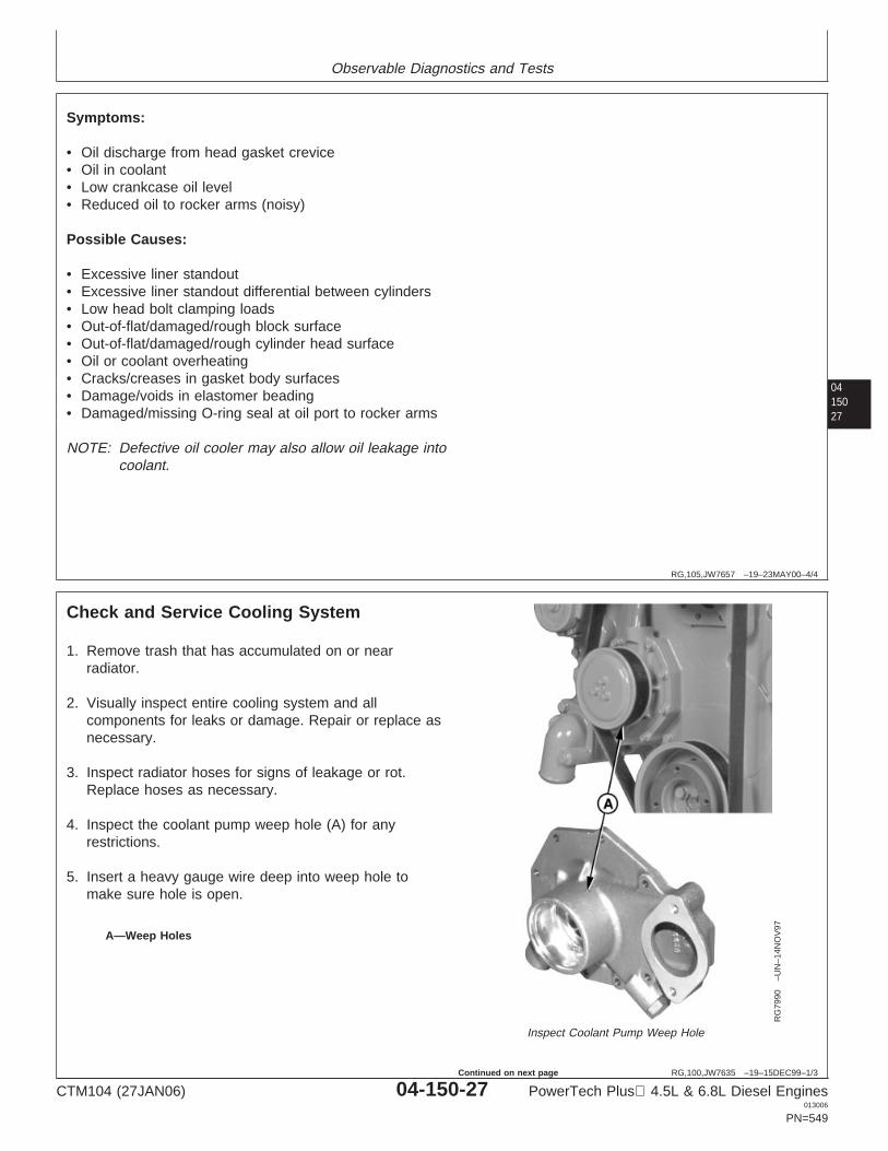
Observable Diagnostics and Tests
0415027
RG,105,JW7657 –19–23MAY00–4/4
Symptoms:
• Oil discharge from head gasket crevice• Oil in coolant• Low crankcase oil level• Reduced oil to rocker arms (noisy)
Possible Causes:
• Excessive liner standout• Excessive liner standout differential between cylinders• Low head bolt clamping loads• Out-of-flat/damaged/rough block surface• Out-of-flat/damaged/rough cylinder head surface• Oil or coolant overheating• Cracks/creases in gasket body surfaces• Damage/voids in elastomer beading• Damaged/missing O-ring seal at oil port to rocker arms
NOTE: Defective oil cooler may also allow oil leakage intocoolant.
RG,100,JW7635 –19–15DEC99–1/3
Check and Service Cooling System
RG
7990
–UN
–14N
OV
97
Inspect Coolant Pump Weep Hole
A—Weep Holes
1. Remove trash that has accumulated on or nearradiator.
2. Visually inspect entire cooling system and allcomponents for leaks or damage. Repair or replace asnecessary.
3. Inspect radiator hoses for signs of leakage or rot.Replace hoses as necessary.
4. Inspect the coolant pump weep hole (A) for anyrestrictions.
5. Insert a heavy gauge wire deep into weep hole tomake sure hole is open.
CTM104 (27JAN06) 04-150-27 PowerTech Plus 4.5L & 6.8L Diesel Engines013006
PN=549
Continued on next page
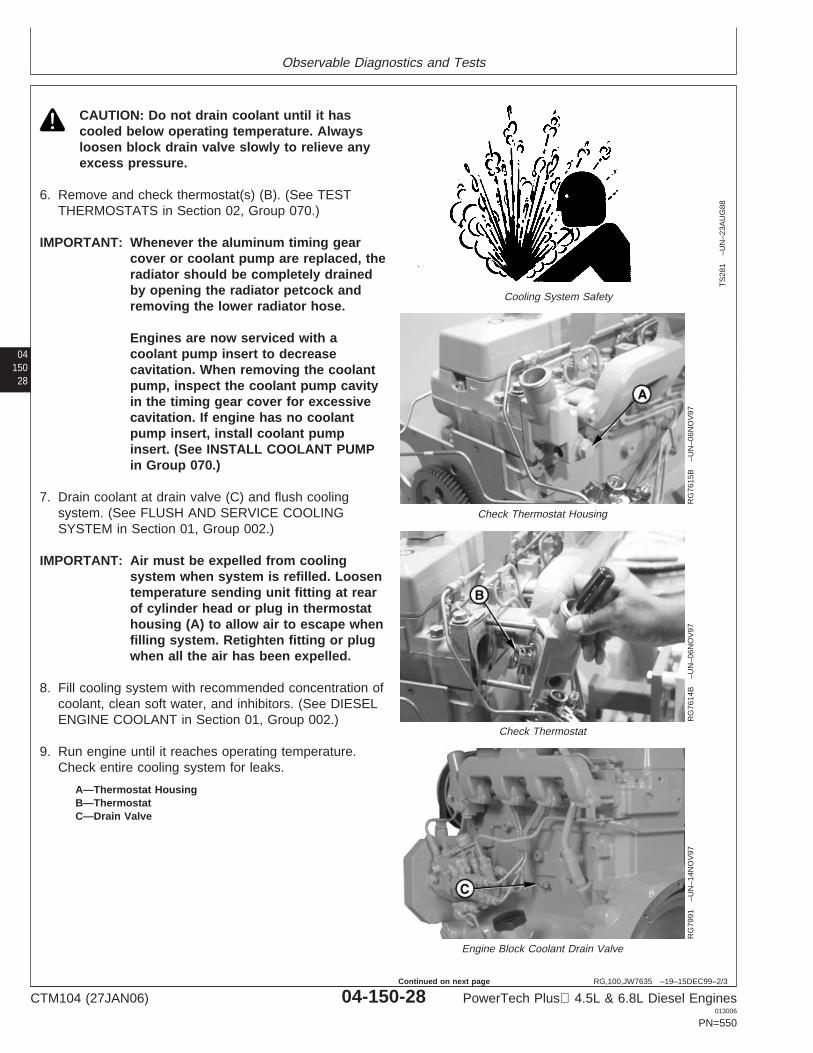
Observable Diagnostics and Tests
04150
28
RG,100,JW7635 –19–15DEC99–2/3
TS
281
–UN
–23A
UG
88
Cooling System Safety
RG
7615
B–U
N–0
6NO
V97
Check Thermostat Housing
RG
7614
B–U
N–0
6NO
V97
Check Thermostat
RG
7991
–UN
–14N
OV
97
Engine Block Coolant Drain Valve
A—Thermostat HousingB—ThermostatC—Drain Valve
CAUTION: Do not drain coolant until it hascooled below operating temperature. Alwaysloosen block drain valve slowly to relieve anyexcess pressure.
6. Remove and check thermostat(s) (B). (See TESTTHERMOSTATS in Section 02, Group 070.)
IMPORTANT: Whenever the aluminum timing gearcover or coolant pump are replaced, theradiator should be completely drainedby opening the radiator petcock andremoving the lower radiator hose.
Engines are now serviced with acoolant pump insert to decreasecavitation. When removing the coolantpump, inspect the coolant pump cavityin the timing gear cover for excessivecavitation. If engine has no coolantpump insert, install coolant pumpinsert. (See INSTALL COOLANT PUMPin Group 070.)
7. Drain coolant at drain valve (C) and flush coolingsystem. (See FLUSH AND SERVICE COOLINGSYSTEM in Section 01, Group 002.)
IMPORTANT: Air must be expelled from coolingsystem when system is refilled. Loosentemperature sending unit fitting at rearof cylinder head or plug in thermostathousing (A) to allow air to escape whenfilling system. Retighten fitting or plugwhen all the air has been expelled.
8. Fill cooling system with recommended concentration ofcoolant, clean soft water, and inhibitors. (See DIESELENGINE COOLANT in Section 01, Group 002.)
9. Run engine until it reaches operating temperature.Check entire cooling system for leaks.
CTM104 (27JAN06) 04-150-28 PowerTech Plus 4.5L & 6.8L Diesel Engines013006
PN=550
Continued on next page
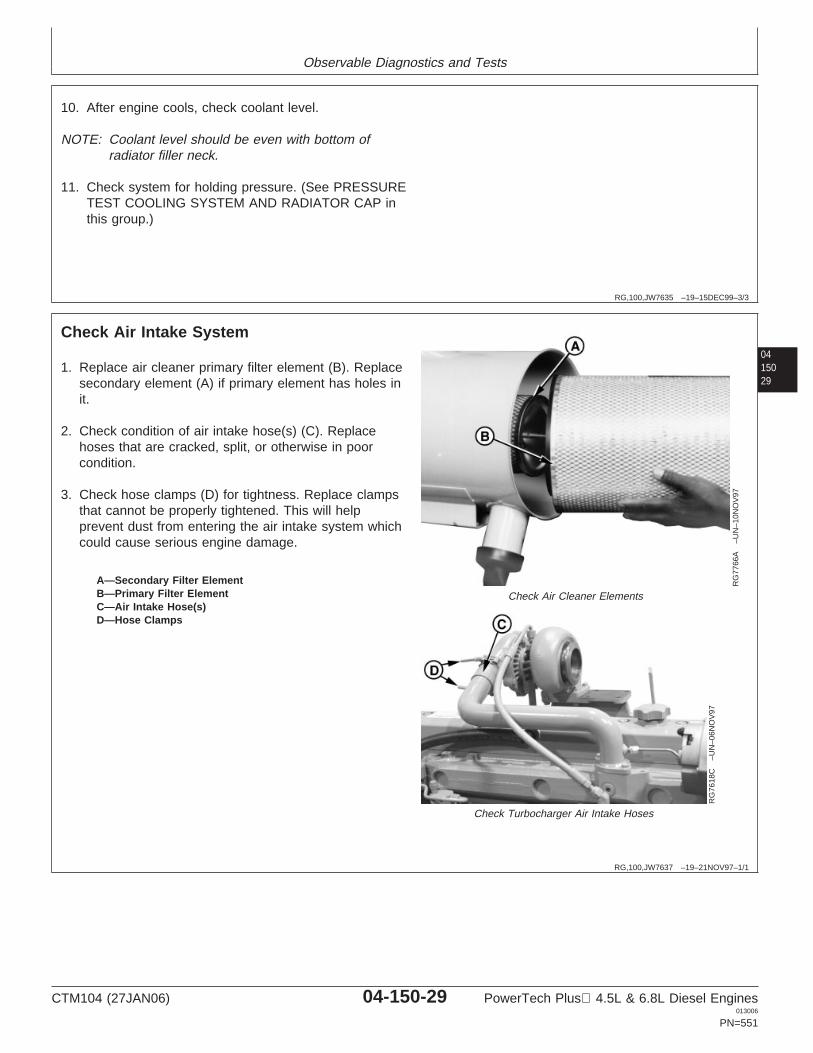
Observable Diagnostics and Tests
RG,100,JW7635 –19–15DEC99–3/3
10. After engine cools, check coolant level.
NOTE: Coolant level should be even with bottom ofradiator filler neck.
11. Check system for holding pressure. (See PRESSURETEST COOLING SYSTEM AND RADIATOR CAP inthis group.)
0415029
RG,100,JW7637 –19–21NOV97–1/1
Check Air Intake System
RG
7766
A–U
N–1
0NO
V97
Check Air Cleaner Elements
RG
7618
C–U
N–0
6NO
V97
Check Turbocharger Air Intake Hoses
A—Secondary Filter ElementB—Primary Filter ElementC—Air Intake Hose(s)D—Hose Clamps
1. Replace air cleaner primary filter element (B). Replacesecondary element (A) if primary element has holes init.
2. Check condition of air intake hose(s) (C). Replacehoses that are cracked, split, or otherwise in poorcondition.
3. Check hose clamps (D) for tightness. Replace clampsthat cannot be properly tightened. This will helpprevent dust from entering the air intake system whichcould cause serious engine damage.
CTM104 (27JAN06) 04-150-29 PowerTech Plus 4.5L & 6.8L Diesel Engines013006
PN=551
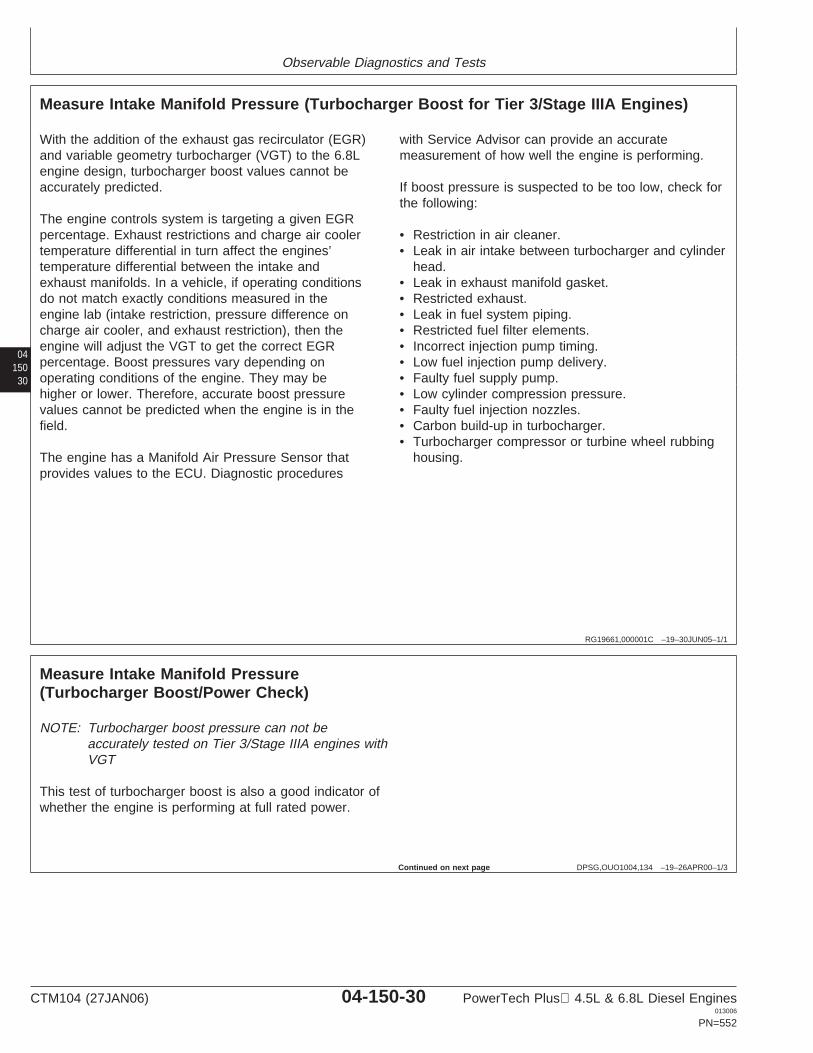
Observable Diagnostics and Tests
04150
30
RG19661,000001C –19–30JUN05–1/1
Measure Intake Manifold Pressure (Turbocharger Boost for Tier 3/Stage IIIA Engines)
With the addition of the exhaust gas recirculator (EGR)and variable geometry turbocharger (VGT) to the 6.8Lengine design, turbocharger boost values cannot beaccurately predicted.
The engine controls system is targeting a given EGRpercentage. Exhaust restrictions and charge air coolertemperature differential in turn affect the engines’temperature differential between the intake andexhaust manifolds. In a vehicle, if operating conditionsdo not match exactly conditions measured in theengine lab (intake restriction, pressure difference oncharge air cooler, and exhaust restriction), then theengine will adjust the VGT to get the correct EGRpercentage. Boost pressures vary depending onoperating conditions of the engine. They may behigher or lower. Therefore, accurate boost pressurevalues cannot be predicted when the engine is in thefield.
The engine has a Manifold Air Pressure Sensor thatprovides values to the ECU. Diagnostic procedures
with Service Advisor can provide an accuratemeasurement of how well the engine is performing.
If boost pressure is suspected to be too low, check forthe following:
• Restriction in air cleaner.• Leak in air intake between turbocharger and cylinder
head.• Leak in exhaust manifold gasket.• Restricted exhaust.• Leak in fuel system piping.• Restricted fuel filter elements.• Incorrect injection pump timing.• Low fuel injection pump delivery.• Faulty fuel supply pump.• Low cylinder compression pressure.• Faulty fuel injection nozzles.• Carbon build-up in turbocharger.• Turbocharger compressor or turbine wheel rubbing
housing.
DPSG,OUO1004,134 –19–26APR00–1/3
Measure Intake Manifold Pressure(Turbocharger Boost/Power Check)
NOTE: Turbocharger boost pressure can not beaccurately tested on Tier 3/Stage IIIA engines withVGT
This test of turbocharger boost is also a good indicator ofwhether the engine is performing at full rated power.
Continued on next page
CTM104 (27JAN06) 04-150-30 PowerTech Plus 4.5L & 6.8L Diesel Engines013006
PN=552
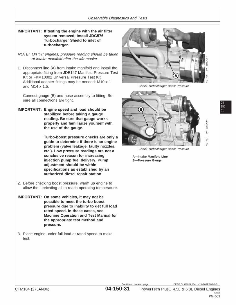
Observable Diagnostics and Tests
0415031
DPSG,OUO1004,134 –19–26APR00–2/3
RG
7776
–UN
–11N
OV
97
Check Turbocharger Boost Pressure
RG
7777
–UN
–11N
OV
97
Check Turbocharger Boost Pressure
A—Intake Manifold LineB—Pressure Gauge
IMPORTANT: If testing the engine with the air filtersystem removed, install JDG576Turbocharger Shield to inlet ofturbocharger.
NOTE: On “H” engines, pressure reading should be takenat intake manifold after the aftercooler.
1. Disconnect line (A) from intake manifold and install theappropriate fitting from JDE147 Manifold Pressure TestKit or FKM10002 Universal Pressure Test Kit.Additional adapter fittings may be needed: M10 x 1and M14 x 1.5.
Connect gauge (B) and hose assembly to fitting. Besure all connections are tight.
IMPORTANT: Engine speed and load should bestabilized before taking a gaugereading. Be sure that gauge worksproperly and familiarize yourself withthe use of the gauge.
Turbo-boost pressure checks are only aguide to determine if there is an engineproblem (valve leakage, faulty nozzles,etc.). Low pressure readings are not aconclusive reason for increasinginjection pump fuel delivery. Pumpadjustment should be withinspecifications as established by anauthorized diesel repair station.
2. Before checking boost pressure, warm up engine toallow the lubricating oil to reach operating temperature.
IMPORTANT: On some vehicles, it may not bepossible to meet the turbo boostpressure due to inability to get full loadrated speed. In these cases, seeMachine Operation and Test Manual forthe appropriate test method andpressure.
3. Place engine under full load at rated speed to maketest.
CTM104 (27JAN06) 04-150-31 PowerTech Plus 4.5L & 6.8L Diesel Engines013006
PN=553
Continued on next page
Observable Diagnostics and Tests
04150
32
DPSG,OUO1004,134 –19–26APR00–3/3
4. Observe pressure reading on gauge. Comparereadings with charts in Section 06, Group 210. Boostpressure should be within ranges shown in chartswhen engine is developing rated power at full loadrated speed.
5. If boost pressure is too high, remove fuel injectionpump and have it checked for high fuel delivery by anauthorized diesel repair station.
If boost pressure is too low, check the following:
• Restricted air filter elements.• Restricted fuel filter elements.• Incorrect fast idle adjustment.• Incorrect injection pump timing.• Exhaust manifold leaks.• Intake manifold leaks.• Faulty fuel transfer pump.• Low compression pressure.• Faulty fuel injection nozzles.• Carbon build-up in turbocharger.• Turbocharger compressor or turbine wheel rubbing
housing.• Low fuel injection pump fuel delivery.• Restricted exhaust.
6. After completing test, remove test equipment and fittingand reconnect line to intake manifold. Tighten securely.
CTM104 (27JAN06) 04-150-32 PowerTech Plus 4.5L & 6.8L Diesel Engines013006
PN=554
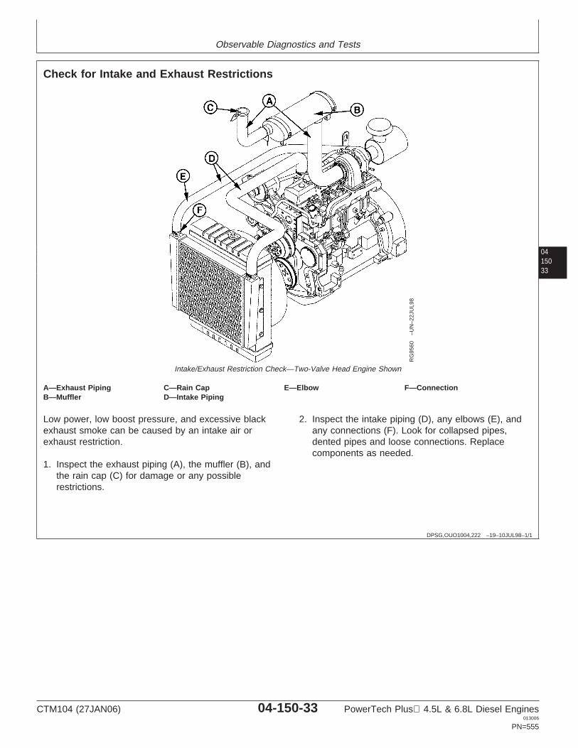
Observable Diagnostics and Tests
0415033
DPSG,OUO1004,222 –19–10JUL98–1/1
Check for Intake and Exhaust Restrictions
RG
9560
–UN
–22J
UL9
8
Intake/Exhaust Restriction Check—Two-Valve Head Engine Shown
A—Exhaust Piping C—Rain Cap E—Elbow F—ConnectionB—Muffler D—Intake Piping
Low power, low boost pressure, and excessive blackexhaust smoke can be caused by an intake air orexhaust restriction.
1. Inspect the exhaust piping (A), the muffler (B), andthe rain cap (C) for damage or any possiblerestrictions.
2. Inspect the intake piping (D), any elbows (E), andany connections (F). Look for collapsed pipes,dented pipes and loose connections. Replacecomponents as needed.
CTM104 (27JAN06) 04-150-33 PowerTech Plus 4.5L & 6.8L Diesel Engines013006
PN=555

Observable Diagnostics and Tests
04150
34
DPSG,OUO1004,220 –19–26APR00–1/1
Test for Intake Air Leaks
T59
06A
P–U
N–2
3FE
B89
Air Intake Leak Test
RG
9148
–UN
–23J
UL9
8
Air Intake Leak Test
C
RG
1240
2–U
N–1
2JU
N02
Air Intake Leak Test - Four Valve Head
A—Start Aid LineB—PlugC—Air Temperature Sensor
Loose connections or cracks in the suction side of the airintake pipe can allow debris to be ingested into the enginecausing rapid wear in the cylinders. Additionally, onturbocharged engines, compressor damage may occurand cause an imbalance resulting in bearing failure.
Air leaking from loose connections or cracks on thepressure side of the turbocharger can cause excessivesmoke and low power.
NOTE: The following test procedure requires that the airintake be sealed off to pressurize the system.Using a plastic bag to seal the air intake filter isused as an example.
CAUTION: Do not start engine during this testprocedure. Plastic bag (or whatevermaterial/object used to seal intake) can besucked into the engine.
1. Remove air cleaner cover and main filter element.
2. Put a plastic bag over secondary filter element andinstall main element and cover.
3. For two valve head engines, remove plug (B) frommanifold or disconnect start aid line (A) from crossovertube (if equipped).
4. For four valve head engines, remove air temperaturesensor (C) from manifold.
5. Using a adapter, connect a regulated air source.
6. Pressurize air intake system to 13.8—20.7 kPa(0.13-0.21 bar) (2—3 psi).
7. Spray soap and water solution over all connectionsfrom the air cleaner to the turbocharger or air inlet tocheck for leaks. Repair all leaks.
8. Remove plastic bag from filter element and reinstallelement and cover.
CTM104 (27JAN06) 04-150-34 PowerTech Plus 4.5L & 6.8L Diesel Engines013006
PN=556
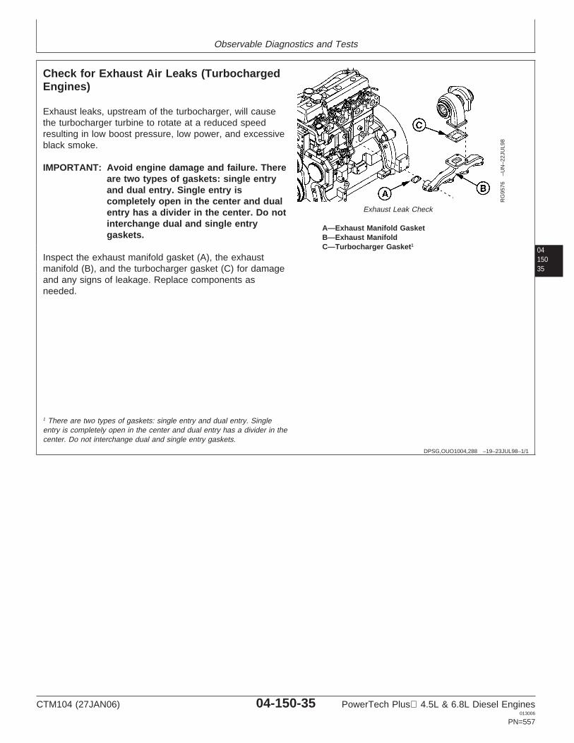
Observable Diagnostics and Tests
0415035
DPSG,OUO1004,288 –19–23JUL98–1/1
Check for Exhaust Air Leaks (TurbochargedEngines)
RG
9576
–UN
–22J
UL9
8
Exhaust Leak Check
A—Exhaust Manifold GasketB—Exhaust ManifoldC—Turbocharger Gasket1
Exhaust leaks, upstream of the turbocharger, will causethe turbocharger turbine to rotate at a reduced speedresulting in low boost pressure, low power, and excessiveblack smoke.
IMPORTANT: Avoid engine damage and failure. Thereare two types of gaskets: single entryand dual entry. Single entry iscompletely open in the center and dualentry has a divider in the center. Do notinterchange dual and single entrygaskets.
Inspect the exhaust manifold gasket (A), the exhaustmanifold (B), and the turbocharger gasket (C) for damageand any signs of leakage. Replace components asneeded.
1 There are two types of gaskets: single entry and dual entry. Singleentry is completely open in the center and dual entry has a divider in thecenter. Do not interchange dual and single entry gaskets.
CTM104 (27JAN06) 04-150-35 PowerTech Plus 4.5L & 6.8L Diesel Engines013006
PN=557

Observable Diagnostics and Tests
04150
36
DPSG,OUO1004,224 –19–10JUL98–1/1
Test Turbocharger Wastegate
RG
9147
–UN
–23J
UL9
8
Wastegate Check
A—Actuator FittingB—Actuator Rod
1. Check hose to wastegate actuator for kinks or cracks.Replace if damaged.
2. Disconnect hose from wastegate actuator.
3. Connect a regulated air source to actuator fitting (A).
4. Vary pressure to wastegate actuator from 62—83 kPa(.62—.83 bar) (9—12 psi).
Actuator rod (B) should move in and out freely aspressure is varied.
If rod does not move freely, check wastegateadjustment. (See ADJUST TURBOCHARGERWASTEGATE ACTUATOR in Section 02, Group 080.)
RG,110,JW7671 –19–24NOV97–1/1
Test Air Filter Restriction Indicator Switch
RG
T61
88A
Q–U
N–1
9NO
V97
Test Air Filter Restriction Indicator
A—GaugeB—Tee FittingC—Pipe Nipple
1. Remove air filter restriction indicator switch from airintake piping.
2. Install pipe nipple (C), tee fitting (B), and gauge (A)from D05022ST Water Vacuum Gauge Kit into air filterrestriction indicator hole. Install air filter restrictionindicator into tee fitting.
3. Start engine and slowly cover the air cleaner inlet witha piece of paper or cardboard.
4. Air restriction indicator must show red at 5.6—6.8 kPa(56—68 bar) (22.7—27.3 in. water) (1.6—2.0 in. hg)vacuum.
If air restriction indicator shows red at any other valuethan listed above, install a new indicator.
CTM104 (27JAN06) 04-150-36 PowerTech Plus 4.5L & 6.8L Diesel Engines013006
PN=558
Section 05Tools and Other Materials
Contents
Page Page
Group 170—Repair Tools and Other Materials Group 180—Diagnostic Service ToolsEngine Rebuild Essential Tools . . . . . . . . . . . .05-170-1 Diagnostic Essential Tools . . . . . . . . . . . . . . .05-180-1Engine Rebuild Service Equipment and Diagnostic Service Equipment and Tools . . . .05-180-3
Tools . . . . . . . . . . . . . . . . . . . . . . . . . . . . . .05-170-2Engine Rebuild Other Materials. . . . . . . . . . . .05-170-3 Group 190—Dealer Fabricated Service ToolsCylinder Head and Valves Essential Tools How to Make Tools . . . . . . . . . . . . . . . . . . . . .05-190-1
(Two-Valve Head) . . . . . . . . . . . . . . . . . . . .05-170-3 DFRG3—Cylinder Liner Holding Fixture . . . . .05-190-1Cylinder Head and Valves Service DFRG5—Injection Pump Front Plate
Equipment and Tools (Two-Valve Head) . . .05-170-9 Timing Mark Transfer Tool. . . . . . . . . . . . . .05-190-2Other Material (Two-Valve Head) . . . . . . . . .05-170-11 Engine Oil Dipstick Tube Driver (6010—Cylinder Head and Valves Essential Tools 6910 Series Tractor Engines) . . . . . . . . . . .05-190-3
(Four-Valve Head) . . . . . . . . . . . . . . . . . . .05-170-1205Service Equipment and Tools (Four-Valve
Head) . . . . . . . . . . . . . . . . . . . . . . . . . . . .05-170-18Other Material (Four-Valve Head) . . . . . . . . .05-170-20Cylinder Block, Liners, Pistons and Rods
Essential Tools . . . . . . . . . . . . . . . . . . . . .05-170-20Cylinder Block, Liners, Pistons and Rods
Service Equipment and Tools . . . . . . . . . .05-170-25Cylinder Block, Liners, Pistons and Rods
Other Materials . . . . . . . . . . . . . . . . . . . . .05-170-26Crankshaft, Main Bearings, Damper and
Flywheel Essential Tools . . . . . . . . . . . . . .05-170-27Crankshaft, Main Bearings and Flywheel
Service Equipment and Tools . . . . . . . . . .05-170-33Crankshaft, Main Bearings and Flywheel
Other Materials . . . . . . . . . . . . . . . . . . . . .05-170-34Camshaft, Balancer Shafts and Timing
Gear Train Essential Tools . . . . . . . . . . . .05-170-35Camshaft, Balancer Shafts and Timing
Gear Train Service Equipment andTools . . . . . . . . . . . . . . . . . . . . . . . . . . . . .05-170-40
Camshaft, Balancer Shafts and TimingGear Train Other Materials . . . . . . . . . . . .05-170-42
Lubrication System Essential Tools . . . . . . . .05-170-43Lubrication System Service Equipment
and Tools. . . . . . . . . . . . . . . . . . . . . . . . . .05-170-47Lubrication System Other Materials. . . . . . . .05-170-49Cooling System Essential Tools . . . . . . . . . .05-170-50Cooling System Service Equipment and
Tools . . . . . . . . . . . . . . . . . . . . . . . . . . . . .05-170-52Cooling System Other Materials . . . . . . . . . .05-170-53Air Intake and Exhaust System Other
Materials . . . . . . . . . . . . . . . . . . . . . . . . . .05-170-54Starting and Charging System Essential
Tools . . . . . . . . . . . . . . . . . . . . . . . . . . . . .05-170-55
CTM104 (27JAN06) 05-1 PowerTech Plus 4.5L & 6.8L Diesel Engines013006
PN=1

Contents
05
CTM104 (27JAN06) 05-2 PowerTech Plus 4.5L & 6.8L Diesel Engines013006
PN=2
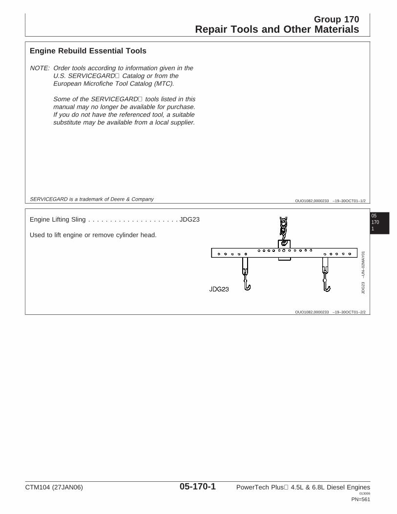
Group 170Repair Tools and Other Materials
OUO1082,0000233 –19–30OCT01–1/2
Engine Rebuild Essential Tools
NOTE: Order tools according to information given in theU.S. SERVICEGARD Catalog or from theEuropean Microfiche Tool Catalog (MTC).
Some of the SERVICEGARD tools listed in thismanual may no longer be available for purchase.If you do not have the referenced tool, a suitablesubstitute may be available from a local supplier.
051701
SERVICEGARD is a trademark of Deere & Company
OUO1082,0000233 –19–30OCT01–2/2
JDG
23–U
N–0
2MA
Y01
Engine Lifting Sling . . . . . . . . . . . . . . . . . . . . . JDG23
Used to lift engine or remove cylinder head.
CTM104 (27JAN06) 05-170-1 PowerTech Plus 4.5L & 6.8L Diesel Engines013006
PN=561
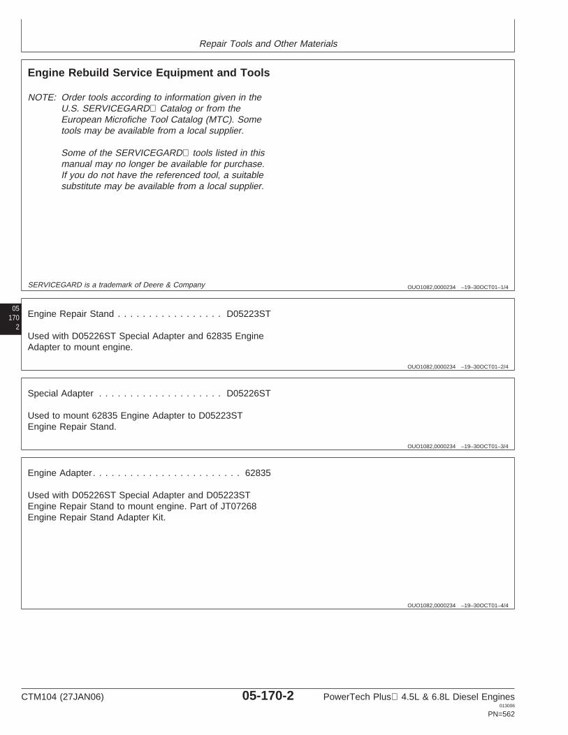
Repair Tools and Other Materials
OUO1082,0000234 –19–30OCT01–1/4
Engine Rebuild Service Equipment and Tools
NOTE: Order tools according to information given in theU.S. SERVICEGARD Catalog or from theEuropean Microfiche Tool Catalog (MTC). Sometools may be available from a local supplier.
Some of the SERVICEGARD tools listed in thismanual may no longer be available for purchase.If you do not have the referenced tool, a suitablesubstitute may be available from a local supplier.
05170
2
SERVICEGARD is a trademark of Deere & Company
OUO1082,0000234 –19–30OCT01–2/4
Engine Repair Stand . . . . . . . . . . . . . . . . . D05223ST
Used with D05226ST Special Adapter and 62835 EngineAdapter to mount engine.
OUO1082,0000234 –19–30OCT01–3/4
Special Adapter . . . . . . . . . . . . . . . . . . . . D05226ST
Used to mount 62835 Engine Adapter to D05223STEngine Repair Stand.
OUO1082,0000234 –19–30OCT01–4/4
Engine Adapter. . . . . . . . . . . . . . . . . . . . . . . . 62835
Used with D05226ST Special Adapter and D05223STEngine Repair Stand to mount engine. Part of JT07268Engine Repair Stand Adapter Kit.
CTM104 (27JAN06) 05-170-2 PowerTech Plus 4.5L & 6.8L Diesel Engines013006
PN=562
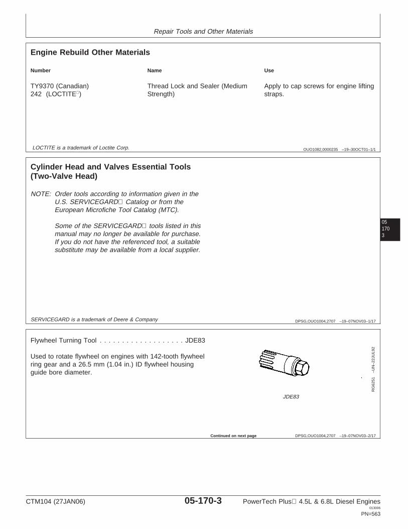
Repair Tools and Other Materials
OUO1082,0000235 –19–30OCT01–1/1
Engine Rebuild Other Materials
Number Name Use
TY9370 (Canadian) Thread Lock and Sealer (Medium Apply to cap screws for engine lifting242 (LOCTITE) Strength) straps.
LOCTITE is a trademark of Loctite Corp.
051703
DPSG,OUO1004,2707 –19–07NOV03–1/17
Cylinder Head and Valves Essential Tools(Two-Valve Head)
NOTE: Order tools according to information given in theU.S. SERVICEGARD Catalog or from theEuropean Microfiche Tool Catalog (MTC).
Some of the SERVICEGARD tools listed in thismanual may no longer be available for purchase.If you do not have the referenced tool, a suitablesubstitute may be available from a local supplier.
SERVICEGARD is a trademark of Deere & Company
DPSG,OUO1004,2707 –19–07NOV03–2/17
RG
6251
–UN
–22J
UL9
2
JDE83
Flywheel Turning Tool . . . . . . . . . . . . . . . . . . . JDE83
Used to rotate flywheel on engines with 142-tooth flywheelring gear and a 26.5 mm (1.04 in.) ID flywheel housingguide bore diameter.
Continued on next page
CTM104 (27JAN06) 05-170-3 PowerTech Plus 4.5L & 6.8L Diesel Engines013006
PN=563
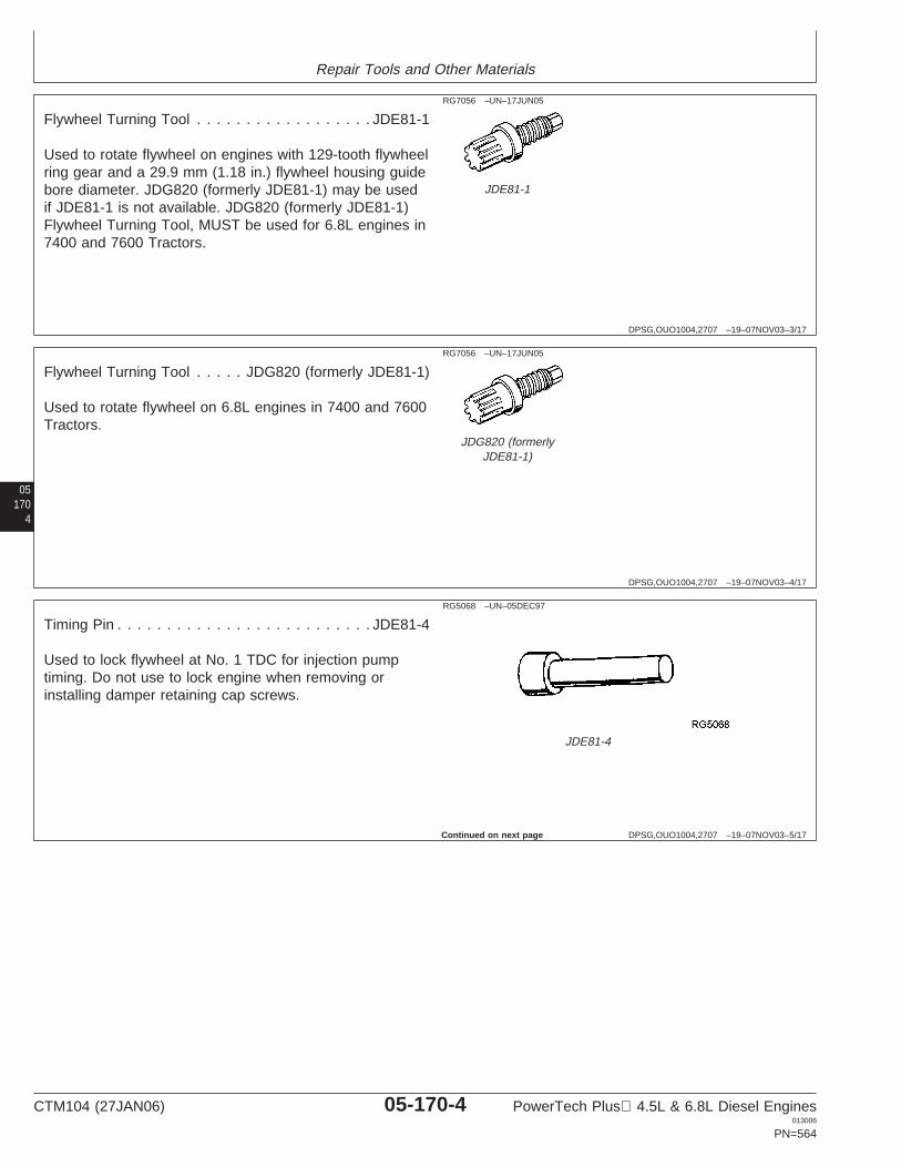
Repair Tools and Other Materials
DPSG,OUO1004,2707 –19–07NOV03–3/17
RG7056 –UN–17JUN05
JDE81-1
Flywheel Turning Tool . . . . . . . . . . . . . . . . . . JDE81-1
Used to rotate flywheel on engines with 129-tooth flywheelring gear and a 29.9 mm (1.18 in.) flywheel housing guidebore diameter. JDG820 (formerly JDE81-1) may be usedif JDE81-1 is not available. JDG820 (formerly JDE81-1)Flywheel Turning Tool, MUST be used for 6.8L engines in7400 and 7600 Tractors.
05170
4
DPSG,OUO1004,2707 –19–07NOV03–4/17
RG7056 –UN–17JUN05
JDG820 (formerlyJDE81-1)
Flywheel Turning Tool . . . . . JDG820 (formerly JDE81-1)
Used to rotate flywheel on 6.8L engines in 7400 and 7600Tractors.
DPSG,OUO1004,2707 –19–07NOV03–5/17
RG5068 –UN–05DEC97
JDE81-4
Timing Pin . . . . . . . . . . . . . . . . . . . . . . . . . . JDE81-4
Used to lock flywheel at No. 1 TDC for injection pumptiming. Do not use to lock engine when removing orinstalling damper retaining cap screws.
Continued on next page
CTM104 (27JAN06) 05-170-4 PowerTech Plus 4.5L & 6.8L Diesel Engines013006
PN=564

Repair Tools and Other Materials
DPSG,OUO1004,2707 –19–07NOV03–6/17
RG
1203
1–U
N–2
0DE
C01
JDG1571
Timing Pin . . . . . . . . . . . . . . . . . . . . . . . . . JDG1571
Used to lock flywheel at No. 1 TDC for injection pumptiming. This timing pin MUST be used on engineapplications using the tapered-nose crankshaft due to thehigher torque specification for damper retaining capscrew.
051705
DPSG,OUO1004,2707 –19–07NOV03–7/17
JDG
23–U
N–0
2MA
Y01
Engine Lifting Sling . . . . . . . . . . . . . . . . . . . . . JDG23
Used to lift engine or remove cylinder head.
DPSG,OUO1004,2707 –19–07NOV03–8/17
RG6246 –UN–05DEC97
D17526CI/D17527CI
Dial Indicator . . . . . D17526CI (English, in.) or D17527CI(Metric, mm)
Use with JDG451 Height Gauge or magnetic base tomeasure valve recess in cylinder head.
Continued on next page
CTM104 (27JAN06) 05-170-5 PowerTech Plus 4.5L & 6.8L Diesel Engines013006
PN=565
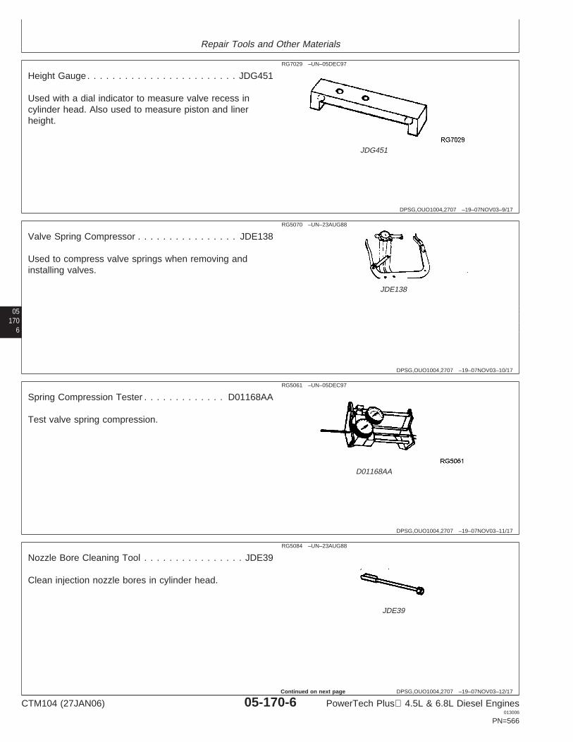
Repair Tools and Other Materials
DPSG,OUO1004,2707 –19–07NOV03–9/17
RG7029 –UN–05DEC97
JDG451
Height Gauge . . . . . . . . . . . . . . . . . . . . . . . . JDG451
Used with a dial indicator to measure valve recess incylinder head. Also used to measure piston and linerheight.
05170
6
DPSG,OUO1004,2707 –19–07NOV03–10/17
RG5070 –UN–23AUG88
JDE138
Valve Spring Compressor . . . . . . . . . . . . . . . . JDE138
Used to compress valve springs when removing andinstalling valves.
DPSG,OUO1004,2707 –19–07NOV03–11/17
RG5061 –UN–05DEC97
D01168AA
Spring Compression Tester . . . . . . . . . . . . . D01168AA
Test valve spring compression.
DPSG,OUO1004,2707 –19–07NOV03–12/17
RG5084 –UN–23AUG88
JDE39
Nozzle Bore Cleaning Tool . . . . . . . . . . . . . . . . JDE39
Clean injection nozzle bores in cylinder head.
CTM104 (27JAN06) 05-170-6 PowerTech Plus 4.5L & 6.8L Diesel Engines013006
PN=566
Continued on next page
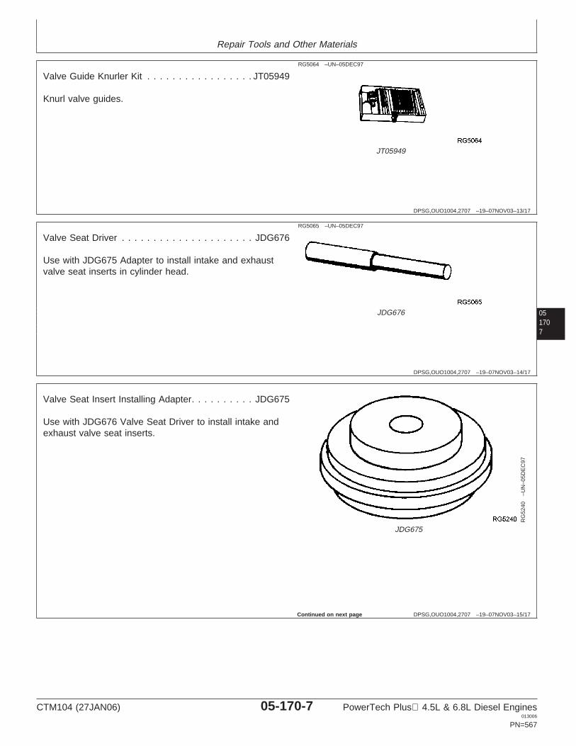
Repair Tools and Other Materials
DPSG,OUO1004,2707 –19–07NOV03–13/17
RG5064 –UN–05DEC97
JT05949
Valve Guide Knurler Kit . . . . . . . . . . . . . . . . . JT05949
Knurl valve guides.
051707
DPSG,OUO1004,2707 –19–07NOV03–14/17
RG5065 –UN–05DEC97
JDG676
Valve Seat Driver . . . . . . . . . . . . . . . . . . . . . JDG676
Use with JDG675 Adapter to install intake and exhaustvalve seat inserts in cylinder head.
DPSG,OUO1004,2707 –19–07NOV03–15/17
RG
5240
–UN
–05D
EC
97JDG675
Valve Seat Insert Installing Adapter. . . . . . . . . . JDG675
Use with JDG676 Valve Seat Driver to install intake andexhaust valve seat inserts.
Continued on next page
CTM104 (27JAN06) 05-170-7 PowerTech Plus 4.5L & 6.8L Diesel Engines013006
PN=567
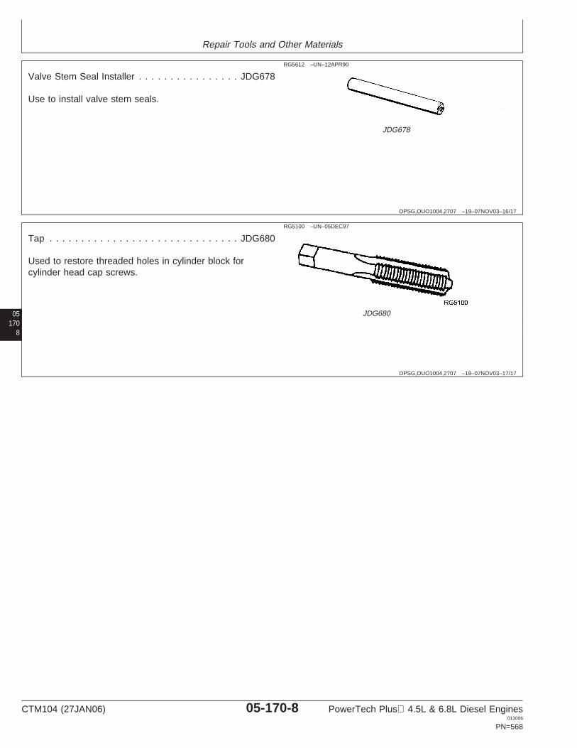
Repair Tools and Other Materials
DPSG,OUO1004,2707 –19–07NOV03–16/17
RG5612 –UN–12APR90
JDG678
Valve Stem Seal Installer . . . . . . . . . . . . . . . . JDG678
Use to install valve stem seals.
05170
8
DPSG,OUO1004,2707 –19–07NOV03–17/17
RG5100 –UN–05DEC97
JDG680
Tap . . . . . . . . . . . . . . . . . . . . . . . . . . . . . . JDG680
Used to restore threaded holes in cylinder block forcylinder head cap screws.
CTM104 (27JAN06) 05-170-8 PowerTech Plus 4.5L & 6.8L Diesel Engines013006
PN=568

Repair Tools and Other Materials
DPSG,OUO1004,2708 –19–26APR00–1/9
Cylinder Head and Valves Service Equipmentand Tools (Two-Valve Head)
NOTE: Order tools according to information given in theU.S. SERVICEGARD Catalog or from theEuropean Microfiche Tool Catalog (MTC). Sometools may be available from a local supplier.
Some of the SERVICEGARD tools listed in thismanual may no longer be available for purchase.If you do not have the referenced tool, a suitablesubstitute may be available from a local supplier.
051709
SERVICEGARD is a trademark of Deere & Company
DPSG,OUO1004,2708 –19–26APR00–2/9
Crankshaft Front/Rear Rotation Adapter. . . . . . . JDG966
Rotate straight nose crankshaft from front and rear withflywheel removed.
DPSG,OUO1004,2708 –19–26APR00–3/9
Valve Inspection Center
Check valves for out-of-round.
DPSG,OUO1004,2708 –19–26APR00–4/9
Precision “Bevelled Edge” Straightedge . . . . . D05012ST
Check cylinder head flatness.
DPSG,OUO1004,2708 –19–26APR00–5/9
Plastic Brush
Clean valve guides.
DPSG,OUO1004,2708 –19–26APR00–6/9
End Brush . . . . . . . . . . . . . . . . . . . . . . . . D17024BR
Remove carbon on valve seats.
CTM104 (27JAN06) 05-170-9 PowerTech Plus 4.5L & 6.8L Diesel Engines013006
PN=569
Continued on next page

Repair Tools and Other Materials
DPSG,OUO1004,2708 –19–26APR00–7/9
Heavy-Duty Seat Grinder . . . . . . . . . . . . . . . . JT05893
Grind valve seats.
DPSG,OUO1004,2708 –19–26APR00–8/9
Eccentrimeter
Measure valve seat runout.
DPSG,OUO1004,2708 –19–26APR00–9/9
Torque Angle Gauge . . . . . . . . . . . . . . . . . . . JT05993
Used to TORQUE-TURN flanged-head cylinder head andconnecting rod cap screws.
05170
10
CTM104 (27JAN06) 05-170-10 PowerTech Plus 4.5L & 6.8L Diesel Engines013006
PN=570
Repair Tools and Other Materials
OUO1082,000029C –19–23JAN04–1/1
Other Material (Two-Valve Head)
Number Name Use
JDT305 (U.S.) Lubricant Lubricate head bolt beforeinstallation.
0517011
CTM104 (27JAN06) 05-170-11 PowerTech Plus 4.5L & 6.8L Diesel Engines013006
PN=571
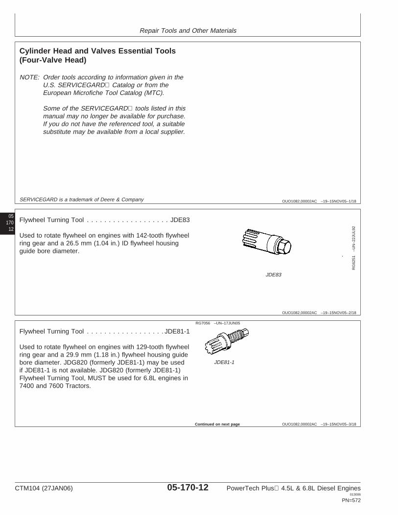
Repair Tools and Other Materials
OUO1082,00002AC –19–15NOV05–1/18
Cylinder Head and Valves Essential Tools(Four-Valve Head)
NOTE: Order tools according to information given in theU.S. SERVICEGARD Catalog or from theEuropean Microfiche Tool Catalog (MTC).
Some of the SERVICEGARD tools listed in thismanual may no longer be available for purchase.If you do not have the referenced tool, a suitablesubstitute may be available from a local supplier.
05170
12
SERVICEGARD is a trademark of Deere & Company
OUO1082,00002AC –19–15NOV05–2/18
RG
6251
–UN
–22J
UL9
2
JDE83
Flywheel Turning Tool . . . . . . . . . . . . . . . . . . . JDE83
Used to rotate flywheel on engines with 142-tooth flywheelring gear and a 26.5 mm (1.04 in.) ID flywheel housingguide bore diameter.
OUO1082,00002AC –19–15NOV05–3/18
RG7056 –UN–17JUN05
JDE81-1
Flywheel Turning Tool . . . . . . . . . . . . . . . . . . JDE81-1
Used to rotate flywheel on engines with 129-tooth flywheelring gear and a 29.9 mm (1.18 in.) flywheel housing guidebore diameter. JDG820 (formerly JDE81-1) may be usedif JDE81-1 is not available. JDG820 (formerly JDE81-1)Flywheel Turning Tool, MUST be used for 6.8L engines in7400 and 7600 Tractors.
Continued on next page
CTM104 (27JAN06) 05-170-12 PowerTech Plus 4.5L & 6.8L Diesel Engines013006
PN=572
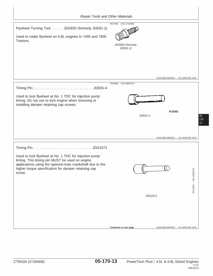
Repair Tools and Other Materials
OUO1082,00002AC –19–15NOV05–4/18
RG7056 –UN–17JUN05
JDG820 (formerlyJDE81-1)
Flywheel Turning Tool . . . . . JDG820 (formerly JDE81-1)
Used to rotate flywheel on 6.8L engines in 7400 and 7600Tractors.
0517013
OUO1082,00002AC –19–15NOV05–5/18
RG5068 –UN–05DEC97
JDE81-4
Timing Pin . . . . . . . . . . . . . . . . . . . . . . . . . . JDE81-4
Used to lock flywheel at No. 1 TDC for injection pumptiming. Do not use to lock engine when removing orinstalling damper retaining cap screws.
OUO1082,00002AC –19–15NOV05–6/18
RG
1203
1–U
N–2
0DE
C01
JDG1571
Timing Pin . . . . . . . . . . . . . . . . . . . . . . . . . JDG1571
Used to lock flywheel at No. 1 TDC for injection pumptiming. This timing pin MUST be used on engineapplications using the tapered-nose crankshaft due to thehigher torque specification for damper retaining capscrew.
Continued on next page
CTM104 (27JAN06) 05-170-13 PowerTech Plus 4.5L & 6.8L Diesel Engines013006
PN=573
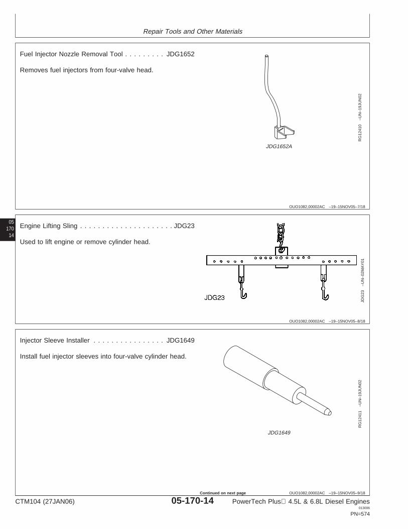
Repair Tools and Other Materials
OUO1082,00002AC –19–15NOV05–7/18
RG
1241
0–U
N–1
9JU
N02
JDG1652A
Fuel Injector Nozzle Removal Tool . . . . . . . . . JDG1652
Removes fuel injectors from four-valve head.
05170
14
OUO1082,00002AC –19–15NOV05–8/18
JDG
23–U
N–0
2MA
Y01
Engine Lifting Sling . . . . . . . . . . . . . . . . . . . . . JDG23
Used to lift engine or remove cylinder head.
OUO1082,00002AC –19–15NOV05–9/18
RG
1241
1–U
N–1
9JU
N02
JDG1649
Injector Sleeve Installer . . . . . . . . . . . . . . . . JDG1649
Install fuel injector sleeves into four-valve cylinder head.
CTM104 (27JAN06) 05-170-14 PowerTech Plus 4.5L & 6.8L Diesel Engines013006
PN=574
Continued on next page
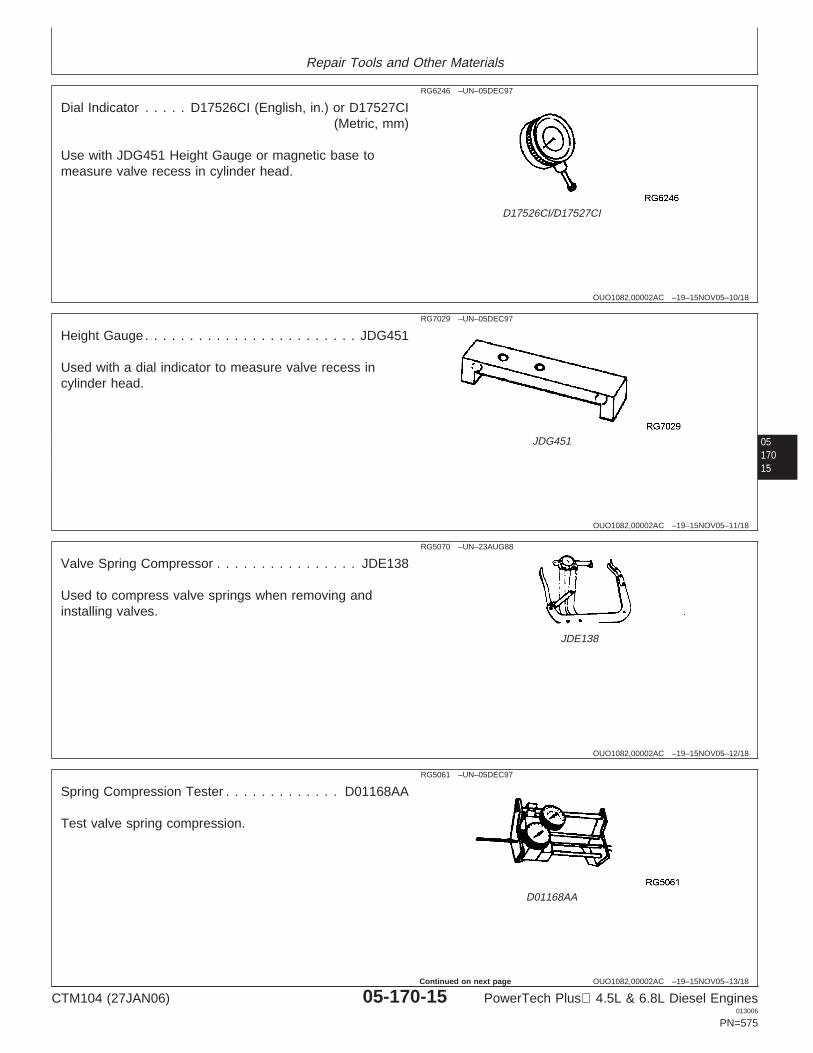
Repair Tools and Other Materials
OUO1082,00002AC –19–15NOV05–10/18
RG6246 –UN–05DEC97
D17526CI/D17527CI
Dial Indicator . . . . . D17526CI (English, in.) or D17527CI(Metric, mm)
Use with JDG451 Height Gauge or magnetic base tomeasure valve recess in cylinder head.
0517015
OUO1082,00002AC –19–15NOV05–11/18
RG7029 –UN–05DEC97
JDG451
Height Gauge . . . . . . . . . . . . . . . . . . . . . . . . JDG451
Used with a dial indicator to measure valve recess incylinder head.
OUO1082,00002AC –19–15NOV05–12/18
RG5070 –UN–23AUG88
JDE138
Valve Spring Compressor . . . . . . . . . . . . . . . . JDE138
Used to compress valve springs when removing andinstalling valves.
OUO1082,00002AC –19–15NOV05–13/18
RG5061 –UN–05DEC97
D01168AA
Spring Compression Tester . . . . . . . . . . . . . D01168AA
Test valve spring compression.
CTM104 (27JAN06) 05-170-15 PowerTech Plus 4.5L & 6.8L Diesel Engines013006
PN=575
Continued on next page
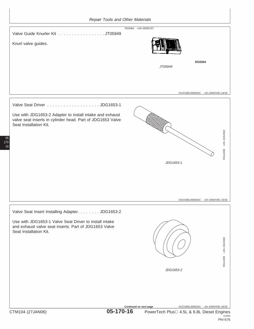
Repair Tools and Other Materials
OUO1082,00002AC –19–15NOV05–14/18
RG5064 –UN–05DEC97
JT05949
Valve Guide Knurler Kit . . . . . . . . . . . . . . . . . JT05949
Knurl valve guides.
05170
16
OUO1082,00002AC –19–15NOV05–15/18
RG
1240
8–U
N–1
9JU
N02
JDG1653-1
Valve Seat Driver . . . . . . . . . . . . . . . . . . . JDG1653-1
Use with JDG1653-2 Adapter to install intake and exhaustvalve seat inserts in cylinder head. Part of JDG1653 ValveSeat Installation Kit.
OUO1082,00002AC –19–15NOV05–16/18
RG
1240
9–U
N–1
9JU
N02
JDG1653-2
Valve Seat Insert Installing Adapter. . . . . . . . JDG1653-2
Use with JDG1653-1 Valve Seat Driver to install intakeand exhaust valve seat inserts. Part of JDG1653 ValveSeat Installation Kit.
CTM104 (27JAN06) 05-170-16 PowerTech Plus 4.5L & 6.8L Diesel Engines013006
PN=576
Continued on next page
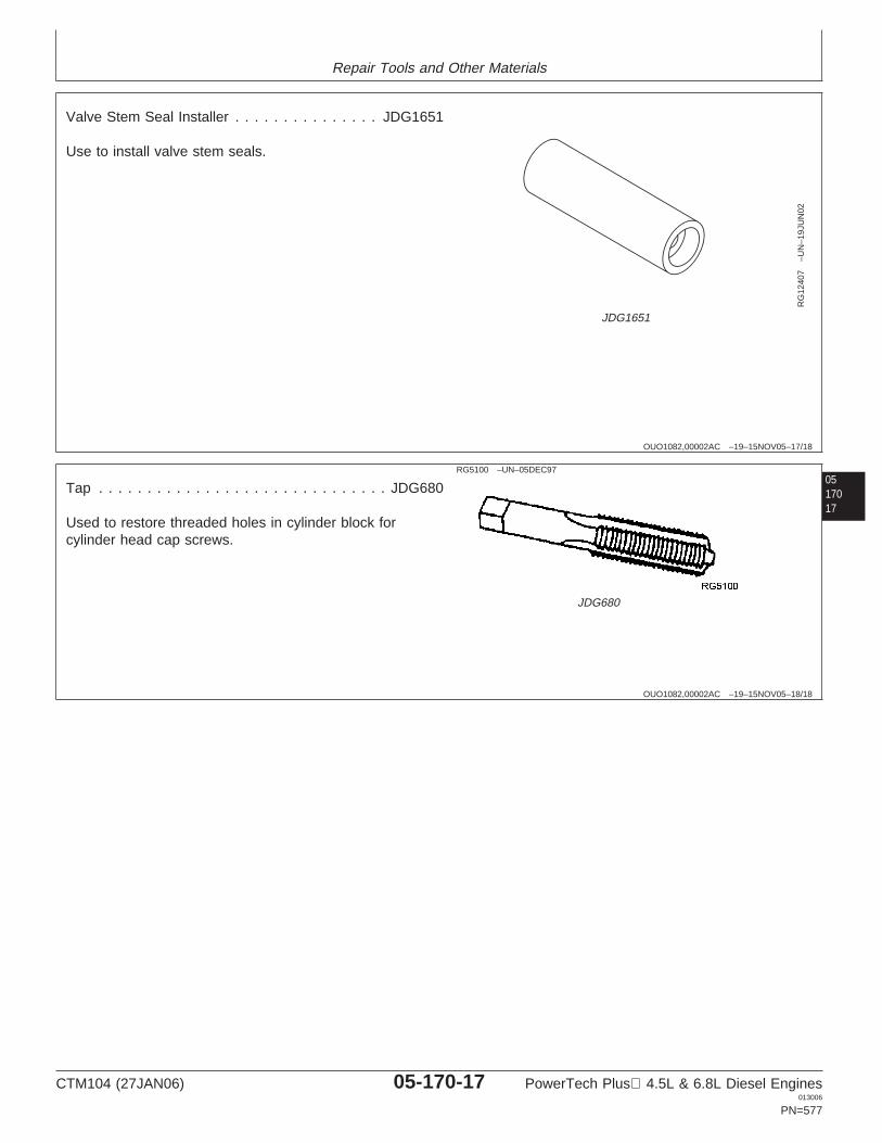
Repair Tools and Other Materials
OUO1082,00002AC –19–15NOV05–17/18
RG
1240
7–U
N–1
9JU
N02
JDG1651
Valve Stem Seal Installer . . . . . . . . . . . . . . . JDG1651
Use to install valve stem seals.
0517017
OUO1082,00002AC –19–15NOV05–18/18
RG5100 –UN–05DEC97
JDG680
Tap . . . . . . . . . . . . . . . . . . . . . . . . . . . . . . JDG680
Used to restore threaded holes in cylinder block forcylinder head cap screws.
CTM104 (27JAN06) 05-170-17 PowerTech Plus 4.5L & 6.8L Diesel Engines013006
PN=577
Repair Tools and Other Materials
OUO1089,0000239 –19–18JUN02–1/9
Service Equipment and Tools (Four-ValveHead)
NOTE: Order tools according to information given in theU.S. SERVICEGARD Catalog or from theEuropean Microfiche Tool Catalog (MTC). Sometools may be available from a local supplier.
Some of the SERVICEGARD tools listed in thismanual may no longer be available for purchase.If you do not have the referenced tool, a suitablesubstitute may be available from a local supplier.
05170
18
SERVICEGARD is a trademark of Deere & Company
OUO1089,0000239 –19–18JUN02–2/9
Crankshaft Front/Rear Rotation Adapter. . . . . . . JDG966
Rotate straight nose crankshaft from front and rear withflywheel removed.
OUO1089,0000239 –19–18JUN02–3/9
Valve Inspection Center
Check valves for out-of-round.
OUO1089,0000239 –19–18JUN02–4/9
Precision “Bevelled Edge” Straightedge . . . . . D05012ST
Check cylinder head flatness.
OUO1089,0000239 –19–18JUN02–5/9
Plastic Brush
Clean fuel injection nozzle bores.
OUO1089,0000239 –19–18JUN02–6/9
Plastic Brush
Clean glow plug bores.
CTM104 (27JAN06) 05-170-18 PowerTech Plus 4.5L & 6.8L Diesel Engines013006
PN=578
Continued on next page
Repair Tools and Other Materials
OUO1089,0000239 –19–18JUN02–7/9
Plastic Brush
Clean valve guides.
OUO1089,0000239 –19–18JUN02–8/9
End Brush . . . . . . . . . . . . . . . . . . . . . . . . D17024BR
Remove carbon on valve seats.
OUO1089,0000239 –19–18JUN02–9/9
Torque Angle Gauge . . . . . . . . . . . . . . . . . . . JT05993
Used to TORQUE-TURN flanged-head cylinder head andconnecting rod cap screws.
0517019
CTM104 (27JAN06) 05-170-19 PowerTech Plus 4.5L & 6.8L Diesel Engines013006
PN=579
Repair Tools and Other Materials
05170
20
OUO1089,000023A –19–23JAN04–1/1
Other Material (Four-Valve Head)
Number Name Use
T43514 (U.S.) LOCTITE 277 High Strength, Used to install end plugs on rockerThreadlock (50 ml Bottle) arm shaft.
TY9375 (U.S.) LOCTITE 592 (50 ml Bottle) Applied to outer surface of fuelinjection nozzle sleeves.
AR44402 (U.S.) Lubricant Coat Valve Stems and entire lengthof valve guide bores.
TY9370 (Canadian) Thread Lock and Sealer (Medium Apply to cap screws for rocker arm242 (LOCTITE) Strength) shaft end clamps.
Number Name Use
JDT305 (U.S.) Lubricant Lubricate head bolt beforeinstallation.
LOCTITE is a trademark of Loctite Corp.
DPSG,OUO1004,2711 –19–26APR00–1/14
Cylinder Block, Liners, Pistons and RodsEssential Tools
NOTE: Order tools according to information given in theU.S. SERVICEGARD Catalog or from theEuropean Microfiche Tool Catalog (MTC).
Some of the SERVICEGARD tools listed in thismanual may no longer be available for purchase.If you do not have the referenced tool, a suitablesubstitute may be available from a local supplier.
SERVICEGARD is a trademark of Deere & Company Continued on next page
CTM104 (27JAN06) 05-170-20 PowerTech Plus 4.5L & 6.8L Diesel Engines013006
PN=580
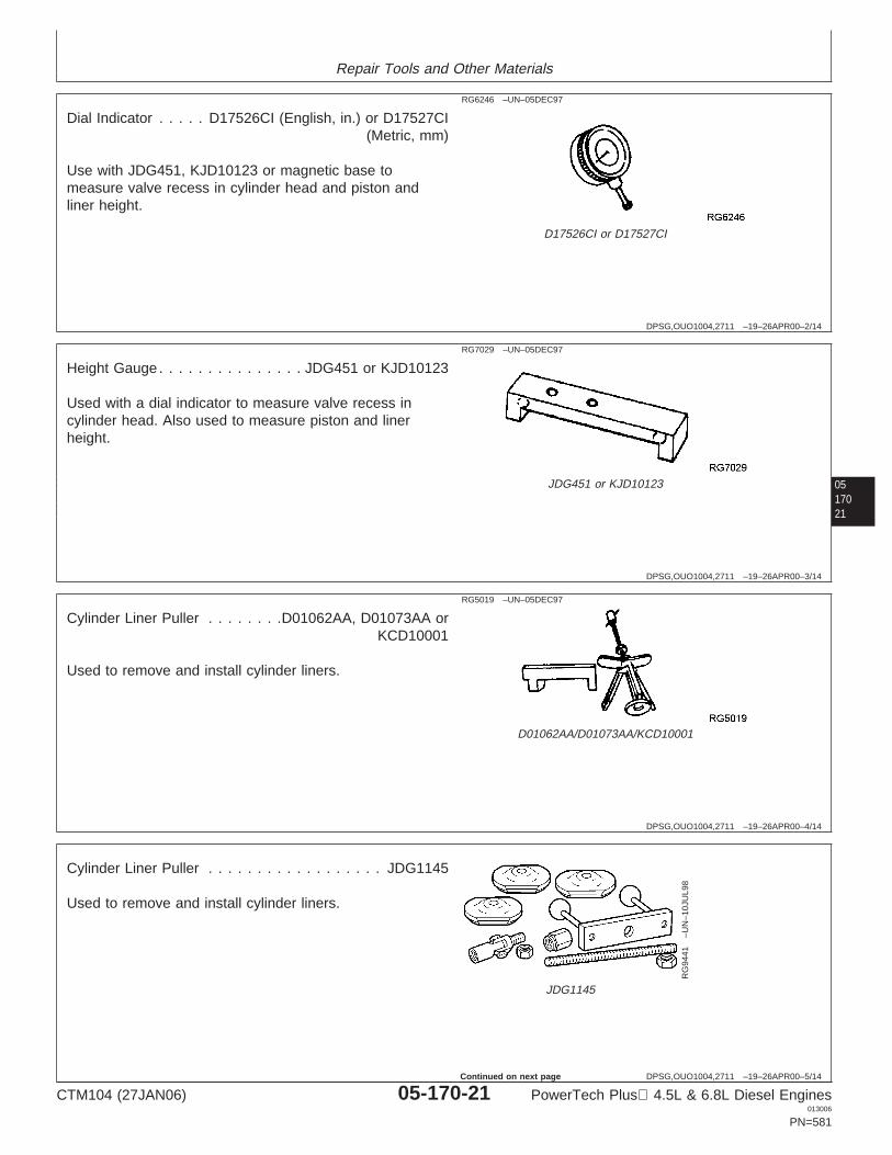
Repair Tools and Other Materials
DPSG,OUO1004,2711 –19–26APR00–2/14
RG6246 –UN–05DEC97
D17526CI or D17527CI
Dial Indicator . . . . . D17526CI (English, in.) or D17527CI(Metric, mm)
Use with JDG451, KJD10123 or magnetic base tomeasure valve recess in cylinder head and piston andliner height.
0517021
DPSG,OUO1004,2711 –19–26APR00–3/14
RG7029 –UN–05DEC97
JDG451 or KJD10123
Height Gauge . . . . . . . . . . . . . . . JDG451 or KJD10123
Used with a dial indicator to measure valve recess incylinder head. Also used to measure piston and linerheight.
DPSG,OUO1004,2711 –19–26APR00–4/14
RG5019 –UN–05DEC97
D01062AA/D01073AA/KCD10001
Cylinder Liner Puller . . . . . . . .D01062AA, D01073AA orKCD10001
Used to remove and install cylinder liners.
DPSG,OUO1004,2711 –19–26APR00–5/14
RG
9441
–UN
–10J
UL9
8
JDG1145
Cylinder Liner Puller . . . . . . . . . . . . . . . . . . JDG1145
Used to remove and install cylinder liners.
CTM104 (27JAN06) 05-170-21 PowerTech Plus 4.5L & 6.8L Diesel Engines013006
PN=581
Continued on next page
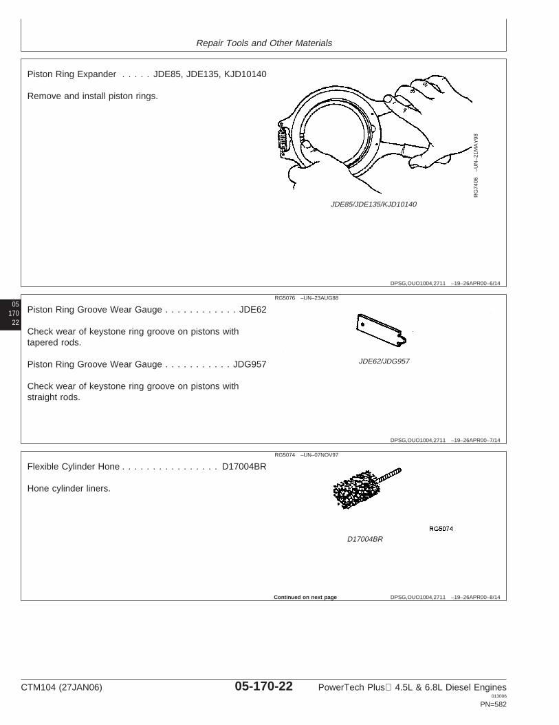
Repair Tools and Other Materials
DPSG,OUO1004,2711 –19–26APR00–6/14
RG
7406
–UN
–21M
AY
98
JDE85/JDE135/KJD10140
Piston Ring Expander . . . . . JDE85, JDE135, KJD10140
Remove and install piston rings.
05170
22
DPSG,OUO1004,2711 –19–26APR00–7/14
RG5076 –UN–23AUG88
JDE62/JDG957
Piston Ring Groove Wear Gauge . . . . . . . . . . . . JDE62
Check wear of keystone ring groove on pistons withtapered rods.
Piston Ring Groove Wear Gauge . . . . . . . . . . . JDG957
Check wear of keystone ring groove on pistons withstraight rods.
DPSG,OUO1004,2711 –19–26APR00–8/14
RG5074 –UN–07NOV97
D17004BR
Flexible Cylinder Hone . . . . . . . . . . . . . . . . D17004BR
Hone cylinder liners.
Continued on next page
CTM104 (27JAN06) 05-170-22 PowerTech Plus 4.5L & 6.8L Diesel Engines013006
PN=582
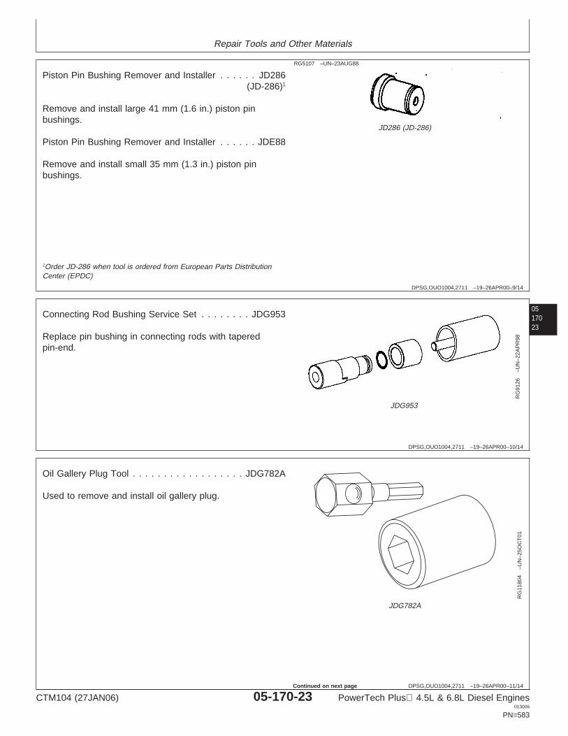
Repair Tools and Other Materials
DPSG,OUO1004,2711 –19–26APR00–9/14
RG5107 –UN–23AUG88
JD286 (JD-286)
Piston Pin Bushing Remover and Installer . . . . . . JD286(JD-286)1
Remove and install large 41 mm (1.6 in.) piston pinbushings.
Piston Pin Bushing Remover and Installer . . . . . . JDE88
Remove and install small 35 mm (1.3 in.) piston pinbushings.
0517023
1Order JD-286 when tool is ordered from European Parts DistributionCenter (EPDC)
DPSG,OUO1004,2711 –19–26APR00–10/14
RG
9126
–UN
–22A
PR
98
JDG953
Connecting Rod Bushing Service Set . . . . . . . . JDG953
Replace pin bushing in connecting rods with taperedpin-end.
DPSG,OUO1004,2711 –19–26APR00–11/14
RG
1180
4–U
N–2
5OC
T01
JDG782A
Oil Gallery Plug Tool . . . . . . . . . . . . . . . . . . JDG782A
Used to remove and install oil gallery plug.
CTM104 (27JAN06) 05-170-23 PowerTech Plus 4.5L & 6.8L Diesel Engines013006
PN=583
Continued on next page
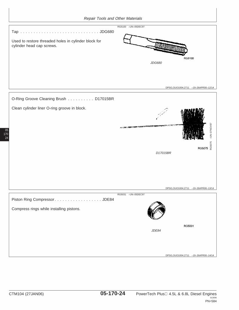
Repair Tools and Other Materials
DPSG,OUO1004,2711 –19–26APR00–12/14
RG5100 –UN–05DEC97
JDG680
Tap . . . . . . . . . . . . . . . . . . . . . . . . . . . . . . JDG680
Used to restore threaded holes in cylinder block forcylinder head cap screws.
05170
24
DPSG,OUO1004,2711 –19–26APR00–13/14
RG
5075
–UN
–07N
OV
97
D17015BR
O-Ring Groove Cleaning Brush . . . . . . . . . . D17015BR
Clean cylinder liner O-ring groove in block.
DPSG,OUO1004,2711 –19–26APR00–14/14
RG5031 –UN–05DEC97
JDE84
Piston Ring Compressor . . . . . . . . . . . . . . . . . . JDE84
Compress rings while installing pistons.
CTM104 (27JAN06) 05-170-24 PowerTech Plus 4.5L & 6.8L Diesel Engines013006
PN=584
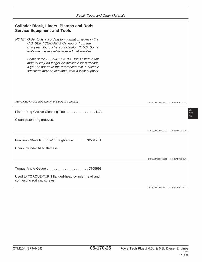
Repair Tools and Other Materials
DPSG,OUO1004,2713 –19–26APR00–1/4
Cylinder Block, Liners, Pistons and RodsService Equipment and Tools
NOTE: Order tools according to information given in theU.S. SERVICEGARD Catalog or from theEuropean Microfiche Tool Catalog (MTC). Sometools may be available from a local supplier.
Some of the SERVICEGARD tools listed in thismanual may no longer be available for purchase.If you do not have the referenced tool, a suitablesubstitute may be available from a local supplier.
0517025
SERVICEGARD is a trademark of Deere & Company
DPSG,OUO1004,2713 –19–26APR00–2/4
Piston Ring Groove Cleaning Tool . . . . . . . . . . . . . N/A
Clean piston ring grooves.
DPSG,OUO1004,2713 –19–26APR00–3/4
Precision “Bevelled Edge” Straightedge . . . . . D05012ST
Check cylinder head flatness.
DPSG,OUO1004,2713 –19–26APR00–4/4
Torque Angle Gauge . . . . . . . . . . . . . . . . . . . JT05993
Used to TORQUE-TURN flanged-head cylinder head andconnecting rod cap screws.
CTM104 (27JAN06) 05-170-25 PowerTech Plus 4.5L & 6.8L Diesel Engines013006
PN=585
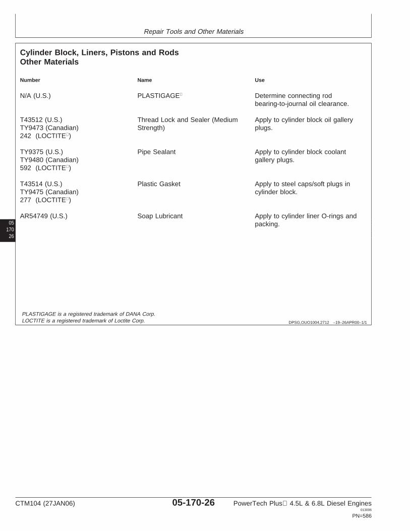
Repair Tools and Other Materials
05170
26
DPSG,OUO1004,2712 –19–26APR00–1/1
Cylinder Block, Liners, Pistons and RodsOther Materials
Number Name Use
N/A (U.S.) PLASTIGAGE Determine connecting rodbearing-to-journal oil clearance.
T43512 (U.S.) Thread Lock and Sealer (Medium Apply to cylinder block oil galleryTY9473 (Canadian) Strength) plugs.242 (LOCTITE)
TY9375 (U.S.) Pipe Sealant Apply to cylinder block coolantTY9480 (Canadian) gallery plugs.592 (LOCTITE)
T43514 (U.S.) Plastic Gasket Apply to steel caps/soft plugs inTY9475 (Canadian) cylinder block.277 (LOCTITE)
AR54749 (U.S.) Soap Lubricant Apply to cylinder liner O-rings andpacking.
PLASTIGAGE is a registered trademark of DANA Corp.LOCTITE is a registered trademark of Loctite Corp.
CTM104 (27JAN06) 05-170-26 PowerTech Plus 4.5L & 6.8L Diesel Engines013006
PN=586

Repair Tools and Other Materials
DPSG,OUO1004,2715 –19–25JAN06–1/18
Crankshaft, Main Bearings, Damper andFlywheel Essential Tools
NOTE: Order tools according to information given in theU.S. SERVICEGARD Catalog or from theEuropean Microfiche Tool Catalog (MTC).
Some of the SERVICEGARD tools listed in thismanual may no longer be available for purchase.If you do not have the referenced tool, a suitablesubstitute may be available from a local supplier.
0517027
SERVICEGARD is a trademark of Deere & Company
DPSG,OUO1004,2715 –19–25JAN06–2/18
RG6246 –UN–05DEC97
D17526CI or D17527CI
Dial Indicator . . . . . D17526CI (English, in.) or D17527CI(Metric, mm)
Used with magnetic base to measure radial runout(concentricity) and wobble on vibration damper.
DPSG,OUO1004,2715 –19–25JAN06–3/18
RG7056 –UN–17JUN05
JDE81-1
Flywheel Turning Tool . . . . . . . . . . . . . . . . . . JDE81-1
Used to rotate flywheel on engines with 129-tooth flywheelring gear and a 29.9 mm (1.18 in.) flywheel housing guidebore diameter. JDG820 (formerly JDE81-1) may be usedif JDE81-1 is not available. JDG820 (formerly JDE81-1)Flywheel Turning Tool, MUST be used for 6.8L engines in7400 and 7600 Tractors.
Continued on next page
CTM104 (27JAN06) 05-170-27 PowerTech Plus 4.5L & 6.8L Diesel Engines013006
PN=587
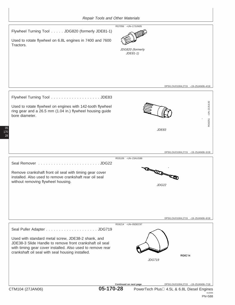
Repair Tools and Other Materials
DPSG,OUO1004,2715 –19–25JAN06–4/18
RG7056 –UN–17JUN05
JDG820 (formerlyJDE81-1)
Flywheel Turning Tool . . . . . JDG820 (formerly JDE81-1)
Used to rotate flywheel on 6.8L engines in 7400 and 7600Tractors.
05170
28
DPSG,OUO1004,2715 –19–25JAN06–5/18
RG
6251
–UN
–22J
UL9
2
JDE83
Flywheel Turning Tool . . . . . . . . . . . . . . . . . . . JDE83
Used to rotate flywheel on engines with 142-tooth flywheelring gear and a 26.5 mm (1.04 in.) flywheel housing guidebore diameter.
DPSG,OUO1004,2715 –19–25JAN06–6/18
RG5109 –UN–23AUG88
JDG22
Seal Remover . . . . . . . . . . . . . . . . . . . . . . . . JDG22
Remove crankshaft front oil seal with timing gear coverinstalled. Also used to remove crankshaft rear oil sealwithout removing flywheel housing.
DPSG,OUO1004,2715 –19–25JAN06–7/18
RG6214 –UN–05DEC97
JDG719
Seal Puller Adapter . . . . . . . . . . . . . . . . . . . . JDG719
Used with standard metal screw, JDE38-2 shank, andJDE38-3 Slide Handle to remove front crankshaft oil sealwith timing gear cover installed. Also used to remove rearcrankshaft oil seal with seal housing installed.
CTM104 (27JAN06) 05-170-28 PowerTech Plus 4.5L & 6.8L Diesel Engines013006
PN=588
Continued on next page
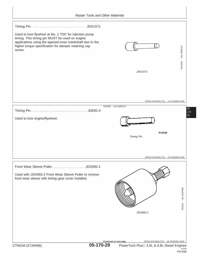
Repair Tools and Other Materials
DPSG,OUO1004,2715 –19–25JAN06–8/18
RG
1203
1–U
N–2
0DE
C01
JDG1571
Timing Pin . . . . . . . . . . . . . . . . . . . . . . . . . JDG1571
Used to lock flywheel at No. 1 TDC for injection pumptiming. This timing pin MUST be used on engineapplications using the tapered-nose crankshaft due to thehigher torque specification for damper retaining capscrew.
0517029
DPSG,OUO1004,2715 –19–25JAN06–9/18
RG5068 –UN–05DEC97
Timing Pin
Timing Pin . . . . . . . . . . . . . . . . . . . . . . . . . . JDE81-4
Used to lock engine/flywheel.
DPSG,OUO1004,2715 –19–25JAN06–10/18
RG
9124
–UN
–22A
PR
98
JDG992-1
Front Wear Sleeve Puller . . . . . . . . . . . . . . . JDG992-1
Used with JDG992-2 Front Wear Sleeve Puller to removefront wear sleeve with timing gear cover installed.
CTM104 (27JAN06) 05-170-29 PowerTech Plus 4.5L & 6.8L Diesel Engines013006
PN=589
Continued on next page
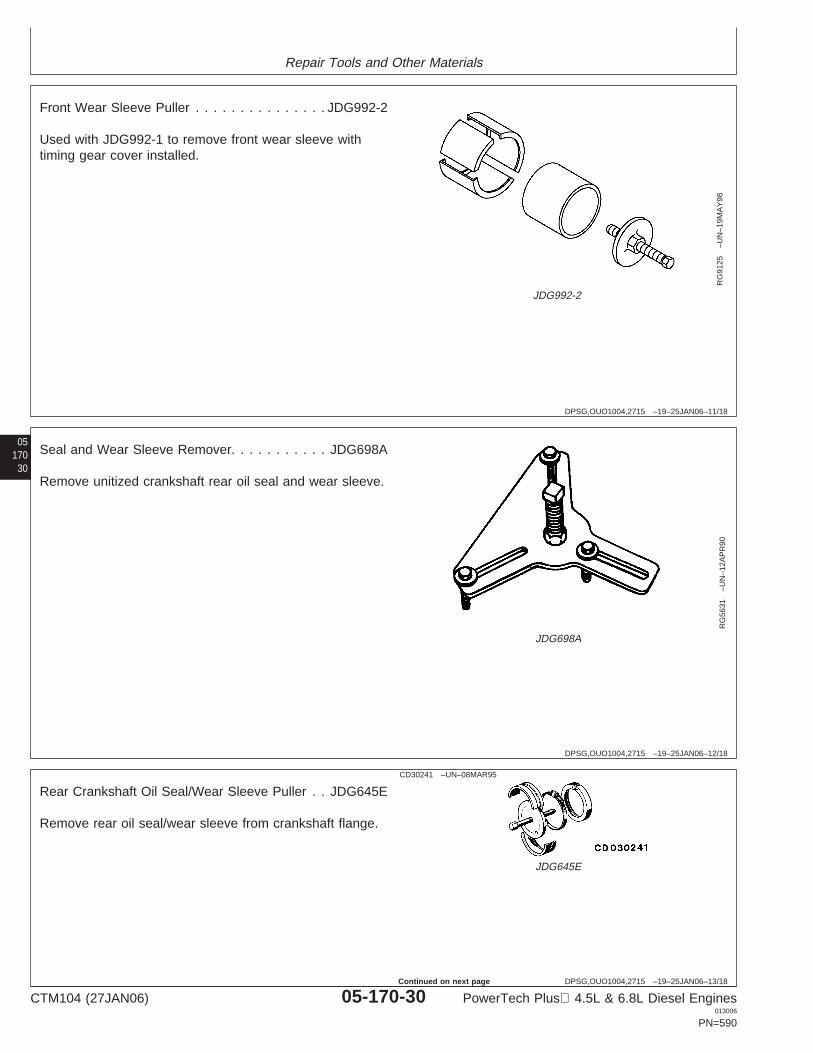
Repair Tools and Other Materials
DPSG,OUO1004,2715 –19–25JAN06–11/18
RG
9125
–UN
–19M
AY
98
JDG992-2
Front Wear Sleeve Puller . . . . . . . . . . . . . . . JDG992-2
Used with JDG992-1 to remove front wear sleeve withtiming gear cover installed.
05170
30
DPSG,OUO1004,2715 –19–25JAN06–12/18
RG
5631
–UN
–12A
PR
90
JDG698A
Seal and Wear Sleeve Remover. . . . . . . . . . . JDG698A
Remove unitized crankshaft rear oil seal and wear sleeve.
DPSG,OUO1004,2715 –19–25JAN06–13/18
CD30241 –UN–08MAR95
JDG645E
Rear Crankshaft Oil Seal/Wear Sleeve Puller . . JDG645E
Remove rear oil seal/wear sleeve from crankshaft flange.
CTM104 (27JAN06) 05-170-30 PowerTech Plus 4.5L & 6.8L Diesel Engines013006
PN=590
Continued on next page
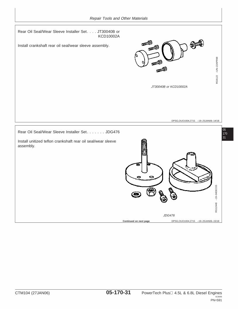
Repair Tools and Other Materials
DPSG,OUO1004,2715 –19–25JAN06–14/18
RG
9122
–UN
–22A
PR
98
JT30040B or KCD10002A
Rear Oil Seal/Wear Sleeve Installer Set . . . . JT30040B orKCD10002A
Install crankshaft rear oil seal/wear sleeve assembly.
0517031
DPSG,OUO1004,2715 –19–25JAN06–15/18
RG
1244
8–1
9–04
DE
C03
JDG476
Rear Oil Seal/Wear Sleeve Installer Set . . . . . . . JDG476
Install unitized teflon crankshaft rear oil seal/wear sleeveassembly.
Continued on next page
CTM104 (27JAN06) 05-170-31 PowerTech Plus 4.5L & 6.8L Diesel Engines013006
PN=591
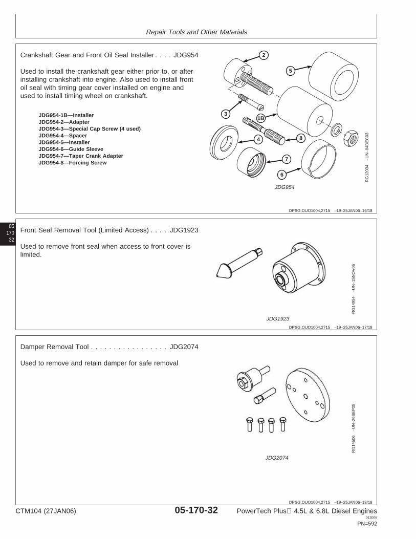
Repair Tools and Other Materials
DPSG,OUO1004,2715 –19–25JAN06–16/18
2
4 8
7
6
31B
5
RG
1203
4–U
N–0
4DE
C03
JDG954
JDG954-1B—InstallerJDG954-2—AdapterJDG954-3—Special Cap Screw (4 used)JDG954-4—SpacerJDG954-5—InstallerJDG954-6—Guide SleeveJDG954-7—Taper Crank AdapterJDG954-8—Forcing Screw
Crankshaft Gear and Front Oil Seal Installer . . . . JDG954
Used to install the crankshaft gear either prior to, or afterinstalling crankshaft into engine. Also used to install frontoil seal with timing gear cover installed on engine andused to install timing wheel on crankshaft.
05170
32
DPSG,OUO1004,2715 –19–25JAN06–17/18
RG
1495
4–U
N–1
5NO
V05
JDG1923
Front Seal Removal Tool (Limited Access) . . . . JDG1923
Used to remove front seal when access to front cover islimited.
DPSG,OUO1004,2715 –19–25JAN06–18/18
RG
1450
6–U
N–2
6SE
P05
JDG2074
Damper Removal Tool . . . . . . . . . . . . . . . . . JDG2074
Used to remove and retain damper for safe removal
CTM104 (27JAN06) 05-170-32 PowerTech Plus 4.5L & 6.8L Diesel Engines013006
PN=592
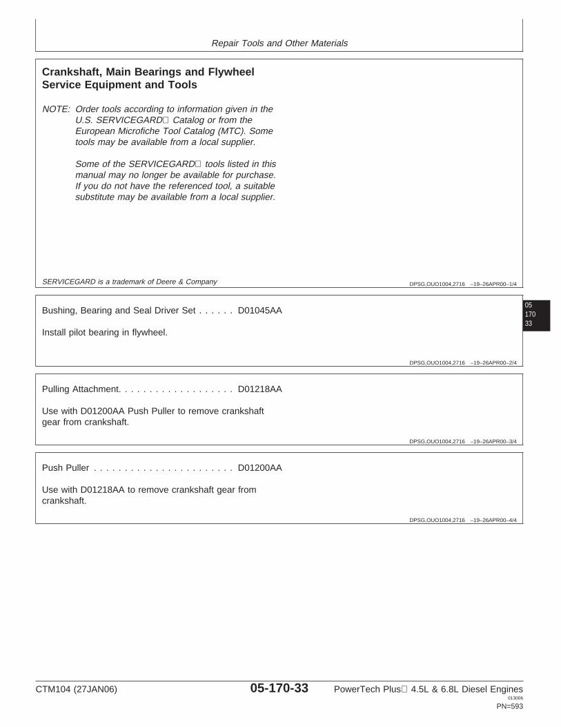
Repair Tools and Other Materials
DPSG,OUO1004,2716 –19–26APR00–1/4
Crankshaft, Main Bearings and FlywheelService Equipment and Tools
NOTE: Order tools according to information given in theU.S. SERVICEGARD Catalog or from theEuropean Microfiche Tool Catalog (MTC). Sometools may be available from a local supplier.
Some of the SERVICEGARD tools listed in thismanual may no longer be available for purchase.If you do not have the referenced tool, a suitablesubstitute may be available from a local supplier.
0517033
SERVICEGARD is a trademark of Deere & Company
DPSG,OUO1004,2716 –19–26APR00–2/4
Bushing, Bearing and Seal Driver Set . . . . . . D01045AA
Install pilot bearing in flywheel.
DPSG,OUO1004,2716 –19–26APR00–3/4
Pulling Attachment. . . . . . . . . . . . . . . . . . . D01218AA
Use with D01200AA Push Puller to remove crankshaftgear from crankshaft.
DPSG,OUO1004,2716 –19–26APR00–4/4
Push Puller . . . . . . . . . . . . . . . . . . . . . . . D01200AA
Use with D01218AA to remove crankshaft gear fromcrankshaft.
CTM104 (27JAN06) 05-170-33 PowerTech Plus 4.5L & 6.8L Diesel Engines013006
PN=593
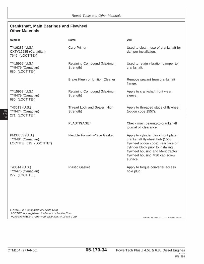
Repair Tools and Other Materials
05170
34
DPSG,OUO1004,2717 –19–24MAY02–1/1
Crankshaft, Main Bearings and FlywheelOther Materials
Number Name Use
TY16285 (U.S.) Cure Primer Used to clean nose of crankshaft forCXTY16285 (Canadian) damper installation.7649 (LOCTITE)
TY15969 (U.S.) Retaining Compound (Maximum Used to retain vibration damper toTY9479 (Canadian) Strength) crankshaft.680 (LOCTITE)
Brake Kleen or Ignition Cleaner Remove sealant from crankshaftflange.
TY15969 (U.S.) Retaining Compound (Maximum Apply to crankshaft front wearTY9479 (Canadian) Strength) sleeve.680 (LOCTITE)
T43513 (U.S.) Thread Lock and Sealer (High Apply to threaded studs of flywheelTY9474 (Canadian) Strength) (option code 1557).271 (LOCTITE)
PLASTIGAGE Check main bearing-to-crankshaftjournal oil clearance.
PM38655 (U.S.) Flexible Form-In-Place Gasket Apply to cylinder block front plate,TY9484 (Canadian) crankshaft flywheel hub (1568LOCTITE 515 (LOCTITE) flywheel option code), rear face of
cylinder block prior to installingflywheel housing and Merit tractorflywheel housing M20 cap screwsurface.
T43514 (U.S.) Plastic Gasket Apply to torque converter accessTY9475 (Canadian) hole plug.277 (LOCTITE)
LOCTITE is a trademark of Loctite Corp.LOCTITE is a registered trademark of Loctite Corp.PLASTIGAGE is a registered trademark of DANA Corp.
CTM104 (27JAN06) 05-170-34 PowerTech Plus 4.5L & 6.8L Diesel Engines013006
PN=594
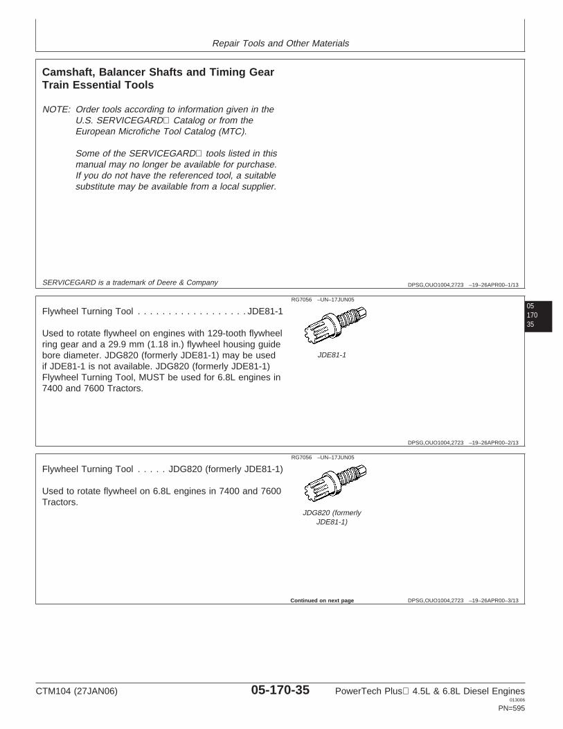
Repair Tools and Other Materials
DPSG,OUO1004,2723 –19–26APR00–1/13
Camshaft, Balancer Shafts and Timing GearTrain Essential Tools
NOTE: Order tools according to information given in theU.S. SERVICEGARD Catalog or from theEuropean Microfiche Tool Catalog (MTC).
Some of the SERVICEGARD tools listed in thismanual may no longer be available for purchase.If you do not have the referenced tool, a suitablesubstitute may be available from a local supplier.
0517035
SERVICEGARD is a trademark of Deere & Company
DPSG,OUO1004,2723 –19–26APR00–2/13
RG7056 –UN–17JUN05
JDE81-1
Flywheel Turning Tool . . . . . . . . . . . . . . . . . . JDE81-1
Used to rotate flywheel on engines with 129-tooth flywheelring gear and a 29.9 mm (1.18 in.) flywheel housing guidebore diameter. JDG820 (formerly JDE81-1) may be usedif JDE81-1 is not available. JDG820 (formerly JDE81-1)Flywheel Turning Tool, MUST be used for 6.8L engines in7400 and 7600 Tractors.
DPSG,OUO1004,2723 –19–26APR00–3/13
RG7056 –UN–17JUN05
JDG820 (formerlyJDE81-1)
Flywheel Turning Tool . . . . . JDG820 (formerly JDE81-1)
Used to rotate flywheel on 6.8L engines in 7400 and 7600Tractors.
Continued on next page
CTM104 (27JAN06) 05-170-35 PowerTech Plus 4.5L & 6.8L Diesel Engines013006
PN=595

Repair Tools and Other Materials
DPSG,OUO1004,2723 –19–26APR00–4/13
RG
6251
–UN
–22J
UL9
2
JDE83
Flywheel Turning Tool . . . . . . . . . . . . . . . . . . . JDE83
Used to rotate flywheel on engines with 142-tooth flywheelring gears and a 26.5 mm (1.04 in.) ID flywheel housingguide bore diameter.
05170
36
DPSG,OUO1004,2723 –19–26APR00–5/13
RG5068 –UN–05DEC97
JDE81-4
Timing Pin . . . . . . . . . . . . . . . . . . . . . . . . . . JDE81-4
Used to lock flywheel at No. 1 TDC for injection pumptiming. Do not use to lock engine when removing orinstalling damper retaining cap screws.
DPSG,OUO1004,2723 –19–26APR00–6/13
RG
1203
1–U
N–2
0DE
C01
JDG1571
Timing Pin . . . . . . . . . . . . . . . . . . . . . . . . . JDG1571
Used to lock flywheel at No. 1 TDC for injection pumptiming. This timing pin MUST be used on engineapplications using the tapered-nose crankshaft due to thehigher torque specification for damper retaining capscrew.
Continued on next page
CTM104 (27JAN06) 05-170-36 PowerTech Plus 4.5L & 6.8L Diesel Engines013006
PN=596
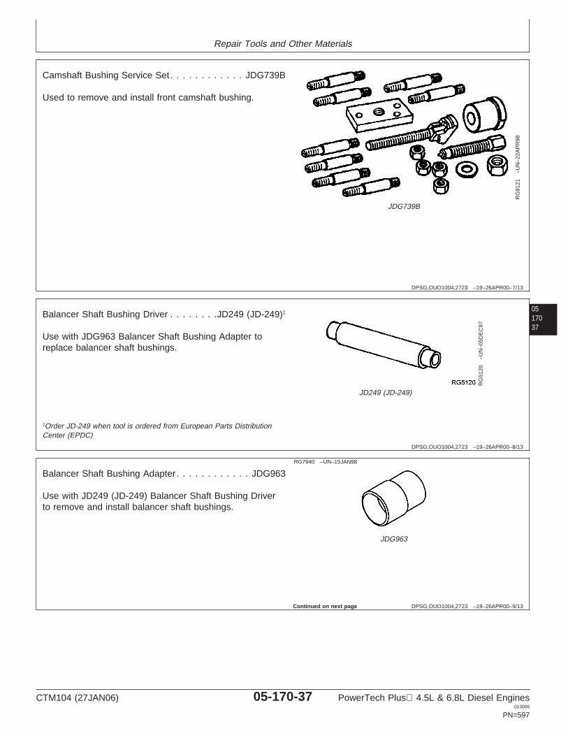
Repair Tools and Other Materials
DPSG,OUO1004,2723 –19–26APR00–7/13
RG
9121
–UN
–22A
PR
98
JDG739B
Camshaft Bushing Service Set. . . . . . . . . . . . JDG739B
Used to remove and install front camshaft bushing.
0517037
DPSG,OUO1004,2723 –19–26APR00–8/13
RG
5120
–UN
–05D
EC
97
JD249 (JD-249)
Balancer Shaft Bushing Driver . . . . . . . .JD249 (JD-249)1
Use with JDG963 Balancer Shaft Bushing Adapter toreplace balancer shaft bushings.
1Order JD-249 when tool is ordered from European Parts DistributionCenter (EPDC)
DPSG,OUO1004,2723 –19–26APR00–9/13
RG7940 –UN–15JAN98
JDG963
Balancer Shaft Bushing Adapter . . . . . . . . . . . . JDG963
Use with JD249 (JD-249) Balancer Shaft Bushing Driverto remove and install balancer shaft bushings.
Continued on next page
CTM104 (27JAN06) 05-170-37 PowerTech Plus 4.5L & 6.8L Diesel Engines013006
PN=597
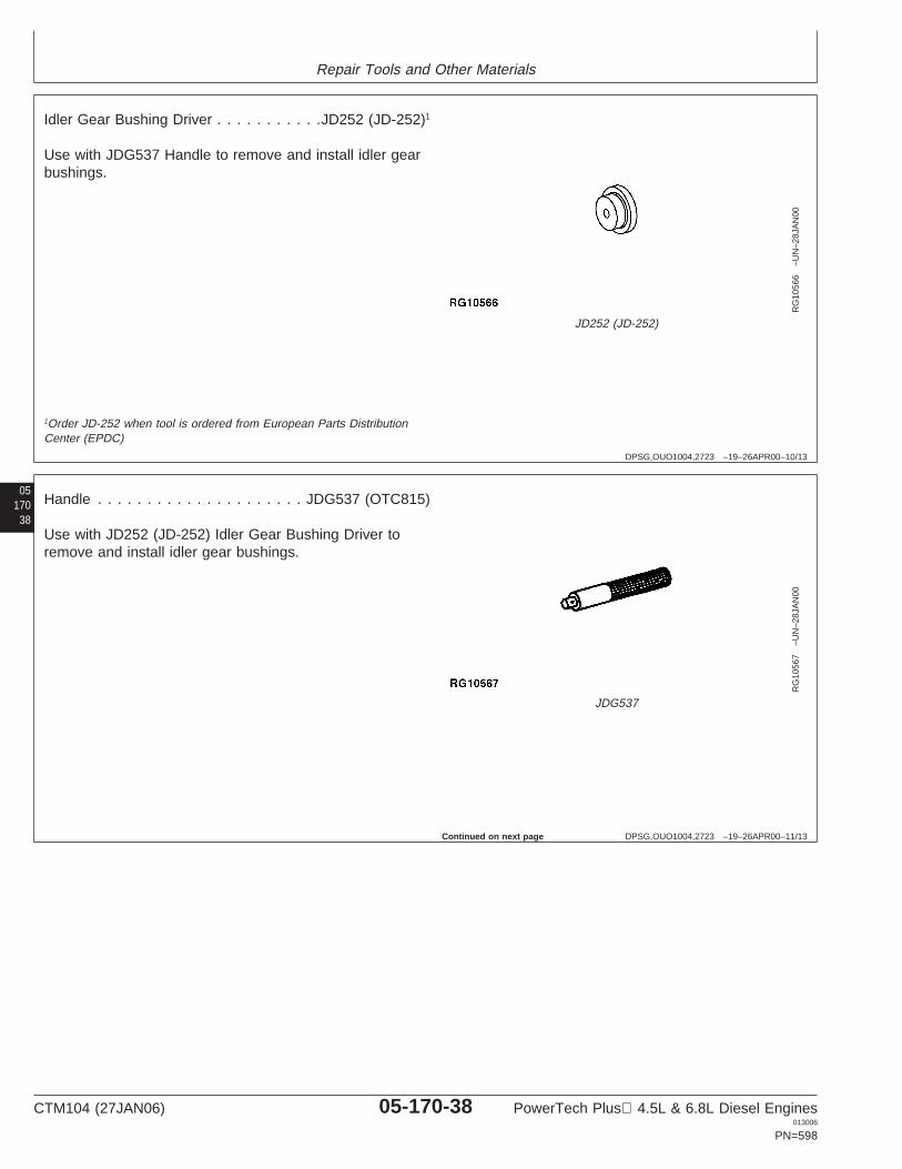
Repair Tools and Other Materials
DPSG,OUO1004,2723 –19–26APR00–10/13
RG
1056
6–U
N–2
8JA
N00
JD252 (JD-252)
Idler Gear Bushing Driver . . . . . . . . . . .JD252 (JD-252)1
Use with JDG537 Handle to remove and install idler gearbushings.
05170
38
1Order JD-252 when tool is ordered from European Parts DistributionCenter (EPDC)
DPSG,OUO1004,2723 –19–26APR00–11/13
RG
1056
7–U
N–2
8JA
N00
JDG537
Handle . . . . . . . . . . . . . . . . . . . . . JDG537 (OTC815)
Use with JD252 (JD-252) Idler Gear Bushing Driver toremove and install idler gear bushings.
Continued on next page
CTM104 (27JAN06) 05-170-38 PowerTech Plus 4.5L & 6.8L Diesel Engines013006
PN=598
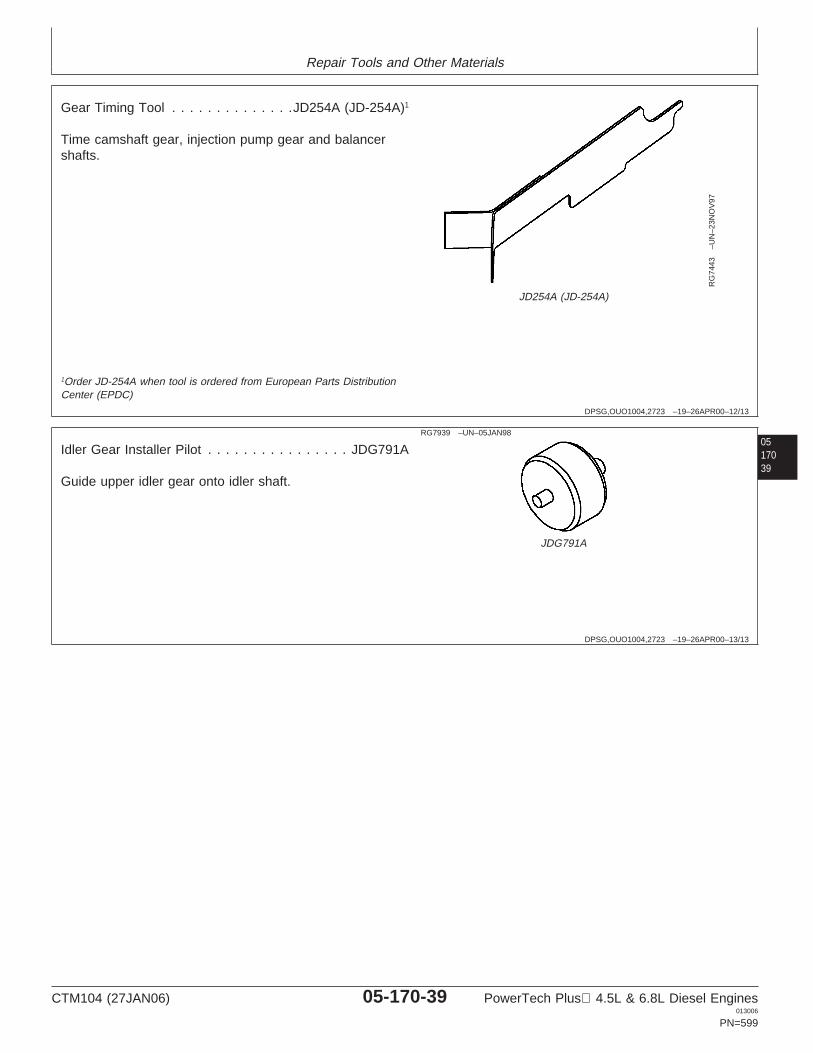
Repair Tools and Other Materials
DPSG,OUO1004,2723 –19–26APR00–12/13
RG
7443
–UN
–23N
OV
97
JD254A (JD-254A)
Gear Timing Tool . . . . . . . . . . . . . .JD254A (JD-254A)1
Time camshaft gear, injection pump gear and balancershafts.
0517039
1Order JD-254A when tool is ordered from European Parts DistributionCenter (EPDC)
DPSG,OUO1004,2723 –19–26APR00–13/13
RG7939 –UN–05JAN98
JDG791A
Idler Gear Installer Pilot . . . . . . . . . . . . . . . . JDG791A
Guide upper idler gear onto idler shaft.
CTM104 (27JAN06) 05-170-39 PowerTech Plus 4.5L & 6.8L Diesel Engines013006
PN=599
Repair Tools and Other Materials
DPSG,OUO1004,2724 –19–26APR00–1/5
Camshaft, Balancer Shafts and Timing GearTrain Service Equipment and Tools
NOTE: Order tools according to information given in theU.S. SERVICEGARD Catalog or from theEuropean Microfiche Tool Catalog (MTC). Sometools may be available from a local supplier.
Some of the SERVICEGARD tools listed in thismanual may no longer be available for purchase.If you do not have the referenced tool, a suitablesubstitute may be available from a local supplier.
05170
40
SERVICEGARD is a trademark of Deere & Company
DPSG,OUO1004,2724 –19–26APR00–2/5
Magnetic Follower Holder Kit . . . . . . . . . . . . D15001NU
Hold camshaft followers when removing and installingcamshaft.
DPSG,OUO1004,2724 –19–26APR00–3/5
Balancer Shaft Holding Tool . . . . . . . . .JD247 (JD-247)1
Hold balancer shaft while pressing gear on shaft.
1Order JD-247 when tool is ordered from European Parts DistributionCenter (EPDC)
DPSG,OUO1004,2724 –19–26APR00–4/5
TORX Driver Set
Remove and install engine front plate mounting hardware.
TORX is a registered trademark of Camcar/Textron
CTM104 (27JAN06) 05-170-40 PowerTech Plus 4.5L & 6.8L Diesel Engines013006
PN=600
Continued on next page
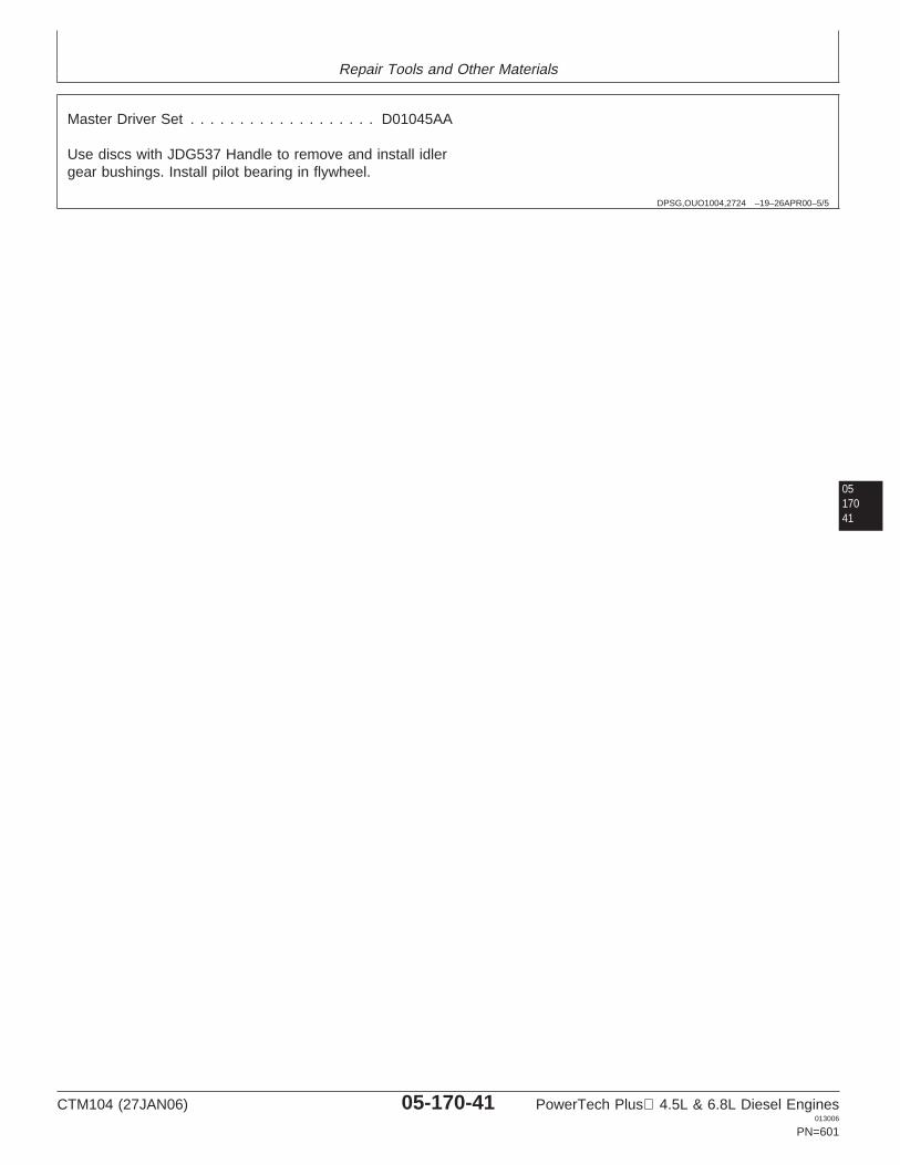
Repair Tools and Other Materials
DPSG,OUO1004,2724 –19–26APR00–5/5
Master Driver Set . . . . . . . . . . . . . . . . . . . D01045AA
Use discs with JDG537 Handle to remove and install idlergear bushings. Install pilot bearing in flywheel.
0517041
CTM104 (27JAN06) 05-170-41 PowerTech Plus 4.5L & 6.8L Diesel Engines013006
PN=601

Repair Tools and Other Materials
05170
42
DPSG,OUO1004,2725 –19–26APR00–1/1
Camshaft, Balancer Shafts and Timing GearTrain Other Materials
Number Name Use
TY6333 (U.S.) High-Temperature Grease Coat camshaft followers, camshaftlobes, journals and bushings duringinstallation. Coat idler gear, bushing,and shaft during installation.
PM38655 (U.S.) Flexible Form-In-Place Gasket Apply to cylinder block front plate.TY9484 (Canadian)515 (LOCTITE)
T43512 (U.S.) Thread Lock and Sealer (Medium Apply to injection pump cover capTY9473 (Canadian) Strength) screws.242 (LOCTITE)
T43513 (U.S.) Thread Lock and Sealer (High Apply to four timing gear cover studsTY9474 (Canadian) Strength) used on OEM engine applications271 (LOCTITE) with auxiliary driven hydraulic pump.
TY9375 (U.S.) Pipe Sealant Apply to one timing gear cover capTY9480 (Canadian) screw.592 (LOCTITE)
LOCTITE is a registered trademark of Loctite Corp.
CTM104 (27JAN06) 05-170-42 PowerTech Plus 4.5L & 6.8L Diesel Engines013006
PN=602
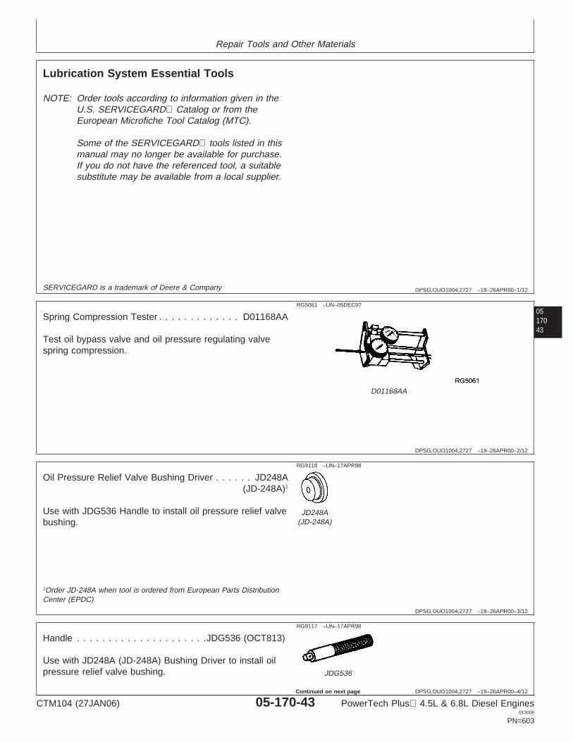
Repair Tools and Other Materials
DPSG,OUO1004,2727 –19–26APR00–1/12
Lubrication System Essential Tools
NOTE: Order tools according to information given in theU.S. SERVICEGARD Catalog or from theEuropean Microfiche Tool Catalog (MTC).
Some of the SERVICEGARD tools listed in thismanual may no longer be available for purchase.If you do not have the referenced tool, a suitablesubstitute may be available from a local supplier.
0517043
SERVICEGARD is a trademark of Deere & Company
DPSG,OUO1004,2727 –19–26APR00–2/12
RG5061 –UN–05DEC97
D01168AA
Spring Compression Tester . . . . . . . . . . . . . D01168AA
Test oil bypass valve and oil pressure regulating valvespring compression.
DPSG,OUO1004,2727 –19–26APR00–3/12
RG9118 –UN–17APR98
JD248A(JD-248A)
Oil Pressure Relief Valve Bushing Driver . . . . . . JD248A(JD-248A)1
Use with JDG536 Handle to install oil pressure relief valvebushing.
1Order JD-248A when tool is ordered from European Parts DistributionCenter (EPDC)
DPSG,OUO1004,2727 –19–26APR00–4/12
RG9117 –UN–17APR98
JDG536
Handle . . . . . . . . . . . . . . . . . . . . .JDG536 (OCT813)
Use with JD248A (JD-248A) Bushing Driver to install oilpressure relief valve bushing.
CTM104 (27JAN06) 05-170-43 PowerTech Plus 4.5L & 6.8L Diesel Engines013006
PN=603
Continued on next page
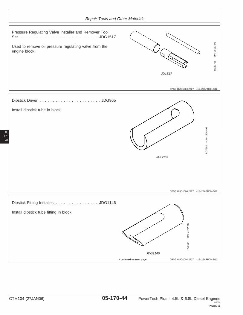
Repair Tools and Other Materials
DPSG,OUO1004,2727 –19–26APR00–5/12
RG
1178
8–U
N–2
5SE
P01
JD1517
Pressure Regulating Valve Installer and Remover ToolSet . . . . . . . . . . . . . . . . . . . . . . . . . . . . . . JDG1517
Used to remove oil pressure regulating valve from theengine block.
05170
44
DPSG,OUO1004,2727 –19–26APR00–6/12
RG
7982
–UN
–15J
AN
98
JDG965
Dipstick Driver . . . . . . . . . . . . . . . . . . . . . . . JDG965
Install dipstick tube in block.
DPSG,OUO1004,2727 –19–26APR00–7/12
RG
9114
–UN
–07A
PR
98
JDG1146
Dipstick Fitting Installer. . . . . . . . . . . . . . . . . JDG1146
Install dipstick tube fitting in block.
Continued on next page
CTM104 (27JAN06) 05-170-44 PowerTech Plus 4.5L & 6.8L Diesel Engines013006
PN=604
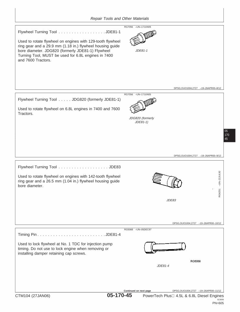
Repair Tools and Other Materials
DPSG,OUO1004,2727 –19–26APR00–8/12
RG7056 –UN–17JUN05
JDE81-1
Flywheel Turning Tool . . . . . . . . . . . . . . . . . . JDE81-1
Used to rotate flywheel on engines with 129-tooth flywheelring gear and a 29.9 mm (1.18 in.) flywheel housing guidebore diameter. JDG820 (formerly JDE81-1) FlywheelTurning Tool, MUST be used for 6.8L engines in 7400and 7600 Tractors.
0517045
DPSG,OUO1004,2727 –19–26APR00–9/12
RG7056 –UN–17JUN05
JDG820 (formerlyJDE81-1)
Flywheel Turning Tool . . . . . JDG820 (formerly JDE81-1)
Used to rotate flywheel on 6.8L engines in 7400 and 7600Tractors.
DPSG,OUO1004,2727 –19–26APR00–10/12R
G62
51–U
N–2
2JU
L92
JDE83
Flywheel Turning Tool . . . . . . . . . . . . . . . . . . . JDE83
Used to rotate flywheel on engines with 142-tooth flywheelring gear and a 26.5 mm (1.04 in.) flywheel housing guidebore diameter.
DPSG,OUO1004,2727 –19–26APR00–11/12
RG5068 –UN–05DEC97
JDE81-4
Timing Pin . . . . . . . . . . . . . . . . . . . . . . . . . . JDE81-4
Used to lock flywheel at No. 1 TDC for injection pumptiming. Do not use to lock engine when removing orinstalling damper retaining cap screws.
CTM104 (27JAN06) 05-170-45 PowerTech Plus 4.5L & 6.8L Diesel Engines013006
PN=605
Continued on next page
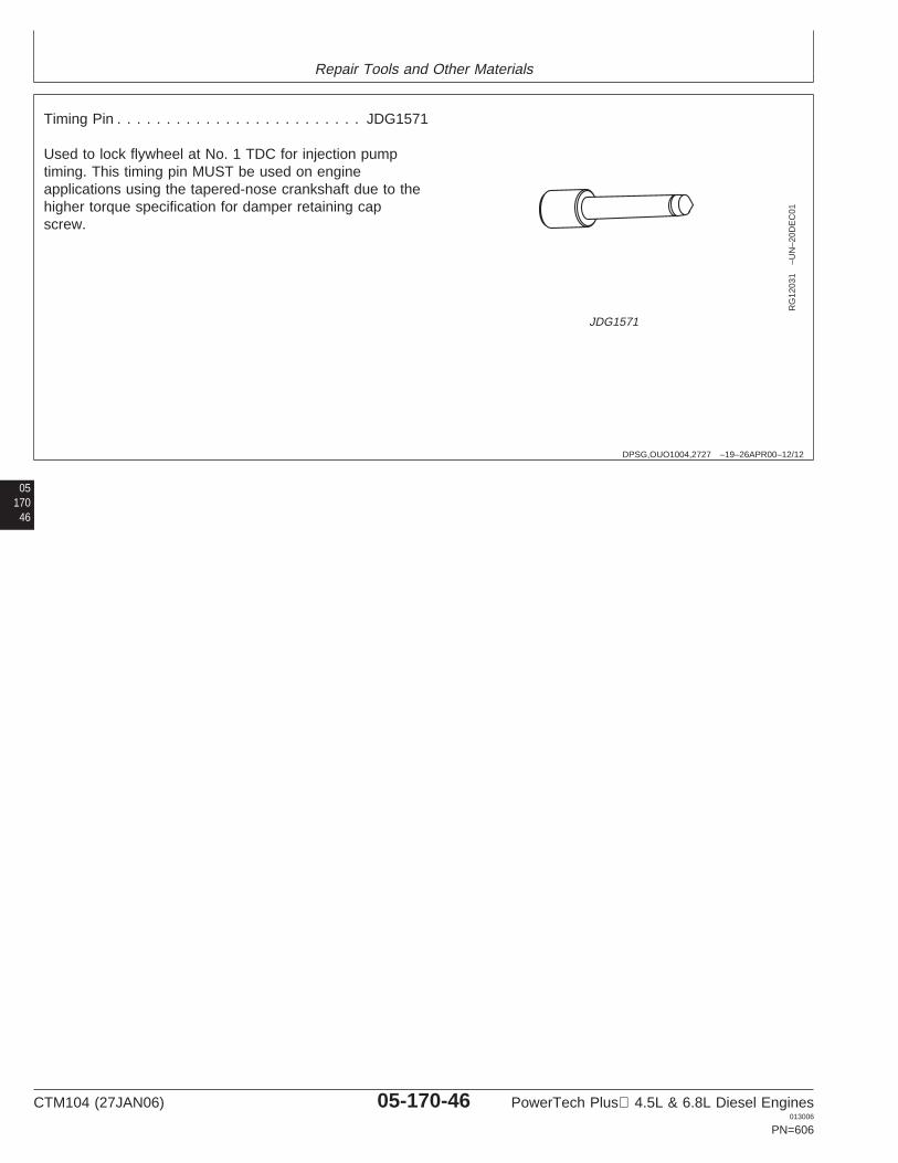
Repair Tools and Other Materials
DPSG,OUO1004,2727 –19–26APR00–12/12
RG
1203
1–U
N–2
0DE
C01
JDG1571
Timing Pin . . . . . . . . . . . . . . . . . . . . . . . . . JDG1571
Used to lock flywheel at No. 1 TDC for injection pumptiming. This timing pin MUST be used on engineapplications using the tapered-nose crankshaft due to thehigher torque specification for damper retaining capscrew.
05170
46
CTM104 (27JAN06) 05-170-46 PowerTech Plus 4.5L & 6.8L Diesel Engines013006
PN=606

Repair Tools and Other Materials
DPSG,OUO1004,2728 –19–26APR00–1/5
Lubrication System Service Equipment andTools
NOTE: Order tools according to information given in theU.S. SERVICEGARD Catalog or from theEuropean Microfiche Tool Catalog (MTC). Sometools may be available from a local supplier.
Some of the SERVICEGARD tools listed in thismanual may no longer be available for purchase.If you do not have the referenced tool, a suitablesubstitute may be available from a local supplier.
0517047
SERVICEGARD is a trademark of Deere & Company
DPSG,OUO1004,2728 –19–26APR00–2/5
Blind-Hole Puller Set . . . . . . . . . . . . . . . . . D01061AA
Remove oil filter bypass valve (extended-life filter), oilpressure regulating valve seat and dipstick tube fromblock.
DPSG,OUO1004,2728 –19–26APR00–3/5
Collet (5/16 in.) . . . . . . . . . . . . . . . . . JT01724 (33856)
Used with JT01720 Actuator Pin and 1156 Slide Hammerto remove dipstick tube from cylinder block.
DPSG,OUO1004,2728 –19–26APR00–4/5
Actuator Pin . . . . . . . . . . . . . . . . . . . JT01720 (28250)
Used with JT01724 Collet and 1156 Slide Hammer toremove dipstick tube from cylinder block.
Continued on next page
CTM104 (27JAN06) 05-170-47 PowerTech Plus 4.5L & 6.8L Diesel Engines013006
PN=607
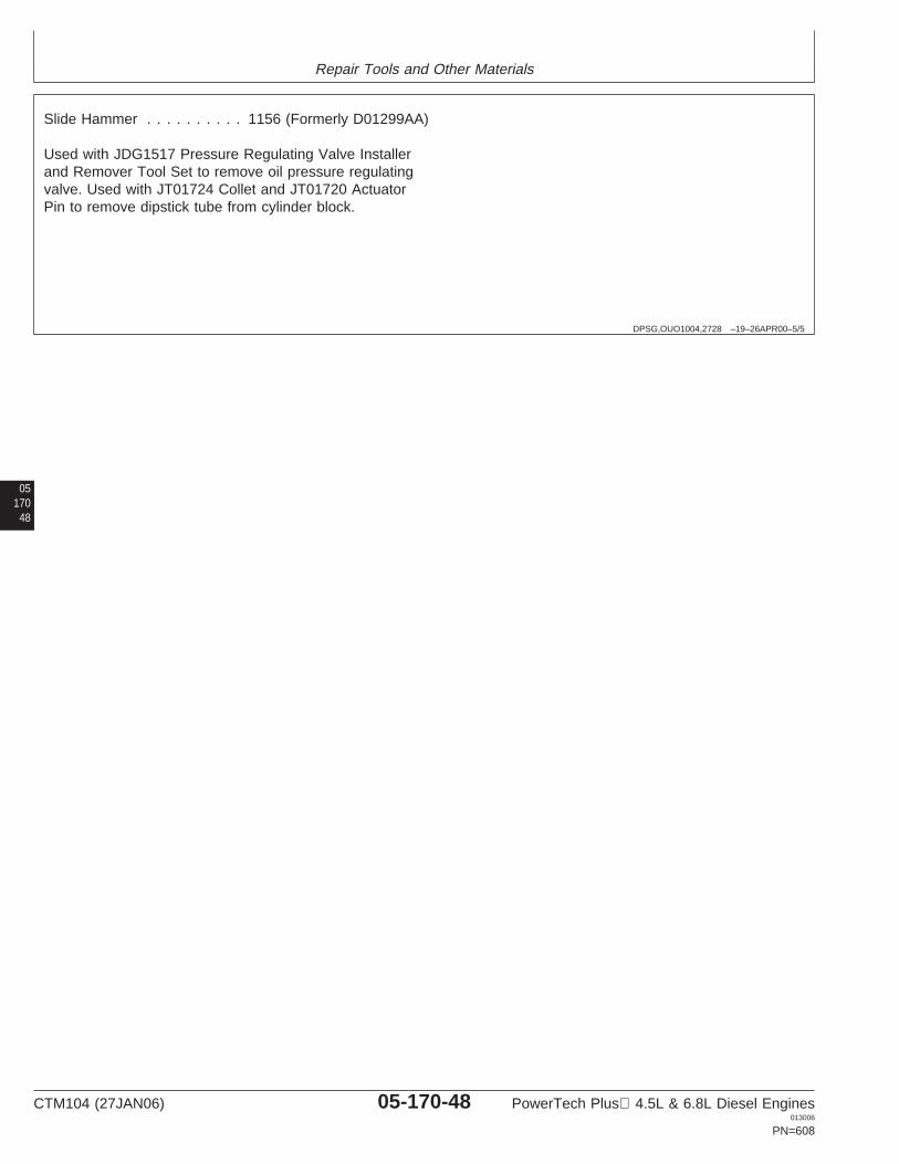
Repair Tools and Other Materials
DPSG,OUO1004,2728 –19–26APR00–5/5
Slide Hammer . . . . . . . . . . 1156 (Formerly D01299AA)
Used with JDG1517 Pressure Regulating Valve Installerand Remover Tool Set to remove oil pressure regulatingvalve. Used with JT01724 Collet and JT01720 ActuatorPin to remove dipstick tube from cylinder block.
05170
48
CTM104 (27JAN06) 05-170-48 PowerTech Plus 4.5L & 6.8L Diesel Engines013006
PN=608
Repair Tools and Other Materials
0517049
DPSG,OUO1004,2729 –19–21NOV03–1/1
Lubrication System Other Materials
Number Name Use
T43512 (U.S.) Thread Lock and Sealer (Medium Apply to oil cooler-to-housing capTY9473 (Canadian) Strength) screws, oil fill tube cap screws, and242 (LOCTITE) end of dipstick tube.
T43512 (U.S.) Thread Lock and Sealer (Medium Apply to oil line clamp cap screw.TY9473 (Canadian) Strength)242 (LOCTITE)
T43513 (U.S.) Thread Lock and Sealer (High Apply to dipstick tube with fitting.TY9474 (Canadian) Strength)271 (LOCTITE)
PM38655 (U.S.) Flexible Form-in-Place Gasket Apply to oil pan rail.TY9484 (Canadian)515 (LOCTITE)
TY9375 (U.S.) Pipe Sealant Apply to oil pan elbow drain fitting.TY9480 (Canadian)592 (LOCTITE)
LOCTITE is a registered trademark of Loctite Corp.
CTM104 (27JAN06) 05-170-49 PowerTech Plus 4.5L & 6.8L Diesel Engines013006
PN=609
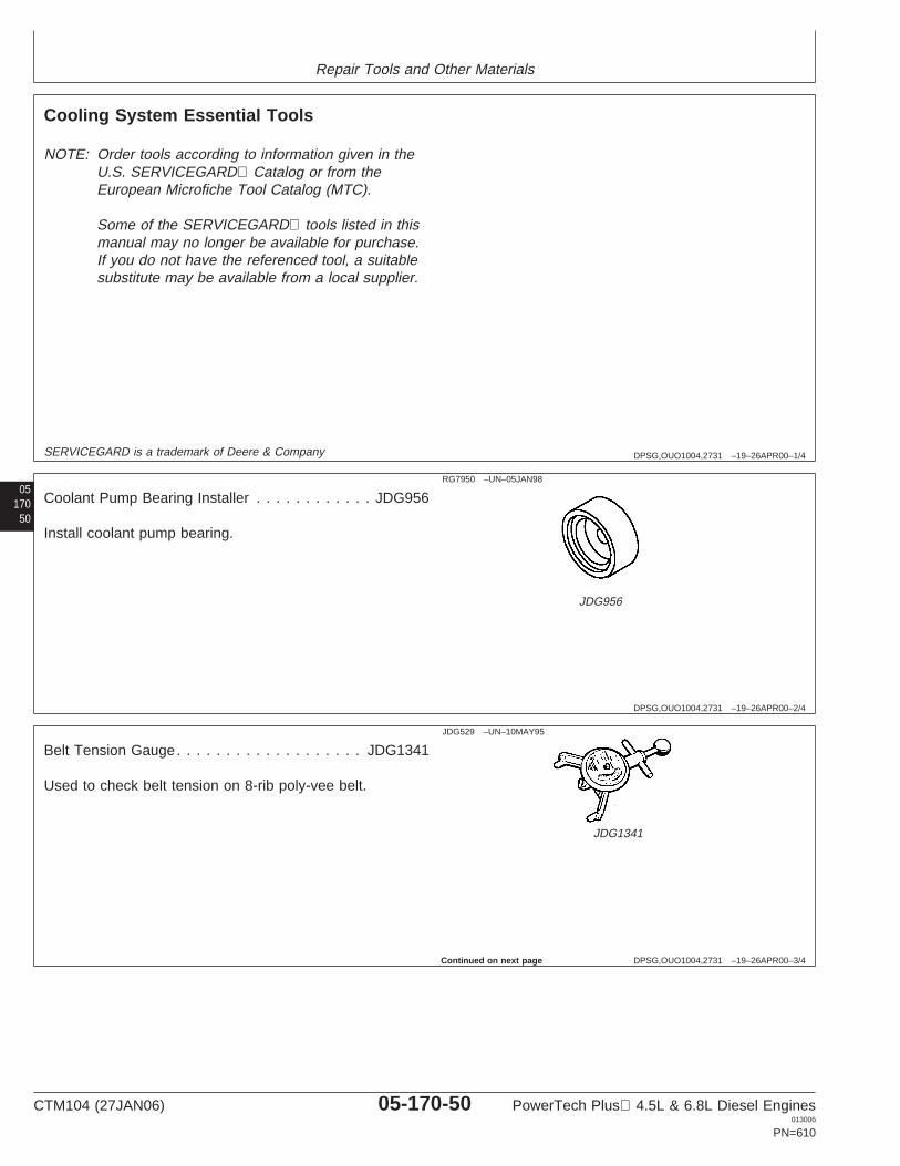
Repair Tools and Other Materials
DPSG,OUO1004,2731 –19–26APR00–1/4
Cooling System Essential Tools
NOTE: Order tools according to information given in theU.S. SERVICEGARD Catalog or from theEuropean Microfiche Tool Catalog (MTC).
Some of the SERVICEGARD tools listed in thismanual may no longer be available for purchase.If you do not have the referenced tool, a suitablesubstitute may be available from a local supplier.
05170
50
SERVICEGARD is a trademark of Deere & Company
DPSG,OUO1004,2731 –19–26APR00–2/4
RG7950 –UN–05JAN98
JDG956
Coolant Pump Bearing Installer . . . . . . . . . . . . JDG956
Install coolant pump bearing.
DPSG,OUO1004,2731 –19–26APR00–3/4
JDG529 –UN–10MAY95
JDG1341
Belt Tension Gauge. . . . . . . . . . . . . . . . . . . JDG1341
Used to check belt tension on 8-rib poly-vee belt.
Continued on next page
CTM104 (27JAN06) 05-170-50 PowerTech Plus 4.5L & 6.8L Diesel Engines013006
PN=610
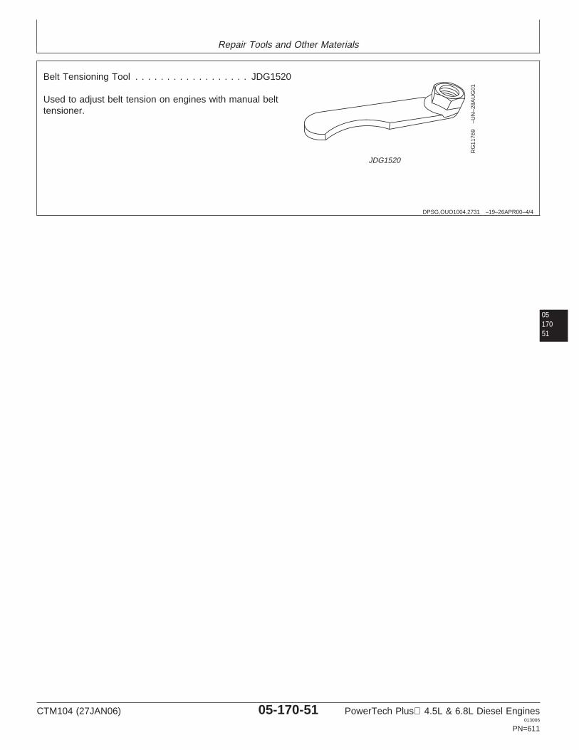
Repair Tools and Other Materials
DPSG,OUO1004,2731 –19–26APR00–4/4
RG
1176
9–U
N–2
8AU
G01
JDG1520
Belt Tensioning Tool . . . . . . . . . . . . . . . . . . JDG1520
Used to adjust belt tension on engines with manual belttensioner.
0517051
CTM104 (27JAN06) 05-170-51 PowerTech Plus 4.5L & 6.8L Diesel Engines013006
PN=611
Repair Tools and Other Materials
DPSG,OUO1004,2732 –19–26APR00–1/2
Cooling System Service Equipment andTools
NOTE: Order tools according to information given in theU.S. SERVICEGARD Catalog or from theEuropean Microfiche Tool Catalog (MTC). Sometools may be available from a local supplier.
Some of the SERVICEGARD tools listed in thismanual may no longer be available for purchase.If you do not have the referenced tool, a suitablesubstitute may be available from a local supplier.
05170
52
SERVICEGARD is a trademark of Deere & Company
DPSG,OUO1004,2732 –19–26APR00–2/2
Bushing, Bearing and Seal Driver Set . . . . . . D01045AA
Remove inner seal in coolant pump housing.
CTM104 (27JAN06) 05-170-52 PowerTech Plus 4.5L & 6.8L Diesel Engines013006
PN=612
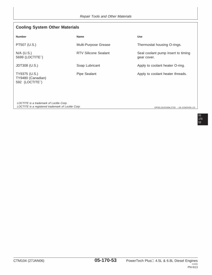
Repair Tools and Other Materials
DPSG,OUO1004,2733 –19–21NOV03–1/1
Cooling System Other Materials
Number Name Use
PT507 (U.S.) Multi-Purpose Grease Thermostat housing O-rings.
N/A (U.S.) RTV Silicone Sealant Seal coolant pump insert to timing5699 (LOCTITE) gear cover.
JDT308 (U.S.) Soap Lubricant Apply to coolant heater O-ring.
TY9375 (U.S.) Pipe Sealant Apply to coolant heater threads.TY9480 (Canadian)592 (LOCTITE)
0517053
LOCTITE is a trademark of Loctite Corp.LOCTITE is a registered trademark of Loctite Corp.
CTM104 (27JAN06) 05-170-53 PowerTech Plus 4.5L & 6.8L Diesel Engines013006
PN=613
Repair Tools and Other Materials
DPSG,OUO1004,2735 –19–26APR00–1/1
Air Intake and Exhaust System OtherMaterials
Number Name Use
PT569 (U.S.) NEVER-SEEZ Exhaust manifold-to-cylinder headcap screws.
TY9375 (U.S.) Pipe Sealant Air heater threads.TY9480 (Canadian)592 (LOCTITE)
05170
54
NEVER-SEEZ is a registered trademark of Emhart Chemical GroupLOCTITE is a registered trademark of Loctite Corp.
CTM104 (27JAN06) 05-170-54 PowerTech Plus 4.5L & 6.8L Diesel Engines013006
PN=614
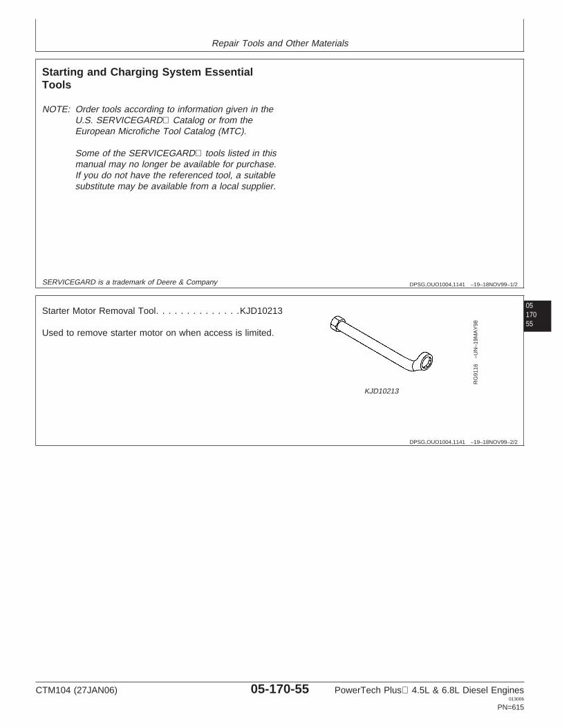
Repair Tools and Other Materials
DPSG,OUO1004,1141 –19–18NOV99–1/2
Starting and Charging System EssentialTools
NOTE: Order tools according to information given in theU.S. SERVICEGARD Catalog or from theEuropean Microfiche Tool Catalog (MTC).
Some of the SERVICEGARD tools listed in thismanual may no longer be available for purchase.If you do not have the referenced tool, a suitablesubstitute may be available from a local supplier.
0517055
SERVICEGARD is a trademark of Deere & Company
DPSG,OUO1004,1141 –19–18NOV99–2/2
RG
9116
–UN
–19M
AY
98
KJD10213
Starter Motor Removal Tool. . . . . . . . . . . . . .KJD10213
Used to remove starter motor on when access is limited.
CTM104 (27JAN06) 05-170-55 PowerTech Plus 4.5L & 6.8L Diesel Engines013006
PN=615

Repair Tools and Other Materials
05170
56
CTM104 (27JAN06) 05-170-56 PowerTech Plus 4.5L & 6.8L Diesel Engines013006
PN=616
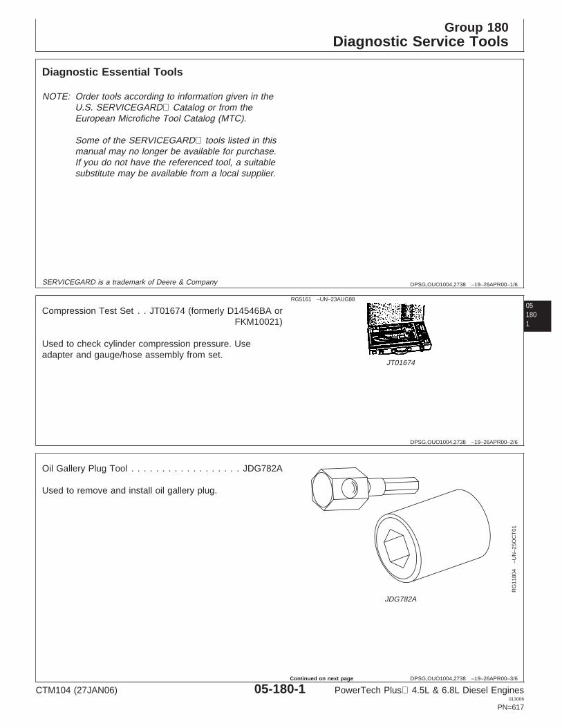
Group 180Diagnostic Service Tools
DPSG,OUO1004,2738 –19–26APR00–1/6
Diagnostic Essential Tools
NOTE: Order tools according to information given in theU.S. SERVICEGARD Catalog or from theEuropean Microfiche Tool Catalog (MTC).
Some of the SERVICEGARD tools listed in thismanual may no longer be available for purchase.If you do not have the referenced tool, a suitablesubstitute may be available from a local supplier.
051801
SERVICEGARD is a trademark of Deere & Company
DPSG,OUO1004,2738 –19–26APR00–2/6
RG5161 –UN–23AUG88
JT01674
Compression Test Set . . JT01674 (formerly D14546BA orFKM10021)
Used to check cylinder compression pressure. Useadapter and gauge/hose assembly from set.
DPSG,OUO1004,2738 –19–26APR00–3/6
RG
1180
4–U
N–2
5OC
T01
JDG782A
Oil Gallery Plug Tool . . . . . . . . . . . . . . . . . . JDG782A
Used to remove and install oil gallery plug.
CTM104 (27JAN06) 05-180-1 PowerTech Plus 4.5L & 6.8L Diesel Engines013006
PN=617
Continued on next page
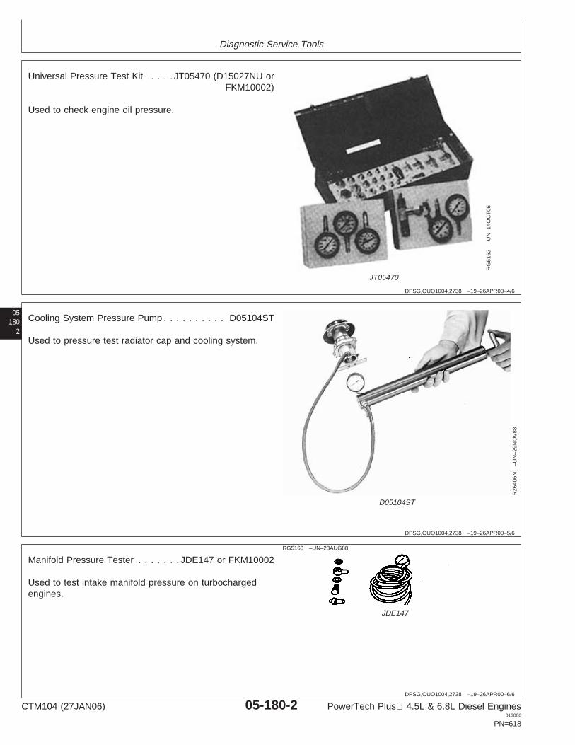
Diagnostic Service Tools
DPSG,OUO1004,2738 –19–26APR00–4/6
RG
5162
–UN
–14O
CT
05
JT05470
Universal Pressure Test Kit . . . . . JT05470 (D15027NU orFKM10002)
Used to check engine oil pressure.
05180
2
DPSG,OUO1004,2738 –19–26APR00–5/6
R26
406N
–UN
–29N
OV
88
D05104ST
Cooling System Pressure Pump . . . . . . . . . . D05104ST
Used to pressure test radiator cap and cooling system.
DPSG,OUO1004,2738 –19–26APR00–6/6
RG5163 –UN–23AUG88
JDE147
Manifold Pressure Tester . . . . . . . JDE147 or FKM10002
Used to test intake manifold pressure on turbochargedengines.
CTM104 (27JAN06) 05-180-2 PowerTech Plus 4.5L & 6.8L Diesel Engines013006
PN=618

Diagnostic Service Tools
DPSG,OUO1004,2739 –19–26APR00–1/4
Diagnostic Service Equipment and Tools
NOTE: Order tools according to information given in theU.S. SERVICEGARD Catalog or from theEuropean Microfiche Tool Catalog (MTC). Sometools may be available from a local supplier.
Some of the SERVICEGARD tools listed in thismanual may no longer be available for purchase.If you do not have the referenced tool, a suitablesubstitute may be available from a local supplier.
051803
SERVICEGARD is a trademark of Deere & Company
DPSG,OUO1004,2739 –19–26APR00–2/4
Water Vacuum Gauge Kit . . . . . . . . . . . . . . D05022ST
Used to test air filter restriction indicator switch.
DPSG,OUO1004,2739 –19–26APR00–3/4
Turbocharger Shield . . . . . . . . . . . . . . . . . . . JDG576
Cover turbocharger inlet when testing engine with air filtersystem removed.
DPSG,OUO1004,2739 –19–26APR00–4/4
Air Regulator with Gauge
Pressurize wastegate actuator to test operation ofwastegate.
CTM104 (27JAN06) 05-180-3 PowerTech Plus 4.5L & 6.8L Diesel Engines013006
PN=619
Diagnostic Service Tools
05180
4
CTM104 (27JAN06) 05-180-4 PowerTech Plus 4.5L & 6.8L Diesel Engines013006
PN=620
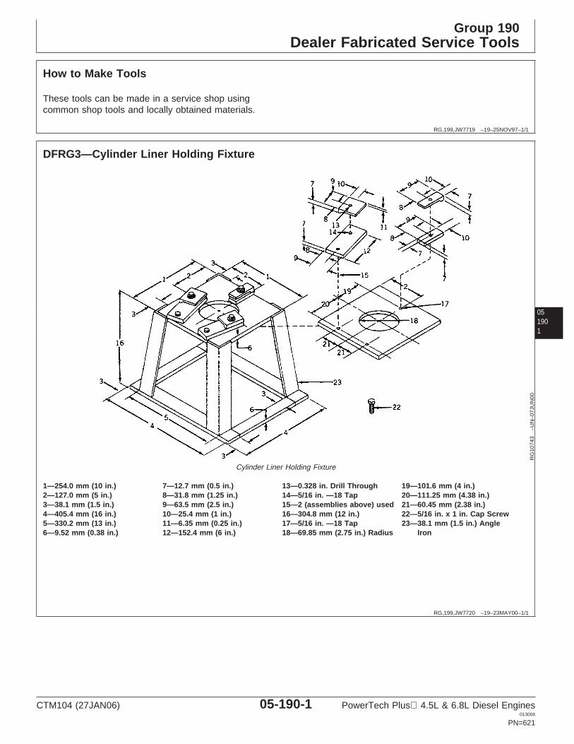
Group 190Dealer Fabricated Service Tools
RG,199,JW7719 –19–25NOV97–1/1
How to Make Tools
These tools can be made in a service shop usingcommon shop tools and locally obtained materials.
051901
RG,199,JW7720 –19–23MAY00–1/1
DFRG3—Cylinder Liner Holding Fixture
RG
1074
3–U
N–0
7JU
N00
Cylinder Liner Holding Fixture
1—254.0 mm (10 in.) 7—12.7 mm (0.5 in.) 13—0.328 in. Drill Through 19—101.6 mm (4 in.)2—127.0 mm (5 in.) 8—31.8 mm (1.25 in.) 14—5/16 in. —18 Tap 20—111.25 mm (4.38 in.)3—38.1 mm (1.5 in.) 9—63.5 mm (2.5 in.) 15—2 (assemblies above) used 21—60.45 mm (2.38 in.)4—405.4 mm (16 in.) 10—25.4 mm (1 in.) 16—304.8 mm (12 in.) 22—5/16 in. x 1 in. Cap Screw5—330.2 mm (13 in.) 11—6.35 mm (0.25 in.) 17—5/16 in. —18 Tap 23—38.1 mm (1.5 in.) Angle6—9.52 mm (0.38 in.) 12—152.4 mm (6 in.) 18—69.85 mm (2.75 in.) Radius Iron
CTM104 (27JAN06) 05-190-1 PowerTech Plus 4.5L & 6.8L Diesel Engines013006
PN=621
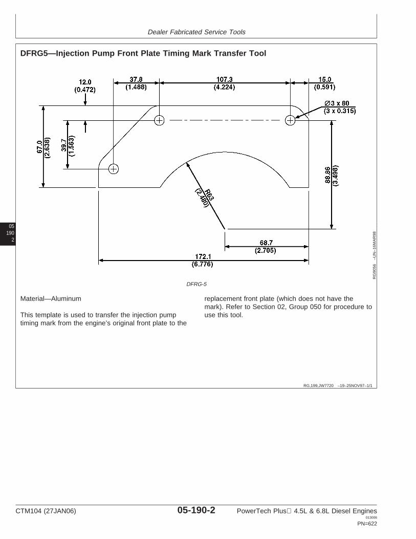
Dealer Fabricated Service Tools
05190
2
RG,199,JW7720 –19–25NOV97–1/1
DFRG5—Injection Pump Front Plate Timing Mark Transfer Tool
RG
9056
–UN
–16M
AR
98
DFRG-5
Material—Aluminum
This template is used to transfer the injection pumptiming mark from the engine’s original front plate to the
replacement front plate (which does not have themark). Refer to Section 02, Group 050 for procedure touse this tool.
CTM104 (27JAN06) 05-190-2 PowerTech Plus 4.5L & 6.8L Diesel Engines013006
PN=622
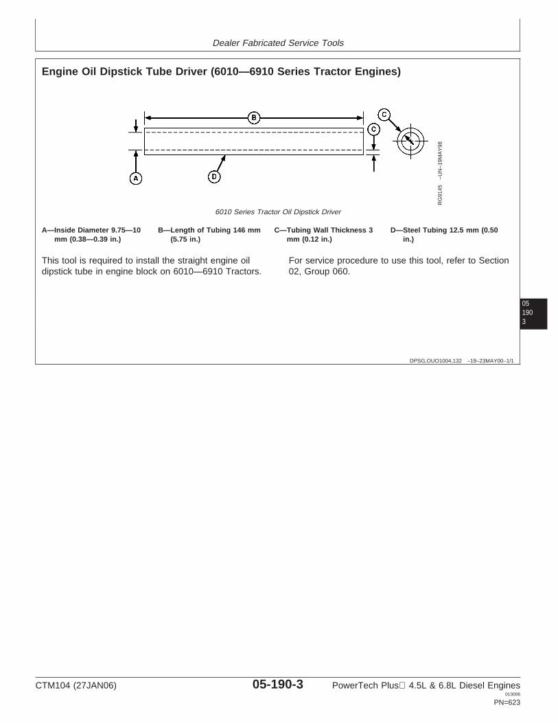
Dealer Fabricated Service Tools
051903
DPSG,OUO1004,132 –19–23MAY00–1/1
Engine Oil Dipstick Tube Driver (6010—6910 Series Tractor Engines)
RG
9145
–UN
–19M
AY
98
6010 Series Tractor Oil Dipstick Driver
A—Inside Diameter 9.75—10 B—Length of Tubing 146 mm C—Tubing Wall Thickness 3 D—Steel Tubing 12.5 mm (0.50mm (0.38—0.39 in.) (5.75 in.) mm (0.12 in.) in.)
This tool is required to install the straight engine oildipstick tube in engine block on 6010—6910 Tractors.
For service procedure to use this tool, refer to Section02, Group 060.
CTM104 (27JAN06) 05-190-3 PowerTech Plus 4.5L & 6.8L Diesel Engines013006
PN=623

Dealer Fabricated Service Tools
05190
4
CTM104 (27JAN06) 05-190-4 PowerTech Plus 4.5L & 6.8L Diesel Engines013006
PN=624
Section 06Specifications
Contents
Page
Group 200—Repair and General OEMSpecifications
Unified Inch Bolt and Screw TorqueValues . . . . . . . . . . . . . . . . . . . . . . . . . . . . .06-200-1
Metric Bolt and Screw Torque Values . . . . . . .06-200-2General OEM Engine Specifications . . . . . . . .06-200-3Engine Rebuild Specifications . . . . . . . . . . . . .06-200-5Cylinder Head and Valves Specifications
(Two-Valve Head) . . . . . . . . . . . . . . . . . . . .06-200-6Cylinder Head and Valves Specifications
(Four-Valve Head) . . . . . . . . . . . . . . . . . . .06-200-10Cylinder Block, Liners, Pistons, and Rods
Specifications. . . . . . . . . . . . . . . . . . . . . . .06-200-14Crankshaft, Main Bearings, and Flywheel
Specifications. . . . . . . . . . . . . . . . . . . . . . .06-200-21Camshaft, Balancer Shafts and Timing Gear
Train Specifications . . . . . . . . . . . . . . . . . .06-200-24Lubrication System Specifications . . . . . . . . .06-200-30
06Cooling System Specifications . . . . . . . . . . .06-200-33Air Intake and Exhaust System
Specifications. . . . . . . . . . . . . . . . . . . . . . .06-200-37Starting and Charging Systems
Specifications. . . . . . . . . . . . . . . . . . . . . . .06-200-38
Group 210—Diagnostic SpecificationsEngine Diagnostic Specifications. . . . . . . . . . .06-210-1Dynamometer Test Specifications . . . . . . . . . .06-210-1Intake Manifold Pressure (Turbocharger
Boost) Specifications . . . . . . . . . . . . . . . . .06-210-23Intake Manifold Pressure (Turbocharger
Boost) Specifications (Continued) . . . . . . .06-210-34Intake Manifold Pressure (Turbocharger
Boost) Specifications (Continued)2 . . . . . .06-210-43Effects of Altitude and Temperature on
Engine Performance . . . . . . . . . . . . . . . . .06-210-65
CTM104 (27JAN06) 06-1 PowerTech Plus 4.5L & 6.8L Diesel Engines013006
PN=1
Contents
06
CTM104 (27JAN06) 06-2 PowerTech Plus 4.5L & 6.8L Diesel Engines013006
PN=2
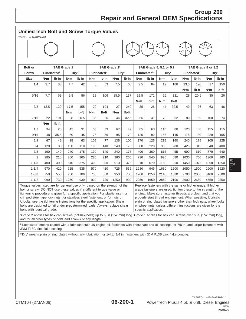
Group 200Repair and General OEM Specifications
062001
DX,TORQ1 –19–24APR03–1/1
Unified Inch Bolt and Screw Torque ValuesTS1671 –UN–01MAY03
Bolt or SAE Grade 1 SAE Grade 2a SAE Grade 5, 5.1 or 5.2 SAE Grade 8 or 8.2
Screw Lubricatedb Dryc Lubricatedb Dryc Lubricatedb Dryc Lubricatedb Dryc
Size N•m lb-in N•m lb-in N•m lb-in N•m lb-in N•m lb-in N•m lb-in N•m lb-in N•m lb-in
1/4 3.7 33 4.7 42 6 53 7.5 66 9.5 84 12 106 13.5 120 17 150
N•m lb-ft N•m lb-ft
5/16 7.7 68 9.8 86 12 106 15.5 137 19.5 172 25 221 28 20.5 35 26
N•m lb-ft N•m lb-ft
3/8 13.5 120 17.5 155 22 194 27 240 35 26 44 32.5 49 36 63 46
N•m lb-ft N•m lb-ft N•m lb-ft
7/16 22 194 28 20.5 35 26 44 32.5 56 41 70 52 80 59 100 74
N•m lb-ft
1/2 34 25 42 31 53 39 67 49 85 63 110 80 120 88 155 115
9/16 48 35.5 60 45 76 56 95 70 125 92 155 115 175 130 220 165
5/8 67 49 85 63 105 77 135 100 170 125 215 160 240 175 305 225
3/4 120 88 150 110 190 140 240 175 300 220 380 280 425 315 540 400
7/8 190 140 240 175 190 140 240 175 490 360 615 455 690 510 870 640
1 285 210 360 265 285 210 360 265 730 540 920 680 1030 760 1300 960
1-1/8 400 300 510 375 400 300 510 375 910 670 1150 850 1450 1075 1850 1350
1-1/4 570 420 725 535 570 420 725 535 1280 945 1630 1200 2050 1500 2600 1920
1-3/8 750 550 950 700 750 550 950 700 1700 1250 2140 1580 2700 2000 3400 2500
1-1/2 990 730 1250 930 990 730 1250 930 2250 1650 2850 2100 3600 2650 4550 3350
Torque values listed are for general use only, based on the strength of the Replace fasteners with the same or higher grade. If higherbolt or screw. DO NOT use these values if a different torque value or grade fasteners are used, tighten these to the strength of thetightening procedure is given for a specific application. For plastic insert or original. Make sure fastener threads are clean and that youcrimped steel type lock nuts, for stainless steel fasteners, or for nuts on properly start thread engagement. When possible, lubricateU-bolts, see the tightening instructions for the specific application. Shear plain or zinc plated fasteners other than lock nuts, wheel boltsbolts are designed to fail under predetermined loads. Always replace shear or wheel nuts, unless different instructions are given for thebolts with identical grade. specific application.aGrade 2 applies for hex cap screws (not hex bolts) up to 6. in (152 mm) long. Grade 1 applies for hex cap screws over 6 in. (152 mm) long,and for all other types of bolts and screws of any length.b“Lubricated” means coated with a lubricant such as engine oil, fasteners with phosphate and oil coatings, or 7/8 in. and larger fasteners withJDM F13C zinc flake coating.c“Dry” means plain or zinc plated without any lubrication, or 1/4 to 3/4 in. fasteners with JDM F13B zinc flake coating.
CTM104 (27JAN06) 06-200-1 PowerTech Plus 4.5L & 6.8L Diesel Engines013006
PN=627
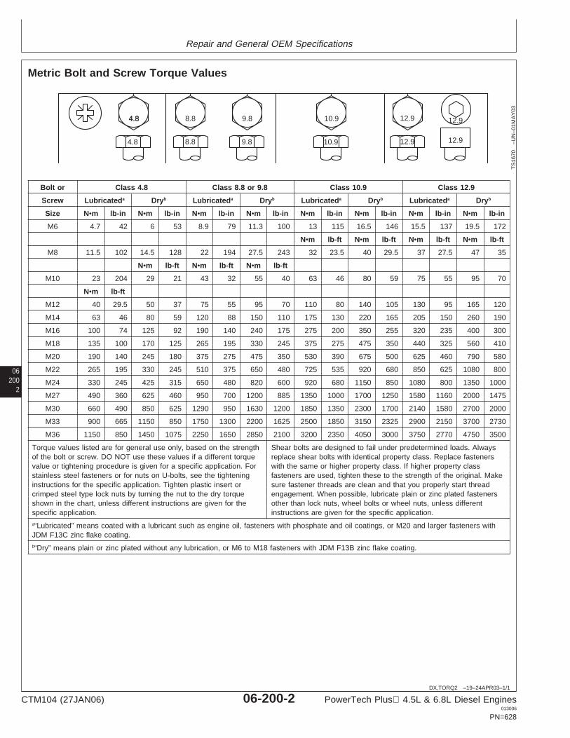
Repair and General OEM Specifications
06200
2
DX,TORQ2 –19–24APR03–1/1
Metric Bolt and Screw Torque Values
4.84.8 8.8 9.8 10.9 12.9 12.9
12.912.910.99.88.84.8
TS
1670
–UN
–01M
AY
03
Bolt or Class 4.8 Class 8.8 or 9.8 Class 10.9 Class 12.9
Screw Lubricateda Dryb Lubricateda Dryb Lubricateda Dryb Lubricateda Dryb
Size N•m lb-in N•m lb-in N•m lb-in N•m lb-in N•m lb-in N•m lb-in N•m lb-in N•m lb-in
M6 4.7 42 6 53 8.9 79 11.3 100 13 115 16.5 146 15.5 137 19.5 172
N•m lb-ft N•m lb-ft N•m lb-ft N•m lb-ft
M8 11.5 102 14.5 128 22 194 27.5 243 32 23.5 40 29.5 37 27.5 47 35
N•m lb-ft N•m lb-ft N•m lb-ft
M10 23 204 29 21 43 32 55 40 63 46 80 59 75 55 95 70
N•m lb-ft
M12 40 29.5 50 37 75 55 95 70 110 80 140 105 130 95 165 120
M14 63 46 80 59 120 88 150 110 175 130 220 165 205 150 260 190
M16 100 74 125 92 190 140 240 175 275 200 350 255 320 235 400 300
M18 135 100 170 125 265 195 330 245 375 275 475 350 440 325 560 410
M20 190 140 245 180 375 275 475 350 530 390 675 500 625 460 790 580
M22 265 195 330 245 510 375 650 480 725 535 920 680 850 625 1080 800
M24 330 245 425 315 650 480 820 600 920 680 1150 850 1080 800 1350 1000
M27 490 360 625 460 950 700 1200 885 1350 1000 1700 1250 1580 1160 2000 1475
M30 660 490 850 625 1290 950 1630 1200 1850 1350 2300 1700 2140 1580 2700 2000
M33 900 665 1150 850 1750 1300 2200 1625 2500 1850 3150 2325 2900 2150 3700 2730
M36 1150 850 1450 1075 2250 1650 2850 2100 3200 2350 4050 3000 3750 2770 4750 3500
Torque values listed are for general use only, based on the strength Shear bolts are designed to fail under predetermined loads. Alwaysof the bolt or screw. DO NOT use these values if a different torque replace shear bolts with identical property class. Replace fastenersvalue or tightening procedure is given for a specific application. For with the same or higher property class. If higher property classstainless steel fasteners or for nuts on U-bolts, see the tightening fasteners are used, tighten these to the strength of the original. Makeinstructions for the specific application. Tighten plastic insert or sure fastener threads are clean and that you properly start threadcrimped steel type lock nuts by turning the nut to the dry torque engagement. When possible, lubricate plain or zinc plated fastenersshown in the chart, unless different instructions are given for the other than lock nuts, wheel bolts or wheel nuts, unless differentspecific application. instructions are given for the specific application.a“Lubricated” means coated with a lubricant such as engine oil, fasteners with phosphate and oil coatings, or M20 and larger fasteners withJDM F13C zinc flake coating.b“Dry” means plain or zinc plated without any lubrication, or M6 to M18 fasteners with JDM F13B zinc flake coating.
CTM104 (27JAN06) 06-200-2 PowerTech Plus 4.5L & 6.8L Diesel Engines013006
PN=628
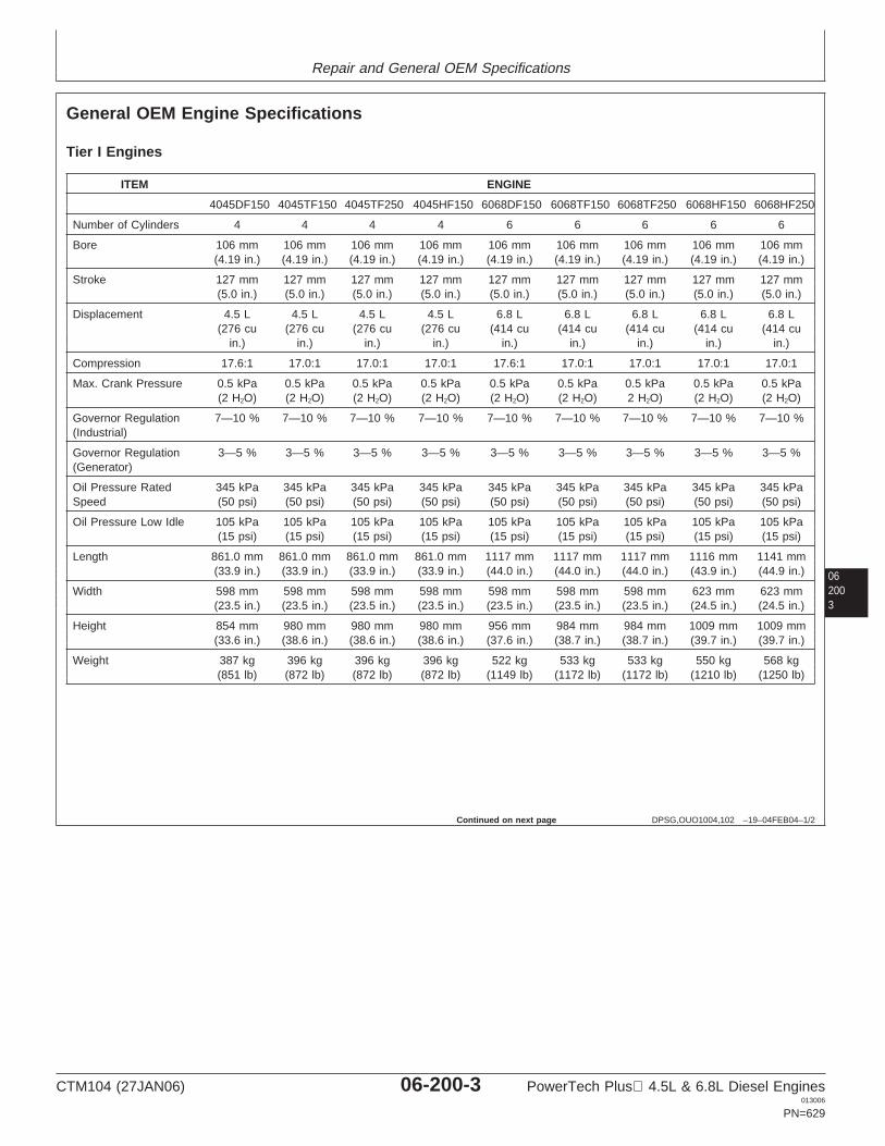
Repair and General OEM Specifications
062003
DPSG,OUO1004,102 –19–04FEB04–1/2
General OEM Engine Specifications
Tier I Engines
ITEM ENGINE
4045DF150 4045TF150 4045TF250 4045HF150 6068DF150 6068TF150 6068TF250 6068HF150 6068HF250
Number of Cylinders 4 4 4 4 6 6 6 6 6
Bore 106 mm 106 mm 106 mm 106 mm 106 mm 106 mm 106 mm 106 mm 106 mm(4.19 in.) (4.19 in.) (4.19 in.) (4.19 in.) (4.19 in.) (4.19 in.) (4.19 in.) (4.19 in.) (4.19 in.)
Stroke 127 mm 127 mm 127 mm 127 mm 127 mm 127 mm 127 mm 127 mm 127 mm(5.0 in.) (5.0 in.) (5.0 in.) (5.0 in.) (5.0 in.) (5.0 in.) (5.0 in.) (5.0 in.) (5.0 in.)
Displacement 4.5 L 4.5 L 4.5 L 4.5 L 6.8 L 6.8 L 6.8 L 6.8 L 6.8 L(276 cu (276 cu (276 cu (276 cu (414 cu (414 cu (414 cu (414 cu (414 cu
in.) in.) in.) in.) in.) in.) in.) in.) in.)
Compression 17.6:1 17.0:1 17.0:1 17.0:1 17.6:1 17.0:1 17.0:1 17.0:1 17.0:1
Max. Crank Pressure 0.5 kPa 0.5 kPa 0.5 kPa 0.5 kPa 0.5 kPa 0.5 kPa 0.5 kPa 0.5 kPa 0.5 kPa(2 H2O) (2 H2O) (2 H2O) (2 H2O) (2 H2O) (2 H2O) 2 H2O) (2 H2O) (2 H2O)
Governor Regulation 7—10 % 7—10 % 7—10 % 7—10 % 7—10 % 7—10 % 7—10 % 7—10 % 7—10 %(Industrial)
Governor Regulation 3—5 % 3—5 % 3—5 % 3—5 % 3—5 % 3—5 % 3—5 % 3—5 % 3—5 %(Generator)
Oil Pressure Rated 345 kPa 345 kPa 345 kPa 345 kPa 345 kPa 345 kPa 345 kPa 345 kPa 345 kPaSpeed (50 psi) (50 psi) (50 psi) (50 psi) (50 psi) (50 psi) (50 psi) (50 psi) (50 psi)
Oil Pressure Low Idle 105 kPa 105 kPa 105 kPa 105 kPa 105 kPa 105 kPa 105 kPa 105 kPa 105 kPa(15 psi) (15 psi) (15 psi) (15 psi) (15 psi) (15 psi) (15 psi) (15 psi) (15 psi)
Length 861.0 mm 861.0 mm 861.0 mm 861.0 mm 1117 mm 1117 mm 1117 mm 1116 mm 1141 mm(33.9 in.) (33.9 in.) (33.9 in.) (33.9 in.) (44.0 in.) (44.0 in.) (44.0 in.) (43.9 in.) (44.9 in.)
Width 598 mm 598 mm 598 mm 598 mm 598 mm 598 mm 598 mm 623 mm 623 mm(23.5 in.) (23.5 in.) (23.5 in.) (23.5 in.) (23.5 in.) (23.5 in.) (23.5 in.) (24.5 in.) (24.5 in.)
Height 854 mm 980 mm 980 mm 980 mm 956 mm 984 mm 984 mm 1009 mm 1009 mm(33.6 in.) (38.6 in.) (38.6 in.) (38.6 in.) (37.6 in.) (38.7 in.) (38.7 in.) (39.7 in.) (39.7 in.)
Weight 387 kg 396 kg 396 kg 396 kg 522 kg 533 kg 533 kg 550 kg 568 kg(851 lb) (872 lb) (872 lb) (872 lb) (1149 lb) (1172 lb) (1172 lb) (1210 lb) (1250 lb)
Continued on next page
CTM104 (27JAN06) 06-200-3 PowerTech Plus 4.5L & 6.8L Diesel Engines013006
PN=629
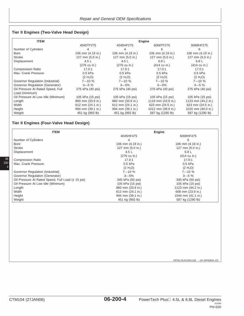
Repair and General OEM Specifications
06200
4
DPSG,OUO1004,102 –19–04FEB04–2/2
Tier II Engines (Two-Valve Head Design)
ITEM Engine4045TF275 4045HF275 6068TF275 6068HF275
Number of Cylinders 4 4 6 6Bore 106 mm (4.19 in.) 106 mm (4.19 in.) 106 mm (4.19 in.) 106 mm (4.19 in.)Stroke 127 mm (5.0 in.) 127 mm (5.0 in.) 127 mm (5.0 in.) 127 mm (5.0 in.)Displacement 4.5 L 4.5 L 6.8 L 6.8 L
(276 cu in.) (276 cu in.) (414 cu in.) (414 cu in.)Compression Ratio 17.0:1 17.0:1 17.0:1 17.0:1Max. Crank Pressure 0.5 kPa 0.5 kPa 0.5 kPa 0.5 kPa
(2 H2O) (2 H2O) (2 H2O) (2 H2O)Governor Regulation (Industrial) 7—10 % 7—10 % 7—10 % 7—10 %Governor Regulation (Generator) 3—5 % 3—5% 3—5% 3—5 %Oil Pressure At Rated Speed, Full 275 kPa (40 psi) 275 kPa (40 psi) 275 kPa (40 psi) 275 kPa (40 psi)Load (minimum)Oil Pressure At Low Idle (Minimum) 105 kPa (15 psi) 105 kPa (15 psi) 105 kPa (15 psi) 105 kPa (15 psi)Length 860 mm (33.9 in.) 860 mm (33.9 in.) 1119 mm (43.9 in.) 1123 mm (44.2 in.)Width 612 mm (24.1 in.) 612 mm (24.1 in.) 623 mm (24.5 in.) 623 mm (24.5 in.)Height 994 mm (39.1 in.) 994 mm (39.1 in.) 1012 mm (39.9 in.) 1015 mm (40.0 in.)Weight 451 kg (993 lb) 451 kg (993 lb) 587 kg (1290 lb) 587 kg (1290 lb)
Tier II Engines (Four-Valve Head Design)
ITEM Engine4045HF475 6068HF475
Number of Cylinders 4 6Bore 106 mm (4.19 in.) 106 mm (4.19 in.)Stroke 127 mm (5.0 in.) 127 mm (5.0 in.)Displacement 4.5 L 6.8 L
(276 cu in.) (414 cu in.)Compression Ratio 17.0:1 17.0:1Max. Crank Pressure 0.5 kPa 0.5 kPa
(2 H2O) (2 H2O)Governor Regulation (Industrial) 7—10 % 7—10 %Governor Regulation (Generator) 3—5% 3—5 %Oil Pressure At Rated Speed, Full Load (± 15 psi) 345 kPa (50 psi) 345 kPa (50 psi)Oil Pressure At Low Idle (Minimum) 105 kPa (15 psi) 105 kPa (15 psi)Length 860 mm (33.9 in.) 1123 mm (44.2 in.)Width 612 mm (24.1 in.) 608 mm (23.9 in.)Height 994 mm (39.1 in.) 1044 mm (41.1 in.)Weight 451 kg (993 lb) 587 kg (1290 lb)
CTM104 (27JAN06) 06-200-4 PowerTech Plus 4.5L & 6.8L Diesel Engines013006
PN=630
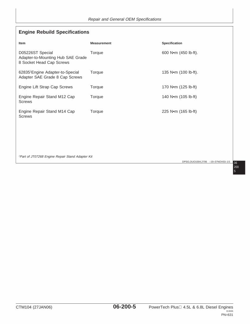
Repair and General OEM Specifications
06DPSG,OUO1004,2706 –19–07NOV03–1/1
Engine Rebuild Specifications
Item Measurement Specification
D05226ST Special Torque 600 N•m (450 lb-ft).Adapter-to-Mounting Hub SAE Grade8 Socket Head Cap Screws
628351Engine Adapter-to-Special Torque 135 N•m (100 lb-ft).Adapter SAE Grade 8 Cap Screws
Engine Lift Strap Cap Screws Torque 170 N•m (125 lb-ft)
Engine Repair Stand M12 Cap Torque 140 N•m (105 lb-ft)Screws
Engine Repair Stand M14 Cap Torque 225 N•m (165 lb-ft)Screws
2005
1Part of JT07268 Engine Repair Stand Adapter Kit
CTM104 (27JAN06) 06-200-5 PowerTech Plus 4.5L & 6.8L Diesel Engines013006
PN=631
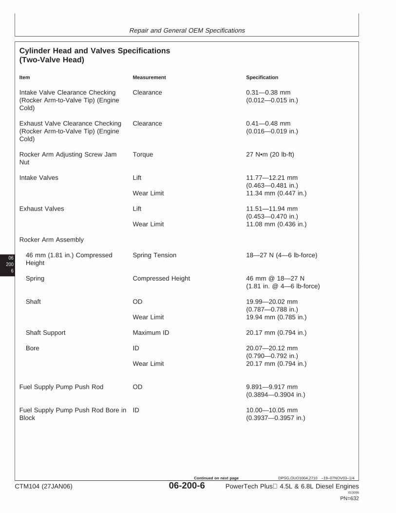
Repair and General OEM Specifications
06200
6
DPSG,OUO1004,2710 –19–07NOV03–1/4
Cylinder Head and Valves Specifications(Two-Valve Head)
Item Measurement Specification
Intake Valve Clearance Checking Clearance 0.31—0.38 mm(Rocker Arm-to-Valve Tip) (Engine (0.012—0.015 in.)Cold)
Exhaust Valve Clearance Checking Clearance 0.41—0.48 mm(Rocker Arm-to-Valve Tip) (Engine (0.016—0.019 in.)Cold)
Rocker Arm Adjusting Screw Jam Torque 27 N•m (20 lb-ft)Nut
Intake Valves Lift 11.77—12.21 mm(0.463—0.481 in.)
Wear Limit 11.34 mm (0.447 in.)
Exhaust Valves Lift 11.51—11.94 mm(0.453—0.470 in.)
Wear Limit 11.08 mm (0.436 in.)
Rocker Arm Assembly
46 mm (1.81 in.) Compressed Spring Tension 18—27 N (4—6 lb-force)Height
Spring Compressed Height 46 mm @ 18—27 N(1.81 in. @ 4—6 lb-force)
Shaft OD 19.99—20.02 mm(0.787—0.788 in.)
Wear Limit 19.94 mm (0.785 in.)
Shaft Support Maximum ID 20.17 mm (0.794 in.)
Bore ID 20.07—20.12 mm(0.790—0.792 in.)
Wear Limit 20.17 mm (0.794 in.)
Fuel Supply Pump Push Rod OD 9.891—9.917 mm(0.3894—0.3904 in.)
Fuel Supply Pump Push Rod Bore in ID 10.00—10.05 mmBlock (0.3937—0.3957 in.)
CTM104 (27JAN06) 06-200-6 PowerTech Plus 4.5L & 6.8L Diesel Engines013006
PN=632
Continued on next page
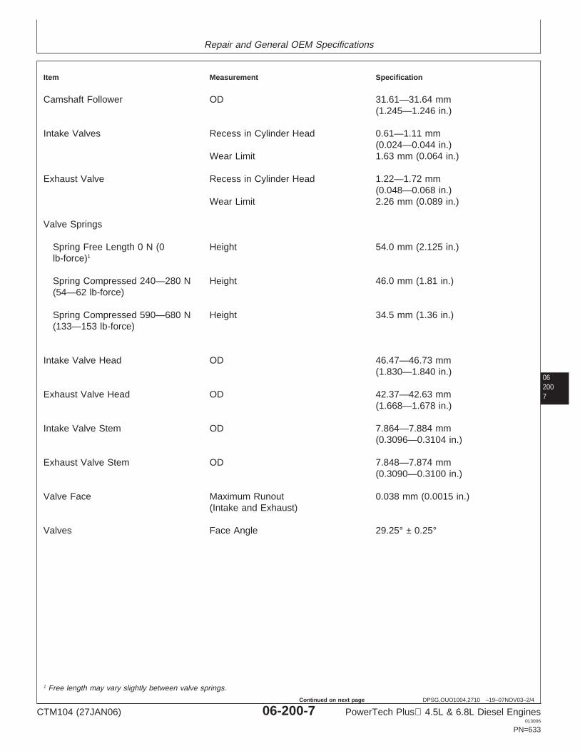
Repair and General OEM Specifications
062007
DPSG,OUO1004,2710 –19–07NOV03–2/4
Item Measurement Specification
Camshaft Follower OD 31.61—31.64 mm(1.245—1.246 in.)
Intake Valves Recess in Cylinder Head 0.61—1.11 mm(0.024—0.044 in.)
Wear Limit 1.63 mm (0.064 in.)
Exhaust Valve Recess in Cylinder Head 1.22—1.72 mm(0.048—0.068 in.)
Wear Limit 2.26 mm (0.089 in.)
Valve Springs
Spring Free Length 0 N (0 Height 54.0 mm (2.125 in.)lb-force)1
Spring Compressed 240—280 N Height 46.0 mm (1.81 in.)(54—62 lb-force)
Spring Compressed 590—680 N Height 34.5 mm (1.36 in.)(133—153 lb-force)
Intake Valve Head OD 46.47—46.73 mm(1.830—1.840 in.)
Exhaust Valve Head OD 42.37—42.63 mm(1.668—1.678 in.)
Intake Valve Stem OD 7.864—7.884 mm(0.3096—0.3104 in.)
Exhaust Valve Stem OD 7.848—7.874 mm(0.3090—0.3100 in.)
Valve Face Maximum Runout 0.038 mm (0.0015 in.)(Intake and Exhaust)
Valves Face Angle 29.25° ± 0.25°
1 Free length may vary slightly between valve springs.
CTM104 (27JAN06) 06-200-7 PowerTech Plus 4.5L & 6.8L Diesel Engines013006
PN=633
Continued on next page

Repair and General OEM Specifications
06200
8
DPSG,OUO1004,2710 –19–07NOV03–3/4
Item Measurement Specification
Cylinder Head Flatness Maximum Acceptable Out-of-Flat for 0.08 mm (0.003 in.)Entire Length or WidthMaximum Acceptable Out-of-Flat for 0.03 mm (0.001 in.)Every 150 mm [5.90 in.]
New Cylinder Head Thickness 104.87—105.13 mm(4.129—4.139 in.)
Minimum Acceptable Thickness 104.24 mm (4.104 in.)Combustion Face Surface Finish 0.7—3.2 micrometers(Surface Grind Only) (AA) (31—125 micro-in.)Maximum Wave Depth 0.012 mm (0.0005 in.)Maximum Material Removal for 0.76 mm (0.030 in.)Resurfacing
Valve Guide Bore (New) ID 7.912—7.938 mm(0.312—0.313 in.)
Valve Guide-to-Valve Stem (New) Clearance 0.05—0.10 mm(0.002—0.004 in.)
Wear Limit 0.15 mm (0.006 in.)
Valve Seat Grinding Seat Angle 30°Valve Seat Width 1.50—2.00 mm (0.059—0.079 in.)Maximum Valve Seat Runout 0.08 mm (0.003 in.)
Cylinder Liner Height above Block 0.030—0.100 mm(0.001—0.004 in.)
Maximum Permissible Height 0.05 mm (0.002 in.)Difference at Nearest Point of TwoAdjacent Liners, or Within a SingleLiner
Cylinder Head Cap Screws
Step 1—Initial Torque 100 N•m (75 lb-ft)
Step 2—Second Torque 150 N•m (110 lb-ft)
Step 3—Verify (After 5 Minutes) Torque 150 N•m (110 lb-ft)
Step 4—Final Torque-Turn Tighten each screw an additional 60°± 10°
CTM104 (27JAN06) 06-200-8 PowerTech Plus 4.5L & 6.8L Diesel Engines013006
PN=634
Continued on next page
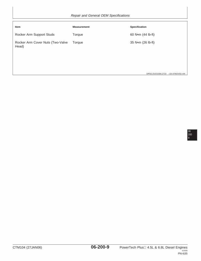
Repair and General OEM Specifications
DPSG,OUO1004,2710 –19–07NOV03–4/4
Item Measurement Specification
Rocker Arm Support Studs Torque 60 N•m (44 lb-ft)
Rocker Arm Cover Nuts (Two-Valve Torque 35 N•m (26 lb-ft)Head)
062009
CTM104 (27JAN06) 06-200-9 PowerTech Plus 4.5L & 6.8L Diesel Engines013006
PN=635
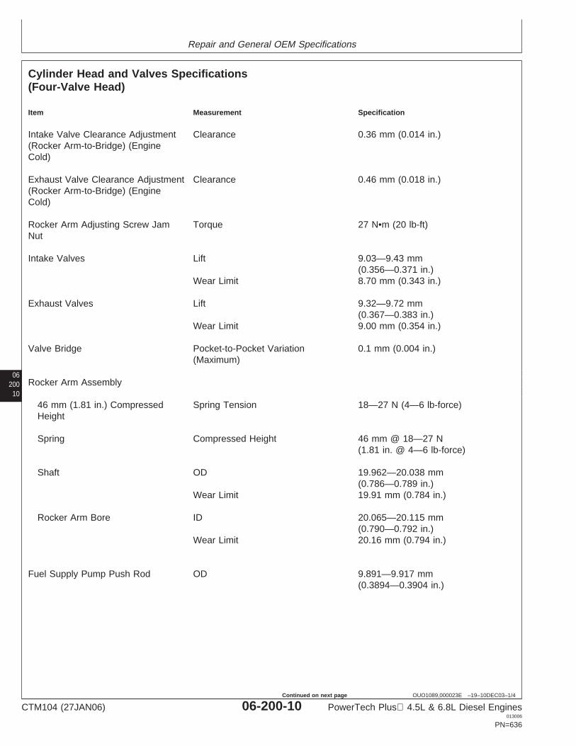
Repair and General OEM Specifications
06200
10
OUO1089,000023E –19–10DEC03–1/4
Cylinder Head and Valves Specifications(Four-Valve Head)
Item Measurement Specification
Intake Valve Clearance Adjustment Clearance 0.36 mm (0.014 in.)(Rocker Arm-to-Bridge) (EngineCold)
Exhaust Valve Clearance Adjustment Clearance 0.46 mm (0.018 in.)(Rocker Arm-to-Bridge) (EngineCold)
Rocker Arm Adjusting Screw Jam Torque 27 N•m (20 lb-ft)Nut
Intake Valves Lift 9.03—9.43 mm(0.356—0.371 in.)
Wear Limit 8.70 mm (0.343 in.)
Exhaust Valves Lift 9.32—9.72 mm(0.367—0.383 in.)
Wear Limit 9.00 mm (0.354 in.)
Valve Bridge Pocket-to-Pocket Variation 0.1 mm (0.004 in.)(Maximum)
Rocker Arm Assembly
46 mm (1.81 in.) Compressed Spring Tension 18—27 N (4—6 lb-force)Height
Spring Compressed Height 46 mm @ 18—27 N(1.81 in. @ 4—6 lb-force)
Shaft OD 19.962—20.038 mm(0.786—0.789 in.)
Wear Limit 19.91 mm (0.784 in.)
Rocker Arm Bore ID 20.065—20.115 mm(0.790—0.792 in.)
Wear Limit 20.16 mm (0.794 in.)
Fuel Supply Pump Push Rod OD 9.891—9.917 mm(0.3894—0.3904 in.)
CTM104 (27JAN06) 06-200-10 PowerTech Plus 4.5L & 6.8L Diesel Engines013006
PN=636
Continued on next page
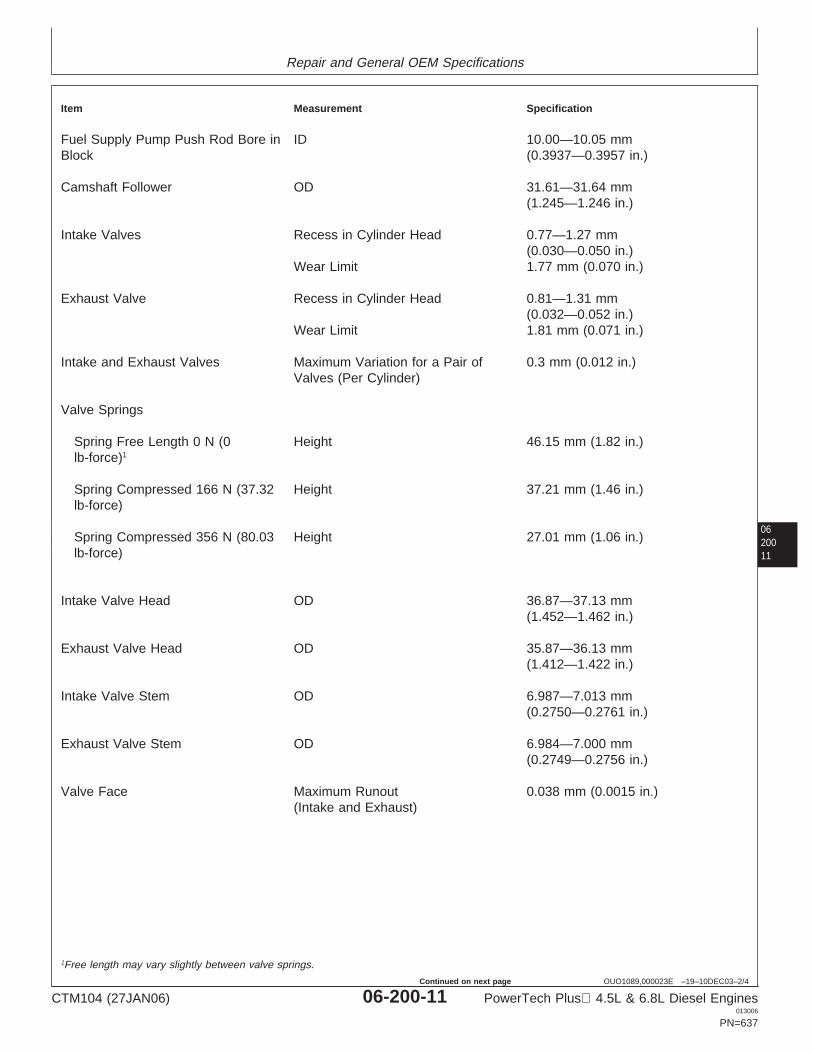
Repair and General OEM Specifications
0620011
OUO1089,000023E –19–10DEC03–2/4
Item Measurement Specification
Fuel Supply Pump Push Rod Bore in ID 10.00—10.05 mmBlock (0.3937—0.3957 in.)
Camshaft Follower OD 31.61—31.64 mm(1.245—1.246 in.)
Intake Valves Recess in Cylinder Head 0.77—1.27 mm(0.030—0.050 in.)
Wear Limit 1.77 mm (0.070 in.)
Exhaust Valve Recess in Cylinder Head 0.81—1.31 mm(0.032—0.052 in.)
Wear Limit 1.81 mm (0.071 in.)
Intake and Exhaust Valves Maximum Variation for a Pair of 0.3 mm (0.012 in.)Valves (Per Cylinder)
Valve Springs
Spring Free Length 0 N (0 Height 46.15 mm (1.82 in.)lb-force)1
Spring Compressed 166 N (37.32 Height 37.21 mm (1.46 in.)lb-force)
Spring Compressed 356 N (80.03 Height 27.01 mm (1.06 in.)lb-force)
Intake Valve Head OD 36.87—37.13 mm(1.452—1.462 in.)
Exhaust Valve Head OD 35.87—36.13 mm(1.412—1.422 in.)
Intake Valve Stem OD 6.987—7.013 mm(0.2750—0.2761 in.)
Exhaust Valve Stem OD 6.984—7.000 mm(0.2749—0.2756 in.)
Valve Face Maximum Runout 0.038 mm (0.0015 in.)(Intake and Exhaust)
1Free length may vary slightly between valve springs.
CTM104 (27JAN06) 06-200-11 PowerTech Plus 4.5L & 6.8L Diesel Engines013006
PN=637
Continued on next page
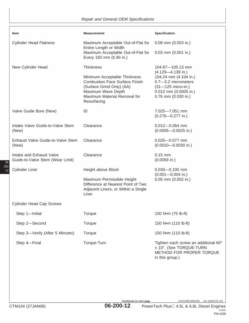
Repair and General OEM Specifications
06200
12
OUO1089,000023E –19–10DEC03–3/4
Item Measurement Specification
Cylinder Head Flatness Maximum Acceptable Out-of-Flat for 0.08 mm (0.003 in.)Entire Length or WidthMaximum Acceptable Out-of-Flat for 0.03 mm (0.001 in.)Every 150 mm (5.90 in.)
New Cylinder Head Thickness 104.87—105.13 mm(4.129—4.139 in.)
Minimum Acceptable Thickness 104.24 mm (4.104 in.)Combustion Face Surface Finish 0.7—3.2 micrometers(Surface Grind Only) (AA) (31—125 micro-in.)Maximum Wave Depth 0.012 mm (0.0005 in.)Maximum Material Removal for 0.76 mm (0.030 in.)Resurfacing
Valve Guide Bore (New) ID 7.025—7.051 mm(0.276—0.277 in.)
Intake Valve Guide-to-Valve Stem Clearance 0.012—0.064 mm(New) (0.0005—0.0025 in.)
Exhaust Valve Guide-to-Valve Stem Clearance 0.025—0.077 mm(New) (0.0010—0.0030 in.)
Intake and Exhaust Valve Clearance 0.15 mmGuide-to-Valve Stem (Wear Limit) (0.0059 in.)
Cylinder Liner Height above Block 0.030—0.100 mm(0.001—0.004 in.)
Maximum Permissible Height 0.05 mm (0.002 in.)Difference at Nearest Point of TwoAdjacent Liners, or Within a SingleLiner
Cylinder Head Cap Screws
Step 1—Initial Torque 100 N•m (75 lb-ft)
Step 2—Second Torque 150 N•m (110 lb-ft)
Step 3—Verify (After 5 Minutes) Torque 150 N•m (110 lb-ft)
Step 4—Final Torque-Turn Tighten each screw an additional 60°± 10°. (See TORQUE-TURNMETHOD FOR PROPER TORQUEin this group.)
CTM104 (27JAN06) 06-200-12 PowerTech Plus 4.5L & 6.8L Diesel Engines013006
PN=638
Continued on next page
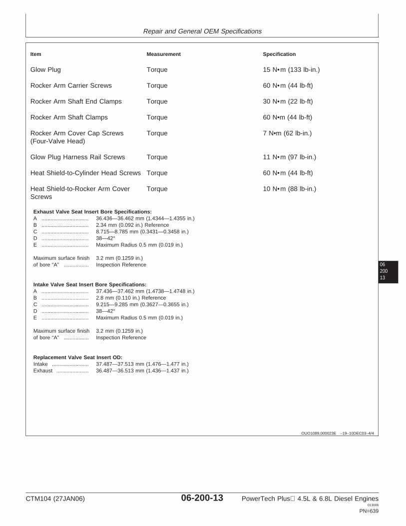
Repair and General OEM Specifications
0620013
OUO1089,000023E –19–10DEC03–4/4
Item Measurement Specification
Glow Plug Torque 15 N•m (133 lb-in.)
Rocker Arm Carrier Screws Torque 60 N•m (44 lb-ft)
Rocker Arm Shaft End Clamps Torque 30 N•m (22 lb-ft)
Rocker Arm Shaft Clamps Torque 60 N•m (44 lb-ft)
Rocker Arm Cover Cap Screws Torque 7 N•m (62 lb-in.)(Four-Valve Head)
Glow Plug Harness Rail Screws Torque 11 N•m (97 lb-in.)
Heat Shield-to-Cylinder Head Screws Torque 60 N•m (44 lb-ft)
Heat Shield-to-Rocker Arm Cover Torque 10 N•m (88 lb-in.)Screws
Exhaust Valve Seat Insert Bore Specifications:A ................................ 36.436—36.462 mm (1.4344—1.4355 in.)B ................................ 2.34 mm (0.092 in.) ReferenceC ................................ 8.715—8.785 mm (0.3431—0.3458 in.)D ................................ 38—42°E ................................ Maximum Radius 0.5 mm (0.019 in.)
Maximum surface finish 3.2 mm (0.1259 in.)of bore “A” ................. Inspection Reference
Intake Valve Seat Insert Bore Specifications:A ................................ 37.436—37.462 mm (1.4738—1.4748 in.)B ................................ 2.8 mm (0.110 in.) ReferenceC ................................ 9.215—9.285 mm (0.3627—0.3655 in.)D ................................ 38—42°E ................................ Maximum Radius 0.5 mm (0.019 in.)
Maximum surface finish 3.2 mm (0.1259 in.)of bore “A” ................. Inspection Reference
Replacement Valve Seat Insert OD:Intake ......................... 37.487—37.513 mm (1.476—1.477 in.)Exhaust ...................... 36.487—36.513 mm (1.436—1.437 in.)
CTM104 (27JAN06) 06-200-13 PowerTech Plus 4.5L & 6.8L Diesel Engines013006
PN=639
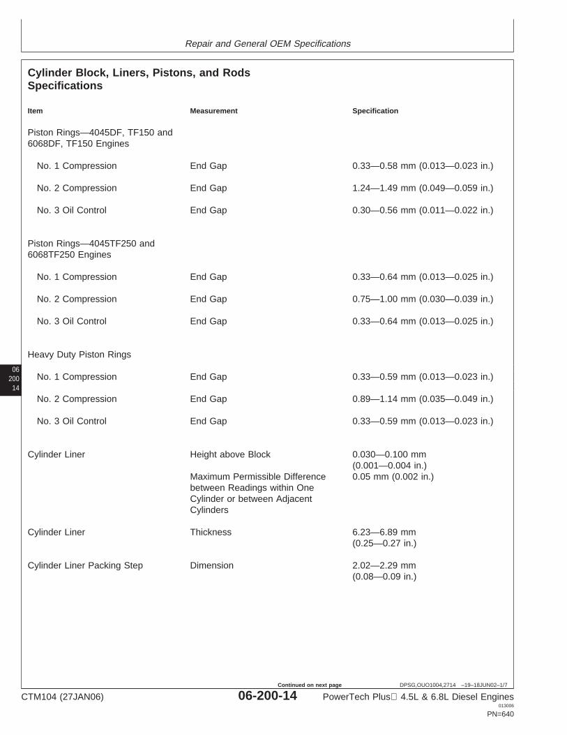
Repair and General OEM Specifications
06200
14
DPSG,OUO1004,2714 –19–18JUN02–1/7
Cylinder Block, Liners, Pistons, and RodsSpecifications
Item Measurement Specification
Piston Rings—4045DF, TF150 and6068DF, TF150 Engines
No. 1 Compression End Gap 0.33—0.58 mm (0.013—0.023 in.)
No. 2 Compression End Gap 1.24—1.49 mm (0.049—0.059 in.)
No. 3 Oil Control End Gap 0.30—0.56 mm (0.011—0.022 in.)
Piston Rings—4045TF250 and6068TF250 Engines
No. 1 Compression End Gap 0.33—0.64 mm (0.013—0.025 in.)
No. 2 Compression End Gap 0.75—1.00 mm (0.030—0.039 in.)
No. 3 Oil Control End Gap 0.33—0.64 mm (0.013—0.025 in.)
Heavy Duty Piston Rings
No. 1 Compression End Gap 0.33—0.59 mm (0.013—0.023 in.)
No. 2 Compression End Gap 0.89—1.14 mm (0.035—0.049 in.)
No. 3 Oil Control End Gap 0.33—0.59 mm (0.013—0.023 in.)
Cylinder Liner Height above Block 0.030—0.100 mm(0.001—0.004 in.)
Maximum Permissible Difference 0.05 mm (0.002 in.)between Readings within OneCylinder or between AdjacentCylinders
Cylinder Liner Thickness 6.23—6.89 mm(0.25—0.27 in.)
Cylinder Liner Packing Step Dimension 2.02—2.29 mm(0.08—0.09 in.)
CTM104 (27JAN06) 06-200-14 PowerTech Plus 4.5L & 6.8L Diesel Engines013006
PN=640
Continued on next page
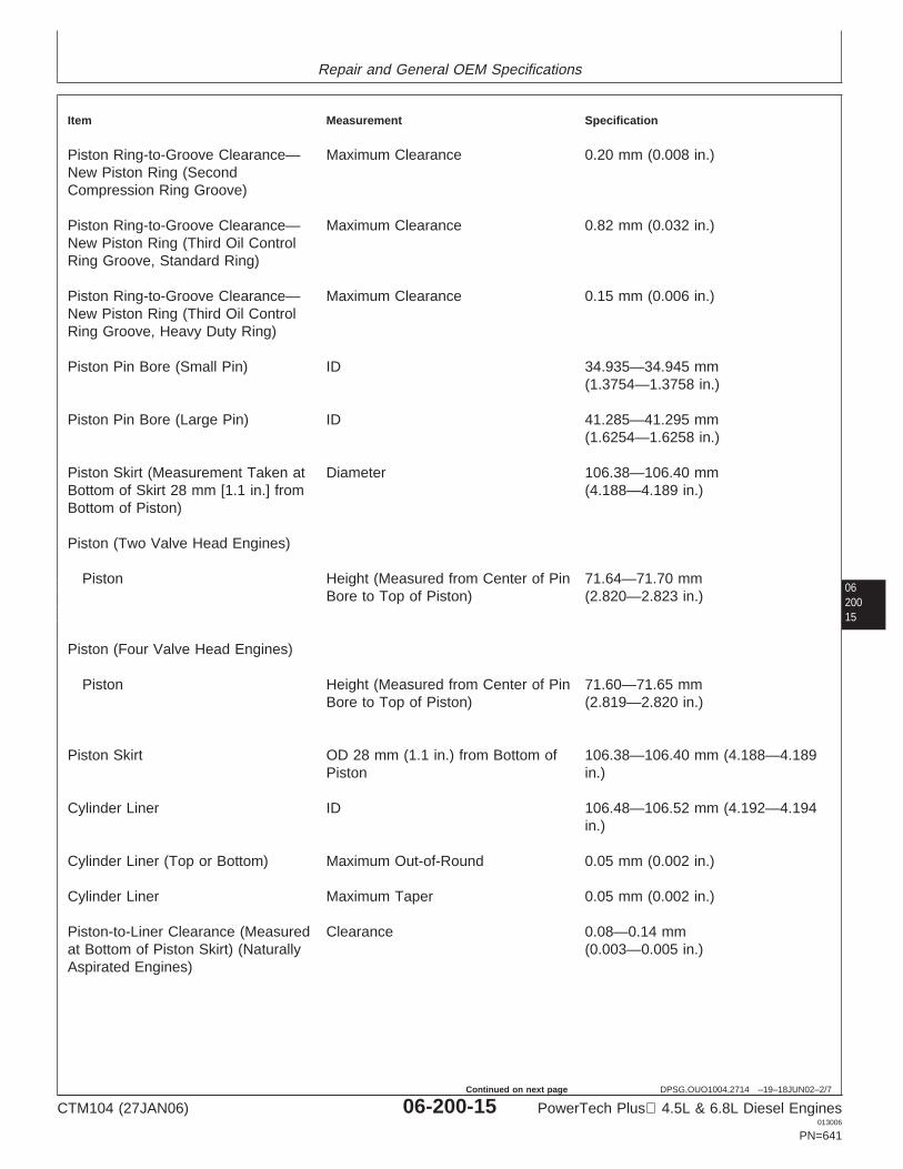
Repair and General OEM Specifications
0620015
DPSG,OUO1004,2714 –19–18JUN02–2/7
Item Measurement Specification
Piston Ring-to-Groove Clearance— Maximum Clearance 0.20 mm (0.008 in.)New Piston Ring (SecondCompression Ring Groove)
Piston Ring-to-Groove Clearance— Maximum Clearance 0.82 mm (0.032 in.)New Piston Ring (Third Oil ControlRing Groove, Standard Ring)
Piston Ring-to-Groove Clearance— Maximum Clearance 0.15 mm (0.006 in.)New Piston Ring (Third Oil ControlRing Groove, Heavy Duty Ring)
Piston Pin Bore (Small Pin) ID 34.935—34.945 mm(1.3754—1.3758 in.)
Piston Pin Bore (Large Pin) ID 41.285—41.295 mm(1.6254—1.6258 in.)
Piston Skirt (Measurement Taken at Diameter 106.38—106.40 mmBottom of Skirt 28 mm [1.1 in.] from (4.188—4.189 in.)Bottom of Piston)
Piston (Two Valve Head Engines)
Piston Height (Measured from Center of Pin 71.64—71.70 mmBore to Top of Piston) (2.820—2.823 in.)
Piston (Four Valve Head Engines)
Piston Height (Measured from Center of Pin 71.60—71.65 mmBore to Top of Piston) (2.819—2.820 in.)
Piston Skirt OD 28 mm (1.1 in.) from Bottom of 106.38—106.40 mm (4.188—4.189Piston in.)
Cylinder Liner ID 106.48—106.52 mm (4.192—4.194in.)
Cylinder Liner (Top or Bottom) Maximum Out-of-Round 0.05 mm (0.002 in.)
Cylinder Liner Maximum Taper 0.05 mm (0.002 in.)
Piston-to-Liner Clearance (Measured Clearance 0.08—0.14 mmat Bottom of Piston Skirt) (Naturally (0.003—0.005 in.)Aspirated Engines)
CTM104 (27JAN06) 06-200-15 PowerTech Plus 4.5L & 6.8L Diesel Engines013006
PN=641
Continued on next page
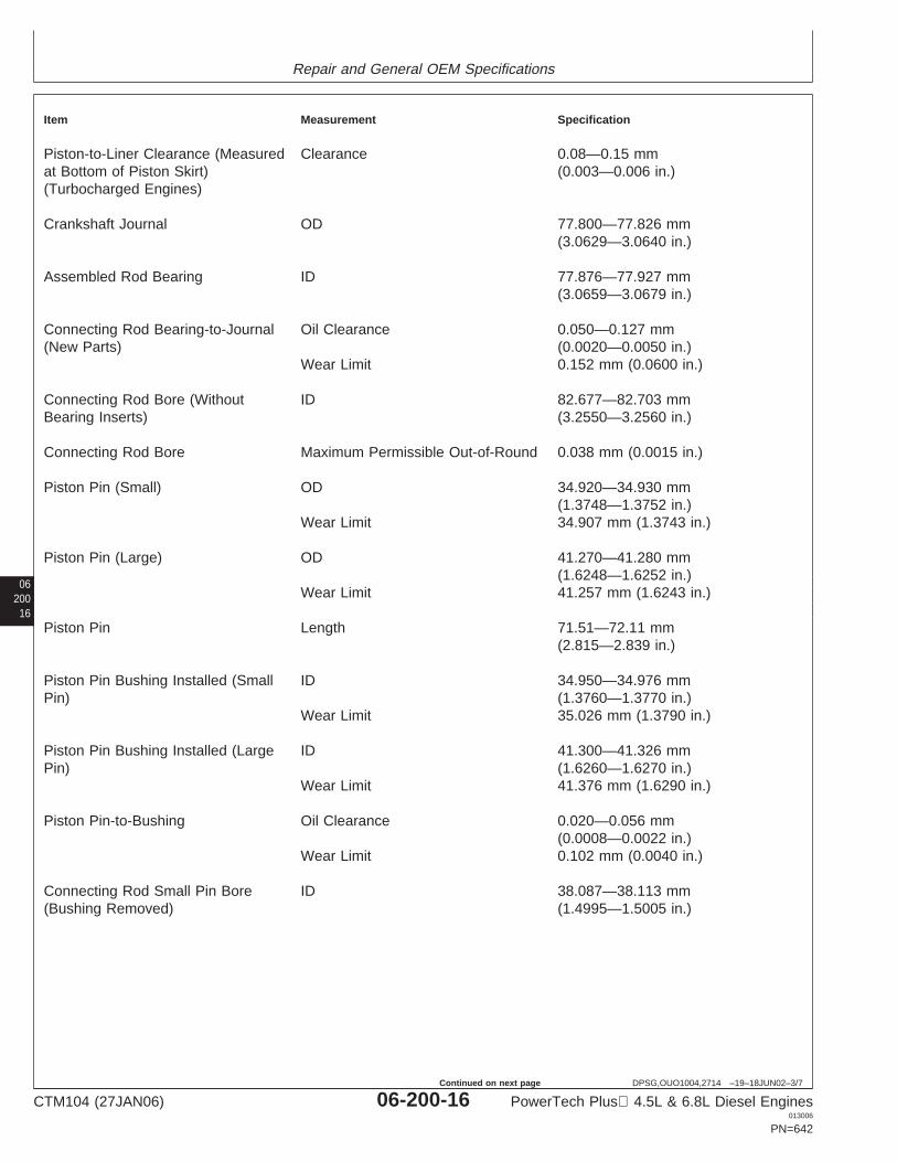
Repair and General OEM Specifications
06200
16
DPSG,OUO1004,2714 –19–18JUN02–3/7
Item Measurement Specification
Piston-to-Liner Clearance (Measured Clearance 0.08—0.15 mmat Bottom of Piston Skirt) (0.003—0.006 in.)(Turbocharged Engines)
Crankshaft Journal OD 77.800—77.826 mm(3.0629—3.0640 in.)
Assembled Rod Bearing ID 77.876—77.927 mm(3.0659—3.0679 in.)
Connecting Rod Bearing-to-Journal Oil Clearance 0.050—0.127 mm(New Parts) (0.0020—0.0050 in.)
Wear Limit 0.152 mm (0.0600 in.)
Connecting Rod Bore (Without ID 82.677—82.703 mmBearing Inserts) (3.2550—3.2560 in.)
Connecting Rod Bore Maximum Permissible Out-of-Round 0.038 mm (0.0015 in.)
Piston Pin (Small) OD 34.920—34.930 mm(1.3748—1.3752 in.)
Wear Limit 34.907 mm (1.3743 in.)
Piston Pin (Large) OD 41.270—41.280 mm(1.6248—1.6252 in.)
Wear Limit 41.257 mm (1.6243 in.)
Piston Pin Length 71.51—72.11 mm(2.815—2.839 in.)
Piston Pin Bushing Installed (Small ID 34.950—34.976 mmPin) (1.3760—1.3770 in.)
Wear Limit 35.026 mm (1.3790 in.)
Piston Pin Bushing Installed (Large ID 41.300—41.326 mmPin) (1.6260—1.6270 in.)
Wear Limit 41.376 mm (1.6290 in.)
Piston Pin-to-Bushing Oil Clearance 0.020—0.056 mm(0.0008—0.0022 in.)
Wear Limit 0.102 mm (0.0040 in.)
Connecting Rod Small Pin Bore ID 38.087—38.113 mm(Bushing Removed) (1.4995—1.5005 in.)
CTM104 (27JAN06) 06-200-16 PowerTech Plus 4.5L & 6.8L Diesel Engines013006
PN=642
Continued on next page
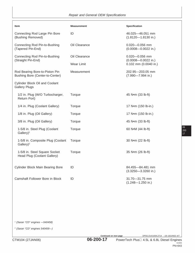
Repair and General OEM Specifications
0620017
DPSG,OUO1004,2714 –19–18JUN02–4/7
Item Measurement Specification
Connecting Rod Large Pin Bore ID 46.025—46.051 mm(Bushing Removed) (1.8120—1.8130 in.)
Connecting Rod Pin-to-Bushing Oil Clearance 0.020—0.056 mm(Tapered Pin-End) (0.0008—0.0022 in.)
Connecting Rod Pin-to-Bushing Oil Clearance 0.020—0.056 mm(Straight Pin-End) (0.0008—0.0022 in.)
Wear Limit 0.102 mm (0.0040 in.)
Rod Bearing Bore-to-Piston Pin Measurement 202.95—203.05 mmBushing Bore (Center-to-Center) (7.990—7.994 in.)
Cylinder Block Oil and CoolantGallery Plugs
1/2 in. Plug (W/O Turbocharger, Torque 45 N•m (33 lb-ft)Return Port)
1/4 in. Plug (Coolant Gallery) Torque 17 N•m (150 lb-in.)
1/8 in. Plug (Oil Gallery) Torque 17 N•m (150 lb-in.)
3/8 in. Plug (Oil Gallery) Torque 45 N•m (33 lb-ft)
1-5/8 in. Steel Plug (Coolant Torque 60 N•M (44 lb-ft)Gallery)1
1-5/8 in. Composite Plug (Coolant Torque 30 N•m (22 lb-ft)Gallery)2
1-5/8 in. Steel Square Socket Torque 35 N•m (26 lb-ft)Head Plug (Coolant Gallery)
Cylinder Block Main Bearing Bore ID 84.455—84.481 mm(3.3250—3.3260 in.)
Camshaft Follower Bore in Block ID 31.70—31.75 mm(1.248—1.250 in.)
1 (Saran “CD” engines —540458)
2 (Saran “CD” engines 540459—)
CTM104 (27JAN06) 06-200-17 PowerTech Plus 4.5L & 6.8L Diesel Engines013006
PN=643
Continued on next page
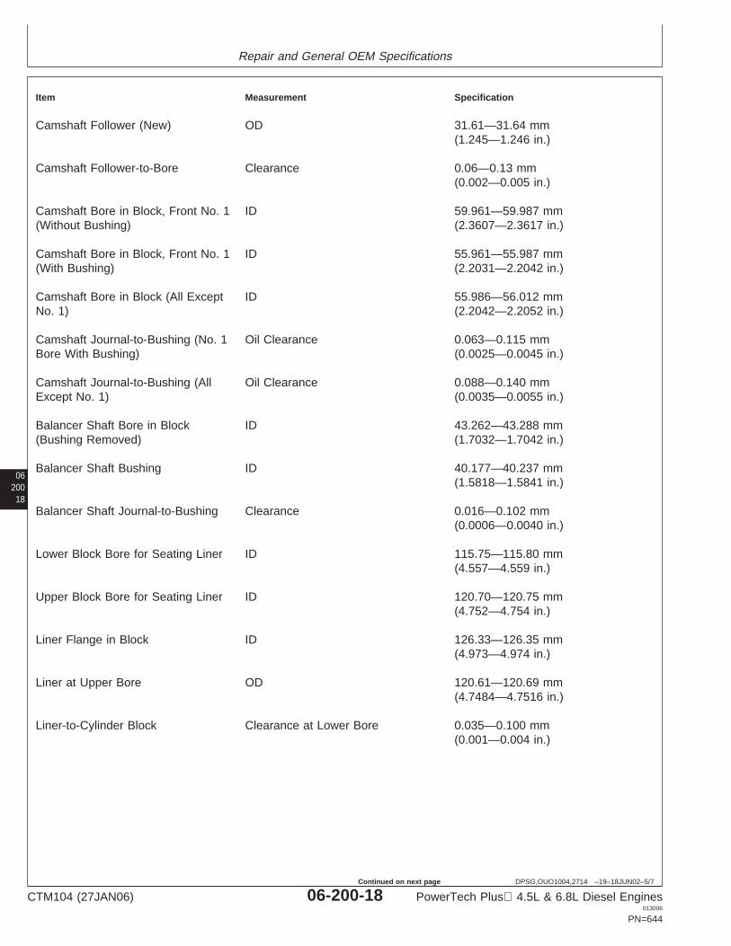
Repair and General OEM Specifications
06200
18
DPSG,OUO1004,2714 –19–18JUN02–5/7
Item Measurement Specification
Camshaft Follower (New) OD 31.61—31.64 mm(1.245—1.246 in.)
Camshaft Follower-to-Bore Clearance 0.06—0.13 mm(0.002—0.005 in.)
Camshaft Bore in Block, Front No. 1 ID 59.961—59.987 mm(Without Bushing) (2.3607—2.3617 in.)
Camshaft Bore in Block, Front No. 1 ID 55.961—55.987 mm(With Bushing) (2.2031—2.2042 in.)
Camshaft Bore in Block (All Except ID 55.986—56.012 mmNo. 1) (2.2042—2.2052 in.)
Camshaft Journal-to-Bushing (No. 1 Oil Clearance 0.063—0.115 mmBore With Bushing) (0.0025—0.0045 in.)
Camshaft Journal-to-Bushing (All Oil Clearance 0.088—0.140 mmExcept No. 1) (0.0035—0.0055 in.)
Balancer Shaft Bore in Block ID 43.262—43.288 mm(Bushing Removed) (1.7032—1.7042 in.)
Balancer Shaft Bushing ID 40.177—40.237 mm(1.5818—1.5841 in.)
Balancer Shaft Journal-to-Bushing Clearance 0.016—0.102 mm(0.0006—0.0040 in.)
Lower Block Bore for Seating Liner ID 115.75—115.80 mm(4.557—4.559 in.)
Upper Block Bore for Seating Liner ID 120.70—120.75 mm(4.752—4.754 in.)
Liner Flange in Block ID 126.33—126.35 mm(4.973—4.974 in.)
Liner at Upper Bore OD 120.61—120.69 mm(4.7484—4.7516 in.)
Liner-to-Cylinder Block Clearance at Lower Bore 0.035—0.100 mm(0.001—0.004 in.)
CTM104 (27JAN06) 06-200-18 PowerTech Plus 4.5L & 6.8L Diesel Engines013006
PN=644
Continued on next page

Repair and General OEM Specifications
0620019
DPSG,OUO1004,2714 –19–18JUN02–6/7
Item Measurement Specification
Liner-to-Cylinder Block Clearance at Upper Bore 0.10—0.14 mm(0.004—0.005 in.)
Cylinder Liner ID 106.48—106.52 mm(4.192—4.194 in.)
Cylinder Maximum Wear 0.10 mm (0.004 in.)
Cylinder Maximum Taper 0.05 mm (0.002 in.)
Cylinder Maximum Out-of-Round 0.05 mm (0.002 in.)
Cylinder Liner Flange Counterbore Depth in Block 5.952—5.988 mm(0.2343—0.2357 in.)
Cylinder Liner Flange Thickness 6.022—6.058 mm(0.2371—0.2385 in.)
Cylinder Block Top Deck
Maximum Acceptable Out-of-Flat, Measurement 0.08 mm (0.003 in.)Entire Length or Width (Used)
Maximum Acceptable Out-of-Flat Measurement 0.025 mm (0.001 in.)(Any 150 mm [5.90 in.] Length)
Top Deck (Surface Grind Only) Surface Finish 0.8—3.2 micrometers(AA) (32—125 micro-in.)
Top Deck Surface Finish Maximum Wave Depth 0.012 mm (0.0005 in.)
Main Bearing Bore Distance 337.896—337.972 mmCenterline-to-Cylinder Block Top (13.3029—13.3059 in.)Deck
Piston Cooling Orifice Jet Diameter 1.4 mm (0.055 in.)
Piston Cooling Orifice Torque 11 ± 1.5 N•m (96 ± 13 lb-in.)
Push Rod OD 9.891—9.917 mm(0.3894—0.3904 in.)
Push Rod Bore in Block ID 10.00—10.05 mm(0.3937—0.3957 in.)
CTM104 (27JAN06) 06-200-19 PowerTech Plus 4.5L & 6.8L Diesel Engines013006
PN=645
Continued on next page
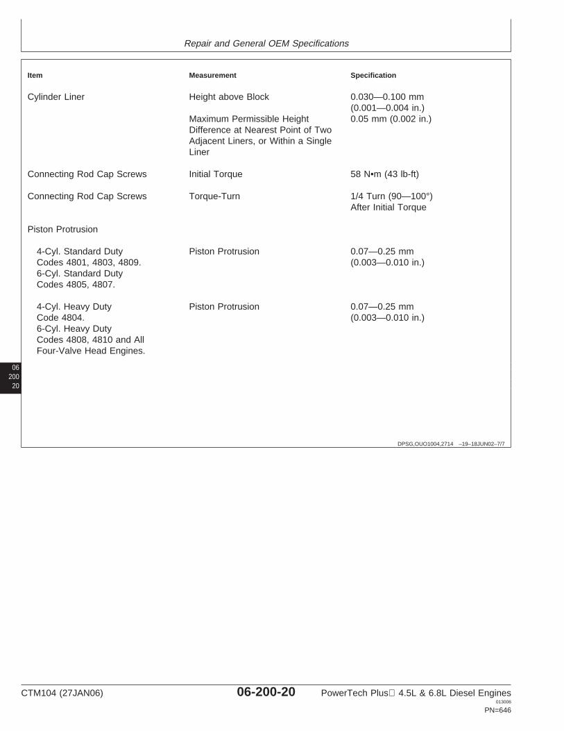
Repair and General OEM Specifications
06200
20
DPSG,OUO1004,2714 –19–18JUN02–7/7
Item Measurement Specification
Cylinder Liner Height above Block 0.030—0.100 mm(0.001—0.004 in.)
Maximum Permissible Height 0.05 mm (0.002 in.)Difference at Nearest Point of TwoAdjacent Liners, or Within a SingleLiner
Connecting Rod Cap Screws Initial Torque 58 N•m (43 lb-ft)
Connecting Rod Cap Screws Torque-Turn 1/4 Turn (90—100°)After Initial Torque
Piston Protrusion
4-Cyl. Standard Duty Piston Protrusion 0.07—0.25 mmCodes 4801, 4803, 4809. (0.003—0.010 in.)6-Cyl. Standard DutyCodes 4805, 4807.
4-Cyl. Heavy Duty Piston Protrusion 0.07—0.25 mmCode 4804. (0.003—0.010 in.)6-Cyl. Heavy DutyCodes 4808, 4810 and AllFour-Valve Head Engines.
CTM104 (27JAN06) 06-200-20 PowerTech Plus 4.5L & 6.8L Diesel Engines013006
PN=646
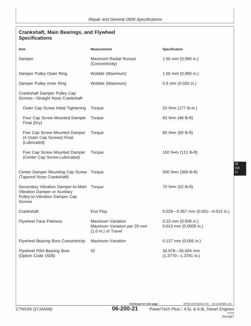
Repair and General OEM Specifications
0620021
DPSG,OUO1004,2718 –19–23JAN04–1/3
Crankshaft, Main Bearings, and FlywheelSpecifications
Item Measurement Specification
Damper Maximum Radial Runout 1.50 mm (0.060 in.)(Concentricity)
Damper Pulley Outer Ring Wobble (Maximum) 1.50 mm (0.060 in.)
Damper Pulley Inner Ring Wobble (Maximum) 0.5 mm (0.020 in.)
Crankshaft Damper Pulley CapScrews—Straight Nose Crankshaft
Outer Cap Screw Initial Tightening Torque 20 N•m (177 lb-in.)
Four Cap Screw Mounted Damper Torque 63 N•m (48 lb-ft)Final (Dry)
Five Cap Screw Mounted Damper Torque 80 N•m (60 lb-ft)(4 Outer Cap Screws) Final(Lubricated)
Five Cap Screw Mounted Damper Torque 150 N•m (111 lb-ft)(Center Cap Screw-Lubricated)
Center Damper Mounting Cap Screw Torque 500 N•m (369 lb-ft)(Tapered Nose Crankshaft)
Secondary Vibration Damper-to-Main Torque 70 N•m (52 lb-ft)Vibration Damper or AuxiliaryPulley-to-Vibration Damper CapScrews
Crankshaft End Play 0.029—0.357 mm (0.001—0.014 in.)
Flywheel Face Flatness Maximum Variation 0.23 mm (0.009 in.)Maximum Variation per 25 mm 0.013 mm (0.0005 in.)(1.0 in.) of Travel
Flywheel Bearing Bore Concentricity Maximum Variation 0.127 mm (0.005 in.)
Flywheel Pilot Bearing Bore ID 34.978—35.004 mm(Option Code 1508) (1.3770—1.3781 in.)
CTM104 (27JAN06) 06-200-21 PowerTech Plus 4.5L & 6.8L Diesel Engines013006
PN=647
Continued on next page
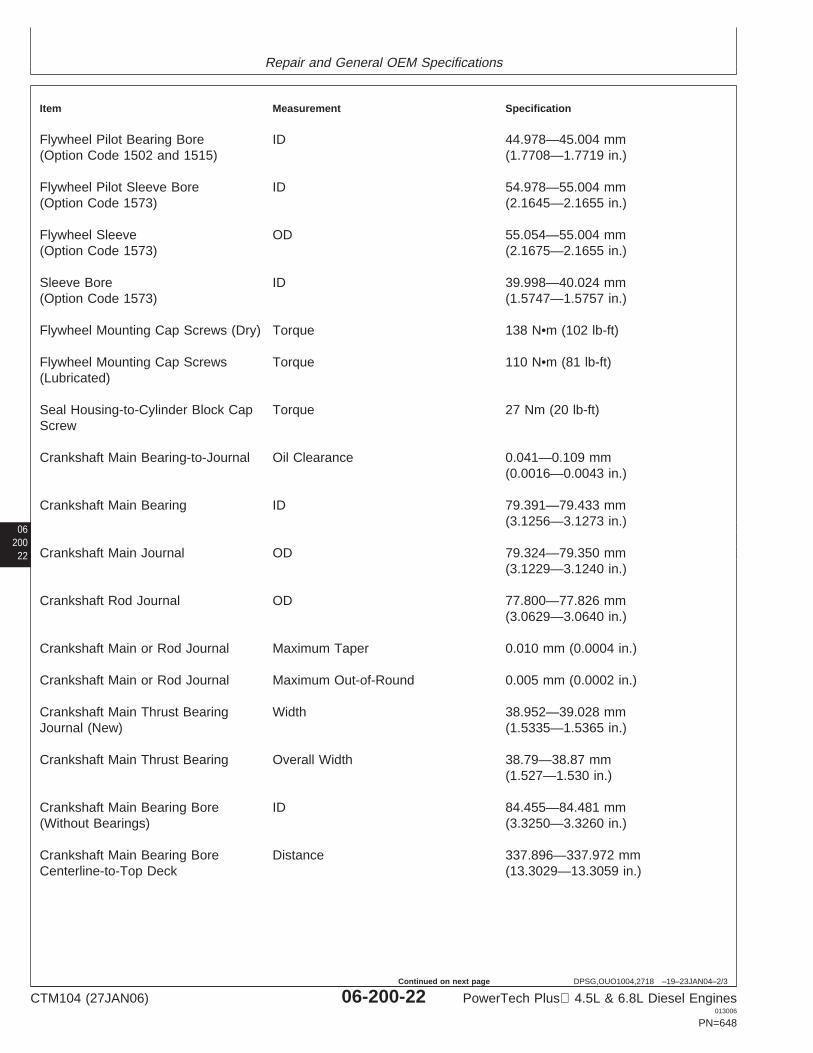
Repair and General OEM Specifications
06200
22
DPSG,OUO1004,2718 –19–23JAN04–2/3
Item Measurement Specification
Flywheel Pilot Bearing Bore ID 44.978—45.004 mm(Option Code 1502 and 1515) (1.7708—1.7719 in.)
Flywheel Pilot Sleeve Bore ID 54.978—55.004 mm(Option Code 1573) (2.1645—2.1655 in.)
Flywheel Sleeve OD 55.054—55.004 mm(Option Code 1573) (2.1675—2.1655 in.)
Sleeve Bore ID 39.998—40.024 mm(Option Code 1573) (1.5747—1.5757 in.)
Flywheel Mounting Cap Screws (Dry) Torque 138 N•m (102 lb-ft)
Flywheel Mounting Cap Screws Torque 110 N•m (81 lb-ft)(Lubricated)
Seal Housing-to-Cylinder Block Cap Torque 27 Nm (20 lb-ft)Screw
Crankshaft Main Bearing-to-Journal Oil Clearance 0.041—0.109 mm(0.0016—0.0043 in.)
Crankshaft Main Bearing ID 79.391—79.433 mm(3.1256—3.1273 in.)
Crankshaft Main Journal OD 79.324—79.350 mm(3.1229—3.1240 in.)
Crankshaft Rod Journal OD 77.800—77.826 mm(3.0629—3.0640 in.)
Crankshaft Main or Rod Journal Maximum Taper 0.010 mm (0.0004 in.)
Crankshaft Main or Rod Journal Maximum Out-of-Round 0.005 mm (0.0002 in.)
Crankshaft Main Thrust Bearing Width 38.952—39.028 mmJournal (New) (1.5335—1.5365 in.)
Crankshaft Main Thrust Bearing Overall Width 38.79—38.87 mm(1.527—1.530 in.)
Crankshaft Main Bearing Bore ID 84.455—84.481 mm(Without Bearings) (3.3250—3.3260 in.)
Crankshaft Main Bearing Bore Distance 337.896—337.972 mmCenterline-to-Top Deck (13.3029—13.3059 in.)
CTM104 (27JAN06) 06-200-22 PowerTech Plus 4.5L & 6.8L Diesel Engines013006
PN=648
Continued on next page
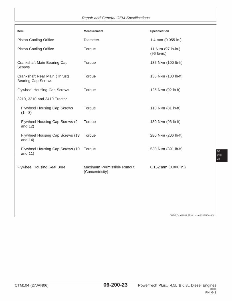
Repair and General OEM Specifications
0620023
DPSG,OUO1004,2718 –19–23JAN04–3/3
Item Measurement Specification
Piston Cooling Orifice Diameter 1.4 mm (0.055 in.)
Piston Cooling Orifice Torque 11 N•m (97 lb-in.)(96 lb-in.)
Crankshaft Main Bearing Cap Torque 135 N•m (100 lb-ft)Screws
Crankshaft Rear Main (Thrust) Torque 135 N•m (100 lb-ft)Bearing Cap Screws
Flywheel Housing Cap Screws Torque 125 N•m (92 lb-ft)
3210, 3310 and 3410 Tractor
Flywheel Housing Cap Screws Torque 110 N•m (81 lb-ft)(1—8)
Flywheel Housing Cap Screws (9 Torque 130 N•m (96 lb-ft)and 12)
Flywheel Housing Cap Screws (13 Torque 280 N•m (206 lb-ft)and 14)
Flywheel Housing Cap Screws (10 Torque 530 N•m (391 lb-ft)and 11)
Flywheel Housing Seal Bore Maximum Permissible Runout 0.152 mm (0.006 in.)(Concentricity)
CTM104 (27JAN06) 06-200-23 PowerTech Plus 4.5L & 6.8L Diesel Engines013006
PN=649
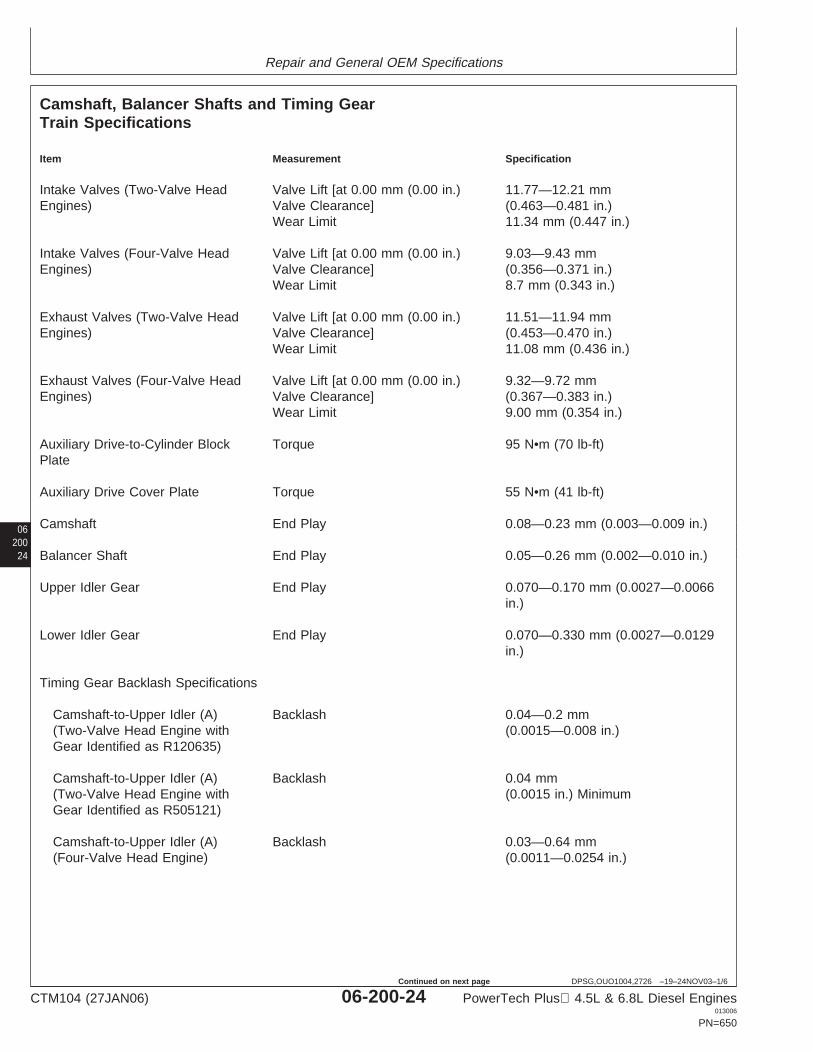
Repair and General OEM Specifications
06200
24
DPSG,OUO1004,2726 –19–24NOV03–1/6
Camshaft, Balancer Shafts and Timing GearTrain Specifications
Item Measurement Specification
Intake Valves (Two-Valve Head Valve Lift [at 0.00 mm (0.00 in.) 11.77—12.21 mmEngines) Valve Clearance] (0.463—0.481 in.)
Wear Limit 11.34 mm (0.447 in.)
Intake Valves (Four-Valve Head Valve Lift [at 0.00 mm (0.00 in.) 9.03—9.43 mmEngines) Valve Clearance] (0.356—0.371 in.)
Wear Limit 8.7 mm (0.343 in.)
Exhaust Valves (Two-Valve Head Valve Lift [at 0.00 mm (0.00 in.) 11.51—11.94 mmEngines) Valve Clearance] (0.453—0.470 in.)
Wear Limit 11.08 mm (0.436 in.)
Exhaust Valves (Four-Valve Head Valve Lift [at 0.00 mm (0.00 in.) 9.32—9.72 mmEngines) Valve Clearance] (0.367—0.383 in.)
Wear Limit 9.00 mm (0.354 in.)
Auxiliary Drive-to-Cylinder Block Torque 95 N•m (70 lb-ft)Plate
Auxiliary Drive Cover Plate Torque 55 N•m (41 lb-ft)
Camshaft End Play 0.08—0.23 mm (0.003—0.009 in.)
Balancer Shaft End Play 0.05—0.26 mm (0.002—0.010 in.)
Upper Idler Gear End Play 0.070—0.170 mm (0.0027—0.0066in.)
Lower Idler Gear End Play 0.070—0.330 mm (0.0027—0.0129in.)
Timing Gear Backlash Specifications
Camshaft-to-Upper Idler (A) Backlash 0.04—0.2 mm(Two-Valve Head Engine with (0.0015—0.008 in.)Gear Identified as R120635)
Camshaft-to-Upper Idler (A) Backlash 0.04 mm(Two-Valve Head Engine with (0.0015 in.) MinimumGear Identified as R505121)
Camshaft-to-Upper Idler (A) Backlash 0.03—0.64 mm(Four-Valve Head Engine) (0.0011—0.0254 in.)
CTM104 (27JAN06) 06-200-24 PowerTech Plus 4.5L & 6.8L Diesel Engines013006
PN=650
Continued on next page

Repair and General OEM Specifications
0620025
DPSG,OUO1004,2726 –19–24NOV03–2/6
Item Measurement Specification
Injection Pump-to-Upper Idler (B) Backlash 0.04—0.2 mm(Two-Valve Head Engine with (0.0015—0.008 in.)Gear Identified as R120635)
Injection Pump-to-Upper Idler (B) Backlash 0.04 mm(Two-Valve Head Engine with (0.0015 in.) MinimumGear Identified as R505121)
Injection Pump-to-Upper Idler (B) Backlash 0.09—0.55 mm(Four-Valve Head Engine) (0.0034—0.0218 in.)
Upper Idler-to-Crankshaft (C) Backlash 0.04—0.2 mm(Two-Valve Head Engine with (0.0015—0.008 in.)Gear Identified as R120635)
Upper Idler-to-Crankshaft (C) Backlash 0.04 mm(Two-Valve Head Engine with (0.0015 in.) MinimumGear Identified as R505121)
Crankshaft-to-Lower Idler (D) Backlash 0.07—0.60 mm(0.0027—0.0236 in.)
Oil Pump-to-Lower Idler (E) Backlash 0.08—0.60 mm(0.0031—0.0236 in.)
Balancer Shaft-to-Oil Pump (4-Cyl. Backlash 0.06—0.65 mmOnly) (F) (0.0025—0.0255 in.)
Lower Idler-to-Balancer Shaft Backlash 0.07—0.65 mm(4-Cyl. Only) (G) (0.0027—0.0255 in.)
Camshaft-to-Auxiliary Drive (Not Backlash 0.05—0.68 mmShown) (0.0021—0.0266 in.)
Camshaft Thrust Plate Clearance 0.08—0.23 mm(0.003—0.009 in.)
Camshaft Thrust Plate Thickness 3.96—4.01 mm (0.156—0.158 in.)
Camshaft Bearing Bores andJournals
Camshaft Journal OD 55.872—55.898 mm(2.1997—2.2007 in.)
CTM104 (27JAN06) 06-200-25 PowerTech Plus 4.5L & 6.8L Diesel Engines013006
PN=651
Continued on next page
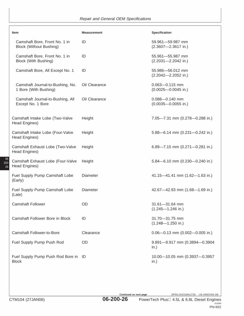
Repair and General OEM Specifications
06200
26
DPSG,OUO1004,2726 –19–24NOV03–3/6
Item Measurement Specification
Camshaft Bore, Front No. 1 in ID 59.961—59.987 mmBlock (Without Bushing) (2.3607—2.3617 in.)
Camshaft Bore, Front No. 1 in ID 55.961—55.987 mmBlock (With Bushing) (2.2031—2.2042 in.)
Camshaft Bore, All Except No. 1 ID 55.986—56.012 mm(2.2042—2.2052 in.)
Camshaft Journal-to-Bushing, No. Oil Clearance 0.063—0.115 mm1 Bore (With Bushing) (0.0025—0.0045 in.)
Camshaft Journal-to-Bushing, All Oil Clearance 0.088—0.140 mmExcept No. 1 Bore (0.0035—0.0055 in.)
Camshaft Intake Lobe (Two-Valve Height 7.05—7.31 mm (0.278—0.288 in.)Head Engines)
Camshaft Intake Lobe (Four-Valve Height 5.88—6.14 mm (0.231—0.242 in.)Head Engines)
Camshaft Exhaust Lobe (Two-Valve Height 6.89—7.15 mm (0.271—0.281 in.)Head Engines)
Camshaft Exhaust Lobe (Four-Valve Height 5.84—6.10 mm (0.230—0.240 in.)Head Engines)
Fuel Supply Pump Camshaft Lobe Diameter 41.15—41.41 mm (1.62—1.63 in.)(Early)
Fuel Supply Pump Camshaft Lobe Diameter 42.67—42.93 mm (1.68—1.69 in.)(Late)
Camshaft Follower OD 31.61—31.64 mm(1.245—1.246 in.)
Camshaft Follower Bore in Block ID 31.70—31.75 mm(1.248—1.250 in.)
Camshaft Follower-to-Bore Clearance 0.06—0.13 mm (0.002—0.005 in.)
Fuel Supply Pump Push Rod OD 9.891—9.917 mm (0.3894—0.3904in.)
Fuel Supply Pump Push Rod Bore in ID 10.00—10.05 mm (0.3937—0.3957Block in.)
CTM104 (27JAN06) 06-200-26 PowerTech Plus 4.5L & 6.8L Diesel Engines013006
PN=652
Continued on next page
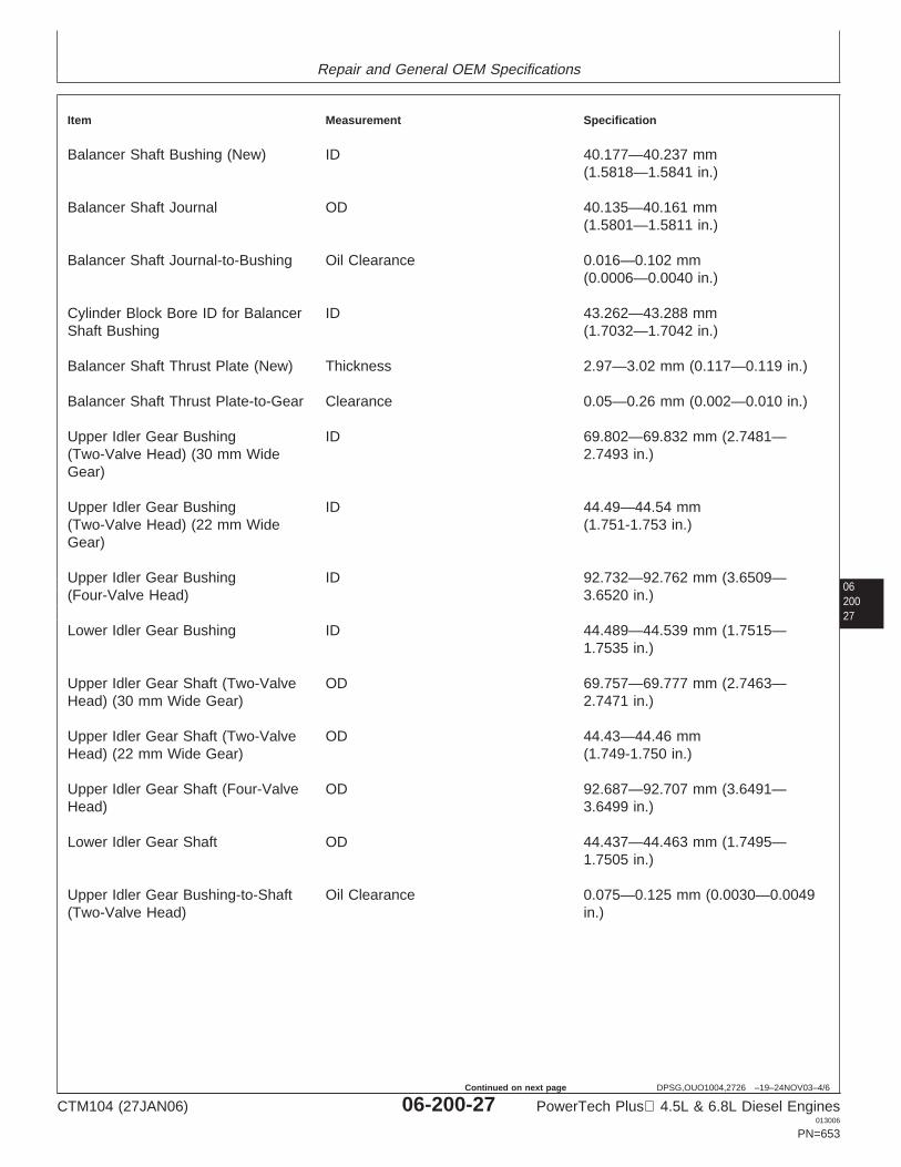
Repair and General OEM Specifications
0620027
DPSG,OUO1004,2726 –19–24NOV03–4/6
Item Measurement Specification
Balancer Shaft Bushing (New) ID 40.177—40.237 mm(1.5818—1.5841 in.)
Balancer Shaft Journal OD 40.135—40.161 mm(1.5801—1.5811 in.)
Balancer Shaft Journal-to-Bushing Oil Clearance 0.016—0.102 mm(0.0006—0.0040 in.)
Cylinder Block Bore ID for Balancer ID 43.262—43.288 mmShaft Bushing (1.7032—1.7042 in.)
Balancer Shaft Thrust Plate (New) Thickness 2.97—3.02 mm (0.117—0.119 in.)
Balancer Shaft Thrust Plate-to-Gear Clearance 0.05—0.26 mm (0.002—0.010 in.)
Upper Idler Gear Bushing ID 69.802—69.832 mm (2.7481—(Two-Valve Head) (30 mm Wide 2.7493 in.)Gear)
Upper Idler Gear Bushing ID 44.49—44.54 mm(Two-Valve Head) (22 mm Wide (1.751-1.753 in.)Gear)
Upper Idler Gear Bushing ID 92.732—92.762 mm (3.6509—(Four-Valve Head) 3.6520 in.)
Lower Idler Gear Bushing ID 44.489—44.539 mm (1.7515—1.7535 in.)
Upper Idler Gear Shaft (Two-Valve OD 69.757—69.777 mm (2.7463—Head) (30 mm Wide Gear) 2.7471 in.)
Upper Idler Gear Shaft (Two-Valve OD 44.43—44.46 mmHead) (22 mm Wide Gear) (1.749-1.750 in.)
Upper Idler Gear Shaft (Four-Valve OD 92.687—92.707 mm (3.6491—Head) 3.6499 in.)
Lower Idler Gear Shaft OD 44.437—44.463 mm (1.7495—1.7505 in.)
Upper Idler Gear Bushing-to-Shaft Oil Clearance 0.075—0.125 mm (0.0030—0.0049(Two-Valve Head) in.)
CTM104 (27JAN06) 06-200-27 PowerTech Plus 4.5L & 6.8L Diesel Engines013006
PN=653
Continued on next page
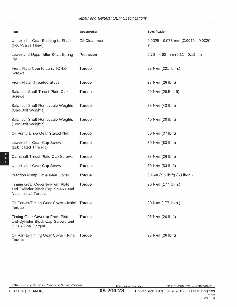
Repair and General OEM Specifications
06200
28
DPSG,OUO1004,2726 –19–24NOV03–5/6
Item Measurement Specification
Upper Idler Gear Bushing-to-Shaft Oil Clearance 0.0025—0.075 mm (0.0010—0.0030(Four-Valve Head) in.)
Lower and Upper Idler Shaft Spring Protrusion 2.79—4.83 mm (0.11—0.19 in.)Pin
Front Plate Countersunk TORX Torque 25 N•m (221 lb-in.)Screws
Front Plate Threaded Studs Torque 35 N•m (26 lb-ft)
Balancer Shaft Thrust Plate Cap Torque 40 N•m (29.5 lb-ft)Screws
Balancer Shaft Removable Weights Torque 58 N•m (43 lb-ft)(One-Bolt Weights)
Balancer Shaft Removable Weights Torque 40 N•m (30 lb-ft)(Two-Bolt Weights)
Oil Pump Drive Gear Staked Nut Torque 50 N•m (37 lb-ft)
Lower Idler Gear Cap Screw Torque 70 N•m (53 lb-ft)(Lubricated Threads)
Camshaft Thrust Plate Cap Screws Torque 35 N•m (26 lb-ft)
Upper Idler Gear Cap Screw Torque 70 N•m (53 lb-ft)
Injection Pump Drive Gear Cover Torque 6 N•m (4.5 lb-ft) (53 lb-in.)
Timing Gear Cover-to-Front Plate Torque 20 N•m (177 lb-in.)and Cylinder Block Cap Screws andNuts - Initial Torque
Oil Pan-to-Timing Gear Cover - Initial Torque 20 N•m (177 lb-in.)Torque
Timing Gear Cover-to-Front Plate Torque 35 N•m (26 lb-ft)and Cylinder Block Cap Screws andNuts - Final Torque
Oil Pan-to-Timing Gear Cover - Final Torque 35 N•m (26 lb-ft)Torque
TORX is a registered trademark of Camcar/Textron
CTM104 (27JAN06) 06-200-28 PowerTech Plus 4.5L & 6.8L Diesel Engines013006
PN=654
Continued on next page
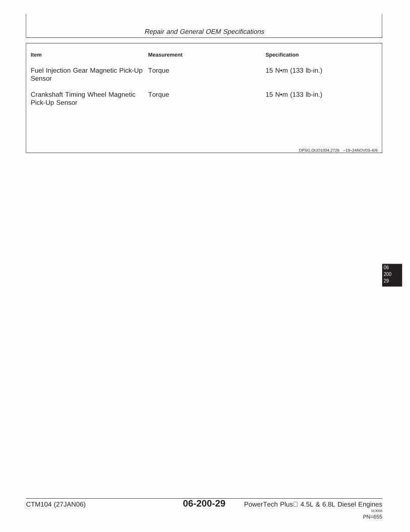
Repair and General OEM Specifications
DPSG,OUO1004,2726 –19–24NOV03–6/6
Item Measurement Specification
Fuel Injection Gear Magnetic Pick-Up Torque 15 N•m (133 lb-in.)Sensor
Crankshaft Timing Wheel Magnetic Torque 15 N•m (133 lb-in.)Pick-Up Sensor
0620029
CTM104 (27JAN06) 06-200-29 PowerTech Plus 4.5L & 6.8L Diesel Engines013006
PN=655
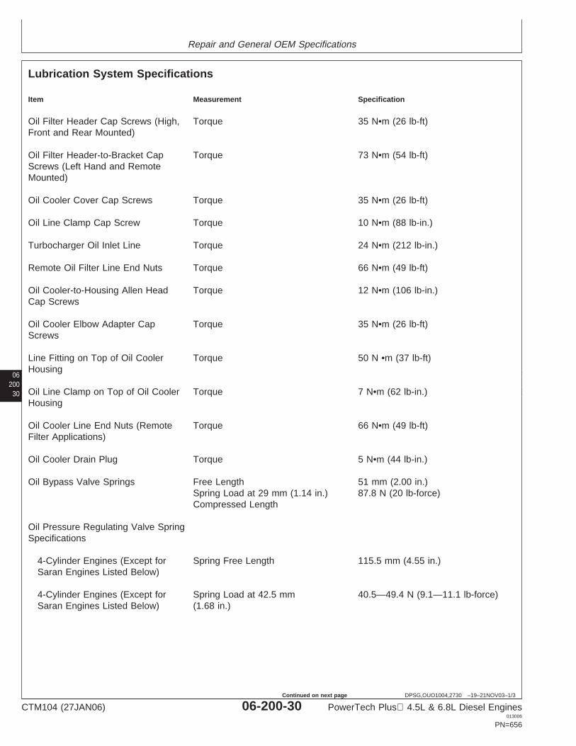
Repair and General OEM Specifications
06200
30
DPSG,OUO1004,2730 –19–21NOV03–1/3
Lubrication System Specifications
Item Measurement Specification
Oil Filter Header Cap Screws (High, Torque 35 N•m (26 lb-ft)Front and Rear Mounted)
Oil Filter Header-to-Bracket Cap Torque 73 N•m (54 lb-ft)Screws (Left Hand and RemoteMounted)
Oil Cooler Cover Cap Screws Torque 35 N•m (26 lb-ft)
Oil Line Clamp Cap Screw Torque 10 N•m (88 lb-in.)
Turbocharger Oil Inlet Line Torque 24 N•m (212 lb-in.)
Remote Oil Filter Line End Nuts Torque 66 N•m (49 lb-ft)
Oil Cooler-to-Housing Allen Head Torque 12 N•m (106 lb-in.)Cap Screws
Oil Cooler Elbow Adapter Cap Torque 35 N•m (26 lb-ft)Screws
Line Fitting on Top of Oil Cooler Torque 50 N •m (37 lb-ft)Housing
Oil Line Clamp on Top of Oil Cooler Torque 7 N•m (62 lb-in.)Housing
Oil Cooler Line End Nuts (Remote Torque 66 N•m (49 lb-ft)Filter Applications)
Oil Cooler Drain Plug Torque 5 N•m (44 lb-in.)
Oil Bypass Valve Springs Free Length 51 mm (2.00 in.)Spring Load at 29 mm (1.14 in.) 87.8 N (20 lb-force)Compressed Length
Oil Pressure Regulating Valve SpringSpecifications
4-Cylinder Engines (Except for Spring Free Length 115.5 mm (4.55 in.)Saran Engines Listed Below)
4-Cylinder Engines (Except for Spring Load at 42.5 mm 40.5—49.4 N (9.1—11.1 lb-force)Saran Engines Listed Below) (1.68 in.)
CTM104 (27JAN06) 06-200-30 PowerTech Plus 4.5L & 6.8L Diesel Engines013006
PN=656
Continued on next page
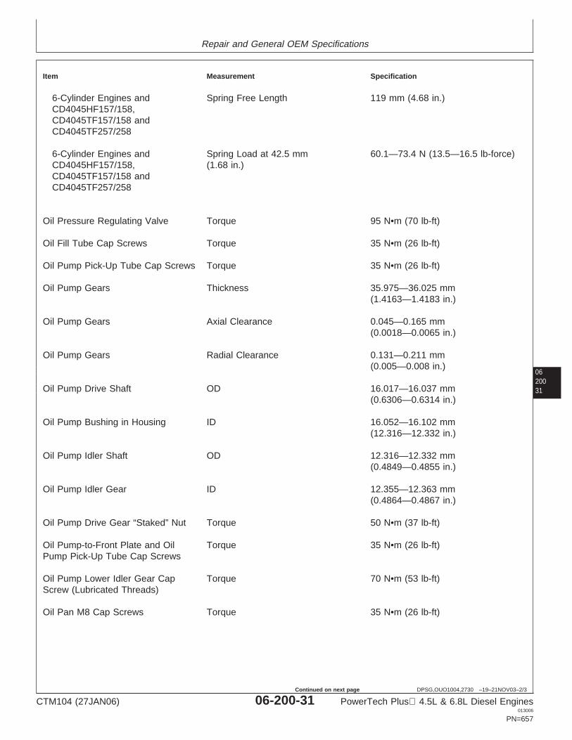
Repair and General OEM Specifications
0620031
DPSG,OUO1004,2730 –19–21NOV03–2/3
Item Measurement Specification
6-Cylinder Engines and Spring Free Length 119 mm (4.68 in.)CD4045HF157/158,CD4045TF157/158 andCD4045TF257/258
6-Cylinder Engines and Spring Load at 42.5 mm 60.1—73.4 N (13.5—16.5 lb-force)CD4045HF157/158, (1.68 in.)CD4045TF157/158 andCD4045TF257/258
Oil Pressure Regulating Valve Torque 95 N•m (70 lb-ft)
Oil Fill Tube Cap Screws Torque 35 N•m (26 lb-ft)
Oil Pump Pick-Up Tube Cap Screws Torque 35 N•m (26 lb-ft)
Oil Pump Gears Thickness 35.975—36.025 mm(1.4163—1.4183 in.)
Oil Pump Gears Axial Clearance 0.045—0.165 mm(0.0018—0.0065 in.)
Oil Pump Gears Radial Clearance 0.131—0.211 mm(0.005—0.008 in.)
Oil Pump Drive Shaft OD 16.017—16.037 mm(0.6306—0.6314 in.)
Oil Pump Bushing in Housing ID 16.052—16.102 mm(12.316—12.332 in.)
Oil Pump Idler Shaft OD 12.316—12.332 mm(0.4849—0.4855 in.)
Oil Pump Idler Gear ID 12.355—12.363 mm(0.4864—0.4867 in.)
Oil Pump Drive Gear “Staked” Nut Torque 50 N•m (37 lb-ft)
Oil Pump-to-Front Plate and Oil Torque 35 N•m (26 lb-ft)Pump Pick-Up Tube Cap Screws
Oil Pump Lower Idler Gear Cap Torque 70 N•m (53 lb-ft)Screw (Lubricated Threads)
Oil Pan M8 Cap Screws Torque 35 N•m (26 lb-ft)
CTM104 (27JAN06) 06-200-31 PowerTech Plus 4.5L & 6.8L Diesel Engines013006
PN=657
Continued on next page
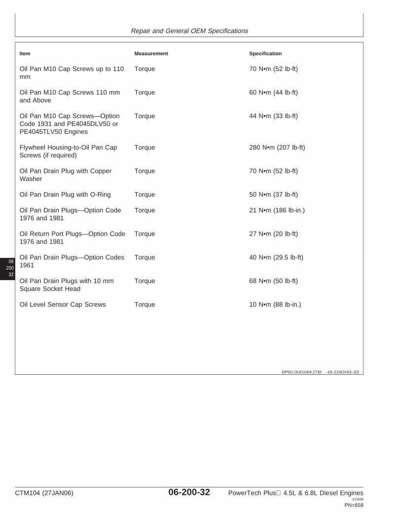
Repair and General OEM Specifications
06200
32
DPSG,OUO1004,2730 –19–21NOV03–3/3
Item Measurement Specification
Oil Pan M10 Cap Screws up to 110 Torque 70 N•m (52 lb-ft)mm
Oil Pan M10 Cap Screws 110 mm Torque 60 N•m (44 lb-ft)and Above
Oil Pan M10 Cap Screws—Option Torque 44 N•m (33 lb-ft)Code 1931 and PE4045DLV50 orPE4045TLV50 Engines
Flywheel Housing-to-Oil Pan Cap Torque 280 N•m (207 lb-ft)Screws (if required)
Oil Pan Drain Plug with Copper Torque 70 N•m (52 lb-ft)Washer
Oil Pan Drain Plug with O-Ring Torque 50 N•m (37 lb-ft)
Oil Pan Drain Plugs—Option Code Torque 21 N•m (186 lb-in.)1976 and 1981
Oil Return Port Plugs—Option Code Torque 27 N•m (20 lb-ft)1976 and 1981
Oil Pan Drain Plugs—Option Codes Torque 40 N•m (29.5 lb-ft)1961
Oil Pan Drain Plugs with 10 mm Torque 68 N•m (50 lb-ft)Square Socket Head
Oil Level Sensor Cap Screws Torque 10 N•m (88 lb-in.)
CTM104 (27JAN06) 06-200-32 PowerTech Plus 4.5L & 6.8L Diesel Engines013006
PN=658
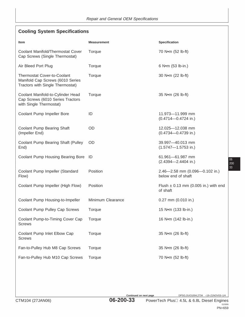
Repair and General OEM Specifications
0620033
DPSG,OUO1004,2734 –19–21NOV03–1/4
Cooling System Specifications
Item Measurement Specification
Coolant Manifold/Thermostat Cover Torque 70 N•m (52 lb-ft)Cap Screws (Single Thermostat)
Air Bleed Port Plug Torque 6 N•m (53 lb-in.)
Thermostat Cover-to-Coolant Torque 30 N•m (22 lb-ft)Manifold Cap Screws (6010 SeriesTractors with Single Thermostat)
Coolant Manifold-to-Cylinder Head Torque 35 N•m (26 lb-ft)Cap Screws (6010 Series Tractorswith Single Thermostat)
Coolant Pump Impeller Bore ID 11.973—11.999 mm(0.4714—0.4724 in.)
Coolant Pump Bearing Shaft OD 12.025—12.038 mm(Impeller End) (0.4734—0.4739 in.)
Coolant Pump Bearing Shaft (Pulley OD 39.997—40.013 mmEnd) (1.5747—1.5753 in.)
Coolant Pump Housing Bearing Bore ID 61.961—61.987 mm(2.4394—2.4404 in.)
Coolant Pump Impeller (Standard Position 2.46—2.58 mm (0.096—0.102 in.)Flow) below end of shaft
Coolant Pump Impeller (High Flow) Position Flush ± 0.13 mm (0.005 in.) with endof shaft
Coolant Pump Housing-to-Impeller Minimum Clearance 0.27 mm (0.010 in.)
Coolant Pump Pulley Cap Screws Torque 15 N•m (133 lb-in.)
Coolant Pump-to-Timing Cover Cap Torque 16 N•m (142 lb-in.)Screws
Coolant Pump Inlet Elbow Cap Torque 35 N•m (26 lb-ft)Screws
Fan-to-Pulley Hub M8 Cap Screws Torque 35 N•m (26 lb-ft)
Fan-to-Pulley Hub M10 Cap Screws Torque 70 N•m (52 lb-ft)
CTM104 (27JAN06) 06-200-33 PowerTech Plus 4.5L & 6.8L Diesel Engines013006
PN=659
Continued on next page
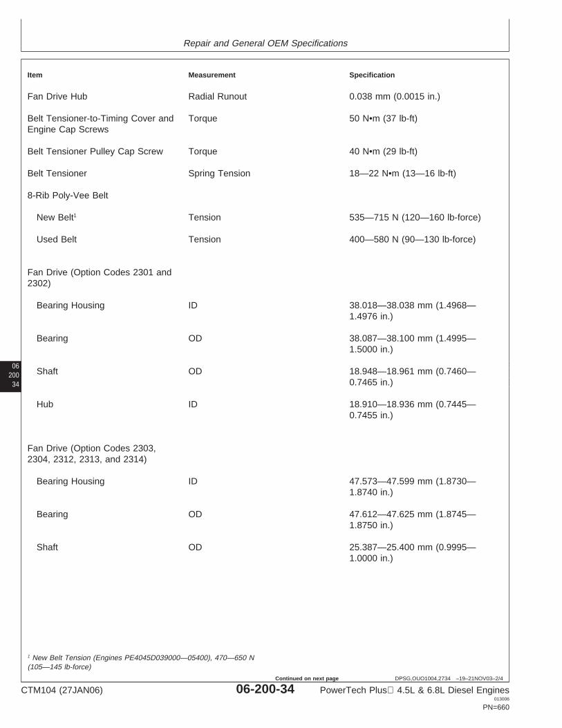
Repair and General OEM Specifications
06200
34
DPSG,OUO1004,2734 –19–21NOV03–2/4
Item Measurement Specification
Fan Drive Hub Radial Runout 0.038 mm (0.0015 in.)
Belt Tensioner-to-Timing Cover and Torque 50 N•m (37 lb-ft)Engine Cap Screws
Belt Tensioner Pulley Cap Screw Torque 40 N•m (29 lb-ft)
Belt Tensioner Spring Tension 18—22 N•m (13—16 lb-ft)
8-Rib Poly-Vee Belt
New Belt1 Tension 535—715 N (120—160 lb-force)
Used Belt Tension 400—580 N (90—130 lb-force)
Fan Drive (Option Codes 2301 and2302)
Bearing Housing ID 38.018—38.038 mm (1.4968—1.4976 in.)
Bearing OD 38.087—38.100 mm (1.4995—1.5000 in.)
Shaft OD 18.948—18.961 mm (0.7460—0.7465 in.)
Hub ID 18.910—18.936 mm (0.7445—0.7455 in.)
Fan Drive (Option Codes 2303,2304, 2312, 2313, and 2314)
Bearing Housing ID 47.573—47.599 mm (1.8730—1.8740 in.)
Bearing OD 47.612—47.625 mm (1.8745—1.8750 in.)
Shaft OD 25.387—25.400 mm (0.9995—1.0000 in.)
1 New Belt Tension (Engines PE4045D039000—05400), 470—650 N(105—145 lb-force)
CTM104 (27JAN06) 06-200-34 PowerTech Plus 4.5L & 6.8L Diesel Engines013006
PN=660
Continued on next page
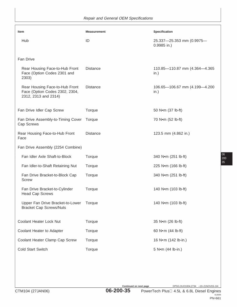
Repair and General OEM Specifications
0620035
DPSG,OUO1004,2734 –19–21NOV03–3/4
Item Measurement Specification
Hub ID 25.337—25.353 mm (0.9975—0.9985 in.)
Fan Drive
Rear Housing Face-to-Hub Front Distance 110.85—110.87 mm (4.364—4.365Face (Option Codes 2301 and in.)2303)
Rear Housing Face-to-Hub Front Distance 106.65—106.67 mm (4.199—4.200Face (Option Codes 2302, 2304, in.)2312, 2313 and 2314)
Fan Drive Idler Cap Screw Torque 50 N•m (37 lb-ft)
Fan Drive Assembly-to-Timing Cover Torque 70 N•m (52 lb-ft)Cap Screws
Rear Housing Face-to-Hub Front Distance 123.5 mm (4.862 in.)Face
Fan Drive Assembly (2254 Combine)
Fan Idler Axle Shaft-to-Block Torque 340 N•m (251 lb-ft)
Fan Idler-to-Shaft Retaining Nut Torque 225 N•m (166 lb-ft)
Fan Drive Bracket-to-Block Cap Torque 340 N•m (251 lb-ft)Screw
Fan Drive Bracket-to-Cylinder Torque 140 N•m (103 lb-ft)Head Cap Screws
Upper Fan Drive Bracket-to-Lower Torque 140 N•m (103 lb-ft)Bracket Cap Screws/Nuts
Coolant Heater Lock Nut Torque 35 N•m (26 lb-ft)
Coolant Heater to Adapter Torque 60 N•m (44 lb-ft)
Coolant Heater Clamp Cap Screw Torque 16 N•m (142 lb-in.)
Cold Start Switch Torque 5 N•m (44 lb-in.)
CTM104 (27JAN06) 06-200-35 PowerTech Plus 4.5L & 6.8L Diesel Engines013006
PN=661
Continued on next page
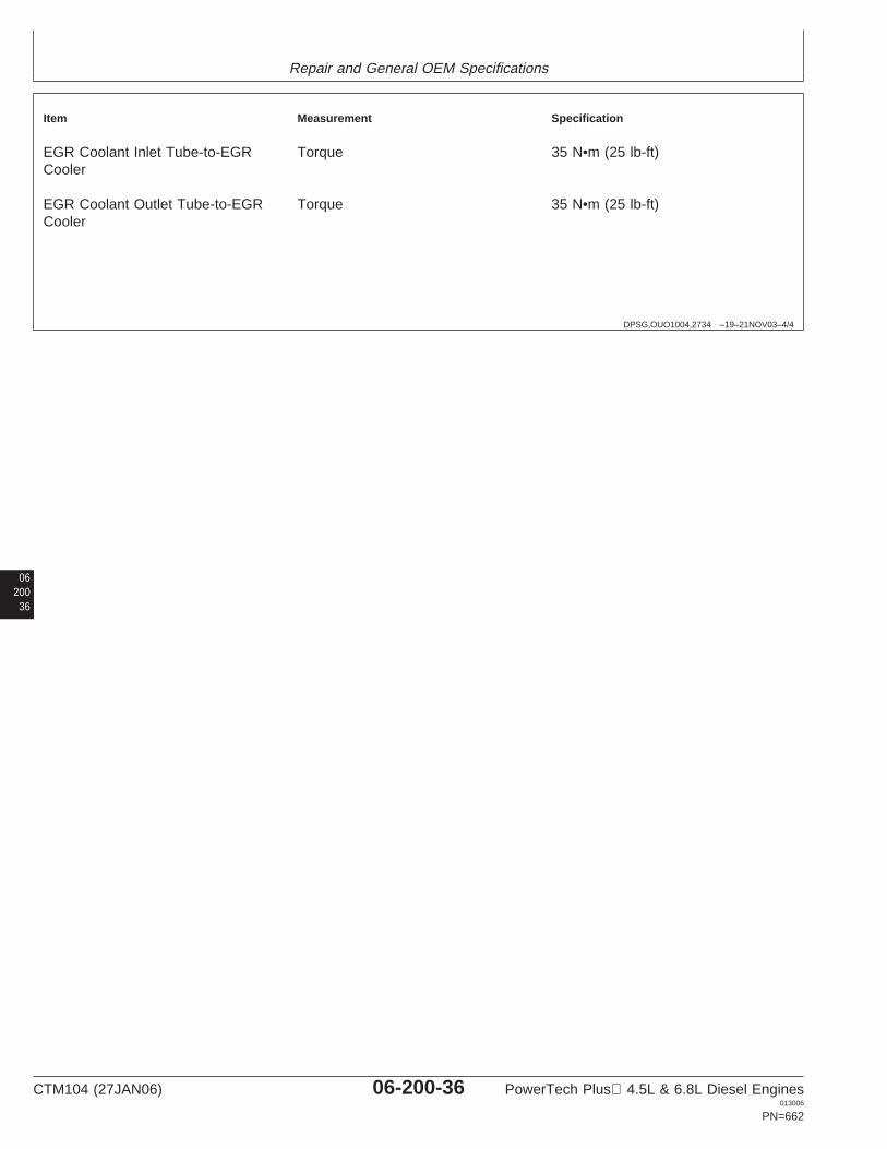
Repair and General OEM Specifications
DPSG,OUO1004,2734 –19–21NOV03–4/4
Item Measurement Specification
EGR Coolant Inlet Tube-to-EGR Torque 35 N•m (25 lb-ft)Cooler
EGR Coolant Outlet Tube-to-EGR Torque 35 N•m (25 lb-ft)Cooler
06200
36
CTM104 (27JAN06) 06-200-36 PowerTech Plus 4.5L & 6.8L Diesel Engines013006
PN=662
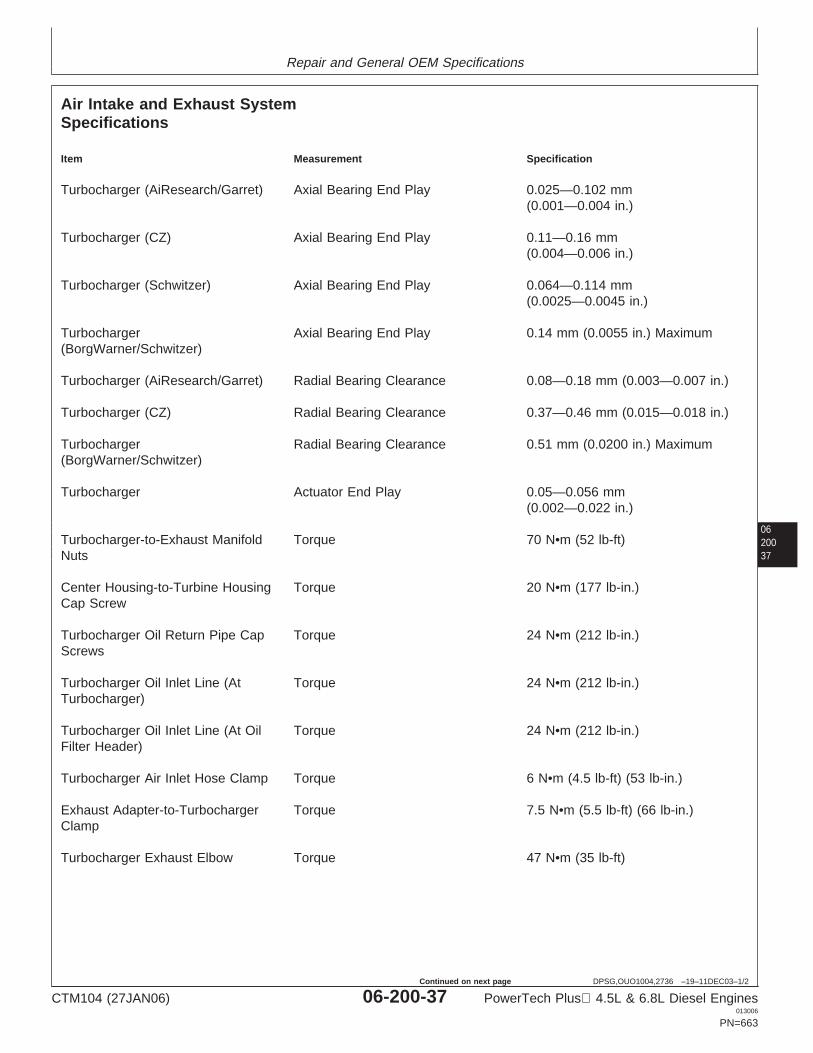
Repair and General OEM Specifications
0620037
DPSG,OUO1004,2736 –19–11DEC03–1/2
Air Intake and Exhaust SystemSpecifications
Item Measurement Specification
Turbocharger (AiResearch/Garret) Axial Bearing End Play 0.025—0.102 mm(0.001—0.004 in.)
Turbocharger (CZ) Axial Bearing End Play 0.11—0.16 mm(0.004—0.006 in.)
Turbocharger (Schwitzer) Axial Bearing End Play 0.064—0.114 mm(0.0025—0.0045 in.)
Turbocharger Axial Bearing End Play 0.14 mm (0.0055 in.) Maximum(BorgWarner/Schwitzer)
Turbocharger (AiResearch/Garret) Radial Bearing Clearance 0.08—0.18 mm (0.003—0.007 in.)
Turbocharger (CZ) Radial Bearing Clearance 0.37—0.46 mm (0.015—0.018 in.)
Turbocharger Radial Bearing Clearance 0.51 mm (0.0200 in.) Maximum(BorgWarner/Schwitzer)
Turbocharger Actuator End Play 0.05—0.056 mm(0.002—0.022 in.)
Turbocharger-to-Exhaust Manifold Torque 70 N•m (52 lb-ft)Nuts
Center Housing-to-Turbine Housing Torque 20 N•m (177 lb-in.)Cap Screw
Turbocharger Oil Return Pipe Cap Torque 24 N•m (212 lb-in.)Screws
Turbocharger Oil Inlet Line (At Torque 24 N•m (212 lb-in.)Turbocharger)
Turbocharger Oil Inlet Line (At Oil Torque 24 N•m (212 lb-in.)Filter Header)
Turbocharger Air Inlet Hose Clamp Torque 6 N•m (4.5 lb-ft) (53 lb-in.)
Exhaust Adapter-to-Turbocharger Torque 7.5 N•m (5.5 lb-ft) (66 lb-in.)Clamp
Turbocharger Exhaust Elbow Torque 47 N•m (35 lb-ft)
CTM104 (27JAN06) 06-200-37 PowerTech Plus 4.5L & 6.8L Diesel Engines013006
PN=663
Continued on next page
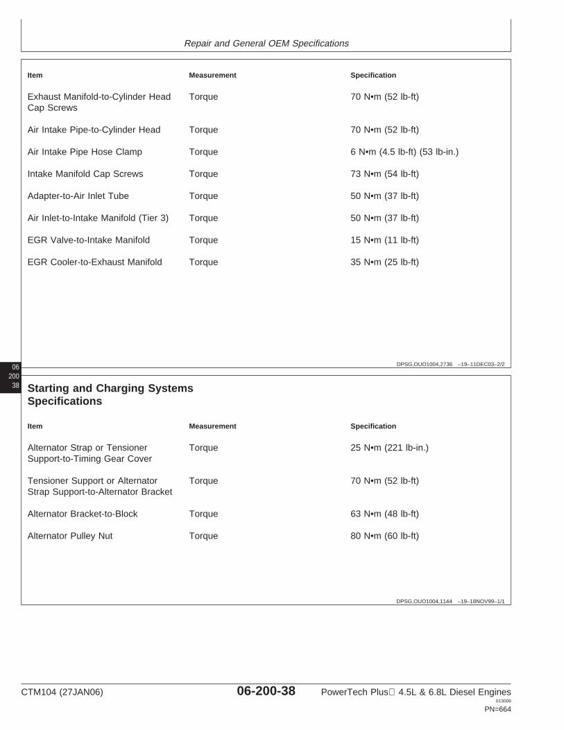
Repair and General OEM Specifications
06 DPSG,OUO1004,2736 –19–11DEC03–2/2
Item Measurement Specification
Exhaust Manifold-to-Cylinder Head Torque 70 N•m (52 lb-ft)Cap Screws
Air Intake Pipe-to-Cylinder Head Torque 70 N•m (52 lb-ft)
Air Intake Pipe Hose Clamp Torque 6 N•m (4.5 lb-ft) (53 lb-in.)
Intake Manifold Cap Screws Torque 73 N•m (54 lb-ft)
Adapter-to-Air Inlet Tube Torque 50 N•m (37 lb-ft)
Air Inlet-to-Intake Manifold (Tier 3) Torque 50 N•m (37 lb-ft)
EGR Valve-to-Intake Manifold Torque 15 N•m (11 lb-ft)
EGR Cooler-to-Exhaust Manifold Torque 35 N•m (25 lb-ft)
20038
DPSG,OUO1004,1144 –19–18NOV99–1/1
Starting and Charging SystemsSpecifications
Item Measurement Specification
Alternator Strap or Tensioner Torque 25 N•m (221 lb-in.)Support-to-Timing Gear Cover
Tensioner Support or Alternator Torque 70 N•m (52 lb-ft)Strap Support-to-Alternator Bracket
Alternator Bracket-to-Block Torque 63 N•m (48 lb-ft)
Alternator Pulley Nut Torque 80 N•m (60 lb-ft)
CTM104 (27JAN06) 06-200-38 PowerTech Plus 4.5L & 6.8L Diesel Engines013006
PN=664
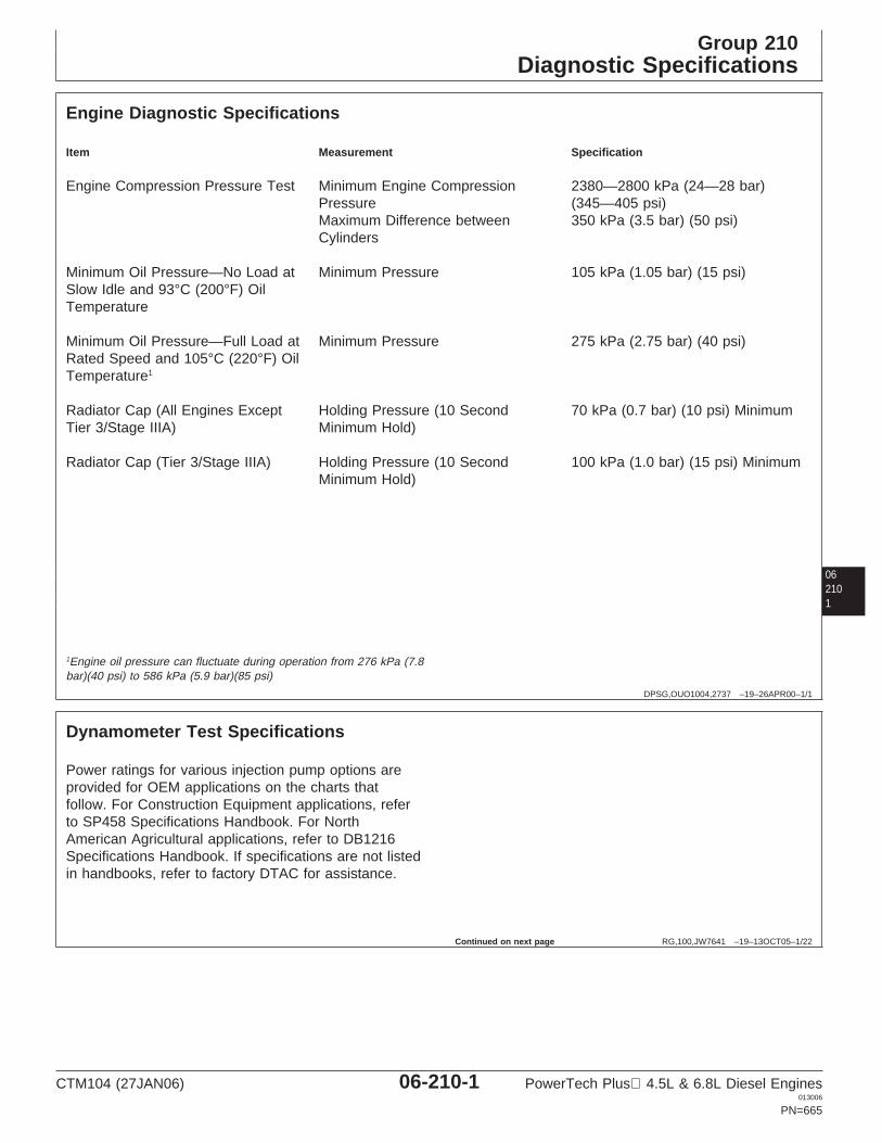
Group 210Diagnostic Specifications
062101
DPSG,OUO1004,2737 –19–26APR00–1/1
Engine Diagnostic Specifications
Item Measurement Specification
Engine Compression Pressure Test Minimum Engine Compression 2380—2800 kPa (24—28 bar)Pressure (345—405 psi)Maximum Difference between 350 kPa (3.5 bar) (50 psi)Cylinders
Minimum Oil Pressure—No Load at Minimum Pressure 105 kPa (1.05 bar) (15 psi)Slow Idle and 93°C (200°F) OilTemperature
Minimum Oil Pressure—Full Load at Minimum Pressure 275 kPa (2.75 bar) (40 psi)Rated Speed and 105°C (220°F) OilTemperature1
Radiator Cap (All Engines Except Holding Pressure (10 Second 70 kPa (0.7 bar) (10 psi) MinimumTier 3/Stage IIIA) Minimum Hold)
Radiator Cap (Tier 3/Stage IIIA) Holding Pressure (10 Second 100 kPa (1.0 bar) (15 psi) MinimumMinimum Hold)
1Engine oil pressure can fluctuate during operation from 276 kPa (7.8bar)(40 psi) to 586 kPa (5.9 bar)(85 psi)
RG,100,JW7641 –19–13OCT05–1/22
Dynamometer Test Specifications
Power ratings for various injection pump options areprovided for OEM applications on the charts thatfollow. For Construction Equipment applications, referto SP458 Specifications Handbook. For NorthAmerican Agricultural applications, refer to DB1216Specifications Handbook. If specifications are not listedin handbooks, refer to factory DTAC for assistance.
Continued on next page
CTM104 (27JAN06) 06-210-1 PowerTech Plus 4.5L & 6.8L Diesel Engines013006
PN=665
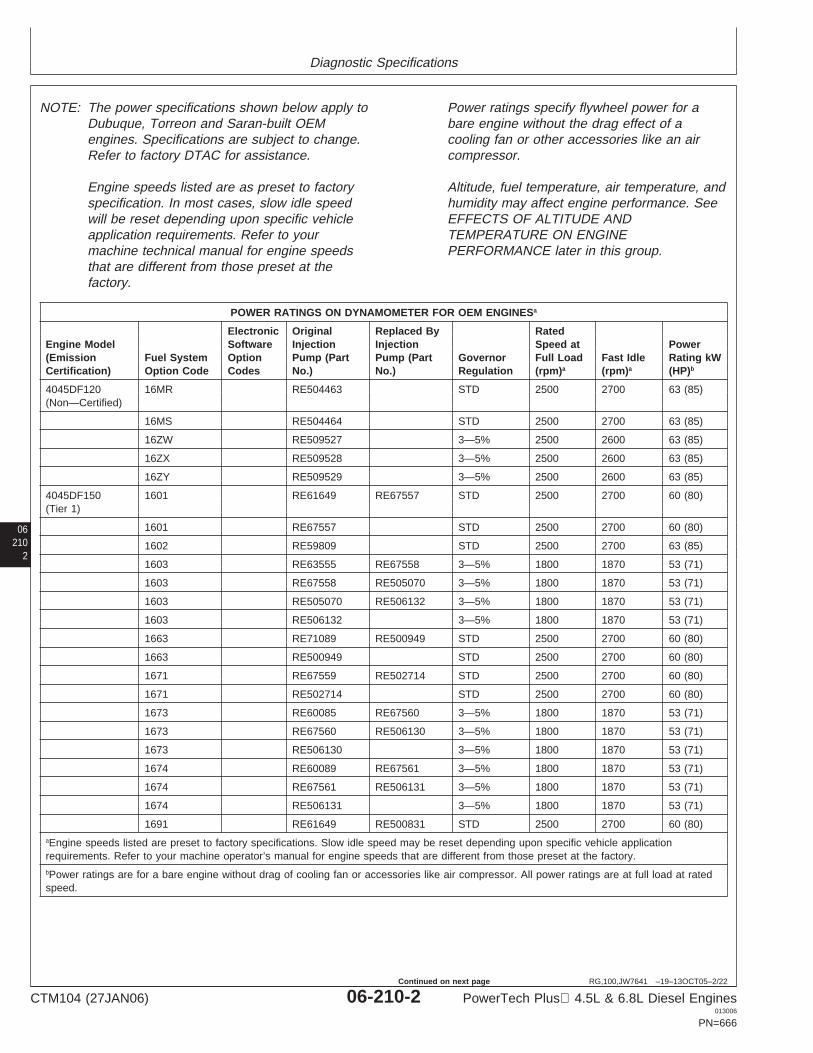
Diagnostic Specifications
06210
2
RG,100,JW7641 –19–13OCT05–2/22
NOTE: The power specifications shown below apply toDubuque, Torreon and Saran-built OEMengines. Specifications are subject to change.Refer to factory DTAC for assistance.
Engine speeds listed are as preset to factoryspecification. In most cases, slow idle speedwill be reset depending upon specific vehicleapplication requirements. Refer to yourmachine technical manual for engine speedsthat are different from those preset at thefactory.
Power ratings specify flywheel power for abare engine without the drag effect of acooling fan or other accessories like an aircompressor.
Altitude, fuel temperature, air temperature, andhumidity may affect engine performance. SeeEFFECTS OF ALTITUDE ANDTEMPERATURE ON ENGINEPERFORMANCE later in this group.
POWER RATINGS ON DYNAMOMETER FOR OEM ENGINESa
Electronic Original Replaced By RatedEngine Model Software Injection Injection Speed at Power(Emission Fuel System Option Pump (Part Pump (Part Governor Full Load Fast Idle Rating kWCertification) Option Code Codes No.) No.) Regulation (rpm)a (rpm)a (HP)b
4045DF120 16MR RE504463 STD 2500 2700 63 (85)(Non—Certified)
16MS RE504464 STD 2500 2700 63 (85)
16ZW RE509527 3—5% 2500 2600 63 (85)
16ZX RE509528 3—5% 2500 2600 63 (85)
16ZY RE509529 3—5% 2500 2600 63 (85)
4045DF150 1601 RE61649 RE67557 STD 2500 2700 60 (80)(Tier 1)
1601 RE67557 STD 2500 2700 60 (80)
1602 RE59809 STD 2500 2700 63 (85)
1603 RE63555 RE67558 3—5% 1800 1870 53 (71)
1603 RE67558 RE505070 3—5% 1800 1870 53 (71)
1603 RE505070 RE506132 3—5% 1800 1870 53 (71)
1603 RE506132 3—5% 1800 1870 53 (71)
1663 RE71089 RE500949 STD 2500 2700 60 (80)
1663 RE500949 STD 2500 2700 60 (80)
1671 RE67559 RE502714 STD 2500 2700 60 (80)
1671 RE502714 STD 2500 2700 60 (80)
1673 RE60085 RE67560 3—5% 1800 1870 53 (71)
1673 RE67560 RE506130 3—5% 1800 1870 53 (71)
1673 RE506130 3—5% 1800 1870 53 (71)
1674 RE60089 RE67561 3—5% 1800 1870 53 (71)
1674 RE67561 RE506131 3—5% 1800 1870 53 (71)
1674 RE506131 3—5% 1800 1870 53 (71)
1691 RE61649 RE500831 STD 2500 2700 60 (80)aEngine speeds listed are preset to factory specifications. Slow idle speed may be reset depending upon specific vehicle applicationrequirements. Refer to your machine operator’s manual for engine speeds that are different from those preset at the factory.bPower ratings are for a bare engine without drag of cooling fan or accessories like air compressor. All power ratings are at full load at ratedspeed.
CTM104 (27JAN06) 06-210-2 PowerTech Plus 4.5L & 6.8L Diesel Engines013006
PN=666
Continued on next page
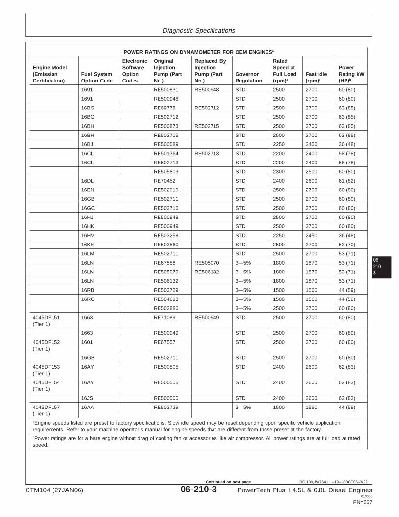
Diagnostic Specifications
062103
RG,100,JW7641 –19–13OCT05–3/22
POWER RATINGS ON DYNAMOMETER FOR OEM ENGINESa
Electronic Original Replaced By RatedEngine Model Software Injection Injection Speed at Power(Emission Fuel System Option Pump (Part Pump (Part Governor Full Load Fast Idle Rating kWCertification) Option Code Codes No.) No.) Regulation (rpm)a (rpm)a (HP)b
1691 RE500831 RE500948 STD 2500 2700 60 (80)
1691 RE500948 STD 2500 2700 60 (80)
16BG RE69778 RE502712 STD 2500 2700 63 (85)
16BG RE502712 STD 2500 2700 63 (85)
16BH RE500873 RE502715 STD 2500 2700 63 (85)
16BH RE502715 STD 2500 2700 63 (85)
16BJ RE500589 STD 2250 2450 36 (48)
16CL RE501364 RE502713 STD 2200 2400 58 (78)
16CL RE502713 STD 2200 2400 58 (78)
RE505803 STD 2300 2500 60 (80)
16DL RE70452 STD 2400 2600 61 (82)
16EN RE502019 STD 2500 2700 60 (80)
16GB RE502711 STD 2500 2700 60 (80)
16GC RE502716 STD 2500 2700 60 (80)
16HJ RE500948 STD 2500 2700 60 (80)
16HK RE500949 STD 2500 2700 60 (80)
16HV RE503258 STD 2250 2450 36 (48)
16KE RE503560 STD 2500 2700 52 (70)
16LM RE502711 STD 2500 2700 53 (71)
16LN RE67558 RE505070 3—5% 1800 1870 53 (71)
16LN RE505070 RE506132 3—5% 1800 1870 53 (71)
16LN RE506132 3—5% 1800 1870 53 (71)
16RB RE503729 3—5% 1500 1560 44 (59)
16RC RE504693 3—5% 1500 1560 44 (59)
RE502886 3—5% 2500 2700 60 (80)
4045DF151 1663 RE71089 RE500949 STD 2500 2700 60 (80)(Tier 1)
1663 RE500949 STD 2500 2700 60 (80)
4045DF152 1601 RE67557 STD 2500 2700 60 (80)(Tier 1)
16GB RE502711 STD 2500 2700 60 (80)
4045DF153 16AY RE500505 STD 2400 2600 62 (83)(Tier 1)
4045DF154 16AY RE500505 STD 2400 2600 62 (83)(Tier 1)
16JS RE500505 STD 2400 2600 62 (83)
4045DF157 16AA RE503729 3—5% 1500 1560 44 (59)(Tier 1)aEngine speeds listed are preset to factory specifications. Slow idle speed may be reset depending upon specific vehicle applicationrequirements. Refer to your machine operator’s manual for engine speeds that are different from those preset at the factory.bPower ratings are for a bare engine without drag of cooling fan or accessories like air compressor. All power ratings are at full load at ratedspeed.
CTM104 (27JAN06) 06-210-3 PowerTech Plus 4.5L & 6.8L Diesel Engines013006
PN=667
Continued on next page
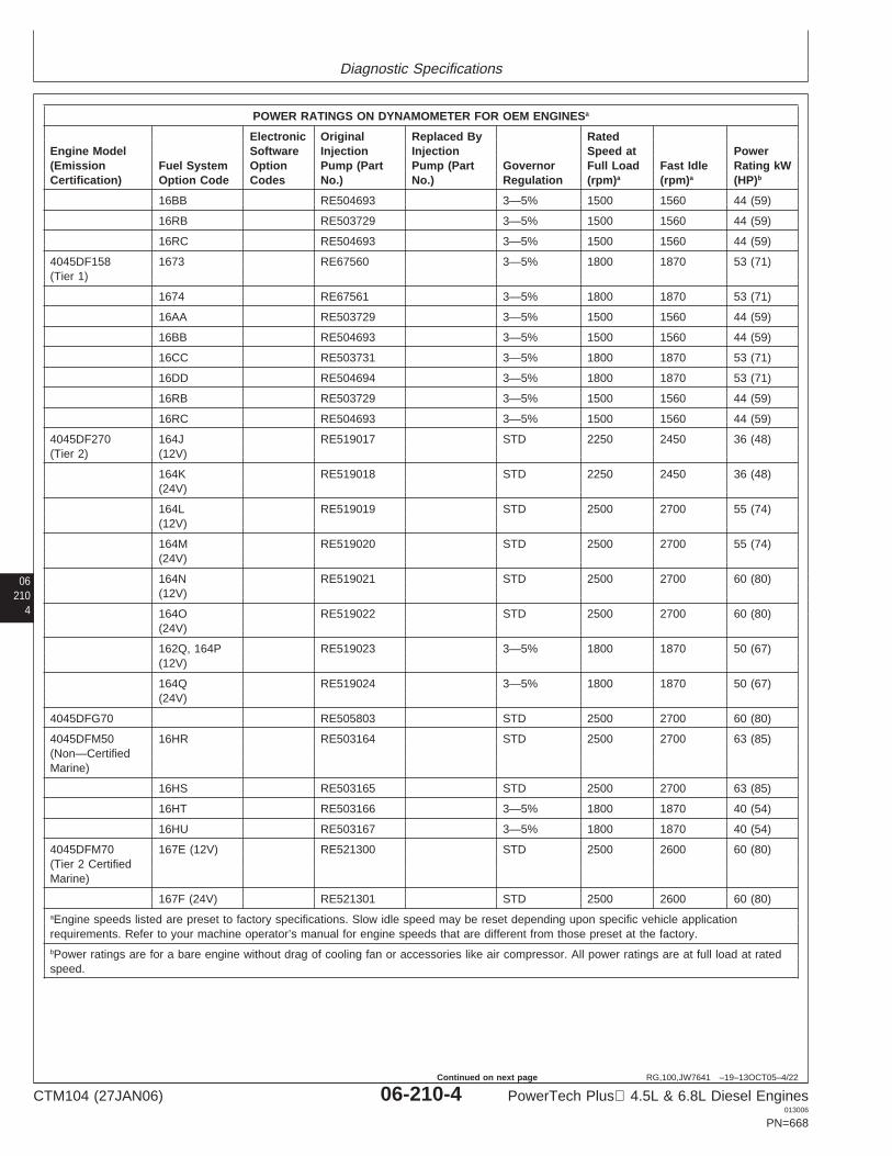
Diagnostic Specifications
06210
4
RG,100,JW7641 –19–13OCT05–4/22
POWER RATINGS ON DYNAMOMETER FOR OEM ENGINESa
Electronic Original Replaced By RatedEngine Model Software Injection Injection Speed at Power(Emission Fuel System Option Pump (Part Pump (Part Governor Full Load Fast Idle Rating kWCertification) Option Code Codes No.) No.) Regulation (rpm)a (rpm)a (HP)b
16BB RE504693 3—5% 1500 1560 44 (59)
16RB RE503729 3—5% 1500 1560 44 (59)
16RC RE504693 3—5% 1500 1560 44 (59)
4045DF158 1673 RE67560 3—5% 1800 1870 53 (71)(Tier 1)
1674 RE67561 3—5% 1800 1870 53 (71)
16AA RE503729 3—5% 1500 1560 44 (59)
16BB RE504693 3—5% 1500 1560 44 (59)
16CC RE503731 3—5% 1800 1870 53 (71)
16DD RE504694 3—5% 1800 1870 53 (71)
16RB RE503729 3—5% 1500 1560 44 (59)
16RC RE504693 3—5% 1500 1560 44 (59)
4045DF270 164J RE519017 STD 2250 2450 36 (48)(Tier 2) (12V)
164K RE519018 STD 2250 2450 36 (48)(24V)
164L RE519019 STD 2500 2700 55 (74)(12V)
164M RE519020 STD 2500 2700 55 (74)(24V)
164N RE519021 STD 2500 2700 60 (80)(12V)
164O RE519022 STD 2500 2700 60 (80)(24V)
162Q, 164P RE519023 3—5% 1800 1870 50 (67)(12V)
164Q RE519024 3—5% 1800 1870 50 (67)(24V)
4045DFG70 RE505803 STD 2500 2700 60 (80)
4045DFM50 16HR RE503164 STD 2500 2700 63 (85)(Non—CertifiedMarine)
16HS RE503165 STD 2500 2700 63 (85)
16HT RE503166 3—5% 1800 1870 40 (54)
16HU RE503167 3—5% 1800 1870 40 (54)
4045DFM70 167E (12V) RE521300 STD 2500 2600 60 (80)(Tier 2 CertifiedMarine)
167F (24V) RE521301 STD 2500 2600 60 (80)aEngine speeds listed are preset to factory specifications. Slow idle speed may be reset depending upon specific vehicle applicationrequirements. Refer to your machine operator’s manual for engine speeds that are different from those preset at the factory.bPower ratings are for a bare engine without drag of cooling fan or accessories like air compressor. All power ratings are at full load at ratedspeed.
CTM104 (27JAN06) 06-210-4 PowerTech Plus 4.5L & 6.8L Diesel Engines013006
PN=668
Continued on next page
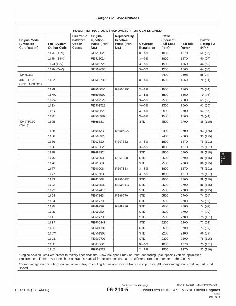
Diagnostic Specifications
062105
RG,100,JW7641 –19–13OCT05–5/22
POWER RATINGS ON DYNAMOMETER FOR OEM ENGINESa
Electronic Original Replaced By RatedEngine Model Software Injection Injection Speed at Power(Emission Fuel System Option Pump (Part Pump (Part Governor Full Load Fast Idle Rating kWCertification) Option Code Codes No.) No.) Regulation (rpm)a (rpm)a (HP)b
167G (12V) RE519023 3—5% 1800 1870 50 (67)
167H (24V) RE519024 3—5% 1800 1870 50 (67)
167J (12V) RE503729 3—5% 1500 1560 44 (59)
167K (24V) RE504693 3—5% 1500 1560 44 (59)
4045DJ31 2400 2605 55(74)
4045TF120 16 MT RE503733 3—5% 1500 1560 70 (94)(Non—Certified)
16MU RE505050 RE506990 3—5% 1500 1560 70 (94)
16MU RE506990 3—5% 1500 1560 70 (94)
16ZW RE509527 3—5% 2500 2600 63 (85)
16ZX RE509528 3—5% 2500 2600 63 (85)
16ZY RE509529 3—5% 2500 2600 63 (85)
16MT RE506989 3—5% 1500 1560 70 (94)
4045TF150 1605 RE69781 STD 2500 2700 86 (115)(Tier 1)
1606 RE64133 RE505927 2400 2600 93 (125)
1606 RE505927 2400 2600 93 (125)
1656 RE63610 RE67562 3—5% 1800 1870 75 (101)
1656 RE67562 3—5% 1800 1870 75 (101)
1675 RE69782 STD 2500 2700 86 (115)
1676 RE60093 RE61668 STD 2500 2700 86 (115)
1676 RE61668 STD 2500 2700 86 (115)
1677 RE60096 RE67563 3—5% 1800 1870 75 (101)
1677 RE67563 3—5% 1800 1870 75 (101)
1692 RE61668 RE500881 STD 2500 2700 86 (115)
1692 RE500881 RE502416 STD 2500 2700 86 (115)
1692 RE502416 STD 2500 2700 86 (115)
1694 RE67863 RE69779 STD 2500 2700 74 (99)
1694 RE69779 STD 2500 2700 74 (99)
1695 RE69739 RE69780 STD 2500 2700 74 (99)
1695 RE69780 STD 2500 2700 74 (99)
16AB RE69779 STD 2500 2700 75 (101)
16BF RE500848 STD 2200 2400 73 (98)
16CE RE501180 STD 2500 2700 74 (99)
16CM RE501365 STD 2200 2400 66 (89)
16GL RE502706 STD 2300 2500 78 (105)
16LP RE67562 3—5% 1800 1870 75 (101)
16LZ RE503735 3—5% 1800 1870 82 (110)aEngine speeds listed are preset to factory specifications. Slow idle speed may be reset depending upon specific vehicle applicationrequirements. Refer to your machine operator’s manual for engine speeds that are different from those preset at the factory.bPower ratings are for a bare engine without drag of cooling fan or accessories like air compressor. All power ratings are at full load at ratedspeed.
CTM104 (27JAN06) 06-210-5 PowerTech Plus 4.5L & 6.8L Diesel Engines013006
PN=669
Continued on next page
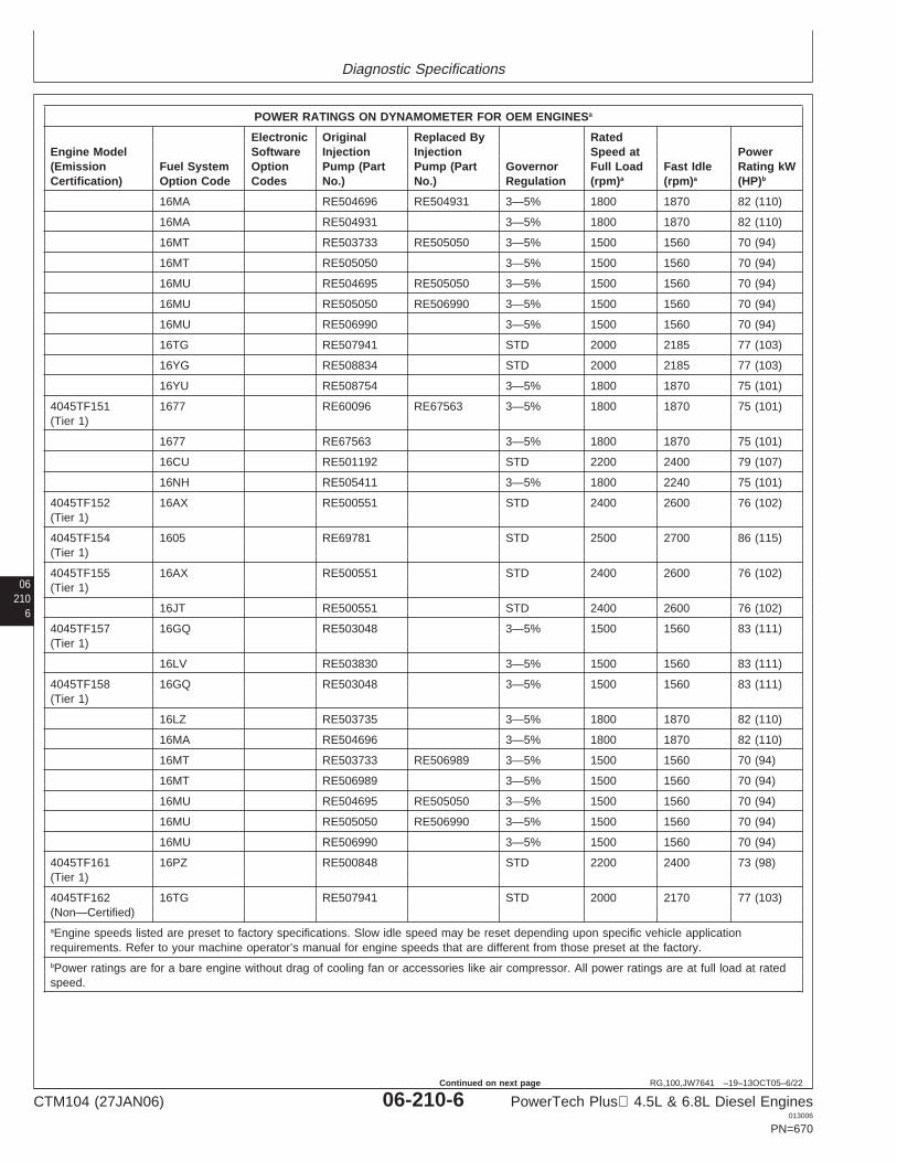
Diagnostic Specifications
06210
6
RG,100,JW7641 –19–13OCT05–6/22
POWER RATINGS ON DYNAMOMETER FOR OEM ENGINESa
Electronic Original Replaced By RatedEngine Model Software Injection Injection Speed at Power(Emission Fuel System Option Pump (Part Pump (Part Governor Full Load Fast Idle Rating kWCertification) Option Code Codes No.) No.) Regulation (rpm)a (rpm)a (HP)b
16MA RE504696 RE504931 3—5% 1800 1870 82 (110)
16MA RE504931 3—5% 1800 1870 82 (110)
16MT RE503733 RE505050 3—5% 1500 1560 70 (94)
16MT RE505050 3—5% 1500 1560 70 (94)
16MU RE504695 RE505050 3—5% 1500 1560 70 (94)
16MU RE505050 RE506990 3—5% 1500 1560 70 (94)
16MU RE506990 3—5% 1500 1560 70 (94)
16TG RE507941 STD 2000 2185 77 (103)
16YG RE508834 STD 2000 2185 77 (103)
16YU RE508754 3—5% 1800 1870 75 (101)
4045TF151 1677 RE60096 RE67563 3—5% 1800 1870 75 (101)(Tier 1)
1677 RE67563 3—5% 1800 1870 75 (101)
16CU RE501192 STD 2200 2400 79 (107)
16NH RE505411 3—5% 1800 2240 75 (101)
4045TF152 16AX RE500551 STD 2400 2600 76 (102)(Tier 1)
4045TF154 1605 RE69781 STD 2500 2700 86 (115)(Tier 1)
4045TF155 16AX RE500551 STD 2400 2600 76 (102)(Tier 1)
16JT RE500551 STD 2400 2600 76 (102)
4045TF157 16GQ RE503048 3—5% 1500 1560 83 (111)(Tier 1)
16LV RE503830 3—5% 1500 1560 83 (111)
4045TF158 16GQ RE503048 3—5% 1500 1560 83 (111)(Tier 1)
16LZ RE503735 3—5% 1800 1870 82 (110)
16MA RE504696 3—5% 1800 1870 82 (110)
16MT RE503733 RE506989 3—5% 1500 1560 70 (94)
16MT RE506989 3—5% 1500 1560 70 (94)
16MU RE504695 RE505050 3—5% 1500 1560 70 (94)
16MU RE505050 RE506990 3—5% 1500 1560 70 (94)
16MU RE506990 3—5% 1500 1560 70 (94)
4045TF161 16PZ RE500848 STD 2200 2400 73 (98)(Tier 1)
4045TF162 16TG RE507941 STD 2000 2170 77 (103)(Non—Certified)aEngine speeds listed are preset to factory specifications. Slow idle speed may be reset depending upon specific vehicle applicationrequirements. Refer to your machine operator’s manual for engine speeds that are different from those preset at the factory.bPower ratings are for a bare engine without drag of cooling fan or accessories like air compressor. All power ratings are at full load at ratedspeed.
CTM104 (27JAN06) 06-210-6 PowerTech Plus 4.5L & 6.8L Diesel Engines013006
PN=670
Continued on next page
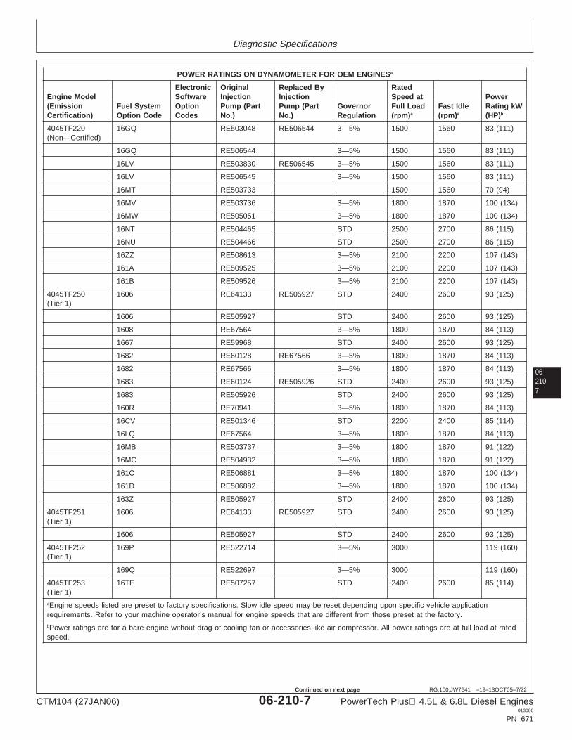
Diagnostic Specifications
062107
RG,100,JW7641 –19–13OCT05–7/22
POWER RATINGS ON DYNAMOMETER FOR OEM ENGINESa
Electronic Original Replaced By RatedEngine Model Software Injection Injection Speed at Power(Emission Fuel System Option Pump (Part Pump (Part Governor Full Load Fast Idle Rating kWCertification) Option Code Codes No.) No.) Regulation (rpm)a (rpm)a (HP)b
4045TF220 16GQ RE503048 RE506544 3—5% 1500 1560 83 (111)(Non—Certified)
16GQ RE506544 3—5% 1500 1560 83 (111)
16LV RE503830 RE506545 3—5% 1500 1560 83 (111)
16LV RE506545 3—5% 1500 1560 83 (111)
16MT RE503733 1500 1560 70 (94)
16MV RE503736 3—5% 1800 1870 100 (134)
16MW RE505051 3—5% 1800 1870 100 (134)
16NT RE504465 STD 2500 2700 86 (115)
16NU RE504466 STD 2500 2700 86 (115)
16ZZ RE508613 3—5% 2100 2200 107 (143)
161A RE509525 3—5% 2100 2200 107 (143)
161B RE509526 3—5% 2100 2200 107 (143)
4045TF250 1606 RE64133 RE505927 STD 2400 2600 93 (125)(Tier 1)
1606 RE505927 STD 2400 2600 93 (125)
1608 RE67564 3—5% 1800 1870 84 (113)
1667 RE59968 STD 2400 2600 93 (125)
1682 RE60128 RE67566 3—5% 1800 1870 84 (113)
1682 RE67566 3—5% 1800 1870 84 (113)
1683 RE60124 RE505926 STD 2400 2600 93 (125)
1683 RE505926 STD 2400 2600 93 (125)
160R RE70941 3—5% 1800 1870 84 (113)
16CV RE501346 STD 2200 2400 85 (114)
16LQ RE67564 3—5% 1800 1870 84 (113)
16MB RE503737 3—5% 1800 1870 91 (122)
16MC RE504932 3—5% 1800 1870 91 (122)
161C RE506881 3—5% 1800 1870 100 (134)
161D RE506882 3—5% 1800 1870 100 (134)
163Z RE505927 STD 2400 2600 93 (125)
4045TF251 1606 RE64133 RE505927 STD 2400 2600 93 (125)(Tier 1)
1606 RE505927 STD 2400 2600 93 (125)
4045TF252 169P RE522714 3—5% 3000 119 (160)(Tier 1)
169Q RE522697 3—5% 3000 119 (160)
4045TF253 16TE RE507257 STD 2400 2600 85 (114)(Tier 1)aEngine speeds listed are preset to factory specifications. Slow idle speed may be reset depending upon specific vehicle applicationrequirements. Refer to your machine operator’s manual for engine speeds that are different from those preset at the factory.bPower ratings are for a bare engine without drag of cooling fan or accessories like air compressor. All power ratings are at full load at ratedspeed.
CTM104 (27JAN06) 06-210-7 PowerTech Plus 4.5L & 6.8L Diesel Engines013006
PN=671
Continued on next page
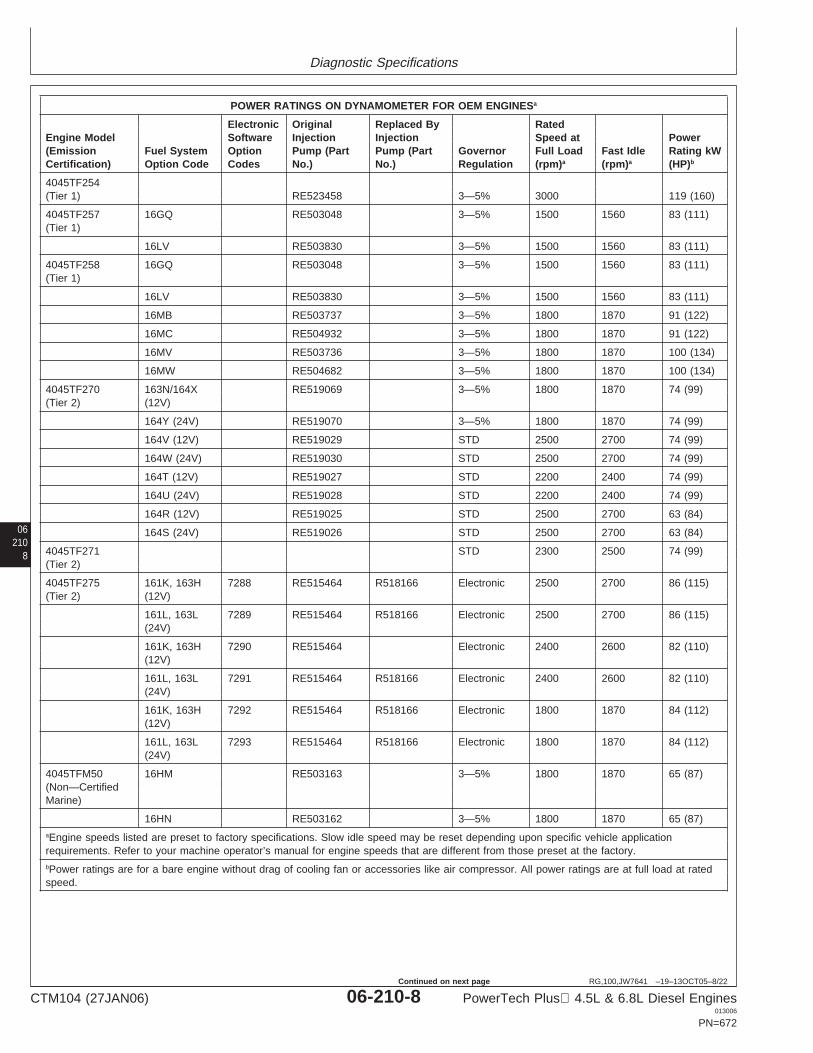
Diagnostic Specifications
06210
8
RG,100,JW7641 –19–13OCT05–8/22
POWER RATINGS ON DYNAMOMETER FOR OEM ENGINESa
Electronic Original Replaced By RatedEngine Model Software Injection Injection Speed at Power(Emission Fuel System Option Pump (Part Pump (Part Governor Full Load Fast Idle Rating kWCertification) Option Code Codes No.) No.) Regulation (rpm)a (rpm)a (HP)b
4045TF254(Tier 1) RE523458 3—5% 3000 119 (160)
4045TF257 16GQ RE503048 3—5% 1500 1560 83 (111)(Tier 1)
16LV RE503830 3—5% 1500 1560 83 (111)
4045TF258 16GQ RE503048 3—5% 1500 1560 83 (111)(Tier 1)
16LV RE503830 3—5% 1500 1560 83 (111)
16MB RE503737 3—5% 1800 1870 91 (122)
16MC RE504932 3—5% 1800 1870 91 (122)
16MV RE503736 3—5% 1800 1870 100 (134)
16MW RE504682 3—5% 1800 1870 100 (134)
4045TF270 163N/164X RE519069 3—5% 1800 1870 74 (99)(Tier 2) (12V)
164Y (24V) RE519070 3—5% 1800 1870 74 (99)
164V (12V) RE519029 STD 2500 2700 74 (99)
164W (24V) RE519030 STD 2500 2700 74 (99)
164T (12V) RE519027 STD 2200 2400 74 (99)
164U (24V) RE519028 STD 2200 2400 74 (99)
164R (12V) RE519025 STD 2500 2700 63 (84)
164S (24V) RE519026 STD 2500 2700 63 (84)
4045TF271 STD 2300 2500 74 (99)(Tier 2)
4045TF275 161K, 163H 7288 RE515464 R518166 Electronic 2500 2700 86 (115)(Tier 2) (12V)
161L, 163L 7289 RE515464 R518166 Electronic 2500 2700 86 (115)(24V)
161K, 163H 7290 RE515464 Electronic 2400 2600 82 (110)(12V)
161L, 163L 7291 RE515464 R518166 Electronic 2400 2600 82 (110)(24V)
161K, 163H 7292 RE515464 R518166 Electronic 1800 1870 84 (112)(12V)
161L, 163L 7293 RE515464 R518166 Electronic 1800 1870 84 (112)(24V)
4045TFM50 16HM RE503163 3—5% 1800 1870 65 (87)(Non—CertifiedMarine)
16HN RE503162 3—5% 1800 1870 65 (87)aEngine speeds listed are preset to factory specifications. Slow idle speed may be reset depending upon specific vehicle applicationrequirements. Refer to your machine operator’s manual for engine speeds that are different from those preset at the factory.bPower ratings are for a bare engine without drag of cooling fan or accessories like air compressor. All power ratings are at full load at ratedspeed.
CTM104 (27JAN06) 06-210-8 PowerTech Plus 4.5L & 6.8L Diesel Engines013006
PN=672
Continued on next page
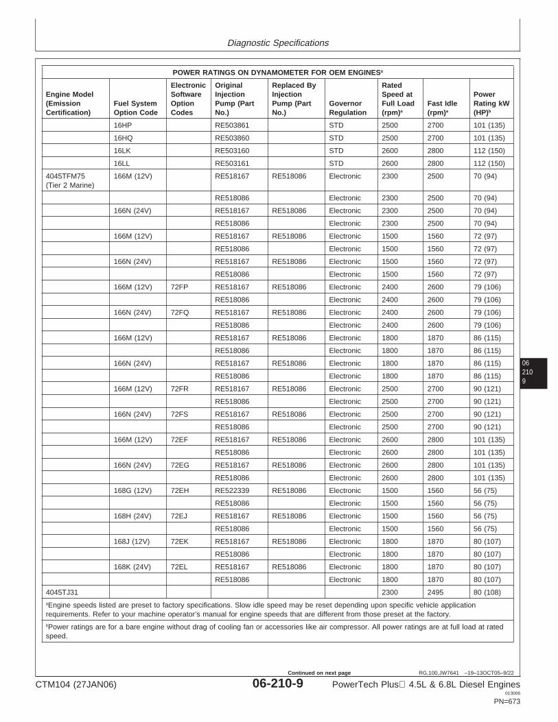
Diagnostic Specifications
062109
RG,100,JW7641 –19–13OCT05–9/22
POWER RATINGS ON DYNAMOMETER FOR OEM ENGINESa
Electronic Original Replaced By RatedEngine Model Software Injection Injection Speed at Power(Emission Fuel System Option Pump (Part Pump (Part Governor Full Load Fast Idle Rating kWCertification) Option Code Codes No.) No.) Regulation (rpm)a (rpm)a (HP)b
16HP RE503861 STD 2500 2700 101 (135)
16HQ RE503860 STD 2500 2700 101 (135)
16LK RE503160 STD 2600 2800 112 (150)
16LL RE503161 STD 2600 2800 112 (150)
4045TFM75 166M (12V) RE518167 RE518086 Electronic 2300 2500 70 (94)(Tier 2 Marine)
RE518086 Electronic 2300 2500 70 (94)
166N (24V) RE518167 RE518086 Electronic 2300 2500 70 (94)
RE518086 Electronic 2300 2500 70 (94)
166M (12V) RE518167 RE518086 Electronic 1500 1560 72 (97)
RE518086 Electronic 1500 1560 72 (97)
166N (24V) RE518167 RE518086 Electronic 1500 1560 72 (97)
RE518086 Electronic 1500 1560 72 (97)
166M (12V) 72FP RE518167 RE518086 Electronic 2400 2600 79 (106)
RE518086 Electronic 2400 2600 79 (106)
166N (24V) 72FQ RE518167 RE518086 Electronic 2400 2600 79 (106)
RE518086 Electronic 2400 2600 79 (106)
166M (12V) RE518167 RE518086 Electronic 1800 1870 86 (115)
RE518086 Electronic 1800 1870 86 (115)
166N (24V) RE518167 RE518086 Electronic 1800 1870 86 (115)
RE518086 Electronic 1800 1870 86 (115)
166M (12V) 72FR RE518167 RE518086 Electronic 2500 2700 90 (121)
RE518086 Electronic 2500 2700 90 (121)
166N (24V) 72FS RE518167 RE518086 Electronic 2500 2700 90 (121)
RE518086 Electronic 2500 2700 90 (121)
166M (12V) 72EF RE518167 RE518086 Electronic 2600 2800 101 (135)
RE518086 Electronic 2600 2800 101 (135)
166N (24V) 72EG RE518167 RE518086 Electronic 2600 2800 101 (135)
RE518086 Electronic 2600 2800 101 (135)
168G (12V) 72EH RE522339 RE518086 Electronic 1500 1560 56 (75)
RE518086 Electronic 1500 1560 56 (75)
168H (24V) 72EJ RE518167 RE518086 Electronic 1500 1560 56 (75)
RE518086 Electronic 1500 1560 56 (75)
168J (12V) 72EK RE518167 RE518086 Electronic 1800 1870 80 (107)
RE518086 Electronic 1800 1870 80 (107)
168K (24V) 72EL RE518167 RE518086 Electronic 1800 1870 80 (107)
RE518086 Electronic 1800 1870 80 (107)
4045TJ31 2300 2495 80 (108)aEngine speeds listed are preset to factory specifications. Slow idle speed may be reset depending upon specific vehicle applicationrequirements. Refer to your machine operator’s manual for engine speeds that are different from those preset at the factory.bPower ratings are for a bare engine without drag of cooling fan or accessories like air compressor. All power ratings are at full load at ratedspeed.
CTM104 (27JAN06) 06-210-9 PowerTech Plus 4.5L & 6.8L Diesel Engines013006
PN=673
Continued on next page
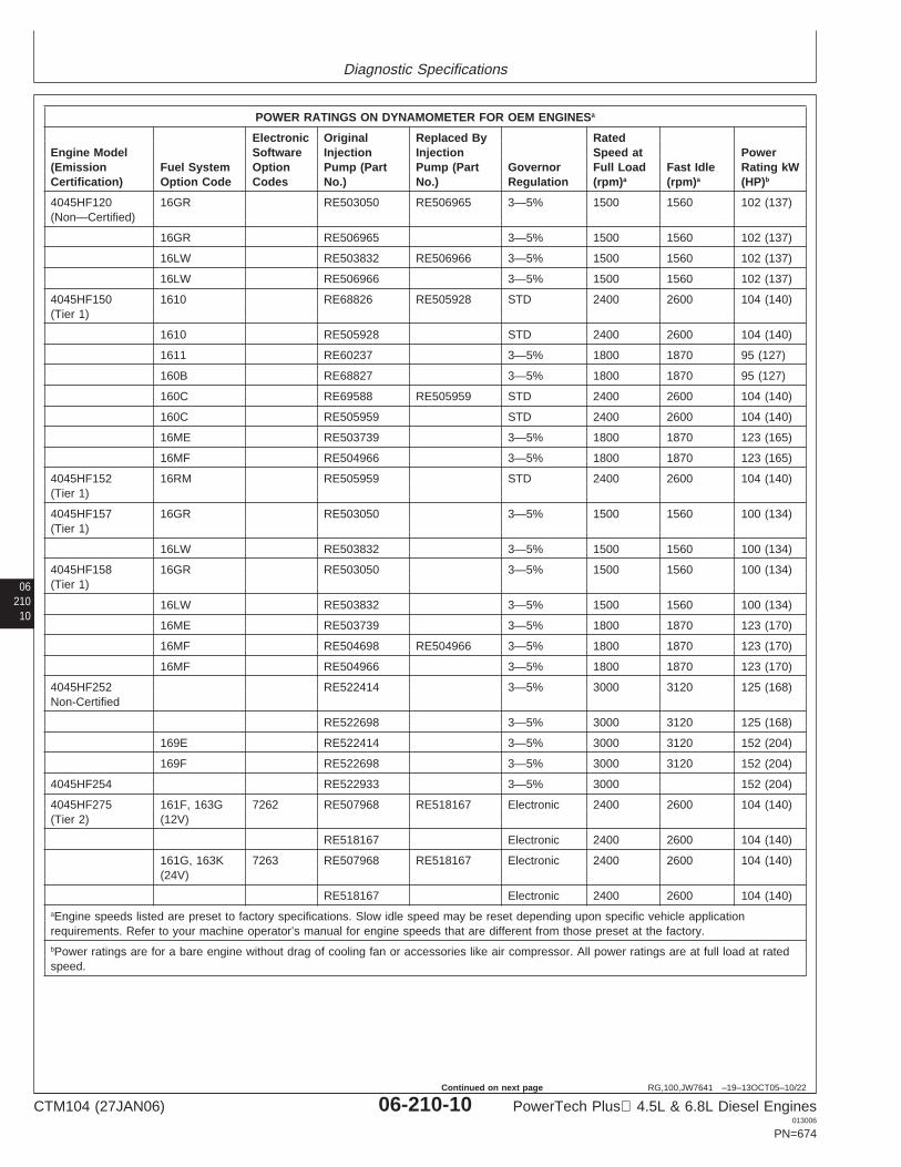
Diagnostic Specifications
06210
10
RG,100,JW7641 –19–13OCT05–10/22
POWER RATINGS ON DYNAMOMETER FOR OEM ENGINESa
Electronic Original Replaced By RatedEngine Model Software Injection Injection Speed at Power(Emission Fuel System Option Pump (Part Pump (Part Governor Full Load Fast Idle Rating kWCertification) Option Code Codes No.) No.) Regulation (rpm)a (rpm)a (HP)b
4045HF120 16GR RE503050 RE506965 3—5% 1500 1560 102 (137)(Non—Certified)
16GR RE506965 3—5% 1500 1560 102 (137)
16LW RE503832 RE506966 3—5% 1500 1560 102 (137)
16LW RE506966 3—5% 1500 1560 102 (137)
4045HF150 1610 RE68826 RE505928 STD 2400 2600 104 (140)(Tier 1)
1610 RE505928 STD 2400 2600 104 (140)
1611 RE60237 3—5% 1800 1870 95 (127)
160B RE68827 3—5% 1800 1870 95 (127)
160C RE69588 RE505959 STD 2400 2600 104 (140)
160C RE505959 STD 2400 2600 104 (140)
16ME RE503739 3—5% 1800 1870 123 (165)
16MF RE504966 3—5% 1800 1870 123 (165)
4045HF152 16RM RE505959 STD 2400 2600 104 (140)(Tier 1)
4045HF157 16GR RE503050 3—5% 1500 1560 100 (134)(Tier 1)
16LW RE503832 3—5% 1500 1560 100 (134)
4045HF158 16GR RE503050 3—5% 1500 1560 100 (134)(Tier 1)
16LW RE503832 3—5% 1500 1560 100 (134)
16ME RE503739 3—5% 1800 1870 123 (170)
16MF RE504698 RE504966 3—5% 1800 1870 123 (170)
16MF RE504966 3—5% 1800 1870 123 (170)
4045HF252 RE522414 3—5% 3000 3120 125 (168)Non-Certified
RE522698 3—5% 3000 3120 125 (168)
169E RE522414 3—5% 3000 3120 152 (204)
169F RE522698 3—5% 3000 3120 152 (204)
4045HF254 RE522933 3—5% 3000 152 (204)
4045HF275 161F, 163G 7262 RE507968 RE518167 Electronic 2400 2600 104 (140)(Tier 2) (12V)
RE518167 Electronic 2400 2600 104 (140)
161G, 163K 7263 RE507968 RE518167 Electronic 2400 2600 104 (140)(24V)
RE518167 Electronic 2400 2600 104 (140)aEngine speeds listed are preset to factory specifications. Slow idle speed may be reset depending upon specific vehicle applicationrequirements. Refer to your machine operator’s manual for engine speeds that are different from those preset at the factory.bPower ratings are for a bare engine without drag of cooling fan or accessories like air compressor. All power ratings are at full load at ratedspeed.
CTM104 (27JAN06) 06-210-10 PowerTech Plus 4.5L & 6.8L Diesel Engines013006
PN=674
Continued on next page
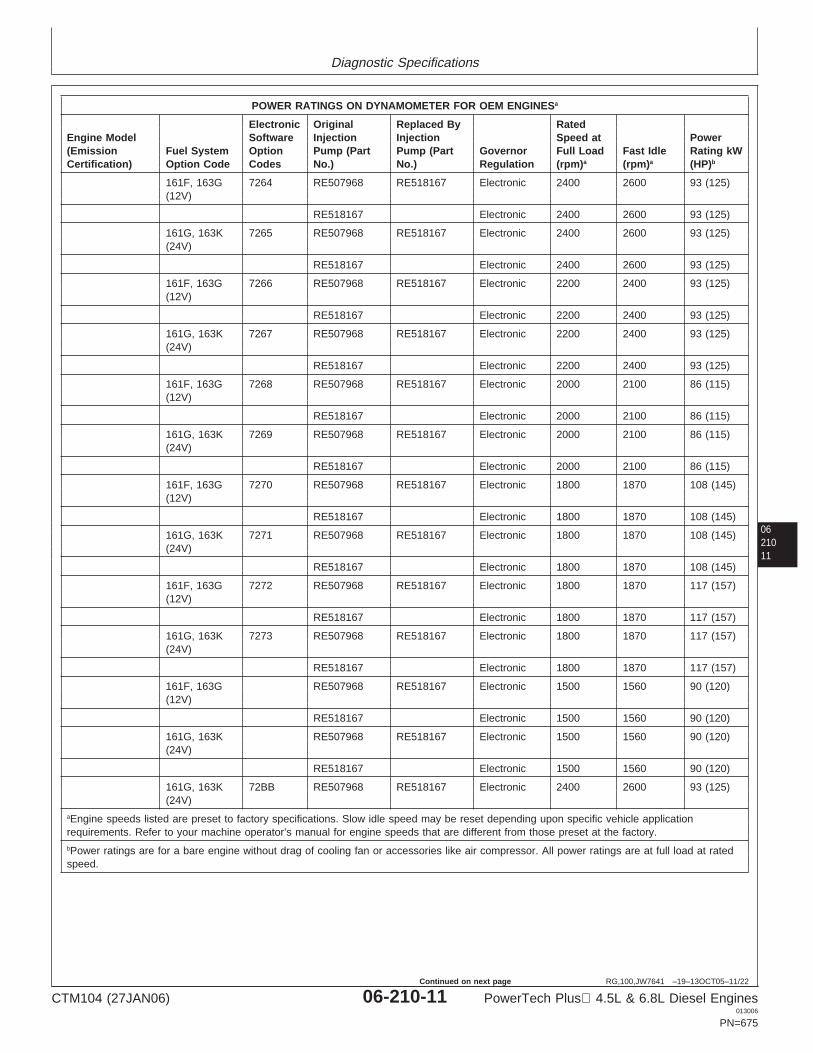
Diagnostic Specifications
0621011
RG,100,JW7641 –19–13OCT05–11/22
POWER RATINGS ON DYNAMOMETER FOR OEM ENGINESa
Electronic Original Replaced By RatedEngine Model Software Injection Injection Speed at Power(Emission Fuel System Option Pump (Part Pump (Part Governor Full Load Fast Idle Rating kWCertification) Option Code Codes No.) No.) Regulation (rpm)a (rpm)a (HP)b
161F, 163G 7264 RE507968 RE518167 Electronic 2400 2600 93 (125)(12V)
RE518167 Electronic 2400 2600 93 (125)
161G, 163K 7265 RE507968 RE518167 Electronic 2400 2600 93 (125)(24V)
RE518167 Electronic 2400 2600 93 (125)
161F, 163G 7266 RE507968 RE518167 Electronic 2200 2400 93 (125)(12V)
RE518167 Electronic 2200 2400 93 (125)
161G, 163K 7267 RE507968 RE518167 Electronic 2200 2400 93 (125)(24V)
RE518167 Electronic 2200 2400 93 (125)
161F, 163G 7268 RE507968 RE518167 Electronic 2000 2100 86 (115)(12V)
RE518167 Electronic 2000 2100 86 (115)
161G, 163K 7269 RE507968 RE518167 Electronic 2000 2100 86 (115)(24V)
RE518167 Electronic 2000 2100 86 (115)
161F, 163G 7270 RE507968 RE518167 Electronic 1800 1870 108 (145)(12V)
RE518167 Electronic 1800 1870 108 (145)
161G, 163K 7271 RE507968 RE518167 Electronic 1800 1870 108 (145)(24V)
RE518167 Electronic 1800 1870 108 (145)
161F, 163G 7272 RE507968 RE518167 Electronic 1800 1870 117 (157)(12V)
RE518167 Electronic 1800 1870 117 (157)
161G, 163K 7273 RE507968 RE518167 Electronic 1800 1870 117 (157)(24V)
RE518167 Electronic 1800 1870 117 (157)
161F, 163G RE507968 RE518167 Electronic 1500 1560 90 (120)(12V)
RE518167 Electronic 1500 1560 90 (120)
161G, 163K RE507968 RE518167 Electronic 1500 1560 90 (120)(24V)
RE518167 Electronic 1500 1560 90 (120)
161G, 163K 72BB RE507968 RE518167 Electronic 2400 2600 93 (125)(24V)
aEngine speeds listed are preset to factory specifications. Slow idle speed may be reset depending upon specific vehicle applicationrequirements. Refer to your machine operator’s manual for engine speeds that are different from those preset at the factory.bPower ratings are for a bare engine without drag of cooling fan or accessories like air compressor. All power ratings are at full load at ratedspeed.
CTM104 (27JAN06) 06-210-11 PowerTech Plus 4.5L & 6.8L Diesel Engines013006
PN=675
Continued on next page
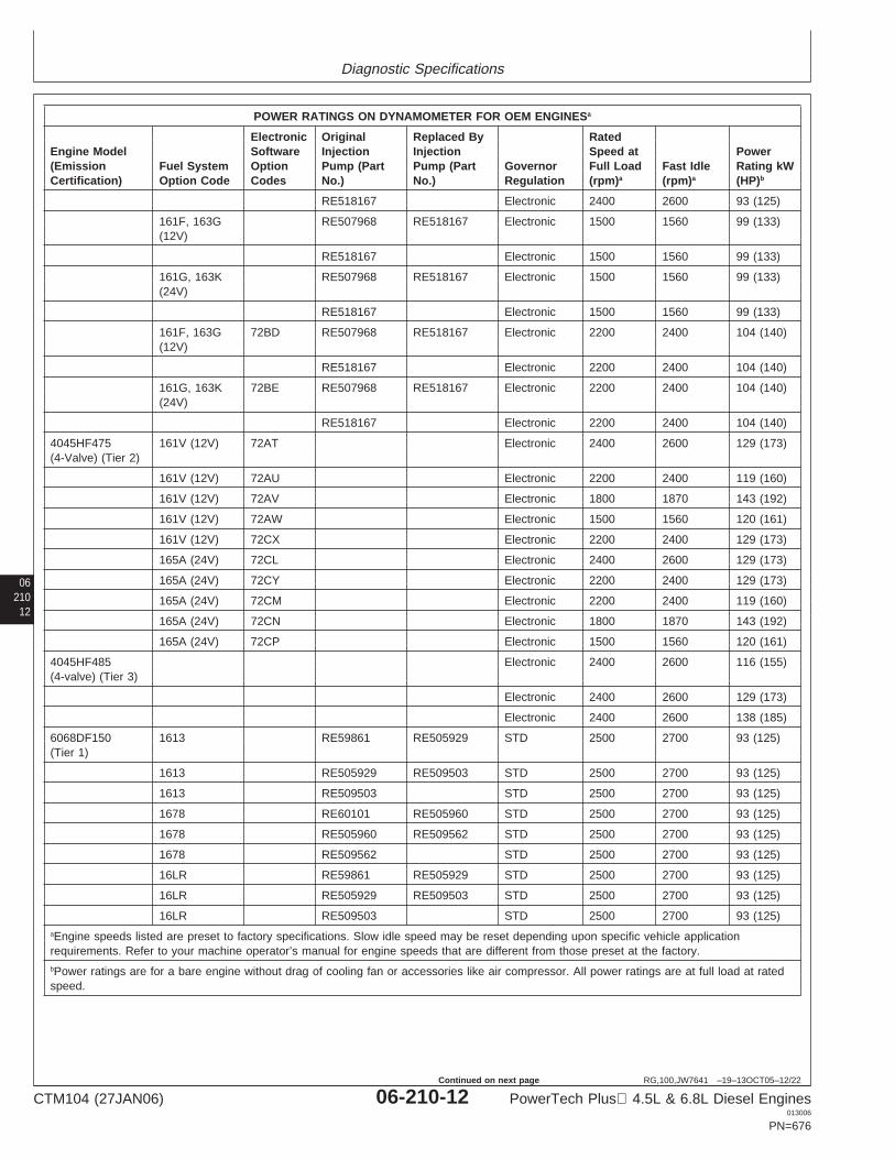
Diagnostic Specifications
06210
12
RG,100,JW7641 –19–13OCT05–12/22
POWER RATINGS ON DYNAMOMETER FOR OEM ENGINESa
Electronic Original Replaced By RatedEngine Model Software Injection Injection Speed at Power(Emission Fuel System Option Pump (Part Pump (Part Governor Full Load Fast Idle Rating kWCertification) Option Code Codes No.) No.) Regulation (rpm)a (rpm)a (HP)b
RE518167 Electronic 2400 2600 93 (125)
161F, 163G RE507968 RE518167 Electronic 1500 1560 99 (133)(12V)
RE518167 Electronic 1500 1560 99 (133)
161G, 163K RE507968 RE518167 Electronic 1500 1560 99 (133)(24V)
RE518167 Electronic 1500 1560 99 (133)
161F, 163G 72BD RE507968 RE518167 Electronic 2200 2400 104 (140)(12V)
RE518167 Electronic 2200 2400 104 (140)
161G, 163K 72BE RE507968 RE518167 Electronic 2200 2400 104 (140)(24V)
RE518167 Electronic 2200 2400 104 (140)
4045HF475 161V (12V) 72AT Electronic 2400 2600 129 (173)(4-Valve) (Tier 2)
161V (12V) 72AU Electronic 2200 2400 119 (160)
161V (12V) 72AV Electronic 1800 1870 143 (192)
161V (12V) 72AW Electronic 1500 1560 120 (161)
161V (12V) 72CX Electronic 2200 2400 129 (173)
165A (24V) 72CL Electronic 2400 2600 129 (173)
165A (24V) 72CY Electronic 2200 2400 129 (173)
165A (24V) 72CM Electronic 2200 2400 119 (160)
165A (24V) 72CN Electronic 1800 1870 143 (192)
165A (24V) 72CP Electronic 1500 1560 120 (161)
4045HF485 Electronic 2400 2600 116 (155)(4-valve) (Tier 3)
Electronic 2400 2600 129 (173)
Electronic 2400 2600 138 (185)
6068DF150 1613 RE59861 RE505929 STD 2500 2700 93 (125)(Tier 1)
1613 RE505929 RE509503 STD 2500 2700 93 (125)
1613 RE509503 STD 2500 2700 93 (125)
1678 RE60101 RE505960 STD 2500 2700 93 (125)
1678 RE505960 RE509562 STD 2500 2700 93 (125)
1678 RE509562 STD 2500 2700 93 (125)
16LR RE59861 RE505929 STD 2500 2700 93 (125)
16LR RE505929 RE509503 STD 2500 2700 93 (125)
16LR RE509503 STD 2500 2700 93 (125)aEngine speeds listed are preset to factory specifications. Slow idle speed may be reset depending upon specific vehicle applicationrequirements. Refer to your machine operator’s manual for engine speeds that are different from those preset at the factory.bPower ratings are for a bare engine without drag of cooling fan or accessories like air compressor. All power ratings are at full load at ratedspeed.
CTM104 (27JAN06) 06-210-12 PowerTech Plus 4.5L & 6.8L Diesel Engines013006
PN=676
Continued on next page
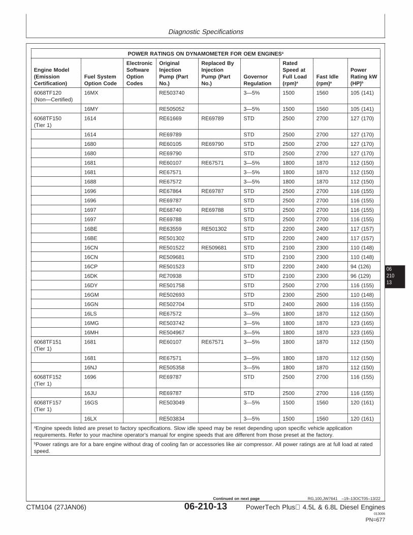
Diagnostic Specifications
0621013
RG,100,JW7641 –19–13OCT05–13/22
POWER RATINGS ON DYNAMOMETER FOR OEM ENGINESa
Electronic Original Replaced By RatedEngine Model Software Injection Injection Speed at Power(Emission Fuel System Option Pump (Part Pump (Part Governor Full Load Fast Idle Rating kWCertification) Option Code Codes No.) No.) Regulation (rpm)a (rpm)a (HP)b
6068TF120 16MX RE503740 3—5% 1500 1560 105 (141)(Non—Certified)
16MY RE505052 3—5% 1500 1560 105 (141)
6068TF150 1614 RE61669 RE69789 STD 2500 2700 127 (170)(Tier 1)
1614 RE69789 STD 2500 2700 127 (170)
1680 RE60105 RE69790 STD 2500 2700 127 (170)
1680 RE69790 STD 2500 2700 127 (170)
1681 RE60107 RE67571 3—5% 1800 1870 112 (150)
1681 RE67571 3—5% 1800 1870 112 (150)
1688 RE67572 3—5% 1800 1870 112 (150)
1696 RE67864 RE69787 STD 2500 2700 116 (155)
1696 RE69787 STD 2500 2700 116 (155)
1697 RE68740 RE69788 STD 2500 2700 116 (155)
1697 RE69788 STD 2500 2700 116 (155)
16BE RE63559 RE501302 STD 2200 2400 117 (157)
16BE RE501302 STD 2200 2400 117 (157)
16CN RE501522 RE509681 STD 2100 2300 110 (148)
16CN RE509681 STD 2100 2300 110 (148)
16CP RE501523 STD 2200 2400 94 (126)
16DK RE70938 STD 2100 2300 96 (129)
16DY RE501758 STD 2500 2700 116 (155)
16GM RE502693 STD 2300 2500 110 (148)
16GN RE502704 STD 2400 2600 116 (155)
16LS RE67572 3—5% 1800 1870 112 (150)
16MG RE503742 3—5% 1800 1870 123 (165)
16MH RE504967 3—5% 1800 1870 123 (165)
6068TF151 1681 RE60107 RE67571 3—5% 1800 1870 112 (150)(Tier 1)
1681 RE67571 3—5% 1800 1870 112 (150)
16NJ RE505358 3—5% 1800 1870 112 (150)
6068TF152 1696 RE69787 STD 2500 2700 116 (155)(Tier 1)
16JU RE69787 STD 2500 2700 116 (155)
6068TF157 16GS RE503049 3—5% 1500 1560 120 (161)(Tier 1)
16LX RE503834 3—5% 1500 1560 120 (161)aEngine speeds listed are preset to factory specifications. Slow idle speed may be reset depending upon specific vehicle applicationrequirements. Refer to your machine operator’s manual for engine speeds that are different from those preset at the factory.bPower ratings are for a bare engine without drag of cooling fan or accessories like air compressor. All power ratings are at full load at ratedspeed.
CTM104 (27JAN06) 06-210-13 PowerTech Plus 4.5L & 6.8L Diesel Engines013006
PN=677
Continued on next page
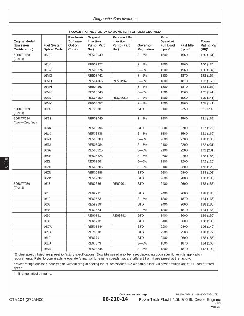
Diagnostic Specifications
06210
14
RG,100,JW7641 –19–13OCT05–14/22
POWER RATINGS ON DYNAMOMETER FOR OEM ENGINESa
Electronic Original Replaced By RatedEngine Model Software Injection Injection Speed at Power(Emission Fuel System Option Pump (Part Pump (Part Governor Full Load Fast Idle Rating kWCertification) Option Code Codes No.) No.) Regulation (rpm)a (rpm)a (HP)b
6068TF158 16GS RE503049 3—5% 1500 1560 120 (161)(Tier 1)
16JV RE503872 3—5% 1500 1560 100 (134)
16JW RE503874 3—5% 1500 1560 100 (134)
16MG RE503742 3—5% 1800 1870 123 (165)
16MH RE504966 RE504967 3—5% 1800 1870 123 (165)
16MH RE504967 3—5% 1800 1870 123 (165)
16MX RE503740 3—5% 1500 1560 105 (141)
16MY RE504699 RE505052 3—5% 1500 1560 105 (141)
16MY RE505052 3—5% 1500 1560 105 (141)
6068TF159 16PD RE70938 STD 2100 2250 96 (129)(Tier 1)
6068TF220 16GS RE503049 3—5% 1500 1560 121 (162)(Non—Certified)
16KK RE502694 STD 2500 2700 127 (170)
16LX RE503836 3—5% 1500 1560 121 (162)
16RK RE506083 3—5% 2600 2700 138 (185)
16RJ RE506084 3—5% 2100 2200 172 (231)
16SG RE506625 3—5% 2100 2200 172 (231)
16SH RE506626 3—5% 2600 2700 138 (185)
16ZL RE509284 3—5% 2100 2200 172 (128)
16ZM RE509285 3—5% 2100 2200 172 (128)
16ZN RE509286 STD 2600 2800 138 (103)
16ZP RE509287 STD 2600 2800 138 (103)
6068TF250 1615 RE62366 RE69791 STD 2400 2600 138 (185)(Tier 1)
1615 RE69791 STD 2400 2600 138 (185)
1619 RE67573 3—5% 1800 1870 124 (166)
1668 RE59969c STD 2400 2600 138 (185)
1685 RE67574 3—5% 1800 1870 124 (166)
1686 RE60131 RE69792 STD 2400 2600 138 (185)
1686 RE69792 STD 2400 2600 138 (185)
16CW RE501344 STD 2200 2400 106 (142)
16CX RE70390 STD 2300 2500 128 (172)
16LT RE69791 STD 2400 2600 138 (185)
16LU RE67573 3—5% 1800 1870 124 (166)
16MJ RE503744 3—5% 1800 1870 142 (190)aEngine speeds listed are preset to factory specifications. Slow idle speed may be reset depending upon specific vehicle applicationrequirements. Refer to your machine operator’s manual for engine speeds that are different from those preset at the factory.bPower ratings are for a bare engine without drag of cooling fan or accessories like air compressor. All power ratings are at full load at ratedspeed.cIn-line fuel injection pump.
CTM104 (27JAN06) 06-210-14 PowerTech Plus 4.5L & 6.8L Diesel Engines013006
PN=678
Continued on next page
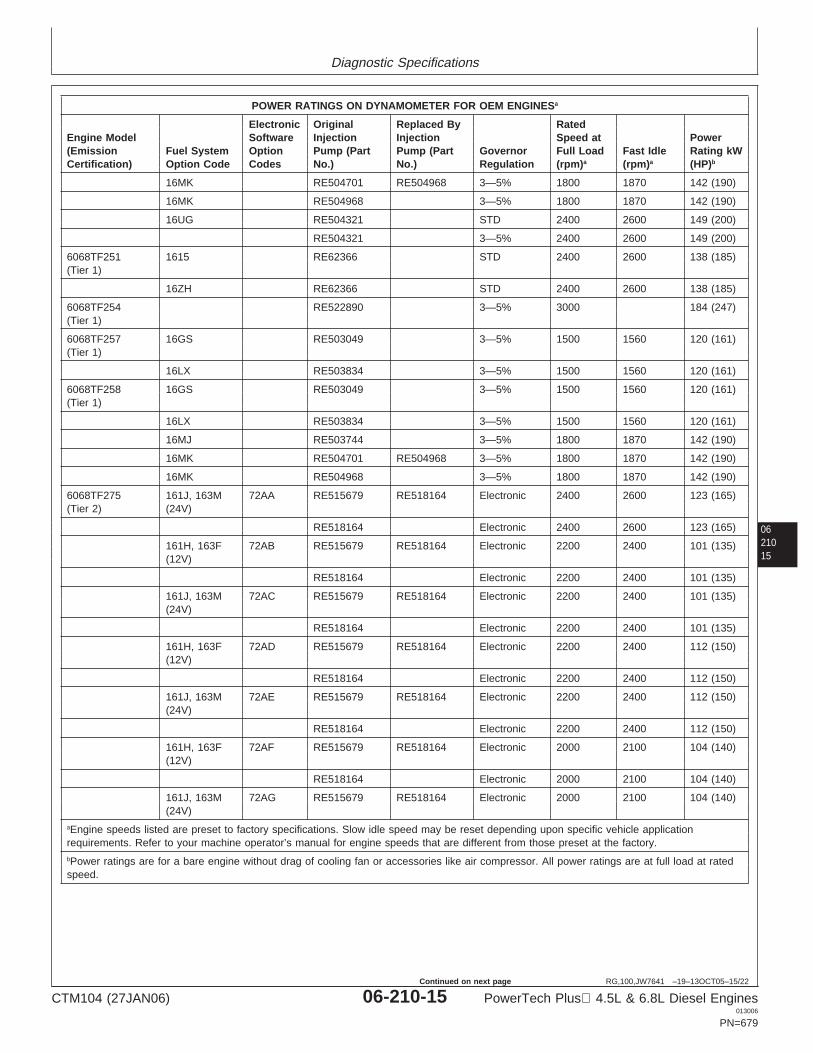
Diagnostic Specifications
0621015
RG,100,JW7641 –19–13OCT05–15/22
POWER RATINGS ON DYNAMOMETER FOR OEM ENGINESa
Electronic Original Replaced By RatedEngine Model Software Injection Injection Speed at Power(Emission Fuel System Option Pump (Part Pump (Part Governor Full Load Fast Idle Rating kWCertification) Option Code Codes No.) No.) Regulation (rpm)a (rpm)a (HP)b
16MK RE504701 RE504968 3—5% 1800 1870 142 (190)
16MK RE504968 3—5% 1800 1870 142 (190)
16UG RE504321 STD 2400 2600 149 (200)
RE504321 3—5% 2400 2600 149 (200)
6068TF251 1615 RE62366 STD 2400 2600 138 (185)(Tier 1)
16ZH RE62366 STD 2400 2600 138 (185)
6068TF254 RE522890 3—5% 3000 184 (247)(Tier 1)
6068TF257 16GS RE503049 3—5% 1500 1560 120 (161)(Tier 1)
16LX RE503834 3—5% 1500 1560 120 (161)
6068TF258 16GS RE503049 3—5% 1500 1560 120 (161)(Tier 1)
16LX RE503834 3—5% 1500 1560 120 (161)
16MJ RE503744 3—5% 1800 1870 142 (190)
16MK RE504701 RE504968 3—5% 1800 1870 142 (190)
16MK RE504968 3—5% 1800 1870 142 (190)
6068TF275 161J, 163M 72AA RE515679 RE518164 Electronic 2400 2600 123 (165)(Tier 2) (24V)
RE518164 Electronic 2400 2600 123 (165)
161H, 163F 72AB RE515679 RE518164 Electronic 2200 2400 101 (135)(12V)
RE518164 Electronic 2200 2400 101 (135)
161J, 163M 72AC RE515679 RE518164 Electronic 2200 2400 101 (135)(24V)
RE518164 Electronic 2200 2400 101 (135)
161H, 163F 72AD RE515679 RE518164 Electronic 2200 2400 112 (150)(12V)
RE518164 Electronic 2200 2400 112 (150)
161J, 163M 72AE RE515679 RE518164 Electronic 2200 2400 112 (150)(24V)
RE518164 Electronic 2200 2400 112 (150)
161H, 163F 72AF RE515679 RE518164 Electronic 2000 2100 104 (140)(12V)
RE518164 Electronic 2000 2100 104 (140)
161J, 163M 72AG RE515679 RE518164 Electronic 2000 2100 104 (140)(24V)
aEngine speeds listed are preset to factory specifications. Slow idle speed may be reset depending upon specific vehicle applicationrequirements. Refer to your machine operator’s manual for engine speeds that are different from those preset at the factory.bPower ratings are for a bare engine without drag of cooling fan or accessories like air compressor. All power ratings are at full load at ratedspeed.
CTM104 (27JAN06) 06-210-15 PowerTech Plus 4.5L & 6.8L Diesel Engines013006
PN=679
Continued on next page
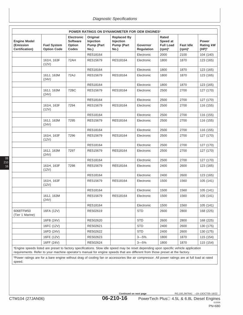
Diagnostic Specifications
06210
16
RG,100,JW7641 –19–13OCT05–16/22
POWER RATINGS ON DYNAMOMETER FOR OEM ENGINESa
Electronic Original Replaced By RatedEngine Model Software Injection Injection Speed at Power(Emission Fuel System Option Pump (Part Pump (Part Governor Full Load Fast Idle Rating kWCertification) Option Code Codes No.) No.) Regulation (rpm)a (rpm)a (HP)b
RE518164 Electronic 2000 2100 104 (140)
161H, 163F 72AH RE515679 RE518164 Electronic 1800 1870 123 (165)(12V)
RE518164 Electronic 1800 1870 123 (165)
161J, 163M 72AJ RE515679 RE518164 Electronic 1800 1870 123 (165)(24V)
RE518164 Electronic 1800 1870 123 (165)
161J, 163M 72BC RE515679 RE518164 Electronic 2500 2700 127 (170)(24V)
RE518164 Electronic 2500 2700 127 (170)
161H, 163F 7294 RE515679 RE518164 Electronic 2500 2700 116 (155)(12V)
RE518164 Electronic 2500 2700 116 (155)
161J, 163M 7295 RE515679 RE518164 Electronic 2500 2700 116 (155)(24V)
RE518164 Electronic 2500 2700 116 (155)
161H, 163F 7296 RE515679 RE518164 Electronic 2500 2700 127 (170)(12V)
RE518164 Electronic 2500 2700 127 (170)
161J, 163M 7297 RE515679 RE518164 Electronic 2500 2700 127 (170)(24V)
RE518164 Electronic 2500 2700 127 (170)
161H, 163F 7298 RE515679 RE518164 Electronic 2400 2600 123 (165)(12V)
RE518164 Electronic 2400 2600 123 (165)
161H, 163F RE515679 RE518164 Electronic 1500 1560 105 (141)(12V)
RE518164 Electronic 1500 1560 105 (141)
161J, 163M RE515679 RE518164 Electronic 1500 1560 105 (141)(24V)
RE518164 Electronic 1500 1560 105 (141)
6068TFM50 16FA (12V) RE502619 STD 2600 2800 168 (225)(Tier 1 Marine)
16FB (24V) RE502620 STD 2600 2800 168 (225)
16FC (12V) RE502621 STD 2400 2600 130 (175)
16FD (24V) RE502622 STD 2400 2600 130 (175)
16FE (12V) RE502623 3—5% 1800 1870 115 (154)
16FF (24V) RE502624 3—5% 1800 1870 115 (154)aEngine speeds listed are preset to factory specifications. Slow idle speed may be reset depending upon specific vehicle applicationrequirements. Refer to your machine operator’s manual for engine speeds that are different from those preset at the factory.bPower ratings are for a bare engine without drag of cooling fan or accessories like air compressor. All power ratings are at full load at ratedspeed.
CTM104 (27JAN06) 06-210-16 PowerTech Plus 4.5L & 6.8L Diesel Engines013006
PN=680
Continued on next page
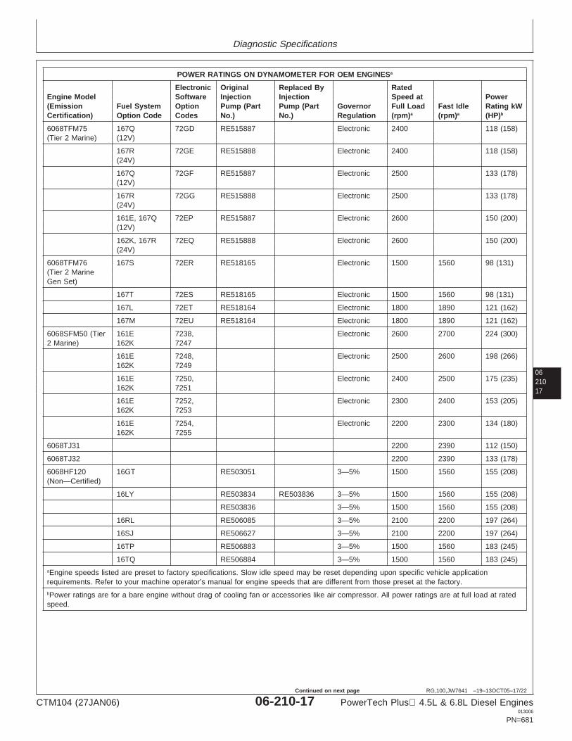
Diagnostic Specifications
0621017
RG,100,JW7641 –19–13OCT05–17/22
POWER RATINGS ON DYNAMOMETER FOR OEM ENGINESa
Electronic Original Replaced By RatedEngine Model Software Injection Injection Speed at Power(Emission Fuel System Option Pump (Part Pump (Part Governor Full Load Fast Idle Rating kWCertification) Option Code Codes No.) No.) Regulation (rpm)a (rpm)a (HP)b
6068TFM75 167Q 72GD RE515887 Electronic 2400 118 (158)(Tier 2 Marine) (12V)
167R 72GE RE515888 Electronic 2400 118 (158)(24V)
167Q 72GF RE515887 Electronic 2500 133 (178)(12V)
167R 72GG RE515888 Electronic 2500 133 (178)(24V)
161E, 167Q 72EP RE515887 Electronic 2600 150 (200)(12V)
162K, 167R 72EQ RE515888 Electronic 2600 150 (200)(24V)
6068TFM76 167S 72ER RE518165 Electronic 1500 1560 98 (131)(Tier 2 MarineGen Set)
167T 72ES RE518165 Electronic 1500 1560 98 (131)
167L 72ET RE518164 Electronic 1800 1890 121 (162)
167M 72EU RE518164 Electronic 1800 1890 121 (162)
6068SFM50 (Tier 161E 7238, Electronic 2600 2700 224 (300)2 Marine) 162K 7247
161E 7248, Electronic 2500 2600 198 (266)162K 7249
161E 7250, Electronic 2400 2500 175 (235)162K 7251
161E 7252, Electronic 2300 2400 153 (205)162K 7253
161E 7254, Electronic 2200 2300 134 (180)162K 7255
6068TJ31 2200 2390 112 (150)
6068TJ32 2200 2390 133 (178)
6068HF120 16GT RE503051 3—5% 1500 1560 155 (208)(Non—Certified)
16LY RE503834 RE503836 3—5% 1500 1560 155 (208)
RE503836 3—5% 1500 1560 155 (208)
16RL RE506085 3—5% 2100 2200 197 (264)
16SJ RE506627 3—5% 2100 2200 197 (264)
16TP RE506883 3—5% 1500 1560 183 (245)
16TQ RE506884 3—5% 1500 1560 183 (245)aEngine speeds listed are preset to factory specifications. Slow idle speed may be reset depending upon specific vehicle applicationrequirements. Refer to your machine operator’s manual for engine speeds that are different from those preset at the factory.bPower ratings are for a bare engine without drag of cooling fan or accessories like air compressor. All power ratings are at full load at ratedspeed.
CTM104 (27JAN06) 06-210-17 PowerTech Plus 4.5L & 6.8L Diesel Engines013006
PN=681
Continued on next page
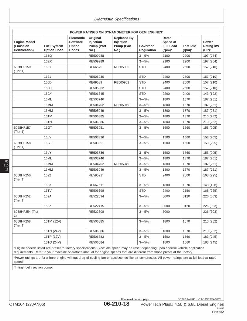
Diagnostic Specifications
06210
18
RG,100,JW7641 –19–13OCT05–18/22
POWER RATINGS ON DYNAMOMETER FOR OEM ENGINESa
Electronic Original Replaced By RatedEngine Model Software Injection Injection Speed at Power(Emission Fuel System Option Pump (Part Pump (Part Governor Full Load Fast Idle Rating kWCertification) Option Code Codes No.) No.) Regulation (rpm)a (rpm)a (HP)b
16ZQ RE509288 3—5% 2100 2200 197 (264)
16ZR RE509289 3—5% 2100 2200 197 (264)
6068HF150 1621 RE66575 RE505930 STD 2400 2600 157 (210)(Tier 1)
1621 RE505930 STD 2400 2600 157 (210)
160D RE69589 RE505962 STD 2400 2600 157 (210)
160D RE505962 STD 2400 2600 157 (210)
16CY RE501345 STD 2200 2400 143 (192)
16ML RE503746 3—5% 1800 1870 187 (251)
16MM RE504702 RE505049 3—5% 1800 1870 187 (251)
16MM RE505049 3—5% 1800 1870 187 (251)
16TM RE506885 3—5% 1800 1870 210 (282)
16TN RE506886 3—5% 1800 1870 210 (282)
6068HF157 16GT RE503051 3—5% 1500 1560 153 (205)(Tier 1)
16LY RE503836 3—5% 1500 1560 153 (205)
6068HF158 16GT RE503051 3—5% 1500 1560 153 (205)(Tier 1)
16LY RE503836 3—5% 1500 1560 153 (205)
16ML RE503746 3—5% 1800 1870 187 (251)
16MM RE504702 RE505049 3—5% 1800 1870 187 (251)
16MM RE505049 3—5% 1800 1870 187 (251)
6068HF250 1622 RE59521c STD 2400 2600 168 (225)(Tier 1)
1623 RE66761c 3—5% 1800 1870 148 (198)
16TV RE506398 STD 2400 2550 168 (225)
6068HF252 169A RE522694 3—5% 3000 3120 226 (303)(Tier 1)
168Z RE522415 3—5% 3000 3120 226 (303)
6068HF254 (Tier RE522808 3—5% 3000 226 (303)1)
6068HF258 16TM (12V) RE506885 3—5% 1800 1870 210 (282)(Tier 1)
16TN (24V) RE506886 3—5% 1800 1870 210 (282)
16TP (12V) RE506883 3—5% 1500 1560 183 (245)
16TQ (24V) RE506884 3—5% 1500 1560 183 (245)aEngine speeds listed are preset to factory specifications. Slow idle speed may be reset depending upon specific vehicle applicationrequirements. Refer to your machine operator’s manual for engine speeds that are different from those preset at the factory.bPower ratings are for a bare engine without drag of cooling fan or accessories like air compressor. All power ratings are at full load at ratedspeed.cIn-line fuel injection pump.
CTM104 (27JAN06) 06-210-18 PowerTech Plus 4.5L & 6.8L Diesel Engines013006
PN=682
Continued on next page
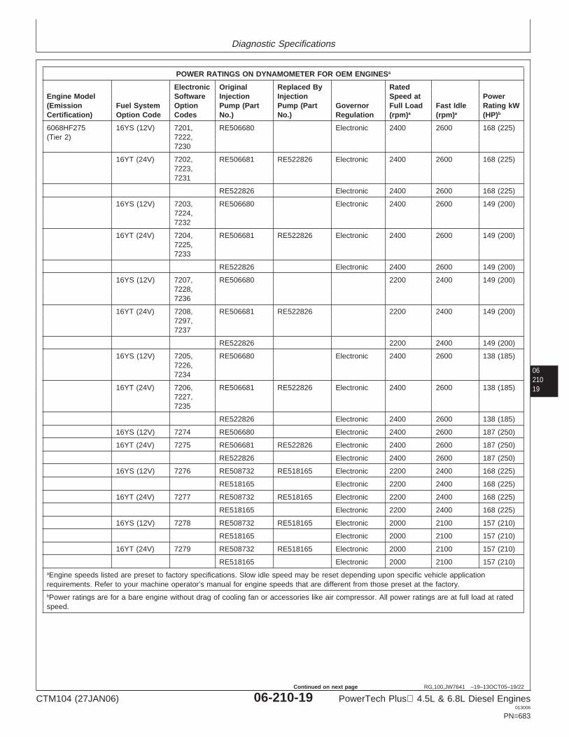
Diagnostic Specifications
0621019
RG,100,JW7641 –19–13OCT05–19/22
POWER RATINGS ON DYNAMOMETER FOR OEM ENGINESa
Electronic Original Replaced By RatedEngine Model Software Injection Injection Speed at Power(Emission Fuel System Option Pump (Part Pump (Part Governor Full Load Fast Idle Rating kWCertification) Option Code Codes No.) No.) Regulation (rpm)a (rpm)a (HP)b
6068HF275 16YS (12V) 7201, RE506680 Electronic 2400 2600 168 (225)(Tier 2) 7222,
7230
16YT (24V) 7202, RE506681 RE522826 Electronic 2400 2600 168 (225)7223,7231
RE522826 Electronic 2400 2600 168 (225)
16YS (12V) 7203, RE506680 Electronic 2400 2600 149 (200)7224,7232
16YT (24V) 7204, RE506681 RE522826 Electronic 2400 2600 149 (200)7225,7233
RE522826 Electronic 2400 2600 149 (200)
16YS (12V) 7207, RE506680 2200 2400 149 (200)7228,7236
16YT (24V) 7208, RE506681 RE522826 2200 2400 149 (200)7297,7237
RE522826 2200 2400 149 (200)
16YS (12V) 7205, RE506680 Electronic 2400 2600 138 (185)7226,7234
16YT (24V) 7206, RE506681 RE522826 Electronic 2400 2600 138 (185)7227,7235
RE522826 Electronic 2400 2600 138 (185)
16YS (12V) 7274 RE506680 Electronic 2400 2600 187 (250)
16YT (24V) 7275 RE506681 RE522826 Electronic 2400 2600 187 (250)
RE522826 Electronic 2400 2600 187 (250)
16YS (12V) 7276 RE508732 RE518165 Electronic 2200 2400 168 (225)
RE518165 Electronic 2200 2400 168 (225)
16YT (24V) 7277 RE508732 RE518165 Electronic 2200 2400 168 (225)
RE518165 Electronic 2200 2400 168 (225)
16YS (12V) 7278 RE508732 RE518165 Electronic 2000 2100 157 (210)
RE518165 Electronic 2000 2100 157 (210)
16YT (24V) 7279 RE508732 RE518165 Electronic 2000 2100 157 (210)
RE518165 Electronic 2000 2100 157 (210)aEngine speeds listed are preset to factory specifications. Slow idle speed may be reset depending upon specific vehicle applicationrequirements. Refer to your machine operator’s manual for engine speeds that are different from those preset at the factory.bPower ratings are for a bare engine without drag of cooling fan or accessories like air compressor. All power ratings are at full load at ratedspeed.
CTM104 (27JAN06) 06-210-19 PowerTech Plus 4.5L & 6.8L Diesel Engines013006
PN=683
Continued on next page
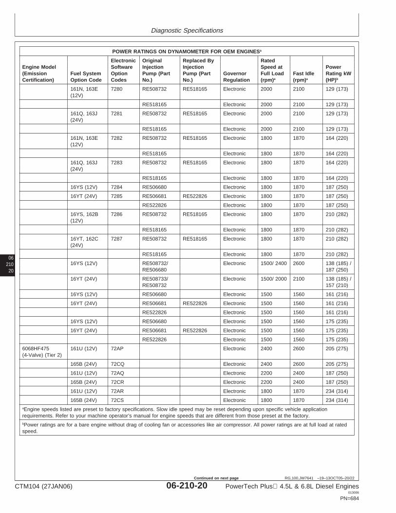
Diagnostic Specifications
06210
20
RG,100,JW7641 –19–13OCT05–20/22
POWER RATINGS ON DYNAMOMETER FOR OEM ENGINESa
Electronic Original Replaced By RatedEngine Model Software Injection Injection Speed at Power(Emission Fuel System Option Pump (Part Pump (Part Governor Full Load Fast Idle Rating kWCertification) Option Code Codes No.) No.) Regulation (rpm)a (rpm)a (HP)b
161N, 163E 7280 RE508732 RE518165 Electronic 2000 2100 129 (173)(12V)
RE518165 Electronic 2000 2100 129 (173)
161Q, 163J 7281 RE508732 RE518165 Electronic 2000 2100 129 (173)(24V)
RE518165 Electronic 2000 2100 129 (173)
161N, 163E 7282 RE508732 RE518165 Electronic 1800 1870 164 (220)(12V)
RE518165 Electronic 1800 1870 164 (220)
161Q, 163J 7283 RE508732 RE518165 Electronic 1800 1870 164 (220)(24V)
RE518165 Electronic 1800 1870 164 (220)
16YS (12V) 7284 RE506680 Electronic 1800 1870 187 (250)
16YT (24V) 7285 RE506681 RE522826 Electronic 1800 1870 187 (250)
RE522826 Electronic 1800 1870 187 (250)
16YS, 162B 7286 RE508732 RE518165 Electronic 1800 1870 210 (282)(12V)
RE518165 Electronic 1800 1870 210 (282)
16YT, 162C 7287 RE508732 RE518165 Electronic 1800 1870 210 (282)(24V)
RE518165 Electronic 1800 1870 210 (282)
16YS (12V) RE508732/ Electronic 1500/ 2400 2600 138 (185) /RE506680 187 (250)
16YT (24V) RE508733/ Electronic 1500/ 2000 2100 138 (185) /RE508732 157 (210)
16YS (12V) RE506680 Electronic 1500 1560 161 (216)
16YT (24V) RE506681 RE522826 Electronic 1500 1560 161 (216)
RE522826 Electronic 1500 1560 161 (216)
16YS (12V) RE506680 Electronic 1500 1560 175 (235)
16YT (24V) RE506681 RE522826 Electronic 1500 1560 175 (235)
RE522826 Electronic 1500 1560 175 (235)
6068HF475 161U (12V) 72AP Electronic 2400 2600 205 (275)(4-Valve) (Tier 2)
165B (24V) 72CQ Electronic 2400 2600 205 (275)
161U (12V) 72AQ Electronic 2200 2400 187 (250)
165B (24V) 72CR Electronic 2200 2400 187 (250)
161U (12V) 72AR Electronic 1800 1870 234 (314)
165B (24V) 72CS Electronic 1800 1870 234 (314)aEngine speeds listed are preset to factory specifications. Slow idle speed may be reset depending upon specific vehicle applicationrequirements. Refer to your machine operator’s manual for engine speeds that are different from those preset at the factory.bPower ratings are for a bare engine without drag of cooling fan or accessories like air compressor. All power ratings are at full load at ratedspeed.
CTM104 (27JAN06) 06-210-20 PowerTech Plus 4.5L & 6.8L Diesel Engines013006
PN=684
Continued on next page

Diagnostic Specifications
0621021
RG,100,JW7641 –19–13OCT05–21/22
POWER RATINGS ON DYNAMOMETER FOR OEM ENGINESa
Electronic Original Replaced By RatedEngine Model Software Injection Injection Speed at Power(Emission Fuel System Option Pump (Part Pump (Part Governor Full Load Fast Idle Rating kWCertification) Option Code Codes No.) No.) Regulation (rpm)a (rpm)a (HP)b
161U (12V) 72AS Electronic 1500 1560 207 (278)
165B (24V) 72CT Electronic 1500 1560 207 (278)
6068HF485 167W (12V) 72JJ Electronic 2200 2400 134 (180)(4-valve)(Tier 3)
167W (24V) 72JK Electronic 2200 2400 134 (180)
167W (12V) 72JC Electronic 2400 2600 138 (185)
167W (24V) 72JD Electronic 2400 2600 138 (185)
167W (12V) 72JE Electronic 2200 2400 138 (185)
167W (24V) 72JF Electronic 2200 2400 138 (185)
167W (12V) 72JG Electronic 2200 2400 138 (185)
167W (24V) 72JH Electronic 2200 2400 138 (185)
167W (12V) 72HY Electronic 2000 2100 144 (193)
167W (24V) 72HZ Electronic 2000 2100 144 (193)
167W (12V) 72JA Electronic 2000 2100 144 (193)
167W (24V) 72JB Electronic 2000 2100 144 (193)
167W (12V) 72HS Electronic 2400 2600 149 (200)
167W (24V) 72HT Electronic 2400 2600 149 (200)
167W (12V) 72HU Electronic 2200 2400 149 (200)
167W (24V) 72HV Electronic 2200 2400 149 (200)
167W (12V) 72HW Electronic 2200 2400 149 (200)
167W (24V) 72HX Electronic 2200 2400 149 (200)
167W (12V) 72HN Electronic 2000 2100 162 (217)
167W (24V) 72HP Electronic 2000 2100 162 (217)
167W (12V) 72HQ Electronic 2000 2100 162 (217)
167W (24V) 72HR Electronic 2000 2100 162 (217)
167W (12V) 72HG Electronic 2400 2600 168 (225)
167W (24V) 72HH Electronic 2400 2600 168 (225)
167W (12V) 72HJ Electronic 2200 2400 168 (225)
167W (24V) 72HK Electronic 2200 2400 168 (225)
167W (12V) 72HL Electronic 2200 2400 168 (225)
167W (24V) 72HM Electronic 2200 2400 168 (225)
167W (12V) 72HE Electronic 2000 2100 181 (243)
167W (24V) 72HF Electronic 2000 2100 181 (243)
167W (12V) 72HA Electronic 2400 2600 187 (250)
167W (24V) 72HB Electronic 2400 2600 187 (250)
167W (12V) 72HC Electronic 2200 2400 187 (250)
167W (24V) 72HD Electronic 2200 2400 187 (250)
167W (12V) 72GY Electronic 2400 2600 205 (275)aEngine speeds listed are preset to factory specifications. Slow idle speed may be reset depending upon specific vehicle applicationrequirements. Refer to your machine operator’s manual for engine speeds that are different from those preset at the factory.bPower ratings are for a bare engine without drag of cooling fan or accessories like air compressor. All power ratings are at full load at ratedspeed.
CTM104 (27JAN06) 06-210-21 PowerTech Plus 4.5L & 6.8L Diesel Engines013006
PN=685
Continued on next page
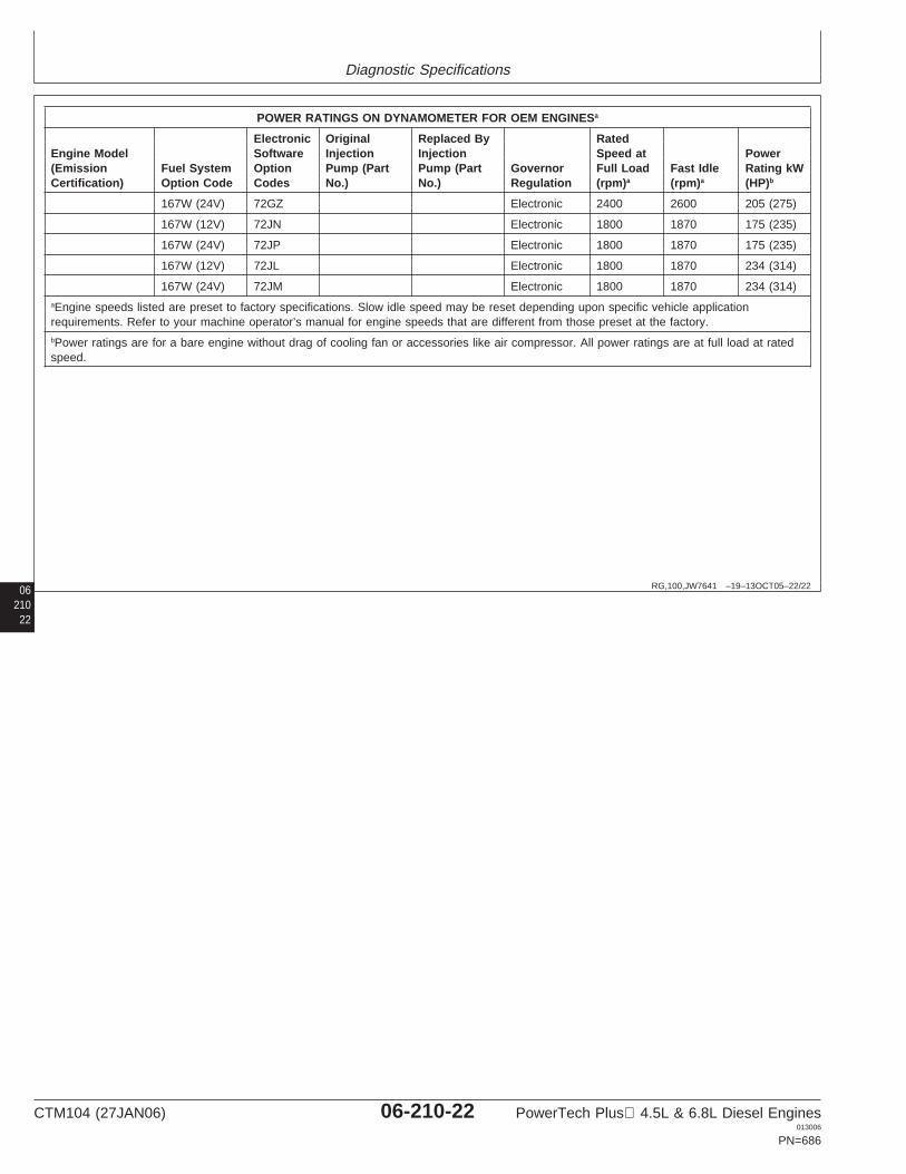
Diagnostic Specifications
06 RG,100,JW7641 –19–13OCT05–22/22
POWER RATINGS ON DYNAMOMETER FOR OEM ENGINESa
Electronic Original Replaced By RatedEngine Model Software Injection Injection Speed at Power(Emission Fuel System Option Pump (Part Pump (Part Governor Full Load Fast Idle Rating kWCertification) Option Code Codes No.) No.) Regulation (rpm)a (rpm)a (HP)b
167W (24V) 72GZ Electronic 2400 2600 205 (275)
167W (12V) 72JN Electronic 1800 1870 175 (235)
167W (24V) 72JP Electronic 1800 1870 175 (235)
167W (12V) 72JL Electronic 1800 1870 234 (314)
167W (24V) 72JM Electronic 1800 1870 234 (314)aEngine speeds listed are preset to factory specifications. Slow idle speed may be reset depending upon specific vehicle applicationrequirements. Refer to your machine operator’s manual for engine speeds that are different from those preset at the factory.bPower ratings are for a bare engine without drag of cooling fan or accessories like air compressor. All power ratings are at full load at ratedspeed.
21022
CTM104 (27JAN06) 06-210-22 PowerTech Plus 4.5L & 6.8L Diesel Engines013006
PN=686
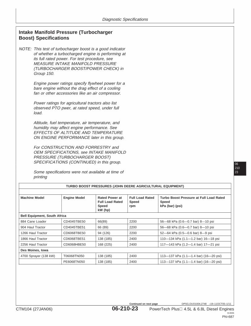
Diagnostic Specifications
0621023
DPSG,OUO1004,2748 –19–11OCT05–1/11
Intake Manifold Pressure (TurbochargerBoost) Specifications
NOTE: This test of turbocharger boost is a good indicatorof whether a turbocharged engine is performing atits full rated power. For test procedure, seeMEASURE INTAKE MANIFOLD PRESSURE(TURBOCHARGER BOOST/POWER CHECK) inGroup 150.
Engine power ratings specify flywheel power for abare engine without the drag effect of a coolingfan or other accessories like an air compressor.
Power ratings for agricultural tractors also listobserved PTO pwer, at rated speed, under fullload.
Altitude, fuel temperature, air temperature, andhumidity may affect engine performance. SeeEFFECTS OF ALTITUDE AND TEMPERATUREON ENGINE PERFORMANCE later in this group.
For CONSTRUCTION AND FORRESTRY andOEM SPECIFICATIONS, see INTAKE MANIFOLDPRESSURE (TURBOCHARGER BOOST)SPECIFICATIONS (CONTINUED) in this group.
Some specifications were not available at time ofprinting
TURBO BOOST PRESSURES (JOHN DEERE AGRICULTURAL EQUIPMENT)
Machine Model Engine Model Rated Power at Full Load Rated Turbo Boost Pressure at Full Load RatedFull Load Rated Speed SpeedSpeed rpm kPa (bar) (psi)kW (hp)
Bell Equipment, South Africa
884 Cane Loader CD4045TBE50 66(89) 2200 56—68 kPa (0.6—0.7 bar) 8—10 psi
904 Haul Tractor CD4045TBE51 66 (89) 2200 56—68 kPa (0.6—0.7 bar) 8—10 psi
1266 Haul Tractor CD6068TBE50 94 (126) 2200 52—64 kPa (0.5—0.6 bar) 8—9 psi
1866 Haul Tractor CD6068TBE51 138 (185) 2400 110—134 kPa (1.1—1.2 bar) 16—18 psi
2256 Haul Tractor CD6068HBE50 168 (225) 2400 117—143 kPa (1.2—1.4 bar) 17—21 psi
Des Moines, Iowa
4700 Sprayer (138 kW) T06068TN050 138 (185) 2400 113—137 kPa (1.1—1.4 bar) (16—20 psi)
PE6068TN050 138 (185) 2400 113—137 kPa (1.1—1.4 bar) (16—20 psi)
CTM104 (27JAN06) 06-210-23 PowerTech Plus 4.5L & 6.8L Diesel Engines013006
PN=687
Continued on next page
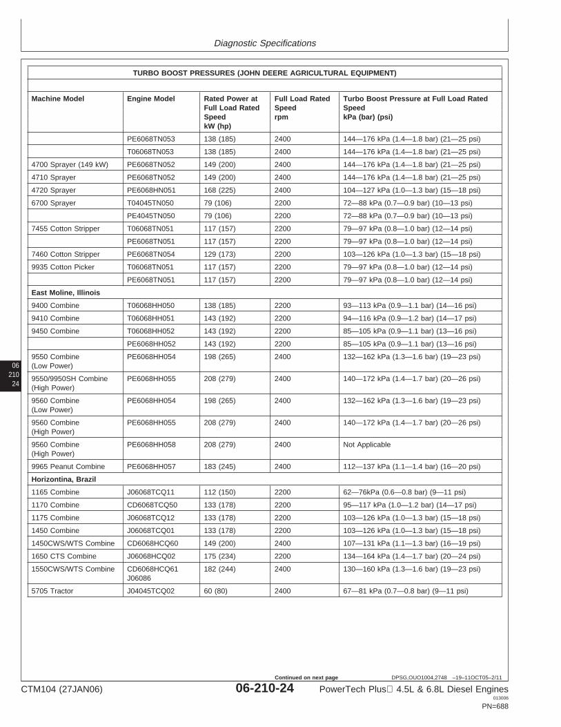
Diagnostic Specifications
06210
24
DPSG,OUO1004,2748 –19–11OCT05–2/11
TURBO BOOST PRESSURES (JOHN DEERE AGRICULTURAL EQUIPMENT)
Machine Model Engine Model Rated Power at Full Load Rated Turbo Boost Pressure at Full Load RatedFull Load Rated Speed SpeedSpeed rpm kPa (bar) (psi)kW (hp)
PE6068TN053 138 (185) 2400 144—176 kPa (1.4—1.8 bar) (21—25 psi)
T06068TN053 138 (185) 2400 144—176 kPa (1.4—1.8 bar) (21—25 psi)
4700 Sprayer (149 kW) PE6068TN052 149 (200) 2400 144—176 kPa (1.4—1.8 bar) (21—25 psi)
4710 Sprayer PE6068TN052 149 (200) 2400 144—176 kPa (1.4—1.8 bar) (21—25 psi)
4720 Sprayer PE6068HN051 168 (225) 2400 104—127 kPa (1.0—1.3 bar) (15—18 psi)
6700 Sprayer T04045TN050 79 (106) 2200 72—88 kPa (0.7—0.9 bar) (10—13 psi)
PE4045TN050 79 (106) 2200 72—88 kPa (0.7—0.9 bar) (10—13 psi)
7455 Cotton Stripper T06068TN051 117 (157) 2200 79—97 kPa (0.8—1.0 bar) (12—14 psi)
PE6068TN051 117 (157) 2200 79—97 kPa (0.8—1.0 bar) (12—14 psi)
7460 Cotton Stripper PE6068TN054 129 (173) 2200 103—126 kPa (1.0—1.3 bar) (15—18 psi)
9935 Cotton Picker T06068TN051 117 (157) 2200 79—97 kPa (0.8—1.0 bar) (12—14 psi)
PE6068TN051 117 (157) 2200 79—97 kPa (0.8—1.0 bar) (12—14 psi)
East Moline, Illinois
9400 Combine T06068HH050 138 (185) 2200 93—113 kPa (0.9—1.1 bar) (14—16 psi)
9410 Combine T06068HH051 143 (192) 2200 94—116 kPa (0.9—1.2 bar) (14—17 psi)
9450 Combine T06068HH052 143 (192) 2200 85—105 kPa (0.9—1.1 bar) (13—16 psi)
PE6068HH052 143 (192) 2200 85—105 kPa (0.9—1.1 bar) (13—16 psi)
9550 Combine PE6068HH054 198 (265) 2400 132—162 kPa (1.3—1.6 bar) (19—23 psi)(Low Power)
9550/9950SH Combine PE6068HH055 208 (279) 2400 140—172 kPa (1.4—1.7 bar) (20—26 psi)(High Power)
9560 Combine PE6068HH054 198 (265) 2400 132—162 kPa (1.3—1.6 bar) (19—23 psi)(Low Power)
9560 Combine PE6068HH055 208 (279) 2400 140—172 kPa (1.4—1.7 bar) (20—26 psi)(High Power)
9560 Combine PE6068HH058 208 (279) 2400 Not Applicable(High Power)
9965 Peanut Combine PE6068HH057 183 (245) 2400 112—137 kPa (1.1—1.4 bar) (16—20 psi)
Horizontina, Brazil
1165 Combine J06068TCQ11 112 (150) 2200 62—76kPa (0.6—0.8 bar) (9—11 psi)
1170 Combine CD6068TCQ50 133 (178) 2200 95—117 kPa (1.0—1.2 bar) (14—17 psi)
1175 Combine J06068TCQ12 133 (178) 2200 103—126 kPa (1.0—1.3 bar) (15—18 psi)
1450 Combine J06068TCQ01 133 (178) 2200 103—126 kPa (1.0—1.3 bar) (15—18 psi)
1450CWS/WTS Combine CD6068HCQ60 149 (200) 2400 107—131 kPa (1.1—1.3 bar) (16—19 psi)
1650 CTS Combine J06068HCQ02 175 (234) 2200 134—164 kPa (1.4—1.7 bar) (20—24 psi)
1550CWS/WTS Combine CD6068HCQ61 182 (244) 2400 130—160 kPa (1.3—1.6 bar) (19—23 psi)J06086
5705 Tractor J04045TCQ02 60 (80) 2400 67—81 kPa (0.7—0.8 bar) (9—11 psi)
CTM104 (27JAN06) 06-210-24 PowerTech Plus 4.5L & 6.8L Diesel Engines013006
PN=688
Continued on next page
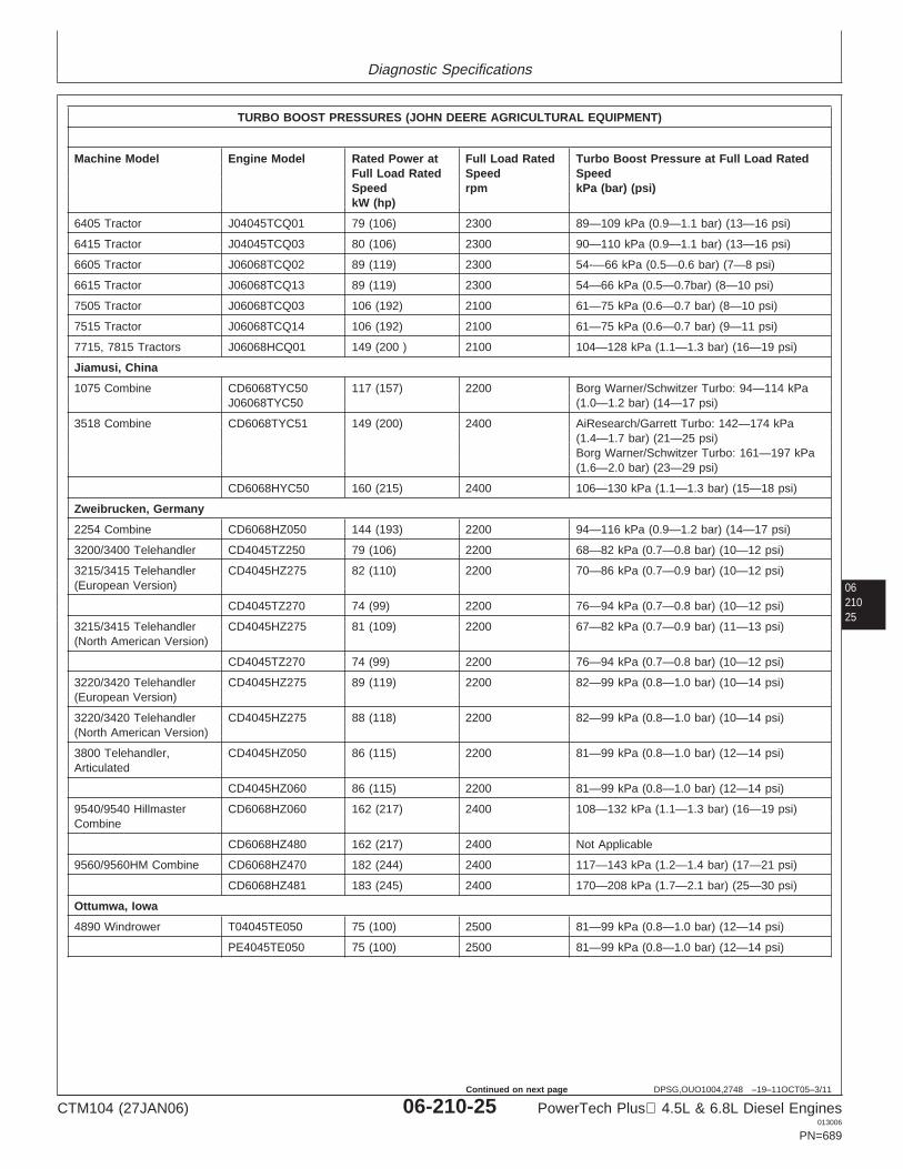
Diagnostic Specifications
0621025
DPSG,OUO1004,2748 –19–11OCT05–3/11
TURBO BOOST PRESSURES (JOHN DEERE AGRICULTURAL EQUIPMENT)
Machine Model Engine Model Rated Power at Full Load Rated Turbo Boost Pressure at Full Load RatedFull Load Rated Speed SpeedSpeed rpm kPa (bar) (psi)kW (hp)
6405 Tractor J04045TCQ01 79 (106) 2300 89—109 kPa (0.9—1.1 bar) (13—16 psi)
6415 Tractor J04045TCQ03 80 (106) 2300 90—110 kPa (0.9—1.1 bar) (13—16 psi)
6605 Tractor J06068TCQ02 89 (119) 2300 54-—66 kPa (0.5—0.6 bar) (7—8 psi)
6615 Tractor J06068TCQ13 89 (119) 2300 54—66 kPa (0.5—0.7bar) (8—10 psi)
7505 Tractor J06068TCQ03 106 (192) 2100 61—75 kPa (0.6—0.7 bar) (8—10 psi)
7515 Tractor J06068TCQ14 106 (192) 2100 61—75 kPa (0.6—0.7 bar) (9—11 psi)
7715, 7815 Tractors J06068HCQ01 149 (200 ) 2100 104—128 kPa (1.1—1.3 bar) (16—19 psi)
Jiamusi, China
1075 Combine CD6068TYC50 117 (157) 2200 Borg Warner/Schwitzer Turbo: 94—114 kPaJ06068TYC50 (1.0—1.2 bar) (14—17 psi)
3518 Combine CD6068TYC51 149 (200) 2400 AiResearch/Garrett Turbo: 142—174 kPa(1.4—1.7 bar) (21—25 psi)Borg Warner/Schwitzer Turbo: 161—197 kPa(1.6—2.0 bar) (23—29 psi)
CD6068HYC50 160 (215) 2400 106—130 kPa (1.1—1.3 bar) (15—18 psi)
Zweibrucken, Germany
2254 Combine CD6068HZ050 144 (193) 2200 94—116 kPa (0.9—1.2 bar) (14—17 psi)
3200/3400 Telehandler CD4045TZ250 79 (106) 2200 68—82 kPa (0.7—0.8 bar) (10—12 psi)
3215/3415 Telehandler CD4045HZ275 82 (110) 2200 70—86 kPa (0.7—0.9 bar) (10—12 psi)(European Version)
CD4045TZ270 74 (99) 2200 76—94 kPa (0.7—0.8 bar) (10—12 psi)
3215/3415 Telehandler CD4045HZ275 81 (109) 2200 67—82 kPa (0.7—0.9 bar) (11—13 psi)(North American Version)
CD4045TZ270 74 (99) 2200 76—94 kPa (0.7—0.8 bar) (10—12 psi)
3220/3420 Telehandler CD4045HZ275 89 (119) 2200 82—99 kPa (0.8—1.0 bar) (10—14 psi)(European Version)
3220/3420 Telehandler CD4045HZ275 88 (118) 2200 82—99 kPa (0.8—1.0 bar) (10—14 psi)(North American Version)
3800 Telehandler, CD4045HZ050 86 (115) 2200 81—99 kPa (0.8—1.0 bar) (12—14 psi)Articulated
CD4045HZ060 86 (115) 2200 81—99 kPa (0.8—1.0 bar) (12—14 psi)
9540/9540 Hillmaster CD6068HZ060 162 (217) 2400 108—132 kPa (1.1—1.3 bar) (16—19 psi)Combine
CD6068HZ480 162 (217) 2400 Not Applicable
9560/9560HM Combine CD6068HZ470 182 (244) 2400 117—143 kPa (1.2—1.4 bar) (17—21 psi)
CD6068HZ481 183 (245) 2400 170—208 kPa (1.7—2.1 bar) (25—30 psi)
Ottumwa, Iowa
4890 Windrower T04045TE050 75 (100) 2500 81—99 kPa (0.8—1.0 bar) (12—14 psi)
PE4045TE050 75 (100) 2500 81—99 kPa (0.8—1.0 bar) (12—14 psi)
CTM104 (27JAN06) 06-210-25 PowerTech Plus 4.5L & 6.8L Diesel Engines013006
PN=689
Continued on next page
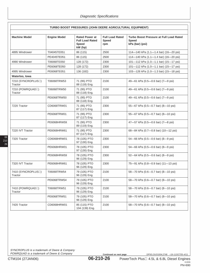
Diagnostic Specifications
06210
26
DPSG,OUO1004,2748 –19–11OCT05–4/11
TURBO BOOST PRESSURES (JOHN DEERE AGRICULTURAL EQUIPMENT)
Machine Model Engine Model Rated Power at Full Load Rated Turbo Boost Pressure at Full Load RatedFull Load Rated Speed SpeedSpeed rpm kPa (bar) (psi)kW (hp)
4895 Windrower T04045TE051 86 (115) 2500 114—140 kPa (1.1—1.4 bar) (16—20 psi)
PE4045TE051 86 (115) 2500 114—140 kPa (1.1—1.4 bar) (16—20 psi)
4990 Windrower T06068TE050 128 (172) 2300 101—112 kPa (1.0—1.1 bar) (15—17 psi)
PE6068TE050 128 (172) 2300 101—112 kPa (1.0—1.1 bar) (15—17 psi)
4995 Windrower PE6068TE051 136 (182) 2300 103—126 kPa (1.0—1.3 bar) (15—18 psi)
Waterloo, Iowa
7210 (SYNCROPLUS) T06068TRW53 71 (95) PTO 2100 49—61 kPa (0.5—0.6 bar) (7—9 psi)Tractor 88 (118) Eng.
7210 (POWRQUAD) T06068TRW50 71 (95) PTO 2100 49—61 kPa (0.5—0.6 bar) (7—9 psi)Tractor 88 (118) Eng.
PE6068TRW50 71 (95) PTO 2100 49—61 kPa (0.5—0.6 bar) (7—9 psi)88 (118) Eng.
7220 Tractor CD6068TRW01 71 (95) PTO 2300 55—67 kPa (0.5—0.7 bar) (8—10 psi)87 (117) Eng.
PE6068TRW01 71 (95) PTO 2300 55—67 kPa (0.5—0.7 bar) (8—10 psi)87 (117) Eng.
PE6068HRW59 71 (95) PTO 2300 47—57 kPa (0.5—0.6 bar) (7—8 psi)89 (119) Eng.
7220 IVT Tractor PE6068HRW61 71 (95) PTO 2300 68—84 kPa (0.7—0.8 bar) (10—12 psi)87 (117) Eng.
7320 Tractor CD6068HRW01 78 (105) PTO 2300 54—66 kPa (0.5—0.6 bar) (8—9 psi)97 (130) Eng.
PE6068HRW01 78 (105) PTO 2300 54—66 kPa (0.5—0.6 bar) (8—9 psi)97 (130) Eng.
PE6068HRW59 78 (105) PTO 2300 52—64 kPa (0.5—0.6 bar) (8—9 psi)96 (129) Eng.
7320 IVT Tractor PE6068HRW61 78 (105) PTO 2300 75—91 kPa (0.8—0.9 bar) (11—13 psi)96 (129) Eng.
7410 (SYNCROPLUS) T06068TRW54 79 (105) PTO 2100 58—70 kPa (0.6—0.7 bar) (8—10 psi)Tractor 96 (129) Eng.
PE6068TRW54 79 (105) PTO 2100 58—70 kPa (0.6—0.7 bar) (8—10 psi)96 (129) Eng.
7410 (POWRQUAD) T06068TRW51 79 (105) PTO 2100 58—70 kPa (0.6—0.7 bar) (8—10 psi)Tractor 96 (129) Eng.
PE6068TRW51 79 (105) PTO 2100 58—70 kPa (0.6—0.7 bar) (8—10 psi)96 (129) Eng.
7420 Tractor CD6068HRW01 85 (115) PTO 2100 58—70 kPa (0.6—0.7 bar) (8—10 psi)104 (139) Eng.
SYNCROPLUS is a trademark of Deere & CompanyPOWRQUAD is a trademark of Deere & Company
CTM104 (27JAN06) 06-210-26 PowerTech Plus 4.5L & 6.8L Diesel Engines013006
PN=690
Continued on next page
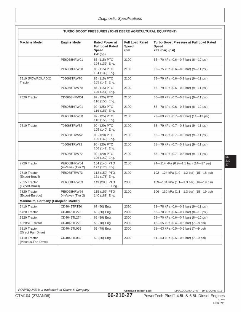
Diagnostic Specifications
0621027
DPSG,OUO1004,2748 –19–11OCT05–5/11
TURBO BOOST PRESSURES (JOHN DEERE AGRICULTURAL EQUIPMENT)
Machine Model Engine Model Rated Power at Full Load Rated Turbo Boost Pressure at Full Load RatedFull Load Rated Speed SpeedSpeed rpm kPa (bar) (psi)kW (hp)
PE6068HRW01 85 (115) PTO 2100 58—70 kPa (0.6—0.7 bar) (8—10 psi)104 (139) Eng.
PE6068HRW60 85 (115) PTO 2100 62—75 kPa (0.6—0.8 bar) (9—11 psi)104 (139) Eng.
7510 (POWRQUAD) T06068TRW70 86 (115) PTO 2100 65—79 kPa (0.6—0.8 bar) (9—11 psi)Tractor 105 (141) Eng.
PE6068TRW70 86 (115) PTO 2100 65—79 kPa (0.6—0.8 bar) (9—11 psi)105 (141) Eng.
7520 Tractor CD6068HRW01 92 (125) PTO 2100 66—80 kPa (0.7—0.8 bar) (9—11 psi)116 (156) Eng.
PE6068HRW01 92 (125) PTO 2100 58—70 kPa (0.6—0.7 bar) (8—10 psi)116 (156) Eng.
PE6068HRW60 92 (125) PTO 2100 73—89 kPa (0.7—0.9 bar) (11—13 psi)116 (156) Eng.
7610 Tractor T06068TRW52 90 (120) PTO 2100 65—79 kPa (0.7—0.8 bar) (9—11 psi)105 (140) Eng.
PE6068TRW52 90 (120) PTO 2100 65—79 kPa (0.7—0.8 bar) (9—11 psi)105 (140) Eng.
T06068TRW72 90 (120) PTO 2100 65—79 kPa (0.7—0.8 bar) (9—11 psi)106 (142) Eng.
PE6068TRW72 90 (120) PTO 2100 65—79 kPa (0.7—0.8 bar) (9—11 psi)106 (142) Eng.
7720 Tractor PE6068HRW54 104 (140) PTO 2100 94—114 kPa (0.9—1.1 bar) (14—17 psi)(4-Valve) (Tier 2) 127 (170) Eng.
7810 Tractor PE6068TRW73 112 (150) PTO 2100 102—124 kPa (1.0—1.2 bar) (15—18 psi)(Export-Brazil) 131 (175) Eng.
7815 Tractor PE6068HRW63 149 (200) PTO 2300 109—134 kPa (1.1—1.3 bar) (16—19 psi)(Export-Brazil) ....................Eng.
7820 Tractor PE6068HRW54 115 (155) PTO 2100 106—130 kPa (1.1—1.3 bar) (15—19 psi)(Export-Europe) (4-Valve) (Tier 2) 140 (188) Eng.
Mannheim, Germany (European Market)
3410 Tractor CD4045TRT50 67 (90) Eng. 2350 63—78 kPa (0.6—0.8 bar) (9—11 psi)
5720 Tractor CD4045TL273 60 (80) Eng. 2300 58—70 kPa (0.6—0.7 bar) (8—10 psi)
5820 Tractor CD4045TL274 66 (89) Eng. 2300 58—70 kPa (0.6—0.7 bar) (8—10 psi)
6020SE Tractor CD4045TL270 58 (78) Eng. 2300 45—55 kPa (0.4—0.5 bar) (7—8 psi)
6110 Tractor CD4045TL058 58 (79) Eng. 2300 51—63 kPa (0.5—0.6 bar) (7—9 psi)(Direct Fan Drive)
6110 Tractor CD4045TL050 59 (80) Eng. 2300 51—63 kPa (0.5—0.6 bar) (7—9 psi)(Viscous Fan Drive)
POWRQUAD is a trademark of Deere & Company
CTM104 (27JAN06) 06-210-27 PowerTech Plus 4.5L & 6.8L Diesel Engines013006
PN=691
Continued on next page
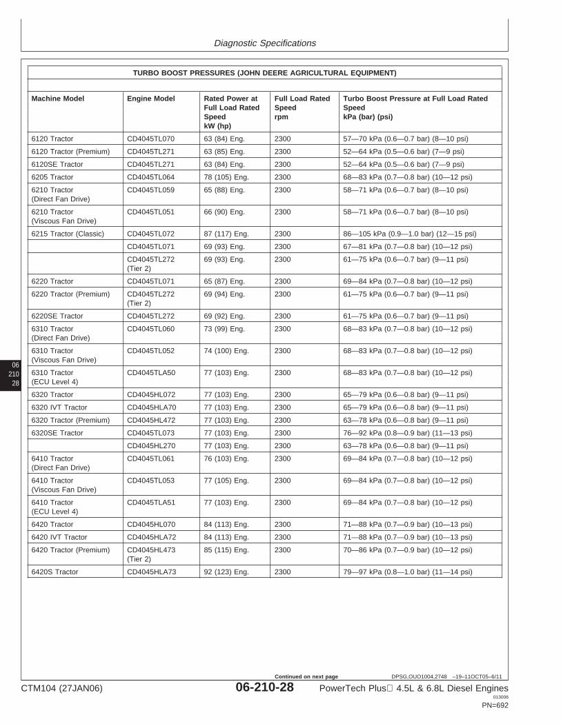
Diagnostic Specifications
06210
28
DPSG,OUO1004,2748 –19–11OCT05–6/11
TURBO BOOST PRESSURES (JOHN DEERE AGRICULTURAL EQUIPMENT)
Machine Model Engine Model Rated Power at Full Load Rated Turbo Boost Pressure at Full Load RatedFull Load Rated Speed SpeedSpeed rpm kPa (bar) (psi)kW (hp)
6120 Tractor CD4045TL070 63 (84) Eng. 2300 57—70 kPa (0.6—0.7 bar) (8—10 psi)
6120 Tractor (Premium) CD4045TL271 63 (85) Eng. 2300 52—64 kPa (0.5—0.6 bar) (7—9 psi)
6120SE Tractor CD4045TL271 63 (84) Eng. 2300 52—64 kPa (0.5—0.6 bar) (7—9 psi)
6205 Tractor CD4045TL064 78 (105) Eng. 2300 68—83 kPa (0.7—0.8 bar) (10—12 psi)
6210 Tractor CD4045TL059 65 (88) Eng. 2300 58—71 kPa (0.6—0.7 bar) (8—10 psi)(Direct Fan Drive)
6210 Tractor CD4045TL051 66 (90) Eng. 2300 58—71 kPa (0.6—0.7 bar) (8—10 psi)(Viscous Fan Drive)
6215 Tractor (Classic) CD4045TL072 87 (117) Eng. 2300 86—105 kPa (0.9—1.0 bar) (12—15 psi)
CD4045TL071 69 (93) Eng. 2300 67—81 kPa (0.7—0.8 bar) (10—12 psi)
CD4045TL272 69 (93) Eng. 2300 61—75 kPa (0.6—0.7 bar) (9—11 psi)(Tier 2)
6220 Tractor CD4045TL071 65 (87) Eng. 2300 69—84 kPa (0.7—0.8 bar) (10—12 psi)
6220 Tractor (Premium) CD4045TL272 69 (94) Eng. 2300 61—75 kPa (0.6—0.7 bar) (9—11 psi)(Tier 2)
6220SE Tractor CD4045TL272 69 (92) Eng. 2300 61—75 kPa (0.6—0.7 bar) (9—11 psi)
6310 Tractor CD4045TL060 73 (99) Eng. 2300 68—83 kPa (0.7—0.8 bar) (10—12 psi)(Direct Fan Drive)
6310 Tractor CD4045TL052 74 (100) Eng. 2300 68—83 kPa (0.7—0.8 bar) (10—12 psi)(Viscous Fan Drive)
6310 Tractor CD4045TLA50 77 (103) Eng. 2300 68—83 kPa (0.7—0.8 bar) (10—12 psi)(ECU Level 4)
6320 Tractor CD4045HL072 77 (103) Eng. 2300 65—79 kPa (0.6—0.8 bar) (9—11 psi)
6320 IVT Tractor CD4045HLA70 77 (103) Eng. 2300 65—79 kPa (0.6—0.8 bar) (9—11 psi)
6320 Tractor (Premium) CD4045HL472 77 (103) Eng. 2300 63—78 kPa (0.6—0.8 bar) (9—11 psi)
6320SE Tractor CD4045TL073 77 (103) Eng. 2300 76—92 kPa (0.8—0.9 bar) (11—13 psi)
CD4045HL270 77 (103) Eng. 2300 63—78 kPa (0.6—0.8 bar) (9—11 psi)
6410 Tractor CD4045TL061 76 (103) Eng. 2300 69—84 kPa (0.7—0.8 bar) (10—12 psi)(Direct Fan Drive)
6410 Tractor CD4045TL053 77 (105) Eng. 2300 69—84 kPa (0.7—0.8 bar) (10—12 psi)(Viscous Fan Drive)
6410 Tractor CD4045TLA51 77 (103) Eng. 2300 69—84 kPa (0.7—0.8 bar) (10—12 psi)(ECU Level 4)
6420 Tractor CD4045HL070 84 (113) Eng. 2300 71—88 kPa (0.7—0.9 bar) (10—13 psi)
6420 IVT Tractor CD4045HLA72 84 (113) Eng. 2300 71—88 kPa (0.7—0.9 bar) (10—13 psi)
6420 Tractor (Premium) CD4045HL473 85 (115) Eng. 2300 70—86 kPa (0.7—0.9 bar) (10—12 psi)(Tier 2)
6420S Tractor CD4045HLA73 92 (123) Eng. 2300 79—97 kPa (0.8—1.0 bar) (11—14 psi)
CTM104 (27JAN06) 06-210-28 PowerTech Plus 4.5L & 6.8L Diesel Engines013006
PN=692
Continued on next page
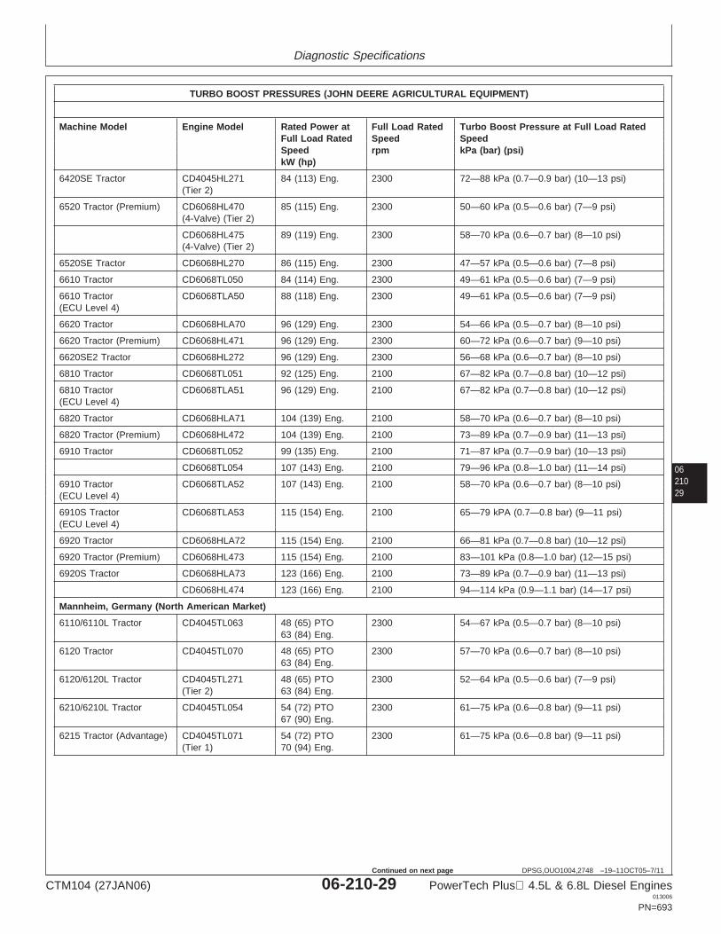
Diagnostic Specifications
0621029
DPSG,OUO1004,2748 –19–11OCT05–7/11
TURBO BOOST PRESSURES (JOHN DEERE AGRICULTURAL EQUIPMENT)
Machine Model Engine Model Rated Power at Full Load Rated Turbo Boost Pressure at Full Load RatedFull Load Rated Speed SpeedSpeed rpm kPa (bar) (psi)kW (hp)
6420SE Tractor CD4045HL271 84 (113) Eng. 2300 72—88 kPa (0.7—0.9 bar) (10—13 psi)(Tier 2)
6520 Tractor (Premium) CD6068HL470 85 (115) Eng. 2300 50—60 kPa (0.5—0.6 bar) (7—9 psi)(4-Valve) (Tier 2)
CD6068HL475 89 (119) Eng. 2300 58—70 kPa (0.6—0.7 bar) (8—10 psi)(4-Valve) (Tier 2)
6520SE Tractor CD6068HL270 86 (115) Eng. 2300 47—57 kPa (0.5—0.6 bar) (7—8 psi)
6610 Tractor CD6068TL050 84 (114) Eng. 2300 49—61 kPa (0.5—0.6 bar) (7—9 psi)
6610 Tractor CD6068TLA50 88 (118) Eng. 2300 49—61 kPa (0.5—0.6 bar) (7—9 psi)(ECU Level 4)
6620 Tractor CD6068HLA70 96 (129) Eng. 2300 54—66 kPa (0.5—0.7 bar) (8—10 psi)
6620 Tractor (Premium) CD6068HL471 96 (129) Eng. 2300 60—72 kPa (0.6—0.7 bar) (9—10 psi)
6620SE2 Tractor CD6068HL272 96 (129) Eng. 2300 56—68 kPa (0.6—0.7 bar) (8—10 psi)
6810 Tractor CD6068TL051 92 (125) Eng. 2100 67—82 kPa (0.7—0.8 bar) (10—12 psi)
6810 Tractor CD6068TLA51 96 (129) Eng. 2100 67—82 kPa (0.7—0.8 bar) (10—12 psi)(ECU Level 4)
6820 Tractor CD6068HLA71 104 (139) Eng. 2100 58—70 kPa (0.6—0.7 bar) (8—10 psi)
6820 Tractor (Premium) CD6068HL472 104 (139) Eng. 2100 73—89 kPa (0.7—0.9 bar) (11—13 psi)
6910 Tractor CD6068TL052 99 (135) Eng. 2100 71—87 kPa (0.7—0.9 bar) (10—13 psi)
CD6068TL054 107 (143) Eng. 2100 79—96 kPa (0.8—1.0 bar) (11—14 psi)
6910 Tractor CD6068TLA52 107 (143) Eng. 2100 58—70 kPa (0.6—0.7 bar) (8—10 psi)(ECU Level 4)
6910S Tractor CD6068TLA53 115 (154) Eng. 2100 65—79 kPA (0.7—0.8 bar) (9—11 psi)(ECU Level 4)
6920 Tractor CD6068HLA72 115 (154) Eng. 2100 66—81 kPa (0.7—0.8 bar) (10—12 psi)
6920 Tractor (Premium) CD6068HL473 115 (154) Eng. 2100 83—101 kPa (0.8—1.0 bar) (12—15 psi)
6920S Tractor CD6068HLA73 123 (166) Eng. 2100 73—89 kPa (0.7—0.9 bar) (11—13 psi)
CD6068HL474 123 (166) Eng. 2100 94—114 kPa (0.9—1.1 bar) (14—17 psi)
Mannheim, Germany (North American Market)
6110/6110L Tractor CD4045TL063 48 (65) PTO 2300 54—67 kPa (0.5—0.7 bar) (8—10 psi)63 (84) Eng.
6120 Tractor CD4045TL070 48 (65) PTO 2300 57—70 kPa (0.6—0.7 bar) (8—10 psi)63 (84) Eng.
6120/6120L Tractor CD4045TL271 48 (65) PTO 2300 52—64 kPa (0.5—0.6 bar) (7—9 psi)(Tier 2) 63 (84) Eng.
6210/6210L Tractor CD4045TL054 54 (72) PTO 2300 61—75 kPa (0.6—0.8 bar) (9—11 psi)67 (90) Eng.
6215 Tractor (Advantage) CD4045TL071 54 (72) PTO 2300 61—75 kPa (0.6—0.8 bar) (9—11 psi)(Tier 1) 70 (94) Eng.
CTM104 (27JAN06) 06-210-29 PowerTech Plus 4.5L & 6.8L Diesel Engines013006
PN=693
Continued on next page
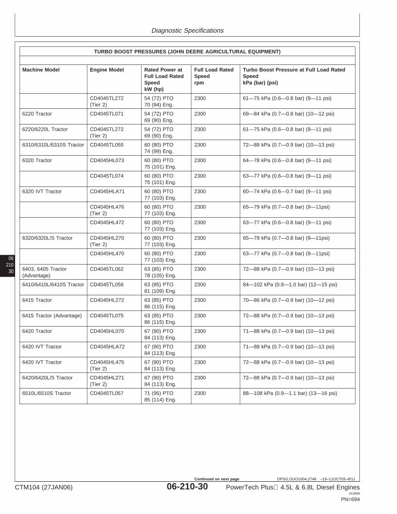
Diagnostic Specifications
06210
30
DPSG,OUO1004,2748 –19–11OCT05–8/11
TURBO BOOST PRESSURES (JOHN DEERE AGRICULTURAL EQUIPMENT)
Machine Model Engine Model Rated Power at Full Load Rated Turbo Boost Pressure at Full Load RatedFull Load Rated Speed SpeedSpeed rpm kPa (bar) (psi)kW (hp)
CD4045TL272 54 (72) PTO 2300 61—75 kPa (0.6—0.8 bar) (9—11 psi)(Tier 2) 70 (94) Eng.
6220 Tractor CD4045TL071 54 (72) PTO 2300 69—84 kPa (0.7—0.8 bar) (10—12 psi)69 (90) Eng.
6220/6220L Tractor CD4045TL272 54 (72) PTO 2300 61—75 kPa (0.6—0.8 bar) (9—11 psi)(Tier 2) 69 (90) Eng.
6310/6310L/6310S Tractor CD4045TL055 60 (80) PTO 2300 72—88 kPa (0.7—0.9 bar) (10—13 psi)74 (99) Eng.
6320 Tractor CD4045HL073 60 (80) PTO 2300 64—78 kPa (0.6—0.8 bar) (9—11 psi)75 (101) Eng.
CD4045TL074 60 (80) PTO 2300 63—77 kPa (0.6—0.8 bar) (9—11 psi)75 (101) Eng.
6320 IVT Tractor CD4045HLA71 60 (80) PTO 2300 60—74 kPa (0.6—0.7 bar) (9—11 psi)77 (103) Eng.
CD4045HL476 60 (80) PTO 2300 65—79 kPa (0.7—0.8 bar) (9—11psi)(Tier 2) 77 (103) Eng.
CD4045HL472 60 (80) PTO 2300 63—77 kPa (0.6—0.8 bar) (9—11 psi)77 (103) Eng.
6320/6320L/S Tractor CD4045HL270 60 (80) PTO 2300 65—79 kPa (0.7—0.8 bar) (9—11psi)(Tier 2) 77 (103) Eng.
CD4045HL470 60 (80) PTO 2300 63—77 kPa (0.7—0.8 bar) (9—11psi)77 (103) Eng.
6403, 6405 Tractor CD4045TL062 63 (85) PTO 2300 72—88 kPa (0.7—0.9 bar) (10—13 psi)(Advantage) 78 (105) Eng.
6410/6410L/6410S Tractor CD4045TL056 63 (85) PTO 2300 84—102 kPa (0.8—1.0 bar) (12—15 psi)81 (109) Eng.
6415 Tractor CD4045HL272 63 (85) PTO 2300 70—86 kPa (0.7—0.9 bar) (10—12 psi)86 (115) Eng.
6415 Tractor (Advantage) CD4045TL075 63 (85) PTO 2300 72—88 kPa (0.7—0.9 bar) (10—13 psi)86 (115) Eng.
6420 Tractor CD4045HL070 67 (90) PTO 2300 71—88 kPa (0.7—0.9 bar) (10—13 psi)84 (113) Eng.
6420 IVT Tractor CD4045HLA72 67 (90) PTO 2300 71—88 kPa (0.7—0.9 bar) (10—13 psi)84 (113) Eng.
6420 IVT Tractor CD4045HL475 67 (90) PTO 2300 72—88 kPa (0.7—0.9 bar) (10—13 psi)(Tier 2) 84 (113) Eng.
6420/6420L/S Tractor CD4045HL271 67 (90) PTO 2300 72—88 kPa (0.7—0.9 bar) (10—13 psi)(Tier 2) 84 (113) Eng.
6510L/6510S Tractor CD4045TL057 71 (95) PTO 2300 88—108 kPa (0.9—1.1 bar) (13—16 psi)85 (114) Eng.
CTM104 (27JAN06) 06-210-30 PowerTech Plus 4.5L & 6.8L Diesel Engines013006
PN=694
Continued on next page
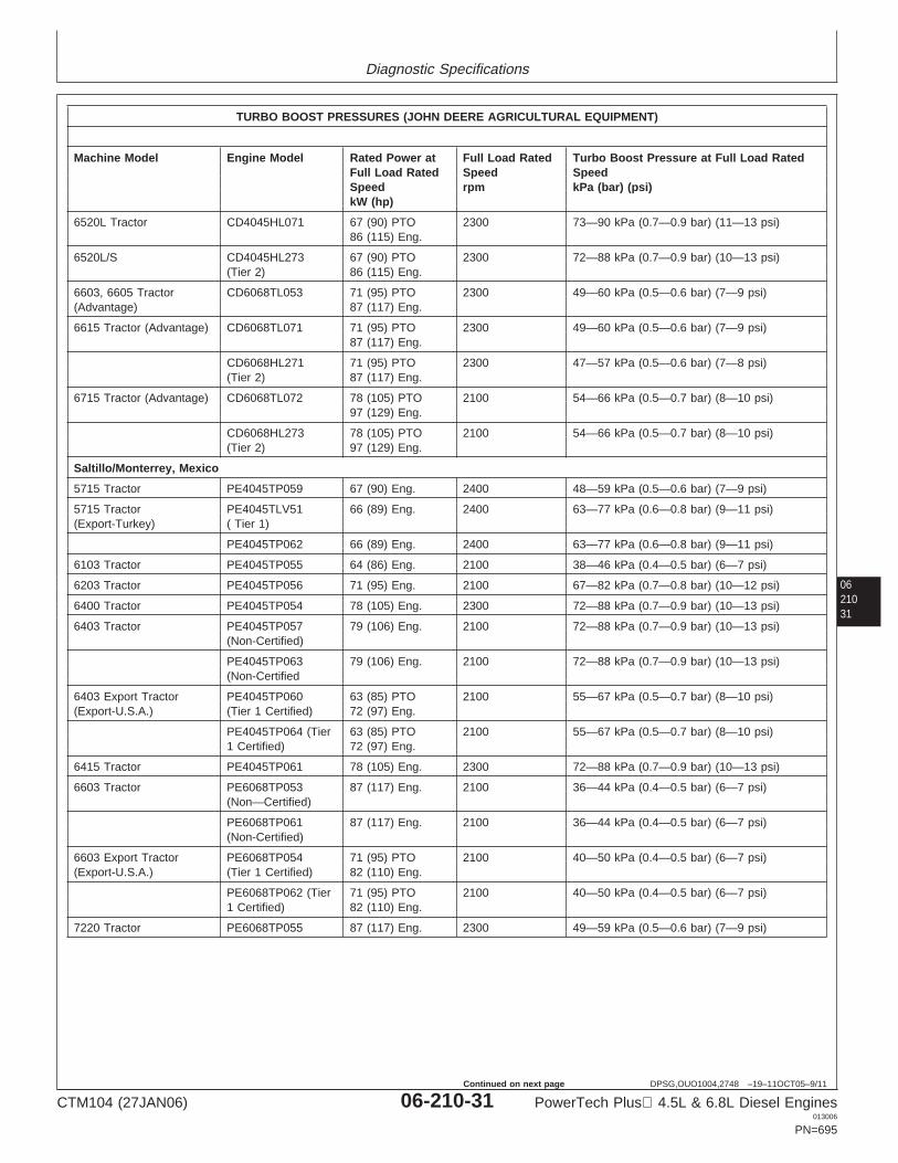
Diagnostic Specifications
0621031
DPSG,OUO1004,2748 –19–11OCT05–9/11
TURBO BOOST PRESSURES (JOHN DEERE AGRICULTURAL EQUIPMENT)
Machine Model Engine Model Rated Power at Full Load Rated Turbo Boost Pressure at Full Load RatedFull Load Rated Speed SpeedSpeed rpm kPa (bar) (psi)kW (hp)
6520L Tractor CD4045HL071 67 (90) PTO 2300 73—90 kPa (0.7—0.9 bar) (11—13 psi)86 (115) Eng.
6520L/S CD4045HL273 67 (90) PTO 2300 72—88 kPa (0.7—0.9 bar) (10—13 psi)(Tier 2) 86 (115) Eng.
6603, 6605 Tractor CD6068TL053 71 (95) PTO 2300 49—60 kPa (0.5—0.6 bar) (7—9 psi)(Advantage) 87 (117) Eng.
6615 Tractor (Advantage) CD6068TL071 71 (95) PTO 2300 49—60 kPa (0.5—0.6 bar) (7—9 psi)87 (117) Eng.
CD6068HL271 71 (95) PTO 2300 47—57 kPa (0.5—0.6 bar) (7—8 psi)(Tier 2) 87 (117) Eng.
6715 Tractor (Advantage) CD6068TL072 78 (105) PTO 2100 54—66 kPa (0.5—0.7 bar) (8—10 psi)97 (129) Eng.
CD6068HL273 78 (105) PTO 2100 54—66 kPa (0.5—0.7 bar) (8—10 psi)(Tier 2) 97 (129) Eng.
Saltillo/Monterrey, Mexico
5715 Tractor PE4045TP059 67 (90) Eng. 2400 48—59 kPa (0.5—0.6 bar) (7—9 psi)
5715 Tractor PE4045TLV51 66 (89) Eng. 2400 63—77 kPa (0.6—0.8 bar) (9—11 psi)(Export-Turkey) ( Tier 1)
PE4045TP062 66 (89) Eng. 2400 63—77 kPa (0.6—0.8 bar) (9—11 psi)
6103 Tractor PE4045TP055 64 (86) Eng. 2100 38—46 kPa (0.4—0.5 bar) (6—7 psi)
6203 Tractor PE4045TP056 71 (95) Eng. 2100 67—82 kPa (0.7—0.8 bar) (10—12 psi)
6400 Tractor PE4045TP054 78 (105) Eng. 2300 72—88 kPa (0.7—0.9 bar) (10—13 psi)
6403 Tractor PE4045TP057 79 (106) Eng. 2100 72—88 kPa (0.7—0.9 bar) (10—13 psi)(Non-Certified)
PE4045TP063 79 (106) Eng. 2100 72—88 kPa (0.7—0.9 bar) (10—13 psi)(Non-Certified
6403 Export Tractor PE4045TP060 63 (85) PTO 2100 55—67 kPa (0.5—0.7 bar) (8—10 psi)(Export-U.S.A.) (Tier 1 Certified) 72 (97) Eng.
PE4045TP064 (Tier 63 (85) PTO 2100 55—67 kPa (0.5—0.7 bar) (8—10 psi)1 Certified) 72 (97) Eng.
6415 Tractor PE4045TP061 78 (105) Eng. 2300 72—88 kPa (0.7—0.9 bar) (10—13 psi)
6603 Tractor PE6068TP053 87 (117) Eng. 2100 36—44 kPa (0.4—0.5 bar) (6—7 psi)(Non—Certified)
PE6068TP061 87 (117) Eng. 2100 36—44 kPa (0.4—0.5 bar) (6—7 psi)(Non-Certified)
6603 Export Tractor PE6068TP054 71 (95) PTO 2100 40—50 kPa (0.4—0.5 bar) (6—7 psi)(Export-U.S.A.) (Tier 1 Certified) 82 (110) Eng.
PE6068TP062 (Tier 71 (95) PTO 2100 40—50 kPa (0.4—0.5 bar) (6—7 psi)1 Certified) 82 (110) Eng.
7220 Tractor PE6068TP055 87 (117) Eng. 2300 49—59 kPa (0.5—0.6 bar) (7—9 psi)
CTM104 (27JAN06) 06-210-31 PowerTech Plus 4.5L & 6.8L Diesel Engines013006
PN=695
Continued on next page
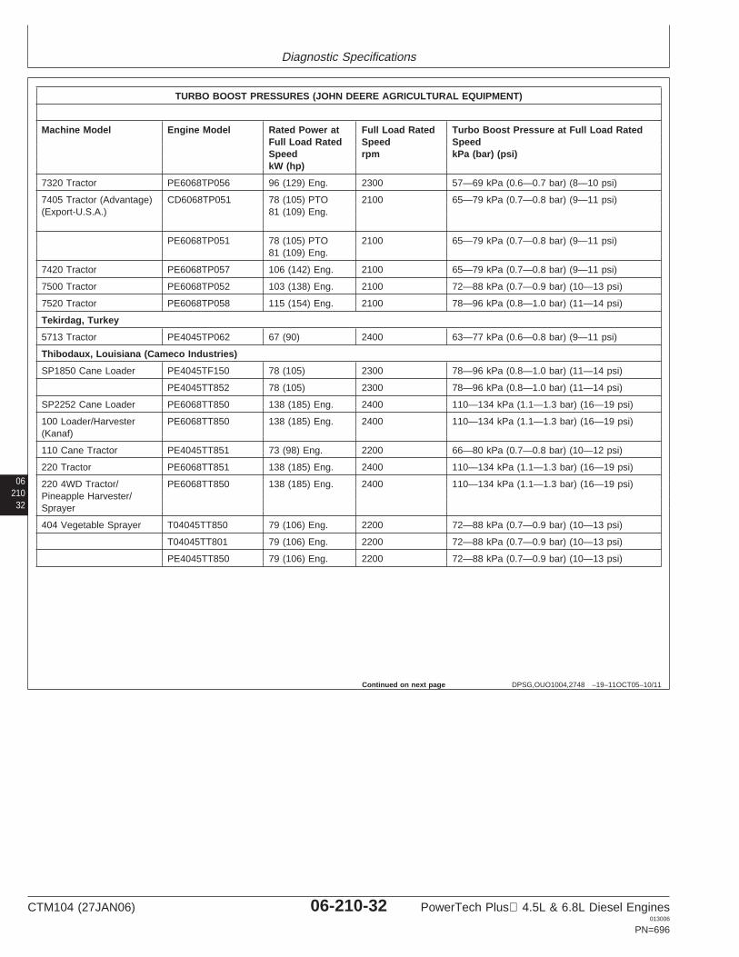
Diagnostic Specifications
06210
32
DPSG,OUO1004,2748 –19–11OCT05–10/11
TURBO BOOST PRESSURES (JOHN DEERE AGRICULTURAL EQUIPMENT)
Machine Model Engine Model Rated Power at Full Load Rated Turbo Boost Pressure at Full Load RatedFull Load Rated Speed SpeedSpeed rpm kPa (bar) (psi)kW (hp)
7320 Tractor PE6068TP056 96 (129) Eng. 2300 57—69 kPa (0.6—0.7 bar) (8—10 psi)
7405 Tractor (Advantage) CD6068TP051 78 (105) PTO 2100 65—79 kPa (0.7—0.8 bar) (9—11 psi)(Export-U.S.A.) 81 (109) Eng.
PE6068TP051 78 (105) PTO 2100 65—79 kPa (0.7—0.8 bar) (9—11 psi)81 (109) Eng.
7420 Tractor PE6068TP057 106 (142) Eng. 2100 65—79 kPa (0.7—0.8 bar) (9—11 psi)
7500 Tractor PE6068TP052 103 (138) Eng. 2100 72—88 kPa (0.7—0.9 bar) (10—13 psi)
7520 Tractor PE6068TP058 115 (154) Eng. 2100 78—96 kPa (0.8—1.0 bar) (11—14 psi)
Tekirdag, Turkey
5713 Tractor PE4045TP062 67 (90) 2400 63—77 kPa (0.6—0.8 bar) (9—11 psi)
Thibodaux, Louisiana (Cameco Industries)
SP1850 Cane Loader PE4045TF150 78 (105) 2300 78—96 kPa (0.8—1.0 bar) (11—14 psi)
PE4045TT852 78 (105) 2300 78—96 kPa (0.8—1.0 bar) (11—14 psi)
SP2252 Cane Loader PE6068TT850 138 (185) Eng. 2400 110—134 kPa (1.1—1.3 bar) (16—19 psi)
100 Loader/Harvester PE6068TT850 138 (185) Eng. 2400 110—134 kPa (1.1—1.3 bar) (16—19 psi)(Kanaf)
110 Cane Tractor PE4045TT851 73 (98) Eng. 2200 66—80 kPa (0.7—0.8 bar) (10—12 psi)
220 Tractor PE6068TT851 138 (185) Eng. 2400 110—134 kPa (1.1—1.3 bar) (16—19 psi)
220 4WD Tractor/ PE6068TT850 138 (185) Eng. 2400 110—134 kPa (1.1—1.3 bar) (16—19 psi)Pineapple Harvester/Sprayer
404 Vegetable Sprayer T04045TT850 79 (106) Eng. 2200 72—88 kPa (0.7—0.9 bar) (10—13 psi)
T04045TT801 79 (106) Eng. 2200 72—88 kPa (0.7—0.9 bar) (10—13 psi)
PE4045TT850 79 (106) Eng. 2200 72—88 kPa (0.7—0.9 bar) (10—13 psi)
Continued on next page
CTM104 (27JAN06) 06-210-32 PowerTech Plus 4.5L & 6.8L Diesel Engines013006
PN=696
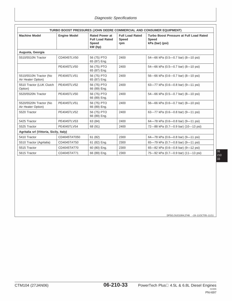
Diagnostic Specifications
0621033
DPSG,OUO1004,2748 –19–11OCT05–11/11
TURBO BOOST PRESSURES (JOHN DEERE COMMERCIAL AND CONSUMER EQUIPMENT)
Machine Model Engine Model Rated Power at Full Load Rated Turbo Boost Pressure at Full Load RatedFull Load Rated Speed SpeedSpeed rpm kPa (bar) (psi)kW (hp)
Augusta, Georgia
5510/5510N Tractor CD4045TLV50 56 (75) PTO 2400 54—66 kPa (0.5—0.7 bar) (8—10 psi)65 (87) Eng.
PE4045TLV50 56 (75) PTO 2400 54—66 kPa (0.5—0.7 bar) (8—10 psi)65 (87) Eng.
5510/5510N Tractor (No PE4045TLV51 56 (75) PTO 2400 56—66 kPa (0.6—0.7 bar) (8—10 psi)Air Heater Option) 65 (87) Eng.
5510 Tractor (LUK Clutch PE4045TLV52 56 (75) PTO 2400 63—77 kPa (0.6—0.8 bar) (9—11 psi)Option) 66 (89) Eng.
5520/5520N Tractor PE4045TLV50 56 (75) PTO 2400 54—66 kPa (0.5—0.7 bar) (8—10 psi)66 (89) Eng.
5520/5520N Tractor (No PE4045TLV51 56 (75) PTO 2400 56—66 kPa (0.6—0.7 bar) (8—10 psi)Air Heater Option) 66 (89) Eng.
5520 Tractor PE4045TLV52 56 (75) PTO 2400 63—77 kPa (0.6—0.8 bar) (9—11 psi)66 (89) Eng.
5425 Tractor PE4045TLV53 63 (84) 2400 64—78 kPa (0.6—0.8 bar) (9—11 psi)
5525 Tractor PE4045TLV54 68 (91) 2400 72—88 kPa (0.7—0.9 bar) (10—13 psi)
Agritalia srl (Vittoria, Sicily, Italy)
5410 Tractor CD4045TAT050 61 (82) 2300 64—78 kPa (0.6—0.8 bar) (9—11 psi)
5510 Tractor (Agritalia) CD4045TAT50 61 (82) Eng. 2300 65—79 kPa (0.7—0.8 bar) (9—11 psi)
5515 Tractor CD4045TAT70 60 (80) Eng. 2300 65—82 kPa (0.6—0.8 bar) (9—12 psi)
5615 Tractor CD4045TAT71 66 (89) Eng. 2300 75—92 kPa (0.7—0.9 bar) (11—13 psi)
CTM104 (27JAN06) 06-210-33 PowerTech Plus 4.5L & 6.8L Diesel Engines013006
PN=697
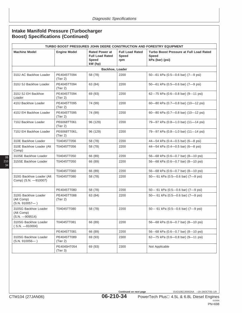
Diagnostic Specifications
06210
34
OUO1082,00002AA –19–26OCT05–1/9
Intake Manifold Pressure (TurbochargerBoost) Specifications (Continued)
TURBO BOOST PRESSURES JOHN DEERE CONSTRUCTION AND FORESTRY EQUIPMENT
Machine Model Engine Model Rated Power at Full Load Rated Turbo Boost Pressure at Full Load RatedFull Load Rated Speed SpeedSpeed rpm kPa (bar) (psi)kW (hp)
Backhoe, Loader
310J AC Backhoe Loader PE4045TT094 58 (78) 2200 50—61 kPa (0.5—0.6 bar) (7—9 psi)(Tier 2)
310J SJ Backhoe Loader PE4045TT094 63 (84) 2200 50—61 kPa (0.5—0.6 bar) (7—9 psi)(Tier 2)
310J SJ EH Backhoe PE4045TT094 69 (93) 2200 62—75 kPa (0.6—0.8 bar) (9—11 psi)Loader (Tier 2)
410J Backhoe Loader PE4045TT095 74 (99) 2200 60—80 kPa (0.7—0.8 bar) (10—12 psi)(Tier 2)
410J EH Backhoe Loader PE4045TT095 74 (99) 2200 60—80 kPa (0.7—0.8 bar) (10—12 psi)(Tier 2)
710J Backhoe Loader PE6068TT061 96 (129) 2200 79—97 kPa (0.8—1.0 bar) (11—14 psi)(Tier 2)
710J EH Backhoe Loader PE6068TT061, 96 (129) 2200 79—97 kPa (0.8—1.0 bar) (11—14 psi)(Tier 2)
310E Backhoe Loader T04045TT056 58 (78) 2200 44—54 kPa (0.4—0.5 bar) (6—8 psi)
310E Backhoe Loader (Alt T04045TT056 58 (78) 2200 44—54 kPa (0.4—0.5 bar) (6—8 psi)Comp)
310SE Backhoe Loader T04045TT050 66 (89) 2200 56—68 kPa (0.6—0.7 bar) (8—10 psi)
315SE Backhoe Loader T04045TT050 66 (89) 2200 56—68 kPa (0.6—0.7 bar) (8—10 psi)
T04045TT060 66 (89) 2200 56—68 kPa (0.6—0.7 bar) (8—10 psi)
310G Backhoe Loader (Alt T04045TT080 58 (78) 2200 50— 61 kPa (0.5—0.6 bar) (7—9 psi)Comp) (S.N. —910007)
PE4045TT080 58 (78) 2200 50— 61 kPa (0.5—0.6 bar) (7—9 psi)
310G Backhoe Loader PE4045TT088 63 (84) 2200 50— 61 kPa (0.5—0.6 bar) (7—9 psi)(Alt Comp) (Tier 2)(S.N. 910057— )
310SG Backhoe Loader T04045TT080 58 (78) 2200 50— 61 kPa (0.5—0.6 bar) (7—9 psi)(Alt Comp)(S.N. —909514)
310SG Backhoe Loader T04045TT081 66 (89) 2200 56—68 kPa (0.6—0.7 bar) (8—10 psi)( S.N. —910004)
PE4045TT081 66 (89) 2200 56—68 kPa (0.6—0.7 bar) (8—10 psi)
310SG Backhoe Loader PE4045TT089 69 (93) 2300 62—75 kPa (0.6—0.8 bar) (9—11 psi)(S.N. 910056— ) (Tier 2)
PE4045HT054 69 (93) 2300 Not Applicable(Tier 3)
CTM104 (27JAN06) 06-210-34 PowerTech Plus 4.5L & 6.8L Diesel Engines013006
PN=698
Continued on next page
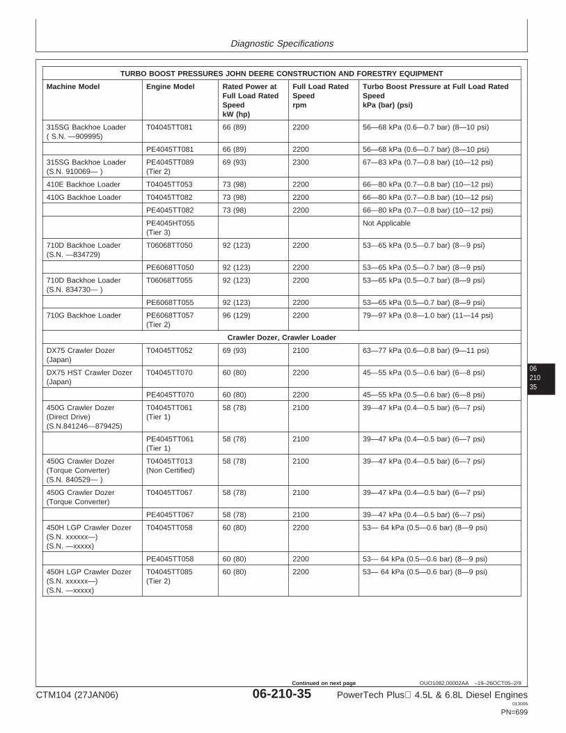
Diagnostic Specifications
0621035
OUO1082,00002AA –19–26OCT05–2/9
TURBO BOOST PRESSURES JOHN DEERE CONSTRUCTION AND FORESTRY EQUIPMENT
Machine Model Engine Model Rated Power at Full Load Rated Turbo Boost Pressure at Full Load RatedFull Load Rated Speed SpeedSpeed rpm kPa (bar) (psi)kW (hp)
315SG Backhoe Loader T04045TT081 66 (89) 2200 56—68 kPa (0.6—0.7 bar) (8—10 psi)( S.N. —909995)
PE4045TT081 66 (89) 2200 56—68 kPa (0.6—0.7 bar) (8—10 psi)
315SG Backhoe Loader PE4045TT089 69 (93) 2300 67—83 kPa (0.7—0.8 bar) (10—12 psi)(S.N. 910069— ) (Tier 2)
410E Backhoe Loader T04045TT053 73 (98) 2200 66—80 kPa (0.7—0.8 bar) (10—12 psi)
410G Backhoe Loader T04045TT082 73 (98) 2200 66—80 kPa (0.7—0.8 bar) (10—12 psi)
PE4045TT082 73 (98) 2200 66—80 kPa (0.7—0.8 bar) (10—12 psi)
PE4045HT055 Not Applicable(Tier 3)
710D Backhoe Loader T06068TT050 92 (123) 2200 53—65 kPa (0.5—0.7 bar) (8—9 psi)(S.N. —834729)
PE6068TT050 92 (123) 2200 53—65 kPa (0.5—0.7 bar) (8—9 psi)
710D Backhoe Loader T06068TT055 92 (123) 2200 53—65 kPa (0.5—0.7 bar) (8—9 psi)(S.N. 834730— )
PE6068TT055 92 (123) 2200 53—65 kPa (0.5—0.7 bar) (8—9 psi)
710G Backhoe Loader PE6068TT057 96 (129) 2200 79—97 kPa (0.8—1.0 bar) (11—14 psi)(Tier 2)
Crawler Dozer, Crawler Loader
DX75 Crawler Dozer T04045TT052 69 (93) 2100 63—77 kPa (0.6—0.8 bar) (9—11 psi)(Japan)
DX75 HST Crawler Dozer T04045TT070 60 (80) 2200 45—55 kPa (0.5—0.6 bar) (6—8 psi)(Japan)
PE4045TT070 60 (80) 2200 45—55 kPa (0.5—0.6 bar) (6—8 psi)
450G Crawler Dozer T04045TT061 58 (78) 2100 39—47 kPa (0.4—0.5 bar) (6—7 psi)(Direct Drive) (Tier 1)(S.N.841246—879425)
PE4045TT061 58 (78) 2100 39—47 kPa (0.4—0.5 bar) (6—7 psi)(Tier 1)
450G Crawler Dozer T04045TT013 58 (78) 2100 39—47 kPa (0.4—0.5 bar) (6—7 psi)(Torque Converter) (Non Certified)(S.N. 840529— )
450G Crawler Dozer T04045TT067 58 (78) 2100 39—47 kPa (0.4—0.5 bar) (6—7 psi)(Torque Converter)
PE4045TT067 58 (78) 2100 39—47 kPa (0.4—0.5 bar) (6—7 psi)
450H LGP Crawler Dozer T04045TT058 60 (80) 2200 53— 64 kPa (0.5—0.6 bar) (8—9 psi)(S.N. xxxxxx—)(S.N. —xxxxx)
PE4045TT058 60 (80) 2200 53— 64 kPa (0.5—0.6 bar) (8—9 psi)
450H LGP Crawler Dozer T04045TT085 60 (80) 2200 53— 64 kPa (0.5—0.6 bar) (8—9 psi)(S.N. xxxxxx—) (Tier 2)(S.N. —xxxxx)
CTM104 (27JAN06) 06-210-35 PowerTech Plus 4.5L & 6.8L Diesel Engines013006
PN=699
Continued on next page

Diagnostic Specifications
06210
36
OUO1082,00002AA –19–26OCT05–3/9
TURBO BOOST PRESSURES JOHN DEERE CONSTRUCTION AND FORESTRY EQUIPMENT
Machine Model Engine Model Rated Power at Full Load Rated Turbo Boost Pressure at Full Load RatedFull Load Rated Speed SpeedSpeed rpm kPa (bar) (psi)kW (hp)
PE4045TT085 60 (80) 2200 53— 64 kPa (0.5—0.6 bar) (8—9 psi)(Tier 2)
PE4045TT090 60 (80) 2200 53— 64 kPa (0.5—0.6 bar) (8—9 psi)(Tier 2)
450H Crawler Dozer (Alt T04045TT057 56 (75) 2200 41—51 kPa (0.4—0.5 bar) (7—8 psi)Comp)
PE4045TT057 56 (75) 2200 41—51 kPa (0.4—0.5 bar) (7—8 psi)
450H Crawler Dozer (Alt T04045TT084 56 (75) 2200 46—56 kPa (0.4—0.6 bar) (7—9 psi)Comp) (Tier 2)
PE4045TT084 56 (75) 2200 46—56 kPa (0.4—0.6 bar) (7—9 psi)(Tier 2)
PE4045TT090 56 (75) 2200 43— 53 kPa (0.4—0.5 bar) (6—8 psi)(Tier 2)
PE4045TT090 60 (80) 2200 53—64 kPa (0.5—0.6 bar) (8—9 psi)(Tier 2)
PE4045TT090 63 (84) 2200 42—52 kPa (0.4—0.5 bar) (6—7 psi)(Tier 2)
PE4045TT090 66 (89) 2200 63—77 kPa (0.6—0.8 bar) (9—11 psi)(Tier 2)
PE4045TT090 74 (99) 2200 71—87 kPa (0.7—0.9 bar) (10—13 psi)(Tier 2)
455G Crawler Loader T04045TT061 58 (78) 2100 38—47 kPa (0.4—0.5 bar) (6—7 psi)(Direct Drive) (Tier 1)
PE4045TT061 58 (78) 2100 38—47 kPa (0.4—0.5 bar) (6—7 psi)(Tier 1)
455G Crawler Loader T04045TT067 58 (78) 2100 38—47 kPa (0.4—0.5 bar) (6—7 psi)(Torque Converter)
PE4045TT067 58 (78) 2100 38—47 kPa (0.4—0.5 bar) (6—7 psi)
550G Crawler Dozer T04045TT006 66 (89) 2100 51—63 kPa (0.5—0.6 bar) (7—9 psi)(Direct Drive)
T04045TT014 66 (89) 2100 51—63 kPa (0.5—0.6 bar) (7—9 psi)
T04045TT062 66 (89) 2100 51—63 kPa (0.5—0.6 bar) (7—9 psi)
550G Crawler Dozer T04045TT062 66 (89) 2100 51—63 kPa (0.5—0.6 bar) (7—9 psi)(Torque Converter)
T04045TT068 66 (89) 2100 51—63 kPa (0.5—0.6 bar) (7—9 psi)
550H Crawler Dozer T04045TT064 63 (84) 2200 42—52 kPa (0.4—0.5 bar) (6—7 psi)(S.N. —909830)
PE4045TT064 63 (84) 2200 42—52 kPa (0.4—0.5 bar) (6—7 psi)
550H Crawler Dozer PE4045TT086 63 (84) 2200 50—62 kPa (0.5—0.6 bar) (7—9 psi)(S.N. 910019— ) (Tier 2)
PE4045TT090 63 (84) 2200 53— 65 kPa (0.5—0.7 bar) (8—9 psi)(Tier 2)
CTM104 (27JAN06) 06-210-36 PowerTech Plus 4.5L & 6.8L Diesel Engines013006
PN=700
Continued on next page
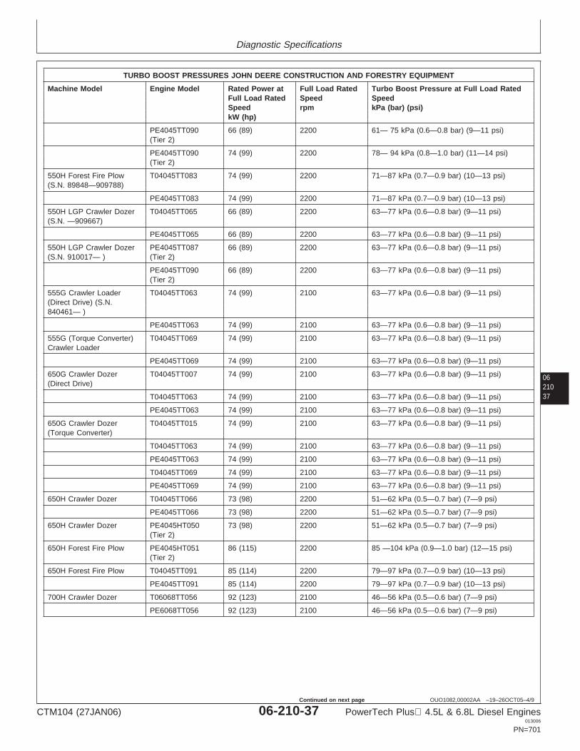
Diagnostic Specifications
0621037
OUO1082,00002AA –19–26OCT05–4/9
TURBO BOOST PRESSURES JOHN DEERE CONSTRUCTION AND FORESTRY EQUIPMENT
Machine Model Engine Model Rated Power at Full Load Rated Turbo Boost Pressure at Full Load RatedFull Load Rated Speed SpeedSpeed rpm kPa (bar) (psi)kW (hp)
PE4045TT090 66 (89) 2200 61— 75 kPa (0.6—0.8 bar) (9—11 psi)(Tier 2)
PE4045TT090 74 (99) 2200 78— 94 kPa (0.8—1.0 bar) (11—14 psi)(Tier 2)
550H Forest Fire Plow T04045TT083 74 (99) 2200 71—87 kPa (0.7—0.9 bar) (10—13 psi)(S.N. 89848—909788)
PE4045TT083 74 (99) 2200 71—87 kPa (0.7—0.9 bar) (10—13 psi)
550H LGP Crawler Dozer T04045TT065 66 (89) 2200 63—77 kPa (0.6—0.8 bar) (9—11 psi)(S.N. —909667)
PE4045TT065 66 (89) 2200 63—77 kPa (0.6—0.8 bar) (9—11 psi)
550H LGP Crawler Dozer PE4045TT087 66 (89) 2200 63—77 kPa (0.6—0.8 bar) (9—11 psi)(S.N. 910017— ) (Tier 2)
PE4045TT090 66 (89) 2200 63—77 kPa (0.6—0.8 bar) (9—11 psi)(Tier 2)
555G Crawler Loader T04045TT063 74 (99) 2100 63—77 kPa (0.6—0.8 bar) (9—11 psi)(Direct Drive) (S.N.840461— )
PE4045TT063 74 (99) 2100 63—77 kPa (0.6—0.8 bar) (9—11 psi)
555G (Torque Converter) T04045TT069 74 (99) 2100 63—77 kPa (0.6—0.8 bar) (9—11 psi)Crawler Loader
PE4045TT069 74 (99) 2100 63—77 kPa (0.6—0.8 bar) (9—11 psi)
650G Crawler Dozer T04045TT007 74 (99) 2100 63—77 kPa (0.6—0.8 bar) (9—11 psi)(Direct Drive)
T04045TT063 74 (99) 2100 63—77 kPa (0.6—0.8 bar) (9—11 psi)
PE4045TT063 74 (99) 2100 63—77 kPa (0.6—0.8 bar) (9—11 psi)
650G Crawler Dozer T04045TT015 74 (99) 2100 63—77 kPa (0.6—0.8 bar) (9—11 psi)(Torque Converter)
T04045TT063 74 (99) 2100 63—77 kPa (0.6—0.8 bar) (9—11 psi)
PE4045TT063 74 (99) 2100 63—77 kPa (0.6—0.8 bar) (9—11 psi)
T04045TT069 74 (99) 2100 63—77 kPa (0.6—0.8 bar) (9—11 psi)
PE4045TT069 74 (99) 2100 63—77 kPa (0.6—0.8 bar) (9—11 psi)
650H Crawler Dozer T04045TT066 73 (98) 2200 51—62 kPa (0.5—0.7 bar) (7—9 psi)
PE4045TT066 73 (98) 2200 51—62 kPa (0.5—0.7 bar) (7—9 psi)
650H Crawler Dozer PE4045HT050 73 (98) 2200 51—62 kPa (0.5—0.7 bar) (7—9 psi)(Tier 2)
650H Forest Fire Plow PE4045HT051 86 (115) 2200 85 —104 kPa (0.9—1.0 bar) (12—15 psi)(Tier 2)
650H Forest Fire Plow T04045TT091 85 (114) 2200 79—97 kPa (0.7—0.9 bar) (10—13 psi)
PE4045TT091 85 (114) 2200 79—97 kPa (0.7—0.9 bar) (10—13 psi)
700H Crawler Dozer T06068TT056 92 (123) 2100 46—56 kPa (0.5—0.6 bar) (7—9 psi)
PE6068TT056 92 (123) 2100 46—56 kPa (0.5—0.6 bar) (7—9 psi)
CTM104 (27JAN06) 06-210-37 PowerTech Plus 4.5L & 6.8L Diesel Engines013006
PN=701
Continued on next page
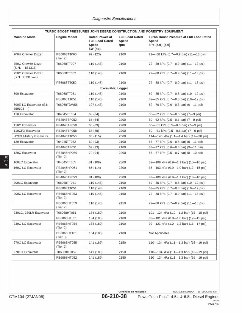
Diagnostic Specifications
06210
38
OUO1082,00002AA –19–26OCT05–5/9
TURBO BOOST PRESSURES JOHN DEERE CONSTRUCTION AND FORESTRY EQUIPMENT
Machine Model Engine Model Rated Power at Full Load Rated Turbo Boost Pressure at Full Load RatedFull Load Rated Speed SpeedSpeed rpm kPa (bar) (psi)kW (hp)
700H Crawler Dozer PE6068TT060 92 (123) 2100 72— 88 kPa (0.7—0.9 bar) (11—13 psi)(Tier 2)
750C Crawler Dozer T06068TT007 110 (148) 2100 72—88 kPa (0.7—0.9 bar) (11—13 psi)(S.N. —831315)
750C Crawler Dozer T06068TT052 110 (148) 2100 72—88 kPa (0.7—0.9 bar) (11—13 psi)(S.N. 831316— )
PE6068TT052 110 (148) 2100 72—88 kPa (0.7—0.9 bar) (11—13 psi)
Excavator, Logger
690 Excavator T06068TT051 110 (148) 2100 69—85 kPa (0.7—0.8 bar) (10—12 psi)
PE6068TT051 110 (148) 2100 69—85 kPa (0.7—0.8 bar) (10—12 psi)
690E LC Excavator (S.N. T06068TDW56 107 (143) 2100 62—76 kPa (0.6—0.8 bar) (9—11 psi)559603— )
110 Excavator T04045TT054 63 (84) 2200 50—62 kPa (0.5—0.6 bar) (7—9 psi)
PE4045TP052 63 (84) 2200 50—62 kPa (0.5—0.6 bar) (7—9 psi)
110C Excavator PE4045TP058 66 (89) 2200 50— 61 kPa (0.5—0.6 bar) (7—9 psi)
110CFX Excavator PE4045TP058 66 (89) 2200 50— 61 kPa (0.5—0.6 bar) (7—9 psi)
HYEX Military Excavator PE4045TT050 86 (115) 2500 114—140 kPa (1.1—1.4 bar) (17—20 psi)
120 Excavator T04045TT052 69 (93) 2100 63—77 kPa (0.6—0.8 bar) (9—11 psi)
PE4045TP051 69 (93) 2100 63—77 kPa (0.6—0.8 bar) (9—11 psi)
120C Excavator PE4045HP050 70 (94) 2200 55—67 kPa (0.5—0.7 bar) (8—10 psi)(Tier 2)
160LC Excavator T04045TT055 81 (109) 2300 89—109 kPa (0.9—1.1 bar) (13—16 psi)
160C LC Excavator PE4045HP051 85 (114) 2300 85—103 kPa (0.9—1.0 bar) (12—15 psi)(Tier 2)
PE4045TP053 81 (109) 2300 89—109 kPa (0.9—1.1 bar) (13—16 psi)
200LC Excavator T06068TT051 110 (148) 2100 69—85 kPa (0.7—0.8 bar) (10—12 psi)
PE6068TT051 110 (148) 2100 69—85 kPa (0.7—0.8 bar) (10—12 psi)
200C LC Excavator PE6068HT053 110 (148) 2150 72—88 kPa (0.7—0.9 bar) (11—13 psi)(Tier 2)
PE6068HT059 110 (148) 2150 72—88 kPa (0.7—0.9 bar) (11—13 psi)(Tier 2)
230LC, 230LR Excavator T06068HT051 134 (180) 2100 101—124 kPa (1.0—1.2 bar) (15—18 psi)
PE6068HT051 134 (180) 2100 83—101 kPa (0.8—1.0 bar) (12—15 psi)
230C LC Excavator PE6068HT054 134 (180) 2100 99—121 kPa (1.0—1.2 bar) (15—17 psi)(Tier 2)
PE6068HT161 134 (180) 2100 Not Applicable(Tier 3)
270C LC Excavator PE6068HT055 141 (189) 2150 110—134 kPa (1.1—1.3 bar) (16—19 psi)(Tier 2)
270LC Excavator T06068HT052 141 (189) 2150 110—134 kPa (1.1—1.3 bar) (16—19 psi)
PE6068HT052 141 (189) 2150 110—134 kPa (1.1—1.3 bar) (16—19 psi)
CTM104 (27JAN06) 06-210-38 PowerTech Plus 4.5L & 6.8L Diesel Engines013006
PN=702
Continued on next page
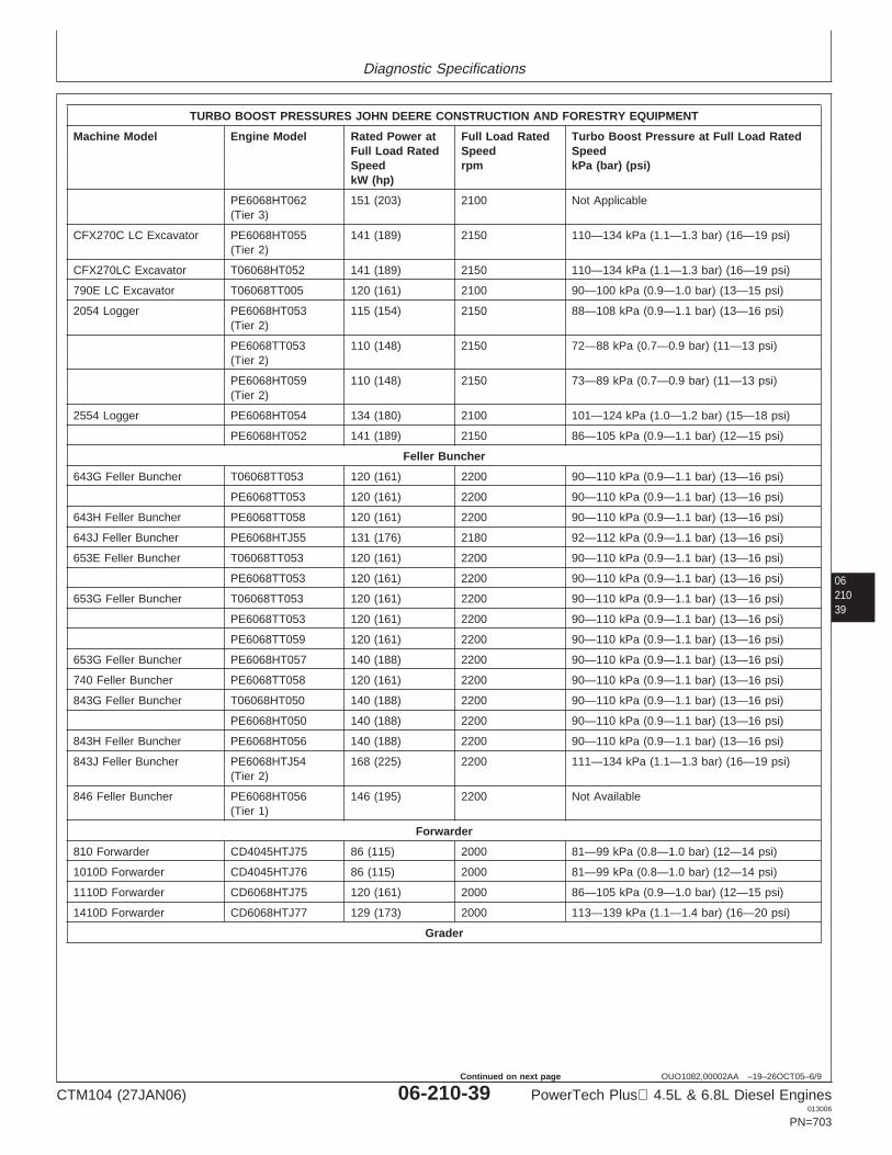
Diagnostic Specifications
0621039
OUO1082,00002AA –19–26OCT05–6/9
TURBO BOOST PRESSURES JOHN DEERE CONSTRUCTION AND FORESTRY EQUIPMENT
Machine Model Engine Model Rated Power at Full Load Rated Turbo Boost Pressure at Full Load RatedFull Load Rated Speed SpeedSpeed rpm kPa (bar) (psi)kW (hp)
PE6068HT062 151 (203) 2100 Not Applicable(Tier 3)
CFX270C LC Excavator PE6068HT055 141 (189) 2150 110—134 kPa (1.1—1.3 bar) (16—19 psi)(Tier 2)
CFX270LC Excavator T06068HT052 141 (189) 2150 110—134 kPa (1.1—1.3 bar) (16—19 psi)
790E LC Excavator T06068TT005 120 (161) 2100 90—100 kPa (0.9—1.0 bar) (13—15 psi)
2054 Logger PE6068HT053 115 (154) 2150 88—108 kPa (0.9—1.1 bar) (13—16 psi)(Tier 2)
PE6068TT053 110 (148) 2150 72—88 kPa (0.7—0.9 bar) (11—13 psi)(Tier 2)
PE6068HT059 110 (148) 2150 73—89 kPa (0.7—0.9 bar) (11—13 psi)(Tier 2)
2554 Logger PE6068HT054 134 (180) 2100 101—124 kPa (1.0—1.2 bar) (15—18 psi)
PE6068HT052 141 (189) 2150 86—105 kPa (0.9—1.1 bar) (12—15 psi)
Feller Buncher
643G Feller Buncher T06068TT053 120 (161) 2200 90—110 kPa (0.9—1.1 bar) (13—16 psi)
PE6068TT053 120 (161) 2200 90—110 kPa (0.9—1.1 bar) (13—16 psi)
643H Feller Buncher PE6068TT058 120 (161) 2200 90—110 kPa (0.9—1.1 bar) (13—16 psi)
643J Feller Buncher PE6068HTJ55 131 (176) 2180 92—112 kPa (0.9—1.1 bar) (13—16 psi)
653E Feller Buncher T06068TT053 120 (161) 2200 90—110 kPa (0.9—1.1 bar) (13—16 psi)
PE6068TT053 120 (161) 2200 90—110 kPa (0.9—1.1 bar) (13—16 psi)
653G Feller Buncher T06068TT053 120 (161) 2200 90—110 kPa (0.9—1.1 bar) (13—16 psi)
PE6068TT053 120 (161) 2200 90—110 kPa (0.9—1.1 bar) (13—16 psi)
PE6068TT059 120 (161) 2200 90—110 kPa (0.9—1.1 bar) (13—16 psi)
653G Feller Buncher PE6068HT057 140 (188) 2200 90—110 kPa (0.9—1.1 bar) (13—16 psi)
740 Feller Buncher PE6068TT058 120 (161) 2200 90—110 kPa (0.9—1.1 bar) (13—16 psi)
843G Feller Buncher T06068HT050 140 (188) 2200 90—110 kPa (0.9—1.1 bar) (13—16 psi)
PE6068HT050 140 (188) 2200 90—110 kPa (0.9—1.1 bar) (13—16 psi)
843H Feller Buncher PE6068HT056 140 (188) 2200 90—110 kPa (0.9—1.1 bar) (13—16 psi)
843J Feller Buncher PE6068HTJ54 168 (225) 2200 111—134 kPa (1.1—1.3 bar) (16—19 psi)(Tier 2)
846 Feller Buncher PE6068HT056 146 (195) 2200 Not Available(Tier 1)
Forwarder
810 Forwarder CD4045HTJ75 86 (115) 2000 81—99 kPa (0.8—1.0 bar) (12—14 psi)
1010D Forwarder CD4045HTJ76 86 (115) 2000 81—99 kPa (0.8—1.0 bar) (12—14 psi)
1110D Forwarder CD6068HTJ75 120 (161) 2000 86—105 kPa (0.9—1.0 bar) (12—15 psi)
1410D Forwarder CD6068HTJ77 129 (173) 2000 113—139 kPa (1.1—1.4 bar) (16—20 psi)
Grader
CTM104 (27JAN06) 06-210-39 PowerTech Plus 4.5L & 6.8L Diesel Engines013006
PN=703
Continued on next page
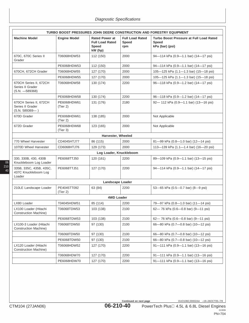
Diagnostic Specifications
06210
40
OUO1082,00002AA –19–26OCT05–7/9
TURBO BOOST PRESSURES JOHN DEERE CONSTRUCTION AND FORESTRY EQUIPMENT
Machine Model Engine Model Rated Power at Full Load Rated Turbo Boost Pressure at Full Load RatedFull Load Rated Speed SpeedSpeed rpm kPa (bar) (psi)kW (hp)
670C, 670C Series II T06068HDW53 112 (150) 2000 94—114 kPa (0.9—1.1 bar) (14—17 psi)Grader
PE6068HDW53 112 (150) 2000 94—114 kPa (0.9—1.1 bar) (14—17 psi)
670CH, 672CH Grader T06068HDW55 127 (170) 2000 105—125 kPa (1.1—1.3 bar) (15—18 psi)
PE6068HDW55 127 (170) 2000 105—125 kPa (1.1—1.3 bar) (15—18 psi)
670CH Series II, 672CH T06068HDW58 130 (174) 2200 96—118 kPa (0.9—1.2 bar) (14—17 psi)Series II Grader(S.N. —589368)
PE6068HDW58 130 (174) 2200 96—118 kPa (0.9—1.2 bar) (14—17 psi)
670CH Series II, 672CH PE6068HDW61 131 (176) 2180 92— 112 kPa (0.9—1.1 bar) (13—16 psi)Series II Grader (Tier 2)(S.N. 589369— )
670D Grader PE6068HDW61 138 (185) 2000 Not Applicable(Tier 2)
672D Grader PE6068HDW68 123 (165) 2000 Not Applicable(Tier 3)
Harvester, Wheeled
770 Wheel Harvester CD4045HTJ77 86 (115) 2000 81—99 kPa (0.8—1.0 bar) (12—14 psi)
1070D Wheel Harvester CD6068HTJ76 129 (173) 2000 113—139 kPa (1.1—1.4 bar) (16—20 psi)
Log Loader, Knuckleboom
330, 330B, 430, 430B PE6068TTJ50 120 (161) 2200 89—109 kPa (0.9—1.1 bar) (13—15 psi)Knuckleboom Log Loader
335B, 335C, 435B, 435C, PE6068TTJ51 127 (170) 2200 94—114 kPa (0.9—1.1 bar) (14—17 psi)437C Knuckleboom LogLoader
Landscape Loader
210LE Landscape Loader PE4045TT092 63 (84) 2200 53—65 kPa (0.5—0.7 bar) (8—9 psi)(Tier 2)
4WD Loader
LX80 Loader T04045HDW51 85 (114) 2200 79—97 kPa (0.8—1.0 bar) (11—14 psi)
LX100 Loader (Hitachi T06068TDW53 103 (138) 2100 62— 76 kPa (0.6—0.8 bar) (9—11 psi)Construction Machine)
PE6068TDW53 103 (138) 2100 62— 76 kPa (0.6—0.8 bar) (9—11 psi)
LX100-3 Loader (Hitachi T06068TDW50 97 (130) 2100 66—80 kPa (0.7—0.8 bar) (10—12 psi)Construction Machine)
T06068TDW50 97 (130) 2100 66—80 kPa (0.7—0.8 bar) (10—12 psi)
PE6068TDW50 97 (130) 2100 66—80 kPa (0.7—0.8 bar) (10—12 psi)
LX120 Loader (Hitachi T06068HDW52 127 (170) 2200 91—111 kPa (0.9—1.1 bar) (13—16 psi)Construction Machine)
T06068HDW70 127 (170) 2200 91—111 kPa (0.9—1.1 bar) (13—16 psi)
PE6068HDW70 127 (170) 2200 91—111 kPa (0.9—1.1 bar) (13—16 psi)
CTM104 (27JAN06) 06-210-40 PowerTech Plus 4.5L & 6.8L Diesel Engines013006
PN=704
Continued on next page
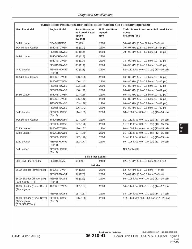
Diagnostic Specifications
0621041
OUO1082,00002AA –19–26OCT05–8/9
TURBO BOOST PRESSURES JOHN DEERE CONSTRUCTION AND FORESTRY EQUIPMENT
Machine Model Engine Model Rated Power at Full Load Rated Turbo Boost Pressure at Full Load RatedFull Load Rated Speed SpeedSpeed rpm kPa (bar) (psi)kW (hp)
344H Loader CD4045TF152 73 (99) 2200 50—62 kPa (0.5—.62 bar) (7—9 psi)
TC44H Tool Carrier T04045TDW50 85 (114) 2200 79—97 kPa (0.8—1.0 bar) (11—14 psi)
PE4045TDW50 85 (114) 2200 79—97 kPa (0.8—1.0 bar) (11—14 psi)
444H Loader T04045HDW50 88 (118) 2200
T04045TDW50 85 (114) 2200 74—90 kPa (0.7—0.9 bar) (10—13 psi)
PE4045TDW50 85 (114) 2200 74—90 kPa (0.7—0.9 bar) (10—13 psi)
444J Loader PE4045HDW52 90 (121) 2200 92—112 kPa (0.9—1.1 bar) (13—16 psi)(Tier 2)
TC54H Tool Carrier T06068TDW50 103 (138) 2200 66—80 kPa (0.7—0.8 bar) (10—12 psi)
T06068TDW50 106 (142 2200 66—80 kPa (0.7—0.8 bar) (10—12 psi)
PE6068TDW50 103 (138) 2200 66—80 kPa (0.7—0.8 bar) (10—12 psi)
PE6068TDW50 106 (142) 2200 66—80 kPa (0.7—0.8 bar) (10—12 psi)
544H Loader T06068TDW50 103 (138) 2200 66—80 kPa (0.7—0.8 bar) (10—12 psi)
T06068TDW50 106 (142) 2200 66—80 kPa (0.7—0.8 bar) (10—12 psi)
PE6068TDW50 103 (138) 2200 66—80 kPa (0.7—0.8 bar) (10—12 psi)
PE6068TDW50 106 (142) 2200 66—80 kPa (0.7—0.8 bar) (10—12 psi)
544J Loader PE6068HDW56 114 (153) 2200 88—108 kPa (0.9—1.1 bar) (13—16 psi)(Tier 2)
TC62H Tool Carrier T06068HDW50 127 (170) 2200 91—111 kPa (0.9—1.1 bar) (13—15 psi)
PE6068HDW50 127 (170) 2200 91—111 kPa (0.9—1.1 bar) (13—15 psi)
624G Loader T06068TDW10 120 (161) 2200 90—100 kPa (0.9—1.0 bar) (13—15 psi)
624H Loader T06068HDW50 127 (170) 2200 91—111 kPa (0.9—1.1 bar) (13—15 psi)
PE6068HDW50 127 (170) 2200 91—111 kPa (0.9—1.1 bar) (13—15 psi)
624J Loader PE6068HDW57 132 (177) 2200 86—105 kPa (0.9—1.0 bar) (12—15 psi)(Tier 2)
644 Loader PE6068HDW69 Not Applicable(Tier 3)
Skid Steer Loader
280 Skid Steer Loader PE4045TKV50 66 (89) 2400 62—76 kPa (0.6—0.8 bar) (9—11 psi)
Skidder
360D Skidder (Timberjack) T06068TDW54 94 (126) 2200 52—64 kPa (0.5—0.6 bar) (7—9 psi)
PE6068TDW54 94 (126) 2200 52—64 kPa (0.5—0.6 bar) (7—9 psi)
360D Skidder (Timberjack) PE6068TDW58 96 (129) 2200 86—105 kPa (0.9—1.0 bar) (12—15 psi)(S.N. 589337— ) (Tier 2)
460D Skidder (Direct Drive) T06068TDW55 117 (157) 2200 94—114 kPa (0.9—1.1 bar) (14—17 psi)(Timberjack)
PE6068TDW55 117 (157) 2200 94—114 kPa (0.9—1.1 bar) (14—17 psi)
460D Skidder (Direct Drive) PE6068HDW60 125 (168) 2200 114—140 kPa (1.1—1.4 bar) (17—20 psi)(Timberjack) (Tier 2)(S.N. 589337— )
CTM104 (27JAN06) 06-210-41 PowerTech Plus 4.5L & 6.8L Diesel Engines013006
PN=705
Continued on next page
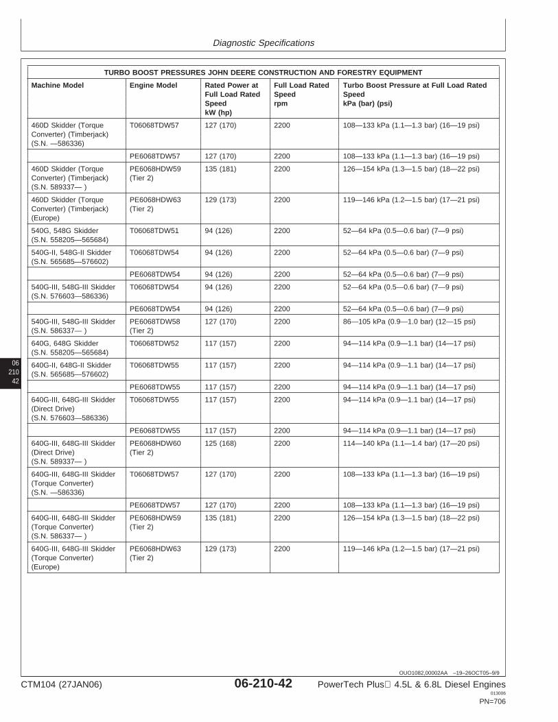
Diagnostic Specifications
06210
42
OUO1082,00002AA –19–26OCT05–9/9
TURBO BOOST PRESSURES JOHN DEERE CONSTRUCTION AND FORESTRY EQUIPMENT
Machine Model Engine Model Rated Power at Full Load Rated Turbo Boost Pressure at Full Load RatedFull Load Rated Speed SpeedSpeed rpm kPa (bar) (psi)kW (hp)
460D Skidder (Torque T06068TDW57 127 (170) 2200 108—133 kPa (1.1—1.3 bar) (16—19 psi)Converter) (Timberjack)(S.N. —586336)
PE6068TDW57 127 (170) 2200 108—133 kPa (1.1—1.3 bar) (16—19 psi)
460D Skidder (Torque PE6068HDW59 135 (181) 2200 126—154 kPa (1.3—1.5 bar) (18—22 psi)Converter) (Timberjack) (Tier 2)(S.N. 589337— )
460D Skidder (Torque PE6068HDW63 129 (173) 2200 119—146 kPa (1.2—1.5 bar) (17—21 psi)Converter) (Timberjack) (Tier 2)(Europe)
540G, 548G Skidder T06068TDW51 94 (126) 2200 52—64 kPa (0.5—0.6 bar) (7—9 psi)(S.N. 558205—565684)
540G-II, 548G-II Skidder T06068TDW54 94 (126) 2200 52—64 kPa (0.5—0.6 bar) (7—9 psi)(S.N. 565685—576602)
PE6068TDW54 94 (126) 2200 52—64 kPa (0.5—0.6 bar) (7—9 psi)
540G-III, 548G-III Skidder T06068TDW54 94 (126) 2200 52—64 kPa (0.5—0.6 bar) (7—9 psi)(S.N. 576603—586336)
PE6068TDW54 94 (126) 2200 52—64 kPa (0.5—0.6 bar) (7—9 psi)
540G-III, 548G-III Skidder PE6068TDW58 127 (170) 2200 86—105 kPa (0.9—1.0 bar) (12—15 psi)(S.N. 586337— ) (Tier 2)
640G, 648G Skidder T06068TDW52 117 (157) 2200 94—114 kPa (0.9—1.1 bar) (14—17 psi)(S.N. 558205—565684)
640G-II, 648G-II Skidder T06068TDW55 117 (157) 2200 94—114 kPa (0.9—1.1 bar) (14—17 psi)(S.N. 565685—576602)
PE6068TDW55 117 (157) 2200 94—114 kPa (0.9—1.1 bar) (14—17 psi)
640G-III, 648G-III Skidder T06068TDW55 117 (157) 2200 94—114 kPa (0.9—1.1 bar) (14—17 psi)(Direct Drive)(S.N. 576603—586336)
PE6068TDW55 117 (157) 2200 94—114 kPa (0.9—1.1 bar) (14—17 psi)
640G-III, 648G-III Skidder PE6068HDW60 125 (168) 2200 114—140 kPa (1.1—1.4 bar) (17—20 psi)(Direct Drive) (Tier 2)(S.N. 589337— )
640G-III, 648G-III Skidder T06068TDW57 127 (170) 2200 108—133 kPa (1.1—1.3 bar) (16—19 psi)(Torque Converter)(S.N. —586336)
PE6068TDW57 127 (170) 2200 108—133 kPa (1.1—1.3 bar) (16—19 psi)
640G-III, 648G-III Skidder PE6068HDW59 135 (181) 2200 126—154 kPa (1.3—1.5 bar) (18—22 psi)(Torque Converter) (Tier 2)(S.N. 586337— )
640G-III, 648G-III Skidder PE6068HDW63 129 (173) 2200 119—146 kPa (1.2—1.5 bar) (17—21 psi)(Torque Converter) (Tier 2)(Europe)
CTM104 (27JAN06) 06-210-42 PowerTech Plus 4.5L & 6.8L Diesel Engines013006
PN=706
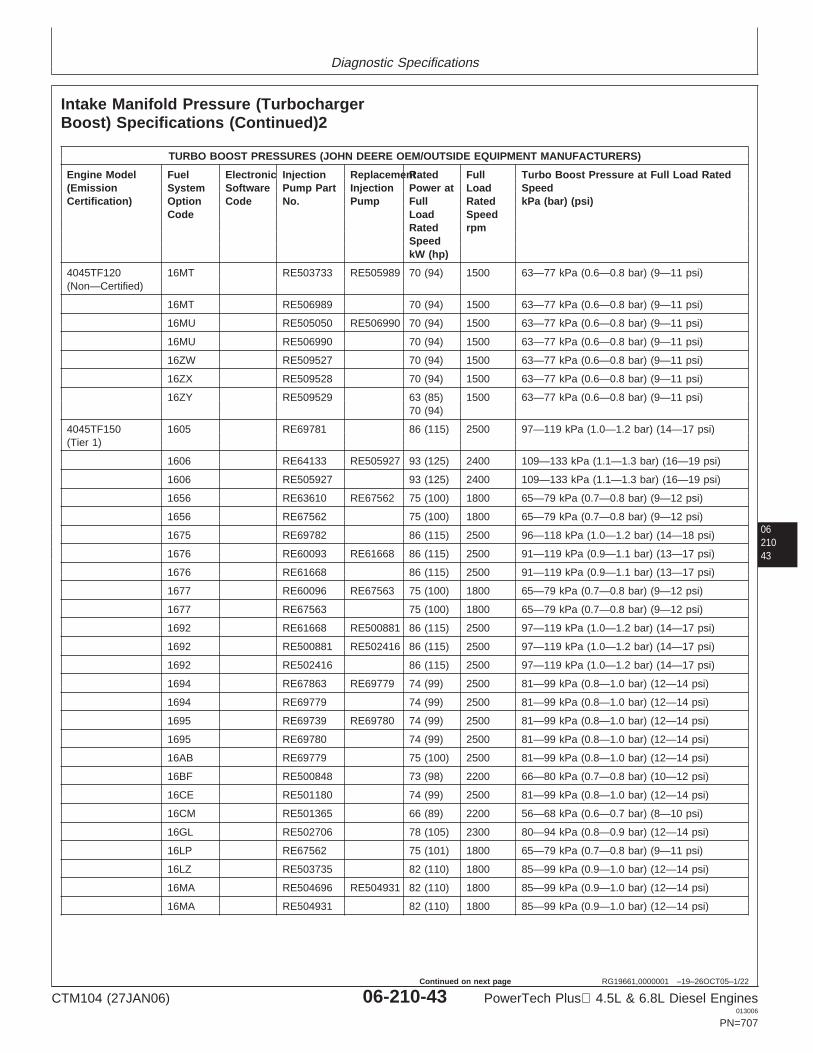
Diagnostic Specifications
0621043
RG19661,0000001 –19–26OCT05–1/22
Intake Manifold Pressure (TurbochargerBoost) Specifications (Continued)2
TURBO BOOST PRESSURES (JOHN DEERE OEM/OUTSIDE EQUIPMENT MANUFACTURERS)
Engine Model Fuel Electronic Injection ReplacementRated Full Turbo Boost Pressure at Full Load Rated(Emission System Software Pump Part Injection Power at Load SpeedCertification) Option Code No. Pump Full Rated kPa (bar) (psi)
Code Load SpeedRated rpmSpeedkW (hp)
4045TF120 16MT RE503733 RE505989 70 (94) 1500 63—77 kPa (0.6—0.8 bar) (9—11 psi)(Non—Certified)
16MT RE506989 70 (94) 1500 63—77 kPa (0.6—0.8 bar) (9—11 psi)
16MU RE505050 RE506990 70 (94) 1500 63—77 kPa (0.6—0.8 bar) (9—11 psi)
16MU RE506990 70 (94) 1500 63—77 kPa (0.6—0.8 bar) (9—11 psi)
16ZW RE509527 70 (94) 1500 63—77 kPa (0.6—0.8 bar) (9—11 psi)
16ZX RE509528 70 (94) 1500 63—77 kPa (0.6—0.8 bar) (9—11 psi)
16ZY RE509529 63 (85) 1500 63—77 kPa (0.6—0.8 bar) (9—11 psi)70 (94)
4045TF150 1605 RE69781 86 (115) 2500 97—119 kPa (1.0—1.2 bar) (14—17 psi)(Tier 1)
1606 RE64133 RE505927 93 (125) 2400 109—133 kPa (1.1—1.3 bar) (16—19 psi)
1606 RE505927 93 (125) 2400 109—133 kPa (1.1—1.3 bar) (16—19 psi)
1656 RE63610 RE67562 75 (100) 1800 65—79 kPa (0.7—0.8 bar) (9—12 psi)
1656 RE67562 75 (100) 1800 65—79 kPa (0.7—0.8 bar) (9—12 psi)
1675 RE69782 86 (115) 2500 96—118 kPa (1.0—1.2 bar) (14—18 psi)
1676 RE60093 RE61668 86 (115) 2500 91—119 kPa (0.9—1.1 bar) (13—17 psi)
1676 RE61668 86 (115) 2500 91—119 kPa (0.9—1.1 bar) (13—17 psi)
1677 RE60096 RE67563 75 (100) 1800 65—79 kPa (0.7—0.8 bar) (9—12 psi)
1677 RE67563 75 (100) 1800 65—79 kPa (0.7—0.8 bar) (9—12 psi)
1692 RE61668 RE500881 86 (115) 2500 97—119 kPa (1.0—1.2 bar) (14—17 psi)
1692 RE500881 RE502416 86 (115) 2500 97—119 kPa (1.0—1.2 bar) (14—17 psi)
1692 RE502416 86 (115) 2500 97—119 kPa (1.0—1.2 bar) (14—17 psi)
1694 RE67863 RE69779 74 (99) 2500 81—99 kPa (0.8—1.0 bar) (12—14 psi)
1694 RE69779 74 (99) 2500 81—99 kPa (0.8—1.0 bar) (12—14 psi)
1695 RE69739 RE69780 74 (99) 2500 81—99 kPa (0.8—1.0 bar) (12—14 psi)
1695 RE69780 74 (99) 2500 81—99 kPa (0.8—1.0 bar) (12—14 psi)
16AB RE69779 75 (100) 2500 81—99 kPa (0.8—1.0 bar) (12—14 psi)
16BF RE500848 73 (98) 2200 66—80 kPa (0.7—0.8 bar) (10—12 psi)
16CE RE501180 74 (99) 2500 81—99 kPa (0.8—1.0 bar) (12—14 psi)
16CM RE501365 66 (89) 2200 56—68 kPa (0.6—0.7 bar) (8—10 psi)
16GL RE502706 78 (105) 2300 80—94 kPa (0.8—0.9 bar) (12—14 psi)
16LP RE67562 75 (101) 1800 65—79 kPa (0.7—0.8 bar) (9—11 psi)
16LZ RE503735 82 (110) 1800 85—99 kPa (0.9—1.0 bar) (12—14 psi)
16MA RE504696 RE504931 82 (110) 1800 85—99 kPa (0.9—1.0 bar) (12—14 psi)
16MA RE504931 82 (110) 1800 85—99 kPa (0.9—1.0 bar) (12—14 psi)
CTM104 (27JAN06) 06-210-43 PowerTech Plus 4.5L & 6.8L Diesel Engines013006
PN=707
Continued on next page
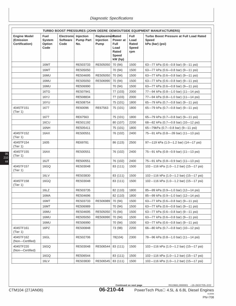
Diagnostic Specifications
06210
44
RG19661,0000001 –19–26OCT05–2/22
TURBO BOOST PRESSURES (JOHN DEERE OEM/OUTSIDE EQUIPMENT MANUFACTURERS)
Engine Model Fuel Electronic Injection ReplacementRated Full Turbo Boost Pressure at Full Load Rated(Emission System Software Pump Part Injection Power at Load SpeedCertification) Option Code No. Pump Full Rated kPa (bar) (psi)
Code Load SpeedRated rpmSpeedkW (hp)
16MT RE503733 RE505050 70 (94) 1500 63—77 kPa (0.6—0.8 bar) (9—11 psi)
16MT RE505050 70 (94) 1500 63—77 kPa (0.6—0.8 bar) (9—11 psi)
16MU RE504695 RE505050 70 (94) 1500 63—77 kPa (0.6—0.8 bar) (9—11 psi)
16MU RE505050 RE506990 70 (94) 1500 63—77 kPa (0.6—0.8 bar) (9—11 psi)
16MU RE506990 70 (94) 1500 63—77 kPa (0.6—0.8 bar) (9—11 psi)
16TG RE507941 77 (103) 2000 77—94 kPa (0.8—1.0 bar) (11—14 psi)
16YJ RE508834 77 (103) 2000 77—94 kPa (0.8—1.0 bar) (11—14 psi)
16YU RE508754 75 (101) 1800 65—79 kPa (0.7—0.8 bar) (9—11 psi)
4045TF151 1677 RE60096 RE67563 75 (101) 1800 65—79 kPa (0.7—0.8 bar) (9—11 psi)(Tier 1)
1677 RE67563 75 (101) 1800 65—79 kPa (0.7—0.8 bar) (9—11 psi)
16CU RE501192 80 (107) 2200 68—82 kPa (0.7—0.8 bar) (10—12 psi)
16NH RE505411 75 (101) 1800 65—79kPa (0.7—0.8 bar) (9—11 psi)
4045TF152 16AX RE500551 76 (102) 2400 75—91 kPa (0.8—.09 bar) (11—13 psi)(Tier 1)
4045TF154 1605 RE69781 86 (115) 2500 97—119 kPa (1.0—1.2 bar) (14—17 psi)(Tier 1)
4045TF155 16AX RE500551 76 (102) 2400 75—91 kPa (0.8—0.9 bar) (11—13 psi)(Tier 1)
16JT RE500551 76 (102) 2400 75—91 kPa (0.8—0.9 bar) (11—13 psi)
4045TF157 16GQ RE503048 83 (111) 1500 102—116 kPa (1.0—1.2 bar) (15—17 psi)(Tier 1)
16LV RE503830 83 (111) 1500 102—116 kPa (1.0—1.2 bar) (15—17 psi)
4045TF158 16GQ RE503048 83 (111) 1500 102—116 kPa (1.0—1.2 bar) (15—17 psi)(Tier 1)
16LZ RE503735 82 (110) 1800 85—99 kPa (0.9—1.0 bar) (12—14 psi)
16MA RE504696 82 (110) 1800 85—99 kPa (0.9—1.0 bar) (12—14 psi)
16MT RE503733 RE506989 70 (94) 1500 63—77 kPa (0.6—0.8 bar) (9—11 psi)
16MT RE506989 70 (94) 1500 63—77 kPa (0.6—0.8 bar) (9—11 psi)
16MU RE504695 RE505050 70 (94) 1500 63—77 kPa (0.6—0.8 bar) (9—11 psi)
16MU RE505050 RE506990 70 (94) 1500 63—77 kPa (0.6—0.8 bar) (9—11 psi)
16MU RE506990 70 (94) 1500 63—77 kPa (0.6—0.8 bar) (9—11 psi)
4045TF161 16PZ RE500848 73 (98) 2200 66—80 kPa (0.7—0.8 bar) (10—12 psi)(Tier 1)
4045TF162 16GL RE502706 78(104) 2300 78—96 kPa (0.8—1.0 bar) (11—14 psi)(Non—Certified)
4045TF220 16GQ RE503048 RE506544 83 (111) 1500 102—116 kPa (1.0—1.2 bar) (15—17 psi)(Non—Certified)
16GQ RE506544 83 (111) 1500 102—116 kPa (1.0—1.2 bar) (15—17 psi)
16LV RE503830 RE506545 83 (111) 1500 102—116 kPa (1.0—1.2 bar) (15—17 psi)
CTM104 (27JAN06) 06-210-44 PowerTech Plus 4.5L & 6.8L Diesel Engines013006
PN=708
Continued on next page
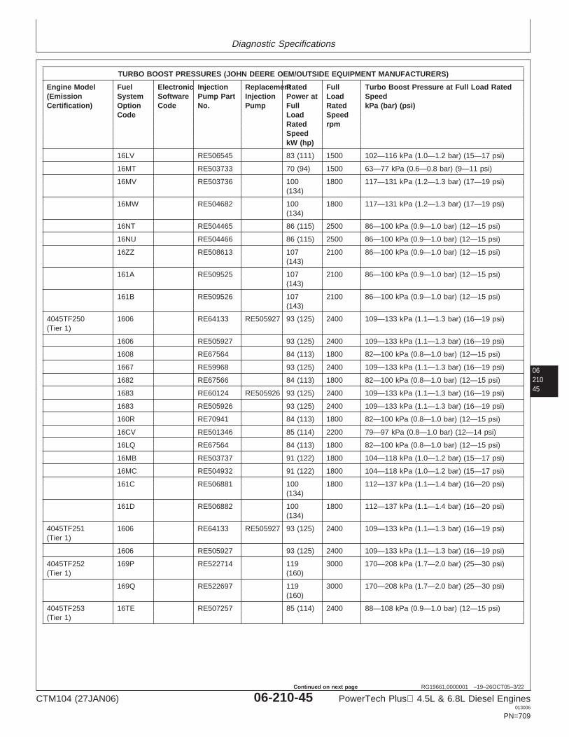
Diagnostic Specifications
0621045
RG19661,0000001 –19–26OCT05–3/22
TURBO BOOST PRESSURES (JOHN DEERE OEM/OUTSIDE EQUIPMENT MANUFACTURERS)
Engine Model Fuel Electronic Injection ReplacementRated Full Turbo Boost Pressure at Full Load Rated(Emission System Software Pump Part Injection Power at Load SpeedCertification) Option Code No. Pump Full Rated kPa (bar) (psi)
Code Load SpeedRated rpmSpeedkW (hp)
16LV RE506545 83 (111) 1500 102—116 kPa (1.0—1.2 bar) (15—17 psi)
16MT RE503733 70 (94) 1500 63—77 kPa (0.6—0.8 bar) (9—11 psi)
16MV RE503736 100 1800 117—131 kPa (1.2—1.3 bar) (17—19 psi)(134)
16MW RE504682 100 1800 117—131 kPa (1.2—1.3 bar) (17—19 psi)(134)
16NT RE504465 86 (115) 2500 86—100 kPa (0.9—1.0 bar) (12—15 psi)
16NU RE504466 86 (115) 2500 86—100 kPa (0.9—1.0 bar) (12—15 psi)
16ZZ RE508613 107 2100 86—100 kPa (0.9—1.0 bar) (12—15 psi)(143)
161A RE509525 107 2100 86—100 kPa (0.9—1.0 bar) (12—15 psi)(143)
161B RE509526 107 2100 86—100 kPa (0.9—1.0 bar) (12—15 psi)(143)
4045TF250 1606 RE64133 RE505927 93 (125) 2400 109—133 kPa (1.1—1.3 bar) (16—19 psi)(Tier 1)
1606 RE505927 93 (125) 2400 109—133 kPa (1.1—1.3 bar) (16—19 psi)
1608 RE67564 84 (113) 1800 82—100 kPa (0.8—1.0 bar) (12—15 psi)
1667 RE59968 93 (125) 2400 109—133 kPa (1.1—1.3 bar) (16—19 psi)
1682 RE67566 84 (113) 1800 82—100 kPa (0.8—1.0 bar) (12—15 psi)
1683 RE60124 RE505926 93 (125) 2400 109—133 kPa (1.1—1.3 bar) (16—19 psi)
1683 RE505926 93 (125) 2400 109—133 kPa (1.1—1.3 bar) (16—19 psi)
160R RE70941 84 (113) 1800 82—100 kPa (0.8—1.0 bar) (12—15 psi)
16CV RE501346 85 (114) 2200 79—97 kPa (0.8—1.0 bar) (12—14 psi)
16LQ RE67564 84 (113) 1800 82—100 kPa (0.8—1.0 bar) (12—15 psi)
16MB RE503737 91 (122) 1800 104—118 kPa (1.0—1.2 bar) (15—17 psi)
16MC RE504932 91 (122) 1800 104—118 kPa (1.0—1.2 bar) (15—17 psi)
161C RE506881 100 1800 112—137 kPa (1.1—1.4 bar) (16—20 psi)(134)
161D RE506882 100 1800 112—137 kPa (1.1—1.4 bar) (16—20 psi)(134)
4045TF251 1606 RE64133 RE505927 93 (125) 2400 109—133 kPa (1.1—1.3 bar) (16—19 psi)(Tier 1)
1606 RE505927 93 (125) 2400 109—133 kPa (1.1—1.3 bar) (16—19 psi)
4045TF252 169P RE522714 119 3000 170—208 kPa (1.7—2.0 bar) (25—30 psi)(Tier 1) (160)
169Q RE522697 119 3000 170—208 kPa (1.7—2.0 bar) (25—30 psi)(160)
4045TF253 16TE RE507257 85 (114) 2400 88—108 kPa (0.9—1.0 bar) (12—15 psi)(Tier 1)
CTM104 (27JAN06) 06-210-45 PowerTech Plus 4.5L & 6.8L Diesel Engines013006
PN=709
Continued on next page
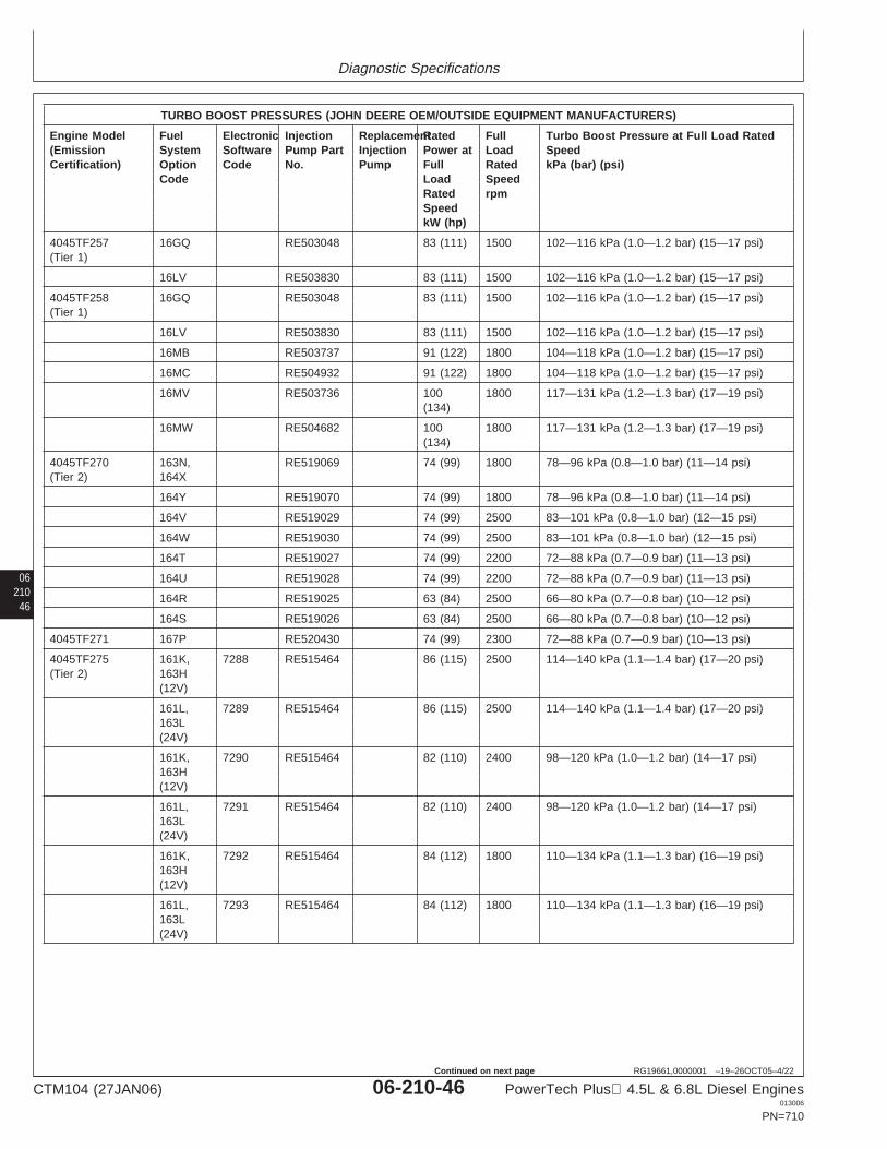
Diagnostic Specifications
06210
46
RG19661,0000001 –19–26OCT05–4/22
TURBO BOOST PRESSURES (JOHN DEERE OEM/OUTSIDE EQUIPMENT MANUFACTURERS)
Engine Model Fuel Electronic Injection ReplacementRated Full Turbo Boost Pressure at Full Load Rated(Emission System Software Pump Part Injection Power at Load SpeedCertification) Option Code No. Pump Full Rated kPa (bar) (psi)
Code Load SpeedRated rpmSpeedkW (hp)
4045TF257 16GQ RE503048 83 (111) 1500 102—116 kPa (1.0—1.2 bar) (15—17 psi)(Tier 1)
16LV RE503830 83 (111) 1500 102—116 kPa (1.0—1.2 bar) (15—17 psi)
4045TF258 16GQ RE503048 83 (111) 1500 102—116 kPa (1.0—1.2 bar) (15—17 psi)(Tier 1)
16LV RE503830 83 (111) 1500 102—116 kPa (1.0—1.2 bar) (15—17 psi)
16MB RE503737 91 (122) 1800 104—118 kPa (1.0—1.2 bar) (15—17 psi)
16MC RE504932 91 (122) 1800 104—118 kPa (1.0—1.2 bar) (15—17 psi)
16MV RE503736 100 1800 117—131 kPa (1.2—1.3 bar) (17—19 psi)(134)
16MW RE504682 100 1800 117—131 kPa (1.2—1.3 bar) (17—19 psi)(134)
4045TF270 163N, RE519069 74 (99) 1800 78—96 kPa (0.8—1.0 bar) (11—14 psi)(Tier 2) 164X
164Y RE519070 74 (99) 1800 78—96 kPa (0.8—1.0 bar) (11—14 psi)
164V RE519029 74 (99) 2500 83—101 kPa (0.8—1.0 bar) (12—15 psi)
164W RE519030 74 (99) 2500 83—101 kPa (0.8—1.0 bar) (12—15 psi)
164T RE519027 74 (99) 2200 72—88 kPa (0.7—0.9 bar) (11—13 psi)
164U RE519028 74 (99) 2200 72—88 kPa (0.7—0.9 bar) (11—13 psi)
164R RE519025 63 (84) 2500 66—80 kPa (0.7—0.8 bar) (10—12 psi)
164S RE519026 63 (84) 2500 66—80 kPa (0.7—0.8 bar) (10—12 psi)
4045TF271 167P RE520430 74 (99) 2300 72—88 kPa (0.7—0.9 bar) (10—13 psi)
4045TF275 161K, 7288 RE515464 86 (115) 2500 114—140 kPa (1.1—1.4 bar) (17—20 psi)(Tier 2) 163H
(12V)
161L, 7289 RE515464 86 (115) 2500 114—140 kPa (1.1—1.4 bar) (17—20 psi)163L(24V)
161K, 7290 RE515464 82 (110) 2400 98—120 kPa (1.0—1.2 bar) (14—17 psi)163H(12V)
161L, 7291 RE515464 82 (110) 2400 98—120 kPa (1.0—1.2 bar) (14—17 psi)163L(24V)
161K, 7292 RE515464 84 (112) 1800 110—134 kPa (1.1—1.3 bar) (16—19 psi)163H(12V)
161L, 7293 RE515464 84 (112) 1800 110—134 kPa (1.1—1.3 bar) (16—19 psi)163L(24V)
CTM104 (27JAN06) 06-210-46 PowerTech Plus 4.5L & 6.8L Diesel Engines013006
PN=710
Continued on next page
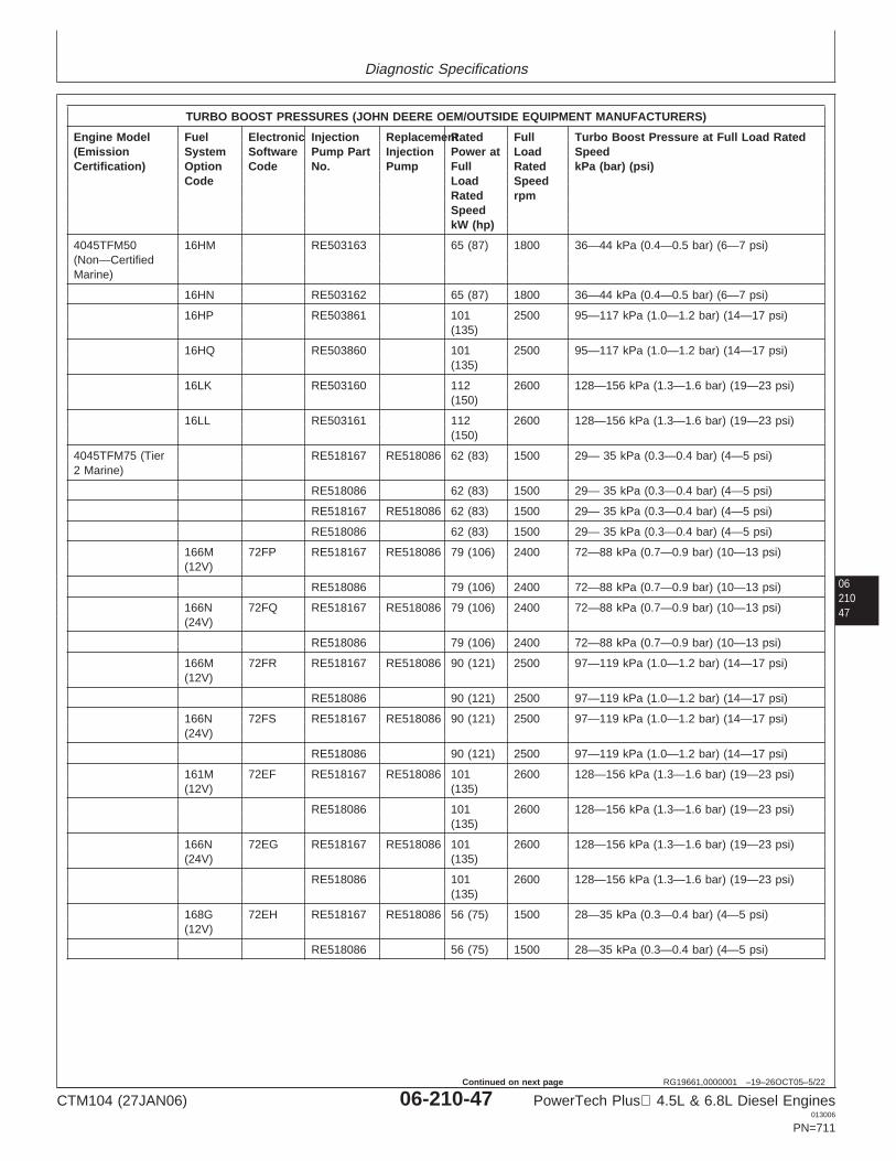
Diagnostic Specifications
0621047
RG19661,0000001 –19–26OCT05–5/22
TURBO BOOST PRESSURES (JOHN DEERE OEM/OUTSIDE EQUIPMENT MANUFACTURERS)
Engine Model Fuel Electronic Injection ReplacementRated Full Turbo Boost Pressure at Full Load Rated(Emission System Software Pump Part Injection Power at Load SpeedCertification) Option Code No. Pump Full Rated kPa (bar) (psi)
Code Load SpeedRated rpmSpeedkW (hp)
4045TFM50 16HM RE503163 65 (87) 1800 36—44 kPa (0.4—0.5 bar) (6—7 psi)(Non—CertifiedMarine)
16HN RE503162 65 (87) 1800 36—44 kPa (0.4—0.5 bar) (6—7 psi)
16HP RE503861 101 2500 95—117 kPa (1.0—1.2 bar) (14—17 psi)(135)
16HQ RE503860 101 2500 95—117 kPa (1.0—1.2 bar) (14—17 psi)(135)
16LK RE503160 112 2600 128—156 kPa (1.3—1.6 bar) (19—23 psi)(150)
16LL RE503161 112 2600 128—156 kPa (1.3—1.6 bar) (19—23 psi)(150)
4045TFM75 (Tier RE518167 RE518086 62 (83) 1500 29— 35 kPa (0.3—0.4 bar) (4—5 psi)2 Marine)
RE518086 62 (83) 1500 29— 35 kPa (0.3—0.4 bar) (4—5 psi)
RE518167 RE518086 62 (83) 1500 29— 35 kPa (0.3—0.4 bar) (4—5 psi)
RE518086 62 (83) 1500 29— 35 kPa (0.3—0.4 bar) (4—5 psi)
166M 72FP RE518167 RE518086 79 (106) 2400 72—88 kPa (0.7—0.9 bar) (10—13 psi)(12V)
RE518086 79 (106) 2400 72—88 kPa (0.7—0.9 bar) (10—13 psi)
166N 72FQ RE518167 RE518086 79 (106) 2400 72—88 kPa (0.7—0.9 bar) (10—13 psi)(24V)
RE518086 79 (106) 2400 72—88 kPa (0.7—0.9 bar) (10—13 psi)
166M 72FR RE518167 RE518086 90 (121) 2500 97—119 kPa (1.0—1.2 bar) (14—17 psi)(12V)
RE518086 90 (121) 2500 97—119 kPa (1.0—1.2 bar) (14—17 psi)
166N 72FS RE518167 RE518086 90 (121) 2500 97—119 kPa (1.0—1.2 bar) (14—17 psi)(24V)
RE518086 90 (121) 2500 97—119 kPa (1.0—1.2 bar) (14—17 psi)
161M 72EF RE518167 RE518086 101 2600 128—156 kPa (1.3—1.6 bar) (19—23 psi)(12V) (135)
RE518086 101 2600 128—156 kPa (1.3—1.6 bar) (19—23 psi)(135)
166N 72EG RE518167 RE518086 101 2600 128—156 kPa (1.3—1.6 bar) (19—23 psi)(24V) (135)
RE518086 101 2600 128—156 kPa (1.3—1.6 bar) (19—23 psi)(135)
168G 72EH RE518167 RE518086 56 (75) 1500 28—35 kPa (0.3—0.4 bar) (4—5 psi)(12V)
RE518086 56 (75) 1500 28—35 kPa (0.3—0.4 bar) (4—5 psi)
CTM104 (27JAN06) 06-210-47 PowerTech Plus 4.5L & 6.8L Diesel Engines013006
PN=711
Continued on next page
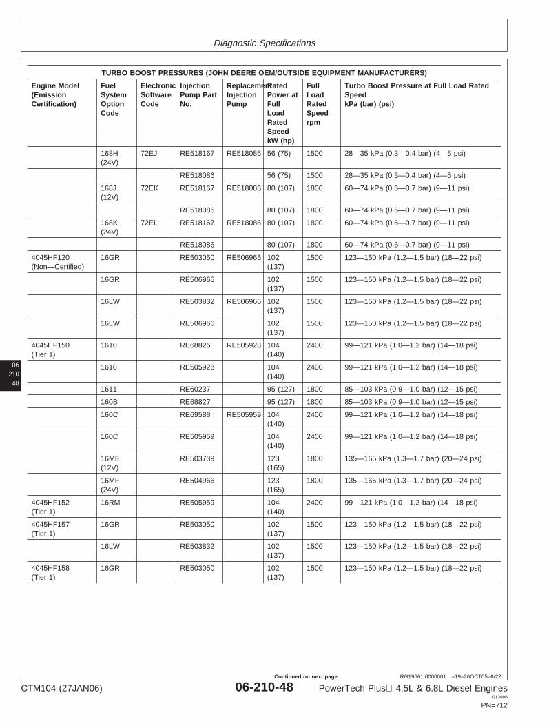
Diagnostic Specifications
06210
48
RG19661,0000001 –19–26OCT05–6/22
TURBO BOOST PRESSURES (JOHN DEERE OEM/OUTSIDE EQUIPMENT MANUFACTURERS)
Engine Model Fuel Electronic Injection ReplacementRated Full Turbo Boost Pressure at Full Load Rated(Emission System Software Pump Part Injection Power at Load SpeedCertification) Option Code No. Pump Full Rated kPa (bar) (psi)
Code Load SpeedRated rpmSpeedkW (hp)
168H 72EJ RE518167 RE518086 56 (75) 1500 28—35 kPa (0.3—0.4 bar) (4—5 psi)(24V)
RE518086 56 (75) 1500 28—35 kPa (0.3—0.4 bar) (4—5 psi)
168J 72EK RE518167 RE518086 80 (107) 1800 60—74 kPa (0.6—0.7 bar) (9—11 psi)(12V)
RE518086 80 (107) 1800 60—74 kPa (0.6—0.7 bar) (9—11 psi)
168K 72EL RE518167 RE518086 80 (107) 1800 60—74 kPa (0.6—0.7 bar) (9—11 psi)(24V)
RE518086 80 (107) 1800 60—74 kPa (0.6—0.7 bar) (9—11 psi)
4045HF120 16GR RE503050 RE506965 102 1500 123—150 kPa (1.2—1.5 bar) (18—22 psi)(Non—Certified) (137)
16GR RE506965 102 1500 123—150 kPa (1.2—1.5 bar) (18—22 psi)(137)
16LW RE503832 RE506966 102 1500 123—150 kPa (1.2—1.5 bar) (18—22 psi)(137)
16LW RE506966 102 1500 123—150 kPa (1.2—1.5 bar) (18—22 psi)(137)
4045HF150 1610 RE68826 RE505928 104 2400 99—121 kPa (1.0—1.2 bar) (14—18 psi)(Tier 1) (140)
1610 RE505928 104 2400 99—121 kPa (1.0—1.2 bar) (14—18 psi)(140)
1611 RE60237 95 (127) 1800 85—103 kPa (0.9—1.0 bar) (12—15 psi)
160B RE68827 95 (127) 1800 85—103 kPa (0.9—1.0 bar) (12—15 psi)
160C RE69588 RE505959 104 2400 99—121 kPa (1.0—1.2 bar) (14—18 psi)(140)
160C RE505959 104 2400 99—121 kPa (1.0—1.2 bar) (14—18 psi)(140)
16ME RE503739 123 1800 135—165 kPa (1.3—1.7 bar) (20—24 psi)(12V) (165)
16MF RE504966 123 1800 135—165 kPa (1.3—1.7 bar) (20—24 psi)(24V) (165)
4045HF152 16RM RE505959 104 2400 99—121 kPa (1.0—1.2 bar) (14—18 psi)(Tier 1) (140)
4045HF157 16GR RE503050 102 1500 123—150 kPa (1.2—1.5 bar) (18—22 psi)(Tier 1) (137)
16LW RE503832 102 1500 123—150 kPa (1.2—1.5 bar) (18—22 psi)(137)
4045HF158 16GR RE503050 102 1500 123—150 kPa (1.2—1.5 bar) (18—22 psi)(Tier 1) (137)
CTM104 (27JAN06) 06-210-48 PowerTech Plus 4.5L & 6.8L Diesel Engines013006
PN=712
Continued on next page
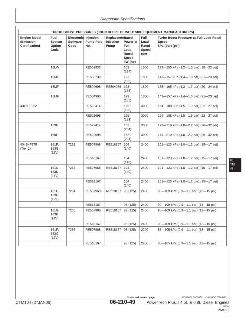
Diagnostic Specifications
0621049
RG19661,0000001 –19–26OCT05–7/22
TURBO BOOST PRESSURES (JOHN DEERE OEM/OUTSIDE EQUIPMENT MANUFACTURERS)
Engine Model Fuel Electronic Injection ReplacementRated Full Turbo Boost Pressure at Full Load Rated(Emission System Software Pump Part Injection Power at Load SpeedCertification) Option Code No. Pump Full Rated kPa (bar) (psi)
Code Load SpeedRated rpmSpeedkW (hp)
16LW RE503832 102 1500 123—150 kPa (1.2—1.5 bar) (18—22 psi)(137)
16ME RE503739 123 1800 143—157 kPa (1.4—1.6 bar) (21—23 psi)(165)
16MF RE504698 RE504966 123 1800 135—165 kPa (1.3—1.7 bar) (20—24 psi)(165)
16MF RE504966 123 1800 143—157 kPa (1.4—1.6 bar) (21—23 psi)(165)
4045HF252 RE522414 125 3000 154—188 kPa (1.5—1.9 bar) (22—27 psi)(168)
RE522698 125 3000 154—188 kPa (1.5—1.9 bar) (22—27 psi)(168)
169E RE522414 152 3000 179—219 kPa (1.8—2.2 bar) (26—32 psi)(204)
169F RE522698 152 3000 179—219 kPa (1.8—2.2 bar) (26—32 psi)(204)
4045HF275 161F, 7262 RE507968 RE518167 104 2400 101—123 kPa (1.0—1.2 bar) (15—17 psi)(Tier 2) 163G (140)
(12V)
RE518167 104 2400 101—123 kPa (1.0—1.2 bar) (15—17 psi)(140)
161G, 7263 RE507968 RE518167 104 2400 101—123 kPa (1.0—1.2 bar) (15—17 psi)163K (140)(24V)
RE518167 104 2400 101—123 kPa (1.0—1.2 bar) (15—17 psi)(140)
161F, 7264 RE507968 RE518167 93 (125) 2400 90—109 kPa (0.9—1.1 bar) (13—15 psi)163G(12V)
RE518167 93 (125) 2400 90—109 kPa (0.9—1.1 bar) (13—15 psi)
161G, 7265 RE507968 RE518167 93 (125) 2400 90—109 kPa (0.9—1.1 bar) (13—15 psi)163K(24V)
RE518167 93 (125) 2400 90—109 kPa (0.9—1.1 bar) (13—15 psi)
161F, 7266 RE507968 RE518167 93 (125) 2200 85—105 kPa (0.9—1.1 bar) (13—15 psi)163G(12V)
RE518167 93 (125) 2200 85—105 kPa (0.9—1.1 bar) (13—15 psi)
CTM104 (27JAN06) 06-210-49 PowerTech Plus 4.5L & 6.8L Diesel Engines013006
PN=713
Continued on next page
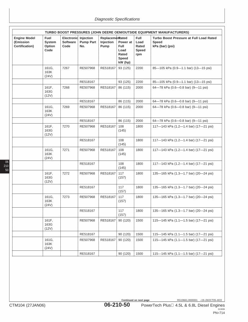
Diagnostic Specifications
06210
50
RG19661,0000001 –19–26OCT05–8/22
TURBO BOOST PRESSURES (JOHN DEERE OEM/OUTSIDE EQUIPMENT MANUFACTURERS)
Engine Model Fuel Electronic Injection ReplacementRated Full Turbo Boost Pressure at Full Load Rated(Emission System Software Pump Part Injection Power at Load SpeedCertification) Option Code No. Pump Full Rated kPa (bar) (psi)
Code Load SpeedRated rpmSpeedkW (hp)
161G, 7267 RE507968 RE518167 93 (125) 2200 85—105 kPa (0.9—1.1 bar) (13—15 psi)163K(24V)
RE518167 93 (125) 2200 85—105 kPa (0.9—1.1 bar) (13—15 psi)
161F, 7268 RE507968 RE518167 86 (115) 2000 64—78 kPa (0.6—0.8 bar) (9—11 psi)163G(12V)
RE518167 86 (115) 2000 64—78 kPa (0.6—0.8 bar) (9—11 psi)
161G, 7269 RE507968 RE518167 86 (115) 2000 64—78 kPa (0.6—0.8 bar) (9—11 psi)163K(24V)
RE518167 86 (115) 2000 64—78 kPa (0.6—0.8 bar) (9—11 psi)
161F, 7270 RE507968 RE518167 108 1800 117—143 kPa (1.2—1.4 bar) (17—21 psi)163G (145)(12V)
RE518167 108 1800 117—143 kPa (1.2—1.4 bar) (17—21 psi)(145)
161G, 7271 RE507968 RE518167 108 1800 117—143 kPa (1.2—1.4 bar) (17—21 psi)163K (145)(24V)
RE518167 108 1800 117—143 kPa (1.2—1.4 bar) (17—21 psi)(145)
161F, 7272 RE507968 RE518167 117 1800 135—165 kPa (1.3—1.7 bar) (20—24 psi)163G (157)(12V)
RE518167 117 1800 135—165 kPa (1.3—1.7 bar) (20—24 psi)(157)
161G, 7273 RE507968 RE518167 117 1800 135—165 kPa (1.3—1.7 bar) (20—24 psi)163K (157)(24V)
RE518167 117 1800 135—165 kPa (1.3—1.7 bar) (20—24 psi)(157)
161F, RE507968 RE518167 90 (120) 1500 115—145 kPa (1.1—1.5 bar) (17—21 psi)163G(12V)
RE518167 90 (120) 1500 115—145 kPa (1.1—1.5 bar) (17—21 psi)
161G, RE507968 RE518167 90 (120) 1500 115—145 kPa (1.1—1.5 bar) (17—21 psi)163K(24V)
RE518167 90 (120) 1500 115—145 kPa (1.1—1.5 bar) (17—21 psi)
CTM104 (27JAN06) 06-210-50 PowerTech Plus 4.5L & 6.8L Diesel Engines013006
PN=714
Continued on next page
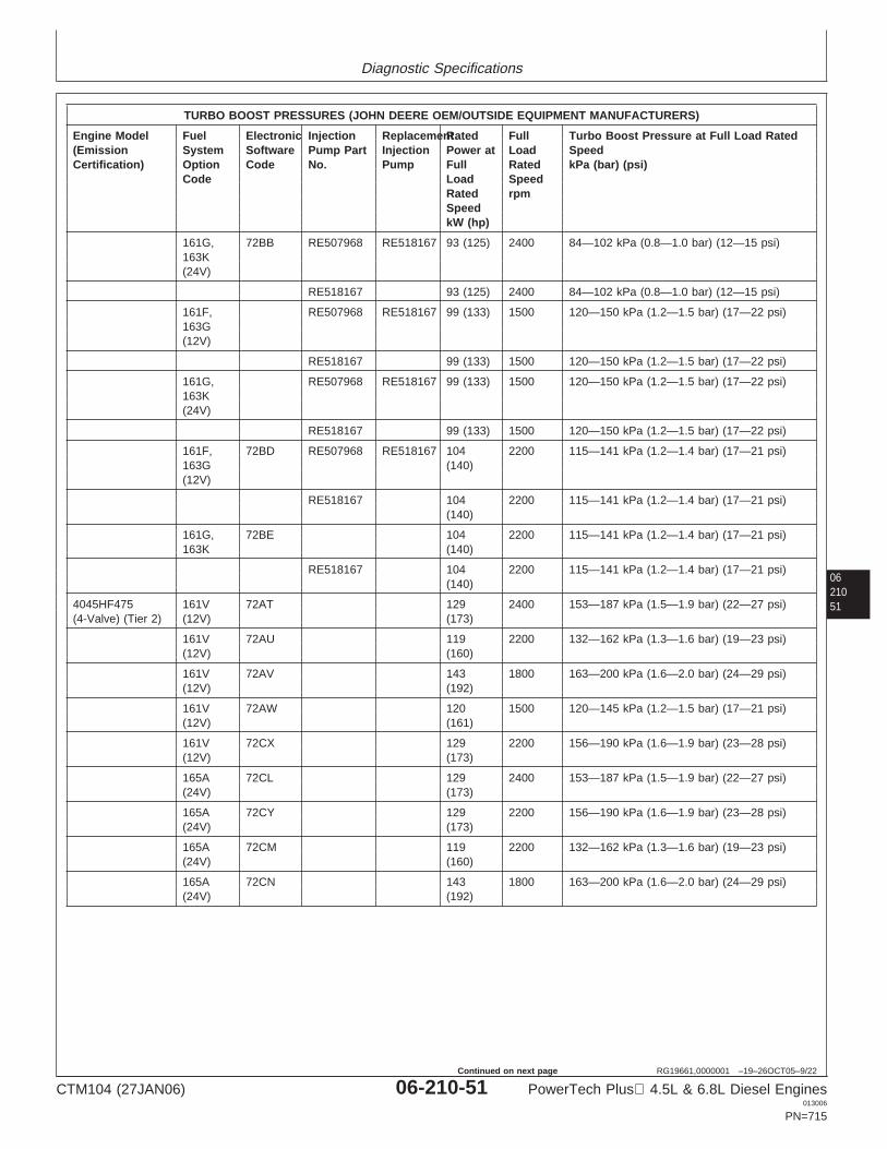
Diagnostic Specifications
0621051
RG19661,0000001 –19–26OCT05–9/22
TURBO BOOST PRESSURES (JOHN DEERE OEM/OUTSIDE EQUIPMENT MANUFACTURERS)
Engine Model Fuel Electronic Injection ReplacementRated Full Turbo Boost Pressure at Full Load Rated(Emission System Software Pump Part Injection Power at Load SpeedCertification) Option Code No. Pump Full Rated kPa (bar) (psi)
Code Load SpeedRated rpmSpeedkW (hp)
161G, 72BB RE507968 RE518167 93 (125) 2400 84—102 kPa (0.8—1.0 bar) (12—15 psi)163K(24V)
RE518167 93 (125) 2400 84—102 kPa (0.8—1.0 bar) (12—15 psi)
161F, RE507968 RE518167 99 (133) 1500 120—150 kPa (1.2—1.5 bar) (17—22 psi)163G(12V)
RE518167 99 (133) 1500 120—150 kPa (1.2—1.5 bar) (17—22 psi)
161G, RE507968 RE518167 99 (133) 1500 120—150 kPa (1.2—1.5 bar) (17—22 psi)163K(24V)
RE518167 99 (133) 1500 120—150 kPa (1.2—1.5 bar) (17—22 psi)
161F, 72BD RE507968 RE518167 104 2200 115—141 kPa (1.2—1.4 bar) (17—21 psi)163G (140)(12V)
RE518167 104 2200 115—141 kPa (1.2—1.4 bar) (17—21 psi)(140)
161G, 72BE 104 2200 115—141 kPa (1.2—1.4 bar) (17—21 psi)163K (140)
RE518167 104 2200 115—141 kPa (1.2—1.4 bar) (17—21 psi)(140)
4045HF475 161V 72AT 129 2400 153—187 kPa (1.5—1.9 bar) (22—27 psi)(4-Valve) (Tier 2) (12V) (173)
161V 72AU 119 2200 132—162 kPa (1.3—1.6 bar) (19—23 psi)(12V) (160)
161V 72AV 143 1800 163—200 kPa (1.6—2.0 bar) (24—29 psi)(12V) (192)
161V 72AW 120 1500 120—145 kPa (1.2—1.5 bar) (17—21 psi)(12V) (161)
161V 72CX 129 2200 156—190 kPa (1.6—1.9 bar) (23—28 psi)(12V) (173)
165A 72CL 129 2400 153—187 kPa (1.5—1.9 bar) (22—27 psi)(24V) (173)
165A 72CY 129 2200 156—190 kPa (1.6—1.9 bar) (23—28 psi)(24V) (173)
165A 72CM 119 2200 132—162 kPa (1.3—1.6 bar) (19—23 psi)(24V) (160)
165A 72CN 143 1800 163—200 kPa (1.6—2.0 bar) (24—29 psi)(24V) (192)
CTM104 (27JAN06) 06-210-51 PowerTech Plus 4.5L & 6.8L Diesel Engines013006
PN=715
Continued on next page
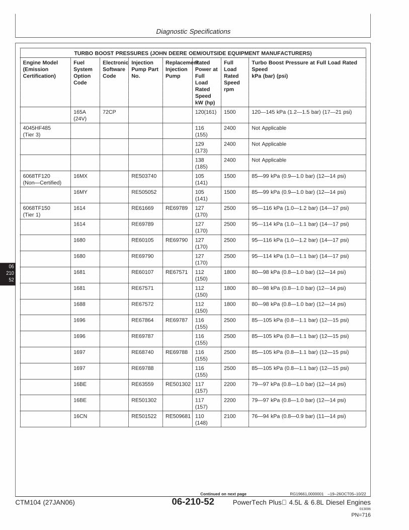
Diagnostic Specifications
06210
52
RG19661,0000001 –19–26OCT05–10/22
TURBO BOOST PRESSURES (JOHN DEERE OEM/OUTSIDE EQUIPMENT MANUFACTURERS)
Engine Model Fuel Electronic Injection ReplacementRated Full Turbo Boost Pressure at Full Load Rated(Emission System Software Pump Part Injection Power at Load SpeedCertification) Option Code No. Pump Full Rated kPa (bar) (psi)
Code Load SpeedRated rpmSpeedkW (hp)
165A 72CP 120(161) 1500 120—145 kPa (1.2—1.5 bar) (17—21 psi)(24V)
4045HF485 116 2400 Not Applicable(Tier 3) (155)
129 2400 Not Applicable(173)
138 2400 Not Applicable(185)
6068TF120 16MX RE503740 105 1500 85—99 kPa (0.9—1.0 bar) (12—14 psi)(Non—Certified) (141)
16MY RE505052 105 1500 85—99 kPa (0.9—1.0 bar) (12—14 psi)(141)
6068TF150 1614 RE61669 RE69789 127 2500 95—116 kPa (1.0—1.2 bar) (14—17 psi)(Tier 1) (170)
1614 RE69789 127 2500 95—114 kPa (1.0—1.1 bar) (14—17 psi)(170)
1680 RE60105 RE69790 127 2500 95—116 kPa (1.0—1.2 bar) (14—17 psi)(170)
1680 RE69790 127 2500 95—114 kPa (1.0—1.1 bar) (14—17 psi)(170)
1681 RE60107 RE67571 112 1800 80—98 kPa (0.8—1.0 bar) (12—14 psi)(150)
1681 RE67571 112 1800 80—98 kPa (0.8—1.0 bar) (12—14 psi)(150)
1688 RE67572 112 1800 80—98 kPa (0.8—1.0 bar) (12—14 psi)(150)
1696 RE67864 RE69787 116 2500 85—105 kPa (0.8—1.1 bar) (12—15 psi)(155)
1696 RE69787 116 2500 85—105 kPa (0.8—1.1 bar) (12—15 psi)(155)
1697 RE68740 RE69788 116 2500 85—105 kPa (0.8—1.1 bar) (12—15 psi)(155)
1697 RE69788 116 2500 85—105 kPa (0.8—1.1 bar) (12—15 psi)(155)
16BE RE63559 RE501302 117 2200 79—97 kPa (0.8—1.0 bar) (12—14 psi)(157)
16BE RE501302 117 2200 79—97 kPa (0.8—1.0 bar) (12—14 psi)(157)
16CN RE501522 RE509681 110 2100 76—94 kPa (0.8—0.9 bar) (11—14 psi)(148)
CTM104 (27JAN06) 06-210-52 PowerTech Plus 4.5L & 6.8L Diesel Engines013006
PN=716
Continued on next page
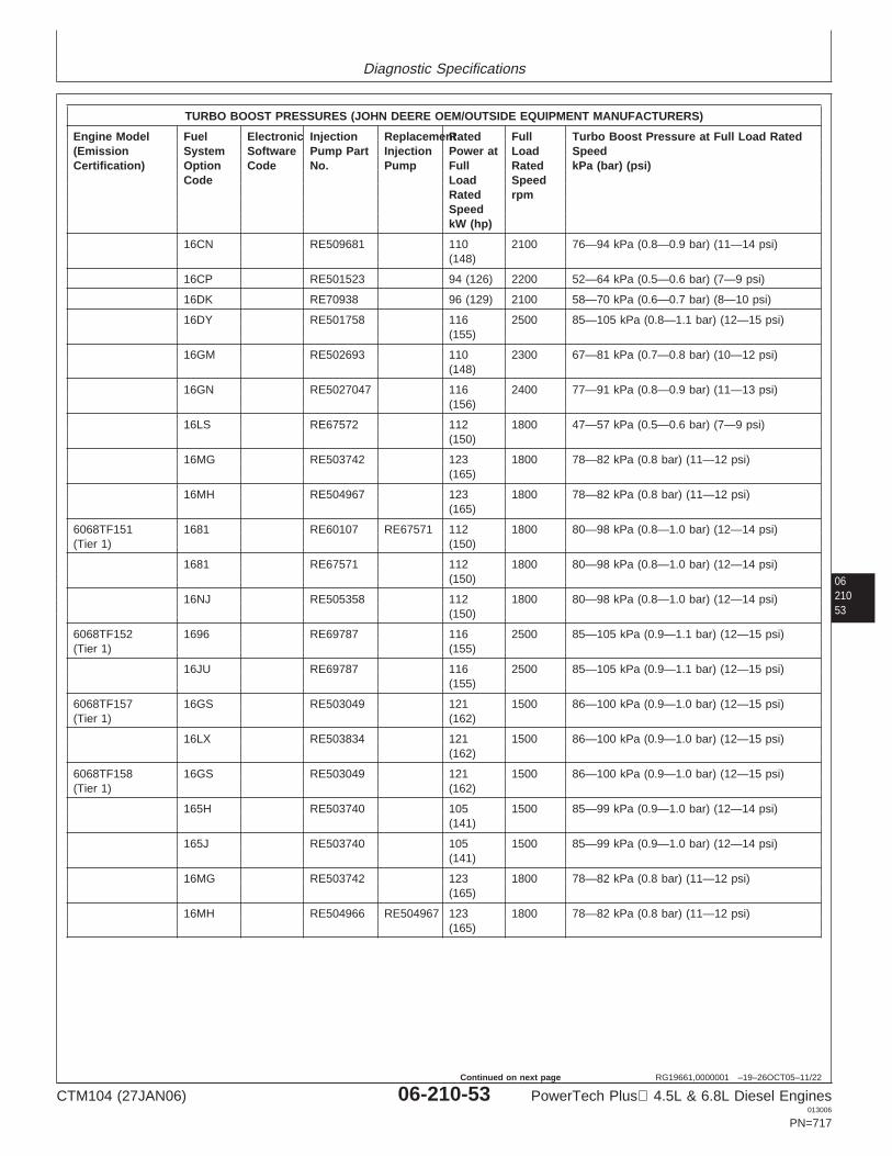
Diagnostic Specifications
0621053
RG19661,0000001 –19–26OCT05–11/22
TURBO BOOST PRESSURES (JOHN DEERE OEM/OUTSIDE EQUIPMENT MANUFACTURERS)
Engine Model Fuel Electronic Injection ReplacementRated Full Turbo Boost Pressure at Full Load Rated(Emission System Software Pump Part Injection Power at Load SpeedCertification) Option Code No. Pump Full Rated kPa (bar) (psi)
Code Load SpeedRated rpmSpeedkW (hp)
16CN RE509681 110 2100 76—94 kPa (0.8—0.9 bar) (11—14 psi)(148)
16CP RE501523 94 (126) 2200 52—64 kPa (0.5—0.6 bar) (7—9 psi)
16DK RE70938 96 (129) 2100 58—70 kPa (0.6—0.7 bar) (8—10 psi)
16DY RE501758 116 2500 85—105 kPa (0.8—1.1 bar) (12—15 psi)(155)
16GM RE502693 110 2300 67—81 kPa (0.7—0.8 bar) (10—12 psi)(148)
16GN RE5027047 116 2400 77—91 kPa (0.8—0.9 bar) (11—13 psi)(156)
16LS RE67572 112 1800 47—57 kPa (0.5—0.6 bar) (7—9 psi)(150)
16MG RE503742 123 1800 78—82 kPa (0.8 bar) (11—12 psi)(165)
16MH RE504967 123 1800 78—82 kPa (0.8 bar) (11—12 psi)(165)
6068TF151 1681 RE60107 RE67571 112 1800 80—98 kPa (0.8—1.0 bar) (12—14 psi)(Tier 1) (150)
1681 RE67571 112 1800 80—98 kPa (0.8—1.0 bar) (12—14 psi)(150)
16NJ RE505358 112 1800 80—98 kPa (0.8—1.0 bar) (12—14 psi)(150)
6068TF152 1696 RE69787 116 2500 85—105 kPa (0.9—1.1 bar) (12—15 psi)(Tier 1) (155)
16JU RE69787 116 2500 85—105 kPa (0.9—1.1 bar) (12—15 psi)(155)
6068TF157 16GS RE503049 121 1500 86—100 kPa (0.9—1.0 bar) (12—15 psi)(Tier 1) (162)
16LX RE503834 121 1500 86—100 kPa (0.9—1.0 bar) (12—15 psi)(162)
6068TF158 16GS RE503049 121 1500 86—100 kPa (0.9—1.0 bar) (12—15 psi)(Tier 1) (162)
165H RE503740 105 1500 85—99 kPa (0.9—1.0 bar) (12—14 psi)(141)
165J RE503740 105 1500 85—99 kPa (0.9—1.0 bar) (12—14 psi)(141)
16MG RE503742 123 1800 78—82 kPa (0.8 bar) (11—12 psi)(165)
16MH RE504966 RE504967 123 1800 78—82 kPa (0.8 bar) (11—12 psi)(165)
CTM104 (27JAN06) 06-210-53 PowerTech Plus 4.5L & 6.8L Diesel Engines013006
PN=717
Continued on next page
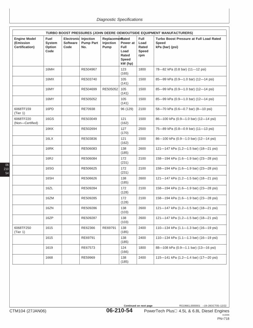
Diagnostic Specifications
06210
54
RG19661,0000001 –19–26OCT05–12/22
TURBO BOOST PRESSURES (JOHN DEERE OEM/OUTSIDE EQUIPMENT MANUFACTURERS)
Engine Model Fuel Electronic Injection ReplacementRated Full Turbo Boost Pressure at Full Load Rated(Emission System Software Pump Part Injection Power at Load SpeedCertification) Option Code No. Pump Full Rated kPa (bar) (psi)
Code Load SpeedRated rpmSpeedkW (hp)
16MH RE504967 123 1800 78—82 kPa (0.8 bar) (11—12 psi)(165)
16MX RE503740 105 1500 85—99 kPa (0.9—1.0 bar) (12—14 psi)(141)
16MY RE504699 RE505052 105 1500 85—99 kPa (0.9—1.0 bar) (12—14 psi)(141)
16MY RE505052 105 1500 85—99 kPa (0.9—1.0 bar) (12—14 psi)(141)
6068TF159 16PD RE70938 96 (129) 2100 58—70 kPa (0.6—0.7 bar) (8—10 psi)(Tier 1)
6068TF220 16GS RE503049 121 1500 86—100 kPa (0.9—1.0 bar) (12—14 psi)(Non—Certified) (162)
16KK RE502694 127 2500 75—89 kPa (0.8—0.9 bar) (11—13 psi)(170)
16LX RE503836 121 1500 86—100 kPa (0.9—1.0 bar) (12—14 psi)(162)
16RK RE506083 138 2600 121—147 kPa (1.2—1.5 bar) (18—21 psi)(185)
16RJ RE506084 172 2100 158—194 kPa (1.6—1.9 bar) (23—28 psi)(231)
16SG RE506625 172 2100 158—194 kPa (1.6—1.9 bar) (23—28 psi)(231)
16SH RE506626 138 2600 121—147 kPa (1.2—1.5 bar) (18—21 psi)(185)
16ZL RE509284 172 2100 158—194 kPa (1.6—1.9 bar) (23—28 psi)(128)
16ZM RE509285 172 2100 158—194 kPa (1.6—1.9 bar) (23—28 psi)(128)
16ZN RE509286 138 2600 121—147 kPa (1.2—1.5 bar) (18—21 psi)(103)
16ZP RE509287 138 2600 121—147 kPa (1.2—1.5 bar) (18—21 psi)(103)
6068TF250 1615 RE62366 RE69791 138 2400 110—134 kPa (1.1—1.3 bar) (16—19 psi)(Tier 1) (185)
1615 RE69791 138 2400 110—134 kPa (1.1—1.3 bar) (16—19 psi)(185)
1619 RE67573 124 1800 88—108 kPa (0.9—1.1 bar) (13—16 psi)(166)
1668 RE59969 138 2400 115—141 kPa (1.2—1.4 bar) (17—20 psi)(185)
CTM104 (27JAN06) 06-210-54 PowerTech Plus 4.5L & 6.8L Diesel Engines013006
PN=718
Continued on next page

Diagnostic Specifications
0621055
RG19661,0000001 –19–26OCT05–13/22
TURBO BOOST PRESSURES (JOHN DEERE OEM/OUTSIDE EQUIPMENT MANUFACTURERS)
Engine Model Fuel Electronic Injection ReplacementRated Full Turbo Boost Pressure at Full Load Rated(Emission System Software Pump Part Injection Power at Load SpeedCertification) Option Code No. Pump Full Rated kPa (bar) (psi)
Code Load SpeedRated rpmSpeedkW (hp)
1685 RE67574 124 1800 88—108 kPa (0.9—1.1 bar) (13—16 psi)(166)
1686 RE60131 RE69792 138 2400 110—134 kPa (1.1—1.3 bar) (16—19 psi)(185)
1686 RE69792 138 2400 110—134 kPa (1.1—1.3 bar) (16—19 psi)(185)
16CW RE501344 106 2200 74—88 kPa (0.7—0.9 bar) (11—13 psi)(142)
16CX RE70390 128 2300 100—122 kPa (1.0—1.2 bar) (15—18 psi)(172)
16LT RE69791 138 2400 110—134 kPa (1.1—1.3 bar) (16—19 psi)(185)
16LU RE67573 124 1800 88—108 kPa (0.9—1.1 bar) (13—16 psi)(166)
16MJ RE503744 142 1800 109—123 kPa (1.1—1.2 bar) (16—18 psi)(190)
16MK RE504701 RE504968 142 1800 109—123 kPa (1.1—1.2 bar) (16—18 psi)(190)
16MK RE504968 142 1800 109—123 kPa (1.1—1.2 bar) (16—18 psi)(190)
16UG RE506956 RE504321 149 2400 150—184 kPa (1.5—1.8 bar) (22—27 psi)(200)
16UG RE504321 149 2400 150—184 kPa (1.5—1.8 bar) (22—27 psi)(200)
16YH RE59959 138 2400 110—134 kPa (1.1—1.3 bar) (16—19 psi)(185)
RE504321 138 2400 110—134 kPa (1.1—1.3 bar) (16—19 psi)(185)
6068TF251 1615 RE62366 138 2400 110—134 kPa (1.1—1.3 bar) (16—19 psi)(Tier 1) (185)
16ZH RE62366 138 2400 110—134 kPa (1.1—1.3 bar) (16—19 psi)(185)
6068TF257 16GS RE503049 121 1500 86—100 kPa (0.9—1.0 bar) (12—15 psi)(Tier 1) (162)
16LX RE503834 155 1500 138—152 kPa (1.4—1.5 bar) (20—22 psi)(208)
6068TF258 16GS RE503049 121 1500 86—100 kPa (0.9—1.0 bar) (12—15 psi)(Tier 1) (162)
16LX RE503834 155 1500 138—152 kPa (1.4—1.5 bar) (20—22 psi)(208)
CTM104 (27JAN06) 06-210-55 PowerTech Plus 4.5L & 6.8L Diesel Engines013006
PN=719
Continued on next page
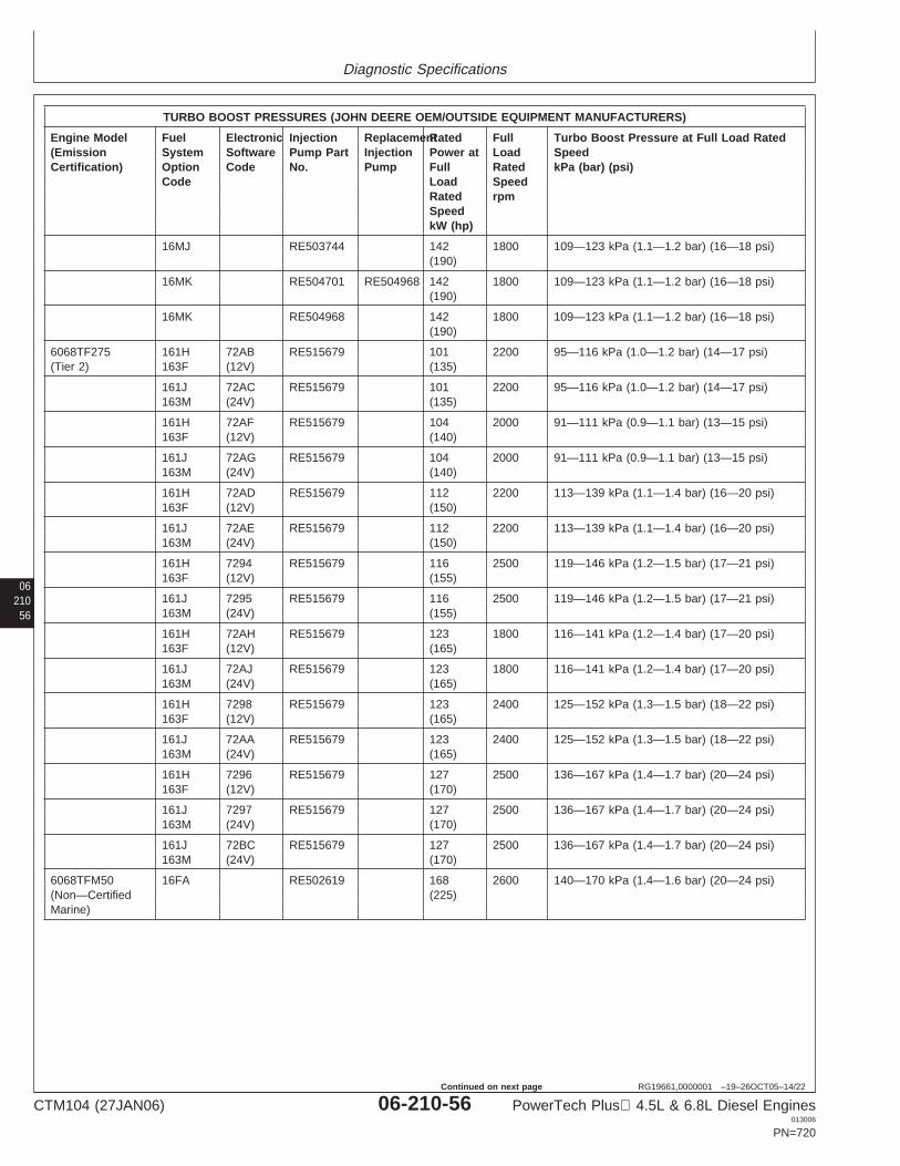
Diagnostic Specifications
06210
56
RG19661,0000001 –19–26OCT05–14/22
TURBO BOOST PRESSURES (JOHN DEERE OEM/OUTSIDE EQUIPMENT MANUFACTURERS)
Engine Model Fuel Electronic Injection ReplacementRated Full Turbo Boost Pressure at Full Load Rated(Emission System Software Pump Part Injection Power at Load SpeedCertification) Option Code No. Pump Full Rated kPa (bar) (psi)
Code Load SpeedRated rpmSpeedkW (hp)
16MJ RE503744 142 1800 109—123 kPa (1.1—1.2 bar) (16—18 psi)(190)
16MK RE504701 RE504968 142 1800 109—123 kPa (1.1—1.2 bar) (16—18 psi)(190)
16MK RE504968 142 1800 109—123 kPa (1.1—1.2 bar) (16—18 psi)(190)
6068TF275 161H 72AB RE515679 101 2200 95—116 kPa (1.0—1.2 bar) (14—17 psi)(Tier 2) 163F (12V) (135)
161J 72AC RE515679 101 2200 95—116 kPa (1.0—1.2 bar) (14—17 psi)163M (24V) (135)
161H 72AF RE515679 104 2000 91—111 kPa (0.9—1.1 bar) (13—15 psi)163F (12V) (140)
161J 72AG RE515679 104 2000 91—111 kPa (0.9—1.1 bar) (13—15 psi)163M (24V) (140)
161H 72AD RE515679 112 2200 113—139 kPa (1.1—1.4 bar) (16—20 psi)163F (12V) (150)
161J 72AE RE515679 112 2200 113—139 kPa (1.1—1.4 bar) (16—20 psi)163M (24V) (150)
161H 7294 RE515679 116 2500 119—146 kPa (1.2—1.5 bar) (17—21 psi)163F (12V) (155)
161J 7295 RE515679 116 2500 119—146 kPa (1.2—1.5 bar) (17—21 psi)163M (24V) (155)
161H 72AH RE515679 123 1800 116—141 kPa (1.2—1.4 bar) (17—20 psi)163F (12V) (165)
161J 72AJ RE515679 123 1800 116—141 kPa (1.2—1.4 bar) (17—20 psi)163M (24V) (165)
161H 7298 RE515679 123 2400 125—152 kPa (1.3—1.5 bar) (18—22 psi)163F (12V) (165)
161J 72AA RE515679 123 2400 125—152 kPa (1.3—1.5 bar) (18—22 psi)163M (24V) (165)
161H 7296 RE515679 127 2500 136—167 kPa (1.4—1.7 bar) (20—24 psi)163F (12V) (170)
161J 7297 RE515679 127 2500 136—167 kPa (1.4—1.7 bar) (20—24 psi)163M (24V) (170)
161J 72BC RE515679 127 2500 136—167 kPa (1.4—1.7 bar) (20—24 psi)163M (24V) (170)
6068TFM50 16FA RE502619 168 2600 140—170 kPa (1.4—1.6 bar) (20—24 psi)(Non—Certified (225)Marine)
CTM104 (27JAN06) 06-210-56 PowerTech Plus 4.5L & 6.8L Diesel Engines013006
PN=720
Continued on next page
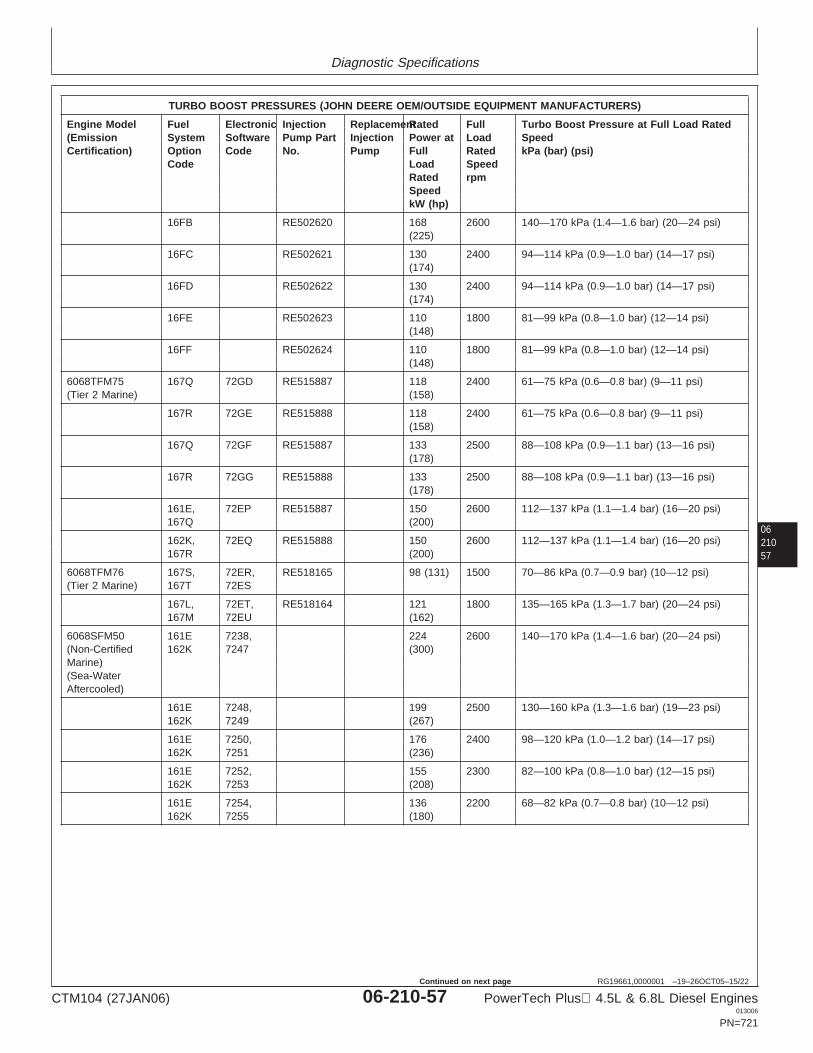
Diagnostic Specifications
0621057
RG19661,0000001 –19–26OCT05–15/22
TURBO BOOST PRESSURES (JOHN DEERE OEM/OUTSIDE EQUIPMENT MANUFACTURERS)
Engine Model Fuel Electronic Injection ReplacementRated Full Turbo Boost Pressure at Full Load Rated(Emission System Software Pump Part Injection Power at Load SpeedCertification) Option Code No. Pump Full Rated kPa (bar) (psi)
Code Load SpeedRated rpmSpeedkW (hp)
16FB RE502620 168 2600 140—170 kPa (1.4—1.6 bar) (20—24 psi)(225)
16FC RE502621 130 2400 94—114 kPa (0.9—1.0 bar) (14—17 psi)(174)
16FD RE502622 130 2400 94—114 kPa (0.9—1.0 bar) (14—17 psi)(174)
16FE RE502623 110 1800 81—99 kPa (0.8—1.0 bar) (12—14 psi)(148)
16FF RE502624 110 1800 81—99 kPa (0.8—1.0 bar) (12—14 psi)(148)
6068TFM75 167Q 72GD RE515887 118 2400 61—75 kPa (0.6—0.8 bar) (9—11 psi)(Tier 2 Marine) (158)
167R 72GE RE515888 118 2400 61—75 kPa (0.6—0.8 bar) (9—11 psi)(158)
167Q 72GF RE515887 133 2500 88—108 kPa (0.9—1.1 bar) (13—16 psi)(178)
167R 72GG RE515888 133 2500 88—108 kPa (0.9—1.1 bar) (13—16 psi)(178)
161E, 72EP RE515887 150 2600 112—137 kPa (1.1—1.4 bar) (16—20 psi)167Q (200)
162K, 72EQ RE515888 150 2600 112—137 kPa (1.1—1.4 bar) (16—20 psi)167R (200)
6068TFM76 167S, 72ER, RE518165 98 (131) 1500 70—86 kPa (0.7—0.9 bar) (10—12 psi)(Tier 2 Marine) 167T 72ES
167L, 72ET, RE518164 121 1800 135—165 kPa (1.3—1.7 bar) (20—24 psi)167M 72EU (162)
6068SFM50 161E 7238, 224 2600 140—170 kPa (1.4—1.6 bar) (20—24 psi)(Non-Certified 162K 7247 (300)Marine)(Sea-WaterAftercooled)
161E 7248, 199 2500 130—160 kPa (1.3—1.6 bar) (19—23 psi)162K 7249 (267)
161E 7250, 176 2400 98—120 kPa (1.0—1.2 bar) (14—17 psi)162K 7251 (236)
161E 7252, 155 2300 82—100 kPa (0.8—1.0 bar) (12—15 psi)162K 7253 (208)
161E 7254, 136 2200 68—82 kPa (0.7—0.8 bar) (10—12 psi)162K 7255 (180)
CTM104 (27JAN06) 06-210-57 PowerTech Plus 4.5L & 6.8L Diesel Engines013006
PN=721
Continued on next page
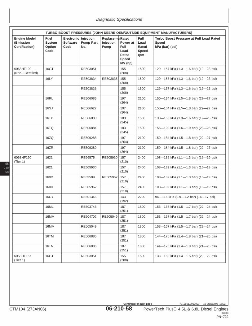
Diagnostic Specifications
06210
58
RG19661,0000001 –19–26OCT05–16/22
TURBO BOOST PRESSURES (JOHN DEERE OEM/OUTSIDE EQUIPMENT MANUFACTURERS)
Engine Model Fuel Electronic Injection ReplacementRated Full Turbo Boost Pressure at Full Load Rated(Emission System Software Pump Part Injection Power at Load SpeedCertification) Option Code No. Pump Full Rated kPa (bar) (psi)
Code Load SpeedRated rpmSpeedkW (hp)
6068HF120 16GT RE503051 155 1500 129—157 kPa (1.3—1.6 bar) (19—23 psi)(Non—Certified) (208)
16LY RE503834 RE503836 155 1500 129—157 kPa (1.3—1.6 bar) (19—23 psi)(208)
RE503836 155 1500 129—157 kPa (1.3—1.6 bar) (19—23 psi)(208)
16RL RE506085 197 2100 150—184 kPa (1.5—1.8 bar) (22—27 psi)(264)
16SJ RE506627 197 2100 150—184 kPa (1.5—1.8 bar) (22—27 psi)(264)
16TP RE506883 183 1500 130—158 kPa (1.3—1.6 bar) (19—23 psi)(245)
16TQ RE506884 183 1500 156—190 kPa (1.6—1.9 bar) (23—28 psi)(245)
16ZQ RE509288 197 2100 150—184 kPa (1.5—1.8 bar) (22—27 psi)(264)
16ZR RE509289 197 2100 150—184 kPa (1.5—1.8 bar) (22—27 psi)(264)
6068HF150 1621 RE66575 RE505930 157 2400 108—132 kPa (1.1—1.3 bar) (16—19 psi)(Tier 1) (210)
1621 RE505930 157 2400 108—132 kPa (1.1—1.3 bar) (16—19 psi)(210)
160D RE69589 RE505962 157 2400 108—132 kPa (1.1—1.3 bar) (16—19 psi)(210)
160D RE505962 157 2400 108—132 kPa (1.1—1.3 bar) (16—19 psi)(210)
16CY RE501345 143 2200 94—116 kPa (0.9—1.2 bar) (14—17 psi)(192)
16ML RE503746 187 1800 153—167 kPa (1.5—1.7 bar) (22—24 psi)(251)
16MM RE504702 RE505049 187 1800 153—167 kPa (1.5—1.7 bar) (22—24 psi)(251)
16MM RE505049 187 1800 153—167 kPa (1.5—1.7 bar) (22—24 psi)(251)
16TM RE506885 187 1800 144—176 kPa (1.4—1.8 bar) (21—25 psi)(251)
16TN RE506886 187 1800 144—176 kPa (1.4—1.8 bar) (21—25 psi)(251)
6068HF157 16GT RE503051 155 1500 138—152 kPa (1.4—1.5 bar) (20—22 psi)(Tier 1) (208)
CTM104 (27JAN06) 06-210-58 PowerTech Plus 4.5L & 6.8L Diesel Engines013006
PN=722
Continued on next page
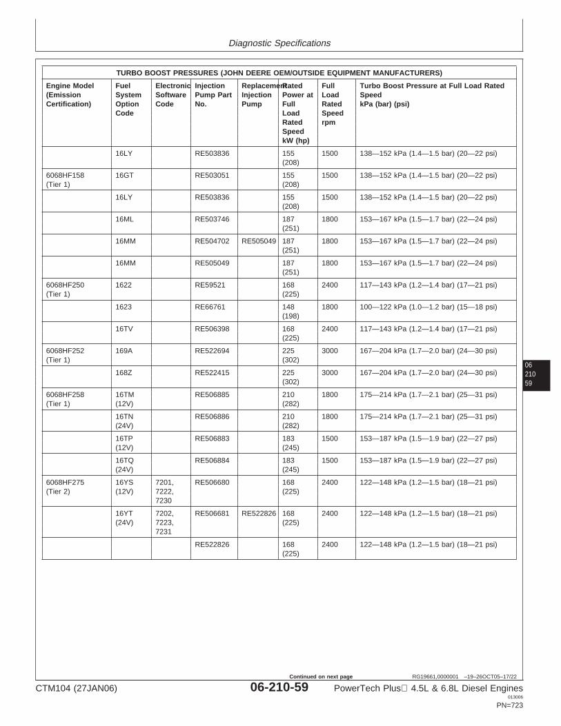
Diagnostic Specifications
0621059
RG19661,0000001 –19–26OCT05–17/22
TURBO BOOST PRESSURES (JOHN DEERE OEM/OUTSIDE EQUIPMENT MANUFACTURERS)
Engine Model Fuel Electronic Injection ReplacementRated Full Turbo Boost Pressure at Full Load Rated(Emission System Software Pump Part Injection Power at Load SpeedCertification) Option Code No. Pump Full Rated kPa (bar) (psi)
Code Load SpeedRated rpmSpeedkW (hp)
16LY RE503836 155 1500 138—152 kPa (1.4—1.5 bar) (20—22 psi)(208)
6068HF158 16GT RE503051 155 1500 138—152 kPa (1.4—1.5 bar) (20—22 psi)(Tier 1) (208)
16LY RE503836 155 1500 138—152 kPa (1.4—1.5 bar) (20—22 psi)(208)
16ML RE503746 187 1800 153—167 kPa (1.5—1.7 bar) (22—24 psi)(251)
16MM RE504702 RE505049 187 1800 153—167 kPa (1.5—1.7 bar) (22—24 psi)(251)
16MM RE505049 187 1800 153—167 kPa (1.5—1.7 bar) (22—24 psi)(251)
6068HF250 1622 RE59521 168 2400 117—143 kPa (1.2—1.4 bar) (17—21 psi)(Tier 1) (225)
1623 RE66761 148 1800 100—122 kPa (1.0—1.2 bar) (15—18 psi)(198)
16TV RE506398 168 2400 117—143 kPa (1.2—1.4 bar) (17—21 psi)(225)
6068HF252 169A RE522694 225 3000 167—204 kPa (1.7—2.0 bar) (24—30 psi)(Tier 1) (302)
168Z RE522415 225 3000 167—204 kPa (1.7—2.0 bar) (24—30 psi)(302)
6068HF258 16TM RE506885 210 1800 175—214 kPa (1.7—2.1 bar) (25—31 psi)(Tier 1) (12V) (282)
16TN RE506886 210 1800 175—214 kPa (1.7—2.1 bar) (25—31 psi)(24V) (282)
16TP RE506883 183 1500 153—187 kPa (1.5—1.9 bar) (22—27 psi)(12V) (245)
16TQ RE506884 183 1500 153—187 kPa (1.5—1.9 bar) (22—27 psi)(24V) (245)
6068HF275 16YS 7201, RE506680 168 2400 122—148 kPa (1.2—1.5 bar) (18—21 psi)(Tier 2) (12V) 7222, (225)
7230
16YT 7202, RE506681 RE522826 168 2400 122—148 kPa (1.2—1.5 bar) (18—21 psi)(24V) 7223, (225)
7231
RE522826 168 2400 122—148 kPa (1.2—1.5 bar) (18—21 psi)(225)
CTM104 (27JAN06) 06-210-59 PowerTech Plus 4.5L & 6.8L Diesel Engines013006
PN=723
Continued on next page
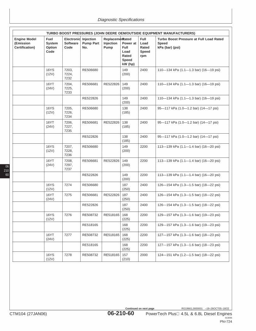
Diagnostic Specifications
06210
60
RG19661,0000001 –19–26OCT05–18/22
TURBO BOOST PRESSURES (JOHN DEERE OEM/OUTSIDE EQUIPMENT MANUFACTURERS)
Engine Model Fuel Electronic Injection ReplacementRated Full Turbo Boost Pressure at Full Load Rated(Emission System Software Pump Part Injection Power at Load SpeedCertification) Option Code No. Pump Full Rated kPa (bar) (psi)
Code Load SpeedRated rpmSpeedkW (hp)
16YS 7203, RE506680 149 2400 110—134 kPa (1.1—1.3 bar) (16—19 psi)(12V) 7224, (200)
7232
16YT 7204, RE506681 RE522826 149 2400 110—134 kPa (1.1—1.3 bar) (16—19 psi)(24V) 7225, (200)
7233
RE522826 149 2400 110—134 kPa (1.1—1.3 bar) (16—19 psi)(200)
16YS 7205, RE506680 138 2400 95—117 kPa (1.0—1.2 bar) (14—17 psi)(12V) 7226, (185)
7234
16YT 7206, RE506681 RE522826 138 2400 95—117 kPa (1.0—1.2 bar) (14—17 psi)(24V) 7227, (185)
7235
RE522826 138 2400 95—117 kPa (1.0—1.2 bar) (14—17 psi)(185)
16YS 7207, RE506680 149 2200 113—139 kPa (1.1—1.4 bar) (16—20 psi)(12V) 7228, (200)
7236
16YT 7208, RE506681 RE522826 149 2200 113—139 kPa (1.1—1.4 bar) (16—20 psi)(24V) 7297, (200)
7237
RE522826 149 2200 113—139 kPa (1.1—1.4 bar) (16—20 psi)(200)
16YS 7274 RE506680 187 2400 126—154 kPa (1.3—1.5 bar) (18—22 psi)(12V) (250)
16YT 7275 RE506681 RE522826 187 2400 126—154 kPa (1.3—1.5 bar) (18—22 psi)(24V) (250)
RE522826 187 2400 126—154 kPa (1.3—1.5 bar) (18—22 psi)(250)
16YS 7276 RE508732 RE518165 168 2200 129—157 kPa (1.3—1.6 bar) (19—23 psi)(12V) (225)
RE518165 168 2200 129—157 kPa (1.3—1.6 bar) (19—23 psi)(225)
16YT 7277 RE508732 RE518165 168 2200 127—157 kPa (1.3—1.6 bar) (18—23 psi)(24V) (225)
RE518165 168 2200 127—157 kPa (1.3—1.6 bar) (18—23 psi)(225)
16YS 7278 RE508732 RE518165 157 2000 124—151 kPa (1.2—1.5 bar) (18—22 psi)(12V) (210)
CTM104 (27JAN06) 06-210-60 PowerTech Plus 4.5L & 6.8L Diesel Engines013006
PN=724
Continued on next page
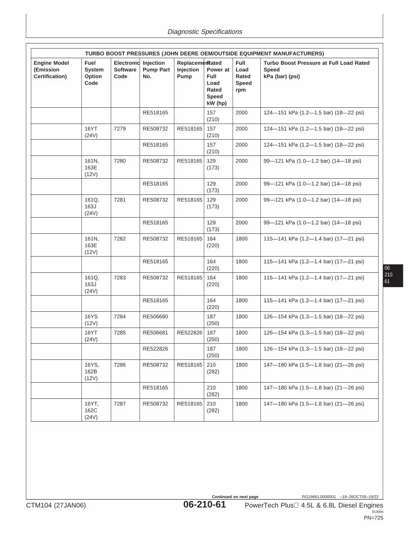
Diagnostic Specifications
0621061
RG19661,0000001 –19–26OCT05–19/22
TURBO BOOST PRESSURES (JOHN DEERE OEM/OUTSIDE EQUIPMENT MANUFACTURERS)
Engine Model Fuel Electronic Injection ReplacementRated Full Turbo Boost Pressure at Full Load Rated(Emission System Software Pump Part Injection Power at Load SpeedCertification) Option Code No. Pump Full Rated kPa (bar) (psi)
Code Load SpeedRated rpmSpeedkW (hp)
RE518165 157 2000 124—151 kPa (1.2—1.5 bar) (18—22 psi)(210)
16YT 7279 RE508732 RE518165 157 2000 124—151 kPa (1.2—1.5 bar) (18—22 psi)(24V) (210)
RE518165 157 2000 124—151 kPa (1.2—1.5 bar) (18—22 psi)(210)
161N, 7280 RE508732 RE518165 129 2000 99—121 kPa (1.0—1.2 bar) (14—18 psi)163E (173)(12V)
RE518165 129 2000 99—121 kPa (1.0—1.2 bar) (14—18 psi)(173)
161Q, 7281 RE508732 RE518165 129 2000 99—121 kPa (1.0—1.2 bar) (14—18 psi)163J (173)(24V)
RE518165 129 2000 99—121 kPa (1.0—1.2 bar) (14—18 psi)(173)
161N, 7282 RE508732 RE518165 164 1800 115—141 kPa (1.2—1.4 bar) (17—21 psi)163E (220)(12V)
RE518165 164 1800 115—141 kPa (1.2—1.4 bar) (17—21 psi)(220)
161Q, 7283 RE508732 RE518165 164 1800 115—141 kPa (1.2—1.4 bar) (17—21 psi)163J (220)(24V)
RE518165 164 1800 115—141 kPa (1.2—1.4 bar) (17—21 psi)(220)
16YS 7284 RE506680 187 1800 126—154 kPa (1.3—1.5 bar) (18—22 psi)(12V) (250)
16YT 7285 RE506681 RE522826 187 1800 126—154 kPa (1.3—1.5 bar) (18—22 psi)(24V) (250)
RE522826 187 1800 126—154 kPa (1.3—1.5 bar) (18—22 psi)(250)
16YS, 7286 RE508732 RE518165 210 1800 147—180 kPa (1.5—1.8 bar) (21—26 psi)162B (282)(12V)
RE518165 210 1800 147—180 kPa (1.5—1.8 bar) (21—26 psi)(282)
16YT, 7287 RE508732 RE518165 210 1800 147—180 kPa (1.5—1.8 bar) (21—26 psi)162C (282)(24V)
CTM104 (27JAN06) 06-210-61 PowerTech Plus 4.5L & 6.8L Diesel Engines013006
PN=725
Continued on next page
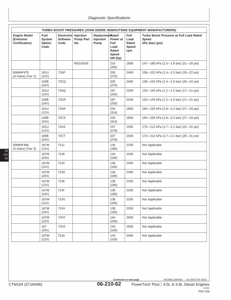
Diagnostic Specifications
06210
62
RG19661,0000001 –19–26OCT05–20/22
TURBO BOOST PRESSURES (JOHN DEERE OEM/OUTSIDE EQUIPMENT MANUFACTURERS)
Engine Model Fuel Electronic Injection ReplacementRated Full Turbo Boost Pressure at Full Load Rated(Emission System Software Pump Part Injection Power at Load SpeedCertification) Option Code No. Pump Full Rated kPa (bar) (psi)
Code Load SpeedRated rpmSpeedkW (hp)
RE518165 210 1800 147—180 kPa (1.5—1.8 bar) (21—26 psi)(282)
6068HF475 161U 72AP 205 2400 138—152 kPa (1.4—1.5 bar) (20—22 psi)(4-Valve) (Tier 2) (12V) (275)
165B 72CQ 205 2400 138—152 kPa (1.4—1.5 bar) (20—22 psi)(24V) (275)
161U 72AQ 187 2200 120—145 kPa (1.2—1.5 bar) (17—21 psi)(12V) (250)
165B 72CR 187 2200 120—145 kPa (1.2—1.5 bar) (17—21 psi)(24V) (250)
161U 72AR 234 1800 184—225 kPa (1.8—2.3 bar) (27—33 psi)(12V) (314)
165B 72CS 234 1800 184—225 kPa (1.8—2.3 bar) (27—33 psi)(24V) (314)
161U 72AS 207 1500 173—212 kPa (1.7—2.1 bar) (25—31 psi)(12V) (278)
165B 72CT 207 1500 173—212 kPa (1.7—2.1 bar) (25—31 psi)(24V) (278)
6068HF485 167W 72JJ 134 2200 Not Applicable(4-Valve) (Tier 3) (12V) (180)
167W 72JK 134 2200 Not Applicable(24V) (180)
167W 72JC 138 2400 Not Applicable(12V) (185)
167W 72JD 138 2400 Not Applicable(24V) (185)
167W 72JE 138 2200 Not Applicable(12V) (185)
167W 72JF 138 2200 Not Applicable(24V) (185)
167W 72JG 138 2200 Not Applicable(12V) (185)
167W 72JH 138 2200 Not Applicable(24V) (185)
167W 72HY 144 2000 Not Applicable(12V) (193)
167 72HZ 144 2000 Not Applicable(24V) (193)
167W 72JA 144 2000 Not Applicable(12V) (193)
CTM104 (27JAN06) 06-210-62 PowerTech Plus 4.5L & 6.8L Diesel Engines013006
PN=726
Continued on next page
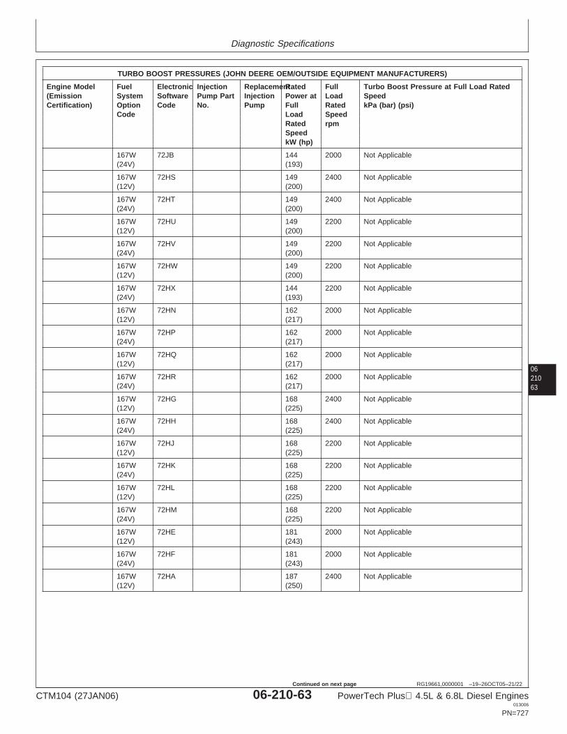
Diagnostic Specifications
0621063
RG19661,0000001 –19–26OCT05–21/22
TURBO BOOST PRESSURES (JOHN DEERE OEM/OUTSIDE EQUIPMENT MANUFACTURERS)
Engine Model Fuel Electronic Injection ReplacementRated Full Turbo Boost Pressure at Full Load Rated(Emission System Software Pump Part Injection Power at Load SpeedCertification) Option Code No. Pump Full Rated kPa (bar) (psi)
Code Load SpeedRated rpmSpeedkW (hp)
167W 72JB 144 2000 Not Applicable(24V) (193)
167W 72HS 149 2400 Not Applicable(12V) (200)
167W 72HT 149 2400 Not Applicable(24V) (200)
167W 72HU 149 2200 Not Applicable(12V) (200)
167W 72HV 149 2200 Not Applicable(24V) (200)
167W 72HW 149 2200 Not Applicable(12V) (200)
167W 72HX 144 2200 Not Applicable(24V) (193)
167W 72HN 162 2000 Not Applicable(12V) (217)
167W 72HP 162 2000 Not Applicable(24V) (217)
167W 72HQ 162 2000 Not Applicable(12V) (217)
167W 72HR 162 2000 Not Applicable(24V) (217)
167W 72HG 168 2400 Not Applicable(12V) (225)
167W 72HH 168 2400 Not Applicable(24V) (225)
167W 72HJ 168 2200 Not Applicable(12V) (225)
167W 72HK 168 2200 Not Applicable(24V) (225)
167W 72HL 168 2200 Not Applicable(12V) (225)
167W 72HM 168 2200 Not Applicable(24V) (225)
167W 72HE 181 2000 Not Applicable(12V) (243)
167W 72HF 181 2000 Not Applicable(24V) (243)
167W 72HA 187 2400 Not Applicable(12V) (250)
CTM104 (27JAN06) 06-210-63 PowerTech Plus 4.5L & 6.8L Diesel Engines013006
PN=727
Continued on next page
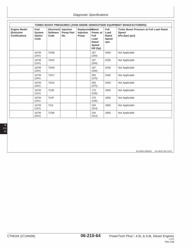
Diagnostic Specifications
06210
64
RG19661,0000001 –19–26OCT05–22/22
TURBO BOOST PRESSURES (JOHN DEERE OEM/OUTSIDE EQUIPMENT MANUFACTURERS)
Engine Model Fuel Electronic Injection ReplacementRated Full Turbo Boost Pressure at Full Load Rated(Emission System Software Pump Part Injection Power at Load SpeedCertification) Option Code No. Pump Full Rated kPa (bar) (psi)
Code Load SpeedRated rpmSpeedkW (hp)
167W 72HB 187 2400 Not Applicable(24V) (250)
167W 72HC 187 2200 Not Applicable(12V) (250)
167W 72HD 187 2200 Not Applicable(24V) (250)
167W 72GY 205 2400 Not Applicable(24V) (275)
167W 72GZ 205 2400 Not Applicable(24V) (275)
167W 72JN 175 1800 Not Applicable(12V) (235)
167W 72JP 175 1800 Not Applicable(24V) (235)
167W 72JL 234 1800 Not Applicable(12V) (314)
167W 72JM 234 1800 Not Applicable(24V) (314)
CTM104 (27JAN06) 06-210-64 PowerTech Plus 4.5L & 6.8L Diesel Engines013006
PN=728
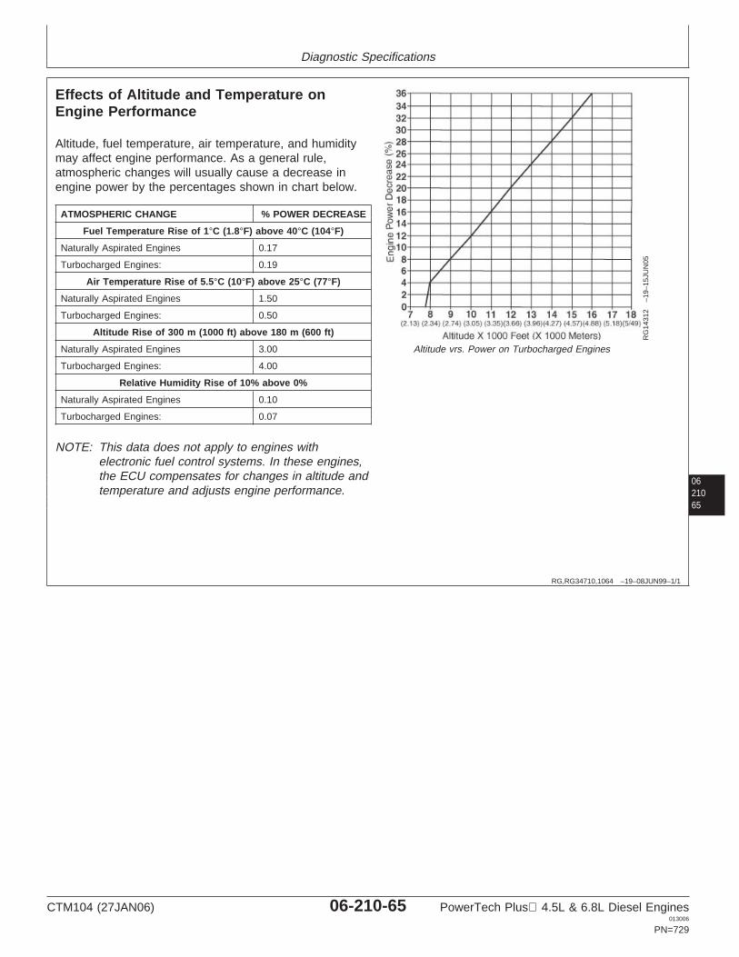
Diagnostic Specifications
0621065
RG,RG34710,1064 –19–08JUN99–1/1
Effects of Altitude and Temperature onEngine Performance
RG
1431
2–1
9–15
JUN
05
Altitude vrs. Power on Turbocharged Engines
Altitude, fuel temperature, air temperature, and humiditymay affect engine performance. As a general rule,atmospheric changes will usually cause a decrease inengine power by the percentages shown in chart below.
ATMOSPHERIC CHANGE % POWER DECREASE
Fuel Temperature Rise of 1°C (1.8°F) above 40°C (104°F)
Naturally Aspirated Engines 0.17
Turbocharged Engines: 0.19
Air Temperature Rise of 5.5°C (10°F) above 25°C (77°F)
Naturally Aspirated Engines 1.50
Turbocharged Engines: 0.50
Altitude Rise of 300 m (1000 ft) above 180 m (600 ft)
Naturally Aspirated Engines 3.00
Turbocharged Engines: 4.00
Relative Humidity Rise of 10% above 0%
Naturally Aspirated Engines 0.10
Turbocharged Engines: 0.07
NOTE: This data does not apply to engines withelectronic fuel control systems. In these engines,the ECU compensates for changes in altitude andtemperature and adjusts engine performance.
CTM104 (27JAN06) 06-210-65 PowerTech Plus 4.5L & 6.8L Diesel Engines013006
PN=729
Diagnostic Specifications
06210
66
CTM104 (27JAN06) 06-210-66 PowerTech Plus 4.5L & 6.8L Diesel Engines013006
PN=730
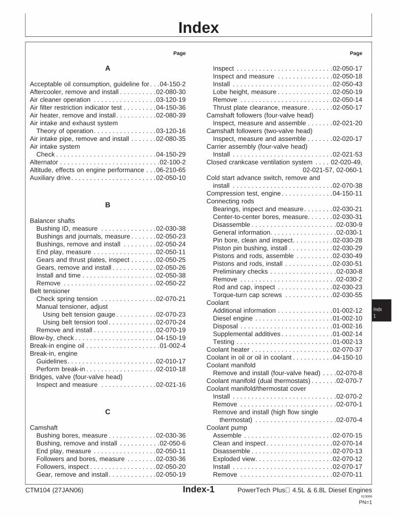
IndexPage Page
A Inspect . . . . . . . . . . . . . . . . . . . . . . . . . .02-050-17Inspect and measure . . . . . . . . . . . . . . .02-050-18Install . . . . . . . . . . . . . . . . . . . . . . . . . . .02-050-43Acceptable oil consumption, guideline for . . .04-150-2
Aftercooler, remove and install . . . . . . . . . .02-080-30 Lobe height, measure . . . . . . . . . . . . . . .02-050-19Remove . . . . . . . . . . . . . . . . . . . . . . . . .02-050-14Air cleaner operation . . . . . . . . . . . . . . . . .03-120-19
Air filter restriction indicator test . . . . . . . . .04-150-36 Thrust plate clearance, measure . . . . . . .02-050-17Camshaft followers (four-valve head)Air heater, remove and install . . . . . . . . . . .02-080-39
Air intake and exhaust system Inspect, measure and assemble . . . . . . .02-021-20Camshaft followers (two-valve head)Theory of operation. . . . . . . . . . . . . . . . .03-120-16
Air intake pipe, remove and install . . . . . . .02-080-35 Inspect, measure and assemble . . . . . . .02-020-17Carrier assembly (four-valve head)Air intake system
Check . . . . . . . . . . . . . . . . . . . . . . . . . . .04-150-29 Install . . . . . . . . . . . . . . . . . . . . . . . . . . .02-021-53Closed crankcase ventilation system . . . . 02-020-49,Alternator . . . . . . . . . . . . . . . . . . . . . . . . . . .02-100-2
Altitude, effects on engine performance . . .06-210-65 02-021-57, 02-060-1Cold start advance switch, remove andAuxiliary drive. . . . . . . . . . . . . . . . . . . . . . .02-050-10
install . . . . . . . . . . . . . . . . . . . . . . . . . . .02-070-38Compression test, engine . . . . . . . . . . . . . .04-150-11Connecting rodsB
Bearings, inspect and measure. . . . . . . .02-030-21Center-to-center bores, measure. . . . . . .02-030-31
Balancer shaftsDisassemble . . . . . . . . . . . . . . . . . . . . . . .02-030-9
Bushing ID, measure . . . . . . . . . . . . . . .02-030-38General information. . . . . . . . . . . . . . . . . .02-030-1
Bushings and journals, measure . . . . . . .02-050-23Pin bore, clean and inspect. . . . . . . . . . .02-030-28
Bushings, remove and install . . . . . . . . .02-050-24Piston pin bushing, install . . . . . . . . . . . .02-030-29
End play, measure . . . . . . . . . . . . . . . . .02-050-11Pistons and rods, assemble . . . . . . . . . .02-030-49
Gears and thrust plates, inspect . . . . . . .02-050-25Pistons and rods, install . . . . . . . . . . . . .02-030-51
Gears, remove and install . . . . . . . . . . . .02-050-26Preliminary checks . . . . . . . . . . . . . . . . . .02-030-8
Install and time . . . . . . . . . . . . . . . . . . . .02-050-38Remove . . . . . . . . . . . . . . . . . . . . . . . . . .02-030-2
Remove . . . . . . . . . . . . . . . . . . . . . . . . .02-050-22Rod and cap, inspect . . . . . . . . . . . . . . .02-030-23
Belt tensionerTorque-turn cap screws . . . . . . . . . . . . .02-030-55
Check spring tension . . . . . . . . . . . . . . .02-070-21Coolant
Manual tensioner, adjust IndxAdditional information . . . . . . . . . . . . . . .01-002-12Using belt tension gauge . . . . . . . . . . .02-070-23 1Diesel engine . . . . . . . . . . . . . . . . . . . . .01-002-10Using belt tension tool . . . . . . . . . . . . .02-070-24
Disposal . . . . . . . . . . . . . . . . . . . . . . . . .01-002-16Remove and install . . . . . . . . . . . . . . . . .02-070-19
Supplemental additives . . . . . . . . . . . . . .01-002-14Blow-by, check . . . . . . . . . . . . . . . . . . . . . .04-150-19
Testing . . . . . . . . . . . . . . . . . . . . . . . . . .01-002-13Break-in engine oil . . . . . . . . . . . . . . . . . . . .01-002-4
Coolant heater . . . . . . . . . . . . . . . . . . . . . .02-070-37Break-in, engine
Coolant in oil or oil in coolant . . . . . . . . . . .04-150-10Guidelines. . . . . . . . . . . . . . . . . . . . . . . .02-010-17
Coolant manifoldPerform break-in . . . . . . . . . . . . . . . . . . .02-010-18
Remove and install (four-valve head) . . . .02-070-8Bridges, valve (four-valve head)
Coolant manifold (dual thermostats) . . . . . . .02-070-7Inspect and measure . . . . . . . . . . . . . . .02-021-16
Coolant manifold/thermostat coverInstall . . . . . . . . . . . . . . . . . . . . . . . . . . . .02-070-2Remove . . . . . . . . . . . . . . . . . . . . . . . . . .02-070-1Remove and install (high flow singleC
thermostat) . . . . . . . . . . . . . . . . . . . . . .02-070-4Coolant pumpCamshaft
Bushing bores, measure . . . . . . . . . . . . .02-030-36 Assemble . . . . . . . . . . . . . . . . . . . . . . . .02-070-15Clean and inspect . . . . . . . . . . . . . . . . . .02-070-14Bushing, remove and install . . . . . . . . . . .02-050-6
End play, measure . . . . . . . . . . . . . . . . .02-050-11 Disassemble . . . . . . . . . . . . . . . . . . . . . .02-070-13Exploded view. . . . . . . . . . . . . . . . . . . . .02-070-12Followers and bores, measure . . . . . . . .02-030-36
Followers, inspect . . . . . . . . . . . . . . . . . .02-050-20 Install . . . . . . . . . . . . . . . . . . . . . . . . . . .02-070-17Remove . . . . . . . . . . . . . . . . . . . . . . . . .02-070-11Gear, remove and install . . . . . . . . . . . . .02-050-19
CTM104 (27JAN06) Index-1 PowerTech Plus 4.5L & 6.8L Diesel Engines013006
PN=1
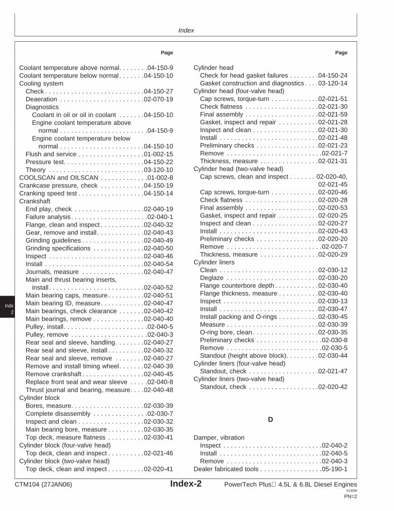
Index
Page Page
Cylinder headCoolant temperature above normal. . . . . . . .04-150-9Check for head gasket failures . . . . . . . .04-150-24Coolant temperature below normal . . . . . . .04-150-10Gasket construction and diagnostics . . . .03-120-14Cooling system
Cylinder head (four-valve head)Check . . . . . . . . . . . . . . . . . . . . . . . . . . .04-150-27Cap screws, torque-turn . . . . . . . . . . . . .02-021-51Deaeration . . . . . . . . . . . . . . . . . . . . . . .02-070-19Check flatness . . . . . . . . . . . . . . . . . . . .02-021-30DiagnosticsFinal assembly . . . . . . . . . . . . . . . . . . . .02-021-59Coolant in oil or oil in coolant . . . . . . .04-150-10Gasket, inspect and repair . . . . . . . . . . .02-021-28Engine coolant temperature aboveInspect and clean . . . . . . . . . . . . . . . . . .02-021-30normal . . . . . . . . . . . . . . . . . . . . . . . .04-150-9Install . . . . . . . . . . . . . . . . . . . . . . . . . . .02-021-48Engine coolant temperature belowPreliminary checks . . . . . . . . . . . . . . . . .02-021-23normal . . . . . . . . . . . . . . . . . . . . . . .04-150-10Remove . . . . . . . . . . . . . . . . . . . . . . . . . .02-021-7Flush and service . . . . . . . . . . . . . . . . . .01-002-15Thickness, measure . . . . . . . . . . . . . . . .02-021-31Pressure test. . . . . . . . . . . . . . . . . . . . . .04-150-22
Cylinder head (two-valve head)Theory . . . . . . . . . . . . . . . . . . . . . . . . . .03-120-10Cap screws, clean and inspect . . . . . . . 02-020-40,COOLSCAN and OILSCAN . . . . . . . . . . . . .01-002-8
02-021-45Crankcase pressure, check . . . . . . . . . . . .04-150-19Cap screws, torque-turn . . . . . . . . . . . . .02-020-46Cranking speed test . . . . . . . . . . . . . . . . . .04-150-14Check flatness . . . . . . . . . . . . . . . . . . . .02-020-28CrankshaftFinal assembly . . . . . . . . . . . . . . . . . . . .02-020-53End play, check . . . . . . . . . . . . . . . . . . .02-040-19Gasket, inspect and repair . . . . . . . . . . .02-020-25Failure analysis . . . . . . . . . . . . . . . . . . . . .02-040-1Inspect and clean . . . . . . . . . . . . . . . . . .02-020-27Flange, clean and inspect . . . . . . . . . . . .02-040-32Install . . . . . . . . . . . . . . . . . . . . . . . . . . .02-020-43Gear, remove and install . . . . . . . . . . . . .02-040-43Preliminary checks . . . . . . . . . . . . . . . . .02-020-20Grinding guidelines . . . . . . . . . . . . . . . . .02-040-49Remove . . . . . . . . . . . . . . . . . . . . . . . . . .02-020-7Grinding specifications . . . . . . . . . . . . . .02-040-50Thickness, measure . . . . . . . . . . . . . . . .02-020-29Inspect . . . . . . . . . . . . . . . . . . . . . . . . . .02-040-46
Cylinder linersInstall . . . . . . . . . . . . . . . . . . . . . . . . . . .02-040-54Clean . . . . . . . . . . . . . . . . . . . . . . . . . . .02-030-12Journals, measure . . . . . . . . . . . . . . . . .02-040-47Deglaze . . . . . . . . . . . . . . . . . . . . . . . . .02-030-20Main and thrust bearing inserts,Flange counterbore depth . . . . . . . . . . . .02-030-40install . . . . . . . . . . . . . . . . . . . . . . . . . .02-040-52Flange thickness, measure . . . . . . . . . . .02-030-40Main bearing caps, measure . . . . . . . . . .02-040-51Inspect . . . . . . . . . . . . . . . . . . . . . . . . . .02-030-13Main bearing ID, measure. . . . . . . . . . . .02-040-47Install . . . . . . . . . . . . . . . . . . . . . . . . . . .02-030-47Main bearings, check clearance . . . . . . .02-040-42Install packing and O-rings . . . . . . . . . . .02-030-45Main bearings, remove . . . . . . . . . . . . . .02-040-40
Indx2
Measure . . . . . . . . . . . . . . . . . . . . . . . . .02-030-39Pulley, install. . . . . . . . . . . . . . . . . . . . . . .02-040-5O-ring bore, clean . . . . . . . . . . . . . . . . . .02-030-35Pulley, remove . . . . . . . . . . . . . . . . . . . . .02-040-3Preliminary checks . . . . . . . . . . . . . . . . . .02-030-8Rear seal and sleeve, handling. . . . . . . .02-040-27Remove . . . . . . . . . . . . . . . . . . . . . . . . . .02-030-5Rear seal and sleeve, install . . . . . . . . . .02-040-32Standout (height above block). . . . . . . . .02-030-44Rear seal and sleeve, remove . . . . . . . .02-040-27
Cylinder liners (four-valve head)Remove and install timing wheel. . . . . . .02-040-39Standout, check . . . . . . . . . . . . . . . . . . .02-021-47Remove crankshaft . . . . . . . . . . . . . . . . .02-040-45
Cylinder liners (two-valve head)Replace front seal and wear sleeve . . . . .02-040-8Standout, check . . . . . . . . . . . . . . . . . . .02-020-42Thrust journal and bearing, measure. . . .02-040-48
Cylinder blockBores, measure. . . . . . . . . . . . . . . . . . . .02-030-39Complete disassembly . . . . . . . . . . . . . . .02-030-7
DInspect and clean . . . . . . . . . . . . . . . . . .02-030-32Main bearing bore, measure . . . . . . . . . .02-030-35Top deck, measure flatness . . . . . . . . . .02-030-41 Damper, vibration
Cylinder block (four-valve head) Inspect . . . . . . . . . . . . . . . . . . . . . . . . . . .02-040-2Top deck, clean and inspect . . . . . . . . . .02-021-46 Install . . . . . . . . . . . . . . . . . . . . . . . . . . . .02-040-5
Cylinder block (two-valve head) Remove . . . . . . . . . . . . . . . . . . . . . . . . . .02-040-3Dealer fabricated tools . . . . . . . . . . . . . . . . .05-190-1Top deck, clean and inspect . . . . . . . . . .02-020-41
CTM104 (27JAN06) Index-2 PowerTech Plus 4.5L & 6.8L Diesel Engines013006
PN=2
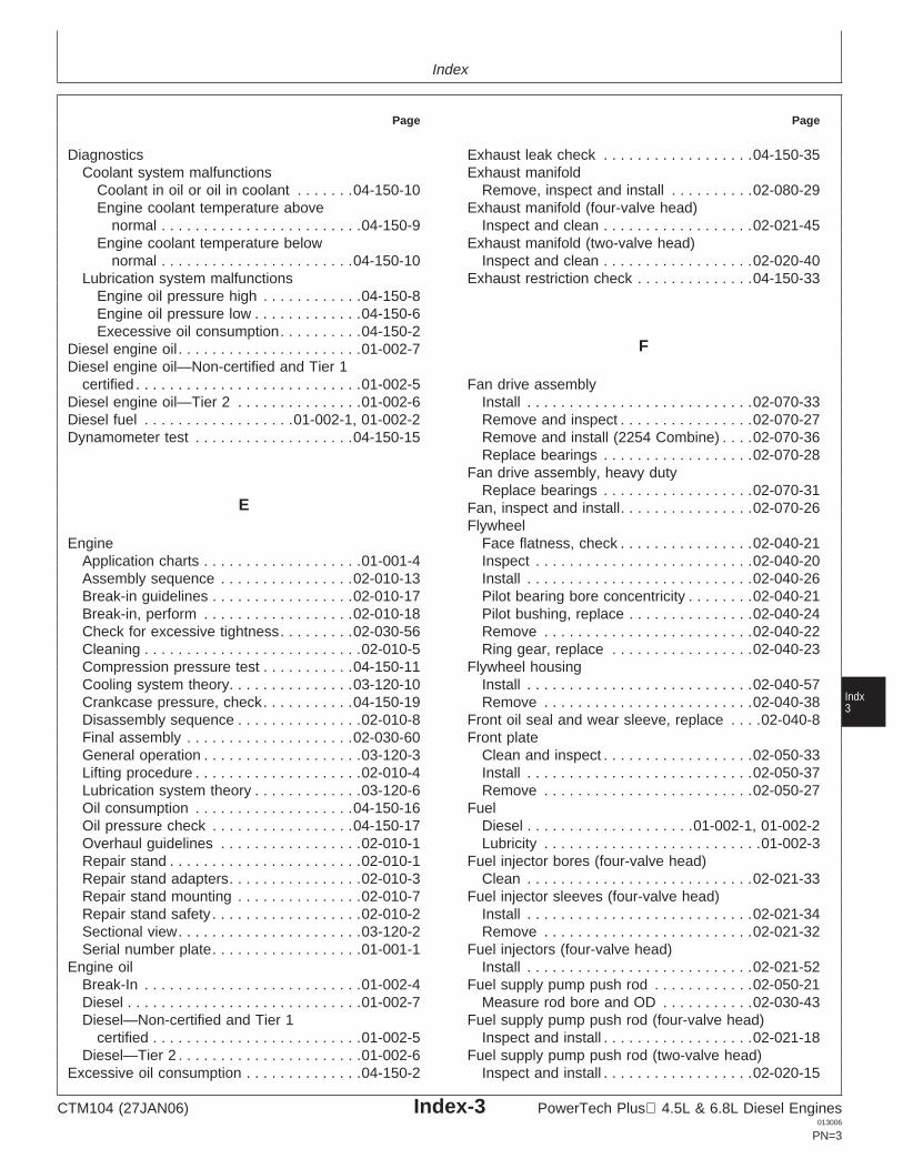
Index
Page Page
Diagnostics Exhaust leak check . . . . . . . . . . . . . . . . . .04-150-35Exhaust manifoldCoolant system malfunctions
Coolant in oil or oil in coolant . . . . . . .04-150-10 Remove, inspect and install . . . . . . . . . .02-080-29Exhaust manifold (four-valve head)Engine coolant temperature above
normal . . . . . . . . . . . . . . . . . . . . . . . .04-150-9 Inspect and clean . . . . . . . . . . . . . . . . . .02-021-45Exhaust manifold (two-valve head)Engine coolant temperature below
normal . . . . . . . . . . . . . . . . . . . . . . .04-150-10 Inspect and clean . . . . . . . . . . . . . . . . . .02-020-40Exhaust restriction check . . . . . . . . . . . . . .04-150-33Lubrication system malfunctions
Engine oil pressure high . . . . . . . . . . . .04-150-8Engine oil pressure low . . . . . . . . . . . . .04-150-6Execessive oil consumption. . . . . . . . . .04-150-2
FDiesel engine oil . . . . . . . . . . . . . . . . . . . . . .01-002-7Diesel engine oil—Non-certified and Tier 1
certified . . . . . . . . . . . . . . . . . . . . . . . . . . .01-002-5 Fan drive assemblyInstall . . . . . . . . . . . . . . . . . . . . . . . . . . .02-070-33Diesel engine oil—Tier 2 . . . . . . . . . . . . . . .01-002-6
Diesel fuel . . . . . . . . . . . . . . . . . .01-002-1, 01-002-2 Remove and inspect . . . . . . . . . . . . . . . .02-070-27Remove and install (2254 Combine) . . . .02-070-36Dynamometer test . . . . . . . . . . . . . . . . . . .04-150-15Replace bearings . . . . . . . . . . . . . . . . . .02-070-28
Fan drive assembly, heavy dutyReplace bearings . . . . . . . . . . . . . . . . . .02-070-31
E Fan, inspect and install. . . . . . . . . . . . . . . .02-070-26Flywheel
Face flatness, check . . . . . . . . . . . . . . . .02-040-21EngineApplication charts . . . . . . . . . . . . . . . . . . .01-001-4 Inspect . . . . . . . . . . . . . . . . . . . . . . . . . .02-040-20
Install . . . . . . . . . . . . . . . . . . . . . . . . . . .02-040-26Assembly sequence . . . . . . . . . . . . . . . .02-010-13Break-in guidelines . . . . . . . . . . . . . . . . .02-010-17 Pilot bearing bore concentricity . . . . . . . .02-040-21
Pilot bushing, replace . . . . . . . . . . . . . . .02-040-24Break-in, perform . . . . . . . . . . . . . . . . . .02-010-18Check for excessive tightness. . . . . . . . .02-030-56 Remove . . . . . . . . . . . . . . . . . . . . . . . . .02-040-22
Ring gear, replace . . . . . . . . . . . . . . . . .02-040-23Cleaning . . . . . . . . . . . . . . . . . . . . . . . . . .02-010-5Compression pressure test . . . . . . . . . . .04-150-11 Flywheel housingCooling system theory. . . . . . . . . . . . . . .03-120-10 Install . . . . . . . . . . . . . . . . . . . . . . . . . . .02-040-57
IndxCrankcase pressure, check. . . . . . . . . . .04-150-19 Remove . . . . . . . . . . . . . . . . . . . . . . . . .02-040-38 3Disassembly sequence . . . . . . . . . . . . . . .02-010-8 Front oil seal and wear sleeve, replace . . . .02-040-8
Front plateFinal assembly . . . . . . . . . . . . . . . . . . . .02-030-60General operation . . . . . . . . . . . . . . . . . . .03-120-3 Clean and inspect . . . . . . . . . . . . . . . . . .02-050-33
Install . . . . . . . . . . . . . . . . . . . . . . . . . . .02-050-37Lifting procedure . . . . . . . . . . . . . . . . . . . .02-010-4Lubrication system theory . . . . . . . . . . . . .03-120-6 Remove . . . . . . . . . . . . . . . . . . . . . . . . .02-050-27
FuelOil consumption . . . . . . . . . . . . . . . . . . .04-150-16Oil pressure check . . . . . . . . . . . . . . . . .04-150-17 Diesel . . . . . . . . . . . . . . . . . . . .01-002-1, 01-002-2
Lubricity . . . . . . . . . . . . . . . . . . . . . . . . . .01-002-3Overhaul guidelines . . . . . . . . . . . . . . . . .02-010-1Repair stand . . . . . . . . . . . . . . . . . . . . . . .02-010-1 Fuel injector bores (four-valve head)
Clean . . . . . . . . . . . . . . . . . . . . . . . . . . .02-021-33Repair stand adapters. . . . . . . . . . . . . . . .02-010-3Repair stand mounting . . . . . . . . . . . . . . .02-010-7 Fuel injector sleeves (four-valve head)
Install . . . . . . . . . . . . . . . . . . . . . . . . . . .02-021-34Repair stand safety . . . . . . . . . . . . . . . . . .02-010-2Sectional view. . . . . . . . . . . . . . . . . . . . . .03-120-2 Remove . . . . . . . . . . . . . . . . . . . . . . . . .02-021-32
Fuel injectors (four-valve head)Serial number plate. . . . . . . . . . . . . . . . . .01-001-1Engine oil Install . . . . . . . . . . . . . . . . . . . . . . . . . . .02-021-52
Fuel supply pump push rod . . . . . . . . . . . .02-050-21Break-In . . . . . . . . . . . . . . . . . . . . . . . . . .01-002-4Diesel . . . . . . . . . . . . . . . . . . . . . . . . . . . .01-002-7 Measure rod bore and OD . . . . . . . . . . .02-030-43
Fuel supply pump push rod (four-valve head)Diesel—Non-certified and Tier 1certified . . . . . . . . . . . . . . . . . . . . . . . . .01-002-5 Inspect and install . . . . . . . . . . . . . . . . . .02-021-18
Fuel supply pump push rod (two-valve head)Diesel—Tier 2 . . . . . . . . . . . . . . . . . . . . . .01-002-6Excessive oil consumption . . . . . . . . . . . . . .04-150-2 Inspect and install . . . . . . . . . . . . . . . . . .02-020-15
CTM104 (27JAN06) Index-3 PowerTech Plus 4.5L & 6.8L Diesel Engines013006
PN=3
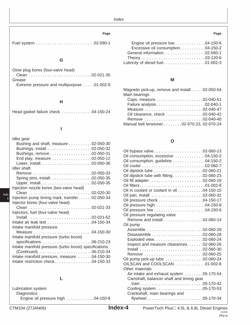
Index
Page Page
Fuel system . . . . . . . . . . . . . . . . . . . . . . . . .02-090-1 Engine oil pressure low . . . . . . . . . . . . .04-150-6Excessive oil consumption. . . . . . . . . . .04-150-2
General information. . . . . . . . . . . . . . . . . .02-060-1Theory . . . . . . . . . . . . . . . . . . . . . . . . . . .03-120-6G
Lubricity of diesel fuel. . . . . . . . . . . . . . . . . .01-002-3
Glow plug bores (four-valve head)Clean . . . . . . . . . . . . . . . . . . . . . . . . . . .02-021-35
Grease MExtreme pressure and multipurpose . . . . .01-002-9
Magnetic pick-up, remove and install . . . . .02-050-54Main bearings
Caps, measure . . . . . . . . . . . . . . . . . . . .02-040-51HFailure analysis . . . . . . . . . . . . . . . . . . . . .02-040-1Measure . . . . . . . . . . . . . . . . . . . . . . . . .02-040-47
Head gasket failure check . . . . . . . . . . . . .04-150-24Oil clearance, check . . . . . . . . . . . . . . . .02-040-42Remove . . . . . . . . . . . . . . . . . . . . . . . . .02-040-40
Manual belt tensioner . . . . . . . .02-070-23, 02-070-24I
Idler gear OBushing and shaft, measure . . . . . . . . . .02-050-30Bushings, install . . . . . . . . . . . . . . . . . . .02-050-32
Oil bypass valve . . . . . . . . . . . . . . . . . . . . .02-060-13Bushings, remove . . . . . . . . . . . . . . . . . .02-050-31
Oil consumption, excessive . . . . . . . . . . . . .04-150-2End play, measure . . . . . . . . . . . . . . . . .02-050-12
Oil consumption, guideline . . . . . . . . . . . . . .04-150-2Lower, install. . . . . . . . . . . . . . . . . . . . . .02-050-36
Oil cooler . . . . . . . . . . . . . . . . . . . . . . . . . . .02-060-7Idler shaft
Oil dipstick tube . . . . . . . . . . . . . . . . . . . . .02-060-21Remove . . . . . . . . . . . . . . . . . . . . . . . . .02-050-33
Oil dipstick tube with fitting . . . . . . . . . . . . .02-060-23Spring pins, install. . . . . . . . . . . . . . . . . .02-050-35
Oil fill adapter . . . . . . . . . . . . . . . . . . . . . . .02-060-19Upper, install. . . . . . . . . . . . . . . . . . . . . .02-050-35
Oil filters . . . . . . . . . . . . . . . . . . . . . . . . . . . .01-002-8Injection nozzle bores (two-valve head)
Oil in coolant or coolant in oil . . . . . . . . . . .04-150-10Clean . . . . . . . . . . . . . . . . . . . . . . . . . . .02-020-30
Oil pan, install . . . . . . . . . . . . . . . . . . . . . .02-060-32Injection pump timing mark, transfer . . . . . .02-050-34
Oil pressure check . . . . . . . . . . . . . . . . . . .04-150-17Injector bores (four-valve head)
Indx4
Oil pressure high . . . . . . . . . . . . . . . . . . . . .04-150-8Clean . . . . . . . . . . . . . . . . . . . . . . . . . . .02-021-33
Oil pressure low . . . . . . . . . . . . . . . . . . . . . .04-150-6Injectors, fuel (four-valve head)
Oil pressure regulating valveInstall . . . . . . . . . . . . . . . . . . . . . . . . . . .02-021-52
Remove and install . . . . . . . . . . . . . . . . .02-060-14Intake air leak test . . . . . . . . . . . . . . . . . . .04-150-34
Oil pumpIntake manifold pressure
Assemble . . . . . . . . . . . . . . . . . . . . . . . .02-060-29Measure . . . . . . . . . . . . . . . . . . . . . . . . .04-150-30
Disassemble . . . . . . . . . . . . . . . . . . . . . .02-060-28Intake manifold pressure (turbo boost)
Exploded view. . . . . . . . . . . . . . . . . . . . .02-060-24specifications . . . . . . . . . . . . . . . . . . . . .06-210-23
Inspect and measure clearances. . . . . . .02-060-26Intake manifold pressure (turbo boost) specifications
Install . . . . . . . . . . . . . . . . . . . . . . . . . . .02-060-30(Continued) . . . . . . . . . . . . . . . . . . . . . . .06-210-34
Remove . . . . . . . . . . . . . . . . . . . . . . . . .02-060-25Intake manifold pressure, measure. . . . . . .04-150-30
Oil pump pick-up tube . . . . . . . . . . . . . . . .02-060-24Intake restriction check. . . . . . . . . . . . . . . .04-150-33
OILSCAN and COOLSCAN . . . . . . . . . . . . .01-002-8Other materials
Air intake and exhaust system . . . . . . . .05-170-54Camshaft, balancer shaft and timing gearL
train . . . . . . . . . . . . . . . . . . . . . . . . . . .05-170-42Cooling system . . . . . . . . . . . . . . . . . . . .05-170-53Lubrication system
Diagnostics Crankshaft, main bearings andflywheel . . . . . . . . . . . . . . . . . . . . . . . .05-170-34Engine oil pressure high . . . . . . . . . . . .04-150-8
CTM104 (27JAN06) Index-4 PowerTech Plus 4.5L & 6.8L Diesel Engines013006
PN=4

Index
Page Page
Cylinder block, liners, pistons and Rocker arm assembly (four-valve head)Assemble . . . . . . . . . . . . . . . . . . . . . . . .02-021-18rods . . . . . . . . . . . . . . . . . . . . . . . . . . .05-170-26
Cylinder head and valves (four-valve Disassemble and inspect . . . . . . . . . . . .02-021-17Install . . . . . . . . . . . . . . . . . . . . . . . . . . .02-021-54head). . . . . . . . . . . . . . . . . . . . . . . . . .05-170-20
Cylinder head and valves (two-valve Rocker arm assembly (two-valve head)Assemble . . . . . . . . . . . . . . . . . . . . . . . .02-020-15head). . . . . . . . . . . . . . . . . . . . . . . . . .05-170-11
Engine rebuild. . . . . . . . . . . . . . . . . . . . . .05-170-3 Disassemble and inspect . . . . . . . . . . . .02-020-14Install . . . . . . . . . . . . . . . . . . . . . . . . . . .02-020-47Lubrication system . . . . . . . . . . . . . . . . .05-170-49
Rocker arm cover (four-valve head)Install . . . . . . . . . . . . . . . . . . . . . . . . . . .02-021-58
Rocker arm cover (two-valve head)P Install . . . . . . . . . . . . . . . . . . . . . . . . . . .02-020-50
Pilot bearing bore concentricity. . . . . . . . . .02-040-21Piston cooling orifices. . . . . . . . . . . . . . . . .02-030-42 SPiston-to-liner clearance, measure . . . . . . .02-030-18Pistons Safety precautions, repair stand
Check ring groove wear . . . . . . . . . . . . .02-030-15 mounting. . . . . . . . . . . . . . . . . . . . . . . . . .02-010-2Clean . . . . . . . . . . . . . . . . . . . . . . . . . . .02-030-10 Sealant application guidelines . . . . . . . . . .02-010-12Disassemble . . . . . . . . . . . . . . . . . . . . . . .02-030-9 SensorInspect . . . . . . . . . . . . . . . . . . . . . . . . . .02-030-11 Magnetic pick-up, remove and install . . .02-050-54Measure height . . . . . . . . . . . . . . . . . . . .02-030-17 Serial number plate . . . . . . . . . . . . . . . . . . .01-001-1Pins and bushings, inspect . . . . . . . . . . .02-030-25 SpecificationsPiston pin bore, measure . . . . . . . . . . . .02-030-16 Air intake and exhaust system . . . . . . . .06-200-37Piston pin bushings, remove . . . . . . . . . .02-030-26 Camshaft, balancer shafts and timing gearPiston-to-liner clearance, measure . . . . .02-030-18 train . . . . . . . . . . . . . . . . . . . . . . . . . . .06-200-24Pistons and rods, assemble . . . . . . . . . .02-030-49 Cooling system . . . . . . . . . . . . . . . . . . . .06-200-33Pistons and rods, install . . . . . . . . . . . . .02-030-51 Crankshaft, main bearings andPreliminary checks . . . . . . . . . . . . . . . . . .02-030-8 flywheel . . . . . . . . . . . . . . . . . . . . . . . .06-200-21Protrusion, measure . . . . . . . . . . . . . . . .02-030-57 Cylinder block, pistons and rods . . . . . . .06-200-14Remove . . . . . . . . . . . . . . . . . . . . . . . . . .02-030-2 Cylinder head and valves (four-valve
IndxRing grooves, check wear. . . . . . . . . . . .02-030-15 head). . . . . . . . . . . . . . . . . . . . . . . . . .06-200-10 5Rings, install . . . . . . . . . . . . . . . . . . . . . .02-030-50 Cylinder head and valves (two-valveSkirt, measure. . . . . . . . . . . . . . . . . . . . .02-030-17 head). . . . . . . . . . . . . . . . . . . . . . . . . . .06-200-6
Pistons and liner sets, replace . . . . . . . . . .02-030-20 Diagnostic, engine . . . . . . . . . . . . . . . . . .06-210-1Pump, coolant Dynamometer . . . . . . . . . . . . . . . . . . . . . .06-210-1
Assemble . . . . . . . . . . . . . . . . . . . . . . . .02-070-15 Engine rebuild. . . . . . . . . . . . . . . . . . . . . .06-200-5Pump, Coolant General OEM engine specifications . . . . .06-200-3
Clean and inspect . . . . . . . . . . . . . . . . . .02-070-14 Lubrication system . . . . . . . . . . . . . . . . .06-200-30Disassemble . . . . . . . . . . . . . . . . . . . . . .02-070-13 Starting and charging systems . . . . . . . .06-200-38Exploded view. . . . . . . . . . . . . . . . . . . . .02-070-12 Turbocharger boost pressure . . . . . . . . .06-210-23Install . . . . . . . . . . . . . . . . . . . . . . . . . . .02-070-17 Turbocharger boost pressureRemove . . . . . . . . . . . . . . . . . . . . . . . . .02-070-11 (Continued) . . . . . . . . . . . . . . . . . . . . .06-210-34
Start aid, remove and install . . . . . . . . . . . .02-080-40Starting and charging system,
specifications . . . . . . . . . . . . . . . . . . . . .06-200-38R Starting motor. . . . . . . . . . . . . . . . . . . . . . . .02-100-1
Radiator cap, pressure test . . . . . . . . . . . .04-150-22Rear seal and sleeve T
Install . . . . . . . . . . . . . . . . . . . . . . . . . . .02-040-32Remove . . . . . . . . . . . . . . . . . . . . . . . . .02-040-27 Temperature, effects on engine
performance . . . . . . . . . . . . . . . . . . . . . .06-210-65Repair stand mounting safety . . . . . . . . . . . .02-010-2
CTM104 (27JAN06) Index-5 PowerTech Plus 4.5L & 6.8L Diesel Engines013006
PN=5
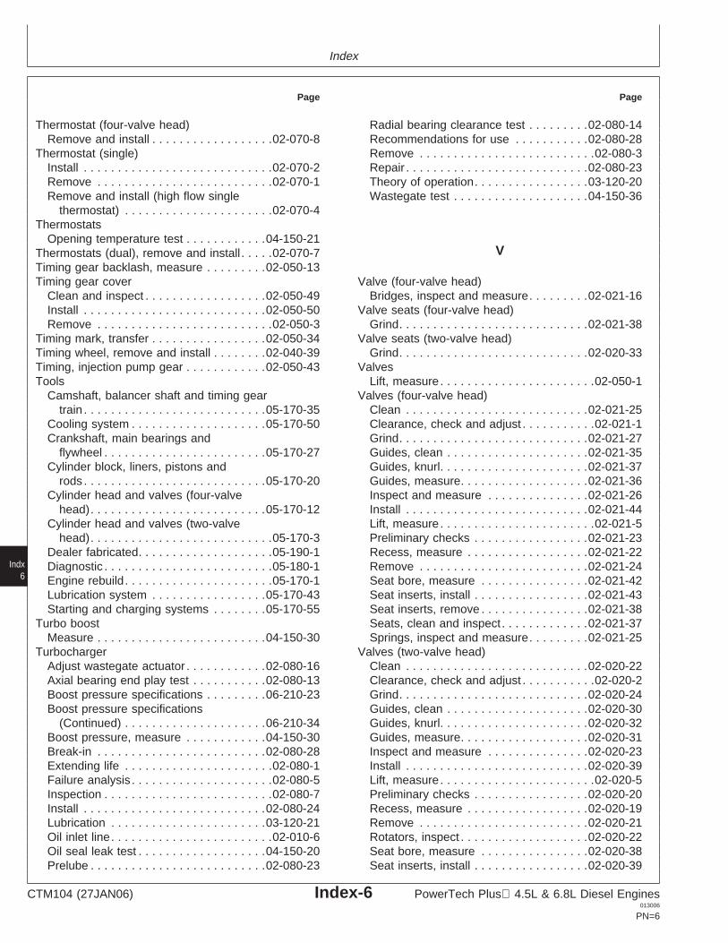
Index
Page Page
Thermostat (four-valve head) Radial bearing clearance test . . . . . . . . .02-080-14Recommendations for use . . . . . . . . . . .02-080-28Remove and install . . . . . . . . . . . . . . . . . .02-070-8
Thermostat (single) Remove . . . . . . . . . . . . . . . . . . . . . . . . . .02-080-3Repair . . . . . . . . . . . . . . . . . . . . . . . . . . .02-080-23Install . . . . . . . . . . . . . . . . . . . . . . . . . . . .02-070-2
Remove . . . . . . . . . . . . . . . . . . . . . . . . . .02-070-1 Theory of operation. . . . . . . . . . . . . . . . .03-120-20Wastegate test . . . . . . . . . . . . . . . . . . . .04-150-36Remove and install (high flow single
thermostat) . . . . . . . . . . . . . . . . . . . . . .02-070-4Thermostats
Opening temperature test . . . . . . . . . . . .04-150-21VThermostats (dual), remove and install . . . . .02-070-7
Timing gear backlash, measure . . . . . . . . .02-050-13Timing gear cover Valve (four-valve head)
Bridges, inspect and measure. . . . . . . . .02-021-16Clean and inspect . . . . . . . . . . . . . . . . . .02-050-49Install . . . . . . . . . . . . . . . . . . . . . . . . . . .02-050-50 Valve seats (four-valve head)
Grind. . . . . . . . . . . . . . . . . . . . . . . . . . . .02-021-38Remove . . . . . . . . . . . . . . . . . . . . . . . . . .02-050-3Timing mark, transfer . . . . . . . . . . . . . . . . .02-050-34 Valve seats (two-valve head)
Grind. . . . . . . . . . . . . . . . . . . . . . . . . . . .02-020-33Timing wheel, remove and install . . . . . . . .02-040-39Timing, injection pump gear . . . . . . . . . . . .02-050-43 Valves
Lift, measure . . . . . . . . . . . . . . . . . . . . . . .02-050-1ToolsCamshaft, balancer shaft and timing gear Valves (four-valve head)
Clean . . . . . . . . . . . . . . . . . . . . . . . . . . .02-021-25train . . . . . . . . . . . . . . . . . . . . . . . . . . .05-170-35Cooling system . . . . . . . . . . . . . . . . . . . .05-170-50 Clearance, check and adjust . . . . . . . . . . .02-021-1
Grind. . . . . . . . . . . . . . . . . . . . . . . . . . . .02-021-27Crankshaft, main bearings andflywheel . . . . . . . . . . . . . . . . . . . . . . . .05-170-27 Guides, clean . . . . . . . . . . . . . . . . . . . . .02-021-35
Guides, knurl. . . . . . . . . . . . . . . . . . . . . .02-021-37Cylinder block, liners, pistons androds . . . . . . . . . . . . . . . . . . . . . . . . . . .05-170-20 Guides, measure. . . . . . . . . . . . . . . . . . .02-021-36
Inspect and measure . . . . . . . . . . . . . . .02-021-26Cylinder head and valves (four-valvehead). . . . . . . . . . . . . . . . . . . . . . . . . .05-170-12 Install . . . . . . . . . . . . . . . . . . . . . . . . . . .02-021-44
Lift, measure . . . . . . . . . . . . . . . . . . . . . . .02-021-5Cylinder head and valves (two-valvehead). . . . . . . . . . . . . . . . . . . . . . . . . . .05-170-3 Preliminary checks . . . . . . . . . . . . . . . . .02-021-23
Recess, measure . . . . . . . . . . . . . . . . . .02-021-22Dealer fabricated. . . . . . . . . . . . . . . . . . . .05-190-1Diagnostic . . . . . . . . . . . . . . . . . . . . . . . . .05-180-1 Remove . . . . . . . . . . . . . . . . . . . . . . . . .02-021-24
Seat bore, measure . . . . . . . . . . . . . . . .02-021-42Engine rebuild. . . . . . . . . . . . . . . . . . . . . .05-170-1
Indx6
Lubrication system . . . . . . . . . . . . . . . . .05-170-43 Seat inserts, install . . . . . . . . . . . . . . . . .02-021-43Seat inserts, remove . . . . . . . . . . . . . . . .02-021-38Starting and charging systems . . . . . . . .05-170-55
Turbo boost Seats, clean and inspect. . . . . . . . . . . . .02-021-37Springs, inspect and measure. . . . . . . . .02-021-25Measure . . . . . . . . . . . . . . . . . . . . . . . . .04-150-30
Turbocharger Valves (two-valve head)Clean . . . . . . . . . . . . . . . . . . . . . . . . . . .02-020-22Adjust wastegate actuator . . . . . . . . . . . .02-080-16
Axial bearing end play test . . . . . . . . . . .02-080-13 Clearance, check and adjust . . . . . . . . . . .02-020-2Grind. . . . . . . . . . . . . . . . . . . . . . . . . . . .02-020-24Boost pressure specifications . . . . . . . . .06-210-23
Boost pressure specifications Guides, clean . . . . . . . . . . . . . . . . . . . . .02-020-30Guides, knurl. . . . . . . . . . . . . . . . . . . . . .02-020-32(Continued) . . . . . . . . . . . . . . . . . . . . .06-210-34
Boost pressure, measure . . . . . . . . . . . .04-150-30 Guides, measure. . . . . . . . . . . . . . . . . . .02-020-31Inspect and measure . . . . . . . . . . . . . . .02-020-23Break-in . . . . . . . . . . . . . . . . . . . . . . . . .02-080-28
Extending life . . . . . . . . . . . . . . . . . . . . . .02-080-1 Install . . . . . . . . . . . . . . . . . . . . . . . . . . .02-020-39Lift, measure . . . . . . . . . . . . . . . . . . . . . . .02-020-5Failure analysis . . . . . . . . . . . . . . . . . . . . .02-080-5
Inspection . . . . . . . . . . . . . . . . . . . . . . . . .02-080-7 Preliminary checks . . . . . . . . . . . . . . . . .02-020-20Recess, measure . . . . . . . . . . . . . . . . . .02-020-19Install . . . . . . . . . . . . . . . . . . . . . . . . . . .02-080-24
Lubrication . . . . . . . . . . . . . . . . . . . . . . .03-120-21 Remove . . . . . . . . . . . . . . . . . . . . . . . . .02-020-21Rotators, inspect . . . . . . . . . . . . . . . . . . .02-020-22Oil inlet line. . . . . . . . . . . . . . . . . . . . . . . .02-010-6
Oil seal leak test . . . . . . . . . . . . . . . . . . .04-150-20 Seat bore, measure . . . . . . . . . . . . . . . .02-020-38Seat inserts, install . . . . . . . . . . . . . . . . .02-020-39Prelube . . . . . . . . . . . . . . . . . . . . . . . . . .02-080-23
CTM104 (27JAN06) Index-6 PowerTech Plus 4.5L & 6.8L Diesel Engines013006
PN=6
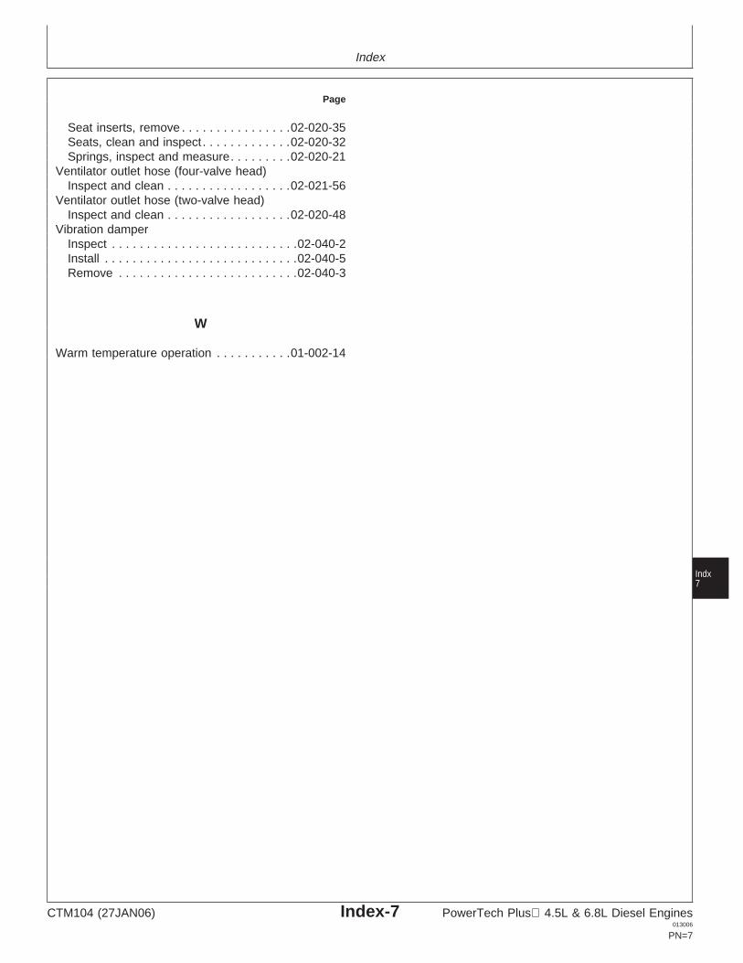
Index
Page
Seat inserts, remove . . . . . . . . . . . . . . . .02-020-35Seats, clean and inspect. . . . . . . . . . . . .02-020-32Springs, inspect and measure. . . . . . . . .02-020-21
Ventilator outlet hose (four-valve head)Inspect and clean . . . . . . . . . . . . . . . . . .02-021-56
Ventilator outlet hose (two-valve head)Inspect and clean . . . . . . . . . . . . . . . . . .02-020-48
Vibration damperInspect . . . . . . . . . . . . . . . . . . . . . . . . . . .02-040-2Install . . . . . . . . . . . . . . . . . . . . . . . . . . . .02-040-5Remove . . . . . . . . . . . . . . . . . . . . . . . . . .02-040-3
W
Warm temperature operation . . . . . . . . . . .01-002-14
Indx7
CTM104 (27JAN06) Index-7 PowerTech Plus 4.5L & 6.8L Diesel Engines013006
PN=7
Index
Indx8
CTM104 (27JAN06) Index-8 PowerTech Plus 4.5L & 6.8L Diesel Engines013006
PN=8