te MARX Type Circuit for the E Target Voltage Modulator
14
Solid-State MARX T ISOLDE Target Vo 22 Set 2009 EPPC 09 21-25 Septem L.M. Redondo *, J. Fernando Silva # , H. R. Soares † , J. Schipp Work supported by FCT * Nuclear Physics Center - Lisbon U # Center for Innovation in Electrical and Energ † ABT Group, TE Departm Type Circuit for the oltage Modulator 9 CERN mber 2009 1/14 . Canacsinh*, N. Ferrão*, C. Mendes*, per † and A. Fowler † T project CERN-FP-83497-2008 University (CFNUL), Lisbon, Portugal gy Engineering – TU Lisbon, Lisbon, Portugal ment, CERN, Switzerland
-
Upload
khangminh22 -
Category
Documents
-
view
3 -
download
0
Transcript of te MARX Type Circuit for the E Target Voltage Modulator
Solid-State MARX Type Circuit for the ISOLDE Target Voltage Modulator
22 Set 2009EPPC 09 CERN
21-25 September
L.M. Redondo*, J. Fernando Silva#, H. Canacsinh*, N. Ferrão*, C. Mendes*, R. Soares†, J. Schipper
Work supported by FCT project
* Nuclear Physics Center - Lisbon University (CFNUL), Lisbon, Portugal# Center for Innovation in Electrical and Energy Engineering
† ABT Group, TE Department, CERN, Switzerland
State MARX Type Circuit for the ISOLDE Target Voltage Modulator
EPPC 09 CERN September 2009 1/14
, H. Canacsinh*, N. Ferrão*, C. Mendes*, , J. Schipper† and A. Fowler†
Work supported by FCT project CERN-FP-83497-2008
Lisbon University (CFNUL), Lisbon, Portugal# Center for Innovation in Electrical and Energy Engineering – TU Lisbon, Lisbon, Portugal
† ABT Group, TE Department, CERN, Switzerland

Summary
• ISOLDE Target Voltage Modulator (the actual system, the issues, the motivation);
• System requirements and new concept
• Proposed solid-state modulator;
22 Set 2009EPPC 09 CERN
21-25 September
• Proposed solid-state modulator;
• Prototype layout and experimental results
• Conclusions and future work
Summary
ISOLDE Target Voltage Modulator (the actual system, the issues, the motivation);
System requirements and new concept;
state modulator;
EPPC 09 CERN September 2009 2/14
state modulator;
Prototype layout and experimental results
Conclusions and future work
ISOLDE Target Voltage Modulator
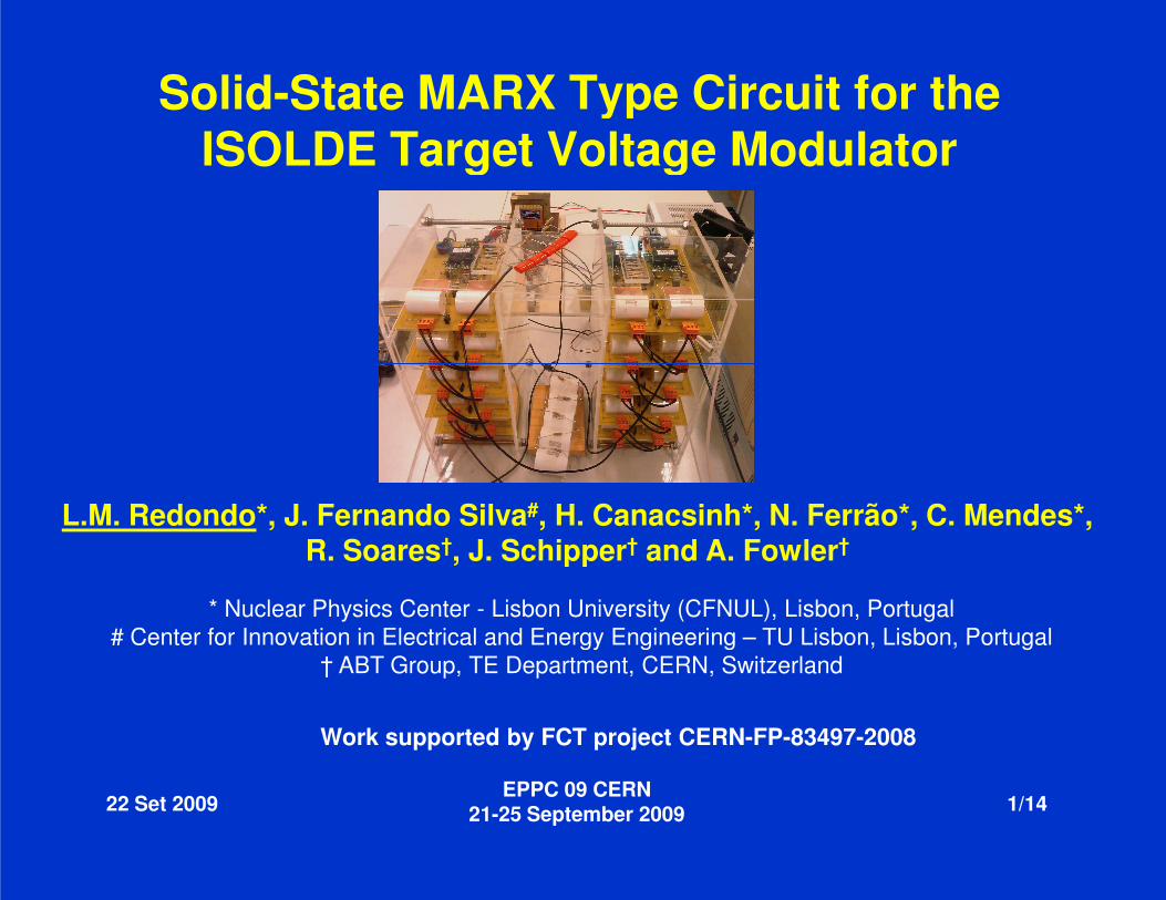
The On-Line Isotope Mass Separatorfacility uses the 1.4 GeV proton beam (up to 2 µA ) from the PS-booster at CERN to bombard a target and produce a wide range of isotopes.
To provide the needed acceleration, the target and ion source must be held at a
22 Set 2009EPPC 09 CERN
21-25 September
The impacting proton beam intensivelythe accelerating voltage because it representspower supply.
target and ion source must be held at a precise voltage (60 kV±1V), with respect to a grounded extraction electrode, if there is to be high mass resolution in the downstream separator.
ISOLDE Target Voltage Modulator
EPPC 09 CERN September 2009 3/14
ionises the air. This ionisation perturbsrepresents a significant additional load on the
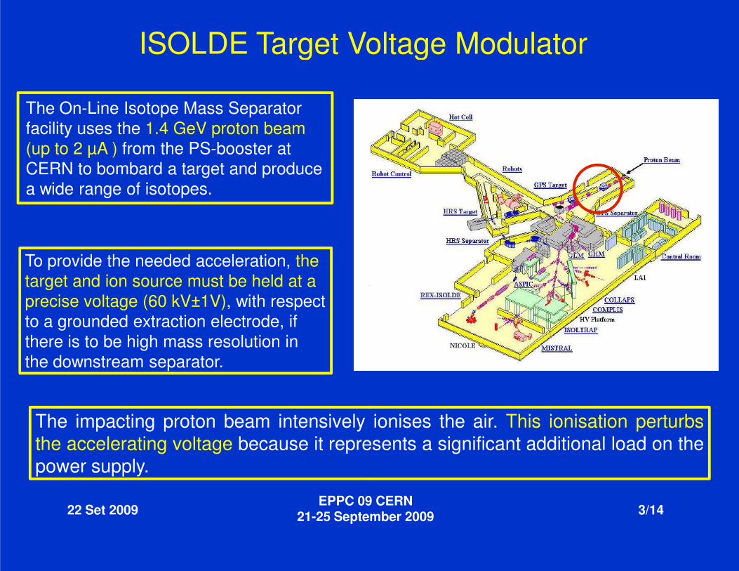
During the critical period when protons strike the target the accelerating voltage is modulated to zero. This is acceptable provided that the stable accelerating voltage of 60 kV +/- 1 V is interrupted for less than 10 ms, so still allowing the detection of very short life-time radio isotopes.
ISOLDE Target Voltage Modulator
[3] D.C. Fiander, A. Fowler, in 20th Power
22 Set 2009EPPC 09 CERN
21-25 September
At present a custom-built positive 60 kV d.c. power supply (PS), Iconnected, via a pulse transformer and a hardcircuit such that prior to beam impact the target is fully circuit in 35µs, which then restores the voltagefurther 200µs. Finally, returns to its nominal value ± 1 V within 5 to 6 ms.
[3] D.C. Fiander, A. Fowler, in 20 Power Modulator Symposium, 1992, pp. 173-176.
1 V is interrupted for less than 10 , so still allowing the detection of very short
ISOLDE Target Voltage Modulator60 kV
EPPC 09 CERN September 2009 4/14
built positive 60 kV d.c. power supply (PS), Imax<40 mA, is connected, via a pulse transformer and a hard-tube switch (tetrode), to a resonant
such that prior to beam impact the target is fully discharged by the resonant restores the voltage close to its nominal value within a
1 V within 5 to 6 ms.
ISOLDE Target Voltage Modulator
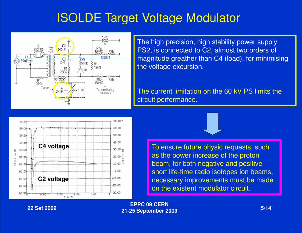
The high precision, high stability power supply PS2, is connected to C2, almost two orders of magnitude greather than C4 (load), for minimising the voltage excursion.
The current limitation on the 60 kV PS limits the circuit performance.
22 Set 2009EPPC 09 CERN
21-25 September
C4 voltage
C2 voltage
ISOLDE Target Voltage Modulator
The high precision, high stability power supply PS2, is connected to C2, almost two orders of magnitude greather than C4 (load), for minimising the voltage excursion.
The current limitation on the 60 kV PS limits the circuit performance.
EPPC 09 CERN September 2009 5/14
To ensure future physic requests, such as the power increase of the proton beam, for both negative and positive short life-time radio isotopes ion beams, necessary improvements must be made on the existent modulator circuit.
System requirements and new concept
Udc
S1
Rdc
Cdc
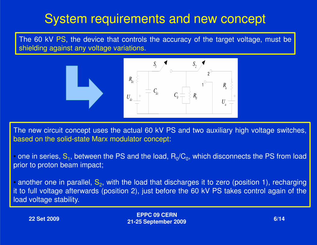
The 60 kV PS, the device that controls theshielding against any voltage variations.
22 Set 2009EPPC 09 CERN
21-25 September
The new circuit concept uses the actual 60 kVbased on the solid-state Marx modulator concept
• one in series, S1, between the PS and the load,prior to proton beam impact;
• another one in parallel, S2, with the load thatit to full voltage afterwards (position 2), just beforeload voltage stability.
System requirements and new concept
Ua
S2
1
2
dc C0 R0
Ra
the accuracy of the target voltage, must be
EPPC 09 CERN September 2009 6/14
kV PS and two auxiliary high voltage switches,concept:
load, R0/C0, which disconnects the PS from load
that discharges it to zero (position 1), rechargingbefore the 60 kV PS takes control again of the
Positive Solid-State Marx generator operation
Tp1
Tc1
C1 C2
Dc1
Tp2
Tc2
Dc2
Cn-1
Tp(n-1)
Tc(n-1)
Dc(n-1)
Tpn
Tcn
Cn
Tc0
Vdc
rdc
Load
i0
v 0
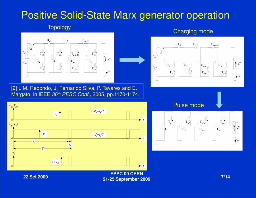
[2] L.M. Redondo, J. Fernando Silva, P. Tavares and E. Margato, in IEEE 36th PESC Conf., 2005, pp.1170-1174
Topology
22 Set 2009EPPC 09 CERN
21-25 September
tp
vgs(Tpi)
vgs(Tci)
Vi
Vi
T
tc
v0
+nVdc0
0
0
dp=tp/T
dc=tc/T
State Marx generator operation
Tc1
C1 C2
Dc1
Tc2
Dc2
Cn-1
Tc(n-1)
Dc(n-1)
Tcn
Cn
Tc0
Vdc
rdc
Load
i0
v 0
L.M. Redondo, J. Fernando Silva, P. Tavares and E. 1174.
Charging mode
EPPC 09 CERN September 2009 7/14
Tp1
C1 C2
Tp2
Cn-1
Tp(n-1) Tpn
Cn Load
i0
v 0
t
t
t
Pulse mode
Proposed Solid-State Modulator
Marx 1
Cn
Dpn
Tcn
Udc
Rdc
vc v0
Cdc
Dp1
Tc1
C1C2
Dc1Dc(n-1)
vm1
22 Set 2009EPPC 09 CERN
21-25 September
R
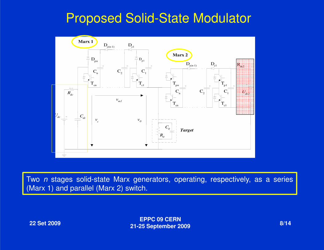
Two n stages solid-state Marx generators,(Marx 1) and parallel (Marx 2) switch.
State Modulator
C
Udc2
Tpn
Cn
Tcn Tc1
C1C2
Dc1Dc(n-1)
Tp1
Rdc2
Marx 2
EPPC 09 CERN September 2009 8/14
TargetR0
C0
generators, operating, respectively, as a series
Marx 1
Tcn
Udc
Rdc
Target
vc v0
Cdc
R0
C0
Udc2
Tc1 Tpn
Cn C1C2
Tp1
Rdc2
Marx 2
vm1
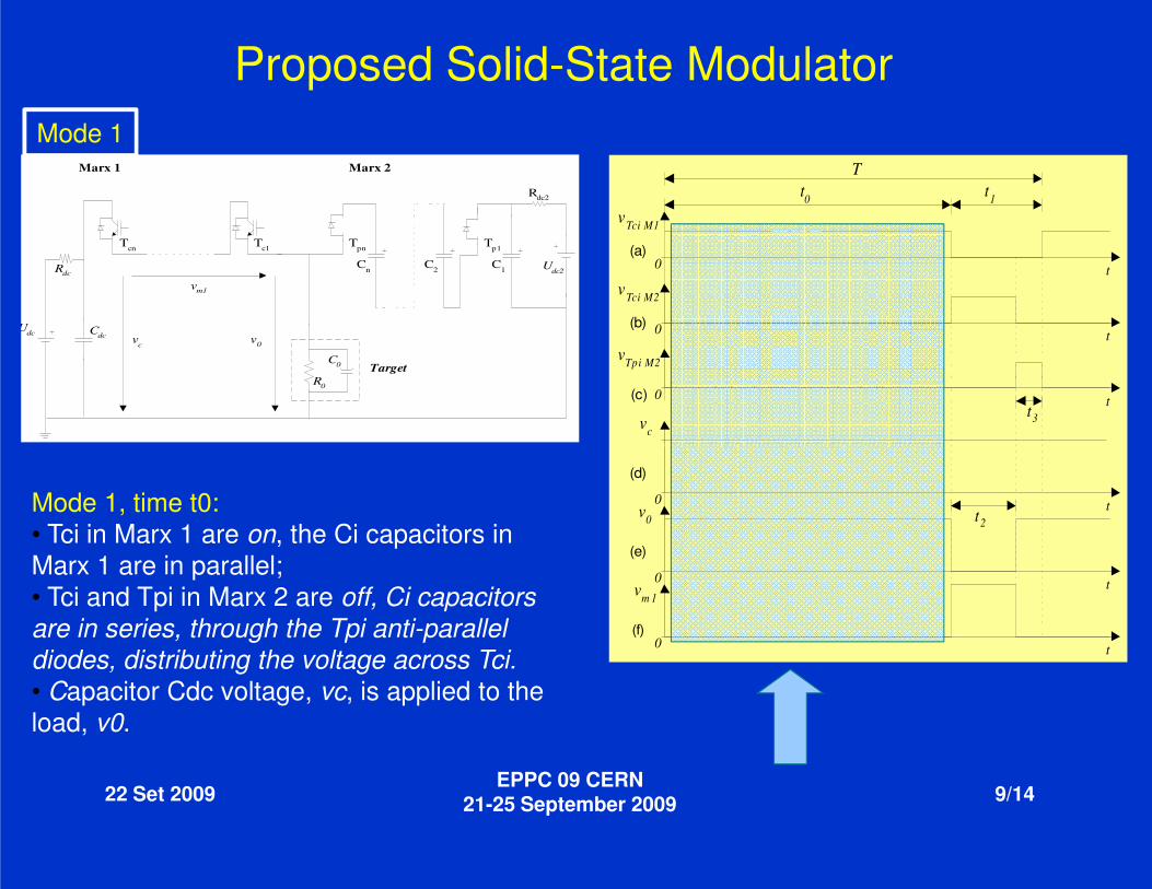
Proposed Solid-State ModulatorMode 1
22 Set 2009EPPC 09 CERN
21-25 September
Mode 1, time t0:• Tci in Marx 1 are on, the Ci capacitors in Marx 1 are in parallel;• Tci and Tpi in Marx 2 are off, Ci capacitors are in series, through the Tpi anti-parallel diodes, distributing the voltage across Tci. • Capacitor Cdc voltage, vc, is applied to the load, v0.
Tt1
t3
t0vTci M1
vTci M2
vTpi M2
0
0
0
vc
t
t
t
(a)
(b)
(c)
State Modulator
EPPC 09 CERN September 2009 9/14
t2
0
0
0v0
vm 1
t
t
t
(d)
(e)
(f)

Marx 1
Cn
Dpn
Udc
Rdc
Target
vc v0
Cdc
R0
C0
Udc2
Dp1
C1C2
Cn
Tcn Tc1
C1C2
Dc1Dc(n-1) Rdc2
Marx 2
vm1
Proposed Solid-State ModulatorMode 2
22 Set 2009EPPC 09 CERN
21-25 September
Mode 2, time t2:• Tci in Marx 1 are off, vc appears between theterminals, and is sustained by the Ci capacitorsin series through the diodes Dpi, distributing thevoltage across the Tci.• Tpi and Tci in Marx 2 are, respectively, off andon;• The load is discharge to zero.
dc2
State Modulator
Tt1
t3
t0vTci M1
vTci M2
vTpi M2
0
0
0
vc
t
t
t
(a)
(b)
(c)
EPPC 09 CERN September 2009 10/14
thecapacitors
the
and
t2
0
0
0v0
vm 1
t
t
t
(d)
(e)
(f)
Marx 1
Tcn
Udc
Rdc
Target
vc v0
Cdc
R
C0
Udc2
Tc1 Tpn
Cn C1C2
Tp1
Rdc2
Marx 2
vm1
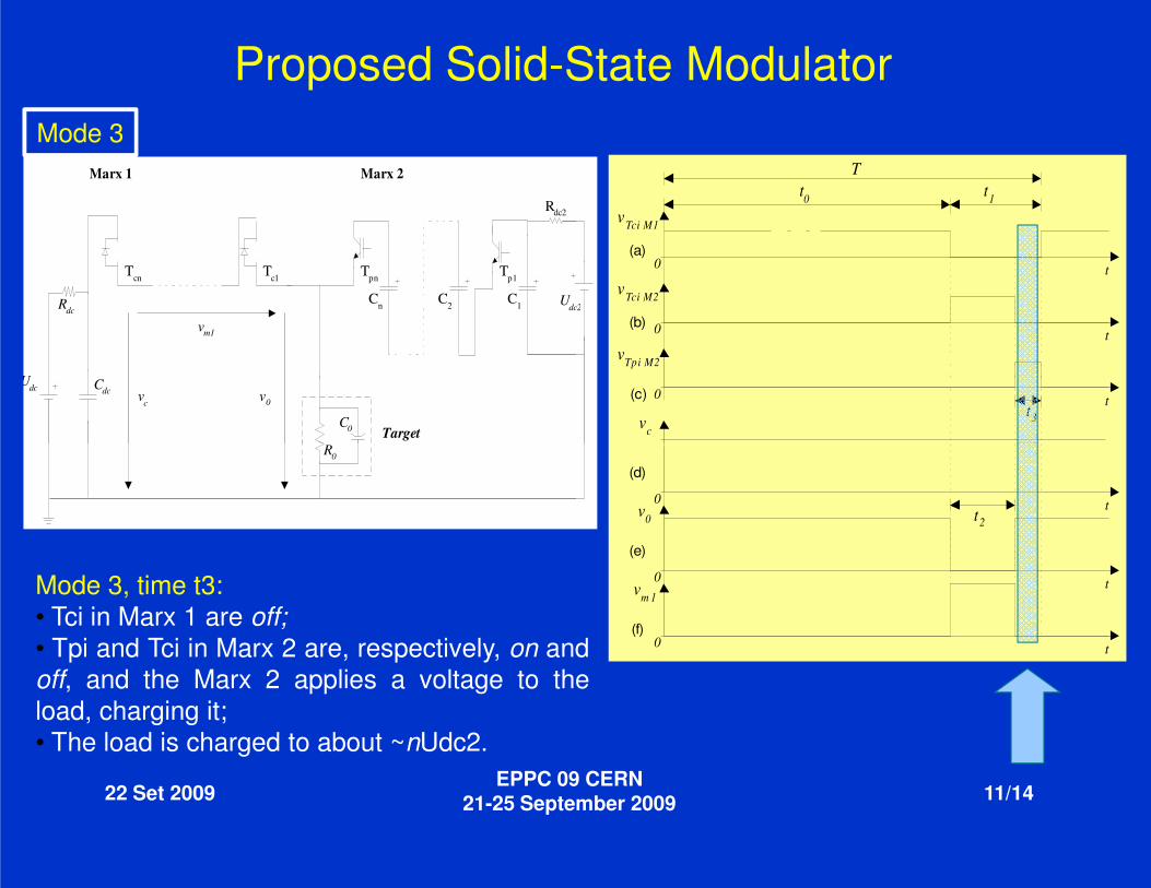
Proposed Solid-State ModulatorMode 3
22 Set 2009EPPC 09 CERN
21-25 September
R0
Mode 3, time t3:• Tci in Marx 1 are off;• Tpi and Tci in Marx 2 are, respectively, on andoff, and the Marx 2 applies a voltage to theload, charging it;• The load is charged to about ~nUdc2.
dc2
State Modulator
Tt1
t3
t0vTci M1
vTci M2
vTpi M2
0
0
0
vc
t
t
t
(a)
(b)
(c)
EPPC 09 CERN September 2009 11/14
andthe
t2
0
0
0v0
vm 1
t
t
t
(d)
(e)
(f)
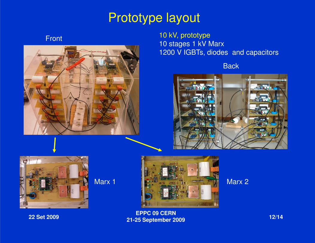
Prototype layoutFront
22 Set 2009EPPC 09 CERN
21-25 September
Marx 1
Prototype layout
Back
10 kV, prototype10 stages 1 kV Marx1200 V IGBTs, diodes and capacitors
EPPC 09 CERN September 2009 12/14
Marx 2
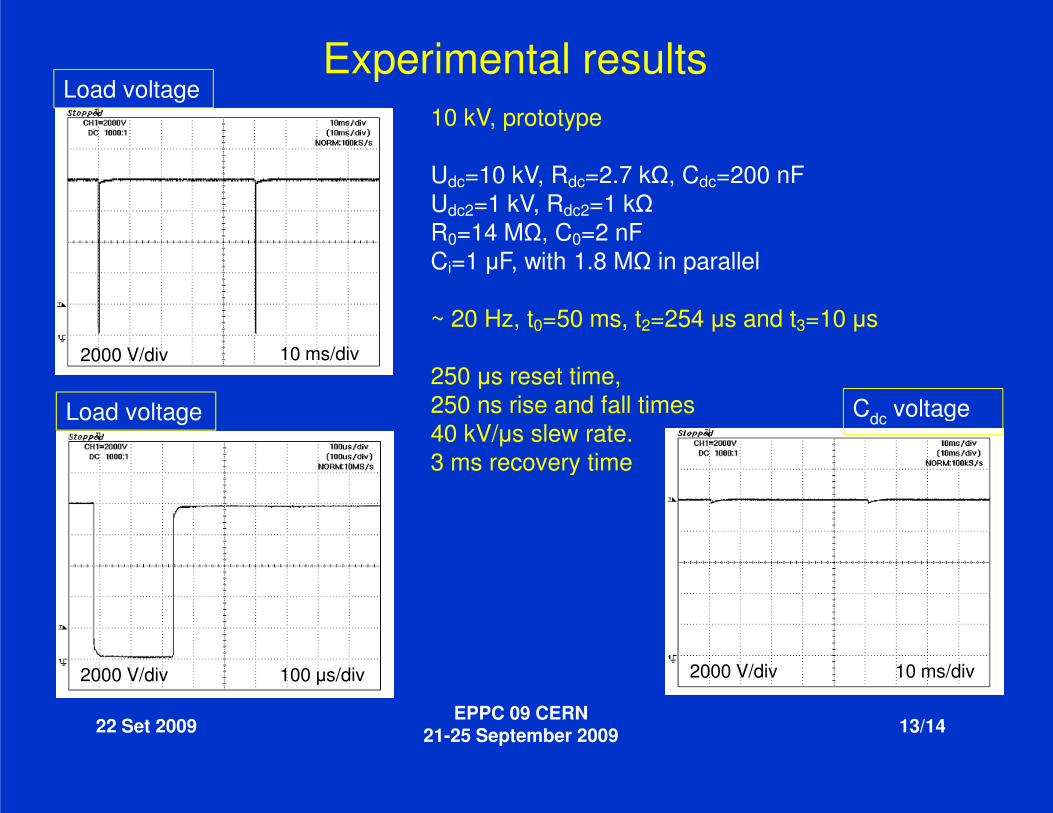
Experimental results10 kV, prototype
Udc=10 kV,Udc2=1 kV,R0=14 MΩCi=1 µF, with 1.8 M
~ 20 Hz, t
250 µs reset time, 250 ns rise and fall times
Load voltage
Load voltage
2000 V/div 10 ms/div
22 Set 2009EPPC 09 CERN
21-25 September
250 ns rise and fall times40 kV/µs slew rate. 3 ms recovery time
Load voltage
2000 V/div 100 µs/div
Experimental results10 kV, prototype
kV, Rdc=2.7 kΩ, Cdc=200 nFkV, Rdc2=1 kΩ
=14 MΩ, C0=2 nFµF, with 1.8 MΩ in parallel
~ 20 Hz, t0=50 ms, t2=254 µs and t3=10 µs
s reset time, 250 ns rise and fall times C voltage
EPPC 09 CERN September 2009 13/14
250 ns rise and fall timesµs slew rate.
3 ms recovery time
2000 V/div
Cdc voltage
10 ms/div
• A new solid-state Marx type topology was proposed for the ISOLDE Target Voltage Modulator;
• Solid-state Marx generators were used as serial and parallel switches;
• The new topology minimizes the effects on the PS from the load voltage excursions
• Preliminary results, from a 10 kV prototype, were presented with two, ten stages 1 kV, Marx generators, with 1200 semiconductors;
Conclusions and future work
22 Set 2009EPPC 09 CERN
21-25 September
stages 1 kV, Marx generators, with 1200 semiconductors;
• Voltage ripple is, mainly, due to the parameters Rsystem as well as the value of the resistors connected in parallel with the Ccapacitors in the two Marx generators;
• It is mandatory to further increase the voltage amplitude to near the 60 kV regime and test the circuit in the off-line target.
state Marx type topology was proposed for the ISOLDE Target
state Marx generators were used as serial and parallel switches;
The new topology minimizes the effects on the PS from the load voltage
Preliminary results, from a 10 kV prototype, were presented with two, ten stages 1 kV, Marx generators, with 1200 semiconductors;
Conclusions and future work
EPPC 09 CERN September 2009 14/14
stages 1 kV, Marx generators, with 1200 semiconductors;
Voltage ripple is, mainly, due to the parameters R0/C0 and Rdc/Cdc of the system as well as the value of the resistors connected in parallel with the Ci
It is mandatory to further increase the voltage amplitude to near the 60 kV line target.